Idea Statica
Steel
Concrete
BIM & Workflows
Support & Learning
Pricing
Company
14-Day Trial
How to model footing with connecting plate
Opening and notch
Stub
How to use a rod (solid bar) member
Connecting plate eccentricity
How to model a single bolt connection (Model type)
How to model footing with connecting plate
Using the plate Editor to shape a plate
General anchoring shapes and options
Shear force transfer in anchoring
Partially supported base plate
How to model footing with connecting plate
Workplane
How to model footing with connecting plate
Connection designSteelKnowledge baseConnectionAnchoring

How to model footing with connecting plate

This article is also available in
ENCSDEESFRITPTNLHURO

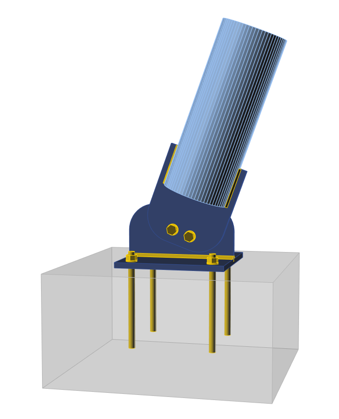
This article shows how to model an inclined tubular member connected by a connecting plate to the base plate, which is anchored to the concrete block. This is a typical anchoring of a bracing member.

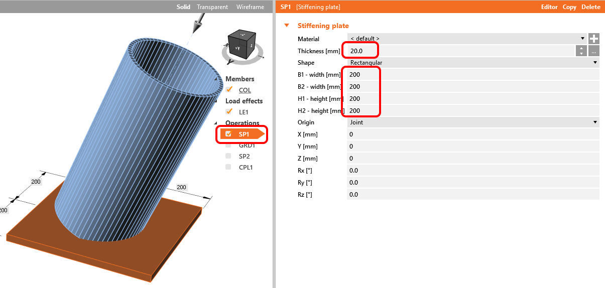
1. Create a general stiffening plate to form the base plate.

How to model footing with connecting plate

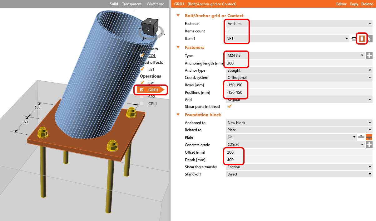
2. Define general anchors with the operation Bolt grid to anchor the base plate to the concrete block

How to model footing with connecting plate

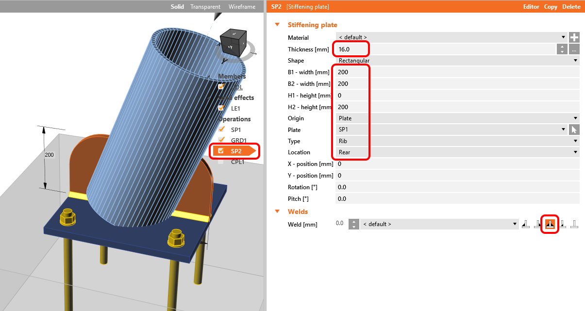
3. Add another general stiffening plate into the right position to create a rib passing through the tube adn weld it to the base plate.

How to model footing with connecting plate

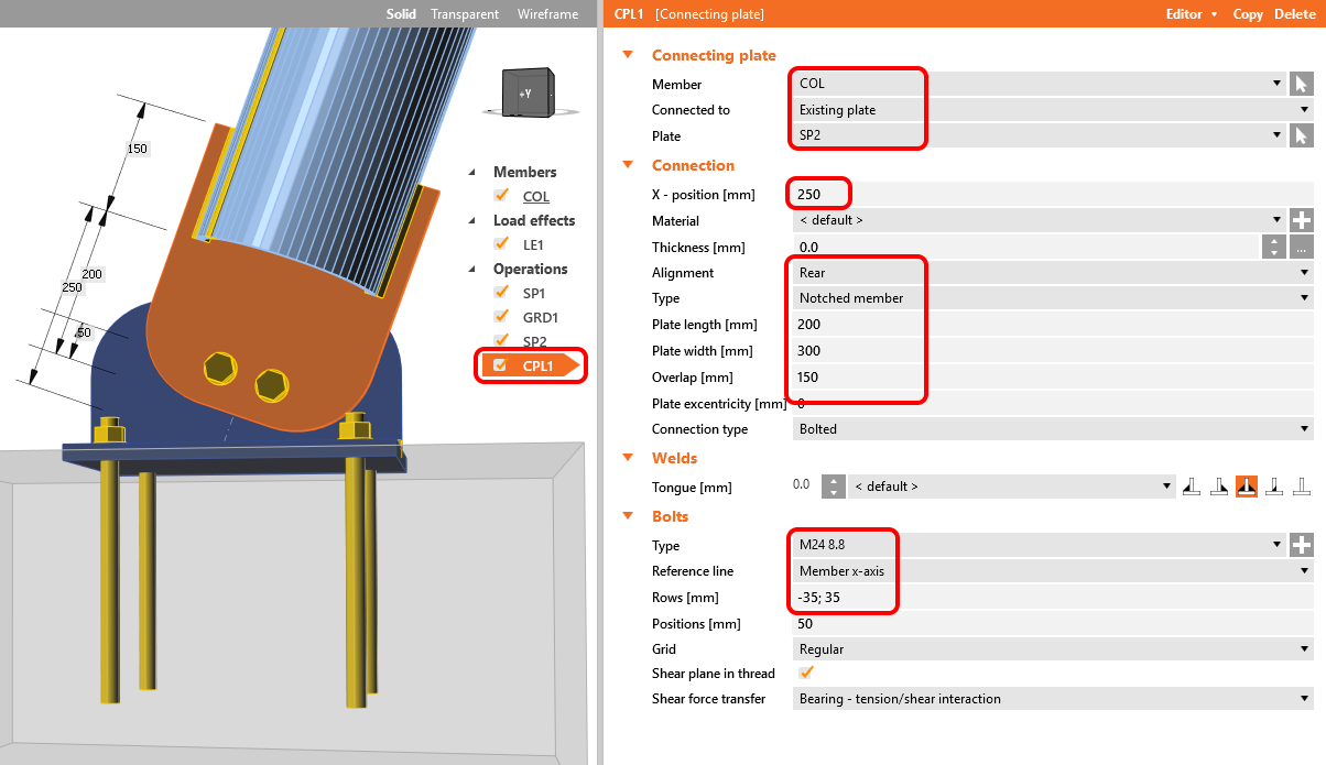
4. Add the connecting plate manufacturing operation and adjust its properties so that it produces two bolts. The plates are shaped in the Editor to a rounded shape.

How to model footing with connecting plate

5. The footing with a connecting plate is ready to be calculated. To simulate the bracing member transferring normal and shear force only, switch the model type to N-Vy-Vz.

How to model footing with connecting plate

See details in the recorded video.