Idea Statica
Steel
Concrete
BIM & Workflows
Support & Learning
Pricing
Company
14-Day Trial
How to use a rod (solid bar) member
How to define correct load position (Forces in)
Equilibrium and supporting member
Key insights into constraints, member length and GMNA vs MNA analysis
When to use a stiffening member?
How to model a single bolt connection (Model type)
Shear force position input and visualization
Default member length in Connection
The right LCS (local coordinate system) orientation
How to use a rod (solid bar) member
Relative positions of members
Steel joint analysis model
Opening and notch
Stub
How to use a rod (solid bar) member
Using the plate Editor to shape a plate
How to use a rod (solid bar) member
Connecting plate eccentricity
How to model a single bolt connection (Model type)
How to model footing with connecting plate
Using the plate Editor to shape a plate
Workplane
How to use a steel rod member
Connection designSteelKnowledge baseConnectionAISC (USA)

How to use a rod (solid bar) member

This article is also available in
ENCSDEESFRITPTNLHURO

There are some specifications that each user should be aware of when employing the rod cross-section (a solid bar) in the IDEA StatiCa Connection model.

The rod cross-section (solid bar) is dedicated mostly to tension elements. It can be found in the library of profiles; nevertheless, its applicability is limited to two manufacturing operations only: the connecting plate and the gusset plate. 

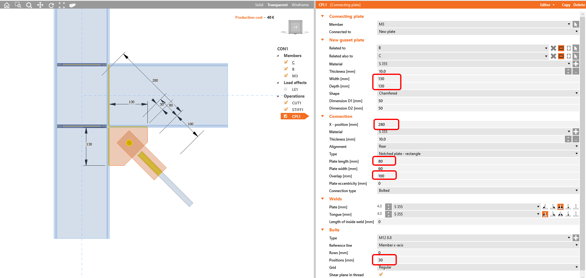
Here are the main dimensions when using  the operation Connecting plate - Notched plate - rectangle:

Rod - connecting plate

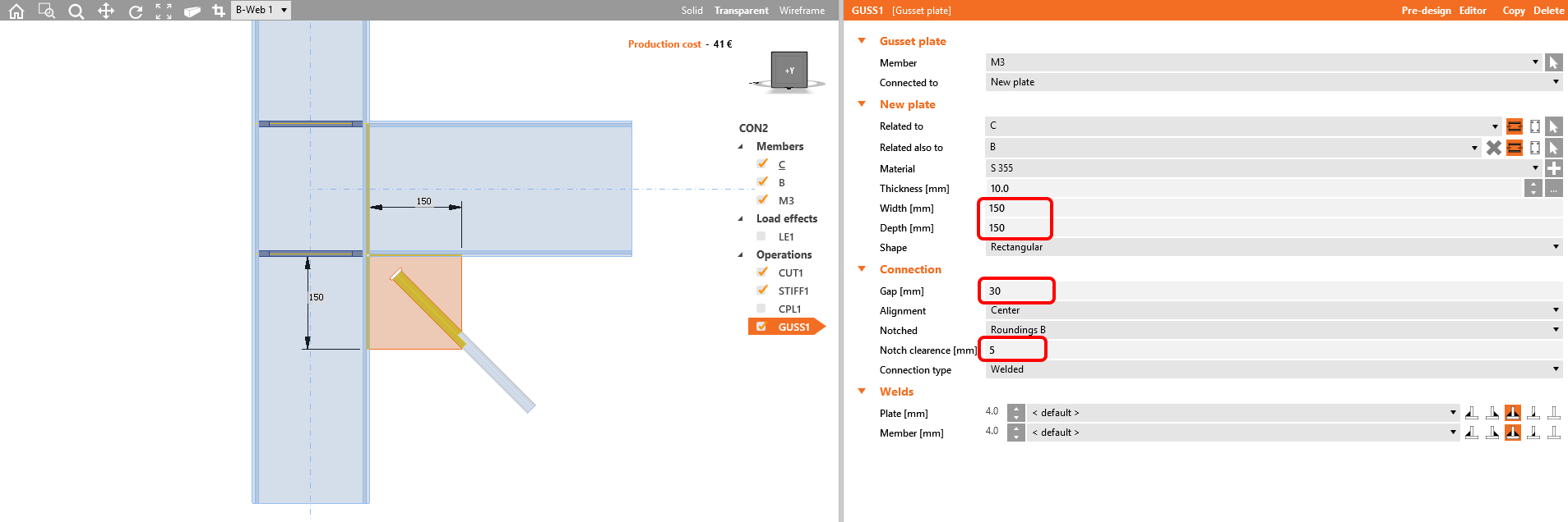
And here, when you use Gusset plate:

Rod - gusset plate

In both cases, the profile is not meshed by shell elements like all others; therefore the software does not present results on them. The check of such a member has to be done in the 3D global analysis model. Despite this, the adjacent welds are checked as usual.

See more in the following video:

Get 14 days of full access, completely free.

Check out IDEA StatiCa for free