1 New project
Start with launching the IDEA StatiCa Connection. Create a new project by selecting a starting template, fill the name and choose AISC 360-22 (LRFD) design code and default steel grade – A992.
Select the "Create a blank design" button to generate the geometry only.

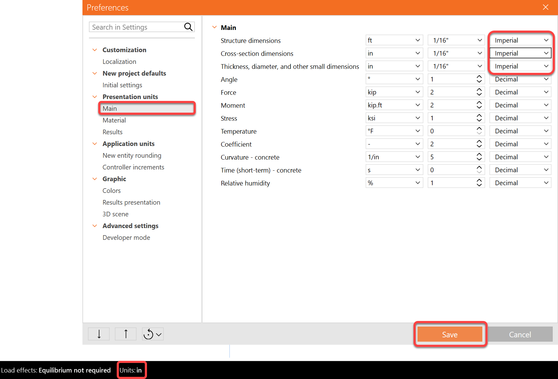
Since you work under the AISC code, make sure to set the imperial units (see How to change the system of units).
The example shown here is using the fraction system. You can change the unit type by clicking Units>Presentation units> Change the following three units to "Imperial"
2 Geometry
The model is a moment-end plate from AISC Design Guide 39: End-Plate Moment Connections. Example 5.3-3 Multiple-Row Extended 1/2 Unstiffened Thick End-Plate.
Start by defining the geometry. A column and a beam are added in the modeling area.
Change the cross-section of member C to W14X99.

Next, modify the cross-section of members B to a built-up I section and input the following dimensions:

Verify that the Force position in the members C and B is= Node
3 Load effects
Next, modify the Load effects. Turn off the loads in equilibrium and enter the force values into the beam table. More load cases can be added.
- My= 400 k-ft
- Vz=-45 kips

4 Design
Next, to model a connection, add a new operation by clicking on the New operation icon>End plate:

Define the following inputs:

Save the connection file, by clicking in the Save button in the top ribbon:

Review the final design of the joint. Press Ctrl keyboard + mouse scroll wheel at the same time to rotate the 3D model and review the design

5 Stress/strain analysis
To have a complete picture of the connection behavior, the stress/strain analysis is run first.
Select Calculate on the ribbon to run the analysis using the CBFEM method. The numerical model is automatically generated, the calculation is performed, and you can directly see the overall check results in the top-left corner of the scene.
The overall check uses a traffic light system to indicate the utilization of the elements.

More detailed results can be displayed under the Check tab: activate the Equivalent stress, Mesh and Deformed shape of the connection in the ribbon to get a full picture of what is happening in the joint.

6 Stiffness analysis
To keep the stress/strain results, copy this project item. A new item will be created in the file.

In the copied connection, click on the Design tab>Connection name>Change the analysis type to Stiffness in the project item data.

Verify that beam B1 is set as an Analyzed member as shown below. (If you want switch Analyzed member, you can use the right mouse button and set another member as an Analyzed member).
The “Theoretical length for My, Mz” can be set for the analyzed member. For more information about the theoretical length, please see Theoretical background and Video – tips for stiffness analysis.

Start the stiffness analysis by clicking the Calculate button in the top ribbon.
The analysis results and load path can be checked in detail in the Rotational stiffness tab. For a better understanding of the results, see the Theoretical Background.
A webinar explaining the results was held here.
In this case, the classification of the connection per AISC was calculated as partially restrained.

- In the results table, the name of the result is shown when the mouse is hovered over it
- Right-click on the graph to get an Excel file with the results to generate a custom graph
- Scroll up and down in the graph area to zoom in or out on the moment-rotation diagram

Change the rotation and rotational stiffness results units if needed:

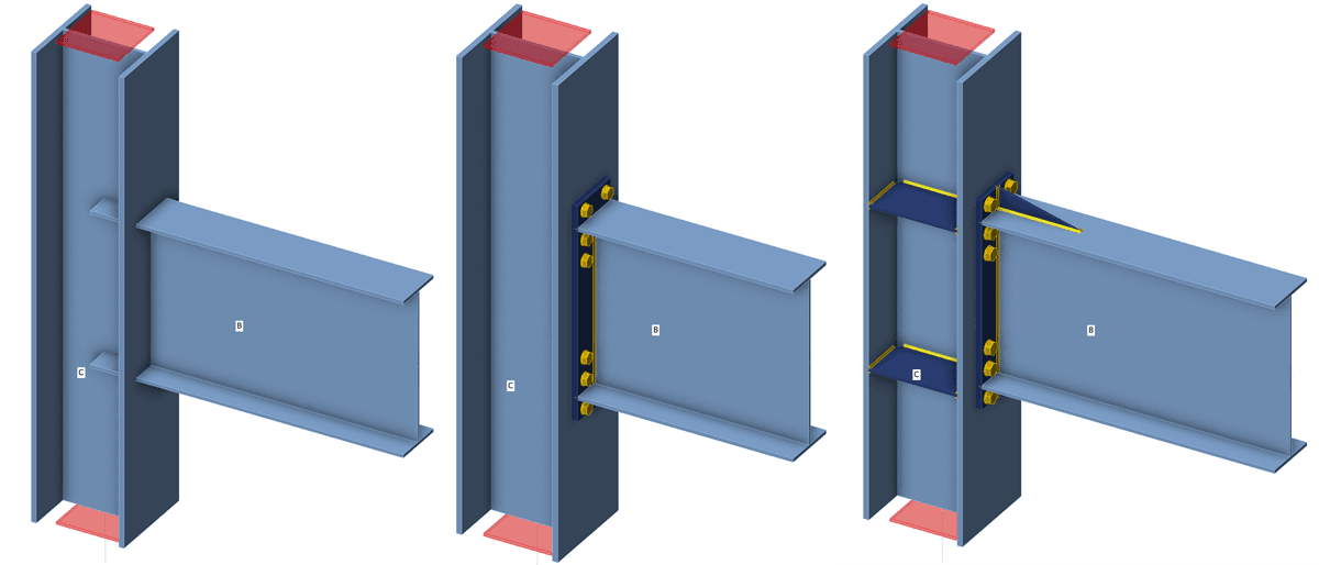
7 Modification of connection
The connection will be modified to get a Rigid connection classification.
To keep the project CON2, copy it and create CON3.

Change the bolt diameter in EP1 to 1 inch A325:

Add a New operation> Select Rib and input the following parameters:

Right-click on the Rib operation and copy it:

Now modify the RIB2 operation and change:
- Cross-section parts to Bottom flange 1
- Surface to Lower

Add a new operation and select Stiffener, input the following parameters:

Now run stiffness analysis again by icon Calculate from the top ribbon. And you can notice the change in results from Partially restrained to Fully restrained:

For more information on stiffness analysis, please check out our Theoretical background.
8 Report
At last, go to the Report tab. IDEA StatiCa offers a fully customizable report that can be printed or saved in an editable format.

You have designed, code-checked, and calculated the stiffness of the connection according to AISC.
9 More information
Video – introduction to stiffness
Video – tips for stiffness analysis
Learn how to use IDEA StatiCa effectively with our self-paced e-learning courses
Start learning

