Idea Statica
Steel
Steel overview
Connection design
Member design
Parametric design
Steel case studies
Concrete
Concrete overview
Walls and D-regions
Anchoring design
Concrete case studies
BIM & Workflows
BIM Overview
Supported integrations
Checkbot
Viewer
APIs
Support & Learning
Support Center
E-learning & certification
Blog
Downloads & Licensing
Pricing
Plans
Free community tool
Enterprise customers
Students & educators
How much will you save?
Company
About us
Contact
Research & development
Authorized resellers
Meet our customers
14-Day Trial
Support CenterKnowledge BaseThe right LCS (local coordinate system) orientation
How to define correct load position (Forces in)
Equilibrium and supporting member
Key insights into constraints, member length and GMNA vs MNA analysis
When to use a stiffening member?
How to model a single bolt connection (Model type)
Shear force position input and visualization
Default member length in Connection
The right LCS (local coordinate system) orientation
How to use a rod member
Relative positions of members
Steel joint analysis model
Different ways to define load effects
Equilibrium and supporting member
Principles of Loading in a Connection: Equilibrium, bearing member etc.
Key insights into constraints, member length and GMNA vs MNA analysis
Calculate load extremes
Shear force position input and visualization
When a shear connection transmits a bending moment
Loads in equilibrium by default
How to import load effects from Excel sheet
Percentage loading
Node equilibrium in the 3D FEM model
Internal forces in the steel connections
The right LCS (local coordinate system) orientation
Orientation of the connecting plate can be modified
Connection designSteelKnowledge baseConnectionManufacturing operations

The right LCS (local coordinate system) orientation

This article is also available in
ENCSDENL

All load effects and manufacturing operations are oriented according to the LCS of the member.

The relation between LCS (local coordinate system) and linked parts such as plates, bolts, or loads is crucial, manipulating the properties of the member position influences their position.

In the following example turning the member beta direction changes the direction of LCS and causes big differences in the joint. See the position of the stiffener and also check the unbalance forces.

LCS


local coordinate system

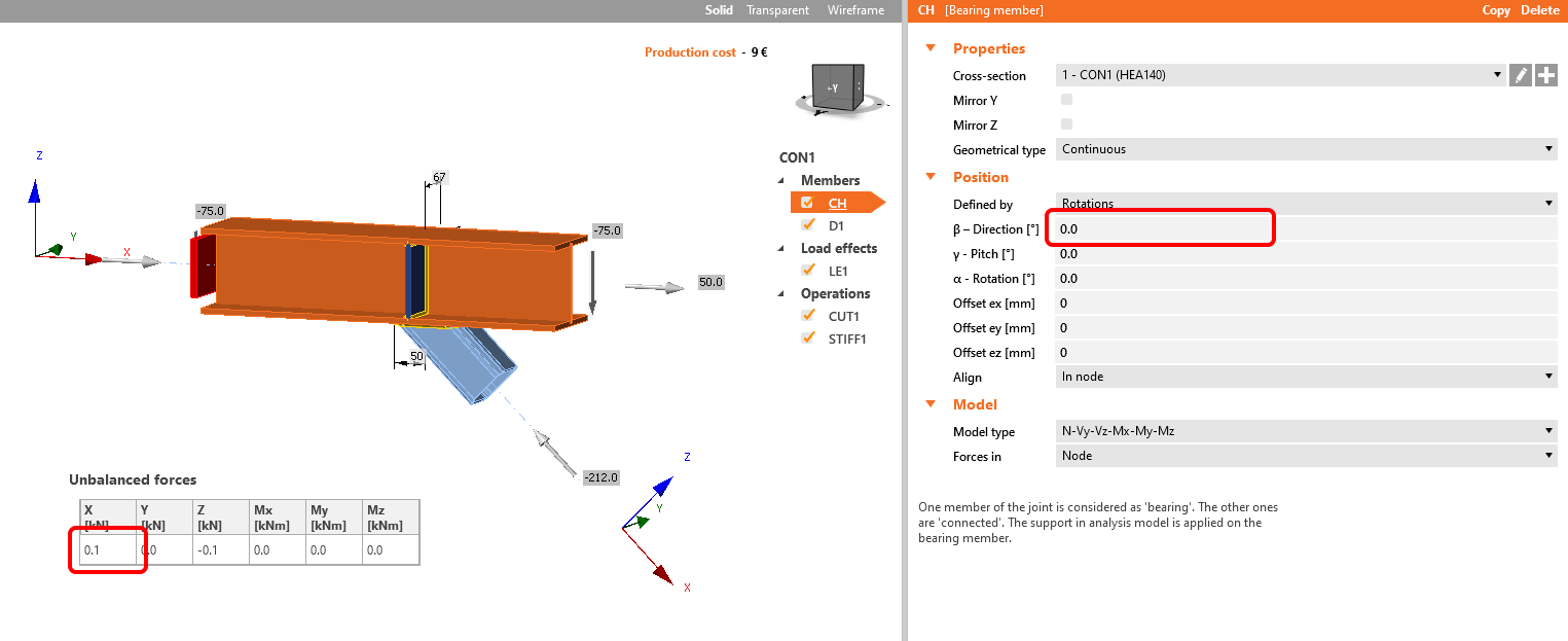
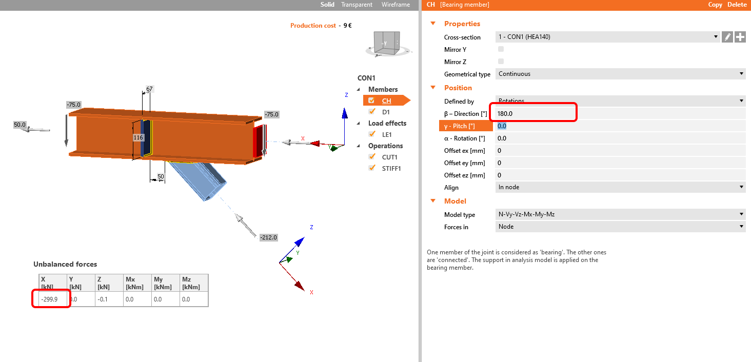
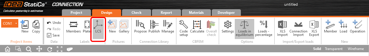
The visibility of the LCS direction can be set in the upper ribbon.

LCS

Watch the following webinar, where matching the local coordinate system (LCS)  of both beams will help you to design the joint. 

Learn how to use IDEA StatiCa effectively with our self-paced e-learning courses

Start learning


Subscribe to our newsletter

Company

  • About us
  • Partnerships
  • Job openings
  • Patented technology for structural engineers

Resources

  • Customer projects
  • Case studies
  • IDEA StatiCa Connection Library
  • Concrete verifications

Legal

  • IDEA StatiCa END USER LICENSE AGREEMENT
  • Privacy policy
  • Terms of Services – IDEA StatiCa Viewer
  • Licensing

Help

  • Contact
  • Get price quote
  • IDEA StatiCa Specialists
  • Download the latest version
FacebookInstagramLinkedInYouTube

© IDEA StatiCa 2009-2026

Trusted and used worldwide by engineers, fabricators & consultants.