Idea Statica
Steel
Steel overview
Connection design
Member design
Parametric design
Steel case studies
Concrete
Concrete overview
Walls and D-regions
Anchoring design
Concrete case studies
BIM & Workflows
BIM Overview
Supported integrations
Checkbot
Viewer
APIs
Support & Learning
Support Center
E-learning & certification
Blog
Downloads & Licensing
Pricing
Plans
Free community tool
Enterprise customers
Students & educators
How much will you save?
Company
About us
Contact
Research & development
Authorized resellers
Meet our customers
14-Day Trial
Support CenterKnowledge BaseCode-check of concrete block according to Canadian standards
Advanced analysis types for your steel structures
Anchor bolts
Structural model of a concrete block
Code-check of anchors (AISC)
Code-check of concrete blocks (AISC)
Code-check of anchors according to Canadian standards
Code-check of concrete block according to Canadian standards
The concrete below the base plate is simulated by Winkler subsoil with uniform stiffness, which provides the contact stresses. IDEA StatiCa - concrete design software for structural code-check of concrete constructions.
Connection designSteelKnowledge baseConnectionAnchoring

Code-check of concrete block according to Canadian standards

This article is also available in
ENNL

The concrete below the base plate is simulated by Winkler subsoil with uniform stiffness, which provides the contact stresses. The average stress at the loaded area in contact with the base plate is used for compressive check.

Concrete in compression

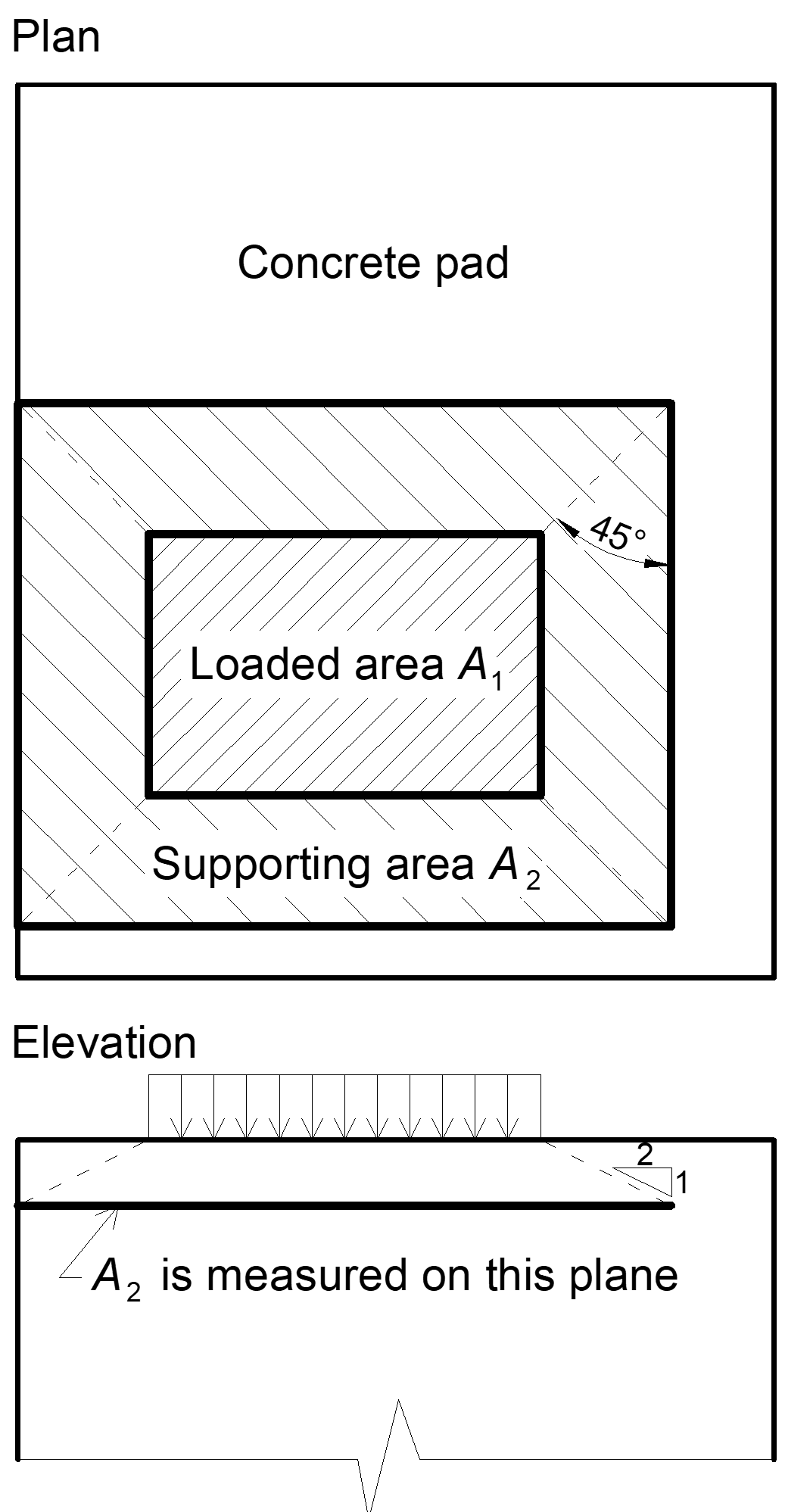
The concrete design bearing strength in compression is determined in accordance with S16-14 – 25.3.1 and CSA A23.3 – 10.8. When the supporting surface of the concrete is larger than the base plate the design bearing strength is defined as

\[ f_{p,(max)} = 0.85 \phi_c f'_c \sqrt{\frac{A_2}{A_1}} \le 1.7 \phi_c f'_c \]

where:

  • ϕc=0.65 – resistance factor for concrete
  • f'c – concrete compressive strength
  • A1 – base plate area in contact with a concrete surface (upper surface area of the frustum)
  • A2 – concrete supporting surface (geometrically similar lower area of the frustum having its slopes of 1 vertical to 2 horizontal)

The assessment of concrete in the bearing is as follows:

σ ≤ fp(max)

where:

  • σ – average compressive stress under the base plate

Transfer of shear forces

Shear loads can be transferred via one of these options:

  • Shear lug,
  • Friction,
  • Anchor bolts.

Shear lug

Shear loads are considered to be transferred only via shear lug. Concrete bearing is not checked in software and should be checked by the user elsewhere. Shear lug and welds are checked using FEM and weld components.

Friction

In the case of compressive force, the shear loads can be transferred via friction between a concrete pad and a base plate. The friction coefficient is editable in the Code setup.

Anchor bolts

If the shear load is transferred via anchor bolts only, the shear force acting on each anchor is determined by FEA and anchor bolts are assessed according to ACI 318-14 as described in the following chapters.

Subscribe to our newsletter

Company

  • About us
  • Partnerships
  • Job openings
  • Patented technology for structural engineers

Resources

  • Customer projects
  • Case studies
  • IDEA StatiCa Connection Library
  • Concrete verifications

Legal

  • IDEA StatiCa END USER LICENSE AGREEMENT
  • Privacy policy
  • Terms of Services – IDEA StatiCa Viewer
  • Licensing

Help

  • Contact
  • Get price quote
  • IDEA StatiCa Specialists
  • Download the latest version
FacebookInstagramLinkedInYouTube

© IDEA StatiCa 2009-2026

Trusted and used worldwide by engineers, fabricators & consultants.