Weld model according to CBFEM
IDEA StatiCa has a unique method in its solver, the Component-based Finite Element Method (CBFEM). The weld model used in CBFEM is described and verified to several steel design codes. The load resistance and deformation capacity are also compared to the main experimental research programs.
There are several options on how to treat welds in numerical models. The large deformations make the mechanical analysis more complex and it is possible to use different mesh descriptions, different kinetic and kinematic variables, and constitutive models. Generally, different types of geometric 2D and 3D models and thereby finite elements with their applicability for different accuracy levels are used. The most often applied material model is the common rate-independent plasticity model based on von Mises yield criterion. Residual stress and deformation caused by welding are not assumed in the design model.
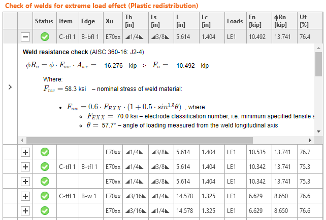
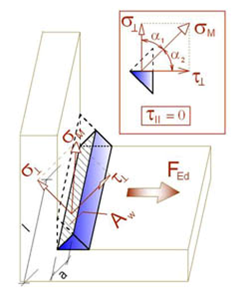
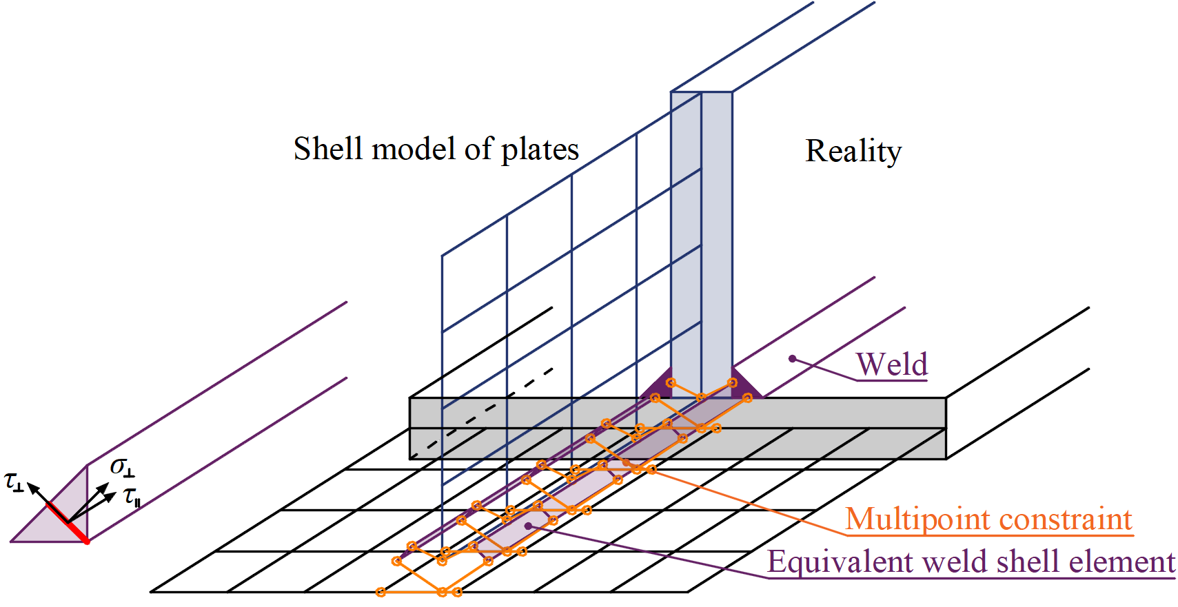
The load is transmitted through force-deformation constraints based on the Lagrangian formulation to the opposite plate. The connection is called multi-point constraint (MPC) and relates the finite element nodes of one plate edge to another edge or surface. The finite element nodes are not connected directly. The advantage of this approach is the ability to connect meshes with different densities. The constraint allows to model midline surface of the connected plates with the offset, which respects the real weld configuration and throat thickness. The load distribution in the weld is derived from the MPC, so the stresses are calculated in the throat section. This is important for the stress distribution in the plate under the weld and for modeling of T-stubs.
In our Theoretical background, you can find more information on how the CBFEM method describes and verifies welds.