The theoretical background is based on COMPATIBLE STRESS FIELD DESIGN OF STRUCTURAL CONCRETE
(Kaufmann et al., 2020)
Structural design of concrete discontinuities in IDEA StatiCa Detail
Introduction to the CSFM method
General introduction for the structural design of concrete details
Main assumptions and limitations
Design tools for reinforcement
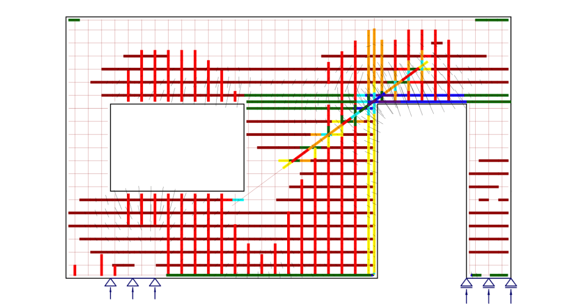
Analysis model of IDEA StatiCa Detail
Introduction to finite element implementation
Supports and load transmitting components
Load transfer at trimmed ends of beams
Geometric modification of cross-sections
Finite element types
Meshing
Solution method and load-control algorithm
Presentation of results
Model verification
Limit states, crack width calculation, and Tension stiffening
Structural verifications according to EUROCODE
- Material models (EN)
- Safety factors
- Ultimate limit state analysis
- Partially loaded areas (PLA)
- Serviceability limit state analysis
Structural verifications according to ACI 318-19
- Material models (ACI)
- Strength reduction and load factors
- Strength verifications
- Bearing and anchorage zones - Partially loaded areas
- Serviceability verifications
Structural verifications according to AS 3600
- Material models (AUS)
- Stress reduction and load factors
- Strength and anchorage verifications
- Serviceability checks
Prestressing in Detail - Model description
Introduction to the CSFM method
Widget #NaN: support_center_article
Name: Theoretical background Detail - Main assumptions and limitations
ID: 2ebdaf9c-827f-4fd6-9f82-28bc96970a64
Show Raw Data
{
"title": {
"name": "Main headline (H1)",
"type": "text",
"value": "Main assumptions and limitations for CSFM in 2D"
},
"preview_image": {
"name": "Preview image",
"type": "asset",
"value": [
{
"name": "Fig. 2 - Basic assumptions of CSFM.png",
"description": "Basic assumptions of Compatible stress field method (CSFM)",
"type": "image/png",
"size": 187222,
"url": "https://assets-us-01.kc-usercontent.com:443/28eac049-c8ed-00e2-220c-12142a968dff/70d687dc-a209-4d67-aeb9-c0bdabacd5c1/Fig.%202%20-%20Basic%20assumptions%20of%20CSFM.png",
"width": 1343,
"height": 824,
"renditions": {}
}
]
},
"post_date": {
"name": "Post date",
"type": "date_time",
"value": null,
"displayTimeZone": null
},
"perex_content": {
"name": "Lead paragraph",
"type": "text",
"value": ""
},
"content": {
"images": [
{
"description": "Basic assumptions of Compatible stress field method (CSFM)",
"imageId": "a5b4f7ac-3fc1-4050-9269-afdb9901a92e",
"url": "https://assets-us-01.kc-usercontent.com:443/28eac049-c8ed-00e2-220c-12142a968dff/70d687dc-a209-4d67-aeb9-c0bdabacd5c1/Fig.%202%20-%20Basic%20assumptions%20of%20CSFM.png",
"height": 824,
"width": 1343
}
],
"linkedItemCodenames": [],
"linkedItems": [],
"links": [
{
"codename": "concrete",
"linkId": "b4790cf9-a605-45b3-b41b-e36909ad4291",
"urlSlug": "concrete",
"type": "landing_page"
}
],
"name": "Content",
"type": "rich_text",
"value": "<p><strong>CSFM considers maximum principal concrete stress in compression (σ</strong><em><strong><sub>c</sub></strong></em><strong><sub>2</sub></strong><em><strong><sub>r</sub></strong></em><strong>) and reinforcement stresses (σ</strong><em><strong><sub>sr</sub></strong></em><strong>) at the cracks while neglecting the concrete tensile strength (σ</strong><em><strong><sub>c</sub></strong></em><strong><sub>1</sub></strong><em><strong><sub>r</sub></strong></em><strong> = 0), except for its stiffening effect on the reinforcement.</strong> The consideration of tension stiffening allows the average reinforcement strains (ε<em><sub>m</sub></em>) to be simulated. Fictitious, rotating, stress-free cracks that open without slip (Fig. 2a) are considered and the equilibrium at the cracks together with the average strains of the reinforcement is also taken into account. </p>\n<figure data-asset-id=\"a5b4f7ac-3fc1-4050-9269-afdb9901a92e\" data-image-id=\"a5b4f7ac-3fc1-4050-9269-afdb9901a92e\"><img src=\"https://assets-us-01.kc-usercontent.com:443/28eac049-c8ed-00e2-220c-12142a968dff/70d687dc-a209-4d67-aeb9-c0bdabacd5c1/Fig.%202%20-%20Basic%20assumptions%20of%20CSFM.png\" data-asset-id=\"a5b4f7ac-3fc1-4050-9269-afdb9901a92e\" data-image-id=\"a5b4f7ac-3fc1-4050-9269-afdb9901a92e\" alt=\"Basic assumptions of Compatible stress field method (CSFM)\"></figure>\n<p><em>\\( \\textsf{\\textit{\\footnotesize{Fig. 2\\qquad Basic assumptions of the CSFM: (a) principal stresses in concrete; (b) stresses in the reinforcement direction;}}}\\) \\( \\textsf{\\textit{\\footnotesize{(c) stress-strain diagram of concrete in terms of maximum stresses with consideration of compression softening;}}}\\) \\( \\textsf{\\textit{\\footnotesize{(d) stress-strain diagram of reinforcement in terms of stresses at cracks and average strains; (e) compression softening}}}\\) \\( \\textsf{\\textit{\\footnotesize{law; (f) bond shear stress-slip relationship for anchorage length verifications.}}}\\)</em></p>\n<p><br></p>\n<p>Despite their simplicity, similar assumptions have been demonstrated to yield accurate predictions for reinforced members subjected to in-plane loading (Kaufmann 1998; Kaufmann and Marti 1998) if the provided reinforcement avoids brittle failures at cracking. Furthermore, the non-consideration of any contribution of the tensile strength of concrete to the ultimate load is consistent with the principles of modern design codes, which are mostly based on plasticity theory.</p>\n<p>However, <strong>the CSFM is not suited for slender elements</strong> without transverse reinforcement since relevant mechanisms for such elements as aggregate interlock, residual tensile stresses at the crack tip, and dowel action – all of them relying directly or indirectly on the tensile strength of the concrete – are disregarded. While some design standards allow the design of such elements based on semi-empirical provisions, the CSFM is not intended for this type of potentially brittle structure.</p>\n<h4>Concrete</h4>\n<p>The concrete model implemented in the CSFM is based on the uniaxial compression constitutive laws prescribed by design codes for the design of cross-sections, which only depend on compressive strength. The parabola-rectangle diagram (Fig. 2c) is used by default in the CSFM, but designers can also choose a more simplified elastic ideal plastic relationship. When assessing according to the ACI code, it is possible to use only the parabola-rectangle stress-strain diagram. As previously mentioned, the tensile strength is neglected, as it is in classic reinforced concrete design.</p>\n<p>The effective compressive strength is automatically evaluated for cracked concrete based on the principal tensile strain (ε<sub>1</sub>) by means of the <em>k</em><em><sub>c</sub></em><sub>2</sub> reduction factor, as shown in Fig. 2c and e. The implemented reduction relationship (Fig. 2e) is a generalization of the <em>fib</em> Model Code 2010 proposal for shear verifications, which contains a limiting value of 0.65 for the maximum ratio of effective concrete strength to concrete compressive strength, which is not applicable to other loading cases.</p>\n<p>The CSFM in <a data-item-id=\"b4790cf9-a605-45b3-b41b-e36909ad4291\" href=\"\"><em>IDEA StatiCa Detail</em></a> does not consider an explicit failure criterion in terms of strains for concrete in compression (i.e., it considers an infinitely plastic branch after the peak stress is reached). This simplification does not allow the deformation capacity of structures failing in compression to be verified. However, their ultimate capacity is properly predicted when, in addition to the factor of cracked concrete (<em>k</em><em><sub>c</sub></em><sub>2</sub>) defined in (Fig. 2e), the increase in the brittleness of concrete as its strength rises is considered by means of the <em>\\( \\eta_{fc} \\)</em> reduction factor defined in <em>fib</em> Model Code 2010 as follows:</p>\n<p>\\[f_{c,red} = k_c \\cdot f_{c} = \\eta _{fc} \\cdot k_{c2} \\cdot f_{c}\\]</p>\n<p>\\[{\\eta _{fc}} = {\\left( {\\frac{{30}}{{{f_{c}}}}} \\right)^{\\frac{1}{3}}} \\le 1\\]</p>\n<p>where:</p>\n<p><em>k</em><em><sub>c </sub></em>is the global reduction factor of the compressive strength</p>\n<p><em>k</em><em><sub>c</sub></em><sub>2</sub> is the reduction factor due to the presence of transverse cracking</p>\n<p><em>f</em><em><sub>c</sub></em> is the concrete cylinder characteristic strength (in MPa for the definition of <em>\\( \\eta_{fc} \\)</em>).</p>\n<p>There is also a reduction of the<em> k</em><em><sub>c</sub></em><sub>2</sub> factor because of the stability of the calculation. This reduction doesn't influence the total strength of members. Assuming <em>f</em><em><sub>cd</sub></em> value as the factored strength of concrete (design value), the <em>k</em><em><sub>c</sub></em><sub>2</sub> value is reduced according to the following rules.</p>\n<p>σ<em><sub>c</sub></em><sub>2</sub><em><sub>r</sub></em><em> < 0.11f</em><em><sub>cd</sub></em><em> k</em><em><sub>c</sub></em><sub>2</sub><em>=1.0<br>\n0.11f</em><em><sub>cd</sub></em><em> < </em>σ<em><sub>c</sub></em><sub>2</sub><em><sub>r</sub></em><em> < 0.37f</em><em><sub>cd</sub></em><em> k</em><em><sub>c</sub></em><sub>2</sub><em> </em>is a linear interpolation between 1.0 and the value taken from the<br>\n graph displayed in Fig. 2f<em><br>\n</em>σ<em><sub>c</sub></em><sub>2</sub><em><sub>r</sub></em><em> > 0.37f</em><em><sub>cd</sub></em><em> k</em><em><sub>c</sub></em><sub>2</sub><em> </em>is directly taken from the graph from Fig. 2f</p>\n<h4>Reinforcement</h4>\n<p>The idealized bilinear stress-strain diagram for the bare reinforcing bars typically defined by design codes (Fig. 2d) is considered. The definition of this diagram only requires the basic properties of the reinforcement to be known during the design phase (strength and ductility class). A user-defined stress-strain relationship can also be defined.</p>\n<p>Tension stiffening is accounted for by modifying the input stress-strain relationship of the bare reinforcing bar in order to capture the average stiffness of the bars embedded in the concrete (ε<em><sub>m</sub></em>).</p>\n<h4>Bond model</h4>\n<p>Bond-slip between reinforcement and concrete is introduced in the finite element model by considering the simplified rigid-perfectly plastic constitutive relationship presented in Fig. 2f, with <em>f</em><em><sub>bd</sub></em> being the design value (factored value) of the ultimate bond stress specified by the design code for the specific bond conditions.</p>\n<p>This is a simplified model with the sole purpose of verifying bond prescriptions according to design codes (i.e., anchorage of reinforcement). The reduction of the anchorage length when using hooks, loops, and similar bar shapes can be considered by defining a certain capacity at the end of the reinforcement, as will be described further. </p>"
},
"regions": {
"name": "Region",
"type": "taxonomy",
"value": [
{
"name": "AMER",
"codename": "amer"
},
{
"name": "EMEA",
"codename": "emea"
},
{
"name": "APAC",
"codename": "apac"
}
],
"taxonomyGroup": "region"
},
"product_groups": {
"name": "Product group",
"type": "taxonomy",
"value": [
{
"name": "Concrete",
"codename": "concrete"
}
],
"taxonomyGroup": "product_group"
},
"support_center_article_types": {
"name": "Support center article",
"type": "taxonomy",
"value": [
{
"name": "Knowledge base",
"codename": "knowledgebase_article"
}
],
"taxonomyGroup": "support_center_article"
},
"expertise_levels": {
"name": "Expertise level",
"type": "taxonomy",
"value": [],
"taxonomyGroup": "expertise_level"
},
"labels": {
"name": "Labels",
"type": "taxonomy",
"value": [
{
"name": "Detail 2D",
"codename": "detail"
},
{
"name": "EN (Eurocode)",
"codename": "eurocode"
},
{
"name": "CSFM",
"codename": "csfm"
},
{
"name": "ACI (USA)",
"codename": "aci__usa_"
}
],
"taxonomyGroup": "labels"
},
"linked_items": {
"name": "Linked items",
"type": "modular_content",
"value": [
"detail_theoretical_background",
"theoretical_background_detail___general___reinforc",
"dimenzovani_zb_konstrukci_podle_csfm",
"prestressed_i_section"
],
"linkedItems": [
{
"elements": {
"title": {
"name": "Main headline (H1)",
"type": "text",
"value": "IDEA StatiCa Detail – Structural design of concrete discontinuities"
},
"preview_image": {
"name": "Preview image",
"type": "asset",
"value": [
{
"name": "Structural design of concrete members in IDEA StatiCa Detail.png",
"description": "IDEA StatiCa Detail is concrete design software for the structural design and code-check of concrete discontinuity regions. Concrete members stress analysis & concrete wall design.",
"type": "image/png",
"size": 163091,
"url": "https://assets-us-01.kc-usercontent.com:443/28eac049-c8ed-00e2-220c-12142a968dff/7885cdc1-8e4a-4744-834e-72ea84ebbaf4/Structural%20design%20of%20concrete%20members%20in%20IDEA%20StatiCa%20Detail.png",
"width": 1200,
"height": 630,
"renditions": {}
}
]
},
"post_date": {
"name": "Post date",
"type": "date_time",
"value": null,
"displayTimeZone": null
},
"perex_content": {
"name": "Lead paragraph",
"type": "text",
"value": ""
},
"content": {
"images": [],
"linkedItemCodenames": [
"n8161827f_4fd0_019b_30ec_1aacffee82a8",
"theoretical_background_detail___general",
"n387365f7_e3d9_01aa_e886_972961a26e65",
"theoretical_background_detail___main_assumptions_a",
"n0a84f631_ea9b_013c_03cc_539ce65deca6",
"theoretical_background_detail___general___reinforc",
"n89f4de7a_1d1c_0124_366a_02fface0ceb4",
"theoretical_background_detail___general___finite_e",
"e688ad2c_cf9f_01bc_f232_0e8775f4ea76",
"theoretical_background_detail___supports_and_load_",
"n7c119da7_a9d0_01c7_1ed2_863545949b9d",
"theoretical_background_detail___load_transfer_at_t",
"n91eb67de_a4e3_0116_4e1d_a5d40a51a9f5",
"theoretical_background_detail___geometric_modifica",
"n0f9ca641_709c_01f7_e9e9_8bc2ba8a3caa",
"theoretical_background_detail___finite_element_typ",
"n733ffebb_6b50_0162_851a_23e757287ac5",
"theoretical_background_detail___meshing",
"n9cb31166_8318_01ab_9863_1f3f0c142b7d",
"theoretical_background_detail___solution_method_an",
"dcdd3559_e216_01a8_796d_905a8bf8dfa4",
"theoretical_background_detail___presentation_of_re",
"n86f24311_5115_0178_6257_893251992815",
"theoretical_background_detail___general___verifica",
"n14632137_15ba_01af_c5f2_f8806b7af7d5",
"theoretical_background_detail___material_models__e",
"n2a996bb1_7427_0141_697a_2f4649d9bbbc",
"theoretical_background_detail___safety_factors",
"n7d7fbadc_7f26_0159_2acd_a508ea63d72e",
"theoretical_background_detail___ultimate_limit_sta",
"ff6e634b_31f7_01aa_ae97_3cc277823534",
"theoretical_background_detail___partially_loaded_a",
"d1ef4528_2e76_010d_453d_fb29f1bbf92c",
"theoretical_background_detail___serviceability_lim",
"n290d9d15_842c_016f_16ed_e82b056aedaa",
"theoretical_background_detail___material_models__a",
"n8db66791_e455_015f_0225_68cb060469a3",
"theoretical_background_detail___factors___aci",
"n5518b5db_9a75_0114_3040_d88e8b8b7a97",
"theoretical_background_detail___strength_analysis_",
"n6f82b2c2_dd71_0110_ff39_352e28b1afb8",
"theoretical_background_detail___bearing_and_anchor",
"n9a0db098_ea3e_012f_f7c6_b8b8582f3e9a",
"theoretical_background_detail___serviceability_ver",
"n93622323_5a16_0121_3cab_de1e1f0fd677",
"theoretical_background_detail___material_models__a_b7035a6",
"n126c047e_65e6_0169_94ce_c74e41c5ca7c",
"theoretical_background_detail___stress_reduction_a",
"abcd9332_ed6f_0156_c6e9_2b18784bffe3",
"theoretical_background_detail___strength_analysis__8bc3bfe",
"ff7c0163_1239_012b_43da_91da8d3dfbcd",
"theoretical_background_detail___serviceability_ver_77b5f2c",
"c1b068bd_e046_0151_e774_bd083e4cceca",
"prestressing_in_detail___model_description__body_",
"e7385921_c260_01af_098b_dcd12e427a3a"
],
"linkedItems": [
{
"elements": {
"title": {
"name": "Title",
"type": "text",
"value": "General introduction"
},
"id": {
"name": "ID",
"type": "text",
"value": "general-introduction"
},
"printable_anchor": {
"name": "Printable anchor used in PDF content table",
"type": "multiple_choice",
"value": []
},
"translation__translation_connector": {
"name": "Translation Connector",
"type": "taxonomy",
"value": [],
"taxonomyGroup": "languages"
},
"translation__force_translation": {
"name": "Force translation",
"type": "multiple_choice",
"value": []
},
"translation__last_translation": {
"images": [],
"linkedItemCodenames": [],
"linkedItems": [],
"links": [],
"name": "Last translation",
"type": "rich_text",
"value": "<p><br></p>"
},
"translation__ai_translated": {
"name": "AI translated",
"type": "multiple_choice",
"value": []
}
},
"system": {
"codename": "n8161827f_4fd0_019b_30ec_1aacffee82a8",
"collection": "default",
"id": "8161827f-4fd0-019b-30ec-1aacffee82a8",
"language": "en-US",
"lastModified": "2025-04-24T07:34:50.0181083Z",
"name": "8161827f-4fd0-019b-30ec-1aacffee82a8",
"sitemapLocations": [],
"type": "widget_anchor_target",
"workflowStep": null,
"workflow": null
}
},
{
"elements": {
"title": {
"name": "Title",
"type": "text",
"value": "Main assumptions and limitations"
},
"id": {
"name": "ID",
"type": "text",
"value": "main-assumptions-and-limitations"
},
"printable_anchor": {
"name": "Printable anchor used in PDF content table",
"type": "multiple_choice",
"value": []
},
"translation__translation_connector": {
"name": "Translation Connector",
"type": "taxonomy",
"value": [],
"taxonomyGroup": "languages"
},
"translation__force_translation": {
"name": "Force translation",
"type": "multiple_choice",
"value": []
},
"translation__last_translation": {
"images": [],
"linkedItemCodenames": [],
"linkedItems": [],
"links": [],
"name": "Last translation",
"type": "rich_text",
"value": "<p><br></p>"
},
"translation__ai_translated": {
"name": "AI translated",
"type": "multiple_choice",
"value": []
}
},
"system": {
"codename": "n387365f7_e3d9_01aa_e886_972961a26e65",
"collection": "default",
"id": "387365f7-e3d9-01aa-e886-972961a26e65",
"language": "en-US",
"lastModified": "2025-04-24T07:34:50.0181083Z",
"name": "387365f7-e3d9-01aa-e886-972961a26e65",
"sitemapLocations": [],
"type": "widget_anchor_target",
"workflowStep": null,
"workflow": null
}
},
{
"elements": "[Circular Reference]",
"system": {
"codename": "theoretical_background_detail___main_assumptions_a",
"collection": "default",
"id": "2ebdaf9c-827f-4fd6-9f82-28bc96970a64",
"language": "en-US",
"lastModified": "2026-02-06T10:33:43.9998346Z",
"name": "Theoretical background Detail - Main assumptions and limitations",
"sitemapLocations": [],
"type": "support_center_article",
"workflowStep": "published",
"workflow": "default"
}
},
{
"elements": {
"title": {
"name": "Title",
"type": "text",
"value": "Design tools for reinforcement"
},
"id": {
"name": "ID",
"type": "text",
"value": "design-tools-for-reinforcement"
},
"printable_anchor": {
"name": "Printable anchor used in PDF content table",
"type": "multiple_choice",
"value": []
},
"translation__translation_connector": {
"name": "Translation Connector",
"type": "taxonomy",
"value": [],
"taxonomyGroup": "languages"
},
"translation__force_translation": {
"name": "Force translation",
"type": "multiple_choice",
"value": []
},
"translation__last_translation": {
"images": [],
"linkedItemCodenames": [],
"linkedItems": [],
"links": [],
"name": "Last translation",
"type": "rich_text",
"value": "<p><br></p>"
},
"translation__ai_translated": {
"name": "AI translated",
"type": "multiple_choice",
"value": []
}
},
"system": {
"codename": "n0a84f631_ea9b_013c_03cc_539ce65deca6",
"collection": "default",
"id": "0a84f631-ea9b-013c-03cc-539ce65deca6",
"language": "en-US",
"lastModified": "2025-04-24T07:34:50.0181083Z",
"name": "0a84f631-ea9b-013c-03cc-539ce65deca6",
"sitemapLocations": [],
"type": "widget_anchor_target",
"workflowStep": null,
"workflow": null
}
},
{
"elements": {
"title": {
"name": "Main headline (H1)",
"type": "text",
"value": "Design tools for reinforcement"
},
"preview_image": {
"name": "Preview image",
"type": "asset",
"value": [
{
"name": "Reinforcement structural design.png",
"description": "IDEA StatiCa Detail theoretical background for the structural design of concrete reinforcement. IDEA StatiCa Detail - a concrete design software.",
"type": "image/png",
"size": 61765,
"url": "https://assets-us-01.kc-usercontent.com:443/28eac049-c8ed-00e2-220c-12142a968dff/8d4e1ab7-8d44-491e-873f-8ea42d620992/Reinforcement%20structural%20design.png",
"width": 1200,
"height": 630,
"renditions": {}
}
]
},
"post_date": {
"name": "Post date",
"type": "date_time",
"value": null,
"displayTimeZone": null
},
"perex_content": {
"name": "Lead paragraph",
"type": "text",
"value": ""
},
"content": {
"images": [
{
"description": "Fig. 5\tModel used to illustrate the use of the reinforcement design tools.",
"imageId": "eee2b9e4-83cd-4b9c-98e7-f575b2ff9cff",
"url": "https://assets-us-01.kc-usercontent.com:443/28eac049-c8ed-00e2-220c-12142a968dff/9b0c4840-5a55-46f3-95ba-86a9baabbf0c/Model%20used%20to%20illustrate%20the%20use%20of%20the%20reinforcement%20design%20tools.png",
"height": 603,
"width": 864
},
{
"description": "Fig. 6\tResults from the linear analysis tool for defining reinforcement layout (red: areas in compression, blue: areas in tension).",
"imageId": "f6c14a09-4d2b-40e6-ac82-5ff08c10439a",
"url": "https://assets-us-01.kc-usercontent.com:443/28eac049-c8ed-00e2-220c-12142a968dff/ea7896d1-8276-4d08-b811-066cca73b455/Results%20from%20the%20linear%20analysis%20tool.jpg",
"height": 315,
"width": 1177
},
{
"description": null,
"imageId": "f4f47d5e-3196-4a88-96ca-7162b0c8c271",
"url": "https://assets-us-01.kc-usercontent.com:443/28eac049-c8ed-00e2-220c-12142a968dff/f4d37064-76c7-4413-b1aa-87455a32852c/Results%20from%20the%20topology%20optimization%201.jpg",
"height": 320,
"width": 1179
},
{
"description": "Fig. 7\tResults from the topology optimization design tool with 20% and 40% effective volume (red: areas in compression, blue: areas in tension).",
"imageId": "7ddd1329-64ea-4a47-be5d-64994439e729",
"url": "https://assets-us-01.kc-usercontent.com:443/28eac049-c8ed-00e2-220c-12142a968dff/d81f2841-8274-414a-8f30-b55427216169/Results%20from%20the%20topology%20optimization%202.png",
"height": 315,
"width": 1179
}
],
"linkedItemCodenames": [],
"linkedItems": [],
"links": [
{
"codename": "csfm_concrete_verification",
"linkId": "42ce7f6b-6491-4224-a01e-c4c0072ed1cd",
"urlSlug": "design-your-structural-concrete-details-with-confidence",
"type": "blog_post"
},
{
"codename": "topology_optimization_for_reinforced_concrete",
"linkId": "decdf07d-a46b-5894-9a22-793436e318c7",
"urlSlug": "topology-optimization-for-reinforced-concrete",
"type": "blog_post"
}
],
"name": "Content",
"type": "rich_text",
"value": "<h3>Workflow and goals</h3>\n<p>The goal of reinforcement design tools in the <a data-item-id=\"42ce7f6b-6491-4224-a01e-c4c0072ed1cd\" href=\"\">CSFM</a> is to help designers determine the location and required amount of reinforcing bars efficiently. The following tools are available to help / guide the user in this process: linear calculation and <a data-item-id=\"decdf07d-a46b-5894-9a22-793436e318c7\" href=\"\">topology optimization</a>.</p>\n<p>Reinforcement design tools consider more simplified constitutive models than the models used for the final verification of the structure. Therefore, the definition of the reinforcement in this step should be considered a pre-design to be confirmed/refined during the final verification step. The use of the different reinforcement design tools will be depicted in the model shown in Fig. 3, which consists of one end of a simply supported beam with variable depth subjected to a uniformly distributed load.</p>\n<figure data-asset-id=\"eee2b9e4-83cd-4b9c-98e7-f575b2ff9cff\" data-image-id=\"eee2b9e4-83cd-4b9c-98e7-f575b2ff9cff\"><img src=\"https://assets-us-01.kc-usercontent.com:443/28eac049-c8ed-00e2-220c-12142a968dff/9b0c4840-5a55-46f3-95ba-86a9baabbf0c/Model%20used%20to%20illustrate%20the%20use%20of%20the%20reinforcement%20design%20tools.png\" data-asset-id=\"eee2b9e4-83cd-4b9c-98e7-f575b2ff9cff\" data-image-id=\"eee2b9e4-83cd-4b9c-98e7-f575b2ff9cff\" alt=\"Fig. 5\tModel used to illustrate the use of the reinforcement design tools.\"></figure>\n<p><em>\\[ \\textsf{\\textit{\\footnotesize{Fig. 3\\qquad Model used to illustrate the use of the reinforcement design tools.}}}\\]</em></p>\n<h3>Linear analysis</h3>\n<p>The linear analysis considers linear elastic material properties and neglects reinforcement in the concrete region. It is, therefore, a very fast calculation that provides a first insight into the locations of tension and compression areas. An example of such a calculation is shown in Fig. 4.</p>\n<figure data-asset-id=\"f6c14a09-4d2b-40e6-ac82-5ff08c10439a\" data-image-id=\"f6c14a09-4d2b-40e6-ac82-5ff08c10439a\"><img src=\"https://assets-us-01.kc-usercontent.com:443/28eac049-c8ed-00e2-220c-12142a968dff/ea7896d1-8276-4d08-b811-066cca73b455/Results%20from%20the%20linear%20analysis%20tool.jpg\" data-asset-id=\"f6c14a09-4d2b-40e6-ac82-5ff08c10439a\" data-image-id=\"f6c14a09-4d2b-40e6-ac82-5ff08c10439a\" alt=\"Fig. 6\tResults from the linear analysis tool for defining reinforcement layout (red: areas in compression, blue: areas in tension).\"></figure>\n<p><em>\\[ \\textsf{\\textit{\\footnotesize{Fig. 4\\qquad Results from the linear analysis tool for defining reinforcement layout}}}\\]</em></p>\n<p><em>\\[ \\textsf{\\textit{\\footnotesize{(red: areas in compression, blue: areas in tension).}}}\\]</em></p>\n<h3>Topology optimization</h3>\n<p>Topology optimization is a method that aims to find the optimal distribution of material in a given volume for a certain load configuration. The topology optimization implemented in <em>Idea StatiCa Detail</em> uses a linear finite element model. Each finite element may have a relative density from 0 to 100 %, representing the relative amount of material used. These element densities are the optimization parameters in the optimization problem. The resulting material distribution is considered optimal for the given set of loads if it minimizes the total strain energy of the system. By definition, the optimal distribution is also the geometry that has the largest possible stiffness for the given loads.</p>\n<p>The iterative optimization process starts with a homogeneous density distribution.<em> </em>The calculation is performed for multiple total volume fractions (20%, 40%, 60%, and 80%), which allows the user to select the most practical result. The resulting shape consists of trusses with struts and ties and represents the optimum shape for the given load cases (Fig. 5).</p>\n<figure data-asset-id=\"f4f47d5e-3196-4a88-96ca-7162b0c8c271\" data-image-id=\"f4f47d5e-3196-4a88-96ca-7162b0c8c271\"><img src=\"https://assets-us-01.kc-usercontent.com:443/28eac049-c8ed-00e2-220c-12142a968dff/f4d37064-76c7-4413-b1aa-87455a32852c/Results%20from%20the%20topology%20optimization%201.jpg\" data-asset-id=\"f4f47d5e-3196-4a88-96ca-7162b0c8c271\" data-image-id=\"f4f47d5e-3196-4a88-96ca-7162b0c8c271\" alt=\"\"></figure>\n<figure data-asset-id=\"7ddd1329-64ea-4a47-be5d-64994439e729\" data-image-id=\"7ddd1329-64ea-4a47-be5d-64994439e729\"><img src=\"https://assets-us-01.kc-usercontent.com:443/28eac049-c8ed-00e2-220c-12142a968dff/d81f2841-8274-414a-8f30-b55427216169/Results%20from%20the%20topology%20optimization%202.png\" data-asset-id=\"7ddd1329-64ea-4a47-be5d-64994439e729\" data-image-id=\"7ddd1329-64ea-4a47-be5d-64994439e729\" alt=\"Fig. 7\tResults from the topology optimization design tool with 20% and 40% effective volume (red: areas in compression, blue: areas in tension).\"></figure>\n<p><em>\\[ \\textsf{\\textit{\\footnotesize{Fig. 5\\qquad Results from the topology optimization design tool with 20\\% and 40\\% effective volume}}}\\]</em></p>\n<p><em>\\[ \\textsf{\\textit{\\footnotesize{(red: areas in compression, blue: areas in tension).}}}\\]</em></p>\n<p><br></p>"
},
"regions": {
"name": "Region",
"type": "taxonomy",
"value": [
{
"name": "AMER",
"codename": "amer"
},
{
"name": "EMEA",
"codename": "emea"
},
{
"name": "APAC",
"codename": "apac"
}
],
"taxonomyGroup": "region"
},
"product_groups": {
"name": "Product group",
"type": "taxonomy",
"value": [
{
"name": "Concrete",
"codename": "concrete"
}
],
"taxonomyGroup": "product_group"
},
"support_center_article_types": {
"name": "Support center article",
"type": "taxonomy",
"value": [
{
"name": "Knowledge base",
"codename": "knowledgebase_article"
}
],
"taxonomyGroup": "support_center_article"
},
"expertise_levels": {
"name": "Expertise level",
"type": "taxonomy",
"value": [],
"taxonomyGroup": "expertise_level"
},
"labels": {
"name": "Labels",
"type": "taxonomy",
"value": [
{
"name": "Detail 2D",
"codename": "detail"
},
{
"name": "EN (Eurocode)",
"codename": "eurocode"
},
{
"name": "Reinforcement",
"codename": "reinforcement"
},
{
"name": "ACI (USA)",
"codename": "aci__usa_"
}
],
"taxonomyGroup": "labels"
},
"linked_items": {
"name": "Linked items",
"type": "modular_content",
"value": [
"theoretical_background_detail___general",
"theoretical_background_detail___general___finite_e",
"how_to_design_rc_beams_and_their_details",
"dimenzovani_zb_konstrukci_podle_csfm"
],
"linkedItems": [
{
"elements": {
"title": {
"name": "Main headline (H1)",
"type": "text",
"value": "Introduction to finite element implementation"
},
"preview_image": {
"name": "Preview image",
"type": "asset",
"value": [
{
"name": "Finite element implementation in IDEA StatiCa Detail.png",
"description": "Detailed description of the finite element implementation in IDEA StatiCa Detail. IDEA StatiCa Detail - a concrete design software.",
"type": "image/png",
"size": 481046,
"url": "https://assets-us-01.kc-usercontent.com:443/28eac049-c8ed-00e2-220c-12142a968dff/0388381a-906d-48f1-a5b2-ce00188fded9/Finite%20element%20implementation%20in%20IDEA%20StatiCa%20Detail.png",
"width": 1200,
"height": 630,
"renditions": {}
}
]
},
"post_date": {
"name": "Post date",
"type": "date_time",
"value": null,
"displayTimeZone": null
},
"perex_content": {
"name": "Lead paragraph",
"type": "text",
"value": ""
},
"content": {
"images": [
{
"description": "Fig. 8\t Visualization of the calculation model of a structural element (trimmed beam) in Idea StatiCa Detail.",
"imageId": "9e86fe68-36a5-433d-9451-40d2b5078b86",
"url": "https://assets-us-01.kc-usercontent.com:443/28eac049-c8ed-00e2-220c-12142a968dff/3f70008c-0c34-4dbe-8219-4d8aa7079bb5/Visualization%20of%20the%20calculation%20model.png",
"height": 562,
"width": 847
}
],
"linkedItemCodenames": [],
"linkedItems": [],
"links": [
{
"codename": "untitled_content_item_a11adc2",
"linkId": "a11adc2d-9c84-4667-8061-600660e1ad87",
"urlSlug": "concrete-walls-challenge-or-routine",
"type": "blog_post"
}
],
"name": "Content",
"type": "rich_text",
"value": "<p>The CSFM considers continuous stress fields in the concrete (2D finite elements), complemented by discrete “rod” elements representing the reinforcement (1D finite elements). Therefore, the reinforcement is not diffusely embedded into the concrete 2D finite elements but explicitly modeled and connected to them. A plane stress state is considered in the calculation model.</p>\n<figure data-asset-id=\"9e86fe68-36a5-433d-9451-40d2b5078b86\" data-image-id=\"9e86fe68-36a5-433d-9451-40d2b5078b86\"><img src=\"https://assets-us-01.kc-usercontent.com:443/28eac049-c8ed-00e2-220c-12142a968dff/3f70008c-0c34-4dbe-8219-4d8aa7079bb5/Visualization%20of%20the%20calculation%20model.png\" data-asset-id=\"9e86fe68-36a5-433d-9451-40d2b5078b86\" data-image-id=\"9e86fe68-36a5-433d-9451-40d2b5078b86\" alt=\"Fig. 8\t Visualization of the calculation model of a structural element (trimmed beam) in Idea StatiCa Detail.\"></figure>\n<p><em>\\[ \\textsf{\\textit{\\footnotesize{Fig. 6\\qquad Visualization of the calculation model of a structural element (trimmed beam) in Idea StatiCa Detail.}}}\\]</em></p>\n<p>Both entire <a data-item-id=\"a11adc2d-9c84-4667-8061-600660e1ad87\" href=\"\">walls</a> and beams, as well as details (parts) of beams (isolated discontinuity region, also called trimmed end), can be modeled. In the case of walls and entire beams, supports must be defined in such a way that an (externally) isostatic (statically determinate) or hyperstatic (statically indeterminate) structure results. The load transfer at the trimmed ends of beams is introduced by means of a special Saint-Venant transfer zone, which ensures a realistic stress distribution in the analyzed detail region.</p>"
},
"regions": {
"name": "Region",
"type": "taxonomy",
"value": [
{
"name": "AMER",
"codename": "amer"
},
{
"name": "EMEA",
"codename": "emea"
},
{
"name": "APAC",
"codename": "apac"
}
],
"taxonomyGroup": "region"
},
"product_groups": {
"name": "Product group",
"type": "taxonomy",
"value": [
{
"name": "Concrete",
"codename": "concrete"
}
],
"taxonomyGroup": "product_group"
},
"support_center_article_types": {
"name": "Support center article",
"type": "taxonomy",
"value": [
{
"name": "Knowledge base",
"codename": "knowledgebase_article"
}
],
"taxonomyGroup": "support_center_article"
},
"expertise_levels": {
"name": "Expertise level",
"type": "taxonomy",
"value": [],
"taxonomyGroup": "expertise_level"
},
"labels": {
"name": "Labels",
"type": "taxonomy",
"value": [
{
"name": "Detail 2D",
"codename": "detail"
},
{
"name": "ACI (USA)",
"codename": "aci__usa_"
},
{
"name": "EN (Eurocode)",
"codename": "eurocode"
}
],
"taxonomyGroup": "labels"
},
"linked_items": {
"name": "Linked items",
"type": "modular_content",
"value": [
"theoretical_background_detail___general___reinforc",
"theoretical_background_detail___general___verifica",
"n2017_solution_for_walls_and_details_of_concrete_st",
"fire_resistance_check_of_concrete_structures"
],
"linkedItems": [
"[Circular Reference]",
{
"elements": {
"title": {
"name": "Main headline (H1)",
"type": "text",
"value": "Limit states and crack width calculation"
},
"preview_image": {
"name": "Preview image",
"type": "asset",
"value": [
{
"name": "Structural element verification in IDEA StatiCa Detail.png",
"description": "Assessment of the structure using the CSFM is performed by two different analyses: one for serviceability and one for ultimate limit state load combinations. IDEA StatiCa Detail - a structural engineering design software.",
"type": "image/png",
"size": 174643,
"url": "https://assets-us-01.kc-usercontent.com:443/28eac049-c8ed-00e2-220c-12142a968dff/3ab2c71e-930c-4975-88fe-72502fad03d5/Structural%20element%20verification%20in%20IDEA%20StatiCa%20Detail.png",
"width": 1200,
"height": 630,
"renditions": {}
}
]
},
"post_date": {
"name": "Post date",
"type": "date_time",
"value": null,
"displayTimeZone": null
},
"perex_content": {
"name": "Lead paragraph",
"type": "text",
"value": ""
},
"content": {
"images": [
{
"description": "Fig. 23\tMesh multiplier.",
"imageId": "8c27dc0f-1cfe-4026-bbf5-4b51604c3558",
"url": "https://assets-us-01.kc-usercontent.com:443/28eac049-c8ed-00e2-220c-12142a968dff/aabe4d74-d599-4c9d-a62d-8e448a66360a/Mesh%20multiplier.PNG",
"height": 55,
"width": 421
}
],
"linkedItemCodenames": [
"theoretical_background_detail___crack_width_calcul"
],
"linkedItems": [
{
"elements": {
"title": {
"name": "Main headline (H1)",
"type": "text",
"value": "Crack width calculation and Tension stiffening"
},
"preview_image": {
"name": "Preview image",
"type": "asset",
"value": [
{
"name": "Structural element verification in IDEA StatiCa Detail.png",
"description": "Assessment of the structure using the CSFM is performed by two different analyses: one for serviceability and one for ultimate limit state load combinations. IDEA StatiCa Detail - a structural engineering design software.",
"type": "image/png",
"size": 174643,
"url": "https://assets-us-01.kc-usercontent.com:443/28eac049-c8ed-00e2-220c-12142a968dff/3ab2c71e-930c-4975-88fe-72502fad03d5/Structural%20element%20verification%20in%20IDEA%20StatiCa%20Detail.png",
"width": 1200,
"height": 630,
"renditions": {}
}
]
},
"post_date": {
"name": "Post date",
"type": "date_time",
"value": null,
"displayTimeZone": null
},
"perex_content": {
"name": "Lead paragraph",
"type": "text",
"value": ""
},
"content": {
"images": [
{
"description": "Fig. 24\tCrack width calculation: (a) considered crack kinematics; (b) projection of crack kinematics into the principal directions of the reinforcing bar; (c) crack width in the direction of the reinforcing bar for stabilized cracking; (d) cases with local non-stabilized cracking regardless of the reinforcement amount; (e) crack width in the direction of the reinforcing bar for non-stabilized cracking.",
"imageId": "4a11f2de-770f-43aa-840a-4c41d9c2abf9",
"url": "https://assets-us-01.kc-usercontent.com:443/28eac049-c8ed-00e2-220c-12142a968dff/62ba3929-8689-4973-8782-fcdd0780002b/Crack%20width%20calculation.PNG",
"height": 903,
"width": 1395
},
{
"description": "Fig. 25\tDefinition of the region at concave corners in which the crack width is computed as if it were non-stabilized.",
"imageId": "cb811a73-9dfe-4b06-8a93-34019678e846",
"url": "https://assets-us-01.kc-usercontent.com:443/28eac049-c8ed-00e2-220c-12142a968dff/5a46a740-1622-47eb-b7f3-186fee0f6fbc/Concave%20corner.png",
"height": 458,
"width": 1167
},
{
"description": "Fig. 3\tTension stiffening model: (a) tension chord element for stabilized cracking with distribution of bond shear, steel and concrete stresses, and steel strains between cracks, considering average crack spacing (λ=0.67); (b) pull-out assumption for non-stabilized cracking with distribution of bond shear and steel stresses and strains around the crack; (c) resulting tension chord behavior in terms of reinforcement stresses at the cracks and average strains for European B500B steel; (d) detail of the initial branches of the tension chord response.",
"imageId": "bcb3e177-6a83-42bd-a51a-7294e4a7d6e8",
"url": "https://assets-us-01.kc-usercontent.com:443/28eac049-c8ed-00e2-220c-12142a968dff/80e8fffe-3c98-4677-af35-7c2ce025e0bb/Tension%20stiffening%20model.PNG",
"height": 823,
"width": 1361
},
{
"description": "Fig. 4\tEffective area of concrete in tension for stabilized cracking: (a) maximum concrete area that can be activated; (b) cover and global symmetry condition; (c) resultant effective area.",
"imageId": "7a370722-a56b-438d-8cf3-21d62a938811",
"url": "https://assets-us-01.kc-usercontent.com:443/28eac049-c8ed-00e2-220c-12142a968dff/2c0d58ae-1639-4b2a-a99c-a5e274a318ac/Effective%20area%20of%20concrete.png",
"height": 560,
"width": 1424
},
{
"description": null,
"imageId": "cd3ad82c-e048-4baa-abd9-c0957e0a7f4b",
"url": "https://assets-us-01.kc-usercontent.com:443/28eac049-c8ed-00e2-220c-12142a968dff/43adc17b-b9e9-4a81-ab9f-ff4c13297b34/Equation%201.2.4.2.PNG",
"height": 459,
"width": 1501
}
],
"linkedItemCodenames": [],
"linkedItems": [],
"links": [],
"name": "Content",
"type": "rich_text",
"value": "<h4>Crack width calculation</h4>\n<p>There are two ways of computing crack widths - stabilized and non-stabilized cracking. According to the geometrical reinforcement ratio in each part of the structure is decided, which type of crack calculation model will be used (TCM for stabilized cracking and POM for non-stabilized cracking model).</p>\n<figure data-asset-id=\"4a11f2de-770f-43aa-840a-4c41d9c2abf9\" data-image-id=\"4a11f2de-770f-43aa-840a-4c41d9c2abf9\"><img src=\"https://assets-us-01.kc-usercontent.com:443/28eac049-c8ed-00e2-220c-12142a968dff/62ba3929-8689-4973-8782-fcdd0780002b/Crack%20width%20calculation.PNG\" data-asset-id=\"4a11f2de-770f-43aa-840a-4c41d9c2abf9\" data-image-id=\"4a11f2de-770f-43aa-840a-4c41d9c2abf9\" alt=\"Fig. 24\tCrack width calculation: (a) considered crack kinematics; (b) projection of crack kinematics into the principal directions of the reinforcing bar; (c) crack width in the direction of the reinforcing bar for stabilized cracking; (d) cases with local non-stabilized cracking regardless of the reinforcement amount; (e) crack width in the direction of the reinforcing bar for non-stabilized cracking.\"></figure>\n<p><em>\\( \\textsf{\\textit{\\footnotesize{Fig. 20 \\qquad Crack width calculation: (a) considered crack kinematics; (b) projection of crack kinematics into the principal}}}\\) \\( \\textsf{\\textit{\\footnotesize{directions of the reinforcing bar; (c) crack width in the direction of the reinforcing bar for stabilized cracking; (d) cases with}}}\\) \\( \\textsf{\\textit{\\footnotesize{local non-stabilized cracking regardless of the reinforcement amount; (e) crack width in the direction of the reinforcing bar}}}\\)\\( \\textsf{\\textit{\\footnotesize{for non-stabilized cracking.}}}\\)</em></p>\n<p><br></p>\n<p>While the CSFM yields a direct result for most verifications (e.g., member capacity, deflections…), crack width results are calculated from the reinforcement strain results directly provided by FE analysis following the methodology described in Fig. 20. A crack kinematic without slip (pure crack opening) is considered (Fig. 20a), which is consistent with the main assumptions of the model. The principal directions of stresses and strains define the inclination of the cracks (θ<em><sub>r</sub></em> = θ<sub>s</sub>= θ<sub>e</sub>). According to (Fig. 20b), the crack width (<em>w</em>) can be projected in the direction of the reinforcing bar (<em>w</em><em><sub>b</sub></em>), leading to:</p>\n<p>\\[w = \\frac{w_b}{\\cos\\left(θ_r + θ_b - \\frac{π}{2}\\right)}\\]</p>\n<p>where θ<em><sub>b</sub></em> is the bar inclination.</p>\n<p>Please note, that the program displays values of θ<em><sub>r</sub></em> and θ<em><sub>b</sub></em> < <em>π/2</em>. It means that the previous equation works for cases, where the reinforcement and crack go through the different quadrants of the Cartesian coordinate system as shown in Fig. 20, where reinforcement goes through I. and III. quadrants and crack through II and IV. For cases where the reinforcement and crack go through the same quadrants, the equation has to be modified as follows:</p>\n<p>\\[w = \\frac{w_b}{\\cos\\left(-θ_r + θ_b + \\frac{π}{2}\\right)}\\]</p>\n<p>The component <em>w</em><em><sub>b</sub></em> is consistently calculated based on the tension stiffening models by integrating the reinforcement strains. For those regions with fully developed crack patterns, the calculated average strains (e<em><sub>m</sub></em>) along the reinforcing bars are directly integrated along the crack spacing (<em>s</em><em><sub>r</sub></em>), as indicated in (Fig. 20c). While this approach to calculating the crack directions does not correspond to the real position of the cracks, it still provides representative values that lead to crack width results that can be compared to code-required crack width values at the position of the reinforcing bar.</p>\n<p>Special situations are observed at concave corners of the calculated structure. In this case, the corner predefines the position of a single crack that behaves in a non-stabilized fashion before additional adjacent cracks develop. These additional cracks generally develop after the serviceability range (Mata-Falcón 2015), which justifies calculating the crack widths in such a region as if they were non-stabilized (Fig. 21).</p>\n<figure data-asset-id=\"cb811a73-9dfe-4b06-8a93-34019678e846\" data-image-id=\"cb811a73-9dfe-4b06-8a93-34019678e846\"><img src=\"https://assets-us-01.kc-usercontent.com:443/28eac049-c8ed-00e2-220c-12142a968dff/5a46a740-1622-47eb-b7f3-186fee0f6fbc/Concave%20corner.png\" data-asset-id=\"cb811a73-9dfe-4b06-8a93-34019678e846\" data-image-id=\"cb811a73-9dfe-4b06-8a93-34019678e846\" alt=\"Fig. 25\tDefinition of the region at concave corners in which the crack width is computed as if it were non-stabilized.\"></figure>\n<p><em>\\[ \\textsf{\\textit{\\footnotesize{Fig. 21\\qquad Definition of the region at concave corners in which the crack width is computed as if it were non-stabilized.}}}\\]</em></p>\n<h4>Tension stiffening</h4>\n<p>The implementation of tension stiffening distinguishes between cases of stabilized and non-stabilized crack patterns. In both cases, the concrete is considered fully cracked before loading by default.</p>\n<figure data-asset-id=\"bcb3e177-6a83-42bd-a51a-7294e4a7d6e8\" data-image-id=\"bcb3e177-6a83-42bd-a51a-7294e4a7d6e8\"><img src=\"https://assets-us-01.kc-usercontent.com:443/28eac049-c8ed-00e2-220c-12142a968dff/80e8fffe-3c98-4677-af35-7c2ce025e0bb/Tension%20stiffening%20model.PNG\" data-asset-id=\"bcb3e177-6a83-42bd-a51a-7294e4a7d6e8\" data-image-id=\"bcb3e177-6a83-42bd-a51a-7294e4a7d6e8\" alt=\"Fig. 3\tTension stiffening model: (a) tension chord element for stabilized cracking with distribution of bond shear, steel and concrete stresses, and steel strains between cracks, considering average crack spacing (λ=0.67); (b) pull-out assumption for non-stabilized cracking with distribution of bond shear and steel stresses and strains around the crack; (c) resulting tension chord behavior in terms of reinforcement stresses at the cracks and average strains for European B500B steel; (d) detail of the initial branches of the tension chord response.\"></figure>\n<p><em>\\( \\textsf{\\textit{\\footnotesize{Fig. 22\\qquad Tension stiffening model: (a) tension chord element for stabilized cracking with distribution of bond shear,}}}\\) </em>\\( \\textsf{\\textit{\\footnotesize{steel and concrete stresses, and steel strains between cracks, considering average crack spacing); (b) pull-out assumption}}}\\) \\( \\textsf{\\textit{\\footnotesize{for non-stabilized cracking with distribution of bond shear and steel stresses and strains around the crack; (c) resulting}}}\\) \\( \\textsf{\\textit{\\footnotesize{tension chord behavior in terms of reinforcement stresses at the cracks and average strains for European B500B steel;}}}\\) \\( \\textsf{\\textit{\\footnotesize{(d) detail of the initial branches of the tension chord response.}}}\\)</p>\n<p><br></p>\n<p><strong>Stabilized cracking</strong></p>\n<p>In fully developed crack patterns, tension stiffening is introduced using the Tension Chord Model (TCM) (Marti et al. 1998; Alvarez 1998) – Fig. 22a – which has been shown to yield excellent response predictions in spite of its simplicity (Burns 2012). The TCM assumes a stepped, rigid-perfectly plastic bond shear stress-slip relationship with τ<em><sub>b </sub></em>= τ<em><sub>b</sub></em><sub>0</sub> =2 <em>f</em><em><sub>ctm</sub></em> for σ<em><sub>s</sub></em> ≤ <em>f</em><em><sub>y</sub></em> and τ<em><sub>b</sub></em> =τ<em><sub>b</sub></em><sub>1</sub> = <em>f</em><em><sub>ctm</sub></em> for σ<em><sub>s </sub></em>> <em>f</em><em><sub>y</sub></em>. Treating every reinforcing bar as a tension chord – Fig. 22b and Fig. 22a – the distribution of bond shear, steel, and concrete stresses and hence the strain distribution between two cracks can be determined for any given value of the maximum steel stresses (or strains) at the cracks.</p>\n<p>For <em>s</em><em><sub>r</sub></em> = <em>s</em><em><sub>r</sub></em><sub>0</sub>, a new crack may or may not form because at the center between two cracks σ<em><sub>c</sub></em><sub>1</sub> = <em>f</em><em><sub>ct</sub></em>. Consequently, the crack spacing may vary by a factor of two, i.e., <em>s</em><em><sub>r</sub></em> = λ<em>s</em><em><sub>r</sub></em><sub>0</sub>, with l = 0.5…1.0. Assuming a certain value for λ, the average strain of the chord (ε<em><sub>m</sub></em>) can be expressed as a function of the maximum reinforcement stresses (i.e., stresses at the cracks, σ<em><sub>sr</sub></em>). For the idealized bilinear stress-strain diagram for the reinforcing bare bars considered by default in the CSFM, the following closed-form analytical expressions are obtained (Marti et al. 1998):</p>\n<p>\\[\\varepsilon_m = \\frac{\\sigma_{sr}}{E_s} - \\frac{\\tau_{b0}s_r}{E_s Ø}\\]</p>\n<p>\\[\\textrm{for}\\qquad\\qquad\\sigma_{sr} \\le f_y\\]</p>\n<p><br></p>\n<p>\\[{\\varepsilon_m} = \\frac{{{{\\left( {{\\sigma_{sr}} - {f_y}} \\right)}^2}Ø}}{{4{E_{sh}}{\\tau _{b1}}{s_r}}}\\left( {1 - \\frac{{{E_{sh}}{\\tau_{b0}}}}{{{E_s}{\\tau_{b1}}}}} \\right) + \\frac{{\\left( {{\\sigma_{sr}} - {f_y}} \\right)}}{{{E_s}}}\\frac{{{\\tau_{b0}}}}{{{\\tau_{b1}}}} + \\left( {{\\varepsilon_y} - \\frac{{{\\tau_{b0}}{s_r}}}{{{E_s}Ø}}} \\right)\\]</p>\n<p><em>\\[\\textrm{for}\\qquad\\qquad{f_y} \\le {\\sigma _{sr}} \\le \\left( {{f_y} + \\frac{{2{\\tau _{b1}}{s_r}}}{Ø}} \\right)\\]</em></p>\n<p><br></p>\n<p>\\[ \\varepsilon_m = \\frac{f_s}{E_s} + \\frac{\\sigma_{sr}-f_y}{E_{sh}} - \\frac{\\tau_{b1} s_r}{E_{sh} Ø}\\]</p>\n<p>\\[\\textrm{for}\\qquad\\qquad\\left(f_y + \\frac{2\\tau_{b1}s_r}{Ø}\\right) \\le \\sigma_{sr} \\le f_t\\]</p>\n<p>where:<br>\n <em>E</em><em><sub>sh</sub></em> the steel hardening modulus <em>E</em><em><sub>sh</sub></em> = (<em>f</em><em><sub>t</sub></em> – <em>f</em><em><sub>y</sub></em>)/(ε<em><sub>u</sub></em> – <em>f</em><em><sub>y</sub></em> /<em>E</em><em><sub>s</sub></em>) ,</p>\n<p><em>E</em><em><sub>s</sub></em> modulus of elasticity of reinforcement,</p>\n<p><em>Ø</em> reinforcing bar diameter,</p>\n<p>s<em><sub>r</sub></em><em><sup> </sup></em>crack spacing,</p>\n<p>σ<em><sub>sr</sub></em><em> </em>reinforcement stresses at the cracks,</p>\n<p>σ<em><sub>s</sub></em><em> </em>actual reinforcement stresses,</p>\n<p><em>f</em><em><sub>y </sub></em>yield strength of reinforcement.</p>\n<p><br></p>\n<p>The Idea StatiCa Detail implementation of the CSFM considers average crack spacing by default when performing computer-aided stress field analysis. The average crack spacing is considered to be 2/3 of the maximum crack spacing (λ = 0.67), which follows recommendations made on the basis of bending and tension tests (Broms 1965; Beeby 1979; Meier 1983). It should be noted that calculations of crack widths consider a maximum crack spacing (λ = 1.0) in order to obtain conservative values.</p>\n<p>The application of the TCM depends on the reinforcement ratio, and hence the assignment of an appropriate concrete area acting in tension between the cracks to each reinforcing bar is crucial. An automatic numerical procedure has been developed to define the corresponding effective reinforcement ratio (ρ<em><sub>eff</sub></em><em> = A</em><em><sub>s</sub></em><em>/A</em><em><sub>c,eff</sub></em>) for any configuration, including skewed reinforcement (Fig. 23).</p>\n<figure data-asset-id=\"7a370722-a56b-438d-8cf3-21d62a938811\" data-image-id=\"7a370722-a56b-438d-8cf3-21d62a938811\"><img src=\"https://assets-us-01.kc-usercontent.com:443/28eac049-c8ed-00e2-220c-12142a968dff/2c0d58ae-1639-4b2a-a99c-a5e274a318ac/Effective%20area%20of%20concrete.png\" data-asset-id=\"7a370722-a56b-438d-8cf3-21d62a938811\" data-image-id=\"7a370722-a56b-438d-8cf3-21d62a938811\" alt=\"Fig. 4\tEffective area of concrete in tension for stabilized cracking: (a) maximum concrete area that can be activated; (b) cover and global symmetry condition; (c) resultant effective area.\"></figure>\n<p><em>\\( \\textsf{\\textit{\\footnotesize{Fig. 23\\qquad Effective area of concrete in tension for stabilized cracking: (a) maximum concrete area that can be activated;}}}\\) \\( \\textsf{\\textit{\\footnotesize{(b) cover and global symmetry condition; (c) resultant effective area.}}}\\)</em></p>\n<p><br></p>\n<p><strong>Non-stabilized cracking</strong></p>\n<p>Cracks existing in regions with geometric reinforcement ratios lower than ρ<em><sub>cr</sub></em>, i.e., the minimum reinforcement amount for which the reinforcement is able to carry the cracking load without yielding, are generated by either non-mechanical actions (e.g. shrinkage) or the progression of cracks controlled by other reinforcement. The value of this minimum reinforcement is obtained as follows:</p>\n<p>\\[{\\rho _{cr}} = \\frac{{{f_{ct}}}}{{{f_y} - \\left( {n - 1} \\right){f_{ct}}}}\\]</p>\n<p>where:</p>\n<p><em>f</em><em><sub>y</sub></em> reinforcement yield strength,</p>\n<p><em>f</em><em><sub>ct</sub></em> concrete tensile strength,</p>\n<p><em>n</em> modular ratio, <em>n</em> = <em>E</em><em><sub>s</sub></em> / <em>E</em><em><sub>c</sub></em> .</p>\n<p>For conventional concrete and reinforcing steel, ρ<em><sub>cr</sub></em> amounts to approximately 0.6%.</p>\n<p>For stirrups with reinforcement ratios below ρ<em><sub>cr</sub></em>, cracking is considered to be non-stabilized and tension stiffening is implemented by means of the Pull-Out Model (POM) described in Fig. 22b. This model analyzes the behavior of a single crack considering no mechanical interaction between separate cracks, neglecting the deformability of concrete in tension and assuming the same stepped, rigid-perfectly plastic bond shear stress-slip relationship used by the TCM. This allows the reinforcement strain distribution (ε<em><sub>s</sub></em>) in the vicinity of the crack to be obtained for any maximum steel stress at the crack (σ<em><sub>sr</sub></em>) directly from equilibrium. Given the fact that the crack spacing is unknown for a non-fully developed crack pattern, the average strain (ε<em><sub>m</sub></em>) is computed for any load level over the distance between points with zero slip when the reinforcing bar reaches its tensile strength (<em>f</em><em><sub>t</sub></em>) at the crack (<em>l</em><sub>ε,</sub><em><sub>avg</sub></em> in Fig. 22b), leading to the following relationships:</p>\n<figure data-asset-id=\"cd3ad82c-e048-4baa-abd9-c0957e0a7f4b\" data-image-id=\"cd3ad82c-e048-4baa-abd9-c0957e0a7f4b\"><img src=\"https://assets-us-01.kc-usercontent.com:443/28eac049-c8ed-00e2-220c-12142a968dff/43adc17b-b9e9-4a81-ab9f-ff4c13297b34/Equation%201.2.4.2.PNG\" data-asset-id=\"cd3ad82c-e048-4baa-abd9-c0957e0a7f4b\" data-image-id=\"cd3ad82c-e048-4baa-abd9-c0957e0a7f4b\" alt=\"\"></figure>\n<p>The proposed models allow the computation of the behavior of bonded reinforcement, which is finally considered in the analysis. This behavior (including tension stiffening) for the most common European reinforcing steel (B500B, with <em>f</em><em><sub>t</sub></em> / <em>f</em><em><sub>y</sub></em> = 1.08 and ε<em><sub>u</sub></em> = 5%) is illustrated in Fig. 22c-d.</p>"
},
"regions": {
"name": "Region",
"type": "taxonomy",
"value": [
{
"name": "AMER",
"codename": "amer"
},
{
"name": "EMEA",
"codename": "emea"
},
{
"name": "APAC",
"codename": "apac"
}
],
"taxonomyGroup": "region"
},
"product_groups": {
"name": "Product group",
"type": "taxonomy",
"value": [
{
"name": "Concrete",
"codename": "concrete"
}
],
"taxonomyGroup": "product_group"
},
"support_center_article_types": {
"name": "Support center article",
"type": "taxonomy",
"value": [
{
"name": "Knowledge base",
"codename": "knowledgebase_article"
}
],
"taxonomyGroup": "support_center_article"
},
"expertise_levels": {
"name": "Expertise level",
"type": "taxonomy",
"value": [],
"taxonomyGroup": "expertise_level"
},
"labels": {
"name": "Labels",
"type": "taxonomy",
"value": [
{
"name": "Detail 2D",
"codename": "detail"
},
{
"name": "ACI (USA)",
"codename": "aci__usa_"
},
{
"name": "EN (Eurocode)",
"codename": "eurocode"
}
],
"taxonomyGroup": "labels"
},
"linked_items": {
"name": "Linked items",
"type": "modular_content",
"value": [
"theoretical_background_detail___general___finite_e",
"theoretical_background_detail___finite_element_typ",
"general_description_of_sls_results_in_detail_appli"
],
"linkedItems": [
"[Circular Reference]",
{
"elements": {
"title": {
"name": "Main headline (H1)",
"type": "text",
"value": "Finite element types"
},
"preview_image": {
"name": "Preview image",
"type": "asset",
"value": [
{
"name": "finite elements.png",
"description": null,
"type": "image/png",
"size": 219517,
"url": "https://assets-us-01.kc-usercontent.com:443/28eac049-c8ed-00e2-220c-12142a968dff/48fa7d1e-4cae-4946-924d-ec19029fa362/finite%20elements.png",
"width": 1230,
"height": 630,
"renditions": {}
}
]
},
"post_date": {
"name": "Post date",
"type": "date_time",
"value": null,
"displayTimeZone": null
},
"perex_content": {
"name": "Lead paragraph",
"type": "text",
"value": ""
},
"content": {
"images": [
{
"description": "Fig. 15\tFinite element model: reinforcement elements mapped to concrete mesh using MPC elements and bond elements.",
"imageId": "03fd72f4-b362-492a-8885-349785eaa70a",
"url": "https://assets-us-01.kc-usercontent.com:443/28eac049-c8ed-00e2-220c-12142a968dff/511cc4d5-618a-4542-ac53-52a29549070f/Finite%20element%20model.png",
"height": 449,
"width": 1177
},
{
"description": "Fig. 16 \t(a) conceptual illustration of the deformation of a bond element, (b) a stress-deformation function. ",
"imageId": "a031a0ff-a5a7-4a37-b59f-cb1c408f080b",
"url": "https://assets-us-01.kc-usercontent.com:443/28eac049-c8ed-00e2-220c-12142a968dff/1cc20fd2-92d7-42dc-ac17-24f318cbd45c/Bond.PNG",
"height": 707,
"width": 1773
},
{
"description": "Fig. 19\t Model for the reduction of the anchorage length: (a) anchorage force along the anchorage length of the reinforcing bar; (b) slip-anchorage force constitutive relationship. ",
"imageId": "6e05f6d3-2d4c-4c6c-90f0-89e34117415c",
"url": "https://assets-us-01.kc-usercontent.com:443/28eac049-c8ed-00e2-220c-12142a968dff/748b5346-4251-4154-b923-919c94d0c6d0/Model%20for%20the%20reduction%20of%20the%20anchorage%20length.PNG",
"height": 702,
"width": 1792
}
],
"linkedItemCodenames": [],
"linkedItems": [],
"links": [],
"name": "Content",
"type": "rich_text",
"value": "<p>The non-linear (inelastic) finite element analysis model is created by several types of finite elements used to model concrete, reinforcement, and the bond between them. Concrete and reinforcement elements are first meshed independently and then connected to each other using multi-point constraints (MPC elements). This allows the reinforcement to occupy an arbitrary, relative position in relation to the concrete. If anchorage length verification is to be calculated, bond and anchorage end spring elements are inserted between the reinforcement and the MPC elements.</p>\n<figure data-asset-id=\"03fd72f4-b362-492a-8885-349785eaa70a\" data-image-id=\"03fd72f4-b362-492a-8885-349785eaa70a\"><img src=\"https://assets-us-01.kc-usercontent.com:443/28eac049-c8ed-00e2-220c-12142a968dff/511cc4d5-618a-4542-ac53-52a29549070f/Finite%20element%20model.png\" data-asset-id=\"03fd72f4-b362-492a-8885-349785eaa70a\" data-image-id=\"03fd72f4-b362-492a-8885-349785eaa70a\" alt=\"Fig. 15\tFinite element model: reinforcement elements mapped to concrete mesh using MPC elements and bond elements.\"></figure>\n<p><em>\\[ \\textsf{\\textit{\\footnotesize{Fig. 13\\qquad Finite element model: reinforcement elements mapped to concrete mesh using MPC elements and bond elements.}}}\\]</em></p>\n<h3>Concrete</h3>\n<p>Concrete is modeled using quadrilateral and trilateral shell elements, CQUAD4 and CTRIA3. These can be defined by four or three nodes, respectively. Only plane stress is assumed to exist in these elements, i.e., stresses or strains in the z-direction are not considered.</p>\n<p>Each element has four or three integration points which are placed at approximately 1/4 of its size. At each integration point in every element, the directions of principal strains α<sub>1</sub>, α<sub>2</sub> are calculated. In both of these directions, the principal stresses σ<em><sub>c</sub></em><sub>1</sub>, σ<em><sub>c</sub></em><sub>2</sub> and stiffnesses <em>E</em><sub>1</sub>, <em>E</em><sub>2</sub> are evaluated according to the specified concrete stress-strain diagram, as per Fig. 2. It should be noted that the impact of the compression softening effect couples the behavior of the main compressive direction to the actual state of the other principal direction.</p>\n<h3>Reinforcement</h3>\n<p>Rebars are modeled by two-node 1D “rod” elements (CROD), which only have axial stiffness. These elements are connected to special “bond” elements which were developed in order to model the slip behavior between a reinforcing bar and the surrounding concrete. These bond elements are subsequently connected by MPC (multi-point constraint) elements to the mesh representing the concrete. This approach allows the independent meshing of reinforcement and concrete, while their interconnection is ensured later.</p>\n<h3>Bond elements</h3>\n<p>The anchorage length is verified by implementing the bond shear stresses between concrete elements (2D) and reinforcing bar elements (1D) in the finite element model. To this end, a “bond” finite element type was developed.</p>\n<p>The definition of the bond element is similar to that of a shell element (CQUAD4). It is also defined by 4 nodes, but in contrast to a shell, it only has a non-zero stiffness in shear between the two upper and two lower nodes. In the model, the upper nodes are connected to the elements representing reinforcement and the lower nodes to those representing concrete. The behavior of this element is described by the bond stress, τ<em><sub>b</sub></em>, as a bilinear function of the slip between the upper and lower nodes, δ<em><sub>u</sub></em>, see Fig. 14.</p>\n<figure data-asset-id=\"a031a0ff-a5a7-4a37-b59f-cb1c408f080b\" data-image-id=\"a031a0ff-a5a7-4a37-b59f-cb1c408f080b\"><img src=\"https://assets-us-01.kc-usercontent.com:443/28eac049-c8ed-00e2-220c-12142a968dff/1cc20fd2-92d7-42dc-ac17-24f318cbd45c/Bond.PNG\" data-asset-id=\"a031a0ff-a5a7-4a37-b59f-cb1c408f080b\" data-image-id=\"a031a0ff-a5a7-4a37-b59f-cb1c408f080b\" alt=\"Fig. 16 \t(a) conceptual illustration of the deformation of a bond element, (b) a stress-deformation function. \"></figure>\n<p><em>\\[ \\textsf{\\textit{\\footnotesize{Fig. 14\\qquad (a) conceptual illustration of the deformation of a bond element; (b) a stress-deformation function.}}}\\]</em></p>\n<p><br></p>\n<p>The elastic stiffness modulus of the bond-slip relationship, <em>G</em><em><sub>b</sub></em>, is defined as follows:</p>\n<p>\\[G_b = k_g \\cdot \\frac{E_c}{Ø}\\]</p>\n<p>where:</p>\n<p><em>k</em><em><sub>g</sub></em> coefficient depending on the reinforcing bar surface (by default <em>k</em><em><sub>g</sub></em><sub> </sub>= 0.2)</p>\n<p><em>E</em><em><sub>c</sub></em> modulus of elasticity of concrete (taken as <em>E</em><em><sub>cm</sub></em> in case of EN)</p>\n<p>Ø the diameter of the reinforcing bar</p>\n<p>The design values (factored values) of ultimate bond shear stress, <em>f</em><em><sub>bd</sub></em>, provided in the respective selected design codes EN 1992-1-1 or ACI 318-19 are used to verify the anchorage length. The hardening of the plastic branch is calculated by default as <em>G</em><em><sub>b</sub></em>/10<sup>5</sup>.</p>\n<h3>Anchorage spring</h3>\n<p>The provision of anchorage ends to the reinforcing bars (i.e., bends, hooks, loops…), which fulfills the prescriptions of design codes, allows the reduction of the basic anchorage length of the bars (<em>l</em><em><sub>b,net</sub></em>) by a certain factor β (referred to as the ‘anchorage coefficient’ below). The design value of the anchorage length (<em>l</em><em><sub>b</sub></em>) is then calculated as follows:</p>\n<p>\\[l_b = \\left(1 - \\beta\\right)l_{b,net}\\]</p>\n<p>The intended reduction in <em>l</em><em><sub>b,net</sub></em> is equivalent to the activation of the reinforcing bar at its end at a percentage of its maximum capacity given by the anchorage reduction coefficient, as shown in Fig. 15a.</p>\n<figure data-asset-id=\"6e05f6d3-2d4c-4c6c-90f0-89e34117415c\" data-image-id=\"6e05f6d3-2d4c-4c6c-90f0-89e34117415c\"><img src=\"https://assets-us-01.kc-usercontent.com:443/28eac049-c8ed-00e2-220c-12142a968dff/748b5346-4251-4154-b923-919c94d0c6d0/Model%20for%20the%20reduction%20of%20the%20anchorage%20length.PNG\" data-asset-id=\"6e05f6d3-2d4c-4c6c-90f0-89e34117415c\" data-image-id=\"6e05f6d3-2d4c-4c6c-90f0-89e34117415c\" alt=\"Fig. 19\t Model for the reduction of the anchorage length: (a) anchorage force along the anchorage length of the reinforcing bar; (b) slip-anchorage force constitutive relationship. \"></figure>\n<p><em>\\[ \\textsf{\\textit{\\footnotesize{Fig. 15\\qquad Model for the reduction of the anchorage length:}}}\\]</em></p>\n<p><em>\\[ \\textsf{\\textit{\\footnotesize{(a) anchorage force along the anchorage length of the reinforcing bar; (b) slip-anchorage force constitutive relationship.}}}\\]</em></p>\n<p>The reduction of the anchorage length is included in the finite element model by means of a spring element at the end of the bar (Fig. 15), which is defined by the constitutive model shown in Fig. 15b. The maximum force transmitted by this spring (<em>F</em><em><sub>au</sub></em>) is:</p>\n<p>\\[F_{au} = \\beta \\cdot A_s \\cdot f_{yd}\\]</p>\n<p>where :</p>\n<p><em>β</em> the anchorage coefficient based on anchorage type,</p>\n<p><em>A</em><em><sub>s</sub></em> the cross-section of the reinforcing bar,</p>\n<p><em>f</em><em><sub>yd</sub></em><em> </em> the design value (factored value) of the yield strength of the reinforcement.</p>"
},
"regions": {
"name": "Region",
"type": "taxonomy",
"value": [
{
"name": "AMER",
"codename": "amer"
},
{
"name": "EMEA",
"codename": "emea"
},
{
"name": "APAC",
"codename": "apac"
}
],
"taxonomyGroup": "region"
},
"product_groups": {
"name": "Product group",
"type": "taxonomy",
"value": [
{
"name": "Concrete",
"codename": "concrete"
}
],
"taxonomyGroup": "product_group"
},
"support_center_article_types": {
"name": "Support center article",
"type": "taxonomy",
"value": [
{
"name": "Knowledge base",
"codename": "knowledgebase_article"
}
],
"taxonomyGroup": "support_center_article"
},
"expertise_levels": {
"name": "Expertise level",
"type": "taxonomy",
"value": [],
"taxonomyGroup": "expertise_level"
},
"labels": {
"name": "Labels",
"type": "taxonomy",
"value": [
{
"name": "Detail 2D",
"codename": "detail"
},
{
"name": "ACI (USA)",
"codename": "aci__usa_"
},
{
"name": "EN (Eurocode)",
"codename": "eurocode"
}
],
"taxonomyGroup": "labels"
},
"linked_items": {
"name": "Linked items",
"type": "modular_content",
"value": [
"theoretical_background_detail___general___reinforc",
"theoretical_background_detail___general___verifica",
"n2017_solution_for_walls_and_details_of_concrete_st",
"fire_resistance_check_of_concrete_structures"
],
"linkedItems": [
"[Circular Reference]",
"[Circular Reference]",
{
"elements": {
"title": {
"name": "Main headline (H1)",
"type": "text",
"value": "Solution for walls and details of concrete structures"
},
"preview_image": {
"name": "Preview image",
"type": "asset",
"value": [
{
"name": "D-regions.png",
"description": null,
"type": "image/png",
"size": 34464,
"url": "https://assets-us-01.kc-usercontent.com:443/28eac049-c8ed-00e2-220c-12142a968dff/c3172ea1-e6fe-4b7b-9b08-7f6d11202d6a/D-regions.png",
"width": 1200,
"height": 630,
"renditions": {}
}
]
},
"post_date": {
"name": "Post date",
"type": "date_time",
"value": null,
"displayTimeZone": null
},
"perex_content": {
"name": "Lead paragraph",
"type": "text",
"value": "Every concrete structure has several parts with some form of discontinuity - bracket, opening, anchorage, etc. In spite of discontinuity regions being present in every concrete structure, no single solution exists so far for the complete design of concrete details, walls, and diaphragms. "
},
"content": {
"images": [],
"linkedItemCodenames": [],
"linkedItems": [],
"links": [],
"name": "Content",
"type": "rich_text",
"value": "<p>Single-purpose, specialized programs or Excel design sheets based on the Strut-and-Tie Method are currently used for the design of discontinuity regions. Conversely, scientifically oriented programs might exceptionally be used with no link-up with national standards and regulations, and without design and optimization of reinforcement. This practice leads to oversimplifications or on the contrary to the attempt to simulate reality. A new method and a software tool allow engineers to design appropriate concrete dimensions as well as location and amount of reinforcement in an efficient way, providing safe and economical designs based on valid standards. It is based on a computer-aided implementation of stress field models. Simplified assumptions similar to the ones used in hand calculations are used, improved to allow ductility and SLS verifications, and based on clear material properties. Stress fields can be seen as a generalized Strut-and-Tie Method in which real members with stresses instead of force resultants are considered. The verification has been done against code independent cases as well as against existing codes with material laws as defined in the codes.</p>\n<p>The paper was published by the team of J. Navratil, P. Sevcik, L. Michalcik, P. Foltyn & J. Kabelac at the Czech Concrete Days conference, 2017. </p>"
},
"regions": {
"name": "Region",
"type": "taxonomy",
"value": [],
"taxonomyGroup": "region"
},
"product_groups": {
"name": "Product group",
"type": "taxonomy",
"value": [
{
"name": "Concrete",
"codename": "concrete"
},
{
"name": "Reinforced concrete",
"codename": "reinforced_concrete"
}
],
"taxonomyGroup": "product_group"
},
"support_center_article_types": {
"name": "Support center article",
"type": "taxonomy",
"value": [
{
"name": "Verifications",
"codename": "verification_example"
}
],
"taxonomyGroup": "support_center_article"
},
"expertise_levels": {
"name": "Expertise level",
"type": "taxonomy",
"value": [
{
"name": "Expert",
"codename": "expert"
},
{
"name": "Intermediate",
"codename": "intermediate"
}
],
"taxonomyGroup": "expertise_level"
},
"labels": {
"name": "Labels",
"type": "taxonomy",
"value": [
{
"name": "Detail 2D",
"codename": "detail"
},
{
"name": "EN (Eurocode)",
"codename": "eurocode"
},
{
"name": "CSFM",
"codename": "csfm"
},
{
"name": "SLS",
"codename": "sls"
},
{
"name": "Wall",
"codename": "wall"
},
{
"name": "ACI (USA)",
"codename": "aci__usa_"
}
],
"taxonomyGroup": "labels"
},
"linked_items": {
"name": "Linked items",
"type": "modular_content",
"value": [],
"linkedItems": []
},
"attachments__files": {
"name": "Attachments",
"type": "asset",
"value": [
{
"name": "A_solution_for_walls_and_details_of_concrete_structures_US.pdf",
"description": null,
"type": "application/pdf",
"size": 663861,
"url": "https://assets-us-01.kc-usercontent.com:443/28eac049-c8ed-00e2-220c-12142a968dff/4aba320d-af20-49f5-b180-69ac09172518/A_solution_for_walls_and_details_of_concrete_structures_US.pdf",
"renditions": null
}
]
},
"content_priority__value": {
"name": "Content priority value",
"type": "number",
"value": 7500
},
"options": {
"name": "Options",
"type": "multiple_choice",
"value": []
},
"url_slug": {
"name": "Url slug",
"type": "url_slug",
"value": "solution-for-walls-and-details-of-concrete-structures"
},
"unique_url_slug": {
"name": "Unique URL slug",
"type": "custom",
"value": "[\"solution-for-walls-and-details-of-concrete-structures\",\"[autogenerated]\"]"
},
"content_settings__sitemap": {
"name": "Show in sitemap",
"type": "multiple_choice",
"value": []
},
"content_settings__robots": {
"name": "Search engine indexing",
"type": "multiple_choice",
"value": []
},
"content_settings__is_hidden": {
"name": "Hidden nested content",
"type": "multiple_choice",
"value": []
},
"content_settings__is_topped": {
"name": "Topped",
"type": "multiple_choice",
"value": []
},
"metadata__page_title": {
"name": "Page title",
"type": "text",
"value": "Solution for walls and details of concrete structures"
},
"metadata__page_description": {
"name": "Page description",
"type": "text",
"value": "In spite of discontinuity regions in concrete structures, no single solution exists so far for the complete design of concrete details, walls, and diaphragms. "
},
"metadata__page_keywords": {
"name": "Page keywords",
"type": "text",
"value": ""
},
"metadata__canonical_url": {
"name": "Canonical URL",
"type": "text",
"value": ""
},
"metadata__og_title": {
"name": "OG:title",
"type": "text",
"value": ""
},
"metadata__og_description": {
"name": "OG:description",
"type": "text",
"value": ""
},
"metadata__og_image": {
"name": "OG:image",
"type": "asset",
"value": []
},
"translation__translation_connector": {
"name": "Translation Connector",
"type": "taxonomy",
"value": [],
"taxonomyGroup": "languages"
},
"translation__force_translation": {
"name": "Force translation",
"type": "multiple_choice",
"value": []
},
"translation__last_translation": {
"images": [],
"linkedItemCodenames": [],
"linkedItems": [],
"links": [],
"name": "Last translation",
"type": "rich_text",
"value": "<p><br></p>"
},
"translation__ai_translated": {
"name": "AI translated",
"type": "multiple_choice",
"value": []
},
"page_tree_settings__page_label": {
"name": "Page label",
"type": "text",
"value": ""
},
"page_tree_settings__path_segment": {
"name": "Path segment",
"type": "text",
"value": ""
},
"page_tree_settings__breadcrumb_style": {
"name": "Breadcrumb style",
"type": "multiple_choice",
"value": []
},
"page_tree_settings__hide_in_breadcrumbs": {
"name": "Hide in breadcrumbs",
"type": "multiple_choice",
"value": []
}
},
"system": {
"codename": "n2017_solution_for_walls_and_details_of_concrete_st",
"collection": "default",
"id": "db504092-788d-40e0-917a-bf7113eb6ba7",
"language": "en-US",
"lastModified": "2023-03-18T18:14:17.9430155Z",
"name": "2017-Solution for walls and details of concrete structures",
"sitemapLocations": [],
"type": "support_center_article",
"workflowStep": "published",
"workflow": "default"
}
},
{
"elements": {
"title": {
"name": "Title",
"type": "text",
"value": "Fire resistance check of concrete structures"
},
"preview_image": {
"name": "Preview image",
"type": "asset",
"value": [
{
"name": "poster-EN.png",
"description": "",
"type": "image/png",
"size": 241022,
"url": "https://assets-us-01.kc-usercontent.com:443/28eac049-c8ed-00e2-220c-12142a968dff/79f01bbe-6e1b-467a-83ff-6564689a0120/poster-EN.png",
"width": 1000,
"height": 600,
"renditions": {}
}
]
},
"post_date": {
"name": "Webinar date",
"type": "date_time",
"value": "2020-02-12T00:00:00Z",
"displayTimeZone": null
},
"post_date_2": {
"name": "Webinar date 2",
"type": "date_time",
"value": null,
"displayTimeZone": null
},
"agenda": {
"images": [],
"linkedItemCodenames": [],
"linkedItems": [],
"links": [],
"name": "Agenda",
"type": "rich_text",
"value": "<ul>\n <li>How to input the correct load effects during fire</li>\n <li>The basics of tabulated data method according to Eurocode</li>\n <li>Special settings for columns, beams, slabs, and walls</li>\n <li>Practical examples in concrete applications</li>\n</ul>"
},
"perex_content": {
"name": "Lead paragraph",
"type": "text",
"value": "Fire resistance of reinforced and prestressed concrete structures is one of the important parameters that an engineer has to check when designing a building structure. From the last version of IDEA StatiCa, users are able to check concrete structures for fire resistance in the application RCS, too."
},
"content": {
"images": [],
"linkedItemCodenames": [],
"linkedItems": [],
"links": [],
"name": "Content",
"type": "rich_text",
"value": "<p>The checks are according to <strong>Eurocode</strong>, based on the tabulated data method. All common structural member types are supported, such as beams, columns, slabs, and walls.</p>\n<h3>Webinar recording</h3>"
},
"presenters": {
"name": "Presenters",
"type": "modular_content",
"value": [
"orsolya_kartali",
"lukas_juricek"
],
"linkedItems": [
{
"elements": {
"name": {
"name": "Name",
"type": "text",
"value": "Orsolya Kartali"
},
"position": {
"name": "Position",
"type": "text",
"value": "Product Engineer\nIDEA StatiCa"
},
"images": {
"name": "Image",
"type": "asset",
"value": [
{
"name": "Untitled design - 2025-06-09T132905.594.png",
"description": "Orsolya Kartali",
"type": "image/png",
"size": 317752,
"url": "https://assets-us-01.kc-usercontent.com:443/28eac049-c8ed-00e2-220c-12142a968dff/b46c3492-00be-43dc-8c8f-99fd39abe139/Untitled%20design%20-%202025-06-09T132905.594.png",
"width": 400,
"height": 400,
"renditions": {}
}
]
},
"perex": {
"name": "Perex",
"type": "text",
"value": "Specialist in concrete applications with expertise in structural, RC, PSC, and bridge design."
},
"content": {
"images": [],
"linkedItemCodenames": [
"b60fa5ed_861e_01c7_dd2b_6ed6fae4d805"
],
"linkedItems": [
{
"elements": {
"title": {
"name": "Title",
"type": "text",
"value": ""
},
"description": {
"name": "Description",
"type": "text",
"value": ""
},
"content_1": {
"images": [],
"linkedItemCodenames": [],
"linkedItems": [],
"links": [],
"name": "Content column 1",
"type": "rich_text",
"value": "<p><br></p>"
},
"content_2": {
"images": [],
"linkedItemCodenames": [],
"linkedItems": [],
"links": [],
"name": "Content column 2",
"type": "rich_text",
"value": "<p><br></p>"
},
"visibleinregion": {
"name": "VisibleInRegion",
"type": "multiple_choice",
"value": []
},
"regions": {
"name": "Region",
"type": "taxonomy",
"value": [],
"taxonomyGroup": "region"
},
"translation__translation_connector": {
"name": "Translation Connector",
"type": "taxonomy",
"value": [],
"taxonomyGroup": "languages"
},
"translation__force_translation": {
"name": "Force translation",
"type": "multiple_choice",
"value": []
},
"translation__last_translation": {
"images": [],
"linkedItemCodenames": [],
"linkedItems": [],
"links": [],
"name": "Last translation",
"type": "rich_text",
"value": "<p><br></p>"
},
"translation__ai_translated": {
"name": "AI translated",
"type": "multiple_choice",
"value": []
}
},
"system": {
"codename": "b60fa5ed_861e_01c7_dd2b_6ed6fae4d805",
"collection": "default",
"id": "b60fa5ed-861e-01c7-dd2b-6ed6fae4d805",
"language": "en-US",
"lastModified": "2026-04-29T15:07:04.0838565Z",
"name": "b60fa5ed-861e-01c7-dd2b-6ed6fae4d805",
"sitemapLocations": [],
"type": "widget_text_block",
"workflowStep": null,
"workflow": null
}
}
],
"links": [],
"name": "Content",
"type": "rich_text",
"value": "<object type=\"application/kenticocloud\" data-type=\"item\" data-rel=\"component\" data-codename=\"b60fa5ed_861e_01c7_dd2b_6ed6fae4d805\"></object>"
},
"linkedin": {
"name": "LinkedIn",
"type": "text",
"value": "https://linkedin.com/in/orsolya-kartali-a35055b4"
},
"url_slug": {
"name": "Url slug",
"type": "url_slug",
"value": "orsolya-kartali"
},
"unique_url_slug": {
"name": "Unique URL slug",
"type": "custom",
"value": "[\"orsolya-kartali\",\"[autogenerated]\"]"
},
"content_settings__sitemap": {
"name": "Show in sitemap",
"type": "multiple_choice",
"value": []
},
"content_settings__robots": {
"name": "Search engine indexing",
"type": "multiple_choice",
"value": []
},
"content_settings__is_hidden": {
"name": "Hidden nested content",
"type": "multiple_choice",
"value": []
},
"content_settings__is_topped": {
"name": "Topped",
"type": "multiple_choice",
"value": []
},
"metadata__page_title": {
"name": "Page title",
"type": "text",
"value": ""
},
"metadata__page_description": {
"name": "Page description",
"type": "text",
"value": ""
},
"metadata__page_keywords": {
"name": "Page keywords",
"type": "text",
"value": ""
},
"metadata__canonical_url": {
"name": "Canonical URL",
"type": "text",
"value": ""
},
"metadata__og_title": {
"name": "OG:title",
"type": "text",
"value": ""
},
"metadata__og_description": {
"name": "OG:description",
"type": "text",
"value": ""
},
"metadata__og_image": {
"name": "OG:image",
"type": "asset",
"value": []
},
"translation__translation_connector": {
"name": "Translation Connector",
"type": "taxonomy",
"value": [],
"taxonomyGroup": "languages"
},
"translation__force_translation": {
"name": "Force translation",
"type": "multiple_choice",
"value": []
},
"translation__last_translation": {
"images": [],
"linkedItemCodenames": [],
"linkedItems": [],
"links": [],
"name": "Last translation",
"type": "rich_text",
"value": "<p><br></p>"
},
"translation__ai_translated": {
"name": "AI translated",
"type": "multiple_choice",
"value": []
},
"page_tree_settings__page_label": {
"name": "Page label",
"type": "text",
"value": "Orsolya Kartali"
},
"page_tree_settings__path_segment": {
"name": "Path segment",
"type": "text",
"value": "orsolya-kartali"
},
"page_tree_settings__breadcrumb_style": {
"name": "Breadcrumb style",
"type": "multiple_choice",
"value": []
},
"page_tree_settings__hide_in_breadcrumbs": {
"name": "Hide in breadcrumbs",
"type": "multiple_choice",
"value": []
}
},
"system": {
"codename": "orsolya_kartali",
"collection": "default",
"id": "58697cf4-dc81-4b80-8a41-e6a3c3fb6360",
"language": "en-US",
"lastModified": "2026-04-29T15:07:04.0838565Z",
"name": "Orsolya Kartali",
"sitemapLocations": [],
"type": "author",
"workflowStep": "published",
"workflow": "default"
}
},
{
"elements": {
"name": {
"name": "Name",
"type": "text",
"value": "Lukas Juricek"
},
"position": {
"name": "Position",
"type": "text",
"value": "Product Engineer\nIDEA StatiCa"
},
"images": {
"name": "Image",
"type": "asset",
"value": [
{
"name": "lukas_juricek.png",
"description": null,
"type": "image/png",
"size": 173196,
"url": "https://assets-us-01.kc-usercontent.com:443/28eac049-c8ed-00e2-220c-12142a968dff/db1d57b0-2844-4543-8cac-e1cc4966da0f/lukas_juricek.png",
"width": 500,
"height": 500,
"renditions": {}
}
]
},
"perex": {
"name": "Perex",
"type": "text",
"value": "Verifying & validating engineering models for accuracy & reliability"
},
"content": {
"images": [],
"linkedItemCodenames": [],
"linkedItems": [],
"links": [],
"name": "Content",
"type": "rich_text",
"value": "<p><br></p>"
},
"linkedin": {
"name": "LinkedIn",
"type": "text",
"value": "https://linkedin.com/in/lukáš-juříček-4848aa11b"
},
"url_slug": {
"name": "Url slug",
"type": "url_slug",
"value": "lukas-juricek"
},
"unique_url_slug": {
"name": "Unique URL slug",
"type": "custom",
"value": "[\"lukas-juricek\",\"[autogenerated]\"]"
},
"content_settings__sitemap": {
"name": "Show in sitemap",
"type": "multiple_choice",
"value": []
},
"content_settings__robots": {
"name": "Search engine indexing",
"type": "multiple_choice",
"value": []
},
"content_settings__is_hidden": {
"name": "Hidden nested content",
"type": "multiple_choice",
"value": []
},
"content_settings__is_topped": {
"name": "Topped",
"type": "multiple_choice",
"value": []
},
"metadata__page_title": {
"name": "Page title",
"type": "text",
"value": ""
},
"metadata__page_description": {
"name": "Page description",
"type": "text",
"value": ""
},
"metadata__page_keywords": {
"name": "Page keywords",
"type": "text",
"value": ""
},
"metadata__canonical_url": {
"name": "Canonical URL",
"type": "text",
"value": ""
},
"metadata__og_title": {
"name": "OG:title",
"type": "text",
"value": ""
},
"metadata__og_description": {
"name": "OG:description",
"type": "text",
"value": ""
},
"metadata__og_image": {
"name": "OG:image",
"type": "asset",
"value": []
},
"translation__translation_connector": {
"name": "Translation Connector",
"type": "taxonomy",
"value": [],
"taxonomyGroup": "languages"
},
"translation__force_translation": {
"name": "Force translation",
"type": "multiple_choice",
"value": []
},
"translation__last_translation": {
"images": [],
"linkedItemCodenames": [],
"linkedItems": [],
"links": [],
"name": "Last translation",
"type": "rich_text",
"value": "<p><br></p>"
},
"translation__ai_translated": {
"name": "AI translated",
"type": "multiple_choice",
"value": []
},
"page_tree_settings__page_label": {
"name": "Page label",
"type": "text",
"value": "Lukas Juricek"
},
"page_tree_settings__path_segment": {
"name": "Path segment",
"type": "text",
"value": "lukas-juricek"
},
"page_tree_settings__breadcrumb_style": {
"name": "Breadcrumb style",
"type": "multiple_choice",
"value": []
},
"page_tree_settings__hide_in_breadcrumbs": {
"name": "Hide in breadcrumbs",
"type": "multiple_choice",
"value": []
}
},
"system": {
"codename": "lukas_juricek",
"collection": "default",
"id": "68d5dfa1-fe0f-4d2d-a66a-5aef93099a83",
"language": "en-US",
"lastModified": "2026-04-29T15:06:29.5181953Z",
"name": "Lukas Juricek",
"sitemapLocations": [],
"type": "author",
"workflowStep": "published",
"workflow": "default"
}
}
]
},
"recorded_video": {
"name": "Recorded video",
"type": "text",
"value": "https://www.youtube.com/embed/4WATNPIbazU?feature=oembed"
},
"gotowebinar_key": {
"name": "GoToWebinar key",
"type": "text",
"value": ""
},
"marketing_consent": {
"images": [],
"linkedItemCodenames": [],
"linkedItems": [],
"links": [],
"name": "Marketing consent",
"type": "rich_text",
"value": "<p><br></p>"
},
"regions": {
"name": "Region",
"type": "taxonomy",
"value": [],
"taxonomyGroup": "region"
},
"product_groups": {
"name": "Product group",
"type": "taxonomy",
"value": [
{
"name": "Concrete",
"codename": "concrete"
},
{
"name": "Reinforced concrete",
"codename": "reinforced_concrete"
}
],
"taxonomyGroup": "product_group"
},
"labels": {
"name": "Labels",
"type": "taxonomy",
"value": [
{
"name": "EN (Eurocode)",
"codename": "eurocode"
},
{
"name": "RCS",
"codename": "rcs"
},
{
"name": "Fire resistance",
"codename": "fire_resistance"
}
],
"taxonomyGroup": "labels"
},
"attachments__files": {
"name": "Attachments",
"type": "asset",
"value": []
},
"preview_image_amer": {
"name": "Preview image AMER",
"type": "asset",
"value": []
},
"preview_image_emea_apac": {
"name": "Preview image EMEA+APAC",
"type": "asset",
"value": []
},
"url_slug": {
"name": "URL slug",
"type": "url_slug",
"value": "fire-resistance-check-of-concrete-structures"
},
"unique_url_slug": {
"name": "Unique URL slug",
"type": "custom",
"value": "[\"fire-resistance-check-of-concrete-structures\",\"[autogenerated]\"]"
},
"metadata__page_title": {
"name": "Page title",
"type": "text",
"value": "Fire resistance check of concrete structures"
},
"metadata__page_description": {
"name": "Page description",
"type": "text",
"value": "Fire resistance of reinforced and prestressed concrete structures is an important parameter that an engineer has to check when designing a building structure. "
},
"metadata__page_keywords": {
"name": "Page keywords",
"type": "text",
"value": ""
},
"metadata__canonical_url": {
"name": "Canonical URL",
"type": "text",
"value": ""
},
"metadata__og_title": {
"name": "OG:title",
"type": "text",
"value": ""
},
"metadata__og_description": {
"name": "OG:description",
"type": "text",
"value": ""
},
"metadata__og_image": {
"name": "OG:image",
"type": "asset",
"value": []
},
"content_settings__sitemap": {
"name": "Show in sitemap",
"type": "multiple_choice",
"value": [
{
"name": "default",
"codename": "default"
}
]
},
"content_settings__robots": {
"name": "Search engine indexing",
"type": "multiple_choice",
"value": [
{
"name": "default",
"codename": "default"
}
]
},
"content_settings__is_hidden": {
"name": "Hidden nested content",
"type": "multiple_choice",
"value": []
},
"content_settings__is_topped": {
"name": "Topped",
"type": "multiple_choice",
"value": []
},
"page_tree_settings__page_label": {
"name": "Page label",
"type": "text",
"value": ""
},
"page_tree_settings__path_segment": {
"name": "Path segment",
"type": "text",
"value": ""
},
"page_tree_settings__breadcrumb_style": {
"name": "Breadcrumb style",
"type": "multiple_choice",
"value": []
},
"page_tree_settings__hide_in_breadcrumbs": {
"name": "Hide in breadcrumbs",
"type": "multiple_choice",
"value": []
}
},
"system": {
"codename": "fire_resistance_check_of_concrete_structures",
"collection": "default",
"id": "55780ef8-ca59-5641-a7e4-5a1b269b6038",
"language": "en-US",
"lastModified": "2023-03-18T19:17:08.3335866Z",
"name": "Fire resistance check of concrete structures",
"sitemapLocations": [],
"type": "webinar",
"workflowStep": "published",
"workflow": "default"
}
}
]
},
"attachments__files": {
"name": "Attachments",
"type": "asset",
"value": []
},
"content_priority__value": {
"name": "Content priority value",
"type": "number",
"value": 7100
},
"options": {
"name": "Options",
"type": "multiple_choice",
"value": []
},
"url_slug": {
"name": "Url slug",
"type": "url_slug",
"value": "finite-element-types"
},
"unique_url_slug": {
"name": "Unique URL slug",
"type": "custom",
"value": "[\"finite-element-types\",\"[autogenerated]\"]"
},
"content_settings__sitemap": {
"name": "Show in sitemap",
"type": "multiple_choice",
"value": []
},
"content_settings__robots": {
"name": "Search engine indexing",
"type": "multiple_choice",
"value": []
},
"content_settings__is_hidden": {
"name": "Hidden nested content",
"type": "multiple_choice",
"value": []
},
"content_settings__is_topped": {
"name": "Topped",
"type": "multiple_choice",
"value": []
},
"metadata__page_title": {
"name": "Page title",
"type": "text",
"value": ""
},
"metadata__page_description": {
"name": "Page description",
"type": "text",
"value": ""
},
"metadata__page_keywords": {
"name": "Page keywords",
"type": "text",
"value": ""
},
"metadata__canonical_url": {
"name": "Canonical URL",
"type": "text",
"value": ""
},
"metadata__og_title": {
"name": "OG:title",
"type": "text",
"value": ""
},
"metadata__og_description": {
"name": "OG:description",
"type": "text",
"value": ""
},
"metadata__og_image": {
"name": "OG:image",
"type": "asset",
"value": []
},
"translation__translation_connector": {
"name": "Translation Connector",
"type": "taxonomy",
"value": [],
"taxonomyGroup": "languages"
},
"translation__force_translation": {
"name": "Force translation",
"type": "multiple_choice",
"value": []
},
"translation__last_translation": {
"images": [],
"linkedItemCodenames": [],
"linkedItems": [],
"links": [],
"name": "Last translation",
"type": "rich_text",
"value": "<p><br></p>"
},
"translation__ai_translated": {
"name": "AI translated",
"type": "multiple_choice",
"value": []
},
"page_tree_settings__page_label": {
"name": "Page label",
"type": "text",
"value": ""
},
"page_tree_settings__path_segment": {
"name": "Path segment",
"type": "text",
"value": ""
},
"page_tree_settings__breadcrumb_style": {
"name": "Breadcrumb style",
"type": "multiple_choice",
"value": []
},
"page_tree_settings__hide_in_breadcrumbs": {
"name": "Hide in breadcrumbs",
"type": "multiple_choice",
"value": []
}
},
"system": {
"codename": "theoretical_background_detail___finite_element_typ",
"collection": "default",
"id": "85424e98-41cd-4bdd-a978-e4b540a10be5",
"language": "en-US",
"lastModified": "2024-01-31T11:31:21.8898508Z",
"name": "Theoretical background Detail - Finite element types",
"sitemapLocations": [],
"type": "support_center_article",
"workflowStep": "published",
"workflow": "default"
}
}
]
},
"attachments__files": {
"name": "Attachments",
"type": "asset",
"value": []
},
"content_priority__value": {
"name": "Content priority value",
"type": "number",
"value": 7000
},
"options": {
"name": "Options",
"type": "multiple_choice",
"value": []
},
"url_slug": {
"name": "Url slug",
"type": "url_slug",
"value": "crack-width-calculation-and-tension-stiffening"
},
"unique_url_slug": {
"name": "Unique URL slug",
"type": "custom",
"value": "[\"crack-width-calculation-and-tension-stiffening\",\"[autogenerated]\"]"
},
"content_settings__sitemap": {
"name": "Show in sitemap",
"type": "multiple_choice",
"value": []
},
"content_settings__robots": {
"name": "Search engine indexing",
"type": "multiple_choice",
"value": []
},
"content_settings__is_hidden": {
"name": "Hidden nested content",
"type": "multiple_choice",
"value": []
},
"content_settings__is_topped": {
"name": "Topped",
"type": "multiple_choice",
"value": []
},
"metadata__page_title": {
"name": "Page title",
"type": "text",
"value": "Structural element verification in IDEA StatiCa Detail"
},
"metadata__page_description": {
"name": "Page description",
"type": "text",
"value": "Assessment of the structure using the CSFM is performed by two different analyses: one for serviceability and one for ultimate limit state load combinations. IDEA StatiCa Detail - a structural engineering design software."
},
"metadata__page_keywords": {
"name": "Page keywords",
"type": "text",
"value": ""
},
"metadata__canonical_url": {
"name": "Canonical URL",
"type": "text",
"value": ""
},
"metadata__og_title": {
"name": "OG:title",
"type": "text",
"value": ""
},
"metadata__og_description": {
"name": "OG:description",
"type": "text",
"value": ""
},
"metadata__og_image": {
"name": "OG:image",
"type": "asset",
"value": []
},
"translation__translation_connector": {
"name": "Translation Connector",
"type": "taxonomy",
"value": [],
"taxonomyGroup": "languages"
},
"translation__force_translation": {
"name": "Force translation",
"type": "multiple_choice",
"value": []
},
"translation__last_translation": {
"images": [],
"linkedItemCodenames": [],
"linkedItems": [],
"links": [],
"name": "Last translation",
"type": "rich_text",
"value": "<p><br></p>"
},
"translation__ai_translated": {
"name": "AI translated",
"type": "multiple_choice",
"value": []
},
"page_tree_settings__page_label": {
"name": "Page label",
"type": "text",
"value": ""
},
"page_tree_settings__path_segment": {
"name": "Path segment",
"type": "text",
"value": ""
},
"page_tree_settings__breadcrumb_style": {
"name": "Breadcrumb style",
"type": "multiple_choice",
"value": []
},
"page_tree_settings__hide_in_breadcrumbs": {
"name": "Hide in breadcrumbs",
"type": "multiple_choice",
"value": []
}
},
"system": {
"codename": "theoretical_background_detail___crack_width_calcul",
"collection": "default",
"id": "3b2ffddf-80fb-4ad0-822b-89d98e3fee43",
"language": "en-US",
"lastModified": "2024-08-20T11:55:53.3723195Z",
"name": "Theoretical background Detail - Crack width calculation and Tension stiffening",
"sitemapLocations": [],
"type": "support_center_article",
"workflowStep": "published",
"workflow": "default"
}
}
],
"links": [],
"name": "Content",
"type": "rich_text",
"value": "<p>Assessment of the structure using the CSFM is performed by two different analyses: one for serviceability and one for ultimate limit state load combinations. The serviceability analysis assumes that the ultimate behavior of the element is satisfactory, and the yield conditions of the material will not be reached at serviceability load levels. This approach enables the use of simplified constitutive models (with a linear branch of concrete stress-strain diagram) for serviceability analysis to enhance numerical stability and calculation speed. Therefore, it is recommended the use the workflow presented below, in which the ultimate limit state analysis is carried out as the first step.</p>\n<h3>Ultimate limit state analysis</h3>\n<p>The different verifications required by specific design codes are assessed based on the direct results provided by the model. ULS verifications are carried out for concrete strength, reinforcement strength, and anchorage (bond shear stresses).</p>\n<p>To ensure a structural element has an efficient design, it is highly recommended to run a preliminary analysis which takes into account the following steps:</p>\n<ul>\n <li>Choose a selection of the most critical load combinations.</li>\n <li>Calculate only Ultimate Limit State (ULS) load combinations.</li>\n <li>Use a coarse mesh (by increasing the multiplier of the default mesh size in Setup (Fig. 19)).</li>\n</ul>\n<figure data-asset-id=\"8c27dc0f-1cfe-4026-bbf5-4b51604c3558\" data-image-id=\"8c27dc0f-1cfe-4026-bbf5-4b51604c3558\"><img src=\"https://assets-us-01.kc-usercontent.com:443/28eac049-c8ed-00e2-220c-12142a968dff/aabe4d74-d599-4c9d-a62d-8e448a66360a/Mesh%20multiplier.PNG\" data-asset-id=\"8c27dc0f-1cfe-4026-bbf5-4b51604c3558\" data-image-id=\"8c27dc0f-1cfe-4026-bbf5-4b51604c3558\" alt=\"Fig. 23\tMesh multiplier.\"></figure>\n<p><em>\\[ \\textsf{\\textit{\\footnotesize{Fig. 19\\qquad Mesh multiplier.}}}\\]</em></p>\n<p>Such a model will calculate very quickly, allowing designers to review the detailing of the structural element efficiently and re-run the analysis until all verification requirements are fulfilled for the most critical load combinations. Once all the verification requirements of this preliminary analysis are fulfilled, it is suggested that the complete ultimate load combinations be included and the use of fine mesh size (the mesh size recommended by the program). User can change mesh size by the multiplier, which can reach values from 0.5 to 5 (Fig. 19).</p>\n<p>The basic results and verifications (stress, strain, and utilization (i.e., the calculated value/limit value from the code), as well as the direction of principal stresses in the case of concrete elements) are displayed by means of different plots where compression is generally presented in red and tension in blue. Global minimum and maximum values for the entire structure can be highlighted as well as minimum and maximum values for every user-defined part. In a separate tab of the program, advanced results such as tensor values, deformations of the structure, and reinforcement ratios (effective and geometric) used for computing the tension stiffening of reinforcing bars can be shown. Furthermore, loads and reactions for selected combinations or load cases can be presented.</p>\n<h3>Serviceability limit state analysis</h3>\n<p>SLS assessments are carried out for stress limitation, crack width, and deflection limits. Stresses are checked in concrete and reinforcement elements according to the applicable code in a similar manner to that specified for the ULS.</p>\n<p>The serviceability analysis contains certain simplifications of the constitutive models which are used for ultimate limit state analysis. A perfect bond is assumed, i.e., the anchorage length is not verified at serviceability. Furthermore, the plastic branch of the stress-strain curve of concrete in compression is disregarded, while the elastic branch is linear and infinite. These simplifications enhance the numerical stability and calculation speed, and do not reduce the generality of the solution as long as the resultant material stress limits at serviceability are clearly below their yielding points (as required by standards). Therefore, the simplified models used for serviceability are only valid if all verification requirements are fulfilled.</p>\n<object type=\"application/kenticocloud\" data-type=\"item\" data-rel=\"link\" data-codename=\"theoretical_background_detail___crack_width_calcul\"></object>"
},
"regions": {
"name": "Region",
"type": "taxonomy",
"value": [
{
"name": "AMER",
"codename": "amer"
},
{
"name": "EMEA",
"codename": "emea"
},
{
"name": "APAC",
"codename": "apac"
}
],
"taxonomyGroup": "region"
},
"product_groups": {
"name": "Product group",
"type": "taxonomy",
"value": [
{
"name": "Concrete",
"codename": "concrete"
}
],
"taxonomyGroup": "product_group"
},
"support_center_article_types": {
"name": "Support center article",
"type": "taxonomy",
"value": [
{
"name": "Knowledge base",
"codename": "knowledgebase_article"
}
],
"taxonomyGroup": "support_center_article"
},
"expertise_levels": {
"name": "Expertise level",
"type": "taxonomy",
"value": [],
"taxonomyGroup": "expertise_level"
},
"labels": {
"name": "Labels",
"type": "taxonomy",
"value": [
{
"name": "Detail 2D",
"codename": "detail"
},
{
"name": "ACI (USA)",
"codename": "aci__usa_"
},
{
"name": "EN (Eurocode)",
"codename": "eurocode"
}
],
"taxonomyGroup": "labels"
},
"linked_items": {
"name": "Linked items",
"type": "modular_content",
"value": [
"theoretical_background_detail___general___finite_e",
"theoretical_background_detail___finite_element_typ",
"general_description_of_sls_results_in_detail_appli"
],
"linkedItems": [
"[Circular Reference]",
"[Circular Reference]"
]
},
"attachments__files": {
"name": "Attachments",
"type": "asset",
"value": []
},
"content_priority__value": {
"name": "Content priority value",
"type": "number",
"value": 7000
},
"options": {
"name": "Options",
"type": "multiple_choice",
"value": []
},
"url_slug": {
"name": "Url slug",
"type": "url_slug",
"value": "limit-states-and-crack-width-calculation"
},
"unique_url_slug": {
"name": "Unique URL slug",
"type": "custom",
"value": "[\"structural-element-verification-in-idea-statica-detail\",\"[autogenerated]\"]"
},
"content_settings__sitemap": {
"name": "Show in sitemap",
"type": "multiple_choice",
"value": []
},
"content_settings__robots": {
"name": "Search engine indexing",
"type": "multiple_choice",
"value": []
},
"content_settings__is_hidden": {
"name": "Hidden nested content",
"type": "multiple_choice",
"value": []
},
"content_settings__is_topped": {
"name": "Topped",
"type": "multiple_choice",
"value": []
},
"metadata__page_title": {
"name": "Page title",
"type": "text",
"value": "Structural element verification in IDEA StatiCa Detail"
},
"metadata__page_description": {
"name": "Page description",
"type": "text",
"value": "Assessment of the structure using the CSFM is performed by two different analyses: one for serviceability and one for ultimate limit state load combinations. IDEA StatiCa Detail - a structural engineering design software."
},
"metadata__page_keywords": {
"name": "Page keywords",
"type": "text",
"value": ""
},
"metadata__canonical_url": {
"name": "Canonical URL",
"type": "text",
"value": ""
},
"metadata__og_title": {
"name": "OG:title",
"type": "text",
"value": ""
},
"metadata__og_description": {
"name": "OG:description",
"type": "text",
"value": ""
},
"metadata__og_image": {
"name": "OG:image",
"type": "asset",
"value": []
},
"translation__translation_connector": {
"name": "Translation Connector",
"type": "taxonomy",
"value": [],
"taxonomyGroup": "languages"
},
"translation__force_translation": {
"name": "Force translation",
"type": "multiple_choice",
"value": []
},
"translation__last_translation": {
"images": [],
"linkedItemCodenames": [],
"linkedItems": [],
"links": [],
"name": "Last translation",
"type": "rich_text",
"value": "<p><br></p>"
},
"translation__ai_translated": {
"name": "AI translated",
"type": "multiple_choice",
"value": []
},
"page_tree_settings__page_label": {
"name": "Page label",
"type": "text",
"value": ""
},
"page_tree_settings__path_segment": {
"name": "Path segment",
"type": "text",
"value": ""
},
"page_tree_settings__breadcrumb_style": {
"name": "Breadcrumb style",
"type": "multiple_choice",
"value": []
},
"page_tree_settings__hide_in_breadcrumbs": {
"name": "Hide in breadcrumbs",
"type": "multiple_choice",
"value": []
}
},
"system": {
"codename": "theoretical_background_detail___general___verifica",
"collection": "default",
"id": "b42f7f51-b2ee-464e-bfeb-5170776cbd10",
"language": "en-US",
"lastModified": "2024-05-20T12:40:36.892035Z",
"name": "Theoretical background Detail - General - Verification of the structural element",
"sitemapLocations": [],
"type": "support_center_article",
"workflowStep": "published",
"workflow": "default"
}
},
"[Circular Reference]",
"[Circular Reference]"
]
},
"attachments__files": {
"name": "Attachments",
"type": "asset",
"value": []
},
"content_priority__value": {
"name": "Content priority value",
"type": "number",
"value": 7100
},
"options": {
"name": "Options",
"type": "multiple_choice",
"value": []
},
"url_slug": {
"name": "Url slug",
"type": "url_slug",
"value": "finite-element-implementation"
},
"unique_url_slug": {
"name": "Unique URL slug",
"type": "custom",
"value": "[\"finite-element-implementation\",\"[autogenerated]\"]"
},
"content_settings__sitemap": {
"name": "Show in sitemap",
"type": "multiple_choice",
"value": []
},
"content_settings__robots": {
"name": "Search engine indexing",
"type": "multiple_choice",
"value": []
},
"content_settings__is_hidden": {
"name": "Hidden nested content",
"type": "multiple_choice",
"value": [
{
"name": "yes",
"codename": "yes"
}
]
},
"content_settings__is_topped": {
"name": "Topped",
"type": "multiple_choice",
"value": []
},
"metadata__page_title": {
"name": "Page title",
"type": "text",
"value": "Finite element implementation in IDEA StatiCa Detail"
},
"metadata__page_description": {
"name": "Page description",
"type": "text",
"value": "Detailed description of the finite element implementation in IDEA StatiCa Detail. IDEA StatiCa Detail - a concrete design software."
},
"metadata__page_keywords": {
"name": "Page keywords",
"type": "text",
"value": ""
},
"metadata__canonical_url": {
"name": "Canonical URL",
"type": "text",
"value": ""
},
"metadata__og_title": {
"name": "OG:title",
"type": "text",
"value": ""
},
"metadata__og_description": {
"name": "OG:description",
"type": "text",
"value": ""
},
"metadata__og_image": {
"name": "OG:image",
"type": "asset",
"value": []
},
"translation__translation_connector": {
"name": "Translation Connector",
"type": "taxonomy",
"value": [],
"taxonomyGroup": "languages"
},
"translation__force_translation": {
"name": "Force translation",
"type": "multiple_choice",
"value": []
},
"translation__last_translation": {
"images": [],
"linkedItemCodenames": [],
"linkedItems": [],
"links": [],
"name": "Last translation",
"type": "rich_text",
"value": "<p><br></p>"
},
"translation__ai_translated": {
"name": "AI translated",
"type": "multiple_choice",
"value": []
},
"page_tree_settings__page_label": {
"name": "Page label",
"type": "text",
"value": ""
},
"page_tree_settings__path_segment": {
"name": "Path segment",
"type": "text",
"value": ""
},
"page_tree_settings__breadcrumb_style": {
"name": "Breadcrumb style",
"type": "multiple_choice",
"value": []
},
"page_tree_settings__hide_in_breadcrumbs": {
"name": "Hide in breadcrumbs",
"type": "multiple_choice",
"value": []
}
},
"system": {
"codename": "theoretical_background_detail___general___finite_e",
"collection": "default",
"id": "1638f9e0-9e47-421b-9191-15d040e77c8a",
"language": "en-US",
"lastModified": "2024-01-31T11:24:46.6783484Z",
"name": "Theoretical background Detail - General - Finite element implementation",
"sitemapLocations": [],
"type": "support_center_article",
"workflowStep": "published",
"workflow": "default"
}
},
{
"elements": {
"title": {
"name": "Title",
"type": "text",
"value": "How to design RC beams and their details"
},
"preview_image": {
"name": "Preview image",
"type": "asset",
"value": [
{
"name": "Snímek1.png",
"description": "How to design RC beams and their details",
"type": "image/png",
"size": 444535,
"url": "https://assets-us-01.kc-usercontent.com:443/28eac049-c8ed-00e2-220c-12142a968dff/835a89ce-0ddb-406f-ab5e-b831d7ec6649/Sn%C3%ADmek1.png",
"width": 960,
"height": 600,
"renditions": {}
}
]
},
"post_date": {
"name": "Webinar date",
"type": "date_time",
"value": "2018-08-14T00:00:00Z",
"displayTimeZone": null
},
"post_date_2": {
"name": "Webinar date 2",
"type": "date_time",
"value": null,
"displayTimeZone": null
},
"agenda": {
"images": [],
"linkedItemCodenames": [],
"linkedItems": [],
"links": [],
"name": "Agenda",
"type": "rich_text",
"value": "<ul>\n <li>How to model, load and support prefabricated reinforced concrete beam in a 3D</li>\n <li>How to reinforce and code-check the beam</li>\n <li>How to set the analysis for correct design</li>\n <li>How to model, load, reinforce and calculate hanging in transport stage of a beam</li>\n <li>How to use IDEA StatiCa Detail</li>\n <li>Deliver clear results and plot them in a nice report</li>\n</ul>"
},
"perex_content": {
"name": "Lead paragraph",
"type": "text",
"value": "We will show the practical workflow on how to design more challenging reinforced concrete beams in IDEA StatiCa Beam and one particular example of hanging in IDEA StatiCa Detail."
},
"content": {
"images": [],
"linkedItemCodenames": [],
"linkedItems": [],
"links": [],
"name": "Content",
"type": "rich_text",
"value": "<p>From time to time we get to design more challenging reinforced concrete beams than usual. How to solve them with the more advanced approach with construction stages and all challenges in the design process? We will do our best to show practical workflow how to do that in IDEA StatiCa Beam and we will show one particular example of hanging in IDEA StatiCa Detail.</p>\n<p><br>\nCalculate yesterday’s estimates with IDEA StatiCa!</p>\n<h2>Webinar recording</h2>"
},
"presenters": {
"name": "Presenters",
"type": "modular_content",
"value": [
"jana_kaderova",
"filip_adler"
],
"linkedItems": [
{
"elements": {
"name": {
"name": "Name",
"type": "text",
"value": "Jana Kaderova"
},
"position": {
"name": "Position",
"type": "text",
"value": "Product Engineer\nIDEA StatiCa"
},
"images": {
"name": "Image",
"type": "asset",
"value": [
{
"name": "Untitled design (55).png",
"description": "Jana Kaderova",
"type": "image/png",
"size": 168279,
"url": "https://assets-us-01.kc-usercontent.com:443/28eac049-c8ed-00e2-220c-12142a968dff/1458d093-7fca-4780-95e4-b65d02c79f11/Untitled%20design%20%2855%29.png",
"width": 380,
"height": 380,
"renditions": {}
}
]
},
"perex": {
"name": "Perex",
"type": "text",
"value": "Technical specialist focusing on steel applications."
},
"content": {
"images": [],
"linkedItemCodenames": [],
"linkedItems": [],
"links": [],
"name": "Content",
"type": "rich_text",
"value": "<p><br></p>"
},
"linkedin": {
"name": "LinkedIn",
"type": "text",
"value": "https://linkedin.com/in/jana-kaderova"
},
"url_slug": {
"name": "Url slug",
"type": "url_slug",
"value": "jana-kaderova"
},
"unique_url_slug": {
"name": "Unique URL slug",
"type": "custom",
"value": "[\"jana-kaderova\",\"[autogenerated]\"]"
},
"content_settings__sitemap": {
"name": "Show in sitemap",
"type": "multiple_choice",
"value": []
},
"content_settings__robots": {
"name": "Search engine indexing",
"type": "multiple_choice",
"value": []
},
"content_settings__is_hidden": {
"name": "Hidden nested content",
"type": "multiple_choice",
"value": []
},
"content_settings__is_topped": {
"name": "Topped",
"type": "multiple_choice",
"value": []
},
"metadata__page_title": {
"name": "Page title",
"type": "text",
"value": "Jana Kaderova"
},
"metadata__page_description": {
"name": "Page description",
"type": "text",
"value": ""
},
"metadata__page_keywords": {
"name": "Page keywords",
"type": "text",
"value": ""
},
"metadata__canonical_url": {
"name": "Canonical URL",
"type": "text",
"value": ""
},
"metadata__og_title": {
"name": "OG:title",
"type": "text",
"value": ""
},
"metadata__og_description": {
"name": "OG:description",
"type": "text",
"value": ""
},
"metadata__og_image": {
"name": "OG:image",
"type": "asset",
"value": []
},
"translation__translation_connector": {
"name": "Translation Connector",
"type": "taxonomy",
"value": [],
"taxonomyGroup": "languages"
},
"translation__force_translation": {
"name": "Force translation",
"type": "multiple_choice",
"value": []
},
"translation__last_translation": {
"images": [],
"linkedItemCodenames": [],
"linkedItems": [],
"links": [],
"name": "Last translation",
"type": "rich_text",
"value": "<p><br></p>"
},
"translation__ai_translated": {
"name": "AI translated",
"type": "multiple_choice",
"value": []
},
"page_tree_settings__page_label": {
"name": "Page label",
"type": "text",
"value": "Jana Kaderova"
},
"page_tree_settings__path_segment": {
"name": "Path segment",
"type": "text",
"value": "jana-kaderova"
},
"page_tree_settings__breadcrumb_style": {
"name": "Breadcrumb style",
"type": "multiple_choice",
"value": []
},
"page_tree_settings__hide_in_breadcrumbs": {
"name": "Hide in breadcrumbs",
"type": "multiple_choice",
"value": []
}
},
"system": {
"codename": "jana_kaderova",
"collection": "default",
"id": "1995feda-c2b8-4792-a4c2-58efb0b3a3c2",
"language": "en-US",
"lastModified": "2026-04-29T15:06:02.3367032Z",
"name": "Jana Kaderova",
"sitemapLocations": [],
"type": "author",
"workflowStep": "published",
"workflow": "default"
}
},
{
"elements": {
"name": {
"name": "Name",
"type": "text",
"value": "Filip Adler"
},
"position": {
"name": "Position",
"type": "text",
"value": "Product Engineer\nIDEA StatiCa"
},
"images": {
"name": "Image",
"type": "asset",
"value": [
{
"name": "Filip WEB.png",
"description": "Filip Adler",
"type": "image/png",
"size": 288446,
"url": "https://assets-us-01.kc-usercontent.com:443/28eac049-c8ed-00e2-220c-12142a968dff/fd0938ff-6f51-4be6-84f1-f04593040c36/Filip%20WEB.png",
"width": 325,
"height": 400,
"renditions": {}
}
]
},
"perex": {
"name": "Perex",
"type": "text",
"value": ""
},
"content": {
"images": [],
"linkedItemCodenames": [],
"linkedItems": [],
"links": [],
"name": "Content",
"type": "rich_text",
"value": "<p><br></p>"
},
"linkedin": {
"name": "LinkedIn",
"type": "text",
"value": ""
},
"url_slug": {
"name": "Url slug",
"type": "url_slug",
"value": "filip-adler"
},
"unique_url_slug": {
"name": "Unique URL slug",
"type": "custom",
"value": "[\"filip-adler\",\"[autogenerated]\"]"
},
"content_settings__sitemap": {
"name": "Show in sitemap",
"type": "multiple_choice",
"value": []
},
"content_settings__robots": {
"name": "Search engine indexing",
"type": "multiple_choice",
"value": []
},
"content_settings__is_hidden": {
"name": "Hidden nested content",
"type": "multiple_choice",
"value": []
},
"content_settings__is_topped": {
"name": "Topped",
"type": "multiple_choice",
"value": []
},
"metadata__page_title": {
"name": "Page title",
"type": "text",
"value": ""
},
"metadata__page_description": {
"name": "Page description",
"type": "text",
"value": ""
},
"metadata__page_keywords": {
"name": "Page keywords",
"type": "text",
"value": ""
},
"metadata__canonical_url": {
"name": "Canonical URL",
"type": "text",
"value": ""
},
"metadata__og_title": {
"name": "OG:title",
"type": "text",
"value": ""
},
"metadata__og_description": {
"name": "OG:description",
"type": "text",
"value": ""
},
"metadata__og_image": {
"name": "OG:image",
"type": "asset",
"value": []
},
"translation__translation_connector": {
"name": "Translation Connector",
"type": "taxonomy",
"value": [],
"taxonomyGroup": "languages"
},
"translation__force_translation": {
"name": "Force translation",
"type": "multiple_choice",
"value": []
},
"translation__last_translation": {
"images": [],
"linkedItemCodenames": [],
"linkedItems": [],
"links": [],
"name": "Last translation",
"type": "rich_text",
"value": "<p><br></p>"
},
"translation__ai_translated": {
"name": "AI translated",
"type": "multiple_choice",
"value": []
},
"page_tree_settings__page_label": {
"name": "Page label",
"type": "text",
"value": "Filip Adler"
},
"page_tree_settings__path_segment": {
"name": "Path segment",
"type": "text",
"value": "filip-adler"
},
"page_tree_settings__breadcrumb_style": {
"name": "Breadcrumb style",
"type": "multiple_choice",
"value": []
},
"page_tree_settings__hide_in_breadcrumbs": {
"name": "Hide in breadcrumbs",
"type": "multiple_choice",
"value": []
}
},
"system": {
"codename": "filip_adler",
"collection": "default",
"id": "6badc000-741e-4ce7-b60f-9e1b4614ce19",
"language": "en-US",
"lastModified": "2026-04-29T15:05:38.9485106Z",
"name": "Filip Adler",
"sitemapLocations": [],
"type": "author",
"workflowStep": "published",
"workflow": "default"
}
}
]
},
"recorded_video": {
"name": "Recorded video",
"type": "text",
"value": "https://youtu.be/7tk2W-GbJQQ"
},
"gotowebinar_key": {
"name": "GoToWebinar key",
"type": "text",
"value": ""
},
"marketing_consent": {
"images": [],
"linkedItemCodenames": [],
"linkedItems": [],
"links": [],
"name": "Marketing consent",
"type": "rich_text",
"value": "<p><br></p>"
},
"regions": {
"name": "Region",
"type": "taxonomy",
"value": [],
"taxonomyGroup": "region"
},
"product_groups": {
"name": "Product group",
"type": "taxonomy",
"value": [
{
"name": "Concrete",
"codename": "concrete"
},
{
"name": "Reinforced concrete",
"codename": "reinforced_concrete"
}
],
"taxonomyGroup": "product_group"
},
"labels": {
"name": "Labels",
"type": "taxonomy",
"value": [
{
"name": "Detail 2D",
"codename": "detail"
},
{
"name": "Beam",
"codename": "beam"
}
],
"taxonomyGroup": "labels"
},
"attachments__files": {
"name": "Attachments",
"type": "asset",
"value": []
},
"preview_image_amer": {
"name": "Preview image AMER",
"type": "asset",
"value": []
},
"preview_image_emea_apac": {
"name": "Preview image EMEA+APAC",
"type": "asset",
"value": []
},
"url_slug": {
"name": "URL slug",
"type": "url_slug",
"value": "how-to-design-rc-beams-and-their-details"
},
"unique_url_slug": {
"name": "Unique URL slug",
"type": "custom",
"value": "[\"how-to-design-rc-beams-and-their-details\",\"[autogenerated]\"]"
},
"metadata__page_title": {
"name": "Page title",
"type": "text",
"value": "How to design RC beams and their details"
},
"metadata__page_description": {
"name": "Page description",
"type": "text",
"value": "Practical workflow on how to design more challenging reinforced concrete beams in IDEA StatiCa Beam and one particular example of hanging in Detail."
},
"metadata__page_keywords": {
"name": "Page keywords",
"type": "text",
"value": ""
},
"metadata__canonical_url": {
"name": "Canonical URL",
"type": "text",
"value": ""
},
"metadata__og_title": {
"name": "OG:title",
"type": "text",
"value": ""
},
"metadata__og_description": {
"name": "OG:description",
"type": "text",
"value": ""
},
"metadata__og_image": {
"name": "OG:image",
"type": "asset",
"value": []
},
"content_settings__sitemap": {
"name": "Show in sitemap",
"type": "multiple_choice",
"value": [
{
"name": "default",
"codename": "default"
}
]
},
"content_settings__robots": {
"name": "Search engine indexing",
"type": "multiple_choice",
"value": [
{
"name": "default",
"codename": "default"
}
]
},
"content_settings__is_hidden": {
"name": "Hidden nested content",
"type": "multiple_choice",
"value": []
},
"content_settings__is_topped": {
"name": "Topped",
"type": "multiple_choice",
"value": []
},
"page_tree_settings__page_label": {
"name": "Page label",
"type": "text",
"value": ""
},
"page_tree_settings__path_segment": {
"name": "Path segment",
"type": "text",
"value": ""
},
"page_tree_settings__breadcrumb_style": {
"name": "Breadcrumb style",
"type": "multiple_choice",
"value": []
},
"page_tree_settings__hide_in_breadcrumbs": {
"name": "Hide in breadcrumbs",
"type": "multiple_choice",
"value": []
}
},
"system": {
"codename": "how_to_design_rc_beams_and_their_details",
"collection": "default",
"id": "f9869b36-3d0d-59f0-b2f5-3d0c10b95006",
"language": "en-US",
"lastModified": "2023-03-18T19:17:13.4955901Z",
"name": "How to design RC beams and their details",
"sitemapLocations": [],
"type": "webinar",
"workflowStep": "published",
"workflow": "default"
}
},
{
"elements": {
"title": {
"name": "Title",
"type": "text",
"value": "Reinforced concrete design via CSFM "
},
"preview_image": {
"name": "Preview image",
"type": "asset",
"value": [
{
"name": "2020-05-13 Reinforced concrete design via CSFM.png",
"description": null,
"type": "image/png",
"size": 715297,
"url": "https://assets-us-01.kc-usercontent.com:443/28eac049-c8ed-00e2-220c-12142a968dff/d5068bff-4c0e-481d-86d4-eb93eabe10c5/2020-05-13%20Reinforced%20concrete%20design%20via%20CSFM.png",
"width": 1000,
"height": 600,
"renditions": {}
}
]
},
"post_date": {
"name": "Webinar date",
"type": "date_time",
"value": "2020-05-13T00:00:00Z",
"displayTimeZone": null
},
"post_date_2": {
"name": "Webinar date 2",
"type": "date_time",
"value": null,
"displayTimeZone": null
},
"agenda": {
"images": [],
"linkedItemCodenames": [],
"linkedItems": [],
"links": [],
"name": "Agenda",
"type": "rich_text",
"value": "<ul>\n <li>New CSFM technology</li>\n <li>Reference example</li>\n <li>Theory of CSFM</li>\n <li>Results interpretation</li>\n <li>ULS and SLS checks</li>\n <li>Comparison of CSFM results to the different methods (STM)</li>\n</ul>"
},
"perex_content": {
"name": "Lead paragraph",
"type": "text",
"value": "CSFM is an innovative method implemented in IDEA StatiCa Concrete used for the design of reinforced concrete structures. Let’s take a look behind the scene of our software and see for yourselves that there is no need to be afraid of using CSFM calculations in your projects."
},
"content": {
"images": [
{
"description": null,
"imageId": "29e7a7f1-3090-4750-9e51-e3b510ba33fd",
"url": "https://assets-us-01.kc-usercontent.com:443/28eac049-c8ed-00e2-220c-12142a968dff/5dbba801-ab70-462e-aa87-a0b87963b1b1/wall-deformation.png",
"height": 656,
"width": 970
},
{
"description": null,
"imageId": "314706ad-bfe3-44e6-aa04-c87cb1a29a68",
"url": "https://assets-us-01.kc-usercontent.com:443/28eac049-c8ed-00e2-220c-12142a968dff/eadb081a-30e5-4cbe-baea-3cfbc00f17d6/wall-results.png",
"height": 656,
"width": 970
}
],
"linkedItemCodenames": [],
"linkedItems": [],
"links": [],
"name": "Content",
"type": "rich_text",
"value": "<p>Join the webinar where the focus will be centered on the theory of the method which hides under the name CSFM (<strong>Compatible Stress Field Method</strong>). The problem of the design of reinforced concrete structures will open the webinar, then the basic assumptions of the method will be introduced, and the types of reinforced concrete structures suitable for this method will be discussed. Afterward, we proceed to a practical example which we use to explain the principles of the analysis and checks of the reinforced concrete structure via CSFM. As a reference example, a <strong>reinforced concrete wall with an opening</strong>, loaded by a concentrated force located on its upper edge, was selected. Many of you have encountered this example when a strut and tie method (STM) is taught. And the STM results will be compared to ones obtained from the CSFM.</p>\n<figure data-asset-id=\"29e7a7f1-3090-4750-9e51-e3b510ba33fd\" data-image-id=\"29e7a7f1-3090-4750-9e51-e3b510ba33fd\"><img src=\"https://assets-us-01.kc-usercontent.com:443/28eac049-c8ed-00e2-220c-12142a968dff/5dbba801-ab70-462e-aa87-a0b87963b1b1/wall-deformation.png\" data-asset-id=\"29e7a7f1-3090-4750-9e51-e3b510ba33fd\" data-image-id=\"29e7a7f1-3090-4750-9e51-e3b510ba33fd\" alt=\"\"></figure>\n<figure data-asset-id=\"314706ad-bfe3-44e6-aa04-c87cb1a29a68\" data-image-id=\"314706ad-bfe3-44e6-aa04-c87cb1a29a68\"><img src=\"https://assets-us-01.kc-usercontent.com:443/28eac049-c8ed-00e2-220c-12142a968dff/eadb081a-30e5-4cbe-baea-3cfbc00f17d6/wall-results.png\" data-asset-id=\"314706ad-bfe3-44e6-aa04-c87cb1a29a68\" data-image-id=\"314706ad-bfe3-44e6-aa04-c87cb1a29a68\" alt=\"\"></figure>\n<p>CSFM offers much more than just ULS checks. The advanced state of the method is based on <strong>modified compression field theory</strong>, implementation of <strong>tension stiffening</strong>, and distinguishing between stabilized or non-stabilized cracking; hence we <strong>perform SLS checks</strong> of the concrete <strong>wall</strong>. Thus, we can observe <strong>crack width</strong>, <strong>deformation</strong>, and <strong>stresses</strong> corresponding to SLS combinations.</p>\n<p><strong>Compatible Stress Field Method (CSFM)</strong>, a new method, enabling a sophisticated reinforced concrete design according to the codes.</p>\n<p>Join our experienced Product Engineers and calculate yesterday’s estimates!</p>\n<h3>Watch the webinar recording</h3>"
},
"presenters": {
"name": "Presenters",
"type": "modular_content",
"value": [
"petra_komarkova",
"lukas_juricek"
],
"linkedItems": [
{
"elements": {
"name": {
"name": "Name",
"type": "text",
"value": "Petra Komarkova"
},
"position": {
"name": "Position",
"type": "text",
"value": "Product Engineer\nIDEA StatiCa"
},
"images": {
"name": "Image",
"type": "asset",
"value": [
{
"name": "Petra WEB.png",
"description": null,
"type": "image/png",
"size": 332370,
"url": "https://assets-us-01.kc-usercontent.com:443/28eac049-c8ed-00e2-220c-12142a968dff/ddab54c4-9de7-4b96-b8c1-0a1b670dcb6b/Petra%20WEB.png",
"width": 325,
"height": 400,
"renditions": {}
}
]
},
"perex": {
"name": "Perex",
"type": "text",
"value": ""
},
"content": {
"images": [],
"linkedItemCodenames": [],
"linkedItems": [],
"links": [],
"name": "Content",
"type": "rich_text",
"value": "<p><br></p>"
},
"linkedin": {
"name": "LinkedIn",
"type": "text",
"value": "https://linkedin.com/in/petra-komárková-265a65b0"
},
"url_slug": {
"name": "Url slug",
"type": "url_slug",
"value": "petra-komarkova"
},
"unique_url_slug": {
"name": "Unique URL slug",
"type": "custom",
"value": "[\"petra-komarkova\",\"[autogenerated]\"]"
},
"content_settings__sitemap": {
"name": "Show in sitemap",
"type": "multiple_choice",
"value": []
},
"content_settings__robots": {
"name": "Search engine indexing",
"type": "multiple_choice",
"value": []
},
"content_settings__is_hidden": {
"name": "Hidden nested content",
"type": "multiple_choice",
"value": []
},
"content_settings__is_topped": {
"name": "Topped",
"type": "multiple_choice",
"value": []
},
"metadata__page_title": {
"name": "Page title",
"type": "text",
"value": ""
},
"metadata__page_description": {
"name": "Page description",
"type": "text",
"value": ""
},
"metadata__page_keywords": {
"name": "Page keywords",
"type": "text",
"value": ""
},
"metadata__canonical_url": {
"name": "Canonical URL",
"type": "text",
"value": ""
},
"metadata__og_title": {
"name": "OG:title",
"type": "text",
"value": ""
},
"metadata__og_description": {
"name": "OG:description",
"type": "text",
"value": ""
},
"metadata__og_image": {
"name": "OG:image",
"type": "asset",
"value": []
},
"translation__translation_connector": {
"name": "Translation Connector",
"type": "taxonomy",
"value": [],
"taxonomyGroup": "languages"
},
"translation__force_translation": {
"name": "Force translation",
"type": "multiple_choice",
"value": []
},
"translation__last_translation": {
"images": [],
"linkedItemCodenames": [],
"linkedItems": [],
"links": [],
"name": "Last translation",
"type": "rich_text",
"value": "<p><br></p>"
},
"translation__ai_translated": {
"name": "AI translated",
"type": "multiple_choice",
"value": []
},
"page_tree_settings__page_label": {
"name": "Page label",
"type": "text",
"value": "Petra Komarkova"
},
"page_tree_settings__path_segment": {
"name": "Path segment",
"type": "text",
"value": "petra-komarkova"
},
"page_tree_settings__breadcrumb_style": {
"name": "Breadcrumb style",
"type": "multiple_choice",
"value": []
},
"page_tree_settings__hide_in_breadcrumbs": {
"name": "Hide in breadcrumbs",
"type": "multiple_choice",
"value": []
}
},
"system": {
"codename": "petra_komarkova",
"collection": "default",
"id": "17313d89-d4f4-4b72-a3e6-16669e2ce3a4",
"language": "en-US",
"lastModified": "2026-04-29T15:07:10.9581209Z",
"name": "Petra Komarkova",
"sitemapLocations": [],
"type": "author",
"workflowStep": "published",
"workflow": "default"
}
},
"[Circular Reference]"
]
},
"recorded_video": {
"name": "Recorded video",
"type": "text",
"value": "https://www.youtube.com/embed/BhfeQV4Ga70"
},
"gotowebinar_key": {
"name": "GoToWebinar key",
"type": "text",
"value": ""
},
"marketing_consent": {
"images": [],
"linkedItemCodenames": [],
"linkedItems": [],
"links": [],
"name": "Marketing consent",
"type": "rich_text",
"value": "<p><br></p>"
},
"regions": {
"name": "Region",
"type": "taxonomy",
"value": [],
"taxonomyGroup": "region"
},
"product_groups": {
"name": "Product group",
"type": "taxonomy",
"value": [
{
"name": "Concrete",
"codename": "concrete"
},
{
"name": "Reinforced concrete",
"codename": "reinforced_concrete"
},
{
"name": "Prestressed concrete",
"codename": "prestressed_concrete"
}
],
"taxonomyGroup": "product_group"
},
"labels": {
"name": "Labels",
"type": "taxonomy",
"value": [
{
"name": "Detail 2D",
"codename": "detail"
},
{
"name": "CSFM",
"codename": "csfm"
},
{
"name": "SLS",
"codename": "sls"
},
{
"name": "ULS",
"codename": "uls"
},
{
"name": "Wall",
"codename": "wall"
}
],
"taxonomyGroup": "labels"
},
"attachments__files": {
"name": "Attachments",
"type": "asset",
"value": []
},
"preview_image_amer": {
"name": "Preview image AMER",
"type": "asset",
"value": []
},
"preview_image_emea_apac": {
"name": "Preview image EMEA+APAC",
"type": "asset",
"value": []
},
"url_slug": {
"name": "URL slug",
"type": "url_slug",
"value": "reinforced-concrete-design-via-csfm"
},
"unique_url_slug": {
"name": "Unique URL slug",
"type": "custom",
"value": "[\"reinforced-concrete-design-via-csfm\",\"[autogenerated]\"]"
},
"metadata__page_title": {
"name": "Page title",
"type": "text",
"value": "Reinforced concrete design via CSFM "
},
"metadata__page_description": {
"name": "Page description",
"type": "text",
"value": "Let’s take a look behind the scene of our software and see for yourselves that there is no need to be afraid of using CSFM calculations in your projects."
},
"metadata__page_keywords": {
"name": "Page keywords",
"type": "text",
"value": ""
},
"metadata__canonical_url": {
"name": "Canonical URL",
"type": "text",
"value": ""
},
"metadata__og_title": {
"name": "OG:title",
"type": "text",
"value": ""
},
"metadata__og_description": {
"name": "OG:description",
"type": "text",
"value": ""
},
"metadata__og_image": {
"name": "OG:image",
"type": "asset",
"value": []
},
"content_settings__sitemap": {
"name": "Show in sitemap",
"type": "multiple_choice",
"value": []
},
"content_settings__robots": {
"name": "Search engine indexing",
"type": "multiple_choice",
"value": []
},
"content_settings__is_hidden": {
"name": "Hidden nested content",
"type": "multiple_choice",
"value": []
},
"content_settings__is_topped": {
"name": "Topped",
"type": "multiple_choice",
"value": []
},
"page_tree_settings__page_label": {
"name": "Page label",
"type": "text",
"value": ""
},
"page_tree_settings__path_segment": {
"name": "Path segment",
"type": "text",
"value": ""
},
"page_tree_settings__breadcrumb_style": {
"name": "Breadcrumb style",
"type": "multiple_choice",
"value": []
},
"page_tree_settings__hide_in_breadcrumbs": {
"name": "Hide in breadcrumbs",
"type": "multiple_choice",
"value": []
}
},
"system": {
"codename": "dimenzovani_zb_konstrukci_podle_csfm",
"collection": "default",
"id": "9b32b5fe-8779-5426-b128-5cd1d52bcdb9",
"language": "en-US",
"lastModified": "2023-03-18T19:17:07.0143539Z",
"name": "Reinforced concrete design via CSFM",
"sitemapLocations": [],
"type": "webinar",
"workflowStep": "published",
"workflow": "default"
}
}
]
},
"attachments__files": {
"name": "Attachments",
"type": "asset",
"value": []
},
"content_priority__value": {
"name": "Content priority value",
"type": "number",
"value": 7200
},
"options": {
"name": "Options",
"type": "multiple_choice",
"value": []
},
"url_slug": {
"name": "Url slug",
"type": "url_slug",
"value": "2-reinforcement-design"
},
"unique_url_slug": {
"name": "Unique URL slug",
"type": "custom",
"value": "[\"2-reinforcement-design\",\"[autogenerated]\"]"
},
"content_settings__sitemap": {
"name": "Show in sitemap",
"type": "multiple_choice",
"value": []
},
"content_settings__robots": {
"name": "Search engine indexing",
"type": "multiple_choice",
"value": []
},
"content_settings__is_hidden": {
"name": "Hidden nested content",
"type": "multiple_choice",
"value": []
},
"content_settings__is_topped": {
"name": "Topped",
"type": "multiple_choice",
"value": []
},
"metadata__page_title": {
"name": "Page title",
"type": "text",
"value": "Reinforcement structural design"
},
"metadata__page_description": {
"name": "Page description",
"type": "text",
"value": "IDEA StatiCa Detail theoretical background for the structural design of concrete reinforcement. IDEA StatiCa Detail - a concrete design software."
},
"metadata__page_keywords": {
"name": "Page keywords",
"type": "text",
"value": ""
},
"metadata__canonical_url": {
"name": "Canonical URL",
"type": "text",
"value": ""
},
"metadata__og_title": {
"name": "OG:title",
"type": "text",
"value": ""
},
"metadata__og_description": {
"name": "OG:description",
"type": "text",
"value": ""
},
"metadata__og_image": {
"name": "OG:image",
"type": "asset",
"value": []
},
"translation__translation_connector": {
"name": "Translation Connector",
"type": "taxonomy",
"value": [],
"taxonomyGroup": "languages"
},
"translation__force_translation": {
"name": "Force translation",
"type": "multiple_choice",
"value": []
},
"translation__last_translation": {
"images": [],
"linkedItemCodenames": [],
"linkedItems": [],
"links": [],
"name": "Last translation",
"type": "rich_text",
"value": "<p><br></p>"
},
"translation__ai_translated": {
"name": "AI translated",
"type": "multiple_choice",
"value": []
},
"page_tree_settings__page_label": {
"name": "Page label",
"type": "text",
"value": ""
},
"page_tree_settings__path_segment": {
"name": "Path segment",
"type": "text",
"value": ""
},
"page_tree_settings__breadcrumb_style": {
"name": "Breadcrumb style",
"type": "multiple_choice",
"value": []
},
"page_tree_settings__hide_in_breadcrumbs": {
"name": "Hide in breadcrumbs",
"type": "multiple_choice",
"value": []
}
},
"system": {
"codename": "theoretical_background_detail___general___reinforc",
"collection": "default",
"id": "0e906322-2262-4075-a13c-2f864a41b7ee",
"language": "en-US",
"lastModified": "2024-01-31T11:45:37.0654164Z",
"name": "Theoretical background Detail - General - Reinforcement design",
"sitemapLocations": [],
"type": "support_center_article",
"workflowStep": "published",
"workflow": "default"
}
},
{
"elements": {
"title": {
"name": "Title",
"type": "text",
"value": "Introduction to finite element implementation"
},
"id": {
"name": "ID",
"type": "text",
"value": "introduction-to-finite-element-implementation"
},
"printable_anchor": {
"name": "Printable anchor used in PDF content table",
"type": "multiple_choice",
"value": []
},
"translation__translation_connector": {
"name": "Translation Connector",
"type": "taxonomy",
"value": [],
"taxonomyGroup": "languages"
},
"translation__force_translation": {
"name": "Force translation",
"type": "multiple_choice",
"value": []
},
"translation__last_translation": {
"images": [],
"linkedItemCodenames": [],
"linkedItems": [],
"links": [],
"name": "Last translation",
"type": "rich_text",
"value": "<p><br></p>"
},
"translation__ai_translated": {
"name": "AI translated",
"type": "multiple_choice",
"value": []
}
},
"system": {
"codename": "n89f4de7a_1d1c_0124_366a_02fface0ceb4",
"collection": "default",
"id": "89f4de7a-1d1c-0124-366a-02fface0ceb4",
"language": "en-US",
"lastModified": "2025-04-24T07:34:50.0181083Z",
"name": "89f4de7a-1d1c-0124-366a-02fface0ceb4",
"sitemapLocations": [],
"type": "widget_anchor_target",
"workflowStep": null,
"workflow": null
}
},
"[Circular Reference]",
{
"elements": {
"title": {
"name": "Title",
"type": "text",
"value": "Supports and load transmitting components"
},
"id": {
"name": "ID",
"type": "text",
"value": "supports-and-load-transmitting-components"
},
"printable_anchor": {
"name": "Printable anchor used in PDF content table",
"type": "multiple_choice",
"value": []
},
"translation__translation_connector": {
"name": "Translation Connector",
"type": "taxonomy",
"value": [],
"taxonomyGroup": "languages"
},
"translation__force_translation": {
"name": "Force translation",
"type": "multiple_choice",
"value": []
},
"translation__last_translation": {
"images": [],
"linkedItemCodenames": [],
"linkedItems": [],
"links": [],
"name": "Last translation",
"type": "rich_text",
"value": "<p><br></p>"
},
"translation__ai_translated": {
"name": "AI translated",
"type": "multiple_choice",
"value": []
}
},
"system": {
"codename": "e688ad2c_cf9f_01bc_f232_0e8775f4ea76",
"collection": "default",
"id": "e688ad2c-cf9f-01bc-f232-0e8775f4ea76",
"language": "en-US",
"lastModified": "2025-04-24T07:34:50.0181083Z",
"name": "e688ad2c-cf9f-01bc-f232-0e8775f4ea76",
"sitemapLocations": [],
"type": "widget_anchor_target",
"workflowStep": null,
"workflow": null
}
},
{
"elements": {
"title": {
"name": "Main headline (H1)",
"type": "text",
"value": "Supports and load transmitting components"
},
"preview_image": {
"name": "Preview image",
"type": "asset",
"value": [
{
"name": "supports and load transmitting components.png",
"description": null,
"type": "image/png",
"size": 61630,
"url": "https://assets-us-01.kc-usercontent.com:443/28eac049-c8ed-00e2-220c-12142a968dff/5a3640a9-3cfd-49bc-a306-ef899e97e9a7/supports%20and%20load%20transmitting%20components.png",
"width": 1230,
"height": 630,
"renditions": {}
}
]
},
"post_date": {
"name": "Post date",
"type": "date_time",
"value": null,
"displayTimeZone": null
},
"perex_content": {
"name": "Lead paragraph",
"type": "text",
"value": ""
},
"content": {
"images": [
{
"description": "Fig. 9\t Various types of supports: (a) point distributed; (b) bearing plate; (c) line support; (d) patch support; (e) hanging.",
"imageId": "168a03f0-9bf7-4893-87d9-9744163d0453",
"url": "https://assets-us-01.kc-usercontent.com:443/28eac049-c8ed-00e2-220c-12142a968dff/e51c52f3-be54-4b55-bb4d-c4089b8239a5/Supports.png",
"height": 119,
"width": 606
},
{
"description": "Fig. 10\t Various types of load transfer components: (a) bearing plate; (b) patch load; (c) hanging; (d) partially loaded area.",
"imageId": "d0cdeffe-373f-419a-8e49-d714b8494a68",
"url": "https://assets-us-01.kc-usercontent.com:443/28eac049-c8ed-00e2-220c-12142a968dff/069fe6fe-74e0-41a9-90ba-1aeeede8a0fb/Load%20transmitting%20devices.png",
"height": 129,
"width": 557
},
{
"description": "Fig. 11\t Patch load: (a) load application; (b) load transferred through reinforcement; (c) load transferred through concrete.",
"imageId": "04324fc6-7d2d-43a7-9248-3056e9bcc513",
"url": "https://assets-us-01.kc-usercontent.com:443/28eac049-c8ed-00e2-220c-12142a968dff/38d4656d-6c90-445a-858b-cd97d4b29730/Patch%20support.png",
"height": 434,
"width": 1311
}
],
"linkedItemCodenames": [],
"linkedItems": [],
"links": [
{
"codename": "types_of_supports_in_idea_statica_detail__csfm_",
"linkId": "5a121972-f384-4f14-8788-9da298e1aae1",
"urlSlug": "types-of-supports-in-idea-statica-detail",
"type": "support_center_article"
}
],
"name": "Content",
"type": "rich_text",
"value": "<p>To model most of the situations during the construction process, many types of supports (Fig. 7) and components used for transferring load (Fig. 8) are available in the CSFM.</p>\n<h3>Supports</h3>\n<p>Point support can be modeled in several ways to ensure that stresses are not localized in one point but rather distributed over a larger area. The first option is a distributed point support (Fig. 7a), which uniformly distributes the load on the edge of the member over the specified width.</p>\n<figure data-asset-id=\"168a03f0-9bf7-4893-87d9-9744163d0453\" data-image-id=\"168a03f0-9bf7-4893-87d9-9744163d0453\"><img src=\"https://assets-us-01.kc-usercontent.com:443/28eac049-c8ed-00e2-220c-12142a968dff/e51c52f3-be54-4b55-bb4d-c4089b8239a5/Supports.png\" data-asset-id=\"168a03f0-9bf7-4893-87d9-9744163d0453\" data-image-id=\"168a03f0-9bf7-4893-87d9-9744163d0453\" alt=\"Fig. 9\t Various types of supports: (a) point distributed; (b) bearing plate; (c) line support; (d) patch support; (e) hanging.\"></figure>\n<p><em>\\[ \\textsf{\\textit{\\footnotesize{Fig. 7\\qquad Various types of supports:}}}\\]</em></p>\n<p><em>\\[ \\textsf{\\textit{\\footnotesize{(a) point distributed; (b) bearing plate; (c) line support; (d) patch support; (e) hanging.}}}\\]</em></p>\n<p>Patch support (Fig. 7d), on the other hand, can only be placed inside a volume of concrete with a defined effective radius. It is then connected by rigid elements to the nodes of the reinforcement mesh within this radius. Therefore, it is required to define a reinforcing cage around patch support.</p>\n<p>For the more precise modeling of some real scenarios, there are two other options for point support. Firstly, there is point support with a bearing plate of defined width and thickness (Fig. 7b). The material of the bearing plate can be specified, and the whole bearing plate is meshed independently. Secondly, there is hanging support available (Fig. 7e), which can be used for modeling lifting anchors or lifting studs.</p>\n<p>Line support (Fig. 7c) can be defined on an edge (by specifying its length) or inside an element (by a polyline). It is also possible to specify its stiffness and/or non-linear behavior (support in compression/tension or only in compression).</p>\n<ul>\n <li>Read detailed descriptions in<strong> </strong><a data-item-id=\"5a121972-f384-4f14-8788-9da298e1aae1\" href=\"\"><strong>Types of supports in IDEA StatiCa Detail</strong></a></li>\n</ul>\n<h3>Load transmitting components</h3>\n<p>The introduction of loads into the structure can also be modeled in several ways. For point loads, a bearing plate (Fig. 8a) can be used similarly as point support, distributing the concentrated load onto a larger area thanks to a steel plate with defined width and thickness. </p>\n<figure data-asset-id=\"d0cdeffe-373f-419a-8e49-d714b8494a68\" data-image-id=\"d0cdeffe-373f-419a-8e49-d714b8494a68\"><img src=\"https://assets-us-01.kc-usercontent.com:443/28eac049-c8ed-00e2-220c-12142a968dff/069fe6fe-74e0-41a9-90ba-1aeeede8a0fb/Load%20transmitting%20devices.png\" data-asset-id=\"d0cdeffe-373f-419a-8e49-d714b8494a68\" data-image-id=\"d0cdeffe-373f-419a-8e49-d714b8494a68\" alt=\"Fig. 10\t Various types of load transfer components: (a) bearing plate; (b) patch load; (c) hanging; (d) partially loaded area.\"></figure>\n<p><em>\\[ \\textsf{\\textit{\\footnotesize{Fig. 8\\qquad Various types of load transfer components:}}}\\]</em></p>\n<p><em>\\[ \\textsf{\\textit{\\footnotesize{(a) bearing plate; (b) patch load; (c) hanging; (d) partially loaded area.}}}\\]</em></p>\n<p>The point load can be applied either directly to the surface of the structure with a defined radius of action (load is applied to the concrete elements) or via a special transmitting device called patch load (Fig. 8b and Fig. 9). Patch load allows transmitting the load directly to the defined reinforcement located within the area of the effective radius. To secure the correct functionality of the patch load, a group of rebars that will be interconnected with the load is necessary to define (in the reinforcement properties). When the interconnected reinforcement is not defined, the load transfer mechanism is the same as for the point load placed on a member surface, and the load is transferred by the constraints to the concrete elements, not directly to the reinforcement. </p>\n<figure data-asset-id=\"04324fc6-7d2d-43a7-9248-3056e9bcc513\" data-image-id=\"04324fc6-7d2d-43a7-9248-3056e9bcc513\"><img src=\"https://assets-us-01.kc-usercontent.com:443/28eac049-c8ed-00e2-220c-12142a968dff/38d4656d-6c90-445a-858b-cd97d4b29730/Patch%20support.png\" data-asset-id=\"04324fc6-7d2d-43a7-9248-3056e9bcc513\" data-image-id=\"04324fc6-7d2d-43a7-9248-3056e9bcc513\" alt=\"Fig. 11\t Patch load: (a) load application; (b) load transferred through reinforcement; (c) load transferred through concrete.\"></figure>\n<p><em>\\[ \\textsf{\\textit{\\footnotesize{Fig. 9\\qquad Patch load: (a) load application; (b) load transferred through rebars (a group of bars for the load transfer is defined);}}}\\]</em></p>\n<p><em>\\[ \\textsf{\\textit{\\footnotesize{(c) load transferred through concrete (a group of bars for the load transfer is not defined).}}}\\]</em></p>\n<p>Lifting anchors or lifting studs can be modeled by a hanging load (Fig. 8c). User can use a partially loaded area (Fig. 8d), which allows for increasing the load-bearing capacity of concrete in compression according to Eurocode (it is not possible to use this type of load transmitting component when ACI is set). The structure can also be loaded with line loads on the edges, by general polyline, or by surface loads. The Detail application is able to automatically consider a self-weight in the analysis.</p>\n<p><br></p>"
},
"regions": {
"name": "Region",
"type": "taxonomy",
"value": [
{
"name": "AMER",
"codename": "amer"
},
{
"name": "EMEA",
"codename": "emea"
},
{
"name": "APAC",
"codename": "apac"
}
],
"taxonomyGroup": "region"
},
"product_groups": {
"name": "Product group",
"type": "taxonomy",
"value": [
{
"name": "Concrete",
"codename": "concrete"
}
],
"taxonomyGroup": "product_group"
},
"support_center_article_types": {
"name": "Support center article",
"type": "taxonomy",
"value": [
{
"name": "Knowledge base",
"codename": "knowledgebase_article"
}
],
"taxonomyGroup": "support_center_article"
},
"expertise_levels": {
"name": "Expertise level",
"type": "taxonomy",
"value": [],
"taxonomyGroup": "expertise_level"
},
"labels": {
"name": "Labels",
"type": "taxonomy",
"value": [
{
"name": "Detail 2D",
"codename": "detail"
},
{
"name": "EN (Eurocode)",
"codename": "eurocode"
}
],
"taxonomyGroup": "labels"
},
"linked_items": {
"name": "Linked items",
"type": "modular_content",
"value": [
"theoretical_background_detail___general___reinforc",
"theoretical_background_detail___general___verifica",
"n2017_solution_for_walls_and_details_of_concrete_st",
"fire_resistance_check_of_concrete_structures"
],
"linkedItems": [
"[Circular Reference]",
"[Circular Reference]",
"[Circular Reference]",
"[Circular Reference]"
]
},
"attachments__files": {
"name": "Attachments",
"type": "asset",
"value": []
},
"content_priority__value": {
"name": "Content priority value",
"type": "number",
"value": 7100
},
"options": {
"name": "Options",
"type": "multiple_choice",
"value": []
},
"url_slug": {
"name": "Url slug",
"type": "url_slug",
"value": "supports-and-load-transmitting-components"
},
"unique_url_slug": {
"name": "Unique URL slug",
"type": "custom",
"value": "[\"supports-and-load-transmitting-components\",\"[autogenerated]\"]"
},
"content_settings__sitemap": {
"name": "Show in sitemap",
"type": "multiple_choice",
"value": []
},
"content_settings__robots": {
"name": "Search engine indexing",
"type": "multiple_choice",
"value": []
},
"content_settings__is_hidden": {
"name": "Hidden nested content",
"type": "multiple_choice",
"value": []
},
"content_settings__is_topped": {
"name": "Topped",
"type": "multiple_choice",
"value": []
},
"metadata__page_title": {
"name": "Page title",
"type": "text",
"value": ""
},
"metadata__page_description": {
"name": "Page description",
"type": "text",
"value": ""
},
"metadata__page_keywords": {
"name": "Page keywords",
"type": "text",
"value": ""
},
"metadata__canonical_url": {
"name": "Canonical URL",
"type": "text",
"value": ""
},
"metadata__og_title": {
"name": "OG:title",
"type": "text",
"value": ""
},
"metadata__og_description": {
"name": "OG:description",
"type": "text",
"value": ""
},
"metadata__og_image": {
"name": "OG:image",
"type": "asset",
"value": []
},
"translation__translation_connector": {
"name": "Translation Connector",
"type": "taxonomy",
"value": [],
"taxonomyGroup": "languages"
},
"translation__force_translation": {
"name": "Force translation",
"type": "multiple_choice",
"value": []
},
"translation__last_translation": {
"images": [],
"linkedItemCodenames": [],
"linkedItems": [],
"links": [],
"name": "Last translation",
"type": "rich_text",
"value": "<p><br></p>"
},
"translation__ai_translated": {
"name": "AI translated",
"type": "multiple_choice",
"value": []
},
"page_tree_settings__page_label": {
"name": "Page label",
"type": "text",
"value": ""
},
"page_tree_settings__path_segment": {
"name": "Path segment",
"type": "text",
"value": ""
},
"page_tree_settings__breadcrumb_style": {
"name": "Breadcrumb style",
"type": "multiple_choice",
"value": []
},
"page_tree_settings__hide_in_breadcrumbs": {
"name": "Hide in breadcrumbs",
"type": "multiple_choice",
"value": []
}
},
"system": {
"codename": "theoretical_background_detail___supports_and_load_",
"collection": "default",
"id": "50ed723b-9b87-4870-a69f-e05b5a8a8150",
"language": "en-US",
"lastModified": "2024-01-31T11:29:02.0096224Z",
"name": "Theoretical background Detail - Supports and load transmitting components",
"sitemapLocations": [],
"type": "support_center_article",
"workflowStep": "published",
"workflow": "default"
}
},
{
"elements": {
"title": {
"name": "Title",
"type": "text",
"value": "Load transfer at trimmed ends of beams"
},
"id": {
"name": "ID",
"type": "text",
"value": "load-transfer-at-trimmed-ends-of-beams"
},
"printable_anchor": {
"name": "Printable anchor used in PDF content table",
"type": "multiple_choice",
"value": []
},
"translation__translation_connector": {
"name": "Translation Connector",
"type": "taxonomy",
"value": [],
"taxonomyGroup": "languages"
},
"translation__force_translation": {
"name": "Force translation",
"type": "multiple_choice",
"value": []
},
"translation__last_translation": {
"images": [],
"linkedItemCodenames": [],
"linkedItems": [],
"links": [],
"name": "Last translation",
"type": "rich_text",
"value": "<p><br></p>"
},
"translation__ai_translated": {
"name": "AI translated",
"type": "multiple_choice",
"value": []
}
},
"system": {
"codename": "n7c119da7_a9d0_01c7_1ed2_863545949b9d",
"collection": "default",
"id": "7c119da7-a9d0-01c7-1ed2-863545949b9d",
"language": "en-US",
"lastModified": "2025-04-24T07:34:50.0181083Z",
"name": "7c119da7-a9d0-01c7-1ed2-863545949b9d",
"sitemapLocations": [],
"type": "widget_anchor_target",
"workflowStep": null,
"workflow": null
}
},
{
"elements": {
"title": {
"name": "Main headline (H1)",
"type": "text",
"value": "Load transfer at trimmed ends of beams"
},
"preview_image": {
"name": "Preview image",
"type": "asset",
"value": [
{
"name": "trimmed end.png",
"description": null,
"type": "image/png",
"size": 103606,
"url": "https://assets-us-01.kc-usercontent.com:443/28eac049-c8ed-00e2-220c-12142a968dff/4af393d0-87fd-40a9-b70f-c259c02b14aa/trimmed%20end.png",
"width": 1230,
"height": 630,
"renditions": {}
}
]
},
"post_date": {
"name": "Post date",
"type": "date_time",
"value": null,
"displayTimeZone": null
},
"perex_content": {
"name": "Lead paragraph",
"type": "text",
"value": ""
},
"content": {
"images": [
{
"description": "Fig. 12\t Transfer of internal forces at a trimmed end.",
"imageId": "aa4c7293-3a3e-4c89-b88b-f6a84b0c457f",
"url": "https://assets-us-01.kc-usercontent.com:443/28eac049-c8ed-00e2-220c-12142a968dff/a2eb228a-7276-410a-a213-edf91bcfb6e9/Saint-Venant%20zone.PNG",
"height": 640,
"width": 1778
}
],
"linkedItemCodenames": [],
"linkedItems": [],
"links": [],
"name": "Content",
"type": "rich_text",
"value": "<p>In many cases, we need to model only some detail (part) of a structural member, such as beam support, opening in the middle of the beam, etc. This approach can lead to support configurations that are unstable but admissible in <em>IDEA StatiCa Detail</em> (including the case of no supports). However, in such cases, it is also necessary to model the section representing the connection to the adjoining B-region, including internal forces at this section that satisfy the equilibrium. In certain cases (e.g., when modeling beam support), these internal forces can be determined automatically by the program.</p>\n<p>Between the B-region and the analyzed discontinuity region, a Saint-Venant transfer zone is automatically created to ensure a realistic stress distribution in the analyzed region. The width of the transfer zone is determined as half of the section’s depth. As the only purpose of the Saint-Venant zone is to achieve a proper stress distribution in the rest of the model, no results from this area are displayed in verification, and no stop criteria are considered here.</p>\n<p>The edge of the Saint-Venant zone that represents the trimmed end of the beam is modeled as rigid, i.e., it may rotate but must rest plane. This is done by connecting all the FEM nodes of the edge to a separate node at the centre of inertia of the section using a rigid body element<em> </em>(RBE2). The internal forces of the element may then be applied at this node, as shown in Fig. 10.</p>\n<figure data-asset-id=\"aa4c7293-3a3e-4c89-b88b-f6a84b0c457f\" data-image-id=\"aa4c7293-3a3e-4c89-b88b-f6a84b0c457f\"><img src=\"https://assets-us-01.kc-usercontent.com:443/28eac049-c8ed-00e2-220c-12142a968dff/a2eb228a-7276-410a-a213-edf91bcfb6e9/Saint-Venant%20zone.PNG\" data-asset-id=\"aa4c7293-3a3e-4c89-b88b-f6a84b0c457f\" data-image-id=\"aa4c7293-3a3e-4c89-b88b-f6a84b0c457f\" alt=\"Fig. 12\t Transfer of internal forces at a trimmed end.\"></figure>\n<p><em>\\[ \\textsf{\\textit{\\footnotesize{Fig. 10\\qquad Transfer of internal forces at a trimmed end.}}}\\]</em></p>"
},
"regions": {
"name": "Region",
"type": "taxonomy",
"value": [
{
"name": "AMER",
"codename": "amer"
},
{
"name": "EMEA",
"codename": "emea"
},
{
"name": "APAC",
"codename": "apac"
}
],
"taxonomyGroup": "region"
},
"product_groups": {
"name": "Product group",
"type": "taxonomy",
"value": [
{
"name": "Concrete",
"codename": "concrete"
}
],
"taxonomyGroup": "product_group"
},
"support_center_article_types": {
"name": "Support center article",
"type": "taxonomy",
"value": [
{
"name": "Knowledge base",
"codename": "knowledgebase_article"
}
],
"taxonomyGroup": "support_center_article"
},
"expertise_levels": {
"name": "Expertise level",
"type": "taxonomy",
"value": [],
"taxonomyGroup": "expertise_level"
},
"labels": {
"name": "Labels",
"type": "taxonomy",
"value": [
{
"name": "Detail 2D",
"codename": "detail"
},
{
"name": "ACI (USA)",
"codename": "aci__usa_"
},
{
"name": "EN (Eurocode)",
"codename": "eurocode"
}
],
"taxonomyGroup": "labels"
},
"linked_items": {
"name": "Linked items",
"type": "modular_content",
"value": [
"theoretical_background_detail___general___reinforc",
"theoretical_background_detail___general___verifica",
"n2017_solution_for_walls_and_details_of_concrete_st",
"fire_resistance_check_of_concrete_structures"
],
"linkedItems": [
"[Circular Reference]",
"[Circular Reference]",
"[Circular Reference]",
"[Circular Reference]"
]
},
"attachments__files": {
"name": "Attachments",
"type": "asset",
"value": []
},
"content_priority__value": {
"name": "Content priority value",
"type": "number",
"value": 7100
},
"options": {
"name": "Options",
"type": "multiple_choice",
"value": []
},
"url_slug": {
"name": "Url slug",
"type": "url_slug",
"value": "load-transfer-at-trimmed-ends-of-beams"
},
"unique_url_slug": {
"name": "Unique URL slug",
"type": "custom",
"value": "[\"load-transfer-at-trimmed-ends-of-beams\",\"[autogenerated]\"]"
},
"content_settings__sitemap": {
"name": "Show in sitemap",
"type": "multiple_choice",
"value": []
},
"content_settings__robots": {
"name": "Search engine indexing",
"type": "multiple_choice",
"value": []
},
"content_settings__is_hidden": {
"name": "Hidden nested content",
"type": "multiple_choice",
"value": []
},
"content_settings__is_topped": {
"name": "Topped",
"type": "multiple_choice",
"value": []
},
"metadata__page_title": {
"name": "Page title",
"type": "text",
"value": ""
},
"metadata__page_description": {
"name": "Page description",
"type": "text",
"value": ""
},
"metadata__page_keywords": {
"name": "Page keywords",
"type": "text",
"value": ""
},
"metadata__canonical_url": {
"name": "Canonical URL",
"type": "text",
"value": ""
},
"metadata__og_title": {
"name": "OG:title",
"type": "text",
"value": ""
},
"metadata__og_description": {
"name": "OG:description",
"type": "text",
"value": ""
},
"metadata__og_image": {
"name": "OG:image",
"type": "asset",
"value": []
},
"translation__translation_connector": {
"name": "Translation Connector",
"type": "taxonomy",
"value": [],
"taxonomyGroup": "languages"
},
"translation__force_translation": {
"name": "Force translation",
"type": "multiple_choice",
"value": []
},
"translation__last_translation": {
"images": [],
"linkedItemCodenames": [],
"linkedItems": [],
"links": [],
"name": "Last translation",
"type": "rich_text",
"value": "<p><br></p>"
},
"translation__ai_translated": {
"name": "AI translated",
"type": "multiple_choice",
"value": []
},
"page_tree_settings__page_label": {
"name": "Page label",
"type": "text",
"value": ""
},
"page_tree_settings__path_segment": {
"name": "Path segment",
"type": "text",
"value": ""
},
"page_tree_settings__breadcrumb_style": {
"name": "Breadcrumb style",
"type": "multiple_choice",
"value": []
},
"page_tree_settings__hide_in_breadcrumbs": {
"name": "Hide in breadcrumbs",
"type": "multiple_choice",
"value": []
}
},
"system": {
"codename": "theoretical_background_detail___load_transfer_at_t",
"collection": "default",
"id": "aa1a5fc8-a069-4196-9c2e-cde472068193",
"language": "en-US",
"lastModified": "2024-01-31T11:27:25.2027766Z",
"name": "Theoretical background Detail - Load transfer at trimmed ends of beams",
"sitemapLocations": [],
"type": "support_center_article",
"workflowStep": "published",
"workflow": "default"
}
},
{
"elements": {
"title": {
"name": "Title",
"type": "text",
"value": "Geometric modification of cross-sections"
},
"id": {
"name": "ID",
"type": "text",
"value": "geometric-modification-of-cross-sections"
},
"printable_anchor": {
"name": "Printable anchor used in PDF content table",
"type": "multiple_choice",
"value": []
},
"translation__translation_connector": {
"name": "Translation Connector",
"type": "taxonomy",
"value": [],
"taxonomyGroup": "languages"
},
"translation__force_translation": {
"name": "Force translation",
"type": "multiple_choice",
"value": []
},
"translation__last_translation": {
"images": [],
"linkedItemCodenames": [],
"linkedItems": [],
"links": [],
"name": "Last translation",
"type": "rich_text",
"value": "<p><br></p>"
},
"translation__ai_translated": {
"name": "AI translated",
"type": "multiple_choice",
"value": []
}
},
"system": {
"codename": "n91eb67de_a4e3_0116_4e1d_a5d40a51a9f5",
"collection": "default",
"id": "91eb67de-a4e3-0116-4e1d-a5d40a51a9f5",
"language": "en-US",
"lastModified": "2025-04-24T07:34:50.0181083Z",
"name": "91eb67de-a4e3-0116-4e1d-a5d40a51a9f5",
"sitemapLocations": [],
"type": "widget_anchor_target",
"workflowStep": null,
"workflow": null
}
},
{
"elements": {
"title": {
"name": "Main headline (H1)",
"type": "text",
"value": "Geometric modification of cross-sections"
},
"preview_image": {
"name": "Preview image",
"type": "asset",
"value": [
{
"name": "cross section.png",
"description": null,
"type": "image/png",
"size": 4944,
"url": "https://assets-us-01.kc-usercontent.com:443/28eac049-c8ed-00e2-220c-12142a968dff/f7db528e-c5cc-4a96-b054-b9db8dc23939/cross%20section.png",
"width": 1230,
"height": 630,
"renditions": {}
}
]
},
"post_date": {
"name": "Post date",
"type": "date_time",
"value": null,
"displayTimeZone": null
},
"perex_content": {
"name": "Lead paragraph",
"type": "text",
"value": ""
},
"content": {
"images": [
{
"description": "Fig. 13\t Width reduction of a cross-section: (a) user input; (b) FE model – automatically determined reduced width of a flange.",
"imageId": "ce95f78c-b3c0-4954-9fb1-7a5435c91008",
"url": "https://assets-us-01.kc-usercontent.com:443/28eac049-c8ed-00e2-220c-12142a968dff/4e366c46-e62a-448b-8a80-26ed25dda17d/Cross-section%20reduction.png",
"height": 441,
"width": 1200
},
{
"description": "Fig. 14\tHorizontal haunch: (a) user input; (b) FE model – a haunch automatically divided into five sections.",
"imageId": "1068a23c-e975-4022-afc5-3143ddacfdd2",
"url": "https://assets-us-01.kc-usercontent.com:443/28eac049-c8ed-00e2-220c-12142a968dff/0baf2a09-9999-4a25-b83b-8433d9fae04d/Horizontal%20haunch.png",
"height": 605,
"width": 1384
}
],
"linkedItemCodenames": [],
"linkedItems": [],
"links": [],
"name": "Content",
"type": "rich_text",
"value": "<p>Reduction of the cross-section is automatically performed for structures defined as a beam or frame joint (defined by the x-axis and a cross-section). This modification is automatically applied on cross-sections with very wide flanges (Fig. 11) and is based on the assumption that a compression stress field would expand from the wall at a 45° angle, so the aforementioned reduced width would be the maximum width capable of transferring loads</p>\n<p>Note that the method of determining the effective width flange implemented in CSFM is different from the one stated in 5.3.2.1 EN 1992-1-1 (2015) or in 9.2.4.4 ACI 318-19. Besides geometry, Eurocode-based effective width flange is explicitly affected by the span lengths and boundary conditions of a structure.</p>\n<figure data-asset-id=\"ce95f78c-b3c0-4954-9fb1-7a5435c91008\" data-image-id=\"ce95f78c-b3c0-4954-9fb1-7a5435c91008\"><img src=\"https://assets-us-01.kc-usercontent.com:443/28eac049-c8ed-00e2-220c-12142a968dff/4e366c46-e62a-448b-8a80-26ed25dda17d/Cross-section%20reduction.png\" data-asset-id=\"ce95f78c-b3c0-4954-9fb1-7a5435c91008\" data-image-id=\"ce95f78c-b3c0-4954-9fb1-7a5435c91008\" alt=\"Fig. 13\t Width reduction of a cross-section: (a) user input; (b) FE model – automatically determined reduced width of a flange.\"></figure>\n<p><em>\\[ \\textsf{\\textit{\\footnotesize{Fig. 11\\qquad Width reduction of a cross-section: (a) user input; (b) FE model – automatically determined reduced flange width.}}}\\]</em></p>\n<p>In the case of haunches lying in the horizontal plane (Fig. 12), each haunch is divided into five sections along its length. Each of these sections is then modeled as a wall with a constant thickness, which is equal to the real thickness in the middle of the respective section.</p>\n<figure data-asset-id=\"1068a23c-e975-4022-afc5-3143ddacfdd2\" data-image-id=\"1068a23c-e975-4022-afc5-3143ddacfdd2\"><img src=\"https://assets-us-01.kc-usercontent.com:443/28eac049-c8ed-00e2-220c-12142a968dff/0baf2a09-9999-4a25-b83b-8433d9fae04d/Horizontal%20haunch.png\" data-asset-id=\"1068a23c-e975-4022-afc5-3143ddacfdd2\" data-image-id=\"1068a23c-e975-4022-afc5-3143ddacfdd2\" alt=\"Fig. 14\tHorizontal haunch: (a) user input; (b) FE model – a haunch automatically divided into five sections.\"></figure>\n<p><em>\\[ \\textsf{\\textit{\\footnotesize{Fig. 12\\qquad Horizontal haunch: (a) user input; (b) FE model – a haunch automatically divided into five sections.}}}\\]</em></p>"
},
"regions": {
"name": "Region",
"type": "taxonomy",
"value": [
{
"name": "AMER",
"codename": "amer"
},
{
"name": "EMEA",
"codename": "emea"
},
{
"name": "APAC",
"codename": "apac"
}
],
"taxonomyGroup": "region"
},
"product_groups": {
"name": "Product group",
"type": "taxonomy",
"value": [
{
"name": "Concrete",
"codename": "concrete"
}
],
"taxonomyGroup": "product_group"
},
"support_center_article_types": {
"name": "Support center article",
"type": "taxonomy",
"value": [
{
"name": "Knowledge base",
"codename": "knowledgebase_article"
}
],
"taxonomyGroup": "support_center_article"
},
"expertise_levels": {
"name": "Expertise level",
"type": "taxonomy",
"value": [],
"taxonomyGroup": "expertise_level"
},
"labels": {
"name": "Labels",
"type": "taxonomy",
"value": [
{
"name": "Detail 2D",
"codename": "detail"
},
{
"name": "ACI (USA)",
"codename": "aci__usa_"
},
{
"name": "EN (Eurocode)",
"codename": "eurocode"
}
],
"taxonomyGroup": "labels"
},
"linked_items": {
"name": "Linked items",
"type": "modular_content",
"value": [
"theoretical_background_detail___general___reinforc",
"theoretical_background_detail___general___verifica",
"n2017_solution_for_walls_and_details_of_concrete_st",
"fire_resistance_check_of_concrete_structures"
],
"linkedItems": [
"[Circular Reference]",
"[Circular Reference]",
"[Circular Reference]",
"[Circular Reference]"
]
},
"attachments__files": {
"name": "Attachments",
"type": "asset",
"value": []
},
"content_priority__value": {
"name": "Content priority value",
"type": "number",
"value": 7100
},
"options": {
"name": "Options",
"type": "multiple_choice",
"value": []
},
"url_slug": {
"name": "Url slug",
"type": "url_slug",
"value": "geometric-modification-of-cross-sections"
},
"unique_url_slug": {
"name": "Unique URL slug",
"type": "custom",
"value": "[\"geometric-modification-of-cross-sections\",\"[autogenerated]\"]"
},
"content_settings__sitemap": {
"name": "Show in sitemap",
"type": "multiple_choice",
"value": []
},
"content_settings__robots": {
"name": "Search engine indexing",
"type": "multiple_choice",
"value": []
},
"content_settings__is_hidden": {
"name": "Hidden nested content",
"type": "multiple_choice",
"value": []
},
"content_settings__is_topped": {
"name": "Topped",
"type": "multiple_choice",
"value": []
},
"metadata__page_title": {
"name": "Page title",
"type": "text",
"value": ""
},
"metadata__page_description": {
"name": "Page description",
"type": "text",
"value": ""
},
"metadata__page_keywords": {
"name": "Page keywords",
"type": "text",
"value": ""
},
"metadata__canonical_url": {
"name": "Canonical URL",
"type": "text",
"value": ""
},
"metadata__og_title": {
"name": "OG:title",
"type": "text",
"value": ""
},
"metadata__og_description": {
"name": "OG:description",
"type": "text",
"value": ""
},
"metadata__og_image": {
"name": "OG:image",
"type": "asset",
"value": []
},
"translation__translation_connector": {
"name": "Translation Connector",
"type": "taxonomy",
"value": [],
"taxonomyGroup": "languages"
},
"translation__force_translation": {
"name": "Force translation",
"type": "multiple_choice",
"value": []
},
"translation__last_translation": {
"images": [],
"linkedItemCodenames": [],
"linkedItems": [],
"links": [],
"name": "Last translation",
"type": "rich_text",
"value": "<p><br></p>"
},
"translation__ai_translated": {
"name": "AI translated",
"type": "multiple_choice",
"value": []
},
"page_tree_settings__page_label": {
"name": "Page label",
"type": "text",
"value": ""
},
"page_tree_settings__path_segment": {
"name": "Path segment",
"type": "text",
"value": ""
},
"page_tree_settings__breadcrumb_style": {
"name": "Breadcrumb style",
"type": "multiple_choice",
"value": []
},
"page_tree_settings__hide_in_breadcrumbs": {
"name": "Hide in breadcrumbs",
"type": "multiple_choice",
"value": []
}
},
"system": {
"codename": "theoretical_background_detail___geometric_modifica",
"collection": "default",
"id": "5cff133b-460c-4bf2-94c2-3957a7b88e47",
"language": "en-US",
"lastModified": "2024-01-31T11:29:53.9085499Z",
"name": "Theoretical background Detail - Geometric modification of cross-sections",
"sitemapLocations": [],
"type": "support_center_article",
"workflowStep": "published",
"workflow": "default"
}
},
{
"elements": {
"title": {
"name": "Title",
"type": "text",
"value": "Finite element types"
},
"id": {
"name": "ID",
"type": "text",
"value": "finite-element-types"
},
"printable_anchor": {
"name": "Printable anchor used in PDF content table",
"type": "multiple_choice",
"value": []
},
"translation__translation_connector": {
"name": "Translation Connector",
"type": "taxonomy",
"value": [],
"taxonomyGroup": "languages"
},
"translation__force_translation": {
"name": "Force translation",
"type": "multiple_choice",
"value": []
},
"translation__last_translation": {
"images": [],
"linkedItemCodenames": [],
"linkedItems": [],
"links": [],
"name": "Last translation",
"type": "rich_text",
"value": "<p><br></p>"
},
"translation__ai_translated": {
"name": "AI translated",
"type": "multiple_choice",
"value": []
}
},
"system": {
"codename": "n0f9ca641_709c_01f7_e9e9_8bc2ba8a3caa",
"collection": "default",
"id": "0f9ca641-709c-01f7-e9e9-8bc2ba8a3caa",
"language": "en-US",
"lastModified": "2025-04-24T07:34:50.0181083Z",
"name": "0f9ca641-709c-01f7-e9e9-8bc2ba8a3caa",
"sitemapLocations": [],
"type": "widget_anchor_target",
"workflowStep": null,
"workflow": null
}
},
"[Circular Reference]",
{
"elements": {
"title": {
"name": "Title",
"type": "text",
"value": "Meshing"
},
"id": {
"name": "ID",
"type": "text",
"value": "meshing"
},
"printable_anchor": {
"name": "Printable anchor used in PDF content table",
"type": "multiple_choice",
"value": []
},
"translation__translation_connector": {
"name": "Translation Connector",
"type": "taxonomy",
"value": [],
"taxonomyGroup": "languages"
},
"translation__force_translation": {
"name": "Force translation",
"type": "multiple_choice",
"value": []
},
"translation__last_translation": {
"images": [],
"linkedItemCodenames": [],
"linkedItems": [],
"links": [],
"name": "Last translation",
"type": "rich_text",
"value": "<p><br></p>"
},
"translation__ai_translated": {
"name": "AI translated",
"type": "multiple_choice",
"value": []
}
},
"system": {
"codename": "n733ffebb_6b50_0162_851a_23e757287ac5",
"collection": "default",
"id": "733ffebb-6b50-0162-851a-23e757287ac5",
"language": "en-US",
"lastModified": "2025-04-24T07:34:50.0181083Z",
"name": "733ffebb-6b50-0162-851a-23e757287ac5",
"sitemapLocations": [],
"type": "widget_anchor_target",
"workflowStep": null,
"workflow": null
}
},
{
"elements": {
"title": {
"name": "Main headline (H1)",
"type": "text",
"value": "Meshing"
},
"preview_image": {
"name": "Preview image",
"type": "asset",
"value": [
{
"name": "meshing.png",
"description": null,
"type": "image/png",
"size": 97183,
"url": "https://assets-us-01.kc-usercontent.com:443/28eac049-c8ed-00e2-220c-12142a968dff/5d7b4b67-07f2-43de-aeb0-425cd2860402/meshing.png",
"width": 1230,
"height": 630,
"renditions": {}
}
]
},
"post_date": {
"name": "Post date",
"type": "date_time",
"value": null,
"displayTimeZone": null
},
"perex_content": {
"name": "Lead paragraph",
"type": "text",
"value": ""
},
"content": {
"images": [
{
"description": "Fig. 20\t Patch load mapping to reinforcement mesh",
"imageId": "fdb308bd-ea8c-424d-84fd-7203d42e3a8d",
"url": "https://assets-us-01.kc-usercontent.com:443/28eac049-c8ed-00e2-220c-12142a968dff/addaaf72-0c44-4147-8ec2-03986c3fa271/Patch%20load%20mapping.png",
"height": 435,
"width": 1400
}
],
"linkedItemCodenames": [],
"linkedItems": [],
"links": [
{
"codename": "general_description_of_load_impulses_in_detail_app",
"linkId": "38cbe005-0e1e-4d75-ae8a-2ef9dcee4c2b",
"urlSlug": "general-description-of-load-impulses-in-detail-application",
"type": "support_center_article"
}
],
"name": "Content",
"type": "rich_text",
"value": "<p>The finite elements are implemented internally, and the analysis model is generated automatically without any need for proficient user interaction. An important part of this process is meshing.</p>\n<h3>Concrete</h3>\n<p>All concrete members are meshed together. A recommended element size is automatically computed by the application based on the size and shape of the structure and taking into account the diameter of the largest reinforcing bar. Moreover, the recommended element size guarantees that a minimum of 4 elements are generated in thin parts of the structure, such as slim columns or thin slabs, to ensure reliable results in these areas. The maximum number of concrete elements is limited to 5000, but this value is sufficient to provide the recommended element size for most structures. Designers can always select a user-defined concrete element size by modifying the multiplier of the default mesh size.</p>\n<h3>Reinforcement</h3>\n<p>The reinforcement is divided into elements with approximately the same length as the concrete element size. Once the reinforcement and concrete meshes are generated, they are interconnected with bond elements as shown in Fig. 13.</p>\n<h3>Bearing plates</h3>\n<p>Auxiliary structural parts, such as bearing plates, are meshed independently. The size of these elements is calculated as 2/3 of the size of concrete elements in the connection area. The nodes of the bearing plate mesh are then connected to the edge nodes of the concrete mesh using interpolation constraint elements (RBE3).</p>\n<h3>Loads and supports</h3>\n<p>Patch loads and patch supports are connected only to the reinforcement, as shown in Fig. 16. Therefore, it is necessary to define the reinforcement around them. Connection to all nodes of the reinforcement within the effective radius is ensured by RBE3 elements with equal weight.</p>\n<figure data-asset-id=\"fdb308bd-ea8c-424d-84fd-7203d42e3a8d\" data-image-id=\"fdb308bd-ea8c-424d-84fd-7203d42e3a8d\"><img src=\"https://assets-us-01.kc-usercontent.com:443/28eac049-c8ed-00e2-220c-12142a968dff/addaaf72-0c44-4147-8ec2-03986c3fa271/Patch%20load%20mapping.png\" data-asset-id=\"fdb308bd-ea8c-424d-84fd-7203d42e3a8d\" data-image-id=\"fdb308bd-ea8c-424d-84fd-7203d42e3a8d\" alt=\"Fig. 20\t Patch load mapping to reinforcement mesh\"></figure>\n<p><em>\\[ \\textsf{\\textit{\\footnotesize{Fig. 16\\qquad Patch load mapping to reinforcement mesh.}}}\\]</em></p>\n<p>Line supports, and line loads are connected to the nodes of the concrete mesh using RBE3 elements based on the specified width or effective radius. The weight of the connections is inversely proportional to the distance from the support or load impulse.</p>\n<ul>\n <li>Read more about the interconnection between individual loads and mesh in <a data-item-id=\"38cbe005-0e1e-4d75-ae8a-2ef9dcee4c2b\" href=\"\"><strong>General description of Load impulses in Detail application</strong></a></li>\n</ul>"
},
"regions": {
"name": "Region",
"type": "taxonomy",
"value": [
{
"name": "AMER",
"codename": "amer"
},
{
"name": "EMEA",
"codename": "emea"
},
{
"name": "APAC",
"codename": "apac"
}
],
"taxonomyGroup": "region"
},
"product_groups": {
"name": "Product group",
"type": "taxonomy",
"value": [
{
"name": "Concrete",
"codename": "concrete"
}
],
"taxonomyGroup": "product_group"
},
"support_center_article_types": {
"name": "Support center article",
"type": "taxonomy",
"value": [
{
"name": "Knowledge base",
"codename": "knowledgebase_article"
}
],
"taxonomyGroup": "support_center_article"
},
"expertise_levels": {
"name": "Expertise level",
"type": "taxonomy",
"value": [],
"taxonomyGroup": "expertise_level"
},
"labels": {
"name": "Labels",
"type": "taxonomy",
"value": [
{
"name": "Detail 2D",
"codename": "detail"
},
{
"name": "ACI (USA)",
"codename": "aci__usa_"
},
{
"name": "EN (Eurocode)",
"codename": "eurocode"
}
],
"taxonomyGroup": "labels"
},
"linked_items": {
"name": "Linked items",
"type": "modular_content",
"value": [
"theoretical_background_detail___general___reinforc",
"theoretical_background_detail___general___verifica",
"n2017_solution_for_walls_and_details_of_concrete_st",
"fire_resistance_check_of_concrete_structures"
],
"linkedItems": [
"[Circular Reference]",
"[Circular Reference]",
"[Circular Reference]",
"[Circular Reference]"
]
},
"attachments__files": {
"name": "Attachments",
"type": "asset",
"value": []
},
"content_priority__value": {
"name": "Content priority value",
"type": "number",
"value": 7100
},
"options": {
"name": "Options",
"type": "multiple_choice",
"value": []
},
"url_slug": {
"name": "Url slug",
"type": "url_slug",
"value": "meshing"
},
"unique_url_slug": {
"name": "Unique URL slug",
"type": "custom",
"value": "[\"meshing\",\"[autogenerated]\"]"
},
"content_settings__sitemap": {
"name": "Show in sitemap",
"type": "multiple_choice",
"value": []
},
"content_settings__robots": {
"name": "Search engine indexing",
"type": "multiple_choice",
"value": []
},
"content_settings__is_hidden": {
"name": "Hidden nested content",
"type": "multiple_choice",
"value": []
},
"content_settings__is_topped": {
"name": "Topped",
"type": "multiple_choice",
"value": []
},
"metadata__page_title": {
"name": "Page title",
"type": "text",
"value": ""
},
"metadata__page_description": {
"name": "Page description",
"type": "text",
"value": ""
},
"metadata__page_keywords": {
"name": "Page keywords",
"type": "text",
"value": ""
},
"metadata__canonical_url": {
"name": "Canonical URL",
"type": "text",
"value": ""
},
"metadata__og_title": {
"name": "OG:title",
"type": "text",
"value": ""
},
"metadata__og_description": {
"name": "OG:description",
"type": "text",
"value": ""
},
"metadata__og_image": {
"name": "OG:image",
"type": "asset",
"value": []
},
"translation__translation_connector": {
"name": "Translation Connector",
"type": "taxonomy",
"value": [],
"taxonomyGroup": "languages"
},
"translation__force_translation": {
"name": "Force translation",
"type": "multiple_choice",
"value": []
},
"translation__last_translation": {
"images": [],
"linkedItemCodenames": [],
"linkedItems": [],
"links": [],
"name": "Last translation",
"type": "rich_text",
"value": "<p><br></p>"
},
"translation__ai_translated": {
"name": "AI translated",
"type": "multiple_choice",
"value": []
},
"page_tree_settings__page_label": {
"name": "Page label",
"type": "text",
"value": ""
},
"page_tree_settings__path_segment": {
"name": "Path segment",
"type": "text",
"value": ""
},
"page_tree_settings__breadcrumb_style": {
"name": "Breadcrumb style",
"type": "multiple_choice",
"value": []
},
"page_tree_settings__hide_in_breadcrumbs": {
"name": "Hide in breadcrumbs",
"type": "multiple_choice",
"value": []
}
},
"system": {
"codename": "theoretical_background_detail___meshing",
"collection": "default",
"id": "5ac4303b-fbe3-4ca1-b1a4-850fd7a9657f",
"language": "en-US",
"lastModified": "2024-01-31T11:33:54.0534648Z",
"name": "Theoretical background Detail - Meshing",
"sitemapLocations": [],
"type": "support_center_article",
"workflowStep": "published",
"workflow": "default"
}
},
{
"elements": {
"title": {
"name": "Title",
"type": "text",
"value": "Solution method and load control algorithm"
},
"id": {
"name": "ID",
"type": "text",
"value": "solution-method-and-load-control-algorithm"
},
"printable_anchor": {
"name": "Printable anchor used in PDF content table",
"type": "multiple_choice",
"value": []
},
"translation__translation_connector": {
"name": "Translation Connector",
"type": "taxonomy",
"value": [],
"taxonomyGroup": "languages"
},
"translation__force_translation": {
"name": "Force translation",
"type": "multiple_choice",
"value": []
},
"translation__last_translation": {
"images": [],
"linkedItemCodenames": [],
"linkedItems": [],
"links": [],
"name": "Last translation",
"type": "rich_text",
"value": "<p><br></p>"
},
"translation__ai_translated": {
"name": "AI translated",
"type": "multiple_choice",
"value": []
}
},
"system": {
"codename": "n9cb31166_8318_01ab_9863_1f3f0c142b7d",
"collection": "default",
"id": "9cb31166-8318-01ab-9863-1f3f0c142b7d",
"language": "en-US",
"lastModified": "2025-04-24T07:34:50.0181083Z",
"name": "9cb31166-8318-01ab-9863-1f3f0c142b7d",
"sitemapLocations": [],
"type": "widget_anchor_target",
"workflowStep": null,
"workflow": null
}
},
{
"elements": {
"title": {
"name": "Main headline (H1)",
"type": "text",
"value": "Solution method and load-control algorithm"
},
"preview_image": {
"name": "Preview image",
"type": "asset",
"value": [
{
"name": "solution method.png",
"description": null,
"type": "image/png",
"size": 17501,
"url": "https://assets-us-01.kc-usercontent.com:443/28eac049-c8ed-00e2-220c-12142a968dff/30d885ad-5360-4a31-bafe-34519ace3c53/solution%20method.png",
"width": 1200,
"height": 630,
"renditions": {}
}
]
},
"post_date": {
"name": "Post date",
"type": "date_time",
"value": null,
"displayTimeZone": null
},
"perex_content": {
"name": "Lead paragraph",
"type": "text",
"value": ""
},
"content": {
"images": [
{
"description": "Fig. 21\t Constitutive relationship of bond and anchorage elements used for anchorage length verification: (a) bond shear stress slip response of a bond element; (b) force-displacement response of an anchorage element.",
"imageId": "883637b4-6077-43ff-b6e8-ac1e86785345",
"url": "https://assets-us-01.kc-usercontent.com:443/28eac049-c8ed-00e2-220c-12142a968dff/c1026dcf-91ed-47ab-af2e-705ca886a9ed/Constitutive%20relationship%20of%20bond%20and%20anchorage.PNG",
"height": 603,
"width": 1788
}
],
"linkedItemCodenames": [],
"linkedItems": [],
"links": [],
"name": "Content",
"type": "rich_text",
"value": "<p>A standard full Newton-Raphson (NR) algorithm is used to find the solution to a non-linear FEM problem. </p>\n<p>Generally, the NR algorithm does not often converge when the full load is applied in a single step. A usual approach, which is also used here, is to apply the load sequentially in multiple increments and use the result from the previous load increment to start the Newton solution of a subsequent one. For this purpose, a load control algorithm was implemented on top of the Newton-Raphson. In the case that the NR iterations do not converge, the current load increment is reduced to half its value, and the NR iterations are retried.</p>\n<p>A second purpose of the load-control algorithm is to find the critical load, which corresponds to certain “stop criteria” – specifically the maximum strain in concrete, the maximum slip in bond elements, the maximum displacement in anchorage elements, and the maximum strain in reinforcing bars. The critical load is found using the bisection method. In the case that the stop criterion is exceeded anywhere in the model, the results of the last load increment are discarded, and a new increment of half the size of the previous one is calculated. This process is repeated until the critical load is found with a certain error tolerance.</p>\n<p>For concrete, the stop criterion was set to a 5% strain in compression (i.e., around an order of magnitude larger than the actual failure strain of concrete) and 7% in tension at the integration points of shell elements. In tension, the value was set to allow for the limit strain in reinforcement, which is usually around 5% without accounting for tension stiffening, to be reached first. In compression, the value was chosen from among several alternatives as one that is large enough for the effects of crushing to be visible in the results, but small enough so as not to cause too many problems with numerical stability.</p>\n<figure data-asset-id=\"883637b4-6077-43ff-b6e8-ac1e86785345\" data-image-id=\"883637b4-6077-43ff-b6e8-ac1e86785345\"><img src=\"https://assets-us-01.kc-usercontent.com:443/28eac049-c8ed-00e2-220c-12142a968dff/c1026dcf-91ed-47ab-af2e-705ca886a9ed/Constitutive%20relationship%20of%20bond%20and%20anchorage.PNG\" data-asset-id=\"883637b4-6077-43ff-b6e8-ac1e86785345\" data-image-id=\"883637b4-6077-43ff-b6e8-ac1e86785345\" alt=\"Fig. 21\t Constitutive relationship of bond and anchorage elements used for anchorage length verification: (a) bond shear stress slip response of a bond element; (b) force-displacement response of an anchorage element.\"></figure>\n<p><em>\\[ \\textsf{\\textit{\\footnotesize{Fig. 17\\qquad Constitutive relationship of bond and anchorage elements used for anchorage length verification:}}}\\]</em></p>\n<p><em>\\[ \\textsf{\\textit{\\footnotesize{(a) bond shear stress slip response of a bond element; (b) force-displacement response of an anchorage element.}}}\\]</em></p>\n<p>For reinforcement, the stop criterion is defined in terms of stresses. Since stresses at the crack are modeled, the criterion in tension corresponds to the reinforcement tensile strength accounting for the safety coefficient. The same value is used for the criterion in compression.</p>\n<p>The stop criterion in bond elements and anchorage springs is α·δ<em>u</em><em><sub>max</sub></em>, where δ<em>u</em><em><sub>max</sub></em> is the maximal slip used in code checks and α = 10.</p>"
},
"regions": {
"name": "Region",
"type": "taxonomy",
"value": [
{
"name": "AMER",
"codename": "amer"
},
{
"name": "EMEA",
"codename": "emea"
},
{
"name": "APAC",
"codename": "apac"
}
],
"taxonomyGroup": "region"
},
"product_groups": {
"name": "Product group",
"type": "taxonomy",
"value": [
{
"name": "Concrete",
"codename": "concrete"
}
],
"taxonomyGroup": "product_group"
},
"support_center_article_types": {
"name": "Support center article",
"type": "taxonomy",
"value": [
{
"name": "Knowledge base",
"codename": "knowledgebase_article"
}
],
"taxonomyGroup": "support_center_article"
},
"expertise_levels": {
"name": "Expertise level",
"type": "taxonomy",
"value": [],
"taxonomyGroup": "expertise_level"
},
"labels": {
"name": "Labels",
"type": "taxonomy",
"value": [
{
"name": "Detail 2D",
"codename": "detail"
},
{
"name": "ACI (USA)",
"codename": "aci__usa_"
},
{
"name": "EN (Eurocode)",
"codename": "eurocode"
}
],
"taxonomyGroup": "labels"
},
"linked_items": {
"name": "Linked items",
"type": "modular_content",
"value": [
"theoretical_background_detail___general___reinforc",
"theoretical_background_detail___general___verifica",
"n2017_solution_for_walls_and_details_of_concrete_st",
"fire_resistance_check_of_concrete_structures"
],
"linkedItems": [
"[Circular Reference]",
"[Circular Reference]",
"[Circular Reference]",
"[Circular Reference]"
]
},
"attachments__files": {
"name": "Attachments",
"type": "asset",
"value": []
},
"content_priority__value": {
"name": "Content priority value",
"type": "number",
"value": 7100
},
"options": {
"name": "Options",
"type": "multiple_choice",
"value": []
},
"url_slug": {
"name": "Url slug",
"type": "url_slug",
"value": "solution-method-and-load-control-algorithm"
},
"unique_url_slug": {
"name": "Unique URL slug",
"type": "custom",
"value": "[\"solution-method-and-load-control-algorithm\",\"[autogenerated]\"]"
},
"content_settings__sitemap": {
"name": "Show in sitemap",
"type": "multiple_choice",
"value": []
},
"content_settings__robots": {
"name": "Search engine indexing",
"type": "multiple_choice",
"value": []
},
"content_settings__is_hidden": {
"name": "Hidden nested content",
"type": "multiple_choice",
"value": []
},
"content_settings__is_topped": {
"name": "Topped",
"type": "multiple_choice",
"value": []
},
"metadata__page_title": {
"name": "Page title",
"type": "text",
"value": ""
},
"metadata__page_description": {
"name": "Page description",
"type": "text",
"value": ""
},
"metadata__page_keywords": {
"name": "Page keywords",
"type": "text",
"value": ""
},
"metadata__canonical_url": {
"name": "Canonical URL",
"type": "text",
"value": ""
},
"metadata__og_title": {
"name": "OG:title",
"type": "text",
"value": ""
},
"metadata__og_description": {
"name": "OG:description",
"type": "text",
"value": ""
},
"metadata__og_image": {
"name": "OG:image",
"type": "asset",
"value": []
},
"translation__translation_connector": {
"name": "Translation Connector",
"type": "taxonomy",
"value": [],
"taxonomyGroup": "languages"
},
"translation__force_translation": {
"name": "Force translation",
"type": "multiple_choice",
"value": []
},
"translation__last_translation": {
"images": [],
"linkedItemCodenames": [],
"linkedItems": [],
"links": [],
"name": "Last translation",
"type": "rich_text",
"value": "<p><br></p>"
},
"translation__ai_translated": {
"name": "AI translated",
"type": "multiple_choice",
"value": []
},
"page_tree_settings__page_label": {
"name": "Page label",
"type": "text",
"value": ""
},
"page_tree_settings__path_segment": {
"name": "Path segment",
"type": "text",
"value": ""
},
"page_tree_settings__breadcrumb_style": {
"name": "Breadcrumb style",
"type": "multiple_choice",
"value": []
},
"page_tree_settings__hide_in_breadcrumbs": {
"name": "Hide in breadcrumbs",
"type": "multiple_choice",
"value": []
}
},
"system": {
"codename": "theoretical_background_detail___solution_method_an",
"collection": "default",
"id": "b1a7fc51-513b-4798-bbdb-4f9488d24004",
"language": "en-US",
"lastModified": "2024-01-31T11:34:13.6153088Z",
"name": "Theoretical background Detail - Solution method and load-control algorithm",
"sitemapLocations": [],
"type": "support_center_article",
"workflowStep": "published",
"workflow": "default"
}
},
{
"elements": {
"title": {
"name": "Title",
"type": "text",
"value": "Presentation of results"
},
"id": {
"name": "ID",
"type": "text",
"value": "presentation-of-results"
},
"printable_anchor": {
"name": "Printable anchor used in PDF content table",
"type": "multiple_choice",
"value": []
},
"translation__translation_connector": {
"name": "Translation Connector",
"type": "taxonomy",
"value": [],
"taxonomyGroup": "languages"
},
"translation__force_translation": {
"name": "Force translation",
"type": "multiple_choice",
"value": []
},
"translation__last_translation": {
"images": [],
"linkedItemCodenames": [],
"linkedItems": [],
"links": [],
"name": "Last translation",
"type": "rich_text",
"value": "<p><br></p>"
},
"translation__ai_translated": {
"name": "AI translated",
"type": "multiple_choice",
"value": []
}
},
"system": {
"codename": "dcdd3559_e216_01a8_796d_905a8bf8dfa4",
"collection": "default",
"id": "dcdd3559-e216-01a8-796d-905a8bf8dfa4",
"language": "en-US",
"lastModified": "2025-04-24T07:34:50.0181083Z",
"name": "dcdd3559-e216-01a8-796d-905a8bf8dfa4",
"sitemapLocations": [],
"type": "widget_anchor_target",
"workflowStep": null,
"workflow": null
}
},
{
"elements": {
"title": {
"name": "Main headline (H1)",
"type": "text",
"value": "Presentation of results"
},
"preview_image": {
"name": "Preview image",
"type": "asset",
"value": [
{
"name": "presentation_results_preview2.png",
"description": null,
"type": "image/png",
"size": 258008,
"url": "https://assets-us-01.kc-usercontent.com:443/28eac049-c8ed-00e2-220c-12142a968dff/b8b2eaf9-d685-410f-bf37-89ac34e16a40/presentation_results_preview2.png",
"width": 1200,
"height": 630,
"renditions": {}
}
]
},
"post_date": {
"name": "Post date",
"type": "date_time",
"value": null,
"displayTimeZone": null
},
"perex_content": {
"name": "Lead paragraph",
"type": "text",
"value": ""
},
"content": {
"images": [
{
"description": "Fig. 22\t Concrete finite element with integration points and nodes: presentation of the results for concrete in nodes and in finite elements.",
"imageId": "5633d094-25c8-46e3-a481-843b6082214b",
"url": "https://assets-us-01.kc-usercontent.com:443/28eac049-c8ed-00e2-220c-12142a968dff/9dac87f5-fd94-41db-bcb2-c56897b22a45/Result%20presentation.PNG",
"height": 801,
"width": 2000
}
],
"linkedItemCodenames": [],
"linkedItems": [],
"links": [],
"name": "Content",
"type": "rich_text",
"value": "<p>Results are presented independently for concrete and for reinforcement elements. The stress and strain values in concrete are calculated at the integration points of shell elements. However, as it is not practical to present the data in such a manner, the results are presented by default in nodes, like the maximal value of compressive stress from adjacent gauss integration points in connected elements (Fig. 18). It should be noted that this representation might locally underestimate the results at compressed edges of members in a case that the finite-element size is similar to the depth of the compression zone.</p>\n<figure data-asset-id=\"5633d094-25c8-46e3-a481-843b6082214b\" data-image-id=\"5633d094-25c8-46e3-a481-843b6082214b\"><img src=\"https://assets-us-01.kc-usercontent.com:443/28eac049-c8ed-00e2-220c-12142a968dff/9dac87f5-fd94-41db-bcb2-c56897b22a45/Result%20presentation.PNG\" data-asset-id=\"5633d094-25c8-46e3-a481-843b6082214b\" data-image-id=\"5633d094-25c8-46e3-a481-843b6082214b\" alt=\"Fig. 22\t Concrete finite element with integration points and nodes: presentation of the results for concrete in nodes and in finite elements.\"></figure>\n<p><em>Fig. 18 - Concrete finite element with integration points and nodes: presentation of the results for concrete in nodes and in finite elements.</em></p>\n<p>The results for the reinforcement finite elements are either constant for each element (one value – e.g., for steel stresses) or linear (two values – for bond results). For auxiliary elements, such as elements of bearing plates, only deformations are presented.</p>"
},
"regions": {
"name": "Region",
"type": "taxonomy",
"value": [
{
"name": "AMER",
"codename": "amer"
},
{
"name": "EMEA",
"codename": "emea"
},
{
"name": "APAC",
"codename": "apac"
}
],
"taxonomyGroup": "region"
},
"product_groups": {
"name": "Product group",
"type": "taxonomy",
"value": [
{
"name": "Concrete",
"codename": "concrete"
}
],
"taxonomyGroup": "product_group"
},
"support_center_article_types": {
"name": "Support center article",
"type": "taxonomy",
"value": [
{
"name": "Knowledge base",
"codename": "knowledgebase_article"
}
],
"taxonomyGroup": "support_center_article"
},
"expertise_levels": {
"name": "Expertise level",
"type": "taxonomy",
"value": [],
"taxonomyGroup": "expertise_level"
},
"labels": {
"name": "Labels",
"type": "taxonomy",
"value": [
{
"name": "Detail 2D",
"codename": "detail"
},
{
"name": "ACI (USA)",
"codename": "aci__usa_"
},
{
"name": "EN (Eurocode)",
"codename": "eurocode"
}
],
"taxonomyGroup": "labels"
},
"linked_items": {
"name": "Linked items",
"type": "modular_content",
"value": [
"theoretical_background_detail___general___reinforc",
"theoretical_background_detail___general___verifica",
"n2017_solution_for_walls_and_details_of_concrete_st",
"fire_resistance_check_of_concrete_structures"
],
"linkedItems": [
"[Circular Reference]",
"[Circular Reference]",
"[Circular Reference]",
"[Circular Reference]"
]
},
"attachments__files": {
"name": "Attachments",
"type": "asset",
"value": []
},
"content_priority__value": {
"name": "Content priority value",
"type": "number",
"value": 7100
},
"options": {
"name": "Options",
"type": "multiple_choice",
"value": []
},
"url_slug": {
"name": "Url slug",
"type": "url_slug",
"value": "presentation-of-results"
},
"unique_url_slug": {
"name": "Unique URL slug",
"type": "custom",
"value": "[\"presentation-of-results\",\"[autogenerated]\"]"
},
"content_settings__sitemap": {
"name": "Show in sitemap",
"type": "multiple_choice",
"value": []
},
"content_settings__robots": {
"name": "Search engine indexing",
"type": "multiple_choice",
"value": []
},
"content_settings__is_hidden": {
"name": "Hidden nested content",
"type": "multiple_choice",
"value": []
},
"content_settings__is_topped": {
"name": "Topped",
"type": "multiple_choice",
"value": []
},
"metadata__page_title": {
"name": "Page title",
"type": "text",
"value": ""
},
"metadata__page_description": {
"name": "Page description",
"type": "text",
"value": ""
},
"metadata__page_keywords": {
"name": "Page keywords",
"type": "text",
"value": ""
},
"metadata__canonical_url": {
"name": "Canonical URL",
"type": "text",
"value": ""
},
"metadata__og_title": {
"name": "OG:title",
"type": "text",
"value": ""
},
"metadata__og_description": {
"name": "OG:description",
"type": "text",
"value": ""
},
"metadata__og_image": {
"name": "OG:image",
"type": "asset",
"value": []
},
"translation__translation_connector": {
"name": "Translation Connector",
"type": "taxonomy",
"value": [],
"taxonomyGroup": "languages"
},
"translation__force_translation": {
"name": "Force translation",
"type": "multiple_choice",
"value": []
},
"translation__last_translation": {
"images": [],
"linkedItemCodenames": [],
"linkedItems": [],
"links": [],
"name": "Last translation",
"type": "rich_text",
"value": "<p><br></p>"
},
"translation__ai_translated": {
"name": "AI translated",
"type": "multiple_choice",
"value": []
},
"page_tree_settings__page_label": {
"name": "Page label",
"type": "text",
"value": ""
},
"page_tree_settings__path_segment": {
"name": "Path segment",
"type": "text",
"value": ""
},
"page_tree_settings__breadcrumb_style": {
"name": "Breadcrumb style",
"type": "multiple_choice",
"value": []
},
"page_tree_settings__hide_in_breadcrumbs": {
"name": "Hide in breadcrumbs",
"type": "multiple_choice",
"value": []
}
},
"system": {
"codename": "theoretical_background_detail___presentation_of_re",
"collection": "default",
"id": "8b9399db-b927-491a-a50f-c66ad97560af",
"language": "en-US",
"lastModified": "2024-02-28T23:10:11.7545296Z",
"name": "Theoretical background Detail - Presentation of results",
"sitemapLocations": [],
"type": "support_center_article",
"workflowStep": "published",
"workflow": "default"
}
},
{
"elements": {
"title": {
"name": "Title",
"type": "text",
"value": "Limit states and crack width calculation"
},
"id": {
"name": "ID",
"type": "text",
"value": "limit-states-and-crack-width-calculation"
},
"printable_anchor": {
"name": "Printable anchor used in PDF content table",
"type": "multiple_choice",
"value": []
},
"translation__translation_connector": {
"name": "Translation Connector",
"type": "taxonomy",
"value": [],
"taxonomyGroup": "languages"
},
"translation__force_translation": {
"name": "Force translation",
"type": "multiple_choice",
"value": []
},
"translation__last_translation": {
"images": [],
"linkedItemCodenames": [],
"linkedItems": [],
"links": [],
"name": "Last translation",
"type": "rich_text",
"value": "<p><br></p>"
},
"translation__ai_translated": {
"name": "AI translated",
"type": "multiple_choice",
"value": []
}
},
"system": {
"codename": "n86f24311_5115_0178_6257_893251992815",
"collection": "default",
"id": "86f24311-5115-0178-6257-893251992815",
"language": "en-US",
"lastModified": "2025-04-24T07:34:50.0181083Z",
"name": "86f24311-5115-0178-6257-893251992815",
"sitemapLocations": [],
"type": "widget_anchor_target",
"workflowStep": null,
"workflow": null
}
},
"[Circular Reference]",
{
"elements": {
"title": {
"name": "Title",
"type": "text",
"value": "Material models EN"
},
"id": {
"name": "ID",
"type": "text",
"value": "material-models-en"
},
"printable_anchor": {
"name": "Printable anchor used in PDF content table",
"type": "multiple_choice",
"value": []
},
"translation__translation_connector": {
"name": "Translation Connector",
"type": "taxonomy",
"value": [],
"taxonomyGroup": "languages"
},
"translation__force_translation": {
"name": "Force translation",
"type": "multiple_choice",
"value": []
},
"translation__last_translation": {
"images": [],
"linkedItemCodenames": [],
"linkedItems": [],
"links": [],
"name": "Last translation",
"type": "rich_text",
"value": "<p><br></p>"
},
"translation__ai_translated": {
"name": "AI translated",
"type": "multiple_choice",
"value": []
}
},
"system": {
"codename": "n14632137_15ba_01af_c5f2_f8806b7af7d5",
"collection": "default",
"id": "14632137-15ba-01af-c5f2-f8806b7af7d5",
"language": "en-US",
"lastModified": "2025-04-24T07:34:50.0181083Z",
"name": "14632137-15ba-01af-c5f2-f8806b7af7d5",
"sitemapLocations": [],
"type": "widget_anchor_target",
"workflowStep": null,
"workflow": null
}
},
{
"elements": {
"title": {
"name": "Main headline (H1)",
"type": "text",
"value": "Material models (EN)"
},
"preview_image": {
"name": "Preview image",
"type": "asset",
"value": [
{
"name": "Verification of the structural concrete elements (EN).png",
"description": null,
"type": "image/png",
"size": 69784,
"url": "https://assets-us-01.kc-usercontent.com:443/28eac049-c8ed-00e2-220c-12142a968dff/5787011f-bbfb-47f8-8496-0401101a4bd0/Verification%20of%20the%20structural%20concrete%20elements%20%28EN%29.png",
"width": 1200,
"height": 630,
"renditions": {}
}
]
},
"post_date": {
"name": "Post date",
"type": "date_time",
"value": null,
"displayTimeZone": null
},
"perex_content": {
"name": "Lead paragraph",
"type": "text",
"value": ""
},
"content": {
"images": [
{
"description": "Fig. 26\tThe stress-strain diagrams of concrete for ULS: a) parabola-rectangle diagram; b) bilinear diagram.",
"imageId": "d99ce820-6afd-4050-a438-c0bd6d3e5e29",
"url": "https://assets-us-01.kc-usercontent.com:443/28eac049-c8ed-00e2-220c-12142a968dff/e72b03ac-c1db-4c39-bbc2-f4d87b7522f2/Concrete%20stress-strain%20diagram%20CSFM.PNG",
"height": 571,
"width": 1739
},
{
"description": "Fig. 27\tThe compression softening law.",
"imageId": "b9d5ff6a-d0b5-43f3-a686-dddbe6675ac1",
"url": "https://assets-us-01.kc-usercontent.com:443/28eac049-c8ed-00e2-220c-12142a968dff/085222c7-055a-4870-9bcb-8f18bd65620f/Compression%20softening%20CSFM.PNG",
"height": 574,
"width": 1500
},
{
"description": null,
"imageId": "78f0e024-ae44-4ec0-b939-6ac74688ae23",
"url": "https://assets-us-01.kc-usercontent.com:443/28eac049-c8ed-00e2-220c-12142a968dff/bca48b51-2839-4b96-8dac-078574e47c12/Fig.%2011%20-%20Concrete%20stress-strain%20for%20serviceability%20.png",
"height": 908,
"width": 1750
},
{
"description": "Fig. 29\tStress-strain diagram of reinforcement: a) bilinear diagram with an inclined top branch; b) bilinear diagram with a horizontal top branch.",
"imageId": "ba3b27c3-ad63-46d8-b734-279c1a98639f",
"url": "https://assets-us-01.kc-usercontent.com:443/28eac049-c8ed-00e2-220c-12142a968dff/47fb26f0-9509-403c-ac42-7d68821d59d1/Steel%20stress-strain%20diagram%20CSFM.PNG",
"height": 719,
"width": 1822
},
{
"description": "Fig. 30\tScheme of tension stiffening.",
"imageId": "4a23c310-98c5-488d-a3a0-2ec9064a2f61",
"url": "https://assets-us-01.kc-usercontent.com:443/28eac049-c8ed-00e2-220c-12142a968dff/111ff130-8480-486a-adca-4c0068bcf66e/Tension%20stiffening%20CSFM.PNG",
"height": 569,
"width": 1761
}
],
"linkedItemCodenames": [],
"linkedItems": [],
"links": [],
"name": "Content",
"type": "rich_text",
"value": "<h3>Concrete - ULS</h3>\n<p>The concrete model implemented in the CSFM is based on the uniaxial compression constitutive laws prescribed by EN 1992-1-1 for the design of cross-sections, which only depend on compressive strength. The parabola-rectangle diagram specified in EN 1992-1-1 Cl. 3.1.7 (1) (Fig. 24a) is used by default in the CSFM, but designers can also choose a more simplified elastic ideal plastic relationship according to EN 1992-1-1 Cl. 3.1.7 (2) (Fig. 24b). The tensile strength is neglected, as it is in classic reinforced concrete design.</p>\n<figure data-asset-id=\"d99ce820-6afd-4050-a438-c0bd6d3e5e29\" data-image-id=\"d99ce820-6afd-4050-a438-c0bd6d3e5e29\"><img src=\"https://assets-us-01.kc-usercontent.com:443/28eac049-c8ed-00e2-220c-12142a968dff/e72b03ac-c1db-4c39-bbc2-f4d87b7522f2/Concrete%20stress-strain%20diagram%20CSFM.PNG\" data-asset-id=\"d99ce820-6afd-4050-a438-c0bd6d3e5e29\" data-image-id=\"d99ce820-6afd-4050-a438-c0bd6d3e5e29\" alt=\"Fig. 26\tThe stress-strain diagrams of concrete for ULS: a) parabola-rectangle diagram; b) bilinear diagram.\"></figure>\n<p><em>\\[ \\textsf{\\textit{\\footnotesize{Fig. 24\\qquad The stress-strain diagrams of concrete for ULS: a) parabola-rectangle diagram; b) bilinear diagram.}}}\\]</em></p>\n<p>The implementation of the CSFM in <em>IDEA StatiCa Detail</em> does not consider an explicit failure criterion in terms of strains for concrete in compression (i.e., after the peak stress is reached it considers a plastic branch with ε<em><sub>cu</sub></em><sub>2</sub> (ε<em><sub>cu</sub></em><sub>3</sub>) in value 5% while EN 1992-1-1 assumes ultimate strain less than 0.35%). This simplification does not allow the deformation capacity of structures failing in compression to be verified. However, their ultimate capacity <em>f</em><em><sub>cd</sub></em> according to EN 1992-1-1 3.1.3 is properly predicted when, in addition to the factor of cracked concrete (<em>k</em><em><sub>c</sub></em><sub>2</sub> defined in (Fig. 25)), the increase in the brittleness of concrete as its strength rises is considered by means of the <em>\\(\\eta_{fc}\\)</em> reduction factor defined in <em>fib</em> Model Code 2010 as follows:</p>\n<p>\\[f_{cd}={\\alpha_{cc}} \\cdot \\frac{f_{ck,red}}{γ_c} = {\\alpha_{cc}} \\cdot \\frac{k_c \\cdot f_{ck}}{γ_c} = {\\alpha_{cc}} \\cdot \\frac{\\eta _{fc} \\cdot k_{c2} \\cdot f_{ck}}{γ_c}\\]</p>\n<p>\\[{\\eta _{fc}} = {\\left( {\\frac{{30}}{{{f_{ck}}}}} \\right)^{\\frac{1}{3}}} \\le 1\\]</p>\n<p>where:</p>\n<p>α<em><sub>cc</sub></em> is the coefficient taking account of long-term effects on the compressive strength and of unfavorable effects resulting from the way the load is applied. It is according to the EN 1992-1-1 Cl. 3.1.6 (1). The default value is 1,0.</p>\n<p><em>k</em><em><sub>c </sub></em>is the global reduction factor of the compressive strength</p>\n<p><em>k</em><em><sub>c</sub></em><sub>2</sub> is the reduction factor due to the presence of transverse cracking</p>\n<p><em>f</em><em><sub>ck</sub></em> is the concrete cylinder characteristic strength (in MPa for the definition of <em>\\( \\eta_{fc} \\)</em>).</p>\n<figure data-asset-id=\"b9d5ff6a-d0b5-43f3-a686-dddbe6675ac1\" data-image-id=\"b9d5ff6a-d0b5-43f3-a686-dddbe6675ac1\"><img src=\"https://assets-us-01.kc-usercontent.com:443/28eac049-c8ed-00e2-220c-12142a968dff/085222c7-055a-4870-9bcb-8f18bd65620f/Compression%20softening%20CSFM.PNG\" data-asset-id=\"b9d5ff6a-d0b5-43f3-a686-dddbe6675ac1\" data-image-id=\"b9d5ff6a-d0b5-43f3-a686-dddbe6675ac1\" alt=\"Fig. 27\tThe compression softening law.\"></figure>\n<p><em>\\[ \\textsf{\\textit{\\footnotesize{Fig. 25\\qquad The compression softening law.}}}\\]</em></p>\n<h3>Concrete - SLS</h3>\n<p>The serviceability analysis contains certain simplifications of the constitutive models which are used for ultimate limit state analysis. The plastic branch of the stress-strain curve of concrete in compression is disregarded, while the elastic branch is linear and infinite. Compression softening law is not considered. These simplifications enhance the numerical stability and calculation speed and do not reduce the generality of the solution as long as the resultant material stress limits at serviceability are clearly below their yielding points (as required by Eurocode). Therefore, the simplified models used for serviceability are only valid if all verification requirements are fulfilled.</p>\n<figure data-asset-id=\"78f0e024-ae44-4ec0-b939-6ac74688ae23\" data-image-id=\"78f0e024-ae44-4ec0-b939-6ac74688ae23\"><img src=\"https://assets-us-01.kc-usercontent.com:443/28eac049-c8ed-00e2-220c-12142a968dff/bca48b51-2839-4b96-8dac-078574e47c12/Fig.%2011%20-%20Concrete%20stress-strain%20for%20serviceability%20.png\" data-asset-id=\"78f0e024-ae44-4ec0-b939-6ac74688ae23\" data-image-id=\"78f0e024-ae44-4ec0-b939-6ac74688ae23\" alt=\"\"></figure>\n<p><em>\\[ \\textsf{\\textit{\\footnotesize{Fig. 26\\qquad Concrete stress-strain diagrams implemented for serviceability analysis: short- and long-term verifications.}}}\\]</em></p>\n<p><br></p>\n<p><strong>Long term effects</strong></p>\n<p>In serviceability analysis, the long-term effects of concrete are considered using an effective infinite creep coefficient (\\(\\varphi\\), taken as a value of 2.5 by default) which modifies the secant modulus of elasticity of concrete (<em>E</em><em><sub>cm</sub></em>) according to EN 1992-1-1, section 3.1.4 (3) resp. 7.4.3 (5) as follows:</p>\n<p>\\[E_{c,eff} = \\frac{E_{cm}}{1+\\varphi}\\]</p>\n<p>When considering long-term effects, a load step with all permanent loads is first calculated considering the creep coefficient (i.e., using the effective modulus of elasticity of concrete, <em>E</em><em><sub>c,eff</sub></em>) and then the additional loads are calculated without the creep coefficient (i.e., using <em>E</em><em><sub>cm</sub></em>). In addition, to conduct short-term verifications, another calculation is performed in which all loads are calculated without the creep coefficient. Both calculations for long and short-term verifications are depicted in Fig. 26.</p>\n<p>Creep factors are defined by the user in material properties and shall be calculated according to EN 1992-1-1, Fig 3.1.</p>\n<h3>Reinforcement</h3>\n<p>By default, the idealized bilinear stress-strain diagram for the bare reinforcing bars defined in EN 1992-1-1, section 3.2.7 (Fig. 27) is considered. The definition of this diagram only requires the basic properties of the reinforcement to be known during the design phase (strength and ductility class). Whenever known, the actual stress-strain relationship of the reinforcement (hot-rolled, cold-worked, quenched and self-tempered, …) can be considered. The reinforcement stress-strain diagram can be defined by the user, but in this case, it is impossible to assume the tension stiffening effect (it is impossible to calculate crack width). Using the stress-strain diagram with a horizontal top branch does not allow for the verification of structural durability. Therefore, manual verification of standard ductility requirements is necessary.</p>\n<figure data-asset-id=\"ba3b27c3-ad63-46d8-b734-279c1a98639f\" data-image-id=\"ba3b27c3-ad63-46d8-b734-279c1a98639f\"><img src=\"https://assets-us-01.kc-usercontent.com:443/28eac049-c8ed-00e2-220c-12142a968dff/47fb26f0-9509-403c-ac42-7d68821d59d1/Steel%20stress-strain%20diagram%20CSFM.PNG\" data-asset-id=\"ba3b27c3-ad63-46d8-b734-279c1a98639f\" data-image-id=\"ba3b27c3-ad63-46d8-b734-279c1a98639f\" alt=\"Fig. 29\tStress-strain diagram of reinforcement: a) bilinear diagram with an inclined top branch; b) bilinear diagram with a horizontal top branch.\"></figure>\n<p><em>\\( \\textsf{\\textit{\\footnotesize{Fig. 27 \\qquad Stress-strain diagram of reinforcement: a) bilinear diagram with an inclined top branch; b) bilinear diagram}}}\\) \\( \\textsf{\\textit{\\footnotesize{with a horizontal top branch.}}}\\)</em></p>\n<p><br></p>\n<p>Tension stiffening (Fig. 28) is accounted for automatically by modifying the input stress-strain relationship of the bare reinforcing bar in order to capture the average stiffness of the bars embedded in the concrete (ε<em><sub>m</sub></em>).</p>\n<figure data-asset-id=\"4a23c310-98c5-488d-a3a0-2ec9064a2f61\" data-image-id=\"4a23c310-98c5-488d-a3a0-2ec9064a2f61\"><img src=\"https://assets-us-01.kc-usercontent.com:443/28eac049-c8ed-00e2-220c-12142a968dff/111ff130-8480-486a-adca-4c0068bcf66e/Tension%20stiffening%20CSFM.PNG\" data-asset-id=\"4a23c310-98c5-488d-a3a0-2ec9064a2f61\" data-image-id=\"4a23c310-98c5-488d-a3a0-2ec9064a2f61\" alt=\"Fig. 30\tScheme of tension stiffening.\"></figure>\n<p><em>\\[ \\textsf{\\textit{\\footnotesize{Fig. 28\\qquad Scheme of tension stiffening.}}}\\]</em></p>"
},
"regions": {
"name": "Region",
"type": "taxonomy",
"value": [
{
"name": "AMER",
"codename": "amer"
},
{
"name": "EMEA",
"codename": "emea"
},
{
"name": "APAC",
"codename": "apac"
}
],
"taxonomyGroup": "region"
},
"product_groups": {
"name": "Product group",
"type": "taxonomy",
"value": [
{
"name": "Concrete",
"codename": "concrete"
}
],
"taxonomyGroup": "product_group"
},
"support_center_article_types": {
"name": "Support center article",
"type": "taxonomy",
"value": [
{
"name": "Knowledge base",
"codename": "knowledgebase_article"
}
],
"taxonomyGroup": "support_center_article"
},
"expertise_levels": {
"name": "Expertise level",
"type": "taxonomy",
"value": [],
"taxonomyGroup": "expertise_level"
},
"labels": {
"name": "Labels",
"type": "taxonomy",
"value": [
{
"name": "Detail 2D",
"codename": "detail"
},
{
"name": "EN (Eurocode)",
"codename": "eurocode"
},
{
"name": "Cracks",
"codename": "cracks"
},
{
"name": "Reinforcement",
"codename": "reinforcement"
}
],
"taxonomyGroup": "labels"
},
"linked_items": {
"name": "Linked items",
"type": "modular_content",
"value": [
"theoretical_background_detail___general___verifica",
"detail_theoretical_background",
"reinforcement_template_in_idea_statica_detail",
"n2022_03_16_code_check_of_walls_and_deep_beams"
],
"linkedItems": [
"[Circular Reference]",
"[Circular Reference]",
{
"elements": {
"title": {
"name": "Main headline (H1)",
"type": "text",
"value": "Reinforcement template in IDEA StatiCa Detail"
},
"preview_image": {
"name": "Preview image",
"type": "asset",
"value": [
{
"name": "Reinforcement template in IDEA StatiCa Detail.png",
"description": null,
"type": "image/png",
"size": 307321,
"url": "https://assets-us-01.kc-usercontent.com:443/28eac049-c8ed-00e2-220c-12142a968dff/dd1fdcca-33d9-4936-a7fa-fa3cef48aed8/Reinforcement%20template%20in%20IDEA%20StatiCa%20Detail.png",
"width": 1200,
"height": 630,
"renditions": {}
}
]
},
"post_date": {
"name": "Post date",
"type": "date_time",
"value": null,
"displayTimeZone": null
},
"perex_content": {
"name": "Lead paragraph",
"type": "text",
"value": ""
},
"content": {
"images": [],
"linkedItemCodenames": [
"n41751eaf_1529_01eb_29ce_ed6115b85028"
],
"linkedItems": [
{
"elements": {
"url": {
"name": "Video URL",
"type": "text",
"value": "https://youtu.be/DRFKxGnbl7U?t=1798"
}
},
"system": {
"codename": "n41751eaf_1529_01eb_29ce_ed6115b85028",
"collection": "default",
"id": "41751eaf-1529-01eb-29ce-ed6115b85028",
"language": "en-US",
"lastModified": "2023-08-02T12:38:04.3979124Z",
"name": "41751eaf-1529-01eb-29ce-ed6115b85028",
"sitemapLocations": [],
"type": "video",
"workflowStep": null,
"workflow": null
}
}
],
"links": [],
"name": "Content",
"type": "rich_text",
"value": "<p>Nobody likes designing the reinforcement of typical concrete details again and again. With IDEA StatiCa you can reinforce your concrete detail just once and then use the reinforcement as a template for future use! </p>\n<p>The template is saved to your local disk and you can apply it whenever you want if the topology of the concrete detail is more or less similar. In order to share the templates with your colleagues, export/import buttons shall be used.</p>\n<p>Watch the recording of one of our webinars, where concrete reinforcement templates were introduced. </p>\n<object type=\"application/kenticocloud\" data-type=\"item\" data-rel=\"component\" data-codename=\"n41751eaf_1529_01eb_29ce_ed6115b85028\"></object>"
},
"regions": {
"name": "Region",
"type": "taxonomy",
"value": [
{
"name": "AMER",
"codename": "amer"
},
{
"name": "EMEA",
"codename": "emea"
},
{
"name": "APAC",
"codename": "apac"
}
],
"taxonomyGroup": "region"
},
"product_groups": {
"name": "Product group",
"type": "taxonomy",
"value": [
{
"name": "Concrete",
"codename": "concrete"
}
],
"taxonomyGroup": "product_group"
},
"support_center_article_types": {
"name": "Support center article",
"type": "taxonomy",
"value": [
{
"name": "Knowledge base",
"codename": "knowledgebase_article"
}
],
"taxonomyGroup": "support_center_article"
},
"expertise_levels": {
"name": "Expertise level",
"type": "taxonomy",
"value": [
{
"name": "Beginner",
"codename": "beginner"
},
{
"name": "Intermediate",
"codename": "intermediate"
}
],
"taxonomyGroup": "expertise_level"
},
"labels": {
"name": "Labels",
"type": "taxonomy",
"value": [
{
"name": "ACI (USA)",
"codename": "aci__usa_"
},
{
"name": "EN (Eurocode)",
"codename": "eurocode"
},
{
"name": "Openings",
"codename": "openings"
},
{
"name": "Reinforcement",
"codename": "reinforcement"
},
{
"name": "Detail 2D",
"codename": "detail"
}
],
"taxonomyGroup": "labels"
},
"linked_items": {
"name": "Linked items",
"type": "modular_content",
"value": [
"idea_statica_tutorial___pier_cap_from_dxf"
],
"linkedItems": []
},
"attachments__files": {
"name": "Attachments",
"type": "asset",
"value": []
},
"content_priority__value": {
"name": "Content priority value",
"type": "number",
"value": null
},
"options": {
"name": "Options",
"type": "multiple_choice",
"value": []
},
"url_slug": {
"name": "Url slug",
"type": "url_slug",
"value": "reinforcement-template-in-idea-statica-detail"
},
"unique_url_slug": {
"name": "Unique URL slug",
"type": "custom",
"value": "[\"reinforcement-template-in-idea-statica-detail\",\"[autogenerated]\"]"
},
"content_settings__sitemap": {
"name": "Show in sitemap",
"type": "multiple_choice",
"value": []
},
"content_settings__robots": {
"name": "Search engine indexing",
"type": "multiple_choice",
"value": []
},
"content_settings__is_hidden": {
"name": "Hidden nested content",
"type": "multiple_choice",
"value": []
},
"content_settings__is_topped": {
"name": "Topped",
"type": "multiple_choice",
"value": []
},
"metadata__page_title": {
"name": "Page title",
"type": "text",
"value": "Reinforcement template in IDEA StatiCa Detail"
},
"metadata__page_description": {
"name": "Page description",
"type": "text",
"value": "With IDEA StatiCa you can reinforce your concrete detail just once and then save the reinforcement as a template for future use! "
},
"metadata__page_keywords": {
"name": "Page keywords",
"type": "text",
"value": ""
},
"metadata__canonical_url": {
"name": "Canonical URL",
"type": "text",
"value": ""
},
"metadata__og_title": {
"name": "OG:title",
"type": "text",
"value": ""
},
"metadata__og_description": {
"name": "OG:description",
"type": "text",
"value": ""
},
"metadata__og_image": {
"name": "OG:image",
"type": "asset",
"value": []
},
"translation__translation_connector": {
"name": "Translation Connector",
"type": "taxonomy",
"value": [],
"taxonomyGroup": "languages"
},
"translation__force_translation": {
"name": "Force translation",
"type": "multiple_choice",
"value": []
},
"translation__last_translation": {
"images": [],
"linkedItemCodenames": [],
"linkedItems": [],
"links": [],
"name": "Last translation",
"type": "rich_text",
"value": "<p><br></p>"
},
"translation__ai_translated": {
"name": "AI translated",
"type": "multiple_choice",
"value": []
},
"page_tree_settings__page_label": {
"name": "Page label",
"type": "text",
"value": ""
},
"page_tree_settings__path_segment": {
"name": "Path segment",
"type": "text",
"value": ""
},
"page_tree_settings__breadcrumb_style": {
"name": "Breadcrumb style",
"type": "multiple_choice",
"value": []
},
"page_tree_settings__hide_in_breadcrumbs": {
"name": "Hide in breadcrumbs",
"type": "multiple_choice",
"value": []
}
},
"system": {
"codename": "reinforcement_template_in_idea_statica_detail",
"collection": "default",
"id": "b8eb5557-9f71-4f26-9e5b-3a90686a1832",
"language": "en-US",
"lastModified": "2023-08-02T12:38:04.3979124Z",
"name": "Reinforcement template in IDEA StatiCa Detail",
"sitemapLocations": [],
"type": "support_center_article",
"workflowStep": "published",
"workflow": "default"
}
},
{
"elements": {
"title": {
"name": "Title",
"type": "text",
"value": "Code-check of walls and deep beams"
},
"preview_image": {
"name": "Preview image",
"type": "asset",
"value": [
{
"name": "2022-03-16 Code-check of walls and deep beams.png",
"description": null,
"type": "image/png",
"size": 396892,
"url": "https://assets-us-01.kc-usercontent.com:443/28eac049-c8ed-00e2-220c-12142a968dff/c732c6a0-fc75-4ab1-8c68-6449c75c3d68/2022-03-16%20%20Code-check%20of%20walls%20and%20deep%20beams.png",
"width": 1000,
"height": 625,
"renditions": {}
}
]
},
"post_date": {
"name": "Webinar date",
"type": "date_time",
"value": "2022-03-16T00:00:00Z",
"displayTimeZone": null
},
"post_date_2": {
"name": "Webinar date 2",
"type": "date_time",
"value": null,
"displayTimeZone": null
},
"agenda": {
"images": [],
"linkedItemCodenames": [],
"linkedItems": [],
"links": [],
"name": "Agenda",
"type": "rich_text",
"value": "<ul>\n <li>Creating a model of reinforced concrete wall</li>\n <li>How to load the submodel and what results from FEA do we need to apply?</li>\n <li>Explaining differences between shell and wall elements</li>\n <li>Limitations and recommendations for IDEA StatiCa Detail</li>\n <li>Interpretation of the results</li>\n</ul>"
},
"perex_content": {
"name": "Lead paragraph",
"type": "text",
"value": "Concrete walls and deep beams are common load-bearing elements in building structures. However, due to the layout requirements, these bearing structures are very often weakened by doors, windows, and other openings. "
},
"content": {
"images": [
{
"description": null,
"imageId": "2a799851-47a8-48ba-a994-6142976c5204",
"url": "https://assets-us-01.kc-usercontent.com:443/28eac049-c8ed-00e2-220c-12142a968dff/177694cc-5c91-42cb-b88c-568f900670fe/Code-check%20of%20walls%20and%20deep%20beams.png",
"height": 600,
"width": 1000
}
],
"linkedItemCodenames": [],
"linkedItems": [],
"links": [
{
"codename": "landing_page_role_navigation",
"linkId": "0c872071-6a3f-4b99-8cd4-66440db9cc0d",
"urlSlug": "role-navigation",
"type": "landing_page"
},
{
"codename": "wall",
"linkId": "1dc3667d-ddd6-5483-8b97-e7b69923fef7",
"urlSlug": "concrete-wall-en",
"type": "support_center_article"
},
{
"codename": "csfm_concrete_verification",
"linkId": "42ce7f6b-6491-4224-a01e-c4c0072ed1cd",
"urlSlug": "design-your-structural-concrete-details-with-confidence",
"type": "blog_post"
},
{
"codename": "n2021_10_30_concrete_webinar_luk",
"linkId": "1300fb1c-8e32-47f3-8b21-0e8e77e1f238",
"urlSlug": "how-to-design-the-prestressed-beam-with-openings-easily",
"type": "webinar"
},
{
"codename": "cast_in_situ_wall___ruzomberok__slovakia_",
"linkId": "73d449cf-610e-5c7c-9e8c-da8093630d24",
"urlSlug": "cast-in-situ-wall-ruzomberok-slovakia",
"type": "webinar"
},
{
"codename": "detail_theoretical_background",
"linkId": "0000c94c-b603-48c4-8d31-bc56d7c95886",
"urlSlug": "theoretical-background-for-idea-statica-detail",
"type": "support_center_article"
}
],
"name": "Content",
"type": "rich_text",
"value": "<h4>Reinforced concrete wall or deep beams full code-check? No problem!</h4>\n<p>The aim of the webinar is to present how to code-check a <strong>general-shape deep beam</strong> in <strong>IDEA StatiCa Detail</strong> in connection with results from the FEA application in minutes. We will show the workflow on an example of a residential concrete building – exporting the geometry, creating the submodel in IDEA StatiCa Detail, applying the <strong>correct loads</strong>, design of the reinforcement, and the final code-check for both <strong>ultimate and serviceability limit</strong> <strong>states</strong>.</p>\n<p>Try it on your own - get the <a data-item-id=\"0c872071-6a3f-4b99-8cd4-66440db9cc0d\" href=\"\">free Trial license</a> and follow the step-by-step tutorial on <a data-item-id=\"1dc3667d-ddd6-5483-8b97-e7b69923fef7\" href=\"\">Concrete wall</a>.</p>\n<figure data-asset-id=\"2a799851-47a8-48ba-a994-6142976c5204\" data-image-id=\"2a799851-47a8-48ba-a994-6142976c5204\"><img src=\"https://assets-us-01.kc-usercontent.com:443/28eac049-c8ed-00e2-220c-12142a968dff/177694cc-5c91-42cb-b88c-568f900670fe/Code-check%20of%20walls%20and%20deep%20beams.png\" data-asset-id=\"2a799851-47a8-48ba-a994-6142976c5204\" data-image-id=\"2a799851-47a8-48ba-a994-6142976c5204\" alt=\"\"></figure>\n<h4>The ultimate solution for concrete details and structural parts</h4>\n<p>Common 3D FEA software considers the linear behavior of concrete. Design and code-checks of reinforcement are limited, especially for the <strong>serviceability limit state</strong> which may lead to the development of <strong>excessive cracks</strong>. All of that is covered within the <a data-item-id=\"42ce7f6b-6491-4224-a01e-c4c0072ed1cd\" href=\"\">CSFM-based</a> application IDEA StatiCa Detail. Now, all engineers can efficiently design and code-check walls or deep beams of any shape and many more.</p>\n<p>If you want to see more of <strong>IDEA StatiCa Detail </strong>in action, there are two other recorded webinars to watch:</p>\n<ul>\n <li><a data-item-id=\"1300fb1c-8e32-47f3-8b21-0e8e77e1f238\" href=\"\">How to design a prestressed beam with openings easily?</a></li>\n <li><a data-item-id=\"73d449cf-610e-5c7c-9e8c-da8093630d24\" href=\"\">Cast in situ wall – Ruzomberok (Slovakia)</a></li>\n</ul>\n<p>Or browse our Support center for <a href=\"https://www.ideastatica.com/support-center-tutorials?product=concrete&label=detail\" title=\"IDEA StatiCa Detail\">tutorials</a> and read the <a data-item-id=\"0000c94c-b603-48c4-8d31-bc56d7c95886\" href=\"\">theoretical background.</a></p>\n<p><br></p>\n<h3>Webinar recording</h3>"
},
"presenters": {
"name": "Presenters",
"type": "modular_content",
"value": [
"lukas_juricek",
"lukas_juricek__copy_"
],
"linkedItems": [
"[Circular Reference]",
{
"elements": {
"name": {
"name": "Name",
"type": "text",
"value": "Vlastimil Konecny"
},
"position": {
"name": "Position",
"type": "text",
"value": "Technical Channel Manager APAC\nIDEA StatiCa"
},
"images": {
"name": "Image",
"type": "asset",
"value": [
{
"name": "vlastimil_konecny.png",
"description": null,
"type": "image/png",
"size": 419003,
"url": "https://assets-us-01.kc-usercontent.com:443/28eac049-c8ed-00e2-220c-12142a968dff/21b91a73-2254-4189-89eb-66a808e4266e/vlastimil_konecny.png",
"width": 500,
"height": 500,
"renditions": {}
}
]
},
"perex": {
"name": "Perex",
"type": "text",
"value": ""
},
"content": {
"images": [],
"linkedItemCodenames": [],
"linkedItems": [],
"links": [],
"name": "Content",
"type": "rich_text",
"value": "<p><br></p>"
},
"linkedin": {
"name": "LinkedIn",
"type": "text",
"value": ""
},
"url_slug": {
"name": "Url slug",
"type": "url_slug",
"value": "vlastimil-konecny"
},
"unique_url_slug": {
"name": "Unique URL slug",
"type": "custom",
"value": "[\"vlastimil-konecny\",\"[autogenerated]\"]"
},
"content_settings__sitemap": {
"name": "Show in sitemap",
"type": "multiple_choice",
"value": []
},
"content_settings__robots": {
"name": "Search engine indexing",
"type": "multiple_choice",
"value": []
},
"content_settings__is_hidden": {
"name": "Hidden nested content",
"type": "multiple_choice",
"value": []
},
"content_settings__is_topped": {
"name": "Topped",
"type": "multiple_choice",
"value": []
},
"metadata__page_title": {
"name": "Page title",
"type": "text",
"value": ""
},
"metadata__page_description": {
"name": "Page description",
"type": "text",
"value": ""
},
"metadata__page_keywords": {
"name": "Page keywords",
"type": "text",
"value": ""
},
"metadata__canonical_url": {
"name": "Canonical URL",
"type": "text",
"value": ""
},
"metadata__og_title": {
"name": "OG:title",
"type": "text",
"value": ""
},
"metadata__og_description": {
"name": "OG:description",
"type": "text",
"value": ""
},
"metadata__og_image": {
"name": "OG:image",
"type": "asset",
"value": []
},
"translation__translation_connector": {
"name": "Translation Connector",
"type": "taxonomy",
"value": [],
"taxonomyGroup": "languages"
},
"translation__force_translation": {
"name": "Force translation",
"type": "multiple_choice",
"value": []
},
"translation__last_translation": {
"images": [],
"linkedItemCodenames": [],
"linkedItems": [],
"links": [],
"name": "Last translation",
"type": "rich_text",
"value": "<p><br></p>"
},
"translation__ai_translated": {
"name": "AI translated",
"type": "multiple_choice",
"value": []
},
"page_tree_settings__page_label": {
"name": "Page label",
"type": "text",
"value": "Vlastimil Konecny"
},
"page_tree_settings__path_segment": {
"name": "Path segment",
"type": "text",
"value": "vlastimil-konecny"
},
"page_tree_settings__breadcrumb_style": {
"name": "Breadcrumb style",
"type": "multiple_choice",
"value": []
},
"page_tree_settings__hide_in_breadcrumbs": {
"name": "Hide in breadcrumbs",
"type": "multiple_choice",
"value": []
}
},
"system": {
"codename": "lukas_juricek__copy_",
"collection": "default",
"id": "d1bcdb59-a417-4556-a71c-983cc44222b8",
"language": "en-US",
"lastModified": "2026-04-29T15:07:41.7650886Z",
"name": "Vlastimil Konecny",
"sitemapLocations": [],
"type": "author",
"workflowStep": "published",
"workflow": "default"
}
}
]
},
"recorded_video": {
"name": "Recorded video",
"type": "text",
"value": "https://youtu.be/odNsICbbuNs"
},
"gotowebinar_key": {
"name": "GoToWebinar key",
"type": "text",
"value": ""
},
"marketing_consent": {
"images": [],
"linkedItemCodenames": [],
"linkedItems": [],
"links": [],
"name": "Marketing consent",
"type": "rich_text",
"value": "<p><br></p>"
},
"regions": {
"name": "Region",
"type": "taxonomy",
"value": [
{
"name": "AMER",
"codename": "amer"
},
{
"name": "EMEA",
"codename": "emea"
},
{
"name": "APAC",
"codename": "apac"
}
],
"taxonomyGroup": "region"
},
"product_groups": {
"name": "Product group",
"type": "taxonomy",
"value": [
{
"name": "Concrete",
"codename": "concrete"
},
{
"name": "Reinforced concrete",
"codename": "reinforced_concrete"
},
{
"name": "Prestressed concrete",
"codename": "prestressed_concrete"
}
],
"taxonomyGroup": "product_group"
},
"labels": {
"name": "Labels",
"type": "taxonomy",
"value": [
{
"name": "Detail 2D",
"codename": "detail"
},
{
"name": "EN (Eurocode)",
"codename": "eurocode"
},
{
"name": "BIM link",
"codename": "bim_links"
},
{
"name": "SCIA Engineer",
"codename": "scia"
},
{
"name": "CSFM",
"codename": "csfm"
}
],
"taxonomyGroup": "labels"
},
"attachments__files": {
"name": "Attachments",
"type": "asset",
"value": []
},
"preview_image_amer": {
"name": "Preview image AMER",
"type": "asset",
"value": []
},
"preview_image_emea_apac": {
"name": "Preview image EMEA+APAC",
"type": "asset",
"value": []
},
"url_slug": {
"name": "URL slug",
"type": "url_slug",
"value": "code-check-of-walls-and-deep-beams"
},
"unique_url_slug": {
"name": "Unique URL slug",
"type": "custom",
"value": "[\"code-check-of-walls-and-deep-beams\",\"[autogenerated]\"]"
},
"metadata__page_title": {
"name": "Page title",
"type": "text",
"value": "Code-check of walls and deep beams"
},
"metadata__page_description": {
"name": "Page description",
"type": "text",
"value": "The aim of the webinar is to present how to code-check a general-shape deep beam in IDEA StatiCa Detail in connection with results from the FEA application in minutes."
},
"metadata__page_keywords": {
"name": "Page keywords",
"type": "text",
"value": ""
},
"metadata__canonical_url": {
"name": "Canonical URL",
"type": "text",
"value": ""
},
"metadata__og_title": {
"name": "OG:title",
"type": "text",
"value": ""
},
"metadata__og_description": {
"name": "OG:description",
"type": "text",
"value": ""
},
"metadata__og_image": {
"name": "OG:image",
"type": "asset",
"value": []
},
"content_settings__sitemap": {
"name": "Show in sitemap",
"type": "multiple_choice",
"value": [
{
"name": "default",
"codename": "default"
}
]
},
"content_settings__robots": {
"name": "Search engine indexing",
"type": "multiple_choice",
"value": [
{
"name": "default",
"codename": "default"
}
]
},
"content_settings__is_hidden": {
"name": "Hidden nested content",
"type": "multiple_choice",
"value": []
},
"content_settings__is_topped": {
"name": "Topped",
"type": "multiple_choice",
"value": []
},
"page_tree_settings__page_label": {
"name": "Page label",
"type": "text",
"value": ""
},
"page_tree_settings__path_segment": {
"name": "Path segment",
"type": "text",
"value": ""
},
"page_tree_settings__breadcrumb_style": {
"name": "Breadcrumb style",
"type": "multiple_choice",
"value": []
},
"page_tree_settings__hide_in_breadcrumbs": {
"name": "Hide in breadcrumbs",
"type": "multiple_choice",
"value": []
}
},
"system": {
"codename": "n2022_03_16_code_check_of_walls_and_deep_beams",
"collection": "default",
"id": "ecc5afad-b381-4b86-8e99-621a2dac9a41",
"language": "en-US",
"lastModified": "2023-03-18T19:17:52.9537761Z",
"name": "2022-03-16 Code-check of walls and deep beams",
"sitemapLocations": [],
"type": "webinar",
"workflowStep": "published",
"workflow": "default"
}
}
]
},
"attachments__files": {
"name": "Attachments",
"type": "asset",
"value": []
},
"content_priority__value": {
"name": "Content priority value",
"type": "number",
"value": 6900
},
"options": {
"name": "Options",
"type": "multiple_choice",
"value": []
},
"url_slug": {
"name": "Url slug",
"type": "url_slug",
"value": "material-models-en"
},
"unique_url_slug": {
"name": "Unique URL slug",
"type": "custom",
"value": "[\"material-models-en\",\"[autogenerated]\"]"
},
"content_settings__sitemap": {
"name": "Show in sitemap",
"type": "multiple_choice",
"value": []
},
"content_settings__robots": {
"name": "Search engine indexing",
"type": "multiple_choice",
"value": []
},
"content_settings__is_hidden": {
"name": "Hidden nested content",
"type": "multiple_choice",
"value": []
},
"content_settings__is_topped": {
"name": "Topped",
"type": "multiple_choice",
"value": []
},
"metadata__page_title": {
"name": "Page title",
"type": "text",
"value": ""
},
"metadata__page_description": {
"name": "Page description",
"type": "text",
"value": ""
},
"metadata__page_keywords": {
"name": "Page keywords",
"type": "text",
"value": ""
},
"metadata__canonical_url": {
"name": "Canonical URL",
"type": "text",
"value": ""
},
"metadata__og_title": {
"name": "OG:title",
"type": "text",
"value": ""
},
"metadata__og_description": {
"name": "OG:description",
"type": "text",
"value": ""
},
"metadata__og_image": {
"name": "OG:image",
"type": "asset",
"value": []
},
"translation__translation_connector": {
"name": "Translation Connector",
"type": "taxonomy",
"value": [],
"taxonomyGroup": "languages"
},
"translation__force_translation": {
"name": "Force translation",
"type": "multiple_choice",
"value": []
},
"translation__last_translation": {
"images": [],
"linkedItemCodenames": [],
"linkedItems": [],
"links": [],
"name": "Last translation",
"type": "rich_text",
"value": "<p><br></p>"
},
"translation__ai_translated": {
"name": "AI translated",
"type": "multiple_choice",
"value": []
},
"page_tree_settings__page_label": {
"name": "Page label",
"type": "text",
"value": ""
},
"page_tree_settings__path_segment": {
"name": "Path segment",
"type": "text",
"value": ""
},
"page_tree_settings__breadcrumb_style": {
"name": "Breadcrumb style",
"type": "multiple_choice",
"value": []
},
"page_tree_settings__hide_in_breadcrumbs": {
"name": "Hide in breadcrumbs",
"type": "multiple_choice",
"value": []
}
},
"system": {
"codename": "theoretical_background_detail___material_models__e",
"collection": "default",
"id": "1838439f-0398-4754-b0c9-6f627127a407",
"language": "en-US",
"lastModified": "2024-01-31T11:41:41.8297159Z",
"name": "Theoretical background Detail - Material models (EN)",
"sitemapLocations": [],
"type": "support_center_article",
"workflowStep": "published",
"workflow": "default"
}
},
{
"elements": {
"title": {
"name": "Title",
"type": "text",
"value": "Safety factors"
},
"id": {
"name": "ID",
"type": "text",
"value": "safety-factors"
},
"printable_anchor": {
"name": "Printable anchor used in PDF content table",
"type": "multiple_choice",
"value": []
},
"translation__translation_connector": {
"name": "Translation Connector",
"type": "taxonomy",
"value": [],
"taxonomyGroup": "languages"
},
"translation__force_translation": {
"name": "Force translation",
"type": "multiple_choice",
"value": []
},
"translation__last_translation": {
"images": [],
"linkedItemCodenames": [],
"linkedItems": [],
"links": [],
"name": "Last translation",
"type": "rich_text",
"value": "<p><br></p>"
},
"translation__ai_translated": {
"name": "AI translated",
"type": "multiple_choice",
"value": []
}
},
"system": {
"codename": "n2a996bb1_7427_0141_697a_2f4649d9bbbc",
"collection": "default",
"id": "2a996bb1-7427-0141-697a-2f4649d9bbbc",
"language": "en-US",
"lastModified": "2025-04-24T07:34:50.0181083Z",
"name": "2a996bb1-7427-0141-697a-2f4649d9bbbc",
"sitemapLocations": [],
"type": "widget_anchor_target",
"workflowStep": null,
"workflow": null
}
},
{
"elements": {
"title": {
"name": "Main headline (H1)",
"type": "text",
"value": "Safety factors"
},
"preview_image": {
"name": "Preview image",
"type": "asset",
"value": [
{
"name": "safety factors.png",
"description": null,
"type": "image/png",
"size": 163446,
"url": "https://assets-us-01.kc-usercontent.com:443/28eac049-c8ed-00e2-220c-12142a968dff/776e0780-6d49-4fbc-9056-8923de185410/safety%20factors.png",
"width": 1200,
"height": 630,
"renditions": {}
}
]
},
"post_date": {
"name": "Post date",
"type": "date_time",
"value": null,
"displayTimeZone": null
},
"perex_content": {
"name": "Lead paragraph",
"type": "text",
"value": ""
},
"content": {
"images": [
{
"description": "Fig. 31\tThe setting of material safety factors in Idea StatiCa Detail.",
"imageId": "7b26aa26-7ec4-4296-9296-645d3d6041b5",
"url": "https://assets-us-01.kc-usercontent.com:443/28eac049-c8ed-00e2-220c-12142a968dff/4cadae4a-9a8a-4f9b-935c-51395116ed4e/Material%20factors.png",
"height": 124,
"width": 417
},
{
"description": "Fig. 32\tThe setting of load partial factors in Idea StatiCa Detail.",
"imageId": "99632028-f378-4338-b74b-bef12aec3f6a",
"url": "https://assets-us-01.kc-usercontent.com:443/28eac049-c8ed-00e2-220c-12142a968dff/2d2607d1-29e9-4dfd-80ef-db2ba7d172bf/Combination%20factors.png",
"height": 164,
"width": 522
}
],
"linkedItemCodenames": [],
"linkedItems": [],
"links": [
{
"codename": "concrete",
"linkId": "b4790cf9-a605-45b3-b41b-e36909ad4291",
"urlSlug": "concrete",
"type": "landing_page"
}
],
"name": "Content",
"type": "rich_text",
"value": "<p>The Compatible Stress Field Method is compliant with modern design codes. As the calculation models only use standard material properties, the partial safety factor format prescribed in the design codes can be applied without any adaptation. In this way, the input loads are factored, and the characteristic material properties are reduced using the respective safety coefficients prescribed in design codes, exactly as in conventional concrete analysis. Values of material safety factors prescribed in EN 1992-1-1 chap. 2.4.2.4 are set by default, but the user can change safety factors in the Code and calculation settings (Fig. 29).</p>\n<figure data-asset-id=\"7b26aa26-7ec4-4296-9296-645d3d6041b5\" data-image-id=\"7b26aa26-7ec4-4296-9296-645d3d6041b5\"><img src=\"https://assets-us-01.kc-usercontent.com:443/28eac049-c8ed-00e2-220c-12142a968dff/4cadae4a-9a8a-4f9b-935c-51395116ed4e/Material%20factors.png\" data-asset-id=\"7b26aa26-7ec4-4296-9296-645d3d6041b5\" data-image-id=\"7b26aa26-7ec4-4296-9296-645d3d6041b5\" alt=\"Fig. 31\tThe setting of material safety factors in Idea StatiCa Detail.\"></figure>\n<p><em>\\[ \\textsf{\\textit{\\footnotesize{Fig. 29\\qquad The setting of material safety factors in Idea StatiCa Detail.}}}\\]</em></p>\n<p><br></p>\n<p>Load safety factors have to be defined by the user in Combination rules for each non-linear combination of load cases (Fig. 30). For all templates implemented in <a data-item-id=\"b4790cf9-a605-45b3-b41b-e36909ad4291\" href=\"\">Idea StatiCa Detail</a>, partial safety factors are already predefined.</p>\n<figure data-asset-id=\"99632028-f378-4338-b74b-bef12aec3f6a\" data-image-id=\"99632028-f378-4338-b74b-bef12aec3f6a\"><img src=\"https://assets-us-01.kc-usercontent.com:443/28eac049-c8ed-00e2-220c-12142a968dff/2d2607d1-29e9-4dfd-80ef-db2ba7d172bf/Combination%20factors.png\" data-asset-id=\"99632028-f378-4338-b74b-bef12aec3f6a\" data-image-id=\"99632028-f378-4338-b74b-bef12aec3f6a\" alt=\"Fig. 32\tThe setting of load partial factors in Idea StatiCa Detail.\"></figure>\n<p><em>\\[ \\textsf{\\textit{\\footnotesize{Fig. 30\\qquad The setting of load partial factors in Idea StatiCa Detail.}}}\\]</em></p>\n<p><br></p>\n<p>By using appropriate user-defined combinations of partial safety factors, users can also compute with the CSFM using the global resistance factor method (Navrátil, et al. 2017), but this approach is hardly ever used in design practice. Some guidelines recommend using the global resistance factor method for non-linear analysis. However, in simplified non-linear analyses (such as the CSFM), which only require those material properties that are used in conventional hand calculations, it is still more desirable to use the partial safety format.</p>"
},
"regions": {
"name": "Region",
"type": "taxonomy",
"value": [
{
"name": "AMER",
"codename": "amer"
},
{
"name": "EMEA",
"codename": "emea"
},
{
"name": "APAC",
"codename": "apac"
}
],
"taxonomyGroup": "region"
},
"product_groups": {
"name": "Product group",
"type": "taxonomy",
"value": [
{
"name": "Concrete",
"codename": "concrete"
}
],
"taxonomyGroup": "product_group"
},
"support_center_article_types": {
"name": "Support center article",
"type": "taxonomy",
"value": [
{
"name": "Knowledge base",
"codename": "knowledgebase_article"
}
],
"taxonomyGroup": "support_center_article"
},
"expertise_levels": {
"name": "Expertise level",
"type": "taxonomy",
"value": [],
"taxonomyGroup": "expertise_level"
},
"labels": {
"name": "Labels",
"type": "taxonomy",
"value": [
{
"name": "Detail 2D",
"codename": "detail"
},
{
"name": "EN (Eurocode)",
"codename": "eurocode"
},
{
"name": "Cracks",
"codename": "cracks"
},
{
"name": "Reinforcement",
"codename": "reinforcement"
}
],
"taxonomyGroup": "labels"
},
"linked_items": {
"name": "Linked items",
"type": "modular_content",
"value": [
"theoretical_background_detail___general___verifica",
"detail_theoretical_background",
"reinforcement_template_in_idea_statica_detail",
"n2022_03_16_code_check_of_walls_and_deep_beams"
],
"linkedItems": [
"[Circular Reference]",
"[Circular Reference]",
"[Circular Reference]",
"[Circular Reference]"
]
},
"attachments__files": {
"name": "Attachments",
"type": "asset",
"value": []
},
"content_priority__value": {
"name": "Content priority value",
"type": "number",
"value": 6900
},
"options": {
"name": "Options",
"type": "multiple_choice",
"value": []
},
"url_slug": {
"name": "Url slug",
"type": "url_slug",
"value": "safety-factors"
},
"unique_url_slug": {
"name": "Unique URL slug",
"type": "custom",
"value": "[\"safety-factors\",\"[autogenerated]\"]"
},
"content_settings__sitemap": {
"name": "Show in sitemap",
"type": "multiple_choice",
"value": []
},
"content_settings__robots": {
"name": "Search engine indexing",
"type": "multiple_choice",
"value": []
},
"content_settings__is_hidden": {
"name": "Hidden nested content",
"type": "multiple_choice",
"value": []
},
"content_settings__is_topped": {
"name": "Topped",
"type": "multiple_choice",
"value": []
},
"metadata__page_title": {
"name": "Page title",
"type": "text",
"value": ""
},
"metadata__page_description": {
"name": "Page description",
"type": "text",
"value": ""
},
"metadata__page_keywords": {
"name": "Page keywords",
"type": "text",
"value": ""
},
"metadata__canonical_url": {
"name": "Canonical URL",
"type": "text",
"value": ""
},
"metadata__og_title": {
"name": "OG:title",
"type": "text",
"value": ""
},
"metadata__og_description": {
"name": "OG:description",
"type": "text",
"value": ""
},
"metadata__og_image": {
"name": "OG:image",
"type": "asset",
"value": []
},
"translation__translation_connector": {
"name": "Translation Connector",
"type": "taxonomy",
"value": [],
"taxonomyGroup": "languages"
},
"translation__force_translation": {
"name": "Force translation",
"type": "multiple_choice",
"value": []
},
"translation__last_translation": {
"images": [],
"linkedItemCodenames": [],
"linkedItems": [],
"links": [],
"name": "Last translation",
"type": "rich_text",
"value": "<p><br></p>"
},
"translation__ai_translated": {
"name": "AI translated",
"type": "multiple_choice",
"value": []
},
"page_tree_settings__page_label": {
"name": "Page label",
"type": "text",
"value": ""
},
"page_tree_settings__path_segment": {
"name": "Path segment",
"type": "text",
"value": ""
},
"page_tree_settings__breadcrumb_style": {
"name": "Breadcrumb style",
"type": "multiple_choice",
"value": []
},
"page_tree_settings__hide_in_breadcrumbs": {
"name": "Hide in breadcrumbs",
"type": "multiple_choice",
"value": []
}
},
"system": {
"codename": "theoretical_background_detail___safety_factors",
"collection": "default",
"id": "3cbd210f-4490-4b0e-9de8-c84044452bc1",
"language": "en-US",
"lastModified": "2024-01-31T11:42:17.7082159Z",
"name": "Theoretical background Detail - Safety factors",
"sitemapLocations": [],
"type": "support_center_article",
"workflowStep": "published",
"workflow": "default"
}
},
{
"elements": {
"title": {
"name": "Title",
"type": "text",
"value": "Ultimate limit state analysis"
},
"id": {
"name": "ID",
"type": "text",
"value": "ultimate-limit-state-analysis"
},
"printable_anchor": {
"name": "Printable anchor used in PDF content table",
"type": "multiple_choice",
"value": []
},
"translation__translation_connector": {
"name": "Translation Connector",
"type": "taxonomy",
"value": [],
"taxonomyGroup": "languages"
},
"translation__force_translation": {
"name": "Force translation",
"type": "multiple_choice",
"value": []
},
"translation__last_translation": {
"images": [],
"linkedItemCodenames": [],
"linkedItems": [],
"links": [],
"name": "Last translation",
"type": "rich_text",
"value": "<p><br></p>"
},
"translation__ai_translated": {
"name": "AI translated",
"type": "multiple_choice",
"value": []
}
},
"system": {
"codename": "n7d7fbadc_7f26_0159_2acd_a508ea63d72e",
"collection": "default",
"id": "7d7fbadc-7f26-0159-2acd-a508ea63d72e",
"language": "en-US",
"lastModified": "2025-04-24T07:34:50.0181083Z",
"name": "7d7fbadc-7f26-0159-2acd-a508ea63d72e",
"sitemapLocations": [],
"type": "widget_anchor_target",
"workflowStep": null,
"workflow": null
}
},
{
"elements": {
"title": {
"name": "Main headline (H1)",
"type": "text",
"value": "Ultimate limit state analysis"
},
"preview_image": {
"name": "Preview image",
"type": "asset",
"value": [
{
"name": "eurocodes.png",
"description": null,
"type": "image/png",
"size": 295317,
"url": "https://assets-us-01.kc-usercontent.com:443/28eac049-c8ed-00e2-220c-12142a968dff/44f1ebbb-483c-4c24-bf68-64ec39607c70/eurocodes.png",
"width": 1200,
"height": 630,
"renditions": {}
}
]
},
"post_date": {
"name": "Post date",
"type": "date_time",
"value": null,
"displayTimeZone": null
},
"perex_content": {
"name": "Lead paragraph",
"type": "text",
"value": ""
},
"content": {
"images": [
{
"description": "Fig. 33\tDescription of bond conditions.",
"imageId": "c6ca9e31-4172-4034-a8b0-cdb2ad98d82a",
"url": "https://assets-us-01.kc-usercontent.com:443/28eac049-c8ed-00e2-220c-12142a968dff/7aa307dc-3cd6-4d42-8dd8-d0ff97994677/Bond%20conditions.PNG",
"height": 701,
"width": 1116
},
{
"description": null,
"imageId": "8a2ed21c-590e-4061-8c46-c5cc4c60ade1",
"url": "https://assets-us-01.kc-usercontent.com:443/28eac049-c8ed-00e2-220c-12142a968dff/e00845bc-3d60-4315-a8b3-67d4a52666a4/Direction%20of%20concreting.png",
"height": 442,
"width": 1011
},
{
"description": null,
"imageId": "d3675eaf-0adb-4512-9366-58e4bdf171b1",
"url": "https://assets-us-01.kc-usercontent.com:443/28eac049-c8ed-00e2-220c-12142a968dff/1a6bbdca-e56b-47e1-a85f-00d4317689a8/Flim.png",
"height": 520,
"width": 1463
},
{
"description": "Fig. 17\t Available anchorage types and respective anchorage coefficients for longitudinal reinforcing bars in the CSFM: (a) straight bar; (b) bend; (c) hook; (d) loop; (e) welded transverse bar; (f) perfect bond; (g) continuous bar.",
"imageId": "a4b32213-4a43-4c1d-a3c3-21d42d5dfbad",
"url": "https://assets-us-01.kc-usercontent.com:443/28eac049-c8ed-00e2-220c-12142a968dff/b16975dc-aeea-4e7e-bfc7-23a8f8b28c7e/Available%20anchorage%20types%20for%20longitudinal%20rebars.png",
"height": 141,
"width": 1200
},
{
"description": "Fig. 18\t Available anchorage types and respective anchorage coefficients for stirrups. Closed stirrups: (a) hook; (b) bend; (c) overlap. Open stirrups: (d) hook; (e) continuous bar.",
"imageId": "ec5159ea-3a7f-43fa-a807-a217b79d6cc9",
"url": "https://assets-us-01.kc-usercontent.com:443/28eac049-c8ed-00e2-220c-12142a968dff/86ffb525-5912-4a7f-9576-fff17481b7a1/Available%20anchorage%20types%20for%20stirrups.png",
"height": 230,
"width": 1200
}
],
"linkedItemCodenames": [],
"linkedItems": [],
"links": [
{
"codename": "rn_25_1__smooth_rebars_in_detail",
"linkId": "182f8ba8-899b-44fc-a1c7-59d562ef8c6c",
"urlSlug": "smooth-rebars-in-detail",
"type": "support_center_article"
}
],
"name": "Content",
"type": "rich_text",
"value": "<p>The different verifications required by EN 1992-1-1 are assessed based on the direct results provided by the model. ULS verifications are carried out for concrete strength, reinforcement strength, and anchorage (bond shear stresses).</p>\n<p>The <strong>concrete strength</strong> in compression is evaluated as the ratio between the maximum principal compressive stress σ<em><sub>c </sub></em>= σ<em><sub>c</sub></em><sub>2</sub> obtained from FE analysis and the limit value σ<em><sub>c,lim</sub></em> = <em>f</em><em><sub>cd</sub></em>. </p>\n<p>The <strong>strength of the reinforcement</strong> is evaluated in both tension and compression as the ratio between the stress in the reinforcement at the cracks σ<em><sub>sr</sub></em> and the specified limit value σ<em><sub>s,lim</sub></em>:</p>\n<p>\\(σ_{s,lim} = \\frac{k \\cdot f_{yk}}{γ_s}\\qquad\\qquad\\textsf{\\small{for bilinear diagram with inclined top branch}}\\)</p>\n<p>\\(σ_{s,lim} = \\frac{f_{yk}}{γ_s}\\qquad\\qquad\\,\\,\\,\\,\\textsf{\\small{for bilinear diagram with horizontal top branch}}\\)</p>\n<p>where:</p>\n<p><em>f</em><em><sub>yk</sub></em> yield strength of the reinforcement according to EN 1992-1-1 Cl. 3.2.3,</p>\n<p><em>k</em> the ratio of tensile strength <em>f</em><em><sub>tk</sub></em> to the yield stress, <br>\n \\(k = \\frac{f_{tk}}{f_{yk}}\\)</p>\n<p><em>γ</em><em><sub>s </sub></em><sub> </sub>is the partial safety factor for reinforcement</p>\n<p>The <strong>bond shear stress</strong> is evaluated independently as the ratio between the bond stress τ<em><sub>b</sub></em> calculated by FE analysis and the ultimate bond strength <em>f</em><em><sub>bd</sub></em><sub>,</sub> according to EN 1992-1-1 chap. 8.4.2:</p>\n<p>\\[\\frac{τ_{b}}{f_{bd}}\\]</p>\n<p>\\[f_{bd} = 2.25 \\cdot η_1\\cdot η_2\\cdot f_{ctd}\\]</p>\n<p>where:</p>\n<p><em>f</em><em><sub>ctd</sub></em><sub> </sub> is the design value of concrete tensile strength according to EN 1992-1-1 Cl. 3.1.6 (2). Due to the increasing brittleness of higher-strength concrete, <em>f</em><em><sub>ctk,0.05</sub></em><sub> </sub>is limited to the value for C60/75 according to EN 1992-1-1 Cl. 8.4.2 (2)</p>\n<p>η<sub>1</sub> is a coefficient related to the quality of the bond condition and the position of the bar during concreting (Fig. 31).</p>\n<p>η<sub>1</sub> = 1.0 when ‘good’ conditions are obtained and</p>\n<p>η<sub>1</sub> = 0.7 for all other cases and for bars in structural elements built with slip-forms, unless it can be shown that ‘good’ bond conditions exist</p>\n<p>η<sub>2</sub> is related to the bar diameter:</p>\n<p> η<sub>2</sub> = 1.0 for Ø ≤ 32 mm</p>\n<p> η<sub>2</sub> = (132 - Ø)/100 for Ø > 32 mm</p>\n<figure data-asset-id=\"c6ca9e31-4172-4034-a8b0-cdb2ad98d82a\" data-image-id=\"c6ca9e31-4172-4034-a8b0-cdb2ad98d82a\"><img src=\"https://assets-us-01.kc-usercontent.com:443/28eac049-c8ed-00e2-220c-12142a968dff/7aa307dc-3cd6-4d42-8dd8-d0ff97994677/Bond%20conditions.PNG\" data-asset-id=\"c6ca9e31-4172-4034-a8b0-cdb2ad98d82a\" data-image-id=\"c6ca9e31-4172-4034-a8b0-cdb2ad98d82a\" alt=\"Fig. 33\tDescription of bond conditions.\"></figure>\n<p><em>\\[ \\textsf{\\textit{\\footnotesize{Fig. 31\\qquad EN 1992-1-1 Figure 8.2 - Description of bond conditions.}}}\\]</em></p>\n<p>In IDEA StatiCa Detail the bond conditions are taken into account according to Fig. 31 c) and d). The direction of concreting can be set in the application for each project item as follows.</p>\n<figure data-asset-id=\"8a2ed21c-590e-4061-8c46-c5cc4c60ade1\" data-image-id=\"8a2ed21c-590e-4061-8c46-c5cc4c60ade1\"><img src=\"https://assets-us-01.kc-usercontent.com:443/28eac049-c8ed-00e2-220c-12142a968dff/e00845bc-3d60-4315-a8b3-67d4a52666a4/Direction%20of%20concreting.png\" data-asset-id=\"8a2ed21c-590e-4061-8c46-c5cc4c60ade1\" data-image-id=\"8a2ed21c-590e-4061-8c46-c5cc4c60ade1\" alt=\"\"></figure>\n<p>These verifications are carried out with respect to the appropriate limit values for the respective parts of the structure (i.e., in spite of having a single grade both for concrete and reinforcement material, the final stress-strain diagrams will differ in each part of the structure due to tension stiffening and compression softening effects).</p>\n<p>There is also an option to model <strong>smooth rebars</strong>. More information can be found here: <a data-item-id=\"182f8ba8-899b-44fc-a1c7-59d562ef8c6c\" href=\"\">Smooth rebars in Detail</a></p>\n<p><strong>Total force </strong><em><strong>F</strong></em><em><strong><sub>tot</sub></strong></em><strong> and Limit force </strong><em><strong>F</strong></em><em><strong><sub>lim</sub></strong></em></p>\n<p>The total force <em><strong>F</strong></em><em><strong><sub>tot</sub></strong></em> is a result of the finite element analysis and can be defined in two ways.</p>\n<p>\\[F_{tot}=A_{s}\\cdot \\sigma_{s}\\]</p>\n<p>where <em>A</em><em><sub>s</sub></em> is the area of the reinforcement bar and <em>σ</em><em><sub>s</sub></em> is the stress in the bar.</p>\n<p>Or as a sum of the anchorage force <em>F</em><em><sub>a </sub></em>and the bond force <em>F</em><em><sub>bond</sub></em><em>.</em></p>\n<p>\\[F_{tot}=F_{a}+F_{bond}\\]</p>\n<p>where <em>F</em><em><sub>a</sub></em> is the actual force in the anchorage spring and <em>F</em><em><sub>bond</sub></em> is the bond force that can be obtained by integrating the bond stress <em>τ</em><em><sub>b</sub></em> along the length of reinforcement bar <em>l.</em></p>\n<p>\\[F_{bond}=C_{s} \\cdot \\int_{0}^{l}\\tau_{b}\\left( x \\right)dx\\]</p>\n<p>C<sub>s</sub> is the circumference of the reinforcement bar.</p>\n<p>The limit force <em><strong>F</strong></em><em><strong><sub>lim</sub></strong></em> is the maximum force in the element of the rebar considering the <strong>ultimate strength</strong> of the rebar and also <strong>anchoring conditions </strong>(bond between concrete and reinforcement and anchorage hooks, loops, etc.).</p>\n<p>\\[F_{lim}=min\\left( F_{lim,bond}+F_{au},F_{u} \\right)\\]</p>\n<p>\\[F_{u}=k\\cdot f_{yd}\\cdot A_{s}\\]</p>\n<p>\\[F_{au}=\\beta\\cdot k\\cdot f_{yd}\\cdot A_{s}\\]</p>\n<p>\\[F_{lim,bond}=C_{s}\\cdot l \\cdot f_{bd}\\]</p>\n<p>where C<sub>s</sub> is the circumference of the reinforcement bar, and <em>l</em> is the length from the beginning of the rebar to the point of interest.</p>\n<figure data-asset-id=\"d3675eaf-0adb-4512-9366-58e4bdf171b1\" data-image-id=\"d3675eaf-0adb-4512-9366-58e4bdf171b1\"><img src=\"https://assets-us-01.kc-usercontent.com:443/28eac049-c8ed-00e2-220c-12142a968dff/1a6bbdca-e56b-47e1-a85f-00d4317689a8/Flim.png\" data-asset-id=\"d3675eaf-0adb-4512-9366-58e4bdf171b1\" data-image-id=\"d3675eaf-0adb-4512-9366-58e4bdf171b1\" alt=\"\"></figure>\n<p><em>\\[ \\textsf{\\textit{\\footnotesize{Fig. 32\\qquad Definition of the limit force Flim}}}\\]</em></p>\n<p><br></p>\n<p>\\[F_{lim,2}=F_{lim,1}+F_{lim,add}\\]</p>\n<p>where <em>F</em><em><sub>lim,add</sub></em> is the additional force calculated from the magnitude of the angle between neighboring elements. <em>F</em><em><sub>lim,2</sub></em> must be always lower than <em>F</em><em><sub>u</sub></em>.</p>\n<p><br></p>\n<p>The available <strong>anchorage types</strong> in the CSFM include a straight bar (i.e., no anchor end reduction), bend, hook, loop, welded transverse bar, perfect bond, and continuous bar. All these types, along with the respective anchorage coefficients β, are shown in Fig. 32 for longitudinal reinforcement and in Fig. 33 for stirrups. The values of the adopted anchorage coefficients are in accordance with EN 1992-1-1 section 8.4.4 Tab. 8.2. It should be noted that in spite of the different available options, the CSFM distinguishes three types of anchorage ends: (i) no reduction in the anchorage length, (ii) a reduction of 30 % of the anchorage length in the case of a normalized anchorage and (iii) perfect bond.</p>\n<figure data-asset-id=\"a4b32213-4a43-4c1d-a3c3-21d42d5dfbad\" data-image-id=\"a4b32213-4a43-4c1d-a3c3-21d42d5dfbad\"><img src=\"https://assets-us-01.kc-usercontent.com:443/28eac049-c8ed-00e2-220c-12142a968dff/b16975dc-aeea-4e7e-bfc7-23a8f8b28c7e/Available%20anchorage%20types%20for%20longitudinal%20rebars.png\" data-asset-id=\"a4b32213-4a43-4c1d-a3c3-21d42d5dfbad\" data-image-id=\"a4b32213-4a43-4c1d-a3c3-21d42d5dfbad\" alt=\"Fig. 17\t Available anchorage types and respective anchorage coefficients for longitudinal reinforcing bars in the CSFM: (a) straight bar; (b) bend; (c) hook; (d) loop; (e) welded transverse bar; (f) perfect bond; (g) continuous bar.\"></figure>\n<p><em>\\[ \\textsf{\\textit{\\footnotesize{Fig. 33\\qquad Available anchorage types and respective anchorage coefficients for longitudinal reinforcing bars in the CSFM:}}}\\]</em></p>\n<p><em>\\[ \\textsf{\\textit{\\footnotesize{(a) straight bar; (b) bend; (c) hook; (d) loop; (e) welded transverse bar; (f) perfect bond; (g) continuous bar.}}}\\]</em></p>\n<p><br></p>\n<figure data-asset-id=\"ec5159ea-3a7f-43fa-a807-a217b79d6cc9\" data-image-id=\"ec5159ea-3a7f-43fa-a807-a217b79d6cc9\"><img src=\"https://assets-us-01.kc-usercontent.com:443/28eac049-c8ed-00e2-220c-12142a968dff/86ffb525-5912-4a7f-9576-fff17481b7a1/Available%20anchorage%20types%20for%20stirrups.png\" data-asset-id=\"ec5159ea-3a7f-43fa-a807-a217b79d6cc9\" data-image-id=\"ec5159ea-3a7f-43fa-a807-a217b79d6cc9\" alt=\"Fig. 18\t Available anchorage types and respective anchorage coefficients for stirrups. Closed stirrups: (a) hook; (b) bend; (c) overlap. Open stirrups: (d) hook; (e) continuous bar.\"></figure>\n<p><em>\\[ \\textsf{\\textit{\\footnotesize{Fig. 33\\qquad Available anchorage types and respective anchorage coefficients for stirrups.}}}\\]</em></p>\n<p><em>\\[ \\textsf{\\textit{\\footnotesize{Closed stirrups: (a) hook; (b) bend; (c) overlap. Open stirrups: (d) hook; (e) continuous bar.}}}\\]</em></p>\n<p>In order to comply with EN 1992-1-1, the anchorage spring should be used in the calculation, the anchorage spring is modified by the β coefficient so the user must use one of the available anchorage types when defining the reinforcement start and end conditions. </p>"
},
"regions": {
"name": "Region",
"type": "taxonomy",
"value": [
{
"name": "AMER",
"codename": "amer"
},
{
"name": "EMEA",
"codename": "emea"
},
{
"name": "APAC",
"codename": "apac"
}
],
"taxonomyGroup": "region"
},
"product_groups": {
"name": "Product group",
"type": "taxonomy",
"value": [
{
"name": "Concrete",
"codename": "concrete"
}
],
"taxonomyGroup": "product_group"
},
"support_center_article_types": {
"name": "Support center article",
"type": "taxonomy",
"value": [
{
"name": "Knowledge base",
"codename": "knowledgebase_article"
}
],
"taxonomyGroup": "support_center_article"
},
"expertise_levels": {
"name": "Expertise level",
"type": "taxonomy",
"value": [],
"taxonomyGroup": "expertise_level"
},
"labels": {
"name": "Labels",
"type": "taxonomy",
"value": [
{
"name": "Detail 2D",
"codename": "detail"
},
{
"name": "EN (Eurocode)",
"codename": "eurocode"
},
{
"name": "Cracks",
"codename": "cracks"
},
{
"name": "Reinforcement",
"codename": "reinforcement"
}
],
"taxonomyGroup": "labels"
},
"linked_items": {
"name": "Linked items",
"type": "modular_content",
"value": [
"theoretical_background_detail___general___verifica",
"detail_theoretical_background",
"reinforcement_template_in_idea_statica_detail",
"n2022_03_16_code_check_of_walls_and_deep_beams"
],
"linkedItems": [
"[Circular Reference]",
"[Circular Reference]",
"[Circular Reference]",
"[Circular Reference]"
]
},
"attachments__files": {
"name": "Attachments",
"type": "asset",
"value": []
},
"content_priority__value": {
"name": "Content priority value",
"type": "number",
"value": 6900
},
"options": {
"name": "Options",
"type": "multiple_choice",
"value": []
},
"url_slug": {
"name": "Url slug",
"type": "url_slug",
"value": "ultimate-limit-state-analysis"
},
"unique_url_slug": {
"name": "Unique URL slug",
"type": "custom",
"value": "[\"ultimate-limit-state-analysis\",\"[autogenerated]\"]"
},
"content_settings__sitemap": {
"name": "Show in sitemap",
"type": "multiple_choice",
"value": []
},
"content_settings__robots": {
"name": "Search engine indexing",
"type": "multiple_choice",
"value": []
},
"content_settings__is_hidden": {
"name": "Hidden nested content",
"type": "multiple_choice",
"value": []
},
"content_settings__is_topped": {
"name": "Topped",
"type": "multiple_choice",
"value": []
},
"metadata__page_title": {
"name": "Page title",
"type": "text",
"value": ""
},
"metadata__page_description": {
"name": "Page description",
"type": "text",
"value": ""
},
"metadata__page_keywords": {
"name": "Page keywords",
"type": "text",
"value": ""
},
"metadata__canonical_url": {
"name": "Canonical URL",
"type": "text",
"value": ""
},
"metadata__og_title": {
"name": "OG:title",
"type": "text",
"value": ""
},
"metadata__og_description": {
"name": "OG:description",
"type": "text",
"value": ""
},
"metadata__og_image": {
"name": "OG:image",
"type": "asset",
"value": []
},
"translation__translation_connector": {
"name": "Translation Connector",
"type": "taxonomy",
"value": [],
"taxonomyGroup": "languages"
},
"translation__force_translation": {
"name": "Force translation",
"type": "multiple_choice",
"value": []
},
"translation__last_translation": {
"images": [],
"linkedItemCodenames": [],
"linkedItems": [],
"links": [],
"name": "Last translation",
"type": "rich_text",
"value": "<p><br></p>"
},
"translation__ai_translated": {
"name": "AI translated",
"type": "multiple_choice",
"value": []
},
"page_tree_settings__page_label": {
"name": "Page label",
"type": "text",
"value": ""
},
"page_tree_settings__path_segment": {
"name": "Path segment",
"type": "text",
"value": ""
},
"page_tree_settings__breadcrumb_style": {
"name": "Breadcrumb style",
"type": "multiple_choice",
"value": []
},
"page_tree_settings__hide_in_breadcrumbs": {
"name": "Hide in breadcrumbs",
"type": "multiple_choice",
"value": []
}
},
"system": {
"codename": "theoretical_background_detail___ultimate_limit_sta",
"collection": "default",
"id": "49596809-9b1e-4b70-8cf6-27aa7f840b83",
"language": "en-US",
"lastModified": "2026-01-05T15:03:23.2759695Z",
"name": "Theoretical background Detail - Ultimate limit state analysis",
"sitemapLocations": [],
"type": "support_center_article",
"workflowStep": "published",
"workflow": "default"
}
},
{
"elements": {
"title": {
"name": "Title",
"type": "text",
"value": "Partially loaded areas (PLA)"
},
"id": {
"name": "ID",
"type": "text",
"value": "partially-loaded-areas"
},
"printable_anchor": {
"name": "Printable anchor used in PDF content table",
"type": "multiple_choice",
"value": []
},
"translation__translation_connector": {
"name": "Translation Connector",
"type": "taxonomy",
"value": [],
"taxonomyGroup": "languages"
},
"translation__force_translation": {
"name": "Force translation",
"type": "multiple_choice",
"value": []
},
"translation__last_translation": {
"images": [],
"linkedItemCodenames": [],
"linkedItems": [],
"links": [],
"name": "Last translation",
"type": "rich_text",
"value": "<p><br></p>"
},
"translation__ai_translated": {
"name": "AI translated",
"type": "multiple_choice",
"value": []
}
},
"system": {
"codename": "ff6e634b_31f7_01aa_ae97_3cc277823534",
"collection": "default",
"id": "ff6e634b-31f7-01aa-ae97-3cc277823534",
"language": "en-US",
"lastModified": "2025-04-24T07:34:50.0181083Z",
"name": "ff6e634b-31f7-01aa-ae97-3cc277823534",
"sitemapLocations": [],
"type": "widget_anchor_target",
"workflowStep": null,
"workflow": null
}
},
{
"elements": {
"title": {
"name": "Title",
"type": "text",
"value": "Serviceability limit state analysis"
},
"id": {
"name": "ID",
"type": "text",
"value": "serviceability-limit-state-analysis"
},
"printable_anchor": {
"name": "Printable anchor used in PDF content table",
"type": "multiple_choice",
"value": []
},
"translation__translation_connector": {
"name": "Translation Connector",
"type": "taxonomy",
"value": [],
"taxonomyGroup": "languages"
},
"translation__force_translation": {
"name": "Force translation",
"type": "multiple_choice",
"value": []
},
"translation__last_translation": {
"images": [],
"linkedItemCodenames": [],
"linkedItems": [],
"links": [],
"name": "Last translation",
"type": "rich_text",
"value": "<p><br></p>"
},
"translation__ai_translated": {
"name": "AI translated",
"type": "multiple_choice",
"value": []
}
},
"system": {
"codename": "d1ef4528_2e76_010d_453d_fb29f1bbf92c",
"collection": "default",
"id": "d1ef4528-2e76-010d-453d-fb29f1bbf92c",
"language": "en-US",
"lastModified": "2025-04-24T07:34:50.0181083Z",
"name": "d1ef4528-2e76-010d-453d-fb29f1bbf92c",
"sitemapLocations": [],
"type": "widget_anchor_target",
"workflowStep": null,
"workflow": null
}
},
{
"elements": {
"title": {
"name": "Title",
"type": "text",
"value": "Material models (ACI)"
},
"id": {
"name": "ID",
"type": "text",
"value": "material-models-aci"
},
"printable_anchor": {
"name": "Printable anchor used in PDF content table",
"type": "multiple_choice",
"value": []
},
"translation__translation_connector": {
"name": "Translation Connector",
"type": "taxonomy",
"value": [],
"taxonomyGroup": "languages"
},
"translation__force_translation": {
"name": "Force translation",
"type": "multiple_choice",
"value": []
},
"translation__last_translation": {
"images": [],
"linkedItemCodenames": [],
"linkedItems": [],
"links": [],
"name": "Last translation",
"type": "rich_text",
"value": "<p><br></p>"
},
"translation__ai_translated": {
"name": "AI translated",
"type": "multiple_choice",
"value": []
}
},
"system": {
"codename": "n290d9d15_842c_016f_16ed_e82b056aedaa",
"collection": "default",
"id": "290d9d15-842c-016f-16ed-e82b056aedaa",
"language": "en-US",
"lastModified": "2025-04-24T07:34:50.0181083Z",
"name": "290d9d15-842c-016f-16ed-e82b056aedaa",
"sitemapLocations": [],
"type": "widget_anchor_target",
"workflowStep": null,
"workflow": null
}
},
{
"elements": {
"title": {
"name": "Main headline (H1)",
"type": "text",
"value": "Material models (ACI)"
},
"preview_image": {
"name": "Preview image",
"type": "asset",
"value": [
{
"name": "Material models (ACI)_00.png",
"description": "IDEA StatiCa material models according to ACI",
"type": "image/png",
"size": 62924,
"url": "https://assets-us-01.kc-usercontent.com:443/28eac049-c8ed-00e2-220c-12142a968dff/f2c16af0-081e-4a8b-9956-2fd59a52d765/Material%20models%20%28ACI%29_00.png",
"width": 1200,
"height": 630,
"renditions": {}
}
]
},
"post_date": {
"name": "Post date",
"type": "date_time",
"value": null,
"displayTimeZone": null
},
"perex_content": {
"name": "Lead paragraph",
"type": "text",
"value": ""
},
"content": {
"images": [
{
"description": null,
"imageId": "a84d11ec-b1f2-431e-afad-b6e1b7e8a83c",
"url": "https://assets-us-01.kc-usercontent.com:443/28eac049-c8ed-00e2-220c-12142a968dff/f578dd02-9167-45e0-b80f-4a1331dfe20a/Concrete%20stress-strain%20diagram%20CSFM%20-%20ACI.png",
"height": 571,
"width": 859
},
{
"description": "Fig. 27\tThe compression softening law.",
"imageId": "b9d5ff6a-d0b5-43f3-a686-dddbe6675ac1",
"url": "https://assets-us-01.kc-usercontent.com:443/28eac049-c8ed-00e2-220c-12142a968dff/085222c7-055a-4870-9bcb-8f18bd65620f/Compression%20softening%20CSFM.PNG",
"height": 574,
"width": 1500
},
{
"description": null,
"imageId": "0d015331-6ce6-4a70-b087-58766f33e248",
"url": "https://assets-us-01.kc-usercontent.com:443/28eac049-c8ed-00e2-220c-12142a968dff/07b977ad-1511-48d6-b96e-12b3c67bb3b9/Concrete%20stress-strain%20for%20serviceability%20-%20ACI.png",
"height": 858,
"width": 1235
},
{
"description": null,
"imageId": "f5a1e9f7-76c9-4bdf-9d6b-a28ade763397",
"url": "https://assets-us-01.kc-usercontent.com:443/28eac049-c8ed-00e2-220c-12142a968dff/1bb4b6d8-065d-4c52-a7e0-66ed3c01281f/Sustained%20load%20duration%20-%20ACI.png",
"height": 220,
"width": 690
},
{
"description": null,
"imageId": "2d9c6401-28af-4bfe-bc92-1d6f830f7c93",
"url": "https://assets-us-01.kc-usercontent.com:443/28eac049-c8ed-00e2-220c-12142a968dff/77dadff9-85d4-402e-94e5-a3725f908933/Steel%20stress-strain%20diagram%20CSFM%20-%20ACI.png",
"height": 719,
"width": 938
},
{
"description": null,
"imageId": "c9add949-2ad5-4922-8e6c-0d75fb47cb70",
"url": "https://assets-us-01.kc-usercontent.com:443/28eac049-c8ed-00e2-220c-12142a968dff/c045fcb6-32c6-4a92-aa15-24530fb11484/Tension%20stiffening%20CSFM%20-%20ACI.png",
"height": 569,
"width": 883
}
],
"linkedItemCodenames": [],
"linkedItems": [],
"links": [],
"name": "Content",
"type": "rich_text",
"value": "<h3>Concrete - Strength</h3>\n<p>The concrete model implemented for strength calculations in CSFM is based on the parabolic-plastic stress-strain curve for concrete based on the Portland Cement Association’s parabolic stress-strain curve described in PCA’s Notes on ACI 318-99 Building Code Requirements for Structural Concrete, Figure 6-8. The tensile strength is neglected, as it is in classic reinforced concrete design.</p>\n<figure data-asset-id=\"a84d11ec-b1f2-431e-afad-b6e1b7e8a83c\" data-image-id=\"a84d11ec-b1f2-431e-afad-b6e1b7e8a83c\"><img src=\"https://assets-us-01.kc-usercontent.com:443/28eac049-c8ed-00e2-220c-12142a968dff/f578dd02-9167-45e0-b80f-4a1331dfe20a/Concrete%20stress-strain%20diagram%20CSFM%20-%20ACI.png\" data-asset-id=\"a84d11ec-b1f2-431e-afad-b6e1b7e8a83c\" data-image-id=\"a84d11ec-b1f2-431e-afad-b6e1b7e8a83c\" alt=\"\"></figure>\n<p><em>\\[ \\textsf{\\textit{\\footnotesize{Fig. 38\\qquad The stress-strain diagram of concrete for Strength analysis}}}\\]</em></p>\n<p>The implementation of CSFM in <em>IDEA StatiCa Detail</em> does not consider an explicit failure criterion in terms of strains for concrete in compression (i.e., after the peak stress is reached, it considers a plastic branch with ε<em><sub>c</sub></em><sub>0</sub> in maximum value 5%, while ACI 318-19 Cl. 22.2.2.1 assumes ultimate strain of less than 0.3%). This simplification does not allow the deformation capacity of structures failing in compression to be verified. However, the strength is properly predicted when, in addition to the factor of cracked concrete (<em>k</em><em><sub>c</sub></em><sub>2</sub> defined in (Fig. 39)), the increase in the brittleness of concrete as its strength rises is considered by means of the <em>\\(\\eta_{fc}\\)</em> reduction factor defined in <em>fib</em> Model Code 2010 as follows:</p>\n<p>\\[f'_{c,lim}=\\alpha_{1}\\cdot\\phi_{c}\\cdot k_{c}\\cdot f'_{c}\\]</p>\n<p>\\[k_{c}=\\eta_{fc}\\cdot k_{c2}\\]</p>\n<p>\\[{\\eta _{fc}} = {\\left( {\\frac{{30}}{{{f'_{c}}}}} \\right)^{\\frac{1}{3}}} \\le 1\\]</p>\n<p>where:</p>\n<p><em>α</em><sub>1</sub> is the reduction factor of concrete compressive strength defined in ACI 318-19 Cl. 22.2.2.4.1. When using a parabola-rectangle stress-strain diagram, it is necessary to reduce the maximum compressive stress by this factor. This averages the stress distribution in the compression zone in such a way that the resulting compressive strength is less than or equal to the compressive strength calculated using a stress-strain diagram with a decreasing plastic branch<em>.</em></p>\n<p><em>Φ</em><em><sub>c </sub></em>is the strength reduction factor for concrete. The default value is set according to ACI 318-19 Table 24.2.1 (b)(f).</p>\n<p><em>k</em><em><sub>c</sub></em><sub>2</sub> is the reduction factor due to the presence of transverse cracking.</p>\n<p><em>f'</em><em><sub>c</sub></em> is the concrete cylinder strength (in MPa for the definition of <em>\\( \\eta_{fc} \\)</em>).</p>\n<figure data-asset-id=\"b9d5ff6a-d0b5-43f3-a686-dddbe6675ac1\" data-image-id=\"b9d5ff6a-d0b5-43f3-a686-dddbe6675ac1\"><img src=\"https://assets-us-01.kc-usercontent.com:443/28eac049-c8ed-00e2-220c-12142a968dff/085222c7-055a-4870-9bcb-8f18bd65620f/Compression%20softening%20CSFM.PNG\" data-asset-id=\"b9d5ff6a-d0b5-43f3-a686-dddbe6675ac1\" data-image-id=\"b9d5ff6a-d0b5-43f3-a686-dddbe6675ac1\" alt=\"Fig. 27\tThe compression softening law.\"></figure>\n<p><em>\\[ \\textsf{\\textit{\\footnotesize{Fig. 39\\qquad The compression softening law.}}}\\]</em></p>\n<p><em>k</em><em><sub>c</sub></em><sub>2</sub> is a reduction factor based on the same assumptions as the nodal zone coefficient <em>β</em><em><sub>n</sub></em> given in ACI 318-19 Table 23.9.2, except that in CSFM, the presence of a principal tensional stress perpendicular to the principal compressional stress is checked for each finite element (not only for nodes of the Strut and Tie model).</p>\n<h3>Concrete – Serviceability</h3>\n<p>The serviceability analysis contains certain simplifications of the constitutive models which are used for strength analysis. The plastic branch of the stress-strain curve of concrete in compression is disregarded, while the elastic branch is linear and infinite. Compression softening law is not considered. These simplifications enhance the numerical stability and calculation speed and do not reduce the generality of the solution as long as the resultant material stress limits at serviceability are clearly below their yielding points (as required by ACI). Therefore, the simplified models used for serviceability are only valid if all verification requirements are fulfilled.</p>\n<figure data-asset-id=\"0d015331-6ce6-4a70-b087-58766f33e248\" data-image-id=\"0d015331-6ce6-4a70-b087-58766f33e248\"><img src=\"https://assets-us-01.kc-usercontent.com:443/28eac049-c8ed-00e2-220c-12142a968dff/07b977ad-1511-48d6-b96e-12b3c67bb3b9/Concrete%20stress-strain%20for%20serviceability%20-%20ACI.png\" data-asset-id=\"0d015331-6ce6-4a70-b087-58766f33e248\" data-image-id=\"0d015331-6ce6-4a70-b087-58766f33e248\" alt=\"\"></figure>\n<p><em>\\[ \\textsf{\\textit{\\footnotesize{Fig. 40\\qquad Concrete stress-strain diagrams implemented for serviceability analysis: short- and long-term verifications.}}}\\]</em></p>\n<p><br></p>\n<p><strong>Long-term effects</strong></p>\n<p>The long-term behavior of the structure, such as long-term deflections or calculation of crack widths caused by sustained loads, is influenced by concrete creep. The ACI 318-19 in paragraph 24.2.4.1.3 defines the time-dependent factor for sustained loads – ξ representing creep effect for specified sustained load duration.</p>\n<p>In the Detail application, the modulus of elasticity <em>E</em><em><sub>c</sub></em> is adjusted to determine the long-term behavior of the structure through the factor ξ. The adjusted modulus of elasticity is referred to as <em>E</em><em><sub>c,eff</sub></em> – see Figure 40.</p>\n<p>Assuming that the deformation of the element is expressed by strain, it can be written that:</p>\n<p>\\[\\epsilon_{tot} = \\epsilon_{0} + \\epsilon_{creep} = \\epsilon_{0} \\cdot (1+\\xi)\\]</p>\n<p>where:</p>\n<p><em>ε</em><em><sub>0</sub></em> is a short-term strain (without the influence of creep) and <em>ε</em><em><sub>creep</sub></em> is a strain caused by creep.</p>\n<p>Using Hooke's law, we can write:</p>\n<p>\\[E_{c,eff} = \\frac{f_{c}}{\\epsilon_{tot}}\\]</p>\n<p>Substituting for \\(\\epsilon_{tot} = \\epsilon_{0} \\cdot (1+\\xi)\\) and \\(\\epsilon_{0} = f_{c} / E_{c}\\) we get:</p>\n<p>\\[E_{c,eff} = \\frac{E_{c}}{1+\\xi}\\]</p>\n<p>Sustained load duration for determination of the factor ξ can be set individually for each service long-term combination.</p>\n<figure data-asset-id=\"f5a1e9f7-76c9-4bdf-9d6b-a28ade763397\" data-image-id=\"f5a1e9f7-76c9-4bdf-9d6b-a28ade763397\"><img src=\"https://assets-us-01.kc-usercontent.com:443/28eac049-c8ed-00e2-220c-12142a968dff/1bb4b6d8-065d-4c52-a7e0-66ed3c01281f/Sustained%20load%20duration%20-%20ACI.png\" data-asset-id=\"f5a1e9f7-76c9-4bdf-9d6b-a28ade763397\" data-image-id=\"f5a1e9f7-76c9-4bdf-9d6b-a28ade763397\" alt=\"\"></figure>\n<p><em>\\[ \\textsf{\\textit{\\footnotesize{Fig. 41\\qquad Sustained load duration}}}\\]</em></p>\n<p>The time-dependent deflections, stresses, and crack widths are then calculated with a modified material model where the effect of compression refinement is taken into account automatically by the nature of the FE analysis. It is, therefore, not necessary to further multiply them by the factor defined in 24.2.4.1.1.</p>\n<p><strong>Short-term effects</strong></p>\n<p>To conduct short-term verifications, another calculation is performed in which all loads are calculated without the time-dependent factor for sustained loads. Both calculations for long and short-term verifications are depicted in Fig. 40.</p>\n<h3>Reinforcement</h3>\n<p>A perfectly elasto-plastic stress-strain diagram with a defined yield point for the non-prestresses reinforcement is considered, see ACI 319-19 CL. 20.2.1. The definition of this diagram only requires the basic properties of the reinforcement to be known – the strength and modulus of elasticity.</p>\n<p>The reinforcement stress-strain diagram can be also defined by the user, but in this case, it is impossible to assume the tension stiffening effect (it is impossible to calculate crack width). </p>\n<figure data-asset-id=\"2d9c6401-28af-4bfe-bc92-1d6f830f7c93\" data-image-id=\"2d9c6401-28af-4bfe-bc92-1d6f830f7c93\"><img src=\"https://assets-us-01.kc-usercontent.com:443/28eac049-c8ed-00e2-220c-12142a968dff/77dadff9-85d4-402e-94e5-a3725f908933/Steel%20stress-strain%20diagram%20CSFM%20-%20ACI.png\" data-asset-id=\"2d9c6401-28af-4bfe-bc92-1d6f830f7c93\" data-image-id=\"2d9c6401-28af-4bfe-bc92-1d6f830f7c93\" alt=\"\"></figure>\n<p><em>\\[ \\textsf{\\textit{\\footnotesize{Fig. 42 \\qquad Stress-strain diagram of reinforcement}}}\\]</em></p>\n<p>where:</p>\n<p><em>Φ</em><em><sub>s </sub></em>is the strength reduction factor for reinforcement. Where the default value is set according to ACI 318-19 Table 24.2.1.</p>\n<p><em>f</em><em><sub>y</sub></em> is the yield strength of reinforcement</p>\n<p><em>E</em><em><sub>s</sub></em> modulus of elasticity of reinforcement</p>\n<p>10% is selected as the limit strain at which the calculation is stopped. This is considered safe based on ASTM A955/A955M-20c Article 7.</p>\n<p>Tension stiffening (Fig. 43) is accounted for automatically by modifying the input stress-strain relationship of the bare reinforcing bar in order to capture the average stiffness of the bars embedded in the concrete (ε<em><sub>m</sub></em>).</p>\n<figure data-asset-id=\"c9add949-2ad5-4922-8e6c-0d75fb47cb70\" data-image-id=\"c9add949-2ad5-4922-8e6c-0d75fb47cb70\"><img src=\"https://assets-us-01.kc-usercontent.com:443/28eac049-c8ed-00e2-220c-12142a968dff/c045fcb6-32c6-4a92-aa15-24530fb11484/Tension%20stiffening%20CSFM%20-%20ACI.png\" data-asset-id=\"c9add949-2ad5-4922-8e6c-0d75fb47cb70\" data-image-id=\"c9add949-2ad5-4922-8e6c-0d75fb47cb70\" alt=\"\"></figure>\n<p><em>\\[ \\textsf{\\textit{\\footnotesize{Fig. 43\\qquad Scheme of tension stiffening.}}}\\]</em></p>"
},
"regions": {
"name": "Region",
"type": "taxonomy",
"value": [
{
"name": "AMER",
"codename": "amer"
},
{
"name": "EMEA",
"codename": "emea"
},
{
"name": "APAC",
"codename": "apac"
}
],
"taxonomyGroup": "region"
},
"product_groups": {
"name": "Product group",
"type": "taxonomy",
"value": [
{
"name": "Concrete",
"codename": "concrete"
},
{
"name": "Reinforced concrete",
"codename": "reinforced_concrete"
},
{
"name": "Prestressed concrete",
"codename": "prestressed_concrete"
}
],
"taxonomyGroup": "product_group"
},
"support_center_article_types": {
"name": "Support center article",
"type": "taxonomy",
"value": [
{
"name": "Knowledge base",
"codename": "knowledgebase_article"
}
],
"taxonomyGroup": "support_center_article"
},
"expertise_levels": {
"name": "Expertise level",
"type": "taxonomy",
"value": [],
"taxonomyGroup": "expertise_level"
},
"labels": {
"name": "Labels",
"type": "taxonomy",
"value": [
{
"name": "Detail 2D",
"codename": "detail"
},
{
"name": "Cracks",
"codename": "cracks"
},
{
"name": "Reinforcement",
"codename": "reinforcement"
},
{
"name": "ACI (USA)",
"codename": "aci__usa_"
}
],
"taxonomyGroup": "labels"
},
"linked_items": {
"name": "Linked items",
"type": "modular_content",
"value": [
"theoretical_background_detail___general___verifica",
"detail_theoretical_background",
"reinforcement_template_in_idea_statica_detail",
"n2022_03_16_code_check_of_walls_and_deep_beams"
],
"linkedItems": [
"[Circular Reference]",
"[Circular Reference]",
"[Circular Reference]",
"[Circular Reference]"
]
},
"attachments__files": {
"name": "Attachments",
"type": "asset",
"value": []
},
"content_priority__value": {
"name": "Content priority value",
"type": "number",
"value": 6900
},
"options": {
"name": "Options",
"type": "multiple_choice",
"value": []
},
"url_slug": {
"name": "Url slug",
"type": "url_slug",
"value": "material-models-aci"
},
"unique_url_slug": {
"name": "Unique URL slug",
"type": "custom",
"value": "[\"material-models-aci\",\"[autogenerated]\"]"
},
"content_settings__sitemap": {
"name": "Show in sitemap",
"type": "multiple_choice",
"value": []
},
"content_settings__robots": {
"name": "Search engine indexing",
"type": "multiple_choice",
"value": []
},
"content_settings__is_hidden": {
"name": "Hidden nested content",
"type": "multiple_choice",
"value": []
},
"content_settings__is_topped": {
"name": "Topped",
"type": "multiple_choice",
"value": []
},
"metadata__page_title": {
"name": "Page title",
"type": "text",
"value": ""
},
"metadata__page_description": {
"name": "Page description",
"type": "text",
"value": ""
},
"metadata__page_keywords": {
"name": "Page keywords",
"type": "text",
"value": ""
},
"metadata__canonical_url": {
"name": "Canonical URL",
"type": "text",
"value": ""
},
"metadata__og_title": {
"name": "OG:title",
"type": "text",
"value": ""
},
"metadata__og_description": {
"name": "OG:description",
"type": "text",
"value": ""
},
"metadata__og_image": {
"name": "OG:image",
"type": "asset",
"value": []
},
"translation__translation_connector": {
"name": "Translation Connector",
"type": "taxonomy",
"value": [],
"taxonomyGroup": "languages"
},
"translation__force_translation": {
"name": "Force translation",
"type": "multiple_choice",
"value": []
},
"translation__last_translation": {
"images": [],
"linkedItemCodenames": [],
"linkedItems": [],
"links": [],
"name": "Last translation",
"type": "rich_text",
"value": "<p><br></p>"
},
"translation__ai_translated": {
"name": "AI translated",
"type": "multiple_choice",
"value": []
},
"page_tree_settings__page_label": {
"name": "Page label",
"type": "text",
"value": ""
},
"page_tree_settings__path_segment": {
"name": "Path segment",
"type": "text",
"value": ""
},
"page_tree_settings__breadcrumb_style": {
"name": "Breadcrumb style",
"type": "multiple_choice",
"value": []
},
"page_tree_settings__hide_in_breadcrumbs": {
"name": "Hide in breadcrumbs",
"type": "multiple_choice",
"value": []
}
},
"system": {
"codename": "theoretical_background_detail___material_models__a",
"collection": "default",
"id": "068aeaae-4e4d-4b95-904a-fe6148f87287",
"language": "en-US",
"lastModified": "2025-03-13T07:24:57.3925118Z",
"name": "Theoretical background Detail - Material models (ACI)",
"sitemapLocations": [],
"type": "support_center_article",
"workflowStep": "published",
"workflow": "default"
}
},
{
"elements": {
"title": {
"name": "Title",
"type": "text",
"value": "Strength reduction and load factors"
},
"id": {
"name": "ID",
"type": "text",
"value": "strength-reduction-and-load-factors"
},
"printable_anchor": {
"name": "Printable anchor used in PDF content table",
"type": "multiple_choice",
"value": []
},
"translation__translation_connector": {
"name": "Translation Connector",
"type": "taxonomy",
"value": [],
"taxonomyGroup": "languages"
},
"translation__force_translation": {
"name": "Force translation",
"type": "multiple_choice",
"value": []
},
"translation__last_translation": {
"images": [],
"linkedItemCodenames": [],
"linkedItems": [],
"links": [],
"name": "Last translation",
"type": "rich_text",
"value": "<p><br></p>"
},
"translation__ai_translated": {
"name": "AI translated",
"type": "multiple_choice",
"value": []
}
},
"system": {
"codename": "n8db66791_e455_015f_0225_68cb060469a3",
"collection": "default",
"id": "8db66791-e455-015f-0225-68cb060469a3",
"language": "en-US",
"lastModified": "2025-04-24T07:34:50.0181083Z",
"name": "8db66791-e455-015f-0225-68cb060469a3",
"sitemapLocations": [],
"type": "widget_anchor_target",
"workflowStep": null,
"workflow": null
}
},
{
"elements": {
"title": {
"name": "Main headline (H1)",
"type": "text",
"value": "Strength reduction and load factors"
},
"preview_image": {
"name": "Preview image",
"type": "asset",
"value": []
},
"post_date": {
"name": "Post date",
"type": "date_time",
"value": null,
"displayTimeZone": null
},
"perex_content": {
"name": "Lead paragraph",
"type": "text",
"value": ""
},
"content": {
"images": [
{
"description": null,
"imageId": "1fa1394b-aa7d-4e35-ba1b-74d51ffa7f89",
"url": "https://assets-us-01.kc-usercontent.com:443/28eac049-c8ed-00e2-220c-12142a968dff/7f5c8c73-4050-4623-9f74-04bee16498f2/Strength%20reduction%20factors%20-%20ACI.png",
"height": 496,
"width": 879
},
{
"description": null,
"imageId": "fe8369c9-e929-4d00-b389-fa2c8d9c0cca",
"url": "https://assets-us-01.kc-usercontent.com:443/28eac049-c8ed-00e2-220c-12142a968dff/db9f1517-72eb-45bd-9f0c-6c748d7c9146/Load%20factors%20-%20ACI.png",
"height": 339,
"width": 678
}
],
"linkedItemCodenames": [],
"linkedItems": [],
"links": [],
"name": "Content",
"type": "rich_text",
"value": "<p>The Compatible Stress Field Method is compliant with modern design codes. As the calculation models only use standard material properties, the partial safety factor format prescribed in the design codes can be applied without any adaptation. In this way, the input loads are factored, and the characteristic material properties are reduced using the respective strength reduction factors, exactly as in conventional concrete analysis.</p>\n<p>Values of <strong>strength reduction factors</strong> are prescribed in ACI 318-19 Cl. 21.2. The default values for concrete and reinforcement are chosen based on the assumption that the typical example solved in the application is shear-controlled (based on Table 21.2.1 (b), (f), (g)). However, it is possible to model any type of element. Therefore, if a compression or tension-controlled element is assessed, the user has the option to change the strength reduction factor value in the Preferences.</p>\n<figure data-asset-id=\"1fa1394b-aa7d-4e35-ba1b-74d51ffa7f89\" data-image-id=\"1fa1394b-aa7d-4e35-ba1b-74d51ffa7f89\"><img src=\"https://assets-us-01.kc-usercontent.com:443/28eac049-c8ed-00e2-220c-12142a968dff/7f5c8c73-4050-4623-9f74-04bee16498f2/Strength%20reduction%20factors%20-%20ACI.png\" data-asset-id=\"1fa1394b-aa7d-4e35-ba1b-74d51ffa7f89\" data-image-id=\"1fa1394b-aa7d-4e35-ba1b-74d51ffa7f89\" alt=\"\"></figure>\n<p><em>\\[ \\textsf{\\textit{\\footnotesize{Fig. 44\\qquad The setting of strength reduction factors in IDEA StatiCa Detail.}}}\\]</em></p>\n<p><br></p>\n<p><strong>Load factors</strong> for Strength combinations shall be defined according to ACI 318-19 Table 5.3.1.</p>\n<p>Except as stated in Chapter 34, service-level load combinations are not defined in ACI 318-19. It is recommended to use combination rules based on Appendix C of ASCE/SEI 7-16. For all templates, load factors are already predefined.</p>\n<figure data-asset-id=\"fe8369c9-e929-4d00-b389-fa2c8d9c0cca\" data-image-id=\"fe8369c9-e929-4d00-b389-fa2c8d9c0cca\"><img src=\"https://assets-us-01.kc-usercontent.com:443/28eac049-c8ed-00e2-220c-12142a968dff/db9f1517-72eb-45bd-9f0c-6c748d7c9146/Load%20factors%20-%20ACI.png\" data-asset-id=\"fe8369c9-e929-4d00-b389-fa2c8d9c0cca\" data-image-id=\"fe8369c9-e929-4d00-b389-fa2c8d9c0cca\" alt=\"\"></figure>\n<p><em>\\[ \\textsf{\\textit{\\footnotesize{Fig. 45\\qquad The setting of load factors in Idea StatiCa Detail.}}}\\]</em></p>"
},
"regions": {
"name": "Region",
"type": "taxonomy",
"value": [
{
"name": "AMER",
"codename": "amer"
},
{
"name": "EMEA",
"codename": "emea"
},
{
"name": "APAC",
"codename": "apac"
}
],
"taxonomyGroup": "region"
},
"product_groups": {
"name": "Product group",
"type": "taxonomy",
"value": [
{
"name": "Concrete",
"codename": "concrete"
}
],
"taxonomyGroup": "product_group"
},
"support_center_article_types": {
"name": "Support center article",
"type": "taxonomy",
"value": [
{
"name": "Knowledge base",
"codename": "knowledgebase_article"
}
],
"taxonomyGroup": "support_center_article"
},
"expertise_levels": {
"name": "Expertise level",
"type": "taxonomy",
"value": [],
"taxonomyGroup": "expertise_level"
},
"labels": {
"name": "Labels",
"type": "taxonomy",
"value": [
{
"name": "Detail 2D",
"codename": "detail"
},
{
"name": "EN (Eurocode)",
"codename": "eurocode"
},
{
"name": "Cracks",
"codename": "cracks"
},
{
"name": "Reinforcement",
"codename": "reinforcement"
}
],
"taxonomyGroup": "labels"
},
"linked_items": {
"name": "Linked items",
"type": "modular_content",
"value": [
"theoretical_background_detail___general___verifica",
"detail_theoretical_background",
"reinforcement_template_in_idea_statica_detail",
"n2022_03_16_code_check_of_walls_and_deep_beams"
],
"linkedItems": [
"[Circular Reference]",
"[Circular Reference]",
"[Circular Reference]",
"[Circular Reference]"
]
},
"attachments__files": {
"name": "Attachments",
"type": "asset",
"value": []
},
"content_priority__value": {
"name": "Content priority value",
"type": "number",
"value": 6900
},
"options": {
"name": "Options",
"type": "multiple_choice",
"value": []
},
"url_slug": {
"name": "Url slug",
"type": "url_slug",
"value": "strength-reduction-and-load-factors"
},
"unique_url_slug": {
"name": "Unique URL slug",
"type": "custom",
"value": "[\"strength-reduction-and-load-factors\",\"[autogenerated]\"]"
},
"content_settings__sitemap": {
"name": "Show in sitemap",
"type": "multiple_choice",
"value": []
},
"content_settings__robots": {
"name": "Search engine indexing",
"type": "multiple_choice",
"value": []
},
"content_settings__is_hidden": {
"name": "Hidden nested content",
"type": "multiple_choice",
"value": [
{
"name": "yes",
"codename": "yes"
}
]
},
"content_settings__is_topped": {
"name": "Topped",
"type": "multiple_choice",
"value": []
},
"metadata__page_title": {
"name": "Page title",
"type": "text",
"value": ""
},
"metadata__page_description": {
"name": "Page description",
"type": "text",
"value": ""
},
"metadata__page_keywords": {
"name": "Page keywords",
"type": "text",
"value": ""
},
"metadata__canonical_url": {
"name": "Canonical URL",
"type": "text",
"value": ""
},
"metadata__og_title": {
"name": "OG:title",
"type": "text",
"value": ""
},
"metadata__og_description": {
"name": "OG:description",
"type": "text",
"value": ""
},
"metadata__og_image": {
"name": "OG:image",
"type": "asset",
"value": []
},
"translation__translation_connector": {
"name": "Translation Connector",
"type": "taxonomy",
"value": [],
"taxonomyGroup": "languages"
},
"translation__force_translation": {
"name": "Force translation",
"type": "multiple_choice",
"value": []
},
"translation__last_translation": {
"images": [],
"linkedItemCodenames": [],
"linkedItems": [],
"links": [],
"name": "Last translation",
"type": "rich_text",
"value": "<p><br></p>"
},
"translation__ai_translated": {
"name": "AI translated",
"type": "multiple_choice",
"value": []
},
"page_tree_settings__page_label": {
"name": "Page label",
"type": "text",
"value": ""
},
"page_tree_settings__path_segment": {
"name": "Path segment",
"type": "text",
"value": ""
},
"page_tree_settings__breadcrumb_style": {
"name": "Breadcrumb style",
"type": "multiple_choice",
"value": []
},
"page_tree_settings__hide_in_breadcrumbs": {
"name": "Hide in breadcrumbs",
"type": "multiple_choice",
"value": []
}
},
"system": {
"codename": "theoretical_background_detail___factors___aci",
"collection": "default",
"id": "bc990646-f698-490d-851e-4ab70850a3bc",
"language": "en-US",
"lastModified": "2025-03-13T07:32:33.6389105Z",
"name": "Theoretical background Detail - Strength reduction and load factors - ACI",
"sitemapLocations": [],
"type": "support_center_article",
"workflowStep": "published",
"workflow": "default"
}
},
{
"elements": {
"title": {
"name": "Title",
"type": "text",
"value": "Strength verifications"
},
"id": {
"name": "ID",
"type": "text",
"value": "strength-verifications"
},
"printable_anchor": {
"name": "Printable anchor used in PDF content table",
"type": "multiple_choice",
"value": []
},
"translation__translation_connector": {
"name": "Translation Connector",
"type": "taxonomy",
"value": [],
"taxonomyGroup": "languages"
},
"translation__force_translation": {
"name": "Force translation",
"type": "multiple_choice",
"value": []
},
"translation__last_translation": {
"images": [],
"linkedItemCodenames": [],
"linkedItems": [],
"links": [],
"name": "Last translation",
"type": "rich_text",
"value": "<p><br></p>"
},
"translation__ai_translated": {
"name": "AI translated",
"type": "multiple_choice",
"value": []
}
},
"system": {
"codename": "n5518b5db_9a75_0114_3040_d88e8b8b7a97",
"collection": "default",
"id": "5518b5db-9a75-0114-3040-d88e8b8b7a97",
"language": "en-US",
"lastModified": "2025-04-24T07:34:50.0181083Z",
"name": "5518b5db-9a75-0114-3040-d88e8b8b7a97",
"sitemapLocations": [],
"type": "widget_anchor_target",
"workflowStep": null,
"workflow": null
}
},
{
"elements": {
"title": {
"name": "Main headline (H1)",
"type": "text",
"value": "Strength verifications"
},
"preview_image": {
"name": "Preview image",
"type": "asset",
"value": []
},
"post_date": {
"name": "Post date",
"type": "date_time",
"value": null,
"displayTimeZone": null
},
"perex_content": {
"name": "Lead paragraph",
"type": "text",
"value": ""
},
"content": {
"images": [
{
"description": null,
"imageId": "8a2ed21c-590e-4061-8c46-c5cc4c60ade1",
"url": "https://assets-us-01.kc-usercontent.com:443/28eac049-c8ed-00e2-220c-12142a968dff/e00845bc-3d60-4315-a8b3-67d4a52666a4/Direction%20of%20concreting.png",
"height": 442,
"width": 1011
},
{
"description": null,
"imageId": "d3675eaf-0adb-4512-9366-58e4bdf171b1",
"url": "https://assets-us-01.kc-usercontent.com:443/28eac049-c8ed-00e2-220c-12142a968dff/1a6bbdca-e56b-47e1-a85f-00d4317689a8/Flim.png",
"height": 520,
"width": 1463
},
{
"description": null,
"imageId": "85c164c0-d864-4723-8c34-a84a426100b2",
"url": "https://assets-us-01.kc-usercontent.com:443/28eac049-c8ed-00e2-220c-12142a968dff/b76bc446-995d-4d16-8ef9-4aa26671edda/Available%20anchorage%20types%20for%20longitudinal%20rebars.png",
"height": 140,
"width": 951
}
],
"linkedItemCodenames": [],
"linkedItems": [],
"links": [
{
"codename": "rn_25_1__smooth_rebars_in_detail",
"linkId": "182f8ba8-899b-44fc-a1c7-59d562ef8c6c",
"urlSlug": "smooth-rebars-in-detail",
"type": "support_center_article"
}
],
"name": "Content",
"type": "rich_text",
"value": "<p>The different verifications required by ACI 318-19 are assessed based on the direct results provided by the model. Verifications are carried out for concrete strength, reinforcement strength, and anchorage (bond shear stresses).</p>\n<p>The <strong>concrete strength</strong> in compression is evaluated as the ratio between the maximum principal compressive stress <em>f</em><em><sub>c</sub></em> (also σ<sub>2</sub> in Auxiliary results) obtained from FE analysis and the limit value <em>f'</em><em><sub>c,lim</sub></em>.</p>\n<p>The <strong>strength of the reinforcement</strong> is evaluated in both tension and compression as the ratio between the stress in the reinforcement at the cracks <em>f</em><em><sub>s</sub></em> and the specified limit value <em>f</em><em><sub>y,lim</sub></em>.</p>\n<p>The <strong>bond shear stress</strong> is evaluated independently as the ratio between the bond stress τ<em><sub>b</sub></em> calculated by FE analysis and the bond strength <em>f</em><em><sub>bu</sub></em>.</p>\n<p>Although the bond strength is not explicitly defined in ACI 318-19, the calculation of the development length can be found in Section 25.4.2. However, since the bond strength is the basic input for determining the development length, see R25.4.1.1 and ACI Committee 408 1966, the bond strength can be calculated as follows:</p>\n<p>Let us assume that if we anchor the reinforcement bar into a concrete block to the development length <em>l</em><em><sub>d</sub></em> or greater, pulling out the reinforcement will lead to rupture of the reinforcement and not to pulling out of the concrete. This can be written with the following formula.</p>\n<p>\\[\\pi\\cdot d_{b} \\cdot l_{d} \\cdot f_{bu}=f_{y}\\cdot A_{s}\\]</p>\n<p>where:</p>\n<p><em>d</em><em><sub>b</sub></em> is the diameter of the reinforcement bar, <em>l</em><em><sub>d</sub></em> is the development length, <em>f</em><em><sub>bu</sub></em> is the bond strength, <em>f</em><em><sub>y</sub></em> is the yield strength of the reinforcement, and <em>A</em><em><sub>s</sub></em> is the area of the reinforcement rebar.</p>\n<p>From the preceding, the formula for calculating bond strength can be easily derived:</p>\n<p>\\[f_{bu}=\\frac{f_{y}\\cdot A_{s}}{\\pi\\cdot d_{b} \\cdot l_{d} }\\]</p>\n<p>The development length <em>l</em><em><sub>d</sub></em> is then determined according to ACI 318-19 Table 25.4.2.3 as follows:</p>\n<p>\\[l_{d}=\\left( \\frac{f_{y}\\cdot\\psi_{t}\\cdot\\psi_{e}\\cdot\\psi_{g}}{C\\cdot\\lambda\\sqrt{f'_{c}}} \\right)\\cdot d_{b}\\]</p>\n<p>where:</p>\n<p><em>C = 25</em> (2.1 for metric) for no. 6 and smaller bars and deformed wires, <em>C = 20</em> (1.7 for metric) for no. 7 and larger bars, λ = 1.0 for normal weight concrete, <em>ψ</em><em><sub>t</sub></em>, <em>ψ</em><em><sub>e</sub></em><sub>,</sub> <em>ψ</em><em><sub>g</sub></em> are determined according to ACI 318-19 Table 25.4.2.3. </p>\n<p>Only uncoated or zinc-coated (galvanized) reinforcement is supported, so <em>ψ</em><em><sub>e</sub></em><em> = 1.0</em>. <em>ψ</em><em><sub>g</sub></em> is automatically determined from the reinforcement grade, and <em>ψ</em><em><sub>t</sub></em> is automatically derived from the position of the reinforcement in the model and from the direction of concreting that can be set in the application for each project item as follows.</p>\n<figure data-asset-id=\"8a2ed21c-590e-4061-8c46-c5cc4c60ade1\" data-image-id=\"8a2ed21c-590e-4061-8c46-c5cc4c60ade1\"><img src=\"https://assets-us-01.kc-usercontent.com:443/28eac049-c8ed-00e2-220c-12142a968dff/e00845bc-3d60-4315-a8b3-67d4a52666a4/Direction%20of%20concreting.png\" data-asset-id=\"8a2ed21c-590e-4061-8c46-c5cc4c60ade1\" data-image-id=\"8a2ed21c-590e-4061-8c46-c5cc4c60ade1\" alt=\"\"></figure>\n<p><em>\\[ \\textsf{\\textit{\\footnotesize{Fig. 46\\qquad Direction of concreting}}}\\]</em></p>\n<p>These verifications are carried out with respect to the appropriate limit values for the respective parts of the structure (i.e., in spite of having a single grade both for concrete and reinforcement material, the final stress-strain diagrams will differ in each part of the structure due to tension stiffening and compression softening effects).</p>\n<p>There is also an option to model <strong>smooth rebars</strong>. More information can be found here: <a data-item-id=\"182f8ba8-899b-44fc-a1c7-59d562ef8c6c\" href=\"\">Smooth rebars in Detail</a></p>\n<p><strong>Total force </strong><em><strong>F</strong></em><em><strong><sub>tot</sub></strong></em><strong> and limit force </strong><em><strong>F</strong></em><em><strong><sub>lim</sub></strong></em></p>\n<p>The total force <em><strong>F</strong></em><em><strong><sub>tot</sub></strong></em> is a result of the finite element analysis and can be defined in two ways.</p>\n<p>\\[F_{tot}=A_{s} \\cdot f_{s}\\]</p>\n<p>where <em>A</em><em><sub>s</sub></em> is the area of the reinforcement bar and <em>f</em><em><sub>s</sub></em> is the stress in the bar.</p>\n<p>Or as a sum of the anchorage force <em>F</em><em><sub>a </sub></em>and the bond force <em>F</em><em><sub>bond</sub></em><em>.</em></p>\n<p>\\[F_{tot}=F_{a}+F_{bond}\\]</p>\n<p>where <em>F</em><em><sub>a</sub></em> is the actual force in the anchorage spring and <em>F</em><em><sub>bond</sub></em> is the bond force that can be obtained by integrating the bond stress <em>τ</em><em><sub>b</sub></em> along the length of reinforcement bar <em>l.</em></p>\n<p>\\[F_{bond}=C_{s} \\cdot \\int_{0}^{l}\\tau_{b}\\left( x \\right)dx\\]</p>\n<p>C<sub>s</sub> is the circumference of the reinforcement bar.</p>\n<p>The limit force <em><strong>F</strong></em><em><strong><sub>lim</sub></strong></em> is the maximum force in the element of the rebar considering the <strong>strength</strong> of the rebar and also <strong>anchoring conditions </strong>(bond between concrete and reinforcement and anchorage hooks, loops, etc.).</p>\n<p>\\[F_{lim}=min\\left( F_{lim,bond}+F_{au},F_{u} \\right)\\]</p>\n<p>\\[F_{u}=f_{y,lim}\\cdot A_{s}\\]</p>\n<p>\\[F_{au}=\\beta\\cdot f_{y,lim}\\cdot A_{s}\\]</p>\n<p>\\[F_{lim,bond}=C_{s}\\cdot l \\cdot f_{bu}\\]</p>\n<p>where C<sub>s</sub> is the circumference of the reinforcement bar, and <em>l</em> is the length from the beginning of the rebar to the point of interest.</p>\n<figure data-asset-id=\"d3675eaf-0adb-4512-9366-58e4bdf171b1\" data-image-id=\"d3675eaf-0adb-4512-9366-58e4bdf171b1\"><img src=\"https://assets-us-01.kc-usercontent.com:443/28eac049-c8ed-00e2-220c-12142a968dff/1a6bbdca-e56b-47e1-a85f-00d4317689a8/Flim.png\" data-asset-id=\"d3675eaf-0adb-4512-9366-58e4bdf171b1\" data-image-id=\"d3675eaf-0adb-4512-9366-58e4bdf171b1\" alt=\"\"></figure>\n<p><em>\\[ \\textsf{\\textit{\\footnotesize{Fig. 47\\qquad Definition of the limit force Flim}}}\\]</em></p>\n<p><br></p>\n<p>\\[F_{lim,2}=F_{lim,1}+F_{lim,add}\\]</p>\n<p>where <em>F</em><em><sub>lim,add</sub></em> is the additional force calculated from the magnitude of the angle between neighboring elements. <em>F</em><em><sub>lim,2</sub></em> must be always lower than <em>F</em><em><sub>u</sub></em>.</p>\n<p><br></p>\n<p>The available <strong>anchorage types</strong> in CSFM include a straight bar (i.e., no anchor end reduction), 90-degree hook, 180-degree hook, perfect bond, and continuous bar. All these types, along with the respective anchorage coefficients β, are shown in Fig. 48 for longitudinal reinforcement. The values of the adopted anchorage coefficients are derived from the comparison of the equation from section ACI 318-19 25.4.3.1 and equations taken from section ACI 318-19 25.4.2.3. It should be noted that, in spite of the different available options, CSFM distinguishes three types of anchorage ends: (i) no reduction in the anchorage length, (ii) a reduction of 30% of the anchorage length in the case of a normalized anchorage, and (iii) perfect bond.</p>\n<figure data-asset-id=\"85c164c0-d864-4723-8c34-a84a426100b2\" data-image-id=\"85c164c0-d864-4723-8c34-a84a426100b2\"><img src=\"https://assets-us-01.kc-usercontent.com:443/28eac049-c8ed-00e2-220c-12142a968dff/b76bc446-995d-4d16-8ef9-4aa26671edda/Available%20anchorage%20types%20for%20longitudinal%20rebars.png\" data-asset-id=\"85c164c0-d864-4723-8c34-a84a426100b2\" data-image-id=\"85c164c0-d864-4723-8c34-a84a426100b2\" alt=\"\"></figure>\n<p><em>\\[ \\textsf{\\textit{\\footnotesize{Fig. 48\\qquad Available anchorage types and respective anchorage coefficients for longitudinal reinforcing bars in CSFM:}}}\\]</em></p>\n<p><em>\\[ \\textsf{\\textit{\\footnotesize{(a) straight bar; (b) 90-degree hook; (c) 180-degree hook; (d) perfect bond; (e) continuous bar}}}\\]</em></p>\n<p>The anchorage coefficient for stirrups is always - β = 1.0.</p>\n<p>In order to comply with ACI, the anchorage spring should be used in the calculation, the anchorage spring is modified by the β coefficient so the user must use one of the available anchorage types when defining the reinforcement start and end conditions. </p>"
},
"regions": {
"name": "Region",
"type": "taxonomy",
"value": [
{
"name": "AMER",
"codename": "amer"
},
{
"name": "EMEA",
"codename": "emea"
},
{
"name": "APAC",
"codename": "apac"
}
],
"taxonomyGroup": "region"
},
"product_groups": {
"name": "Product group",
"type": "taxonomy",
"value": [
{
"name": "Concrete",
"codename": "concrete"
}
],
"taxonomyGroup": "product_group"
},
"support_center_article_types": {
"name": "Support center article",
"type": "taxonomy",
"value": [
{
"name": "Knowledge base",
"codename": "knowledgebase_article"
}
],
"taxonomyGroup": "support_center_article"
},
"expertise_levels": {
"name": "Expertise level",
"type": "taxonomy",
"value": [],
"taxonomyGroup": "expertise_level"
},
"labels": {
"name": "Labels",
"type": "taxonomy",
"value": [
{
"name": "Detail 2D",
"codename": "detail"
},
{
"name": "EN (Eurocode)",
"codename": "eurocode"
},
{
"name": "Cracks",
"codename": "cracks"
},
{
"name": "Reinforcement",
"codename": "reinforcement"
}
],
"taxonomyGroup": "labels"
},
"linked_items": {
"name": "Linked items",
"type": "modular_content",
"value": [
"theoretical_background_detail___general___verifica",
"detail_theoretical_background",
"reinforcement_template_in_idea_statica_detail",
"n2022_03_16_code_check_of_walls_and_deep_beams"
],
"linkedItems": [
"[Circular Reference]",
"[Circular Reference]",
"[Circular Reference]",
"[Circular Reference]"
]
},
"attachments__files": {
"name": "Attachments",
"type": "asset",
"value": []
},
"content_priority__value": {
"name": "Content priority value",
"type": "number",
"value": 6900
},
"options": {
"name": "Options",
"type": "multiple_choice",
"value": []
},
"url_slug": {
"name": "Url slug",
"type": "url_slug",
"value": "strength-verifications"
},
"unique_url_slug": {
"name": "Unique URL slug",
"type": "custom",
"value": "[\"strength-verifications\",\"[autogenerated]\"]"
},
"content_settings__sitemap": {
"name": "Show in sitemap",
"type": "multiple_choice",
"value": []
},
"content_settings__robots": {
"name": "Search engine indexing",
"type": "multiple_choice",
"value": []
},
"content_settings__is_hidden": {
"name": "Hidden nested content",
"type": "multiple_choice",
"value": [
{
"name": "yes",
"codename": "yes"
}
]
},
"content_settings__is_topped": {
"name": "Topped",
"type": "multiple_choice",
"value": []
},
"metadata__page_title": {
"name": "Page title",
"type": "text",
"value": ""
},
"metadata__page_description": {
"name": "Page description",
"type": "text",
"value": ""
},
"metadata__page_keywords": {
"name": "Page keywords",
"type": "text",
"value": ""
},
"metadata__canonical_url": {
"name": "Canonical URL",
"type": "text",
"value": ""
},
"metadata__og_title": {
"name": "OG:title",
"type": "text",
"value": ""
},
"metadata__og_description": {
"name": "OG:description",
"type": "text",
"value": ""
},
"metadata__og_image": {
"name": "OG:image",
"type": "asset",
"value": []
},
"translation__translation_connector": {
"name": "Translation Connector",
"type": "taxonomy",
"value": [],
"taxonomyGroup": "languages"
},
"translation__force_translation": {
"name": "Force translation",
"type": "multiple_choice",
"value": []
},
"translation__last_translation": {
"images": [],
"linkedItemCodenames": [],
"linkedItems": [],
"links": [],
"name": "Last translation",
"type": "rich_text",
"value": "<p><br></p>"
},
"translation__ai_translated": {
"name": "AI translated",
"type": "multiple_choice",
"value": []
},
"page_tree_settings__page_label": {
"name": "Page label",
"type": "text",
"value": ""
},
"page_tree_settings__path_segment": {
"name": "Path segment",
"type": "text",
"value": ""
},
"page_tree_settings__breadcrumb_style": {
"name": "Breadcrumb style",
"type": "multiple_choice",
"value": []
},
"page_tree_settings__hide_in_breadcrumbs": {
"name": "Hide in breadcrumbs",
"type": "multiple_choice",
"value": []
}
},
"system": {
"codename": "theoretical_background_detail___strength_analysis_",
"collection": "default",
"id": "6364de3b-5531-4046-a57b-f8150ac0e9f6",
"language": "en-US",
"lastModified": "2026-01-05T15:04:10.1382059Z",
"name": "Theoretical background Detail - Strength analysis - ACI",
"sitemapLocations": [],
"type": "support_center_article",
"workflowStep": "published",
"workflow": "default"
}
},
{
"elements": {
"title": {
"name": "Title",
"type": "text",
"value": "Bearing and anchorage zones - Partially loaded areas"
},
"id": {
"name": "ID",
"type": "text",
"value": "bearing-and-anchorage-zones-partially-loaded-areas"
},
"printable_anchor": {
"name": "Printable anchor used in PDF content table",
"type": "multiple_choice",
"value": []
},
"translation__translation_connector": {
"name": "Translation Connector",
"type": "taxonomy",
"value": [],
"taxonomyGroup": "languages"
},
"translation__force_translation": {
"name": "Force translation",
"type": "multiple_choice",
"value": []
},
"translation__last_translation": {
"images": [],
"linkedItemCodenames": [],
"linkedItems": [],
"links": [],
"name": "Last translation",
"type": "rich_text",
"value": "<p><br></p>"
},
"translation__ai_translated": {
"name": "AI translated",
"type": "multiple_choice",
"value": []
}
},
"system": {
"codename": "n6f82b2c2_dd71_0110_ff39_352e28b1afb8",
"collection": "default",
"id": "6f82b2c2-dd71-0110-ff39-352e28b1afb8",
"language": "en-US",
"lastModified": "2025-04-24T07:34:50.0181083Z",
"name": "6f82b2c2-dd71-0110-ff39-352e28b1afb8",
"sitemapLocations": [],
"type": "widget_anchor_target",
"workflowStep": null,
"workflow": null
}
},
{
"elements": {
"title": {
"name": "Main headline (H1)",
"type": "text",
"value": "Bearing and anchorage zones – Partially loaded areas"
},
"preview_image": {
"name": "Preview image",
"type": "asset",
"value": []
},
"post_date": {
"name": "Post date",
"type": "date_time",
"value": null,
"displayTimeZone": null
},
"perex_content": {
"name": "Lead paragraph",
"type": "text",
"value": ""
},
"content": {
"images": [
{
"description": null,
"imageId": "0d1d9eab-8cca-488d-a1fc-a0e55a22ba6e",
"url": "https://assets-us-01.kc-usercontent.com:443/28eac049-c8ed-00e2-220c-12142a968dff/2d1db553-b91c-4327-8c20-396cc2144140/Partially%20loaded%20areas%20Bearings.png",
"height": 659,
"width": 1059
},
{
"description": "Fig. 35\tFictitious struts with concrete finite element mesh.",
"imageId": "77fdebe4-afac-4ee7-aee5-716984d4e6d3",
"url": "https://assets-us-01.kc-usercontent.com:443/28eac049-c8ed-00e2-220c-12142a968dff/3dcea2b1-7700-46f3-a938-4c08204d52e8/Fictitious%20struts.PNG",
"height": 420,
"width": 1633
},
{
"description": "Fig. 36\tAllowable cone geometries.",
"imageId": "05c2e193-bc14-42b5-bc07-da8610febda8",
"url": "https://assets-us-01.kc-usercontent.com:443/28eac049-c8ed-00e2-220c-12142a968dff/6ae87bd2-682b-4b92-ab1f-4b12e9d3a0df/Cone%20geometry.png",
"height": 406,
"width": 1857
},
{
"description": null,
"imageId": "aff079fa-74f7-4575-a46b-8e589950238a",
"url": "https://assets-us-01.kc-usercontent.com:443/28eac049-c8ed-00e2-220c-12142a968dff/1dae350c-2f3a-445d-930f-f383e991dcca/Partially%20loaded%20areas%20-%20ACI.png",
"height": 474,
"width": 1791
}
],
"linkedItemCodenames": [],
"linkedItems": [],
"links": [],
"name": "Content",
"type": "rich_text",
"value": "<p>When designing concrete structures, we meet two large groups of partially loaded areas (PLA) – the first of these comprises <strong>bearings</strong>, while the other consists of <strong>anchoring areas</strong>. </p>\n<p>According to currently valid standards for the design of reinforced concrete structures ACI 318-19 chap. 22.8, local crushing of concrete and transverse tension forces should be considered for <strong>bearings</strong>. For a uniformly distributed load on an area, <em>A</em><em><sub>c1</sub></em>, the compressive capacity of concrete may be increased by up to two times depending on the design distribution area <em>A</em><em><sub>c2</sub></em>. See the ACI 318-19 table 22.8.3.2.</p>\n<figure data-asset-id=\"0d1d9eab-8cca-488d-a1fc-a0e55a22ba6e\" data-image-id=\"0d1d9eab-8cca-488d-a1fc-a0e55a22ba6e\"><img src=\"https://assets-us-01.kc-usercontent.com:443/28eac049-c8ed-00e2-220c-12142a968dff/2d1db553-b91c-4327-8c20-396cc2144140/Partially%20loaded%20areas%20Bearings.png\" data-asset-id=\"0d1d9eab-8cca-488d-a1fc-a0e55a22ba6e\" data-image-id=\"0d1d9eab-8cca-488d-a1fc-a0e55a22ba6e\" alt=\"\"></figure>\n<p><em>\\[ \\textsf{\\textit{\\footnotesize{Fig. 49\\qquad Partially loaded areas for bearings according to ACI 318-19}}}\\]</em></p>\n<p>For post-tensioned <strong>anchorage zones</strong>, the following should be followed ACI 318-19 chap. 25.9.</p>\n<p>The partially loaded area must be sufficiently reinforced with transverse reinforcement designed to transmit the splitting forces that occur in the area. Without the required transverse reinforcement, it is not possible to consider increasing the compressive capacity of the concrete.</p>\n<p><br></p>\n<p><strong>Partially loaded areas in CSFM</strong></p>\n<figure data-asset-id=\"77fdebe4-afac-4ee7-aee5-716984d4e6d3\" data-image-id=\"77fdebe4-afac-4ee7-aee5-716984d4e6d3\"><img src=\"https://assets-us-01.kc-usercontent.com:443/28eac049-c8ed-00e2-220c-12142a968dff/3dcea2b1-7700-46f3-a938-4c08204d52e8/Fictitious%20struts.PNG\" data-asset-id=\"77fdebe4-afac-4ee7-aee5-716984d4e6d3\" data-image-id=\"77fdebe4-afac-4ee7-aee5-716984d4e6d3\" alt=\"Fig. 35\tFictitious struts with concrete finite element mesh.\"></figure>\n<p><em>\\[ \\textsf{\\textit{\\footnotesize{Fig. 50\\qquad Fictitious struts with concrete finite element mesh.}}}\\]</em></p>\n<p>Using CSFM, it is possible to design and assess reinforced concrete structures while including the influence of the increasing compressive resistance of concrete in partially loaded areas. Because CSFM is a wall (2D) model and the partially loaded areas are a spatial (3D) task, it was necessary to find a solution that combines these two different types of tasks (<em>Fig. 50</em>). If the “partially loaded areas” function is activated, the allowable cone geometry is created according to the ACI (<em>Fig. 49</em>). All geometric collisions are solved fully in 3D for the specified concrete member geometry and the dimensions of each PLA. Subsequently, a computational model of the partially loaded area is created.</p>\n<figure data-asset-id=\"05c2e193-bc14-42b5-bc07-da8610febda8\" data-image-id=\"05c2e193-bc14-42b5-bc07-da8610febda8\"><img src=\"https://assets-us-01.kc-usercontent.com:443/28eac049-c8ed-00e2-220c-12142a968dff/6ae87bd2-682b-4b92-ab1f-4b12e9d3a0df/Cone%20geometry.png\" data-asset-id=\"05c2e193-bc14-42b5-bc07-da8610febda8\" data-image-id=\"05c2e193-bc14-42b5-bc07-da8610febda8\" alt=\"Fig. 36\tAllowable cone geometries.\"></figure>\n<p><em>\\[ \\textsf{\\textit{\\footnotesize{Fig. 51\\qquad Allowable cone geometries.}}}\\]</em></p>\n<p>The modification of the material model proved to be an unsuitable approach, which was mainly because the mapping of properties to the finite element mesh is problematic. It was determined that an approach independent of the finite element mesh is a more appropriate solution. Absolutely coherent fictitious struts are created for the known compression cone geometry (<em>Fig. 51</em> <em>and Fig. 52</em>). These struts have identical material properties to the concrete used in the model, including the stress-strain diagram. The shape of the cone determines the direction of the struts, which gradually distributes the load over the PLA to the design distribution area. The area density of the fictitious struts is variable at each part of the cone, and it adds a fictitious concrete area in the load direction. At the level of the loaded area (<em>A</em><em><sub>c1</sub></em>), a fictitious area of concrete is added according to the ratio \\(\\sqrt{A_{c1} \\cdot A_{c2}} - A_{real}\\) (where <em>A</em><em><sub>real</sub></em> is an area of the support assumed in the 2D computational model), and this area decreases linearly to zero towards the design distribution area (<em>A</em><em><sub>c2</sub></em>). This solution ensures that the compressive stress in the concrete is constant over the entire cone volume.</p>\n<figure data-asset-id=\"aff079fa-74f7-4575-a46b-8e589950238a\" data-image-id=\"aff079fa-74f7-4575-a46b-8e589950238a\"><img src=\"https://assets-us-01.kc-usercontent.com:443/28eac049-c8ed-00e2-220c-12142a968dff/1dae350c-2f3a-445d-930f-f383e991dcca/Partially%20loaded%20areas%20-%20ACI.png\" data-asset-id=\"aff079fa-74f7-4575-a46b-8e589950238a\" data-image-id=\"aff079fa-74f7-4575-a46b-8e589950238a\" alt=\"\"></figure>\n<p>\\[\\rho \\left( {\\beta ,z} \\right) = \\left( {\\sqrt {\\frac{A_{c2}}{A_{c1}}} - \\frac{A_{real}}{A_{c1}}} \\right)\\,\\cdot\\,\\left( {1 - \\frac{z}{h}} \\right)\\,\\cdot\\,\\frac{1}{{\\cos \\beta }}\\]</p>\n<p><em>\\[ \\textsf{\\textit{\\footnotesize{Fig. 52\\qquad Fictitious struts in the computational model}}}\\]</em></p>\n<p>The resistance of the partially loaded area is increased according to the ratio of the design distributed area and the loaded area laid in ACI 318-19 chap. 22.8. It should be remembered that this is a design model that cannot precisely describe the stress state over a partially loaded area whose actual flow is much more complicated. However, this solution allows the correct distribution of load to the whole model while respecting the increased load capacity of the partially loaded area. In addition, it correctly introduces transverse stresses in this area to correctly design reinforcement for splitting forces.</p>\n<p>The permissible <strong>bearing</strong> stress of <em>0.85f</em><em><sub>c</sub></em><em>'</em> is listed in Table 22.8.3.2. The density is limited so that the maximum double capacity given in the formula in Table 22.8.3.2(b) is not exceeded. </p>\n<p>For the <strong>anchorage zones</strong>, PLA is used in the same way as for bearings in the application. That is why the local zones defined in ACI 318-19 chapter 25.9 must checked according to the ACI 318-19 25.9.3 manually. The PLA is, therefore, only used to avoid exceeding strain criterion in the local zone and thus prematurely stopping the calculation. On the other hand, according to ACI 318-19, Cl. 25.9.4.3.1 (b), reinforcement resisting the bursting and spalling in-plane stresses can be directly and advantageously verified in the application.</p>"
},
"regions": {
"name": "Region",
"type": "taxonomy",
"value": [
{
"name": "EMEA",
"codename": "emea"
},
{
"name": "APAC",
"codename": "apac"
},
{
"name": "AMER",
"codename": "amer"
}
],
"taxonomyGroup": "region"
},
"product_groups": {
"name": "Product group",
"type": "taxonomy",
"value": [
{
"name": "Concrete",
"codename": "concrete"
},
{
"name": "Reinforced concrete",
"codename": "reinforced_concrete"
},
{
"name": "Prestressed concrete",
"codename": "prestressed_concrete"
}
],
"taxonomyGroup": "product_group"
},
"support_center_article_types": {
"name": "Support center article",
"type": "taxonomy",
"value": [
{
"name": "Knowledge base",
"codename": "knowledgebase_article"
}
],
"taxonomyGroup": "support_center_article"
},
"expertise_levels": {
"name": "Expertise level",
"type": "taxonomy",
"value": [],
"taxonomyGroup": "expertise_level"
},
"labels": {
"name": "Labels",
"type": "taxonomy",
"value": [
{
"name": "Detail 2D",
"codename": "detail"
},
{
"name": "EN (Eurocode)",
"codename": "eurocode"
},
{
"name": "ACI (USA)",
"codename": "aci__usa_"
},
{
"name": "Cracks",
"codename": "cracks"
},
{
"name": "Reinforcement",
"codename": "reinforcement"
}
],
"taxonomyGroup": "labels"
},
"linked_items": {
"name": "Linked items",
"type": "modular_content",
"value": [
"theoretical_background_detail___general___verifica",
"detail_theoretical_background",
"reinforcement_template_in_idea_statica_detail",
"n2022_03_16_code_check_of_walls_and_deep_beams"
],
"linkedItems": [
"[Circular Reference]",
"[Circular Reference]",
"[Circular Reference]",
"[Circular Reference]"
]
},
"attachments__files": {
"name": "Attachments",
"type": "asset",
"value": []
},
"content_priority__value": {
"name": "Content priority value",
"type": "number",
"value": 6900
},
"options": {
"name": "Options",
"type": "multiple_choice",
"value": []
},
"url_slug": {
"name": "Url slug",
"type": "url_slug",
"value": "bearing-and-anchorage-zones-partially-loaded-areas"
},
"unique_url_slug": {
"name": "Unique URL slug",
"type": "custom",
"value": "[\"bearing-and-anchorage-zones-partially-loaded-areas\",\"[autogenerated]\"]"
},
"content_settings__sitemap": {
"name": "Show in sitemap",
"type": "multiple_choice",
"value": []
},
"content_settings__robots": {
"name": "Search engine indexing",
"type": "multiple_choice",
"value": []
},
"content_settings__is_hidden": {
"name": "Hidden nested content",
"type": "multiple_choice",
"value": [
{
"name": "yes",
"codename": "yes"
}
]
},
"content_settings__is_topped": {
"name": "Topped",
"type": "multiple_choice",
"value": []
},
"metadata__page_title": {
"name": "Page title",
"type": "text",
"value": ""
},
"metadata__page_description": {
"name": "Page description",
"type": "text",
"value": ""
},
"metadata__page_keywords": {
"name": "Page keywords",
"type": "text",
"value": ""
},
"metadata__canonical_url": {
"name": "Canonical URL",
"type": "text",
"value": ""
},
"metadata__og_title": {
"name": "OG:title",
"type": "text",
"value": ""
},
"metadata__og_description": {
"name": "OG:description",
"type": "text",
"value": ""
},
"metadata__og_image": {
"name": "OG:image",
"type": "asset",
"value": []
},
"translation__translation_connector": {
"name": "Translation Connector",
"type": "taxonomy",
"value": [],
"taxonomyGroup": "languages"
},
"translation__force_translation": {
"name": "Force translation",
"type": "multiple_choice",
"value": []
},
"translation__last_translation": {
"images": [],
"linkedItemCodenames": [],
"linkedItems": [],
"links": [],
"name": "Last translation",
"type": "rich_text",
"value": "<p><br></p>"
},
"translation__ai_translated": {
"name": "AI translated",
"type": "multiple_choice",
"value": []
},
"page_tree_settings__page_label": {
"name": "Page label",
"type": "text",
"value": ""
},
"page_tree_settings__path_segment": {
"name": "Path segment",
"type": "text",
"value": ""
},
"page_tree_settings__breadcrumb_style": {
"name": "Breadcrumb style",
"type": "multiple_choice",
"value": []
},
"page_tree_settings__hide_in_breadcrumbs": {
"name": "Hide in breadcrumbs",
"type": "multiple_choice",
"value": []
}
},
"system": {
"codename": "theoretical_background_detail___bearing_and_anchor",
"collection": "default",
"id": "e1ddec17-9dd8-4216-bef1-8157fd1a576d",
"language": "en-US",
"lastModified": "2025-03-17T13:21:04.3062383Z",
"name": "Theoretical background Detail – Bearing and anchorage zones – Partially loaded areas - ACI",
"sitemapLocations": [],
"type": "support_center_article",
"workflowStep": "published",
"workflow": "default"
}
},
{
"elements": {
"title": {
"name": "Title",
"type": "text",
"value": "Serviceability verifications"
},
"id": {
"name": "ID",
"type": "text",
"value": "serviceability-verifications"
},
"printable_anchor": {
"name": "Printable anchor used in PDF content table",
"type": "multiple_choice",
"value": []
},
"translation__translation_connector": {
"name": "Translation Connector",
"type": "taxonomy",
"value": [],
"taxonomyGroup": "languages"
},
"translation__force_translation": {
"name": "Force translation",
"type": "multiple_choice",
"value": []
},
"translation__last_translation": {
"images": [],
"linkedItemCodenames": [],
"linkedItems": [],
"links": [],
"name": "Last translation",
"type": "rich_text",
"value": "<p><br></p>"
},
"translation__ai_translated": {
"name": "AI translated",
"type": "multiple_choice",
"value": []
}
},
"system": {
"codename": "n9a0db098_ea3e_012f_f7c6_b8b8582f3e9a",
"collection": "default",
"id": "9a0db098-ea3e-012f-f7c6-b8b8582f3e9a",
"language": "en-US",
"lastModified": "2025-04-24T07:34:50.0181083Z",
"name": "9a0db098-ea3e-012f-f7c6-b8b8582f3e9a",
"sitemapLocations": [],
"type": "widget_anchor_target",
"workflowStep": null,
"workflow": null
}
},
{
"elements": {
"title": {
"name": "Main headline (H1)",
"type": "text",
"value": "Serviceability verifications"
},
"preview_image": {
"name": "Preview image",
"type": "asset",
"value": []
},
"post_date": {
"name": "Post date",
"type": "date_time",
"value": null,
"displayTimeZone": null
},
"perex_content": {
"name": "Lead paragraph",
"type": "text",
"value": ""
},
"content": {
"images": [
{
"description": null,
"imageId": "aebd4701-afaa-4f1f-b7f6-e531c65ed403",
"url": "https://assets-us-01.kc-usercontent.com:443/28eac049-c8ed-00e2-220c-12142a968dff/5dff4f86-fd02-432a-812c-cf520aabe92b/Prestressed%20member%20class.png",
"height": 445,
"width": 856
},
{
"description": null,
"imageId": "5f5abc59-7c83-43de-9aa6-045ba160e215",
"url": "https://assets-us-01.kc-usercontent.com:443/28eac049-c8ed-00e2-220c-12142a968dff/26aa9ff8-a409-41a2-b69b-b28fc2841ec0/Concrete%20compressive%20stress%20limits%20at%20service%20loads%20-%20ACI.png",
"height": 156,
"width": 455
},
{
"description": null,
"imageId": "977137a7-f1f0-4e67-8f44-06634328b1a4",
"url": "https://assets-us-01.kc-usercontent.com:443/28eac049-c8ed-00e2-220c-12142a968dff/35ae9de1-6a34-4952-a6e7-ffc528e1e5aa/Deflection%20limit%20value%20selection.png",
"height": 94,
"width": 588
},
{
"description": null,
"imageId": "00675749-f338-4b86-80b7-14648ef6e0b5",
"url": "https://assets-us-01.kc-usercontent.com:443/28eac049-c8ed-00e2-220c-12142a968dff/4af498a4-6b3b-4043-be8f-f10522f5b188/Reasonable%20crack%20widths%20-%20ACI.png",
"height": 414,
"width": 1150
}
],
"linkedItemCodenames": [],
"linkedItems": [],
"links": [],
"name": "Content",
"type": "rich_text",
"value": "<p>Serviceability assessments are carried out for stress limitation, crack width, and deflection limits. Stresses are checked in concrete and reinforcement elements according to ACI 318-19 in a similar manner to that specified for the Strength.</p>\n<h3>Stress limitation</h3>\n<p>Permissible concrete compressive stresses at service load shall be verified for prestressed members Class U and T. Based on Table R24.5.2.1, there is no stress limitation check required for concrete that is assumed to be cracked. The user needs to set the class of the prestressed member in the design member settings.</p>\n<figure data-asset-id=\"aebd4701-afaa-4f1f-b7f6-e531c65ed403\" data-image-id=\"aebd4701-afaa-4f1f-b7f6-e531c65ed403\"><img src=\"https://assets-us-01.kc-usercontent.com:443/28eac049-c8ed-00e2-220c-12142a968dff/5dff4f86-fd02-432a-812c-cf520aabe92b/Prestressed%20member%20class.png\" data-asset-id=\"aebd4701-afaa-4f1f-b7f6-e531c65ed403\" data-image-id=\"aebd4701-afaa-4f1f-b7f6-e531c65ed403\" alt=\"\"></figure>\n<p><em>\\[ \\textsf{\\textit{\\footnotesize{Fig. 53\\qquad Prestressed flexural member class selection}}}\\]</em></p>\n<p>The allowable compressive stress for members subjected to transient loads is specified by ACI 318-19 24.5.4.1 as <em>0.6f</em><em><sub>c</sub></em><em>'. </em>The compressive stress limit of <em>0.45f</em><em><sub>c</sub></em><em>'</em> was established to decrease the probability of failure of prestressed concrete members due to repeated loads. This limit also seemed reasonable to preclude excessive creep deformation. At higher values of stress, creep strains tend to increase more rapidly as applied stress increases.</p>\n<p>The concrete stress in compression is evaluated as the ratio between the maximum principal compressive stress <em>f</em><em><sub>c</sub></em> <em>= σ</em><em><sub>c</sub></em><sub>2</sub><em><sub> </sub></em>obtained from FE analysis for serviceability and the limit value, which is set based on Table 24.5.4.1.</p>\n<figure data-asset-id=\"5f5abc59-7c83-43de-9aa6-045ba160e215\" data-image-id=\"5f5abc59-7c83-43de-9aa6-045ba160e215\"><img src=\"https://assets-us-01.kc-usercontent.com:443/28eac049-c8ed-00e2-220c-12142a968dff/26aa9ff8-a409-41a2-b69b-b28fc2841ec0/Concrete%20compressive%20stress%20limits%20at%20service%20loads%20-%20ACI.png\" data-asset-id=\"5f5abc59-7c83-43de-9aa6-045ba160e215\" data-image-id=\"5f5abc59-7c83-43de-9aa6-045ba160e215\" alt=\"\"></figure>\n<p><em>\\[ \\textsf{\\textit{\\footnotesize{Fig. 54\\qquad Concrete compressive stress limits at service loads}}}\\]</em></p>\n<p>In the application, <em>Prestress plus sustained load</em> is treated as a Long-term combination, and <em>Prestress plus total load</em> as a Short-term combination.</p>\n<h3>Deflection</h3>\n<p>Based on the selected combination type (long-term or short-term), either long-term or short-term deflection is evaluated. The maximum allowable deflection value shall be determined by the user and shall be considered in accordance with ACI 138-19 24.2. </p>\n<figure data-asset-id=\"977137a7-f1f0-4e67-8f44-06634328b1a4\" data-image-id=\"977137a7-f1f0-4e67-8f44-06634328b1a4\"><img src=\"https://assets-us-01.kc-usercontent.com:443/28eac049-c8ed-00e2-220c-12142a968dff/35ae9de1-6a34-4952-a6e7-ffc528e1e5aa/Deflection%20limit%20value%20selection.png\" data-asset-id=\"977137a7-f1f0-4e67-8f44-06634328b1a4\" data-image-id=\"977137a7-f1f0-4e67-8f44-06634328b1a4\" alt=\"\"></figure>\n<p><em>\\[ \\textsf{\\textit{\\footnotesize{Fig. 55\\qquad Maximum allowable deflection value}}}\\]</em></p>\n<p>In the application, it is possible to display the deflections from dead load <em>Δ</em><em><sub>DL</sub></em> and live load <em>Δ</em><em><sub>LL</sub></em> separately as well as the total deflection <em>Δ</em><em><sub>Tot</sub></em><sub> </sub>(deal+live), all while displaying the deformed shape.</p>\n<p>Deflections at trimmed ends cannot be checked.</p>\n<h3>Crack width</h3>\n<p><br></p>\n<p>Crack widths and crack orientations are calculated for serviceability short-term or long-term combinations. Since ACI does not directly prescribe limiting crack widths, the user must specify a limiting crack width <em>w</em><em><sub>lim</sub></em>.</p>\n<p>The verifications are presented as follows:</p>\n<p>\\[\\frac{w}{w_{lim}}\\]</p>\n<p>where:</p>\n<p><em>w</em> short- or long-term crack width calculated by FE analysis,</p>\n<p><em>w</em><em><sub>lim</sub></em> limit value of the crack width defined by the user.</p>\n<p>The method of calculating crack widths used in the application, also described in more detail in this document, is in accordance with ACI 224R-01. It is, therefore, possible to use ACI 224R-01 Table 4.1 to determine the limiting value of crack widths.</p>\n<figure data-asset-id=\"00675749-f338-4b86-80b7-14648ef6e0b5\" data-image-id=\"00675749-f338-4b86-80b7-14648ef6e0b5\"><img src=\"https://assets-us-01.kc-usercontent.com:443/28eac049-c8ed-00e2-220c-12142a968dff/4af498a4-6b3b-4043-be8f-f10522f5b188/Reasonable%20crack%20widths%20-%20ACI.png\" data-asset-id=\"00675749-f338-4b86-80b7-14648ef6e0b5\" data-image-id=\"00675749-f338-4b86-80b7-14648ef6e0b5\" alt=\"\"></figure>\n<p><em>\\[ \\textsf{\\textit{\\footnotesize{Fig. 56\\qquad Reasonable crack widths for reinforced concrete under service load}}}\\]</em></p>\n<p>There are two ways of computing crack widths (stabilized and non-stabilized cracking). In the general case (stabilized cracking), the crack width is calculated by integrating the strains on 1D elements of reinforcing bars. The crack direction is then calculated from the three closest (from the center of the given 1D finite element of reinforcement) integration points of 2D concrete elements. While this approach to calculating the crack directions does not correspond to the real position of the cracks, it still provides representative values that lead to crack width results that can be compared to code-required crack width values at the position of the reinforcing bar.</p>"
},
"regions": {
"name": "Region",
"type": "taxonomy",
"value": [
{
"name": "EMEA",
"codename": "emea"
},
{
"name": "APAC",
"codename": "apac"
},
{
"name": "AMER",
"codename": "amer"
}
],
"taxonomyGroup": "region"
},
"product_groups": {
"name": "Product group",
"type": "taxonomy",
"value": [
{
"name": "Concrete",
"codename": "concrete"
},
{
"name": "Reinforced concrete",
"codename": "reinforced_concrete"
},
{
"name": "Prestressed concrete",
"codename": "prestressed_concrete"
}
],
"taxonomyGroup": "product_group"
},
"support_center_article_types": {
"name": "Support center article",
"type": "taxonomy",
"value": [
{
"name": "Knowledge base",
"codename": "knowledgebase_article"
}
],
"taxonomyGroup": "support_center_article"
},
"expertise_levels": {
"name": "Expertise level",
"type": "taxonomy",
"value": [],
"taxonomyGroup": "expertise_level"
},
"labels": {
"name": "Labels",
"type": "taxonomy",
"value": [
{
"name": "Detail 2D",
"codename": "detail"
},
{
"name": "Cracks",
"codename": "cracks"
},
{
"name": "Reinforcement",
"codename": "reinforcement"
},
{
"name": "ACI (USA)",
"codename": "aci__usa_"
}
],
"taxonomyGroup": "labels"
},
"linked_items": {
"name": "Linked items",
"type": "modular_content",
"value": [
"theoretical_background_detail___general___verifica",
"detail_theoretical_background",
"reinforcement_template_in_idea_statica_detail",
"n2022_03_16_code_check_of_walls_and_deep_beams"
],
"linkedItems": [
"[Circular Reference]",
"[Circular Reference]",
"[Circular Reference]",
"[Circular Reference]"
]
},
"attachments__files": {
"name": "Attachments",
"type": "asset",
"value": []
},
"content_priority__value": {
"name": "Content priority value",
"type": "number",
"value": 6900
},
"options": {
"name": "Options",
"type": "multiple_choice",
"value": []
},
"url_slug": {
"name": "Url slug",
"type": "url_slug",
"value": "serviceability-verifications"
},
"unique_url_slug": {
"name": "Unique URL slug",
"type": "custom",
"value": "[\"serviceability-verifications\",\"[autogenerated]\"]"
},
"content_settings__sitemap": {
"name": "Show in sitemap",
"type": "multiple_choice",
"value": []
},
"content_settings__robots": {
"name": "Search engine indexing",
"type": "multiple_choice",
"value": []
},
"content_settings__is_hidden": {
"name": "Hidden nested content",
"type": "multiple_choice",
"value": [
{
"name": "yes",
"codename": "yes"
}
]
},
"content_settings__is_topped": {
"name": "Topped",
"type": "multiple_choice",
"value": []
},
"metadata__page_title": {
"name": "Page title",
"type": "text",
"value": ""
},
"metadata__page_description": {
"name": "Page description",
"type": "text",
"value": ""
},
"metadata__page_keywords": {
"name": "Page keywords",
"type": "text",
"value": ""
},
"metadata__canonical_url": {
"name": "Canonical URL",
"type": "text",
"value": ""
},
"metadata__og_title": {
"name": "OG:title",
"type": "text",
"value": ""
},
"metadata__og_description": {
"name": "OG:description",
"type": "text",
"value": ""
},
"metadata__og_image": {
"name": "OG:image",
"type": "asset",
"value": []
},
"translation__translation_connector": {
"name": "Translation Connector",
"type": "taxonomy",
"value": [],
"taxonomyGroup": "languages"
},
"translation__force_translation": {
"name": "Force translation",
"type": "multiple_choice",
"value": []
},
"translation__last_translation": {
"images": [],
"linkedItemCodenames": [],
"linkedItems": [],
"links": [],
"name": "Last translation",
"type": "rich_text",
"value": "<p><br></p>"
},
"translation__ai_translated": {
"name": "AI translated",
"type": "multiple_choice",
"value": []
},
"page_tree_settings__page_label": {
"name": "Page label",
"type": "text",
"value": ""
},
"page_tree_settings__path_segment": {
"name": "Path segment",
"type": "text",
"value": ""
},
"page_tree_settings__breadcrumb_style": {
"name": "Breadcrumb style",
"type": "multiple_choice",
"value": []
},
"page_tree_settings__hide_in_breadcrumbs": {
"name": "Hide in breadcrumbs",
"type": "multiple_choice",
"value": []
}
},
"system": {
"codename": "theoretical_background_detail___serviceability_ver",
"collection": "default",
"id": "6a23f6dd-ff47-4acc-8fab-37165f10b585",
"language": "en-US",
"lastModified": "2025-04-23T13:25:31.5136872Z",
"name": "Theoretical background Detail – Serviceability verifications – ACI",
"sitemapLocations": [],
"type": "support_center_article",
"workflowStep": "published",
"workflow": "default"
}
},
{
"elements": {
"title": {
"name": "Title",
"type": "text",
"value": "Material models (AUS)"
},
"id": {
"name": "ID",
"type": "text",
"value": "material-models-aus"
},
"printable_anchor": {
"name": "Printable anchor used in PDF content table",
"type": "multiple_choice",
"value": []
},
"translation__translation_connector": {
"name": "Translation Connector",
"type": "taxonomy",
"value": [],
"taxonomyGroup": "languages"
},
"translation__force_translation": {
"name": "Force translation",
"type": "multiple_choice",
"value": []
},
"translation__last_translation": {
"images": [],
"linkedItemCodenames": [],
"linkedItems": [],
"links": [],
"name": "Last translation",
"type": "rich_text",
"value": "<p><br></p>"
},
"translation__ai_translated": {
"name": "AI translated",
"type": "multiple_choice",
"value": []
}
},
"system": {
"codename": "n93622323_5a16_0121_3cab_de1e1f0fd677",
"collection": "default",
"id": "93622323-5a16-0121-3cab-de1e1f0fd677",
"language": "en-US",
"lastModified": "2025-04-24T07:34:50.0181083Z",
"name": "93622323-5a16-0121-3cab-de1e1f0fd677",
"sitemapLocations": [],
"type": "widget_anchor_target",
"workflowStep": null,
"workflow": null
}
},
{
"elements": {
"title": {
"name": "Main headline (H1)",
"type": "text",
"value": "Material models (AS 3600)"
},
"preview_image": {
"name": "Preview image",
"type": "asset",
"value": []
},
"post_date": {
"name": "Post date",
"type": "date_time",
"value": null,
"displayTimeZone": null
},
"perex_content": {
"name": "Lead paragraph",
"type": "text",
"value": ""
},
"content": {
"images": [
{
"description": null,
"imageId": "1ce5c049-0015-4d84-8bd2-9bacc8e4b5b4",
"url": "https://assets-us-01.kc-usercontent.com:443/28eac049-c8ed-00e2-220c-12142a968dff/dc47139c-3c53-4397-bfa6-71fe09d5c24b/Concrete%20stress-strain%20diagram%20CSFM%20-%20AUS.png",
"height": 571,
"width": 859
},
{
"description": "Fig. 27\tThe compression softening law.",
"imageId": "b9d5ff6a-d0b5-43f3-a686-dddbe6675ac1",
"url": "https://assets-us-01.kc-usercontent.com:443/28eac049-c8ed-00e2-220c-12142a968dff/085222c7-055a-4870-9bcb-8f18bd65620f/Compression%20softening%20CSFM.PNG",
"height": 574,
"width": 1500
},
{
"description": null,
"imageId": "1a187098-8984-42f2-b203-d261cab0f727",
"url": "https://assets-us-01.kc-usercontent.com:443/28eac049-c8ed-00e2-220c-12142a968dff/5b3dc17b-2a5b-4258-8495-b5d436e4885b/Concrete%20stress-strain%20for%20serviceability%20-%20AUS.png",
"height": 628,
"width": 1181
},
{
"description": null,
"imageId": "7c1e2af1-4d0f-46da-8cf0-d5bee4931cf3",
"url": "https://assets-us-01.kc-usercontent.com:443/28eac049-c8ed-00e2-220c-12142a968dff/f9c75c70-4a16-4077-963e-7ccbed22202a/Desgn%20creep%20factor%20-%20AUS.png",
"height": 649,
"width": 1916
},
{
"description": null,
"imageId": "b5b99d46-a4ed-4625-853e-cdc4c4ede122",
"url": "https://assets-us-01.kc-usercontent.com:443/28eac049-c8ed-00e2-220c-12142a968dff/4e33b934-9d0f-4ba7-9764-4f31801c752b/Steel%20stress-strain%20diagram%20CSFM%20-%20AUS.png",
"height": 719,
"width": 938
},
{
"description": null,
"imageId": "c9465d3e-05e3-4514-a218-3a96876ed503",
"url": "https://assets-us-01.kc-usercontent.com:443/28eac049-c8ed-00e2-220c-12142a968dff/b27b5ab6-24ea-410b-901a-fccbd7e4005f/Tension%20stiffening%20CSFM%20-%20AUS.png",
"height": 569,
"width": 883
}
],
"linkedItemCodenames": [],
"linkedItems": [],
"links": [],
"name": "Content",
"type": "rich_text",
"value": "<h3>Concrete - Strength</h3>\n<p>The concrete model implemented for strength calculations in CSFM is based on the parabolic-plastic stress-strain curve. The tensile strength is neglected, as it is in classic reinforced concrete design.</p>\n<figure data-asset-id=\"1ce5c049-0015-4d84-8bd2-9bacc8e4b5b4\" data-image-id=\"1ce5c049-0015-4d84-8bd2-9bacc8e4b5b4\"><img src=\"https://assets-us-01.kc-usercontent.com:443/28eac049-c8ed-00e2-220c-12142a968dff/dc47139c-3c53-4397-bfa6-71fe09d5c24b/Concrete%20stress-strain%20diagram%20CSFM%20-%20AUS.png\" data-asset-id=\"1ce5c049-0015-4d84-8bd2-9bacc8e4b5b4\" data-image-id=\"1ce5c049-0015-4d84-8bd2-9bacc8e4b5b4\" alt=\"\"></figure>\n<p><em>\\[ \\textsf{\\textit{\\footnotesize{Fig. 57\\qquad The stress-strain diagram of concrete for Strength analysis}}}\\]</em></p>\n<p>The implementation of CSFM in <em>IDEA StatiCa Detail</em> does not consider an explicit failure criterion in terms of strains for concrete in compression (i.e., after the peak stress is reached, it considers a plastic branch with ε<em><sub>c</sub></em><sub>0</sub> in maximum value 5%, while AS 3600 Cl. 8.3.1 assumes ultimate strain of less than 0.3%). This simplification does not allow the deformation capacity of structures failing in compression to be verified. However, the strength is properly predicted when, in addition to the factor of cracked concrete (<em>k</em><em><sub>c</sub></em><sub>2</sub> defined in (Fig. 58)), the increase in the brittleness of concrete as its strength rises is considered by means of the <em>\\(\\eta_{fc}\\)</em> reduction factor defined in <em>fib</em> Model Code 2010 as follows:</p>\n<p>\\[f'_{c,lim}=\\alpha_{2}\\cdot\\phi_{s}\\cdot \\beta \\cdot \\eta_{fc}\\cdot f'_{c}\\]</p>\n<p>\\[{\\eta _{fc}} = {\\left( {\\frac{{30}}{{{f'_{c}}}}} \\right)^{\\frac{1}{3}}} \\le 1\\]</p>\n<p>where:</p>\n<p><em>α</em><sub>2</sub> is the reduction factor of concrete compressive strength defined in AS 3600 Cl. 8.3.1 <br>\nWhen using a parabola-rectangle stress-strain diagram, it is necessary to reduce the maximum compressive stress by this factor. This averages the stress distribution in the compression zone in such a way that the resulting compressive strength is less than or equal to the compressive strength calculated using a stress-strain diagram with a decreasing plastic branch<em>. </em>An analogous approach is defined for the Rectangular stress block in Chapter 8.1.3.</p>\n<p><em>Φ</em><em><sub>s </sub></em>is the stress reduction factor for concrete. The default value is set according to AS 3600 Table 2.2.3.</p>\n<p><em>β</em> is the reduction factor due to the presence of transverse cracking (also referred to as <em>k</em><em><sub>c</sub></em><sub>2</sub> in this text)</p>\n<p><em>f'</em><em><sub>c</sub></em> is the concrete cylinder strength (in MPa for the definition of <em>\\( \\eta_{fc} \\)</em>).</p>\n<figure data-asset-id=\"b9d5ff6a-d0b5-43f3-a686-dddbe6675ac1\" data-image-id=\"b9d5ff6a-d0b5-43f3-a686-dddbe6675ac1\"><img src=\"https://assets-us-01.kc-usercontent.com:443/28eac049-c8ed-00e2-220c-12142a968dff/085222c7-055a-4870-9bcb-8f18bd65620f/Compression%20softening%20CSFM.PNG\" data-asset-id=\"b9d5ff6a-d0b5-43f3-a686-dddbe6675ac1\" data-image-id=\"b9d5ff6a-d0b5-43f3-a686-dddbe6675ac1\" alt=\"Fig. 27\tThe compression softening law.\"></figure>\n<p><em>\\[ \\textsf{\\textit{\\footnotesize{Fig. 58\\qquad The compression softening law.}}}\\]</em></p>\n<p><em>β</em> is a reduction factor based on the same principles as an effective compressive strength factor defined in Chapter 2.2.3. The literature against which this factor is determined can be found (including the context of the AS3600 standard) in AS3600:2018 Sup 1:2022 CL. C2.2.3.</p>\n<h3>Concrete – Serviceability</h3>\n<p>The serviceability analysis contains certain simplifications of the constitutive models which are used for strength analysis. The plastic branch of the stress-strain curve of concrete in compression is disregarded, while the elastic branch is linear and infinite. Compression softening law is not considered. These simplifications enhance the numerical stability and calculation speed and do not reduce the generality of the solution as long as the resultant material stress limits at serviceability are clearly below their yielding points (as required by AS3600). Therefore, the simplified models used for serviceability are only valid if all verification requirements are fulfilled.</p>\n<figure data-asset-id=\"1a187098-8984-42f2-b203-d261cab0f727\" data-image-id=\"1a187098-8984-42f2-b203-d261cab0f727\"><img src=\"https://assets-us-01.kc-usercontent.com:443/28eac049-c8ed-00e2-220c-12142a968dff/5b3dc17b-2a5b-4258-8495-b5d436e4885b/Concrete%20stress-strain%20for%20serviceability%20-%20AUS.png\" data-asset-id=\"1a187098-8984-42f2-b203-d261cab0f727\" data-image-id=\"1a187098-8984-42f2-b203-d261cab0f727\" alt=\"\"></figure>\n<p><em>\\[ \\textsf{\\textit{\\footnotesize{Fig. 59\\qquad Concrete stress-strain diagrams implemented for serviceability analysis: short- and long-term verifications.}}}\\]</em></p>\n<p><br></p>\n<p><strong>Long-term effects</strong></p>\n<p>In serviceability analysis, the long-term effects of concrete are considered using the Design creep coefficient according to AS 3600 CL 3.1.8 (<em>φ</em><em><sub>cc</sub></em>, taken as a value of 2.5 by default), which modifies the secant modulus of elasticity of concrete (<em>E</em><em><sub>c</sub></em>) as follows:</p>\n<p>\\[E_{c,eff} = \\frac{E_{c}}{1+\\varphi_{cc}}\\]</p>\n<p>Load increments are sequentially calculated in the order: Prestressing - Permanent - Imposed, using the appropriate effective modulus of elasticity for each increment as shown in Fig. 59. Creep factors are defined by the user in material properties and shall be calculated according to AS 3600 CL 3.1.8.3</p>\n<figure data-asset-id=\"7c1e2af1-4d0f-46da-8cf0-d5bee4931cf3\" data-image-id=\"7c1e2af1-4d0f-46da-8cf0-d5bee4931cf3\"><img src=\"https://assets-us-01.kc-usercontent.com:443/28eac049-c8ed-00e2-220c-12142a968dff/f9c75c70-4a16-4077-963e-7ccbed22202a/Desgn%20creep%20factor%20-%20AUS.png\" data-asset-id=\"7c1e2af1-4d0f-46da-8cf0-d5bee4931cf3\" data-image-id=\"7c1e2af1-4d0f-46da-8cf0-d5bee4931cf3\" alt=\"\"></figure>\n<p><em>\\[ \\textsf{\\textit{\\footnotesize{Fig. 60\\qquad Definition of the design creep factor}}}\\]</em></p>\n<p><strong>Short-term effects</strong></p>\n<p>To conduct short-term verifications, another calculation is performed in which all loads are calculated without the time-dependent factor for sustained loads. Both calculations for long and short-term verifications are depicted in Fig. 59.</p>\n<h3>Reinforcement</h3>\n<p>A perfectly elasto-plastic stress-strain diagram with a defined yield point for the non-prestresses reinforcement is considered, see AS 3600 Section 3.2. The definition of this diagram only requires the basic properties of the reinforcement to be known – the strength and modulus of elasticity.</p>\n<p>The reinforcement stress-strain diagram can be also defined by the user, but in this case, it is impossible to assume the tension stiffening effect (it is impossible to calculate crack width). </p>\n<figure data-asset-id=\"b5b99d46-a4ed-4625-853e-cdc4c4ede122\" data-image-id=\"b5b99d46-a4ed-4625-853e-cdc4c4ede122\"><img src=\"https://assets-us-01.kc-usercontent.com:443/28eac049-c8ed-00e2-220c-12142a968dff/4e33b934-9d0f-4ba7-9764-4f31801c752b/Steel%20stress-strain%20diagram%20CSFM%20-%20AUS.png\" data-asset-id=\"b5b99d46-a4ed-4625-853e-cdc4c4ede122\" data-image-id=\"b5b99d46-a4ed-4625-853e-cdc4c4ede122\" alt=\"\"></figure>\n<p><em>\\[ \\textsf{\\textit{\\footnotesize{Fig. 61 \\qquad Stress-strain diagram of reinforcement}}}\\]</em></p>\n<p>where:</p>\n<p><em>Φ</em><em><sub>s </sub></em>is the strength reduction factor for reinforcement. Where the default value is set according to AS 3600 Table 2.2.3.</p>\n<p><em>f</em><em><sub>y</sub></em> is the yield strength of reinforcement</p>\n<p><em>E</em><em><sub>s</sub></em> modulus of elasticity of reinforcement</p>\n<p>Tension stiffening (Fig. 62) is accounted for automatically by modifying the input stress-strain relationship of the bare reinforcing bar in order to capture the average stiffness of the bars embedded in the concrete (ε<em><sub>m</sub></em>).</p>\n<figure data-asset-id=\"c9465d3e-05e3-4514-a218-3a96876ed503\" data-image-id=\"c9465d3e-05e3-4514-a218-3a96876ed503\"><img src=\"https://assets-us-01.kc-usercontent.com:443/28eac049-c8ed-00e2-220c-12142a968dff/b27b5ab6-24ea-410b-901a-fccbd7e4005f/Tension%20stiffening%20CSFM%20-%20AUS.png\" data-asset-id=\"c9465d3e-05e3-4514-a218-3a96876ed503\" data-image-id=\"c9465d3e-05e3-4514-a218-3a96876ed503\" alt=\"\"></figure>\n<p><em>\\[ \\textsf{\\textit{\\footnotesize{Fig. 62\\qquad Scheme of tension stiffening.}}}\\]</em></p>"
},
"regions": {
"name": "Region",
"type": "taxonomy",
"value": [
{
"name": "AMER",
"codename": "amer"
},
{
"name": "EMEA",
"codename": "emea"
},
{
"name": "APAC",
"codename": "apac"
}
],
"taxonomyGroup": "region"
},
"product_groups": {
"name": "Product group",
"type": "taxonomy",
"value": [
{
"name": "Concrete",
"codename": "concrete"
},
{
"name": "Reinforced concrete",
"codename": "reinforced_concrete"
},
{
"name": "Prestressed concrete",
"codename": "prestressed_concrete"
}
],
"taxonomyGroup": "product_group"
},
"support_center_article_types": {
"name": "Support center article",
"type": "taxonomy",
"value": [
{
"name": "Knowledge base",
"codename": "knowledgebase_article"
}
],
"taxonomyGroup": "support_center_article"
},
"expertise_levels": {
"name": "Expertise level",
"type": "taxonomy",
"value": [],
"taxonomyGroup": "expertise_level"
},
"labels": {
"name": "Labels",
"type": "taxonomy",
"value": [
{
"name": "Detail 2D",
"codename": "detail"
},
{
"name": "Cracks",
"codename": "cracks"
},
{
"name": "Reinforcement",
"codename": "reinforcement"
},
{
"name": "ACI (USA)",
"codename": "aci__usa_"
}
],
"taxonomyGroup": "labels"
},
"linked_items": {
"name": "Linked items",
"type": "modular_content",
"value": [
"theoretical_background_detail___general___verifica",
"detail_theoretical_background",
"reinforcement_template_in_idea_statica_detail",
"n2022_03_16_code_check_of_walls_and_deep_beams"
],
"linkedItems": [
"[Circular Reference]",
"[Circular Reference]",
"[Circular Reference]",
"[Circular Reference]"
]
},
"attachments__files": {
"name": "Attachments",
"type": "asset",
"value": []
},
"content_priority__value": {
"name": "Content priority value",
"type": "number",
"value": 6900
},
"options": {
"name": "Options",
"type": "multiple_choice",
"value": []
},
"url_slug": {
"name": "Url slug",
"type": "url_slug",
"value": "material-models-as-3600"
},
"unique_url_slug": {
"name": "Unique URL slug",
"type": "custom",
"value": "[\"material-models-aci\",\"[autogenerated]\"]"
},
"content_settings__sitemap": {
"name": "Show in sitemap",
"type": "multiple_choice",
"value": []
},
"content_settings__robots": {
"name": "Search engine indexing",
"type": "multiple_choice",
"value": []
},
"content_settings__is_hidden": {
"name": "Hidden nested content",
"type": "multiple_choice",
"value": []
},
"content_settings__is_topped": {
"name": "Topped",
"type": "multiple_choice",
"value": []
},
"metadata__page_title": {
"name": "Page title",
"type": "text",
"value": ""
},
"metadata__page_description": {
"name": "Page description",
"type": "text",
"value": ""
},
"metadata__page_keywords": {
"name": "Page keywords",
"type": "text",
"value": ""
},
"metadata__canonical_url": {
"name": "Canonical URL",
"type": "text",
"value": ""
},
"metadata__og_title": {
"name": "OG:title",
"type": "text",
"value": ""
},
"metadata__og_description": {
"name": "OG:description",
"type": "text",
"value": ""
},
"metadata__og_image": {
"name": "OG:image",
"type": "asset",
"value": []
},
"translation__translation_connector": {
"name": "Translation Connector",
"type": "taxonomy",
"value": [],
"taxonomyGroup": "languages"
},
"translation__force_translation": {
"name": "Force translation",
"type": "multiple_choice",
"value": []
},
"translation__last_translation": {
"images": [],
"linkedItemCodenames": [],
"linkedItems": [],
"links": [],
"name": "Last translation",
"type": "rich_text",
"value": "<p><br></p>"
},
"translation__ai_translated": {
"name": "AI translated",
"type": "multiple_choice",
"value": []
},
"page_tree_settings__page_label": {
"name": "Page label",
"type": "text",
"value": ""
},
"page_tree_settings__path_segment": {
"name": "Path segment",
"type": "text",
"value": ""
},
"page_tree_settings__breadcrumb_style": {
"name": "Breadcrumb style",
"type": "multiple_choice",
"value": []
},
"page_tree_settings__hide_in_breadcrumbs": {
"name": "Hide in breadcrumbs",
"type": "multiple_choice",
"value": []
}
},
"system": {
"codename": "theoretical_background_detail___material_models__a_b7035a6",
"collection": "default",
"id": "b7035a6c-2e63-49b0-9f5a-4924322cc969",
"language": "en-US",
"lastModified": "2025-04-24T12:28:46.6030238Z",
"name": "Theoretical background Detail - Material models (AS 3600)",
"sitemapLocations": [],
"type": "support_center_article",
"workflowStep": "published",
"workflow": "default"
}
},
{
"elements": {
"title": {
"name": "Title",
"type": "text",
"value": "Stress reduction and load factors"
},
"id": {
"name": "ID",
"type": "text",
"value": "stress-reduction-and-load-factors"
},
"printable_anchor": {
"name": "Printable anchor used in PDF content table",
"type": "multiple_choice",
"value": []
},
"translation__translation_connector": {
"name": "Translation Connector",
"type": "taxonomy",
"value": [],
"taxonomyGroup": "languages"
},
"translation__force_translation": {
"name": "Force translation",
"type": "multiple_choice",
"value": []
},
"translation__last_translation": {
"images": [],
"linkedItemCodenames": [],
"linkedItems": [],
"links": [],
"name": "Last translation",
"type": "rich_text",
"value": "<p><br></p>"
},
"translation__ai_translated": {
"name": "AI translated",
"type": "multiple_choice",
"value": []
}
},
"system": {
"codename": "n126c047e_65e6_0169_94ce_c74e41c5ca7c",
"collection": "default",
"id": "126c047e-65e6-0169-94ce-c74e41c5ca7c",
"language": "en-US",
"lastModified": "2025-04-24T07:34:50.0181083Z",
"name": "126c047e-65e6-0169-94ce-c74e41c5ca7c",
"sitemapLocations": [],
"type": "widget_anchor_target",
"workflowStep": null,
"workflow": null
}
},
{
"elements": {
"title": {
"name": "Main headline (H1)",
"type": "text",
"value": "Stress reduction and load factors"
},
"preview_image": {
"name": "Preview image",
"type": "asset",
"value": []
},
"post_date": {
"name": "Post date",
"type": "date_time",
"value": null,
"displayTimeZone": null
},
"perex_content": {
"name": "Lead paragraph",
"type": "text",
"value": ""
},
"content": {
"images": [
{
"description": null,
"imageId": "61735d28-361b-4275-b2d7-9ca00e01ebcf",
"url": "https://assets-us-01.kc-usercontent.com:443/28eac049-c8ed-00e2-220c-12142a968dff/1d32796c-ae70-42fb-a3d3-4542e785f5b1/Stress%20reduction%20factors_AUS.png",
"height": 496,
"width": 876
},
{
"description": null,
"imageId": "c986c0fc-2e9a-42e1-95b4-1055d3ae76e2",
"url": "https://assets-us-01.kc-usercontent.com:443/28eac049-c8ed-00e2-220c-12142a968dff/887ee546-c598-41fd-b494-c43ccbc55194/Load%20factors%20AUS.png",
"height": 217,
"width": 609
}
],
"linkedItemCodenames": [],
"linkedItems": [],
"links": [],
"name": "Content",
"type": "rich_text",
"value": "<p>The Compatible Stress Field Method is compliant with modern design codes. As the calculation models only use standard material properties, the partial safety factor format prescribed in the design codes can be applied without any adaptation. In this way, the input loads are factored, and the characteristic material properties are reduced using the respective stress reduction factors, exactly as in conventional concrete analysis.</p>\n<p>Values of <strong>stress reduction factors</strong> are prescribed in AUS 3600 Cl. 2.2.3. The default values for concrete and reinforcement are set according to Table 2.2.3</p>\n<figure data-asset-id=\"61735d28-361b-4275-b2d7-9ca00e01ebcf\" data-image-id=\"61735d28-361b-4275-b2d7-9ca00e01ebcf\"><img src=\"https://assets-us-01.kc-usercontent.com:443/28eac049-c8ed-00e2-220c-12142a968dff/1d32796c-ae70-42fb-a3d3-4542e785f5b1/Stress%20reduction%20factors_AUS.png\" data-asset-id=\"61735d28-361b-4275-b2d7-9ca00e01ebcf\" data-image-id=\"61735d28-361b-4275-b2d7-9ca00e01ebcf\" alt=\"\"></figure>\n<p><em>\\[ \\textsf{\\textit{\\footnotesize{Fig. 63\\qquad The setting of stress reduction factors in IDEA StatiCa Detail.}}}\\]</em></p>\n<p><br></p>\n<p><strong>Load factors</strong> for Strength combinations shall be defined according to AS 3600 Cl. 4.2.2. Load factors for Serviceability combinations shall be determined according to Table 4.1. For all templates, load factors are already predefined.</p>\n<figure data-asset-id=\"c986c0fc-2e9a-42e1-95b4-1055d3ae76e2\" data-image-id=\"c986c0fc-2e9a-42e1-95b4-1055d3ae76e2\"><img src=\"https://assets-us-01.kc-usercontent.com:443/28eac049-c8ed-00e2-220c-12142a968dff/887ee546-c598-41fd-b494-c43ccbc55194/Load%20factors%20AUS.png\" data-asset-id=\"c986c0fc-2e9a-42e1-95b4-1055d3ae76e2\" data-image-id=\"c986c0fc-2e9a-42e1-95b4-1055d3ae76e2\" alt=\"\"></figure>\n<p><em>\\[ \\textsf{\\textit{\\footnotesize{Fig. 64\\qquad The setting of load factors in Idea StatiCa Detail.}}}\\]</em></p>"
},
"regions": {
"name": "Region",
"type": "taxonomy",
"value": [
{
"name": "AMER",
"codename": "amer"
},
{
"name": "EMEA",
"codename": "emea"
},
{
"name": "APAC",
"codename": "apac"
}
],
"taxonomyGroup": "region"
},
"product_groups": {
"name": "Product group",
"type": "taxonomy",
"value": [
{
"name": "Concrete",
"codename": "concrete"
}
],
"taxonomyGroup": "product_group"
},
"support_center_article_types": {
"name": "Support center article",
"type": "taxonomy",
"value": [
{
"name": "Knowledge base",
"codename": "knowledgebase_article"
}
],
"taxonomyGroup": "support_center_article"
},
"expertise_levels": {
"name": "Expertise level",
"type": "taxonomy",
"value": [],
"taxonomyGroup": "expertise_level"
},
"labels": {
"name": "Labels",
"type": "taxonomy",
"value": [
{
"name": "Detail 2D",
"codename": "detail"
},
{
"name": "EN (Eurocode)",
"codename": "eurocode"
},
{
"name": "Cracks",
"codename": "cracks"
},
{
"name": "Reinforcement",
"codename": "reinforcement"
}
],
"taxonomyGroup": "labels"
},
"linked_items": {
"name": "Linked items",
"type": "modular_content",
"value": [
"theoretical_background_detail___general___verifica",
"detail_theoretical_background",
"reinforcement_template_in_idea_statica_detail",
"n2022_03_16_code_check_of_walls_and_deep_beams"
],
"linkedItems": [
"[Circular Reference]",
"[Circular Reference]",
"[Circular Reference]",
"[Circular Reference]"
]
},
"attachments__files": {
"name": "Attachments",
"type": "asset",
"value": []
},
"content_priority__value": {
"name": "Content priority value",
"type": "number",
"value": 6900
},
"options": {
"name": "Options",
"type": "multiple_choice",
"value": []
},
"url_slug": {
"name": "Url slug",
"type": "url_slug",
"value": "stress-reduction-and-load-factors"
},
"unique_url_slug": {
"name": "Unique URL slug",
"type": "custom",
"value": "[\"stress-reduction-and-load-factors\",\"[autogenerated]\"]"
},
"content_settings__sitemap": {
"name": "Show in sitemap",
"type": "multiple_choice",
"value": []
},
"content_settings__robots": {
"name": "Search engine indexing",
"type": "multiple_choice",
"value": []
},
"content_settings__is_hidden": {
"name": "Hidden nested content",
"type": "multiple_choice",
"value": [
{
"name": "yes",
"codename": "yes"
}
]
},
"content_settings__is_topped": {
"name": "Topped",
"type": "multiple_choice",
"value": []
},
"metadata__page_title": {
"name": "Page title",
"type": "text",
"value": ""
},
"metadata__page_description": {
"name": "Page description",
"type": "text",
"value": ""
},
"metadata__page_keywords": {
"name": "Page keywords",
"type": "text",
"value": ""
},
"metadata__canonical_url": {
"name": "Canonical URL",
"type": "text",
"value": ""
},
"metadata__og_title": {
"name": "OG:title",
"type": "text",
"value": ""
},
"metadata__og_description": {
"name": "OG:description",
"type": "text",
"value": ""
},
"metadata__og_image": {
"name": "OG:image",
"type": "asset",
"value": []
},
"translation__translation_connector": {
"name": "Translation Connector",
"type": "taxonomy",
"value": [],
"taxonomyGroup": "languages"
},
"translation__force_translation": {
"name": "Force translation",
"type": "multiple_choice",
"value": []
},
"translation__last_translation": {
"images": [],
"linkedItemCodenames": [],
"linkedItems": [],
"links": [],
"name": "Last translation",
"type": "rich_text",
"value": "<p><br></p>"
},
"translation__ai_translated": {
"name": "AI translated",
"type": "multiple_choice",
"value": []
},
"page_tree_settings__page_label": {
"name": "Page label",
"type": "text",
"value": ""
},
"page_tree_settings__path_segment": {
"name": "Path segment",
"type": "text",
"value": ""
},
"page_tree_settings__breadcrumb_style": {
"name": "Breadcrumb style",
"type": "multiple_choice",
"value": []
},
"page_tree_settings__hide_in_breadcrumbs": {
"name": "Hide in breadcrumbs",
"type": "multiple_choice",
"value": []
}
},
"system": {
"codename": "theoretical_background_detail___stress_reduction_a",
"collection": "default",
"id": "86837551-3791-4e0a-bdac-5523ce25f882",
"language": "en-US",
"lastModified": "2025-04-24T12:40:57.3491656Z",
"name": "Theoretical background Detail - Stress reduction and load factors - AUS",
"sitemapLocations": [],
"type": "support_center_article",
"workflowStep": "published",
"workflow": "default"
}
},
{
"elements": {
"title": {
"name": "Title",
"type": "text",
"value": "Strength and anchorage verifications"
},
"id": {
"name": "ID",
"type": "text",
"value": "strength-and-anchorage-verifications"
},
"printable_anchor": {
"name": "Printable anchor used in PDF content table",
"type": "multiple_choice",
"value": []
},
"translation__translation_connector": {
"name": "Translation Connector",
"type": "taxonomy",
"value": [],
"taxonomyGroup": "languages"
},
"translation__force_translation": {
"name": "Force translation",
"type": "multiple_choice",
"value": []
},
"translation__last_translation": {
"images": [],
"linkedItemCodenames": [],
"linkedItems": [],
"links": [],
"name": "Last translation",
"type": "rich_text",
"value": "<p><br></p>"
},
"translation__ai_translated": {
"name": "AI translated",
"type": "multiple_choice",
"value": []
}
},
"system": {
"codename": "abcd9332_ed6f_0156_c6e9_2b18784bffe3",
"collection": "default",
"id": "abcd9332-ed6f-0156-c6e9-2b18784bffe3",
"language": "en-US",
"lastModified": "2025-04-24T07:34:50.0181083Z",
"name": "abcd9332-ed6f-0156-c6e9-2b18784bffe3",
"sitemapLocations": [],
"type": "widget_anchor_target",
"workflowStep": null,
"workflow": null
}
},
{
"elements": {
"title": {
"name": "Main headline (H1)",
"type": "text",
"value": "Strength and anchorage verifications"
},
"preview_image": {
"name": "Preview image",
"type": "asset",
"value": []
},
"post_date": {
"name": "Post date",
"type": "date_time",
"value": null,
"displayTimeZone": null
},
"perex_content": {
"name": "Lead paragraph",
"type": "text",
"value": ""
},
"content": {
"images": [
{
"description": null,
"imageId": "8a2ed21c-590e-4061-8c46-c5cc4c60ade1",
"url": "https://assets-us-01.kc-usercontent.com:443/28eac049-c8ed-00e2-220c-12142a968dff/e00845bc-3d60-4315-a8b3-67d4a52666a4/Direction%20of%20concreting.png",
"height": 442,
"width": 1011
},
{
"description": null,
"imageId": "d3675eaf-0adb-4512-9366-58e4bdf171b1",
"url": "https://assets-us-01.kc-usercontent.com:443/28eac049-c8ed-00e2-220c-12142a968dff/1a6bbdca-e56b-47e1-a85f-00d4317689a8/Flim.png",
"height": 520,
"width": 1463
},
{
"description": null,
"imageId": "ea687a47-41cc-487f-b7b9-2ed97bfb2932",
"url": "https://assets-us-01.kc-usercontent.com:443/28eac049-c8ed-00e2-220c-12142a968dff/021688e6-24c8-441b-8210-9f0bb4377e75/Available%20anchorage%20types%20for%20longitudinal%20rebars_AUS.png",
"height": 140,
"width": 951
}
],
"linkedItemCodenames": [],
"linkedItems": [],
"links": [
{
"codename": "rn_25_1__smooth_rebars_in_detail",
"linkId": "182f8ba8-899b-44fc-a1c7-59d562ef8c6c",
"urlSlug": "smooth-rebars-in-detail",
"type": "support_center_article"
}
],
"name": "Content",
"type": "rich_text",
"value": "<p>The different verifications required by AS 3600 are assessed based on the direct results provided by the model. Verifications are carried out for concrete strength, reinforcement strength, and anchorage (bond shear stresses).</p>\n<p>The <strong>concrete strength</strong> in compression is evaluated as the ratio between the maximum principal compressive stress <em>f</em><em><sub>c</sub></em> (also σ<sub>2</sub> in Auxiliary results) obtained from FE analysis and the limit value <em>f'</em><em><sub>c,lim</sub></em>.</p>\n<p>The <strong>strength of the reinforcement</strong> is evaluated in both tension and compression as the ratio between the stress in the reinforcement at the cracks <em>f</em><em><sub>s</sub></em> and the specified limit value <em>f</em><em><sub>sy,lim</sub></em>.</p>\n<p>The <strong>bond shear stress</strong> is evaluated independently as the ratio between the bond stress τ<em><sub>b</sub></em> calculated by FE analysis and the design ultimate bond stress <em>f</em><em><sub>bu</sub></em>.</p>\n<p>For the determination of the design ultimate bond stress <em>f</em><em><sub>bu</sub></em>, the formula C13.1.2.2 defined in AS3600:2018 Sup 1:2022 is considered in the application.</p>\n<p>\\[f_{bu}=\\frac{k_{2}}{k_{1} \\cdot k_{3}} \\cdot (0.5 \\cdot \\sqrt{f'_{c}})\\]</p>\n<p>Where <em>f'</em><em><sub>c</sub></em><em> ≤ 65 MPa</em> (in the formula is in MPa), and <em>k</em> factors are determined from AS 3600 Cl. 13.1.2.2 as follows:</p>\n<p><em>k</em><em><sub>3</sub></em><em> = 0.7</em> (conservative value for all reinforcement)<br>\n<em>k</em><em><sub>2</sub></em><em> = (132 - d</em><em><sub>b</sub></em><em>) / 100</em> (<em>d</em><em><sub>b</sub></em> is diameret of rebar in millimeters)<br>\n = 1.3 for a horizontal bar with more than 300 mm of concrete cast below the bar, or 1.0 otherwise</p>\n<p><em>k</em><em><sub>1</sub></em> is automatically derived from the position of the reinforcement in the model and from the direction of concreting that can be set in the application for each project item as follows.</p>\n<figure data-asset-id=\"8a2ed21c-590e-4061-8c46-c5cc4c60ade1\" data-image-id=\"8a2ed21c-590e-4061-8c46-c5cc4c60ade1\"><img src=\"https://assets-us-01.kc-usercontent.com:443/28eac049-c8ed-00e2-220c-12142a968dff/e00845bc-3d60-4315-a8b3-67d4a52666a4/Direction%20of%20concreting.png\" data-asset-id=\"8a2ed21c-590e-4061-8c46-c5cc4c60ade1\" data-image-id=\"8a2ed21c-590e-4061-8c46-c5cc4c60ade1\" alt=\"\"></figure>\n<p><em>\\[ \\textsf{\\textit{\\footnotesize{Fig. 65\\qquad Direction of concreting}}}\\]</em></p>\n<p>The basic development length <em>L</em><em><sub>sy,tb</sub></em> is calculated according to formula 13.1.2.2 in AS 3600 as follows:</p>\n<p>\\[L_{sy,tb}=\\frac{0.5\\cdot k_{1}\\cdot k_{3}\\cdot f_{sy}\\cdot d_{b}}{k_{2}\\cdot \\sqrt{f'_{c}}}\\ge 29 \\cdot k_{1}\\cdot d_{b}\\]</p>\n<p>As can be seen in the formula, the basic development length <em>L</em><em><sub>sy,tb</sub></em> is limited from below, and therefore the design ultimate bond stress <em>f</em><em><sub>bu</sub></em> must be limited in the same way in the application, so the following applies:</p>\n<p>\\[f_{bu}\\le \\frac{f_{sy}}{116 \\cdot k_{1}} \\]</p>\n<p>Where <em>f</em><em><sub>sy</sub></em> is in MPa.</p>\n<p>The derivation of the <em>f</em><em><sub>bu</sub></em> limitation is as follows:</p>\n<p>\\[f_{bu}= \\frac{f_{sy}\\cdot A_{s}}{ \\pi \\cdot d_{b} \\cdot L_{sy,tb}}=\\frac{f_{sy}\\cdot \\pi \\cdot d_{b}^{2}}{4 \\cdot \\pi \\cdot d_{b} \\cdot 29 \\cdot k{1} \\cdot d_{b}} =\\frac{f_{sy}}{116 \\cdot k_{1}} \\]</p>\n<p>There is also an option to model <strong>smooth rebars</strong>. More information can be found here: <a data-item-id=\"182f8ba8-899b-44fc-a1c7-59d562ef8c6c\" href=\"\">Smooth rebars in Detail</a></p>\n<p><br></p>\n<p><strong>Total force </strong><em><strong>F</strong></em><em><strong><sub>tot</sub></strong></em><strong> and limit force </strong><em><strong>F</strong></em><em><strong><sub>lim</sub></strong></em></p>\n<p>The total force <em><strong>F</strong></em><em><strong><sub>tot</sub></strong></em> is a result of the finite element analysis and can be defined in two ways.</p>\n<p>\\[F_{tot}=A_{s} \\cdot f_{s}\\]</p>\n<p>where <em>A</em><em><sub>s</sub></em> is the area of the reinforcement bar and <em>f</em><em><sub>s</sub></em> is the stress in the bar.</p>\n<p>Or as a sum of the anchorage force <em>F</em><em><sub>a </sub></em>and the bond force <em>F</em><em><sub>bond</sub></em><em>.</em></p>\n<p>\\[F_{tot}=F_{a}+F_{bond}\\]</p>\n<p>where <em>F</em><em><sub>a</sub></em> is the actual force in the anchorage spring and <em>F</em><em><sub>bond</sub></em> is the bond force that can be obtained by integrating the bond stress <em>τ</em><em><sub>b</sub></em> along the length of reinforcement bar <em>l.</em></p>\n<p>\\[F_{bond}=C_{s} \\cdot \\int_{0}^{l}\\tau_{b}\\left( x \\right)dx\\]</p>\n<p>C<sub>s</sub> is the circumference of the reinforcement bar.</p>\n<p>The limit force <em><strong>F</strong></em><em><strong><sub>lim</sub></strong></em> is the maximum force in the element of the rebar considering the <strong>strength</strong> of the rebar and also <strong>anchoring conditions </strong>(bond between concrete and reinforcement and anchorage hooks, loops, etc.).</p>\n<p>\\[F_{lim}=min\\left( F_{lim,bond}+F_{au},F_{u} \\right)\\]</p>\n<p>\\[F_{u}=f_{y,lim}\\cdot A_{s}\\]</p>\n<p>\\[F_{au}=\\beta\\cdot f_{y,lim}\\cdot A_{s}\\]</p>\n<p>\\[F_{lim,bond}=C_{s}\\cdot l \\cdot f_{bu}\\]</p>\n<p>where C<sub>s</sub> is the circumference of the reinforcement bar, and <em>l</em> is the length from the beginning of the rebar to the point of interest.</p>\n<figure data-asset-id=\"d3675eaf-0adb-4512-9366-58e4bdf171b1\" data-image-id=\"d3675eaf-0adb-4512-9366-58e4bdf171b1\"><img src=\"https://assets-us-01.kc-usercontent.com:443/28eac049-c8ed-00e2-220c-12142a968dff/1a6bbdca-e56b-47e1-a85f-00d4317689a8/Flim.png\" data-asset-id=\"d3675eaf-0adb-4512-9366-58e4bdf171b1\" data-image-id=\"d3675eaf-0adb-4512-9366-58e4bdf171b1\" alt=\"\"></figure>\n<p><em>\\[ \\textsf{\\textit{\\footnotesize{Fig. 66\\qquad Definition of the limit force Flim}}}\\]</em></p>\n<p><br></p>\n<p>\\[F_{lim,2}=F_{lim,1}+F_{lim,add}\\]</p>\n<p>where <em>F</em><em><sub>lim,add</sub></em> is the additional force calculated from the magnitude of the angle between neighboring elements. <em>F</em><em><sub>lim,2</sub></em> must be always lower than <em>F</em><em><sub>u</sub></em>.</p>\n<p><br></p>\n<p>The available <strong>anchorage types</strong> in CSFM include a straight bar (i.e., no anchor end reduction), Standard cog, Standard hook, perfect bond, and continuous bar. All these types, along with the respective anchorage coefficients β, are shown in Fig. 67 for longitudinal reinforcement. The values of the adopted anchorage coefficients are derived from AS 3600 Cl. 13.1.2. It should be noted that, CSFM distinguishes three types of anchorage ends: (i) no reduction in the anchorage length, (ii) a reduction of 50% of the anchorage length in the case of a normalized anchorage, and (iii) perfect bond.</p>\n<figure data-asset-id=\"ea687a47-41cc-487f-b7b9-2ed97bfb2932\" data-image-id=\"ea687a47-41cc-487f-b7b9-2ed97bfb2932\"><img src=\"https://assets-us-01.kc-usercontent.com:443/28eac049-c8ed-00e2-220c-12142a968dff/021688e6-24c8-441b-8210-9f0bb4377e75/Available%20anchorage%20types%20for%20longitudinal%20rebars_AUS.png\" data-asset-id=\"ea687a47-41cc-487f-b7b9-2ed97bfb2932\" data-image-id=\"ea687a47-41cc-487f-b7b9-2ed97bfb2932\" alt=\"\"></figure>\n<p><em>\\[ \\textsf{\\textit{\\footnotesize{Fig. 67\\qquad Available anchorage types and respective anchorage coefficients for longitudinal reinforcing bars in CSFM:}}}\\]</em></p>\n<p><em>\\[ \\textsf{\\textit{\\footnotesize{(a) straight bar; (b) Standard cog; (c) Standard hook; (d) perfect bond; (e) continuous bar}}}\\]</em></p>\n<p>The anchorage coefficient for stirrups is always - β = 1.0.</p>\n<p>In order to comply with AS 3600, the anchorage spring should be used in the calculation, the anchorage spring is modified by the β coefficient so the user must use one of the available anchorage types when defining the reinforcement start and end conditions. </p>"
},
"regions": {
"name": "Region",
"type": "taxonomy",
"value": [
{
"name": "AMER",
"codename": "amer"
},
{
"name": "EMEA",
"codename": "emea"
},
{
"name": "APAC",
"codename": "apac"
}
],
"taxonomyGroup": "region"
},
"product_groups": {
"name": "Product group",
"type": "taxonomy",
"value": [
{
"name": "Concrete",
"codename": "concrete"
}
],
"taxonomyGroup": "product_group"
},
"support_center_article_types": {
"name": "Support center article",
"type": "taxonomy",
"value": [
{
"name": "Knowledge base",
"codename": "knowledgebase_article"
}
],
"taxonomyGroup": "support_center_article"
},
"expertise_levels": {
"name": "Expertise level",
"type": "taxonomy",
"value": [],
"taxonomyGroup": "expertise_level"
},
"labels": {
"name": "Labels",
"type": "taxonomy",
"value": [
{
"name": "Detail 2D",
"codename": "detail"
},
{
"name": "EN (Eurocode)",
"codename": "eurocode"
},
{
"name": "Cracks",
"codename": "cracks"
},
{
"name": "Reinforcement",
"codename": "reinforcement"
}
],
"taxonomyGroup": "labels"
},
"linked_items": {
"name": "Linked items",
"type": "modular_content",
"value": [
"theoretical_background_detail___general___verifica",
"detail_theoretical_background",
"reinforcement_template_in_idea_statica_detail",
"n2022_03_16_code_check_of_walls_and_deep_beams"
],
"linkedItems": [
"[Circular Reference]",
"[Circular Reference]",
"[Circular Reference]",
"[Circular Reference]"
]
},
"attachments__files": {
"name": "Attachments",
"type": "asset",
"value": []
},
"content_priority__value": {
"name": "Content priority value",
"type": "number",
"value": 6900
},
"options": {
"name": "Options",
"type": "multiple_choice",
"value": []
},
"url_slug": {
"name": "Url slug",
"type": "url_slug",
"value": "strength-and-anchorage-verifications"
},
"unique_url_slug": {
"name": "Unique URL slug",
"type": "custom",
"value": "[\"strength-and-anchorage-verifications\",\"[autogenerated]\"]"
},
"content_settings__sitemap": {
"name": "Show in sitemap",
"type": "multiple_choice",
"value": []
},
"content_settings__robots": {
"name": "Search engine indexing",
"type": "multiple_choice",
"value": []
},
"content_settings__is_hidden": {
"name": "Hidden nested content",
"type": "multiple_choice",
"value": [
{
"name": "yes",
"codename": "yes"
}
]
},
"content_settings__is_topped": {
"name": "Topped",
"type": "multiple_choice",
"value": []
},
"metadata__page_title": {
"name": "Page title",
"type": "text",
"value": ""
},
"metadata__page_description": {
"name": "Page description",
"type": "text",
"value": ""
},
"metadata__page_keywords": {
"name": "Page keywords",
"type": "text",
"value": ""
},
"metadata__canonical_url": {
"name": "Canonical URL",
"type": "text",
"value": ""
},
"metadata__og_title": {
"name": "OG:title",
"type": "text",
"value": ""
},
"metadata__og_description": {
"name": "OG:description",
"type": "text",
"value": ""
},
"metadata__og_image": {
"name": "OG:image",
"type": "asset",
"value": []
},
"translation__translation_connector": {
"name": "Translation Connector",
"type": "taxonomy",
"value": [],
"taxonomyGroup": "languages"
},
"translation__force_translation": {
"name": "Force translation",
"type": "multiple_choice",
"value": []
},
"translation__last_translation": {
"images": [],
"linkedItemCodenames": [],
"linkedItems": [],
"links": [],
"name": "Last translation",
"type": "rich_text",
"value": "<p><br></p>"
},
"translation__ai_translated": {
"name": "AI translated",
"type": "multiple_choice",
"value": []
},
"page_tree_settings__page_label": {
"name": "Page label",
"type": "text",
"value": ""
},
"page_tree_settings__path_segment": {
"name": "Path segment",
"type": "text",
"value": ""
},
"page_tree_settings__breadcrumb_style": {
"name": "Breadcrumb style",
"type": "multiple_choice",
"value": []
},
"page_tree_settings__hide_in_breadcrumbs": {
"name": "Hide in breadcrumbs",
"type": "multiple_choice",
"value": []
}
},
"system": {
"codename": "theoretical_background_detail___strength_analysis__8bc3bfe",
"collection": "default",
"id": "8bc3bfea-3de7-4f48-bc7e-4b5c199c56ba",
"language": "en-US",
"lastModified": "2026-01-05T15:04:40.2691486Z",
"name": "Theoretical background Detail - Strength analysis - AUS",
"sitemapLocations": [],
"type": "support_center_article",
"workflowStep": "published",
"workflow": "default"
}
},
{
"elements": {
"title": {
"name": "Title",
"type": "text",
"value": "Serviceability checks"
},
"id": {
"name": "ID",
"type": "text",
"value": "serviceability-checks"
},
"printable_anchor": {
"name": "Printable anchor used in PDF content table",
"type": "multiple_choice",
"value": []
},
"translation__translation_connector": {
"name": "Translation Connector",
"type": "taxonomy",
"value": [],
"taxonomyGroup": "languages"
},
"translation__force_translation": {
"name": "Force translation",
"type": "multiple_choice",
"value": []
},
"translation__last_translation": {
"images": [],
"linkedItemCodenames": [],
"linkedItems": [],
"links": [],
"name": "Last translation",
"type": "rich_text",
"value": "<p><br></p>"
},
"translation__ai_translated": {
"name": "AI translated",
"type": "multiple_choice",
"value": []
}
},
"system": {
"codename": "ff7c0163_1239_012b_43da_91da8d3dfbcd",
"collection": "default",
"id": "ff7c0163-1239-012b-43da-91da8d3dfbcd",
"language": "en-US",
"lastModified": "2025-04-24T07:34:50.0181083Z",
"name": "ff7c0163-1239-012b-43da-91da8d3dfbcd",
"sitemapLocations": [],
"type": "widget_anchor_target",
"workflowStep": null,
"workflow": null
}
},
{
"elements": {
"title": {
"name": "Main headline (H1)",
"type": "text",
"value": "Serviceability checks"
},
"preview_image": {
"name": "Preview image",
"type": "asset",
"value": []
},
"post_date": {
"name": "Post date",
"type": "date_time",
"value": null,
"displayTimeZone": null
},
"perex_content": {
"name": "Lead paragraph",
"type": "text",
"value": ""
},
"content": {
"images": [
{
"description": null,
"imageId": "c0d94b19-9672-487a-ac1b-41ee34a7f969",
"url": "https://assets-us-01.kc-usercontent.com:443/28eac049-c8ed-00e2-220c-12142a968dff/b1e12226-ebe6-4ecf-be42-0f9857c02cf9/Maximum%20allowable%20deflections.png",
"height": 96,
"width": 587
},
{
"description": null,
"imageId": "58beec32-b322-44cc-8a6f-af552cb75f67",
"url": "https://assets-us-01.kc-usercontent.com:443/28eac049-c8ed-00e2-220c-12142a968dff/34472a7f-e0a5-4d30-b990-361d7cd59f2b/REcommended%20final%20design%20crack%20widths%20-%20AUS.png",
"height": 619,
"width": 1035
},
{
"description": null,
"imageId": "709c3d3e-e2bf-4160-9dc7-8edfba902ee0",
"url": "https://assets-us-01.kc-usercontent.com:443/28eac049-c8ed-00e2-220c-12142a968dff/e16caacd-4f7b-4ba4-a7d1-48dd71a47890/Reccomended%20max%20cracks%20widths%20values%20for%20long-term%20loads.png",
"height": 310,
"width": 1130
}
],
"linkedItemCodenames": [],
"linkedItems": [],
"links": [],
"name": "Content",
"type": "rich_text",
"value": "<p>Serviceability assessments are carried out for crack width and deflection limits. </p>\n<h3>Deflection</h3>\n<p>Based on the selected combination type (long-term or short-term), either long-term or short-term deflection is evaluated. The maximum allowable deflection value shall be determined by the user and shall be considered in accordance with AS 3600 Cl. 2.3.2. </p>\n<figure data-asset-id=\"c0d94b19-9672-487a-ac1b-41ee34a7f969\" data-image-id=\"c0d94b19-9672-487a-ac1b-41ee34a7f969\"><img src=\"https://assets-us-01.kc-usercontent.com:443/28eac049-c8ed-00e2-220c-12142a968dff/b1e12226-ebe6-4ecf-be42-0f9857c02cf9/Maximum%20allowable%20deflections.png\" data-asset-id=\"c0d94b19-9672-487a-ac1b-41ee34a7f969\" data-image-id=\"c0d94b19-9672-487a-ac1b-41ee34a7f969\" alt=\"\"></figure>\n<p><em>\\[ \\textsf{\\textit{\\footnotesize{Fig. 68\\qquad Maximum allowable deflection values}}}\\]</em></p>\n<p>In the application, it is possible to display the deflections from permanent load <em>Δ</em><em><sub>PL</sub></em> and imposed load <em>Δ</em><em><sub>IL</sub></em> separately as well as the total deflection <em>Δ</em><em><sub>Tot</sub></em><sub> </sub>(permanent + imposed), all while displaying the deformed shape.</p>\n<p>Deflections at trimmed ends cannot be checked.</p>\n<h3>Crack width</h3>\n<p>Crack widths and crack orientations are calculated for serviceability short-term or long-term combinations. The method of direct calculation of crack widths in the application is in accordance with (based on) the method given in AS 3600 8.6.2.3. </p>\n<p>The verifications are presented as follows:</p>\n<p>\\[\\frac{w}{w_{lim}}\\]</p>\n<p>where:</p>\n<p><em>w</em> short- or long-term crack width calculated by FE analysis,</p>\n<p><em>w</em><em><sub>lim</sub></em> limit value of the crack width defined by the user.</p>\n<p>Recommended maximum crack widths can be found in AS3600:2018 Sup 1:2022 Table C2.3.3.1.</p>\n<figure data-asset-id=\"58beec32-b322-44cc-8a6f-af552cb75f67\" data-image-id=\"58beec32-b322-44cc-8a6f-af552cb75f67\"><img src=\"https://assets-us-01.kc-usercontent.com:443/28eac049-c8ed-00e2-220c-12142a968dff/34472a7f-e0a5-4d30-b990-361d7cd59f2b/REcommended%20final%20design%20crack%20widths%20-%20AUS.png\" data-asset-id=\"58beec32-b322-44cc-8a6f-af552cb75f67\" data-image-id=\"58beec32-b322-44cc-8a6f-af552cb75f67\" alt=\"\"></figure>\n<p><em>\\[ \\textsf{\\textit{\\footnotesize{Fig. 69\\qquad Recommended final design crack widths}}}\\]</em></p>\n<p>Alternatively, according to AS3600:2018 Sup 1:2022 Cl. C8.6.1 - For structures subjected to the long-term service loads, recommended values for <em>w</em><em><sub>lim</sub></em> are as follows:</p>\n<figure data-asset-id=\"709c3d3e-e2bf-4160-9dc7-8edfba902ee0\" data-image-id=\"709c3d3e-e2bf-4160-9dc7-8edfba902ee0\"><img src=\"https://assets-us-01.kc-usercontent.com:443/28eac049-c8ed-00e2-220c-12142a968dff/e16caacd-4f7b-4ba4-a7d1-48dd71a47890/Reccomended%20max%20cracks%20widths%20values%20for%20long-term%20loads.png\" data-asset-id=\"709c3d3e-e2bf-4160-9dc7-8edfba902ee0\" data-image-id=\"709c3d3e-e2bf-4160-9dc7-8edfba902ee0\" alt=\"\"></figure>\n<p><em>\\[ \\textsf{\\textit{\\footnotesize{Fig. 70\\qquad Recommended values for the limit value of the crack width for beams based on exposure classes}}}\\]</em></p>\n<p>There are two ways of computing crack widths (stabilized and non-stabilized cracking). In the general case (stabilized cracking), the crack width is calculated by integrating the strains on 1D elements of reinforcing bars. The crack direction is then calculated from the three closest (from the center of the given 1D finite element of reinforcement) integration points of 2D concrete elements. While this approach to calculating the crack directions does not correspond to the real position of the cracks, it still provides representative values that lead to crack width results that can be compared to code-required crack width values at the position of the reinforcing bar.</p>"
},
"regions": {
"name": "Region",
"type": "taxonomy",
"value": [
{
"name": "EMEA",
"codename": "emea"
},
{
"name": "APAC",
"codename": "apac"
},
{
"name": "AMER",
"codename": "amer"
}
],
"taxonomyGroup": "region"
},
"product_groups": {
"name": "Product group",
"type": "taxonomy",
"value": [
{
"name": "Concrete",
"codename": "concrete"
},
{
"name": "Reinforced concrete",
"codename": "reinforced_concrete"
},
{
"name": "Prestressed concrete",
"codename": "prestressed_concrete"
}
],
"taxonomyGroup": "product_group"
},
"support_center_article_types": {
"name": "Support center article",
"type": "taxonomy",
"value": [
{
"name": "Knowledge base",
"codename": "knowledgebase_article"
}
],
"taxonomyGroup": "support_center_article"
},
"expertise_levels": {
"name": "Expertise level",
"type": "taxonomy",
"value": [],
"taxonomyGroup": "expertise_level"
},
"labels": {
"name": "Labels",
"type": "taxonomy",
"value": [
{
"name": "Detail 2D",
"codename": "detail"
},
{
"name": "EN (Eurocode)",
"codename": "eurocode"
},
{
"name": "Cracks",
"codename": "cracks"
},
{
"name": "Reinforcement",
"codename": "reinforcement"
}
],
"taxonomyGroup": "labels"
},
"linked_items": {
"name": "Linked items",
"type": "modular_content",
"value": [
"theoretical_background_detail___general___verifica",
"detail_theoretical_background",
"reinforcement_template_in_idea_statica_detail",
"n2022_03_16_code_check_of_walls_and_deep_beams"
],
"linkedItems": [
"[Circular Reference]",
"[Circular Reference]",
"[Circular Reference]",
"[Circular Reference]"
]
},
"attachments__files": {
"name": "Attachments",
"type": "asset",
"value": []
},
"content_priority__value": {
"name": "Content priority value",
"type": "number",
"value": 6900
},
"options": {
"name": "Options",
"type": "multiple_choice",
"value": []
},
"url_slug": {
"name": "Url slug",
"type": "url_slug",
"value": "serviceability-checks"
},
"unique_url_slug": {
"name": "Unique URL slug",
"type": "custom",
"value": "[\"serviceability-checks\",\"[autogenerated]\"]"
},
"content_settings__sitemap": {
"name": "Show in sitemap",
"type": "multiple_choice",
"value": []
},
"content_settings__robots": {
"name": "Search engine indexing",
"type": "multiple_choice",
"value": []
},
"content_settings__is_hidden": {
"name": "Hidden nested content",
"type": "multiple_choice",
"value": [
{
"name": "yes",
"codename": "yes"
}
]
},
"content_settings__is_topped": {
"name": "Topped",
"type": "multiple_choice",
"value": []
},
"metadata__page_title": {
"name": "Page title",
"type": "text",
"value": ""
},
"metadata__page_description": {
"name": "Page description",
"type": "text",
"value": ""
},
"metadata__page_keywords": {
"name": "Page keywords",
"type": "text",
"value": ""
},
"metadata__canonical_url": {
"name": "Canonical URL",
"type": "text",
"value": ""
},
"metadata__og_title": {
"name": "OG:title",
"type": "text",
"value": ""
},
"metadata__og_description": {
"name": "OG:description",
"type": "text",
"value": ""
},
"metadata__og_image": {
"name": "OG:image",
"type": "asset",
"value": []
},
"translation__translation_connector": {
"name": "Translation Connector",
"type": "taxonomy",
"value": [],
"taxonomyGroup": "languages"
},
"translation__force_translation": {
"name": "Force translation",
"type": "multiple_choice",
"value": []
},
"translation__last_translation": {
"images": [],
"linkedItemCodenames": [],
"linkedItems": [],
"links": [],
"name": "Last translation",
"type": "rich_text",
"value": "<p><br></p>"
},
"translation__ai_translated": {
"name": "AI translated",
"type": "multiple_choice",
"value": []
},
"page_tree_settings__page_label": {
"name": "Page label",
"type": "text",
"value": ""
},
"page_tree_settings__path_segment": {
"name": "Path segment",
"type": "text",
"value": ""
},
"page_tree_settings__breadcrumb_style": {
"name": "Breadcrumb style",
"type": "multiple_choice",
"value": []
},
"page_tree_settings__hide_in_breadcrumbs": {
"name": "Hide in breadcrumbs",
"type": "multiple_choice",
"value": []
}
},
"system": {
"codename": "theoretical_background_detail___serviceability_ver_77b5f2c",
"collection": "default",
"id": "77b5f2cf-4383-4009-baad-662643d8f2ad",
"language": "en-US",
"lastModified": "2025-04-24T07:40:36.7809736Z",
"name": "Theoretical background Detail – Serviceability verifications – AUS",
"sitemapLocations": [],
"type": "support_center_article",
"workflowStep": "published",
"workflow": "default"
}
},
{
"elements": {
"title": {
"name": "Title",
"type": "text",
"value": "Prestressing in Detail - Model description"
},
"id": {
"name": "ID",
"type": "text",
"value": "prestressing-in-detail-model-description"
},
"printable_anchor": {
"name": "Printable anchor used in PDF content table",
"type": "multiple_choice",
"value": []
},
"translation__translation_connector": {
"name": "Translation Connector",
"type": "taxonomy",
"value": [],
"taxonomyGroup": "languages"
},
"translation__force_translation": {
"name": "Force translation",
"type": "multiple_choice",
"value": []
},
"translation__last_translation": {
"images": [],
"linkedItemCodenames": [],
"linkedItems": [],
"links": [],
"name": "Last translation",
"type": "rich_text",
"value": "<p><br></p>"
},
"translation__ai_translated": {
"name": "AI translated",
"type": "multiple_choice",
"value": []
}
},
"system": {
"codename": "c1b068bd_e046_0151_e774_bd083e4cceca",
"collection": "default",
"id": "c1b068bd-e046-0151-e774-bd083e4cceca",
"language": "en-US",
"lastModified": "2025-04-24T07:34:50.0181083Z",
"name": "c1b068bd-e046-0151-e774-bd083e4cceca",
"sitemapLocations": [],
"type": "widget_anchor_target",
"workflowStep": null,
"workflow": null
}
},
{
"elements": {
"title": {
"name": "Main headline (H1)",
"type": "text",
"value": "Introduction and material models"
},
"preview_image": {
"name": "Preview image",
"type": "asset",
"value": []
},
"post_date": {
"name": "Post date",
"type": "date_time",
"value": null,
"displayTimeZone": "Europe/Prague"
},
"perex_content": {
"name": "Lead paragraph",
"type": "text",
"value": ""
},
"content": {
"images": [
{
"description": null,
"imageId": "7d9fac4b-fa97-49d3-a624-ddfab1bf7dee",
"url": "https://assets-us-01.kc-usercontent.com:443/28eac049-c8ed-00e2-220c-12142a968dff/aa25e678-c691-4887-9f8f-b5ae0c4a4fb2/prestressing%20model_Detail_01.png",
"height": 605,
"width": 2141
},
{
"description": null,
"imageId": "7b26f280-9951-4255-98c4-90f558de030f",
"url": "https://assets-us-01.kc-usercontent.com:443/28eac049-c8ed-00e2-220c-12142a968dff/1c112ef0-c06a-4141-9d09-1e3cfa42d079/prestressing%20model_Detail__ACI.png",
"height": 605,
"width": 2141
},
{
"description": null,
"imageId": "cd6cee68-68e6-44b3-921a-4ccf8cd4df35",
"url": "https://assets-us-01.kc-usercontent.com:443/28eac049-c8ed-00e2-220c-12142a968dff/035bbeed-4b37-4477-b848-8ee98b174f72/prestressing%20model_Detail_02.png",
"height": 361,
"width": 1387
},
{
"description": null,
"imageId": "3b267c80-ee0e-457f-af00-f74c91a48d7d",
"url": "https://assets-us-01.kc-usercontent.com:443/28eac049-c8ed-00e2-220c-12142a968dff/a028db63-b458-44e7-945b-bedabb1a6785/prestressing%20model_Detail_03.png",
"height": 309,
"width": 1011
}
],
"linkedItemCodenames": [],
"linkedItems": [],
"links": [
{
"codename": "theoretical_background_detail___finite_element_typ",
"linkId": "85424e98-41cd-4bdd-a978-e4b540a10be5",
"urlSlug": "finite-element-types",
"type": "support_center_article"
}
],
"name": "Content",
"type": "rich_text",
"value": "<p>The Compatible Stress Field Method (CSFM) is a computational method based on 2D plane stresses in which concrete is modelled using 2D finite elements to which 1D reinforcement elements are connected by constraints. There can be also special types of 1D elements representing bonded prestressing reinforcement added to the model, which can be modelled as pre-tensioned and post-tensioned.</p>\n<p>Prestressed reinforcement is modelled similarly to conventional reinforcement using linear elements transmitting the axial force. Each individual prestressed reinforcement element is characterised by its area and material properties. These properties are given by the characteristic material curve according to the used code (EN 1992-1-1, ACI 318-19, etc.)</p>\n<p><strong>EUROCODE</strong></p>\n<p>Stress-strain diagram of prestressing reinforcement: a) Stress-strain diagram as defined in EN 1992-1-1; b) initial strain for pre-tensioned reinforcement</p>\n<figure data-asset-id=\"7d9fac4b-fa97-49d3-a624-ddfab1bf7dee\" data-image-id=\"7d9fac4b-fa97-49d3-a624-ddfab1bf7dee\"><img src=\"https://assets-us-01.kc-usercontent.com:443/28eac049-c8ed-00e2-220c-12142a968dff/aa25e678-c691-4887-9f8f-b5ae0c4a4fb2/prestressing%20model_Detail_01.png\" data-asset-id=\"7d9fac4b-fa97-49d3-a624-ddfab1bf7dee\" data-image-id=\"7d9fac4b-fa97-49d3-a624-ddfab1bf7dee\" alt=\"\"></figure>\n<p><strong>ACI</strong></p>\n<p>Stress-strain diagram of prestressing reinforcement: a) Stress-strain diagram; b) initial strain for pre-tensioned reinforcement</p>\n<figure data-asset-id=\"7b26f280-9951-4255-98c4-90f558de030f\" data-image-id=\"7b26f280-9951-4255-98c4-90f558de030f\"><img src=\"https://assets-us-01.kc-usercontent.com:443/28eac049-c8ed-00e2-220c-12142a968dff/1c112ef0-c06a-4141-9d09-1e3cfa42d079/prestressing%20model_Detail__ACI.png\" data-asset-id=\"7b26f280-9951-4255-98c4-90f558de030f\" data-image-id=\"7b26f280-9951-4255-98c4-90f558de030f\" alt=\"\"></figure>\n<p><br></p>\n<p>The reinforcement elements are connected by a bond model to the 2D elements of the concrete model in the same way as the classical concrete reinforcement. </p>\n<ul>\n <li>Read <a data-item-id=\"85424e98-41cd-4bdd-a978-e4b540a10be5\" href=\"\">Finite element types</a></li>\n</ul>\n<p>The bond model elements allow the relative deformation of the prestressed reinforcement and the concrete with appropriate nonlinear characteristics. This correctly models the cohesion of the reinforcement with the concrete and also the anchorage model of the pre-tensioned reinforcement. The end modifications of the post-tensioned reinforcement e.g., the anchor plate, are modelled by an element with a stiffness corresponding to the anchor at the end of the prestressing reinforcement, and the end prestressing force is applied as an area load into the concrete model over an area of the anchoring plate size. The model cannot correctly describe the local triaxial stress in the sub-anchor region, and this region must be considered separately. </p>\n<p>The tension stiffening of the reinforcement due to concrete interactions is not considered in the prestressing reinforcement because the concrete in the vicinity of the prestressing reinforcement is assumed to be in compression.</p>\n<h2>Pre-tensioned reinforcement</h2>\n<p>The pre-tensioned reinforcement is prestressed before the casting of the element, the prestressing reinforcement is almost always routed as a straight line, therefore no frictional prestressing losses occur. Once the required concrete strength is reached, the reinforcement is released from the anchor blocks, thus activating the prestressed reinforcement and transferring the forces from the reinforcement to the concrete. This effect is physically equivalent to the subcooling of the reinforcement and is modelled by an initial strain similar to that of thermal loading. This gives a stress-strain diagram of prestressed reinforcement as shown in the figure above in b). The computational model automatically calculates the deformation response of the structure to the applied prestress, and therefore directly determines the prestress losses by elastic strain of the element.</p>\n<p>Since the prestressing force is known, and therefore also the prestressing stress <em>σ</em><em><sub>pmo</sub></em>, the material diagram of the reinforcement is used for the stress dependence on the deformation and can be written as:</p>\n<p><em>\\[{{σ}_{p}}=~{{f}}({{ε}}-{{ε}_{0}})\\]</em></p>\n<p>Assuming that the prestress in the reinforcement is lower than the yield strength (i.e. the conditions defined in EN 1992-1-1, chapter 5.10.3 are fulfilled), the initial deformation can also be calculated as:</p>\n<p><em>\\[{{ε}_{0}}=\\frac{{{σ}_{pm0}}}{{{E}_{p}}}\\]</em></p>\n<p><em>ε</em><em><sub>0</sub></em> - initial strain from prestressing<br>\n<em>σ</em><em><sub>pm0</sub></em> - stress just before release<br>\n<em>E</em><em><sub>p</sub></em> - modulus of elasticity for restressing reinforcement</p>\n<p>Pre-tensioned reinforcement is specific in that its anchoring of the ends is accomplished by several different mechanisms - adhesion of the reinforcement and concrete at the molecular level, the friction generated at the interface between the surface of the reinforcement and concrete, mechanical pushing of the spiral reinforcement into the concrete, and an increase in the diameter of the prestressing reinforcement known as the wedge mechanism or Hoyer effect. The aforementioned effects are included in the CSFM computational model by modifying the properties of the anchorage model in the end region of the pre-tensioned reinforcement.</p>\n<p>Interaction of pre-tensioned reinforcement and concrete: a) spiral reinforcement pushing into concrete; b) Hoyer effect</p>\n<figure data-asset-id=\"cd6cee68-68e6-44b3-921a-4ccf8cd4df35\" data-image-id=\"cd6cee68-68e6-44b3-921a-4ccf8cd4df35\"><img src=\"https://assets-us-01.kc-usercontent.com:443/28eac049-c8ed-00e2-220c-12142a968dff/035bbeed-4b37-4477-b848-8ee98b174f72/prestressing%20model_Detail_02.png\" data-asset-id=\"cd6cee68-68e6-44b3-921a-4ccf8cd4df35\" data-image-id=\"cd6cee68-68e6-44b3-921a-4ccf8cd4df35\" alt=\"\"></figure>\n<h2>Post-tensioned reinforcement</h2>\n<p>The post-tensioned reinforcement is prestressed after the structure has been cast. The prestressing device is supported directly in the structure, thus eliminating the losses due to the elastic strain of the structure from prestressing. Once the desired prestressing force is achieved, the reinforcement is anchored, and then the cable ducts are grouted, thereby achieving a reinforcement bond with the structure. When modelling post-tensioned reinforcement, the calculation is therefore divided into several loading steps - prestressing, application of other permanent loads and application of variable loads.</p>\n<p>Finite-element concrete mesh with attached 1D prestressing reinforcement elements:</p>\n<figure data-asset-id=\"3b267c80-ee0e-457f-af00-f74c91a48d7d\" data-image-id=\"3b267c80-ee0e-457f-af00-f74c91a48d7d\"><img src=\"https://assets-us-01.kc-usercontent.com:443/28eac049-c8ed-00e2-220c-12142a968dff/a028db63-b458-44e7-945b-bedabb1a6785/prestressing%20model_Detail_03.png\" data-asset-id=\"3b267c80-ee0e-457f-af00-f74c91a48d7d\" data-image-id=\"3b267c80-ee0e-457f-af00-f74c91a48d7d\" alt=\"\"></figure>\n<h4>Load step \"prestressing\"</h4>\n<p>When prestressing the reinforcement, the stiffness of the reinforcement is not incorporated into the stiffness of the structure. In this loading step, the stiffness of the linear element is not considered in the model, the reinforcement elements are replaced by a substitute load corresponding to the prestressing stress and reinforcement area as shown in the figure above. After reaching the full load from the prestress and convergence of this loading step, the deformation of the specific linear element is read off, based on the deformation the initial strain <em>ε</em><em><sub>0</sub></em> of the individual linear elements of the prestressing reinforcement is determined.</p>\n<p>The prestressing stress can be defined manually along the length of the reinforcement or calculated automatically based on the geometry of the reinforcement. If the automatic calculation of losses is chosen, frictional loss (according to EN 1992-1-1, 5.10.5.2, or ACI 318-19, 20.3.2) and reinforcement slip (pressing of anchor wedges) during anchoring are considered. As all prestressing reinforcement is applied in one step, loss by successive prestressing is not considered.</p>\n<h4>Subsequent loading steps with prestressing reinforcement engaged</h4>\n<p>In the following loading steps (application of other permanent and variable loads) the same procedure is followed as for pre-tensioned reinforcement. The full stiffness of the prestressed reinforcement is considered, the bond between the reinforcement and the surrounding concrete is considered, and the stress-strain diagram of the prestressed reinforcement is modified by the initial strain <em>ε</em><em><sub>0</sub></em>. This strain is different for each element and was obtained from the previous loading step \"prestressing\". Due to the bond of the reinforcement and the concrete, the change of prestress due to the elastic deformation of the structure from the external load is correctly considered in the model.</p>"
},
"regions": {
"name": "Region",
"type": "taxonomy",
"value": [
{
"name": "AMER",
"codename": "amer"
},
{
"name": "EMEA",
"codename": "emea"
},
{
"name": "APAC",
"codename": "apac"
}
],
"taxonomyGroup": "region"
},
"product_groups": {
"name": "Product group",
"type": "taxonomy",
"value": [
{
"name": "Concrete",
"codename": "concrete"
},
{
"name": "Reinforced concrete",
"codename": "reinforced_concrete"
},
{
"name": "Prestressed concrete",
"codename": "prestressed_concrete"
}
],
"taxonomyGroup": "product_group"
},
"support_center_article_types": {
"name": "Support center article",
"type": "taxonomy",
"value": [
{
"name": "Knowledge base",
"codename": "knowledgebase_article"
}
],
"taxonomyGroup": "support_center_article"
},
"expertise_levels": {
"name": "Expertise level",
"type": "taxonomy",
"value": [
{
"name": "Beginner",
"codename": "beginner"
},
{
"name": "Intermediate",
"codename": "intermediate"
},
{
"name": "Expert",
"codename": "expert"
}
],
"taxonomyGroup": "expertise_level"
},
"labels": {
"name": "Labels",
"type": "taxonomy",
"value": [
{
"name": "Detail 2D",
"codename": "detail"
},
{
"name": "CSFM",
"codename": "csfm"
},
{
"name": "Prestressed members",
"codename": "prestressed_members"
},
{
"name": "Prestressing losses",
"codename": "prestressing_losses"
},
{
"name": "Reinforcement",
"codename": "reinforcement"
},
{
"name": "EN (Eurocode)",
"codename": "eurocode"
},
{
"name": "AISC (USA)",
"codename": "aisc"
}
],
"taxonomyGroup": "labels"
},
"linked_items": {
"name": "Linked items",
"type": "modular_content",
"value": [],
"linkedItems": []
},
"attachments__files": {
"name": "Attachments",
"type": "asset",
"value": []
},
"content_priority__value": {
"name": "Content priority value",
"type": "number",
"value": null
},
"options": {
"name": "Options",
"type": "multiple_choice",
"value": []
},
"url_slug": {
"name": "Url slug",
"type": "url_slug",
"value": "introduction-and-material-models"
},
"unique_url_slug": {
"name": "Unique URL slug",
"type": "custom",
"value": "[\"introduction-and-material-models\",\"[autogenerated]\"]"
},
"content_settings__sitemap": {
"name": "Show in sitemap",
"type": "multiple_choice",
"value": []
},
"content_settings__robots": {
"name": "Search engine indexing",
"type": "multiple_choice",
"value": []
},
"content_settings__is_hidden": {
"name": "Hidden nested content",
"type": "multiple_choice",
"value": [
{
"name": "yes",
"codename": "yes"
}
]
},
"content_settings__is_topped": {
"name": "Topped",
"type": "multiple_choice",
"value": []
},
"metadata__page_title": {
"name": "Page title",
"type": "text",
"value": ""
},
"metadata__page_description": {
"name": "Page description",
"type": "text",
"value": ""
},
"metadata__page_keywords": {
"name": "Page keywords",
"type": "text",
"value": ""
},
"metadata__canonical_url": {
"name": "Canonical URL",
"type": "text",
"value": ""
},
"metadata__og_title": {
"name": "OG:title",
"type": "text",
"value": ""
},
"metadata__og_description": {
"name": "OG:description",
"type": "text",
"value": ""
},
"metadata__og_image": {
"name": "OG:image",
"type": "asset",
"value": []
},
"translation__translation_connector": {
"name": "Translation Connector",
"type": "taxonomy",
"value": [],
"taxonomyGroup": "languages"
},
"translation__force_translation": {
"name": "Force translation",
"type": "multiple_choice",
"value": []
},
"translation__last_translation": {
"images": [],
"linkedItemCodenames": [],
"linkedItems": [],
"links": [],
"name": "Last translation",
"type": "rich_text",
"value": "<p><br></p>"
},
"translation__ai_translated": {
"name": "AI translated",
"type": "multiple_choice",
"value": []
},
"page_tree_settings__page_label": {
"name": "Page label",
"type": "text",
"value": ""
},
"page_tree_settings__path_segment": {
"name": "Path segment",
"type": "text",
"value": ""
},
"page_tree_settings__breadcrumb_style": {
"name": "Breadcrumb style",
"type": "multiple_choice",
"value": []
},
"page_tree_settings__hide_in_breadcrumbs": {
"name": "Hide in breadcrumbs",
"type": "multiple_choice",
"value": []
}
},
"system": {
"codename": "prestressing_in_detail___model_description__body_",
"collection": "default",
"id": "9e466f52-e5a6-4543-9d32-164897c5165e",
"language": "en-US",
"lastModified": "2025-03-17T13:43:18.9349761Z",
"name": "Prestressing in Detail - Model description (body)",
"sitemapLocations": [],
"type": "support_center_article",
"workflowStep": "published",
"workflow": "default"
}
},
{
"elements": {
"title": {
"name": "Title",
"type": "text",
"value": ""
},
"event_id": {
"name": "Event ID",
"type": "text",
"value": ""
},
"description_top": {
"name": "Description before",
"type": "text",
"value": ""
},
"link_text": {
"name": "Link text",
"type": "text",
"value": "Start FREE trial"
},
"link_url": {
"name": "Link URL",
"type": "text",
"value": ""
},
"content_item_link": {
"name": "Content Item Link",
"type": "modular_content",
"value": [
"landing_page_role_navigation"
],
"linkedItems": [
{
"elements": {
"title": {
"name": "Main headline (H1)",
"type": "text",
"value": "Get started for FREE"
},
"subtitle": {
"name": "Subtitle",
"type": "text",
"value": ""
},
"breadcrumbs_page_title": {
"name": "Breadcrumbs page title",
"type": "text",
"value": ""
},
"breadcrumbs_parent": {
"name": "Breadcrumbs parent",
"type": "modular_content",
"value": [],
"linkedItems": []
},
"content": {
"images": [],
"linkedItemCodenames": [],
"linkedItems": [],
"links": [],
"name": "Content",
"type": "rich_text",
"value": "<p>Select your role below, and we will send you the right free IDEA StatiCa license for your needs.</p>"
},
"shared_content": {
"images": [],
"linkedItemCodenames": [],
"linkedItems": [],
"links": [
{
"codename": "portal_dashboard_landing_page",
"linkId": "2f0412c5-5b52-423c-a352-8af4da02be92",
"urlSlug": "dashboard",
"type": "portal_landing_page"
}
],
"name": "Shared content",
"type": "rich_text",
"value": "<h3>Already have an account? <a data-item-id=\"2f0412c5-5b52-423c-a352-8af4da02be92\" href=\"\">Log In</a></h3>"
},
"design": {
"name": "Design",
"type": "multiple_choice",
"value": []
},
"header_link": {
"name": "Header link",
"type": "text",
"value": ""
},
"header_content_item_link": {
"name": "Header Content Item Link",
"type": "modular_content",
"value": [],
"linkedItems": []
},
"header_cross_links": {
"name": "Header cross links",
"type": "modular_content",
"value": [],
"linkedItems": []
},
"header_content": {
"images": [],
"linkedItemCodenames": [],
"linkedItems": [],
"links": [],
"name": "Header content",
"type": "rich_text",
"value": "<p><br></p>"
},
"header_title": {
"name": "Header title",
"type": "text",
"value": ""
},
"header_alignment": {
"name": "Header alignment",
"type": "multiple_choice",
"value": []
},
"header_button_text": {
"name": "Header button text",
"type": "text",
"value": ""
},
"is_breadcrumbs_hidden": {
"name": "Hide breadcrumbs",
"type": "multiple_choice",
"value": []
},
"header_background_image": {
"name": "Background image",
"type": "asset",
"value": []
},
"header_background_image_effects": {
"name": "Background image effect",
"type": "multiple_choice",
"value": []
},
"is_header_full_height": {
"name": "Small height header",
"type": "multiple_choice",
"value": []
},
"header_background_video": {
"name": "Background video",
"type": "asset",
"value": []
},
"url_slug": {
"name": "URL slug",
"type": "url_slug",
"value": "role-navigation"
},
"unique_url_slug": {
"name": "Unique URL slug",
"type": "custom",
"value": "[\"role-navigation\",\"[autogenerated]\"]"
},
"content_settings__sitemap": {
"name": "Show in sitemap",
"type": "multiple_choice",
"value": []
},
"content_settings__robots": {
"name": "Search engine indexing",
"type": "multiple_choice",
"value": []
},
"content_settings__is_hidden": {
"name": "Hidden nested content",
"type": "multiple_choice",
"value": []
},
"content_settings__is_topped": {
"name": "Topped",
"type": "multiple_choice",
"value": []
},
"metadata__page_title": {
"name": "Page title",
"type": "text",
"value": "14-Day Free Trial"
},
"metadata__page_description": {
"name": "Page description",
"type": "text",
"value": "Get the free license which suits you best. For business users, we offer a 14-day free trial license, students would enjoy 1-year educational license. "
},
"metadata__page_keywords": {
"name": "Page keywords",
"type": "text",
"value": ""
},
"metadata__canonical_url": {
"name": "Canonical URL",
"type": "text",
"value": ""
},
"metadata__og_title": {
"name": "OG:title",
"type": "text",
"value": ""
},
"metadata__og_description": {
"name": "OG:description",
"type": "text",
"value": ""
},
"metadata__og_image": {
"name": "OG:image",
"type": "asset",
"value": []
},
"translation__translation_connector": {
"name": "Translation Connector",
"type": "taxonomy",
"value": [],
"taxonomyGroup": "languages"
},
"translation__force_translation": {
"name": "Force translation",
"type": "multiple_choice",
"value": []
},
"translation__last_translation": {
"images": [],
"linkedItemCodenames": [],
"linkedItems": [],
"links": [],
"name": "Last translation",
"type": "rich_text",
"value": "<p><br></p>"
},
"translation__ai_translated": {
"name": "AI translated",
"type": "multiple_choice",
"value": []
},
"page_tree_settings__page_label": {
"name": "Page label",
"type": "text",
"value": ""
},
"page_tree_settings__path_segment": {
"name": "Path segment",
"type": "text",
"value": ""
},
"page_tree_settings__breadcrumb_style": {
"name": "Breadcrumb style",
"type": "multiple_choice",
"value": []
},
"page_tree_settings__hide_in_breadcrumbs": {
"name": "Hide in breadcrumbs",
"type": "multiple_choice",
"value": []
}
},
"system": {
"codename": "landing_page_role_navigation",
"collection": "default",
"id": "0c872071-6a3f-4b99-8cd4-66440db9cc0d",
"language": "en-US",
"lastModified": "2026-03-30T09:49:59.3701156Z",
"name": "Free trial / EDU license request – Role-navigation",
"sitemapLocations": [],
"type": "landing_page",
"workflowStep": "published",
"workflow": "default"
}
}
]
},
"description_bottom": {
"name": "Description after",
"type": "text",
"value": ""
},
"button_styles": {
"name": "Button style",
"type": "multiple_choice",
"value": [
{
"name": "filled button",
"codename": "filled_button"
}
]
},
"button_position": {
"name": "Button position",
"type": "multiple_choice",
"value": [
{
"name": "center",
"codename": "center"
}
]
},
"visibleinregion": {
"name": "VisibleInRegion",
"type": "multiple_choice",
"value": []
},
"regions": {
"name": "Region",
"type": "taxonomy",
"value": [],
"taxonomyGroup": "region"
},
"translation__translation_connector": {
"name": "Translation Connector",
"type": "taxonomy",
"value": [],
"taxonomyGroup": "languages"
},
"translation__force_translation": {
"name": "Force translation",
"type": "multiple_choice",
"value": []
},
"translation__last_translation": {
"images": [],
"linkedItemCodenames": [],
"linkedItems": [],
"links": [],
"name": "Last translation",
"type": "rich_text",
"value": "<p><br></p>"
},
"translation__ai_translated": {
"name": "AI translated",
"type": "multiple_choice",
"value": []
}
},
"system": {
"codename": "e7385921_c260_01af_098b_dcd12e427a3a",
"collection": "default",
"id": "e7385921-c260-01af-098b-dcd12e427a3a",
"language": "en-US",
"lastModified": "2025-04-24T07:34:50.0181083Z",
"name": "e7385921-c260-01af-098b-dcd12e427a3a",
"sitemapLocations": [],
"type": "widget_cta_button",
"workflowStep": null,
"workflow": null
}
}
],
"links": [],
"name": "Content",
"type": "rich_text",
"value": "<p><br></p>\n<p>The theoretical background is based on COMPATIBLE STRESS FIELD DESIGN OF STRUCTURAL CONCRETE<br>\n(Kaufmann et al., 2020)</p>\n<h1>Structural design of concrete discontinuities in IDEA StatiCa Detail</h1>\n<h2>Introduction to the CSFM method</h2>\n<p><a href=\"#general-introduction\">General introduction for the structural design of concrete details</a><br>\n<a href=\"#main-assumptions-and-limitations\">Main assumptions and limitations</a><br>\n<a href=\"#design-tools-for-reinforcement\">Design tools for reinforcement</a></p>\n<h2>Analysis model of IDEA StatiCa Detail</h2>\n<p><a href=\"#introduction-to-finite-element-implementation\">Introduction to finite element implementation</a><br>\n<a href=\"#supports-and-load-transmitting-components\">Supports and load transmitting components</a><br>\n<a href=\"#load-transfer-at-trimmed-ends-of-beams\">Load transfer at trimmed ends of beams</a><br>\n<a href=\"#geometric-modification-of-cross-sections\">Geometric modification of cross-sections</a><br>\n<a href=\"#finite-element-types\">Finite element types</a><br>\n<a href=\"#meshing\">Meshing</a><br>\n<a href=\"#solution-method-and-load-control-algorithm\">Solution method and load-control algorithm</a><br>\n<a href=\"#presentation-of-results\">Presentation of results</a></p>\n<h2>Model verification</h2>\n<p><a href=\"#limit-states-and-crack-width-calculation\">Limit states, crack width calculation, and Tension stiffening</a></p>\n<h3>Structural verifications according to EUROCODE</h3>\n<p>- <a href=\"#material-models-en\">Material models (EN)</a><br>\n- <a href=\"#safety-factors\">Safety factors</a><br>\n- <a href=\"#ultimate-limit-state-analysis\">Ultimate limit state analysis</a><br>\n- <a href=\"#partially-loaded-areas\">Partially loaded areas (PLA)<br>\n</a>- <a href=\"#serviceability-limit-state-analysis\">Serviceability limit state analysis</a></p>\n<h3>Structural verifications according to ACI 318-19</h3>\n<p>- <a href=\"#material-models-aci\">Material models (ACI)</a><br>\n- <a href=\"#strength-reduction-and-load-factors\">Strength reduction and load factors</a><br>\n- <a href=\"#strength-verifications\">Strength verifications</a><br>\n- <a href=\"#bearing-and-anchorage-zones-partially-loaded-areas\">Bearing and anchorage zones - Partially loaded areas<br>\n</a>- <a href=\"#serviceability-verifications\">Serviceability verifications</a></p>\n<h3>Structural verifications according to AS 3600</h3>\n<p>- <a href=\"#material-models-aus\">Material models (AUS)</a><br>\n- <a href=\"#stress-reduction-and-load-factors\">Stress reduction and load factors</a><br>\n- <a href=\"#strength-and-anchorage-verifications\">Strength and anchorage verifications</a><a href=\"#bearing-and-anchorage-zones-partially-loaded-areas\"><br>\n</a>- <a href=\"#serviceability-checks\">Serviceability checks</a></p>\n<p><br></p>\n<p><a href=\"#prestressing-in-detail-model-description\">Prestressing in Detail - Model description</a></p>\n<p><br></p>\n<h1>Introduction to the CSFM method</h1>\n<object type=\"application/kenticocloud\" data-type=\"item\" data-rel=\"component\" data-codename=\"n8161827f_4fd0_019b_30ec_1aacffee82a8\"></object>\n<object type=\"application/kenticocloud\" data-type=\"item\" data-rel=\"link\" data-codename=\"theoretical_background_detail___general\"></object>\n<object type=\"application/kenticocloud\" data-type=\"item\" data-rel=\"component\" data-codename=\"n387365f7_e3d9_01aa_e886_972961a26e65\"></object>\n<object type=\"application/kenticocloud\" data-type=\"item\" data-rel=\"link\" data-codename=\"theoretical_background_detail___main_assumptions_a\"></object>\n<object type=\"application/kenticocloud\" data-type=\"item\" data-rel=\"component\" data-codename=\"n0a84f631_ea9b_013c_03cc_539ce65deca6\"></object>\n<object type=\"application/kenticocloud\" data-type=\"item\" data-rel=\"link\" data-codename=\"theoretical_background_detail___general___reinforc\"></object>\n<h1><br></h1>\n<h1>Analysis model of IDEA StatiCa Detail</h1>\n<object type=\"application/kenticocloud\" data-type=\"item\" data-rel=\"component\" data-codename=\"n89f4de7a_1d1c_0124_366a_02fface0ceb4\"></object>\n<object type=\"application/kenticocloud\" data-type=\"item\" data-rel=\"link\" data-codename=\"theoretical_background_detail___general___finite_e\"></object>\n<object type=\"application/kenticocloud\" data-type=\"item\" data-rel=\"component\" data-codename=\"e688ad2c_cf9f_01bc_f232_0e8775f4ea76\"></object>\n<object type=\"application/kenticocloud\" data-type=\"item\" data-rel=\"link\" data-codename=\"theoretical_background_detail___supports_and_load_\"></object>\n<object type=\"application/kenticocloud\" data-type=\"item\" data-rel=\"component\" data-codename=\"n7c119da7_a9d0_01c7_1ed2_863545949b9d\"></object>\n<object type=\"application/kenticocloud\" data-type=\"item\" data-rel=\"link\" data-codename=\"theoretical_background_detail___load_transfer_at_t\"></object>\n<object type=\"application/kenticocloud\" data-type=\"item\" data-rel=\"component\" data-codename=\"n91eb67de_a4e3_0116_4e1d_a5d40a51a9f5\"></object>\n<object type=\"application/kenticocloud\" data-type=\"item\" data-rel=\"link\" data-codename=\"theoretical_background_detail___geometric_modifica\"></object>\n<object type=\"application/kenticocloud\" data-type=\"item\" data-rel=\"component\" data-codename=\"n0f9ca641_709c_01f7_e9e9_8bc2ba8a3caa\"></object>\n<object type=\"application/kenticocloud\" data-type=\"item\" data-rel=\"link\" data-codename=\"theoretical_background_detail___finite_element_typ\"></object>\n<object type=\"application/kenticocloud\" data-type=\"item\" data-rel=\"component\" data-codename=\"n733ffebb_6b50_0162_851a_23e757287ac5\"></object>\n<object type=\"application/kenticocloud\" data-type=\"item\" data-rel=\"link\" data-codename=\"theoretical_background_detail___meshing\"></object>\n<object type=\"application/kenticocloud\" data-type=\"item\" data-rel=\"component\" data-codename=\"n9cb31166_8318_01ab_9863_1f3f0c142b7d\"></object>\n<object type=\"application/kenticocloud\" data-type=\"item\" data-rel=\"link\" data-codename=\"theoretical_background_detail___solution_method_an\"></object>\n<object type=\"application/kenticocloud\" data-type=\"item\" data-rel=\"component\" data-codename=\"dcdd3559_e216_01a8_796d_905a8bf8dfa4\"></object>\n<object type=\"application/kenticocloud\" data-type=\"item\" data-rel=\"link\" data-codename=\"theoretical_background_detail___presentation_of_re\"></object>\n<h1><br></h1>\n<h1>Model verification</h1>\n<object type=\"application/kenticocloud\" data-type=\"item\" data-rel=\"component\" data-codename=\"n86f24311_5115_0178_6257_893251992815\"></object>\n<object type=\"application/kenticocloud\" data-type=\"item\" data-rel=\"link\" data-codename=\"theoretical_background_detail___general___verifica\"></object>\n<h1><br></h1>\n<h1>Structural verifications according to Eurocode</h1>\n<p>Assessment of the structure using CSFM is performed by two different analyses: one for serviceability, and one for ultimate limit state load combinations. The serviceability analysis assumes that the ultimate behavior of the element is satisfactory, and the yield conditions of the material will not be reached at serviceability load levels. This approach enables the use of simplified constitutive models (with a linear branch of concrete stress-strain diagram) for serviceability analysis to enhance numerical stability and calculation speed.</p>\n<p><br></p>\n<object type=\"application/kenticocloud\" data-type=\"item\" data-rel=\"component\" data-codename=\"n14632137_15ba_01af_c5f2_f8806b7af7d5\"></object>\n<object type=\"application/kenticocloud\" data-type=\"item\" data-rel=\"link\" data-codename=\"theoretical_background_detail___material_models__e\"></object>\n<object type=\"application/kenticocloud\" data-type=\"item\" data-rel=\"component\" data-codename=\"n2a996bb1_7427_0141_697a_2f4649d9bbbc\"></object>\n<object type=\"application/kenticocloud\" data-type=\"item\" data-rel=\"link\" data-codename=\"theoretical_background_detail___safety_factors\"></object>\n<object type=\"application/kenticocloud\" data-type=\"item\" data-rel=\"component\" data-codename=\"n7d7fbadc_7f26_0159_2acd_a508ea63d72e\"></object>\n<object type=\"application/kenticocloud\" data-type=\"item\" data-rel=\"link\" data-codename=\"theoretical_background_detail___ultimate_limit_sta\"></object>\n<object type=\"application/kenticocloud\" data-type=\"item\" data-rel=\"component\" data-codename=\"ff6e634b_31f7_01aa_ae97_3cc277823534\"></object>\n<object type=\"application/kenticocloud\" data-type=\"item\" data-rel=\"link\" data-codename=\"theoretical_background_detail___partially_loaded_a\"></object>\n<object type=\"application/kenticocloud\" data-type=\"item\" data-rel=\"component\" data-codename=\"d1ef4528_2e76_010d_453d_fb29f1bbf92c\"></object>\n<object type=\"application/kenticocloud\" data-type=\"item\" data-rel=\"link\" data-codename=\"theoretical_background_detail___serviceability_lim\"></object>\n<h1><br></h1>\n<h1>Structural verifications according to ACI 318-19</h1>\n<p>Assessment of the structure using the CSFM is performed by two different analyses: one for serviceability, and one for strength load combinations. The serviceability analysis assumes that the behavior under factored loads is satisfactory, and the yield conditions of the material will not be reached at serviceability load levels. This approach enables the use of simplified constitutive models (with a linear branch of concrete stress-strain diagram) for serviceability analysis to enhance numerical stability and calculation speed.</p>\n<p>CSFM is in accordance with ACI 318-19, chapter 6.8.1.1. In order for the CSFM to meet the requirements from ACI 318-19 Section 6.8.1.2, a lot of verification testing was done at various universities. Individual articles summarizing the results of verification and validation can be found at the following link.</p>\n<ul>\n <li><a href=\"https://www.ideastatica.com/support-center-verifications?label=detail\">Verifications: Detail 2D</a></li>\n</ul>\n<object type=\"application/kenticocloud\" data-type=\"item\" data-rel=\"component\" data-codename=\"n290d9d15_842c_016f_16ed_e82b056aedaa\"></object>\n<object type=\"application/kenticocloud\" data-type=\"item\" data-rel=\"link\" data-codename=\"theoretical_background_detail___material_models__a\"></object>\n<object type=\"application/kenticocloud\" data-type=\"item\" data-rel=\"component\" data-codename=\"n8db66791_e455_015f_0225_68cb060469a3\"></object>\n<object type=\"application/kenticocloud\" data-type=\"item\" data-rel=\"link\" data-codename=\"theoretical_background_detail___factors___aci\"></object>\n<object type=\"application/kenticocloud\" data-type=\"item\" data-rel=\"component\" data-codename=\"n5518b5db_9a75_0114_3040_d88e8b8b7a97\"></object>\n<object type=\"application/kenticocloud\" data-type=\"item\" data-rel=\"link\" data-codename=\"theoretical_background_detail___strength_analysis_\"></object>\n<object type=\"application/kenticocloud\" data-type=\"item\" data-rel=\"component\" data-codename=\"n6f82b2c2_dd71_0110_ff39_352e28b1afb8\"></object>\n<object type=\"application/kenticocloud\" data-type=\"item\" data-rel=\"link\" data-codename=\"theoretical_background_detail___bearing_and_anchor\"></object>\n<object type=\"application/kenticocloud\" data-type=\"item\" data-rel=\"component\" data-codename=\"n9a0db098_ea3e_012f_f7c6_b8b8582f3e9a\"></object>\n<object type=\"application/kenticocloud\" data-type=\"item\" data-rel=\"link\" data-codename=\"theoretical_background_detail___serviceability_ver\"></object>\n<h1><br></h1>\n<h1>Structural verifications according to Australian standard AS 3600 (2018)</h1>\n<p>Assessment of the structure using the CSFM is performed by two different analyses: one for serviceability, and one for strength load combinations. The serviceability analysis assumes that the behavior under factored loads is satisfactory, and the yield conditions of the material will not be reached at serviceability load levels. This approach enables the use of simplified constitutive models (with a linear branch of concrete stress-strain diagram) for serviceability analysis to enhance numerical stability and calculation speed.</p>\n<p>The CSFM is a structural analysis method that satisfies the general rules in Chapters 6.1.1 and 6.1.2 and is defined as (f) non-linear stress analysis in Chapter 6.1.3 - further in Chapter 6.6. </p>\n<p>The analysis by CSFM takes into account all relevant non-linear and inelastic effects (except shrinkage) defined in 6.6.3. </p>\n<p>In order to satisfy the requirements in Sections 6.6.4 and 6.6.5 - more can be found in AS3600:2018 Sup 1:2022 Section C6.6 - verification and validations of the method were done at various universities. Individual articles summarizing the results of verification and validation can be found at the following link.</p>\n<ul>\n <li><a href=\"https://www.ideastatica.com/support-center-verifications?label=detail\">Verifications: Detail 2D</a></li>\n</ul>\n<p>Since IDEA StatiCa Detail is a practical design program, factored characteristic compressive cylinder strength at 28 days <em>f'</em><em><sub>c</sub></em> is used for calculations, as is described in the next chapter.</p>\n<object type=\"application/kenticocloud\" data-type=\"item\" data-rel=\"component\" data-codename=\"n93622323_5a16_0121_3cab_de1e1f0fd677\"></object>\n<object type=\"application/kenticocloud\" data-type=\"item\" data-rel=\"link\" data-codename=\"theoretical_background_detail___material_models__a_b7035a6\"></object>\n<object type=\"application/kenticocloud\" data-type=\"item\" data-rel=\"component\" data-codename=\"n126c047e_65e6_0169_94ce_c74e41c5ca7c\"></object>\n<object type=\"application/kenticocloud\" data-type=\"item\" data-rel=\"link\" data-codename=\"theoretical_background_detail___stress_reduction_a\"></object>\n<object type=\"application/kenticocloud\" data-type=\"item\" data-rel=\"component\" data-codename=\"abcd9332_ed6f_0156_c6e9_2b18784bffe3\"></object>\n<object type=\"application/kenticocloud\" data-type=\"item\" data-rel=\"link\" data-codename=\"theoretical_background_detail___strength_analysis__8bc3bfe\"></object>\n<object type=\"application/kenticocloud\" data-type=\"item\" data-rel=\"component\" data-codename=\"ff7c0163_1239_012b_43da_91da8d3dfbcd\"></object>\n<object type=\"application/kenticocloud\" data-type=\"item\" data-rel=\"link\" data-codename=\"theoretical_background_detail___serviceability_ver_77b5f2c\"></object>\n<h1><br></h1>\n<h1>Prestressing - model description</h1>\n<object type=\"application/kenticocloud\" data-type=\"item\" data-rel=\"component\" data-codename=\"c1b068bd_e046_0151_e774_bd083e4cceca\"></object>\n<object type=\"application/kenticocloud\" data-type=\"item\" data-rel=\"link\" data-codename=\"prestressing_in_detail___model_description__body_\"></object>\n<object type=\"application/kenticocloud\" data-type=\"item\" data-rel=\"component\" data-codename=\"e7385921_c260_01af_098b_dcd12e427a3a\"></object>\n<h1><br></h1>\n<h1>References</h1>\n<p>ACI Committee 318. 2019. <em>Building Code Requirements for Structural Concrete (ACI 318-19) and Commentary</em>. Farmington Hills, MI: American Concrete Institute.</p>\n<p><br></p>\n<p>Alvarez, Manuel. 1998. <em>Einfluss des Verbundverhaltens auf das Verformungsvermögen von Stahlbeton</em>. IBK Bericht 236. Basel: Institut für Baustatik und Konstruktion, ETH Zurich, Birkhäuser Verlag.</p>\n<p><br></p>\n<p>Beeby, A. W. 1979. “The Prediction of Crack Widths in Hardened Concrete.” <em>The Structural Engineer</em> 57A (1): 9–17.</p>\n<p><br></p>\n<p>Broms, Bengt B. 1965. “Crack Width and Crack Spacing In Reinforced Concrete Members.” <em>ACI Journal Proceedings</em> 62 (10): 1237–56. https://doi.org/10.14359/7742.</p>\n<p><br></p>\n<p>Burns, C.. 2012. “Serviceability Analysis of Reinforced Concrete Members Based on the Tension Chord Model.” IBK Report Nr. 342, Zurich, Switzerland: ETH Zurich.</p>\n<p><br></p>\n<p>Crisfield, M. A. 1997. <em>Non-Linear Finite Element Analysis of Solids and Structures</em>. Wiley.</p>\n<p><br></p>\n<p>European Committee for Standardization (CEN). 2015. <em>1 Eurocode 2: Design of concrete structures - Part 1-1: General rules and rules for buildings</em>. Brussels: CEN, 2005.</p>\n<p><br></p>\n<p>Fernández Ruiz, M., and A. Muttoni. 2007. “On Development of Suitable Stress Fields for Structural Concrete.” <em>ACI Structural Journal</em> 104 (4): 495–502.</p>\n<p><br></p>\n<p>Kaufmann, W., J. Mata-Falcón, M. Weber, T. Galkovski, D. Thong Tran, J. Kabelac, M. Konecny, J. Navratil, M. Cihal, and P. Komarkova. 2020. “<em>Compatible Stress Field Design Of Structural Concrete</em>. Berlin, Germany.”AZ Druck und Datentechnik GmbH, ISBN 978-3-906916-95-8.</p>\n<p><br></p>\n<p>Kaufmann, W., and P. Marti. 1998. “Structural Concrete: Cracked Membrane Model.” <em>Journal of Structural Engineering</em> 124 (12): 1467–75. https://doi.org/10.1061/(ASCE)0733-9445(1998)124:12(1467).</p>\n<p><br></p>\n<p>Kaufmann, W.. 1998. “Strength and Deformations of Structural Concrete Subjected to In-Plane Shear and Normal Forces.” Doctoral dissertation, Basel: Institut für Baustatik und Konstruktion, ETH Zürich. https://doi.org/10.1007/978-3-0348-7612-4.</p>\n<p><br></p>\n<p>Konečný, M., J. Kabeláč, and J. Navrátil. 2017. <em>Use of Topology Optimization in Concrete Reinforcement Design</em>. 24. Czech Concrete Days (2017). ČBS ČSSI. https://resources.ideastatica.com/Content/06_Detail/Verification/Articles/Topology_optimization_US.pdf.</p>\n<p><br></p>\n<p>Marti, P. 1985. “Truss Models in Detailing.” <em>Concrete International</em> 7 (12): 66–73.</p>\n<p><br></p>\n<p>Marti, P. 2013. <em>Theory of Structures: Fundamentals, Framed Structures, Plates and Shells</em>. First edition. Berlin, Germany: Wiley Ernst & Sohn.</p>\n<p>http://sfx.ethz.ch/sfx_locater?sid=ALEPH:EBI01&genre=book&isbn=9783433029916.</p>\n<p><br></p>\n<p>Marti, P., M.Alvarez, W. Kaufmann, and V. Sigrist. 1998. “Tension Chord Model for Structural Concrete.” <em>Structural Engineering International</em> 8 (4): 287–298.</p>\n<p>https://doi.org/10.2749/101686698780488875.</p>\n<p><br></p>\n<p>Mata-Falcón, J. 2015. “Serviceability and Ultimate Behaviour of Dapped-End Beams (In Spanish: Estudio Del Comportamiento En Servicio y Rotura de Los Apoyos a Media Madera).” PhD thesis, Valencia: Universitat Politècnica de València.</p>\n<p><br></p>\n<p>Meier, H. 1983. “Berücksichtigung Des Wirklichkeitsnahen Werkstoffverhaltens Beim Standsicherheitsnachweis Turmartiger Stahlbetonbauwerke.” Institut für Massivbau, Universität Stuttgart.</p>\n<p><br></p>\n<p>Navrátil, J., P. Ševčík, L. Michalčík, P. Foltyn, and J. Kabeláč. 2017. <em>A Solution for Walls and Details of Concrete Structures</em>. 24. Czech Concrete Days.</p>\n<p><br></p>\n<p>Schlaich, J., K. Schäfer, and M. Jennewein. 1987a. “Toward a Consistent Design of Structural Concrete.” <em>PCI Journal</em> 32 (3): 74–150.</p>\n<p><br></p>\n<p>Standards Australia. 2018. <em>Concrete Structures (AS 3600:2018)</em>. Sydney, NSW: Standards Australia.</p>\n<p><br></p>\n<p>Standards Australia. 2022. <em>Concrete Structures – Commentary (Supplement 1 to AS 3600:2018)</em>. Sydney, NSW: Standards Australia.</p>\n<p><br></p>\n<p>Vecchio, F.J., and M.P. Collins. 1986. “The Modified Compression Field Theory for Reinforced Concrete Elements Subjected to Shear.” <em>ACI Journal</em> 83 (2): 219–31.</p>"
},
"regions": {
"name": "Region",
"type": "taxonomy",
"value": [
{
"name": "AMER",
"codename": "amer"
},
{
"name": "EMEA",
"codename": "emea"
},
{
"name": "APAC",
"codename": "apac"
},
{
"name": "CZ/SK",
"codename": "cz_sk"
}
],
"taxonomyGroup": "region"
},
"product_groups": {
"name": "Product group",
"type": "taxonomy",
"value": [
{
"name": "Reinforced concrete",
"codename": "reinforced_concrete"
},
{
"name": "Concrete",
"codename": "concrete"
}
],
"taxonomyGroup": "product_group"
},
"support_center_article_types": {
"name": "Support center article",
"type": "taxonomy",
"value": [
{
"name": "Theoretical background",
"codename": "theoretical_background"
}
],
"taxonomyGroup": "support_center_article"
},
"expertise_levels": {
"name": "Expertise level",
"type": "taxonomy",
"value": [],
"taxonomyGroup": "expertise_level"
},
"labels": {
"name": "Labels",
"type": "taxonomy",
"value": [
{
"name": "ACI (USA)",
"codename": "aci__usa_"
},
{
"name": "EN (Eurocode)",
"codename": "eurocode"
},
{
"name": "Geometry",
"codename": "geometry"
},
{
"name": "Load effects",
"codename": "load_effects"
},
{
"name": "Overall check",
"codename": "check"
},
{
"name": "Material settings",
"codename": "material_settings"
},
{
"name": "Corbels/Brackets",
"codename": "corbels_brackets"
},
{
"name": "CSFM",
"codename": "csfm"
},
{
"name": "Cracks",
"codename": "cracks"
},
{
"name": "Deflections",
"codename": "deflections"
},
{
"name": "Diaphragms",
"codename": "diaphragms"
},
{
"name": "Openings",
"codename": "openings"
},
{
"name": "SLS",
"codename": "sls"
},
{
"name": "Stress in reinforcement",
"codename": "stress_in_reinforcement"
},
{
"name": "TDA",
"codename": "tda"
},
{
"name": "Topology optimization",
"codename": "topology_optimization"
},
{
"name": "ULS",
"codename": "uls"
},
{
"name": "Detail 2D",
"codename": "detail"
}
],
"taxonomyGroup": "labels"
},
"linked_items": {
"name": "Linked items",
"type": "modular_content",
"value": [
"why_idea_statica_detail_",
"types_of_supports_in_idea_statica_detail__csfm_",
"design_and_code_check_of_a_diaphragm_using_idea_st",
"how_to_design_rc_beams_and_their_details"
],
"linkedItems": [
{
"elements": {
"title": {
"name": "Main headline (H1)",
"type": "text",
"value": "Why IDEA StatiCa Detail?"
},
"preview_image": {
"name": "Preview image",
"type": "asset",
"value": [
{
"name": "Why IDEA StatiCa Detail.png",
"description": "Why IDEA StatiCa Detail?",
"type": "image/png",
"size": 115014,
"url": "https://assets-us-01.kc-usercontent.com:443/28eac049-c8ed-00e2-220c-12142a968dff/1ed4518c-8a8b-410a-8861-5d3ae3651a38/Why%20IDEA%20StatiCa%20Detail.png",
"width": 1200,
"height": 630,
"renditions": {}
}
]
},
"post_date": {
"name": "Post date",
"type": "date_time",
"value": null,
"displayTimeZone": null
},
"perex_content": {
"name": "Lead paragraph",
"type": "text",
"value": "IDEA StatiCa Detail has been introduced to the engineering world in 2016. Since then, it brought to its users a true revolution and significant advantages on time-saving, productivity, and safety of concrete structures."
},
"content": {
"images": [
{
"description": null,
"imageId": "e64e76ed-1716-4e7f-b9ec-be1320f955bb",
"url": "https://assets-us-01.kc-usercontent.com:443/28eac049-c8ed-00e2-220c-12142a968dff/d689c8e2-667e-473d-8397-b5baafe7b6fb/CSFM_model.PNG",
"height": 226,
"width": 817
},
{
"description": "CSFM Book – Compatible stress field design of structural concrete",
"imageId": "dda944fc-8343-4468-9ce6-b1bf1afbd332",
"url": "https://assets-us-01.kc-usercontent.com:443/28eac049-c8ed-00e2-220c-12142a968dff/956577c4-179b-4257-b59f-fa94e79df096/CSFM%20Book%20visualization%201200x630.png",
"height": 630,
"width": 1200
}
],
"linkedItemCodenames": [
"n79deeb94_4aa5_0111_63d9_eec6f0c540f6"
],
"linkedItems": [
{
"elements": {
"url": {
"name": "Video URL",
"type": "text",
"value": "https://www.youtube.com/embed/2VXrcu_Sobw"
}
},
"system": {
"codename": "n79deeb94_4aa5_0111_63d9_eec6f0c540f6",
"collection": "default",
"id": "79deeb94-4aa5-0111-63d9-eec6f0c540f6",
"language": "en-US",
"lastModified": "2023-03-18T18:26:37.7769878Z",
"name": "79deeb94-4aa5-0111-63d9-eec6f0c540f6",
"sitemapLocations": [],
"type": "video",
"workflowStep": null,
"workflow": null
}
}
],
"links": [],
"name": "Content",
"type": "rich_text",
"value": "<p>For years, we have been researching new ways how to reinforce and code-check concrete details of all topologies and loading. In 2016, we partnered up with one of the top technical universities worldwide – ETH Zurich – to create IDEA StatiCa Detail, a revolutionary tool for concrete design with unique solver, material models, GUI, and output report.</p>\n<p>Watch this introductory webinar to know the key features, method inside the software, and validation of results:</p>\n<object type=\"application/kenticocloud\" data-type=\"item\" data-rel=\"component\" data-codename=\"n79deeb94_4aa5_0111_63d9_eec6f0c540f6\"></object>\n<p>IDEA StatiCa Detail reinforces and checks all types of walls, beams, and details (in 2D) such as dapped ends, openings, hangings, brackets, diaphragms, frame joints, and many more. We provide clear pass / fail checks of ULS and SLS according to the code with complete report and bill of material. The most effective position of reinforcement is identified automatically. Results were verified by ETH Zurich.</p>\n<h2>New CSFM method inside changes the game of concrete design</h2>\n<p>Together with the top technical universities, we created a new method for analysis and check of concrete details of general shapes and loading. It is called the Compatible Stress Field Method (CSFM). After years of primary research and theoretical preparations, the first version of the application was coded and released.</p>\n<h2>How CSFM works</h2>\n<p>IDEA StatiCa Detail uses finite element analysis to break the limits of the standard design approach. </p>\n<ul>\n <li>Non-linear analysis performed in the background.</li>\n <li>Stress and strain determined by the modified compression field theory.</li>\n <li>Reinforcement results based on the tension chord model.</li>\n <li> Crack width and deflection checks.</li>\n <li>Compression softening.</li>\n <li>Tension stiffening.</li>\n</ul>\n<figure data-asset-id=\"e64e76ed-1716-4e7f-b9ec-be1320f955bb\" data-image-id=\"e64e76ed-1716-4e7f-b9ec-be1320f955bb\"><img src=\"https://assets-us-01.kc-usercontent.com:443/28eac049-c8ed-00e2-220c-12142a968dff/d689c8e2-667e-473d-8397-b5baafe7b6fb/CSFM_model.PNG\" data-asset-id=\"e64e76ed-1716-4e7f-b9ec-be1320f955bb\" data-image-id=\"e64e76ed-1716-4e7f-b9ec-be1320f955bb\" alt=\"\"></figure>\n<h2>Validation and verification</h2>\n<p>Results of all tests performed to confirm the safety and reliability of the CSFM method and IDEA StatiCa Detail are published and available. Visit our website to examine them. Professor Kaufmann and his team are also publishing a book devoted to structural concrete design using the CSFM method.</p>\n<figure data-asset-id=\"dda944fc-8343-4468-9ce6-b1bf1afbd332\" data-image-id=\"dda944fc-8343-4468-9ce6-b1bf1afbd332\"><img src=\"https://assets-us-01.kc-usercontent.com:443/28eac049-c8ed-00e2-220c-12142a968dff/956577c4-179b-4257-b59f-fa94e79df096/CSFM%20Book%20visualization%201200x630.png\" data-asset-id=\"dda944fc-8343-4468-9ce6-b1bf1afbd332\" data-image-id=\"dda944fc-8343-4468-9ce6-b1bf1afbd332\" alt=\"CSFM Book – Compatible stress field design of structural concrete\"></figure>"
},
"regions": {
"name": "Region",
"type": "taxonomy",
"value": [],
"taxonomyGroup": "region"
},
"product_groups": {
"name": "Product group",
"type": "taxonomy",
"value": [
{
"name": "Concrete",
"codename": "concrete"
}
],
"taxonomyGroup": "product_group"
},
"support_center_article_types": {
"name": "Support center article",
"type": "taxonomy",
"value": [
{
"name": "FAQ",
"codename": "faq"
}
],
"taxonomyGroup": "support_center_article"
},
"expertise_levels": {
"name": "Expertise level",
"type": "taxonomy",
"value": [
{
"name": "Beginner",
"codename": "beginner"
},
{
"name": "Intermediate",
"codename": "intermediate"
}
],
"taxonomyGroup": "expertise_level"
},
"labels": {
"name": "Labels",
"type": "taxonomy",
"value": [
{
"name": "Detail 2D",
"codename": "detail"
},
{
"name": "EN (Eurocode)",
"codename": "eurocode"
},
{
"name": "CSFM",
"codename": "csfm"
},
{
"name": "ACI (USA)",
"codename": "aci__usa_"
}
],
"taxonomyGroup": "labels"
},
"linked_items": {
"name": "Linked items",
"type": "modular_content",
"value": [],
"linkedItems": []
},
"attachments__files": {
"name": "Attachments",
"type": "asset",
"value": []
},
"content_priority__value": {
"name": "Content priority value",
"type": "number",
"value": null
},
"options": {
"name": "Options",
"type": "multiple_choice",
"value": []
},
"url_slug": {
"name": "Url slug",
"type": "url_slug",
"value": "why-idea-statica-detail"
},
"unique_url_slug": {
"name": "Unique URL slug",
"type": "custom",
"value": "[\"why-idea-statica-detail\",\"[autogenerated]\"]"
},
"content_settings__sitemap": {
"name": "Show in sitemap",
"type": "multiple_choice",
"value": [
{
"name": "default",
"codename": "default"
}
]
},
"content_settings__robots": {
"name": "Search engine indexing",
"type": "multiple_choice",
"value": [
{
"name": "default",
"codename": "default"
}
]
},
"content_settings__is_hidden": {
"name": "Hidden nested content",
"type": "multiple_choice",
"value": []
},
"content_settings__is_topped": {
"name": "Topped",
"type": "multiple_choice",
"value": []
},
"metadata__page_title": {
"name": "Page title",
"type": "text",
"value": "Why IDEA StatiCa Detail?"
},
"metadata__page_description": {
"name": "Page description",
"type": "text",
"value": "IDEA StatiCa Concrete products bring engineers a true revolution and significant advantages on time-saving, productivity and safety of concrete structures."
},
"metadata__page_keywords": {
"name": "Page keywords",
"type": "text",
"value": ""
},
"metadata__canonical_url": {
"name": "Canonical URL",
"type": "text",
"value": ""
},
"metadata__og_title": {
"name": "OG:title",
"type": "text",
"value": ""
},
"metadata__og_description": {
"name": "OG:description",
"type": "text",
"value": ""
},
"metadata__og_image": {
"name": "OG:image",
"type": "asset",
"value": []
},
"translation__translation_connector": {
"name": "Translation Connector",
"type": "taxonomy",
"value": [],
"taxonomyGroup": "languages"
},
"translation__force_translation": {
"name": "Force translation",
"type": "multiple_choice",
"value": []
},
"translation__last_translation": {
"images": [],
"linkedItemCodenames": [],
"linkedItems": [],
"links": [],
"name": "Last translation",
"type": "rich_text",
"value": "<p><br></p>"
},
"translation__ai_translated": {
"name": "AI translated",
"type": "multiple_choice",
"value": []
},
"page_tree_settings__page_label": {
"name": "Page label",
"type": "text",
"value": ""
},
"page_tree_settings__path_segment": {
"name": "Path segment",
"type": "text",
"value": ""
},
"page_tree_settings__breadcrumb_style": {
"name": "Breadcrumb style",
"type": "multiple_choice",
"value": []
},
"page_tree_settings__hide_in_breadcrumbs": {
"name": "Hide in breadcrumbs",
"type": "multiple_choice",
"value": []
}
},
"system": {
"codename": "why_idea_statica_detail_",
"collection": "default",
"id": "51f5d8ce-efb6-4282-a309-9b903b226e41",
"language": "en-US",
"lastModified": "2023-03-18T18:26:37.7769878Z",
"name": "Why IDEA StatiCa Detail?",
"sitemapLocations": [],
"type": "support_center_article",
"workflowStep": "published",
"workflow": "default"
}
},
{
"elements": {
"title": {
"name": "Title",
"type": "text",
"value": "Design and code check of a diaphragm using IDEA StatiCa Detail"
},
"preview_image": {
"name": "Preview image",
"type": "asset",
"value": [
{
"name": "Design-and-code-check-of-a-diaphragm-using-IDEA-StatiCa-Detail.png",
"description": "Design and code check of a diaphragm using IDEA StatiCa Detail",
"type": "image/png",
"size": 543696,
"url": "https://assets-us-01.kc-usercontent.com:443/28eac049-c8ed-00e2-220c-12142a968dff/64033588-5c40-458f-af47-9b6d8455041f/Design-and-code-check-of-a-diaphragm-using-IDEA-StatiCa-Detail.png",
"width": 1000,
"height": 625,
"renditions": {}
}
]
},
"post_date": {
"name": "Webinar date",
"type": "date_time",
"value": "2018-11-16T00:00:00Z",
"displayTimeZone": null
},
"post_date_2": {
"name": "Webinar date 2",
"type": "date_time",
"value": null,
"displayTimeZone": null
},
"agenda": {
"images": [],
"linkedItemCodenames": [],
"linkedItems": [],
"links": [],
"name": "Agenda",
"type": "rich_text",
"value": "<ul>\n <li>How to add the effect of longitudinal prestressed tendons</li>\n <li>How to arrange the transverse prestressing</li>\n <li>How to input the shear stress flow from the vehicle loads</li>\n <li>How does fixed bearing influence the topology of compression struts and tensile areas</li>\n <li>How to interpret the results</li>\n <li>How to work in IDEA StatiCa Detail</li>\n</ul>"
},
"perex_content": {
"name": "Lead paragraph",
"type": "text",
"value": "Diaphragms are important D-regions in the bridge structures, which are carrying effects of all loads by torsion, shear, and flexure through the bearings to the piers or directly to the substructure. Due to that fact it is necessary to keep bigger attention to its design and analysis."
},
"content": {
"images": [],
"linkedItemCodenames": [],
"linkedItems": [],
"links": [],
"name": "Content",
"type": "rich_text",
"value": "<p>The topology of compression struts and tensile areas are influenced by many factors as the rate of concrete plasticity, tension stiffening effect, size of the bearings, type of loads, etc.</p>\n<p>The webinar will be focused on the design, reinforcement, and code-check of a box diaphragm which is part of a continuous bridge with the spans 40, 45, and 40 meters. Using non-linear analysis and the effect of tension stiffening we can also check the serviceability limit state, which was impossible in the strut and tie method.</p>\n<p>Join our experienced Product Engineers and calculate yesterday’s estimates!</p>\n<h2>Webinar recording</h2>"
},
"presenters": {
"name": "Presenters",
"type": "modular_content",
"value": [
"petra_komarkova",
"orsolya_kartali"
],
"linkedItems": [
"[Circular Reference]",
"[Circular Reference]"
]
},
"recorded_video": {
"name": "Recorded video",
"type": "text",
"value": "https://youtu.be/raLSkc-Xlh4"
},
"gotowebinar_key": {
"name": "GoToWebinar key",
"type": "text",
"value": ""
},
"marketing_consent": {
"images": [],
"linkedItemCodenames": [],
"linkedItems": [],
"links": [],
"name": "Marketing consent",
"type": "rich_text",
"value": "<p><br></p>"
},
"regions": {
"name": "Region",
"type": "taxonomy",
"value": [],
"taxonomyGroup": "region"
},
"product_groups": {
"name": "Product group",
"type": "taxonomy",
"value": [
{
"name": "Concrete",
"codename": "concrete"
},
{
"name": "Reinforced concrete",
"codename": "reinforced_concrete"
},
{
"name": "Prestressed concrete",
"codename": "prestressed_concrete"
}
],
"taxonomyGroup": "product_group"
},
"labels": {
"name": "Labels",
"type": "taxonomy",
"value": [
{
"name": "Diaphragms",
"codename": "diaphragms"
},
{
"name": "Detail 2D",
"codename": "detail"
},
{
"name": "Bridges",
"codename": "bridges"
}
],
"taxonomyGroup": "labels"
},
"attachments__files": {
"name": "Attachments",
"type": "asset",
"value": []
},
"preview_image_amer": {
"name": "Preview image AMER",
"type": "asset",
"value": []
},
"preview_image_emea_apac": {
"name": "Preview image EMEA+APAC",
"type": "asset",
"value": []
},
"url_slug": {
"name": "URL slug",
"type": "url_slug",
"value": "design-and-code-check-of-a-diaphragm-using-idea-statica-detail"
},
"unique_url_slug": {
"name": "Unique URL slug",
"type": "custom",
"value": "[\"design-and-code-check-of-a-diaphragm-using-idea-statica-detail\",\"[autogenerated]\"]"
},
"metadata__page_title": {
"name": "Page title",
"type": "text",
"value": "Design and check of a diaphragm using IDEA StatiCa Detail"
},
"metadata__page_description": {
"name": "Page description",
"type": "text",
"value": "Diaphragms are important D-regions in the bridges, are carrying effects of all loads by torsion, shear, and flexure through the bearings to the substructure."
},
"metadata__page_keywords": {
"name": "Page keywords",
"type": "text",
"value": ""
},
"metadata__canonical_url": {
"name": "Canonical URL",
"type": "text",
"value": ""
},
"metadata__og_title": {
"name": "OG:title",
"type": "text",
"value": ""
},
"metadata__og_description": {
"name": "OG:description",
"type": "text",
"value": ""
},
"metadata__og_image": {
"name": "OG:image",
"type": "asset",
"value": []
},
"content_settings__sitemap": {
"name": "Show in sitemap",
"type": "multiple_choice",
"value": [
{
"name": "default",
"codename": "default"
}
]
},
"content_settings__robots": {
"name": "Search engine indexing",
"type": "multiple_choice",
"value": [
{
"name": "default",
"codename": "default"
}
]
},
"content_settings__is_hidden": {
"name": "Hidden nested content",
"type": "multiple_choice",
"value": []
},
"content_settings__is_topped": {
"name": "Topped",
"type": "multiple_choice",
"value": []
},
"page_tree_settings__page_label": {
"name": "Page label",
"type": "text",
"value": ""
},
"page_tree_settings__path_segment": {
"name": "Path segment",
"type": "text",
"value": ""
},
"page_tree_settings__breadcrumb_style": {
"name": "Breadcrumb style",
"type": "multiple_choice",
"value": []
},
"page_tree_settings__hide_in_breadcrumbs": {
"name": "Hide in breadcrumbs",
"type": "multiple_choice",
"value": []
}
},
"system": {
"codename": "design_and_code_check_of_a_diaphragm_using_idea_st",
"collection": "default",
"id": "81a52469-2031-5bee-847d-d0fcd645eb40",
"language": "en-US",
"lastModified": "2023-03-18T19:17:01.6518058Z",
"name": "Design and code check of a diaphragm using IDEA StatiCa Detail",
"sitemapLocations": [],
"type": "webinar",
"workflowStep": "published",
"workflow": "default"
}
},
"[Circular Reference]"
]
},
"attachments__files": {
"name": "Attachments",
"type": "asset",
"value": []
},
"content_priority__value": {
"name": "Content priority value",
"type": "number",
"value": 9970
},
"options": {
"name": "Options",
"type": "multiple_choice",
"value": [
{
"name": "Show Print Button",
"codename": "show_print_button"
},
{
"name": "Show Navigation",
"codename": "show_navigation"
}
]
},
"url_slug": {
"name": "Url slug",
"type": "url_slug",
"value": "theoretical-background-for-idea-statica-detail"
},
"unique_url_slug": {
"name": "Unique URL slug",
"type": "custom",
"value": "[\"theoretical-background-for-idea-statica-detail\",\"[autogenerated]\"]"
},
"content_settings__sitemap": {
"name": "Show in sitemap",
"type": "multiple_choice",
"value": [
{
"name": "default",
"codename": "default"
}
]
},
"content_settings__robots": {
"name": "Search engine indexing",
"type": "multiple_choice",
"value": [
{
"name": "default",
"codename": "default"
}
]
},
"content_settings__is_hidden": {
"name": "Hidden nested content",
"type": "multiple_choice",
"value": []
},
"content_settings__is_topped": {
"name": "Topped",
"type": "multiple_choice",
"value": []
},
"metadata__page_title": {
"name": "Page title",
"type": "text",
"value": "IDEA StatiCa Detail – Structural design of concrete discontinuities"
},
"metadata__page_description": {
"name": "Page description",
"type": "text",
"value": "IDEA StatiCa Detail is concrete design software for the structural design and code-check of concrete discontinuity regions. Concrete members stress analysis & concrete wall design."
},
"metadata__page_keywords": {
"name": "Page keywords",
"type": "text",
"value": ""
},
"metadata__canonical_url": {
"name": "Canonical URL",
"type": "text",
"value": ""
},
"metadata__og_title": {
"name": "OG:title",
"type": "text",
"value": ""
},
"metadata__og_description": {
"name": "OG:description",
"type": "text",
"value": ""
},
"metadata__og_image": {
"name": "OG:image",
"type": "asset",
"value": []
},
"translation__translation_connector": {
"name": "Translation Connector",
"type": "taxonomy",
"value": [],
"taxonomyGroup": "languages"
},
"translation__force_translation": {
"name": "Force translation",
"type": "multiple_choice",
"value": []
},
"translation__last_translation": {
"images": [],
"linkedItemCodenames": [],
"linkedItems": [],
"links": [],
"name": "Last translation",
"type": "rich_text",
"value": "<p><br></p>"
},
"translation__ai_translated": {
"name": "AI translated",
"type": "multiple_choice",
"value": []
},
"page_tree_settings__page_label": {
"name": "Page label",
"type": "text",
"value": ""
},
"page_tree_settings__path_segment": {
"name": "Path segment",
"type": "text",
"value": ""
},
"page_tree_settings__breadcrumb_style": {
"name": "Breadcrumb style",
"type": "multiple_choice",
"value": []
},
"page_tree_settings__hide_in_breadcrumbs": {
"name": "Hide in breadcrumbs",
"type": "multiple_choice",
"value": []
}
},
"system": {
"codename": "detail_theoretical_background",
"collection": "default",
"id": "0000c94c-b603-48c4-8d31-bc56d7c95886",
"language": "en-US",
"lastModified": "2025-04-24T07:34:50.0181083Z",
"name": "Theoretical background Detail",
"sitemapLocations": [],
"type": "support_center_article",
"workflowStep": "published",
"workflow": "default"
}
},
"[Circular Reference]",
"[Circular Reference]"
]
},
"attachments__files": {
"name": "Attachments",
"type": "asset",
"value": []
},
"content_priority__value": {
"name": "Content priority value",
"type": "number",
"value": 7300
},
"options": {
"name": "Options",
"type": "multiple_choice",
"value": []
},
"url_slug": {
"name": "Url slug",
"type": "url_slug",
"value": "main-assumptions-and-limitations-for-csfm"
},
"unique_url_slug": {
"name": "Unique URL slug",
"type": "custom",
"value": "[\"main-assumptions-and-limitations-for-csfm\",\"[autogenerated]\"]"
},
"content_settings__sitemap": {
"name": "Show in sitemap",
"type": "multiple_choice",
"value": []
},
"content_settings__robots": {
"name": "Search engine indexing",
"type": "multiple_choice",
"value": []
},
"content_settings__is_hidden": {
"name": "Hidden nested content",
"type": "multiple_choice",
"value": []
},
"content_settings__is_topped": {
"name": "Topped",
"type": "multiple_choice",
"value": []
},
"metadata__page_title": {
"name": "Page title",
"type": "text",
"value": ""
},
"metadata__page_description": {
"name": "Page description",
"type": "text",
"value": ""
},
"metadata__page_keywords": {
"name": "Page keywords",
"type": "text",
"value": ""
},
"metadata__canonical_url": {
"name": "Canonical URL",
"type": "text",
"value": ""
},
"metadata__og_title": {
"name": "OG:title",
"type": "text",
"value": ""
},
"metadata__og_description": {
"name": "OG:description",
"type": "text",
"value": ""
},
"metadata__og_image": {
"name": "OG:image",
"type": "asset",
"value": []
},
"translation__translation_connector": {
"name": "Translation Connector",
"type": "taxonomy",
"value": [],
"taxonomyGroup": "languages"
},
"translation__force_translation": {
"name": "Force translation",
"type": "multiple_choice",
"value": []
},
"translation__last_translation": {
"images": [],
"linkedItemCodenames": [],
"linkedItems": [],
"links": [],
"name": "Last translation",
"type": "rich_text",
"value": "<p><br></p>"
},
"translation__ai_translated": {
"name": "AI translated",
"type": "multiple_choice",
"value": []
},
"page_tree_settings__page_label": {
"name": "Page label",
"type": "text",
"value": ""
},
"page_tree_settings__path_segment": {
"name": "Path segment",
"type": "text",
"value": ""
},
"page_tree_settings__breadcrumb_style": {
"name": "Breadcrumb style",
"type": "multiple_choice",
"value": []
},
"page_tree_settings__hide_in_breadcrumbs": {
"name": "Hide in breadcrumbs",
"type": "multiple_choice",
"value": []
}
}Widget #NaN: support_center_article
Name: Theoretical background Detail - General - Reinforcement design
ID: 0e906322-2262-4075-a13c-2f864a41b7ee
Show Raw Data
{
"title": {
"name": "Main headline (H1)",
"type": "text",
"value": "Design tools for reinforcement"
},
"preview_image": {
"name": "Preview image",
"type": "asset",
"value": [
{
"name": "Reinforcement structural design.png",
"description": "IDEA StatiCa Detail theoretical background for the structural design of concrete reinforcement. IDEA StatiCa Detail - a concrete design software.",
"type": "image/png",
"size": 61765,
"url": "https://assets-us-01.kc-usercontent.com:443/28eac049-c8ed-00e2-220c-12142a968dff/8d4e1ab7-8d44-491e-873f-8ea42d620992/Reinforcement%20structural%20design.png",
"width": 1200,
"height": 630,
"renditions": {}
}
]
},
"post_date": {
"name": "Post date",
"type": "date_time",
"value": null,
"displayTimeZone": null
},
"perex_content": {
"name": "Lead paragraph",
"type": "text",
"value": ""
},
"content": {
"images": [
{
"description": "Fig. 5\tModel used to illustrate the use of the reinforcement design tools.",
"imageId": "eee2b9e4-83cd-4b9c-98e7-f575b2ff9cff",
"url": "https://assets-us-01.kc-usercontent.com:443/28eac049-c8ed-00e2-220c-12142a968dff/9b0c4840-5a55-46f3-95ba-86a9baabbf0c/Model%20used%20to%20illustrate%20the%20use%20of%20the%20reinforcement%20design%20tools.png",
"height": 603,
"width": 864
},
{
"description": "Fig. 6\tResults from the linear analysis tool for defining reinforcement layout (red: areas in compression, blue: areas in tension).",
"imageId": "f6c14a09-4d2b-40e6-ac82-5ff08c10439a",
"url": "https://assets-us-01.kc-usercontent.com:443/28eac049-c8ed-00e2-220c-12142a968dff/ea7896d1-8276-4d08-b811-066cca73b455/Results%20from%20the%20linear%20analysis%20tool.jpg",
"height": 315,
"width": 1177
},
{
"description": null,
"imageId": "f4f47d5e-3196-4a88-96ca-7162b0c8c271",
"url": "https://assets-us-01.kc-usercontent.com:443/28eac049-c8ed-00e2-220c-12142a968dff/f4d37064-76c7-4413-b1aa-87455a32852c/Results%20from%20the%20topology%20optimization%201.jpg",
"height": 320,
"width": 1179
},
{
"description": "Fig. 7\tResults from the topology optimization design tool with 20% and 40% effective volume (red: areas in compression, blue: areas in tension).",
"imageId": "7ddd1329-64ea-4a47-be5d-64994439e729",
"url": "https://assets-us-01.kc-usercontent.com:443/28eac049-c8ed-00e2-220c-12142a968dff/d81f2841-8274-414a-8f30-b55427216169/Results%20from%20the%20topology%20optimization%202.png",
"height": 315,
"width": 1179
}
],
"linkedItemCodenames": [],
"linkedItems": [],
"links": [
{
"codename": "csfm_concrete_verification",
"linkId": "42ce7f6b-6491-4224-a01e-c4c0072ed1cd",
"urlSlug": "design-your-structural-concrete-details-with-confidence",
"type": "blog_post"
},
{
"codename": "topology_optimization_for_reinforced_concrete",
"linkId": "decdf07d-a46b-5894-9a22-793436e318c7",
"urlSlug": "topology-optimization-for-reinforced-concrete",
"type": "blog_post"
}
],
"name": "Content",
"type": "rich_text",
"value": "<h3>Workflow and goals</h3>\n<p>The goal of reinforcement design tools in the <a data-item-id=\"42ce7f6b-6491-4224-a01e-c4c0072ed1cd\" href=\"\">CSFM</a> is to help designers determine the location and required amount of reinforcing bars efficiently. The following tools are available to help / guide the user in this process: linear calculation and <a data-item-id=\"decdf07d-a46b-5894-9a22-793436e318c7\" href=\"\">topology optimization</a>.</p>\n<p>Reinforcement design tools consider more simplified constitutive models than the models used for the final verification of the structure. Therefore, the definition of the reinforcement in this step should be considered a pre-design to be confirmed/refined during the final verification step. The use of the different reinforcement design tools will be depicted in the model shown in Fig. 3, which consists of one end of a simply supported beam with variable depth subjected to a uniformly distributed load.</p>\n<figure data-asset-id=\"eee2b9e4-83cd-4b9c-98e7-f575b2ff9cff\" data-image-id=\"eee2b9e4-83cd-4b9c-98e7-f575b2ff9cff\"><img src=\"https://assets-us-01.kc-usercontent.com:443/28eac049-c8ed-00e2-220c-12142a968dff/9b0c4840-5a55-46f3-95ba-86a9baabbf0c/Model%20used%20to%20illustrate%20the%20use%20of%20the%20reinforcement%20design%20tools.png\" data-asset-id=\"eee2b9e4-83cd-4b9c-98e7-f575b2ff9cff\" data-image-id=\"eee2b9e4-83cd-4b9c-98e7-f575b2ff9cff\" alt=\"Fig. 5\tModel used to illustrate the use of the reinforcement design tools.\"></figure>\n<p><em>\\[ \\textsf{\\textit{\\footnotesize{Fig. 3\\qquad Model used to illustrate the use of the reinforcement design tools.}}}\\]</em></p>\n<h3>Linear analysis</h3>\n<p>The linear analysis considers linear elastic material properties and neglects reinforcement in the concrete region. It is, therefore, a very fast calculation that provides a first insight into the locations of tension and compression areas. An example of such a calculation is shown in Fig. 4.</p>\n<figure data-asset-id=\"f6c14a09-4d2b-40e6-ac82-5ff08c10439a\" data-image-id=\"f6c14a09-4d2b-40e6-ac82-5ff08c10439a\"><img src=\"https://assets-us-01.kc-usercontent.com:443/28eac049-c8ed-00e2-220c-12142a968dff/ea7896d1-8276-4d08-b811-066cca73b455/Results%20from%20the%20linear%20analysis%20tool.jpg\" data-asset-id=\"f6c14a09-4d2b-40e6-ac82-5ff08c10439a\" data-image-id=\"f6c14a09-4d2b-40e6-ac82-5ff08c10439a\" alt=\"Fig. 6\tResults from the linear analysis tool for defining reinforcement layout (red: areas in compression, blue: areas in tension).\"></figure>\n<p><em>\\[ \\textsf{\\textit{\\footnotesize{Fig. 4\\qquad Results from the linear analysis tool for defining reinforcement layout}}}\\]</em></p>\n<p><em>\\[ \\textsf{\\textit{\\footnotesize{(red: areas in compression, blue: areas in tension).}}}\\]</em></p>\n<h3>Topology optimization</h3>\n<p>Topology optimization is a method that aims to find the optimal distribution of material in a given volume for a certain load configuration. The topology optimization implemented in <em>Idea StatiCa Detail</em> uses a linear finite element model. Each finite element may have a relative density from 0 to 100 %, representing the relative amount of material used. These element densities are the optimization parameters in the optimization problem. The resulting material distribution is considered optimal for the given set of loads if it minimizes the total strain energy of the system. By definition, the optimal distribution is also the geometry that has the largest possible stiffness for the given loads.</p>\n<p>The iterative optimization process starts with a homogeneous density distribution.<em> </em>The calculation is performed for multiple total volume fractions (20%, 40%, 60%, and 80%), which allows the user to select the most practical result. The resulting shape consists of trusses with struts and ties and represents the optimum shape for the given load cases (Fig. 5).</p>\n<figure data-asset-id=\"f4f47d5e-3196-4a88-96ca-7162b0c8c271\" data-image-id=\"f4f47d5e-3196-4a88-96ca-7162b0c8c271\"><img src=\"https://assets-us-01.kc-usercontent.com:443/28eac049-c8ed-00e2-220c-12142a968dff/f4d37064-76c7-4413-b1aa-87455a32852c/Results%20from%20the%20topology%20optimization%201.jpg\" data-asset-id=\"f4f47d5e-3196-4a88-96ca-7162b0c8c271\" data-image-id=\"f4f47d5e-3196-4a88-96ca-7162b0c8c271\" alt=\"\"></figure>\n<figure data-asset-id=\"7ddd1329-64ea-4a47-be5d-64994439e729\" data-image-id=\"7ddd1329-64ea-4a47-be5d-64994439e729\"><img src=\"https://assets-us-01.kc-usercontent.com:443/28eac049-c8ed-00e2-220c-12142a968dff/d81f2841-8274-414a-8f30-b55427216169/Results%20from%20the%20topology%20optimization%202.png\" data-asset-id=\"7ddd1329-64ea-4a47-be5d-64994439e729\" data-image-id=\"7ddd1329-64ea-4a47-be5d-64994439e729\" alt=\"Fig. 7\tResults from the topology optimization design tool with 20% and 40% effective volume (red: areas in compression, blue: areas in tension).\"></figure>\n<p><em>\\[ \\textsf{\\textit{\\footnotesize{Fig. 5\\qquad Results from the topology optimization design tool with 20\\% and 40\\% effective volume}}}\\]</em></p>\n<p><em>\\[ \\textsf{\\textit{\\footnotesize{(red: areas in compression, blue: areas in tension).}}}\\]</em></p>\n<p><br></p>"
},
"regions": {
"name": "Region",
"type": "taxonomy",
"value": [
{
"name": "AMER",
"codename": "amer"
},
{
"name": "EMEA",
"codename": "emea"
},
{
"name": "APAC",
"codename": "apac"
}
],
"taxonomyGroup": "region"
},
"product_groups": {
"name": "Product group",
"type": "taxonomy",
"value": [
{
"name": "Concrete",
"codename": "concrete"
}
],
"taxonomyGroup": "product_group"
},
"support_center_article_types": {
"name": "Support center article",
"type": "taxonomy",
"value": [
{
"name": "Knowledge base",
"codename": "knowledgebase_article"
}
],
"taxonomyGroup": "support_center_article"
},
"expertise_levels": {
"name": "Expertise level",
"type": "taxonomy",
"value": [],
"taxonomyGroup": "expertise_level"
},
"labels": {
"name": "Labels",
"type": "taxonomy",
"value": [
{
"name": "Detail 2D",
"codename": "detail"
},
{
"name": "EN (Eurocode)",
"codename": "eurocode"
},
{
"name": "Reinforcement",
"codename": "reinforcement"
},
{
"name": "ACI (USA)",
"codename": "aci__usa_"
}
],
"taxonomyGroup": "labels"
},
"linked_items": {
"name": "Linked items",
"type": "modular_content",
"value": [
"theoretical_background_detail___general",
"theoretical_background_detail___general___finite_e",
"how_to_design_rc_beams_and_their_details",
"dimenzovani_zb_konstrukci_podle_csfm"
],
"linkedItems": [
{
"elements": {
"title": {
"name": "Main headline (H1)",
"type": "text",
"value": "Introduction to finite element implementation"
},
"preview_image": {
"name": "Preview image",
"type": "asset",
"value": [
{
"name": "Finite element implementation in IDEA StatiCa Detail.png",
"description": "Detailed description of the finite element implementation in IDEA StatiCa Detail. IDEA StatiCa Detail - a concrete design software.",
"type": "image/png",
"size": 481046,
"url": "https://assets-us-01.kc-usercontent.com:443/28eac049-c8ed-00e2-220c-12142a968dff/0388381a-906d-48f1-a5b2-ce00188fded9/Finite%20element%20implementation%20in%20IDEA%20StatiCa%20Detail.png",
"width": 1200,
"height": 630,
"renditions": {}
}
]
},
"post_date": {
"name": "Post date",
"type": "date_time",
"value": null,
"displayTimeZone": null
},
"perex_content": {
"name": "Lead paragraph",
"type": "text",
"value": ""
},
"content": {
"images": [
{
"description": "Fig. 8\t Visualization of the calculation model of a structural element (trimmed beam) in Idea StatiCa Detail.",
"imageId": "9e86fe68-36a5-433d-9451-40d2b5078b86",
"url": "https://assets-us-01.kc-usercontent.com:443/28eac049-c8ed-00e2-220c-12142a968dff/3f70008c-0c34-4dbe-8219-4d8aa7079bb5/Visualization%20of%20the%20calculation%20model.png",
"height": 562,
"width": 847
}
],
"linkedItemCodenames": [],
"linkedItems": [],
"links": [
{
"codename": "untitled_content_item_a11adc2",
"linkId": "a11adc2d-9c84-4667-8061-600660e1ad87",
"urlSlug": "concrete-walls-challenge-or-routine",
"type": "blog_post"
}
],
"name": "Content",
"type": "rich_text",
"value": "<p>The CSFM considers continuous stress fields in the concrete (2D finite elements), complemented by discrete “rod” elements representing the reinforcement (1D finite elements). Therefore, the reinforcement is not diffusely embedded into the concrete 2D finite elements but explicitly modeled and connected to them. A plane stress state is considered in the calculation model.</p>\n<figure data-asset-id=\"9e86fe68-36a5-433d-9451-40d2b5078b86\" data-image-id=\"9e86fe68-36a5-433d-9451-40d2b5078b86\"><img src=\"https://assets-us-01.kc-usercontent.com:443/28eac049-c8ed-00e2-220c-12142a968dff/3f70008c-0c34-4dbe-8219-4d8aa7079bb5/Visualization%20of%20the%20calculation%20model.png\" data-asset-id=\"9e86fe68-36a5-433d-9451-40d2b5078b86\" data-image-id=\"9e86fe68-36a5-433d-9451-40d2b5078b86\" alt=\"Fig. 8\t Visualization of the calculation model of a structural element (trimmed beam) in Idea StatiCa Detail.\"></figure>\n<p><em>\\[ \\textsf{\\textit{\\footnotesize{Fig. 6\\qquad Visualization of the calculation model of a structural element (trimmed beam) in Idea StatiCa Detail.}}}\\]</em></p>\n<p>Both entire <a data-item-id=\"a11adc2d-9c84-4667-8061-600660e1ad87\" href=\"\">walls</a> and beams, as well as details (parts) of beams (isolated discontinuity region, also called trimmed end), can be modeled. In the case of walls and entire beams, supports must be defined in such a way that an (externally) isostatic (statically determinate) or hyperstatic (statically indeterminate) structure results. The load transfer at the trimmed ends of beams is introduced by means of a special Saint-Venant transfer zone, which ensures a realistic stress distribution in the analyzed detail region.</p>"
},
"regions": {
"name": "Region",
"type": "taxonomy",
"value": [
{
"name": "AMER",
"codename": "amer"
},
{
"name": "EMEA",
"codename": "emea"
},
{
"name": "APAC",
"codename": "apac"
}
],
"taxonomyGroup": "region"
},
"product_groups": {
"name": "Product group",
"type": "taxonomy",
"value": [
{
"name": "Concrete",
"codename": "concrete"
}
],
"taxonomyGroup": "product_group"
},
"support_center_article_types": {
"name": "Support center article",
"type": "taxonomy",
"value": [
{
"name": "Knowledge base",
"codename": "knowledgebase_article"
}
],
"taxonomyGroup": "support_center_article"
},
"expertise_levels": {
"name": "Expertise level",
"type": "taxonomy",
"value": [],
"taxonomyGroup": "expertise_level"
},
"labels": {
"name": "Labels",
"type": "taxonomy",
"value": [
{
"name": "Detail 2D",
"codename": "detail"
},
{
"name": "ACI (USA)",
"codename": "aci__usa_"
},
{
"name": "EN (Eurocode)",
"codename": "eurocode"
}
],
"taxonomyGroup": "labels"
},
"linked_items": {
"name": "Linked items",
"type": "modular_content",
"value": [
"theoretical_background_detail___general___reinforc",
"theoretical_background_detail___general___verifica",
"n2017_solution_for_walls_and_details_of_concrete_st",
"fire_resistance_check_of_concrete_structures"
],
"linkedItems": [
{
"elements": "[Circular Reference]",
"system": {
"codename": "theoretical_background_detail___general___reinforc",
"collection": "default",
"id": "0e906322-2262-4075-a13c-2f864a41b7ee",
"language": "en-US",
"lastModified": "2024-01-31T11:45:37.0654164Z",
"name": "Theoretical background Detail - General - Reinforcement design",
"sitemapLocations": [],
"type": "support_center_article",
"workflowStep": "published",
"workflow": "default"
}
},
{
"elements": {
"title": {
"name": "Main headline (H1)",
"type": "text",
"value": "Limit states and crack width calculation"
},
"preview_image": {
"name": "Preview image",
"type": "asset",
"value": [
{
"name": "Structural element verification in IDEA StatiCa Detail.png",
"description": "Assessment of the structure using the CSFM is performed by two different analyses: one for serviceability and one for ultimate limit state load combinations. IDEA StatiCa Detail - a structural engineering design software.",
"type": "image/png",
"size": 174643,
"url": "https://assets-us-01.kc-usercontent.com:443/28eac049-c8ed-00e2-220c-12142a968dff/3ab2c71e-930c-4975-88fe-72502fad03d5/Structural%20element%20verification%20in%20IDEA%20StatiCa%20Detail.png",
"width": 1200,
"height": 630,
"renditions": {}
}
]
},
"post_date": {
"name": "Post date",
"type": "date_time",
"value": null,
"displayTimeZone": null
},
"perex_content": {
"name": "Lead paragraph",
"type": "text",
"value": ""
},
"content": {
"images": [
{
"description": "Fig. 23\tMesh multiplier.",
"imageId": "8c27dc0f-1cfe-4026-bbf5-4b51604c3558",
"url": "https://assets-us-01.kc-usercontent.com:443/28eac049-c8ed-00e2-220c-12142a968dff/aabe4d74-d599-4c9d-a62d-8e448a66360a/Mesh%20multiplier.PNG",
"height": 55,
"width": 421
}
],
"linkedItemCodenames": [
"theoretical_background_detail___crack_width_calcul"
],
"linkedItems": [
{
"elements": {
"title": {
"name": "Main headline (H1)",
"type": "text",
"value": "Crack width calculation and Tension stiffening"
},
"preview_image": {
"name": "Preview image",
"type": "asset",
"value": [
{
"name": "Structural element verification in IDEA StatiCa Detail.png",
"description": "Assessment of the structure using the CSFM is performed by two different analyses: one for serviceability and one for ultimate limit state load combinations. IDEA StatiCa Detail - a structural engineering design software.",
"type": "image/png",
"size": 174643,
"url": "https://assets-us-01.kc-usercontent.com:443/28eac049-c8ed-00e2-220c-12142a968dff/3ab2c71e-930c-4975-88fe-72502fad03d5/Structural%20element%20verification%20in%20IDEA%20StatiCa%20Detail.png",
"width": 1200,
"height": 630,
"renditions": {}
}
]
},
"post_date": {
"name": "Post date",
"type": "date_time",
"value": null,
"displayTimeZone": null
},
"perex_content": {
"name": "Lead paragraph",
"type": "text",
"value": ""
},
"content": {
"images": [
{
"description": "Fig. 24\tCrack width calculation: (a) considered crack kinematics; (b) projection of crack kinematics into the principal directions of the reinforcing bar; (c) crack width in the direction of the reinforcing bar for stabilized cracking; (d) cases with local non-stabilized cracking regardless of the reinforcement amount; (e) crack width in the direction of the reinforcing bar for non-stabilized cracking.",
"imageId": "4a11f2de-770f-43aa-840a-4c41d9c2abf9",
"url": "https://assets-us-01.kc-usercontent.com:443/28eac049-c8ed-00e2-220c-12142a968dff/62ba3929-8689-4973-8782-fcdd0780002b/Crack%20width%20calculation.PNG",
"height": 903,
"width": 1395
},
{
"description": "Fig. 25\tDefinition of the region at concave corners in which the crack width is computed as if it were non-stabilized.",
"imageId": "cb811a73-9dfe-4b06-8a93-34019678e846",
"url": "https://assets-us-01.kc-usercontent.com:443/28eac049-c8ed-00e2-220c-12142a968dff/5a46a740-1622-47eb-b7f3-186fee0f6fbc/Concave%20corner.png",
"height": 458,
"width": 1167
},
{
"description": "Fig. 3\tTension stiffening model: (a) tension chord element for stabilized cracking with distribution of bond shear, steel and concrete stresses, and steel strains between cracks, considering average crack spacing (λ=0.67); (b) pull-out assumption for non-stabilized cracking with distribution of bond shear and steel stresses and strains around the crack; (c) resulting tension chord behavior in terms of reinforcement stresses at the cracks and average strains for European B500B steel; (d) detail of the initial branches of the tension chord response.",
"imageId": "bcb3e177-6a83-42bd-a51a-7294e4a7d6e8",
"url": "https://assets-us-01.kc-usercontent.com:443/28eac049-c8ed-00e2-220c-12142a968dff/80e8fffe-3c98-4677-af35-7c2ce025e0bb/Tension%20stiffening%20model.PNG",
"height": 823,
"width": 1361
},
{
"description": "Fig. 4\tEffective area of concrete in tension for stabilized cracking: (a) maximum concrete area that can be activated; (b) cover and global symmetry condition; (c) resultant effective area.",
"imageId": "7a370722-a56b-438d-8cf3-21d62a938811",
"url": "https://assets-us-01.kc-usercontent.com:443/28eac049-c8ed-00e2-220c-12142a968dff/2c0d58ae-1639-4b2a-a99c-a5e274a318ac/Effective%20area%20of%20concrete.png",
"height": 560,
"width": 1424
},
{
"description": null,
"imageId": "cd3ad82c-e048-4baa-abd9-c0957e0a7f4b",
"url": "https://assets-us-01.kc-usercontent.com:443/28eac049-c8ed-00e2-220c-12142a968dff/43adc17b-b9e9-4a81-ab9f-ff4c13297b34/Equation%201.2.4.2.PNG",
"height": 459,
"width": 1501
}
],
"linkedItemCodenames": [],
"linkedItems": [],
"links": [],
"name": "Content",
"type": "rich_text",
"value": "<h4>Crack width calculation</h4>\n<p>There are two ways of computing crack widths - stabilized and non-stabilized cracking. According to the geometrical reinforcement ratio in each part of the structure is decided, which type of crack calculation model will be used (TCM for stabilized cracking and POM for non-stabilized cracking model).</p>\n<figure data-asset-id=\"4a11f2de-770f-43aa-840a-4c41d9c2abf9\" data-image-id=\"4a11f2de-770f-43aa-840a-4c41d9c2abf9\"><img src=\"https://assets-us-01.kc-usercontent.com:443/28eac049-c8ed-00e2-220c-12142a968dff/62ba3929-8689-4973-8782-fcdd0780002b/Crack%20width%20calculation.PNG\" data-asset-id=\"4a11f2de-770f-43aa-840a-4c41d9c2abf9\" data-image-id=\"4a11f2de-770f-43aa-840a-4c41d9c2abf9\" alt=\"Fig. 24\tCrack width calculation: (a) considered crack kinematics; (b) projection of crack kinematics into the principal directions of the reinforcing bar; (c) crack width in the direction of the reinforcing bar for stabilized cracking; (d) cases with local non-stabilized cracking regardless of the reinforcement amount; (e) crack width in the direction of the reinforcing bar for non-stabilized cracking.\"></figure>\n<p><em>\\( \\textsf{\\textit{\\footnotesize{Fig. 20 \\qquad Crack width calculation: (a) considered crack kinematics; (b) projection of crack kinematics into the principal}}}\\) \\( \\textsf{\\textit{\\footnotesize{directions of the reinforcing bar; (c) crack width in the direction of the reinforcing bar for stabilized cracking; (d) cases with}}}\\) \\( \\textsf{\\textit{\\footnotesize{local non-stabilized cracking regardless of the reinforcement amount; (e) crack width in the direction of the reinforcing bar}}}\\)\\( \\textsf{\\textit{\\footnotesize{for non-stabilized cracking.}}}\\)</em></p>\n<p><br></p>\n<p>While the CSFM yields a direct result for most verifications (e.g., member capacity, deflections…), crack width results are calculated from the reinforcement strain results directly provided by FE analysis following the methodology described in Fig. 20. A crack kinematic without slip (pure crack opening) is considered (Fig. 20a), which is consistent with the main assumptions of the model. The principal directions of stresses and strains define the inclination of the cracks (θ<em><sub>r</sub></em> = θ<sub>s</sub>= θ<sub>e</sub>). According to (Fig. 20b), the crack width (<em>w</em>) can be projected in the direction of the reinforcing bar (<em>w</em><em><sub>b</sub></em>), leading to:</p>\n<p>\\[w = \\frac{w_b}{\\cos\\left(θ_r + θ_b - \\frac{π}{2}\\right)}\\]</p>\n<p>where θ<em><sub>b</sub></em> is the bar inclination.</p>\n<p>Please note, that the program displays values of θ<em><sub>r</sub></em> and θ<em><sub>b</sub></em> < <em>π/2</em>. It means that the previous equation works for cases, where the reinforcement and crack go through the different quadrants of the Cartesian coordinate system as shown in Fig. 20, where reinforcement goes through I. and III. quadrants and crack through II and IV. For cases where the reinforcement and crack go through the same quadrants, the equation has to be modified as follows:</p>\n<p>\\[w = \\frac{w_b}{\\cos\\left(-θ_r + θ_b + \\frac{π}{2}\\right)}\\]</p>\n<p>The component <em>w</em><em><sub>b</sub></em> is consistently calculated based on the tension stiffening models by integrating the reinforcement strains. For those regions with fully developed crack patterns, the calculated average strains (e<em><sub>m</sub></em>) along the reinforcing bars are directly integrated along the crack spacing (<em>s</em><em><sub>r</sub></em>), as indicated in (Fig. 20c). While this approach to calculating the crack directions does not correspond to the real position of the cracks, it still provides representative values that lead to crack width results that can be compared to code-required crack width values at the position of the reinforcing bar.</p>\n<p>Special situations are observed at concave corners of the calculated structure. In this case, the corner predefines the position of a single crack that behaves in a non-stabilized fashion before additional adjacent cracks develop. These additional cracks generally develop after the serviceability range (Mata-Falcón 2015), which justifies calculating the crack widths in such a region as if they were non-stabilized (Fig. 21).</p>\n<figure data-asset-id=\"cb811a73-9dfe-4b06-8a93-34019678e846\" data-image-id=\"cb811a73-9dfe-4b06-8a93-34019678e846\"><img src=\"https://assets-us-01.kc-usercontent.com:443/28eac049-c8ed-00e2-220c-12142a968dff/5a46a740-1622-47eb-b7f3-186fee0f6fbc/Concave%20corner.png\" data-asset-id=\"cb811a73-9dfe-4b06-8a93-34019678e846\" data-image-id=\"cb811a73-9dfe-4b06-8a93-34019678e846\" alt=\"Fig. 25\tDefinition of the region at concave corners in which the crack width is computed as if it were non-stabilized.\"></figure>\n<p><em>\\[ \\textsf{\\textit{\\footnotesize{Fig. 21\\qquad Definition of the region at concave corners in which the crack width is computed as if it were non-stabilized.}}}\\]</em></p>\n<h4>Tension stiffening</h4>\n<p>The implementation of tension stiffening distinguishes between cases of stabilized and non-stabilized crack patterns. In both cases, the concrete is considered fully cracked before loading by default.</p>\n<figure data-asset-id=\"bcb3e177-6a83-42bd-a51a-7294e4a7d6e8\" data-image-id=\"bcb3e177-6a83-42bd-a51a-7294e4a7d6e8\"><img src=\"https://assets-us-01.kc-usercontent.com:443/28eac049-c8ed-00e2-220c-12142a968dff/80e8fffe-3c98-4677-af35-7c2ce025e0bb/Tension%20stiffening%20model.PNG\" data-asset-id=\"bcb3e177-6a83-42bd-a51a-7294e4a7d6e8\" data-image-id=\"bcb3e177-6a83-42bd-a51a-7294e4a7d6e8\" alt=\"Fig. 3\tTension stiffening model: (a) tension chord element for stabilized cracking with distribution of bond shear, steel and concrete stresses, and steel strains between cracks, considering average crack spacing (λ=0.67); (b) pull-out assumption for non-stabilized cracking with distribution of bond shear and steel stresses and strains around the crack; (c) resulting tension chord behavior in terms of reinforcement stresses at the cracks and average strains for European B500B steel; (d) detail of the initial branches of the tension chord response.\"></figure>\n<p><em>\\( \\textsf{\\textit{\\footnotesize{Fig. 22\\qquad Tension stiffening model: (a) tension chord element for stabilized cracking with distribution of bond shear,}}}\\) </em>\\( \\textsf{\\textit{\\footnotesize{steel and concrete stresses, and steel strains between cracks, considering average crack spacing); (b) pull-out assumption}}}\\) \\( \\textsf{\\textit{\\footnotesize{for non-stabilized cracking with distribution of bond shear and steel stresses and strains around the crack; (c) resulting}}}\\) \\( \\textsf{\\textit{\\footnotesize{tension chord behavior in terms of reinforcement stresses at the cracks and average strains for European B500B steel;}}}\\) \\( \\textsf{\\textit{\\footnotesize{(d) detail of the initial branches of the tension chord response.}}}\\)</p>\n<p><br></p>\n<p><strong>Stabilized cracking</strong></p>\n<p>In fully developed crack patterns, tension stiffening is introduced using the Tension Chord Model (TCM) (Marti et al. 1998; Alvarez 1998) – Fig. 22a – which has been shown to yield excellent response predictions in spite of its simplicity (Burns 2012). The TCM assumes a stepped, rigid-perfectly plastic bond shear stress-slip relationship with τ<em><sub>b </sub></em>= τ<em><sub>b</sub></em><sub>0</sub> =2 <em>f</em><em><sub>ctm</sub></em> for σ<em><sub>s</sub></em> ≤ <em>f</em><em><sub>y</sub></em> and τ<em><sub>b</sub></em> =τ<em><sub>b</sub></em><sub>1</sub> = <em>f</em><em><sub>ctm</sub></em> for σ<em><sub>s </sub></em>> <em>f</em><em><sub>y</sub></em>. Treating every reinforcing bar as a tension chord – Fig. 22b and Fig. 22a – the distribution of bond shear, steel, and concrete stresses and hence the strain distribution between two cracks can be determined for any given value of the maximum steel stresses (or strains) at the cracks.</p>\n<p>For <em>s</em><em><sub>r</sub></em> = <em>s</em><em><sub>r</sub></em><sub>0</sub>, a new crack may or may not form because at the center between two cracks σ<em><sub>c</sub></em><sub>1</sub> = <em>f</em><em><sub>ct</sub></em>. Consequently, the crack spacing may vary by a factor of two, i.e., <em>s</em><em><sub>r</sub></em> = λ<em>s</em><em><sub>r</sub></em><sub>0</sub>, with l = 0.5…1.0. Assuming a certain value for λ, the average strain of the chord (ε<em><sub>m</sub></em>) can be expressed as a function of the maximum reinforcement stresses (i.e., stresses at the cracks, σ<em><sub>sr</sub></em>). For the idealized bilinear stress-strain diagram for the reinforcing bare bars considered by default in the CSFM, the following closed-form analytical expressions are obtained (Marti et al. 1998):</p>\n<p>\\[\\varepsilon_m = \\frac{\\sigma_{sr}}{E_s} - \\frac{\\tau_{b0}s_r}{E_s Ø}\\]</p>\n<p>\\[\\textrm{for}\\qquad\\qquad\\sigma_{sr} \\le f_y\\]</p>\n<p><br></p>\n<p>\\[{\\varepsilon_m} = \\frac{{{{\\left( {{\\sigma_{sr}} - {f_y}} \\right)}^2}Ø}}{{4{E_{sh}}{\\tau _{b1}}{s_r}}}\\left( {1 - \\frac{{{E_{sh}}{\\tau_{b0}}}}{{{E_s}{\\tau_{b1}}}}} \\right) + \\frac{{\\left( {{\\sigma_{sr}} - {f_y}} \\right)}}{{{E_s}}}\\frac{{{\\tau_{b0}}}}{{{\\tau_{b1}}}} + \\left( {{\\varepsilon_y} - \\frac{{{\\tau_{b0}}{s_r}}}{{{E_s}Ø}}} \\right)\\]</p>\n<p><em>\\[\\textrm{for}\\qquad\\qquad{f_y} \\le {\\sigma _{sr}} \\le \\left( {{f_y} + \\frac{{2{\\tau _{b1}}{s_r}}}{Ø}} \\right)\\]</em></p>\n<p><br></p>\n<p>\\[ \\varepsilon_m = \\frac{f_s}{E_s} + \\frac{\\sigma_{sr}-f_y}{E_{sh}} - \\frac{\\tau_{b1} s_r}{E_{sh} Ø}\\]</p>\n<p>\\[\\textrm{for}\\qquad\\qquad\\left(f_y + \\frac{2\\tau_{b1}s_r}{Ø}\\right) \\le \\sigma_{sr} \\le f_t\\]</p>\n<p>where:<br>\n <em>E</em><em><sub>sh</sub></em> the steel hardening modulus <em>E</em><em><sub>sh</sub></em> = (<em>f</em><em><sub>t</sub></em> – <em>f</em><em><sub>y</sub></em>)/(ε<em><sub>u</sub></em> – <em>f</em><em><sub>y</sub></em> /<em>E</em><em><sub>s</sub></em>) ,</p>\n<p><em>E</em><em><sub>s</sub></em> modulus of elasticity of reinforcement,</p>\n<p><em>Ø</em> reinforcing bar diameter,</p>\n<p>s<em><sub>r</sub></em><em><sup> </sup></em>crack spacing,</p>\n<p>σ<em><sub>sr</sub></em><em> </em>reinforcement stresses at the cracks,</p>\n<p>σ<em><sub>s</sub></em><em> </em>actual reinforcement stresses,</p>\n<p><em>f</em><em><sub>y </sub></em>yield strength of reinforcement.</p>\n<p><br></p>\n<p>The Idea StatiCa Detail implementation of the CSFM considers average crack spacing by default when performing computer-aided stress field analysis. The average crack spacing is considered to be 2/3 of the maximum crack spacing (λ = 0.67), which follows recommendations made on the basis of bending and tension tests (Broms 1965; Beeby 1979; Meier 1983). It should be noted that calculations of crack widths consider a maximum crack spacing (λ = 1.0) in order to obtain conservative values.</p>\n<p>The application of the TCM depends on the reinforcement ratio, and hence the assignment of an appropriate concrete area acting in tension between the cracks to each reinforcing bar is crucial. An automatic numerical procedure has been developed to define the corresponding effective reinforcement ratio (ρ<em><sub>eff</sub></em><em> = A</em><em><sub>s</sub></em><em>/A</em><em><sub>c,eff</sub></em>) for any configuration, including skewed reinforcement (Fig. 23).</p>\n<figure data-asset-id=\"7a370722-a56b-438d-8cf3-21d62a938811\" data-image-id=\"7a370722-a56b-438d-8cf3-21d62a938811\"><img src=\"https://assets-us-01.kc-usercontent.com:443/28eac049-c8ed-00e2-220c-12142a968dff/2c0d58ae-1639-4b2a-a99c-a5e274a318ac/Effective%20area%20of%20concrete.png\" data-asset-id=\"7a370722-a56b-438d-8cf3-21d62a938811\" data-image-id=\"7a370722-a56b-438d-8cf3-21d62a938811\" alt=\"Fig. 4\tEffective area of concrete in tension for stabilized cracking: (a) maximum concrete area that can be activated; (b) cover and global symmetry condition; (c) resultant effective area.\"></figure>\n<p><em>\\( \\textsf{\\textit{\\footnotesize{Fig. 23\\qquad Effective area of concrete in tension for stabilized cracking: (a) maximum concrete area that can be activated;}}}\\) \\( \\textsf{\\textit{\\footnotesize{(b) cover and global symmetry condition; (c) resultant effective area.}}}\\)</em></p>\n<p><br></p>\n<p><strong>Non-stabilized cracking</strong></p>\n<p>Cracks existing in regions with geometric reinforcement ratios lower than ρ<em><sub>cr</sub></em>, i.e., the minimum reinforcement amount for which the reinforcement is able to carry the cracking load without yielding, are generated by either non-mechanical actions (e.g. shrinkage) or the progression of cracks controlled by other reinforcement. The value of this minimum reinforcement is obtained as follows:</p>\n<p>\\[{\\rho _{cr}} = \\frac{{{f_{ct}}}}{{{f_y} - \\left( {n - 1} \\right){f_{ct}}}}\\]</p>\n<p>where:</p>\n<p><em>f</em><em><sub>y</sub></em> reinforcement yield strength,</p>\n<p><em>f</em><em><sub>ct</sub></em> concrete tensile strength,</p>\n<p><em>n</em> modular ratio, <em>n</em> = <em>E</em><em><sub>s</sub></em> / <em>E</em><em><sub>c</sub></em> .</p>\n<p>For conventional concrete and reinforcing steel, ρ<em><sub>cr</sub></em> amounts to approximately 0.6%.</p>\n<p>For stirrups with reinforcement ratios below ρ<em><sub>cr</sub></em>, cracking is considered to be non-stabilized and tension stiffening is implemented by means of the Pull-Out Model (POM) described in Fig. 22b. This model analyzes the behavior of a single crack considering no mechanical interaction between separate cracks, neglecting the deformability of concrete in tension and assuming the same stepped, rigid-perfectly plastic bond shear stress-slip relationship used by the TCM. This allows the reinforcement strain distribution (ε<em><sub>s</sub></em>) in the vicinity of the crack to be obtained for any maximum steel stress at the crack (σ<em><sub>sr</sub></em>) directly from equilibrium. Given the fact that the crack spacing is unknown for a non-fully developed crack pattern, the average strain (ε<em><sub>m</sub></em>) is computed for any load level over the distance between points with zero slip when the reinforcing bar reaches its tensile strength (<em>f</em><em><sub>t</sub></em>) at the crack (<em>l</em><sub>ε,</sub><em><sub>avg</sub></em> in Fig. 22b), leading to the following relationships:</p>\n<figure data-asset-id=\"cd3ad82c-e048-4baa-abd9-c0957e0a7f4b\" data-image-id=\"cd3ad82c-e048-4baa-abd9-c0957e0a7f4b\"><img src=\"https://assets-us-01.kc-usercontent.com:443/28eac049-c8ed-00e2-220c-12142a968dff/43adc17b-b9e9-4a81-ab9f-ff4c13297b34/Equation%201.2.4.2.PNG\" data-asset-id=\"cd3ad82c-e048-4baa-abd9-c0957e0a7f4b\" data-image-id=\"cd3ad82c-e048-4baa-abd9-c0957e0a7f4b\" alt=\"\"></figure>\n<p>The proposed models allow the computation of the behavior of bonded reinforcement, which is finally considered in the analysis. This behavior (including tension stiffening) for the most common European reinforcing steel (B500B, with <em>f</em><em><sub>t</sub></em> / <em>f</em><em><sub>y</sub></em> = 1.08 and ε<em><sub>u</sub></em> = 5%) is illustrated in Fig. 22c-d.</p>"
},
"regions": {
"name": "Region",
"type": "taxonomy",
"value": [
{
"name": "AMER",
"codename": "amer"
},
{
"name": "EMEA",
"codename": "emea"
},
{
"name": "APAC",
"codename": "apac"
}
],
"taxonomyGroup": "region"
},
"product_groups": {
"name": "Product group",
"type": "taxonomy",
"value": [
{
"name": "Concrete",
"codename": "concrete"
}
],
"taxonomyGroup": "product_group"
},
"support_center_article_types": {
"name": "Support center article",
"type": "taxonomy",
"value": [
{
"name": "Knowledge base",
"codename": "knowledgebase_article"
}
],
"taxonomyGroup": "support_center_article"
},
"expertise_levels": {
"name": "Expertise level",
"type": "taxonomy",
"value": [],
"taxonomyGroup": "expertise_level"
},
"labels": {
"name": "Labels",
"type": "taxonomy",
"value": [
{
"name": "Detail 2D",
"codename": "detail"
},
{
"name": "ACI (USA)",
"codename": "aci__usa_"
},
{
"name": "EN (Eurocode)",
"codename": "eurocode"
}
],
"taxonomyGroup": "labels"
},
"linked_items": {
"name": "Linked items",
"type": "modular_content",
"value": [
"theoretical_background_detail___general___finite_e",
"theoretical_background_detail___finite_element_typ",
"general_description_of_sls_results_in_detail_appli"
],
"linkedItems": [
"[Circular Reference]",
{
"elements": {
"title": {
"name": "Main headline (H1)",
"type": "text",
"value": "Finite element types"
},
"preview_image": {
"name": "Preview image",
"type": "asset",
"value": [
{
"name": "finite elements.png",
"description": null,
"type": "image/png",
"size": 219517,
"url": "https://assets-us-01.kc-usercontent.com:443/28eac049-c8ed-00e2-220c-12142a968dff/48fa7d1e-4cae-4946-924d-ec19029fa362/finite%20elements.png",
"width": 1230,
"height": 630,
"renditions": {}
}
]
},
"post_date": {
"name": "Post date",
"type": "date_time",
"value": null,
"displayTimeZone": null
},
"perex_content": {
"name": "Lead paragraph",
"type": "text",
"value": ""
},
"content": {
"images": [
{
"description": "Fig. 15\tFinite element model: reinforcement elements mapped to concrete mesh using MPC elements and bond elements.",
"imageId": "03fd72f4-b362-492a-8885-349785eaa70a",
"url": "https://assets-us-01.kc-usercontent.com:443/28eac049-c8ed-00e2-220c-12142a968dff/511cc4d5-618a-4542-ac53-52a29549070f/Finite%20element%20model.png",
"height": 449,
"width": 1177
},
{
"description": "Fig. 16 \t(a) conceptual illustration of the deformation of a bond element, (b) a stress-deformation function. ",
"imageId": "a031a0ff-a5a7-4a37-b59f-cb1c408f080b",
"url": "https://assets-us-01.kc-usercontent.com:443/28eac049-c8ed-00e2-220c-12142a968dff/1cc20fd2-92d7-42dc-ac17-24f318cbd45c/Bond.PNG",
"height": 707,
"width": 1773
},
{
"description": "Fig. 19\t Model for the reduction of the anchorage length: (a) anchorage force along the anchorage length of the reinforcing bar; (b) slip-anchorage force constitutive relationship. ",
"imageId": "6e05f6d3-2d4c-4c6c-90f0-89e34117415c",
"url": "https://assets-us-01.kc-usercontent.com:443/28eac049-c8ed-00e2-220c-12142a968dff/748b5346-4251-4154-b923-919c94d0c6d0/Model%20for%20the%20reduction%20of%20the%20anchorage%20length.PNG",
"height": 702,
"width": 1792
}
],
"linkedItemCodenames": [],
"linkedItems": [],
"links": [],
"name": "Content",
"type": "rich_text",
"value": "<p>The non-linear (inelastic) finite element analysis model is created by several types of finite elements used to model concrete, reinforcement, and the bond between them. Concrete and reinforcement elements are first meshed independently and then connected to each other using multi-point constraints (MPC elements). This allows the reinforcement to occupy an arbitrary, relative position in relation to the concrete. If anchorage length verification is to be calculated, bond and anchorage end spring elements are inserted between the reinforcement and the MPC elements.</p>\n<figure data-asset-id=\"03fd72f4-b362-492a-8885-349785eaa70a\" data-image-id=\"03fd72f4-b362-492a-8885-349785eaa70a\"><img src=\"https://assets-us-01.kc-usercontent.com:443/28eac049-c8ed-00e2-220c-12142a968dff/511cc4d5-618a-4542-ac53-52a29549070f/Finite%20element%20model.png\" data-asset-id=\"03fd72f4-b362-492a-8885-349785eaa70a\" data-image-id=\"03fd72f4-b362-492a-8885-349785eaa70a\" alt=\"Fig. 15\tFinite element model: reinforcement elements mapped to concrete mesh using MPC elements and bond elements.\"></figure>\n<p><em>\\[ \\textsf{\\textit{\\footnotesize{Fig. 13\\qquad Finite element model: reinforcement elements mapped to concrete mesh using MPC elements and bond elements.}}}\\]</em></p>\n<h3>Concrete</h3>\n<p>Concrete is modeled using quadrilateral and trilateral shell elements, CQUAD4 and CTRIA3. These can be defined by four or three nodes, respectively. Only plane stress is assumed to exist in these elements, i.e., stresses or strains in the z-direction are not considered.</p>\n<p>Each element has four or three integration points which are placed at approximately 1/4 of its size. At each integration point in every element, the directions of principal strains α<sub>1</sub>, α<sub>2</sub> are calculated. In both of these directions, the principal stresses σ<em><sub>c</sub></em><sub>1</sub>, σ<em><sub>c</sub></em><sub>2</sub> and stiffnesses <em>E</em><sub>1</sub>, <em>E</em><sub>2</sub> are evaluated according to the specified concrete stress-strain diagram, as per Fig. 2. It should be noted that the impact of the compression softening effect couples the behavior of the main compressive direction to the actual state of the other principal direction.</p>\n<h3>Reinforcement</h3>\n<p>Rebars are modeled by two-node 1D “rod” elements (CROD), which only have axial stiffness. These elements are connected to special “bond” elements which were developed in order to model the slip behavior between a reinforcing bar and the surrounding concrete. These bond elements are subsequently connected by MPC (multi-point constraint) elements to the mesh representing the concrete. This approach allows the independent meshing of reinforcement and concrete, while their interconnection is ensured later.</p>\n<h3>Bond elements</h3>\n<p>The anchorage length is verified by implementing the bond shear stresses between concrete elements (2D) and reinforcing bar elements (1D) in the finite element model. To this end, a “bond” finite element type was developed.</p>\n<p>The definition of the bond element is similar to that of a shell element (CQUAD4). It is also defined by 4 nodes, but in contrast to a shell, it only has a non-zero stiffness in shear between the two upper and two lower nodes. In the model, the upper nodes are connected to the elements representing reinforcement and the lower nodes to those representing concrete. The behavior of this element is described by the bond stress, τ<em><sub>b</sub></em>, as a bilinear function of the slip between the upper and lower nodes, δ<em><sub>u</sub></em>, see Fig. 14.</p>\n<figure data-asset-id=\"a031a0ff-a5a7-4a37-b59f-cb1c408f080b\" data-image-id=\"a031a0ff-a5a7-4a37-b59f-cb1c408f080b\"><img src=\"https://assets-us-01.kc-usercontent.com:443/28eac049-c8ed-00e2-220c-12142a968dff/1cc20fd2-92d7-42dc-ac17-24f318cbd45c/Bond.PNG\" data-asset-id=\"a031a0ff-a5a7-4a37-b59f-cb1c408f080b\" data-image-id=\"a031a0ff-a5a7-4a37-b59f-cb1c408f080b\" alt=\"Fig. 16 \t(a) conceptual illustration of the deformation of a bond element, (b) a stress-deformation function. \"></figure>\n<p><em>\\[ \\textsf{\\textit{\\footnotesize{Fig. 14\\qquad (a) conceptual illustration of the deformation of a bond element; (b) a stress-deformation function.}}}\\]</em></p>\n<p><br></p>\n<p>The elastic stiffness modulus of the bond-slip relationship, <em>G</em><em><sub>b</sub></em>, is defined as follows:</p>\n<p>\\[G_b = k_g \\cdot \\frac{E_c}{Ø}\\]</p>\n<p>where:</p>\n<p><em>k</em><em><sub>g</sub></em> coefficient depending on the reinforcing bar surface (by default <em>k</em><em><sub>g</sub></em><sub> </sub>= 0.2)</p>\n<p><em>E</em><em><sub>c</sub></em> modulus of elasticity of concrete (taken as <em>E</em><em><sub>cm</sub></em> in case of EN)</p>\n<p>Ø the diameter of the reinforcing bar</p>\n<p>The design values (factored values) of ultimate bond shear stress, <em>f</em><em><sub>bd</sub></em>, provided in the respective selected design codes EN 1992-1-1 or ACI 318-19 are used to verify the anchorage length. The hardening of the plastic branch is calculated by default as <em>G</em><em><sub>b</sub></em>/10<sup>5</sup>.</p>\n<h3>Anchorage spring</h3>\n<p>The provision of anchorage ends to the reinforcing bars (i.e., bends, hooks, loops…), which fulfills the prescriptions of design codes, allows the reduction of the basic anchorage length of the bars (<em>l</em><em><sub>b,net</sub></em>) by a certain factor β (referred to as the ‘anchorage coefficient’ below). The design value of the anchorage length (<em>l</em><em><sub>b</sub></em>) is then calculated as follows:</p>\n<p>\\[l_b = \\left(1 - \\beta\\right)l_{b,net}\\]</p>\n<p>The intended reduction in <em>l</em><em><sub>b,net</sub></em> is equivalent to the activation of the reinforcing bar at its end at a percentage of its maximum capacity given by the anchorage reduction coefficient, as shown in Fig. 15a.</p>\n<figure data-asset-id=\"6e05f6d3-2d4c-4c6c-90f0-89e34117415c\" data-image-id=\"6e05f6d3-2d4c-4c6c-90f0-89e34117415c\"><img src=\"https://assets-us-01.kc-usercontent.com:443/28eac049-c8ed-00e2-220c-12142a968dff/748b5346-4251-4154-b923-919c94d0c6d0/Model%20for%20the%20reduction%20of%20the%20anchorage%20length.PNG\" data-asset-id=\"6e05f6d3-2d4c-4c6c-90f0-89e34117415c\" data-image-id=\"6e05f6d3-2d4c-4c6c-90f0-89e34117415c\" alt=\"Fig. 19\t Model for the reduction of the anchorage length: (a) anchorage force along the anchorage length of the reinforcing bar; (b) slip-anchorage force constitutive relationship. \"></figure>\n<p><em>\\[ \\textsf{\\textit{\\footnotesize{Fig. 15\\qquad Model for the reduction of the anchorage length:}}}\\]</em></p>\n<p><em>\\[ \\textsf{\\textit{\\footnotesize{(a) anchorage force along the anchorage length of the reinforcing bar; (b) slip-anchorage force constitutive relationship.}}}\\]</em></p>\n<p>The reduction of the anchorage length is included in the finite element model by means of a spring element at the end of the bar (Fig. 15), which is defined by the constitutive model shown in Fig. 15b. The maximum force transmitted by this spring (<em>F</em><em><sub>au</sub></em>) is:</p>\n<p>\\[F_{au} = \\beta \\cdot A_s \\cdot f_{yd}\\]</p>\n<p>where :</p>\n<p><em>β</em> the anchorage coefficient based on anchorage type,</p>\n<p><em>A</em><em><sub>s</sub></em> the cross-section of the reinforcing bar,</p>\n<p><em>f</em><em><sub>yd</sub></em><em> </em> the design value (factored value) of the yield strength of the reinforcement.</p>"
},
"regions": {
"name": "Region",
"type": "taxonomy",
"value": [
{
"name": "AMER",
"codename": "amer"
},
{
"name": "EMEA",
"codename": "emea"
},
{
"name": "APAC",
"codename": "apac"
}
],
"taxonomyGroup": "region"
},
"product_groups": {
"name": "Product group",
"type": "taxonomy",
"value": [
{
"name": "Concrete",
"codename": "concrete"
}
],
"taxonomyGroup": "product_group"
},
"support_center_article_types": {
"name": "Support center article",
"type": "taxonomy",
"value": [
{
"name": "Knowledge base",
"codename": "knowledgebase_article"
}
],
"taxonomyGroup": "support_center_article"
},
"expertise_levels": {
"name": "Expertise level",
"type": "taxonomy",
"value": [],
"taxonomyGroup": "expertise_level"
},
"labels": {
"name": "Labels",
"type": "taxonomy",
"value": [
{
"name": "Detail 2D",
"codename": "detail"
},
{
"name": "ACI (USA)",
"codename": "aci__usa_"
},
{
"name": "EN (Eurocode)",
"codename": "eurocode"
}
],
"taxonomyGroup": "labels"
},
"linked_items": {
"name": "Linked items",
"type": "modular_content",
"value": [
"theoretical_background_detail___general___reinforc",
"theoretical_background_detail___general___verifica",
"n2017_solution_for_walls_and_details_of_concrete_st",
"fire_resistance_check_of_concrete_structures"
],
"linkedItems": [
"[Circular Reference]",
"[Circular Reference]",
{
"elements": {
"title": {
"name": "Main headline (H1)",
"type": "text",
"value": "Solution for walls and details of concrete structures"
},
"preview_image": {
"name": "Preview image",
"type": "asset",
"value": [
{
"name": "D-regions.png",
"description": null,
"type": "image/png",
"size": 34464,
"url": "https://assets-us-01.kc-usercontent.com:443/28eac049-c8ed-00e2-220c-12142a968dff/c3172ea1-e6fe-4b7b-9b08-7f6d11202d6a/D-regions.png",
"width": 1200,
"height": 630,
"renditions": {}
}
]
},
"post_date": {
"name": "Post date",
"type": "date_time",
"value": null,
"displayTimeZone": null
},
"perex_content": {
"name": "Lead paragraph",
"type": "text",
"value": "Every concrete structure has several parts with some form of discontinuity - bracket, opening, anchorage, etc. In spite of discontinuity regions being present in every concrete structure, no single solution exists so far for the complete design of concrete details, walls, and diaphragms. "
},
"content": {
"images": [],
"linkedItemCodenames": [],
"linkedItems": [],
"links": [],
"name": "Content",
"type": "rich_text",
"value": "<p>Single-purpose, specialized programs or Excel design sheets based on the Strut-and-Tie Method are currently used for the design of discontinuity regions. Conversely, scientifically oriented programs might exceptionally be used with no link-up with national standards and regulations, and without design and optimization of reinforcement. This practice leads to oversimplifications or on the contrary to the attempt to simulate reality. A new method and a software tool allow engineers to design appropriate concrete dimensions as well as location and amount of reinforcement in an efficient way, providing safe and economical designs based on valid standards. It is based on a computer-aided implementation of stress field models. Simplified assumptions similar to the ones used in hand calculations are used, improved to allow ductility and SLS verifications, and based on clear material properties. Stress fields can be seen as a generalized Strut-and-Tie Method in which real members with stresses instead of force resultants are considered. The verification has been done against code independent cases as well as against existing codes with material laws as defined in the codes.</p>\n<p>The paper was published by the team of J. Navratil, P. Sevcik, L. Michalcik, P. Foltyn & J. Kabelac at the Czech Concrete Days conference, 2017. </p>"
},
"regions": {
"name": "Region",
"type": "taxonomy",
"value": [],
"taxonomyGroup": "region"
},
"product_groups": {
"name": "Product group",
"type": "taxonomy",
"value": [
{
"name": "Concrete",
"codename": "concrete"
},
{
"name": "Reinforced concrete",
"codename": "reinforced_concrete"
}
],
"taxonomyGroup": "product_group"
},
"support_center_article_types": {
"name": "Support center article",
"type": "taxonomy",
"value": [
{
"name": "Verifications",
"codename": "verification_example"
}
],
"taxonomyGroup": "support_center_article"
},
"expertise_levels": {
"name": "Expertise level",
"type": "taxonomy",
"value": [
{
"name": "Expert",
"codename": "expert"
},
{
"name": "Intermediate",
"codename": "intermediate"
}
],
"taxonomyGroup": "expertise_level"
},
"labels": {
"name": "Labels",
"type": "taxonomy",
"value": [
{
"name": "Detail 2D",
"codename": "detail"
},
{
"name": "EN (Eurocode)",
"codename": "eurocode"
},
{
"name": "CSFM",
"codename": "csfm"
},
{
"name": "SLS",
"codename": "sls"
},
{
"name": "Wall",
"codename": "wall"
},
{
"name": "ACI (USA)",
"codename": "aci__usa_"
}
],
"taxonomyGroup": "labels"
},
"linked_items": {
"name": "Linked items",
"type": "modular_content",
"value": [],
"linkedItems": []
},
"attachments__files": {
"name": "Attachments",
"type": "asset",
"value": [
{
"name": "A_solution_for_walls_and_details_of_concrete_structures_US.pdf",
"description": null,
"type": "application/pdf",
"size": 663861,
"url": "https://assets-us-01.kc-usercontent.com:443/28eac049-c8ed-00e2-220c-12142a968dff/4aba320d-af20-49f5-b180-69ac09172518/A_solution_for_walls_and_details_of_concrete_structures_US.pdf",
"renditions": null
}
]
},
"content_priority__value": {
"name": "Content priority value",
"type": "number",
"value": 7500
},
"options": {
"name": "Options",
"type": "multiple_choice",
"value": []
},
"url_slug": {
"name": "Url slug",
"type": "url_slug",
"value": "solution-for-walls-and-details-of-concrete-structures"
},
"unique_url_slug": {
"name": "Unique URL slug",
"type": "custom",
"value": "[\"solution-for-walls-and-details-of-concrete-structures\",\"[autogenerated]\"]"
},
"content_settings__sitemap": {
"name": "Show in sitemap",
"type": "multiple_choice",
"value": []
},
"content_settings__robots": {
"name": "Search engine indexing",
"type": "multiple_choice",
"value": []
},
"content_settings__is_hidden": {
"name": "Hidden nested content",
"type": "multiple_choice",
"value": []
},
"content_settings__is_topped": {
"name": "Topped",
"type": "multiple_choice",
"value": []
},
"metadata__page_title": {
"name": "Page title",
"type": "text",
"value": "Solution for walls and details of concrete structures"
},
"metadata__page_description": {
"name": "Page description",
"type": "text",
"value": "In spite of discontinuity regions in concrete structures, no single solution exists so far for the complete design of concrete details, walls, and diaphragms. "
},
"metadata__page_keywords": {
"name": "Page keywords",
"type": "text",
"value": ""
},
"metadata__canonical_url": {
"name": "Canonical URL",
"type": "text",
"value": ""
},
"metadata__og_title": {
"name": "OG:title",
"type": "text",
"value": ""
},
"metadata__og_description": {
"name": "OG:description",
"type": "text",
"value": ""
},
"metadata__og_image": {
"name": "OG:image",
"type": "asset",
"value": []
},
"translation__translation_connector": {
"name": "Translation Connector",
"type": "taxonomy",
"value": [],
"taxonomyGroup": "languages"
},
"translation__force_translation": {
"name": "Force translation",
"type": "multiple_choice",
"value": []
},
"translation__last_translation": {
"images": [],
"linkedItemCodenames": [],
"linkedItems": [],
"links": [],
"name": "Last translation",
"type": "rich_text",
"value": "<p><br></p>"
},
"translation__ai_translated": {
"name": "AI translated",
"type": "multiple_choice",
"value": []
},
"page_tree_settings__page_label": {
"name": "Page label",
"type": "text",
"value": ""
},
"page_tree_settings__path_segment": {
"name": "Path segment",
"type": "text",
"value": ""
},
"page_tree_settings__breadcrumb_style": {
"name": "Breadcrumb style",
"type": "multiple_choice",
"value": []
},
"page_tree_settings__hide_in_breadcrumbs": {
"name": "Hide in breadcrumbs",
"type": "multiple_choice",
"value": []
}
},
"system": {
"codename": "n2017_solution_for_walls_and_details_of_concrete_st",
"collection": "default",
"id": "db504092-788d-40e0-917a-bf7113eb6ba7",
"language": "en-US",
"lastModified": "2023-03-18T18:14:17.9430155Z",
"name": "2017-Solution for walls and details of concrete structures",
"sitemapLocations": [],
"type": "support_center_article",
"workflowStep": "published",
"workflow": "default"
}
},
{
"elements": {
"title": {
"name": "Title",
"type": "text",
"value": "Fire resistance check of concrete structures"
},
"preview_image": {
"name": "Preview image",
"type": "asset",
"value": [
{
"name": "poster-EN.png",
"description": "",
"type": "image/png",
"size": 241022,
"url": "https://assets-us-01.kc-usercontent.com:443/28eac049-c8ed-00e2-220c-12142a968dff/79f01bbe-6e1b-467a-83ff-6564689a0120/poster-EN.png",
"width": 1000,
"height": 600,
"renditions": {}
}
]
},
"post_date": {
"name": "Webinar date",
"type": "date_time",
"value": "2020-02-12T00:00:00Z",
"displayTimeZone": null
},
"post_date_2": {
"name": "Webinar date 2",
"type": "date_time",
"value": null,
"displayTimeZone": null
},
"agenda": {
"images": [],
"linkedItemCodenames": [],
"linkedItems": [],
"links": [],
"name": "Agenda",
"type": "rich_text",
"value": "<ul>\n <li>How to input the correct load effects during fire</li>\n <li>The basics of tabulated data method according to Eurocode</li>\n <li>Special settings for columns, beams, slabs, and walls</li>\n <li>Practical examples in concrete applications</li>\n</ul>"
},
"perex_content": {
"name": "Lead paragraph",
"type": "text",
"value": "Fire resistance of reinforced and prestressed concrete structures is one of the important parameters that an engineer has to check when designing a building structure. From the last version of IDEA StatiCa, users are able to check concrete structures for fire resistance in the application RCS, too."
},
"content": {
"images": [],
"linkedItemCodenames": [],
"linkedItems": [],
"links": [],
"name": "Content",
"type": "rich_text",
"value": "<p>The checks are according to <strong>Eurocode</strong>, based on the tabulated data method. All common structural member types are supported, such as beams, columns, slabs, and walls.</p>\n<h3>Webinar recording</h3>"
},
"presenters": {
"name": "Presenters",
"type": "modular_content",
"value": [
"orsolya_kartali",
"lukas_juricek"
],
"linkedItems": [
{
"elements": {
"name": {
"name": "Name",
"type": "text",
"value": "Orsolya Kartali"
},
"position": {
"name": "Position",
"type": "text",
"value": "Product Engineer\nIDEA StatiCa"
},
"images": {
"name": "Image",
"type": "asset",
"value": [
{
"name": "Untitled design - 2025-06-09T132905.594.png",
"description": "Orsolya Kartali",
"type": "image/png",
"size": 317752,
"url": "https://assets-us-01.kc-usercontent.com:443/28eac049-c8ed-00e2-220c-12142a968dff/b46c3492-00be-43dc-8c8f-99fd39abe139/Untitled%20design%20-%202025-06-09T132905.594.png",
"width": 400,
"height": 400,
"renditions": {}
}
]
},
"perex": {
"name": "Perex",
"type": "text",
"value": "Specialist in concrete applications with expertise in structural, RC, PSC, and bridge design."
},
"content": {
"images": [],
"linkedItemCodenames": [
"b60fa5ed_861e_01c7_dd2b_6ed6fae4d805"
],
"linkedItems": [
{
"elements": {
"title": {
"name": "Title",
"type": "text",
"value": ""
},
"description": {
"name": "Description",
"type": "text",
"value": ""
},
"content_1": {
"images": [],
"linkedItemCodenames": [],
"linkedItems": [],
"links": [],
"name": "Content column 1",
"type": "rich_text",
"value": "<p><br></p>"
},
"content_2": {
"images": [],
"linkedItemCodenames": [],
"linkedItems": [],
"links": [],
"name": "Content column 2",
"type": "rich_text",
"value": "<p><br></p>"
},
"visibleinregion": {
"name": "VisibleInRegion",
"type": "multiple_choice",
"value": []
},
"regions": {
"name": "Region",
"type": "taxonomy",
"value": [],
"taxonomyGroup": "region"
},
"translation__translation_connector": {
"name": "Translation Connector",
"type": "taxonomy",
"value": [],
"taxonomyGroup": "languages"
},
"translation__force_translation": {
"name": "Force translation",
"type": "multiple_choice",
"value": []
},
"translation__last_translation": {
"images": [],
"linkedItemCodenames": [],
"linkedItems": [],
"links": [],
"name": "Last translation",
"type": "rich_text",
"value": "<p><br></p>"
},
"translation__ai_translated": {
"name": "AI translated",
"type": "multiple_choice",
"value": []
}
},
"system": {
"codename": "b60fa5ed_861e_01c7_dd2b_6ed6fae4d805",
"collection": "default",
"id": "b60fa5ed-861e-01c7-dd2b-6ed6fae4d805",
"language": "en-US",
"lastModified": "2026-04-29T15:07:04.0838565Z",
"name": "b60fa5ed-861e-01c7-dd2b-6ed6fae4d805",
"sitemapLocations": [],
"type": "widget_text_block",
"workflowStep": null,
"workflow": null
}
}
],
"links": [],
"name": "Content",
"type": "rich_text",
"value": "<object type=\"application/kenticocloud\" data-type=\"item\" data-rel=\"component\" data-codename=\"b60fa5ed_861e_01c7_dd2b_6ed6fae4d805\"></object>"
},
"linkedin": {
"name": "LinkedIn",
"type": "text",
"value": "https://linkedin.com/in/orsolya-kartali-a35055b4"
},
"url_slug": {
"name": "Url slug",
"type": "url_slug",
"value": "orsolya-kartali"
},
"unique_url_slug": {
"name": "Unique URL slug",
"type": "custom",
"value": "[\"orsolya-kartali\",\"[autogenerated]\"]"
},
"content_settings__sitemap": {
"name": "Show in sitemap",
"type": "multiple_choice",
"value": []
},
"content_settings__robots": {
"name": "Search engine indexing",
"type": "multiple_choice",
"value": []
},
"content_settings__is_hidden": {
"name": "Hidden nested content",
"type": "multiple_choice",
"value": []
},
"content_settings__is_topped": {
"name": "Topped",
"type": "multiple_choice",
"value": []
},
"metadata__page_title": {
"name": "Page title",
"type": "text",
"value": ""
},
"metadata__page_description": {
"name": "Page description",
"type": "text",
"value": ""
},
"metadata__page_keywords": {
"name": "Page keywords",
"type": "text",
"value": ""
},
"metadata__canonical_url": {
"name": "Canonical URL",
"type": "text",
"value": ""
},
"metadata__og_title": {
"name": "OG:title",
"type": "text",
"value": ""
},
"metadata__og_description": {
"name": "OG:description",
"type": "text",
"value": ""
},
"metadata__og_image": {
"name": "OG:image",
"type": "asset",
"value": []
},
"translation__translation_connector": {
"name": "Translation Connector",
"type": "taxonomy",
"value": [],
"taxonomyGroup": "languages"
},
"translation__force_translation": {
"name": "Force translation",
"type": "multiple_choice",
"value": []
},
"translation__last_translation": {
"images": [],
"linkedItemCodenames": [],
"linkedItems": [],
"links": [],
"name": "Last translation",
"type": "rich_text",
"value": "<p><br></p>"
},
"translation__ai_translated": {
"name": "AI translated",
"type": "multiple_choice",
"value": []
},
"page_tree_settings__page_label": {
"name": "Page label",
"type": "text",
"value": "Orsolya Kartali"
},
"page_tree_settings__path_segment": {
"name": "Path segment",
"type": "text",
"value": "orsolya-kartali"
},
"page_tree_settings__breadcrumb_style": {
"name": "Breadcrumb style",
"type": "multiple_choice",
"value": []
},
"page_tree_settings__hide_in_breadcrumbs": {
"name": "Hide in breadcrumbs",
"type": "multiple_choice",
"value": []
}
},
"system": {
"codename": "orsolya_kartali",
"collection": "default",
"id": "58697cf4-dc81-4b80-8a41-e6a3c3fb6360",
"language": "en-US",
"lastModified": "2026-04-29T15:07:04.0838565Z",
"name": "Orsolya Kartali",
"sitemapLocations": [],
"type": "author",
"workflowStep": "published",
"workflow": "default"
}
},
{
"elements": {
"name": {
"name": "Name",
"type": "text",
"value": "Lukas Juricek"
},
"position": {
"name": "Position",
"type": "text",
"value": "Product Engineer\nIDEA StatiCa"
},
"images": {
"name": "Image",
"type": "asset",
"value": [
{
"name": "lukas_juricek.png",
"description": null,
"type": "image/png",
"size": 173196,
"url": "https://assets-us-01.kc-usercontent.com:443/28eac049-c8ed-00e2-220c-12142a968dff/db1d57b0-2844-4543-8cac-e1cc4966da0f/lukas_juricek.png",
"width": 500,
"height": 500,
"renditions": {}
}
]
},
"perex": {
"name": "Perex",
"type": "text",
"value": "Verifying & validating engineering models for accuracy & reliability"
},
"content": {
"images": [],
"linkedItemCodenames": [],
"linkedItems": [],
"links": [],
"name": "Content",
"type": "rich_text",
"value": "<p><br></p>"
},
"linkedin": {
"name": "LinkedIn",
"type": "text",
"value": "https://linkedin.com/in/lukáš-juříček-4848aa11b"
},
"url_slug": {
"name": "Url slug",
"type": "url_slug",
"value": "lukas-juricek"
},
"unique_url_slug": {
"name": "Unique URL slug",
"type": "custom",
"value": "[\"lukas-juricek\",\"[autogenerated]\"]"
},
"content_settings__sitemap": {
"name": "Show in sitemap",
"type": "multiple_choice",
"value": []
},
"content_settings__robots": {
"name": "Search engine indexing",
"type": "multiple_choice",
"value": []
},
"content_settings__is_hidden": {
"name": "Hidden nested content",
"type": "multiple_choice",
"value": []
},
"content_settings__is_topped": {
"name": "Topped",
"type": "multiple_choice",
"value": []
},
"metadata__page_title": {
"name": "Page title",
"type": "text",
"value": ""
},
"metadata__page_description": {
"name": "Page description",
"type": "text",
"value": ""
},
"metadata__page_keywords": {
"name": "Page keywords",
"type": "text",
"value": ""
},
"metadata__canonical_url": {
"name": "Canonical URL",
"type": "text",
"value": ""
},
"metadata__og_title": {
"name": "OG:title",
"type": "text",
"value": ""
},
"metadata__og_description": {
"name": "OG:description",
"type": "text",
"value": ""
},
"metadata__og_image": {
"name": "OG:image",
"type": "asset",
"value": []
},
"translation__translation_connector": {
"name": "Translation Connector",
"type": "taxonomy",
"value": [],
"taxonomyGroup": "languages"
},
"translation__force_translation": {
"name": "Force translation",
"type": "multiple_choice",
"value": []
},
"translation__last_translation": {
"images": [],
"linkedItemCodenames": [],
"linkedItems": [],
"links": [],
"name": "Last translation",
"type": "rich_text",
"value": "<p><br></p>"
},
"translation__ai_translated": {
"name": "AI translated",
"type": "multiple_choice",
"value": []
},
"page_tree_settings__page_label": {
"name": "Page label",
"type": "text",
"value": "Lukas Juricek"
},
"page_tree_settings__path_segment": {
"name": "Path segment",
"type": "text",
"value": "lukas-juricek"
},
"page_tree_settings__breadcrumb_style": {
"name": "Breadcrumb style",
"type": "multiple_choice",
"value": []
},
"page_tree_settings__hide_in_breadcrumbs": {
"name": "Hide in breadcrumbs",
"type": "multiple_choice",
"value": []
}
},
"system": {
"codename": "lukas_juricek",
"collection": "default",
"id": "68d5dfa1-fe0f-4d2d-a66a-5aef93099a83",
"language": "en-US",
"lastModified": "2026-04-29T15:06:29.5181953Z",
"name": "Lukas Juricek",
"sitemapLocations": [],
"type": "author",
"workflowStep": "published",
"workflow": "default"
}
}
]
},
"recorded_video": {
"name": "Recorded video",
"type": "text",
"value": "https://www.youtube.com/embed/4WATNPIbazU?feature=oembed"
},
"gotowebinar_key": {
"name": "GoToWebinar key",
"type": "text",
"value": ""
},
"marketing_consent": {
"images": [],
"linkedItemCodenames": [],
"linkedItems": [],
"links": [],
"name": "Marketing consent",
"type": "rich_text",
"value": "<p><br></p>"
},
"regions": {
"name": "Region",
"type": "taxonomy",
"value": [],
"taxonomyGroup": "region"
},
"product_groups": {
"name": "Product group",
"type": "taxonomy",
"value": [
{
"name": "Concrete",
"codename": "concrete"
},
{
"name": "Reinforced concrete",
"codename": "reinforced_concrete"
}
],
"taxonomyGroup": "product_group"
},
"labels": {
"name": "Labels",
"type": "taxonomy",
"value": [
{
"name": "EN (Eurocode)",
"codename": "eurocode"
},
{
"name": "RCS",
"codename": "rcs"
},
{
"name": "Fire resistance",
"codename": "fire_resistance"
}
],
"taxonomyGroup": "labels"
},
"attachments__files": {
"name": "Attachments",
"type": "asset",
"value": []
},
"preview_image_amer": {
"name": "Preview image AMER",
"type": "asset",
"value": []
},
"preview_image_emea_apac": {
"name": "Preview image EMEA+APAC",
"type": "asset",
"value": []
},
"url_slug": {
"name": "URL slug",
"type": "url_slug",
"value": "fire-resistance-check-of-concrete-structures"
},
"unique_url_slug": {
"name": "Unique URL slug",
"type": "custom",
"value": "[\"fire-resistance-check-of-concrete-structures\",\"[autogenerated]\"]"
},
"metadata__page_title": {
"name": "Page title",
"type": "text",
"value": "Fire resistance check of concrete structures"
},
"metadata__page_description": {
"name": "Page description",
"type": "text",
"value": "Fire resistance of reinforced and prestressed concrete structures is an important parameter that an engineer has to check when designing a building structure. "
},
"metadata__page_keywords": {
"name": "Page keywords",
"type": "text",
"value": ""
},
"metadata__canonical_url": {
"name": "Canonical URL",
"type": "text",
"value": ""
},
"metadata__og_title": {
"name": "OG:title",
"type": "text",
"value": ""
},
"metadata__og_description": {
"name": "OG:description",
"type": "text",
"value": ""
},
"metadata__og_image": {
"name": "OG:image",
"type": "asset",
"value": []
},
"content_settings__sitemap": {
"name": "Show in sitemap",
"type": "multiple_choice",
"value": [
{
"name": "default",
"codename": "default"
}
]
},
"content_settings__robots": {
"name": "Search engine indexing",
"type": "multiple_choice",
"value": [
{
"name": "default",
"codename": "default"
}
]
},
"content_settings__is_hidden": {
"name": "Hidden nested content",
"type": "multiple_choice",
"value": []
},
"content_settings__is_topped": {
"name": "Topped",
"type": "multiple_choice",
"value": []
},
"page_tree_settings__page_label": {
"name": "Page label",
"type": "text",
"value": ""
},
"page_tree_settings__path_segment": {
"name": "Path segment",
"type": "text",
"value": ""
},
"page_tree_settings__breadcrumb_style": {
"name": "Breadcrumb style",
"type": "multiple_choice",
"value": []
},
"page_tree_settings__hide_in_breadcrumbs": {
"name": "Hide in breadcrumbs",
"type": "multiple_choice",
"value": []
}
},
"system": {
"codename": "fire_resistance_check_of_concrete_structures",
"collection": "default",
"id": "55780ef8-ca59-5641-a7e4-5a1b269b6038",
"language": "en-US",
"lastModified": "2023-03-18T19:17:08.3335866Z",
"name": "Fire resistance check of concrete structures",
"sitemapLocations": [],
"type": "webinar",
"workflowStep": "published",
"workflow": "default"
}
}
]
},
"attachments__files": {
"name": "Attachments",
"type": "asset",
"value": []
},
"content_priority__value": {
"name": "Content priority value",
"type": "number",
"value": 7100
},
"options": {
"name": "Options",
"type": "multiple_choice",
"value": []
},
"url_slug": {
"name": "Url slug",
"type": "url_slug",
"value": "finite-element-types"
},
"unique_url_slug": {
"name": "Unique URL slug",
"type": "custom",
"value": "[\"finite-element-types\",\"[autogenerated]\"]"
},
"content_settings__sitemap": {
"name": "Show in sitemap",
"type": "multiple_choice",
"value": []
},
"content_settings__robots": {
"name": "Search engine indexing",
"type": "multiple_choice",
"value": []
},
"content_settings__is_hidden": {
"name": "Hidden nested content",
"type": "multiple_choice",
"value": []
},
"content_settings__is_topped": {
"name": "Topped",
"type": "multiple_choice",
"value": []
},
"metadata__page_title": {
"name": "Page title",
"type": "text",
"value": ""
},
"metadata__page_description": {
"name": "Page description",
"type": "text",
"value": ""
},
"metadata__page_keywords": {
"name": "Page keywords",
"type": "text",
"value": ""
},
"metadata__canonical_url": {
"name": "Canonical URL",
"type": "text",
"value": ""
},
"metadata__og_title": {
"name": "OG:title",
"type": "text",
"value": ""
},
"metadata__og_description": {
"name": "OG:description",
"type": "text",
"value": ""
},
"metadata__og_image": {
"name": "OG:image",
"type": "asset",
"value": []
},
"translation__translation_connector": {
"name": "Translation Connector",
"type": "taxonomy",
"value": [],
"taxonomyGroup": "languages"
},
"translation__force_translation": {
"name": "Force translation",
"type": "multiple_choice",
"value": []
},
"translation__last_translation": {
"images": [],
"linkedItemCodenames": [],
"linkedItems": [],
"links": [],
"name": "Last translation",
"type": "rich_text",
"value": "<p><br></p>"
},
"translation__ai_translated": {
"name": "AI translated",
"type": "multiple_choice",
"value": []
},
"page_tree_settings__page_label": {
"name": "Page label",
"type": "text",
"value": ""
},
"page_tree_settings__path_segment": {
"name": "Path segment",
"type": "text",
"value": ""
},
"page_tree_settings__breadcrumb_style": {
"name": "Breadcrumb style",
"type": "multiple_choice",
"value": []
},
"page_tree_settings__hide_in_breadcrumbs": {
"name": "Hide in breadcrumbs",
"type": "multiple_choice",
"value": []
}
},
"system": {
"codename": "theoretical_background_detail___finite_element_typ",
"collection": "default",
"id": "85424e98-41cd-4bdd-a978-e4b540a10be5",
"language": "en-US",
"lastModified": "2024-01-31T11:31:21.8898508Z",
"name": "Theoretical background Detail - Finite element types",
"sitemapLocations": [],
"type": "support_center_article",
"workflowStep": "published",
"workflow": "default"
}
}
]
},
"attachments__files": {
"name": "Attachments",
"type": "asset",
"value": []
},
"content_priority__value": {
"name": "Content priority value",
"type": "number",
"value": 7000
},
"options": {
"name": "Options",
"type": "multiple_choice",
"value": []
},
"url_slug": {
"name": "Url slug",
"type": "url_slug",
"value": "crack-width-calculation-and-tension-stiffening"
},
"unique_url_slug": {
"name": "Unique URL slug",
"type": "custom",
"value": "[\"crack-width-calculation-and-tension-stiffening\",\"[autogenerated]\"]"
},
"content_settings__sitemap": {
"name": "Show in sitemap",
"type": "multiple_choice",
"value": []
},
"content_settings__robots": {
"name": "Search engine indexing",
"type": "multiple_choice",
"value": []
},
"content_settings__is_hidden": {
"name": "Hidden nested content",
"type": "multiple_choice",
"value": []
},
"content_settings__is_topped": {
"name": "Topped",
"type": "multiple_choice",
"value": []
},
"metadata__page_title": {
"name": "Page title",
"type": "text",
"value": "Structural element verification in IDEA StatiCa Detail"
},
"metadata__page_description": {
"name": "Page description",
"type": "text",
"value": "Assessment of the structure using the CSFM is performed by two different analyses: one for serviceability and one for ultimate limit state load combinations. IDEA StatiCa Detail - a structural engineering design software."
},
"metadata__page_keywords": {
"name": "Page keywords",
"type": "text",
"value": ""
},
"metadata__canonical_url": {
"name": "Canonical URL",
"type": "text",
"value": ""
},
"metadata__og_title": {
"name": "OG:title",
"type": "text",
"value": ""
},
"metadata__og_description": {
"name": "OG:description",
"type": "text",
"value": ""
},
"metadata__og_image": {
"name": "OG:image",
"type": "asset",
"value": []
},
"translation__translation_connector": {
"name": "Translation Connector",
"type": "taxonomy",
"value": [],
"taxonomyGroup": "languages"
},
"translation__force_translation": {
"name": "Force translation",
"type": "multiple_choice",
"value": []
},
"translation__last_translation": {
"images": [],
"linkedItemCodenames": [],
"linkedItems": [],
"links": [],
"name": "Last translation",
"type": "rich_text",
"value": "<p><br></p>"
},
"translation__ai_translated": {
"name": "AI translated",
"type": "multiple_choice",
"value": []
},
"page_tree_settings__page_label": {
"name": "Page label",
"type": "text",
"value": ""
},
"page_tree_settings__path_segment": {
"name": "Path segment",
"type": "text",
"value": ""
},
"page_tree_settings__breadcrumb_style": {
"name": "Breadcrumb style",
"type": "multiple_choice",
"value": []
},
"page_tree_settings__hide_in_breadcrumbs": {
"name": "Hide in breadcrumbs",
"type": "multiple_choice",
"value": []
}
},
"system": {
"codename": "theoretical_background_detail___crack_width_calcul",
"collection": "default",
"id": "3b2ffddf-80fb-4ad0-822b-89d98e3fee43",
"language": "en-US",
"lastModified": "2024-08-20T11:55:53.3723195Z",
"name": "Theoretical background Detail - Crack width calculation and Tension stiffening",
"sitemapLocations": [],
"type": "support_center_article",
"workflowStep": "published",
"workflow": "default"
}
}
],
"links": [],
"name": "Content",
"type": "rich_text",
"value": "<p>Assessment of the structure using the CSFM is performed by two different analyses: one for serviceability and one for ultimate limit state load combinations. The serviceability analysis assumes that the ultimate behavior of the element is satisfactory, and the yield conditions of the material will not be reached at serviceability load levels. This approach enables the use of simplified constitutive models (with a linear branch of concrete stress-strain diagram) for serviceability analysis to enhance numerical stability and calculation speed. Therefore, it is recommended the use the workflow presented below, in which the ultimate limit state analysis is carried out as the first step.</p>\n<h3>Ultimate limit state analysis</h3>\n<p>The different verifications required by specific design codes are assessed based on the direct results provided by the model. ULS verifications are carried out for concrete strength, reinforcement strength, and anchorage (bond shear stresses).</p>\n<p>To ensure a structural element has an efficient design, it is highly recommended to run a preliminary analysis which takes into account the following steps:</p>\n<ul>\n <li>Choose a selection of the most critical load combinations.</li>\n <li>Calculate only Ultimate Limit State (ULS) load combinations.</li>\n <li>Use a coarse mesh (by increasing the multiplier of the default mesh size in Setup (Fig. 19)).</li>\n</ul>\n<figure data-asset-id=\"8c27dc0f-1cfe-4026-bbf5-4b51604c3558\" data-image-id=\"8c27dc0f-1cfe-4026-bbf5-4b51604c3558\"><img src=\"https://assets-us-01.kc-usercontent.com:443/28eac049-c8ed-00e2-220c-12142a968dff/aabe4d74-d599-4c9d-a62d-8e448a66360a/Mesh%20multiplier.PNG\" data-asset-id=\"8c27dc0f-1cfe-4026-bbf5-4b51604c3558\" data-image-id=\"8c27dc0f-1cfe-4026-bbf5-4b51604c3558\" alt=\"Fig. 23\tMesh multiplier.\"></figure>\n<p><em>\\[ \\textsf{\\textit{\\footnotesize{Fig. 19\\qquad Mesh multiplier.}}}\\]</em></p>\n<p>Such a model will calculate very quickly, allowing designers to review the detailing of the structural element efficiently and re-run the analysis until all verification requirements are fulfilled for the most critical load combinations. Once all the verification requirements of this preliminary analysis are fulfilled, it is suggested that the complete ultimate load combinations be included and the use of fine mesh size (the mesh size recommended by the program). User can change mesh size by the multiplier, which can reach values from 0.5 to 5 (Fig. 19).</p>\n<p>The basic results and verifications (stress, strain, and utilization (i.e., the calculated value/limit value from the code), as well as the direction of principal stresses in the case of concrete elements) are displayed by means of different plots where compression is generally presented in red and tension in blue. Global minimum and maximum values for the entire structure can be highlighted as well as minimum and maximum values for every user-defined part. In a separate tab of the program, advanced results such as tensor values, deformations of the structure, and reinforcement ratios (effective and geometric) used for computing the tension stiffening of reinforcing bars can be shown. Furthermore, loads and reactions for selected combinations or load cases can be presented.</p>\n<h3>Serviceability limit state analysis</h3>\n<p>SLS assessments are carried out for stress limitation, crack width, and deflection limits. Stresses are checked in concrete and reinforcement elements according to the applicable code in a similar manner to that specified for the ULS.</p>\n<p>The serviceability analysis contains certain simplifications of the constitutive models which are used for ultimate limit state analysis. A perfect bond is assumed, i.e., the anchorage length is not verified at serviceability. Furthermore, the plastic branch of the stress-strain curve of concrete in compression is disregarded, while the elastic branch is linear and infinite. These simplifications enhance the numerical stability and calculation speed, and do not reduce the generality of the solution as long as the resultant material stress limits at serviceability are clearly below their yielding points (as required by standards). Therefore, the simplified models used for serviceability are only valid if all verification requirements are fulfilled.</p>\n<object type=\"application/kenticocloud\" data-type=\"item\" data-rel=\"link\" data-codename=\"theoretical_background_detail___crack_width_calcul\"></object>"
},
"regions": {
"name": "Region",
"type": "taxonomy",
"value": [
{
"name": "AMER",
"codename": "amer"
},
{
"name": "EMEA",
"codename": "emea"
},
{
"name": "APAC",
"codename": "apac"
}
],
"taxonomyGroup": "region"
},
"product_groups": {
"name": "Product group",
"type": "taxonomy",
"value": [
{
"name": "Concrete",
"codename": "concrete"
}
],
"taxonomyGroup": "product_group"
},
"support_center_article_types": {
"name": "Support center article",
"type": "taxonomy",
"value": [
{
"name": "Knowledge base",
"codename": "knowledgebase_article"
}
],
"taxonomyGroup": "support_center_article"
},
"expertise_levels": {
"name": "Expertise level",
"type": "taxonomy",
"value": [],
"taxonomyGroup": "expertise_level"
},
"labels": {
"name": "Labels",
"type": "taxonomy",
"value": [
{
"name": "Detail 2D",
"codename": "detail"
},
{
"name": "ACI (USA)",
"codename": "aci__usa_"
},
{
"name": "EN (Eurocode)",
"codename": "eurocode"
}
],
"taxonomyGroup": "labels"
},
"linked_items": {
"name": "Linked items",
"type": "modular_content",
"value": [
"theoretical_background_detail___general___finite_e",
"theoretical_background_detail___finite_element_typ",
"general_description_of_sls_results_in_detail_appli"
],
"linkedItems": [
"[Circular Reference]",
"[Circular Reference]"
]
},
"attachments__files": {
"name": "Attachments",
"type": "asset",
"value": []
},
"content_priority__value": {
"name": "Content priority value",
"type": "number",
"value": 7000
},
"options": {
"name": "Options",
"type": "multiple_choice",
"value": []
},
"url_slug": {
"name": "Url slug",
"type": "url_slug",
"value": "limit-states-and-crack-width-calculation"
},
"unique_url_slug": {
"name": "Unique URL slug",
"type": "custom",
"value": "[\"structural-element-verification-in-idea-statica-detail\",\"[autogenerated]\"]"
},
"content_settings__sitemap": {
"name": "Show in sitemap",
"type": "multiple_choice",
"value": []
},
"content_settings__robots": {
"name": "Search engine indexing",
"type": "multiple_choice",
"value": []
},
"content_settings__is_hidden": {
"name": "Hidden nested content",
"type": "multiple_choice",
"value": []
},
"content_settings__is_topped": {
"name": "Topped",
"type": "multiple_choice",
"value": []
},
"metadata__page_title": {
"name": "Page title",
"type": "text",
"value": "Structural element verification in IDEA StatiCa Detail"
},
"metadata__page_description": {
"name": "Page description",
"type": "text",
"value": "Assessment of the structure using the CSFM is performed by two different analyses: one for serviceability and one for ultimate limit state load combinations. IDEA StatiCa Detail - a structural engineering design software."
},
"metadata__page_keywords": {
"name": "Page keywords",
"type": "text",
"value": ""
},
"metadata__canonical_url": {
"name": "Canonical URL",
"type": "text",
"value": ""
},
"metadata__og_title": {
"name": "OG:title",
"type": "text",
"value": ""
},
"metadata__og_description": {
"name": "OG:description",
"type": "text",
"value": ""
},
"metadata__og_image": {
"name": "OG:image",
"type": "asset",
"value": []
},
"translation__translation_connector": {
"name": "Translation Connector",
"type": "taxonomy",
"value": [],
"taxonomyGroup": "languages"
},
"translation__force_translation": {
"name": "Force translation",
"type": "multiple_choice",
"value": []
},
"translation__last_translation": {
"images": [],
"linkedItemCodenames": [],
"linkedItems": [],
"links": [],
"name": "Last translation",
"type": "rich_text",
"value": "<p><br></p>"
},
"translation__ai_translated": {
"name": "AI translated",
"type": "multiple_choice",
"value": []
},
"page_tree_settings__page_label": {
"name": "Page label",
"type": "text",
"value": ""
},
"page_tree_settings__path_segment": {
"name": "Path segment",
"type": "text",
"value": ""
},
"page_tree_settings__breadcrumb_style": {
"name": "Breadcrumb style",
"type": "multiple_choice",
"value": []
},
"page_tree_settings__hide_in_breadcrumbs": {
"name": "Hide in breadcrumbs",
"type": "multiple_choice",
"value": []
}
},
"system": {
"codename": "theoretical_background_detail___general___verifica",
"collection": "default",
"id": "b42f7f51-b2ee-464e-bfeb-5170776cbd10",
"language": "en-US",
"lastModified": "2024-05-20T12:40:36.892035Z",
"name": "Theoretical background Detail - General - Verification of the structural element",
"sitemapLocations": [],
"type": "support_center_article",
"workflowStep": "published",
"workflow": "default"
}
},
"[Circular Reference]",
"[Circular Reference]"
]
},
"attachments__files": {
"name": "Attachments",
"type": "asset",
"value": []
},
"content_priority__value": {
"name": "Content priority value",
"type": "number",
"value": 7100
},
"options": {
"name": "Options",
"type": "multiple_choice",
"value": []
},
"url_slug": {
"name": "Url slug",
"type": "url_slug",
"value": "finite-element-implementation"
},
"unique_url_slug": {
"name": "Unique URL slug",
"type": "custom",
"value": "[\"finite-element-implementation\",\"[autogenerated]\"]"
},
"content_settings__sitemap": {
"name": "Show in sitemap",
"type": "multiple_choice",
"value": []
},
"content_settings__robots": {
"name": "Search engine indexing",
"type": "multiple_choice",
"value": []
},
"content_settings__is_hidden": {
"name": "Hidden nested content",
"type": "multiple_choice",
"value": [
{
"name": "yes",
"codename": "yes"
}
]
},
"content_settings__is_topped": {
"name": "Topped",
"type": "multiple_choice",
"value": []
},
"metadata__page_title": {
"name": "Page title",
"type": "text",
"value": "Finite element implementation in IDEA StatiCa Detail"
},
"metadata__page_description": {
"name": "Page description",
"type": "text",
"value": "Detailed description of the finite element implementation in IDEA StatiCa Detail. IDEA StatiCa Detail - a concrete design software."
},
"metadata__page_keywords": {
"name": "Page keywords",
"type": "text",
"value": ""
},
"metadata__canonical_url": {
"name": "Canonical URL",
"type": "text",
"value": ""
},
"metadata__og_title": {
"name": "OG:title",
"type": "text",
"value": ""
},
"metadata__og_description": {
"name": "OG:description",
"type": "text",
"value": ""
},
"metadata__og_image": {
"name": "OG:image",
"type": "asset",
"value": []
},
"translation__translation_connector": {
"name": "Translation Connector",
"type": "taxonomy",
"value": [],
"taxonomyGroup": "languages"
},
"translation__force_translation": {
"name": "Force translation",
"type": "multiple_choice",
"value": []
},
"translation__last_translation": {
"images": [],
"linkedItemCodenames": [],
"linkedItems": [],
"links": [],
"name": "Last translation",
"type": "rich_text",
"value": "<p><br></p>"
},
"translation__ai_translated": {
"name": "AI translated",
"type": "multiple_choice",
"value": []
},
"page_tree_settings__page_label": {
"name": "Page label",
"type": "text",
"value": ""
},
"page_tree_settings__path_segment": {
"name": "Path segment",
"type": "text",
"value": ""
},
"page_tree_settings__breadcrumb_style": {
"name": "Breadcrumb style",
"type": "multiple_choice",
"value": []
},
"page_tree_settings__hide_in_breadcrumbs": {
"name": "Hide in breadcrumbs",
"type": "multiple_choice",
"value": []
}
},
"system": {
"codename": "theoretical_background_detail___general___finite_e",
"collection": "default",
"id": "1638f9e0-9e47-421b-9191-15d040e77c8a",
"language": "en-US",
"lastModified": "2024-01-31T11:24:46.6783484Z",
"name": "Theoretical background Detail - General - Finite element implementation",
"sitemapLocations": [],
"type": "support_center_article",
"workflowStep": "published",
"workflow": "default"
}
},
{
"elements": {
"title": {
"name": "Title",
"type": "text",
"value": "How to design RC beams and their details"
},
"preview_image": {
"name": "Preview image",
"type": "asset",
"value": [
{
"name": "Snímek1.png",
"description": "How to design RC beams and their details",
"type": "image/png",
"size": 444535,
"url": "https://assets-us-01.kc-usercontent.com:443/28eac049-c8ed-00e2-220c-12142a968dff/835a89ce-0ddb-406f-ab5e-b831d7ec6649/Sn%C3%ADmek1.png",
"width": 960,
"height": 600,
"renditions": {}
}
]
},
"post_date": {
"name": "Webinar date",
"type": "date_time",
"value": "2018-08-14T00:00:00Z",
"displayTimeZone": null
},
"post_date_2": {
"name": "Webinar date 2",
"type": "date_time",
"value": null,
"displayTimeZone": null
},
"agenda": {
"images": [],
"linkedItemCodenames": [],
"linkedItems": [],
"links": [],
"name": "Agenda",
"type": "rich_text",
"value": "<ul>\n <li>How to model, load and support prefabricated reinforced concrete beam in a 3D</li>\n <li>How to reinforce and code-check the beam</li>\n <li>How to set the analysis for correct design</li>\n <li>How to model, load, reinforce and calculate hanging in transport stage of a beam</li>\n <li>How to use IDEA StatiCa Detail</li>\n <li>Deliver clear results and plot them in a nice report</li>\n</ul>"
},
"perex_content": {
"name": "Lead paragraph",
"type": "text",
"value": "We will show the practical workflow on how to design more challenging reinforced concrete beams in IDEA StatiCa Beam and one particular example of hanging in IDEA StatiCa Detail."
},
"content": {
"images": [],
"linkedItemCodenames": [],
"linkedItems": [],
"links": [],
"name": "Content",
"type": "rich_text",
"value": "<p>From time to time we get to design more challenging reinforced concrete beams than usual. How to solve them with the more advanced approach with construction stages and all challenges in the design process? We will do our best to show practical workflow how to do that in IDEA StatiCa Beam and we will show one particular example of hanging in IDEA StatiCa Detail.</p>\n<p><br>\nCalculate yesterday’s estimates with IDEA StatiCa!</p>\n<h2>Webinar recording</h2>"
},
"presenters": {
"name": "Presenters",
"type": "modular_content",
"value": [
"jana_kaderova",
"filip_adler"
],
"linkedItems": [
{
"elements": {
"name": {
"name": "Name",
"type": "text",
"value": "Jana Kaderova"
},
"position": {
"name": "Position",
"type": "text",
"value": "Product Engineer\nIDEA StatiCa"
},
"images": {
"name": "Image",
"type": "asset",
"value": [
{
"name": "Untitled design (55).png",
"description": "Jana Kaderova",
"type": "image/png",
"size": 168279,
"url": "https://assets-us-01.kc-usercontent.com:443/28eac049-c8ed-00e2-220c-12142a968dff/1458d093-7fca-4780-95e4-b65d02c79f11/Untitled%20design%20%2855%29.png",
"width": 380,
"height": 380,
"renditions": {}
}
]
},
"perex": {
"name": "Perex",
"type": "text",
"value": "Technical specialist focusing on steel applications."
},
"content": {
"images": [],
"linkedItemCodenames": [],
"linkedItems": [],
"links": [],
"name": "Content",
"type": "rich_text",
"value": "<p><br></p>"
},
"linkedin": {
"name": "LinkedIn",
"type": "text",
"value": "https://linkedin.com/in/jana-kaderova"
},
"url_slug": {
"name": "Url slug",
"type": "url_slug",
"value": "jana-kaderova"
},
"unique_url_slug": {
"name": "Unique URL slug",
"type": "custom",
"value": "[\"jana-kaderova\",\"[autogenerated]\"]"
},
"content_settings__sitemap": {
"name": "Show in sitemap",
"type": "multiple_choice",
"value": []
},
"content_settings__robots": {
"name": "Search engine indexing",
"type": "multiple_choice",
"value": []
},
"content_settings__is_hidden": {
"name": "Hidden nested content",
"type": "multiple_choice",
"value": []
},
"content_settings__is_topped": {
"name": "Topped",
"type": "multiple_choice",
"value": []
},
"metadata__page_title": {
"name": "Page title",
"type": "text",
"value": "Jana Kaderova"
},
"metadata__page_description": {
"name": "Page description",
"type": "text",
"value": ""
},
"metadata__page_keywords": {
"name": "Page keywords",
"type": "text",
"value": ""
},
"metadata__canonical_url": {
"name": "Canonical URL",
"type": "text",
"value": ""
},
"metadata__og_title": {
"name": "OG:title",
"type": "text",
"value": ""
},
"metadata__og_description": {
"name": "OG:description",
"type": "text",
"value": ""
},
"metadata__og_image": {
"name": "OG:image",
"type": "asset",
"value": []
},
"translation__translation_connector": {
"name": "Translation Connector",
"type": "taxonomy",
"value": [],
"taxonomyGroup": "languages"
},
"translation__force_translation": {
"name": "Force translation",
"type": "multiple_choice",
"value": []
},
"translation__last_translation": {
"images": [],
"linkedItemCodenames": [],
"linkedItems": [],
"links": [],
"name": "Last translation",
"type": "rich_text",
"value": "<p><br></p>"
},
"translation__ai_translated": {
"name": "AI translated",
"type": "multiple_choice",
"value": []
},
"page_tree_settings__page_label": {
"name": "Page label",
"type": "text",
"value": "Jana Kaderova"
},
"page_tree_settings__path_segment": {
"name": "Path segment",
"type": "text",
"value": "jana-kaderova"
},
"page_tree_settings__breadcrumb_style": {
"name": "Breadcrumb style",
"type": "multiple_choice",
"value": []
},
"page_tree_settings__hide_in_breadcrumbs": {
"name": "Hide in breadcrumbs",
"type": "multiple_choice",
"value": []
}
},
"system": {
"codename": "jana_kaderova",
"collection": "default",
"id": "1995feda-c2b8-4792-a4c2-58efb0b3a3c2",
"language": "en-US",
"lastModified": "2026-04-29T15:06:02.3367032Z",
"name": "Jana Kaderova",
"sitemapLocations": [],
"type": "author",
"workflowStep": "published",
"workflow": "default"
}
},
{
"elements": {
"name": {
"name": "Name",
"type": "text",
"value": "Filip Adler"
},
"position": {
"name": "Position",
"type": "text",
"value": "Product Engineer\nIDEA StatiCa"
},
"images": {
"name": "Image",
"type": "asset",
"value": [
{
"name": "Filip WEB.png",
"description": "Filip Adler",
"type": "image/png",
"size": 288446,
"url": "https://assets-us-01.kc-usercontent.com:443/28eac049-c8ed-00e2-220c-12142a968dff/fd0938ff-6f51-4be6-84f1-f04593040c36/Filip%20WEB.png",
"width": 325,
"height": 400,
"renditions": {}
}
]
},
"perex": {
"name": "Perex",
"type": "text",
"value": ""
},
"content": {
"images": [],
"linkedItemCodenames": [],
"linkedItems": [],
"links": [],
"name": "Content",
"type": "rich_text",
"value": "<p><br></p>"
},
"linkedin": {
"name": "LinkedIn",
"type": "text",
"value": ""
},
"url_slug": {
"name": "Url slug",
"type": "url_slug",
"value": "filip-adler"
},
"unique_url_slug": {
"name": "Unique URL slug",
"type": "custom",
"value": "[\"filip-adler\",\"[autogenerated]\"]"
},
"content_settings__sitemap": {
"name": "Show in sitemap",
"type": "multiple_choice",
"value": []
},
"content_settings__robots": {
"name": "Search engine indexing",
"type": "multiple_choice",
"value": []
},
"content_settings__is_hidden": {
"name": "Hidden nested content",
"type": "multiple_choice",
"value": []
},
"content_settings__is_topped": {
"name": "Topped",
"type": "multiple_choice",
"value": []
},
"metadata__page_title": {
"name": "Page title",
"type": "text",
"value": ""
},
"metadata__page_description": {
"name": "Page description",
"type": "text",
"value": ""
},
"metadata__page_keywords": {
"name": "Page keywords",
"type": "text",
"value": ""
},
"metadata__canonical_url": {
"name": "Canonical URL",
"type": "text",
"value": ""
},
"metadata__og_title": {
"name": "OG:title",
"type": "text",
"value": ""
},
"metadata__og_description": {
"name": "OG:description",
"type": "text",
"value": ""
},
"metadata__og_image": {
"name": "OG:image",
"type": "asset",
"value": []
},
"translation__translation_connector": {
"name": "Translation Connector",
"type": "taxonomy",
"value": [],
"taxonomyGroup": "languages"
},
"translation__force_translation": {
"name": "Force translation",
"type": "multiple_choice",
"value": []
},
"translation__last_translation": {
"images": [],
"linkedItemCodenames": [],
"linkedItems": [],
"links": [],
"name": "Last translation",
"type": "rich_text",
"value": "<p><br></p>"
},
"translation__ai_translated": {
"name": "AI translated",
"type": "multiple_choice",
"value": []
},
"page_tree_settings__page_label": {
"name": "Page label",
"type": "text",
"value": "Filip Adler"
},
"page_tree_settings__path_segment": {
"name": "Path segment",
"type": "text",
"value": "filip-adler"
},
"page_tree_settings__breadcrumb_style": {
"name": "Breadcrumb style",
"type": "multiple_choice",
"value": []
},
"page_tree_settings__hide_in_breadcrumbs": {
"name": "Hide in breadcrumbs",
"type": "multiple_choice",
"value": []
}
},
"system": {
"codename": "filip_adler",
"collection": "default",
"id": "6badc000-741e-4ce7-b60f-9e1b4614ce19",
"language": "en-US",
"lastModified": "2026-04-29T15:05:38.9485106Z",
"name": "Filip Adler",
"sitemapLocations": [],
"type": "author",
"workflowStep": "published",
"workflow": "default"
}
}
]
},
"recorded_video": {
"name": "Recorded video",
"type": "text",
"value": "https://youtu.be/7tk2W-GbJQQ"
},
"gotowebinar_key": {
"name": "GoToWebinar key",
"type": "text",
"value": ""
},
"marketing_consent": {
"images": [],
"linkedItemCodenames": [],
"linkedItems": [],
"links": [],
"name": "Marketing consent",
"type": "rich_text",
"value": "<p><br></p>"
},
"regions": {
"name": "Region",
"type": "taxonomy",
"value": [],
"taxonomyGroup": "region"
},
"product_groups": {
"name": "Product group",
"type": "taxonomy",
"value": [
{
"name": "Concrete",
"codename": "concrete"
},
{
"name": "Reinforced concrete",
"codename": "reinforced_concrete"
}
],
"taxonomyGroup": "product_group"
},
"labels": {
"name": "Labels",
"type": "taxonomy",
"value": [
{
"name": "Detail 2D",
"codename": "detail"
},
{
"name": "Beam",
"codename": "beam"
}
],
"taxonomyGroup": "labels"
},
"attachments__files": {
"name": "Attachments",
"type": "asset",
"value": []
},
"preview_image_amer": {
"name": "Preview image AMER",
"type": "asset",
"value": []
},
"preview_image_emea_apac": {
"name": "Preview image EMEA+APAC",
"type": "asset",
"value": []
},
"url_slug": {
"name": "URL slug",
"type": "url_slug",
"value": "how-to-design-rc-beams-and-their-details"
},
"unique_url_slug": {
"name": "Unique URL slug",
"type": "custom",
"value": "[\"how-to-design-rc-beams-and-their-details\",\"[autogenerated]\"]"
},
"metadata__page_title": {
"name": "Page title",
"type": "text",
"value": "How to design RC beams and their details"
},
"metadata__page_description": {
"name": "Page description",
"type": "text",
"value": "Practical workflow on how to design more challenging reinforced concrete beams in IDEA StatiCa Beam and one particular example of hanging in Detail."
},
"metadata__page_keywords": {
"name": "Page keywords",
"type": "text",
"value": ""
},
"metadata__canonical_url": {
"name": "Canonical URL",
"type": "text",
"value": ""
},
"metadata__og_title": {
"name": "OG:title",
"type": "text",
"value": ""
},
"metadata__og_description": {
"name": "OG:description",
"type": "text",
"value": ""
},
"metadata__og_image": {
"name": "OG:image",
"type": "asset",
"value": []
},
"content_settings__sitemap": {
"name": "Show in sitemap",
"type": "multiple_choice",
"value": [
{
"name": "default",
"codename": "default"
}
]
},
"content_settings__robots": {
"name": "Search engine indexing",
"type": "multiple_choice",
"value": [
{
"name": "default",
"codename": "default"
}
]
},
"content_settings__is_hidden": {
"name": "Hidden nested content",
"type": "multiple_choice",
"value": []
},
"content_settings__is_topped": {
"name": "Topped",
"type": "multiple_choice",
"value": []
},
"page_tree_settings__page_label": {
"name": "Page label",
"type": "text",
"value": ""
},
"page_tree_settings__path_segment": {
"name": "Path segment",
"type": "text",
"value": ""
},
"page_tree_settings__breadcrumb_style": {
"name": "Breadcrumb style",
"type": "multiple_choice",
"value": []
},
"page_tree_settings__hide_in_breadcrumbs": {
"name": "Hide in breadcrumbs",
"type": "multiple_choice",
"value": []
}
},
"system": {
"codename": "how_to_design_rc_beams_and_their_details",
"collection": "default",
"id": "f9869b36-3d0d-59f0-b2f5-3d0c10b95006",
"language": "en-US",
"lastModified": "2023-03-18T19:17:13.4955901Z",
"name": "How to design RC beams and their details",
"sitemapLocations": [],
"type": "webinar",
"workflowStep": "published",
"workflow": "default"
}
},
{
"elements": {
"title": {
"name": "Title",
"type": "text",
"value": "Reinforced concrete design via CSFM "
},
"preview_image": {
"name": "Preview image",
"type": "asset",
"value": [
{
"name": "2020-05-13 Reinforced concrete design via CSFM.png",
"description": null,
"type": "image/png",
"size": 715297,
"url": "https://assets-us-01.kc-usercontent.com:443/28eac049-c8ed-00e2-220c-12142a968dff/d5068bff-4c0e-481d-86d4-eb93eabe10c5/2020-05-13%20Reinforced%20concrete%20design%20via%20CSFM.png",
"width": 1000,
"height": 600,
"renditions": {}
}
]
},
"post_date": {
"name": "Webinar date",
"type": "date_time",
"value": "2020-05-13T00:00:00Z",
"displayTimeZone": null
},
"post_date_2": {
"name": "Webinar date 2",
"type": "date_time",
"value": null,
"displayTimeZone": null
},
"agenda": {
"images": [],
"linkedItemCodenames": [],
"linkedItems": [],
"links": [],
"name": "Agenda",
"type": "rich_text",
"value": "<ul>\n <li>New CSFM technology</li>\n <li>Reference example</li>\n <li>Theory of CSFM</li>\n <li>Results interpretation</li>\n <li>ULS and SLS checks</li>\n <li>Comparison of CSFM results to the different methods (STM)</li>\n</ul>"
},
"perex_content": {
"name": "Lead paragraph",
"type": "text",
"value": "CSFM is an innovative method implemented in IDEA StatiCa Concrete used for the design of reinforced concrete structures. Let’s take a look behind the scene of our software and see for yourselves that there is no need to be afraid of using CSFM calculations in your projects."
},
"content": {
"images": [
{
"description": null,
"imageId": "29e7a7f1-3090-4750-9e51-e3b510ba33fd",
"url": "https://assets-us-01.kc-usercontent.com:443/28eac049-c8ed-00e2-220c-12142a968dff/5dbba801-ab70-462e-aa87-a0b87963b1b1/wall-deformation.png",
"height": 656,
"width": 970
},
{
"description": null,
"imageId": "314706ad-bfe3-44e6-aa04-c87cb1a29a68",
"url": "https://assets-us-01.kc-usercontent.com:443/28eac049-c8ed-00e2-220c-12142a968dff/eadb081a-30e5-4cbe-baea-3cfbc00f17d6/wall-results.png",
"height": 656,
"width": 970
}
],
"linkedItemCodenames": [],
"linkedItems": [],
"links": [],
"name": "Content",
"type": "rich_text",
"value": "<p>Join the webinar where the focus will be centered on the theory of the method which hides under the name CSFM (<strong>Compatible Stress Field Method</strong>). The problem of the design of reinforced concrete structures will open the webinar, then the basic assumptions of the method will be introduced, and the types of reinforced concrete structures suitable for this method will be discussed. Afterward, we proceed to a practical example which we use to explain the principles of the analysis and checks of the reinforced concrete structure via CSFM. As a reference example, a <strong>reinforced concrete wall with an opening</strong>, loaded by a concentrated force located on its upper edge, was selected. Many of you have encountered this example when a strut and tie method (STM) is taught. And the STM results will be compared to ones obtained from the CSFM.</p>\n<figure data-asset-id=\"29e7a7f1-3090-4750-9e51-e3b510ba33fd\" data-image-id=\"29e7a7f1-3090-4750-9e51-e3b510ba33fd\"><img src=\"https://assets-us-01.kc-usercontent.com:443/28eac049-c8ed-00e2-220c-12142a968dff/5dbba801-ab70-462e-aa87-a0b87963b1b1/wall-deformation.png\" data-asset-id=\"29e7a7f1-3090-4750-9e51-e3b510ba33fd\" data-image-id=\"29e7a7f1-3090-4750-9e51-e3b510ba33fd\" alt=\"\"></figure>\n<figure data-asset-id=\"314706ad-bfe3-44e6-aa04-c87cb1a29a68\" data-image-id=\"314706ad-bfe3-44e6-aa04-c87cb1a29a68\"><img src=\"https://assets-us-01.kc-usercontent.com:443/28eac049-c8ed-00e2-220c-12142a968dff/eadb081a-30e5-4cbe-baea-3cfbc00f17d6/wall-results.png\" data-asset-id=\"314706ad-bfe3-44e6-aa04-c87cb1a29a68\" data-image-id=\"314706ad-bfe3-44e6-aa04-c87cb1a29a68\" alt=\"\"></figure>\n<p>CSFM offers much more than just ULS checks. The advanced state of the method is based on <strong>modified compression field theory</strong>, implementation of <strong>tension stiffening</strong>, and distinguishing between stabilized or non-stabilized cracking; hence we <strong>perform SLS checks</strong> of the concrete <strong>wall</strong>. Thus, we can observe <strong>crack width</strong>, <strong>deformation</strong>, and <strong>stresses</strong> corresponding to SLS combinations.</p>\n<p><strong>Compatible Stress Field Method (CSFM)</strong>, a new method, enabling a sophisticated reinforced concrete design according to the codes.</p>\n<p>Join our experienced Product Engineers and calculate yesterday’s estimates!</p>\n<h3>Watch the webinar recording</h3>"
},
"presenters": {
"name": "Presenters",
"type": "modular_content",
"value": [
"petra_komarkova",
"lukas_juricek"
],
"linkedItems": [
{
"elements": {
"name": {
"name": "Name",
"type": "text",
"value": "Petra Komarkova"
},
"position": {
"name": "Position",
"type": "text",
"value": "Product Engineer\nIDEA StatiCa"
},
"images": {
"name": "Image",
"type": "asset",
"value": [
{
"name": "Petra WEB.png",
"description": null,
"type": "image/png",
"size": 332370,
"url": "https://assets-us-01.kc-usercontent.com:443/28eac049-c8ed-00e2-220c-12142a968dff/ddab54c4-9de7-4b96-b8c1-0a1b670dcb6b/Petra%20WEB.png",
"width": 325,
"height": 400,
"renditions": {}
}
]
},
"perex": {
"name": "Perex",
"type": "text",
"value": ""
},
"content": {
"images": [],
"linkedItemCodenames": [],
"linkedItems": [],
"links": [],
"name": "Content",
"type": "rich_text",
"value": "<p><br></p>"
},
"linkedin": {
"name": "LinkedIn",
"type": "text",
"value": "https://linkedin.com/in/petra-komárková-265a65b0"
},
"url_slug": {
"name": "Url slug",
"type": "url_slug",
"value": "petra-komarkova"
},
"unique_url_slug": {
"name": "Unique URL slug",
"type": "custom",
"value": "[\"petra-komarkova\",\"[autogenerated]\"]"
},
"content_settings__sitemap": {
"name": "Show in sitemap",
"type": "multiple_choice",
"value": []
},
"content_settings__robots": {
"name": "Search engine indexing",
"type": "multiple_choice",
"value": []
},
"content_settings__is_hidden": {
"name": "Hidden nested content",
"type": "multiple_choice",
"value": []
},
"content_settings__is_topped": {
"name": "Topped",
"type": "multiple_choice",
"value": []
},
"metadata__page_title": {
"name": "Page title",
"type": "text",
"value": ""
},
"metadata__page_description": {
"name": "Page description",
"type": "text",
"value": ""
},
"metadata__page_keywords": {
"name": "Page keywords",
"type": "text",
"value": ""
},
"metadata__canonical_url": {
"name": "Canonical URL",
"type": "text",
"value": ""
},
"metadata__og_title": {
"name": "OG:title",
"type": "text",
"value": ""
},
"metadata__og_description": {
"name": "OG:description",
"type": "text",
"value": ""
},
"metadata__og_image": {
"name": "OG:image",
"type": "asset",
"value": []
},
"translation__translation_connector": {
"name": "Translation Connector",
"type": "taxonomy",
"value": [],
"taxonomyGroup": "languages"
},
"translation__force_translation": {
"name": "Force translation",
"type": "multiple_choice",
"value": []
},
"translation__last_translation": {
"images": [],
"linkedItemCodenames": [],
"linkedItems": [],
"links": [],
"name": "Last translation",
"type": "rich_text",
"value": "<p><br></p>"
},
"translation__ai_translated": {
"name": "AI translated",
"type": "multiple_choice",
"value": []
},
"page_tree_settings__page_label": {
"name": "Page label",
"type": "text",
"value": "Petra Komarkova"
},
"page_tree_settings__path_segment": {
"name": "Path segment",
"type": "text",
"value": "petra-komarkova"
},
"page_tree_settings__breadcrumb_style": {
"name": "Breadcrumb style",
"type": "multiple_choice",
"value": []
},
"page_tree_settings__hide_in_breadcrumbs": {
"name": "Hide in breadcrumbs",
"type": "multiple_choice",
"value": []
}
},
"system": {
"codename": "petra_komarkova",
"collection": "default",
"id": "17313d89-d4f4-4b72-a3e6-16669e2ce3a4",
"language": "en-US",
"lastModified": "2026-04-29T15:07:10.9581209Z",
"name": "Petra Komarkova",
"sitemapLocations": [],
"type": "author",
"workflowStep": "published",
"workflow": "default"
}
},
"[Circular Reference]"
]
},
"recorded_video": {
"name": "Recorded video",
"type": "text",
"value": "https://www.youtube.com/embed/BhfeQV4Ga70"
},
"gotowebinar_key": {
"name": "GoToWebinar key",
"type": "text",
"value": ""
},
"marketing_consent": {
"images": [],
"linkedItemCodenames": [],
"linkedItems": [],
"links": [],
"name": "Marketing consent",
"type": "rich_text",
"value": "<p><br></p>"
},
"regions": {
"name": "Region",
"type": "taxonomy",
"value": [],
"taxonomyGroup": "region"
},
"product_groups": {
"name": "Product group",
"type": "taxonomy",
"value": [
{
"name": "Concrete",
"codename": "concrete"
},
{
"name": "Reinforced concrete",
"codename": "reinforced_concrete"
},
{
"name": "Prestressed concrete",
"codename": "prestressed_concrete"
}
],
"taxonomyGroup": "product_group"
},
"labels": {
"name": "Labels",
"type": "taxonomy",
"value": [
{
"name": "Detail 2D",
"codename": "detail"
},
{
"name": "CSFM",
"codename": "csfm"
},
{
"name": "SLS",
"codename": "sls"
},
{
"name": "ULS",
"codename": "uls"
},
{
"name": "Wall",
"codename": "wall"
}
],
"taxonomyGroup": "labels"
},
"attachments__files": {
"name": "Attachments",
"type": "asset",
"value": []
},
"preview_image_amer": {
"name": "Preview image AMER",
"type": "asset",
"value": []
},
"preview_image_emea_apac": {
"name": "Preview image EMEA+APAC",
"type": "asset",
"value": []
},
"url_slug": {
"name": "URL slug",
"type": "url_slug",
"value": "reinforced-concrete-design-via-csfm"
},
"unique_url_slug": {
"name": "Unique URL slug",
"type": "custom",
"value": "[\"reinforced-concrete-design-via-csfm\",\"[autogenerated]\"]"
},
"metadata__page_title": {
"name": "Page title",
"type": "text",
"value": "Reinforced concrete design via CSFM "
},
"metadata__page_description": {
"name": "Page description",
"type": "text",
"value": "Let’s take a look behind the scene of our software and see for yourselves that there is no need to be afraid of using CSFM calculations in your projects."
},
"metadata__page_keywords": {
"name": "Page keywords",
"type": "text",
"value": ""
},
"metadata__canonical_url": {
"name": "Canonical URL",
"type": "text",
"value": ""
},
"metadata__og_title": {
"name": "OG:title",
"type": "text",
"value": ""
},
"metadata__og_description": {
"name": "OG:description",
"type": "text",
"value": ""
},
"metadata__og_image": {
"name": "OG:image",
"type": "asset",
"value": []
},
"content_settings__sitemap": {
"name": "Show in sitemap",
"type": "multiple_choice",
"value": []
},
"content_settings__robots": {
"name": "Search engine indexing",
"type": "multiple_choice",
"value": []
},
"content_settings__is_hidden": {
"name": "Hidden nested content",
"type": "multiple_choice",
"value": []
},
"content_settings__is_topped": {
"name": "Topped",
"type": "multiple_choice",
"value": []
},
"page_tree_settings__page_label": {
"name": "Page label",
"type": "text",
"value": ""
},
"page_tree_settings__path_segment": {
"name": "Path segment",
"type": "text",
"value": ""
},
"page_tree_settings__breadcrumb_style": {
"name": "Breadcrumb style",
"type": "multiple_choice",
"value": []
},
"page_tree_settings__hide_in_breadcrumbs": {
"name": "Hide in breadcrumbs",
"type": "multiple_choice",
"value": []
}
},
"system": {
"codename": "dimenzovani_zb_konstrukci_podle_csfm",
"collection": "default",
"id": "9b32b5fe-8779-5426-b128-5cd1d52bcdb9",
"language": "en-US",
"lastModified": "2023-03-18T19:17:07.0143539Z",
"name": "Reinforced concrete design via CSFM",
"sitemapLocations": [],
"type": "webinar",
"workflowStep": "published",
"workflow": "default"
}
}
]
},
"attachments__files": {
"name": "Attachments",
"type": "asset",
"value": []
},
"content_priority__value": {
"name": "Content priority value",
"type": "number",
"value": 7200
},
"options": {
"name": "Options",
"type": "multiple_choice",
"value": []
},
"url_slug": {
"name": "Url slug",
"type": "url_slug",
"value": "2-reinforcement-design"
},
"unique_url_slug": {
"name": "Unique URL slug",
"type": "custom",
"value": "[\"2-reinforcement-design\",\"[autogenerated]\"]"
},
"content_settings__sitemap": {
"name": "Show in sitemap",
"type": "multiple_choice",
"value": []
},
"content_settings__robots": {
"name": "Search engine indexing",
"type": "multiple_choice",
"value": []
},
"content_settings__is_hidden": {
"name": "Hidden nested content",
"type": "multiple_choice",
"value": []
},
"content_settings__is_topped": {
"name": "Topped",
"type": "multiple_choice",
"value": []
},
"metadata__page_title": {
"name": "Page title",
"type": "text",
"value": "Reinforcement structural design"
},
"metadata__page_description": {
"name": "Page description",
"type": "text",
"value": "IDEA StatiCa Detail theoretical background for the structural design of concrete reinforcement. IDEA StatiCa Detail - a concrete design software."
},
"metadata__page_keywords": {
"name": "Page keywords",
"type": "text",
"value": ""
},
"metadata__canonical_url": {
"name": "Canonical URL",
"type": "text",
"value": ""
},
"metadata__og_title": {
"name": "OG:title",
"type": "text",
"value": ""
},
"metadata__og_description": {
"name": "OG:description",
"type": "text",
"value": ""
},
"metadata__og_image": {
"name": "OG:image",
"type": "asset",
"value": []
},
"translation__translation_connector": {
"name": "Translation Connector",
"type": "taxonomy",
"value": [],
"taxonomyGroup": "languages"
},
"translation__force_translation": {
"name": "Force translation",
"type": "multiple_choice",
"value": []
},
"translation__last_translation": {
"images": [],
"linkedItemCodenames": [],
"linkedItems": [],
"links": [],
"name": "Last translation",
"type": "rich_text",
"value": "<p><br></p>"
},
"translation__ai_translated": {
"name": "AI translated",
"type": "multiple_choice",
"value": []
},
"page_tree_settings__page_label": {
"name": "Page label",
"type": "text",
"value": ""
},
"page_tree_settings__path_segment": {
"name": "Path segment",
"type": "text",
"value": ""
},
"page_tree_settings__breadcrumb_style": {
"name": "Breadcrumb style",
"type": "multiple_choice",
"value": []
},
"page_tree_settings__hide_in_breadcrumbs": {
"name": "Hide in breadcrumbs",
"type": "multiple_choice",
"value": []
}
}Analysis model of IDEA StatiCa Detail
Widget #NaN: support_center_article
Name: Theoretical background Detail - General - Finite element implementation
ID: 1638f9e0-9e47-421b-9191-15d040e77c8a
Show Raw Data
{
"title": {
"name": "Main headline (H1)",
"type": "text",
"value": "Introduction to finite element implementation"
},
"preview_image": {
"name": "Preview image",
"type": "asset",
"value": [
{
"name": "Finite element implementation in IDEA StatiCa Detail.png",
"description": "Detailed description of the finite element implementation in IDEA StatiCa Detail. IDEA StatiCa Detail - a concrete design software.",
"type": "image/png",
"size": 481046,
"url": "https://assets-us-01.kc-usercontent.com:443/28eac049-c8ed-00e2-220c-12142a968dff/0388381a-906d-48f1-a5b2-ce00188fded9/Finite%20element%20implementation%20in%20IDEA%20StatiCa%20Detail.png",
"width": 1200,
"height": 630,
"renditions": {}
}
]
},
"post_date": {
"name": "Post date",
"type": "date_time",
"value": null,
"displayTimeZone": null
},
"perex_content": {
"name": "Lead paragraph",
"type": "text",
"value": ""
},
"content": {
"images": [
{
"description": "Fig. 8\t Visualization of the calculation model of a structural element (trimmed beam) in Idea StatiCa Detail.",
"imageId": "9e86fe68-36a5-433d-9451-40d2b5078b86",
"url": "https://assets-us-01.kc-usercontent.com:443/28eac049-c8ed-00e2-220c-12142a968dff/3f70008c-0c34-4dbe-8219-4d8aa7079bb5/Visualization%20of%20the%20calculation%20model.png",
"height": 562,
"width": 847
}
],
"linkedItemCodenames": [],
"linkedItems": [],
"links": [
{
"codename": "untitled_content_item_a11adc2",
"linkId": "a11adc2d-9c84-4667-8061-600660e1ad87",
"urlSlug": "concrete-walls-challenge-or-routine",
"type": "blog_post"
}
],
"name": "Content",
"type": "rich_text",
"value": "<p>The CSFM considers continuous stress fields in the concrete (2D finite elements), complemented by discrete “rod” elements representing the reinforcement (1D finite elements). Therefore, the reinforcement is not diffusely embedded into the concrete 2D finite elements but explicitly modeled and connected to them. A plane stress state is considered in the calculation model.</p>\n<figure data-asset-id=\"9e86fe68-36a5-433d-9451-40d2b5078b86\" data-image-id=\"9e86fe68-36a5-433d-9451-40d2b5078b86\"><img src=\"https://assets-us-01.kc-usercontent.com:443/28eac049-c8ed-00e2-220c-12142a968dff/3f70008c-0c34-4dbe-8219-4d8aa7079bb5/Visualization%20of%20the%20calculation%20model.png\" data-asset-id=\"9e86fe68-36a5-433d-9451-40d2b5078b86\" data-image-id=\"9e86fe68-36a5-433d-9451-40d2b5078b86\" alt=\"Fig. 8\t Visualization of the calculation model of a structural element (trimmed beam) in Idea StatiCa Detail.\"></figure>\n<p><em>\\[ \\textsf{\\textit{\\footnotesize{Fig. 6\\qquad Visualization of the calculation model of a structural element (trimmed beam) in Idea StatiCa Detail.}}}\\]</em></p>\n<p>Both entire <a data-item-id=\"a11adc2d-9c84-4667-8061-600660e1ad87\" href=\"\">walls</a> and beams, as well as details (parts) of beams (isolated discontinuity region, also called trimmed end), can be modeled. In the case of walls and entire beams, supports must be defined in such a way that an (externally) isostatic (statically determinate) or hyperstatic (statically indeterminate) structure results. The load transfer at the trimmed ends of beams is introduced by means of a special Saint-Venant transfer zone, which ensures a realistic stress distribution in the analyzed detail region.</p>"
},
"regions": {
"name": "Region",
"type": "taxonomy",
"value": [
{
"name": "AMER",
"codename": "amer"
},
{
"name": "EMEA",
"codename": "emea"
},
{
"name": "APAC",
"codename": "apac"
}
],
"taxonomyGroup": "region"
},
"product_groups": {
"name": "Product group",
"type": "taxonomy",
"value": [
{
"name": "Concrete",
"codename": "concrete"
}
],
"taxonomyGroup": "product_group"
},
"support_center_article_types": {
"name": "Support center article",
"type": "taxonomy",
"value": [
{
"name": "Knowledge base",
"codename": "knowledgebase_article"
}
],
"taxonomyGroup": "support_center_article"
},
"expertise_levels": {
"name": "Expertise level",
"type": "taxonomy",
"value": [],
"taxonomyGroup": "expertise_level"
},
"labels": {
"name": "Labels",
"type": "taxonomy",
"value": [
{
"name": "Detail 2D",
"codename": "detail"
},
{
"name": "ACI (USA)",
"codename": "aci__usa_"
},
{
"name": "EN (Eurocode)",
"codename": "eurocode"
}
],
"taxonomyGroup": "labels"
},
"linked_items": {
"name": "Linked items",
"type": "modular_content",
"value": [
"theoretical_background_detail___general___reinforc",
"theoretical_background_detail___general___verifica",
"n2017_solution_for_walls_and_details_of_concrete_st",
"fire_resistance_check_of_concrete_structures"
],
"linkedItems": [
{
"elements": {
"title": {
"name": "Main headline (H1)",
"type": "text",
"value": "Design tools for reinforcement"
},
"preview_image": {
"name": "Preview image",
"type": "asset",
"value": [
{
"name": "Reinforcement structural design.png",
"description": "IDEA StatiCa Detail theoretical background for the structural design of concrete reinforcement. IDEA StatiCa Detail - a concrete design software.",
"type": "image/png",
"size": 61765,
"url": "https://assets-us-01.kc-usercontent.com:443/28eac049-c8ed-00e2-220c-12142a968dff/8d4e1ab7-8d44-491e-873f-8ea42d620992/Reinforcement%20structural%20design.png",
"width": 1200,
"height": 630,
"renditions": {}
}
]
},
"post_date": {
"name": "Post date",
"type": "date_time",
"value": null,
"displayTimeZone": null
},
"perex_content": {
"name": "Lead paragraph",
"type": "text",
"value": ""
},
"content": {
"images": [
{
"description": "Fig. 5\tModel used to illustrate the use of the reinforcement design tools.",
"imageId": "eee2b9e4-83cd-4b9c-98e7-f575b2ff9cff",
"url": "https://assets-us-01.kc-usercontent.com:443/28eac049-c8ed-00e2-220c-12142a968dff/9b0c4840-5a55-46f3-95ba-86a9baabbf0c/Model%20used%20to%20illustrate%20the%20use%20of%20the%20reinforcement%20design%20tools.png",
"height": 603,
"width": 864
},
{
"description": "Fig. 6\tResults from the linear analysis tool for defining reinforcement layout (red: areas in compression, blue: areas in tension).",
"imageId": "f6c14a09-4d2b-40e6-ac82-5ff08c10439a",
"url": "https://assets-us-01.kc-usercontent.com:443/28eac049-c8ed-00e2-220c-12142a968dff/ea7896d1-8276-4d08-b811-066cca73b455/Results%20from%20the%20linear%20analysis%20tool.jpg",
"height": 315,
"width": 1177
},
{
"description": null,
"imageId": "f4f47d5e-3196-4a88-96ca-7162b0c8c271",
"url": "https://assets-us-01.kc-usercontent.com:443/28eac049-c8ed-00e2-220c-12142a968dff/f4d37064-76c7-4413-b1aa-87455a32852c/Results%20from%20the%20topology%20optimization%201.jpg",
"height": 320,
"width": 1179
},
{
"description": "Fig. 7\tResults from the topology optimization design tool with 20% and 40% effective volume (red: areas in compression, blue: areas in tension).",
"imageId": "7ddd1329-64ea-4a47-be5d-64994439e729",
"url": "https://assets-us-01.kc-usercontent.com:443/28eac049-c8ed-00e2-220c-12142a968dff/d81f2841-8274-414a-8f30-b55427216169/Results%20from%20the%20topology%20optimization%202.png",
"height": 315,
"width": 1179
}
],
"linkedItemCodenames": [],
"linkedItems": [],
"links": [
{
"codename": "csfm_concrete_verification",
"linkId": "42ce7f6b-6491-4224-a01e-c4c0072ed1cd",
"urlSlug": "design-your-structural-concrete-details-with-confidence",
"type": "blog_post"
},
{
"codename": "topology_optimization_for_reinforced_concrete",
"linkId": "decdf07d-a46b-5894-9a22-793436e318c7",
"urlSlug": "topology-optimization-for-reinforced-concrete",
"type": "blog_post"
}
],
"name": "Content",
"type": "rich_text",
"value": "<h3>Workflow and goals</h3>\n<p>The goal of reinforcement design tools in the <a data-item-id=\"42ce7f6b-6491-4224-a01e-c4c0072ed1cd\" href=\"\">CSFM</a> is to help designers determine the location and required amount of reinforcing bars efficiently. The following tools are available to help / guide the user in this process: linear calculation and <a data-item-id=\"decdf07d-a46b-5894-9a22-793436e318c7\" href=\"\">topology optimization</a>.</p>\n<p>Reinforcement design tools consider more simplified constitutive models than the models used for the final verification of the structure. Therefore, the definition of the reinforcement in this step should be considered a pre-design to be confirmed/refined during the final verification step. The use of the different reinforcement design tools will be depicted in the model shown in Fig. 3, which consists of one end of a simply supported beam with variable depth subjected to a uniformly distributed load.</p>\n<figure data-asset-id=\"eee2b9e4-83cd-4b9c-98e7-f575b2ff9cff\" data-image-id=\"eee2b9e4-83cd-4b9c-98e7-f575b2ff9cff\"><img src=\"https://assets-us-01.kc-usercontent.com:443/28eac049-c8ed-00e2-220c-12142a968dff/9b0c4840-5a55-46f3-95ba-86a9baabbf0c/Model%20used%20to%20illustrate%20the%20use%20of%20the%20reinforcement%20design%20tools.png\" data-asset-id=\"eee2b9e4-83cd-4b9c-98e7-f575b2ff9cff\" data-image-id=\"eee2b9e4-83cd-4b9c-98e7-f575b2ff9cff\" alt=\"Fig. 5\tModel used to illustrate the use of the reinforcement design tools.\"></figure>\n<p><em>\\[ \\textsf{\\textit{\\footnotesize{Fig. 3\\qquad Model used to illustrate the use of the reinforcement design tools.}}}\\]</em></p>\n<h3>Linear analysis</h3>\n<p>The linear analysis considers linear elastic material properties and neglects reinforcement in the concrete region. It is, therefore, a very fast calculation that provides a first insight into the locations of tension and compression areas. An example of such a calculation is shown in Fig. 4.</p>\n<figure data-asset-id=\"f6c14a09-4d2b-40e6-ac82-5ff08c10439a\" data-image-id=\"f6c14a09-4d2b-40e6-ac82-5ff08c10439a\"><img src=\"https://assets-us-01.kc-usercontent.com:443/28eac049-c8ed-00e2-220c-12142a968dff/ea7896d1-8276-4d08-b811-066cca73b455/Results%20from%20the%20linear%20analysis%20tool.jpg\" data-asset-id=\"f6c14a09-4d2b-40e6-ac82-5ff08c10439a\" data-image-id=\"f6c14a09-4d2b-40e6-ac82-5ff08c10439a\" alt=\"Fig. 6\tResults from the linear analysis tool for defining reinforcement layout (red: areas in compression, blue: areas in tension).\"></figure>\n<p><em>\\[ \\textsf{\\textit{\\footnotesize{Fig. 4\\qquad Results from the linear analysis tool for defining reinforcement layout}}}\\]</em></p>\n<p><em>\\[ \\textsf{\\textit{\\footnotesize{(red: areas in compression, blue: areas in tension).}}}\\]</em></p>\n<h3>Topology optimization</h3>\n<p>Topology optimization is a method that aims to find the optimal distribution of material in a given volume for a certain load configuration. The topology optimization implemented in <em>Idea StatiCa Detail</em> uses a linear finite element model. Each finite element may have a relative density from 0 to 100 %, representing the relative amount of material used. These element densities are the optimization parameters in the optimization problem. The resulting material distribution is considered optimal for the given set of loads if it minimizes the total strain energy of the system. By definition, the optimal distribution is also the geometry that has the largest possible stiffness for the given loads.</p>\n<p>The iterative optimization process starts with a homogeneous density distribution.<em> </em>The calculation is performed for multiple total volume fractions (20%, 40%, 60%, and 80%), which allows the user to select the most practical result. The resulting shape consists of trusses with struts and ties and represents the optimum shape for the given load cases (Fig. 5).</p>\n<figure data-asset-id=\"f4f47d5e-3196-4a88-96ca-7162b0c8c271\" data-image-id=\"f4f47d5e-3196-4a88-96ca-7162b0c8c271\"><img src=\"https://assets-us-01.kc-usercontent.com:443/28eac049-c8ed-00e2-220c-12142a968dff/f4d37064-76c7-4413-b1aa-87455a32852c/Results%20from%20the%20topology%20optimization%201.jpg\" data-asset-id=\"f4f47d5e-3196-4a88-96ca-7162b0c8c271\" data-image-id=\"f4f47d5e-3196-4a88-96ca-7162b0c8c271\" alt=\"\"></figure>\n<figure data-asset-id=\"7ddd1329-64ea-4a47-be5d-64994439e729\" data-image-id=\"7ddd1329-64ea-4a47-be5d-64994439e729\"><img src=\"https://assets-us-01.kc-usercontent.com:443/28eac049-c8ed-00e2-220c-12142a968dff/d81f2841-8274-414a-8f30-b55427216169/Results%20from%20the%20topology%20optimization%202.png\" data-asset-id=\"7ddd1329-64ea-4a47-be5d-64994439e729\" data-image-id=\"7ddd1329-64ea-4a47-be5d-64994439e729\" alt=\"Fig. 7\tResults from the topology optimization design tool with 20% and 40% effective volume (red: areas in compression, blue: areas in tension).\"></figure>\n<p><em>\\[ \\textsf{\\textit{\\footnotesize{Fig. 5\\qquad Results from the topology optimization design tool with 20\\% and 40\\% effective volume}}}\\]</em></p>\n<p><em>\\[ \\textsf{\\textit{\\footnotesize{(red: areas in compression, blue: areas in tension).}}}\\]</em></p>\n<p><br></p>"
},
"regions": {
"name": "Region",
"type": "taxonomy",
"value": [
{
"name": "AMER",
"codename": "amer"
},
{
"name": "EMEA",
"codename": "emea"
},
{
"name": "APAC",
"codename": "apac"
}
],
"taxonomyGroup": "region"
},
"product_groups": {
"name": "Product group",
"type": "taxonomy",
"value": [
{
"name": "Concrete",
"codename": "concrete"
}
],
"taxonomyGroup": "product_group"
},
"support_center_article_types": {
"name": "Support center article",
"type": "taxonomy",
"value": [
{
"name": "Knowledge base",
"codename": "knowledgebase_article"
}
],
"taxonomyGroup": "support_center_article"
},
"expertise_levels": {
"name": "Expertise level",
"type": "taxonomy",
"value": [],
"taxonomyGroup": "expertise_level"
},
"labels": {
"name": "Labels",
"type": "taxonomy",
"value": [
{
"name": "Detail 2D",
"codename": "detail"
},
{
"name": "EN (Eurocode)",
"codename": "eurocode"
},
{
"name": "Reinforcement",
"codename": "reinforcement"
},
{
"name": "ACI (USA)",
"codename": "aci__usa_"
}
],
"taxonomyGroup": "labels"
},
"linked_items": {
"name": "Linked items",
"type": "modular_content",
"value": [
"theoretical_background_detail___general",
"theoretical_background_detail___general___finite_e",
"how_to_design_rc_beams_and_their_details",
"dimenzovani_zb_konstrukci_podle_csfm"
],
"linkedItems": [
{
"elements": "[Circular Reference]",
"system": {
"codename": "theoretical_background_detail___general___finite_e",
"collection": "default",
"id": "1638f9e0-9e47-421b-9191-15d040e77c8a",
"language": "en-US",
"lastModified": "2024-01-31T11:24:46.6783484Z",
"name": "Theoretical background Detail - General - Finite element implementation",
"sitemapLocations": [],
"type": "support_center_article",
"workflowStep": "published",
"workflow": "default"
}
},
{
"elements": {
"title": {
"name": "Title",
"type": "text",
"value": "How to design RC beams and their details"
},
"preview_image": {
"name": "Preview image",
"type": "asset",
"value": [
{
"name": "Snímek1.png",
"description": "How to design RC beams and their details",
"type": "image/png",
"size": 444535,
"url": "https://assets-us-01.kc-usercontent.com:443/28eac049-c8ed-00e2-220c-12142a968dff/835a89ce-0ddb-406f-ab5e-b831d7ec6649/Sn%C3%ADmek1.png",
"width": 960,
"height": 600,
"renditions": {}
}
]
},
"post_date": {
"name": "Webinar date",
"type": "date_time",
"value": "2018-08-14T00:00:00Z",
"displayTimeZone": null
},
"post_date_2": {
"name": "Webinar date 2",
"type": "date_time",
"value": null,
"displayTimeZone": null
},
"agenda": {
"images": [],
"linkedItemCodenames": [],
"linkedItems": [],
"links": [],
"name": "Agenda",
"type": "rich_text",
"value": "<ul>\n <li>How to model, load and support prefabricated reinforced concrete beam in a 3D</li>\n <li>How to reinforce and code-check the beam</li>\n <li>How to set the analysis for correct design</li>\n <li>How to model, load, reinforce and calculate hanging in transport stage of a beam</li>\n <li>How to use IDEA StatiCa Detail</li>\n <li>Deliver clear results and plot them in a nice report</li>\n</ul>"
},
"perex_content": {
"name": "Lead paragraph",
"type": "text",
"value": "We will show the practical workflow on how to design more challenging reinforced concrete beams in IDEA StatiCa Beam and one particular example of hanging in IDEA StatiCa Detail."
},
"content": {
"images": [],
"linkedItemCodenames": [],
"linkedItems": [],
"links": [],
"name": "Content",
"type": "rich_text",
"value": "<p>From time to time we get to design more challenging reinforced concrete beams than usual. How to solve them with the more advanced approach with construction stages and all challenges in the design process? We will do our best to show practical workflow how to do that in IDEA StatiCa Beam and we will show one particular example of hanging in IDEA StatiCa Detail.</p>\n<p><br>\nCalculate yesterday’s estimates with IDEA StatiCa!</p>\n<h2>Webinar recording</h2>"
},
"presenters": {
"name": "Presenters",
"type": "modular_content",
"value": [
"jana_kaderova",
"filip_adler"
],
"linkedItems": [
{
"elements": {
"name": {
"name": "Name",
"type": "text",
"value": "Jana Kaderova"
},
"position": {
"name": "Position",
"type": "text",
"value": "Product Engineer\nIDEA StatiCa"
},
"images": {
"name": "Image",
"type": "asset",
"value": [
{
"name": "Untitled design (55).png",
"description": "Jana Kaderova",
"type": "image/png",
"size": 168279,
"url": "https://assets-us-01.kc-usercontent.com:443/28eac049-c8ed-00e2-220c-12142a968dff/1458d093-7fca-4780-95e4-b65d02c79f11/Untitled%20design%20%2855%29.png",
"width": 380,
"height": 380,
"renditions": {}
}
]
},
"perex": {
"name": "Perex",
"type": "text",
"value": "Technical specialist focusing on steel applications."
},
"content": {
"images": [],
"linkedItemCodenames": [],
"linkedItems": [],
"links": [],
"name": "Content",
"type": "rich_text",
"value": "<p><br></p>"
},
"linkedin": {
"name": "LinkedIn",
"type": "text",
"value": "https://linkedin.com/in/jana-kaderova"
},
"url_slug": {
"name": "Url slug",
"type": "url_slug",
"value": "jana-kaderova"
},
"unique_url_slug": {
"name": "Unique URL slug",
"type": "custom",
"value": "[\"jana-kaderova\",\"[autogenerated]\"]"
},
"content_settings__sitemap": {
"name": "Show in sitemap",
"type": "multiple_choice",
"value": []
},
"content_settings__robots": {
"name": "Search engine indexing",
"type": "multiple_choice",
"value": []
},
"content_settings__is_hidden": {
"name": "Hidden nested content",
"type": "multiple_choice",
"value": []
},
"content_settings__is_topped": {
"name": "Topped",
"type": "multiple_choice",
"value": []
},
"metadata__page_title": {
"name": "Page title",
"type": "text",
"value": "Jana Kaderova"
},
"metadata__page_description": {
"name": "Page description",
"type": "text",
"value": ""
},
"metadata__page_keywords": {
"name": "Page keywords",
"type": "text",
"value": ""
},
"metadata__canonical_url": {
"name": "Canonical URL",
"type": "text",
"value": ""
},
"metadata__og_title": {
"name": "OG:title",
"type": "text",
"value": ""
},
"metadata__og_description": {
"name": "OG:description",
"type": "text",
"value": ""
},
"metadata__og_image": {
"name": "OG:image",
"type": "asset",
"value": []
},
"translation__translation_connector": {
"name": "Translation Connector",
"type": "taxonomy",
"value": [],
"taxonomyGroup": "languages"
},
"translation__force_translation": {
"name": "Force translation",
"type": "multiple_choice",
"value": []
},
"translation__last_translation": {
"images": [],
"linkedItemCodenames": [],
"linkedItems": [],
"links": [],
"name": "Last translation",
"type": "rich_text",
"value": "<p><br></p>"
},
"translation__ai_translated": {
"name": "AI translated",
"type": "multiple_choice",
"value": []
},
"page_tree_settings__page_label": {
"name": "Page label",
"type": "text",
"value": "Jana Kaderova"
},
"page_tree_settings__path_segment": {
"name": "Path segment",
"type": "text",
"value": "jana-kaderova"
},
"page_tree_settings__breadcrumb_style": {
"name": "Breadcrumb style",
"type": "multiple_choice",
"value": []
},
"page_tree_settings__hide_in_breadcrumbs": {
"name": "Hide in breadcrumbs",
"type": "multiple_choice",
"value": []
}
},
"system": {
"codename": "jana_kaderova",
"collection": "default",
"id": "1995feda-c2b8-4792-a4c2-58efb0b3a3c2",
"language": "en-US",
"lastModified": "2026-04-29T15:06:02.3367032Z",
"name": "Jana Kaderova",
"sitemapLocations": [],
"type": "author",
"workflowStep": "published",
"workflow": "default"
}
},
{
"elements": {
"name": {
"name": "Name",
"type": "text",
"value": "Filip Adler"
},
"position": {
"name": "Position",
"type": "text",
"value": "Product Engineer\nIDEA StatiCa"
},
"images": {
"name": "Image",
"type": "asset",
"value": [
{
"name": "Filip WEB.png",
"description": "Filip Adler",
"type": "image/png",
"size": 288446,
"url": "https://assets-us-01.kc-usercontent.com:443/28eac049-c8ed-00e2-220c-12142a968dff/fd0938ff-6f51-4be6-84f1-f04593040c36/Filip%20WEB.png",
"width": 325,
"height": 400,
"renditions": {}
}
]
},
"perex": {
"name": "Perex",
"type": "text",
"value": ""
},
"content": {
"images": [],
"linkedItemCodenames": [],
"linkedItems": [],
"links": [],
"name": "Content",
"type": "rich_text",
"value": "<p><br></p>"
},
"linkedin": {
"name": "LinkedIn",
"type": "text",
"value": ""
},
"url_slug": {
"name": "Url slug",
"type": "url_slug",
"value": "filip-adler"
},
"unique_url_slug": {
"name": "Unique URL slug",
"type": "custom",
"value": "[\"filip-adler\",\"[autogenerated]\"]"
},
"content_settings__sitemap": {
"name": "Show in sitemap",
"type": "multiple_choice",
"value": []
},
"content_settings__robots": {
"name": "Search engine indexing",
"type": "multiple_choice",
"value": []
},
"content_settings__is_hidden": {
"name": "Hidden nested content",
"type": "multiple_choice",
"value": []
},
"content_settings__is_topped": {
"name": "Topped",
"type": "multiple_choice",
"value": []
},
"metadata__page_title": {
"name": "Page title",
"type": "text",
"value": ""
},
"metadata__page_description": {
"name": "Page description",
"type": "text",
"value": ""
},
"metadata__page_keywords": {
"name": "Page keywords",
"type": "text",
"value": ""
},
"metadata__canonical_url": {
"name": "Canonical URL",
"type": "text",
"value": ""
},
"metadata__og_title": {
"name": "OG:title",
"type": "text",
"value": ""
},
"metadata__og_description": {
"name": "OG:description",
"type": "text",
"value": ""
},
"metadata__og_image": {
"name": "OG:image",
"type": "asset",
"value": []
},
"translation__translation_connector": {
"name": "Translation Connector",
"type": "taxonomy",
"value": [],
"taxonomyGroup": "languages"
},
"translation__force_translation": {
"name": "Force translation",
"type": "multiple_choice",
"value": []
},
"translation__last_translation": {
"images": [],
"linkedItemCodenames": [],
"linkedItems": [],
"links": [],
"name": "Last translation",
"type": "rich_text",
"value": "<p><br></p>"
},
"translation__ai_translated": {
"name": "AI translated",
"type": "multiple_choice",
"value": []
},
"page_tree_settings__page_label": {
"name": "Page label",
"type": "text",
"value": "Filip Adler"
},
"page_tree_settings__path_segment": {
"name": "Path segment",
"type": "text",
"value": "filip-adler"
},
"page_tree_settings__breadcrumb_style": {
"name": "Breadcrumb style",
"type": "multiple_choice",
"value": []
},
"page_tree_settings__hide_in_breadcrumbs": {
"name": "Hide in breadcrumbs",
"type": "multiple_choice",
"value": []
}
},
"system": {
"codename": "filip_adler",
"collection": "default",
"id": "6badc000-741e-4ce7-b60f-9e1b4614ce19",
"language": "en-US",
"lastModified": "2026-04-29T15:05:38.9485106Z",
"name": "Filip Adler",
"sitemapLocations": [],
"type": "author",
"workflowStep": "published",
"workflow": "default"
}
}
]
},
"recorded_video": {
"name": "Recorded video",
"type": "text",
"value": "https://youtu.be/7tk2W-GbJQQ"
},
"gotowebinar_key": {
"name": "GoToWebinar key",
"type": "text",
"value": ""
},
"marketing_consent": {
"images": [],
"linkedItemCodenames": [],
"linkedItems": [],
"links": [],
"name": "Marketing consent",
"type": "rich_text",
"value": "<p><br></p>"
},
"regions": {
"name": "Region",
"type": "taxonomy",
"value": [],
"taxonomyGroup": "region"
},
"product_groups": {
"name": "Product group",
"type": "taxonomy",
"value": [
{
"name": "Concrete",
"codename": "concrete"
},
{
"name": "Reinforced concrete",
"codename": "reinforced_concrete"
}
],
"taxonomyGroup": "product_group"
},
"labels": {
"name": "Labels",
"type": "taxonomy",
"value": [
{
"name": "Detail 2D",
"codename": "detail"
},
{
"name": "Beam",
"codename": "beam"
}
],
"taxonomyGroup": "labels"
},
"attachments__files": {
"name": "Attachments",
"type": "asset",
"value": []
},
"preview_image_amer": {
"name": "Preview image AMER",
"type": "asset",
"value": []
},
"preview_image_emea_apac": {
"name": "Preview image EMEA+APAC",
"type": "asset",
"value": []
},
"url_slug": {
"name": "URL slug",
"type": "url_slug",
"value": "how-to-design-rc-beams-and-their-details"
},
"unique_url_slug": {
"name": "Unique URL slug",
"type": "custom",
"value": "[\"how-to-design-rc-beams-and-their-details\",\"[autogenerated]\"]"
},
"metadata__page_title": {
"name": "Page title",
"type": "text",
"value": "How to design RC beams and their details"
},
"metadata__page_description": {
"name": "Page description",
"type": "text",
"value": "Practical workflow on how to design more challenging reinforced concrete beams in IDEA StatiCa Beam and one particular example of hanging in Detail."
},
"metadata__page_keywords": {
"name": "Page keywords",
"type": "text",
"value": ""
},
"metadata__canonical_url": {
"name": "Canonical URL",
"type": "text",
"value": ""
},
"metadata__og_title": {
"name": "OG:title",
"type": "text",
"value": ""
},
"metadata__og_description": {
"name": "OG:description",
"type": "text",
"value": ""
},
"metadata__og_image": {
"name": "OG:image",
"type": "asset",
"value": []
},
"content_settings__sitemap": {
"name": "Show in sitemap",
"type": "multiple_choice",
"value": [
{
"name": "default",
"codename": "default"
}
]
},
"content_settings__robots": {
"name": "Search engine indexing",
"type": "multiple_choice",
"value": [
{
"name": "default",
"codename": "default"
}
]
},
"content_settings__is_hidden": {
"name": "Hidden nested content",
"type": "multiple_choice",
"value": []
},
"content_settings__is_topped": {
"name": "Topped",
"type": "multiple_choice",
"value": []
},
"page_tree_settings__page_label": {
"name": "Page label",
"type": "text",
"value": ""
},
"page_tree_settings__path_segment": {
"name": "Path segment",
"type": "text",
"value": ""
},
"page_tree_settings__breadcrumb_style": {
"name": "Breadcrumb style",
"type": "multiple_choice",
"value": []
},
"page_tree_settings__hide_in_breadcrumbs": {
"name": "Hide in breadcrumbs",
"type": "multiple_choice",
"value": []
}
},
"system": {
"codename": "how_to_design_rc_beams_and_their_details",
"collection": "default",
"id": "f9869b36-3d0d-59f0-b2f5-3d0c10b95006",
"language": "en-US",
"lastModified": "2023-03-18T19:17:13.4955901Z",
"name": "How to design RC beams and their details",
"sitemapLocations": [],
"type": "webinar",
"workflowStep": "published",
"workflow": "default"
}
},
{
"elements": {
"title": {
"name": "Title",
"type": "text",
"value": "Reinforced concrete design via CSFM "
},
"preview_image": {
"name": "Preview image",
"type": "asset",
"value": [
{
"name": "2020-05-13 Reinforced concrete design via CSFM.png",
"description": null,
"type": "image/png",
"size": 715297,
"url": "https://assets-us-01.kc-usercontent.com:443/28eac049-c8ed-00e2-220c-12142a968dff/d5068bff-4c0e-481d-86d4-eb93eabe10c5/2020-05-13%20Reinforced%20concrete%20design%20via%20CSFM.png",
"width": 1000,
"height": 600,
"renditions": {}
}
]
},
"post_date": {
"name": "Webinar date",
"type": "date_time",
"value": "2020-05-13T00:00:00Z",
"displayTimeZone": null
},
"post_date_2": {
"name": "Webinar date 2",
"type": "date_time",
"value": null,
"displayTimeZone": null
},
"agenda": {
"images": [],
"linkedItemCodenames": [],
"linkedItems": [],
"links": [],
"name": "Agenda",
"type": "rich_text",
"value": "<ul>\n <li>New CSFM technology</li>\n <li>Reference example</li>\n <li>Theory of CSFM</li>\n <li>Results interpretation</li>\n <li>ULS and SLS checks</li>\n <li>Comparison of CSFM results to the different methods (STM)</li>\n</ul>"
},
"perex_content": {
"name": "Lead paragraph",
"type": "text",
"value": "CSFM is an innovative method implemented in IDEA StatiCa Concrete used for the design of reinforced concrete structures. Let’s take a look behind the scene of our software and see for yourselves that there is no need to be afraid of using CSFM calculations in your projects."
},
"content": {
"images": [
{
"description": null,
"imageId": "29e7a7f1-3090-4750-9e51-e3b510ba33fd",
"url": "https://assets-us-01.kc-usercontent.com:443/28eac049-c8ed-00e2-220c-12142a968dff/5dbba801-ab70-462e-aa87-a0b87963b1b1/wall-deformation.png",
"height": 656,
"width": 970
},
{
"description": null,
"imageId": "314706ad-bfe3-44e6-aa04-c87cb1a29a68",
"url": "https://assets-us-01.kc-usercontent.com:443/28eac049-c8ed-00e2-220c-12142a968dff/eadb081a-30e5-4cbe-baea-3cfbc00f17d6/wall-results.png",
"height": 656,
"width": 970
}
],
"linkedItemCodenames": [],
"linkedItems": [],
"links": [],
"name": "Content",
"type": "rich_text",
"value": "<p>Join the webinar where the focus will be centered on the theory of the method which hides under the name CSFM (<strong>Compatible Stress Field Method</strong>). The problem of the design of reinforced concrete structures will open the webinar, then the basic assumptions of the method will be introduced, and the types of reinforced concrete structures suitable for this method will be discussed. Afterward, we proceed to a practical example which we use to explain the principles of the analysis and checks of the reinforced concrete structure via CSFM. As a reference example, a <strong>reinforced concrete wall with an opening</strong>, loaded by a concentrated force located on its upper edge, was selected. Many of you have encountered this example when a strut and tie method (STM) is taught. And the STM results will be compared to ones obtained from the CSFM.</p>\n<figure data-asset-id=\"29e7a7f1-3090-4750-9e51-e3b510ba33fd\" data-image-id=\"29e7a7f1-3090-4750-9e51-e3b510ba33fd\"><img src=\"https://assets-us-01.kc-usercontent.com:443/28eac049-c8ed-00e2-220c-12142a968dff/5dbba801-ab70-462e-aa87-a0b87963b1b1/wall-deformation.png\" data-asset-id=\"29e7a7f1-3090-4750-9e51-e3b510ba33fd\" data-image-id=\"29e7a7f1-3090-4750-9e51-e3b510ba33fd\" alt=\"\"></figure>\n<figure data-asset-id=\"314706ad-bfe3-44e6-aa04-c87cb1a29a68\" data-image-id=\"314706ad-bfe3-44e6-aa04-c87cb1a29a68\"><img src=\"https://assets-us-01.kc-usercontent.com:443/28eac049-c8ed-00e2-220c-12142a968dff/eadb081a-30e5-4cbe-baea-3cfbc00f17d6/wall-results.png\" data-asset-id=\"314706ad-bfe3-44e6-aa04-c87cb1a29a68\" data-image-id=\"314706ad-bfe3-44e6-aa04-c87cb1a29a68\" alt=\"\"></figure>\n<p>CSFM offers much more than just ULS checks. The advanced state of the method is based on <strong>modified compression field theory</strong>, implementation of <strong>tension stiffening</strong>, and distinguishing between stabilized or non-stabilized cracking; hence we <strong>perform SLS checks</strong> of the concrete <strong>wall</strong>. Thus, we can observe <strong>crack width</strong>, <strong>deformation</strong>, and <strong>stresses</strong> corresponding to SLS combinations.</p>\n<p><strong>Compatible Stress Field Method (CSFM)</strong>, a new method, enabling a sophisticated reinforced concrete design according to the codes.</p>\n<p>Join our experienced Product Engineers and calculate yesterday’s estimates!</p>\n<h3>Watch the webinar recording</h3>"
},
"presenters": {
"name": "Presenters",
"type": "modular_content",
"value": [
"petra_komarkova",
"lukas_juricek"
],
"linkedItems": [
{
"elements": {
"name": {
"name": "Name",
"type": "text",
"value": "Petra Komarkova"
},
"position": {
"name": "Position",
"type": "text",
"value": "Product Engineer\nIDEA StatiCa"
},
"images": {
"name": "Image",
"type": "asset",
"value": [
{
"name": "Petra WEB.png",
"description": null,
"type": "image/png",
"size": 332370,
"url": "https://assets-us-01.kc-usercontent.com:443/28eac049-c8ed-00e2-220c-12142a968dff/ddab54c4-9de7-4b96-b8c1-0a1b670dcb6b/Petra%20WEB.png",
"width": 325,
"height": 400,
"renditions": {}
}
]
},
"perex": {
"name": "Perex",
"type": "text",
"value": ""
},
"content": {
"images": [],
"linkedItemCodenames": [],
"linkedItems": [],
"links": [],
"name": "Content",
"type": "rich_text",
"value": "<p><br></p>"
},
"linkedin": {
"name": "LinkedIn",
"type": "text",
"value": "https://linkedin.com/in/petra-komárková-265a65b0"
},
"url_slug": {
"name": "Url slug",
"type": "url_slug",
"value": "petra-komarkova"
},
"unique_url_slug": {
"name": "Unique URL slug",
"type": "custom",
"value": "[\"petra-komarkova\",\"[autogenerated]\"]"
},
"content_settings__sitemap": {
"name": "Show in sitemap",
"type": "multiple_choice",
"value": []
},
"content_settings__robots": {
"name": "Search engine indexing",
"type": "multiple_choice",
"value": []
},
"content_settings__is_hidden": {
"name": "Hidden nested content",
"type": "multiple_choice",
"value": []
},
"content_settings__is_topped": {
"name": "Topped",
"type": "multiple_choice",
"value": []
},
"metadata__page_title": {
"name": "Page title",
"type": "text",
"value": ""
},
"metadata__page_description": {
"name": "Page description",
"type": "text",
"value": ""
},
"metadata__page_keywords": {
"name": "Page keywords",
"type": "text",
"value": ""
},
"metadata__canonical_url": {
"name": "Canonical URL",
"type": "text",
"value": ""
},
"metadata__og_title": {
"name": "OG:title",
"type": "text",
"value": ""
},
"metadata__og_description": {
"name": "OG:description",
"type": "text",
"value": ""
},
"metadata__og_image": {
"name": "OG:image",
"type": "asset",
"value": []
},
"translation__translation_connector": {
"name": "Translation Connector",
"type": "taxonomy",
"value": [],
"taxonomyGroup": "languages"
},
"translation__force_translation": {
"name": "Force translation",
"type": "multiple_choice",
"value": []
},
"translation__last_translation": {
"images": [],
"linkedItemCodenames": [],
"linkedItems": [],
"links": [],
"name": "Last translation",
"type": "rich_text",
"value": "<p><br></p>"
},
"translation__ai_translated": {
"name": "AI translated",
"type": "multiple_choice",
"value": []
},
"page_tree_settings__page_label": {
"name": "Page label",
"type": "text",
"value": "Petra Komarkova"
},
"page_tree_settings__path_segment": {
"name": "Path segment",
"type": "text",
"value": "petra-komarkova"
},
"page_tree_settings__breadcrumb_style": {
"name": "Breadcrumb style",
"type": "multiple_choice",
"value": []
},
"page_tree_settings__hide_in_breadcrumbs": {
"name": "Hide in breadcrumbs",
"type": "multiple_choice",
"value": []
}
},
"system": {
"codename": "petra_komarkova",
"collection": "default",
"id": "17313d89-d4f4-4b72-a3e6-16669e2ce3a4",
"language": "en-US",
"lastModified": "2026-04-29T15:07:10.9581209Z",
"name": "Petra Komarkova",
"sitemapLocations": [],
"type": "author",
"workflowStep": "published",
"workflow": "default"
}
},
{
"elements": {
"name": {
"name": "Name",
"type": "text",
"value": "Lukas Juricek"
},
"position": {
"name": "Position",
"type": "text",
"value": "Product Engineer\nIDEA StatiCa"
},
"images": {
"name": "Image",
"type": "asset",
"value": [
{
"name": "lukas_juricek.png",
"description": null,
"type": "image/png",
"size": 173196,
"url": "https://assets-us-01.kc-usercontent.com:443/28eac049-c8ed-00e2-220c-12142a968dff/db1d57b0-2844-4543-8cac-e1cc4966da0f/lukas_juricek.png",
"width": 500,
"height": 500,
"renditions": {}
}
]
},
"perex": {
"name": "Perex",
"type": "text",
"value": "Verifying & validating engineering models for accuracy & reliability"
},
"content": {
"images": [],
"linkedItemCodenames": [],
"linkedItems": [],
"links": [],
"name": "Content",
"type": "rich_text",
"value": "<p><br></p>"
},
"linkedin": {
"name": "LinkedIn",
"type": "text",
"value": "https://linkedin.com/in/lukáš-juříček-4848aa11b"
},
"url_slug": {
"name": "Url slug",
"type": "url_slug",
"value": "lukas-juricek"
},
"unique_url_slug": {
"name": "Unique URL slug",
"type": "custom",
"value": "[\"lukas-juricek\",\"[autogenerated]\"]"
},
"content_settings__sitemap": {
"name": "Show in sitemap",
"type": "multiple_choice",
"value": []
},
"content_settings__robots": {
"name": "Search engine indexing",
"type": "multiple_choice",
"value": []
},
"content_settings__is_hidden": {
"name": "Hidden nested content",
"type": "multiple_choice",
"value": []
},
"content_settings__is_topped": {
"name": "Topped",
"type": "multiple_choice",
"value": []
},
"metadata__page_title": {
"name": "Page title",
"type": "text",
"value": ""
},
"metadata__page_description": {
"name": "Page description",
"type": "text",
"value": ""
},
"metadata__page_keywords": {
"name": "Page keywords",
"type": "text",
"value": ""
},
"metadata__canonical_url": {
"name": "Canonical URL",
"type": "text",
"value": ""
},
"metadata__og_title": {
"name": "OG:title",
"type": "text",
"value": ""
},
"metadata__og_description": {
"name": "OG:description",
"type": "text",
"value": ""
},
"metadata__og_image": {
"name": "OG:image",
"type": "asset",
"value": []
},
"translation__translation_connector": {
"name": "Translation Connector",
"type": "taxonomy",
"value": [],
"taxonomyGroup": "languages"
},
"translation__force_translation": {
"name": "Force translation",
"type": "multiple_choice",
"value": []
},
"translation__last_translation": {
"images": [],
"linkedItemCodenames": [],
"linkedItems": [],
"links": [],
"name": "Last translation",
"type": "rich_text",
"value": "<p><br></p>"
},
"translation__ai_translated": {
"name": "AI translated",
"type": "multiple_choice",
"value": []
},
"page_tree_settings__page_label": {
"name": "Page label",
"type": "text",
"value": "Lukas Juricek"
},
"page_tree_settings__path_segment": {
"name": "Path segment",
"type": "text",
"value": "lukas-juricek"
},
"page_tree_settings__breadcrumb_style": {
"name": "Breadcrumb style",
"type": "multiple_choice",
"value": []
},
"page_tree_settings__hide_in_breadcrumbs": {
"name": "Hide in breadcrumbs",
"type": "multiple_choice",
"value": []
}
},
"system": {
"codename": "lukas_juricek",
"collection": "default",
"id": "68d5dfa1-fe0f-4d2d-a66a-5aef93099a83",
"language": "en-US",
"lastModified": "2026-04-29T15:06:29.5181953Z",
"name": "Lukas Juricek",
"sitemapLocations": [],
"type": "author",
"workflowStep": "published",
"workflow": "default"
}
}
]
},
"recorded_video": {
"name": "Recorded video",
"type": "text",
"value": "https://www.youtube.com/embed/BhfeQV4Ga70"
},
"gotowebinar_key": {
"name": "GoToWebinar key",
"type": "text",
"value": ""
},
"marketing_consent": {
"images": [],
"linkedItemCodenames": [],
"linkedItems": [],
"links": [],
"name": "Marketing consent",
"type": "rich_text",
"value": "<p><br></p>"
},
"regions": {
"name": "Region",
"type": "taxonomy",
"value": [],
"taxonomyGroup": "region"
},
"product_groups": {
"name": "Product group",
"type": "taxonomy",
"value": [
{
"name": "Concrete",
"codename": "concrete"
},
{
"name": "Reinforced concrete",
"codename": "reinforced_concrete"
},
{
"name": "Prestressed concrete",
"codename": "prestressed_concrete"
}
],
"taxonomyGroup": "product_group"
},
"labels": {
"name": "Labels",
"type": "taxonomy",
"value": [
{
"name": "Detail 2D",
"codename": "detail"
},
{
"name": "CSFM",
"codename": "csfm"
},
{
"name": "SLS",
"codename": "sls"
},
{
"name": "ULS",
"codename": "uls"
},
{
"name": "Wall",
"codename": "wall"
}
],
"taxonomyGroup": "labels"
},
"attachments__files": {
"name": "Attachments",
"type": "asset",
"value": []
},
"preview_image_amer": {
"name": "Preview image AMER",
"type": "asset",
"value": []
},
"preview_image_emea_apac": {
"name": "Preview image EMEA+APAC",
"type": "asset",
"value": []
},
"url_slug": {
"name": "URL slug",
"type": "url_slug",
"value": "reinforced-concrete-design-via-csfm"
},
"unique_url_slug": {
"name": "Unique URL slug",
"type": "custom",
"value": "[\"reinforced-concrete-design-via-csfm\",\"[autogenerated]\"]"
},
"metadata__page_title": {
"name": "Page title",
"type": "text",
"value": "Reinforced concrete design via CSFM "
},
"metadata__page_description": {
"name": "Page description",
"type": "text",
"value": "Let’s take a look behind the scene of our software and see for yourselves that there is no need to be afraid of using CSFM calculations in your projects."
},
"metadata__page_keywords": {
"name": "Page keywords",
"type": "text",
"value": ""
},
"metadata__canonical_url": {
"name": "Canonical URL",
"type": "text",
"value": ""
},
"metadata__og_title": {
"name": "OG:title",
"type": "text",
"value": ""
},
"metadata__og_description": {
"name": "OG:description",
"type": "text",
"value": ""
},
"metadata__og_image": {
"name": "OG:image",
"type": "asset",
"value": []
},
"content_settings__sitemap": {
"name": "Show in sitemap",
"type": "multiple_choice",
"value": []
},
"content_settings__robots": {
"name": "Search engine indexing",
"type": "multiple_choice",
"value": []
},
"content_settings__is_hidden": {
"name": "Hidden nested content",
"type": "multiple_choice",
"value": []
},
"content_settings__is_topped": {
"name": "Topped",
"type": "multiple_choice",
"value": []
},
"page_tree_settings__page_label": {
"name": "Page label",
"type": "text",
"value": ""
},
"page_tree_settings__path_segment": {
"name": "Path segment",
"type": "text",
"value": ""
},
"page_tree_settings__breadcrumb_style": {
"name": "Breadcrumb style",
"type": "multiple_choice",
"value": []
},
"page_tree_settings__hide_in_breadcrumbs": {
"name": "Hide in breadcrumbs",
"type": "multiple_choice",
"value": []
}
},
"system": {
"codename": "dimenzovani_zb_konstrukci_podle_csfm",
"collection": "default",
"id": "9b32b5fe-8779-5426-b128-5cd1d52bcdb9",
"language": "en-US",
"lastModified": "2023-03-18T19:17:07.0143539Z",
"name": "Reinforced concrete design via CSFM",
"sitemapLocations": [],
"type": "webinar",
"workflowStep": "published",
"workflow": "default"
}
}
]
},
"attachments__files": {
"name": "Attachments",
"type": "asset",
"value": []
},
"content_priority__value": {
"name": "Content priority value",
"type": "number",
"value": 7200
},
"options": {
"name": "Options",
"type": "multiple_choice",
"value": []
},
"url_slug": {
"name": "Url slug",
"type": "url_slug",
"value": "2-reinforcement-design"
},
"unique_url_slug": {
"name": "Unique URL slug",
"type": "custom",
"value": "[\"2-reinforcement-design\",\"[autogenerated]\"]"
},
"content_settings__sitemap": {
"name": "Show in sitemap",
"type": "multiple_choice",
"value": []
},
"content_settings__robots": {
"name": "Search engine indexing",
"type": "multiple_choice",
"value": []
},
"content_settings__is_hidden": {
"name": "Hidden nested content",
"type": "multiple_choice",
"value": []
},
"content_settings__is_topped": {
"name": "Topped",
"type": "multiple_choice",
"value": []
},
"metadata__page_title": {
"name": "Page title",
"type": "text",
"value": "Reinforcement structural design"
},
"metadata__page_description": {
"name": "Page description",
"type": "text",
"value": "IDEA StatiCa Detail theoretical background for the structural design of concrete reinforcement. IDEA StatiCa Detail - a concrete design software."
},
"metadata__page_keywords": {
"name": "Page keywords",
"type": "text",
"value": ""
},
"metadata__canonical_url": {
"name": "Canonical URL",
"type": "text",
"value": ""
},
"metadata__og_title": {
"name": "OG:title",
"type": "text",
"value": ""
},
"metadata__og_description": {
"name": "OG:description",
"type": "text",
"value": ""
},
"metadata__og_image": {
"name": "OG:image",
"type": "asset",
"value": []
},
"translation__translation_connector": {
"name": "Translation Connector",
"type": "taxonomy",
"value": [],
"taxonomyGroup": "languages"
},
"translation__force_translation": {
"name": "Force translation",
"type": "multiple_choice",
"value": []
},
"translation__last_translation": {
"images": [],
"linkedItemCodenames": [],
"linkedItems": [],
"links": [],
"name": "Last translation",
"type": "rich_text",
"value": "<p><br></p>"
},
"translation__ai_translated": {
"name": "AI translated",
"type": "multiple_choice",
"value": []
},
"page_tree_settings__page_label": {
"name": "Page label",
"type": "text",
"value": ""
},
"page_tree_settings__path_segment": {
"name": "Path segment",
"type": "text",
"value": ""
},
"page_tree_settings__breadcrumb_style": {
"name": "Breadcrumb style",
"type": "multiple_choice",
"value": []
},
"page_tree_settings__hide_in_breadcrumbs": {
"name": "Hide in breadcrumbs",
"type": "multiple_choice",
"value": []
}
},
"system": {
"codename": "theoretical_background_detail___general___reinforc",
"collection": "default",
"id": "0e906322-2262-4075-a13c-2f864a41b7ee",
"language": "en-US",
"lastModified": "2024-01-31T11:45:37.0654164Z",
"name": "Theoretical background Detail - General - Reinforcement design",
"sitemapLocations": [],
"type": "support_center_article",
"workflowStep": "published",
"workflow": "default"
}
},
{
"elements": {
"title": {
"name": "Main headline (H1)",
"type": "text",
"value": "Limit states and crack width calculation"
},
"preview_image": {
"name": "Preview image",
"type": "asset",
"value": [
{
"name": "Structural element verification in IDEA StatiCa Detail.png",
"description": "Assessment of the structure using the CSFM is performed by two different analyses: one for serviceability and one for ultimate limit state load combinations. IDEA StatiCa Detail - a structural engineering design software.",
"type": "image/png",
"size": 174643,
"url": "https://assets-us-01.kc-usercontent.com:443/28eac049-c8ed-00e2-220c-12142a968dff/3ab2c71e-930c-4975-88fe-72502fad03d5/Structural%20element%20verification%20in%20IDEA%20StatiCa%20Detail.png",
"width": 1200,
"height": 630,
"renditions": {}
}
]
},
"post_date": {
"name": "Post date",
"type": "date_time",
"value": null,
"displayTimeZone": null
},
"perex_content": {
"name": "Lead paragraph",
"type": "text",
"value": ""
},
"content": {
"images": [
{
"description": "Fig. 23\tMesh multiplier.",
"imageId": "8c27dc0f-1cfe-4026-bbf5-4b51604c3558",
"url": "https://assets-us-01.kc-usercontent.com:443/28eac049-c8ed-00e2-220c-12142a968dff/aabe4d74-d599-4c9d-a62d-8e448a66360a/Mesh%20multiplier.PNG",
"height": 55,
"width": 421
}
],
"linkedItemCodenames": [
"theoretical_background_detail___crack_width_calcul"
],
"linkedItems": [
{
"elements": {
"title": {
"name": "Main headline (H1)",
"type": "text",
"value": "Crack width calculation and Tension stiffening"
},
"preview_image": {
"name": "Preview image",
"type": "asset",
"value": [
{
"name": "Structural element verification in IDEA StatiCa Detail.png",
"description": "Assessment of the structure using the CSFM is performed by two different analyses: one for serviceability and one for ultimate limit state load combinations. IDEA StatiCa Detail - a structural engineering design software.",
"type": "image/png",
"size": 174643,
"url": "https://assets-us-01.kc-usercontent.com:443/28eac049-c8ed-00e2-220c-12142a968dff/3ab2c71e-930c-4975-88fe-72502fad03d5/Structural%20element%20verification%20in%20IDEA%20StatiCa%20Detail.png",
"width": 1200,
"height": 630,
"renditions": {}
}
]
},
"post_date": {
"name": "Post date",
"type": "date_time",
"value": null,
"displayTimeZone": null
},
"perex_content": {
"name": "Lead paragraph",
"type": "text",
"value": ""
},
"content": {
"images": [
{
"description": "Fig. 24\tCrack width calculation: (a) considered crack kinematics; (b) projection of crack kinematics into the principal directions of the reinforcing bar; (c) crack width in the direction of the reinforcing bar for stabilized cracking; (d) cases with local non-stabilized cracking regardless of the reinforcement amount; (e) crack width in the direction of the reinforcing bar for non-stabilized cracking.",
"imageId": "4a11f2de-770f-43aa-840a-4c41d9c2abf9",
"url": "https://assets-us-01.kc-usercontent.com:443/28eac049-c8ed-00e2-220c-12142a968dff/62ba3929-8689-4973-8782-fcdd0780002b/Crack%20width%20calculation.PNG",
"height": 903,
"width": 1395
},
{
"description": "Fig. 25\tDefinition of the region at concave corners in which the crack width is computed as if it were non-stabilized.",
"imageId": "cb811a73-9dfe-4b06-8a93-34019678e846",
"url": "https://assets-us-01.kc-usercontent.com:443/28eac049-c8ed-00e2-220c-12142a968dff/5a46a740-1622-47eb-b7f3-186fee0f6fbc/Concave%20corner.png",
"height": 458,
"width": 1167
},
{
"description": "Fig. 3\tTension stiffening model: (a) tension chord element for stabilized cracking with distribution of bond shear, steel and concrete stresses, and steel strains between cracks, considering average crack spacing (λ=0.67); (b) pull-out assumption for non-stabilized cracking with distribution of bond shear and steel stresses and strains around the crack; (c) resulting tension chord behavior in terms of reinforcement stresses at the cracks and average strains for European B500B steel; (d) detail of the initial branches of the tension chord response.",
"imageId": "bcb3e177-6a83-42bd-a51a-7294e4a7d6e8",
"url": "https://assets-us-01.kc-usercontent.com:443/28eac049-c8ed-00e2-220c-12142a968dff/80e8fffe-3c98-4677-af35-7c2ce025e0bb/Tension%20stiffening%20model.PNG",
"height": 823,
"width": 1361
},
{
"description": "Fig. 4\tEffective area of concrete in tension for stabilized cracking: (a) maximum concrete area that can be activated; (b) cover and global symmetry condition; (c) resultant effective area.",
"imageId": "7a370722-a56b-438d-8cf3-21d62a938811",
"url": "https://assets-us-01.kc-usercontent.com:443/28eac049-c8ed-00e2-220c-12142a968dff/2c0d58ae-1639-4b2a-a99c-a5e274a318ac/Effective%20area%20of%20concrete.png",
"height": 560,
"width": 1424
},
{
"description": null,
"imageId": "cd3ad82c-e048-4baa-abd9-c0957e0a7f4b",
"url": "https://assets-us-01.kc-usercontent.com:443/28eac049-c8ed-00e2-220c-12142a968dff/43adc17b-b9e9-4a81-ab9f-ff4c13297b34/Equation%201.2.4.2.PNG",
"height": 459,
"width": 1501
}
],
"linkedItemCodenames": [],
"linkedItems": [],
"links": [],
"name": "Content",
"type": "rich_text",
"value": "<h4>Crack width calculation</h4>\n<p>There are two ways of computing crack widths - stabilized and non-stabilized cracking. According to the geometrical reinforcement ratio in each part of the structure is decided, which type of crack calculation model will be used (TCM for stabilized cracking and POM for non-stabilized cracking model).</p>\n<figure data-asset-id=\"4a11f2de-770f-43aa-840a-4c41d9c2abf9\" data-image-id=\"4a11f2de-770f-43aa-840a-4c41d9c2abf9\"><img src=\"https://assets-us-01.kc-usercontent.com:443/28eac049-c8ed-00e2-220c-12142a968dff/62ba3929-8689-4973-8782-fcdd0780002b/Crack%20width%20calculation.PNG\" data-asset-id=\"4a11f2de-770f-43aa-840a-4c41d9c2abf9\" data-image-id=\"4a11f2de-770f-43aa-840a-4c41d9c2abf9\" alt=\"Fig. 24\tCrack width calculation: (a) considered crack kinematics; (b) projection of crack kinematics into the principal directions of the reinforcing bar; (c) crack width in the direction of the reinforcing bar for stabilized cracking; (d) cases with local non-stabilized cracking regardless of the reinforcement amount; (e) crack width in the direction of the reinforcing bar for non-stabilized cracking.\"></figure>\n<p><em>\\( \\textsf{\\textit{\\footnotesize{Fig. 20 \\qquad Crack width calculation: (a) considered crack kinematics; (b) projection of crack kinematics into the principal}}}\\) \\( \\textsf{\\textit{\\footnotesize{directions of the reinforcing bar; (c) crack width in the direction of the reinforcing bar for stabilized cracking; (d) cases with}}}\\) \\( \\textsf{\\textit{\\footnotesize{local non-stabilized cracking regardless of the reinforcement amount; (e) crack width in the direction of the reinforcing bar}}}\\)\\( \\textsf{\\textit{\\footnotesize{for non-stabilized cracking.}}}\\)</em></p>\n<p><br></p>\n<p>While the CSFM yields a direct result for most verifications (e.g., member capacity, deflections…), crack width results are calculated from the reinforcement strain results directly provided by FE analysis following the methodology described in Fig. 20. A crack kinematic without slip (pure crack opening) is considered (Fig. 20a), which is consistent with the main assumptions of the model. The principal directions of stresses and strains define the inclination of the cracks (θ<em><sub>r</sub></em> = θ<sub>s</sub>= θ<sub>e</sub>). According to (Fig. 20b), the crack width (<em>w</em>) can be projected in the direction of the reinforcing bar (<em>w</em><em><sub>b</sub></em>), leading to:</p>\n<p>\\[w = \\frac{w_b}{\\cos\\left(θ_r + θ_b - \\frac{π}{2}\\right)}\\]</p>\n<p>where θ<em><sub>b</sub></em> is the bar inclination.</p>\n<p>Please note, that the program displays values of θ<em><sub>r</sub></em> and θ<em><sub>b</sub></em> < <em>π/2</em>. It means that the previous equation works for cases, where the reinforcement and crack go through the different quadrants of the Cartesian coordinate system as shown in Fig. 20, where reinforcement goes through I. and III. quadrants and crack through II and IV. For cases where the reinforcement and crack go through the same quadrants, the equation has to be modified as follows:</p>\n<p>\\[w = \\frac{w_b}{\\cos\\left(-θ_r + θ_b + \\frac{π}{2}\\right)}\\]</p>\n<p>The component <em>w</em><em><sub>b</sub></em> is consistently calculated based on the tension stiffening models by integrating the reinforcement strains. For those regions with fully developed crack patterns, the calculated average strains (e<em><sub>m</sub></em>) along the reinforcing bars are directly integrated along the crack spacing (<em>s</em><em><sub>r</sub></em>), as indicated in (Fig. 20c). While this approach to calculating the crack directions does not correspond to the real position of the cracks, it still provides representative values that lead to crack width results that can be compared to code-required crack width values at the position of the reinforcing bar.</p>\n<p>Special situations are observed at concave corners of the calculated structure. In this case, the corner predefines the position of a single crack that behaves in a non-stabilized fashion before additional adjacent cracks develop. These additional cracks generally develop after the serviceability range (Mata-Falcón 2015), which justifies calculating the crack widths in such a region as if they were non-stabilized (Fig. 21).</p>\n<figure data-asset-id=\"cb811a73-9dfe-4b06-8a93-34019678e846\" data-image-id=\"cb811a73-9dfe-4b06-8a93-34019678e846\"><img src=\"https://assets-us-01.kc-usercontent.com:443/28eac049-c8ed-00e2-220c-12142a968dff/5a46a740-1622-47eb-b7f3-186fee0f6fbc/Concave%20corner.png\" data-asset-id=\"cb811a73-9dfe-4b06-8a93-34019678e846\" data-image-id=\"cb811a73-9dfe-4b06-8a93-34019678e846\" alt=\"Fig. 25\tDefinition of the region at concave corners in which the crack width is computed as if it were non-stabilized.\"></figure>\n<p><em>\\[ \\textsf{\\textit{\\footnotesize{Fig. 21\\qquad Definition of the region at concave corners in which the crack width is computed as if it were non-stabilized.}}}\\]</em></p>\n<h4>Tension stiffening</h4>\n<p>The implementation of tension stiffening distinguishes between cases of stabilized and non-stabilized crack patterns. In both cases, the concrete is considered fully cracked before loading by default.</p>\n<figure data-asset-id=\"bcb3e177-6a83-42bd-a51a-7294e4a7d6e8\" data-image-id=\"bcb3e177-6a83-42bd-a51a-7294e4a7d6e8\"><img src=\"https://assets-us-01.kc-usercontent.com:443/28eac049-c8ed-00e2-220c-12142a968dff/80e8fffe-3c98-4677-af35-7c2ce025e0bb/Tension%20stiffening%20model.PNG\" data-asset-id=\"bcb3e177-6a83-42bd-a51a-7294e4a7d6e8\" data-image-id=\"bcb3e177-6a83-42bd-a51a-7294e4a7d6e8\" alt=\"Fig. 3\tTension stiffening model: (a) tension chord element for stabilized cracking with distribution of bond shear, steel and concrete stresses, and steel strains between cracks, considering average crack spacing (λ=0.67); (b) pull-out assumption for non-stabilized cracking with distribution of bond shear and steel stresses and strains around the crack; (c) resulting tension chord behavior in terms of reinforcement stresses at the cracks and average strains for European B500B steel; (d) detail of the initial branches of the tension chord response.\"></figure>\n<p><em>\\( \\textsf{\\textit{\\footnotesize{Fig. 22\\qquad Tension stiffening model: (a) tension chord element for stabilized cracking with distribution of bond shear,}}}\\) </em>\\( \\textsf{\\textit{\\footnotesize{steel and concrete stresses, and steel strains between cracks, considering average crack spacing); (b) pull-out assumption}}}\\) \\( \\textsf{\\textit{\\footnotesize{for non-stabilized cracking with distribution of bond shear and steel stresses and strains around the crack; (c) resulting}}}\\) \\( \\textsf{\\textit{\\footnotesize{tension chord behavior in terms of reinforcement stresses at the cracks and average strains for European B500B steel;}}}\\) \\( \\textsf{\\textit{\\footnotesize{(d) detail of the initial branches of the tension chord response.}}}\\)</p>\n<p><br></p>\n<p><strong>Stabilized cracking</strong></p>\n<p>In fully developed crack patterns, tension stiffening is introduced using the Tension Chord Model (TCM) (Marti et al. 1998; Alvarez 1998) – Fig. 22a – which has been shown to yield excellent response predictions in spite of its simplicity (Burns 2012). The TCM assumes a stepped, rigid-perfectly plastic bond shear stress-slip relationship with τ<em><sub>b </sub></em>= τ<em><sub>b</sub></em><sub>0</sub> =2 <em>f</em><em><sub>ctm</sub></em> for σ<em><sub>s</sub></em> ≤ <em>f</em><em><sub>y</sub></em> and τ<em><sub>b</sub></em> =τ<em><sub>b</sub></em><sub>1</sub> = <em>f</em><em><sub>ctm</sub></em> for σ<em><sub>s </sub></em>> <em>f</em><em><sub>y</sub></em>. Treating every reinforcing bar as a tension chord – Fig. 22b and Fig. 22a – the distribution of bond shear, steel, and concrete stresses and hence the strain distribution between two cracks can be determined for any given value of the maximum steel stresses (or strains) at the cracks.</p>\n<p>For <em>s</em><em><sub>r</sub></em> = <em>s</em><em><sub>r</sub></em><sub>0</sub>, a new crack may or may not form because at the center between two cracks σ<em><sub>c</sub></em><sub>1</sub> = <em>f</em><em><sub>ct</sub></em>. Consequently, the crack spacing may vary by a factor of two, i.e., <em>s</em><em><sub>r</sub></em> = λ<em>s</em><em><sub>r</sub></em><sub>0</sub>, with l = 0.5…1.0. Assuming a certain value for λ, the average strain of the chord (ε<em><sub>m</sub></em>) can be expressed as a function of the maximum reinforcement stresses (i.e., stresses at the cracks, σ<em><sub>sr</sub></em>). For the idealized bilinear stress-strain diagram for the reinforcing bare bars considered by default in the CSFM, the following closed-form analytical expressions are obtained (Marti et al. 1998):</p>\n<p>\\[\\varepsilon_m = \\frac{\\sigma_{sr}}{E_s} - \\frac{\\tau_{b0}s_r}{E_s Ø}\\]</p>\n<p>\\[\\textrm{for}\\qquad\\qquad\\sigma_{sr} \\le f_y\\]</p>\n<p><br></p>\n<p>\\[{\\varepsilon_m} = \\frac{{{{\\left( {{\\sigma_{sr}} - {f_y}} \\right)}^2}Ø}}{{4{E_{sh}}{\\tau _{b1}}{s_r}}}\\left( {1 - \\frac{{{E_{sh}}{\\tau_{b0}}}}{{{E_s}{\\tau_{b1}}}}} \\right) + \\frac{{\\left( {{\\sigma_{sr}} - {f_y}} \\right)}}{{{E_s}}}\\frac{{{\\tau_{b0}}}}{{{\\tau_{b1}}}} + \\left( {{\\varepsilon_y} - \\frac{{{\\tau_{b0}}{s_r}}}{{{E_s}Ø}}} \\right)\\]</p>\n<p><em>\\[\\textrm{for}\\qquad\\qquad{f_y} \\le {\\sigma _{sr}} \\le \\left( {{f_y} + \\frac{{2{\\tau _{b1}}{s_r}}}{Ø}} \\right)\\]</em></p>\n<p><br></p>\n<p>\\[ \\varepsilon_m = \\frac{f_s}{E_s} + \\frac{\\sigma_{sr}-f_y}{E_{sh}} - \\frac{\\tau_{b1} s_r}{E_{sh} Ø}\\]</p>\n<p>\\[\\textrm{for}\\qquad\\qquad\\left(f_y + \\frac{2\\tau_{b1}s_r}{Ø}\\right) \\le \\sigma_{sr} \\le f_t\\]</p>\n<p>where:<br>\n <em>E</em><em><sub>sh</sub></em> the steel hardening modulus <em>E</em><em><sub>sh</sub></em> = (<em>f</em><em><sub>t</sub></em> – <em>f</em><em><sub>y</sub></em>)/(ε<em><sub>u</sub></em> – <em>f</em><em><sub>y</sub></em> /<em>E</em><em><sub>s</sub></em>) ,</p>\n<p><em>E</em><em><sub>s</sub></em> modulus of elasticity of reinforcement,</p>\n<p><em>Ø</em> reinforcing bar diameter,</p>\n<p>s<em><sub>r</sub></em><em><sup> </sup></em>crack spacing,</p>\n<p>σ<em><sub>sr</sub></em><em> </em>reinforcement stresses at the cracks,</p>\n<p>σ<em><sub>s</sub></em><em> </em>actual reinforcement stresses,</p>\n<p><em>f</em><em><sub>y </sub></em>yield strength of reinforcement.</p>\n<p><br></p>\n<p>The Idea StatiCa Detail implementation of the CSFM considers average crack spacing by default when performing computer-aided stress field analysis. The average crack spacing is considered to be 2/3 of the maximum crack spacing (λ = 0.67), which follows recommendations made on the basis of bending and tension tests (Broms 1965; Beeby 1979; Meier 1983). It should be noted that calculations of crack widths consider a maximum crack spacing (λ = 1.0) in order to obtain conservative values.</p>\n<p>The application of the TCM depends on the reinforcement ratio, and hence the assignment of an appropriate concrete area acting in tension between the cracks to each reinforcing bar is crucial. An automatic numerical procedure has been developed to define the corresponding effective reinforcement ratio (ρ<em><sub>eff</sub></em><em> = A</em><em><sub>s</sub></em><em>/A</em><em><sub>c,eff</sub></em>) for any configuration, including skewed reinforcement (Fig. 23).</p>\n<figure data-asset-id=\"7a370722-a56b-438d-8cf3-21d62a938811\" data-image-id=\"7a370722-a56b-438d-8cf3-21d62a938811\"><img src=\"https://assets-us-01.kc-usercontent.com:443/28eac049-c8ed-00e2-220c-12142a968dff/2c0d58ae-1639-4b2a-a99c-a5e274a318ac/Effective%20area%20of%20concrete.png\" data-asset-id=\"7a370722-a56b-438d-8cf3-21d62a938811\" data-image-id=\"7a370722-a56b-438d-8cf3-21d62a938811\" alt=\"Fig. 4\tEffective area of concrete in tension for stabilized cracking: (a) maximum concrete area that can be activated; (b) cover and global symmetry condition; (c) resultant effective area.\"></figure>\n<p><em>\\( \\textsf{\\textit{\\footnotesize{Fig. 23\\qquad Effective area of concrete in tension for stabilized cracking: (a) maximum concrete area that can be activated;}}}\\) \\( \\textsf{\\textit{\\footnotesize{(b) cover and global symmetry condition; (c) resultant effective area.}}}\\)</em></p>\n<p><br></p>\n<p><strong>Non-stabilized cracking</strong></p>\n<p>Cracks existing in regions with geometric reinforcement ratios lower than ρ<em><sub>cr</sub></em>, i.e., the minimum reinforcement amount for which the reinforcement is able to carry the cracking load without yielding, are generated by either non-mechanical actions (e.g. shrinkage) or the progression of cracks controlled by other reinforcement. The value of this minimum reinforcement is obtained as follows:</p>\n<p>\\[{\\rho _{cr}} = \\frac{{{f_{ct}}}}{{{f_y} - \\left( {n - 1} \\right){f_{ct}}}}\\]</p>\n<p>where:</p>\n<p><em>f</em><em><sub>y</sub></em> reinforcement yield strength,</p>\n<p><em>f</em><em><sub>ct</sub></em> concrete tensile strength,</p>\n<p><em>n</em> modular ratio, <em>n</em> = <em>E</em><em><sub>s</sub></em> / <em>E</em><em><sub>c</sub></em> .</p>\n<p>For conventional concrete and reinforcing steel, ρ<em><sub>cr</sub></em> amounts to approximately 0.6%.</p>\n<p>For stirrups with reinforcement ratios below ρ<em><sub>cr</sub></em>, cracking is considered to be non-stabilized and tension stiffening is implemented by means of the Pull-Out Model (POM) described in Fig. 22b. This model analyzes the behavior of a single crack considering no mechanical interaction between separate cracks, neglecting the deformability of concrete in tension and assuming the same stepped, rigid-perfectly plastic bond shear stress-slip relationship used by the TCM. This allows the reinforcement strain distribution (ε<em><sub>s</sub></em>) in the vicinity of the crack to be obtained for any maximum steel stress at the crack (σ<em><sub>sr</sub></em>) directly from equilibrium. Given the fact that the crack spacing is unknown for a non-fully developed crack pattern, the average strain (ε<em><sub>m</sub></em>) is computed for any load level over the distance between points with zero slip when the reinforcing bar reaches its tensile strength (<em>f</em><em><sub>t</sub></em>) at the crack (<em>l</em><sub>ε,</sub><em><sub>avg</sub></em> in Fig. 22b), leading to the following relationships:</p>\n<figure data-asset-id=\"cd3ad82c-e048-4baa-abd9-c0957e0a7f4b\" data-image-id=\"cd3ad82c-e048-4baa-abd9-c0957e0a7f4b\"><img src=\"https://assets-us-01.kc-usercontent.com:443/28eac049-c8ed-00e2-220c-12142a968dff/43adc17b-b9e9-4a81-ab9f-ff4c13297b34/Equation%201.2.4.2.PNG\" data-asset-id=\"cd3ad82c-e048-4baa-abd9-c0957e0a7f4b\" data-image-id=\"cd3ad82c-e048-4baa-abd9-c0957e0a7f4b\" alt=\"\"></figure>\n<p>The proposed models allow the computation of the behavior of bonded reinforcement, which is finally considered in the analysis. This behavior (including tension stiffening) for the most common European reinforcing steel (B500B, with <em>f</em><em><sub>t</sub></em> / <em>f</em><em><sub>y</sub></em> = 1.08 and ε<em><sub>u</sub></em> = 5%) is illustrated in Fig. 22c-d.</p>"
},
"regions": {
"name": "Region",
"type": "taxonomy",
"value": [
{
"name": "AMER",
"codename": "amer"
},
{
"name": "EMEA",
"codename": "emea"
},
{
"name": "APAC",
"codename": "apac"
}
],
"taxonomyGroup": "region"
},
"product_groups": {
"name": "Product group",
"type": "taxonomy",
"value": [
{
"name": "Concrete",
"codename": "concrete"
}
],
"taxonomyGroup": "product_group"
},
"support_center_article_types": {
"name": "Support center article",
"type": "taxonomy",
"value": [
{
"name": "Knowledge base",
"codename": "knowledgebase_article"
}
],
"taxonomyGroup": "support_center_article"
},
"expertise_levels": {
"name": "Expertise level",
"type": "taxonomy",
"value": [],
"taxonomyGroup": "expertise_level"
},
"labels": {
"name": "Labels",
"type": "taxonomy",
"value": [
{
"name": "Detail 2D",
"codename": "detail"
},
{
"name": "ACI (USA)",
"codename": "aci__usa_"
},
{
"name": "EN (Eurocode)",
"codename": "eurocode"
}
],
"taxonomyGroup": "labels"
},
"linked_items": {
"name": "Linked items",
"type": "modular_content",
"value": [
"theoretical_background_detail___general___finite_e",
"theoretical_background_detail___finite_element_typ",
"general_description_of_sls_results_in_detail_appli"
],
"linkedItems": [
"[Circular Reference]",
{
"elements": {
"title": {
"name": "Main headline (H1)",
"type": "text",
"value": "Finite element types"
},
"preview_image": {
"name": "Preview image",
"type": "asset",
"value": [
{
"name": "finite elements.png",
"description": null,
"type": "image/png",
"size": 219517,
"url": "https://assets-us-01.kc-usercontent.com:443/28eac049-c8ed-00e2-220c-12142a968dff/48fa7d1e-4cae-4946-924d-ec19029fa362/finite%20elements.png",
"width": 1230,
"height": 630,
"renditions": {}
}
]
},
"post_date": {
"name": "Post date",
"type": "date_time",
"value": null,
"displayTimeZone": null
},
"perex_content": {
"name": "Lead paragraph",
"type": "text",
"value": ""
},
"content": {
"images": [
{
"description": "Fig. 15\tFinite element model: reinforcement elements mapped to concrete mesh using MPC elements and bond elements.",
"imageId": "03fd72f4-b362-492a-8885-349785eaa70a",
"url": "https://assets-us-01.kc-usercontent.com:443/28eac049-c8ed-00e2-220c-12142a968dff/511cc4d5-618a-4542-ac53-52a29549070f/Finite%20element%20model.png",
"height": 449,
"width": 1177
},
{
"description": "Fig. 16 \t(a) conceptual illustration of the deformation of a bond element, (b) a stress-deformation function. ",
"imageId": "a031a0ff-a5a7-4a37-b59f-cb1c408f080b",
"url": "https://assets-us-01.kc-usercontent.com:443/28eac049-c8ed-00e2-220c-12142a968dff/1cc20fd2-92d7-42dc-ac17-24f318cbd45c/Bond.PNG",
"height": 707,
"width": 1773
},
{
"description": "Fig. 19\t Model for the reduction of the anchorage length: (a) anchorage force along the anchorage length of the reinforcing bar; (b) slip-anchorage force constitutive relationship. ",
"imageId": "6e05f6d3-2d4c-4c6c-90f0-89e34117415c",
"url": "https://assets-us-01.kc-usercontent.com:443/28eac049-c8ed-00e2-220c-12142a968dff/748b5346-4251-4154-b923-919c94d0c6d0/Model%20for%20the%20reduction%20of%20the%20anchorage%20length.PNG",
"height": 702,
"width": 1792
}
],
"linkedItemCodenames": [],
"linkedItems": [],
"links": [],
"name": "Content",
"type": "rich_text",
"value": "<p>The non-linear (inelastic) finite element analysis model is created by several types of finite elements used to model concrete, reinforcement, and the bond between them. Concrete and reinforcement elements are first meshed independently and then connected to each other using multi-point constraints (MPC elements). This allows the reinforcement to occupy an arbitrary, relative position in relation to the concrete. If anchorage length verification is to be calculated, bond and anchorage end spring elements are inserted between the reinforcement and the MPC elements.</p>\n<figure data-asset-id=\"03fd72f4-b362-492a-8885-349785eaa70a\" data-image-id=\"03fd72f4-b362-492a-8885-349785eaa70a\"><img src=\"https://assets-us-01.kc-usercontent.com:443/28eac049-c8ed-00e2-220c-12142a968dff/511cc4d5-618a-4542-ac53-52a29549070f/Finite%20element%20model.png\" data-asset-id=\"03fd72f4-b362-492a-8885-349785eaa70a\" data-image-id=\"03fd72f4-b362-492a-8885-349785eaa70a\" alt=\"Fig. 15\tFinite element model: reinforcement elements mapped to concrete mesh using MPC elements and bond elements.\"></figure>\n<p><em>\\[ \\textsf{\\textit{\\footnotesize{Fig. 13\\qquad Finite element model: reinforcement elements mapped to concrete mesh using MPC elements and bond elements.}}}\\]</em></p>\n<h3>Concrete</h3>\n<p>Concrete is modeled using quadrilateral and trilateral shell elements, CQUAD4 and CTRIA3. These can be defined by four or three nodes, respectively. Only plane stress is assumed to exist in these elements, i.e., stresses or strains in the z-direction are not considered.</p>\n<p>Each element has four or three integration points which are placed at approximately 1/4 of its size. At each integration point in every element, the directions of principal strains α<sub>1</sub>, α<sub>2</sub> are calculated. In both of these directions, the principal stresses σ<em><sub>c</sub></em><sub>1</sub>, σ<em><sub>c</sub></em><sub>2</sub> and stiffnesses <em>E</em><sub>1</sub>, <em>E</em><sub>2</sub> are evaluated according to the specified concrete stress-strain diagram, as per Fig. 2. It should be noted that the impact of the compression softening effect couples the behavior of the main compressive direction to the actual state of the other principal direction.</p>\n<h3>Reinforcement</h3>\n<p>Rebars are modeled by two-node 1D “rod” elements (CROD), which only have axial stiffness. These elements are connected to special “bond” elements which were developed in order to model the slip behavior between a reinforcing bar and the surrounding concrete. These bond elements are subsequently connected by MPC (multi-point constraint) elements to the mesh representing the concrete. This approach allows the independent meshing of reinforcement and concrete, while their interconnection is ensured later.</p>\n<h3>Bond elements</h3>\n<p>The anchorage length is verified by implementing the bond shear stresses between concrete elements (2D) and reinforcing bar elements (1D) in the finite element model. To this end, a “bond” finite element type was developed.</p>\n<p>The definition of the bond element is similar to that of a shell element (CQUAD4). It is also defined by 4 nodes, but in contrast to a shell, it only has a non-zero stiffness in shear between the two upper and two lower nodes. In the model, the upper nodes are connected to the elements representing reinforcement and the lower nodes to those representing concrete. The behavior of this element is described by the bond stress, τ<em><sub>b</sub></em>, as a bilinear function of the slip between the upper and lower nodes, δ<em><sub>u</sub></em>, see Fig. 14.</p>\n<figure data-asset-id=\"a031a0ff-a5a7-4a37-b59f-cb1c408f080b\" data-image-id=\"a031a0ff-a5a7-4a37-b59f-cb1c408f080b\"><img src=\"https://assets-us-01.kc-usercontent.com:443/28eac049-c8ed-00e2-220c-12142a968dff/1cc20fd2-92d7-42dc-ac17-24f318cbd45c/Bond.PNG\" data-asset-id=\"a031a0ff-a5a7-4a37-b59f-cb1c408f080b\" data-image-id=\"a031a0ff-a5a7-4a37-b59f-cb1c408f080b\" alt=\"Fig. 16 \t(a) conceptual illustration of the deformation of a bond element, (b) a stress-deformation function. \"></figure>\n<p><em>\\[ \\textsf{\\textit{\\footnotesize{Fig. 14\\qquad (a) conceptual illustration of the deformation of a bond element; (b) a stress-deformation function.}}}\\]</em></p>\n<p><br></p>\n<p>The elastic stiffness modulus of the bond-slip relationship, <em>G</em><em><sub>b</sub></em>, is defined as follows:</p>\n<p>\\[G_b = k_g \\cdot \\frac{E_c}{Ø}\\]</p>\n<p>where:</p>\n<p><em>k</em><em><sub>g</sub></em> coefficient depending on the reinforcing bar surface (by default <em>k</em><em><sub>g</sub></em><sub> </sub>= 0.2)</p>\n<p><em>E</em><em><sub>c</sub></em> modulus of elasticity of concrete (taken as <em>E</em><em><sub>cm</sub></em> in case of EN)</p>\n<p>Ø the diameter of the reinforcing bar</p>\n<p>The design values (factored values) of ultimate bond shear stress, <em>f</em><em><sub>bd</sub></em>, provided in the respective selected design codes EN 1992-1-1 or ACI 318-19 are used to verify the anchorage length. The hardening of the plastic branch is calculated by default as <em>G</em><em><sub>b</sub></em>/10<sup>5</sup>.</p>\n<h3>Anchorage spring</h3>\n<p>The provision of anchorage ends to the reinforcing bars (i.e., bends, hooks, loops…), which fulfills the prescriptions of design codes, allows the reduction of the basic anchorage length of the bars (<em>l</em><em><sub>b,net</sub></em>) by a certain factor β (referred to as the ‘anchorage coefficient’ below). The design value of the anchorage length (<em>l</em><em><sub>b</sub></em>) is then calculated as follows:</p>\n<p>\\[l_b = \\left(1 - \\beta\\right)l_{b,net}\\]</p>\n<p>The intended reduction in <em>l</em><em><sub>b,net</sub></em> is equivalent to the activation of the reinforcing bar at its end at a percentage of its maximum capacity given by the anchorage reduction coefficient, as shown in Fig. 15a.</p>\n<figure data-asset-id=\"6e05f6d3-2d4c-4c6c-90f0-89e34117415c\" data-image-id=\"6e05f6d3-2d4c-4c6c-90f0-89e34117415c\"><img src=\"https://assets-us-01.kc-usercontent.com:443/28eac049-c8ed-00e2-220c-12142a968dff/748b5346-4251-4154-b923-919c94d0c6d0/Model%20for%20the%20reduction%20of%20the%20anchorage%20length.PNG\" data-asset-id=\"6e05f6d3-2d4c-4c6c-90f0-89e34117415c\" data-image-id=\"6e05f6d3-2d4c-4c6c-90f0-89e34117415c\" alt=\"Fig. 19\t Model for the reduction of the anchorage length: (a) anchorage force along the anchorage length of the reinforcing bar; (b) slip-anchorage force constitutive relationship. \"></figure>\n<p><em>\\[ \\textsf{\\textit{\\footnotesize{Fig. 15\\qquad Model for the reduction of the anchorage length:}}}\\]</em></p>\n<p><em>\\[ \\textsf{\\textit{\\footnotesize{(a) anchorage force along the anchorage length of the reinforcing bar; (b) slip-anchorage force constitutive relationship.}}}\\]</em></p>\n<p>The reduction of the anchorage length is included in the finite element model by means of a spring element at the end of the bar (Fig. 15), which is defined by the constitutive model shown in Fig. 15b. The maximum force transmitted by this spring (<em>F</em><em><sub>au</sub></em>) is:</p>\n<p>\\[F_{au} = \\beta \\cdot A_s \\cdot f_{yd}\\]</p>\n<p>where :</p>\n<p><em>β</em> the anchorage coefficient based on anchorage type,</p>\n<p><em>A</em><em><sub>s</sub></em> the cross-section of the reinforcing bar,</p>\n<p><em>f</em><em><sub>yd</sub></em><em> </em> the design value (factored value) of the yield strength of the reinforcement.</p>"
},
"regions": {
"name": "Region",
"type": "taxonomy",
"value": [
{
"name": "AMER",
"codename": "amer"
},
{
"name": "EMEA",
"codename": "emea"
},
{
"name": "APAC",
"codename": "apac"
}
],
"taxonomyGroup": "region"
},
"product_groups": {
"name": "Product group",
"type": "taxonomy",
"value": [
{
"name": "Concrete",
"codename": "concrete"
}
],
"taxonomyGroup": "product_group"
},
"support_center_article_types": {
"name": "Support center article",
"type": "taxonomy",
"value": [
{
"name": "Knowledge base",
"codename": "knowledgebase_article"
}
],
"taxonomyGroup": "support_center_article"
},
"expertise_levels": {
"name": "Expertise level",
"type": "taxonomy",
"value": [],
"taxonomyGroup": "expertise_level"
},
"labels": {
"name": "Labels",
"type": "taxonomy",
"value": [
{
"name": "Detail 2D",
"codename": "detail"
},
{
"name": "ACI (USA)",
"codename": "aci__usa_"
},
{
"name": "EN (Eurocode)",
"codename": "eurocode"
}
],
"taxonomyGroup": "labels"
},
"linked_items": {
"name": "Linked items",
"type": "modular_content",
"value": [
"theoretical_background_detail___general___reinforc",
"theoretical_background_detail___general___verifica",
"n2017_solution_for_walls_and_details_of_concrete_st",
"fire_resistance_check_of_concrete_structures"
],
"linkedItems": [
"[Circular Reference]",
"[Circular Reference]",
{
"elements": {
"title": {
"name": "Main headline (H1)",
"type": "text",
"value": "Solution for walls and details of concrete structures"
},
"preview_image": {
"name": "Preview image",
"type": "asset",
"value": [
{
"name": "D-regions.png",
"description": null,
"type": "image/png",
"size": 34464,
"url": "https://assets-us-01.kc-usercontent.com:443/28eac049-c8ed-00e2-220c-12142a968dff/c3172ea1-e6fe-4b7b-9b08-7f6d11202d6a/D-regions.png",
"width": 1200,
"height": 630,
"renditions": {}
}
]
},
"post_date": {
"name": "Post date",
"type": "date_time",
"value": null,
"displayTimeZone": null
},
"perex_content": {
"name": "Lead paragraph",
"type": "text",
"value": "Every concrete structure has several parts with some form of discontinuity - bracket, opening, anchorage, etc. In spite of discontinuity regions being present in every concrete structure, no single solution exists so far for the complete design of concrete details, walls, and diaphragms. "
},
"content": {
"images": [],
"linkedItemCodenames": [],
"linkedItems": [],
"links": [],
"name": "Content",
"type": "rich_text",
"value": "<p>Single-purpose, specialized programs or Excel design sheets based on the Strut-and-Tie Method are currently used for the design of discontinuity regions. Conversely, scientifically oriented programs might exceptionally be used with no link-up with national standards and regulations, and without design and optimization of reinforcement. This practice leads to oversimplifications or on the contrary to the attempt to simulate reality. A new method and a software tool allow engineers to design appropriate concrete dimensions as well as location and amount of reinforcement in an efficient way, providing safe and economical designs based on valid standards. It is based on a computer-aided implementation of stress field models. Simplified assumptions similar to the ones used in hand calculations are used, improved to allow ductility and SLS verifications, and based on clear material properties. Stress fields can be seen as a generalized Strut-and-Tie Method in which real members with stresses instead of force resultants are considered. The verification has been done against code independent cases as well as against existing codes with material laws as defined in the codes.</p>\n<p>The paper was published by the team of J. Navratil, P. Sevcik, L. Michalcik, P. Foltyn & J. Kabelac at the Czech Concrete Days conference, 2017. </p>"
},
"regions": {
"name": "Region",
"type": "taxonomy",
"value": [],
"taxonomyGroup": "region"
},
"product_groups": {
"name": "Product group",
"type": "taxonomy",
"value": [
{
"name": "Concrete",
"codename": "concrete"
},
{
"name": "Reinforced concrete",
"codename": "reinforced_concrete"
}
],
"taxonomyGroup": "product_group"
},
"support_center_article_types": {
"name": "Support center article",
"type": "taxonomy",
"value": [
{
"name": "Verifications",
"codename": "verification_example"
}
],
"taxonomyGroup": "support_center_article"
},
"expertise_levels": {
"name": "Expertise level",
"type": "taxonomy",
"value": [
{
"name": "Expert",
"codename": "expert"
},
{
"name": "Intermediate",
"codename": "intermediate"
}
],
"taxonomyGroup": "expertise_level"
},
"labels": {
"name": "Labels",
"type": "taxonomy",
"value": [
{
"name": "Detail 2D",
"codename": "detail"
},
{
"name": "EN (Eurocode)",
"codename": "eurocode"
},
{
"name": "CSFM",
"codename": "csfm"
},
{
"name": "SLS",
"codename": "sls"
},
{
"name": "Wall",
"codename": "wall"
},
{
"name": "ACI (USA)",
"codename": "aci__usa_"
}
],
"taxonomyGroup": "labels"
},
"linked_items": {
"name": "Linked items",
"type": "modular_content",
"value": [],
"linkedItems": []
},
"attachments__files": {
"name": "Attachments",
"type": "asset",
"value": [
{
"name": "A_solution_for_walls_and_details_of_concrete_structures_US.pdf",
"description": null,
"type": "application/pdf",
"size": 663861,
"url": "https://assets-us-01.kc-usercontent.com:443/28eac049-c8ed-00e2-220c-12142a968dff/4aba320d-af20-49f5-b180-69ac09172518/A_solution_for_walls_and_details_of_concrete_structures_US.pdf",
"renditions": null
}
]
},
"content_priority__value": {
"name": "Content priority value",
"type": "number",
"value": 7500
},
"options": {
"name": "Options",
"type": "multiple_choice",
"value": []
},
"url_slug": {
"name": "Url slug",
"type": "url_slug",
"value": "solution-for-walls-and-details-of-concrete-structures"
},
"unique_url_slug": {
"name": "Unique URL slug",
"type": "custom",
"value": "[\"solution-for-walls-and-details-of-concrete-structures\",\"[autogenerated]\"]"
},
"content_settings__sitemap": {
"name": "Show in sitemap",
"type": "multiple_choice",
"value": []
},
"content_settings__robots": {
"name": "Search engine indexing",
"type": "multiple_choice",
"value": []
},
"content_settings__is_hidden": {
"name": "Hidden nested content",
"type": "multiple_choice",
"value": []
},
"content_settings__is_topped": {
"name": "Topped",
"type": "multiple_choice",
"value": []
},
"metadata__page_title": {
"name": "Page title",
"type": "text",
"value": "Solution for walls and details of concrete structures"
},
"metadata__page_description": {
"name": "Page description",
"type": "text",
"value": "In spite of discontinuity regions in concrete structures, no single solution exists so far for the complete design of concrete details, walls, and diaphragms. "
},
"metadata__page_keywords": {
"name": "Page keywords",
"type": "text",
"value": ""
},
"metadata__canonical_url": {
"name": "Canonical URL",
"type": "text",
"value": ""
},
"metadata__og_title": {
"name": "OG:title",
"type": "text",
"value": ""
},
"metadata__og_description": {
"name": "OG:description",
"type": "text",
"value": ""
},
"metadata__og_image": {
"name": "OG:image",
"type": "asset",
"value": []
},
"translation__translation_connector": {
"name": "Translation Connector",
"type": "taxonomy",
"value": [],
"taxonomyGroup": "languages"
},
"translation__force_translation": {
"name": "Force translation",
"type": "multiple_choice",
"value": []
},
"translation__last_translation": {
"images": [],
"linkedItemCodenames": [],
"linkedItems": [],
"links": [],
"name": "Last translation",
"type": "rich_text",
"value": "<p><br></p>"
},
"translation__ai_translated": {
"name": "AI translated",
"type": "multiple_choice",
"value": []
},
"page_tree_settings__page_label": {
"name": "Page label",
"type": "text",
"value": ""
},
"page_tree_settings__path_segment": {
"name": "Path segment",
"type": "text",
"value": ""
},
"page_tree_settings__breadcrumb_style": {
"name": "Breadcrumb style",
"type": "multiple_choice",
"value": []
},
"page_tree_settings__hide_in_breadcrumbs": {
"name": "Hide in breadcrumbs",
"type": "multiple_choice",
"value": []
}
},
"system": {
"codename": "n2017_solution_for_walls_and_details_of_concrete_st",
"collection": "default",
"id": "db504092-788d-40e0-917a-bf7113eb6ba7",
"language": "en-US",
"lastModified": "2023-03-18T18:14:17.9430155Z",
"name": "2017-Solution for walls and details of concrete structures",
"sitemapLocations": [],
"type": "support_center_article",
"workflowStep": "published",
"workflow": "default"
}
},
{
"elements": {
"title": {
"name": "Title",
"type": "text",
"value": "Fire resistance check of concrete structures"
},
"preview_image": {
"name": "Preview image",
"type": "asset",
"value": [
{
"name": "poster-EN.png",
"description": "",
"type": "image/png",
"size": 241022,
"url": "https://assets-us-01.kc-usercontent.com:443/28eac049-c8ed-00e2-220c-12142a968dff/79f01bbe-6e1b-467a-83ff-6564689a0120/poster-EN.png",
"width": 1000,
"height": 600,
"renditions": {}
}
]
},
"post_date": {
"name": "Webinar date",
"type": "date_time",
"value": "2020-02-12T00:00:00Z",
"displayTimeZone": null
},
"post_date_2": {
"name": "Webinar date 2",
"type": "date_time",
"value": null,
"displayTimeZone": null
},
"agenda": {
"images": [],
"linkedItemCodenames": [],
"linkedItems": [],
"links": [],
"name": "Agenda",
"type": "rich_text",
"value": "<ul>\n <li>How to input the correct load effects during fire</li>\n <li>The basics of tabulated data method according to Eurocode</li>\n <li>Special settings for columns, beams, slabs, and walls</li>\n <li>Practical examples in concrete applications</li>\n</ul>"
},
"perex_content": {
"name": "Lead paragraph",
"type": "text",
"value": "Fire resistance of reinforced and prestressed concrete structures is one of the important parameters that an engineer has to check when designing a building structure. From the last version of IDEA StatiCa, users are able to check concrete structures for fire resistance in the application RCS, too."
},
"content": {
"images": [],
"linkedItemCodenames": [],
"linkedItems": [],
"links": [],
"name": "Content",
"type": "rich_text",
"value": "<p>The checks are according to <strong>Eurocode</strong>, based on the tabulated data method. All common structural member types are supported, such as beams, columns, slabs, and walls.</p>\n<h3>Webinar recording</h3>"
},
"presenters": {
"name": "Presenters",
"type": "modular_content",
"value": [
"orsolya_kartali",
"lukas_juricek"
],
"linkedItems": [
{
"elements": {
"name": {
"name": "Name",
"type": "text",
"value": "Orsolya Kartali"
},
"position": {
"name": "Position",
"type": "text",
"value": "Product Engineer\nIDEA StatiCa"
},
"images": {
"name": "Image",
"type": "asset",
"value": [
{
"name": "Untitled design - 2025-06-09T132905.594.png",
"description": "Orsolya Kartali",
"type": "image/png",
"size": 317752,
"url": "https://assets-us-01.kc-usercontent.com:443/28eac049-c8ed-00e2-220c-12142a968dff/b46c3492-00be-43dc-8c8f-99fd39abe139/Untitled%20design%20-%202025-06-09T132905.594.png",
"width": 400,
"height": 400,
"renditions": {}
}
]
},
"perex": {
"name": "Perex",
"type": "text",
"value": "Specialist in concrete applications with expertise in structural, RC, PSC, and bridge design."
},
"content": {
"images": [],
"linkedItemCodenames": [
"b60fa5ed_861e_01c7_dd2b_6ed6fae4d805"
],
"linkedItems": [
{
"elements": {
"title": {
"name": "Title",
"type": "text",
"value": ""
},
"description": {
"name": "Description",
"type": "text",
"value": ""
},
"content_1": {
"images": [],
"linkedItemCodenames": [],
"linkedItems": [],
"links": [],
"name": "Content column 1",
"type": "rich_text",
"value": "<p><br></p>"
},
"content_2": {
"images": [],
"linkedItemCodenames": [],
"linkedItems": [],
"links": [],
"name": "Content column 2",
"type": "rich_text",
"value": "<p><br></p>"
},
"visibleinregion": {
"name": "VisibleInRegion",
"type": "multiple_choice",
"value": []
},
"regions": {
"name": "Region",
"type": "taxonomy",
"value": [],
"taxonomyGroup": "region"
},
"translation__translation_connector": {
"name": "Translation Connector",
"type": "taxonomy",
"value": [],
"taxonomyGroup": "languages"
},
"translation__force_translation": {
"name": "Force translation",
"type": "multiple_choice",
"value": []
},
"translation__last_translation": {
"images": [],
"linkedItemCodenames": [],
"linkedItems": [],
"links": [],
"name": "Last translation",
"type": "rich_text",
"value": "<p><br></p>"
},
"translation__ai_translated": {
"name": "AI translated",
"type": "multiple_choice",
"value": []
}
},
"system": {
"codename": "b60fa5ed_861e_01c7_dd2b_6ed6fae4d805",
"collection": "default",
"id": "b60fa5ed-861e-01c7-dd2b-6ed6fae4d805",
"language": "en-US",
"lastModified": "2026-04-29T15:07:04.0838565Z",
"name": "b60fa5ed-861e-01c7-dd2b-6ed6fae4d805",
"sitemapLocations": [],
"type": "widget_text_block",
"workflowStep": null,
"workflow": null
}
}
],
"links": [],
"name": "Content",
"type": "rich_text",
"value": "<object type=\"application/kenticocloud\" data-type=\"item\" data-rel=\"component\" data-codename=\"b60fa5ed_861e_01c7_dd2b_6ed6fae4d805\"></object>"
},
"linkedin": {
"name": "LinkedIn",
"type": "text",
"value": "https://linkedin.com/in/orsolya-kartali-a35055b4"
},
"url_slug": {
"name": "Url slug",
"type": "url_slug",
"value": "orsolya-kartali"
},
"unique_url_slug": {
"name": "Unique URL slug",
"type": "custom",
"value": "[\"orsolya-kartali\",\"[autogenerated]\"]"
},
"content_settings__sitemap": {
"name": "Show in sitemap",
"type": "multiple_choice",
"value": []
},
"content_settings__robots": {
"name": "Search engine indexing",
"type": "multiple_choice",
"value": []
},
"content_settings__is_hidden": {
"name": "Hidden nested content",
"type": "multiple_choice",
"value": []
},
"content_settings__is_topped": {
"name": "Topped",
"type": "multiple_choice",
"value": []
},
"metadata__page_title": {
"name": "Page title",
"type": "text",
"value": ""
},
"metadata__page_description": {
"name": "Page description",
"type": "text",
"value": ""
},
"metadata__page_keywords": {
"name": "Page keywords",
"type": "text",
"value": ""
},
"metadata__canonical_url": {
"name": "Canonical URL",
"type": "text",
"value": ""
},
"metadata__og_title": {
"name": "OG:title",
"type": "text",
"value": ""
},
"metadata__og_description": {
"name": "OG:description",
"type": "text",
"value": ""
},
"metadata__og_image": {
"name": "OG:image",
"type": "asset",
"value": []
},
"translation__translation_connector": {
"name": "Translation Connector",
"type": "taxonomy",
"value": [],
"taxonomyGroup": "languages"
},
"translation__force_translation": {
"name": "Force translation",
"type": "multiple_choice",
"value": []
},
"translation__last_translation": {
"images": [],
"linkedItemCodenames": [],
"linkedItems": [],
"links": [],
"name": "Last translation",
"type": "rich_text",
"value": "<p><br></p>"
},
"translation__ai_translated": {
"name": "AI translated",
"type": "multiple_choice",
"value": []
},
"page_tree_settings__page_label": {
"name": "Page label",
"type": "text",
"value": "Orsolya Kartali"
},
"page_tree_settings__path_segment": {
"name": "Path segment",
"type": "text",
"value": "orsolya-kartali"
},
"page_tree_settings__breadcrumb_style": {
"name": "Breadcrumb style",
"type": "multiple_choice",
"value": []
},
"page_tree_settings__hide_in_breadcrumbs": {
"name": "Hide in breadcrumbs",
"type": "multiple_choice",
"value": []
}
},
"system": {
"codename": "orsolya_kartali",
"collection": "default",
"id": "58697cf4-dc81-4b80-8a41-e6a3c3fb6360",
"language": "en-US",
"lastModified": "2026-04-29T15:07:04.0838565Z",
"name": "Orsolya Kartali",
"sitemapLocations": [],
"type": "author",
"workflowStep": "published",
"workflow": "default"
}
},
"[Circular Reference]"
]
},
"recorded_video": {
"name": "Recorded video",
"type": "text",
"value": "https://www.youtube.com/embed/4WATNPIbazU?feature=oembed"
},
"gotowebinar_key": {
"name": "GoToWebinar key",
"type": "text",
"value": ""
},
"marketing_consent": {
"images": [],
"linkedItemCodenames": [],
"linkedItems": [],
"links": [],
"name": "Marketing consent",
"type": "rich_text",
"value": "<p><br></p>"
},
"regions": {
"name": "Region",
"type": "taxonomy",
"value": [],
"taxonomyGroup": "region"
},
"product_groups": {
"name": "Product group",
"type": "taxonomy",
"value": [
{
"name": "Concrete",
"codename": "concrete"
},
{
"name": "Reinforced concrete",
"codename": "reinforced_concrete"
}
],
"taxonomyGroup": "product_group"
},
"labels": {
"name": "Labels",
"type": "taxonomy",
"value": [
{
"name": "EN (Eurocode)",
"codename": "eurocode"
},
{
"name": "RCS",
"codename": "rcs"
},
{
"name": "Fire resistance",
"codename": "fire_resistance"
}
],
"taxonomyGroup": "labels"
},
"attachments__files": {
"name": "Attachments",
"type": "asset",
"value": []
},
"preview_image_amer": {
"name": "Preview image AMER",
"type": "asset",
"value": []
},
"preview_image_emea_apac": {
"name": "Preview image EMEA+APAC",
"type": "asset",
"value": []
},
"url_slug": {
"name": "URL slug",
"type": "url_slug",
"value": "fire-resistance-check-of-concrete-structures"
},
"unique_url_slug": {
"name": "Unique URL slug",
"type": "custom",
"value": "[\"fire-resistance-check-of-concrete-structures\",\"[autogenerated]\"]"
},
"metadata__page_title": {
"name": "Page title",
"type": "text",
"value": "Fire resistance check of concrete structures"
},
"metadata__page_description": {
"name": "Page description",
"type": "text",
"value": "Fire resistance of reinforced and prestressed concrete structures is an important parameter that an engineer has to check when designing a building structure. "
},
"metadata__page_keywords": {
"name": "Page keywords",
"type": "text",
"value": ""
},
"metadata__canonical_url": {
"name": "Canonical URL",
"type": "text",
"value": ""
},
"metadata__og_title": {
"name": "OG:title",
"type": "text",
"value": ""
},
"metadata__og_description": {
"name": "OG:description",
"type": "text",
"value": ""
},
"metadata__og_image": {
"name": "OG:image",
"type": "asset",
"value": []
},
"content_settings__sitemap": {
"name": "Show in sitemap",
"type": "multiple_choice",
"value": [
{
"name": "default",
"codename": "default"
}
]
},
"content_settings__robots": {
"name": "Search engine indexing",
"type": "multiple_choice",
"value": [
{
"name": "default",
"codename": "default"
}
]
},
"content_settings__is_hidden": {
"name": "Hidden nested content",
"type": "multiple_choice",
"value": []
},
"content_settings__is_topped": {
"name": "Topped",
"type": "multiple_choice",
"value": []
},
"page_tree_settings__page_label": {
"name": "Page label",
"type": "text",
"value": ""
},
"page_tree_settings__path_segment": {
"name": "Path segment",
"type": "text",
"value": ""
},
"page_tree_settings__breadcrumb_style": {
"name": "Breadcrumb style",
"type": "multiple_choice",
"value": []
},
"page_tree_settings__hide_in_breadcrumbs": {
"name": "Hide in breadcrumbs",
"type": "multiple_choice",
"value": []
}
},
"system": {
"codename": "fire_resistance_check_of_concrete_structures",
"collection": "default",
"id": "55780ef8-ca59-5641-a7e4-5a1b269b6038",
"language": "en-US",
"lastModified": "2023-03-18T19:17:08.3335866Z",
"name": "Fire resistance check of concrete structures",
"sitemapLocations": [],
"type": "webinar",
"workflowStep": "published",
"workflow": "default"
}
}
]
},
"attachments__files": {
"name": "Attachments",
"type": "asset",
"value": []
},
"content_priority__value": {
"name": "Content priority value",
"type": "number",
"value": 7100
},
"options": {
"name": "Options",
"type": "multiple_choice",
"value": []
},
"url_slug": {
"name": "Url slug",
"type": "url_slug",
"value": "finite-element-types"
},
"unique_url_slug": {
"name": "Unique URL slug",
"type": "custom",
"value": "[\"finite-element-types\",\"[autogenerated]\"]"
},
"content_settings__sitemap": {
"name": "Show in sitemap",
"type": "multiple_choice",
"value": []
},
"content_settings__robots": {
"name": "Search engine indexing",
"type": "multiple_choice",
"value": []
},
"content_settings__is_hidden": {
"name": "Hidden nested content",
"type": "multiple_choice",
"value": []
},
"content_settings__is_topped": {
"name": "Topped",
"type": "multiple_choice",
"value": []
},
"metadata__page_title": {
"name": "Page title",
"type": "text",
"value": ""
},
"metadata__page_description": {
"name": "Page description",
"type": "text",
"value": ""
},
"metadata__page_keywords": {
"name": "Page keywords",
"type": "text",
"value": ""
},
"metadata__canonical_url": {
"name": "Canonical URL",
"type": "text",
"value": ""
},
"metadata__og_title": {
"name": "OG:title",
"type": "text",
"value": ""
},
"metadata__og_description": {
"name": "OG:description",
"type": "text",
"value": ""
},
"metadata__og_image": {
"name": "OG:image",
"type": "asset",
"value": []
},
"translation__translation_connector": {
"name": "Translation Connector",
"type": "taxonomy",
"value": [],
"taxonomyGroup": "languages"
},
"translation__force_translation": {
"name": "Force translation",
"type": "multiple_choice",
"value": []
},
"translation__last_translation": {
"images": [],
"linkedItemCodenames": [],
"linkedItems": [],
"links": [],
"name": "Last translation",
"type": "rich_text",
"value": "<p><br></p>"
},
"translation__ai_translated": {
"name": "AI translated",
"type": "multiple_choice",
"value": []
},
"page_tree_settings__page_label": {
"name": "Page label",
"type": "text",
"value": ""
},
"page_tree_settings__path_segment": {
"name": "Path segment",
"type": "text",
"value": ""
},
"page_tree_settings__breadcrumb_style": {
"name": "Breadcrumb style",
"type": "multiple_choice",
"value": []
},
"page_tree_settings__hide_in_breadcrumbs": {
"name": "Hide in breadcrumbs",
"type": "multiple_choice",
"value": []
}
},
"system": {
"codename": "theoretical_background_detail___finite_element_typ",
"collection": "default",
"id": "85424e98-41cd-4bdd-a978-e4b540a10be5",
"language": "en-US",
"lastModified": "2024-01-31T11:31:21.8898508Z",
"name": "Theoretical background Detail - Finite element types",
"sitemapLocations": [],
"type": "support_center_article",
"workflowStep": "published",
"workflow": "default"
}
}
]
},
"attachments__files": {
"name": "Attachments",
"type": "asset",
"value": []
},
"content_priority__value": {
"name": "Content priority value",
"type": "number",
"value": 7000
},
"options": {
"name": "Options",
"type": "multiple_choice",
"value": []
},
"url_slug": {
"name": "Url slug",
"type": "url_slug",
"value": "crack-width-calculation-and-tension-stiffening"
},
"unique_url_slug": {
"name": "Unique URL slug",
"type": "custom",
"value": "[\"crack-width-calculation-and-tension-stiffening\",\"[autogenerated]\"]"
},
"content_settings__sitemap": {
"name": "Show in sitemap",
"type": "multiple_choice",
"value": []
},
"content_settings__robots": {
"name": "Search engine indexing",
"type": "multiple_choice",
"value": []
},
"content_settings__is_hidden": {
"name": "Hidden nested content",
"type": "multiple_choice",
"value": []
},
"content_settings__is_topped": {
"name": "Topped",
"type": "multiple_choice",
"value": []
},
"metadata__page_title": {
"name": "Page title",
"type": "text",
"value": "Structural element verification in IDEA StatiCa Detail"
},
"metadata__page_description": {
"name": "Page description",
"type": "text",
"value": "Assessment of the structure using the CSFM is performed by two different analyses: one for serviceability and one for ultimate limit state load combinations. IDEA StatiCa Detail - a structural engineering design software."
},
"metadata__page_keywords": {
"name": "Page keywords",
"type": "text",
"value": ""
},
"metadata__canonical_url": {
"name": "Canonical URL",
"type": "text",
"value": ""
},
"metadata__og_title": {
"name": "OG:title",
"type": "text",
"value": ""
},
"metadata__og_description": {
"name": "OG:description",
"type": "text",
"value": ""
},
"metadata__og_image": {
"name": "OG:image",
"type": "asset",
"value": []
},
"translation__translation_connector": {
"name": "Translation Connector",
"type": "taxonomy",
"value": [],
"taxonomyGroup": "languages"
},
"translation__force_translation": {
"name": "Force translation",
"type": "multiple_choice",
"value": []
},
"translation__last_translation": {
"images": [],
"linkedItemCodenames": [],
"linkedItems": [],
"links": [],
"name": "Last translation",
"type": "rich_text",
"value": "<p><br></p>"
},
"translation__ai_translated": {
"name": "AI translated",
"type": "multiple_choice",
"value": []
},
"page_tree_settings__page_label": {
"name": "Page label",
"type": "text",
"value": ""
},
"page_tree_settings__path_segment": {
"name": "Path segment",
"type": "text",
"value": ""
},
"page_tree_settings__breadcrumb_style": {
"name": "Breadcrumb style",
"type": "multiple_choice",
"value": []
},
"page_tree_settings__hide_in_breadcrumbs": {
"name": "Hide in breadcrumbs",
"type": "multiple_choice",
"value": []
}
},
"system": {
"codename": "theoretical_background_detail___crack_width_calcul",
"collection": "default",
"id": "3b2ffddf-80fb-4ad0-822b-89d98e3fee43",
"language": "en-US",
"lastModified": "2024-08-20T11:55:53.3723195Z",
"name": "Theoretical background Detail - Crack width calculation and Tension stiffening",
"sitemapLocations": [],
"type": "support_center_article",
"workflowStep": "published",
"workflow": "default"
}
}
],
"links": [],
"name": "Content",
"type": "rich_text",
"value": "<p>Assessment of the structure using the CSFM is performed by two different analyses: one for serviceability and one for ultimate limit state load combinations. The serviceability analysis assumes that the ultimate behavior of the element is satisfactory, and the yield conditions of the material will not be reached at serviceability load levels. This approach enables the use of simplified constitutive models (with a linear branch of concrete stress-strain diagram) for serviceability analysis to enhance numerical stability and calculation speed. Therefore, it is recommended the use the workflow presented below, in which the ultimate limit state analysis is carried out as the first step.</p>\n<h3>Ultimate limit state analysis</h3>\n<p>The different verifications required by specific design codes are assessed based on the direct results provided by the model. ULS verifications are carried out for concrete strength, reinforcement strength, and anchorage (bond shear stresses).</p>\n<p>To ensure a structural element has an efficient design, it is highly recommended to run a preliminary analysis which takes into account the following steps:</p>\n<ul>\n <li>Choose a selection of the most critical load combinations.</li>\n <li>Calculate only Ultimate Limit State (ULS) load combinations.</li>\n <li>Use a coarse mesh (by increasing the multiplier of the default mesh size in Setup (Fig. 19)).</li>\n</ul>\n<figure data-asset-id=\"8c27dc0f-1cfe-4026-bbf5-4b51604c3558\" data-image-id=\"8c27dc0f-1cfe-4026-bbf5-4b51604c3558\"><img src=\"https://assets-us-01.kc-usercontent.com:443/28eac049-c8ed-00e2-220c-12142a968dff/aabe4d74-d599-4c9d-a62d-8e448a66360a/Mesh%20multiplier.PNG\" data-asset-id=\"8c27dc0f-1cfe-4026-bbf5-4b51604c3558\" data-image-id=\"8c27dc0f-1cfe-4026-bbf5-4b51604c3558\" alt=\"Fig. 23\tMesh multiplier.\"></figure>\n<p><em>\\[ \\textsf{\\textit{\\footnotesize{Fig. 19\\qquad Mesh multiplier.}}}\\]</em></p>\n<p>Such a model will calculate very quickly, allowing designers to review the detailing of the structural element efficiently and re-run the analysis until all verification requirements are fulfilled for the most critical load combinations. Once all the verification requirements of this preliminary analysis are fulfilled, it is suggested that the complete ultimate load combinations be included and the use of fine mesh size (the mesh size recommended by the program). User can change mesh size by the multiplier, which can reach values from 0.5 to 5 (Fig. 19).</p>\n<p>The basic results and verifications (stress, strain, and utilization (i.e., the calculated value/limit value from the code), as well as the direction of principal stresses in the case of concrete elements) are displayed by means of different plots where compression is generally presented in red and tension in blue. Global minimum and maximum values for the entire structure can be highlighted as well as minimum and maximum values for every user-defined part. In a separate tab of the program, advanced results such as tensor values, deformations of the structure, and reinforcement ratios (effective and geometric) used for computing the tension stiffening of reinforcing bars can be shown. Furthermore, loads and reactions for selected combinations or load cases can be presented.</p>\n<h3>Serviceability limit state analysis</h3>\n<p>SLS assessments are carried out for stress limitation, crack width, and deflection limits. Stresses are checked in concrete and reinforcement elements according to the applicable code in a similar manner to that specified for the ULS.</p>\n<p>The serviceability analysis contains certain simplifications of the constitutive models which are used for ultimate limit state analysis. A perfect bond is assumed, i.e., the anchorage length is not verified at serviceability. Furthermore, the plastic branch of the stress-strain curve of concrete in compression is disregarded, while the elastic branch is linear and infinite. These simplifications enhance the numerical stability and calculation speed, and do not reduce the generality of the solution as long as the resultant material stress limits at serviceability are clearly below their yielding points (as required by standards). Therefore, the simplified models used for serviceability are only valid if all verification requirements are fulfilled.</p>\n<object type=\"application/kenticocloud\" data-type=\"item\" data-rel=\"link\" data-codename=\"theoretical_background_detail___crack_width_calcul\"></object>"
},
"regions": {
"name": "Region",
"type": "taxonomy",
"value": [
{
"name": "AMER",
"codename": "amer"
},
{
"name": "EMEA",
"codename": "emea"
},
{
"name": "APAC",
"codename": "apac"
}
],
"taxonomyGroup": "region"
},
"product_groups": {
"name": "Product group",
"type": "taxonomy",
"value": [
{
"name": "Concrete",
"codename": "concrete"
}
],
"taxonomyGroup": "product_group"
},
"support_center_article_types": {
"name": "Support center article",
"type": "taxonomy",
"value": [
{
"name": "Knowledge base",
"codename": "knowledgebase_article"
}
],
"taxonomyGroup": "support_center_article"
},
"expertise_levels": {
"name": "Expertise level",
"type": "taxonomy",
"value": [],
"taxonomyGroup": "expertise_level"
},
"labels": {
"name": "Labels",
"type": "taxonomy",
"value": [
{
"name": "Detail 2D",
"codename": "detail"
},
{
"name": "ACI (USA)",
"codename": "aci__usa_"
},
{
"name": "EN (Eurocode)",
"codename": "eurocode"
}
],
"taxonomyGroup": "labels"
},
"linked_items": {
"name": "Linked items",
"type": "modular_content",
"value": [
"theoretical_background_detail___general___finite_e",
"theoretical_background_detail___finite_element_typ",
"general_description_of_sls_results_in_detail_appli"
],
"linkedItems": [
"[Circular Reference]",
"[Circular Reference]"
]
},
"attachments__files": {
"name": "Attachments",
"type": "asset",
"value": []
},
"content_priority__value": {
"name": "Content priority value",
"type": "number",
"value": 7000
},
"options": {
"name": "Options",
"type": "multiple_choice",
"value": []
},
"url_slug": {
"name": "Url slug",
"type": "url_slug",
"value": "limit-states-and-crack-width-calculation"
},
"unique_url_slug": {
"name": "Unique URL slug",
"type": "custom",
"value": "[\"structural-element-verification-in-idea-statica-detail\",\"[autogenerated]\"]"
},
"content_settings__sitemap": {
"name": "Show in sitemap",
"type": "multiple_choice",
"value": []
},
"content_settings__robots": {
"name": "Search engine indexing",
"type": "multiple_choice",
"value": []
},
"content_settings__is_hidden": {
"name": "Hidden nested content",
"type": "multiple_choice",
"value": []
},
"content_settings__is_topped": {
"name": "Topped",
"type": "multiple_choice",
"value": []
},
"metadata__page_title": {
"name": "Page title",
"type": "text",
"value": "Structural element verification in IDEA StatiCa Detail"
},
"metadata__page_description": {
"name": "Page description",
"type": "text",
"value": "Assessment of the structure using the CSFM is performed by two different analyses: one for serviceability and one for ultimate limit state load combinations. IDEA StatiCa Detail - a structural engineering design software."
},
"metadata__page_keywords": {
"name": "Page keywords",
"type": "text",
"value": ""
},
"metadata__canonical_url": {
"name": "Canonical URL",
"type": "text",
"value": ""
},
"metadata__og_title": {
"name": "OG:title",
"type": "text",
"value": ""
},
"metadata__og_description": {
"name": "OG:description",
"type": "text",
"value": ""
},
"metadata__og_image": {
"name": "OG:image",
"type": "asset",
"value": []
},
"translation__translation_connector": {
"name": "Translation Connector",
"type": "taxonomy",
"value": [],
"taxonomyGroup": "languages"
},
"translation__force_translation": {
"name": "Force translation",
"type": "multiple_choice",
"value": []
},
"translation__last_translation": {
"images": [],
"linkedItemCodenames": [],
"linkedItems": [],
"links": [],
"name": "Last translation",
"type": "rich_text",
"value": "<p><br></p>"
},
"translation__ai_translated": {
"name": "AI translated",
"type": "multiple_choice",
"value": []
},
"page_tree_settings__page_label": {
"name": "Page label",
"type": "text",
"value": ""
},
"page_tree_settings__path_segment": {
"name": "Path segment",
"type": "text",
"value": ""
},
"page_tree_settings__breadcrumb_style": {
"name": "Breadcrumb style",
"type": "multiple_choice",
"value": []
},
"page_tree_settings__hide_in_breadcrumbs": {
"name": "Hide in breadcrumbs",
"type": "multiple_choice",
"value": []
}
},
"system": {
"codename": "theoretical_background_detail___general___verifica",
"collection": "default",
"id": "b42f7f51-b2ee-464e-bfeb-5170776cbd10",
"language": "en-US",
"lastModified": "2024-05-20T12:40:36.892035Z",
"name": "Theoretical background Detail - General - Verification of the structural element",
"sitemapLocations": [],
"type": "support_center_article",
"workflowStep": "published",
"workflow": "default"
}
},
"[Circular Reference]",
"[Circular Reference]"
]
},
"attachments__files": {
"name": "Attachments",
"type": "asset",
"value": []
},
"content_priority__value": {
"name": "Content priority value",
"type": "number",
"value": 7100
},
"options": {
"name": "Options",
"type": "multiple_choice",
"value": []
},
"url_slug": {
"name": "Url slug",
"type": "url_slug",
"value": "finite-element-implementation"
},
"unique_url_slug": {
"name": "Unique URL slug",
"type": "custom",
"value": "[\"finite-element-implementation\",\"[autogenerated]\"]"
},
"content_settings__sitemap": {
"name": "Show in sitemap",
"type": "multiple_choice",
"value": []
},
"content_settings__robots": {
"name": "Search engine indexing",
"type": "multiple_choice",
"value": []
},
"content_settings__is_hidden": {
"name": "Hidden nested content",
"type": "multiple_choice",
"value": [
{
"name": "yes",
"codename": "yes"
}
]
},
"content_settings__is_topped": {
"name": "Topped",
"type": "multiple_choice",
"value": []
},
"metadata__page_title": {
"name": "Page title",
"type": "text",
"value": "Finite element implementation in IDEA StatiCa Detail"
},
"metadata__page_description": {
"name": "Page description",
"type": "text",
"value": "Detailed description of the finite element implementation in IDEA StatiCa Detail. IDEA StatiCa Detail - a concrete design software."
},
"metadata__page_keywords": {
"name": "Page keywords",
"type": "text",
"value": ""
},
"metadata__canonical_url": {
"name": "Canonical URL",
"type": "text",
"value": ""
},
"metadata__og_title": {
"name": "OG:title",
"type": "text",
"value": ""
},
"metadata__og_description": {
"name": "OG:description",
"type": "text",
"value": ""
},
"metadata__og_image": {
"name": "OG:image",
"type": "asset",
"value": []
},
"translation__translation_connector": {
"name": "Translation Connector",
"type": "taxonomy",
"value": [],
"taxonomyGroup": "languages"
},
"translation__force_translation": {
"name": "Force translation",
"type": "multiple_choice",
"value": []
},
"translation__last_translation": {
"images": [],
"linkedItemCodenames": [],
"linkedItems": [],
"links": [],
"name": "Last translation",
"type": "rich_text",
"value": "<p><br></p>"
},
"translation__ai_translated": {
"name": "AI translated",
"type": "multiple_choice",
"value": []
},
"page_tree_settings__page_label": {
"name": "Page label",
"type": "text",
"value": ""
},
"page_tree_settings__path_segment": {
"name": "Path segment",
"type": "text",
"value": ""
},
"page_tree_settings__breadcrumb_style": {
"name": "Breadcrumb style",
"type": "multiple_choice",
"value": []
},
"page_tree_settings__hide_in_breadcrumbs": {
"name": "Hide in breadcrumbs",
"type": "multiple_choice",
"value": []
}
}Widget #NaN: support_center_article
Name: Theoretical background Detail - Supports and load transmitting components
ID: 50ed723b-9b87-4870-a69f-e05b5a8a8150
Show Raw Data
{
"title": {
"name": "Main headline (H1)",
"type": "text",
"value": "Supports and load transmitting components"
},
"preview_image": {
"name": "Preview image",
"type": "asset",
"value": [
{
"name": "supports and load transmitting components.png",
"description": null,
"type": "image/png",
"size": 61630,
"url": "https://assets-us-01.kc-usercontent.com:443/28eac049-c8ed-00e2-220c-12142a968dff/5a3640a9-3cfd-49bc-a306-ef899e97e9a7/supports%20and%20load%20transmitting%20components.png",
"width": 1230,
"height": 630,
"renditions": {}
}
]
},
"post_date": {
"name": "Post date",
"type": "date_time",
"value": null,
"displayTimeZone": null
},
"perex_content": {
"name": "Lead paragraph",
"type": "text",
"value": ""
},
"content": {
"images": [
{
"description": "Fig. 9\t Various types of supports: (a) point distributed; (b) bearing plate; (c) line support; (d) patch support; (e) hanging.",
"imageId": "168a03f0-9bf7-4893-87d9-9744163d0453",
"url": "https://assets-us-01.kc-usercontent.com:443/28eac049-c8ed-00e2-220c-12142a968dff/e51c52f3-be54-4b55-bb4d-c4089b8239a5/Supports.png",
"height": 119,
"width": 606
},
{
"description": "Fig. 10\t Various types of load transfer components: (a) bearing plate; (b) patch load; (c) hanging; (d) partially loaded area.",
"imageId": "d0cdeffe-373f-419a-8e49-d714b8494a68",
"url": "https://assets-us-01.kc-usercontent.com:443/28eac049-c8ed-00e2-220c-12142a968dff/069fe6fe-74e0-41a9-90ba-1aeeede8a0fb/Load%20transmitting%20devices.png",
"height": 129,
"width": 557
},
{
"description": "Fig. 11\t Patch load: (a) load application; (b) load transferred through reinforcement; (c) load transferred through concrete.",
"imageId": "04324fc6-7d2d-43a7-9248-3056e9bcc513",
"url": "https://assets-us-01.kc-usercontent.com:443/28eac049-c8ed-00e2-220c-12142a968dff/38d4656d-6c90-445a-858b-cd97d4b29730/Patch%20support.png",
"height": 434,
"width": 1311
}
],
"linkedItemCodenames": [],
"linkedItems": [],
"links": [
{
"codename": "types_of_supports_in_idea_statica_detail__csfm_",
"linkId": "5a121972-f384-4f14-8788-9da298e1aae1",
"urlSlug": "types-of-supports-in-idea-statica-detail",
"type": "support_center_article"
}
],
"name": "Content",
"type": "rich_text",
"value": "<p>To model most of the situations during the construction process, many types of supports (Fig. 7) and components used for transferring load (Fig. 8) are available in the CSFM.</p>\n<h3>Supports</h3>\n<p>Point support can be modeled in several ways to ensure that stresses are not localized in one point but rather distributed over a larger area. The first option is a distributed point support (Fig. 7a), which uniformly distributes the load on the edge of the member over the specified width.</p>\n<figure data-asset-id=\"168a03f0-9bf7-4893-87d9-9744163d0453\" data-image-id=\"168a03f0-9bf7-4893-87d9-9744163d0453\"><img src=\"https://assets-us-01.kc-usercontent.com:443/28eac049-c8ed-00e2-220c-12142a968dff/e51c52f3-be54-4b55-bb4d-c4089b8239a5/Supports.png\" data-asset-id=\"168a03f0-9bf7-4893-87d9-9744163d0453\" data-image-id=\"168a03f0-9bf7-4893-87d9-9744163d0453\" alt=\"Fig. 9\t Various types of supports: (a) point distributed; (b) bearing plate; (c) line support; (d) patch support; (e) hanging.\"></figure>\n<p><em>\\[ \\textsf{\\textit{\\footnotesize{Fig. 7\\qquad Various types of supports:}}}\\]</em></p>\n<p><em>\\[ \\textsf{\\textit{\\footnotesize{(a) point distributed; (b) bearing plate; (c) line support; (d) patch support; (e) hanging.}}}\\]</em></p>\n<p>Patch support (Fig. 7d), on the other hand, can only be placed inside a volume of concrete with a defined effective radius. It is then connected by rigid elements to the nodes of the reinforcement mesh within this radius. Therefore, it is required to define a reinforcing cage around patch support.</p>\n<p>For the more precise modeling of some real scenarios, there are two other options for point support. Firstly, there is point support with a bearing plate of defined width and thickness (Fig. 7b). The material of the bearing plate can be specified, and the whole bearing plate is meshed independently. Secondly, there is hanging support available (Fig. 7e), which can be used for modeling lifting anchors or lifting studs.</p>\n<p>Line support (Fig. 7c) can be defined on an edge (by specifying its length) or inside an element (by a polyline). It is also possible to specify its stiffness and/or non-linear behavior (support in compression/tension or only in compression).</p>\n<ul>\n <li>Read detailed descriptions in<strong> </strong><a data-item-id=\"5a121972-f384-4f14-8788-9da298e1aae1\" href=\"\"><strong>Types of supports in IDEA StatiCa Detail</strong></a></li>\n</ul>\n<h3>Load transmitting components</h3>\n<p>The introduction of loads into the structure can also be modeled in several ways. For point loads, a bearing plate (Fig. 8a) can be used similarly as point support, distributing the concentrated load onto a larger area thanks to a steel plate with defined width and thickness. </p>\n<figure data-asset-id=\"d0cdeffe-373f-419a-8e49-d714b8494a68\" data-image-id=\"d0cdeffe-373f-419a-8e49-d714b8494a68\"><img src=\"https://assets-us-01.kc-usercontent.com:443/28eac049-c8ed-00e2-220c-12142a968dff/069fe6fe-74e0-41a9-90ba-1aeeede8a0fb/Load%20transmitting%20devices.png\" data-asset-id=\"d0cdeffe-373f-419a-8e49-d714b8494a68\" data-image-id=\"d0cdeffe-373f-419a-8e49-d714b8494a68\" alt=\"Fig. 10\t Various types of load transfer components: (a) bearing plate; (b) patch load; (c) hanging; (d) partially loaded area.\"></figure>\n<p><em>\\[ \\textsf{\\textit{\\footnotesize{Fig. 8\\qquad Various types of load transfer components:}}}\\]</em></p>\n<p><em>\\[ \\textsf{\\textit{\\footnotesize{(a) bearing plate; (b) patch load; (c) hanging; (d) partially loaded area.}}}\\]</em></p>\n<p>The point load can be applied either directly to the surface of the structure with a defined radius of action (load is applied to the concrete elements) or via a special transmitting device called patch load (Fig. 8b and Fig. 9). Patch load allows transmitting the load directly to the defined reinforcement located within the area of the effective radius. To secure the correct functionality of the patch load, a group of rebars that will be interconnected with the load is necessary to define (in the reinforcement properties). When the interconnected reinforcement is not defined, the load transfer mechanism is the same as for the point load placed on a member surface, and the load is transferred by the constraints to the concrete elements, not directly to the reinforcement. </p>\n<figure data-asset-id=\"04324fc6-7d2d-43a7-9248-3056e9bcc513\" data-image-id=\"04324fc6-7d2d-43a7-9248-3056e9bcc513\"><img src=\"https://assets-us-01.kc-usercontent.com:443/28eac049-c8ed-00e2-220c-12142a968dff/38d4656d-6c90-445a-858b-cd97d4b29730/Patch%20support.png\" data-asset-id=\"04324fc6-7d2d-43a7-9248-3056e9bcc513\" data-image-id=\"04324fc6-7d2d-43a7-9248-3056e9bcc513\" alt=\"Fig. 11\t Patch load: (a) load application; (b) load transferred through reinforcement; (c) load transferred through concrete.\"></figure>\n<p><em>\\[ \\textsf{\\textit{\\footnotesize{Fig. 9\\qquad Patch load: (a) load application; (b) load transferred through rebars (a group of bars for the load transfer is defined);}}}\\]</em></p>\n<p><em>\\[ \\textsf{\\textit{\\footnotesize{(c) load transferred through concrete (a group of bars for the load transfer is not defined).}}}\\]</em></p>\n<p>Lifting anchors or lifting studs can be modeled by a hanging load (Fig. 8c). User can use a partially loaded area (Fig. 8d), which allows for increasing the load-bearing capacity of concrete in compression according to Eurocode (it is not possible to use this type of load transmitting component when ACI is set). The structure can also be loaded with line loads on the edges, by general polyline, or by surface loads. The Detail application is able to automatically consider a self-weight in the analysis.</p>\n<p><br></p>"
},
"regions": {
"name": "Region",
"type": "taxonomy",
"value": [
{
"name": "AMER",
"codename": "amer"
},
{
"name": "EMEA",
"codename": "emea"
},
{
"name": "APAC",
"codename": "apac"
}
],
"taxonomyGroup": "region"
},
"product_groups": {
"name": "Product group",
"type": "taxonomy",
"value": [
{
"name": "Concrete",
"codename": "concrete"
}
],
"taxonomyGroup": "product_group"
},
"support_center_article_types": {
"name": "Support center article",
"type": "taxonomy",
"value": [
{
"name": "Knowledge base",
"codename": "knowledgebase_article"
}
],
"taxonomyGroup": "support_center_article"
},
"expertise_levels": {
"name": "Expertise level",
"type": "taxonomy",
"value": [],
"taxonomyGroup": "expertise_level"
},
"labels": {
"name": "Labels",
"type": "taxonomy",
"value": [
{
"name": "Detail 2D",
"codename": "detail"
},
{
"name": "EN (Eurocode)",
"codename": "eurocode"
}
],
"taxonomyGroup": "labels"
},
"linked_items": {
"name": "Linked items",
"type": "modular_content",
"value": [
"theoretical_background_detail___general___reinforc",
"theoretical_background_detail___general___verifica",
"n2017_solution_for_walls_and_details_of_concrete_st",
"fire_resistance_check_of_concrete_structures"
],
"linkedItems": [
{
"elements": {
"title": {
"name": "Main headline (H1)",
"type": "text",
"value": "Design tools for reinforcement"
},
"preview_image": {
"name": "Preview image",
"type": "asset",
"value": [
{
"name": "Reinforcement structural design.png",
"description": "IDEA StatiCa Detail theoretical background for the structural design of concrete reinforcement. IDEA StatiCa Detail - a concrete design software.",
"type": "image/png",
"size": 61765,
"url": "https://assets-us-01.kc-usercontent.com:443/28eac049-c8ed-00e2-220c-12142a968dff/8d4e1ab7-8d44-491e-873f-8ea42d620992/Reinforcement%20structural%20design.png",
"width": 1200,
"height": 630,
"renditions": {}
}
]
},
"post_date": {
"name": "Post date",
"type": "date_time",
"value": null,
"displayTimeZone": null
},
"perex_content": {
"name": "Lead paragraph",
"type": "text",
"value": ""
},
"content": {
"images": [
{
"description": "Fig. 5\tModel used to illustrate the use of the reinforcement design tools.",
"imageId": "eee2b9e4-83cd-4b9c-98e7-f575b2ff9cff",
"url": "https://assets-us-01.kc-usercontent.com:443/28eac049-c8ed-00e2-220c-12142a968dff/9b0c4840-5a55-46f3-95ba-86a9baabbf0c/Model%20used%20to%20illustrate%20the%20use%20of%20the%20reinforcement%20design%20tools.png",
"height": 603,
"width": 864
},
{
"description": "Fig. 6\tResults from the linear analysis tool for defining reinforcement layout (red: areas in compression, blue: areas in tension).",
"imageId": "f6c14a09-4d2b-40e6-ac82-5ff08c10439a",
"url": "https://assets-us-01.kc-usercontent.com:443/28eac049-c8ed-00e2-220c-12142a968dff/ea7896d1-8276-4d08-b811-066cca73b455/Results%20from%20the%20linear%20analysis%20tool.jpg",
"height": 315,
"width": 1177
},
{
"description": null,
"imageId": "f4f47d5e-3196-4a88-96ca-7162b0c8c271",
"url": "https://assets-us-01.kc-usercontent.com:443/28eac049-c8ed-00e2-220c-12142a968dff/f4d37064-76c7-4413-b1aa-87455a32852c/Results%20from%20the%20topology%20optimization%201.jpg",
"height": 320,
"width": 1179
},
{
"description": "Fig. 7\tResults from the topology optimization design tool with 20% and 40% effective volume (red: areas in compression, blue: areas in tension).",
"imageId": "7ddd1329-64ea-4a47-be5d-64994439e729",
"url": "https://assets-us-01.kc-usercontent.com:443/28eac049-c8ed-00e2-220c-12142a968dff/d81f2841-8274-414a-8f30-b55427216169/Results%20from%20the%20topology%20optimization%202.png",
"height": 315,
"width": 1179
}
],
"linkedItemCodenames": [],
"linkedItems": [],
"links": [
{
"codename": "csfm_concrete_verification",
"linkId": "42ce7f6b-6491-4224-a01e-c4c0072ed1cd",
"urlSlug": "design-your-structural-concrete-details-with-confidence",
"type": "blog_post"
},
{
"codename": "topology_optimization_for_reinforced_concrete",
"linkId": "decdf07d-a46b-5894-9a22-793436e318c7",
"urlSlug": "topology-optimization-for-reinforced-concrete",
"type": "blog_post"
}
],
"name": "Content",
"type": "rich_text",
"value": "<h3>Workflow and goals</h3>\n<p>The goal of reinforcement design tools in the <a data-item-id=\"42ce7f6b-6491-4224-a01e-c4c0072ed1cd\" href=\"\">CSFM</a> is to help designers determine the location and required amount of reinforcing bars efficiently. The following tools are available to help / guide the user in this process: linear calculation and <a data-item-id=\"decdf07d-a46b-5894-9a22-793436e318c7\" href=\"\">topology optimization</a>.</p>\n<p>Reinforcement design tools consider more simplified constitutive models than the models used for the final verification of the structure. Therefore, the definition of the reinforcement in this step should be considered a pre-design to be confirmed/refined during the final verification step. The use of the different reinforcement design tools will be depicted in the model shown in Fig. 3, which consists of one end of a simply supported beam with variable depth subjected to a uniformly distributed load.</p>\n<figure data-asset-id=\"eee2b9e4-83cd-4b9c-98e7-f575b2ff9cff\" data-image-id=\"eee2b9e4-83cd-4b9c-98e7-f575b2ff9cff\"><img src=\"https://assets-us-01.kc-usercontent.com:443/28eac049-c8ed-00e2-220c-12142a968dff/9b0c4840-5a55-46f3-95ba-86a9baabbf0c/Model%20used%20to%20illustrate%20the%20use%20of%20the%20reinforcement%20design%20tools.png\" data-asset-id=\"eee2b9e4-83cd-4b9c-98e7-f575b2ff9cff\" data-image-id=\"eee2b9e4-83cd-4b9c-98e7-f575b2ff9cff\" alt=\"Fig. 5\tModel used to illustrate the use of the reinforcement design tools.\"></figure>\n<p><em>\\[ \\textsf{\\textit{\\footnotesize{Fig. 3\\qquad Model used to illustrate the use of the reinforcement design tools.}}}\\]</em></p>\n<h3>Linear analysis</h3>\n<p>The linear analysis considers linear elastic material properties and neglects reinforcement in the concrete region. It is, therefore, a very fast calculation that provides a first insight into the locations of tension and compression areas. An example of such a calculation is shown in Fig. 4.</p>\n<figure data-asset-id=\"f6c14a09-4d2b-40e6-ac82-5ff08c10439a\" data-image-id=\"f6c14a09-4d2b-40e6-ac82-5ff08c10439a\"><img src=\"https://assets-us-01.kc-usercontent.com:443/28eac049-c8ed-00e2-220c-12142a968dff/ea7896d1-8276-4d08-b811-066cca73b455/Results%20from%20the%20linear%20analysis%20tool.jpg\" data-asset-id=\"f6c14a09-4d2b-40e6-ac82-5ff08c10439a\" data-image-id=\"f6c14a09-4d2b-40e6-ac82-5ff08c10439a\" alt=\"Fig. 6\tResults from the linear analysis tool for defining reinforcement layout (red: areas in compression, blue: areas in tension).\"></figure>\n<p><em>\\[ \\textsf{\\textit{\\footnotesize{Fig. 4\\qquad Results from the linear analysis tool for defining reinforcement layout}}}\\]</em></p>\n<p><em>\\[ \\textsf{\\textit{\\footnotesize{(red: areas in compression, blue: areas in tension).}}}\\]</em></p>\n<h3>Topology optimization</h3>\n<p>Topology optimization is a method that aims to find the optimal distribution of material in a given volume for a certain load configuration. The topology optimization implemented in <em>Idea StatiCa Detail</em> uses a linear finite element model. Each finite element may have a relative density from 0 to 100 %, representing the relative amount of material used. These element densities are the optimization parameters in the optimization problem. The resulting material distribution is considered optimal for the given set of loads if it minimizes the total strain energy of the system. By definition, the optimal distribution is also the geometry that has the largest possible stiffness for the given loads.</p>\n<p>The iterative optimization process starts with a homogeneous density distribution.<em> </em>The calculation is performed for multiple total volume fractions (20%, 40%, 60%, and 80%), which allows the user to select the most practical result. The resulting shape consists of trusses with struts and ties and represents the optimum shape for the given load cases (Fig. 5).</p>\n<figure data-asset-id=\"f4f47d5e-3196-4a88-96ca-7162b0c8c271\" data-image-id=\"f4f47d5e-3196-4a88-96ca-7162b0c8c271\"><img src=\"https://assets-us-01.kc-usercontent.com:443/28eac049-c8ed-00e2-220c-12142a968dff/f4d37064-76c7-4413-b1aa-87455a32852c/Results%20from%20the%20topology%20optimization%201.jpg\" data-asset-id=\"f4f47d5e-3196-4a88-96ca-7162b0c8c271\" data-image-id=\"f4f47d5e-3196-4a88-96ca-7162b0c8c271\" alt=\"\"></figure>\n<figure data-asset-id=\"7ddd1329-64ea-4a47-be5d-64994439e729\" data-image-id=\"7ddd1329-64ea-4a47-be5d-64994439e729\"><img src=\"https://assets-us-01.kc-usercontent.com:443/28eac049-c8ed-00e2-220c-12142a968dff/d81f2841-8274-414a-8f30-b55427216169/Results%20from%20the%20topology%20optimization%202.png\" data-asset-id=\"7ddd1329-64ea-4a47-be5d-64994439e729\" data-image-id=\"7ddd1329-64ea-4a47-be5d-64994439e729\" alt=\"Fig. 7\tResults from the topology optimization design tool with 20% and 40% effective volume (red: areas in compression, blue: areas in tension).\"></figure>\n<p><em>\\[ \\textsf{\\textit{\\footnotesize{Fig. 5\\qquad Results from the topology optimization design tool with 20\\% and 40\\% effective volume}}}\\]</em></p>\n<p><em>\\[ \\textsf{\\textit{\\footnotesize{(red: areas in compression, blue: areas in tension).}}}\\]</em></p>\n<p><br></p>"
},
"regions": {
"name": "Region",
"type": "taxonomy",
"value": [
{
"name": "AMER",
"codename": "amer"
},
{
"name": "EMEA",
"codename": "emea"
},
{
"name": "APAC",
"codename": "apac"
}
],
"taxonomyGroup": "region"
},
"product_groups": {
"name": "Product group",
"type": "taxonomy",
"value": [
{
"name": "Concrete",
"codename": "concrete"
}
],
"taxonomyGroup": "product_group"
},
"support_center_article_types": {
"name": "Support center article",
"type": "taxonomy",
"value": [
{
"name": "Knowledge base",
"codename": "knowledgebase_article"
}
],
"taxonomyGroup": "support_center_article"
},
"expertise_levels": {
"name": "Expertise level",
"type": "taxonomy",
"value": [],
"taxonomyGroup": "expertise_level"
},
"labels": {
"name": "Labels",
"type": "taxonomy",
"value": [
{
"name": "Detail 2D",
"codename": "detail"
},
{
"name": "EN (Eurocode)",
"codename": "eurocode"
},
{
"name": "Reinforcement",
"codename": "reinforcement"
},
{
"name": "ACI (USA)",
"codename": "aci__usa_"
}
],
"taxonomyGroup": "labels"
},
"linked_items": {
"name": "Linked items",
"type": "modular_content",
"value": [
"theoretical_background_detail___general",
"theoretical_background_detail___general___finite_e",
"how_to_design_rc_beams_and_their_details",
"dimenzovani_zb_konstrukci_podle_csfm"
],
"linkedItems": [
{
"elements": {
"title": {
"name": "Main headline (H1)",
"type": "text",
"value": "Introduction to finite element implementation"
},
"preview_image": {
"name": "Preview image",
"type": "asset",
"value": [
{
"name": "Finite element implementation in IDEA StatiCa Detail.png",
"description": "Detailed description of the finite element implementation in IDEA StatiCa Detail. IDEA StatiCa Detail - a concrete design software.",
"type": "image/png",
"size": 481046,
"url": "https://assets-us-01.kc-usercontent.com:443/28eac049-c8ed-00e2-220c-12142a968dff/0388381a-906d-48f1-a5b2-ce00188fded9/Finite%20element%20implementation%20in%20IDEA%20StatiCa%20Detail.png",
"width": 1200,
"height": 630,
"renditions": {}
}
]
},
"post_date": {
"name": "Post date",
"type": "date_time",
"value": null,
"displayTimeZone": null
},
"perex_content": {
"name": "Lead paragraph",
"type": "text",
"value": ""
},
"content": {
"images": [
{
"description": "Fig. 8\t Visualization of the calculation model of a structural element (trimmed beam) in Idea StatiCa Detail.",
"imageId": "9e86fe68-36a5-433d-9451-40d2b5078b86",
"url": "https://assets-us-01.kc-usercontent.com:443/28eac049-c8ed-00e2-220c-12142a968dff/3f70008c-0c34-4dbe-8219-4d8aa7079bb5/Visualization%20of%20the%20calculation%20model.png",
"height": 562,
"width": 847
}
],
"linkedItemCodenames": [],
"linkedItems": [],
"links": [
{
"codename": "untitled_content_item_a11adc2",
"linkId": "a11adc2d-9c84-4667-8061-600660e1ad87",
"urlSlug": "concrete-walls-challenge-or-routine",
"type": "blog_post"
}
],
"name": "Content",
"type": "rich_text",
"value": "<p>The CSFM considers continuous stress fields in the concrete (2D finite elements), complemented by discrete “rod” elements representing the reinforcement (1D finite elements). Therefore, the reinforcement is not diffusely embedded into the concrete 2D finite elements but explicitly modeled and connected to them. A plane stress state is considered in the calculation model.</p>\n<figure data-asset-id=\"9e86fe68-36a5-433d-9451-40d2b5078b86\" data-image-id=\"9e86fe68-36a5-433d-9451-40d2b5078b86\"><img src=\"https://assets-us-01.kc-usercontent.com:443/28eac049-c8ed-00e2-220c-12142a968dff/3f70008c-0c34-4dbe-8219-4d8aa7079bb5/Visualization%20of%20the%20calculation%20model.png\" data-asset-id=\"9e86fe68-36a5-433d-9451-40d2b5078b86\" data-image-id=\"9e86fe68-36a5-433d-9451-40d2b5078b86\" alt=\"Fig. 8\t Visualization of the calculation model of a structural element (trimmed beam) in Idea StatiCa Detail.\"></figure>\n<p><em>\\[ \\textsf{\\textit{\\footnotesize{Fig. 6\\qquad Visualization of the calculation model of a structural element (trimmed beam) in Idea StatiCa Detail.}}}\\]</em></p>\n<p>Both entire <a data-item-id=\"a11adc2d-9c84-4667-8061-600660e1ad87\" href=\"\">walls</a> and beams, as well as details (parts) of beams (isolated discontinuity region, also called trimmed end), can be modeled. In the case of walls and entire beams, supports must be defined in such a way that an (externally) isostatic (statically determinate) or hyperstatic (statically indeterminate) structure results. The load transfer at the trimmed ends of beams is introduced by means of a special Saint-Venant transfer zone, which ensures a realistic stress distribution in the analyzed detail region.</p>"
},
"regions": {
"name": "Region",
"type": "taxonomy",
"value": [
{
"name": "AMER",
"codename": "amer"
},
{
"name": "EMEA",
"codename": "emea"
},
{
"name": "APAC",
"codename": "apac"
}
],
"taxonomyGroup": "region"
},
"product_groups": {
"name": "Product group",
"type": "taxonomy",
"value": [
{
"name": "Concrete",
"codename": "concrete"
}
],
"taxonomyGroup": "product_group"
},
"support_center_article_types": {
"name": "Support center article",
"type": "taxonomy",
"value": [
{
"name": "Knowledge base",
"codename": "knowledgebase_article"
}
],
"taxonomyGroup": "support_center_article"
},
"expertise_levels": {
"name": "Expertise level",
"type": "taxonomy",
"value": [],
"taxonomyGroup": "expertise_level"
},
"labels": {
"name": "Labels",
"type": "taxonomy",
"value": [
{
"name": "Detail 2D",
"codename": "detail"
},
{
"name": "ACI (USA)",
"codename": "aci__usa_"
},
{
"name": "EN (Eurocode)",
"codename": "eurocode"
}
],
"taxonomyGroup": "labels"
},
"linked_items": {
"name": "Linked items",
"type": "modular_content",
"value": [
"theoretical_background_detail___general___reinforc",
"theoretical_background_detail___general___verifica",
"n2017_solution_for_walls_and_details_of_concrete_st",
"fire_resistance_check_of_concrete_structures"
],
"linkedItems": [
"[Circular Reference]",
{
"elements": {
"title": {
"name": "Main headline (H1)",
"type": "text",
"value": "Limit states and crack width calculation"
},
"preview_image": {
"name": "Preview image",
"type": "asset",
"value": [
{
"name": "Structural element verification in IDEA StatiCa Detail.png",
"description": "Assessment of the structure using the CSFM is performed by two different analyses: one for serviceability and one for ultimate limit state load combinations. IDEA StatiCa Detail - a structural engineering design software.",
"type": "image/png",
"size": 174643,
"url": "https://assets-us-01.kc-usercontent.com:443/28eac049-c8ed-00e2-220c-12142a968dff/3ab2c71e-930c-4975-88fe-72502fad03d5/Structural%20element%20verification%20in%20IDEA%20StatiCa%20Detail.png",
"width": 1200,
"height": 630,
"renditions": {}
}
]
},
"post_date": {
"name": "Post date",
"type": "date_time",
"value": null,
"displayTimeZone": null
},
"perex_content": {
"name": "Lead paragraph",
"type": "text",
"value": ""
},
"content": {
"images": [
{
"description": "Fig. 23\tMesh multiplier.",
"imageId": "8c27dc0f-1cfe-4026-bbf5-4b51604c3558",
"url": "https://assets-us-01.kc-usercontent.com:443/28eac049-c8ed-00e2-220c-12142a968dff/aabe4d74-d599-4c9d-a62d-8e448a66360a/Mesh%20multiplier.PNG",
"height": 55,
"width": 421
}
],
"linkedItemCodenames": [
"theoretical_background_detail___crack_width_calcul"
],
"linkedItems": [
{
"elements": {
"title": {
"name": "Main headline (H1)",
"type": "text",
"value": "Crack width calculation and Tension stiffening"
},
"preview_image": {
"name": "Preview image",
"type": "asset",
"value": [
{
"name": "Structural element verification in IDEA StatiCa Detail.png",
"description": "Assessment of the structure using the CSFM is performed by two different analyses: one for serviceability and one for ultimate limit state load combinations. IDEA StatiCa Detail - a structural engineering design software.",
"type": "image/png",
"size": 174643,
"url": "https://assets-us-01.kc-usercontent.com:443/28eac049-c8ed-00e2-220c-12142a968dff/3ab2c71e-930c-4975-88fe-72502fad03d5/Structural%20element%20verification%20in%20IDEA%20StatiCa%20Detail.png",
"width": 1200,
"height": 630,
"renditions": {}
}
]
},
"post_date": {
"name": "Post date",
"type": "date_time",
"value": null,
"displayTimeZone": null
},
"perex_content": {
"name": "Lead paragraph",
"type": "text",
"value": ""
},
"content": {
"images": [
{
"description": "Fig. 24\tCrack width calculation: (a) considered crack kinematics; (b) projection of crack kinematics into the principal directions of the reinforcing bar; (c) crack width in the direction of the reinforcing bar for stabilized cracking; (d) cases with local non-stabilized cracking regardless of the reinforcement amount; (e) crack width in the direction of the reinforcing bar for non-stabilized cracking.",
"imageId": "4a11f2de-770f-43aa-840a-4c41d9c2abf9",
"url": "https://assets-us-01.kc-usercontent.com:443/28eac049-c8ed-00e2-220c-12142a968dff/62ba3929-8689-4973-8782-fcdd0780002b/Crack%20width%20calculation.PNG",
"height": 903,
"width": 1395
},
{
"description": "Fig. 25\tDefinition of the region at concave corners in which the crack width is computed as if it were non-stabilized.",
"imageId": "cb811a73-9dfe-4b06-8a93-34019678e846",
"url": "https://assets-us-01.kc-usercontent.com:443/28eac049-c8ed-00e2-220c-12142a968dff/5a46a740-1622-47eb-b7f3-186fee0f6fbc/Concave%20corner.png",
"height": 458,
"width": 1167
},
{
"description": "Fig. 3\tTension stiffening model: (a) tension chord element for stabilized cracking with distribution of bond shear, steel and concrete stresses, and steel strains between cracks, considering average crack spacing (λ=0.67); (b) pull-out assumption for non-stabilized cracking with distribution of bond shear and steel stresses and strains around the crack; (c) resulting tension chord behavior in terms of reinforcement stresses at the cracks and average strains for European B500B steel; (d) detail of the initial branches of the tension chord response.",
"imageId": "bcb3e177-6a83-42bd-a51a-7294e4a7d6e8",
"url": "https://assets-us-01.kc-usercontent.com:443/28eac049-c8ed-00e2-220c-12142a968dff/80e8fffe-3c98-4677-af35-7c2ce025e0bb/Tension%20stiffening%20model.PNG",
"height": 823,
"width": 1361
},
{
"description": "Fig. 4\tEffective area of concrete in tension for stabilized cracking: (a) maximum concrete area that can be activated; (b) cover and global symmetry condition; (c) resultant effective area.",
"imageId": "7a370722-a56b-438d-8cf3-21d62a938811",
"url": "https://assets-us-01.kc-usercontent.com:443/28eac049-c8ed-00e2-220c-12142a968dff/2c0d58ae-1639-4b2a-a99c-a5e274a318ac/Effective%20area%20of%20concrete.png",
"height": 560,
"width": 1424
},
{
"description": null,
"imageId": "cd3ad82c-e048-4baa-abd9-c0957e0a7f4b",
"url": "https://assets-us-01.kc-usercontent.com:443/28eac049-c8ed-00e2-220c-12142a968dff/43adc17b-b9e9-4a81-ab9f-ff4c13297b34/Equation%201.2.4.2.PNG",
"height": 459,
"width": 1501
}
],
"linkedItemCodenames": [],
"linkedItems": [],
"links": [],
"name": "Content",
"type": "rich_text",
"value": "<h4>Crack width calculation</h4>\n<p>There are two ways of computing crack widths - stabilized and non-stabilized cracking. According to the geometrical reinforcement ratio in each part of the structure is decided, which type of crack calculation model will be used (TCM for stabilized cracking and POM for non-stabilized cracking model).</p>\n<figure data-asset-id=\"4a11f2de-770f-43aa-840a-4c41d9c2abf9\" data-image-id=\"4a11f2de-770f-43aa-840a-4c41d9c2abf9\"><img src=\"https://assets-us-01.kc-usercontent.com:443/28eac049-c8ed-00e2-220c-12142a968dff/62ba3929-8689-4973-8782-fcdd0780002b/Crack%20width%20calculation.PNG\" data-asset-id=\"4a11f2de-770f-43aa-840a-4c41d9c2abf9\" data-image-id=\"4a11f2de-770f-43aa-840a-4c41d9c2abf9\" alt=\"Fig. 24\tCrack width calculation: (a) considered crack kinematics; (b) projection of crack kinematics into the principal directions of the reinforcing bar; (c) crack width in the direction of the reinforcing bar for stabilized cracking; (d) cases with local non-stabilized cracking regardless of the reinforcement amount; (e) crack width in the direction of the reinforcing bar for non-stabilized cracking.\"></figure>\n<p><em>\\( \\textsf{\\textit{\\footnotesize{Fig. 20 \\qquad Crack width calculation: (a) considered crack kinematics; (b) projection of crack kinematics into the principal}}}\\) \\( \\textsf{\\textit{\\footnotesize{directions of the reinforcing bar; (c) crack width in the direction of the reinforcing bar for stabilized cracking; (d) cases with}}}\\) \\( \\textsf{\\textit{\\footnotesize{local non-stabilized cracking regardless of the reinforcement amount; (e) crack width in the direction of the reinforcing bar}}}\\)\\( \\textsf{\\textit{\\footnotesize{for non-stabilized cracking.}}}\\)</em></p>\n<p><br></p>\n<p>While the CSFM yields a direct result for most verifications (e.g., member capacity, deflections…), crack width results are calculated from the reinforcement strain results directly provided by FE analysis following the methodology described in Fig. 20. A crack kinematic without slip (pure crack opening) is considered (Fig. 20a), which is consistent with the main assumptions of the model. The principal directions of stresses and strains define the inclination of the cracks (θ<em><sub>r</sub></em> = θ<sub>s</sub>= θ<sub>e</sub>). According to (Fig. 20b), the crack width (<em>w</em>) can be projected in the direction of the reinforcing bar (<em>w</em><em><sub>b</sub></em>), leading to:</p>\n<p>\\[w = \\frac{w_b}{\\cos\\left(θ_r + θ_b - \\frac{π}{2}\\right)}\\]</p>\n<p>where θ<em><sub>b</sub></em> is the bar inclination.</p>\n<p>Please note, that the program displays values of θ<em><sub>r</sub></em> and θ<em><sub>b</sub></em> < <em>π/2</em>. It means that the previous equation works for cases, where the reinforcement and crack go through the different quadrants of the Cartesian coordinate system as shown in Fig. 20, where reinforcement goes through I. and III. quadrants and crack through II and IV. For cases where the reinforcement and crack go through the same quadrants, the equation has to be modified as follows:</p>\n<p>\\[w = \\frac{w_b}{\\cos\\left(-θ_r + θ_b + \\frac{π}{2}\\right)}\\]</p>\n<p>The component <em>w</em><em><sub>b</sub></em> is consistently calculated based on the tension stiffening models by integrating the reinforcement strains. For those regions with fully developed crack patterns, the calculated average strains (e<em><sub>m</sub></em>) along the reinforcing bars are directly integrated along the crack spacing (<em>s</em><em><sub>r</sub></em>), as indicated in (Fig. 20c). While this approach to calculating the crack directions does not correspond to the real position of the cracks, it still provides representative values that lead to crack width results that can be compared to code-required crack width values at the position of the reinforcing bar.</p>\n<p>Special situations are observed at concave corners of the calculated structure. In this case, the corner predefines the position of a single crack that behaves in a non-stabilized fashion before additional adjacent cracks develop. These additional cracks generally develop after the serviceability range (Mata-Falcón 2015), which justifies calculating the crack widths in such a region as if they were non-stabilized (Fig. 21).</p>\n<figure data-asset-id=\"cb811a73-9dfe-4b06-8a93-34019678e846\" data-image-id=\"cb811a73-9dfe-4b06-8a93-34019678e846\"><img src=\"https://assets-us-01.kc-usercontent.com:443/28eac049-c8ed-00e2-220c-12142a968dff/5a46a740-1622-47eb-b7f3-186fee0f6fbc/Concave%20corner.png\" data-asset-id=\"cb811a73-9dfe-4b06-8a93-34019678e846\" data-image-id=\"cb811a73-9dfe-4b06-8a93-34019678e846\" alt=\"Fig. 25\tDefinition of the region at concave corners in which the crack width is computed as if it were non-stabilized.\"></figure>\n<p><em>\\[ \\textsf{\\textit{\\footnotesize{Fig. 21\\qquad Definition of the region at concave corners in which the crack width is computed as if it were non-stabilized.}}}\\]</em></p>\n<h4>Tension stiffening</h4>\n<p>The implementation of tension stiffening distinguishes between cases of stabilized and non-stabilized crack patterns. In both cases, the concrete is considered fully cracked before loading by default.</p>\n<figure data-asset-id=\"bcb3e177-6a83-42bd-a51a-7294e4a7d6e8\" data-image-id=\"bcb3e177-6a83-42bd-a51a-7294e4a7d6e8\"><img src=\"https://assets-us-01.kc-usercontent.com:443/28eac049-c8ed-00e2-220c-12142a968dff/80e8fffe-3c98-4677-af35-7c2ce025e0bb/Tension%20stiffening%20model.PNG\" data-asset-id=\"bcb3e177-6a83-42bd-a51a-7294e4a7d6e8\" data-image-id=\"bcb3e177-6a83-42bd-a51a-7294e4a7d6e8\" alt=\"Fig. 3\tTension stiffening model: (a) tension chord element for stabilized cracking with distribution of bond shear, steel and concrete stresses, and steel strains between cracks, considering average crack spacing (λ=0.67); (b) pull-out assumption for non-stabilized cracking with distribution of bond shear and steel stresses and strains around the crack; (c) resulting tension chord behavior in terms of reinforcement stresses at the cracks and average strains for European B500B steel; (d) detail of the initial branches of the tension chord response.\"></figure>\n<p><em>\\( \\textsf{\\textit{\\footnotesize{Fig. 22\\qquad Tension stiffening model: (a) tension chord element for stabilized cracking with distribution of bond shear,}}}\\) </em>\\( \\textsf{\\textit{\\footnotesize{steel and concrete stresses, and steel strains between cracks, considering average crack spacing); (b) pull-out assumption}}}\\) \\( \\textsf{\\textit{\\footnotesize{for non-stabilized cracking with distribution of bond shear and steel stresses and strains around the crack; (c) resulting}}}\\) \\( \\textsf{\\textit{\\footnotesize{tension chord behavior in terms of reinforcement stresses at the cracks and average strains for European B500B steel;}}}\\) \\( \\textsf{\\textit{\\footnotesize{(d) detail of the initial branches of the tension chord response.}}}\\)</p>\n<p><br></p>\n<p><strong>Stabilized cracking</strong></p>\n<p>In fully developed crack patterns, tension stiffening is introduced using the Tension Chord Model (TCM) (Marti et al. 1998; Alvarez 1998) – Fig. 22a – which has been shown to yield excellent response predictions in spite of its simplicity (Burns 2012). The TCM assumes a stepped, rigid-perfectly plastic bond shear stress-slip relationship with τ<em><sub>b </sub></em>= τ<em><sub>b</sub></em><sub>0</sub> =2 <em>f</em><em><sub>ctm</sub></em> for σ<em><sub>s</sub></em> ≤ <em>f</em><em><sub>y</sub></em> and τ<em><sub>b</sub></em> =τ<em><sub>b</sub></em><sub>1</sub> = <em>f</em><em><sub>ctm</sub></em> for σ<em><sub>s </sub></em>> <em>f</em><em><sub>y</sub></em>. Treating every reinforcing bar as a tension chord – Fig. 22b and Fig. 22a – the distribution of bond shear, steel, and concrete stresses and hence the strain distribution between two cracks can be determined for any given value of the maximum steel stresses (or strains) at the cracks.</p>\n<p>For <em>s</em><em><sub>r</sub></em> = <em>s</em><em><sub>r</sub></em><sub>0</sub>, a new crack may or may not form because at the center between two cracks σ<em><sub>c</sub></em><sub>1</sub> = <em>f</em><em><sub>ct</sub></em>. Consequently, the crack spacing may vary by a factor of two, i.e., <em>s</em><em><sub>r</sub></em> = λ<em>s</em><em><sub>r</sub></em><sub>0</sub>, with l = 0.5…1.0. Assuming a certain value for λ, the average strain of the chord (ε<em><sub>m</sub></em>) can be expressed as a function of the maximum reinforcement stresses (i.e., stresses at the cracks, σ<em><sub>sr</sub></em>). For the idealized bilinear stress-strain diagram for the reinforcing bare bars considered by default in the CSFM, the following closed-form analytical expressions are obtained (Marti et al. 1998):</p>\n<p>\\[\\varepsilon_m = \\frac{\\sigma_{sr}}{E_s} - \\frac{\\tau_{b0}s_r}{E_s Ø}\\]</p>\n<p>\\[\\textrm{for}\\qquad\\qquad\\sigma_{sr} \\le f_y\\]</p>\n<p><br></p>\n<p>\\[{\\varepsilon_m} = \\frac{{{{\\left( {{\\sigma_{sr}} - {f_y}} \\right)}^2}Ø}}{{4{E_{sh}}{\\tau _{b1}}{s_r}}}\\left( {1 - \\frac{{{E_{sh}}{\\tau_{b0}}}}{{{E_s}{\\tau_{b1}}}}} \\right) + \\frac{{\\left( {{\\sigma_{sr}} - {f_y}} \\right)}}{{{E_s}}}\\frac{{{\\tau_{b0}}}}{{{\\tau_{b1}}}} + \\left( {{\\varepsilon_y} - \\frac{{{\\tau_{b0}}{s_r}}}{{{E_s}Ø}}} \\right)\\]</p>\n<p><em>\\[\\textrm{for}\\qquad\\qquad{f_y} \\le {\\sigma _{sr}} \\le \\left( {{f_y} + \\frac{{2{\\tau _{b1}}{s_r}}}{Ø}} \\right)\\]</em></p>\n<p><br></p>\n<p>\\[ \\varepsilon_m = \\frac{f_s}{E_s} + \\frac{\\sigma_{sr}-f_y}{E_{sh}} - \\frac{\\tau_{b1} s_r}{E_{sh} Ø}\\]</p>\n<p>\\[\\textrm{for}\\qquad\\qquad\\left(f_y + \\frac{2\\tau_{b1}s_r}{Ø}\\right) \\le \\sigma_{sr} \\le f_t\\]</p>\n<p>where:<br>\n <em>E</em><em><sub>sh</sub></em> the steel hardening modulus <em>E</em><em><sub>sh</sub></em> = (<em>f</em><em><sub>t</sub></em> – <em>f</em><em><sub>y</sub></em>)/(ε<em><sub>u</sub></em> – <em>f</em><em><sub>y</sub></em> /<em>E</em><em><sub>s</sub></em>) ,</p>\n<p><em>E</em><em><sub>s</sub></em> modulus of elasticity of reinforcement,</p>\n<p><em>Ø</em> reinforcing bar diameter,</p>\n<p>s<em><sub>r</sub></em><em><sup> </sup></em>crack spacing,</p>\n<p>σ<em><sub>sr</sub></em><em> </em>reinforcement stresses at the cracks,</p>\n<p>σ<em><sub>s</sub></em><em> </em>actual reinforcement stresses,</p>\n<p><em>f</em><em><sub>y </sub></em>yield strength of reinforcement.</p>\n<p><br></p>\n<p>The Idea StatiCa Detail implementation of the CSFM considers average crack spacing by default when performing computer-aided stress field analysis. The average crack spacing is considered to be 2/3 of the maximum crack spacing (λ = 0.67), which follows recommendations made on the basis of bending and tension tests (Broms 1965; Beeby 1979; Meier 1983). It should be noted that calculations of crack widths consider a maximum crack spacing (λ = 1.0) in order to obtain conservative values.</p>\n<p>The application of the TCM depends on the reinforcement ratio, and hence the assignment of an appropriate concrete area acting in tension between the cracks to each reinforcing bar is crucial. An automatic numerical procedure has been developed to define the corresponding effective reinforcement ratio (ρ<em><sub>eff</sub></em><em> = A</em><em><sub>s</sub></em><em>/A</em><em><sub>c,eff</sub></em>) for any configuration, including skewed reinforcement (Fig. 23).</p>\n<figure data-asset-id=\"7a370722-a56b-438d-8cf3-21d62a938811\" data-image-id=\"7a370722-a56b-438d-8cf3-21d62a938811\"><img src=\"https://assets-us-01.kc-usercontent.com:443/28eac049-c8ed-00e2-220c-12142a968dff/2c0d58ae-1639-4b2a-a99c-a5e274a318ac/Effective%20area%20of%20concrete.png\" data-asset-id=\"7a370722-a56b-438d-8cf3-21d62a938811\" data-image-id=\"7a370722-a56b-438d-8cf3-21d62a938811\" alt=\"Fig. 4\tEffective area of concrete in tension for stabilized cracking: (a) maximum concrete area that can be activated; (b) cover and global symmetry condition; (c) resultant effective area.\"></figure>\n<p><em>\\( \\textsf{\\textit{\\footnotesize{Fig. 23\\qquad Effective area of concrete in tension for stabilized cracking: (a) maximum concrete area that can be activated;}}}\\) \\( \\textsf{\\textit{\\footnotesize{(b) cover and global symmetry condition; (c) resultant effective area.}}}\\)</em></p>\n<p><br></p>\n<p><strong>Non-stabilized cracking</strong></p>\n<p>Cracks existing in regions with geometric reinforcement ratios lower than ρ<em><sub>cr</sub></em>, i.e., the minimum reinforcement amount for which the reinforcement is able to carry the cracking load without yielding, are generated by either non-mechanical actions (e.g. shrinkage) or the progression of cracks controlled by other reinforcement. The value of this minimum reinforcement is obtained as follows:</p>\n<p>\\[{\\rho _{cr}} = \\frac{{{f_{ct}}}}{{{f_y} - \\left( {n - 1} \\right){f_{ct}}}}\\]</p>\n<p>where:</p>\n<p><em>f</em><em><sub>y</sub></em> reinforcement yield strength,</p>\n<p><em>f</em><em><sub>ct</sub></em> concrete tensile strength,</p>\n<p><em>n</em> modular ratio, <em>n</em> = <em>E</em><em><sub>s</sub></em> / <em>E</em><em><sub>c</sub></em> .</p>\n<p>For conventional concrete and reinforcing steel, ρ<em><sub>cr</sub></em> amounts to approximately 0.6%.</p>\n<p>For stirrups with reinforcement ratios below ρ<em><sub>cr</sub></em>, cracking is considered to be non-stabilized and tension stiffening is implemented by means of the Pull-Out Model (POM) described in Fig. 22b. This model analyzes the behavior of a single crack considering no mechanical interaction between separate cracks, neglecting the deformability of concrete in tension and assuming the same stepped, rigid-perfectly plastic bond shear stress-slip relationship used by the TCM. This allows the reinforcement strain distribution (ε<em><sub>s</sub></em>) in the vicinity of the crack to be obtained for any maximum steel stress at the crack (σ<em><sub>sr</sub></em>) directly from equilibrium. Given the fact that the crack spacing is unknown for a non-fully developed crack pattern, the average strain (ε<em><sub>m</sub></em>) is computed for any load level over the distance between points with zero slip when the reinforcing bar reaches its tensile strength (<em>f</em><em><sub>t</sub></em>) at the crack (<em>l</em><sub>ε,</sub><em><sub>avg</sub></em> in Fig. 22b), leading to the following relationships:</p>\n<figure data-asset-id=\"cd3ad82c-e048-4baa-abd9-c0957e0a7f4b\" data-image-id=\"cd3ad82c-e048-4baa-abd9-c0957e0a7f4b\"><img src=\"https://assets-us-01.kc-usercontent.com:443/28eac049-c8ed-00e2-220c-12142a968dff/43adc17b-b9e9-4a81-ab9f-ff4c13297b34/Equation%201.2.4.2.PNG\" data-asset-id=\"cd3ad82c-e048-4baa-abd9-c0957e0a7f4b\" data-image-id=\"cd3ad82c-e048-4baa-abd9-c0957e0a7f4b\" alt=\"\"></figure>\n<p>The proposed models allow the computation of the behavior of bonded reinforcement, which is finally considered in the analysis. This behavior (including tension stiffening) for the most common European reinforcing steel (B500B, with <em>f</em><em><sub>t</sub></em> / <em>f</em><em><sub>y</sub></em> = 1.08 and ε<em><sub>u</sub></em> = 5%) is illustrated in Fig. 22c-d.</p>"
},
"regions": {
"name": "Region",
"type": "taxonomy",
"value": [
{
"name": "AMER",
"codename": "amer"
},
{
"name": "EMEA",
"codename": "emea"
},
{
"name": "APAC",
"codename": "apac"
}
],
"taxonomyGroup": "region"
},
"product_groups": {
"name": "Product group",
"type": "taxonomy",
"value": [
{
"name": "Concrete",
"codename": "concrete"
}
],
"taxonomyGroup": "product_group"
},
"support_center_article_types": {
"name": "Support center article",
"type": "taxonomy",
"value": [
{
"name": "Knowledge base",
"codename": "knowledgebase_article"
}
],
"taxonomyGroup": "support_center_article"
},
"expertise_levels": {
"name": "Expertise level",
"type": "taxonomy",
"value": [],
"taxonomyGroup": "expertise_level"
},
"labels": {
"name": "Labels",
"type": "taxonomy",
"value": [
{
"name": "Detail 2D",
"codename": "detail"
},
{
"name": "ACI (USA)",
"codename": "aci__usa_"
},
{
"name": "EN (Eurocode)",
"codename": "eurocode"
}
],
"taxonomyGroup": "labels"
},
"linked_items": {
"name": "Linked items",
"type": "modular_content",
"value": [
"theoretical_background_detail___general___finite_e",
"theoretical_background_detail___finite_element_typ",
"general_description_of_sls_results_in_detail_appli"
],
"linkedItems": [
"[Circular Reference]",
{
"elements": {
"title": {
"name": "Main headline (H1)",
"type": "text",
"value": "Finite element types"
},
"preview_image": {
"name": "Preview image",
"type": "asset",
"value": [
{
"name": "finite elements.png",
"description": null,
"type": "image/png",
"size": 219517,
"url": "https://assets-us-01.kc-usercontent.com:443/28eac049-c8ed-00e2-220c-12142a968dff/48fa7d1e-4cae-4946-924d-ec19029fa362/finite%20elements.png",
"width": 1230,
"height": 630,
"renditions": {}
}
]
},
"post_date": {
"name": "Post date",
"type": "date_time",
"value": null,
"displayTimeZone": null
},
"perex_content": {
"name": "Lead paragraph",
"type": "text",
"value": ""
},
"content": {
"images": [
{
"description": "Fig. 15\tFinite element model: reinforcement elements mapped to concrete mesh using MPC elements and bond elements.",
"imageId": "03fd72f4-b362-492a-8885-349785eaa70a",
"url": "https://assets-us-01.kc-usercontent.com:443/28eac049-c8ed-00e2-220c-12142a968dff/511cc4d5-618a-4542-ac53-52a29549070f/Finite%20element%20model.png",
"height": 449,
"width": 1177
},
{
"description": "Fig. 16 \t(a) conceptual illustration of the deformation of a bond element, (b) a stress-deformation function. ",
"imageId": "a031a0ff-a5a7-4a37-b59f-cb1c408f080b",
"url": "https://assets-us-01.kc-usercontent.com:443/28eac049-c8ed-00e2-220c-12142a968dff/1cc20fd2-92d7-42dc-ac17-24f318cbd45c/Bond.PNG",
"height": 707,
"width": 1773
},
{
"description": "Fig. 19\t Model for the reduction of the anchorage length: (a) anchorage force along the anchorage length of the reinforcing bar; (b) slip-anchorage force constitutive relationship. ",
"imageId": "6e05f6d3-2d4c-4c6c-90f0-89e34117415c",
"url": "https://assets-us-01.kc-usercontent.com:443/28eac049-c8ed-00e2-220c-12142a968dff/748b5346-4251-4154-b923-919c94d0c6d0/Model%20for%20the%20reduction%20of%20the%20anchorage%20length.PNG",
"height": 702,
"width": 1792
}
],
"linkedItemCodenames": [],
"linkedItems": [],
"links": [],
"name": "Content",
"type": "rich_text",
"value": "<p>The non-linear (inelastic) finite element analysis model is created by several types of finite elements used to model concrete, reinforcement, and the bond between them. Concrete and reinforcement elements are first meshed independently and then connected to each other using multi-point constraints (MPC elements). This allows the reinforcement to occupy an arbitrary, relative position in relation to the concrete. If anchorage length verification is to be calculated, bond and anchorage end spring elements are inserted between the reinforcement and the MPC elements.</p>\n<figure data-asset-id=\"03fd72f4-b362-492a-8885-349785eaa70a\" data-image-id=\"03fd72f4-b362-492a-8885-349785eaa70a\"><img src=\"https://assets-us-01.kc-usercontent.com:443/28eac049-c8ed-00e2-220c-12142a968dff/511cc4d5-618a-4542-ac53-52a29549070f/Finite%20element%20model.png\" data-asset-id=\"03fd72f4-b362-492a-8885-349785eaa70a\" data-image-id=\"03fd72f4-b362-492a-8885-349785eaa70a\" alt=\"Fig. 15\tFinite element model: reinforcement elements mapped to concrete mesh using MPC elements and bond elements.\"></figure>\n<p><em>\\[ \\textsf{\\textit{\\footnotesize{Fig. 13\\qquad Finite element model: reinforcement elements mapped to concrete mesh using MPC elements and bond elements.}}}\\]</em></p>\n<h3>Concrete</h3>\n<p>Concrete is modeled using quadrilateral and trilateral shell elements, CQUAD4 and CTRIA3. These can be defined by four or three nodes, respectively. Only plane stress is assumed to exist in these elements, i.e., stresses or strains in the z-direction are not considered.</p>\n<p>Each element has four or three integration points which are placed at approximately 1/4 of its size. At each integration point in every element, the directions of principal strains α<sub>1</sub>, α<sub>2</sub> are calculated. In both of these directions, the principal stresses σ<em><sub>c</sub></em><sub>1</sub>, σ<em><sub>c</sub></em><sub>2</sub> and stiffnesses <em>E</em><sub>1</sub>, <em>E</em><sub>2</sub> are evaluated according to the specified concrete stress-strain diagram, as per Fig. 2. It should be noted that the impact of the compression softening effect couples the behavior of the main compressive direction to the actual state of the other principal direction.</p>\n<h3>Reinforcement</h3>\n<p>Rebars are modeled by two-node 1D “rod” elements (CROD), which only have axial stiffness. These elements are connected to special “bond” elements which were developed in order to model the slip behavior between a reinforcing bar and the surrounding concrete. These bond elements are subsequently connected by MPC (multi-point constraint) elements to the mesh representing the concrete. This approach allows the independent meshing of reinforcement and concrete, while their interconnection is ensured later.</p>\n<h3>Bond elements</h3>\n<p>The anchorage length is verified by implementing the bond shear stresses between concrete elements (2D) and reinforcing bar elements (1D) in the finite element model. To this end, a “bond” finite element type was developed.</p>\n<p>The definition of the bond element is similar to that of a shell element (CQUAD4). It is also defined by 4 nodes, but in contrast to a shell, it only has a non-zero stiffness in shear between the two upper and two lower nodes. In the model, the upper nodes are connected to the elements representing reinforcement and the lower nodes to those representing concrete. The behavior of this element is described by the bond stress, τ<em><sub>b</sub></em>, as a bilinear function of the slip between the upper and lower nodes, δ<em><sub>u</sub></em>, see Fig. 14.</p>\n<figure data-asset-id=\"a031a0ff-a5a7-4a37-b59f-cb1c408f080b\" data-image-id=\"a031a0ff-a5a7-4a37-b59f-cb1c408f080b\"><img src=\"https://assets-us-01.kc-usercontent.com:443/28eac049-c8ed-00e2-220c-12142a968dff/1cc20fd2-92d7-42dc-ac17-24f318cbd45c/Bond.PNG\" data-asset-id=\"a031a0ff-a5a7-4a37-b59f-cb1c408f080b\" data-image-id=\"a031a0ff-a5a7-4a37-b59f-cb1c408f080b\" alt=\"Fig. 16 \t(a) conceptual illustration of the deformation of a bond element, (b) a stress-deformation function. \"></figure>\n<p><em>\\[ \\textsf{\\textit{\\footnotesize{Fig. 14\\qquad (a) conceptual illustration of the deformation of a bond element; (b) a stress-deformation function.}}}\\]</em></p>\n<p><br></p>\n<p>The elastic stiffness modulus of the bond-slip relationship, <em>G</em><em><sub>b</sub></em>, is defined as follows:</p>\n<p>\\[G_b = k_g \\cdot \\frac{E_c}{Ø}\\]</p>\n<p>where:</p>\n<p><em>k</em><em><sub>g</sub></em> coefficient depending on the reinforcing bar surface (by default <em>k</em><em><sub>g</sub></em><sub> </sub>= 0.2)</p>\n<p><em>E</em><em><sub>c</sub></em> modulus of elasticity of concrete (taken as <em>E</em><em><sub>cm</sub></em> in case of EN)</p>\n<p>Ø the diameter of the reinforcing bar</p>\n<p>The design values (factored values) of ultimate bond shear stress, <em>f</em><em><sub>bd</sub></em>, provided in the respective selected design codes EN 1992-1-1 or ACI 318-19 are used to verify the anchorage length. The hardening of the plastic branch is calculated by default as <em>G</em><em><sub>b</sub></em>/10<sup>5</sup>.</p>\n<h3>Anchorage spring</h3>\n<p>The provision of anchorage ends to the reinforcing bars (i.e., bends, hooks, loops…), which fulfills the prescriptions of design codes, allows the reduction of the basic anchorage length of the bars (<em>l</em><em><sub>b,net</sub></em>) by a certain factor β (referred to as the ‘anchorage coefficient’ below). The design value of the anchorage length (<em>l</em><em><sub>b</sub></em>) is then calculated as follows:</p>\n<p>\\[l_b = \\left(1 - \\beta\\right)l_{b,net}\\]</p>\n<p>The intended reduction in <em>l</em><em><sub>b,net</sub></em> is equivalent to the activation of the reinforcing bar at its end at a percentage of its maximum capacity given by the anchorage reduction coefficient, as shown in Fig. 15a.</p>\n<figure data-asset-id=\"6e05f6d3-2d4c-4c6c-90f0-89e34117415c\" data-image-id=\"6e05f6d3-2d4c-4c6c-90f0-89e34117415c\"><img src=\"https://assets-us-01.kc-usercontent.com:443/28eac049-c8ed-00e2-220c-12142a968dff/748b5346-4251-4154-b923-919c94d0c6d0/Model%20for%20the%20reduction%20of%20the%20anchorage%20length.PNG\" data-asset-id=\"6e05f6d3-2d4c-4c6c-90f0-89e34117415c\" data-image-id=\"6e05f6d3-2d4c-4c6c-90f0-89e34117415c\" alt=\"Fig. 19\t Model for the reduction of the anchorage length: (a) anchorage force along the anchorage length of the reinforcing bar; (b) slip-anchorage force constitutive relationship. \"></figure>\n<p><em>\\[ \\textsf{\\textit{\\footnotesize{Fig. 15\\qquad Model for the reduction of the anchorage length:}}}\\]</em></p>\n<p><em>\\[ \\textsf{\\textit{\\footnotesize{(a) anchorage force along the anchorage length of the reinforcing bar; (b) slip-anchorage force constitutive relationship.}}}\\]</em></p>\n<p>The reduction of the anchorage length is included in the finite element model by means of a spring element at the end of the bar (Fig. 15), which is defined by the constitutive model shown in Fig. 15b. The maximum force transmitted by this spring (<em>F</em><em><sub>au</sub></em>) is:</p>\n<p>\\[F_{au} = \\beta \\cdot A_s \\cdot f_{yd}\\]</p>\n<p>where :</p>\n<p><em>β</em> the anchorage coefficient based on anchorage type,</p>\n<p><em>A</em><em><sub>s</sub></em> the cross-section of the reinforcing bar,</p>\n<p><em>f</em><em><sub>yd</sub></em><em> </em> the design value (factored value) of the yield strength of the reinforcement.</p>"
},
"regions": {
"name": "Region",
"type": "taxonomy",
"value": [
{
"name": "AMER",
"codename": "amer"
},
{
"name": "EMEA",
"codename": "emea"
},
{
"name": "APAC",
"codename": "apac"
}
],
"taxonomyGroup": "region"
},
"product_groups": {
"name": "Product group",
"type": "taxonomy",
"value": [
{
"name": "Concrete",
"codename": "concrete"
}
],
"taxonomyGroup": "product_group"
},
"support_center_article_types": {
"name": "Support center article",
"type": "taxonomy",
"value": [
{
"name": "Knowledge base",
"codename": "knowledgebase_article"
}
],
"taxonomyGroup": "support_center_article"
},
"expertise_levels": {
"name": "Expertise level",
"type": "taxonomy",
"value": [],
"taxonomyGroup": "expertise_level"
},
"labels": {
"name": "Labels",
"type": "taxonomy",
"value": [
{
"name": "Detail 2D",
"codename": "detail"
},
{
"name": "ACI (USA)",
"codename": "aci__usa_"
},
{
"name": "EN (Eurocode)",
"codename": "eurocode"
}
],
"taxonomyGroup": "labels"
},
"linked_items": {
"name": "Linked items",
"type": "modular_content",
"value": [
"theoretical_background_detail___general___reinforc",
"theoretical_background_detail___general___verifica",
"n2017_solution_for_walls_and_details_of_concrete_st",
"fire_resistance_check_of_concrete_structures"
],
"linkedItems": [
"[Circular Reference]",
"[Circular Reference]",
{
"elements": {
"title": {
"name": "Main headline (H1)",
"type": "text",
"value": "Solution for walls and details of concrete structures"
},
"preview_image": {
"name": "Preview image",
"type": "asset",
"value": [
{
"name": "D-regions.png",
"description": null,
"type": "image/png",
"size": 34464,
"url": "https://assets-us-01.kc-usercontent.com:443/28eac049-c8ed-00e2-220c-12142a968dff/c3172ea1-e6fe-4b7b-9b08-7f6d11202d6a/D-regions.png",
"width": 1200,
"height": 630,
"renditions": {}
}
]
},
"post_date": {
"name": "Post date",
"type": "date_time",
"value": null,
"displayTimeZone": null
},
"perex_content": {
"name": "Lead paragraph",
"type": "text",
"value": "Every concrete structure has several parts with some form of discontinuity - bracket, opening, anchorage, etc. In spite of discontinuity regions being present in every concrete structure, no single solution exists so far for the complete design of concrete details, walls, and diaphragms. "
},
"content": {
"images": [],
"linkedItemCodenames": [],
"linkedItems": [],
"links": [],
"name": "Content",
"type": "rich_text",
"value": "<p>Single-purpose, specialized programs or Excel design sheets based on the Strut-and-Tie Method are currently used for the design of discontinuity regions. Conversely, scientifically oriented programs might exceptionally be used with no link-up with national standards and regulations, and without design and optimization of reinforcement. This practice leads to oversimplifications or on the contrary to the attempt to simulate reality. A new method and a software tool allow engineers to design appropriate concrete dimensions as well as location and amount of reinforcement in an efficient way, providing safe and economical designs based on valid standards. It is based on a computer-aided implementation of stress field models. Simplified assumptions similar to the ones used in hand calculations are used, improved to allow ductility and SLS verifications, and based on clear material properties. Stress fields can be seen as a generalized Strut-and-Tie Method in which real members with stresses instead of force resultants are considered. The verification has been done against code independent cases as well as against existing codes with material laws as defined in the codes.</p>\n<p>The paper was published by the team of J. Navratil, P. Sevcik, L. Michalcik, P. Foltyn & J. Kabelac at the Czech Concrete Days conference, 2017. </p>"
},
"regions": {
"name": "Region",
"type": "taxonomy",
"value": [],
"taxonomyGroup": "region"
},
"product_groups": {
"name": "Product group",
"type": "taxonomy",
"value": [
{
"name": "Concrete",
"codename": "concrete"
},
{
"name": "Reinforced concrete",
"codename": "reinforced_concrete"
}
],
"taxonomyGroup": "product_group"
},
"support_center_article_types": {
"name": "Support center article",
"type": "taxonomy",
"value": [
{
"name": "Verifications",
"codename": "verification_example"
}
],
"taxonomyGroup": "support_center_article"
},
"expertise_levels": {
"name": "Expertise level",
"type": "taxonomy",
"value": [
{
"name": "Expert",
"codename": "expert"
},
{
"name": "Intermediate",
"codename": "intermediate"
}
],
"taxonomyGroup": "expertise_level"
},
"labels": {
"name": "Labels",
"type": "taxonomy",
"value": [
{
"name": "Detail 2D",
"codename": "detail"
},
{
"name": "EN (Eurocode)",
"codename": "eurocode"
},
{
"name": "CSFM",
"codename": "csfm"
},
{
"name": "SLS",
"codename": "sls"
},
{
"name": "Wall",
"codename": "wall"
},
{
"name": "ACI (USA)",
"codename": "aci__usa_"
}
],
"taxonomyGroup": "labels"
},
"linked_items": {
"name": "Linked items",
"type": "modular_content",
"value": [],
"linkedItems": []
},
"attachments__files": {
"name": "Attachments",
"type": "asset",
"value": [
{
"name": "A_solution_for_walls_and_details_of_concrete_structures_US.pdf",
"description": null,
"type": "application/pdf",
"size": 663861,
"url": "https://assets-us-01.kc-usercontent.com:443/28eac049-c8ed-00e2-220c-12142a968dff/4aba320d-af20-49f5-b180-69ac09172518/A_solution_for_walls_and_details_of_concrete_structures_US.pdf",
"renditions": null
}
]
},
"content_priority__value": {
"name": "Content priority value",
"type": "number",
"value": 7500
},
"options": {
"name": "Options",
"type": "multiple_choice",
"value": []
},
"url_slug": {
"name": "Url slug",
"type": "url_slug",
"value": "solution-for-walls-and-details-of-concrete-structures"
},
"unique_url_slug": {
"name": "Unique URL slug",
"type": "custom",
"value": "[\"solution-for-walls-and-details-of-concrete-structures\",\"[autogenerated]\"]"
},
"content_settings__sitemap": {
"name": "Show in sitemap",
"type": "multiple_choice",
"value": []
},
"content_settings__robots": {
"name": "Search engine indexing",
"type": "multiple_choice",
"value": []
},
"content_settings__is_hidden": {
"name": "Hidden nested content",
"type": "multiple_choice",
"value": []
},
"content_settings__is_topped": {
"name": "Topped",
"type": "multiple_choice",
"value": []
},
"metadata__page_title": {
"name": "Page title",
"type": "text",
"value": "Solution for walls and details of concrete structures"
},
"metadata__page_description": {
"name": "Page description",
"type": "text",
"value": "In spite of discontinuity regions in concrete structures, no single solution exists so far for the complete design of concrete details, walls, and diaphragms. "
},
"metadata__page_keywords": {
"name": "Page keywords",
"type": "text",
"value": ""
},
"metadata__canonical_url": {
"name": "Canonical URL",
"type": "text",
"value": ""
},
"metadata__og_title": {
"name": "OG:title",
"type": "text",
"value": ""
},
"metadata__og_description": {
"name": "OG:description",
"type": "text",
"value": ""
},
"metadata__og_image": {
"name": "OG:image",
"type": "asset",
"value": []
},
"translation__translation_connector": {
"name": "Translation Connector",
"type": "taxonomy",
"value": [],
"taxonomyGroup": "languages"
},
"translation__force_translation": {
"name": "Force translation",
"type": "multiple_choice",
"value": []
},
"translation__last_translation": {
"images": [],
"linkedItemCodenames": [],
"linkedItems": [],
"links": [],
"name": "Last translation",
"type": "rich_text",
"value": "<p><br></p>"
},
"translation__ai_translated": {
"name": "AI translated",
"type": "multiple_choice",
"value": []
},
"page_tree_settings__page_label": {
"name": "Page label",
"type": "text",
"value": ""
},
"page_tree_settings__path_segment": {
"name": "Path segment",
"type": "text",
"value": ""
},
"page_tree_settings__breadcrumb_style": {
"name": "Breadcrumb style",
"type": "multiple_choice",
"value": []
},
"page_tree_settings__hide_in_breadcrumbs": {
"name": "Hide in breadcrumbs",
"type": "multiple_choice",
"value": []
}
},
"system": {
"codename": "n2017_solution_for_walls_and_details_of_concrete_st",
"collection": "default",
"id": "db504092-788d-40e0-917a-bf7113eb6ba7",
"language": "en-US",
"lastModified": "2023-03-18T18:14:17.9430155Z",
"name": "2017-Solution for walls and details of concrete structures",
"sitemapLocations": [],
"type": "support_center_article",
"workflowStep": "published",
"workflow": "default"
}
},
{
"elements": {
"title": {
"name": "Title",
"type": "text",
"value": "Fire resistance check of concrete structures"
},
"preview_image": {
"name": "Preview image",
"type": "asset",
"value": [
{
"name": "poster-EN.png",
"description": "",
"type": "image/png",
"size": 241022,
"url": "https://assets-us-01.kc-usercontent.com:443/28eac049-c8ed-00e2-220c-12142a968dff/79f01bbe-6e1b-467a-83ff-6564689a0120/poster-EN.png",
"width": 1000,
"height": 600,
"renditions": {}
}
]
},
"post_date": {
"name": "Webinar date",
"type": "date_time",
"value": "2020-02-12T00:00:00Z",
"displayTimeZone": null
},
"post_date_2": {
"name": "Webinar date 2",
"type": "date_time",
"value": null,
"displayTimeZone": null
},
"agenda": {
"images": [],
"linkedItemCodenames": [],
"linkedItems": [],
"links": [],
"name": "Agenda",
"type": "rich_text",
"value": "<ul>\n <li>How to input the correct load effects during fire</li>\n <li>The basics of tabulated data method according to Eurocode</li>\n <li>Special settings for columns, beams, slabs, and walls</li>\n <li>Practical examples in concrete applications</li>\n</ul>"
},
"perex_content": {
"name": "Lead paragraph",
"type": "text",
"value": "Fire resistance of reinforced and prestressed concrete structures is one of the important parameters that an engineer has to check when designing a building structure. From the last version of IDEA StatiCa, users are able to check concrete structures for fire resistance in the application RCS, too."
},
"content": {
"images": [],
"linkedItemCodenames": [],
"linkedItems": [],
"links": [],
"name": "Content",
"type": "rich_text",
"value": "<p>The checks are according to <strong>Eurocode</strong>, based on the tabulated data method. All common structural member types are supported, such as beams, columns, slabs, and walls.</p>\n<h3>Webinar recording</h3>"
},
"presenters": {
"name": "Presenters",
"type": "modular_content",
"value": [
"orsolya_kartali",
"lukas_juricek"
],
"linkedItems": [
{
"elements": {
"name": {
"name": "Name",
"type": "text",
"value": "Orsolya Kartali"
},
"position": {
"name": "Position",
"type": "text",
"value": "Product Engineer\nIDEA StatiCa"
},
"images": {
"name": "Image",
"type": "asset",
"value": [
{
"name": "Untitled design - 2025-06-09T132905.594.png",
"description": "Orsolya Kartali",
"type": "image/png",
"size": 317752,
"url": "https://assets-us-01.kc-usercontent.com:443/28eac049-c8ed-00e2-220c-12142a968dff/b46c3492-00be-43dc-8c8f-99fd39abe139/Untitled%20design%20-%202025-06-09T132905.594.png",
"width": 400,
"height": 400,
"renditions": {}
}
]
},
"perex": {
"name": "Perex",
"type": "text",
"value": "Specialist in concrete applications with expertise in structural, RC, PSC, and bridge design."
},
"content": {
"images": [],
"linkedItemCodenames": [
"b60fa5ed_861e_01c7_dd2b_6ed6fae4d805"
],
"linkedItems": [
{
"elements": {
"title": {
"name": "Title",
"type": "text",
"value": ""
},
"description": {
"name": "Description",
"type": "text",
"value": ""
},
"content_1": {
"images": [],
"linkedItemCodenames": [],
"linkedItems": [],
"links": [],
"name": "Content column 1",
"type": "rich_text",
"value": "<p><br></p>"
},
"content_2": {
"images": [],
"linkedItemCodenames": [],
"linkedItems": [],
"links": [],
"name": "Content column 2",
"type": "rich_text",
"value": "<p><br></p>"
},
"visibleinregion": {
"name": "VisibleInRegion",
"type": "multiple_choice",
"value": []
},
"regions": {
"name": "Region",
"type": "taxonomy",
"value": [],
"taxonomyGroup": "region"
},
"translation__translation_connector": {
"name": "Translation Connector",
"type": "taxonomy",
"value": [],
"taxonomyGroup": "languages"
},
"translation__force_translation": {
"name": "Force translation",
"type": "multiple_choice",
"value": []
},
"translation__last_translation": {
"images": [],
"linkedItemCodenames": [],
"linkedItems": [],
"links": [],
"name": "Last translation",
"type": "rich_text",
"value": "<p><br></p>"
},
"translation__ai_translated": {
"name": "AI translated",
"type": "multiple_choice",
"value": []
}
},
"system": {
"codename": "b60fa5ed_861e_01c7_dd2b_6ed6fae4d805",
"collection": "default",
"id": "b60fa5ed-861e-01c7-dd2b-6ed6fae4d805",
"language": "en-US",
"lastModified": "2026-04-29T15:07:04.0838565Z",
"name": "b60fa5ed-861e-01c7-dd2b-6ed6fae4d805",
"sitemapLocations": [],
"type": "widget_text_block",
"workflowStep": null,
"workflow": null
}
}
],
"links": [],
"name": "Content",
"type": "rich_text",
"value": "<object type=\"application/kenticocloud\" data-type=\"item\" data-rel=\"component\" data-codename=\"b60fa5ed_861e_01c7_dd2b_6ed6fae4d805\"></object>"
},
"linkedin": {
"name": "LinkedIn",
"type": "text",
"value": "https://linkedin.com/in/orsolya-kartali-a35055b4"
},
"url_slug": {
"name": "Url slug",
"type": "url_slug",
"value": "orsolya-kartali"
},
"unique_url_slug": {
"name": "Unique URL slug",
"type": "custom",
"value": "[\"orsolya-kartali\",\"[autogenerated]\"]"
},
"content_settings__sitemap": {
"name": "Show in sitemap",
"type": "multiple_choice",
"value": []
},
"content_settings__robots": {
"name": "Search engine indexing",
"type": "multiple_choice",
"value": []
},
"content_settings__is_hidden": {
"name": "Hidden nested content",
"type": "multiple_choice",
"value": []
},
"content_settings__is_topped": {
"name": "Topped",
"type": "multiple_choice",
"value": []
},
"metadata__page_title": {
"name": "Page title",
"type": "text",
"value": ""
},
"metadata__page_description": {
"name": "Page description",
"type": "text",
"value": ""
},
"metadata__page_keywords": {
"name": "Page keywords",
"type": "text",
"value": ""
},
"metadata__canonical_url": {
"name": "Canonical URL",
"type": "text",
"value": ""
},
"metadata__og_title": {
"name": "OG:title",
"type": "text",
"value": ""
},
"metadata__og_description": {
"name": "OG:description",
"type": "text",
"value": ""
},
"metadata__og_image": {
"name": "OG:image",
"type": "asset",
"value": []
},
"translation__translation_connector": {
"name": "Translation Connector",
"type": "taxonomy",
"value": [],
"taxonomyGroup": "languages"
},
"translation__force_translation": {
"name": "Force translation",
"type": "multiple_choice",
"value": []
},
"translation__last_translation": {
"images": [],
"linkedItemCodenames": [],
"linkedItems": [],
"links": [],
"name": "Last translation",
"type": "rich_text",
"value": "<p><br></p>"
},
"translation__ai_translated": {
"name": "AI translated",
"type": "multiple_choice",
"value": []
},
"page_tree_settings__page_label": {
"name": "Page label",
"type": "text",
"value": "Orsolya Kartali"
},
"page_tree_settings__path_segment": {
"name": "Path segment",
"type": "text",
"value": "orsolya-kartali"
},
"page_tree_settings__breadcrumb_style": {
"name": "Breadcrumb style",
"type": "multiple_choice",
"value": []
},
"page_tree_settings__hide_in_breadcrumbs": {
"name": "Hide in breadcrumbs",
"type": "multiple_choice",
"value": []
}
},
"system": {
"codename": "orsolya_kartali",
"collection": "default",
"id": "58697cf4-dc81-4b80-8a41-e6a3c3fb6360",
"language": "en-US",
"lastModified": "2026-04-29T15:07:04.0838565Z",
"name": "Orsolya Kartali",
"sitemapLocations": [],
"type": "author",
"workflowStep": "published",
"workflow": "default"
}
},
{
"elements": {
"name": {
"name": "Name",
"type": "text",
"value": "Lukas Juricek"
},
"position": {
"name": "Position",
"type": "text",
"value": "Product Engineer\nIDEA StatiCa"
},
"images": {
"name": "Image",
"type": "asset",
"value": [
{
"name": "lukas_juricek.png",
"description": null,
"type": "image/png",
"size": 173196,
"url": "https://assets-us-01.kc-usercontent.com:443/28eac049-c8ed-00e2-220c-12142a968dff/db1d57b0-2844-4543-8cac-e1cc4966da0f/lukas_juricek.png",
"width": 500,
"height": 500,
"renditions": {}
}
]
},
"perex": {
"name": "Perex",
"type": "text",
"value": "Verifying & validating engineering models for accuracy & reliability"
},
"content": {
"images": [],
"linkedItemCodenames": [],
"linkedItems": [],
"links": [],
"name": "Content",
"type": "rich_text",
"value": "<p><br></p>"
},
"linkedin": {
"name": "LinkedIn",
"type": "text",
"value": "https://linkedin.com/in/lukáš-juříček-4848aa11b"
},
"url_slug": {
"name": "Url slug",
"type": "url_slug",
"value": "lukas-juricek"
},
"unique_url_slug": {
"name": "Unique URL slug",
"type": "custom",
"value": "[\"lukas-juricek\",\"[autogenerated]\"]"
},
"content_settings__sitemap": {
"name": "Show in sitemap",
"type": "multiple_choice",
"value": []
},
"content_settings__robots": {
"name": "Search engine indexing",
"type": "multiple_choice",
"value": []
},
"content_settings__is_hidden": {
"name": "Hidden nested content",
"type": "multiple_choice",
"value": []
},
"content_settings__is_topped": {
"name": "Topped",
"type": "multiple_choice",
"value": []
},
"metadata__page_title": {
"name": "Page title",
"type": "text",
"value": ""
},
"metadata__page_description": {
"name": "Page description",
"type": "text",
"value": ""
},
"metadata__page_keywords": {
"name": "Page keywords",
"type": "text",
"value": ""
},
"metadata__canonical_url": {
"name": "Canonical URL",
"type": "text",
"value": ""
},
"metadata__og_title": {
"name": "OG:title",
"type": "text",
"value": ""
},
"metadata__og_description": {
"name": "OG:description",
"type": "text",
"value": ""
},
"metadata__og_image": {
"name": "OG:image",
"type": "asset",
"value": []
},
"translation__translation_connector": {
"name": "Translation Connector",
"type": "taxonomy",
"value": [],
"taxonomyGroup": "languages"
},
"translation__force_translation": {
"name": "Force translation",
"type": "multiple_choice",
"value": []
},
"translation__last_translation": {
"images": [],
"linkedItemCodenames": [],
"linkedItems": [],
"links": [],
"name": "Last translation",
"type": "rich_text",
"value": "<p><br></p>"
},
"translation__ai_translated": {
"name": "AI translated",
"type": "multiple_choice",
"value": []
},
"page_tree_settings__page_label": {
"name": "Page label",
"type": "text",
"value": "Lukas Juricek"
},
"page_tree_settings__path_segment": {
"name": "Path segment",
"type": "text",
"value": "lukas-juricek"
},
"page_tree_settings__breadcrumb_style": {
"name": "Breadcrumb style",
"type": "multiple_choice",
"value": []
},
"page_tree_settings__hide_in_breadcrumbs": {
"name": "Hide in breadcrumbs",
"type": "multiple_choice",
"value": []
}
},
"system": {
"codename": "lukas_juricek",
"collection": "default",
"id": "68d5dfa1-fe0f-4d2d-a66a-5aef93099a83",
"language": "en-US",
"lastModified": "2026-04-29T15:06:29.5181953Z",
"name": "Lukas Juricek",
"sitemapLocations": [],
"type": "author",
"workflowStep": "published",
"workflow": "default"
}
}
]
},
"recorded_video": {
"name": "Recorded video",
"type": "text",
"value": "https://www.youtube.com/embed/4WATNPIbazU?feature=oembed"
},
"gotowebinar_key": {
"name": "GoToWebinar key",
"type": "text",
"value": ""
},
"marketing_consent": {
"images": [],
"linkedItemCodenames": [],
"linkedItems": [],
"links": [],
"name": "Marketing consent",
"type": "rich_text",
"value": "<p><br></p>"
},
"regions": {
"name": "Region",
"type": "taxonomy",
"value": [],
"taxonomyGroup": "region"
},
"product_groups": {
"name": "Product group",
"type": "taxonomy",
"value": [
{
"name": "Concrete",
"codename": "concrete"
},
{
"name": "Reinforced concrete",
"codename": "reinforced_concrete"
}
],
"taxonomyGroup": "product_group"
},
"labels": {
"name": "Labels",
"type": "taxonomy",
"value": [
{
"name": "EN (Eurocode)",
"codename": "eurocode"
},
{
"name": "RCS",
"codename": "rcs"
},
{
"name": "Fire resistance",
"codename": "fire_resistance"
}
],
"taxonomyGroup": "labels"
},
"attachments__files": {
"name": "Attachments",
"type": "asset",
"value": []
},
"preview_image_amer": {
"name": "Preview image AMER",
"type": "asset",
"value": []
},
"preview_image_emea_apac": {
"name": "Preview image EMEA+APAC",
"type": "asset",
"value": []
},
"url_slug": {
"name": "URL slug",
"type": "url_slug",
"value": "fire-resistance-check-of-concrete-structures"
},
"unique_url_slug": {
"name": "Unique URL slug",
"type": "custom",
"value": "[\"fire-resistance-check-of-concrete-structures\",\"[autogenerated]\"]"
},
"metadata__page_title": {
"name": "Page title",
"type": "text",
"value": "Fire resistance check of concrete structures"
},
"metadata__page_description": {
"name": "Page description",
"type": "text",
"value": "Fire resistance of reinforced and prestressed concrete structures is an important parameter that an engineer has to check when designing a building structure. "
},
"metadata__page_keywords": {
"name": "Page keywords",
"type": "text",
"value": ""
},
"metadata__canonical_url": {
"name": "Canonical URL",
"type": "text",
"value": ""
},
"metadata__og_title": {
"name": "OG:title",
"type": "text",
"value": ""
},
"metadata__og_description": {
"name": "OG:description",
"type": "text",
"value": ""
},
"metadata__og_image": {
"name": "OG:image",
"type": "asset",
"value": []
},
"content_settings__sitemap": {
"name": "Show in sitemap",
"type": "multiple_choice",
"value": [
{
"name": "default",
"codename": "default"
}
]
},
"content_settings__robots": {
"name": "Search engine indexing",
"type": "multiple_choice",
"value": [
{
"name": "default",
"codename": "default"
}
]
},
"content_settings__is_hidden": {
"name": "Hidden nested content",
"type": "multiple_choice",
"value": []
},
"content_settings__is_topped": {
"name": "Topped",
"type": "multiple_choice",
"value": []
},
"page_tree_settings__page_label": {
"name": "Page label",
"type": "text",
"value": ""
},
"page_tree_settings__path_segment": {
"name": "Path segment",
"type": "text",
"value": ""
},
"page_tree_settings__breadcrumb_style": {
"name": "Breadcrumb style",
"type": "multiple_choice",
"value": []
},
"page_tree_settings__hide_in_breadcrumbs": {
"name": "Hide in breadcrumbs",
"type": "multiple_choice",
"value": []
}
},
"system": {
"codename": "fire_resistance_check_of_concrete_structures",
"collection": "default",
"id": "55780ef8-ca59-5641-a7e4-5a1b269b6038",
"language": "en-US",
"lastModified": "2023-03-18T19:17:08.3335866Z",
"name": "Fire resistance check of concrete structures",
"sitemapLocations": [],
"type": "webinar",
"workflowStep": "published",
"workflow": "default"
}
}
]
},
"attachments__files": {
"name": "Attachments",
"type": "asset",
"value": []
},
"content_priority__value": {
"name": "Content priority value",
"type": "number",
"value": 7100
},
"options": {
"name": "Options",
"type": "multiple_choice",
"value": []
},
"url_slug": {
"name": "Url slug",
"type": "url_slug",
"value": "finite-element-types"
},
"unique_url_slug": {
"name": "Unique URL slug",
"type": "custom",
"value": "[\"finite-element-types\",\"[autogenerated]\"]"
},
"content_settings__sitemap": {
"name": "Show in sitemap",
"type": "multiple_choice",
"value": []
},
"content_settings__robots": {
"name": "Search engine indexing",
"type": "multiple_choice",
"value": []
},
"content_settings__is_hidden": {
"name": "Hidden nested content",
"type": "multiple_choice",
"value": []
},
"content_settings__is_topped": {
"name": "Topped",
"type": "multiple_choice",
"value": []
},
"metadata__page_title": {
"name": "Page title",
"type": "text",
"value": ""
},
"metadata__page_description": {
"name": "Page description",
"type": "text",
"value": ""
},
"metadata__page_keywords": {
"name": "Page keywords",
"type": "text",
"value": ""
},
"metadata__canonical_url": {
"name": "Canonical URL",
"type": "text",
"value": ""
},
"metadata__og_title": {
"name": "OG:title",
"type": "text",
"value": ""
},
"metadata__og_description": {
"name": "OG:description",
"type": "text",
"value": ""
},
"metadata__og_image": {
"name": "OG:image",
"type": "asset",
"value": []
},
"translation__translation_connector": {
"name": "Translation Connector",
"type": "taxonomy",
"value": [],
"taxonomyGroup": "languages"
},
"translation__force_translation": {
"name": "Force translation",
"type": "multiple_choice",
"value": []
},
"translation__last_translation": {
"images": [],
"linkedItemCodenames": [],
"linkedItems": [],
"links": [],
"name": "Last translation",
"type": "rich_text",
"value": "<p><br></p>"
},
"translation__ai_translated": {
"name": "AI translated",
"type": "multiple_choice",
"value": []
},
"page_tree_settings__page_label": {
"name": "Page label",
"type": "text",
"value": ""
},
"page_tree_settings__path_segment": {
"name": "Path segment",
"type": "text",
"value": ""
},
"page_tree_settings__breadcrumb_style": {
"name": "Breadcrumb style",
"type": "multiple_choice",
"value": []
},
"page_tree_settings__hide_in_breadcrumbs": {
"name": "Hide in breadcrumbs",
"type": "multiple_choice",
"value": []
}
},
"system": {
"codename": "theoretical_background_detail___finite_element_typ",
"collection": "default",
"id": "85424e98-41cd-4bdd-a978-e4b540a10be5",
"language": "en-US",
"lastModified": "2024-01-31T11:31:21.8898508Z",
"name": "Theoretical background Detail - Finite element types",
"sitemapLocations": [],
"type": "support_center_article",
"workflowStep": "published",
"workflow": "default"
}
}
]
},
"attachments__files": {
"name": "Attachments",
"type": "asset",
"value": []
},
"content_priority__value": {
"name": "Content priority value",
"type": "number",
"value": 7000
},
"options": {
"name": "Options",
"type": "multiple_choice",
"value": []
},
"url_slug": {
"name": "Url slug",
"type": "url_slug",
"value": "crack-width-calculation-and-tension-stiffening"
},
"unique_url_slug": {
"name": "Unique URL slug",
"type": "custom",
"value": "[\"crack-width-calculation-and-tension-stiffening\",\"[autogenerated]\"]"
},
"content_settings__sitemap": {
"name": "Show in sitemap",
"type": "multiple_choice",
"value": []
},
"content_settings__robots": {
"name": "Search engine indexing",
"type": "multiple_choice",
"value": []
},
"content_settings__is_hidden": {
"name": "Hidden nested content",
"type": "multiple_choice",
"value": []
},
"content_settings__is_topped": {
"name": "Topped",
"type": "multiple_choice",
"value": []
},
"metadata__page_title": {
"name": "Page title",
"type": "text",
"value": "Structural element verification in IDEA StatiCa Detail"
},
"metadata__page_description": {
"name": "Page description",
"type": "text",
"value": "Assessment of the structure using the CSFM is performed by two different analyses: one for serviceability and one for ultimate limit state load combinations. IDEA StatiCa Detail - a structural engineering design software."
},
"metadata__page_keywords": {
"name": "Page keywords",
"type": "text",
"value": ""
},
"metadata__canonical_url": {
"name": "Canonical URL",
"type": "text",
"value": ""
},
"metadata__og_title": {
"name": "OG:title",
"type": "text",
"value": ""
},
"metadata__og_description": {
"name": "OG:description",
"type": "text",
"value": ""
},
"metadata__og_image": {
"name": "OG:image",
"type": "asset",
"value": []
},
"translation__translation_connector": {
"name": "Translation Connector",
"type": "taxonomy",
"value": [],
"taxonomyGroup": "languages"
},
"translation__force_translation": {
"name": "Force translation",
"type": "multiple_choice",
"value": []
},
"translation__last_translation": {
"images": [],
"linkedItemCodenames": [],
"linkedItems": [],
"links": [],
"name": "Last translation",
"type": "rich_text",
"value": "<p><br></p>"
},
"translation__ai_translated": {
"name": "AI translated",
"type": "multiple_choice",
"value": []
},
"page_tree_settings__page_label": {
"name": "Page label",
"type": "text",
"value": ""
},
"page_tree_settings__path_segment": {
"name": "Path segment",
"type": "text",
"value": ""
},
"page_tree_settings__breadcrumb_style": {
"name": "Breadcrumb style",
"type": "multiple_choice",
"value": []
},
"page_tree_settings__hide_in_breadcrumbs": {
"name": "Hide in breadcrumbs",
"type": "multiple_choice",
"value": []
}
},
"system": {
"codename": "theoretical_background_detail___crack_width_calcul",
"collection": "default",
"id": "3b2ffddf-80fb-4ad0-822b-89d98e3fee43",
"language": "en-US",
"lastModified": "2024-08-20T11:55:53.3723195Z",
"name": "Theoretical background Detail - Crack width calculation and Tension stiffening",
"sitemapLocations": [],
"type": "support_center_article",
"workflowStep": "published",
"workflow": "default"
}
}
],
"links": [],
"name": "Content",
"type": "rich_text",
"value": "<p>Assessment of the structure using the CSFM is performed by two different analyses: one for serviceability and one for ultimate limit state load combinations. The serviceability analysis assumes that the ultimate behavior of the element is satisfactory, and the yield conditions of the material will not be reached at serviceability load levels. This approach enables the use of simplified constitutive models (with a linear branch of concrete stress-strain diagram) for serviceability analysis to enhance numerical stability and calculation speed. Therefore, it is recommended the use the workflow presented below, in which the ultimate limit state analysis is carried out as the first step.</p>\n<h3>Ultimate limit state analysis</h3>\n<p>The different verifications required by specific design codes are assessed based on the direct results provided by the model. ULS verifications are carried out for concrete strength, reinforcement strength, and anchorage (bond shear stresses).</p>\n<p>To ensure a structural element has an efficient design, it is highly recommended to run a preliminary analysis which takes into account the following steps:</p>\n<ul>\n <li>Choose a selection of the most critical load combinations.</li>\n <li>Calculate only Ultimate Limit State (ULS) load combinations.</li>\n <li>Use a coarse mesh (by increasing the multiplier of the default mesh size in Setup (Fig. 19)).</li>\n</ul>\n<figure data-asset-id=\"8c27dc0f-1cfe-4026-bbf5-4b51604c3558\" data-image-id=\"8c27dc0f-1cfe-4026-bbf5-4b51604c3558\"><img src=\"https://assets-us-01.kc-usercontent.com:443/28eac049-c8ed-00e2-220c-12142a968dff/aabe4d74-d599-4c9d-a62d-8e448a66360a/Mesh%20multiplier.PNG\" data-asset-id=\"8c27dc0f-1cfe-4026-bbf5-4b51604c3558\" data-image-id=\"8c27dc0f-1cfe-4026-bbf5-4b51604c3558\" alt=\"Fig. 23\tMesh multiplier.\"></figure>\n<p><em>\\[ \\textsf{\\textit{\\footnotesize{Fig. 19\\qquad Mesh multiplier.}}}\\]</em></p>\n<p>Such a model will calculate very quickly, allowing designers to review the detailing of the structural element efficiently and re-run the analysis until all verification requirements are fulfilled for the most critical load combinations. Once all the verification requirements of this preliminary analysis are fulfilled, it is suggested that the complete ultimate load combinations be included and the use of fine mesh size (the mesh size recommended by the program). User can change mesh size by the multiplier, which can reach values from 0.5 to 5 (Fig. 19).</p>\n<p>The basic results and verifications (stress, strain, and utilization (i.e., the calculated value/limit value from the code), as well as the direction of principal stresses in the case of concrete elements) are displayed by means of different plots where compression is generally presented in red and tension in blue. Global minimum and maximum values for the entire structure can be highlighted as well as minimum and maximum values for every user-defined part. In a separate tab of the program, advanced results such as tensor values, deformations of the structure, and reinforcement ratios (effective and geometric) used for computing the tension stiffening of reinforcing bars can be shown. Furthermore, loads and reactions for selected combinations or load cases can be presented.</p>\n<h3>Serviceability limit state analysis</h3>\n<p>SLS assessments are carried out for stress limitation, crack width, and deflection limits. Stresses are checked in concrete and reinforcement elements according to the applicable code in a similar manner to that specified for the ULS.</p>\n<p>The serviceability analysis contains certain simplifications of the constitutive models which are used for ultimate limit state analysis. A perfect bond is assumed, i.e., the anchorage length is not verified at serviceability. Furthermore, the plastic branch of the stress-strain curve of concrete in compression is disregarded, while the elastic branch is linear and infinite. These simplifications enhance the numerical stability and calculation speed, and do not reduce the generality of the solution as long as the resultant material stress limits at serviceability are clearly below their yielding points (as required by standards). Therefore, the simplified models used for serviceability are only valid if all verification requirements are fulfilled.</p>\n<object type=\"application/kenticocloud\" data-type=\"item\" data-rel=\"link\" data-codename=\"theoretical_background_detail___crack_width_calcul\"></object>"
},
"regions": {
"name": "Region",
"type": "taxonomy",
"value": [
{
"name": "AMER",
"codename": "amer"
},
{
"name": "EMEA",
"codename": "emea"
},
{
"name": "APAC",
"codename": "apac"
}
],
"taxonomyGroup": "region"
},
"product_groups": {
"name": "Product group",
"type": "taxonomy",
"value": [
{
"name": "Concrete",
"codename": "concrete"
}
],
"taxonomyGroup": "product_group"
},
"support_center_article_types": {
"name": "Support center article",
"type": "taxonomy",
"value": [
{
"name": "Knowledge base",
"codename": "knowledgebase_article"
}
],
"taxonomyGroup": "support_center_article"
},
"expertise_levels": {
"name": "Expertise level",
"type": "taxonomy",
"value": [],
"taxonomyGroup": "expertise_level"
},
"labels": {
"name": "Labels",
"type": "taxonomy",
"value": [
{
"name": "Detail 2D",
"codename": "detail"
},
{
"name": "ACI (USA)",
"codename": "aci__usa_"
},
{
"name": "EN (Eurocode)",
"codename": "eurocode"
}
],
"taxonomyGroup": "labels"
},
"linked_items": {
"name": "Linked items",
"type": "modular_content",
"value": [
"theoretical_background_detail___general___finite_e",
"theoretical_background_detail___finite_element_typ",
"general_description_of_sls_results_in_detail_appli"
],
"linkedItems": [
"[Circular Reference]",
"[Circular Reference]"
]
},
"attachments__files": {
"name": "Attachments",
"type": "asset",
"value": []
},
"content_priority__value": {
"name": "Content priority value",
"type": "number",
"value": 7000
},
"options": {
"name": "Options",
"type": "multiple_choice",
"value": []
},
"url_slug": {
"name": "Url slug",
"type": "url_slug",
"value": "limit-states-and-crack-width-calculation"
},
"unique_url_slug": {
"name": "Unique URL slug",
"type": "custom",
"value": "[\"structural-element-verification-in-idea-statica-detail\",\"[autogenerated]\"]"
},
"content_settings__sitemap": {
"name": "Show in sitemap",
"type": "multiple_choice",
"value": []
},
"content_settings__robots": {
"name": "Search engine indexing",
"type": "multiple_choice",
"value": []
},
"content_settings__is_hidden": {
"name": "Hidden nested content",
"type": "multiple_choice",
"value": []
},
"content_settings__is_topped": {
"name": "Topped",
"type": "multiple_choice",
"value": []
},
"metadata__page_title": {
"name": "Page title",
"type": "text",
"value": "Structural element verification in IDEA StatiCa Detail"
},
"metadata__page_description": {
"name": "Page description",
"type": "text",
"value": "Assessment of the structure using the CSFM is performed by two different analyses: one for serviceability and one for ultimate limit state load combinations. IDEA StatiCa Detail - a structural engineering design software."
},
"metadata__page_keywords": {
"name": "Page keywords",
"type": "text",
"value": ""
},
"metadata__canonical_url": {
"name": "Canonical URL",
"type": "text",
"value": ""
},
"metadata__og_title": {
"name": "OG:title",
"type": "text",
"value": ""
},
"metadata__og_description": {
"name": "OG:description",
"type": "text",
"value": ""
},
"metadata__og_image": {
"name": "OG:image",
"type": "asset",
"value": []
},
"translation__translation_connector": {
"name": "Translation Connector",
"type": "taxonomy",
"value": [],
"taxonomyGroup": "languages"
},
"translation__force_translation": {
"name": "Force translation",
"type": "multiple_choice",
"value": []
},
"translation__last_translation": {
"images": [],
"linkedItemCodenames": [],
"linkedItems": [],
"links": [],
"name": "Last translation",
"type": "rich_text",
"value": "<p><br></p>"
},
"translation__ai_translated": {
"name": "AI translated",
"type": "multiple_choice",
"value": []
},
"page_tree_settings__page_label": {
"name": "Page label",
"type": "text",
"value": ""
},
"page_tree_settings__path_segment": {
"name": "Path segment",
"type": "text",
"value": ""
},
"page_tree_settings__breadcrumb_style": {
"name": "Breadcrumb style",
"type": "multiple_choice",
"value": []
},
"page_tree_settings__hide_in_breadcrumbs": {
"name": "Hide in breadcrumbs",
"type": "multiple_choice",
"value": []
}
},
"system": {
"codename": "theoretical_background_detail___general___verifica",
"collection": "default",
"id": "b42f7f51-b2ee-464e-bfeb-5170776cbd10",
"language": "en-US",
"lastModified": "2024-05-20T12:40:36.892035Z",
"name": "Theoretical background Detail - General - Verification of the structural element",
"sitemapLocations": [],
"type": "support_center_article",
"workflowStep": "published",
"workflow": "default"
}
},
"[Circular Reference]",
"[Circular Reference]"
]
},
"attachments__files": {
"name": "Attachments",
"type": "asset",
"value": []
},
"content_priority__value": {
"name": "Content priority value",
"type": "number",
"value": 7100
},
"options": {
"name": "Options",
"type": "multiple_choice",
"value": []
},
"url_slug": {
"name": "Url slug",
"type": "url_slug",
"value": "finite-element-implementation"
},
"unique_url_slug": {
"name": "Unique URL slug",
"type": "custom",
"value": "[\"finite-element-implementation\",\"[autogenerated]\"]"
},
"content_settings__sitemap": {
"name": "Show in sitemap",
"type": "multiple_choice",
"value": []
},
"content_settings__robots": {
"name": "Search engine indexing",
"type": "multiple_choice",
"value": []
},
"content_settings__is_hidden": {
"name": "Hidden nested content",
"type": "multiple_choice",
"value": [
{
"name": "yes",
"codename": "yes"
}
]
},
"content_settings__is_topped": {
"name": "Topped",
"type": "multiple_choice",
"value": []
},
"metadata__page_title": {
"name": "Page title",
"type": "text",
"value": "Finite element implementation in IDEA StatiCa Detail"
},
"metadata__page_description": {
"name": "Page description",
"type": "text",
"value": "Detailed description of the finite element implementation in IDEA StatiCa Detail. IDEA StatiCa Detail - a concrete design software."
},
"metadata__page_keywords": {
"name": "Page keywords",
"type": "text",
"value": ""
},
"metadata__canonical_url": {
"name": "Canonical URL",
"type": "text",
"value": ""
},
"metadata__og_title": {
"name": "OG:title",
"type": "text",
"value": ""
},
"metadata__og_description": {
"name": "OG:description",
"type": "text",
"value": ""
},
"metadata__og_image": {
"name": "OG:image",
"type": "asset",
"value": []
},
"translation__translation_connector": {
"name": "Translation Connector",
"type": "taxonomy",
"value": [],
"taxonomyGroup": "languages"
},
"translation__force_translation": {
"name": "Force translation",
"type": "multiple_choice",
"value": []
},
"translation__last_translation": {
"images": [],
"linkedItemCodenames": [],
"linkedItems": [],
"links": [],
"name": "Last translation",
"type": "rich_text",
"value": "<p><br></p>"
},
"translation__ai_translated": {
"name": "AI translated",
"type": "multiple_choice",
"value": []
},
"page_tree_settings__page_label": {
"name": "Page label",
"type": "text",
"value": ""
},
"page_tree_settings__path_segment": {
"name": "Path segment",
"type": "text",
"value": ""
},
"page_tree_settings__breadcrumb_style": {
"name": "Breadcrumb style",
"type": "multiple_choice",
"value": []
},
"page_tree_settings__hide_in_breadcrumbs": {
"name": "Hide in breadcrumbs",
"type": "multiple_choice",
"value": []
}
},
"system": {
"codename": "theoretical_background_detail___general___finite_e",
"collection": "default",
"id": "1638f9e0-9e47-421b-9191-15d040e77c8a",
"language": "en-US",
"lastModified": "2024-01-31T11:24:46.6783484Z",
"name": "Theoretical background Detail - General - Finite element implementation",
"sitemapLocations": [],
"type": "support_center_article",
"workflowStep": "published",
"workflow": "default"
}
},
{
"elements": {
"title": {
"name": "Title",
"type": "text",
"value": "How to design RC beams and their details"
},
"preview_image": {
"name": "Preview image",
"type": "asset",
"value": [
{
"name": "Snímek1.png",
"description": "How to design RC beams and their details",
"type": "image/png",
"size": 444535,
"url": "https://assets-us-01.kc-usercontent.com:443/28eac049-c8ed-00e2-220c-12142a968dff/835a89ce-0ddb-406f-ab5e-b831d7ec6649/Sn%C3%ADmek1.png",
"width": 960,
"height": 600,
"renditions": {}
}
]
},
"post_date": {
"name": "Webinar date",
"type": "date_time",
"value": "2018-08-14T00:00:00Z",
"displayTimeZone": null
},
"post_date_2": {
"name": "Webinar date 2",
"type": "date_time",
"value": null,
"displayTimeZone": null
},
"agenda": {
"images": [],
"linkedItemCodenames": [],
"linkedItems": [],
"links": [],
"name": "Agenda",
"type": "rich_text",
"value": "<ul>\n <li>How to model, load and support prefabricated reinforced concrete beam in a 3D</li>\n <li>How to reinforce and code-check the beam</li>\n <li>How to set the analysis for correct design</li>\n <li>How to model, load, reinforce and calculate hanging in transport stage of a beam</li>\n <li>How to use IDEA StatiCa Detail</li>\n <li>Deliver clear results and plot them in a nice report</li>\n</ul>"
},
"perex_content": {
"name": "Lead paragraph",
"type": "text",
"value": "We will show the practical workflow on how to design more challenging reinforced concrete beams in IDEA StatiCa Beam and one particular example of hanging in IDEA StatiCa Detail."
},
"content": {
"images": [],
"linkedItemCodenames": [],
"linkedItems": [],
"links": [],
"name": "Content",
"type": "rich_text",
"value": "<p>From time to time we get to design more challenging reinforced concrete beams than usual. How to solve them with the more advanced approach with construction stages and all challenges in the design process? We will do our best to show practical workflow how to do that in IDEA StatiCa Beam and we will show one particular example of hanging in IDEA StatiCa Detail.</p>\n<p><br>\nCalculate yesterday’s estimates with IDEA StatiCa!</p>\n<h2>Webinar recording</h2>"
},
"presenters": {
"name": "Presenters",
"type": "modular_content",
"value": [
"jana_kaderova",
"filip_adler"
],
"linkedItems": [
{
"elements": {
"name": {
"name": "Name",
"type": "text",
"value": "Jana Kaderova"
},
"position": {
"name": "Position",
"type": "text",
"value": "Product Engineer\nIDEA StatiCa"
},
"images": {
"name": "Image",
"type": "asset",
"value": [
{
"name": "Untitled design (55).png",
"description": "Jana Kaderova",
"type": "image/png",
"size": 168279,
"url": "https://assets-us-01.kc-usercontent.com:443/28eac049-c8ed-00e2-220c-12142a968dff/1458d093-7fca-4780-95e4-b65d02c79f11/Untitled%20design%20%2855%29.png",
"width": 380,
"height": 380,
"renditions": {}
}
]
},
"perex": {
"name": "Perex",
"type": "text",
"value": "Technical specialist focusing on steel applications."
},
"content": {
"images": [],
"linkedItemCodenames": [],
"linkedItems": [],
"links": [],
"name": "Content",
"type": "rich_text",
"value": "<p><br></p>"
},
"linkedin": {
"name": "LinkedIn",
"type": "text",
"value": "https://linkedin.com/in/jana-kaderova"
},
"url_slug": {
"name": "Url slug",
"type": "url_slug",
"value": "jana-kaderova"
},
"unique_url_slug": {
"name": "Unique URL slug",
"type": "custom",
"value": "[\"jana-kaderova\",\"[autogenerated]\"]"
},
"content_settings__sitemap": {
"name": "Show in sitemap",
"type": "multiple_choice",
"value": []
},
"content_settings__robots": {
"name": "Search engine indexing",
"type": "multiple_choice",
"value": []
},
"content_settings__is_hidden": {
"name": "Hidden nested content",
"type": "multiple_choice",
"value": []
},
"content_settings__is_topped": {
"name": "Topped",
"type": "multiple_choice",
"value": []
},
"metadata__page_title": {
"name": "Page title",
"type": "text",
"value": "Jana Kaderova"
},
"metadata__page_description": {
"name": "Page description",
"type": "text",
"value": ""
},
"metadata__page_keywords": {
"name": "Page keywords",
"type": "text",
"value": ""
},
"metadata__canonical_url": {
"name": "Canonical URL",
"type": "text",
"value": ""
},
"metadata__og_title": {
"name": "OG:title",
"type": "text",
"value": ""
},
"metadata__og_description": {
"name": "OG:description",
"type": "text",
"value": ""
},
"metadata__og_image": {
"name": "OG:image",
"type": "asset",
"value": []
},
"translation__translation_connector": {
"name": "Translation Connector",
"type": "taxonomy",
"value": [],
"taxonomyGroup": "languages"
},
"translation__force_translation": {
"name": "Force translation",
"type": "multiple_choice",
"value": []
},
"translation__last_translation": {
"images": [],
"linkedItemCodenames": [],
"linkedItems": [],
"links": [],
"name": "Last translation",
"type": "rich_text",
"value": "<p><br></p>"
},
"translation__ai_translated": {
"name": "AI translated",
"type": "multiple_choice",
"value": []
},
"page_tree_settings__page_label": {
"name": "Page label",
"type": "text",
"value": "Jana Kaderova"
},
"page_tree_settings__path_segment": {
"name": "Path segment",
"type": "text",
"value": "jana-kaderova"
},
"page_tree_settings__breadcrumb_style": {
"name": "Breadcrumb style",
"type": "multiple_choice",
"value": []
},
"page_tree_settings__hide_in_breadcrumbs": {
"name": "Hide in breadcrumbs",
"type": "multiple_choice",
"value": []
}
},
"system": {
"codename": "jana_kaderova",
"collection": "default",
"id": "1995feda-c2b8-4792-a4c2-58efb0b3a3c2",
"language": "en-US",
"lastModified": "2026-04-29T15:06:02.3367032Z",
"name": "Jana Kaderova",
"sitemapLocations": [],
"type": "author",
"workflowStep": "published",
"workflow": "default"
}
},
{
"elements": {
"name": {
"name": "Name",
"type": "text",
"value": "Filip Adler"
},
"position": {
"name": "Position",
"type": "text",
"value": "Product Engineer\nIDEA StatiCa"
},
"images": {
"name": "Image",
"type": "asset",
"value": [
{
"name": "Filip WEB.png",
"description": "Filip Adler",
"type": "image/png",
"size": 288446,
"url": "https://assets-us-01.kc-usercontent.com:443/28eac049-c8ed-00e2-220c-12142a968dff/fd0938ff-6f51-4be6-84f1-f04593040c36/Filip%20WEB.png",
"width": 325,
"height": 400,
"renditions": {}
}
]
},
"perex": {
"name": "Perex",
"type": "text",
"value": ""
},
"content": {
"images": [],
"linkedItemCodenames": [],
"linkedItems": [],
"links": [],
"name": "Content",
"type": "rich_text",
"value": "<p><br></p>"
},
"linkedin": {
"name": "LinkedIn",
"type": "text",
"value": ""
},
"url_slug": {
"name": "Url slug",
"type": "url_slug",
"value": "filip-adler"
},
"unique_url_slug": {
"name": "Unique URL slug",
"type": "custom",
"value": "[\"filip-adler\",\"[autogenerated]\"]"
},
"content_settings__sitemap": {
"name": "Show in sitemap",
"type": "multiple_choice",
"value": []
},
"content_settings__robots": {
"name": "Search engine indexing",
"type": "multiple_choice",
"value": []
},
"content_settings__is_hidden": {
"name": "Hidden nested content",
"type": "multiple_choice",
"value": []
},
"content_settings__is_topped": {
"name": "Topped",
"type": "multiple_choice",
"value": []
},
"metadata__page_title": {
"name": "Page title",
"type": "text",
"value": ""
},
"metadata__page_description": {
"name": "Page description",
"type": "text",
"value": ""
},
"metadata__page_keywords": {
"name": "Page keywords",
"type": "text",
"value": ""
},
"metadata__canonical_url": {
"name": "Canonical URL",
"type": "text",
"value": ""
},
"metadata__og_title": {
"name": "OG:title",
"type": "text",
"value": ""
},
"metadata__og_description": {
"name": "OG:description",
"type": "text",
"value": ""
},
"metadata__og_image": {
"name": "OG:image",
"type": "asset",
"value": []
},
"translation__translation_connector": {
"name": "Translation Connector",
"type": "taxonomy",
"value": [],
"taxonomyGroup": "languages"
},
"translation__force_translation": {
"name": "Force translation",
"type": "multiple_choice",
"value": []
},
"translation__last_translation": {
"images": [],
"linkedItemCodenames": [],
"linkedItems": [],
"links": [],
"name": "Last translation",
"type": "rich_text",
"value": "<p><br></p>"
},
"translation__ai_translated": {
"name": "AI translated",
"type": "multiple_choice",
"value": []
},
"page_tree_settings__page_label": {
"name": "Page label",
"type": "text",
"value": "Filip Adler"
},
"page_tree_settings__path_segment": {
"name": "Path segment",
"type": "text",
"value": "filip-adler"
},
"page_tree_settings__breadcrumb_style": {
"name": "Breadcrumb style",
"type": "multiple_choice",
"value": []
},
"page_tree_settings__hide_in_breadcrumbs": {
"name": "Hide in breadcrumbs",
"type": "multiple_choice",
"value": []
}
},
"system": {
"codename": "filip_adler",
"collection": "default",
"id": "6badc000-741e-4ce7-b60f-9e1b4614ce19",
"language": "en-US",
"lastModified": "2026-04-29T15:05:38.9485106Z",
"name": "Filip Adler",
"sitemapLocations": [],
"type": "author",
"workflowStep": "published",
"workflow": "default"
}
}
]
},
"recorded_video": {
"name": "Recorded video",
"type": "text",
"value": "https://youtu.be/7tk2W-GbJQQ"
},
"gotowebinar_key": {
"name": "GoToWebinar key",
"type": "text",
"value": ""
},
"marketing_consent": {
"images": [],
"linkedItemCodenames": [],
"linkedItems": [],
"links": [],
"name": "Marketing consent",
"type": "rich_text",
"value": "<p><br></p>"
},
"regions": {
"name": "Region",
"type": "taxonomy",
"value": [],
"taxonomyGroup": "region"
},
"product_groups": {
"name": "Product group",
"type": "taxonomy",
"value": [
{
"name": "Concrete",
"codename": "concrete"
},
{
"name": "Reinforced concrete",
"codename": "reinforced_concrete"
}
],
"taxonomyGroup": "product_group"
},
"labels": {
"name": "Labels",
"type": "taxonomy",
"value": [
{
"name": "Detail 2D",
"codename": "detail"
},
{
"name": "Beam",
"codename": "beam"
}
],
"taxonomyGroup": "labels"
},
"attachments__files": {
"name": "Attachments",
"type": "asset",
"value": []
},
"preview_image_amer": {
"name": "Preview image AMER",
"type": "asset",
"value": []
},
"preview_image_emea_apac": {
"name": "Preview image EMEA+APAC",
"type": "asset",
"value": []
},
"url_slug": {
"name": "URL slug",
"type": "url_slug",
"value": "how-to-design-rc-beams-and-their-details"
},
"unique_url_slug": {
"name": "Unique URL slug",
"type": "custom",
"value": "[\"how-to-design-rc-beams-and-their-details\",\"[autogenerated]\"]"
},
"metadata__page_title": {
"name": "Page title",
"type": "text",
"value": "How to design RC beams and their details"
},
"metadata__page_description": {
"name": "Page description",
"type": "text",
"value": "Practical workflow on how to design more challenging reinforced concrete beams in IDEA StatiCa Beam and one particular example of hanging in Detail."
},
"metadata__page_keywords": {
"name": "Page keywords",
"type": "text",
"value": ""
},
"metadata__canonical_url": {
"name": "Canonical URL",
"type": "text",
"value": ""
},
"metadata__og_title": {
"name": "OG:title",
"type": "text",
"value": ""
},
"metadata__og_description": {
"name": "OG:description",
"type": "text",
"value": ""
},
"metadata__og_image": {
"name": "OG:image",
"type": "asset",
"value": []
},
"content_settings__sitemap": {
"name": "Show in sitemap",
"type": "multiple_choice",
"value": [
{
"name": "default",
"codename": "default"
}
]
},
"content_settings__robots": {
"name": "Search engine indexing",
"type": "multiple_choice",
"value": [
{
"name": "default",
"codename": "default"
}
]
},
"content_settings__is_hidden": {
"name": "Hidden nested content",
"type": "multiple_choice",
"value": []
},
"content_settings__is_topped": {
"name": "Topped",
"type": "multiple_choice",
"value": []
},
"page_tree_settings__page_label": {
"name": "Page label",
"type": "text",
"value": ""
},
"page_tree_settings__path_segment": {
"name": "Path segment",
"type": "text",
"value": ""
},
"page_tree_settings__breadcrumb_style": {
"name": "Breadcrumb style",
"type": "multiple_choice",
"value": []
},
"page_tree_settings__hide_in_breadcrumbs": {
"name": "Hide in breadcrumbs",
"type": "multiple_choice",
"value": []
}
},
"system": {
"codename": "how_to_design_rc_beams_and_their_details",
"collection": "default",
"id": "f9869b36-3d0d-59f0-b2f5-3d0c10b95006",
"language": "en-US",
"lastModified": "2023-03-18T19:17:13.4955901Z",
"name": "How to design RC beams and their details",
"sitemapLocations": [],
"type": "webinar",
"workflowStep": "published",
"workflow": "default"
}
},
{
"elements": {
"title": {
"name": "Title",
"type": "text",
"value": "Reinforced concrete design via CSFM "
},
"preview_image": {
"name": "Preview image",
"type": "asset",
"value": [
{
"name": "2020-05-13 Reinforced concrete design via CSFM.png",
"description": null,
"type": "image/png",
"size": 715297,
"url": "https://assets-us-01.kc-usercontent.com:443/28eac049-c8ed-00e2-220c-12142a968dff/d5068bff-4c0e-481d-86d4-eb93eabe10c5/2020-05-13%20Reinforced%20concrete%20design%20via%20CSFM.png",
"width": 1000,
"height": 600,
"renditions": {}
}
]
},
"post_date": {
"name": "Webinar date",
"type": "date_time",
"value": "2020-05-13T00:00:00Z",
"displayTimeZone": null
},
"post_date_2": {
"name": "Webinar date 2",
"type": "date_time",
"value": null,
"displayTimeZone": null
},
"agenda": {
"images": [],
"linkedItemCodenames": [],
"linkedItems": [],
"links": [],
"name": "Agenda",
"type": "rich_text",
"value": "<ul>\n <li>New CSFM technology</li>\n <li>Reference example</li>\n <li>Theory of CSFM</li>\n <li>Results interpretation</li>\n <li>ULS and SLS checks</li>\n <li>Comparison of CSFM results to the different methods (STM)</li>\n</ul>"
},
"perex_content": {
"name": "Lead paragraph",
"type": "text",
"value": "CSFM is an innovative method implemented in IDEA StatiCa Concrete used for the design of reinforced concrete structures. Let’s take a look behind the scene of our software and see for yourselves that there is no need to be afraid of using CSFM calculations in your projects."
},
"content": {
"images": [
{
"description": null,
"imageId": "29e7a7f1-3090-4750-9e51-e3b510ba33fd",
"url": "https://assets-us-01.kc-usercontent.com:443/28eac049-c8ed-00e2-220c-12142a968dff/5dbba801-ab70-462e-aa87-a0b87963b1b1/wall-deformation.png",
"height": 656,
"width": 970
},
{
"description": null,
"imageId": "314706ad-bfe3-44e6-aa04-c87cb1a29a68",
"url": "https://assets-us-01.kc-usercontent.com:443/28eac049-c8ed-00e2-220c-12142a968dff/eadb081a-30e5-4cbe-baea-3cfbc00f17d6/wall-results.png",
"height": 656,
"width": 970
}
],
"linkedItemCodenames": [],
"linkedItems": [],
"links": [],
"name": "Content",
"type": "rich_text",
"value": "<p>Join the webinar where the focus will be centered on the theory of the method which hides under the name CSFM (<strong>Compatible Stress Field Method</strong>). The problem of the design of reinforced concrete structures will open the webinar, then the basic assumptions of the method will be introduced, and the types of reinforced concrete structures suitable for this method will be discussed. Afterward, we proceed to a practical example which we use to explain the principles of the analysis and checks of the reinforced concrete structure via CSFM. As a reference example, a <strong>reinforced concrete wall with an opening</strong>, loaded by a concentrated force located on its upper edge, was selected. Many of you have encountered this example when a strut and tie method (STM) is taught. And the STM results will be compared to ones obtained from the CSFM.</p>\n<figure data-asset-id=\"29e7a7f1-3090-4750-9e51-e3b510ba33fd\" data-image-id=\"29e7a7f1-3090-4750-9e51-e3b510ba33fd\"><img src=\"https://assets-us-01.kc-usercontent.com:443/28eac049-c8ed-00e2-220c-12142a968dff/5dbba801-ab70-462e-aa87-a0b87963b1b1/wall-deformation.png\" data-asset-id=\"29e7a7f1-3090-4750-9e51-e3b510ba33fd\" data-image-id=\"29e7a7f1-3090-4750-9e51-e3b510ba33fd\" alt=\"\"></figure>\n<figure data-asset-id=\"314706ad-bfe3-44e6-aa04-c87cb1a29a68\" data-image-id=\"314706ad-bfe3-44e6-aa04-c87cb1a29a68\"><img src=\"https://assets-us-01.kc-usercontent.com:443/28eac049-c8ed-00e2-220c-12142a968dff/eadb081a-30e5-4cbe-baea-3cfbc00f17d6/wall-results.png\" data-asset-id=\"314706ad-bfe3-44e6-aa04-c87cb1a29a68\" data-image-id=\"314706ad-bfe3-44e6-aa04-c87cb1a29a68\" alt=\"\"></figure>\n<p>CSFM offers much more than just ULS checks. The advanced state of the method is based on <strong>modified compression field theory</strong>, implementation of <strong>tension stiffening</strong>, and distinguishing between stabilized or non-stabilized cracking; hence we <strong>perform SLS checks</strong> of the concrete <strong>wall</strong>. Thus, we can observe <strong>crack width</strong>, <strong>deformation</strong>, and <strong>stresses</strong> corresponding to SLS combinations.</p>\n<p><strong>Compatible Stress Field Method (CSFM)</strong>, a new method, enabling a sophisticated reinforced concrete design according to the codes.</p>\n<p>Join our experienced Product Engineers and calculate yesterday’s estimates!</p>\n<h3>Watch the webinar recording</h3>"
},
"presenters": {
"name": "Presenters",
"type": "modular_content",
"value": [
"petra_komarkova",
"lukas_juricek"
],
"linkedItems": [
{
"elements": {
"name": {
"name": "Name",
"type": "text",
"value": "Petra Komarkova"
},
"position": {
"name": "Position",
"type": "text",
"value": "Product Engineer\nIDEA StatiCa"
},
"images": {
"name": "Image",
"type": "asset",
"value": [
{
"name": "Petra WEB.png",
"description": null,
"type": "image/png",
"size": 332370,
"url": "https://assets-us-01.kc-usercontent.com:443/28eac049-c8ed-00e2-220c-12142a968dff/ddab54c4-9de7-4b96-b8c1-0a1b670dcb6b/Petra%20WEB.png",
"width": 325,
"height": 400,
"renditions": {}
}
]
},
"perex": {
"name": "Perex",
"type": "text",
"value": ""
},
"content": {
"images": [],
"linkedItemCodenames": [],
"linkedItems": [],
"links": [],
"name": "Content",
"type": "rich_text",
"value": "<p><br></p>"
},
"linkedin": {
"name": "LinkedIn",
"type": "text",
"value": "https://linkedin.com/in/petra-komárková-265a65b0"
},
"url_slug": {
"name": "Url slug",
"type": "url_slug",
"value": "petra-komarkova"
},
"unique_url_slug": {
"name": "Unique URL slug",
"type": "custom",
"value": "[\"petra-komarkova\",\"[autogenerated]\"]"
},
"content_settings__sitemap": {
"name": "Show in sitemap",
"type": "multiple_choice",
"value": []
},
"content_settings__robots": {
"name": "Search engine indexing",
"type": "multiple_choice",
"value": []
},
"content_settings__is_hidden": {
"name": "Hidden nested content",
"type": "multiple_choice",
"value": []
},
"content_settings__is_topped": {
"name": "Topped",
"type": "multiple_choice",
"value": []
},
"metadata__page_title": {
"name": "Page title",
"type": "text",
"value": ""
},
"metadata__page_description": {
"name": "Page description",
"type": "text",
"value": ""
},
"metadata__page_keywords": {
"name": "Page keywords",
"type": "text",
"value": ""
},
"metadata__canonical_url": {
"name": "Canonical URL",
"type": "text",
"value": ""
},
"metadata__og_title": {
"name": "OG:title",
"type": "text",
"value": ""
},
"metadata__og_description": {
"name": "OG:description",
"type": "text",
"value": ""
},
"metadata__og_image": {
"name": "OG:image",
"type": "asset",
"value": []
},
"translation__translation_connector": {
"name": "Translation Connector",
"type": "taxonomy",
"value": [],
"taxonomyGroup": "languages"
},
"translation__force_translation": {
"name": "Force translation",
"type": "multiple_choice",
"value": []
},
"translation__last_translation": {
"images": [],
"linkedItemCodenames": [],
"linkedItems": [],
"links": [],
"name": "Last translation",
"type": "rich_text",
"value": "<p><br></p>"
},
"translation__ai_translated": {
"name": "AI translated",
"type": "multiple_choice",
"value": []
},
"page_tree_settings__page_label": {
"name": "Page label",
"type": "text",
"value": "Petra Komarkova"
},
"page_tree_settings__path_segment": {
"name": "Path segment",
"type": "text",
"value": "petra-komarkova"
},
"page_tree_settings__breadcrumb_style": {
"name": "Breadcrumb style",
"type": "multiple_choice",
"value": []
},
"page_tree_settings__hide_in_breadcrumbs": {
"name": "Hide in breadcrumbs",
"type": "multiple_choice",
"value": []
}
},
"system": {
"codename": "petra_komarkova",
"collection": "default",
"id": "17313d89-d4f4-4b72-a3e6-16669e2ce3a4",
"language": "en-US",
"lastModified": "2026-04-29T15:07:10.9581209Z",
"name": "Petra Komarkova",
"sitemapLocations": [],
"type": "author",
"workflowStep": "published",
"workflow": "default"
}
},
"[Circular Reference]"
]
},
"recorded_video": {
"name": "Recorded video",
"type": "text",
"value": "https://www.youtube.com/embed/BhfeQV4Ga70"
},
"gotowebinar_key": {
"name": "GoToWebinar key",
"type": "text",
"value": ""
},
"marketing_consent": {
"images": [],
"linkedItemCodenames": [],
"linkedItems": [],
"links": [],
"name": "Marketing consent",
"type": "rich_text",
"value": "<p><br></p>"
},
"regions": {
"name": "Region",
"type": "taxonomy",
"value": [],
"taxonomyGroup": "region"
},
"product_groups": {
"name": "Product group",
"type": "taxonomy",
"value": [
{
"name": "Concrete",
"codename": "concrete"
},
{
"name": "Reinforced concrete",
"codename": "reinforced_concrete"
},
{
"name": "Prestressed concrete",
"codename": "prestressed_concrete"
}
],
"taxonomyGroup": "product_group"
},
"labels": {
"name": "Labels",
"type": "taxonomy",
"value": [
{
"name": "Detail 2D",
"codename": "detail"
},
{
"name": "CSFM",
"codename": "csfm"
},
{
"name": "SLS",
"codename": "sls"
},
{
"name": "ULS",
"codename": "uls"
},
{
"name": "Wall",
"codename": "wall"
}
],
"taxonomyGroup": "labels"
},
"attachments__files": {
"name": "Attachments",
"type": "asset",
"value": []
},
"preview_image_amer": {
"name": "Preview image AMER",
"type": "asset",
"value": []
},
"preview_image_emea_apac": {
"name": "Preview image EMEA+APAC",
"type": "asset",
"value": []
},
"url_slug": {
"name": "URL slug",
"type": "url_slug",
"value": "reinforced-concrete-design-via-csfm"
},
"unique_url_slug": {
"name": "Unique URL slug",
"type": "custom",
"value": "[\"reinforced-concrete-design-via-csfm\",\"[autogenerated]\"]"
},
"metadata__page_title": {
"name": "Page title",
"type": "text",
"value": "Reinforced concrete design via CSFM "
},
"metadata__page_description": {
"name": "Page description",
"type": "text",
"value": "Let’s take a look behind the scene of our software and see for yourselves that there is no need to be afraid of using CSFM calculations in your projects."
},
"metadata__page_keywords": {
"name": "Page keywords",
"type": "text",
"value": ""
},
"metadata__canonical_url": {
"name": "Canonical URL",
"type": "text",
"value": ""
},
"metadata__og_title": {
"name": "OG:title",
"type": "text",
"value": ""
},
"metadata__og_description": {
"name": "OG:description",
"type": "text",
"value": ""
},
"metadata__og_image": {
"name": "OG:image",
"type": "asset",
"value": []
},
"content_settings__sitemap": {
"name": "Show in sitemap",
"type": "multiple_choice",
"value": []
},
"content_settings__robots": {
"name": "Search engine indexing",
"type": "multiple_choice",
"value": []
},
"content_settings__is_hidden": {
"name": "Hidden nested content",
"type": "multiple_choice",
"value": []
},
"content_settings__is_topped": {
"name": "Topped",
"type": "multiple_choice",
"value": []
},
"page_tree_settings__page_label": {
"name": "Page label",
"type": "text",
"value": ""
},
"page_tree_settings__path_segment": {
"name": "Path segment",
"type": "text",
"value": ""
},
"page_tree_settings__breadcrumb_style": {
"name": "Breadcrumb style",
"type": "multiple_choice",
"value": []
},
"page_tree_settings__hide_in_breadcrumbs": {
"name": "Hide in breadcrumbs",
"type": "multiple_choice",
"value": []
}
},
"system": {
"codename": "dimenzovani_zb_konstrukci_podle_csfm",
"collection": "default",
"id": "9b32b5fe-8779-5426-b128-5cd1d52bcdb9",
"language": "en-US",
"lastModified": "2023-03-18T19:17:07.0143539Z",
"name": "Reinforced concrete design via CSFM",
"sitemapLocations": [],
"type": "webinar",
"workflowStep": "published",
"workflow": "default"
}
}
]
},
"attachments__files": {
"name": "Attachments",
"type": "asset",
"value": []
},
"content_priority__value": {
"name": "Content priority value",
"type": "number",
"value": 7200
},
"options": {
"name": "Options",
"type": "multiple_choice",
"value": []
},
"url_slug": {
"name": "Url slug",
"type": "url_slug",
"value": "2-reinforcement-design"
},
"unique_url_slug": {
"name": "Unique URL slug",
"type": "custom",
"value": "[\"2-reinforcement-design\",\"[autogenerated]\"]"
},
"content_settings__sitemap": {
"name": "Show in sitemap",
"type": "multiple_choice",
"value": []
},
"content_settings__robots": {
"name": "Search engine indexing",
"type": "multiple_choice",
"value": []
},
"content_settings__is_hidden": {
"name": "Hidden nested content",
"type": "multiple_choice",
"value": []
},
"content_settings__is_topped": {
"name": "Topped",
"type": "multiple_choice",
"value": []
},
"metadata__page_title": {
"name": "Page title",
"type": "text",
"value": "Reinforcement structural design"
},
"metadata__page_description": {
"name": "Page description",
"type": "text",
"value": "IDEA StatiCa Detail theoretical background for the structural design of concrete reinforcement. IDEA StatiCa Detail - a concrete design software."
},
"metadata__page_keywords": {
"name": "Page keywords",
"type": "text",
"value": ""
},
"metadata__canonical_url": {
"name": "Canonical URL",
"type": "text",
"value": ""
},
"metadata__og_title": {
"name": "OG:title",
"type": "text",
"value": ""
},
"metadata__og_description": {
"name": "OG:description",
"type": "text",
"value": ""
},
"metadata__og_image": {
"name": "OG:image",
"type": "asset",
"value": []
},
"translation__translation_connector": {
"name": "Translation Connector",
"type": "taxonomy",
"value": [],
"taxonomyGroup": "languages"
},
"translation__force_translation": {
"name": "Force translation",
"type": "multiple_choice",
"value": []
},
"translation__last_translation": {
"images": [],
"linkedItemCodenames": [],
"linkedItems": [],
"links": [],
"name": "Last translation",
"type": "rich_text",
"value": "<p><br></p>"
},
"translation__ai_translated": {
"name": "AI translated",
"type": "multiple_choice",
"value": []
},
"page_tree_settings__page_label": {
"name": "Page label",
"type": "text",
"value": ""
},
"page_tree_settings__path_segment": {
"name": "Path segment",
"type": "text",
"value": ""
},
"page_tree_settings__breadcrumb_style": {
"name": "Breadcrumb style",
"type": "multiple_choice",
"value": []
},
"page_tree_settings__hide_in_breadcrumbs": {
"name": "Hide in breadcrumbs",
"type": "multiple_choice",
"value": []
}
},
"system": {
"codename": "theoretical_background_detail___general___reinforc",
"collection": "default",
"id": "0e906322-2262-4075-a13c-2f864a41b7ee",
"language": "en-US",
"lastModified": "2024-01-31T11:45:37.0654164Z",
"name": "Theoretical background Detail - General - Reinforcement design",
"sitemapLocations": [],
"type": "support_center_article",
"workflowStep": "published",
"workflow": "default"
}
},
"[Circular Reference]",
"[Circular Reference]",
"[Circular Reference]"
]
},
"attachments__files": {
"name": "Attachments",
"type": "asset",
"value": []
},
"content_priority__value": {
"name": "Content priority value",
"type": "number",
"value": 7100
},
"options": {
"name": "Options",
"type": "multiple_choice",
"value": []
},
"url_slug": {
"name": "Url slug",
"type": "url_slug",
"value": "supports-and-load-transmitting-components"
},
"unique_url_slug": {
"name": "Unique URL slug",
"type": "custom",
"value": "[\"supports-and-load-transmitting-components\",\"[autogenerated]\"]"
},
"content_settings__sitemap": {
"name": "Show in sitemap",
"type": "multiple_choice",
"value": []
},
"content_settings__robots": {
"name": "Search engine indexing",
"type": "multiple_choice",
"value": []
},
"content_settings__is_hidden": {
"name": "Hidden nested content",
"type": "multiple_choice",
"value": []
},
"content_settings__is_topped": {
"name": "Topped",
"type": "multiple_choice",
"value": []
},
"metadata__page_title": {
"name": "Page title",
"type": "text",
"value": ""
},
"metadata__page_description": {
"name": "Page description",
"type": "text",
"value": ""
},
"metadata__page_keywords": {
"name": "Page keywords",
"type": "text",
"value": ""
},
"metadata__canonical_url": {
"name": "Canonical URL",
"type": "text",
"value": ""
},
"metadata__og_title": {
"name": "OG:title",
"type": "text",
"value": ""
},
"metadata__og_description": {
"name": "OG:description",
"type": "text",
"value": ""
},
"metadata__og_image": {
"name": "OG:image",
"type": "asset",
"value": []
},
"translation__translation_connector": {
"name": "Translation Connector",
"type": "taxonomy",
"value": [],
"taxonomyGroup": "languages"
},
"translation__force_translation": {
"name": "Force translation",
"type": "multiple_choice",
"value": []
},
"translation__last_translation": {
"images": [],
"linkedItemCodenames": [],
"linkedItems": [],
"links": [],
"name": "Last translation",
"type": "rich_text",
"value": "<p><br></p>"
},
"translation__ai_translated": {
"name": "AI translated",
"type": "multiple_choice",
"value": []
},
"page_tree_settings__page_label": {
"name": "Page label",
"type": "text",
"value": ""
},
"page_tree_settings__path_segment": {
"name": "Path segment",
"type": "text",
"value": ""
},
"page_tree_settings__breadcrumb_style": {
"name": "Breadcrumb style",
"type": "multiple_choice",
"value": []
},
"page_tree_settings__hide_in_breadcrumbs": {
"name": "Hide in breadcrumbs",
"type": "multiple_choice",
"value": []
}
}Widget #NaN: support_center_article
Name: Theoretical background Detail - Load transfer at trimmed ends of beams
ID: aa1a5fc8-a069-4196-9c2e-cde472068193
Show Raw Data
{
"title": {
"name": "Main headline (H1)",
"type": "text",
"value": "Load transfer at trimmed ends of beams"
},
"preview_image": {
"name": "Preview image",
"type": "asset",
"value": [
{
"name": "trimmed end.png",
"description": null,
"type": "image/png",
"size": 103606,
"url": "https://assets-us-01.kc-usercontent.com:443/28eac049-c8ed-00e2-220c-12142a968dff/4af393d0-87fd-40a9-b70f-c259c02b14aa/trimmed%20end.png",
"width": 1230,
"height": 630,
"renditions": {}
}
]
},
"post_date": {
"name": "Post date",
"type": "date_time",
"value": null,
"displayTimeZone": null
},
"perex_content": {
"name": "Lead paragraph",
"type": "text",
"value": ""
},
"content": {
"images": [
{
"description": "Fig. 12\t Transfer of internal forces at a trimmed end.",
"imageId": "aa4c7293-3a3e-4c89-b88b-f6a84b0c457f",
"url": "https://assets-us-01.kc-usercontent.com:443/28eac049-c8ed-00e2-220c-12142a968dff/a2eb228a-7276-410a-a213-edf91bcfb6e9/Saint-Venant%20zone.PNG",
"height": 640,
"width": 1778
}
],
"linkedItemCodenames": [],
"linkedItems": [],
"links": [],
"name": "Content",
"type": "rich_text",
"value": "<p>In many cases, we need to model only some detail (part) of a structural member, such as beam support, opening in the middle of the beam, etc. This approach can lead to support configurations that are unstable but admissible in <em>IDEA StatiCa Detail</em> (including the case of no supports). However, in such cases, it is also necessary to model the section representing the connection to the adjoining B-region, including internal forces at this section that satisfy the equilibrium. In certain cases (e.g., when modeling beam support), these internal forces can be determined automatically by the program.</p>\n<p>Between the B-region and the analyzed discontinuity region, a Saint-Venant transfer zone is automatically created to ensure a realistic stress distribution in the analyzed region. The width of the transfer zone is determined as half of the section’s depth. As the only purpose of the Saint-Venant zone is to achieve a proper stress distribution in the rest of the model, no results from this area are displayed in verification, and no stop criteria are considered here.</p>\n<p>The edge of the Saint-Venant zone that represents the trimmed end of the beam is modeled as rigid, i.e., it may rotate but must rest plane. This is done by connecting all the FEM nodes of the edge to a separate node at the centre of inertia of the section using a rigid body element<em> </em>(RBE2). The internal forces of the element may then be applied at this node, as shown in Fig. 10.</p>\n<figure data-asset-id=\"aa4c7293-3a3e-4c89-b88b-f6a84b0c457f\" data-image-id=\"aa4c7293-3a3e-4c89-b88b-f6a84b0c457f\"><img src=\"https://assets-us-01.kc-usercontent.com:443/28eac049-c8ed-00e2-220c-12142a968dff/a2eb228a-7276-410a-a213-edf91bcfb6e9/Saint-Venant%20zone.PNG\" data-asset-id=\"aa4c7293-3a3e-4c89-b88b-f6a84b0c457f\" data-image-id=\"aa4c7293-3a3e-4c89-b88b-f6a84b0c457f\" alt=\"Fig. 12\t Transfer of internal forces at a trimmed end.\"></figure>\n<p><em>\\[ \\textsf{\\textit{\\footnotesize{Fig. 10\\qquad Transfer of internal forces at a trimmed end.}}}\\]</em></p>"
},
"regions": {
"name": "Region",
"type": "taxonomy",
"value": [
{
"name": "AMER",
"codename": "amer"
},
{
"name": "EMEA",
"codename": "emea"
},
{
"name": "APAC",
"codename": "apac"
}
],
"taxonomyGroup": "region"
},
"product_groups": {
"name": "Product group",
"type": "taxonomy",
"value": [
{
"name": "Concrete",
"codename": "concrete"
}
],
"taxonomyGroup": "product_group"
},
"support_center_article_types": {
"name": "Support center article",
"type": "taxonomy",
"value": [
{
"name": "Knowledge base",
"codename": "knowledgebase_article"
}
],
"taxonomyGroup": "support_center_article"
},
"expertise_levels": {
"name": "Expertise level",
"type": "taxonomy",
"value": [],
"taxonomyGroup": "expertise_level"
},
"labels": {
"name": "Labels",
"type": "taxonomy",
"value": [
{
"name": "Detail 2D",
"codename": "detail"
},
{
"name": "ACI (USA)",
"codename": "aci__usa_"
},
{
"name": "EN (Eurocode)",
"codename": "eurocode"
}
],
"taxonomyGroup": "labels"
},
"linked_items": {
"name": "Linked items",
"type": "modular_content",
"value": [
"theoretical_background_detail___general___reinforc",
"theoretical_background_detail___general___verifica",
"n2017_solution_for_walls_and_details_of_concrete_st",
"fire_resistance_check_of_concrete_structures"
],
"linkedItems": [
{
"elements": {
"title": {
"name": "Main headline (H1)",
"type": "text",
"value": "Design tools for reinforcement"
},
"preview_image": {
"name": "Preview image",
"type": "asset",
"value": [
{
"name": "Reinforcement structural design.png",
"description": "IDEA StatiCa Detail theoretical background for the structural design of concrete reinforcement. IDEA StatiCa Detail - a concrete design software.",
"type": "image/png",
"size": 61765,
"url": "https://assets-us-01.kc-usercontent.com:443/28eac049-c8ed-00e2-220c-12142a968dff/8d4e1ab7-8d44-491e-873f-8ea42d620992/Reinforcement%20structural%20design.png",
"width": 1200,
"height": 630,
"renditions": {}
}
]
},
"post_date": {
"name": "Post date",
"type": "date_time",
"value": null,
"displayTimeZone": null
},
"perex_content": {
"name": "Lead paragraph",
"type": "text",
"value": ""
},
"content": {
"images": [
{
"description": "Fig. 5\tModel used to illustrate the use of the reinforcement design tools.",
"imageId": "eee2b9e4-83cd-4b9c-98e7-f575b2ff9cff",
"url": "https://assets-us-01.kc-usercontent.com:443/28eac049-c8ed-00e2-220c-12142a968dff/9b0c4840-5a55-46f3-95ba-86a9baabbf0c/Model%20used%20to%20illustrate%20the%20use%20of%20the%20reinforcement%20design%20tools.png",
"height": 603,
"width": 864
},
{
"description": "Fig. 6\tResults from the linear analysis tool for defining reinforcement layout (red: areas in compression, blue: areas in tension).",
"imageId": "f6c14a09-4d2b-40e6-ac82-5ff08c10439a",
"url": "https://assets-us-01.kc-usercontent.com:443/28eac049-c8ed-00e2-220c-12142a968dff/ea7896d1-8276-4d08-b811-066cca73b455/Results%20from%20the%20linear%20analysis%20tool.jpg",
"height": 315,
"width": 1177
},
{
"description": null,
"imageId": "f4f47d5e-3196-4a88-96ca-7162b0c8c271",
"url": "https://assets-us-01.kc-usercontent.com:443/28eac049-c8ed-00e2-220c-12142a968dff/f4d37064-76c7-4413-b1aa-87455a32852c/Results%20from%20the%20topology%20optimization%201.jpg",
"height": 320,
"width": 1179
},
{
"description": "Fig. 7\tResults from the topology optimization design tool with 20% and 40% effective volume (red: areas in compression, blue: areas in tension).",
"imageId": "7ddd1329-64ea-4a47-be5d-64994439e729",
"url": "https://assets-us-01.kc-usercontent.com:443/28eac049-c8ed-00e2-220c-12142a968dff/d81f2841-8274-414a-8f30-b55427216169/Results%20from%20the%20topology%20optimization%202.png",
"height": 315,
"width": 1179
}
],
"linkedItemCodenames": [],
"linkedItems": [],
"links": [
{
"codename": "csfm_concrete_verification",
"linkId": "42ce7f6b-6491-4224-a01e-c4c0072ed1cd",
"urlSlug": "design-your-structural-concrete-details-with-confidence",
"type": "blog_post"
},
{
"codename": "topology_optimization_for_reinforced_concrete",
"linkId": "decdf07d-a46b-5894-9a22-793436e318c7",
"urlSlug": "topology-optimization-for-reinforced-concrete",
"type": "blog_post"
}
],
"name": "Content",
"type": "rich_text",
"value": "<h3>Workflow and goals</h3>\n<p>The goal of reinforcement design tools in the <a data-item-id=\"42ce7f6b-6491-4224-a01e-c4c0072ed1cd\" href=\"\">CSFM</a> is to help designers determine the location and required amount of reinforcing bars efficiently. The following tools are available to help / guide the user in this process: linear calculation and <a data-item-id=\"decdf07d-a46b-5894-9a22-793436e318c7\" href=\"\">topology optimization</a>.</p>\n<p>Reinforcement design tools consider more simplified constitutive models than the models used for the final verification of the structure. Therefore, the definition of the reinforcement in this step should be considered a pre-design to be confirmed/refined during the final verification step. The use of the different reinforcement design tools will be depicted in the model shown in Fig. 3, which consists of one end of a simply supported beam with variable depth subjected to a uniformly distributed load.</p>\n<figure data-asset-id=\"eee2b9e4-83cd-4b9c-98e7-f575b2ff9cff\" data-image-id=\"eee2b9e4-83cd-4b9c-98e7-f575b2ff9cff\"><img src=\"https://assets-us-01.kc-usercontent.com:443/28eac049-c8ed-00e2-220c-12142a968dff/9b0c4840-5a55-46f3-95ba-86a9baabbf0c/Model%20used%20to%20illustrate%20the%20use%20of%20the%20reinforcement%20design%20tools.png\" data-asset-id=\"eee2b9e4-83cd-4b9c-98e7-f575b2ff9cff\" data-image-id=\"eee2b9e4-83cd-4b9c-98e7-f575b2ff9cff\" alt=\"Fig. 5\tModel used to illustrate the use of the reinforcement design tools.\"></figure>\n<p><em>\\[ \\textsf{\\textit{\\footnotesize{Fig. 3\\qquad Model used to illustrate the use of the reinforcement design tools.}}}\\]</em></p>\n<h3>Linear analysis</h3>\n<p>The linear analysis considers linear elastic material properties and neglects reinforcement in the concrete region. It is, therefore, a very fast calculation that provides a first insight into the locations of tension and compression areas. An example of such a calculation is shown in Fig. 4.</p>\n<figure data-asset-id=\"f6c14a09-4d2b-40e6-ac82-5ff08c10439a\" data-image-id=\"f6c14a09-4d2b-40e6-ac82-5ff08c10439a\"><img src=\"https://assets-us-01.kc-usercontent.com:443/28eac049-c8ed-00e2-220c-12142a968dff/ea7896d1-8276-4d08-b811-066cca73b455/Results%20from%20the%20linear%20analysis%20tool.jpg\" data-asset-id=\"f6c14a09-4d2b-40e6-ac82-5ff08c10439a\" data-image-id=\"f6c14a09-4d2b-40e6-ac82-5ff08c10439a\" alt=\"Fig. 6\tResults from the linear analysis tool for defining reinforcement layout (red: areas in compression, blue: areas in tension).\"></figure>\n<p><em>\\[ \\textsf{\\textit{\\footnotesize{Fig. 4\\qquad Results from the linear analysis tool for defining reinforcement layout}}}\\]</em></p>\n<p><em>\\[ \\textsf{\\textit{\\footnotesize{(red: areas in compression, blue: areas in tension).}}}\\]</em></p>\n<h3>Topology optimization</h3>\n<p>Topology optimization is a method that aims to find the optimal distribution of material in a given volume for a certain load configuration. The topology optimization implemented in <em>Idea StatiCa Detail</em> uses a linear finite element model. Each finite element may have a relative density from 0 to 100 %, representing the relative amount of material used. These element densities are the optimization parameters in the optimization problem. The resulting material distribution is considered optimal for the given set of loads if it minimizes the total strain energy of the system. By definition, the optimal distribution is also the geometry that has the largest possible stiffness for the given loads.</p>\n<p>The iterative optimization process starts with a homogeneous density distribution.<em> </em>The calculation is performed for multiple total volume fractions (20%, 40%, 60%, and 80%), which allows the user to select the most practical result. The resulting shape consists of trusses with struts and ties and represents the optimum shape for the given load cases (Fig. 5).</p>\n<figure data-asset-id=\"f4f47d5e-3196-4a88-96ca-7162b0c8c271\" data-image-id=\"f4f47d5e-3196-4a88-96ca-7162b0c8c271\"><img src=\"https://assets-us-01.kc-usercontent.com:443/28eac049-c8ed-00e2-220c-12142a968dff/f4d37064-76c7-4413-b1aa-87455a32852c/Results%20from%20the%20topology%20optimization%201.jpg\" data-asset-id=\"f4f47d5e-3196-4a88-96ca-7162b0c8c271\" data-image-id=\"f4f47d5e-3196-4a88-96ca-7162b0c8c271\" alt=\"\"></figure>\n<figure data-asset-id=\"7ddd1329-64ea-4a47-be5d-64994439e729\" data-image-id=\"7ddd1329-64ea-4a47-be5d-64994439e729\"><img src=\"https://assets-us-01.kc-usercontent.com:443/28eac049-c8ed-00e2-220c-12142a968dff/d81f2841-8274-414a-8f30-b55427216169/Results%20from%20the%20topology%20optimization%202.png\" data-asset-id=\"7ddd1329-64ea-4a47-be5d-64994439e729\" data-image-id=\"7ddd1329-64ea-4a47-be5d-64994439e729\" alt=\"Fig. 7\tResults from the topology optimization design tool with 20% and 40% effective volume (red: areas in compression, blue: areas in tension).\"></figure>\n<p><em>\\[ \\textsf{\\textit{\\footnotesize{Fig. 5\\qquad Results from the topology optimization design tool with 20\\% and 40\\% effective volume}}}\\]</em></p>\n<p><em>\\[ \\textsf{\\textit{\\footnotesize{(red: areas in compression, blue: areas in tension).}}}\\]</em></p>\n<p><br></p>"
},
"regions": {
"name": "Region",
"type": "taxonomy",
"value": [
{
"name": "AMER",
"codename": "amer"
},
{
"name": "EMEA",
"codename": "emea"
},
{
"name": "APAC",
"codename": "apac"
}
],
"taxonomyGroup": "region"
},
"product_groups": {
"name": "Product group",
"type": "taxonomy",
"value": [
{
"name": "Concrete",
"codename": "concrete"
}
],
"taxonomyGroup": "product_group"
},
"support_center_article_types": {
"name": "Support center article",
"type": "taxonomy",
"value": [
{
"name": "Knowledge base",
"codename": "knowledgebase_article"
}
],
"taxonomyGroup": "support_center_article"
},
"expertise_levels": {
"name": "Expertise level",
"type": "taxonomy",
"value": [],
"taxonomyGroup": "expertise_level"
},
"labels": {
"name": "Labels",
"type": "taxonomy",
"value": [
{
"name": "Detail 2D",
"codename": "detail"
},
{
"name": "EN (Eurocode)",
"codename": "eurocode"
},
{
"name": "Reinforcement",
"codename": "reinforcement"
},
{
"name": "ACI (USA)",
"codename": "aci__usa_"
}
],
"taxonomyGroup": "labels"
},
"linked_items": {
"name": "Linked items",
"type": "modular_content",
"value": [
"theoretical_background_detail___general",
"theoretical_background_detail___general___finite_e",
"how_to_design_rc_beams_and_their_details",
"dimenzovani_zb_konstrukci_podle_csfm"
],
"linkedItems": [
{
"elements": {
"title": {
"name": "Main headline (H1)",
"type": "text",
"value": "Introduction to finite element implementation"
},
"preview_image": {
"name": "Preview image",
"type": "asset",
"value": [
{
"name": "Finite element implementation in IDEA StatiCa Detail.png",
"description": "Detailed description of the finite element implementation in IDEA StatiCa Detail. IDEA StatiCa Detail - a concrete design software.",
"type": "image/png",
"size": 481046,
"url": "https://assets-us-01.kc-usercontent.com:443/28eac049-c8ed-00e2-220c-12142a968dff/0388381a-906d-48f1-a5b2-ce00188fded9/Finite%20element%20implementation%20in%20IDEA%20StatiCa%20Detail.png",
"width": 1200,
"height": 630,
"renditions": {}
}
]
},
"post_date": {
"name": "Post date",
"type": "date_time",
"value": null,
"displayTimeZone": null
},
"perex_content": {
"name": "Lead paragraph",
"type": "text",
"value": ""
},
"content": {
"images": [
{
"description": "Fig. 8\t Visualization of the calculation model of a structural element (trimmed beam) in Idea StatiCa Detail.",
"imageId": "9e86fe68-36a5-433d-9451-40d2b5078b86",
"url": "https://assets-us-01.kc-usercontent.com:443/28eac049-c8ed-00e2-220c-12142a968dff/3f70008c-0c34-4dbe-8219-4d8aa7079bb5/Visualization%20of%20the%20calculation%20model.png",
"height": 562,
"width": 847
}
],
"linkedItemCodenames": [],
"linkedItems": [],
"links": [
{
"codename": "untitled_content_item_a11adc2",
"linkId": "a11adc2d-9c84-4667-8061-600660e1ad87",
"urlSlug": "concrete-walls-challenge-or-routine",
"type": "blog_post"
}
],
"name": "Content",
"type": "rich_text",
"value": "<p>The CSFM considers continuous stress fields in the concrete (2D finite elements), complemented by discrete “rod” elements representing the reinforcement (1D finite elements). Therefore, the reinforcement is not diffusely embedded into the concrete 2D finite elements but explicitly modeled and connected to them. A plane stress state is considered in the calculation model.</p>\n<figure data-asset-id=\"9e86fe68-36a5-433d-9451-40d2b5078b86\" data-image-id=\"9e86fe68-36a5-433d-9451-40d2b5078b86\"><img src=\"https://assets-us-01.kc-usercontent.com:443/28eac049-c8ed-00e2-220c-12142a968dff/3f70008c-0c34-4dbe-8219-4d8aa7079bb5/Visualization%20of%20the%20calculation%20model.png\" data-asset-id=\"9e86fe68-36a5-433d-9451-40d2b5078b86\" data-image-id=\"9e86fe68-36a5-433d-9451-40d2b5078b86\" alt=\"Fig. 8\t Visualization of the calculation model of a structural element (trimmed beam) in Idea StatiCa Detail.\"></figure>\n<p><em>\\[ \\textsf{\\textit{\\footnotesize{Fig. 6\\qquad Visualization of the calculation model of a structural element (trimmed beam) in Idea StatiCa Detail.}}}\\]</em></p>\n<p>Both entire <a data-item-id=\"a11adc2d-9c84-4667-8061-600660e1ad87\" href=\"\">walls</a> and beams, as well as details (parts) of beams (isolated discontinuity region, also called trimmed end), can be modeled. In the case of walls and entire beams, supports must be defined in such a way that an (externally) isostatic (statically determinate) or hyperstatic (statically indeterminate) structure results. The load transfer at the trimmed ends of beams is introduced by means of a special Saint-Venant transfer zone, which ensures a realistic stress distribution in the analyzed detail region.</p>"
},
"regions": {
"name": "Region",
"type": "taxonomy",
"value": [
{
"name": "AMER",
"codename": "amer"
},
{
"name": "EMEA",
"codename": "emea"
},
{
"name": "APAC",
"codename": "apac"
}
],
"taxonomyGroup": "region"
},
"product_groups": {
"name": "Product group",
"type": "taxonomy",
"value": [
{
"name": "Concrete",
"codename": "concrete"
}
],
"taxonomyGroup": "product_group"
},
"support_center_article_types": {
"name": "Support center article",
"type": "taxonomy",
"value": [
{
"name": "Knowledge base",
"codename": "knowledgebase_article"
}
],
"taxonomyGroup": "support_center_article"
},
"expertise_levels": {
"name": "Expertise level",
"type": "taxonomy",
"value": [],
"taxonomyGroup": "expertise_level"
},
"labels": {
"name": "Labels",
"type": "taxonomy",
"value": [
{
"name": "Detail 2D",
"codename": "detail"
},
{
"name": "ACI (USA)",
"codename": "aci__usa_"
},
{
"name": "EN (Eurocode)",
"codename": "eurocode"
}
],
"taxonomyGroup": "labels"
},
"linked_items": {
"name": "Linked items",
"type": "modular_content",
"value": [
"theoretical_background_detail___general___reinforc",
"theoretical_background_detail___general___verifica",
"n2017_solution_for_walls_and_details_of_concrete_st",
"fire_resistance_check_of_concrete_structures"
],
"linkedItems": [
"[Circular Reference]",
{
"elements": {
"title": {
"name": "Main headline (H1)",
"type": "text",
"value": "Limit states and crack width calculation"
},
"preview_image": {
"name": "Preview image",
"type": "asset",
"value": [
{
"name": "Structural element verification in IDEA StatiCa Detail.png",
"description": "Assessment of the structure using the CSFM is performed by two different analyses: one for serviceability and one for ultimate limit state load combinations. IDEA StatiCa Detail - a structural engineering design software.",
"type": "image/png",
"size": 174643,
"url": "https://assets-us-01.kc-usercontent.com:443/28eac049-c8ed-00e2-220c-12142a968dff/3ab2c71e-930c-4975-88fe-72502fad03d5/Structural%20element%20verification%20in%20IDEA%20StatiCa%20Detail.png",
"width": 1200,
"height": 630,
"renditions": {}
}
]
},
"post_date": {
"name": "Post date",
"type": "date_time",
"value": null,
"displayTimeZone": null
},
"perex_content": {
"name": "Lead paragraph",
"type": "text",
"value": ""
},
"content": {
"images": [
{
"description": "Fig. 23\tMesh multiplier.",
"imageId": "8c27dc0f-1cfe-4026-bbf5-4b51604c3558",
"url": "https://assets-us-01.kc-usercontent.com:443/28eac049-c8ed-00e2-220c-12142a968dff/aabe4d74-d599-4c9d-a62d-8e448a66360a/Mesh%20multiplier.PNG",
"height": 55,
"width": 421
}
],
"linkedItemCodenames": [
"theoretical_background_detail___crack_width_calcul"
],
"linkedItems": [
{
"elements": {
"title": {
"name": "Main headline (H1)",
"type": "text",
"value": "Crack width calculation and Tension stiffening"
},
"preview_image": {
"name": "Preview image",
"type": "asset",
"value": [
{
"name": "Structural element verification in IDEA StatiCa Detail.png",
"description": "Assessment of the structure using the CSFM is performed by two different analyses: one for serviceability and one for ultimate limit state load combinations. IDEA StatiCa Detail - a structural engineering design software.",
"type": "image/png",
"size": 174643,
"url": "https://assets-us-01.kc-usercontent.com:443/28eac049-c8ed-00e2-220c-12142a968dff/3ab2c71e-930c-4975-88fe-72502fad03d5/Structural%20element%20verification%20in%20IDEA%20StatiCa%20Detail.png",
"width": 1200,
"height": 630,
"renditions": {}
}
]
},
"post_date": {
"name": "Post date",
"type": "date_time",
"value": null,
"displayTimeZone": null
},
"perex_content": {
"name": "Lead paragraph",
"type": "text",
"value": ""
},
"content": {
"images": [
{
"description": "Fig. 24\tCrack width calculation: (a) considered crack kinematics; (b) projection of crack kinematics into the principal directions of the reinforcing bar; (c) crack width in the direction of the reinforcing bar for stabilized cracking; (d) cases with local non-stabilized cracking regardless of the reinforcement amount; (e) crack width in the direction of the reinforcing bar for non-stabilized cracking.",
"imageId": "4a11f2de-770f-43aa-840a-4c41d9c2abf9",
"url": "https://assets-us-01.kc-usercontent.com:443/28eac049-c8ed-00e2-220c-12142a968dff/62ba3929-8689-4973-8782-fcdd0780002b/Crack%20width%20calculation.PNG",
"height": 903,
"width": 1395
},
{
"description": "Fig. 25\tDefinition of the region at concave corners in which the crack width is computed as if it were non-stabilized.",
"imageId": "cb811a73-9dfe-4b06-8a93-34019678e846",
"url": "https://assets-us-01.kc-usercontent.com:443/28eac049-c8ed-00e2-220c-12142a968dff/5a46a740-1622-47eb-b7f3-186fee0f6fbc/Concave%20corner.png",
"height": 458,
"width": 1167
},
{
"description": "Fig. 3\tTension stiffening model: (a) tension chord element for stabilized cracking with distribution of bond shear, steel and concrete stresses, and steel strains between cracks, considering average crack spacing (λ=0.67); (b) pull-out assumption for non-stabilized cracking with distribution of bond shear and steel stresses and strains around the crack; (c) resulting tension chord behavior in terms of reinforcement stresses at the cracks and average strains for European B500B steel; (d) detail of the initial branches of the tension chord response.",
"imageId": "bcb3e177-6a83-42bd-a51a-7294e4a7d6e8",
"url": "https://assets-us-01.kc-usercontent.com:443/28eac049-c8ed-00e2-220c-12142a968dff/80e8fffe-3c98-4677-af35-7c2ce025e0bb/Tension%20stiffening%20model.PNG",
"height": 823,
"width": 1361
},
{
"description": "Fig. 4\tEffective area of concrete in tension for stabilized cracking: (a) maximum concrete area that can be activated; (b) cover and global symmetry condition; (c) resultant effective area.",
"imageId": "7a370722-a56b-438d-8cf3-21d62a938811",
"url": "https://assets-us-01.kc-usercontent.com:443/28eac049-c8ed-00e2-220c-12142a968dff/2c0d58ae-1639-4b2a-a99c-a5e274a318ac/Effective%20area%20of%20concrete.png",
"height": 560,
"width": 1424
},
{
"description": null,
"imageId": "cd3ad82c-e048-4baa-abd9-c0957e0a7f4b",
"url": "https://assets-us-01.kc-usercontent.com:443/28eac049-c8ed-00e2-220c-12142a968dff/43adc17b-b9e9-4a81-ab9f-ff4c13297b34/Equation%201.2.4.2.PNG",
"height": 459,
"width": 1501
}
],
"linkedItemCodenames": [],
"linkedItems": [],
"links": [],
"name": "Content",
"type": "rich_text",
"value": "<h4>Crack width calculation</h4>\n<p>There are two ways of computing crack widths - stabilized and non-stabilized cracking. According to the geometrical reinforcement ratio in each part of the structure is decided, which type of crack calculation model will be used (TCM for stabilized cracking and POM for non-stabilized cracking model).</p>\n<figure data-asset-id=\"4a11f2de-770f-43aa-840a-4c41d9c2abf9\" data-image-id=\"4a11f2de-770f-43aa-840a-4c41d9c2abf9\"><img src=\"https://assets-us-01.kc-usercontent.com:443/28eac049-c8ed-00e2-220c-12142a968dff/62ba3929-8689-4973-8782-fcdd0780002b/Crack%20width%20calculation.PNG\" data-asset-id=\"4a11f2de-770f-43aa-840a-4c41d9c2abf9\" data-image-id=\"4a11f2de-770f-43aa-840a-4c41d9c2abf9\" alt=\"Fig. 24\tCrack width calculation: (a) considered crack kinematics; (b) projection of crack kinematics into the principal directions of the reinforcing bar; (c) crack width in the direction of the reinforcing bar for stabilized cracking; (d) cases with local non-stabilized cracking regardless of the reinforcement amount; (e) crack width in the direction of the reinforcing bar for non-stabilized cracking.\"></figure>\n<p><em>\\( \\textsf{\\textit{\\footnotesize{Fig. 20 \\qquad Crack width calculation: (a) considered crack kinematics; (b) projection of crack kinematics into the principal}}}\\) \\( \\textsf{\\textit{\\footnotesize{directions of the reinforcing bar; (c) crack width in the direction of the reinforcing bar for stabilized cracking; (d) cases with}}}\\) \\( \\textsf{\\textit{\\footnotesize{local non-stabilized cracking regardless of the reinforcement amount; (e) crack width in the direction of the reinforcing bar}}}\\)\\( \\textsf{\\textit{\\footnotesize{for non-stabilized cracking.}}}\\)</em></p>\n<p><br></p>\n<p>While the CSFM yields a direct result for most verifications (e.g., member capacity, deflections…), crack width results are calculated from the reinforcement strain results directly provided by FE analysis following the methodology described in Fig. 20. A crack kinematic without slip (pure crack opening) is considered (Fig. 20a), which is consistent with the main assumptions of the model. The principal directions of stresses and strains define the inclination of the cracks (θ<em><sub>r</sub></em> = θ<sub>s</sub>= θ<sub>e</sub>). According to (Fig. 20b), the crack width (<em>w</em>) can be projected in the direction of the reinforcing bar (<em>w</em><em><sub>b</sub></em>), leading to:</p>\n<p>\\[w = \\frac{w_b}{\\cos\\left(θ_r + θ_b - \\frac{π}{2}\\right)}\\]</p>\n<p>where θ<em><sub>b</sub></em> is the bar inclination.</p>\n<p>Please note, that the program displays values of θ<em><sub>r</sub></em> and θ<em><sub>b</sub></em> < <em>π/2</em>. It means that the previous equation works for cases, where the reinforcement and crack go through the different quadrants of the Cartesian coordinate system as shown in Fig. 20, where reinforcement goes through I. and III. quadrants and crack through II and IV. For cases where the reinforcement and crack go through the same quadrants, the equation has to be modified as follows:</p>\n<p>\\[w = \\frac{w_b}{\\cos\\left(-θ_r + θ_b + \\frac{π}{2}\\right)}\\]</p>\n<p>The component <em>w</em><em><sub>b</sub></em> is consistently calculated based on the tension stiffening models by integrating the reinforcement strains. For those regions with fully developed crack patterns, the calculated average strains (e<em><sub>m</sub></em>) along the reinforcing bars are directly integrated along the crack spacing (<em>s</em><em><sub>r</sub></em>), as indicated in (Fig. 20c). While this approach to calculating the crack directions does not correspond to the real position of the cracks, it still provides representative values that lead to crack width results that can be compared to code-required crack width values at the position of the reinforcing bar.</p>\n<p>Special situations are observed at concave corners of the calculated structure. In this case, the corner predefines the position of a single crack that behaves in a non-stabilized fashion before additional adjacent cracks develop. These additional cracks generally develop after the serviceability range (Mata-Falcón 2015), which justifies calculating the crack widths in such a region as if they were non-stabilized (Fig. 21).</p>\n<figure data-asset-id=\"cb811a73-9dfe-4b06-8a93-34019678e846\" data-image-id=\"cb811a73-9dfe-4b06-8a93-34019678e846\"><img src=\"https://assets-us-01.kc-usercontent.com:443/28eac049-c8ed-00e2-220c-12142a968dff/5a46a740-1622-47eb-b7f3-186fee0f6fbc/Concave%20corner.png\" data-asset-id=\"cb811a73-9dfe-4b06-8a93-34019678e846\" data-image-id=\"cb811a73-9dfe-4b06-8a93-34019678e846\" alt=\"Fig. 25\tDefinition of the region at concave corners in which the crack width is computed as if it were non-stabilized.\"></figure>\n<p><em>\\[ \\textsf{\\textit{\\footnotesize{Fig. 21\\qquad Definition of the region at concave corners in which the crack width is computed as if it were non-stabilized.}}}\\]</em></p>\n<h4>Tension stiffening</h4>\n<p>The implementation of tension stiffening distinguishes between cases of stabilized and non-stabilized crack patterns. In both cases, the concrete is considered fully cracked before loading by default.</p>\n<figure data-asset-id=\"bcb3e177-6a83-42bd-a51a-7294e4a7d6e8\" data-image-id=\"bcb3e177-6a83-42bd-a51a-7294e4a7d6e8\"><img src=\"https://assets-us-01.kc-usercontent.com:443/28eac049-c8ed-00e2-220c-12142a968dff/80e8fffe-3c98-4677-af35-7c2ce025e0bb/Tension%20stiffening%20model.PNG\" data-asset-id=\"bcb3e177-6a83-42bd-a51a-7294e4a7d6e8\" data-image-id=\"bcb3e177-6a83-42bd-a51a-7294e4a7d6e8\" alt=\"Fig. 3\tTension stiffening model: (a) tension chord element for stabilized cracking with distribution of bond shear, steel and concrete stresses, and steel strains between cracks, considering average crack spacing (λ=0.67); (b) pull-out assumption for non-stabilized cracking with distribution of bond shear and steel stresses and strains around the crack; (c) resulting tension chord behavior in terms of reinforcement stresses at the cracks and average strains for European B500B steel; (d) detail of the initial branches of the tension chord response.\"></figure>\n<p><em>\\( \\textsf{\\textit{\\footnotesize{Fig. 22\\qquad Tension stiffening model: (a) tension chord element for stabilized cracking with distribution of bond shear,}}}\\) </em>\\( \\textsf{\\textit{\\footnotesize{steel and concrete stresses, and steel strains between cracks, considering average crack spacing); (b) pull-out assumption}}}\\) \\( \\textsf{\\textit{\\footnotesize{for non-stabilized cracking with distribution of bond shear and steel stresses and strains around the crack; (c) resulting}}}\\) \\( \\textsf{\\textit{\\footnotesize{tension chord behavior in terms of reinforcement stresses at the cracks and average strains for European B500B steel;}}}\\) \\( \\textsf{\\textit{\\footnotesize{(d) detail of the initial branches of the tension chord response.}}}\\)</p>\n<p><br></p>\n<p><strong>Stabilized cracking</strong></p>\n<p>In fully developed crack patterns, tension stiffening is introduced using the Tension Chord Model (TCM) (Marti et al. 1998; Alvarez 1998) – Fig. 22a – which has been shown to yield excellent response predictions in spite of its simplicity (Burns 2012). The TCM assumes a stepped, rigid-perfectly plastic bond shear stress-slip relationship with τ<em><sub>b </sub></em>= τ<em><sub>b</sub></em><sub>0</sub> =2 <em>f</em><em><sub>ctm</sub></em> for σ<em><sub>s</sub></em> ≤ <em>f</em><em><sub>y</sub></em> and τ<em><sub>b</sub></em> =τ<em><sub>b</sub></em><sub>1</sub> = <em>f</em><em><sub>ctm</sub></em> for σ<em><sub>s </sub></em>> <em>f</em><em><sub>y</sub></em>. Treating every reinforcing bar as a tension chord – Fig. 22b and Fig. 22a – the distribution of bond shear, steel, and concrete stresses and hence the strain distribution between two cracks can be determined for any given value of the maximum steel stresses (or strains) at the cracks.</p>\n<p>For <em>s</em><em><sub>r</sub></em> = <em>s</em><em><sub>r</sub></em><sub>0</sub>, a new crack may or may not form because at the center between two cracks σ<em><sub>c</sub></em><sub>1</sub> = <em>f</em><em><sub>ct</sub></em>. Consequently, the crack spacing may vary by a factor of two, i.e., <em>s</em><em><sub>r</sub></em> = λ<em>s</em><em><sub>r</sub></em><sub>0</sub>, with l = 0.5…1.0. Assuming a certain value for λ, the average strain of the chord (ε<em><sub>m</sub></em>) can be expressed as a function of the maximum reinforcement stresses (i.e., stresses at the cracks, σ<em><sub>sr</sub></em>). For the idealized bilinear stress-strain diagram for the reinforcing bare bars considered by default in the CSFM, the following closed-form analytical expressions are obtained (Marti et al. 1998):</p>\n<p>\\[\\varepsilon_m = \\frac{\\sigma_{sr}}{E_s} - \\frac{\\tau_{b0}s_r}{E_s Ø}\\]</p>\n<p>\\[\\textrm{for}\\qquad\\qquad\\sigma_{sr} \\le f_y\\]</p>\n<p><br></p>\n<p>\\[{\\varepsilon_m} = \\frac{{{{\\left( {{\\sigma_{sr}} - {f_y}} \\right)}^2}Ø}}{{4{E_{sh}}{\\tau _{b1}}{s_r}}}\\left( {1 - \\frac{{{E_{sh}}{\\tau_{b0}}}}{{{E_s}{\\tau_{b1}}}}} \\right) + \\frac{{\\left( {{\\sigma_{sr}} - {f_y}} \\right)}}{{{E_s}}}\\frac{{{\\tau_{b0}}}}{{{\\tau_{b1}}}} + \\left( {{\\varepsilon_y} - \\frac{{{\\tau_{b0}}{s_r}}}{{{E_s}Ø}}} \\right)\\]</p>\n<p><em>\\[\\textrm{for}\\qquad\\qquad{f_y} \\le {\\sigma _{sr}} \\le \\left( {{f_y} + \\frac{{2{\\tau _{b1}}{s_r}}}{Ø}} \\right)\\]</em></p>\n<p><br></p>\n<p>\\[ \\varepsilon_m = \\frac{f_s}{E_s} + \\frac{\\sigma_{sr}-f_y}{E_{sh}} - \\frac{\\tau_{b1} s_r}{E_{sh} Ø}\\]</p>\n<p>\\[\\textrm{for}\\qquad\\qquad\\left(f_y + \\frac{2\\tau_{b1}s_r}{Ø}\\right) \\le \\sigma_{sr} \\le f_t\\]</p>\n<p>where:<br>\n <em>E</em><em><sub>sh</sub></em> the steel hardening modulus <em>E</em><em><sub>sh</sub></em> = (<em>f</em><em><sub>t</sub></em> – <em>f</em><em><sub>y</sub></em>)/(ε<em><sub>u</sub></em> – <em>f</em><em><sub>y</sub></em> /<em>E</em><em><sub>s</sub></em>) ,</p>\n<p><em>E</em><em><sub>s</sub></em> modulus of elasticity of reinforcement,</p>\n<p><em>Ø</em> reinforcing bar diameter,</p>\n<p>s<em><sub>r</sub></em><em><sup> </sup></em>crack spacing,</p>\n<p>σ<em><sub>sr</sub></em><em> </em>reinforcement stresses at the cracks,</p>\n<p>σ<em><sub>s</sub></em><em> </em>actual reinforcement stresses,</p>\n<p><em>f</em><em><sub>y </sub></em>yield strength of reinforcement.</p>\n<p><br></p>\n<p>The Idea StatiCa Detail implementation of the CSFM considers average crack spacing by default when performing computer-aided stress field analysis. The average crack spacing is considered to be 2/3 of the maximum crack spacing (λ = 0.67), which follows recommendations made on the basis of bending and tension tests (Broms 1965; Beeby 1979; Meier 1983). It should be noted that calculations of crack widths consider a maximum crack spacing (λ = 1.0) in order to obtain conservative values.</p>\n<p>The application of the TCM depends on the reinforcement ratio, and hence the assignment of an appropriate concrete area acting in tension between the cracks to each reinforcing bar is crucial. An automatic numerical procedure has been developed to define the corresponding effective reinforcement ratio (ρ<em><sub>eff</sub></em><em> = A</em><em><sub>s</sub></em><em>/A</em><em><sub>c,eff</sub></em>) for any configuration, including skewed reinforcement (Fig. 23).</p>\n<figure data-asset-id=\"7a370722-a56b-438d-8cf3-21d62a938811\" data-image-id=\"7a370722-a56b-438d-8cf3-21d62a938811\"><img src=\"https://assets-us-01.kc-usercontent.com:443/28eac049-c8ed-00e2-220c-12142a968dff/2c0d58ae-1639-4b2a-a99c-a5e274a318ac/Effective%20area%20of%20concrete.png\" data-asset-id=\"7a370722-a56b-438d-8cf3-21d62a938811\" data-image-id=\"7a370722-a56b-438d-8cf3-21d62a938811\" alt=\"Fig. 4\tEffective area of concrete in tension for stabilized cracking: (a) maximum concrete area that can be activated; (b) cover and global symmetry condition; (c) resultant effective area.\"></figure>\n<p><em>\\( \\textsf{\\textit{\\footnotesize{Fig. 23\\qquad Effective area of concrete in tension for stabilized cracking: (a) maximum concrete area that can be activated;}}}\\) \\( \\textsf{\\textit{\\footnotesize{(b) cover and global symmetry condition; (c) resultant effective area.}}}\\)</em></p>\n<p><br></p>\n<p><strong>Non-stabilized cracking</strong></p>\n<p>Cracks existing in regions with geometric reinforcement ratios lower than ρ<em><sub>cr</sub></em>, i.e., the minimum reinforcement amount for which the reinforcement is able to carry the cracking load without yielding, are generated by either non-mechanical actions (e.g. shrinkage) or the progression of cracks controlled by other reinforcement. The value of this minimum reinforcement is obtained as follows:</p>\n<p>\\[{\\rho _{cr}} = \\frac{{{f_{ct}}}}{{{f_y} - \\left( {n - 1} \\right){f_{ct}}}}\\]</p>\n<p>where:</p>\n<p><em>f</em><em><sub>y</sub></em> reinforcement yield strength,</p>\n<p><em>f</em><em><sub>ct</sub></em> concrete tensile strength,</p>\n<p><em>n</em> modular ratio, <em>n</em> = <em>E</em><em><sub>s</sub></em> / <em>E</em><em><sub>c</sub></em> .</p>\n<p>For conventional concrete and reinforcing steel, ρ<em><sub>cr</sub></em> amounts to approximately 0.6%.</p>\n<p>For stirrups with reinforcement ratios below ρ<em><sub>cr</sub></em>, cracking is considered to be non-stabilized and tension stiffening is implemented by means of the Pull-Out Model (POM) described in Fig. 22b. This model analyzes the behavior of a single crack considering no mechanical interaction between separate cracks, neglecting the deformability of concrete in tension and assuming the same stepped, rigid-perfectly plastic bond shear stress-slip relationship used by the TCM. This allows the reinforcement strain distribution (ε<em><sub>s</sub></em>) in the vicinity of the crack to be obtained for any maximum steel stress at the crack (σ<em><sub>sr</sub></em>) directly from equilibrium. Given the fact that the crack spacing is unknown for a non-fully developed crack pattern, the average strain (ε<em><sub>m</sub></em>) is computed for any load level over the distance between points with zero slip when the reinforcing bar reaches its tensile strength (<em>f</em><em><sub>t</sub></em>) at the crack (<em>l</em><sub>ε,</sub><em><sub>avg</sub></em> in Fig. 22b), leading to the following relationships:</p>\n<figure data-asset-id=\"cd3ad82c-e048-4baa-abd9-c0957e0a7f4b\" data-image-id=\"cd3ad82c-e048-4baa-abd9-c0957e0a7f4b\"><img src=\"https://assets-us-01.kc-usercontent.com:443/28eac049-c8ed-00e2-220c-12142a968dff/43adc17b-b9e9-4a81-ab9f-ff4c13297b34/Equation%201.2.4.2.PNG\" data-asset-id=\"cd3ad82c-e048-4baa-abd9-c0957e0a7f4b\" data-image-id=\"cd3ad82c-e048-4baa-abd9-c0957e0a7f4b\" alt=\"\"></figure>\n<p>The proposed models allow the computation of the behavior of bonded reinforcement, which is finally considered in the analysis. This behavior (including tension stiffening) for the most common European reinforcing steel (B500B, with <em>f</em><em><sub>t</sub></em> / <em>f</em><em><sub>y</sub></em> = 1.08 and ε<em><sub>u</sub></em> = 5%) is illustrated in Fig. 22c-d.</p>"
},
"regions": {
"name": "Region",
"type": "taxonomy",
"value": [
{
"name": "AMER",
"codename": "amer"
},
{
"name": "EMEA",
"codename": "emea"
},
{
"name": "APAC",
"codename": "apac"
}
],
"taxonomyGroup": "region"
},
"product_groups": {
"name": "Product group",
"type": "taxonomy",
"value": [
{
"name": "Concrete",
"codename": "concrete"
}
],
"taxonomyGroup": "product_group"
},
"support_center_article_types": {
"name": "Support center article",
"type": "taxonomy",
"value": [
{
"name": "Knowledge base",
"codename": "knowledgebase_article"
}
],
"taxonomyGroup": "support_center_article"
},
"expertise_levels": {
"name": "Expertise level",
"type": "taxonomy",
"value": [],
"taxonomyGroup": "expertise_level"
},
"labels": {
"name": "Labels",
"type": "taxonomy",
"value": [
{
"name": "Detail 2D",
"codename": "detail"
},
{
"name": "ACI (USA)",
"codename": "aci__usa_"
},
{
"name": "EN (Eurocode)",
"codename": "eurocode"
}
],
"taxonomyGroup": "labels"
},
"linked_items": {
"name": "Linked items",
"type": "modular_content",
"value": [
"theoretical_background_detail___general___finite_e",
"theoretical_background_detail___finite_element_typ",
"general_description_of_sls_results_in_detail_appli"
],
"linkedItems": [
"[Circular Reference]",
{
"elements": {
"title": {
"name": "Main headline (H1)",
"type": "text",
"value": "Finite element types"
},
"preview_image": {
"name": "Preview image",
"type": "asset",
"value": [
{
"name": "finite elements.png",
"description": null,
"type": "image/png",
"size": 219517,
"url": "https://assets-us-01.kc-usercontent.com:443/28eac049-c8ed-00e2-220c-12142a968dff/48fa7d1e-4cae-4946-924d-ec19029fa362/finite%20elements.png",
"width": 1230,
"height": 630,
"renditions": {}
}
]
},
"post_date": {
"name": "Post date",
"type": "date_time",
"value": null,
"displayTimeZone": null
},
"perex_content": {
"name": "Lead paragraph",
"type": "text",
"value": ""
},
"content": {
"images": [
{
"description": "Fig. 15\tFinite element model: reinforcement elements mapped to concrete mesh using MPC elements and bond elements.",
"imageId": "03fd72f4-b362-492a-8885-349785eaa70a",
"url": "https://assets-us-01.kc-usercontent.com:443/28eac049-c8ed-00e2-220c-12142a968dff/511cc4d5-618a-4542-ac53-52a29549070f/Finite%20element%20model.png",
"height": 449,
"width": 1177
},
{
"description": "Fig. 16 \t(a) conceptual illustration of the deformation of a bond element, (b) a stress-deformation function. ",
"imageId": "a031a0ff-a5a7-4a37-b59f-cb1c408f080b",
"url": "https://assets-us-01.kc-usercontent.com:443/28eac049-c8ed-00e2-220c-12142a968dff/1cc20fd2-92d7-42dc-ac17-24f318cbd45c/Bond.PNG",
"height": 707,
"width": 1773
},
{
"description": "Fig. 19\t Model for the reduction of the anchorage length: (a) anchorage force along the anchorage length of the reinforcing bar; (b) slip-anchorage force constitutive relationship. ",
"imageId": "6e05f6d3-2d4c-4c6c-90f0-89e34117415c",
"url": "https://assets-us-01.kc-usercontent.com:443/28eac049-c8ed-00e2-220c-12142a968dff/748b5346-4251-4154-b923-919c94d0c6d0/Model%20for%20the%20reduction%20of%20the%20anchorage%20length.PNG",
"height": 702,
"width": 1792
}
],
"linkedItemCodenames": [],
"linkedItems": [],
"links": [],
"name": "Content",
"type": "rich_text",
"value": "<p>The non-linear (inelastic) finite element analysis model is created by several types of finite elements used to model concrete, reinforcement, and the bond between them. Concrete and reinforcement elements are first meshed independently and then connected to each other using multi-point constraints (MPC elements). This allows the reinforcement to occupy an arbitrary, relative position in relation to the concrete. If anchorage length verification is to be calculated, bond and anchorage end spring elements are inserted between the reinforcement and the MPC elements.</p>\n<figure data-asset-id=\"03fd72f4-b362-492a-8885-349785eaa70a\" data-image-id=\"03fd72f4-b362-492a-8885-349785eaa70a\"><img src=\"https://assets-us-01.kc-usercontent.com:443/28eac049-c8ed-00e2-220c-12142a968dff/511cc4d5-618a-4542-ac53-52a29549070f/Finite%20element%20model.png\" data-asset-id=\"03fd72f4-b362-492a-8885-349785eaa70a\" data-image-id=\"03fd72f4-b362-492a-8885-349785eaa70a\" alt=\"Fig. 15\tFinite element model: reinforcement elements mapped to concrete mesh using MPC elements and bond elements.\"></figure>\n<p><em>\\[ \\textsf{\\textit{\\footnotesize{Fig. 13\\qquad Finite element model: reinforcement elements mapped to concrete mesh using MPC elements and bond elements.}}}\\]</em></p>\n<h3>Concrete</h3>\n<p>Concrete is modeled using quadrilateral and trilateral shell elements, CQUAD4 and CTRIA3. These can be defined by four or three nodes, respectively. Only plane stress is assumed to exist in these elements, i.e., stresses or strains in the z-direction are not considered.</p>\n<p>Each element has four or three integration points which are placed at approximately 1/4 of its size. At each integration point in every element, the directions of principal strains α<sub>1</sub>, α<sub>2</sub> are calculated. In both of these directions, the principal stresses σ<em><sub>c</sub></em><sub>1</sub>, σ<em><sub>c</sub></em><sub>2</sub> and stiffnesses <em>E</em><sub>1</sub>, <em>E</em><sub>2</sub> are evaluated according to the specified concrete stress-strain diagram, as per Fig. 2. It should be noted that the impact of the compression softening effect couples the behavior of the main compressive direction to the actual state of the other principal direction.</p>\n<h3>Reinforcement</h3>\n<p>Rebars are modeled by two-node 1D “rod” elements (CROD), which only have axial stiffness. These elements are connected to special “bond” elements which were developed in order to model the slip behavior between a reinforcing bar and the surrounding concrete. These bond elements are subsequently connected by MPC (multi-point constraint) elements to the mesh representing the concrete. This approach allows the independent meshing of reinforcement and concrete, while their interconnection is ensured later.</p>\n<h3>Bond elements</h3>\n<p>The anchorage length is verified by implementing the bond shear stresses between concrete elements (2D) and reinforcing bar elements (1D) in the finite element model. To this end, a “bond” finite element type was developed.</p>\n<p>The definition of the bond element is similar to that of a shell element (CQUAD4). It is also defined by 4 nodes, but in contrast to a shell, it only has a non-zero stiffness in shear between the two upper and two lower nodes. In the model, the upper nodes are connected to the elements representing reinforcement and the lower nodes to those representing concrete. The behavior of this element is described by the bond stress, τ<em><sub>b</sub></em>, as a bilinear function of the slip between the upper and lower nodes, δ<em><sub>u</sub></em>, see Fig. 14.</p>\n<figure data-asset-id=\"a031a0ff-a5a7-4a37-b59f-cb1c408f080b\" data-image-id=\"a031a0ff-a5a7-4a37-b59f-cb1c408f080b\"><img src=\"https://assets-us-01.kc-usercontent.com:443/28eac049-c8ed-00e2-220c-12142a968dff/1cc20fd2-92d7-42dc-ac17-24f318cbd45c/Bond.PNG\" data-asset-id=\"a031a0ff-a5a7-4a37-b59f-cb1c408f080b\" data-image-id=\"a031a0ff-a5a7-4a37-b59f-cb1c408f080b\" alt=\"Fig. 16 \t(a) conceptual illustration of the deformation of a bond element, (b) a stress-deformation function. \"></figure>\n<p><em>\\[ \\textsf{\\textit{\\footnotesize{Fig. 14\\qquad (a) conceptual illustration of the deformation of a bond element; (b) a stress-deformation function.}}}\\]</em></p>\n<p><br></p>\n<p>The elastic stiffness modulus of the bond-slip relationship, <em>G</em><em><sub>b</sub></em>, is defined as follows:</p>\n<p>\\[G_b = k_g \\cdot \\frac{E_c}{Ø}\\]</p>\n<p>where:</p>\n<p><em>k</em><em><sub>g</sub></em> coefficient depending on the reinforcing bar surface (by default <em>k</em><em><sub>g</sub></em><sub> </sub>= 0.2)</p>\n<p><em>E</em><em><sub>c</sub></em> modulus of elasticity of concrete (taken as <em>E</em><em><sub>cm</sub></em> in case of EN)</p>\n<p>Ø the diameter of the reinforcing bar</p>\n<p>The design values (factored values) of ultimate bond shear stress, <em>f</em><em><sub>bd</sub></em>, provided in the respective selected design codes EN 1992-1-1 or ACI 318-19 are used to verify the anchorage length. The hardening of the plastic branch is calculated by default as <em>G</em><em><sub>b</sub></em>/10<sup>5</sup>.</p>\n<h3>Anchorage spring</h3>\n<p>The provision of anchorage ends to the reinforcing bars (i.e., bends, hooks, loops…), which fulfills the prescriptions of design codes, allows the reduction of the basic anchorage length of the bars (<em>l</em><em><sub>b,net</sub></em>) by a certain factor β (referred to as the ‘anchorage coefficient’ below). The design value of the anchorage length (<em>l</em><em><sub>b</sub></em>) is then calculated as follows:</p>\n<p>\\[l_b = \\left(1 - \\beta\\right)l_{b,net}\\]</p>\n<p>The intended reduction in <em>l</em><em><sub>b,net</sub></em> is equivalent to the activation of the reinforcing bar at its end at a percentage of its maximum capacity given by the anchorage reduction coefficient, as shown in Fig. 15a.</p>\n<figure data-asset-id=\"6e05f6d3-2d4c-4c6c-90f0-89e34117415c\" data-image-id=\"6e05f6d3-2d4c-4c6c-90f0-89e34117415c\"><img src=\"https://assets-us-01.kc-usercontent.com:443/28eac049-c8ed-00e2-220c-12142a968dff/748b5346-4251-4154-b923-919c94d0c6d0/Model%20for%20the%20reduction%20of%20the%20anchorage%20length.PNG\" data-asset-id=\"6e05f6d3-2d4c-4c6c-90f0-89e34117415c\" data-image-id=\"6e05f6d3-2d4c-4c6c-90f0-89e34117415c\" alt=\"Fig. 19\t Model for the reduction of the anchorage length: (a) anchorage force along the anchorage length of the reinforcing bar; (b) slip-anchorage force constitutive relationship. \"></figure>\n<p><em>\\[ \\textsf{\\textit{\\footnotesize{Fig. 15\\qquad Model for the reduction of the anchorage length:}}}\\]</em></p>\n<p><em>\\[ \\textsf{\\textit{\\footnotesize{(a) anchorage force along the anchorage length of the reinforcing bar; (b) slip-anchorage force constitutive relationship.}}}\\]</em></p>\n<p>The reduction of the anchorage length is included in the finite element model by means of a spring element at the end of the bar (Fig. 15), which is defined by the constitutive model shown in Fig. 15b. The maximum force transmitted by this spring (<em>F</em><em><sub>au</sub></em>) is:</p>\n<p>\\[F_{au} = \\beta \\cdot A_s \\cdot f_{yd}\\]</p>\n<p>where :</p>\n<p><em>β</em> the anchorage coefficient based on anchorage type,</p>\n<p><em>A</em><em><sub>s</sub></em> the cross-section of the reinforcing bar,</p>\n<p><em>f</em><em><sub>yd</sub></em><em> </em> the design value (factored value) of the yield strength of the reinforcement.</p>"
},
"regions": {
"name": "Region",
"type": "taxonomy",
"value": [
{
"name": "AMER",
"codename": "amer"
},
{
"name": "EMEA",
"codename": "emea"
},
{
"name": "APAC",
"codename": "apac"
}
],
"taxonomyGroup": "region"
},
"product_groups": {
"name": "Product group",
"type": "taxonomy",
"value": [
{
"name": "Concrete",
"codename": "concrete"
}
],
"taxonomyGroup": "product_group"
},
"support_center_article_types": {
"name": "Support center article",
"type": "taxonomy",
"value": [
{
"name": "Knowledge base",
"codename": "knowledgebase_article"
}
],
"taxonomyGroup": "support_center_article"
},
"expertise_levels": {
"name": "Expertise level",
"type": "taxonomy",
"value": [],
"taxonomyGroup": "expertise_level"
},
"labels": {
"name": "Labels",
"type": "taxonomy",
"value": [
{
"name": "Detail 2D",
"codename": "detail"
},
{
"name": "ACI (USA)",
"codename": "aci__usa_"
},
{
"name": "EN (Eurocode)",
"codename": "eurocode"
}
],
"taxonomyGroup": "labels"
},
"linked_items": {
"name": "Linked items",
"type": "modular_content",
"value": [
"theoretical_background_detail___general___reinforc",
"theoretical_background_detail___general___verifica",
"n2017_solution_for_walls_and_details_of_concrete_st",
"fire_resistance_check_of_concrete_structures"
],
"linkedItems": [
"[Circular Reference]",
"[Circular Reference]",
{
"elements": {
"title": {
"name": "Main headline (H1)",
"type": "text",
"value": "Solution for walls and details of concrete structures"
},
"preview_image": {
"name": "Preview image",
"type": "asset",
"value": [
{
"name": "D-regions.png",
"description": null,
"type": "image/png",
"size": 34464,
"url": "https://assets-us-01.kc-usercontent.com:443/28eac049-c8ed-00e2-220c-12142a968dff/c3172ea1-e6fe-4b7b-9b08-7f6d11202d6a/D-regions.png",
"width": 1200,
"height": 630,
"renditions": {}
}
]
},
"post_date": {
"name": "Post date",
"type": "date_time",
"value": null,
"displayTimeZone": null
},
"perex_content": {
"name": "Lead paragraph",
"type": "text",
"value": "Every concrete structure has several parts with some form of discontinuity - bracket, opening, anchorage, etc. In spite of discontinuity regions being present in every concrete structure, no single solution exists so far for the complete design of concrete details, walls, and diaphragms. "
},
"content": {
"images": [],
"linkedItemCodenames": [],
"linkedItems": [],
"links": [],
"name": "Content",
"type": "rich_text",
"value": "<p>Single-purpose, specialized programs or Excel design sheets based on the Strut-and-Tie Method are currently used for the design of discontinuity regions. Conversely, scientifically oriented programs might exceptionally be used with no link-up with national standards and regulations, and without design and optimization of reinforcement. This practice leads to oversimplifications or on the contrary to the attempt to simulate reality. A new method and a software tool allow engineers to design appropriate concrete dimensions as well as location and amount of reinforcement in an efficient way, providing safe and economical designs based on valid standards. It is based on a computer-aided implementation of stress field models. Simplified assumptions similar to the ones used in hand calculations are used, improved to allow ductility and SLS verifications, and based on clear material properties. Stress fields can be seen as a generalized Strut-and-Tie Method in which real members with stresses instead of force resultants are considered. The verification has been done against code independent cases as well as against existing codes with material laws as defined in the codes.</p>\n<p>The paper was published by the team of J. Navratil, P. Sevcik, L. Michalcik, P. Foltyn & J. Kabelac at the Czech Concrete Days conference, 2017. </p>"
},
"regions": {
"name": "Region",
"type": "taxonomy",
"value": [],
"taxonomyGroup": "region"
},
"product_groups": {
"name": "Product group",
"type": "taxonomy",
"value": [
{
"name": "Concrete",
"codename": "concrete"
},
{
"name": "Reinforced concrete",
"codename": "reinforced_concrete"
}
],
"taxonomyGroup": "product_group"
},
"support_center_article_types": {
"name": "Support center article",
"type": "taxonomy",
"value": [
{
"name": "Verifications",
"codename": "verification_example"
}
],
"taxonomyGroup": "support_center_article"
},
"expertise_levels": {
"name": "Expertise level",
"type": "taxonomy",
"value": [
{
"name": "Expert",
"codename": "expert"
},
{
"name": "Intermediate",
"codename": "intermediate"
}
],
"taxonomyGroup": "expertise_level"
},
"labels": {
"name": "Labels",
"type": "taxonomy",
"value": [
{
"name": "Detail 2D",
"codename": "detail"
},
{
"name": "EN (Eurocode)",
"codename": "eurocode"
},
{
"name": "CSFM",
"codename": "csfm"
},
{
"name": "SLS",
"codename": "sls"
},
{
"name": "Wall",
"codename": "wall"
},
{
"name": "ACI (USA)",
"codename": "aci__usa_"
}
],
"taxonomyGroup": "labels"
},
"linked_items": {
"name": "Linked items",
"type": "modular_content",
"value": [],
"linkedItems": []
},
"attachments__files": {
"name": "Attachments",
"type": "asset",
"value": [
{
"name": "A_solution_for_walls_and_details_of_concrete_structures_US.pdf",
"description": null,
"type": "application/pdf",
"size": 663861,
"url": "https://assets-us-01.kc-usercontent.com:443/28eac049-c8ed-00e2-220c-12142a968dff/4aba320d-af20-49f5-b180-69ac09172518/A_solution_for_walls_and_details_of_concrete_structures_US.pdf",
"renditions": null
}
]
},
"content_priority__value": {
"name": "Content priority value",
"type": "number",
"value": 7500
},
"options": {
"name": "Options",
"type": "multiple_choice",
"value": []
},
"url_slug": {
"name": "Url slug",
"type": "url_slug",
"value": "solution-for-walls-and-details-of-concrete-structures"
},
"unique_url_slug": {
"name": "Unique URL slug",
"type": "custom",
"value": "[\"solution-for-walls-and-details-of-concrete-structures\",\"[autogenerated]\"]"
},
"content_settings__sitemap": {
"name": "Show in sitemap",
"type": "multiple_choice",
"value": []
},
"content_settings__robots": {
"name": "Search engine indexing",
"type": "multiple_choice",
"value": []
},
"content_settings__is_hidden": {
"name": "Hidden nested content",
"type": "multiple_choice",
"value": []
},
"content_settings__is_topped": {
"name": "Topped",
"type": "multiple_choice",
"value": []
},
"metadata__page_title": {
"name": "Page title",
"type": "text",
"value": "Solution for walls and details of concrete structures"
},
"metadata__page_description": {
"name": "Page description",
"type": "text",
"value": "In spite of discontinuity regions in concrete structures, no single solution exists so far for the complete design of concrete details, walls, and diaphragms. "
},
"metadata__page_keywords": {
"name": "Page keywords",
"type": "text",
"value": ""
},
"metadata__canonical_url": {
"name": "Canonical URL",
"type": "text",
"value": ""
},
"metadata__og_title": {
"name": "OG:title",
"type": "text",
"value": ""
},
"metadata__og_description": {
"name": "OG:description",
"type": "text",
"value": ""
},
"metadata__og_image": {
"name": "OG:image",
"type": "asset",
"value": []
},
"translation__translation_connector": {
"name": "Translation Connector",
"type": "taxonomy",
"value": [],
"taxonomyGroup": "languages"
},
"translation__force_translation": {
"name": "Force translation",
"type": "multiple_choice",
"value": []
},
"translation__last_translation": {
"images": [],
"linkedItemCodenames": [],
"linkedItems": [],
"links": [],
"name": "Last translation",
"type": "rich_text",
"value": "<p><br></p>"
},
"translation__ai_translated": {
"name": "AI translated",
"type": "multiple_choice",
"value": []
},
"page_tree_settings__page_label": {
"name": "Page label",
"type": "text",
"value": ""
},
"page_tree_settings__path_segment": {
"name": "Path segment",
"type": "text",
"value": ""
},
"page_tree_settings__breadcrumb_style": {
"name": "Breadcrumb style",
"type": "multiple_choice",
"value": []
},
"page_tree_settings__hide_in_breadcrumbs": {
"name": "Hide in breadcrumbs",
"type": "multiple_choice",
"value": []
}
},
"system": {
"codename": "n2017_solution_for_walls_and_details_of_concrete_st",
"collection": "default",
"id": "db504092-788d-40e0-917a-bf7113eb6ba7",
"language": "en-US",
"lastModified": "2023-03-18T18:14:17.9430155Z",
"name": "2017-Solution for walls and details of concrete structures",
"sitemapLocations": [],
"type": "support_center_article",
"workflowStep": "published",
"workflow": "default"
}
},
{
"elements": {
"title": {
"name": "Title",
"type": "text",
"value": "Fire resistance check of concrete structures"
},
"preview_image": {
"name": "Preview image",
"type": "asset",
"value": [
{
"name": "poster-EN.png",
"description": "",
"type": "image/png",
"size": 241022,
"url": "https://assets-us-01.kc-usercontent.com:443/28eac049-c8ed-00e2-220c-12142a968dff/79f01bbe-6e1b-467a-83ff-6564689a0120/poster-EN.png",
"width": 1000,
"height": 600,
"renditions": {}
}
]
},
"post_date": {
"name": "Webinar date",
"type": "date_time",
"value": "2020-02-12T00:00:00Z",
"displayTimeZone": null
},
"post_date_2": {
"name": "Webinar date 2",
"type": "date_time",
"value": null,
"displayTimeZone": null
},
"agenda": {
"images": [],
"linkedItemCodenames": [],
"linkedItems": [],
"links": [],
"name": "Agenda",
"type": "rich_text",
"value": "<ul>\n <li>How to input the correct load effects during fire</li>\n <li>The basics of tabulated data method according to Eurocode</li>\n <li>Special settings for columns, beams, slabs, and walls</li>\n <li>Practical examples in concrete applications</li>\n</ul>"
},
"perex_content": {
"name": "Lead paragraph",
"type": "text",
"value": "Fire resistance of reinforced and prestressed concrete structures is one of the important parameters that an engineer has to check when designing a building structure. From the last version of IDEA StatiCa, users are able to check concrete structures for fire resistance in the application RCS, too."
},
"content": {
"images": [],
"linkedItemCodenames": [],
"linkedItems": [],
"links": [],
"name": "Content",
"type": "rich_text",
"value": "<p>The checks are according to <strong>Eurocode</strong>, based on the tabulated data method. All common structural member types are supported, such as beams, columns, slabs, and walls.</p>\n<h3>Webinar recording</h3>"
},
"presenters": {
"name": "Presenters",
"type": "modular_content",
"value": [
"orsolya_kartali",
"lukas_juricek"
],
"linkedItems": [
{
"elements": {
"name": {
"name": "Name",
"type": "text",
"value": "Orsolya Kartali"
},
"position": {
"name": "Position",
"type": "text",
"value": "Product Engineer\nIDEA StatiCa"
},
"images": {
"name": "Image",
"type": "asset",
"value": [
{
"name": "Untitled design - 2025-06-09T132905.594.png",
"description": "Orsolya Kartali",
"type": "image/png",
"size": 317752,
"url": "https://assets-us-01.kc-usercontent.com:443/28eac049-c8ed-00e2-220c-12142a968dff/b46c3492-00be-43dc-8c8f-99fd39abe139/Untitled%20design%20-%202025-06-09T132905.594.png",
"width": 400,
"height": 400,
"renditions": {}
}
]
},
"perex": {
"name": "Perex",
"type": "text",
"value": "Specialist in concrete applications with expertise in structural, RC, PSC, and bridge design."
},
"content": {
"images": [],
"linkedItemCodenames": [
"b60fa5ed_861e_01c7_dd2b_6ed6fae4d805"
],
"linkedItems": [
{
"elements": {
"title": {
"name": "Title",
"type": "text",
"value": ""
},
"description": {
"name": "Description",
"type": "text",
"value": ""
},
"content_1": {
"images": [],
"linkedItemCodenames": [],
"linkedItems": [],
"links": [],
"name": "Content column 1",
"type": "rich_text",
"value": "<p><br></p>"
},
"content_2": {
"images": [],
"linkedItemCodenames": [],
"linkedItems": [],
"links": [],
"name": "Content column 2",
"type": "rich_text",
"value": "<p><br></p>"
},
"visibleinregion": {
"name": "VisibleInRegion",
"type": "multiple_choice",
"value": []
},
"regions": {
"name": "Region",
"type": "taxonomy",
"value": [],
"taxonomyGroup": "region"
},
"translation__translation_connector": {
"name": "Translation Connector",
"type": "taxonomy",
"value": [],
"taxonomyGroup": "languages"
},
"translation__force_translation": {
"name": "Force translation",
"type": "multiple_choice",
"value": []
},
"translation__last_translation": {
"images": [],
"linkedItemCodenames": [],
"linkedItems": [],
"links": [],
"name": "Last translation",
"type": "rich_text",
"value": "<p><br></p>"
},
"translation__ai_translated": {
"name": "AI translated",
"type": "multiple_choice",
"value": []
}
},
"system": {
"codename": "b60fa5ed_861e_01c7_dd2b_6ed6fae4d805",
"collection": "default",
"id": "b60fa5ed-861e-01c7-dd2b-6ed6fae4d805",
"language": "en-US",
"lastModified": "2026-04-29T15:07:04.0838565Z",
"name": "b60fa5ed-861e-01c7-dd2b-6ed6fae4d805",
"sitemapLocations": [],
"type": "widget_text_block",
"workflowStep": null,
"workflow": null
}
}
],
"links": [],
"name": "Content",
"type": "rich_text",
"value": "<object type=\"application/kenticocloud\" data-type=\"item\" data-rel=\"component\" data-codename=\"b60fa5ed_861e_01c7_dd2b_6ed6fae4d805\"></object>"
},
"linkedin": {
"name": "LinkedIn",
"type": "text",
"value": "https://linkedin.com/in/orsolya-kartali-a35055b4"
},
"url_slug": {
"name": "Url slug",
"type": "url_slug",
"value": "orsolya-kartali"
},
"unique_url_slug": {
"name": "Unique URL slug",
"type": "custom",
"value": "[\"orsolya-kartali\",\"[autogenerated]\"]"
},
"content_settings__sitemap": {
"name": "Show in sitemap",
"type": "multiple_choice",
"value": []
},
"content_settings__robots": {
"name": "Search engine indexing",
"type": "multiple_choice",
"value": []
},
"content_settings__is_hidden": {
"name": "Hidden nested content",
"type": "multiple_choice",
"value": []
},
"content_settings__is_topped": {
"name": "Topped",
"type": "multiple_choice",
"value": []
},
"metadata__page_title": {
"name": "Page title",
"type": "text",
"value": ""
},
"metadata__page_description": {
"name": "Page description",
"type": "text",
"value": ""
},
"metadata__page_keywords": {
"name": "Page keywords",
"type": "text",
"value": ""
},
"metadata__canonical_url": {
"name": "Canonical URL",
"type": "text",
"value": ""
},
"metadata__og_title": {
"name": "OG:title",
"type": "text",
"value": ""
},
"metadata__og_description": {
"name": "OG:description",
"type": "text",
"value": ""
},
"metadata__og_image": {
"name": "OG:image",
"type": "asset",
"value": []
},
"translation__translation_connector": {
"name": "Translation Connector",
"type": "taxonomy",
"value": [],
"taxonomyGroup": "languages"
},
"translation__force_translation": {
"name": "Force translation",
"type": "multiple_choice",
"value": []
},
"translation__last_translation": {
"images": [],
"linkedItemCodenames": [],
"linkedItems": [],
"links": [],
"name": "Last translation",
"type": "rich_text",
"value": "<p><br></p>"
},
"translation__ai_translated": {
"name": "AI translated",
"type": "multiple_choice",
"value": []
},
"page_tree_settings__page_label": {
"name": "Page label",
"type": "text",
"value": "Orsolya Kartali"
},
"page_tree_settings__path_segment": {
"name": "Path segment",
"type": "text",
"value": "orsolya-kartali"
},
"page_tree_settings__breadcrumb_style": {
"name": "Breadcrumb style",
"type": "multiple_choice",
"value": []
},
"page_tree_settings__hide_in_breadcrumbs": {
"name": "Hide in breadcrumbs",
"type": "multiple_choice",
"value": []
}
},
"system": {
"codename": "orsolya_kartali",
"collection": "default",
"id": "58697cf4-dc81-4b80-8a41-e6a3c3fb6360",
"language": "en-US",
"lastModified": "2026-04-29T15:07:04.0838565Z",
"name": "Orsolya Kartali",
"sitemapLocations": [],
"type": "author",
"workflowStep": "published",
"workflow": "default"
}
},
{
"elements": {
"name": {
"name": "Name",
"type": "text",
"value": "Lukas Juricek"
},
"position": {
"name": "Position",
"type": "text",
"value": "Product Engineer\nIDEA StatiCa"
},
"images": {
"name": "Image",
"type": "asset",
"value": [
{
"name": "lukas_juricek.png",
"description": null,
"type": "image/png",
"size": 173196,
"url": "https://assets-us-01.kc-usercontent.com:443/28eac049-c8ed-00e2-220c-12142a968dff/db1d57b0-2844-4543-8cac-e1cc4966da0f/lukas_juricek.png",
"width": 500,
"height": 500,
"renditions": {}
}
]
},
"perex": {
"name": "Perex",
"type": "text",
"value": "Verifying & validating engineering models for accuracy & reliability"
},
"content": {
"images": [],
"linkedItemCodenames": [],
"linkedItems": [],
"links": [],
"name": "Content",
"type": "rich_text",
"value": "<p><br></p>"
},
"linkedin": {
"name": "LinkedIn",
"type": "text",
"value": "https://linkedin.com/in/lukáš-juříček-4848aa11b"
},
"url_slug": {
"name": "Url slug",
"type": "url_slug",
"value": "lukas-juricek"
},
"unique_url_slug": {
"name": "Unique URL slug",
"type": "custom",
"value": "[\"lukas-juricek\",\"[autogenerated]\"]"
},
"content_settings__sitemap": {
"name": "Show in sitemap",
"type": "multiple_choice",
"value": []
},
"content_settings__robots": {
"name": "Search engine indexing",
"type": "multiple_choice",
"value": []
},
"content_settings__is_hidden": {
"name": "Hidden nested content",
"type": "multiple_choice",
"value": []
},
"content_settings__is_topped": {
"name": "Topped",
"type": "multiple_choice",
"value": []
},
"metadata__page_title": {
"name": "Page title",
"type": "text",
"value": ""
},
"metadata__page_description": {
"name": "Page description",
"type": "text",
"value": ""
},
"metadata__page_keywords": {
"name": "Page keywords",
"type": "text",
"value": ""
},
"metadata__canonical_url": {
"name": "Canonical URL",
"type": "text",
"value": ""
},
"metadata__og_title": {
"name": "OG:title",
"type": "text",
"value": ""
},
"metadata__og_description": {
"name": "OG:description",
"type": "text",
"value": ""
},
"metadata__og_image": {
"name": "OG:image",
"type": "asset",
"value": []
},
"translation__translation_connector": {
"name": "Translation Connector",
"type": "taxonomy",
"value": [],
"taxonomyGroup": "languages"
},
"translation__force_translation": {
"name": "Force translation",
"type": "multiple_choice",
"value": []
},
"translation__last_translation": {
"images": [],
"linkedItemCodenames": [],
"linkedItems": [],
"links": [],
"name": "Last translation",
"type": "rich_text",
"value": "<p><br></p>"
},
"translation__ai_translated": {
"name": "AI translated",
"type": "multiple_choice",
"value": []
},
"page_tree_settings__page_label": {
"name": "Page label",
"type": "text",
"value": "Lukas Juricek"
},
"page_tree_settings__path_segment": {
"name": "Path segment",
"type": "text",
"value": "lukas-juricek"
},
"page_tree_settings__breadcrumb_style": {
"name": "Breadcrumb style",
"type": "multiple_choice",
"value": []
},
"page_tree_settings__hide_in_breadcrumbs": {
"name": "Hide in breadcrumbs",
"type": "multiple_choice",
"value": []
}
},
"system": {
"codename": "lukas_juricek",
"collection": "default",
"id": "68d5dfa1-fe0f-4d2d-a66a-5aef93099a83",
"language": "en-US",
"lastModified": "2026-04-29T15:06:29.5181953Z",
"name": "Lukas Juricek",
"sitemapLocations": [],
"type": "author",
"workflowStep": "published",
"workflow": "default"
}
}
]
},
"recorded_video": {
"name": "Recorded video",
"type": "text",
"value": "https://www.youtube.com/embed/4WATNPIbazU?feature=oembed"
},
"gotowebinar_key": {
"name": "GoToWebinar key",
"type": "text",
"value": ""
},
"marketing_consent": {
"images": [],
"linkedItemCodenames": [],
"linkedItems": [],
"links": [],
"name": "Marketing consent",
"type": "rich_text",
"value": "<p><br></p>"
},
"regions": {
"name": "Region",
"type": "taxonomy",
"value": [],
"taxonomyGroup": "region"
},
"product_groups": {
"name": "Product group",
"type": "taxonomy",
"value": [
{
"name": "Concrete",
"codename": "concrete"
},
{
"name": "Reinforced concrete",
"codename": "reinforced_concrete"
}
],
"taxonomyGroup": "product_group"
},
"labels": {
"name": "Labels",
"type": "taxonomy",
"value": [
{
"name": "EN (Eurocode)",
"codename": "eurocode"
},
{
"name": "RCS",
"codename": "rcs"
},
{
"name": "Fire resistance",
"codename": "fire_resistance"
}
],
"taxonomyGroup": "labels"
},
"attachments__files": {
"name": "Attachments",
"type": "asset",
"value": []
},
"preview_image_amer": {
"name": "Preview image AMER",
"type": "asset",
"value": []
},
"preview_image_emea_apac": {
"name": "Preview image EMEA+APAC",
"type": "asset",
"value": []
},
"url_slug": {
"name": "URL slug",
"type": "url_slug",
"value": "fire-resistance-check-of-concrete-structures"
},
"unique_url_slug": {
"name": "Unique URL slug",
"type": "custom",
"value": "[\"fire-resistance-check-of-concrete-structures\",\"[autogenerated]\"]"
},
"metadata__page_title": {
"name": "Page title",
"type": "text",
"value": "Fire resistance check of concrete structures"
},
"metadata__page_description": {
"name": "Page description",
"type": "text",
"value": "Fire resistance of reinforced and prestressed concrete structures is an important parameter that an engineer has to check when designing a building structure. "
},
"metadata__page_keywords": {
"name": "Page keywords",
"type": "text",
"value": ""
},
"metadata__canonical_url": {
"name": "Canonical URL",
"type": "text",
"value": ""
},
"metadata__og_title": {
"name": "OG:title",
"type": "text",
"value": ""
},
"metadata__og_description": {
"name": "OG:description",
"type": "text",
"value": ""
},
"metadata__og_image": {
"name": "OG:image",
"type": "asset",
"value": []
},
"content_settings__sitemap": {
"name": "Show in sitemap",
"type": "multiple_choice",
"value": [
{
"name": "default",
"codename": "default"
}
]
},
"content_settings__robots": {
"name": "Search engine indexing",
"type": "multiple_choice",
"value": [
{
"name": "default",
"codename": "default"
}
]
},
"content_settings__is_hidden": {
"name": "Hidden nested content",
"type": "multiple_choice",
"value": []
},
"content_settings__is_topped": {
"name": "Topped",
"type": "multiple_choice",
"value": []
},
"page_tree_settings__page_label": {
"name": "Page label",
"type": "text",
"value": ""
},
"page_tree_settings__path_segment": {
"name": "Path segment",
"type": "text",
"value": ""
},
"page_tree_settings__breadcrumb_style": {
"name": "Breadcrumb style",
"type": "multiple_choice",
"value": []
},
"page_tree_settings__hide_in_breadcrumbs": {
"name": "Hide in breadcrumbs",
"type": "multiple_choice",
"value": []
}
},
"system": {
"codename": "fire_resistance_check_of_concrete_structures",
"collection": "default",
"id": "55780ef8-ca59-5641-a7e4-5a1b269b6038",
"language": "en-US",
"lastModified": "2023-03-18T19:17:08.3335866Z",
"name": "Fire resistance check of concrete structures",
"sitemapLocations": [],
"type": "webinar",
"workflowStep": "published",
"workflow": "default"
}
}
]
},
"attachments__files": {
"name": "Attachments",
"type": "asset",
"value": []
},
"content_priority__value": {
"name": "Content priority value",
"type": "number",
"value": 7100
},
"options": {
"name": "Options",
"type": "multiple_choice",
"value": []
},
"url_slug": {
"name": "Url slug",
"type": "url_slug",
"value": "finite-element-types"
},
"unique_url_slug": {
"name": "Unique URL slug",
"type": "custom",
"value": "[\"finite-element-types\",\"[autogenerated]\"]"
},
"content_settings__sitemap": {
"name": "Show in sitemap",
"type": "multiple_choice",
"value": []
},
"content_settings__robots": {
"name": "Search engine indexing",
"type": "multiple_choice",
"value": []
},
"content_settings__is_hidden": {
"name": "Hidden nested content",
"type": "multiple_choice",
"value": []
},
"content_settings__is_topped": {
"name": "Topped",
"type": "multiple_choice",
"value": []
},
"metadata__page_title": {
"name": "Page title",
"type": "text",
"value": ""
},
"metadata__page_description": {
"name": "Page description",
"type": "text",
"value": ""
},
"metadata__page_keywords": {
"name": "Page keywords",
"type": "text",
"value": ""
},
"metadata__canonical_url": {
"name": "Canonical URL",
"type": "text",
"value": ""
},
"metadata__og_title": {
"name": "OG:title",
"type": "text",
"value": ""
},
"metadata__og_description": {
"name": "OG:description",
"type": "text",
"value": ""
},
"metadata__og_image": {
"name": "OG:image",
"type": "asset",
"value": []
},
"translation__translation_connector": {
"name": "Translation Connector",
"type": "taxonomy",
"value": [],
"taxonomyGroup": "languages"
},
"translation__force_translation": {
"name": "Force translation",
"type": "multiple_choice",
"value": []
},
"translation__last_translation": {
"images": [],
"linkedItemCodenames": [],
"linkedItems": [],
"links": [],
"name": "Last translation",
"type": "rich_text",
"value": "<p><br></p>"
},
"translation__ai_translated": {
"name": "AI translated",
"type": "multiple_choice",
"value": []
},
"page_tree_settings__page_label": {
"name": "Page label",
"type": "text",
"value": ""
},
"page_tree_settings__path_segment": {
"name": "Path segment",
"type": "text",
"value": ""
},
"page_tree_settings__breadcrumb_style": {
"name": "Breadcrumb style",
"type": "multiple_choice",
"value": []
},
"page_tree_settings__hide_in_breadcrumbs": {
"name": "Hide in breadcrumbs",
"type": "multiple_choice",
"value": []
}
},
"system": {
"codename": "theoretical_background_detail___finite_element_typ",
"collection": "default",
"id": "85424e98-41cd-4bdd-a978-e4b540a10be5",
"language": "en-US",
"lastModified": "2024-01-31T11:31:21.8898508Z",
"name": "Theoretical background Detail - Finite element types",
"sitemapLocations": [],
"type": "support_center_article",
"workflowStep": "published",
"workflow": "default"
}
}
]
},
"attachments__files": {
"name": "Attachments",
"type": "asset",
"value": []
},
"content_priority__value": {
"name": "Content priority value",
"type": "number",
"value": 7000
},
"options": {
"name": "Options",
"type": "multiple_choice",
"value": []
},
"url_slug": {
"name": "Url slug",
"type": "url_slug",
"value": "crack-width-calculation-and-tension-stiffening"
},
"unique_url_slug": {
"name": "Unique URL slug",
"type": "custom",
"value": "[\"crack-width-calculation-and-tension-stiffening\",\"[autogenerated]\"]"
},
"content_settings__sitemap": {
"name": "Show in sitemap",
"type": "multiple_choice",
"value": []
},
"content_settings__robots": {
"name": "Search engine indexing",
"type": "multiple_choice",
"value": []
},
"content_settings__is_hidden": {
"name": "Hidden nested content",
"type": "multiple_choice",
"value": []
},
"content_settings__is_topped": {
"name": "Topped",
"type": "multiple_choice",
"value": []
},
"metadata__page_title": {
"name": "Page title",
"type": "text",
"value": "Structural element verification in IDEA StatiCa Detail"
},
"metadata__page_description": {
"name": "Page description",
"type": "text",
"value": "Assessment of the structure using the CSFM is performed by two different analyses: one for serviceability and one for ultimate limit state load combinations. IDEA StatiCa Detail - a structural engineering design software."
},
"metadata__page_keywords": {
"name": "Page keywords",
"type": "text",
"value": ""
},
"metadata__canonical_url": {
"name": "Canonical URL",
"type": "text",
"value": ""
},
"metadata__og_title": {
"name": "OG:title",
"type": "text",
"value": ""
},
"metadata__og_description": {
"name": "OG:description",
"type": "text",
"value": ""
},
"metadata__og_image": {
"name": "OG:image",
"type": "asset",
"value": []
},
"translation__translation_connector": {
"name": "Translation Connector",
"type": "taxonomy",
"value": [],
"taxonomyGroup": "languages"
},
"translation__force_translation": {
"name": "Force translation",
"type": "multiple_choice",
"value": []
},
"translation__last_translation": {
"images": [],
"linkedItemCodenames": [],
"linkedItems": [],
"links": [],
"name": "Last translation",
"type": "rich_text",
"value": "<p><br></p>"
},
"translation__ai_translated": {
"name": "AI translated",
"type": "multiple_choice",
"value": []
},
"page_tree_settings__page_label": {
"name": "Page label",
"type": "text",
"value": ""
},
"page_tree_settings__path_segment": {
"name": "Path segment",
"type": "text",
"value": ""
},
"page_tree_settings__breadcrumb_style": {
"name": "Breadcrumb style",
"type": "multiple_choice",
"value": []
},
"page_tree_settings__hide_in_breadcrumbs": {
"name": "Hide in breadcrumbs",
"type": "multiple_choice",
"value": []
}
},
"system": {
"codename": "theoretical_background_detail___crack_width_calcul",
"collection": "default",
"id": "3b2ffddf-80fb-4ad0-822b-89d98e3fee43",
"language": "en-US",
"lastModified": "2024-08-20T11:55:53.3723195Z",
"name": "Theoretical background Detail - Crack width calculation and Tension stiffening",
"sitemapLocations": [],
"type": "support_center_article",
"workflowStep": "published",
"workflow": "default"
}
}
],
"links": [],
"name": "Content",
"type": "rich_text",
"value": "<p>Assessment of the structure using the CSFM is performed by two different analyses: one for serviceability and one for ultimate limit state load combinations. The serviceability analysis assumes that the ultimate behavior of the element is satisfactory, and the yield conditions of the material will not be reached at serviceability load levels. This approach enables the use of simplified constitutive models (with a linear branch of concrete stress-strain diagram) for serviceability analysis to enhance numerical stability and calculation speed. Therefore, it is recommended the use the workflow presented below, in which the ultimate limit state analysis is carried out as the first step.</p>\n<h3>Ultimate limit state analysis</h3>\n<p>The different verifications required by specific design codes are assessed based on the direct results provided by the model. ULS verifications are carried out for concrete strength, reinforcement strength, and anchorage (bond shear stresses).</p>\n<p>To ensure a structural element has an efficient design, it is highly recommended to run a preliminary analysis which takes into account the following steps:</p>\n<ul>\n <li>Choose a selection of the most critical load combinations.</li>\n <li>Calculate only Ultimate Limit State (ULS) load combinations.</li>\n <li>Use a coarse mesh (by increasing the multiplier of the default mesh size in Setup (Fig. 19)).</li>\n</ul>\n<figure data-asset-id=\"8c27dc0f-1cfe-4026-bbf5-4b51604c3558\" data-image-id=\"8c27dc0f-1cfe-4026-bbf5-4b51604c3558\"><img src=\"https://assets-us-01.kc-usercontent.com:443/28eac049-c8ed-00e2-220c-12142a968dff/aabe4d74-d599-4c9d-a62d-8e448a66360a/Mesh%20multiplier.PNG\" data-asset-id=\"8c27dc0f-1cfe-4026-bbf5-4b51604c3558\" data-image-id=\"8c27dc0f-1cfe-4026-bbf5-4b51604c3558\" alt=\"Fig. 23\tMesh multiplier.\"></figure>\n<p><em>\\[ \\textsf{\\textit{\\footnotesize{Fig. 19\\qquad Mesh multiplier.}}}\\]</em></p>\n<p>Such a model will calculate very quickly, allowing designers to review the detailing of the structural element efficiently and re-run the analysis until all verification requirements are fulfilled for the most critical load combinations. Once all the verification requirements of this preliminary analysis are fulfilled, it is suggested that the complete ultimate load combinations be included and the use of fine mesh size (the mesh size recommended by the program). User can change mesh size by the multiplier, which can reach values from 0.5 to 5 (Fig. 19).</p>\n<p>The basic results and verifications (stress, strain, and utilization (i.e., the calculated value/limit value from the code), as well as the direction of principal stresses in the case of concrete elements) are displayed by means of different plots where compression is generally presented in red and tension in blue. Global minimum and maximum values for the entire structure can be highlighted as well as minimum and maximum values for every user-defined part. In a separate tab of the program, advanced results such as tensor values, deformations of the structure, and reinforcement ratios (effective and geometric) used for computing the tension stiffening of reinforcing bars can be shown. Furthermore, loads and reactions for selected combinations or load cases can be presented.</p>\n<h3>Serviceability limit state analysis</h3>\n<p>SLS assessments are carried out for stress limitation, crack width, and deflection limits. Stresses are checked in concrete and reinforcement elements according to the applicable code in a similar manner to that specified for the ULS.</p>\n<p>The serviceability analysis contains certain simplifications of the constitutive models which are used for ultimate limit state analysis. A perfect bond is assumed, i.e., the anchorage length is not verified at serviceability. Furthermore, the plastic branch of the stress-strain curve of concrete in compression is disregarded, while the elastic branch is linear and infinite. These simplifications enhance the numerical stability and calculation speed, and do not reduce the generality of the solution as long as the resultant material stress limits at serviceability are clearly below their yielding points (as required by standards). Therefore, the simplified models used for serviceability are only valid if all verification requirements are fulfilled.</p>\n<object type=\"application/kenticocloud\" data-type=\"item\" data-rel=\"link\" data-codename=\"theoretical_background_detail___crack_width_calcul\"></object>"
},
"regions": {
"name": "Region",
"type": "taxonomy",
"value": [
{
"name": "AMER",
"codename": "amer"
},
{
"name": "EMEA",
"codename": "emea"
},
{
"name": "APAC",
"codename": "apac"
}
],
"taxonomyGroup": "region"
},
"product_groups": {
"name": "Product group",
"type": "taxonomy",
"value": [
{
"name": "Concrete",
"codename": "concrete"
}
],
"taxonomyGroup": "product_group"
},
"support_center_article_types": {
"name": "Support center article",
"type": "taxonomy",
"value": [
{
"name": "Knowledge base",
"codename": "knowledgebase_article"
}
],
"taxonomyGroup": "support_center_article"
},
"expertise_levels": {
"name": "Expertise level",
"type": "taxonomy",
"value": [],
"taxonomyGroup": "expertise_level"
},
"labels": {
"name": "Labels",
"type": "taxonomy",
"value": [
{
"name": "Detail 2D",
"codename": "detail"
},
{
"name": "ACI (USA)",
"codename": "aci__usa_"
},
{
"name": "EN (Eurocode)",
"codename": "eurocode"
}
],
"taxonomyGroup": "labels"
},
"linked_items": {
"name": "Linked items",
"type": "modular_content",
"value": [
"theoretical_background_detail___general___finite_e",
"theoretical_background_detail___finite_element_typ",
"general_description_of_sls_results_in_detail_appli"
],
"linkedItems": [
"[Circular Reference]",
"[Circular Reference]"
]
},
"attachments__files": {
"name": "Attachments",
"type": "asset",
"value": []
},
"content_priority__value": {
"name": "Content priority value",
"type": "number",
"value": 7000
},
"options": {
"name": "Options",
"type": "multiple_choice",
"value": []
},
"url_slug": {
"name": "Url slug",
"type": "url_slug",
"value": "limit-states-and-crack-width-calculation"
},
"unique_url_slug": {
"name": "Unique URL slug",
"type": "custom",
"value": "[\"structural-element-verification-in-idea-statica-detail\",\"[autogenerated]\"]"
},
"content_settings__sitemap": {
"name": "Show in sitemap",
"type": "multiple_choice",
"value": []
},
"content_settings__robots": {
"name": "Search engine indexing",
"type": "multiple_choice",
"value": []
},
"content_settings__is_hidden": {
"name": "Hidden nested content",
"type": "multiple_choice",
"value": []
},
"content_settings__is_topped": {
"name": "Topped",
"type": "multiple_choice",
"value": []
},
"metadata__page_title": {
"name": "Page title",
"type": "text",
"value": "Structural element verification in IDEA StatiCa Detail"
},
"metadata__page_description": {
"name": "Page description",
"type": "text",
"value": "Assessment of the structure using the CSFM is performed by two different analyses: one for serviceability and one for ultimate limit state load combinations. IDEA StatiCa Detail - a structural engineering design software."
},
"metadata__page_keywords": {
"name": "Page keywords",
"type": "text",
"value": ""
},
"metadata__canonical_url": {
"name": "Canonical URL",
"type": "text",
"value": ""
},
"metadata__og_title": {
"name": "OG:title",
"type": "text",
"value": ""
},
"metadata__og_description": {
"name": "OG:description",
"type": "text",
"value": ""
},
"metadata__og_image": {
"name": "OG:image",
"type": "asset",
"value": []
},
"translation__translation_connector": {
"name": "Translation Connector",
"type": "taxonomy",
"value": [],
"taxonomyGroup": "languages"
},
"translation__force_translation": {
"name": "Force translation",
"type": "multiple_choice",
"value": []
},
"translation__last_translation": {
"images": [],
"linkedItemCodenames": [],
"linkedItems": [],
"links": [],
"name": "Last translation",
"type": "rich_text",
"value": "<p><br></p>"
},
"translation__ai_translated": {
"name": "AI translated",
"type": "multiple_choice",
"value": []
},
"page_tree_settings__page_label": {
"name": "Page label",
"type": "text",
"value": ""
},
"page_tree_settings__path_segment": {
"name": "Path segment",
"type": "text",
"value": ""
},
"page_tree_settings__breadcrumb_style": {
"name": "Breadcrumb style",
"type": "multiple_choice",
"value": []
},
"page_tree_settings__hide_in_breadcrumbs": {
"name": "Hide in breadcrumbs",
"type": "multiple_choice",
"value": []
}
},
"system": {
"codename": "theoretical_background_detail___general___verifica",
"collection": "default",
"id": "b42f7f51-b2ee-464e-bfeb-5170776cbd10",
"language": "en-US",
"lastModified": "2024-05-20T12:40:36.892035Z",
"name": "Theoretical background Detail - General - Verification of the structural element",
"sitemapLocations": [],
"type": "support_center_article",
"workflowStep": "published",
"workflow": "default"
}
},
"[Circular Reference]",
"[Circular Reference]"
]
},
"attachments__files": {
"name": "Attachments",
"type": "asset",
"value": []
},
"content_priority__value": {
"name": "Content priority value",
"type": "number",
"value": 7100
},
"options": {
"name": "Options",
"type": "multiple_choice",
"value": []
},
"url_slug": {
"name": "Url slug",
"type": "url_slug",
"value": "finite-element-implementation"
},
"unique_url_slug": {
"name": "Unique URL slug",
"type": "custom",
"value": "[\"finite-element-implementation\",\"[autogenerated]\"]"
},
"content_settings__sitemap": {
"name": "Show in sitemap",
"type": "multiple_choice",
"value": []
},
"content_settings__robots": {
"name": "Search engine indexing",
"type": "multiple_choice",
"value": []
},
"content_settings__is_hidden": {
"name": "Hidden nested content",
"type": "multiple_choice",
"value": [
{
"name": "yes",
"codename": "yes"
}
]
},
"content_settings__is_topped": {
"name": "Topped",
"type": "multiple_choice",
"value": []
},
"metadata__page_title": {
"name": "Page title",
"type": "text",
"value": "Finite element implementation in IDEA StatiCa Detail"
},
"metadata__page_description": {
"name": "Page description",
"type": "text",
"value": "Detailed description of the finite element implementation in IDEA StatiCa Detail. IDEA StatiCa Detail - a concrete design software."
},
"metadata__page_keywords": {
"name": "Page keywords",
"type": "text",
"value": ""
},
"metadata__canonical_url": {
"name": "Canonical URL",
"type": "text",
"value": ""
},
"metadata__og_title": {
"name": "OG:title",
"type": "text",
"value": ""
},
"metadata__og_description": {
"name": "OG:description",
"type": "text",
"value": ""
},
"metadata__og_image": {
"name": "OG:image",
"type": "asset",
"value": []
},
"translation__translation_connector": {
"name": "Translation Connector",
"type": "taxonomy",
"value": [],
"taxonomyGroup": "languages"
},
"translation__force_translation": {
"name": "Force translation",
"type": "multiple_choice",
"value": []
},
"translation__last_translation": {
"images": [],
"linkedItemCodenames": [],
"linkedItems": [],
"links": [],
"name": "Last translation",
"type": "rich_text",
"value": "<p><br></p>"
},
"translation__ai_translated": {
"name": "AI translated",
"type": "multiple_choice",
"value": []
},
"page_tree_settings__page_label": {
"name": "Page label",
"type": "text",
"value": ""
},
"page_tree_settings__path_segment": {
"name": "Path segment",
"type": "text",
"value": ""
},
"page_tree_settings__breadcrumb_style": {
"name": "Breadcrumb style",
"type": "multiple_choice",
"value": []
},
"page_tree_settings__hide_in_breadcrumbs": {
"name": "Hide in breadcrumbs",
"type": "multiple_choice",
"value": []
}
},
"system": {
"codename": "theoretical_background_detail___general___finite_e",
"collection": "default",
"id": "1638f9e0-9e47-421b-9191-15d040e77c8a",
"language": "en-US",
"lastModified": "2024-01-31T11:24:46.6783484Z",
"name": "Theoretical background Detail - General - Finite element implementation",
"sitemapLocations": [],
"type": "support_center_article",
"workflowStep": "published",
"workflow": "default"
}
},
{
"elements": {
"title": {
"name": "Title",
"type": "text",
"value": "How to design RC beams and their details"
},
"preview_image": {
"name": "Preview image",
"type": "asset",
"value": [
{
"name": "Snímek1.png",
"description": "How to design RC beams and their details",
"type": "image/png",
"size": 444535,
"url": "https://assets-us-01.kc-usercontent.com:443/28eac049-c8ed-00e2-220c-12142a968dff/835a89ce-0ddb-406f-ab5e-b831d7ec6649/Sn%C3%ADmek1.png",
"width": 960,
"height": 600,
"renditions": {}
}
]
},
"post_date": {
"name": "Webinar date",
"type": "date_time",
"value": "2018-08-14T00:00:00Z",
"displayTimeZone": null
},
"post_date_2": {
"name": "Webinar date 2",
"type": "date_time",
"value": null,
"displayTimeZone": null
},
"agenda": {
"images": [],
"linkedItemCodenames": [],
"linkedItems": [],
"links": [],
"name": "Agenda",
"type": "rich_text",
"value": "<ul>\n <li>How to model, load and support prefabricated reinforced concrete beam in a 3D</li>\n <li>How to reinforce and code-check the beam</li>\n <li>How to set the analysis for correct design</li>\n <li>How to model, load, reinforce and calculate hanging in transport stage of a beam</li>\n <li>How to use IDEA StatiCa Detail</li>\n <li>Deliver clear results and plot them in a nice report</li>\n</ul>"
},
"perex_content": {
"name": "Lead paragraph",
"type": "text",
"value": "We will show the practical workflow on how to design more challenging reinforced concrete beams in IDEA StatiCa Beam and one particular example of hanging in IDEA StatiCa Detail."
},
"content": {
"images": [],
"linkedItemCodenames": [],
"linkedItems": [],
"links": [],
"name": "Content",
"type": "rich_text",
"value": "<p>From time to time we get to design more challenging reinforced concrete beams than usual. How to solve them with the more advanced approach with construction stages and all challenges in the design process? We will do our best to show practical workflow how to do that in IDEA StatiCa Beam and we will show one particular example of hanging in IDEA StatiCa Detail.</p>\n<p><br>\nCalculate yesterday’s estimates with IDEA StatiCa!</p>\n<h2>Webinar recording</h2>"
},
"presenters": {
"name": "Presenters",
"type": "modular_content",
"value": [
"jana_kaderova",
"filip_adler"
],
"linkedItems": [
{
"elements": {
"name": {
"name": "Name",
"type": "text",
"value": "Jana Kaderova"
},
"position": {
"name": "Position",
"type": "text",
"value": "Product Engineer\nIDEA StatiCa"
},
"images": {
"name": "Image",
"type": "asset",
"value": [
{
"name": "Untitled design (55).png",
"description": "Jana Kaderova",
"type": "image/png",
"size": 168279,
"url": "https://assets-us-01.kc-usercontent.com:443/28eac049-c8ed-00e2-220c-12142a968dff/1458d093-7fca-4780-95e4-b65d02c79f11/Untitled%20design%20%2855%29.png",
"width": 380,
"height": 380,
"renditions": {}
}
]
},
"perex": {
"name": "Perex",
"type": "text",
"value": "Technical specialist focusing on steel applications."
},
"content": {
"images": [],
"linkedItemCodenames": [],
"linkedItems": [],
"links": [],
"name": "Content",
"type": "rich_text",
"value": "<p><br></p>"
},
"linkedin": {
"name": "LinkedIn",
"type": "text",
"value": "https://linkedin.com/in/jana-kaderova"
},
"url_slug": {
"name": "Url slug",
"type": "url_slug",
"value": "jana-kaderova"
},
"unique_url_slug": {
"name": "Unique URL slug",
"type": "custom",
"value": "[\"jana-kaderova\",\"[autogenerated]\"]"
},
"content_settings__sitemap": {
"name": "Show in sitemap",
"type": "multiple_choice",
"value": []
},
"content_settings__robots": {
"name": "Search engine indexing",
"type": "multiple_choice",
"value": []
},
"content_settings__is_hidden": {
"name": "Hidden nested content",
"type": "multiple_choice",
"value": []
},
"content_settings__is_topped": {
"name": "Topped",
"type": "multiple_choice",
"value": []
},
"metadata__page_title": {
"name": "Page title",
"type": "text",
"value": "Jana Kaderova"
},
"metadata__page_description": {
"name": "Page description",
"type": "text",
"value": ""
},
"metadata__page_keywords": {
"name": "Page keywords",
"type": "text",
"value": ""
},
"metadata__canonical_url": {
"name": "Canonical URL",
"type": "text",
"value": ""
},
"metadata__og_title": {
"name": "OG:title",
"type": "text",
"value": ""
},
"metadata__og_description": {
"name": "OG:description",
"type": "text",
"value": ""
},
"metadata__og_image": {
"name": "OG:image",
"type": "asset",
"value": []
},
"translation__translation_connector": {
"name": "Translation Connector",
"type": "taxonomy",
"value": [],
"taxonomyGroup": "languages"
},
"translation__force_translation": {
"name": "Force translation",
"type": "multiple_choice",
"value": []
},
"translation__last_translation": {
"images": [],
"linkedItemCodenames": [],
"linkedItems": [],
"links": [],
"name": "Last translation",
"type": "rich_text",
"value": "<p><br></p>"
},
"translation__ai_translated": {
"name": "AI translated",
"type": "multiple_choice",
"value": []
},
"page_tree_settings__page_label": {
"name": "Page label",
"type": "text",
"value": "Jana Kaderova"
},
"page_tree_settings__path_segment": {
"name": "Path segment",
"type": "text",
"value": "jana-kaderova"
},
"page_tree_settings__breadcrumb_style": {
"name": "Breadcrumb style",
"type": "multiple_choice",
"value": []
},
"page_tree_settings__hide_in_breadcrumbs": {
"name": "Hide in breadcrumbs",
"type": "multiple_choice",
"value": []
}
},
"system": {
"codename": "jana_kaderova",
"collection": "default",
"id": "1995feda-c2b8-4792-a4c2-58efb0b3a3c2",
"language": "en-US",
"lastModified": "2026-04-29T15:06:02.3367032Z",
"name": "Jana Kaderova",
"sitemapLocations": [],
"type": "author",
"workflowStep": "published",
"workflow": "default"
}
},
{
"elements": {
"name": {
"name": "Name",
"type": "text",
"value": "Filip Adler"
},
"position": {
"name": "Position",
"type": "text",
"value": "Product Engineer\nIDEA StatiCa"
},
"images": {
"name": "Image",
"type": "asset",
"value": [
{
"name": "Filip WEB.png",
"description": "Filip Adler",
"type": "image/png",
"size": 288446,
"url": "https://assets-us-01.kc-usercontent.com:443/28eac049-c8ed-00e2-220c-12142a968dff/fd0938ff-6f51-4be6-84f1-f04593040c36/Filip%20WEB.png",
"width": 325,
"height": 400,
"renditions": {}
}
]
},
"perex": {
"name": "Perex",
"type": "text",
"value": ""
},
"content": {
"images": [],
"linkedItemCodenames": [],
"linkedItems": [],
"links": [],
"name": "Content",
"type": "rich_text",
"value": "<p><br></p>"
},
"linkedin": {
"name": "LinkedIn",
"type": "text",
"value": ""
},
"url_slug": {
"name": "Url slug",
"type": "url_slug",
"value": "filip-adler"
},
"unique_url_slug": {
"name": "Unique URL slug",
"type": "custom",
"value": "[\"filip-adler\",\"[autogenerated]\"]"
},
"content_settings__sitemap": {
"name": "Show in sitemap",
"type": "multiple_choice",
"value": []
},
"content_settings__robots": {
"name": "Search engine indexing",
"type": "multiple_choice",
"value": []
},
"content_settings__is_hidden": {
"name": "Hidden nested content",
"type": "multiple_choice",
"value": []
},
"content_settings__is_topped": {
"name": "Topped",
"type": "multiple_choice",
"value": []
},
"metadata__page_title": {
"name": "Page title",
"type": "text",
"value": ""
},
"metadata__page_description": {
"name": "Page description",
"type": "text",
"value": ""
},
"metadata__page_keywords": {
"name": "Page keywords",
"type": "text",
"value": ""
},
"metadata__canonical_url": {
"name": "Canonical URL",
"type": "text",
"value": ""
},
"metadata__og_title": {
"name": "OG:title",
"type": "text",
"value": ""
},
"metadata__og_description": {
"name": "OG:description",
"type": "text",
"value": ""
},
"metadata__og_image": {
"name": "OG:image",
"type": "asset",
"value": []
},
"translation__translation_connector": {
"name": "Translation Connector",
"type": "taxonomy",
"value": [],
"taxonomyGroup": "languages"
},
"translation__force_translation": {
"name": "Force translation",
"type": "multiple_choice",
"value": []
},
"translation__last_translation": {
"images": [],
"linkedItemCodenames": [],
"linkedItems": [],
"links": [],
"name": "Last translation",
"type": "rich_text",
"value": "<p><br></p>"
},
"translation__ai_translated": {
"name": "AI translated",
"type": "multiple_choice",
"value": []
},
"page_tree_settings__page_label": {
"name": "Page label",
"type": "text",
"value": "Filip Adler"
},
"page_tree_settings__path_segment": {
"name": "Path segment",
"type": "text",
"value": "filip-adler"
},
"page_tree_settings__breadcrumb_style": {
"name": "Breadcrumb style",
"type": "multiple_choice",
"value": []
},
"page_tree_settings__hide_in_breadcrumbs": {
"name": "Hide in breadcrumbs",
"type": "multiple_choice",
"value": []
}
},
"system": {
"codename": "filip_adler",
"collection": "default",
"id": "6badc000-741e-4ce7-b60f-9e1b4614ce19",
"language": "en-US",
"lastModified": "2026-04-29T15:05:38.9485106Z",
"name": "Filip Adler",
"sitemapLocations": [],
"type": "author",
"workflowStep": "published",
"workflow": "default"
}
}
]
},
"recorded_video": {
"name": "Recorded video",
"type": "text",
"value": "https://youtu.be/7tk2W-GbJQQ"
},
"gotowebinar_key": {
"name": "GoToWebinar key",
"type": "text",
"value": ""
},
"marketing_consent": {
"images": [],
"linkedItemCodenames": [],
"linkedItems": [],
"links": [],
"name": "Marketing consent",
"type": "rich_text",
"value": "<p><br></p>"
},
"regions": {
"name": "Region",
"type": "taxonomy",
"value": [],
"taxonomyGroup": "region"
},
"product_groups": {
"name": "Product group",
"type": "taxonomy",
"value": [
{
"name": "Concrete",
"codename": "concrete"
},
{
"name": "Reinforced concrete",
"codename": "reinforced_concrete"
}
],
"taxonomyGroup": "product_group"
},
"labels": {
"name": "Labels",
"type": "taxonomy",
"value": [
{
"name": "Detail 2D",
"codename": "detail"
},
{
"name": "Beam",
"codename": "beam"
}
],
"taxonomyGroup": "labels"
},
"attachments__files": {
"name": "Attachments",
"type": "asset",
"value": []
},
"preview_image_amer": {
"name": "Preview image AMER",
"type": "asset",
"value": []
},
"preview_image_emea_apac": {
"name": "Preview image EMEA+APAC",
"type": "asset",
"value": []
},
"url_slug": {
"name": "URL slug",
"type": "url_slug",
"value": "how-to-design-rc-beams-and-their-details"
},
"unique_url_slug": {
"name": "Unique URL slug",
"type": "custom",
"value": "[\"how-to-design-rc-beams-and-their-details\",\"[autogenerated]\"]"
},
"metadata__page_title": {
"name": "Page title",
"type": "text",
"value": "How to design RC beams and their details"
},
"metadata__page_description": {
"name": "Page description",
"type": "text",
"value": "Practical workflow on how to design more challenging reinforced concrete beams in IDEA StatiCa Beam and one particular example of hanging in Detail."
},
"metadata__page_keywords": {
"name": "Page keywords",
"type": "text",
"value": ""
},
"metadata__canonical_url": {
"name": "Canonical URL",
"type": "text",
"value": ""
},
"metadata__og_title": {
"name": "OG:title",
"type": "text",
"value": ""
},
"metadata__og_description": {
"name": "OG:description",
"type": "text",
"value": ""
},
"metadata__og_image": {
"name": "OG:image",
"type": "asset",
"value": []
},
"content_settings__sitemap": {
"name": "Show in sitemap",
"type": "multiple_choice",
"value": [
{
"name": "default",
"codename": "default"
}
]
},
"content_settings__robots": {
"name": "Search engine indexing",
"type": "multiple_choice",
"value": [
{
"name": "default",
"codename": "default"
}
]
},
"content_settings__is_hidden": {
"name": "Hidden nested content",
"type": "multiple_choice",
"value": []
},
"content_settings__is_topped": {
"name": "Topped",
"type": "multiple_choice",
"value": []
},
"page_tree_settings__page_label": {
"name": "Page label",
"type": "text",
"value": ""
},
"page_tree_settings__path_segment": {
"name": "Path segment",
"type": "text",
"value": ""
},
"page_tree_settings__breadcrumb_style": {
"name": "Breadcrumb style",
"type": "multiple_choice",
"value": []
},
"page_tree_settings__hide_in_breadcrumbs": {
"name": "Hide in breadcrumbs",
"type": "multiple_choice",
"value": []
}
},
"system": {
"codename": "how_to_design_rc_beams_and_their_details",
"collection": "default",
"id": "f9869b36-3d0d-59f0-b2f5-3d0c10b95006",
"language": "en-US",
"lastModified": "2023-03-18T19:17:13.4955901Z",
"name": "How to design RC beams and their details",
"sitemapLocations": [],
"type": "webinar",
"workflowStep": "published",
"workflow": "default"
}
},
{
"elements": {
"title": {
"name": "Title",
"type": "text",
"value": "Reinforced concrete design via CSFM "
},
"preview_image": {
"name": "Preview image",
"type": "asset",
"value": [
{
"name": "2020-05-13 Reinforced concrete design via CSFM.png",
"description": null,
"type": "image/png",
"size": 715297,
"url": "https://assets-us-01.kc-usercontent.com:443/28eac049-c8ed-00e2-220c-12142a968dff/d5068bff-4c0e-481d-86d4-eb93eabe10c5/2020-05-13%20Reinforced%20concrete%20design%20via%20CSFM.png",
"width": 1000,
"height": 600,
"renditions": {}
}
]
},
"post_date": {
"name": "Webinar date",
"type": "date_time",
"value": "2020-05-13T00:00:00Z",
"displayTimeZone": null
},
"post_date_2": {
"name": "Webinar date 2",
"type": "date_time",
"value": null,
"displayTimeZone": null
},
"agenda": {
"images": [],
"linkedItemCodenames": [],
"linkedItems": [],
"links": [],
"name": "Agenda",
"type": "rich_text",
"value": "<ul>\n <li>New CSFM technology</li>\n <li>Reference example</li>\n <li>Theory of CSFM</li>\n <li>Results interpretation</li>\n <li>ULS and SLS checks</li>\n <li>Comparison of CSFM results to the different methods (STM)</li>\n</ul>"
},
"perex_content": {
"name": "Lead paragraph",
"type": "text",
"value": "CSFM is an innovative method implemented in IDEA StatiCa Concrete used for the design of reinforced concrete structures. Let’s take a look behind the scene of our software and see for yourselves that there is no need to be afraid of using CSFM calculations in your projects."
},
"content": {
"images": [
{
"description": null,
"imageId": "29e7a7f1-3090-4750-9e51-e3b510ba33fd",
"url": "https://assets-us-01.kc-usercontent.com:443/28eac049-c8ed-00e2-220c-12142a968dff/5dbba801-ab70-462e-aa87-a0b87963b1b1/wall-deformation.png",
"height": 656,
"width": 970
},
{
"description": null,
"imageId": "314706ad-bfe3-44e6-aa04-c87cb1a29a68",
"url": "https://assets-us-01.kc-usercontent.com:443/28eac049-c8ed-00e2-220c-12142a968dff/eadb081a-30e5-4cbe-baea-3cfbc00f17d6/wall-results.png",
"height": 656,
"width": 970
}
],
"linkedItemCodenames": [],
"linkedItems": [],
"links": [],
"name": "Content",
"type": "rich_text",
"value": "<p>Join the webinar where the focus will be centered on the theory of the method which hides under the name CSFM (<strong>Compatible Stress Field Method</strong>). The problem of the design of reinforced concrete structures will open the webinar, then the basic assumptions of the method will be introduced, and the types of reinforced concrete structures suitable for this method will be discussed. Afterward, we proceed to a practical example which we use to explain the principles of the analysis and checks of the reinforced concrete structure via CSFM. As a reference example, a <strong>reinforced concrete wall with an opening</strong>, loaded by a concentrated force located on its upper edge, was selected. Many of you have encountered this example when a strut and tie method (STM) is taught. And the STM results will be compared to ones obtained from the CSFM.</p>\n<figure data-asset-id=\"29e7a7f1-3090-4750-9e51-e3b510ba33fd\" data-image-id=\"29e7a7f1-3090-4750-9e51-e3b510ba33fd\"><img src=\"https://assets-us-01.kc-usercontent.com:443/28eac049-c8ed-00e2-220c-12142a968dff/5dbba801-ab70-462e-aa87-a0b87963b1b1/wall-deformation.png\" data-asset-id=\"29e7a7f1-3090-4750-9e51-e3b510ba33fd\" data-image-id=\"29e7a7f1-3090-4750-9e51-e3b510ba33fd\" alt=\"\"></figure>\n<figure data-asset-id=\"314706ad-bfe3-44e6-aa04-c87cb1a29a68\" data-image-id=\"314706ad-bfe3-44e6-aa04-c87cb1a29a68\"><img src=\"https://assets-us-01.kc-usercontent.com:443/28eac049-c8ed-00e2-220c-12142a968dff/eadb081a-30e5-4cbe-baea-3cfbc00f17d6/wall-results.png\" data-asset-id=\"314706ad-bfe3-44e6-aa04-c87cb1a29a68\" data-image-id=\"314706ad-bfe3-44e6-aa04-c87cb1a29a68\" alt=\"\"></figure>\n<p>CSFM offers much more than just ULS checks. The advanced state of the method is based on <strong>modified compression field theory</strong>, implementation of <strong>tension stiffening</strong>, and distinguishing between stabilized or non-stabilized cracking; hence we <strong>perform SLS checks</strong> of the concrete <strong>wall</strong>. Thus, we can observe <strong>crack width</strong>, <strong>deformation</strong>, and <strong>stresses</strong> corresponding to SLS combinations.</p>\n<p><strong>Compatible Stress Field Method (CSFM)</strong>, a new method, enabling a sophisticated reinforced concrete design according to the codes.</p>\n<p>Join our experienced Product Engineers and calculate yesterday’s estimates!</p>\n<h3>Watch the webinar recording</h3>"
},
"presenters": {
"name": "Presenters",
"type": "modular_content",
"value": [
"petra_komarkova",
"lukas_juricek"
],
"linkedItems": [
{
"elements": {
"name": {
"name": "Name",
"type": "text",
"value": "Petra Komarkova"
},
"position": {
"name": "Position",
"type": "text",
"value": "Product Engineer\nIDEA StatiCa"
},
"images": {
"name": "Image",
"type": "asset",
"value": [
{
"name": "Petra WEB.png",
"description": null,
"type": "image/png",
"size": 332370,
"url": "https://assets-us-01.kc-usercontent.com:443/28eac049-c8ed-00e2-220c-12142a968dff/ddab54c4-9de7-4b96-b8c1-0a1b670dcb6b/Petra%20WEB.png",
"width": 325,
"height": 400,
"renditions": {}
}
]
},
"perex": {
"name": "Perex",
"type": "text",
"value": ""
},
"content": {
"images": [],
"linkedItemCodenames": [],
"linkedItems": [],
"links": [],
"name": "Content",
"type": "rich_text",
"value": "<p><br></p>"
},
"linkedin": {
"name": "LinkedIn",
"type": "text",
"value": "https://linkedin.com/in/petra-komárková-265a65b0"
},
"url_slug": {
"name": "Url slug",
"type": "url_slug",
"value": "petra-komarkova"
},
"unique_url_slug": {
"name": "Unique URL slug",
"type": "custom",
"value": "[\"petra-komarkova\",\"[autogenerated]\"]"
},
"content_settings__sitemap": {
"name": "Show in sitemap",
"type": "multiple_choice",
"value": []
},
"content_settings__robots": {
"name": "Search engine indexing",
"type": "multiple_choice",
"value": []
},
"content_settings__is_hidden": {
"name": "Hidden nested content",
"type": "multiple_choice",
"value": []
},
"content_settings__is_topped": {
"name": "Topped",
"type": "multiple_choice",
"value": []
},
"metadata__page_title": {
"name": "Page title",
"type": "text",
"value": ""
},
"metadata__page_description": {
"name": "Page description",
"type": "text",
"value": ""
},
"metadata__page_keywords": {
"name": "Page keywords",
"type": "text",
"value": ""
},
"metadata__canonical_url": {
"name": "Canonical URL",
"type": "text",
"value": ""
},
"metadata__og_title": {
"name": "OG:title",
"type": "text",
"value": ""
},
"metadata__og_description": {
"name": "OG:description",
"type": "text",
"value": ""
},
"metadata__og_image": {
"name": "OG:image",
"type": "asset",
"value": []
},
"translation__translation_connector": {
"name": "Translation Connector",
"type": "taxonomy",
"value": [],
"taxonomyGroup": "languages"
},
"translation__force_translation": {
"name": "Force translation",
"type": "multiple_choice",
"value": []
},
"translation__last_translation": {
"images": [],
"linkedItemCodenames": [],
"linkedItems": [],
"links": [],
"name": "Last translation",
"type": "rich_text",
"value": "<p><br></p>"
},
"translation__ai_translated": {
"name": "AI translated",
"type": "multiple_choice",
"value": []
},
"page_tree_settings__page_label": {
"name": "Page label",
"type": "text",
"value": "Petra Komarkova"
},
"page_tree_settings__path_segment": {
"name": "Path segment",
"type": "text",
"value": "petra-komarkova"
},
"page_tree_settings__breadcrumb_style": {
"name": "Breadcrumb style",
"type": "multiple_choice",
"value": []
},
"page_tree_settings__hide_in_breadcrumbs": {
"name": "Hide in breadcrumbs",
"type": "multiple_choice",
"value": []
}
},
"system": {
"codename": "petra_komarkova",
"collection": "default",
"id": "17313d89-d4f4-4b72-a3e6-16669e2ce3a4",
"language": "en-US",
"lastModified": "2026-04-29T15:07:10.9581209Z",
"name": "Petra Komarkova",
"sitemapLocations": [],
"type": "author",
"workflowStep": "published",
"workflow": "default"
}
},
"[Circular Reference]"
]
},
"recorded_video": {
"name": "Recorded video",
"type": "text",
"value": "https://www.youtube.com/embed/BhfeQV4Ga70"
},
"gotowebinar_key": {
"name": "GoToWebinar key",
"type": "text",
"value": ""
},
"marketing_consent": {
"images": [],
"linkedItemCodenames": [],
"linkedItems": [],
"links": [],
"name": "Marketing consent",
"type": "rich_text",
"value": "<p><br></p>"
},
"regions": {
"name": "Region",
"type": "taxonomy",
"value": [],
"taxonomyGroup": "region"
},
"product_groups": {
"name": "Product group",
"type": "taxonomy",
"value": [
{
"name": "Concrete",
"codename": "concrete"
},
{
"name": "Reinforced concrete",
"codename": "reinforced_concrete"
},
{
"name": "Prestressed concrete",
"codename": "prestressed_concrete"
}
],
"taxonomyGroup": "product_group"
},
"labels": {
"name": "Labels",
"type": "taxonomy",
"value": [
{
"name": "Detail 2D",
"codename": "detail"
},
{
"name": "CSFM",
"codename": "csfm"
},
{
"name": "SLS",
"codename": "sls"
},
{
"name": "ULS",
"codename": "uls"
},
{
"name": "Wall",
"codename": "wall"
}
],
"taxonomyGroup": "labels"
},
"attachments__files": {
"name": "Attachments",
"type": "asset",
"value": []
},
"preview_image_amer": {
"name": "Preview image AMER",
"type": "asset",
"value": []
},
"preview_image_emea_apac": {
"name": "Preview image EMEA+APAC",
"type": "asset",
"value": []
},
"url_slug": {
"name": "URL slug",
"type": "url_slug",
"value": "reinforced-concrete-design-via-csfm"
},
"unique_url_slug": {
"name": "Unique URL slug",
"type": "custom",
"value": "[\"reinforced-concrete-design-via-csfm\",\"[autogenerated]\"]"
},
"metadata__page_title": {
"name": "Page title",
"type": "text",
"value": "Reinforced concrete design via CSFM "
},
"metadata__page_description": {
"name": "Page description",
"type": "text",
"value": "Let’s take a look behind the scene of our software and see for yourselves that there is no need to be afraid of using CSFM calculations in your projects."
},
"metadata__page_keywords": {
"name": "Page keywords",
"type": "text",
"value": ""
},
"metadata__canonical_url": {
"name": "Canonical URL",
"type": "text",
"value": ""
},
"metadata__og_title": {
"name": "OG:title",
"type": "text",
"value": ""
},
"metadata__og_description": {
"name": "OG:description",
"type": "text",
"value": ""
},
"metadata__og_image": {
"name": "OG:image",
"type": "asset",
"value": []
},
"content_settings__sitemap": {
"name": "Show in sitemap",
"type": "multiple_choice",
"value": []
},
"content_settings__robots": {
"name": "Search engine indexing",
"type": "multiple_choice",
"value": []
},
"content_settings__is_hidden": {
"name": "Hidden nested content",
"type": "multiple_choice",
"value": []
},
"content_settings__is_topped": {
"name": "Topped",
"type": "multiple_choice",
"value": []
},
"page_tree_settings__page_label": {
"name": "Page label",
"type": "text",
"value": ""
},
"page_tree_settings__path_segment": {
"name": "Path segment",
"type": "text",
"value": ""
},
"page_tree_settings__breadcrumb_style": {
"name": "Breadcrumb style",
"type": "multiple_choice",
"value": []
},
"page_tree_settings__hide_in_breadcrumbs": {
"name": "Hide in breadcrumbs",
"type": "multiple_choice",
"value": []
}
},
"system": {
"codename": "dimenzovani_zb_konstrukci_podle_csfm",
"collection": "default",
"id": "9b32b5fe-8779-5426-b128-5cd1d52bcdb9",
"language": "en-US",
"lastModified": "2023-03-18T19:17:07.0143539Z",
"name": "Reinforced concrete design via CSFM",
"sitemapLocations": [],
"type": "webinar",
"workflowStep": "published",
"workflow": "default"
}
}
]
},
"attachments__files": {
"name": "Attachments",
"type": "asset",
"value": []
},
"content_priority__value": {
"name": "Content priority value",
"type": "number",
"value": 7200
},
"options": {
"name": "Options",
"type": "multiple_choice",
"value": []
},
"url_slug": {
"name": "Url slug",
"type": "url_slug",
"value": "2-reinforcement-design"
},
"unique_url_slug": {
"name": "Unique URL slug",
"type": "custom",
"value": "[\"2-reinforcement-design\",\"[autogenerated]\"]"
},
"content_settings__sitemap": {
"name": "Show in sitemap",
"type": "multiple_choice",
"value": []
},
"content_settings__robots": {
"name": "Search engine indexing",
"type": "multiple_choice",
"value": []
},
"content_settings__is_hidden": {
"name": "Hidden nested content",
"type": "multiple_choice",
"value": []
},
"content_settings__is_topped": {
"name": "Topped",
"type": "multiple_choice",
"value": []
},
"metadata__page_title": {
"name": "Page title",
"type": "text",
"value": "Reinforcement structural design"
},
"metadata__page_description": {
"name": "Page description",
"type": "text",
"value": "IDEA StatiCa Detail theoretical background for the structural design of concrete reinforcement. IDEA StatiCa Detail - a concrete design software."
},
"metadata__page_keywords": {
"name": "Page keywords",
"type": "text",
"value": ""
},
"metadata__canonical_url": {
"name": "Canonical URL",
"type": "text",
"value": ""
},
"metadata__og_title": {
"name": "OG:title",
"type": "text",
"value": ""
},
"metadata__og_description": {
"name": "OG:description",
"type": "text",
"value": ""
},
"metadata__og_image": {
"name": "OG:image",
"type": "asset",
"value": []
},
"translation__translation_connector": {
"name": "Translation Connector",
"type": "taxonomy",
"value": [],
"taxonomyGroup": "languages"
},
"translation__force_translation": {
"name": "Force translation",
"type": "multiple_choice",
"value": []
},
"translation__last_translation": {
"images": [],
"linkedItemCodenames": [],
"linkedItems": [],
"links": [],
"name": "Last translation",
"type": "rich_text",
"value": "<p><br></p>"
},
"translation__ai_translated": {
"name": "AI translated",
"type": "multiple_choice",
"value": []
},
"page_tree_settings__page_label": {
"name": "Page label",
"type": "text",
"value": ""
},
"page_tree_settings__path_segment": {
"name": "Path segment",
"type": "text",
"value": ""
},
"page_tree_settings__breadcrumb_style": {
"name": "Breadcrumb style",
"type": "multiple_choice",
"value": []
},
"page_tree_settings__hide_in_breadcrumbs": {
"name": "Hide in breadcrumbs",
"type": "multiple_choice",
"value": []
}
},
"system": {
"codename": "theoretical_background_detail___general___reinforc",
"collection": "default",
"id": "0e906322-2262-4075-a13c-2f864a41b7ee",
"language": "en-US",
"lastModified": "2024-01-31T11:45:37.0654164Z",
"name": "Theoretical background Detail - General - Reinforcement design",
"sitemapLocations": [],
"type": "support_center_article",
"workflowStep": "published",
"workflow": "default"
}
},
"[Circular Reference]",
"[Circular Reference]",
"[Circular Reference]"
]
},
"attachments__files": {
"name": "Attachments",
"type": "asset",
"value": []
},
"content_priority__value": {
"name": "Content priority value",
"type": "number",
"value": 7100
},
"options": {
"name": "Options",
"type": "multiple_choice",
"value": []
},
"url_slug": {
"name": "Url slug",
"type": "url_slug",
"value": "load-transfer-at-trimmed-ends-of-beams"
},
"unique_url_slug": {
"name": "Unique URL slug",
"type": "custom",
"value": "[\"load-transfer-at-trimmed-ends-of-beams\",\"[autogenerated]\"]"
},
"content_settings__sitemap": {
"name": "Show in sitemap",
"type": "multiple_choice",
"value": []
},
"content_settings__robots": {
"name": "Search engine indexing",
"type": "multiple_choice",
"value": []
},
"content_settings__is_hidden": {
"name": "Hidden nested content",
"type": "multiple_choice",
"value": []
},
"content_settings__is_topped": {
"name": "Topped",
"type": "multiple_choice",
"value": []
},
"metadata__page_title": {
"name": "Page title",
"type": "text",
"value": ""
},
"metadata__page_description": {
"name": "Page description",
"type": "text",
"value": ""
},
"metadata__page_keywords": {
"name": "Page keywords",
"type": "text",
"value": ""
},
"metadata__canonical_url": {
"name": "Canonical URL",
"type": "text",
"value": ""
},
"metadata__og_title": {
"name": "OG:title",
"type": "text",
"value": ""
},
"metadata__og_description": {
"name": "OG:description",
"type": "text",
"value": ""
},
"metadata__og_image": {
"name": "OG:image",
"type": "asset",
"value": []
},
"translation__translation_connector": {
"name": "Translation Connector",
"type": "taxonomy",
"value": [],
"taxonomyGroup": "languages"
},
"translation__force_translation": {
"name": "Force translation",
"type": "multiple_choice",
"value": []
},
"translation__last_translation": {
"images": [],
"linkedItemCodenames": [],
"linkedItems": [],
"links": [],
"name": "Last translation",
"type": "rich_text",
"value": "<p><br></p>"
},
"translation__ai_translated": {
"name": "AI translated",
"type": "multiple_choice",
"value": []
},
"page_tree_settings__page_label": {
"name": "Page label",
"type": "text",
"value": ""
},
"page_tree_settings__path_segment": {
"name": "Path segment",
"type": "text",
"value": ""
},
"page_tree_settings__breadcrumb_style": {
"name": "Breadcrumb style",
"type": "multiple_choice",
"value": []
},
"page_tree_settings__hide_in_breadcrumbs": {
"name": "Hide in breadcrumbs",
"type": "multiple_choice",
"value": []
}
}Widget #NaN: support_center_article
Name: Theoretical background Detail - Geometric modification of cross-sections
ID: 5cff133b-460c-4bf2-94c2-3957a7b88e47
Show Raw Data
{
"title": {
"name": "Main headline (H1)",
"type": "text",
"value": "Geometric modification of cross-sections"
},
"preview_image": {
"name": "Preview image",
"type": "asset",
"value": [
{
"name": "cross section.png",
"description": null,
"type": "image/png",
"size": 4944,
"url": "https://assets-us-01.kc-usercontent.com:443/28eac049-c8ed-00e2-220c-12142a968dff/f7db528e-c5cc-4a96-b054-b9db8dc23939/cross%20section.png",
"width": 1230,
"height": 630,
"renditions": {}
}
]
},
"post_date": {
"name": "Post date",
"type": "date_time",
"value": null,
"displayTimeZone": null
},
"perex_content": {
"name": "Lead paragraph",
"type": "text",
"value": ""
},
"content": {
"images": [
{
"description": "Fig. 13\t Width reduction of a cross-section: (a) user input; (b) FE model – automatically determined reduced width of a flange.",
"imageId": "ce95f78c-b3c0-4954-9fb1-7a5435c91008",
"url": "https://assets-us-01.kc-usercontent.com:443/28eac049-c8ed-00e2-220c-12142a968dff/4e366c46-e62a-448b-8a80-26ed25dda17d/Cross-section%20reduction.png",
"height": 441,
"width": 1200
},
{
"description": "Fig. 14\tHorizontal haunch: (a) user input; (b) FE model – a haunch automatically divided into five sections.",
"imageId": "1068a23c-e975-4022-afc5-3143ddacfdd2",
"url": "https://assets-us-01.kc-usercontent.com:443/28eac049-c8ed-00e2-220c-12142a968dff/0baf2a09-9999-4a25-b83b-8433d9fae04d/Horizontal%20haunch.png",
"height": 605,
"width": 1384
}
],
"linkedItemCodenames": [],
"linkedItems": [],
"links": [],
"name": "Content",
"type": "rich_text",
"value": "<p>Reduction of the cross-section is automatically performed for structures defined as a beam or frame joint (defined by the x-axis and a cross-section). This modification is automatically applied on cross-sections with very wide flanges (Fig. 11) and is based on the assumption that a compression stress field would expand from the wall at a 45° angle, so the aforementioned reduced width would be the maximum width capable of transferring loads</p>\n<p>Note that the method of determining the effective width flange implemented in CSFM is different from the one stated in 5.3.2.1 EN 1992-1-1 (2015) or in 9.2.4.4 ACI 318-19. Besides geometry, Eurocode-based effective width flange is explicitly affected by the span lengths and boundary conditions of a structure.</p>\n<figure data-asset-id=\"ce95f78c-b3c0-4954-9fb1-7a5435c91008\" data-image-id=\"ce95f78c-b3c0-4954-9fb1-7a5435c91008\"><img src=\"https://assets-us-01.kc-usercontent.com:443/28eac049-c8ed-00e2-220c-12142a968dff/4e366c46-e62a-448b-8a80-26ed25dda17d/Cross-section%20reduction.png\" data-asset-id=\"ce95f78c-b3c0-4954-9fb1-7a5435c91008\" data-image-id=\"ce95f78c-b3c0-4954-9fb1-7a5435c91008\" alt=\"Fig. 13\t Width reduction of a cross-section: (a) user input; (b) FE model – automatically determined reduced width of a flange.\"></figure>\n<p><em>\\[ \\textsf{\\textit{\\footnotesize{Fig. 11\\qquad Width reduction of a cross-section: (a) user input; (b) FE model – automatically determined reduced flange width.}}}\\]</em></p>\n<p>In the case of haunches lying in the horizontal plane (Fig. 12), each haunch is divided into five sections along its length. Each of these sections is then modeled as a wall with a constant thickness, which is equal to the real thickness in the middle of the respective section.</p>\n<figure data-asset-id=\"1068a23c-e975-4022-afc5-3143ddacfdd2\" data-image-id=\"1068a23c-e975-4022-afc5-3143ddacfdd2\"><img src=\"https://assets-us-01.kc-usercontent.com:443/28eac049-c8ed-00e2-220c-12142a968dff/0baf2a09-9999-4a25-b83b-8433d9fae04d/Horizontal%20haunch.png\" data-asset-id=\"1068a23c-e975-4022-afc5-3143ddacfdd2\" data-image-id=\"1068a23c-e975-4022-afc5-3143ddacfdd2\" alt=\"Fig. 14\tHorizontal haunch: (a) user input; (b) FE model – a haunch automatically divided into five sections.\"></figure>\n<p><em>\\[ \\textsf{\\textit{\\footnotesize{Fig. 12\\qquad Horizontal haunch: (a) user input; (b) FE model – a haunch automatically divided into five sections.}}}\\]</em></p>"
},
"regions": {
"name": "Region",
"type": "taxonomy",
"value": [
{
"name": "AMER",
"codename": "amer"
},
{
"name": "EMEA",
"codename": "emea"
},
{
"name": "APAC",
"codename": "apac"
}
],
"taxonomyGroup": "region"
},
"product_groups": {
"name": "Product group",
"type": "taxonomy",
"value": [
{
"name": "Concrete",
"codename": "concrete"
}
],
"taxonomyGroup": "product_group"
},
"support_center_article_types": {
"name": "Support center article",
"type": "taxonomy",
"value": [
{
"name": "Knowledge base",
"codename": "knowledgebase_article"
}
],
"taxonomyGroup": "support_center_article"
},
"expertise_levels": {
"name": "Expertise level",
"type": "taxonomy",
"value": [],
"taxonomyGroup": "expertise_level"
},
"labels": {
"name": "Labels",
"type": "taxonomy",
"value": [
{
"name": "Detail 2D",
"codename": "detail"
},
{
"name": "ACI (USA)",
"codename": "aci__usa_"
},
{
"name": "EN (Eurocode)",
"codename": "eurocode"
}
],
"taxonomyGroup": "labels"
},
"linked_items": {
"name": "Linked items",
"type": "modular_content",
"value": [
"theoretical_background_detail___general___reinforc",
"theoretical_background_detail___general___verifica",
"n2017_solution_for_walls_and_details_of_concrete_st",
"fire_resistance_check_of_concrete_structures"
],
"linkedItems": [
{
"elements": {
"title": {
"name": "Main headline (H1)",
"type": "text",
"value": "Design tools for reinforcement"
},
"preview_image": {
"name": "Preview image",
"type": "asset",
"value": [
{
"name": "Reinforcement structural design.png",
"description": "IDEA StatiCa Detail theoretical background for the structural design of concrete reinforcement. IDEA StatiCa Detail - a concrete design software.",
"type": "image/png",
"size": 61765,
"url": "https://assets-us-01.kc-usercontent.com:443/28eac049-c8ed-00e2-220c-12142a968dff/8d4e1ab7-8d44-491e-873f-8ea42d620992/Reinforcement%20structural%20design.png",
"width": 1200,
"height": 630,
"renditions": {}
}
]
},
"post_date": {
"name": "Post date",
"type": "date_time",
"value": null,
"displayTimeZone": null
},
"perex_content": {
"name": "Lead paragraph",
"type": "text",
"value": ""
},
"content": {
"images": [
{
"description": "Fig. 5\tModel used to illustrate the use of the reinforcement design tools.",
"imageId": "eee2b9e4-83cd-4b9c-98e7-f575b2ff9cff",
"url": "https://assets-us-01.kc-usercontent.com:443/28eac049-c8ed-00e2-220c-12142a968dff/9b0c4840-5a55-46f3-95ba-86a9baabbf0c/Model%20used%20to%20illustrate%20the%20use%20of%20the%20reinforcement%20design%20tools.png",
"height": 603,
"width": 864
},
{
"description": "Fig. 6\tResults from the linear analysis tool for defining reinforcement layout (red: areas in compression, blue: areas in tension).",
"imageId": "f6c14a09-4d2b-40e6-ac82-5ff08c10439a",
"url": "https://assets-us-01.kc-usercontent.com:443/28eac049-c8ed-00e2-220c-12142a968dff/ea7896d1-8276-4d08-b811-066cca73b455/Results%20from%20the%20linear%20analysis%20tool.jpg",
"height": 315,
"width": 1177
},
{
"description": null,
"imageId": "f4f47d5e-3196-4a88-96ca-7162b0c8c271",
"url": "https://assets-us-01.kc-usercontent.com:443/28eac049-c8ed-00e2-220c-12142a968dff/f4d37064-76c7-4413-b1aa-87455a32852c/Results%20from%20the%20topology%20optimization%201.jpg",
"height": 320,
"width": 1179
},
{
"description": "Fig. 7\tResults from the topology optimization design tool with 20% and 40% effective volume (red: areas in compression, blue: areas in tension).",
"imageId": "7ddd1329-64ea-4a47-be5d-64994439e729",
"url": "https://assets-us-01.kc-usercontent.com:443/28eac049-c8ed-00e2-220c-12142a968dff/d81f2841-8274-414a-8f30-b55427216169/Results%20from%20the%20topology%20optimization%202.png",
"height": 315,
"width": 1179
}
],
"linkedItemCodenames": [],
"linkedItems": [],
"links": [
{
"codename": "csfm_concrete_verification",
"linkId": "42ce7f6b-6491-4224-a01e-c4c0072ed1cd",
"urlSlug": "design-your-structural-concrete-details-with-confidence",
"type": "blog_post"
},
{
"codename": "topology_optimization_for_reinforced_concrete",
"linkId": "decdf07d-a46b-5894-9a22-793436e318c7",
"urlSlug": "topology-optimization-for-reinforced-concrete",
"type": "blog_post"
}
],
"name": "Content",
"type": "rich_text",
"value": "<h3>Workflow and goals</h3>\n<p>The goal of reinforcement design tools in the <a data-item-id=\"42ce7f6b-6491-4224-a01e-c4c0072ed1cd\" href=\"\">CSFM</a> is to help designers determine the location and required amount of reinforcing bars efficiently. The following tools are available to help / guide the user in this process: linear calculation and <a data-item-id=\"decdf07d-a46b-5894-9a22-793436e318c7\" href=\"\">topology optimization</a>.</p>\n<p>Reinforcement design tools consider more simplified constitutive models than the models used for the final verification of the structure. Therefore, the definition of the reinforcement in this step should be considered a pre-design to be confirmed/refined during the final verification step. The use of the different reinforcement design tools will be depicted in the model shown in Fig. 3, which consists of one end of a simply supported beam with variable depth subjected to a uniformly distributed load.</p>\n<figure data-asset-id=\"eee2b9e4-83cd-4b9c-98e7-f575b2ff9cff\" data-image-id=\"eee2b9e4-83cd-4b9c-98e7-f575b2ff9cff\"><img src=\"https://assets-us-01.kc-usercontent.com:443/28eac049-c8ed-00e2-220c-12142a968dff/9b0c4840-5a55-46f3-95ba-86a9baabbf0c/Model%20used%20to%20illustrate%20the%20use%20of%20the%20reinforcement%20design%20tools.png\" data-asset-id=\"eee2b9e4-83cd-4b9c-98e7-f575b2ff9cff\" data-image-id=\"eee2b9e4-83cd-4b9c-98e7-f575b2ff9cff\" alt=\"Fig. 5\tModel used to illustrate the use of the reinforcement design tools.\"></figure>\n<p><em>\\[ \\textsf{\\textit{\\footnotesize{Fig. 3\\qquad Model used to illustrate the use of the reinforcement design tools.}}}\\]</em></p>\n<h3>Linear analysis</h3>\n<p>The linear analysis considers linear elastic material properties and neglects reinforcement in the concrete region. It is, therefore, a very fast calculation that provides a first insight into the locations of tension and compression areas. An example of such a calculation is shown in Fig. 4.</p>\n<figure data-asset-id=\"f6c14a09-4d2b-40e6-ac82-5ff08c10439a\" data-image-id=\"f6c14a09-4d2b-40e6-ac82-5ff08c10439a\"><img src=\"https://assets-us-01.kc-usercontent.com:443/28eac049-c8ed-00e2-220c-12142a968dff/ea7896d1-8276-4d08-b811-066cca73b455/Results%20from%20the%20linear%20analysis%20tool.jpg\" data-asset-id=\"f6c14a09-4d2b-40e6-ac82-5ff08c10439a\" data-image-id=\"f6c14a09-4d2b-40e6-ac82-5ff08c10439a\" alt=\"Fig. 6\tResults from the linear analysis tool for defining reinforcement layout (red: areas in compression, blue: areas in tension).\"></figure>\n<p><em>\\[ \\textsf{\\textit{\\footnotesize{Fig. 4\\qquad Results from the linear analysis tool for defining reinforcement layout}}}\\]</em></p>\n<p><em>\\[ \\textsf{\\textit{\\footnotesize{(red: areas in compression, blue: areas in tension).}}}\\]</em></p>\n<h3>Topology optimization</h3>\n<p>Topology optimization is a method that aims to find the optimal distribution of material in a given volume for a certain load configuration. The topology optimization implemented in <em>Idea StatiCa Detail</em> uses a linear finite element model. Each finite element may have a relative density from 0 to 100 %, representing the relative amount of material used. These element densities are the optimization parameters in the optimization problem. The resulting material distribution is considered optimal for the given set of loads if it minimizes the total strain energy of the system. By definition, the optimal distribution is also the geometry that has the largest possible stiffness for the given loads.</p>\n<p>The iterative optimization process starts with a homogeneous density distribution.<em> </em>The calculation is performed for multiple total volume fractions (20%, 40%, 60%, and 80%), which allows the user to select the most practical result. The resulting shape consists of trusses with struts and ties and represents the optimum shape for the given load cases (Fig. 5).</p>\n<figure data-asset-id=\"f4f47d5e-3196-4a88-96ca-7162b0c8c271\" data-image-id=\"f4f47d5e-3196-4a88-96ca-7162b0c8c271\"><img src=\"https://assets-us-01.kc-usercontent.com:443/28eac049-c8ed-00e2-220c-12142a968dff/f4d37064-76c7-4413-b1aa-87455a32852c/Results%20from%20the%20topology%20optimization%201.jpg\" data-asset-id=\"f4f47d5e-3196-4a88-96ca-7162b0c8c271\" data-image-id=\"f4f47d5e-3196-4a88-96ca-7162b0c8c271\" alt=\"\"></figure>\n<figure data-asset-id=\"7ddd1329-64ea-4a47-be5d-64994439e729\" data-image-id=\"7ddd1329-64ea-4a47-be5d-64994439e729\"><img src=\"https://assets-us-01.kc-usercontent.com:443/28eac049-c8ed-00e2-220c-12142a968dff/d81f2841-8274-414a-8f30-b55427216169/Results%20from%20the%20topology%20optimization%202.png\" data-asset-id=\"7ddd1329-64ea-4a47-be5d-64994439e729\" data-image-id=\"7ddd1329-64ea-4a47-be5d-64994439e729\" alt=\"Fig. 7\tResults from the topology optimization design tool with 20% and 40% effective volume (red: areas in compression, blue: areas in tension).\"></figure>\n<p><em>\\[ \\textsf{\\textit{\\footnotesize{Fig. 5\\qquad Results from the topology optimization design tool with 20\\% and 40\\% effective volume}}}\\]</em></p>\n<p><em>\\[ \\textsf{\\textit{\\footnotesize{(red: areas in compression, blue: areas in tension).}}}\\]</em></p>\n<p><br></p>"
},
"regions": {
"name": "Region",
"type": "taxonomy",
"value": [
{
"name": "AMER",
"codename": "amer"
},
{
"name": "EMEA",
"codename": "emea"
},
{
"name": "APAC",
"codename": "apac"
}
],
"taxonomyGroup": "region"
},
"product_groups": {
"name": "Product group",
"type": "taxonomy",
"value": [
{
"name": "Concrete",
"codename": "concrete"
}
],
"taxonomyGroup": "product_group"
},
"support_center_article_types": {
"name": "Support center article",
"type": "taxonomy",
"value": [
{
"name": "Knowledge base",
"codename": "knowledgebase_article"
}
],
"taxonomyGroup": "support_center_article"
},
"expertise_levels": {
"name": "Expertise level",
"type": "taxonomy",
"value": [],
"taxonomyGroup": "expertise_level"
},
"labels": {
"name": "Labels",
"type": "taxonomy",
"value": [
{
"name": "Detail 2D",
"codename": "detail"
},
{
"name": "EN (Eurocode)",
"codename": "eurocode"
},
{
"name": "Reinforcement",
"codename": "reinforcement"
},
{
"name": "ACI (USA)",
"codename": "aci__usa_"
}
],
"taxonomyGroup": "labels"
},
"linked_items": {
"name": "Linked items",
"type": "modular_content",
"value": [
"theoretical_background_detail___general",
"theoretical_background_detail___general___finite_e",
"how_to_design_rc_beams_and_their_details",
"dimenzovani_zb_konstrukci_podle_csfm"
],
"linkedItems": [
{
"elements": {
"title": {
"name": "Main headline (H1)",
"type": "text",
"value": "Introduction to finite element implementation"
},
"preview_image": {
"name": "Preview image",
"type": "asset",
"value": [
{
"name": "Finite element implementation in IDEA StatiCa Detail.png",
"description": "Detailed description of the finite element implementation in IDEA StatiCa Detail. IDEA StatiCa Detail - a concrete design software.",
"type": "image/png",
"size": 481046,
"url": "https://assets-us-01.kc-usercontent.com:443/28eac049-c8ed-00e2-220c-12142a968dff/0388381a-906d-48f1-a5b2-ce00188fded9/Finite%20element%20implementation%20in%20IDEA%20StatiCa%20Detail.png",
"width": 1200,
"height": 630,
"renditions": {}
}
]
},
"post_date": {
"name": "Post date",
"type": "date_time",
"value": null,
"displayTimeZone": null
},
"perex_content": {
"name": "Lead paragraph",
"type": "text",
"value": ""
},
"content": {
"images": [
{
"description": "Fig. 8\t Visualization of the calculation model of a structural element (trimmed beam) in Idea StatiCa Detail.",
"imageId": "9e86fe68-36a5-433d-9451-40d2b5078b86",
"url": "https://assets-us-01.kc-usercontent.com:443/28eac049-c8ed-00e2-220c-12142a968dff/3f70008c-0c34-4dbe-8219-4d8aa7079bb5/Visualization%20of%20the%20calculation%20model.png",
"height": 562,
"width": 847
}
],
"linkedItemCodenames": [],
"linkedItems": [],
"links": [
{
"codename": "untitled_content_item_a11adc2",
"linkId": "a11adc2d-9c84-4667-8061-600660e1ad87",
"urlSlug": "concrete-walls-challenge-or-routine",
"type": "blog_post"
}
],
"name": "Content",
"type": "rich_text",
"value": "<p>The CSFM considers continuous stress fields in the concrete (2D finite elements), complemented by discrete “rod” elements representing the reinforcement (1D finite elements). Therefore, the reinforcement is not diffusely embedded into the concrete 2D finite elements but explicitly modeled and connected to them. A plane stress state is considered in the calculation model.</p>\n<figure data-asset-id=\"9e86fe68-36a5-433d-9451-40d2b5078b86\" data-image-id=\"9e86fe68-36a5-433d-9451-40d2b5078b86\"><img src=\"https://assets-us-01.kc-usercontent.com:443/28eac049-c8ed-00e2-220c-12142a968dff/3f70008c-0c34-4dbe-8219-4d8aa7079bb5/Visualization%20of%20the%20calculation%20model.png\" data-asset-id=\"9e86fe68-36a5-433d-9451-40d2b5078b86\" data-image-id=\"9e86fe68-36a5-433d-9451-40d2b5078b86\" alt=\"Fig. 8\t Visualization of the calculation model of a structural element (trimmed beam) in Idea StatiCa Detail.\"></figure>\n<p><em>\\[ \\textsf{\\textit{\\footnotesize{Fig. 6\\qquad Visualization of the calculation model of a structural element (trimmed beam) in Idea StatiCa Detail.}}}\\]</em></p>\n<p>Both entire <a data-item-id=\"a11adc2d-9c84-4667-8061-600660e1ad87\" href=\"\">walls</a> and beams, as well as details (parts) of beams (isolated discontinuity region, also called trimmed end), can be modeled. In the case of walls and entire beams, supports must be defined in such a way that an (externally) isostatic (statically determinate) or hyperstatic (statically indeterminate) structure results. The load transfer at the trimmed ends of beams is introduced by means of a special Saint-Venant transfer zone, which ensures a realistic stress distribution in the analyzed detail region.</p>"
},
"regions": {
"name": "Region",
"type": "taxonomy",
"value": [
{
"name": "AMER",
"codename": "amer"
},
{
"name": "EMEA",
"codename": "emea"
},
{
"name": "APAC",
"codename": "apac"
}
],
"taxonomyGroup": "region"
},
"product_groups": {
"name": "Product group",
"type": "taxonomy",
"value": [
{
"name": "Concrete",
"codename": "concrete"
}
],
"taxonomyGroup": "product_group"
},
"support_center_article_types": {
"name": "Support center article",
"type": "taxonomy",
"value": [
{
"name": "Knowledge base",
"codename": "knowledgebase_article"
}
],
"taxonomyGroup": "support_center_article"
},
"expertise_levels": {
"name": "Expertise level",
"type": "taxonomy",
"value": [],
"taxonomyGroup": "expertise_level"
},
"labels": {
"name": "Labels",
"type": "taxonomy",
"value": [
{
"name": "Detail 2D",
"codename": "detail"
},
{
"name": "ACI (USA)",
"codename": "aci__usa_"
},
{
"name": "EN (Eurocode)",
"codename": "eurocode"
}
],
"taxonomyGroup": "labels"
},
"linked_items": {
"name": "Linked items",
"type": "modular_content",
"value": [
"theoretical_background_detail___general___reinforc",
"theoretical_background_detail___general___verifica",
"n2017_solution_for_walls_and_details_of_concrete_st",
"fire_resistance_check_of_concrete_structures"
],
"linkedItems": [
"[Circular Reference]",
{
"elements": {
"title": {
"name": "Main headline (H1)",
"type": "text",
"value": "Limit states and crack width calculation"
},
"preview_image": {
"name": "Preview image",
"type": "asset",
"value": [
{
"name": "Structural element verification in IDEA StatiCa Detail.png",
"description": "Assessment of the structure using the CSFM is performed by two different analyses: one for serviceability and one for ultimate limit state load combinations. IDEA StatiCa Detail - a structural engineering design software.",
"type": "image/png",
"size": 174643,
"url": "https://assets-us-01.kc-usercontent.com:443/28eac049-c8ed-00e2-220c-12142a968dff/3ab2c71e-930c-4975-88fe-72502fad03d5/Structural%20element%20verification%20in%20IDEA%20StatiCa%20Detail.png",
"width": 1200,
"height": 630,
"renditions": {}
}
]
},
"post_date": {
"name": "Post date",
"type": "date_time",
"value": null,
"displayTimeZone": null
},
"perex_content": {
"name": "Lead paragraph",
"type": "text",
"value": ""
},
"content": {
"images": [
{
"description": "Fig. 23\tMesh multiplier.",
"imageId": "8c27dc0f-1cfe-4026-bbf5-4b51604c3558",
"url": "https://assets-us-01.kc-usercontent.com:443/28eac049-c8ed-00e2-220c-12142a968dff/aabe4d74-d599-4c9d-a62d-8e448a66360a/Mesh%20multiplier.PNG",
"height": 55,
"width": 421
}
],
"linkedItemCodenames": [
"theoretical_background_detail___crack_width_calcul"
],
"linkedItems": [
{
"elements": {
"title": {
"name": "Main headline (H1)",
"type": "text",
"value": "Crack width calculation and Tension stiffening"
},
"preview_image": {
"name": "Preview image",
"type": "asset",
"value": [
{
"name": "Structural element verification in IDEA StatiCa Detail.png",
"description": "Assessment of the structure using the CSFM is performed by two different analyses: one for serviceability and one for ultimate limit state load combinations. IDEA StatiCa Detail - a structural engineering design software.",
"type": "image/png",
"size": 174643,
"url": "https://assets-us-01.kc-usercontent.com:443/28eac049-c8ed-00e2-220c-12142a968dff/3ab2c71e-930c-4975-88fe-72502fad03d5/Structural%20element%20verification%20in%20IDEA%20StatiCa%20Detail.png",
"width": 1200,
"height": 630,
"renditions": {}
}
]
},
"post_date": {
"name": "Post date",
"type": "date_time",
"value": null,
"displayTimeZone": null
},
"perex_content": {
"name": "Lead paragraph",
"type": "text",
"value": ""
},
"content": {
"images": [
{
"description": "Fig. 24\tCrack width calculation: (a) considered crack kinematics; (b) projection of crack kinematics into the principal directions of the reinforcing bar; (c) crack width in the direction of the reinforcing bar for stabilized cracking; (d) cases with local non-stabilized cracking regardless of the reinforcement amount; (e) crack width in the direction of the reinforcing bar for non-stabilized cracking.",
"imageId": "4a11f2de-770f-43aa-840a-4c41d9c2abf9",
"url": "https://assets-us-01.kc-usercontent.com:443/28eac049-c8ed-00e2-220c-12142a968dff/62ba3929-8689-4973-8782-fcdd0780002b/Crack%20width%20calculation.PNG",
"height": 903,
"width": 1395
},
{
"description": "Fig. 25\tDefinition of the region at concave corners in which the crack width is computed as if it were non-stabilized.",
"imageId": "cb811a73-9dfe-4b06-8a93-34019678e846",
"url": "https://assets-us-01.kc-usercontent.com:443/28eac049-c8ed-00e2-220c-12142a968dff/5a46a740-1622-47eb-b7f3-186fee0f6fbc/Concave%20corner.png",
"height": 458,
"width": 1167
},
{
"description": "Fig. 3\tTension stiffening model: (a) tension chord element for stabilized cracking with distribution of bond shear, steel and concrete stresses, and steel strains between cracks, considering average crack spacing (λ=0.67); (b) pull-out assumption for non-stabilized cracking with distribution of bond shear and steel stresses and strains around the crack; (c) resulting tension chord behavior in terms of reinforcement stresses at the cracks and average strains for European B500B steel; (d) detail of the initial branches of the tension chord response.",
"imageId": "bcb3e177-6a83-42bd-a51a-7294e4a7d6e8",
"url": "https://assets-us-01.kc-usercontent.com:443/28eac049-c8ed-00e2-220c-12142a968dff/80e8fffe-3c98-4677-af35-7c2ce025e0bb/Tension%20stiffening%20model.PNG",
"height": 823,
"width": 1361
},
{
"description": "Fig. 4\tEffective area of concrete in tension for stabilized cracking: (a) maximum concrete area that can be activated; (b) cover and global symmetry condition; (c) resultant effective area.",
"imageId": "7a370722-a56b-438d-8cf3-21d62a938811",
"url": "https://assets-us-01.kc-usercontent.com:443/28eac049-c8ed-00e2-220c-12142a968dff/2c0d58ae-1639-4b2a-a99c-a5e274a318ac/Effective%20area%20of%20concrete.png",
"height": 560,
"width": 1424
},
{
"description": null,
"imageId": "cd3ad82c-e048-4baa-abd9-c0957e0a7f4b",
"url": "https://assets-us-01.kc-usercontent.com:443/28eac049-c8ed-00e2-220c-12142a968dff/43adc17b-b9e9-4a81-ab9f-ff4c13297b34/Equation%201.2.4.2.PNG",
"height": 459,
"width": 1501
}
],
"linkedItemCodenames": [],
"linkedItems": [],
"links": [],
"name": "Content",
"type": "rich_text",
"value": "<h4>Crack width calculation</h4>\n<p>There are two ways of computing crack widths - stabilized and non-stabilized cracking. According to the geometrical reinforcement ratio in each part of the structure is decided, which type of crack calculation model will be used (TCM for stabilized cracking and POM for non-stabilized cracking model).</p>\n<figure data-asset-id=\"4a11f2de-770f-43aa-840a-4c41d9c2abf9\" data-image-id=\"4a11f2de-770f-43aa-840a-4c41d9c2abf9\"><img src=\"https://assets-us-01.kc-usercontent.com:443/28eac049-c8ed-00e2-220c-12142a968dff/62ba3929-8689-4973-8782-fcdd0780002b/Crack%20width%20calculation.PNG\" data-asset-id=\"4a11f2de-770f-43aa-840a-4c41d9c2abf9\" data-image-id=\"4a11f2de-770f-43aa-840a-4c41d9c2abf9\" alt=\"Fig. 24\tCrack width calculation: (a) considered crack kinematics; (b) projection of crack kinematics into the principal directions of the reinforcing bar; (c) crack width in the direction of the reinforcing bar for stabilized cracking; (d) cases with local non-stabilized cracking regardless of the reinforcement amount; (e) crack width in the direction of the reinforcing bar for non-stabilized cracking.\"></figure>\n<p><em>\\( \\textsf{\\textit{\\footnotesize{Fig. 20 \\qquad Crack width calculation: (a) considered crack kinematics; (b) projection of crack kinematics into the principal}}}\\) \\( \\textsf{\\textit{\\footnotesize{directions of the reinforcing bar; (c) crack width in the direction of the reinforcing bar for stabilized cracking; (d) cases with}}}\\) \\( \\textsf{\\textit{\\footnotesize{local non-stabilized cracking regardless of the reinforcement amount; (e) crack width in the direction of the reinforcing bar}}}\\)\\( \\textsf{\\textit{\\footnotesize{for non-stabilized cracking.}}}\\)</em></p>\n<p><br></p>\n<p>While the CSFM yields a direct result for most verifications (e.g., member capacity, deflections…), crack width results are calculated from the reinforcement strain results directly provided by FE analysis following the methodology described in Fig. 20. A crack kinematic without slip (pure crack opening) is considered (Fig. 20a), which is consistent with the main assumptions of the model. The principal directions of stresses and strains define the inclination of the cracks (θ<em><sub>r</sub></em> = θ<sub>s</sub>= θ<sub>e</sub>). According to (Fig. 20b), the crack width (<em>w</em>) can be projected in the direction of the reinforcing bar (<em>w</em><em><sub>b</sub></em>), leading to:</p>\n<p>\\[w = \\frac{w_b}{\\cos\\left(θ_r + θ_b - \\frac{π}{2}\\right)}\\]</p>\n<p>where θ<em><sub>b</sub></em> is the bar inclination.</p>\n<p>Please note, that the program displays values of θ<em><sub>r</sub></em> and θ<em><sub>b</sub></em> < <em>π/2</em>. It means that the previous equation works for cases, where the reinforcement and crack go through the different quadrants of the Cartesian coordinate system as shown in Fig. 20, where reinforcement goes through I. and III. quadrants and crack through II and IV. For cases where the reinforcement and crack go through the same quadrants, the equation has to be modified as follows:</p>\n<p>\\[w = \\frac{w_b}{\\cos\\left(-θ_r + θ_b + \\frac{π}{2}\\right)}\\]</p>\n<p>The component <em>w</em><em><sub>b</sub></em> is consistently calculated based on the tension stiffening models by integrating the reinforcement strains. For those regions with fully developed crack patterns, the calculated average strains (e<em><sub>m</sub></em>) along the reinforcing bars are directly integrated along the crack spacing (<em>s</em><em><sub>r</sub></em>), as indicated in (Fig. 20c). While this approach to calculating the crack directions does not correspond to the real position of the cracks, it still provides representative values that lead to crack width results that can be compared to code-required crack width values at the position of the reinforcing bar.</p>\n<p>Special situations are observed at concave corners of the calculated structure. In this case, the corner predefines the position of a single crack that behaves in a non-stabilized fashion before additional adjacent cracks develop. These additional cracks generally develop after the serviceability range (Mata-Falcón 2015), which justifies calculating the crack widths in such a region as if they were non-stabilized (Fig. 21).</p>\n<figure data-asset-id=\"cb811a73-9dfe-4b06-8a93-34019678e846\" data-image-id=\"cb811a73-9dfe-4b06-8a93-34019678e846\"><img src=\"https://assets-us-01.kc-usercontent.com:443/28eac049-c8ed-00e2-220c-12142a968dff/5a46a740-1622-47eb-b7f3-186fee0f6fbc/Concave%20corner.png\" data-asset-id=\"cb811a73-9dfe-4b06-8a93-34019678e846\" data-image-id=\"cb811a73-9dfe-4b06-8a93-34019678e846\" alt=\"Fig. 25\tDefinition of the region at concave corners in which the crack width is computed as if it were non-stabilized.\"></figure>\n<p><em>\\[ \\textsf{\\textit{\\footnotesize{Fig. 21\\qquad Definition of the region at concave corners in which the crack width is computed as if it were non-stabilized.}}}\\]</em></p>\n<h4>Tension stiffening</h4>\n<p>The implementation of tension stiffening distinguishes between cases of stabilized and non-stabilized crack patterns. In both cases, the concrete is considered fully cracked before loading by default.</p>\n<figure data-asset-id=\"bcb3e177-6a83-42bd-a51a-7294e4a7d6e8\" data-image-id=\"bcb3e177-6a83-42bd-a51a-7294e4a7d6e8\"><img src=\"https://assets-us-01.kc-usercontent.com:443/28eac049-c8ed-00e2-220c-12142a968dff/80e8fffe-3c98-4677-af35-7c2ce025e0bb/Tension%20stiffening%20model.PNG\" data-asset-id=\"bcb3e177-6a83-42bd-a51a-7294e4a7d6e8\" data-image-id=\"bcb3e177-6a83-42bd-a51a-7294e4a7d6e8\" alt=\"Fig. 3\tTension stiffening model: (a) tension chord element for stabilized cracking with distribution of bond shear, steel and concrete stresses, and steel strains between cracks, considering average crack spacing (λ=0.67); (b) pull-out assumption for non-stabilized cracking with distribution of bond shear and steel stresses and strains around the crack; (c) resulting tension chord behavior in terms of reinforcement stresses at the cracks and average strains for European B500B steel; (d) detail of the initial branches of the tension chord response.\"></figure>\n<p><em>\\( \\textsf{\\textit{\\footnotesize{Fig. 22\\qquad Tension stiffening model: (a) tension chord element for stabilized cracking with distribution of bond shear,}}}\\) </em>\\( \\textsf{\\textit{\\footnotesize{steel and concrete stresses, and steel strains between cracks, considering average crack spacing); (b) pull-out assumption}}}\\) \\( \\textsf{\\textit{\\footnotesize{for non-stabilized cracking with distribution of bond shear and steel stresses and strains around the crack; (c) resulting}}}\\) \\( \\textsf{\\textit{\\footnotesize{tension chord behavior in terms of reinforcement stresses at the cracks and average strains for European B500B steel;}}}\\) \\( \\textsf{\\textit{\\footnotesize{(d) detail of the initial branches of the tension chord response.}}}\\)</p>\n<p><br></p>\n<p><strong>Stabilized cracking</strong></p>\n<p>In fully developed crack patterns, tension stiffening is introduced using the Tension Chord Model (TCM) (Marti et al. 1998; Alvarez 1998) – Fig. 22a – which has been shown to yield excellent response predictions in spite of its simplicity (Burns 2012). The TCM assumes a stepped, rigid-perfectly plastic bond shear stress-slip relationship with τ<em><sub>b </sub></em>= τ<em><sub>b</sub></em><sub>0</sub> =2 <em>f</em><em><sub>ctm</sub></em> for σ<em><sub>s</sub></em> ≤ <em>f</em><em><sub>y</sub></em> and τ<em><sub>b</sub></em> =τ<em><sub>b</sub></em><sub>1</sub> = <em>f</em><em><sub>ctm</sub></em> for σ<em><sub>s </sub></em>> <em>f</em><em><sub>y</sub></em>. Treating every reinforcing bar as a tension chord – Fig. 22b and Fig. 22a – the distribution of bond shear, steel, and concrete stresses and hence the strain distribution between two cracks can be determined for any given value of the maximum steel stresses (or strains) at the cracks.</p>\n<p>For <em>s</em><em><sub>r</sub></em> = <em>s</em><em><sub>r</sub></em><sub>0</sub>, a new crack may or may not form because at the center between two cracks σ<em><sub>c</sub></em><sub>1</sub> = <em>f</em><em><sub>ct</sub></em>. Consequently, the crack spacing may vary by a factor of two, i.e., <em>s</em><em><sub>r</sub></em> = λ<em>s</em><em><sub>r</sub></em><sub>0</sub>, with l = 0.5…1.0. Assuming a certain value for λ, the average strain of the chord (ε<em><sub>m</sub></em>) can be expressed as a function of the maximum reinforcement stresses (i.e., stresses at the cracks, σ<em><sub>sr</sub></em>). For the idealized bilinear stress-strain diagram for the reinforcing bare bars considered by default in the CSFM, the following closed-form analytical expressions are obtained (Marti et al. 1998):</p>\n<p>\\[\\varepsilon_m = \\frac{\\sigma_{sr}}{E_s} - \\frac{\\tau_{b0}s_r}{E_s Ø}\\]</p>\n<p>\\[\\textrm{for}\\qquad\\qquad\\sigma_{sr} \\le f_y\\]</p>\n<p><br></p>\n<p>\\[{\\varepsilon_m} = \\frac{{{{\\left( {{\\sigma_{sr}} - {f_y}} \\right)}^2}Ø}}{{4{E_{sh}}{\\tau _{b1}}{s_r}}}\\left( {1 - \\frac{{{E_{sh}}{\\tau_{b0}}}}{{{E_s}{\\tau_{b1}}}}} \\right) + \\frac{{\\left( {{\\sigma_{sr}} - {f_y}} \\right)}}{{{E_s}}}\\frac{{{\\tau_{b0}}}}{{{\\tau_{b1}}}} + \\left( {{\\varepsilon_y} - \\frac{{{\\tau_{b0}}{s_r}}}{{{E_s}Ø}}} \\right)\\]</p>\n<p><em>\\[\\textrm{for}\\qquad\\qquad{f_y} \\le {\\sigma _{sr}} \\le \\left( {{f_y} + \\frac{{2{\\tau _{b1}}{s_r}}}{Ø}} \\right)\\]</em></p>\n<p><br></p>\n<p>\\[ \\varepsilon_m = \\frac{f_s}{E_s} + \\frac{\\sigma_{sr}-f_y}{E_{sh}} - \\frac{\\tau_{b1} s_r}{E_{sh} Ø}\\]</p>\n<p>\\[\\textrm{for}\\qquad\\qquad\\left(f_y + \\frac{2\\tau_{b1}s_r}{Ø}\\right) \\le \\sigma_{sr} \\le f_t\\]</p>\n<p>where:<br>\n <em>E</em><em><sub>sh</sub></em> the steel hardening modulus <em>E</em><em><sub>sh</sub></em> = (<em>f</em><em><sub>t</sub></em> – <em>f</em><em><sub>y</sub></em>)/(ε<em><sub>u</sub></em> – <em>f</em><em><sub>y</sub></em> /<em>E</em><em><sub>s</sub></em>) ,</p>\n<p><em>E</em><em><sub>s</sub></em> modulus of elasticity of reinforcement,</p>\n<p><em>Ø</em> reinforcing bar diameter,</p>\n<p>s<em><sub>r</sub></em><em><sup> </sup></em>crack spacing,</p>\n<p>σ<em><sub>sr</sub></em><em> </em>reinforcement stresses at the cracks,</p>\n<p>σ<em><sub>s</sub></em><em> </em>actual reinforcement stresses,</p>\n<p><em>f</em><em><sub>y </sub></em>yield strength of reinforcement.</p>\n<p><br></p>\n<p>The Idea StatiCa Detail implementation of the CSFM considers average crack spacing by default when performing computer-aided stress field analysis. The average crack spacing is considered to be 2/3 of the maximum crack spacing (λ = 0.67), which follows recommendations made on the basis of bending and tension tests (Broms 1965; Beeby 1979; Meier 1983). It should be noted that calculations of crack widths consider a maximum crack spacing (λ = 1.0) in order to obtain conservative values.</p>\n<p>The application of the TCM depends on the reinforcement ratio, and hence the assignment of an appropriate concrete area acting in tension between the cracks to each reinforcing bar is crucial. An automatic numerical procedure has been developed to define the corresponding effective reinforcement ratio (ρ<em><sub>eff</sub></em><em> = A</em><em><sub>s</sub></em><em>/A</em><em><sub>c,eff</sub></em>) for any configuration, including skewed reinforcement (Fig. 23).</p>\n<figure data-asset-id=\"7a370722-a56b-438d-8cf3-21d62a938811\" data-image-id=\"7a370722-a56b-438d-8cf3-21d62a938811\"><img src=\"https://assets-us-01.kc-usercontent.com:443/28eac049-c8ed-00e2-220c-12142a968dff/2c0d58ae-1639-4b2a-a99c-a5e274a318ac/Effective%20area%20of%20concrete.png\" data-asset-id=\"7a370722-a56b-438d-8cf3-21d62a938811\" data-image-id=\"7a370722-a56b-438d-8cf3-21d62a938811\" alt=\"Fig. 4\tEffective area of concrete in tension for stabilized cracking: (a) maximum concrete area that can be activated; (b) cover and global symmetry condition; (c) resultant effective area.\"></figure>\n<p><em>\\( \\textsf{\\textit{\\footnotesize{Fig. 23\\qquad Effective area of concrete in tension for stabilized cracking: (a) maximum concrete area that can be activated;}}}\\) \\( \\textsf{\\textit{\\footnotesize{(b) cover and global symmetry condition; (c) resultant effective area.}}}\\)</em></p>\n<p><br></p>\n<p><strong>Non-stabilized cracking</strong></p>\n<p>Cracks existing in regions with geometric reinforcement ratios lower than ρ<em><sub>cr</sub></em>, i.e., the minimum reinforcement amount for which the reinforcement is able to carry the cracking load without yielding, are generated by either non-mechanical actions (e.g. shrinkage) or the progression of cracks controlled by other reinforcement. The value of this minimum reinforcement is obtained as follows:</p>\n<p>\\[{\\rho _{cr}} = \\frac{{{f_{ct}}}}{{{f_y} - \\left( {n - 1} \\right){f_{ct}}}}\\]</p>\n<p>where:</p>\n<p><em>f</em><em><sub>y</sub></em> reinforcement yield strength,</p>\n<p><em>f</em><em><sub>ct</sub></em> concrete tensile strength,</p>\n<p><em>n</em> modular ratio, <em>n</em> = <em>E</em><em><sub>s</sub></em> / <em>E</em><em><sub>c</sub></em> .</p>\n<p>For conventional concrete and reinforcing steel, ρ<em><sub>cr</sub></em> amounts to approximately 0.6%.</p>\n<p>For stirrups with reinforcement ratios below ρ<em><sub>cr</sub></em>, cracking is considered to be non-stabilized and tension stiffening is implemented by means of the Pull-Out Model (POM) described in Fig. 22b. This model analyzes the behavior of a single crack considering no mechanical interaction between separate cracks, neglecting the deformability of concrete in tension and assuming the same stepped, rigid-perfectly plastic bond shear stress-slip relationship used by the TCM. This allows the reinforcement strain distribution (ε<em><sub>s</sub></em>) in the vicinity of the crack to be obtained for any maximum steel stress at the crack (σ<em><sub>sr</sub></em>) directly from equilibrium. Given the fact that the crack spacing is unknown for a non-fully developed crack pattern, the average strain (ε<em><sub>m</sub></em>) is computed for any load level over the distance between points with zero slip when the reinforcing bar reaches its tensile strength (<em>f</em><em><sub>t</sub></em>) at the crack (<em>l</em><sub>ε,</sub><em><sub>avg</sub></em> in Fig. 22b), leading to the following relationships:</p>\n<figure data-asset-id=\"cd3ad82c-e048-4baa-abd9-c0957e0a7f4b\" data-image-id=\"cd3ad82c-e048-4baa-abd9-c0957e0a7f4b\"><img src=\"https://assets-us-01.kc-usercontent.com:443/28eac049-c8ed-00e2-220c-12142a968dff/43adc17b-b9e9-4a81-ab9f-ff4c13297b34/Equation%201.2.4.2.PNG\" data-asset-id=\"cd3ad82c-e048-4baa-abd9-c0957e0a7f4b\" data-image-id=\"cd3ad82c-e048-4baa-abd9-c0957e0a7f4b\" alt=\"\"></figure>\n<p>The proposed models allow the computation of the behavior of bonded reinforcement, which is finally considered in the analysis. This behavior (including tension stiffening) for the most common European reinforcing steel (B500B, with <em>f</em><em><sub>t</sub></em> / <em>f</em><em><sub>y</sub></em> = 1.08 and ε<em><sub>u</sub></em> = 5%) is illustrated in Fig. 22c-d.</p>"
},
"regions": {
"name": "Region",
"type": "taxonomy",
"value": [
{
"name": "AMER",
"codename": "amer"
},
{
"name": "EMEA",
"codename": "emea"
},
{
"name": "APAC",
"codename": "apac"
}
],
"taxonomyGroup": "region"
},
"product_groups": {
"name": "Product group",
"type": "taxonomy",
"value": [
{
"name": "Concrete",
"codename": "concrete"
}
],
"taxonomyGroup": "product_group"
},
"support_center_article_types": {
"name": "Support center article",
"type": "taxonomy",
"value": [
{
"name": "Knowledge base",
"codename": "knowledgebase_article"
}
],
"taxonomyGroup": "support_center_article"
},
"expertise_levels": {
"name": "Expertise level",
"type": "taxonomy",
"value": [],
"taxonomyGroup": "expertise_level"
},
"labels": {
"name": "Labels",
"type": "taxonomy",
"value": [
{
"name": "Detail 2D",
"codename": "detail"
},
{
"name": "ACI (USA)",
"codename": "aci__usa_"
},
{
"name": "EN (Eurocode)",
"codename": "eurocode"
}
],
"taxonomyGroup": "labels"
},
"linked_items": {
"name": "Linked items",
"type": "modular_content",
"value": [
"theoretical_background_detail___general___finite_e",
"theoretical_background_detail___finite_element_typ",
"general_description_of_sls_results_in_detail_appli"
],
"linkedItems": [
"[Circular Reference]",
{
"elements": {
"title": {
"name": "Main headline (H1)",
"type": "text",
"value": "Finite element types"
},
"preview_image": {
"name": "Preview image",
"type": "asset",
"value": [
{
"name": "finite elements.png",
"description": null,
"type": "image/png",
"size": 219517,
"url": "https://assets-us-01.kc-usercontent.com:443/28eac049-c8ed-00e2-220c-12142a968dff/48fa7d1e-4cae-4946-924d-ec19029fa362/finite%20elements.png",
"width": 1230,
"height": 630,
"renditions": {}
}
]
},
"post_date": {
"name": "Post date",
"type": "date_time",
"value": null,
"displayTimeZone": null
},
"perex_content": {
"name": "Lead paragraph",
"type": "text",
"value": ""
},
"content": {
"images": [
{
"description": "Fig. 15\tFinite element model: reinforcement elements mapped to concrete mesh using MPC elements and bond elements.",
"imageId": "03fd72f4-b362-492a-8885-349785eaa70a",
"url": "https://assets-us-01.kc-usercontent.com:443/28eac049-c8ed-00e2-220c-12142a968dff/511cc4d5-618a-4542-ac53-52a29549070f/Finite%20element%20model.png",
"height": 449,
"width": 1177
},
{
"description": "Fig. 16 \t(a) conceptual illustration of the deformation of a bond element, (b) a stress-deformation function. ",
"imageId": "a031a0ff-a5a7-4a37-b59f-cb1c408f080b",
"url": "https://assets-us-01.kc-usercontent.com:443/28eac049-c8ed-00e2-220c-12142a968dff/1cc20fd2-92d7-42dc-ac17-24f318cbd45c/Bond.PNG",
"height": 707,
"width": 1773
},
{
"description": "Fig. 19\t Model for the reduction of the anchorage length: (a) anchorage force along the anchorage length of the reinforcing bar; (b) slip-anchorage force constitutive relationship. ",
"imageId": "6e05f6d3-2d4c-4c6c-90f0-89e34117415c",
"url": "https://assets-us-01.kc-usercontent.com:443/28eac049-c8ed-00e2-220c-12142a968dff/748b5346-4251-4154-b923-919c94d0c6d0/Model%20for%20the%20reduction%20of%20the%20anchorage%20length.PNG",
"height": 702,
"width": 1792
}
],
"linkedItemCodenames": [],
"linkedItems": [],
"links": [],
"name": "Content",
"type": "rich_text",
"value": "<p>The non-linear (inelastic) finite element analysis model is created by several types of finite elements used to model concrete, reinforcement, and the bond between them. Concrete and reinforcement elements are first meshed independently and then connected to each other using multi-point constraints (MPC elements). This allows the reinforcement to occupy an arbitrary, relative position in relation to the concrete. If anchorage length verification is to be calculated, bond and anchorage end spring elements are inserted between the reinforcement and the MPC elements.</p>\n<figure data-asset-id=\"03fd72f4-b362-492a-8885-349785eaa70a\" data-image-id=\"03fd72f4-b362-492a-8885-349785eaa70a\"><img src=\"https://assets-us-01.kc-usercontent.com:443/28eac049-c8ed-00e2-220c-12142a968dff/511cc4d5-618a-4542-ac53-52a29549070f/Finite%20element%20model.png\" data-asset-id=\"03fd72f4-b362-492a-8885-349785eaa70a\" data-image-id=\"03fd72f4-b362-492a-8885-349785eaa70a\" alt=\"Fig. 15\tFinite element model: reinforcement elements mapped to concrete mesh using MPC elements and bond elements.\"></figure>\n<p><em>\\[ \\textsf{\\textit{\\footnotesize{Fig. 13\\qquad Finite element model: reinforcement elements mapped to concrete mesh using MPC elements and bond elements.}}}\\]</em></p>\n<h3>Concrete</h3>\n<p>Concrete is modeled using quadrilateral and trilateral shell elements, CQUAD4 and CTRIA3. These can be defined by four or three nodes, respectively. Only plane stress is assumed to exist in these elements, i.e., stresses or strains in the z-direction are not considered.</p>\n<p>Each element has four or three integration points which are placed at approximately 1/4 of its size. At each integration point in every element, the directions of principal strains α<sub>1</sub>, α<sub>2</sub> are calculated. In both of these directions, the principal stresses σ<em><sub>c</sub></em><sub>1</sub>, σ<em><sub>c</sub></em><sub>2</sub> and stiffnesses <em>E</em><sub>1</sub>, <em>E</em><sub>2</sub> are evaluated according to the specified concrete stress-strain diagram, as per Fig. 2. It should be noted that the impact of the compression softening effect couples the behavior of the main compressive direction to the actual state of the other principal direction.</p>\n<h3>Reinforcement</h3>\n<p>Rebars are modeled by two-node 1D “rod” elements (CROD), which only have axial stiffness. These elements are connected to special “bond” elements which were developed in order to model the slip behavior between a reinforcing bar and the surrounding concrete. These bond elements are subsequently connected by MPC (multi-point constraint) elements to the mesh representing the concrete. This approach allows the independent meshing of reinforcement and concrete, while their interconnection is ensured later.</p>\n<h3>Bond elements</h3>\n<p>The anchorage length is verified by implementing the bond shear stresses between concrete elements (2D) and reinforcing bar elements (1D) in the finite element model. To this end, a “bond” finite element type was developed.</p>\n<p>The definition of the bond element is similar to that of a shell element (CQUAD4). It is also defined by 4 nodes, but in contrast to a shell, it only has a non-zero stiffness in shear between the two upper and two lower nodes. In the model, the upper nodes are connected to the elements representing reinforcement and the lower nodes to those representing concrete. The behavior of this element is described by the bond stress, τ<em><sub>b</sub></em>, as a bilinear function of the slip between the upper and lower nodes, δ<em><sub>u</sub></em>, see Fig. 14.</p>\n<figure data-asset-id=\"a031a0ff-a5a7-4a37-b59f-cb1c408f080b\" data-image-id=\"a031a0ff-a5a7-4a37-b59f-cb1c408f080b\"><img src=\"https://assets-us-01.kc-usercontent.com:443/28eac049-c8ed-00e2-220c-12142a968dff/1cc20fd2-92d7-42dc-ac17-24f318cbd45c/Bond.PNG\" data-asset-id=\"a031a0ff-a5a7-4a37-b59f-cb1c408f080b\" data-image-id=\"a031a0ff-a5a7-4a37-b59f-cb1c408f080b\" alt=\"Fig. 16 \t(a) conceptual illustration of the deformation of a bond element, (b) a stress-deformation function. \"></figure>\n<p><em>\\[ \\textsf{\\textit{\\footnotesize{Fig. 14\\qquad (a) conceptual illustration of the deformation of a bond element; (b) a stress-deformation function.}}}\\]</em></p>\n<p><br></p>\n<p>The elastic stiffness modulus of the bond-slip relationship, <em>G</em><em><sub>b</sub></em>, is defined as follows:</p>\n<p>\\[G_b = k_g \\cdot \\frac{E_c}{Ø}\\]</p>\n<p>where:</p>\n<p><em>k</em><em><sub>g</sub></em> coefficient depending on the reinforcing bar surface (by default <em>k</em><em><sub>g</sub></em><sub> </sub>= 0.2)</p>\n<p><em>E</em><em><sub>c</sub></em> modulus of elasticity of concrete (taken as <em>E</em><em><sub>cm</sub></em> in case of EN)</p>\n<p>Ø the diameter of the reinforcing bar</p>\n<p>The design values (factored values) of ultimate bond shear stress, <em>f</em><em><sub>bd</sub></em>, provided in the respective selected design codes EN 1992-1-1 or ACI 318-19 are used to verify the anchorage length. The hardening of the plastic branch is calculated by default as <em>G</em><em><sub>b</sub></em>/10<sup>5</sup>.</p>\n<h3>Anchorage spring</h3>\n<p>The provision of anchorage ends to the reinforcing bars (i.e., bends, hooks, loops…), which fulfills the prescriptions of design codes, allows the reduction of the basic anchorage length of the bars (<em>l</em><em><sub>b,net</sub></em>) by a certain factor β (referred to as the ‘anchorage coefficient’ below). The design value of the anchorage length (<em>l</em><em><sub>b</sub></em>) is then calculated as follows:</p>\n<p>\\[l_b = \\left(1 - \\beta\\right)l_{b,net}\\]</p>\n<p>The intended reduction in <em>l</em><em><sub>b,net</sub></em> is equivalent to the activation of the reinforcing bar at its end at a percentage of its maximum capacity given by the anchorage reduction coefficient, as shown in Fig. 15a.</p>\n<figure data-asset-id=\"6e05f6d3-2d4c-4c6c-90f0-89e34117415c\" data-image-id=\"6e05f6d3-2d4c-4c6c-90f0-89e34117415c\"><img src=\"https://assets-us-01.kc-usercontent.com:443/28eac049-c8ed-00e2-220c-12142a968dff/748b5346-4251-4154-b923-919c94d0c6d0/Model%20for%20the%20reduction%20of%20the%20anchorage%20length.PNG\" data-asset-id=\"6e05f6d3-2d4c-4c6c-90f0-89e34117415c\" data-image-id=\"6e05f6d3-2d4c-4c6c-90f0-89e34117415c\" alt=\"Fig. 19\t Model for the reduction of the anchorage length: (a) anchorage force along the anchorage length of the reinforcing bar; (b) slip-anchorage force constitutive relationship. \"></figure>\n<p><em>\\[ \\textsf{\\textit{\\footnotesize{Fig. 15\\qquad Model for the reduction of the anchorage length:}}}\\]</em></p>\n<p><em>\\[ \\textsf{\\textit{\\footnotesize{(a) anchorage force along the anchorage length of the reinforcing bar; (b) slip-anchorage force constitutive relationship.}}}\\]</em></p>\n<p>The reduction of the anchorage length is included in the finite element model by means of a spring element at the end of the bar (Fig. 15), which is defined by the constitutive model shown in Fig. 15b. The maximum force transmitted by this spring (<em>F</em><em><sub>au</sub></em>) is:</p>\n<p>\\[F_{au} = \\beta \\cdot A_s \\cdot f_{yd}\\]</p>\n<p>where :</p>\n<p><em>β</em> the anchorage coefficient based on anchorage type,</p>\n<p><em>A</em><em><sub>s</sub></em> the cross-section of the reinforcing bar,</p>\n<p><em>f</em><em><sub>yd</sub></em><em> </em> the design value (factored value) of the yield strength of the reinforcement.</p>"
},
"regions": {
"name": "Region",
"type": "taxonomy",
"value": [
{
"name": "AMER",
"codename": "amer"
},
{
"name": "EMEA",
"codename": "emea"
},
{
"name": "APAC",
"codename": "apac"
}
],
"taxonomyGroup": "region"
},
"product_groups": {
"name": "Product group",
"type": "taxonomy",
"value": [
{
"name": "Concrete",
"codename": "concrete"
}
],
"taxonomyGroup": "product_group"
},
"support_center_article_types": {
"name": "Support center article",
"type": "taxonomy",
"value": [
{
"name": "Knowledge base",
"codename": "knowledgebase_article"
}
],
"taxonomyGroup": "support_center_article"
},
"expertise_levels": {
"name": "Expertise level",
"type": "taxonomy",
"value": [],
"taxonomyGroup": "expertise_level"
},
"labels": {
"name": "Labels",
"type": "taxonomy",
"value": [
{
"name": "Detail 2D",
"codename": "detail"
},
{
"name": "ACI (USA)",
"codename": "aci__usa_"
},
{
"name": "EN (Eurocode)",
"codename": "eurocode"
}
],
"taxonomyGroup": "labels"
},
"linked_items": {
"name": "Linked items",
"type": "modular_content",
"value": [
"theoretical_background_detail___general___reinforc",
"theoretical_background_detail___general___verifica",
"n2017_solution_for_walls_and_details_of_concrete_st",
"fire_resistance_check_of_concrete_structures"
],
"linkedItems": [
"[Circular Reference]",
"[Circular Reference]",
{
"elements": {
"title": {
"name": "Main headline (H1)",
"type": "text",
"value": "Solution for walls and details of concrete structures"
},
"preview_image": {
"name": "Preview image",
"type": "asset",
"value": [
{
"name": "D-regions.png",
"description": null,
"type": "image/png",
"size": 34464,
"url": "https://assets-us-01.kc-usercontent.com:443/28eac049-c8ed-00e2-220c-12142a968dff/c3172ea1-e6fe-4b7b-9b08-7f6d11202d6a/D-regions.png",
"width": 1200,
"height": 630,
"renditions": {}
}
]
},
"post_date": {
"name": "Post date",
"type": "date_time",
"value": null,
"displayTimeZone": null
},
"perex_content": {
"name": "Lead paragraph",
"type": "text",
"value": "Every concrete structure has several parts with some form of discontinuity - bracket, opening, anchorage, etc. In spite of discontinuity regions being present in every concrete structure, no single solution exists so far for the complete design of concrete details, walls, and diaphragms. "
},
"content": {
"images": [],
"linkedItemCodenames": [],
"linkedItems": [],
"links": [],
"name": "Content",
"type": "rich_text",
"value": "<p>Single-purpose, specialized programs or Excel design sheets based on the Strut-and-Tie Method are currently used for the design of discontinuity regions. Conversely, scientifically oriented programs might exceptionally be used with no link-up with national standards and regulations, and without design and optimization of reinforcement. This practice leads to oversimplifications or on the contrary to the attempt to simulate reality. A new method and a software tool allow engineers to design appropriate concrete dimensions as well as location and amount of reinforcement in an efficient way, providing safe and economical designs based on valid standards. It is based on a computer-aided implementation of stress field models. Simplified assumptions similar to the ones used in hand calculations are used, improved to allow ductility and SLS verifications, and based on clear material properties. Stress fields can be seen as a generalized Strut-and-Tie Method in which real members with stresses instead of force resultants are considered. The verification has been done against code independent cases as well as against existing codes with material laws as defined in the codes.</p>\n<p>The paper was published by the team of J. Navratil, P. Sevcik, L. Michalcik, P. Foltyn & J. Kabelac at the Czech Concrete Days conference, 2017. </p>"
},
"regions": {
"name": "Region",
"type": "taxonomy",
"value": [],
"taxonomyGroup": "region"
},
"product_groups": {
"name": "Product group",
"type": "taxonomy",
"value": [
{
"name": "Concrete",
"codename": "concrete"
},
{
"name": "Reinforced concrete",
"codename": "reinforced_concrete"
}
],
"taxonomyGroup": "product_group"
},
"support_center_article_types": {
"name": "Support center article",
"type": "taxonomy",
"value": [
{
"name": "Verifications",
"codename": "verification_example"
}
],
"taxonomyGroup": "support_center_article"
},
"expertise_levels": {
"name": "Expertise level",
"type": "taxonomy",
"value": [
{
"name": "Expert",
"codename": "expert"
},
{
"name": "Intermediate",
"codename": "intermediate"
}
],
"taxonomyGroup": "expertise_level"
},
"labels": {
"name": "Labels",
"type": "taxonomy",
"value": [
{
"name": "Detail 2D",
"codename": "detail"
},
{
"name": "EN (Eurocode)",
"codename": "eurocode"
},
{
"name": "CSFM",
"codename": "csfm"
},
{
"name": "SLS",
"codename": "sls"
},
{
"name": "Wall",
"codename": "wall"
},
{
"name": "ACI (USA)",
"codename": "aci__usa_"
}
],
"taxonomyGroup": "labels"
},
"linked_items": {
"name": "Linked items",
"type": "modular_content",
"value": [],
"linkedItems": []
},
"attachments__files": {
"name": "Attachments",
"type": "asset",
"value": [
{
"name": "A_solution_for_walls_and_details_of_concrete_structures_US.pdf",
"description": null,
"type": "application/pdf",
"size": 663861,
"url": "https://assets-us-01.kc-usercontent.com:443/28eac049-c8ed-00e2-220c-12142a968dff/4aba320d-af20-49f5-b180-69ac09172518/A_solution_for_walls_and_details_of_concrete_structures_US.pdf",
"renditions": null
}
]
},
"content_priority__value": {
"name": "Content priority value",
"type": "number",
"value": 7500
},
"options": {
"name": "Options",
"type": "multiple_choice",
"value": []
},
"url_slug": {
"name": "Url slug",
"type": "url_slug",
"value": "solution-for-walls-and-details-of-concrete-structures"
},
"unique_url_slug": {
"name": "Unique URL slug",
"type": "custom",
"value": "[\"solution-for-walls-and-details-of-concrete-structures\",\"[autogenerated]\"]"
},
"content_settings__sitemap": {
"name": "Show in sitemap",
"type": "multiple_choice",
"value": []
},
"content_settings__robots": {
"name": "Search engine indexing",
"type": "multiple_choice",
"value": []
},
"content_settings__is_hidden": {
"name": "Hidden nested content",
"type": "multiple_choice",
"value": []
},
"content_settings__is_topped": {
"name": "Topped",
"type": "multiple_choice",
"value": []
},
"metadata__page_title": {
"name": "Page title",
"type": "text",
"value": "Solution for walls and details of concrete structures"
},
"metadata__page_description": {
"name": "Page description",
"type": "text",
"value": "In spite of discontinuity regions in concrete structures, no single solution exists so far for the complete design of concrete details, walls, and diaphragms. "
},
"metadata__page_keywords": {
"name": "Page keywords",
"type": "text",
"value": ""
},
"metadata__canonical_url": {
"name": "Canonical URL",
"type": "text",
"value": ""
},
"metadata__og_title": {
"name": "OG:title",
"type": "text",
"value": ""
},
"metadata__og_description": {
"name": "OG:description",
"type": "text",
"value": ""
},
"metadata__og_image": {
"name": "OG:image",
"type": "asset",
"value": []
},
"translation__translation_connector": {
"name": "Translation Connector",
"type": "taxonomy",
"value": [],
"taxonomyGroup": "languages"
},
"translation__force_translation": {
"name": "Force translation",
"type": "multiple_choice",
"value": []
},
"translation__last_translation": {
"images": [],
"linkedItemCodenames": [],
"linkedItems": [],
"links": [],
"name": "Last translation",
"type": "rich_text",
"value": "<p><br></p>"
},
"translation__ai_translated": {
"name": "AI translated",
"type": "multiple_choice",
"value": []
},
"page_tree_settings__page_label": {
"name": "Page label",
"type": "text",
"value": ""
},
"page_tree_settings__path_segment": {
"name": "Path segment",
"type": "text",
"value": ""
},
"page_tree_settings__breadcrumb_style": {
"name": "Breadcrumb style",
"type": "multiple_choice",
"value": []
},
"page_tree_settings__hide_in_breadcrumbs": {
"name": "Hide in breadcrumbs",
"type": "multiple_choice",
"value": []
}
},
"system": {
"codename": "n2017_solution_for_walls_and_details_of_concrete_st",
"collection": "default",
"id": "db504092-788d-40e0-917a-bf7113eb6ba7",
"language": "en-US",
"lastModified": "2023-03-18T18:14:17.9430155Z",
"name": "2017-Solution for walls and details of concrete structures",
"sitemapLocations": [],
"type": "support_center_article",
"workflowStep": "published",
"workflow": "default"
}
},
{
"elements": {
"title": {
"name": "Title",
"type": "text",
"value": "Fire resistance check of concrete structures"
},
"preview_image": {
"name": "Preview image",
"type": "asset",
"value": [
{
"name": "poster-EN.png",
"description": "",
"type": "image/png",
"size": 241022,
"url": "https://assets-us-01.kc-usercontent.com:443/28eac049-c8ed-00e2-220c-12142a968dff/79f01bbe-6e1b-467a-83ff-6564689a0120/poster-EN.png",
"width": 1000,
"height": 600,
"renditions": {}
}
]
},
"post_date": {
"name": "Webinar date",
"type": "date_time",
"value": "2020-02-12T00:00:00Z",
"displayTimeZone": null
},
"post_date_2": {
"name": "Webinar date 2",
"type": "date_time",
"value": null,
"displayTimeZone": null
},
"agenda": {
"images": [],
"linkedItemCodenames": [],
"linkedItems": [],
"links": [],
"name": "Agenda",
"type": "rich_text",
"value": "<ul>\n <li>How to input the correct load effects during fire</li>\n <li>The basics of tabulated data method according to Eurocode</li>\n <li>Special settings for columns, beams, slabs, and walls</li>\n <li>Practical examples in concrete applications</li>\n</ul>"
},
"perex_content": {
"name": "Lead paragraph",
"type": "text",
"value": "Fire resistance of reinforced and prestressed concrete structures is one of the important parameters that an engineer has to check when designing a building structure. From the last version of IDEA StatiCa, users are able to check concrete structures for fire resistance in the application RCS, too."
},
"content": {
"images": [],
"linkedItemCodenames": [],
"linkedItems": [],
"links": [],
"name": "Content",
"type": "rich_text",
"value": "<p>The checks are according to <strong>Eurocode</strong>, based on the tabulated data method. All common structural member types are supported, such as beams, columns, slabs, and walls.</p>\n<h3>Webinar recording</h3>"
},
"presenters": {
"name": "Presenters",
"type": "modular_content",
"value": [
"orsolya_kartali",
"lukas_juricek"
],
"linkedItems": [
{
"elements": {
"name": {
"name": "Name",
"type": "text",
"value": "Orsolya Kartali"
},
"position": {
"name": "Position",
"type": "text",
"value": "Product Engineer\nIDEA StatiCa"
},
"images": {
"name": "Image",
"type": "asset",
"value": [
{
"name": "Untitled design - 2025-06-09T132905.594.png",
"description": "Orsolya Kartali",
"type": "image/png",
"size": 317752,
"url": "https://assets-us-01.kc-usercontent.com:443/28eac049-c8ed-00e2-220c-12142a968dff/b46c3492-00be-43dc-8c8f-99fd39abe139/Untitled%20design%20-%202025-06-09T132905.594.png",
"width": 400,
"height": 400,
"renditions": {}
}
]
},
"perex": {
"name": "Perex",
"type": "text",
"value": "Specialist in concrete applications with expertise in structural, RC, PSC, and bridge design."
},
"content": {
"images": [],
"linkedItemCodenames": [
"b60fa5ed_861e_01c7_dd2b_6ed6fae4d805"
],
"linkedItems": [
{
"elements": {
"title": {
"name": "Title",
"type": "text",
"value": ""
},
"description": {
"name": "Description",
"type": "text",
"value": ""
},
"content_1": {
"images": [],
"linkedItemCodenames": [],
"linkedItems": [],
"links": [],
"name": "Content column 1",
"type": "rich_text",
"value": "<p><br></p>"
},
"content_2": {
"images": [],
"linkedItemCodenames": [],
"linkedItems": [],
"links": [],
"name": "Content column 2",
"type": "rich_text",
"value": "<p><br></p>"
},
"visibleinregion": {
"name": "VisibleInRegion",
"type": "multiple_choice",
"value": []
},
"regions": {
"name": "Region",
"type": "taxonomy",
"value": [],
"taxonomyGroup": "region"
},
"translation__translation_connector": {
"name": "Translation Connector",
"type": "taxonomy",
"value": [],
"taxonomyGroup": "languages"
},
"translation__force_translation": {
"name": "Force translation",
"type": "multiple_choice",
"value": []
},
"translation__last_translation": {
"images": [],
"linkedItemCodenames": [],
"linkedItems": [],
"links": [],
"name": "Last translation",
"type": "rich_text",
"value": "<p><br></p>"
},
"translation__ai_translated": {
"name": "AI translated",
"type": "multiple_choice",
"value": []
}
},
"system": {
"codename": "b60fa5ed_861e_01c7_dd2b_6ed6fae4d805",
"collection": "default",
"id": "b60fa5ed-861e-01c7-dd2b-6ed6fae4d805",
"language": "en-US",
"lastModified": "2026-04-29T15:07:04.0838565Z",
"name": "b60fa5ed-861e-01c7-dd2b-6ed6fae4d805",
"sitemapLocations": [],
"type": "widget_text_block",
"workflowStep": null,
"workflow": null
}
}
],
"links": [],
"name": "Content",
"type": "rich_text",
"value": "<object type=\"application/kenticocloud\" data-type=\"item\" data-rel=\"component\" data-codename=\"b60fa5ed_861e_01c7_dd2b_6ed6fae4d805\"></object>"
},
"linkedin": {
"name": "LinkedIn",
"type": "text",
"value": "https://linkedin.com/in/orsolya-kartali-a35055b4"
},
"url_slug": {
"name": "Url slug",
"type": "url_slug",
"value": "orsolya-kartali"
},
"unique_url_slug": {
"name": "Unique URL slug",
"type": "custom",
"value": "[\"orsolya-kartali\",\"[autogenerated]\"]"
},
"content_settings__sitemap": {
"name": "Show in sitemap",
"type": "multiple_choice",
"value": []
},
"content_settings__robots": {
"name": "Search engine indexing",
"type": "multiple_choice",
"value": []
},
"content_settings__is_hidden": {
"name": "Hidden nested content",
"type": "multiple_choice",
"value": []
},
"content_settings__is_topped": {
"name": "Topped",
"type": "multiple_choice",
"value": []
},
"metadata__page_title": {
"name": "Page title",
"type": "text",
"value": ""
},
"metadata__page_description": {
"name": "Page description",
"type": "text",
"value": ""
},
"metadata__page_keywords": {
"name": "Page keywords",
"type": "text",
"value": ""
},
"metadata__canonical_url": {
"name": "Canonical URL",
"type": "text",
"value": ""
},
"metadata__og_title": {
"name": "OG:title",
"type": "text",
"value": ""
},
"metadata__og_description": {
"name": "OG:description",
"type": "text",
"value": ""
},
"metadata__og_image": {
"name": "OG:image",
"type": "asset",
"value": []
},
"translation__translation_connector": {
"name": "Translation Connector",
"type": "taxonomy",
"value": [],
"taxonomyGroup": "languages"
},
"translation__force_translation": {
"name": "Force translation",
"type": "multiple_choice",
"value": []
},
"translation__last_translation": {
"images": [],
"linkedItemCodenames": [],
"linkedItems": [],
"links": [],
"name": "Last translation",
"type": "rich_text",
"value": "<p><br></p>"
},
"translation__ai_translated": {
"name": "AI translated",
"type": "multiple_choice",
"value": []
},
"page_tree_settings__page_label": {
"name": "Page label",
"type": "text",
"value": "Orsolya Kartali"
},
"page_tree_settings__path_segment": {
"name": "Path segment",
"type": "text",
"value": "orsolya-kartali"
},
"page_tree_settings__breadcrumb_style": {
"name": "Breadcrumb style",
"type": "multiple_choice",
"value": []
},
"page_tree_settings__hide_in_breadcrumbs": {
"name": "Hide in breadcrumbs",
"type": "multiple_choice",
"value": []
}
},
"system": {
"codename": "orsolya_kartali",
"collection": "default",
"id": "58697cf4-dc81-4b80-8a41-e6a3c3fb6360",
"language": "en-US",
"lastModified": "2026-04-29T15:07:04.0838565Z",
"name": "Orsolya Kartali",
"sitemapLocations": [],
"type": "author",
"workflowStep": "published",
"workflow": "default"
}
},
{
"elements": {
"name": {
"name": "Name",
"type": "text",
"value": "Lukas Juricek"
},
"position": {
"name": "Position",
"type": "text",
"value": "Product Engineer\nIDEA StatiCa"
},
"images": {
"name": "Image",
"type": "asset",
"value": [
{
"name": "lukas_juricek.png",
"description": null,
"type": "image/png",
"size": 173196,
"url": "https://assets-us-01.kc-usercontent.com:443/28eac049-c8ed-00e2-220c-12142a968dff/db1d57b0-2844-4543-8cac-e1cc4966da0f/lukas_juricek.png",
"width": 500,
"height": 500,
"renditions": {}
}
]
},
"perex": {
"name": "Perex",
"type": "text",
"value": "Verifying & validating engineering models for accuracy & reliability"
},
"content": {
"images": [],
"linkedItemCodenames": [],
"linkedItems": [],
"links": [],
"name": "Content",
"type": "rich_text",
"value": "<p><br></p>"
},
"linkedin": {
"name": "LinkedIn",
"type": "text",
"value": "https://linkedin.com/in/lukáš-juříček-4848aa11b"
},
"url_slug": {
"name": "Url slug",
"type": "url_slug",
"value": "lukas-juricek"
},
"unique_url_slug": {
"name": "Unique URL slug",
"type": "custom",
"value": "[\"lukas-juricek\",\"[autogenerated]\"]"
},
"content_settings__sitemap": {
"name": "Show in sitemap",
"type": "multiple_choice",
"value": []
},
"content_settings__robots": {
"name": "Search engine indexing",
"type": "multiple_choice",
"value": []
},
"content_settings__is_hidden": {
"name": "Hidden nested content",
"type": "multiple_choice",
"value": []
},
"content_settings__is_topped": {
"name": "Topped",
"type": "multiple_choice",
"value": []
},
"metadata__page_title": {
"name": "Page title",
"type": "text",
"value": ""
},
"metadata__page_description": {
"name": "Page description",
"type": "text",
"value": ""
},
"metadata__page_keywords": {
"name": "Page keywords",
"type": "text",
"value": ""
},
"metadata__canonical_url": {
"name": "Canonical URL",
"type": "text",
"value": ""
},
"metadata__og_title": {
"name": "OG:title",
"type": "text",
"value": ""
},
"metadata__og_description": {
"name": "OG:description",
"type": "text",
"value": ""
},
"metadata__og_image": {
"name": "OG:image",
"type": "asset",
"value": []
},
"translation__translation_connector": {
"name": "Translation Connector",
"type": "taxonomy",
"value": [],
"taxonomyGroup": "languages"
},
"translation__force_translation": {
"name": "Force translation",
"type": "multiple_choice",
"value": []
},
"translation__last_translation": {
"images": [],
"linkedItemCodenames": [],
"linkedItems": [],
"links": [],
"name": "Last translation",
"type": "rich_text",
"value": "<p><br></p>"
},
"translation__ai_translated": {
"name": "AI translated",
"type": "multiple_choice",
"value": []
},
"page_tree_settings__page_label": {
"name": "Page label",
"type": "text",
"value": "Lukas Juricek"
},
"page_tree_settings__path_segment": {
"name": "Path segment",
"type": "text",
"value": "lukas-juricek"
},
"page_tree_settings__breadcrumb_style": {
"name": "Breadcrumb style",
"type": "multiple_choice",
"value": []
},
"page_tree_settings__hide_in_breadcrumbs": {
"name": "Hide in breadcrumbs",
"type": "multiple_choice",
"value": []
}
},
"system": {
"codename": "lukas_juricek",
"collection": "default",
"id": "68d5dfa1-fe0f-4d2d-a66a-5aef93099a83",
"language": "en-US",
"lastModified": "2026-04-29T15:06:29.5181953Z",
"name": "Lukas Juricek",
"sitemapLocations": [],
"type": "author",
"workflowStep": "published",
"workflow": "default"
}
}
]
},
"recorded_video": {
"name": "Recorded video",
"type": "text",
"value": "https://www.youtube.com/embed/4WATNPIbazU?feature=oembed"
},
"gotowebinar_key": {
"name": "GoToWebinar key",
"type": "text",
"value": ""
},
"marketing_consent": {
"images": [],
"linkedItemCodenames": [],
"linkedItems": [],
"links": [],
"name": "Marketing consent",
"type": "rich_text",
"value": "<p><br></p>"
},
"regions": {
"name": "Region",
"type": "taxonomy",
"value": [],
"taxonomyGroup": "region"
},
"product_groups": {
"name": "Product group",
"type": "taxonomy",
"value": [
{
"name": "Concrete",
"codename": "concrete"
},
{
"name": "Reinforced concrete",
"codename": "reinforced_concrete"
}
],
"taxonomyGroup": "product_group"
},
"labels": {
"name": "Labels",
"type": "taxonomy",
"value": [
{
"name": "EN (Eurocode)",
"codename": "eurocode"
},
{
"name": "RCS",
"codename": "rcs"
},
{
"name": "Fire resistance",
"codename": "fire_resistance"
}
],
"taxonomyGroup": "labels"
},
"attachments__files": {
"name": "Attachments",
"type": "asset",
"value": []
},
"preview_image_amer": {
"name": "Preview image AMER",
"type": "asset",
"value": []
},
"preview_image_emea_apac": {
"name": "Preview image EMEA+APAC",
"type": "asset",
"value": []
},
"url_slug": {
"name": "URL slug",
"type": "url_slug",
"value": "fire-resistance-check-of-concrete-structures"
},
"unique_url_slug": {
"name": "Unique URL slug",
"type": "custom",
"value": "[\"fire-resistance-check-of-concrete-structures\",\"[autogenerated]\"]"
},
"metadata__page_title": {
"name": "Page title",
"type": "text",
"value": "Fire resistance check of concrete structures"
},
"metadata__page_description": {
"name": "Page description",
"type": "text",
"value": "Fire resistance of reinforced and prestressed concrete structures is an important parameter that an engineer has to check when designing a building structure. "
},
"metadata__page_keywords": {
"name": "Page keywords",
"type": "text",
"value": ""
},
"metadata__canonical_url": {
"name": "Canonical URL",
"type": "text",
"value": ""
},
"metadata__og_title": {
"name": "OG:title",
"type": "text",
"value": ""
},
"metadata__og_description": {
"name": "OG:description",
"type": "text",
"value": ""
},
"metadata__og_image": {
"name": "OG:image",
"type": "asset",
"value": []
},
"content_settings__sitemap": {
"name": "Show in sitemap",
"type": "multiple_choice",
"value": [
{
"name": "default",
"codename": "default"
}
]
},
"content_settings__robots": {
"name": "Search engine indexing",
"type": "multiple_choice",
"value": [
{
"name": "default",
"codename": "default"
}
]
},
"content_settings__is_hidden": {
"name": "Hidden nested content",
"type": "multiple_choice",
"value": []
},
"content_settings__is_topped": {
"name": "Topped",
"type": "multiple_choice",
"value": []
},
"page_tree_settings__page_label": {
"name": "Page label",
"type": "text",
"value": ""
},
"page_tree_settings__path_segment": {
"name": "Path segment",
"type": "text",
"value": ""
},
"page_tree_settings__breadcrumb_style": {
"name": "Breadcrumb style",
"type": "multiple_choice",
"value": []
},
"page_tree_settings__hide_in_breadcrumbs": {
"name": "Hide in breadcrumbs",
"type": "multiple_choice",
"value": []
}
},
"system": {
"codename": "fire_resistance_check_of_concrete_structures",
"collection": "default",
"id": "55780ef8-ca59-5641-a7e4-5a1b269b6038",
"language": "en-US",
"lastModified": "2023-03-18T19:17:08.3335866Z",
"name": "Fire resistance check of concrete structures",
"sitemapLocations": [],
"type": "webinar",
"workflowStep": "published",
"workflow": "default"
}
}
]
},
"attachments__files": {
"name": "Attachments",
"type": "asset",
"value": []
},
"content_priority__value": {
"name": "Content priority value",
"type": "number",
"value": 7100
},
"options": {
"name": "Options",
"type": "multiple_choice",
"value": []
},
"url_slug": {
"name": "Url slug",
"type": "url_slug",
"value": "finite-element-types"
},
"unique_url_slug": {
"name": "Unique URL slug",
"type": "custom",
"value": "[\"finite-element-types\",\"[autogenerated]\"]"
},
"content_settings__sitemap": {
"name": "Show in sitemap",
"type": "multiple_choice",
"value": []
},
"content_settings__robots": {
"name": "Search engine indexing",
"type": "multiple_choice",
"value": []
},
"content_settings__is_hidden": {
"name": "Hidden nested content",
"type": "multiple_choice",
"value": []
},
"content_settings__is_topped": {
"name": "Topped",
"type": "multiple_choice",
"value": []
},
"metadata__page_title": {
"name": "Page title",
"type": "text",
"value": ""
},
"metadata__page_description": {
"name": "Page description",
"type": "text",
"value": ""
},
"metadata__page_keywords": {
"name": "Page keywords",
"type": "text",
"value": ""
},
"metadata__canonical_url": {
"name": "Canonical URL",
"type": "text",
"value": ""
},
"metadata__og_title": {
"name": "OG:title",
"type": "text",
"value": ""
},
"metadata__og_description": {
"name": "OG:description",
"type": "text",
"value": ""
},
"metadata__og_image": {
"name": "OG:image",
"type": "asset",
"value": []
},
"translation__translation_connector": {
"name": "Translation Connector",
"type": "taxonomy",
"value": [],
"taxonomyGroup": "languages"
},
"translation__force_translation": {
"name": "Force translation",
"type": "multiple_choice",
"value": []
},
"translation__last_translation": {
"images": [],
"linkedItemCodenames": [],
"linkedItems": [],
"links": [],
"name": "Last translation",
"type": "rich_text",
"value": "<p><br></p>"
},
"translation__ai_translated": {
"name": "AI translated",
"type": "multiple_choice",
"value": []
},
"page_tree_settings__page_label": {
"name": "Page label",
"type": "text",
"value": ""
},
"page_tree_settings__path_segment": {
"name": "Path segment",
"type": "text",
"value": ""
},
"page_tree_settings__breadcrumb_style": {
"name": "Breadcrumb style",
"type": "multiple_choice",
"value": []
},
"page_tree_settings__hide_in_breadcrumbs": {
"name": "Hide in breadcrumbs",
"type": "multiple_choice",
"value": []
}
},
"system": {
"codename": "theoretical_background_detail___finite_element_typ",
"collection": "default",
"id": "85424e98-41cd-4bdd-a978-e4b540a10be5",
"language": "en-US",
"lastModified": "2024-01-31T11:31:21.8898508Z",
"name": "Theoretical background Detail - Finite element types",
"sitemapLocations": [],
"type": "support_center_article",
"workflowStep": "published",
"workflow": "default"
}
}
]
},
"attachments__files": {
"name": "Attachments",
"type": "asset",
"value": []
},
"content_priority__value": {
"name": "Content priority value",
"type": "number",
"value": 7000
},
"options": {
"name": "Options",
"type": "multiple_choice",
"value": []
},
"url_slug": {
"name": "Url slug",
"type": "url_slug",
"value": "crack-width-calculation-and-tension-stiffening"
},
"unique_url_slug": {
"name": "Unique URL slug",
"type": "custom",
"value": "[\"crack-width-calculation-and-tension-stiffening\",\"[autogenerated]\"]"
},
"content_settings__sitemap": {
"name": "Show in sitemap",
"type": "multiple_choice",
"value": []
},
"content_settings__robots": {
"name": "Search engine indexing",
"type": "multiple_choice",
"value": []
},
"content_settings__is_hidden": {
"name": "Hidden nested content",
"type": "multiple_choice",
"value": []
},
"content_settings__is_topped": {
"name": "Topped",
"type": "multiple_choice",
"value": []
},
"metadata__page_title": {
"name": "Page title",
"type": "text",
"value": "Structural element verification in IDEA StatiCa Detail"
},
"metadata__page_description": {
"name": "Page description",
"type": "text",
"value": "Assessment of the structure using the CSFM is performed by two different analyses: one for serviceability and one for ultimate limit state load combinations. IDEA StatiCa Detail - a structural engineering design software."
},
"metadata__page_keywords": {
"name": "Page keywords",
"type": "text",
"value": ""
},
"metadata__canonical_url": {
"name": "Canonical URL",
"type": "text",
"value": ""
},
"metadata__og_title": {
"name": "OG:title",
"type": "text",
"value": ""
},
"metadata__og_description": {
"name": "OG:description",
"type": "text",
"value": ""
},
"metadata__og_image": {
"name": "OG:image",
"type": "asset",
"value": []
},
"translation__translation_connector": {
"name": "Translation Connector",
"type": "taxonomy",
"value": [],
"taxonomyGroup": "languages"
},
"translation__force_translation": {
"name": "Force translation",
"type": "multiple_choice",
"value": []
},
"translation__last_translation": {
"images": [],
"linkedItemCodenames": [],
"linkedItems": [],
"links": [],
"name": "Last translation",
"type": "rich_text",
"value": "<p><br></p>"
},
"translation__ai_translated": {
"name": "AI translated",
"type": "multiple_choice",
"value": []
},
"page_tree_settings__page_label": {
"name": "Page label",
"type": "text",
"value": ""
},
"page_tree_settings__path_segment": {
"name": "Path segment",
"type": "text",
"value": ""
},
"page_tree_settings__breadcrumb_style": {
"name": "Breadcrumb style",
"type": "multiple_choice",
"value": []
},
"page_tree_settings__hide_in_breadcrumbs": {
"name": "Hide in breadcrumbs",
"type": "multiple_choice",
"value": []
}
},
"system": {
"codename": "theoretical_background_detail___crack_width_calcul",
"collection": "default",
"id": "3b2ffddf-80fb-4ad0-822b-89d98e3fee43",
"language": "en-US",
"lastModified": "2024-08-20T11:55:53.3723195Z",
"name": "Theoretical background Detail - Crack width calculation and Tension stiffening",
"sitemapLocations": [],
"type": "support_center_article",
"workflowStep": "published",
"workflow": "default"
}
}
],
"links": [],
"name": "Content",
"type": "rich_text",
"value": "<p>Assessment of the structure using the CSFM is performed by two different analyses: one for serviceability and one for ultimate limit state load combinations. The serviceability analysis assumes that the ultimate behavior of the element is satisfactory, and the yield conditions of the material will not be reached at serviceability load levels. This approach enables the use of simplified constitutive models (with a linear branch of concrete stress-strain diagram) for serviceability analysis to enhance numerical stability and calculation speed. Therefore, it is recommended the use the workflow presented below, in which the ultimate limit state analysis is carried out as the first step.</p>\n<h3>Ultimate limit state analysis</h3>\n<p>The different verifications required by specific design codes are assessed based on the direct results provided by the model. ULS verifications are carried out for concrete strength, reinforcement strength, and anchorage (bond shear stresses).</p>\n<p>To ensure a structural element has an efficient design, it is highly recommended to run a preliminary analysis which takes into account the following steps:</p>\n<ul>\n <li>Choose a selection of the most critical load combinations.</li>\n <li>Calculate only Ultimate Limit State (ULS) load combinations.</li>\n <li>Use a coarse mesh (by increasing the multiplier of the default mesh size in Setup (Fig. 19)).</li>\n</ul>\n<figure data-asset-id=\"8c27dc0f-1cfe-4026-bbf5-4b51604c3558\" data-image-id=\"8c27dc0f-1cfe-4026-bbf5-4b51604c3558\"><img src=\"https://assets-us-01.kc-usercontent.com:443/28eac049-c8ed-00e2-220c-12142a968dff/aabe4d74-d599-4c9d-a62d-8e448a66360a/Mesh%20multiplier.PNG\" data-asset-id=\"8c27dc0f-1cfe-4026-bbf5-4b51604c3558\" data-image-id=\"8c27dc0f-1cfe-4026-bbf5-4b51604c3558\" alt=\"Fig. 23\tMesh multiplier.\"></figure>\n<p><em>\\[ \\textsf{\\textit{\\footnotesize{Fig. 19\\qquad Mesh multiplier.}}}\\]</em></p>\n<p>Such a model will calculate very quickly, allowing designers to review the detailing of the structural element efficiently and re-run the analysis until all verification requirements are fulfilled for the most critical load combinations. Once all the verification requirements of this preliminary analysis are fulfilled, it is suggested that the complete ultimate load combinations be included and the use of fine mesh size (the mesh size recommended by the program). User can change mesh size by the multiplier, which can reach values from 0.5 to 5 (Fig. 19).</p>\n<p>The basic results and verifications (stress, strain, and utilization (i.e., the calculated value/limit value from the code), as well as the direction of principal stresses in the case of concrete elements) are displayed by means of different plots where compression is generally presented in red and tension in blue. Global minimum and maximum values for the entire structure can be highlighted as well as minimum and maximum values for every user-defined part. In a separate tab of the program, advanced results such as tensor values, deformations of the structure, and reinforcement ratios (effective and geometric) used for computing the tension stiffening of reinforcing bars can be shown. Furthermore, loads and reactions for selected combinations or load cases can be presented.</p>\n<h3>Serviceability limit state analysis</h3>\n<p>SLS assessments are carried out for stress limitation, crack width, and deflection limits. Stresses are checked in concrete and reinforcement elements according to the applicable code in a similar manner to that specified for the ULS.</p>\n<p>The serviceability analysis contains certain simplifications of the constitutive models which are used for ultimate limit state analysis. A perfect bond is assumed, i.e., the anchorage length is not verified at serviceability. Furthermore, the plastic branch of the stress-strain curve of concrete in compression is disregarded, while the elastic branch is linear and infinite. These simplifications enhance the numerical stability and calculation speed, and do not reduce the generality of the solution as long as the resultant material stress limits at serviceability are clearly below their yielding points (as required by standards). Therefore, the simplified models used for serviceability are only valid if all verification requirements are fulfilled.</p>\n<object type=\"application/kenticocloud\" data-type=\"item\" data-rel=\"link\" data-codename=\"theoretical_background_detail___crack_width_calcul\"></object>"
},
"regions": {
"name": "Region",
"type": "taxonomy",
"value": [
{
"name": "AMER",
"codename": "amer"
},
{
"name": "EMEA",
"codename": "emea"
},
{
"name": "APAC",
"codename": "apac"
}
],
"taxonomyGroup": "region"
},
"product_groups": {
"name": "Product group",
"type": "taxonomy",
"value": [
{
"name": "Concrete",
"codename": "concrete"
}
],
"taxonomyGroup": "product_group"
},
"support_center_article_types": {
"name": "Support center article",
"type": "taxonomy",
"value": [
{
"name": "Knowledge base",
"codename": "knowledgebase_article"
}
],
"taxonomyGroup": "support_center_article"
},
"expertise_levels": {
"name": "Expertise level",
"type": "taxonomy",
"value": [],
"taxonomyGroup": "expertise_level"
},
"labels": {
"name": "Labels",
"type": "taxonomy",
"value": [
{
"name": "Detail 2D",
"codename": "detail"
},
{
"name": "ACI (USA)",
"codename": "aci__usa_"
},
{
"name": "EN (Eurocode)",
"codename": "eurocode"
}
],
"taxonomyGroup": "labels"
},
"linked_items": {
"name": "Linked items",
"type": "modular_content",
"value": [
"theoretical_background_detail___general___finite_e",
"theoretical_background_detail___finite_element_typ",
"general_description_of_sls_results_in_detail_appli"
],
"linkedItems": [
"[Circular Reference]",
"[Circular Reference]"
]
},
"attachments__files": {
"name": "Attachments",
"type": "asset",
"value": []
},
"content_priority__value": {
"name": "Content priority value",
"type": "number",
"value": 7000
},
"options": {
"name": "Options",
"type": "multiple_choice",
"value": []
},
"url_slug": {
"name": "Url slug",
"type": "url_slug",
"value": "limit-states-and-crack-width-calculation"
},
"unique_url_slug": {
"name": "Unique URL slug",
"type": "custom",
"value": "[\"structural-element-verification-in-idea-statica-detail\",\"[autogenerated]\"]"
},
"content_settings__sitemap": {
"name": "Show in sitemap",
"type": "multiple_choice",
"value": []
},
"content_settings__robots": {
"name": "Search engine indexing",
"type": "multiple_choice",
"value": []
},
"content_settings__is_hidden": {
"name": "Hidden nested content",
"type": "multiple_choice",
"value": []
},
"content_settings__is_topped": {
"name": "Topped",
"type": "multiple_choice",
"value": []
},
"metadata__page_title": {
"name": "Page title",
"type": "text",
"value": "Structural element verification in IDEA StatiCa Detail"
},
"metadata__page_description": {
"name": "Page description",
"type": "text",
"value": "Assessment of the structure using the CSFM is performed by two different analyses: one for serviceability and one for ultimate limit state load combinations. IDEA StatiCa Detail - a structural engineering design software."
},
"metadata__page_keywords": {
"name": "Page keywords",
"type": "text",
"value": ""
},
"metadata__canonical_url": {
"name": "Canonical URL",
"type": "text",
"value": ""
},
"metadata__og_title": {
"name": "OG:title",
"type": "text",
"value": ""
},
"metadata__og_description": {
"name": "OG:description",
"type": "text",
"value": ""
},
"metadata__og_image": {
"name": "OG:image",
"type": "asset",
"value": []
},
"translation__translation_connector": {
"name": "Translation Connector",
"type": "taxonomy",
"value": [],
"taxonomyGroup": "languages"
},
"translation__force_translation": {
"name": "Force translation",
"type": "multiple_choice",
"value": []
},
"translation__last_translation": {
"images": [],
"linkedItemCodenames": [],
"linkedItems": [],
"links": [],
"name": "Last translation",
"type": "rich_text",
"value": "<p><br></p>"
},
"translation__ai_translated": {
"name": "AI translated",
"type": "multiple_choice",
"value": []
},
"page_tree_settings__page_label": {
"name": "Page label",
"type": "text",
"value": ""
},
"page_tree_settings__path_segment": {
"name": "Path segment",
"type": "text",
"value": ""
},
"page_tree_settings__breadcrumb_style": {
"name": "Breadcrumb style",
"type": "multiple_choice",
"value": []
},
"page_tree_settings__hide_in_breadcrumbs": {
"name": "Hide in breadcrumbs",
"type": "multiple_choice",
"value": []
}
},
"system": {
"codename": "theoretical_background_detail___general___verifica",
"collection": "default",
"id": "b42f7f51-b2ee-464e-bfeb-5170776cbd10",
"language": "en-US",
"lastModified": "2024-05-20T12:40:36.892035Z",
"name": "Theoretical background Detail - General - Verification of the structural element",
"sitemapLocations": [],
"type": "support_center_article",
"workflowStep": "published",
"workflow": "default"
}
},
"[Circular Reference]",
"[Circular Reference]"
]
},
"attachments__files": {
"name": "Attachments",
"type": "asset",
"value": []
},
"content_priority__value": {
"name": "Content priority value",
"type": "number",
"value": 7100
},
"options": {
"name": "Options",
"type": "multiple_choice",
"value": []
},
"url_slug": {
"name": "Url slug",
"type": "url_slug",
"value": "finite-element-implementation"
},
"unique_url_slug": {
"name": "Unique URL slug",
"type": "custom",
"value": "[\"finite-element-implementation\",\"[autogenerated]\"]"
},
"content_settings__sitemap": {
"name": "Show in sitemap",
"type": "multiple_choice",
"value": []
},
"content_settings__robots": {
"name": "Search engine indexing",
"type": "multiple_choice",
"value": []
},
"content_settings__is_hidden": {
"name": "Hidden nested content",
"type": "multiple_choice",
"value": [
{
"name": "yes",
"codename": "yes"
}
]
},
"content_settings__is_topped": {
"name": "Topped",
"type": "multiple_choice",
"value": []
},
"metadata__page_title": {
"name": "Page title",
"type": "text",
"value": "Finite element implementation in IDEA StatiCa Detail"
},
"metadata__page_description": {
"name": "Page description",
"type": "text",
"value": "Detailed description of the finite element implementation in IDEA StatiCa Detail. IDEA StatiCa Detail - a concrete design software."
},
"metadata__page_keywords": {
"name": "Page keywords",
"type": "text",
"value": ""
},
"metadata__canonical_url": {
"name": "Canonical URL",
"type": "text",
"value": ""
},
"metadata__og_title": {
"name": "OG:title",
"type": "text",
"value": ""
},
"metadata__og_description": {
"name": "OG:description",
"type": "text",
"value": ""
},
"metadata__og_image": {
"name": "OG:image",
"type": "asset",
"value": []
},
"translation__translation_connector": {
"name": "Translation Connector",
"type": "taxonomy",
"value": [],
"taxonomyGroup": "languages"
},
"translation__force_translation": {
"name": "Force translation",
"type": "multiple_choice",
"value": []
},
"translation__last_translation": {
"images": [],
"linkedItemCodenames": [],
"linkedItems": [],
"links": [],
"name": "Last translation",
"type": "rich_text",
"value": "<p><br></p>"
},
"translation__ai_translated": {
"name": "AI translated",
"type": "multiple_choice",
"value": []
},
"page_tree_settings__page_label": {
"name": "Page label",
"type": "text",
"value": ""
},
"page_tree_settings__path_segment": {
"name": "Path segment",
"type": "text",
"value": ""
},
"page_tree_settings__breadcrumb_style": {
"name": "Breadcrumb style",
"type": "multiple_choice",
"value": []
},
"page_tree_settings__hide_in_breadcrumbs": {
"name": "Hide in breadcrumbs",
"type": "multiple_choice",
"value": []
}
},
"system": {
"codename": "theoretical_background_detail___general___finite_e",
"collection": "default",
"id": "1638f9e0-9e47-421b-9191-15d040e77c8a",
"language": "en-US",
"lastModified": "2024-01-31T11:24:46.6783484Z",
"name": "Theoretical background Detail - General - Finite element implementation",
"sitemapLocations": [],
"type": "support_center_article",
"workflowStep": "published",
"workflow": "default"
}
},
{
"elements": {
"title": {
"name": "Title",
"type": "text",
"value": "How to design RC beams and their details"
},
"preview_image": {
"name": "Preview image",
"type": "asset",
"value": [
{
"name": "Snímek1.png",
"description": "How to design RC beams and their details",
"type": "image/png",
"size": 444535,
"url": "https://assets-us-01.kc-usercontent.com:443/28eac049-c8ed-00e2-220c-12142a968dff/835a89ce-0ddb-406f-ab5e-b831d7ec6649/Sn%C3%ADmek1.png",
"width": 960,
"height": 600,
"renditions": {}
}
]
},
"post_date": {
"name": "Webinar date",
"type": "date_time",
"value": "2018-08-14T00:00:00Z",
"displayTimeZone": null
},
"post_date_2": {
"name": "Webinar date 2",
"type": "date_time",
"value": null,
"displayTimeZone": null
},
"agenda": {
"images": [],
"linkedItemCodenames": [],
"linkedItems": [],
"links": [],
"name": "Agenda",
"type": "rich_text",
"value": "<ul>\n <li>How to model, load and support prefabricated reinforced concrete beam in a 3D</li>\n <li>How to reinforce and code-check the beam</li>\n <li>How to set the analysis for correct design</li>\n <li>How to model, load, reinforce and calculate hanging in transport stage of a beam</li>\n <li>How to use IDEA StatiCa Detail</li>\n <li>Deliver clear results and plot them in a nice report</li>\n</ul>"
},
"perex_content": {
"name": "Lead paragraph",
"type": "text",
"value": "We will show the practical workflow on how to design more challenging reinforced concrete beams in IDEA StatiCa Beam and one particular example of hanging in IDEA StatiCa Detail."
},
"content": {
"images": [],
"linkedItemCodenames": [],
"linkedItems": [],
"links": [],
"name": "Content",
"type": "rich_text",
"value": "<p>From time to time we get to design more challenging reinforced concrete beams than usual. How to solve them with the more advanced approach with construction stages and all challenges in the design process? We will do our best to show practical workflow how to do that in IDEA StatiCa Beam and we will show one particular example of hanging in IDEA StatiCa Detail.</p>\n<p><br>\nCalculate yesterday’s estimates with IDEA StatiCa!</p>\n<h2>Webinar recording</h2>"
},
"presenters": {
"name": "Presenters",
"type": "modular_content",
"value": [
"jana_kaderova",
"filip_adler"
],
"linkedItems": [
{
"elements": {
"name": {
"name": "Name",
"type": "text",
"value": "Jana Kaderova"
},
"position": {
"name": "Position",
"type": "text",
"value": "Product Engineer\nIDEA StatiCa"
},
"images": {
"name": "Image",
"type": "asset",
"value": [
{
"name": "Untitled design (55).png",
"description": "Jana Kaderova",
"type": "image/png",
"size": 168279,
"url": "https://assets-us-01.kc-usercontent.com:443/28eac049-c8ed-00e2-220c-12142a968dff/1458d093-7fca-4780-95e4-b65d02c79f11/Untitled%20design%20%2855%29.png",
"width": 380,
"height": 380,
"renditions": {}
}
]
},
"perex": {
"name": "Perex",
"type": "text",
"value": "Technical specialist focusing on steel applications."
},
"content": {
"images": [],
"linkedItemCodenames": [],
"linkedItems": [],
"links": [],
"name": "Content",
"type": "rich_text",
"value": "<p><br></p>"
},
"linkedin": {
"name": "LinkedIn",
"type": "text",
"value": "https://linkedin.com/in/jana-kaderova"
},
"url_slug": {
"name": "Url slug",
"type": "url_slug",
"value": "jana-kaderova"
},
"unique_url_slug": {
"name": "Unique URL slug",
"type": "custom",
"value": "[\"jana-kaderova\",\"[autogenerated]\"]"
},
"content_settings__sitemap": {
"name": "Show in sitemap",
"type": "multiple_choice",
"value": []
},
"content_settings__robots": {
"name": "Search engine indexing",
"type": "multiple_choice",
"value": []
},
"content_settings__is_hidden": {
"name": "Hidden nested content",
"type": "multiple_choice",
"value": []
},
"content_settings__is_topped": {
"name": "Topped",
"type": "multiple_choice",
"value": []
},
"metadata__page_title": {
"name": "Page title",
"type": "text",
"value": "Jana Kaderova"
},
"metadata__page_description": {
"name": "Page description",
"type": "text",
"value": ""
},
"metadata__page_keywords": {
"name": "Page keywords",
"type": "text",
"value": ""
},
"metadata__canonical_url": {
"name": "Canonical URL",
"type": "text",
"value": ""
},
"metadata__og_title": {
"name": "OG:title",
"type": "text",
"value": ""
},
"metadata__og_description": {
"name": "OG:description",
"type": "text",
"value": ""
},
"metadata__og_image": {
"name": "OG:image",
"type": "asset",
"value": []
},
"translation__translation_connector": {
"name": "Translation Connector",
"type": "taxonomy",
"value": [],
"taxonomyGroup": "languages"
},
"translation__force_translation": {
"name": "Force translation",
"type": "multiple_choice",
"value": []
},
"translation__last_translation": {
"images": [],
"linkedItemCodenames": [],
"linkedItems": [],
"links": [],
"name": "Last translation",
"type": "rich_text",
"value": "<p><br></p>"
},
"translation__ai_translated": {
"name": "AI translated",
"type": "multiple_choice",
"value": []
},
"page_tree_settings__page_label": {
"name": "Page label",
"type": "text",
"value": "Jana Kaderova"
},
"page_tree_settings__path_segment": {
"name": "Path segment",
"type": "text",
"value": "jana-kaderova"
},
"page_tree_settings__breadcrumb_style": {
"name": "Breadcrumb style",
"type": "multiple_choice",
"value": []
},
"page_tree_settings__hide_in_breadcrumbs": {
"name": "Hide in breadcrumbs",
"type": "multiple_choice",
"value": []
}
},
"system": {
"codename": "jana_kaderova",
"collection": "default",
"id": "1995feda-c2b8-4792-a4c2-58efb0b3a3c2",
"language": "en-US",
"lastModified": "2026-04-29T15:06:02.3367032Z",
"name": "Jana Kaderova",
"sitemapLocations": [],
"type": "author",
"workflowStep": "published",
"workflow": "default"
}
},
{
"elements": {
"name": {
"name": "Name",
"type": "text",
"value": "Filip Adler"
},
"position": {
"name": "Position",
"type": "text",
"value": "Product Engineer\nIDEA StatiCa"
},
"images": {
"name": "Image",
"type": "asset",
"value": [
{
"name": "Filip WEB.png",
"description": "Filip Adler",
"type": "image/png",
"size": 288446,
"url": "https://assets-us-01.kc-usercontent.com:443/28eac049-c8ed-00e2-220c-12142a968dff/fd0938ff-6f51-4be6-84f1-f04593040c36/Filip%20WEB.png",
"width": 325,
"height": 400,
"renditions": {}
}
]
},
"perex": {
"name": "Perex",
"type": "text",
"value": ""
},
"content": {
"images": [],
"linkedItemCodenames": [],
"linkedItems": [],
"links": [],
"name": "Content",
"type": "rich_text",
"value": "<p><br></p>"
},
"linkedin": {
"name": "LinkedIn",
"type": "text",
"value": ""
},
"url_slug": {
"name": "Url slug",
"type": "url_slug",
"value": "filip-adler"
},
"unique_url_slug": {
"name": "Unique URL slug",
"type": "custom",
"value": "[\"filip-adler\",\"[autogenerated]\"]"
},
"content_settings__sitemap": {
"name": "Show in sitemap",
"type": "multiple_choice",
"value": []
},
"content_settings__robots": {
"name": "Search engine indexing",
"type": "multiple_choice",
"value": []
},
"content_settings__is_hidden": {
"name": "Hidden nested content",
"type": "multiple_choice",
"value": []
},
"content_settings__is_topped": {
"name": "Topped",
"type": "multiple_choice",
"value": []
},
"metadata__page_title": {
"name": "Page title",
"type": "text",
"value": ""
},
"metadata__page_description": {
"name": "Page description",
"type": "text",
"value": ""
},
"metadata__page_keywords": {
"name": "Page keywords",
"type": "text",
"value": ""
},
"metadata__canonical_url": {
"name": "Canonical URL",
"type": "text",
"value": ""
},
"metadata__og_title": {
"name": "OG:title",
"type": "text",
"value": ""
},
"metadata__og_description": {
"name": "OG:description",
"type": "text",
"value": ""
},
"metadata__og_image": {
"name": "OG:image",
"type": "asset",
"value": []
},
"translation__translation_connector": {
"name": "Translation Connector",
"type": "taxonomy",
"value": [],
"taxonomyGroup": "languages"
},
"translation__force_translation": {
"name": "Force translation",
"type": "multiple_choice",
"value": []
},
"translation__last_translation": {
"images": [],
"linkedItemCodenames": [],
"linkedItems": [],
"links": [],
"name": "Last translation",
"type": "rich_text",
"value": "<p><br></p>"
},
"translation__ai_translated": {
"name": "AI translated",
"type": "multiple_choice",
"value": []
},
"page_tree_settings__page_label": {
"name": "Page label",
"type": "text",
"value": "Filip Adler"
},
"page_tree_settings__path_segment": {
"name": "Path segment",
"type": "text",
"value": "filip-adler"
},
"page_tree_settings__breadcrumb_style": {
"name": "Breadcrumb style",
"type": "multiple_choice",
"value": []
},
"page_tree_settings__hide_in_breadcrumbs": {
"name": "Hide in breadcrumbs",
"type": "multiple_choice",
"value": []
}
},
"system": {
"codename": "filip_adler",
"collection": "default",
"id": "6badc000-741e-4ce7-b60f-9e1b4614ce19",
"language": "en-US",
"lastModified": "2026-04-29T15:05:38.9485106Z",
"name": "Filip Adler",
"sitemapLocations": [],
"type": "author",
"workflowStep": "published",
"workflow": "default"
}
}
]
},
"recorded_video": {
"name": "Recorded video",
"type": "text",
"value": "https://youtu.be/7tk2W-GbJQQ"
},
"gotowebinar_key": {
"name": "GoToWebinar key",
"type": "text",
"value": ""
},
"marketing_consent": {
"images": [],
"linkedItemCodenames": [],
"linkedItems": [],
"links": [],
"name": "Marketing consent",
"type": "rich_text",
"value": "<p><br></p>"
},
"regions": {
"name": "Region",
"type": "taxonomy",
"value": [],
"taxonomyGroup": "region"
},
"product_groups": {
"name": "Product group",
"type": "taxonomy",
"value": [
{
"name": "Concrete",
"codename": "concrete"
},
{
"name": "Reinforced concrete",
"codename": "reinforced_concrete"
}
],
"taxonomyGroup": "product_group"
},
"labels": {
"name": "Labels",
"type": "taxonomy",
"value": [
{
"name": "Detail 2D",
"codename": "detail"
},
{
"name": "Beam",
"codename": "beam"
}
],
"taxonomyGroup": "labels"
},
"attachments__files": {
"name": "Attachments",
"type": "asset",
"value": []
},
"preview_image_amer": {
"name": "Preview image AMER",
"type": "asset",
"value": []
},
"preview_image_emea_apac": {
"name": "Preview image EMEA+APAC",
"type": "asset",
"value": []
},
"url_slug": {
"name": "URL slug",
"type": "url_slug",
"value": "how-to-design-rc-beams-and-their-details"
},
"unique_url_slug": {
"name": "Unique URL slug",
"type": "custom",
"value": "[\"how-to-design-rc-beams-and-their-details\",\"[autogenerated]\"]"
},
"metadata__page_title": {
"name": "Page title",
"type": "text",
"value": "How to design RC beams and their details"
},
"metadata__page_description": {
"name": "Page description",
"type": "text",
"value": "Practical workflow on how to design more challenging reinforced concrete beams in IDEA StatiCa Beam and one particular example of hanging in Detail."
},
"metadata__page_keywords": {
"name": "Page keywords",
"type": "text",
"value": ""
},
"metadata__canonical_url": {
"name": "Canonical URL",
"type": "text",
"value": ""
},
"metadata__og_title": {
"name": "OG:title",
"type": "text",
"value": ""
},
"metadata__og_description": {
"name": "OG:description",
"type": "text",
"value": ""
},
"metadata__og_image": {
"name": "OG:image",
"type": "asset",
"value": []
},
"content_settings__sitemap": {
"name": "Show in sitemap",
"type": "multiple_choice",
"value": [
{
"name": "default",
"codename": "default"
}
]
},
"content_settings__robots": {
"name": "Search engine indexing",
"type": "multiple_choice",
"value": [
{
"name": "default",
"codename": "default"
}
]
},
"content_settings__is_hidden": {
"name": "Hidden nested content",
"type": "multiple_choice",
"value": []
},
"content_settings__is_topped": {
"name": "Topped",
"type": "multiple_choice",
"value": []
},
"page_tree_settings__page_label": {
"name": "Page label",
"type": "text",
"value": ""
},
"page_tree_settings__path_segment": {
"name": "Path segment",
"type": "text",
"value": ""
},
"page_tree_settings__breadcrumb_style": {
"name": "Breadcrumb style",
"type": "multiple_choice",
"value": []
},
"page_tree_settings__hide_in_breadcrumbs": {
"name": "Hide in breadcrumbs",
"type": "multiple_choice",
"value": []
}
},
"system": {
"codename": "how_to_design_rc_beams_and_their_details",
"collection": "default",
"id": "f9869b36-3d0d-59f0-b2f5-3d0c10b95006",
"language": "en-US",
"lastModified": "2023-03-18T19:17:13.4955901Z",
"name": "How to design RC beams and their details",
"sitemapLocations": [],
"type": "webinar",
"workflowStep": "published",
"workflow": "default"
}
},
{
"elements": {
"title": {
"name": "Title",
"type": "text",
"value": "Reinforced concrete design via CSFM "
},
"preview_image": {
"name": "Preview image",
"type": "asset",
"value": [
{
"name": "2020-05-13 Reinforced concrete design via CSFM.png",
"description": null,
"type": "image/png",
"size": 715297,
"url": "https://assets-us-01.kc-usercontent.com:443/28eac049-c8ed-00e2-220c-12142a968dff/d5068bff-4c0e-481d-86d4-eb93eabe10c5/2020-05-13%20Reinforced%20concrete%20design%20via%20CSFM.png",
"width": 1000,
"height": 600,
"renditions": {}
}
]
},
"post_date": {
"name": "Webinar date",
"type": "date_time",
"value": "2020-05-13T00:00:00Z",
"displayTimeZone": null
},
"post_date_2": {
"name": "Webinar date 2",
"type": "date_time",
"value": null,
"displayTimeZone": null
},
"agenda": {
"images": [],
"linkedItemCodenames": [],
"linkedItems": [],
"links": [],
"name": "Agenda",
"type": "rich_text",
"value": "<ul>\n <li>New CSFM technology</li>\n <li>Reference example</li>\n <li>Theory of CSFM</li>\n <li>Results interpretation</li>\n <li>ULS and SLS checks</li>\n <li>Comparison of CSFM results to the different methods (STM)</li>\n</ul>"
},
"perex_content": {
"name": "Lead paragraph",
"type": "text",
"value": "CSFM is an innovative method implemented in IDEA StatiCa Concrete used for the design of reinforced concrete structures. Let’s take a look behind the scene of our software and see for yourselves that there is no need to be afraid of using CSFM calculations in your projects."
},
"content": {
"images": [
{
"description": null,
"imageId": "29e7a7f1-3090-4750-9e51-e3b510ba33fd",
"url": "https://assets-us-01.kc-usercontent.com:443/28eac049-c8ed-00e2-220c-12142a968dff/5dbba801-ab70-462e-aa87-a0b87963b1b1/wall-deformation.png",
"height": 656,
"width": 970
},
{
"description": null,
"imageId": "314706ad-bfe3-44e6-aa04-c87cb1a29a68",
"url": "https://assets-us-01.kc-usercontent.com:443/28eac049-c8ed-00e2-220c-12142a968dff/eadb081a-30e5-4cbe-baea-3cfbc00f17d6/wall-results.png",
"height": 656,
"width": 970
}
],
"linkedItemCodenames": [],
"linkedItems": [],
"links": [],
"name": "Content",
"type": "rich_text",
"value": "<p>Join the webinar where the focus will be centered on the theory of the method which hides under the name CSFM (<strong>Compatible Stress Field Method</strong>). The problem of the design of reinforced concrete structures will open the webinar, then the basic assumptions of the method will be introduced, and the types of reinforced concrete structures suitable for this method will be discussed. Afterward, we proceed to a practical example which we use to explain the principles of the analysis and checks of the reinforced concrete structure via CSFM. As a reference example, a <strong>reinforced concrete wall with an opening</strong>, loaded by a concentrated force located on its upper edge, was selected. Many of you have encountered this example when a strut and tie method (STM) is taught. And the STM results will be compared to ones obtained from the CSFM.</p>\n<figure data-asset-id=\"29e7a7f1-3090-4750-9e51-e3b510ba33fd\" data-image-id=\"29e7a7f1-3090-4750-9e51-e3b510ba33fd\"><img src=\"https://assets-us-01.kc-usercontent.com:443/28eac049-c8ed-00e2-220c-12142a968dff/5dbba801-ab70-462e-aa87-a0b87963b1b1/wall-deformation.png\" data-asset-id=\"29e7a7f1-3090-4750-9e51-e3b510ba33fd\" data-image-id=\"29e7a7f1-3090-4750-9e51-e3b510ba33fd\" alt=\"\"></figure>\n<figure data-asset-id=\"314706ad-bfe3-44e6-aa04-c87cb1a29a68\" data-image-id=\"314706ad-bfe3-44e6-aa04-c87cb1a29a68\"><img src=\"https://assets-us-01.kc-usercontent.com:443/28eac049-c8ed-00e2-220c-12142a968dff/eadb081a-30e5-4cbe-baea-3cfbc00f17d6/wall-results.png\" data-asset-id=\"314706ad-bfe3-44e6-aa04-c87cb1a29a68\" data-image-id=\"314706ad-bfe3-44e6-aa04-c87cb1a29a68\" alt=\"\"></figure>\n<p>CSFM offers much more than just ULS checks. The advanced state of the method is based on <strong>modified compression field theory</strong>, implementation of <strong>tension stiffening</strong>, and distinguishing between stabilized or non-stabilized cracking; hence we <strong>perform SLS checks</strong> of the concrete <strong>wall</strong>. Thus, we can observe <strong>crack width</strong>, <strong>deformation</strong>, and <strong>stresses</strong> corresponding to SLS combinations.</p>\n<p><strong>Compatible Stress Field Method (CSFM)</strong>, a new method, enabling a sophisticated reinforced concrete design according to the codes.</p>\n<p>Join our experienced Product Engineers and calculate yesterday’s estimates!</p>\n<h3>Watch the webinar recording</h3>"
},
"presenters": {
"name": "Presenters",
"type": "modular_content",
"value": [
"petra_komarkova",
"lukas_juricek"
],
"linkedItems": [
{
"elements": {
"name": {
"name": "Name",
"type": "text",
"value": "Petra Komarkova"
},
"position": {
"name": "Position",
"type": "text",
"value": "Product Engineer\nIDEA StatiCa"
},
"images": {
"name": "Image",
"type": "asset",
"value": [
{
"name": "Petra WEB.png",
"description": null,
"type": "image/png",
"size": 332370,
"url": "https://assets-us-01.kc-usercontent.com:443/28eac049-c8ed-00e2-220c-12142a968dff/ddab54c4-9de7-4b96-b8c1-0a1b670dcb6b/Petra%20WEB.png",
"width": 325,
"height": 400,
"renditions": {}
}
]
},
"perex": {
"name": "Perex",
"type": "text",
"value": ""
},
"content": {
"images": [],
"linkedItemCodenames": [],
"linkedItems": [],
"links": [],
"name": "Content",
"type": "rich_text",
"value": "<p><br></p>"
},
"linkedin": {
"name": "LinkedIn",
"type": "text",
"value": "https://linkedin.com/in/petra-komárková-265a65b0"
},
"url_slug": {
"name": "Url slug",
"type": "url_slug",
"value": "petra-komarkova"
},
"unique_url_slug": {
"name": "Unique URL slug",
"type": "custom",
"value": "[\"petra-komarkova\",\"[autogenerated]\"]"
},
"content_settings__sitemap": {
"name": "Show in sitemap",
"type": "multiple_choice",
"value": []
},
"content_settings__robots": {
"name": "Search engine indexing",
"type": "multiple_choice",
"value": []
},
"content_settings__is_hidden": {
"name": "Hidden nested content",
"type": "multiple_choice",
"value": []
},
"content_settings__is_topped": {
"name": "Topped",
"type": "multiple_choice",
"value": []
},
"metadata__page_title": {
"name": "Page title",
"type": "text",
"value": ""
},
"metadata__page_description": {
"name": "Page description",
"type": "text",
"value": ""
},
"metadata__page_keywords": {
"name": "Page keywords",
"type": "text",
"value": ""
},
"metadata__canonical_url": {
"name": "Canonical URL",
"type": "text",
"value": ""
},
"metadata__og_title": {
"name": "OG:title",
"type": "text",
"value": ""
},
"metadata__og_description": {
"name": "OG:description",
"type": "text",
"value": ""
},
"metadata__og_image": {
"name": "OG:image",
"type": "asset",
"value": []
},
"translation__translation_connector": {
"name": "Translation Connector",
"type": "taxonomy",
"value": [],
"taxonomyGroup": "languages"
},
"translation__force_translation": {
"name": "Force translation",
"type": "multiple_choice",
"value": []
},
"translation__last_translation": {
"images": [],
"linkedItemCodenames": [],
"linkedItems": [],
"links": [],
"name": "Last translation",
"type": "rich_text",
"value": "<p><br></p>"
},
"translation__ai_translated": {
"name": "AI translated",
"type": "multiple_choice",
"value": []
},
"page_tree_settings__page_label": {
"name": "Page label",
"type": "text",
"value": "Petra Komarkova"
},
"page_tree_settings__path_segment": {
"name": "Path segment",
"type": "text",
"value": "petra-komarkova"
},
"page_tree_settings__breadcrumb_style": {
"name": "Breadcrumb style",
"type": "multiple_choice",
"value": []
},
"page_tree_settings__hide_in_breadcrumbs": {
"name": "Hide in breadcrumbs",
"type": "multiple_choice",
"value": []
}
},
"system": {
"codename": "petra_komarkova",
"collection": "default",
"id": "17313d89-d4f4-4b72-a3e6-16669e2ce3a4",
"language": "en-US",
"lastModified": "2026-04-29T15:07:10.9581209Z",
"name": "Petra Komarkova",
"sitemapLocations": [],
"type": "author",
"workflowStep": "published",
"workflow": "default"
}
},
"[Circular Reference]"
]
},
"recorded_video": {
"name": "Recorded video",
"type": "text",
"value": "https://www.youtube.com/embed/BhfeQV4Ga70"
},
"gotowebinar_key": {
"name": "GoToWebinar key",
"type": "text",
"value": ""
},
"marketing_consent": {
"images": [],
"linkedItemCodenames": [],
"linkedItems": [],
"links": [],
"name": "Marketing consent",
"type": "rich_text",
"value": "<p><br></p>"
},
"regions": {
"name": "Region",
"type": "taxonomy",
"value": [],
"taxonomyGroup": "region"
},
"product_groups": {
"name": "Product group",
"type": "taxonomy",
"value": [
{
"name": "Concrete",
"codename": "concrete"
},
{
"name": "Reinforced concrete",
"codename": "reinforced_concrete"
},
{
"name": "Prestressed concrete",
"codename": "prestressed_concrete"
}
],
"taxonomyGroup": "product_group"
},
"labels": {
"name": "Labels",
"type": "taxonomy",
"value": [
{
"name": "Detail 2D",
"codename": "detail"
},
{
"name": "CSFM",
"codename": "csfm"
},
{
"name": "SLS",
"codename": "sls"
},
{
"name": "ULS",
"codename": "uls"
},
{
"name": "Wall",
"codename": "wall"
}
],
"taxonomyGroup": "labels"
},
"attachments__files": {
"name": "Attachments",
"type": "asset",
"value": []
},
"preview_image_amer": {
"name": "Preview image AMER",
"type": "asset",
"value": []
},
"preview_image_emea_apac": {
"name": "Preview image EMEA+APAC",
"type": "asset",
"value": []
},
"url_slug": {
"name": "URL slug",
"type": "url_slug",
"value": "reinforced-concrete-design-via-csfm"
},
"unique_url_slug": {
"name": "Unique URL slug",
"type": "custom",
"value": "[\"reinforced-concrete-design-via-csfm\",\"[autogenerated]\"]"
},
"metadata__page_title": {
"name": "Page title",
"type": "text",
"value": "Reinforced concrete design via CSFM "
},
"metadata__page_description": {
"name": "Page description",
"type": "text",
"value": "Let’s take a look behind the scene of our software and see for yourselves that there is no need to be afraid of using CSFM calculations in your projects."
},
"metadata__page_keywords": {
"name": "Page keywords",
"type": "text",
"value": ""
},
"metadata__canonical_url": {
"name": "Canonical URL",
"type": "text",
"value": ""
},
"metadata__og_title": {
"name": "OG:title",
"type": "text",
"value": ""
},
"metadata__og_description": {
"name": "OG:description",
"type": "text",
"value": ""
},
"metadata__og_image": {
"name": "OG:image",
"type": "asset",
"value": []
},
"content_settings__sitemap": {
"name": "Show in sitemap",
"type": "multiple_choice",
"value": []
},
"content_settings__robots": {
"name": "Search engine indexing",
"type": "multiple_choice",
"value": []
},
"content_settings__is_hidden": {
"name": "Hidden nested content",
"type": "multiple_choice",
"value": []
},
"content_settings__is_topped": {
"name": "Topped",
"type": "multiple_choice",
"value": []
},
"page_tree_settings__page_label": {
"name": "Page label",
"type": "text",
"value": ""
},
"page_tree_settings__path_segment": {
"name": "Path segment",
"type": "text",
"value": ""
},
"page_tree_settings__breadcrumb_style": {
"name": "Breadcrumb style",
"type": "multiple_choice",
"value": []
},
"page_tree_settings__hide_in_breadcrumbs": {
"name": "Hide in breadcrumbs",
"type": "multiple_choice",
"value": []
}
},
"system": {
"codename": "dimenzovani_zb_konstrukci_podle_csfm",
"collection": "default",
"id": "9b32b5fe-8779-5426-b128-5cd1d52bcdb9",
"language": "en-US",
"lastModified": "2023-03-18T19:17:07.0143539Z",
"name": "Reinforced concrete design via CSFM",
"sitemapLocations": [],
"type": "webinar",
"workflowStep": "published",
"workflow": "default"
}
}
]
},
"attachments__files": {
"name": "Attachments",
"type": "asset",
"value": []
},
"content_priority__value": {
"name": "Content priority value",
"type": "number",
"value": 7200
},
"options": {
"name": "Options",
"type": "multiple_choice",
"value": []
},
"url_slug": {
"name": "Url slug",
"type": "url_slug",
"value": "2-reinforcement-design"
},
"unique_url_slug": {
"name": "Unique URL slug",
"type": "custom",
"value": "[\"2-reinforcement-design\",\"[autogenerated]\"]"
},
"content_settings__sitemap": {
"name": "Show in sitemap",
"type": "multiple_choice",
"value": []
},
"content_settings__robots": {
"name": "Search engine indexing",
"type": "multiple_choice",
"value": []
},
"content_settings__is_hidden": {
"name": "Hidden nested content",
"type": "multiple_choice",
"value": []
},
"content_settings__is_topped": {
"name": "Topped",
"type": "multiple_choice",
"value": []
},
"metadata__page_title": {
"name": "Page title",
"type": "text",
"value": "Reinforcement structural design"
},
"metadata__page_description": {
"name": "Page description",
"type": "text",
"value": "IDEA StatiCa Detail theoretical background for the structural design of concrete reinforcement. IDEA StatiCa Detail - a concrete design software."
},
"metadata__page_keywords": {
"name": "Page keywords",
"type": "text",
"value": ""
},
"metadata__canonical_url": {
"name": "Canonical URL",
"type": "text",
"value": ""
},
"metadata__og_title": {
"name": "OG:title",
"type": "text",
"value": ""
},
"metadata__og_description": {
"name": "OG:description",
"type": "text",
"value": ""
},
"metadata__og_image": {
"name": "OG:image",
"type": "asset",
"value": []
},
"translation__translation_connector": {
"name": "Translation Connector",
"type": "taxonomy",
"value": [],
"taxonomyGroup": "languages"
},
"translation__force_translation": {
"name": "Force translation",
"type": "multiple_choice",
"value": []
},
"translation__last_translation": {
"images": [],
"linkedItemCodenames": [],
"linkedItems": [],
"links": [],
"name": "Last translation",
"type": "rich_text",
"value": "<p><br></p>"
},
"translation__ai_translated": {
"name": "AI translated",
"type": "multiple_choice",
"value": []
},
"page_tree_settings__page_label": {
"name": "Page label",
"type": "text",
"value": ""
},
"page_tree_settings__path_segment": {
"name": "Path segment",
"type": "text",
"value": ""
},
"page_tree_settings__breadcrumb_style": {
"name": "Breadcrumb style",
"type": "multiple_choice",
"value": []
},
"page_tree_settings__hide_in_breadcrumbs": {
"name": "Hide in breadcrumbs",
"type": "multiple_choice",
"value": []
}
},
"system": {
"codename": "theoretical_background_detail___general___reinforc",
"collection": "default",
"id": "0e906322-2262-4075-a13c-2f864a41b7ee",
"language": "en-US",
"lastModified": "2024-01-31T11:45:37.0654164Z",
"name": "Theoretical background Detail - General - Reinforcement design",
"sitemapLocations": [],
"type": "support_center_article",
"workflowStep": "published",
"workflow": "default"
}
},
"[Circular Reference]",
"[Circular Reference]",
"[Circular Reference]"
]
},
"attachments__files": {
"name": "Attachments",
"type": "asset",
"value": []
},
"content_priority__value": {
"name": "Content priority value",
"type": "number",
"value": 7100
},
"options": {
"name": "Options",
"type": "multiple_choice",
"value": []
},
"url_slug": {
"name": "Url slug",
"type": "url_slug",
"value": "geometric-modification-of-cross-sections"
},
"unique_url_slug": {
"name": "Unique URL slug",
"type": "custom",
"value": "[\"geometric-modification-of-cross-sections\",\"[autogenerated]\"]"
},
"content_settings__sitemap": {
"name": "Show in sitemap",
"type": "multiple_choice",
"value": []
},
"content_settings__robots": {
"name": "Search engine indexing",
"type": "multiple_choice",
"value": []
},
"content_settings__is_hidden": {
"name": "Hidden nested content",
"type": "multiple_choice",
"value": []
},
"content_settings__is_topped": {
"name": "Topped",
"type": "multiple_choice",
"value": []
},
"metadata__page_title": {
"name": "Page title",
"type": "text",
"value": ""
},
"metadata__page_description": {
"name": "Page description",
"type": "text",
"value": ""
},
"metadata__page_keywords": {
"name": "Page keywords",
"type": "text",
"value": ""
},
"metadata__canonical_url": {
"name": "Canonical URL",
"type": "text",
"value": ""
},
"metadata__og_title": {
"name": "OG:title",
"type": "text",
"value": ""
},
"metadata__og_description": {
"name": "OG:description",
"type": "text",
"value": ""
},
"metadata__og_image": {
"name": "OG:image",
"type": "asset",
"value": []
},
"translation__translation_connector": {
"name": "Translation Connector",
"type": "taxonomy",
"value": [],
"taxonomyGroup": "languages"
},
"translation__force_translation": {
"name": "Force translation",
"type": "multiple_choice",
"value": []
},
"translation__last_translation": {
"images": [],
"linkedItemCodenames": [],
"linkedItems": [],
"links": [],
"name": "Last translation",
"type": "rich_text",
"value": "<p><br></p>"
},
"translation__ai_translated": {
"name": "AI translated",
"type": "multiple_choice",
"value": []
},
"page_tree_settings__page_label": {
"name": "Page label",
"type": "text",
"value": ""
},
"page_tree_settings__path_segment": {
"name": "Path segment",
"type": "text",
"value": ""
},
"page_tree_settings__breadcrumb_style": {
"name": "Breadcrumb style",
"type": "multiple_choice",
"value": []
},
"page_tree_settings__hide_in_breadcrumbs": {
"name": "Hide in breadcrumbs",
"type": "multiple_choice",
"value": []
}
}Widget #NaN: support_center_article
Name: Theoretical background Detail - Finite element types
ID: 85424e98-41cd-4bdd-a978-e4b540a10be5
Show Raw Data
{
"title": {
"name": "Main headline (H1)",
"type": "text",
"value": "Finite element types"
},
"preview_image": {
"name": "Preview image",
"type": "asset",
"value": [
{
"name": "finite elements.png",
"description": null,
"type": "image/png",
"size": 219517,
"url": "https://assets-us-01.kc-usercontent.com:443/28eac049-c8ed-00e2-220c-12142a968dff/48fa7d1e-4cae-4946-924d-ec19029fa362/finite%20elements.png",
"width": 1230,
"height": 630,
"renditions": {}
}
]
},
"post_date": {
"name": "Post date",
"type": "date_time",
"value": null,
"displayTimeZone": null
},
"perex_content": {
"name": "Lead paragraph",
"type": "text",
"value": ""
},
"content": {
"images": [
{
"description": "Fig. 15\tFinite element model: reinforcement elements mapped to concrete mesh using MPC elements and bond elements.",
"imageId": "03fd72f4-b362-492a-8885-349785eaa70a",
"url": "https://assets-us-01.kc-usercontent.com:443/28eac049-c8ed-00e2-220c-12142a968dff/511cc4d5-618a-4542-ac53-52a29549070f/Finite%20element%20model.png",
"height": 449,
"width": 1177
},
{
"description": "Fig. 16 \t(a) conceptual illustration of the deformation of a bond element, (b) a stress-deformation function. ",
"imageId": "a031a0ff-a5a7-4a37-b59f-cb1c408f080b",
"url": "https://assets-us-01.kc-usercontent.com:443/28eac049-c8ed-00e2-220c-12142a968dff/1cc20fd2-92d7-42dc-ac17-24f318cbd45c/Bond.PNG",
"height": 707,
"width": 1773
},
{
"description": "Fig. 19\t Model for the reduction of the anchorage length: (a) anchorage force along the anchorage length of the reinforcing bar; (b) slip-anchorage force constitutive relationship. ",
"imageId": "6e05f6d3-2d4c-4c6c-90f0-89e34117415c",
"url": "https://assets-us-01.kc-usercontent.com:443/28eac049-c8ed-00e2-220c-12142a968dff/748b5346-4251-4154-b923-919c94d0c6d0/Model%20for%20the%20reduction%20of%20the%20anchorage%20length.PNG",
"height": 702,
"width": 1792
}
],
"linkedItemCodenames": [],
"linkedItems": [],
"links": [],
"name": "Content",
"type": "rich_text",
"value": "<p>The non-linear (inelastic) finite element analysis model is created by several types of finite elements used to model concrete, reinforcement, and the bond between them. Concrete and reinforcement elements are first meshed independently and then connected to each other using multi-point constraints (MPC elements). This allows the reinforcement to occupy an arbitrary, relative position in relation to the concrete. If anchorage length verification is to be calculated, bond and anchorage end spring elements are inserted between the reinforcement and the MPC elements.</p>\n<figure data-asset-id=\"03fd72f4-b362-492a-8885-349785eaa70a\" data-image-id=\"03fd72f4-b362-492a-8885-349785eaa70a\"><img src=\"https://assets-us-01.kc-usercontent.com:443/28eac049-c8ed-00e2-220c-12142a968dff/511cc4d5-618a-4542-ac53-52a29549070f/Finite%20element%20model.png\" data-asset-id=\"03fd72f4-b362-492a-8885-349785eaa70a\" data-image-id=\"03fd72f4-b362-492a-8885-349785eaa70a\" alt=\"Fig. 15\tFinite element model: reinforcement elements mapped to concrete mesh using MPC elements and bond elements.\"></figure>\n<p><em>\\[ \\textsf{\\textit{\\footnotesize{Fig. 13\\qquad Finite element model: reinforcement elements mapped to concrete mesh using MPC elements and bond elements.}}}\\]</em></p>\n<h3>Concrete</h3>\n<p>Concrete is modeled using quadrilateral and trilateral shell elements, CQUAD4 and CTRIA3. These can be defined by four or three nodes, respectively. Only plane stress is assumed to exist in these elements, i.e., stresses or strains in the z-direction are not considered.</p>\n<p>Each element has four or three integration points which are placed at approximately 1/4 of its size. At each integration point in every element, the directions of principal strains α<sub>1</sub>, α<sub>2</sub> are calculated. In both of these directions, the principal stresses σ<em><sub>c</sub></em><sub>1</sub>, σ<em><sub>c</sub></em><sub>2</sub> and stiffnesses <em>E</em><sub>1</sub>, <em>E</em><sub>2</sub> are evaluated according to the specified concrete stress-strain diagram, as per Fig. 2. It should be noted that the impact of the compression softening effect couples the behavior of the main compressive direction to the actual state of the other principal direction.</p>\n<h3>Reinforcement</h3>\n<p>Rebars are modeled by two-node 1D “rod” elements (CROD), which only have axial stiffness. These elements are connected to special “bond” elements which were developed in order to model the slip behavior between a reinforcing bar and the surrounding concrete. These bond elements are subsequently connected by MPC (multi-point constraint) elements to the mesh representing the concrete. This approach allows the independent meshing of reinforcement and concrete, while their interconnection is ensured later.</p>\n<h3>Bond elements</h3>\n<p>The anchorage length is verified by implementing the bond shear stresses between concrete elements (2D) and reinforcing bar elements (1D) in the finite element model. To this end, a “bond” finite element type was developed.</p>\n<p>The definition of the bond element is similar to that of a shell element (CQUAD4). It is also defined by 4 nodes, but in contrast to a shell, it only has a non-zero stiffness in shear between the two upper and two lower nodes. In the model, the upper nodes are connected to the elements representing reinforcement and the lower nodes to those representing concrete. The behavior of this element is described by the bond stress, τ<em><sub>b</sub></em>, as a bilinear function of the slip between the upper and lower nodes, δ<em><sub>u</sub></em>, see Fig. 14.</p>\n<figure data-asset-id=\"a031a0ff-a5a7-4a37-b59f-cb1c408f080b\" data-image-id=\"a031a0ff-a5a7-4a37-b59f-cb1c408f080b\"><img src=\"https://assets-us-01.kc-usercontent.com:443/28eac049-c8ed-00e2-220c-12142a968dff/1cc20fd2-92d7-42dc-ac17-24f318cbd45c/Bond.PNG\" data-asset-id=\"a031a0ff-a5a7-4a37-b59f-cb1c408f080b\" data-image-id=\"a031a0ff-a5a7-4a37-b59f-cb1c408f080b\" alt=\"Fig. 16 \t(a) conceptual illustration of the deformation of a bond element, (b) a stress-deformation function. \"></figure>\n<p><em>\\[ \\textsf{\\textit{\\footnotesize{Fig. 14\\qquad (a) conceptual illustration of the deformation of a bond element; (b) a stress-deformation function.}}}\\]</em></p>\n<p><br></p>\n<p>The elastic stiffness modulus of the bond-slip relationship, <em>G</em><em><sub>b</sub></em>, is defined as follows:</p>\n<p>\\[G_b = k_g \\cdot \\frac{E_c}{Ø}\\]</p>\n<p>where:</p>\n<p><em>k</em><em><sub>g</sub></em> coefficient depending on the reinforcing bar surface (by default <em>k</em><em><sub>g</sub></em><sub> </sub>= 0.2)</p>\n<p><em>E</em><em><sub>c</sub></em> modulus of elasticity of concrete (taken as <em>E</em><em><sub>cm</sub></em> in case of EN)</p>\n<p>Ø the diameter of the reinforcing bar</p>\n<p>The design values (factored values) of ultimate bond shear stress, <em>f</em><em><sub>bd</sub></em>, provided in the respective selected design codes EN 1992-1-1 or ACI 318-19 are used to verify the anchorage length. The hardening of the plastic branch is calculated by default as <em>G</em><em><sub>b</sub></em>/10<sup>5</sup>.</p>\n<h3>Anchorage spring</h3>\n<p>The provision of anchorage ends to the reinforcing bars (i.e., bends, hooks, loops…), which fulfills the prescriptions of design codes, allows the reduction of the basic anchorage length of the bars (<em>l</em><em><sub>b,net</sub></em>) by a certain factor β (referred to as the ‘anchorage coefficient’ below). The design value of the anchorage length (<em>l</em><em><sub>b</sub></em>) is then calculated as follows:</p>\n<p>\\[l_b = \\left(1 - \\beta\\right)l_{b,net}\\]</p>\n<p>The intended reduction in <em>l</em><em><sub>b,net</sub></em> is equivalent to the activation of the reinforcing bar at its end at a percentage of its maximum capacity given by the anchorage reduction coefficient, as shown in Fig. 15a.</p>\n<figure data-asset-id=\"6e05f6d3-2d4c-4c6c-90f0-89e34117415c\" data-image-id=\"6e05f6d3-2d4c-4c6c-90f0-89e34117415c\"><img src=\"https://assets-us-01.kc-usercontent.com:443/28eac049-c8ed-00e2-220c-12142a968dff/748b5346-4251-4154-b923-919c94d0c6d0/Model%20for%20the%20reduction%20of%20the%20anchorage%20length.PNG\" data-asset-id=\"6e05f6d3-2d4c-4c6c-90f0-89e34117415c\" data-image-id=\"6e05f6d3-2d4c-4c6c-90f0-89e34117415c\" alt=\"Fig. 19\t Model for the reduction of the anchorage length: (a) anchorage force along the anchorage length of the reinforcing bar; (b) slip-anchorage force constitutive relationship. \"></figure>\n<p><em>\\[ \\textsf{\\textit{\\footnotesize{Fig. 15\\qquad Model for the reduction of the anchorage length:}}}\\]</em></p>\n<p><em>\\[ \\textsf{\\textit{\\footnotesize{(a) anchorage force along the anchorage length of the reinforcing bar; (b) slip-anchorage force constitutive relationship.}}}\\]</em></p>\n<p>The reduction of the anchorage length is included in the finite element model by means of a spring element at the end of the bar (Fig. 15), which is defined by the constitutive model shown in Fig. 15b. The maximum force transmitted by this spring (<em>F</em><em><sub>au</sub></em>) is:</p>\n<p>\\[F_{au} = \\beta \\cdot A_s \\cdot f_{yd}\\]</p>\n<p>where :</p>\n<p><em>β</em> the anchorage coefficient based on anchorage type,</p>\n<p><em>A</em><em><sub>s</sub></em> the cross-section of the reinforcing bar,</p>\n<p><em>f</em><em><sub>yd</sub></em><em> </em> the design value (factored value) of the yield strength of the reinforcement.</p>"
},
"regions": {
"name": "Region",
"type": "taxonomy",
"value": [
{
"name": "AMER",
"codename": "amer"
},
{
"name": "EMEA",
"codename": "emea"
},
{
"name": "APAC",
"codename": "apac"
}
],
"taxonomyGroup": "region"
},
"product_groups": {
"name": "Product group",
"type": "taxonomy",
"value": [
{
"name": "Concrete",
"codename": "concrete"
}
],
"taxonomyGroup": "product_group"
},
"support_center_article_types": {
"name": "Support center article",
"type": "taxonomy",
"value": [
{
"name": "Knowledge base",
"codename": "knowledgebase_article"
}
],
"taxonomyGroup": "support_center_article"
},
"expertise_levels": {
"name": "Expertise level",
"type": "taxonomy",
"value": [],
"taxonomyGroup": "expertise_level"
},
"labels": {
"name": "Labels",
"type": "taxonomy",
"value": [
{
"name": "Detail 2D",
"codename": "detail"
},
{
"name": "ACI (USA)",
"codename": "aci__usa_"
},
{
"name": "EN (Eurocode)",
"codename": "eurocode"
}
],
"taxonomyGroup": "labels"
},
"linked_items": {
"name": "Linked items",
"type": "modular_content",
"value": [
"theoretical_background_detail___general___reinforc",
"theoretical_background_detail___general___verifica",
"n2017_solution_for_walls_and_details_of_concrete_st",
"fire_resistance_check_of_concrete_structures"
],
"linkedItems": [
{
"elements": {
"title": {
"name": "Main headline (H1)",
"type": "text",
"value": "Design tools for reinforcement"
},
"preview_image": {
"name": "Preview image",
"type": "asset",
"value": [
{
"name": "Reinforcement structural design.png",
"description": "IDEA StatiCa Detail theoretical background for the structural design of concrete reinforcement. IDEA StatiCa Detail - a concrete design software.",
"type": "image/png",
"size": 61765,
"url": "https://assets-us-01.kc-usercontent.com:443/28eac049-c8ed-00e2-220c-12142a968dff/8d4e1ab7-8d44-491e-873f-8ea42d620992/Reinforcement%20structural%20design.png",
"width": 1200,
"height": 630,
"renditions": {}
}
]
},
"post_date": {
"name": "Post date",
"type": "date_time",
"value": null,
"displayTimeZone": null
},
"perex_content": {
"name": "Lead paragraph",
"type": "text",
"value": ""
},
"content": {
"images": [
{
"description": "Fig. 5\tModel used to illustrate the use of the reinforcement design tools.",
"imageId": "eee2b9e4-83cd-4b9c-98e7-f575b2ff9cff",
"url": "https://assets-us-01.kc-usercontent.com:443/28eac049-c8ed-00e2-220c-12142a968dff/9b0c4840-5a55-46f3-95ba-86a9baabbf0c/Model%20used%20to%20illustrate%20the%20use%20of%20the%20reinforcement%20design%20tools.png",
"height": 603,
"width": 864
},
{
"description": "Fig. 6\tResults from the linear analysis tool for defining reinforcement layout (red: areas in compression, blue: areas in tension).",
"imageId": "f6c14a09-4d2b-40e6-ac82-5ff08c10439a",
"url": "https://assets-us-01.kc-usercontent.com:443/28eac049-c8ed-00e2-220c-12142a968dff/ea7896d1-8276-4d08-b811-066cca73b455/Results%20from%20the%20linear%20analysis%20tool.jpg",
"height": 315,
"width": 1177
},
{
"description": null,
"imageId": "f4f47d5e-3196-4a88-96ca-7162b0c8c271",
"url": "https://assets-us-01.kc-usercontent.com:443/28eac049-c8ed-00e2-220c-12142a968dff/f4d37064-76c7-4413-b1aa-87455a32852c/Results%20from%20the%20topology%20optimization%201.jpg",
"height": 320,
"width": 1179
},
{
"description": "Fig. 7\tResults from the topology optimization design tool with 20% and 40% effective volume (red: areas in compression, blue: areas in tension).",
"imageId": "7ddd1329-64ea-4a47-be5d-64994439e729",
"url": "https://assets-us-01.kc-usercontent.com:443/28eac049-c8ed-00e2-220c-12142a968dff/d81f2841-8274-414a-8f30-b55427216169/Results%20from%20the%20topology%20optimization%202.png",
"height": 315,
"width": 1179
}
],
"linkedItemCodenames": [],
"linkedItems": [],
"links": [
{
"codename": "csfm_concrete_verification",
"linkId": "42ce7f6b-6491-4224-a01e-c4c0072ed1cd",
"urlSlug": "design-your-structural-concrete-details-with-confidence",
"type": "blog_post"
},
{
"codename": "topology_optimization_for_reinforced_concrete",
"linkId": "decdf07d-a46b-5894-9a22-793436e318c7",
"urlSlug": "topology-optimization-for-reinforced-concrete",
"type": "blog_post"
}
],
"name": "Content",
"type": "rich_text",
"value": "<h3>Workflow and goals</h3>\n<p>The goal of reinforcement design tools in the <a data-item-id=\"42ce7f6b-6491-4224-a01e-c4c0072ed1cd\" href=\"\">CSFM</a> is to help designers determine the location and required amount of reinforcing bars efficiently. The following tools are available to help / guide the user in this process: linear calculation and <a data-item-id=\"decdf07d-a46b-5894-9a22-793436e318c7\" href=\"\">topology optimization</a>.</p>\n<p>Reinforcement design tools consider more simplified constitutive models than the models used for the final verification of the structure. Therefore, the definition of the reinforcement in this step should be considered a pre-design to be confirmed/refined during the final verification step. The use of the different reinforcement design tools will be depicted in the model shown in Fig. 3, which consists of one end of a simply supported beam with variable depth subjected to a uniformly distributed load.</p>\n<figure data-asset-id=\"eee2b9e4-83cd-4b9c-98e7-f575b2ff9cff\" data-image-id=\"eee2b9e4-83cd-4b9c-98e7-f575b2ff9cff\"><img src=\"https://assets-us-01.kc-usercontent.com:443/28eac049-c8ed-00e2-220c-12142a968dff/9b0c4840-5a55-46f3-95ba-86a9baabbf0c/Model%20used%20to%20illustrate%20the%20use%20of%20the%20reinforcement%20design%20tools.png\" data-asset-id=\"eee2b9e4-83cd-4b9c-98e7-f575b2ff9cff\" data-image-id=\"eee2b9e4-83cd-4b9c-98e7-f575b2ff9cff\" alt=\"Fig. 5\tModel used to illustrate the use of the reinforcement design tools.\"></figure>\n<p><em>\\[ \\textsf{\\textit{\\footnotesize{Fig. 3\\qquad Model used to illustrate the use of the reinforcement design tools.}}}\\]</em></p>\n<h3>Linear analysis</h3>\n<p>The linear analysis considers linear elastic material properties and neglects reinforcement in the concrete region. It is, therefore, a very fast calculation that provides a first insight into the locations of tension and compression areas. An example of such a calculation is shown in Fig. 4.</p>\n<figure data-asset-id=\"f6c14a09-4d2b-40e6-ac82-5ff08c10439a\" data-image-id=\"f6c14a09-4d2b-40e6-ac82-5ff08c10439a\"><img src=\"https://assets-us-01.kc-usercontent.com:443/28eac049-c8ed-00e2-220c-12142a968dff/ea7896d1-8276-4d08-b811-066cca73b455/Results%20from%20the%20linear%20analysis%20tool.jpg\" data-asset-id=\"f6c14a09-4d2b-40e6-ac82-5ff08c10439a\" data-image-id=\"f6c14a09-4d2b-40e6-ac82-5ff08c10439a\" alt=\"Fig. 6\tResults from the linear analysis tool for defining reinforcement layout (red: areas in compression, blue: areas in tension).\"></figure>\n<p><em>\\[ \\textsf{\\textit{\\footnotesize{Fig. 4\\qquad Results from the linear analysis tool for defining reinforcement layout}}}\\]</em></p>\n<p><em>\\[ \\textsf{\\textit{\\footnotesize{(red: areas in compression, blue: areas in tension).}}}\\]</em></p>\n<h3>Topology optimization</h3>\n<p>Topology optimization is a method that aims to find the optimal distribution of material in a given volume for a certain load configuration. The topology optimization implemented in <em>Idea StatiCa Detail</em> uses a linear finite element model. Each finite element may have a relative density from 0 to 100 %, representing the relative amount of material used. These element densities are the optimization parameters in the optimization problem. The resulting material distribution is considered optimal for the given set of loads if it minimizes the total strain energy of the system. By definition, the optimal distribution is also the geometry that has the largest possible stiffness for the given loads.</p>\n<p>The iterative optimization process starts with a homogeneous density distribution.<em> </em>The calculation is performed for multiple total volume fractions (20%, 40%, 60%, and 80%), which allows the user to select the most practical result. The resulting shape consists of trusses with struts and ties and represents the optimum shape for the given load cases (Fig. 5).</p>\n<figure data-asset-id=\"f4f47d5e-3196-4a88-96ca-7162b0c8c271\" data-image-id=\"f4f47d5e-3196-4a88-96ca-7162b0c8c271\"><img src=\"https://assets-us-01.kc-usercontent.com:443/28eac049-c8ed-00e2-220c-12142a968dff/f4d37064-76c7-4413-b1aa-87455a32852c/Results%20from%20the%20topology%20optimization%201.jpg\" data-asset-id=\"f4f47d5e-3196-4a88-96ca-7162b0c8c271\" data-image-id=\"f4f47d5e-3196-4a88-96ca-7162b0c8c271\" alt=\"\"></figure>\n<figure data-asset-id=\"7ddd1329-64ea-4a47-be5d-64994439e729\" data-image-id=\"7ddd1329-64ea-4a47-be5d-64994439e729\"><img src=\"https://assets-us-01.kc-usercontent.com:443/28eac049-c8ed-00e2-220c-12142a968dff/d81f2841-8274-414a-8f30-b55427216169/Results%20from%20the%20topology%20optimization%202.png\" data-asset-id=\"7ddd1329-64ea-4a47-be5d-64994439e729\" data-image-id=\"7ddd1329-64ea-4a47-be5d-64994439e729\" alt=\"Fig. 7\tResults from the topology optimization design tool with 20% and 40% effective volume (red: areas in compression, blue: areas in tension).\"></figure>\n<p><em>\\[ \\textsf{\\textit{\\footnotesize{Fig. 5\\qquad Results from the topology optimization design tool with 20\\% and 40\\% effective volume}}}\\]</em></p>\n<p><em>\\[ \\textsf{\\textit{\\footnotesize{(red: areas in compression, blue: areas in tension).}}}\\]</em></p>\n<p><br></p>"
},
"regions": {
"name": "Region",
"type": "taxonomy",
"value": [
{
"name": "AMER",
"codename": "amer"
},
{
"name": "EMEA",
"codename": "emea"
},
{
"name": "APAC",
"codename": "apac"
}
],
"taxonomyGroup": "region"
},
"product_groups": {
"name": "Product group",
"type": "taxonomy",
"value": [
{
"name": "Concrete",
"codename": "concrete"
}
],
"taxonomyGroup": "product_group"
},
"support_center_article_types": {
"name": "Support center article",
"type": "taxonomy",
"value": [
{
"name": "Knowledge base",
"codename": "knowledgebase_article"
}
],
"taxonomyGroup": "support_center_article"
},
"expertise_levels": {
"name": "Expertise level",
"type": "taxonomy",
"value": [],
"taxonomyGroup": "expertise_level"
},
"labels": {
"name": "Labels",
"type": "taxonomy",
"value": [
{
"name": "Detail 2D",
"codename": "detail"
},
{
"name": "EN (Eurocode)",
"codename": "eurocode"
},
{
"name": "Reinforcement",
"codename": "reinforcement"
},
{
"name": "ACI (USA)",
"codename": "aci__usa_"
}
],
"taxonomyGroup": "labels"
},
"linked_items": {
"name": "Linked items",
"type": "modular_content",
"value": [
"theoretical_background_detail___general",
"theoretical_background_detail___general___finite_e",
"how_to_design_rc_beams_and_their_details",
"dimenzovani_zb_konstrukci_podle_csfm"
],
"linkedItems": [
{
"elements": {
"title": {
"name": "Main headline (H1)",
"type": "text",
"value": "Introduction to finite element implementation"
},
"preview_image": {
"name": "Preview image",
"type": "asset",
"value": [
{
"name": "Finite element implementation in IDEA StatiCa Detail.png",
"description": "Detailed description of the finite element implementation in IDEA StatiCa Detail. IDEA StatiCa Detail - a concrete design software.",
"type": "image/png",
"size": 481046,
"url": "https://assets-us-01.kc-usercontent.com:443/28eac049-c8ed-00e2-220c-12142a968dff/0388381a-906d-48f1-a5b2-ce00188fded9/Finite%20element%20implementation%20in%20IDEA%20StatiCa%20Detail.png",
"width": 1200,
"height": 630,
"renditions": {}
}
]
},
"post_date": {
"name": "Post date",
"type": "date_time",
"value": null,
"displayTimeZone": null
},
"perex_content": {
"name": "Lead paragraph",
"type": "text",
"value": ""
},
"content": {
"images": [
{
"description": "Fig. 8\t Visualization of the calculation model of a structural element (trimmed beam) in Idea StatiCa Detail.",
"imageId": "9e86fe68-36a5-433d-9451-40d2b5078b86",
"url": "https://assets-us-01.kc-usercontent.com:443/28eac049-c8ed-00e2-220c-12142a968dff/3f70008c-0c34-4dbe-8219-4d8aa7079bb5/Visualization%20of%20the%20calculation%20model.png",
"height": 562,
"width": 847
}
],
"linkedItemCodenames": [],
"linkedItems": [],
"links": [
{
"codename": "untitled_content_item_a11adc2",
"linkId": "a11adc2d-9c84-4667-8061-600660e1ad87",
"urlSlug": "concrete-walls-challenge-or-routine",
"type": "blog_post"
}
],
"name": "Content",
"type": "rich_text",
"value": "<p>The CSFM considers continuous stress fields in the concrete (2D finite elements), complemented by discrete “rod” elements representing the reinforcement (1D finite elements). Therefore, the reinforcement is not diffusely embedded into the concrete 2D finite elements but explicitly modeled and connected to them. A plane stress state is considered in the calculation model.</p>\n<figure data-asset-id=\"9e86fe68-36a5-433d-9451-40d2b5078b86\" data-image-id=\"9e86fe68-36a5-433d-9451-40d2b5078b86\"><img src=\"https://assets-us-01.kc-usercontent.com:443/28eac049-c8ed-00e2-220c-12142a968dff/3f70008c-0c34-4dbe-8219-4d8aa7079bb5/Visualization%20of%20the%20calculation%20model.png\" data-asset-id=\"9e86fe68-36a5-433d-9451-40d2b5078b86\" data-image-id=\"9e86fe68-36a5-433d-9451-40d2b5078b86\" alt=\"Fig. 8\t Visualization of the calculation model of a structural element (trimmed beam) in Idea StatiCa Detail.\"></figure>\n<p><em>\\[ \\textsf{\\textit{\\footnotesize{Fig. 6\\qquad Visualization of the calculation model of a structural element (trimmed beam) in Idea StatiCa Detail.}}}\\]</em></p>\n<p>Both entire <a data-item-id=\"a11adc2d-9c84-4667-8061-600660e1ad87\" href=\"\">walls</a> and beams, as well as details (parts) of beams (isolated discontinuity region, also called trimmed end), can be modeled. In the case of walls and entire beams, supports must be defined in such a way that an (externally) isostatic (statically determinate) or hyperstatic (statically indeterminate) structure results. The load transfer at the trimmed ends of beams is introduced by means of a special Saint-Venant transfer zone, which ensures a realistic stress distribution in the analyzed detail region.</p>"
},
"regions": {
"name": "Region",
"type": "taxonomy",
"value": [
{
"name": "AMER",
"codename": "amer"
},
{
"name": "EMEA",
"codename": "emea"
},
{
"name": "APAC",
"codename": "apac"
}
],
"taxonomyGroup": "region"
},
"product_groups": {
"name": "Product group",
"type": "taxonomy",
"value": [
{
"name": "Concrete",
"codename": "concrete"
}
],
"taxonomyGroup": "product_group"
},
"support_center_article_types": {
"name": "Support center article",
"type": "taxonomy",
"value": [
{
"name": "Knowledge base",
"codename": "knowledgebase_article"
}
],
"taxonomyGroup": "support_center_article"
},
"expertise_levels": {
"name": "Expertise level",
"type": "taxonomy",
"value": [],
"taxonomyGroup": "expertise_level"
},
"labels": {
"name": "Labels",
"type": "taxonomy",
"value": [
{
"name": "Detail 2D",
"codename": "detail"
},
{
"name": "ACI (USA)",
"codename": "aci__usa_"
},
{
"name": "EN (Eurocode)",
"codename": "eurocode"
}
],
"taxonomyGroup": "labels"
},
"linked_items": {
"name": "Linked items",
"type": "modular_content",
"value": [
"theoretical_background_detail___general___reinforc",
"theoretical_background_detail___general___verifica",
"n2017_solution_for_walls_and_details_of_concrete_st",
"fire_resistance_check_of_concrete_structures"
],
"linkedItems": [
"[Circular Reference]",
{
"elements": {
"title": {
"name": "Main headline (H1)",
"type": "text",
"value": "Limit states and crack width calculation"
},
"preview_image": {
"name": "Preview image",
"type": "asset",
"value": [
{
"name": "Structural element verification in IDEA StatiCa Detail.png",
"description": "Assessment of the structure using the CSFM is performed by two different analyses: one for serviceability and one for ultimate limit state load combinations. IDEA StatiCa Detail - a structural engineering design software.",
"type": "image/png",
"size": 174643,
"url": "https://assets-us-01.kc-usercontent.com:443/28eac049-c8ed-00e2-220c-12142a968dff/3ab2c71e-930c-4975-88fe-72502fad03d5/Structural%20element%20verification%20in%20IDEA%20StatiCa%20Detail.png",
"width": 1200,
"height": 630,
"renditions": {}
}
]
},
"post_date": {
"name": "Post date",
"type": "date_time",
"value": null,
"displayTimeZone": null
},
"perex_content": {
"name": "Lead paragraph",
"type": "text",
"value": ""
},
"content": {
"images": [
{
"description": "Fig. 23\tMesh multiplier.",
"imageId": "8c27dc0f-1cfe-4026-bbf5-4b51604c3558",
"url": "https://assets-us-01.kc-usercontent.com:443/28eac049-c8ed-00e2-220c-12142a968dff/aabe4d74-d599-4c9d-a62d-8e448a66360a/Mesh%20multiplier.PNG",
"height": 55,
"width": 421
}
],
"linkedItemCodenames": [
"theoretical_background_detail___crack_width_calcul"
],
"linkedItems": [
{
"elements": {
"title": {
"name": "Main headline (H1)",
"type": "text",
"value": "Crack width calculation and Tension stiffening"
},
"preview_image": {
"name": "Preview image",
"type": "asset",
"value": [
{
"name": "Structural element verification in IDEA StatiCa Detail.png",
"description": "Assessment of the structure using the CSFM is performed by two different analyses: one for serviceability and one for ultimate limit state load combinations. IDEA StatiCa Detail - a structural engineering design software.",
"type": "image/png",
"size": 174643,
"url": "https://assets-us-01.kc-usercontent.com:443/28eac049-c8ed-00e2-220c-12142a968dff/3ab2c71e-930c-4975-88fe-72502fad03d5/Structural%20element%20verification%20in%20IDEA%20StatiCa%20Detail.png",
"width": 1200,
"height": 630,
"renditions": {}
}
]
},
"post_date": {
"name": "Post date",
"type": "date_time",
"value": null,
"displayTimeZone": null
},
"perex_content": {
"name": "Lead paragraph",
"type": "text",
"value": ""
},
"content": {
"images": [
{
"description": "Fig. 24\tCrack width calculation: (a) considered crack kinematics; (b) projection of crack kinematics into the principal directions of the reinforcing bar; (c) crack width in the direction of the reinforcing bar for stabilized cracking; (d) cases with local non-stabilized cracking regardless of the reinforcement amount; (e) crack width in the direction of the reinforcing bar for non-stabilized cracking.",
"imageId": "4a11f2de-770f-43aa-840a-4c41d9c2abf9",
"url": "https://assets-us-01.kc-usercontent.com:443/28eac049-c8ed-00e2-220c-12142a968dff/62ba3929-8689-4973-8782-fcdd0780002b/Crack%20width%20calculation.PNG",
"height": 903,
"width": 1395
},
{
"description": "Fig. 25\tDefinition of the region at concave corners in which the crack width is computed as if it were non-stabilized.",
"imageId": "cb811a73-9dfe-4b06-8a93-34019678e846",
"url": "https://assets-us-01.kc-usercontent.com:443/28eac049-c8ed-00e2-220c-12142a968dff/5a46a740-1622-47eb-b7f3-186fee0f6fbc/Concave%20corner.png",
"height": 458,
"width": 1167
},
{
"description": "Fig. 3\tTension stiffening model: (a) tension chord element for stabilized cracking with distribution of bond shear, steel and concrete stresses, and steel strains between cracks, considering average crack spacing (λ=0.67); (b) pull-out assumption for non-stabilized cracking with distribution of bond shear and steel stresses and strains around the crack; (c) resulting tension chord behavior in terms of reinforcement stresses at the cracks and average strains for European B500B steel; (d) detail of the initial branches of the tension chord response.",
"imageId": "bcb3e177-6a83-42bd-a51a-7294e4a7d6e8",
"url": "https://assets-us-01.kc-usercontent.com:443/28eac049-c8ed-00e2-220c-12142a968dff/80e8fffe-3c98-4677-af35-7c2ce025e0bb/Tension%20stiffening%20model.PNG",
"height": 823,
"width": 1361
},
{
"description": "Fig. 4\tEffective area of concrete in tension for stabilized cracking: (a) maximum concrete area that can be activated; (b) cover and global symmetry condition; (c) resultant effective area.",
"imageId": "7a370722-a56b-438d-8cf3-21d62a938811",
"url": "https://assets-us-01.kc-usercontent.com:443/28eac049-c8ed-00e2-220c-12142a968dff/2c0d58ae-1639-4b2a-a99c-a5e274a318ac/Effective%20area%20of%20concrete.png",
"height": 560,
"width": 1424
},
{
"description": null,
"imageId": "cd3ad82c-e048-4baa-abd9-c0957e0a7f4b",
"url": "https://assets-us-01.kc-usercontent.com:443/28eac049-c8ed-00e2-220c-12142a968dff/43adc17b-b9e9-4a81-ab9f-ff4c13297b34/Equation%201.2.4.2.PNG",
"height": 459,
"width": 1501
}
],
"linkedItemCodenames": [],
"linkedItems": [],
"links": [],
"name": "Content",
"type": "rich_text",
"value": "<h4>Crack width calculation</h4>\n<p>There are two ways of computing crack widths - stabilized and non-stabilized cracking. According to the geometrical reinforcement ratio in each part of the structure is decided, which type of crack calculation model will be used (TCM for stabilized cracking and POM for non-stabilized cracking model).</p>\n<figure data-asset-id=\"4a11f2de-770f-43aa-840a-4c41d9c2abf9\" data-image-id=\"4a11f2de-770f-43aa-840a-4c41d9c2abf9\"><img src=\"https://assets-us-01.kc-usercontent.com:443/28eac049-c8ed-00e2-220c-12142a968dff/62ba3929-8689-4973-8782-fcdd0780002b/Crack%20width%20calculation.PNG\" data-asset-id=\"4a11f2de-770f-43aa-840a-4c41d9c2abf9\" data-image-id=\"4a11f2de-770f-43aa-840a-4c41d9c2abf9\" alt=\"Fig. 24\tCrack width calculation: (a) considered crack kinematics; (b) projection of crack kinematics into the principal directions of the reinforcing bar; (c) crack width in the direction of the reinforcing bar for stabilized cracking; (d) cases with local non-stabilized cracking regardless of the reinforcement amount; (e) crack width in the direction of the reinforcing bar for non-stabilized cracking.\"></figure>\n<p><em>\\( \\textsf{\\textit{\\footnotesize{Fig. 20 \\qquad Crack width calculation: (a) considered crack kinematics; (b) projection of crack kinematics into the principal}}}\\) \\( \\textsf{\\textit{\\footnotesize{directions of the reinforcing bar; (c) crack width in the direction of the reinforcing bar for stabilized cracking; (d) cases with}}}\\) \\( \\textsf{\\textit{\\footnotesize{local non-stabilized cracking regardless of the reinforcement amount; (e) crack width in the direction of the reinforcing bar}}}\\)\\( \\textsf{\\textit{\\footnotesize{for non-stabilized cracking.}}}\\)</em></p>\n<p><br></p>\n<p>While the CSFM yields a direct result for most verifications (e.g., member capacity, deflections…), crack width results are calculated from the reinforcement strain results directly provided by FE analysis following the methodology described in Fig. 20. A crack kinematic without slip (pure crack opening) is considered (Fig. 20a), which is consistent with the main assumptions of the model. The principal directions of stresses and strains define the inclination of the cracks (θ<em><sub>r</sub></em> = θ<sub>s</sub>= θ<sub>e</sub>). According to (Fig. 20b), the crack width (<em>w</em>) can be projected in the direction of the reinforcing bar (<em>w</em><em><sub>b</sub></em>), leading to:</p>\n<p>\\[w = \\frac{w_b}{\\cos\\left(θ_r + θ_b - \\frac{π}{2}\\right)}\\]</p>\n<p>where θ<em><sub>b</sub></em> is the bar inclination.</p>\n<p>Please note, that the program displays values of θ<em><sub>r</sub></em> and θ<em><sub>b</sub></em> < <em>π/2</em>. It means that the previous equation works for cases, where the reinforcement and crack go through the different quadrants of the Cartesian coordinate system as shown in Fig. 20, where reinforcement goes through I. and III. quadrants and crack through II and IV. For cases where the reinforcement and crack go through the same quadrants, the equation has to be modified as follows:</p>\n<p>\\[w = \\frac{w_b}{\\cos\\left(-θ_r + θ_b + \\frac{π}{2}\\right)}\\]</p>\n<p>The component <em>w</em><em><sub>b</sub></em> is consistently calculated based on the tension stiffening models by integrating the reinforcement strains. For those regions with fully developed crack patterns, the calculated average strains (e<em><sub>m</sub></em>) along the reinforcing bars are directly integrated along the crack spacing (<em>s</em><em><sub>r</sub></em>), as indicated in (Fig. 20c). While this approach to calculating the crack directions does not correspond to the real position of the cracks, it still provides representative values that lead to crack width results that can be compared to code-required crack width values at the position of the reinforcing bar.</p>\n<p>Special situations are observed at concave corners of the calculated structure. In this case, the corner predefines the position of a single crack that behaves in a non-stabilized fashion before additional adjacent cracks develop. These additional cracks generally develop after the serviceability range (Mata-Falcón 2015), which justifies calculating the crack widths in such a region as if they were non-stabilized (Fig. 21).</p>\n<figure data-asset-id=\"cb811a73-9dfe-4b06-8a93-34019678e846\" data-image-id=\"cb811a73-9dfe-4b06-8a93-34019678e846\"><img src=\"https://assets-us-01.kc-usercontent.com:443/28eac049-c8ed-00e2-220c-12142a968dff/5a46a740-1622-47eb-b7f3-186fee0f6fbc/Concave%20corner.png\" data-asset-id=\"cb811a73-9dfe-4b06-8a93-34019678e846\" data-image-id=\"cb811a73-9dfe-4b06-8a93-34019678e846\" alt=\"Fig. 25\tDefinition of the region at concave corners in which the crack width is computed as if it were non-stabilized.\"></figure>\n<p><em>\\[ \\textsf{\\textit{\\footnotesize{Fig. 21\\qquad Definition of the region at concave corners in which the crack width is computed as if it were non-stabilized.}}}\\]</em></p>\n<h4>Tension stiffening</h4>\n<p>The implementation of tension stiffening distinguishes between cases of stabilized and non-stabilized crack patterns. In both cases, the concrete is considered fully cracked before loading by default.</p>\n<figure data-asset-id=\"bcb3e177-6a83-42bd-a51a-7294e4a7d6e8\" data-image-id=\"bcb3e177-6a83-42bd-a51a-7294e4a7d6e8\"><img src=\"https://assets-us-01.kc-usercontent.com:443/28eac049-c8ed-00e2-220c-12142a968dff/80e8fffe-3c98-4677-af35-7c2ce025e0bb/Tension%20stiffening%20model.PNG\" data-asset-id=\"bcb3e177-6a83-42bd-a51a-7294e4a7d6e8\" data-image-id=\"bcb3e177-6a83-42bd-a51a-7294e4a7d6e8\" alt=\"Fig. 3\tTension stiffening model: (a) tension chord element for stabilized cracking with distribution of bond shear, steel and concrete stresses, and steel strains between cracks, considering average crack spacing (λ=0.67); (b) pull-out assumption for non-stabilized cracking with distribution of bond shear and steel stresses and strains around the crack; (c) resulting tension chord behavior in terms of reinforcement stresses at the cracks and average strains for European B500B steel; (d) detail of the initial branches of the tension chord response.\"></figure>\n<p><em>\\( \\textsf{\\textit{\\footnotesize{Fig. 22\\qquad Tension stiffening model: (a) tension chord element for stabilized cracking with distribution of bond shear,}}}\\) </em>\\( \\textsf{\\textit{\\footnotesize{steel and concrete stresses, and steel strains between cracks, considering average crack spacing); (b) pull-out assumption}}}\\) \\( \\textsf{\\textit{\\footnotesize{for non-stabilized cracking with distribution of bond shear and steel stresses and strains around the crack; (c) resulting}}}\\) \\( \\textsf{\\textit{\\footnotesize{tension chord behavior in terms of reinforcement stresses at the cracks and average strains for European B500B steel;}}}\\) \\( \\textsf{\\textit{\\footnotesize{(d) detail of the initial branches of the tension chord response.}}}\\)</p>\n<p><br></p>\n<p><strong>Stabilized cracking</strong></p>\n<p>In fully developed crack patterns, tension stiffening is introduced using the Tension Chord Model (TCM) (Marti et al. 1998; Alvarez 1998) – Fig. 22a – which has been shown to yield excellent response predictions in spite of its simplicity (Burns 2012). The TCM assumes a stepped, rigid-perfectly plastic bond shear stress-slip relationship with τ<em><sub>b </sub></em>= τ<em><sub>b</sub></em><sub>0</sub> =2 <em>f</em><em><sub>ctm</sub></em> for σ<em><sub>s</sub></em> ≤ <em>f</em><em><sub>y</sub></em> and τ<em><sub>b</sub></em> =τ<em><sub>b</sub></em><sub>1</sub> = <em>f</em><em><sub>ctm</sub></em> for σ<em><sub>s </sub></em>> <em>f</em><em><sub>y</sub></em>. Treating every reinforcing bar as a tension chord – Fig. 22b and Fig. 22a – the distribution of bond shear, steel, and concrete stresses and hence the strain distribution between two cracks can be determined for any given value of the maximum steel stresses (or strains) at the cracks.</p>\n<p>For <em>s</em><em><sub>r</sub></em> = <em>s</em><em><sub>r</sub></em><sub>0</sub>, a new crack may or may not form because at the center between two cracks σ<em><sub>c</sub></em><sub>1</sub> = <em>f</em><em><sub>ct</sub></em>. Consequently, the crack spacing may vary by a factor of two, i.e., <em>s</em><em><sub>r</sub></em> = λ<em>s</em><em><sub>r</sub></em><sub>0</sub>, with l = 0.5…1.0. Assuming a certain value for λ, the average strain of the chord (ε<em><sub>m</sub></em>) can be expressed as a function of the maximum reinforcement stresses (i.e., stresses at the cracks, σ<em><sub>sr</sub></em>). For the idealized bilinear stress-strain diagram for the reinforcing bare bars considered by default in the CSFM, the following closed-form analytical expressions are obtained (Marti et al. 1998):</p>\n<p>\\[\\varepsilon_m = \\frac{\\sigma_{sr}}{E_s} - \\frac{\\tau_{b0}s_r}{E_s Ø}\\]</p>\n<p>\\[\\textrm{for}\\qquad\\qquad\\sigma_{sr} \\le f_y\\]</p>\n<p><br></p>\n<p>\\[{\\varepsilon_m} = \\frac{{{{\\left( {{\\sigma_{sr}} - {f_y}} \\right)}^2}Ø}}{{4{E_{sh}}{\\tau _{b1}}{s_r}}}\\left( {1 - \\frac{{{E_{sh}}{\\tau_{b0}}}}{{{E_s}{\\tau_{b1}}}}} \\right) + \\frac{{\\left( {{\\sigma_{sr}} - {f_y}} \\right)}}{{{E_s}}}\\frac{{{\\tau_{b0}}}}{{{\\tau_{b1}}}} + \\left( {{\\varepsilon_y} - \\frac{{{\\tau_{b0}}{s_r}}}{{{E_s}Ø}}} \\right)\\]</p>\n<p><em>\\[\\textrm{for}\\qquad\\qquad{f_y} \\le {\\sigma _{sr}} \\le \\left( {{f_y} + \\frac{{2{\\tau _{b1}}{s_r}}}{Ø}} \\right)\\]</em></p>\n<p><br></p>\n<p>\\[ \\varepsilon_m = \\frac{f_s}{E_s} + \\frac{\\sigma_{sr}-f_y}{E_{sh}} - \\frac{\\tau_{b1} s_r}{E_{sh} Ø}\\]</p>\n<p>\\[\\textrm{for}\\qquad\\qquad\\left(f_y + \\frac{2\\tau_{b1}s_r}{Ø}\\right) \\le \\sigma_{sr} \\le f_t\\]</p>\n<p>where:<br>\n <em>E</em><em><sub>sh</sub></em> the steel hardening modulus <em>E</em><em><sub>sh</sub></em> = (<em>f</em><em><sub>t</sub></em> – <em>f</em><em><sub>y</sub></em>)/(ε<em><sub>u</sub></em> – <em>f</em><em><sub>y</sub></em> /<em>E</em><em><sub>s</sub></em>) ,</p>\n<p><em>E</em><em><sub>s</sub></em> modulus of elasticity of reinforcement,</p>\n<p><em>Ø</em> reinforcing bar diameter,</p>\n<p>s<em><sub>r</sub></em><em><sup> </sup></em>crack spacing,</p>\n<p>σ<em><sub>sr</sub></em><em> </em>reinforcement stresses at the cracks,</p>\n<p>σ<em><sub>s</sub></em><em> </em>actual reinforcement stresses,</p>\n<p><em>f</em><em><sub>y </sub></em>yield strength of reinforcement.</p>\n<p><br></p>\n<p>The Idea StatiCa Detail implementation of the CSFM considers average crack spacing by default when performing computer-aided stress field analysis. The average crack spacing is considered to be 2/3 of the maximum crack spacing (λ = 0.67), which follows recommendations made on the basis of bending and tension tests (Broms 1965; Beeby 1979; Meier 1983). It should be noted that calculations of crack widths consider a maximum crack spacing (λ = 1.0) in order to obtain conservative values.</p>\n<p>The application of the TCM depends on the reinforcement ratio, and hence the assignment of an appropriate concrete area acting in tension between the cracks to each reinforcing bar is crucial. An automatic numerical procedure has been developed to define the corresponding effective reinforcement ratio (ρ<em><sub>eff</sub></em><em> = A</em><em><sub>s</sub></em><em>/A</em><em><sub>c,eff</sub></em>) for any configuration, including skewed reinforcement (Fig. 23).</p>\n<figure data-asset-id=\"7a370722-a56b-438d-8cf3-21d62a938811\" data-image-id=\"7a370722-a56b-438d-8cf3-21d62a938811\"><img src=\"https://assets-us-01.kc-usercontent.com:443/28eac049-c8ed-00e2-220c-12142a968dff/2c0d58ae-1639-4b2a-a99c-a5e274a318ac/Effective%20area%20of%20concrete.png\" data-asset-id=\"7a370722-a56b-438d-8cf3-21d62a938811\" data-image-id=\"7a370722-a56b-438d-8cf3-21d62a938811\" alt=\"Fig. 4\tEffective area of concrete in tension for stabilized cracking: (a) maximum concrete area that can be activated; (b) cover and global symmetry condition; (c) resultant effective area.\"></figure>\n<p><em>\\( \\textsf{\\textit{\\footnotesize{Fig. 23\\qquad Effective area of concrete in tension for stabilized cracking: (a) maximum concrete area that can be activated;}}}\\) \\( \\textsf{\\textit{\\footnotesize{(b) cover and global symmetry condition; (c) resultant effective area.}}}\\)</em></p>\n<p><br></p>\n<p><strong>Non-stabilized cracking</strong></p>\n<p>Cracks existing in regions with geometric reinforcement ratios lower than ρ<em><sub>cr</sub></em>, i.e., the minimum reinforcement amount for which the reinforcement is able to carry the cracking load without yielding, are generated by either non-mechanical actions (e.g. shrinkage) or the progression of cracks controlled by other reinforcement. The value of this minimum reinforcement is obtained as follows:</p>\n<p>\\[{\\rho _{cr}} = \\frac{{{f_{ct}}}}{{{f_y} - \\left( {n - 1} \\right){f_{ct}}}}\\]</p>\n<p>where:</p>\n<p><em>f</em><em><sub>y</sub></em> reinforcement yield strength,</p>\n<p><em>f</em><em><sub>ct</sub></em> concrete tensile strength,</p>\n<p><em>n</em> modular ratio, <em>n</em> = <em>E</em><em><sub>s</sub></em> / <em>E</em><em><sub>c</sub></em> .</p>\n<p>For conventional concrete and reinforcing steel, ρ<em><sub>cr</sub></em> amounts to approximately 0.6%.</p>\n<p>For stirrups with reinforcement ratios below ρ<em><sub>cr</sub></em>, cracking is considered to be non-stabilized and tension stiffening is implemented by means of the Pull-Out Model (POM) described in Fig. 22b. This model analyzes the behavior of a single crack considering no mechanical interaction between separate cracks, neglecting the deformability of concrete in tension and assuming the same stepped, rigid-perfectly plastic bond shear stress-slip relationship used by the TCM. This allows the reinforcement strain distribution (ε<em><sub>s</sub></em>) in the vicinity of the crack to be obtained for any maximum steel stress at the crack (σ<em><sub>sr</sub></em>) directly from equilibrium. Given the fact that the crack spacing is unknown for a non-fully developed crack pattern, the average strain (ε<em><sub>m</sub></em>) is computed for any load level over the distance between points with zero slip when the reinforcing bar reaches its tensile strength (<em>f</em><em><sub>t</sub></em>) at the crack (<em>l</em><sub>ε,</sub><em><sub>avg</sub></em> in Fig. 22b), leading to the following relationships:</p>\n<figure data-asset-id=\"cd3ad82c-e048-4baa-abd9-c0957e0a7f4b\" data-image-id=\"cd3ad82c-e048-4baa-abd9-c0957e0a7f4b\"><img src=\"https://assets-us-01.kc-usercontent.com:443/28eac049-c8ed-00e2-220c-12142a968dff/43adc17b-b9e9-4a81-ab9f-ff4c13297b34/Equation%201.2.4.2.PNG\" data-asset-id=\"cd3ad82c-e048-4baa-abd9-c0957e0a7f4b\" data-image-id=\"cd3ad82c-e048-4baa-abd9-c0957e0a7f4b\" alt=\"\"></figure>\n<p>The proposed models allow the computation of the behavior of bonded reinforcement, which is finally considered in the analysis. This behavior (including tension stiffening) for the most common European reinforcing steel (B500B, with <em>f</em><em><sub>t</sub></em> / <em>f</em><em><sub>y</sub></em> = 1.08 and ε<em><sub>u</sub></em> = 5%) is illustrated in Fig. 22c-d.</p>"
},
"regions": {
"name": "Region",
"type": "taxonomy",
"value": [
{
"name": "AMER",
"codename": "amer"
},
{
"name": "EMEA",
"codename": "emea"
},
{
"name": "APAC",
"codename": "apac"
}
],
"taxonomyGroup": "region"
},
"product_groups": {
"name": "Product group",
"type": "taxonomy",
"value": [
{
"name": "Concrete",
"codename": "concrete"
}
],
"taxonomyGroup": "product_group"
},
"support_center_article_types": {
"name": "Support center article",
"type": "taxonomy",
"value": [
{
"name": "Knowledge base",
"codename": "knowledgebase_article"
}
],
"taxonomyGroup": "support_center_article"
},
"expertise_levels": {
"name": "Expertise level",
"type": "taxonomy",
"value": [],
"taxonomyGroup": "expertise_level"
},
"labels": {
"name": "Labels",
"type": "taxonomy",
"value": [
{
"name": "Detail 2D",
"codename": "detail"
},
{
"name": "ACI (USA)",
"codename": "aci__usa_"
},
{
"name": "EN (Eurocode)",
"codename": "eurocode"
}
],
"taxonomyGroup": "labels"
},
"linked_items": {
"name": "Linked items",
"type": "modular_content",
"value": [
"theoretical_background_detail___general___finite_e",
"theoretical_background_detail___finite_element_typ",
"general_description_of_sls_results_in_detail_appli"
],
"linkedItems": [
"[Circular Reference]",
{
"elements": "[Circular Reference]",
"system": {
"codename": "theoretical_background_detail___finite_element_typ",
"collection": "default",
"id": "85424e98-41cd-4bdd-a978-e4b540a10be5",
"language": "en-US",
"lastModified": "2024-01-31T11:31:21.8898508Z",
"name": "Theoretical background Detail - Finite element types",
"sitemapLocations": [],
"type": "support_center_article",
"workflowStep": "published",
"workflow": "default"
}
}
]
},
"attachments__files": {
"name": "Attachments",
"type": "asset",
"value": []
},
"content_priority__value": {
"name": "Content priority value",
"type": "number",
"value": 7000
},
"options": {
"name": "Options",
"type": "multiple_choice",
"value": []
},
"url_slug": {
"name": "Url slug",
"type": "url_slug",
"value": "crack-width-calculation-and-tension-stiffening"
},
"unique_url_slug": {
"name": "Unique URL slug",
"type": "custom",
"value": "[\"crack-width-calculation-and-tension-stiffening\",\"[autogenerated]\"]"
},
"content_settings__sitemap": {
"name": "Show in sitemap",
"type": "multiple_choice",
"value": []
},
"content_settings__robots": {
"name": "Search engine indexing",
"type": "multiple_choice",
"value": []
},
"content_settings__is_hidden": {
"name": "Hidden nested content",
"type": "multiple_choice",
"value": []
},
"content_settings__is_topped": {
"name": "Topped",
"type": "multiple_choice",
"value": []
},
"metadata__page_title": {
"name": "Page title",
"type": "text",
"value": "Structural element verification in IDEA StatiCa Detail"
},
"metadata__page_description": {
"name": "Page description",
"type": "text",
"value": "Assessment of the structure using the CSFM is performed by two different analyses: one for serviceability and one for ultimate limit state load combinations. IDEA StatiCa Detail - a structural engineering design software."
},
"metadata__page_keywords": {
"name": "Page keywords",
"type": "text",
"value": ""
},
"metadata__canonical_url": {
"name": "Canonical URL",
"type": "text",
"value": ""
},
"metadata__og_title": {
"name": "OG:title",
"type": "text",
"value": ""
},
"metadata__og_description": {
"name": "OG:description",
"type": "text",
"value": ""
},
"metadata__og_image": {
"name": "OG:image",
"type": "asset",
"value": []
},
"translation__translation_connector": {
"name": "Translation Connector",
"type": "taxonomy",
"value": [],
"taxonomyGroup": "languages"
},
"translation__force_translation": {
"name": "Force translation",
"type": "multiple_choice",
"value": []
},
"translation__last_translation": {
"images": [],
"linkedItemCodenames": [],
"linkedItems": [],
"links": [],
"name": "Last translation",
"type": "rich_text",
"value": "<p><br></p>"
},
"translation__ai_translated": {
"name": "AI translated",
"type": "multiple_choice",
"value": []
},
"page_tree_settings__page_label": {
"name": "Page label",
"type": "text",
"value": ""
},
"page_tree_settings__path_segment": {
"name": "Path segment",
"type": "text",
"value": ""
},
"page_tree_settings__breadcrumb_style": {
"name": "Breadcrumb style",
"type": "multiple_choice",
"value": []
},
"page_tree_settings__hide_in_breadcrumbs": {
"name": "Hide in breadcrumbs",
"type": "multiple_choice",
"value": []
}
},
"system": {
"codename": "theoretical_background_detail___crack_width_calcul",
"collection": "default",
"id": "3b2ffddf-80fb-4ad0-822b-89d98e3fee43",
"language": "en-US",
"lastModified": "2024-08-20T11:55:53.3723195Z",
"name": "Theoretical background Detail - Crack width calculation and Tension stiffening",
"sitemapLocations": [],
"type": "support_center_article",
"workflowStep": "published",
"workflow": "default"
}
}
],
"links": [],
"name": "Content",
"type": "rich_text",
"value": "<p>Assessment of the structure using the CSFM is performed by two different analyses: one for serviceability and one for ultimate limit state load combinations. The serviceability analysis assumes that the ultimate behavior of the element is satisfactory, and the yield conditions of the material will not be reached at serviceability load levels. This approach enables the use of simplified constitutive models (with a linear branch of concrete stress-strain diagram) for serviceability analysis to enhance numerical stability and calculation speed. Therefore, it is recommended the use the workflow presented below, in which the ultimate limit state analysis is carried out as the first step.</p>\n<h3>Ultimate limit state analysis</h3>\n<p>The different verifications required by specific design codes are assessed based on the direct results provided by the model. ULS verifications are carried out for concrete strength, reinforcement strength, and anchorage (bond shear stresses).</p>\n<p>To ensure a structural element has an efficient design, it is highly recommended to run a preliminary analysis which takes into account the following steps:</p>\n<ul>\n <li>Choose a selection of the most critical load combinations.</li>\n <li>Calculate only Ultimate Limit State (ULS) load combinations.</li>\n <li>Use a coarse mesh (by increasing the multiplier of the default mesh size in Setup (Fig. 19)).</li>\n</ul>\n<figure data-asset-id=\"8c27dc0f-1cfe-4026-bbf5-4b51604c3558\" data-image-id=\"8c27dc0f-1cfe-4026-bbf5-4b51604c3558\"><img src=\"https://assets-us-01.kc-usercontent.com:443/28eac049-c8ed-00e2-220c-12142a968dff/aabe4d74-d599-4c9d-a62d-8e448a66360a/Mesh%20multiplier.PNG\" data-asset-id=\"8c27dc0f-1cfe-4026-bbf5-4b51604c3558\" data-image-id=\"8c27dc0f-1cfe-4026-bbf5-4b51604c3558\" alt=\"Fig. 23\tMesh multiplier.\"></figure>\n<p><em>\\[ \\textsf{\\textit{\\footnotesize{Fig. 19\\qquad Mesh multiplier.}}}\\]</em></p>\n<p>Such a model will calculate very quickly, allowing designers to review the detailing of the structural element efficiently and re-run the analysis until all verification requirements are fulfilled for the most critical load combinations. Once all the verification requirements of this preliminary analysis are fulfilled, it is suggested that the complete ultimate load combinations be included and the use of fine mesh size (the mesh size recommended by the program). User can change mesh size by the multiplier, which can reach values from 0.5 to 5 (Fig. 19).</p>\n<p>The basic results and verifications (stress, strain, and utilization (i.e., the calculated value/limit value from the code), as well as the direction of principal stresses in the case of concrete elements) are displayed by means of different plots where compression is generally presented in red and tension in blue. Global minimum and maximum values for the entire structure can be highlighted as well as minimum and maximum values for every user-defined part. In a separate tab of the program, advanced results such as tensor values, deformations of the structure, and reinforcement ratios (effective and geometric) used for computing the tension stiffening of reinforcing bars can be shown. Furthermore, loads and reactions for selected combinations or load cases can be presented.</p>\n<h3>Serviceability limit state analysis</h3>\n<p>SLS assessments are carried out for stress limitation, crack width, and deflection limits. Stresses are checked in concrete and reinforcement elements according to the applicable code in a similar manner to that specified for the ULS.</p>\n<p>The serviceability analysis contains certain simplifications of the constitutive models which are used for ultimate limit state analysis. A perfect bond is assumed, i.e., the anchorage length is not verified at serviceability. Furthermore, the plastic branch of the stress-strain curve of concrete in compression is disregarded, while the elastic branch is linear and infinite. These simplifications enhance the numerical stability and calculation speed, and do not reduce the generality of the solution as long as the resultant material stress limits at serviceability are clearly below their yielding points (as required by standards). Therefore, the simplified models used for serviceability are only valid if all verification requirements are fulfilled.</p>\n<object type=\"application/kenticocloud\" data-type=\"item\" data-rel=\"link\" data-codename=\"theoretical_background_detail___crack_width_calcul\"></object>"
},
"regions": {
"name": "Region",
"type": "taxonomy",
"value": [
{
"name": "AMER",
"codename": "amer"
},
{
"name": "EMEA",
"codename": "emea"
},
{
"name": "APAC",
"codename": "apac"
}
],
"taxonomyGroup": "region"
},
"product_groups": {
"name": "Product group",
"type": "taxonomy",
"value": [
{
"name": "Concrete",
"codename": "concrete"
}
],
"taxonomyGroup": "product_group"
},
"support_center_article_types": {
"name": "Support center article",
"type": "taxonomy",
"value": [
{
"name": "Knowledge base",
"codename": "knowledgebase_article"
}
],
"taxonomyGroup": "support_center_article"
},
"expertise_levels": {
"name": "Expertise level",
"type": "taxonomy",
"value": [],
"taxonomyGroup": "expertise_level"
},
"labels": {
"name": "Labels",
"type": "taxonomy",
"value": [
{
"name": "Detail 2D",
"codename": "detail"
},
{
"name": "ACI (USA)",
"codename": "aci__usa_"
},
{
"name": "EN (Eurocode)",
"codename": "eurocode"
}
],
"taxonomyGroup": "labels"
},
"linked_items": {
"name": "Linked items",
"type": "modular_content",
"value": [
"theoretical_background_detail___general___finite_e",
"theoretical_background_detail___finite_element_typ",
"general_description_of_sls_results_in_detail_appli"
],
"linkedItems": [
"[Circular Reference]",
"[Circular Reference]"
]
},
"attachments__files": {
"name": "Attachments",
"type": "asset",
"value": []
},
"content_priority__value": {
"name": "Content priority value",
"type": "number",
"value": 7000
},
"options": {
"name": "Options",
"type": "multiple_choice",
"value": []
},
"url_slug": {
"name": "Url slug",
"type": "url_slug",
"value": "limit-states-and-crack-width-calculation"
},
"unique_url_slug": {
"name": "Unique URL slug",
"type": "custom",
"value": "[\"structural-element-verification-in-idea-statica-detail\",\"[autogenerated]\"]"
},
"content_settings__sitemap": {
"name": "Show in sitemap",
"type": "multiple_choice",
"value": []
},
"content_settings__robots": {
"name": "Search engine indexing",
"type": "multiple_choice",
"value": []
},
"content_settings__is_hidden": {
"name": "Hidden nested content",
"type": "multiple_choice",
"value": []
},
"content_settings__is_topped": {
"name": "Topped",
"type": "multiple_choice",
"value": []
},
"metadata__page_title": {
"name": "Page title",
"type": "text",
"value": "Structural element verification in IDEA StatiCa Detail"
},
"metadata__page_description": {
"name": "Page description",
"type": "text",
"value": "Assessment of the structure using the CSFM is performed by two different analyses: one for serviceability and one for ultimate limit state load combinations. IDEA StatiCa Detail - a structural engineering design software."
},
"metadata__page_keywords": {
"name": "Page keywords",
"type": "text",
"value": ""
},
"metadata__canonical_url": {
"name": "Canonical URL",
"type": "text",
"value": ""
},
"metadata__og_title": {
"name": "OG:title",
"type": "text",
"value": ""
},
"metadata__og_description": {
"name": "OG:description",
"type": "text",
"value": ""
},
"metadata__og_image": {
"name": "OG:image",
"type": "asset",
"value": []
},
"translation__translation_connector": {
"name": "Translation Connector",
"type": "taxonomy",
"value": [],
"taxonomyGroup": "languages"
},
"translation__force_translation": {
"name": "Force translation",
"type": "multiple_choice",
"value": []
},
"translation__last_translation": {
"images": [],
"linkedItemCodenames": [],
"linkedItems": [],
"links": [],
"name": "Last translation",
"type": "rich_text",
"value": "<p><br></p>"
},
"translation__ai_translated": {
"name": "AI translated",
"type": "multiple_choice",
"value": []
},
"page_tree_settings__page_label": {
"name": "Page label",
"type": "text",
"value": ""
},
"page_tree_settings__path_segment": {
"name": "Path segment",
"type": "text",
"value": ""
},
"page_tree_settings__breadcrumb_style": {
"name": "Breadcrumb style",
"type": "multiple_choice",
"value": []
},
"page_tree_settings__hide_in_breadcrumbs": {
"name": "Hide in breadcrumbs",
"type": "multiple_choice",
"value": []
}
},
"system": {
"codename": "theoretical_background_detail___general___verifica",
"collection": "default",
"id": "b42f7f51-b2ee-464e-bfeb-5170776cbd10",
"language": "en-US",
"lastModified": "2024-05-20T12:40:36.892035Z",
"name": "Theoretical background Detail - General - Verification of the structural element",
"sitemapLocations": [],
"type": "support_center_article",
"workflowStep": "published",
"workflow": "default"
}
},
{
"elements": {
"title": {
"name": "Main headline (H1)",
"type": "text",
"value": "Solution for walls and details of concrete structures"
},
"preview_image": {
"name": "Preview image",
"type": "asset",
"value": [
{
"name": "D-regions.png",
"description": null,
"type": "image/png",
"size": 34464,
"url": "https://assets-us-01.kc-usercontent.com:443/28eac049-c8ed-00e2-220c-12142a968dff/c3172ea1-e6fe-4b7b-9b08-7f6d11202d6a/D-regions.png",
"width": 1200,
"height": 630,
"renditions": {}
}
]
},
"post_date": {
"name": "Post date",
"type": "date_time",
"value": null,
"displayTimeZone": null
},
"perex_content": {
"name": "Lead paragraph",
"type": "text",
"value": "Every concrete structure has several parts with some form of discontinuity - bracket, opening, anchorage, etc. In spite of discontinuity regions being present in every concrete structure, no single solution exists so far for the complete design of concrete details, walls, and diaphragms. "
},
"content": {
"images": [],
"linkedItemCodenames": [],
"linkedItems": [],
"links": [],
"name": "Content",
"type": "rich_text",
"value": "<p>Single-purpose, specialized programs or Excel design sheets based on the Strut-and-Tie Method are currently used for the design of discontinuity regions. Conversely, scientifically oriented programs might exceptionally be used with no link-up with national standards and regulations, and without design and optimization of reinforcement. This practice leads to oversimplifications or on the contrary to the attempt to simulate reality. A new method and a software tool allow engineers to design appropriate concrete dimensions as well as location and amount of reinforcement in an efficient way, providing safe and economical designs based on valid standards. It is based on a computer-aided implementation of stress field models. Simplified assumptions similar to the ones used in hand calculations are used, improved to allow ductility and SLS verifications, and based on clear material properties. Stress fields can be seen as a generalized Strut-and-Tie Method in which real members with stresses instead of force resultants are considered. The verification has been done against code independent cases as well as against existing codes with material laws as defined in the codes.</p>\n<p>The paper was published by the team of J. Navratil, P. Sevcik, L. Michalcik, P. Foltyn & J. Kabelac at the Czech Concrete Days conference, 2017. </p>"
},
"regions": {
"name": "Region",
"type": "taxonomy",
"value": [],
"taxonomyGroup": "region"
},
"product_groups": {
"name": "Product group",
"type": "taxonomy",
"value": [
{
"name": "Concrete",
"codename": "concrete"
},
{
"name": "Reinforced concrete",
"codename": "reinforced_concrete"
}
],
"taxonomyGroup": "product_group"
},
"support_center_article_types": {
"name": "Support center article",
"type": "taxonomy",
"value": [
{
"name": "Verifications",
"codename": "verification_example"
}
],
"taxonomyGroup": "support_center_article"
},
"expertise_levels": {
"name": "Expertise level",
"type": "taxonomy",
"value": [
{
"name": "Expert",
"codename": "expert"
},
{
"name": "Intermediate",
"codename": "intermediate"
}
],
"taxonomyGroup": "expertise_level"
},
"labels": {
"name": "Labels",
"type": "taxonomy",
"value": [
{
"name": "Detail 2D",
"codename": "detail"
},
{
"name": "EN (Eurocode)",
"codename": "eurocode"
},
{
"name": "CSFM",
"codename": "csfm"
},
{
"name": "SLS",
"codename": "sls"
},
{
"name": "Wall",
"codename": "wall"
},
{
"name": "ACI (USA)",
"codename": "aci__usa_"
}
],
"taxonomyGroup": "labels"
},
"linked_items": {
"name": "Linked items",
"type": "modular_content",
"value": [],
"linkedItems": []
},
"attachments__files": {
"name": "Attachments",
"type": "asset",
"value": [
{
"name": "A_solution_for_walls_and_details_of_concrete_structures_US.pdf",
"description": null,
"type": "application/pdf",
"size": 663861,
"url": "https://assets-us-01.kc-usercontent.com:443/28eac049-c8ed-00e2-220c-12142a968dff/4aba320d-af20-49f5-b180-69ac09172518/A_solution_for_walls_and_details_of_concrete_structures_US.pdf",
"renditions": null
}
]
},
"content_priority__value": {
"name": "Content priority value",
"type": "number",
"value": 7500
},
"options": {
"name": "Options",
"type": "multiple_choice",
"value": []
},
"url_slug": {
"name": "Url slug",
"type": "url_slug",
"value": "solution-for-walls-and-details-of-concrete-structures"
},
"unique_url_slug": {
"name": "Unique URL slug",
"type": "custom",
"value": "[\"solution-for-walls-and-details-of-concrete-structures\",\"[autogenerated]\"]"
},
"content_settings__sitemap": {
"name": "Show in sitemap",
"type": "multiple_choice",
"value": []
},
"content_settings__robots": {
"name": "Search engine indexing",
"type": "multiple_choice",
"value": []
},
"content_settings__is_hidden": {
"name": "Hidden nested content",
"type": "multiple_choice",
"value": []
},
"content_settings__is_topped": {
"name": "Topped",
"type": "multiple_choice",
"value": []
},
"metadata__page_title": {
"name": "Page title",
"type": "text",
"value": "Solution for walls and details of concrete structures"
},
"metadata__page_description": {
"name": "Page description",
"type": "text",
"value": "In spite of discontinuity regions in concrete structures, no single solution exists so far for the complete design of concrete details, walls, and diaphragms. "
},
"metadata__page_keywords": {
"name": "Page keywords",
"type": "text",
"value": ""
},
"metadata__canonical_url": {
"name": "Canonical URL",
"type": "text",
"value": ""
},
"metadata__og_title": {
"name": "OG:title",
"type": "text",
"value": ""
},
"metadata__og_description": {
"name": "OG:description",
"type": "text",
"value": ""
},
"metadata__og_image": {
"name": "OG:image",
"type": "asset",
"value": []
},
"translation__translation_connector": {
"name": "Translation Connector",
"type": "taxonomy",
"value": [],
"taxonomyGroup": "languages"
},
"translation__force_translation": {
"name": "Force translation",
"type": "multiple_choice",
"value": []
},
"translation__last_translation": {
"images": [],
"linkedItemCodenames": [],
"linkedItems": [],
"links": [],
"name": "Last translation",
"type": "rich_text",
"value": "<p><br></p>"
},
"translation__ai_translated": {
"name": "AI translated",
"type": "multiple_choice",
"value": []
},
"page_tree_settings__page_label": {
"name": "Page label",
"type": "text",
"value": ""
},
"page_tree_settings__path_segment": {
"name": "Path segment",
"type": "text",
"value": ""
},
"page_tree_settings__breadcrumb_style": {
"name": "Breadcrumb style",
"type": "multiple_choice",
"value": []
},
"page_tree_settings__hide_in_breadcrumbs": {
"name": "Hide in breadcrumbs",
"type": "multiple_choice",
"value": []
}
},
"system": {
"codename": "n2017_solution_for_walls_and_details_of_concrete_st",
"collection": "default",
"id": "db504092-788d-40e0-917a-bf7113eb6ba7",
"language": "en-US",
"lastModified": "2023-03-18T18:14:17.9430155Z",
"name": "2017-Solution for walls and details of concrete structures",
"sitemapLocations": [],
"type": "support_center_article",
"workflowStep": "published",
"workflow": "default"
}
},
{
"elements": {
"title": {
"name": "Title",
"type": "text",
"value": "Fire resistance check of concrete structures"
},
"preview_image": {
"name": "Preview image",
"type": "asset",
"value": [
{
"name": "poster-EN.png",
"description": "",
"type": "image/png",
"size": 241022,
"url": "https://assets-us-01.kc-usercontent.com:443/28eac049-c8ed-00e2-220c-12142a968dff/79f01bbe-6e1b-467a-83ff-6564689a0120/poster-EN.png",
"width": 1000,
"height": 600,
"renditions": {}
}
]
},
"post_date": {
"name": "Webinar date",
"type": "date_time",
"value": "2020-02-12T00:00:00Z",
"displayTimeZone": null
},
"post_date_2": {
"name": "Webinar date 2",
"type": "date_time",
"value": null,
"displayTimeZone": null
},
"agenda": {
"images": [],
"linkedItemCodenames": [],
"linkedItems": [],
"links": [],
"name": "Agenda",
"type": "rich_text",
"value": "<ul>\n <li>How to input the correct load effects during fire</li>\n <li>The basics of tabulated data method according to Eurocode</li>\n <li>Special settings for columns, beams, slabs, and walls</li>\n <li>Practical examples in concrete applications</li>\n</ul>"
},
"perex_content": {
"name": "Lead paragraph",
"type": "text",
"value": "Fire resistance of reinforced and prestressed concrete structures is one of the important parameters that an engineer has to check when designing a building structure. From the last version of IDEA StatiCa, users are able to check concrete structures for fire resistance in the application RCS, too."
},
"content": {
"images": [],
"linkedItemCodenames": [],
"linkedItems": [],
"links": [],
"name": "Content",
"type": "rich_text",
"value": "<p>The checks are according to <strong>Eurocode</strong>, based on the tabulated data method. All common structural member types are supported, such as beams, columns, slabs, and walls.</p>\n<h3>Webinar recording</h3>"
},
"presenters": {
"name": "Presenters",
"type": "modular_content",
"value": [
"orsolya_kartali",
"lukas_juricek"
],
"linkedItems": [
{
"elements": {
"name": {
"name": "Name",
"type": "text",
"value": "Orsolya Kartali"
},
"position": {
"name": "Position",
"type": "text",
"value": "Product Engineer\nIDEA StatiCa"
},
"images": {
"name": "Image",
"type": "asset",
"value": [
{
"name": "Untitled design - 2025-06-09T132905.594.png",
"description": "Orsolya Kartali",
"type": "image/png",
"size": 317752,
"url": "https://assets-us-01.kc-usercontent.com:443/28eac049-c8ed-00e2-220c-12142a968dff/b46c3492-00be-43dc-8c8f-99fd39abe139/Untitled%20design%20-%202025-06-09T132905.594.png",
"width": 400,
"height": 400,
"renditions": {}
}
]
},
"perex": {
"name": "Perex",
"type": "text",
"value": "Specialist in concrete applications with expertise in structural, RC, PSC, and bridge design."
},
"content": {
"images": [],
"linkedItemCodenames": [
"b60fa5ed_861e_01c7_dd2b_6ed6fae4d805"
],
"linkedItems": [
{
"elements": {
"title": {
"name": "Title",
"type": "text",
"value": ""
},
"description": {
"name": "Description",
"type": "text",
"value": ""
},
"content_1": {
"images": [],
"linkedItemCodenames": [],
"linkedItems": [],
"links": [],
"name": "Content column 1",
"type": "rich_text",
"value": "<p><br></p>"
},
"content_2": {
"images": [],
"linkedItemCodenames": [],
"linkedItems": [],
"links": [],
"name": "Content column 2",
"type": "rich_text",
"value": "<p><br></p>"
},
"visibleinregion": {
"name": "VisibleInRegion",
"type": "multiple_choice",
"value": []
},
"regions": {
"name": "Region",
"type": "taxonomy",
"value": [],
"taxonomyGroup": "region"
},
"translation__translation_connector": {
"name": "Translation Connector",
"type": "taxonomy",
"value": [],
"taxonomyGroup": "languages"
},
"translation__force_translation": {
"name": "Force translation",
"type": "multiple_choice",
"value": []
},
"translation__last_translation": {
"images": [],
"linkedItemCodenames": [],
"linkedItems": [],
"links": [],
"name": "Last translation",
"type": "rich_text",
"value": "<p><br></p>"
},
"translation__ai_translated": {
"name": "AI translated",
"type": "multiple_choice",
"value": []
}
},
"system": {
"codename": "b60fa5ed_861e_01c7_dd2b_6ed6fae4d805",
"collection": "default",
"id": "b60fa5ed-861e-01c7-dd2b-6ed6fae4d805",
"language": "en-US",
"lastModified": "2026-04-29T15:07:04.0838565Z",
"name": "b60fa5ed-861e-01c7-dd2b-6ed6fae4d805",
"sitemapLocations": [],
"type": "widget_text_block",
"workflowStep": null,
"workflow": null
}
}
],
"links": [],
"name": "Content",
"type": "rich_text",
"value": "<object type=\"application/kenticocloud\" data-type=\"item\" data-rel=\"component\" data-codename=\"b60fa5ed_861e_01c7_dd2b_6ed6fae4d805\"></object>"
},
"linkedin": {
"name": "LinkedIn",
"type": "text",
"value": "https://linkedin.com/in/orsolya-kartali-a35055b4"
},
"url_slug": {
"name": "Url slug",
"type": "url_slug",
"value": "orsolya-kartali"
},
"unique_url_slug": {
"name": "Unique URL slug",
"type": "custom",
"value": "[\"orsolya-kartali\",\"[autogenerated]\"]"
},
"content_settings__sitemap": {
"name": "Show in sitemap",
"type": "multiple_choice",
"value": []
},
"content_settings__robots": {
"name": "Search engine indexing",
"type": "multiple_choice",
"value": []
},
"content_settings__is_hidden": {
"name": "Hidden nested content",
"type": "multiple_choice",
"value": []
},
"content_settings__is_topped": {
"name": "Topped",
"type": "multiple_choice",
"value": []
},
"metadata__page_title": {
"name": "Page title",
"type": "text",
"value": ""
},
"metadata__page_description": {
"name": "Page description",
"type": "text",
"value": ""
},
"metadata__page_keywords": {
"name": "Page keywords",
"type": "text",
"value": ""
},
"metadata__canonical_url": {
"name": "Canonical URL",
"type": "text",
"value": ""
},
"metadata__og_title": {
"name": "OG:title",
"type": "text",
"value": ""
},
"metadata__og_description": {
"name": "OG:description",
"type": "text",
"value": ""
},
"metadata__og_image": {
"name": "OG:image",
"type": "asset",
"value": []
},
"translation__translation_connector": {
"name": "Translation Connector",
"type": "taxonomy",
"value": [],
"taxonomyGroup": "languages"
},
"translation__force_translation": {
"name": "Force translation",
"type": "multiple_choice",
"value": []
},
"translation__last_translation": {
"images": [],
"linkedItemCodenames": [],
"linkedItems": [],
"links": [],
"name": "Last translation",
"type": "rich_text",
"value": "<p><br></p>"
},
"translation__ai_translated": {
"name": "AI translated",
"type": "multiple_choice",
"value": []
},
"page_tree_settings__page_label": {
"name": "Page label",
"type": "text",
"value": "Orsolya Kartali"
},
"page_tree_settings__path_segment": {
"name": "Path segment",
"type": "text",
"value": "orsolya-kartali"
},
"page_tree_settings__breadcrumb_style": {
"name": "Breadcrumb style",
"type": "multiple_choice",
"value": []
},
"page_tree_settings__hide_in_breadcrumbs": {
"name": "Hide in breadcrumbs",
"type": "multiple_choice",
"value": []
}
},
"system": {
"codename": "orsolya_kartali",
"collection": "default",
"id": "58697cf4-dc81-4b80-8a41-e6a3c3fb6360",
"language": "en-US",
"lastModified": "2026-04-29T15:07:04.0838565Z",
"name": "Orsolya Kartali",
"sitemapLocations": [],
"type": "author",
"workflowStep": "published",
"workflow": "default"
}
},
{
"elements": {
"name": {
"name": "Name",
"type": "text",
"value": "Lukas Juricek"
},
"position": {
"name": "Position",
"type": "text",
"value": "Product Engineer\nIDEA StatiCa"
},
"images": {
"name": "Image",
"type": "asset",
"value": [
{
"name": "lukas_juricek.png",
"description": null,
"type": "image/png",
"size": 173196,
"url": "https://assets-us-01.kc-usercontent.com:443/28eac049-c8ed-00e2-220c-12142a968dff/db1d57b0-2844-4543-8cac-e1cc4966da0f/lukas_juricek.png",
"width": 500,
"height": 500,
"renditions": {}
}
]
},
"perex": {
"name": "Perex",
"type": "text",
"value": "Verifying & validating engineering models for accuracy & reliability"
},
"content": {
"images": [],
"linkedItemCodenames": [],
"linkedItems": [],
"links": [],
"name": "Content",
"type": "rich_text",
"value": "<p><br></p>"
},
"linkedin": {
"name": "LinkedIn",
"type": "text",
"value": "https://linkedin.com/in/lukáš-juříček-4848aa11b"
},
"url_slug": {
"name": "Url slug",
"type": "url_slug",
"value": "lukas-juricek"
},
"unique_url_slug": {
"name": "Unique URL slug",
"type": "custom",
"value": "[\"lukas-juricek\",\"[autogenerated]\"]"
},
"content_settings__sitemap": {
"name": "Show in sitemap",
"type": "multiple_choice",
"value": []
},
"content_settings__robots": {
"name": "Search engine indexing",
"type": "multiple_choice",
"value": []
},
"content_settings__is_hidden": {
"name": "Hidden nested content",
"type": "multiple_choice",
"value": []
},
"content_settings__is_topped": {
"name": "Topped",
"type": "multiple_choice",
"value": []
},
"metadata__page_title": {
"name": "Page title",
"type": "text",
"value": ""
},
"metadata__page_description": {
"name": "Page description",
"type": "text",
"value": ""
},
"metadata__page_keywords": {
"name": "Page keywords",
"type": "text",
"value": ""
},
"metadata__canonical_url": {
"name": "Canonical URL",
"type": "text",
"value": ""
},
"metadata__og_title": {
"name": "OG:title",
"type": "text",
"value": ""
},
"metadata__og_description": {
"name": "OG:description",
"type": "text",
"value": ""
},
"metadata__og_image": {
"name": "OG:image",
"type": "asset",
"value": []
},
"translation__translation_connector": {
"name": "Translation Connector",
"type": "taxonomy",
"value": [],
"taxonomyGroup": "languages"
},
"translation__force_translation": {
"name": "Force translation",
"type": "multiple_choice",
"value": []
},
"translation__last_translation": {
"images": [],
"linkedItemCodenames": [],
"linkedItems": [],
"links": [],
"name": "Last translation",
"type": "rich_text",
"value": "<p><br></p>"
},
"translation__ai_translated": {
"name": "AI translated",
"type": "multiple_choice",
"value": []
},
"page_tree_settings__page_label": {
"name": "Page label",
"type": "text",
"value": "Lukas Juricek"
},
"page_tree_settings__path_segment": {
"name": "Path segment",
"type": "text",
"value": "lukas-juricek"
},
"page_tree_settings__breadcrumb_style": {
"name": "Breadcrumb style",
"type": "multiple_choice",
"value": []
},
"page_tree_settings__hide_in_breadcrumbs": {
"name": "Hide in breadcrumbs",
"type": "multiple_choice",
"value": []
}
},
"system": {
"codename": "lukas_juricek",
"collection": "default",
"id": "68d5dfa1-fe0f-4d2d-a66a-5aef93099a83",
"language": "en-US",
"lastModified": "2026-04-29T15:06:29.5181953Z",
"name": "Lukas Juricek",
"sitemapLocations": [],
"type": "author",
"workflowStep": "published",
"workflow": "default"
}
}
]
},
"recorded_video": {
"name": "Recorded video",
"type": "text",
"value": "https://www.youtube.com/embed/4WATNPIbazU?feature=oembed"
},
"gotowebinar_key": {
"name": "GoToWebinar key",
"type": "text",
"value": ""
},
"marketing_consent": {
"images": [],
"linkedItemCodenames": [],
"linkedItems": [],
"links": [],
"name": "Marketing consent",
"type": "rich_text",
"value": "<p><br></p>"
},
"regions": {
"name": "Region",
"type": "taxonomy",
"value": [],
"taxonomyGroup": "region"
},
"product_groups": {
"name": "Product group",
"type": "taxonomy",
"value": [
{
"name": "Concrete",
"codename": "concrete"
},
{
"name": "Reinforced concrete",
"codename": "reinforced_concrete"
}
],
"taxonomyGroup": "product_group"
},
"labels": {
"name": "Labels",
"type": "taxonomy",
"value": [
{
"name": "EN (Eurocode)",
"codename": "eurocode"
},
{
"name": "RCS",
"codename": "rcs"
},
{
"name": "Fire resistance",
"codename": "fire_resistance"
}
],
"taxonomyGroup": "labels"
},
"attachments__files": {
"name": "Attachments",
"type": "asset",
"value": []
},
"preview_image_amer": {
"name": "Preview image AMER",
"type": "asset",
"value": []
},
"preview_image_emea_apac": {
"name": "Preview image EMEA+APAC",
"type": "asset",
"value": []
},
"url_slug": {
"name": "URL slug",
"type": "url_slug",
"value": "fire-resistance-check-of-concrete-structures"
},
"unique_url_slug": {
"name": "Unique URL slug",
"type": "custom",
"value": "[\"fire-resistance-check-of-concrete-structures\",\"[autogenerated]\"]"
},
"metadata__page_title": {
"name": "Page title",
"type": "text",
"value": "Fire resistance check of concrete structures"
},
"metadata__page_description": {
"name": "Page description",
"type": "text",
"value": "Fire resistance of reinforced and prestressed concrete structures is an important parameter that an engineer has to check when designing a building structure. "
},
"metadata__page_keywords": {
"name": "Page keywords",
"type": "text",
"value": ""
},
"metadata__canonical_url": {
"name": "Canonical URL",
"type": "text",
"value": ""
},
"metadata__og_title": {
"name": "OG:title",
"type": "text",
"value": ""
},
"metadata__og_description": {
"name": "OG:description",
"type": "text",
"value": ""
},
"metadata__og_image": {
"name": "OG:image",
"type": "asset",
"value": []
},
"content_settings__sitemap": {
"name": "Show in sitemap",
"type": "multiple_choice",
"value": [
{
"name": "default",
"codename": "default"
}
]
},
"content_settings__robots": {
"name": "Search engine indexing",
"type": "multiple_choice",
"value": [
{
"name": "default",
"codename": "default"
}
]
},
"content_settings__is_hidden": {
"name": "Hidden nested content",
"type": "multiple_choice",
"value": []
},
"content_settings__is_topped": {
"name": "Topped",
"type": "multiple_choice",
"value": []
},
"page_tree_settings__page_label": {
"name": "Page label",
"type": "text",
"value": ""
},
"page_tree_settings__path_segment": {
"name": "Path segment",
"type": "text",
"value": ""
},
"page_tree_settings__breadcrumb_style": {
"name": "Breadcrumb style",
"type": "multiple_choice",
"value": []
},
"page_tree_settings__hide_in_breadcrumbs": {
"name": "Hide in breadcrumbs",
"type": "multiple_choice",
"value": []
}
},
"system": {
"codename": "fire_resistance_check_of_concrete_structures",
"collection": "default",
"id": "55780ef8-ca59-5641-a7e4-5a1b269b6038",
"language": "en-US",
"lastModified": "2023-03-18T19:17:08.3335866Z",
"name": "Fire resistance check of concrete structures",
"sitemapLocations": [],
"type": "webinar",
"workflowStep": "published",
"workflow": "default"
}
}
]
},
"attachments__files": {
"name": "Attachments",
"type": "asset",
"value": []
},
"content_priority__value": {
"name": "Content priority value",
"type": "number",
"value": 7100
},
"options": {
"name": "Options",
"type": "multiple_choice",
"value": []
},
"url_slug": {
"name": "Url slug",
"type": "url_slug",
"value": "finite-element-implementation"
},
"unique_url_slug": {
"name": "Unique URL slug",
"type": "custom",
"value": "[\"finite-element-implementation\",\"[autogenerated]\"]"
},
"content_settings__sitemap": {
"name": "Show in sitemap",
"type": "multiple_choice",
"value": []
},
"content_settings__robots": {
"name": "Search engine indexing",
"type": "multiple_choice",
"value": []
},
"content_settings__is_hidden": {
"name": "Hidden nested content",
"type": "multiple_choice",
"value": [
{
"name": "yes",
"codename": "yes"
}
]
},
"content_settings__is_topped": {
"name": "Topped",
"type": "multiple_choice",
"value": []
},
"metadata__page_title": {
"name": "Page title",
"type": "text",
"value": "Finite element implementation in IDEA StatiCa Detail"
},
"metadata__page_description": {
"name": "Page description",
"type": "text",
"value": "Detailed description of the finite element implementation in IDEA StatiCa Detail. IDEA StatiCa Detail - a concrete design software."
},
"metadata__page_keywords": {
"name": "Page keywords",
"type": "text",
"value": ""
},
"metadata__canonical_url": {
"name": "Canonical URL",
"type": "text",
"value": ""
},
"metadata__og_title": {
"name": "OG:title",
"type": "text",
"value": ""
},
"metadata__og_description": {
"name": "OG:description",
"type": "text",
"value": ""
},
"metadata__og_image": {
"name": "OG:image",
"type": "asset",
"value": []
},
"translation__translation_connector": {
"name": "Translation Connector",
"type": "taxonomy",
"value": [],
"taxonomyGroup": "languages"
},
"translation__force_translation": {
"name": "Force translation",
"type": "multiple_choice",
"value": []
},
"translation__last_translation": {
"images": [],
"linkedItemCodenames": [],
"linkedItems": [],
"links": [],
"name": "Last translation",
"type": "rich_text",
"value": "<p><br></p>"
},
"translation__ai_translated": {
"name": "AI translated",
"type": "multiple_choice",
"value": []
},
"page_tree_settings__page_label": {
"name": "Page label",
"type": "text",
"value": ""
},
"page_tree_settings__path_segment": {
"name": "Path segment",
"type": "text",
"value": ""
},
"page_tree_settings__breadcrumb_style": {
"name": "Breadcrumb style",
"type": "multiple_choice",
"value": []
},
"page_tree_settings__hide_in_breadcrumbs": {
"name": "Hide in breadcrumbs",
"type": "multiple_choice",
"value": []
}
},
"system": {
"codename": "theoretical_background_detail___general___finite_e",
"collection": "default",
"id": "1638f9e0-9e47-421b-9191-15d040e77c8a",
"language": "en-US",
"lastModified": "2024-01-31T11:24:46.6783484Z",
"name": "Theoretical background Detail - General - Finite element implementation",
"sitemapLocations": [],
"type": "support_center_article",
"workflowStep": "published",
"workflow": "default"
}
},
{
"elements": {
"title": {
"name": "Title",
"type": "text",
"value": "How to design RC beams and their details"
},
"preview_image": {
"name": "Preview image",
"type": "asset",
"value": [
{
"name": "Snímek1.png",
"description": "How to design RC beams and their details",
"type": "image/png",
"size": 444535,
"url": "https://assets-us-01.kc-usercontent.com:443/28eac049-c8ed-00e2-220c-12142a968dff/835a89ce-0ddb-406f-ab5e-b831d7ec6649/Sn%C3%ADmek1.png",
"width": 960,
"height": 600,
"renditions": {}
}
]
},
"post_date": {
"name": "Webinar date",
"type": "date_time",
"value": "2018-08-14T00:00:00Z",
"displayTimeZone": null
},
"post_date_2": {
"name": "Webinar date 2",
"type": "date_time",
"value": null,
"displayTimeZone": null
},
"agenda": {
"images": [],
"linkedItemCodenames": [],
"linkedItems": [],
"links": [],
"name": "Agenda",
"type": "rich_text",
"value": "<ul>\n <li>How to model, load and support prefabricated reinforced concrete beam in a 3D</li>\n <li>How to reinforce and code-check the beam</li>\n <li>How to set the analysis for correct design</li>\n <li>How to model, load, reinforce and calculate hanging in transport stage of a beam</li>\n <li>How to use IDEA StatiCa Detail</li>\n <li>Deliver clear results and plot them in a nice report</li>\n</ul>"
},
"perex_content": {
"name": "Lead paragraph",
"type": "text",
"value": "We will show the practical workflow on how to design more challenging reinforced concrete beams in IDEA StatiCa Beam and one particular example of hanging in IDEA StatiCa Detail."
},
"content": {
"images": [],
"linkedItemCodenames": [],
"linkedItems": [],
"links": [],
"name": "Content",
"type": "rich_text",
"value": "<p>From time to time we get to design more challenging reinforced concrete beams than usual. How to solve them with the more advanced approach with construction stages and all challenges in the design process? We will do our best to show practical workflow how to do that in IDEA StatiCa Beam and we will show one particular example of hanging in IDEA StatiCa Detail.</p>\n<p><br>\nCalculate yesterday’s estimates with IDEA StatiCa!</p>\n<h2>Webinar recording</h2>"
},
"presenters": {
"name": "Presenters",
"type": "modular_content",
"value": [
"jana_kaderova",
"filip_adler"
],
"linkedItems": [
{
"elements": {
"name": {
"name": "Name",
"type": "text",
"value": "Jana Kaderova"
},
"position": {
"name": "Position",
"type": "text",
"value": "Product Engineer\nIDEA StatiCa"
},
"images": {
"name": "Image",
"type": "asset",
"value": [
{
"name": "Untitled design (55).png",
"description": "Jana Kaderova",
"type": "image/png",
"size": 168279,
"url": "https://assets-us-01.kc-usercontent.com:443/28eac049-c8ed-00e2-220c-12142a968dff/1458d093-7fca-4780-95e4-b65d02c79f11/Untitled%20design%20%2855%29.png",
"width": 380,
"height": 380,
"renditions": {}
}
]
},
"perex": {
"name": "Perex",
"type": "text",
"value": "Technical specialist focusing on steel applications."
},
"content": {
"images": [],
"linkedItemCodenames": [],
"linkedItems": [],
"links": [],
"name": "Content",
"type": "rich_text",
"value": "<p><br></p>"
},
"linkedin": {
"name": "LinkedIn",
"type": "text",
"value": "https://linkedin.com/in/jana-kaderova"
},
"url_slug": {
"name": "Url slug",
"type": "url_slug",
"value": "jana-kaderova"
},
"unique_url_slug": {
"name": "Unique URL slug",
"type": "custom",
"value": "[\"jana-kaderova\",\"[autogenerated]\"]"
},
"content_settings__sitemap": {
"name": "Show in sitemap",
"type": "multiple_choice",
"value": []
},
"content_settings__robots": {
"name": "Search engine indexing",
"type": "multiple_choice",
"value": []
},
"content_settings__is_hidden": {
"name": "Hidden nested content",
"type": "multiple_choice",
"value": []
},
"content_settings__is_topped": {
"name": "Topped",
"type": "multiple_choice",
"value": []
},
"metadata__page_title": {
"name": "Page title",
"type": "text",
"value": "Jana Kaderova"
},
"metadata__page_description": {
"name": "Page description",
"type": "text",
"value": ""
},
"metadata__page_keywords": {
"name": "Page keywords",
"type": "text",
"value": ""
},
"metadata__canonical_url": {
"name": "Canonical URL",
"type": "text",
"value": ""
},
"metadata__og_title": {
"name": "OG:title",
"type": "text",
"value": ""
},
"metadata__og_description": {
"name": "OG:description",
"type": "text",
"value": ""
},
"metadata__og_image": {
"name": "OG:image",
"type": "asset",
"value": []
},
"translation__translation_connector": {
"name": "Translation Connector",
"type": "taxonomy",
"value": [],
"taxonomyGroup": "languages"
},
"translation__force_translation": {
"name": "Force translation",
"type": "multiple_choice",
"value": []
},
"translation__last_translation": {
"images": [],
"linkedItemCodenames": [],
"linkedItems": [],
"links": [],
"name": "Last translation",
"type": "rich_text",
"value": "<p><br></p>"
},
"translation__ai_translated": {
"name": "AI translated",
"type": "multiple_choice",
"value": []
},
"page_tree_settings__page_label": {
"name": "Page label",
"type": "text",
"value": "Jana Kaderova"
},
"page_tree_settings__path_segment": {
"name": "Path segment",
"type": "text",
"value": "jana-kaderova"
},
"page_tree_settings__breadcrumb_style": {
"name": "Breadcrumb style",
"type": "multiple_choice",
"value": []
},
"page_tree_settings__hide_in_breadcrumbs": {
"name": "Hide in breadcrumbs",
"type": "multiple_choice",
"value": []
}
},
"system": {
"codename": "jana_kaderova",
"collection": "default",
"id": "1995feda-c2b8-4792-a4c2-58efb0b3a3c2",
"language": "en-US",
"lastModified": "2026-04-29T15:06:02.3367032Z",
"name": "Jana Kaderova",
"sitemapLocations": [],
"type": "author",
"workflowStep": "published",
"workflow": "default"
}
},
{
"elements": {
"name": {
"name": "Name",
"type": "text",
"value": "Filip Adler"
},
"position": {
"name": "Position",
"type": "text",
"value": "Product Engineer\nIDEA StatiCa"
},
"images": {
"name": "Image",
"type": "asset",
"value": [
{
"name": "Filip WEB.png",
"description": "Filip Adler",
"type": "image/png",
"size": 288446,
"url": "https://assets-us-01.kc-usercontent.com:443/28eac049-c8ed-00e2-220c-12142a968dff/fd0938ff-6f51-4be6-84f1-f04593040c36/Filip%20WEB.png",
"width": 325,
"height": 400,
"renditions": {}
}
]
},
"perex": {
"name": "Perex",
"type": "text",
"value": ""
},
"content": {
"images": [],
"linkedItemCodenames": [],
"linkedItems": [],
"links": [],
"name": "Content",
"type": "rich_text",
"value": "<p><br></p>"
},
"linkedin": {
"name": "LinkedIn",
"type": "text",
"value": ""
},
"url_slug": {
"name": "Url slug",
"type": "url_slug",
"value": "filip-adler"
},
"unique_url_slug": {
"name": "Unique URL slug",
"type": "custom",
"value": "[\"filip-adler\",\"[autogenerated]\"]"
},
"content_settings__sitemap": {
"name": "Show in sitemap",
"type": "multiple_choice",
"value": []
},
"content_settings__robots": {
"name": "Search engine indexing",
"type": "multiple_choice",
"value": []
},
"content_settings__is_hidden": {
"name": "Hidden nested content",
"type": "multiple_choice",
"value": []
},
"content_settings__is_topped": {
"name": "Topped",
"type": "multiple_choice",
"value": []
},
"metadata__page_title": {
"name": "Page title",
"type": "text",
"value": ""
},
"metadata__page_description": {
"name": "Page description",
"type": "text",
"value": ""
},
"metadata__page_keywords": {
"name": "Page keywords",
"type": "text",
"value": ""
},
"metadata__canonical_url": {
"name": "Canonical URL",
"type": "text",
"value": ""
},
"metadata__og_title": {
"name": "OG:title",
"type": "text",
"value": ""
},
"metadata__og_description": {
"name": "OG:description",
"type": "text",
"value": ""
},
"metadata__og_image": {
"name": "OG:image",
"type": "asset",
"value": []
},
"translation__translation_connector": {
"name": "Translation Connector",
"type": "taxonomy",
"value": [],
"taxonomyGroup": "languages"
},
"translation__force_translation": {
"name": "Force translation",
"type": "multiple_choice",
"value": []
},
"translation__last_translation": {
"images": [],
"linkedItemCodenames": [],
"linkedItems": [],
"links": [],
"name": "Last translation",
"type": "rich_text",
"value": "<p><br></p>"
},
"translation__ai_translated": {
"name": "AI translated",
"type": "multiple_choice",
"value": []
},
"page_tree_settings__page_label": {
"name": "Page label",
"type": "text",
"value": "Filip Adler"
},
"page_tree_settings__path_segment": {
"name": "Path segment",
"type": "text",
"value": "filip-adler"
},
"page_tree_settings__breadcrumb_style": {
"name": "Breadcrumb style",
"type": "multiple_choice",
"value": []
},
"page_tree_settings__hide_in_breadcrumbs": {
"name": "Hide in breadcrumbs",
"type": "multiple_choice",
"value": []
}
},
"system": {
"codename": "filip_adler",
"collection": "default",
"id": "6badc000-741e-4ce7-b60f-9e1b4614ce19",
"language": "en-US",
"lastModified": "2026-04-29T15:05:38.9485106Z",
"name": "Filip Adler",
"sitemapLocations": [],
"type": "author",
"workflowStep": "published",
"workflow": "default"
}
}
]
},
"recorded_video": {
"name": "Recorded video",
"type": "text",
"value": "https://youtu.be/7tk2W-GbJQQ"
},
"gotowebinar_key": {
"name": "GoToWebinar key",
"type": "text",
"value": ""
},
"marketing_consent": {
"images": [],
"linkedItemCodenames": [],
"linkedItems": [],
"links": [],
"name": "Marketing consent",
"type": "rich_text",
"value": "<p><br></p>"
},
"regions": {
"name": "Region",
"type": "taxonomy",
"value": [],
"taxonomyGroup": "region"
},
"product_groups": {
"name": "Product group",
"type": "taxonomy",
"value": [
{
"name": "Concrete",
"codename": "concrete"
},
{
"name": "Reinforced concrete",
"codename": "reinforced_concrete"
}
],
"taxonomyGroup": "product_group"
},
"labels": {
"name": "Labels",
"type": "taxonomy",
"value": [
{
"name": "Detail 2D",
"codename": "detail"
},
{
"name": "Beam",
"codename": "beam"
}
],
"taxonomyGroup": "labels"
},
"attachments__files": {
"name": "Attachments",
"type": "asset",
"value": []
},
"preview_image_amer": {
"name": "Preview image AMER",
"type": "asset",
"value": []
},
"preview_image_emea_apac": {
"name": "Preview image EMEA+APAC",
"type": "asset",
"value": []
},
"url_slug": {
"name": "URL slug",
"type": "url_slug",
"value": "how-to-design-rc-beams-and-their-details"
},
"unique_url_slug": {
"name": "Unique URL slug",
"type": "custom",
"value": "[\"how-to-design-rc-beams-and-their-details\",\"[autogenerated]\"]"
},
"metadata__page_title": {
"name": "Page title",
"type": "text",
"value": "How to design RC beams and their details"
},
"metadata__page_description": {
"name": "Page description",
"type": "text",
"value": "Practical workflow on how to design more challenging reinforced concrete beams in IDEA StatiCa Beam and one particular example of hanging in Detail."
},
"metadata__page_keywords": {
"name": "Page keywords",
"type": "text",
"value": ""
},
"metadata__canonical_url": {
"name": "Canonical URL",
"type": "text",
"value": ""
},
"metadata__og_title": {
"name": "OG:title",
"type": "text",
"value": ""
},
"metadata__og_description": {
"name": "OG:description",
"type": "text",
"value": ""
},
"metadata__og_image": {
"name": "OG:image",
"type": "asset",
"value": []
},
"content_settings__sitemap": {
"name": "Show in sitemap",
"type": "multiple_choice",
"value": [
{
"name": "default",
"codename": "default"
}
]
},
"content_settings__robots": {
"name": "Search engine indexing",
"type": "multiple_choice",
"value": [
{
"name": "default",
"codename": "default"
}
]
},
"content_settings__is_hidden": {
"name": "Hidden nested content",
"type": "multiple_choice",
"value": []
},
"content_settings__is_topped": {
"name": "Topped",
"type": "multiple_choice",
"value": []
},
"page_tree_settings__page_label": {
"name": "Page label",
"type": "text",
"value": ""
},
"page_tree_settings__path_segment": {
"name": "Path segment",
"type": "text",
"value": ""
},
"page_tree_settings__breadcrumb_style": {
"name": "Breadcrumb style",
"type": "multiple_choice",
"value": []
},
"page_tree_settings__hide_in_breadcrumbs": {
"name": "Hide in breadcrumbs",
"type": "multiple_choice",
"value": []
}
},
"system": {
"codename": "how_to_design_rc_beams_and_their_details",
"collection": "default",
"id": "f9869b36-3d0d-59f0-b2f5-3d0c10b95006",
"language": "en-US",
"lastModified": "2023-03-18T19:17:13.4955901Z",
"name": "How to design RC beams and their details",
"sitemapLocations": [],
"type": "webinar",
"workflowStep": "published",
"workflow": "default"
}
},
{
"elements": {
"title": {
"name": "Title",
"type": "text",
"value": "Reinforced concrete design via CSFM "
},
"preview_image": {
"name": "Preview image",
"type": "asset",
"value": [
{
"name": "2020-05-13 Reinforced concrete design via CSFM.png",
"description": null,
"type": "image/png",
"size": 715297,
"url": "https://assets-us-01.kc-usercontent.com:443/28eac049-c8ed-00e2-220c-12142a968dff/d5068bff-4c0e-481d-86d4-eb93eabe10c5/2020-05-13%20Reinforced%20concrete%20design%20via%20CSFM.png",
"width": 1000,
"height": 600,
"renditions": {}
}
]
},
"post_date": {
"name": "Webinar date",
"type": "date_time",
"value": "2020-05-13T00:00:00Z",
"displayTimeZone": null
},
"post_date_2": {
"name": "Webinar date 2",
"type": "date_time",
"value": null,
"displayTimeZone": null
},
"agenda": {
"images": [],
"linkedItemCodenames": [],
"linkedItems": [],
"links": [],
"name": "Agenda",
"type": "rich_text",
"value": "<ul>\n <li>New CSFM technology</li>\n <li>Reference example</li>\n <li>Theory of CSFM</li>\n <li>Results interpretation</li>\n <li>ULS and SLS checks</li>\n <li>Comparison of CSFM results to the different methods (STM)</li>\n</ul>"
},
"perex_content": {
"name": "Lead paragraph",
"type": "text",
"value": "CSFM is an innovative method implemented in IDEA StatiCa Concrete used for the design of reinforced concrete structures. Let’s take a look behind the scene of our software and see for yourselves that there is no need to be afraid of using CSFM calculations in your projects."
},
"content": {
"images": [
{
"description": null,
"imageId": "29e7a7f1-3090-4750-9e51-e3b510ba33fd",
"url": "https://assets-us-01.kc-usercontent.com:443/28eac049-c8ed-00e2-220c-12142a968dff/5dbba801-ab70-462e-aa87-a0b87963b1b1/wall-deformation.png",
"height": 656,
"width": 970
},
{
"description": null,
"imageId": "314706ad-bfe3-44e6-aa04-c87cb1a29a68",
"url": "https://assets-us-01.kc-usercontent.com:443/28eac049-c8ed-00e2-220c-12142a968dff/eadb081a-30e5-4cbe-baea-3cfbc00f17d6/wall-results.png",
"height": 656,
"width": 970
}
],
"linkedItemCodenames": [],
"linkedItems": [],
"links": [],
"name": "Content",
"type": "rich_text",
"value": "<p>Join the webinar where the focus will be centered on the theory of the method which hides under the name CSFM (<strong>Compatible Stress Field Method</strong>). The problem of the design of reinforced concrete structures will open the webinar, then the basic assumptions of the method will be introduced, and the types of reinforced concrete structures suitable for this method will be discussed. Afterward, we proceed to a practical example which we use to explain the principles of the analysis and checks of the reinforced concrete structure via CSFM. As a reference example, a <strong>reinforced concrete wall with an opening</strong>, loaded by a concentrated force located on its upper edge, was selected. Many of you have encountered this example when a strut and tie method (STM) is taught. And the STM results will be compared to ones obtained from the CSFM.</p>\n<figure data-asset-id=\"29e7a7f1-3090-4750-9e51-e3b510ba33fd\" data-image-id=\"29e7a7f1-3090-4750-9e51-e3b510ba33fd\"><img src=\"https://assets-us-01.kc-usercontent.com:443/28eac049-c8ed-00e2-220c-12142a968dff/5dbba801-ab70-462e-aa87-a0b87963b1b1/wall-deformation.png\" data-asset-id=\"29e7a7f1-3090-4750-9e51-e3b510ba33fd\" data-image-id=\"29e7a7f1-3090-4750-9e51-e3b510ba33fd\" alt=\"\"></figure>\n<figure data-asset-id=\"314706ad-bfe3-44e6-aa04-c87cb1a29a68\" data-image-id=\"314706ad-bfe3-44e6-aa04-c87cb1a29a68\"><img src=\"https://assets-us-01.kc-usercontent.com:443/28eac049-c8ed-00e2-220c-12142a968dff/eadb081a-30e5-4cbe-baea-3cfbc00f17d6/wall-results.png\" data-asset-id=\"314706ad-bfe3-44e6-aa04-c87cb1a29a68\" data-image-id=\"314706ad-bfe3-44e6-aa04-c87cb1a29a68\" alt=\"\"></figure>\n<p>CSFM offers much more than just ULS checks. The advanced state of the method is based on <strong>modified compression field theory</strong>, implementation of <strong>tension stiffening</strong>, and distinguishing between stabilized or non-stabilized cracking; hence we <strong>perform SLS checks</strong> of the concrete <strong>wall</strong>. Thus, we can observe <strong>crack width</strong>, <strong>deformation</strong>, and <strong>stresses</strong> corresponding to SLS combinations.</p>\n<p><strong>Compatible Stress Field Method (CSFM)</strong>, a new method, enabling a sophisticated reinforced concrete design according to the codes.</p>\n<p>Join our experienced Product Engineers and calculate yesterday’s estimates!</p>\n<h3>Watch the webinar recording</h3>"
},
"presenters": {
"name": "Presenters",
"type": "modular_content",
"value": [
"petra_komarkova",
"lukas_juricek"
],
"linkedItems": [
{
"elements": {
"name": {
"name": "Name",
"type": "text",
"value": "Petra Komarkova"
},
"position": {
"name": "Position",
"type": "text",
"value": "Product Engineer\nIDEA StatiCa"
},
"images": {
"name": "Image",
"type": "asset",
"value": [
{
"name": "Petra WEB.png",
"description": null,
"type": "image/png",
"size": 332370,
"url": "https://assets-us-01.kc-usercontent.com:443/28eac049-c8ed-00e2-220c-12142a968dff/ddab54c4-9de7-4b96-b8c1-0a1b670dcb6b/Petra%20WEB.png",
"width": 325,
"height": 400,
"renditions": {}
}
]
},
"perex": {
"name": "Perex",
"type": "text",
"value": ""
},
"content": {
"images": [],
"linkedItemCodenames": [],
"linkedItems": [],
"links": [],
"name": "Content",
"type": "rich_text",
"value": "<p><br></p>"
},
"linkedin": {
"name": "LinkedIn",
"type": "text",
"value": "https://linkedin.com/in/petra-komárková-265a65b0"
},
"url_slug": {
"name": "Url slug",
"type": "url_slug",
"value": "petra-komarkova"
},
"unique_url_slug": {
"name": "Unique URL slug",
"type": "custom",
"value": "[\"petra-komarkova\",\"[autogenerated]\"]"
},
"content_settings__sitemap": {
"name": "Show in sitemap",
"type": "multiple_choice",
"value": []
},
"content_settings__robots": {
"name": "Search engine indexing",
"type": "multiple_choice",
"value": []
},
"content_settings__is_hidden": {
"name": "Hidden nested content",
"type": "multiple_choice",
"value": []
},
"content_settings__is_topped": {
"name": "Topped",
"type": "multiple_choice",
"value": []
},
"metadata__page_title": {
"name": "Page title",
"type": "text",
"value": ""
},
"metadata__page_description": {
"name": "Page description",
"type": "text",
"value": ""
},
"metadata__page_keywords": {
"name": "Page keywords",
"type": "text",
"value": ""
},
"metadata__canonical_url": {
"name": "Canonical URL",
"type": "text",
"value": ""
},
"metadata__og_title": {
"name": "OG:title",
"type": "text",
"value": ""
},
"metadata__og_description": {
"name": "OG:description",
"type": "text",
"value": ""
},
"metadata__og_image": {
"name": "OG:image",
"type": "asset",
"value": []
},
"translation__translation_connector": {
"name": "Translation Connector",
"type": "taxonomy",
"value": [],
"taxonomyGroup": "languages"
},
"translation__force_translation": {
"name": "Force translation",
"type": "multiple_choice",
"value": []
},
"translation__last_translation": {
"images": [],
"linkedItemCodenames": [],
"linkedItems": [],
"links": [],
"name": "Last translation",
"type": "rich_text",
"value": "<p><br></p>"
},
"translation__ai_translated": {
"name": "AI translated",
"type": "multiple_choice",
"value": []
},
"page_tree_settings__page_label": {
"name": "Page label",
"type": "text",
"value": "Petra Komarkova"
},
"page_tree_settings__path_segment": {
"name": "Path segment",
"type": "text",
"value": "petra-komarkova"
},
"page_tree_settings__breadcrumb_style": {
"name": "Breadcrumb style",
"type": "multiple_choice",
"value": []
},
"page_tree_settings__hide_in_breadcrumbs": {
"name": "Hide in breadcrumbs",
"type": "multiple_choice",
"value": []
}
},
"system": {
"codename": "petra_komarkova",
"collection": "default",
"id": "17313d89-d4f4-4b72-a3e6-16669e2ce3a4",
"language": "en-US",
"lastModified": "2026-04-29T15:07:10.9581209Z",
"name": "Petra Komarkova",
"sitemapLocations": [],
"type": "author",
"workflowStep": "published",
"workflow": "default"
}
},
"[Circular Reference]"
]
},
"recorded_video": {
"name": "Recorded video",
"type": "text",
"value": "https://www.youtube.com/embed/BhfeQV4Ga70"
},
"gotowebinar_key": {
"name": "GoToWebinar key",
"type": "text",
"value": ""
},
"marketing_consent": {
"images": [],
"linkedItemCodenames": [],
"linkedItems": [],
"links": [],
"name": "Marketing consent",
"type": "rich_text",
"value": "<p><br></p>"
},
"regions": {
"name": "Region",
"type": "taxonomy",
"value": [],
"taxonomyGroup": "region"
},
"product_groups": {
"name": "Product group",
"type": "taxonomy",
"value": [
{
"name": "Concrete",
"codename": "concrete"
},
{
"name": "Reinforced concrete",
"codename": "reinforced_concrete"
},
{
"name": "Prestressed concrete",
"codename": "prestressed_concrete"
}
],
"taxonomyGroup": "product_group"
},
"labels": {
"name": "Labels",
"type": "taxonomy",
"value": [
{
"name": "Detail 2D",
"codename": "detail"
},
{
"name": "CSFM",
"codename": "csfm"
},
{
"name": "SLS",
"codename": "sls"
},
{
"name": "ULS",
"codename": "uls"
},
{
"name": "Wall",
"codename": "wall"
}
],
"taxonomyGroup": "labels"
},
"attachments__files": {
"name": "Attachments",
"type": "asset",
"value": []
},
"preview_image_amer": {
"name": "Preview image AMER",
"type": "asset",
"value": []
},
"preview_image_emea_apac": {
"name": "Preview image EMEA+APAC",
"type": "asset",
"value": []
},
"url_slug": {
"name": "URL slug",
"type": "url_slug",
"value": "reinforced-concrete-design-via-csfm"
},
"unique_url_slug": {
"name": "Unique URL slug",
"type": "custom",
"value": "[\"reinforced-concrete-design-via-csfm\",\"[autogenerated]\"]"
},
"metadata__page_title": {
"name": "Page title",
"type": "text",
"value": "Reinforced concrete design via CSFM "
},
"metadata__page_description": {
"name": "Page description",
"type": "text",
"value": "Let’s take a look behind the scene of our software and see for yourselves that there is no need to be afraid of using CSFM calculations in your projects."
},
"metadata__page_keywords": {
"name": "Page keywords",
"type": "text",
"value": ""
},
"metadata__canonical_url": {
"name": "Canonical URL",
"type": "text",
"value": ""
},
"metadata__og_title": {
"name": "OG:title",
"type": "text",
"value": ""
},
"metadata__og_description": {
"name": "OG:description",
"type": "text",
"value": ""
},
"metadata__og_image": {
"name": "OG:image",
"type": "asset",
"value": []
},
"content_settings__sitemap": {
"name": "Show in sitemap",
"type": "multiple_choice",
"value": []
},
"content_settings__robots": {
"name": "Search engine indexing",
"type": "multiple_choice",
"value": []
},
"content_settings__is_hidden": {
"name": "Hidden nested content",
"type": "multiple_choice",
"value": []
},
"content_settings__is_topped": {
"name": "Topped",
"type": "multiple_choice",
"value": []
},
"page_tree_settings__page_label": {
"name": "Page label",
"type": "text",
"value": ""
},
"page_tree_settings__path_segment": {
"name": "Path segment",
"type": "text",
"value": ""
},
"page_tree_settings__breadcrumb_style": {
"name": "Breadcrumb style",
"type": "multiple_choice",
"value": []
},
"page_tree_settings__hide_in_breadcrumbs": {
"name": "Hide in breadcrumbs",
"type": "multiple_choice",
"value": []
}
},
"system": {
"codename": "dimenzovani_zb_konstrukci_podle_csfm",
"collection": "default",
"id": "9b32b5fe-8779-5426-b128-5cd1d52bcdb9",
"language": "en-US",
"lastModified": "2023-03-18T19:17:07.0143539Z",
"name": "Reinforced concrete design via CSFM",
"sitemapLocations": [],
"type": "webinar",
"workflowStep": "published",
"workflow": "default"
}
}
]
},
"attachments__files": {
"name": "Attachments",
"type": "asset",
"value": []
},
"content_priority__value": {
"name": "Content priority value",
"type": "number",
"value": 7200
},
"options": {
"name": "Options",
"type": "multiple_choice",
"value": []
},
"url_slug": {
"name": "Url slug",
"type": "url_slug",
"value": "2-reinforcement-design"
},
"unique_url_slug": {
"name": "Unique URL slug",
"type": "custom",
"value": "[\"2-reinforcement-design\",\"[autogenerated]\"]"
},
"content_settings__sitemap": {
"name": "Show in sitemap",
"type": "multiple_choice",
"value": []
},
"content_settings__robots": {
"name": "Search engine indexing",
"type": "multiple_choice",
"value": []
},
"content_settings__is_hidden": {
"name": "Hidden nested content",
"type": "multiple_choice",
"value": []
},
"content_settings__is_topped": {
"name": "Topped",
"type": "multiple_choice",
"value": []
},
"metadata__page_title": {
"name": "Page title",
"type": "text",
"value": "Reinforcement structural design"
},
"metadata__page_description": {
"name": "Page description",
"type": "text",
"value": "IDEA StatiCa Detail theoretical background for the structural design of concrete reinforcement. IDEA StatiCa Detail - a concrete design software."
},
"metadata__page_keywords": {
"name": "Page keywords",
"type": "text",
"value": ""
},
"metadata__canonical_url": {
"name": "Canonical URL",
"type": "text",
"value": ""
},
"metadata__og_title": {
"name": "OG:title",
"type": "text",
"value": ""
},
"metadata__og_description": {
"name": "OG:description",
"type": "text",
"value": ""
},
"metadata__og_image": {
"name": "OG:image",
"type": "asset",
"value": []
},
"translation__translation_connector": {
"name": "Translation Connector",
"type": "taxonomy",
"value": [],
"taxonomyGroup": "languages"
},
"translation__force_translation": {
"name": "Force translation",
"type": "multiple_choice",
"value": []
},
"translation__last_translation": {
"images": [],
"linkedItemCodenames": [],
"linkedItems": [],
"links": [],
"name": "Last translation",
"type": "rich_text",
"value": "<p><br></p>"
},
"translation__ai_translated": {
"name": "AI translated",
"type": "multiple_choice",
"value": []
},
"page_tree_settings__page_label": {
"name": "Page label",
"type": "text",
"value": ""
},
"page_tree_settings__path_segment": {
"name": "Path segment",
"type": "text",
"value": ""
},
"page_tree_settings__breadcrumb_style": {
"name": "Breadcrumb style",
"type": "multiple_choice",
"value": []
},
"page_tree_settings__hide_in_breadcrumbs": {
"name": "Hide in breadcrumbs",
"type": "multiple_choice",
"value": []
}
},
"system": {
"codename": "theoretical_background_detail___general___reinforc",
"collection": "default",
"id": "0e906322-2262-4075-a13c-2f864a41b7ee",
"language": "en-US",
"lastModified": "2024-01-31T11:45:37.0654164Z",
"name": "Theoretical background Detail - General - Reinforcement design",
"sitemapLocations": [],
"type": "support_center_article",
"workflowStep": "published",
"workflow": "default"
}
},
"[Circular Reference]",
"[Circular Reference]",
"[Circular Reference]"
]
},
"attachments__files": {
"name": "Attachments",
"type": "asset",
"value": []
},
"content_priority__value": {
"name": "Content priority value",
"type": "number",
"value": 7100
},
"options": {
"name": "Options",
"type": "multiple_choice",
"value": []
},
"url_slug": {
"name": "Url slug",
"type": "url_slug",
"value": "finite-element-types"
},
"unique_url_slug": {
"name": "Unique URL slug",
"type": "custom",
"value": "[\"finite-element-types\",\"[autogenerated]\"]"
},
"content_settings__sitemap": {
"name": "Show in sitemap",
"type": "multiple_choice",
"value": []
},
"content_settings__robots": {
"name": "Search engine indexing",
"type": "multiple_choice",
"value": []
},
"content_settings__is_hidden": {
"name": "Hidden nested content",
"type": "multiple_choice",
"value": []
},
"content_settings__is_topped": {
"name": "Topped",
"type": "multiple_choice",
"value": []
},
"metadata__page_title": {
"name": "Page title",
"type": "text",
"value": ""
},
"metadata__page_description": {
"name": "Page description",
"type": "text",
"value": ""
},
"metadata__page_keywords": {
"name": "Page keywords",
"type": "text",
"value": ""
},
"metadata__canonical_url": {
"name": "Canonical URL",
"type": "text",
"value": ""
},
"metadata__og_title": {
"name": "OG:title",
"type": "text",
"value": ""
},
"metadata__og_description": {
"name": "OG:description",
"type": "text",
"value": ""
},
"metadata__og_image": {
"name": "OG:image",
"type": "asset",
"value": []
},
"translation__translation_connector": {
"name": "Translation Connector",
"type": "taxonomy",
"value": [],
"taxonomyGroup": "languages"
},
"translation__force_translation": {
"name": "Force translation",
"type": "multiple_choice",
"value": []
},
"translation__last_translation": {
"images": [],
"linkedItemCodenames": [],
"linkedItems": [],
"links": [],
"name": "Last translation",
"type": "rich_text",
"value": "<p><br></p>"
},
"translation__ai_translated": {
"name": "AI translated",
"type": "multiple_choice",
"value": []
},
"page_tree_settings__page_label": {
"name": "Page label",
"type": "text",
"value": ""
},
"page_tree_settings__path_segment": {
"name": "Path segment",
"type": "text",
"value": ""
},
"page_tree_settings__breadcrumb_style": {
"name": "Breadcrumb style",
"type": "multiple_choice",
"value": []
},
"page_tree_settings__hide_in_breadcrumbs": {
"name": "Hide in breadcrumbs",
"type": "multiple_choice",
"value": []
}
}Widget #NaN: support_center_article
Name: Theoretical background Detail - Meshing
ID: 5ac4303b-fbe3-4ca1-b1a4-850fd7a9657f
Show Raw Data
{
"title": {
"name": "Main headline (H1)",
"type": "text",
"value": "Meshing"
},
"preview_image": {
"name": "Preview image",
"type": "asset",
"value": [
{
"name": "meshing.png",
"description": null,
"type": "image/png",
"size": 97183,
"url": "https://assets-us-01.kc-usercontent.com:443/28eac049-c8ed-00e2-220c-12142a968dff/5d7b4b67-07f2-43de-aeb0-425cd2860402/meshing.png",
"width": 1230,
"height": 630,
"renditions": {}
}
]
},
"post_date": {
"name": "Post date",
"type": "date_time",
"value": null,
"displayTimeZone": null
},
"perex_content": {
"name": "Lead paragraph",
"type": "text",
"value": ""
},
"content": {
"images": [
{
"description": "Fig. 20\t Patch load mapping to reinforcement mesh",
"imageId": "fdb308bd-ea8c-424d-84fd-7203d42e3a8d",
"url": "https://assets-us-01.kc-usercontent.com:443/28eac049-c8ed-00e2-220c-12142a968dff/addaaf72-0c44-4147-8ec2-03986c3fa271/Patch%20load%20mapping.png",
"height": 435,
"width": 1400
}
],
"linkedItemCodenames": [],
"linkedItems": [],
"links": [
{
"codename": "general_description_of_load_impulses_in_detail_app",
"linkId": "38cbe005-0e1e-4d75-ae8a-2ef9dcee4c2b",
"urlSlug": "general-description-of-load-impulses-in-detail-application",
"type": "support_center_article"
}
],
"name": "Content",
"type": "rich_text",
"value": "<p>The finite elements are implemented internally, and the analysis model is generated automatically without any need for proficient user interaction. An important part of this process is meshing.</p>\n<h3>Concrete</h3>\n<p>All concrete members are meshed together. A recommended element size is automatically computed by the application based on the size and shape of the structure and taking into account the diameter of the largest reinforcing bar. Moreover, the recommended element size guarantees that a minimum of 4 elements are generated in thin parts of the structure, such as slim columns or thin slabs, to ensure reliable results in these areas. The maximum number of concrete elements is limited to 5000, but this value is sufficient to provide the recommended element size for most structures. Designers can always select a user-defined concrete element size by modifying the multiplier of the default mesh size.</p>\n<h3>Reinforcement</h3>\n<p>The reinforcement is divided into elements with approximately the same length as the concrete element size. Once the reinforcement and concrete meshes are generated, they are interconnected with bond elements as shown in Fig. 13.</p>\n<h3>Bearing plates</h3>\n<p>Auxiliary structural parts, such as bearing plates, are meshed independently. The size of these elements is calculated as 2/3 of the size of concrete elements in the connection area. The nodes of the bearing plate mesh are then connected to the edge nodes of the concrete mesh using interpolation constraint elements (RBE3).</p>\n<h3>Loads and supports</h3>\n<p>Patch loads and patch supports are connected only to the reinforcement, as shown in Fig. 16. Therefore, it is necessary to define the reinforcement around them. Connection to all nodes of the reinforcement within the effective radius is ensured by RBE3 elements with equal weight.</p>\n<figure data-asset-id=\"fdb308bd-ea8c-424d-84fd-7203d42e3a8d\" data-image-id=\"fdb308bd-ea8c-424d-84fd-7203d42e3a8d\"><img src=\"https://assets-us-01.kc-usercontent.com:443/28eac049-c8ed-00e2-220c-12142a968dff/addaaf72-0c44-4147-8ec2-03986c3fa271/Patch%20load%20mapping.png\" data-asset-id=\"fdb308bd-ea8c-424d-84fd-7203d42e3a8d\" data-image-id=\"fdb308bd-ea8c-424d-84fd-7203d42e3a8d\" alt=\"Fig. 20\t Patch load mapping to reinforcement mesh\"></figure>\n<p><em>\\[ \\textsf{\\textit{\\footnotesize{Fig. 16\\qquad Patch load mapping to reinforcement mesh.}}}\\]</em></p>\n<p>Line supports, and line loads are connected to the nodes of the concrete mesh using RBE3 elements based on the specified width or effective radius. The weight of the connections is inversely proportional to the distance from the support or load impulse.</p>\n<ul>\n <li>Read more about the interconnection between individual loads and mesh in <a data-item-id=\"38cbe005-0e1e-4d75-ae8a-2ef9dcee4c2b\" href=\"\"><strong>General description of Load impulses in Detail application</strong></a></li>\n</ul>"
},
"regions": {
"name": "Region",
"type": "taxonomy",
"value": [
{
"name": "AMER",
"codename": "amer"
},
{
"name": "EMEA",
"codename": "emea"
},
{
"name": "APAC",
"codename": "apac"
}
],
"taxonomyGroup": "region"
},
"product_groups": {
"name": "Product group",
"type": "taxonomy",
"value": [
{
"name": "Concrete",
"codename": "concrete"
}
],
"taxonomyGroup": "product_group"
},
"support_center_article_types": {
"name": "Support center article",
"type": "taxonomy",
"value": [
{
"name": "Knowledge base",
"codename": "knowledgebase_article"
}
],
"taxonomyGroup": "support_center_article"
},
"expertise_levels": {
"name": "Expertise level",
"type": "taxonomy",
"value": [],
"taxonomyGroup": "expertise_level"
},
"labels": {
"name": "Labels",
"type": "taxonomy",
"value": [
{
"name": "Detail 2D",
"codename": "detail"
},
{
"name": "ACI (USA)",
"codename": "aci__usa_"
},
{
"name": "EN (Eurocode)",
"codename": "eurocode"
}
],
"taxonomyGroup": "labels"
},
"linked_items": {
"name": "Linked items",
"type": "modular_content",
"value": [
"theoretical_background_detail___general___reinforc",
"theoretical_background_detail___general___verifica",
"n2017_solution_for_walls_and_details_of_concrete_st",
"fire_resistance_check_of_concrete_structures"
],
"linkedItems": [
{
"elements": {
"title": {
"name": "Main headline (H1)",
"type": "text",
"value": "Design tools for reinforcement"
},
"preview_image": {
"name": "Preview image",
"type": "asset",
"value": [
{
"name": "Reinforcement structural design.png",
"description": "IDEA StatiCa Detail theoretical background for the structural design of concrete reinforcement. IDEA StatiCa Detail - a concrete design software.",
"type": "image/png",
"size": 61765,
"url": "https://assets-us-01.kc-usercontent.com:443/28eac049-c8ed-00e2-220c-12142a968dff/8d4e1ab7-8d44-491e-873f-8ea42d620992/Reinforcement%20structural%20design.png",
"width": 1200,
"height": 630,
"renditions": {}
}
]
},
"post_date": {
"name": "Post date",
"type": "date_time",
"value": null,
"displayTimeZone": null
},
"perex_content": {
"name": "Lead paragraph",
"type": "text",
"value": ""
},
"content": {
"images": [
{
"description": "Fig. 5\tModel used to illustrate the use of the reinforcement design tools.",
"imageId": "eee2b9e4-83cd-4b9c-98e7-f575b2ff9cff",
"url": "https://assets-us-01.kc-usercontent.com:443/28eac049-c8ed-00e2-220c-12142a968dff/9b0c4840-5a55-46f3-95ba-86a9baabbf0c/Model%20used%20to%20illustrate%20the%20use%20of%20the%20reinforcement%20design%20tools.png",
"height": 603,
"width": 864
},
{
"description": "Fig. 6\tResults from the linear analysis tool for defining reinforcement layout (red: areas in compression, blue: areas in tension).",
"imageId": "f6c14a09-4d2b-40e6-ac82-5ff08c10439a",
"url": "https://assets-us-01.kc-usercontent.com:443/28eac049-c8ed-00e2-220c-12142a968dff/ea7896d1-8276-4d08-b811-066cca73b455/Results%20from%20the%20linear%20analysis%20tool.jpg",
"height": 315,
"width": 1177
},
{
"description": null,
"imageId": "f4f47d5e-3196-4a88-96ca-7162b0c8c271",
"url": "https://assets-us-01.kc-usercontent.com:443/28eac049-c8ed-00e2-220c-12142a968dff/f4d37064-76c7-4413-b1aa-87455a32852c/Results%20from%20the%20topology%20optimization%201.jpg",
"height": 320,
"width": 1179
},
{
"description": "Fig. 7\tResults from the topology optimization design tool with 20% and 40% effective volume (red: areas in compression, blue: areas in tension).",
"imageId": "7ddd1329-64ea-4a47-be5d-64994439e729",
"url": "https://assets-us-01.kc-usercontent.com:443/28eac049-c8ed-00e2-220c-12142a968dff/d81f2841-8274-414a-8f30-b55427216169/Results%20from%20the%20topology%20optimization%202.png",
"height": 315,
"width": 1179
}
],
"linkedItemCodenames": [],
"linkedItems": [],
"links": [
{
"codename": "csfm_concrete_verification",
"linkId": "42ce7f6b-6491-4224-a01e-c4c0072ed1cd",
"urlSlug": "design-your-structural-concrete-details-with-confidence",
"type": "blog_post"
},
{
"codename": "topology_optimization_for_reinforced_concrete",
"linkId": "decdf07d-a46b-5894-9a22-793436e318c7",
"urlSlug": "topology-optimization-for-reinforced-concrete",
"type": "blog_post"
}
],
"name": "Content",
"type": "rich_text",
"value": "<h3>Workflow and goals</h3>\n<p>The goal of reinforcement design tools in the <a data-item-id=\"42ce7f6b-6491-4224-a01e-c4c0072ed1cd\" href=\"\">CSFM</a> is to help designers determine the location and required amount of reinforcing bars efficiently. The following tools are available to help / guide the user in this process: linear calculation and <a data-item-id=\"decdf07d-a46b-5894-9a22-793436e318c7\" href=\"\">topology optimization</a>.</p>\n<p>Reinforcement design tools consider more simplified constitutive models than the models used for the final verification of the structure. Therefore, the definition of the reinforcement in this step should be considered a pre-design to be confirmed/refined during the final verification step. The use of the different reinforcement design tools will be depicted in the model shown in Fig. 3, which consists of one end of a simply supported beam with variable depth subjected to a uniformly distributed load.</p>\n<figure data-asset-id=\"eee2b9e4-83cd-4b9c-98e7-f575b2ff9cff\" data-image-id=\"eee2b9e4-83cd-4b9c-98e7-f575b2ff9cff\"><img src=\"https://assets-us-01.kc-usercontent.com:443/28eac049-c8ed-00e2-220c-12142a968dff/9b0c4840-5a55-46f3-95ba-86a9baabbf0c/Model%20used%20to%20illustrate%20the%20use%20of%20the%20reinforcement%20design%20tools.png\" data-asset-id=\"eee2b9e4-83cd-4b9c-98e7-f575b2ff9cff\" data-image-id=\"eee2b9e4-83cd-4b9c-98e7-f575b2ff9cff\" alt=\"Fig. 5\tModel used to illustrate the use of the reinforcement design tools.\"></figure>\n<p><em>\\[ \\textsf{\\textit{\\footnotesize{Fig. 3\\qquad Model used to illustrate the use of the reinforcement design tools.}}}\\]</em></p>\n<h3>Linear analysis</h3>\n<p>The linear analysis considers linear elastic material properties and neglects reinforcement in the concrete region. It is, therefore, a very fast calculation that provides a first insight into the locations of tension and compression areas. An example of such a calculation is shown in Fig. 4.</p>\n<figure data-asset-id=\"f6c14a09-4d2b-40e6-ac82-5ff08c10439a\" data-image-id=\"f6c14a09-4d2b-40e6-ac82-5ff08c10439a\"><img src=\"https://assets-us-01.kc-usercontent.com:443/28eac049-c8ed-00e2-220c-12142a968dff/ea7896d1-8276-4d08-b811-066cca73b455/Results%20from%20the%20linear%20analysis%20tool.jpg\" data-asset-id=\"f6c14a09-4d2b-40e6-ac82-5ff08c10439a\" data-image-id=\"f6c14a09-4d2b-40e6-ac82-5ff08c10439a\" alt=\"Fig. 6\tResults from the linear analysis tool for defining reinforcement layout (red: areas in compression, blue: areas in tension).\"></figure>\n<p><em>\\[ \\textsf{\\textit{\\footnotesize{Fig. 4\\qquad Results from the linear analysis tool for defining reinforcement layout}}}\\]</em></p>\n<p><em>\\[ \\textsf{\\textit{\\footnotesize{(red: areas in compression, blue: areas in tension).}}}\\]</em></p>\n<h3>Topology optimization</h3>\n<p>Topology optimization is a method that aims to find the optimal distribution of material in a given volume for a certain load configuration. The topology optimization implemented in <em>Idea StatiCa Detail</em> uses a linear finite element model. Each finite element may have a relative density from 0 to 100 %, representing the relative amount of material used. These element densities are the optimization parameters in the optimization problem. The resulting material distribution is considered optimal for the given set of loads if it minimizes the total strain energy of the system. By definition, the optimal distribution is also the geometry that has the largest possible stiffness for the given loads.</p>\n<p>The iterative optimization process starts with a homogeneous density distribution.<em> </em>The calculation is performed for multiple total volume fractions (20%, 40%, 60%, and 80%), which allows the user to select the most practical result. The resulting shape consists of trusses with struts and ties and represents the optimum shape for the given load cases (Fig. 5).</p>\n<figure data-asset-id=\"f4f47d5e-3196-4a88-96ca-7162b0c8c271\" data-image-id=\"f4f47d5e-3196-4a88-96ca-7162b0c8c271\"><img src=\"https://assets-us-01.kc-usercontent.com:443/28eac049-c8ed-00e2-220c-12142a968dff/f4d37064-76c7-4413-b1aa-87455a32852c/Results%20from%20the%20topology%20optimization%201.jpg\" data-asset-id=\"f4f47d5e-3196-4a88-96ca-7162b0c8c271\" data-image-id=\"f4f47d5e-3196-4a88-96ca-7162b0c8c271\" alt=\"\"></figure>\n<figure data-asset-id=\"7ddd1329-64ea-4a47-be5d-64994439e729\" data-image-id=\"7ddd1329-64ea-4a47-be5d-64994439e729\"><img src=\"https://assets-us-01.kc-usercontent.com:443/28eac049-c8ed-00e2-220c-12142a968dff/d81f2841-8274-414a-8f30-b55427216169/Results%20from%20the%20topology%20optimization%202.png\" data-asset-id=\"7ddd1329-64ea-4a47-be5d-64994439e729\" data-image-id=\"7ddd1329-64ea-4a47-be5d-64994439e729\" alt=\"Fig. 7\tResults from the topology optimization design tool with 20% and 40% effective volume (red: areas in compression, blue: areas in tension).\"></figure>\n<p><em>\\[ \\textsf{\\textit{\\footnotesize{Fig. 5\\qquad Results from the topology optimization design tool with 20\\% and 40\\% effective volume}}}\\]</em></p>\n<p><em>\\[ \\textsf{\\textit{\\footnotesize{(red: areas in compression, blue: areas in tension).}}}\\]</em></p>\n<p><br></p>"
},
"regions": {
"name": "Region",
"type": "taxonomy",
"value": [
{
"name": "AMER",
"codename": "amer"
},
{
"name": "EMEA",
"codename": "emea"
},
{
"name": "APAC",
"codename": "apac"
}
],
"taxonomyGroup": "region"
},
"product_groups": {
"name": "Product group",
"type": "taxonomy",
"value": [
{
"name": "Concrete",
"codename": "concrete"
}
],
"taxonomyGroup": "product_group"
},
"support_center_article_types": {
"name": "Support center article",
"type": "taxonomy",
"value": [
{
"name": "Knowledge base",
"codename": "knowledgebase_article"
}
],
"taxonomyGroup": "support_center_article"
},
"expertise_levels": {
"name": "Expertise level",
"type": "taxonomy",
"value": [],
"taxonomyGroup": "expertise_level"
},
"labels": {
"name": "Labels",
"type": "taxonomy",
"value": [
{
"name": "Detail 2D",
"codename": "detail"
},
{
"name": "EN (Eurocode)",
"codename": "eurocode"
},
{
"name": "Reinforcement",
"codename": "reinforcement"
},
{
"name": "ACI (USA)",
"codename": "aci__usa_"
}
],
"taxonomyGroup": "labels"
},
"linked_items": {
"name": "Linked items",
"type": "modular_content",
"value": [
"theoretical_background_detail___general",
"theoretical_background_detail___general___finite_e",
"how_to_design_rc_beams_and_their_details",
"dimenzovani_zb_konstrukci_podle_csfm"
],
"linkedItems": [
{
"elements": {
"title": {
"name": "Main headline (H1)",
"type": "text",
"value": "Introduction to finite element implementation"
},
"preview_image": {
"name": "Preview image",
"type": "asset",
"value": [
{
"name": "Finite element implementation in IDEA StatiCa Detail.png",
"description": "Detailed description of the finite element implementation in IDEA StatiCa Detail. IDEA StatiCa Detail - a concrete design software.",
"type": "image/png",
"size": 481046,
"url": "https://assets-us-01.kc-usercontent.com:443/28eac049-c8ed-00e2-220c-12142a968dff/0388381a-906d-48f1-a5b2-ce00188fded9/Finite%20element%20implementation%20in%20IDEA%20StatiCa%20Detail.png",
"width": 1200,
"height": 630,
"renditions": {}
}
]
},
"post_date": {
"name": "Post date",
"type": "date_time",
"value": null,
"displayTimeZone": null
},
"perex_content": {
"name": "Lead paragraph",
"type": "text",
"value": ""
},
"content": {
"images": [
{
"description": "Fig. 8\t Visualization of the calculation model of a structural element (trimmed beam) in Idea StatiCa Detail.",
"imageId": "9e86fe68-36a5-433d-9451-40d2b5078b86",
"url": "https://assets-us-01.kc-usercontent.com:443/28eac049-c8ed-00e2-220c-12142a968dff/3f70008c-0c34-4dbe-8219-4d8aa7079bb5/Visualization%20of%20the%20calculation%20model.png",
"height": 562,
"width": 847
}
],
"linkedItemCodenames": [],
"linkedItems": [],
"links": [
{
"codename": "untitled_content_item_a11adc2",
"linkId": "a11adc2d-9c84-4667-8061-600660e1ad87",
"urlSlug": "concrete-walls-challenge-or-routine",
"type": "blog_post"
}
],
"name": "Content",
"type": "rich_text",
"value": "<p>The CSFM considers continuous stress fields in the concrete (2D finite elements), complemented by discrete “rod” elements representing the reinforcement (1D finite elements). Therefore, the reinforcement is not diffusely embedded into the concrete 2D finite elements but explicitly modeled and connected to them. A plane stress state is considered in the calculation model.</p>\n<figure data-asset-id=\"9e86fe68-36a5-433d-9451-40d2b5078b86\" data-image-id=\"9e86fe68-36a5-433d-9451-40d2b5078b86\"><img src=\"https://assets-us-01.kc-usercontent.com:443/28eac049-c8ed-00e2-220c-12142a968dff/3f70008c-0c34-4dbe-8219-4d8aa7079bb5/Visualization%20of%20the%20calculation%20model.png\" data-asset-id=\"9e86fe68-36a5-433d-9451-40d2b5078b86\" data-image-id=\"9e86fe68-36a5-433d-9451-40d2b5078b86\" alt=\"Fig. 8\t Visualization of the calculation model of a structural element (trimmed beam) in Idea StatiCa Detail.\"></figure>\n<p><em>\\[ \\textsf{\\textit{\\footnotesize{Fig. 6\\qquad Visualization of the calculation model of a structural element (trimmed beam) in Idea StatiCa Detail.}}}\\]</em></p>\n<p>Both entire <a data-item-id=\"a11adc2d-9c84-4667-8061-600660e1ad87\" href=\"\">walls</a> and beams, as well as details (parts) of beams (isolated discontinuity region, also called trimmed end), can be modeled. In the case of walls and entire beams, supports must be defined in such a way that an (externally) isostatic (statically determinate) or hyperstatic (statically indeterminate) structure results. The load transfer at the trimmed ends of beams is introduced by means of a special Saint-Venant transfer zone, which ensures a realistic stress distribution in the analyzed detail region.</p>"
},
"regions": {
"name": "Region",
"type": "taxonomy",
"value": [
{
"name": "AMER",
"codename": "amer"
},
{
"name": "EMEA",
"codename": "emea"
},
{
"name": "APAC",
"codename": "apac"
}
],
"taxonomyGroup": "region"
},
"product_groups": {
"name": "Product group",
"type": "taxonomy",
"value": [
{
"name": "Concrete",
"codename": "concrete"
}
],
"taxonomyGroup": "product_group"
},
"support_center_article_types": {
"name": "Support center article",
"type": "taxonomy",
"value": [
{
"name": "Knowledge base",
"codename": "knowledgebase_article"
}
],
"taxonomyGroup": "support_center_article"
},
"expertise_levels": {
"name": "Expertise level",
"type": "taxonomy",
"value": [],
"taxonomyGroup": "expertise_level"
},
"labels": {
"name": "Labels",
"type": "taxonomy",
"value": [
{
"name": "Detail 2D",
"codename": "detail"
},
{
"name": "ACI (USA)",
"codename": "aci__usa_"
},
{
"name": "EN (Eurocode)",
"codename": "eurocode"
}
],
"taxonomyGroup": "labels"
},
"linked_items": {
"name": "Linked items",
"type": "modular_content",
"value": [
"theoretical_background_detail___general___reinforc",
"theoretical_background_detail___general___verifica",
"n2017_solution_for_walls_and_details_of_concrete_st",
"fire_resistance_check_of_concrete_structures"
],
"linkedItems": [
"[Circular Reference]",
{
"elements": {
"title": {
"name": "Main headline (H1)",
"type": "text",
"value": "Limit states and crack width calculation"
},
"preview_image": {
"name": "Preview image",
"type": "asset",
"value": [
{
"name": "Structural element verification in IDEA StatiCa Detail.png",
"description": "Assessment of the structure using the CSFM is performed by two different analyses: one for serviceability and one for ultimate limit state load combinations. IDEA StatiCa Detail - a structural engineering design software.",
"type": "image/png",
"size": 174643,
"url": "https://assets-us-01.kc-usercontent.com:443/28eac049-c8ed-00e2-220c-12142a968dff/3ab2c71e-930c-4975-88fe-72502fad03d5/Structural%20element%20verification%20in%20IDEA%20StatiCa%20Detail.png",
"width": 1200,
"height": 630,
"renditions": {}
}
]
},
"post_date": {
"name": "Post date",
"type": "date_time",
"value": null,
"displayTimeZone": null
},
"perex_content": {
"name": "Lead paragraph",
"type": "text",
"value": ""
},
"content": {
"images": [
{
"description": "Fig. 23\tMesh multiplier.",
"imageId": "8c27dc0f-1cfe-4026-bbf5-4b51604c3558",
"url": "https://assets-us-01.kc-usercontent.com:443/28eac049-c8ed-00e2-220c-12142a968dff/aabe4d74-d599-4c9d-a62d-8e448a66360a/Mesh%20multiplier.PNG",
"height": 55,
"width": 421
}
],
"linkedItemCodenames": [
"theoretical_background_detail___crack_width_calcul"
],
"linkedItems": [
{
"elements": {
"title": {
"name": "Main headline (H1)",
"type": "text",
"value": "Crack width calculation and Tension stiffening"
},
"preview_image": {
"name": "Preview image",
"type": "asset",
"value": [
{
"name": "Structural element verification in IDEA StatiCa Detail.png",
"description": "Assessment of the structure using the CSFM is performed by two different analyses: one for serviceability and one for ultimate limit state load combinations. IDEA StatiCa Detail - a structural engineering design software.",
"type": "image/png",
"size": 174643,
"url": "https://assets-us-01.kc-usercontent.com:443/28eac049-c8ed-00e2-220c-12142a968dff/3ab2c71e-930c-4975-88fe-72502fad03d5/Structural%20element%20verification%20in%20IDEA%20StatiCa%20Detail.png",
"width": 1200,
"height": 630,
"renditions": {}
}
]
},
"post_date": {
"name": "Post date",
"type": "date_time",
"value": null,
"displayTimeZone": null
},
"perex_content": {
"name": "Lead paragraph",
"type": "text",
"value": ""
},
"content": {
"images": [
{
"description": "Fig. 24\tCrack width calculation: (a) considered crack kinematics; (b) projection of crack kinematics into the principal directions of the reinforcing bar; (c) crack width in the direction of the reinforcing bar for stabilized cracking; (d) cases with local non-stabilized cracking regardless of the reinforcement amount; (e) crack width in the direction of the reinforcing bar for non-stabilized cracking.",
"imageId": "4a11f2de-770f-43aa-840a-4c41d9c2abf9",
"url": "https://assets-us-01.kc-usercontent.com:443/28eac049-c8ed-00e2-220c-12142a968dff/62ba3929-8689-4973-8782-fcdd0780002b/Crack%20width%20calculation.PNG",
"height": 903,
"width": 1395
},
{
"description": "Fig. 25\tDefinition of the region at concave corners in which the crack width is computed as if it were non-stabilized.",
"imageId": "cb811a73-9dfe-4b06-8a93-34019678e846",
"url": "https://assets-us-01.kc-usercontent.com:443/28eac049-c8ed-00e2-220c-12142a968dff/5a46a740-1622-47eb-b7f3-186fee0f6fbc/Concave%20corner.png",
"height": 458,
"width": 1167
},
{
"description": "Fig. 3\tTension stiffening model: (a) tension chord element for stabilized cracking with distribution of bond shear, steel and concrete stresses, and steel strains between cracks, considering average crack spacing (λ=0.67); (b) pull-out assumption for non-stabilized cracking with distribution of bond shear and steel stresses and strains around the crack; (c) resulting tension chord behavior in terms of reinforcement stresses at the cracks and average strains for European B500B steel; (d) detail of the initial branches of the tension chord response.",
"imageId": "bcb3e177-6a83-42bd-a51a-7294e4a7d6e8",
"url": "https://assets-us-01.kc-usercontent.com:443/28eac049-c8ed-00e2-220c-12142a968dff/80e8fffe-3c98-4677-af35-7c2ce025e0bb/Tension%20stiffening%20model.PNG",
"height": 823,
"width": 1361
},
{
"description": "Fig. 4\tEffective area of concrete in tension for stabilized cracking: (a) maximum concrete area that can be activated; (b) cover and global symmetry condition; (c) resultant effective area.",
"imageId": "7a370722-a56b-438d-8cf3-21d62a938811",
"url": "https://assets-us-01.kc-usercontent.com:443/28eac049-c8ed-00e2-220c-12142a968dff/2c0d58ae-1639-4b2a-a99c-a5e274a318ac/Effective%20area%20of%20concrete.png",
"height": 560,
"width": 1424
},
{
"description": null,
"imageId": "cd3ad82c-e048-4baa-abd9-c0957e0a7f4b",
"url": "https://assets-us-01.kc-usercontent.com:443/28eac049-c8ed-00e2-220c-12142a968dff/43adc17b-b9e9-4a81-ab9f-ff4c13297b34/Equation%201.2.4.2.PNG",
"height": 459,
"width": 1501
}
],
"linkedItemCodenames": [],
"linkedItems": [],
"links": [],
"name": "Content",
"type": "rich_text",
"value": "<h4>Crack width calculation</h4>\n<p>There are two ways of computing crack widths - stabilized and non-stabilized cracking. According to the geometrical reinforcement ratio in each part of the structure is decided, which type of crack calculation model will be used (TCM for stabilized cracking and POM for non-stabilized cracking model).</p>\n<figure data-asset-id=\"4a11f2de-770f-43aa-840a-4c41d9c2abf9\" data-image-id=\"4a11f2de-770f-43aa-840a-4c41d9c2abf9\"><img src=\"https://assets-us-01.kc-usercontent.com:443/28eac049-c8ed-00e2-220c-12142a968dff/62ba3929-8689-4973-8782-fcdd0780002b/Crack%20width%20calculation.PNG\" data-asset-id=\"4a11f2de-770f-43aa-840a-4c41d9c2abf9\" data-image-id=\"4a11f2de-770f-43aa-840a-4c41d9c2abf9\" alt=\"Fig. 24\tCrack width calculation: (a) considered crack kinematics; (b) projection of crack kinematics into the principal directions of the reinforcing bar; (c) crack width in the direction of the reinforcing bar for stabilized cracking; (d) cases with local non-stabilized cracking regardless of the reinforcement amount; (e) crack width in the direction of the reinforcing bar for non-stabilized cracking.\"></figure>\n<p><em>\\( \\textsf{\\textit{\\footnotesize{Fig. 20 \\qquad Crack width calculation: (a) considered crack kinematics; (b) projection of crack kinematics into the principal}}}\\) \\( \\textsf{\\textit{\\footnotesize{directions of the reinforcing bar; (c) crack width in the direction of the reinforcing bar for stabilized cracking; (d) cases with}}}\\) \\( \\textsf{\\textit{\\footnotesize{local non-stabilized cracking regardless of the reinforcement amount; (e) crack width in the direction of the reinforcing bar}}}\\)\\( \\textsf{\\textit{\\footnotesize{for non-stabilized cracking.}}}\\)</em></p>\n<p><br></p>\n<p>While the CSFM yields a direct result for most verifications (e.g., member capacity, deflections…), crack width results are calculated from the reinforcement strain results directly provided by FE analysis following the methodology described in Fig. 20. A crack kinematic without slip (pure crack opening) is considered (Fig. 20a), which is consistent with the main assumptions of the model. The principal directions of stresses and strains define the inclination of the cracks (θ<em><sub>r</sub></em> = θ<sub>s</sub>= θ<sub>e</sub>). According to (Fig. 20b), the crack width (<em>w</em>) can be projected in the direction of the reinforcing bar (<em>w</em><em><sub>b</sub></em>), leading to:</p>\n<p>\\[w = \\frac{w_b}{\\cos\\left(θ_r + θ_b - \\frac{π}{2}\\right)}\\]</p>\n<p>where θ<em><sub>b</sub></em> is the bar inclination.</p>\n<p>Please note, that the program displays values of θ<em><sub>r</sub></em> and θ<em><sub>b</sub></em> < <em>π/2</em>. It means that the previous equation works for cases, where the reinforcement and crack go through the different quadrants of the Cartesian coordinate system as shown in Fig. 20, where reinforcement goes through I. and III. quadrants and crack through II and IV. For cases where the reinforcement and crack go through the same quadrants, the equation has to be modified as follows:</p>\n<p>\\[w = \\frac{w_b}{\\cos\\left(-θ_r + θ_b + \\frac{π}{2}\\right)}\\]</p>\n<p>The component <em>w</em><em><sub>b</sub></em> is consistently calculated based on the tension stiffening models by integrating the reinforcement strains. For those regions with fully developed crack patterns, the calculated average strains (e<em><sub>m</sub></em>) along the reinforcing bars are directly integrated along the crack spacing (<em>s</em><em><sub>r</sub></em>), as indicated in (Fig. 20c). While this approach to calculating the crack directions does not correspond to the real position of the cracks, it still provides representative values that lead to crack width results that can be compared to code-required crack width values at the position of the reinforcing bar.</p>\n<p>Special situations are observed at concave corners of the calculated structure. In this case, the corner predefines the position of a single crack that behaves in a non-stabilized fashion before additional adjacent cracks develop. These additional cracks generally develop after the serviceability range (Mata-Falcón 2015), which justifies calculating the crack widths in such a region as if they were non-stabilized (Fig. 21).</p>\n<figure data-asset-id=\"cb811a73-9dfe-4b06-8a93-34019678e846\" data-image-id=\"cb811a73-9dfe-4b06-8a93-34019678e846\"><img src=\"https://assets-us-01.kc-usercontent.com:443/28eac049-c8ed-00e2-220c-12142a968dff/5a46a740-1622-47eb-b7f3-186fee0f6fbc/Concave%20corner.png\" data-asset-id=\"cb811a73-9dfe-4b06-8a93-34019678e846\" data-image-id=\"cb811a73-9dfe-4b06-8a93-34019678e846\" alt=\"Fig. 25\tDefinition of the region at concave corners in which the crack width is computed as if it were non-stabilized.\"></figure>\n<p><em>\\[ \\textsf{\\textit{\\footnotesize{Fig. 21\\qquad Definition of the region at concave corners in which the crack width is computed as if it were non-stabilized.}}}\\]</em></p>\n<h4>Tension stiffening</h4>\n<p>The implementation of tension stiffening distinguishes between cases of stabilized and non-stabilized crack patterns. In both cases, the concrete is considered fully cracked before loading by default.</p>\n<figure data-asset-id=\"bcb3e177-6a83-42bd-a51a-7294e4a7d6e8\" data-image-id=\"bcb3e177-6a83-42bd-a51a-7294e4a7d6e8\"><img src=\"https://assets-us-01.kc-usercontent.com:443/28eac049-c8ed-00e2-220c-12142a968dff/80e8fffe-3c98-4677-af35-7c2ce025e0bb/Tension%20stiffening%20model.PNG\" data-asset-id=\"bcb3e177-6a83-42bd-a51a-7294e4a7d6e8\" data-image-id=\"bcb3e177-6a83-42bd-a51a-7294e4a7d6e8\" alt=\"Fig. 3\tTension stiffening model: (a) tension chord element for stabilized cracking with distribution of bond shear, steel and concrete stresses, and steel strains between cracks, considering average crack spacing (λ=0.67); (b) pull-out assumption for non-stabilized cracking with distribution of bond shear and steel stresses and strains around the crack; (c) resulting tension chord behavior in terms of reinforcement stresses at the cracks and average strains for European B500B steel; (d) detail of the initial branches of the tension chord response.\"></figure>\n<p><em>\\( \\textsf{\\textit{\\footnotesize{Fig. 22\\qquad Tension stiffening model: (a) tension chord element for stabilized cracking with distribution of bond shear,}}}\\) </em>\\( \\textsf{\\textit{\\footnotesize{steel and concrete stresses, and steel strains between cracks, considering average crack spacing); (b) pull-out assumption}}}\\) \\( \\textsf{\\textit{\\footnotesize{for non-stabilized cracking with distribution of bond shear and steel stresses and strains around the crack; (c) resulting}}}\\) \\( \\textsf{\\textit{\\footnotesize{tension chord behavior in terms of reinforcement stresses at the cracks and average strains for European B500B steel;}}}\\) \\( \\textsf{\\textit{\\footnotesize{(d) detail of the initial branches of the tension chord response.}}}\\)</p>\n<p><br></p>\n<p><strong>Stabilized cracking</strong></p>\n<p>In fully developed crack patterns, tension stiffening is introduced using the Tension Chord Model (TCM) (Marti et al. 1998; Alvarez 1998) – Fig. 22a – which has been shown to yield excellent response predictions in spite of its simplicity (Burns 2012). The TCM assumes a stepped, rigid-perfectly plastic bond shear stress-slip relationship with τ<em><sub>b </sub></em>= τ<em><sub>b</sub></em><sub>0</sub> =2 <em>f</em><em><sub>ctm</sub></em> for σ<em><sub>s</sub></em> ≤ <em>f</em><em><sub>y</sub></em> and τ<em><sub>b</sub></em> =τ<em><sub>b</sub></em><sub>1</sub> = <em>f</em><em><sub>ctm</sub></em> for σ<em><sub>s </sub></em>> <em>f</em><em><sub>y</sub></em>. Treating every reinforcing bar as a tension chord – Fig. 22b and Fig. 22a – the distribution of bond shear, steel, and concrete stresses and hence the strain distribution between two cracks can be determined for any given value of the maximum steel stresses (or strains) at the cracks.</p>\n<p>For <em>s</em><em><sub>r</sub></em> = <em>s</em><em><sub>r</sub></em><sub>0</sub>, a new crack may or may not form because at the center between two cracks σ<em><sub>c</sub></em><sub>1</sub> = <em>f</em><em><sub>ct</sub></em>. Consequently, the crack spacing may vary by a factor of two, i.e., <em>s</em><em><sub>r</sub></em> = λ<em>s</em><em><sub>r</sub></em><sub>0</sub>, with l = 0.5…1.0. Assuming a certain value for λ, the average strain of the chord (ε<em><sub>m</sub></em>) can be expressed as a function of the maximum reinforcement stresses (i.e., stresses at the cracks, σ<em><sub>sr</sub></em>). For the idealized bilinear stress-strain diagram for the reinforcing bare bars considered by default in the CSFM, the following closed-form analytical expressions are obtained (Marti et al. 1998):</p>\n<p>\\[\\varepsilon_m = \\frac{\\sigma_{sr}}{E_s} - \\frac{\\tau_{b0}s_r}{E_s Ø}\\]</p>\n<p>\\[\\textrm{for}\\qquad\\qquad\\sigma_{sr} \\le f_y\\]</p>\n<p><br></p>\n<p>\\[{\\varepsilon_m} = \\frac{{{{\\left( {{\\sigma_{sr}} - {f_y}} \\right)}^2}Ø}}{{4{E_{sh}}{\\tau _{b1}}{s_r}}}\\left( {1 - \\frac{{{E_{sh}}{\\tau_{b0}}}}{{{E_s}{\\tau_{b1}}}}} \\right) + \\frac{{\\left( {{\\sigma_{sr}} - {f_y}} \\right)}}{{{E_s}}}\\frac{{{\\tau_{b0}}}}{{{\\tau_{b1}}}} + \\left( {{\\varepsilon_y} - \\frac{{{\\tau_{b0}}{s_r}}}{{{E_s}Ø}}} \\right)\\]</p>\n<p><em>\\[\\textrm{for}\\qquad\\qquad{f_y} \\le {\\sigma _{sr}} \\le \\left( {{f_y} + \\frac{{2{\\tau _{b1}}{s_r}}}{Ø}} \\right)\\]</em></p>\n<p><br></p>\n<p>\\[ \\varepsilon_m = \\frac{f_s}{E_s} + \\frac{\\sigma_{sr}-f_y}{E_{sh}} - \\frac{\\tau_{b1} s_r}{E_{sh} Ø}\\]</p>\n<p>\\[\\textrm{for}\\qquad\\qquad\\left(f_y + \\frac{2\\tau_{b1}s_r}{Ø}\\right) \\le \\sigma_{sr} \\le f_t\\]</p>\n<p>where:<br>\n <em>E</em><em><sub>sh</sub></em> the steel hardening modulus <em>E</em><em><sub>sh</sub></em> = (<em>f</em><em><sub>t</sub></em> – <em>f</em><em><sub>y</sub></em>)/(ε<em><sub>u</sub></em> – <em>f</em><em><sub>y</sub></em> /<em>E</em><em><sub>s</sub></em>) ,</p>\n<p><em>E</em><em><sub>s</sub></em> modulus of elasticity of reinforcement,</p>\n<p><em>Ø</em> reinforcing bar diameter,</p>\n<p>s<em><sub>r</sub></em><em><sup> </sup></em>crack spacing,</p>\n<p>σ<em><sub>sr</sub></em><em> </em>reinforcement stresses at the cracks,</p>\n<p>σ<em><sub>s</sub></em><em> </em>actual reinforcement stresses,</p>\n<p><em>f</em><em><sub>y </sub></em>yield strength of reinforcement.</p>\n<p><br></p>\n<p>The Idea StatiCa Detail implementation of the CSFM considers average crack spacing by default when performing computer-aided stress field analysis. The average crack spacing is considered to be 2/3 of the maximum crack spacing (λ = 0.67), which follows recommendations made on the basis of bending and tension tests (Broms 1965; Beeby 1979; Meier 1983). It should be noted that calculations of crack widths consider a maximum crack spacing (λ = 1.0) in order to obtain conservative values.</p>\n<p>The application of the TCM depends on the reinforcement ratio, and hence the assignment of an appropriate concrete area acting in tension between the cracks to each reinforcing bar is crucial. An automatic numerical procedure has been developed to define the corresponding effective reinforcement ratio (ρ<em><sub>eff</sub></em><em> = A</em><em><sub>s</sub></em><em>/A</em><em><sub>c,eff</sub></em>) for any configuration, including skewed reinforcement (Fig. 23).</p>\n<figure data-asset-id=\"7a370722-a56b-438d-8cf3-21d62a938811\" data-image-id=\"7a370722-a56b-438d-8cf3-21d62a938811\"><img src=\"https://assets-us-01.kc-usercontent.com:443/28eac049-c8ed-00e2-220c-12142a968dff/2c0d58ae-1639-4b2a-a99c-a5e274a318ac/Effective%20area%20of%20concrete.png\" data-asset-id=\"7a370722-a56b-438d-8cf3-21d62a938811\" data-image-id=\"7a370722-a56b-438d-8cf3-21d62a938811\" alt=\"Fig. 4\tEffective area of concrete in tension for stabilized cracking: (a) maximum concrete area that can be activated; (b) cover and global symmetry condition; (c) resultant effective area.\"></figure>\n<p><em>\\( \\textsf{\\textit{\\footnotesize{Fig. 23\\qquad Effective area of concrete in tension for stabilized cracking: (a) maximum concrete area that can be activated;}}}\\) \\( \\textsf{\\textit{\\footnotesize{(b) cover and global symmetry condition; (c) resultant effective area.}}}\\)</em></p>\n<p><br></p>\n<p><strong>Non-stabilized cracking</strong></p>\n<p>Cracks existing in regions with geometric reinforcement ratios lower than ρ<em><sub>cr</sub></em>, i.e., the minimum reinforcement amount for which the reinforcement is able to carry the cracking load without yielding, are generated by either non-mechanical actions (e.g. shrinkage) or the progression of cracks controlled by other reinforcement. The value of this minimum reinforcement is obtained as follows:</p>\n<p>\\[{\\rho _{cr}} = \\frac{{{f_{ct}}}}{{{f_y} - \\left( {n - 1} \\right){f_{ct}}}}\\]</p>\n<p>where:</p>\n<p><em>f</em><em><sub>y</sub></em> reinforcement yield strength,</p>\n<p><em>f</em><em><sub>ct</sub></em> concrete tensile strength,</p>\n<p><em>n</em> modular ratio, <em>n</em> = <em>E</em><em><sub>s</sub></em> / <em>E</em><em><sub>c</sub></em> .</p>\n<p>For conventional concrete and reinforcing steel, ρ<em><sub>cr</sub></em> amounts to approximately 0.6%.</p>\n<p>For stirrups with reinforcement ratios below ρ<em><sub>cr</sub></em>, cracking is considered to be non-stabilized and tension stiffening is implemented by means of the Pull-Out Model (POM) described in Fig. 22b. This model analyzes the behavior of a single crack considering no mechanical interaction between separate cracks, neglecting the deformability of concrete in tension and assuming the same stepped, rigid-perfectly plastic bond shear stress-slip relationship used by the TCM. This allows the reinforcement strain distribution (ε<em><sub>s</sub></em>) in the vicinity of the crack to be obtained for any maximum steel stress at the crack (σ<em><sub>sr</sub></em>) directly from equilibrium. Given the fact that the crack spacing is unknown for a non-fully developed crack pattern, the average strain (ε<em><sub>m</sub></em>) is computed for any load level over the distance between points with zero slip when the reinforcing bar reaches its tensile strength (<em>f</em><em><sub>t</sub></em>) at the crack (<em>l</em><sub>ε,</sub><em><sub>avg</sub></em> in Fig. 22b), leading to the following relationships:</p>\n<figure data-asset-id=\"cd3ad82c-e048-4baa-abd9-c0957e0a7f4b\" data-image-id=\"cd3ad82c-e048-4baa-abd9-c0957e0a7f4b\"><img src=\"https://assets-us-01.kc-usercontent.com:443/28eac049-c8ed-00e2-220c-12142a968dff/43adc17b-b9e9-4a81-ab9f-ff4c13297b34/Equation%201.2.4.2.PNG\" data-asset-id=\"cd3ad82c-e048-4baa-abd9-c0957e0a7f4b\" data-image-id=\"cd3ad82c-e048-4baa-abd9-c0957e0a7f4b\" alt=\"\"></figure>\n<p>The proposed models allow the computation of the behavior of bonded reinforcement, which is finally considered in the analysis. This behavior (including tension stiffening) for the most common European reinforcing steel (B500B, with <em>f</em><em><sub>t</sub></em> / <em>f</em><em><sub>y</sub></em> = 1.08 and ε<em><sub>u</sub></em> = 5%) is illustrated in Fig. 22c-d.</p>"
},
"regions": {
"name": "Region",
"type": "taxonomy",
"value": [
{
"name": "AMER",
"codename": "amer"
},
{
"name": "EMEA",
"codename": "emea"
},
{
"name": "APAC",
"codename": "apac"
}
],
"taxonomyGroup": "region"
},
"product_groups": {
"name": "Product group",
"type": "taxonomy",
"value": [
{
"name": "Concrete",
"codename": "concrete"
}
],
"taxonomyGroup": "product_group"
},
"support_center_article_types": {
"name": "Support center article",
"type": "taxonomy",
"value": [
{
"name": "Knowledge base",
"codename": "knowledgebase_article"
}
],
"taxonomyGroup": "support_center_article"
},
"expertise_levels": {
"name": "Expertise level",
"type": "taxonomy",
"value": [],
"taxonomyGroup": "expertise_level"
},
"labels": {
"name": "Labels",
"type": "taxonomy",
"value": [
{
"name": "Detail 2D",
"codename": "detail"
},
{
"name": "ACI (USA)",
"codename": "aci__usa_"
},
{
"name": "EN (Eurocode)",
"codename": "eurocode"
}
],
"taxonomyGroup": "labels"
},
"linked_items": {
"name": "Linked items",
"type": "modular_content",
"value": [
"theoretical_background_detail___general___finite_e",
"theoretical_background_detail___finite_element_typ",
"general_description_of_sls_results_in_detail_appli"
],
"linkedItems": [
"[Circular Reference]",
{
"elements": {
"title": {
"name": "Main headline (H1)",
"type": "text",
"value": "Finite element types"
},
"preview_image": {
"name": "Preview image",
"type": "asset",
"value": [
{
"name": "finite elements.png",
"description": null,
"type": "image/png",
"size": 219517,
"url": "https://assets-us-01.kc-usercontent.com:443/28eac049-c8ed-00e2-220c-12142a968dff/48fa7d1e-4cae-4946-924d-ec19029fa362/finite%20elements.png",
"width": 1230,
"height": 630,
"renditions": {}
}
]
},
"post_date": {
"name": "Post date",
"type": "date_time",
"value": null,
"displayTimeZone": null
},
"perex_content": {
"name": "Lead paragraph",
"type": "text",
"value": ""
},
"content": {
"images": [
{
"description": "Fig. 15\tFinite element model: reinforcement elements mapped to concrete mesh using MPC elements and bond elements.",
"imageId": "03fd72f4-b362-492a-8885-349785eaa70a",
"url": "https://assets-us-01.kc-usercontent.com:443/28eac049-c8ed-00e2-220c-12142a968dff/511cc4d5-618a-4542-ac53-52a29549070f/Finite%20element%20model.png",
"height": 449,
"width": 1177
},
{
"description": "Fig. 16 \t(a) conceptual illustration of the deformation of a bond element, (b) a stress-deformation function. ",
"imageId": "a031a0ff-a5a7-4a37-b59f-cb1c408f080b",
"url": "https://assets-us-01.kc-usercontent.com:443/28eac049-c8ed-00e2-220c-12142a968dff/1cc20fd2-92d7-42dc-ac17-24f318cbd45c/Bond.PNG",
"height": 707,
"width": 1773
},
{
"description": "Fig. 19\t Model for the reduction of the anchorage length: (a) anchorage force along the anchorage length of the reinforcing bar; (b) slip-anchorage force constitutive relationship. ",
"imageId": "6e05f6d3-2d4c-4c6c-90f0-89e34117415c",
"url": "https://assets-us-01.kc-usercontent.com:443/28eac049-c8ed-00e2-220c-12142a968dff/748b5346-4251-4154-b923-919c94d0c6d0/Model%20for%20the%20reduction%20of%20the%20anchorage%20length.PNG",
"height": 702,
"width": 1792
}
],
"linkedItemCodenames": [],
"linkedItems": [],
"links": [],
"name": "Content",
"type": "rich_text",
"value": "<p>The non-linear (inelastic) finite element analysis model is created by several types of finite elements used to model concrete, reinforcement, and the bond between them. Concrete and reinforcement elements are first meshed independently and then connected to each other using multi-point constraints (MPC elements). This allows the reinforcement to occupy an arbitrary, relative position in relation to the concrete. If anchorage length verification is to be calculated, bond and anchorage end spring elements are inserted between the reinforcement and the MPC elements.</p>\n<figure data-asset-id=\"03fd72f4-b362-492a-8885-349785eaa70a\" data-image-id=\"03fd72f4-b362-492a-8885-349785eaa70a\"><img src=\"https://assets-us-01.kc-usercontent.com:443/28eac049-c8ed-00e2-220c-12142a968dff/511cc4d5-618a-4542-ac53-52a29549070f/Finite%20element%20model.png\" data-asset-id=\"03fd72f4-b362-492a-8885-349785eaa70a\" data-image-id=\"03fd72f4-b362-492a-8885-349785eaa70a\" alt=\"Fig. 15\tFinite element model: reinforcement elements mapped to concrete mesh using MPC elements and bond elements.\"></figure>\n<p><em>\\[ \\textsf{\\textit{\\footnotesize{Fig. 13\\qquad Finite element model: reinforcement elements mapped to concrete mesh using MPC elements and bond elements.}}}\\]</em></p>\n<h3>Concrete</h3>\n<p>Concrete is modeled using quadrilateral and trilateral shell elements, CQUAD4 and CTRIA3. These can be defined by four or three nodes, respectively. Only plane stress is assumed to exist in these elements, i.e., stresses or strains in the z-direction are not considered.</p>\n<p>Each element has four or three integration points which are placed at approximately 1/4 of its size. At each integration point in every element, the directions of principal strains α<sub>1</sub>, α<sub>2</sub> are calculated. In both of these directions, the principal stresses σ<em><sub>c</sub></em><sub>1</sub>, σ<em><sub>c</sub></em><sub>2</sub> and stiffnesses <em>E</em><sub>1</sub>, <em>E</em><sub>2</sub> are evaluated according to the specified concrete stress-strain diagram, as per Fig. 2. It should be noted that the impact of the compression softening effect couples the behavior of the main compressive direction to the actual state of the other principal direction.</p>\n<h3>Reinforcement</h3>\n<p>Rebars are modeled by two-node 1D “rod” elements (CROD), which only have axial stiffness. These elements are connected to special “bond” elements which were developed in order to model the slip behavior between a reinforcing bar and the surrounding concrete. These bond elements are subsequently connected by MPC (multi-point constraint) elements to the mesh representing the concrete. This approach allows the independent meshing of reinforcement and concrete, while their interconnection is ensured later.</p>\n<h3>Bond elements</h3>\n<p>The anchorage length is verified by implementing the bond shear stresses between concrete elements (2D) and reinforcing bar elements (1D) in the finite element model. To this end, a “bond” finite element type was developed.</p>\n<p>The definition of the bond element is similar to that of a shell element (CQUAD4). It is also defined by 4 nodes, but in contrast to a shell, it only has a non-zero stiffness in shear between the two upper and two lower nodes. In the model, the upper nodes are connected to the elements representing reinforcement and the lower nodes to those representing concrete. The behavior of this element is described by the bond stress, τ<em><sub>b</sub></em>, as a bilinear function of the slip between the upper and lower nodes, δ<em><sub>u</sub></em>, see Fig. 14.</p>\n<figure data-asset-id=\"a031a0ff-a5a7-4a37-b59f-cb1c408f080b\" data-image-id=\"a031a0ff-a5a7-4a37-b59f-cb1c408f080b\"><img src=\"https://assets-us-01.kc-usercontent.com:443/28eac049-c8ed-00e2-220c-12142a968dff/1cc20fd2-92d7-42dc-ac17-24f318cbd45c/Bond.PNG\" data-asset-id=\"a031a0ff-a5a7-4a37-b59f-cb1c408f080b\" data-image-id=\"a031a0ff-a5a7-4a37-b59f-cb1c408f080b\" alt=\"Fig. 16 \t(a) conceptual illustration of the deformation of a bond element, (b) a stress-deformation function. \"></figure>\n<p><em>\\[ \\textsf{\\textit{\\footnotesize{Fig. 14\\qquad (a) conceptual illustration of the deformation of a bond element; (b) a stress-deformation function.}}}\\]</em></p>\n<p><br></p>\n<p>The elastic stiffness modulus of the bond-slip relationship, <em>G</em><em><sub>b</sub></em>, is defined as follows:</p>\n<p>\\[G_b = k_g \\cdot \\frac{E_c}{Ø}\\]</p>\n<p>where:</p>\n<p><em>k</em><em><sub>g</sub></em> coefficient depending on the reinforcing bar surface (by default <em>k</em><em><sub>g</sub></em><sub> </sub>= 0.2)</p>\n<p><em>E</em><em><sub>c</sub></em> modulus of elasticity of concrete (taken as <em>E</em><em><sub>cm</sub></em> in case of EN)</p>\n<p>Ø the diameter of the reinforcing bar</p>\n<p>The design values (factored values) of ultimate bond shear stress, <em>f</em><em><sub>bd</sub></em>, provided in the respective selected design codes EN 1992-1-1 or ACI 318-19 are used to verify the anchorage length. The hardening of the plastic branch is calculated by default as <em>G</em><em><sub>b</sub></em>/10<sup>5</sup>.</p>\n<h3>Anchorage spring</h3>\n<p>The provision of anchorage ends to the reinforcing bars (i.e., bends, hooks, loops…), which fulfills the prescriptions of design codes, allows the reduction of the basic anchorage length of the bars (<em>l</em><em><sub>b,net</sub></em>) by a certain factor β (referred to as the ‘anchorage coefficient’ below). The design value of the anchorage length (<em>l</em><em><sub>b</sub></em>) is then calculated as follows:</p>\n<p>\\[l_b = \\left(1 - \\beta\\right)l_{b,net}\\]</p>\n<p>The intended reduction in <em>l</em><em><sub>b,net</sub></em> is equivalent to the activation of the reinforcing bar at its end at a percentage of its maximum capacity given by the anchorage reduction coefficient, as shown in Fig. 15a.</p>\n<figure data-asset-id=\"6e05f6d3-2d4c-4c6c-90f0-89e34117415c\" data-image-id=\"6e05f6d3-2d4c-4c6c-90f0-89e34117415c\"><img src=\"https://assets-us-01.kc-usercontent.com:443/28eac049-c8ed-00e2-220c-12142a968dff/748b5346-4251-4154-b923-919c94d0c6d0/Model%20for%20the%20reduction%20of%20the%20anchorage%20length.PNG\" data-asset-id=\"6e05f6d3-2d4c-4c6c-90f0-89e34117415c\" data-image-id=\"6e05f6d3-2d4c-4c6c-90f0-89e34117415c\" alt=\"Fig. 19\t Model for the reduction of the anchorage length: (a) anchorage force along the anchorage length of the reinforcing bar; (b) slip-anchorage force constitutive relationship. \"></figure>\n<p><em>\\[ \\textsf{\\textit{\\footnotesize{Fig. 15\\qquad Model for the reduction of the anchorage length:}}}\\]</em></p>\n<p><em>\\[ \\textsf{\\textit{\\footnotesize{(a) anchorage force along the anchorage length of the reinforcing bar; (b) slip-anchorage force constitutive relationship.}}}\\]</em></p>\n<p>The reduction of the anchorage length is included in the finite element model by means of a spring element at the end of the bar (Fig. 15), which is defined by the constitutive model shown in Fig. 15b. The maximum force transmitted by this spring (<em>F</em><em><sub>au</sub></em>) is:</p>\n<p>\\[F_{au} = \\beta \\cdot A_s \\cdot f_{yd}\\]</p>\n<p>where :</p>\n<p><em>β</em> the anchorage coefficient based on anchorage type,</p>\n<p><em>A</em><em><sub>s</sub></em> the cross-section of the reinforcing bar,</p>\n<p><em>f</em><em><sub>yd</sub></em><em> </em> the design value (factored value) of the yield strength of the reinforcement.</p>"
},
"regions": {
"name": "Region",
"type": "taxonomy",
"value": [
{
"name": "AMER",
"codename": "amer"
},
{
"name": "EMEA",
"codename": "emea"
},
{
"name": "APAC",
"codename": "apac"
}
],
"taxonomyGroup": "region"
},
"product_groups": {
"name": "Product group",
"type": "taxonomy",
"value": [
{
"name": "Concrete",
"codename": "concrete"
}
],
"taxonomyGroup": "product_group"
},
"support_center_article_types": {
"name": "Support center article",
"type": "taxonomy",
"value": [
{
"name": "Knowledge base",
"codename": "knowledgebase_article"
}
],
"taxonomyGroup": "support_center_article"
},
"expertise_levels": {
"name": "Expertise level",
"type": "taxonomy",
"value": [],
"taxonomyGroup": "expertise_level"
},
"labels": {
"name": "Labels",
"type": "taxonomy",
"value": [
{
"name": "Detail 2D",
"codename": "detail"
},
{
"name": "ACI (USA)",
"codename": "aci__usa_"
},
{
"name": "EN (Eurocode)",
"codename": "eurocode"
}
],
"taxonomyGroup": "labels"
},
"linked_items": {
"name": "Linked items",
"type": "modular_content",
"value": [
"theoretical_background_detail___general___reinforc",
"theoretical_background_detail___general___verifica",
"n2017_solution_for_walls_and_details_of_concrete_st",
"fire_resistance_check_of_concrete_structures"
],
"linkedItems": [
"[Circular Reference]",
"[Circular Reference]",
{
"elements": {
"title": {
"name": "Main headline (H1)",
"type": "text",
"value": "Solution for walls and details of concrete structures"
},
"preview_image": {
"name": "Preview image",
"type": "asset",
"value": [
{
"name": "D-regions.png",
"description": null,
"type": "image/png",
"size": 34464,
"url": "https://assets-us-01.kc-usercontent.com:443/28eac049-c8ed-00e2-220c-12142a968dff/c3172ea1-e6fe-4b7b-9b08-7f6d11202d6a/D-regions.png",
"width": 1200,
"height": 630,
"renditions": {}
}
]
},
"post_date": {
"name": "Post date",
"type": "date_time",
"value": null,
"displayTimeZone": null
},
"perex_content": {
"name": "Lead paragraph",
"type": "text",
"value": "Every concrete structure has several parts with some form of discontinuity - bracket, opening, anchorage, etc. In spite of discontinuity regions being present in every concrete structure, no single solution exists so far for the complete design of concrete details, walls, and diaphragms. "
},
"content": {
"images": [],
"linkedItemCodenames": [],
"linkedItems": [],
"links": [],
"name": "Content",
"type": "rich_text",
"value": "<p>Single-purpose, specialized programs or Excel design sheets based on the Strut-and-Tie Method are currently used for the design of discontinuity regions. Conversely, scientifically oriented programs might exceptionally be used with no link-up with national standards and regulations, and without design and optimization of reinforcement. This practice leads to oversimplifications or on the contrary to the attempt to simulate reality. A new method and a software tool allow engineers to design appropriate concrete dimensions as well as location and amount of reinforcement in an efficient way, providing safe and economical designs based on valid standards. It is based on a computer-aided implementation of stress field models. Simplified assumptions similar to the ones used in hand calculations are used, improved to allow ductility and SLS verifications, and based on clear material properties. Stress fields can be seen as a generalized Strut-and-Tie Method in which real members with stresses instead of force resultants are considered. The verification has been done against code independent cases as well as against existing codes with material laws as defined in the codes.</p>\n<p>The paper was published by the team of J. Navratil, P. Sevcik, L. Michalcik, P. Foltyn & J. Kabelac at the Czech Concrete Days conference, 2017. </p>"
},
"regions": {
"name": "Region",
"type": "taxonomy",
"value": [],
"taxonomyGroup": "region"
},
"product_groups": {
"name": "Product group",
"type": "taxonomy",
"value": [
{
"name": "Concrete",
"codename": "concrete"
},
{
"name": "Reinforced concrete",
"codename": "reinforced_concrete"
}
],
"taxonomyGroup": "product_group"
},
"support_center_article_types": {
"name": "Support center article",
"type": "taxonomy",
"value": [
{
"name": "Verifications",
"codename": "verification_example"
}
],
"taxonomyGroup": "support_center_article"
},
"expertise_levels": {
"name": "Expertise level",
"type": "taxonomy",
"value": [
{
"name": "Expert",
"codename": "expert"
},
{
"name": "Intermediate",
"codename": "intermediate"
}
],
"taxonomyGroup": "expertise_level"
},
"labels": {
"name": "Labels",
"type": "taxonomy",
"value": [
{
"name": "Detail 2D",
"codename": "detail"
},
{
"name": "EN (Eurocode)",
"codename": "eurocode"
},
{
"name": "CSFM",
"codename": "csfm"
},
{
"name": "SLS",
"codename": "sls"
},
{
"name": "Wall",
"codename": "wall"
},
{
"name": "ACI (USA)",
"codename": "aci__usa_"
}
],
"taxonomyGroup": "labels"
},
"linked_items": {
"name": "Linked items",
"type": "modular_content",
"value": [],
"linkedItems": []
},
"attachments__files": {
"name": "Attachments",
"type": "asset",
"value": [
{
"name": "A_solution_for_walls_and_details_of_concrete_structures_US.pdf",
"description": null,
"type": "application/pdf",
"size": 663861,
"url": "https://assets-us-01.kc-usercontent.com:443/28eac049-c8ed-00e2-220c-12142a968dff/4aba320d-af20-49f5-b180-69ac09172518/A_solution_for_walls_and_details_of_concrete_structures_US.pdf",
"renditions": null
}
]
},
"content_priority__value": {
"name": "Content priority value",
"type": "number",
"value": 7500
},
"options": {
"name": "Options",
"type": "multiple_choice",
"value": []
},
"url_slug": {
"name": "Url slug",
"type": "url_slug",
"value": "solution-for-walls-and-details-of-concrete-structures"
},
"unique_url_slug": {
"name": "Unique URL slug",
"type": "custom",
"value": "[\"solution-for-walls-and-details-of-concrete-structures\",\"[autogenerated]\"]"
},
"content_settings__sitemap": {
"name": "Show in sitemap",
"type": "multiple_choice",
"value": []
},
"content_settings__robots": {
"name": "Search engine indexing",
"type": "multiple_choice",
"value": []
},
"content_settings__is_hidden": {
"name": "Hidden nested content",
"type": "multiple_choice",
"value": []
},
"content_settings__is_topped": {
"name": "Topped",
"type": "multiple_choice",
"value": []
},
"metadata__page_title": {
"name": "Page title",
"type": "text",
"value": "Solution for walls and details of concrete structures"
},
"metadata__page_description": {
"name": "Page description",
"type": "text",
"value": "In spite of discontinuity regions in concrete structures, no single solution exists so far for the complete design of concrete details, walls, and diaphragms. "
},
"metadata__page_keywords": {
"name": "Page keywords",
"type": "text",
"value": ""
},
"metadata__canonical_url": {
"name": "Canonical URL",
"type": "text",
"value": ""
},
"metadata__og_title": {
"name": "OG:title",
"type": "text",
"value": ""
},
"metadata__og_description": {
"name": "OG:description",
"type": "text",
"value": ""
},
"metadata__og_image": {
"name": "OG:image",
"type": "asset",
"value": []
},
"translation__translation_connector": {
"name": "Translation Connector",
"type": "taxonomy",
"value": [],
"taxonomyGroup": "languages"
},
"translation__force_translation": {
"name": "Force translation",
"type": "multiple_choice",
"value": []
},
"translation__last_translation": {
"images": [],
"linkedItemCodenames": [],
"linkedItems": [],
"links": [],
"name": "Last translation",
"type": "rich_text",
"value": "<p><br></p>"
},
"translation__ai_translated": {
"name": "AI translated",
"type": "multiple_choice",
"value": []
},
"page_tree_settings__page_label": {
"name": "Page label",
"type": "text",
"value": ""
},
"page_tree_settings__path_segment": {
"name": "Path segment",
"type": "text",
"value": ""
},
"page_tree_settings__breadcrumb_style": {
"name": "Breadcrumb style",
"type": "multiple_choice",
"value": []
},
"page_tree_settings__hide_in_breadcrumbs": {
"name": "Hide in breadcrumbs",
"type": "multiple_choice",
"value": []
}
},
"system": {
"codename": "n2017_solution_for_walls_and_details_of_concrete_st",
"collection": "default",
"id": "db504092-788d-40e0-917a-bf7113eb6ba7",
"language": "en-US",
"lastModified": "2023-03-18T18:14:17.9430155Z",
"name": "2017-Solution for walls and details of concrete structures",
"sitemapLocations": [],
"type": "support_center_article",
"workflowStep": "published",
"workflow": "default"
}
},
{
"elements": {
"title": {
"name": "Title",
"type": "text",
"value": "Fire resistance check of concrete structures"
},
"preview_image": {
"name": "Preview image",
"type": "asset",
"value": [
{
"name": "poster-EN.png",
"description": "",
"type": "image/png",
"size": 241022,
"url": "https://assets-us-01.kc-usercontent.com:443/28eac049-c8ed-00e2-220c-12142a968dff/79f01bbe-6e1b-467a-83ff-6564689a0120/poster-EN.png",
"width": 1000,
"height": 600,
"renditions": {}
}
]
},
"post_date": {
"name": "Webinar date",
"type": "date_time",
"value": "2020-02-12T00:00:00Z",
"displayTimeZone": null
},
"post_date_2": {
"name": "Webinar date 2",
"type": "date_time",
"value": null,
"displayTimeZone": null
},
"agenda": {
"images": [],
"linkedItemCodenames": [],
"linkedItems": [],
"links": [],
"name": "Agenda",
"type": "rich_text",
"value": "<ul>\n <li>How to input the correct load effects during fire</li>\n <li>The basics of tabulated data method according to Eurocode</li>\n <li>Special settings for columns, beams, slabs, and walls</li>\n <li>Practical examples in concrete applications</li>\n</ul>"
},
"perex_content": {
"name": "Lead paragraph",
"type": "text",
"value": "Fire resistance of reinforced and prestressed concrete structures is one of the important parameters that an engineer has to check when designing a building structure. From the last version of IDEA StatiCa, users are able to check concrete structures for fire resistance in the application RCS, too."
},
"content": {
"images": [],
"linkedItemCodenames": [],
"linkedItems": [],
"links": [],
"name": "Content",
"type": "rich_text",
"value": "<p>The checks are according to <strong>Eurocode</strong>, based on the tabulated data method. All common structural member types are supported, such as beams, columns, slabs, and walls.</p>\n<h3>Webinar recording</h3>"
},
"presenters": {
"name": "Presenters",
"type": "modular_content",
"value": [
"orsolya_kartali",
"lukas_juricek"
],
"linkedItems": [
{
"elements": {
"name": {
"name": "Name",
"type": "text",
"value": "Orsolya Kartali"
},
"position": {
"name": "Position",
"type": "text",
"value": "Product Engineer\nIDEA StatiCa"
},
"images": {
"name": "Image",
"type": "asset",
"value": [
{
"name": "Untitled design - 2025-06-09T132905.594.png",
"description": "Orsolya Kartali",
"type": "image/png",
"size": 317752,
"url": "https://assets-us-01.kc-usercontent.com:443/28eac049-c8ed-00e2-220c-12142a968dff/b46c3492-00be-43dc-8c8f-99fd39abe139/Untitled%20design%20-%202025-06-09T132905.594.png",
"width": 400,
"height": 400,
"renditions": {}
}
]
},
"perex": {
"name": "Perex",
"type": "text",
"value": "Specialist in concrete applications with expertise in structural, RC, PSC, and bridge design."
},
"content": {
"images": [],
"linkedItemCodenames": [
"b60fa5ed_861e_01c7_dd2b_6ed6fae4d805"
],
"linkedItems": [
{
"elements": {
"title": {
"name": "Title",
"type": "text",
"value": ""
},
"description": {
"name": "Description",
"type": "text",
"value": ""
},
"content_1": {
"images": [],
"linkedItemCodenames": [],
"linkedItems": [],
"links": [],
"name": "Content column 1",
"type": "rich_text",
"value": "<p><br></p>"
},
"content_2": {
"images": [],
"linkedItemCodenames": [],
"linkedItems": [],
"links": [],
"name": "Content column 2",
"type": "rich_text",
"value": "<p><br></p>"
},
"visibleinregion": {
"name": "VisibleInRegion",
"type": "multiple_choice",
"value": []
},
"regions": {
"name": "Region",
"type": "taxonomy",
"value": [],
"taxonomyGroup": "region"
},
"translation__translation_connector": {
"name": "Translation Connector",
"type": "taxonomy",
"value": [],
"taxonomyGroup": "languages"
},
"translation__force_translation": {
"name": "Force translation",
"type": "multiple_choice",
"value": []
},
"translation__last_translation": {
"images": [],
"linkedItemCodenames": [],
"linkedItems": [],
"links": [],
"name": "Last translation",
"type": "rich_text",
"value": "<p><br></p>"
},
"translation__ai_translated": {
"name": "AI translated",
"type": "multiple_choice",
"value": []
}
},
"system": {
"codename": "b60fa5ed_861e_01c7_dd2b_6ed6fae4d805",
"collection": "default",
"id": "b60fa5ed-861e-01c7-dd2b-6ed6fae4d805",
"language": "en-US",
"lastModified": "2026-04-29T15:07:04.0838565Z",
"name": "b60fa5ed-861e-01c7-dd2b-6ed6fae4d805",
"sitemapLocations": [],
"type": "widget_text_block",
"workflowStep": null,
"workflow": null
}
}
],
"links": [],
"name": "Content",
"type": "rich_text",
"value": "<object type=\"application/kenticocloud\" data-type=\"item\" data-rel=\"component\" data-codename=\"b60fa5ed_861e_01c7_dd2b_6ed6fae4d805\"></object>"
},
"linkedin": {
"name": "LinkedIn",
"type": "text",
"value": "https://linkedin.com/in/orsolya-kartali-a35055b4"
},
"url_slug": {
"name": "Url slug",
"type": "url_slug",
"value": "orsolya-kartali"
},
"unique_url_slug": {
"name": "Unique URL slug",
"type": "custom",
"value": "[\"orsolya-kartali\",\"[autogenerated]\"]"
},
"content_settings__sitemap": {
"name": "Show in sitemap",
"type": "multiple_choice",
"value": []
},
"content_settings__robots": {
"name": "Search engine indexing",
"type": "multiple_choice",
"value": []
},
"content_settings__is_hidden": {
"name": "Hidden nested content",
"type": "multiple_choice",
"value": []
},
"content_settings__is_topped": {
"name": "Topped",
"type": "multiple_choice",
"value": []
},
"metadata__page_title": {
"name": "Page title",
"type": "text",
"value": ""
},
"metadata__page_description": {
"name": "Page description",
"type": "text",
"value": ""
},
"metadata__page_keywords": {
"name": "Page keywords",
"type": "text",
"value": ""
},
"metadata__canonical_url": {
"name": "Canonical URL",
"type": "text",
"value": ""
},
"metadata__og_title": {
"name": "OG:title",
"type": "text",
"value": ""
},
"metadata__og_description": {
"name": "OG:description",
"type": "text",
"value": ""
},
"metadata__og_image": {
"name": "OG:image",
"type": "asset",
"value": []
},
"translation__translation_connector": {
"name": "Translation Connector",
"type": "taxonomy",
"value": [],
"taxonomyGroup": "languages"
},
"translation__force_translation": {
"name": "Force translation",
"type": "multiple_choice",
"value": []
},
"translation__last_translation": {
"images": [],
"linkedItemCodenames": [],
"linkedItems": [],
"links": [],
"name": "Last translation",
"type": "rich_text",
"value": "<p><br></p>"
},
"translation__ai_translated": {
"name": "AI translated",
"type": "multiple_choice",
"value": []
},
"page_tree_settings__page_label": {
"name": "Page label",
"type": "text",
"value": "Orsolya Kartali"
},
"page_tree_settings__path_segment": {
"name": "Path segment",
"type": "text",
"value": "orsolya-kartali"
},
"page_tree_settings__breadcrumb_style": {
"name": "Breadcrumb style",
"type": "multiple_choice",
"value": []
},
"page_tree_settings__hide_in_breadcrumbs": {
"name": "Hide in breadcrumbs",
"type": "multiple_choice",
"value": []
}
},
"system": {
"codename": "orsolya_kartali",
"collection": "default",
"id": "58697cf4-dc81-4b80-8a41-e6a3c3fb6360",
"language": "en-US",
"lastModified": "2026-04-29T15:07:04.0838565Z",
"name": "Orsolya Kartali",
"sitemapLocations": [],
"type": "author",
"workflowStep": "published",
"workflow": "default"
}
},
{
"elements": {
"name": {
"name": "Name",
"type": "text",
"value": "Lukas Juricek"
},
"position": {
"name": "Position",
"type": "text",
"value": "Product Engineer\nIDEA StatiCa"
},
"images": {
"name": "Image",
"type": "asset",
"value": [
{
"name": "lukas_juricek.png",
"description": null,
"type": "image/png",
"size": 173196,
"url": "https://assets-us-01.kc-usercontent.com:443/28eac049-c8ed-00e2-220c-12142a968dff/db1d57b0-2844-4543-8cac-e1cc4966da0f/lukas_juricek.png",
"width": 500,
"height": 500,
"renditions": {}
}
]
},
"perex": {
"name": "Perex",
"type": "text",
"value": "Verifying & validating engineering models for accuracy & reliability"
},
"content": {
"images": [],
"linkedItemCodenames": [],
"linkedItems": [],
"links": [],
"name": "Content",
"type": "rich_text",
"value": "<p><br></p>"
},
"linkedin": {
"name": "LinkedIn",
"type": "text",
"value": "https://linkedin.com/in/lukáš-juříček-4848aa11b"
},
"url_slug": {
"name": "Url slug",
"type": "url_slug",
"value": "lukas-juricek"
},
"unique_url_slug": {
"name": "Unique URL slug",
"type": "custom",
"value": "[\"lukas-juricek\",\"[autogenerated]\"]"
},
"content_settings__sitemap": {
"name": "Show in sitemap",
"type": "multiple_choice",
"value": []
},
"content_settings__robots": {
"name": "Search engine indexing",
"type": "multiple_choice",
"value": []
},
"content_settings__is_hidden": {
"name": "Hidden nested content",
"type": "multiple_choice",
"value": []
},
"content_settings__is_topped": {
"name": "Topped",
"type": "multiple_choice",
"value": []
},
"metadata__page_title": {
"name": "Page title",
"type": "text",
"value": ""
},
"metadata__page_description": {
"name": "Page description",
"type": "text",
"value": ""
},
"metadata__page_keywords": {
"name": "Page keywords",
"type": "text",
"value": ""
},
"metadata__canonical_url": {
"name": "Canonical URL",
"type": "text",
"value": ""
},
"metadata__og_title": {
"name": "OG:title",
"type": "text",
"value": ""
},
"metadata__og_description": {
"name": "OG:description",
"type": "text",
"value": ""
},
"metadata__og_image": {
"name": "OG:image",
"type": "asset",
"value": []
},
"translation__translation_connector": {
"name": "Translation Connector",
"type": "taxonomy",
"value": [],
"taxonomyGroup": "languages"
},
"translation__force_translation": {
"name": "Force translation",
"type": "multiple_choice",
"value": []
},
"translation__last_translation": {
"images": [],
"linkedItemCodenames": [],
"linkedItems": [],
"links": [],
"name": "Last translation",
"type": "rich_text",
"value": "<p><br></p>"
},
"translation__ai_translated": {
"name": "AI translated",
"type": "multiple_choice",
"value": []
},
"page_tree_settings__page_label": {
"name": "Page label",
"type": "text",
"value": "Lukas Juricek"
},
"page_tree_settings__path_segment": {
"name": "Path segment",
"type": "text",
"value": "lukas-juricek"
},
"page_tree_settings__breadcrumb_style": {
"name": "Breadcrumb style",
"type": "multiple_choice",
"value": []
},
"page_tree_settings__hide_in_breadcrumbs": {
"name": "Hide in breadcrumbs",
"type": "multiple_choice",
"value": []
}
},
"system": {
"codename": "lukas_juricek",
"collection": "default",
"id": "68d5dfa1-fe0f-4d2d-a66a-5aef93099a83",
"language": "en-US",
"lastModified": "2026-04-29T15:06:29.5181953Z",
"name": "Lukas Juricek",
"sitemapLocations": [],
"type": "author",
"workflowStep": "published",
"workflow": "default"
}
}
]
},
"recorded_video": {
"name": "Recorded video",
"type": "text",
"value": "https://www.youtube.com/embed/4WATNPIbazU?feature=oembed"
},
"gotowebinar_key": {
"name": "GoToWebinar key",
"type": "text",
"value": ""
},
"marketing_consent": {
"images": [],
"linkedItemCodenames": [],
"linkedItems": [],
"links": [],
"name": "Marketing consent",
"type": "rich_text",
"value": "<p><br></p>"
},
"regions": {
"name": "Region",
"type": "taxonomy",
"value": [],
"taxonomyGroup": "region"
},
"product_groups": {
"name": "Product group",
"type": "taxonomy",
"value": [
{
"name": "Concrete",
"codename": "concrete"
},
{
"name": "Reinforced concrete",
"codename": "reinforced_concrete"
}
],
"taxonomyGroup": "product_group"
},
"labels": {
"name": "Labels",
"type": "taxonomy",
"value": [
{
"name": "EN (Eurocode)",
"codename": "eurocode"
},
{
"name": "RCS",
"codename": "rcs"
},
{
"name": "Fire resistance",
"codename": "fire_resistance"
}
],
"taxonomyGroup": "labels"
},
"attachments__files": {
"name": "Attachments",
"type": "asset",
"value": []
},
"preview_image_amer": {
"name": "Preview image AMER",
"type": "asset",
"value": []
},
"preview_image_emea_apac": {
"name": "Preview image EMEA+APAC",
"type": "asset",
"value": []
},
"url_slug": {
"name": "URL slug",
"type": "url_slug",
"value": "fire-resistance-check-of-concrete-structures"
},
"unique_url_slug": {
"name": "Unique URL slug",
"type": "custom",
"value": "[\"fire-resistance-check-of-concrete-structures\",\"[autogenerated]\"]"
},
"metadata__page_title": {
"name": "Page title",
"type": "text",
"value": "Fire resistance check of concrete structures"
},
"metadata__page_description": {
"name": "Page description",
"type": "text",
"value": "Fire resistance of reinforced and prestressed concrete structures is an important parameter that an engineer has to check when designing a building structure. "
},
"metadata__page_keywords": {
"name": "Page keywords",
"type": "text",
"value": ""
},
"metadata__canonical_url": {
"name": "Canonical URL",
"type": "text",
"value": ""
},
"metadata__og_title": {
"name": "OG:title",
"type": "text",
"value": ""
},
"metadata__og_description": {
"name": "OG:description",
"type": "text",
"value": ""
},
"metadata__og_image": {
"name": "OG:image",
"type": "asset",
"value": []
},
"content_settings__sitemap": {
"name": "Show in sitemap",
"type": "multiple_choice",
"value": [
{
"name": "default",
"codename": "default"
}
]
},
"content_settings__robots": {
"name": "Search engine indexing",
"type": "multiple_choice",
"value": [
{
"name": "default",
"codename": "default"
}
]
},
"content_settings__is_hidden": {
"name": "Hidden nested content",
"type": "multiple_choice",
"value": []
},
"content_settings__is_topped": {
"name": "Topped",
"type": "multiple_choice",
"value": []
},
"page_tree_settings__page_label": {
"name": "Page label",
"type": "text",
"value": ""
},
"page_tree_settings__path_segment": {
"name": "Path segment",
"type": "text",
"value": ""
},
"page_tree_settings__breadcrumb_style": {
"name": "Breadcrumb style",
"type": "multiple_choice",
"value": []
},
"page_tree_settings__hide_in_breadcrumbs": {
"name": "Hide in breadcrumbs",
"type": "multiple_choice",
"value": []
}
},
"system": {
"codename": "fire_resistance_check_of_concrete_structures",
"collection": "default",
"id": "55780ef8-ca59-5641-a7e4-5a1b269b6038",
"language": "en-US",
"lastModified": "2023-03-18T19:17:08.3335866Z",
"name": "Fire resistance check of concrete structures",
"sitemapLocations": [],
"type": "webinar",
"workflowStep": "published",
"workflow": "default"
}
}
]
},
"attachments__files": {
"name": "Attachments",
"type": "asset",
"value": []
},
"content_priority__value": {
"name": "Content priority value",
"type": "number",
"value": 7100
},
"options": {
"name": "Options",
"type": "multiple_choice",
"value": []
},
"url_slug": {
"name": "Url slug",
"type": "url_slug",
"value": "finite-element-types"
},
"unique_url_slug": {
"name": "Unique URL slug",
"type": "custom",
"value": "[\"finite-element-types\",\"[autogenerated]\"]"
},
"content_settings__sitemap": {
"name": "Show in sitemap",
"type": "multiple_choice",
"value": []
},
"content_settings__robots": {
"name": "Search engine indexing",
"type": "multiple_choice",
"value": []
},
"content_settings__is_hidden": {
"name": "Hidden nested content",
"type": "multiple_choice",
"value": []
},
"content_settings__is_topped": {
"name": "Topped",
"type": "multiple_choice",
"value": []
},
"metadata__page_title": {
"name": "Page title",
"type": "text",
"value": ""
},
"metadata__page_description": {
"name": "Page description",
"type": "text",
"value": ""
},
"metadata__page_keywords": {
"name": "Page keywords",
"type": "text",
"value": ""
},
"metadata__canonical_url": {
"name": "Canonical URL",
"type": "text",
"value": ""
},
"metadata__og_title": {
"name": "OG:title",
"type": "text",
"value": ""
},
"metadata__og_description": {
"name": "OG:description",
"type": "text",
"value": ""
},
"metadata__og_image": {
"name": "OG:image",
"type": "asset",
"value": []
},
"translation__translation_connector": {
"name": "Translation Connector",
"type": "taxonomy",
"value": [],
"taxonomyGroup": "languages"
},
"translation__force_translation": {
"name": "Force translation",
"type": "multiple_choice",
"value": []
},
"translation__last_translation": {
"images": [],
"linkedItemCodenames": [],
"linkedItems": [],
"links": [],
"name": "Last translation",
"type": "rich_text",
"value": "<p><br></p>"
},
"translation__ai_translated": {
"name": "AI translated",
"type": "multiple_choice",
"value": []
},
"page_tree_settings__page_label": {
"name": "Page label",
"type": "text",
"value": ""
},
"page_tree_settings__path_segment": {
"name": "Path segment",
"type": "text",
"value": ""
},
"page_tree_settings__breadcrumb_style": {
"name": "Breadcrumb style",
"type": "multiple_choice",
"value": []
},
"page_tree_settings__hide_in_breadcrumbs": {
"name": "Hide in breadcrumbs",
"type": "multiple_choice",
"value": []
}
},
"system": {
"codename": "theoretical_background_detail___finite_element_typ",
"collection": "default",
"id": "85424e98-41cd-4bdd-a978-e4b540a10be5",
"language": "en-US",
"lastModified": "2024-01-31T11:31:21.8898508Z",
"name": "Theoretical background Detail - Finite element types",
"sitemapLocations": [],
"type": "support_center_article",
"workflowStep": "published",
"workflow": "default"
}
}
]
},
"attachments__files": {
"name": "Attachments",
"type": "asset",
"value": []
},
"content_priority__value": {
"name": "Content priority value",
"type": "number",
"value": 7000
},
"options": {
"name": "Options",
"type": "multiple_choice",
"value": []
},
"url_slug": {
"name": "Url slug",
"type": "url_slug",
"value": "crack-width-calculation-and-tension-stiffening"
},
"unique_url_slug": {
"name": "Unique URL slug",
"type": "custom",
"value": "[\"crack-width-calculation-and-tension-stiffening\",\"[autogenerated]\"]"
},
"content_settings__sitemap": {
"name": "Show in sitemap",
"type": "multiple_choice",
"value": []
},
"content_settings__robots": {
"name": "Search engine indexing",
"type": "multiple_choice",
"value": []
},
"content_settings__is_hidden": {
"name": "Hidden nested content",
"type": "multiple_choice",
"value": []
},
"content_settings__is_topped": {
"name": "Topped",
"type": "multiple_choice",
"value": []
},
"metadata__page_title": {
"name": "Page title",
"type": "text",
"value": "Structural element verification in IDEA StatiCa Detail"
},
"metadata__page_description": {
"name": "Page description",
"type": "text",
"value": "Assessment of the structure using the CSFM is performed by two different analyses: one for serviceability and one for ultimate limit state load combinations. IDEA StatiCa Detail - a structural engineering design software."
},
"metadata__page_keywords": {
"name": "Page keywords",
"type": "text",
"value": ""
},
"metadata__canonical_url": {
"name": "Canonical URL",
"type": "text",
"value": ""
},
"metadata__og_title": {
"name": "OG:title",
"type": "text",
"value": ""
},
"metadata__og_description": {
"name": "OG:description",
"type": "text",
"value": ""
},
"metadata__og_image": {
"name": "OG:image",
"type": "asset",
"value": []
},
"translation__translation_connector": {
"name": "Translation Connector",
"type": "taxonomy",
"value": [],
"taxonomyGroup": "languages"
},
"translation__force_translation": {
"name": "Force translation",
"type": "multiple_choice",
"value": []
},
"translation__last_translation": {
"images": [],
"linkedItemCodenames": [],
"linkedItems": [],
"links": [],
"name": "Last translation",
"type": "rich_text",
"value": "<p><br></p>"
},
"translation__ai_translated": {
"name": "AI translated",
"type": "multiple_choice",
"value": []
},
"page_tree_settings__page_label": {
"name": "Page label",
"type": "text",
"value": ""
},
"page_tree_settings__path_segment": {
"name": "Path segment",
"type": "text",
"value": ""
},
"page_tree_settings__breadcrumb_style": {
"name": "Breadcrumb style",
"type": "multiple_choice",
"value": []
},
"page_tree_settings__hide_in_breadcrumbs": {
"name": "Hide in breadcrumbs",
"type": "multiple_choice",
"value": []
}
},
"system": {
"codename": "theoretical_background_detail___crack_width_calcul",
"collection": "default",
"id": "3b2ffddf-80fb-4ad0-822b-89d98e3fee43",
"language": "en-US",
"lastModified": "2024-08-20T11:55:53.3723195Z",
"name": "Theoretical background Detail - Crack width calculation and Tension stiffening",
"sitemapLocations": [],
"type": "support_center_article",
"workflowStep": "published",
"workflow": "default"
}
}
],
"links": [],
"name": "Content",
"type": "rich_text",
"value": "<p>Assessment of the structure using the CSFM is performed by two different analyses: one for serviceability and one for ultimate limit state load combinations. The serviceability analysis assumes that the ultimate behavior of the element is satisfactory, and the yield conditions of the material will not be reached at serviceability load levels. This approach enables the use of simplified constitutive models (with a linear branch of concrete stress-strain diagram) for serviceability analysis to enhance numerical stability and calculation speed. Therefore, it is recommended the use the workflow presented below, in which the ultimate limit state analysis is carried out as the first step.</p>\n<h3>Ultimate limit state analysis</h3>\n<p>The different verifications required by specific design codes are assessed based on the direct results provided by the model. ULS verifications are carried out for concrete strength, reinforcement strength, and anchorage (bond shear stresses).</p>\n<p>To ensure a structural element has an efficient design, it is highly recommended to run a preliminary analysis which takes into account the following steps:</p>\n<ul>\n <li>Choose a selection of the most critical load combinations.</li>\n <li>Calculate only Ultimate Limit State (ULS) load combinations.</li>\n <li>Use a coarse mesh (by increasing the multiplier of the default mesh size in Setup (Fig. 19)).</li>\n</ul>\n<figure data-asset-id=\"8c27dc0f-1cfe-4026-bbf5-4b51604c3558\" data-image-id=\"8c27dc0f-1cfe-4026-bbf5-4b51604c3558\"><img src=\"https://assets-us-01.kc-usercontent.com:443/28eac049-c8ed-00e2-220c-12142a968dff/aabe4d74-d599-4c9d-a62d-8e448a66360a/Mesh%20multiplier.PNG\" data-asset-id=\"8c27dc0f-1cfe-4026-bbf5-4b51604c3558\" data-image-id=\"8c27dc0f-1cfe-4026-bbf5-4b51604c3558\" alt=\"Fig. 23\tMesh multiplier.\"></figure>\n<p><em>\\[ \\textsf{\\textit{\\footnotesize{Fig. 19\\qquad Mesh multiplier.}}}\\]</em></p>\n<p>Such a model will calculate very quickly, allowing designers to review the detailing of the structural element efficiently and re-run the analysis until all verification requirements are fulfilled for the most critical load combinations. Once all the verification requirements of this preliminary analysis are fulfilled, it is suggested that the complete ultimate load combinations be included and the use of fine mesh size (the mesh size recommended by the program). User can change mesh size by the multiplier, which can reach values from 0.5 to 5 (Fig. 19).</p>\n<p>The basic results and verifications (stress, strain, and utilization (i.e., the calculated value/limit value from the code), as well as the direction of principal stresses in the case of concrete elements) are displayed by means of different plots where compression is generally presented in red and tension in blue. Global minimum and maximum values for the entire structure can be highlighted as well as minimum and maximum values for every user-defined part. In a separate tab of the program, advanced results such as tensor values, deformations of the structure, and reinforcement ratios (effective and geometric) used for computing the tension stiffening of reinforcing bars can be shown. Furthermore, loads and reactions for selected combinations or load cases can be presented.</p>\n<h3>Serviceability limit state analysis</h3>\n<p>SLS assessments are carried out for stress limitation, crack width, and deflection limits. Stresses are checked in concrete and reinforcement elements according to the applicable code in a similar manner to that specified for the ULS.</p>\n<p>The serviceability analysis contains certain simplifications of the constitutive models which are used for ultimate limit state analysis. A perfect bond is assumed, i.e., the anchorage length is not verified at serviceability. Furthermore, the plastic branch of the stress-strain curve of concrete in compression is disregarded, while the elastic branch is linear and infinite. These simplifications enhance the numerical stability and calculation speed, and do not reduce the generality of the solution as long as the resultant material stress limits at serviceability are clearly below their yielding points (as required by standards). Therefore, the simplified models used for serviceability are only valid if all verification requirements are fulfilled.</p>\n<object type=\"application/kenticocloud\" data-type=\"item\" data-rel=\"link\" data-codename=\"theoretical_background_detail___crack_width_calcul\"></object>"
},
"regions": {
"name": "Region",
"type": "taxonomy",
"value": [
{
"name": "AMER",
"codename": "amer"
},
{
"name": "EMEA",
"codename": "emea"
},
{
"name": "APAC",
"codename": "apac"
}
],
"taxonomyGroup": "region"
},
"product_groups": {
"name": "Product group",
"type": "taxonomy",
"value": [
{
"name": "Concrete",
"codename": "concrete"
}
],
"taxonomyGroup": "product_group"
},
"support_center_article_types": {
"name": "Support center article",
"type": "taxonomy",
"value": [
{
"name": "Knowledge base",
"codename": "knowledgebase_article"
}
],
"taxonomyGroup": "support_center_article"
},
"expertise_levels": {
"name": "Expertise level",
"type": "taxonomy",
"value": [],
"taxonomyGroup": "expertise_level"
},
"labels": {
"name": "Labels",
"type": "taxonomy",
"value": [
{
"name": "Detail 2D",
"codename": "detail"
},
{
"name": "ACI (USA)",
"codename": "aci__usa_"
},
{
"name": "EN (Eurocode)",
"codename": "eurocode"
}
],
"taxonomyGroup": "labels"
},
"linked_items": {
"name": "Linked items",
"type": "modular_content",
"value": [
"theoretical_background_detail___general___finite_e",
"theoretical_background_detail___finite_element_typ",
"general_description_of_sls_results_in_detail_appli"
],
"linkedItems": [
"[Circular Reference]",
"[Circular Reference]"
]
},
"attachments__files": {
"name": "Attachments",
"type": "asset",
"value": []
},
"content_priority__value": {
"name": "Content priority value",
"type": "number",
"value": 7000
},
"options": {
"name": "Options",
"type": "multiple_choice",
"value": []
},
"url_slug": {
"name": "Url slug",
"type": "url_slug",
"value": "limit-states-and-crack-width-calculation"
},
"unique_url_slug": {
"name": "Unique URL slug",
"type": "custom",
"value": "[\"structural-element-verification-in-idea-statica-detail\",\"[autogenerated]\"]"
},
"content_settings__sitemap": {
"name": "Show in sitemap",
"type": "multiple_choice",
"value": []
},
"content_settings__robots": {
"name": "Search engine indexing",
"type": "multiple_choice",
"value": []
},
"content_settings__is_hidden": {
"name": "Hidden nested content",
"type": "multiple_choice",
"value": []
},
"content_settings__is_topped": {
"name": "Topped",
"type": "multiple_choice",
"value": []
},
"metadata__page_title": {
"name": "Page title",
"type": "text",
"value": "Structural element verification in IDEA StatiCa Detail"
},
"metadata__page_description": {
"name": "Page description",
"type": "text",
"value": "Assessment of the structure using the CSFM is performed by two different analyses: one for serviceability and one for ultimate limit state load combinations. IDEA StatiCa Detail - a structural engineering design software."
},
"metadata__page_keywords": {
"name": "Page keywords",
"type": "text",
"value": ""
},
"metadata__canonical_url": {
"name": "Canonical URL",
"type": "text",
"value": ""
},
"metadata__og_title": {
"name": "OG:title",
"type": "text",
"value": ""
},
"metadata__og_description": {
"name": "OG:description",
"type": "text",
"value": ""
},
"metadata__og_image": {
"name": "OG:image",
"type": "asset",
"value": []
},
"translation__translation_connector": {
"name": "Translation Connector",
"type": "taxonomy",
"value": [],
"taxonomyGroup": "languages"
},
"translation__force_translation": {
"name": "Force translation",
"type": "multiple_choice",
"value": []
},
"translation__last_translation": {
"images": [],
"linkedItemCodenames": [],
"linkedItems": [],
"links": [],
"name": "Last translation",
"type": "rich_text",
"value": "<p><br></p>"
},
"translation__ai_translated": {
"name": "AI translated",
"type": "multiple_choice",
"value": []
},
"page_tree_settings__page_label": {
"name": "Page label",
"type": "text",
"value": ""
},
"page_tree_settings__path_segment": {
"name": "Path segment",
"type": "text",
"value": ""
},
"page_tree_settings__breadcrumb_style": {
"name": "Breadcrumb style",
"type": "multiple_choice",
"value": []
},
"page_tree_settings__hide_in_breadcrumbs": {
"name": "Hide in breadcrumbs",
"type": "multiple_choice",
"value": []
}
},
"system": {
"codename": "theoretical_background_detail___general___verifica",
"collection": "default",
"id": "b42f7f51-b2ee-464e-bfeb-5170776cbd10",
"language": "en-US",
"lastModified": "2024-05-20T12:40:36.892035Z",
"name": "Theoretical background Detail - General - Verification of the structural element",
"sitemapLocations": [],
"type": "support_center_article",
"workflowStep": "published",
"workflow": "default"
}
},
"[Circular Reference]",
"[Circular Reference]"
]
},
"attachments__files": {
"name": "Attachments",
"type": "asset",
"value": []
},
"content_priority__value": {
"name": "Content priority value",
"type": "number",
"value": 7100
},
"options": {
"name": "Options",
"type": "multiple_choice",
"value": []
},
"url_slug": {
"name": "Url slug",
"type": "url_slug",
"value": "finite-element-implementation"
},
"unique_url_slug": {
"name": "Unique URL slug",
"type": "custom",
"value": "[\"finite-element-implementation\",\"[autogenerated]\"]"
},
"content_settings__sitemap": {
"name": "Show in sitemap",
"type": "multiple_choice",
"value": []
},
"content_settings__robots": {
"name": "Search engine indexing",
"type": "multiple_choice",
"value": []
},
"content_settings__is_hidden": {
"name": "Hidden nested content",
"type": "multiple_choice",
"value": [
{
"name": "yes",
"codename": "yes"
}
]
},
"content_settings__is_topped": {
"name": "Topped",
"type": "multiple_choice",
"value": []
},
"metadata__page_title": {
"name": "Page title",
"type": "text",
"value": "Finite element implementation in IDEA StatiCa Detail"
},
"metadata__page_description": {
"name": "Page description",
"type": "text",
"value": "Detailed description of the finite element implementation in IDEA StatiCa Detail. IDEA StatiCa Detail - a concrete design software."
},
"metadata__page_keywords": {
"name": "Page keywords",
"type": "text",
"value": ""
},
"metadata__canonical_url": {
"name": "Canonical URL",
"type": "text",
"value": ""
},
"metadata__og_title": {
"name": "OG:title",
"type": "text",
"value": ""
},
"metadata__og_description": {
"name": "OG:description",
"type": "text",
"value": ""
},
"metadata__og_image": {
"name": "OG:image",
"type": "asset",
"value": []
},
"translation__translation_connector": {
"name": "Translation Connector",
"type": "taxonomy",
"value": [],
"taxonomyGroup": "languages"
},
"translation__force_translation": {
"name": "Force translation",
"type": "multiple_choice",
"value": []
},
"translation__last_translation": {
"images": [],
"linkedItemCodenames": [],
"linkedItems": [],
"links": [],
"name": "Last translation",
"type": "rich_text",
"value": "<p><br></p>"
},
"translation__ai_translated": {
"name": "AI translated",
"type": "multiple_choice",
"value": []
},
"page_tree_settings__page_label": {
"name": "Page label",
"type": "text",
"value": ""
},
"page_tree_settings__path_segment": {
"name": "Path segment",
"type": "text",
"value": ""
},
"page_tree_settings__breadcrumb_style": {
"name": "Breadcrumb style",
"type": "multiple_choice",
"value": []
},
"page_tree_settings__hide_in_breadcrumbs": {
"name": "Hide in breadcrumbs",
"type": "multiple_choice",
"value": []
}
},
"system": {
"codename": "theoretical_background_detail___general___finite_e",
"collection": "default",
"id": "1638f9e0-9e47-421b-9191-15d040e77c8a",
"language": "en-US",
"lastModified": "2024-01-31T11:24:46.6783484Z",
"name": "Theoretical background Detail - General - Finite element implementation",
"sitemapLocations": [],
"type": "support_center_article",
"workflowStep": "published",
"workflow": "default"
}
},
{
"elements": {
"title": {
"name": "Title",
"type": "text",
"value": "How to design RC beams and their details"
},
"preview_image": {
"name": "Preview image",
"type": "asset",
"value": [
{
"name": "Snímek1.png",
"description": "How to design RC beams and their details",
"type": "image/png",
"size": 444535,
"url": "https://assets-us-01.kc-usercontent.com:443/28eac049-c8ed-00e2-220c-12142a968dff/835a89ce-0ddb-406f-ab5e-b831d7ec6649/Sn%C3%ADmek1.png",
"width": 960,
"height": 600,
"renditions": {}
}
]
},
"post_date": {
"name": "Webinar date",
"type": "date_time",
"value": "2018-08-14T00:00:00Z",
"displayTimeZone": null
},
"post_date_2": {
"name": "Webinar date 2",
"type": "date_time",
"value": null,
"displayTimeZone": null
},
"agenda": {
"images": [],
"linkedItemCodenames": [],
"linkedItems": [],
"links": [],
"name": "Agenda",
"type": "rich_text",
"value": "<ul>\n <li>How to model, load and support prefabricated reinforced concrete beam in a 3D</li>\n <li>How to reinforce and code-check the beam</li>\n <li>How to set the analysis for correct design</li>\n <li>How to model, load, reinforce and calculate hanging in transport stage of a beam</li>\n <li>How to use IDEA StatiCa Detail</li>\n <li>Deliver clear results and plot them in a nice report</li>\n</ul>"
},
"perex_content": {
"name": "Lead paragraph",
"type": "text",
"value": "We will show the practical workflow on how to design more challenging reinforced concrete beams in IDEA StatiCa Beam and one particular example of hanging in IDEA StatiCa Detail."
},
"content": {
"images": [],
"linkedItemCodenames": [],
"linkedItems": [],
"links": [],
"name": "Content",
"type": "rich_text",
"value": "<p>From time to time we get to design more challenging reinforced concrete beams than usual. How to solve them with the more advanced approach with construction stages and all challenges in the design process? We will do our best to show practical workflow how to do that in IDEA StatiCa Beam and we will show one particular example of hanging in IDEA StatiCa Detail.</p>\n<p><br>\nCalculate yesterday’s estimates with IDEA StatiCa!</p>\n<h2>Webinar recording</h2>"
},
"presenters": {
"name": "Presenters",
"type": "modular_content",
"value": [
"jana_kaderova",
"filip_adler"
],
"linkedItems": [
{
"elements": {
"name": {
"name": "Name",
"type": "text",
"value": "Jana Kaderova"
},
"position": {
"name": "Position",
"type": "text",
"value": "Product Engineer\nIDEA StatiCa"
},
"images": {
"name": "Image",
"type": "asset",
"value": [
{
"name": "Untitled design (55).png",
"description": "Jana Kaderova",
"type": "image/png",
"size": 168279,
"url": "https://assets-us-01.kc-usercontent.com:443/28eac049-c8ed-00e2-220c-12142a968dff/1458d093-7fca-4780-95e4-b65d02c79f11/Untitled%20design%20%2855%29.png",
"width": 380,
"height": 380,
"renditions": {}
}
]
},
"perex": {
"name": "Perex",
"type": "text",
"value": "Technical specialist focusing on steel applications."
},
"content": {
"images": [],
"linkedItemCodenames": [],
"linkedItems": [],
"links": [],
"name": "Content",
"type": "rich_text",
"value": "<p><br></p>"
},
"linkedin": {
"name": "LinkedIn",
"type": "text",
"value": "https://linkedin.com/in/jana-kaderova"
},
"url_slug": {
"name": "Url slug",
"type": "url_slug",
"value": "jana-kaderova"
},
"unique_url_slug": {
"name": "Unique URL slug",
"type": "custom",
"value": "[\"jana-kaderova\",\"[autogenerated]\"]"
},
"content_settings__sitemap": {
"name": "Show in sitemap",
"type": "multiple_choice",
"value": []
},
"content_settings__robots": {
"name": "Search engine indexing",
"type": "multiple_choice",
"value": []
},
"content_settings__is_hidden": {
"name": "Hidden nested content",
"type": "multiple_choice",
"value": []
},
"content_settings__is_topped": {
"name": "Topped",
"type": "multiple_choice",
"value": []
},
"metadata__page_title": {
"name": "Page title",
"type": "text",
"value": "Jana Kaderova"
},
"metadata__page_description": {
"name": "Page description",
"type": "text",
"value": ""
},
"metadata__page_keywords": {
"name": "Page keywords",
"type": "text",
"value": ""
},
"metadata__canonical_url": {
"name": "Canonical URL",
"type": "text",
"value": ""
},
"metadata__og_title": {
"name": "OG:title",
"type": "text",
"value": ""
},
"metadata__og_description": {
"name": "OG:description",
"type": "text",
"value": ""
},
"metadata__og_image": {
"name": "OG:image",
"type": "asset",
"value": []
},
"translation__translation_connector": {
"name": "Translation Connector",
"type": "taxonomy",
"value": [],
"taxonomyGroup": "languages"
},
"translation__force_translation": {
"name": "Force translation",
"type": "multiple_choice",
"value": []
},
"translation__last_translation": {
"images": [],
"linkedItemCodenames": [],
"linkedItems": [],
"links": [],
"name": "Last translation",
"type": "rich_text",
"value": "<p><br></p>"
},
"translation__ai_translated": {
"name": "AI translated",
"type": "multiple_choice",
"value": []
},
"page_tree_settings__page_label": {
"name": "Page label",
"type": "text",
"value": "Jana Kaderova"
},
"page_tree_settings__path_segment": {
"name": "Path segment",
"type": "text",
"value": "jana-kaderova"
},
"page_tree_settings__breadcrumb_style": {
"name": "Breadcrumb style",
"type": "multiple_choice",
"value": []
},
"page_tree_settings__hide_in_breadcrumbs": {
"name": "Hide in breadcrumbs",
"type": "multiple_choice",
"value": []
}
},
"system": {
"codename": "jana_kaderova",
"collection": "default",
"id": "1995feda-c2b8-4792-a4c2-58efb0b3a3c2",
"language": "en-US",
"lastModified": "2026-04-29T15:06:02.3367032Z",
"name": "Jana Kaderova",
"sitemapLocations": [],
"type": "author",
"workflowStep": "published",
"workflow": "default"
}
},
{
"elements": {
"name": {
"name": "Name",
"type": "text",
"value": "Filip Adler"
},
"position": {
"name": "Position",
"type": "text",
"value": "Product Engineer\nIDEA StatiCa"
},
"images": {
"name": "Image",
"type": "asset",
"value": [
{
"name": "Filip WEB.png",
"description": "Filip Adler",
"type": "image/png",
"size": 288446,
"url": "https://assets-us-01.kc-usercontent.com:443/28eac049-c8ed-00e2-220c-12142a968dff/fd0938ff-6f51-4be6-84f1-f04593040c36/Filip%20WEB.png",
"width": 325,
"height": 400,
"renditions": {}
}
]
},
"perex": {
"name": "Perex",
"type": "text",
"value": ""
},
"content": {
"images": [],
"linkedItemCodenames": [],
"linkedItems": [],
"links": [],
"name": "Content",
"type": "rich_text",
"value": "<p><br></p>"
},
"linkedin": {
"name": "LinkedIn",
"type": "text",
"value": ""
},
"url_slug": {
"name": "Url slug",
"type": "url_slug",
"value": "filip-adler"
},
"unique_url_slug": {
"name": "Unique URL slug",
"type": "custom",
"value": "[\"filip-adler\",\"[autogenerated]\"]"
},
"content_settings__sitemap": {
"name": "Show in sitemap",
"type": "multiple_choice",
"value": []
},
"content_settings__robots": {
"name": "Search engine indexing",
"type": "multiple_choice",
"value": []
},
"content_settings__is_hidden": {
"name": "Hidden nested content",
"type": "multiple_choice",
"value": []
},
"content_settings__is_topped": {
"name": "Topped",
"type": "multiple_choice",
"value": []
},
"metadata__page_title": {
"name": "Page title",
"type": "text",
"value": ""
},
"metadata__page_description": {
"name": "Page description",
"type": "text",
"value": ""
},
"metadata__page_keywords": {
"name": "Page keywords",
"type": "text",
"value": ""
},
"metadata__canonical_url": {
"name": "Canonical URL",
"type": "text",
"value": ""
},
"metadata__og_title": {
"name": "OG:title",
"type": "text",
"value": ""
},
"metadata__og_description": {
"name": "OG:description",
"type": "text",
"value": ""
},
"metadata__og_image": {
"name": "OG:image",
"type": "asset",
"value": []
},
"translation__translation_connector": {
"name": "Translation Connector",
"type": "taxonomy",
"value": [],
"taxonomyGroup": "languages"
},
"translation__force_translation": {
"name": "Force translation",
"type": "multiple_choice",
"value": []
},
"translation__last_translation": {
"images": [],
"linkedItemCodenames": [],
"linkedItems": [],
"links": [],
"name": "Last translation",
"type": "rich_text",
"value": "<p><br></p>"
},
"translation__ai_translated": {
"name": "AI translated",
"type": "multiple_choice",
"value": []
},
"page_tree_settings__page_label": {
"name": "Page label",
"type": "text",
"value": "Filip Adler"
},
"page_tree_settings__path_segment": {
"name": "Path segment",
"type": "text",
"value": "filip-adler"
},
"page_tree_settings__breadcrumb_style": {
"name": "Breadcrumb style",
"type": "multiple_choice",
"value": []
},
"page_tree_settings__hide_in_breadcrumbs": {
"name": "Hide in breadcrumbs",
"type": "multiple_choice",
"value": []
}
},
"system": {
"codename": "filip_adler",
"collection": "default",
"id": "6badc000-741e-4ce7-b60f-9e1b4614ce19",
"language": "en-US",
"lastModified": "2026-04-29T15:05:38.9485106Z",
"name": "Filip Adler",
"sitemapLocations": [],
"type": "author",
"workflowStep": "published",
"workflow": "default"
}
}
]
},
"recorded_video": {
"name": "Recorded video",
"type": "text",
"value": "https://youtu.be/7tk2W-GbJQQ"
},
"gotowebinar_key": {
"name": "GoToWebinar key",
"type": "text",
"value": ""
},
"marketing_consent": {
"images": [],
"linkedItemCodenames": [],
"linkedItems": [],
"links": [],
"name": "Marketing consent",
"type": "rich_text",
"value": "<p><br></p>"
},
"regions": {
"name": "Region",
"type": "taxonomy",
"value": [],
"taxonomyGroup": "region"
},
"product_groups": {
"name": "Product group",
"type": "taxonomy",
"value": [
{
"name": "Concrete",
"codename": "concrete"
},
{
"name": "Reinforced concrete",
"codename": "reinforced_concrete"
}
],
"taxonomyGroup": "product_group"
},
"labels": {
"name": "Labels",
"type": "taxonomy",
"value": [
{
"name": "Detail 2D",
"codename": "detail"
},
{
"name": "Beam",
"codename": "beam"
}
],
"taxonomyGroup": "labels"
},
"attachments__files": {
"name": "Attachments",
"type": "asset",
"value": []
},
"preview_image_amer": {
"name": "Preview image AMER",
"type": "asset",
"value": []
},
"preview_image_emea_apac": {
"name": "Preview image EMEA+APAC",
"type": "asset",
"value": []
},
"url_slug": {
"name": "URL slug",
"type": "url_slug",
"value": "how-to-design-rc-beams-and-their-details"
},
"unique_url_slug": {
"name": "Unique URL slug",
"type": "custom",
"value": "[\"how-to-design-rc-beams-and-their-details\",\"[autogenerated]\"]"
},
"metadata__page_title": {
"name": "Page title",
"type": "text",
"value": "How to design RC beams and their details"
},
"metadata__page_description": {
"name": "Page description",
"type": "text",
"value": "Practical workflow on how to design more challenging reinforced concrete beams in IDEA StatiCa Beam and one particular example of hanging in Detail."
},
"metadata__page_keywords": {
"name": "Page keywords",
"type": "text",
"value": ""
},
"metadata__canonical_url": {
"name": "Canonical URL",
"type": "text",
"value": ""
},
"metadata__og_title": {
"name": "OG:title",
"type": "text",
"value": ""
},
"metadata__og_description": {
"name": "OG:description",
"type": "text",
"value": ""
},
"metadata__og_image": {
"name": "OG:image",
"type": "asset",
"value": []
},
"content_settings__sitemap": {
"name": "Show in sitemap",
"type": "multiple_choice",
"value": [
{
"name": "default",
"codename": "default"
}
]
},
"content_settings__robots": {
"name": "Search engine indexing",
"type": "multiple_choice",
"value": [
{
"name": "default",
"codename": "default"
}
]
},
"content_settings__is_hidden": {
"name": "Hidden nested content",
"type": "multiple_choice",
"value": []
},
"content_settings__is_topped": {
"name": "Topped",
"type": "multiple_choice",
"value": []
},
"page_tree_settings__page_label": {
"name": "Page label",
"type": "text",
"value": ""
},
"page_tree_settings__path_segment": {
"name": "Path segment",
"type": "text",
"value": ""
},
"page_tree_settings__breadcrumb_style": {
"name": "Breadcrumb style",
"type": "multiple_choice",
"value": []
},
"page_tree_settings__hide_in_breadcrumbs": {
"name": "Hide in breadcrumbs",
"type": "multiple_choice",
"value": []
}
},
"system": {
"codename": "how_to_design_rc_beams_and_their_details",
"collection": "default",
"id": "f9869b36-3d0d-59f0-b2f5-3d0c10b95006",
"language": "en-US",
"lastModified": "2023-03-18T19:17:13.4955901Z",
"name": "How to design RC beams and their details",
"sitemapLocations": [],
"type": "webinar",
"workflowStep": "published",
"workflow": "default"
}
},
{
"elements": {
"title": {
"name": "Title",
"type": "text",
"value": "Reinforced concrete design via CSFM "
},
"preview_image": {
"name": "Preview image",
"type": "asset",
"value": [
{
"name": "2020-05-13 Reinforced concrete design via CSFM.png",
"description": null,
"type": "image/png",
"size": 715297,
"url": "https://assets-us-01.kc-usercontent.com:443/28eac049-c8ed-00e2-220c-12142a968dff/d5068bff-4c0e-481d-86d4-eb93eabe10c5/2020-05-13%20Reinforced%20concrete%20design%20via%20CSFM.png",
"width": 1000,
"height": 600,
"renditions": {}
}
]
},
"post_date": {
"name": "Webinar date",
"type": "date_time",
"value": "2020-05-13T00:00:00Z",
"displayTimeZone": null
},
"post_date_2": {
"name": "Webinar date 2",
"type": "date_time",
"value": null,
"displayTimeZone": null
},
"agenda": {
"images": [],
"linkedItemCodenames": [],
"linkedItems": [],
"links": [],
"name": "Agenda",
"type": "rich_text",
"value": "<ul>\n <li>New CSFM technology</li>\n <li>Reference example</li>\n <li>Theory of CSFM</li>\n <li>Results interpretation</li>\n <li>ULS and SLS checks</li>\n <li>Comparison of CSFM results to the different methods (STM)</li>\n</ul>"
},
"perex_content": {
"name": "Lead paragraph",
"type": "text",
"value": "CSFM is an innovative method implemented in IDEA StatiCa Concrete used for the design of reinforced concrete structures. Let’s take a look behind the scene of our software and see for yourselves that there is no need to be afraid of using CSFM calculations in your projects."
},
"content": {
"images": [
{
"description": null,
"imageId": "29e7a7f1-3090-4750-9e51-e3b510ba33fd",
"url": "https://assets-us-01.kc-usercontent.com:443/28eac049-c8ed-00e2-220c-12142a968dff/5dbba801-ab70-462e-aa87-a0b87963b1b1/wall-deformation.png",
"height": 656,
"width": 970
},
{
"description": null,
"imageId": "314706ad-bfe3-44e6-aa04-c87cb1a29a68",
"url": "https://assets-us-01.kc-usercontent.com:443/28eac049-c8ed-00e2-220c-12142a968dff/eadb081a-30e5-4cbe-baea-3cfbc00f17d6/wall-results.png",
"height": 656,
"width": 970
}
],
"linkedItemCodenames": [],
"linkedItems": [],
"links": [],
"name": "Content",
"type": "rich_text",
"value": "<p>Join the webinar where the focus will be centered on the theory of the method which hides under the name CSFM (<strong>Compatible Stress Field Method</strong>). The problem of the design of reinforced concrete structures will open the webinar, then the basic assumptions of the method will be introduced, and the types of reinforced concrete structures suitable for this method will be discussed. Afterward, we proceed to a practical example which we use to explain the principles of the analysis and checks of the reinforced concrete structure via CSFM. As a reference example, a <strong>reinforced concrete wall with an opening</strong>, loaded by a concentrated force located on its upper edge, was selected. Many of you have encountered this example when a strut and tie method (STM) is taught. And the STM results will be compared to ones obtained from the CSFM.</p>\n<figure data-asset-id=\"29e7a7f1-3090-4750-9e51-e3b510ba33fd\" data-image-id=\"29e7a7f1-3090-4750-9e51-e3b510ba33fd\"><img src=\"https://assets-us-01.kc-usercontent.com:443/28eac049-c8ed-00e2-220c-12142a968dff/5dbba801-ab70-462e-aa87-a0b87963b1b1/wall-deformation.png\" data-asset-id=\"29e7a7f1-3090-4750-9e51-e3b510ba33fd\" data-image-id=\"29e7a7f1-3090-4750-9e51-e3b510ba33fd\" alt=\"\"></figure>\n<figure data-asset-id=\"314706ad-bfe3-44e6-aa04-c87cb1a29a68\" data-image-id=\"314706ad-bfe3-44e6-aa04-c87cb1a29a68\"><img src=\"https://assets-us-01.kc-usercontent.com:443/28eac049-c8ed-00e2-220c-12142a968dff/eadb081a-30e5-4cbe-baea-3cfbc00f17d6/wall-results.png\" data-asset-id=\"314706ad-bfe3-44e6-aa04-c87cb1a29a68\" data-image-id=\"314706ad-bfe3-44e6-aa04-c87cb1a29a68\" alt=\"\"></figure>\n<p>CSFM offers much more than just ULS checks. The advanced state of the method is based on <strong>modified compression field theory</strong>, implementation of <strong>tension stiffening</strong>, and distinguishing between stabilized or non-stabilized cracking; hence we <strong>perform SLS checks</strong> of the concrete <strong>wall</strong>. Thus, we can observe <strong>crack width</strong>, <strong>deformation</strong>, and <strong>stresses</strong> corresponding to SLS combinations.</p>\n<p><strong>Compatible Stress Field Method (CSFM)</strong>, a new method, enabling a sophisticated reinforced concrete design according to the codes.</p>\n<p>Join our experienced Product Engineers and calculate yesterday’s estimates!</p>\n<h3>Watch the webinar recording</h3>"
},
"presenters": {
"name": "Presenters",
"type": "modular_content",
"value": [
"petra_komarkova",
"lukas_juricek"
],
"linkedItems": [
{
"elements": {
"name": {
"name": "Name",
"type": "text",
"value": "Petra Komarkova"
},
"position": {
"name": "Position",
"type": "text",
"value": "Product Engineer\nIDEA StatiCa"
},
"images": {
"name": "Image",
"type": "asset",
"value": [
{
"name": "Petra WEB.png",
"description": null,
"type": "image/png",
"size": 332370,
"url": "https://assets-us-01.kc-usercontent.com:443/28eac049-c8ed-00e2-220c-12142a968dff/ddab54c4-9de7-4b96-b8c1-0a1b670dcb6b/Petra%20WEB.png",
"width": 325,
"height": 400,
"renditions": {}
}
]
},
"perex": {
"name": "Perex",
"type": "text",
"value": ""
},
"content": {
"images": [],
"linkedItemCodenames": [],
"linkedItems": [],
"links": [],
"name": "Content",
"type": "rich_text",
"value": "<p><br></p>"
},
"linkedin": {
"name": "LinkedIn",
"type": "text",
"value": "https://linkedin.com/in/petra-komárková-265a65b0"
},
"url_slug": {
"name": "Url slug",
"type": "url_slug",
"value": "petra-komarkova"
},
"unique_url_slug": {
"name": "Unique URL slug",
"type": "custom",
"value": "[\"petra-komarkova\",\"[autogenerated]\"]"
},
"content_settings__sitemap": {
"name": "Show in sitemap",
"type": "multiple_choice",
"value": []
},
"content_settings__robots": {
"name": "Search engine indexing",
"type": "multiple_choice",
"value": []
},
"content_settings__is_hidden": {
"name": "Hidden nested content",
"type": "multiple_choice",
"value": []
},
"content_settings__is_topped": {
"name": "Topped",
"type": "multiple_choice",
"value": []
},
"metadata__page_title": {
"name": "Page title",
"type": "text",
"value": ""
},
"metadata__page_description": {
"name": "Page description",
"type": "text",
"value": ""
},
"metadata__page_keywords": {
"name": "Page keywords",
"type": "text",
"value": ""
},
"metadata__canonical_url": {
"name": "Canonical URL",
"type": "text",
"value": ""
},
"metadata__og_title": {
"name": "OG:title",
"type": "text",
"value": ""
},
"metadata__og_description": {
"name": "OG:description",
"type": "text",
"value": ""
},
"metadata__og_image": {
"name": "OG:image",
"type": "asset",
"value": []
},
"translation__translation_connector": {
"name": "Translation Connector",
"type": "taxonomy",
"value": [],
"taxonomyGroup": "languages"
},
"translation__force_translation": {
"name": "Force translation",
"type": "multiple_choice",
"value": []
},
"translation__last_translation": {
"images": [],
"linkedItemCodenames": [],
"linkedItems": [],
"links": [],
"name": "Last translation",
"type": "rich_text",
"value": "<p><br></p>"
},
"translation__ai_translated": {
"name": "AI translated",
"type": "multiple_choice",
"value": []
},
"page_tree_settings__page_label": {
"name": "Page label",
"type": "text",
"value": "Petra Komarkova"
},
"page_tree_settings__path_segment": {
"name": "Path segment",
"type": "text",
"value": "petra-komarkova"
},
"page_tree_settings__breadcrumb_style": {
"name": "Breadcrumb style",
"type": "multiple_choice",
"value": []
},
"page_tree_settings__hide_in_breadcrumbs": {
"name": "Hide in breadcrumbs",
"type": "multiple_choice",
"value": []
}
},
"system": {
"codename": "petra_komarkova",
"collection": "default",
"id": "17313d89-d4f4-4b72-a3e6-16669e2ce3a4",
"language": "en-US",
"lastModified": "2026-04-29T15:07:10.9581209Z",
"name": "Petra Komarkova",
"sitemapLocations": [],
"type": "author",
"workflowStep": "published",
"workflow": "default"
}
},
"[Circular Reference]"
]
},
"recorded_video": {
"name": "Recorded video",
"type": "text",
"value": "https://www.youtube.com/embed/BhfeQV4Ga70"
},
"gotowebinar_key": {
"name": "GoToWebinar key",
"type": "text",
"value": ""
},
"marketing_consent": {
"images": [],
"linkedItemCodenames": [],
"linkedItems": [],
"links": [],
"name": "Marketing consent",
"type": "rich_text",
"value": "<p><br></p>"
},
"regions": {
"name": "Region",
"type": "taxonomy",
"value": [],
"taxonomyGroup": "region"
},
"product_groups": {
"name": "Product group",
"type": "taxonomy",
"value": [
{
"name": "Concrete",
"codename": "concrete"
},
{
"name": "Reinforced concrete",
"codename": "reinforced_concrete"
},
{
"name": "Prestressed concrete",
"codename": "prestressed_concrete"
}
],
"taxonomyGroup": "product_group"
},
"labels": {
"name": "Labels",
"type": "taxonomy",
"value": [
{
"name": "Detail 2D",
"codename": "detail"
},
{
"name": "CSFM",
"codename": "csfm"
},
{
"name": "SLS",
"codename": "sls"
},
{
"name": "ULS",
"codename": "uls"
},
{
"name": "Wall",
"codename": "wall"
}
],
"taxonomyGroup": "labels"
},
"attachments__files": {
"name": "Attachments",
"type": "asset",
"value": []
},
"preview_image_amer": {
"name": "Preview image AMER",
"type": "asset",
"value": []
},
"preview_image_emea_apac": {
"name": "Preview image EMEA+APAC",
"type": "asset",
"value": []
},
"url_slug": {
"name": "URL slug",
"type": "url_slug",
"value": "reinforced-concrete-design-via-csfm"
},
"unique_url_slug": {
"name": "Unique URL slug",
"type": "custom",
"value": "[\"reinforced-concrete-design-via-csfm\",\"[autogenerated]\"]"
},
"metadata__page_title": {
"name": "Page title",
"type": "text",
"value": "Reinforced concrete design via CSFM "
},
"metadata__page_description": {
"name": "Page description",
"type": "text",
"value": "Let’s take a look behind the scene of our software and see for yourselves that there is no need to be afraid of using CSFM calculations in your projects."
},
"metadata__page_keywords": {
"name": "Page keywords",
"type": "text",
"value": ""
},
"metadata__canonical_url": {
"name": "Canonical URL",
"type": "text",
"value": ""
},
"metadata__og_title": {
"name": "OG:title",
"type": "text",
"value": ""
},
"metadata__og_description": {
"name": "OG:description",
"type": "text",
"value": ""
},
"metadata__og_image": {
"name": "OG:image",
"type": "asset",
"value": []
},
"content_settings__sitemap": {
"name": "Show in sitemap",
"type": "multiple_choice",
"value": []
},
"content_settings__robots": {
"name": "Search engine indexing",
"type": "multiple_choice",
"value": []
},
"content_settings__is_hidden": {
"name": "Hidden nested content",
"type": "multiple_choice",
"value": []
},
"content_settings__is_topped": {
"name": "Topped",
"type": "multiple_choice",
"value": []
},
"page_tree_settings__page_label": {
"name": "Page label",
"type": "text",
"value": ""
},
"page_tree_settings__path_segment": {
"name": "Path segment",
"type": "text",
"value": ""
},
"page_tree_settings__breadcrumb_style": {
"name": "Breadcrumb style",
"type": "multiple_choice",
"value": []
},
"page_tree_settings__hide_in_breadcrumbs": {
"name": "Hide in breadcrumbs",
"type": "multiple_choice",
"value": []
}
},
"system": {
"codename": "dimenzovani_zb_konstrukci_podle_csfm",
"collection": "default",
"id": "9b32b5fe-8779-5426-b128-5cd1d52bcdb9",
"language": "en-US",
"lastModified": "2023-03-18T19:17:07.0143539Z",
"name": "Reinforced concrete design via CSFM",
"sitemapLocations": [],
"type": "webinar",
"workflowStep": "published",
"workflow": "default"
}
}
]
},
"attachments__files": {
"name": "Attachments",
"type": "asset",
"value": []
},
"content_priority__value": {
"name": "Content priority value",
"type": "number",
"value": 7200
},
"options": {
"name": "Options",
"type": "multiple_choice",
"value": []
},
"url_slug": {
"name": "Url slug",
"type": "url_slug",
"value": "2-reinforcement-design"
},
"unique_url_slug": {
"name": "Unique URL slug",
"type": "custom",
"value": "[\"2-reinforcement-design\",\"[autogenerated]\"]"
},
"content_settings__sitemap": {
"name": "Show in sitemap",
"type": "multiple_choice",
"value": []
},
"content_settings__robots": {
"name": "Search engine indexing",
"type": "multiple_choice",
"value": []
},
"content_settings__is_hidden": {
"name": "Hidden nested content",
"type": "multiple_choice",
"value": []
},
"content_settings__is_topped": {
"name": "Topped",
"type": "multiple_choice",
"value": []
},
"metadata__page_title": {
"name": "Page title",
"type": "text",
"value": "Reinforcement structural design"
},
"metadata__page_description": {
"name": "Page description",
"type": "text",
"value": "IDEA StatiCa Detail theoretical background for the structural design of concrete reinforcement. IDEA StatiCa Detail - a concrete design software."
},
"metadata__page_keywords": {
"name": "Page keywords",
"type": "text",
"value": ""
},
"metadata__canonical_url": {
"name": "Canonical URL",
"type": "text",
"value": ""
},
"metadata__og_title": {
"name": "OG:title",
"type": "text",
"value": ""
},
"metadata__og_description": {
"name": "OG:description",
"type": "text",
"value": ""
},
"metadata__og_image": {
"name": "OG:image",
"type": "asset",
"value": []
},
"translation__translation_connector": {
"name": "Translation Connector",
"type": "taxonomy",
"value": [],
"taxonomyGroup": "languages"
},
"translation__force_translation": {
"name": "Force translation",
"type": "multiple_choice",
"value": []
},
"translation__last_translation": {
"images": [],
"linkedItemCodenames": [],
"linkedItems": [],
"links": [],
"name": "Last translation",
"type": "rich_text",
"value": "<p><br></p>"
},
"translation__ai_translated": {
"name": "AI translated",
"type": "multiple_choice",
"value": []
},
"page_tree_settings__page_label": {
"name": "Page label",
"type": "text",
"value": ""
},
"page_tree_settings__path_segment": {
"name": "Path segment",
"type": "text",
"value": ""
},
"page_tree_settings__breadcrumb_style": {
"name": "Breadcrumb style",
"type": "multiple_choice",
"value": []
},
"page_tree_settings__hide_in_breadcrumbs": {
"name": "Hide in breadcrumbs",
"type": "multiple_choice",
"value": []
}
},
"system": {
"codename": "theoretical_background_detail___general___reinforc",
"collection": "default",
"id": "0e906322-2262-4075-a13c-2f864a41b7ee",
"language": "en-US",
"lastModified": "2024-01-31T11:45:37.0654164Z",
"name": "Theoretical background Detail - General - Reinforcement design",
"sitemapLocations": [],
"type": "support_center_article",
"workflowStep": "published",
"workflow": "default"
}
},
"[Circular Reference]",
"[Circular Reference]",
"[Circular Reference]"
]
},
"attachments__files": {
"name": "Attachments",
"type": "asset",
"value": []
},
"content_priority__value": {
"name": "Content priority value",
"type": "number",
"value": 7100
},
"options": {
"name": "Options",
"type": "multiple_choice",
"value": []
},
"url_slug": {
"name": "Url slug",
"type": "url_slug",
"value": "meshing"
},
"unique_url_slug": {
"name": "Unique URL slug",
"type": "custom",
"value": "[\"meshing\",\"[autogenerated]\"]"
},
"content_settings__sitemap": {
"name": "Show in sitemap",
"type": "multiple_choice",
"value": []
},
"content_settings__robots": {
"name": "Search engine indexing",
"type": "multiple_choice",
"value": []
},
"content_settings__is_hidden": {
"name": "Hidden nested content",
"type": "multiple_choice",
"value": []
},
"content_settings__is_topped": {
"name": "Topped",
"type": "multiple_choice",
"value": []
},
"metadata__page_title": {
"name": "Page title",
"type": "text",
"value": ""
},
"metadata__page_description": {
"name": "Page description",
"type": "text",
"value": ""
},
"metadata__page_keywords": {
"name": "Page keywords",
"type": "text",
"value": ""
},
"metadata__canonical_url": {
"name": "Canonical URL",
"type": "text",
"value": ""
},
"metadata__og_title": {
"name": "OG:title",
"type": "text",
"value": ""
},
"metadata__og_description": {
"name": "OG:description",
"type": "text",
"value": ""
},
"metadata__og_image": {
"name": "OG:image",
"type": "asset",
"value": []
},
"translation__translation_connector": {
"name": "Translation Connector",
"type": "taxonomy",
"value": [],
"taxonomyGroup": "languages"
},
"translation__force_translation": {
"name": "Force translation",
"type": "multiple_choice",
"value": []
},
"translation__last_translation": {
"images": [],
"linkedItemCodenames": [],
"linkedItems": [],
"links": [],
"name": "Last translation",
"type": "rich_text",
"value": "<p><br></p>"
},
"translation__ai_translated": {
"name": "AI translated",
"type": "multiple_choice",
"value": []
},
"page_tree_settings__page_label": {
"name": "Page label",
"type": "text",
"value": ""
},
"page_tree_settings__path_segment": {
"name": "Path segment",
"type": "text",
"value": ""
},
"page_tree_settings__breadcrumb_style": {
"name": "Breadcrumb style",
"type": "multiple_choice",
"value": []
},
"page_tree_settings__hide_in_breadcrumbs": {
"name": "Hide in breadcrumbs",
"type": "multiple_choice",
"value": []
}
}Widget #NaN: support_center_article
Name: Theoretical background Detail - Solution method and load-control algorithm
ID: b1a7fc51-513b-4798-bbdb-4f9488d24004
Show Raw Data
{
"title": {
"name": "Main headline (H1)",
"type": "text",
"value": "Solution method and load-control algorithm"
},
"preview_image": {
"name": "Preview image",
"type": "asset",
"value": [
{
"name": "solution method.png",
"description": null,
"type": "image/png",
"size": 17501,
"url": "https://assets-us-01.kc-usercontent.com:443/28eac049-c8ed-00e2-220c-12142a968dff/30d885ad-5360-4a31-bafe-34519ace3c53/solution%20method.png",
"width": 1200,
"height": 630,
"renditions": {}
}
]
},
"post_date": {
"name": "Post date",
"type": "date_time",
"value": null,
"displayTimeZone": null
},
"perex_content": {
"name": "Lead paragraph",
"type": "text",
"value": ""
},
"content": {
"images": [
{
"description": "Fig. 21\t Constitutive relationship of bond and anchorage elements used for anchorage length verification: (a) bond shear stress slip response of a bond element; (b) force-displacement response of an anchorage element.",
"imageId": "883637b4-6077-43ff-b6e8-ac1e86785345",
"url": "https://assets-us-01.kc-usercontent.com:443/28eac049-c8ed-00e2-220c-12142a968dff/c1026dcf-91ed-47ab-af2e-705ca886a9ed/Constitutive%20relationship%20of%20bond%20and%20anchorage.PNG",
"height": 603,
"width": 1788
}
],
"linkedItemCodenames": [],
"linkedItems": [],
"links": [],
"name": "Content",
"type": "rich_text",
"value": "<p>A standard full Newton-Raphson (NR) algorithm is used to find the solution to a non-linear FEM problem. </p>\n<p>Generally, the NR algorithm does not often converge when the full load is applied in a single step. A usual approach, which is also used here, is to apply the load sequentially in multiple increments and use the result from the previous load increment to start the Newton solution of a subsequent one. For this purpose, a load control algorithm was implemented on top of the Newton-Raphson. In the case that the NR iterations do not converge, the current load increment is reduced to half its value, and the NR iterations are retried.</p>\n<p>A second purpose of the load-control algorithm is to find the critical load, which corresponds to certain “stop criteria” – specifically the maximum strain in concrete, the maximum slip in bond elements, the maximum displacement in anchorage elements, and the maximum strain in reinforcing bars. The critical load is found using the bisection method. In the case that the stop criterion is exceeded anywhere in the model, the results of the last load increment are discarded, and a new increment of half the size of the previous one is calculated. This process is repeated until the critical load is found with a certain error tolerance.</p>\n<p>For concrete, the stop criterion was set to a 5% strain in compression (i.e., around an order of magnitude larger than the actual failure strain of concrete) and 7% in tension at the integration points of shell elements. In tension, the value was set to allow for the limit strain in reinforcement, which is usually around 5% without accounting for tension stiffening, to be reached first. In compression, the value was chosen from among several alternatives as one that is large enough for the effects of crushing to be visible in the results, but small enough so as not to cause too many problems with numerical stability.</p>\n<figure data-asset-id=\"883637b4-6077-43ff-b6e8-ac1e86785345\" data-image-id=\"883637b4-6077-43ff-b6e8-ac1e86785345\"><img src=\"https://assets-us-01.kc-usercontent.com:443/28eac049-c8ed-00e2-220c-12142a968dff/c1026dcf-91ed-47ab-af2e-705ca886a9ed/Constitutive%20relationship%20of%20bond%20and%20anchorage.PNG\" data-asset-id=\"883637b4-6077-43ff-b6e8-ac1e86785345\" data-image-id=\"883637b4-6077-43ff-b6e8-ac1e86785345\" alt=\"Fig. 21\t Constitutive relationship of bond and anchorage elements used for anchorage length verification: (a) bond shear stress slip response of a bond element; (b) force-displacement response of an anchorage element.\"></figure>\n<p><em>\\[ \\textsf{\\textit{\\footnotesize{Fig. 17\\qquad Constitutive relationship of bond and anchorage elements used for anchorage length verification:}}}\\]</em></p>\n<p><em>\\[ \\textsf{\\textit{\\footnotesize{(a) bond shear stress slip response of a bond element; (b) force-displacement response of an anchorage element.}}}\\]</em></p>\n<p>For reinforcement, the stop criterion is defined in terms of stresses. Since stresses at the crack are modeled, the criterion in tension corresponds to the reinforcement tensile strength accounting for the safety coefficient. The same value is used for the criterion in compression.</p>\n<p>The stop criterion in bond elements and anchorage springs is α·δ<em>u</em><em><sub>max</sub></em>, where δ<em>u</em><em><sub>max</sub></em> is the maximal slip used in code checks and α = 10.</p>"
},
"regions": {
"name": "Region",
"type": "taxonomy",
"value": [
{
"name": "AMER",
"codename": "amer"
},
{
"name": "EMEA",
"codename": "emea"
},
{
"name": "APAC",
"codename": "apac"
}
],
"taxonomyGroup": "region"
},
"product_groups": {
"name": "Product group",
"type": "taxonomy",
"value": [
{
"name": "Concrete",
"codename": "concrete"
}
],
"taxonomyGroup": "product_group"
},
"support_center_article_types": {
"name": "Support center article",
"type": "taxonomy",
"value": [
{
"name": "Knowledge base",
"codename": "knowledgebase_article"
}
],
"taxonomyGroup": "support_center_article"
},
"expertise_levels": {
"name": "Expertise level",
"type": "taxonomy",
"value": [],
"taxonomyGroup": "expertise_level"
},
"labels": {
"name": "Labels",
"type": "taxonomy",
"value": [
{
"name": "Detail 2D",
"codename": "detail"
},
{
"name": "ACI (USA)",
"codename": "aci__usa_"
},
{
"name": "EN (Eurocode)",
"codename": "eurocode"
}
],
"taxonomyGroup": "labels"
},
"linked_items": {
"name": "Linked items",
"type": "modular_content",
"value": [
"theoretical_background_detail___general___reinforc",
"theoretical_background_detail___general___verifica",
"n2017_solution_for_walls_and_details_of_concrete_st",
"fire_resistance_check_of_concrete_structures"
],
"linkedItems": [
{
"elements": {
"title": {
"name": "Main headline (H1)",
"type": "text",
"value": "Design tools for reinforcement"
},
"preview_image": {
"name": "Preview image",
"type": "asset",
"value": [
{
"name": "Reinforcement structural design.png",
"description": "IDEA StatiCa Detail theoretical background for the structural design of concrete reinforcement. IDEA StatiCa Detail - a concrete design software.",
"type": "image/png",
"size": 61765,
"url": "https://assets-us-01.kc-usercontent.com:443/28eac049-c8ed-00e2-220c-12142a968dff/8d4e1ab7-8d44-491e-873f-8ea42d620992/Reinforcement%20structural%20design.png",
"width": 1200,
"height": 630,
"renditions": {}
}
]
},
"post_date": {
"name": "Post date",
"type": "date_time",
"value": null,
"displayTimeZone": null
},
"perex_content": {
"name": "Lead paragraph",
"type": "text",
"value": ""
},
"content": {
"images": [
{
"description": "Fig. 5\tModel used to illustrate the use of the reinforcement design tools.",
"imageId": "eee2b9e4-83cd-4b9c-98e7-f575b2ff9cff",
"url": "https://assets-us-01.kc-usercontent.com:443/28eac049-c8ed-00e2-220c-12142a968dff/9b0c4840-5a55-46f3-95ba-86a9baabbf0c/Model%20used%20to%20illustrate%20the%20use%20of%20the%20reinforcement%20design%20tools.png",
"height": 603,
"width": 864
},
{
"description": "Fig. 6\tResults from the linear analysis tool for defining reinforcement layout (red: areas in compression, blue: areas in tension).",
"imageId": "f6c14a09-4d2b-40e6-ac82-5ff08c10439a",
"url": "https://assets-us-01.kc-usercontent.com:443/28eac049-c8ed-00e2-220c-12142a968dff/ea7896d1-8276-4d08-b811-066cca73b455/Results%20from%20the%20linear%20analysis%20tool.jpg",
"height": 315,
"width": 1177
},
{
"description": null,
"imageId": "f4f47d5e-3196-4a88-96ca-7162b0c8c271",
"url": "https://assets-us-01.kc-usercontent.com:443/28eac049-c8ed-00e2-220c-12142a968dff/f4d37064-76c7-4413-b1aa-87455a32852c/Results%20from%20the%20topology%20optimization%201.jpg",
"height": 320,
"width": 1179
},
{
"description": "Fig. 7\tResults from the topology optimization design tool with 20% and 40% effective volume (red: areas in compression, blue: areas in tension).",
"imageId": "7ddd1329-64ea-4a47-be5d-64994439e729",
"url": "https://assets-us-01.kc-usercontent.com:443/28eac049-c8ed-00e2-220c-12142a968dff/d81f2841-8274-414a-8f30-b55427216169/Results%20from%20the%20topology%20optimization%202.png",
"height": 315,
"width": 1179
}
],
"linkedItemCodenames": [],
"linkedItems": [],
"links": [
{
"codename": "csfm_concrete_verification",
"linkId": "42ce7f6b-6491-4224-a01e-c4c0072ed1cd",
"urlSlug": "design-your-structural-concrete-details-with-confidence",
"type": "blog_post"
},
{
"codename": "topology_optimization_for_reinforced_concrete",
"linkId": "decdf07d-a46b-5894-9a22-793436e318c7",
"urlSlug": "topology-optimization-for-reinforced-concrete",
"type": "blog_post"
}
],
"name": "Content",
"type": "rich_text",
"value": "<h3>Workflow and goals</h3>\n<p>The goal of reinforcement design tools in the <a data-item-id=\"42ce7f6b-6491-4224-a01e-c4c0072ed1cd\" href=\"\">CSFM</a> is to help designers determine the location and required amount of reinforcing bars efficiently. The following tools are available to help / guide the user in this process: linear calculation and <a data-item-id=\"decdf07d-a46b-5894-9a22-793436e318c7\" href=\"\">topology optimization</a>.</p>\n<p>Reinforcement design tools consider more simplified constitutive models than the models used for the final verification of the structure. Therefore, the definition of the reinforcement in this step should be considered a pre-design to be confirmed/refined during the final verification step. The use of the different reinforcement design tools will be depicted in the model shown in Fig. 3, which consists of one end of a simply supported beam with variable depth subjected to a uniformly distributed load.</p>\n<figure data-asset-id=\"eee2b9e4-83cd-4b9c-98e7-f575b2ff9cff\" data-image-id=\"eee2b9e4-83cd-4b9c-98e7-f575b2ff9cff\"><img src=\"https://assets-us-01.kc-usercontent.com:443/28eac049-c8ed-00e2-220c-12142a968dff/9b0c4840-5a55-46f3-95ba-86a9baabbf0c/Model%20used%20to%20illustrate%20the%20use%20of%20the%20reinforcement%20design%20tools.png\" data-asset-id=\"eee2b9e4-83cd-4b9c-98e7-f575b2ff9cff\" data-image-id=\"eee2b9e4-83cd-4b9c-98e7-f575b2ff9cff\" alt=\"Fig. 5\tModel used to illustrate the use of the reinforcement design tools.\"></figure>\n<p><em>\\[ \\textsf{\\textit{\\footnotesize{Fig. 3\\qquad Model used to illustrate the use of the reinforcement design tools.}}}\\]</em></p>\n<h3>Linear analysis</h3>\n<p>The linear analysis considers linear elastic material properties and neglects reinforcement in the concrete region. It is, therefore, a very fast calculation that provides a first insight into the locations of tension and compression areas. An example of such a calculation is shown in Fig. 4.</p>\n<figure data-asset-id=\"f6c14a09-4d2b-40e6-ac82-5ff08c10439a\" data-image-id=\"f6c14a09-4d2b-40e6-ac82-5ff08c10439a\"><img src=\"https://assets-us-01.kc-usercontent.com:443/28eac049-c8ed-00e2-220c-12142a968dff/ea7896d1-8276-4d08-b811-066cca73b455/Results%20from%20the%20linear%20analysis%20tool.jpg\" data-asset-id=\"f6c14a09-4d2b-40e6-ac82-5ff08c10439a\" data-image-id=\"f6c14a09-4d2b-40e6-ac82-5ff08c10439a\" alt=\"Fig. 6\tResults from the linear analysis tool for defining reinforcement layout (red: areas in compression, blue: areas in tension).\"></figure>\n<p><em>\\[ \\textsf{\\textit{\\footnotesize{Fig. 4\\qquad Results from the linear analysis tool for defining reinforcement layout}}}\\]</em></p>\n<p><em>\\[ \\textsf{\\textit{\\footnotesize{(red: areas in compression, blue: areas in tension).}}}\\]</em></p>\n<h3>Topology optimization</h3>\n<p>Topology optimization is a method that aims to find the optimal distribution of material in a given volume for a certain load configuration. The topology optimization implemented in <em>Idea StatiCa Detail</em> uses a linear finite element model. Each finite element may have a relative density from 0 to 100 %, representing the relative amount of material used. These element densities are the optimization parameters in the optimization problem. The resulting material distribution is considered optimal for the given set of loads if it minimizes the total strain energy of the system. By definition, the optimal distribution is also the geometry that has the largest possible stiffness for the given loads.</p>\n<p>The iterative optimization process starts with a homogeneous density distribution.<em> </em>The calculation is performed for multiple total volume fractions (20%, 40%, 60%, and 80%), which allows the user to select the most practical result. The resulting shape consists of trusses with struts and ties and represents the optimum shape for the given load cases (Fig. 5).</p>\n<figure data-asset-id=\"f4f47d5e-3196-4a88-96ca-7162b0c8c271\" data-image-id=\"f4f47d5e-3196-4a88-96ca-7162b0c8c271\"><img src=\"https://assets-us-01.kc-usercontent.com:443/28eac049-c8ed-00e2-220c-12142a968dff/f4d37064-76c7-4413-b1aa-87455a32852c/Results%20from%20the%20topology%20optimization%201.jpg\" data-asset-id=\"f4f47d5e-3196-4a88-96ca-7162b0c8c271\" data-image-id=\"f4f47d5e-3196-4a88-96ca-7162b0c8c271\" alt=\"\"></figure>\n<figure data-asset-id=\"7ddd1329-64ea-4a47-be5d-64994439e729\" data-image-id=\"7ddd1329-64ea-4a47-be5d-64994439e729\"><img src=\"https://assets-us-01.kc-usercontent.com:443/28eac049-c8ed-00e2-220c-12142a968dff/d81f2841-8274-414a-8f30-b55427216169/Results%20from%20the%20topology%20optimization%202.png\" data-asset-id=\"7ddd1329-64ea-4a47-be5d-64994439e729\" data-image-id=\"7ddd1329-64ea-4a47-be5d-64994439e729\" alt=\"Fig. 7\tResults from the topology optimization design tool with 20% and 40% effective volume (red: areas in compression, blue: areas in tension).\"></figure>\n<p><em>\\[ \\textsf{\\textit{\\footnotesize{Fig. 5\\qquad Results from the topology optimization design tool with 20\\% and 40\\% effective volume}}}\\]</em></p>\n<p><em>\\[ \\textsf{\\textit{\\footnotesize{(red: areas in compression, blue: areas in tension).}}}\\]</em></p>\n<p><br></p>"
},
"regions": {
"name": "Region",
"type": "taxonomy",
"value": [
{
"name": "AMER",
"codename": "amer"
},
{
"name": "EMEA",
"codename": "emea"
},
{
"name": "APAC",
"codename": "apac"
}
],
"taxonomyGroup": "region"
},
"product_groups": {
"name": "Product group",
"type": "taxonomy",
"value": [
{
"name": "Concrete",
"codename": "concrete"
}
],
"taxonomyGroup": "product_group"
},
"support_center_article_types": {
"name": "Support center article",
"type": "taxonomy",
"value": [
{
"name": "Knowledge base",
"codename": "knowledgebase_article"
}
],
"taxonomyGroup": "support_center_article"
},
"expertise_levels": {
"name": "Expertise level",
"type": "taxonomy",
"value": [],
"taxonomyGroup": "expertise_level"
},
"labels": {
"name": "Labels",
"type": "taxonomy",
"value": [
{
"name": "Detail 2D",
"codename": "detail"
},
{
"name": "EN (Eurocode)",
"codename": "eurocode"
},
{
"name": "Reinforcement",
"codename": "reinforcement"
},
{
"name": "ACI (USA)",
"codename": "aci__usa_"
}
],
"taxonomyGroup": "labels"
},
"linked_items": {
"name": "Linked items",
"type": "modular_content",
"value": [
"theoretical_background_detail___general",
"theoretical_background_detail___general___finite_e",
"how_to_design_rc_beams_and_their_details",
"dimenzovani_zb_konstrukci_podle_csfm"
],
"linkedItems": [
{
"elements": {
"title": {
"name": "Main headline (H1)",
"type": "text",
"value": "Introduction to finite element implementation"
},
"preview_image": {
"name": "Preview image",
"type": "asset",
"value": [
{
"name": "Finite element implementation in IDEA StatiCa Detail.png",
"description": "Detailed description of the finite element implementation in IDEA StatiCa Detail. IDEA StatiCa Detail - a concrete design software.",
"type": "image/png",
"size": 481046,
"url": "https://assets-us-01.kc-usercontent.com:443/28eac049-c8ed-00e2-220c-12142a968dff/0388381a-906d-48f1-a5b2-ce00188fded9/Finite%20element%20implementation%20in%20IDEA%20StatiCa%20Detail.png",
"width": 1200,
"height": 630,
"renditions": {}
}
]
},
"post_date": {
"name": "Post date",
"type": "date_time",
"value": null,
"displayTimeZone": null
},
"perex_content": {
"name": "Lead paragraph",
"type": "text",
"value": ""
},
"content": {
"images": [
{
"description": "Fig. 8\t Visualization of the calculation model of a structural element (trimmed beam) in Idea StatiCa Detail.",
"imageId": "9e86fe68-36a5-433d-9451-40d2b5078b86",
"url": "https://assets-us-01.kc-usercontent.com:443/28eac049-c8ed-00e2-220c-12142a968dff/3f70008c-0c34-4dbe-8219-4d8aa7079bb5/Visualization%20of%20the%20calculation%20model.png",
"height": 562,
"width": 847
}
],
"linkedItemCodenames": [],
"linkedItems": [],
"links": [
{
"codename": "untitled_content_item_a11adc2",
"linkId": "a11adc2d-9c84-4667-8061-600660e1ad87",
"urlSlug": "concrete-walls-challenge-or-routine",
"type": "blog_post"
}
],
"name": "Content",
"type": "rich_text",
"value": "<p>The CSFM considers continuous stress fields in the concrete (2D finite elements), complemented by discrete “rod” elements representing the reinforcement (1D finite elements). Therefore, the reinforcement is not diffusely embedded into the concrete 2D finite elements but explicitly modeled and connected to them. A plane stress state is considered in the calculation model.</p>\n<figure data-asset-id=\"9e86fe68-36a5-433d-9451-40d2b5078b86\" data-image-id=\"9e86fe68-36a5-433d-9451-40d2b5078b86\"><img src=\"https://assets-us-01.kc-usercontent.com:443/28eac049-c8ed-00e2-220c-12142a968dff/3f70008c-0c34-4dbe-8219-4d8aa7079bb5/Visualization%20of%20the%20calculation%20model.png\" data-asset-id=\"9e86fe68-36a5-433d-9451-40d2b5078b86\" data-image-id=\"9e86fe68-36a5-433d-9451-40d2b5078b86\" alt=\"Fig. 8\t Visualization of the calculation model of a structural element (trimmed beam) in Idea StatiCa Detail.\"></figure>\n<p><em>\\[ \\textsf{\\textit{\\footnotesize{Fig. 6\\qquad Visualization of the calculation model of a structural element (trimmed beam) in Idea StatiCa Detail.}}}\\]</em></p>\n<p>Both entire <a data-item-id=\"a11adc2d-9c84-4667-8061-600660e1ad87\" href=\"\">walls</a> and beams, as well as details (parts) of beams (isolated discontinuity region, also called trimmed end), can be modeled. In the case of walls and entire beams, supports must be defined in such a way that an (externally) isostatic (statically determinate) or hyperstatic (statically indeterminate) structure results. The load transfer at the trimmed ends of beams is introduced by means of a special Saint-Venant transfer zone, which ensures a realistic stress distribution in the analyzed detail region.</p>"
},
"regions": {
"name": "Region",
"type": "taxonomy",
"value": [
{
"name": "AMER",
"codename": "amer"
},
{
"name": "EMEA",
"codename": "emea"
},
{
"name": "APAC",
"codename": "apac"
}
],
"taxonomyGroup": "region"
},
"product_groups": {
"name": "Product group",
"type": "taxonomy",
"value": [
{
"name": "Concrete",
"codename": "concrete"
}
],
"taxonomyGroup": "product_group"
},
"support_center_article_types": {
"name": "Support center article",
"type": "taxonomy",
"value": [
{
"name": "Knowledge base",
"codename": "knowledgebase_article"
}
],
"taxonomyGroup": "support_center_article"
},
"expertise_levels": {
"name": "Expertise level",
"type": "taxonomy",
"value": [],
"taxonomyGroup": "expertise_level"
},
"labels": {
"name": "Labels",
"type": "taxonomy",
"value": [
{
"name": "Detail 2D",
"codename": "detail"
},
{
"name": "ACI (USA)",
"codename": "aci__usa_"
},
{
"name": "EN (Eurocode)",
"codename": "eurocode"
}
],
"taxonomyGroup": "labels"
},
"linked_items": {
"name": "Linked items",
"type": "modular_content",
"value": [
"theoretical_background_detail___general___reinforc",
"theoretical_background_detail___general___verifica",
"n2017_solution_for_walls_and_details_of_concrete_st",
"fire_resistance_check_of_concrete_structures"
],
"linkedItems": [
"[Circular Reference]",
{
"elements": {
"title": {
"name": "Main headline (H1)",
"type": "text",
"value": "Limit states and crack width calculation"
},
"preview_image": {
"name": "Preview image",
"type": "asset",
"value": [
{
"name": "Structural element verification in IDEA StatiCa Detail.png",
"description": "Assessment of the structure using the CSFM is performed by two different analyses: one for serviceability and one for ultimate limit state load combinations. IDEA StatiCa Detail - a structural engineering design software.",
"type": "image/png",
"size": 174643,
"url": "https://assets-us-01.kc-usercontent.com:443/28eac049-c8ed-00e2-220c-12142a968dff/3ab2c71e-930c-4975-88fe-72502fad03d5/Structural%20element%20verification%20in%20IDEA%20StatiCa%20Detail.png",
"width": 1200,
"height": 630,
"renditions": {}
}
]
},
"post_date": {
"name": "Post date",
"type": "date_time",
"value": null,
"displayTimeZone": null
},
"perex_content": {
"name": "Lead paragraph",
"type": "text",
"value": ""
},
"content": {
"images": [
{
"description": "Fig. 23\tMesh multiplier.",
"imageId": "8c27dc0f-1cfe-4026-bbf5-4b51604c3558",
"url": "https://assets-us-01.kc-usercontent.com:443/28eac049-c8ed-00e2-220c-12142a968dff/aabe4d74-d599-4c9d-a62d-8e448a66360a/Mesh%20multiplier.PNG",
"height": 55,
"width": 421
}
],
"linkedItemCodenames": [
"theoretical_background_detail___crack_width_calcul"
],
"linkedItems": [
{
"elements": {
"title": {
"name": "Main headline (H1)",
"type": "text",
"value": "Crack width calculation and Tension stiffening"
},
"preview_image": {
"name": "Preview image",
"type": "asset",
"value": [
{
"name": "Structural element verification in IDEA StatiCa Detail.png",
"description": "Assessment of the structure using the CSFM is performed by two different analyses: one for serviceability and one for ultimate limit state load combinations. IDEA StatiCa Detail - a structural engineering design software.",
"type": "image/png",
"size": 174643,
"url": "https://assets-us-01.kc-usercontent.com:443/28eac049-c8ed-00e2-220c-12142a968dff/3ab2c71e-930c-4975-88fe-72502fad03d5/Structural%20element%20verification%20in%20IDEA%20StatiCa%20Detail.png",
"width": 1200,
"height": 630,
"renditions": {}
}
]
},
"post_date": {
"name": "Post date",
"type": "date_time",
"value": null,
"displayTimeZone": null
},
"perex_content": {
"name": "Lead paragraph",
"type": "text",
"value": ""
},
"content": {
"images": [
{
"description": "Fig. 24\tCrack width calculation: (a) considered crack kinematics; (b) projection of crack kinematics into the principal directions of the reinforcing bar; (c) crack width in the direction of the reinforcing bar for stabilized cracking; (d) cases with local non-stabilized cracking regardless of the reinforcement amount; (e) crack width in the direction of the reinforcing bar for non-stabilized cracking.",
"imageId": "4a11f2de-770f-43aa-840a-4c41d9c2abf9",
"url": "https://assets-us-01.kc-usercontent.com:443/28eac049-c8ed-00e2-220c-12142a968dff/62ba3929-8689-4973-8782-fcdd0780002b/Crack%20width%20calculation.PNG",
"height": 903,
"width": 1395
},
{
"description": "Fig. 25\tDefinition of the region at concave corners in which the crack width is computed as if it were non-stabilized.",
"imageId": "cb811a73-9dfe-4b06-8a93-34019678e846",
"url": "https://assets-us-01.kc-usercontent.com:443/28eac049-c8ed-00e2-220c-12142a968dff/5a46a740-1622-47eb-b7f3-186fee0f6fbc/Concave%20corner.png",
"height": 458,
"width": 1167
},
{
"description": "Fig. 3\tTension stiffening model: (a) tension chord element for stabilized cracking with distribution of bond shear, steel and concrete stresses, and steel strains between cracks, considering average crack spacing (λ=0.67); (b) pull-out assumption for non-stabilized cracking with distribution of bond shear and steel stresses and strains around the crack; (c) resulting tension chord behavior in terms of reinforcement stresses at the cracks and average strains for European B500B steel; (d) detail of the initial branches of the tension chord response.",
"imageId": "bcb3e177-6a83-42bd-a51a-7294e4a7d6e8",
"url": "https://assets-us-01.kc-usercontent.com:443/28eac049-c8ed-00e2-220c-12142a968dff/80e8fffe-3c98-4677-af35-7c2ce025e0bb/Tension%20stiffening%20model.PNG",
"height": 823,
"width": 1361
},
{
"description": "Fig. 4\tEffective area of concrete in tension for stabilized cracking: (a) maximum concrete area that can be activated; (b) cover and global symmetry condition; (c) resultant effective area.",
"imageId": "7a370722-a56b-438d-8cf3-21d62a938811",
"url": "https://assets-us-01.kc-usercontent.com:443/28eac049-c8ed-00e2-220c-12142a968dff/2c0d58ae-1639-4b2a-a99c-a5e274a318ac/Effective%20area%20of%20concrete.png",
"height": 560,
"width": 1424
},
{
"description": null,
"imageId": "cd3ad82c-e048-4baa-abd9-c0957e0a7f4b",
"url": "https://assets-us-01.kc-usercontent.com:443/28eac049-c8ed-00e2-220c-12142a968dff/43adc17b-b9e9-4a81-ab9f-ff4c13297b34/Equation%201.2.4.2.PNG",
"height": 459,
"width": 1501
}
],
"linkedItemCodenames": [],
"linkedItems": [],
"links": [],
"name": "Content",
"type": "rich_text",
"value": "<h4>Crack width calculation</h4>\n<p>There are two ways of computing crack widths - stabilized and non-stabilized cracking. According to the geometrical reinforcement ratio in each part of the structure is decided, which type of crack calculation model will be used (TCM for stabilized cracking and POM for non-stabilized cracking model).</p>\n<figure data-asset-id=\"4a11f2de-770f-43aa-840a-4c41d9c2abf9\" data-image-id=\"4a11f2de-770f-43aa-840a-4c41d9c2abf9\"><img src=\"https://assets-us-01.kc-usercontent.com:443/28eac049-c8ed-00e2-220c-12142a968dff/62ba3929-8689-4973-8782-fcdd0780002b/Crack%20width%20calculation.PNG\" data-asset-id=\"4a11f2de-770f-43aa-840a-4c41d9c2abf9\" data-image-id=\"4a11f2de-770f-43aa-840a-4c41d9c2abf9\" alt=\"Fig. 24\tCrack width calculation: (a) considered crack kinematics; (b) projection of crack kinematics into the principal directions of the reinforcing bar; (c) crack width in the direction of the reinforcing bar for stabilized cracking; (d) cases with local non-stabilized cracking regardless of the reinforcement amount; (e) crack width in the direction of the reinforcing bar for non-stabilized cracking.\"></figure>\n<p><em>\\( \\textsf{\\textit{\\footnotesize{Fig. 20 \\qquad Crack width calculation: (a) considered crack kinematics; (b) projection of crack kinematics into the principal}}}\\) \\( \\textsf{\\textit{\\footnotesize{directions of the reinforcing bar; (c) crack width in the direction of the reinforcing bar for stabilized cracking; (d) cases with}}}\\) \\( \\textsf{\\textit{\\footnotesize{local non-stabilized cracking regardless of the reinforcement amount; (e) crack width in the direction of the reinforcing bar}}}\\)\\( \\textsf{\\textit{\\footnotesize{for non-stabilized cracking.}}}\\)</em></p>\n<p><br></p>\n<p>While the CSFM yields a direct result for most verifications (e.g., member capacity, deflections…), crack width results are calculated from the reinforcement strain results directly provided by FE analysis following the methodology described in Fig. 20. A crack kinematic without slip (pure crack opening) is considered (Fig. 20a), which is consistent with the main assumptions of the model. The principal directions of stresses and strains define the inclination of the cracks (θ<em><sub>r</sub></em> = θ<sub>s</sub>= θ<sub>e</sub>). According to (Fig. 20b), the crack width (<em>w</em>) can be projected in the direction of the reinforcing bar (<em>w</em><em><sub>b</sub></em>), leading to:</p>\n<p>\\[w = \\frac{w_b}{\\cos\\left(θ_r + θ_b - \\frac{π}{2}\\right)}\\]</p>\n<p>where θ<em><sub>b</sub></em> is the bar inclination.</p>\n<p>Please note, that the program displays values of θ<em><sub>r</sub></em> and θ<em><sub>b</sub></em> < <em>π/2</em>. It means that the previous equation works for cases, where the reinforcement and crack go through the different quadrants of the Cartesian coordinate system as shown in Fig. 20, where reinforcement goes through I. and III. quadrants and crack through II and IV. For cases where the reinforcement and crack go through the same quadrants, the equation has to be modified as follows:</p>\n<p>\\[w = \\frac{w_b}{\\cos\\left(-θ_r + θ_b + \\frac{π}{2}\\right)}\\]</p>\n<p>The component <em>w</em><em><sub>b</sub></em> is consistently calculated based on the tension stiffening models by integrating the reinforcement strains. For those regions with fully developed crack patterns, the calculated average strains (e<em><sub>m</sub></em>) along the reinforcing bars are directly integrated along the crack spacing (<em>s</em><em><sub>r</sub></em>), as indicated in (Fig. 20c). While this approach to calculating the crack directions does not correspond to the real position of the cracks, it still provides representative values that lead to crack width results that can be compared to code-required crack width values at the position of the reinforcing bar.</p>\n<p>Special situations are observed at concave corners of the calculated structure. In this case, the corner predefines the position of a single crack that behaves in a non-stabilized fashion before additional adjacent cracks develop. These additional cracks generally develop after the serviceability range (Mata-Falcón 2015), which justifies calculating the crack widths in such a region as if they were non-stabilized (Fig. 21).</p>\n<figure data-asset-id=\"cb811a73-9dfe-4b06-8a93-34019678e846\" data-image-id=\"cb811a73-9dfe-4b06-8a93-34019678e846\"><img src=\"https://assets-us-01.kc-usercontent.com:443/28eac049-c8ed-00e2-220c-12142a968dff/5a46a740-1622-47eb-b7f3-186fee0f6fbc/Concave%20corner.png\" data-asset-id=\"cb811a73-9dfe-4b06-8a93-34019678e846\" data-image-id=\"cb811a73-9dfe-4b06-8a93-34019678e846\" alt=\"Fig. 25\tDefinition of the region at concave corners in which the crack width is computed as if it were non-stabilized.\"></figure>\n<p><em>\\[ \\textsf{\\textit{\\footnotesize{Fig. 21\\qquad Definition of the region at concave corners in which the crack width is computed as if it were non-stabilized.}}}\\]</em></p>\n<h4>Tension stiffening</h4>\n<p>The implementation of tension stiffening distinguishes between cases of stabilized and non-stabilized crack patterns. In both cases, the concrete is considered fully cracked before loading by default.</p>\n<figure data-asset-id=\"bcb3e177-6a83-42bd-a51a-7294e4a7d6e8\" data-image-id=\"bcb3e177-6a83-42bd-a51a-7294e4a7d6e8\"><img src=\"https://assets-us-01.kc-usercontent.com:443/28eac049-c8ed-00e2-220c-12142a968dff/80e8fffe-3c98-4677-af35-7c2ce025e0bb/Tension%20stiffening%20model.PNG\" data-asset-id=\"bcb3e177-6a83-42bd-a51a-7294e4a7d6e8\" data-image-id=\"bcb3e177-6a83-42bd-a51a-7294e4a7d6e8\" alt=\"Fig. 3\tTension stiffening model: (a) tension chord element for stabilized cracking with distribution of bond shear, steel and concrete stresses, and steel strains between cracks, considering average crack spacing (λ=0.67); (b) pull-out assumption for non-stabilized cracking with distribution of bond shear and steel stresses and strains around the crack; (c) resulting tension chord behavior in terms of reinforcement stresses at the cracks and average strains for European B500B steel; (d) detail of the initial branches of the tension chord response.\"></figure>\n<p><em>\\( \\textsf{\\textit{\\footnotesize{Fig. 22\\qquad Tension stiffening model: (a) tension chord element for stabilized cracking with distribution of bond shear,}}}\\) </em>\\( \\textsf{\\textit{\\footnotesize{steel and concrete stresses, and steel strains between cracks, considering average crack spacing); (b) pull-out assumption}}}\\) \\( \\textsf{\\textit{\\footnotesize{for non-stabilized cracking with distribution of bond shear and steel stresses and strains around the crack; (c) resulting}}}\\) \\( \\textsf{\\textit{\\footnotesize{tension chord behavior in terms of reinforcement stresses at the cracks and average strains for European B500B steel;}}}\\) \\( \\textsf{\\textit{\\footnotesize{(d) detail of the initial branches of the tension chord response.}}}\\)</p>\n<p><br></p>\n<p><strong>Stabilized cracking</strong></p>\n<p>In fully developed crack patterns, tension stiffening is introduced using the Tension Chord Model (TCM) (Marti et al. 1998; Alvarez 1998) – Fig. 22a – which has been shown to yield excellent response predictions in spite of its simplicity (Burns 2012). The TCM assumes a stepped, rigid-perfectly plastic bond shear stress-slip relationship with τ<em><sub>b </sub></em>= τ<em><sub>b</sub></em><sub>0</sub> =2 <em>f</em><em><sub>ctm</sub></em> for σ<em><sub>s</sub></em> ≤ <em>f</em><em><sub>y</sub></em> and τ<em><sub>b</sub></em> =τ<em><sub>b</sub></em><sub>1</sub> = <em>f</em><em><sub>ctm</sub></em> for σ<em><sub>s </sub></em>> <em>f</em><em><sub>y</sub></em>. Treating every reinforcing bar as a tension chord – Fig. 22b and Fig. 22a – the distribution of bond shear, steel, and concrete stresses and hence the strain distribution between two cracks can be determined for any given value of the maximum steel stresses (or strains) at the cracks.</p>\n<p>For <em>s</em><em><sub>r</sub></em> = <em>s</em><em><sub>r</sub></em><sub>0</sub>, a new crack may or may not form because at the center between two cracks σ<em><sub>c</sub></em><sub>1</sub> = <em>f</em><em><sub>ct</sub></em>. Consequently, the crack spacing may vary by a factor of two, i.e., <em>s</em><em><sub>r</sub></em> = λ<em>s</em><em><sub>r</sub></em><sub>0</sub>, with l = 0.5…1.0. Assuming a certain value for λ, the average strain of the chord (ε<em><sub>m</sub></em>) can be expressed as a function of the maximum reinforcement stresses (i.e., stresses at the cracks, σ<em><sub>sr</sub></em>). For the idealized bilinear stress-strain diagram for the reinforcing bare bars considered by default in the CSFM, the following closed-form analytical expressions are obtained (Marti et al. 1998):</p>\n<p>\\[\\varepsilon_m = \\frac{\\sigma_{sr}}{E_s} - \\frac{\\tau_{b0}s_r}{E_s Ø}\\]</p>\n<p>\\[\\textrm{for}\\qquad\\qquad\\sigma_{sr} \\le f_y\\]</p>\n<p><br></p>\n<p>\\[{\\varepsilon_m} = \\frac{{{{\\left( {{\\sigma_{sr}} - {f_y}} \\right)}^2}Ø}}{{4{E_{sh}}{\\tau _{b1}}{s_r}}}\\left( {1 - \\frac{{{E_{sh}}{\\tau_{b0}}}}{{{E_s}{\\tau_{b1}}}}} \\right) + \\frac{{\\left( {{\\sigma_{sr}} - {f_y}} \\right)}}{{{E_s}}}\\frac{{{\\tau_{b0}}}}{{{\\tau_{b1}}}} + \\left( {{\\varepsilon_y} - \\frac{{{\\tau_{b0}}{s_r}}}{{{E_s}Ø}}} \\right)\\]</p>\n<p><em>\\[\\textrm{for}\\qquad\\qquad{f_y} \\le {\\sigma _{sr}} \\le \\left( {{f_y} + \\frac{{2{\\tau _{b1}}{s_r}}}{Ø}} \\right)\\]</em></p>\n<p><br></p>\n<p>\\[ \\varepsilon_m = \\frac{f_s}{E_s} + \\frac{\\sigma_{sr}-f_y}{E_{sh}} - \\frac{\\tau_{b1} s_r}{E_{sh} Ø}\\]</p>\n<p>\\[\\textrm{for}\\qquad\\qquad\\left(f_y + \\frac{2\\tau_{b1}s_r}{Ø}\\right) \\le \\sigma_{sr} \\le f_t\\]</p>\n<p>where:<br>\n <em>E</em><em><sub>sh</sub></em> the steel hardening modulus <em>E</em><em><sub>sh</sub></em> = (<em>f</em><em><sub>t</sub></em> – <em>f</em><em><sub>y</sub></em>)/(ε<em><sub>u</sub></em> – <em>f</em><em><sub>y</sub></em> /<em>E</em><em><sub>s</sub></em>) ,</p>\n<p><em>E</em><em><sub>s</sub></em> modulus of elasticity of reinforcement,</p>\n<p><em>Ø</em> reinforcing bar diameter,</p>\n<p>s<em><sub>r</sub></em><em><sup> </sup></em>crack spacing,</p>\n<p>σ<em><sub>sr</sub></em><em> </em>reinforcement stresses at the cracks,</p>\n<p>σ<em><sub>s</sub></em><em> </em>actual reinforcement stresses,</p>\n<p><em>f</em><em><sub>y </sub></em>yield strength of reinforcement.</p>\n<p><br></p>\n<p>The Idea StatiCa Detail implementation of the CSFM considers average crack spacing by default when performing computer-aided stress field analysis. The average crack spacing is considered to be 2/3 of the maximum crack spacing (λ = 0.67), which follows recommendations made on the basis of bending and tension tests (Broms 1965; Beeby 1979; Meier 1983). It should be noted that calculations of crack widths consider a maximum crack spacing (λ = 1.0) in order to obtain conservative values.</p>\n<p>The application of the TCM depends on the reinforcement ratio, and hence the assignment of an appropriate concrete area acting in tension between the cracks to each reinforcing bar is crucial. An automatic numerical procedure has been developed to define the corresponding effective reinforcement ratio (ρ<em><sub>eff</sub></em><em> = A</em><em><sub>s</sub></em><em>/A</em><em><sub>c,eff</sub></em>) for any configuration, including skewed reinforcement (Fig. 23).</p>\n<figure data-asset-id=\"7a370722-a56b-438d-8cf3-21d62a938811\" data-image-id=\"7a370722-a56b-438d-8cf3-21d62a938811\"><img src=\"https://assets-us-01.kc-usercontent.com:443/28eac049-c8ed-00e2-220c-12142a968dff/2c0d58ae-1639-4b2a-a99c-a5e274a318ac/Effective%20area%20of%20concrete.png\" data-asset-id=\"7a370722-a56b-438d-8cf3-21d62a938811\" data-image-id=\"7a370722-a56b-438d-8cf3-21d62a938811\" alt=\"Fig. 4\tEffective area of concrete in tension for stabilized cracking: (a) maximum concrete area that can be activated; (b) cover and global symmetry condition; (c) resultant effective area.\"></figure>\n<p><em>\\( \\textsf{\\textit{\\footnotesize{Fig. 23\\qquad Effective area of concrete in tension for stabilized cracking: (a) maximum concrete area that can be activated;}}}\\) \\( \\textsf{\\textit{\\footnotesize{(b) cover and global symmetry condition; (c) resultant effective area.}}}\\)</em></p>\n<p><br></p>\n<p><strong>Non-stabilized cracking</strong></p>\n<p>Cracks existing in regions with geometric reinforcement ratios lower than ρ<em><sub>cr</sub></em>, i.e., the minimum reinforcement amount for which the reinforcement is able to carry the cracking load without yielding, are generated by either non-mechanical actions (e.g. shrinkage) or the progression of cracks controlled by other reinforcement. The value of this minimum reinforcement is obtained as follows:</p>\n<p>\\[{\\rho _{cr}} = \\frac{{{f_{ct}}}}{{{f_y} - \\left( {n - 1} \\right){f_{ct}}}}\\]</p>\n<p>where:</p>\n<p><em>f</em><em><sub>y</sub></em> reinforcement yield strength,</p>\n<p><em>f</em><em><sub>ct</sub></em> concrete tensile strength,</p>\n<p><em>n</em> modular ratio, <em>n</em> = <em>E</em><em><sub>s</sub></em> / <em>E</em><em><sub>c</sub></em> .</p>\n<p>For conventional concrete and reinforcing steel, ρ<em><sub>cr</sub></em> amounts to approximately 0.6%.</p>\n<p>For stirrups with reinforcement ratios below ρ<em><sub>cr</sub></em>, cracking is considered to be non-stabilized and tension stiffening is implemented by means of the Pull-Out Model (POM) described in Fig. 22b. This model analyzes the behavior of a single crack considering no mechanical interaction between separate cracks, neglecting the deformability of concrete in tension and assuming the same stepped, rigid-perfectly plastic bond shear stress-slip relationship used by the TCM. This allows the reinforcement strain distribution (ε<em><sub>s</sub></em>) in the vicinity of the crack to be obtained for any maximum steel stress at the crack (σ<em><sub>sr</sub></em>) directly from equilibrium. Given the fact that the crack spacing is unknown for a non-fully developed crack pattern, the average strain (ε<em><sub>m</sub></em>) is computed for any load level over the distance between points with zero slip when the reinforcing bar reaches its tensile strength (<em>f</em><em><sub>t</sub></em>) at the crack (<em>l</em><sub>ε,</sub><em><sub>avg</sub></em> in Fig. 22b), leading to the following relationships:</p>\n<figure data-asset-id=\"cd3ad82c-e048-4baa-abd9-c0957e0a7f4b\" data-image-id=\"cd3ad82c-e048-4baa-abd9-c0957e0a7f4b\"><img src=\"https://assets-us-01.kc-usercontent.com:443/28eac049-c8ed-00e2-220c-12142a968dff/43adc17b-b9e9-4a81-ab9f-ff4c13297b34/Equation%201.2.4.2.PNG\" data-asset-id=\"cd3ad82c-e048-4baa-abd9-c0957e0a7f4b\" data-image-id=\"cd3ad82c-e048-4baa-abd9-c0957e0a7f4b\" alt=\"\"></figure>\n<p>The proposed models allow the computation of the behavior of bonded reinforcement, which is finally considered in the analysis. This behavior (including tension stiffening) for the most common European reinforcing steel (B500B, with <em>f</em><em><sub>t</sub></em> / <em>f</em><em><sub>y</sub></em> = 1.08 and ε<em><sub>u</sub></em> = 5%) is illustrated in Fig. 22c-d.</p>"
},
"regions": {
"name": "Region",
"type": "taxonomy",
"value": [
{
"name": "AMER",
"codename": "amer"
},
{
"name": "EMEA",
"codename": "emea"
},
{
"name": "APAC",
"codename": "apac"
}
],
"taxonomyGroup": "region"
},
"product_groups": {
"name": "Product group",
"type": "taxonomy",
"value": [
{
"name": "Concrete",
"codename": "concrete"
}
],
"taxonomyGroup": "product_group"
},
"support_center_article_types": {
"name": "Support center article",
"type": "taxonomy",
"value": [
{
"name": "Knowledge base",
"codename": "knowledgebase_article"
}
],
"taxonomyGroup": "support_center_article"
},
"expertise_levels": {
"name": "Expertise level",
"type": "taxonomy",
"value": [],
"taxonomyGroup": "expertise_level"
},
"labels": {
"name": "Labels",
"type": "taxonomy",
"value": [
{
"name": "Detail 2D",
"codename": "detail"
},
{
"name": "ACI (USA)",
"codename": "aci__usa_"
},
{
"name": "EN (Eurocode)",
"codename": "eurocode"
}
],
"taxonomyGroup": "labels"
},
"linked_items": {
"name": "Linked items",
"type": "modular_content",
"value": [
"theoretical_background_detail___general___finite_e",
"theoretical_background_detail___finite_element_typ",
"general_description_of_sls_results_in_detail_appli"
],
"linkedItems": [
"[Circular Reference]",
{
"elements": {
"title": {
"name": "Main headline (H1)",
"type": "text",
"value": "Finite element types"
},
"preview_image": {
"name": "Preview image",
"type": "asset",
"value": [
{
"name": "finite elements.png",
"description": null,
"type": "image/png",
"size": 219517,
"url": "https://assets-us-01.kc-usercontent.com:443/28eac049-c8ed-00e2-220c-12142a968dff/48fa7d1e-4cae-4946-924d-ec19029fa362/finite%20elements.png",
"width": 1230,
"height": 630,
"renditions": {}
}
]
},
"post_date": {
"name": "Post date",
"type": "date_time",
"value": null,
"displayTimeZone": null
},
"perex_content": {
"name": "Lead paragraph",
"type": "text",
"value": ""
},
"content": {
"images": [
{
"description": "Fig. 15\tFinite element model: reinforcement elements mapped to concrete mesh using MPC elements and bond elements.",
"imageId": "03fd72f4-b362-492a-8885-349785eaa70a",
"url": "https://assets-us-01.kc-usercontent.com:443/28eac049-c8ed-00e2-220c-12142a968dff/511cc4d5-618a-4542-ac53-52a29549070f/Finite%20element%20model.png",
"height": 449,
"width": 1177
},
{
"description": "Fig. 16 \t(a) conceptual illustration of the deformation of a bond element, (b) a stress-deformation function. ",
"imageId": "a031a0ff-a5a7-4a37-b59f-cb1c408f080b",
"url": "https://assets-us-01.kc-usercontent.com:443/28eac049-c8ed-00e2-220c-12142a968dff/1cc20fd2-92d7-42dc-ac17-24f318cbd45c/Bond.PNG",
"height": 707,
"width": 1773
},
{
"description": "Fig. 19\t Model for the reduction of the anchorage length: (a) anchorage force along the anchorage length of the reinforcing bar; (b) slip-anchorage force constitutive relationship. ",
"imageId": "6e05f6d3-2d4c-4c6c-90f0-89e34117415c",
"url": "https://assets-us-01.kc-usercontent.com:443/28eac049-c8ed-00e2-220c-12142a968dff/748b5346-4251-4154-b923-919c94d0c6d0/Model%20for%20the%20reduction%20of%20the%20anchorage%20length.PNG",
"height": 702,
"width": 1792
}
],
"linkedItemCodenames": [],
"linkedItems": [],
"links": [],
"name": "Content",
"type": "rich_text",
"value": "<p>The non-linear (inelastic) finite element analysis model is created by several types of finite elements used to model concrete, reinforcement, and the bond between them. Concrete and reinforcement elements are first meshed independently and then connected to each other using multi-point constraints (MPC elements). This allows the reinforcement to occupy an arbitrary, relative position in relation to the concrete. If anchorage length verification is to be calculated, bond and anchorage end spring elements are inserted between the reinforcement and the MPC elements.</p>\n<figure data-asset-id=\"03fd72f4-b362-492a-8885-349785eaa70a\" data-image-id=\"03fd72f4-b362-492a-8885-349785eaa70a\"><img src=\"https://assets-us-01.kc-usercontent.com:443/28eac049-c8ed-00e2-220c-12142a968dff/511cc4d5-618a-4542-ac53-52a29549070f/Finite%20element%20model.png\" data-asset-id=\"03fd72f4-b362-492a-8885-349785eaa70a\" data-image-id=\"03fd72f4-b362-492a-8885-349785eaa70a\" alt=\"Fig. 15\tFinite element model: reinforcement elements mapped to concrete mesh using MPC elements and bond elements.\"></figure>\n<p><em>\\[ \\textsf{\\textit{\\footnotesize{Fig. 13\\qquad Finite element model: reinforcement elements mapped to concrete mesh using MPC elements and bond elements.}}}\\]</em></p>\n<h3>Concrete</h3>\n<p>Concrete is modeled using quadrilateral and trilateral shell elements, CQUAD4 and CTRIA3. These can be defined by four or three nodes, respectively. Only plane stress is assumed to exist in these elements, i.e., stresses or strains in the z-direction are not considered.</p>\n<p>Each element has four or three integration points which are placed at approximately 1/4 of its size. At each integration point in every element, the directions of principal strains α<sub>1</sub>, α<sub>2</sub> are calculated. In both of these directions, the principal stresses σ<em><sub>c</sub></em><sub>1</sub>, σ<em><sub>c</sub></em><sub>2</sub> and stiffnesses <em>E</em><sub>1</sub>, <em>E</em><sub>2</sub> are evaluated according to the specified concrete stress-strain diagram, as per Fig. 2. It should be noted that the impact of the compression softening effect couples the behavior of the main compressive direction to the actual state of the other principal direction.</p>\n<h3>Reinforcement</h3>\n<p>Rebars are modeled by two-node 1D “rod” elements (CROD), which only have axial stiffness. These elements are connected to special “bond” elements which were developed in order to model the slip behavior between a reinforcing bar and the surrounding concrete. These bond elements are subsequently connected by MPC (multi-point constraint) elements to the mesh representing the concrete. This approach allows the independent meshing of reinforcement and concrete, while their interconnection is ensured later.</p>\n<h3>Bond elements</h3>\n<p>The anchorage length is verified by implementing the bond shear stresses between concrete elements (2D) and reinforcing bar elements (1D) in the finite element model. To this end, a “bond” finite element type was developed.</p>\n<p>The definition of the bond element is similar to that of a shell element (CQUAD4). It is also defined by 4 nodes, but in contrast to a shell, it only has a non-zero stiffness in shear between the two upper and two lower nodes. In the model, the upper nodes are connected to the elements representing reinforcement and the lower nodes to those representing concrete. The behavior of this element is described by the bond stress, τ<em><sub>b</sub></em>, as a bilinear function of the slip between the upper and lower nodes, δ<em><sub>u</sub></em>, see Fig. 14.</p>\n<figure data-asset-id=\"a031a0ff-a5a7-4a37-b59f-cb1c408f080b\" data-image-id=\"a031a0ff-a5a7-4a37-b59f-cb1c408f080b\"><img src=\"https://assets-us-01.kc-usercontent.com:443/28eac049-c8ed-00e2-220c-12142a968dff/1cc20fd2-92d7-42dc-ac17-24f318cbd45c/Bond.PNG\" data-asset-id=\"a031a0ff-a5a7-4a37-b59f-cb1c408f080b\" data-image-id=\"a031a0ff-a5a7-4a37-b59f-cb1c408f080b\" alt=\"Fig. 16 \t(a) conceptual illustration of the deformation of a bond element, (b) a stress-deformation function. \"></figure>\n<p><em>\\[ \\textsf{\\textit{\\footnotesize{Fig. 14\\qquad (a) conceptual illustration of the deformation of a bond element; (b) a stress-deformation function.}}}\\]</em></p>\n<p><br></p>\n<p>The elastic stiffness modulus of the bond-slip relationship, <em>G</em><em><sub>b</sub></em>, is defined as follows:</p>\n<p>\\[G_b = k_g \\cdot \\frac{E_c}{Ø}\\]</p>\n<p>where:</p>\n<p><em>k</em><em><sub>g</sub></em> coefficient depending on the reinforcing bar surface (by default <em>k</em><em><sub>g</sub></em><sub> </sub>= 0.2)</p>\n<p><em>E</em><em><sub>c</sub></em> modulus of elasticity of concrete (taken as <em>E</em><em><sub>cm</sub></em> in case of EN)</p>\n<p>Ø the diameter of the reinforcing bar</p>\n<p>The design values (factored values) of ultimate bond shear stress, <em>f</em><em><sub>bd</sub></em>, provided in the respective selected design codes EN 1992-1-1 or ACI 318-19 are used to verify the anchorage length. The hardening of the plastic branch is calculated by default as <em>G</em><em><sub>b</sub></em>/10<sup>5</sup>.</p>\n<h3>Anchorage spring</h3>\n<p>The provision of anchorage ends to the reinforcing bars (i.e., bends, hooks, loops…), which fulfills the prescriptions of design codes, allows the reduction of the basic anchorage length of the bars (<em>l</em><em><sub>b,net</sub></em>) by a certain factor β (referred to as the ‘anchorage coefficient’ below). The design value of the anchorage length (<em>l</em><em><sub>b</sub></em>) is then calculated as follows:</p>\n<p>\\[l_b = \\left(1 - \\beta\\right)l_{b,net}\\]</p>\n<p>The intended reduction in <em>l</em><em><sub>b,net</sub></em> is equivalent to the activation of the reinforcing bar at its end at a percentage of its maximum capacity given by the anchorage reduction coefficient, as shown in Fig. 15a.</p>\n<figure data-asset-id=\"6e05f6d3-2d4c-4c6c-90f0-89e34117415c\" data-image-id=\"6e05f6d3-2d4c-4c6c-90f0-89e34117415c\"><img src=\"https://assets-us-01.kc-usercontent.com:443/28eac049-c8ed-00e2-220c-12142a968dff/748b5346-4251-4154-b923-919c94d0c6d0/Model%20for%20the%20reduction%20of%20the%20anchorage%20length.PNG\" data-asset-id=\"6e05f6d3-2d4c-4c6c-90f0-89e34117415c\" data-image-id=\"6e05f6d3-2d4c-4c6c-90f0-89e34117415c\" alt=\"Fig. 19\t Model for the reduction of the anchorage length: (a) anchorage force along the anchorage length of the reinforcing bar; (b) slip-anchorage force constitutive relationship. \"></figure>\n<p><em>\\[ \\textsf{\\textit{\\footnotesize{Fig. 15\\qquad Model for the reduction of the anchorage length:}}}\\]</em></p>\n<p><em>\\[ \\textsf{\\textit{\\footnotesize{(a) anchorage force along the anchorage length of the reinforcing bar; (b) slip-anchorage force constitutive relationship.}}}\\]</em></p>\n<p>The reduction of the anchorage length is included in the finite element model by means of a spring element at the end of the bar (Fig. 15), which is defined by the constitutive model shown in Fig. 15b. The maximum force transmitted by this spring (<em>F</em><em><sub>au</sub></em>) is:</p>\n<p>\\[F_{au} = \\beta \\cdot A_s \\cdot f_{yd}\\]</p>\n<p>where :</p>\n<p><em>β</em> the anchorage coefficient based on anchorage type,</p>\n<p><em>A</em><em><sub>s</sub></em> the cross-section of the reinforcing bar,</p>\n<p><em>f</em><em><sub>yd</sub></em><em> </em> the design value (factored value) of the yield strength of the reinforcement.</p>"
},
"regions": {
"name": "Region",
"type": "taxonomy",
"value": [
{
"name": "AMER",
"codename": "amer"
},
{
"name": "EMEA",
"codename": "emea"
},
{
"name": "APAC",
"codename": "apac"
}
],
"taxonomyGroup": "region"
},
"product_groups": {
"name": "Product group",
"type": "taxonomy",
"value": [
{
"name": "Concrete",
"codename": "concrete"
}
],
"taxonomyGroup": "product_group"
},
"support_center_article_types": {
"name": "Support center article",
"type": "taxonomy",
"value": [
{
"name": "Knowledge base",
"codename": "knowledgebase_article"
}
],
"taxonomyGroup": "support_center_article"
},
"expertise_levels": {
"name": "Expertise level",
"type": "taxonomy",
"value": [],
"taxonomyGroup": "expertise_level"
},
"labels": {
"name": "Labels",
"type": "taxonomy",
"value": [
{
"name": "Detail 2D",
"codename": "detail"
},
{
"name": "ACI (USA)",
"codename": "aci__usa_"
},
{
"name": "EN (Eurocode)",
"codename": "eurocode"
}
],
"taxonomyGroup": "labels"
},
"linked_items": {
"name": "Linked items",
"type": "modular_content",
"value": [
"theoretical_background_detail___general___reinforc",
"theoretical_background_detail___general___verifica",
"n2017_solution_for_walls_and_details_of_concrete_st",
"fire_resistance_check_of_concrete_structures"
],
"linkedItems": [
"[Circular Reference]",
"[Circular Reference]",
{
"elements": {
"title": {
"name": "Main headline (H1)",
"type": "text",
"value": "Solution for walls and details of concrete structures"
},
"preview_image": {
"name": "Preview image",
"type": "asset",
"value": [
{
"name": "D-regions.png",
"description": null,
"type": "image/png",
"size": 34464,
"url": "https://assets-us-01.kc-usercontent.com:443/28eac049-c8ed-00e2-220c-12142a968dff/c3172ea1-e6fe-4b7b-9b08-7f6d11202d6a/D-regions.png",
"width": 1200,
"height": 630,
"renditions": {}
}
]
},
"post_date": {
"name": "Post date",
"type": "date_time",
"value": null,
"displayTimeZone": null
},
"perex_content": {
"name": "Lead paragraph",
"type": "text",
"value": "Every concrete structure has several parts with some form of discontinuity - bracket, opening, anchorage, etc. In spite of discontinuity regions being present in every concrete structure, no single solution exists so far for the complete design of concrete details, walls, and diaphragms. "
},
"content": {
"images": [],
"linkedItemCodenames": [],
"linkedItems": [],
"links": [],
"name": "Content",
"type": "rich_text",
"value": "<p>Single-purpose, specialized programs or Excel design sheets based on the Strut-and-Tie Method are currently used for the design of discontinuity regions. Conversely, scientifically oriented programs might exceptionally be used with no link-up with national standards and regulations, and without design and optimization of reinforcement. This practice leads to oversimplifications or on the contrary to the attempt to simulate reality. A new method and a software tool allow engineers to design appropriate concrete dimensions as well as location and amount of reinforcement in an efficient way, providing safe and economical designs based on valid standards. It is based on a computer-aided implementation of stress field models. Simplified assumptions similar to the ones used in hand calculations are used, improved to allow ductility and SLS verifications, and based on clear material properties. Stress fields can be seen as a generalized Strut-and-Tie Method in which real members with stresses instead of force resultants are considered. The verification has been done against code independent cases as well as against existing codes with material laws as defined in the codes.</p>\n<p>The paper was published by the team of J. Navratil, P. Sevcik, L. Michalcik, P. Foltyn & J. Kabelac at the Czech Concrete Days conference, 2017. </p>"
},
"regions": {
"name": "Region",
"type": "taxonomy",
"value": [],
"taxonomyGroup": "region"
},
"product_groups": {
"name": "Product group",
"type": "taxonomy",
"value": [
{
"name": "Concrete",
"codename": "concrete"
},
{
"name": "Reinforced concrete",
"codename": "reinforced_concrete"
}
],
"taxonomyGroup": "product_group"
},
"support_center_article_types": {
"name": "Support center article",
"type": "taxonomy",
"value": [
{
"name": "Verifications",
"codename": "verification_example"
}
],
"taxonomyGroup": "support_center_article"
},
"expertise_levels": {
"name": "Expertise level",
"type": "taxonomy",
"value": [
{
"name": "Expert",
"codename": "expert"
},
{
"name": "Intermediate",
"codename": "intermediate"
}
],
"taxonomyGroup": "expertise_level"
},
"labels": {
"name": "Labels",
"type": "taxonomy",
"value": [
{
"name": "Detail 2D",
"codename": "detail"
},
{
"name": "EN (Eurocode)",
"codename": "eurocode"
},
{
"name": "CSFM",
"codename": "csfm"
},
{
"name": "SLS",
"codename": "sls"
},
{
"name": "Wall",
"codename": "wall"
},
{
"name": "ACI (USA)",
"codename": "aci__usa_"
}
],
"taxonomyGroup": "labels"
},
"linked_items": {
"name": "Linked items",
"type": "modular_content",
"value": [],
"linkedItems": []
},
"attachments__files": {
"name": "Attachments",
"type": "asset",
"value": [
{
"name": "A_solution_for_walls_and_details_of_concrete_structures_US.pdf",
"description": null,
"type": "application/pdf",
"size": 663861,
"url": "https://assets-us-01.kc-usercontent.com:443/28eac049-c8ed-00e2-220c-12142a968dff/4aba320d-af20-49f5-b180-69ac09172518/A_solution_for_walls_and_details_of_concrete_structures_US.pdf",
"renditions": null
}
]
},
"content_priority__value": {
"name": "Content priority value",
"type": "number",
"value": 7500
},
"options": {
"name": "Options",
"type": "multiple_choice",
"value": []
},
"url_slug": {
"name": "Url slug",
"type": "url_slug",
"value": "solution-for-walls-and-details-of-concrete-structures"
},
"unique_url_slug": {
"name": "Unique URL slug",
"type": "custom",
"value": "[\"solution-for-walls-and-details-of-concrete-structures\",\"[autogenerated]\"]"
},
"content_settings__sitemap": {
"name": "Show in sitemap",
"type": "multiple_choice",
"value": []
},
"content_settings__robots": {
"name": "Search engine indexing",
"type": "multiple_choice",
"value": []
},
"content_settings__is_hidden": {
"name": "Hidden nested content",
"type": "multiple_choice",
"value": []
},
"content_settings__is_topped": {
"name": "Topped",
"type": "multiple_choice",
"value": []
},
"metadata__page_title": {
"name": "Page title",
"type": "text",
"value": "Solution for walls and details of concrete structures"
},
"metadata__page_description": {
"name": "Page description",
"type": "text",
"value": "In spite of discontinuity regions in concrete structures, no single solution exists so far for the complete design of concrete details, walls, and diaphragms. "
},
"metadata__page_keywords": {
"name": "Page keywords",
"type": "text",
"value": ""
},
"metadata__canonical_url": {
"name": "Canonical URL",
"type": "text",
"value": ""
},
"metadata__og_title": {
"name": "OG:title",
"type": "text",
"value": ""
},
"metadata__og_description": {
"name": "OG:description",
"type": "text",
"value": ""
},
"metadata__og_image": {
"name": "OG:image",
"type": "asset",
"value": []
},
"translation__translation_connector": {
"name": "Translation Connector",
"type": "taxonomy",
"value": [],
"taxonomyGroup": "languages"
},
"translation__force_translation": {
"name": "Force translation",
"type": "multiple_choice",
"value": []
},
"translation__last_translation": {
"images": [],
"linkedItemCodenames": [],
"linkedItems": [],
"links": [],
"name": "Last translation",
"type": "rich_text",
"value": "<p><br></p>"
},
"translation__ai_translated": {
"name": "AI translated",
"type": "multiple_choice",
"value": []
},
"page_tree_settings__page_label": {
"name": "Page label",
"type": "text",
"value": ""
},
"page_tree_settings__path_segment": {
"name": "Path segment",
"type": "text",
"value": ""
},
"page_tree_settings__breadcrumb_style": {
"name": "Breadcrumb style",
"type": "multiple_choice",
"value": []
},
"page_tree_settings__hide_in_breadcrumbs": {
"name": "Hide in breadcrumbs",
"type": "multiple_choice",
"value": []
}
},
"system": {
"codename": "n2017_solution_for_walls_and_details_of_concrete_st",
"collection": "default",
"id": "db504092-788d-40e0-917a-bf7113eb6ba7",
"language": "en-US",
"lastModified": "2023-03-18T18:14:17.9430155Z",
"name": "2017-Solution for walls and details of concrete structures",
"sitemapLocations": [],
"type": "support_center_article",
"workflowStep": "published",
"workflow": "default"
}
},
{
"elements": {
"title": {
"name": "Title",
"type": "text",
"value": "Fire resistance check of concrete structures"
},
"preview_image": {
"name": "Preview image",
"type": "asset",
"value": [
{
"name": "poster-EN.png",
"description": "",
"type": "image/png",
"size": 241022,
"url": "https://assets-us-01.kc-usercontent.com:443/28eac049-c8ed-00e2-220c-12142a968dff/79f01bbe-6e1b-467a-83ff-6564689a0120/poster-EN.png",
"width": 1000,
"height": 600,
"renditions": {}
}
]
},
"post_date": {
"name": "Webinar date",
"type": "date_time",
"value": "2020-02-12T00:00:00Z",
"displayTimeZone": null
},
"post_date_2": {
"name": "Webinar date 2",
"type": "date_time",
"value": null,
"displayTimeZone": null
},
"agenda": {
"images": [],
"linkedItemCodenames": [],
"linkedItems": [],
"links": [],
"name": "Agenda",
"type": "rich_text",
"value": "<ul>\n <li>How to input the correct load effects during fire</li>\n <li>The basics of tabulated data method according to Eurocode</li>\n <li>Special settings for columns, beams, slabs, and walls</li>\n <li>Practical examples in concrete applications</li>\n</ul>"
},
"perex_content": {
"name": "Lead paragraph",
"type": "text",
"value": "Fire resistance of reinforced and prestressed concrete structures is one of the important parameters that an engineer has to check when designing a building structure. From the last version of IDEA StatiCa, users are able to check concrete structures for fire resistance in the application RCS, too."
},
"content": {
"images": [],
"linkedItemCodenames": [],
"linkedItems": [],
"links": [],
"name": "Content",
"type": "rich_text",
"value": "<p>The checks are according to <strong>Eurocode</strong>, based on the tabulated data method. All common structural member types are supported, such as beams, columns, slabs, and walls.</p>\n<h3>Webinar recording</h3>"
},
"presenters": {
"name": "Presenters",
"type": "modular_content",
"value": [
"orsolya_kartali",
"lukas_juricek"
],
"linkedItems": [
{
"elements": {
"name": {
"name": "Name",
"type": "text",
"value": "Orsolya Kartali"
},
"position": {
"name": "Position",
"type": "text",
"value": "Product Engineer\nIDEA StatiCa"
},
"images": {
"name": "Image",
"type": "asset",
"value": [
{
"name": "Untitled design - 2025-06-09T132905.594.png",
"description": "Orsolya Kartali",
"type": "image/png",
"size": 317752,
"url": "https://assets-us-01.kc-usercontent.com:443/28eac049-c8ed-00e2-220c-12142a968dff/b46c3492-00be-43dc-8c8f-99fd39abe139/Untitled%20design%20-%202025-06-09T132905.594.png",
"width": 400,
"height": 400,
"renditions": {}
}
]
},
"perex": {
"name": "Perex",
"type": "text",
"value": "Specialist in concrete applications with expertise in structural, RC, PSC, and bridge design."
},
"content": {
"images": [],
"linkedItemCodenames": [
"b60fa5ed_861e_01c7_dd2b_6ed6fae4d805"
],
"linkedItems": [
{
"elements": {
"title": {
"name": "Title",
"type": "text",
"value": ""
},
"description": {
"name": "Description",
"type": "text",
"value": ""
},
"content_1": {
"images": [],
"linkedItemCodenames": [],
"linkedItems": [],
"links": [],
"name": "Content column 1",
"type": "rich_text",
"value": "<p><br></p>"
},
"content_2": {
"images": [],
"linkedItemCodenames": [],
"linkedItems": [],
"links": [],
"name": "Content column 2",
"type": "rich_text",
"value": "<p><br></p>"
},
"visibleinregion": {
"name": "VisibleInRegion",
"type": "multiple_choice",
"value": []
},
"regions": {
"name": "Region",
"type": "taxonomy",
"value": [],
"taxonomyGroup": "region"
},
"translation__translation_connector": {
"name": "Translation Connector",
"type": "taxonomy",
"value": [],
"taxonomyGroup": "languages"
},
"translation__force_translation": {
"name": "Force translation",
"type": "multiple_choice",
"value": []
},
"translation__last_translation": {
"images": [],
"linkedItemCodenames": [],
"linkedItems": [],
"links": [],
"name": "Last translation",
"type": "rich_text",
"value": "<p><br></p>"
},
"translation__ai_translated": {
"name": "AI translated",
"type": "multiple_choice",
"value": []
}
},
"system": {
"codename": "b60fa5ed_861e_01c7_dd2b_6ed6fae4d805",
"collection": "default",
"id": "b60fa5ed-861e-01c7-dd2b-6ed6fae4d805",
"language": "en-US",
"lastModified": "2026-04-29T15:07:04.0838565Z",
"name": "b60fa5ed-861e-01c7-dd2b-6ed6fae4d805",
"sitemapLocations": [],
"type": "widget_text_block",
"workflowStep": null,
"workflow": null
}
}
],
"links": [],
"name": "Content",
"type": "rich_text",
"value": "<object type=\"application/kenticocloud\" data-type=\"item\" data-rel=\"component\" data-codename=\"b60fa5ed_861e_01c7_dd2b_6ed6fae4d805\"></object>"
},
"linkedin": {
"name": "LinkedIn",
"type": "text",
"value": "https://linkedin.com/in/orsolya-kartali-a35055b4"
},
"url_slug": {
"name": "Url slug",
"type": "url_slug",
"value": "orsolya-kartali"
},
"unique_url_slug": {
"name": "Unique URL slug",
"type": "custom",
"value": "[\"orsolya-kartali\",\"[autogenerated]\"]"
},
"content_settings__sitemap": {
"name": "Show in sitemap",
"type": "multiple_choice",
"value": []
},
"content_settings__robots": {
"name": "Search engine indexing",
"type": "multiple_choice",
"value": []
},
"content_settings__is_hidden": {
"name": "Hidden nested content",
"type": "multiple_choice",
"value": []
},
"content_settings__is_topped": {
"name": "Topped",
"type": "multiple_choice",
"value": []
},
"metadata__page_title": {
"name": "Page title",
"type": "text",
"value": ""
},
"metadata__page_description": {
"name": "Page description",
"type": "text",
"value": ""
},
"metadata__page_keywords": {
"name": "Page keywords",
"type": "text",
"value": ""
},
"metadata__canonical_url": {
"name": "Canonical URL",
"type": "text",
"value": ""
},
"metadata__og_title": {
"name": "OG:title",
"type": "text",
"value": ""
},
"metadata__og_description": {
"name": "OG:description",
"type": "text",
"value": ""
},
"metadata__og_image": {
"name": "OG:image",
"type": "asset",
"value": []
},
"translation__translation_connector": {
"name": "Translation Connector",
"type": "taxonomy",
"value": [],
"taxonomyGroup": "languages"
},
"translation__force_translation": {
"name": "Force translation",
"type": "multiple_choice",
"value": []
},
"translation__last_translation": {
"images": [],
"linkedItemCodenames": [],
"linkedItems": [],
"links": [],
"name": "Last translation",
"type": "rich_text",
"value": "<p><br></p>"
},
"translation__ai_translated": {
"name": "AI translated",
"type": "multiple_choice",
"value": []
},
"page_tree_settings__page_label": {
"name": "Page label",
"type": "text",
"value": "Orsolya Kartali"
},
"page_tree_settings__path_segment": {
"name": "Path segment",
"type": "text",
"value": "orsolya-kartali"
},
"page_tree_settings__breadcrumb_style": {
"name": "Breadcrumb style",
"type": "multiple_choice",
"value": []
},
"page_tree_settings__hide_in_breadcrumbs": {
"name": "Hide in breadcrumbs",
"type": "multiple_choice",
"value": []
}
},
"system": {
"codename": "orsolya_kartali",
"collection": "default",
"id": "58697cf4-dc81-4b80-8a41-e6a3c3fb6360",
"language": "en-US",
"lastModified": "2026-04-29T15:07:04.0838565Z",
"name": "Orsolya Kartali",
"sitemapLocations": [],
"type": "author",
"workflowStep": "published",
"workflow": "default"
}
},
{
"elements": {
"name": {
"name": "Name",
"type": "text",
"value": "Lukas Juricek"
},
"position": {
"name": "Position",
"type": "text",
"value": "Product Engineer\nIDEA StatiCa"
},
"images": {
"name": "Image",
"type": "asset",
"value": [
{
"name": "lukas_juricek.png",
"description": null,
"type": "image/png",
"size": 173196,
"url": "https://assets-us-01.kc-usercontent.com:443/28eac049-c8ed-00e2-220c-12142a968dff/db1d57b0-2844-4543-8cac-e1cc4966da0f/lukas_juricek.png",
"width": 500,
"height": 500,
"renditions": {}
}
]
},
"perex": {
"name": "Perex",
"type": "text",
"value": "Verifying & validating engineering models for accuracy & reliability"
},
"content": {
"images": [],
"linkedItemCodenames": [],
"linkedItems": [],
"links": [],
"name": "Content",
"type": "rich_text",
"value": "<p><br></p>"
},
"linkedin": {
"name": "LinkedIn",
"type": "text",
"value": "https://linkedin.com/in/lukáš-juříček-4848aa11b"
},
"url_slug": {
"name": "Url slug",
"type": "url_slug",
"value": "lukas-juricek"
},
"unique_url_slug": {
"name": "Unique URL slug",
"type": "custom",
"value": "[\"lukas-juricek\",\"[autogenerated]\"]"
},
"content_settings__sitemap": {
"name": "Show in sitemap",
"type": "multiple_choice",
"value": []
},
"content_settings__robots": {
"name": "Search engine indexing",
"type": "multiple_choice",
"value": []
},
"content_settings__is_hidden": {
"name": "Hidden nested content",
"type": "multiple_choice",
"value": []
},
"content_settings__is_topped": {
"name": "Topped",
"type": "multiple_choice",
"value": []
},
"metadata__page_title": {
"name": "Page title",
"type": "text",
"value": ""
},
"metadata__page_description": {
"name": "Page description",
"type": "text",
"value": ""
},
"metadata__page_keywords": {
"name": "Page keywords",
"type": "text",
"value": ""
},
"metadata__canonical_url": {
"name": "Canonical URL",
"type": "text",
"value": ""
},
"metadata__og_title": {
"name": "OG:title",
"type": "text",
"value": ""
},
"metadata__og_description": {
"name": "OG:description",
"type": "text",
"value": ""
},
"metadata__og_image": {
"name": "OG:image",
"type": "asset",
"value": []
},
"translation__translation_connector": {
"name": "Translation Connector",
"type": "taxonomy",
"value": [],
"taxonomyGroup": "languages"
},
"translation__force_translation": {
"name": "Force translation",
"type": "multiple_choice",
"value": []
},
"translation__last_translation": {
"images": [],
"linkedItemCodenames": [],
"linkedItems": [],
"links": [],
"name": "Last translation",
"type": "rich_text",
"value": "<p><br></p>"
},
"translation__ai_translated": {
"name": "AI translated",
"type": "multiple_choice",
"value": []
},
"page_tree_settings__page_label": {
"name": "Page label",
"type": "text",
"value": "Lukas Juricek"
},
"page_tree_settings__path_segment": {
"name": "Path segment",
"type": "text",
"value": "lukas-juricek"
},
"page_tree_settings__breadcrumb_style": {
"name": "Breadcrumb style",
"type": "multiple_choice",
"value": []
},
"page_tree_settings__hide_in_breadcrumbs": {
"name": "Hide in breadcrumbs",
"type": "multiple_choice",
"value": []
}
},
"system": {
"codename": "lukas_juricek",
"collection": "default",
"id": "68d5dfa1-fe0f-4d2d-a66a-5aef93099a83",
"language": "en-US",
"lastModified": "2026-04-29T15:06:29.5181953Z",
"name": "Lukas Juricek",
"sitemapLocations": [],
"type": "author",
"workflowStep": "published",
"workflow": "default"
}
}
]
},
"recorded_video": {
"name": "Recorded video",
"type": "text",
"value": "https://www.youtube.com/embed/4WATNPIbazU?feature=oembed"
},
"gotowebinar_key": {
"name": "GoToWebinar key",
"type": "text",
"value": ""
},
"marketing_consent": {
"images": [],
"linkedItemCodenames": [],
"linkedItems": [],
"links": [],
"name": "Marketing consent",
"type": "rich_text",
"value": "<p><br></p>"
},
"regions": {
"name": "Region",
"type": "taxonomy",
"value": [],
"taxonomyGroup": "region"
},
"product_groups": {
"name": "Product group",
"type": "taxonomy",
"value": [
{
"name": "Concrete",
"codename": "concrete"
},
{
"name": "Reinforced concrete",
"codename": "reinforced_concrete"
}
],
"taxonomyGroup": "product_group"
},
"labels": {
"name": "Labels",
"type": "taxonomy",
"value": [
{
"name": "EN (Eurocode)",
"codename": "eurocode"
},
{
"name": "RCS",
"codename": "rcs"
},
{
"name": "Fire resistance",
"codename": "fire_resistance"
}
],
"taxonomyGroup": "labels"
},
"attachments__files": {
"name": "Attachments",
"type": "asset",
"value": []
},
"preview_image_amer": {
"name": "Preview image AMER",
"type": "asset",
"value": []
},
"preview_image_emea_apac": {
"name": "Preview image EMEA+APAC",
"type": "asset",
"value": []
},
"url_slug": {
"name": "URL slug",
"type": "url_slug",
"value": "fire-resistance-check-of-concrete-structures"
},
"unique_url_slug": {
"name": "Unique URL slug",
"type": "custom",
"value": "[\"fire-resistance-check-of-concrete-structures\",\"[autogenerated]\"]"
},
"metadata__page_title": {
"name": "Page title",
"type": "text",
"value": "Fire resistance check of concrete structures"
},
"metadata__page_description": {
"name": "Page description",
"type": "text",
"value": "Fire resistance of reinforced and prestressed concrete structures is an important parameter that an engineer has to check when designing a building structure. "
},
"metadata__page_keywords": {
"name": "Page keywords",
"type": "text",
"value": ""
},
"metadata__canonical_url": {
"name": "Canonical URL",
"type": "text",
"value": ""
},
"metadata__og_title": {
"name": "OG:title",
"type": "text",
"value": ""
},
"metadata__og_description": {
"name": "OG:description",
"type": "text",
"value": ""
},
"metadata__og_image": {
"name": "OG:image",
"type": "asset",
"value": []
},
"content_settings__sitemap": {
"name": "Show in sitemap",
"type": "multiple_choice",
"value": [
{
"name": "default",
"codename": "default"
}
]
},
"content_settings__robots": {
"name": "Search engine indexing",
"type": "multiple_choice",
"value": [
{
"name": "default",
"codename": "default"
}
]
},
"content_settings__is_hidden": {
"name": "Hidden nested content",
"type": "multiple_choice",
"value": []
},
"content_settings__is_topped": {
"name": "Topped",
"type": "multiple_choice",
"value": []
},
"page_tree_settings__page_label": {
"name": "Page label",
"type": "text",
"value": ""
},
"page_tree_settings__path_segment": {
"name": "Path segment",
"type": "text",
"value": ""
},
"page_tree_settings__breadcrumb_style": {
"name": "Breadcrumb style",
"type": "multiple_choice",
"value": []
},
"page_tree_settings__hide_in_breadcrumbs": {
"name": "Hide in breadcrumbs",
"type": "multiple_choice",
"value": []
}
},
"system": {
"codename": "fire_resistance_check_of_concrete_structures",
"collection": "default",
"id": "55780ef8-ca59-5641-a7e4-5a1b269b6038",
"language": "en-US",
"lastModified": "2023-03-18T19:17:08.3335866Z",
"name": "Fire resistance check of concrete structures",
"sitemapLocations": [],
"type": "webinar",
"workflowStep": "published",
"workflow": "default"
}
}
]
},
"attachments__files": {
"name": "Attachments",
"type": "asset",
"value": []
},
"content_priority__value": {
"name": "Content priority value",
"type": "number",
"value": 7100
},
"options": {
"name": "Options",
"type": "multiple_choice",
"value": []
},
"url_slug": {
"name": "Url slug",
"type": "url_slug",
"value": "finite-element-types"
},
"unique_url_slug": {
"name": "Unique URL slug",
"type": "custom",
"value": "[\"finite-element-types\",\"[autogenerated]\"]"
},
"content_settings__sitemap": {
"name": "Show in sitemap",
"type": "multiple_choice",
"value": []
},
"content_settings__robots": {
"name": "Search engine indexing",
"type": "multiple_choice",
"value": []
},
"content_settings__is_hidden": {
"name": "Hidden nested content",
"type": "multiple_choice",
"value": []
},
"content_settings__is_topped": {
"name": "Topped",
"type": "multiple_choice",
"value": []
},
"metadata__page_title": {
"name": "Page title",
"type": "text",
"value": ""
},
"metadata__page_description": {
"name": "Page description",
"type": "text",
"value": ""
},
"metadata__page_keywords": {
"name": "Page keywords",
"type": "text",
"value": ""
},
"metadata__canonical_url": {
"name": "Canonical URL",
"type": "text",
"value": ""
},
"metadata__og_title": {
"name": "OG:title",
"type": "text",
"value": ""
},
"metadata__og_description": {
"name": "OG:description",
"type": "text",
"value": ""
},
"metadata__og_image": {
"name": "OG:image",
"type": "asset",
"value": []
},
"translation__translation_connector": {
"name": "Translation Connector",
"type": "taxonomy",
"value": [],
"taxonomyGroup": "languages"
},
"translation__force_translation": {
"name": "Force translation",
"type": "multiple_choice",
"value": []
},
"translation__last_translation": {
"images": [],
"linkedItemCodenames": [],
"linkedItems": [],
"links": [],
"name": "Last translation",
"type": "rich_text",
"value": "<p><br></p>"
},
"translation__ai_translated": {
"name": "AI translated",
"type": "multiple_choice",
"value": []
},
"page_tree_settings__page_label": {
"name": "Page label",
"type": "text",
"value": ""
},
"page_tree_settings__path_segment": {
"name": "Path segment",
"type": "text",
"value": ""
},
"page_tree_settings__breadcrumb_style": {
"name": "Breadcrumb style",
"type": "multiple_choice",
"value": []
},
"page_tree_settings__hide_in_breadcrumbs": {
"name": "Hide in breadcrumbs",
"type": "multiple_choice",
"value": []
}
},
"system": {
"codename": "theoretical_background_detail___finite_element_typ",
"collection": "default",
"id": "85424e98-41cd-4bdd-a978-e4b540a10be5",
"language": "en-US",
"lastModified": "2024-01-31T11:31:21.8898508Z",
"name": "Theoretical background Detail - Finite element types",
"sitemapLocations": [],
"type": "support_center_article",
"workflowStep": "published",
"workflow": "default"
}
}
]
},
"attachments__files": {
"name": "Attachments",
"type": "asset",
"value": []
},
"content_priority__value": {
"name": "Content priority value",
"type": "number",
"value": 7000
},
"options": {
"name": "Options",
"type": "multiple_choice",
"value": []
},
"url_slug": {
"name": "Url slug",
"type": "url_slug",
"value": "crack-width-calculation-and-tension-stiffening"
},
"unique_url_slug": {
"name": "Unique URL slug",
"type": "custom",
"value": "[\"crack-width-calculation-and-tension-stiffening\",\"[autogenerated]\"]"
},
"content_settings__sitemap": {
"name": "Show in sitemap",
"type": "multiple_choice",
"value": []
},
"content_settings__robots": {
"name": "Search engine indexing",
"type": "multiple_choice",
"value": []
},
"content_settings__is_hidden": {
"name": "Hidden nested content",
"type": "multiple_choice",
"value": []
},
"content_settings__is_topped": {
"name": "Topped",
"type": "multiple_choice",
"value": []
},
"metadata__page_title": {
"name": "Page title",
"type": "text",
"value": "Structural element verification in IDEA StatiCa Detail"
},
"metadata__page_description": {
"name": "Page description",
"type": "text",
"value": "Assessment of the structure using the CSFM is performed by two different analyses: one for serviceability and one for ultimate limit state load combinations. IDEA StatiCa Detail - a structural engineering design software."
},
"metadata__page_keywords": {
"name": "Page keywords",
"type": "text",
"value": ""
},
"metadata__canonical_url": {
"name": "Canonical URL",
"type": "text",
"value": ""
},
"metadata__og_title": {
"name": "OG:title",
"type": "text",
"value": ""
},
"metadata__og_description": {
"name": "OG:description",
"type": "text",
"value": ""
},
"metadata__og_image": {
"name": "OG:image",
"type": "asset",
"value": []
},
"translation__translation_connector": {
"name": "Translation Connector",
"type": "taxonomy",
"value": [],
"taxonomyGroup": "languages"
},
"translation__force_translation": {
"name": "Force translation",
"type": "multiple_choice",
"value": []
},
"translation__last_translation": {
"images": [],
"linkedItemCodenames": [],
"linkedItems": [],
"links": [],
"name": "Last translation",
"type": "rich_text",
"value": "<p><br></p>"
},
"translation__ai_translated": {
"name": "AI translated",
"type": "multiple_choice",
"value": []
},
"page_tree_settings__page_label": {
"name": "Page label",
"type": "text",
"value": ""
},
"page_tree_settings__path_segment": {
"name": "Path segment",
"type": "text",
"value": ""
},
"page_tree_settings__breadcrumb_style": {
"name": "Breadcrumb style",
"type": "multiple_choice",
"value": []
},
"page_tree_settings__hide_in_breadcrumbs": {
"name": "Hide in breadcrumbs",
"type": "multiple_choice",
"value": []
}
},
"system": {
"codename": "theoretical_background_detail___crack_width_calcul",
"collection": "default",
"id": "3b2ffddf-80fb-4ad0-822b-89d98e3fee43",
"language": "en-US",
"lastModified": "2024-08-20T11:55:53.3723195Z",
"name": "Theoretical background Detail - Crack width calculation and Tension stiffening",
"sitemapLocations": [],
"type": "support_center_article",
"workflowStep": "published",
"workflow": "default"
}
}
],
"links": [],
"name": "Content",
"type": "rich_text",
"value": "<p>Assessment of the structure using the CSFM is performed by two different analyses: one for serviceability and one for ultimate limit state load combinations. The serviceability analysis assumes that the ultimate behavior of the element is satisfactory, and the yield conditions of the material will not be reached at serviceability load levels. This approach enables the use of simplified constitutive models (with a linear branch of concrete stress-strain diagram) for serviceability analysis to enhance numerical stability and calculation speed. Therefore, it is recommended the use the workflow presented below, in which the ultimate limit state analysis is carried out as the first step.</p>\n<h3>Ultimate limit state analysis</h3>\n<p>The different verifications required by specific design codes are assessed based on the direct results provided by the model. ULS verifications are carried out for concrete strength, reinforcement strength, and anchorage (bond shear stresses).</p>\n<p>To ensure a structural element has an efficient design, it is highly recommended to run a preliminary analysis which takes into account the following steps:</p>\n<ul>\n <li>Choose a selection of the most critical load combinations.</li>\n <li>Calculate only Ultimate Limit State (ULS) load combinations.</li>\n <li>Use a coarse mesh (by increasing the multiplier of the default mesh size in Setup (Fig. 19)).</li>\n</ul>\n<figure data-asset-id=\"8c27dc0f-1cfe-4026-bbf5-4b51604c3558\" data-image-id=\"8c27dc0f-1cfe-4026-bbf5-4b51604c3558\"><img src=\"https://assets-us-01.kc-usercontent.com:443/28eac049-c8ed-00e2-220c-12142a968dff/aabe4d74-d599-4c9d-a62d-8e448a66360a/Mesh%20multiplier.PNG\" data-asset-id=\"8c27dc0f-1cfe-4026-bbf5-4b51604c3558\" data-image-id=\"8c27dc0f-1cfe-4026-bbf5-4b51604c3558\" alt=\"Fig. 23\tMesh multiplier.\"></figure>\n<p><em>\\[ \\textsf{\\textit{\\footnotesize{Fig. 19\\qquad Mesh multiplier.}}}\\]</em></p>\n<p>Such a model will calculate very quickly, allowing designers to review the detailing of the structural element efficiently and re-run the analysis until all verification requirements are fulfilled for the most critical load combinations. Once all the verification requirements of this preliminary analysis are fulfilled, it is suggested that the complete ultimate load combinations be included and the use of fine mesh size (the mesh size recommended by the program). User can change mesh size by the multiplier, which can reach values from 0.5 to 5 (Fig. 19).</p>\n<p>The basic results and verifications (stress, strain, and utilization (i.e., the calculated value/limit value from the code), as well as the direction of principal stresses in the case of concrete elements) are displayed by means of different plots where compression is generally presented in red and tension in blue. Global minimum and maximum values for the entire structure can be highlighted as well as minimum and maximum values for every user-defined part. In a separate tab of the program, advanced results such as tensor values, deformations of the structure, and reinforcement ratios (effective and geometric) used for computing the tension stiffening of reinforcing bars can be shown. Furthermore, loads and reactions for selected combinations or load cases can be presented.</p>\n<h3>Serviceability limit state analysis</h3>\n<p>SLS assessments are carried out for stress limitation, crack width, and deflection limits. Stresses are checked in concrete and reinforcement elements according to the applicable code in a similar manner to that specified for the ULS.</p>\n<p>The serviceability analysis contains certain simplifications of the constitutive models which are used for ultimate limit state analysis. A perfect bond is assumed, i.e., the anchorage length is not verified at serviceability. Furthermore, the plastic branch of the stress-strain curve of concrete in compression is disregarded, while the elastic branch is linear and infinite. These simplifications enhance the numerical stability and calculation speed, and do not reduce the generality of the solution as long as the resultant material stress limits at serviceability are clearly below their yielding points (as required by standards). Therefore, the simplified models used for serviceability are only valid if all verification requirements are fulfilled.</p>\n<object type=\"application/kenticocloud\" data-type=\"item\" data-rel=\"link\" data-codename=\"theoretical_background_detail___crack_width_calcul\"></object>"
},
"regions": {
"name": "Region",
"type": "taxonomy",
"value": [
{
"name": "AMER",
"codename": "amer"
},
{
"name": "EMEA",
"codename": "emea"
},
{
"name": "APAC",
"codename": "apac"
}
],
"taxonomyGroup": "region"
},
"product_groups": {
"name": "Product group",
"type": "taxonomy",
"value": [
{
"name": "Concrete",
"codename": "concrete"
}
],
"taxonomyGroup": "product_group"
},
"support_center_article_types": {
"name": "Support center article",
"type": "taxonomy",
"value": [
{
"name": "Knowledge base",
"codename": "knowledgebase_article"
}
],
"taxonomyGroup": "support_center_article"
},
"expertise_levels": {
"name": "Expertise level",
"type": "taxonomy",
"value": [],
"taxonomyGroup": "expertise_level"
},
"labels": {
"name": "Labels",
"type": "taxonomy",
"value": [
{
"name": "Detail 2D",
"codename": "detail"
},
{
"name": "ACI (USA)",
"codename": "aci__usa_"
},
{
"name": "EN (Eurocode)",
"codename": "eurocode"
}
],
"taxonomyGroup": "labels"
},
"linked_items": {
"name": "Linked items",
"type": "modular_content",
"value": [
"theoretical_background_detail___general___finite_e",
"theoretical_background_detail___finite_element_typ",
"general_description_of_sls_results_in_detail_appli"
],
"linkedItems": [
"[Circular Reference]",
"[Circular Reference]"
]
},
"attachments__files": {
"name": "Attachments",
"type": "asset",
"value": []
},
"content_priority__value": {
"name": "Content priority value",
"type": "number",
"value": 7000
},
"options": {
"name": "Options",
"type": "multiple_choice",
"value": []
},
"url_slug": {
"name": "Url slug",
"type": "url_slug",
"value": "limit-states-and-crack-width-calculation"
},
"unique_url_slug": {
"name": "Unique URL slug",
"type": "custom",
"value": "[\"structural-element-verification-in-idea-statica-detail\",\"[autogenerated]\"]"
},
"content_settings__sitemap": {
"name": "Show in sitemap",
"type": "multiple_choice",
"value": []
},
"content_settings__robots": {
"name": "Search engine indexing",
"type": "multiple_choice",
"value": []
},
"content_settings__is_hidden": {
"name": "Hidden nested content",
"type": "multiple_choice",
"value": []
},
"content_settings__is_topped": {
"name": "Topped",
"type": "multiple_choice",
"value": []
},
"metadata__page_title": {
"name": "Page title",
"type": "text",
"value": "Structural element verification in IDEA StatiCa Detail"
},
"metadata__page_description": {
"name": "Page description",
"type": "text",
"value": "Assessment of the structure using the CSFM is performed by two different analyses: one for serviceability and one for ultimate limit state load combinations. IDEA StatiCa Detail - a structural engineering design software."
},
"metadata__page_keywords": {
"name": "Page keywords",
"type": "text",
"value": ""
},
"metadata__canonical_url": {
"name": "Canonical URL",
"type": "text",
"value": ""
},
"metadata__og_title": {
"name": "OG:title",
"type": "text",
"value": ""
},
"metadata__og_description": {
"name": "OG:description",
"type": "text",
"value": ""
},
"metadata__og_image": {
"name": "OG:image",
"type": "asset",
"value": []
},
"translation__translation_connector": {
"name": "Translation Connector",
"type": "taxonomy",
"value": [],
"taxonomyGroup": "languages"
},
"translation__force_translation": {
"name": "Force translation",
"type": "multiple_choice",
"value": []
},
"translation__last_translation": {
"images": [],
"linkedItemCodenames": [],
"linkedItems": [],
"links": [],
"name": "Last translation",
"type": "rich_text",
"value": "<p><br></p>"
},
"translation__ai_translated": {
"name": "AI translated",
"type": "multiple_choice",
"value": []
},
"page_tree_settings__page_label": {
"name": "Page label",
"type": "text",
"value": ""
},
"page_tree_settings__path_segment": {
"name": "Path segment",
"type": "text",
"value": ""
},
"page_tree_settings__breadcrumb_style": {
"name": "Breadcrumb style",
"type": "multiple_choice",
"value": []
},
"page_tree_settings__hide_in_breadcrumbs": {
"name": "Hide in breadcrumbs",
"type": "multiple_choice",
"value": []
}
},
"system": {
"codename": "theoretical_background_detail___general___verifica",
"collection": "default",
"id": "b42f7f51-b2ee-464e-bfeb-5170776cbd10",
"language": "en-US",
"lastModified": "2024-05-20T12:40:36.892035Z",
"name": "Theoretical background Detail - General - Verification of the structural element",
"sitemapLocations": [],
"type": "support_center_article",
"workflowStep": "published",
"workflow": "default"
}
},
"[Circular Reference]",
"[Circular Reference]"
]
},
"attachments__files": {
"name": "Attachments",
"type": "asset",
"value": []
},
"content_priority__value": {
"name": "Content priority value",
"type": "number",
"value": 7100
},
"options": {
"name": "Options",
"type": "multiple_choice",
"value": []
},
"url_slug": {
"name": "Url slug",
"type": "url_slug",
"value": "finite-element-implementation"
},
"unique_url_slug": {
"name": "Unique URL slug",
"type": "custom",
"value": "[\"finite-element-implementation\",\"[autogenerated]\"]"
},
"content_settings__sitemap": {
"name": "Show in sitemap",
"type": "multiple_choice",
"value": []
},
"content_settings__robots": {
"name": "Search engine indexing",
"type": "multiple_choice",
"value": []
},
"content_settings__is_hidden": {
"name": "Hidden nested content",
"type": "multiple_choice",
"value": [
{
"name": "yes",
"codename": "yes"
}
]
},
"content_settings__is_topped": {
"name": "Topped",
"type": "multiple_choice",
"value": []
},
"metadata__page_title": {
"name": "Page title",
"type": "text",
"value": "Finite element implementation in IDEA StatiCa Detail"
},
"metadata__page_description": {
"name": "Page description",
"type": "text",
"value": "Detailed description of the finite element implementation in IDEA StatiCa Detail. IDEA StatiCa Detail - a concrete design software."
},
"metadata__page_keywords": {
"name": "Page keywords",
"type": "text",
"value": ""
},
"metadata__canonical_url": {
"name": "Canonical URL",
"type": "text",
"value": ""
},
"metadata__og_title": {
"name": "OG:title",
"type": "text",
"value": ""
},
"metadata__og_description": {
"name": "OG:description",
"type": "text",
"value": ""
},
"metadata__og_image": {
"name": "OG:image",
"type": "asset",
"value": []
},
"translation__translation_connector": {
"name": "Translation Connector",
"type": "taxonomy",
"value": [],
"taxonomyGroup": "languages"
},
"translation__force_translation": {
"name": "Force translation",
"type": "multiple_choice",
"value": []
},
"translation__last_translation": {
"images": [],
"linkedItemCodenames": [],
"linkedItems": [],
"links": [],
"name": "Last translation",
"type": "rich_text",
"value": "<p><br></p>"
},
"translation__ai_translated": {
"name": "AI translated",
"type": "multiple_choice",
"value": []
},
"page_tree_settings__page_label": {
"name": "Page label",
"type": "text",
"value": ""
},
"page_tree_settings__path_segment": {
"name": "Path segment",
"type": "text",
"value": ""
},
"page_tree_settings__breadcrumb_style": {
"name": "Breadcrumb style",
"type": "multiple_choice",
"value": []
},
"page_tree_settings__hide_in_breadcrumbs": {
"name": "Hide in breadcrumbs",
"type": "multiple_choice",
"value": []
}
},
"system": {
"codename": "theoretical_background_detail___general___finite_e",
"collection": "default",
"id": "1638f9e0-9e47-421b-9191-15d040e77c8a",
"language": "en-US",
"lastModified": "2024-01-31T11:24:46.6783484Z",
"name": "Theoretical background Detail - General - Finite element implementation",
"sitemapLocations": [],
"type": "support_center_article",
"workflowStep": "published",
"workflow": "default"
}
},
{
"elements": {
"title": {
"name": "Title",
"type": "text",
"value": "How to design RC beams and their details"
},
"preview_image": {
"name": "Preview image",
"type": "asset",
"value": [
{
"name": "Snímek1.png",
"description": "How to design RC beams and their details",
"type": "image/png",
"size": 444535,
"url": "https://assets-us-01.kc-usercontent.com:443/28eac049-c8ed-00e2-220c-12142a968dff/835a89ce-0ddb-406f-ab5e-b831d7ec6649/Sn%C3%ADmek1.png",
"width": 960,
"height": 600,
"renditions": {}
}
]
},
"post_date": {
"name": "Webinar date",
"type": "date_time",
"value": "2018-08-14T00:00:00Z",
"displayTimeZone": null
},
"post_date_2": {
"name": "Webinar date 2",
"type": "date_time",
"value": null,
"displayTimeZone": null
},
"agenda": {
"images": [],
"linkedItemCodenames": [],
"linkedItems": [],
"links": [],
"name": "Agenda",
"type": "rich_text",
"value": "<ul>\n <li>How to model, load and support prefabricated reinforced concrete beam in a 3D</li>\n <li>How to reinforce and code-check the beam</li>\n <li>How to set the analysis for correct design</li>\n <li>How to model, load, reinforce and calculate hanging in transport stage of a beam</li>\n <li>How to use IDEA StatiCa Detail</li>\n <li>Deliver clear results and plot them in a nice report</li>\n</ul>"
},
"perex_content": {
"name": "Lead paragraph",
"type": "text",
"value": "We will show the practical workflow on how to design more challenging reinforced concrete beams in IDEA StatiCa Beam and one particular example of hanging in IDEA StatiCa Detail."
},
"content": {
"images": [],
"linkedItemCodenames": [],
"linkedItems": [],
"links": [],
"name": "Content",
"type": "rich_text",
"value": "<p>From time to time we get to design more challenging reinforced concrete beams than usual. How to solve them with the more advanced approach with construction stages and all challenges in the design process? We will do our best to show practical workflow how to do that in IDEA StatiCa Beam and we will show one particular example of hanging in IDEA StatiCa Detail.</p>\n<p><br>\nCalculate yesterday’s estimates with IDEA StatiCa!</p>\n<h2>Webinar recording</h2>"
},
"presenters": {
"name": "Presenters",
"type": "modular_content",
"value": [
"jana_kaderova",
"filip_adler"
],
"linkedItems": [
{
"elements": {
"name": {
"name": "Name",
"type": "text",
"value": "Jana Kaderova"
},
"position": {
"name": "Position",
"type": "text",
"value": "Product Engineer\nIDEA StatiCa"
},
"images": {
"name": "Image",
"type": "asset",
"value": [
{
"name": "Untitled design (55).png",
"description": "Jana Kaderova",
"type": "image/png",
"size": 168279,
"url": "https://assets-us-01.kc-usercontent.com:443/28eac049-c8ed-00e2-220c-12142a968dff/1458d093-7fca-4780-95e4-b65d02c79f11/Untitled%20design%20%2855%29.png",
"width": 380,
"height": 380,
"renditions": {}
}
]
},
"perex": {
"name": "Perex",
"type": "text",
"value": "Technical specialist focusing on steel applications."
},
"content": {
"images": [],
"linkedItemCodenames": [],
"linkedItems": [],
"links": [],
"name": "Content",
"type": "rich_text",
"value": "<p><br></p>"
},
"linkedin": {
"name": "LinkedIn",
"type": "text",
"value": "https://linkedin.com/in/jana-kaderova"
},
"url_slug": {
"name": "Url slug",
"type": "url_slug",
"value": "jana-kaderova"
},
"unique_url_slug": {
"name": "Unique URL slug",
"type": "custom",
"value": "[\"jana-kaderova\",\"[autogenerated]\"]"
},
"content_settings__sitemap": {
"name": "Show in sitemap",
"type": "multiple_choice",
"value": []
},
"content_settings__robots": {
"name": "Search engine indexing",
"type": "multiple_choice",
"value": []
},
"content_settings__is_hidden": {
"name": "Hidden nested content",
"type": "multiple_choice",
"value": []
},
"content_settings__is_topped": {
"name": "Topped",
"type": "multiple_choice",
"value": []
},
"metadata__page_title": {
"name": "Page title",
"type": "text",
"value": "Jana Kaderova"
},
"metadata__page_description": {
"name": "Page description",
"type": "text",
"value": ""
},
"metadata__page_keywords": {
"name": "Page keywords",
"type": "text",
"value": ""
},
"metadata__canonical_url": {
"name": "Canonical URL",
"type": "text",
"value": ""
},
"metadata__og_title": {
"name": "OG:title",
"type": "text",
"value": ""
},
"metadata__og_description": {
"name": "OG:description",
"type": "text",
"value": ""
},
"metadata__og_image": {
"name": "OG:image",
"type": "asset",
"value": []
},
"translation__translation_connector": {
"name": "Translation Connector",
"type": "taxonomy",
"value": [],
"taxonomyGroup": "languages"
},
"translation__force_translation": {
"name": "Force translation",
"type": "multiple_choice",
"value": []
},
"translation__last_translation": {
"images": [],
"linkedItemCodenames": [],
"linkedItems": [],
"links": [],
"name": "Last translation",
"type": "rich_text",
"value": "<p><br></p>"
},
"translation__ai_translated": {
"name": "AI translated",
"type": "multiple_choice",
"value": []
},
"page_tree_settings__page_label": {
"name": "Page label",
"type": "text",
"value": "Jana Kaderova"
},
"page_tree_settings__path_segment": {
"name": "Path segment",
"type": "text",
"value": "jana-kaderova"
},
"page_tree_settings__breadcrumb_style": {
"name": "Breadcrumb style",
"type": "multiple_choice",
"value": []
},
"page_tree_settings__hide_in_breadcrumbs": {
"name": "Hide in breadcrumbs",
"type": "multiple_choice",
"value": []
}
},
"system": {
"codename": "jana_kaderova",
"collection": "default",
"id": "1995feda-c2b8-4792-a4c2-58efb0b3a3c2",
"language": "en-US",
"lastModified": "2026-04-29T15:06:02.3367032Z",
"name": "Jana Kaderova",
"sitemapLocations": [],
"type": "author",
"workflowStep": "published",
"workflow": "default"
}
},
{
"elements": {
"name": {
"name": "Name",
"type": "text",
"value": "Filip Adler"
},
"position": {
"name": "Position",
"type": "text",
"value": "Product Engineer\nIDEA StatiCa"
},
"images": {
"name": "Image",
"type": "asset",
"value": [
{
"name": "Filip WEB.png",
"description": "Filip Adler",
"type": "image/png",
"size": 288446,
"url": "https://assets-us-01.kc-usercontent.com:443/28eac049-c8ed-00e2-220c-12142a968dff/fd0938ff-6f51-4be6-84f1-f04593040c36/Filip%20WEB.png",
"width": 325,
"height": 400,
"renditions": {}
}
]
},
"perex": {
"name": "Perex",
"type": "text",
"value": ""
},
"content": {
"images": [],
"linkedItemCodenames": [],
"linkedItems": [],
"links": [],
"name": "Content",
"type": "rich_text",
"value": "<p><br></p>"
},
"linkedin": {
"name": "LinkedIn",
"type": "text",
"value": ""
},
"url_slug": {
"name": "Url slug",
"type": "url_slug",
"value": "filip-adler"
},
"unique_url_slug": {
"name": "Unique URL slug",
"type": "custom",
"value": "[\"filip-adler\",\"[autogenerated]\"]"
},
"content_settings__sitemap": {
"name": "Show in sitemap",
"type": "multiple_choice",
"value": []
},
"content_settings__robots": {
"name": "Search engine indexing",
"type": "multiple_choice",
"value": []
},
"content_settings__is_hidden": {
"name": "Hidden nested content",
"type": "multiple_choice",
"value": []
},
"content_settings__is_topped": {
"name": "Topped",
"type": "multiple_choice",
"value": []
},
"metadata__page_title": {
"name": "Page title",
"type": "text",
"value": ""
},
"metadata__page_description": {
"name": "Page description",
"type": "text",
"value": ""
},
"metadata__page_keywords": {
"name": "Page keywords",
"type": "text",
"value": ""
},
"metadata__canonical_url": {
"name": "Canonical URL",
"type": "text",
"value": ""
},
"metadata__og_title": {
"name": "OG:title",
"type": "text",
"value": ""
},
"metadata__og_description": {
"name": "OG:description",
"type": "text",
"value": ""
},
"metadata__og_image": {
"name": "OG:image",
"type": "asset",
"value": []
},
"translation__translation_connector": {
"name": "Translation Connector",
"type": "taxonomy",
"value": [],
"taxonomyGroup": "languages"
},
"translation__force_translation": {
"name": "Force translation",
"type": "multiple_choice",
"value": []
},
"translation__last_translation": {
"images": [],
"linkedItemCodenames": [],
"linkedItems": [],
"links": [],
"name": "Last translation",
"type": "rich_text",
"value": "<p><br></p>"
},
"translation__ai_translated": {
"name": "AI translated",
"type": "multiple_choice",
"value": []
},
"page_tree_settings__page_label": {
"name": "Page label",
"type": "text",
"value": "Filip Adler"
},
"page_tree_settings__path_segment": {
"name": "Path segment",
"type": "text",
"value": "filip-adler"
},
"page_tree_settings__breadcrumb_style": {
"name": "Breadcrumb style",
"type": "multiple_choice",
"value": []
},
"page_tree_settings__hide_in_breadcrumbs": {
"name": "Hide in breadcrumbs",
"type": "multiple_choice",
"value": []
}
},
"system": {
"codename": "filip_adler",
"collection": "default",
"id": "6badc000-741e-4ce7-b60f-9e1b4614ce19",
"language": "en-US",
"lastModified": "2026-04-29T15:05:38.9485106Z",
"name": "Filip Adler",
"sitemapLocations": [],
"type": "author",
"workflowStep": "published",
"workflow": "default"
}
}
]
},
"recorded_video": {
"name": "Recorded video",
"type": "text",
"value": "https://youtu.be/7tk2W-GbJQQ"
},
"gotowebinar_key": {
"name": "GoToWebinar key",
"type": "text",
"value": ""
},
"marketing_consent": {
"images": [],
"linkedItemCodenames": [],
"linkedItems": [],
"links": [],
"name": "Marketing consent",
"type": "rich_text",
"value": "<p><br></p>"
},
"regions": {
"name": "Region",
"type": "taxonomy",
"value": [],
"taxonomyGroup": "region"
},
"product_groups": {
"name": "Product group",
"type": "taxonomy",
"value": [
{
"name": "Concrete",
"codename": "concrete"
},
{
"name": "Reinforced concrete",
"codename": "reinforced_concrete"
}
],
"taxonomyGroup": "product_group"
},
"labels": {
"name": "Labels",
"type": "taxonomy",
"value": [
{
"name": "Detail 2D",
"codename": "detail"
},
{
"name": "Beam",
"codename": "beam"
}
],
"taxonomyGroup": "labels"
},
"attachments__files": {
"name": "Attachments",
"type": "asset",
"value": []
},
"preview_image_amer": {
"name": "Preview image AMER",
"type": "asset",
"value": []
},
"preview_image_emea_apac": {
"name": "Preview image EMEA+APAC",
"type": "asset",
"value": []
},
"url_slug": {
"name": "URL slug",
"type": "url_slug",
"value": "how-to-design-rc-beams-and-their-details"
},
"unique_url_slug": {
"name": "Unique URL slug",
"type": "custom",
"value": "[\"how-to-design-rc-beams-and-their-details\",\"[autogenerated]\"]"
},
"metadata__page_title": {
"name": "Page title",
"type": "text",
"value": "How to design RC beams and their details"
},
"metadata__page_description": {
"name": "Page description",
"type": "text",
"value": "Practical workflow on how to design more challenging reinforced concrete beams in IDEA StatiCa Beam and one particular example of hanging in Detail."
},
"metadata__page_keywords": {
"name": "Page keywords",
"type": "text",
"value": ""
},
"metadata__canonical_url": {
"name": "Canonical URL",
"type": "text",
"value": ""
},
"metadata__og_title": {
"name": "OG:title",
"type": "text",
"value": ""
},
"metadata__og_description": {
"name": "OG:description",
"type": "text",
"value": ""
},
"metadata__og_image": {
"name": "OG:image",
"type": "asset",
"value": []
},
"content_settings__sitemap": {
"name": "Show in sitemap",
"type": "multiple_choice",
"value": [
{
"name": "default",
"codename": "default"
}
]
},
"content_settings__robots": {
"name": "Search engine indexing",
"type": "multiple_choice",
"value": [
{
"name": "default",
"codename": "default"
}
]
},
"content_settings__is_hidden": {
"name": "Hidden nested content",
"type": "multiple_choice",
"value": []
},
"content_settings__is_topped": {
"name": "Topped",
"type": "multiple_choice",
"value": []
},
"page_tree_settings__page_label": {
"name": "Page label",
"type": "text",
"value": ""
},
"page_tree_settings__path_segment": {
"name": "Path segment",
"type": "text",
"value": ""
},
"page_tree_settings__breadcrumb_style": {
"name": "Breadcrumb style",
"type": "multiple_choice",
"value": []
},
"page_tree_settings__hide_in_breadcrumbs": {
"name": "Hide in breadcrumbs",
"type": "multiple_choice",
"value": []
}
},
"system": {
"codename": "how_to_design_rc_beams_and_their_details",
"collection": "default",
"id": "f9869b36-3d0d-59f0-b2f5-3d0c10b95006",
"language": "en-US",
"lastModified": "2023-03-18T19:17:13.4955901Z",
"name": "How to design RC beams and their details",
"sitemapLocations": [],
"type": "webinar",
"workflowStep": "published",
"workflow": "default"
}
},
{
"elements": {
"title": {
"name": "Title",
"type": "text",
"value": "Reinforced concrete design via CSFM "
},
"preview_image": {
"name": "Preview image",
"type": "asset",
"value": [
{
"name": "2020-05-13 Reinforced concrete design via CSFM.png",
"description": null,
"type": "image/png",
"size": 715297,
"url": "https://assets-us-01.kc-usercontent.com:443/28eac049-c8ed-00e2-220c-12142a968dff/d5068bff-4c0e-481d-86d4-eb93eabe10c5/2020-05-13%20Reinforced%20concrete%20design%20via%20CSFM.png",
"width": 1000,
"height": 600,
"renditions": {}
}
]
},
"post_date": {
"name": "Webinar date",
"type": "date_time",
"value": "2020-05-13T00:00:00Z",
"displayTimeZone": null
},
"post_date_2": {
"name": "Webinar date 2",
"type": "date_time",
"value": null,
"displayTimeZone": null
},
"agenda": {
"images": [],
"linkedItemCodenames": [],
"linkedItems": [],
"links": [],
"name": "Agenda",
"type": "rich_text",
"value": "<ul>\n <li>New CSFM technology</li>\n <li>Reference example</li>\n <li>Theory of CSFM</li>\n <li>Results interpretation</li>\n <li>ULS and SLS checks</li>\n <li>Comparison of CSFM results to the different methods (STM)</li>\n</ul>"
},
"perex_content": {
"name": "Lead paragraph",
"type": "text",
"value": "CSFM is an innovative method implemented in IDEA StatiCa Concrete used for the design of reinforced concrete structures. Let’s take a look behind the scene of our software and see for yourselves that there is no need to be afraid of using CSFM calculations in your projects."
},
"content": {
"images": [
{
"description": null,
"imageId": "29e7a7f1-3090-4750-9e51-e3b510ba33fd",
"url": "https://assets-us-01.kc-usercontent.com:443/28eac049-c8ed-00e2-220c-12142a968dff/5dbba801-ab70-462e-aa87-a0b87963b1b1/wall-deformation.png",
"height": 656,
"width": 970
},
{
"description": null,
"imageId": "314706ad-bfe3-44e6-aa04-c87cb1a29a68",
"url": "https://assets-us-01.kc-usercontent.com:443/28eac049-c8ed-00e2-220c-12142a968dff/eadb081a-30e5-4cbe-baea-3cfbc00f17d6/wall-results.png",
"height": 656,
"width": 970
}
],
"linkedItemCodenames": [],
"linkedItems": [],
"links": [],
"name": "Content",
"type": "rich_text",
"value": "<p>Join the webinar where the focus will be centered on the theory of the method which hides under the name CSFM (<strong>Compatible Stress Field Method</strong>). The problem of the design of reinforced concrete structures will open the webinar, then the basic assumptions of the method will be introduced, and the types of reinforced concrete structures suitable for this method will be discussed. Afterward, we proceed to a practical example which we use to explain the principles of the analysis and checks of the reinforced concrete structure via CSFM. As a reference example, a <strong>reinforced concrete wall with an opening</strong>, loaded by a concentrated force located on its upper edge, was selected. Many of you have encountered this example when a strut and tie method (STM) is taught. And the STM results will be compared to ones obtained from the CSFM.</p>\n<figure data-asset-id=\"29e7a7f1-3090-4750-9e51-e3b510ba33fd\" data-image-id=\"29e7a7f1-3090-4750-9e51-e3b510ba33fd\"><img src=\"https://assets-us-01.kc-usercontent.com:443/28eac049-c8ed-00e2-220c-12142a968dff/5dbba801-ab70-462e-aa87-a0b87963b1b1/wall-deformation.png\" data-asset-id=\"29e7a7f1-3090-4750-9e51-e3b510ba33fd\" data-image-id=\"29e7a7f1-3090-4750-9e51-e3b510ba33fd\" alt=\"\"></figure>\n<figure data-asset-id=\"314706ad-bfe3-44e6-aa04-c87cb1a29a68\" data-image-id=\"314706ad-bfe3-44e6-aa04-c87cb1a29a68\"><img src=\"https://assets-us-01.kc-usercontent.com:443/28eac049-c8ed-00e2-220c-12142a968dff/eadb081a-30e5-4cbe-baea-3cfbc00f17d6/wall-results.png\" data-asset-id=\"314706ad-bfe3-44e6-aa04-c87cb1a29a68\" data-image-id=\"314706ad-bfe3-44e6-aa04-c87cb1a29a68\" alt=\"\"></figure>\n<p>CSFM offers much more than just ULS checks. The advanced state of the method is based on <strong>modified compression field theory</strong>, implementation of <strong>tension stiffening</strong>, and distinguishing between stabilized or non-stabilized cracking; hence we <strong>perform SLS checks</strong> of the concrete <strong>wall</strong>. Thus, we can observe <strong>crack width</strong>, <strong>deformation</strong>, and <strong>stresses</strong> corresponding to SLS combinations.</p>\n<p><strong>Compatible Stress Field Method (CSFM)</strong>, a new method, enabling a sophisticated reinforced concrete design according to the codes.</p>\n<p>Join our experienced Product Engineers and calculate yesterday’s estimates!</p>\n<h3>Watch the webinar recording</h3>"
},
"presenters": {
"name": "Presenters",
"type": "modular_content",
"value": [
"petra_komarkova",
"lukas_juricek"
],
"linkedItems": [
{
"elements": {
"name": {
"name": "Name",
"type": "text",
"value": "Petra Komarkova"
},
"position": {
"name": "Position",
"type": "text",
"value": "Product Engineer\nIDEA StatiCa"
},
"images": {
"name": "Image",
"type": "asset",
"value": [
{
"name": "Petra WEB.png",
"description": null,
"type": "image/png",
"size": 332370,
"url": "https://assets-us-01.kc-usercontent.com:443/28eac049-c8ed-00e2-220c-12142a968dff/ddab54c4-9de7-4b96-b8c1-0a1b670dcb6b/Petra%20WEB.png",
"width": 325,
"height": 400,
"renditions": {}
}
]
},
"perex": {
"name": "Perex",
"type": "text",
"value": ""
},
"content": {
"images": [],
"linkedItemCodenames": [],
"linkedItems": [],
"links": [],
"name": "Content",
"type": "rich_text",
"value": "<p><br></p>"
},
"linkedin": {
"name": "LinkedIn",
"type": "text",
"value": "https://linkedin.com/in/petra-komárková-265a65b0"
},
"url_slug": {
"name": "Url slug",
"type": "url_slug",
"value": "petra-komarkova"
},
"unique_url_slug": {
"name": "Unique URL slug",
"type": "custom",
"value": "[\"petra-komarkova\",\"[autogenerated]\"]"
},
"content_settings__sitemap": {
"name": "Show in sitemap",
"type": "multiple_choice",
"value": []
},
"content_settings__robots": {
"name": "Search engine indexing",
"type": "multiple_choice",
"value": []
},
"content_settings__is_hidden": {
"name": "Hidden nested content",
"type": "multiple_choice",
"value": []
},
"content_settings__is_topped": {
"name": "Topped",
"type": "multiple_choice",
"value": []
},
"metadata__page_title": {
"name": "Page title",
"type": "text",
"value": ""
},
"metadata__page_description": {
"name": "Page description",
"type": "text",
"value": ""
},
"metadata__page_keywords": {
"name": "Page keywords",
"type": "text",
"value": ""
},
"metadata__canonical_url": {
"name": "Canonical URL",
"type": "text",
"value": ""
},
"metadata__og_title": {
"name": "OG:title",
"type": "text",
"value": ""
},
"metadata__og_description": {
"name": "OG:description",
"type": "text",
"value": ""
},
"metadata__og_image": {
"name": "OG:image",
"type": "asset",
"value": []
},
"translation__translation_connector": {
"name": "Translation Connector",
"type": "taxonomy",
"value": [],
"taxonomyGroup": "languages"
},
"translation__force_translation": {
"name": "Force translation",
"type": "multiple_choice",
"value": []
},
"translation__last_translation": {
"images": [],
"linkedItemCodenames": [],
"linkedItems": [],
"links": [],
"name": "Last translation",
"type": "rich_text",
"value": "<p><br></p>"
},
"translation__ai_translated": {
"name": "AI translated",
"type": "multiple_choice",
"value": []
},
"page_tree_settings__page_label": {
"name": "Page label",
"type": "text",
"value": "Petra Komarkova"
},
"page_tree_settings__path_segment": {
"name": "Path segment",
"type": "text",
"value": "petra-komarkova"
},
"page_tree_settings__breadcrumb_style": {
"name": "Breadcrumb style",
"type": "multiple_choice",
"value": []
},
"page_tree_settings__hide_in_breadcrumbs": {
"name": "Hide in breadcrumbs",
"type": "multiple_choice",
"value": []
}
},
"system": {
"codename": "petra_komarkova",
"collection": "default",
"id": "17313d89-d4f4-4b72-a3e6-16669e2ce3a4",
"language": "en-US",
"lastModified": "2026-04-29T15:07:10.9581209Z",
"name": "Petra Komarkova",
"sitemapLocations": [],
"type": "author",
"workflowStep": "published",
"workflow": "default"
}
},
"[Circular Reference]"
]
},
"recorded_video": {
"name": "Recorded video",
"type": "text",
"value": "https://www.youtube.com/embed/BhfeQV4Ga70"
},
"gotowebinar_key": {
"name": "GoToWebinar key",
"type": "text",
"value": ""
},
"marketing_consent": {
"images": [],
"linkedItemCodenames": [],
"linkedItems": [],
"links": [],
"name": "Marketing consent",
"type": "rich_text",
"value": "<p><br></p>"
},
"regions": {
"name": "Region",
"type": "taxonomy",
"value": [],
"taxonomyGroup": "region"
},
"product_groups": {
"name": "Product group",
"type": "taxonomy",
"value": [
{
"name": "Concrete",
"codename": "concrete"
},
{
"name": "Reinforced concrete",
"codename": "reinforced_concrete"
},
{
"name": "Prestressed concrete",
"codename": "prestressed_concrete"
}
],
"taxonomyGroup": "product_group"
},
"labels": {
"name": "Labels",
"type": "taxonomy",
"value": [
{
"name": "Detail 2D",
"codename": "detail"
},
{
"name": "CSFM",
"codename": "csfm"
},
{
"name": "SLS",
"codename": "sls"
},
{
"name": "ULS",
"codename": "uls"
},
{
"name": "Wall",
"codename": "wall"
}
],
"taxonomyGroup": "labels"
},
"attachments__files": {
"name": "Attachments",
"type": "asset",
"value": []
},
"preview_image_amer": {
"name": "Preview image AMER",
"type": "asset",
"value": []
},
"preview_image_emea_apac": {
"name": "Preview image EMEA+APAC",
"type": "asset",
"value": []
},
"url_slug": {
"name": "URL slug",
"type": "url_slug",
"value": "reinforced-concrete-design-via-csfm"
},
"unique_url_slug": {
"name": "Unique URL slug",
"type": "custom",
"value": "[\"reinforced-concrete-design-via-csfm\",\"[autogenerated]\"]"
},
"metadata__page_title": {
"name": "Page title",
"type": "text",
"value": "Reinforced concrete design via CSFM "
},
"metadata__page_description": {
"name": "Page description",
"type": "text",
"value": "Let’s take a look behind the scene of our software and see for yourselves that there is no need to be afraid of using CSFM calculations in your projects."
},
"metadata__page_keywords": {
"name": "Page keywords",
"type": "text",
"value": ""
},
"metadata__canonical_url": {
"name": "Canonical URL",
"type": "text",
"value": ""
},
"metadata__og_title": {
"name": "OG:title",
"type": "text",
"value": ""
},
"metadata__og_description": {
"name": "OG:description",
"type": "text",
"value": ""
},
"metadata__og_image": {
"name": "OG:image",
"type": "asset",
"value": []
},
"content_settings__sitemap": {
"name": "Show in sitemap",
"type": "multiple_choice",
"value": []
},
"content_settings__robots": {
"name": "Search engine indexing",
"type": "multiple_choice",
"value": []
},
"content_settings__is_hidden": {
"name": "Hidden nested content",
"type": "multiple_choice",
"value": []
},
"content_settings__is_topped": {
"name": "Topped",
"type": "multiple_choice",
"value": []
},
"page_tree_settings__page_label": {
"name": "Page label",
"type": "text",
"value": ""
},
"page_tree_settings__path_segment": {
"name": "Path segment",
"type": "text",
"value": ""
},
"page_tree_settings__breadcrumb_style": {
"name": "Breadcrumb style",
"type": "multiple_choice",
"value": []
},
"page_tree_settings__hide_in_breadcrumbs": {
"name": "Hide in breadcrumbs",
"type": "multiple_choice",
"value": []
}
},
"system": {
"codename": "dimenzovani_zb_konstrukci_podle_csfm",
"collection": "default",
"id": "9b32b5fe-8779-5426-b128-5cd1d52bcdb9",
"language": "en-US",
"lastModified": "2023-03-18T19:17:07.0143539Z",
"name": "Reinforced concrete design via CSFM",
"sitemapLocations": [],
"type": "webinar",
"workflowStep": "published",
"workflow": "default"
}
}
]
},
"attachments__files": {
"name": "Attachments",
"type": "asset",
"value": []
},
"content_priority__value": {
"name": "Content priority value",
"type": "number",
"value": 7200
},
"options": {
"name": "Options",
"type": "multiple_choice",
"value": []
},
"url_slug": {
"name": "Url slug",
"type": "url_slug",
"value": "2-reinforcement-design"
},
"unique_url_slug": {
"name": "Unique URL slug",
"type": "custom",
"value": "[\"2-reinforcement-design\",\"[autogenerated]\"]"
},
"content_settings__sitemap": {
"name": "Show in sitemap",
"type": "multiple_choice",
"value": []
},
"content_settings__robots": {
"name": "Search engine indexing",
"type": "multiple_choice",
"value": []
},
"content_settings__is_hidden": {
"name": "Hidden nested content",
"type": "multiple_choice",
"value": []
},
"content_settings__is_topped": {
"name": "Topped",
"type": "multiple_choice",
"value": []
},
"metadata__page_title": {
"name": "Page title",
"type": "text",
"value": "Reinforcement structural design"
},
"metadata__page_description": {
"name": "Page description",
"type": "text",
"value": "IDEA StatiCa Detail theoretical background for the structural design of concrete reinforcement. IDEA StatiCa Detail - a concrete design software."
},
"metadata__page_keywords": {
"name": "Page keywords",
"type": "text",
"value": ""
},
"metadata__canonical_url": {
"name": "Canonical URL",
"type": "text",
"value": ""
},
"metadata__og_title": {
"name": "OG:title",
"type": "text",
"value": ""
},
"metadata__og_description": {
"name": "OG:description",
"type": "text",
"value": ""
},
"metadata__og_image": {
"name": "OG:image",
"type": "asset",
"value": []
},
"translation__translation_connector": {
"name": "Translation Connector",
"type": "taxonomy",
"value": [],
"taxonomyGroup": "languages"
},
"translation__force_translation": {
"name": "Force translation",
"type": "multiple_choice",
"value": []
},
"translation__last_translation": {
"images": [],
"linkedItemCodenames": [],
"linkedItems": [],
"links": [],
"name": "Last translation",
"type": "rich_text",
"value": "<p><br></p>"
},
"translation__ai_translated": {
"name": "AI translated",
"type": "multiple_choice",
"value": []
},
"page_tree_settings__page_label": {
"name": "Page label",
"type": "text",
"value": ""
},
"page_tree_settings__path_segment": {
"name": "Path segment",
"type": "text",
"value": ""
},
"page_tree_settings__breadcrumb_style": {
"name": "Breadcrumb style",
"type": "multiple_choice",
"value": []
},
"page_tree_settings__hide_in_breadcrumbs": {
"name": "Hide in breadcrumbs",
"type": "multiple_choice",
"value": []
}
},
"system": {
"codename": "theoretical_background_detail___general___reinforc",
"collection": "default",
"id": "0e906322-2262-4075-a13c-2f864a41b7ee",
"language": "en-US",
"lastModified": "2024-01-31T11:45:37.0654164Z",
"name": "Theoretical background Detail - General - Reinforcement design",
"sitemapLocations": [],
"type": "support_center_article",
"workflowStep": "published",
"workflow": "default"
}
},
"[Circular Reference]",
"[Circular Reference]",
"[Circular Reference]"
]
},
"attachments__files": {
"name": "Attachments",
"type": "asset",
"value": []
},
"content_priority__value": {
"name": "Content priority value",
"type": "number",
"value": 7100
},
"options": {
"name": "Options",
"type": "multiple_choice",
"value": []
},
"url_slug": {
"name": "Url slug",
"type": "url_slug",
"value": "solution-method-and-load-control-algorithm"
},
"unique_url_slug": {
"name": "Unique URL slug",
"type": "custom",
"value": "[\"solution-method-and-load-control-algorithm\",\"[autogenerated]\"]"
},
"content_settings__sitemap": {
"name": "Show in sitemap",
"type": "multiple_choice",
"value": []
},
"content_settings__robots": {
"name": "Search engine indexing",
"type": "multiple_choice",
"value": []
},
"content_settings__is_hidden": {
"name": "Hidden nested content",
"type": "multiple_choice",
"value": []
},
"content_settings__is_topped": {
"name": "Topped",
"type": "multiple_choice",
"value": []
},
"metadata__page_title": {
"name": "Page title",
"type": "text",
"value": ""
},
"metadata__page_description": {
"name": "Page description",
"type": "text",
"value": ""
},
"metadata__page_keywords": {
"name": "Page keywords",
"type": "text",
"value": ""
},
"metadata__canonical_url": {
"name": "Canonical URL",
"type": "text",
"value": ""
},
"metadata__og_title": {
"name": "OG:title",
"type": "text",
"value": ""
},
"metadata__og_description": {
"name": "OG:description",
"type": "text",
"value": ""
},
"metadata__og_image": {
"name": "OG:image",
"type": "asset",
"value": []
},
"translation__translation_connector": {
"name": "Translation Connector",
"type": "taxonomy",
"value": [],
"taxonomyGroup": "languages"
},
"translation__force_translation": {
"name": "Force translation",
"type": "multiple_choice",
"value": []
},
"translation__last_translation": {
"images": [],
"linkedItemCodenames": [],
"linkedItems": [],
"links": [],
"name": "Last translation",
"type": "rich_text",
"value": "<p><br></p>"
},
"translation__ai_translated": {
"name": "AI translated",
"type": "multiple_choice",
"value": []
},
"page_tree_settings__page_label": {
"name": "Page label",
"type": "text",
"value": ""
},
"page_tree_settings__path_segment": {
"name": "Path segment",
"type": "text",
"value": ""
},
"page_tree_settings__breadcrumb_style": {
"name": "Breadcrumb style",
"type": "multiple_choice",
"value": []
},
"page_tree_settings__hide_in_breadcrumbs": {
"name": "Hide in breadcrumbs",
"type": "multiple_choice",
"value": []
}
}Widget #NaN: support_center_article
Name: Theoretical background Detail - Presentation of results
ID: 8b9399db-b927-491a-a50f-c66ad97560af
Show Raw Data
{
"title": {
"name": "Main headline (H1)",
"type": "text",
"value": "Presentation of results"
},
"preview_image": {
"name": "Preview image",
"type": "asset",
"value": [
{
"name": "presentation_results_preview2.png",
"description": null,
"type": "image/png",
"size": 258008,
"url": "https://assets-us-01.kc-usercontent.com:443/28eac049-c8ed-00e2-220c-12142a968dff/b8b2eaf9-d685-410f-bf37-89ac34e16a40/presentation_results_preview2.png",
"width": 1200,
"height": 630,
"renditions": {}
}
]
},
"post_date": {
"name": "Post date",
"type": "date_time",
"value": null,
"displayTimeZone": null
},
"perex_content": {
"name": "Lead paragraph",
"type": "text",
"value": ""
},
"content": {
"images": [
{
"description": "Fig. 22\t Concrete finite element with integration points and nodes: presentation of the results for concrete in nodes and in finite elements.",
"imageId": "5633d094-25c8-46e3-a481-843b6082214b",
"url": "https://assets-us-01.kc-usercontent.com:443/28eac049-c8ed-00e2-220c-12142a968dff/9dac87f5-fd94-41db-bcb2-c56897b22a45/Result%20presentation.PNG",
"height": 801,
"width": 2000
}
],
"linkedItemCodenames": [],
"linkedItems": [],
"links": [],
"name": "Content",
"type": "rich_text",
"value": "<p>Results are presented independently for concrete and for reinforcement elements. The stress and strain values in concrete are calculated at the integration points of shell elements. However, as it is not practical to present the data in such a manner, the results are presented by default in nodes, like the maximal value of compressive stress from adjacent gauss integration points in connected elements (Fig. 18). It should be noted that this representation might locally underestimate the results at compressed edges of members in a case that the finite-element size is similar to the depth of the compression zone.</p>\n<figure data-asset-id=\"5633d094-25c8-46e3-a481-843b6082214b\" data-image-id=\"5633d094-25c8-46e3-a481-843b6082214b\"><img src=\"https://assets-us-01.kc-usercontent.com:443/28eac049-c8ed-00e2-220c-12142a968dff/9dac87f5-fd94-41db-bcb2-c56897b22a45/Result%20presentation.PNG\" data-asset-id=\"5633d094-25c8-46e3-a481-843b6082214b\" data-image-id=\"5633d094-25c8-46e3-a481-843b6082214b\" alt=\"Fig. 22\t Concrete finite element with integration points and nodes: presentation of the results for concrete in nodes and in finite elements.\"></figure>\n<p><em>Fig. 18 - Concrete finite element with integration points and nodes: presentation of the results for concrete in nodes and in finite elements.</em></p>\n<p>The results for the reinforcement finite elements are either constant for each element (one value – e.g., for steel stresses) or linear (two values – for bond results). For auxiliary elements, such as elements of bearing plates, only deformations are presented.</p>"
},
"regions": {
"name": "Region",
"type": "taxonomy",
"value": [
{
"name": "AMER",
"codename": "amer"
},
{
"name": "EMEA",
"codename": "emea"
},
{
"name": "APAC",
"codename": "apac"
}
],
"taxonomyGroup": "region"
},
"product_groups": {
"name": "Product group",
"type": "taxonomy",
"value": [
{
"name": "Concrete",
"codename": "concrete"
}
],
"taxonomyGroup": "product_group"
},
"support_center_article_types": {
"name": "Support center article",
"type": "taxonomy",
"value": [
{
"name": "Knowledge base",
"codename": "knowledgebase_article"
}
],
"taxonomyGroup": "support_center_article"
},
"expertise_levels": {
"name": "Expertise level",
"type": "taxonomy",
"value": [],
"taxonomyGroup": "expertise_level"
},
"labels": {
"name": "Labels",
"type": "taxonomy",
"value": [
{
"name": "Detail 2D",
"codename": "detail"
},
{
"name": "ACI (USA)",
"codename": "aci__usa_"
},
{
"name": "EN (Eurocode)",
"codename": "eurocode"
}
],
"taxonomyGroup": "labels"
},
"linked_items": {
"name": "Linked items",
"type": "modular_content",
"value": [
"theoretical_background_detail___general___reinforc",
"theoretical_background_detail___general___verifica",
"n2017_solution_for_walls_and_details_of_concrete_st",
"fire_resistance_check_of_concrete_structures"
],
"linkedItems": [
{
"elements": {
"title": {
"name": "Main headline (H1)",
"type": "text",
"value": "Design tools for reinforcement"
},
"preview_image": {
"name": "Preview image",
"type": "asset",
"value": [
{
"name": "Reinforcement structural design.png",
"description": "IDEA StatiCa Detail theoretical background for the structural design of concrete reinforcement. IDEA StatiCa Detail - a concrete design software.",
"type": "image/png",
"size": 61765,
"url": "https://assets-us-01.kc-usercontent.com:443/28eac049-c8ed-00e2-220c-12142a968dff/8d4e1ab7-8d44-491e-873f-8ea42d620992/Reinforcement%20structural%20design.png",
"width": 1200,
"height": 630,
"renditions": {}
}
]
},
"post_date": {
"name": "Post date",
"type": "date_time",
"value": null,
"displayTimeZone": null
},
"perex_content": {
"name": "Lead paragraph",
"type": "text",
"value": ""
},
"content": {
"images": [
{
"description": "Fig. 5\tModel used to illustrate the use of the reinforcement design tools.",
"imageId": "eee2b9e4-83cd-4b9c-98e7-f575b2ff9cff",
"url": "https://assets-us-01.kc-usercontent.com:443/28eac049-c8ed-00e2-220c-12142a968dff/9b0c4840-5a55-46f3-95ba-86a9baabbf0c/Model%20used%20to%20illustrate%20the%20use%20of%20the%20reinforcement%20design%20tools.png",
"height": 603,
"width": 864
},
{
"description": "Fig. 6\tResults from the linear analysis tool for defining reinforcement layout (red: areas in compression, blue: areas in tension).",
"imageId": "f6c14a09-4d2b-40e6-ac82-5ff08c10439a",
"url": "https://assets-us-01.kc-usercontent.com:443/28eac049-c8ed-00e2-220c-12142a968dff/ea7896d1-8276-4d08-b811-066cca73b455/Results%20from%20the%20linear%20analysis%20tool.jpg",
"height": 315,
"width": 1177
},
{
"description": null,
"imageId": "f4f47d5e-3196-4a88-96ca-7162b0c8c271",
"url": "https://assets-us-01.kc-usercontent.com:443/28eac049-c8ed-00e2-220c-12142a968dff/f4d37064-76c7-4413-b1aa-87455a32852c/Results%20from%20the%20topology%20optimization%201.jpg",
"height": 320,
"width": 1179
},
{
"description": "Fig. 7\tResults from the topology optimization design tool with 20% and 40% effective volume (red: areas in compression, blue: areas in tension).",
"imageId": "7ddd1329-64ea-4a47-be5d-64994439e729",
"url": "https://assets-us-01.kc-usercontent.com:443/28eac049-c8ed-00e2-220c-12142a968dff/d81f2841-8274-414a-8f30-b55427216169/Results%20from%20the%20topology%20optimization%202.png",
"height": 315,
"width": 1179
}
],
"linkedItemCodenames": [],
"linkedItems": [],
"links": [
{
"codename": "csfm_concrete_verification",
"linkId": "42ce7f6b-6491-4224-a01e-c4c0072ed1cd",
"urlSlug": "design-your-structural-concrete-details-with-confidence",
"type": "blog_post"
},
{
"codename": "topology_optimization_for_reinforced_concrete",
"linkId": "decdf07d-a46b-5894-9a22-793436e318c7",
"urlSlug": "topology-optimization-for-reinforced-concrete",
"type": "blog_post"
}
],
"name": "Content",
"type": "rich_text",
"value": "<h3>Workflow and goals</h3>\n<p>The goal of reinforcement design tools in the <a data-item-id=\"42ce7f6b-6491-4224-a01e-c4c0072ed1cd\" href=\"\">CSFM</a> is to help designers determine the location and required amount of reinforcing bars efficiently. The following tools are available to help / guide the user in this process: linear calculation and <a data-item-id=\"decdf07d-a46b-5894-9a22-793436e318c7\" href=\"\">topology optimization</a>.</p>\n<p>Reinforcement design tools consider more simplified constitutive models than the models used for the final verification of the structure. Therefore, the definition of the reinforcement in this step should be considered a pre-design to be confirmed/refined during the final verification step. The use of the different reinforcement design tools will be depicted in the model shown in Fig. 3, which consists of one end of a simply supported beam with variable depth subjected to a uniformly distributed load.</p>\n<figure data-asset-id=\"eee2b9e4-83cd-4b9c-98e7-f575b2ff9cff\" data-image-id=\"eee2b9e4-83cd-4b9c-98e7-f575b2ff9cff\"><img src=\"https://assets-us-01.kc-usercontent.com:443/28eac049-c8ed-00e2-220c-12142a968dff/9b0c4840-5a55-46f3-95ba-86a9baabbf0c/Model%20used%20to%20illustrate%20the%20use%20of%20the%20reinforcement%20design%20tools.png\" data-asset-id=\"eee2b9e4-83cd-4b9c-98e7-f575b2ff9cff\" data-image-id=\"eee2b9e4-83cd-4b9c-98e7-f575b2ff9cff\" alt=\"Fig. 5\tModel used to illustrate the use of the reinforcement design tools.\"></figure>\n<p><em>\\[ \\textsf{\\textit{\\footnotesize{Fig. 3\\qquad Model used to illustrate the use of the reinforcement design tools.}}}\\]</em></p>\n<h3>Linear analysis</h3>\n<p>The linear analysis considers linear elastic material properties and neglects reinforcement in the concrete region. It is, therefore, a very fast calculation that provides a first insight into the locations of tension and compression areas. An example of such a calculation is shown in Fig. 4.</p>\n<figure data-asset-id=\"f6c14a09-4d2b-40e6-ac82-5ff08c10439a\" data-image-id=\"f6c14a09-4d2b-40e6-ac82-5ff08c10439a\"><img src=\"https://assets-us-01.kc-usercontent.com:443/28eac049-c8ed-00e2-220c-12142a968dff/ea7896d1-8276-4d08-b811-066cca73b455/Results%20from%20the%20linear%20analysis%20tool.jpg\" data-asset-id=\"f6c14a09-4d2b-40e6-ac82-5ff08c10439a\" data-image-id=\"f6c14a09-4d2b-40e6-ac82-5ff08c10439a\" alt=\"Fig. 6\tResults from the linear analysis tool for defining reinforcement layout (red: areas in compression, blue: areas in tension).\"></figure>\n<p><em>\\[ \\textsf{\\textit{\\footnotesize{Fig. 4\\qquad Results from the linear analysis tool for defining reinforcement layout}}}\\]</em></p>\n<p><em>\\[ \\textsf{\\textit{\\footnotesize{(red: areas in compression, blue: areas in tension).}}}\\]</em></p>\n<h3>Topology optimization</h3>\n<p>Topology optimization is a method that aims to find the optimal distribution of material in a given volume for a certain load configuration. The topology optimization implemented in <em>Idea StatiCa Detail</em> uses a linear finite element model. Each finite element may have a relative density from 0 to 100 %, representing the relative amount of material used. These element densities are the optimization parameters in the optimization problem. The resulting material distribution is considered optimal for the given set of loads if it minimizes the total strain energy of the system. By definition, the optimal distribution is also the geometry that has the largest possible stiffness for the given loads.</p>\n<p>The iterative optimization process starts with a homogeneous density distribution.<em> </em>The calculation is performed for multiple total volume fractions (20%, 40%, 60%, and 80%), which allows the user to select the most practical result. The resulting shape consists of trusses with struts and ties and represents the optimum shape for the given load cases (Fig. 5).</p>\n<figure data-asset-id=\"f4f47d5e-3196-4a88-96ca-7162b0c8c271\" data-image-id=\"f4f47d5e-3196-4a88-96ca-7162b0c8c271\"><img src=\"https://assets-us-01.kc-usercontent.com:443/28eac049-c8ed-00e2-220c-12142a968dff/f4d37064-76c7-4413-b1aa-87455a32852c/Results%20from%20the%20topology%20optimization%201.jpg\" data-asset-id=\"f4f47d5e-3196-4a88-96ca-7162b0c8c271\" data-image-id=\"f4f47d5e-3196-4a88-96ca-7162b0c8c271\" alt=\"\"></figure>\n<figure data-asset-id=\"7ddd1329-64ea-4a47-be5d-64994439e729\" data-image-id=\"7ddd1329-64ea-4a47-be5d-64994439e729\"><img src=\"https://assets-us-01.kc-usercontent.com:443/28eac049-c8ed-00e2-220c-12142a968dff/d81f2841-8274-414a-8f30-b55427216169/Results%20from%20the%20topology%20optimization%202.png\" data-asset-id=\"7ddd1329-64ea-4a47-be5d-64994439e729\" data-image-id=\"7ddd1329-64ea-4a47-be5d-64994439e729\" alt=\"Fig. 7\tResults from the topology optimization design tool with 20% and 40% effective volume (red: areas in compression, blue: areas in tension).\"></figure>\n<p><em>\\[ \\textsf{\\textit{\\footnotesize{Fig. 5\\qquad Results from the topology optimization design tool with 20\\% and 40\\% effective volume}}}\\]</em></p>\n<p><em>\\[ \\textsf{\\textit{\\footnotesize{(red: areas in compression, blue: areas in tension).}}}\\]</em></p>\n<p><br></p>"
},
"regions": {
"name": "Region",
"type": "taxonomy",
"value": [
{
"name": "AMER",
"codename": "amer"
},
{
"name": "EMEA",
"codename": "emea"
},
{
"name": "APAC",
"codename": "apac"
}
],
"taxonomyGroup": "region"
},
"product_groups": {
"name": "Product group",
"type": "taxonomy",
"value": [
{
"name": "Concrete",
"codename": "concrete"
}
],
"taxonomyGroup": "product_group"
},
"support_center_article_types": {
"name": "Support center article",
"type": "taxonomy",
"value": [
{
"name": "Knowledge base",
"codename": "knowledgebase_article"
}
],
"taxonomyGroup": "support_center_article"
},
"expertise_levels": {
"name": "Expertise level",
"type": "taxonomy",
"value": [],
"taxonomyGroup": "expertise_level"
},
"labels": {
"name": "Labels",
"type": "taxonomy",
"value": [
{
"name": "Detail 2D",
"codename": "detail"
},
{
"name": "EN (Eurocode)",
"codename": "eurocode"
},
{
"name": "Reinforcement",
"codename": "reinforcement"
},
{
"name": "ACI (USA)",
"codename": "aci__usa_"
}
],
"taxonomyGroup": "labels"
},
"linked_items": {
"name": "Linked items",
"type": "modular_content",
"value": [
"theoretical_background_detail___general",
"theoretical_background_detail___general___finite_e",
"how_to_design_rc_beams_and_their_details",
"dimenzovani_zb_konstrukci_podle_csfm"
],
"linkedItems": [
{
"elements": {
"title": {
"name": "Main headline (H1)",
"type": "text",
"value": "Introduction to finite element implementation"
},
"preview_image": {
"name": "Preview image",
"type": "asset",
"value": [
{
"name": "Finite element implementation in IDEA StatiCa Detail.png",
"description": "Detailed description of the finite element implementation in IDEA StatiCa Detail. IDEA StatiCa Detail - a concrete design software.",
"type": "image/png",
"size": 481046,
"url": "https://assets-us-01.kc-usercontent.com:443/28eac049-c8ed-00e2-220c-12142a968dff/0388381a-906d-48f1-a5b2-ce00188fded9/Finite%20element%20implementation%20in%20IDEA%20StatiCa%20Detail.png",
"width": 1200,
"height": 630,
"renditions": {}
}
]
},
"post_date": {
"name": "Post date",
"type": "date_time",
"value": null,
"displayTimeZone": null
},
"perex_content": {
"name": "Lead paragraph",
"type": "text",
"value": ""
},
"content": {
"images": [
{
"description": "Fig. 8\t Visualization of the calculation model of a structural element (trimmed beam) in Idea StatiCa Detail.",
"imageId": "9e86fe68-36a5-433d-9451-40d2b5078b86",
"url": "https://assets-us-01.kc-usercontent.com:443/28eac049-c8ed-00e2-220c-12142a968dff/3f70008c-0c34-4dbe-8219-4d8aa7079bb5/Visualization%20of%20the%20calculation%20model.png",
"height": 562,
"width": 847
}
],
"linkedItemCodenames": [],
"linkedItems": [],
"links": [
{
"codename": "untitled_content_item_a11adc2",
"linkId": "a11adc2d-9c84-4667-8061-600660e1ad87",
"urlSlug": "concrete-walls-challenge-or-routine",
"type": "blog_post"
}
],
"name": "Content",
"type": "rich_text",
"value": "<p>The CSFM considers continuous stress fields in the concrete (2D finite elements), complemented by discrete “rod” elements representing the reinforcement (1D finite elements). Therefore, the reinforcement is not diffusely embedded into the concrete 2D finite elements but explicitly modeled and connected to them. A plane stress state is considered in the calculation model.</p>\n<figure data-asset-id=\"9e86fe68-36a5-433d-9451-40d2b5078b86\" data-image-id=\"9e86fe68-36a5-433d-9451-40d2b5078b86\"><img src=\"https://assets-us-01.kc-usercontent.com:443/28eac049-c8ed-00e2-220c-12142a968dff/3f70008c-0c34-4dbe-8219-4d8aa7079bb5/Visualization%20of%20the%20calculation%20model.png\" data-asset-id=\"9e86fe68-36a5-433d-9451-40d2b5078b86\" data-image-id=\"9e86fe68-36a5-433d-9451-40d2b5078b86\" alt=\"Fig. 8\t Visualization of the calculation model of a structural element (trimmed beam) in Idea StatiCa Detail.\"></figure>\n<p><em>\\[ \\textsf{\\textit{\\footnotesize{Fig. 6\\qquad Visualization of the calculation model of a structural element (trimmed beam) in Idea StatiCa Detail.}}}\\]</em></p>\n<p>Both entire <a data-item-id=\"a11adc2d-9c84-4667-8061-600660e1ad87\" href=\"\">walls</a> and beams, as well as details (parts) of beams (isolated discontinuity region, also called trimmed end), can be modeled. In the case of walls and entire beams, supports must be defined in such a way that an (externally) isostatic (statically determinate) or hyperstatic (statically indeterminate) structure results. The load transfer at the trimmed ends of beams is introduced by means of a special Saint-Venant transfer zone, which ensures a realistic stress distribution in the analyzed detail region.</p>"
},
"regions": {
"name": "Region",
"type": "taxonomy",
"value": [
{
"name": "AMER",
"codename": "amer"
},
{
"name": "EMEA",
"codename": "emea"
},
{
"name": "APAC",
"codename": "apac"
}
],
"taxonomyGroup": "region"
},
"product_groups": {
"name": "Product group",
"type": "taxonomy",
"value": [
{
"name": "Concrete",
"codename": "concrete"
}
],
"taxonomyGroup": "product_group"
},
"support_center_article_types": {
"name": "Support center article",
"type": "taxonomy",
"value": [
{
"name": "Knowledge base",
"codename": "knowledgebase_article"
}
],
"taxonomyGroup": "support_center_article"
},
"expertise_levels": {
"name": "Expertise level",
"type": "taxonomy",
"value": [],
"taxonomyGroup": "expertise_level"
},
"labels": {
"name": "Labels",
"type": "taxonomy",
"value": [
{
"name": "Detail 2D",
"codename": "detail"
},
{
"name": "ACI (USA)",
"codename": "aci__usa_"
},
{
"name": "EN (Eurocode)",
"codename": "eurocode"
}
],
"taxonomyGroup": "labels"
},
"linked_items": {
"name": "Linked items",
"type": "modular_content",
"value": [
"theoretical_background_detail___general___reinforc",
"theoretical_background_detail___general___verifica",
"n2017_solution_for_walls_and_details_of_concrete_st",
"fire_resistance_check_of_concrete_structures"
],
"linkedItems": [
"[Circular Reference]",
{
"elements": {
"title": {
"name": "Main headline (H1)",
"type": "text",
"value": "Limit states and crack width calculation"
},
"preview_image": {
"name": "Preview image",
"type": "asset",
"value": [
{
"name": "Structural element verification in IDEA StatiCa Detail.png",
"description": "Assessment of the structure using the CSFM is performed by two different analyses: one for serviceability and one for ultimate limit state load combinations. IDEA StatiCa Detail - a structural engineering design software.",
"type": "image/png",
"size": 174643,
"url": "https://assets-us-01.kc-usercontent.com:443/28eac049-c8ed-00e2-220c-12142a968dff/3ab2c71e-930c-4975-88fe-72502fad03d5/Structural%20element%20verification%20in%20IDEA%20StatiCa%20Detail.png",
"width": 1200,
"height": 630,
"renditions": {}
}
]
},
"post_date": {
"name": "Post date",
"type": "date_time",
"value": null,
"displayTimeZone": null
},
"perex_content": {
"name": "Lead paragraph",
"type": "text",
"value": ""
},
"content": {
"images": [
{
"description": "Fig. 23\tMesh multiplier.",
"imageId": "8c27dc0f-1cfe-4026-bbf5-4b51604c3558",
"url": "https://assets-us-01.kc-usercontent.com:443/28eac049-c8ed-00e2-220c-12142a968dff/aabe4d74-d599-4c9d-a62d-8e448a66360a/Mesh%20multiplier.PNG",
"height": 55,
"width": 421
}
],
"linkedItemCodenames": [
"theoretical_background_detail___crack_width_calcul"
],
"linkedItems": [
{
"elements": {
"title": {
"name": "Main headline (H1)",
"type": "text",
"value": "Crack width calculation and Tension stiffening"
},
"preview_image": {
"name": "Preview image",
"type": "asset",
"value": [
{
"name": "Structural element verification in IDEA StatiCa Detail.png",
"description": "Assessment of the structure using the CSFM is performed by two different analyses: one for serviceability and one for ultimate limit state load combinations. IDEA StatiCa Detail - a structural engineering design software.",
"type": "image/png",
"size": 174643,
"url": "https://assets-us-01.kc-usercontent.com:443/28eac049-c8ed-00e2-220c-12142a968dff/3ab2c71e-930c-4975-88fe-72502fad03d5/Structural%20element%20verification%20in%20IDEA%20StatiCa%20Detail.png",
"width": 1200,
"height": 630,
"renditions": {}
}
]
},
"post_date": {
"name": "Post date",
"type": "date_time",
"value": null,
"displayTimeZone": null
},
"perex_content": {
"name": "Lead paragraph",
"type": "text",
"value": ""
},
"content": {
"images": [
{
"description": "Fig. 24\tCrack width calculation: (a) considered crack kinematics; (b) projection of crack kinematics into the principal directions of the reinforcing bar; (c) crack width in the direction of the reinforcing bar for stabilized cracking; (d) cases with local non-stabilized cracking regardless of the reinforcement amount; (e) crack width in the direction of the reinforcing bar for non-stabilized cracking.",
"imageId": "4a11f2de-770f-43aa-840a-4c41d9c2abf9",
"url": "https://assets-us-01.kc-usercontent.com:443/28eac049-c8ed-00e2-220c-12142a968dff/62ba3929-8689-4973-8782-fcdd0780002b/Crack%20width%20calculation.PNG",
"height": 903,
"width": 1395
},
{
"description": "Fig. 25\tDefinition of the region at concave corners in which the crack width is computed as if it were non-stabilized.",
"imageId": "cb811a73-9dfe-4b06-8a93-34019678e846",
"url": "https://assets-us-01.kc-usercontent.com:443/28eac049-c8ed-00e2-220c-12142a968dff/5a46a740-1622-47eb-b7f3-186fee0f6fbc/Concave%20corner.png",
"height": 458,
"width": 1167
},
{
"description": "Fig. 3\tTension stiffening model: (a) tension chord element for stabilized cracking with distribution of bond shear, steel and concrete stresses, and steel strains between cracks, considering average crack spacing (λ=0.67); (b) pull-out assumption for non-stabilized cracking with distribution of bond shear and steel stresses and strains around the crack; (c) resulting tension chord behavior in terms of reinforcement stresses at the cracks and average strains for European B500B steel; (d) detail of the initial branches of the tension chord response.",
"imageId": "bcb3e177-6a83-42bd-a51a-7294e4a7d6e8",
"url": "https://assets-us-01.kc-usercontent.com:443/28eac049-c8ed-00e2-220c-12142a968dff/80e8fffe-3c98-4677-af35-7c2ce025e0bb/Tension%20stiffening%20model.PNG",
"height": 823,
"width": 1361
},
{
"description": "Fig. 4\tEffective area of concrete in tension for stabilized cracking: (a) maximum concrete area that can be activated; (b) cover and global symmetry condition; (c) resultant effective area.",
"imageId": "7a370722-a56b-438d-8cf3-21d62a938811",
"url": "https://assets-us-01.kc-usercontent.com:443/28eac049-c8ed-00e2-220c-12142a968dff/2c0d58ae-1639-4b2a-a99c-a5e274a318ac/Effective%20area%20of%20concrete.png",
"height": 560,
"width": 1424
},
{
"description": null,
"imageId": "cd3ad82c-e048-4baa-abd9-c0957e0a7f4b",
"url": "https://assets-us-01.kc-usercontent.com:443/28eac049-c8ed-00e2-220c-12142a968dff/43adc17b-b9e9-4a81-ab9f-ff4c13297b34/Equation%201.2.4.2.PNG",
"height": 459,
"width": 1501
}
],
"linkedItemCodenames": [],
"linkedItems": [],
"links": [],
"name": "Content",
"type": "rich_text",
"value": "<h4>Crack width calculation</h4>\n<p>There are two ways of computing crack widths - stabilized and non-stabilized cracking. According to the geometrical reinforcement ratio in each part of the structure is decided, which type of crack calculation model will be used (TCM for stabilized cracking and POM for non-stabilized cracking model).</p>\n<figure data-asset-id=\"4a11f2de-770f-43aa-840a-4c41d9c2abf9\" data-image-id=\"4a11f2de-770f-43aa-840a-4c41d9c2abf9\"><img src=\"https://assets-us-01.kc-usercontent.com:443/28eac049-c8ed-00e2-220c-12142a968dff/62ba3929-8689-4973-8782-fcdd0780002b/Crack%20width%20calculation.PNG\" data-asset-id=\"4a11f2de-770f-43aa-840a-4c41d9c2abf9\" data-image-id=\"4a11f2de-770f-43aa-840a-4c41d9c2abf9\" alt=\"Fig. 24\tCrack width calculation: (a) considered crack kinematics; (b) projection of crack kinematics into the principal directions of the reinforcing bar; (c) crack width in the direction of the reinforcing bar for stabilized cracking; (d) cases with local non-stabilized cracking regardless of the reinforcement amount; (e) crack width in the direction of the reinforcing bar for non-stabilized cracking.\"></figure>\n<p><em>\\( \\textsf{\\textit{\\footnotesize{Fig. 20 \\qquad Crack width calculation: (a) considered crack kinematics; (b) projection of crack kinematics into the principal}}}\\) \\( \\textsf{\\textit{\\footnotesize{directions of the reinforcing bar; (c) crack width in the direction of the reinforcing bar for stabilized cracking; (d) cases with}}}\\) \\( \\textsf{\\textit{\\footnotesize{local non-stabilized cracking regardless of the reinforcement amount; (e) crack width in the direction of the reinforcing bar}}}\\)\\( \\textsf{\\textit{\\footnotesize{for non-stabilized cracking.}}}\\)</em></p>\n<p><br></p>\n<p>While the CSFM yields a direct result for most verifications (e.g., member capacity, deflections…), crack width results are calculated from the reinforcement strain results directly provided by FE analysis following the methodology described in Fig. 20. A crack kinematic without slip (pure crack opening) is considered (Fig. 20a), which is consistent with the main assumptions of the model. The principal directions of stresses and strains define the inclination of the cracks (θ<em><sub>r</sub></em> = θ<sub>s</sub>= θ<sub>e</sub>). According to (Fig. 20b), the crack width (<em>w</em>) can be projected in the direction of the reinforcing bar (<em>w</em><em><sub>b</sub></em>), leading to:</p>\n<p>\\[w = \\frac{w_b}{\\cos\\left(θ_r + θ_b - \\frac{π}{2}\\right)}\\]</p>\n<p>where θ<em><sub>b</sub></em> is the bar inclination.</p>\n<p>Please note, that the program displays values of θ<em><sub>r</sub></em> and θ<em><sub>b</sub></em> < <em>π/2</em>. It means that the previous equation works for cases, where the reinforcement and crack go through the different quadrants of the Cartesian coordinate system as shown in Fig. 20, where reinforcement goes through I. and III. quadrants and crack through II and IV. For cases where the reinforcement and crack go through the same quadrants, the equation has to be modified as follows:</p>\n<p>\\[w = \\frac{w_b}{\\cos\\left(-θ_r + θ_b + \\frac{π}{2}\\right)}\\]</p>\n<p>The component <em>w</em><em><sub>b</sub></em> is consistently calculated based on the tension stiffening models by integrating the reinforcement strains. For those regions with fully developed crack patterns, the calculated average strains (e<em><sub>m</sub></em>) along the reinforcing bars are directly integrated along the crack spacing (<em>s</em><em><sub>r</sub></em>), as indicated in (Fig. 20c). While this approach to calculating the crack directions does not correspond to the real position of the cracks, it still provides representative values that lead to crack width results that can be compared to code-required crack width values at the position of the reinforcing bar.</p>\n<p>Special situations are observed at concave corners of the calculated structure. In this case, the corner predefines the position of a single crack that behaves in a non-stabilized fashion before additional adjacent cracks develop. These additional cracks generally develop after the serviceability range (Mata-Falcón 2015), which justifies calculating the crack widths in such a region as if they were non-stabilized (Fig. 21).</p>\n<figure data-asset-id=\"cb811a73-9dfe-4b06-8a93-34019678e846\" data-image-id=\"cb811a73-9dfe-4b06-8a93-34019678e846\"><img src=\"https://assets-us-01.kc-usercontent.com:443/28eac049-c8ed-00e2-220c-12142a968dff/5a46a740-1622-47eb-b7f3-186fee0f6fbc/Concave%20corner.png\" data-asset-id=\"cb811a73-9dfe-4b06-8a93-34019678e846\" data-image-id=\"cb811a73-9dfe-4b06-8a93-34019678e846\" alt=\"Fig. 25\tDefinition of the region at concave corners in which the crack width is computed as if it were non-stabilized.\"></figure>\n<p><em>\\[ \\textsf{\\textit{\\footnotesize{Fig. 21\\qquad Definition of the region at concave corners in which the crack width is computed as if it were non-stabilized.}}}\\]</em></p>\n<h4>Tension stiffening</h4>\n<p>The implementation of tension stiffening distinguishes between cases of stabilized and non-stabilized crack patterns. In both cases, the concrete is considered fully cracked before loading by default.</p>\n<figure data-asset-id=\"bcb3e177-6a83-42bd-a51a-7294e4a7d6e8\" data-image-id=\"bcb3e177-6a83-42bd-a51a-7294e4a7d6e8\"><img src=\"https://assets-us-01.kc-usercontent.com:443/28eac049-c8ed-00e2-220c-12142a968dff/80e8fffe-3c98-4677-af35-7c2ce025e0bb/Tension%20stiffening%20model.PNG\" data-asset-id=\"bcb3e177-6a83-42bd-a51a-7294e4a7d6e8\" data-image-id=\"bcb3e177-6a83-42bd-a51a-7294e4a7d6e8\" alt=\"Fig. 3\tTension stiffening model: (a) tension chord element for stabilized cracking with distribution of bond shear, steel and concrete stresses, and steel strains between cracks, considering average crack spacing (λ=0.67); (b) pull-out assumption for non-stabilized cracking with distribution of bond shear and steel stresses and strains around the crack; (c) resulting tension chord behavior in terms of reinforcement stresses at the cracks and average strains for European B500B steel; (d) detail of the initial branches of the tension chord response.\"></figure>\n<p><em>\\( \\textsf{\\textit{\\footnotesize{Fig. 22\\qquad Tension stiffening model: (a) tension chord element for stabilized cracking with distribution of bond shear,}}}\\) </em>\\( \\textsf{\\textit{\\footnotesize{steel and concrete stresses, and steel strains between cracks, considering average crack spacing); (b) pull-out assumption}}}\\) \\( \\textsf{\\textit{\\footnotesize{for non-stabilized cracking with distribution of bond shear and steel stresses and strains around the crack; (c) resulting}}}\\) \\( \\textsf{\\textit{\\footnotesize{tension chord behavior in terms of reinforcement stresses at the cracks and average strains for European B500B steel;}}}\\) \\( \\textsf{\\textit{\\footnotesize{(d) detail of the initial branches of the tension chord response.}}}\\)</p>\n<p><br></p>\n<p><strong>Stabilized cracking</strong></p>\n<p>In fully developed crack patterns, tension stiffening is introduced using the Tension Chord Model (TCM) (Marti et al. 1998; Alvarez 1998) – Fig. 22a – which has been shown to yield excellent response predictions in spite of its simplicity (Burns 2012). The TCM assumes a stepped, rigid-perfectly plastic bond shear stress-slip relationship with τ<em><sub>b </sub></em>= τ<em><sub>b</sub></em><sub>0</sub> =2 <em>f</em><em><sub>ctm</sub></em> for σ<em><sub>s</sub></em> ≤ <em>f</em><em><sub>y</sub></em> and τ<em><sub>b</sub></em> =τ<em><sub>b</sub></em><sub>1</sub> = <em>f</em><em><sub>ctm</sub></em> for σ<em><sub>s </sub></em>> <em>f</em><em><sub>y</sub></em>. Treating every reinforcing bar as a tension chord – Fig. 22b and Fig. 22a – the distribution of bond shear, steel, and concrete stresses and hence the strain distribution between two cracks can be determined for any given value of the maximum steel stresses (or strains) at the cracks.</p>\n<p>For <em>s</em><em><sub>r</sub></em> = <em>s</em><em><sub>r</sub></em><sub>0</sub>, a new crack may or may not form because at the center between two cracks σ<em><sub>c</sub></em><sub>1</sub> = <em>f</em><em><sub>ct</sub></em>. Consequently, the crack spacing may vary by a factor of two, i.e., <em>s</em><em><sub>r</sub></em> = λ<em>s</em><em><sub>r</sub></em><sub>0</sub>, with l = 0.5…1.0. Assuming a certain value for λ, the average strain of the chord (ε<em><sub>m</sub></em>) can be expressed as a function of the maximum reinforcement stresses (i.e., stresses at the cracks, σ<em><sub>sr</sub></em>). For the idealized bilinear stress-strain diagram for the reinforcing bare bars considered by default in the CSFM, the following closed-form analytical expressions are obtained (Marti et al. 1998):</p>\n<p>\\[\\varepsilon_m = \\frac{\\sigma_{sr}}{E_s} - \\frac{\\tau_{b0}s_r}{E_s Ø}\\]</p>\n<p>\\[\\textrm{for}\\qquad\\qquad\\sigma_{sr} \\le f_y\\]</p>\n<p><br></p>\n<p>\\[{\\varepsilon_m} = \\frac{{{{\\left( {{\\sigma_{sr}} - {f_y}} \\right)}^2}Ø}}{{4{E_{sh}}{\\tau _{b1}}{s_r}}}\\left( {1 - \\frac{{{E_{sh}}{\\tau_{b0}}}}{{{E_s}{\\tau_{b1}}}}} \\right) + \\frac{{\\left( {{\\sigma_{sr}} - {f_y}} \\right)}}{{{E_s}}}\\frac{{{\\tau_{b0}}}}{{{\\tau_{b1}}}} + \\left( {{\\varepsilon_y} - \\frac{{{\\tau_{b0}}{s_r}}}{{{E_s}Ø}}} \\right)\\]</p>\n<p><em>\\[\\textrm{for}\\qquad\\qquad{f_y} \\le {\\sigma _{sr}} \\le \\left( {{f_y} + \\frac{{2{\\tau _{b1}}{s_r}}}{Ø}} \\right)\\]</em></p>\n<p><br></p>\n<p>\\[ \\varepsilon_m = \\frac{f_s}{E_s} + \\frac{\\sigma_{sr}-f_y}{E_{sh}} - \\frac{\\tau_{b1} s_r}{E_{sh} Ø}\\]</p>\n<p>\\[\\textrm{for}\\qquad\\qquad\\left(f_y + \\frac{2\\tau_{b1}s_r}{Ø}\\right) \\le \\sigma_{sr} \\le f_t\\]</p>\n<p>where:<br>\n <em>E</em><em><sub>sh</sub></em> the steel hardening modulus <em>E</em><em><sub>sh</sub></em> = (<em>f</em><em><sub>t</sub></em> – <em>f</em><em><sub>y</sub></em>)/(ε<em><sub>u</sub></em> – <em>f</em><em><sub>y</sub></em> /<em>E</em><em><sub>s</sub></em>) ,</p>\n<p><em>E</em><em><sub>s</sub></em> modulus of elasticity of reinforcement,</p>\n<p><em>Ø</em> reinforcing bar diameter,</p>\n<p>s<em><sub>r</sub></em><em><sup> </sup></em>crack spacing,</p>\n<p>σ<em><sub>sr</sub></em><em> </em>reinforcement stresses at the cracks,</p>\n<p>σ<em><sub>s</sub></em><em> </em>actual reinforcement stresses,</p>\n<p><em>f</em><em><sub>y </sub></em>yield strength of reinforcement.</p>\n<p><br></p>\n<p>The Idea StatiCa Detail implementation of the CSFM considers average crack spacing by default when performing computer-aided stress field analysis. The average crack spacing is considered to be 2/3 of the maximum crack spacing (λ = 0.67), which follows recommendations made on the basis of bending and tension tests (Broms 1965; Beeby 1979; Meier 1983). It should be noted that calculations of crack widths consider a maximum crack spacing (λ = 1.0) in order to obtain conservative values.</p>\n<p>The application of the TCM depends on the reinforcement ratio, and hence the assignment of an appropriate concrete area acting in tension between the cracks to each reinforcing bar is crucial. An automatic numerical procedure has been developed to define the corresponding effective reinforcement ratio (ρ<em><sub>eff</sub></em><em> = A</em><em><sub>s</sub></em><em>/A</em><em><sub>c,eff</sub></em>) for any configuration, including skewed reinforcement (Fig. 23).</p>\n<figure data-asset-id=\"7a370722-a56b-438d-8cf3-21d62a938811\" data-image-id=\"7a370722-a56b-438d-8cf3-21d62a938811\"><img src=\"https://assets-us-01.kc-usercontent.com:443/28eac049-c8ed-00e2-220c-12142a968dff/2c0d58ae-1639-4b2a-a99c-a5e274a318ac/Effective%20area%20of%20concrete.png\" data-asset-id=\"7a370722-a56b-438d-8cf3-21d62a938811\" data-image-id=\"7a370722-a56b-438d-8cf3-21d62a938811\" alt=\"Fig. 4\tEffective area of concrete in tension for stabilized cracking: (a) maximum concrete area that can be activated; (b) cover and global symmetry condition; (c) resultant effective area.\"></figure>\n<p><em>\\( \\textsf{\\textit{\\footnotesize{Fig. 23\\qquad Effective area of concrete in tension for stabilized cracking: (a) maximum concrete area that can be activated;}}}\\) \\( \\textsf{\\textit{\\footnotesize{(b) cover and global symmetry condition; (c) resultant effective area.}}}\\)</em></p>\n<p><br></p>\n<p><strong>Non-stabilized cracking</strong></p>\n<p>Cracks existing in regions with geometric reinforcement ratios lower than ρ<em><sub>cr</sub></em>, i.e., the minimum reinforcement amount for which the reinforcement is able to carry the cracking load without yielding, are generated by either non-mechanical actions (e.g. shrinkage) or the progression of cracks controlled by other reinforcement. The value of this minimum reinforcement is obtained as follows:</p>\n<p>\\[{\\rho _{cr}} = \\frac{{{f_{ct}}}}{{{f_y} - \\left( {n - 1} \\right){f_{ct}}}}\\]</p>\n<p>where:</p>\n<p><em>f</em><em><sub>y</sub></em> reinforcement yield strength,</p>\n<p><em>f</em><em><sub>ct</sub></em> concrete tensile strength,</p>\n<p><em>n</em> modular ratio, <em>n</em> = <em>E</em><em><sub>s</sub></em> / <em>E</em><em><sub>c</sub></em> .</p>\n<p>For conventional concrete and reinforcing steel, ρ<em><sub>cr</sub></em> amounts to approximately 0.6%.</p>\n<p>For stirrups with reinforcement ratios below ρ<em><sub>cr</sub></em>, cracking is considered to be non-stabilized and tension stiffening is implemented by means of the Pull-Out Model (POM) described in Fig. 22b. This model analyzes the behavior of a single crack considering no mechanical interaction between separate cracks, neglecting the deformability of concrete in tension and assuming the same stepped, rigid-perfectly plastic bond shear stress-slip relationship used by the TCM. This allows the reinforcement strain distribution (ε<em><sub>s</sub></em>) in the vicinity of the crack to be obtained for any maximum steel stress at the crack (σ<em><sub>sr</sub></em>) directly from equilibrium. Given the fact that the crack spacing is unknown for a non-fully developed crack pattern, the average strain (ε<em><sub>m</sub></em>) is computed for any load level over the distance between points with zero slip when the reinforcing bar reaches its tensile strength (<em>f</em><em><sub>t</sub></em>) at the crack (<em>l</em><sub>ε,</sub><em><sub>avg</sub></em> in Fig. 22b), leading to the following relationships:</p>\n<figure data-asset-id=\"cd3ad82c-e048-4baa-abd9-c0957e0a7f4b\" data-image-id=\"cd3ad82c-e048-4baa-abd9-c0957e0a7f4b\"><img src=\"https://assets-us-01.kc-usercontent.com:443/28eac049-c8ed-00e2-220c-12142a968dff/43adc17b-b9e9-4a81-ab9f-ff4c13297b34/Equation%201.2.4.2.PNG\" data-asset-id=\"cd3ad82c-e048-4baa-abd9-c0957e0a7f4b\" data-image-id=\"cd3ad82c-e048-4baa-abd9-c0957e0a7f4b\" alt=\"\"></figure>\n<p>The proposed models allow the computation of the behavior of bonded reinforcement, which is finally considered in the analysis. This behavior (including tension stiffening) for the most common European reinforcing steel (B500B, with <em>f</em><em><sub>t</sub></em> / <em>f</em><em><sub>y</sub></em> = 1.08 and ε<em><sub>u</sub></em> = 5%) is illustrated in Fig. 22c-d.</p>"
},
"regions": {
"name": "Region",
"type": "taxonomy",
"value": [
{
"name": "AMER",
"codename": "amer"
},
{
"name": "EMEA",
"codename": "emea"
},
{
"name": "APAC",
"codename": "apac"
}
],
"taxonomyGroup": "region"
},
"product_groups": {
"name": "Product group",
"type": "taxonomy",
"value": [
{
"name": "Concrete",
"codename": "concrete"
}
],
"taxonomyGroup": "product_group"
},
"support_center_article_types": {
"name": "Support center article",
"type": "taxonomy",
"value": [
{
"name": "Knowledge base",
"codename": "knowledgebase_article"
}
],
"taxonomyGroup": "support_center_article"
},
"expertise_levels": {
"name": "Expertise level",
"type": "taxonomy",
"value": [],
"taxonomyGroup": "expertise_level"
},
"labels": {
"name": "Labels",
"type": "taxonomy",
"value": [
{
"name": "Detail 2D",
"codename": "detail"
},
{
"name": "ACI (USA)",
"codename": "aci__usa_"
},
{
"name": "EN (Eurocode)",
"codename": "eurocode"
}
],
"taxonomyGroup": "labels"
},
"linked_items": {
"name": "Linked items",
"type": "modular_content",
"value": [
"theoretical_background_detail___general___finite_e",
"theoretical_background_detail___finite_element_typ",
"general_description_of_sls_results_in_detail_appli"
],
"linkedItems": [
"[Circular Reference]",
{
"elements": {
"title": {
"name": "Main headline (H1)",
"type": "text",
"value": "Finite element types"
},
"preview_image": {
"name": "Preview image",
"type": "asset",
"value": [
{
"name": "finite elements.png",
"description": null,
"type": "image/png",
"size": 219517,
"url": "https://assets-us-01.kc-usercontent.com:443/28eac049-c8ed-00e2-220c-12142a968dff/48fa7d1e-4cae-4946-924d-ec19029fa362/finite%20elements.png",
"width": 1230,
"height": 630,
"renditions": {}
}
]
},
"post_date": {
"name": "Post date",
"type": "date_time",
"value": null,
"displayTimeZone": null
},
"perex_content": {
"name": "Lead paragraph",
"type": "text",
"value": ""
},
"content": {
"images": [
{
"description": "Fig. 15\tFinite element model: reinforcement elements mapped to concrete mesh using MPC elements and bond elements.",
"imageId": "03fd72f4-b362-492a-8885-349785eaa70a",
"url": "https://assets-us-01.kc-usercontent.com:443/28eac049-c8ed-00e2-220c-12142a968dff/511cc4d5-618a-4542-ac53-52a29549070f/Finite%20element%20model.png",
"height": 449,
"width": 1177
},
{
"description": "Fig. 16 \t(a) conceptual illustration of the deformation of a bond element, (b) a stress-deformation function. ",
"imageId": "a031a0ff-a5a7-4a37-b59f-cb1c408f080b",
"url": "https://assets-us-01.kc-usercontent.com:443/28eac049-c8ed-00e2-220c-12142a968dff/1cc20fd2-92d7-42dc-ac17-24f318cbd45c/Bond.PNG",
"height": 707,
"width": 1773
},
{
"description": "Fig. 19\t Model for the reduction of the anchorage length: (a) anchorage force along the anchorage length of the reinforcing bar; (b) slip-anchorage force constitutive relationship. ",
"imageId": "6e05f6d3-2d4c-4c6c-90f0-89e34117415c",
"url": "https://assets-us-01.kc-usercontent.com:443/28eac049-c8ed-00e2-220c-12142a968dff/748b5346-4251-4154-b923-919c94d0c6d0/Model%20for%20the%20reduction%20of%20the%20anchorage%20length.PNG",
"height": 702,
"width": 1792
}
],
"linkedItemCodenames": [],
"linkedItems": [],
"links": [],
"name": "Content",
"type": "rich_text",
"value": "<p>The non-linear (inelastic) finite element analysis model is created by several types of finite elements used to model concrete, reinforcement, and the bond between them. Concrete and reinforcement elements are first meshed independently and then connected to each other using multi-point constraints (MPC elements). This allows the reinforcement to occupy an arbitrary, relative position in relation to the concrete. If anchorage length verification is to be calculated, bond and anchorage end spring elements are inserted between the reinforcement and the MPC elements.</p>\n<figure data-asset-id=\"03fd72f4-b362-492a-8885-349785eaa70a\" data-image-id=\"03fd72f4-b362-492a-8885-349785eaa70a\"><img src=\"https://assets-us-01.kc-usercontent.com:443/28eac049-c8ed-00e2-220c-12142a968dff/511cc4d5-618a-4542-ac53-52a29549070f/Finite%20element%20model.png\" data-asset-id=\"03fd72f4-b362-492a-8885-349785eaa70a\" data-image-id=\"03fd72f4-b362-492a-8885-349785eaa70a\" alt=\"Fig. 15\tFinite element model: reinforcement elements mapped to concrete mesh using MPC elements and bond elements.\"></figure>\n<p><em>\\[ \\textsf{\\textit{\\footnotesize{Fig. 13\\qquad Finite element model: reinforcement elements mapped to concrete mesh using MPC elements and bond elements.}}}\\]</em></p>\n<h3>Concrete</h3>\n<p>Concrete is modeled using quadrilateral and trilateral shell elements, CQUAD4 and CTRIA3. These can be defined by four or three nodes, respectively. Only plane stress is assumed to exist in these elements, i.e., stresses or strains in the z-direction are not considered.</p>\n<p>Each element has four or three integration points which are placed at approximately 1/4 of its size. At each integration point in every element, the directions of principal strains α<sub>1</sub>, α<sub>2</sub> are calculated. In both of these directions, the principal stresses σ<em><sub>c</sub></em><sub>1</sub>, σ<em><sub>c</sub></em><sub>2</sub> and stiffnesses <em>E</em><sub>1</sub>, <em>E</em><sub>2</sub> are evaluated according to the specified concrete stress-strain diagram, as per Fig. 2. It should be noted that the impact of the compression softening effect couples the behavior of the main compressive direction to the actual state of the other principal direction.</p>\n<h3>Reinforcement</h3>\n<p>Rebars are modeled by two-node 1D “rod” elements (CROD), which only have axial stiffness. These elements are connected to special “bond” elements which were developed in order to model the slip behavior between a reinforcing bar and the surrounding concrete. These bond elements are subsequently connected by MPC (multi-point constraint) elements to the mesh representing the concrete. This approach allows the independent meshing of reinforcement and concrete, while their interconnection is ensured later.</p>\n<h3>Bond elements</h3>\n<p>The anchorage length is verified by implementing the bond shear stresses between concrete elements (2D) and reinforcing bar elements (1D) in the finite element model. To this end, a “bond” finite element type was developed.</p>\n<p>The definition of the bond element is similar to that of a shell element (CQUAD4). It is also defined by 4 nodes, but in contrast to a shell, it only has a non-zero stiffness in shear between the two upper and two lower nodes. In the model, the upper nodes are connected to the elements representing reinforcement and the lower nodes to those representing concrete. The behavior of this element is described by the bond stress, τ<em><sub>b</sub></em>, as a bilinear function of the slip between the upper and lower nodes, δ<em><sub>u</sub></em>, see Fig. 14.</p>\n<figure data-asset-id=\"a031a0ff-a5a7-4a37-b59f-cb1c408f080b\" data-image-id=\"a031a0ff-a5a7-4a37-b59f-cb1c408f080b\"><img src=\"https://assets-us-01.kc-usercontent.com:443/28eac049-c8ed-00e2-220c-12142a968dff/1cc20fd2-92d7-42dc-ac17-24f318cbd45c/Bond.PNG\" data-asset-id=\"a031a0ff-a5a7-4a37-b59f-cb1c408f080b\" data-image-id=\"a031a0ff-a5a7-4a37-b59f-cb1c408f080b\" alt=\"Fig. 16 \t(a) conceptual illustration of the deformation of a bond element, (b) a stress-deformation function. \"></figure>\n<p><em>\\[ \\textsf{\\textit{\\footnotesize{Fig. 14\\qquad (a) conceptual illustration of the deformation of a bond element; (b) a stress-deformation function.}}}\\]</em></p>\n<p><br></p>\n<p>The elastic stiffness modulus of the bond-slip relationship, <em>G</em><em><sub>b</sub></em>, is defined as follows:</p>\n<p>\\[G_b = k_g \\cdot \\frac{E_c}{Ø}\\]</p>\n<p>where:</p>\n<p><em>k</em><em><sub>g</sub></em> coefficient depending on the reinforcing bar surface (by default <em>k</em><em><sub>g</sub></em><sub> </sub>= 0.2)</p>\n<p><em>E</em><em><sub>c</sub></em> modulus of elasticity of concrete (taken as <em>E</em><em><sub>cm</sub></em> in case of EN)</p>\n<p>Ø the diameter of the reinforcing bar</p>\n<p>The design values (factored values) of ultimate bond shear stress, <em>f</em><em><sub>bd</sub></em>, provided in the respective selected design codes EN 1992-1-1 or ACI 318-19 are used to verify the anchorage length. The hardening of the plastic branch is calculated by default as <em>G</em><em><sub>b</sub></em>/10<sup>5</sup>.</p>\n<h3>Anchorage spring</h3>\n<p>The provision of anchorage ends to the reinforcing bars (i.e., bends, hooks, loops…), which fulfills the prescriptions of design codes, allows the reduction of the basic anchorage length of the bars (<em>l</em><em><sub>b,net</sub></em>) by a certain factor β (referred to as the ‘anchorage coefficient’ below). The design value of the anchorage length (<em>l</em><em><sub>b</sub></em>) is then calculated as follows:</p>\n<p>\\[l_b = \\left(1 - \\beta\\right)l_{b,net}\\]</p>\n<p>The intended reduction in <em>l</em><em><sub>b,net</sub></em> is equivalent to the activation of the reinforcing bar at its end at a percentage of its maximum capacity given by the anchorage reduction coefficient, as shown in Fig. 15a.</p>\n<figure data-asset-id=\"6e05f6d3-2d4c-4c6c-90f0-89e34117415c\" data-image-id=\"6e05f6d3-2d4c-4c6c-90f0-89e34117415c\"><img src=\"https://assets-us-01.kc-usercontent.com:443/28eac049-c8ed-00e2-220c-12142a968dff/748b5346-4251-4154-b923-919c94d0c6d0/Model%20for%20the%20reduction%20of%20the%20anchorage%20length.PNG\" data-asset-id=\"6e05f6d3-2d4c-4c6c-90f0-89e34117415c\" data-image-id=\"6e05f6d3-2d4c-4c6c-90f0-89e34117415c\" alt=\"Fig. 19\t Model for the reduction of the anchorage length: (a) anchorage force along the anchorage length of the reinforcing bar; (b) slip-anchorage force constitutive relationship. \"></figure>\n<p><em>\\[ \\textsf{\\textit{\\footnotesize{Fig. 15\\qquad Model for the reduction of the anchorage length:}}}\\]</em></p>\n<p><em>\\[ \\textsf{\\textit{\\footnotesize{(a) anchorage force along the anchorage length of the reinforcing bar; (b) slip-anchorage force constitutive relationship.}}}\\]</em></p>\n<p>The reduction of the anchorage length is included in the finite element model by means of a spring element at the end of the bar (Fig. 15), which is defined by the constitutive model shown in Fig. 15b. The maximum force transmitted by this spring (<em>F</em><em><sub>au</sub></em>) is:</p>\n<p>\\[F_{au} = \\beta \\cdot A_s \\cdot f_{yd}\\]</p>\n<p>where :</p>\n<p><em>β</em> the anchorage coefficient based on anchorage type,</p>\n<p><em>A</em><em><sub>s</sub></em> the cross-section of the reinforcing bar,</p>\n<p><em>f</em><em><sub>yd</sub></em><em> </em> the design value (factored value) of the yield strength of the reinforcement.</p>"
},
"regions": {
"name": "Region",
"type": "taxonomy",
"value": [
{
"name": "AMER",
"codename": "amer"
},
{
"name": "EMEA",
"codename": "emea"
},
{
"name": "APAC",
"codename": "apac"
}
],
"taxonomyGroup": "region"
},
"product_groups": {
"name": "Product group",
"type": "taxonomy",
"value": [
{
"name": "Concrete",
"codename": "concrete"
}
],
"taxonomyGroup": "product_group"
},
"support_center_article_types": {
"name": "Support center article",
"type": "taxonomy",
"value": [
{
"name": "Knowledge base",
"codename": "knowledgebase_article"
}
],
"taxonomyGroup": "support_center_article"
},
"expertise_levels": {
"name": "Expertise level",
"type": "taxonomy",
"value": [],
"taxonomyGroup": "expertise_level"
},
"labels": {
"name": "Labels",
"type": "taxonomy",
"value": [
{
"name": "Detail 2D",
"codename": "detail"
},
{
"name": "ACI (USA)",
"codename": "aci__usa_"
},
{
"name": "EN (Eurocode)",
"codename": "eurocode"
}
],
"taxonomyGroup": "labels"
},
"linked_items": {
"name": "Linked items",
"type": "modular_content",
"value": [
"theoretical_background_detail___general___reinforc",
"theoretical_background_detail___general___verifica",
"n2017_solution_for_walls_and_details_of_concrete_st",
"fire_resistance_check_of_concrete_structures"
],
"linkedItems": [
"[Circular Reference]",
"[Circular Reference]",
{
"elements": {
"title": {
"name": "Main headline (H1)",
"type": "text",
"value": "Solution for walls and details of concrete structures"
},
"preview_image": {
"name": "Preview image",
"type": "asset",
"value": [
{
"name": "D-regions.png",
"description": null,
"type": "image/png",
"size": 34464,
"url": "https://assets-us-01.kc-usercontent.com:443/28eac049-c8ed-00e2-220c-12142a968dff/c3172ea1-e6fe-4b7b-9b08-7f6d11202d6a/D-regions.png",
"width": 1200,
"height": 630,
"renditions": {}
}
]
},
"post_date": {
"name": "Post date",
"type": "date_time",
"value": null,
"displayTimeZone": null
},
"perex_content": {
"name": "Lead paragraph",
"type": "text",
"value": "Every concrete structure has several parts with some form of discontinuity - bracket, opening, anchorage, etc. In spite of discontinuity regions being present in every concrete structure, no single solution exists so far for the complete design of concrete details, walls, and diaphragms. "
},
"content": {
"images": [],
"linkedItemCodenames": [],
"linkedItems": [],
"links": [],
"name": "Content",
"type": "rich_text",
"value": "<p>Single-purpose, specialized programs or Excel design sheets based on the Strut-and-Tie Method are currently used for the design of discontinuity regions. Conversely, scientifically oriented programs might exceptionally be used with no link-up with national standards and regulations, and without design and optimization of reinforcement. This practice leads to oversimplifications or on the contrary to the attempt to simulate reality. A new method and a software tool allow engineers to design appropriate concrete dimensions as well as location and amount of reinforcement in an efficient way, providing safe and economical designs based on valid standards. It is based on a computer-aided implementation of stress field models. Simplified assumptions similar to the ones used in hand calculations are used, improved to allow ductility and SLS verifications, and based on clear material properties. Stress fields can be seen as a generalized Strut-and-Tie Method in which real members with stresses instead of force resultants are considered. The verification has been done against code independent cases as well as against existing codes with material laws as defined in the codes.</p>\n<p>The paper was published by the team of J. Navratil, P. Sevcik, L. Michalcik, P. Foltyn & J. Kabelac at the Czech Concrete Days conference, 2017. </p>"
},
"regions": {
"name": "Region",
"type": "taxonomy",
"value": [],
"taxonomyGroup": "region"
},
"product_groups": {
"name": "Product group",
"type": "taxonomy",
"value": [
{
"name": "Concrete",
"codename": "concrete"
},
{
"name": "Reinforced concrete",
"codename": "reinforced_concrete"
}
],
"taxonomyGroup": "product_group"
},
"support_center_article_types": {
"name": "Support center article",
"type": "taxonomy",
"value": [
{
"name": "Verifications",
"codename": "verification_example"
}
],
"taxonomyGroup": "support_center_article"
},
"expertise_levels": {
"name": "Expertise level",
"type": "taxonomy",
"value": [
{
"name": "Expert",
"codename": "expert"
},
{
"name": "Intermediate",
"codename": "intermediate"
}
],
"taxonomyGroup": "expertise_level"
},
"labels": {
"name": "Labels",
"type": "taxonomy",
"value": [
{
"name": "Detail 2D",
"codename": "detail"
},
{
"name": "EN (Eurocode)",
"codename": "eurocode"
},
{
"name": "CSFM",
"codename": "csfm"
},
{
"name": "SLS",
"codename": "sls"
},
{
"name": "Wall",
"codename": "wall"
},
{
"name": "ACI (USA)",
"codename": "aci__usa_"
}
],
"taxonomyGroup": "labels"
},
"linked_items": {
"name": "Linked items",
"type": "modular_content",
"value": [],
"linkedItems": []
},
"attachments__files": {
"name": "Attachments",
"type": "asset",
"value": [
{
"name": "A_solution_for_walls_and_details_of_concrete_structures_US.pdf",
"description": null,
"type": "application/pdf",
"size": 663861,
"url": "https://assets-us-01.kc-usercontent.com:443/28eac049-c8ed-00e2-220c-12142a968dff/4aba320d-af20-49f5-b180-69ac09172518/A_solution_for_walls_and_details_of_concrete_structures_US.pdf",
"renditions": null
}
]
},
"content_priority__value": {
"name": "Content priority value",
"type": "number",
"value": 7500
},
"options": {
"name": "Options",
"type": "multiple_choice",
"value": []
},
"url_slug": {
"name": "Url slug",
"type": "url_slug",
"value": "solution-for-walls-and-details-of-concrete-structures"
},
"unique_url_slug": {
"name": "Unique URL slug",
"type": "custom",
"value": "[\"solution-for-walls-and-details-of-concrete-structures\",\"[autogenerated]\"]"
},
"content_settings__sitemap": {
"name": "Show in sitemap",
"type": "multiple_choice",
"value": []
},
"content_settings__robots": {
"name": "Search engine indexing",
"type": "multiple_choice",
"value": []
},
"content_settings__is_hidden": {
"name": "Hidden nested content",
"type": "multiple_choice",
"value": []
},
"content_settings__is_topped": {
"name": "Topped",
"type": "multiple_choice",
"value": []
},
"metadata__page_title": {
"name": "Page title",
"type": "text",
"value": "Solution for walls and details of concrete structures"
},
"metadata__page_description": {
"name": "Page description",
"type": "text",
"value": "In spite of discontinuity regions in concrete structures, no single solution exists so far for the complete design of concrete details, walls, and diaphragms. "
},
"metadata__page_keywords": {
"name": "Page keywords",
"type": "text",
"value": ""
},
"metadata__canonical_url": {
"name": "Canonical URL",
"type": "text",
"value": ""
},
"metadata__og_title": {
"name": "OG:title",
"type": "text",
"value": ""
},
"metadata__og_description": {
"name": "OG:description",
"type": "text",
"value": ""
},
"metadata__og_image": {
"name": "OG:image",
"type": "asset",
"value": []
},
"translation__translation_connector": {
"name": "Translation Connector",
"type": "taxonomy",
"value": [],
"taxonomyGroup": "languages"
},
"translation__force_translation": {
"name": "Force translation",
"type": "multiple_choice",
"value": []
},
"translation__last_translation": {
"images": [],
"linkedItemCodenames": [],
"linkedItems": [],
"links": [],
"name": "Last translation",
"type": "rich_text",
"value": "<p><br></p>"
},
"translation__ai_translated": {
"name": "AI translated",
"type": "multiple_choice",
"value": []
},
"page_tree_settings__page_label": {
"name": "Page label",
"type": "text",
"value": ""
},
"page_tree_settings__path_segment": {
"name": "Path segment",
"type": "text",
"value": ""
},
"page_tree_settings__breadcrumb_style": {
"name": "Breadcrumb style",
"type": "multiple_choice",
"value": []
},
"page_tree_settings__hide_in_breadcrumbs": {
"name": "Hide in breadcrumbs",
"type": "multiple_choice",
"value": []
}
},
"system": {
"codename": "n2017_solution_for_walls_and_details_of_concrete_st",
"collection": "default",
"id": "db504092-788d-40e0-917a-bf7113eb6ba7",
"language": "en-US",
"lastModified": "2023-03-18T18:14:17.9430155Z",
"name": "2017-Solution for walls and details of concrete structures",
"sitemapLocations": [],
"type": "support_center_article",
"workflowStep": "published",
"workflow": "default"
}
},
{
"elements": {
"title": {
"name": "Title",
"type": "text",
"value": "Fire resistance check of concrete structures"
},
"preview_image": {
"name": "Preview image",
"type": "asset",
"value": [
{
"name": "poster-EN.png",
"description": "",
"type": "image/png",
"size": 241022,
"url": "https://assets-us-01.kc-usercontent.com:443/28eac049-c8ed-00e2-220c-12142a968dff/79f01bbe-6e1b-467a-83ff-6564689a0120/poster-EN.png",
"width": 1000,
"height": 600,
"renditions": {}
}
]
},
"post_date": {
"name": "Webinar date",
"type": "date_time",
"value": "2020-02-12T00:00:00Z",
"displayTimeZone": null
},
"post_date_2": {
"name": "Webinar date 2",
"type": "date_time",
"value": null,
"displayTimeZone": null
},
"agenda": {
"images": [],
"linkedItemCodenames": [],
"linkedItems": [],
"links": [],
"name": "Agenda",
"type": "rich_text",
"value": "<ul>\n <li>How to input the correct load effects during fire</li>\n <li>The basics of tabulated data method according to Eurocode</li>\n <li>Special settings for columns, beams, slabs, and walls</li>\n <li>Practical examples in concrete applications</li>\n</ul>"
},
"perex_content": {
"name": "Lead paragraph",
"type": "text",
"value": "Fire resistance of reinforced and prestressed concrete structures is one of the important parameters that an engineer has to check when designing a building structure. From the last version of IDEA StatiCa, users are able to check concrete structures for fire resistance in the application RCS, too."
},
"content": {
"images": [],
"linkedItemCodenames": [],
"linkedItems": [],
"links": [],
"name": "Content",
"type": "rich_text",
"value": "<p>The checks are according to <strong>Eurocode</strong>, based on the tabulated data method. All common structural member types are supported, such as beams, columns, slabs, and walls.</p>\n<h3>Webinar recording</h3>"
},
"presenters": {
"name": "Presenters",
"type": "modular_content",
"value": [
"orsolya_kartali",
"lukas_juricek"
],
"linkedItems": [
{
"elements": {
"name": {
"name": "Name",
"type": "text",
"value": "Orsolya Kartali"
},
"position": {
"name": "Position",
"type": "text",
"value": "Product Engineer\nIDEA StatiCa"
},
"images": {
"name": "Image",
"type": "asset",
"value": [
{
"name": "Untitled design - 2025-06-09T132905.594.png",
"description": "Orsolya Kartali",
"type": "image/png",
"size": 317752,
"url": "https://assets-us-01.kc-usercontent.com:443/28eac049-c8ed-00e2-220c-12142a968dff/b46c3492-00be-43dc-8c8f-99fd39abe139/Untitled%20design%20-%202025-06-09T132905.594.png",
"width": 400,
"height": 400,
"renditions": {}
}
]
},
"perex": {
"name": "Perex",
"type": "text",
"value": "Specialist in concrete applications with expertise in structural, RC, PSC, and bridge design."
},
"content": {
"images": [],
"linkedItemCodenames": [
"b60fa5ed_861e_01c7_dd2b_6ed6fae4d805"
],
"linkedItems": [
{
"elements": {
"title": {
"name": "Title",
"type": "text",
"value": ""
},
"description": {
"name": "Description",
"type": "text",
"value": ""
},
"content_1": {
"images": [],
"linkedItemCodenames": [],
"linkedItems": [],
"links": [],
"name": "Content column 1",
"type": "rich_text",
"value": "<p><br></p>"
},
"content_2": {
"images": [],
"linkedItemCodenames": [],
"linkedItems": [],
"links": [],
"name": "Content column 2",
"type": "rich_text",
"value": "<p><br></p>"
},
"visibleinregion": {
"name": "VisibleInRegion",
"type": "multiple_choice",
"value": []
},
"regions": {
"name": "Region",
"type": "taxonomy",
"value": [],
"taxonomyGroup": "region"
},
"translation__translation_connector": {
"name": "Translation Connector",
"type": "taxonomy",
"value": [],
"taxonomyGroup": "languages"
},
"translation__force_translation": {
"name": "Force translation",
"type": "multiple_choice",
"value": []
},
"translation__last_translation": {
"images": [],
"linkedItemCodenames": [],
"linkedItems": [],
"links": [],
"name": "Last translation",
"type": "rich_text",
"value": "<p><br></p>"
},
"translation__ai_translated": {
"name": "AI translated",
"type": "multiple_choice",
"value": []
}
},
"system": {
"codename": "b60fa5ed_861e_01c7_dd2b_6ed6fae4d805",
"collection": "default",
"id": "b60fa5ed-861e-01c7-dd2b-6ed6fae4d805",
"language": "en-US",
"lastModified": "2026-04-29T15:07:04.0838565Z",
"name": "b60fa5ed-861e-01c7-dd2b-6ed6fae4d805",
"sitemapLocations": [],
"type": "widget_text_block",
"workflowStep": null,
"workflow": null
}
}
],
"links": [],
"name": "Content",
"type": "rich_text",
"value": "<object type=\"application/kenticocloud\" data-type=\"item\" data-rel=\"component\" data-codename=\"b60fa5ed_861e_01c7_dd2b_6ed6fae4d805\"></object>"
},
"linkedin": {
"name": "LinkedIn",
"type": "text",
"value": "https://linkedin.com/in/orsolya-kartali-a35055b4"
},
"url_slug": {
"name": "Url slug",
"type": "url_slug",
"value": "orsolya-kartali"
},
"unique_url_slug": {
"name": "Unique URL slug",
"type": "custom",
"value": "[\"orsolya-kartali\",\"[autogenerated]\"]"
},
"content_settings__sitemap": {
"name": "Show in sitemap",
"type": "multiple_choice",
"value": []
},
"content_settings__robots": {
"name": "Search engine indexing",
"type": "multiple_choice",
"value": []
},
"content_settings__is_hidden": {
"name": "Hidden nested content",
"type": "multiple_choice",
"value": []
},
"content_settings__is_topped": {
"name": "Topped",
"type": "multiple_choice",
"value": []
},
"metadata__page_title": {
"name": "Page title",
"type": "text",
"value": ""
},
"metadata__page_description": {
"name": "Page description",
"type": "text",
"value": ""
},
"metadata__page_keywords": {
"name": "Page keywords",
"type": "text",
"value": ""
},
"metadata__canonical_url": {
"name": "Canonical URL",
"type": "text",
"value": ""
},
"metadata__og_title": {
"name": "OG:title",
"type": "text",
"value": ""
},
"metadata__og_description": {
"name": "OG:description",
"type": "text",
"value": ""
},
"metadata__og_image": {
"name": "OG:image",
"type": "asset",
"value": []
},
"translation__translation_connector": {
"name": "Translation Connector",
"type": "taxonomy",
"value": [],
"taxonomyGroup": "languages"
},
"translation__force_translation": {
"name": "Force translation",
"type": "multiple_choice",
"value": []
},
"translation__last_translation": {
"images": [],
"linkedItemCodenames": [],
"linkedItems": [],
"links": [],
"name": "Last translation",
"type": "rich_text",
"value": "<p><br></p>"
},
"translation__ai_translated": {
"name": "AI translated",
"type": "multiple_choice",
"value": []
},
"page_tree_settings__page_label": {
"name": "Page label",
"type": "text",
"value": "Orsolya Kartali"
},
"page_tree_settings__path_segment": {
"name": "Path segment",
"type": "text",
"value": "orsolya-kartali"
},
"page_tree_settings__breadcrumb_style": {
"name": "Breadcrumb style",
"type": "multiple_choice",
"value": []
},
"page_tree_settings__hide_in_breadcrumbs": {
"name": "Hide in breadcrumbs",
"type": "multiple_choice",
"value": []
}
},
"system": {
"codename": "orsolya_kartali",
"collection": "default",
"id": "58697cf4-dc81-4b80-8a41-e6a3c3fb6360",
"language": "en-US",
"lastModified": "2026-04-29T15:07:04.0838565Z",
"name": "Orsolya Kartali",
"sitemapLocations": [],
"type": "author",
"workflowStep": "published",
"workflow": "default"
}
},
{
"elements": {
"name": {
"name": "Name",
"type": "text",
"value": "Lukas Juricek"
},
"position": {
"name": "Position",
"type": "text",
"value": "Product Engineer\nIDEA StatiCa"
},
"images": {
"name": "Image",
"type": "asset",
"value": [
{
"name": "lukas_juricek.png",
"description": null,
"type": "image/png",
"size": 173196,
"url": "https://assets-us-01.kc-usercontent.com:443/28eac049-c8ed-00e2-220c-12142a968dff/db1d57b0-2844-4543-8cac-e1cc4966da0f/lukas_juricek.png",
"width": 500,
"height": 500,
"renditions": {}
}
]
},
"perex": {
"name": "Perex",
"type": "text",
"value": "Verifying & validating engineering models for accuracy & reliability"
},
"content": {
"images": [],
"linkedItemCodenames": [],
"linkedItems": [],
"links": [],
"name": "Content",
"type": "rich_text",
"value": "<p><br></p>"
},
"linkedin": {
"name": "LinkedIn",
"type": "text",
"value": "https://linkedin.com/in/lukáš-juříček-4848aa11b"
},
"url_slug": {
"name": "Url slug",
"type": "url_slug",
"value": "lukas-juricek"
},
"unique_url_slug": {
"name": "Unique URL slug",
"type": "custom",
"value": "[\"lukas-juricek\",\"[autogenerated]\"]"
},
"content_settings__sitemap": {
"name": "Show in sitemap",
"type": "multiple_choice",
"value": []
},
"content_settings__robots": {
"name": "Search engine indexing",
"type": "multiple_choice",
"value": []
},
"content_settings__is_hidden": {
"name": "Hidden nested content",
"type": "multiple_choice",
"value": []
},
"content_settings__is_topped": {
"name": "Topped",
"type": "multiple_choice",
"value": []
},
"metadata__page_title": {
"name": "Page title",
"type": "text",
"value": ""
},
"metadata__page_description": {
"name": "Page description",
"type": "text",
"value": ""
},
"metadata__page_keywords": {
"name": "Page keywords",
"type": "text",
"value": ""
},
"metadata__canonical_url": {
"name": "Canonical URL",
"type": "text",
"value": ""
},
"metadata__og_title": {
"name": "OG:title",
"type": "text",
"value": ""
},
"metadata__og_description": {
"name": "OG:description",
"type": "text",
"value": ""
},
"metadata__og_image": {
"name": "OG:image",
"type": "asset",
"value": []
},
"translation__translation_connector": {
"name": "Translation Connector",
"type": "taxonomy",
"value": [],
"taxonomyGroup": "languages"
},
"translation__force_translation": {
"name": "Force translation",
"type": "multiple_choice",
"value": []
},
"translation__last_translation": {
"images": [],
"linkedItemCodenames": [],
"linkedItems": [],
"links": [],
"name": "Last translation",
"type": "rich_text",
"value": "<p><br></p>"
},
"translation__ai_translated": {
"name": "AI translated",
"type": "multiple_choice",
"value": []
},
"page_tree_settings__page_label": {
"name": "Page label",
"type": "text",
"value": "Lukas Juricek"
},
"page_tree_settings__path_segment": {
"name": "Path segment",
"type": "text",
"value": "lukas-juricek"
},
"page_tree_settings__breadcrumb_style": {
"name": "Breadcrumb style",
"type": "multiple_choice",
"value": []
},
"page_tree_settings__hide_in_breadcrumbs": {
"name": "Hide in breadcrumbs",
"type": "multiple_choice",
"value": []
}
},
"system": {
"codename": "lukas_juricek",
"collection": "default",
"id": "68d5dfa1-fe0f-4d2d-a66a-5aef93099a83",
"language": "en-US",
"lastModified": "2026-04-29T15:06:29.5181953Z",
"name": "Lukas Juricek",
"sitemapLocations": [],
"type": "author",
"workflowStep": "published",
"workflow": "default"
}
}
]
},
"recorded_video": {
"name": "Recorded video",
"type": "text",
"value": "https://www.youtube.com/embed/4WATNPIbazU?feature=oembed"
},
"gotowebinar_key": {
"name": "GoToWebinar key",
"type": "text",
"value": ""
},
"marketing_consent": {
"images": [],
"linkedItemCodenames": [],
"linkedItems": [],
"links": [],
"name": "Marketing consent",
"type": "rich_text",
"value": "<p><br></p>"
},
"regions": {
"name": "Region",
"type": "taxonomy",
"value": [],
"taxonomyGroup": "region"
},
"product_groups": {
"name": "Product group",
"type": "taxonomy",
"value": [
{
"name": "Concrete",
"codename": "concrete"
},
{
"name": "Reinforced concrete",
"codename": "reinforced_concrete"
}
],
"taxonomyGroup": "product_group"
},
"labels": {
"name": "Labels",
"type": "taxonomy",
"value": [
{
"name": "EN (Eurocode)",
"codename": "eurocode"
},
{
"name": "RCS",
"codename": "rcs"
},
{
"name": "Fire resistance",
"codename": "fire_resistance"
}
],
"taxonomyGroup": "labels"
},
"attachments__files": {
"name": "Attachments",
"type": "asset",
"value": []
},
"preview_image_amer": {
"name": "Preview image AMER",
"type": "asset",
"value": []
},
"preview_image_emea_apac": {
"name": "Preview image EMEA+APAC",
"type": "asset",
"value": []
},
"url_slug": {
"name": "URL slug",
"type": "url_slug",
"value": "fire-resistance-check-of-concrete-structures"
},
"unique_url_slug": {
"name": "Unique URL slug",
"type": "custom",
"value": "[\"fire-resistance-check-of-concrete-structures\",\"[autogenerated]\"]"
},
"metadata__page_title": {
"name": "Page title",
"type": "text",
"value": "Fire resistance check of concrete structures"
},
"metadata__page_description": {
"name": "Page description",
"type": "text",
"value": "Fire resistance of reinforced and prestressed concrete structures is an important parameter that an engineer has to check when designing a building structure. "
},
"metadata__page_keywords": {
"name": "Page keywords",
"type": "text",
"value": ""
},
"metadata__canonical_url": {
"name": "Canonical URL",
"type": "text",
"value": ""
},
"metadata__og_title": {
"name": "OG:title",
"type": "text",
"value": ""
},
"metadata__og_description": {
"name": "OG:description",
"type": "text",
"value": ""
},
"metadata__og_image": {
"name": "OG:image",
"type": "asset",
"value": []
},
"content_settings__sitemap": {
"name": "Show in sitemap",
"type": "multiple_choice",
"value": [
{
"name": "default",
"codename": "default"
}
]
},
"content_settings__robots": {
"name": "Search engine indexing",
"type": "multiple_choice",
"value": [
{
"name": "default",
"codename": "default"
}
]
},
"content_settings__is_hidden": {
"name": "Hidden nested content",
"type": "multiple_choice",
"value": []
},
"content_settings__is_topped": {
"name": "Topped",
"type": "multiple_choice",
"value": []
},
"page_tree_settings__page_label": {
"name": "Page label",
"type": "text",
"value": ""
},
"page_tree_settings__path_segment": {
"name": "Path segment",
"type": "text",
"value": ""
},
"page_tree_settings__breadcrumb_style": {
"name": "Breadcrumb style",
"type": "multiple_choice",
"value": []
},
"page_tree_settings__hide_in_breadcrumbs": {
"name": "Hide in breadcrumbs",
"type": "multiple_choice",
"value": []
}
},
"system": {
"codename": "fire_resistance_check_of_concrete_structures",
"collection": "default",
"id": "55780ef8-ca59-5641-a7e4-5a1b269b6038",
"language": "en-US",
"lastModified": "2023-03-18T19:17:08.3335866Z",
"name": "Fire resistance check of concrete structures",
"sitemapLocations": [],
"type": "webinar",
"workflowStep": "published",
"workflow": "default"
}
}
]
},
"attachments__files": {
"name": "Attachments",
"type": "asset",
"value": []
},
"content_priority__value": {
"name": "Content priority value",
"type": "number",
"value": 7100
},
"options": {
"name": "Options",
"type": "multiple_choice",
"value": []
},
"url_slug": {
"name": "Url slug",
"type": "url_slug",
"value": "finite-element-types"
},
"unique_url_slug": {
"name": "Unique URL slug",
"type": "custom",
"value": "[\"finite-element-types\",\"[autogenerated]\"]"
},
"content_settings__sitemap": {
"name": "Show in sitemap",
"type": "multiple_choice",
"value": []
},
"content_settings__robots": {
"name": "Search engine indexing",
"type": "multiple_choice",
"value": []
},
"content_settings__is_hidden": {
"name": "Hidden nested content",
"type": "multiple_choice",
"value": []
},
"content_settings__is_topped": {
"name": "Topped",
"type": "multiple_choice",
"value": []
},
"metadata__page_title": {
"name": "Page title",
"type": "text",
"value": ""
},
"metadata__page_description": {
"name": "Page description",
"type": "text",
"value": ""
},
"metadata__page_keywords": {
"name": "Page keywords",
"type": "text",
"value": ""
},
"metadata__canonical_url": {
"name": "Canonical URL",
"type": "text",
"value": ""
},
"metadata__og_title": {
"name": "OG:title",
"type": "text",
"value": ""
},
"metadata__og_description": {
"name": "OG:description",
"type": "text",
"value": ""
},
"metadata__og_image": {
"name": "OG:image",
"type": "asset",
"value": []
},
"translation__translation_connector": {
"name": "Translation Connector",
"type": "taxonomy",
"value": [],
"taxonomyGroup": "languages"
},
"translation__force_translation": {
"name": "Force translation",
"type": "multiple_choice",
"value": []
},
"translation__last_translation": {
"images": [],
"linkedItemCodenames": [],
"linkedItems": [],
"links": [],
"name": "Last translation",
"type": "rich_text",
"value": "<p><br></p>"
},
"translation__ai_translated": {
"name": "AI translated",
"type": "multiple_choice",
"value": []
},
"page_tree_settings__page_label": {
"name": "Page label",
"type": "text",
"value": ""
},
"page_tree_settings__path_segment": {
"name": "Path segment",
"type": "text",
"value": ""
},
"page_tree_settings__breadcrumb_style": {
"name": "Breadcrumb style",
"type": "multiple_choice",
"value": []
},
"page_tree_settings__hide_in_breadcrumbs": {
"name": "Hide in breadcrumbs",
"type": "multiple_choice",
"value": []
}
},
"system": {
"codename": "theoretical_background_detail___finite_element_typ",
"collection": "default",
"id": "85424e98-41cd-4bdd-a978-e4b540a10be5",
"language": "en-US",
"lastModified": "2024-01-31T11:31:21.8898508Z",
"name": "Theoretical background Detail - Finite element types",
"sitemapLocations": [],
"type": "support_center_article",
"workflowStep": "published",
"workflow": "default"
}
}
]
},
"attachments__files": {
"name": "Attachments",
"type": "asset",
"value": []
},
"content_priority__value": {
"name": "Content priority value",
"type": "number",
"value": 7000
},
"options": {
"name": "Options",
"type": "multiple_choice",
"value": []
},
"url_slug": {
"name": "Url slug",
"type": "url_slug",
"value": "crack-width-calculation-and-tension-stiffening"
},
"unique_url_slug": {
"name": "Unique URL slug",
"type": "custom",
"value": "[\"crack-width-calculation-and-tension-stiffening\",\"[autogenerated]\"]"
},
"content_settings__sitemap": {
"name": "Show in sitemap",
"type": "multiple_choice",
"value": []
},
"content_settings__robots": {
"name": "Search engine indexing",
"type": "multiple_choice",
"value": []
},
"content_settings__is_hidden": {
"name": "Hidden nested content",
"type": "multiple_choice",
"value": []
},
"content_settings__is_topped": {
"name": "Topped",
"type": "multiple_choice",
"value": []
},
"metadata__page_title": {
"name": "Page title",
"type": "text",
"value": "Structural element verification in IDEA StatiCa Detail"
},
"metadata__page_description": {
"name": "Page description",
"type": "text",
"value": "Assessment of the structure using the CSFM is performed by two different analyses: one for serviceability and one for ultimate limit state load combinations. IDEA StatiCa Detail - a structural engineering design software."
},
"metadata__page_keywords": {
"name": "Page keywords",
"type": "text",
"value": ""
},
"metadata__canonical_url": {
"name": "Canonical URL",
"type": "text",
"value": ""
},
"metadata__og_title": {
"name": "OG:title",
"type": "text",
"value": ""
},
"metadata__og_description": {
"name": "OG:description",
"type": "text",
"value": ""
},
"metadata__og_image": {
"name": "OG:image",
"type": "asset",
"value": []
},
"translation__translation_connector": {
"name": "Translation Connector",
"type": "taxonomy",
"value": [],
"taxonomyGroup": "languages"
},
"translation__force_translation": {
"name": "Force translation",
"type": "multiple_choice",
"value": []
},
"translation__last_translation": {
"images": [],
"linkedItemCodenames": [],
"linkedItems": [],
"links": [],
"name": "Last translation",
"type": "rich_text",
"value": "<p><br></p>"
},
"translation__ai_translated": {
"name": "AI translated",
"type": "multiple_choice",
"value": []
},
"page_tree_settings__page_label": {
"name": "Page label",
"type": "text",
"value": ""
},
"page_tree_settings__path_segment": {
"name": "Path segment",
"type": "text",
"value": ""
},
"page_tree_settings__breadcrumb_style": {
"name": "Breadcrumb style",
"type": "multiple_choice",
"value": []
},
"page_tree_settings__hide_in_breadcrumbs": {
"name": "Hide in breadcrumbs",
"type": "multiple_choice",
"value": []
}
},
"system": {
"codename": "theoretical_background_detail___crack_width_calcul",
"collection": "default",
"id": "3b2ffddf-80fb-4ad0-822b-89d98e3fee43",
"language": "en-US",
"lastModified": "2024-08-20T11:55:53.3723195Z",
"name": "Theoretical background Detail - Crack width calculation and Tension stiffening",
"sitemapLocations": [],
"type": "support_center_article",
"workflowStep": "published",
"workflow": "default"
}
}
],
"links": [],
"name": "Content",
"type": "rich_text",
"value": "<p>Assessment of the structure using the CSFM is performed by two different analyses: one for serviceability and one for ultimate limit state load combinations. The serviceability analysis assumes that the ultimate behavior of the element is satisfactory, and the yield conditions of the material will not be reached at serviceability load levels. This approach enables the use of simplified constitutive models (with a linear branch of concrete stress-strain diagram) for serviceability analysis to enhance numerical stability and calculation speed. Therefore, it is recommended the use the workflow presented below, in which the ultimate limit state analysis is carried out as the first step.</p>\n<h3>Ultimate limit state analysis</h3>\n<p>The different verifications required by specific design codes are assessed based on the direct results provided by the model. ULS verifications are carried out for concrete strength, reinforcement strength, and anchorage (bond shear stresses).</p>\n<p>To ensure a structural element has an efficient design, it is highly recommended to run a preliminary analysis which takes into account the following steps:</p>\n<ul>\n <li>Choose a selection of the most critical load combinations.</li>\n <li>Calculate only Ultimate Limit State (ULS) load combinations.</li>\n <li>Use a coarse mesh (by increasing the multiplier of the default mesh size in Setup (Fig. 19)).</li>\n</ul>\n<figure data-asset-id=\"8c27dc0f-1cfe-4026-bbf5-4b51604c3558\" data-image-id=\"8c27dc0f-1cfe-4026-bbf5-4b51604c3558\"><img src=\"https://assets-us-01.kc-usercontent.com:443/28eac049-c8ed-00e2-220c-12142a968dff/aabe4d74-d599-4c9d-a62d-8e448a66360a/Mesh%20multiplier.PNG\" data-asset-id=\"8c27dc0f-1cfe-4026-bbf5-4b51604c3558\" data-image-id=\"8c27dc0f-1cfe-4026-bbf5-4b51604c3558\" alt=\"Fig. 23\tMesh multiplier.\"></figure>\n<p><em>\\[ \\textsf{\\textit{\\footnotesize{Fig. 19\\qquad Mesh multiplier.}}}\\]</em></p>\n<p>Such a model will calculate very quickly, allowing designers to review the detailing of the structural element efficiently and re-run the analysis until all verification requirements are fulfilled for the most critical load combinations. Once all the verification requirements of this preliminary analysis are fulfilled, it is suggested that the complete ultimate load combinations be included and the use of fine mesh size (the mesh size recommended by the program). User can change mesh size by the multiplier, which can reach values from 0.5 to 5 (Fig. 19).</p>\n<p>The basic results and verifications (stress, strain, and utilization (i.e., the calculated value/limit value from the code), as well as the direction of principal stresses in the case of concrete elements) are displayed by means of different plots where compression is generally presented in red and tension in blue. Global minimum and maximum values for the entire structure can be highlighted as well as minimum and maximum values for every user-defined part. In a separate tab of the program, advanced results such as tensor values, deformations of the structure, and reinforcement ratios (effective and geometric) used for computing the tension stiffening of reinforcing bars can be shown. Furthermore, loads and reactions for selected combinations or load cases can be presented.</p>\n<h3>Serviceability limit state analysis</h3>\n<p>SLS assessments are carried out for stress limitation, crack width, and deflection limits. Stresses are checked in concrete and reinforcement elements according to the applicable code in a similar manner to that specified for the ULS.</p>\n<p>The serviceability analysis contains certain simplifications of the constitutive models which are used for ultimate limit state analysis. A perfect bond is assumed, i.e., the anchorage length is not verified at serviceability. Furthermore, the plastic branch of the stress-strain curve of concrete in compression is disregarded, while the elastic branch is linear and infinite. These simplifications enhance the numerical stability and calculation speed, and do not reduce the generality of the solution as long as the resultant material stress limits at serviceability are clearly below their yielding points (as required by standards). Therefore, the simplified models used for serviceability are only valid if all verification requirements are fulfilled.</p>\n<object type=\"application/kenticocloud\" data-type=\"item\" data-rel=\"link\" data-codename=\"theoretical_background_detail___crack_width_calcul\"></object>"
},
"regions": {
"name": "Region",
"type": "taxonomy",
"value": [
{
"name": "AMER",
"codename": "amer"
},
{
"name": "EMEA",
"codename": "emea"
},
{
"name": "APAC",
"codename": "apac"
}
],
"taxonomyGroup": "region"
},
"product_groups": {
"name": "Product group",
"type": "taxonomy",
"value": [
{
"name": "Concrete",
"codename": "concrete"
}
],
"taxonomyGroup": "product_group"
},
"support_center_article_types": {
"name": "Support center article",
"type": "taxonomy",
"value": [
{
"name": "Knowledge base",
"codename": "knowledgebase_article"
}
],
"taxonomyGroup": "support_center_article"
},
"expertise_levels": {
"name": "Expertise level",
"type": "taxonomy",
"value": [],
"taxonomyGroup": "expertise_level"
},
"labels": {
"name": "Labels",
"type": "taxonomy",
"value": [
{
"name": "Detail 2D",
"codename": "detail"
},
{
"name": "ACI (USA)",
"codename": "aci__usa_"
},
{
"name": "EN (Eurocode)",
"codename": "eurocode"
}
],
"taxonomyGroup": "labels"
},
"linked_items": {
"name": "Linked items",
"type": "modular_content",
"value": [
"theoretical_background_detail___general___finite_e",
"theoretical_background_detail___finite_element_typ",
"general_description_of_sls_results_in_detail_appli"
],
"linkedItems": [
"[Circular Reference]",
"[Circular Reference]"
]
},
"attachments__files": {
"name": "Attachments",
"type": "asset",
"value": []
},
"content_priority__value": {
"name": "Content priority value",
"type": "number",
"value": 7000
},
"options": {
"name": "Options",
"type": "multiple_choice",
"value": []
},
"url_slug": {
"name": "Url slug",
"type": "url_slug",
"value": "limit-states-and-crack-width-calculation"
},
"unique_url_slug": {
"name": "Unique URL slug",
"type": "custom",
"value": "[\"structural-element-verification-in-idea-statica-detail\",\"[autogenerated]\"]"
},
"content_settings__sitemap": {
"name": "Show in sitemap",
"type": "multiple_choice",
"value": []
},
"content_settings__robots": {
"name": "Search engine indexing",
"type": "multiple_choice",
"value": []
},
"content_settings__is_hidden": {
"name": "Hidden nested content",
"type": "multiple_choice",
"value": []
},
"content_settings__is_topped": {
"name": "Topped",
"type": "multiple_choice",
"value": []
},
"metadata__page_title": {
"name": "Page title",
"type": "text",
"value": "Structural element verification in IDEA StatiCa Detail"
},
"metadata__page_description": {
"name": "Page description",
"type": "text",
"value": "Assessment of the structure using the CSFM is performed by two different analyses: one for serviceability and one for ultimate limit state load combinations. IDEA StatiCa Detail - a structural engineering design software."
},
"metadata__page_keywords": {
"name": "Page keywords",
"type": "text",
"value": ""
},
"metadata__canonical_url": {
"name": "Canonical URL",
"type": "text",
"value": ""
},
"metadata__og_title": {
"name": "OG:title",
"type": "text",
"value": ""
},
"metadata__og_description": {
"name": "OG:description",
"type": "text",
"value": ""
},
"metadata__og_image": {
"name": "OG:image",
"type": "asset",
"value": []
},
"translation__translation_connector": {
"name": "Translation Connector",
"type": "taxonomy",
"value": [],
"taxonomyGroup": "languages"
},
"translation__force_translation": {
"name": "Force translation",
"type": "multiple_choice",
"value": []
},
"translation__last_translation": {
"images": [],
"linkedItemCodenames": [],
"linkedItems": [],
"links": [],
"name": "Last translation",
"type": "rich_text",
"value": "<p><br></p>"
},
"translation__ai_translated": {
"name": "AI translated",
"type": "multiple_choice",
"value": []
},
"page_tree_settings__page_label": {
"name": "Page label",
"type": "text",
"value": ""
},
"page_tree_settings__path_segment": {
"name": "Path segment",
"type": "text",
"value": ""
},
"page_tree_settings__breadcrumb_style": {
"name": "Breadcrumb style",
"type": "multiple_choice",
"value": []
},
"page_tree_settings__hide_in_breadcrumbs": {
"name": "Hide in breadcrumbs",
"type": "multiple_choice",
"value": []
}
},
"system": {
"codename": "theoretical_background_detail___general___verifica",
"collection": "default",
"id": "b42f7f51-b2ee-464e-bfeb-5170776cbd10",
"language": "en-US",
"lastModified": "2024-05-20T12:40:36.892035Z",
"name": "Theoretical background Detail - General - Verification of the structural element",
"sitemapLocations": [],
"type": "support_center_article",
"workflowStep": "published",
"workflow": "default"
}
},
"[Circular Reference]",
"[Circular Reference]"
]
},
"attachments__files": {
"name": "Attachments",
"type": "asset",
"value": []
},
"content_priority__value": {
"name": "Content priority value",
"type": "number",
"value": 7100
},
"options": {
"name": "Options",
"type": "multiple_choice",
"value": []
},
"url_slug": {
"name": "Url slug",
"type": "url_slug",
"value": "finite-element-implementation"
},
"unique_url_slug": {
"name": "Unique URL slug",
"type": "custom",
"value": "[\"finite-element-implementation\",\"[autogenerated]\"]"
},
"content_settings__sitemap": {
"name": "Show in sitemap",
"type": "multiple_choice",
"value": []
},
"content_settings__robots": {
"name": "Search engine indexing",
"type": "multiple_choice",
"value": []
},
"content_settings__is_hidden": {
"name": "Hidden nested content",
"type": "multiple_choice",
"value": [
{
"name": "yes",
"codename": "yes"
}
]
},
"content_settings__is_topped": {
"name": "Topped",
"type": "multiple_choice",
"value": []
},
"metadata__page_title": {
"name": "Page title",
"type": "text",
"value": "Finite element implementation in IDEA StatiCa Detail"
},
"metadata__page_description": {
"name": "Page description",
"type": "text",
"value": "Detailed description of the finite element implementation in IDEA StatiCa Detail. IDEA StatiCa Detail - a concrete design software."
},
"metadata__page_keywords": {
"name": "Page keywords",
"type": "text",
"value": ""
},
"metadata__canonical_url": {
"name": "Canonical URL",
"type": "text",
"value": ""
},
"metadata__og_title": {
"name": "OG:title",
"type": "text",
"value": ""
},
"metadata__og_description": {
"name": "OG:description",
"type": "text",
"value": ""
},
"metadata__og_image": {
"name": "OG:image",
"type": "asset",
"value": []
},
"translation__translation_connector": {
"name": "Translation Connector",
"type": "taxonomy",
"value": [],
"taxonomyGroup": "languages"
},
"translation__force_translation": {
"name": "Force translation",
"type": "multiple_choice",
"value": []
},
"translation__last_translation": {
"images": [],
"linkedItemCodenames": [],
"linkedItems": [],
"links": [],
"name": "Last translation",
"type": "rich_text",
"value": "<p><br></p>"
},
"translation__ai_translated": {
"name": "AI translated",
"type": "multiple_choice",
"value": []
},
"page_tree_settings__page_label": {
"name": "Page label",
"type": "text",
"value": ""
},
"page_tree_settings__path_segment": {
"name": "Path segment",
"type": "text",
"value": ""
},
"page_tree_settings__breadcrumb_style": {
"name": "Breadcrumb style",
"type": "multiple_choice",
"value": []
},
"page_tree_settings__hide_in_breadcrumbs": {
"name": "Hide in breadcrumbs",
"type": "multiple_choice",
"value": []
}
},
"system": {
"codename": "theoretical_background_detail___general___finite_e",
"collection": "default",
"id": "1638f9e0-9e47-421b-9191-15d040e77c8a",
"language": "en-US",
"lastModified": "2024-01-31T11:24:46.6783484Z",
"name": "Theoretical background Detail - General - Finite element implementation",
"sitemapLocations": [],
"type": "support_center_article",
"workflowStep": "published",
"workflow": "default"
}
},
{
"elements": {
"title": {
"name": "Title",
"type": "text",
"value": "How to design RC beams and their details"
},
"preview_image": {
"name": "Preview image",
"type": "asset",
"value": [
{
"name": "Snímek1.png",
"description": "How to design RC beams and their details",
"type": "image/png",
"size": 444535,
"url": "https://assets-us-01.kc-usercontent.com:443/28eac049-c8ed-00e2-220c-12142a968dff/835a89ce-0ddb-406f-ab5e-b831d7ec6649/Sn%C3%ADmek1.png",
"width": 960,
"height": 600,
"renditions": {}
}
]
},
"post_date": {
"name": "Webinar date",
"type": "date_time",
"value": "2018-08-14T00:00:00Z",
"displayTimeZone": null
},
"post_date_2": {
"name": "Webinar date 2",
"type": "date_time",
"value": null,
"displayTimeZone": null
},
"agenda": {
"images": [],
"linkedItemCodenames": [],
"linkedItems": [],
"links": [],
"name": "Agenda",
"type": "rich_text",
"value": "<ul>\n <li>How to model, load and support prefabricated reinforced concrete beam in a 3D</li>\n <li>How to reinforce and code-check the beam</li>\n <li>How to set the analysis for correct design</li>\n <li>How to model, load, reinforce and calculate hanging in transport stage of a beam</li>\n <li>How to use IDEA StatiCa Detail</li>\n <li>Deliver clear results and plot them in a nice report</li>\n</ul>"
},
"perex_content": {
"name": "Lead paragraph",
"type": "text",
"value": "We will show the practical workflow on how to design more challenging reinforced concrete beams in IDEA StatiCa Beam and one particular example of hanging in IDEA StatiCa Detail."
},
"content": {
"images": [],
"linkedItemCodenames": [],
"linkedItems": [],
"links": [],
"name": "Content",
"type": "rich_text",
"value": "<p>From time to time we get to design more challenging reinforced concrete beams than usual. How to solve them with the more advanced approach with construction stages and all challenges in the design process? We will do our best to show practical workflow how to do that in IDEA StatiCa Beam and we will show one particular example of hanging in IDEA StatiCa Detail.</p>\n<p><br>\nCalculate yesterday’s estimates with IDEA StatiCa!</p>\n<h2>Webinar recording</h2>"
},
"presenters": {
"name": "Presenters",
"type": "modular_content",
"value": [
"jana_kaderova",
"filip_adler"
],
"linkedItems": [
{
"elements": {
"name": {
"name": "Name",
"type": "text",
"value": "Jana Kaderova"
},
"position": {
"name": "Position",
"type": "text",
"value": "Product Engineer\nIDEA StatiCa"
},
"images": {
"name": "Image",
"type": "asset",
"value": [
{
"name": "Untitled design (55).png",
"description": "Jana Kaderova",
"type": "image/png",
"size": 168279,
"url": "https://assets-us-01.kc-usercontent.com:443/28eac049-c8ed-00e2-220c-12142a968dff/1458d093-7fca-4780-95e4-b65d02c79f11/Untitled%20design%20%2855%29.png",
"width": 380,
"height": 380,
"renditions": {}
}
]
},
"perex": {
"name": "Perex",
"type": "text",
"value": "Technical specialist focusing on steel applications."
},
"content": {
"images": [],
"linkedItemCodenames": [],
"linkedItems": [],
"links": [],
"name": "Content",
"type": "rich_text",
"value": "<p><br></p>"
},
"linkedin": {
"name": "LinkedIn",
"type": "text",
"value": "https://linkedin.com/in/jana-kaderova"
},
"url_slug": {
"name": "Url slug",
"type": "url_slug",
"value": "jana-kaderova"
},
"unique_url_slug": {
"name": "Unique URL slug",
"type": "custom",
"value": "[\"jana-kaderova\",\"[autogenerated]\"]"
},
"content_settings__sitemap": {
"name": "Show in sitemap",
"type": "multiple_choice",
"value": []
},
"content_settings__robots": {
"name": "Search engine indexing",
"type": "multiple_choice",
"value": []
},
"content_settings__is_hidden": {
"name": "Hidden nested content",
"type": "multiple_choice",
"value": []
},
"content_settings__is_topped": {
"name": "Topped",
"type": "multiple_choice",
"value": []
},
"metadata__page_title": {
"name": "Page title",
"type": "text",
"value": "Jana Kaderova"
},
"metadata__page_description": {
"name": "Page description",
"type": "text",
"value": ""
},
"metadata__page_keywords": {
"name": "Page keywords",
"type": "text",
"value": ""
},
"metadata__canonical_url": {
"name": "Canonical URL",
"type": "text",
"value": ""
},
"metadata__og_title": {
"name": "OG:title",
"type": "text",
"value": ""
},
"metadata__og_description": {
"name": "OG:description",
"type": "text",
"value": ""
},
"metadata__og_image": {
"name": "OG:image",
"type": "asset",
"value": []
},
"translation__translation_connector": {
"name": "Translation Connector",
"type": "taxonomy",
"value": [],
"taxonomyGroup": "languages"
},
"translation__force_translation": {
"name": "Force translation",
"type": "multiple_choice",
"value": []
},
"translation__last_translation": {
"images": [],
"linkedItemCodenames": [],
"linkedItems": [],
"links": [],
"name": "Last translation",
"type": "rich_text",
"value": "<p><br></p>"
},
"translation__ai_translated": {
"name": "AI translated",
"type": "multiple_choice",
"value": []
},
"page_tree_settings__page_label": {
"name": "Page label",
"type": "text",
"value": "Jana Kaderova"
},
"page_tree_settings__path_segment": {
"name": "Path segment",
"type": "text",
"value": "jana-kaderova"
},
"page_tree_settings__breadcrumb_style": {
"name": "Breadcrumb style",
"type": "multiple_choice",
"value": []
},
"page_tree_settings__hide_in_breadcrumbs": {
"name": "Hide in breadcrumbs",
"type": "multiple_choice",
"value": []
}
},
"system": {
"codename": "jana_kaderova",
"collection": "default",
"id": "1995feda-c2b8-4792-a4c2-58efb0b3a3c2",
"language": "en-US",
"lastModified": "2026-04-29T15:06:02.3367032Z",
"name": "Jana Kaderova",
"sitemapLocations": [],
"type": "author",
"workflowStep": "published",
"workflow": "default"
}
},
{
"elements": {
"name": {
"name": "Name",
"type": "text",
"value": "Filip Adler"
},
"position": {
"name": "Position",
"type": "text",
"value": "Product Engineer\nIDEA StatiCa"
},
"images": {
"name": "Image",
"type": "asset",
"value": [
{
"name": "Filip WEB.png",
"description": "Filip Adler",
"type": "image/png",
"size": 288446,
"url": "https://assets-us-01.kc-usercontent.com:443/28eac049-c8ed-00e2-220c-12142a968dff/fd0938ff-6f51-4be6-84f1-f04593040c36/Filip%20WEB.png",
"width": 325,
"height": 400,
"renditions": {}
}
]
},
"perex": {
"name": "Perex",
"type": "text",
"value": ""
},
"content": {
"images": [],
"linkedItemCodenames": [],
"linkedItems": [],
"links": [],
"name": "Content",
"type": "rich_text",
"value": "<p><br></p>"
},
"linkedin": {
"name": "LinkedIn",
"type": "text",
"value": ""
},
"url_slug": {
"name": "Url slug",
"type": "url_slug",
"value": "filip-adler"
},
"unique_url_slug": {
"name": "Unique URL slug",
"type": "custom",
"value": "[\"filip-adler\",\"[autogenerated]\"]"
},
"content_settings__sitemap": {
"name": "Show in sitemap",
"type": "multiple_choice",
"value": []
},
"content_settings__robots": {
"name": "Search engine indexing",
"type": "multiple_choice",
"value": []
},
"content_settings__is_hidden": {
"name": "Hidden nested content",
"type": "multiple_choice",
"value": []
},
"content_settings__is_topped": {
"name": "Topped",
"type": "multiple_choice",
"value": []
},
"metadata__page_title": {
"name": "Page title",
"type": "text",
"value": ""
},
"metadata__page_description": {
"name": "Page description",
"type": "text",
"value": ""
},
"metadata__page_keywords": {
"name": "Page keywords",
"type": "text",
"value": ""
},
"metadata__canonical_url": {
"name": "Canonical URL",
"type": "text",
"value": ""
},
"metadata__og_title": {
"name": "OG:title",
"type": "text",
"value": ""
},
"metadata__og_description": {
"name": "OG:description",
"type": "text",
"value": ""
},
"metadata__og_image": {
"name": "OG:image",
"type": "asset",
"value": []
},
"translation__translation_connector": {
"name": "Translation Connector",
"type": "taxonomy",
"value": [],
"taxonomyGroup": "languages"
},
"translation__force_translation": {
"name": "Force translation",
"type": "multiple_choice",
"value": []
},
"translation__last_translation": {
"images": [],
"linkedItemCodenames": [],
"linkedItems": [],
"links": [],
"name": "Last translation",
"type": "rich_text",
"value": "<p><br></p>"
},
"translation__ai_translated": {
"name": "AI translated",
"type": "multiple_choice",
"value": []
},
"page_tree_settings__page_label": {
"name": "Page label",
"type": "text",
"value": "Filip Adler"
},
"page_tree_settings__path_segment": {
"name": "Path segment",
"type": "text",
"value": "filip-adler"
},
"page_tree_settings__breadcrumb_style": {
"name": "Breadcrumb style",
"type": "multiple_choice",
"value": []
},
"page_tree_settings__hide_in_breadcrumbs": {
"name": "Hide in breadcrumbs",
"type": "multiple_choice",
"value": []
}
},
"system": {
"codename": "filip_adler",
"collection": "default",
"id": "6badc000-741e-4ce7-b60f-9e1b4614ce19",
"language": "en-US",
"lastModified": "2026-04-29T15:05:38.9485106Z",
"name": "Filip Adler",
"sitemapLocations": [],
"type": "author",
"workflowStep": "published",
"workflow": "default"
}
}
]
},
"recorded_video": {
"name": "Recorded video",
"type": "text",
"value": "https://youtu.be/7tk2W-GbJQQ"
},
"gotowebinar_key": {
"name": "GoToWebinar key",
"type": "text",
"value": ""
},
"marketing_consent": {
"images": [],
"linkedItemCodenames": [],
"linkedItems": [],
"links": [],
"name": "Marketing consent",
"type": "rich_text",
"value": "<p><br></p>"
},
"regions": {
"name": "Region",
"type": "taxonomy",
"value": [],
"taxonomyGroup": "region"
},
"product_groups": {
"name": "Product group",
"type": "taxonomy",
"value": [
{
"name": "Concrete",
"codename": "concrete"
},
{
"name": "Reinforced concrete",
"codename": "reinforced_concrete"
}
],
"taxonomyGroup": "product_group"
},
"labels": {
"name": "Labels",
"type": "taxonomy",
"value": [
{
"name": "Detail 2D",
"codename": "detail"
},
{
"name": "Beam",
"codename": "beam"
}
],
"taxonomyGroup": "labels"
},
"attachments__files": {
"name": "Attachments",
"type": "asset",
"value": []
},
"preview_image_amer": {
"name": "Preview image AMER",
"type": "asset",
"value": []
},
"preview_image_emea_apac": {
"name": "Preview image EMEA+APAC",
"type": "asset",
"value": []
},
"url_slug": {
"name": "URL slug",
"type": "url_slug",
"value": "how-to-design-rc-beams-and-their-details"
},
"unique_url_slug": {
"name": "Unique URL slug",
"type": "custom",
"value": "[\"how-to-design-rc-beams-and-their-details\",\"[autogenerated]\"]"
},
"metadata__page_title": {
"name": "Page title",
"type": "text",
"value": "How to design RC beams and their details"
},
"metadata__page_description": {
"name": "Page description",
"type": "text",
"value": "Practical workflow on how to design more challenging reinforced concrete beams in IDEA StatiCa Beam and one particular example of hanging in Detail."
},
"metadata__page_keywords": {
"name": "Page keywords",
"type": "text",
"value": ""
},
"metadata__canonical_url": {
"name": "Canonical URL",
"type": "text",
"value": ""
},
"metadata__og_title": {
"name": "OG:title",
"type": "text",
"value": ""
},
"metadata__og_description": {
"name": "OG:description",
"type": "text",
"value": ""
},
"metadata__og_image": {
"name": "OG:image",
"type": "asset",
"value": []
},
"content_settings__sitemap": {
"name": "Show in sitemap",
"type": "multiple_choice",
"value": [
{
"name": "default",
"codename": "default"
}
]
},
"content_settings__robots": {
"name": "Search engine indexing",
"type": "multiple_choice",
"value": [
{
"name": "default",
"codename": "default"
}
]
},
"content_settings__is_hidden": {
"name": "Hidden nested content",
"type": "multiple_choice",
"value": []
},
"content_settings__is_topped": {
"name": "Topped",
"type": "multiple_choice",
"value": []
},
"page_tree_settings__page_label": {
"name": "Page label",
"type": "text",
"value": ""
},
"page_tree_settings__path_segment": {
"name": "Path segment",
"type": "text",
"value": ""
},
"page_tree_settings__breadcrumb_style": {
"name": "Breadcrumb style",
"type": "multiple_choice",
"value": []
},
"page_tree_settings__hide_in_breadcrumbs": {
"name": "Hide in breadcrumbs",
"type": "multiple_choice",
"value": []
}
},
"system": {
"codename": "how_to_design_rc_beams_and_their_details",
"collection": "default",
"id": "f9869b36-3d0d-59f0-b2f5-3d0c10b95006",
"language": "en-US",
"lastModified": "2023-03-18T19:17:13.4955901Z",
"name": "How to design RC beams and their details",
"sitemapLocations": [],
"type": "webinar",
"workflowStep": "published",
"workflow": "default"
}
},
{
"elements": {
"title": {
"name": "Title",
"type": "text",
"value": "Reinforced concrete design via CSFM "
},
"preview_image": {
"name": "Preview image",
"type": "asset",
"value": [
{
"name": "2020-05-13 Reinforced concrete design via CSFM.png",
"description": null,
"type": "image/png",
"size": 715297,
"url": "https://assets-us-01.kc-usercontent.com:443/28eac049-c8ed-00e2-220c-12142a968dff/d5068bff-4c0e-481d-86d4-eb93eabe10c5/2020-05-13%20Reinforced%20concrete%20design%20via%20CSFM.png",
"width": 1000,
"height": 600,
"renditions": {}
}
]
},
"post_date": {
"name": "Webinar date",
"type": "date_time",
"value": "2020-05-13T00:00:00Z",
"displayTimeZone": null
},
"post_date_2": {
"name": "Webinar date 2",
"type": "date_time",
"value": null,
"displayTimeZone": null
},
"agenda": {
"images": [],
"linkedItemCodenames": [],
"linkedItems": [],
"links": [],
"name": "Agenda",
"type": "rich_text",
"value": "<ul>\n <li>New CSFM technology</li>\n <li>Reference example</li>\n <li>Theory of CSFM</li>\n <li>Results interpretation</li>\n <li>ULS and SLS checks</li>\n <li>Comparison of CSFM results to the different methods (STM)</li>\n</ul>"
},
"perex_content": {
"name": "Lead paragraph",
"type": "text",
"value": "CSFM is an innovative method implemented in IDEA StatiCa Concrete used for the design of reinforced concrete structures. Let’s take a look behind the scene of our software and see for yourselves that there is no need to be afraid of using CSFM calculations in your projects."
},
"content": {
"images": [
{
"description": null,
"imageId": "29e7a7f1-3090-4750-9e51-e3b510ba33fd",
"url": "https://assets-us-01.kc-usercontent.com:443/28eac049-c8ed-00e2-220c-12142a968dff/5dbba801-ab70-462e-aa87-a0b87963b1b1/wall-deformation.png",
"height": 656,
"width": 970
},
{
"description": null,
"imageId": "314706ad-bfe3-44e6-aa04-c87cb1a29a68",
"url": "https://assets-us-01.kc-usercontent.com:443/28eac049-c8ed-00e2-220c-12142a968dff/eadb081a-30e5-4cbe-baea-3cfbc00f17d6/wall-results.png",
"height": 656,
"width": 970
}
],
"linkedItemCodenames": [],
"linkedItems": [],
"links": [],
"name": "Content",
"type": "rich_text",
"value": "<p>Join the webinar where the focus will be centered on the theory of the method which hides under the name CSFM (<strong>Compatible Stress Field Method</strong>). The problem of the design of reinforced concrete structures will open the webinar, then the basic assumptions of the method will be introduced, and the types of reinforced concrete structures suitable for this method will be discussed. Afterward, we proceed to a practical example which we use to explain the principles of the analysis and checks of the reinforced concrete structure via CSFM. As a reference example, a <strong>reinforced concrete wall with an opening</strong>, loaded by a concentrated force located on its upper edge, was selected. Many of you have encountered this example when a strut and tie method (STM) is taught. And the STM results will be compared to ones obtained from the CSFM.</p>\n<figure data-asset-id=\"29e7a7f1-3090-4750-9e51-e3b510ba33fd\" data-image-id=\"29e7a7f1-3090-4750-9e51-e3b510ba33fd\"><img src=\"https://assets-us-01.kc-usercontent.com:443/28eac049-c8ed-00e2-220c-12142a968dff/5dbba801-ab70-462e-aa87-a0b87963b1b1/wall-deformation.png\" data-asset-id=\"29e7a7f1-3090-4750-9e51-e3b510ba33fd\" data-image-id=\"29e7a7f1-3090-4750-9e51-e3b510ba33fd\" alt=\"\"></figure>\n<figure data-asset-id=\"314706ad-bfe3-44e6-aa04-c87cb1a29a68\" data-image-id=\"314706ad-bfe3-44e6-aa04-c87cb1a29a68\"><img src=\"https://assets-us-01.kc-usercontent.com:443/28eac049-c8ed-00e2-220c-12142a968dff/eadb081a-30e5-4cbe-baea-3cfbc00f17d6/wall-results.png\" data-asset-id=\"314706ad-bfe3-44e6-aa04-c87cb1a29a68\" data-image-id=\"314706ad-bfe3-44e6-aa04-c87cb1a29a68\" alt=\"\"></figure>\n<p>CSFM offers much more than just ULS checks. The advanced state of the method is based on <strong>modified compression field theory</strong>, implementation of <strong>tension stiffening</strong>, and distinguishing between stabilized or non-stabilized cracking; hence we <strong>perform SLS checks</strong> of the concrete <strong>wall</strong>. Thus, we can observe <strong>crack width</strong>, <strong>deformation</strong>, and <strong>stresses</strong> corresponding to SLS combinations.</p>\n<p><strong>Compatible Stress Field Method (CSFM)</strong>, a new method, enabling a sophisticated reinforced concrete design according to the codes.</p>\n<p>Join our experienced Product Engineers and calculate yesterday’s estimates!</p>\n<h3>Watch the webinar recording</h3>"
},
"presenters": {
"name": "Presenters",
"type": "modular_content",
"value": [
"petra_komarkova",
"lukas_juricek"
],
"linkedItems": [
{
"elements": {
"name": {
"name": "Name",
"type": "text",
"value": "Petra Komarkova"
},
"position": {
"name": "Position",
"type": "text",
"value": "Product Engineer\nIDEA StatiCa"
},
"images": {
"name": "Image",
"type": "asset",
"value": [
{
"name": "Petra WEB.png",
"description": null,
"type": "image/png",
"size": 332370,
"url": "https://assets-us-01.kc-usercontent.com:443/28eac049-c8ed-00e2-220c-12142a968dff/ddab54c4-9de7-4b96-b8c1-0a1b670dcb6b/Petra%20WEB.png",
"width": 325,
"height": 400,
"renditions": {}
}
]
},
"perex": {
"name": "Perex",
"type": "text",
"value": ""
},
"content": {
"images": [],
"linkedItemCodenames": [],
"linkedItems": [],
"links": [],
"name": "Content",
"type": "rich_text",
"value": "<p><br></p>"
},
"linkedin": {
"name": "LinkedIn",
"type": "text",
"value": "https://linkedin.com/in/petra-komárková-265a65b0"
},
"url_slug": {
"name": "Url slug",
"type": "url_slug",
"value": "petra-komarkova"
},
"unique_url_slug": {
"name": "Unique URL slug",
"type": "custom",
"value": "[\"petra-komarkova\",\"[autogenerated]\"]"
},
"content_settings__sitemap": {
"name": "Show in sitemap",
"type": "multiple_choice",
"value": []
},
"content_settings__robots": {
"name": "Search engine indexing",
"type": "multiple_choice",
"value": []
},
"content_settings__is_hidden": {
"name": "Hidden nested content",
"type": "multiple_choice",
"value": []
},
"content_settings__is_topped": {
"name": "Topped",
"type": "multiple_choice",
"value": []
},
"metadata__page_title": {
"name": "Page title",
"type": "text",
"value": ""
},
"metadata__page_description": {
"name": "Page description",
"type": "text",
"value": ""
},
"metadata__page_keywords": {
"name": "Page keywords",
"type": "text",
"value": ""
},
"metadata__canonical_url": {
"name": "Canonical URL",
"type": "text",
"value": ""
},
"metadata__og_title": {
"name": "OG:title",
"type": "text",
"value": ""
},
"metadata__og_description": {
"name": "OG:description",
"type": "text",
"value": ""
},
"metadata__og_image": {
"name": "OG:image",
"type": "asset",
"value": []
},
"translation__translation_connector": {
"name": "Translation Connector",
"type": "taxonomy",
"value": [],
"taxonomyGroup": "languages"
},
"translation__force_translation": {
"name": "Force translation",
"type": "multiple_choice",
"value": []
},
"translation__last_translation": {
"images": [],
"linkedItemCodenames": [],
"linkedItems": [],
"links": [],
"name": "Last translation",
"type": "rich_text",
"value": "<p><br></p>"
},
"translation__ai_translated": {
"name": "AI translated",
"type": "multiple_choice",
"value": []
},
"page_tree_settings__page_label": {
"name": "Page label",
"type": "text",
"value": "Petra Komarkova"
},
"page_tree_settings__path_segment": {
"name": "Path segment",
"type": "text",
"value": "petra-komarkova"
},
"page_tree_settings__breadcrumb_style": {
"name": "Breadcrumb style",
"type": "multiple_choice",
"value": []
},
"page_tree_settings__hide_in_breadcrumbs": {
"name": "Hide in breadcrumbs",
"type": "multiple_choice",
"value": []
}
},
"system": {
"codename": "petra_komarkova",
"collection": "default",
"id": "17313d89-d4f4-4b72-a3e6-16669e2ce3a4",
"language": "en-US",
"lastModified": "2026-04-29T15:07:10.9581209Z",
"name": "Petra Komarkova",
"sitemapLocations": [],
"type": "author",
"workflowStep": "published",
"workflow": "default"
}
},
"[Circular Reference]"
]
},
"recorded_video": {
"name": "Recorded video",
"type": "text",
"value": "https://www.youtube.com/embed/BhfeQV4Ga70"
},
"gotowebinar_key": {
"name": "GoToWebinar key",
"type": "text",
"value": ""
},
"marketing_consent": {
"images": [],
"linkedItemCodenames": [],
"linkedItems": [],
"links": [],
"name": "Marketing consent",
"type": "rich_text",
"value": "<p><br></p>"
},
"regions": {
"name": "Region",
"type": "taxonomy",
"value": [],
"taxonomyGroup": "region"
},
"product_groups": {
"name": "Product group",
"type": "taxonomy",
"value": [
{
"name": "Concrete",
"codename": "concrete"
},
{
"name": "Reinforced concrete",
"codename": "reinforced_concrete"
},
{
"name": "Prestressed concrete",
"codename": "prestressed_concrete"
}
],
"taxonomyGroup": "product_group"
},
"labels": {
"name": "Labels",
"type": "taxonomy",
"value": [
{
"name": "Detail 2D",
"codename": "detail"
},
{
"name": "CSFM",
"codename": "csfm"
},
{
"name": "SLS",
"codename": "sls"
},
{
"name": "ULS",
"codename": "uls"
},
{
"name": "Wall",
"codename": "wall"
}
],
"taxonomyGroup": "labels"
},
"attachments__files": {
"name": "Attachments",
"type": "asset",
"value": []
},
"preview_image_amer": {
"name": "Preview image AMER",
"type": "asset",
"value": []
},
"preview_image_emea_apac": {
"name": "Preview image EMEA+APAC",
"type": "asset",
"value": []
},
"url_slug": {
"name": "URL slug",
"type": "url_slug",
"value": "reinforced-concrete-design-via-csfm"
},
"unique_url_slug": {
"name": "Unique URL slug",
"type": "custom",
"value": "[\"reinforced-concrete-design-via-csfm\",\"[autogenerated]\"]"
},
"metadata__page_title": {
"name": "Page title",
"type": "text",
"value": "Reinforced concrete design via CSFM "
},
"metadata__page_description": {
"name": "Page description",
"type": "text",
"value": "Let’s take a look behind the scene of our software and see for yourselves that there is no need to be afraid of using CSFM calculations in your projects."
},
"metadata__page_keywords": {
"name": "Page keywords",
"type": "text",
"value": ""
},
"metadata__canonical_url": {
"name": "Canonical URL",
"type": "text",
"value": ""
},
"metadata__og_title": {
"name": "OG:title",
"type": "text",
"value": ""
},
"metadata__og_description": {
"name": "OG:description",
"type": "text",
"value": ""
},
"metadata__og_image": {
"name": "OG:image",
"type": "asset",
"value": []
},
"content_settings__sitemap": {
"name": "Show in sitemap",
"type": "multiple_choice",
"value": []
},
"content_settings__robots": {
"name": "Search engine indexing",
"type": "multiple_choice",
"value": []
},
"content_settings__is_hidden": {
"name": "Hidden nested content",
"type": "multiple_choice",
"value": []
},
"content_settings__is_topped": {
"name": "Topped",
"type": "multiple_choice",
"value": []
},
"page_tree_settings__page_label": {
"name": "Page label",
"type": "text",
"value": ""
},
"page_tree_settings__path_segment": {
"name": "Path segment",
"type": "text",
"value": ""
},
"page_tree_settings__breadcrumb_style": {
"name": "Breadcrumb style",
"type": "multiple_choice",
"value": []
},
"page_tree_settings__hide_in_breadcrumbs": {
"name": "Hide in breadcrumbs",
"type": "multiple_choice",
"value": []
}
},
"system": {
"codename": "dimenzovani_zb_konstrukci_podle_csfm",
"collection": "default",
"id": "9b32b5fe-8779-5426-b128-5cd1d52bcdb9",
"language": "en-US",
"lastModified": "2023-03-18T19:17:07.0143539Z",
"name": "Reinforced concrete design via CSFM",
"sitemapLocations": [],
"type": "webinar",
"workflowStep": "published",
"workflow": "default"
}
}
]
},
"attachments__files": {
"name": "Attachments",
"type": "asset",
"value": []
},
"content_priority__value": {
"name": "Content priority value",
"type": "number",
"value": 7200
},
"options": {
"name": "Options",
"type": "multiple_choice",
"value": []
},
"url_slug": {
"name": "Url slug",
"type": "url_slug",
"value": "2-reinforcement-design"
},
"unique_url_slug": {
"name": "Unique URL slug",
"type": "custom",
"value": "[\"2-reinforcement-design\",\"[autogenerated]\"]"
},
"content_settings__sitemap": {
"name": "Show in sitemap",
"type": "multiple_choice",
"value": []
},
"content_settings__robots": {
"name": "Search engine indexing",
"type": "multiple_choice",
"value": []
},
"content_settings__is_hidden": {
"name": "Hidden nested content",
"type": "multiple_choice",
"value": []
},
"content_settings__is_topped": {
"name": "Topped",
"type": "multiple_choice",
"value": []
},
"metadata__page_title": {
"name": "Page title",
"type": "text",
"value": "Reinforcement structural design"
},
"metadata__page_description": {
"name": "Page description",
"type": "text",
"value": "IDEA StatiCa Detail theoretical background for the structural design of concrete reinforcement. IDEA StatiCa Detail - a concrete design software."
},
"metadata__page_keywords": {
"name": "Page keywords",
"type": "text",
"value": ""
},
"metadata__canonical_url": {
"name": "Canonical URL",
"type": "text",
"value": ""
},
"metadata__og_title": {
"name": "OG:title",
"type": "text",
"value": ""
},
"metadata__og_description": {
"name": "OG:description",
"type": "text",
"value": ""
},
"metadata__og_image": {
"name": "OG:image",
"type": "asset",
"value": []
},
"translation__translation_connector": {
"name": "Translation Connector",
"type": "taxonomy",
"value": [],
"taxonomyGroup": "languages"
},
"translation__force_translation": {
"name": "Force translation",
"type": "multiple_choice",
"value": []
},
"translation__last_translation": {
"images": [],
"linkedItemCodenames": [],
"linkedItems": [],
"links": [],
"name": "Last translation",
"type": "rich_text",
"value": "<p><br></p>"
},
"translation__ai_translated": {
"name": "AI translated",
"type": "multiple_choice",
"value": []
},
"page_tree_settings__page_label": {
"name": "Page label",
"type": "text",
"value": ""
},
"page_tree_settings__path_segment": {
"name": "Path segment",
"type": "text",
"value": ""
},
"page_tree_settings__breadcrumb_style": {
"name": "Breadcrumb style",
"type": "multiple_choice",
"value": []
},
"page_tree_settings__hide_in_breadcrumbs": {
"name": "Hide in breadcrumbs",
"type": "multiple_choice",
"value": []
}
},
"system": {
"codename": "theoretical_background_detail___general___reinforc",
"collection": "default",
"id": "0e906322-2262-4075-a13c-2f864a41b7ee",
"language": "en-US",
"lastModified": "2024-01-31T11:45:37.0654164Z",
"name": "Theoretical background Detail - General - Reinforcement design",
"sitemapLocations": [],
"type": "support_center_article",
"workflowStep": "published",
"workflow": "default"
}
},
"[Circular Reference]",
"[Circular Reference]",
"[Circular Reference]"
]
},
"attachments__files": {
"name": "Attachments",
"type": "asset",
"value": []
},
"content_priority__value": {
"name": "Content priority value",
"type": "number",
"value": 7100
},
"options": {
"name": "Options",
"type": "multiple_choice",
"value": []
},
"url_slug": {
"name": "Url slug",
"type": "url_slug",
"value": "presentation-of-results"
},
"unique_url_slug": {
"name": "Unique URL slug",
"type": "custom",
"value": "[\"presentation-of-results\",\"[autogenerated]\"]"
},
"content_settings__sitemap": {
"name": "Show in sitemap",
"type": "multiple_choice",
"value": []
},
"content_settings__robots": {
"name": "Search engine indexing",
"type": "multiple_choice",
"value": []
},
"content_settings__is_hidden": {
"name": "Hidden nested content",
"type": "multiple_choice",
"value": []
},
"content_settings__is_topped": {
"name": "Topped",
"type": "multiple_choice",
"value": []
},
"metadata__page_title": {
"name": "Page title",
"type": "text",
"value": ""
},
"metadata__page_description": {
"name": "Page description",
"type": "text",
"value": ""
},
"metadata__page_keywords": {
"name": "Page keywords",
"type": "text",
"value": ""
},
"metadata__canonical_url": {
"name": "Canonical URL",
"type": "text",
"value": ""
},
"metadata__og_title": {
"name": "OG:title",
"type": "text",
"value": ""
},
"metadata__og_description": {
"name": "OG:description",
"type": "text",
"value": ""
},
"metadata__og_image": {
"name": "OG:image",
"type": "asset",
"value": []
},
"translation__translation_connector": {
"name": "Translation Connector",
"type": "taxonomy",
"value": [],
"taxonomyGroup": "languages"
},
"translation__force_translation": {
"name": "Force translation",
"type": "multiple_choice",
"value": []
},
"translation__last_translation": {
"images": [],
"linkedItemCodenames": [],
"linkedItems": [],
"links": [],
"name": "Last translation",
"type": "rich_text",
"value": "<p><br></p>"
},
"translation__ai_translated": {
"name": "AI translated",
"type": "multiple_choice",
"value": []
},
"page_tree_settings__page_label": {
"name": "Page label",
"type": "text",
"value": ""
},
"page_tree_settings__path_segment": {
"name": "Path segment",
"type": "text",
"value": ""
},
"page_tree_settings__breadcrumb_style": {
"name": "Breadcrumb style",
"type": "multiple_choice",
"value": []
},
"page_tree_settings__hide_in_breadcrumbs": {
"name": "Hide in breadcrumbs",
"type": "multiple_choice",
"value": []
}
}Model verification
Widget #NaN: support_center_article
Name: Theoretical background Detail - General - Verification of the structural element
ID: b42f7f51-b2ee-464e-bfeb-5170776cbd10
Show Raw Data
{
"title": {
"name": "Main headline (H1)",
"type": "text",
"value": "Limit states and crack width calculation"
},
"preview_image": {
"name": "Preview image",
"type": "asset",
"value": [
{
"name": "Structural element verification in IDEA StatiCa Detail.png",
"description": "Assessment of the structure using the CSFM is performed by two different analyses: one for serviceability and one for ultimate limit state load combinations. IDEA StatiCa Detail - a structural engineering design software.",
"type": "image/png",
"size": 174643,
"url": "https://assets-us-01.kc-usercontent.com:443/28eac049-c8ed-00e2-220c-12142a968dff/3ab2c71e-930c-4975-88fe-72502fad03d5/Structural%20element%20verification%20in%20IDEA%20StatiCa%20Detail.png",
"width": 1200,
"height": 630,
"renditions": {}
}
]
},
"post_date": {
"name": "Post date",
"type": "date_time",
"value": null,
"displayTimeZone": null
},
"perex_content": {
"name": "Lead paragraph",
"type": "text",
"value": ""
},
"content": {
"images": [
{
"description": "Fig. 23\tMesh multiplier.",
"imageId": "8c27dc0f-1cfe-4026-bbf5-4b51604c3558",
"url": "https://assets-us-01.kc-usercontent.com:443/28eac049-c8ed-00e2-220c-12142a968dff/aabe4d74-d599-4c9d-a62d-8e448a66360a/Mesh%20multiplier.PNG",
"height": 55,
"width": 421
}
],
"linkedItemCodenames": [
"theoretical_background_detail___crack_width_calcul"
],
"linkedItems": [
{
"elements": {
"title": {
"name": "Main headline (H1)",
"type": "text",
"value": "Crack width calculation and Tension stiffening"
},
"preview_image": {
"name": "Preview image",
"type": "asset",
"value": [
{
"name": "Structural element verification in IDEA StatiCa Detail.png",
"description": "Assessment of the structure using the CSFM is performed by two different analyses: one for serviceability and one for ultimate limit state load combinations. IDEA StatiCa Detail - a structural engineering design software.",
"type": "image/png",
"size": 174643,
"url": "https://assets-us-01.kc-usercontent.com:443/28eac049-c8ed-00e2-220c-12142a968dff/3ab2c71e-930c-4975-88fe-72502fad03d5/Structural%20element%20verification%20in%20IDEA%20StatiCa%20Detail.png",
"width": 1200,
"height": 630,
"renditions": {}
}
]
},
"post_date": {
"name": "Post date",
"type": "date_time",
"value": null,
"displayTimeZone": null
},
"perex_content": {
"name": "Lead paragraph",
"type": "text",
"value": ""
},
"content": {
"images": [
{
"description": "Fig. 24\tCrack width calculation: (a) considered crack kinematics; (b) projection of crack kinematics into the principal directions of the reinforcing bar; (c) crack width in the direction of the reinforcing bar for stabilized cracking; (d) cases with local non-stabilized cracking regardless of the reinforcement amount; (e) crack width in the direction of the reinforcing bar for non-stabilized cracking.",
"imageId": "4a11f2de-770f-43aa-840a-4c41d9c2abf9",
"url": "https://assets-us-01.kc-usercontent.com:443/28eac049-c8ed-00e2-220c-12142a968dff/62ba3929-8689-4973-8782-fcdd0780002b/Crack%20width%20calculation.PNG",
"height": 903,
"width": 1395
},
{
"description": "Fig. 25\tDefinition of the region at concave corners in which the crack width is computed as if it were non-stabilized.",
"imageId": "cb811a73-9dfe-4b06-8a93-34019678e846",
"url": "https://assets-us-01.kc-usercontent.com:443/28eac049-c8ed-00e2-220c-12142a968dff/5a46a740-1622-47eb-b7f3-186fee0f6fbc/Concave%20corner.png",
"height": 458,
"width": 1167
},
{
"description": "Fig. 3\tTension stiffening model: (a) tension chord element for stabilized cracking with distribution of bond shear, steel and concrete stresses, and steel strains between cracks, considering average crack spacing (λ=0.67); (b) pull-out assumption for non-stabilized cracking with distribution of bond shear and steel stresses and strains around the crack; (c) resulting tension chord behavior in terms of reinforcement stresses at the cracks and average strains for European B500B steel; (d) detail of the initial branches of the tension chord response.",
"imageId": "bcb3e177-6a83-42bd-a51a-7294e4a7d6e8",
"url": "https://assets-us-01.kc-usercontent.com:443/28eac049-c8ed-00e2-220c-12142a968dff/80e8fffe-3c98-4677-af35-7c2ce025e0bb/Tension%20stiffening%20model.PNG",
"height": 823,
"width": 1361
},
{
"description": "Fig. 4\tEffective area of concrete in tension for stabilized cracking: (a) maximum concrete area that can be activated; (b) cover and global symmetry condition; (c) resultant effective area.",
"imageId": "7a370722-a56b-438d-8cf3-21d62a938811",
"url": "https://assets-us-01.kc-usercontent.com:443/28eac049-c8ed-00e2-220c-12142a968dff/2c0d58ae-1639-4b2a-a99c-a5e274a318ac/Effective%20area%20of%20concrete.png",
"height": 560,
"width": 1424
},
{
"description": null,
"imageId": "cd3ad82c-e048-4baa-abd9-c0957e0a7f4b",
"url": "https://assets-us-01.kc-usercontent.com:443/28eac049-c8ed-00e2-220c-12142a968dff/43adc17b-b9e9-4a81-ab9f-ff4c13297b34/Equation%201.2.4.2.PNG",
"height": 459,
"width": 1501
}
],
"linkedItemCodenames": [],
"linkedItems": [],
"links": [],
"name": "Content",
"type": "rich_text",
"value": "<h4>Crack width calculation</h4>\n<p>There are two ways of computing crack widths - stabilized and non-stabilized cracking. According to the geometrical reinforcement ratio in each part of the structure is decided, which type of crack calculation model will be used (TCM for stabilized cracking and POM for non-stabilized cracking model).</p>\n<figure data-asset-id=\"4a11f2de-770f-43aa-840a-4c41d9c2abf9\" data-image-id=\"4a11f2de-770f-43aa-840a-4c41d9c2abf9\"><img src=\"https://assets-us-01.kc-usercontent.com:443/28eac049-c8ed-00e2-220c-12142a968dff/62ba3929-8689-4973-8782-fcdd0780002b/Crack%20width%20calculation.PNG\" data-asset-id=\"4a11f2de-770f-43aa-840a-4c41d9c2abf9\" data-image-id=\"4a11f2de-770f-43aa-840a-4c41d9c2abf9\" alt=\"Fig. 24\tCrack width calculation: (a) considered crack kinematics; (b) projection of crack kinematics into the principal directions of the reinforcing bar; (c) crack width in the direction of the reinforcing bar for stabilized cracking; (d) cases with local non-stabilized cracking regardless of the reinforcement amount; (e) crack width in the direction of the reinforcing bar for non-stabilized cracking.\"></figure>\n<p><em>\\( \\textsf{\\textit{\\footnotesize{Fig. 20 \\qquad Crack width calculation: (a) considered crack kinematics; (b) projection of crack kinematics into the principal}}}\\) \\( \\textsf{\\textit{\\footnotesize{directions of the reinforcing bar; (c) crack width in the direction of the reinforcing bar for stabilized cracking; (d) cases with}}}\\) \\( \\textsf{\\textit{\\footnotesize{local non-stabilized cracking regardless of the reinforcement amount; (e) crack width in the direction of the reinforcing bar}}}\\)\\( \\textsf{\\textit{\\footnotesize{for non-stabilized cracking.}}}\\)</em></p>\n<p><br></p>\n<p>While the CSFM yields a direct result for most verifications (e.g., member capacity, deflections…), crack width results are calculated from the reinforcement strain results directly provided by FE analysis following the methodology described in Fig. 20. A crack kinematic without slip (pure crack opening) is considered (Fig. 20a), which is consistent with the main assumptions of the model. The principal directions of stresses and strains define the inclination of the cracks (θ<em><sub>r</sub></em> = θ<sub>s</sub>= θ<sub>e</sub>). According to (Fig. 20b), the crack width (<em>w</em>) can be projected in the direction of the reinforcing bar (<em>w</em><em><sub>b</sub></em>), leading to:</p>\n<p>\\[w = \\frac{w_b}{\\cos\\left(θ_r + θ_b - \\frac{π}{2}\\right)}\\]</p>\n<p>where θ<em><sub>b</sub></em> is the bar inclination.</p>\n<p>Please note, that the program displays values of θ<em><sub>r</sub></em> and θ<em><sub>b</sub></em> < <em>π/2</em>. It means that the previous equation works for cases, where the reinforcement and crack go through the different quadrants of the Cartesian coordinate system as shown in Fig. 20, where reinforcement goes through I. and III. quadrants and crack through II and IV. For cases where the reinforcement and crack go through the same quadrants, the equation has to be modified as follows:</p>\n<p>\\[w = \\frac{w_b}{\\cos\\left(-θ_r + θ_b + \\frac{π}{2}\\right)}\\]</p>\n<p>The component <em>w</em><em><sub>b</sub></em> is consistently calculated based on the tension stiffening models by integrating the reinforcement strains. For those regions with fully developed crack patterns, the calculated average strains (e<em><sub>m</sub></em>) along the reinforcing bars are directly integrated along the crack spacing (<em>s</em><em><sub>r</sub></em>), as indicated in (Fig. 20c). While this approach to calculating the crack directions does not correspond to the real position of the cracks, it still provides representative values that lead to crack width results that can be compared to code-required crack width values at the position of the reinforcing bar.</p>\n<p>Special situations are observed at concave corners of the calculated structure. In this case, the corner predefines the position of a single crack that behaves in a non-stabilized fashion before additional adjacent cracks develop. These additional cracks generally develop after the serviceability range (Mata-Falcón 2015), which justifies calculating the crack widths in such a region as if they were non-stabilized (Fig. 21).</p>\n<figure data-asset-id=\"cb811a73-9dfe-4b06-8a93-34019678e846\" data-image-id=\"cb811a73-9dfe-4b06-8a93-34019678e846\"><img src=\"https://assets-us-01.kc-usercontent.com:443/28eac049-c8ed-00e2-220c-12142a968dff/5a46a740-1622-47eb-b7f3-186fee0f6fbc/Concave%20corner.png\" data-asset-id=\"cb811a73-9dfe-4b06-8a93-34019678e846\" data-image-id=\"cb811a73-9dfe-4b06-8a93-34019678e846\" alt=\"Fig. 25\tDefinition of the region at concave corners in which the crack width is computed as if it were non-stabilized.\"></figure>\n<p><em>\\[ \\textsf{\\textit{\\footnotesize{Fig. 21\\qquad Definition of the region at concave corners in which the crack width is computed as if it were non-stabilized.}}}\\]</em></p>\n<h4>Tension stiffening</h4>\n<p>The implementation of tension stiffening distinguishes between cases of stabilized and non-stabilized crack patterns. In both cases, the concrete is considered fully cracked before loading by default.</p>\n<figure data-asset-id=\"bcb3e177-6a83-42bd-a51a-7294e4a7d6e8\" data-image-id=\"bcb3e177-6a83-42bd-a51a-7294e4a7d6e8\"><img src=\"https://assets-us-01.kc-usercontent.com:443/28eac049-c8ed-00e2-220c-12142a968dff/80e8fffe-3c98-4677-af35-7c2ce025e0bb/Tension%20stiffening%20model.PNG\" data-asset-id=\"bcb3e177-6a83-42bd-a51a-7294e4a7d6e8\" data-image-id=\"bcb3e177-6a83-42bd-a51a-7294e4a7d6e8\" alt=\"Fig. 3\tTension stiffening model: (a) tension chord element for stabilized cracking with distribution of bond shear, steel and concrete stresses, and steel strains between cracks, considering average crack spacing (λ=0.67); (b) pull-out assumption for non-stabilized cracking with distribution of bond shear and steel stresses and strains around the crack; (c) resulting tension chord behavior in terms of reinforcement stresses at the cracks and average strains for European B500B steel; (d) detail of the initial branches of the tension chord response.\"></figure>\n<p><em>\\( \\textsf{\\textit{\\footnotesize{Fig. 22\\qquad Tension stiffening model: (a) tension chord element for stabilized cracking with distribution of bond shear,}}}\\) </em>\\( \\textsf{\\textit{\\footnotesize{steel and concrete stresses, and steel strains between cracks, considering average crack spacing); (b) pull-out assumption}}}\\) \\( \\textsf{\\textit{\\footnotesize{for non-stabilized cracking with distribution of bond shear and steel stresses and strains around the crack; (c) resulting}}}\\) \\( \\textsf{\\textit{\\footnotesize{tension chord behavior in terms of reinforcement stresses at the cracks and average strains for European B500B steel;}}}\\) \\( \\textsf{\\textit{\\footnotesize{(d) detail of the initial branches of the tension chord response.}}}\\)</p>\n<p><br></p>\n<p><strong>Stabilized cracking</strong></p>\n<p>In fully developed crack patterns, tension stiffening is introduced using the Tension Chord Model (TCM) (Marti et al. 1998; Alvarez 1998) – Fig. 22a – which has been shown to yield excellent response predictions in spite of its simplicity (Burns 2012). The TCM assumes a stepped, rigid-perfectly plastic bond shear stress-slip relationship with τ<em><sub>b </sub></em>= τ<em><sub>b</sub></em><sub>0</sub> =2 <em>f</em><em><sub>ctm</sub></em> for σ<em><sub>s</sub></em> ≤ <em>f</em><em><sub>y</sub></em> and τ<em><sub>b</sub></em> =τ<em><sub>b</sub></em><sub>1</sub> = <em>f</em><em><sub>ctm</sub></em> for σ<em><sub>s </sub></em>> <em>f</em><em><sub>y</sub></em>. Treating every reinforcing bar as a tension chord – Fig. 22b and Fig. 22a – the distribution of bond shear, steel, and concrete stresses and hence the strain distribution between two cracks can be determined for any given value of the maximum steel stresses (or strains) at the cracks.</p>\n<p>For <em>s</em><em><sub>r</sub></em> = <em>s</em><em><sub>r</sub></em><sub>0</sub>, a new crack may or may not form because at the center between two cracks σ<em><sub>c</sub></em><sub>1</sub> = <em>f</em><em><sub>ct</sub></em>. Consequently, the crack spacing may vary by a factor of two, i.e., <em>s</em><em><sub>r</sub></em> = λ<em>s</em><em><sub>r</sub></em><sub>0</sub>, with l = 0.5…1.0. Assuming a certain value for λ, the average strain of the chord (ε<em><sub>m</sub></em>) can be expressed as a function of the maximum reinforcement stresses (i.e., stresses at the cracks, σ<em><sub>sr</sub></em>). For the idealized bilinear stress-strain diagram for the reinforcing bare bars considered by default in the CSFM, the following closed-form analytical expressions are obtained (Marti et al. 1998):</p>\n<p>\\[\\varepsilon_m = \\frac{\\sigma_{sr}}{E_s} - \\frac{\\tau_{b0}s_r}{E_s Ø}\\]</p>\n<p>\\[\\textrm{for}\\qquad\\qquad\\sigma_{sr} \\le f_y\\]</p>\n<p><br></p>\n<p>\\[{\\varepsilon_m} = \\frac{{{{\\left( {{\\sigma_{sr}} - {f_y}} \\right)}^2}Ø}}{{4{E_{sh}}{\\tau _{b1}}{s_r}}}\\left( {1 - \\frac{{{E_{sh}}{\\tau_{b0}}}}{{{E_s}{\\tau_{b1}}}}} \\right) + \\frac{{\\left( {{\\sigma_{sr}} - {f_y}} \\right)}}{{{E_s}}}\\frac{{{\\tau_{b0}}}}{{{\\tau_{b1}}}} + \\left( {{\\varepsilon_y} - \\frac{{{\\tau_{b0}}{s_r}}}{{{E_s}Ø}}} \\right)\\]</p>\n<p><em>\\[\\textrm{for}\\qquad\\qquad{f_y} \\le {\\sigma _{sr}} \\le \\left( {{f_y} + \\frac{{2{\\tau _{b1}}{s_r}}}{Ø}} \\right)\\]</em></p>\n<p><br></p>\n<p>\\[ \\varepsilon_m = \\frac{f_s}{E_s} + \\frac{\\sigma_{sr}-f_y}{E_{sh}} - \\frac{\\tau_{b1} s_r}{E_{sh} Ø}\\]</p>\n<p>\\[\\textrm{for}\\qquad\\qquad\\left(f_y + \\frac{2\\tau_{b1}s_r}{Ø}\\right) \\le \\sigma_{sr} \\le f_t\\]</p>\n<p>where:<br>\n <em>E</em><em><sub>sh</sub></em> the steel hardening modulus <em>E</em><em><sub>sh</sub></em> = (<em>f</em><em><sub>t</sub></em> – <em>f</em><em><sub>y</sub></em>)/(ε<em><sub>u</sub></em> – <em>f</em><em><sub>y</sub></em> /<em>E</em><em><sub>s</sub></em>) ,</p>\n<p><em>E</em><em><sub>s</sub></em> modulus of elasticity of reinforcement,</p>\n<p><em>Ø</em> reinforcing bar diameter,</p>\n<p>s<em><sub>r</sub></em><em><sup> </sup></em>crack spacing,</p>\n<p>σ<em><sub>sr</sub></em><em> </em>reinforcement stresses at the cracks,</p>\n<p>σ<em><sub>s</sub></em><em> </em>actual reinforcement stresses,</p>\n<p><em>f</em><em><sub>y </sub></em>yield strength of reinforcement.</p>\n<p><br></p>\n<p>The Idea StatiCa Detail implementation of the CSFM considers average crack spacing by default when performing computer-aided stress field analysis. The average crack spacing is considered to be 2/3 of the maximum crack spacing (λ = 0.67), which follows recommendations made on the basis of bending and tension tests (Broms 1965; Beeby 1979; Meier 1983). It should be noted that calculations of crack widths consider a maximum crack spacing (λ = 1.0) in order to obtain conservative values.</p>\n<p>The application of the TCM depends on the reinforcement ratio, and hence the assignment of an appropriate concrete area acting in tension between the cracks to each reinforcing bar is crucial. An automatic numerical procedure has been developed to define the corresponding effective reinforcement ratio (ρ<em><sub>eff</sub></em><em> = A</em><em><sub>s</sub></em><em>/A</em><em><sub>c,eff</sub></em>) for any configuration, including skewed reinforcement (Fig. 23).</p>\n<figure data-asset-id=\"7a370722-a56b-438d-8cf3-21d62a938811\" data-image-id=\"7a370722-a56b-438d-8cf3-21d62a938811\"><img src=\"https://assets-us-01.kc-usercontent.com:443/28eac049-c8ed-00e2-220c-12142a968dff/2c0d58ae-1639-4b2a-a99c-a5e274a318ac/Effective%20area%20of%20concrete.png\" data-asset-id=\"7a370722-a56b-438d-8cf3-21d62a938811\" data-image-id=\"7a370722-a56b-438d-8cf3-21d62a938811\" alt=\"Fig. 4\tEffective area of concrete in tension for stabilized cracking: (a) maximum concrete area that can be activated; (b) cover and global symmetry condition; (c) resultant effective area.\"></figure>\n<p><em>\\( \\textsf{\\textit{\\footnotesize{Fig. 23\\qquad Effective area of concrete in tension for stabilized cracking: (a) maximum concrete area that can be activated;}}}\\) \\( \\textsf{\\textit{\\footnotesize{(b) cover and global symmetry condition; (c) resultant effective area.}}}\\)</em></p>\n<p><br></p>\n<p><strong>Non-stabilized cracking</strong></p>\n<p>Cracks existing in regions with geometric reinforcement ratios lower than ρ<em><sub>cr</sub></em>, i.e., the minimum reinforcement amount for which the reinforcement is able to carry the cracking load without yielding, are generated by either non-mechanical actions (e.g. shrinkage) or the progression of cracks controlled by other reinforcement. The value of this minimum reinforcement is obtained as follows:</p>\n<p>\\[{\\rho _{cr}} = \\frac{{{f_{ct}}}}{{{f_y} - \\left( {n - 1} \\right){f_{ct}}}}\\]</p>\n<p>where:</p>\n<p><em>f</em><em><sub>y</sub></em> reinforcement yield strength,</p>\n<p><em>f</em><em><sub>ct</sub></em> concrete tensile strength,</p>\n<p><em>n</em> modular ratio, <em>n</em> = <em>E</em><em><sub>s</sub></em> / <em>E</em><em><sub>c</sub></em> .</p>\n<p>For conventional concrete and reinforcing steel, ρ<em><sub>cr</sub></em> amounts to approximately 0.6%.</p>\n<p>For stirrups with reinforcement ratios below ρ<em><sub>cr</sub></em>, cracking is considered to be non-stabilized and tension stiffening is implemented by means of the Pull-Out Model (POM) described in Fig. 22b. This model analyzes the behavior of a single crack considering no mechanical interaction between separate cracks, neglecting the deformability of concrete in tension and assuming the same stepped, rigid-perfectly plastic bond shear stress-slip relationship used by the TCM. This allows the reinforcement strain distribution (ε<em><sub>s</sub></em>) in the vicinity of the crack to be obtained for any maximum steel stress at the crack (σ<em><sub>sr</sub></em>) directly from equilibrium. Given the fact that the crack spacing is unknown for a non-fully developed crack pattern, the average strain (ε<em><sub>m</sub></em>) is computed for any load level over the distance between points with zero slip when the reinforcing bar reaches its tensile strength (<em>f</em><em><sub>t</sub></em>) at the crack (<em>l</em><sub>ε,</sub><em><sub>avg</sub></em> in Fig. 22b), leading to the following relationships:</p>\n<figure data-asset-id=\"cd3ad82c-e048-4baa-abd9-c0957e0a7f4b\" data-image-id=\"cd3ad82c-e048-4baa-abd9-c0957e0a7f4b\"><img src=\"https://assets-us-01.kc-usercontent.com:443/28eac049-c8ed-00e2-220c-12142a968dff/43adc17b-b9e9-4a81-ab9f-ff4c13297b34/Equation%201.2.4.2.PNG\" data-asset-id=\"cd3ad82c-e048-4baa-abd9-c0957e0a7f4b\" data-image-id=\"cd3ad82c-e048-4baa-abd9-c0957e0a7f4b\" alt=\"\"></figure>\n<p>The proposed models allow the computation of the behavior of bonded reinforcement, which is finally considered in the analysis. This behavior (including tension stiffening) for the most common European reinforcing steel (B500B, with <em>f</em><em><sub>t</sub></em> / <em>f</em><em><sub>y</sub></em> = 1.08 and ε<em><sub>u</sub></em> = 5%) is illustrated in Fig. 22c-d.</p>"
},
"regions": {
"name": "Region",
"type": "taxonomy",
"value": [
{
"name": "AMER",
"codename": "amer"
},
{
"name": "EMEA",
"codename": "emea"
},
{
"name": "APAC",
"codename": "apac"
}
],
"taxonomyGroup": "region"
},
"product_groups": {
"name": "Product group",
"type": "taxonomy",
"value": [
{
"name": "Concrete",
"codename": "concrete"
}
],
"taxonomyGroup": "product_group"
},
"support_center_article_types": {
"name": "Support center article",
"type": "taxonomy",
"value": [
{
"name": "Knowledge base",
"codename": "knowledgebase_article"
}
],
"taxonomyGroup": "support_center_article"
},
"expertise_levels": {
"name": "Expertise level",
"type": "taxonomy",
"value": [],
"taxonomyGroup": "expertise_level"
},
"labels": {
"name": "Labels",
"type": "taxonomy",
"value": [
{
"name": "Detail 2D",
"codename": "detail"
},
{
"name": "ACI (USA)",
"codename": "aci__usa_"
},
{
"name": "EN (Eurocode)",
"codename": "eurocode"
}
],
"taxonomyGroup": "labels"
},
"linked_items": {
"name": "Linked items",
"type": "modular_content",
"value": [
"theoretical_background_detail___general___finite_e",
"theoretical_background_detail___finite_element_typ",
"general_description_of_sls_results_in_detail_appli"
],
"linkedItems": [
{
"elements": {
"title": {
"name": "Main headline (H1)",
"type": "text",
"value": "Introduction to finite element implementation"
},
"preview_image": {
"name": "Preview image",
"type": "asset",
"value": [
{
"name": "Finite element implementation in IDEA StatiCa Detail.png",
"description": "Detailed description of the finite element implementation in IDEA StatiCa Detail. IDEA StatiCa Detail - a concrete design software.",
"type": "image/png",
"size": 481046,
"url": "https://assets-us-01.kc-usercontent.com:443/28eac049-c8ed-00e2-220c-12142a968dff/0388381a-906d-48f1-a5b2-ce00188fded9/Finite%20element%20implementation%20in%20IDEA%20StatiCa%20Detail.png",
"width": 1200,
"height": 630,
"renditions": {}
}
]
},
"post_date": {
"name": "Post date",
"type": "date_time",
"value": null,
"displayTimeZone": null
},
"perex_content": {
"name": "Lead paragraph",
"type": "text",
"value": ""
},
"content": {
"images": [
{
"description": "Fig. 8\t Visualization of the calculation model of a structural element (trimmed beam) in Idea StatiCa Detail.",
"imageId": "9e86fe68-36a5-433d-9451-40d2b5078b86",
"url": "https://assets-us-01.kc-usercontent.com:443/28eac049-c8ed-00e2-220c-12142a968dff/3f70008c-0c34-4dbe-8219-4d8aa7079bb5/Visualization%20of%20the%20calculation%20model.png",
"height": 562,
"width": 847
}
],
"linkedItemCodenames": [],
"linkedItems": [],
"links": [
{
"codename": "untitled_content_item_a11adc2",
"linkId": "a11adc2d-9c84-4667-8061-600660e1ad87",
"urlSlug": "concrete-walls-challenge-or-routine",
"type": "blog_post"
}
],
"name": "Content",
"type": "rich_text",
"value": "<p>The CSFM considers continuous stress fields in the concrete (2D finite elements), complemented by discrete “rod” elements representing the reinforcement (1D finite elements). Therefore, the reinforcement is not diffusely embedded into the concrete 2D finite elements but explicitly modeled and connected to them. A plane stress state is considered in the calculation model.</p>\n<figure data-asset-id=\"9e86fe68-36a5-433d-9451-40d2b5078b86\" data-image-id=\"9e86fe68-36a5-433d-9451-40d2b5078b86\"><img src=\"https://assets-us-01.kc-usercontent.com:443/28eac049-c8ed-00e2-220c-12142a968dff/3f70008c-0c34-4dbe-8219-4d8aa7079bb5/Visualization%20of%20the%20calculation%20model.png\" data-asset-id=\"9e86fe68-36a5-433d-9451-40d2b5078b86\" data-image-id=\"9e86fe68-36a5-433d-9451-40d2b5078b86\" alt=\"Fig. 8\t Visualization of the calculation model of a structural element (trimmed beam) in Idea StatiCa Detail.\"></figure>\n<p><em>\\[ \\textsf{\\textit{\\footnotesize{Fig. 6\\qquad Visualization of the calculation model of a structural element (trimmed beam) in Idea StatiCa Detail.}}}\\]</em></p>\n<p>Both entire <a data-item-id=\"a11adc2d-9c84-4667-8061-600660e1ad87\" href=\"\">walls</a> and beams, as well as details (parts) of beams (isolated discontinuity region, also called trimmed end), can be modeled. In the case of walls and entire beams, supports must be defined in such a way that an (externally) isostatic (statically determinate) or hyperstatic (statically indeterminate) structure results. The load transfer at the trimmed ends of beams is introduced by means of a special Saint-Venant transfer zone, which ensures a realistic stress distribution in the analyzed detail region.</p>"
},
"regions": {
"name": "Region",
"type": "taxonomy",
"value": [
{
"name": "AMER",
"codename": "amer"
},
{
"name": "EMEA",
"codename": "emea"
},
{
"name": "APAC",
"codename": "apac"
}
],
"taxonomyGroup": "region"
},
"product_groups": {
"name": "Product group",
"type": "taxonomy",
"value": [
{
"name": "Concrete",
"codename": "concrete"
}
],
"taxonomyGroup": "product_group"
},
"support_center_article_types": {
"name": "Support center article",
"type": "taxonomy",
"value": [
{
"name": "Knowledge base",
"codename": "knowledgebase_article"
}
],
"taxonomyGroup": "support_center_article"
},
"expertise_levels": {
"name": "Expertise level",
"type": "taxonomy",
"value": [],
"taxonomyGroup": "expertise_level"
},
"labels": {
"name": "Labels",
"type": "taxonomy",
"value": [
{
"name": "Detail 2D",
"codename": "detail"
},
{
"name": "ACI (USA)",
"codename": "aci__usa_"
},
{
"name": "EN (Eurocode)",
"codename": "eurocode"
}
],
"taxonomyGroup": "labels"
},
"linked_items": {
"name": "Linked items",
"type": "modular_content",
"value": [
"theoretical_background_detail___general___reinforc",
"theoretical_background_detail___general___verifica",
"n2017_solution_for_walls_and_details_of_concrete_st",
"fire_resistance_check_of_concrete_structures"
],
"linkedItems": [
{
"elements": {
"title": {
"name": "Main headline (H1)",
"type": "text",
"value": "Design tools for reinforcement"
},
"preview_image": {
"name": "Preview image",
"type": "asset",
"value": [
{
"name": "Reinforcement structural design.png",
"description": "IDEA StatiCa Detail theoretical background for the structural design of concrete reinforcement. IDEA StatiCa Detail - a concrete design software.",
"type": "image/png",
"size": 61765,
"url": "https://assets-us-01.kc-usercontent.com:443/28eac049-c8ed-00e2-220c-12142a968dff/8d4e1ab7-8d44-491e-873f-8ea42d620992/Reinforcement%20structural%20design.png",
"width": 1200,
"height": 630,
"renditions": {}
}
]
},
"post_date": {
"name": "Post date",
"type": "date_time",
"value": null,
"displayTimeZone": null
},
"perex_content": {
"name": "Lead paragraph",
"type": "text",
"value": ""
},
"content": {
"images": [
{
"description": "Fig. 5\tModel used to illustrate the use of the reinforcement design tools.",
"imageId": "eee2b9e4-83cd-4b9c-98e7-f575b2ff9cff",
"url": "https://assets-us-01.kc-usercontent.com:443/28eac049-c8ed-00e2-220c-12142a968dff/9b0c4840-5a55-46f3-95ba-86a9baabbf0c/Model%20used%20to%20illustrate%20the%20use%20of%20the%20reinforcement%20design%20tools.png",
"height": 603,
"width": 864
},
{
"description": "Fig. 6\tResults from the linear analysis tool for defining reinforcement layout (red: areas in compression, blue: areas in tension).",
"imageId": "f6c14a09-4d2b-40e6-ac82-5ff08c10439a",
"url": "https://assets-us-01.kc-usercontent.com:443/28eac049-c8ed-00e2-220c-12142a968dff/ea7896d1-8276-4d08-b811-066cca73b455/Results%20from%20the%20linear%20analysis%20tool.jpg",
"height": 315,
"width": 1177
},
{
"description": null,
"imageId": "f4f47d5e-3196-4a88-96ca-7162b0c8c271",
"url": "https://assets-us-01.kc-usercontent.com:443/28eac049-c8ed-00e2-220c-12142a968dff/f4d37064-76c7-4413-b1aa-87455a32852c/Results%20from%20the%20topology%20optimization%201.jpg",
"height": 320,
"width": 1179
},
{
"description": "Fig. 7\tResults from the topology optimization design tool with 20% and 40% effective volume (red: areas in compression, blue: areas in tension).",
"imageId": "7ddd1329-64ea-4a47-be5d-64994439e729",
"url": "https://assets-us-01.kc-usercontent.com:443/28eac049-c8ed-00e2-220c-12142a968dff/d81f2841-8274-414a-8f30-b55427216169/Results%20from%20the%20topology%20optimization%202.png",
"height": 315,
"width": 1179
}
],
"linkedItemCodenames": [],
"linkedItems": [],
"links": [
{
"codename": "csfm_concrete_verification",
"linkId": "42ce7f6b-6491-4224-a01e-c4c0072ed1cd",
"urlSlug": "design-your-structural-concrete-details-with-confidence",
"type": "blog_post"
},
{
"codename": "topology_optimization_for_reinforced_concrete",
"linkId": "decdf07d-a46b-5894-9a22-793436e318c7",
"urlSlug": "topology-optimization-for-reinforced-concrete",
"type": "blog_post"
}
],
"name": "Content",
"type": "rich_text",
"value": "<h3>Workflow and goals</h3>\n<p>The goal of reinforcement design tools in the <a data-item-id=\"42ce7f6b-6491-4224-a01e-c4c0072ed1cd\" href=\"\">CSFM</a> is to help designers determine the location and required amount of reinforcing bars efficiently. The following tools are available to help / guide the user in this process: linear calculation and <a data-item-id=\"decdf07d-a46b-5894-9a22-793436e318c7\" href=\"\">topology optimization</a>.</p>\n<p>Reinforcement design tools consider more simplified constitutive models than the models used for the final verification of the structure. Therefore, the definition of the reinforcement in this step should be considered a pre-design to be confirmed/refined during the final verification step. The use of the different reinforcement design tools will be depicted in the model shown in Fig. 3, which consists of one end of a simply supported beam with variable depth subjected to a uniformly distributed load.</p>\n<figure data-asset-id=\"eee2b9e4-83cd-4b9c-98e7-f575b2ff9cff\" data-image-id=\"eee2b9e4-83cd-4b9c-98e7-f575b2ff9cff\"><img src=\"https://assets-us-01.kc-usercontent.com:443/28eac049-c8ed-00e2-220c-12142a968dff/9b0c4840-5a55-46f3-95ba-86a9baabbf0c/Model%20used%20to%20illustrate%20the%20use%20of%20the%20reinforcement%20design%20tools.png\" data-asset-id=\"eee2b9e4-83cd-4b9c-98e7-f575b2ff9cff\" data-image-id=\"eee2b9e4-83cd-4b9c-98e7-f575b2ff9cff\" alt=\"Fig. 5\tModel used to illustrate the use of the reinforcement design tools.\"></figure>\n<p><em>\\[ \\textsf{\\textit{\\footnotesize{Fig. 3\\qquad Model used to illustrate the use of the reinforcement design tools.}}}\\]</em></p>\n<h3>Linear analysis</h3>\n<p>The linear analysis considers linear elastic material properties and neglects reinforcement in the concrete region. It is, therefore, a very fast calculation that provides a first insight into the locations of tension and compression areas. An example of such a calculation is shown in Fig. 4.</p>\n<figure data-asset-id=\"f6c14a09-4d2b-40e6-ac82-5ff08c10439a\" data-image-id=\"f6c14a09-4d2b-40e6-ac82-5ff08c10439a\"><img src=\"https://assets-us-01.kc-usercontent.com:443/28eac049-c8ed-00e2-220c-12142a968dff/ea7896d1-8276-4d08-b811-066cca73b455/Results%20from%20the%20linear%20analysis%20tool.jpg\" data-asset-id=\"f6c14a09-4d2b-40e6-ac82-5ff08c10439a\" data-image-id=\"f6c14a09-4d2b-40e6-ac82-5ff08c10439a\" alt=\"Fig. 6\tResults from the linear analysis tool for defining reinforcement layout (red: areas in compression, blue: areas in tension).\"></figure>\n<p><em>\\[ \\textsf{\\textit{\\footnotesize{Fig. 4\\qquad Results from the linear analysis tool for defining reinforcement layout}}}\\]</em></p>\n<p><em>\\[ \\textsf{\\textit{\\footnotesize{(red: areas in compression, blue: areas in tension).}}}\\]</em></p>\n<h3>Topology optimization</h3>\n<p>Topology optimization is a method that aims to find the optimal distribution of material in a given volume for a certain load configuration. The topology optimization implemented in <em>Idea StatiCa Detail</em> uses a linear finite element model. Each finite element may have a relative density from 0 to 100 %, representing the relative amount of material used. These element densities are the optimization parameters in the optimization problem. The resulting material distribution is considered optimal for the given set of loads if it minimizes the total strain energy of the system. By definition, the optimal distribution is also the geometry that has the largest possible stiffness for the given loads.</p>\n<p>The iterative optimization process starts with a homogeneous density distribution.<em> </em>The calculation is performed for multiple total volume fractions (20%, 40%, 60%, and 80%), which allows the user to select the most practical result. The resulting shape consists of trusses with struts and ties and represents the optimum shape for the given load cases (Fig. 5).</p>\n<figure data-asset-id=\"f4f47d5e-3196-4a88-96ca-7162b0c8c271\" data-image-id=\"f4f47d5e-3196-4a88-96ca-7162b0c8c271\"><img src=\"https://assets-us-01.kc-usercontent.com:443/28eac049-c8ed-00e2-220c-12142a968dff/f4d37064-76c7-4413-b1aa-87455a32852c/Results%20from%20the%20topology%20optimization%201.jpg\" data-asset-id=\"f4f47d5e-3196-4a88-96ca-7162b0c8c271\" data-image-id=\"f4f47d5e-3196-4a88-96ca-7162b0c8c271\" alt=\"\"></figure>\n<figure data-asset-id=\"7ddd1329-64ea-4a47-be5d-64994439e729\" data-image-id=\"7ddd1329-64ea-4a47-be5d-64994439e729\"><img src=\"https://assets-us-01.kc-usercontent.com:443/28eac049-c8ed-00e2-220c-12142a968dff/d81f2841-8274-414a-8f30-b55427216169/Results%20from%20the%20topology%20optimization%202.png\" data-asset-id=\"7ddd1329-64ea-4a47-be5d-64994439e729\" data-image-id=\"7ddd1329-64ea-4a47-be5d-64994439e729\" alt=\"Fig. 7\tResults from the topology optimization design tool with 20% and 40% effective volume (red: areas in compression, blue: areas in tension).\"></figure>\n<p><em>\\[ \\textsf{\\textit{\\footnotesize{Fig. 5\\qquad Results from the topology optimization design tool with 20\\% and 40\\% effective volume}}}\\]</em></p>\n<p><em>\\[ \\textsf{\\textit{\\footnotesize{(red: areas in compression, blue: areas in tension).}}}\\]</em></p>\n<p><br></p>"
},
"regions": {
"name": "Region",
"type": "taxonomy",
"value": [
{
"name": "AMER",
"codename": "amer"
},
{
"name": "EMEA",
"codename": "emea"
},
{
"name": "APAC",
"codename": "apac"
}
],
"taxonomyGroup": "region"
},
"product_groups": {
"name": "Product group",
"type": "taxonomy",
"value": [
{
"name": "Concrete",
"codename": "concrete"
}
],
"taxonomyGroup": "product_group"
},
"support_center_article_types": {
"name": "Support center article",
"type": "taxonomy",
"value": [
{
"name": "Knowledge base",
"codename": "knowledgebase_article"
}
],
"taxonomyGroup": "support_center_article"
},
"expertise_levels": {
"name": "Expertise level",
"type": "taxonomy",
"value": [],
"taxonomyGroup": "expertise_level"
},
"labels": {
"name": "Labels",
"type": "taxonomy",
"value": [
{
"name": "Detail 2D",
"codename": "detail"
},
{
"name": "EN (Eurocode)",
"codename": "eurocode"
},
{
"name": "Reinforcement",
"codename": "reinforcement"
},
{
"name": "ACI (USA)",
"codename": "aci__usa_"
}
],
"taxonomyGroup": "labels"
},
"linked_items": {
"name": "Linked items",
"type": "modular_content",
"value": [
"theoretical_background_detail___general",
"theoretical_background_detail___general___finite_e",
"how_to_design_rc_beams_and_their_details",
"dimenzovani_zb_konstrukci_podle_csfm"
],
"linkedItems": [
"[Circular Reference]",
{
"elements": {
"title": {
"name": "Title",
"type": "text",
"value": "How to design RC beams and their details"
},
"preview_image": {
"name": "Preview image",
"type": "asset",
"value": [
{
"name": "Snímek1.png",
"description": "How to design RC beams and their details",
"type": "image/png",
"size": 444535,
"url": "https://assets-us-01.kc-usercontent.com:443/28eac049-c8ed-00e2-220c-12142a968dff/835a89ce-0ddb-406f-ab5e-b831d7ec6649/Sn%C3%ADmek1.png",
"width": 960,
"height": 600,
"renditions": {}
}
]
},
"post_date": {
"name": "Webinar date",
"type": "date_time",
"value": "2018-08-14T00:00:00Z",
"displayTimeZone": null
},
"post_date_2": {
"name": "Webinar date 2",
"type": "date_time",
"value": null,
"displayTimeZone": null
},
"agenda": {
"images": [],
"linkedItemCodenames": [],
"linkedItems": [],
"links": [],
"name": "Agenda",
"type": "rich_text",
"value": "<ul>\n <li>How to model, load and support prefabricated reinforced concrete beam in a 3D</li>\n <li>How to reinforce and code-check the beam</li>\n <li>How to set the analysis for correct design</li>\n <li>How to model, load, reinforce and calculate hanging in transport stage of a beam</li>\n <li>How to use IDEA StatiCa Detail</li>\n <li>Deliver clear results and plot them in a nice report</li>\n</ul>"
},
"perex_content": {
"name": "Lead paragraph",
"type": "text",
"value": "We will show the practical workflow on how to design more challenging reinforced concrete beams in IDEA StatiCa Beam and one particular example of hanging in IDEA StatiCa Detail."
},
"content": {
"images": [],
"linkedItemCodenames": [],
"linkedItems": [],
"links": [],
"name": "Content",
"type": "rich_text",
"value": "<p>From time to time we get to design more challenging reinforced concrete beams than usual. How to solve them with the more advanced approach with construction stages and all challenges in the design process? We will do our best to show practical workflow how to do that in IDEA StatiCa Beam and we will show one particular example of hanging in IDEA StatiCa Detail.</p>\n<p><br>\nCalculate yesterday’s estimates with IDEA StatiCa!</p>\n<h2>Webinar recording</h2>"
},
"presenters": {
"name": "Presenters",
"type": "modular_content",
"value": [
"jana_kaderova",
"filip_adler"
],
"linkedItems": [
{
"elements": {
"name": {
"name": "Name",
"type": "text",
"value": "Jana Kaderova"
},
"position": {
"name": "Position",
"type": "text",
"value": "Product Engineer\nIDEA StatiCa"
},
"images": {
"name": "Image",
"type": "asset",
"value": [
{
"name": "Untitled design (55).png",
"description": "Jana Kaderova",
"type": "image/png",
"size": 168279,
"url": "https://assets-us-01.kc-usercontent.com:443/28eac049-c8ed-00e2-220c-12142a968dff/1458d093-7fca-4780-95e4-b65d02c79f11/Untitled%20design%20%2855%29.png",
"width": 380,
"height": 380,
"renditions": {}
}
]
},
"perex": {
"name": "Perex",
"type": "text",
"value": "Technical specialist focusing on steel applications."
},
"content": {
"images": [],
"linkedItemCodenames": [],
"linkedItems": [],
"links": [],
"name": "Content",
"type": "rich_text",
"value": "<p><br></p>"
},
"linkedin": {
"name": "LinkedIn",
"type": "text",
"value": "https://linkedin.com/in/jana-kaderova"
},
"url_slug": {
"name": "Url slug",
"type": "url_slug",
"value": "jana-kaderova"
},
"unique_url_slug": {
"name": "Unique URL slug",
"type": "custom",
"value": "[\"jana-kaderova\",\"[autogenerated]\"]"
},
"content_settings__sitemap": {
"name": "Show in sitemap",
"type": "multiple_choice",
"value": []
},
"content_settings__robots": {
"name": "Search engine indexing",
"type": "multiple_choice",
"value": []
},
"content_settings__is_hidden": {
"name": "Hidden nested content",
"type": "multiple_choice",
"value": []
},
"content_settings__is_topped": {
"name": "Topped",
"type": "multiple_choice",
"value": []
},
"metadata__page_title": {
"name": "Page title",
"type": "text",
"value": "Jana Kaderova"
},
"metadata__page_description": {
"name": "Page description",
"type": "text",
"value": ""
},
"metadata__page_keywords": {
"name": "Page keywords",
"type": "text",
"value": ""
},
"metadata__canonical_url": {
"name": "Canonical URL",
"type": "text",
"value": ""
},
"metadata__og_title": {
"name": "OG:title",
"type": "text",
"value": ""
},
"metadata__og_description": {
"name": "OG:description",
"type": "text",
"value": ""
},
"metadata__og_image": {
"name": "OG:image",
"type": "asset",
"value": []
},
"translation__translation_connector": {
"name": "Translation Connector",
"type": "taxonomy",
"value": [],
"taxonomyGroup": "languages"
},
"translation__force_translation": {
"name": "Force translation",
"type": "multiple_choice",
"value": []
},
"translation__last_translation": {
"images": [],
"linkedItemCodenames": [],
"linkedItems": [],
"links": [],
"name": "Last translation",
"type": "rich_text",
"value": "<p><br></p>"
},
"translation__ai_translated": {
"name": "AI translated",
"type": "multiple_choice",
"value": []
},
"page_tree_settings__page_label": {
"name": "Page label",
"type": "text",
"value": "Jana Kaderova"
},
"page_tree_settings__path_segment": {
"name": "Path segment",
"type": "text",
"value": "jana-kaderova"
},
"page_tree_settings__breadcrumb_style": {
"name": "Breadcrumb style",
"type": "multiple_choice",
"value": []
},
"page_tree_settings__hide_in_breadcrumbs": {
"name": "Hide in breadcrumbs",
"type": "multiple_choice",
"value": []
}
},
"system": {
"codename": "jana_kaderova",
"collection": "default",
"id": "1995feda-c2b8-4792-a4c2-58efb0b3a3c2",
"language": "en-US",
"lastModified": "2026-04-29T15:06:02.3367032Z",
"name": "Jana Kaderova",
"sitemapLocations": [],
"type": "author",
"workflowStep": "published",
"workflow": "default"
}
},
{
"elements": {
"name": {
"name": "Name",
"type": "text",
"value": "Filip Adler"
},
"position": {
"name": "Position",
"type": "text",
"value": "Product Engineer\nIDEA StatiCa"
},
"images": {
"name": "Image",
"type": "asset",
"value": [
{
"name": "Filip WEB.png",
"description": "Filip Adler",
"type": "image/png",
"size": 288446,
"url": "https://assets-us-01.kc-usercontent.com:443/28eac049-c8ed-00e2-220c-12142a968dff/fd0938ff-6f51-4be6-84f1-f04593040c36/Filip%20WEB.png",
"width": 325,
"height": 400,
"renditions": {}
}
]
},
"perex": {
"name": "Perex",
"type": "text",
"value": ""
},
"content": {
"images": [],
"linkedItemCodenames": [],
"linkedItems": [],
"links": [],
"name": "Content",
"type": "rich_text",
"value": "<p><br></p>"
},
"linkedin": {
"name": "LinkedIn",
"type": "text",
"value": ""
},
"url_slug": {
"name": "Url slug",
"type": "url_slug",
"value": "filip-adler"
},
"unique_url_slug": {
"name": "Unique URL slug",
"type": "custom",
"value": "[\"filip-adler\",\"[autogenerated]\"]"
},
"content_settings__sitemap": {
"name": "Show in sitemap",
"type": "multiple_choice",
"value": []
},
"content_settings__robots": {
"name": "Search engine indexing",
"type": "multiple_choice",
"value": []
},
"content_settings__is_hidden": {
"name": "Hidden nested content",
"type": "multiple_choice",
"value": []
},
"content_settings__is_topped": {
"name": "Topped",
"type": "multiple_choice",
"value": []
},
"metadata__page_title": {
"name": "Page title",
"type": "text",
"value": ""
},
"metadata__page_description": {
"name": "Page description",
"type": "text",
"value": ""
},
"metadata__page_keywords": {
"name": "Page keywords",
"type": "text",
"value": ""
},
"metadata__canonical_url": {
"name": "Canonical URL",
"type": "text",
"value": ""
},
"metadata__og_title": {
"name": "OG:title",
"type": "text",
"value": ""
},
"metadata__og_description": {
"name": "OG:description",
"type": "text",
"value": ""
},
"metadata__og_image": {
"name": "OG:image",
"type": "asset",
"value": []
},
"translation__translation_connector": {
"name": "Translation Connector",
"type": "taxonomy",
"value": [],
"taxonomyGroup": "languages"
},
"translation__force_translation": {
"name": "Force translation",
"type": "multiple_choice",
"value": []
},
"translation__last_translation": {
"images": [],
"linkedItemCodenames": [],
"linkedItems": [],
"links": [],
"name": "Last translation",
"type": "rich_text",
"value": "<p><br></p>"
},
"translation__ai_translated": {
"name": "AI translated",
"type": "multiple_choice",
"value": []
},
"page_tree_settings__page_label": {
"name": "Page label",
"type": "text",
"value": "Filip Adler"
},
"page_tree_settings__path_segment": {
"name": "Path segment",
"type": "text",
"value": "filip-adler"
},
"page_tree_settings__breadcrumb_style": {
"name": "Breadcrumb style",
"type": "multiple_choice",
"value": []
},
"page_tree_settings__hide_in_breadcrumbs": {
"name": "Hide in breadcrumbs",
"type": "multiple_choice",
"value": []
}
},
"system": {
"codename": "filip_adler",
"collection": "default",
"id": "6badc000-741e-4ce7-b60f-9e1b4614ce19",
"language": "en-US",
"lastModified": "2026-04-29T15:05:38.9485106Z",
"name": "Filip Adler",
"sitemapLocations": [],
"type": "author",
"workflowStep": "published",
"workflow": "default"
}
}
]
},
"recorded_video": {
"name": "Recorded video",
"type": "text",
"value": "https://youtu.be/7tk2W-GbJQQ"
},
"gotowebinar_key": {
"name": "GoToWebinar key",
"type": "text",
"value": ""
},
"marketing_consent": {
"images": [],
"linkedItemCodenames": [],
"linkedItems": [],
"links": [],
"name": "Marketing consent",
"type": "rich_text",
"value": "<p><br></p>"
},
"regions": {
"name": "Region",
"type": "taxonomy",
"value": [],
"taxonomyGroup": "region"
},
"product_groups": {
"name": "Product group",
"type": "taxonomy",
"value": [
{
"name": "Concrete",
"codename": "concrete"
},
{
"name": "Reinforced concrete",
"codename": "reinforced_concrete"
}
],
"taxonomyGroup": "product_group"
},
"labels": {
"name": "Labels",
"type": "taxonomy",
"value": [
{
"name": "Detail 2D",
"codename": "detail"
},
{
"name": "Beam",
"codename": "beam"
}
],
"taxonomyGroup": "labels"
},
"attachments__files": {
"name": "Attachments",
"type": "asset",
"value": []
},
"preview_image_amer": {
"name": "Preview image AMER",
"type": "asset",
"value": []
},
"preview_image_emea_apac": {
"name": "Preview image EMEA+APAC",
"type": "asset",
"value": []
},
"url_slug": {
"name": "URL slug",
"type": "url_slug",
"value": "how-to-design-rc-beams-and-their-details"
},
"unique_url_slug": {
"name": "Unique URL slug",
"type": "custom",
"value": "[\"how-to-design-rc-beams-and-their-details\",\"[autogenerated]\"]"
},
"metadata__page_title": {
"name": "Page title",
"type": "text",
"value": "How to design RC beams and their details"
},
"metadata__page_description": {
"name": "Page description",
"type": "text",
"value": "Practical workflow on how to design more challenging reinforced concrete beams in IDEA StatiCa Beam and one particular example of hanging in Detail."
},
"metadata__page_keywords": {
"name": "Page keywords",
"type": "text",
"value": ""
},
"metadata__canonical_url": {
"name": "Canonical URL",
"type": "text",
"value": ""
},
"metadata__og_title": {
"name": "OG:title",
"type": "text",
"value": ""
},
"metadata__og_description": {
"name": "OG:description",
"type": "text",
"value": ""
},
"metadata__og_image": {
"name": "OG:image",
"type": "asset",
"value": []
},
"content_settings__sitemap": {
"name": "Show in sitemap",
"type": "multiple_choice",
"value": [
{
"name": "default",
"codename": "default"
}
]
},
"content_settings__robots": {
"name": "Search engine indexing",
"type": "multiple_choice",
"value": [
{
"name": "default",
"codename": "default"
}
]
},
"content_settings__is_hidden": {
"name": "Hidden nested content",
"type": "multiple_choice",
"value": []
},
"content_settings__is_topped": {
"name": "Topped",
"type": "multiple_choice",
"value": []
},
"page_tree_settings__page_label": {
"name": "Page label",
"type": "text",
"value": ""
},
"page_tree_settings__path_segment": {
"name": "Path segment",
"type": "text",
"value": ""
},
"page_tree_settings__breadcrumb_style": {
"name": "Breadcrumb style",
"type": "multiple_choice",
"value": []
},
"page_tree_settings__hide_in_breadcrumbs": {
"name": "Hide in breadcrumbs",
"type": "multiple_choice",
"value": []
}
},
"system": {
"codename": "how_to_design_rc_beams_and_their_details",
"collection": "default",
"id": "f9869b36-3d0d-59f0-b2f5-3d0c10b95006",
"language": "en-US",
"lastModified": "2023-03-18T19:17:13.4955901Z",
"name": "How to design RC beams and their details",
"sitemapLocations": [],
"type": "webinar",
"workflowStep": "published",
"workflow": "default"
}
},
{
"elements": {
"title": {
"name": "Title",
"type": "text",
"value": "Reinforced concrete design via CSFM "
},
"preview_image": {
"name": "Preview image",
"type": "asset",
"value": [
{
"name": "2020-05-13 Reinforced concrete design via CSFM.png",
"description": null,
"type": "image/png",
"size": 715297,
"url": "https://assets-us-01.kc-usercontent.com:443/28eac049-c8ed-00e2-220c-12142a968dff/d5068bff-4c0e-481d-86d4-eb93eabe10c5/2020-05-13%20Reinforced%20concrete%20design%20via%20CSFM.png",
"width": 1000,
"height": 600,
"renditions": {}
}
]
},
"post_date": {
"name": "Webinar date",
"type": "date_time",
"value": "2020-05-13T00:00:00Z",
"displayTimeZone": null
},
"post_date_2": {
"name": "Webinar date 2",
"type": "date_time",
"value": null,
"displayTimeZone": null
},
"agenda": {
"images": [],
"linkedItemCodenames": [],
"linkedItems": [],
"links": [],
"name": "Agenda",
"type": "rich_text",
"value": "<ul>\n <li>New CSFM technology</li>\n <li>Reference example</li>\n <li>Theory of CSFM</li>\n <li>Results interpretation</li>\n <li>ULS and SLS checks</li>\n <li>Comparison of CSFM results to the different methods (STM)</li>\n</ul>"
},
"perex_content": {
"name": "Lead paragraph",
"type": "text",
"value": "CSFM is an innovative method implemented in IDEA StatiCa Concrete used for the design of reinforced concrete structures. Let’s take a look behind the scene of our software and see for yourselves that there is no need to be afraid of using CSFM calculations in your projects."
},
"content": {
"images": [
{
"description": null,
"imageId": "29e7a7f1-3090-4750-9e51-e3b510ba33fd",
"url": "https://assets-us-01.kc-usercontent.com:443/28eac049-c8ed-00e2-220c-12142a968dff/5dbba801-ab70-462e-aa87-a0b87963b1b1/wall-deformation.png",
"height": 656,
"width": 970
},
{
"description": null,
"imageId": "314706ad-bfe3-44e6-aa04-c87cb1a29a68",
"url": "https://assets-us-01.kc-usercontent.com:443/28eac049-c8ed-00e2-220c-12142a968dff/eadb081a-30e5-4cbe-baea-3cfbc00f17d6/wall-results.png",
"height": 656,
"width": 970
}
],
"linkedItemCodenames": [],
"linkedItems": [],
"links": [],
"name": "Content",
"type": "rich_text",
"value": "<p>Join the webinar where the focus will be centered on the theory of the method which hides under the name CSFM (<strong>Compatible Stress Field Method</strong>). The problem of the design of reinforced concrete structures will open the webinar, then the basic assumptions of the method will be introduced, and the types of reinforced concrete structures suitable for this method will be discussed. Afterward, we proceed to a practical example which we use to explain the principles of the analysis and checks of the reinforced concrete structure via CSFM. As a reference example, a <strong>reinforced concrete wall with an opening</strong>, loaded by a concentrated force located on its upper edge, was selected. Many of you have encountered this example when a strut and tie method (STM) is taught. And the STM results will be compared to ones obtained from the CSFM.</p>\n<figure data-asset-id=\"29e7a7f1-3090-4750-9e51-e3b510ba33fd\" data-image-id=\"29e7a7f1-3090-4750-9e51-e3b510ba33fd\"><img src=\"https://assets-us-01.kc-usercontent.com:443/28eac049-c8ed-00e2-220c-12142a968dff/5dbba801-ab70-462e-aa87-a0b87963b1b1/wall-deformation.png\" data-asset-id=\"29e7a7f1-3090-4750-9e51-e3b510ba33fd\" data-image-id=\"29e7a7f1-3090-4750-9e51-e3b510ba33fd\" alt=\"\"></figure>\n<figure data-asset-id=\"314706ad-bfe3-44e6-aa04-c87cb1a29a68\" data-image-id=\"314706ad-bfe3-44e6-aa04-c87cb1a29a68\"><img src=\"https://assets-us-01.kc-usercontent.com:443/28eac049-c8ed-00e2-220c-12142a968dff/eadb081a-30e5-4cbe-baea-3cfbc00f17d6/wall-results.png\" data-asset-id=\"314706ad-bfe3-44e6-aa04-c87cb1a29a68\" data-image-id=\"314706ad-bfe3-44e6-aa04-c87cb1a29a68\" alt=\"\"></figure>\n<p>CSFM offers much more than just ULS checks. The advanced state of the method is based on <strong>modified compression field theory</strong>, implementation of <strong>tension stiffening</strong>, and distinguishing between stabilized or non-stabilized cracking; hence we <strong>perform SLS checks</strong> of the concrete <strong>wall</strong>. Thus, we can observe <strong>crack width</strong>, <strong>deformation</strong>, and <strong>stresses</strong> corresponding to SLS combinations.</p>\n<p><strong>Compatible Stress Field Method (CSFM)</strong>, a new method, enabling a sophisticated reinforced concrete design according to the codes.</p>\n<p>Join our experienced Product Engineers and calculate yesterday’s estimates!</p>\n<h3>Watch the webinar recording</h3>"
},
"presenters": {
"name": "Presenters",
"type": "modular_content",
"value": [
"petra_komarkova",
"lukas_juricek"
],
"linkedItems": [
{
"elements": {
"name": {
"name": "Name",
"type": "text",
"value": "Petra Komarkova"
},
"position": {
"name": "Position",
"type": "text",
"value": "Product Engineer\nIDEA StatiCa"
},
"images": {
"name": "Image",
"type": "asset",
"value": [
{
"name": "Petra WEB.png",
"description": null,
"type": "image/png",
"size": 332370,
"url": "https://assets-us-01.kc-usercontent.com:443/28eac049-c8ed-00e2-220c-12142a968dff/ddab54c4-9de7-4b96-b8c1-0a1b670dcb6b/Petra%20WEB.png",
"width": 325,
"height": 400,
"renditions": {}
}
]
},
"perex": {
"name": "Perex",
"type": "text",
"value": ""
},
"content": {
"images": [],
"linkedItemCodenames": [],
"linkedItems": [],
"links": [],
"name": "Content",
"type": "rich_text",
"value": "<p><br></p>"
},
"linkedin": {
"name": "LinkedIn",
"type": "text",
"value": "https://linkedin.com/in/petra-komárková-265a65b0"
},
"url_slug": {
"name": "Url slug",
"type": "url_slug",
"value": "petra-komarkova"
},
"unique_url_slug": {
"name": "Unique URL slug",
"type": "custom",
"value": "[\"petra-komarkova\",\"[autogenerated]\"]"
},
"content_settings__sitemap": {
"name": "Show in sitemap",
"type": "multiple_choice",
"value": []
},
"content_settings__robots": {
"name": "Search engine indexing",
"type": "multiple_choice",
"value": []
},
"content_settings__is_hidden": {
"name": "Hidden nested content",
"type": "multiple_choice",
"value": []
},
"content_settings__is_topped": {
"name": "Topped",
"type": "multiple_choice",
"value": []
},
"metadata__page_title": {
"name": "Page title",
"type": "text",
"value": ""
},
"metadata__page_description": {
"name": "Page description",
"type": "text",
"value": ""
},
"metadata__page_keywords": {
"name": "Page keywords",
"type": "text",
"value": ""
},
"metadata__canonical_url": {
"name": "Canonical URL",
"type": "text",
"value": ""
},
"metadata__og_title": {
"name": "OG:title",
"type": "text",
"value": ""
},
"metadata__og_description": {
"name": "OG:description",
"type": "text",
"value": ""
},
"metadata__og_image": {
"name": "OG:image",
"type": "asset",
"value": []
},
"translation__translation_connector": {
"name": "Translation Connector",
"type": "taxonomy",
"value": [],
"taxonomyGroup": "languages"
},
"translation__force_translation": {
"name": "Force translation",
"type": "multiple_choice",
"value": []
},
"translation__last_translation": {
"images": [],
"linkedItemCodenames": [],
"linkedItems": [],
"links": [],
"name": "Last translation",
"type": "rich_text",
"value": "<p><br></p>"
},
"translation__ai_translated": {
"name": "AI translated",
"type": "multiple_choice",
"value": []
},
"page_tree_settings__page_label": {
"name": "Page label",
"type": "text",
"value": "Petra Komarkova"
},
"page_tree_settings__path_segment": {
"name": "Path segment",
"type": "text",
"value": "petra-komarkova"
},
"page_tree_settings__breadcrumb_style": {
"name": "Breadcrumb style",
"type": "multiple_choice",
"value": []
},
"page_tree_settings__hide_in_breadcrumbs": {
"name": "Hide in breadcrumbs",
"type": "multiple_choice",
"value": []
}
},
"system": {
"codename": "petra_komarkova",
"collection": "default",
"id": "17313d89-d4f4-4b72-a3e6-16669e2ce3a4",
"language": "en-US",
"lastModified": "2026-04-29T15:07:10.9581209Z",
"name": "Petra Komarkova",
"sitemapLocations": [],
"type": "author",
"workflowStep": "published",
"workflow": "default"
}
},
{
"elements": {
"name": {
"name": "Name",
"type": "text",
"value": "Lukas Juricek"
},
"position": {
"name": "Position",
"type": "text",
"value": "Product Engineer\nIDEA StatiCa"
},
"images": {
"name": "Image",
"type": "asset",
"value": [
{
"name": "lukas_juricek.png",
"description": null,
"type": "image/png",
"size": 173196,
"url": "https://assets-us-01.kc-usercontent.com:443/28eac049-c8ed-00e2-220c-12142a968dff/db1d57b0-2844-4543-8cac-e1cc4966da0f/lukas_juricek.png",
"width": 500,
"height": 500,
"renditions": {}
}
]
},
"perex": {
"name": "Perex",
"type": "text",
"value": "Verifying & validating engineering models for accuracy & reliability"
},
"content": {
"images": [],
"linkedItemCodenames": [],
"linkedItems": [],
"links": [],
"name": "Content",
"type": "rich_text",
"value": "<p><br></p>"
},
"linkedin": {
"name": "LinkedIn",
"type": "text",
"value": "https://linkedin.com/in/lukáš-juříček-4848aa11b"
},
"url_slug": {
"name": "Url slug",
"type": "url_slug",
"value": "lukas-juricek"
},
"unique_url_slug": {
"name": "Unique URL slug",
"type": "custom",
"value": "[\"lukas-juricek\",\"[autogenerated]\"]"
},
"content_settings__sitemap": {
"name": "Show in sitemap",
"type": "multiple_choice",
"value": []
},
"content_settings__robots": {
"name": "Search engine indexing",
"type": "multiple_choice",
"value": []
},
"content_settings__is_hidden": {
"name": "Hidden nested content",
"type": "multiple_choice",
"value": []
},
"content_settings__is_topped": {
"name": "Topped",
"type": "multiple_choice",
"value": []
},
"metadata__page_title": {
"name": "Page title",
"type": "text",
"value": ""
},
"metadata__page_description": {
"name": "Page description",
"type": "text",
"value": ""
},
"metadata__page_keywords": {
"name": "Page keywords",
"type": "text",
"value": ""
},
"metadata__canonical_url": {
"name": "Canonical URL",
"type": "text",
"value": ""
},
"metadata__og_title": {
"name": "OG:title",
"type": "text",
"value": ""
},
"metadata__og_description": {
"name": "OG:description",
"type": "text",
"value": ""
},
"metadata__og_image": {
"name": "OG:image",
"type": "asset",
"value": []
},
"translation__translation_connector": {
"name": "Translation Connector",
"type": "taxonomy",
"value": [],
"taxonomyGroup": "languages"
},
"translation__force_translation": {
"name": "Force translation",
"type": "multiple_choice",
"value": []
},
"translation__last_translation": {
"images": [],
"linkedItemCodenames": [],
"linkedItems": [],
"links": [],
"name": "Last translation",
"type": "rich_text",
"value": "<p><br></p>"
},
"translation__ai_translated": {
"name": "AI translated",
"type": "multiple_choice",
"value": []
},
"page_tree_settings__page_label": {
"name": "Page label",
"type": "text",
"value": "Lukas Juricek"
},
"page_tree_settings__path_segment": {
"name": "Path segment",
"type": "text",
"value": "lukas-juricek"
},
"page_tree_settings__breadcrumb_style": {
"name": "Breadcrumb style",
"type": "multiple_choice",
"value": []
},
"page_tree_settings__hide_in_breadcrumbs": {
"name": "Hide in breadcrumbs",
"type": "multiple_choice",
"value": []
}
},
"system": {
"codename": "lukas_juricek",
"collection": "default",
"id": "68d5dfa1-fe0f-4d2d-a66a-5aef93099a83",
"language": "en-US",
"lastModified": "2026-04-29T15:06:29.5181953Z",
"name": "Lukas Juricek",
"sitemapLocations": [],
"type": "author",
"workflowStep": "published",
"workflow": "default"
}
}
]
},
"recorded_video": {
"name": "Recorded video",
"type": "text",
"value": "https://www.youtube.com/embed/BhfeQV4Ga70"
},
"gotowebinar_key": {
"name": "GoToWebinar key",
"type": "text",
"value": ""
},
"marketing_consent": {
"images": [],
"linkedItemCodenames": [],
"linkedItems": [],
"links": [],
"name": "Marketing consent",
"type": "rich_text",
"value": "<p><br></p>"
},
"regions": {
"name": "Region",
"type": "taxonomy",
"value": [],
"taxonomyGroup": "region"
},
"product_groups": {
"name": "Product group",
"type": "taxonomy",
"value": [
{
"name": "Concrete",
"codename": "concrete"
},
{
"name": "Reinforced concrete",
"codename": "reinforced_concrete"
},
{
"name": "Prestressed concrete",
"codename": "prestressed_concrete"
}
],
"taxonomyGroup": "product_group"
},
"labels": {
"name": "Labels",
"type": "taxonomy",
"value": [
{
"name": "Detail 2D",
"codename": "detail"
},
{
"name": "CSFM",
"codename": "csfm"
},
{
"name": "SLS",
"codename": "sls"
},
{
"name": "ULS",
"codename": "uls"
},
{
"name": "Wall",
"codename": "wall"
}
],
"taxonomyGroup": "labels"
},
"attachments__files": {
"name": "Attachments",
"type": "asset",
"value": []
},
"preview_image_amer": {
"name": "Preview image AMER",
"type": "asset",
"value": []
},
"preview_image_emea_apac": {
"name": "Preview image EMEA+APAC",
"type": "asset",
"value": []
},
"url_slug": {
"name": "URL slug",
"type": "url_slug",
"value": "reinforced-concrete-design-via-csfm"
},
"unique_url_slug": {
"name": "Unique URL slug",
"type": "custom",
"value": "[\"reinforced-concrete-design-via-csfm\",\"[autogenerated]\"]"
},
"metadata__page_title": {
"name": "Page title",
"type": "text",
"value": "Reinforced concrete design via CSFM "
},
"metadata__page_description": {
"name": "Page description",
"type": "text",
"value": "Let’s take a look behind the scene of our software and see for yourselves that there is no need to be afraid of using CSFM calculations in your projects."
},
"metadata__page_keywords": {
"name": "Page keywords",
"type": "text",
"value": ""
},
"metadata__canonical_url": {
"name": "Canonical URL",
"type": "text",
"value": ""
},
"metadata__og_title": {
"name": "OG:title",
"type": "text",
"value": ""
},
"metadata__og_description": {
"name": "OG:description",
"type": "text",
"value": ""
},
"metadata__og_image": {
"name": "OG:image",
"type": "asset",
"value": []
},
"content_settings__sitemap": {
"name": "Show in sitemap",
"type": "multiple_choice",
"value": []
},
"content_settings__robots": {
"name": "Search engine indexing",
"type": "multiple_choice",
"value": []
},
"content_settings__is_hidden": {
"name": "Hidden nested content",
"type": "multiple_choice",
"value": []
},
"content_settings__is_topped": {
"name": "Topped",
"type": "multiple_choice",
"value": []
},
"page_tree_settings__page_label": {
"name": "Page label",
"type": "text",
"value": ""
},
"page_tree_settings__path_segment": {
"name": "Path segment",
"type": "text",
"value": ""
},
"page_tree_settings__breadcrumb_style": {
"name": "Breadcrumb style",
"type": "multiple_choice",
"value": []
},
"page_tree_settings__hide_in_breadcrumbs": {
"name": "Hide in breadcrumbs",
"type": "multiple_choice",
"value": []
}
},
"system": {
"codename": "dimenzovani_zb_konstrukci_podle_csfm",
"collection": "default",
"id": "9b32b5fe-8779-5426-b128-5cd1d52bcdb9",
"language": "en-US",
"lastModified": "2023-03-18T19:17:07.0143539Z",
"name": "Reinforced concrete design via CSFM",
"sitemapLocations": [],
"type": "webinar",
"workflowStep": "published",
"workflow": "default"
}
}
]
},
"attachments__files": {
"name": "Attachments",
"type": "asset",
"value": []
},
"content_priority__value": {
"name": "Content priority value",
"type": "number",
"value": 7200
},
"options": {
"name": "Options",
"type": "multiple_choice",
"value": []
},
"url_slug": {
"name": "Url slug",
"type": "url_slug",
"value": "2-reinforcement-design"
},
"unique_url_slug": {
"name": "Unique URL slug",
"type": "custom",
"value": "[\"2-reinforcement-design\",\"[autogenerated]\"]"
},
"content_settings__sitemap": {
"name": "Show in sitemap",
"type": "multiple_choice",
"value": []
},
"content_settings__robots": {
"name": "Search engine indexing",
"type": "multiple_choice",
"value": []
},
"content_settings__is_hidden": {
"name": "Hidden nested content",
"type": "multiple_choice",
"value": []
},
"content_settings__is_topped": {
"name": "Topped",
"type": "multiple_choice",
"value": []
},
"metadata__page_title": {
"name": "Page title",
"type": "text",
"value": "Reinforcement structural design"
},
"metadata__page_description": {
"name": "Page description",
"type": "text",
"value": "IDEA StatiCa Detail theoretical background for the structural design of concrete reinforcement. IDEA StatiCa Detail - a concrete design software."
},
"metadata__page_keywords": {
"name": "Page keywords",
"type": "text",
"value": ""
},
"metadata__canonical_url": {
"name": "Canonical URL",
"type": "text",
"value": ""
},
"metadata__og_title": {
"name": "OG:title",
"type": "text",
"value": ""
},
"metadata__og_description": {
"name": "OG:description",
"type": "text",
"value": ""
},
"metadata__og_image": {
"name": "OG:image",
"type": "asset",
"value": []
},
"translation__translation_connector": {
"name": "Translation Connector",
"type": "taxonomy",
"value": [],
"taxonomyGroup": "languages"
},
"translation__force_translation": {
"name": "Force translation",
"type": "multiple_choice",
"value": []
},
"translation__last_translation": {
"images": [],
"linkedItemCodenames": [],
"linkedItems": [],
"links": [],
"name": "Last translation",
"type": "rich_text",
"value": "<p><br></p>"
},
"translation__ai_translated": {
"name": "AI translated",
"type": "multiple_choice",
"value": []
},
"page_tree_settings__page_label": {
"name": "Page label",
"type": "text",
"value": ""
},
"page_tree_settings__path_segment": {
"name": "Path segment",
"type": "text",
"value": ""
},
"page_tree_settings__breadcrumb_style": {
"name": "Breadcrumb style",
"type": "multiple_choice",
"value": []
},
"page_tree_settings__hide_in_breadcrumbs": {
"name": "Hide in breadcrumbs",
"type": "multiple_choice",
"value": []
}
},
"system": {
"codename": "theoretical_background_detail___general___reinforc",
"collection": "default",
"id": "0e906322-2262-4075-a13c-2f864a41b7ee",
"language": "en-US",
"lastModified": "2024-01-31T11:45:37.0654164Z",
"name": "Theoretical background Detail - General - Reinforcement design",
"sitemapLocations": [],
"type": "support_center_article",
"workflowStep": "published",
"workflow": "default"
}
},
{
"elements": "[Circular Reference]",
"system": {
"codename": "theoretical_background_detail___general___verifica",
"collection": "default",
"id": "b42f7f51-b2ee-464e-bfeb-5170776cbd10",
"language": "en-US",
"lastModified": "2024-05-20T12:40:36.892035Z",
"name": "Theoretical background Detail - General - Verification of the structural element",
"sitemapLocations": [],
"type": "support_center_article",
"workflowStep": "published",
"workflow": "default"
}
},
{
"elements": {
"title": {
"name": "Main headline (H1)",
"type": "text",
"value": "Solution for walls and details of concrete structures"
},
"preview_image": {
"name": "Preview image",
"type": "asset",
"value": [
{
"name": "D-regions.png",
"description": null,
"type": "image/png",
"size": 34464,
"url": "https://assets-us-01.kc-usercontent.com:443/28eac049-c8ed-00e2-220c-12142a968dff/c3172ea1-e6fe-4b7b-9b08-7f6d11202d6a/D-regions.png",
"width": 1200,
"height": 630,
"renditions": {}
}
]
},
"post_date": {
"name": "Post date",
"type": "date_time",
"value": null,
"displayTimeZone": null
},
"perex_content": {
"name": "Lead paragraph",
"type": "text",
"value": "Every concrete structure has several parts with some form of discontinuity - bracket, opening, anchorage, etc. In spite of discontinuity regions being present in every concrete structure, no single solution exists so far for the complete design of concrete details, walls, and diaphragms. "
},
"content": {
"images": [],
"linkedItemCodenames": [],
"linkedItems": [],
"links": [],
"name": "Content",
"type": "rich_text",
"value": "<p>Single-purpose, specialized programs or Excel design sheets based on the Strut-and-Tie Method are currently used for the design of discontinuity regions. Conversely, scientifically oriented programs might exceptionally be used with no link-up with national standards and regulations, and without design and optimization of reinforcement. This practice leads to oversimplifications or on the contrary to the attempt to simulate reality. A new method and a software tool allow engineers to design appropriate concrete dimensions as well as location and amount of reinforcement in an efficient way, providing safe and economical designs based on valid standards. It is based on a computer-aided implementation of stress field models. Simplified assumptions similar to the ones used in hand calculations are used, improved to allow ductility and SLS verifications, and based on clear material properties. Stress fields can be seen as a generalized Strut-and-Tie Method in which real members with stresses instead of force resultants are considered. The verification has been done against code independent cases as well as against existing codes with material laws as defined in the codes.</p>\n<p>The paper was published by the team of J. Navratil, P. Sevcik, L. Michalcik, P. Foltyn & J. Kabelac at the Czech Concrete Days conference, 2017. </p>"
},
"regions": {
"name": "Region",
"type": "taxonomy",
"value": [],
"taxonomyGroup": "region"
},
"product_groups": {
"name": "Product group",
"type": "taxonomy",
"value": [
{
"name": "Concrete",
"codename": "concrete"
},
{
"name": "Reinforced concrete",
"codename": "reinforced_concrete"
}
],
"taxonomyGroup": "product_group"
},
"support_center_article_types": {
"name": "Support center article",
"type": "taxonomy",
"value": [
{
"name": "Verifications",
"codename": "verification_example"
}
],
"taxonomyGroup": "support_center_article"
},
"expertise_levels": {
"name": "Expertise level",
"type": "taxonomy",
"value": [
{
"name": "Expert",
"codename": "expert"
},
{
"name": "Intermediate",
"codename": "intermediate"
}
],
"taxonomyGroup": "expertise_level"
},
"labels": {
"name": "Labels",
"type": "taxonomy",
"value": [
{
"name": "Detail 2D",
"codename": "detail"
},
{
"name": "EN (Eurocode)",
"codename": "eurocode"
},
{
"name": "CSFM",
"codename": "csfm"
},
{
"name": "SLS",
"codename": "sls"
},
{
"name": "Wall",
"codename": "wall"
},
{
"name": "ACI (USA)",
"codename": "aci__usa_"
}
],
"taxonomyGroup": "labels"
},
"linked_items": {
"name": "Linked items",
"type": "modular_content",
"value": [],
"linkedItems": []
},
"attachments__files": {
"name": "Attachments",
"type": "asset",
"value": [
{
"name": "A_solution_for_walls_and_details_of_concrete_structures_US.pdf",
"description": null,
"type": "application/pdf",
"size": 663861,
"url": "https://assets-us-01.kc-usercontent.com:443/28eac049-c8ed-00e2-220c-12142a968dff/4aba320d-af20-49f5-b180-69ac09172518/A_solution_for_walls_and_details_of_concrete_structures_US.pdf",
"renditions": null
}
]
},
"content_priority__value": {
"name": "Content priority value",
"type": "number",
"value": 7500
},
"options": {
"name": "Options",
"type": "multiple_choice",
"value": []
},
"url_slug": {
"name": "Url slug",
"type": "url_slug",
"value": "solution-for-walls-and-details-of-concrete-structures"
},
"unique_url_slug": {
"name": "Unique URL slug",
"type": "custom",
"value": "[\"solution-for-walls-and-details-of-concrete-structures\",\"[autogenerated]\"]"
},
"content_settings__sitemap": {
"name": "Show in sitemap",
"type": "multiple_choice",
"value": []
},
"content_settings__robots": {
"name": "Search engine indexing",
"type": "multiple_choice",
"value": []
},
"content_settings__is_hidden": {
"name": "Hidden nested content",
"type": "multiple_choice",
"value": []
},
"content_settings__is_topped": {
"name": "Topped",
"type": "multiple_choice",
"value": []
},
"metadata__page_title": {
"name": "Page title",
"type": "text",
"value": "Solution for walls and details of concrete structures"
},
"metadata__page_description": {
"name": "Page description",
"type": "text",
"value": "In spite of discontinuity regions in concrete structures, no single solution exists so far for the complete design of concrete details, walls, and diaphragms. "
},
"metadata__page_keywords": {
"name": "Page keywords",
"type": "text",
"value": ""
},
"metadata__canonical_url": {
"name": "Canonical URL",
"type": "text",
"value": ""
},
"metadata__og_title": {
"name": "OG:title",
"type": "text",
"value": ""
},
"metadata__og_description": {
"name": "OG:description",
"type": "text",
"value": ""
},
"metadata__og_image": {
"name": "OG:image",
"type": "asset",
"value": []
},
"translation__translation_connector": {
"name": "Translation Connector",
"type": "taxonomy",
"value": [],
"taxonomyGroup": "languages"
},
"translation__force_translation": {
"name": "Force translation",
"type": "multiple_choice",
"value": []
},
"translation__last_translation": {
"images": [],
"linkedItemCodenames": [],
"linkedItems": [],
"links": [],
"name": "Last translation",
"type": "rich_text",
"value": "<p><br></p>"
},
"translation__ai_translated": {
"name": "AI translated",
"type": "multiple_choice",
"value": []
},
"page_tree_settings__page_label": {
"name": "Page label",
"type": "text",
"value": ""
},
"page_tree_settings__path_segment": {
"name": "Path segment",
"type": "text",
"value": ""
},
"page_tree_settings__breadcrumb_style": {
"name": "Breadcrumb style",
"type": "multiple_choice",
"value": []
},
"page_tree_settings__hide_in_breadcrumbs": {
"name": "Hide in breadcrumbs",
"type": "multiple_choice",
"value": []
}
},
"system": {
"codename": "n2017_solution_for_walls_and_details_of_concrete_st",
"collection": "default",
"id": "db504092-788d-40e0-917a-bf7113eb6ba7",
"language": "en-US",
"lastModified": "2023-03-18T18:14:17.9430155Z",
"name": "2017-Solution for walls and details of concrete structures",
"sitemapLocations": [],
"type": "support_center_article",
"workflowStep": "published",
"workflow": "default"
}
},
{
"elements": {
"title": {
"name": "Title",
"type": "text",
"value": "Fire resistance check of concrete structures"
},
"preview_image": {
"name": "Preview image",
"type": "asset",
"value": [
{
"name": "poster-EN.png",
"description": "",
"type": "image/png",
"size": 241022,
"url": "https://assets-us-01.kc-usercontent.com:443/28eac049-c8ed-00e2-220c-12142a968dff/79f01bbe-6e1b-467a-83ff-6564689a0120/poster-EN.png",
"width": 1000,
"height": 600,
"renditions": {}
}
]
},
"post_date": {
"name": "Webinar date",
"type": "date_time",
"value": "2020-02-12T00:00:00Z",
"displayTimeZone": null
},
"post_date_2": {
"name": "Webinar date 2",
"type": "date_time",
"value": null,
"displayTimeZone": null
},
"agenda": {
"images": [],
"linkedItemCodenames": [],
"linkedItems": [],
"links": [],
"name": "Agenda",
"type": "rich_text",
"value": "<ul>\n <li>How to input the correct load effects during fire</li>\n <li>The basics of tabulated data method according to Eurocode</li>\n <li>Special settings for columns, beams, slabs, and walls</li>\n <li>Practical examples in concrete applications</li>\n</ul>"
},
"perex_content": {
"name": "Lead paragraph",
"type": "text",
"value": "Fire resistance of reinforced and prestressed concrete structures is one of the important parameters that an engineer has to check when designing a building structure. From the last version of IDEA StatiCa, users are able to check concrete structures for fire resistance in the application RCS, too."
},
"content": {
"images": [],
"linkedItemCodenames": [],
"linkedItems": [],
"links": [],
"name": "Content",
"type": "rich_text",
"value": "<p>The checks are according to <strong>Eurocode</strong>, based on the tabulated data method. All common structural member types are supported, such as beams, columns, slabs, and walls.</p>\n<h3>Webinar recording</h3>"
},
"presenters": {
"name": "Presenters",
"type": "modular_content",
"value": [
"orsolya_kartali",
"lukas_juricek"
],
"linkedItems": [
{
"elements": {
"name": {
"name": "Name",
"type": "text",
"value": "Orsolya Kartali"
},
"position": {
"name": "Position",
"type": "text",
"value": "Product Engineer\nIDEA StatiCa"
},
"images": {
"name": "Image",
"type": "asset",
"value": [
{
"name": "Untitled design - 2025-06-09T132905.594.png",
"description": "Orsolya Kartali",
"type": "image/png",
"size": 317752,
"url": "https://assets-us-01.kc-usercontent.com:443/28eac049-c8ed-00e2-220c-12142a968dff/b46c3492-00be-43dc-8c8f-99fd39abe139/Untitled%20design%20-%202025-06-09T132905.594.png",
"width": 400,
"height": 400,
"renditions": {}
}
]
},
"perex": {
"name": "Perex",
"type": "text",
"value": "Specialist in concrete applications with expertise in structural, RC, PSC, and bridge design."
},
"content": {
"images": [],
"linkedItemCodenames": [
"b60fa5ed_861e_01c7_dd2b_6ed6fae4d805"
],
"linkedItems": [
{
"elements": {
"title": {
"name": "Title",
"type": "text",
"value": ""
},
"description": {
"name": "Description",
"type": "text",
"value": ""
},
"content_1": {
"images": [],
"linkedItemCodenames": [],
"linkedItems": [],
"links": [],
"name": "Content column 1",
"type": "rich_text",
"value": "<p><br></p>"
},
"content_2": {
"images": [],
"linkedItemCodenames": [],
"linkedItems": [],
"links": [],
"name": "Content column 2",
"type": "rich_text",
"value": "<p><br></p>"
},
"visibleinregion": {
"name": "VisibleInRegion",
"type": "multiple_choice",
"value": []
},
"regions": {
"name": "Region",
"type": "taxonomy",
"value": [],
"taxonomyGroup": "region"
},
"translation__translation_connector": {
"name": "Translation Connector",
"type": "taxonomy",
"value": [],
"taxonomyGroup": "languages"
},
"translation__force_translation": {
"name": "Force translation",
"type": "multiple_choice",
"value": []
},
"translation__last_translation": {
"images": [],
"linkedItemCodenames": [],
"linkedItems": [],
"links": [],
"name": "Last translation",
"type": "rich_text",
"value": "<p><br></p>"
},
"translation__ai_translated": {
"name": "AI translated",
"type": "multiple_choice",
"value": []
}
},
"system": {
"codename": "b60fa5ed_861e_01c7_dd2b_6ed6fae4d805",
"collection": "default",
"id": "b60fa5ed-861e-01c7-dd2b-6ed6fae4d805",
"language": "en-US",
"lastModified": "2026-04-29T15:07:04.0838565Z",
"name": "b60fa5ed-861e-01c7-dd2b-6ed6fae4d805",
"sitemapLocations": [],
"type": "widget_text_block",
"workflowStep": null,
"workflow": null
}
}
],
"links": [],
"name": "Content",
"type": "rich_text",
"value": "<object type=\"application/kenticocloud\" data-type=\"item\" data-rel=\"component\" data-codename=\"b60fa5ed_861e_01c7_dd2b_6ed6fae4d805\"></object>"
},
"linkedin": {
"name": "LinkedIn",
"type": "text",
"value": "https://linkedin.com/in/orsolya-kartali-a35055b4"
},
"url_slug": {
"name": "Url slug",
"type": "url_slug",
"value": "orsolya-kartali"
},
"unique_url_slug": {
"name": "Unique URL slug",
"type": "custom",
"value": "[\"orsolya-kartali\",\"[autogenerated]\"]"
},
"content_settings__sitemap": {
"name": "Show in sitemap",
"type": "multiple_choice",
"value": []
},
"content_settings__robots": {
"name": "Search engine indexing",
"type": "multiple_choice",
"value": []
},
"content_settings__is_hidden": {
"name": "Hidden nested content",
"type": "multiple_choice",
"value": []
},
"content_settings__is_topped": {
"name": "Topped",
"type": "multiple_choice",
"value": []
},
"metadata__page_title": {
"name": "Page title",
"type": "text",
"value": ""
},
"metadata__page_description": {
"name": "Page description",
"type": "text",
"value": ""
},
"metadata__page_keywords": {
"name": "Page keywords",
"type": "text",
"value": ""
},
"metadata__canonical_url": {
"name": "Canonical URL",
"type": "text",
"value": ""
},
"metadata__og_title": {
"name": "OG:title",
"type": "text",
"value": ""
},
"metadata__og_description": {
"name": "OG:description",
"type": "text",
"value": ""
},
"metadata__og_image": {
"name": "OG:image",
"type": "asset",
"value": []
},
"translation__translation_connector": {
"name": "Translation Connector",
"type": "taxonomy",
"value": [],
"taxonomyGroup": "languages"
},
"translation__force_translation": {
"name": "Force translation",
"type": "multiple_choice",
"value": []
},
"translation__last_translation": {
"images": [],
"linkedItemCodenames": [],
"linkedItems": [],
"links": [],
"name": "Last translation",
"type": "rich_text",
"value": "<p><br></p>"
},
"translation__ai_translated": {
"name": "AI translated",
"type": "multiple_choice",
"value": []
},
"page_tree_settings__page_label": {
"name": "Page label",
"type": "text",
"value": "Orsolya Kartali"
},
"page_tree_settings__path_segment": {
"name": "Path segment",
"type": "text",
"value": "orsolya-kartali"
},
"page_tree_settings__breadcrumb_style": {
"name": "Breadcrumb style",
"type": "multiple_choice",
"value": []
},
"page_tree_settings__hide_in_breadcrumbs": {
"name": "Hide in breadcrumbs",
"type": "multiple_choice",
"value": []
}
},
"system": {
"codename": "orsolya_kartali",
"collection": "default",
"id": "58697cf4-dc81-4b80-8a41-e6a3c3fb6360",
"language": "en-US",
"lastModified": "2026-04-29T15:07:04.0838565Z",
"name": "Orsolya Kartali",
"sitemapLocations": [],
"type": "author",
"workflowStep": "published",
"workflow": "default"
}
},
"[Circular Reference]"
]
},
"recorded_video": {
"name": "Recorded video",
"type": "text",
"value": "https://www.youtube.com/embed/4WATNPIbazU?feature=oembed"
},
"gotowebinar_key": {
"name": "GoToWebinar key",
"type": "text",
"value": ""
},
"marketing_consent": {
"images": [],
"linkedItemCodenames": [],
"linkedItems": [],
"links": [],
"name": "Marketing consent",
"type": "rich_text",
"value": "<p><br></p>"
},
"regions": {
"name": "Region",
"type": "taxonomy",
"value": [],
"taxonomyGroup": "region"
},
"product_groups": {
"name": "Product group",
"type": "taxonomy",
"value": [
{
"name": "Concrete",
"codename": "concrete"
},
{
"name": "Reinforced concrete",
"codename": "reinforced_concrete"
}
],
"taxonomyGroup": "product_group"
},
"labels": {
"name": "Labels",
"type": "taxonomy",
"value": [
{
"name": "EN (Eurocode)",
"codename": "eurocode"
},
{
"name": "RCS",
"codename": "rcs"
},
{
"name": "Fire resistance",
"codename": "fire_resistance"
}
],
"taxonomyGroup": "labels"
},
"attachments__files": {
"name": "Attachments",
"type": "asset",
"value": []
},
"preview_image_amer": {
"name": "Preview image AMER",
"type": "asset",
"value": []
},
"preview_image_emea_apac": {
"name": "Preview image EMEA+APAC",
"type": "asset",
"value": []
},
"url_slug": {
"name": "URL slug",
"type": "url_slug",
"value": "fire-resistance-check-of-concrete-structures"
},
"unique_url_slug": {
"name": "Unique URL slug",
"type": "custom",
"value": "[\"fire-resistance-check-of-concrete-structures\",\"[autogenerated]\"]"
},
"metadata__page_title": {
"name": "Page title",
"type": "text",
"value": "Fire resistance check of concrete structures"
},
"metadata__page_description": {
"name": "Page description",
"type": "text",
"value": "Fire resistance of reinforced and prestressed concrete structures is an important parameter that an engineer has to check when designing a building structure. "
},
"metadata__page_keywords": {
"name": "Page keywords",
"type": "text",
"value": ""
},
"metadata__canonical_url": {
"name": "Canonical URL",
"type": "text",
"value": ""
},
"metadata__og_title": {
"name": "OG:title",
"type": "text",
"value": ""
},
"metadata__og_description": {
"name": "OG:description",
"type": "text",
"value": ""
},
"metadata__og_image": {
"name": "OG:image",
"type": "asset",
"value": []
},
"content_settings__sitemap": {
"name": "Show in sitemap",
"type": "multiple_choice",
"value": [
{
"name": "default",
"codename": "default"
}
]
},
"content_settings__robots": {
"name": "Search engine indexing",
"type": "multiple_choice",
"value": [
{
"name": "default",
"codename": "default"
}
]
},
"content_settings__is_hidden": {
"name": "Hidden nested content",
"type": "multiple_choice",
"value": []
},
"content_settings__is_topped": {
"name": "Topped",
"type": "multiple_choice",
"value": []
},
"page_tree_settings__page_label": {
"name": "Page label",
"type": "text",
"value": ""
},
"page_tree_settings__path_segment": {
"name": "Path segment",
"type": "text",
"value": ""
},
"page_tree_settings__breadcrumb_style": {
"name": "Breadcrumb style",
"type": "multiple_choice",
"value": []
},
"page_tree_settings__hide_in_breadcrumbs": {
"name": "Hide in breadcrumbs",
"type": "multiple_choice",
"value": []
}
},
"system": {
"codename": "fire_resistance_check_of_concrete_structures",
"collection": "default",
"id": "55780ef8-ca59-5641-a7e4-5a1b269b6038",
"language": "en-US",
"lastModified": "2023-03-18T19:17:08.3335866Z",
"name": "Fire resistance check of concrete structures",
"sitemapLocations": [],
"type": "webinar",
"workflowStep": "published",
"workflow": "default"
}
}
]
},
"attachments__files": {
"name": "Attachments",
"type": "asset",
"value": []
},
"content_priority__value": {
"name": "Content priority value",
"type": "number",
"value": 7100
},
"options": {
"name": "Options",
"type": "multiple_choice",
"value": []
},
"url_slug": {
"name": "Url slug",
"type": "url_slug",
"value": "finite-element-implementation"
},
"unique_url_slug": {
"name": "Unique URL slug",
"type": "custom",
"value": "[\"finite-element-implementation\",\"[autogenerated]\"]"
},
"content_settings__sitemap": {
"name": "Show in sitemap",
"type": "multiple_choice",
"value": []
},
"content_settings__robots": {
"name": "Search engine indexing",
"type": "multiple_choice",
"value": []
},
"content_settings__is_hidden": {
"name": "Hidden nested content",
"type": "multiple_choice",
"value": [
{
"name": "yes",
"codename": "yes"
}
]
},
"content_settings__is_topped": {
"name": "Topped",
"type": "multiple_choice",
"value": []
},
"metadata__page_title": {
"name": "Page title",
"type": "text",
"value": "Finite element implementation in IDEA StatiCa Detail"
},
"metadata__page_description": {
"name": "Page description",
"type": "text",
"value": "Detailed description of the finite element implementation in IDEA StatiCa Detail. IDEA StatiCa Detail - a concrete design software."
},
"metadata__page_keywords": {
"name": "Page keywords",
"type": "text",
"value": ""
},
"metadata__canonical_url": {
"name": "Canonical URL",
"type": "text",
"value": ""
},
"metadata__og_title": {
"name": "OG:title",
"type": "text",
"value": ""
},
"metadata__og_description": {
"name": "OG:description",
"type": "text",
"value": ""
},
"metadata__og_image": {
"name": "OG:image",
"type": "asset",
"value": []
},
"translation__translation_connector": {
"name": "Translation Connector",
"type": "taxonomy",
"value": [],
"taxonomyGroup": "languages"
},
"translation__force_translation": {
"name": "Force translation",
"type": "multiple_choice",
"value": []
},
"translation__last_translation": {
"images": [],
"linkedItemCodenames": [],
"linkedItems": [],
"links": [],
"name": "Last translation",
"type": "rich_text",
"value": "<p><br></p>"
},
"translation__ai_translated": {
"name": "AI translated",
"type": "multiple_choice",
"value": []
},
"page_tree_settings__page_label": {
"name": "Page label",
"type": "text",
"value": ""
},
"page_tree_settings__path_segment": {
"name": "Path segment",
"type": "text",
"value": ""
},
"page_tree_settings__breadcrumb_style": {
"name": "Breadcrumb style",
"type": "multiple_choice",
"value": []
},
"page_tree_settings__hide_in_breadcrumbs": {
"name": "Hide in breadcrumbs",
"type": "multiple_choice",
"value": []
}
},
"system": {
"codename": "theoretical_background_detail___general___finite_e",
"collection": "default",
"id": "1638f9e0-9e47-421b-9191-15d040e77c8a",
"language": "en-US",
"lastModified": "2024-01-31T11:24:46.6783484Z",
"name": "Theoretical background Detail - General - Finite element implementation",
"sitemapLocations": [],
"type": "support_center_article",
"workflowStep": "published",
"workflow": "default"
}
},
{
"elements": {
"title": {
"name": "Main headline (H1)",
"type": "text",
"value": "Finite element types"
},
"preview_image": {
"name": "Preview image",
"type": "asset",
"value": [
{
"name": "finite elements.png",
"description": null,
"type": "image/png",
"size": 219517,
"url": "https://assets-us-01.kc-usercontent.com:443/28eac049-c8ed-00e2-220c-12142a968dff/48fa7d1e-4cae-4946-924d-ec19029fa362/finite%20elements.png",
"width": 1230,
"height": 630,
"renditions": {}
}
]
},
"post_date": {
"name": "Post date",
"type": "date_time",
"value": null,
"displayTimeZone": null
},
"perex_content": {
"name": "Lead paragraph",
"type": "text",
"value": ""
},
"content": {
"images": [
{
"description": "Fig. 15\tFinite element model: reinforcement elements mapped to concrete mesh using MPC elements and bond elements.",
"imageId": "03fd72f4-b362-492a-8885-349785eaa70a",
"url": "https://assets-us-01.kc-usercontent.com:443/28eac049-c8ed-00e2-220c-12142a968dff/511cc4d5-618a-4542-ac53-52a29549070f/Finite%20element%20model.png",
"height": 449,
"width": 1177
},
{
"description": "Fig. 16 \t(a) conceptual illustration of the deformation of a bond element, (b) a stress-deformation function. ",
"imageId": "a031a0ff-a5a7-4a37-b59f-cb1c408f080b",
"url": "https://assets-us-01.kc-usercontent.com:443/28eac049-c8ed-00e2-220c-12142a968dff/1cc20fd2-92d7-42dc-ac17-24f318cbd45c/Bond.PNG",
"height": 707,
"width": 1773
},
{
"description": "Fig. 19\t Model for the reduction of the anchorage length: (a) anchorage force along the anchorage length of the reinforcing bar; (b) slip-anchorage force constitutive relationship. ",
"imageId": "6e05f6d3-2d4c-4c6c-90f0-89e34117415c",
"url": "https://assets-us-01.kc-usercontent.com:443/28eac049-c8ed-00e2-220c-12142a968dff/748b5346-4251-4154-b923-919c94d0c6d0/Model%20for%20the%20reduction%20of%20the%20anchorage%20length.PNG",
"height": 702,
"width": 1792
}
],
"linkedItemCodenames": [],
"linkedItems": [],
"links": [],
"name": "Content",
"type": "rich_text",
"value": "<p>The non-linear (inelastic) finite element analysis model is created by several types of finite elements used to model concrete, reinforcement, and the bond between them. Concrete and reinforcement elements are first meshed independently and then connected to each other using multi-point constraints (MPC elements). This allows the reinforcement to occupy an arbitrary, relative position in relation to the concrete. If anchorage length verification is to be calculated, bond and anchorage end spring elements are inserted between the reinforcement and the MPC elements.</p>\n<figure data-asset-id=\"03fd72f4-b362-492a-8885-349785eaa70a\" data-image-id=\"03fd72f4-b362-492a-8885-349785eaa70a\"><img src=\"https://assets-us-01.kc-usercontent.com:443/28eac049-c8ed-00e2-220c-12142a968dff/511cc4d5-618a-4542-ac53-52a29549070f/Finite%20element%20model.png\" data-asset-id=\"03fd72f4-b362-492a-8885-349785eaa70a\" data-image-id=\"03fd72f4-b362-492a-8885-349785eaa70a\" alt=\"Fig. 15\tFinite element model: reinforcement elements mapped to concrete mesh using MPC elements and bond elements.\"></figure>\n<p><em>\\[ \\textsf{\\textit{\\footnotesize{Fig. 13\\qquad Finite element model: reinforcement elements mapped to concrete mesh using MPC elements and bond elements.}}}\\]</em></p>\n<h3>Concrete</h3>\n<p>Concrete is modeled using quadrilateral and trilateral shell elements, CQUAD4 and CTRIA3. These can be defined by four or three nodes, respectively. Only plane stress is assumed to exist in these elements, i.e., stresses or strains in the z-direction are not considered.</p>\n<p>Each element has four or three integration points which are placed at approximately 1/4 of its size. At each integration point in every element, the directions of principal strains α<sub>1</sub>, α<sub>2</sub> are calculated. In both of these directions, the principal stresses σ<em><sub>c</sub></em><sub>1</sub>, σ<em><sub>c</sub></em><sub>2</sub> and stiffnesses <em>E</em><sub>1</sub>, <em>E</em><sub>2</sub> are evaluated according to the specified concrete stress-strain diagram, as per Fig. 2. It should be noted that the impact of the compression softening effect couples the behavior of the main compressive direction to the actual state of the other principal direction.</p>\n<h3>Reinforcement</h3>\n<p>Rebars are modeled by two-node 1D “rod” elements (CROD), which only have axial stiffness. These elements are connected to special “bond” elements which were developed in order to model the slip behavior between a reinforcing bar and the surrounding concrete. These bond elements are subsequently connected by MPC (multi-point constraint) elements to the mesh representing the concrete. This approach allows the independent meshing of reinforcement and concrete, while their interconnection is ensured later.</p>\n<h3>Bond elements</h3>\n<p>The anchorage length is verified by implementing the bond shear stresses between concrete elements (2D) and reinforcing bar elements (1D) in the finite element model. To this end, a “bond” finite element type was developed.</p>\n<p>The definition of the bond element is similar to that of a shell element (CQUAD4). It is also defined by 4 nodes, but in contrast to a shell, it only has a non-zero stiffness in shear between the two upper and two lower nodes. In the model, the upper nodes are connected to the elements representing reinforcement and the lower nodes to those representing concrete. The behavior of this element is described by the bond stress, τ<em><sub>b</sub></em>, as a bilinear function of the slip between the upper and lower nodes, δ<em><sub>u</sub></em>, see Fig. 14.</p>\n<figure data-asset-id=\"a031a0ff-a5a7-4a37-b59f-cb1c408f080b\" data-image-id=\"a031a0ff-a5a7-4a37-b59f-cb1c408f080b\"><img src=\"https://assets-us-01.kc-usercontent.com:443/28eac049-c8ed-00e2-220c-12142a968dff/1cc20fd2-92d7-42dc-ac17-24f318cbd45c/Bond.PNG\" data-asset-id=\"a031a0ff-a5a7-4a37-b59f-cb1c408f080b\" data-image-id=\"a031a0ff-a5a7-4a37-b59f-cb1c408f080b\" alt=\"Fig. 16 \t(a) conceptual illustration of the deformation of a bond element, (b) a stress-deformation function. \"></figure>\n<p><em>\\[ \\textsf{\\textit{\\footnotesize{Fig. 14\\qquad (a) conceptual illustration of the deformation of a bond element; (b) a stress-deformation function.}}}\\]</em></p>\n<p><br></p>\n<p>The elastic stiffness modulus of the bond-slip relationship, <em>G</em><em><sub>b</sub></em>, is defined as follows:</p>\n<p>\\[G_b = k_g \\cdot \\frac{E_c}{Ø}\\]</p>\n<p>where:</p>\n<p><em>k</em><em><sub>g</sub></em> coefficient depending on the reinforcing bar surface (by default <em>k</em><em><sub>g</sub></em><sub> </sub>= 0.2)</p>\n<p><em>E</em><em><sub>c</sub></em> modulus of elasticity of concrete (taken as <em>E</em><em><sub>cm</sub></em> in case of EN)</p>\n<p>Ø the diameter of the reinforcing bar</p>\n<p>The design values (factored values) of ultimate bond shear stress, <em>f</em><em><sub>bd</sub></em>, provided in the respective selected design codes EN 1992-1-1 or ACI 318-19 are used to verify the anchorage length. The hardening of the plastic branch is calculated by default as <em>G</em><em><sub>b</sub></em>/10<sup>5</sup>.</p>\n<h3>Anchorage spring</h3>\n<p>The provision of anchorage ends to the reinforcing bars (i.e., bends, hooks, loops…), which fulfills the prescriptions of design codes, allows the reduction of the basic anchorage length of the bars (<em>l</em><em><sub>b,net</sub></em>) by a certain factor β (referred to as the ‘anchorage coefficient’ below). The design value of the anchorage length (<em>l</em><em><sub>b</sub></em>) is then calculated as follows:</p>\n<p>\\[l_b = \\left(1 - \\beta\\right)l_{b,net}\\]</p>\n<p>The intended reduction in <em>l</em><em><sub>b,net</sub></em> is equivalent to the activation of the reinforcing bar at its end at a percentage of its maximum capacity given by the anchorage reduction coefficient, as shown in Fig. 15a.</p>\n<figure data-asset-id=\"6e05f6d3-2d4c-4c6c-90f0-89e34117415c\" data-image-id=\"6e05f6d3-2d4c-4c6c-90f0-89e34117415c\"><img src=\"https://assets-us-01.kc-usercontent.com:443/28eac049-c8ed-00e2-220c-12142a968dff/748b5346-4251-4154-b923-919c94d0c6d0/Model%20for%20the%20reduction%20of%20the%20anchorage%20length.PNG\" data-asset-id=\"6e05f6d3-2d4c-4c6c-90f0-89e34117415c\" data-image-id=\"6e05f6d3-2d4c-4c6c-90f0-89e34117415c\" alt=\"Fig. 19\t Model for the reduction of the anchorage length: (a) anchorage force along the anchorage length of the reinforcing bar; (b) slip-anchorage force constitutive relationship. \"></figure>\n<p><em>\\[ \\textsf{\\textit{\\footnotesize{Fig. 15\\qquad Model for the reduction of the anchorage length:}}}\\]</em></p>\n<p><em>\\[ \\textsf{\\textit{\\footnotesize{(a) anchorage force along the anchorage length of the reinforcing bar; (b) slip-anchorage force constitutive relationship.}}}\\]</em></p>\n<p>The reduction of the anchorage length is included in the finite element model by means of a spring element at the end of the bar (Fig. 15), which is defined by the constitutive model shown in Fig. 15b. The maximum force transmitted by this spring (<em>F</em><em><sub>au</sub></em>) is:</p>\n<p>\\[F_{au} = \\beta \\cdot A_s \\cdot f_{yd}\\]</p>\n<p>where :</p>\n<p><em>β</em> the anchorage coefficient based on anchorage type,</p>\n<p><em>A</em><em><sub>s</sub></em> the cross-section of the reinforcing bar,</p>\n<p><em>f</em><em><sub>yd</sub></em><em> </em> the design value (factored value) of the yield strength of the reinforcement.</p>"
},
"regions": {
"name": "Region",
"type": "taxonomy",
"value": [
{
"name": "AMER",
"codename": "amer"
},
{
"name": "EMEA",
"codename": "emea"
},
{
"name": "APAC",
"codename": "apac"
}
],
"taxonomyGroup": "region"
},
"product_groups": {
"name": "Product group",
"type": "taxonomy",
"value": [
{
"name": "Concrete",
"codename": "concrete"
}
],
"taxonomyGroup": "product_group"
},
"support_center_article_types": {
"name": "Support center article",
"type": "taxonomy",
"value": [
{
"name": "Knowledge base",
"codename": "knowledgebase_article"
}
],
"taxonomyGroup": "support_center_article"
},
"expertise_levels": {
"name": "Expertise level",
"type": "taxonomy",
"value": [],
"taxonomyGroup": "expertise_level"
},
"labels": {
"name": "Labels",
"type": "taxonomy",
"value": [
{
"name": "Detail 2D",
"codename": "detail"
},
{
"name": "ACI (USA)",
"codename": "aci__usa_"
},
{
"name": "EN (Eurocode)",
"codename": "eurocode"
}
],
"taxonomyGroup": "labels"
},
"linked_items": {
"name": "Linked items",
"type": "modular_content",
"value": [
"theoretical_background_detail___general___reinforc",
"theoretical_background_detail___general___verifica",
"n2017_solution_for_walls_and_details_of_concrete_st",
"fire_resistance_check_of_concrete_structures"
],
"linkedItems": [
"[Circular Reference]",
"[Circular Reference]",
"[Circular Reference]",
"[Circular Reference]"
]
},
"attachments__files": {
"name": "Attachments",
"type": "asset",
"value": []
},
"content_priority__value": {
"name": "Content priority value",
"type": "number",
"value": 7100
},
"options": {
"name": "Options",
"type": "multiple_choice",
"value": []
},
"url_slug": {
"name": "Url slug",
"type": "url_slug",
"value": "finite-element-types"
},
"unique_url_slug": {
"name": "Unique URL slug",
"type": "custom",
"value": "[\"finite-element-types\",\"[autogenerated]\"]"
},
"content_settings__sitemap": {
"name": "Show in sitemap",
"type": "multiple_choice",
"value": []
},
"content_settings__robots": {
"name": "Search engine indexing",
"type": "multiple_choice",
"value": []
},
"content_settings__is_hidden": {
"name": "Hidden nested content",
"type": "multiple_choice",
"value": []
},
"content_settings__is_topped": {
"name": "Topped",
"type": "multiple_choice",
"value": []
},
"metadata__page_title": {
"name": "Page title",
"type": "text",
"value": ""
},
"metadata__page_description": {
"name": "Page description",
"type": "text",
"value": ""
},
"metadata__page_keywords": {
"name": "Page keywords",
"type": "text",
"value": ""
},
"metadata__canonical_url": {
"name": "Canonical URL",
"type": "text",
"value": ""
},
"metadata__og_title": {
"name": "OG:title",
"type": "text",
"value": ""
},
"metadata__og_description": {
"name": "OG:description",
"type": "text",
"value": ""
},
"metadata__og_image": {
"name": "OG:image",
"type": "asset",
"value": []
},
"translation__translation_connector": {
"name": "Translation Connector",
"type": "taxonomy",
"value": [],
"taxonomyGroup": "languages"
},
"translation__force_translation": {
"name": "Force translation",
"type": "multiple_choice",
"value": []
},
"translation__last_translation": {
"images": [],
"linkedItemCodenames": [],
"linkedItems": [],
"links": [],
"name": "Last translation",
"type": "rich_text",
"value": "<p><br></p>"
},
"translation__ai_translated": {
"name": "AI translated",
"type": "multiple_choice",
"value": []
},
"page_tree_settings__page_label": {
"name": "Page label",
"type": "text",
"value": ""
},
"page_tree_settings__path_segment": {
"name": "Path segment",
"type": "text",
"value": ""
},
"page_tree_settings__breadcrumb_style": {
"name": "Breadcrumb style",
"type": "multiple_choice",
"value": []
},
"page_tree_settings__hide_in_breadcrumbs": {
"name": "Hide in breadcrumbs",
"type": "multiple_choice",
"value": []
}
},
"system": {
"codename": "theoretical_background_detail___finite_element_typ",
"collection": "default",
"id": "85424e98-41cd-4bdd-a978-e4b540a10be5",
"language": "en-US",
"lastModified": "2024-01-31T11:31:21.8898508Z",
"name": "Theoretical background Detail - Finite element types",
"sitemapLocations": [],
"type": "support_center_article",
"workflowStep": "published",
"workflow": "default"
}
}
]
},
"attachments__files": {
"name": "Attachments",
"type": "asset",
"value": []
},
"content_priority__value": {
"name": "Content priority value",
"type": "number",
"value": 7000
},
"options": {
"name": "Options",
"type": "multiple_choice",
"value": []
},
"url_slug": {
"name": "Url slug",
"type": "url_slug",
"value": "crack-width-calculation-and-tension-stiffening"
},
"unique_url_slug": {
"name": "Unique URL slug",
"type": "custom",
"value": "[\"crack-width-calculation-and-tension-stiffening\",\"[autogenerated]\"]"
},
"content_settings__sitemap": {
"name": "Show in sitemap",
"type": "multiple_choice",
"value": []
},
"content_settings__robots": {
"name": "Search engine indexing",
"type": "multiple_choice",
"value": []
},
"content_settings__is_hidden": {
"name": "Hidden nested content",
"type": "multiple_choice",
"value": []
},
"content_settings__is_topped": {
"name": "Topped",
"type": "multiple_choice",
"value": []
},
"metadata__page_title": {
"name": "Page title",
"type": "text",
"value": "Structural element verification in IDEA StatiCa Detail"
},
"metadata__page_description": {
"name": "Page description",
"type": "text",
"value": "Assessment of the structure using the CSFM is performed by two different analyses: one for serviceability and one for ultimate limit state load combinations. IDEA StatiCa Detail - a structural engineering design software."
},
"metadata__page_keywords": {
"name": "Page keywords",
"type": "text",
"value": ""
},
"metadata__canonical_url": {
"name": "Canonical URL",
"type": "text",
"value": ""
},
"metadata__og_title": {
"name": "OG:title",
"type": "text",
"value": ""
},
"metadata__og_description": {
"name": "OG:description",
"type": "text",
"value": ""
},
"metadata__og_image": {
"name": "OG:image",
"type": "asset",
"value": []
},
"translation__translation_connector": {
"name": "Translation Connector",
"type": "taxonomy",
"value": [],
"taxonomyGroup": "languages"
},
"translation__force_translation": {
"name": "Force translation",
"type": "multiple_choice",
"value": []
},
"translation__last_translation": {
"images": [],
"linkedItemCodenames": [],
"linkedItems": [],
"links": [],
"name": "Last translation",
"type": "rich_text",
"value": "<p><br></p>"
},
"translation__ai_translated": {
"name": "AI translated",
"type": "multiple_choice",
"value": []
},
"page_tree_settings__page_label": {
"name": "Page label",
"type": "text",
"value": ""
},
"page_tree_settings__path_segment": {
"name": "Path segment",
"type": "text",
"value": ""
},
"page_tree_settings__breadcrumb_style": {
"name": "Breadcrumb style",
"type": "multiple_choice",
"value": []
},
"page_tree_settings__hide_in_breadcrumbs": {
"name": "Hide in breadcrumbs",
"type": "multiple_choice",
"value": []
}
},
"system": {
"codename": "theoretical_background_detail___crack_width_calcul",
"collection": "default",
"id": "3b2ffddf-80fb-4ad0-822b-89d98e3fee43",
"language": "en-US",
"lastModified": "2024-08-20T11:55:53.3723195Z",
"name": "Theoretical background Detail - Crack width calculation and Tension stiffening",
"sitemapLocations": [],
"type": "support_center_article",
"workflowStep": "published",
"workflow": "default"
}
}
],
"links": [],
"name": "Content",
"type": "rich_text",
"value": "<p>Assessment of the structure using the CSFM is performed by two different analyses: one for serviceability and one for ultimate limit state load combinations. The serviceability analysis assumes that the ultimate behavior of the element is satisfactory, and the yield conditions of the material will not be reached at serviceability load levels. This approach enables the use of simplified constitutive models (with a linear branch of concrete stress-strain diagram) for serviceability analysis to enhance numerical stability and calculation speed. Therefore, it is recommended the use the workflow presented below, in which the ultimate limit state analysis is carried out as the first step.</p>\n<h3>Ultimate limit state analysis</h3>\n<p>The different verifications required by specific design codes are assessed based on the direct results provided by the model. ULS verifications are carried out for concrete strength, reinforcement strength, and anchorage (bond shear stresses).</p>\n<p>To ensure a structural element has an efficient design, it is highly recommended to run a preliminary analysis which takes into account the following steps:</p>\n<ul>\n <li>Choose a selection of the most critical load combinations.</li>\n <li>Calculate only Ultimate Limit State (ULS) load combinations.</li>\n <li>Use a coarse mesh (by increasing the multiplier of the default mesh size in Setup (Fig. 19)).</li>\n</ul>\n<figure data-asset-id=\"8c27dc0f-1cfe-4026-bbf5-4b51604c3558\" data-image-id=\"8c27dc0f-1cfe-4026-bbf5-4b51604c3558\"><img src=\"https://assets-us-01.kc-usercontent.com:443/28eac049-c8ed-00e2-220c-12142a968dff/aabe4d74-d599-4c9d-a62d-8e448a66360a/Mesh%20multiplier.PNG\" data-asset-id=\"8c27dc0f-1cfe-4026-bbf5-4b51604c3558\" data-image-id=\"8c27dc0f-1cfe-4026-bbf5-4b51604c3558\" alt=\"Fig. 23\tMesh multiplier.\"></figure>\n<p><em>\\[ \\textsf{\\textit{\\footnotesize{Fig. 19\\qquad Mesh multiplier.}}}\\]</em></p>\n<p>Such a model will calculate very quickly, allowing designers to review the detailing of the structural element efficiently and re-run the analysis until all verification requirements are fulfilled for the most critical load combinations. Once all the verification requirements of this preliminary analysis are fulfilled, it is suggested that the complete ultimate load combinations be included and the use of fine mesh size (the mesh size recommended by the program). User can change mesh size by the multiplier, which can reach values from 0.5 to 5 (Fig. 19).</p>\n<p>The basic results and verifications (stress, strain, and utilization (i.e., the calculated value/limit value from the code), as well as the direction of principal stresses in the case of concrete elements) are displayed by means of different plots where compression is generally presented in red and tension in blue. Global minimum and maximum values for the entire structure can be highlighted as well as minimum and maximum values for every user-defined part. In a separate tab of the program, advanced results such as tensor values, deformations of the structure, and reinforcement ratios (effective and geometric) used for computing the tension stiffening of reinforcing bars can be shown. Furthermore, loads and reactions for selected combinations or load cases can be presented.</p>\n<h3>Serviceability limit state analysis</h3>\n<p>SLS assessments are carried out for stress limitation, crack width, and deflection limits. Stresses are checked in concrete and reinforcement elements according to the applicable code in a similar manner to that specified for the ULS.</p>\n<p>The serviceability analysis contains certain simplifications of the constitutive models which are used for ultimate limit state analysis. A perfect bond is assumed, i.e., the anchorage length is not verified at serviceability. Furthermore, the plastic branch of the stress-strain curve of concrete in compression is disregarded, while the elastic branch is linear and infinite. These simplifications enhance the numerical stability and calculation speed, and do not reduce the generality of the solution as long as the resultant material stress limits at serviceability are clearly below their yielding points (as required by standards). Therefore, the simplified models used for serviceability are only valid if all verification requirements are fulfilled.</p>\n<object type=\"application/kenticocloud\" data-type=\"item\" data-rel=\"link\" data-codename=\"theoretical_background_detail___crack_width_calcul\"></object>"
},
"regions": {
"name": "Region",
"type": "taxonomy",
"value": [
{
"name": "AMER",
"codename": "amer"
},
{
"name": "EMEA",
"codename": "emea"
},
{
"name": "APAC",
"codename": "apac"
}
],
"taxonomyGroup": "region"
},
"product_groups": {
"name": "Product group",
"type": "taxonomy",
"value": [
{
"name": "Concrete",
"codename": "concrete"
}
],
"taxonomyGroup": "product_group"
},
"support_center_article_types": {
"name": "Support center article",
"type": "taxonomy",
"value": [
{
"name": "Knowledge base",
"codename": "knowledgebase_article"
}
],
"taxonomyGroup": "support_center_article"
},
"expertise_levels": {
"name": "Expertise level",
"type": "taxonomy",
"value": [],
"taxonomyGroup": "expertise_level"
},
"labels": {
"name": "Labels",
"type": "taxonomy",
"value": [
{
"name": "Detail 2D",
"codename": "detail"
},
{
"name": "ACI (USA)",
"codename": "aci__usa_"
},
{
"name": "EN (Eurocode)",
"codename": "eurocode"
}
],
"taxonomyGroup": "labels"
},
"linked_items": {
"name": "Linked items",
"type": "modular_content",
"value": [
"theoretical_background_detail___general___finite_e",
"theoretical_background_detail___finite_element_typ",
"general_description_of_sls_results_in_detail_appli"
],
"linkedItems": [
"[Circular Reference]",
"[Circular Reference]"
]
},
"attachments__files": {
"name": "Attachments",
"type": "asset",
"value": []
},
"content_priority__value": {
"name": "Content priority value",
"type": "number",
"value": 7000
},
"options": {
"name": "Options",
"type": "multiple_choice",
"value": []
},
"url_slug": {
"name": "Url slug",
"type": "url_slug",
"value": "limit-states-and-crack-width-calculation"
},
"unique_url_slug": {
"name": "Unique URL slug",
"type": "custom",
"value": "[\"structural-element-verification-in-idea-statica-detail\",\"[autogenerated]\"]"
},
"content_settings__sitemap": {
"name": "Show in sitemap",
"type": "multiple_choice",
"value": []
},
"content_settings__robots": {
"name": "Search engine indexing",
"type": "multiple_choice",
"value": []
},
"content_settings__is_hidden": {
"name": "Hidden nested content",
"type": "multiple_choice",
"value": []
},
"content_settings__is_topped": {
"name": "Topped",
"type": "multiple_choice",
"value": []
},
"metadata__page_title": {
"name": "Page title",
"type": "text",
"value": "Structural element verification in IDEA StatiCa Detail"
},
"metadata__page_description": {
"name": "Page description",
"type": "text",
"value": "Assessment of the structure using the CSFM is performed by two different analyses: one for serviceability and one for ultimate limit state load combinations. IDEA StatiCa Detail - a structural engineering design software."
},
"metadata__page_keywords": {
"name": "Page keywords",
"type": "text",
"value": ""
},
"metadata__canonical_url": {
"name": "Canonical URL",
"type": "text",
"value": ""
},
"metadata__og_title": {
"name": "OG:title",
"type": "text",
"value": ""
},
"metadata__og_description": {
"name": "OG:description",
"type": "text",
"value": ""
},
"metadata__og_image": {
"name": "OG:image",
"type": "asset",
"value": []
},
"translation__translation_connector": {
"name": "Translation Connector",
"type": "taxonomy",
"value": [],
"taxonomyGroup": "languages"
},
"translation__force_translation": {
"name": "Force translation",
"type": "multiple_choice",
"value": []
},
"translation__last_translation": {
"images": [],
"linkedItemCodenames": [],
"linkedItems": [],
"links": [],
"name": "Last translation",
"type": "rich_text",
"value": "<p><br></p>"
},
"translation__ai_translated": {
"name": "AI translated",
"type": "multiple_choice",
"value": []
},
"page_tree_settings__page_label": {
"name": "Page label",
"type": "text",
"value": ""
},
"page_tree_settings__path_segment": {
"name": "Path segment",
"type": "text",
"value": ""
},
"page_tree_settings__breadcrumb_style": {
"name": "Breadcrumb style",
"type": "multiple_choice",
"value": []
},
"page_tree_settings__hide_in_breadcrumbs": {
"name": "Hide in breadcrumbs",
"type": "multiple_choice",
"value": []
}
}Structural verifications according to Eurocode
Assessment of the structure using CSFM is performed by two different analyses: one for serviceability, and one for ultimate limit state load combinations. The serviceability analysis assumes that the ultimate behavior of the element is satisfactory, and the yield conditions of the material will not be reached at serviceability load levels. This approach enables the use of simplified constitutive models (with a linear branch of concrete stress-strain diagram) for serviceability analysis to enhance numerical stability and calculation speed.
Widget #NaN: support_center_article
Name: Theoretical background Detail - Material models (EN)
ID: 1838439f-0398-4754-b0c9-6f627127a407
Show Raw Data
{
"title": {
"name": "Main headline (H1)",
"type": "text",
"value": "Material models (EN)"
},
"preview_image": {
"name": "Preview image",
"type": "asset",
"value": [
{
"name": "Verification of the structural concrete elements (EN).png",
"description": null,
"type": "image/png",
"size": 69784,
"url": "https://assets-us-01.kc-usercontent.com:443/28eac049-c8ed-00e2-220c-12142a968dff/5787011f-bbfb-47f8-8496-0401101a4bd0/Verification%20of%20the%20structural%20concrete%20elements%20%28EN%29.png",
"width": 1200,
"height": 630,
"renditions": {}
}
]
},
"post_date": {
"name": "Post date",
"type": "date_time",
"value": null,
"displayTimeZone": null
},
"perex_content": {
"name": "Lead paragraph",
"type": "text",
"value": ""
},
"content": {
"images": [
{
"description": "Fig. 26\tThe stress-strain diagrams of concrete for ULS: a) parabola-rectangle diagram; b) bilinear diagram.",
"imageId": "d99ce820-6afd-4050-a438-c0bd6d3e5e29",
"url": "https://assets-us-01.kc-usercontent.com:443/28eac049-c8ed-00e2-220c-12142a968dff/e72b03ac-c1db-4c39-bbc2-f4d87b7522f2/Concrete%20stress-strain%20diagram%20CSFM.PNG",
"height": 571,
"width": 1739
},
{
"description": "Fig. 27\tThe compression softening law.",
"imageId": "b9d5ff6a-d0b5-43f3-a686-dddbe6675ac1",
"url": "https://assets-us-01.kc-usercontent.com:443/28eac049-c8ed-00e2-220c-12142a968dff/085222c7-055a-4870-9bcb-8f18bd65620f/Compression%20softening%20CSFM.PNG",
"height": 574,
"width": 1500
},
{
"description": null,
"imageId": "78f0e024-ae44-4ec0-b939-6ac74688ae23",
"url": "https://assets-us-01.kc-usercontent.com:443/28eac049-c8ed-00e2-220c-12142a968dff/bca48b51-2839-4b96-8dac-078574e47c12/Fig.%2011%20-%20Concrete%20stress-strain%20for%20serviceability%20.png",
"height": 908,
"width": 1750
},
{
"description": "Fig. 29\tStress-strain diagram of reinforcement: a) bilinear diagram with an inclined top branch; b) bilinear diagram with a horizontal top branch.",
"imageId": "ba3b27c3-ad63-46d8-b734-279c1a98639f",
"url": "https://assets-us-01.kc-usercontent.com:443/28eac049-c8ed-00e2-220c-12142a968dff/47fb26f0-9509-403c-ac42-7d68821d59d1/Steel%20stress-strain%20diagram%20CSFM.PNG",
"height": 719,
"width": 1822
},
{
"description": "Fig. 30\tScheme of tension stiffening.",
"imageId": "4a23c310-98c5-488d-a3a0-2ec9064a2f61",
"url": "https://assets-us-01.kc-usercontent.com:443/28eac049-c8ed-00e2-220c-12142a968dff/111ff130-8480-486a-adca-4c0068bcf66e/Tension%20stiffening%20CSFM.PNG",
"height": 569,
"width": 1761
}
],
"linkedItemCodenames": [],
"linkedItems": [],
"links": [],
"name": "Content",
"type": "rich_text",
"value": "<h3>Concrete - ULS</h3>\n<p>The concrete model implemented in the CSFM is based on the uniaxial compression constitutive laws prescribed by EN 1992-1-1 for the design of cross-sections, which only depend on compressive strength. The parabola-rectangle diagram specified in EN 1992-1-1 Cl. 3.1.7 (1) (Fig. 24a) is used by default in the CSFM, but designers can also choose a more simplified elastic ideal plastic relationship according to EN 1992-1-1 Cl. 3.1.7 (2) (Fig. 24b). The tensile strength is neglected, as it is in classic reinforced concrete design.</p>\n<figure data-asset-id=\"d99ce820-6afd-4050-a438-c0bd6d3e5e29\" data-image-id=\"d99ce820-6afd-4050-a438-c0bd6d3e5e29\"><img src=\"https://assets-us-01.kc-usercontent.com:443/28eac049-c8ed-00e2-220c-12142a968dff/e72b03ac-c1db-4c39-bbc2-f4d87b7522f2/Concrete%20stress-strain%20diagram%20CSFM.PNG\" data-asset-id=\"d99ce820-6afd-4050-a438-c0bd6d3e5e29\" data-image-id=\"d99ce820-6afd-4050-a438-c0bd6d3e5e29\" alt=\"Fig. 26\tThe stress-strain diagrams of concrete for ULS: a) parabola-rectangle diagram; b) bilinear diagram.\"></figure>\n<p><em>\\[ \\textsf{\\textit{\\footnotesize{Fig. 24\\qquad The stress-strain diagrams of concrete for ULS: a) parabola-rectangle diagram; b) bilinear diagram.}}}\\]</em></p>\n<p>The implementation of the CSFM in <em>IDEA StatiCa Detail</em> does not consider an explicit failure criterion in terms of strains for concrete in compression (i.e., after the peak stress is reached it considers a plastic branch with ε<em><sub>cu</sub></em><sub>2</sub> (ε<em><sub>cu</sub></em><sub>3</sub>) in value 5% while EN 1992-1-1 assumes ultimate strain less than 0.35%). This simplification does not allow the deformation capacity of structures failing in compression to be verified. However, their ultimate capacity <em>f</em><em><sub>cd</sub></em> according to EN 1992-1-1 3.1.3 is properly predicted when, in addition to the factor of cracked concrete (<em>k</em><em><sub>c</sub></em><sub>2</sub> defined in (Fig. 25)), the increase in the brittleness of concrete as its strength rises is considered by means of the <em>\\(\\eta_{fc}\\)</em> reduction factor defined in <em>fib</em> Model Code 2010 as follows:</p>\n<p>\\[f_{cd}={\\alpha_{cc}} \\cdot \\frac{f_{ck,red}}{γ_c} = {\\alpha_{cc}} \\cdot \\frac{k_c \\cdot f_{ck}}{γ_c} = {\\alpha_{cc}} \\cdot \\frac{\\eta _{fc} \\cdot k_{c2} \\cdot f_{ck}}{γ_c}\\]</p>\n<p>\\[{\\eta _{fc}} = {\\left( {\\frac{{30}}{{{f_{ck}}}}} \\right)^{\\frac{1}{3}}} \\le 1\\]</p>\n<p>where:</p>\n<p>α<em><sub>cc</sub></em> is the coefficient taking account of long-term effects on the compressive strength and of unfavorable effects resulting from the way the load is applied. It is according to the EN 1992-1-1 Cl. 3.1.6 (1). The default value is 1,0.</p>\n<p><em>k</em><em><sub>c </sub></em>is the global reduction factor of the compressive strength</p>\n<p><em>k</em><em><sub>c</sub></em><sub>2</sub> is the reduction factor due to the presence of transverse cracking</p>\n<p><em>f</em><em><sub>ck</sub></em> is the concrete cylinder characteristic strength (in MPa for the definition of <em>\\( \\eta_{fc} \\)</em>).</p>\n<figure data-asset-id=\"b9d5ff6a-d0b5-43f3-a686-dddbe6675ac1\" data-image-id=\"b9d5ff6a-d0b5-43f3-a686-dddbe6675ac1\"><img src=\"https://assets-us-01.kc-usercontent.com:443/28eac049-c8ed-00e2-220c-12142a968dff/085222c7-055a-4870-9bcb-8f18bd65620f/Compression%20softening%20CSFM.PNG\" data-asset-id=\"b9d5ff6a-d0b5-43f3-a686-dddbe6675ac1\" data-image-id=\"b9d5ff6a-d0b5-43f3-a686-dddbe6675ac1\" alt=\"Fig. 27\tThe compression softening law.\"></figure>\n<p><em>\\[ \\textsf{\\textit{\\footnotesize{Fig. 25\\qquad The compression softening law.}}}\\]</em></p>\n<h3>Concrete - SLS</h3>\n<p>The serviceability analysis contains certain simplifications of the constitutive models which are used for ultimate limit state analysis. The plastic branch of the stress-strain curve of concrete in compression is disregarded, while the elastic branch is linear and infinite. Compression softening law is not considered. These simplifications enhance the numerical stability and calculation speed and do not reduce the generality of the solution as long as the resultant material stress limits at serviceability are clearly below their yielding points (as required by Eurocode). Therefore, the simplified models used for serviceability are only valid if all verification requirements are fulfilled.</p>\n<figure data-asset-id=\"78f0e024-ae44-4ec0-b939-6ac74688ae23\" data-image-id=\"78f0e024-ae44-4ec0-b939-6ac74688ae23\"><img src=\"https://assets-us-01.kc-usercontent.com:443/28eac049-c8ed-00e2-220c-12142a968dff/bca48b51-2839-4b96-8dac-078574e47c12/Fig.%2011%20-%20Concrete%20stress-strain%20for%20serviceability%20.png\" data-asset-id=\"78f0e024-ae44-4ec0-b939-6ac74688ae23\" data-image-id=\"78f0e024-ae44-4ec0-b939-6ac74688ae23\" alt=\"\"></figure>\n<p><em>\\[ \\textsf{\\textit{\\footnotesize{Fig. 26\\qquad Concrete stress-strain diagrams implemented for serviceability analysis: short- and long-term verifications.}}}\\]</em></p>\n<p><br></p>\n<p><strong>Long term effects</strong></p>\n<p>In serviceability analysis, the long-term effects of concrete are considered using an effective infinite creep coefficient (\\(\\varphi\\), taken as a value of 2.5 by default) which modifies the secant modulus of elasticity of concrete (<em>E</em><em><sub>cm</sub></em>) according to EN 1992-1-1, section 3.1.4 (3) resp. 7.4.3 (5) as follows:</p>\n<p>\\[E_{c,eff} = \\frac{E_{cm}}{1+\\varphi}\\]</p>\n<p>When considering long-term effects, a load step with all permanent loads is first calculated considering the creep coefficient (i.e., using the effective modulus of elasticity of concrete, <em>E</em><em><sub>c,eff</sub></em>) and then the additional loads are calculated without the creep coefficient (i.e., using <em>E</em><em><sub>cm</sub></em>). In addition, to conduct short-term verifications, another calculation is performed in which all loads are calculated without the creep coefficient. Both calculations for long and short-term verifications are depicted in Fig. 26.</p>\n<p>Creep factors are defined by the user in material properties and shall be calculated according to EN 1992-1-1, Fig 3.1.</p>\n<h3>Reinforcement</h3>\n<p>By default, the idealized bilinear stress-strain diagram for the bare reinforcing bars defined in EN 1992-1-1, section 3.2.7 (Fig. 27) is considered. The definition of this diagram only requires the basic properties of the reinforcement to be known during the design phase (strength and ductility class). Whenever known, the actual stress-strain relationship of the reinforcement (hot-rolled, cold-worked, quenched and self-tempered, …) can be considered. The reinforcement stress-strain diagram can be defined by the user, but in this case, it is impossible to assume the tension stiffening effect (it is impossible to calculate crack width). Using the stress-strain diagram with a horizontal top branch does not allow for the verification of structural durability. Therefore, manual verification of standard ductility requirements is necessary.</p>\n<figure data-asset-id=\"ba3b27c3-ad63-46d8-b734-279c1a98639f\" data-image-id=\"ba3b27c3-ad63-46d8-b734-279c1a98639f\"><img src=\"https://assets-us-01.kc-usercontent.com:443/28eac049-c8ed-00e2-220c-12142a968dff/47fb26f0-9509-403c-ac42-7d68821d59d1/Steel%20stress-strain%20diagram%20CSFM.PNG\" data-asset-id=\"ba3b27c3-ad63-46d8-b734-279c1a98639f\" data-image-id=\"ba3b27c3-ad63-46d8-b734-279c1a98639f\" alt=\"Fig. 29\tStress-strain diagram of reinforcement: a) bilinear diagram with an inclined top branch; b) bilinear diagram with a horizontal top branch.\"></figure>\n<p><em>\\( \\textsf{\\textit{\\footnotesize{Fig. 27 \\qquad Stress-strain diagram of reinforcement: a) bilinear diagram with an inclined top branch; b) bilinear diagram}}}\\) \\( \\textsf{\\textit{\\footnotesize{with a horizontal top branch.}}}\\)</em></p>\n<p><br></p>\n<p>Tension stiffening (Fig. 28) is accounted for automatically by modifying the input stress-strain relationship of the bare reinforcing bar in order to capture the average stiffness of the bars embedded in the concrete (ε<em><sub>m</sub></em>).</p>\n<figure data-asset-id=\"4a23c310-98c5-488d-a3a0-2ec9064a2f61\" data-image-id=\"4a23c310-98c5-488d-a3a0-2ec9064a2f61\"><img src=\"https://assets-us-01.kc-usercontent.com:443/28eac049-c8ed-00e2-220c-12142a968dff/111ff130-8480-486a-adca-4c0068bcf66e/Tension%20stiffening%20CSFM.PNG\" data-asset-id=\"4a23c310-98c5-488d-a3a0-2ec9064a2f61\" data-image-id=\"4a23c310-98c5-488d-a3a0-2ec9064a2f61\" alt=\"Fig. 30\tScheme of tension stiffening.\"></figure>\n<p><em>\\[ \\textsf{\\textit{\\footnotesize{Fig. 28\\qquad Scheme of tension stiffening.}}}\\]</em></p>"
},
"regions": {
"name": "Region",
"type": "taxonomy",
"value": [
{
"name": "AMER",
"codename": "amer"
},
{
"name": "EMEA",
"codename": "emea"
},
{
"name": "APAC",
"codename": "apac"
}
],
"taxonomyGroup": "region"
},
"product_groups": {
"name": "Product group",
"type": "taxonomy",
"value": [
{
"name": "Concrete",
"codename": "concrete"
}
],
"taxonomyGroup": "product_group"
},
"support_center_article_types": {
"name": "Support center article",
"type": "taxonomy",
"value": [
{
"name": "Knowledge base",
"codename": "knowledgebase_article"
}
],
"taxonomyGroup": "support_center_article"
},
"expertise_levels": {
"name": "Expertise level",
"type": "taxonomy",
"value": [],
"taxonomyGroup": "expertise_level"
},
"labels": {
"name": "Labels",
"type": "taxonomy",
"value": [
{
"name": "Detail 2D",
"codename": "detail"
},
{
"name": "EN (Eurocode)",
"codename": "eurocode"
},
{
"name": "Cracks",
"codename": "cracks"
},
{
"name": "Reinforcement",
"codename": "reinforcement"
}
],
"taxonomyGroup": "labels"
},
"linked_items": {
"name": "Linked items",
"type": "modular_content",
"value": [
"theoretical_background_detail___general___verifica",
"detail_theoretical_background",
"reinforcement_template_in_idea_statica_detail",
"n2022_03_16_code_check_of_walls_and_deep_beams"
],
"linkedItems": [
{
"elements": {
"title": {
"name": "Main headline (H1)",
"type": "text",
"value": "Limit states and crack width calculation"
},
"preview_image": {
"name": "Preview image",
"type": "asset",
"value": [
{
"name": "Structural element verification in IDEA StatiCa Detail.png",
"description": "Assessment of the structure using the CSFM is performed by two different analyses: one for serviceability and one for ultimate limit state load combinations. IDEA StatiCa Detail - a structural engineering design software.",
"type": "image/png",
"size": 174643,
"url": "https://assets-us-01.kc-usercontent.com:443/28eac049-c8ed-00e2-220c-12142a968dff/3ab2c71e-930c-4975-88fe-72502fad03d5/Structural%20element%20verification%20in%20IDEA%20StatiCa%20Detail.png",
"width": 1200,
"height": 630,
"renditions": {}
}
]
},
"post_date": {
"name": "Post date",
"type": "date_time",
"value": null,
"displayTimeZone": null
},
"perex_content": {
"name": "Lead paragraph",
"type": "text",
"value": ""
},
"content": {
"images": [
{
"description": "Fig. 23\tMesh multiplier.",
"imageId": "8c27dc0f-1cfe-4026-bbf5-4b51604c3558",
"url": "https://assets-us-01.kc-usercontent.com:443/28eac049-c8ed-00e2-220c-12142a968dff/aabe4d74-d599-4c9d-a62d-8e448a66360a/Mesh%20multiplier.PNG",
"height": 55,
"width": 421
}
],
"linkedItemCodenames": [
"theoretical_background_detail___crack_width_calcul"
],
"linkedItems": [
{
"elements": {
"title": {
"name": "Main headline (H1)",
"type": "text",
"value": "Crack width calculation and Tension stiffening"
},
"preview_image": {
"name": "Preview image",
"type": "asset",
"value": [
{
"name": "Structural element verification in IDEA StatiCa Detail.png",
"description": "Assessment of the structure using the CSFM is performed by two different analyses: one for serviceability and one for ultimate limit state load combinations. IDEA StatiCa Detail - a structural engineering design software.",
"type": "image/png",
"size": 174643,
"url": "https://assets-us-01.kc-usercontent.com:443/28eac049-c8ed-00e2-220c-12142a968dff/3ab2c71e-930c-4975-88fe-72502fad03d5/Structural%20element%20verification%20in%20IDEA%20StatiCa%20Detail.png",
"width": 1200,
"height": 630,
"renditions": {}
}
]
},
"post_date": {
"name": "Post date",
"type": "date_time",
"value": null,
"displayTimeZone": null
},
"perex_content": {
"name": "Lead paragraph",
"type": "text",
"value": ""
},
"content": {
"images": [
{
"description": "Fig. 24\tCrack width calculation: (a) considered crack kinematics; (b) projection of crack kinematics into the principal directions of the reinforcing bar; (c) crack width in the direction of the reinforcing bar for stabilized cracking; (d) cases with local non-stabilized cracking regardless of the reinforcement amount; (e) crack width in the direction of the reinforcing bar for non-stabilized cracking.",
"imageId": "4a11f2de-770f-43aa-840a-4c41d9c2abf9",
"url": "https://assets-us-01.kc-usercontent.com:443/28eac049-c8ed-00e2-220c-12142a968dff/62ba3929-8689-4973-8782-fcdd0780002b/Crack%20width%20calculation.PNG",
"height": 903,
"width": 1395
},
{
"description": "Fig. 25\tDefinition of the region at concave corners in which the crack width is computed as if it were non-stabilized.",
"imageId": "cb811a73-9dfe-4b06-8a93-34019678e846",
"url": "https://assets-us-01.kc-usercontent.com:443/28eac049-c8ed-00e2-220c-12142a968dff/5a46a740-1622-47eb-b7f3-186fee0f6fbc/Concave%20corner.png",
"height": 458,
"width": 1167
},
{
"description": "Fig. 3\tTension stiffening model: (a) tension chord element for stabilized cracking with distribution of bond shear, steel and concrete stresses, and steel strains between cracks, considering average crack spacing (λ=0.67); (b) pull-out assumption for non-stabilized cracking with distribution of bond shear and steel stresses and strains around the crack; (c) resulting tension chord behavior in terms of reinforcement stresses at the cracks and average strains for European B500B steel; (d) detail of the initial branches of the tension chord response.",
"imageId": "bcb3e177-6a83-42bd-a51a-7294e4a7d6e8",
"url": "https://assets-us-01.kc-usercontent.com:443/28eac049-c8ed-00e2-220c-12142a968dff/80e8fffe-3c98-4677-af35-7c2ce025e0bb/Tension%20stiffening%20model.PNG",
"height": 823,
"width": 1361
},
{
"description": "Fig. 4\tEffective area of concrete in tension for stabilized cracking: (a) maximum concrete area that can be activated; (b) cover and global symmetry condition; (c) resultant effective area.",
"imageId": "7a370722-a56b-438d-8cf3-21d62a938811",
"url": "https://assets-us-01.kc-usercontent.com:443/28eac049-c8ed-00e2-220c-12142a968dff/2c0d58ae-1639-4b2a-a99c-a5e274a318ac/Effective%20area%20of%20concrete.png",
"height": 560,
"width": 1424
},
{
"description": null,
"imageId": "cd3ad82c-e048-4baa-abd9-c0957e0a7f4b",
"url": "https://assets-us-01.kc-usercontent.com:443/28eac049-c8ed-00e2-220c-12142a968dff/43adc17b-b9e9-4a81-ab9f-ff4c13297b34/Equation%201.2.4.2.PNG",
"height": 459,
"width": 1501
}
],
"linkedItemCodenames": [],
"linkedItems": [],
"links": [],
"name": "Content",
"type": "rich_text",
"value": "<h4>Crack width calculation</h4>\n<p>There are two ways of computing crack widths - stabilized and non-stabilized cracking. According to the geometrical reinforcement ratio in each part of the structure is decided, which type of crack calculation model will be used (TCM for stabilized cracking and POM for non-stabilized cracking model).</p>\n<figure data-asset-id=\"4a11f2de-770f-43aa-840a-4c41d9c2abf9\" data-image-id=\"4a11f2de-770f-43aa-840a-4c41d9c2abf9\"><img src=\"https://assets-us-01.kc-usercontent.com:443/28eac049-c8ed-00e2-220c-12142a968dff/62ba3929-8689-4973-8782-fcdd0780002b/Crack%20width%20calculation.PNG\" data-asset-id=\"4a11f2de-770f-43aa-840a-4c41d9c2abf9\" data-image-id=\"4a11f2de-770f-43aa-840a-4c41d9c2abf9\" alt=\"Fig. 24\tCrack width calculation: (a) considered crack kinematics; (b) projection of crack kinematics into the principal directions of the reinforcing bar; (c) crack width in the direction of the reinforcing bar for stabilized cracking; (d) cases with local non-stabilized cracking regardless of the reinforcement amount; (e) crack width in the direction of the reinforcing bar for non-stabilized cracking.\"></figure>\n<p><em>\\( \\textsf{\\textit{\\footnotesize{Fig. 20 \\qquad Crack width calculation: (a) considered crack kinematics; (b) projection of crack kinematics into the principal}}}\\) \\( \\textsf{\\textit{\\footnotesize{directions of the reinforcing bar; (c) crack width in the direction of the reinforcing bar for stabilized cracking; (d) cases with}}}\\) \\( \\textsf{\\textit{\\footnotesize{local non-stabilized cracking regardless of the reinforcement amount; (e) crack width in the direction of the reinforcing bar}}}\\)\\( \\textsf{\\textit{\\footnotesize{for non-stabilized cracking.}}}\\)</em></p>\n<p><br></p>\n<p>While the CSFM yields a direct result for most verifications (e.g., member capacity, deflections…), crack width results are calculated from the reinforcement strain results directly provided by FE analysis following the methodology described in Fig. 20. A crack kinematic without slip (pure crack opening) is considered (Fig. 20a), which is consistent with the main assumptions of the model. The principal directions of stresses and strains define the inclination of the cracks (θ<em><sub>r</sub></em> = θ<sub>s</sub>= θ<sub>e</sub>). According to (Fig. 20b), the crack width (<em>w</em>) can be projected in the direction of the reinforcing bar (<em>w</em><em><sub>b</sub></em>), leading to:</p>\n<p>\\[w = \\frac{w_b}{\\cos\\left(θ_r + θ_b - \\frac{π}{2}\\right)}\\]</p>\n<p>where θ<em><sub>b</sub></em> is the bar inclination.</p>\n<p>Please note, that the program displays values of θ<em><sub>r</sub></em> and θ<em><sub>b</sub></em> < <em>π/2</em>. It means that the previous equation works for cases, where the reinforcement and crack go through the different quadrants of the Cartesian coordinate system as shown in Fig. 20, where reinforcement goes through I. and III. quadrants and crack through II and IV. For cases where the reinforcement and crack go through the same quadrants, the equation has to be modified as follows:</p>\n<p>\\[w = \\frac{w_b}{\\cos\\left(-θ_r + θ_b + \\frac{π}{2}\\right)}\\]</p>\n<p>The component <em>w</em><em><sub>b</sub></em> is consistently calculated based on the tension stiffening models by integrating the reinforcement strains. For those regions with fully developed crack patterns, the calculated average strains (e<em><sub>m</sub></em>) along the reinforcing bars are directly integrated along the crack spacing (<em>s</em><em><sub>r</sub></em>), as indicated in (Fig. 20c). While this approach to calculating the crack directions does not correspond to the real position of the cracks, it still provides representative values that lead to crack width results that can be compared to code-required crack width values at the position of the reinforcing bar.</p>\n<p>Special situations are observed at concave corners of the calculated structure. In this case, the corner predefines the position of a single crack that behaves in a non-stabilized fashion before additional adjacent cracks develop. These additional cracks generally develop after the serviceability range (Mata-Falcón 2015), which justifies calculating the crack widths in such a region as if they were non-stabilized (Fig. 21).</p>\n<figure data-asset-id=\"cb811a73-9dfe-4b06-8a93-34019678e846\" data-image-id=\"cb811a73-9dfe-4b06-8a93-34019678e846\"><img src=\"https://assets-us-01.kc-usercontent.com:443/28eac049-c8ed-00e2-220c-12142a968dff/5a46a740-1622-47eb-b7f3-186fee0f6fbc/Concave%20corner.png\" data-asset-id=\"cb811a73-9dfe-4b06-8a93-34019678e846\" data-image-id=\"cb811a73-9dfe-4b06-8a93-34019678e846\" alt=\"Fig. 25\tDefinition of the region at concave corners in which the crack width is computed as if it were non-stabilized.\"></figure>\n<p><em>\\[ \\textsf{\\textit{\\footnotesize{Fig. 21\\qquad Definition of the region at concave corners in which the crack width is computed as if it were non-stabilized.}}}\\]</em></p>\n<h4>Tension stiffening</h4>\n<p>The implementation of tension stiffening distinguishes between cases of stabilized and non-stabilized crack patterns. In both cases, the concrete is considered fully cracked before loading by default.</p>\n<figure data-asset-id=\"bcb3e177-6a83-42bd-a51a-7294e4a7d6e8\" data-image-id=\"bcb3e177-6a83-42bd-a51a-7294e4a7d6e8\"><img src=\"https://assets-us-01.kc-usercontent.com:443/28eac049-c8ed-00e2-220c-12142a968dff/80e8fffe-3c98-4677-af35-7c2ce025e0bb/Tension%20stiffening%20model.PNG\" data-asset-id=\"bcb3e177-6a83-42bd-a51a-7294e4a7d6e8\" data-image-id=\"bcb3e177-6a83-42bd-a51a-7294e4a7d6e8\" alt=\"Fig. 3\tTension stiffening model: (a) tension chord element for stabilized cracking with distribution of bond shear, steel and concrete stresses, and steel strains between cracks, considering average crack spacing (λ=0.67); (b) pull-out assumption for non-stabilized cracking with distribution of bond shear and steel stresses and strains around the crack; (c) resulting tension chord behavior in terms of reinforcement stresses at the cracks and average strains for European B500B steel; (d) detail of the initial branches of the tension chord response.\"></figure>\n<p><em>\\( \\textsf{\\textit{\\footnotesize{Fig. 22\\qquad Tension stiffening model: (a) tension chord element for stabilized cracking with distribution of bond shear,}}}\\) </em>\\( \\textsf{\\textit{\\footnotesize{steel and concrete stresses, and steel strains between cracks, considering average crack spacing); (b) pull-out assumption}}}\\) \\( \\textsf{\\textit{\\footnotesize{for non-stabilized cracking with distribution of bond shear and steel stresses and strains around the crack; (c) resulting}}}\\) \\( \\textsf{\\textit{\\footnotesize{tension chord behavior in terms of reinforcement stresses at the cracks and average strains for European B500B steel;}}}\\) \\( \\textsf{\\textit{\\footnotesize{(d) detail of the initial branches of the tension chord response.}}}\\)</p>\n<p><br></p>\n<p><strong>Stabilized cracking</strong></p>\n<p>In fully developed crack patterns, tension stiffening is introduced using the Tension Chord Model (TCM) (Marti et al. 1998; Alvarez 1998) – Fig. 22a – which has been shown to yield excellent response predictions in spite of its simplicity (Burns 2012). The TCM assumes a stepped, rigid-perfectly plastic bond shear stress-slip relationship with τ<em><sub>b </sub></em>= τ<em><sub>b</sub></em><sub>0</sub> =2 <em>f</em><em><sub>ctm</sub></em> for σ<em><sub>s</sub></em> ≤ <em>f</em><em><sub>y</sub></em> and τ<em><sub>b</sub></em> =τ<em><sub>b</sub></em><sub>1</sub> = <em>f</em><em><sub>ctm</sub></em> for σ<em><sub>s </sub></em>> <em>f</em><em><sub>y</sub></em>. Treating every reinforcing bar as a tension chord – Fig. 22b and Fig. 22a – the distribution of bond shear, steel, and concrete stresses and hence the strain distribution between two cracks can be determined for any given value of the maximum steel stresses (or strains) at the cracks.</p>\n<p>For <em>s</em><em><sub>r</sub></em> = <em>s</em><em><sub>r</sub></em><sub>0</sub>, a new crack may or may not form because at the center between two cracks σ<em><sub>c</sub></em><sub>1</sub> = <em>f</em><em><sub>ct</sub></em>. Consequently, the crack spacing may vary by a factor of two, i.e., <em>s</em><em><sub>r</sub></em> = λ<em>s</em><em><sub>r</sub></em><sub>0</sub>, with l = 0.5…1.0. Assuming a certain value for λ, the average strain of the chord (ε<em><sub>m</sub></em>) can be expressed as a function of the maximum reinforcement stresses (i.e., stresses at the cracks, σ<em><sub>sr</sub></em>). For the idealized bilinear stress-strain diagram for the reinforcing bare bars considered by default in the CSFM, the following closed-form analytical expressions are obtained (Marti et al. 1998):</p>\n<p>\\[\\varepsilon_m = \\frac{\\sigma_{sr}}{E_s} - \\frac{\\tau_{b0}s_r}{E_s Ø}\\]</p>\n<p>\\[\\textrm{for}\\qquad\\qquad\\sigma_{sr} \\le f_y\\]</p>\n<p><br></p>\n<p>\\[{\\varepsilon_m} = \\frac{{{{\\left( {{\\sigma_{sr}} - {f_y}} \\right)}^2}Ø}}{{4{E_{sh}}{\\tau _{b1}}{s_r}}}\\left( {1 - \\frac{{{E_{sh}}{\\tau_{b0}}}}{{{E_s}{\\tau_{b1}}}}} \\right) + \\frac{{\\left( {{\\sigma_{sr}} - {f_y}} \\right)}}{{{E_s}}}\\frac{{{\\tau_{b0}}}}{{{\\tau_{b1}}}} + \\left( {{\\varepsilon_y} - \\frac{{{\\tau_{b0}}{s_r}}}{{{E_s}Ø}}} \\right)\\]</p>\n<p><em>\\[\\textrm{for}\\qquad\\qquad{f_y} \\le {\\sigma _{sr}} \\le \\left( {{f_y} + \\frac{{2{\\tau _{b1}}{s_r}}}{Ø}} \\right)\\]</em></p>\n<p><br></p>\n<p>\\[ \\varepsilon_m = \\frac{f_s}{E_s} + \\frac{\\sigma_{sr}-f_y}{E_{sh}} - \\frac{\\tau_{b1} s_r}{E_{sh} Ø}\\]</p>\n<p>\\[\\textrm{for}\\qquad\\qquad\\left(f_y + \\frac{2\\tau_{b1}s_r}{Ø}\\right) \\le \\sigma_{sr} \\le f_t\\]</p>\n<p>where:<br>\n <em>E</em><em><sub>sh</sub></em> the steel hardening modulus <em>E</em><em><sub>sh</sub></em> = (<em>f</em><em><sub>t</sub></em> – <em>f</em><em><sub>y</sub></em>)/(ε<em><sub>u</sub></em> – <em>f</em><em><sub>y</sub></em> /<em>E</em><em><sub>s</sub></em>) ,</p>\n<p><em>E</em><em><sub>s</sub></em> modulus of elasticity of reinforcement,</p>\n<p><em>Ø</em> reinforcing bar diameter,</p>\n<p>s<em><sub>r</sub></em><em><sup> </sup></em>crack spacing,</p>\n<p>σ<em><sub>sr</sub></em><em> </em>reinforcement stresses at the cracks,</p>\n<p>σ<em><sub>s</sub></em><em> </em>actual reinforcement stresses,</p>\n<p><em>f</em><em><sub>y </sub></em>yield strength of reinforcement.</p>\n<p><br></p>\n<p>The Idea StatiCa Detail implementation of the CSFM considers average crack spacing by default when performing computer-aided stress field analysis. The average crack spacing is considered to be 2/3 of the maximum crack spacing (λ = 0.67), which follows recommendations made on the basis of bending and tension tests (Broms 1965; Beeby 1979; Meier 1983). It should be noted that calculations of crack widths consider a maximum crack spacing (λ = 1.0) in order to obtain conservative values.</p>\n<p>The application of the TCM depends on the reinforcement ratio, and hence the assignment of an appropriate concrete area acting in tension between the cracks to each reinforcing bar is crucial. An automatic numerical procedure has been developed to define the corresponding effective reinforcement ratio (ρ<em><sub>eff</sub></em><em> = A</em><em><sub>s</sub></em><em>/A</em><em><sub>c,eff</sub></em>) for any configuration, including skewed reinforcement (Fig. 23).</p>\n<figure data-asset-id=\"7a370722-a56b-438d-8cf3-21d62a938811\" data-image-id=\"7a370722-a56b-438d-8cf3-21d62a938811\"><img src=\"https://assets-us-01.kc-usercontent.com:443/28eac049-c8ed-00e2-220c-12142a968dff/2c0d58ae-1639-4b2a-a99c-a5e274a318ac/Effective%20area%20of%20concrete.png\" data-asset-id=\"7a370722-a56b-438d-8cf3-21d62a938811\" data-image-id=\"7a370722-a56b-438d-8cf3-21d62a938811\" alt=\"Fig. 4\tEffective area of concrete in tension for stabilized cracking: (a) maximum concrete area that can be activated; (b) cover and global symmetry condition; (c) resultant effective area.\"></figure>\n<p><em>\\( \\textsf{\\textit{\\footnotesize{Fig. 23\\qquad Effective area of concrete in tension for stabilized cracking: (a) maximum concrete area that can be activated;}}}\\) \\( \\textsf{\\textit{\\footnotesize{(b) cover and global symmetry condition; (c) resultant effective area.}}}\\)</em></p>\n<p><br></p>\n<p><strong>Non-stabilized cracking</strong></p>\n<p>Cracks existing in regions with geometric reinforcement ratios lower than ρ<em><sub>cr</sub></em>, i.e., the minimum reinforcement amount for which the reinforcement is able to carry the cracking load without yielding, are generated by either non-mechanical actions (e.g. shrinkage) or the progression of cracks controlled by other reinforcement. The value of this minimum reinforcement is obtained as follows:</p>\n<p>\\[{\\rho _{cr}} = \\frac{{{f_{ct}}}}{{{f_y} - \\left( {n - 1} \\right){f_{ct}}}}\\]</p>\n<p>where:</p>\n<p><em>f</em><em><sub>y</sub></em> reinforcement yield strength,</p>\n<p><em>f</em><em><sub>ct</sub></em> concrete tensile strength,</p>\n<p><em>n</em> modular ratio, <em>n</em> = <em>E</em><em><sub>s</sub></em> / <em>E</em><em><sub>c</sub></em> .</p>\n<p>For conventional concrete and reinforcing steel, ρ<em><sub>cr</sub></em> amounts to approximately 0.6%.</p>\n<p>For stirrups with reinforcement ratios below ρ<em><sub>cr</sub></em>, cracking is considered to be non-stabilized and tension stiffening is implemented by means of the Pull-Out Model (POM) described in Fig. 22b. This model analyzes the behavior of a single crack considering no mechanical interaction between separate cracks, neglecting the deformability of concrete in tension and assuming the same stepped, rigid-perfectly plastic bond shear stress-slip relationship used by the TCM. This allows the reinforcement strain distribution (ε<em><sub>s</sub></em>) in the vicinity of the crack to be obtained for any maximum steel stress at the crack (σ<em><sub>sr</sub></em>) directly from equilibrium. Given the fact that the crack spacing is unknown for a non-fully developed crack pattern, the average strain (ε<em><sub>m</sub></em>) is computed for any load level over the distance between points with zero slip when the reinforcing bar reaches its tensile strength (<em>f</em><em><sub>t</sub></em>) at the crack (<em>l</em><sub>ε,</sub><em><sub>avg</sub></em> in Fig. 22b), leading to the following relationships:</p>\n<figure data-asset-id=\"cd3ad82c-e048-4baa-abd9-c0957e0a7f4b\" data-image-id=\"cd3ad82c-e048-4baa-abd9-c0957e0a7f4b\"><img src=\"https://assets-us-01.kc-usercontent.com:443/28eac049-c8ed-00e2-220c-12142a968dff/43adc17b-b9e9-4a81-ab9f-ff4c13297b34/Equation%201.2.4.2.PNG\" data-asset-id=\"cd3ad82c-e048-4baa-abd9-c0957e0a7f4b\" data-image-id=\"cd3ad82c-e048-4baa-abd9-c0957e0a7f4b\" alt=\"\"></figure>\n<p>The proposed models allow the computation of the behavior of bonded reinforcement, which is finally considered in the analysis. This behavior (including tension stiffening) for the most common European reinforcing steel (B500B, with <em>f</em><em><sub>t</sub></em> / <em>f</em><em><sub>y</sub></em> = 1.08 and ε<em><sub>u</sub></em> = 5%) is illustrated in Fig. 22c-d.</p>"
},
"regions": {
"name": "Region",
"type": "taxonomy",
"value": [
{
"name": "AMER",
"codename": "amer"
},
{
"name": "EMEA",
"codename": "emea"
},
{
"name": "APAC",
"codename": "apac"
}
],
"taxonomyGroup": "region"
},
"product_groups": {
"name": "Product group",
"type": "taxonomy",
"value": [
{
"name": "Concrete",
"codename": "concrete"
}
],
"taxonomyGroup": "product_group"
},
"support_center_article_types": {
"name": "Support center article",
"type": "taxonomy",
"value": [
{
"name": "Knowledge base",
"codename": "knowledgebase_article"
}
],
"taxonomyGroup": "support_center_article"
},
"expertise_levels": {
"name": "Expertise level",
"type": "taxonomy",
"value": [],
"taxonomyGroup": "expertise_level"
},
"labels": {
"name": "Labels",
"type": "taxonomy",
"value": [
{
"name": "Detail 2D",
"codename": "detail"
},
{
"name": "ACI (USA)",
"codename": "aci__usa_"
},
{
"name": "EN (Eurocode)",
"codename": "eurocode"
}
],
"taxonomyGroup": "labels"
},
"linked_items": {
"name": "Linked items",
"type": "modular_content",
"value": [
"theoretical_background_detail___general___finite_e",
"theoretical_background_detail___finite_element_typ",
"general_description_of_sls_results_in_detail_appli"
],
"linkedItems": [
{
"elements": {
"title": {
"name": "Main headline (H1)",
"type": "text",
"value": "Introduction to finite element implementation"
},
"preview_image": {
"name": "Preview image",
"type": "asset",
"value": [
{
"name": "Finite element implementation in IDEA StatiCa Detail.png",
"description": "Detailed description of the finite element implementation in IDEA StatiCa Detail. IDEA StatiCa Detail - a concrete design software.",
"type": "image/png",
"size": 481046,
"url": "https://assets-us-01.kc-usercontent.com:443/28eac049-c8ed-00e2-220c-12142a968dff/0388381a-906d-48f1-a5b2-ce00188fded9/Finite%20element%20implementation%20in%20IDEA%20StatiCa%20Detail.png",
"width": 1200,
"height": 630,
"renditions": {}
}
]
},
"post_date": {
"name": "Post date",
"type": "date_time",
"value": null,
"displayTimeZone": null
},
"perex_content": {
"name": "Lead paragraph",
"type": "text",
"value": ""
},
"content": {
"images": [
{
"description": "Fig. 8\t Visualization of the calculation model of a structural element (trimmed beam) in Idea StatiCa Detail.",
"imageId": "9e86fe68-36a5-433d-9451-40d2b5078b86",
"url": "https://assets-us-01.kc-usercontent.com:443/28eac049-c8ed-00e2-220c-12142a968dff/3f70008c-0c34-4dbe-8219-4d8aa7079bb5/Visualization%20of%20the%20calculation%20model.png",
"height": 562,
"width": 847
}
],
"linkedItemCodenames": [],
"linkedItems": [],
"links": [
{
"codename": "untitled_content_item_a11adc2",
"linkId": "a11adc2d-9c84-4667-8061-600660e1ad87",
"urlSlug": "concrete-walls-challenge-or-routine",
"type": "blog_post"
}
],
"name": "Content",
"type": "rich_text",
"value": "<p>The CSFM considers continuous stress fields in the concrete (2D finite elements), complemented by discrete “rod” elements representing the reinforcement (1D finite elements). Therefore, the reinforcement is not diffusely embedded into the concrete 2D finite elements but explicitly modeled and connected to them. A plane stress state is considered in the calculation model.</p>\n<figure data-asset-id=\"9e86fe68-36a5-433d-9451-40d2b5078b86\" data-image-id=\"9e86fe68-36a5-433d-9451-40d2b5078b86\"><img src=\"https://assets-us-01.kc-usercontent.com:443/28eac049-c8ed-00e2-220c-12142a968dff/3f70008c-0c34-4dbe-8219-4d8aa7079bb5/Visualization%20of%20the%20calculation%20model.png\" data-asset-id=\"9e86fe68-36a5-433d-9451-40d2b5078b86\" data-image-id=\"9e86fe68-36a5-433d-9451-40d2b5078b86\" alt=\"Fig. 8\t Visualization of the calculation model of a structural element (trimmed beam) in Idea StatiCa Detail.\"></figure>\n<p><em>\\[ \\textsf{\\textit{\\footnotesize{Fig. 6\\qquad Visualization of the calculation model of a structural element (trimmed beam) in Idea StatiCa Detail.}}}\\]</em></p>\n<p>Both entire <a data-item-id=\"a11adc2d-9c84-4667-8061-600660e1ad87\" href=\"\">walls</a> and beams, as well as details (parts) of beams (isolated discontinuity region, also called trimmed end), can be modeled. In the case of walls and entire beams, supports must be defined in such a way that an (externally) isostatic (statically determinate) or hyperstatic (statically indeterminate) structure results. The load transfer at the trimmed ends of beams is introduced by means of a special Saint-Venant transfer zone, which ensures a realistic stress distribution in the analyzed detail region.</p>"
},
"regions": {
"name": "Region",
"type": "taxonomy",
"value": [
{
"name": "AMER",
"codename": "amer"
},
{
"name": "EMEA",
"codename": "emea"
},
{
"name": "APAC",
"codename": "apac"
}
],
"taxonomyGroup": "region"
},
"product_groups": {
"name": "Product group",
"type": "taxonomy",
"value": [
{
"name": "Concrete",
"codename": "concrete"
}
],
"taxonomyGroup": "product_group"
},
"support_center_article_types": {
"name": "Support center article",
"type": "taxonomy",
"value": [
{
"name": "Knowledge base",
"codename": "knowledgebase_article"
}
],
"taxonomyGroup": "support_center_article"
},
"expertise_levels": {
"name": "Expertise level",
"type": "taxonomy",
"value": [],
"taxonomyGroup": "expertise_level"
},
"labels": {
"name": "Labels",
"type": "taxonomy",
"value": [
{
"name": "Detail 2D",
"codename": "detail"
},
{
"name": "ACI (USA)",
"codename": "aci__usa_"
},
{
"name": "EN (Eurocode)",
"codename": "eurocode"
}
],
"taxonomyGroup": "labels"
},
"linked_items": {
"name": "Linked items",
"type": "modular_content",
"value": [
"theoretical_background_detail___general___reinforc",
"theoretical_background_detail___general___verifica",
"n2017_solution_for_walls_and_details_of_concrete_st",
"fire_resistance_check_of_concrete_structures"
],
"linkedItems": [
{
"elements": {
"title": {
"name": "Main headline (H1)",
"type": "text",
"value": "Design tools for reinforcement"
},
"preview_image": {
"name": "Preview image",
"type": "asset",
"value": [
{
"name": "Reinforcement structural design.png",
"description": "IDEA StatiCa Detail theoretical background for the structural design of concrete reinforcement. IDEA StatiCa Detail - a concrete design software.",
"type": "image/png",
"size": 61765,
"url": "https://assets-us-01.kc-usercontent.com:443/28eac049-c8ed-00e2-220c-12142a968dff/8d4e1ab7-8d44-491e-873f-8ea42d620992/Reinforcement%20structural%20design.png",
"width": 1200,
"height": 630,
"renditions": {}
}
]
},
"post_date": {
"name": "Post date",
"type": "date_time",
"value": null,
"displayTimeZone": null
},
"perex_content": {
"name": "Lead paragraph",
"type": "text",
"value": ""
},
"content": {
"images": [
{
"description": "Fig. 5\tModel used to illustrate the use of the reinforcement design tools.",
"imageId": "eee2b9e4-83cd-4b9c-98e7-f575b2ff9cff",
"url": "https://assets-us-01.kc-usercontent.com:443/28eac049-c8ed-00e2-220c-12142a968dff/9b0c4840-5a55-46f3-95ba-86a9baabbf0c/Model%20used%20to%20illustrate%20the%20use%20of%20the%20reinforcement%20design%20tools.png",
"height": 603,
"width": 864
},
{
"description": "Fig. 6\tResults from the linear analysis tool for defining reinforcement layout (red: areas in compression, blue: areas in tension).",
"imageId": "f6c14a09-4d2b-40e6-ac82-5ff08c10439a",
"url": "https://assets-us-01.kc-usercontent.com:443/28eac049-c8ed-00e2-220c-12142a968dff/ea7896d1-8276-4d08-b811-066cca73b455/Results%20from%20the%20linear%20analysis%20tool.jpg",
"height": 315,
"width": 1177
},
{
"description": null,
"imageId": "f4f47d5e-3196-4a88-96ca-7162b0c8c271",
"url": "https://assets-us-01.kc-usercontent.com:443/28eac049-c8ed-00e2-220c-12142a968dff/f4d37064-76c7-4413-b1aa-87455a32852c/Results%20from%20the%20topology%20optimization%201.jpg",
"height": 320,
"width": 1179
},
{
"description": "Fig. 7\tResults from the topology optimization design tool with 20% and 40% effective volume (red: areas in compression, blue: areas in tension).",
"imageId": "7ddd1329-64ea-4a47-be5d-64994439e729",
"url": "https://assets-us-01.kc-usercontent.com:443/28eac049-c8ed-00e2-220c-12142a968dff/d81f2841-8274-414a-8f30-b55427216169/Results%20from%20the%20topology%20optimization%202.png",
"height": 315,
"width": 1179
}
],
"linkedItemCodenames": [],
"linkedItems": [],
"links": [
{
"codename": "csfm_concrete_verification",
"linkId": "42ce7f6b-6491-4224-a01e-c4c0072ed1cd",
"urlSlug": "design-your-structural-concrete-details-with-confidence",
"type": "blog_post"
},
{
"codename": "topology_optimization_for_reinforced_concrete",
"linkId": "decdf07d-a46b-5894-9a22-793436e318c7",
"urlSlug": "topology-optimization-for-reinforced-concrete",
"type": "blog_post"
}
],
"name": "Content",
"type": "rich_text",
"value": "<h3>Workflow and goals</h3>\n<p>The goal of reinforcement design tools in the <a data-item-id=\"42ce7f6b-6491-4224-a01e-c4c0072ed1cd\" href=\"\">CSFM</a> is to help designers determine the location and required amount of reinforcing bars efficiently. The following tools are available to help / guide the user in this process: linear calculation and <a data-item-id=\"decdf07d-a46b-5894-9a22-793436e318c7\" href=\"\">topology optimization</a>.</p>\n<p>Reinforcement design tools consider more simplified constitutive models than the models used for the final verification of the structure. Therefore, the definition of the reinforcement in this step should be considered a pre-design to be confirmed/refined during the final verification step. The use of the different reinforcement design tools will be depicted in the model shown in Fig. 3, which consists of one end of a simply supported beam with variable depth subjected to a uniformly distributed load.</p>\n<figure data-asset-id=\"eee2b9e4-83cd-4b9c-98e7-f575b2ff9cff\" data-image-id=\"eee2b9e4-83cd-4b9c-98e7-f575b2ff9cff\"><img src=\"https://assets-us-01.kc-usercontent.com:443/28eac049-c8ed-00e2-220c-12142a968dff/9b0c4840-5a55-46f3-95ba-86a9baabbf0c/Model%20used%20to%20illustrate%20the%20use%20of%20the%20reinforcement%20design%20tools.png\" data-asset-id=\"eee2b9e4-83cd-4b9c-98e7-f575b2ff9cff\" data-image-id=\"eee2b9e4-83cd-4b9c-98e7-f575b2ff9cff\" alt=\"Fig. 5\tModel used to illustrate the use of the reinforcement design tools.\"></figure>\n<p><em>\\[ \\textsf{\\textit{\\footnotesize{Fig. 3\\qquad Model used to illustrate the use of the reinforcement design tools.}}}\\]</em></p>\n<h3>Linear analysis</h3>\n<p>The linear analysis considers linear elastic material properties and neglects reinforcement in the concrete region. It is, therefore, a very fast calculation that provides a first insight into the locations of tension and compression areas. An example of such a calculation is shown in Fig. 4.</p>\n<figure data-asset-id=\"f6c14a09-4d2b-40e6-ac82-5ff08c10439a\" data-image-id=\"f6c14a09-4d2b-40e6-ac82-5ff08c10439a\"><img src=\"https://assets-us-01.kc-usercontent.com:443/28eac049-c8ed-00e2-220c-12142a968dff/ea7896d1-8276-4d08-b811-066cca73b455/Results%20from%20the%20linear%20analysis%20tool.jpg\" data-asset-id=\"f6c14a09-4d2b-40e6-ac82-5ff08c10439a\" data-image-id=\"f6c14a09-4d2b-40e6-ac82-5ff08c10439a\" alt=\"Fig. 6\tResults from the linear analysis tool for defining reinforcement layout (red: areas in compression, blue: areas in tension).\"></figure>\n<p><em>\\[ \\textsf{\\textit{\\footnotesize{Fig. 4\\qquad Results from the linear analysis tool for defining reinforcement layout}}}\\]</em></p>\n<p><em>\\[ \\textsf{\\textit{\\footnotesize{(red: areas in compression, blue: areas in tension).}}}\\]</em></p>\n<h3>Topology optimization</h3>\n<p>Topology optimization is a method that aims to find the optimal distribution of material in a given volume for a certain load configuration. The topology optimization implemented in <em>Idea StatiCa Detail</em> uses a linear finite element model. Each finite element may have a relative density from 0 to 100 %, representing the relative amount of material used. These element densities are the optimization parameters in the optimization problem. The resulting material distribution is considered optimal for the given set of loads if it minimizes the total strain energy of the system. By definition, the optimal distribution is also the geometry that has the largest possible stiffness for the given loads.</p>\n<p>The iterative optimization process starts with a homogeneous density distribution.<em> </em>The calculation is performed for multiple total volume fractions (20%, 40%, 60%, and 80%), which allows the user to select the most practical result. The resulting shape consists of trusses with struts and ties and represents the optimum shape for the given load cases (Fig. 5).</p>\n<figure data-asset-id=\"f4f47d5e-3196-4a88-96ca-7162b0c8c271\" data-image-id=\"f4f47d5e-3196-4a88-96ca-7162b0c8c271\"><img src=\"https://assets-us-01.kc-usercontent.com:443/28eac049-c8ed-00e2-220c-12142a968dff/f4d37064-76c7-4413-b1aa-87455a32852c/Results%20from%20the%20topology%20optimization%201.jpg\" data-asset-id=\"f4f47d5e-3196-4a88-96ca-7162b0c8c271\" data-image-id=\"f4f47d5e-3196-4a88-96ca-7162b0c8c271\" alt=\"\"></figure>\n<figure data-asset-id=\"7ddd1329-64ea-4a47-be5d-64994439e729\" data-image-id=\"7ddd1329-64ea-4a47-be5d-64994439e729\"><img src=\"https://assets-us-01.kc-usercontent.com:443/28eac049-c8ed-00e2-220c-12142a968dff/d81f2841-8274-414a-8f30-b55427216169/Results%20from%20the%20topology%20optimization%202.png\" data-asset-id=\"7ddd1329-64ea-4a47-be5d-64994439e729\" data-image-id=\"7ddd1329-64ea-4a47-be5d-64994439e729\" alt=\"Fig. 7\tResults from the topology optimization design tool with 20% and 40% effective volume (red: areas in compression, blue: areas in tension).\"></figure>\n<p><em>\\[ \\textsf{\\textit{\\footnotesize{Fig. 5\\qquad Results from the topology optimization design tool with 20\\% and 40\\% effective volume}}}\\]</em></p>\n<p><em>\\[ \\textsf{\\textit{\\footnotesize{(red: areas in compression, blue: areas in tension).}}}\\]</em></p>\n<p><br></p>"
},
"regions": {
"name": "Region",
"type": "taxonomy",
"value": [
{
"name": "AMER",
"codename": "amer"
},
{
"name": "EMEA",
"codename": "emea"
},
{
"name": "APAC",
"codename": "apac"
}
],
"taxonomyGroup": "region"
},
"product_groups": {
"name": "Product group",
"type": "taxonomy",
"value": [
{
"name": "Concrete",
"codename": "concrete"
}
],
"taxonomyGroup": "product_group"
},
"support_center_article_types": {
"name": "Support center article",
"type": "taxonomy",
"value": [
{
"name": "Knowledge base",
"codename": "knowledgebase_article"
}
],
"taxonomyGroup": "support_center_article"
},
"expertise_levels": {
"name": "Expertise level",
"type": "taxonomy",
"value": [],
"taxonomyGroup": "expertise_level"
},
"labels": {
"name": "Labels",
"type": "taxonomy",
"value": [
{
"name": "Detail 2D",
"codename": "detail"
},
{
"name": "EN (Eurocode)",
"codename": "eurocode"
},
{
"name": "Reinforcement",
"codename": "reinforcement"
},
{
"name": "ACI (USA)",
"codename": "aci__usa_"
}
],
"taxonomyGroup": "labels"
},
"linked_items": {
"name": "Linked items",
"type": "modular_content",
"value": [
"theoretical_background_detail___general",
"theoretical_background_detail___general___finite_e",
"how_to_design_rc_beams_and_their_details",
"dimenzovani_zb_konstrukci_podle_csfm"
],
"linkedItems": [
"[Circular Reference]",
{
"elements": {
"title": {
"name": "Title",
"type": "text",
"value": "How to design RC beams and their details"
},
"preview_image": {
"name": "Preview image",
"type": "asset",
"value": [
{
"name": "Snímek1.png",
"description": "How to design RC beams and their details",
"type": "image/png",
"size": 444535,
"url": "https://assets-us-01.kc-usercontent.com:443/28eac049-c8ed-00e2-220c-12142a968dff/835a89ce-0ddb-406f-ab5e-b831d7ec6649/Sn%C3%ADmek1.png",
"width": 960,
"height": 600,
"renditions": {}
}
]
},
"post_date": {
"name": "Webinar date",
"type": "date_time",
"value": "2018-08-14T00:00:00Z",
"displayTimeZone": null
},
"post_date_2": {
"name": "Webinar date 2",
"type": "date_time",
"value": null,
"displayTimeZone": null
},
"agenda": {
"images": [],
"linkedItemCodenames": [],
"linkedItems": [],
"links": [],
"name": "Agenda",
"type": "rich_text",
"value": "<ul>\n <li>How to model, load and support prefabricated reinforced concrete beam in a 3D</li>\n <li>How to reinforce and code-check the beam</li>\n <li>How to set the analysis for correct design</li>\n <li>How to model, load, reinforce and calculate hanging in transport stage of a beam</li>\n <li>How to use IDEA StatiCa Detail</li>\n <li>Deliver clear results and plot them in a nice report</li>\n</ul>"
},
"perex_content": {
"name": "Lead paragraph",
"type": "text",
"value": "We will show the practical workflow on how to design more challenging reinforced concrete beams in IDEA StatiCa Beam and one particular example of hanging in IDEA StatiCa Detail."
},
"content": {
"images": [],
"linkedItemCodenames": [],
"linkedItems": [],
"links": [],
"name": "Content",
"type": "rich_text",
"value": "<p>From time to time we get to design more challenging reinforced concrete beams than usual. How to solve them with the more advanced approach with construction stages and all challenges in the design process? We will do our best to show practical workflow how to do that in IDEA StatiCa Beam and we will show one particular example of hanging in IDEA StatiCa Detail.</p>\n<p><br>\nCalculate yesterday’s estimates with IDEA StatiCa!</p>\n<h2>Webinar recording</h2>"
},
"presenters": {
"name": "Presenters",
"type": "modular_content",
"value": [
"jana_kaderova",
"filip_adler"
],
"linkedItems": [
{
"elements": {
"name": {
"name": "Name",
"type": "text",
"value": "Jana Kaderova"
},
"position": {
"name": "Position",
"type": "text",
"value": "Product Engineer\nIDEA StatiCa"
},
"images": {
"name": "Image",
"type": "asset",
"value": [
{
"name": "Untitled design (55).png",
"description": "Jana Kaderova",
"type": "image/png",
"size": 168279,
"url": "https://assets-us-01.kc-usercontent.com:443/28eac049-c8ed-00e2-220c-12142a968dff/1458d093-7fca-4780-95e4-b65d02c79f11/Untitled%20design%20%2855%29.png",
"width": 380,
"height": 380,
"renditions": {}
}
]
},
"perex": {
"name": "Perex",
"type": "text",
"value": "Technical specialist focusing on steel applications."
},
"content": {
"images": [],
"linkedItemCodenames": [],
"linkedItems": [],
"links": [],
"name": "Content",
"type": "rich_text",
"value": "<p><br></p>"
},
"linkedin": {
"name": "LinkedIn",
"type": "text",
"value": "https://linkedin.com/in/jana-kaderova"
},
"url_slug": {
"name": "Url slug",
"type": "url_slug",
"value": "jana-kaderova"
},
"unique_url_slug": {
"name": "Unique URL slug",
"type": "custom",
"value": "[\"jana-kaderova\",\"[autogenerated]\"]"
},
"content_settings__sitemap": {
"name": "Show in sitemap",
"type": "multiple_choice",
"value": []
},
"content_settings__robots": {
"name": "Search engine indexing",
"type": "multiple_choice",
"value": []
},
"content_settings__is_hidden": {
"name": "Hidden nested content",
"type": "multiple_choice",
"value": []
},
"content_settings__is_topped": {
"name": "Topped",
"type": "multiple_choice",
"value": []
},
"metadata__page_title": {
"name": "Page title",
"type": "text",
"value": "Jana Kaderova"
},
"metadata__page_description": {
"name": "Page description",
"type": "text",
"value": ""
},
"metadata__page_keywords": {
"name": "Page keywords",
"type": "text",
"value": ""
},
"metadata__canonical_url": {
"name": "Canonical URL",
"type": "text",
"value": ""
},
"metadata__og_title": {
"name": "OG:title",
"type": "text",
"value": ""
},
"metadata__og_description": {
"name": "OG:description",
"type": "text",
"value": ""
},
"metadata__og_image": {
"name": "OG:image",
"type": "asset",
"value": []
},
"translation__translation_connector": {
"name": "Translation Connector",
"type": "taxonomy",
"value": [],
"taxonomyGroup": "languages"
},
"translation__force_translation": {
"name": "Force translation",
"type": "multiple_choice",
"value": []
},
"translation__last_translation": {
"images": [],
"linkedItemCodenames": [],
"linkedItems": [],
"links": [],
"name": "Last translation",
"type": "rich_text",
"value": "<p><br></p>"
},
"translation__ai_translated": {
"name": "AI translated",
"type": "multiple_choice",
"value": []
},
"page_tree_settings__page_label": {
"name": "Page label",
"type": "text",
"value": "Jana Kaderova"
},
"page_tree_settings__path_segment": {
"name": "Path segment",
"type": "text",
"value": "jana-kaderova"
},
"page_tree_settings__breadcrumb_style": {
"name": "Breadcrumb style",
"type": "multiple_choice",
"value": []
},
"page_tree_settings__hide_in_breadcrumbs": {
"name": "Hide in breadcrumbs",
"type": "multiple_choice",
"value": []
}
},
"system": {
"codename": "jana_kaderova",
"collection": "default",
"id": "1995feda-c2b8-4792-a4c2-58efb0b3a3c2",
"language": "en-US",
"lastModified": "2026-04-29T15:06:02.3367032Z",
"name": "Jana Kaderova",
"sitemapLocations": [],
"type": "author",
"workflowStep": "published",
"workflow": "default"
}
},
{
"elements": {
"name": {
"name": "Name",
"type": "text",
"value": "Filip Adler"
},
"position": {
"name": "Position",
"type": "text",
"value": "Product Engineer\nIDEA StatiCa"
},
"images": {
"name": "Image",
"type": "asset",
"value": [
{
"name": "Filip WEB.png",
"description": "Filip Adler",
"type": "image/png",
"size": 288446,
"url": "https://assets-us-01.kc-usercontent.com:443/28eac049-c8ed-00e2-220c-12142a968dff/fd0938ff-6f51-4be6-84f1-f04593040c36/Filip%20WEB.png",
"width": 325,
"height": 400,
"renditions": {}
}
]
},
"perex": {
"name": "Perex",
"type": "text",
"value": ""
},
"content": {
"images": [],
"linkedItemCodenames": [],
"linkedItems": [],
"links": [],
"name": "Content",
"type": "rich_text",
"value": "<p><br></p>"
},
"linkedin": {
"name": "LinkedIn",
"type": "text",
"value": ""
},
"url_slug": {
"name": "Url slug",
"type": "url_slug",
"value": "filip-adler"
},
"unique_url_slug": {
"name": "Unique URL slug",
"type": "custom",
"value": "[\"filip-adler\",\"[autogenerated]\"]"
},
"content_settings__sitemap": {
"name": "Show in sitemap",
"type": "multiple_choice",
"value": []
},
"content_settings__robots": {
"name": "Search engine indexing",
"type": "multiple_choice",
"value": []
},
"content_settings__is_hidden": {
"name": "Hidden nested content",
"type": "multiple_choice",
"value": []
},
"content_settings__is_topped": {
"name": "Topped",
"type": "multiple_choice",
"value": []
},
"metadata__page_title": {
"name": "Page title",
"type": "text",
"value": ""
},
"metadata__page_description": {
"name": "Page description",
"type": "text",
"value": ""
},
"metadata__page_keywords": {
"name": "Page keywords",
"type": "text",
"value": ""
},
"metadata__canonical_url": {
"name": "Canonical URL",
"type": "text",
"value": ""
},
"metadata__og_title": {
"name": "OG:title",
"type": "text",
"value": ""
},
"metadata__og_description": {
"name": "OG:description",
"type": "text",
"value": ""
},
"metadata__og_image": {
"name": "OG:image",
"type": "asset",
"value": []
},
"translation__translation_connector": {
"name": "Translation Connector",
"type": "taxonomy",
"value": [],
"taxonomyGroup": "languages"
},
"translation__force_translation": {
"name": "Force translation",
"type": "multiple_choice",
"value": []
},
"translation__last_translation": {
"images": [],
"linkedItemCodenames": [],
"linkedItems": [],
"links": [],
"name": "Last translation",
"type": "rich_text",
"value": "<p><br></p>"
},
"translation__ai_translated": {
"name": "AI translated",
"type": "multiple_choice",
"value": []
},
"page_tree_settings__page_label": {
"name": "Page label",
"type": "text",
"value": "Filip Adler"
},
"page_tree_settings__path_segment": {
"name": "Path segment",
"type": "text",
"value": "filip-adler"
},
"page_tree_settings__breadcrumb_style": {
"name": "Breadcrumb style",
"type": "multiple_choice",
"value": []
},
"page_tree_settings__hide_in_breadcrumbs": {
"name": "Hide in breadcrumbs",
"type": "multiple_choice",
"value": []
}
},
"system": {
"codename": "filip_adler",
"collection": "default",
"id": "6badc000-741e-4ce7-b60f-9e1b4614ce19",
"language": "en-US",
"lastModified": "2026-04-29T15:05:38.9485106Z",
"name": "Filip Adler",
"sitemapLocations": [],
"type": "author",
"workflowStep": "published",
"workflow": "default"
}
}
]
},
"recorded_video": {
"name": "Recorded video",
"type": "text",
"value": "https://youtu.be/7tk2W-GbJQQ"
},
"gotowebinar_key": {
"name": "GoToWebinar key",
"type": "text",
"value": ""
},
"marketing_consent": {
"images": [],
"linkedItemCodenames": [],
"linkedItems": [],
"links": [],
"name": "Marketing consent",
"type": "rich_text",
"value": "<p><br></p>"
},
"regions": {
"name": "Region",
"type": "taxonomy",
"value": [],
"taxonomyGroup": "region"
},
"product_groups": {
"name": "Product group",
"type": "taxonomy",
"value": [
{
"name": "Concrete",
"codename": "concrete"
},
{
"name": "Reinforced concrete",
"codename": "reinforced_concrete"
}
],
"taxonomyGroup": "product_group"
},
"labels": {
"name": "Labels",
"type": "taxonomy",
"value": [
{
"name": "Detail 2D",
"codename": "detail"
},
{
"name": "Beam",
"codename": "beam"
}
],
"taxonomyGroup": "labels"
},
"attachments__files": {
"name": "Attachments",
"type": "asset",
"value": []
},
"preview_image_amer": {
"name": "Preview image AMER",
"type": "asset",
"value": []
},
"preview_image_emea_apac": {
"name": "Preview image EMEA+APAC",
"type": "asset",
"value": []
},
"url_slug": {
"name": "URL slug",
"type": "url_slug",
"value": "how-to-design-rc-beams-and-their-details"
},
"unique_url_slug": {
"name": "Unique URL slug",
"type": "custom",
"value": "[\"how-to-design-rc-beams-and-their-details\",\"[autogenerated]\"]"
},
"metadata__page_title": {
"name": "Page title",
"type": "text",
"value": "How to design RC beams and their details"
},
"metadata__page_description": {
"name": "Page description",
"type": "text",
"value": "Practical workflow on how to design more challenging reinforced concrete beams in IDEA StatiCa Beam and one particular example of hanging in Detail."
},
"metadata__page_keywords": {
"name": "Page keywords",
"type": "text",
"value": ""
},
"metadata__canonical_url": {
"name": "Canonical URL",
"type": "text",
"value": ""
},
"metadata__og_title": {
"name": "OG:title",
"type": "text",
"value": ""
},
"metadata__og_description": {
"name": "OG:description",
"type": "text",
"value": ""
},
"metadata__og_image": {
"name": "OG:image",
"type": "asset",
"value": []
},
"content_settings__sitemap": {
"name": "Show in sitemap",
"type": "multiple_choice",
"value": [
{
"name": "default",
"codename": "default"
}
]
},
"content_settings__robots": {
"name": "Search engine indexing",
"type": "multiple_choice",
"value": [
{
"name": "default",
"codename": "default"
}
]
},
"content_settings__is_hidden": {
"name": "Hidden nested content",
"type": "multiple_choice",
"value": []
},
"content_settings__is_topped": {
"name": "Topped",
"type": "multiple_choice",
"value": []
},
"page_tree_settings__page_label": {
"name": "Page label",
"type": "text",
"value": ""
},
"page_tree_settings__path_segment": {
"name": "Path segment",
"type": "text",
"value": ""
},
"page_tree_settings__breadcrumb_style": {
"name": "Breadcrumb style",
"type": "multiple_choice",
"value": []
},
"page_tree_settings__hide_in_breadcrumbs": {
"name": "Hide in breadcrumbs",
"type": "multiple_choice",
"value": []
}
},
"system": {
"codename": "how_to_design_rc_beams_and_their_details",
"collection": "default",
"id": "f9869b36-3d0d-59f0-b2f5-3d0c10b95006",
"language": "en-US",
"lastModified": "2023-03-18T19:17:13.4955901Z",
"name": "How to design RC beams and their details",
"sitemapLocations": [],
"type": "webinar",
"workflowStep": "published",
"workflow": "default"
}
},
{
"elements": {
"title": {
"name": "Title",
"type": "text",
"value": "Reinforced concrete design via CSFM "
},
"preview_image": {
"name": "Preview image",
"type": "asset",
"value": [
{
"name": "2020-05-13 Reinforced concrete design via CSFM.png",
"description": null,
"type": "image/png",
"size": 715297,
"url": "https://assets-us-01.kc-usercontent.com:443/28eac049-c8ed-00e2-220c-12142a968dff/d5068bff-4c0e-481d-86d4-eb93eabe10c5/2020-05-13%20Reinforced%20concrete%20design%20via%20CSFM.png",
"width": 1000,
"height": 600,
"renditions": {}
}
]
},
"post_date": {
"name": "Webinar date",
"type": "date_time",
"value": "2020-05-13T00:00:00Z",
"displayTimeZone": null
},
"post_date_2": {
"name": "Webinar date 2",
"type": "date_time",
"value": null,
"displayTimeZone": null
},
"agenda": {
"images": [],
"linkedItemCodenames": [],
"linkedItems": [],
"links": [],
"name": "Agenda",
"type": "rich_text",
"value": "<ul>\n <li>New CSFM technology</li>\n <li>Reference example</li>\n <li>Theory of CSFM</li>\n <li>Results interpretation</li>\n <li>ULS and SLS checks</li>\n <li>Comparison of CSFM results to the different methods (STM)</li>\n</ul>"
},
"perex_content": {
"name": "Lead paragraph",
"type": "text",
"value": "CSFM is an innovative method implemented in IDEA StatiCa Concrete used for the design of reinforced concrete structures. Let’s take a look behind the scene of our software and see for yourselves that there is no need to be afraid of using CSFM calculations in your projects."
},
"content": {
"images": [
{
"description": null,
"imageId": "29e7a7f1-3090-4750-9e51-e3b510ba33fd",
"url": "https://assets-us-01.kc-usercontent.com:443/28eac049-c8ed-00e2-220c-12142a968dff/5dbba801-ab70-462e-aa87-a0b87963b1b1/wall-deformation.png",
"height": 656,
"width": 970
},
{
"description": null,
"imageId": "314706ad-bfe3-44e6-aa04-c87cb1a29a68",
"url": "https://assets-us-01.kc-usercontent.com:443/28eac049-c8ed-00e2-220c-12142a968dff/eadb081a-30e5-4cbe-baea-3cfbc00f17d6/wall-results.png",
"height": 656,
"width": 970
}
],
"linkedItemCodenames": [],
"linkedItems": [],
"links": [],
"name": "Content",
"type": "rich_text",
"value": "<p>Join the webinar where the focus will be centered on the theory of the method which hides under the name CSFM (<strong>Compatible Stress Field Method</strong>). The problem of the design of reinforced concrete structures will open the webinar, then the basic assumptions of the method will be introduced, and the types of reinforced concrete structures suitable for this method will be discussed. Afterward, we proceed to a practical example which we use to explain the principles of the analysis and checks of the reinforced concrete structure via CSFM. As a reference example, a <strong>reinforced concrete wall with an opening</strong>, loaded by a concentrated force located on its upper edge, was selected. Many of you have encountered this example when a strut and tie method (STM) is taught. And the STM results will be compared to ones obtained from the CSFM.</p>\n<figure data-asset-id=\"29e7a7f1-3090-4750-9e51-e3b510ba33fd\" data-image-id=\"29e7a7f1-3090-4750-9e51-e3b510ba33fd\"><img src=\"https://assets-us-01.kc-usercontent.com:443/28eac049-c8ed-00e2-220c-12142a968dff/5dbba801-ab70-462e-aa87-a0b87963b1b1/wall-deformation.png\" data-asset-id=\"29e7a7f1-3090-4750-9e51-e3b510ba33fd\" data-image-id=\"29e7a7f1-3090-4750-9e51-e3b510ba33fd\" alt=\"\"></figure>\n<figure data-asset-id=\"314706ad-bfe3-44e6-aa04-c87cb1a29a68\" data-image-id=\"314706ad-bfe3-44e6-aa04-c87cb1a29a68\"><img src=\"https://assets-us-01.kc-usercontent.com:443/28eac049-c8ed-00e2-220c-12142a968dff/eadb081a-30e5-4cbe-baea-3cfbc00f17d6/wall-results.png\" data-asset-id=\"314706ad-bfe3-44e6-aa04-c87cb1a29a68\" data-image-id=\"314706ad-bfe3-44e6-aa04-c87cb1a29a68\" alt=\"\"></figure>\n<p>CSFM offers much more than just ULS checks. The advanced state of the method is based on <strong>modified compression field theory</strong>, implementation of <strong>tension stiffening</strong>, and distinguishing between stabilized or non-stabilized cracking; hence we <strong>perform SLS checks</strong> of the concrete <strong>wall</strong>. Thus, we can observe <strong>crack width</strong>, <strong>deformation</strong>, and <strong>stresses</strong> corresponding to SLS combinations.</p>\n<p><strong>Compatible Stress Field Method (CSFM)</strong>, a new method, enabling a sophisticated reinforced concrete design according to the codes.</p>\n<p>Join our experienced Product Engineers and calculate yesterday’s estimates!</p>\n<h3>Watch the webinar recording</h3>"
},
"presenters": {
"name": "Presenters",
"type": "modular_content",
"value": [
"petra_komarkova",
"lukas_juricek"
],
"linkedItems": [
{
"elements": {
"name": {
"name": "Name",
"type": "text",
"value": "Petra Komarkova"
},
"position": {
"name": "Position",
"type": "text",
"value": "Product Engineer\nIDEA StatiCa"
},
"images": {
"name": "Image",
"type": "asset",
"value": [
{
"name": "Petra WEB.png",
"description": null,
"type": "image/png",
"size": 332370,
"url": "https://assets-us-01.kc-usercontent.com:443/28eac049-c8ed-00e2-220c-12142a968dff/ddab54c4-9de7-4b96-b8c1-0a1b670dcb6b/Petra%20WEB.png",
"width": 325,
"height": 400,
"renditions": {}
}
]
},
"perex": {
"name": "Perex",
"type": "text",
"value": ""
},
"content": {
"images": [],
"linkedItemCodenames": [],
"linkedItems": [],
"links": [],
"name": "Content",
"type": "rich_text",
"value": "<p><br></p>"
},
"linkedin": {
"name": "LinkedIn",
"type": "text",
"value": "https://linkedin.com/in/petra-komárková-265a65b0"
},
"url_slug": {
"name": "Url slug",
"type": "url_slug",
"value": "petra-komarkova"
},
"unique_url_slug": {
"name": "Unique URL slug",
"type": "custom",
"value": "[\"petra-komarkova\",\"[autogenerated]\"]"
},
"content_settings__sitemap": {
"name": "Show in sitemap",
"type": "multiple_choice",
"value": []
},
"content_settings__robots": {
"name": "Search engine indexing",
"type": "multiple_choice",
"value": []
},
"content_settings__is_hidden": {
"name": "Hidden nested content",
"type": "multiple_choice",
"value": []
},
"content_settings__is_topped": {
"name": "Topped",
"type": "multiple_choice",
"value": []
},
"metadata__page_title": {
"name": "Page title",
"type": "text",
"value": ""
},
"metadata__page_description": {
"name": "Page description",
"type": "text",
"value": ""
},
"metadata__page_keywords": {
"name": "Page keywords",
"type": "text",
"value": ""
},
"metadata__canonical_url": {
"name": "Canonical URL",
"type": "text",
"value": ""
},
"metadata__og_title": {
"name": "OG:title",
"type": "text",
"value": ""
},
"metadata__og_description": {
"name": "OG:description",
"type": "text",
"value": ""
},
"metadata__og_image": {
"name": "OG:image",
"type": "asset",
"value": []
},
"translation__translation_connector": {
"name": "Translation Connector",
"type": "taxonomy",
"value": [],
"taxonomyGroup": "languages"
},
"translation__force_translation": {
"name": "Force translation",
"type": "multiple_choice",
"value": []
},
"translation__last_translation": {
"images": [],
"linkedItemCodenames": [],
"linkedItems": [],
"links": [],
"name": "Last translation",
"type": "rich_text",
"value": "<p><br></p>"
},
"translation__ai_translated": {
"name": "AI translated",
"type": "multiple_choice",
"value": []
},
"page_tree_settings__page_label": {
"name": "Page label",
"type": "text",
"value": "Petra Komarkova"
},
"page_tree_settings__path_segment": {
"name": "Path segment",
"type": "text",
"value": "petra-komarkova"
},
"page_tree_settings__breadcrumb_style": {
"name": "Breadcrumb style",
"type": "multiple_choice",
"value": []
},
"page_tree_settings__hide_in_breadcrumbs": {
"name": "Hide in breadcrumbs",
"type": "multiple_choice",
"value": []
}
},
"system": {
"codename": "petra_komarkova",
"collection": "default",
"id": "17313d89-d4f4-4b72-a3e6-16669e2ce3a4",
"language": "en-US",
"lastModified": "2026-04-29T15:07:10.9581209Z",
"name": "Petra Komarkova",
"sitemapLocations": [],
"type": "author",
"workflowStep": "published",
"workflow": "default"
}
},
{
"elements": {
"name": {
"name": "Name",
"type": "text",
"value": "Lukas Juricek"
},
"position": {
"name": "Position",
"type": "text",
"value": "Product Engineer\nIDEA StatiCa"
},
"images": {
"name": "Image",
"type": "asset",
"value": [
{
"name": "lukas_juricek.png",
"description": null,
"type": "image/png",
"size": 173196,
"url": "https://assets-us-01.kc-usercontent.com:443/28eac049-c8ed-00e2-220c-12142a968dff/db1d57b0-2844-4543-8cac-e1cc4966da0f/lukas_juricek.png",
"width": 500,
"height": 500,
"renditions": {}
}
]
},
"perex": {
"name": "Perex",
"type": "text",
"value": "Verifying & validating engineering models for accuracy & reliability"
},
"content": {
"images": [],
"linkedItemCodenames": [],
"linkedItems": [],
"links": [],
"name": "Content",
"type": "rich_text",
"value": "<p><br></p>"
},
"linkedin": {
"name": "LinkedIn",
"type": "text",
"value": "https://linkedin.com/in/lukáš-juříček-4848aa11b"
},
"url_slug": {
"name": "Url slug",
"type": "url_slug",
"value": "lukas-juricek"
},
"unique_url_slug": {
"name": "Unique URL slug",
"type": "custom",
"value": "[\"lukas-juricek\",\"[autogenerated]\"]"
},
"content_settings__sitemap": {
"name": "Show in sitemap",
"type": "multiple_choice",
"value": []
},
"content_settings__robots": {
"name": "Search engine indexing",
"type": "multiple_choice",
"value": []
},
"content_settings__is_hidden": {
"name": "Hidden nested content",
"type": "multiple_choice",
"value": []
},
"content_settings__is_topped": {
"name": "Topped",
"type": "multiple_choice",
"value": []
},
"metadata__page_title": {
"name": "Page title",
"type": "text",
"value": ""
},
"metadata__page_description": {
"name": "Page description",
"type": "text",
"value": ""
},
"metadata__page_keywords": {
"name": "Page keywords",
"type": "text",
"value": ""
},
"metadata__canonical_url": {
"name": "Canonical URL",
"type": "text",
"value": ""
},
"metadata__og_title": {
"name": "OG:title",
"type": "text",
"value": ""
},
"metadata__og_description": {
"name": "OG:description",
"type": "text",
"value": ""
},
"metadata__og_image": {
"name": "OG:image",
"type": "asset",
"value": []
},
"translation__translation_connector": {
"name": "Translation Connector",
"type": "taxonomy",
"value": [],
"taxonomyGroup": "languages"
},
"translation__force_translation": {
"name": "Force translation",
"type": "multiple_choice",
"value": []
},
"translation__last_translation": {
"images": [],
"linkedItemCodenames": [],
"linkedItems": [],
"links": [],
"name": "Last translation",
"type": "rich_text",
"value": "<p><br></p>"
},
"translation__ai_translated": {
"name": "AI translated",
"type": "multiple_choice",
"value": []
},
"page_tree_settings__page_label": {
"name": "Page label",
"type": "text",
"value": "Lukas Juricek"
},
"page_tree_settings__path_segment": {
"name": "Path segment",
"type": "text",
"value": "lukas-juricek"
},
"page_tree_settings__breadcrumb_style": {
"name": "Breadcrumb style",
"type": "multiple_choice",
"value": []
},
"page_tree_settings__hide_in_breadcrumbs": {
"name": "Hide in breadcrumbs",
"type": "multiple_choice",
"value": []
}
},
"system": {
"codename": "lukas_juricek",
"collection": "default",
"id": "68d5dfa1-fe0f-4d2d-a66a-5aef93099a83",
"language": "en-US",
"lastModified": "2026-04-29T15:06:29.5181953Z",
"name": "Lukas Juricek",
"sitemapLocations": [],
"type": "author",
"workflowStep": "published",
"workflow": "default"
}
}
]
},
"recorded_video": {
"name": "Recorded video",
"type": "text",
"value": "https://www.youtube.com/embed/BhfeQV4Ga70"
},
"gotowebinar_key": {
"name": "GoToWebinar key",
"type": "text",
"value": ""
},
"marketing_consent": {
"images": [],
"linkedItemCodenames": [],
"linkedItems": [],
"links": [],
"name": "Marketing consent",
"type": "rich_text",
"value": "<p><br></p>"
},
"regions": {
"name": "Region",
"type": "taxonomy",
"value": [],
"taxonomyGroup": "region"
},
"product_groups": {
"name": "Product group",
"type": "taxonomy",
"value": [
{
"name": "Concrete",
"codename": "concrete"
},
{
"name": "Reinforced concrete",
"codename": "reinforced_concrete"
},
{
"name": "Prestressed concrete",
"codename": "prestressed_concrete"
}
],
"taxonomyGroup": "product_group"
},
"labels": {
"name": "Labels",
"type": "taxonomy",
"value": [
{
"name": "Detail 2D",
"codename": "detail"
},
{
"name": "CSFM",
"codename": "csfm"
},
{
"name": "SLS",
"codename": "sls"
},
{
"name": "ULS",
"codename": "uls"
},
{
"name": "Wall",
"codename": "wall"
}
],
"taxonomyGroup": "labels"
},
"attachments__files": {
"name": "Attachments",
"type": "asset",
"value": []
},
"preview_image_amer": {
"name": "Preview image AMER",
"type": "asset",
"value": []
},
"preview_image_emea_apac": {
"name": "Preview image EMEA+APAC",
"type": "asset",
"value": []
},
"url_slug": {
"name": "URL slug",
"type": "url_slug",
"value": "reinforced-concrete-design-via-csfm"
},
"unique_url_slug": {
"name": "Unique URL slug",
"type": "custom",
"value": "[\"reinforced-concrete-design-via-csfm\",\"[autogenerated]\"]"
},
"metadata__page_title": {
"name": "Page title",
"type": "text",
"value": "Reinforced concrete design via CSFM "
},
"metadata__page_description": {
"name": "Page description",
"type": "text",
"value": "Let’s take a look behind the scene of our software and see for yourselves that there is no need to be afraid of using CSFM calculations in your projects."
},
"metadata__page_keywords": {
"name": "Page keywords",
"type": "text",
"value": ""
},
"metadata__canonical_url": {
"name": "Canonical URL",
"type": "text",
"value": ""
},
"metadata__og_title": {
"name": "OG:title",
"type": "text",
"value": ""
},
"metadata__og_description": {
"name": "OG:description",
"type": "text",
"value": ""
},
"metadata__og_image": {
"name": "OG:image",
"type": "asset",
"value": []
},
"content_settings__sitemap": {
"name": "Show in sitemap",
"type": "multiple_choice",
"value": []
},
"content_settings__robots": {
"name": "Search engine indexing",
"type": "multiple_choice",
"value": []
},
"content_settings__is_hidden": {
"name": "Hidden nested content",
"type": "multiple_choice",
"value": []
},
"content_settings__is_topped": {
"name": "Topped",
"type": "multiple_choice",
"value": []
},
"page_tree_settings__page_label": {
"name": "Page label",
"type": "text",
"value": ""
},
"page_tree_settings__path_segment": {
"name": "Path segment",
"type": "text",
"value": ""
},
"page_tree_settings__breadcrumb_style": {
"name": "Breadcrumb style",
"type": "multiple_choice",
"value": []
},
"page_tree_settings__hide_in_breadcrumbs": {
"name": "Hide in breadcrumbs",
"type": "multiple_choice",
"value": []
}
},
"system": {
"codename": "dimenzovani_zb_konstrukci_podle_csfm",
"collection": "default",
"id": "9b32b5fe-8779-5426-b128-5cd1d52bcdb9",
"language": "en-US",
"lastModified": "2023-03-18T19:17:07.0143539Z",
"name": "Reinforced concrete design via CSFM",
"sitemapLocations": [],
"type": "webinar",
"workflowStep": "published",
"workflow": "default"
}
}
]
},
"attachments__files": {
"name": "Attachments",
"type": "asset",
"value": []
},
"content_priority__value": {
"name": "Content priority value",
"type": "number",
"value": 7200
},
"options": {
"name": "Options",
"type": "multiple_choice",
"value": []
},
"url_slug": {
"name": "Url slug",
"type": "url_slug",
"value": "2-reinforcement-design"
},
"unique_url_slug": {
"name": "Unique URL slug",
"type": "custom",
"value": "[\"2-reinforcement-design\",\"[autogenerated]\"]"
},
"content_settings__sitemap": {
"name": "Show in sitemap",
"type": "multiple_choice",
"value": []
},
"content_settings__robots": {
"name": "Search engine indexing",
"type": "multiple_choice",
"value": []
},
"content_settings__is_hidden": {
"name": "Hidden nested content",
"type": "multiple_choice",
"value": []
},
"content_settings__is_topped": {
"name": "Topped",
"type": "multiple_choice",
"value": []
},
"metadata__page_title": {
"name": "Page title",
"type": "text",
"value": "Reinforcement structural design"
},
"metadata__page_description": {
"name": "Page description",
"type": "text",
"value": "IDEA StatiCa Detail theoretical background for the structural design of concrete reinforcement. IDEA StatiCa Detail - a concrete design software."
},
"metadata__page_keywords": {
"name": "Page keywords",
"type": "text",
"value": ""
},
"metadata__canonical_url": {
"name": "Canonical URL",
"type": "text",
"value": ""
},
"metadata__og_title": {
"name": "OG:title",
"type": "text",
"value": ""
},
"metadata__og_description": {
"name": "OG:description",
"type": "text",
"value": ""
},
"metadata__og_image": {
"name": "OG:image",
"type": "asset",
"value": []
},
"translation__translation_connector": {
"name": "Translation Connector",
"type": "taxonomy",
"value": [],
"taxonomyGroup": "languages"
},
"translation__force_translation": {
"name": "Force translation",
"type": "multiple_choice",
"value": []
},
"translation__last_translation": {
"images": [],
"linkedItemCodenames": [],
"linkedItems": [],
"links": [],
"name": "Last translation",
"type": "rich_text",
"value": "<p><br></p>"
},
"translation__ai_translated": {
"name": "AI translated",
"type": "multiple_choice",
"value": []
},
"page_tree_settings__page_label": {
"name": "Page label",
"type": "text",
"value": ""
},
"page_tree_settings__path_segment": {
"name": "Path segment",
"type": "text",
"value": ""
},
"page_tree_settings__breadcrumb_style": {
"name": "Breadcrumb style",
"type": "multiple_choice",
"value": []
},
"page_tree_settings__hide_in_breadcrumbs": {
"name": "Hide in breadcrumbs",
"type": "multiple_choice",
"value": []
}
},
"system": {
"codename": "theoretical_background_detail___general___reinforc",
"collection": "default",
"id": "0e906322-2262-4075-a13c-2f864a41b7ee",
"language": "en-US",
"lastModified": "2024-01-31T11:45:37.0654164Z",
"name": "Theoretical background Detail - General - Reinforcement design",
"sitemapLocations": [],
"type": "support_center_article",
"workflowStep": "published",
"workflow": "default"
}
},
"[Circular Reference]",
{
"elements": {
"title": {
"name": "Main headline (H1)",
"type": "text",
"value": "Solution for walls and details of concrete structures"
},
"preview_image": {
"name": "Preview image",
"type": "asset",
"value": [
{
"name": "D-regions.png",
"description": null,
"type": "image/png",
"size": 34464,
"url": "https://assets-us-01.kc-usercontent.com:443/28eac049-c8ed-00e2-220c-12142a968dff/c3172ea1-e6fe-4b7b-9b08-7f6d11202d6a/D-regions.png",
"width": 1200,
"height": 630,
"renditions": {}
}
]
},
"post_date": {
"name": "Post date",
"type": "date_time",
"value": null,
"displayTimeZone": null
},
"perex_content": {
"name": "Lead paragraph",
"type": "text",
"value": "Every concrete structure has several parts with some form of discontinuity - bracket, opening, anchorage, etc. In spite of discontinuity regions being present in every concrete structure, no single solution exists so far for the complete design of concrete details, walls, and diaphragms. "
},
"content": {
"images": [],
"linkedItemCodenames": [],
"linkedItems": [],
"links": [],
"name": "Content",
"type": "rich_text",
"value": "<p>Single-purpose, specialized programs or Excel design sheets based on the Strut-and-Tie Method are currently used for the design of discontinuity regions. Conversely, scientifically oriented programs might exceptionally be used with no link-up with national standards and regulations, and without design and optimization of reinforcement. This practice leads to oversimplifications or on the contrary to the attempt to simulate reality. A new method and a software tool allow engineers to design appropriate concrete dimensions as well as location and amount of reinforcement in an efficient way, providing safe and economical designs based on valid standards. It is based on a computer-aided implementation of stress field models. Simplified assumptions similar to the ones used in hand calculations are used, improved to allow ductility and SLS verifications, and based on clear material properties. Stress fields can be seen as a generalized Strut-and-Tie Method in which real members with stresses instead of force resultants are considered. The verification has been done against code independent cases as well as against existing codes with material laws as defined in the codes.</p>\n<p>The paper was published by the team of J. Navratil, P. Sevcik, L. Michalcik, P. Foltyn & J. Kabelac at the Czech Concrete Days conference, 2017. </p>"
},
"regions": {
"name": "Region",
"type": "taxonomy",
"value": [],
"taxonomyGroup": "region"
},
"product_groups": {
"name": "Product group",
"type": "taxonomy",
"value": [
{
"name": "Concrete",
"codename": "concrete"
},
{
"name": "Reinforced concrete",
"codename": "reinforced_concrete"
}
],
"taxonomyGroup": "product_group"
},
"support_center_article_types": {
"name": "Support center article",
"type": "taxonomy",
"value": [
{
"name": "Verifications",
"codename": "verification_example"
}
],
"taxonomyGroup": "support_center_article"
},
"expertise_levels": {
"name": "Expertise level",
"type": "taxonomy",
"value": [
{
"name": "Expert",
"codename": "expert"
},
{
"name": "Intermediate",
"codename": "intermediate"
}
],
"taxonomyGroup": "expertise_level"
},
"labels": {
"name": "Labels",
"type": "taxonomy",
"value": [
{
"name": "Detail 2D",
"codename": "detail"
},
{
"name": "EN (Eurocode)",
"codename": "eurocode"
},
{
"name": "CSFM",
"codename": "csfm"
},
{
"name": "SLS",
"codename": "sls"
},
{
"name": "Wall",
"codename": "wall"
},
{
"name": "ACI (USA)",
"codename": "aci__usa_"
}
],
"taxonomyGroup": "labels"
},
"linked_items": {
"name": "Linked items",
"type": "modular_content",
"value": [],
"linkedItems": []
},
"attachments__files": {
"name": "Attachments",
"type": "asset",
"value": [
{
"name": "A_solution_for_walls_and_details_of_concrete_structures_US.pdf",
"description": null,
"type": "application/pdf",
"size": 663861,
"url": "https://assets-us-01.kc-usercontent.com:443/28eac049-c8ed-00e2-220c-12142a968dff/4aba320d-af20-49f5-b180-69ac09172518/A_solution_for_walls_and_details_of_concrete_structures_US.pdf",
"renditions": null
}
]
},
"content_priority__value": {
"name": "Content priority value",
"type": "number",
"value": 7500
},
"options": {
"name": "Options",
"type": "multiple_choice",
"value": []
},
"url_slug": {
"name": "Url slug",
"type": "url_slug",
"value": "solution-for-walls-and-details-of-concrete-structures"
},
"unique_url_slug": {
"name": "Unique URL slug",
"type": "custom",
"value": "[\"solution-for-walls-and-details-of-concrete-structures\",\"[autogenerated]\"]"
},
"content_settings__sitemap": {
"name": "Show in sitemap",
"type": "multiple_choice",
"value": []
},
"content_settings__robots": {
"name": "Search engine indexing",
"type": "multiple_choice",
"value": []
},
"content_settings__is_hidden": {
"name": "Hidden nested content",
"type": "multiple_choice",
"value": []
},
"content_settings__is_topped": {
"name": "Topped",
"type": "multiple_choice",
"value": []
},
"metadata__page_title": {
"name": "Page title",
"type": "text",
"value": "Solution for walls and details of concrete structures"
},
"metadata__page_description": {
"name": "Page description",
"type": "text",
"value": "In spite of discontinuity regions in concrete structures, no single solution exists so far for the complete design of concrete details, walls, and diaphragms. "
},
"metadata__page_keywords": {
"name": "Page keywords",
"type": "text",
"value": ""
},
"metadata__canonical_url": {
"name": "Canonical URL",
"type": "text",
"value": ""
},
"metadata__og_title": {
"name": "OG:title",
"type": "text",
"value": ""
},
"metadata__og_description": {
"name": "OG:description",
"type": "text",
"value": ""
},
"metadata__og_image": {
"name": "OG:image",
"type": "asset",
"value": []
},
"translation__translation_connector": {
"name": "Translation Connector",
"type": "taxonomy",
"value": [],
"taxonomyGroup": "languages"
},
"translation__force_translation": {
"name": "Force translation",
"type": "multiple_choice",
"value": []
},
"translation__last_translation": {
"images": [],
"linkedItemCodenames": [],
"linkedItems": [],
"links": [],
"name": "Last translation",
"type": "rich_text",
"value": "<p><br></p>"
},
"translation__ai_translated": {
"name": "AI translated",
"type": "multiple_choice",
"value": []
},
"page_tree_settings__page_label": {
"name": "Page label",
"type": "text",
"value": ""
},
"page_tree_settings__path_segment": {
"name": "Path segment",
"type": "text",
"value": ""
},
"page_tree_settings__breadcrumb_style": {
"name": "Breadcrumb style",
"type": "multiple_choice",
"value": []
},
"page_tree_settings__hide_in_breadcrumbs": {
"name": "Hide in breadcrumbs",
"type": "multiple_choice",
"value": []
}
},
"system": {
"codename": "n2017_solution_for_walls_and_details_of_concrete_st",
"collection": "default",
"id": "db504092-788d-40e0-917a-bf7113eb6ba7",
"language": "en-US",
"lastModified": "2023-03-18T18:14:17.9430155Z",
"name": "2017-Solution for walls and details of concrete structures",
"sitemapLocations": [],
"type": "support_center_article",
"workflowStep": "published",
"workflow": "default"
}
},
{
"elements": {
"title": {
"name": "Title",
"type": "text",
"value": "Fire resistance check of concrete structures"
},
"preview_image": {
"name": "Preview image",
"type": "asset",
"value": [
{
"name": "poster-EN.png",
"description": "",
"type": "image/png",
"size": 241022,
"url": "https://assets-us-01.kc-usercontent.com:443/28eac049-c8ed-00e2-220c-12142a968dff/79f01bbe-6e1b-467a-83ff-6564689a0120/poster-EN.png",
"width": 1000,
"height": 600,
"renditions": {}
}
]
},
"post_date": {
"name": "Webinar date",
"type": "date_time",
"value": "2020-02-12T00:00:00Z",
"displayTimeZone": null
},
"post_date_2": {
"name": "Webinar date 2",
"type": "date_time",
"value": null,
"displayTimeZone": null
},
"agenda": {
"images": [],
"linkedItemCodenames": [],
"linkedItems": [],
"links": [],
"name": "Agenda",
"type": "rich_text",
"value": "<ul>\n <li>How to input the correct load effects during fire</li>\n <li>The basics of tabulated data method according to Eurocode</li>\n <li>Special settings for columns, beams, slabs, and walls</li>\n <li>Practical examples in concrete applications</li>\n</ul>"
},
"perex_content": {
"name": "Lead paragraph",
"type": "text",
"value": "Fire resistance of reinforced and prestressed concrete structures is one of the important parameters that an engineer has to check when designing a building structure. From the last version of IDEA StatiCa, users are able to check concrete structures for fire resistance in the application RCS, too."
},
"content": {
"images": [],
"linkedItemCodenames": [],
"linkedItems": [],
"links": [],
"name": "Content",
"type": "rich_text",
"value": "<p>The checks are according to <strong>Eurocode</strong>, based on the tabulated data method. All common structural member types are supported, such as beams, columns, slabs, and walls.</p>\n<h3>Webinar recording</h3>"
},
"presenters": {
"name": "Presenters",
"type": "modular_content",
"value": [
"orsolya_kartali",
"lukas_juricek"
],
"linkedItems": [
{
"elements": {
"name": {
"name": "Name",
"type": "text",
"value": "Orsolya Kartali"
},
"position": {
"name": "Position",
"type": "text",
"value": "Product Engineer\nIDEA StatiCa"
},
"images": {
"name": "Image",
"type": "asset",
"value": [
{
"name": "Untitled design - 2025-06-09T132905.594.png",
"description": "Orsolya Kartali",
"type": "image/png",
"size": 317752,
"url": "https://assets-us-01.kc-usercontent.com:443/28eac049-c8ed-00e2-220c-12142a968dff/b46c3492-00be-43dc-8c8f-99fd39abe139/Untitled%20design%20-%202025-06-09T132905.594.png",
"width": 400,
"height": 400,
"renditions": {}
}
]
},
"perex": {
"name": "Perex",
"type": "text",
"value": "Specialist in concrete applications with expertise in structural, RC, PSC, and bridge design."
},
"content": {
"images": [],
"linkedItemCodenames": [
"b60fa5ed_861e_01c7_dd2b_6ed6fae4d805"
],
"linkedItems": [
{
"elements": {
"title": {
"name": "Title",
"type": "text",
"value": ""
},
"description": {
"name": "Description",
"type": "text",
"value": ""
},
"content_1": {
"images": [],
"linkedItemCodenames": [],
"linkedItems": [],
"links": [],
"name": "Content column 1",
"type": "rich_text",
"value": "<p><br></p>"
},
"content_2": {
"images": [],
"linkedItemCodenames": [],
"linkedItems": [],
"links": [],
"name": "Content column 2",
"type": "rich_text",
"value": "<p><br></p>"
},
"visibleinregion": {
"name": "VisibleInRegion",
"type": "multiple_choice",
"value": []
},
"regions": {
"name": "Region",
"type": "taxonomy",
"value": [],
"taxonomyGroup": "region"
},
"translation__translation_connector": {
"name": "Translation Connector",
"type": "taxonomy",
"value": [],
"taxonomyGroup": "languages"
},
"translation__force_translation": {
"name": "Force translation",
"type": "multiple_choice",
"value": []
},
"translation__last_translation": {
"images": [],
"linkedItemCodenames": [],
"linkedItems": [],
"links": [],
"name": "Last translation",
"type": "rich_text",
"value": "<p><br></p>"
},
"translation__ai_translated": {
"name": "AI translated",
"type": "multiple_choice",
"value": []
}
},
"system": {
"codename": "b60fa5ed_861e_01c7_dd2b_6ed6fae4d805",
"collection": "default",
"id": "b60fa5ed-861e-01c7-dd2b-6ed6fae4d805",
"language": "en-US",
"lastModified": "2026-04-29T15:07:04.0838565Z",
"name": "b60fa5ed-861e-01c7-dd2b-6ed6fae4d805",
"sitemapLocations": [],
"type": "widget_text_block",
"workflowStep": null,
"workflow": null
}
}
],
"links": [],
"name": "Content",
"type": "rich_text",
"value": "<object type=\"application/kenticocloud\" data-type=\"item\" data-rel=\"component\" data-codename=\"b60fa5ed_861e_01c7_dd2b_6ed6fae4d805\"></object>"
},
"linkedin": {
"name": "LinkedIn",
"type": "text",
"value": "https://linkedin.com/in/orsolya-kartali-a35055b4"
},
"url_slug": {
"name": "Url slug",
"type": "url_slug",
"value": "orsolya-kartali"
},
"unique_url_slug": {
"name": "Unique URL slug",
"type": "custom",
"value": "[\"orsolya-kartali\",\"[autogenerated]\"]"
},
"content_settings__sitemap": {
"name": "Show in sitemap",
"type": "multiple_choice",
"value": []
},
"content_settings__robots": {
"name": "Search engine indexing",
"type": "multiple_choice",
"value": []
},
"content_settings__is_hidden": {
"name": "Hidden nested content",
"type": "multiple_choice",
"value": []
},
"content_settings__is_topped": {
"name": "Topped",
"type": "multiple_choice",
"value": []
},
"metadata__page_title": {
"name": "Page title",
"type": "text",
"value": ""
},
"metadata__page_description": {
"name": "Page description",
"type": "text",
"value": ""
},
"metadata__page_keywords": {
"name": "Page keywords",
"type": "text",
"value": ""
},
"metadata__canonical_url": {
"name": "Canonical URL",
"type": "text",
"value": ""
},
"metadata__og_title": {
"name": "OG:title",
"type": "text",
"value": ""
},
"metadata__og_description": {
"name": "OG:description",
"type": "text",
"value": ""
},
"metadata__og_image": {
"name": "OG:image",
"type": "asset",
"value": []
},
"translation__translation_connector": {
"name": "Translation Connector",
"type": "taxonomy",
"value": [],
"taxonomyGroup": "languages"
},
"translation__force_translation": {
"name": "Force translation",
"type": "multiple_choice",
"value": []
},
"translation__last_translation": {
"images": [],
"linkedItemCodenames": [],
"linkedItems": [],
"links": [],
"name": "Last translation",
"type": "rich_text",
"value": "<p><br></p>"
},
"translation__ai_translated": {
"name": "AI translated",
"type": "multiple_choice",
"value": []
},
"page_tree_settings__page_label": {
"name": "Page label",
"type": "text",
"value": "Orsolya Kartali"
},
"page_tree_settings__path_segment": {
"name": "Path segment",
"type": "text",
"value": "orsolya-kartali"
},
"page_tree_settings__breadcrumb_style": {
"name": "Breadcrumb style",
"type": "multiple_choice",
"value": []
},
"page_tree_settings__hide_in_breadcrumbs": {
"name": "Hide in breadcrumbs",
"type": "multiple_choice",
"value": []
}
},
"system": {
"codename": "orsolya_kartali",
"collection": "default",
"id": "58697cf4-dc81-4b80-8a41-e6a3c3fb6360",
"language": "en-US",
"lastModified": "2026-04-29T15:07:04.0838565Z",
"name": "Orsolya Kartali",
"sitemapLocations": [],
"type": "author",
"workflowStep": "published",
"workflow": "default"
}
},
"[Circular Reference]"
]
},
"recorded_video": {
"name": "Recorded video",
"type": "text",
"value": "https://www.youtube.com/embed/4WATNPIbazU?feature=oembed"
},
"gotowebinar_key": {
"name": "GoToWebinar key",
"type": "text",
"value": ""
},
"marketing_consent": {
"images": [],
"linkedItemCodenames": [],
"linkedItems": [],
"links": [],
"name": "Marketing consent",
"type": "rich_text",
"value": "<p><br></p>"
},
"regions": {
"name": "Region",
"type": "taxonomy",
"value": [],
"taxonomyGroup": "region"
},
"product_groups": {
"name": "Product group",
"type": "taxonomy",
"value": [
{
"name": "Concrete",
"codename": "concrete"
},
{
"name": "Reinforced concrete",
"codename": "reinforced_concrete"
}
],
"taxonomyGroup": "product_group"
},
"labels": {
"name": "Labels",
"type": "taxonomy",
"value": [
{
"name": "EN (Eurocode)",
"codename": "eurocode"
},
{
"name": "RCS",
"codename": "rcs"
},
{
"name": "Fire resistance",
"codename": "fire_resistance"
}
],
"taxonomyGroup": "labels"
},
"attachments__files": {
"name": "Attachments",
"type": "asset",
"value": []
},
"preview_image_amer": {
"name": "Preview image AMER",
"type": "asset",
"value": []
},
"preview_image_emea_apac": {
"name": "Preview image EMEA+APAC",
"type": "asset",
"value": []
},
"url_slug": {
"name": "URL slug",
"type": "url_slug",
"value": "fire-resistance-check-of-concrete-structures"
},
"unique_url_slug": {
"name": "Unique URL slug",
"type": "custom",
"value": "[\"fire-resistance-check-of-concrete-structures\",\"[autogenerated]\"]"
},
"metadata__page_title": {
"name": "Page title",
"type": "text",
"value": "Fire resistance check of concrete structures"
},
"metadata__page_description": {
"name": "Page description",
"type": "text",
"value": "Fire resistance of reinforced and prestressed concrete structures is an important parameter that an engineer has to check when designing a building structure. "
},
"metadata__page_keywords": {
"name": "Page keywords",
"type": "text",
"value": ""
},
"metadata__canonical_url": {
"name": "Canonical URL",
"type": "text",
"value": ""
},
"metadata__og_title": {
"name": "OG:title",
"type": "text",
"value": ""
},
"metadata__og_description": {
"name": "OG:description",
"type": "text",
"value": ""
},
"metadata__og_image": {
"name": "OG:image",
"type": "asset",
"value": []
},
"content_settings__sitemap": {
"name": "Show in sitemap",
"type": "multiple_choice",
"value": [
{
"name": "default",
"codename": "default"
}
]
},
"content_settings__robots": {
"name": "Search engine indexing",
"type": "multiple_choice",
"value": [
{
"name": "default",
"codename": "default"
}
]
},
"content_settings__is_hidden": {
"name": "Hidden nested content",
"type": "multiple_choice",
"value": []
},
"content_settings__is_topped": {
"name": "Topped",
"type": "multiple_choice",
"value": []
},
"page_tree_settings__page_label": {
"name": "Page label",
"type": "text",
"value": ""
},
"page_tree_settings__path_segment": {
"name": "Path segment",
"type": "text",
"value": ""
},
"page_tree_settings__breadcrumb_style": {
"name": "Breadcrumb style",
"type": "multiple_choice",
"value": []
},
"page_tree_settings__hide_in_breadcrumbs": {
"name": "Hide in breadcrumbs",
"type": "multiple_choice",
"value": []
}
},
"system": {
"codename": "fire_resistance_check_of_concrete_structures",
"collection": "default",
"id": "55780ef8-ca59-5641-a7e4-5a1b269b6038",
"language": "en-US",
"lastModified": "2023-03-18T19:17:08.3335866Z",
"name": "Fire resistance check of concrete structures",
"sitemapLocations": [],
"type": "webinar",
"workflowStep": "published",
"workflow": "default"
}
}
]
},
"attachments__files": {
"name": "Attachments",
"type": "asset",
"value": []
},
"content_priority__value": {
"name": "Content priority value",
"type": "number",
"value": 7100
},
"options": {
"name": "Options",
"type": "multiple_choice",
"value": []
},
"url_slug": {
"name": "Url slug",
"type": "url_slug",
"value": "finite-element-implementation"
},
"unique_url_slug": {
"name": "Unique URL slug",
"type": "custom",
"value": "[\"finite-element-implementation\",\"[autogenerated]\"]"
},
"content_settings__sitemap": {
"name": "Show in sitemap",
"type": "multiple_choice",
"value": []
},
"content_settings__robots": {
"name": "Search engine indexing",
"type": "multiple_choice",
"value": []
},
"content_settings__is_hidden": {
"name": "Hidden nested content",
"type": "multiple_choice",
"value": [
{
"name": "yes",
"codename": "yes"
}
]
},
"content_settings__is_topped": {
"name": "Topped",
"type": "multiple_choice",
"value": []
},
"metadata__page_title": {
"name": "Page title",
"type": "text",
"value": "Finite element implementation in IDEA StatiCa Detail"
},
"metadata__page_description": {
"name": "Page description",
"type": "text",
"value": "Detailed description of the finite element implementation in IDEA StatiCa Detail. IDEA StatiCa Detail - a concrete design software."
},
"metadata__page_keywords": {
"name": "Page keywords",
"type": "text",
"value": ""
},
"metadata__canonical_url": {
"name": "Canonical URL",
"type": "text",
"value": ""
},
"metadata__og_title": {
"name": "OG:title",
"type": "text",
"value": ""
},
"metadata__og_description": {
"name": "OG:description",
"type": "text",
"value": ""
},
"metadata__og_image": {
"name": "OG:image",
"type": "asset",
"value": []
},
"translation__translation_connector": {
"name": "Translation Connector",
"type": "taxonomy",
"value": [],
"taxonomyGroup": "languages"
},
"translation__force_translation": {
"name": "Force translation",
"type": "multiple_choice",
"value": []
},
"translation__last_translation": {
"images": [],
"linkedItemCodenames": [],
"linkedItems": [],
"links": [],
"name": "Last translation",
"type": "rich_text",
"value": "<p><br></p>"
},
"translation__ai_translated": {
"name": "AI translated",
"type": "multiple_choice",
"value": []
},
"page_tree_settings__page_label": {
"name": "Page label",
"type": "text",
"value": ""
},
"page_tree_settings__path_segment": {
"name": "Path segment",
"type": "text",
"value": ""
},
"page_tree_settings__breadcrumb_style": {
"name": "Breadcrumb style",
"type": "multiple_choice",
"value": []
},
"page_tree_settings__hide_in_breadcrumbs": {
"name": "Hide in breadcrumbs",
"type": "multiple_choice",
"value": []
}
},
"system": {
"codename": "theoretical_background_detail___general___finite_e",
"collection": "default",
"id": "1638f9e0-9e47-421b-9191-15d040e77c8a",
"language": "en-US",
"lastModified": "2024-01-31T11:24:46.6783484Z",
"name": "Theoretical background Detail - General - Finite element implementation",
"sitemapLocations": [],
"type": "support_center_article",
"workflowStep": "published",
"workflow": "default"
}
},
{
"elements": {
"title": {
"name": "Main headline (H1)",
"type": "text",
"value": "Finite element types"
},
"preview_image": {
"name": "Preview image",
"type": "asset",
"value": [
{
"name": "finite elements.png",
"description": null,
"type": "image/png",
"size": 219517,
"url": "https://assets-us-01.kc-usercontent.com:443/28eac049-c8ed-00e2-220c-12142a968dff/48fa7d1e-4cae-4946-924d-ec19029fa362/finite%20elements.png",
"width": 1230,
"height": 630,
"renditions": {}
}
]
},
"post_date": {
"name": "Post date",
"type": "date_time",
"value": null,
"displayTimeZone": null
},
"perex_content": {
"name": "Lead paragraph",
"type": "text",
"value": ""
},
"content": {
"images": [
{
"description": "Fig. 15\tFinite element model: reinforcement elements mapped to concrete mesh using MPC elements and bond elements.",
"imageId": "03fd72f4-b362-492a-8885-349785eaa70a",
"url": "https://assets-us-01.kc-usercontent.com:443/28eac049-c8ed-00e2-220c-12142a968dff/511cc4d5-618a-4542-ac53-52a29549070f/Finite%20element%20model.png",
"height": 449,
"width": 1177
},
{
"description": "Fig. 16 \t(a) conceptual illustration of the deformation of a bond element, (b) a stress-deformation function. ",
"imageId": "a031a0ff-a5a7-4a37-b59f-cb1c408f080b",
"url": "https://assets-us-01.kc-usercontent.com:443/28eac049-c8ed-00e2-220c-12142a968dff/1cc20fd2-92d7-42dc-ac17-24f318cbd45c/Bond.PNG",
"height": 707,
"width": 1773
},
{
"description": "Fig. 19\t Model for the reduction of the anchorage length: (a) anchorage force along the anchorage length of the reinforcing bar; (b) slip-anchorage force constitutive relationship. ",
"imageId": "6e05f6d3-2d4c-4c6c-90f0-89e34117415c",
"url": "https://assets-us-01.kc-usercontent.com:443/28eac049-c8ed-00e2-220c-12142a968dff/748b5346-4251-4154-b923-919c94d0c6d0/Model%20for%20the%20reduction%20of%20the%20anchorage%20length.PNG",
"height": 702,
"width": 1792
}
],
"linkedItemCodenames": [],
"linkedItems": [],
"links": [],
"name": "Content",
"type": "rich_text",
"value": "<p>The non-linear (inelastic) finite element analysis model is created by several types of finite elements used to model concrete, reinforcement, and the bond between them. Concrete and reinforcement elements are first meshed independently and then connected to each other using multi-point constraints (MPC elements). This allows the reinforcement to occupy an arbitrary, relative position in relation to the concrete. If anchorage length verification is to be calculated, bond and anchorage end spring elements are inserted between the reinforcement and the MPC elements.</p>\n<figure data-asset-id=\"03fd72f4-b362-492a-8885-349785eaa70a\" data-image-id=\"03fd72f4-b362-492a-8885-349785eaa70a\"><img src=\"https://assets-us-01.kc-usercontent.com:443/28eac049-c8ed-00e2-220c-12142a968dff/511cc4d5-618a-4542-ac53-52a29549070f/Finite%20element%20model.png\" data-asset-id=\"03fd72f4-b362-492a-8885-349785eaa70a\" data-image-id=\"03fd72f4-b362-492a-8885-349785eaa70a\" alt=\"Fig. 15\tFinite element model: reinforcement elements mapped to concrete mesh using MPC elements and bond elements.\"></figure>\n<p><em>\\[ \\textsf{\\textit{\\footnotesize{Fig. 13\\qquad Finite element model: reinforcement elements mapped to concrete mesh using MPC elements and bond elements.}}}\\]</em></p>\n<h3>Concrete</h3>\n<p>Concrete is modeled using quadrilateral and trilateral shell elements, CQUAD4 and CTRIA3. These can be defined by four or three nodes, respectively. Only plane stress is assumed to exist in these elements, i.e., stresses or strains in the z-direction are not considered.</p>\n<p>Each element has four or three integration points which are placed at approximately 1/4 of its size. At each integration point in every element, the directions of principal strains α<sub>1</sub>, α<sub>2</sub> are calculated. In both of these directions, the principal stresses σ<em><sub>c</sub></em><sub>1</sub>, σ<em><sub>c</sub></em><sub>2</sub> and stiffnesses <em>E</em><sub>1</sub>, <em>E</em><sub>2</sub> are evaluated according to the specified concrete stress-strain diagram, as per Fig. 2. It should be noted that the impact of the compression softening effect couples the behavior of the main compressive direction to the actual state of the other principal direction.</p>\n<h3>Reinforcement</h3>\n<p>Rebars are modeled by two-node 1D “rod” elements (CROD), which only have axial stiffness. These elements are connected to special “bond” elements which were developed in order to model the slip behavior between a reinforcing bar and the surrounding concrete. These bond elements are subsequently connected by MPC (multi-point constraint) elements to the mesh representing the concrete. This approach allows the independent meshing of reinforcement and concrete, while their interconnection is ensured later.</p>\n<h3>Bond elements</h3>\n<p>The anchorage length is verified by implementing the bond shear stresses between concrete elements (2D) and reinforcing bar elements (1D) in the finite element model. To this end, a “bond” finite element type was developed.</p>\n<p>The definition of the bond element is similar to that of a shell element (CQUAD4). It is also defined by 4 nodes, but in contrast to a shell, it only has a non-zero stiffness in shear between the two upper and two lower nodes. In the model, the upper nodes are connected to the elements representing reinforcement and the lower nodes to those representing concrete. The behavior of this element is described by the bond stress, τ<em><sub>b</sub></em>, as a bilinear function of the slip between the upper and lower nodes, δ<em><sub>u</sub></em>, see Fig. 14.</p>\n<figure data-asset-id=\"a031a0ff-a5a7-4a37-b59f-cb1c408f080b\" data-image-id=\"a031a0ff-a5a7-4a37-b59f-cb1c408f080b\"><img src=\"https://assets-us-01.kc-usercontent.com:443/28eac049-c8ed-00e2-220c-12142a968dff/1cc20fd2-92d7-42dc-ac17-24f318cbd45c/Bond.PNG\" data-asset-id=\"a031a0ff-a5a7-4a37-b59f-cb1c408f080b\" data-image-id=\"a031a0ff-a5a7-4a37-b59f-cb1c408f080b\" alt=\"Fig. 16 \t(a) conceptual illustration of the deformation of a bond element, (b) a stress-deformation function. \"></figure>\n<p><em>\\[ \\textsf{\\textit{\\footnotesize{Fig. 14\\qquad (a) conceptual illustration of the deformation of a bond element; (b) a stress-deformation function.}}}\\]</em></p>\n<p><br></p>\n<p>The elastic stiffness modulus of the bond-slip relationship, <em>G</em><em><sub>b</sub></em>, is defined as follows:</p>\n<p>\\[G_b = k_g \\cdot \\frac{E_c}{Ø}\\]</p>\n<p>where:</p>\n<p><em>k</em><em><sub>g</sub></em> coefficient depending on the reinforcing bar surface (by default <em>k</em><em><sub>g</sub></em><sub> </sub>= 0.2)</p>\n<p><em>E</em><em><sub>c</sub></em> modulus of elasticity of concrete (taken as <em>E</em><em><sub>cm</sub></em> in case of EN)</p>\n<p>Ø the diameter of the reinforcing bar</p>\n<p>The design values (factored values) of ultimate bond shear stress, <em>f</em><em><sub>bd</sub></em>, provided in the respective selected design codes EN 1992-1-1 or ACI 318-19 are used to verify the anchorage length. The hardening of the plastic branch is calculated by default as <em>G</em><em><sub>b</sub></em>/10<sup>5</sup>.</p>\n<h3>Anchorage spring</h3>\n<p>The provision of anchorage ends to the reinforcing bars (i.e., bends, hooks, loops…), which fulfills the prescriptions of design codes, allows the reduction of the basic anchorage length of the bars (<em>l</em><em><sub>b,net</sub></em>) by a certain factor β (referred to as the ‘anchorage coefficient’ below). The design value of the anchorage length (<em>l</em><em><sub>b</sub></em>) is then calculated as follows:</p>\n<p>\\[l_b = \\left(1 - \\beta\\right)l_{b,net}\\]</p>\n<p>The intended reduction in <em>l</em><em><sub>b,net</sub></em> is equivalent to the activation of the reinforcing bar at its end at a percentage of its maximum capacity given by the anchorage reduction coefficient, as shown in Fig. 15a.</p>\n<figure data-asset-id=\"6e05f6d3-2d4c-4c6c-90f0-89e34117415c\" data-image-id=\"6e05f6d3-2d4c-4c6c-90f0-89e34117415c\"><img src=\"https://assets-us-01.kc-usercontent.com:443/28eac049-c8ed-00e2-220c-12142a968dff/748b5346-4251-4154-b923-919c94d0c6d0/Model%20for%20the%20reduction%20of%20the%20anchorage%20length.PNG\" data-asset-id=\"6e05f6d3-2d4c-4c6c-90f0-89e34117415c\" data-image-id=\"6e05f6d3-2d4c-4c6c-90f0-89e34117415c\" alt=\"Fig. 19\t Model for the reduction of the anchorage length: (a) anchorage force along the anchorage length of the reinforcing bar; (b) slip-anchorage force constitutive relationship. \"></figure>\n<p><em>\\[ \\textsf{\\textit{\\footnotesize{Fig. 15\\qquad Model for the reduction of the anchorage length:}}}\\]</em></p>\n<p><em>\\[ \\textsf{\\textit{\\footnotesize{(a) anchorage force along the anchorage length of the reinforcing bar; (b) slip-anchorage force constitutive relationship.}}}\\]</em></p>\n<p>The reduction of the anchorage length is included in the finite element model by means of a spring element at the end of the bar (Fig. 15), which is defined by the constitutive model shown in Fig. 15b. The maximum force transmitted by this spring (<em>F</em><em><sub>au</sub></em>) is:</p>\n<p>\\[F_{au} = \\beta \\cdot A_s \\cdot f_{yd}\\]</p>\n<p>where :</p>\n<p><em>β</em> the anchorage coefficient based on anchorage type,</p>\n<p><em>A</em><em><sub>s</sub></em> the cross-section of the reinforcing bar,</p>\n<p><em>f</em><em><sub>yd</sub></em><em> </em> the design value (factored value) of the yield strength of the reinforcement.</p>"
},
"regions": {
"name": "Region",
"type": "taxonomy",
"value": [
{
"name": "AMER",
"codename": "amer"
},
{
"name": "EMEA",
"codename": "emea"
},
{
"name": "APAC",
"codename": "apac"
}
],
"taxonomyGroup": "region"
},
"product_groups": {
"name": "Product group",
"type": "taxonomy",
"value": [
{
"name": "Concrete",
"codename": "concrete"
}
],
"taxonomyGroup": "product_group"
},
"support_center_article_types": {
"name": "Support center article",
"type": "taxonomy",
"value": [
{
"name": "Knowledge base",
"codename": "knowledgebase_article"
}
],
"taxonomyGroup": "support_center_article"
},
"expertise_levels": {
"name": "Expertise level",
"type": "taxonomy",
"value": [],
"taxonomyGroup": "expertise_level"
},
"labels": {
"name": "Labels",
"type": "taxonomy",
"value": [
{
"name": "Detail 2D",
"codename": "detail"
},
{
"name": "ACI (USA)",
"codename": "aci__usa_"
},
{
"name": "EN (Eurocode)",
"codename": "eurocode"
}
],
"taxonomyGroup": "labels"
},
"linked_items": {
"name": "Linked items",
"type": "modular_content",
"value": [
"theoretical_background_detail___general___reinforc",
"theoretical_background_detail___general___verifica",
"n2017_solution_for_walls_and_details_of_concrete_st",
"fire_resistance_check_of_concrete_structures"
],
"linkedItems": [
"[Circular Reference]",
"[Circular Reference]",
"[Circular Reference]",
"[Circular Reference]"
]
},
"attachments__files": {
"name": "Attachments",
"type": "asset",
"value": []
},
"content_priority__value": {
"name": "Content priority value",
"type": "number",
"value": 7100
},
"options": {
"name": "Options",
"type": "multiple_choice",
"value": []
},
"url_slug": {
"name": "Url slug",
"type": "url_slug",
"value": "finite-element-types"
},
"unique_url_slug": {
"name": "Unique URL slug",
"type": "custom",
"value": "[\"finite-element-types\",\"[autogenerated]\"]"
},
"content_settings__sitemap": {
"name": "Show in sitemap",
"type": "multiple_choice",
"value": []
},
"content_settings__robots": {
"name": "Search engine indexing",
"type": "multiple_choice",
"value": []
},
"content_settings__is_hidden": {
"name": "Hidden nested content",
"type": "multiple_choice",
"value": []
},
"content_settings__is_topped": {
"name": "Topped",
"type": "multiple_choice",
"value": []
},
"metadata__page_title": {
"name": "Page title",
"type": "text",
"value": ""
},
"metadata__page_description": {
"name": "Page description",
"type": "text",
"value": ""
},
"metadata__page_keywords": {
"name": "Page keywords",
"type": "text",
"value": ""
},
"metadata__canonical_url": {
"name": "Canonical URL",
"type": "text",
"value": ""
},
"metadata__og_title": {
"name": "OG:title",
"type": "text",
"value": ""
},
"metadata__og_description": {
"name": "OG:description",
"type": "text",
"value": ""
},
"metadata__og_image": {
"name": "OG:image",
"type": "asset",
"value": []
},
"translation__translation_connector": {
"name": "Translation Connector",
"type": "taxonomy",
"value": [],
"taxonomyGroup": "languages"
},
"translation__force_translation": {
"name": "Force translation",
"type": "multiple_choice",
"value": []
},
"translation__last_translation": {
"images": [],
"linkedItemCodenames": [],
"linkedItems": [],
"links": [],
"name": "Last translation",
"type": "rich_text",
"value": "<p><br></p>"
},
"translation__ai_translated": {
"name": "AI translated",
"type": "multiple_choice",
"value": []
},
"page_tree_settings__page_label": {
"name": "Page label",
"type": "text",
"value": ""
},
"page_tree_settings__path_segment": {
"name": "Path segment",
"type": "text",
"value": ""
},
"page_tree_settings__breadcrumb_style": {
"name": "Breadcrumb style",
"type": "multiple_choice",
"value": []
},
"page_tree_settings__hide_in_breadcrumbs": {
"name": "Hide in breadcrumbs",
"type": "multiple_choice",
"value": []
}
},
"system": {
"codename": "theoretical_background_detail___finite_element_typ",
"collection": "default",
"id": "85424e98-41cd-4bdd-a978-e4b540a10be5",
"language": "en-US",
"lastModified": "2024-01-31T11:31:21.8898508Z",
"name": "Theoretical background Detail - Finite element types",
"sitemapLocations": [],
"type": "support_center_article",
"workflowStep": "published",
"workflow": "default"
}
}
]
},
"attachments__files": {
"name": "Attachments",
"type": "asset",
"value": []
},
"content_priority__value": {
"name": "Content priority value",
"type": "number",
"value": 7000
},
"options": {
"name": "Options",
"type": "multiple_choice",
"value": []
},
"url_slug": {
"name": "Url slug",
"type": "url_slug",
"value": "crack-width-calculation-and-tension-stiffening"
},
"unique_url_slug": {
"name": "Unique URL slug",
"type": "custom",
"value": "[\"crack-width-calculation-and-tension-stiffening\",\"[autogenerated]\"]"
},
"content_settings__sitemap": {
"name": "Show in sitemap",
"type": "multiple_choice",
"value": []
},
"content_settings__robots": {
"name": "Search engine indexing",
"type": "multiple_choice",
"value": []
},
"content_settings__is_hidden": {
"name": "Hidden nested content",
"type": "multiple_choice",
"value": []
},
"content_settings__is_topped": {
"name": "Topped",
"type": "multiple_choice",
"value": []
},
"metadata__page_title": {
"name": "Page title",
"type": "text",
"value": "Structural element verification in IDEA StatiCa Detail"
},
"metadata__page_description": {
"name": "Page description",
"type": "text",
"value": "Assessment of the structure using the CSFM is performed by two different analyses: one for serviceability and one for ultimate limit state load combinations. IDEA StatiCa Detail - a structural engineering design software."
},
"metadata__page_keywords": {
"name": "Page keywords",
"type": "text",
"value": ""
},
"metadata__canonical_url": {
"name": "Canonical URL",
"type": "text",
"value": ""
},
"metadata__og_title": {
"name": "OG:title",
"type": "text",
"value": ""
},
"metadata__og_description": {
"name": "OG:description",
"type": "text",
"value": ""
},
"metadata__og_image": {
"name": "OG:image",
"type": "asset",
"value": []
},
"translation__translation_connector": {
"name": "Translation Connector",
"type": "taxonomy",
"value": [],
"taxonomyGroup": "languages"
},
"translation__force_translation": {
"name": "Force translation",
"type": "multiple_choice",
"value": []
},
"translation__last_translation": {
"images": [],
"linkedItemCodenames": [],
"linkedItems": [],
"links": [],
"name": "Last translation",
"type": "rich_text",
"value": "<p><br></p>"
},
"translation__ai_translated": {
"name": "AI translated",
"type": "multiple_choice",
"value": []
},
"page_tree_settings__page_label": {
"name": "Page label",
"type": "text",
"value": ""
},
"page_tree_settings__path_segment": {
"name": "Path segment",
"type": "text",
"value": ""
},
"page_tree_settings__breadcrumb_style": {
"name": "Breadcrumb style",
"type": "multiple_choice",
"value": []
},
"page_tree_settings__hide_in_breadcrumbs": {
"name": "Hide in breadcrumbs",
"type": "multiple_choice",
"value": []
}
},
"system": {
"codename": "theoretical_background_detail___crack_width_calcul",
"collection": "default",
"id": "3b2ffddf-80fb-4ad0-822b-89d98e3fee43",
"language": "en-US",
"lastModified": "2024-08-20T11:55:53.3723195Z",
"name": "Theoretical background Detail - Crack width calculation and Tension stiffening",
"sitemapLocations": [],
"type": "support_center_article",
"workflowStep": "published",
"workflow": "default"
}
}
],
"links": [],
"name": "Content",
"type": "rich_text",
"value": "<p>Assessment of the structure using the CSFM is performed by two different analyses: one for serviceability and one for ultimate limit state load combinations. The serviceability analysis assumes that the ultimate behavior of the element is satisfactory, and the yield conditions of the material will not be reached at serviceability load levels. This approach enables the use of simplified constitutive models (with a linear branch of concrete stress-strain diagram) for serviceability analysis to enhance numerical stability and calculation speed. Therefore, it is recommended the use the workflow presented below, in which the ultimate limit state analysis is carried out as the first step.</p>\n<h3>Ultimate limit state analysis</h3>\n<p>The different verifications required by specific design codes are assessed based on the direct results provided by the model. ULS verifications are carried out for concrete strength, reinforcement strength, and anchorage (bond shear stresses).</p>\n<p>To ensure a structural element has an efficient design, it is highly recommended to run a preliminary analysis which takes into account the following steps:</p>\n<ul>\n <li>Choose a selection of the most critical load combinations.</li>\n <li>Calculate only Ultimate Limit State (ULS) load combinations.</li>\n <li>Use a coarse mesh (by increasing the multiplier of the default mesh size in Setup (Fig. 19)).</li>\n</ul>\n<figure data-asset-id=\"8c27dc0f-1cfe-4026-bbf5-4b51604c3558\" data-image-id=\"8c27dc0f-1cfe-4026-bbf5-4b51604c3558\"><img src=\"https://assets-us-01.kc-usercontent.com:443/28eac049-c8ed-00e2-220c-12142a968dff/aabe4d74-d599-4c9d-a62d-8e448a66360a/Mesh%20multiplier.PNG\" data-asset-id=\"8c27dc0f-1cfe-4026-bbf5-4b51604c3558\" data-image-id=\"8c27dc0f-1cfe-4026-bbf5-4b51604c3558\" alt=\"Fig. 23\tMesh multiplier.\"></figure>\n<p><em>\\[ \\textsf{\\textit{\\footnotesize{Fig. 19\\qquad Mesh multiplier.}}}\\]</em></p>\n<p>Such a model will calculate very quickly, allowing designers to review the detailing of the structural element efficiently and re-run the analysis until all verification requirements are fulfilled for the most critical load combinations. Once all the verification requirements of this preliminary analysis are fulfilled, it is suggested that the complete ultimate load combinations be included and the use of fine mesh size (the mesh size recommended by the program). User can change mesh size by the multiplier, which can reach values from 0.5 to 5 (Fig. 19).</p>\n<p>The basic results and verifications (stress, strain, and utilization (i.e., the calculated value/limit value from the code), as well as the direction of principal stresses in the case of concrete elements) are displayed by means of different plots where compression is generally presented in red and tension in blue. Global minimum and maximum values for the entire structure can be highlighted as well as minimum and maximum values for every user-defined part. In a separate tab of the program, advanced results such as tensor values, deformations of the structure, and reinforcement ratios (effective and geometric) used for computing the tension stiffening of reinforcing bars can be shown. Furthermore, loads and reactions for selected combinations or load cases can be presented.</p>\n<h3>Serviceability limit state analysis</h3>\n<p>SLS assessments are carried out for stress limitation, crack width, and deflection limits. Stresses are checked in concrete and reinforcement elements according to the applicable code in a similar manner to that specified for the ULS.</p>\n<p>The serviceability analysis contains certain simplifications of the constitutive models which are used for ultimate limit state analysis. A perfect bond is assumed, i.e., the anchorage length is not verified at serviceability. Furthermore, the plastic branch of the stress-strain curve of concrete in compression is disregarded, while the elastic branch is linear and infinite. These simplifications enhance the numerical stability and calculation speed, and do not reduce the generality of the solution as long as the resultant material stress limits at serviceability are clearly below their yielding points (as required by standards). Therefore, the simplified models used for serviceability are only valid if all verification requirements are fulfilled.</p>\n<object type=\"application/kenticocloud\" data-type=\"item\" data-rel=\"link\" data-codename=\"theoretical_background_detail___crack_width_calcul\"></object>"
},
"regions": {
"name": "Region",
"type": "taxonomy",
"value": [
{
"name": "AMER",
"codename": "amer"
},
{
"name": "EMEA",
"codename": "emea"
},
{
"name": "APAC",
"codename": "apac"
}
],
"taxonomyGroup": "region"
},
"product_groups": {
"name": "Product group",
"type": "taxonomy",
"value": [
{
"name": "Concrete",
"codename": "concrete"
}
],
"taxonomyGroup": "product_group"
},
"support_center_article_types": {
"name": "Support center article",
"type": "taxonomy",
"value": [
{
"name": "Knowledge base",
"codename": "knowledgebase_article"
}
],
"taxonomyGroup": "support_center_article"
},
"expertise_levels": {
"name": "Expertise level",
"type": "taxonomy",
"value": [],
"taxonomyGroup": "expertise_level"
},
"labels": {
"name": "Labels",
"type": "taxonomy",
"value": [
{
"name": "Detail 2D",
"codename": "detail"
},
{
"name": "ACI (USA)",
"codename": "aci__usa_"
},
{
"name": "EN (Eurocode)",
"codename": "eurocode"
}
],
"taxonomyGroup": "labels"
},
"linked_items": {
"name": "Linked items",
"type": "modular_content",
"value": [
"theoretical_background_detail___general___finite_e",
"theoretical_background_detail___finite_element_typ",
"general_description_of_sls_results_in_detail_appli"
],
"linkedItems": [
"[Circular Reference]",
"[Circular Reference]"
]
},
"attachments__files": {
"name": "Attachments",
"type": "asset",
"value": []
},
"content_priority__value": {
"name": "Content priority value",
"type": "number",
"value": 7000
},
"options": {
"name": "Options",
"type": "multiple_choice",
"value": []
},
"url_slug": {
"name": "Url slug",
"type": "url_slug",
"value": "limit-states-and-crack-width-calculation"
},
"unique_url_slug": {
"name": "Unique URL slug",
"type": "custom",
"value": "[\"structural-element-verification-in-idea-statica-detail\",\"[autogenerated]\"]"
},
"content_settings__sitemap": {
"name": "Show in sitemap",
"type": "multiple_choice",
"value": []
},
"content_settings__robots": {
"name": "Search engine indexing",
"type": "multiple_choice",
"value": []
},
"content_settings__is_hidden": {
"name": "Hidden nested content",
"type": "multiple_choice",
"value": []
},
"content_settings__is_topped": {
"name": "Topped",
"type": "multiple_choice",
"value": []
},
"metadata__page_title": {
"name": "Page title",
"type": "text",
"value": "Structural element verification in IDEA StatiCa Detail"
},
"metadata__page_description": {
"name": "Page description",
"type": "text",
"value": "Assessment of the structure using the CSFM is performed by two different analyses: one for serviceability and one for ultimate limit state load combinations. IDEA StatiCa Detail - a structural engineering design software."
},
"metadata__page_keywords": {
"name": "Page keywords",
"type": "text",
"value": ""
},
"metadata__canonical_url": {
"name": "Canonical URL",
"type": "text",
"value": ""
},
"metadata__og_title": {
"name": "OG:title",
"type": "text",
"value": ""
},
"metadata__og_description": {
"name": "OG:description",
"type": "text",
"value": ""
},
"metadata__og_image": {
"name": "OG:image",
"type": "asset",
"value": []
},
"translation__translation_connector": {
"name": "Translation Connector",
"type": "taxonomy",
"value": [],
"taxonomyGroup": "languages"
},
"translation__force_translation": {
"name": "Force translation",
"type": "multiple_choice",
"value": []
},
"translation__last_translation": {
"images": [],
"linkedItemCodenames": [],
"linkedItems": [],
"links": [],
"name": "Last translation",
"type": "rich_text",
"value": "<p><br></p>"
},
"translation__ai_translated": {
"name": "AI translated",
"type": "multiple_choice",
"value": []
},
"page_tree_settings__page_label": {
"name": "Page label",
"type": "text",
"value": ""
},
"page_tree_settings__path_segment": {
"name": "Path segment",
"type": "text",
"value": ""
},
"page_tree_settings__breadcrumb_style": {
"name": "Breadcrumb style",
"type": "multiple_choice",
"value": []
},
"page_tree_settings__hide_in_breadcrumbs": {
"name": "Hide in breadcrumbs",
"type": "multiple_choice",
"value": []
}
},
"system": {
"codename": "theoretical_background_detail___general___verifica",
"collection": "default",
"id": "b42f7f51-b2ee-464e-bfeb-5170776cbd10",
"language": "en-US",
"lastModified": "2024-05-20T12:40:36.892035Z",
"name": "Theoretical background Detail - General - Verification of the structural element",
"sitemapLocations": [],
"type": "support_center_article",
"workflowStep": "published",
"workflow": "default"
}
},
{
"elements": {
"title": {
"name": "Main headline (H1)",
"type": "text",
"value": "IDEA StatiCa Detail – Structural design of concrete discontinuities"
},
"preview_image": {
"name": "Preview image",
"type": "asset",
"value": [
{
"name": "Structural design of concrete members in IDEA StatiCa Detail.png",
"description": "IDEA StatiCa Detail is concrete design software for the structural design and code-check of concrete discontinuity regions. Concrete members stress analysis & concrete wall design.",
"type": "image/png",
"size": 163091,
"url": "https://assets-us-01.kc-usercontent.com:443/28eac049-c8ed-00e2-220c-12142a968dff/7885cdc1-8e4a-4744-834e-72ea84ebbaf4/Structural%20design%20of%20concrete%20members%20in%20IDEA%20StatiCa%20Detail.png",
"width": 1200,
"height": 630,
"renditions": {}
}
]
},
"post_date": {
"name": "Post date",
"type": "date_time",
"value": null,
"displayTimeZone": null
},
"perex_content": {
"name": "Lead paragraph",
"type": "text",
"value": ""
},
"content": {
"images": [],
"linkedItemCodenames": [
"n8161827f_4fd0_019b_30ec_1aacffee82a8",
"theoretical_background_detail___general",
"n387365f7_e3d9_01aa_e886_972961a26e65",
"theoretical_background_detail___main_assumptions_a",
"n0a84f631_ea9b_013c_03cc_539ce65deca6",
"theoretical_background_detail___general___reinforc",
"n89f4de7a_1d1c_0124_366a_02fface0ceb4",
"theoretical_background_detail___general___finite_e",
"e688ad2c_cf9f_01bc_f232_0e8775f4ea76",
"theoretical_background_detail___supports_and_load_",
"n7c119da7_a9d0_01c7_1ed2_863545949b9d",
"theoretical_background_detail___load_transfer_at_t",
"n91eb67de_a4e3_0116_4e1d_a5d40a51a9f5",
"theoretical_background_detail___geometric_modifica",
"n0f9ca641_709c_01f7_e9e9_8bc2ba8a3caa",
"theoretical_background_detail___finite_element_typ",
"n733ffebb_6b50_0162_851a_23e757287ac5",
"theoretical_background_detail___meshing",
"n9cb31166_8318_01ab_9863_1f3f0c142b7d",
"theoretical_background_detail___solution_method_an",
"dcdd3559_e216_01a8_796d_905a8bf8dfa4",
"theoretical_background_detail___presentation_of_re",
"n86f24311_5115_0178_6257_893251992815",
"theoretical_background_detail___general___verifica",
"n14632137_15ba_01af_c5f2_f8806b7af7d5",
"theoretical_background_detail___material_models__e",
"n2a996bb1_7427_0141_697a_2f4649d9bbbc",
"theoretical_background_detail___safety_factors",
"n7d7fbadc_7f26_0159_2acd_a508ea63d72e",
"theoretical_background_detail___ultimate_limit_sta",
"ff6e634b_31f7_01aa_ae97_3cc277823534",
"theoretical_background_detail___partially_loaded_a",
"d1ef4528_2e76_010d_453d_fb29f1bbf92c",
"theoretical_background_detail___serviceability_lim",
"n290d9d15_842c_016f_16ed_e82b056aedaa",
"theoretical_background_detail___material_models__a",
"n8db66791_e455_015f_0225_68cb060469a3",
"theoretical_background_detail___factors___aci",
"n5518b5db_9a75_0114_3040_d88e8b8b7a97",
"theoretical_background_detail___strength_analysis_",
"n6f82b2c2_dd71_0110_ff39_352e28b1afb8",
"theoretical_background_detail___bearing_and_anchor",
"n9a0db098_ea3e_012f_f7c6_b8b8582f3e9a",
"theoretical_background_detail___serviceability_ver",
"n93622323_5a16_0121_3cab_de1e1f0fd677",
"theoretical_background_detail___material_models__a_b7035a6",
"n126c047e_65e6_0169_94ce_c74e41c5ca7c",
"theoretical_background_detail___stress_reduction_a",
"abcd9332_ed6f_0156_c6e9_2b18784bffe3",
"theoretical_background_detail___strength_analysis__8bc3bfe",
"ff7c0163_1239_012b_43da_91da8d3dfbcd",
"theoretical_background_detail___serviceability_ver_77b5f2c",
"c1b068bd_e046_0151_e774_bd083e4cceca",
"prestressing_in_detail___model_description__body_",
"e7385921_c260_01af_098b_dcd12e427a3a"
],
"linkedItems": [
{
"elements": {
"title": {
"name": "Title",
"type": "text",
"value": "General introduction"
},
"id": {
"name": "ID",
"type": "text",
"value": "general-introduction"
},
"printable_anchor": {
"name": "Printable anchor used in PDF content table",
"type": "multiple_choice",
"value": []
},
"translation__translation_connector": {
"name": "Translation Connector",
"type": "taxonomy",
"value": [],
"taxonomyGroup": "languages"
},
"translation__force_translation": {
"name": "Force translation",
"type": "multiple_choice",
"value": []
},
"translation__last_translation": {
"images": [],
"linkedItemCodenames": [],
"linkedItems": [],
"links": [],
"name": "Last translation",
"type": "rich_text",
"value": "<p><br></p>"
},
"translation__ai_translated": {
"name": "AI translated",
"type": "multiple_choice",
"value": []
}
},
"system": {
"codename": "n8161827f_4fd0_019b_30ec_1aacffee82a8",
"collection": "default",
"id": "8161827f-4fd0-019b-30ec-1aacffee82a8",
"language": "en-US",
"lastModified": "2025-04-24T07:34:50.0181083Z",
"name": "8161827f-4fd0-019b-30ec-1aacffee82a8",
"sitemapLocations": [],
"type": "widget_anchor_target",
"workflowStep": null,
"workflow": null
}
},
{
"elements": {
"title": {
"name": "Title",
"type": "text",
"value": "Main assumptions and limitations"
},
"id": {
"name": "ID",
"type": "text",
"value": "main-assumptions-and-limitations"
},
"printable_anchor": {
"name": "Printable anchor used in PDF content table",
"type": "multiple_choice",
"value": []
},
"translation__translation_connector": {
"name": "Translation Connector",
"type": "taxonomy",
"value": [],
"taxonomyGroup": "languages"
},
"translation__force_translation": {
"name": "Force translation",
"type": "multiple_choice",
"value": []
},
"translation__last_translation": {
"images": [],
"linkedItemCodenames": [],
"linkedItems": [],
"links": [],
"name": "Last translation",
"type": "rich_text",
"value": "<p><br></p>"
},
"translation__ai_translated": {
"name": "AI translated",
"type": "multiple_choice",
"value": []
}
},
"system": {
"codename": "n387365f7_e3d9_01aa_e886_972961a26e65",
"collection": "default",
"id": "387365f7-e3d9-01aa-e886-972961a26e65",
"language": "en-US",
"lastModified": "2025-04-24T07:34:50.0181083Z",
"name": "387365f7-e3d9-01aa-e886-972961a26e65",
"sitemapLocations": [],
"type": "widget_anchor_target",
"workflowStep": null,
"workflow": null
}
},
{
"elements": {
"title": {
"name": "Main headline (H1)",
"type": "text",
"value": "Main assumptions and limitations for CSFM in 2D"
},
"preview_image": {
"name": "Preview image",
"type": "asset",
"value": [
{
"name": "Fig. 2 - Basic assumptions of CSFM.png",
"description": "Basic assumptions of Compatible stress field method (CSFM)",
"type": "image/png",
"size": 187222,
"url": "https://assets-us-01.kc-usercontent.com:443/28eac049-c8ed-00e2-220c-12142a968dff/70d687dc-a209-4d67-aeb9-c0bdabacd5c1/Fig.%202%20-%20Basic%20assumptions%20of%20CSFM.png",
"width": 1343,
"height": 824,
"renditions": {}
}
]
},
"post_date": {
"name": "Post date",
"type": "date_time",
"value": null,
"displayTimeZone": null
},
"perex_content": {
"name": "Lead paragraph",
"type": "text",
"value": ""
},
"content": {
"images": [
{
"description": "Basic assumptions of Compatible stress field method (CSFM)",
"imageId": "a5b4f7ac-3fc1-4050-9269-afdb9901a92e",
"url": "https://assets-us-01.kc-usercontent.com:443/28eac049-c8ed-00e2-220c-12142a968dff/70d687dc-a209-4d67-aeb9-c0bdabacd5c1/Fig.%202%20-%20Basic%20assumptions%20of%20CSFM.png",
"height": 824,
"width": 1343
}
],
"linkedItemCodenames": [],
"linkedItems": [],
"links": [
{
"codename": "concrete",
"linkId": "b4790cf9-a605-45b3-b41b-e36909ad4291",
"urlSlug": "concrete",
"type": "landing_page"
}
],
"name": "Content",
"type": "rich_text",
"value": "<p><strong>CSFM considers maximum principal concrete stress in compression (σ</strong><em><strong><sub>c</sub></strong></em><strong><sub>2</sub></strong><em><strong><sub>r</sub></strong></em><strong>) and reinforcement stresses (σ</strong><em><strong><sub>sr</sub></strong></em><strong>) at the cracks while neglecting the concrete tensile strength (σ</strong><em><strong><sub>c</sub></strong></em><strong><sub>1</sub></strong><em><strong><sub>r</sub></strong></em><strong> = 0), except for its stiffening effect on the reinforcement.</strong> The consideration of tension stiffening allows the average reinforcement strains (ε<em><sub>m</sub></em>) to be simulated. Fictitious, rotating, stress-free cracks that open without slip (Fig. 2a) are considered and the equilibrium at the cracks together with the average strains of the reinforcement is also taken into account. </p>\n<figure data-asset-id=\"a5b4f7ac-3fc1-4050-9269-afdb9901a92e\" data-image-id=\"a5b4f7ac-3fc1-4050-9269-afdb9901a92e\"><img src=\"https://assets-us-01.kc-usercontent.com:443/28eac049-c8ed-00e2-220c-12142a968dff/70d687dc-a209-4d67-aeb9-c0bdabacd5c1/Fig.%202%20-%20Basic%20assumptions%20of%20CSFM.png\" data-asset-id=\"a5b4f7ac-3fc1-4050-9269-afdb9901a92e\" data-image-id=\"a5b4f7ac-3fc1-4050-9269-afdb9901a92e\" alt=\"Basic assumptions of Compatible stress field method (CSFM)\"></figure>\n<p><em>\\( \\textsf{\\textit{\\footnotesize{Fig. 2\\qquad Basic assumptions of the CSFM: (a) principal stresses in concrete; (b) stresses in the reinforcement direction;}}}\\) \\( \\textsf{\\textit{\\footnotesize{(c) stress-strain diagram of concrete in terms of maximum stresses with consideration of compression softening;}}}\\) \\( \\textsf{\\textit{\\footnotesize{(d) stress-strain diagram of reinforcement in terms of stresses at cracks and average strains; (e) compression softening}}}\\) \\( \\textsf{\\textit{\\footnotesize{law; (f) bond shear stress-slip relationship for anchorage length verifications.}}}\\)</em></p>\n<p><br></p>\n<p>Despite their simplicity, similar assumptions have been demonstrated to yield accurate predictions for reinforced members subjected to in-plane loading (Kaufmann 1998; Kaufmann and Marti 1998) if the provided reinforcement avoids brittle failures at cracking. Furthermore, the non-consideration of any contribution of the tensile strength of concrete to the ultimate load is consistent with the principles of modern design codes, which are mostly based on plasticity theory.</p>\n<p>However, <strong>the CSFM is not suited for slender elements</strong> without transverse reinforcement since relevant mechanisms for such elements as aggregate interlock, residual tensile stresses at the crack tip, and dowel action – all of them relying directly or indirectly on the tensile strength of the concrete – are disregarded. While some design standards allow the design of such elements based on semi-empirical provisions, the CSFM is not intended for this type of potentially brittle structure.</p>\n<h4>Concrete</h4>\n<p>The concrete model implemented in the CSFM is based on the uniaxial compression constitutive laws prescribed by design codes for the design of cross-sections, which only depend on compressive strength. The parabola-rectangle diagram (Fig. 2c) is used by default in the CSFM, but designers can also choose a more simplified elastic ideal plastic relationship. When assessing according to the ACI code, it is possible to use only the parabola-rectangle stress-strain diagram. As previously mentioned, the tensile strength is neglected, as it is in classic reinforced concrete design.</p>\n<p>The effective compressive strength is automatically evaluated for cracked concrete based on the principal tensile strain (ε<sub>1</sub>) by means of the <em>k</em><em><sub>c</sub></em><sub>2</sub> reduction factor, as shown in Fig. 2c and e. The implemented reduction relationship (Fig. 2e) is a generalization of the <em>fib</em> Model Code 2010 proposal for shear verifications, which contains a limiting value of 0.65 for the maximum ratio of effective concrete strength to concrete compressive strength, which is not applicable to other loading cases.</p>\n<p>The CSFM in <a data-item-id=\"b4790cf9-a605-45b3-b41b-e36909ad4291\" href=\"\"><em>IDEA StatiCa Detail</em></a> does not consider an explicit failure criterion in terms of strains for concrete in compression (i.e., it considers an infinitely plastic branch after the peak stress is reached). This simplification does not allow the deformation capacity of structures failing in compression to be verified. However, their ultimate capacity is properly predicted when, in addition to the factor of cracked concrete (<em>k</em><em><sub>c</sub></em><sub>2</sub>) defined in (Fig. 2e), the increase in the brittleness of concrete as its strength rises is considered by means of the <em>\\( \\eta_{fc} \\)</em> reduction factor defined in <em>fib</em> Model Code 2010 as follows:</p>\n<p>\\[f_{c,red} = k_c \\cdot f_{c} = \\eta _{fc} \\cdot k_{c2} \\cdot f_{c}\\]</p>\n<p>\\[{\\eta _{fc}} = {\\left( {\\frac{{30}}{{{f_{c}}}}} \\right)^{\\frac{1}{3}}} \\le 1\\]</p>\n<p>where:</p>\n<p><em>k</em><em><sub>c </sub></em>is the global reduction factor of the compressive strength</p>\n<p><em>k</em><em><sub>c</sub></em><sub>2</sub> is the reduction factor due to the presence of transverse cracking</p>\n<p><em>f</em><em><sub>c</sub></em> is the concrete cylinder characteristic strength (in MPa for the definition of <em>\\( \\eta_{fc} \\)</em>).</p>\n<p>There is also a reduction of the<em> k</em><em><sub>c</sub></em><sub>2</sub> factor because of the stability of the calculation. This reduction doesn't influence the total strength of members. Assuming <em>f</em><em><sub>cd</sub></em> value as the factored strength of concrete (design value), the <em>k</em><em><sub>c</sub></em><sub>2</sub> value is reduced according to the following rules.</p>\n<p>σ<em><sub>c</sub></em><sub>2</sub><em><sub>r</sub></em><em> < 0.11f</em><em><sub>cd</sub></em><em> k</em><em><sub>c</sub></em><sub>2</sub><em>=1.0<br>\n0.11f</em><em><sub>cd</sub></em><em> < </em>σ<em><sub>c</sub></em><sub>2</sub><em><sub>r</sub></em><em> < 0.37f</em><em><sub>cd</sub></em><em> k</em><em><sub>c</sub></em><sub>2</sub><em> </em>is a linear interpolation between 1.0 and the value taken from the<br>\n graph displayed in Fig. 2f<em><br>\n</em>σ<em><sub>c</sub></em><sub>2</sub><em><sub>r</sub></em><em> > 0.37f</em><em><sub>cd</sub></em><em> k</em><em><sub>c</sub></em><sub>2</sub><em> </em>is directly taken from the graph from Fig. 2f</p>\n<h4>Reinforcement</h4>\n<p>The idealized bilinear stress-strain diagram for the bare reinforcing bars typically defined by design codes (Fig. 2d) is considered. The definition of this diagram only requires the basic properties of the reinforcement to be known during the design phase (strength and ductility class). A user-defined stress-strain relationship can also be defined.</p>\n<p>Tension stiffening is accounted for by modifying the input stress-strain relationship of the bare reinforcing bar in order to capture the average stiffness of the bars embedded in the concrete (ε<em><sub>m</sub></em>).</p>\n<h4>Bond model</h4>\n<p>Bond-slip between reinforcement and concrete is introduced in the finite element model by considering the simplified rigid-perfectly plastic constitutive relationship presented in Fig. 2f, with <em>f</em><em><sub>bd</sub></em> being the design value (factored value) of the ultimate bond stress specified by the design code for the specific bond conditions.</p>\n<p>This is a simplified model with the sole purpose of verifying bond prescriptions according to design codes (i.e., anchorage of reinforcement). The reduction of the anchorage length when using hooks, loops, and similar bar shapes can be considered by defining a certain capacity at the end of the reinforcement, as will be described further. </p>"
},
"regions": {
"name": "Region",
"type": "taxonomy",
"value": [
{
"name": "AMER",
"codename": "amer"
},
{
"name": "EMEA",
"codename": "emea"
},
{
"name": "APAC",
"codename": "apac"
}
],
"taxonomyGroup": "region"
},
"product_groups": {
"name": "Product group",
"type": "taxonomy",
"value": [
{
"name": "Concrete",
"codename": "concrete"
}
],
"taxonomyGroup": "product_group"
},
"support_center_article_types": {
"name": "Support center article",
"type": "taxonomy",
"value": [
{
"name": "Knowledge base",
"codename": "knowledgebase_article"
}
],
"taxonomyGroup": "support_center_article"
},
"expertise_levels": {
"name": "Expertise level",
"type": "taxonomy",
"value": [],
"taxonomyGroup": "expertise_level"
},
"labels": {
"name": "Labels",
"type": "taxonomy",
"value": [
{
"name": "Detail 2D",
"codename": "detail"
},
{
"name": "EN (Eurocode)",
"codename": "eurocode"
},
{
"name": "CSFM",
"codename": "csfm"
},
{
"name": "ACI (USA)",
"codename": "aci__usa_"
}
],
"taxonomyGroup": "labels"
},
"linked_items": {
"name": "Linked items",
"type": "modular_content",
"value": [
"detail_theoretical_background",
"theoretical_background_detail___general___reinforc",
"dimenzovani_zb_konstrukci_podle_csfm",
"prestressed_i_section"
],
"linkedItems": [
"[Circular Reference]",
"[Circular Reference]",
"[Circular Reference]"
]
},
"attachments__files": {
"name": "Attachments",
"type": "asset",
"value": []
},
"content_priority__value": {
"name": "Content priority value",
"type": "number",
"value": 7300
},
"options": {
"name": "Options",
"type": "multiple_choice",
"value": []
},
"url_slug": {
"name": "Url slug",
"type": "url_slug",
"value": "main-assumptions-and-limitations-for-csfm"
},
"unique_url_slug": {
"name": "Unique URL slug",
"type": "custom",
"value": "[\"main-assumptions-and-limitations-for-csfm\",\"[autogenerated]\"]"
},
"content_settings__sitemap": {
"name": "Show in sitemap",
"type": "multiple_choice",
"value": []
},
"content_settings__robots": {
"name": "Search engine indexing",
"type": "multiple_choice",
"value": []
},
"content_settings__is_hidden": {
"name": "Hidden nested content",
"type": "multiple_choice",
"value": []
},
"content_settings__is_topped": {
"name": "Topped",
"type": "multiple_choice",
"value": []
},
"metadata__page_title": {
"name": "Page title",
"type": "text",
"value": ""
},
"metadata__page_description": {
"name": "Page description",
"type": "text",
"value": ""
},
"metadata__page_keywords": {
"name": "Page keywords",
"type": "text",
"value": ""
},
"metadata__canonical_url": {
"name": "Canonical URL",
"type": "text",
"value": ""
},
"metadata__og_title": {
"name": "OG:title",
"type": "text",
"value": ""
},
"metadata__og_description": {
"name": "OG:description",
"type": "text",
"value": ""
},
"metadata__og_image": {
"name": "OG:image",
"type": "asset",
"value": []
},
"translation__translation_connector": {
"name": "Translation Connector",
"type": "taxonomy",
"value": [],
"taxonomyGroup": "languages"
},
"translation__force_translation": {
"name": "Force translation",
"type": "multiple_choice",
"value": []
},
"translation__last_translation": {
"images": [],
"linkedItemCodenames": [],
"linkedItems": [],
"links": [],
"name": "Last translation",
"type": "rich_text",
"value": "<p><br></p>"
},
"translation__ai_translated": {
"name": "AI translated",
"type": "multiple_choice",
"value": []
},
"page_tree_settings__page_label": {
"name": "Page label",
"type": "text",
"value": ""
},
"page_tree_settings__path_segment": {
"name": "Path segment",
"type": "text",
"value": ""
},
"page_tree_settings__breadcrumb_style": {
"name": "Breadcrumb style",
"type": "multiple_choice",
"value": []
},
"page_tree_settings__hide_in_breadcrumbs": {
"name": "Hide in breadcrumbs",
"type": "multiple_choice",
"value": []
}
},
"system": {
"codename": "theoretical_background_detail___main_assumptions_a",
"collection": "default",
"id": "2ebdaf9c-827f-4fd6-9f82-28bc96970a64",
"language": "en-US",
"lastModified": "2026-02-06T10:33:43.9998346Z",
"name": "Theoretical background Detail - Main assumptions and limitations",
"sitemapLocations": [],
"type": "support_center_article",
"workflowStep": "published",
"workflow": "default"
}
},
{
"elements": {
"title": {
"name": "Title",
"type": "text",
"value": "Design tools for reinforcement"
},
"id": {
"name": "ID",
"type": "text",
"value": "design-tools-for-reinforcement"
},
"printable_anchor": {
"name": "Printable anchor used in PDF content table",
"type": "multiple_choice",
"value": []
},
"translation__translation_connector": {
"name": "Translation Connector",
"type": "taxonomy",
"value": [],
"taxonomyGroup": "languages"
},
"translation__force_translation": {
"name": "Force translation",
"type": "multiple_choice",
"value": []
},
"translation__last_translation": {
"images": [],
"linkedItemCodenames": [],
"linkedItems": [],
"links": [],
"name": "Last translation",
"type": "rich_text",
"value": "<p><br></p>"
},
"translation__ai_translated": {
"name": "AI translated",
"type": "multiple_choice",
"value": []
}
},
"system": {
"codename": "n0a84f631_ea9b_013c_03cc_539ce65deca6",
"collection": "default",
"id": "0a84f631-ea9b-013c-03cc-539ce65deca6",
"language": "en-US",
"lastModified": "2025-04-24T07:34:50.0181083Z",
"name": "0a84f631-ea9b-013c-03cc-539ce65deca6",
"sitemapLocations": [],
"type": "widget_anchor_target",
"workflowStep": null,
"workflow": null
}
},
"[Circular Reference]",
{
"elements": {
"title": {
"name": "Title",
"type": "text",
"value": "Introduction to finite element implementation"
},
"id": {
"name": "ID",
"type": "text",
"value": "introduction-to-finite-element-implementation"
},
"printable_anchor": {
"name": "Printable anchor used in PDF content table",
"type": "multiple_choice",
"value": []
},
"translation__translation_connector": {
"name": "Translation Connector",
"type": "taxonomy",
"value": [],
"taxonomyGroup": "languages"
},
"translation__force_translation": {
"name": "Force translation",
"type": "multiple_choice",
"value": []
},
"translation__last_translation": {
"images": [],
"linkedItemCodenames": [],
"linkedItems": [],
"links": [],
"name": "Last translation",
"type": "rich_text",
"value": "<p><br></p>"
},
"translation__ai_translated": {
"name": "AI translated",
"type": "multiple_choice",
"value": []
}
},
"system": {
"codename": "n89f4de7a_1d1c_0124_366a_02fface0ceb4",
"collection": "default",
"id": "89f4de7a-1d1c-0124-366a-02fface0ceb4",
"language": "en-US",
"lastModified": "2025-04-24T07:34:50.0181083Z",
"name": "89f4de7a-1d1c-0124-366a-02fface0ceb4",
"sitemapLocations": [],
"type": "widget_anchor_target",
"workflowStep": null,
"workflow": null
}
},
"[Circular Reference]",
{
"elements": {
"title": {
"name": "Title",
"type": "text",
"value": "Supports and load transmitting components"
},
"id": {
"name": "ID",
"type": "text",
"value": "supports-and-load-transmitting-components"
},
"printable_anchor": {
"name": "Printable anchor used in PDF content table",
"type": "multiple_choice",
"value": []
},
"translation__translation_connector": {
"name": "Translation Connector",
"type": "taxonomy",
"value": [],
"taxonomyGroup": "languages"
},
"translation__force_translation": {
"name": "Force translation",
"type": "multiple_choice",
"value": []
},
"translation__last_translation": {
"images": [],
"linkedItemCodenames": [],
"linkedItems": [],
"links": [],
"name": "Last translation",
"type": "rich_text",
"value": "<p><br></p>"
},
"translation__ai_translated": {
"name": "AI translated",
"type": "multiple_choice",
"value": []
}
},
"system": {
"codename": "e688ad2c_cf9f_01bc_f232_0e8775f4ea76",
"collection": "default",
"id": "e688ad2c-cf9f-01bc-f232-0e8775f4ea76",
"language": "en-US",
"lastModified": "2025-04-24T07:34:50.0181083Z",
"name": "e688ad2c-cf9f-01bc-f232-0e8775f4ea76",
"sitemapLocations": [],
"type": "widget_anchor_target",
"workflowStep": null,
"workflow": null
}
},
{
"elements": {
"title": {
"name": "Main headline (H1)",
"type": "text",
"value": "Supports and load transmitting components"
},
"preview_image": {
"name": "Preview image",
"type": "asset",
"value": [
{
"name": "supports and load transmitting components.png",
"description": null,
"type": "image/png",
"size": 61630,
"url": "https://assets-us-01.kc-usercontent.com:443/28eac049-c8ed-00e2-220c-12142a968dff/5a3640a9-3cfd-49bc-a306-ef899e97e9a7/supports%20and%20load%20transmitting%20components.png",
"width": 1230,
"height": 630,
"renditions": {}
}
]
},
"post_date": {
"name": "Post date",
"type": "date_time",
"value": null,
"displayTimeZone": null
},
"perex_content": {
"name": "Lead paragraph",
"type": "text",
"value": ""
},
"content": {
"images": [
{
"description": "Fig. 9\t Various types of supports: (a) point distributed; (b) bearing plate; (c) line support; (d) patch support; (e) hanging.",
"imageId": "168a03f0-9bf7-4893-87d9-9744163d0453",
"url": "https://assets-us-01.kc-usercontent.com:443/28eac049-c8ed-00e2-220c-12142a968dff/e51c52f3-be54-4b55-bb4d-c4089b8239a5/Supports.png",
"height": 119,
"width": 606
},
{
"description": "Fig. 10\t Various types of load transfer components: (a) bearing plate; (b) patch load; (c) hanging; (d) partially loaded area.",
"imageId": "d0cdeffe-373f-419a-8e49-d714b8494a68",
"url": "https://assets-us-01.kc-usercontent.com:443/28eac049-c8ed-00e2-220c-12142a968dff/069fe6fe-74e0-41a9-90ba-1aeeede8a0fb/Load%20transmitting%20devices.png",
"height": 129,
"width": 557
},
{
"description": "Fig. 11\t Patch load: (a) load application; (b) load transferred through reinforcement; (c) load transferred through concrete.",
"imageId": "04324fc6-7d2d-43a7-9248-3056e9bcc513",
"url": "https://assets-us-01.kc-usercontent.com:443/28eac049-c8ed-00e2-220c-12142a968dff/38d4656d-6c90-445a-858b-cd97d4b29730/Patch%20support.png",
"height": 434,
"width": 1311
}
],
"linkedItemCodenames": [],
"linkedItems": [],
"links": [
{
"codename": "types_of_supports_in_idea_statica_detail__csfm_",
"linkId": "5a121972-f384-4f14-8788-9da298e1aae1",
"urlSlug": "types-of-supports-in-idea-statica-detail",
"type": "support_center_article"
}
],
"name": "Content",
"type": "rich_text",
"value": "<p>To model most of the situations during the construction process, many types of supports (Fig. 7) and components used for transferring load (Fig. 8) are available in the CSFM.</p>\n<h3>Supports</h3>\n<p>Point support can be modeled in several ways to ensure that stresses are not localized in one point but rather distributed over a larger area. The first option is a distributed point support (Fig. 7a), which uniformly distributes the load on the edge of the member over the specified width.</p>\n<figure data-asset-id=\"168a03f0-9bf7-4893-87d9-9744163d0453\" data-image-id=\"168a03f0-9bf7-4893-87d9-9744163d0453\"><img src=\"https://assets-us-01.kc-usercontent.com:443/28eac049-c8ed-00e2-220c-12142a968dff/e51c52f3-be54-4b55-bb4d-c4089b8239a5/Supports.png\" data-asset-id=\"168a03f0-9bf7-4893-87d9-9744163d0453\" data-image-id=\"168a03f0-9bf7-4893-87d9-9744163d0453\" alt=\"Fig. 9\t Various types of supports: (a) point distributed; (b) bearing plate; (c) line support; (d) patch support; (e) hanging.\"></figure>\n<p><em>\\[ \\textsf{\\textit{\\footnotesize{Fig. 7\\qquad Various types of supports:}}}\\]</em></p>\n<p><em>\\[ \\textsf{\\textit{\\footnotesize{(a) point distributed; (b) bearing plate; (c) line support; (d) patch support; (e) hanging.}}}\\]</em></p>\n<p>Patch support (Fig. 7d), on the other hand, can only be placed inside a volume of concrete with a defined effective radius. It is then connected by rigid elements to the nodes of the reinforcement mesh within this radius. Therefore, it is required to define a reinforcing cage around patch support.</p>\n<p>For the more precise modeling of some real scenarios, there are two other options for point support. Firstly, there is point support with a bearing plate of defined width and thickness (Fig. 7b). The material of the bearing plate can be specified, and the whole bearing plate is meshed independently. Secondly, there is hanging support available (Fig. 7e), which can be used for modeling lifting anchors or lifting studs.</p>\n<p>Line support (Fig. 7c) can be defined on an edge (by specifying its length) or inside an element (by a polyline). It is also possible to specify its stiffness and/or non-linear behavior (support in compression/tension or only in compression).</p>\n<ul>\n <li>Read detailed descriptions in<strong> </strong><a data-item-id=\"5a121972-f384-4f14-8788-9da298e1aae1\" href=\"\"><strong>Types of supports in IDEA StatiCa Detail</strong></a></li>\n</ul>\n<h3>Load transmitting components</h3>\n<p>The introduction of loads into the structure can also be modeled in several ways. For point loads, a bearing plate (Fig. 8a) can be used similarly as point support, distributing the concentrated load onto a larger area thanks to a steel plate with defined width and thickness. </p>\n<figure data-asset-id=\"d0cdeffe-373f-419a-8e49-d714b8494a68\" data-image-id=\"d0cdeffe-373f-419a-8e49-d714b8494a68\"><img src=\"https://assets-us-01.kc-usercontent.com:443/28eac049-c8ed-00e2-220c-12142a968dff/069fe6fe-74e0-41a9-90ba-1aeeede8a0fb/Load%20transmitting%20devices.png\" data-asset-id=\"d0cdeffe-373f-419a-8e49-d714b8494a68\" data-image-id=\"d0cdeffe-373f-419a-8e49-d714b8494a68\" alt=\"Fig. 10\t Various types of load transfer components: (a) bearing plate; (b) patch load; (c) hanging; (d) partially loaded area.\"></figure>\n<p><em>\\[ \\textsf{\\textit{\\footnotesize{Fig. 8\\qquad Various types of load transfer components:}}}\\]</em></p>\n<p><em>\\[ \\textsf{\\textit{\\footnotesize{(a) bearing plate; (b) patch load; (c) hanging; (d) partially loaded area.}}}\\]</em></p>\n<p>The point load can be applied either directly to the surface of the structure with a defined radius of action (load is applied to the concrete elements) or via a special transmitting device called patch load (Fig. 8b and Fig. 9). Patch load allows transmitting the load directly to the defined reinforcement located within the area of the effective radius. To secure the correct functionality of the patch load, a group of rebars that will be interconnected with the load is necessary to define (in the reinforcement properties). When the interconnected reinforcement is not defined, the load transfer mechanism is the same as for the point load placed on a member surface, and the load is transferred by the constraints to the concrete elements, not directly to the reinforcement. </p>\n<figure data-asset-id=\"04324fc6-7d2d-43a7-9248-3056e9bcc513\" data-image-id=\"04324fc6-7d2d-43a7-9248-3056e9bcc513\"><img src=\"https://assets-us-01.kc-usercontent.com:443/28eac049-c8ed-00e2-220c-12142a968dff/38d4656d-6c90-445a-858b-cd97d4b29730/Patch%20support.png\" data-asset-id=\"04324fc6-7d2d-43a7-9248-3056e9bcc513\" data-image-id=\"04324fc6-7d2d-43a7-9248-3056e9bcc513\" alt=\"Fig. 11\t Patch load: (a) load application; (b) load transferred through reinforcement; (c) load transferred through concrete.\"></figure>\n<p><em>\\[ \\textsf{\\textit{\\footnotesize{Fig. 9\\qquad Patch load: (a) load application; (b) load transferred through rebars (a group of bars for the load transfer is defined);}}}\\]</em></p>\n<p><em>\\[ \\textsf{\\textit{\\footnotesize{(c) load transferred through concrete (a group of bars for the load transfer is not defined).}}}\\]</em></p>\n<p>Lifting anchors or lifting studs can be modeled by a hanging load (Fig. 8c). User can use a partially loaded area (Fig. 8d), which allows for increasing the load-bearing capacity of concrete in compression according to Eurocode (it is not possible to use this type of load transmitting component when ACI is set). The structure can also be loaded with line loads on the edges, by general polyline, or by surface loads. The Detail application is able to automatically consider a self-weight in the analysis.</p>\n<p><br></p>"
},
"regions": {
"name": "Region",
"type": "taxonomy",
"value": [
{
"name": "AMER",
"codename": "amer"
},
{
"name": "EMEA",
"codename": "emea"
},
{
"name": "APAC",
"codename": "apac"
}
],
"taxonomyGroup": "region"
},
"product_groups": {
"name": "Product group",
"type": "taxonomy",
"value": [
{
"name": "Concrete",
"codename": "concrete"
}
],
"taxonomyGroup": "product_group"
},
"support_center_article_types": {
"name": "Support center article",
"type": "taxonomy",
"value": [
{
"name": "Knowledge base",
"codename": "knowledgebase_article"
}
],
"taxonomyGroup": "support_center_article"
},
"expertise_levels": {
"name": "Expertise level",
"type": "taxonomy",
"value": [],
"taxonomyGroup": "expertise_level"
},
"labels": {
"name": "Labels",
"type": "taxonomy",
"value": [
{
"name": "Detail 2D",
"codename": "detail"
},
{
"name": "EN (Eurocode)",
"codename": "eurocode"
}
],
"taxonomyGroup": "labels"
},
"linked_items": {
"name": "Linked items",
"type": "modular_content",
"value": [
"theoretical_background_detail___general___reinforc",
"theoretical_background_detail___general___verifica",
"n2017_solution_for_walls_and_details_of_concrete_st",
"fire_resistance_check_of_concrete_structures"
],
"linkedItems": [
"[Circular Reference]",
"[Circular Reference]",
"[Circular Reference]",
"[Circular Reference]"
]
},
"attachments__files": {
"name": "Attachments",
"type": "asset",
"value": []
},
"content_priority__value": {
"name": "Content priority value",
"type": "number",
"value": 7100
},
"options": {
"name": "Options",
"type": "multiple_choice",
"value": []
},
"url_slug": {
"name": "Url slug",
"type": "url_slug",
"value": "supports-and-load-transmitting-components"
},
"unique_url_slug": {
"name": "Unique URL slug",
"type": "custom",
"value": "[\"supports-and-load-transmitting-components\",\"[autogenerated]\"]"
},
"content_settings__sitemap": {
"name": "Show in sitemap",
"type": "multiple_choice",
"value": []
},
"content_settings__robots": {
"name": "Search engine indexing",
"type": "multiple_choice",
"value": []
},
"content_settings__is_hidden": {
"name": "Hidden nested content",
"type": "multiple_choice",
"value": []
},
"content_settings__is_topped": {
"name": "Topped",
"type": "multiple_choice",
"value": []
},
"metadata__page_title": {
"name": "Page title",
"type": "text",
"value": ""
},
"metadata__page_description": {
"name": "Page description",
"type": "text",
"value": ""
},
"metadata__page_keywords": {
"name": "Page keywords",
"type": "text",
"value": ""
},
"metadata__canonical_url": {
"name": "Canonical URL",
"type": "text",
"value": ""
},
"metadata__og_title": {
"name": "OG:title",
"type": "text",
"value": ""
},
"metadata__og_description": {
"name": "OG:description",
"type": "text",
"value": ""
},
"metadata__og_image": {
"name": "OG:image",
"type": "asset",
"value": []
},
"translation__translation_connector": {
"name": "Translation Connector",
"type": "taxonomy",
"value": [],
"taxonomyGroup": "languages"
},
"translation__force_translation": {
"name": "Force translation",
"type": "multiple_choice",
"value": []
},
"translation__last_translation": {
"images": [],
"linkedItemCodenames": [],
"linkedItems": [],
"links": [],
"name": "Last translation",
"type": "rich_text",
"value": "<p><br></p>"
},
"translation__ai_translated": {
"name": "AI translated",
"type": "multiple_choice",
"value": []
},
"page_tree_settings__page_label": {
"name": "Page label",
"type": "text",
"value": ""
},
"page_tree_settings__path_segment": {
"name": "Path segment",
"type": "text",
"value": ""
},
"page_tree_settings__breadcrumb_style": {
"name": "Breadcrumb style",
"type": "multiple_choice",
"value": []
},
"page_tree_settings__hide_in_breadcrumbs": {
"name": "Hide in breadcrumbs",
"type": "multiple_choice",
"value": []
}
},
"system": {
"codename": "theoretical_background_detail___supports_and_load_",
"collection": "default",
"id": "50ed723b-9b87-4870-a69f-e05b5a8a8150",
"language": "en-US",
"lastModified": "2024-01-31T11:29:02.0096224Z",
"name": "Theoretical background Detail - Supports and load transmitting components",
"sitemapLocations": [],
"type": "support_center_article",
"workflowStep": "published",
"workflow": "default"
}
},
{
"elements": {
"title": {
"name": "Title",
"type": "text",
"value": "Load transfer at trimmed ends of beams"
},
"id": {
"name": "ID",
"type": "text",
"value": "load-transfer-at-trimmed-ends-of-beams"
},
"printable_anchor": {
"name": "Printable anchor used in PDF content table",
"type": "multiple_choice",
"value": []
},
"translation__translation_connector": {
"name": "Translation Connector",
"type": "taxonomy",
"value": [],
"taxonomyGroup": "languages"
},
"translation__force_translation": {
"name": "Force translation",
"type": "multiple_choice",
"value": []
},
"translation__last_translation": {
"images": [],
"linkedItemCodenames": [],
"linkedItems": [],
"links": [],
"name": "Last translation",
"type": "rich_text",
"value": "<p><br></p>"
},
"translation__ai_translated": {
"name": "AI translated",
"type": "multiple_choice",
"value": []
}
},
"system": {
"codename": "n7c119da7_a9d0_01c7_1ed2_863545949b9d",
"collection": "default",
"id": "7c119da7-a9d0-01c7-1ed2-863545949b9d",
"language": "en-US",
"lastModified": "2025-04-24T07:34:50.0181083Z",
"name": "7c119da7-a9d0-01c7-1ed2-863545949b9d",
"sitemapLocations": [],
"type": "widget_anchor_target",
"workflowStep": null,
"workflow": null
}
},
{
"elements": {
"title": {
"name": "Main headline (H1)",
"type": "text",
"value": "Load transfer at trimmed ends of beams"
},
"preview_image": {
"name": "Preview image",
"type": "asset",
"value": [
{
"name": "trimmed end.png",
"description": null,
"type": "image/png",
"size": 103606,
"url": "https://assets-us-01.kc-usercontent.com:443/28eac049-c8ed-00e2-220c-12142a968dff/4af393d0-87fd-40a9-b70f-c259c02b14aa/trimmed%20end.png",
"width": 1230,
"height": 630,
"renditions": {}
}
]
},
"post_date": {
"name": "Post date",
"type": "date_time",
"value": null,
"displayTimeZone": null
},
"perex_content": {
"name": "Lead paragraph",
"type": "text",
"value": ""
},
"content": {
"images": [
{
"description": "Fig. 12\t Transfer of internal forces at a trimmed end.",
"imageId": "aa4c7293-3a3e-4c89-b88b-f6a84b0c457f",
"url": "https://assets-us-01.kc-usercontent.com:443/28eac049-c8ed-00e2-220c-12142a968dff/a2eb228a-7276-410a-a213-edf91bcfb6e9/Saint-Venant%20zone.PNG",
"height": 640,
"width": 1778
}
],
"linkedItemCodenames": [],
"linkedItems": [],
"links": [],
"name": "Content",
"type": "rich_text",
"value": "<p>In many cases, we need to model only some detail (part) of a structural member, such as beam support, opening in the middle of the beam, etc. This approach can lead to support configurations that are unstable but admissible in <em>IDEA StatiCa Detail</em> (including the case of no supports). However, in such cases, it is also necessary to model the section representing the connection to the adjoining B-region, including internal forces at this section that satisfy the equilibrium. In certain cases (e.g., when modeling beam support), these internal forces can be determined automatically by the program.</p>\n<p>Between the B-region and the analyzed discontinuity region, a Saint-Venant transfer zone is automatically created to ensure a realistic stress distribution in the analyzed region. The width of the transfer zone is determined as half of the section’s depth. As the only purpose of the Saint-Venant zone is to achieve a proper stress distribution in the rest of the model, no results from this area are displayed in verification, and no stop criteria are considered here.</p>\n<p>The edge of the Saint-Venant zone that represents the trimmed end of the beam is modeled as rigid, i.e., it may rotate but must rest plane. This is done by connecting all the FEM nodes of the edge to a separate node at the centre of inertia of the section using a rigid body element<em> </em>(RBE2). The internal forces of the element may then be applied at this node, as shown in Fig. 10.</p>\n<figure data-asset-id=\"aa4c7293-3a3e-4c89-b88b-f6a84b0c457f\" data-image-id=\"aa4c7293-3a3e-4c89-b88b-f6a84b0c457f\"><img src=\"https://assets-us-01.kc-usercontent.com:443/28eac049-c8ed-00e2-220c-12142a968dff/a2eb228a-7276-410a-a213-edf91bcfb6e9/Saint-Venant%20zone.PNG\" data-asset-id=\"aa4c7293-3a3e-4c89-b88b-f6a84b0c457f\" data-image-id=\"aa4c7293-3a3e-4c89-b88b-f6a84b0c457f\" alt=\"Fig. 12\t Transfer of internal forces at a trimmed end.\"></figure>\n<p><em>\\[ \\textsf{\\textit{\\footnotesize{Fig. 10\\qquad Transfer of internal forces at a trimmed end.}}}\\]</em></p>"
},
"regions": {
"name": "Region",
"type": "taxonomy",
"value": [
{
"name": "AMER",
"codename": "amer"
},
{
"name": "EMEA",
"codename": "emea"
},
{
"name": "APAC",
"codename": "apac"
}
],
"taxonomyGroup": "region"
},
"product_groups": {
"name": "Product group",
"type": "taxonomy",
"value": [
{
"name": "Concrete",
"codename": "concrete"
}
],
"taxonomyGroup": "product_group"
},
"support_center_article_types": {
"name": "Support center article",
"type": "taxonomy",
"value": [
{
"name": "Knowledge base",
"codename": "knowledgebase_article"
}
],
"taxonomyGroup": "support_center_article"
},
"expertise_levels": {
"name": "Expertise level",
"type": "taxonomy",
"value": [],
"taxonomyGroup": "expertise_level"
},
"labels": {
"name": "Labels",
"type": "taxonomy",
"value": [
{
"name": "Detail 2D",
"codename": "detail"
},
{
"name": "ACI (USA)",
"codename": "aci__usa_"
},
{
"name": "EN (Eurocode)",
"codename": "eurocode"
}
],
"taxonomyGroup": "labels"
},
"linked_items": {
"name": "Linked items",
"type": "modular_content",
"value": [
"theoretical_background_detail___general___reinforc",
"theoretical_background_detail___general___verifica",
"n2017_solution_for_walls_and_details_of_concrete_st",
"fire_resistance_check_of_concrete_structures"
],
"linkedItems": [
"[Circular Reference]",
"[Circular Reference]",
"[Circular Reference]",
"[Circular Reference]"
]
},
"attachments__files": {
"name": "Attachments",
"type": "asset",
"value": []
},
"content_priority__value": {
"name": "Content priority value",
"type": "number",
"value": 7100
},
"options": {
"name": "Options",
"type": "multiple_choice",
"value": []
},
"url_slug": {
"name": "Url slug",
"type": "url_slug",
"value": "load-transfer-at-trimmed-ends-of-beams"
},
"unique_url_slug": {
"name": "Unique URL slug",
"type": "custom",
"value": "[\"load-transfer-at-trimmed-ends-of-beams\",\"[autogenerated]\"]"
},
"content_settings__sitemap": {
"name": "Show in sitemap",
"type": "multiple_choice",
"value": []
},
"content_settings__robots": {
"name": "Search engine indexing",
"type": "multiple_choice",
"value": []
},
"content_settings__is_hidden": {
"name": "Hidden nested content",
"type": "multiple_choice",
"value": []
},
"content_settings__is_topped": {
"name": "Topped",
"type": "multiple_choice",
"value": []
},
"metadata__page_title": {
"name": "Page title",
"type": "text",
"value": ""
},
"metadata__page_description": {
"name": "Page description",
"type": "text",
"value": ""
},
"metadata__page_keywords": {
"name": "Page keywords",
"type": "text",
"value": ""
},
"metadata__canonical_url": {
"name": "Canonical URL",
"type": "text",
"value": ""
},
"metadata__og_title": {
"name": "OG:title",
"type": "text",
"value": ""
},
"metadata__og_description": {
"name": "OG:description",
"type": "text",
"value": ""
},
"metadata__og_image": {
"name": "OG:image",
"type": "asset",
"value": []
},
"translation__translation_connector": {
"name": "Translation Connector",
"type": "taxonomy",
"value": [],
"taxonomyGroup": "languages"
},
"translation__force_translation": {
"name": "Force translation",
"type": "multiple_choice",
"value": []
},
"translation__last_translation": {
"images": [],
"linkedItemCodenames": [],
"linkedItems": [],
"links": [],
"name": "Last translation",
"type": "rich_text",
"value": "<p><br></p>"
},
"translation__ai_translated": {
"name": "AI translated",
"type": "multiple_choice",
"value": []
},
"page_tree_settings__page_label": {
"name": "Page label",
"type": "text",
"value": ""
},
"page_tree_settings__path_segment": {
"name": "Path segment",
"type": "text",
"value": ""
},
"page_tree_settings__breadcrumb_style": {
"name": "Breadcrumb style",
"type": "multiple_choice",
"value": []
},
"page_tree_settings__hide_in_breadcrumbs": {
"name": "Hide in breadcrumbs",
"type": "multiple_choice",
"value": []
}
},
"system": {
"codename": "theoretical_background_detail___load_transfer_at_t",
"collection": "default",
"id": "aa1a5fc8-a069-4196-9c2e-cde472068193",
"language": "en-US",
"lastModified": "2024-01-31T11:27:25.2027766Z",
"name": "Theoretical background Detail - Load transfer at trimmed ends of beams",
"sitemapLocations": [],
"type": "support_center_article",
"workflowStep": "published",
"workflow": "default"
}
},
{
"elements": {
"title": {
"name": "Title",
"type": "text",
"value": "Geometric modification of cross-sections"
},
"id": {
"name": "ID",
"type": "text",
"value": "geometric-modification-of-cross-sections"
},
"printable_anchor": {
"name": "Printable anchor used in PDF content table",
"type": "multiple_choice",
"value": []
},
"translation__translation_connector": {
"name": "Translation Connector",
"type": "taxonomy",
"value": [],
"taxonomyGroup": "languages"
},
"translation__force_translation": {
"name": "Force translation",
"type": "multiple_choice",
"value": []
},
"translation__last_translation": {
"images": [],
"linkedItemCodenames": [],
"linkedItems": [],
"links": [],
"name": "Last translation",
"type": "rich_text",
"value": "<p><br></p>"
},
"translation__ai_translated": {
"name": "AI translated",
"type": "multiple_choice",
"value": []
}
},
"system": {
"codename": "n91eb67de_a4e3_0116_4e1d_a5d40a51a9f5",
"collection": "default",
"id": "91eb67de-a4e3-0116-4e1d-a5d40a51a9f5",
"language": "en-US",
"lastModified": "2025-04-24T07:34:50.0181083Z",
"name": "91eb67de-a4e3-0116-4e1d-a5d40a51a9f5",
"sitemapLocations": [],
"type": "widget_anchor_target",
"workflowStep": null,
"workflow": null
}
},
{
"elements": {
"title": {
"name": "Main headline (H1)",
"type": "text",
"value": "Geometric modification of cross-sections"
},
"preview_image": {
"name": "Preview image",
"type": "asset",
"value": [
{
"name": "cross section.png",
"description": null,
"type": "image/png",
"size": 4944,
"url": "https://assets-us-01.kc-usercontent.com:443/28eac049-c8ed-00e2-220c-12142a968dff/f7db528e-c5cc-4a96-b054-b9db8dc23939/cross%20section.png",
"width": 1230,
"height": 630,
"renditions": {}
}
]
},
"post_date": {
"name": "Post date",
"type": "date_time",
"value": null,
"displayTimeZone": null
},
"perex_content": {
"name": "Lead paragraph",
"type": "text",
"value": ""
},
"content": {
"images": [
{
"description": "Fig. 13\t Width reduction of a cross-section: (a) user input; (b) FE model – automatically determined reduced width of a flange.",
"imageId": "ce95f78c-b3c0-4954-9fb1-7a5435c91008",
"url": "https://assets-us-01.kc-usercontent.com:443/28eac049-c8ed-00e2-220c-12142a968dff/4e366c46-e62a-448b-8a80-26ed25dda17d/Cross-section%20reduction.png",
"height": 441,
"width": 1200
},
{
"description": "Fig. 14\tHorizontal haunch: (a) user input; (b) FE model – a haunch automatically divided into five sections.",
"imageId": "1068a23c-e975-4022-afc5-3143ddacfdd2",
"url": "https://assets-us-01.kc-usercontent.com:443/28eac049-c8ed-00e2-220c-12142a968dff/0baf2a09-9999-4a25-b83b-8433d9fae04d/Horizontal%20haunch.png",
"height": 605,
"width": 1384
}
],
"linkedItemCodenames": [],
"linkedItems": [],
"links": [],
"name": "Content",
"type": "rich_text",
"value": "<p>Reduction of the cross-section is automatically performed for structures defined as a beam or frame joint (defined by the x-axis and a cross-section). This modification is automatically applied on cross-sections with very wide flanges (Fig. 11) and is based on the assumption that a compression stress field would expand from the wall at a 45° angle, so the aforementioned reduced width would be the maximum width capable of transferring loads</p>\n<p>Note that the method of determining the effective width flange implemented in CSFM is different from the one stated in 5.3.2.1 EN 1992-1-1 (2015) or in 9.2.4.4 ACI 318-19. Besides geometry, Eurocode-based effective width flange is explicitly affected by the span lengths and boundary conditions of a structure.</p>\n<figure data-asset-id=\"ce95f78c-b3c0-4954-9fb1-7a5435c91008\" data-image-id=\"ce95f78c-b3c0-4954-9fb1-7a5435c91008\"><img src=\"https://assets-us-01.kc-usercontent.com:443/28eac049-c8ed-00e2-220c-12142a968dff/4e366c46-e62a-448b-8a80-26ed25dda17d/Cross-section%20reduction.png\" data-asset-id=\"ce95f78c-b3c0-4954-9fb1-7a5435c91008\" data-image-id=\"ce95f78c-b3c0-4954-9fb1-7a5435c91008\" alt=\"Fig. 13\t Width reduction of a cross-section: (a) user input; (b) FE model – automatically determined reduced width of a flange.\"></figure>\n<p><em>\\[ \\textsf{\\textit{\\footnotesize{Fig. 11\\qquad Width reduction of a cross-section: (a) user input; (b) FE model – automatically determined reduced flange width.}}}\\]</em></p>\n<p>In the case of haunches lying in the horizontal plane (Fig. 12), each haunch is divided into five sections along its length. Each of these sections is then modeled as a wall with a constant thickness, which is equal to the real thickness in the middle of the respective section.</p>\n<figure data-asset-id=\"1068a23c-e975-4022-afc5-3143ddacfdd2\" data-image-id=\"1068a23c-e975-4022-afc5-3143ddacfdd2\"><img src=\"https://assets-us-01.kc-usercontent.com:443/28eac049-c8ed-00e2-220c-12142a968dff/0baf2a09-9999-4a25-b83b-8433d9fae04d/Horizontal%20haunch.png\" data-asset-id=\"1068a23c-e975-4022-afc5-3143ddacfdd2\" data-image-id=\"1068a23c-e975-4022-afc5-3143ddacfdd2\" alt=\"Fig. 14\tHorizontal haunch: (a) user input; (b) FE model – a haunch automatically divided into five sections.\"></figure>\n<p><em>\\[ \\textsf{\\textit{\\footnotesize{Fig. 12\\qquad Horizontal haunch: (a) user input; (b) FE model – a haunch automatically divided into five sections.}}}\\]</em></p>"
},
"regions": {
"name": "Region",
"type": "taxonomy",
"value": [
{
"name": "AMER",
"codename": "amer"
},
{
"name": "EMEA",
"codename": "emea"
},
{
"name": "APAC",
"codename": "apac"
}
],
"taxonomyGroup": "region"
},
"product_groups": {
"name": "Product group",
"type": "taxonomy",
"value": [
{
"name": "Concrete",
"codename": "concrete"
}
],
"taxonomyGroup": "product_group"
},
"support_center_article_types": {
"name": "Support center article",
"type": "taxonomy",
"value": [
{
"name": "Knowledge base",
"codename": "knowledgebase_article"
}
],
"taxonomyGroup": "support_center_article"
},
"expertise_levels": {
"name": "Expertise level",
"type": "taxonomy",
"value": [],
"taxonomyGroup": "expertise_level"
},
"labels": {
"name": "Labels",
"type": "taxonomy",
"value": [
{
"name": "Detail 2D",
"codename": "detail"
},
{
"name": "ACI (USA)",
"codename": "aci__usa_"
},
{
"name": "EN (Eurocode)",
"codename": "eurocode"
}
],
"taxonomyGroup": "labels"
},
"linked_items": {
"name": "Linked items",
"type": "modular_content",
"value": [
"theoretical_background_detail___general___reinforc",
"theoretical_background_detail___general___verifica",
"n2017_solution_for_walls_and_details_of_concrete_st",
"fire_resistance_check_of_concrete_structures"
],
"linkedItems": [
"[Circular Reference]",
"[Circular Reference]",
"[Circular Reference]",
"[Circular Reference]"
]
},
"attachments__files": {
"name": "Attachments",
"type": "asset",
"value": []
},
"content_priority__value": {
"name": "Content priority value",
"type": "number",
"value": 7100
},
"options": {
"name": "Options",
"type": "multiple_choice",
"value": []
},
"url_slug": {
"name": "Url slug",
"type": "url_slug",
"value": "geometric-modification-of-cross-sections"
},
"unique_url_slug": {
"name": "Unique URL slug",
"type": "custom",
"value": "[\"geometric-modification-of-cross-sections\",\"[autogenerated]\"]"
},
"content_settings__sitemap": {
"name": "Show in sitemap",
"type": "multiple_choice",
"value": []
},
"content_settings__robots": {
"name": "Search engine indexing",
"type": "multiple_choice",
"value": []
},
"content_settings__is_hidden": {
"name": "Hidden nested content",
"type": "multiple_choice",
"value": []
},
"content_settings__is_topped": {
"name": "Topped",
"type": "multiple_choice",
"value": []
},
"metadata__page_title": {
"name": "Page title",
"type": "text",
"value": ""
},
"metadata__page_description": {
"name": "Page description",
"type": "text",
"value": ""
},
"metadata__page_keywords": {
"name": "Page keywords",
"type": "text",
"value": ""
},
"metadata__canonical_url": {
"name": "Canonical URL",
"type": "text",
"value": ""
},
"metadata__og_title": {
"name": "OG:title",
"type": "text",
"value": ""
},
"metadata__og_description": {
"name": "OG:description",
"type": "text",
"value": ""
},
"metadata__og_image": {
"name": "OG:image",
"type": "asset",
"value": []
},
"translation__translation_connector": {
"name": "Translation Connector",
"type": "taxonomy",
"value": [],
"taxonomyGroup": "languages"
},
"translation__force_translation": {
"name": "Force translation",
"type": "multiple_choice",
"value": []
},
"translation__last_translation": {
"images": [],
"linkedItemCodenames": [],
"linkedItems": [],
"links": [],
"name": "Last translation",
"type": "rich_text",
"value": "<p><br></p>"
},
"translation__ai_translated": {
"name": "AI translated",
"type": "multiple_choice",
"value": []
},
"page_tree_settings__page_label": {
"name": "Page label",
"type": "text",
"value": ""
},
"page_tree_settings__path_segment": {
"name": "Path segment",
"type": "text",
"value": ""
},
"page_tree_settings__breadcrumb_style": {
"name": "Breadcrumb style",
"type": "multiple_choice",
"value": []
},
"page_tree_settings__hide_in_breadcrumbs": {
"name": "Hide in breadcrumbs",
"type": "multiple_choice",
"value": []
}
},
"system": {
"codename": "theoretical_background_detail___geometric_modifica",
"collection": "default",
"id": "5cff133b-460c-4bf2-94c2-3957a7b88e47",
"language": "en-US",
"lastModified": "2024-01-31T11:29:53.9085499Z",
"name": "Theoretical background Detail - Geometric modification of cross-sections",
"sitemapLocations": [],
"type": "support_center_article",
"workflowStep": "published",
"workflow": "default"
}
},
{
"elements": {
"title": {
"name": "Title",
"type": "text",
"value": "Finite element types"
},
"id": {
"name": "ID",
"type": "text",
"value": "finite-element-types"
},
"printable_anchor": {
"name": "Printable anchor used in PDF content table",
"type": "multiple_choice",
"value": []
},
"translation__translation_connector": {
"name": "Translation Connector",
"type": "taxonomy",
"value": [],
"taxonomyGroup": "languages"
},
"translation__force_translation": {
"name": "Force translation",
"type": "multiple_choice",
"value": []
},
"translation__last_translation": {
"images": [],
"linkedItemCodenames": [],
"linkedItems": [],
"links": [],
"name": "Last translation",
"type": "rich_text",
"value": "<p><br></p>"
},
"translation__ai_translated": {
"name": "AI translated",
"type": "multiple_choice",
"value": []
}
},
"system": {
"codename": "n0f9ca641_709c_01f7_e9e9_8bc2ba8a3caa",
"collection": "default",
"id": "0f9ca641-709c-01f7-e9e9-8bc2ba8a3caa",
"language": "en-US",
"lastModified": "2025-04-24T07:34:50.0181083Z",
"name": "0f9ca641-709c-01f7-e9e9-8bc2ba8a3caa",
"sitemapLocations": [],
"type": "widget_anchor_target",
"workflowStep": null,
"workflow": null
}
},
"[Circular Reference]",
{
"elements": {
"title": {
"name": "Title",
"type": "text",
"value": "Meshing"
},
"id": {
"name": "ID",
"type": "text",
"value": "meshing"
},
"printable_anchor": {
"name": "Printable anchor used in PDF content table",
"type": "multiple_choice",
"value": []
},
"translation__translation_connector": {
"name": "Translation Connector",
"type": "taxonomy",
"value": [],
"taxonomyGroup": "languages"
},
"translation__force_translation": {
"name": "Force translation",
"type": "multiple_choice",
"value": []
},
"translation__last_translation": {
"images": [],
"linkedItemCodenames": [],
"linkedItems": [],
"links": [],
"name": "Last translation",
"type": "rich_text",
"value": "<p><br></p>"
},
"translation__ai_translated": {
"name": "AI translated",
"type": "multiple_choice",
"value": []
}
},
"system": {
"codename": "n733ffebb_6b50_0162_851a_23e757287ac5",
"collection": "default",
"id": "733ffebb-6b50-0162-851a-23e757287ac5",
"language": "en-US",
"lastModified": "2025-04-24T07:34:50.0181083Z",
"name": "733ffebb-6b50-0162-851a-23e757287ac5",
"sitemapLocations": [],
"type": "widget_anchor_target",
"workflowStep": null,
"workflow": null
}
},
{
"elements": {
"title": {
"name": "Main headline (H1)",
"type": "text",
"value": "Meshing"
},
"preview_image": {
"name": "Preview image",
"type": "asset",
"value": [
{
"name": "meshing.png",
"description": null,
"type": "image/png",
"size": 97183,
"url": "https://assets-us-01.kc-usercontent.com:443/28eac049-c8ed-00e2-220c-12142a968dff/5d7b4b67-07f2-43de-aeb0-425cd2860402/meshing.png",
"width": 1230,
"height": 630,
"renditions": {}
}
]
},
"post_date": {
"name": "Post date",
"type": "date_time",
"value": null,
"displayTimeZone": null
},
"perex_content": {
"name": "Lead paragraph",
"type": "text",
"value": ""
},
"content": {
"images": [
{
"description": "Fig. 20\t Patch load mapping to reinforcement mesh",
"imageId": "fdb308bd-ea8c-424d-84fd-7203d42e3a8d",
"url": "https://assets-us-01.kc-usercontent.com:443/28eac049-c8ed-00e2-220c-12142a968dff/addaaf72-0c44-4147-8ec2-03986c3fa271/Patch%20load%20mapping.png",
"height": 435,
"width": 1400
}
],
"linkedItemCodenames": [],
"linkedItems": [],
"links": [
{
"codename": "general_description_of_load_impulses_in_detail_app",
"linkId": "38cbe005-0e1e-4d75-ae8a-2ef9dcee4c2b",
"urlSlug": "general-description-of-load-impulses-in-detail-application",
"type": "support_center_article"
}
],
"name": "Content",
"type": "rich_text",
"value": "<p>The finite elements are implemented internally, and the analysis model is generated automatically without any need for proficient user interaction. An important part of this process is meshing.</p>\n<h3>Concrete</h3>\n<p>All concrete members are meshed together. A recommended element size is automatically computed by the application based on the size and shape of the structure and taking into account the diameter of the largest reinforcing bar. Moreover, the recommended element size guarantees that a minimum of 4 elements are generated in thin parts of the structure, such as slim columns or thin slabs, to ensure reliable results in these areas. The maximum number of concrete elements is limited to 5000, but this value is sufficient to provide the recommended element size for most structures. Designers can always select a user-defined concrete element size by modifying the multiplier of the default mesh size.</p>\n<h3>Reinforcement</h3>\n<p>The reinforcement is divided into elements with approximately the same length as the concrete element size. Once the reinforcement and concrete meshes are generated, they are interconnected with bond elements as shown in Fig. 13.</p>\n<h3>Bearing plates</h3>\n<p>Auxiliary structural parts, such as bearing plates, are meshed independently. The size of these elements is calculated as 2/3 of the size of concrete elements in the connection area. The nodes of the bearing plate mesh are then connected to the edge nodes of the concrete mesh using interpolation constraint elements (RBE3).</p>\n<h3>Loads and supports</h3>\n<p>Patch loads and patch supports are connected only to the reinforcement, as shown in Fig. 16. Therefore, it is necessary to define the reinforcement around them. Connection to all nodes of the reinforcement within the effective radius is ensured by RBE3 elements with equal weight.</p>\n<figure data-asset-id=\"fdb308bd-ea8c-424d-84fd-7203d42e3a8d\" data-image-id=\"fdb308bd-ea8c-424d-84fd-7203d42e3a8d\"><img src=\"https://assets-us-01.kc-usercontent.com:443/28eac049-c8ed-00e2-220c-12142a968dff/addaaf72-0c44-4147-8ec2-03986c3fa271/Patch%20load%20mapping.png\" data-asset-id=\"fdb308bd-ea8c-424d-84fd-7203d42e3a8d\" data-image-id=\"fdb308bd-ea8c-424d-84fd-7203d42e3a8d\" alt=\"Fig. 20\t Patch load mapping to reinforcement mesh\"></figure>\n<p><em>\\[ \\textsf{\\textit{\\footnotesize{Fig. 16\\qquad Patch load mapping to reinforcement mesh.}}}\\]</em></p>\n<p>Line supports, and line loads are connected to the nodes of the concrete mesh using RBE3 elements based on the specified width or effective radius. The weight of the connections is inversely proportional to the distance from the support or load impulse.</p>\n<ul>\n <li>Read more about the interconnection between individual loads and mesh in <a data-item-id=\"38cbe005-0e1e-4d75-ae8a-2ef9dcee4c2b\" href=\"\"><strong>General description of Load impulses in Detail application</strong></a></li>\n</ul>"
},
"regions": {
"name": "Region",
"type": "taxonomy",
"value": [
{
"name": "AMER",
"codename": "amer"
},
{
"name": "EMEA",
"codename": "emea"
},
{
"name": "APAC",
"codename": "apac"
}
],
"taxonomyGroup": "region"
},
"product_groups": {
"name": "Product group",
"type": "taxonomy",
"value": [
{
"name": "Concrete",
"codename": "concrete"
}
],
"taxonomyGroup": "product_group"
},
"support_center_article_types": {
"name": "Support center article",
"type": "taxonomy",
"value": [
{
"name": "Knowledge base",
"codename": "knowledgebase_article"
}
],
"taxonomyGroup": "support_center_article"
},
"expertise_levels": {
"name": "Expertise level",
"type": "taxonomy",
"value": [],
"taxonomyGroup": "expertise_level"
},
"labels": {
"name": "Labels",
"type": "taxonomy",
"value": [
{
"name": "Detail 2D",
"codename": "detail"
},
{
"name": "ACI (USA)",
"codename": "aci__usa_"
},
{
"name": "EN (Eurocode)",
"codename": "eurocode"
}
],
"taxonomyGroup": "labels"
},
"linked_items": {
"name": "Linked items",
"type": "modular_content",
"value": [
"theoretical_background_detail___general___reinforc",
"theoretical_background_detail___general___verifica",
"n2017_solution_for_walls_and_details_of_concrete_st",
"fire_resistance_check_of_concrete_structures"
],
"linkedItems": [
"[Circular Reference]",
"[Circular Reference]",
"[Circular Reference]",
"[Circular Reference]"
]
},
"attachments__files": {
"name": "Attachments",
"type": "asset",
"value": []
},
"content_priority__value": {
"name": "Content priority value",
"type": "number",
"value": 7100
},
"options": {
"name": "Options",
"type": "multiple_choice",
"value": []
},
"url_slug": {
"name": "Url slug",
"type": "url_slug",
"value": "meshing"
},
"unique_url_slug": {
"name": "Unique URL slug",
"type": "custom",
"value": "[\"meshing\",\"[autogenerated]\"]"
},
"content_settings__sitemap": {
"name": "Show in sitemap",
"type": "multiple_choice",
"value": []
},
"content_settings__robots": {
"name": "Search engine indexing",
"type": "multiple_choice",
"value": []
},
"content_settings__is_hidden": {
"name": "Hidden nested content",
"type": "multiple_choice",
"value": []
},
"content_settings__is_topped": {
"name": "Topped",
"type": "multiple_choice",
"value": []
},
"metadata__page_title": {
"name": "Page title",
"type": "text",
"value": ""
},
"metadata__page_description": {
"name": "Page description",
"type": "text",
"value": ""
},
"metadata__page_keywords": {
"name": "Page keywords",
"type": "text",
"value": ""
},
"metadata__canonical_url": {
"name": "Canonical URL",
"type": "text",
"value": ""
},
"metadata__og_title": {
"name": "OG:title",
"type": "text",
"value": ""
},
"metadata__og_description": {
"name": "OG:description",
"type": "text",
"value": ""
},
"metadata__og_image": {
"name": "OG:image",
"type": "asset",
"value": []
},
"translation__translation_connector": {
"name": "Translation Connector",
"type": "taxonomy",
"value": [],
"taxonomyGroup": "languages"
},
"translation__force_translation": {
"name": "Force translation",
"type": "multiple_choice",
"value": []
},
"translation__last_translation": {
"images": [],
"linkedItemCodenames": [],
"linkedItems": [],
"links": [],
"name": "Last translation",
"type": "rich_text",
"value": "<p><br></p>"
},
"translation__ai_translated": {
"name": "AI translated",
"type": "multiple_choice",
"value": []
},
"page_tree_settings__page_label": {
"name": "Page label",
"type": "text",
"value": ""
},
"page_tree_settings__path_segment": {
"name": "Path segment",
"type": "text",
"value": ""
},
"page_tree_settings__breadcrumb_style": {
"name": "Breadcrumb style",
"type": "multiple_choice",
"value": []
},
"page_tree_settings__hide_in_breadcrumbs": {
"name": "Hide in breadcrumbs",
"type": "multiple_choice",
"value": []
}
},
"system": {
"codename": "theoretical_background_detail___meshing",
"collection": "default",
"id": "5ac4303b-fbe3-4ca1-b1a4-850fd7a9657f",
"language": "en-US",
"lastModified": "2024-01-31T11:33:54.0534648Z",
"name": "Theoretical background Detail - Meshing",
"sitemapLocations": [],
"type": "support_center_article",
"workflowStep": "published",
"workflow": "default"
}
},
{
"elements": {
"title": {
"name": "Title",
"type": "text",
"value": "Solution method and load control algorithm"
},
"id": {
"name": "ID",
"type": "text",
"value": "solution-method-and-load-control-algorithm"
},
"printable_anchor": {
"name": "Printable anchor used in PDF content table",
"type": "multiple_choice",
"value": []
},
"translation__translation_connector": {
"name": "Translation Connector",
"type": "taxonomy",
"value": [],
"taxonomyGroup": "languages"
},
"translation__force_translation": {
"name": "Force translation",
"type": "multiple_choice",
"value": []
},
"translation__last_translation": {
"images": [],
"linkedItemCodenames": [],
"linkedItems": [],
"links": [],
"name": "Last translation",
"type": "rich_text",
"value": "<p><br></p>"
},
"translation__ai_translated": {
"name": "AI translated",
"type": "multiple_choice",
"value": []
}
},
"system": {
"codename": "n9cb31166_8318_01ab_9863_1f3f0c142b7d",
"collection": "default",
"id": "9cb31166-8318-01ab-9863-1f3f0c142b7d",
"language": "en-US",
"lastModified": "2025-04-24T07:34:50.0181083Z",
"name": "9cb31166-8318-01ab-9863-1f3f0c142b7d",
"sitemapLocations": [],
"type": "widget_anchor_target",
"workflowStep": null,
"workflow": null
}
},
{
"elements": {
"title": {
"name": "Main headline (H1)",
"type": "text",
"value": "Solution method and load-control algorithm"
},
"preview_image": {
"name": "Preview image",
"type": "asset",
"value": [
{
"name": "solution method.png",
"description": null,
"type": "image/png",
"size": 17501,
"url": "https://assets-us-01.kc-usercontent.com:443/28eac049-c8ed-00e2-220c-12142a968dff/30d885ad-5360-4a31-bafe-34519ace3c53/solution%20method.png",
"width": 1200,
"height": 630,
"renditions": {}
}
]
},
"post_date": {
"name": "Post date",
"type": "date_time",
"value": null,
"displayTimeZone": null
},
"perex_content": {
"name": "Lead paragraph",
"type": "text",
"value": ""
},
"content": {
"images": [
{
"description": "Fig. 21\t Constitutive relationship of bond and anchorage elements used for anchorage length verification: (a) bond shear stress slip response of a bond element; (b) force-displacement response of an anchorage element.",
"imageId": "883637b4-6077-43ff-b6e8-ac1e86785345",
"url": "https://assets-us-01.kc-usercontent.com:443/28eac049-c8ed-00e2-220c-12142a968dff/c1026dcf-91ed-47ab-af2e-705ca886a9ed/Constitutive%20relationship%20of%20bond%20and%20anchorage.PNG",
"height": 603,
"width": 1788
}
],
"linkedItemCodenames": [],
"linkedItems": [],
"links": [],
"name": "Content",
"type": "rich_text",
"value": "<p>A standard full Newton-Raphson (NR) algorithm is used to find the solution to a non-linear FEM problem. </p>\n<p>Generally, the NR algorithm does not often converge when the full load is applied in a single step. A usual approach, which is also used here, is to apply the load sequentially in multiple increments and use the result from the previous load increment to start the Newton solution of a subsequent one. For this purpose, a load control algorithm was implemented on top of the Newton-Raphson. In the case that the NR iterations do not converge, the current load increment is reduced to half its value, and the NR iterations are retried.</p>\n<p>A second purpose of the load-control algorithm is to find the critical load, which corresponds to certain “stop criteria” – specifically the maximum strain in concrete, the maximum slip in bond elements, the maximum displacement in anchorage elements, and the maximum strain in reinforcing bars. The critical load is found using the bisection method. In the case that the stop criterion is exceeded anywhere in the model, the results of the last load increment are discarded, and a new increment of half the size of the previous one is calculated. This process is repeated until the critical load is found with a certain error tolerance.</p>\n<p>For concrete, the stop criterion was set to a 5% strain in compression (i.e., around an order of magnitude larger than the actual failure strain of concrete) and 7% in tension at the integration points of shell elements. In tension, the value was set to allow for the limit strain in reinforcement, which is usually around 5% without accounting for tension stiffening, to be reached first. In compression, the value was chosen from among several alternatives as one that is large enough for the effects of crushing to be visible in the results, but small enough so as not to cause too many problems with numerical stability.</p>\n<figure data-asset-id=\"883637b4-6077-43ff-b6e8-ac1e86785345\" data-image-id=\"883637b4-6077-43ff-b6e8-ac1e86785345\"><img src=\"https://assets-us-01.kc-usercontent.com:443/28eac049-c8ed-00e2-220c-12142a968dff/c1026dcf-91ed-47ab-af2e-705ca886a9ed/Constitutive%20relationship%20of%20bond%20and%20anchorage.PNG\" data-asset-id=\"883637b4-6077-43ff-b6e8-ac1e86785345\" data-image-id=\"883637b4-6077-43ff-b6e8-ac1e86785345\" alt=\"Fig. 21\t Constitutive relationship of bond and anchorage elements used for anchorage length verification: (a) bond shear stress slip response of a bond element; (b) force-displacement response of an anchorage element.\"></figure>\n<p><em>\\[ \\textsf{\\textit{\\footnotesize{Fig. 17\\qquad Constitutive relationship of bond and anchorage elements used for anchorage length verification:}}}\\]</em></p>\n<p><em>\\[ \\textsf{\\textit{\\footnotesize{(a) bond shear stress slip response of a bond element; (b) force-displacement response of an anchorage element.}}}\\]</em></p>\n<p>For reinforcement, the stop criterion is defined in terms of stresses. Since stresses at the crack are modeled, the criterion in tension corresponds to the reinforcement tensile strength accounting for the safety coefficient. The same value is used for the criterion in compression.</p>\n<p>The stop criterion in bond elements and anchorage springs is α·δ<em>u</em><em><sub>max</sub></em>, where δ<em>u</em><em><sub>max</sub></em> is the maximal slip used in code checks and α = 10.</p>"
},
"regions": {
"name": "Region",
"type": "taxonomy",
"value": [
{
"name": "AMER",
"codename": "amer"
},
{
"name": "EMEA",
"codename": "emea"
},
{
"name": "APAC",
"codename": "apac"
}
],
"taxonomyGroup": "region"
},
"product_groups": {
"name": "Product group",
"type": "taxonomy",
"value": [
{
"name": "Concrete",
"codename": "concrete"
}
],
"taxonomyGroup": "product_group"
},
"support_center_article_types": {
"name": "Support center article",
"type": "taxonomy",
"value": [
{
"name": "Knowledge base",
"codename": "knowledgebase_article"
}
],
"taxonomyGroup": "support_center_article"
},
"expertise_levels": {
"name": "Expertise level",
"type": "taxonomy",
"value": [],
"taxonomyGroup": "expertise_level"
},
"labels": {
"name": "Labels",
"type": "taxonomy",
"value": [
{
"name": "Detail 2D",
"codename": "detail"
},
{
"name": "ACI (USA)",
"codename": "aci__usa_"
},
{
"name": "EN (Eurocode)",
"codename": "eurocode"
}
],
"taxonomyGroup": "labels"
},
"linked_items": {
"name": "Linked items",
"type": "modular_content",
"value": [
"theoretical_background_detail___general___reinforc",
"theoretical_background_detail___general___verifica",
"n2017_solution_for_walls_and_details_of_concrete_st",
"fire_resistance_check_of_concrete_structures"
],
"linkedItems": [
"[Circular Reference]",
"[Circular Reference]",
"[Circular Reference]",
"[Circular Reference]"
]
},
"attachments__files": {
"name": "Attachments",
"type": "asset",
"value": []
},
"content_priority__value": {
"name": "Content priority value",
"type": "number",
"value": 7100
},
"options": {
"name": "Options",
"type": "multiple_choice",
"value": []
},
"url_slug": {
"name": "Url slug",
"type": "url_slug",
"value": "solution-method-and-load-control-algorithm"
},
"unique_url_slug": {
"name": "Unique URL slug",
"type": "custom",
"value": "[\"solution-method-and-load-control-algorithm\",\"[autogenerated]\"]"
},
"content_settings__sitemap": {
"name": "Show in sitemap",
"type": "multiple_choice",
"value": []
},
"content_settings__robots": {
"name": "Search engine indexing",
"type": "multiple_choice",
"value": []
},
"content_settings__is_hidden": {
"name": "Hidden nested content",
"type": "multiple_choice",
"value": []
},
"content_settings__is_topped": {
"name": "Topped",
"type": "multiple_choice",
"value": []
},
"metadata__page_title": {
"name": "Page title",
"type": "text",
"value": ""
},
"metadata__page_description": {
"name": "Page description",
"type": "text",
"value": ""
},
"metadata__page_keywords": {
"name": "Page keywords",
"type": "text",
"value": ""
},
"metadata__canonical_url": {
"name": "Canonical URL",
"type": "text",
"value": ""
},
"metadata__og_title": {
"name": "OG:title",
"type": "text",
"value": ""
},
"metadata__og_description": {
"name": "OG:description",
"type": "text",
"value": ""
},
"metadata__og_image": {
"name": "OG:image",
"type": "asset",
"value": []
},
"translation__translation_connector": {
"name": "Translation Connector",
"type": "taxonomy",
"value": [],
"taxonomyGroup": "languages"
},
"translation__force_translation": {
"name": "Force translation",
"type": "multiple_choice",
"value": []
},
"translation__last_translation": {
"images": [],
"linkedItemCodenames": [],
"linkedItems": [],
"links": [],
"name": "Last translation",
"type": "rich_text",
"value": "<p><br></p>"
},
"translation__ai_translated": {
"name": "AI translated",
"type": "multiple_choice",
"value": []
},
"page_tree_settings__page_label": {
"name": "Page label",
"type": "text",
"value": ""
},
"page_tree_settings__path_segment": {
"name": "Path segment",
"type": "text",
"value": ""
},
"page_tree_settings__breadcrumb_style": {
"name": "Breadcrumb style",
"type": "multiple_choice",
"value": []
},
"page_tree_settings__hide_in_breadcrumbs": {
"name": "Hide in breadcrumbs",
"type": "multiple_choice",
"value": []
}
},
"system": {
"codename": "theoretical_background_detail___solution_method_an",
"collection": "default",
"id": "b1a7fc51-513b-4798-bbdb-4f9488d24004",
"language": "en-US",
"lastModified": "2024-01-31T11:34:13.6153088Z",
"name": "Theoretical background Detail - Solution method and load-control algorithm",
"sitemapLocations": [],
"type": "support_center_article",
"workflowStep": "published",
"workflow": "default"
}
},
{
"elements": {
"title": {
"name": "Title",
"type": "text",
"value": "Presentation of results"
},
"id": {
"name": "ID",
"type": "text",
"value": "presentation-of-results"
},
"printable_anchor": {
"name": "Printable anchor used in PDF content table",
"type": "multiple_choice",
"value": []
},
"translation__translation_connector": {
"name": "Translation Connector",
"type": "taxonomy",
"value": [],
"taxonomyGroup": "languages"
},
"translation__force_translation": {
"name": "Force translation",
"type": "multiple_choice",
"value": []
},
"translation__last_translation": {
"images": [],
"linkedItemCodenames": [],
"linkedItems": [],
"links": [],
"name": "Last translation",
"type": "rich_text",
"value": "<p><br></p>"
},
"translation__ai_translated": {
"name": "AI translated",
"type": "multiple_choice",
"value": []
}
},
"system": {
"codename": "dcdd3559_e216_01a8_796d_905a8bf8dfa4",
"collection": "default",
"id": "dcdd3559-e216-01a8-796d-905a8bf8dfa4",
"language": "en-US",
"lastModified": "2025-04-24T07:34:50.0181083Z",
"name": "dcdd3559-e216-01a8-796d-905a8bf8dfa4",
"sitemapLocations": [],
"type": "widget_anchor_target",
"workflowStep": null,
"workflow": null
}
},
{
"elements": {
"title": {
"name": "Main headline (H1)",
"type": "text",
"value": "Presentation of results"
},
"preview_image": {
"name": "Preview image",
"type": "asset",
"value": [
{
"name": "presentation_results_preview2.png",
"description": null,
"type": "image/png",
"size": 258008,
"url": "https://assets-us-01.kc-usercontent.com:443/28eac049-c8ed-00e2-220c-12142a968dff/b8b2eaf9-d685-410f-bf37-89ac34e16a40/presentation_results_preview2.png",
"width": 1200,
"height": 630,
"renditions": {}
}
]
},
"post_date": {
"name": "Post date",
"type": "date_time",
"value": null,
"displayTimeZone": null
},
"perex_content": {
"name": "Lead paragraph",
"type": "text",
"value": ""
},
"content": {
"images": [
{
"description": "Fig. 22\t Concrete finite element with integration points and nodes: presentation of the results for concrete in nodes and in finite elements.",
"imageId": "5633d094-25c8-46e3-a481-843b6082214b",
"url": "https://assets-us-01.kc-usercontent.com:443/28eac049-c8ed-00e2-220c-12142a968dff/9dac87f5-fd94-41db-bcb2-c56897b22a45/Result%20presentation.PNG",
"height": 801,
"width": 2000
}
],
"linkedItemCodenames": [],
"linkedItems": [],
"links": [],
"name": "Content",
"type": "rich_text",
"value": "<p>Results are presented independently for concrete and for reinforcement elements. The stress and strain values in concrete are calculated at the integration points of shell elements. However, as it is not practical to present the data in such a manner, the results are presented by default in nodes, like the maximal value of compressive stress from adjacent gauss integration points in connected elements (Fig. 18). It should be noted that this representation might locally underestimate the results at compressed edges of members in a case that the finite-element size is similar to the depth of the compression zone.</p>\n<figure data-asset-id=\"5633d094-25c8-46e3-a481-843b6082214b\" data-image-id=\"5633d094-25c8-46e3-a481-843b6082214b\"><img src=\"https://assets-us-01.kc-usercontent.com:443/28eac049-c8ed-00e2-220c-12142a968dff/9dac87f5-fd94-41db-bcb2-c56897b22a45/Result%20presentation.PNG\" data-asset-id=\"5633d094-25c8-46e3-a481-843b6082214b\" data-image-id=\"5633d094-25c8-46e3-a481-843b6082214b\" alt=\"Fig. 22\t Concrete finite element with integration points and nodes: presentation of the results for concrete in nodes and in finite elements.\"></figure>\n<p><em>Fig. 18 - Concrete finite element with integration points and nodes: presentation of the results for concrete in nodes and in finite elements.</em></p>\n<p>The results for the reinforcement finite elements are either constant for each element (one value – e.g., for steel stresses) or linear (two values – for bond results). For auxiliary elements, such as elements of bearing plates, only deformations are presented.</p>"
},
"regions": {
"name": "Region",
"type": "taxonomy",
"value": [
{
"name": "AMER",
"codename": "amer"
},
{
"name": "EMEA",
"codename": "emea"
},
{
"name": "APAC",
"codename": "apac"
}
],
"taxonomyGroup": "region"
},
"product_groups": {
"name": "Product group",
"type": "taxonomy",
"value": [
{
"name": "Concrete",
"codename": "concrete"
}
],
"taxonomyGroup": "product_group"
},
"support_center_article_types": {
"name": "Support center article",
"type": "taxonomy",
"value": [
{
"name": "Knowledge base",
"codename": "knowledgebase_article"
}
],
"taxonomyGroup": "support_center_article"
},
"expertise_levels": {
"name": "Expertise level",
"type": "taxonomy",
"value": [],
"taxonomyGroup": "expertise_level"
},
"labels": {
"name": "Labels",
"type": "taxonomy",
"value": [
{
"name": "Detail 2D",
"codename": "detail"
},
{
"name": "ACI (USA)",
"codename": "aci__usa_"
},
{
"name": "EN (Eurocode)",
"codename": "eurocode"
}
],
"taxonomyGroup": "labels"
},
"linked_items": {
"name": "Linked items",
"type": "modular_content",
"value": [
"theoretical_background_detail___general___reinforc",
"theoretical_background_detail___general___verifica",
"n2017_solution_for_walls_and_details_of_concrete_st",
"fire_resistance_check_of_concrete_structures"
],
"linkedItems": [
"[Circular Reference]",
"[Circular Reference]",
"[Circular Reference]",
"[Circular Reference]"
]
},
"attachments__files": {
"name": "Attachments",
"type": "asset",
"value": []
},
"content_priority__value": {
"name": "Content priority value",
"type": "number",
"value": 7100
},
"options": {
"name": "Options",
"type": "multiple_choice",
"value": []
},
"url_slug": {
"name": "Url slug",
"type": "url_slug",
"value": "presentation-of-results"
},
"unique_url_slug": {
"name": "Unique URL slug",
"type": "custom",
"value": "[\"presentation-of-results\",\"[autogenerated]\"]"
},
"content_settings__sitemap": {
"name": "Show in sitemap",
"type": "multiple_choice",
"value": []
},
"content_settings__robots": {
"name": "Search engine indexing",
"type": "multiple_choice",
"value": []
},
"content_settings__is_hidden": {
"name": "Hidden nested content",
"type": "multiple_choice",
"value": []
},
"content_settings__is_topped": {
"name": "Topped",
"type": "multiple_choice",
"value": []
},
"metadata__page_title": {
"name": "Page title",
"type": "text",
"value": ""
},
"metadata__page_description": {
"name": "Page description",
"type": "text",
"value": ""
},
"metadata__page_keywords": {
"name": "Page keywords",
"type": "text",
"value": ""
},
"metadata__canonical_url": {
"name": "Canonical URL",
"type": "text",
"value": ""
},
"metadata__og_title": {
"name": "OG:title",
"type": "text",
"value": ""
},
"metadata__og_description": {
"name": "OG:description",
"type": "text",
"value": ""
},
"metadata__og_image": {
"name": "OG:image",
"type": "asset",
"value": []
},
"translation__translation_connector": {
"name": "Translation Connector",
"type": "taxonomy",
"value": [],
"taxonomyGroup": "languages"
},
"translation__force_translation": {
"name": "Force translation",
"type": "multiple_choice",
"value": []
},
"translation__last_translation": {
"images": [],
"linkedItemCodenames": [],
"linkedItems": [],
"links": [],
"name": "Last translation",
"type": "rich_text",
"value": "<p><br></p>"
},
"translation__ai_translated": {
"name": "AI translated",
"type": "multiple_choice",
"value": []
},
"page_tree_settings__page_label": {
"name": "Page label",
"type": "text",
"value": ""
},
"page_tree_settings__path_segment": {
"name": "Path segment",
"type": "text",
"value": ""
},
"page_tree_settings__breadcrumb_style": {
"name": "Breadcrumb style",
"type": "multiple_choice",
"value": []
},
"page_tree_settings__hide_in_breadcrumbs": {
"name": "Hide in breadcrumbs",
"type": "multiple_choice",
"value": []
}
},
"system": {
"codename": "theoretical_background_detail___presentation_of_re",
"collection": "default",
"id": "8b9399db-b927-491a-a50f-c66ad97560af",
"language": "en-US",
"lastModified": "2024-02-28T23:10:11.7545296Z",
"name": "Theoretical background Detail - Presentation of results",
"sitemapLocations": [],
"type": "support_center_article",
"workflowStep": "published",
"workflow": "default"
}
},
{
"elements": {
"title": {
"name": "Title",
"type": "text",
"value": "Limit states and crack width calculation"
},
"id": {
"name": "ID",
"type": "text",
"value": "limit-states-and-crack-width-calculation"
},
"printable_anchor": {
"name": "Printable anchor used in PDF content table",
"type": "multiple_choice",
"value": []
},
"translation__translation_connector": {
"name": "Translation Connector",
"type": "taxonomy",
"value": [],
"taxonomyGroup": "languages"
},
"translation__force_translation": {
"name": "Force translation",
"type": "multiple_choice",
"value": []
},
"translation__last_translation": {
"images": [],
"linkedItemCodenames": [],
"linkedItems": [],
"links": [],
"name": "Last translation",
"type": "rich_text",
"value": "<p><br></p>"
},
"translation__ai_translated": {
"name": "AI translated",
"type": "multiple_choice",
"value": []
}
},
"system": {
"codename": "n86f24311_5115_0178_6257_893251992815",
"collection": "default",
"id": "86f24311-5115-0178-6257-893251992815",
"language": "en-US",
"lastModified": "2025-04-24T07:34:50.0181083Z",
"name": "86f24311-5115-0178-6257-893251992815",
"sitemapLocations": [],
"type": "widget_anchor_target",
"workflowStep": null,
"workflow": null
}
},
"[Circular Reference]",
{
"elements": {
"title": {
"name": "Title",
"type": "text",
"value": "Material models EN"
},
"id": {
"name": "ID",
"type": "text",
"value": "material-models-en"
},
"printable_anchor": {
"name": "Printable anchor used in PDF content table",
"type": "multiple_choice",
"value": []
},
"translation__translation_connector": {
"name": "Translation Connector",
"type": "taxonomy",
"value": [],
"taxonomyGroup": "languages"
},
"translation__force_translation": {
"name": "Force translation",
"type": "multiple_choice",
"value": []
},
"translation__last_translation": {
"images": [],
"linkedItemCodenames": [],
"linkedItems": [],
"links": [],
"name": "Last translation",
"type": "rich_text",
"value": "<p><br></p>"
},
"translation__ai_translated": {
"name": "AI translated",
"type": "multiple_choice",
"value": []
}
},
"system": {
"codename": "n14632137_15ba_01af_c5f2_f8806b7af7d5",
"collection": "default",
"id": "14632137-15ba-01af-c5f2-f8806b7af7d5",
"language": "en-US",
"lastModified": "2025-04-24T07:34:50.0181083Z",
"name": "14632137-15ba-01af-c5f2-f8806b7af7d5",
"sitemapLocations": [],
"type": "widget_anchor_target",
"workflowStep": null,
"workflow": null
}
},
{
"elements": "[Circular Reference]",
"system": {
"codename": "theoretical_background_detail___material_models__e",
"collection": "default",
"id": "1838439f-0398-4754-b0c9-6f627127a407",
"language": "en-US",
"lastModified": "2024-01-31T11:41:41.8297159Z",
"name": "Theoretical background Detail - Material models (EN)",
"sitemapLocations": [],
"type": "support_center_article",
"workflowStep": "published",
"workflow": "default"
}
},
{
"elements": {
"title": {
"name": "Title",
"type": "text",
"value": "Safety factors"
},
"id": {
"name": "ID",
"type": "text",
"value": "safety-factors"
},
"printable_anchor": {
"name": "Printable anchor used in PDF content table",
"type": "multiple_choice",
"value": []
},
"translation__translation_connector": {
"name": "Translation Connector",
"type": "taxonomy",
"value": [],
"taxonomyGroup": "languages"
},
"translation__force_translation": {
"name": "Force translation",
"type": "multiple_choice",
"value": []
},
"translation__last_translation": {
"images": [],
"linkedItemCodenames": [],
"linkedItems": [],
"links": [],
"name": "Last translation",
"type": "rich_text",
"value": "<p><br></p>"
},
"translation__ai_translated": {
"name": "AI translated",
"type": "multiple_choice",
"value": []
}
},
"system": {
"codename": "n2a996bb1_7427_0141_697a_2f4649d9bbbc",
"collection": "default",
"id": "2a996bb1-7427-0141-697a-2f4649d9bbbc",
"language": "en-US",
"lastModified": "2025-04-24T07:34:50.0181083Z",
"name": "2a996bb1-7427-0141-697a-2f4649d9bbbc",
"sitemapLocations": [],
"type": "widget_anchor_target",
"workflowStep": null,
"workflow": null
}
},
{
"elements": {
"title": {
"name": "Main headline (H1)",
"type": "text",
"value": "Safety factors"
},
"preview_image": {
"name": "Preview image",
"type": "asset",
"value": [
{
"name": "safety factors.png",
"description": null,
"type": "image/png",
"size": 163446,
"url": "https://assets-us-01.kc-usercontent.com:443/28eac049-c8ed-00e2-220c-12142a968dff/776e0780-6d49-4fbc-9056-8923de185410/safety%20factors.png",
"width": 1200,
"height": 630,
"renditions": {}
}
]
},
"post_date": {
"name": "Post date",
"type": "date_time",
"value": null,
"displayTimeZone": null
},
"perex_content": {
"name": "Lead paragraph",
"type": "text",
"value": ""
},
"content": {
"images": [
{
"description": "Fig. 31\tThe setting of material safety factors in Idea StatiCa Detail.",
"imageId": "7b26aa26-7ec4-4296-9296-645d3d6041b5",
"url": "https://assets-us-01.kc-usercontent.com:443/28eac049-c8ed-00e2-220c-12142a968dff/4cadae4a-9a8a-4f9b-935c-51395116ed4e/Material%20factors.png",
"height": 124,
"width": 417
},
{
"description": "Fig. 32\tThe setting of load partial factors in Idea StatiCa Detail.",
"imageId": "99632028-f378-4338-b74b-bef12aec3f6a",
"url": "https://assets-us-01.kc-usercontent.com:443/28eac049-c8ed-00e2-220c-12142a968dff/2d2607d1-29e9-4dfd-80ef-db2ba7d172bf/Combination%20factors.png",
"height": 164,
"width": 522
}
],
"linkedItemCodenames": [],
"linkedItems": [],
"links": [
{
"codename": "concrete",
"linkId": "b4790cf9-a605-45b3-b41b-e36909ad4291",
"urlSlug": "concrete",
"type": "landing_page"
}
],
"name": "Content",
"type": "rich_text",
"value": "<p>The Compatible Stress Field Method is compliant with modern design codes. As the calculation models only use standard material properties, the partial safety factor format prescribed in the design codes can be applied without any adaptation. In this way, the input loads are factored, and the characteristic material properties are reduced using the respective safety coefficients prescribed in design codes, exactly as in conventional concrete analysis. Values of material safety factors prescribed in EN 1992-1-1 chap. 2.4.2.4 are set by default, but the user can change safety factors in the Code and calculation settings (Fig. 29).</p>\n<figure data-asset-id=\"7b26aa26-7ec4-4296-9296-645d3d6041b5\" data-image-id=\"7b26aa26-7ec4-4296-9296-645d3d6041b5\"><img src=\"https://assets-us-01.kc-usercontent.com:443/28eac049-c8ed-00e2-220c-12142a968dff/4cadae4a-9a8a-4f9b-935c-51395116ed4e/Material%20factors.png\" data-asset-id=\"7b26aa26-7ec4-4296-9296-645d3d6041b5\" data-image-id=\"7b26aa26-7ec4-4296-9296-645d3d6041b5\" alt=\"Fig. 31\tThe setting of material safety factors in Idea StatiCa Detail.\"></figure>\n<p><em>\\[ \\textsf{\\textit{\\footnotesize{Fig. 29\\qquad The setting of material safety factors in Idea StatiCa Detail.}}}\\]</em></p>\n<p><br></p>\n<p>Load safety factors have to be defined by the user in Combination rules for each non-linear combination of load cases (Fig. 30). For all templates implemented in <a data-item-id=\"b4790cf9-a605-45b3-b41b-e36909ad4291\" href=\"\">Idea StatiCa Detail</a>, partial safety factors are already predefined.</p>\n<figure data-asset-id=\"99632028-f378-4338-b74b-bef12aec3f6a\" data-image-id=\"99632028-f378-4338-b74b-bef12aec3f6a\"><img src=\"https://assets-us-01.kc-usercontent.com:443/28eac049-c8ed-00e2-220c-12142a968dff/2d2607d1-29e9-4dfd-80ef-db2ba7d172bf/Combination%20factors.png\" data-asset-id=\"99632028-f378-4338-b74b-bef12aec3f6a\" data-image-id=\"99632028-f378-4338-b74b-bef12aec3f6a\" alt=\"Fig. 32\tThe setting of load partial factors in Idea StatiCa Detail.\"></figure>\n<p><em>\\[ \\textsf{\\textit{\\footnotesize{Fig. 30\\qquad The setting of load partial factors in Idea StatiCa Detail.}}}\\]</em></p>\n<p><br></p>\n<p>By using appropriate user-defined combinations of partial safety factors, users can also compute with the CSFM using the global resistance factor method (Navrátil, et al. 2017), but this approach is hardly ever used in design practice. Some guidelines recommend using the global resistance factor method for non-linear analysis. However, in simplified non-linear analyses (such as the CSFM), which only require those material properties that are used in conventional hand calculations, it is still more desirable to use the partial safety format.</p>"
},
"regions": {
"name": "Region",
"type": "taxonomy",
"value": [
{
"name": "AMER",
"codename": "amer"
},
{
"name": "EMEA",
"codename": "emea"
},
{
"name": "APAC",
"codename": "apac"
}
],
"taxonomyGroup": "region"
},
"product_groups": {
"name": "Product group",
"type": "taxonomy",
"value": [
{
"name": "Concrete",
"codename": "concrete"
}
],
"taxonomyGroup": "product_group"
},
"support_center_article_types": {
"name": "Support center article",
"type": "taxonomy",
"value": [
{
"name": "Knowledge base",
"codename": "knowledgebase_article"
}
],
"taxonomyGroup": "support_center_article"
},
"expertise_levels": {
"name": "Expertise level",
"type": "taxonomy",
"value": [],
"taxonomyGroup": "expertise_level"
},
"labels": {
"name": "Labels",
"type": "taxonomy",
"value": [
{
"name": "Detail 2D",
"codename": "detail"
},
{
"name": "EN (Eurocode)",
"codename": "eurocode"
},
{
"name": "Cracks",
"codename": "cracks"
},
{
"name": "Reinforcement",
"codename": "reinforcement"
}
],
"taxonomyGroup": "labels"
},
"linked_items": {
"name": "Linked items",
"type": "modular_content",
"value": [
"theoretical_background_detail___general___verifica",
"detail_theoretical_background",
"reinforcement_template_in_idea_statica_detail",
"n2022_03_16_code_check_of_walls_and_deep_beams"
],
"linkedItems": [
"[Circular Reference]",
"[Circular Reference]",
{
"elements": {
"title": {
"name": "Main headline (H1)",
"type": "text",
"value": "Reinforcement template in IDEA StatiCa Detail"
},
"preview_image": {
"name": "Preview image",
"type": "asset",
"value": [
{
"name": "Reinforcement template in IDEA StatiCa Detail.png",
"description": null,
"type": "image/png",
"size": 307321,
"url": "https://assets-us-01.kc-usercontent.com:443/28eac049-c8ed-00e2-220c-12142a968dff/dd1fdcca-33d9-4936-a7fa-fa3cef48aed8/Reinforcement%20template%20in%20IDEA%20StatiCa%20Detail.png",
"width": 1200,
"height": 630,
"renditions": {}
}
]
},
"post_date": {
"name": "Post date",
"type": "date_time",
"value": null,
"displayTimeZone": null
},
"perex_content": {
"name": "Lead paragraph",
"type": "text",
"value": ""
},
"content": {
"images": [],
"linkedItemCodenames": [
"n41751eaf_1529_01eb_29ce_ed6115b85028"
],
"linkedItems": [
{
"elements": {
"url": {
"name": "Video URL",
"type": "text",
"value": "https://youtu.be/DRFKxGnbl7U?t=1798"
}
},
"system": {
"codename": "n41751eaf_1529_01eb_29ce_ed6115b85028",
"collection": "default",
"id": "41751eaf-1529-01eb-29ce-ed6115b85028",
"language": "en-US",
"lastModified": "2023-08-02T12:38:04.3979124Z",
"name": "41751eaf-1529-01eb-29ce-ed6115b85028",
"sitemapLocations": [],
"type": "video",
"workflowStep": null,
"workflow": null
}
}
],
"links": [],
"name": "Content",
"type": "rich_text",
"value": "<p>Nobody likes designing the reinforcement of typical concrete details again and again. With IDEA StatiCa you can reinforce your concrete detail just once and then use the reinforcement as a template for future use! </p>\n<p>The template is saved to your local disk and you can apply it whenever you want if the topology of the concrete detail is more or less similar. In order to share the templates with your colleagues, export/import buttons shall be used.</p>\n<p>Watch the recording of one of our webinars, where concrete reinforcement templates were introduced. </p>\n<object type=\"application/kenticocloud\" data-type=\"item\" data-rel=\"component\" data-codename=\"n41751eaf_1529_01eb_29ce_ed6115b85028\"></object>"
},
"regions": {
"name": "Region",
"type": "taxonomy",
"value": [
{
"name": "AMER",
"codename": "amer"
},
{
"name": "EMEA",
"codename": "emea"
},
{
"name": "APAC",
"codename": "apac"
}
],
"taxonomyGroup": "region"
},
"product_groups": {
"name": "Product group",
"type": "taxonomy",
"value": [
{
"name": "Concrete",
"codename": "concrete"
}
],
"taxonomyGroup": "product_group"
},
"support_center_article_types": {
"name": "Support center article",
"type": "taxonomy",
"value": [
{
"name": "Knowledge base",
"codename": "knowledgebase_article"
}
],
"taxonomyGroup": "support_center_article"
},
"expertise_levels": {
"name": "Expertise level",
"type": "taxonomy",
"value": [
{
"name": "Beginner",
"codename": "beginner"
},
{
"name": "Intermediate",
"codename": "intermediate"
}
],
"taxonomyGroup": "expertise_level"
},
"labels": {
"name": "Labels",
"type": "taxonomy",
"value": [
{
"name": "ACI (USA)",
"codename": "aci__usa_"
},
{
"name": "EN (Eurocode)",
"codename": "eurocode"
},
{
"name": "Openings",
"codename": "openings"
},
{
"name": "Reinforcement",
"codename": "reinforcement"
},
{
"name": "Detail 2D",
"codename": "detail"
}
],
"taxonomyGroup": "labels"
},
"linked_items": {
"name": "Linked items",
"type": "modular_content",
"value": [
"idea_statica_tutorial___pier_cap_from_dxf"
],
"linkedItems": []
},
"attachments__files": {
"name": "Attachments",
"type": "asset",
"value": []
},
"content_priority__value": {
"name": "Content priority value",
"type": "number",
"value": null
},
"options": {
"name": "Options",
"type": "multiple_choice",
"value": []
},
"url_slug": {
"name": "Url slug",
"type": "url_slug",
"value": "reinforcement-template-in-idea-statica-detail"
},
"unique_url_slug": {
"name": "Unique URL slug",
"type": "custom",
"value": "[\"reinforcement-template-in-idea-statica-detail\",\"[autogenerated]\"]"
},
"content_settings__sitemap": {
"name": "Show in sitemap",
"type": "multiple_choice",
"value": []
},
"content_settings__robots": {
"name": "Search engine indexing",
"type": "multiple_choice",
"value": []
},
"content_settings__is_hidden": {
"name": "Hidden nested content",
"type": "multiple_choice",
"value": []
},
"content_settings__is_topped": {
"name": "Topped",
"type": "multiple_choice",
"value": []
},
"metadata__page_title": {
"name": "Page title",
"type": "text",
"value": "Reinforcement template in IDEA StatiCa Detail"
},
"metadata__page_description": {
"name": "Page description",
"type": "text",
"value": "With IDEA StatiCa you can reinforce your concrete detail just once and then save the reinforcement as a template for future use! "
},
"metadata__page_keywords": {
"name": "Page keywords",
"type": "text",
"value": ""
},
"metadata__canonical_url": {
"name": "Canonical URL",
"type": "text",
"value": ""
},
"metadata__og_title": {
"name": "OG:title",
"type": "text",
"value": ""
},
"metadata__og_description": {
"name": "OG:description",
"type": "text",
"value": ""
},
"metadata__og_image": {
"name": "OG:image",
"type": "asset",
"value": []
},
"translation__translation_connector": {
"name": "Translation Connector",
"type": "taxonomy",
"value": [],
"taxonomyGroup": "languages"
},
"translation__force_translation": {
"name": "Force translation",
"type": "multiple_choice",
"value": []
},
"translation__last_translation": {
"images": [],
"linkedItemCodenames": [],
"linkedItems": [],
"links": [],
"name": "Last translation",
"type": "rich_text",
"value": "<p><br></p>"
},
"translation__ai_translated": {
"name": "AI translated",
"type": "multiple_choice",
"value": []
},
"page_tree_settings__page_label": {
"name": "Page label",
"type": "text",
"value": ""
},
"page_tree_settings__path_segment": {
"name": "Path segment",
"type": "text",
"value": ""
},
"page_tree_settings__breadcrumb_style": {
"name": "Breadcrumb style",
"type": "multiple_choice",
"value": []
},
"page_tree_settings__hide_in_breadcrumbs": {
"name": "Hide in breadcrumbs",
"type": "multiple_choice",
"value": []
}
},
"system": {
"codename": "reinforcement_template_in_idea_statica_detail",
"collection": "default",
"id": "b8eb5557-9f71-4f26-9e5b-3a90686a1832",
"language": "en-US",
"lastModified": "2023-08-02T12:38:04.3979124Z",
"name": "Reinforcement template in IDEA StatiCa Detail",
"sitemapLocations": [],
"type": "support_center_article",
"workflowStep": "published",
"workflow": "default"
}
},
{
"elements": {
"title": {
"name": "Title",
"type": "text",
"value": "Code-check of walls and deep beams"
},
"preview_image": {
"name": "Preview image",
"type": "asset",
"value": [
{
"name": "2022-03-16 Code-check of walls and deep beams.png",
"description": null,
"type": "image/png",
"size": 396892,
"url": "https://assets-us-01.kc-usercontent.com:443/28eac049-c8ed-00e2-220c-12142a968dff/c732c6a0-fc75-4ab1-8c68-6449c75c3d68/2022-03-16%20%20Code-check%20of%20walls%20and%20deep%20beams.png",
"width": 1000,
"height": 625,
"renditions": {}
}
]
},
"post_date": {
"name": "Webinar date",
"type": "date_time",
"value": "2022-03-16T00:00:00Z",
"displayTimeZone": null
},
"post_date_2": {
"name": "Webinar date 2",
"type": "date_time",
"value": null,
"displayTimeZone": null
},
"agenda": {
"images": [],
"linkedItemCodenames": [],
"linkedItems": [],
"links": [],
"name": "Agenda",
"type": "rich_text",
"value": "<ul>\n <li>Creating a model of reinforced concrete wall</li>\n <li>How to load the submodel and what results from FEA do we need to apply?</li>\n <li>Explaining differences between shell and wall elements</li>\n <li>Limitations and recommendations for IDEA StatiCa Detail</li>\n <li>Interpretation of the results</li>\n</ul>"
},
"perex_content": {
"name": "Lead paragraph",
"type": "text",
"value": "Concrete walls and deep beams are common load-bearing elements in building structures. However, due to the layout requirements, these bearing structures are very often weakened by doors, windows, and other openings. "
},
"content": {
"images": [
{
"description": null,
"imageId": "2a799851-47a8-48ba-a994-6142976c5204",
"url": "https://assets-us-01.kc-usercontent.com:443/28eac049-c8ed-00e2-220c-12142a968dff/177694cc-5c91-42cb-b88c-568f900670fe/Code-check%20of%20walls%20and%20deep%20beams.png",
"height": 600,
"width": 1000
}
],
"linkedItemCodenames": [],
"linkedItems": [],
"links": [
{
"codename": "landing_page_role_navigation",
"linkId": "0c872071-6a3f-4b99-8cd4-66440db9cc0d",
"urlSlug": "role-navigation",
"type": "landing_page"
},
{
"codename": "wall",
"linkId": "1dc3667d-ddd6-5483-8b97-e7b69923fef7",
"urlSlug": "concrete-wall-en",
"type": "support_center_article"
},
{
"codename": "csfm_concrete_verification",
"linkId": "42ce7f6b-6491-4224-a01e-c4c0072ed1cd",
"urlSlug": "design-your-structural-concrete-details-with-confidence",
"type": "blog_post"
},
{
"codename": "n2021_10_30_concrete_webinar_luk",
"linkId": "1300fb1c-8e32-47f3-8b21-0e8e77e1f238",
"urlSlug": "how-to-design-the-prestressed-beam-with-openings-easily",
"type": "webinar"
},
{
"codename": "cast_in_situ_wall___ruzomberok__slovakia_",
"linkId": "73d449cf-610e-5c7c-9e8c-da8093630d24",
"urlSlug": "cast-in-situ-wall-ruzomberok-slovakia",
"type": "webinar"
},
{
"codename": "detail_theoretical_background",
"linkId": "0000c94c-b603-48c4-8d31-bc56d7c95886",
"urlSlug": "theoretical-background-for-idea-statica-detail",
"type": "support_center_article"
}
],
"name": "Content",
"type": "rich_text",
"value": "<h4>Reinforced concrete wall or deep beams full code-check? No problem!</h4>\n<p>The aim of the webinar is to present how to code-check a <strong>general-shape deep beam</strong> in <strong>IDEA StatiCa Detail</strong> in connection with results from the FEA application in minutes. We will show the workflow on an example of a residential concrete building – exporting the geometry, creating the submodel in IDEA StatiCa Detail, applying the <strong>correct loads</strong>, design of the reinforcement, and the final code-check for both <strong>ultimate and serviceability limit</strong> <strong>states</strong>.</p>\n<p>Try it on your own - get the <a data-item-id=\"0c872071-6a3f-4b99-8cd4-66440db9cc0d\" href=\"\">free Trial license</a> and follow the step-by-step tutorial on <a data-item-id=\"1dc3667d-ddd6-5483-8b97-e7b69923fef7\" href=\"\">Concrete wall</a>.</p>\n<figure data-asset-id=\"2a799851-47a8-48ba-a994-6142976c5204\" data-image-id=\"2a799851-47a8-48ba-a994-6142976c5204\"><img src=\"https://assets-us-01.kc-usercontent.com:443/28eac049-c8ed-00e2-220c-12142a968dff/177694cc-5c91-42cb-b88c-568f900670fe/Code-check%20of%20walls%20and%20deep%20beams.png\" data-asset-id=\"2a799851-47a8-48ba-a994-6142976c5204\" data-image-id=\"2a799851-47a8-48ba-a994-6142976c5204\" alt=\"\"></figure>\n<h4>The ultimate solution for concrete details and structural parts</h4>\n<p>Common 3D FEA software considers the linear behavior of concrete. Design and code-checks of reinforcement are limited, especially for the <strong>serviceability limit state</strong> which may lead to the development of <strong>excessive cracks</strong>. All of that is covered within the <a data-item-id=\"42ce7f6b-6491-4224-a01e-c4c0072ed1cd\" href=\"\">CSFM-based</a> application IDEA StatiCa Detail. Now, all engineers can efficiently design and code-check walls or deep beams of any shape and many more.</p>\n<p>If you want to see more of <strong>IDEA StatiCa Detail </strong>in action, there are two other recorded webinars to watch:</p>\n<ul>\n <li><a data-item-id=\"1300fb1c-8e32-47f3-8b21-0e8e77e1f238\" href=\"\">How to design a prestressed beam with openings easily?</a></li>\n <li><a data-item-id=\"73d449cf-610e-5c7c-9e8c-da8093630d24\" href=\"\">Cast in situ wall – Ruzomberok (Slovakia)</a></li>\n</ul>\n<p>Or browse our Support center for <a href=\"https://www.ideastatica.com/support-center-tutorials?product=concrete&label=detail\" title=\"IDEA StatiCa Detail\">tutorials</a> and read the <a data-item-id=\"0000c94c-b603-48c4-8d31-bc56d7c95886\" href=\"\">theoretical background.</a></p>\n<p><br></p>\n<h3>Webinar recording</h3>"
},
"presenters": {
"name": "Presenters",
"type": "modular_content",
"value": [
"lukas_juricek",
"lukas_juricek__copy_"
],
"linkedItems": [
"[Circular Reference]",
{
"elements": {
"name": {
"name": "Name",
"type": "text",
"value": "Vlastimil Konecny"
},
"position": {
"name": "Position",
"type": "text",
"value": "Technical Channel Manager APAC\nIDEA StatiCa"
},
"images": {
"name": "Image",
"type": "asset",
"value": [
{
"name": "vlastimil_konecny.png",
"description": null,
"type": "image/png",
"size": 419003,
"url": "https://assets-us-01.kc-usercontent.com:443/28eac049-c8ed-00e2-220c-12142a968dff/21b91a73-2254-4189-89eb-66a808e4266e/vlastimil_konecny.png",
"width": 500,
"height": 500,
"renditions": {}
}
]
},
"perex": {
"name": "Perex",
"type": "text",
"value": ""
},
"content": {
"images": [],
"linkedItemCodenames": [],
"linkedItems": [],
"links": [],
"name": "Content",
"type": "rich_text",
"value": "<p><br></p>"
},
"linkedin": {
"name": "LinkedIn",
"type": "text",
"value": ""
},
"url_slug": {
"name": "Url slug",
"type": "url_slug",
"value": "vlastimil-konecny"
},
"unique_url_slug": {
"name": "Unique URL slug",
"type": "custom",
"value": "[\"vlastimil-konecny\",\"[autogenerated]\"]"
},
"content_settings__sitemap": {
"name": "Show in sitemap",
"type": "multiple_choice",
"value": []
},
"content_settings__robots": {
"name": "Search engine indexing",
"type": "multiple_choice",
"value": []
},
"content_settings__is_hidden": {
"name": "Hidden nested content",
"type": "multiple_choice",
"value": []
},
"content_settings__is_topped": {
"name": "Topped",
"type": "multiple_choice",
"value": []
},
"metadata__page_title": {
"name": "Page title",
"type": "text",
"value": ""
},
"metadata__page_description": {
"name": "Page description",
"type": "text",
"value": ""
},
"metadata__page_keywords": {
"name": "Page keywords",
"type": "text",
"value": ""
},
"metadata__canonical_url": {
"name": "Canonical URL",
"type": "text",
"value": ""
},
"metadata__og_title": {
"name": "OG:title",
"type": "text",
"value": ""
},
"metadata__og_description": {
"name": "OG:description",
"type": "text",
"value": ""
},
"metadata__og_image": {
"name": "OG:image",
"type": "asset",
"value": []
},
"translation__translation_connector": {
"name": "Translation Connector",
"type": "taxonomy",
"value": [],
"taxonomyGroup": "languages"
},
"translation__force_translation": {
"name": "Force translation",
"type": "multiple_choice",
"value": []
},
"translation__last_translation": {
"images": [],
"linkedItemCodenames": [],
"linkedItems": [],
"links": [],
"name": "Last translation",
"type": "rich_text",
"value": "<p><br></p>"
},
"translation__ai_translated": {
"name": "AI translated",
"type": "multiple_choice",
"value": []
},
"page_tree_settings__page_label": {
"name": "Page label",
"type": "text",
"value": "Vlastimil Konecny"
},
"page_tree_settings__path_segment": {
"name": "Path segment",
"type": "text",
"value": "vlastimil-konecny"
},
"page_tree_settings__breadcrumb_style": {
"name": "Breadcrumb style",
"type": "multiple_choice",
"value": []
},
"page_tree_settings__hide_in_breadcrumbs": {
"name": "Hide in breadcrumbs",
"type": "multiple_choice",
"value": []
}
},
"system": {
"codename": "lukas_juricek__copy_",
"collection": "default",
"id": "d1bcdb59-a417-4556-a71c-983cc44222b8",
"language": "en-US",
"lastModified": "2026-04-29T15:07:41.7650886Z",
"name": "Vlastimil Konecny",
"sitemapLocations": [],
"type": "author",
"workflowStep": "published",
"workflow": "default"
}
}
]
},
"recorded_video": {
"name": "Recorded video",
"type": "text",
"value": "https://youtu.be/odNsICbbuNs"
},
"gotowebinar_key": {
"name": "GoToWebinar key",
"type": "text",
"value": ""
},
"marketing_consent": {
"images": [],
"linkedItemCodenames": [],
"linkedItems": [],
"links": [],
"name": "Marketing consent",
"type": "rich_text",
"value": "<p><br></p>"
},
"regions": {
"name": "Region",
"type": "taxonomy",
"value": [
{
"name": "AMER",
"codename": "amer"
},
{
"name": "EMEA",
"codename": "emea"
},
{
"name": "APAC",
"codename": "apac"
}
],
"taxonomyGroup": "region"
},
"product_groups": {
"name": "Product group",
"type": "taxonomy",
"value": [
{
"name": "Concrete",
"codename": "concrete"
},
{
"name": "Reinforced concrete",
"codename": "reinforced_concrete"
},
{
"name": "Prestressed concrete",
"codename": "prestressed_concrete"
}
],
"taxonomyGroup": "product_group"
},
"labels": {
"name": "Labels",
"type": "taxonomy",
"value": [
{
"name": "Detail 2D",
"codename": "detail"
},
{
"name": "EN (Eurocode)",
"codename": "eurocode"
},
{
"name": "BIM link",
"codename": "bim_links"
},
{
"name": "SCIA Engineer",
"codename": "scia"
},
{
"name": "CSFM",
"codename": "csfm"
}
],
"taxonomyGroup": "labels"
},
"attachments__files": {
"name": "Attachments",
"type": "asset",
"value": []
},
"preview_image_amer": {
"name": "Preview image AMER",
"type": "asset",
"value": []
},
"preview_image_emea_apac": {
"name": "Preview image EMEA+APAC",
"type": "asset",
"value": []
},
"url_slug": {
"name": "URL slug",
"type": "url_slug",
"value": "code-check-of-walls-and-deep-beams"
},
"unique_url_slug": {
"name": "Unique URL slug",
"type": "custom",
"value": "[\"code-check-of-walls-and-deep-beams\",\"[autogenerated]\"]"
},
"metadata__page_title": {
"name": "Page title",
"type": "text",
"value": "Code-check of walls and deep beams"
},
"metadata__page_description": {
"name": "Page description",
"type": "text",
"value": "The aim of the webinar is to present how to code-check a general-shape deep beam in IDEA StatiCa Detail in connection with results from the FEA application in minutes."
},
"metadata__page_keywords": {
"name": "Page keywords",
"type": "text",
"value": ""
},
"metadata__canonical_url": {
"name": "Canonical URL",
"type": "text",
"value": ""
},
"metadata__og_title": {
"name": "OG:title",
"type": "text",
"value": ""
},
"metadata__og_description": {
"name": "OG:description",
"type": "text",
"value": ""
},
"metadata__og_image": {
"name": "OG:image",
"type": "asset",
"value": []
},
"content_settings__sitemap": {
"name": "Show in sitemap",
"type": "multiple_choice",
"value": [
{
"name": "default",
"codename": "default"
}
]
},
"content_settings__robots": {
"name": "Search engine indexing",
"type": "multiple_choice",
"value": [
{
"name": "default",
"codename": "default"
}
]
},
"content_settings__is_hidden": {
"name": "Hidden nested content",
"type": "multiple_choice",
"value": []
},
"content_settings__is_topped": {
"name": "Topped",
"type": "multiple_choice",
"value": []
},
"page_tree_settings__page_label": {
"name": "Page label",
"type": "text",
"value": ""
},
"page_tree_settings__path_segment": {
"name": "Path segment",
"type": "text",
"value": ""
},
"page_tree_settings__breadcrumb_style": {
"name": "Breadcrumb style",
"type": "multiple_choice",
"value": []
},
"page_tree_settings__hide_in_breadcrumbs": {
"name": "Hide in breadcrumbs",
"type": "multiple_choice",
"value": []
}
},
"system": {
"codename": "n2022_03_16_code_check_of_walls_and_deep_beams",
"collection": "default",
"id": "ecc5afad-b381-4b86-8e99-621a2dac9a41",
"language": "en-US",
"lastModified": "2023-03-18T19:17:52.9537761Z",
"name": "2022-03-16 Code-check of walls and deep beams",
"sitemapLocations": [],
"type": "webinar",
"workflowStep": "published",
"workflow": "default"
}
}
]
},
"attachments__files": {
"name": "Attachments",
"type": "asset",
"value": []
},
"content_priority__value": {
"name": "Content priority value",
"type": "number",
"value": 6900
},
"options": {
"name": "Options",
"type": "multiple_choice",
"value": []
},
"url_slug": {
"name": "Url slug",
"type": "url_slug",
"value": "safety-factors"
},
"unique_url_slug": {
"name": "Unique URL slug",
"type": "custom",
"value": "[\"safety-factors\",\"[autogenerated]\"]"
},
"content_settings__sitemap": {
"name": "Show in sitemap",
"type": "multiple_choice",
"value": []
},
"content_settings__robots": {
"name": "Search engine indexing",
"type": "multiple_choice",
"value": []
},
"content_settings__is_hidden": {
"name": "Hidden nested content",
"type": "multiple_choice",
"value": []
},
"content_settings__is_topped": {
"name": "Topped",
"type": "multiple_choice",
"value": []
},
"metadata__page_title": {
"name": "Page title",
"type": "text",
"value": ""
},
"metadata__page_description": {
"name": "Page description",
"type": "text",
"value": ""
},
"metadata__page_keywords": {
"name": "Page keywords",
"type": "text",
"value": ""
},
"metadata__canonical_url": {
"name": "Canonical URL",
"type": "text",
"value": ""
},
"metadata__og_title": {
"name": "OG:title",
"type": "text",
"value": ""
},
"metadata__og_description": {
"name": "OG:description",
"type": "text",
"value": ""
},
"metadata__og_image": {
"name": "OG:image",
"type": "asset",
"value": []
},
"translation__translation_connector": {
"name": "Translation Connector",
"type": "taxonomy",
"value": [],
"taxonomyGroup": "languages"
},
"translation__force_translation": {
"name": "Force translation",
"type": "multiple_choice",
"value": []
},
"translation__last_translation": {
"images": [],
"linkedItemCodenames": [],
"linkedItems": [],
"links": [],
"name": "Last translation",
"type": "rich_text",
"value": "<p><br></p>"
},
"translation__ai_translated": {
"name": "AI translated",
"type": "multiple_choice",
"value": []
},
"page_tree_settings__page_label": {
"name": "Page label",
"type": "text",
"value": ""
},
"page_tree_settings__path_segment": {
"name": "Path segment",
"type": "text",
"value": ""
},
"page_tree_settings__breadcrumb_style": {
"name": "Breadcrumb style",
"type": "multiple_choice",
"value": []
},
"page_tree_settings__hide_in_breadcrumbs": {
"name": "Hide in breadcrumbs",
"type": "multiple_choice",
"value": []
}
},
"system": {
"codename": "theoretical_background_detail___safety_factors",
"collection": "default",
"id": "3cbd210f-4490-4b0e-9de8-c84044452bc1",
"language": "en-US",
"lastModified": "2024-01-31T11:42:17.7082159Z",
"name": "Theoretical background Detail - Safety factors",
"sitemapLocations": [],
"type": "support_center_article",
"workflowStep": "published",
"workflow": "default"
}
},
{
"elements": {
"title": {
"name": "Title",
"type": "text",
"value": "Ultimate limit state analysis"
},
"id": {
"name": "ID",
"type": "text",
"value": "ultimate-limit-state-analysis"
},
"printable_anchor": {
"name": "Printable anchor used in PDF content table",
"type": "multiple_choice",
"value": []
},
"translation__translation_connector": {
"name": "Translation Connector",
"type": "taxonomy",
"value": [],
"taxonomyGroup": "languages"
},
"translation__force_translation": {
"name": "Force translation",
"type": "multiple_choice",
"value": []
},
"translation__last_translation": {
"images": [],
"linkedItemCodenames": [],
"linkedItems": [],
"links": [],
"name": "Last translation",
"type": "rich_text",
"value": "<p><br></p>"
},
"translation__ai_translated": {
"name": "AI translated",
"type": "multiple_choice",
"value": []
}
},
"system": {
"codename": "n7d7fbadc_7f26_0159_2acd_a508ea63d72e",
"collection": "default",
"id": "7d7fbadc-7f26-0159-2acd-a508ea63d72e",
"language": "en-US",
"lastModified": "2025-04-24T07:34:50.0181083Z",
"name": "7d7fbadc-7f26-0159-2acd-a508ea63d72e",
"sitemapLocations": [],
"type": "widget_anchor_target",
"workflowStep": null,
"workflow": null
}
},
{
"elements": {
"title": {
"name": "Main headline (H1)",
"type": "text",
"value": "Ultimate limit state analysis"
},
"preview_image": {
"name": "Preview image",
"type": "asset",
"value": [
{
"name": "eurocodes.png",
"description": null,
"type": "image/png",
"size": 295317,
"url": "https://assets-us-01.kc-usercontent.com:443/28eac049-c8ed-00e2-220c-12142a968dff/44f1ebbb-483c-4c24-bf68-64ec39607c70/eurocodes.png",
"width": 1200,
"height": 630,
"renditions": {}
}
]
},
"post_date": {
"name": "Post date",
"type": "date_time",
"value": null,
"displayTimeZone": null
},
"perex_content": {
"name": "Lead paragraph",
"type": "text",
"value": ""
},
"content": {
"images": [
{
"description": "Fig. 33\tDescription of bond conditions.",
"imageId": "c6ca9e31-4172-4034-a8b0-cdb2ad98d82a",
"url": "https://assets-us-01.kc-usercontent.com:443/28eac049-c8ed-00e2-220c-12142a968dff/7aa307dc-3cd6-4d42-8dd8-d0ff97994677/Bond%20conditions.PNG",
"height": 701,
"width": 1116
},
{
"description": null,
"imageId": "8a2ed21c-590e-4061-8c46-c5cc4c60ade1",
"url": "https://assets-us-01.kc-usercontent.com:443/28eac049-c8ed-00e2-220c-12142a968dff/e00845bc-3d60-4315-a8b3-67d4a52666a4/Direction%20of%20concreting.png",
"height": 442,
"width": 1011
},
{
"description": null,
"imageId": "d3675eaf-0adb-4512-9366-58e4bdf171b1",
"url": "https://assets-us-01.kc-usercontent.com:443/28eac049-c8ed-00e2-220c-12142a968dff/1a6bbdca-e56b-47e1-a85f-00d4317689a8/Flim.png",
"height": 520,
"width": 1463
},
{
"description": "Fig. 17\t Available anchorage types and respective anchorage coefficients for longitudinal reinforcing bars in the CSFM: (a) straight bar; (b) bend; (c) hook; (d) loop; (e) welded transverse bar; (f) perfect bond; (g) continuous bar.",
"imageId": "a4b32213-4a43-4c1d-a3c3-21d42d5dfbad",
"url": "https://assets-us-01.kc-usercontent.com:443/28eac049-c8ed-00e2-220c-12142a968dff/b16975dc-aeea-4e7e-bfc7-23a8f8b28c7e/Available%20anchorage%20types%20for%20longitudinal%20rebars.png",
"height": 141,
"width": 1200
},
{
"description": "Fig. 18\t Available anchorage types and respective anchorage coefficients for stirrups. Closed stirrups: (a) hook; (b) bend; (c) overlap. Open stirrups: (d) hook; (e) continuous bar.",
"imageId": "ec5159ea-3a7f-43fa-a807-a217b79d6cc9",
"url": "https://assets-us-01.kc-usercontent.com:443/28eac049-c8ed-00e2-220c-12142a968dff/86ffb525-5912-4a7f-9576-fff17481b7a1/Available%20anchorage%20types%20for%20stirrups.png",
"height": 230,
"width": 1200
}
],
"linkedItemCodenames": [],
"linkedItems": [],
"links": [
{
"codename": "rn_25_1__smooth_rebars_in_detail",
"linkId": "182f8ba8-899b-44fc-a1c7-59d562ef8c6c",
"urlSlug": "smooth-rebars-in-detail",
"type": "support_center_article"
}
],
"name": "Content",
"type": "rich_text",
"value": "<p>The different verifications required by EN 1992-1-1 are assessed based on the direct results provided by the model. ULS verifications are carried out for concrete strength, reinforcement strength, and anchorage (bond shear stresses).</p>\n<p>The <strong>concrete strength</strong> in compression is evaluated as the ratio between the maximum principal compressive stress σ<em><sub>c </sub></em>= σ<em><sub>c</sub></em><sub>2</sub> obtained from FE analysis and the limit value σ<em><sub>c,lim</sub></em> = <em>f</em><em><sub>cd</sub></em>. </p>\n<p>The <strong>strength of the reinforcement</strong> is evaluated in both tension and compression as the ratio between the stress in the reinforcement at the cracks σ<em><sub>sr</sub></em> and the specified limit value σ<em><sub>s,lim</sub></em>:</p>\n<p>\\(σ_{s,lim} = \\frac{k \\cdot f_{yk}}{γ_s}\\qquad\\qquad\\textsf{\\small{for bilinear diagram with inclined top branch}}\\)</p>\n<p>\\(σ_{s,lim} = \\frac{f_{yk}}{γ_s}\\qquad\\qquad\\,\\,\\,\\,\\textsf{\\small{for bilinear diagram with horizontal top branch}}\\)</p>\n<p>where:</p>\n<p><em>f</em><em><sub>yk</sub></em> yield strength of the reinforcement according to EN 1992-1-1 Cl. 3.2.3,</p>\n<p><em>k</em> the ratio of tensile strength <em>f</em><em><sub>tk</sub></em> to the yield stress, <br>\n \\(k = \\frac{f_{tk}}{f_{yk}}\\)</p>\n<p><em>γ</em><em><sub>s </sub></em><sub> </sub>is the partial safety factor for reinforcement</p>\n<p>The <strong>bond shear stress</strong> is evaluated independently as the ratio between the bond stress τ<em><sub>b</sub></em> calculated by FE analysis and the ultimate bond strength <em>f</em><em><sub>bd</sub></em><sub>,</sub> according to EN 1992-1-1 chap. 8.4.2:</p>\n<p>\\[\\frac{τ_{b}}{f_{bd}}\\]</p>\n<p>\\[f_{bd} = 2.25 \\cdot η_1\\cdot η_2\\cdot f_{ctd}\\]</p>\n<p>where:</p>\n<p><em>f</em><em><sub>ctd</sub></em><sub> </sub> is the design value of concrete tensile strength according to EN 1992-1-1 Cl. 3.1.6 (2). Due to the increasing brittleness of higher-strength concrete, <em>f</em><em><sub>ctk,0.05</sub></em><sub> </sub>is limited to the value for C60/75 according to EN 1992-1-1 Cl. 8.4.2 (2)</p>\n<p>η<sub>1</sub> is a coefficient related to the quality of the bond condition and the position of the bar during concreting (Fig. 31).</p>\n<p>η<sub>1</sub> = 1.0 when ‘good’ conditions are obtained and</p>\n<p>η<sub>1</sub> = 0.7 for all other cases and for bars in structural elements built with slip-forms, unless it can be shown that ‘good’ bond conditions exist</p>\n<p>η<sub>2</sub> is related to the bar diameter:</p>\n<p> η<sub>2</sub> = 1.0 for Ø ≤ 32 mm</p>\n<p> η<sub>2</sub> = (132 - Ø)/100 for Ø > 32 mm</p>\n<figure data-asset-id=\"c6ca9e31-4172-4034-a8b0-cdb2ad98d82a\" data-image-id=\"c6ca9e31-4172-4034-a8b0-cdb2ad98d82a\"><img src=\"https://assets-us-01.kc-usercontent.com:443/28eac049-c8ed-00e2-220c-12142a968dff/7aa307dc-3cd6-4d42-8dd8-d0ff97994677/Bond%20conditions.PNG\" data-asset-id=\"c6ca9e31-4172-4034-a8b0-cdb2ad98d82a\" data-image-id=\"c6ca9e31-4172-4034-a8b0-cdb2ad98d82a\" alt=\"Fig. 33\tDescription of bond conditions.\"></figure>\n<p><em>\\[ \\textsf{\\textit{\\footnotesize{Fig. 31\\qquad EN 1992-1-1 Figure 8.2 - Description of bond conditions.}}}\\]</em></p>\n<p>In IDEA StatiCa Detail the bond conditions are taken into account according to Fig. 31 c) and d). The direction of concreting can be set in the application for each project item as follows.</p>\n<figure data-asset-id=\"8a2ed21c-590e-4061-8c46-c5cc4c60ade1\" data-image-id=\"8a2ed21c-590e-4061-8c46-c5cc4c60ade1\"><img src=\"https://assets-us-01.kc-usercontent.com:443/28eac049-c8ed-00e2-220c-12142a968dff/e00845bc-3d60-4315-a8b3-67d4a52666a4/Direction%20of%20concreting.png\" data-asset-id=\"8a2ed21c-590e-4061-8c46-c5cc4c60ade1\" data-image-id=\"8a2ed21c-590e-4061-8c46-c5cc4c60ade1\" alt=\"\"></figure>\n<p>These verifications are carried out with respect to the appropriate limit values for the respective parts of the structure (i.e., in spite of having a single grade both for concrete and reinforcement material, the final stress-strain diagrams will differ in each part of the structure due to tension stiffening and compression softening effects).</p>\n<p>There is also an option to model <strong>smooth rebars</strong>. More information can be found here: <a data-item-id=\"182f8ba8-899b-44fc-a1c7-59d562ef8c6c\" href=\"\">Smooth rebars in Detail</a></p>\n<p><strong>Total force </strong><em><strong>F</strong></em><em><strong><sub>tot</sub></strong></em><strong> and Limit force </strong><em><strong>F</strong></em><em><strong><sub>lim</sub></strong></em></p>\n<p>The total force <em><strong>F</strong></em><em><strong><sub>tot</sub></strong></em> is a result of the finite element analysis and can be defined in two ways.</p>\n<p>\\[F_{tot}=A_{s}\\cdot \\sigma_{s}\\]</p>\n<p>where <em>A</em><em><sub>s</sub></em> is the area of the reinforcement bar and <em>σ</em><em><sub>s</sub></em> is the stress in the bar.</p>\n<p>Or as a sum of the anchorage force <em>F</em><em><sub>a </sub></em>and the bond force <em>F</em><em><sub>bond</sub></em><em>.</em></p>\n<p>\\[F_{tot}=F_{a}+F_{bond}\\]</p>\n<p>where <em>F</em><em><sub>a</sub></em> is the actual force in the anchorage spring and <em>F</em><em><sub>bond</sub></em> is the bond force that can be obtained by integrating the bond stress <em>τ</em><em><sub>b</sub></em> along the length of reinforcement bar <em>l.</em></p>\n<p>\\[F_{bond}=C_{s} \\cdot \\int_{0}^{l}\\tau_{b}\\left( x \\right)dx\\]</p>\n<p>C<sub>s</sub> is the circumference of the reinforcement bar.</p>\n<p>The limit force <em><strong>F</strong></em><em><strong><sub>lim</sub></strong></em> is the maximum force in the element of the rebar considering the <strong>ultimate strength</strong> of the rebar and also <strong>anchoring conditions </strong>(bond between concrete and reinforcement and anchorage hooks, loops, etc.).</p>\n<p>\\[F_{lim}=min\\left( F_{lim,bond}+F_{au},F_{u} \\right)\\]</p>\n<p>\\[F_{u}=k\\cdot f_{yd}\\cdot A_{s}\\]</p>\n<p>\\[F_{au}=\\beta\\cdot k\\cdot f_{yd}\\cdot A_{s}\\]</p>\n<p>\\[F_{lim,bond}=C_{s}\\cdot l \\cdot f_{bd}\\]</p>\n<p>where C<sub>s</sub> is the circumference of the reinforcement bar, and <em>l</em> is the length from the beginning of the rebar to the point of interest.</p>\n<figure data-asset-id=\"d3675eaf-0adb-4512-9366-58e4bdf171b1\" data-image-id=\"d3675eaf-0adb-4512-9366-58e4bdf171b1\"><img src=\"https://assets-us-01.kc-usercontent.com:443/28eac049-c8ed-00e2-220c-12142a968dff/1a6bbdca-e56b-47e1-a85f-00d4317689a8/Flim.png\" data-asset-id=\"d3675eaf-0adb-4512-9366-58e4bdf171b1\" data-image-id=\"d3675eaf-0adb-4512-9366-58e4bdf171b1\" alt=\"\"></figure>\n<p><em>\\[ \\textsf{\\textit{\\footnotesize{Fig. 32\\qquad Definition of the limit force Flim}}}\\]</em></p>\n<p><br></p>\n<p>\\[F_{lim,2}=F_{lim,1}+F_{lim,add}\\]</p>\n<p>where <em>F</em><em><sub>lim,add</sub></em> is the additional force calculated from the magnitude of the angle between neighboring elements. <em>F</em><em><sub>lim,2</sub></em> must be always lower than <em>F</em><em><sub>u</sub></em>.</p>\n<p><br></p>\n<p>The available <strong>anchorage types</strong> in the CSFM include a straight bar (i.e., no anchor end reduction), bend, hook, loop, welded transverse bar, perfect bond, and continuous bar. All these types, along with the respective anchorage coefficients β, are shown in Fig. 32 for longitudinal reinforcement and in Fig. 33 for stirrups. The values of the adopted anchorage coefficients are in accordance with EN 1992-1-1 section 8.4.4 Tab. 8.2. It should be noted that in spite of the different available options, the CSFM distinguishes three types of anchorage ends: (i) no reduction in the anchorage length, (ii) a reduction of 30 % of the anchorage length in the case of a normalized anchorage and (iii) perfect bond.</p>\n<figure data-asset-id=\"a4b32213-4a43-4c1d-a3c3-21d42d5dfbad\" data-image-id=\"a4b32213-4a43-4c1d-a3c3-21d42d5dfbad\"><img src=\"https://assets-us-01.kc-usercontent.com:443/28eac049-c8ed-00e2-220c-12142a968dff/b16975dc-aeea-4e7e-bfc7-23a8f8b28c7e/Available%20anchorage%20types%20for%20longitudinal%20rebars.png\" data-asset-id=\"a4b32213-4a43-4c1d-a3c3-21d42d5dfbad\" data-image-id=\"a4b32213-4a43-4c1d-a3c3-21d42d5dfbad\" alt=\"Fig. 17\t Available anchorage types and respective anchorage coefficients for longitudinal reinforcing bars in the CSFM: (a) straight bar; (b) bend; (c) hook; (d) loop; (e) welded transverse bar; (f) perfect bond; (g) continuous bar.\"></figure>\n<p><em>\\[ \\textsf{\\textit{\\footnotesize{Fig. 33\\qquad Available anchorage types and respective anchorage coefficients for longitudinal reinforcing bars in the CSFM:}}}\\]</em></p>\n<p><em>\\[ \\textsf{\\textit{\\footnotesize{(a) straight bar; (b) bend; (c) hook; (d) loop; (e) welded transverse bar; (f) perfect bond; (g) continuous bar.}}}\\]</em></p>\n<p><br></p>\n<figure data-asset-id=\"ec5159ea-3a7f-43fa-a807-a217b79d6cc9\" data-image-id=\"ec5159ea-3a7f-43fa-a807-a217b79d6cc9\"><img src=\"https://assets-us-01.kc-usercontent.com:443/28eac049-c8ed-00e2-220c-12142a968dff/86ffb525-5912-4a7f-9576-fff17481b7a1/Available%20anchorage%20types%20for%20stirrups.png\" data-asset-id=\"ec5159ea-3a7f-43fa-a807-a217b79d6cc9\" data-image-id=\"ec5159ea-3a7f-43fa-a807-a217b79d6cc9\" alt=\"Fig. 18\t Available anchorage types and respective anchorage coefficients for stirrups. Closed stirrups: (a) hook; (b) bend; (c) overlap. Open stirrups: (d) hook; (e) continuous bar.\"></figure>\n<p><em>\\[ \\textsf{\\textit{\\footnotesize{Fig. 33\\qquad Available anchorage types and respective anchorage coefficients for stirrups.}}}\\]</em></p>\n<p><em>\\[ \\textsf{\\textit{\\footnotesize{Closed stirrups: (a) hook; (b) bend; (c) overlap. Open stirrups: (d) hook; (e) continuous bar.}}}\\]</em></p>\n<p>In order to comply with EN 1992-1-1, the anchorage spring should be used in the calculation, the anchorage spring is modified by the β coefficient so the user must use one of the available anchorage types when defining the reinforcement start and end conditions. </p>"
},
"regions": {
"name": "Region",
"type": "taxonomy",
"value": [
{
"name": "AMER",
"codename": "amer"
},
{
"name": "EMEA",
"codename": "emea"
},
{
"name": "APAC",
"codename": "apac"
}
],
"taxonomyGroup": "region"
},
"product_groups": {
"name": "Product group",
"type": "taxonomy",
"value": [
{
"name": "Concrete",
"codename": "concrete"
}
],
"taxonomyGroup": "product_group"
},
"support_center_article_types": {
"name": "Support center article",
"type": "taxonomy",
"value": [
{
"name": "Knowledge base",
"codename": "knowledgebase_article"
}
],
"taxonomyGroup": "support_center_article"
},
"expertise_levels": {
"name": "Expertise level",
"type": "taxonomy",
"value": [],
"taxonomyGroup": "expertise_level"
},
"labels": {
"name": "Labels",
"type": "taxonomy",
"value": [
{
"name": "Detail 2D",
"codename": "detail"
},
{
"name": "EN (Eurocode)",
"codename": "eurocode"
},
{
"name": "Cracks",
"codename": "cracks"
},
{
"name": "Reinforcement",
"codename": "reinforcement"
}
],
"taxonomyGroup": "labels"
},
"linked_items": {
"name": "Linked items",
"type": "modular_content",
"value": [
"theoretical_background_detail___general___verifica",
"detail_theoretical_background",
"reinforcement_template_in_idea_statica_detail",
"n2022_03_16_code_check_of_walls_and_deep_beams"
],
"linkedItems": [
"[Circular Reference]",
"[Circular Reference]",
"[Circular Reference]",
"[Circular Reference]"
]
},
"attachments__files": {
"name": "Attachments",
"type": "asset",
"value": []
},
"content_priority__value": {
"name": "Content priority value",
"type": "number",
"value": 6900
},
"options": {
"name": "Options",
"type": "multiple_choice",
"value": []
},
"url_slug": {
"name": "Url slug",
"type": "url_slug",
"value": "ultimate-limit-state-analysis"
},
"unique_url_slug": {
"name": "Unique URL slug",
"type": "custom",
"value": "[\"ultimate-limit-state-analysis\",\"[autogenerated]\"]"
},
"content_settings__sitemap": {
"name": "Show in sitemap",
"type": "multiple_choice",
"value": []
},
"content_settings__robots": {
"name": "Search engine indexing",
"type": "multiple_choice",
"value": []
},
"content_settings__is_hidden": {
"name": "Hidden nested content",
"type": "multiple_choice",
"value": []
},
"content_settings__is_topped": {
"name": "Topped",
"type": "multiple_choice",
"value": []
},
"metadata__page_title": {
"name": "Page title",
"type": "text",
"value": ""
},
"metadata__page_description": {
"name": "Page description",
"type": "text",
"value": ""
},
"metadata__page_keywords": {
"name": "Page keywords",
"type": "text",
"value": ""
},
"metadata__canonical_url": {
"name": "Canonical URL",
"type": "text",
"value": ""
},
"metadata__og_title": {
"name": "OG:title",
"type": "text",
"value": ""
},
"metadata__og_description": {
"name": "OG:description",
"type": "text",
"value": ""
},
"metadata__og_image": {
"name": "OG:image",
"type": "asset",
"value": []
},
"translation__translation_connector": {
"name": "Translation Connector",
"type": "taxonomy",
"value": [],
"taxonomyGroup": "languages"
},
"translation__force_translation": {
"name": "Force translation",
"type": "multiple_choice",
"value": []
},
"translation__last_translation": {
"images": [],
"linkedItemCodenames": [],
"linkedItems": [],
"links": [],
"name": "Last translation",
"type": "rich_text",
"value": "<p><br></p>"
},
"translation__ai_translated": {
"name": "AI translated",
"type": "multiple_choice",
"value": []
},
"page_tree_settings__page_label": {
"name": "Page label",
"type": "text",
"value": ""
},
"page_tree_settings__path_segment": {
"name": "Path segment",
"type": "text",
"value": ""
},
"page_tree_settings__breadcrumb_style": {
"name": "Breadcrumb style",
"type": "multiple_choice",
"value": []
},
"page_tree_settings__hide_in_breadcrumbs": {
"name": "Hide in breadcrumbs",
"type": "multiple_choice",
"value": []
}
},
"system": {
"codename": "theoretical_background_detail___ultimate_limit_sta",
"collection": "default",
"id": "49596809-9b1e-4b70-8cf6-27aa7f840b83",
"language": "en-US",
"lastModified": "2026-01-05T15:03:23.2759695Z",
"name": "Theoretical background Detail - Ultimate limit state analysis",
"sitemapLocations": [],
"type": "support_center_article",
"workflowStep": "published",
"workflow": "default"
}
},
{
"elements": {
"title": {
"name": "Title",
"type": "text",
"value": "Partially loaded areas (PLA)"
},
"id": {
"name": "ID",
"type": "text",
"value": "partially-loaded-areas"
},
"printable_anchor": {
"name": "Printable anchor used in PDF content table",
"type": "multiple_choice",
"value": []
},
"translation__translation_connector": {
"name": "Translation Connector",
"type": "taxonomy",
"value": [],
"taxonomyGroup": "languages"
},
"translation__force_translation": {
"name": "Force translation",
"type": "multiple_choice",
"value": []
},
"translation__last_translation": {
"images": [],
"linkedItemCodenames": [],
"linkedItems": [],
"links": [],
"name": "Last translation",
"type": "rich_text",
"value": "<p><br></p>"
},
"translation__ai_translated": {
"name": "AI translated",
"type": "multiple_choice",
"value": []
}
},
"system": {
"codename": "ff6e634b_31f7_01aa_ae97_3cc277823534",
"collection": "default",
"id": "ff6e634b-31f7-01aa-ae97-3cc277823534",
"language": "en-US",
"lastModified": "2025-04-24T07:34:50.0181083Z",
"name": "ff6e634b-31f7-01aa-ae97-3cc277823534",
"sitemapLocations": [],
"type": "widget_anchor_target",
"workflowStep": null,
"workflow": null
}
},
{
"elements": {
"title": {
"name": "Title",
"type": "text",
"value": "Serviceability limit state analysis"
},
"id": {
"name": "ID",
"type": "text",
"value": "serviceability-limit-state-analysis"
},
"printable_anchor": {
"name": "Printable anchor used in PDF content table",
"type": "multiple_choice",
"value": []
},
"translation__translation_connector": {
"name": "Translation Connector",
"type": "taxonomy",
"value": [],
"taxonomyGroup": "languages"
},
"translation__force_translation": {
"name": "Force translation",
"type": "multiple_choice",
"value": []
},
"translation__last_translation": {
"images": [],
"linkedItemCodenames": [],
"linkedItems": [],
"links": [],
"name": "Last translation",
"type": "rich_text",
"value": "<p><br></p>"
},
"translation__ai_translated": {
"name": "AI translated",
"type": "multiple_choice",
"value": []
}
},
"system": {
"codename": "d1ef4528_2e76_010d_453d_fb29f1bbf92c",
"collection": "default",
"id": "d1ef4528-2e76-010d-453d-fb29f1bbf92c",
"language": "en-US",
"lastModified": "2025-04-24T07:34:50.0181083Z",
"name": "d1ef4528-2e76-010d-453d-fb29f1bbf92c",
"sitemapLocations": [],
"type": "widget_anchor_target",
"workflowStep": null,
"workflow": null
}
},
{
"elements": {
"title": {
"name": "Title",
"type": "text",
"value": "Material models (ACI)"
},
"id": {
"name": "ID",
"type": "text",
"value": "material-models-aci"
},
"printable_anchor": {
"name": "Printable anchor used in PDF content table",
"type": "multiple_choice",
"value": []
},
"translation__translation_connector": {
"name": "Translation Connector",
"type": "taxonomy",
"value": [],
"taxonomyGroup": "languages"
},
"translation__force_translation": {
"name": "Force translation",
"type": "multiple_choice",
"value": []
},
"translation__last_translation": {
"images": [],
"linkedItemCodenames": [],
"linkedItems": [],
"links": [],
"name": "Last translation",
"type": "rich_text",
"value": "<p><br></p>"
},
"translation__ai_translated": {
"name": "AI translated",
"type": "multiple_choice",
"value": []
}
},
"system": {
"codename": "n290d9d15_842c_016f_16ed_e82b056aedaa",
"collection": "default",
"id": "290d9d15-842c-016f-16ed-e82b056aedaa",
"language": "en-US",
"lastModified": "2025-04-24T07:34:50.0181083Z",
"name": "290d9d15-842c-016f-16ed-e82b056aedaa",
"sitemapLocations": [],
"type": "widget_anchor_target",
"workflowStep": null,
"workflow": null
}
},
{
"elements": {
"title": {
"name": "Main headline (H1)",
"type": "text",
"value": "Material models (ACI)"
},
"preview_image": {
"name": "Preview image",
"type": "asset",
"value": [
{
"name": "Material models (ACI)_00.png",
"description": "IDEA StatiCa material models according to ACI",
"type": "image/png",
"size": 62924,
"url": "https://assets-us-01.kc-usercontent.com:443/28eac049-c8ed-00e2-220c-12142a968dff/f2c16af0-081e-4a8b-9956-2fd59a52d765/Material%20models%20%28ACI%29_00.png",
"width": 1200,
"height": 630,
"renditions": {}
}
]
},
"post_date": {
"name": "Post date",
"type": "date_time",
"value": null,
"displayTimeZone": null
},
"perex_content": {
"name": "Lead paragraph",
"type": "text",
"value": ""
},
"content": {
"images": [
{
"description": null,
"imageId": "a84d11ec-b1f2-431e-afad-b6e1b7e8a83c",
"url": "https://assets-us-01.kc-usercontent.com:443/28eac049-c8ed-00e2-220c-12142a968dff/f578dd02-9167-45e0-b80f-4a1331dfe20a/Concrete%20stress-strain%20diagram%20CSFM%20-%20ACI.png",
"height": 571,
"width": 859
},
{
"description": "Fig. 27\tThe compression softening law.",
"imageId": "b9d5ff6a-d0b5-43f3-a686-dddbe6675ac1",
"url": "https://assets-us-01.kc-usercontent.com:443/28eac049-c8ed-00e2-220c-12142a968dff/085222c7-055a-4870-9bcb-8f18bd65620f/Compression%20softening%20CSFM.PNG",
"height": 574,
"width": 1500
},
{
"description": null,
"imageId": "0d015331-6ce6-4a70-b087-58766f33e248",
"url": "https://assets-us-01.kc-usercontent.com:443/28eac049-c8ed-00e2-220c-12142a968dff/07b977ad-1511-48d6-b96e-12b3c67bb3b9/Concrete%20stress-strain%20for%20serviceability%20-%20ACI.png",
"height": 858,
"width": 1235
},
{
"description": null,
"imageId": "f5a1e9f7-76c9-4bdf-9d6b-a28ade763397",
"url": "https://assets-us-01.kc-usercontent.com:443/28eac049-c8ed-00e2-220c-12142a968dff/1bb4b6d8-065d-4c52-a7e0-66ed3c01281f/Sustained%20load%20duration%20-%20ACI.png",
"height": 220,
"width": 690
},
{
"description": null,
"imageId": "2d9c6401-28af-4bfe-bc92-1d6f830f7c93",
"url": "https://assets-us-01.kc-usercontent.com:443/28eac049-c8ed-00e2-220c-12142a968dff/77dadff9-85d4-402e-94e5-a3725f908933/Steel%20stress-strain%20diagram%20CSFM%20-%20ACI.png",
"height": 719,
"width": 938
},
{
"description": null,
"imageId": "c9add949-2ad5-4922-8e6c-0d75fb47cb70",
"url": "https://assets-us-01.kc-usercontent.com:443/28eac049-c8ed-00e2-220c-12142a968dff/c045fcb6-32c6-4a92-aa15-24530fb11484/Tension%20stiffening%20CSFM%20-%20ACI.png",
"height": 569,
"width": 883
}
],
"linkedItemCodenames": [],
"linkedItems": [],
"links": [],
"name": "Content",
"type": "rich_text",
"value": "<h3>Concrete - Strength</h3>\n<p>The concrete model implemented for strength calculations in CSFM is based on the parabolic-plastic stress-strain curve for concrete based on the Portland Cement Association’s parabolic stress-strain curve described in PCA’s Notes on ACI 318-99 Building Code Requirements for Structural Concrete, Figure 6-8. The tensile strength is neglected, as it is in classic reinforced concrete design.</p>\n<figure data-asset-id=\"a84d11ec-b1f2-431e-afad-b6e1b7e8a83c\" data-image-id=\"a84d11ec-b1f2-431e-afad-b6e1b7e8a83c\"><img src=\"https://assets-us-01.kc-usercontent.com:443/28eac049-c8ed-00e2-220c-12142a968dff/f578dd02-9167-45e0-b80f-4a1331dfe20a/Concrete%20stress-strain%20diagram%20CSFM%20-%20ACI.png\" data-asset-id=\"a84d11ec-b1f2-431e-afad-b6e1b7e8a83c\" data-image-id=\"a84d11ec-b1f2-431e-afad-b6e1b7e8a83c\" alt=\"\"></figure>\n<p><em>\\[ \\textsf{\\textit{\\footnotesize{Fig. 38\\qquad The stress-strain diagram of concrete for Strength analysis}}}\\]</em></p>\n<p>The implementation of CSFM in <em>IDEA StatiCa Detail</em> does not consider an explicit failure criterion in terms of strains for concrete in compression (i.e., after the peak stress is reached, it considers a plastic branch with ε<em><sub>c</sub></em><sub>0</sub> in maximum value 5%, while ACI 318-19 Cl. 22.2.2.1 assumes ultimate strain of less than 0.3%). This simplification does not allow the deformation capacity of structures failing in compression to be verified. However, the strength is properly predicted when, in addition to the factor of cracked concrete (<em>k</em><em><sub>c</sub></em><sub>2</sub> defined in (Fig. 39)), the increase in the brittleness of concrete as its strength rises is considered by means of the <em>\\(\\eta_{fc}\\)</em> reduction factor defined in <em>fib</em> Model Code 2010 as follows:</p>\n<p>\\[f'_{c,lim}=\\alpha_{1}\\cdot\\phi_{c}\\cdot k_{c}\\cdot f'_{c}\\]</p>\n<p>\\[k_{c}=\\eta_{fc}\\cdot k_{c2}\\]</p>\n<p>\\[{\\eta _{fc}} = {\\left( {\\frac{{30}}{{{f'_{c}}}}} \\right)^{\\frac{1}{3}}} \\le 1\\]</p>\n<p>where:</p>\n<p><em>α</em><sub>1</sub> is the reduction factor of concrete compressive strength defined in ACI 318-19 Cl. 22.2.2.4.1. When using a parabola-rectangle stress-strain diagram, it is necessary to reduce the maximum compressive stress by this factor. This averages the stress distribution in the compression zone in such a way that the resulting compressive strength is less than or equal to the compressive strength calculated using a stress-strain diagram with a decreasing plastic branch<em>.</em></p>\n<p><em>Φ</em><em><sub>c </sub></em>is the strength reduction factor for concrete. The default value is set according to ACI 318-19 Table 24.2.1 (b)(f).</p>\n<p><em>k</em><em><sub>c</sub></em><sub>2</sub> is the reduction factor due to the presence of transverse cracking.</p>\n<p><em>f'</em><em><sub>c</sub></em> is the concrete cylinder strength (in MPa for the definition of <em>\\( \\eta_{fc} \\)</em>).</p>\n<figure data-asset-id=\"b9d5ff6a-d0b5-43f3-a686-dddbe6675ac1\" data-image-id=\"b9d5ff6a-d0b5-43f3-a686-dddbe6675ac1\"><img src=\"https://assets-us-01.kc-usercontent.com:443/28eac049-c8ed-00e2-220c-12142a968dff/085222c7-055a-4870-9bcb-8f18bd65620f/Compression%20softening%20CSFM.PNG\" data-asset-id=\"b9d5ff6a-d0b5-43f3-a686-dddbe6675ac1\" data-image-id=\"b9d5ff6a-d0b5-43f3-a686-dddbe6675ac1\" alt=\"Fig. 27\tThe compression softening law.\"></figure>\n<p><em>\\[ \\textsf{\\textit{\\footnotesize{Fig. 39\\qquad The compression softening law.}}}\\]</em></p>\n<p><em>k</em><em><sub>c</sub></em><sub>2</sub> is a reduction factor based on the same assumptions as the nodal zone coefficient <em>β</em><em><sub>n</sub></em> given in ACI 318-19 Table 23.9.2, except that in CSFM, the presence of a principal tensional stress perpendicular to the principal compressional stress is checked for each finite element (not only for nodes of the Strut and Tie model).</p>\n<h3>Concrete – Serviceability</h3>\n<p>The serviceability analysis contains certain simplifications of the constitutive models which are used for strength analysis. The plastic branch of the stress-strain curve of concrete in compression is disregarded, while the elastic branch is linear and infinite. Compression softening law is not considered. These simplifications enhance the numerical stability and calculation speed and do not reduce the generality of the solution as long as the resultant material stress limits at serviceability are clearly below their yielding points (as required by ACI). Therefore, the simplified models used for serviceability are only valid if all verification requirements are fulfilled.</p>\n<figure data-asset-id=\"0d015331-6ce6-4a70-b087-58766f33e248\" data-image-id=\"0d015331-6ce6-4a70-b087-58766f33e248\"><img src=\"https://assets-us-01.kc-usercontent.com:443/28eac049-c8ed-00e2-220c-12142a968dff/07b977ad-1511-48d6-b96e-12b3c67bb3b9/Concrete%20stress-strain%20for%20serviceability%20-%20ACI.png\" data-asset-id=\"0d015331-6ce6-4a70-b087-58766f33e248\" data-image-id=\"0d015331-6ce6-4a70-b087-58766f33e248\" alt=\"\"></figure>\n<p><em>\\[ \\textsf{\\textit{\\footnotesize{Fig. 40\\qquad Concrete stress-strain diagrams implemented for serviceability analysis: short- and long-term verifications.}}}\\]</em></p>\n<p><br></p>\n<p><strong>Long-term effects</strong></p>\n<p>The long-term behavior of the structure, such as long-term deflections or calculation of crack widths caused by sustained loads, is influenced by concrete creep. The ACI 318-19 in paragraph 24.2.4.1.3 defines the time-dependent factor for sustained loads – ξ representing creep effect for specified sustained load duration.</p>\n<p>In the Detail application, the modulus of elasticity <em>E</em><em><sub>c</sub></em> is adjusted to determine the long-term behavior of the structure through the factor ξ. The adjusted modulus of elasticity is referred to as <em>E</em><em><sub>c,eff</sub></em> – see Figure 40.</p>\n<p>Assuming that the deformation of the element is expressed by strain, it can be written that:</p>\n<p>\\[\\epsilon_{tot} = \\epsilon_{0} + \\epsilon_{creep} = \\epsilon_{0} \\cdot (1+\\xi)\\]</p>\n<p>where:</p>\n<p><em>ε</em><em><sub>0</sub></em> is a short-term strain (without the influence of creep) and <em>ε</em><em><sub>creep</sub></em> is a strain caused by creep.</p>\n<p>Using Hooke's law, we can write:</p>\n<p>\\[E_{c,eff} = \\frac{f_{c}}{\\epsilon_{tot}}\\]</p>\n<p>Substituting for \\(\\epsilon_{tot} = \\epsilon_{0} \\cdot (1+\\xi)\\) and \\(\\epsilon_{0} = f_{c} / E_{c}\\) we get:</p>\n<p>\\[E_{c,eff} = \\frac{E_{c}}{1+\\xi}\\]</p>\n<p>Sustained load duration for determination of the factor ξ can be set individually for each service long-term combination.</p>\n<figure data-asset-id=\"f5a1e9f7-76c9-4bdf-9d6b-a28ade763397\" data-image-id=\"f5a1e9f7-76c9-4bdf-9d6b-a28ade763397\"><img src=\"https://assets-us-01.kc-usercontent.com:443/28eac049-c8ed-00e2-220c-12142a968dff/1bb4b6d8-065d-4c52-a7e0-66ed3c01281f/Sustained%20load%20duration%20-%20ACI.png\" data-asset-id=\"f5a1e9f7-76c9-4bdf-9d6b-a28ade763397\" data-image-id=\"f5a1e9f7-76c9-4bdf-9d6b-a28ade763397\" alt=\"\"></figure>\n<p><em>\\[ \\textsf{\\textit{\\footnotesize{Fig. 41\\qquad Sustained load duration}}}\\]</em></p>\n<p>The time-dependent deflections, stresses, and crack widths are then calculated with a modified material model where the effect of compression refinement is taken into account automatically by the nature of the FE analysis. It is, therefore, not necessary to further multiply them by the factor defined in 24.2.4.1.1.</p>\n<p><strong>Short-term effects</strong></p>\n<p>To conduct short-term verifications, another calculation is performed in which all loads are calculated without the time-dependent factor for sustained loads. Both calculations for long and short-term verifications are depicted in Fig. 40.</p>\n<h3>Reinforcement</h3>\n<p>A perfectly elasto-plastic stress-strain diagram with a defined yield point for the non-prestresses reinforcement is considered, see ACI 319-19 CL. 20.2.1. The definition of this diagram only requires the basic properties of the reinforcement to be known – the strength and modulus of elasticity.</p>\n<p>The reinforcement stress-strain diagram can be also defined by the user, but in this case, it is impossible to assume the tension stiffening effect (it is impossible to calculate crack width). </p>\n<figure data-asset-id=\"2d9c6401-28af-4bfe-bc92-1d6f830f7c93\" data-image-id=\"2d9c6401-28af-4bfe-bc92-1d6f830f7c93\"><img src=\"https://assets-us-01.kc-usercontent.com:443/28eac049-c8ed-00e2-220c-12142a968dff/77dadff9-85d4-402e-94e5-a3725f908933/Steel%20stress-strain%20diagram%20CSFM%20-%20ACI.png\" data-asset-id=\"2d9c6401-28af-4bfe-bc92-1d6f830f7c93\" data-image-id=\"2d9c6401-28af-4bfe-bc92-1d6f830f7c93\" alt=\"\"></figure>\n<p><em>\\[ \\textsf{\\textit{\\footnotesize{Fig. 42 \\qquad Stress-strain diagram of reinforcement}}}\\]</em></p>\n<p>where:</p>\n<p><em>Φ</em><em><sub>s </sub></em>is the strength reduction factor for reinforcement. Where the default value is set according to ACI 318-19 Table 24.2.1.</p>\n<p><em>f</em><em><sub>y</sub></em> is the yield strength of reinforcement</p>\n<p><em>E</em><em><sub>s</sub></em> modulus of elasticity of reinforcement</p>\n<p>10% is selected as the limit strain at which the calculation is stopped. This is considered safe based on ASTM A955/A955M-20c Article 7.</p>\n<p>Tension stiffening (Fig. 43) is accounted for automatically by modifying the input stress-strain relationship of the bare reinforcing bar in order to capture the average stiffness of the bars embedded in the concrete (ε<em><sub>m</sub></em>).</p>\n<figure data-asset-id=\"c9add949-2ad5-4922-8e6c-0d75fb47cb70\" data-image-id=\"c9add949-2ad5-4922-8e6c-0d75fb47cb70\"><img src=\"https://assets-us-01.kc-usercontent.com:443/28eac049-c8ed-00e2-220c-12142a968dff/c045fcb6-32c6-4a92-aa15-24530fb11484/Tension%20stiffening%20CSFM%20-%20ACI.png\" data-asset-id=\"c9add949-2ad5-4922-8e6c-0d75fb47cb70\" data-image-id=\"c9add949-2ad5-4922-8e6c-0d75fb47cb70\" alt=\"\"></figure>\n<p><em>\\[ \\textsf{\\textit{\\footnotesize{Fig. 43\\qquad Scheme of tension stiffening.}}}\\]</em></p>"
},
"regions": {
"name": "Region",
"type": "taxonomy",
"value": [
{
"name": "AMER",
"codename": "amer"
},
{
"name": "EMEA",
"codename": "emea"
},
{
"name": "APAC",
"codename": "apac"
}
],
"taxonomyGroup": "region"
},
"product_groups": {
"name": "Product group",
"type": "taxonomy",
"value": [
{
"name": "Concrete",
"codename": "concrete"
},
{
"name": "Reinforced concrete",
"codename": "reinforced_concrete"
},
{
"name": "Prestressed concrete",
"codename": "prestressed_concrete"
}
],
"taxonomyGroup": "product_group"
},
"support_center_article_types": {
"name": "Support center article",
"type": "taxonomy",
"value": [
{
"name": "Knowledge base",
"codename": "knowledgebase_article"
}
],
"taxonomyGroup": "support_center_article"
},
"expertise_levels": {
"name": "Expertise level",
"type": "taxonomy",
"value": [],
"taxonomyGroup": "expertise_level"
},
"labels": {
"name": "Labels",
"type": "taxonomy",
"value": [
{
"name": "Detail 2D",
"codename": "detail"
},
{
"name": "Cracks",
"codename": "cracks"
},
{
"name": "Reinforcement",
"codename": "reinforcement"
},
{
"name": "ACI (USA)",
"codename": "aci__usa_"
}
],
"taxonomyGroup": "labels"
},
"linked_items": {
"name": "Linked items",
"type": "modular_content",
"value": [
"theoretical_background_detail___general___verifica",
"detail_theoretical_background",
"reinforcement_template_in_idea_statica_detail",
"n2022_03_16_code_check_of_walls_and_deep_beams"
],
"linkedItems": [
"[Circular Reference]",
"[Circular Reference]",
"[Circular Reference]",
"[Circular Reference]"
]
},
"attachments__files": {
"name": "Attachments",
"type": "asset",
"value": []
},
"content_priority__value": {
"name": "Content priority value",
"type": "number",
"value": 6900
},
"options": {
"name": "Options",
"type": "multiple_choice",
"value": []
},
"url_slug": {
"name": "Url slug",
"type": "url_slug",
"value": "material-models-aci"
},
"unique_url_slug": {
"name": "Unique URL slug",
"type": "custom",
"value": "[\"material-models-aci\",\"[autogenerated]\"]"
},
"content_settings__sitemap": {
"name": "Show in sitemap",
"type": "multiple_choice",
"value": []
},
"content_settings__robots": {
"name": "Search engine indexing",
"type": "multiple_choice",
"value": []
},
"content_settings__is_hidden": {
"name": "Hidden nested content",
"type": "multiple_choice",
"value": []
},
"content_settings__is_topped": {
"name": "Topped",
"type": "multiple_choice",
"value": []
},
"metadata__page_title": {
"name": "Page title",
"type": "text",
"value": ""
},
"metadata__page_description": {
"name": "Page description",
"type": "text",
"value": ""
},
"metadata__page_keywords": {
"name": "Page keywords",
"type": "text",
"value": ""
},
"metadata__canonical_url": {
"name": "Canonical URL",
"type": "text",
"value": ""
},
"metadata__og_title": {
"name": "OG:title",
"type": "text",
"value": ""
},
"metadata__og_description": {
"name": "OG:description",
"type": "text",
"value": ""
},
"metadata__og_image": {
"name": "OG:image",
"type": "asset",
"value": []
},
"translation__translation_connector": {
"name": "Translation Connector",
"type": "taxonomy",
"value": [],
"taxonomyGroup": "languages"
},
"translation__force_translation": {
"name": "Force translation",
"type": "multiple_choice",
"value": []
},
"translation__last_translation": {
"images": [],
"linkedItemCodenames": [],
"linkedItems": [],
"links": [],
"name": "Last translation",
"type": "rich_text",
"value": "<p><br></p>"
},
"translation__ai_translated": {
"name": "AI translated",
"type": "multiple_choice",
"value": []
},
"page_tree_settings__page_label": {
"name": "Page label",
"type": "text",
"value": ""
},
"page_tree_settings__path_segment": {
"name": "Path segment",
"type": "text",
"value": ""
},
"page_tree_settings__breadcrumb_style": {
"name": "Breadcrumb style",
"type": "multiple_choice",
"value": []
},
"page_tree_settings__hide_in_breadcrumbs": {
"name": "Hide in breadcrumbs",
"type": "multiple_choice",
"value": []
}
},
"system": {
"codename": "theoretical_background_detail___material_models__a",
"collection": "default",
"id": "068aeaae-4e4d-4b95-904a-fe6148f87287",
"language": "en-US",
"lastModified": "2025-03-13T07:24:57.3925118Z",
"name": "Theoretical background Detail - Material models (ACI)",
"sitemapLocations": [],
"type": "support_center_article",
"workflowStep": "published",
"workflow": "default"
}
},
{
"elements": {
"title": {
"name": "Title",
"type": "text",
"value": "Strength reduction and load factors"
},
"id": {
"name": "ID",
"type": "text",
"value": "strength-reduction-and-load-factors"
},
"printable_anchor": {
"name": "Printable anchor used in PDF content table",
"type": "multiple_choice",
"value": []
},
"translation__translation_connector": {
"name": "Translation Connector",
"type": "taxonomy",
"value": [],
"taxonomyGroup": "languages"
},
"translation__force_translation": {
"name": "Force translation",
"type": "multiple_choice",
"value": []
},
"translation__last_translation": {
"images": [],
"linkedItemCodenames": [],
"linkedItems": [],
"links": [],
"name": "Last translation",
"type": "rich_text",
"value": "<p><br></p>"
},
"translation__ai_translated": {
"name": "AI translated",
"type": "multiple_choice",
"value": []
}
},
"system": {
"codename": "n8db66791_e455_015f_0225_68cb060469a3",
"collection": "default",
"id": "8db66791-e455-015f-0225-68cb060469a3",
"language": "en-US",
"lastModified": "2025-04-24T07:34:50.0181083Z",
"name": "8db66791-e455-015f-0225-68cb060469a3",
"sitemapLocations": [],
"type": "widget_anchor_target",
"workflowStep": null,
"workflow": null
}
},
{
"elements": {
"title": {
"name": "Main headline (H1)",
"type": "text",
"value": "Strength reduction and load factors"
},
"preview_image": {
"name": "Preview image",
"type": "asset",
"value": []
},
"post_date": {
"name": "Post date",
"type": "date_time",
"value": null,
"displayTimeZone": null
},
"perex_content": {
"name": "Lead paragraph",
"type": "text",
"value": ""
},
"content": {
"images": [
{
"description": null,
"imageId": "1fa1394b-aa7d-4e35-ba1b-74d51ffa7f89",
"url": "https://assets-us-01.kc-usercontent.com:443/28eac049-c8ed-00e2-220c-12142a968dff/7f5c8c73-4050-4623-9f74-04bee16498f2/Strength%20reduction%20factors%20-%20ACI.png",
"height": 496,
"width": 879
},
{
"description": null,
"imageId": "fe8369c9-e929-4d00-b389-fa2c8d9c0cca",
"url": "https://assets-us-01.kc-usercontent.com:443/28eac049-c8ed-00e2-220c-12142a968dff/db9f1517-72eb-45bd-9f0c-6c748d7c9146/Load%20factors%20-%20ACI.png",
"height": 339,
"width": 678
}
],
"linkedItemCodenames": [],
"linkedItems": [],
"links": [],
"name": "Content",
"type": "rich_text",
"value": "<p>The Compatible Stress Field Method is compliant with modern design codes. As the calculation models only use standard material properties, the partial safety factor format prescribed in the design codes can be applied without any adaptation. In this way, the input loads are factored, and the characteristic material properties are reduced using the respective strength reduction factors, exactly as in conventional concrete analysis.</p>\n<p>Values of <strong>strength reduction factors</strong> are prescribed in ACI 318-19 Cl. 21.2. The default values for concrete and reinforcement are chosen based on the assumption that the typical example solved in the application is shear-controlled (based on Table 21.2.1 (b), (f), (g)). However, it is possible to model any type of element. Therefore, if a compression or tension-controlled element is assessed, the user has the option to change the strength reduction factor value in the Preferences.</p>\n<figure data-asset-id=\"1fa1394b-aa7d-4e35-ba1b-74d51ffa7f89\" data-image-id=\"1fa1394b-aa7d-4e35-ba1b-74d51ffa7f89\"><img src=\"https://assets-us-01.kc-usercontent.com:443/28eac049-c8ed-00e2-220c-12142a968dff/7f5c8c73-4050-4623-9f74-04bee16498f2/Strength%20reduction%20factors%20-%20ACI.png\" data-asset-id=\"1fa1394b-aa7d-4e35-ba1b-74d51ffa7f89\" data-image-id=\"1fa1394b-aa7d-4e35-ba1b-74d51ffa7f89\" alt=\"\"></figure>\n<p><em>\\[ \\textsf{\\textit{\\footnotesize{Fig. 44\\qquad The setting of strength reduction factors in IDEA StatiCa Detail.}}}\\]</em></p>\n<p><br></p>\n<p><strong>Load factors</strong> for Strength combinations shall be defined according to ACI 318-19 Table 5.3.1.</p>\n<p>Except as stated in Chapter 34, service-level load combinations are not defined in ACI 318-19. It is recommended to use combination rules based on Appendix C of ASCE/SEI 7-16. For all templates, load factors are already predefined.</p>\n<figure data-asset-id=\"fe8369c9-e929-4d00-b389-fa2c8d9c0cca\" data-image-id=\"fe8369c9-e929-4d00-b389-fa2c8d9c0cca\"><img src=\"https://assets-us-01.kc-usercontent.com:443/28eac049-c8ed-00e2-220c-12142a968dff/db9f1517-72eb-45bd-9f0c-6c748d7c9146/Load%20factors%20-%20ACI.png\" data-asset-id=\"fe8369c9-e929-4d00-b389-fa2c8d9c0cca\" data-image-id=\"fe8369c9-e929-4d00-b389-fa2c8d9c0cca\" alt=\"\"></figure>\n<p><em>\\[ \\textsf{\\textit{\\footnotesize{Fig. 45\\qquad The setting of load factors in Idea StatiCa Detail.}}}\\]</em></p>"
},
"regions": {
"name": "Region",
"type": "taxonomy",
"value": [
{
"name": "AMER",
"codename": "amer"
},
{
"name": "EMEA",
"codename": "emea"
},
{
"name": "APAC",
"codename": "apac"
}
],
"taxonomyGroup": "region"
},
"product_groups": {
"name": "Product group",
"type": "taxonomy",
"value": [
{
"name": "Concrete",
"codename": "concrete"
}
],
"taxonomyGroup": "product_group"
},
"support_center_article_types": {
"name": "Support center article",
"type": "taxonomy",
"value": [
{
"name": "Knowledge base",
"codename": "knowledgebase_article"
}
],
"taxonomyGroup": "support_center_article"
},
"expertise_levels": {
"name": "Expertise level",
"type": "taxonomy",
"value": [],
"taxonomyGroup": "expertise_level"
},
"labels": {
"name": "Labels",
"type": "taxonomy",
"value": [
{
"name": "Detail 2D",
"codename": "detail"
},
{
"name": "EN (Eurocode)",
"codename": "eurocode"
},
{
"name": "Cracks",
"codename": "cracks"
},
{
"name": "Reinforcement",
"codename": "reinforcement"
}
],
"taxonomyGroup": "labels"
},
"linked_items": {
"name": "Linked items",
"type": "modular_content",
"value": [
"theoretical_background_detail___general___verifica",
"detail_theoretical_background",
"reinforcement_template_in_idea_statica_detail",
"n2022_03_16_code_check_of_walls_and_deep_beams"
],
"linkedItems": [
"[Circular Reference]",
"[Circular Reference]",
"[Circular Reference]",
"[Circular Reference]"
]
},
"attachments__files": {
"name": "Attachments",
"type": "asset",
"value": []
},
"content_priority__value": {
"name": "Content priority value",
"type": "number",
"value": 6900
},
"options": {
"name": "Options",
"type": "multiple_choice",
"value": []
},
"url_slug": {
"name": "Url slug",
"type": "url_slug",
"value": "strength-reduction-and-load-factors"
},
"unique_url_slug": {
"name": "Unique URL slug",
"type": "custom",
"value": "[\"strength-reduction-and-load-factors\",\"[autogenerated]\"]"
},
"content_settings__sitemap": {
"name": "Show in sitemap",
"type": "multiple_choice",
"value": []
},
"content_settings__robots": {
"name": "Search engine indexing",
"type": "multiple_choice",
"value": []
},
"content_settings__is_hidden": {
"name": "Hidden nested content",
"type": "multiple_choice",
"value": [
{
"name": "yes",
"codename": "yes"
}
]
},
"content_settings__is_topped": {
"name": "Topped",
"type": "multiple_choice",
"value": []
},
"metadata__page_title": {
"name": "Page title",
"type": "text",
"value": ""
},
"metadata__page_description": {
"name": "Page description",
"type": "text",
"value": ""
},
"metadata__page_keywords": {
"name": "Page keywords",
"type": "text",
"value": ""
},
"metadata__canonical_url": {
"name": "Canonical URL",
"type": "text",
"value": ""
},
"metadata__og_title": {
"name": "OG:title",
"type": "text",
"value": ""
},
"metadata__og_description": {
"name": "OG:description",
"type": "text",
"value": ""
},
"metadata__og_image": {
"name": "OG:image",
"type": "asset",
"value": []
},
"translation__translation_connector": {
"name": "Translation Connector",
"type": "taxonomy",
"value": [],
"taxonomyGroup": "languages"
},
"translation__force_translation": {
"name": "Force translation",
"type": "multiple_choice",
"value": []
},
"translation__last_translation": {
"images": [],
"linkedItemCodenames": [],
"linkedItems": [],
"links": [],
"name": "Last translation",
"type": "rich_text",
"value": "<p><br></p>"
},
"translation__ai_translated": {
"name": "AI translated",
"type": "multiple_choice",
"value": []
},
"page_tree_settings__page_label": {
"name": "Page label",
"type": "text",
"value": ""
},
"page_tree_settings__path_segment": {
"name": "Path segment",
"type": "text",
"value": ""
},
"page_tree_settings__breadcrumb_style": {
"name": "Breadcrumb style",
"type": "multiple_choice",
"value": []
},
"page_tree_settings__hide_in_breadcrumbs": {
"name": "Hide in breadcrumbs",
"type": "multiple_choice",
"value": []
}
},
"system": {
"codename": "theoretical_background_detail___factors___aci",
"collection": "default",
"id": "bc990646-f698-490d-851e-4ab70850a3bc",
"language": "en-US",
"lastModified": "2025-03-13T07:32:33.6389105Z",
"name": "Theoretical background Detail - Strength reduction and load factors - ACI",
"sitemapLocations": [],
"type": "support_center_article",
"workflowStep": "published",
"workflow": "default"
}
},
{
"elements": {
"title": {
"name": "Title",
"type": "text",
"value": "Strength verifications"
},
"id": {
"name": "ID",
"type": "text",
"value": "strength-verifications"
},
"printable_anchor": {
"name": "Printable anchor used in PDF content table",
"type": "multiple_choice",
"value": []
},
"translation__translation_connector": {
"name": "Translation Connector",
"type": "taxonomy",
"value": [],
"taxonomyGroup": "languages"
},
"translation__force_translation": {
"name": "Force translation",
"type": "multiple_choice",
"value": []
},
"translation__last_translation": {
"images": [],
"linkedItemCodenames": [],
"linkedItems": [],
"links": [],
"name": "Last translation",
"type": "rich_text",
"value": "<p><br></p>"
},
"translation__ai_translated": {
"name": "AI translated",
"type": "multiple_choice",
"value": []
}
},
"system": {
"codename": "n5518b5db_9a75_0114_3040_d88e8b8b7a97",
"collection": "default",
"id": "5518b5db-9a75-0114-3040-d88e8b8b7a97",
"language": "en-US",
"lastModified": "2025-04-24T07:34:50.0181083Z",
"name": "5518b5db-9a75-0114-3040-d88e8b8b7a97",
"sitemapLocations": [],
"type": "widget_anchor_target",
"workflowStep": null,
"workflow": null
}
},
{
"elements": {
"title": {
"name": "Main headline (H1)",
"type": "text",
"value": "Strength verifications"
},
"preview_image": {
"name": "Preview image",
"type": "asset",
"value": []
},
"post_date": {
"name": "Post date",
"type": "date_time",
"value": null,
"displayTimeZone": null
},
"perex_content": {
"name": "Lead paragraph",
"type": "text",
"value": ""
},
"content": {
"images": [
{
"description": null,
"imageId": "8a2ed21c-590e-4061-8c46-c5cc4c60ade1",
"url": "https://assets-us-01.kc-usercontent.com:443/28eac049-c8ed-00e2-220c-12142a968dff/e00845bc-3d60-4315-a8b3-67d4a52666a4/Direction%20of%20concreting.png",
"height": 442,
"width": 1011
},
{
"description": null,
"imageId": "d3675eaf-0adb-4512-9366-58e4bdf171b1",
"url": "https://assets-us-01.kc-usercontent.com:443/28eac049-c8ed-00e2-220c-12142a968dff/1a6bbdca-e56b-47e1-a85f-00d4317689a8/Flim.png",
"height": 520,
"width": 1463
},
{
"description": null,
"imageId": "85c164c0-d864-4723-8c34-a84a426100b2",
"url": "https://assets-us-01.kc-usercontent.com:443/28eac049-c8ed-00e2-220c-12142a968dff/b76bc446-995d-4d16-8ef9-4aa26671edda/Available%20anchorage%20types%20for%20longitudinal%20rebars.png",
"height": 140,
"width": 951
}
],
"linkedItemCodenames": [],
"linkedItems": [],
"links": [
{
"codename": "rn_25_1__smooth_rebars_in_detail",
"linkId": "182f8ba8-899b-44fc-a1c7-59d562ef8c6c",
"urlSlug": "smooth-rebars-in-detail",
"type": "support_center_article"
}
],
"name": "Content",
"type": "rich_text",
"value": "<p>The different verifications required by ACI 318-19 are assessed based on the direct results provided by the model. Verifications are carried out for concrete strength, reinforcement strength, and anchorage (bond shear stresses).</p>\n<p>The <strong>concrete strength</strong> in compression is evaluated as the ratio between the maximum principal compressive stress <em>f</em><em><sub>c</sub></em> (also σ<sub>2</sub> in Auxiliary results) obtained from FE analysis and the limit value <em>f'</em><em><sub>c,lim</sub></em>.</p>\n<p>The <strong>strength of the reinforcement</strong> is evaluated in both tension and compression as the ratio between the stress in the reinforcement at the cracks <em>f</em><em><sub>s</sub></em> and the specified limit value <em>f</em><em><sub>y,lim</sub></em>.</p>\n<p>The <strong>bond shear stress</strong> is evaluated independently as the ratio between the bond stress τ<em><sub>b</sub></em> calculated by FE analysis and the bond strength <em>f</em><em><sub>bu</sub></em>.</p>\n<p>Although the bond strength is not explicitly defined in ACI 318-19, the calculation of the development length can be found in Section 25.4.2. However, since the bond strength is the basic input for determining the development length, see R25.4.1.1 and ACI Committee 408 1966, the bond strength can be calculated as follows:</p>\n<p>Let us assume that if we anchor the reinforcement bar into a concrete block to the development length <em>l</em><em><sub>d</sub></em> or greater, pulling out the reinforcement will lead to rupture of the reinforcement and not to pulling out of the concrete. This can be written with the following formula.</p>\n<p>\\[\\pi\\cdot d_{b} \\cdot l_{d} \\cdot f_{bu}=f_{y}\\cdot A_{s}\\]</p>\n<p>where:</p>\n<p><em>d</em><em><sub>b</sub></em> is the diameter of the reinforcement bar, <em>l</em><em><sub>d</sub></em> is the development length, <em>f</em><em><sub>bu</sub></em> is the bond strength, <em>f</em><em><sub>y</sub></em> is the yield strength of the reinforcement, and <em>A</em><em><sub>s</sub></em> is the area of the reinforcement rebar.</p>\n<p>From the preceding, the formula for calculating bond strength can be easily derived:</p>\n<p>\\[f_{bu}=\\frac{f_{y}\\cdot A_{s}}{\\pi\\cdot d_{b} \\cdot l_{d} }\\]</p>\n<p>The development length <em>l</em><em><sub>d</sub></em> is then determined according to ACI 318-19 Table 25.4.2.3 as follows:</p>\n<p>\\[l_{d}=\\left( \\frac{f_{y}\\cdot\\psi_{t}\\cdot\\psi_{e}\\cdot\\psi_{g}}{C\\cdot\\lambda\\sqrt{f'_{c}}} \\right)\\cdot d_{b}\\]</p>\n<p>where:</p>\n<p><em>C = 25</em> (2.1 for metric) for no. 6 and smaller bars and deformed wires, <em>C = 20</em> (1.7 for metric) for no. 7 and larger bars, λ = 1.0 for normal weight concrete, <em>ψ</em><em><sub>t</sub></em>, <em>ψ</em><em><sub>e</sub></em><sub>,</sub> <em>ψ</em><em><sub>g</sub></em> are determined according to ACI 318-19 Table 25.4.2.3. </p>\n<p>Only uncoated or zinc-coated (galvanized) reinforcement is supported, so <em>ψ</em><em><sub>e</sub></em><em> = 1.0</em>. <em>ψ</em><em><sub>g</sub></em> is automatically determined from the reinforcement grade, and <em>ψ</em><em><sub>t</sub></em> is automatically derived from the position of the reinforcement in the model and from the direction of concreting that can be set in the application for each project item as follows.</p>\n<figure data-asset-id=\"8a2ed21c-590e-4061-8c46-c5cc4c60ade1\" data-image-id=\"8a2ed21c-590e-4061-8c46-c5cc4c60ade1\"><img src=\"https://assets-us-01.kc-usercontent.com:443/28eac049-c8ed-00e2-220c-12142a968dff/e00845bc-3d60-4315-a8b3-67d4a52666a4/Direction%20of%20concreting.png\" data-asset-id=\"8a2ed21c-590e-4061-8c46-c5cc4c60ade1\" data-image-id=\"8a2ed21c-590e-4061-8c46-c5cc4c60ade1\" alt=\"\"></figure>\n<p><em>\\[ \\textsf{\\textit{\\footnotesize{Fig. 46\\qquad Direction of concreting}}}\\]</em></p>\n<p>These verifications are carried out with respect to the appropriate limit values for the respective parts of the structure (i.e., in spite of having a single grade both for concrete and reinforcement material, the final stress-strain diagrams will differ in each part of the structure due to tension stiffening and compression softening effects).</p>\n<p>There is also an option to model <strong>smooth rebars</strong>. More information can be found here: <a data-item-id=\"182f8ba8-899b-44fc-a1c7-59d562ef8c6c\" href=\"\">Smooth rebars in Detail</a></p>\n<p><strong>Total force </strong><em><strong>F</strong></em><em><strong><sub>tot</sub></strong></em><strong> and limit force </strong><em><strong>F</strong></em><em><strong><sub>lim</sub></strong></em></p>\n<p>The total force <em><strong>F</strong></em><em><strong><sub>tot</sub></strong></em> is a result of the finite element analysis and can be defined in two ways.</p>\n<p>\\[F_{tot}=A_{s} \\cdot f_{s}\\]</p>\n<p>where <em>A</em><em><sub>s</sub></em> is the area of the reinforcement bar and <em>f</em><em><sub>s</sub></em> is the stress in the bar.</p>\n<p>Or as a sum of the anchorage force <em>F</em><em><sub>a </sub></em>and the bond force <em>F</em><em><sub>bond</sub></em><em>.</em></p>\n<p>\\[F_{tot}=F_{a}+F_{bond}\\]</p>\n<p>where <em>F</em><em><sub>a</sub></em> is the actual force in the anchorage spring and <em>F</em><em><sub>bond</sub></em> is the bond force that can be obtained by integrating the bond stress <em>τ</em><em><sub>b</sub></em> along the length of reinforcement bar <em>l.</em></p>\n<p>\\[F_{bond}=C_{s} \\cdot \\int_{0}^{l}\\tau_{b}\\left( x \\right)dx\\]</p>\n<p>C<sub>s</sub> is the circumference of the reinforcement bar.</p>\n<p>The limit force <em><strong>F</strong></em><em><strong><sub>lim</sub></strong></em> is the maximum force in the element of the rebar considering the <strong>strength</strong> of the rebar and also <strong>anchoring conditions </strong>(bond between concrete and reinforcement and anchorage hooks, loops, etc.).</p>\n<p>\\[F_{lim}=min\\left( F_{lim,bond}+F_{au},F_{u} \\right)\\]</p>\n<p>\\[F_{u}=f_{y,lim}\\cdot A_{s}\\]</p>\n<p>\\[F_{au}=\\beta\\cdot f_{y,lim}\\cdot A_{s}\\]</p>\n<p>\\[F_{lim,bond}=C_{s}\\cdot l \\cdot f_{bu}\\]</p>\n<p>where C<sub>s</sub> is the circumference of the reinforcement bar, and <em>l</em> is the length from the beginning of the rebar to the point of interest.</p>\n<figure data-asset-id=\"d3675eaf-0adb-4512-9366-58e4bdf171b1\" data-image-id=\"d3675eaf-0adb-4512-9366-58e4bdf171b1\"><img src=\"https://assets-us-01.kc-usercontent.com:443/28eac049-c8ed-00e2-220c-12142a968dff/1a6bbdca-e56b-47e1-a85f-00d4317689a8/Flim.png\" data-asset-id=\"d3675eaf-0adb-4512-9366-58e4bdf171b1\" data-image-id=\"d3675eaf-0adb-4512-9366-58e4bdf171b1\" alt=\"\"></figure>\n<p><em>\\[ \\textsf{\\textit{\\footnotesize{Fig. 47\\qquad Definition of the limit force Flim}}}\\]</em></p>\n<p><br></p>\n<p>\\[F_{lim,2}=F_{lim,1}+F_{lim,add}\\]</p>\n<p>where <em>F</em><em><sub>lim,add</sub></em> is the additional force calculated from the magnitude of the angle between neighboring elements. <em>F</em><em><sub>lim,2</sub></em> must be always lower than <em>F</em><em><sub>u</sub></em>.</p>\n<p><br></p>\n<p>The available <strong>anchorage types</strong> in CSFM include a straight bar (i.e., no anchor end reduction), 90-degree hook, 180-degree hook, perfect bond, and continuous bar. All these types, along with the respective anchorage coefficients β, are shown in Fig. 48 for longitudinal reinforcement. The values of the adopted anchorage coefficients are derived from the comparison of the equation from section ACI 318-19 25.4.3.1 and equations taken from section ACI 318-19 25.4.2.3. It should be noted that, in spite of the different available options, CSFM distinguishes three types of anchorage ends: (i) no reduction in the anchorage length, (ii) a reduction of 30% of the anchorage length in the case of a normalized anchorage, and (iii) perfect bond.</p>\n<figure data-asset-id=\"85c164c0-d864-4723-8c34-a84a426100b2\" data-image-id=\"85c164c0-d864-4723-8c34-a84a426100b2\"><img src=\"https://assets-us-01.kc-usercontent.com:443/28eac049-c8ed-00e2-220c-12142a968dff/b76bc446-995d-4d16-8ef9-4aa26671edda/Available%20anchorage%20types%20for%20longitudinal%20rebars.png\" data-asset-id=\"85c164c0-d864-4723-8c34-a84a426100b2\" data-image-id=\"85c164c0-d864-4723-8c34-a84a426100b2\" alt=\"\"></figure>\n<p><em>\\[ \\textsf{\\textit{\\footnotesize{Fig. 48\\qquad Available anchorage types and respective anchorage coefficients for longitudinal reinforcing bars in CSFM:}}}\\]</em></p>\n<p><em>\\[ \\textsf{\\textit{\\footnotesize{(a) straight bar; (b) 90-degree hook; (c) 180-degree hook; (d) perfect bond; (e) continuous bar}}}\\]</em></p>\n<p>The anchorage coefficient for stirrups is always - β = 1.0.</p>\n<p>In order to comply with ACI, the anchorage spring should be used in the calculation, the anchorage spring is modified by the β coefficient so the user must use one of the available anchorage types when defining the reinforcement start and end conditions. </p>"
},
"regions": {
"name": "Region",
"type": "taxonomy",
"value": [
{
"name": "AMER",
"codename": "amer"
},
{
"name": "EMEA",
"codename": "emea"
},
{
"name": "APAC",
"codename": "apac"
}
],
"taxonomyGroup": "region"
},
"product_groups": {
"name": "Product group",
"type": "taxonomy",
"value": [
{
"name": "Concrete",
"codename": "concrete"
}
],
"taxonomyGroup": "product_group"
},
"support_center_article_types": {
"name": "Support center article",
"type": "taxonomy",
"value": [
{
"name": "Knowledge base",
"codename": "knowledgebase_article"
}
],
"taxonomyGroup": "support_center_article"
},
"expertise_levels": {
"name": "Expertise level",
"type": "taxonomy",
"value": [],
"taxonomyGroup": "expertise_level"
},
"labels": {
"name": "Labels",
"type": "taxonomy",
"value": [
{
"name": "Detail 2D",
"codename": "detail"
},
{
"name": "EN (Eurocode)",
"codename": "eurocode"
},
{
"name": "Cracks",
"codename": "cracks"
},
{
"name": "Reinforcement",
"codename": "reinforcement"
}
],
"taxonomyGroup": "labels"
},
"linked_items": {
"name": "Linked items",
"type": "modular_content",
"value": [
"theoretical_background_detail___general___verifica",
"detail_theoretical_background",
"reinforcement_template_in_idea_statica_detail",
"n2022_03_16_code_check_of_walls_and_deep_beams"
],
"linkedItems": [
"[Circular Reference]",
"[Circular Reference]",
"[Circular Reference]",
"[Circular Reference]"
]
},
"attachments__files": {
"name": "Attachments",
"type": "asset",
"value": []
},
"content_priority__value": {
"name": "Content priority value",
"type": "number",
"value": 6900
},
"options": {
"name": "Options",
"type": "multiple_choice",
"value": []
},
"url_slug": {
"name": "Url slug",
"type": "url_slug",
"value": "strength-verifications"
},
"unique_url_slug": {
"name": "Unique URL slug",
"type": "custom",
"value": "[\"strength-verifications\",\"[autogenerated]\"]"
},
"content_settings__sitemap": {
"name": "Show in sitemap",
"type": "multiple_choice",
"value": []
},
"content_settings__robots": {
"name": "Search engine indexing",
"type": "multiple_choice",
"value": []
},
"content_settings__is_hidden": {
"name": "Hidden nested content",
"type": "multiple_choice",
"value": [
{
"name": "yes",
"codename": "yes"
}
]
},
"content_settings__is_topped": {
"name": "Topped",
"type": "multiple_choice",
"value": []
},
"metadata__page_title": {
"name": "Page title",
"type": "text",
"value": ""
},
"metadata__page_description": {
"name": "Page description",
"type": "text",
"value": ""
},
"metadata__page_keywords": {
"name": "Page keywords",
"type": "text",
"value": ""
},
"metadata__canonical_url": {
"name": "Canonical URL",
"type": "text",
"value": ""
},
"metadata__og_title": {
"name": "OG:title",
"type": "text",
"value": ""
},
"metadata__og_description": {
"name": "OG:description",
"type": "text",
"value": ""
},
"metadata__og_image": {
"name": "OG:image",
"type": "asset",
"value": []
},
"translation__translation_connector": {
"name": "Translation Connector",
"type": "taxonomy",
"value": [],
"taxonomyGroup": "languages"
},
"translation__force_translation": {
"name": "Force translation",
"type": "multiple_choice",
"value": []
},
"translation__last_translation": {
"images": [],
"linkedItemCodenames": [],
"linkedItems": [],
"links": [],
"name": "Last translation",
"type": "rich_text",
"value": "<p><br></p>"
},
"translation__ai_translated": {
"name": "AI translated",
"type": "multiple_choice",
"value": []
},
"page_tree_settings__page_label": {
"name": "Page label",
"type": "text",
"value": ""
},
"page_tree_settings__path_segment": {
"name": "Path segment",
"type": "text",
"value": ""
},
"page_tree_settings__breadcrumb_style": {
"name": "Breadcrumb style",
"type": "multiple_choice",
"value": []
},
"page_tree_settings__hide_in_breadcrumbs": {
"name": "Hide in breadcrumbs",
"type": "multiple_choice",
"value": []
}
},
"system": {
"codename": "theoretical_background_detail___strength_analysis_",
"collection": "default",
"id": "6364de3b-5531-4046-a57b-f8150ac0e9f6",
"language": "en-US",
"lastModified": "2026-01-05T15:04:10.1382059Z",
"name": "Theoretical background Detail - Strength analysis - ACI",
"sitemapLocations": [],
"type": "support_center_article",
"workflowStep": "published",
"workflow": "default"
}
},
{
"elements": {
"title": {
"name": "Title",
"type": "text",
"value": "Bearing and anchorage zones - Partially loaded areas"
},
"id": {
"name": "ID",
"type": "text",
"value": "bearing-and-anchorage-zones-partially-loaded-areas"
},
"printable_anchor": {
"name": "Printable anchor used in PDF content table",
"type": "multiple_choice",
"value": []
},
"translation__translation_connector": {
"name": "Translation Connector",
"type": "taxonomy",
"value": [],
"taxonomyGroup": "languages"
},
"translation__force_translation": {
"name": "Force translation",
"type": "multiple_choice",
"value": []
},
"translation__last_translation": {
"images": [],
"linkedItemCodenames": [],
"linkedItems": [],
"links": [],
"name": "Last translation",
"type": "rich_text",
"value": "<p><br></p>"
},
"translation__ai_translated": {
"name": "AI translated",
"type": "multiple_choice",
"value": []
}
},
"system": {
"codename": "n6f82b2c2_dd71_0110_ff39_352e28b1afb8",
"collection": "default",
"id": "6f82b2c2-dd71-0110-ff39-352e28b1afb8",
"language": "en-US",
"lastModified": "2025-04-24T07:34:50.0181083Z",
"name": "6f82b2c2-dd71-0110-ff39-352e28b1afb8",
"sitemapLocations": [],
"type": "widget_anchor_target",
"workflowStep": null,
"workflow": null
}
},
{
"elements": {
"title": {
"name": "Main headline (H1)",
"type": "text",
"value": "Bearing and anchorage zones – Partially loaded areas"
},
"preview_image": {
"name": "Preview image",
"type": "asset",
"value": []
},
"post_date": {
"name": "Post date",
"type": "date_time",
"value": null,
"displayTimeZone": null
},
"perex_content": {
"name": "Lead paragraph",
"type": "text",
"value": ""
},
"content": {
"images": [
{
"description": null,
"imageId": "0d1d9eab-8cca-488d-a1fc-a0e55a22ba6e",
"url": "https://assets-us-01.kc-usercontent.com:443/28eac049-c8ed-00e2-220c-12142a968dff/2d1db553-b91c-4327-8c20-396cc2144140/Partially%20loaded%20areas%20Bearings.png",
"height": 659,
"width": 1059
},
{
"description": "Fig. 35\tFictitious struts with concrete finite element mesh.",
"imageId": "77fdebe4-afac-4ee7-aee5-716984d4e6d3",
"url": "https://assets-us-01.kc-usercontent.com:443/28eac049-c8ed-00e2-220c-12142a968dff/3dcea2b1-7700-46f3-a938-4c08204d52e8/Fictitious%20struts.PNG",
"height": 420,
"width": 1633
},
{
"description": "Fig. 36\tAllowable cone geometries.",
"imageId": "05c2e193-bc14-42b5-bc07-da8610febda8",
"url": "https://assets-us-01.kc-usercontent.com:443/28eac049-c8ed-00e2-220c-12142a968dff/6ae87bd2-682b-4b92-ab1f-4b12e9d3a0df/Cone%20geometry.png",
"height": 406,
"width": 1857
},
{
"description": null,
"imageId": "aff079fa-74f7-4575-a46b-8e589950238a",
"url": "https://assets-us-01.kc-usercontent.com:443/28eac049-c8ed-00e2-220c-12142a968dff/1dae350c-2f3a-445d-930f-f383e991dcca/Partially%20loaded%20areas%20-%20ACI.png",
"height": 474,
"width": 1791
}
],
"linkedItemCodenames": [],
"linkedItems": [],
"links": [],
"name": "Content",
"type": "rich_text",
"value": "<p>When designing concrete structures, we meet two large groups of partially loaded areas (PLA) – the first of these comprises <strong>bearings</strong>, while the other consists of <strong>anchoring areas</strong>. </p>\n<p>According to currently valid standards for the design of reinforced concrete structures ACI 318-19 chap. 22.8, local crushing of concrete and transverse tension forces should be considered for <strong>bearings</strong>. For a uniformly distributed load on an area, <em>A</em><em><sub>c1</sub></em>, the compressive capacity of concrete may be increased by up to two times depending on the design distribution area <em>A</em><em><sub>c2</sub></em>. See the ACI 318-19 table 22.8.3.2.</p>\n<figure data-asset-id=\"0d1d9eab-8cca-488d-a1fc-a0e55a22ba6e\" data-image-id=\"0d1d9eab-8cca-488d-a1fc-a0e55a22ba6e\"><img src=\"https://assets-us-01.kc-usercontent.com:443/28eac049-c8ed-00e2-220c-12142a968dff/2d1db553-b91c-4327-8c20-396cc2144140/Partially%20loaded%20areas%20Bearings.png\" data-asset-id=\"0d1d9eab-8cca-488d-a1fc-a0e55a22ba6e\" data-image-id=\"0d1d9eab-8cca-488d-a1fc-a0e55a22ba6e\" alt=\"\"></figure>\n<p><em>\\[ \\textsf{\\textit{\\footnotesize{Fig. 49\\qquad Partially loaded areas for bearings according to ACI 318-19}}}\\]</em></p>\n<p>For post-tensioned <strong>anchorage zones</strong>, the following should be followed ACI 318-19 chap. 25.9.</p>\n<p>The partially loaded area must be sufficiently reinforced with transverse reinforcement designed to transmit the splitting forces that occur in the area. Without the required transverse reinforcement, it is not possible to consider increasing the compressive capacity of the concrete.</p>\n<p><br></p>\n<p><strong>Partially loaded areas in CSFM</strong></p>\n<figure data-asset-id=\"77fdebe4-afac-4ee7-aee5-716984d4e6d3\" data-image-id=\"77fdebe4-afac-4ee7-aee5-716984d4e6d3\"><img src=\"https://assets-us-01.kc-usercontent.com:443/28eac049-c8ed-00e2-220c-12142a968dff/3dcea2b1-7700-46f3-a938-4c08204d52e8/Fictitious%20struts.PNG\" data-asset-id=\"77fdebe4-afac-4ee7-aee5-716984d4e6d3\" data-image-id=\"77fdebe4-afac-4ee7-aee5-716984d4e6d3\" alt=\"Fig. 35\tFictitious struts with concrete finite element mesh.\"></figure>\n<p><em>\\[ \\textsf{\\textit{\\footnotesize{Fig. 50\\qquad Fictitious struts with concrete finite element mesh.}}}\\]</em></p>\n<p>Using CSFM, it is possible to design and assess reinforced concrete structures while including the influence of the increasing compressive resistance of concrete in partially loaded areas. Because CSFM is a wall (2D) model and the partially loaded areas are a spatial (3D) task, it was necessary to find a solution that combines these two different types of tasks (<em>Fig. 50</em>). If the “partially loaded areas” function is activated, the allowable cone geometry is created according to the ACI (<em>Fig. 49</em>). All geometric collisions are solved fully in 3D for the specified concrete member geometry and the dimensions of each PLA. Subsequently, a computational model of the partially loaded area is created.</p>\n<figure data-asset-id=\"05c2e193-bc14-42b5-bc07-da8610febda8\" data-image-id=\"05c2e193-bc14-42b5-bc07-da8610febda8\"><img src=\"https://assets-us-01.kc-usercontent.com:443/28eac049-c8ed-00e2-220c-12142a968dff/6ae87bd2-682b-4b92-ab1f-4b12e9d3a0df/Cone%20geometry.png\" data-asset-id=\"05c2e193-bc14-42b5-bc07-da8610febda8\" data-image-id=\"05c2e193-bc14-42b5-bc07-da8610febda8\" alt=\"Fig. 36\tAllowable cone geometries.\"></figure>\n<p><em>\\[ \\textsf{\\textit{\\footnotesize{Fig. 51\\qquad Allowable cone geometries.}}}\\]</em></p>\n<p>The modification of the material model proved to be an unsuitable approach, which was mainly because the mapping of properties to the finite element mesh is problematic. It was determined that an approach independent of the finite element mesh is a more appropriate solution. Absolutely coherent fictitious struts are created for the known compression cone geometry (<em>Fig. 51</em> <em>and Fig. 52</em>). These struts have identical material properties to the concrete used in the model, including the stress-strain diagram. The shape of the cone determines the direction of the struts, which gradually distributes the load over the PLA to the design distribution area. The area density of the fictitious struts is variable at each part of the cone, and it adds a fictitious concrete area in the load direction. At the level of the loaded area (<em>A</em><em><sub>c1</sub></em>), a fictitious area of concrete is added according to the ratio \\(\\sqrt{A_{c1} \\cdot A_{c2}} - A_{real}\\) (where <em>A</em><em><sub>real</sub></em> is an area of the support assumed in the 2D computational model), and this area decreases linearly to zero towards the design distribution area (<em>A</em><em><sub>c2</sub></em>). This solution ensures that the compressive stress in the concrete is constant over the entire cone volume.</p>\n<figure data-asset-id=\"aff079fa-74f7-4575-a46b-8e589950238a\" data-image-id=\"aff079fa-74f7-4575-a46b-8e589950238a\"><img src=\"https://assets-us-01.kc-usercontent.com:443/28eac049-c8ed-00e2-220c-12142a968dff/1dae350c-2f3a-445d-930f-f383e991dcca/Partially%20loaded%20areas%20-%20ACI.png\" data-asset-id=\"aff079fa-74f7-4575-a46b-8e589950238a\" data-image-id=\"aff079fa-74f7-4575-a46b-8e589950238a\" alt=\"\"></figure>\n<p>\\[\\rho \\left( {\\beta ,z} \\right) = \\left( {\\sqrt {\\frac{A_{c2}}{A_{c1}}} - \\frac{A_{real}}{A_{c1}}} \\right)\\,\\cdot\\,\\left( {1 - \\frac{z}{h}} \\right)\\,\\cdot\\,\\frac{1}{{\\cos \\beta }}\\]</p>\n<p><em>\\[ \\textsf{\\textit{\\footnotesize{Fig. 52\\qquad Fictitious struts in the computational model}}}\\]</em></p>\n<p>The resistance of the partially loaded area is increased according to the ratio of the design distributed area and the loaded area laid in ACI 318-19 chap. 22.8. It should be remembered that this is a design model that cannot precisely describe the stress state over a partially loaded area whose actual flow is much more complicated. However, this solution allows the correct distribution of load to the whole model while respecting the increased load capacity of the partially loaded area. In addition, it correctly introduces transverse stresses in this area to correctly design reinforcement for splitting forces.</p>\n<p>The permissible <strong>bearing</strong> stress of <em>0.85f</em><em><sub>c</sub></em><em>'</em> is listed in Table 22.8.3.2. The density is limited so that the maximum double capacity given in the formula in Table 22.8.3.2(b) is not exceeded. </p>\n<p>For the <strong>anchorage zones</strong>, PLA is used in the same way as for bearings in the application. That is why the local zones defined in ACI 318-19 chapter 25.9 must checked according to the ACI 318-19 25.9.3 manually. The PLA is, therefore, only used to avoid exceeding strain criterion in the local zone and thus prematurely stopping the calculation. On the other hand, according to ACI 318-19, Cl. 25.9.4.3.1 (b), reinforcement resisting the bursting and spalling in-plane stresses can be directly and advantageously verified in the application.</p>"
},
"regions": {
"name": "Region",
"type": "taxonomy",
"value": [
{
"name": "EMEA",
"codename": "emea"
},
{
"name": "APAC",
"codename": "apac"
},
{
"name": "AMER",
"codename": "amer"
}
],
"taxonomyGroup": "region"
},
"product_groups": {
"name": "Product group",
"type": "taxonomy",
"value": [
{
"name": "Concrete",
"codename": "concrete"
},
{
"name": "Reinforced concrete",
"codename": "reinforced_concrete"
},
{
"name": "Prestressed concrete",
"codename": "prestressed_concrete"
}
],
"taxonomyGroup": "product_group"
},
"support_center_article_types": {
"name": "Support center article",
"type": "taxonomy",
"value": [
{
"name": "Knowledge base",
"codename": "knowledgebase_article"
}
],
"taxonomyGroup": "support_center_article"
},
"expertise_levels": {
"name": "Expertise level",
"type": "taxonomy",
"value": [],
"taxonomyGroup": "expertise_level"
},
"labels": {
"name": "Labels",
"type": "taxonomy",
"value": [
{
"name": "Detail 2D",
"codename": "detail"
},
{
"name": "EN (Eurocode)",
"codename": "eurocode"
},
{
"name": "ACI (USA)",
"codename": "aci__usa_"
},
{
"name": "Cracks",
"codename": "cracks"
},
{
"name": "Reinforcement",
"codename": "reinforcement"
}
],
"taxonomyGroup": "labels"
},
"linked_items": {
"name": "Linked items",
"type": "modular_content",
"value": [
"theoretical_background_detail___general___verifica",
"detail_theoretical_background",
"reinforcement_template_in_idea_statica_detail",
"n2022_03_16_code_check_of_walls_and_deep_beams"
],
"linkedItems": [
"[Circular Reference]",
"[Circular Reference]",
"[Circular Reference]",
"[Circular Reference]"
]
},
"attachments__files": {
"name": "Attachments",
"type": "asset",
"value": []
},
"content_priority__value": {
"name": "Content priority value",
"type": "number",
"value": 6900
},
"options": {
"name": "Options",
"type": "multiple_choice",
"value": []
},
"url_slug": {
"name": "Url slug",
"type": "url_slug",
"value": "bearing-and-anchorage-zones-partially-loaded-areas"
},
"unique_url_slug": {
"name": "Unique URL slug",
"type": "custom",
"value": "[\"bearing-and-anchorage-zones-partially-loaded-areas\",\"[autogenerated]\"]"
},
"content_settings__sitemap": {
"name": "Show in sitemap",
"type": "multiple_choice",
"value": []
},
"content_settings__robots": {
"name": "Search engine indexing",
"type": "multiple_choice",
"value": []
},
"content_settings__is_hidden": {
"name": "Hidden nested content",
"type": "multiple_choice",
"value": [
{
"name": "yes",
"codename": "yes"
}
]
},
"content_settings__is_topped": {
"name": "Topped",
"type": "multiple_choice",
"value": []
},
"metadata__page_title": {
"name": "Page title",
"type": "text",
"value": ""
},
"metadata__page_description": {
"name": "Page description",
"type": "text",
"value": ""
},
"metadata__page_keywords": {
"name": "Page keywords",
"type": "text",
"value": ""
},
"metadata__canonical_url": {
"name": "Canonical URL",
"type": "text",
"value": ""
},
"metadata__og_title": {
"name": "OG:title",
"type": "text",
"value": ""
},
"metadata__og_description": {
"name": "OG:description",
"type": "text",
"value": ""
},
"metadata__og_image": {
"name": "OG:image",
"type": "asset",
"value": []
},
"translation__translation_connector": {
"name": "Translation Connector",
"type": "taxonomy",
"value": [],
"taxonomyGroup": "languages"
},
"translation__force_translation": {
"name": "Force translation",
"type": "multiple_choice",
"value": []
},
"translation__last_translation": {
"images": [],
"linkedItemCodenames": [],
"linkedItems": [],
"links": [],
"name": "Last translation",
"type": "rich_text",
"value": "<p><br></p>"
},
"translation__ai_translated": {
"name": "AI translated",
"type": "multiple_choice",
"value": []
},
"page_tree_settings__page_label": {
"name": "Page label",
"type": "text",
"value": ""
},
"page_tree_settings__path_segment": {
"name": "Path segment",
"type": "text",
"value": ""
},
"page_tree_settings__breadcrumb_style": {
"name": "Breadcrumb style",
"type": "multiple_choice",
"value": []
},
"page_tree_settings__hide_in_breadcrumbs": {
"name": "Hide in breadcrumbs",
"type": "multiple_choice",
"value": []
}
},
"system": {
"codename": "theoretical_background_detail___bearing_and_anchor",
"collection": "default",
"id": "e1ddec17-9dd8-4216-bef1-8157fd1a576d",
"language": "en-US",
"lastModified": "2025-03-17T13:21:04.3062383Z",
"name": "Theoretical background Detail – Bearing and anchorage zones – Partially loaded areas - ACI",
"sitemapLocations": [],
"type": "support_center_article",
"workflowStep": "published",
"workflow": "default"
}
},
{
"elements": {
"title": {
"name": "Title",
"type": "text",
"value": "Serviceability verifications"
},
"id": {
"name": "ID",
"type": "text",
"value": "serviceability-verifications"
},
"printable_anchor": {
"name": "Printable anchor used in PDF content table",
"type": "multiple_choice",
"value": []
},
"translation__translation_connector": {
"name": "Translation Connector",
"type": "taxonomy",
"value": [],
"taxonomyGroup": "languages"
},
"translation__force_translation": {
"name": "Force translation",
"type": "multiple_choice",
"value": []
},
"translation__last_translation": {
"images": [],
"linkedItemCodenames": [],
"linkedItems": [],
"links": [],
"name": "Last translation",
"type": "rich_text",
"value": "<p><br></p>"
},
"translation__ai_translated": {
"name": "AI translated",
"type": "multiple_choice",
"value": []
}
},
"system": {
"codename": "n9a0db098_ea3e_012f_f7c6_b8b8582f3e9a",
"collection": "default",
"id": "9a0db098-ea3e-012f-f7c6-b8b8582f3e9a",
"language": "en-US",
"lastModified": "2025-04-24T07:34:50.0181083Z",
"name": "9a0db098-ea3e-012f-f7c6-b8b8582f3e9a",
"sitemapLocations": [],
"type": "widget_anchor_target",
"workflowStep": null,
"workflow": null
}
},
{
"elements": {
"title": {
"name": "Main headline (H1)",
"type": "text",
"value": "Serviceability verifications"
},
"preview_image": {
"name": "Preview image",
"type": "asset",
"value": []
},
"post_date": {
"name": "Post date",
"type": "date_time",
"value": null,
"displayTimeZone": null
},
"perex_content": {
"name": "Lead paragraph",
"type": "text",
"value": ""
},
"content": {
"images": [
{
"description": null,
"imageId": "aebd4701-afaa-4f1f-b7f6-e531c65ed403",
"url": "https://assets-us-01.kc-usercontent.com:443/28eac049-c8ed-00e2-220c-12142a968dff/5dff4f86-fd02-432a-812c-cf520aabe92b/Prestressed%20member%20class.png",
"height": 445,
"width": 856
},
{
"description": null,
"imageId": "5f5abc59-7c83-43de-9aa6-045ba160e215",
"url": "https://assets-us-01.kc-usercontent.com:443/28eac049-c8ed-00e2-220c-12142a968dff/26aa9ff8-a409-41a2-b69b-b28fc2841ec0/Concrete%20compressive%20stress%20limits%20at%20service%20loads%20-%20ACI.png",
"height": 156,
"width": 455
},
{
"description": null,
"imageId": "977137a7-f1f0-4e67-8f44-06634328b1a4",
"url": "https://assets-us-01.kc-usercontent.com:443/28eac049-c8ed-00e2-220c-12142a968dff/35ae9de1-6a34-4952-a6e7-ffc528e1e5aa/Deflection%20limit%20value%20selection.png",
"height": 94,
"width": 588
},
{
"description": null,
"imageId": "00675749-f338-4b86-80b7-14648ef6e0b5",
"url": "https://assets-us-01.kc-usercontent.com:443/28eac049-c8ed-00e2-220c-12142a968dff/4af498a4-6b3b-4043-be8f-f10522f5b188/Reasonable%20crack%20widths%20-%20ACI.png",
"height": 414,
"width": 1150
}
],
"linkedItemCodenames": [],
"linkedItems": [],
"links": [],
"name": "Content",
"type": "rich_text",
"value": "<p>Serviceability assessments are carried out for stress limitation, crack width, and deflection limits. Stresses are checked in concrete and reinforcement elements according to ACI 318-19 in a similar manner to that specified for the Strength.</p>\n<h3>Stress limitation</h3>\n<p>Permissible concrete compressive stresses at service load shall be verified for prestressed members Class U and T. Based on Table R24.5.2.1, there is no stress limitation check required for concrete that is assumed to be cracked. The user needs to set the class of the prestressed member in the design member settings.</p>\n<figure data-asset-id=\"aebd4701-afaa-4f1f-b7f6-e531c65ed403\" data-image-id=\"aebd4701-afaa-4f1f-b7f6-e531c65ed403\"><img src=\"https://assets-us-01.kc-usercontent.com:443/28eac049-c8ed-00e2-220c-12142a968dff/5dff4f86-fd02-432a-812c-cf520aabe92b/Prestressed%20member%20class.png\" data-asset-id=\"aebd4701-afaa-4f1f-b7f6-e531c65ed403\" data-image-id=\"aebd4701-afaa-4f1f-b7f6-e531c65ed403\" alt=\"\"></figure>\n<p><em>\\[ \\textsf{\\textit{\\footnotesize{Fig. 53\\qquad Prestressed flexural member class selection}}}\\]</em></p>\n<p>The allowable compressive stress for members subjected to transient loads is specified by ACI 318-19 24.5.4.1 as <em>0.6f</em><em><sub>c</sub></em><em>'. </em>The compressive stress limit of <em>0.45f</em><em><sub>c</sub></em><em>'</em> was established to decrease the probability of failure of prestressed concrete members due to repeated loads. This limit also seemed reasonable to preclude excessive creep deformation. At higher values of stress, creep strains tend to increase more rapidly as applied stress increases.</p>\n<p>The concrete stress in compression is evaluated as the ratio between the maximum principal compressive stress <em>f</em><em><sub>c</sub></em> <em>= σ</em><em><sub>c</sub></em><sub>2</sub><em><sub> </sub></em>obtained from FE analysis for serviceability and the limit value, which is set based on Table 24.5.4.1.</p>\n<figure data-asset-id=\"5f5abc59-7c83-43de-9aa6-045ba160e215\" data-image-id=\"5f5abc59-7c83-43de-9aa6-045ba160e215\"><img src=\"https://assets-us-01.kc-usercontent.com:443/28eac049-c8ed-00e2-220c-12142a968dff/26aa9ff8-a409-41a2-b69b-b28fc2841ec0/Concrete%20compressive%20stress%20limits%20at%20service%20loads%20-%20ACI.png\" data-asset-id=\"5f5abc59-7c83-43de-9aa6-045ba160e215\" data-image-id=\"5f5abc59-7c83-43de-9aa6-045ba160e215\" alt=\"\"></figure>\n<p><em>\\[ \\textsf{\\textit{\\footnotesize{Fig. 54\\qquad Concrete compressive stress limits at service loads}}}\\]</em></p>\n<p>In the application, <em>Prestress plus sustained load</em> is treated as a Long-term combination, and <em>Prestress plus total load</em> as a Short-term combination.</p>\n<h3>Deflection</h3>\n<p>Based on the selected combination type (long-term or short-term), either long-term or short-term deflection is evaluated. The maximum allowable deflection value shall be determined by the user and shall be considered in accordance with ACI 138-19 24.2. </p>\n<figure data-asset-id=\"977137a7-f1f0-4e67-8f44-06634328b1a4\" data-image-id=\"977137a7-f1f0-4e67-8f44-06634328b1a4\"><img src=\"https://assets-us-01.kc-usercontent.com:443/28eac049-c8ed-00e2-220c-12142a968dff/35ae9de1-6a34-4952-a6e7-ffc528e1e5aa/Deflection%20limit%20value%20selection.png\" data-asset-id=\"977137a7-f1f0-4e67-8f44-06634328b1a4\" data-image-id=\"977137a7-f1f0-4e67-8f44-06634328b1a4\" alt=\"\"></figure>\n<p><em>\\[ \\textsf{\\textit{\\footnotesize{Fig. 55\\qquad Maximum allowable deflection value}}}\\]</em></p>\n<p>In the application, it is possible to display the deflections from dead load <em>Δ</em><em><sub>DL</sub></em> and live load <em>Δ</em><em><sub>LL</sub></em> separately as well as the total deflection <em>Δ</em><em><sub>Tot</sub></em><sub> </sub>(deal+live), all while displaying the deformed shape.</p>\n<p>Deflections at trimmed ends cannot be checked.</p>\n<h3>Crack width</h3>\n<p><br></p>\n<p>Crack widths and crack orientations are calculated for serviceability short-term or long-term combinations. Since ACI does not directly prescribe limiting crack widths, the user must specify a limiting crack width <em>w</em><em><sub>lim</sub></em>.</p>\n<p>The verifications are presented as follows:</p>\n<p>\\[\\frac{w}{w_{lim}}\\]</p>\n<p>where:</p>\n<p><em>w</em> short- or long-term crack width calculated by FE analysis,</p>\n<p><em>w</em><em><sub>lim</sub></em> limit value of the crack width defined by the user.</p>\n<p>The method of calculating crack widths used in the application, also described in more detail in this document, is in accordance with ACI 224R-01. It is, therefore, possible to use ACI 224R-01 Table 4.1 to determine the limiting value of crack widths.</p>\n<figure data-asset-id=\"00675749-f338-4b86-80b7-14648ef6e0b5\" data-image-id=\"00675749-f338-4b86-80b7-14648ef6e0b5\"><img src=\"https://assets-us-01.kc-usercontent.com:443/28eac049-c8ed-00e2-220c-12142a968dff/4af498a4-6b3b-4043-be8f-f10522f5b188/Reasonable%20crack%20widths%20-%20ACI.png\" data-asset-id=\"00675749-f338-4b86-80b7-14648ef6e0b5\" data-image-id=\"00675749-f338-4b86-80b7-14648ef6e0b5\" alt=\"\"></figure>\n<p><em>\\[ \\textsf{\\textit{\\footnotesize{Fig. 56\\qquad Reasonable crack widths for reinforced concrete under service load}}}\\]</em></p>\n<p>There are two ways of computing crack widths (stabilized and non-stabilized cracking). In the general case (stabilized cracking), the crack width is calculated by integrating the strains on 1D elements of reinforcing bars. The crack direction is then calculated from the three closest (from the center of the given 1D finite element of reinforcement) integration points of 2D concrete elements. While this approach to calculating the crack directions does not correspond to the real position of the cracks, it still provides representative values that lead to crack width results that can be compared to code-required crack width values at the position of the reinforcing bar.</p>"
},
"regions": {
"name": "Region",
"type": "taxonomy",
"value": [
{
"name": "EMEA",
"codename": "emea"
},
{
"name": "APAC",
"codename": "apac"
},
{
"name": "AMER",
"codename": "amer"
}
],
"taxonomyGroup": "region"
},
"product_groups": {
"name": "Product group",
"type": "taxonomy",
"value": [
{
"name": "Concrete",
"codename": "concrete"
},
{
"name": "Reinforced concrete",
"codename": "reinforced_concrete"
},
{
"name": "Prestressed concrete",
"codename": "prestressed_concrete"
}
],
"taxonomyGroup": "product_group"
},
"support_center_article_types": {
"name": "Support center article",
"type": "taxonomy",
"value": [
{
"name": "Knowledge base",
"codename": "knowledgebase_article"
}
],
"taxonomyGroup": "support_center_article"
},
"expertise_levels": {
"name": "Expertise level",
"type": "taxonomy",
"value": [],
"taxonomyGroup": "expertise_level"
},
"labels": {
"name": "Labels",
"type": "taxonomy",
"value": [
{
"name": "Detail 2D",
"codename": "detail"
},
{
"name": "Cracks",
"codename": "cracks"
},
{
"name": "Reinforcement",
"codename": "reinforcement"
},
{
"name": "ACI (USA)",
"codename": "aci__usa_"
}
],
"taxonomyGroup": "labels"
},
"linked_items": {
"name": "Linked items",
"type": "modular_content",
"value": [
"theoretical_background_detail___general___verifica",
"detail_theoretical_background",
"reinforcement_template_in_idea_statica_detail",
"n2022_03_16_code_check_of_walls_and_deep_beams"
],
"linkedItems": [
"[Circular Reference]",
"[Circular Reference]",
"[Circular Reference]",
"[Circular Reference]"
]
},
"attachments__files": {
"name": "Attachments",
"type": "asset",
"value": []
},
"content_priority__value": {
"name": "Content priority value",
"type": "number",
"value": 6900
},
"options": {
"name": "Options",
"type": "multiple_choice",
"value": []
},
"url_slug": {
"name": "Url slug",
"type": "url_slug",
"value": "serviceability-verifications"
},
"unique_url_slug": {
"name": "Unique URL slug",
"type": "custom",
"value": "[\"serviceability-verifications\",\"[autogenerated]\"]"
},
"content_settings__sitemap": {
"name": "Show in sitemap",
"type": "multiple_choice",
"value": []
},
"content_settings__robots": {
"name": "Search engine indexing",
"type": "multiple_choice",
"value": []
},
"content_settings__is_hidden": {
"name": "Hidden nested content",
"type": "multiple_choice",
"value": [
{
"name": "yes",
"codename": "yes"
}
]
},
"content_settings__is_topped": {
"name": "Topped",
"type": "multiple_choice",
"value": []
},
"metadata__page_title": {
"name": "Page title",
"type": "text",
"value": ""
},
"metadata__page_description": {
"name": "Page description",
"type": "text",
"value": ""
},
"metadata__page_keywords": {
"name": "Page keywords",
"type": "text",
"value": ""
},
"metadata__canonical_url": {
"name": "Canonical URL",
"type": "text",
"value": ""
},
"metadata__og_title": {
"name": "OG:title",
"type": "text",
"value": ""
},
"metadata__og_description": {
"name": "OG:description",
"type": "text",
"value": ""
},
"metadata__og_image": {
"name": "OG:image",
"type": "asset",
"value": []
},
"translation__translation_connector": {
"name": "Translation Connector",
"type": "taxonomy",
"value": [],
"taxonomyGroup": "languages"
},
"translation__force_translation": {
"name": "Force translation",
"type": "multiple_choice",
"value": []
},
"translation__last_translation": {
"images": [],
"linkedItemCodenames": [],
"linkedItems": [],
"links": [],
"name": "Last translation",
"type": "rich_text",
"value": "<p><br></p>"
},
"translation__ai_translated": {
"name": "AI translated",
"type": "multiple_choice",
"value": []
},
"page_tree_settings__page_label": {
"name": "Page label",
"type": "text",
"value": ""
},
"page_tree_settings__path_segment": {
"name": "Path segment",
"type": "text",
"value": ""
},
"page_tree_settings__breadcrumb_style": {
"name": "Breadcrumb style",
"type": "multiple_choice",
"value": []
},
"page_tree_settings__hide_in_breadcrumbs": {
"name": "Hide in breadcrumbs",
"type": "multiple_choice",
"value": []
}
},
"system": {
"codename": "theoretical_background_detail___serviceability_ver",
"collection": "default",
"id": "6a23f6dd-ff47-4acc-8fab-37165f10b585",
"language": "en-US",
"lastModified": "2025-04-23T13:25:31.5136872Z",
"name": "Theoretical background Detail – Serviceability verifications – ACI",
"sitemapLocations": [],
"type": "support_center_article",
"workflowStep": "published",
"workflow": "default"
}
},
{
"elements": {
"title": {
"name": "Title",
"type": "text",
"value": "Material models (AUS)"
},
"id": {
"name": "ID",
"type": "text",
"value": "material-models-aus"
},
"printable_anchor": {
"name": "Printable anchor used in PDF content table",
"type": "multiple_choice",
"value": []
},
"translation__translation_connector": {
"name": "Translation Connector",
"type": "taxonomy",
"value": [],
"taxonomyGroup": "languages"
},
"translation__force_translation": {
"name": "Force translation",
"type": "multiple_choice",
"value": []
},
"translation__last_translation": {
"images": [],
"linkedItemCodenames": [],
"linkedItems": [],
"links": [],
"name": "Last translation",
"type": "rich_text",
"value": "<p><br></p>"
},
"translation__ai_translated": {
"name": "AI translated",
"type": "multiple_choice",
"value": []
}
},
"system": {
"codename": "n93622323_5a16_0121_3cab_de1e1f0fd677",
"collection": "default",
"id": "93622323-5a16-0121-3cab-de1e1f0fd677",
"language": "en-US",
"lastModified": "2025-04-24T07:34:50.0181083Z",
"name": "93622323-5a16-0121-3cab-de1e1f0fd677",
"sitemapLocations": [],
"type": "widget_anchor_target",
"workflowStep": null,
"workflow": null
}
},
{
"elements": {
"title": {
"name": "Main headline (H1)",
"type": "text",
"value": "Material models (AS 3600)"
},
"preview_image": {
"name": "Preview image",
"type": "asset",
"value": []
},
"post_date": {
"name": "Post date",
"type": "date_time",
"value": null,
"displayTimeZone": null
},
"perex_content": {
"name": "Lead paragraph",
"type": "text",
"value": ""
},
"content": {
"images": [
{
"description": null,
"imageId": "1ce5c049-0015-4d84-8bd2-9bacc8e4b5b4",
"url": "https://assets-us-01.kc-usercontent.com:443/28eac049-c8ed-00e2-220c-12142a968dff/dc47139c-3c53-4397-bfa6-71fe09d5c24b/Concrete%20stress-strain%20diagram%20CSFM%20-%20AUS.png",
"height": 571,
"width": 859
},
{
"description": "Fig. 27\tThe compression softening law.",
"imageId": "b9d5ff6a-d0b5-43f3-a686-dddbe6675ac1",
"url": "https://assets-us-01.kc-usercontent.com:443/28eac049-c8ed-00e2-220c-12142a968dff/085222c7-055a-4870-9bcb-8f18bd65620f/Compression%20softening%20CSFM.PNG",
"height": 574,
"width": 1500
},
{
"description": null,
"imageId": "1a187098-8984-42f2-b203-d261cab0f727",
"url": "https://assets-us-01.kc-usercontent.com:443/28eac049-c8ed-00e2-220c-12142a968dff/5b3dc17b-2a5b-4258-8495-b5d436e4885b/Concrete%20stress-strain%20for%20serviceability%20-%20AUS.png",
"height": 628,
"width": 1181
},
{
"description": null,
"imageId": "7c1e2af1-4d0f-46da-8cf0-d5bee4931cf3",
"url": "https://assets-us-01.kc-usercontent.com:443/28eac049-c8ed-00e2-220c-12142a968dff/f9c75c70-4a16-4077-963e-7ccbed22202a/Desgn%20creep%20factor%20-%20AUS.png",
"height": 649,
"width": 1916
},
{
"description": null,
"imageId": "b5b99d46-a4ed-4625-853e-cdc4c4ede122",
"url": "https://assets-us-01.kc-usercontent.com:443/28eac049-c8ed-00e2-220c-12142a968dff/4e33b934-9d0f-4ba7-9764-4f31801c752b/Steel%20stress-strain%20diagram%20CSFM%20-%20AUS.png",
"height": 719,
"width": 938
},
{
"description": null,
"imageId": "c9465d3e-05e3-4514-a218-3a96876ed503",
"url": "https://assets-us-01.kc-usercontent.com:443/28eac049-c8ed-00e2-220c-12142a968dff/b27b5ab6-24ea-410b-901a-fccbd7e4005f/Tension%20stiffening%20CSFM%20-%20AUS.png",
"height": 569,
"width": 883
}
],
"linkedItemCodenames": [],
"linkedItems": [],
"links": [],
"name": "Content",
"type": "rich_text",
"value": "<h3>Concrete - Strength</h3>\n<p>The concrete model implemented for strength calculations in CSFM is based on the parabolic-plastic stress-strain curve. The tensile strength is neglected, as it is in classic reinforced concrete design.</p>\n<figure data-asset-id=\"1ce5c049-0015-4d84-8bd2-9bacc8e4b5b4\" data-image-id=\"1ce5c049-0015-4d84-8bd2-9bacc8e4b5b4\"><img src=\"https://assets-us-01.kc-usercontent.com:443/28eac049-c8ed-00e2-220c-12142a968dff/dc47139c-3c53-4397-bfa6-71fe09d5c24b/Concrete%20stress-strain%20diagram%20CSFM%20-%20AUS.png\" data-asset-id=\"1ce5c049-0015-4d84-8bd2-9bacc8e4b5b4\" data-image-id=\"1ce5c049-0015-4d84-8bd2-9bacc8e4b5b4\" alt=\"\"></figure>\n<p><em>\\[ \\textsf{\\textit{\\footnotesize{Fig. 57\\qquad The stress-strain diagram of concrete for Strength analysis}}}\\]</em></p>\n<p>The implementation of CSFM in <em>IDEA StatiCa Detail</em> does not consider an explicit failure criterion in terms of strains for concrete in compression (i.e., after the peak stress is reached, it considers a plastic branch with ε<em><sub>c</sub></em><sub>0</sub> in maximum value 5%, while AS 3600 Cl. 8.3.1 assumes ultimate strain of less than 0.3%). This simplification does not allow the deformation capacity of structures failing in compression to be verified. However, the strength is properly predicted when, in addition to the factor of cracked concrete (<em>k</em><em><sub>c</sub></em><sub>2</sub> defined in (Fig. 58)), the increase in the brittleness of concrete as its strength rises is considered by means of the <em>\\(\\eta_{fc}\\)</em> reduction factor defined in <em>fib</em> Model Code 2010 as follows:</p>\n<p>\\[f'_{c,lim}=\\alpha_{2}\\cdot\\phi_{s}\\cdot \\beta \\cdot \\eta_{fc}\\cdot f'_{c}\\]</p>\n<p>\\[{\\eta _{fc}} = {\\left( {\\frac{{30}}{{{f'_{c}}}}} \\right)^{\\frac{1}{3}}} \\le 1\\]</p>\n<p>where:</p>\n<p><em>α</em><sub>2</sub> is the reduction factor of concrete compressive strength defined in AS 3600 Cl. 8.3.1 <br>\nWhen using a parabola-rectangle stress-strain diagram, it is necessary to reduce the maximum compressive stress by this factor. This averages the stress distribution in the compression zone in such a way that the resulting compressive strength is less than or equal to the compressive strength calculated using a stress-strain diagram with a decreasing plastic branch<em>. </em>An analogous approach is defined for the Rectangular stress block in Chapter 8.1.3.</p>\n<p><em>Φ</em><em><sub>s </sub></em>is the stress reduction factor for concrete. The default value is set according to AS 3600 Table 2.2.3.</p>\n<p><em>β</em> is the reduction factor due to the presence of transverse cracking (also referred to as <em>k</em><em><sub>c</sub></em><sub>2</sub> in this text)</p>\n<p><em>f'</em><em><sub>c</sub></em> is the concrete cylinder strength (in MPa for the definition of <em>\\( \\eta_{fc} \\)</em>).</p>\n<figure data-asset-id=\"b9d5ff6a-d0b5-43f3-a686-dddbe6675ac1\" data-image-id=\"b9d5ff6a-d0b5-43f3-a686-dddbe6675ac1\"><img src=\"https://assets-us-01.kc-usercontent.com:443/28eac049-c8ed-00e2-220c-12142a968dff/085222c7-055a-4870-9bcb-8f18bd65620f/Compression%20softening%20CSFM.PNG\" data-asset-id=\"b9d5ff6a-d0b5-43f3-a686-dddbe6675ac1\" data-image-id=\"b9d5ff6a-d0b5-43f3-a686-dddbe6675ac1\" alt=\"Fig. 27\tThe compression softening law.\"></figure>\n<p><em>\\[ \\textsf{\\textit{\\footnotesize{Fig. 58\\qquad The compression softening law.}}}\\]</em></p>\n<p><em>β</em> is a reduction factor based on the same principles as an effective compressive strength factor defined in Chapter 2.2.3. The literature against which this factor is determined can be found (including the context of the AS3600 standard) in AS3600:2018 Sup 1:2022 CL. C2.2.3.</p>\n<h3>Concrete – Serviceability</h3>\n<p>The serviceability analysis contains certain simplifications of the constitutive models which are used for strength analysis. The plastic branch of the stress-strain curve of concrete in compression is disregarded, while the elastic branch is linear and infinite. Compression softening law is not considered. These simplifications enhance the numerical stability and calculation speed and do not reduce the generality of the solution as long as the resultant material stress limits at serviceability are clearly below their yielding points (as required by AS3600). Therefore, the simplified models used for serviceability are only valid if all verification requirements are fulfilled.</p>\n<figure data-asset-id=\"1a187098-8984-42f2-b203-d261cab0f727\" data-image-id=\"1a187098-8984-42f2-b203-d261cab0f727\"><img src=\"https://assets-us-01.kc-usercontent.com:443/28eac049-c8ed-00e2-220c-12142a968dff/5b3dc17b-2a5b-4258-8495-b5d436e4885b/Concrete%20stress-strain%20for%20serviceability%20-%20AUS.png\" data-asset-id=\"1a187098-8984-42f2-b203-d261cab0f727\" data-image-id=\"1a187098-8984-42f2-b203-d261cab0f727\" alt=\"\"></figure>\n<p><em>\\[ \\textsf{\\textit{\\footnotesize{Fig. 59\\qquad Concrete stress-strain diagrams implemented for serviceability analysis: short- and long-term verifications.}}}\\]</em></p>\n<p><br></p>\n<p><strong>Long-term effects</strong></p>\n<p>In serviceability analysis, the long-term effects of concrete are considered using the Design creep coefficient according to AS 3600 CL 3.1.8 (<em>φ</em><em><sub>cc</sub></em>, taken as a value of 2.5 by default), which modifies the secant modulus of elasticity of concrete (<em>E</em><em><sub>c</sub></em>) as follows:</p>\n<p>\\[E_{c,eff} = \\frac{E_{c}}{1+\\varphi_{cc}}\\]</p>\n<p>Load increments are sequentially calculated in the order: Prestressing - Permanent - Imposed, using the appropriate effective modulus of elasticity for each increment as shown in Fig. 59. Creep factors are defined by the user in material properties and shall be calculated according to AS 3600 CL 3.1.8.3</p>\n<figure data-asset-id=\"7c1e2af1-4d0f-46da-8cf0-d5bee4931cf3\" data-image-id=\"7c1e2af1-4d0f-46da-8cf0-d5bee4931cf3\"><img src=\"https://assets-us-01.kc-usercontent.com:443/28eac049-c8ed-00e2-220c-12142a968dff/f9c75c70-4a16-4077-963e-7ccbed22202a/Desgn%20creep%20factor%20-%20AUS.png\" data-asset-id=\"7c1e2af1-4d0f-46da-8cf0-d5bee4931cf3\" data-image-id=\"7c1e2af1-4d0f-46da-8cf0-d5bee4931cf3\" alt=\"\"></figure>\n<p><em>\\[ \\textsf{\\textit{\\footnotesize{Fig. 60\\qquad Definition of the design creep factor}}}\\]</em></p>\n<p><strong>Short-term effects</strong></p>\n<p>To conduct short-term verifications, another calculation is performed in which all loads are calculated without the time-dependent factor for sustained loads. Both calculations for long and short-term verifications are depicted in Fig. 59.</p>\n<h3>Reinforcement</h3>\n<p>A perfectly elasto-plastic stress-strain diagram with a defined yield point for the non-prestresses reinforcement is considered, see AS 3600 Section 3.2. The definition of this diagram only requires the basic properties of the reinforcement to be known – the strength and modulus of elasticity.</p>\n<p>The reinforcement stress-strain diagram can be also defined by the user, but in this case, it is impossible to assume the tension stiffening effect (it is impossible to calculate crack width). </p>\n<figure data-asset-id=\"b5b99d46-a4ed-4625-853e-cdc4c4ede122\" data-image-id=\"b5b99d46-a4ed-4625-853e-cdc4c4ede122\"><img src=\"https://assets-us-01.kc-usercontent.com:443/28eac049-c8ed-00e2-220c-12142a968dff/4e33b934-9d0f-4ba7-9764-4f31801c752b/Steel%20stress-strain%20diagram%20CSFM%20-%20AUS.png\" data-asset-id=\"b5b99d46-a4ed-4625-853e-cdc4c4ede122\" data-image-id=\"b5b99d46-a4ed-4625-853e-cdc4c4ede122\" alt=\"\"></figure>\n<p><em>\\[ \\textsf{\\textit{\\footnotesize{Fig. 61 \\qquad Stress-strain diagram of reinforcement}}}\\]</em></p>\n<p>where:</p>\n<p><em>Φ</em><em><sub>s </sub></em>is the strength reduction factor for reinforcement. Where the default value is set according to AS 3600 Table 2.2.3.</p>\n<p><em>f</em><em><sub>y</sub></em> is the yield strength of reinforcement</p>\n<p><em>E</em><em><sub>s</sub></em> modulus of elasticity of reinforcement</p>\n<p>Tension stiffening (Fig. 62) is accounted for automatically by modifying the input stress-strain relationship of the bare reinforcing bar in order to capture the average stiffness of the bars embedded in the concrete (ε<em><sub>m</sub></em>).</p>\n<figure data-asset-id=\"c9465d3e-05e3-4514-a218-3a96876ed503\" data-image-id=\"c9465d3e-05e3-4514-a218-3a96876ed503\"><img src=\"https://assets-us-01.kc-usercontent.com:443/28eac049-c8ed-00e2-220c-12142a968dff/b27b5ab6-24ea-410b-901a-fccbd7e4005f/Tension%20stiffening%20CSFM%20-%20AUS.png\" data-asset-id=\"c9465d3e-05e3-4514-a218-3a96876ed503\" data-image-id=\"c9465d3e-05e3-4514-a218-3a96876ed503\" alt=\"\"></figure>\n<p><em>\\[ \\textsf{\\textit{\\footnotesize{Fig. 62\\qquad Scheme of tension stiffening.}}}\\]</em></p>"
},
"regions": {
"name": "Region",
"type": "taxonomy",
"value": [
{
"name": "AMER",
"codename": "amer"
},
{
"name": "EMEA",
"codename": "emea"
},
{
"name": "APAC",
"codename": "apac"
}
],
"taxonomyGroup": "region"
},
"product_groups": {
"name": "Product group",
"type": "taxonomy",
"value": [
{
"name": "Concrete",
"codename": "concrete"
},
{
"name": "Reinforced concrete",
"codename": "reinforced_concrete"
},
{
"name": "Prestressed concrete",
"codename": "prestressed_concrete"
}
],
"taxonomyGroup": "product_group"
},
"support_center_article_types": {
"name": "Support center article",
"type": "taxonomy",
"value": [
{
"name": "Knowledge base",
"codename": "knowledgebase_article"
}
],
"taxonomyGroup": "support_center_article"
},
"expertise_levels": {
"name": "Expertise level",
"type": "taxonomy",
"value": [],
"taxonomyGroup": "expertise_level"
},
"labels": {
"name": "Labels",
"type": "taxonomy",
"value": [
{
"name": "Detail 2D",
"codename": "detail"
},
{
"name": "Cracks",
"codename": "cracks"
},
{
"name": "Reinforcement",
"codename": "reinforcement"
},
{
"name": "ACI (USA)",
"codename": "aci__usa_"
}
],
"taxonomyGroup": "labels"
},
"linked_items": {
"name": "Linked items",
"type": "modular_content",
"value": [
"theoretical_background_detail___general___verifica",
"detail_theoretical_background",
"reinforcement_template_in_idea_statica_detail",
"n2022_03_16_code_check_of_walls_and_deep_beams"
],
"linkedItems": [
"[Circular Reference]",
"[Circular Reference]",
"[Circular Reference]",
"[Circular Reference]"
]
},
"attachments__files": {
"name": "Attachments",
"type": "asset",
"value": []
},
"content_priority__value": {
"name": "Content priority value",
"type": "number",
"value": 6900
},
"options": {
"name": "Options",
"type": "multiple_choice",
"value": []
},
"url_slug": {
"name": "Url slug",
"type": "url_slug",
"value": "material-models-as-3600"
},
"unique_url_slug": {
"name": "Unique URL slug",
"type": "custom",
"value": "[\"material-models-aci\",\"[autogenerated]\"]"
},
"content_settings__sitemap": {
"name": "Show in sitemap",
"type": "multiple_choice",
"value": []
},
"content_settings__robots": {
"name": "Search engine indexing",
"type": "multiple_choice",
"value": []
},
"content_settings__is_hidden": {
"name": "Hidden nested content",
"type": "multiple_choice",
"value": []
},
"content_settings__is_topped": {
"name": "Topped",
"type": "multiple_choice",
"value": []
},
"metadata__page_title": {
"name": "Page title",
"type": "text",
"value": ""
},
"metadata__page_description": {
"name": "Page description",
"type": "text",
"value": ""
},
"metadata__page_keywords": {
"name": "Page keywords",
"type": "text",
"value": ""
},
"metadata__canonical_url": {
"name": "Canonical URL",
"type": "text",
"value": ""
},
"metadata__og_title": {
"name": "OG:title",
"type": "text",
"value": ""
},
"metadata__og_description": {
"name": "OG:description",
"type": "text",
"value": ""
},
"metadata__og_image": {
"name": "OG:image",
"type": "asset",
"value": []
},
"translation__translation_connector": {
"name": "Translation Connector",
"type": "taxonomy",
"value": [],
"taxonomyGroup": "languages"
},
"translation__force_translation": {
"name": "Force translation",
"type": "multiple_choice",
"value": []
},
"translation__last_translation": {
"images": [],
"linkedItemCodenames": [],
"linkedItems": [],
"links": [],
"name": "Last translation",
"type": "rich_text",
"value": "<p><br></p>"
},
"translation__ai_translated": {
"name": "AI translated",
"type": "multiple_choice",
"value": []
},
"page_tree_settings__page_label": {
"name": "Page label",
"type": "text",
"value": ""
},
"page_tree_settings__path_segment": {
"name": "Path segment",
"type": "text",
"value": ""
},
"page_tree_settings__breadcrumb_style": {
"name": "Breadcrumb style",
"type": "multiple_choice",
"value": []
},
"page_tree_settings__hide_in_breadcrumbs": {
"name": "Hide in breadcrumbs",
"type": "multiple_choice",
"value": []
}
},
"system": {
"codename": "theoretical_background_detail___material_models__a_b7035a6",
"collection": "default",
"id": "b7035a6c-2e63-49b0-9f5a-4924322cc969",
"language": "en-US",
"lastModified": "2025-04-24T12:28:46.6030238Z",
"name": "Theoretical background Detail - Material models (AS 3600)",
"sitemapLocations": [],
"type": "support_center_article",
"workflowStep": "published",
"workflow": "default"
}
},
{
"elements": {
"title": {
"name": "Title",
"type": "text",
"value": "Stress reduction and load factors"
},
"id": {
"name": "ID",
"type": "text",
"value": "stress-reduction-and-load-factors"
},
"printable_anchor": {
"name": "Printable anchor used in PDF content table",
"type": "multiple_choice",
"value": []
},
"translation__translation_connector": {
"name": "Translation Connector",
"type": "taxonomy",
"value": [],
"taxonomyGroup": "languages"
},
"translation__force_translation": {
"name": "Force translation",
"type": "multiple_choice",
"value": []
},
"translation__last_translation": {
"images": [],
"linkedItemCodenames": [],
"linkedItems": [],
"links": [],
"name": "Last translation",
"type": "rich_text",
"value": "<p><br></p>"
},
"translation__ai_translated": {
"name": "AI translated",
"type": "multiple_choice",
"value": []
}
},
"system": {
"codename": "n126c047e_65e6_0169_94ce_c74e41c5ca7c",
"collection": "default",
"id": "126c047e-65e6-0169-94ce-c74e41c5ca7c",
"language": "en-US",
"lastModified": "2025-04-24T07:34:50.0181083Z",
"name": "126c047e-65e6-0169-94ce-c74e41c5ca7c",
"sitemapLocations": [],
"type": "widget_anchor_target",
"workflowStep": null,
"workflow": null
}
},
{
"elements": {
"title": {
"name": "Main headline (H1)",
"type": "text",
"value": "Stress reduction and load factors"
},
"preview_image": {
"name": "Preview image",
"type": "asset",
"value": []
},
"post_date": {
"name": "Post date",
"type": "date_time",
"value": null,
"displayTimeZone": null
},
"perex_content": {
"name": "Lead paragraph",
"type": "text",
"value": ""
},
"content": {
"images": [
{
"description": null,
"imageId": "61735d28-361b-4275-b2d7-9ca00e01ebcf",
"url": "https://assets-us-01.kc-usercontent.com:443/28eac049-c8ed-00e2-220c-12142a968dff/1d32796c-ae70-42fb-a3d3-4542e785f5b1/Stress%20reduction%20factors_AUS.png",
"height": 496,
"width": 876
},
{
"description": null,
"imageId": "c986c0fc-2e9a-42e1-95b4-1055d3ae76e2",
"url": "https://assets-us-01.kc-usercontent.com:443/28eac049-c8ed-00e2-220c-12142a968dff/887ee546-c598-41fd-b494-c43ccbc55194/Load%20factors%20AUS.png",
"height": 217,
"width": 609
}
],
"linkedItemCodenames": [],
"linkedItems": [],
"links": [],
"name": "Content",
"type": "rich_text",
"value": "<p>The Compatible Stress Field Method is compliant with modern design codes. As the calculation models only use standard material properties, the partial safety factor format prescribed in the design codes can be applied without any adaptation. In this way, the input loads are factored, and the characteristic material properties are reduced using the respective stress reduction factors, exactly as in conventional concrete analysis.</p>\n<p>Values of <strong>stress reduction factors</strong> are prescribed in AUS 3600 Cl. 2.2.3. The default values for concrete and reinforcement are set according to Table 2.2.3</p>\n<figure data-asset-id=\"61735d28-361b-4275-b2d7-9ca00e01ebcf\" data-image-id=\"61735d28-361b-4275-b2d7-9ca00e01ebcf\"><img src=\"https://assets-us-01.kc-usercontent.com:443/28eac049-c8ed-00e2-220c-12142a968dff/1d32796c-ae70-42fb-a3d3-4542e785f5b1/Stress%20reduction%20factors_AUS.png\" data-asset-id=\"61735d28-361b-4275-b2d7-9ca00e01ebcf\" data-image-id=\"61735d28-361b-4275-b2d7-9ca00e01ebcf\" alt=\"\"></figure>\n<p><em>\\[ \\textsf{\\textit{\\footnotesize{Fig. 63\\qquad The setting of stress reduction factors in IDEA StatiCa Detail.}}}\\]</em></p>\n<p><br></p>\n<p><strong>Load factors</strong> for Strength combinations shall be defined according to AS 3600 Cl. 4.2.2. Load factors for Serviceability combinations shall be determined according to Table 4.1. For all templates, load factors are already predefined.</p>\n<figure data-asset-id=\"c986c0fc-2e9a-42e1-95b4-1055d3ae76e2\" data-image-id=\"c986c0fc-2e9a-42e1-95b4-1055d3ae76e2\"><img src=\"https://assets-us-01.kc-usercontent.com:443/28eac049-c8ed-00e2-220c-12142a968dff/887ee546-c598-41fd-b494-c43ccbc55194/Load%20factors%20AUS.png\" data-asset-id=\"c986c0fc-2e9a-42e1-95b4-1055d3ae76e2\" data-image-id=\"c986c0fc-2e9a-42e1-95b4-1055d3ae76e2\" alt=\"\"></figure>\n<p><em>\\[ \\textsf{\\textit{\\footnotesize{Fig. 64\\qquad The setting of load factors in Idea StatiCa Detail.}}}\\]</em></p>"
},
"regions": {
"name": "Region",
"type": "taxonomy",
"value": [
{
"name": "AMER",
"codename": "amer"
},
{
"name": "EMEA",
"codename": "emea"
},
{
"name": "APAC",
"codename": "apac"
}
],
"taxonomyGroup": "region"
},
"product_groups": {
"name": "Product group",
"type": "taxonomy",
"value": [
{
"name": "Concrete",
"codename": "concrete"
}
],
"taxonomyGroup": "product_group"
},
"support_center_article_types": {
"name": "Support center article",
"type": "taxonomy",
"value": [
{
"name": "Knowledge base",
"codename": "knowledgebase_article"
}
],
"taxonomyGroup": "support_center_article"
},
"expertise_levels": {
"name": "Expertise level",
"type": "taxonomy",
"value": [],
"taxonomyGroup": "expertise_level"
},
"labels": {
"name": "Labels",
"type": "taxonomy",
"value": [
{
"name": "Detail 2D",
"codename": "detail"
},
{
"name": "EN (Eurocode)",
"codename": "eurocode"
},
{
"name": "Cracks",
"codename": "cracks"
},
{
"name": "Reinforcement",
"codename": "reinforcement"
}
],
"taxonomyGroup": "labels"
},
"linked_items": {
"name": "Linked items",
"type": "modular_content",
"value": [
"theoretical_background_detail___general___verifica",
"detail_theoretical_background",
"reinforcement_template_in_idea_statica_detail",
"n2022_03_16_code_check_of_walls_and_deep_beams"
],
"linkedItems": [
"[Circular Reference]",
"[Circular Reference]",
"[Circular Reference]",
"[Circular Reference]"
]
},
"attachments__files": {
"name": "Attachments",
"type": "asset",
"value": []
},
"content_priority__value": {
"name": "Content priority value",
"type": "number",
"value": 6900
},
"options": {
"name": "Options",
"type": "multiple_choice",
"value": []
},
"url_slug": {
"name": "Url slug",
"type": "url_slug",
"value": "stress-reduction-and-load-factors"
},
"unique_url_slug": {
"name": "Unique URL slug",
"type": "custom",
"value": "[\"stress-reduction-and-load-factors\",\"[autogenerated]\"]"
},
"content_settings__sitemap": {
"name": "Show in sitemap",
"type": "multiple_choice",
"value": []
},
"content_settings__robots": {
"name": "Search engine indexing",
"type": "multiple_choice",
"value": []
},
"content_settings__is_hidden": {
"name": "Hidden nested content",
"type": "multiple_choice",
"value": [
{
"name": "yes",
"codename": "yes"
}
]
},
"content_settings__is_topped": {
"name": "Topped",
"type": "multiple_choice",
"value": []
},
"metadata__page_title": {
"name": "Page title",
"type": "text",
"value": ""
},
"metadata__page_description": {
"name": "Page description",
"type": "text",
"value": ""
},
"metadata__page_keywords": {
"name": "Page keywords",
"type": "text",
"value": ""
},
"metadata__canonical_url": {
"name": "Canonical URL",
"type": "text",
"value": ""
},
"metadata__og_title": {
"name": "OG:title",
"type": "text",
"value": ""
},
"metadata__og_description": {
"name": "OG:description",
"type": "text",
"value": ""
},
"metadata__og_image": {
"name": "OG:image",
"type": "asset",
"value": []
},
"translation__translation_connector": {
"name": "Translation Connector",
"type": "taxonomy",
"value": [],
"taxonomyGroup": "languages"
},
"translation__force_translation": {
"name": "Force translation",
"type": "multiple_choice",
"value": []
},
"translation__last_translation": {
"images": [],
"linkedItemCodenames": [],
"linkedItems": [],
"links": [],
"name": "Last translation",
"type": "rich_text",
"value": "<p><br></p>"
},
"translation__ai_translated": {
"name": "AI translated",
"type": "multiple_choice",
"value": []
},
"page_tree_settings__page_label": {
"name": "Page label",
"type": "text",
"value": ""
},
"page_tree_settings__path_segment": {
"name": "Path segment",
"type": "text",
"value": ""
},
"page_tree_settings__breadcrumb_style": {
"name": "Breadcrumb style",
"type": "multiple_choice",
"value": []
},
"page_tree_settings__hide_in_breadcrumbs": {
"name": "Hide in breadcrumbs",
"type": "multiple_choice",
"value": []
}
},
"system": {
"codename": "theoretical_background_detail___stress_reduction_a",
"collection": "default",
"id": "86837551-3791-4e0a-bdac-5523ce25f882",
"language": "en-US",
"lastModified": "2025-04-24T12:40:57.3491656Z",
"name": "Theoretical background Detail - Stress reduction and load factors - AUS",
"sitemapLocations": [],
"type": "support_center_article",
"workflowStep": "published",
"workflow": "default"
}
},
{
"elements": {
"title": {
"name": "Title",
"type": "text",
"value": "Strength and anchorage verifications"
},
"id": {
"name": "ID",
"type": "text",
"value": "strength-and-anchorage-verifications"
},
"printable_anchor": {
"name": "Printable anchor used in PDF content table",
"type": "multiple_choice",
"value": []
},
"translation__translation_connector": {
"name": "Translation Connector",
"type": "taxonomy",
"value": [],
"taxonomyGroup": "languages"
},
"translation__force_translation": {
"name": "Force translation",
"type": "multiple_choice",
"value": []
},
"translation__last_translation": {
"images": [],
"linkedItemCodenames": [],
"linkedItems": [],
"links": [],
"name": "Last translation",
"type": "rich_text",
"value": "<p><br></p>"
},
"translation__ai_translated": {
"name": "AI translated",
"type": "multiple_choice",
"value": []
}
},
"system": {
"codename": "abcd9332_ed6f_0156_c6e9_2b18784bffe3",
"collection": "default",
"id": "abcd9332-ed6f-0156-c6e9-2b18784bffe3",
"language": "en-US",
"lastModified": "2025-04-24T07:34:50.0181083Z",
"name": "abcd9332-ed6f-0156-c6e9-2b18784bffe3",
"sitemapLocations": [],
"type": "widget_anchor_target",
"workflowStep": null,
"workflow": null
}
},
{
"elements": {
"title": {
"name": "Main headline (H1)",
"type": "text",
"value": "Strength and anchorage verifications"
},
"preview_image": {
"name": "Preview image",
"type": "asset",
"value": []
},
"post_date": {
"name": "Post date",
"type": "date_time",
"value": null,
"displayTimeZone": null
},
"perex_content": {
"name": "Lead paragraph",
"type": "text",
"value": ""
},
"content": {
"images": [
{
"description": null,
"imageId": "8a2ed21c-590e-4061-8c46-c5cc4c60ade1",
"url": "https://assets-us-01.kc-usercontent.com:443/28eac049-c8ed-00e2-220c-12142a968dff/e00845bc-3d60-4315-a8b3-67d4a52666a4/Direction%20of%20concreting.png",
"height": 442,
"width": 1011
},
{
"description": null,
"imageId": "d3675eaf-0adb-4512-9366-58e4bdf171b1",
"url": "https://assets-us-01.kc-usercontent.com:443/28eac049-c8ed-00e2-220c-12142a968dff/1a6bbdca-e56b-47e1-a85f-00d4317689a8/Flim.png",
"height": 520,
"width": 1463
},
{
"description": null,
"imageId": "ea687a47-41cc-487f-b7b9-2ed97bfb2932",
"url": "https://assets-us-01.kc-usercontent.com:443/28eac049-c8ed-00e2-220c-12142a968dff/021688e6-24c8-441b-8210-9f0bb4377e75/Available%20anchorage%20types%20for%20longitudinal%20rebars_AUS.png",
"height": 140,
"width": 951
}
],
"linkedItemCodenames": [],
"linkedItems": [],
"links": [
{
"codename": "rn_25_1__smooth_rebars_in_detail",
"linkId": "182f8ba8-899b-44fc-a1c7-59d562ef8c6c",
"urlSlug": "smooth-rebars-in-detail",
"type": "support_center_article"
}
],
"name": "Content",
"type": "rich_text",
"value": "<p>The different verifications required by AS 3600 are assessed based on the direct results provided by the model. Verifications are carried out for concrete strength, reinforcement strength, and anchorage (bond shear stresses).</p>\n<p>The <strong>concrete strength</strong> in compression is evaluated as the ratio between the maximum principal compressive stress <em>f</em><em><sub>c</sub></em> (also σ<sub>2</sub> in Auxiliary results) obtained from FE analysis and the limit value <em>f'</em><em><sub>c,lim</sub></em>.</p>\n<p>The <strong>strength of the reinforcement</strong> is evaluated in both tension and compression as the ratio between the stress in the reinforcement at the cracks <em>f</em><em><sub>s</sub></em> and the specified limit value <em>f</em><em><sub>sy,lim</sub></em>.</p>\n<p>The <strong>bond shear stress</strong> is evaluated independently as the ratio between the bond stress τ<em><sub>b</sub></em> calculated by FE analysis and the design ultimate bond stress <em>f</em><em><sub>bu</sub></em>.</p>\n<p>For the determination of the design ultimate bond stress <em>f</em><em><sub>bu</sub></em>, the formula C13.1.2.2 defined in AS3600:2018 Sup 1:2022 is considered in the application.</p>\n<p>\\[f_{bu}=\\frac{k_{2}}{k_{1} \\cdot k_{3}} \\cdot (0.5 \\cdot \\sqrt{f'_{c}})\\]</p>\n<p>Where <em>f'</em><em><sub>c</sub></em><em> ≤ 65 MPa</em> (in the formula is in MPa), and <em>k</em> factors are determined from AS 3600 Cl. 13.1.2.2 as follows:</p>\n<p><em>k</em><em><sub>3</sub></em><em> = 0.7</em> (conservative value for all reinforcement)<br>\n<em>k</em><em><sub>2</sub></em><em> = (132 - d</em><em><sub>b</sub></em><em>) / 100</em> (<em>d</em><em><sub>b</sub></em> is diameret of rebar in millimeters)<br>\n = 1.3 for a horizontal bar with more than 300 mm of concrete cast below the bar, or 1.0 otherwise</p>\n<p><em>k</em><em><sub>1</sub></em> is automatically derived from the position of the reinforcement in the model and from the direction of concreting that can be set in the application for each project item as follows.</p>\n<figure data-asset-id=\"8a2ed21c-590e-4061-8c46-c5cc4c60ade1\" data-image-id=\"8a2ed21c-590e-4061-8c46-c5cc4c60ade1\"><img src=\"https://assets-us-01.kc-usercontent.com:443/28eac049-c8ed-00e2-220c-12142a968dff/e00845bc-3d60-4315-a8b3-67d4a52666a4/Direction%20of%20concreting.png\" data-asset-id=\"8a2ed21c-590e-4061-8c46-c5cc4c60ade1\" data-image-id=\"8a2ed21c-590e-4061-8c46-c5cc4c60ade1\" alt=\"\"></figure>\n<p><em>\\[ \\textsf{\\textit{\\footnotesize{Fig. 65\\qquad Direction of concreting}}}\\]</em></p>\n<p>The basic development length <em>L</em><em><sub>sy,tb</sub></em> is calculated according to formula 13.1.2.2 in AS 3600 as follows:</p>\n<p>\\[L_{sy,tb}=\\frac{0.5\\cdot k_{1}\\cdot k_{3}\\cdot f_{sy}\\cdot d_{b}}{k_{2}\\cdot \\sqrt{f'_{c}}}\\ge 29 \\cdot k_{1}\\cdot d_{b}\\]</p>\n<p>As can be seen in the formula, the basic development length <em>L</em><em><sub>sy,tb</sub></em> is limited from below, and therefore the design ultimate bond stress <em>f</em><em><sub>bu</sub></em> must be limited in the same way in the application, so the following applies:</p>\n<p>\\[f_{bu}\\le \\frac{f_{sy}}{116 \\cdot k_{1}} \\]</p>\n<p>Where <em>f</em><em><sub>sy</sub></em> is in MPa.</p>\n<p>The derivation of the <em>f</em><em><sub>bu</sub></em> limitation is as follows:</p>\n<p>\\[f_{bu}= \\frac{f_{sy}\\cdot A_{s}}{ \\pi \\cdot d_{b} \\cdot L_{sy,tb}}=\\frac{f_{sy}\\cdot \\pi \\cdot d_{b}^{2}}{4 \\cdot \\pi \\cdot d_{b} \\cdot 29 \\cdot k{1} \\cdot d_{b}} =\\frac{f_{sy}}{116 \\cdot k_{1}} \\]</p>\n<p>There is also an option to model <strong>smooth rebars</strong>. More information can be found here: <a data-item-id=\"182f8ba8-899b-44fc-a1c7-59d562ef8c6c\" href=\"\">Smooth rebars in Detail</a></p>\n<p><br></p>\n<p><strong>Total force </strong><em><strong>F</strong></em><em><strong><sub>tot</sub></strong></em><strong> and limit force </strong><em><strong>F</strong></em><em><strong><sub>lim</sub></strong></em></p>\n<p>The total force <em><strong>F</strong></em><em><strong><sub>tot</sub></strong></em> is a result of the finite element analysis and can be defined in two ways.</p>\n<p>\\[F_{tot}=A_{s} \\cdot f_{s}\\]</p>\n<p>where <em>A</em><em><sub>s</sub></em> is the area of the reinforcement bar and <em>f</em><em><sub>s</sub></em> is the stress in the bar.</p>\n<p>Or as a sum of the anchorage force <em>F</em><em><sub>a </sub></em>and the bond force <em>F</em><em><sub>bond</sub></em><em>.</em></p>\n<p>\\[F_{tot}=F_{a}+F_{bond}\\]</p>\n<p>where <em>F</em><em><sub>a</sub></em> is the actual force in the anchorage spring and <em>F</em><em><sub>bond</sub></em> is the bond force that can be obtained by integrating the bond stress <em>τ</em><em><sub>b</sub></em> along the length of reinforcement bar <em>l.</em></p>\n<p>\\[F_{bond}=C_{s} \\cdot \\int_{0}^{l}\\tau_{b}\\left( x \\right)dx\\]</p>\n<p>C<sub>s</sub> is the circumference of the reinforcement bar.</p>\n<p>The limit force <em><strong>F</strong></em><em><strong><sub>lim</sub></strong></em> is the maximum force in the element of the rebar considering the <strong>strength</strong> of the rebar and also <strong>anchoring conditions </strong>(bond between concrete and reinforcement and anchorage hooks, loops, etc.).</p>\n<p>\\[F_{lim}=min\\left( F_{lim,bond}+F_{au},F_{u} \\right)\\]</p>\n<p>\\[F_{u}=f_{y,lim}\\cdot A_{s}\\]</p>\n<p>\\[F_{au}=\\beta\\cdot f_{y,lim}\\cdot A_{s}\\]</p>\n<p>\\[F_{lim,bond}=C_{s}\\cdot l \\cdot f_{bu}\\]</p>\n<p>where C<sub>s</sub> is the circumference of the reinforcement bar, and <em>l</em> is the length from the beginning of the rebar to the point of interest.</p>\n<figure data-asset-id=\"d3675eaf-0adb-4512-9366-58e4bdf171b1\" data-image-id=\"d3675eaf-0adb-4512-9366-58e4bdf171b1\"><img src=\"https://assets-us-01.kc-usercontent.com:443/28eac049-c8ed-00e2-220c-12142a968dff/1a6bbdca-e56b-47e1-a85f-00d4317689a8/Flim.png\" data-asset-id=\"d3675eaf-0adb-4512-9366-58e4bdf171b1\" data-image-id=\"d3675eaf-0adb-4512-9366-58e4bdf171b1\" alt=\"\"></figure>\n<p><em>\\[ \\textsf{\\textit{\\footnotesize{Fig. 66\\qquad Definition of the limit force Flim}}}\\]</em></p>\n<p><br></p>\n<p>\\[F_{lim,2}=F_{lim,1}+F_{lim,add}\\]</p>\n<p>where <em>F</em><em><sub>lim,add</sub></em> is the additional force calculated from the magnitude of the angle between neighboring elements. <em>F</em><em><sub>lim,2</sub></em> must be always lower than <em>F</em><em><sub>u</sub></em>.</p>\n<p><br></p>\n<p>The available <strong>anchorage types</strong> in CSFM include a straight bar (i.e., no anchor end reduction), Standard cog, Standard hook, perfect bond, and continuous bar. All these types, along with the respective anchorage coefficients β, are shown in Fig. 67 for longitudinal reinforcement. The values of the adopted anchorage coefficients are derived from AS 3600 Cl. 13.1.2. It should be noted that, CSFM distinguishes three types of anchorage ends: (i) no reduction in the anchorage length, (ii) a reduction of 50% of the anchorage length in the case of a normalized anchorage, and (iii) perfect bond.</p>\n<figure data-asset-id=\"ea687a47-41cc-487f-b7b9-2ed97bfb2932\" data-image-id=\"ea687a47-41cc-487f-b7b9-2ed97bfb2932\"><img src=\"https://assets-us-01.kc-usercontent.com:443/28eac049-c8ed-00e2-220c-12142a968dff/021688e6-24c8-441b-8210-9f0bb4377e75/Available%20anchorage%20types%20for%20longitudinal%20rebars_AUS.png\" data-asset-id=\"ea687a47-41cc-487f-b7b9-2ed97bfb2932\" data-image-id=\"ea687a47-41cc-487f-b7b9-2ed97bfb2932\" alt=\"\"></figure>\n<p><em>\\[ \\textsf{\\textit{\\footnotesize{Fig. 67\\qquad Available anchorage types and respective anchorage coefficients for longitudinal reinforcing bars in CSFM:}}}\\]</em></p>\n<p><em>\\[ \\textsf{\\textit{\\footnotesize{(a) straight bar; (b) Standard cog; (c) Standard hook; (d) perfect bond; (e) continuous bar}}}\\]</em></p>\n<p>The anchorage coefficient for stirrups is always - β = 1.0.</p>\n<p>In order to comply with AS 3600, the anchorage spring should be used in the calculation, the anchorage spring is modified by the β coefficient so the user must use one of the available anchorage types when defining the reinforcement start and end conditions. </p>"
},
"regions": {
"name": "Region",
"type": "taxonomy",
"value": [
{
"name": "AMER",
"codename": "amer"
},
{
"name": "EMEA",
"codename": "emea"
},
{
"name": "APAC",
"codename": "apac"
}
],
"taxonomyGroup": "region"
},
"product_groups": {
"name": "Product group",
"type": "taxonomy",
"value": [
{
"name": "Concrete",
"codename": "concrete"
}
],
"taxonomyGroup": "product_group"
},
"support_center_article_types": {
"name": "Support center article",
"type": "taxonomy",
"value": [
{
"name": "Knowledge base",
"codename": "knowledgebase_article"
}
],
"taxonomyGroup": "support_center_article"
},
"expertise_levels": {
"name": "Expertise level",
"type": "taxonomy",
"value": [],
"taxonomyGroup": "expertise_level"
},
"labels": {
"name": "Labels",
"type": "taxonomy",
"value": [
{
"name": "Detail 2D",
"codename": "detail"
},
{
"name": "EN (Eurocode)",
"codename": "eurocode"
},
{
"name": "Cracks",
"codename": "cracks"
},
{
"name": "Reinforcement",
"codename": "reinforcement"
}
],
"taxonomyGroup": "labels"
},
"linked_items": {
"name": "Linked items",
"type": "modular_content",
"value": [
"theoretical_background_detail___general___verifica",
"detail_theoretical_background",
"reinforcement_template_in_idea_statica_detail",
"n2022_03_16_code_check_of_walls_and_deep_beams"
],
"linkedItems": [
"[Circular Reference]",
"[Circular Reference]",
"[Circular Reference]",
"[Circular Reference]"
]
},
"attachments__files": {
"name": "Attachments",
"type": "asset",
"value": []
},
"content_priority__value": {
"name": "Content priority value",
"type": "number",
"value": 6900
},
"options": {
"name": "Options",
"type": "multiple_choice",
"value": []
},
"url_slug": {
"name": "Url slug",
"type": "url_slug",
"value": "strength-and-anchorage-verifications"
},
"unique_url_slug": {
"name": "Unique URL slug",
"type": "custom",
"value": "[\"strength-and-anchorage-verifications\",\"[autogenerated]\"]"
},
"content_settings__sitemap": {
"name": "Show in sitemap",
"type": "multiple_choice",
"value": []
},
"content_settings__robots": {
"name": "Search engine indexing",
"type": "multiple_choice",
"value": []
},
"content_settings__is_hidden": {
"name": "Hidden nested content",
"type": "multiple_choice",
"value": [
{
"name": "yes",
"codename": "yes"
}
]
},
"content_settings__is_topped": {
"name": "Topped",
"type": "multiple_choice",
"value": []
},
"metadata__page_title": {
"name": "Page title",
"type": "text",
"value": ""
},
"metadata__page_description": {
"name": "Page description",
"type": "text",
"value": ""
},
"metadata__page_keywords": {
"name": "Page keywords",
"type": "text",
"value": ""
},
"metadata__canonical_url": {
"name": "Canonical URL",
"type": "text",
"value": ""
},
"metadata__og_title": {
"name": "OG:title",
"type": "text",
"value": ""
},
"metadata__og_description": {
"name": "OG:description",
"type": "text",
"value": ""
},
"metadata__og_image": {
"name": "OG:image",
"type": "asset",
"value": []
},
"translation__translation_connector": {
"name": "Translation Connector",
"type": "taxonomy",
"value": [],
"taxonomyGroup": "languages"
},
"translation__force_translation": {
"name": "Force translation",
"type": "multiple_choice",
"value": []
},
"translation__last_translation": {
"images": [],
"linkedItemCodenames": [],
"linkedItems": [],
"links": [],
"name": "Last translation",
"type": "rich_text",
"value": "<p><br></p>"
},
"translation__ai_translated": {
"name": "AI translated",
"type": "multiple_choice",
"value": []
},
"page_tree_settings__page_label": {
"name": "Page label",
"type": "text",
"value": ""
},
"page_tree_settings__path_segment": {
"name": "Path segment",
"type": "text",
"value": ""
},
"page_tree_settings__breadcrumb_style": {
"name": "Breadcrumb style",
"type": "multiple_choice",
"value": []
},
"page_tree_settings__hide_in_breadcrumbs": {
"name": "Hide in breadcrumbs",
"type": "multiple_choice",
"value": []
}
},
"system": {
"codename": "theoretical_background_detail___strength_analysis__8bc3bfe",
"collection": "default",
"id": "8bc3bfea-3de7-4f48-bc7e-4b5c199c56ba",
"language": "en-US",
"lastModified": "2026-01-05T15:04:40.2691486Z",
"name": "Theoretical background Detail - Strength analysis - AUS",
"sitemapLocations": [],
"type": "support_center_article",
"workflowStep": "published",
"workflow": "default"
}
},
{
"elements": {
"title": {
"name": "Title",
"type": "text",
"value": "Serviceability checks"
},
"id": {
"name": "ID",
"type": "text",
"value": "serviceability-checks"
},
"printable_anchor": {
"name": "Printable anchor used in PDF content table",
"type": "multiple_choice",
"value": []
},
"translation__translation_connector": {
"name": "Translation Connector",
"type": "taxonomy",
"value": [],
"taxonomyGroup": "languages"
},
"translation__force_translation": {
"name": "Force translation",
"type": "multiple_choice",
"value": []
},
"translation__last_translation": {
"images": [],
"linkedItemCodenames": [],
"linkedItems": [],
"links": [],
"name": "Last translation",
"type": "rich_text",
"value": "<p><br></p>"
},
"translation__ai_translated": {
"name": "AI translated",
"type": "multiple_choice",
"value": []
}
},
"system": {
"codename": "ff7c0163_1239_012b_43da_91da8d3dfbcd",
"collection": "default",
"id": "ff7c0163-1239-012b-43da-91da8d3dfbcd",
"language": "en-US",
"lastModified": "2025-04-24T07:34:50.0181083Z",
"name": "ff7c0163-1239-012b-43da-91da8d3dfbcd",
"sitemapLocations": [],
"type": "widget_anchor_target",
"workflowStep": null,
"workflow": null
}
},
{
"elements": {
"title": {
"name": "Main headline (H1)",
"type": "text",
"value": "Serviceability checks"
},
"preview_image": {
"name": "Preview image",
"type": "asset",
"value": []
},
"post_date": {
"name": "Post date",
"type": "date_time",
"value": null,
"displayTimeZone": null
},
"perex_content": {
"name": "Lead paragraph",
"type": "text",
"value": ""
},
"content": {
"images": [
{
"description": null,
"imageId": "c0d94b19-9672-487a-ac1b-41ee34a7f969",
"url": "https://assets-us-01.kc-usercontent.com:443/28eac049-c8ed-00e2-220c-12142a968dff/b1e12226-ebe6-4ecf-be42-0f9857c02cf9/Maximum%20allowable%20deflections.png",
"height": 96,
"width": 587
},
{
"description": null,
"imageId": "58beec32-b322-44cc-8a6f-af552cb75f67",
"url": "https://assets-us-01.kc-usercontent.com:443/28eac049-c8ed-00e2-220c-12142a968dff/34472a7f-e0a5-4d30-b990-361d7cd59f2b/REcommended%20final%20design%20crack%20widths%20-%20AUS.png",
"height": 619,
"width": 1035
},
{
"description": null,
"imageId": "709c3d3e-e2bf-4160-9dc7-8edfba902ee0",
"url": "https://assets-us-01.kc-usercontent.com:443/28eac049-c8ed-00e2-220c-12142a968dff/e16caacd-4f7b-4ba4-a7d1-48dd71a47890/Reccomended%20max%20cracks%20widths%20values%20for%20long-term%20loads.png",
"height": 310,
"width": 1130
}
],
"linkedItemCodenames": [],
"linkedItems": [],
"links": [],
"name": "Content",
"type": "rich_text",
"value": "<p>Serviceability assessments are carried out for crack width and deflection limits. </p>\n<h3>Deflection</h3>\n<p>Based on the selected combination type (long-term or short-term), either long-term or short-term deflection is evaluated. The maximum allowable deflection value shall be determined by the user and shall be considered in accordance with AS 3600 Cl. 2.3.2. </p>\n<figure data-asset-id=\"c0d94b19-9672-487a-ac1b-41ee34a7f969\" data-image-id=\"c0d94b19-9672-487a-ac1b-41ee34a7f969\"><img src=\"https://assets-us-01.kc-usercontent.com:443/28eac049-c8ed-00e2-220c-12142a968dff/b1e12226-ebe6-4ecf-be42-0f9857c02cf9/Maximum%20allowable%20deflections.png\" data-asset-id=\"c0d94b19-9672-487a-ac1b-41ee34a7f969\" data-image-id=\"c0d94b19-9672-487a-ac1b-41ee34a7f969\" alt=\"\"></figure>\n<p><em>\\[ \\textsf{\\textit{\\footnotesize{Fig. 68\\qquad Maximum allowable deflection values}}}\\]</em></p>\n<p>In the application, it is possible to display the deflections from permanent load <em>Δ</em><em><sub>PL</sub></em> and imposed load <em>Δ</em><em><sub>IL</sub></em> separately as well as the total deflection <em>Δ</em><em><sub>Tot</sub></em><sub> </sub>(permanent + imposed), all while displaying the deformed shape.</p>\n<p>Deflections at trimmed ends cannot be checked.</p>\n<h3>Crack width</h3>\n<p>Crack widths and crack orientations are calculated for serviceability short-term or long-term combinations. The method of direct calculation of crack widths in the application is in accordance with (based on) the method given in AS 3600 8.6.2.3. </p>\n<p>The verifications are presented as follows:</p>\n<p>\\[\\frac{w}{w_{lim}}\\]</p>\n<p>where:</p>\n<p><em>w</em> short- or long-term crack width calculated by FE analysis,</p>\n<p><em>w</em><em><sub>lim</sub></em> limit value of the crack width defined by the user.</p>\n<p>Recommended maximum crack widths can be found in AS3600:2018 Sup 1:2022 Table C2.3.3.1.</p>\n<figure data-asset-id=\"58beec32-b322-44cc-8a6f-af552cb75f67\" data-image-id=\"58beec32-b322-44cc-8a6f-af552cb75f67\"><img src=\"https://assets-us-01.kc-usercontent.com:443/28eac049-c8ed-00e2-220c-12142a968dff/34472a7f-e0a5-4d30-b990-361d7cd59f2b/REcommended%20final%20design%20crack%20widths%20-%20AUS.png\" data-asset-id=\"58beec32-b322-44cc-8a6f-af552cb75f67\" data-image-id=\"58beec32-b322-44cc-8a6f-af552cb75f67\" alt=\"\"></figure>\n<p><em>\\[ \\textsf{\\textit{\\footnotesize{Fig. 69\\qquad Recommended final design crack widths}}}\\]</em></p>\n<p>Alternatively, according to AS3600:2018 Sup 1:2022 Cl. C8.6.1 - For structures subjected to the long-term service loads, recommended values for <em>w</em><em><sub>lim</sub></em> are as follows:</p>\n<figure data-asset-id=\"709c3d3e-e2bf-4160-9dc7-8edfba902ee0\" data-image-id=\"709c3d3e-e2bf-4160-9dc7-8edfba902ee0\"><img src=\"https://assets-us-01.kc-usercontent.com:443/28eac049-c8ed-00e2-220c-12142a968dff/e16caacd-4f7b-4ba4-a7d1-48dd71a47890/Reccomended%20max%20cracks%20widths%20values%20for%20long-term%20loads.png\" data-asset-id=\"709c3d3e-e2bf-4160-9dc7-8edfba902ee0\" data-image-id=\"709c3d3e-e2bf-4160-9dc7-8edfba902ee0\" alt=\"\"></figure>\n<p><em>\\[ \\textsf{\\textit{\\footnotesize{Fig. 70\\qquad Recommended values for the limit value of the crack width for beams based on exposure classes}}}\\]</em></p>\n<p>There are two ways of computing crack widths (stabilized and non-stabilized cracking). In the general case (stabilized cracking), the crack width is calculated by integrating the strains on 1D elements of reinforcing bars. The crack direction is then calculated from the three closest (from the center of the given 1D finite element of reinforcement) integration points of 2D concrete elements. While this approach to calculating the crack directions does not correspond to the real position of the cracks, it still provides representative values that lead to crack width results that can be compared to code-required crack width values at the position of the reinforcing bar.</p>"
},
"regions": {
"name": "Region",
"type": "taxonomy",
"value": [
{
"name": "EMEA",
"codename": "emea"
},
{
"name": "APAC",
"codename": "apac"
},
{
"name": "AMER",
"codename": "amer"
}
],
"taxonomyGroup": "region"
},
"product_groups": {
"name": "Product group",
"type": "taxonomy",
"value": [
{
"name": "Concrete",
"codename": "concrete"
},
{
"name": "Reinforced concrete",
"codename": "reinforced_concrete"
},
{
"name": "Prestressed concrete",
"codename": "prestressed_concrete"
}
],
"taxonomyGroup": "product_group"
},
"support_center_article_types": {
"name": "Support center article",
"type": "taxonomy",
"value": [
{
"name": "Knowledge base",
"codename": "knowledgebase_article"
}
],
"taxonomyGroup": "support_center_article"
},
"expertise_levels": {
"name": "Expertise level",
"type": "taxonomy",
"value": [],
"taxonomyGroup": "expertise_level"
},
"labels": {
"name": "Labels",
"type": "taxonomy",
"value": [
{
"name": "Detail 2D",
"codename": "detail"
},
{
"name": "EN (Eurocode)",
"codename": "eurocode"
},
{
"name": "Cracks",
"codename": "cracks"
},
{
"name": "Reinforcement",
"codename": "reinforcement"
}
],
"taxonomyGroup": "labels"
},
"linked_items": {
"name": "Linked items",
"type": "modular_content",
"value": [
"theoretical_background_detail___general___verifica",
"detail_theoretical_background",
"reinforcement_template_in_idea_statica_detail",
"n2022_03_16_code_check_of_walls_and_deep_beams"
],
"linkedItems": [
"[Circular Reference]",
"[Circular Reference]",
"[Circular Reference]",
"[Circular Reference]"
]
},
"attachments__files": {
"name": "Attachments",
"type": "asset",
"value": []
},
"content_priority__value": {
"name": "Content priority value",
"type": "number",
"value": 6900
},
"options": {
"name": "Options",
"type": "multiple_choice",
"value": []
},
"url_slug": {
"name": "Url slug",
"type": "url_slug",
"value": "serviceability-checks"
},
"unique_url_slug": {
"name": "Unique URL slug",
"type": "custom",
"value": "[\"serviceability-checks\",\"[autogenerated]\"]"
},
"content_settings__sitemap": {
"name": "Show in sitemap",
"type": "multiple_choice",
"value": []
},
"content_settings__robots": {
"name": "Search engine indexing",
"type": "multiple_choice",
"value": []
},
"content_settings__is_hidden": {
"name": "Hidden nested content",
"type": "multiple_choice",
"value": [
{
"name": "yes",
"codename": "yes"
}
]
},
"content_settings__is_topped": {
"name": "Topped",
"type": "multiple_choice",
"value": []
},
"metadata__page_title": {
"name": "Page title",
"type": "text",
"value": ""
},
"metadata__page_description": {
"name": "Page description",
"type": "text",
"value": ""
},
"metadata__page_keywords": {
"name": "Page keywords",
"type": "text",
"value": ""
},
"metadata__canonical_url": {
"name": "Canonical URL",
"type": "text",
"value": ""
},
"metadata__og_title": {
"name": "OG:title",
"type": "text",
"value": ""
},
"metadata__og_description": {
"name": "OG:description",
"type": "text",
"value": ""
},
"metadata__og_image": {
"name": "OG:image",
"type": "asset",
"value": []
},
"translation__translation_connector": {
"name": "Translation Connector",
"type": "taxonomy",
"value": [],
"taxonomyGroup": "languages"
},
"translation__force_translation": {
"name": "Force translation",
"type": "multiple_choice",
"value": []
},
"translation__last_translation": {
"images": [],
"linkedItemCodenames": [],
"linkedItems": [],
"links": [],
"name": "Last translation",
"type": "rich_text",
"value": "<p><br></p>"
},
"translation__ai_translated": {
"name": "AI translated",
"type": "multiple_choice",
"value": []
},
"page_tree_settings__page_label": {
"name": "Page label",
"type": "text",
"value": ""
},
"page_tree_settings__path_segment": {
"name": "Path segment",
"type": "text",
"value": ""
},
"page_tree_settings__breadcrumb_style": {
"name": "Breadcrumb style",
"type": "multiple_choice",
"value": []
},
"page_tree_settings__hide_in_breadcrumbs": {
"name": "Hide in breadcrumbs",
"type": "multiple_choice",
"value": []
}
},
"system": {
"codename": "theoretical_background_detail___serviceability_ver_77b5f2c",
"collection": "default",
"id": "77b5f2cf-4383-4009-baad-662643d8f2ad",
"language": "en-US",
"lastModified": "2025-04-24T07:40:36.7809736Z",
"name": "Theoretical background Detail – Serviceability verifications – AUS",
"sitemapLocations": [],
"type": "support_center_article",
"workflowStep": "published",
"workflow": "default"
}
},
{
"elements": {
"title": {
"name": "Title",
"type": "text",
"value": "Prestressing in Detail - Model description"
},
"id": {
"name": "ID",
"type": "text",
"value": "prestressing-in-detail-model-description"
},
"printable_anchor": {
"name": "Printable anchor used in PDF content table",
"type": "multiple_choice",
"value": []
},
"translation__translation_connector": {
"name": "Translation Connector",
"type": "taxonomy",
"value": [],
"taxonomyGroup": "languages"
},
"translation__force_translation": {
"name": "Force translation",
"type": "multiple_choice",
"value": []
},
"translation__last_translation": {
"images": [],
"linkedItemCodenames": [],
"linkedItems": [],
"links": [],
"name": "Last translation",
"type": "rich_text",
"value": "<p><br></p>"
},
"translation__ai_translated": {
"name": "AI translated",
"type": "multiple_choice",
"value": []
}
},
"system": {
"codename": "c1b068bd_e046_0151_e774_bd083e4cceca",
"collection": "default",
"id": "c1b068bd-e046-0151-e774-bd083e4cceca",
"language": "en-US",
"lastModified": "2025-04-24T07:34:50.0181083Z",
"name": "c1b068bd-e046-0151-e774-bd083e4cceca",
"sitemapLocations": [],
"type": "widget_anchor_target",
"workflowStep": null,
"workflow": null
}
},
{
"elements": {
"title": {
"name": "Main headline (H1)",
"type": "text",
"value": "Introduction and material models"
},
"preview_image": {
"name": "Preview image",
"type": "asset",
"value": []
},
"post_date": {
"name": "Post date",
"type": "date_time",
"value": null,
"displayTimeZone": "Europe/Prague"
},
"perex_content": {
"name": "Lead paragraph",
"type": "text",
"value": ""
},
"content": {
"images": [
{
"description": null,
"imageId": "7d9fac4b-fa97-49d3-a624-ddfab1bf7dee",
"url": "https://assets-us-01.kc-usercontent.com:443/28eac049-c8ed-00e2-220c-12142a968dff/aa25e678-c691-4887-9f8f-b5ae0c4a4fb2/prestressing%20model_Detail_01.png",
"height": 605,
"width": 2141
},
{
"description": null,
"imageId": "7b26f280-9951-4255-98c4-90f558de030f",
"url": "https://assets-us-01.kc-usercontent.com:443/28eac049-c8ed-00e2-220c-12142a968dff/1c112ef0-c06a-4141-9d09-1e3cfa42d079/prestressing%20model_Detail__ACI.png",
"height": 605,
"width": 2141
},
{
"description": null,
"imageId": "cd6cee68-68e6-44b3-921a-4ccf8cd4df35",
"url": "https://assets-us-01.kc-usercontent.com:443/28eac049-c8ed-00e2-220c-12142a968dff/035bbeed-4b37-4477-b848-8ee98b174f72/prestressing%20model_Detail_02.png",
"height": 361,
"width": 1387
},
{
"description": null,
"imageId": "3b267c80-ee0e-457f-af00-f74c91a48d7d",
"url": "https://assets-us-01.kc-usercontent.com:443/28eac049-c8ed-00e2-220c-12142a968dff/a028db63-b458-44e7-945b-bedabb1a6785/prestressing%20model_Detail_03.png",
"height": 309,
"width": 1011
}
],
"linkedItemCodenames": [],
"linkedItems": [],
"links": [
{
"codename": "theoretical_background_detail___finite_element_typ",
"linkId": "85424e98-41cd-4bdd-a978-e4b540a10be5",
"urlSlug": "finite-element-types",
"type": "support_center_article"
}
],
"name": "Content",
"type": "rich_text",
"value": "<p>The Compatible Stress Field Method (CSFM) is a computational method based on 2D plane stresses in which concrete is modelled using 2D finite elements to which 1D reinforcement elements are connected by constraints. There can be also special types of 1D elements representing bonded prestressing reinforcement added to the model, which can be modelled as pre-tensioned and post-tensioned.</p>\n<p>Prestressed reinforcement is modelled similarly to conventional reinforcement using linear elements transmitting the axial force. Each individual prestressed reinforcement element is characterised by its area and material properties. These properties are given by the characteristic material curve according to the used code (EN 1992-1-1, ACI 318-19, etc.)</p>\n<p><strong>EUROCODE</strong></p>\n<p>Stress-strain diagram of prestressing reinforcement: a) Stress-strain diagram as defined in EN 1992-1-1; b) initial strain for pre-tensioned reinforcement</p>\n<figure data-asset-id=\"7d9fac4b-fa97-49d3-a624-ddfab1bf7dee\" data-image-id=\"7d9fac4b-fa97-49d3-a624-ddfab1bf7dee\"><img src=\"https://assets-us-01.kc-usercontent.com:443/28eac049-c8ed-00e2-220c-12142a968dff/aa25e678-c691-4887-9f8f-b5ae0c4a4fb2/prestressing%20model_Detail_01.png\" data-asset-id=\"7d9fac4b-fa97-49d3-a624-ddfab1bf7dee\" data-image-id=\"7d9fac4b-fa97-49d3-a624-ddfab1bf7dee\" alt=\"\"></figure>\n<p><strong>ACI</strong></p>\n<p>Stress-strain diagram of prestressing reinforcement: a) Stress-strain diagram; b) initial strain for pre-tensioned reinforcement</p>\n<figure data-asset-id=\"7b26f280-9951-4255-98c4-90f558de030f\" data-image-id=\"7b26f280-9951-4255-98c4-90f558de030f\"><img src=\"https://assets-us-01.kc-usercontent.com:443/28eac049-c8ed-00e2-220c-12142a968dff/1c112ef0-c06a-4141-9d09-1e3cfa42d079/prestressing%20model_Detail__ACI.png\" data-asset-id=\"7b26f280-9951-4255-98c4-90f558de030f\" data-image-id=\"7b26f280-9951-4255-98c4-90f558de030f\" alt=\"\"></figure>\n<p><br></p>\n<p>The reinforcement elements are connected by a bond model to the 2D elements of the concrete model in the same way as the classical concrete reinforcement. </p>\n<ul>\n <li>Read <a data-item-id=\"85424e98-41cd-4bdd-a978-e4b540a10be5\" href=\"\">Finite element types</a></li>\n</ul>\n<p>The bond model elements allow the relative deformation of the prestressed reinforcement and the concrete with appropriate nonlinear characteristics. This correctly models the cohesion of the reinforcement with the concrete and also the anchorage model of the pre-tensioned reinforcement. The end modifications of the post-tensioned reinforcement e.g., the anchor plate, are modelled by an element with a stiffness corresponding to the anchor at the end of the prestressing reinforcement, and the end prestressing force is applied as an area load into the concrete model over an area of the anchoring plate size. The model cannot correctly describe the local triaxial stress in the sub-anchor region, and this region must be considered separately. </p>\n<p>The tension stiffening of the reinforcement due to concrete interactions is not considered in the prestressing reinforcement because the concrete in the vicinity of the prestressing reinforcement is assumed to be in compression.</p>\n<h2>Pre-tensioned reinforcement</h2>\n<p>The pre-tensioned reinforcement is prestressed before the casting of the element, the prestressing reinforcement is almost always routed as a straight line, therefore no frictional prestressing losses occur. Once the required concrete strength is reached, the reinforcement is released from the anchor blocks, thus activating the prestressed reinforcement and transferring the forces from the reinforcement to the concrete. This effect is physically equivalent to the subcooling of the reinforcement and is modelled by an initial strain similar to that of thermal loading. This gives a stress-strain diagram of prestressed reinforcement as shown in the figure above in b). The computational model automatically calculates the deformation response of the structure to the applied prestress, and therefore directly determines the prestress losses by elastic strain of the element.</p>\n<p>Since the prestressing force is known, and therefore also the prestressing stress <em>σ</em><em><sub>pmo</sub></em>, the material diagram of the reinforcement is used for the stress dependence on the deformation and can be written as:</p>\n<p><em>\\[{{σ}_{p}}=~{{f}}({{ε}}-{{ε}_{0}})\\]</em></p>\n<p>Assuming that the prestress in the reinforcement is lower than the yield strength (i.e. the conditions defined in EN 1992-1-1, chapter 5.10.3 are fulfilled), the initial deformation can also be calculated as:</p>\n<p><em>\\[{{ε}_{0}}=\\frac{{{σ}_{pm0}}}{{{E}_{p}}}\\]</em></p>\n<p><em>ε</em><em><sub>0</sub></em> - initial strain from prestressing<br>\n<em>σ</em><em><sub>pm0</sub></em> - stress just before release<br>\n<em>E</em><em><sub>p</sub></em> - modulus of elasticity for restressing reinforcement</p>\n<p>Pre-tensioned reinforcement is specific in that its anchoring of the ends is accomplished by several different mechanisms - adhesion of the reinforcement and concrete at the molecular level, the friction generated at the interface between the surface of the reinforcement and concrete, mechanical pushing of the spiral reinforcement into the concrete, and an increase in the diameter of the prestressing reinforcement known as the wedge mechanism or Hoyer effect. The aforementioned effects are included in the CSFM computational model by modifying the properties of the anchorage model in the end region of the pre-tensioned reinforcement.</p>\n<p>Interaction of pre-tensioned reinforcement and concrete: a) spiral reinforcement pushing into concrete; b) Hoyer effect</p>\n<figure data-asset-id=\"cd6cee68-68e6-44b3-921a-4ccf8cd4df35\" data-image-id=\"cd6cee68-68e6-44b3-921a-4ccf8cd4df35\"><img src=\"https://assets-us-01.kc-usercontent.com:443/28eac049-c8ed-00e2-220c-12142a968dff/035bbeed-4b37-4477-b848-8ee98b174f72/prestressing%20model_Detail_02.png\" data-asset-id=\"cd6cee68-68e6-44b3-921a-4ccf8cd4df35\" data-image-id=\"cd6cee68-68e6-44b3-921a-4ccf8cd4df35\" alt=\"\"></figure>\n<h2>Post-tensioned reinforcement</h2>\n<p>The post-tensioned reinforcement is prestressed after the structure has been cast. The prestressing device is supported directly in the structure, thus eliminating the losses due to the elastic strain of the structure from prestressing. Once the desired prestressing force is achieved, the reinforcement is anchored, and then the cable ducts are grouted, thereby achieving a reinforcement bond with the structure. When modelling post-tensioned reinforcement, the calculation is therefore divided into several loading steps - prestressing, application of other permanent loads and application of variable loads.</p>\n<p>Finite-element concrete mesh with attached 1D prestressing reinforcement elements:</p>\n<figure data-asset-id=\"3b267c80-ee0e-457f-af00-f74c91a48d7d\" data-image-id=\"3b267c80-ee0e-457f-af00-f74c91a48d7d\"><img src=\"https://assets-us-01.kc-usercontent.com:443/28eac049-c8ed-00e2-220c-12142a968dff/a028db63-b458-44e7-945b-bedabb1a6785/prestressing%20model_Detail_03.png\" data-asset-id=\"3b267c80-ee0e-457f-af00-f74c91a48d7d\" data-image-id=\"3b267c80-ee0e-457f-af00-f74c91a48d7d\" alt=\"\"></figure>\n<h4>Load step \"prestressing\"</h4>\n<p>When prestressing the reinforcement, the stiffness of the reinforcement is not incorporated into the stiffness of the structure. In this loading step, the stiffness of the linear element is not considered in the model, the reinforcement elements are replaced by a substitute load corresponding to the prestressing stress and reinforcement area as shown in the figure above. After reaching the full load from the prestress and convergence of this loading step, the deformation of the specific linear element is read off, based on the deformation the initial strain <em>ε</em><em><sub>0</sub></em> of the individual linear elements of the prestressing reinforcement is determined.</p>\n<p>The prestressing stress can be defined manually along the length of the reinforcement or calculated automatically based on the geometry of the reinforcement. If the automatic calculation of losses is chosen, frictional loss (according to EN 1992-1-1, 5.10.5.2, or ACI 318-19, 20.3.2) and reinforcement slip (pressing of anchor wedges) during anchoring are considered. As all prestressing reinforcement is applied in one step, loss by successive prestressing is not considered.</p>\n<h4>Subsequent loading steps with prestressing reinforcement engaged</h4>\n<p>In the following loading steps (application of other permanent and variable loads) the same procedure is followed as for pre-tensioned reinforcement. The full stiffness of the prestressed reinforcement is considered, the bond between the reinforcement and the surrounding concrete is considered, and the stress-strain diagram of the prestressed reinforcement is modified by the initial strain <em>ε</em><em><sub>0</sub></em>. This strain is different for each element and was obtained from the previous loading step \"prestressing\". Due to the bond of the reinforcement and the concrete, the change of prestress due to the elastic deformation of the structure from the external load is correctly considered in the model.</p>"
},
"regions": {
"name": "Region",
"type": "taxonomy",
"value": [
{
"name": "AMER",
"codename": "amer"
},
{
"name": "EMEA",
"codename": "emea"
},
{
"name": "APAC",
"codename": "apac"
}
],
"taxonomyGroup": "region"
},
"product_groups": {
"name": "Product group",
"type": "taxonomy",
"value": [
{
"name": "Concrete",
"codename": "concrete"
},
{
"name": "Reinforced concrete",
"codename": "reinforced_concrete"
},
{
"name": "Prestressed concrete",
"codename": "prestressed_concrete"
}
],
"taxonomyGroup": "product_group"
},
"support_center_article_types": {
"name": "Support center article",
"type": "taxonomy",
"value": [
{
"name": "Knowledge base",
"codename": "knowledgebase_article"
}
],
"taxonomyGroup": "support_center_article"
},
"expertise_levels": {
"name": "Expertise level",
"type": "taxonomy",
"value": [
{
"name": "Beginner",
"codename": "beginner"
},
{
"name": "Intermediate",
"codename": "intermediate"
},
{
"name": "Expert",
"codename": "expert"
}
],
"taxonomyGroup": "expertise_level"
},
"labels": {
"name": "Labels",
"type": "taxonomy",
"value": [
{
"name": "Detail 2D",
"codename": "detail"
},
{
"name": "CSFM",
"codename": "csfm"
},
{
"name": "Prestressed members",
"codename": "prestressed_members"
},
{
"name": "Prestressing losses",
"codename": "prestressing_losses"
},
{
"name": "Reinforcement",
"codename": "reinforcement"
},
{
"name": "EN (Eurocode)",
"codename": "eurocode"
},
{
"name": "AISC (USA)",
"codename": "aisc"
}
],
"taxonomyGroup": "labels"
},
"linked_items": {
"name": "Linked items",
"type": "modular_content",
"value": [],
"linkedItems": []
},
"attachments__files": {
"name": "Attachments",
"type": "asset",
"value": []
},
"content_priority__value": {
"name": "Content priority value",
"type": "number",
"value": null
},
"options": {
"name": "Options",
"type": "multiple_choice",
"value": []
},
"url_slug": {
"name": "Url slug",
"type": "url_slug",
"value": "introduction-and-material-models"
},
"unique_url_slug": {
"name": "Unique URL slug",
"type": "custom",
"value": "[\"introduction-and-material-models\",\"[autogenerated]\"]"
},
"content_settings__sitemap": {
"name": "Show in sitemap",
"type": "multiple_choice",
"value": []
},
"content_settings__robots": {
"name": "Search engine indexing",
"type": "multiple_choice",
"value": []
},
"content_settings__is_hidden": {
"name": "Hidden nested content",
"type": "multiple_choice",
"value": [
{
"name": "yes",
"codename": "yes"
}
]
},
"content_settings__is_topped": {
"name": "Topped",
"type": "multiple_choice",
"value": []
},
"metadata__page_title": {
"name": "Page title",
"type": "text",
"value": ""
},
"metadata__page_description": {
"name": "Page description",
"type": "text",
"value": ""
},
"metadata__page_keywords": {
"name": "Page keywords",
"type": "text",
"value": ""
},
"metadata__canonical_url": {
"name": "Canonical URL",
"type": "text",
"value": ""
},
"metadata__og_title": {
"name": "OG:title",
"type": "text",
"value": ""
},
"metadata__og_description": {
"name": "OG:description",
"type": "text",
"value": ""
},
"metadata__og_image": {
"name": "OG:image",
"type": "asset",
"value": []
},
"translation__translation_connector": {
"name": "Translation Connector",
"type": "taxonomy",
"value": [],
"taxonomyGroup": "languages"
},
"translation__force_translation": {
"name": "Force translation",
"type": "multiple_choice",
"value": []
},
"translation__last_translation": {
"images": [],
"linkedItemCodenames": [],
"linkedItems": [],
"links": [],
"name": "Last translation",
"type": "rich_text",
"value": "<p><br></p>"
},
"translation__ai_translated": {
"name": "AI translated",
"type": "multiple_choice",
"value": []
},
"page_tree_settings__page_label": {
"name": "Page label",
"type": "text",
"value": ""
},
"page_tree_settings__path_segment": {
"name": "Path segment",
"type": "text",
"value": ""
},
"page_tree_settings__breadcrumb_style": {
"name": "Breadcrumb style",
"type": "multiple_choice",
"value": []
},
"page_tree_settings__hide_in_breadcrumbs": {
"name": "Hide in breadcrumbs",
"type": "multiple_choice",
"value": []
}
},
"system": {
"codename": "prestressing_in_detail___model_description__body_",
"collection": "default",
"id": "9e466f52-e5a6-4543-9d32-164897c5165e",
"language": "en-US",
"lastModified": "2025-03-17T13:43:18.9349761Z",
"name": "Prestressing in Detail - Model description (body)",
"sitemapLocations": [],
"type": "support_center_article",
"workflowStep": "published",
"workflow": "default"
}
},
{
"elements": {
"title": {
"name": "Title",
"type": "text",
"value": ""
},
"event_id": {
"name": "Event ID",
"type": "text",
"value": ""
},
"description_top": {
"name": "Description before",
"type": "text",
"value": ""
},
"link_text": {
"name": "Link text",
"type": "text",
"value": "Start FREE trial"
},
"link_url": {
"name": "Link URL",
"type": "text",
"value": ""
},
"content_item_link": {
"name": "Content Item Link",
"type": "modular_content",
"value": [
"landing_page_role_navigation"
],
"linkedItems": [
{
"elements": {
"title": {
"name": "Main headline (H1)",
"type": "text",
"value": "Get started for FREE"
},
"subtitle": {
"name": "Subtitle",
"type": "text",
"value": ""
},
"breadcrumbs_page_title": {
"name": "Breadcrumbs page title",
"type": "text",
"value": ""
},
"breadcrumbs_parent": {
"name": "Breadcrumbs parent",
"type": "modular_content",
"value": [],
"linkedItems": []
},
"content": {
"images": [],
"linkedItemCodenames": [],
"linkedItems": [],
"links": [],
"name": "Content",
"type": "rich_text",
"value": "<p>Select your role below, and we will send you the right free IDEA StatiCa license for your needs.</p>"
},
"shared_content": {
"images": [],
"linkedItemCodenames": [],
"linkedItems": [],
"links": [
{
"codename": "portal_dashboard_landing_page",
"linkId": "2f0412c5-5b52-423c-a352-8af4da02be92",
"urlSlug": "dashboard",
"type": "portal_landing_page"
}
],
"name": "Shared content",
"type": "rich_text",
"value": "<h3>Already have an account? <a data-item-id=\"2f0412c5-5b52-423c-a352-8af4da02be92\" href=\"\">Log In</a></h3>"
},
"design": {
"name": "Design",
"type": "multiple_choice",
"value": []
},
"header_link": {
"name": "Header link",
"type": "text",
"value": ""
},
"header_content_item_link": {
"name": "Header Content Item Link",
"type": "modular_content",
"value": [],
"linkedItems": []
},
"header_cross_links": {
"name": "Header cross links",
"type": "modular_content",
"value": [],
"linkedItems": []
},
"header_content": {
"images": [],
"linkedItemCodenames": [],
"linkedItems": [],
"links": [],
"name": "Header content",
"type": "rich_text",
"value": "<p><br></p>"
},
"header_title": {
"name": "Header title",
"type": "text",
"value": ""
},
"header_alignment": {
"name": "Header alignment",
"type": "multiple_choice",
"value": []
},
"header_button_text": {
"name": "Header button text",
"type": "text",
"value": ""
},
"is_breadcrumbs_hidden": {
"name": "Hide breadcrumbs",
"type": "multiple_choice",
"value": []
},
"header_background_image": {
"name": "Background image",
"type": "asset",
"value": []
},
"header_background_image_effects": {
"name": "Background image effect",
"type": "multiple_choice",
"value": []
},
"is_header_full_height": {
"name": "Small height header",
"type": "multiple_choice",
"value": []
},
"header_background_video": {
"name": "Background video",
"type": "asset",
"value": []
},
"url_slug": {
"name": "URL slug",
"type": "url_slug",
"value": "role-navigation"
},
"unique_url_slug": {
"name": "Unique URL slug",
"type": "custom",
"value": "[\"role-navigation\",\"[autogenerated]\"]"
},
"content_settings__sitemap": {
"name": "Show in sitemap",
"type": "multiple_choice",
"value": []
},
"content_settings__robots": {
"name": "Search engine indexing",
"type": "multiple_choice",
"value": []
},
"content_settings__is_hidden": {
"name": "Hidden nested content",
"type": "multiple_choice",
"value": []
},
"content_settings__is_topped": {
"name": "Topped",
"type": "multiple_choice",
"value": []
},
"metadata__page_title": {
"name": "Page title",
"type": "text",
"value": "14-Day Free Trial"
},
"metadata__page_description": {
"name": "Page description",
"type": "text",
"value": "Get the free license which suits you best. For business users, we offer a 14-day free trial license, students would enjoy 1-year educational license. "
},
"metadata__page_keywords": {
"name": "Page keywords",
"type": "text",
"value": ""
},
"metadata__canonical_url": {
"name": "Canonical URL",
"type": "text",
"value": ""
},
"metadata__og_title": {
"name": "OG:title",
"type": "text",
"value": ""
},
"metadata__og_description": {
"name": "OG:description",
"type": "text",
"value": ""
},
"metadata__og_image": {
"name": "OG:image",
"type": "asset",
"value": []
},
"translation__translation_connector": {
"name": "Translation Connector",
"type": "taxonomy",
"value": [],
"taxonomyGroup": "languages"
},
"translation__force_translation": {
"name": "Force translation",
"type": "multiple_choice",
"value": []
},
"translation__last_translation": {
"images": [],
"linkedItemCodenames": [],
"linkedItems": [],
"links": [],
"name": "Last translation",
"type": "rich_text",
"value": "<p><br></p>"
},
"translation__ai_translated": {
"name": "AI translated",
"type": "multiple_choice",
"value": []
},
"page_tree_settings__page_label": {
"name": "Page label",
"type": "text",
"value": ""
},
"page_tree_settings__path_segment": {
"name": "Path segment",
"type": "text",
"value": ""
},
"page_tree_settings__breadcrumb_style": {
"name": "Breadcrumb style",
"type": "multiple_choice",
"value": []
},
"page_tree_settings__hide_in_breadcrumbs": {
"name": "Hide in breadcrumbs",
"type": "multiple_choice",
"value": []
}
},
"system": {
"codename": "landing_page_role_navigation",
"collection": "default",
"id": "0c872071-6a3f-4b99-8cd4-66440db9cc0d",
"language": "en-US",
"lastModified": "2026-03-30T09:49:59.3701156Z",
"name": "Free trial / EDU license request – Role-navigation",
"sitemapLocations": [],
"type": "landing_page",
"workflowStep": "published",
"workflow": "default"
}
}
]
},
"description_bottom": {
"name": "Description after",
"type": "text",
"value": ""
},
"button_styles": {
"name": "Button style",
"type": "multiple_choice",
"value": [
{
"name": "filled button",
"codename": "filled_button"
}
]
},
"button_position": {
"name": "Button position",
"type": "multiple_choice",
"value": [
{
"name": "center",
"codename": "center"
}
]
},
"visibleinregion": {
"name": "VisibleInRegion",
"type": "multiple_choice",
"value": []
},
"regions": {
"name": "Region",
"type": "taxonomy",
"value": [],
"taxonomyGroup": "region"
},
"translation__translation_connector": {
"name": "Translation Connector",
"type": "taxonomy",
"value": [],
"taxonomyGroup": "languages"
},
"translation__force_translation": {
"name": "Force translation",
"type": "multiple_choice",
"value": []
},
"translation__last_translation": {
"images": [],
"linkedItemCodenames": [],
"linkedItems": [],
"links": [],
"name": "Last translation",
"type": "rich_text",
"value": "<p><br></p>"
},
"translation__ai_translated": {
"name": "AI translated",
"type": "multiple_choice",
"value": []
}
},
"system": {
"codename": "e7385921_c260_01af_098b_dcd12e427a3a",
"collection": "default",
"id": "e7385921-c260-01af-098b-dcd12e427a3a",
"language": "en-US",
"lastModified": "2025-04-24T07:34:50.0181083Z",
"name": "e7385921-c260-01af-098b-dcd12e427a3a",
"sitemapLocations": [],
"type": "widget_cta_button",
"workflowStep": null,
"workflow": null
}
}
],
"links": [],
"name": "Content",
"type": "rich_text",
"value": "<p><br></p>\n<p>The theoretical background is based on COMPATIBLE STRESS FIELD DESIGN OF STRUCTURAL CONCRETE<br>\n(Kaufmann et al., 2020)</p>\n<h1>Structural design of concrete discontinuities in IDEA StatiCa Detail</h1>\n<h2>Introduction to the CSFM method</h2>\n<p><a href=\"#general-introduction\">General introduction for the structural design of concrete details</a><br>\n<a href=\"#main-assumptions-and-limitations\">Main assumptions and limitations</a><br>\n<a href=\"#design-tools-for-reinforcement\">Design tools for reinforcement</a></p>\n<h2>Analysis model of IDEA StatiCa Detail</h2>\n<p><a href=\"#introduction-to-finite-element-implementation\">Introduction to finite element implementation</a><br>\n<a href=\"#supports-and-load-transmitting-components\">Supports and load transmitting components</a><br>\n<a href=\"#load-transfer-at-trimmed-ends-of-beams\">Load transfer at trimmed ends of beams</a><br>\n<a href=\"#geometric-modification-of-cross-sections\">Geometric modification of cross-sections</a><br>\n<a href=\"#finite-element-types\">Finite element types</a><br>\n<a href=\"#meshing\">Meshing</a><br>\n<a href=\"#solution-method-and-load-control-algorithm\">Solution method and load-control algorithm</a><br>\n<a href=\"#presentation-of-results\">Presentation of results</a></p>\n<h2>Model verification</h2>\n<p><a href=\"#limit-states-and-crack-width-calculation\">Limit states, crack width calculation, and Tension stiffening</a></p>\n<h3>Structural verifications according to EUROCODE</h3>\n<p>- <a href=\"#material-models-en\">Material models (EN)</a><br>\n- <a href=\"#safety-factors\">Safety factors</a><br>\n- <a href=\"#ultimate-limit-state-analysis\">Ultimate limit state analysis</a><br>\n- <a href=\"#partially-loaded-areas\">Partially loaded areas (PLA)<br>\n</a>- <a href=\"#serviceability-limit-state-analysis\">Serviceability limit state analysis</a></p>\n<h3>Structural verifications according to ACI 318-19</h3>\n<p>- <a href=\"#material-models-aci\">Material models (ACI)</a><br>\n- <a href=\"#strength-reduction-and-load-factors\">Strength reduction and load factors</a><br>\n- <a href=\"#strength-verifications\">Strength verifications</a><br>\n- <a href=\"#bearing-and-anchorage-zones-partially-loaded-areas\">Bearing and anchorage zones - Partially loaded areas<br>\n</a>- <a href=\"#serviceability-verifications\">Serviceability verifications</a></p>\n<h3>Structural verifications according to AS 3600</h3>\n<p>- <a href=\"#material-models-aus\">Material models (AUS)</a><br>\n- <a href=\"#stress-reduction-and-load-factors\">Stress reduction and load factors</a><br>\n- <a href=\"#strength-and-anchorage-verifications\">Strength and anchorage verifications</a><a href=\"#bearing-and-anchorage-zones-partially-loaded-areas\"><br>\n</a>- <a href=\"#serviceability-checks\">Serviceability checks</a></p>\n<p><br></p>\n<p><a href=\"#prestressing-in-detail-model-description\">Prestressing in Detail - Model description</a></p>\n<p><br></p>\n<h1>Introduction to the CSFM method</h1>\n<object type=\"application/kenticocloud\" data-type=\"item\" data-rel=\"component\" data-codename=\"n8161827f_4fd0_019b_30ec_1aacffee82a8\"></object>\n<object type=\"application/kenticocloud\" data-type=\"item\" data-rel=\"link\" data-codename=\"theoretical_background_detail___general\"></object>\n<object type=\"application/kenticocloud\" data-type=\"item\" data-rel=\"component\" data-codename=\"n387365f7_e3d9_01aa_e886_972961a26e65\"></object>\n<object type=\"application/kenticocloud\" data-type=\"item\" data-rel=\"link\" data-codename=\"theoretical_background_detail___main_assumptions_a\"></object>\n<object type=\"application/kenticocloud\" data-type=\"item\" data-rel=\"component\" data-codename=\"n0a84f631_ea9b_013c_03cc_539ce65deca6\"></object>\n<object type=\"application/kenticocloud\" data-type=\"item\" data-rel=\"link\" data-codename=\"theoretical_background_detail___general___reinforc\"></object>\n<h1><br></h1>\n<h1>Analysis model of IDEA StatiCa Detail</h1>\n<object type=\"application/kenticocloud\" data-type=\"item\" data-rel=\"component\" data-codename=\"n89f4de7a_1d1c_0124_366a_02fface0ceb4\"></object>\n<object type=\"application/kenticocloud\" data-type=\"item\" data-rel=\"link\" data-codename=\"theoretical_background_detail___general___finite_e\"></object>\n<object type=\"application/kenticocloud\" data-type=\"item\" data-rel=\"component\" data-codename=\"e688ad2c_cf9f_01bc_f232_0e8775f4ea76\"></object>\n<object type=\"application/kenticocloud\" data-type=\"item\" data-rel=\"link\" data-codename=\"theoretical_background_detail___supports_and_load_\"></object>\n<object type=\"application/kenticocloud\" data-type=\"item\" data-rel=\"component\" data-codename=\"n7c119da7_a9d0_01c7_1ed2_863545949b9d\"></object>\n<object type=\"application/kenticocloud\" data-type=\"item\" data-rel=\"link\" data-codename=\"theoretical_background_detail___load_transfer_at_t\"></object>\n<object type=\"application/kenticocloud\" data-type=\"item\" data-rel=\"component\" data-codename=\"n91eb67de_a4e3_0116_4e1d_a5d40a51a9f5\"></object>\n<object type=\"application/kenticocloud\" data-type=\"item\" data-rel=\"link\" data-codename=\"theoretical_background_detail___geometric_modifica\"></object>\n<object type=\"application/kenticocloud\" data-type=\"item\" data-rel=\"component\" data-codename=\"n0f9ca641_709c_01f7_e9e9_8bc2ba8a3caa\"></object>\n<object type=\"application/kenticocloud\" data-type=\"item\" data-rel=\"link\" data-codename=\"theoretical_background_detail___finite_element_typ\"></object>\n<object type=\"application/kenticocloud\" data-type=\"item\" data-rel=\"component\" data-codename=\"n733ffebb_6b50_0162_851a_23e757287ac5\"></object>\n<object type=\"application/kenticocloud\" data-type=\"item\" data-rel=\"link\" data-codename=\"theoretical_background_detail___meshing\"></object>\n<object type=\"application/kenticocloud\" data-type=\"item\" data-rel=\"component\" data-codename=\"n9cb31166_8318_01ab_9863_1f3f0c142b7d\"></object>\n<object type=\"application/kenticocloud\" data-type=\"item\" data-rel=\"link\" data-codename=\"theoretical_background_detail___solution_method_an\"></object>\n<object type=\"application/kenticocloud\" data-type=\"item\" data-rel=\"component\" data-codename=\"dcdd3559_e216_01a8_796d_905a8bf8dfa4\"></object>\n<object type=\"application/kenticocloud\" data-type=\"item\" data-rel=\"link\" data-codename=\"theoretical_background_detail___presentation_of_re\"></object>\n<h1><br></h1>\n<h1>Model verification</h1>\n<object type=\"application/kenticocloud\" data-type=\"item\" data-rel=\"component\" data-codename=\"n86f24311_5115_0178_6257_893251992815\"></object>\n<object type=\"application/kenticocloud\" data-type=\"item\" data-rel=\"link\" data-codename=\"theoretical_background_detail___general___verifica\"></object>\n<h1><br></h1>\n<h1>Structural verifications according to Eurocode</h1>\n<p>Assessment of the structure using CSFM is performed by two different analyses: one for serviceability, and one for ultimate limit state load combinations. The serviceability analysis assumes that the ultimate behavior of the element is satisfactory, and the yield conditions of the material will not be reached at serviceability load levels. This approach enables the use of simplified constitutive models (with a linear branch of concrete stress-strain diagram) for serviceability analysis to enhance numerical stability and calculation speed.</p>\n<p><br></p>\n<object type=\"application/kenticocloud\" data-type=\"item\" data-rel=\"component\" data-codename=\"n14632137_15ba_01af_c5f2_f8806b7af7d5\"></object>\n<object type=\"application/kenticocloud\" data-type=\"item\" data-rel=\"link\" data-codename=\"theoretical_background_detail___material_models__e\"></object>\n<object type=\"application/kenticocloud\" data-type=\"item\" data-rel=\"component\" data-codename=\"n2a996bb1_7427_0141_697a_2f4649d9bbbc\"></object>\n<object type=\"application/kenticocloud\" data-type=\"item\" data-rel=\"link\" data-codename=\"theoretical_background_detail___safety_factors\"></object>\n<object type=\"application/kenticocloud\" data-type=\"item\" data-rel=\"component\" data-codename=\"n7d7fbadc_7f26_0159_2acd_a508ea63d72e\"></object>\n<object type=\"application/kenticocloud\" data-type=\"item\" data-rel=\"link\" data-codename=\"theoretical_background_detail___ultimate_limit_sta\"></object>\n<object type=\"application/kenticocloud\" data-type=\"item\" data-rel=\"component\" data-codename=\"ff6e634b_31f7_01aa_ae97_3cc277823534\"></object>\n<object type=\"application/kenticocloud\" data-type=\"item\" data-rel=\"link\" data-codename=\"theoretical_background_detail___partially_loaded_a\"></object>\n<object type=\"application/kenticocloud\" data-type=\"item\" data-rel=\"component\" data-codename=\"d1ef4528_2e76_010d_453d_fb29f1bbf92c\"></object>\n<object type=\"application/kenticocloud\" data-type=\"item\" data-rel=\"link\" data-codename=\"theoretical_background_detail___serviceability_lim\"></object>\n<h1><br></h1>\n<h1>Structural verifications according to ACI 318-19</h1>\n<p>Assessment of the structure using the CSFM is performed by two different analyses: one for serviceability, and one for strength load combinations. The serviceability analysis assumes that the behavior under factored loads is satisfactory, and the yield conditions of the material will not be reached at serviceability load levels. This approach enables the use of simplified constitutive models (with a linear branch of concrete stress-strain diagram) for serviceability analysis to enhance numerical stability and calculation speed.</p>\n<p>CSFM is in accordance with ACI 318-19, chapter 6.8.1.1. In order for the CSFM to meet the requirements from ACI 318-19 Section 6.8.1.2, a lot of verification testing was done at various universities. Individual articles summarizing the results of verification and validation can be found at the following link.</p>\n<ul>\n <li><a href=\"https://www.ideastatica.com/support-center-verifications?label=detail\">Verifications: Detail 2D</a></li>\n</ul>\n<object type=\"application/kenticocloud\" data-type=\"item\" data-rel=\"component\" data-codename=\"n290d9d15_842c_016f_16ed_e82b056aedaa\"></object>\n<object type=\"application/kenticocloud\" data-type=\"item\" data-rel=\"link\" data-codename=\"theoretical_background_detail___material_models__a\"></object>\n<object type=\"application/kenticocloud\" data-type=\"item\" data-rel=\"component\" data-codename=\"n8db66791_e455_015f_0225_68cb060469a3\"></object>\n<object type=\"application/kenticocloud\" data-type=\"item\" data-rel=\"link\" data-codename=\"theoretical_background_detail___factors___aci\"></object>\n<object type=\"application/kenticocloud\" data-type=\"item\" data-rel=\"component\" data-codename=\"n5518b5db_9a75_0114_3040_d88e8b8b7a97\"></object>\n<object type=\"application/kenticocloud\" data-type=\"item\" data-rel=\"link\" data-codename=\"theoretical_background_detail___strength_analysis_\"></object>\n<object type=\"application/kenticocloud\" data-type=\"item\" data-rel=\"component\" data-codename=\"n6f82b2c2_dd71_0110_ff39_352e28b1afb8\"></object>\n<object type=\"application/kenticocloud\" data-type=\"item\" data-rel=\"link\" data-codename=\"theoretical_background_detail___bearing_and_anchor\"></object>\n<object type=\"application/kenticocloud\" data-type=\"item\" data-rel=\"component\" data-codename=\"n9a0db098_ea3e_012f_f7c6_b8b8582f3e9a\"></object>\n<object type=\"application/kenticocloud\" data-type=\"item\" data-rel=\"link\" data-codename=\"theoretical_background_detail___serviceability_ver\"></object>\n<h1><br></h1>\n<h1>Structural verifications according to Australian standard AS 3600 (2018)</h1>\n<p>Assessment of the structure using the CSFM is performed by two different analyses: one for serviceability, and one for strength load combinations. The serviceability analysis assumes that the behavior under factored loads is satisfactory, and the yield conditions of the material will not be reached at serviceability load levels. This approach enables the use of simplified constitutive models (with a linear branch of concrete stress-strain diagram) for serviceability analysis to enhance numerical stability and calculation speed.</p>\n<p>The CSFM is a structural analysis method that satisfies the general rules in Chapters 6.1.1 and 6.1.2 and is defined as (f) non-linear stress analysis in Chapter 6.1.3 - further in Chapter 6.6. </p>\n<p>The analysis by CSFM takes into account all relevant non-linear and inelastic effects (except shrinkage) defined in 6.6.3. </p>\n<p>In order to satisfy the requirements in Sections 6.6.4 and 6.6.5 - more can be found in AS3600:2018 Sup 1:2022 Section C6.6 - verification and validations of the method were done at various universities. Individual articles summarizing the results of verification and validation can be found at the following link.</p>\n<ul>\n <li><a href=\"https://www.ideastatica.com/support-center-verifications?label=detail\">Verifications: Detail 2D</a></li>\n</ul>\n<p>Since IDEA StatiCa Detail is a practical design program, factored characteristic compressive cylinder strength at 28 days <em>f'</em><em><sub>c</sub></em> is used for calculations, as is described in the next chapter.</p>\n<object type=\"application/kenticocloud\" data-type=\"item\" data-rel=\"component\" data-codename=\"n93622323_5a16_0121_3cab_de1e1f0fd677\"></object>\n<object type=\"application/kenticocloud\" data-type=\"item\" data-rel=\"link\" data-codename=\"theoretical_background_detail___material_models__a_b7035a6\"></object>\n<object type=\"application/kenticocloud\" data-type=\"item\" data-rel=\"component\" data-codename=\"n126c047e_65e6_0169_94ce_c74e41c5ca7c\"></object>\n<object type=\"application/kenticocloud\" data-type=\"item\" data-rel=\"link\" data-codename=\"theoretical_background_detail___stress_reduction_a\"></object>\n<object type=\"application/kenticocloud\" data-type=\"item\" data-rel=\"component\" data-codename=\"abcd9332_ed6f_0156_c6e9_2b18784bffe3\"></object>\n<object type=\"application/kenticocloud\" data-type=\"item\" data-rel=\"link\" data-codename=\"theoretical_background_detail___strength_analysis__8bc3bfe\"></object>\n<object type=\"application/kenticocloud\" data-type=\"item\" data-rel=\"component\" data-codename=\"ff7c0163_1239_012b_43da_91da8d3dfbcd\"></object>\n<object type=\"application/kenticocloud\" data-type=\"item\" data-rel=\"link\" data-codename=\"theoretical_background_detail___serviceability_ver_77b5f2c\"></object>\n<h1><br></h1>\n<h1>Prestressing - model description</h1>\n<object type=\"application/kenticocloud\" data-type=\"item\" data-rel=\"component\" data-codename=\"c1b068bd_e046_0151_e774_bd083e4cceca\"></object>\n<object type=\"application/kenticocloud\" data-type=\"item\" data-rel=\"link\" data-codename=\"prestressing_in_detail___model_description__body_\"></object>\n<object type=\"application/kenticocloud\" data-type=\"item\" data-rel=\"component\" data-codename=\"e7385921_c260_01af_098b_dcd12e427a3a\"></object>\n<h1><br></h1>\n<h1>References</h1>\n<p>ACI Committee 318. 2019. <em>Building Code Requirements for Structural Concrete (ACI 318-19) and Commentary</em>. Farmington Hills, MI: American Concrete Institute.</p>\n<p><br></p>\n<p>Alvarez, Manuel. 1998. <em>Einfluss des Verbundverhaltens auf das Verformungsvermögen von Stahlbeton</em>. IBK Bericht 236. Basel: Institut für Baustatik und Konstruktion, ETH Zurich, Birkhäuser Verlag.</p>\n<p><br></p>\n<p>Beeby, A. W. 1979. “The Prediction of Crack Widths in Hardened Concrete.” <em>The Structural Engineer</em> 57A (1): 9–17.</p>\n<p><br></p>\n<p>Broms, Bengt B. 1965. “Crack Width and Crack Spacing In Reinforced Concrete Members.” <em>ACI Journal Proceedings</em> 62 (10): 1237–56. https://doi.org/10.14359/7742.</p>\n<p><br></p>\n<p>Burns, C.. 2012. “Serviceability Analysis of Reinforced Concrete Members Based on the Tension Chord Model.” IBK Report Nr. 342, Zurich, Switzerland: ETH Zurich.</p>\n<p><br></p>\n<p>Crisfield, M. A. 1997. <em>Non-Linear Finite Element Analysis of Solids and Structures</em>. Wiley.</p>\n<p><br></p>\n<p>European Committee for Standardization (CEN). 2015. <em>1 Eurocode 2: Design of concrete structures - Part 1-1: General rules and rules for buildings</em>. Brussels: CEN, 2005.</p>\n<p><br></p>\n<p>Fernández Ruiz, M., and A. Muttoni. 2007. “On Development of Suitable Stress Fields for Structural Concrete.” <em>ACI Structural Journal</em> 104 (4): 495–502.</p>\n<p><br></p>\n<p>Kaufmann, W., J. Mata-Falcón, M. Weber, T. Galkovski, D. Thong Tran, J. Kabelac, M. Konecny, J. Navratil, M. Cihal, and P. Komarkova. 2020. “<em>Compatible Stress Field Design Of Structural Concrete</em>. Berlin, Germany.”AZ Druck und Datentechnik GmbH, ISBN 978-3-906916-95-8.</p>\n<p><br></p>\n<p>Kaufmann, W., and P. Marti. 1998. “Structural Concrete: Cracked Membrane Model.” <em>Journal of Structural Engineering</em> 124 (12): 1467–75. https://doi.org/10.1061/(ASCE)0733-9445(1998)124:12(1467).</p>\n<p><br></p>\n<p>Kaufmann, W.. 1998. “Strength and Deformations of Structural Concrete Subjected to In-Plane Shear and Normal Forces.” Doctoral dissertation, Basel: Institut für Baustatik und Konstruktion, ETH Zürich. https://doi.org/10.1007/978-3-0348-7612-4.</p>\n<p><br></p>\n<p>Konečný, M., J. Kabeláč, and J. Navrátil. 2017. <em>Use of Topology Optimization in Concrete Reinforcement Design</em>. 24. Czech Concrete Days (2017). ČBS ČSSI. https://resources.ideastatica.com/Content/06_Detail/Verification/Articles/Topology_optimization_US.pdf.</p>\n<p><br></p>\n<p>Marti, P. 1985. “Truss Models in Detailing.” <em>Concrete International</em> 7 (12): 66–73.</p>\n<p><br></p>\n<p>Marti, P. 2013. <em>Theory of Structures: Fundamentals, Framed Structures, Plates and Shells</em>. First edition. Berlin, Germany: Wiley Ernst & Sohn.</p>\n<p>http://sfx.ethz.ch/sfx_locater?sid=ALEPH:EBI01&genre=book&isbn=9783433029916.</p>\n<p><br></p>\n<p>Marti, P., M.Alvarez, W. Kaufmann, and V. Sigrist. 1998. “Tension Chord Model for Structural Concrete.” <em>Structural Engineering International</em> 8 (4): 287–298.</p>\n<p>https://doi.org/10.2749/101686698780488875.</p>\n<p><br></p>\n<p>Mata-Falcón, J. 2015. “Serviceability and Ultimate Behaviour of Dapped-End Beams (In Spanish: Estudio Del Comportamiento En Servicio y Rotura de Los Apoyos a Media Madera).” PhD thesis, Valencia: Universitat Politècnica de València.</p>\n<p><br></p>\n<p>Meier, H. 1983. “Berücksichtigung Des Wirklichkeitsnahen Werkstoffverhaltens Beim Standsicherheitsnachweis Turmartiger Stahlbetonbauwerke.” Institut für Massivbau, Universität Stuttgart.</p>\n<p><br></p>\n<p>Navrátil, J., P. Ševčík, L. Michalčík, P. Foltyn, and J. Kabeláč. 2017. <em>A Solution for Walls and Details of Concrete Structures</em>. 24. Czech Concrete Days.</p>\n<p><br></p>\n<p>Schlaich, J., K. Schäfer, and M. Jennewein. 1987a. “Toward a Consistent Design of Structural Concrete.” <em>PCI Journal</em> 32 (3): 74–150.</p>\n<p><br></p>\n<p>Standards Australia. 2018. <em>Concrete Structures (AS 3600:2018)</em>. Sydney, NSW: Standards Australia.</p>\n<p><br></p>\n<p>Standards Australia. 2022. <em>Concrete Structures – Commentary (Supplement 1 to AS 3600:2018)</em>. Sydney, NSW: Standards Australia.</p>\n<p><br></p>\n<p>Vecchio, F.J., and M.P. Collins. 1986. “The Modified Compression Field Theory for Reinforced Concrete Elements Subjected to Shear.” <em>ACI Journal</em> 83 (2): 219–31.</p>"
},
"regions": {
"name": "Region",
"type": "taxonomy",
"value": [
{
"name": "AMER",
"codename": "amer"
},
{
"name": "EMEA",
"codename": "emea"
},
{
"name": "APAC",
"codename": "apac"
},
{
"name": "CZ/SK",
"codename": "cz_sk"
}
],
"taxonomyGroup": "region"
},
"product_groups": {
"name": "Product group",
"type": "taxonomy",
"value": [
{
"name": "Reinforced concrete",
"codename": "reinforced_concrete"
},
{
"name": "Concrete",
"codename": "concrete"
}
],
"taxonomyGroup": "product_group"
},
"support_center_article_types": {
"name": "Support center article",
"type": "taxonomy",
"value": [
{
"name": "Theoretical background",
"codename": "theoretical_background"
}
],
"taxonomyGroup": "support_center_article"
},
"expertise_levels": {
"name": "Expertise level",
"type": "taxonomy",
"value": [],
"taxonomyGroup": "expertise_level"
},
"labels": {
"name": "Labels",
"type": "taxonomy",
"value": [
{
"name": "ACI (USA)",
"codename": "aci__usa_"
},
{
"name": "EN (Eurocode)",
"codename": "eurocode"
},
{
"name": "Geometry",
"codename": "geometry"
},
{
"name": "Load effects",
"codename": "load_effects"
},
{
"name": "Overall check",
"codename": "check"
},
{
"name": "Material settings",
"codename": "material_settings"
},
{
"name": "Corbels/Brackets",
"codename": "corbels_brackets"
},
{
"name": "CSFM",
"codename": "csfm"
},
{
"name": "Cracks",
"codename": "cracks"
},
{
"name": "Deflections",
"codename": "deflections"
},
{
"name": "Diaphragms",
"codename": "diaphragms"
},
{
"name": "Openings",
"codename": "openings"
},
{
"name": "SLS",
"codename": "sls"
},
{
"name": "Stress in reinforcement",
"codename": "stress_in_reinforcement"
},
{
"name": "TDA",
"codename": "tda"
},
{
"name": "Topology optimization",
"codename": "topology_optimization"
},
{
"name": "ULS",
"codename": "uls"
},
{
"name": "Detail 2D",
"codename": "detail"
}
],
"taxonomyGroup": "labels"
},
"linked_items": {
"name": "Linked items",
"type": "modular_content",
"value": [
"why_idea_statica_detail_",
"types_of_supports_in_idea_statica_detail__csfm_",
"design_and_code_check_of_a_diaphragm_using_idea_st",
"how_to_design_rc_beams_and_their_details"
],
"linkedItems": [
{
"elements": {
"title": {
"name": "Main headline (H1)",
"type": "text",
"value": "Why IDEA StatiCa Detail?"
},
"preview_image": {
"name": "Preview image",
"type": "asset",
"value": [
{
"name": "Why IDEA StatiCa Detail.png",
"description": "Why IDEA StatiCa Detail?",
"type": "image/png",
"size": 115014,
"url": "https://assets-us-01.kc-usercontent.com:443/28eac049-c8ed-00e2-220c-12142a968dff/1ed4518c-8a8b-410a-8861-5d3ae3651a38/Why%20IDEA%20StatiCa%20Detail.png",
"width": 1200,
"height": 630,
"renditions": {}
}
]
},
"post_date": {
"name": "Post date",
"type": "date_time",
"value": null,
"displayTimeZone": null
},
"perex_content": {
"name": "Lead paragraph",
"type": "text",
"value": "IDEA StatiCa Detail has been introduced to the engineering world in 2016. Since then, it brought to its users a true revolution and significant advantages on time-saving, productivity, and safety of concrete structures."
},
"content": {
"images": [
{
"description": null,
"imageId": "e64e76ed-1716-4e7f-b9ec-be1320f955bb",
"url": "https://assets-us-01.kc-usercontent.com:443/28eac049-c8ed-00e2-220c-12142a968dff/d689c8e2-667e-473d-8397-b5baafe7b6fb/CSFM_model.PNG",
"height": 226,
"width": 817
},
{
"description": "CSFM Book – Compatible stress field design of structural concrete",
"imageId": "dda944fc-8343-4468-9ce6-b1bf1afbd332",
"url": "https://assets-us-01.kc-usercontent.com:443/28eac049-c8ed-00e2-220c-12142a968dff/956577c4-179b-4257-b59f-fa94e79df096/CSFM%20Book%20visualization%201200x630.png",
"height": 630,
"width": 1200
}
],
"linkedItemCodenames": [
"n79deeb94_4aa5_0111_63d9_eec6f0c540f6"
],
"linkedItems": [
{
"elements": {
"url": {
"name": "Video URL",
"type": "text",
"value": "https://www.youtube.com/embed/2VXrcu_Sobw"
}
},
"system": {
"codename": "n79deeb94_4aa5_0111_63d9_eec6f0c540f6",
"collection": "default",
"id": "79deeb94-4aa5-0111-63d9-eec6f0c540f6",
"language": "en-US",
"lastModified": "2023-03-18T18:26:37.7769878Z",
"name": "79deeb94-4aa5-0111-63d9-eec6f0c540f6",
"sitemapLocations": [],
"type": "video",
"workflowStep": null,
"workflow": null
}
}
],
"links": [],
"name": "Content",
"type": "rich_text",
"value": "<p>For years, we have been researching new ways how to reinforce and code-check concrete details of all topologies and loading. In 2016, we partnered up with one of the top technical universities worldwide – ETH Zurich – to create IDEA StatiCa Detail, a revolutionary tool for concrete design with unique solver, material models, GUI, and output report.</p>\n<p>Watch this introductory webinar to know the key features, method inside the software, and validation of results:</p>\n<object type=\"application/kenticocloud\" data-type=\"item\" data-rel=\"component\" data-codename=\"n79deeb94_4aa5_0111_63d9_eec6f0c540f6\"></object>\n<p>IDEA StatiCa Detail reinforces and checks all types of walls, beams, and details (in 2D) such as dapped ends, openings, hangings, brackets, diaphragms, frame joints, and many more. We provide clear pass / fail checks of ULS and SLS according to the code with complete report and bill of material. The most effective position of reinforcement is identified automatically. Results were verified by ETH Zurich.</p>\n<h2>New CSFM method inside changes the game of concrete design</h2>\n<p>Together with the top technical universities, we created a new method for analysis and check of concrete details of general shapes and loading. It is called the Compatible Stress Field Method (CSFM). After years of primary research and theoretical preparations, the first version of the application was coded and released.</p>\n<h2>How CSFM works</h2>\n<p>IDEA StatiCa Detail uses finite element analysis to break the limits of the standard design approach. </p>\n<ul>\n <li>Non-linear analysis performed in the background.</li>\n <li>Stress and strain determined by the modified compression field theory.</li>\n <li>Reinforcement results based on the tension chord model.</li>\n <li> Crack width and deflection checks.</li>\n <li>Compression softening.</li>\n <li>Tension stiffening.</li>\n</ul>\n<figure data-asset-id=\"e64e76ed-1716-4e7f-b9ec-be1320f955bb\" data-image-id=\"e64e76ed-1716-4e7f-b9ec-be1320f955bb\"><img src=\"https://assets-us-01.kc-usercontent.com:443/28eac049-c8ed-00e2-220c-12142a968dff/d689c8e2-667e-473d-8397-b5baafe7b6fb/CSFM_model.PNG\" data-asset-id=\"e64e76ed-1716-4e7f-b9ec-be1320f955bb\" data-image-id=\"e64e76ed-1716-4e7f-b9ec-be1320f955bb\" alt=\"\"></figure>\n<h2>Validation and verification</h2>\n<p>Results of all tests performed to confirm the safety and reliability of the CSFM method and IDEA StatiCa Detail are published and available. Visit our website to examine them. Professor Kaufmann and his team are also publishing a book devoted to structural concrete design using the CSFM method.</p>\n<figure data-asset-id=\"dda944fc-8343-4468-9ce6-b1bf1afbd332\" data-image-id=\"dda944fc-8343-4468-9ce6-b1bf1afbd332\"><img src=\"https://assets-us-01.kc-usercontent.com:443/28eac049-c8ed-00e2-220c-12142a968dff/956577c4-179b-4257-b59f-fa94e79df096/CSFM%20Book%20visualization%201200x630.png\" data-asset-id=\"dda944fc-8343-4468-9ce6-b1bf1afbd332\" data-image-id=\"dda944fc-8343-4468-9ce6-b1bf1afbd332\" alt=\"CSFM Book – Compatible stress field design of structural concrete\"></figure>"
},
"regions": {
"name": "Region",
"type": "taxonomy",
"value": [],
"taxonomyGroup": "region"
},
"product_groups": {
"name": "Product group",
"type": "taxonomy",
"value": [
{
"name": "Concrete",
"codename": "concrete"
}
],
"taxonomyGroup": "product_group"
},
"support_center_article_types": {
"name": "Support center article",
"type": "taxonomy",
"value": [
{
"name": "FAQ",
"codename": "faq"
}
],
"taxonomyGroup": "support_center_article"
},
"expertise_levels": {
"name": "Expertise level",
"type": "taxonomy",
"value": [
{
"name": "Beginner",
"codename": "beginner"
},
{
"name": "Intermediate",
"codename": "intermediate"
}
],
"taxonomyGroup": "expertise_level"
},
"labels": {
"name": "Labels",
"type": "taxonomy",
"value": [
{
"name": "Detail 2D",
"codename": "detail"
},
{
"name": "EN (Eurocode)",
"codename": "eurocode"
},
{
"name": "CSFM",
"codename": "csfm"
},
{
"name": "ACI (USA)",
"codename": "aci__usa_"
}
],
"taxonomyGroup": "labels"
},
"linked_items": {
"name": "Linked items",
"type": "modular_content",
"value": [],
"linkedItems": []
},
"attachments__files": {
"name": "Attachments",
"type": "asset",
"value": []
},
"content_priority__value": {
"name": "Content priority value",
"type": "number",
"value": null
},
"options": {
"name": "Options",
"type": "multiple_choice",
"value": []
},
"url_slug": {
"name": "Url slug",
"type": "url_slug",
"value": "why-idea-statica-detail"
},
"unique_url_slug": {
"name": "Unique URL slug",
"type": "custom",
"value": "[\"why-idea-statica-detail\",\"[autogenerated]\"]"
},
"content_settings__sitemap": {
"name": "Show in sitemap",
"type": "multiple_choice",
"value": [
{
"name": "default",
"codename": "default"
}
]
},
"content_settings__robots": {
"name": "Search engine indexing",
"type": "multiple_choice",
"value": [
{
"name": "default",
"codename": "default"
}
]
},
"content_settings__is_hidden": {
"name": "Hidden nested content",
"type": "multiple_choice",
"value": []
},
"content_settings__is_topped": {
"name": "Topped",
"type": "multiple_choice",
"value": []
},
"metadata__page_title": {
"name": "Page title",
"type": "text",
"value": "Why IDEA StatiCa Detail?"
},
"metadata__page_description": {
"name": "Page description",
"type": "text",
"value": "IDEA StatiCa Concrete products bring engineers a true revolution and significant advantages on time-saving, productivity and safety of concrete structures."
},
"metadata__page_keywords": {
"name": "Page keywords",
"type": "text",
"value": ""
},
"metadata__canonical_url": {
"name": "Canonical URL",
"type": "text",
"value": ""
},
"metadata__og_title": {
"name": "OG:title",
"type": "text",
"value": ""
},
"metadata__og_description": {
"name": "OG:description",
"type": "text",
"value": ""
},
"metadata__og_image": {
"name": "OG:image",
"type": "asset",
"value": []
},
"translation__translation_connector": {
"name": "Translation Connector",
"type": "taxonomy",
"value": [],
"taxonomyGroup": "languages"
},
"translation__force_translation": {
"name": "Force translation",
"type": "multiple_choice",
"value": []
},
"translation__last_translation": {
"images": [],
"linkedItemCodenames": [],
"linkedItems": [],
"links": [],
"name": "Last translation",
"type": "rich_text",
"value": "<p><br></p>"
},
"translation__ai_translated": {
"name": "AI translated",
"type": "multiple_choice",
"value": []
},
"page_tree_settings__page_label": {
"name": "Page label",
"type": "text",
"value": ""
},
"page_tree_settings__path_segment": {
"name": "Path segment",
"type": "text",
"value": ""
},
"page_tree_settings__breadcrumb_style": {
"name": "Breadcrumb style",
"type": "multiple_choice",
"value": []
},
"page_tree_settings__hide_in_breadcrumbs": {
"name": "Hide in breadcrumbs",
"type": "multiple_choice",
"value": []
}
},
"system": {
"codename": "why_idea_statica_detail_",
"collection": "default",
"id": "51f5d8ce-efb6-4282-a309-9b903b226e41",
"language": "en-US",
"lastModified": "2023-03-18T18:26:37.7769878Z",
"name": "Why IDEA StatiCa Detail?",
"sitemapLocations": [],
"type": "support_center_article",
"workflowStep": "published",
"workflow": "default"
}
},
{
"elements": {
"title": {
"name": "Title",
"type": "text",
"value": "Design and code check of a diaphragm using IDEA StatiCa Detail"
},
"preview_image": {
"name": "Preview image",
"type": "asset",
"value": [
{
"name": "Design-and-code-check-of-a-diaphragm-using-IDEA-StatiCa-Detail.png",
"description": "Design and code check of a diaphragm using IDEA StatiCa Detail",
"type": "image/png",
"size": 543696,
"url": "https://assets-us-01.kc-usercontent.com:443/28eac049-c8ed-00e2-220c-12142a968dff/64033588-5c40-458f-af47-9b6d8455041f/Design-and-code-check-of-a-diaphragm-using-IDEA-StatiCa-Detail.png",
"width": 1000,
"height": 625,
"renditions": {}
}
]
},
"post_date": {
"name": "Webinar date",
"type": "date_time",
"value": "2018-11-16T00:00:00Z",
"displayTimeZone": null
},
"post_date_2": {
"name": "Webinar date 2",
"type": "date_time",
"value": null,
"displayTimeZone": null
},
"agenda": {
"images": [],
"linkedItemCodenames": [],
"linkedItems": [],
"links": [],
"name": "Agenda",
"type": "rich_text",
"value": "<ul>\n <li>How to add the effect of longitudinal prestressed tendons</li>\n <li>How to arrange the transverse prestressing</li>\n <li>How to input the shear stress flow from the vehicle loads</li>\n <li>How does fixed bearing influence the topology of compression struts and tensile areas</li>\n <li>How to interpret the results</li>\n <li>How to work in IDEA StatiCa Detail</li>\n</ul>"
},
"perex_content": {
"name": "Lead paragraph",
"type": "text",
"value": "Diaphragms are important D-regions in the bridge structures, which are carrying effects of all loads by torsion, shear, and flexure through the bearings to the piers or directly to the substructure. Due to that fact it is necessary to keep bigger attention to its design and analysis."
},
"content": {
"images": [],
"linkedItemCodenames": [],
"linkedItems": [],
"links": [],
"name": "Content",
"type": "rich_text",
"value": "<p>The topology of compression struts and tensile areas are influenced by many factors as the rate of concrete plasticity, tension stiffening effect, size of the bearings, type of loads, etc.</p>\n<p>The webinar will be focused on the design, reinforcement, and code-check of a box diaphragm which is part of a continuous bridge with the spans 40, 45, and 40 meters. Using non-linear analysis and the effect of tension stiffening we can also check the serviceability limit state, which was impossible in the strut and tie method.</p>\n<p>Join our experienced Product Engineers and calculate yesterday’s estimates!</p>\n<h2>Webinar recording</h2>"
},
"presenters": {
"name": "Presenters",
"type": "modular_content",
"value": [
"petra_komarkova",
"orsolya_kartali"
],
"linkedItems": [
"[Circular Reference]",
"[Circular Reference]"
]
},
"recorded_video": {
"name": "Recorded video",
"type": "text",
"value": "https://youtu.be/raLSkc-Xlh4"
},
"gotowebinar_key": {
"name": "GoToWebinar key",
"type": "text",
"value": ""
},
"marketing_consent": {
"images": [],
"linkedItemCodenames": [],
"linkedItems": [],
"links": [],
"name": "Marketing consent",
"type": "rich_text",
"value": "<p><br></p>"
},
"regions": {
"name": "Region",
"type": "taxonomy",
"value": [],
"taxonomyGroup": "region"
},
"product_groups": {
"name": "Product group",
"type": "taxonomy",
"value": [
{
"name": "Concrete",
"codename": "concrete"
},
{
"name": "Reinforced concrete",
"codename": "reinforced_concrete"
},
{
"name": "Prestressed concrete",
"codename": "prestressed_concrete"
}
],
"taxonomyGroup": "product_group"
},
"labels": {
"name": "Labels",
"type": "taxonomy",
"value": [
{
"name": "Diaphragms",
"codename": "diaphragms"
},
{
"name": "Detail 2D",
"codename": "detail"
},
{
"name": "Bridges",
"codename": "bridges"
}
],
"taxonomyGroup": "labels"
},
"attachments__files": {
"name": "Attachments",
"type": "asset",
"value": []
},
"preview_image_amer": {
"name": "Preview image AMER",
"type": "asset",
"value": []
},
"preview_image_emea_apac": {
"name": "Preview image EMEA+APAC",
"type": "asset",
"value": []
},
"url_slug": {
"name": "URL slug",
"type": "url_slug",
"value": "design-and-code-check-of-a-diaphragm-using-idea-statica-detail"
},
"unique_url_slug": {
"name": "Unique URL slug",
"type": "custom",
"value": "[\"design-and-code-check-of-a-diaphragm-using-idea-statica-detail\",\"[autogenerated]\"]"
},
"metadata__page_title": {
"name": "Page title",
"type": "text",
"value": "Design and check of a diaphragm using IDEA StatiCa Detail"
},
"metadata__page_description": {
"name": "Page description",
"type": "text",
"value": "Diaphragms are important D-regions in the bridges, are carrying effects of all loads by torsion, shear, and flexure through the bearings to the substructure."
},
"metadata__page_keywords": {
"name": "Page keywords",
"type": "text",
"value": ""
},
"metadata__canonical_url": {
"name": "Canonical URL",
"type": "text",
"value": ""
},
"metadata__og_title": {
"name": "OG:title",
"type": "text",
"value": ""
},
"metadata__og_description": {
"name": "OG:description",
"type": "text",
"value": ""
},
"metadata__og_image": {
"name": "OG:image",
"type": "asset",
"value": []
},
"content_settings__sitemap": {
"name": "Show in sitemap",
"type": "multiple_choice",
"value": [
{
"name": "default",
"codename": "default"
}
]
},
"content_settings__robots": {
"name": "Search engine indexing",
"type": "multiple_choice",
"value": [
{
"name": "default",
"codename": "default"
}
]
},
"content_settings__is_hidden": {
"name": "Hidden nested content",
"type": "multiple_choice",
"value": []
},
"content_settings__is_topped": {
"name": "Topped",
"type": "multiple_choice",
"value": []
},
"page_tree_settings__page_label": {
"name": "Page label",
"type": "text",
"value": ""
},
"page_tree_settings__path_segment": {
"name": "Path segment",
"type": "text",
"value": ""
},
"page_tree_settings__breadcrumb_style": {
"name": "Breadcrumb style",
"type": "multiple_choice",
"value": []
},
"page_tree_settings__hide_in_breadcrumbs": {
"name": "Hide in breadcrumbs",
"type": "multiple_choice",
"value": []
}
},
"system": {
"codename": "design_and_code_check_of_a_diaphragm_using_idea_st",
"collection": "default",
"id": "81a52469-2031-5bee-847d-d0fcd645eb40",
"language": "en-US",
"lastModified": "2023-03-18T19:17:01.6518058Z",
"name": "Design and code check of a diaphragm using IDEA StatiCa Detail",
"sitemapLocations": [],
"type": "webinar",
"workflowStep": "published",
"workflow": "default"
}
},
"[Circular Reference]"
]
},
"attachments__files": {
"name": "Attachments",
"type": "asset",
"value": []
},
"content_priority__value": {
"name": "Content priority value",
"type": "number",
"value": 9970
},
"options": {
"name": "Options",
"type": "multiple_choice",
"value": [
{
"name": "Show Print Button",
"codename": "show_print_button"
},
{
"name": "Show Navigation",
"codename": "show_navigation"
}
]
},
"url_slug": {
"name": "Url slug",
"type": "url_slug",
"value": "theoretical-background-for-idea-statica-detail"
},
"unique_url_slug": {
"name": "Unique URL slug",
"type": "custom",
"value": "[\"theoretical-background-for-idea-statica-detail\",\"[autogenerated]\"]"
},
"content_settings__sitemap": {
"name": "Show in sitemap",
"type": "multiple_choice",
"value": [
{
"name": "default",
"codename": "default"
}
]
},
"content_settings__robots": {
"name": "Search engine indexing",
"type": "multiple_choice",
"value": [
{
"name": "default",
"codename": "default"
}
]
},
"content_settings__is_hidden": {
"name": "Hidden nested content",
"type": "multiple_choice",
"value": []
},
"content_settings__is_topped": {
"name": "Topped",
"type": "multiple_choice",
"value": []
},
"metadata__page_title": {
"name": "Page title",
"type": "text",
"value": "IDEA StatiCa Detail – Structural design of concrete discontinuities"
},
"metadata__page_description": {
"name": "Page description",
"type": "text",
"value": "IDEA StatiCa Detail is concrete design software for the structural design and code-check of concrete discontinuity regions. Concrete members stress analysis & concrete wall design."
},
"metadata__page_keywords": {
"name": "Page keywords",
"type": "text",
"value": ""
},
"metadata__canonical_url": {
"name": "Canonical URL",
"type": "text",
"value": ""
},
"metadata__og_title": {
"name": "OG:title",
"type": "text",
"value": ""
},
"metadata__og_description": {
"name": "OG:description",
"type": "text",
"value": ""
},
"metadata__og_image": {
"name": "OG:image",
"type": "asset",
"value": []
},
"translation__translation_connector": {
"name": "Translation Connector",
"type": "taxonomy",
"value": [],
"taxonomyGroup": "languages"
},
"translation__force_translation": {
"name": "Force translation",
"type": "multiple_choice",
"value": []
},
"translation__last_translation": {
"images": [],
"linkedItemCodenames": [],
"linkedItems": [],
"links": [],
"name": "Last translation",
"type": "rich_text",
"value": "<p><br></p>"
},
"translation__ai_translated": {
"name": "AI translated",
"type": "multiple_choice",
"value": []
},
"page_tree_settings__page_label": {
"name": "Page label",
"type": "text",
"value": ""
},
"page_tree_settings__path_segment": {
"name": "Path segment",
"type": "text",
"value": ""
},
"page_tree_settings__breadcrumb_style": {
"name": "Breadcrumb style",
"type": "multiple_choice",
"value": []
},
"page_tree_settings__hide_in_breadcrumbs": {
"name": "Hide in breadcrumbs",
"type": "multiple_choice",
"value": []
}
},
"system": {
"codename": "detail_theoretical_background",
"collection": "default",
"id": "0000c94c-b603-48c4-8d31-bc56d7c95886",
"language": "en-US",
"lastModified": "2025-04-24T07:34:50.0181083Z",
"name": "Theoretical background Detail",
"sitemapLocations": [],
"type": "support_center_article",
"workflowStep": "published",
"workflow": "default"
}
},
"[Circular Reference]",
"[Circular Reference]"
]
},
"attachments__files": {
"name": "Attachments",
"type": "asset",
"value": []
},
"content_priority__value": {
"name": "Content priority value",
"type": "number",
"value": 6900
},
"options": {
"name": "Options",
"type": "multiple_choice",
"value": []
},
"url_slug": {
"name": "Url slug",
"type": "url_slug",
"value": "material-models-en"
},
"unique_url_slug": {
"name": "Unique URL slug",
"type": "custom",
"value": "[\"material-models-en\",\"[autogenerated]\"]"
},
"content_settings__sitemap": {
"name": "Show in sitemap",
"type": "multiple_choice",
"value": []
},
"content_settings__robots": {
"name": "Search engine indexing",
"type": "multiple_choice",
"value": []
},
"content_settings__is_hidden": {
"name": "Hidden nested content",
"type": "multiple_choice",
"value": []
},
"content_settings__is_topped": {
"name": "Topped",
"type": "multiple_choice",
"value": []
},
"metadata__page_title": {
"name": "Page title",
"type": "text",
"value": ""
},
"metadata__page_description": {
"name": "Page description",
"type": "text",
"value": ""
},
"metadata__page_keywords": {
"name": "Page keywords",
"type": "text",
"value": ""
},
"metadata__canonical_url": {
"name": "Canonical URL",
"type": "text",
"value": ""
},
"metadata__og_title": {
"name": "OG:title",
"type": "text",
"value": ""
},
"metadata__og_description": {
"name": "OG:description",
"type": "text",
"value": ""
},
"metadata__og_image": {
"name": "OG:image",
"type": "asset",
"value": []
},
"translation__translation_connector": {
"name": "Translation Connector",
"type": "taxonomy",
"value": [],
"taxonomyGroup": "languages"
},
"translation__force_translation": {
"name": "Force translation",
"type": "multiple_choice",
"value": []
},
"translation__last_translation": {
"images": [],
"linkedItemCodenames": [],
"linkedItems": [],
"links": [],
"name": "Last translation",
"type": "rich_text",
"value": "<p><br></p>"
},
"translation__ai_translated": {
"name": "AI translated",
"type": "multiple_choice",
"value": []
},
"page_tree_settings__page_label": {
"name": "Page label",
"type": "text",
"value": ""
},
"page_tree_settings__path_segment": {
"name": "Path segment",
"type": "text",
"value": ""
},
"page_tree_settings__breadcrumb_style": {
"name": "Breadcrumb style",
"type": "multiple_choice",
"value": []
},
"page_tree_settings__hide_in_breadcrumbs": {
"name": "Hide in breadcrumbs",
"type": "multiple_choice",
"value": []
}
}Widget #NaN: support_center_article
Name: Theoretical background Detail - Safety factors
ID: 3cbd210f-4490-4b0e-9de8-c84044452bc1
Show Raw Data
{
"title": {
"name": "Main headline (H1)",
"type": "text",
"value": "Safety factors"
},
"preview_image": {
"name": "Preview image",
"type": "asset",
"value": [
{
"name": "safety factors.png",
"description": null,
"type": "image/png",
"size": 163446,
"url": "https://assets-us-01.kc-usercontent.com:443/28eac049-c8ed-00e2-220c-12142a968dff/776e0780-6d49-4fbc-9056-8923de185410/safety%20factors.png",
"width": 1200,
"height": 630,
"renditions": {}
}
]
},
"post_date": {
"name": "Post date",
"type": "date_time",
"value": null,
"displayTimeZone": null
},
"perex_content": {
"name": "Lead paragraph",
"type": "text",
"value": ""
},
"content": {
"images": [
{
"description": "Fig. 31\tThe setting of material safety factors in Idea StatiCa Detail.",
"imageId": "7b26aa26-7ec4-4296-9296-645d3d6041b5",
"url": "https://assets-us-01.kc-usercontent.com:443/28eac049-c8ed-00e2-220c-12142a968dff/4cadae4a-9a8a-4f9b-935c-51395116ed4e/Material%20factors.png",
"height": 124,
"width": 417
},
{
"description": "Fig. 32\tThe setting of load partial factors in Idea StatiCa Detail.",
"imageId": "99632028-f378-4338-b74b-bef12aec3f6a",
"url": "https://assets-us-01.kc-usercontent.com:443/28eac049-c8ed-00e2-220c-12142a968dff/2d2607d1-29e9-4dfd-80ef-db2ba7d172bf/Combination%20factors.png",
"height": 164,
"width": 522
}
],
"linkedItemCodenames": [],
"linkedItems": [],
"links": [
{
"codename": "concrete",
"linkId": "b4790cf9-a605-45b3-b41b-e36909ad4291",
"urlSlug": "concrete",
"type": "landing_page"
}
],
"name": "Content",
"type": "rich_text",
"value": "<p>The Compatible Stress Field Method is compliant with modern design codes. As the calculation models only use standard material properties, the partial safety factor format prescribed in the design codes can be applied without any adaptation. In this way, the input loads are factored, and the characteristic material properties are reduced using the respective safety coefficients prescribed in design codes, exactly as in conventional concrete analysis. Values of material safety factors prescribed in EN 1992-1-1 chap. 2.4.2.4 are set by default, but the user can change safety factors in the Code and calculation settings (Fig. 29).</p>\n<figure data-asset-id=\"7b26aa26-7ec4-4296-9296-645d3d6041b5\" data-image-id=\"7b26aa26-7ec4-4296-9296-645d3d6041b5\"><img src=\"https://assets-us-01.kc-usercontent.com:443/28eac049-c8ed-00e2-220c-12142a968dff/4cadae4a-9a8a-4f9b-935c-51395116ed4e/Material%20factors.png\" data-asset-id=\"7b26aa26-7ec4-4296-9296-645d3d6041b5\" data-image-id=\"7b26aa26-7ec4-4296-9296-645d3d6041b5\" alt=\"Fig. 31\tThe setting of material safety factors in Idea StatiCa Detail.\"></figure>\n<p><em>\\[ \\textsf{\\textit{\\footnotesize{Fig. 29\\qquad The setting of material safety factors in Idea StatiCa Detail.}}}\\]</em></p>\n<p><br></p>\n<p>Load safety factors have to be defined by the user in Combination rules for each non-linear combination of load cases (Fig. 30). For all templates implemented in <a data-item-id=\"b4790cf9-a605-45b3-b41b-e36909ad4291\" href=\"\">Idea StatiCa Detail</a>, partial safety factors are already predefined.</p>\n<figure data-asset-id=\"99632028-f378-4338-b74b-bef12aec3f6a\" data-image-id=\"99632028-f378-4338-b74b-bef12aec3f6a\"><img src=\"https://assets-us-01.kc-usercontent.com:443/28eac049-c8ed-00e2-220c-12142a968dff/2d2607d1-29e9-4dfd-80ef-db2ba7d172bf/Combination%20factors.png\" data-asset-id=\"99632028-f378-4338-b74b-bef12aec3f6a\" data-image-id=\"99632028-f378-4338-b74b-bef12aec3f6a\" alt=\"Fig. 32\tThe setting of load partial factors in Idea StatiCa Detail.\"></figure>\n<p><em>\\[ \\textsf{\\textit{\\footnotesize{Fig. 30\\qquad The setting of load partial factors in Idea StatiCa Detail.}}}\\]</em></p>\n<p><br></p>\n<p>By using appropriate user-defined combinations of partial safety factors, users can also compute with the CSFM using the global resistance factor method (Navrátil, et al. 2017), but this approach is hardly ever used in design practice. Some guidelines recommend using the global resistance factor method for non-linear analysis. However, in simplified non-linear analyses (such as the CSFM), which only require those material properties that are used in conventional hand calculations, it is still more desirable to use the partial safety format.</p>"
},
"regions": {
"name": "Region",
"type": "taxonomy",
"value": [
{
"name": "AMER",
"codename": "amer"
},
{
"name": "EMEA",
"codename": "emea"
},
{
"name": "APAC",
"codename": "apac"
}
],
"taxonomyGroup": "region"
},
"product_groups": {
"name": "Product group",
"type": "taxonomy",
"value": [
{
"name": "Concrete",
"codename": "concrete"
}
],
"taxonomyGroup": "product_group"
},
"support_center_article_types": {
"name": "Support center article",
"type": "taxonomy",
"value": [
{
"name": "Knowledge base",
"codename": "knowledgebase_article"
}
],
"taxonomyGroup": "support_center_article"
},
"expertise_levels": {
"name": "Expertise level",
"type": "taxonomy",
"value": [],
"taxonomyGroup": "expertise_level"
},
"labels": {
"name": "Labels",
"type": "taxonomy",
"value": [
{
"name": "Detail 2D",
"codename": "detail"
},
{
"name": "EN (Eurocode)",
"codename": "eurocode"
},
{
"name": "Cracks",
"codename": "cracks"
},
{
"name": "Reinforcement",
"codename": "reinforcement"
}
],
"taxonomyGroup": "labels"
},
"linked_items": {
"name": "Linked items",
"type": "modular_content",
"value": [
"theoretical_background_detail___general___verifica",
"detail_theoretical_background",
"reinforcement_template_in_idea_statica_detail",
"n2022_03_16_code_check_of_walls_and_deep_beams"
],
"linkedItems": [
{
"elements": {
"title": {
"name": "Main headline (H1)",
"type": "text",
"value": "Limit states and crack width calculation"
},
"preview_image": {
"name": "Preview image",
"type": "asset",
"value": [
{
"name": "Structural element verification in IDEA StatiCa Detail.png",
"description": "Assessment of the structure using the CSFM is performed by two different analyses: one for serviceability and one for ultimate limit state load combinations. IDEA StatiCa Detail - a structural engineering design software.",
"type": "image/png",
"size": 174643,
"url": "https://assets-us-01.kc-usercontent.com:443/28eac049-c8ed-00e2-220c-12142a968dff/3ab2c71e-930c-4975-88fe-72502fad03d5/Structural%20element%20verification%20in%20IDEA%20StatiCa%20Detail.png",
"width": 1200,
"height": 630,
"renditions": {}
}
]
},
"post_date": {
"name": "Post date",
"type": "date_time",
"value": null,
"displayTimeZone": null
},
"perex_content": {
"name": "Lead paragraph",
"type": "text",
"value": ""
},
"content": {
"images": [
{
"description": "Fig. 23\tMesh multiplier.",
"imageId": "8c27dc0f-1cfe-4026-bbf5-4b51604c3558",
"url": "https://assets-us-01.kc-usercontent.com:443/28eac049-c8ed-00e2-220c-12142a968dff/aabe4d74-d599-4c9d-a62d-8e448a66360a/Mesh%20multiplier.PNG",
"height": 55,
"width": 421
}
],
"linkedItemCodenames": [
"theoretical_background_detail___crack_width_calcul"
],
"linkedItems": [
{
"elements": {
"title": {
"name": "Main headline (H1)",
"type": "text",
"value": "Crack width calculation and Tension stiffening"
},
"preview_image": {
"name": "Preview image",
"type": "asset",
"value": [
{
"name": "Structural element verification in IDEA StatiCa Detail.png",
"description": "Assessment of the structure using the CSFM is performed by two different analyses: one for serviceability and one for ultimate limit state load combinations. IDEA StatiCa Detail - a structural engineering design software.",
"type": "image/png",
"size": 174643,
"url": "https://assets-us-01.kc-usercontent.com:443/28eac049-c8ed-00e2-220c-12142a968dff/3ab2c71e-930c-4975-88fe-72502fad03d5/Structural%20element%20verification%20in%20IDEA%20StatiCa%20Detail.png",
"width": 1200,
"height": 630,
"renditions": {}
}
]
},
"post_date": {
"name": "Post date",
"type": "date_time",
"value": null,
"displayTimeZone": null
},
"perex_content": {
"name": "Lead paragraph",
"type": "text",
"value": ""
},
"content": {
"images": [
{
"description": "Fig. 24\tCrack width calculation: (a) considered crack kinematics; (b) projection of crack kinematics into the principal directions of the reinforcing bar; (c) crack width in the direction of the reinforcing bar for stabilized cracking; (d) cases with local non-stabilized cracking regardless of the reinforcement amount; (e) crack width in the direction of the reinforcing bar for non-stabilized cracking.",
"imageId": "4a11f2de-770f-43aa-840a-4c41d9c2abf9",
"url": "https://assets-us-01.kc-usercontent.com:443/28eac049-c8ed-00e2-220c-12142a968dff/62ba3929-8689-4973-8782-fcdd0780002b/Crack%20width%20calculation.PNG",
"height": 903,
"width": 1395
},
{
"description": "Fig. 25\tDefinition of the region at concave corners in which the crack width is computed as if it were non-stabilized.",
"imageId": "cb811a73-9dfe-4b06-8a93-34019678e846",
"url": "https://assets-us-01.kc-usercontent.com:443/28eac049-c8ed-00e2-220c-12142a968dff/5a46a740-1622-47eb-b7f3-186fee0f6fbc/Concave%20corner.png",
"height": 458,
"width": 1167
},
{
"description": "Fig. 3\tTension stiffening model: (a) tension chord element for stabilized cracking with distribution of bond shear, steel and concrete stresses, and steel strains between cracks, considering average crack spacing (λ=0.67); (b) pull-out assumption for non-stabilized cracking with distribution of bond shear and steel stresses and strains around the crack; (c) resulting tension chord behavior in terms of reinforcement stresses at the cracks and average strains for European B500B steel; (d) detail of the initial branches of the tension chord response.",
"imageId": "bcb3e177-6a83-42bd-a51a-7294e4a7d6e8",
"url": "https://assets-us-01.kc-usercontent.com:443/28eac049-c8ed-00e2-220c-12142a968dff/80e8fffe-3c98-4677-af35-7c2ce025e0bb/Tension%20stiffening%20model.PNG",
"height": 823,
"width": 1361
},
{
"description": "Fig. 4\tEffective area of concrete in tension for stabilized cracking: (a) maximum concrete area that can be activated; (b) cover and global symmetry condition; (c) resultant effective area.",
"imageId": "7a370722-a56b-438d-8cf3-21d62a938811",
"url": "https://assets-us-01.kc-usercontent.com:443/28eac049-c8ed-00e2-220c-12142a968dff/2c0d58ae-1639-4b2a-a99c-a5e274a318ac/Effective%20area%20of%20concrete.png",
"height": 560,
"width": 1424
},
{
"description": null,
"imageId": "cd3ad82c-e048-4baa-abd9-c0957e0a7f4b",
"url": "https://assets-us-01.kc-usercontent.com:443/28eac049-c8ed-00e2-220c-12142a968dff/43adc17b-b9e9-4a81-ab9f-ff4c13297b34/Equation%201.2.4.2.PNG",
"height": 459,
"width": 1501
}
],
"linkedItemCodenames": [],
"linkedItems": [],
"links": [],
"name": "Content",
"type": "rich_text",
"value": "<h4>Crack width calculation</h4>\n<p>There are two ways of computing crack widths - stabilized and non-stabilized cracking. According to the geometrical reinforcement ratio in each part of the structure is decided, which type of crack calculation model will be used (TCM for stabilized cracking and POM for non-stabilized cracking model).</p>\n<figure data-asset-id=\"4a11f2de-770f-43aa-840a-4c41d9c2abf9\" data-image-id=\"4a11f2de-770f-43aa-840a-4c41d9c2abf9\"><img src=\"https://assets-us-01.kc-usercontent.com:443/28eac049-c8ed-00e2-220c-12142a968dff/62ba3929-8689-4973-8782-fcdd0780002b/Crack%20width%20calculation.PNG\" data-asset-id=\"4a11f2de-770f-43aa-840a-4c41d9c2abf9\" data-image-id=\"4a11f2de-770f-43aa-840a-4c41d9c2abf9\" alt=\"Fig. 24\tCrack width calculation: (a) considered crack kinematics; (b) projection of crack kinematics into the principal directions of the reinforcing bar; (c) crack width in the direction of the reinforcing bar for stabilized cracking; (d) cases with local non-stabilized cracking regardless of the reinforcement amount; (e) crack width in the direction of the reinforcing bar for non-stabilized cracking.\"></figure>\n<p><em>\\( \\textsf{\\textit{\\footnotesize{Fig. 20 \\qquad Crack width calculation: (a) considered crack kinematics; (b) projection of crack kinematics into the principal}}}\\) \\( \\textsf{\\textit{\\footnotesize{directions of the reinforcing bar; (c) crack width in the direction of the reinforcing bar for stabilized cracking; (d) cases with}}}\\) \\( \\textsf{\\textit{\\footnotesize{local non-stabilized cracking regardless of the reinforcement amount; (e) crack width in the direction of the reinforcing bar}}}\\)\\( \\textsf{\\textit{\\footnotesize{for non-stabilized cracking.}}}\\)</em></p>\n<p><br></p>\n<p>While the CSFM yields a direct result for most verifications (e.g., member capacity, deflections…), crack width results are calculated from the reinforcement strain results directly provided by FE analysis following the methodology described in Fig. 20. A crack kinematic without slip (pure crack opening) is considered (Fig. 20a), which is consistent with the main assumptions of the model. The principal directions of stresses and strains define the inclination of the cracks (θ<em><sub>r</sub></em> = θ<sub>s</sub>= θ<sub>e</sub>). According to (Fig. 20b), the crack width (<em>w</em>) can be projected in the direction of the reinforcing bar (<em>w</em><em><sub>b</sub></em>), leading to:</p>\n<p>\\[w = \\frac{w_b}{\\cos\\left(θ_r + θ_b - \\frac{π}{2}\\right)}\\]</p>\n<p>where θ<em><sub>b</sub></em> is the bar inclination.</p>\n<p>Please note, that the program displays values of θ<em><sub>r</sub></em> and θ<em><sub>b</sub></em> < <em>π/2</em>. It means that the previous equation works for cases, where the reinforcement and crack go through the different quadrants of the Cartesian coordinate system as shown in Fig. 20, where reinforcement goes through I. and III. quadrants and crack through II and IV. For cases where the reinforcement and crack go through the same quadrants, the equation has to be modified as follows:</p>\n<p>\\[w = \\frac{w_b}{\\cos\\left(-θ_r + θ_b + \\frac{π}{2}\\right)}\\]</p>\n<p>The component <em>w</em><em><sub>b</sub></em> is consistently calculated based on the tension stiffening models by integrating the reinforcement strains. For those regions with fully developed crack patterns, the calculated average strains (e<em><sub>m</sub></em>) along the reinforcing bars are directly integrated along the crack spacing (<em>s</em><em><sub>r</sub></em>), as indicated in (Fig. 20c). While this approach to calculating the crack directions does not correspond to the real position of the cracks, it still provides representative values that lead to crack width results that can be compared to code-required crack width values at the position of the reinforcing bar.</p>\n<p>Special situations are observed at concave corners of the calculated structure. In this case, the corner predefines the position of a single crack that behaves in a non-stabilized fashion before additional adjacent cracks develop. These additional cracks generally develop after the serviceability range (Mata-Falcón 2015), which justifies calculating the crack widths in such a region as if they were non-stabilized (Fig. 21).</p>\n<figure data-asset-id=\"cb811a73-9dfe-4b06-8a93-34019678e846\" data-image-id=\"cb811a73-9dfe-4b06-8a93-34019678e846\"><img src=\"https://assets-us-01.kc-usercontent.com:443/28eac049-c8ed-00e2-220c-12142a968dff/5a46a740-1622-47eb-b7f3-186fee0f6fbc/Concave%20corner.png\" data-asset-id=\"cb811a73-9dfe-4b06-8a93-34019678e846\" data-image-id=\"cb811a73-9dfe-4b06-8a93-34019678e846\" alt=\"Fig. 25\tDefinition of the region at concave corners in which the crack width is computed as if it were non-stabilized.\"></figure>\n<p><em>\\[ \\textsf{\\textit{\\footnotesize{Fig. 21\\qquad Definition of the region at concave corners in which the crack width is computed as if it were non-stabilized.}}}\\]</em></p>\n<h4>Tension stiffening</h4>\n<p>The implementation of tension stiffening distinguishes between cases of stabilized and non-stabilized crack patterns. In both cases, the concrete is considered fully cracked before loading by default.</p>\n<figure data-asset-id=\"bcb3e177-6a83-42bd-a51a-7294e4a7d6e8\" data-image-id=\"bcb3e177-6a83-42bd-a51a-7294e4a7d6e8\"><img src=\"https://assets-us-01.kc-usercontent.com:443/28eac049-c8ed-00e2-220c-12142a968dff/80e8fffe-3c98-4677-af35-7c2ce025e0bb/Tension%20stiffening%20model.PNG\" data-asset-id=\"bcb3e177-6a83-42bd-a51a-7294e4a7d6e8\" data-image-id=\"bcb3e177-6a83-42bd-a51a-7294e4a7d6e8\" alt=\"Fig. 3\tTension stiffening model: (a) tension chord element for stabilized cracking with distribution of bond shear, steel and concrete stresses, and steel strains between cracks, considering average crack spacing (λ=0.67); (b) pull-out assumption for non-stabilized cracking with distribution of bond shear and steel stresses and strains around the crack; (c) resulting tension chord behavior in terms of reinforcement stresses at the cracks and average strains for European B500B steel; (d) detail of the initial branches of the tension chord response.\"></figure>\n<p><em>\\( \\textsf{\\textit{\\footnotesize{Fig. 22\\qquad Tension stiffening model: (a) tension chord element for stabilized cracking with distribution of bond shear,}}}\\) </em>\\( \\textsf{\\textit{\\footnotesize{steel and concrete stresses, and steel strains between cracks, considering average crack spacing); (b) pull-out assumption}}}\\) \\( \\textsf{\\textit{\\footnotesize{for non-stabilized cracking with distribution of bond shear and steel stresses and strains around the crack; (c) resulting}}}\\) \\( \\textsf{\\textit{\\footnotesize{tension chord behavior in terms of reinforcement stresses at the cracks and average strains for European B500B steel;}}}\\) \\( \\textsf{\\textit{\\footnotesize{(d) detail of the initial branches of the tension chord response.}}}\\)</p>\n<p><br></p>\n<p><strong>Stabilized cracking</strong></p>\n<p>In fully developed crack patterns, tension stiffening is introduced using the Tension Chord Model (TCM) (Marti et al. 1998; Alvarez 1998) – Fig. 22a – which has been shown to yield excellent response predictions in spite of its simplicity (Burns 2012). The TCM assumes a stepped, rigid-perfectly plastic bond shear stress-slip relationship with τ<em><sub>b </sub></em>= τ<em><sub>b</sub></em><sub>0</sub> =2 <em>f</em><em><sub>ctm</sub></em> for σ<em><sub>s</sub></em> ≤ <em>f</em><em><sub>y</sub></em> and τ<em><sub>b</sub></em> =τ<em><sub>b</sub></em><sub>1</sub> = <em>f</em><em><sub>ctm</sub></em> for σ<em><sub>s </sub></em>> <em>f</em><em><sub>y</sub></em>. Treating every reinforcing bar as a tension chord – Fig. 22b and Fig. 22a – the distribution of bond shear, steel, and concrete stresses and hence the strain distribution between two cracks can be determined for any given value of the maximum steel stresses (or strains) at the cracks.</p>\n<p>For <em>s</em><em><sub>r</sub></em> = <em>s</em><em><sub>r</sub></em><sub>0</sub>, a new crack may or may not form because at the center between two cracks σ<em><sub>c</sub></em><sub>1</sub> = <em>f</em><em><sub>ct</sub></em>. Consequently, the crack spacing may vary by a factor of two, i.e., <em>s</em><em><sub>r</sub></em> = λ<em>s</em><em><sub>r</sub></em><sub>0</sub>, with l = 0.5…1.0. Assuming a certain value for λ, the average strain of the chord (ε<em><sub>m</sub></em>) can be expressed as a function of the maximum reinforcement stresses (i.e., stresses at the cracks, σ<em><sub>sr</sub></em>). For the idealized bilinear stress-strain diagram for the reinforcing bare bars considered by default in the CSFM, the following closed-form analytical expressions are obtained (Marti et al. 1998):</p>\n<p>\\[\\varepsilon_m = \\frac{\\sigma_{sr}}{E_s} - \\frac{\\tau_{b0}s_r}{E_s Ø}\\]</p>\n<p>\\[\\textrm{for}\\qquad\\qquad\\sigma_{sr} \\le f_y\\]</p>\n<p><br></p>\n<p>\\[{\\varepsilon_m} = \\frac{{{{\\left( {{\\sigma_{sr}} - {f_y}} \\right)}^2}Ø}}{{4{E_{sh}}{\\tau _{b1}}{s_r}}}\\left( {1 - \\frac{{{E_{sh}}{\\tau_{b0}}}}{{{E_s}{\\tau_{b1}}}}} \\right) + \\frac{{\\left( {{\\sigma_{sr}} - {f_y}} \\right)}}{{{E_s}}}\\frac{{{\\tau_{b0}}}}{{{\\tau_{b1}}}} + \\left( {{\\varepsilon_y} - \\frac{{{\\tau_{b0}}{s_r}}}{{{E_s}Ø}}} \\right)\\]</p>\n<p><em>\\[\\textrm{for}\\qquad\\qquad{f_y} \\le {\\sigma _{sr}} \\le \\left( {{f_y} + \\frac{{2{\\tau _{b1}}{s_r}}}{Ø}} \\right)\\]</em></p>\n<p><br></p>\n<p>\\[ \\varepsilon_m = \\frac{f_s}{E_s} + \\frac{\\sigma_{sr}-f_y}{E_{sh}} - \\frac{\\tau_{b1} s_r}{E_{sh} Ø}\\]</p>\n<p>\\[\\textrm{for}\\qquad\\qquad\\left(f_y + \\frac{2\\tau_{b1}s_r}{Ø}\\right) \\le \\sigma_{sr} \\le f_t\\]</p>\n<p>where:<br>\n <em>E</em><em><sub>sh</sub></em> the steel hardening modulus <em>E</em><em><sub>sh</sub></em> = (<em>f</em><em><sub>t</sub></em> – <em>f</em><em><sub>y</sub></em>)/(ε<em><sub>u</sub></em> – <em>f</em><em><sub>y</sub></em> /<em>E</em><em><sub>s</sub></em>) ,</p>\n<p><em>E</em><em><sub>s</sub></em> modulus of elasticity of reinforcement,</p>\n<p><em>Ø</em> reinforcing bar diameter,</p>\n<p>s<em><sub>r</sub></em><em><sup> </sup></em>crack spacing,</p>\n<p>σ<em><sub>sr</sub></em><em> </em>reinforcement stresses at the cracks,</p>\n<p>σ<em><sub>s</sub></em><em> </em>actual reinforcement stresses,</p>\n<p><em>f</em><em><sub>y </sub></em>yield strength of reinforcement.</p>\n<p><br></p>\n<p>The Idea StatiCa Detail implementation of the CSFM considers average crack spacing by default when performing computer-aided stress field analysis. The average crack spacing is considered to be 2/3 of the maximum crack spacing (λ = 0.67), which follows recommendations made on the basis of bending and tension tests (Broms 1965; Beeby 1979; Meier 1983). It should be noted that calculations of crack widths consider a maximum crack spacing (λ = 1.0) in order to obtain conservative values.</p>\n<p>The application of the TCM depends on the reinforcement ratio, and hence the assignment of an appropriate concrete area acting in tension between the cracks to each reinforcing bar is crucial. An automatic numerical procedure has been developed to define the corresponding effective reinforcement ratio (ρ<em><sub>eff</sub></em><em> = A</em><em><sub>s</sub></em><em>/A</em><em><sub>c,eff</sub></em>) for any configuration, including skewed reinforcement (Fig. 23).</p>\n<figure data-asset-id=\"7a370722-a56b-438d-8cf3-21d62a938811\" data-image-id=\"7a370722-a56b-438d-8cf3-21d62a938811\"><img src=\"https://assets-us-01.kc-usercontent.com:443/28eac049-c8ed-00e2-220c-12142a968dff/2c0d58ae-1639-4b2a-a99c-a5e274a318ac/Effective%20area%20of%20concrete.png\" data-asset-id=\"7a370722-a56b-438d-8cf3-21d62a938811\" data-image-id=\"7a370722-a56b-438d-8cf3-21d62a938811\" alt=\"Fig. 4\tEffective area of concrete in tension for stabilized cracking: (a) maximum concrete area that can be activated; (b) cover and global symmetry condition; (c) resultant effective area.\"></figure>\n<p><em>\\( \\textsf{\\textit{\\footnotesize{Fig. 23\\qquad Effective area of concrete in tension for stabilized cracking: (a) maximum concrete area that can be activated;}}}\\) \\( \\textsf{\\textit{\\footnotesize{(b) cover and global symmetry condition; (c) resultant effective area.}}}\\)</em></p>\n<p><br></p>\n<p><strong>Non-stabilized cracking</strong></p>\n<p>Cracks existing in regions with geometric reinforcement ratios lower than ρ<em><sub>cr</sub></em>, i.e., the minimum reinforcement amount for which the reinforcement is able to carry the cracking load without yielding, are generated by either non-mechanical actions (e.g. shrinkage) or the progression of cracks controlled by other reinforcement. The value of this minimum reinforcement is obtained as follows:</p>\n<p>\\[{\\rho _{cr}} = \\frac{{{f_{ct}}}}{{{f_y} - \\left( {n - 1} \\right){f_{ct}}}}\\]</p>\n<p>where:</p>\n<p><em>f</em><em><sub>y</sub></em> reinforcement yield strength,</p>\n<p><em>f</em><em><sub>ct</sub></em> concrete tensile strength,</p>\n<p><em>n</em> modular ratio, <em>n</em> = <em>E</em><em><sub>s</sub></em> / <em>E</em><em><sub>c</sub></em> .</p>\n<p>For conventional concrete and reinforcing steel, ρ<em><sub>cr</sub></em> amounts to approximately 0.6%.</p>\n<p>For stirrups with reinforcement ratios below ρ<em><sub>cr</sub></em>, cracking is considered to be non-stabilized and tension stiffening is implemented by means of the Pull-Out Model (POM) described in Fig. 22b. This model analyzes the behavior of a single crack considering no mechanical interaction between separate cracks, neglecting the deformability of concrete in tension and assuming the same stepped, rigid-perfectly plastic bond shear stress-slip relationship used by the TCM. This allows the reinforcement strain distribution (ε<em><sub>s</sub></em>) in the vicinity of the crack to be obtained for any maximum steel stress at the crack (σ<em><sub>sr</sub></em>) directly from equilibrium. Given the fact that the crack spacing is unknown for a non-fully developed crack pattern, the average strain (ε<em><sub>m</sub></em>) is computed for any load level over the distance between points with zero slip when the reinforcing bar reaches its tensile strength (<em>f</em><em><sub>t</sub></em>) at the crack (<em>l</em><sub>ε,</sub><em><sub>avg</sub></em> in Fig. 22b), leading to the following relationships:</p>\n<figure data-asset-id=\"cd3ad82c-e048-4baa-abd9-c0957e0a7f4b\" data-image-id=\"cd3ad82c-e048-4baa-abd9-c0957e0a7f4b\"><img src=\"https://assets-us-01.kc-usercontent.com:443/28eac049-c8ed-00e2-220c-12142a968dff/43adc17b-b9e9-4a81-ab9f-ff4c13297b34/Equation%201.2.4.2.PNG\" data-asset-id=\"cd3ad82c-e048-4baa-abd9-c0957e0a7f4b\" data-image-id=\"cd3ad82c-e048-4baa-abd9-c0957e0a7f4b\" alt=\"\"></figure>\n<p>The proposed models allow the computation of the behavior of bonded reinforcement, which is finally considered in the analysis. This behavior (including tension stiffening) for the most common European reinforcing steel (B500B, with <em>f</em><em><sub>t</sub></em> / <em>f</em><em><sub>y</sub></em> = 1.08 and ε<em><sub>u</sub></em> = 5%) is illustrated in Fig. 22c-d.</p>"
},
"regions": {
"name": "Region",
"type": "taxonomy",
"value": [
{
"name": "AMER",
"codename": "amer"
},
{
"name": "EMEA",
"codename": "emea"
},
{
"name": "APAC",
"codename": "apac"
}
],
"taxonomyGroup": "region"
},
"product_groups": {
"name": "Product group",
"type": "taxonomy",
"value": [
{
"name": "Concrete",
"codename": "concrete"
}
],
"taxonomyGroup": "product_group"
},
"support_center_article_types": {
"name": "Support center article",
"type": "taxonomy",
"value": [
{
"name": "Knowledge base",
"codename": "knowledgebase_article"
}
],
"taxonomyGroup": "support_center_article"
},
"expertise_levels": {
"name": "Expertise level",
"type": "taxonomy",
"value": [],
"taxonomyGroup": "expertise_level"
},
"labels": {
"name": "Labels",
"type": "taxonomy",
"value": [
{
"name": "Detail 2D",
"codename": "detail"
},
{
"name": "ACI (USA)",
"codename": "aci__usa_"
},
{
"name": "EN (Eurocode)",
"codename": "eurocode"
}
],
"taxonomyGroup": "labels"
},
"linked_items": {
"name": "Linked items",
"type": "modular_content",
"value": [
"theoretical_background_detail___general___finite_e",
"theoretical_background_detail___finite_element_typ",
"general_description_of_sls_results_in_detail_appli"
],
"linkedItems": [
{
"elements": {
"title": {
"name": "Main headline (H1)",
"type": "text",
"value": "Introduction to finite element implementation"
},
"preview_image": {
"name": "Preview image",
"type": "asset",
"value": [
{
"name": "Finite element implementation in IDEA StatiCa Detail.png",
"description": "Detailed description of the finite element implementation in IDEA StatiCa Detail. IDEA StatiCa Detail - a concrete design software.",
"type": "image/png",
"size": 481046,
"url": "https://assets-us-01.kc-usercontent.com:443/28eac049-c8ed-00e2-220c-12142a968dff/0388381a-906d-48f1-a5b2-ce00188fded9/Finite%20element%20implementation%20in%20IDEA%20StatiCa%20Detail.png",
"width": 1200,
"height": 630,
"renditions": {}
}
]
},
"post_date": {
"name": "Post date",
"type": "date_time",
"value": null,
"displayTimeZone": null
},
"perex_content": {
"name": "Lead paragraph",
"type": "text",
"value": ""
},
"content": {
"images": [
{
"description": "Fig. 8\t Visualization of the calculation model of a structural element (trimmed beam) in Idea StatiCa Detail.",
"imageId": "9e86fe68-36a5-433d-9451-40d2b5078b86",
"url": "https://assets-us-01.kc-usercontent.com:443/28eac049-c8ed-00e2-220c-12142a968dff/3f70008c-0c34-4dbe-8219-4d8aa7079bb5/Visualization%20of%20the%20calculation%20model.png",
"height": 562,
"width": 847
}
],
"linkedItemCodenames": [],
"linkedItems": [],
"links": [
{
"codename": "untitled_content_item_a11adc2",
"linkId": "a11adc2d-9c84-4667-8061-600660e1ad87",
"urlSlug": "concrete-walls-challenge-or-routine",
"type": "blog_post"
}
],
"name": "Content",
"type": "rich_text",
"value": "<p>The CSFM considers continuous stress fields in the concrete (2D finite elements), complemented by discrete “rod” elements representing the reinforcement (1D finite elements). Therefore, the reinforcement is not diffusely embedded into the concrete 2D finite elements but explicitly modeled and connected to them. A plane stress state is considered in the calculation model.</p>\n<figure data-asset-id=\"9e86fe68-36a5-433d-9451-40d2b5078b86\" data-image-id=\"9e86fe68-36a5-433d-9451-40d2b5078b86\"><img src=\"https://assets-us-01.kc-usercontent.com:443/28eac049-c8ed-00e2-220c-12142a968dff/3f70008c-0c34-4dbe-8219-4d8aa7079bb5/Visualization%20of%20the%20calculation%20model.png\" data-asset-id=\"9e86fe68-36a5-433d-9451-40d2b5078b86\" data-image-id=\"9e86fe68-36a5-433d-9451-40d2b5078b86\" alt=\"Fig. 8\t Visualization of the calculation model of a structural element (trimmed beam) in Idea StatiCa Detail.\"></figure>\n<p><em>\\[ \\textsf{\\textit{\\footnotesize{Fig. 6\\qquad Visualization of the calculation model of a structural element (trimmed beam) in Idea StatiCa Detail.}}}\\]</em></p>\n<p>Both entire <a data-item-id=\"a11adc2d-9c84-4667-8061-600660e1ad87\" href=\"\">walls</a> and beams, as well as details (parts) of beams (isolated discontinuity region, also called trimmed end), can be modeled. In the case of walls and entire beams, supports must be defined in such a way that an (externally) isostatic (statically determinate) or hyperstatic (statically indeterminate) structure results. The load transfer at the trimmed ends of beams is introduced by means of a special Saint-Venant transfer zone, which ensures a realistic stress distribution in the analyzed detail region.</p>"
},
"regions": {
"name": "Region",
"type": "taxonomy",
"value": [
{
"name": "AMER",
"codename": "amer"
},
{
"name": "EMEA",
"codename": "emea"
},
{
"name": "APAC",
"codename": "apac"
}
],
"taxonomyGroup": "region"
},
"product_groups": {
"name": "Product group",
"type": "taxonomy",
"value": [
{
"name": "Concrete",
"codename": "concrete"
}
],
"taxonomyGroup": "product_group"
},
"support_center_article_types": {
"name": "Support center article",
"type": "taxonomy",
"value": [
{
"name": "Knowledge base",
"codename": "knowledgebase_article"
}
],
"taxonomyGroup": "support_center_article"
},
"expertise_levels": {
"name": "Expertise level",
"type": "taxonomy",
"value": [],
"taxonomyGroup": "expertise_level"
},
"labels": {
"name": "Labels",
"type": "taxonomy",
"value": [
{
"name": "Detail 2D",
"codename": "detail"
},
{
"name": "ACI (USA)",
"codename": "aci__usa_"
},
{
"name": "EN (Eurocode)",
"codename": "eurocode"
}
],
"taxonomyGroup": "labels"
},
"linked_items": {
"name": "Linked items",
"type": "modular_content",
"value": [
"theoretical_background_detail___general___reinforc",
"theoretical_background_detail___general___verifica",
"n2017_solution_for_walls_and_details_of_concrete_st",
"fire_resistance_check_of_concrete_structures"
],
"linkedItems": [
{
"elements": {
"title": {
"name": "Main headline (H1)",
"type": "text",
"value": "Design tools for reinforcement"
},
"preview_image": {
"name": "Preview image",
"type": "asset",
"value": [
{
"name": "Reinforcement structural design.png",
"description": "IDEA StatiCa Detail theoretical background for the structural design of concrete reinforcement. IDEA StatiCa Detail - a concrete design software.",
"type": "image/png",
"size": 61765,
"url": "https://assets-us-01.kc-usercontent.com:443/28eac049-c8ed-00e2-220c-12142a968dff/8d4e1ab7-8d44-491e-873f-8ea42d620992/Reinforcement%20structural%20design.png",
"width": 1200,
"height": 630,
"renditions": {}
}
]
},
"post_date": {
"name": "Post date",
"type": "date_time",
"value": null,
"displayTimeZone": null
},
"perex_content": {
"name": "Lead paragraph",
"type": "text",
"value": ""
},
"content": {
"images": [
{
"description": "Fig. 5\tModel used to illustrate the use of the reinforcement design tools.",
"imageId": "eee2b9e4-83cd-4b9c-98e7-f575b2ff9cff",
"url": "https://assets-us-01.kc-usercontent.com:443/28eac049-c8ed-00e2-220c-12142a968dff/9b0c4840-5a55-46f3-95ba-86a9baabbf0c/Model%20used%20to%20illustrate%20the%20use%20of%20the%20reinforcement%20design%20tools.png",
"height": 603,
"width": 864
},
{
"description": "Fig. 6\tResults from the linear analysis tool for defining reinforcement layout (red: areas in compression, blue: areas in tension).",
"imageId": "f6c14a09-4d2b-40e6-ac82-5ff08c10439a",
"url": "https://assets-us-01.kc-usercontent.com:443/28eac049-c8ed-00e2-220c-12142a968dff/ea7896d1-8276-4d08-b811-066cca73b455/Results%20from%20the%20linear%20analysis%20tool.jpg",
"height": 315,
"width": 1177
},
{
"description": null,
"imageId": "f4f47d5e-3196-4a88-96ca-7162b0c8c271",
"url": "https://assets-us-01.kc-usercontent.com:443/28eac049-c8ed-00e2-220c-12142a968dff/f4d37064-76c7-4413-b1aa-87455a32852c/Results%20from%20the%20topology%20optimization%201.jpg",
"height": 320,
"width": 1179
},
{
"description": "Fig. 7\tResults from the topology optimization design tool with 20% and 40% effective volume (red: areas in compression, blue: areas in tension).",
"imageId": "7ddd1329-64ea-4a47-be5d-64994439e729",
"url": "https://assets-us-01.kc-usercontent.com:443/28eac049-c8ed-00e2-220c-12142a968dff/d81f2841-8274-414a-8f30-b55427216169/Results%20from%20the%20topology%20optimization%202.png",
"height": 315,
"width": 1179
}
],
"linkedItemCodenames": [],
"linkedItems": [],
"links": [
{
"codename": "csfm_concrete_verification",
"linkId": "42ce7f6b-6491-4224-a01e-c4c0072ed1cd",
"urlSlug": "design-your-structural-concrete-details-with-confidence",
"type": "blog_post"
},
{
"codename": "topology_optimization_for_reinforced_concrete",
"linkId": "decdf07d-a46b-5894-9a22-793436e318c7",
"urlSlug": "topology-optimization-for-reinforced-concrete",
"type": "blog_post"
}
],
"name": "Content",
"type": "rich_text",
"value": "<h3>Workflow and goals</h3>\n<p>The goal of reinforcement design tools in the <a data-item-id=\"42ce7f6b-6491-4224-a01e-c4c0072ed1cd\" href=\"\">CSFM</a> is to help designers determine the location and required amount of reinforcing bars efficiently. The following tools are available to help / guide the user in this process: linear calculation and <a data-item-id=\"decdf07d-a46b-5894-9a22-793436e318c7\" href=\"\">topology optimization</a>.</p>\n<p>Reinforcement design tools consider more simplified constitutive models than the models used for the final verification of the structure. Therefore, the definition of the reinforcement in this step should be considered a pre-design to be confirmed/refined during the final verification step. The use of the different reinforcement design tools will be depicted in the model shown in Fig. 3, which consists of one end of a simply supported beam with variable depth subjected to a uniformly distributed load.</p>\n<figure data-asset-id=\"eee2b9e4-83cd-4b9c-98e7-f575b2ff9cff\" data-image-id=\"eee2b9e4-83cd-4b9c-98e7-f575b2ff9cff\"><img src=\"https://assets-us-01.kc-usercontent.com:443/28eac049-c8ed-00e2-220c-12142a968dff/9b0c4840-5a55-46f3-95ba-86a9baabbf0c/Model%20used%20to%20illustrate%20the%20use%20of%20the%20reinforcement%20design%20tools.png\" data-asset-id=\"eee2b9e4-83cd-4b9c-98e7-f575b2ff9cff\" data-image-id=\"eee2b9e4-83cd-4b9c-98e7-f575b2ff9cff\" alt=\"Fig. 5\tModel used to illustrate the use of the reinforcement design tools.\"></figure>\n<p><em>\\[ \\textsf{\\textit{\\footnotesize{Fig. 3\\qquad Model used to illustrate the use of the reinforcement design tools.}}}\\]</em></p>\n<h3>Linear analysis</h3>\n<p>The linear analysis considers linear elastic material properties and neglects reinforcement in the concrete region. It is, therefore, a very fast calculation that provides a first insight into the locations of tension and compression areas. An example of such a calculation is shown in Fig. 4.</p>\n<figure data-asset-id=\"f6c14a09-4d2b-40e6-ac82-5ff08c10439a\" data-image-id=\"f6c14a09-4d2b-40e6-ac82-5ff08c10439a\"><img src=\"https://assets-us-01.kc-usercontent.com:443/28eac049-c8ed-00e2-220c-12142a968dff/ea7896d1-8276-4d08-b811-066cca73b455/Results%20from%20the%20linear%20analysis%20tool.jpg\" data-asset-id=\"f6c14a09-4d2b-40e6-ac82-5ff08c10439a\" data-image-id=\"f6c14a09-4d2b-40e6-ac82-5ff08c10439a\" alt=\"Fig. 6\tResults from the linear analysis tool for defining reinforcement layout (red: areas in compression, blue: areas in tension).\"></figure>\n<p><em>\\[ \\textsf{\\textit{\\footnotesize{Fig. 4\\qquad Results from the linear analysis tool for defining reinforcement layout}}}\\]</em></p>\n<p><em>\\[ \\textsf{\\textit{\\footnotesize{(red: areas in compression, blue: areas in tension).}}}\\]</em></p>\n<h3>Topology optimization</h3>\n<p>Topology optimization is a method that aims to find the optimal distribution of material in a given volume for a certain load configuration. The topology optimization implemented in <em>Idea StatiCa Detail</em> uses a linear finite element model. Each finite element may have a relative density from 0 to 100 %, representing the relative amount of material used. These element densities are the optimization parameters in the optimization problem. The resulting material distribution is considered optimal for the given set of loads if it minimizes the total strain energy of the system. By definition, the optimal distribution is also the geometry that has the largest possible stiffness for the given loads.</p>\n<p>The iterative optimization process starts with a homogeneous density distribution.<em> </em>The calculation is performed for multiple total volume fractions (20%, 40%, 60%, and 80%), which allows the user to select the most practical result. The resulting shape consists of trusses with struts and ties and represents the optimum shape for the given load cases (Fig. 5).</p>\n<figure data-asset-id=\"f4f47d5e-3196-4a88-96ca-7162b0c8c271\" data-image-id=\"f4f47d5e-3196-4a88-96ca-7162b0c8c271\"><img src=\"https://assets-us-01.kc-usercontent.com:443/28eac049-c8ed-00e2-220c-12142a968dff/f4d37064-76c7-4413-b1aa-87455a32852c/Results%20from%20the%20topology%20optimization%201.jpg\" data-asset-id=\"f4f47d5e-3196-4a88-96ca-7162b0c8c271\" data-image-id=\"f4f47d5e-3196-4a88-96ca-7162b0c8c271\" alt=\"\"></figure>\n<figure data-asset-id=\"7ddd1329-64ea-4a47-be5d-64994439e729\" data-image-id=\"7ddd1329-64ea-4a47-be5d-64994439e729\"><img src=\"https://assets-us-01.kc-usercontent.com:443/28eac049-c8ed-00e2-220c-12142a968dff/d81f2841-8274-414a-8f30-b55427216169/Results%20from%20the%20topology%20optimization%202.png\" data-asset-id=\"7ddd1329-64ea-4a47-be5d-64994439e729\" data-image-id=\"7ddd1329-64ea-4a47-be5d-64994439e729\" alt=\"Fig. 7\tResults from the topology optimization design tool with 20% and 40% effective volume (red: areas in compression, blue: areas in tension).\"></figure>\n<p><em>\\[ \\textsf{\\textit{\\footnotesize{Fig. 5\\qquad Results from the topology optimization design tool with 20\\% and 40\\% effective volume}}}\\]</em></p>\n<p><em>\\[ \\textsf{\\textit{\\footnotesize{(red: areas in compression, blue: areas in tension).}}}\\]</em></p>\n<p><br></p>"
},
"regions": {
"name": "Region",
"type": "taxonomy",
"value": [
{
"name": "AMER",
"codename": "amer"
},
{
"name": "EMEA",
"codename": "emea"
},
{
"name": "APAC",
"codename": "apac"
}
],
"taxonomyGroup": "region"
},
"product_groups": {
"name": "Product group",
"type": "taxonomy",
"value": [
{
"name": "Concrete",
"codename": "concrete"
}
],
"taxonomyGroup": "product_group"
},
"support_center_article_types": {
"name": "Support center article",
"type": "taxonomy",
"value": [
{
"name": "Knowledge base",
"codename": "knowledgebase_article"
}
],
"taxonomyGroup": "support_center_article"
},
"expertise_levels": {
"name": "Expertise level",
"type": "taxonomy",
"value": [],
"taxonomyGroup": "expertise_level"
},
"labels": {
"name": "Labels",
"type": "taxonomy",
"value": [
{
"name": "Detail 2D",
"codename": "detail"
},
{
"name": "EN (Eurocode)",
"codename": "eurocode"
},
{
"name": "Reinforcement",
"codename": "reinforcement"
},
{
"name": "ACI (USA)",
"codename": "aci__usa_"
}
],
"taxonomyGroup": "labels"
},
"linked_items": {
"name": "Linked items",
"type": "modular_content",
"value": [
"theoretical_background_detail___general",
"theoretical_background_detail___general___finite_e",
"how_to_design_rc_beams_and_their_details",
"dimenzovani_zb_konstrukci_podle_csfm"
],
"linkedItems": [
"[Circular Reference]",
{
"elements": {
"title": {
"name": "Title",
"type": "text",
"value": "How to design RC beams and their details"
},
"preview_image": {
"name": "Preview image",
"type": "asset",
"value": [
{
"name": "Snímek1.png",
"description": "How to design RC beams and their details",
"type": "image/png",
"size": 444535,
"url": "https://assets-us-01.kc-usercontent.com:443/28eac049-c8ed-00e2-220c-12142a968dff/835a89ce-0ddb-406f-ab5e-b831d7ec6649/Sn%C3%ADmek1.png",
"width": 960,
"height": 600,
"renditions": {}
}
]
},
"post_date": {
"name": "Webinar date",
"type": "date_time",
"value": "2018-08-14T00:00:00Z",
"displayTimeZone": null
},
"post_date_2": {
"name": "Webinar date 2",
"type": "date_time",
"value": null,
"displayTimeZone": null
},
"agenda": {
"images": [],
"linkedItemCodenames": [],
"linkedItems": [],
"links": [],
"name": "Agenda",
"type": "rich_text",
"value": "<ul>\n <li>How to model, load and support prefabricated reinforced concrete beam in a 3D</li>\n <li>How to reinforce and code-check the beam</li>\n <li>How to set the analysis for correct design</li>\n <li>How to model, load, reinforce and calculate hanging in transport stage of a beam</li>\n <li>How to use IDEA StatiCa Detail</li>\n <li>Deliver clear results and plot them in a nice report</li>\n</ul>"
},
"perex_content": {
"name": "Lead paragraph",
"type": "text",
"value": "We will show the practical workflow on how to design more challenging reinforced concrete beams in IDEA StatiCa Beam and one particular example of hanging in IDEA StatiCa Detail."
},
"content": {
"images": [],
"linkedItemCodenames": [],
"linkedItems": [],
"links": [],
"name": "Content",
"type": "rich_text",
"value": "<p>From time to time we get to design more challenging reinforced concrete beams than usual. How to solve them with the more advanced approach with construction stages and all challenges in the design process? We will do our best to show practical workflow how to do that in IDEA StatiCa Beam and we will show one particular example of hanging in IDEA StatiCa Detail.</p>\n<p><br>\nCalculate yesterday’s estimates with IDEA StatiCa!</p>\n<h2>Webinar recording</h2>"
},
"presenters": {
"name": "Presenters",
"type": "modular_content",
"value": [
"jana_kaderova",
"filip_adler"
],
"linkedItems": [
{
"elements": {
"name": {
"name": "Name",
"type": "text",
"value": "Jana Kaderova"
},
"position": {
"name": "Position",
"type": "text",
"value": "Product Engineer\nIDEA StatiCa"
},
"images": {
"name": "Image",
"type": "asset",
"value": [
{
"name": "Untitled design (55).png",
"description": "Jana Kaderova",
"type": "image/png",
"size": 168279,
"url": "https://assets-us-01.kc-usercontent.com:443/28eac049-c8ed-00e2-220c-12142a968dff/1458d093-7fca-4780-95e4-b65d02c79f11/Untitled%20design%20%2855%29.png",
"width": 380,
"height": 380,
"renditions": {}
}
]
},
"perex": {
"name": "Perex",
"type": "text",
"value": "Technical specialist focusing on steel applications."
},
"content": {
"images": [],
"linkedItemCodenames": [],
"linkedItems": [],
"links": [],
"name": "Content",
"type": "rich_text",
"value": "<p><br></p>"
},
"linkedin": {
"name": "LinkedIn",
"type": "text",
"value": "https://linkedin.com/in/jana-kaderova"
},
"url_slug": {
"name": "Url slug",
"type": "url_slug",
"value": "jana-kaderova"
},
"unique_url_slug": {
"name": "Unique URL slug",
"type": "custom",
"value": "[\"jana-kaderova\",\"[autogenerated]\"]"
},
"content_settings__sitemap": {
"name": "Show in sitemap",
"type": "multiple_choice",
"value": []
},
"content_settings__robots": {
"name": "Search engine indexing",
"type": "multiple_choice",
"value": []
},
"content_settings__is_hidden": {
"name": "Hidden nested content",
"type": "multiple_choice",
"value": []
},
"content_settings__is_topped": {
"name": "Topped",
"type": "multiple_choice",
"value": []
},
"metadata__page_title": {
"name": "Page title",
"type": "text",
"value": "Jana Kaderova"
},
"metadata__page_description": {
"name": "Page description",
"type": "text",
"value": ""
},
"metadata__page_keywords": {
"name": "Page keywords",
"type": "text",
"value": ""
},
"metadata__canonical_url": {
"name": "Canonical URL",
"type": "text",
"value": ""
},
"metadata__og_title": {
"name": "OG:title",
"type": "text",
"value": ""
},
"metadata__og_description": {
"name": "OG:description",
"type": "text",
"value": ""
},
"metadata__og_image": {
"name": "OG:image",
"type": "asset",
"value": []
},
"translation__translation_connector": {
"name": "Translation Connector",
"type": "taxonomy",
"value": [],
"taxonomyGroup": "languages"
},
"translation__force_translation": {
"name": "Force translation",
"type": "multiple_choice",
"value": []
},
"translation__last_translation": {
"images": [],
"linkedItemCodenames": [],
"linkedItems": [],
"links": [],
"name": "Last translation",
"type": "rich_text",
"value": "<p><br></p>"
},
"translation__ai_translated": {
"name": "AI translated",
"type": "multiple_choice",
"value": []
},
"page_tree_settings__page_label": {
"name": "Page label",
"type": "text",
"value": "Jana Kaderova"
},
"page_tree_settings__path_segment": {
"name": "Path segment",
"type": "text",
"value": "jana-kaderova"
},
"page_tree_settings__breadcrumb_style": {
"name": "Breadcrumb style",
"type": "multiple_choice",
"value": []
},
"page_tree_settings__hide_in_breadcrumbs": {
"name": "Hide in breadcrumbs",
"type": "multiple_choice",
"value": []
}
},
"system": {
"codename": "jana_kaderova",
"collection": "default",
"id": "1995feda-c2b8-4792-a4c2-58efb0b3a3c2",
"language": "en-US",
"lastModified": "2026-04-29T15:06:02.3367032Z",
"name": "Jana Kaderova",
"sitemapLocations": [],
"type": "author",
"workflowStep": "published",
"workflow": "default"
}
},
{
"elements": {
"name": {
"name": "Name",
"type": "text",
"value": "Filip Adler"
},
"position": {
"name": "Position",
"type": "text",
"value": "Product Engineer\nIDEA StatiCa"
},
"images": {
"name": "Image",
"type": "asset",
"value": [
{
"name": "Filip WEB.png",
"description": "Filip Adler",
"type": "image/png",
"size": 288446,
"url": "https://assets-us-01.kc-usercontent.com:443/28eac049-c8ed-00e2-220c-12142a968dff/fd0938ff-6f51-4be6-84f1-f04593040c36/Filip%20WEB.png",
"width": 325,
"height": 400,
"renditions": {}
}
]
},
"perex": {
"name": "Perex",
"type": "text",
"value": ""
},
"content": {
"images": [],
"linkedItemCodenames": [],
"linkedItems": [],
"links": [],
"name": "Content",
"type": "rich_text",
"value": "<p><br></p>"
},
"linkedin": {
"name": "LinkedIn",
"type": "text",
"value": ""
},
"url_slug": {
"name": "Url slug",
"type": "url_slug",
"value": "filip-adler"
},
"unique_url_slug": {
"name": "Unique URL slug",
"type": "custom",
"value": "[\"filip-adler\",\"[autogenerated]\"]"
},
"content_settings__sitemap": {
"name": "Show in sitemap",
"type": "multiple_choice",
"value": []
},
"content_settings__robots": {
"name": "Search engine indexing",
"type": "multiple_choice",
"value": []
},
"content_settings__is_hidden": {
"name": "Hidden nested content",
"type": "multiple_choice",
"value": []
},
"content_settings__is_topped": {
"name": "Topped",
"type": "multiple_choice",
"value": []
},
"metadata__page_title": {
"name": "Page title",
"type": "text",
"value": ""
},
"metadata__page_description": {
"name": "Page description",
"type": "text",
"value": ""
},
"metadata__page_keywords": {
"name": "Page keywords",
"type": "text",
"value": ""
},
"metadata__canonical_url": {
"name": "Canonical URL",
"type": "text",
"value": ""
},
"metadata__og_title": {
"name": "OG:title",
"type": "text",
"value": ""
},
"metadata__og_description": {
"name": "OG:description",
"type": "text",
"value": ""
},
"metadata__og_image": {
"name": "OG:image",
"type": "asset",
"value": []
},
"translation__translation_connector": {
"name": "Translation Connector",
"type": "taxonomy",
"value": [],
"taxonomyGroup": "languages"
},
"translation__force_translation": {
"name": "Force translation",
"type": "multiple_choice",
"value": []
},
"translation__last_translation": {
"images": [],
"linkedItemCodenames": [],
"linkedItems": [],
"links": [],
"name": "Last translation",
"type": "rich_text",
"value": "<p><br></p>"
},
"translation__ai_translated": {
"name": "AI translated",
"type": "multiple_choice",
"value": []
},
"page_tree_settings__page_label": {
"name": "Page label",
"type": "text",
"value": "Filip Adler"
},
"page_tree_settings__path_segment": {
"name": "Path segment",
"type": "text",
"value": "filip-adler"
},
"page_tree_settings__breadcrumb_style": {
"name": "Breadcrumb style",
"type": "multiple_choice",
"value": []
},
"page_tree_settings__hide_in_breadcrumbs": {
"name": "Hide in breadcrumbs",
"type": "multiple_choice",
"value": []
}
},
"system": {
"codename": "filip_adler",
"collection": "default",
"id": "6badc000-741e-4ce7-b60f-9e1b4614ce19",
"language": "en-US",
"lastModified": "2026-04-29T15:05:38.9485106Z",
"name": "Filip Adler",
"sitemapLocations": [],
"type": "author",
"workflowStep": "published",
"workflow": "default"
}
}
]
},
"recorded_video": {
"name": "Recorded video",
"type": "text",
"value": "https://youtu.be/7tk2W-GbJQQ"
},
"gotowebinar_key": {
"name": "GoToWebinar key",
"type": "text",
"value": ""
},
"marketing_consent": {
"images": [],
"linkedItemCodenames": [],
"linkedItems": [],
"links": [],
"name": "Marketing consent",
"type": "rich_text",
"value": "<p><br></p>"
},
"regions": {
"name": "Region",
"type": "taxonomy",
"value": [],
"taxonomyGroup": "region"
},
"product_groups": {
"name": "Product group",
"type": "taxonomy",
"value": [
{
"name": "Concrete",
"codename": "concrete"
},
{
"name": "Reinforced concrete",
"codename": "reinforced_concrete"
}
],
"taxonomyGroup": "product_group"
},
"labels": {
"name": "Labels",
"type": "taxonomy",
"value": [
{
"name": "Detail 2D",
"codename": "detail"
},
{
"name": "Beam",
"codename": "beam"
}
],
"taxonomyGroup": "labels"
},
"attachments__files": {
"name": "Attachments",
"type": "asset",
"value": []
},
"preview_image_amer": {
"name": "Preview image AMER",
"type": "asset",
"value": []
},
"preview_image_emea_apac": {
"name": "Preview image EMEA+APAC",
"type": "asset",
"value": []
},
"url_slug": {
"name": "URL slug",
"type": "url_slug",
"value": "how-to-design-rc-beams-and-their-details"
},
"unique_url_slug": {
"name": "Unique URL slug",
"type": "custom",
"value": "[\"how-to-design-rc-beams-and-their-details\",\"[autogenerated]\"]"
},
"metadata__page_title": {
"name": "Page title",
"type": "text",
"value": "How to design RC beams and their details"
},
"metadata__page_description": {
"name": "Page description",
"type": "text",
"value": "Practical workflow on how to design more challenging reinforced concrete beams in IDEA StatiCa Beam and one particular example of hanging in Detail."
},
"metadata__page_keywords": {
"name": "Page keywords",
"type": "text",
"value": ""
},
"metadata__canonical_url": {
"name": "Canonical URL",
"type": "text",
"value": ""
},
"metadata__og_title": {
"name": "OG:title",
"type": "text",
"value": ""
},
"metadata__og_description": {
"name": "OG:description",
"type": "text",
"value": ""
},
"metadata__og_image": {
"name": "OG:image",
"type": "asset",
"value": []
},
"content_settings__sitemap": {
"name": "Show in sitemap",
"type": "multiple_choice",
"value": [
{
"name": "default",
"codename": "default"
}
]
},
"content_settings__robots": {
"name": "Search engine indexing",
"type": "multiple_choice",
"value": [
{
"name": "default",
"codename": "default"
}
]
},
"content_settings__is_hidden": {
"name": "Hidden nested content",
"type": "multiple_choice",
"value": []
},
"content_settings__is_topped": {
"name": "Topped",
"type": "multiple_choice",
"value": []
},
"page_tree_settings__page_label": {
"name": "Page label",
"type": "text",
"value": ""
},
"page_tree_settings__path_segment": {
"name": "Path segment",
"type": "text",
"value": ""
},
"page_tree_settings__breadcrumb_style": {
"name": "Breadcrumb style",
"type": "multiple_choice",
"value": []
},
"page_tree_settings__hide_in_breadcrumbs": {
"name": "Hide in breadcrumbs",
"type": "multiple_choice",
"value": []
}
},
"system": {
"codename": "how_to_design_rc_beams_and_their_details",
"collection": "default",
"id": "f9869b36-3d0d-59f0-b2f5-3d0c10b95006",
"language": "en-US",
"lastModified": "2023-03-18T19:17:13.4955901Z",
"name": "How to design RC beams and their details",
"sitemapLocations": [],
"type": "webinar",
"workflowStep": "published",
"workflow": "default"
}
},
{
"elements": {
"title": {
"name": "Title",
"type": "text",
"value": "Reinforced concrete design via CSFM "
},
"preview_image": {
"name": "Preview image",
"type": "asset",
"value": [
{
"name": "2020-05-13 Reinforced concrete design via CSFM.png",
"description": null,
"type": "image/png",
"size": 715297,
"url": "https://assets-us-01.kc-usercontent.com:443/28eac049-c8ed-00e2-220c-12142a968dff/d5068bff-4c0e-481d-86d4-eb93eabe10c5/2020-05-13%20Reinforced%20concrete%20design%20via%20CSFM.png",
"width": 1000,
"height": 600,
"renditions": {}
}
]
},
"post_date": {
"name": "Webinar date",
"type": "date_time",
"value": "2020-05-13T00:00:00Z",
"displayTimeZone": null
},
"post_date_2": {
"name": "Webinar date 2",
"type": "date_time",
"value": null,
"displayTimeZone": null
},
"agenda": {
"images": [],
"linkedItemCodenames": [],
"linkedItems": [],
"links": [],
"name": "Agenda",
"type": "rich_text",
"value": "<ul>\n <li>New CSFM technology</li>\n <li>Reference example</li>\n <li>Theory of CSFM</li>\n <li>Results interpretation</li>\n <li>ULS and SLS checks</li>\n <li>Comparison of CSFM results to the different methods (STM)</li>\n</ul>"
},
"perex_content": {
"name": "Lead paragraph",
"type": "text",
"value": "CSFM is an innovative method implemented in IDEA StatiCa Concrete used for the design of reinforced concrete structures. Let’s take a look behind the scene of our software and see for yourselves that there is no need to be afraid of using CSFM calculations in your projects."
},
"content": {
"images": [
{
"description": null,
"imageId": "29e7a7f1-3090-4750-9e51-e3b510ba33fd",
"url": "https://assets-us-01.kc-usercontent.com:443/28eac049-c8ed-00e2-220c-12142a968dff/5dbba801-ab70-462e-aa87-a0b87963b1b1/wall-deformation.png",
"height": 656,
"width": 970
},
{
"description": null,
"imageId": "314706ad-bfe3-44e6-aa04-c87cb1a29a68",
"url": "https://assets-us-01.kc-usercontent.com:443/28eac049-c8ed-00e2-220c-12142a968dff/eadb081a-30e5-4cbe-baea-3cfbc00f17d6/wall-results.png",
"height": 656,
"width": 970
}
],
"linkedItemCodenames": [],
"linkedItems": [],
"links": [],
"name": "Content",
"type": "rich_text",
"value": "<p>Join the webinar where the focus will be centered on the theory of the method which hides under the name CSFM (<strong>Compatible Stress Field Method</strong>). The problem of the design of reinforced concrete structures will open the webinar, then the basic assumptions of the method will be introduced, and the types of reinforced concrete structures suitable for this method will be discussed. Afterward, we proceed to a practical example which we use to explain the principles of the analysis and checks of the reinforced concrete structure via CSFM. As a reference example, a <strong>reinforced concrete wall with an opening</strong>, loaded by a concentrated force located on its upper edge, was selected. Many of you have encountered this example when a strut and tie method (STM) is taught. And the STM results will be compared to ones obtained from the CSFM.</p>\n<figure data-asset-id=\"29e7a7f1-3090-4750-9e51-e3b510ba33fd\" data-image-id=\"29e7a7f1-3090-4750-9e51-e3b510ba33fd\"><img src=\"https://assets-us-01.kc-usercontent.com:443/28eac049-c8ed-00e2-220c-12142a968dff/5dbba801-ab70-462e-aa87-a0b87963b1b1/wall-deformation.png\" data-asset-id=\"29e7a7f1-3090-4750-9e51-e3b510ba33fd\" data-image-id=\"29e7a7f1-3090-4750-9e51-e3b510ba33fd\" alt=\"\"></figure>\n<figure data-asset-id=\"314706ad-bfe3-44e6-aa04-c87cb1a29a68\" data-image-id=\"314706ad-bfe3-44e6-aa04-c87cb1a29a68\"><img src=\"https://assets-us-01.kc-usercontent.com:443/28eac049-c8ed-00e2-220c-12142a968dff/eadb081a-30e5-4cbe-baea-3cfbc00f17d6/wall-results.png\" data-asset-id=\"314706ad-bfe3-44e6-aa04-c87cb1a29a68\" data-image-id=\"314706ad-bfe3-44e6-aa04-c87cb1a29a68\" alt=\"\"></figure>\n<p>CSFM offers much more than just ULS checks. The advanced state of the method is based on <strong>modified compression field theory</strong>, implementation of <strong>tension stiffening</strong>, and distinguishing between stabilized or non-stabilized cracking; hence we <strong>perform SLS checks</strong> of the concrete <strong>wall</strong>. Thus, we can observe <strong>crack width</strong>, <strong>deformation</strong>, and <strong>stresses</strong> corresponding to SLS combinations.</p>\n<p><strong>Compatible Stress Field Method (CSFM)</strong>, a new method, enabling a sophisticated reinforced concrete design according to the codes.</p>\n<p>Join our experienced Product Engineers and calculate yesterday’s estimates!</p>\n<h3>Watch the webinar recording</h3>"
},
"presenters": {
"name": "Presenters",
"type": "modular_content",
"value": [
"petra_komarkova",
"lukas_juricek"
],
"linkedItems": [
{
"elements": {
"name": {
"name": "Name",
"type": "text",
"value": "Petra Komarkova"
},
"position": {
"name": "Position",
"type": "text",
"value": "Product Engineer\nIDEA StatiCa"
},
"images": {
"name": "Image",
"type": "asset",
"value": [
{
"name": "Petra WEB.png",
"description": null,
"type": "image/png",
"size": 332370,
"url": "https://assets-us-01.kc-usercontent.com:443/28eac049-c8ed-00e2-220c-12142a968dff/ddab54c4-9de7-4b96-b8c1-0a1b670dcb6b/Petra%20WEB.png",
"width": 325,
"height": 400,
"renditions": {}
}
]
},
"perex": {
"name": "Perex",
"type": "text",
"value": ""
},
"content": {
"images": [],
"linkedItemCodenames": [],
"linkedItems": [],
"links": [],
"name": "Content",
"type": "rich_text",
"value": "<p><br></p>"
},
"linkedin": {
"name": "LinkedIn",
"type": "text",
"value": "https://linkedin.com/in/petra-komárková-265a65b0"
},
"url_slug": {
"name": "Url slug",
"type": "url_slug",
"value": "petra-komarkova"
},
"unique_url_slug": {
"name": "Unique URL slug",
"type": "custom",
"value": "[\"petra-komarkova\",\"[autogenerated]\"]"
},
"content_settings__sitemap": {
"name": "Show in sitemap",
"type": "multiple_choice",
"value": []
},
"content_settings__robots": {
"name": "Search engine indexing",
"type": "multiple_choice",
"value": []
},
"content_settings__is_hidden": {
"name": "Hidden nested content",
"type": "multiple_choice",
"value": []
},
"content_settings__is_topped": {
"name": "Topped",
"type": "multiple_choice",
"value": []
},
"metadata__page_title": {
"name": "Page title",
"type": "text",
"value": ""
},
"metadata__page_description": {
"name": "Page description",
"type": "text",
"value": ""
},
"metadata__page_keywords": {
"name": "Page keywords",
"type": "text",
"value": ""
},
"metadata__canonical_url": {
"name": "Canonical URL",
"type": "text",
"value": ""
},
"metadata__og_title": {
"name": "OG:title",
"type": "text",
"value": ""
},
"metadata__og_description": {
"name": "OG:description",
"type": "text",
"value": ""
},
"metadata__og_image": {
"name": "OG:image",
"type": "asset",
"value": []
},
"translation__translation_connector": {
"name": "Translation Connector",
"type": "taxonomy",
"value": [],
"taxonomyGroup": "languages"
},
"translation__force_translation": {
"name": "Force translation",
"type": "multiple_choice",
"value": []
},
"translation__last_translation": {
"images": [],
"linkedItemCodenames": [],
"linkedItems": [],
"links": [],
"name": "Last translation",
"type": "rich_text",
"value": "<p><br></p>"
},
"translation__ai_translated": {
"name": "AI translated",
"type": "multiple_choice",
"value": []
},
"page_tree_settings__page_label": {
"name": "Page label",
"type": "text",
"value": "Petra Komarkova"
},
"page_tree_settings__path_segment": {
"name": "Path segment",
"type": "text",
"value": "petra-komarkova"
},
"page_tree_settings__breadcrumb_style": {
"name": "Breadcrumb style",
"type": "multiple_choice",
"value": []
},
"page_tree_settings__hide_in_breadcrumbs": {
"name": "Hide in breadcrumbs",
"type": "multiple_choice",
"value": []
}
},
"system": {
"codename": "petra_komarkova",
"collection": "default",
"id": "17313d89-d4f4-4b72-a3e6-16669e2ce3a4",
"language": "en-US",
"lastModified": "2026-04-29T15:07:10.9581209Z",
"name": "Petra Komarkova",
"sitemapLocations": [],
"type": "author",
"workflowStep": "published",
"workflow": "default"
}
},
{
"elements": {
"name": {
"name": "Name",
"type": "text",
"value": "Lukas Juricek"
},
"position": {
"name": "Position",
"type": "text",
"value": "Product Engineer\nIDEA StatiCa"
},
"images": {
"name": "Image",
"type": "asset",
"value": [
{
"name": "lukas_juricek.png",
"description": null,
"type": "image/png",
"size": 173196,
"url": "https://assets-us-01.kc-usercontent.com:443/28eac049-c8ed-00e2-220c-12142a968dff/db1d57b0-2844-4543-8cac-e1cc4966da0f/lukas_juricek.png",
"width": 500,
"height": 500,
"renditions": {}
}
]
},
"perex": {
"name": "Perex",
"type": "text",
"value": "Verifying & validating engineering models for accuracy & reliability"
},
"content": {
"images": [],
"linkedItemCodenames": [],
"linkedItems": [],
"links": [],
"name": "Content",
"type": "rich_text",
"value": "<p><br></p>"
},
"linkedin": {
"name": "LinkedIn",
"type": "text",
"value": "https://linkedin.com/in/lukáš-juříček-4848aa11b"
},
"url_slug": {
"name": "Url slug",
"type": "url_slug",
"value": "lukas-juricek"
},
"unique_url_slug": {
"name": "Unique URL slug",
"type": "custom",
"value": "[\"lukas-juricek\",\"[autogenerated]\"]"
},
"content_settings__sitemap": {
"name": "Show in sitemap",
"type": "multiple_choice",
"value": []
},
"content_settings__robots": {
"name": "Search engine indexing",
"type": "multiple_choice",
"value": []
},
"content_settings__is_hidden": {
"name": "Hidden nested content",
"type": "multiple_choice",
"value": []
},
"content_settings__is_topped": {
"name": "Topped",
"type": "multiple_choice",
"value": []
},
"metadata__page_title": {
"name": "Page title",
"type": "text",
"value": ""
},
"metadata__page_description": {
"name": "Page description",
"type": "text",
"value": ""
},
"metadata__page_keywords": {
"name": "Page keywords",
"type": "text",
"value": ""
},
"metadata__canonical_url": {
"name": "Canonical URL",
"type": "text",
"value": ""
},
"metadata__og_title": {
"name": "OG:title",
"type": "text",
"value": ""
},
"metadata__og_description": {
"name": "OG:description",
"type": "text",
"value": ""
},
"metadata__og_image": {
"name": "OG:image",
"type": "asset",
"value": []
},
"translation__translation_connector": {
"name": "Translation Connector",
"type": "taxonomy",
"value": [],
"taxonomyGroup": "languages"
},
"translation__force_translation": {
"name": "Force translation",
"type": "multiple_choice",
"value": []
},
"translation__last_translation": {
"images": [],
"linkedItemCodenames": [],
"linkedItems": [],
"links": [],
"name": "Last translation",
"type": "rich_text",
"value": "<p><br></p>"
},
"translation__ai_translated": {
"name": "AI translated",
"type": "multiple_choice",
"value": []
},
"page_tree_settings__page_label": {
"name": "Page label",
"type": "text",
"value": "Lukas Juricek"
},
"page_tree_settings__path_segment": {
"name": "Path segment",
"type": "text",
"value": "lukas-juricek"
},
"page_tree_settings__breadcrumb_style": {
"name": "Breadcrumb style",
"type": "multiple_choice",
"value": []
},
"page_tree_settings__hide_in_breadcrumbs": {
"name": "Hide in breadcrumbs",
"type": "multiple_choice",
"value": []
}
},
"system": {
"codename": "lukas_juricek",
"collection": "default",
"id": "68d5dfa1-fe0f-4d2d-a66a-5aef93099a83",
"language": "en-US",
"lastModified": "2026-04-29T15:06:29.5181953Z",
"name": "Lukas Juricek",
"sitemapLocations": [],
"type": "author",
"workflowStep": "published",
"workflow": "default"
}
}
]
},
"recorded_video": {
"name": "Recorded video",
"type": "text",
"value": "https://www.youtube.com/embed/BhfeQV4Ga70"
},
"gotowebinar_key": {
"name": "GoToWebinar key",
"type": "text",
"value": ""
},
"marketing_consent": {
"images": [],
"linkedItemCodenames": [],
"linkedItems": [],
"links": [],
"name": "Marketing consent",
"type": "rich_text",
"value": "<p><br></p>"
},
"regions": {
"name": "Region",
"type": "taxonomy",
"value": [],
"taxonomyGroup": "region"
},
"product_groups": {
"name": "Product group",
"type": "taxonomy",
"value": [
{
"name": "Concrete",
"codename": "concrete"
},
{
"name": "Reinforced concrete",
"codename": "reinforced_concrete"
},
{
"name": "Prestressed concrete",
"codename": "prestressed_concrete"
}
],
"taxonomyGroup": "product_group"
},
"labels": {
"name": "Labels",
"type": "taxonomy",
"value": [
{
"name": "Detail 2D",
"codename": "detail"
},
{
"name": "CSFM",
"codename": "csfm"
},
{
"name": "SLS",
"codename": "sls"
},
{
"name": "ULS",
"codename": "uls"
},
{
"name": "Wall",
"codename": "wall"
}
],
"taxonomyGroup": "labels"
},
"attachments__files": {
"name": "Attachments",
"type": "asset",
"value": []
},
"preview_image_amer": {
"name": "Preview image AMER",
"type": "asset",
"value": []
},
"preview_image_emea_apac": {
"name": "Preview image EMEA+APAC",
"type": "asset",
"value": []
},
"url_slug": {
"name": "URL slug",
"type": "url_slug",
"value": "reinforced-concrete-design-via-csfm"
},
"unique_url_slug": {
"name": "Unique URL slug",
"type": "custom",
"value": "[\"reinforced-concrete-design-via-csfm\",\"[autogenerated]\"]"
},
"metadata__page_title": {
"name": "Page title",
"type": "text",
"value": "Reinforced concrete design via CSFM "
},
"metadata__page_description": {
"name": "Page description",
"type": "text",
"value": "Let’s take a look behind the scene of our software and see for yourselves that there is no need to be afraid of using CSFM calculations in your projects."
},
"metadata__page_keywords": {
"name": "Page keywords",
"type": "text",
"value": ""
},
"metadata__canonical_url": {
"name": "Canonical URL",
"type": "text",
"value": ""
},
"metadata__og_title": {
"name": "OG:title",
"type": "text",
"value": ""
},
"metadata__og_description": {
"name": "OG:description",
"type": "text",
"value": ""
},
"metadata__og_image": {
"name": "OG:image",
"type": "asset",
"value": []
},
"content_settings__sitemap": {
"name": "Show in sitemap",
"type": "multiple_choice",
"value": []
},
"content_settings__robots": {
"name": "Search engine indexing",
"type": "multiple_choice",
"value": []
},
"content_settings__is_hidden": {
"name": "Hidden nested content",
"type": "multiple_choice",
"value": []
},
"content_settings__is_topped": {
"name": "Topped",
"type": "multiple_choice",
"value": []
},
"page_tree_settings__page_label": {
"name": "Page label",
"type": "text",
"value": ""
},
"page_tree_settings__path_segment": {
"name": "Path segment",
"type": "text",
"value": ""
},
"page_tree_settings__breadcrumb_style": {
"name": "Breadcrumb style",
"type": "multiple_choice",
"value": []
},
"page_tree_settings__hide_in_breadcrumbs": {
"name": "Hide in breadcrumbs",
"type": "multiple_choice",
"value": []
}
},
"system": {
"codename": "dimenzovani_zb_konstrukci_podle_csfm",
"collection": "default",
"id": "9b32b5fe-8779-5426-b128-5cd1d52bcdb9",
"language": "en-US",
"lastModified": "2023-03-18T19:17:07.0143539Z",
"name": "Reinforced concrete design via CSFM",
"sitemapLocations": [],
"type": "webinar",
"workflowStep": "published",
"workflow": "default"
}
}
]
},
"attachments__files": {
"name": "Attachments",
"type": "asset",
"value": []
},
"content_priority__value": {
"name": "Content priority value",
"type": "number",
"value": 7200
},
"options": {
"name": "Options",
"type": "multiple_choice",
"value": []
},
"url_slug": {
"name": "Url slug",
"type": "url_slug",
"value": "2-reinforcement-design"
},
"unique_url_slug": {
"name": "Unique URL slug",
"type": "custom",
"value": "[\"2-reinforcement-design\",\"[autogenerated]\"]"
},
"content_settings__sitemap": {
"name": "Show in sitemap",
"type": "multiple_choice",
"value": []
},
"content_settings__robots": {
"name": "Search engine indexing",
"type": "multiple_choice",
"value": []
},
"content_settings__is_hidden": {
"name": "Hidden nested content",
"type": "multiple_choice",
"value": []
},
"content_settings__is_topped": {
"name": "Topped",
"type": "multiple_choice",
"value": []
},
"metadata__page_title": {
"name": "Page title",
"type": "text",
"value": "Reinforcement structural design"
},
"metadata__page_description": {
"name": "Page description",
"type": "text",
"value": "IDEA StatiCa Detail theoretical background for the structural design of concrete reinforcement. IDEA StatiCa Detail - a concrete design software."
},
"metadata__page_keywords": {
"name": "Page keywords",
"type": "text",
"value": ""
},
"metadata__canonical_url": {
"name": "Canonical URL",
"type": "text",
"value": ""
},
"metadata__og_title": {
"name": "OG:title",
"type": "text",
"value": ""
},
"metadata__og_description": {
"name": "OG:description",
"type": "text",
"value": ""
},
"metadata__og_image": {
"name": "OG:image",
"type": "asset",
"value": []
},
"translation__translation_connector": {
"name": "Translation Connector",
"type": "taxonomy",
"value": [],
"taxonomyGroup": "languages"
},
"translation__force_translation": {
"name": "Force translation",
"type": "multiple_choice",
"value": []
},
"translation__last_translation": {
"images": [],
"linkedItemCodenames": [],
"linkedItems": [],
"links": [],
"name": "Last translation",
"type": "rich_text",
"value": "<p><br></p>"
},
"translation__ai_translated": {
"name": "AI translated",
"type": "multiple_choice",
"value": []
},
"page_tree_settings__page_label": {
"name": "Page label",
"type": "text",
"value": ""
},
"page_tree_settings__path_segment": {
"name": "Path segment",
"type": "text",
"value": ""
},
"page_tree_settings__breadcrumb_style": {
"name": "Breadcrumb style",
"type": "multiple_choice",
"value": []
},
"page_tree_settings__hide_in_breadcrumbs": {
"name": "Hide in breadcrumbs",
"type": "multiple_choice",
"value": []
}
},
"system": {
"codename": "theoretical_background_detail___general___reinforc",
"collection": "default",
"id": "0e906322-2262-4075-a13c-2f864a41b7ee",
"language": "en-US",
"lastModified": "2024-01-31T11:45:37.0654164Z",
"name": "Theoretical background Detail - General - Reinforcement design",
"sitemapLocations": [],
"type": "support_center_article",
"workflowStep": "published",
"workflow": "default"
}
},
"[Circular Reference]",
{
"elements": {
"title": {
"name": "Main headline (H1)",
"type": "text",
"value": "Solution for walls and details of concrete structures"
},
"preview_image": {
"name": "Preview image",
"type": "asset",
"value": [
{
"name": "D-regions.png",
"description": null,
"type": "image/png",
"size": 34464,
"url": "https://assets-us-01.kc-usercontent.com:443/28eac049-c8ed-00e2-220c-12142a968dff/c3172ea1-e6fe-4b7b-9b08-7f6d11202d6a/D-regions.png",
"width": 1200,
"height": 630,
"renditions": {}
}
]
},
"post_date": {
"name": "Post date",
"type": "date_time",
"value": null,
"displayTimeZone": null
},
"perex_content": {
"name": "Lead paragraph",
"type": "text",
"value": "Every concrete structure has several parts with some form of discontinuity - bracket, opening, anchorage, etc. In spite of discontinuity regions being present in every concrete structure, no single solution exists so far for the complete design of concrete details, walls, and diaphragms. "
},
"content": {
"images": [],
"linkedItemCodenames": [],
"linkedItems": [],
"links": [],
"name": "Content",
"type": "rich_text",
"value": "<p>Single-purpose, specialized programs or Excel design sheets based on the Strut-and-Tie Method are currently used for the design of discontinuity regions. Conversely, scientifically oriented programs might exceptionally be used with no link-up with national standards and regulations, and without design and optimization of reinforcement. This practice leads to oversimplifications or on the contrary to the attempt to simulate reality. A new method and a software tool allow engineers to design appropriate concrete dimensions as well as location and amount of reinforcement in an efficient way, providing safe and economical designs based on valid standards. It is based on a computer-aided implementation of stress field models. Simplified assumptions similar to the ones used in hand calculations are used, improved to allow ductility and SLS verifications, and based on clear material properties. Stress fields can be seen as a generalized Strut-and-Tie Method in which real members with stresses instead of force resultants are considered. The verification has been done against code independent cases as well as against existing codes with material laws as defined in the codes.</p>\n<p>The paper was published by the team of J. Navratil, P. Sevcik, L. Michalcik, P. Foltyn & J. Kabelac at the Czech Concrete Days conference, 2017. </p>"
},
"regions": {
"name": "Region",
"type": "taxonomy",
"value": [],
"taxonomyGroup": "region"
},
"product_groups": {
"name": "Product group",
"type": "taxonomy",
"value": [
{
"name": "Concrete",
"codename": "concrete"
},
{
"name": "Reinforced concrete",
"codename": "reinforced_concrete"
}
],
"taxonomyGroup": "product_group"
},
"support_center_article_types": {
"name": "Support center article",
"type": "taxonomy",
"value": [
{
"name": "Verifications",
"codename": "verification_example"
}
],
"taxonomyGroup": "support_center_article"
},
"expertise_levels": {
"name": "Expertise level",
"type": "taxonomy",
"value": [
{
"name": "Expert",
"codename": "expert"
},
{
"name": "Intermediate",
"codename": "intermediate"
}
],
"taxonomyGroup": "expertise_level"
},
"labels": {
"name": "Labels",
"type": "taxonomy",
"value": [
{
"name": "Detail 2D",
"codename": "detail"
},
{
"name": "EN (Eurocode)",
"codename": "eurocode"
},
{
"name": "CSFM",
"codename": "csfm"
},
{
"name": "SLS",
"codename": "sls"
},
{
"name": "Wall",
"codename": "wall"
},
{
"name": "ACI (USA)",
"codename": "aci__usa_"
}
],
"taxonomyGroup": "labels"
},
"linked_items": {
"name": "Linked items",
"type": "modular_content",
"value": [],
"linkedItems": []
},
"attachments__files": {
"name": "Attachments",
"type": "asset",
"value": [
{
"name": "A_solution_for_walls_and_details_of_concrete_structures_US.pdf",
"description": null,
"type": "application/pdf",
"size": 663861,
"url": "https://assets-us-01.kc-usercontent.com:443/28eac049-c8ed-00e2-220c-12142a968dff/4aba320d-af20-49f5-b180-69ac09172518/A_solution_for_walls_and_details_of_concrete_structures_US.pdf",
"renditions": null
}
]
},
"content_priority__value": {
"name": "Content priority value",
"type": "number",
"value": 7500
},
"options": {
"name": "Options",
"type": "multiple_choice",
"value": []
},
"url_slug": {
"name": "Url slug",
"type": "url_slug",
"value": "solution-for-walls-and-details-of-concrete-structures"
},
"unique_url_slug": {
"name": "Unique URL slug",
"type": "custom",
"value": "[\"solution-for-walls-and-details-of-concrete-structures\",\"[autogenerated]\"]"
},
"content_settings__sitemap": {
"name": "Show in sitemap",
"type": "multiple_choice",
"value": []
},
"content_settings__robots": {
"name": "Search engine indexing",
"type": "multiple_choice",
"value": []
},
"content_settings__is_hidden": {
"name": "Hidden nested content",
"type": "multiple_choice",
"value": []
},
"content_settings__is_topped": {
"name": "Topped",
"type": "multiple_choice",
"value": []
},
"metadata__page_title": {
"name": "Page title",
"type": "text",
"value": "Solution for walls and details of concrete structures"
},
"metadata__page_description": {
"name": "Page description",
"type": "text",
"value": "In spite of discontinuity regions in concrete structures, no single solution exists so far for the complete design of concrete details, walls, and diaphragms. "
},
"metadata__page_keywords": {
"name": "Page keywords",
"type": "text",
"value": ""
},
"metadata__canonical_url": {
"name": "Canonical URL",
"type": "text",
"value": ""
},
"metadata__og_title": {
"name": "OG:title",
"type": "text",
"value": ""
},
"metadata__og_description": {
"name": "OG:description",
"type": "text",
"value": ""
},
"metadata__og_image": {
"name": "OG:image",
"type": "asset",
"value": []
},
"translation__translation_connector": {
"name": "Translation Connector",
"type": "taxonomy",
"value": [],
"taxonomyGroup": "languages"
},
"translation__force_translation": {
"name": "Force translation",
"type": "multiple_choice",
"value": []
},
"translation__last_translation": {
"images": [],
"linkedItemCodenames": [],
"linkedItems": [],
"links": [],
"name": "Last translation",
"type": "rich_text",
"value": "<p><br></p>"
},
"translation__ai_translated": {
"name": "AI translated",
"type": "multiple_choice",
"value": []
},
"page_tree_settings__page_label": {
"name": "Page label",
"type": "text",
"value": ""
},
"page_tree_settings__path_segment": {
"name": "Path segment",
"type": "text",
"value": ""
},
"page_tree_settings__breadcrumb_style": {
"name": "Breadcrumb style",
"type": "multiple_choice",
"value": []
},
"page_tree_settings__hide_in_breadcrumbs": {
"name": "Hide in breadcrumbs",
"type": "multiple_choice",
"value": []
}
},
"system": {
"codename": "n2017_solution_for_walls_and_details_of_concrete_st",
"collection": "default",
"id": "db504092-788d-40e0-917a-bf7113eb6ba7",
"language": "en-US",
"lastModified": "2023-03-18T18:14:17.9430155Z",
"name": "2017-Solution for walls and details of concrete structures",
"sitemapLocations": [],
"type": "support_center_article",
"workflowStep": "published",
"workflow": "default"
}
},
{
"elements": {
"title": {
"name": "Title",
"type": "text",
"value": "Fire resistance check of concrete structures"
},
"preview_image": {
"name": "Preview image",
"type": "asset",
"value": [
{
"name": "poster-EN.png",
"description": "",
"type": "image/png",
"size": 241022,
"url": "https://assets-us-01.kc-usercontent.com:443/28eac049-c8ed-00e2-220c-12142a968dff/79f01bbe-6e1b-467a-83ff-6564689a0120/poster-EN.png",
"width": 1000,
"height": 600,
"renditions": {}
}
]
},
"post_date": {
"name": "Webinar date",
"type": "date_time",
"value": "2020-02-12T00:00:00Z",
"displayTimeZone": null
},
"post_date_2": {
"name": "Webinar date 2",
"type": "date_time",
"value": null,
"displayTimeZone": null
},
"agenda": {
"images": [],
"linkedItemCodenames": [],
"linkedItems": [],
"links": [],
"name": "Agenda",
"type": "rich_text",
"value": "<ul>\n <li>How to input the correct load effects during fire</li>\n <li>The basics of tabulated data method according to Eurocode</li>\n <li>Special settings for columns, beams, slabs, and walls</li>\n <li>Practical examples in concrete applications</li>\n</ul>"
},
"perex_content": {
"name": "Lead paragraph",
"type": "text",
"value": "Fire resistance of reinforced and prestressed concrete structures is one of the important parameters that an engineer has to check when designing a building structure. From the last version of IDEA StatiCa, users are able to check concrete structures for fire resistance in the application RCS, too."
},
"content": {
"images": [],
"linkedItemCodenames": [],
"linkedItems": [],
"links": [],
"name": "Content",
"type": "rich_text",
"value": "<p>The checks are according to <strong>Eurocode</strong>, based on the tabulated data method. All common structural member types are supported, such as beams, columns, slabs, and walls.</p>\n<h3>Webinar recording</h3>"
},
"presenters": {
"name": "Presenters",
"type": "modular_content",
"value": [
"orsolya_kartali",
"lukas_juricek"
],
"linkedItems": [
{
"elements": {
"name": {
"name": "Name",
"type": "text",
"value": "Orsolya Kartali"
},
"position": {
"name": "Position",
"type": "text",
"value": "Product Engineer\nIDEA StatiCa"
},
"images": {
"name": "Image",
"type": "asset",
"value": [
{
"name": "Untitled design - 2025-06-09T132905.594.png",
"description": "Orsolya Kartali",
"type": "image/png",
"size": 317752,
"url": "https://assets-us-01.kc-usercontent.com:443/28eac049-c8ed-00e2-220c-12142a968dff/b46c3492-00be-43dc-8c8f-99fd39abe139/Untitled%20design%20-%202025-06-09T132905.594.png",
"width": 400,
"height": 400,
"renditions": {}
}
]
},
"perex": {
"name": "Perex",
"type": "text",
"value": "Specialist in concrete applications with expertise in structural, RC, PSC, and bridge design."
},
"content": {
"images": [],
"linkedItemCodenames": [
"b60fa5ed_861e_01c7_dd2b_6ed6fae4d805"
],
"linkedItems": [
{
"elements": {
"title": {
"name": "Title",
"type": "text",
"value": ""
},
"description": {
"name": "Description",
"type": "text",
"value": ""
},
"content_1": {
"images": [],
"linkedItemCodenames": [],
"linkedItems": [],
"links": [],
"name": "Content column 1",
"type": "rich_text",
"value": "<p><br></p>"
},
"content_2": {
"images": [],
"linkedItemCodenames": [],
"linkedItems": [],
"links": [],
"name": "Content column 2",
"type": "rich_text",
"value": "<p><br></p>"
},
"visibleinregion": {
"name": "VisibleInRegion",
"type": "multiple_choice",
"value": []
},
"regions": {
"name": "Region",
"type": "taxonomy",
"value": [],
"taxonomyGroup": "region"
},
"translation__translation_connector": {
"name": "Translation Connector",
"type": "taxonomy",
"value": [],
"taxonomyGroup": "languages"
},
"translation__force_translation": {
"name": "Force translation",
"type": "multiple_choice",
"value": []
},
"translation__last_translation": {
"images": [],
"linkedItemCodenames": [],
"linkedItems": [],
"links": [],
"name": "Last translation",
"type": "rich_text",
"value": "<p><br></p>"
},
"translation__ai_translated": {
"name": "AI translated",
"type": "multiple_choice",
"value": []
}
},
"system": {
"codename": "b60fa5ed_861e_01c7_dd2b_6ed6fae4d805",
"collection": "default",
"id": "b60fa5ed-861e-01c7-dd2b-6ed6fae4d805",
"language": "en-US",
"lastModified": "2026-04-29T15:07:04.0838565Z",
"name": "b60fa5ed-861e-01c7-dd2b-6ed6fae4d805",
"sitemapLocations": [],
"type": "widget_text_block",
"workflowStep": null,
"workflow": null
}
}
],
"links": [],
"name": "Content",
"type": "rich_text",
"value": "<object type=\"application/kenticocloud\" data-type=\"item\" data-rel=\"component\" data-codename=\"b60fa5ed_861e_01c7_dd2b_6ed6fae4d805\"></object>"
},
"linkedin": {
"name": "LinkedIn",
"type": "text",
"value": "https://linkedin.com/in/orsolya-kartali-a35055b4"
},
"url_slug": {
"name": "Url slug",
"type": "url_slug",
"value": "orsolya-kartali"
},
"unique_url_slug": {
"name": "Unique URL slug",
"type": "custom",
"value": "[\"orsolya-kartali\",\"[autogenerated]\"]"
},
"content_settings__sitemap": {
"name": "Show in sitemap",
"type": "multiple_choice",
"value": []
},
"content_settings__robots": {
"name": "Search engine indexing",
"type": "multiple_choice",
"value": []
},
"content_settings__is_hidden": {
"name": "Hidden nested content",
"type": "multiple_choice",
"value": []
},
"content_settings__is_topped": {
"name": "Topped",
"type": "multiple_choice",
"value": []
},
"metadata__page_title": {
"name": "Page title",
"type": "text",
"value": ""
},
"metadata__page_description": {
"name": "Page description",
"type": "text",
"value": ""
},
"metadata__page_keywords": {
"name": "Page keywords",
"type": "text",
"value": ""
},
"metadata__canonical_url": {
"name": "Canonical URL",
"type": "text",
"value": ""
},
"metadata__og_title": {
"name": "OG:title",
"type": "text",
"value": ""
},
"metadata__og_description": {
"name": "OG:description",
"type": "text",
"value": ""
},
"metadata__og_image": {
"name": "OG:image",
"type": "asset",
"value": []
},
"translation__translation_connector": {
"name": "Translation Connector",
"type": "taxonomy",
"value": [],
"taxonomyGroup": "languages"
},
"translation__force_translation": {
"name": "Force translation",
"type": "multiple_choice",
"value": []
},
"translation__last_translation": {
"images": [],
"linkedItemCodenames": [],
"linkedItems": [],
"links": [],
"name": "Last translation",
"type": "rich_text",
"value": "<p><br></p>"
},
"translation__ai_translated": {
"name": "AI translated",
"type": "multiple_choice",
"value": []
},
"page_tree_settings__page_label": {
"name": "Page label",
"type": "text",
"value": "Orsolya Kartali"
},
"page_tree_settings__path_segment": {
"name": "Path segment",
"type": "text",
"value": "orsolya-kartali"
},
"page_tree_settings__breadcrumb_style": {
"name": "Breadcrumb style",
"type": "multiple_choice",
"value": []
},
"page_tree_settings__hide_in_breadcrumbs": {
"name": "Hide in breadcrumbs",
"type": "multiple_choice",
"value": []
}
},
"system": {
"codename": "orsolya_kartali",
"collection": "default",
"id": "58697cf4-dc81-4b80-8a41-e6a3c3fb6360",
"language": "en-US",
"lastModified": "2026-04-29T15:07:04.0838565Z",
"name": "Orsolya Kartali",
"sitemapLocations": [],
"type": "author",
"workflowStep": "published",
"workflow": "default"
}
},
"[Circular Reference]"
]
},
"recorded_video": {
"name": "Recorded video",
"type": "text",
"value": "https://www.youtube.com/embed/4WATNPIbazU?feature=oembed"
},
"gotowebinar_key": {
"name": "GoToWebinar key",
"type": "text",
"value": ""
},
"marketing_consent": {
"images": [],
"linkedItemCodenames": [],
"linkedItems": [],
"links": [],
"name": "Marketing consent",
"type": "rich_text",
"value": "<p><br></p>"
},
"regions": {
"name": "Region",
"type": "taxonomy",
"value": [],
"taxonomyGroup": "region"
},
"product_groups": {
"name": "Product group",
"type": "taxonomy",
"value": [
{
"name": "Concrete",
"codename": "concrete"
},
{
"name": "Reinforced concrete",
"codename": "reinforced_concrete"
}
],
"taxonomyGroup": "product_group"
},
"labels": {
"name": "Labels",
"type": "taxonomy",
"value": [
{
"name": "EN (Eurocode)",
"codename": "eurocode"
},
{
"name": "RCS",
"codename": "rcs"
},
{
"name": "Fire resistance",
"codename": "fire_resistance"
}
],
"taxonomyGroup": "labels"
},
"attachments__files": {
"name": "Attachments",
"type": "asset",
"value": []
},
"preview_image_amer": {
"name": "Preview image AMER",
"type": "asset",
"value": []
},
"preview_image_emea_apac": {
"name": "Preview image EMEA+APAC",
"type": "asset",
"value": []
},
"url_slug": {
"name": "URL slug",
"type": "url_slug",
"value": "fire-resistance-check-of-concrete-structures"
},
"unique_url_slug": {
"name": "Unique URL slug",
"type": "custom",
"value": "[\"fire-resistance-check-of-concrete-structures\",\"[autogenerated]\"]"
},
"metadata__page_title": {
"name": "Page title",
"type": "text",
"value": "Fire resistance check of concrete structures"
},
"metadata__page_description": {
"name": "Page description",
"type": "text",
"value": "Fire resistance of reinforced and prestressed concrete structures is an important parameter that an engineer has to check when designing a building structure. "
},
"metadata__page_keywords": {
"name": "Page keywords",
"type": "text",
"value": ""
},
"metadata__canonical_url": {
"name": "Canonical URL",
"type": "text",
"value": ""
},
"metadata__og_title": {
"name": "OG:title",
"type": "text",
"value": ""
},
"metadata__og_description": {
"name": "OG:description",
"type": "text",
"value": ""
},
"metadata__og_image": {
"name": "OG:image",
"type": "asset",
"value": []
},
"content_settings__sitemap": {
"name": "Show in sitemap",
"type": "multiple_choice",
"value": [
{
"name": "default",
"codename": "default"
}
]
},
"content_settings__robots": {
"name": "Search engine indexing",
"type": "multiple_choice",
"value": [
{
"name": "default",
"codename": "default"
}
]
},
"content_settings__is_hidden": {
"name": "Hidden nested content",
"type": "multiple_choice",
"value": []
},
"content_settings__is_topped": {
"name": "Topped",
"type": "multiple_choice",
"value": []
},
"page_tree_settings__page_label": {
"name": "Page label",
"type": "text",
"value": ""
},
"page_tree_settings__path_segment": {
"name": "Path segment",
"type": "text",
"value": ""
},
"page_tree_settings__breadcrumb_style": {
"name": "Breadcrumb style",
"type": "multiple_choice",
"value": []
},
"page_tree_settings__hide_in_breadcrumbs": {
"name": "Hide in breadcrumbs",
"type": "multiple_choice",
"value": []
}
},
"system": {
"codename": "fire_resistance_check_of_concrete_structures",
"collection": "default",
"id": "55780ef8-ca59-5641-a7e4-5a1b269b6038",
"language": "en-US",
"lastModified": "2023-03-18T19:17:08.3335866Z",
"name": "Fire resistance check of concrete structures",
"sitemapLocations": [],
"type": "webinar",
"workflowStep": "published",
"workflow": "default"
}
}
]
},
"attachments__files": {
"name": "Attachments",
"type": "asset",
"value": []
},
"content_priority__value": {
"name": "Content priority value",
"type": "number",
"value": 7100
},
"options": {
"name": "Options",
"type": "multiple_choice",
"value": []
},
"url_slug": {
"name": "Url slug",
"type": "url_slug",
"value": "finite-element-implementation"
},
"unique_url_slug": {
"name": "Unique URL slug",
"type": "custom",
"value": "[\"finite-element-implementation\",\"[autogenerated]\"]"
},
"content_settings__sitemap": {
"name": "Show in sitemap",
"type": "multiple_choice",
"value": []
},
"content_settings__robots": {
"name": "Search engine indexing",
"type": "multiple_choice",
"value": []
},
"content_settings__is_hidden": {
"name": "Hidden nested content",
"type": "multiple_choice",
"value": [
{
"name": "yes",
"codename": "yes"
}
]
},
"content_settings__is_topped": {
"name": "Topped",
"type": "multiple_choice",
"value": []
},
"metadata__page_title": {
"name": "Page title",
"type": "text",
"value": "Finite element implementation in IDEA StatiCa Detail"
},
"metadata__page_description": {
"name": "Page description",
"type": "text",
"value": "Detailed description of the finite element implementation in IDEA StatiCa Detail. IDEA StatiCa Detail - a concrete design software."
},
"metadata__page_keywords": {
"name": "Page keywords",
"type": "text",
"value": ""
},
"metadata__canonical_url": {
"name": "Canonical URL",
"type": "text",
"value": ""
},
"metadata__og_title": {
"name": "OG:title",
"type": "text",
"value": ""
},
"metadata__og_description": {
"name": "OG:description",
"type": "text",
"value": ""
},
"metadata__og_image": {
"name": "OG:image",
"type": "asset",
"value": []
},
"translation__translation_connector": {
"name": "Translation Connector",
"type": "taxonomy",
"value": [],
"taxonomyGroup": "languages"
},
"translation__force_translation": {
"name": "Force translation",
"type": "multiple_choice",
"value": []
},
"translation__last_translation": {
"images": [],
"linkedItemCodenames": [],
"linkedItems": [],
"links": [],
"name": "Last translation",
"type": "rich_text",
"value": "<p><br></p>"
},
"translation__ai_translated": {
"name": "AI translated",
"type": "multiple_choice",
"value": []
},
"page_tree_settings__page_label": {
"name": "Page label",
"type": "text",
"value": ""
},
"page_tree_settings__path_segment": {
"name": "Path segment",
"type": "text",
"value": ""
},
"page_tree_settings__breadcrumb_style": {
"name": "Breadcrumb style",
"type": "multiple_choice",
"value": []
},
"page_tree_settings__hide_in_breadcrumbs": {
"name": "Hide in breadcrumbs",
"type": "multiple_choice",
"value": []
}
},
"system": {
"codename": "theoretical_background_detail___general___finite_e",
"collection": "default",
"id": "1638f9e0-9e47-421b-9191-15d040e77c8a",
"language": "en-US",
"lastModified": "2024-01-31T11:24:46.6783484Z",
"name": "Theoretical background Detail - General - Finite element implementation",
"sitemapLocations": [],
"type": "support_center_article",
"workflowStep": "published",
"workflow": "default"
}
},
{
"elements": {
"title": {
"name": "Main headline (H1)",
"type": "text",
"value": "Finite element types"
},
"preview_image": {
"name": "Preview image",
"type": "asset",
"value": [
{
"name": "finite elements.png",
"description": null,
"type": "image/png",
"size": 219517,
"url": "https://assets-us-01.kc-usercontent.com:443/28eac049-c8ed-00e2-220c-12142a968dff/48fa7d1e-4cae-4946-924d-ec19029fa362/finite%20elements.png",
"width": 1230,
"height": 630,
"renditions": {}
}
]
},
"post_date": {
"name": "Post date",
"type": "date_time",
"value": null,
"displayTimeZone": null
},
"perex_content": {
"name": "Lead paragraph",
"type": "text",
"value": ""
},
"content": {
"images": [
{
"description": "Fig. 15\tFinite element model: reinforcement elements mapped to concrete mesh using MPC elements and bond elements.",
"imageId": "03fd72f4-b362-492a-8885-349785eaa70a",
"url": "https://assets-us-01.kc-usercontent.com:443/28eac049-c8ed-00e2-220c-12142a968dff/511cc4d5-618a-4542-ac53-52a29549070f/Finite%20element%20model.png",
"height": 449,
"width": 1177
},
{
"description": "Fig. 16 \t(a) conceptual illustration of the deformation of a bond element, (b) a stress-deformation function. ",
"imageId": "a031a0ff-a5a7-4a37-b59f-cb1c408f080b",
"url": "https://assets-us-01.kc-usercontent.com:443/28eac049-c8ed-00e2-220c-12142a968dff/1cc20fd2-92d7-42dc-ac17-24f318cbd45c/Bond.PNG",
"height": 707,
"width": 1773
},
{
"description": "Fig. 19\t Model for the reduction of the anchorage length: (a) anchorage force along the anchorage length of the reinforcing bar; (b) slip-anchorage force constitutive relationship. ",
"imageId": "6e05f6d3-2d4c-4c6c-90f0-89e34117415c",
"url": "https://assets-us-01.kc-usercontent.com:443/28eac049-c8ed-00e2-220c-12142a968dff/748b5346-4251-4154-b923-919c94d0c6d0/Model%20for%20the%20reduction%20of%20the%20anchorage%20length.PNG",
"height": 702,
"width": 1792
}
],
"linkedItemCodenames": [],
"linkedItems": [],
"links": [],
"name": "Content",
"type": "rich_text",
"value": "<p>The non-linear (inelastic) finite element analysis model is created by several types of finite elements used to model concrete, reinforcement, and the bond between them. Concrete and reinforcement elements are first meshed independently and then connected to each other using multi-point constraints (MPC elements). This allows the reinforcement to occupy an arbitrary, relative position in relation to the concrete. If anchorage length verification is to be calculated, bond and anchorage end spring elements are inserted between the reinforcement and the MPC elements.</p>\n<figure data-asset-id=\"03fd72f4-b362-492a-8885-349785eaa70a\" data-image-id=\"03fd72f4-b362-492a-8885-349785eaa70a\"><img src=\"https://assets-us-01.kc-usercontent.com:443/28eac049-c8ed-00e2-220c-12142a968dff/511cc4d5-618a-4542-ac53-52a29549070f/Finite%20element%20model.png\" data-asset-id=\"03fd72f4-b362-492a-8885-349785eaa70a\" data-image-id=\"03fd72f4-b362-492a-8885-349785eaa70a\" alt=\"Fig. 15\tFinite element model: reinforcement elements mapped to concrete mesh using MPC elements and bond elements.\"></figure>\n<p><em>\\[ \\textsf{\\textit{\\footnotesize{Fig. 13\\qquad Finite element model: reinforcement elements mapped to concrete mesh using MPC elements and bond elements.}}}\\]</em></p>\n<h3>Concrete</h3>\n<p>Concrete is modeled using quadrilateral and trilateral shell elements, CQUAD4 and CTRIA3. These can be defined by four or three nodes, respectively. Only plane stress is assumed to exist in these elements, i.e., stresses or strains in the z-direction are not considered.</p>\n<p>Each element has four or three integration points which are placed at approximately 1/4 of its size. At each integration point in every element, the directions of principal strains α<sub>1</sub>, α<sub>2</sub> are calculated. In both of these directions, the principal stresses σ<em><sub>c</sub></em><sub>1</sub>, σ<em><sub>c</sub></em><sub>2</sub> and stiffnesses <em>E</em><sub>1</sub>, <em>E</em><sub>2</sub> are evaluated according to the specified concrete stress-strain diagram, as per Fig. 2. It should be noted that the impact of the compression softening effect couples the behavior of the main compressive direction to the actual state of the other principal direction.</p>\n<h3>Reinforcement</h3>\n<p>Rebars are modeled by two-node 1D “rod” elements (CROD), which only have axial stiffness. These elements are connected to special “bond” elements which were developed in order to model the slip behavior between a reinforcing bar and the surrounding concrete. These bond elements are subsequently connected by MPC (multi-point constraint) elements to the mesh representing the concrete. This approach allows the independent meshing of reinforcement and concrete, while their interconnection is ensured later.</p>\n<h3>Bond elements</h3>\n<p>The anchorage length is verified by implementing the bond shear stresses between concrete elements (2D) and reinforcing bar elements (1D) in the finite element model. To this end, a “bond” finite element type was developed.</p>\n<p>The definition of the bond element is similar to that of a shell element (CQUAD4). It is also defined by 4 nodes, but in contrast to a shell, it only has a non-zero stiffness in shear between the two upper and two lower nodes. In the model, the upper nodes are connected to the elements representing reinforcement and the lower nodes to those representing concrete. The behavior of this element is described by the bond stress, τ<em><sub>b</sub></em>, as a bilinear function of the slip between the upper and lower nodes, δ<em><sub>u</sub></em>, see Fig. 14.</p>\n<figure data-asset-id=\"a031a0ff-a5a7-4a37-b59f-cb1c408f080b\" data-image-id=\"a031a0ff-a5a7-4a37-b59f-cb1c408f080b\"><img src=\"https://assets-us-01.kc-usercontent.com:443/28eac049-c8ed-00e2-220c-12142a968dff/1cc20fd2-92d7-42dc-ac17-24f318cbd45c/Bond.PNG\" data-asset-id=\"a031a0ff-a5a7-4a37-b59f-cb1c408f080b\" data-image-id=\"a031a0ff-a5a7-4a37-b59f-cb1c408f080b\" alt=\"Fig. 16 \t(a) conceptual illustration of the deformation of a bond element, (b) a stress-deformation function. \"></figure>\n<p><em>\\[ \\textsf{\\textit{\\footnotesize{Fig. 14\\qquad (a) conceptual illustration of the deformation of a bond element; (b) a stress-deformation function.}}}\\]</em></p>\n<p><br></p>\n<p>The elastic stiffness modulus of the bond-slip relationship, <em>G</em><em><sub>b</sub></em>, is defined as follows:</p>\n<p>\\[G_b = k_g \\cdot \\frac{E_c}{Ø}\\]</p>\n<p>where:</p>\n<p><em>k</em><em><sub>g</sub></em> coefficient depending on the reinforcing bar surface (by default <em>k</em><em><sub>g</sub></em><sub> </sub>= 0.2)</p>\n<p><em>E</em><em><sub>c</sub></em> modulus of elasticity of concrete (taken as <em>E</em><em><sub>cm</sub></em> in case of EN)</p>\n<p>Ø the diameter of the reinforcing bar</p>\n<p>The design values (factored values) of ultimate bond shear stress, <em>f</em><em><sub>bd</sub></em>, provided in the respective selected design codes EN 1992-1-1 or ACI 318-19 are used to verify the anchorage length. The hardening of the plastic branch is calculated by default as <em>G</em><em><sub>b</sub></em>/10<sup>5</sup>.</p>\n<h3>Anchorage spring</h3>\n<p>The provision of anchorage ends to the reinforcing bars (i.e., bends, hooks, loops…), which fulfills the prescriptions of design codes, allows the reduction of the basic anchorage length of the bars (<em>l</em><em><sub>b,net</sub></em>) by a certain factor β (referred to as the ‘anchorage coefficient’ below). The design value of the anchorage length (<em>l</em><em><sub>b</sub></em>) is then calculated as follows:</p>\n<p>\\[l_b = \\left(1 - \\beta\\right)l_{b,net}\\]</p>\n<p>The intended reduction in <em>l</em><em><sub>b,net</sub></em> is equivalent to the activation of the reinforcing bar at its end at a percentage of its maximum capacity given by the anchorage reduction coefficient, as shown in Fig. 15a.</p>\n<figure data-asset-id=\"6e05f6d3-2d4c-4c6c-90f0-89e34117415c\" data-image-id=\"6e05f6d3-2d4c-4c6c-90f0-89e34117415c\"><img src=\"https://assets-us-01.kc-usercontent.com:443/28eac049-c8ed-00e2-220c-12142a968dff/748b5346-4251-4154-b923-919c94d0c6d0/Model%20for%20the%20reduction%20of%20the%20anchorage%20length.PNG\" data-asset-id=\"6e05f6d3-2d4c-4c6c-90f0-89e34117415c\" data-image-id=\"6e05f6d3-2d4c-4c6c-90f0-89e34117415c\" alt=\"Fig. 19\t Model for the reduction of the anchorage length: (a) anchorage force along the anchorage length of the reinforcing bar; (b) slip-anchorage force constitutive relationship. \"></figure>\n<p><em>\\[ \\textsf{\\textit{\\footnotesize{Fig. 15\\qquad Model for the reduction of the anchorage length:}}}\\]</em></p>\n<p><em>\\[ \\textsf{\\textit{\\footnotesize{(a) anchorage force along the anchorage length of the reinforcing bar; (b) slip-anchorage force constitutive relationship.}}}\\]</em></p>\n<p>The reduction of the anchorage length is included in the finite element model by means of a spring element at the end of the bar (Fig. 15), which is defined by the constitutive model shown in Fig. 15b. The maximum force transmitted by this spring (<em>F</em><em><sub>au</sub></em>) is:</p>\n<p>\\[F_{au} = \\beta \\cdot A_s \\cdot f_{yd}\\]</p>\n<p>where :</p>\n<p><em>β</em> the anchorage coefficient based on anchorage type,</p>\n<p><em>A</em><em><sub>s</sub></em> the cross-section of the reinforcing bar,</p>\n<p><em>f</em><em><sub>yd</sub></em><em> </em> the design value (factored value) of the yield strength of the reinforcement.</p>"
},
"regions": {
"name": "Region",
"type": "taxonomy",
"value": [
{
"name": "AMER",
"codename": "amer"
},
{
"name": "EMEA",
"codename": "emea"
},
{
"name": "APAC",
"codename": "apac"
}
],
"taxonomyGroup": "region"
},
"product_groups": {
"name": "Product group",
"type": "taxonomy",
"value": [
{
"name": "Concrete",
"codename": "concrete"
}
],
"taxonomyGroup": "product_group"
},
"support_center_article_types": {
"name": "Support center article",
"type": "taxonomy",
"value": [
{
"name": "Knowledge base",
"codename": "knowledgebase_article"
}
],
"taxonomyGroup": "support_center_article"
},
"expertise_levels": {
"name": "Expertise level",
"type": "taxonomy",
"value": [],
"taxonomyGroup": "expertise_level"
},
"labels": {
"name": "Labels",
"type": "taxonomy",
"value": [
{
"name": "Detail 2D",
"codename": "detail"
},
{
"name": "ACI (USA)",
"codename": "aci__usa_"
},
{
"name": "EN (Eurocode)",
"codename": "eurocode"
}
],
"taxonomyGroup": "labels"
},
"linked_items": {
"name": "Linked items",
"type": "modular_content",
"value": [
"theoretical_background_detail___general___reinforc",
"theoretical_background_detail___general___verifica",
"n2017_solution_for_walls_and_details_of_concrete_st",
"fire_resistance_check_of_concrete_structures"
],
"linkedItems": [
"[Circular Reference]",
"[Circular Reference]",
"[Circular Reference]",
"[Circular Reference]"
]
},
"attachments__files": {
"name": "Attachments",
"type": "asset",
"value": []
},
"content_priority__value": {
"name": "Content priority value",
"type": "number",
"value": 7100
},
"options": {
"name": "Options",
"type": "multiple_choice",
"value": []
},
"url_slug": {
"name": "Url slug",
"type": "url_slug",
"value": "finite-element-types"
},
"unique_url_slug": {
"name": "Unique URL slug",
"type": "custom",
"value": "[\"finite-element-types\",\"[autogenerated]\"]"
},
"content_settings__sitemap": {
"name": "Show in sitemap",
"type": "multiple_choice",
"value": []
},
"content_settings__robots": {
"name": "Search engine indexing",
"type": "multiple_choice",
"value": []
},
"content_settings__is_hidden": {
"name": "Hidden nested content",
"type": "multiple_choice",
"value": []
},
"content_settings__is_topped": {
"name": "Topped",
"type": "multiple_choice",
"value": []
},
"metadata__page_title": {
"name": "Page title",
"type": "text",
"value": ""
},
"metadata__page_description": {
"name": "Page description",
"type": "text",
"value": ""
},
"metadata__page_keywords": {
"name": "Page keywords",
"type": "text",
"value": ""
},
"metadata__canonical_url": {
"name": "Canonical URL",
"type": "text",
"value": ""
},
"metadata__og_title": {
"name": "OG:title",
"type": "text",
"value": ""
},
"metadata__og_description": {
"name": "OG:description",
"type": "text",
"value": ""
},
"metadata__og_image": {
"name": "OG:image",
"type": "asset",
"value": []
},
"translation__translation_connector": {
"name": "Translation Connector",
"type": "taxonomy",
"value": [],
"taxonomyGroup": "languages"
},
"translation__force_translation": {
"name": "Force translation",
"type": "multiple_choice",
"value": []
},
"translation__last_translation": {
"images": [],
"linkedItemCodenames": [],
"linkedItems": [],
"links": [],
"name": "Last translation",
"type": "rich_text",
"value": "<p><br></p>"
},
"translation__ai_translated": {
"name": "AI translated",
"type": "multiple_choice",
"value": []
},
"page_tree_settings__page_label": {
"name": "Page label",
"type": "text",
"value": ""
},
"page_tree_settings__path_segment": {
"name": "Path segment",
"type": "text",
"value": ""
},
"page_tree_settings__breadcrumb_style": {
"name": "Breadcrumb style",
"type": "multiple_choice",
"value": []
},
"page_tree_settings__hide_in_breadcrumbs": {
"name": "Hide in breadcrumbs",
"type": "multiple_choice",
"value": []
}
},
"system": {
"codename": "theoretical_background_detail___finite_element_typ",
"collection": "default",
"id": "85424e98-41cd-4bdd-a978-e4b540a10be5",
"language": "en-US",
"lastModified": "2024-01-31T11:31:21.8898508Z",
"name": "Theoretical background Detail - Finite element types",
"sitemapLocations": [],
"type": "support_center_article",
"workflowStep": "published",
"workflow": "default"
}
}
]
},
"attachments__files": {
"name": "Attachments",
"type": "asset",
"value": []
},
"content_priority__value": {
"name": "Content priority value",
"type": "number",
"value": 7000
},
"options": {
"name": "Options",
"type": "multiple_choice",
"value": []
},
"url_slug": {
"name": "Url slug",
"type": "url_slug",
"value": "crack-width-calculation-and-tension-stiffening"
},
"unique_url_slug": {
"name": "Unique URL slug",
"type": "custom",
"value": "[\"crack-width-calculation-and-tension-stiffening\",\"[autogenerated]\"]"
},
"content_settings__sitemap": {
"name": "Show in sitemap",
"type": "multiple_choice",
"value": []
},
"content_settings__robots": {
"name": "Search engine indexing",
"type": "multiple_choice",
"value": []
},
"content_settings__is_hidden": {
"name": "Hidden nested content",
"type": "multiple_choice",
"value": []
},
"content_settings__is_topped": {
"name": "Topped",
"type": "multiple_choice",
"value": []
},
"metadata__page_title": {
"name": "Page title",
"type": "text",
"value": "Structural element verification in IDEA StatiCa Detail"
},
"metadata__page_description": {
"name": "Page description",
"type": "text",
"value": "Assessment of the structure using the CSFM is performed by two different analyses: one for serviceability and one for ultimate limit state load combinations. IDEA StatiCa Detail - a structural engineering design software."
},
"metadata__page_keywords": {
"name": "Page keywords",
"type": "text",
"value": ""
},
"metadata__canonical_url": {
"name": "Canonical URL",
"type": "text",
"value": ""
},
"metadata__og_title": {
"name": "OG:title",
"type": "text",
"value": ""
},
"metadata__og_description": {
"name": "OG:description",
"type": "text",
"value": ""
},
"metadata__og_image": {
"name": "OG:image",
"type": "asset",
"value": []
},
"translation__translation_connector": {
"name": "Translation Connector",
"type": "taxonomy",
"value": [],
"taxonomyGroup": "languages"
},
"translation__force_translation": {
"name": "Force translation",
"type": "multiple_choice",
"value": []
},
"translation__last_translation": {
"images": [],
"linkedItemCodenames": [],
"linkedItems": [],
"links": [],
"name": "Last translation",
"type": "rich_text",
"value": "<p><br></p>"
},
"translation__ai_translated": {
"name": "AI translated",
"type": "multiple_choice",
"value": []
},
"page_tree_settings__page_label": {
"name": "Page label",
"type": "text",
"value": ""
},
"page_tree_settings__path_segment": {
"name": "Path segment",
"type": "text",
"value": ""
},
"page_tree_settings__breadcrumb_style": {
"name": "Breadcrumb style",
"type": "multiple_choice",
"value": []
},
"page_tree_settings__hide_in_breadcrumbs": {
"name": "Hide in breadcrumbs",
"type": "multiple_choice",
"value": []
}
},
"system": {
"codename": "theoretical_background_detail___crack_width_calcul",
"collection": "default",
"id": "3b2ffddf-80fb-4ad0-822b-89d98e3fee43",
"language": "en-US",
"lastModified": "2024-08-20T11:55:53.3723195Z",
"name": "Theoretical background Detail - Crack width calculation and Tension stiffening",
"sitemapLocations": [],
"type": "support_center_article",
"workflowStep": "published",
"workflow": "default"
}
}
],
"links": [],
"name": "Content",
"type": "rich_text",
"value": "<p>Assessment of the structure using the CSFM is performed by two different analyses: one for serviceability and one for ultimate limit state load combinations. The serviceability analysis assumes that the ultimate behavior of the element is satisfactory, and the yield conditions of the material will not be reached at serviceability load levels. This approach enables the use of simplified constitutive models (with a linear branch of concrete stress-strain diagram) for serviceability analysis to enhance numerical stability and calculation speed. Therefore, it is recommended the use the workflow presented below, in which the ultimate limit state analysis is carried out as the first step.</p>\n<h3>Ultimate limit state analysis</h3>\n<p>The different verifications required by specific design codes are assessed based on the direct results provided by the model. ULS verifications are carried out for concrete strength, reinforcement strength, and anchorage (bond shear stresses).</p>\n<p>To ensure a structural element has an efficient design, it is highly recommended to run a preliminary analysis which takes into account the following steps:</p>\n<ul>\n <li>Choose a selection of the most critical load combinations.</li>\n <li>Calculate only Ultimate Limit State (ULS) load combinations.</li>\n <li>Use a coarse mesh (by increasing the multiplier of the default mesh size in Setup (Fig. 19)).</li>\n</ul>\n<figure data-asset-id=\"8c27dc0f-1cfe-4026-bbf5-4b51604c3558\" data-image-id=\"8c27dc0f-1cfe-4026-bbf5-4b51604c3558\"><img src=\"https://assets-us-01.kc-usercontent.com:443/28eac049-c8ed-00e2-220c-12142a968dff/aabe4d74-d599-4c9d-a62d-8e448a66360a/Mesh%20multiplier.PNG\" data-asset-id=\"8c27dc0f-1cfe-4026-bbf5-4b51604c3558\" data-image-id=\"8c27dc0f-1cfe-4026-bbf5-4b51604c3558\" alt=\"Fig. 23\tMesh multiplier.\"></figure>\n<p><em>\\[ \\textsf{\\textit{\\footnotesize{Fig. 19\\qquad Mesh multiplier.}}}\\]</em></p>\n<p>Such a model will calculate very quickly, allowing designers to review the detailing of the structural element efficiently and re-run the analysis until all verification requirements are fulfilled for the most critical load combinations. Once all the verification requirements of this preliminary analysis are fulfilled, it is suggested that the complete ultimate load combinations be included and the use of fine mesh size (the mesh size recommended by the program). User can change mesh size by the multiplier, which can reach values from 0.5 to 5 (Fig. 19).</p>\n<p>The basic results and verifications (stress, strain, and utilization (i.e., the calculated value/limit value from the code), as well as the direction of principal stresses in the case of concrete elements) are displayed by means of different plots where compression is generally presented in red and tension in blue. Global minimum and maximum values for the entire structure can be highlighted as well as minimum and maximum values for every user-defined part. In a separate tab of the program, advanced results such as tensor values, deformations of the structure, and reinforcement ratios (effective and geometric) used for computing the tension stiffening of reinforcing bars can be shown. Furthermore, loads and reactions for selected combinations or load cases can be presented.</p>\n<h3>Serviceability limit state analysis</h3>\n<p>SLS assessments are carried out for stress limitation, crack width, and deflection limits. Stresses are checked in concrete and reinforcement elements according to the applicable code in a similar manner to that specified for the ULS.</p>\n<p>The serviceability analysis contains certain simplifications of the constitutive models which are used for ultimate limit state analysis. A perfect bond is assumed, i.e., the anchorage length is not verified at serviceability. Furthermore, the plastic branch of the stress-strain curve of concrete in compression is disregarded, while the elastic branch is linear and infinite. These simplifications enhance the numerical stability and calculation speed, and do not reduce the generality of the solution as long as the resultant material stress limits at serviceability are clearly below their yielding points (as required by standards). Therefore, the simplified models used for serviceability are only valid if all verification requirements are fulfilled.</p>\n<object type=\"application/kenticocloud\" data-type=\"item\" data-rel=\"link\" data-codename=\"theoretical_background_detail___crack_width_calcul\"></object>"
},
"regions": {
"name": "Region",
"type": "taxonomy",
"value": [
{
"name": "AMER",
"codename": "amer"
},
{
"name": "EMEA",
"codename": "emea"
},
{
"name": "APAC",
"codename": "apac"
}
],
"taxonomyGroup": "region"
},
"product_groups": {
"name": "Product group",
"type": "taxonomy",
"value": [
{
"name": "Concrete",
"codename": "concrete"
}
],
"taxonomyGroup": "product_group"
},
"support_center_article_types": {
"name": "Support center article",
"type": "taxonomy",
"value": [
{
"name": "Knowledge base",
"codename": "knowledgebase_article"
}
],
"taxonomyGroup": "support_center_article"
},
"expertise_levels": {
"name": "Expertise level",
"type": "taxonomy",
"value": [],
"taxonomyGroup": "expertise_level"
},
"labels": {
"name": "Labels",
"type": "taxonomy",
"value": [
{
"name": "Detail 2D",
"codename": "detail"
},
{
"name": "ACI (USA)",
"codename": "aci__usa_"
},
{
"name": "EN (Eurocode)",
"codename": "eurocode"
}
],
"taxonomyGroup": "labels"
},
"linked_items": {
"name": "Linked items",
"type": "modular_content",
"value": [
"theoretical_background_detail___general___finite_e",
"theoretical_background_detail___finite_element_typ",
"general_description_of_sls_results_in_detail_appli"
],
"linkedItems": [
"[Circular Reference]",
"[Circular Reference]"
]
},
"attachments__files": {
"name": "Attachments",
"type": "asset",
"value": []
},
"content_priority__value": {
"name": "Content priority value",
"type": "number",
"value": 7000
},
"options": {
"name": "Options",
"type": "multiple_choice",
"value": []
},
"url_slug": {
"name": "Url slug",
"type": "url_slug",
"value": "limit-states-and-crack-width-calculation"
},
"unique_url_slug": {
"name": "Unique URL slug",
"type": "custom",
"value": "[\"structural-element-verification-in-idea-statica-detail\",\"[autogenerated]\"]"
},
"content_settings__sitemap": {
"name": "Show in sitemap",
"type": "multiple_choice",
"value": []
},
"content_settings__robots": {
"name": "Search engine indexing",
"type": "multiple_choice",
"value": []
},
"content_settings__is_hidden": {
"name": "Hidden nested content",
"type": "multiple_choice",
"value": []
},
"content_settings__is_topped": {
"name": "Topped",
"type": "multiple_choice",
"value": []
},
"metadata__page_title": {
"name": "Page title",
"type": "text",
"value": "Structural element verification in IDEA StatiCa Detail"
},
"metadata__page_description": {
"name": "Page description",
"type": "text",
"value": "Assessment of the structure using the CSFM is performed by two different analyses: one for serviceability and one for ultimate limit state load combinations. IDEA StatiCa Detail - a structural engineering design software."
},
"metadata__page_keywords": {
"name": "Page keywords",
"type": "text",
"value": ""
},
"metadata__canonical_url": {
"name": "Canonical URL",
"type": "text",
"value": ""
},
"metadata__og_title": {
"name": "OG:title",
"type": "text",
"value": ""
},
"metadata__og_description": {
"name": "OG:description",
"type": "text",
"value": ""
},
"metadata__og_image": {
"name": "OG:image",
"type": "asset",
"value": []
},
"translation__translation_connector": {
"name": "Translation Connector",
"type": "taxonomy",
"value": [],
"taxonomyGroup": "languages"
},
"translation__force_translation": {
"name": "Force translation",
"type": "multiple_choice",
"value": []
},
"translation__last_translation": {
"images": [],
"linkedItemCodenames": [],
"linkedItems": [],
"links": [],
"name": "Last translation",
"type": "rich_text",
"value": "<p><br></p>"
},
"translation__ai_translated": {
"name": "AI translated",
"type": "multiple_choice",
"value": []
},
"page_tree_settings__page_label": {
"name": "Page label",
"type": "text",
"value": ""
},
"page_tree_settings__path_segment": {
"name": "Path segment",
"type": "text",
"value": ""
},
"page_tree_settings__breadcrumb_style": {
"name": "Breadcrumb style",
"type": "multiple_choice",
"value": []
},
"page_tree_settings__hide_in_breadcrumbs": {
"name": "Hide in breadcrumbs",
"type": "multiple_choice",
"value": []
}
},
"system": {
"codename": "theoretical_background_detail___general___verifica",
"collection": "default",
"id": "b42f7f51-b2ee-464e-bfeb-5170776cbd10",
"language": "en-US",
"lastModified": "2024-05-20T12:40:36.892035Z",
"name": "Theoretical background Detail - General - Verification of the structural element",
"sitemapLocations": [],
"type": "support_center_article",
"workflowStep": "published",
"workflow": "default"
}
},
{
"elements": {
"title": {
"name": "Main headline (H1)",
"type": "text",
"value": "IDEA StatiCa Detail – Structural design of concrete discontinuities"
},
"preview_image": {
"name": "Preview image",
"type": "asset",
"value": [
{
"name": "Structural design of concrete members in IDEA StatiCa Detail.png",
"description": "IDEA StatiCa Detail is concrete design software for the structural design and code-check of concrete discontinuity regions. Concrete members stress analysis & concrete wall design.",
"type": "image/png",
"size": 163091,
"url": "https://assets-us-01.kc-usercontent.com:443/28eac049-c8ed-00e2-220c-12142a968dff/7885cdc1-8e4a-4744-834e-72ea84ebbaf4/Structural%20design%20of%20concrete%20members%20in%20IDEA%20StatiCa%20Detail.png",
"width": 1200,
"height": 630,
"renditions": {}
}
]
},
"post_date": {
"name": "Post date",
"type": "date_time",
"value": null,
"displayTimeZone": null
},
"perex_content": {
"name": "Lead paragraph",
"type": "text",
"value": ""
},
"content": {
"images": [],
"linkedItemCodenames": [
"n8161827f_4fd0_019b_30ec_1aacffee82a8",
"theoretical_background_detail___general",
"n387365f7_e3d9_01aa_e886_972961a26e65",
"theoretical_background_detail___main_assumptions_a",
"n0a84f631_ea9b_013c_03cc_539ce65deca6",
"theoretical_background_detail___general___reinforc",
"n89f4de7a_1d1c_0124_366a_02fface0ceb4",
"theoretical_background_detail___general___finite_e",
"e688ad2c_cf9f_01bc_f232_0e8775f4ea76",
"theoretical_background_detail___supports_and_load_",
"n7c119da7_a9d0_01c7_1ed2_863545949b9d",
"theoretical_background_detail___load_transfer_at_t",
"n91eb67de_a4e3_0116_4e1d_a5d40a51a9f5",
"theoretical_background_detail___geometric_modifica",
"n0f9ca641_709c_01f7_e9e9_8bc2ba8a3caa",
"theoretical_background_detail___finite_element_typ",
"n733ffebb_6b50_0162_851a_23e757287ac5",
"theoretical_background_detail___meshing",
"n9cb31166_8318_01ab_9863_1f3f0c142b7d",
"theoretical_background_detail___solution_method_an",
"dcdd3559_e216_01a8_796d_905a8bf8dfa4",
"theoretical_background_detail___presentation_of_re",
"n86f24311_5115_0178_6257_893251992815",
"theoretical_background_detail___general___verifica",
"n14632137_15ba_01af_c5f2_f8806b7af7d5",
"theoretical_background_detail___material_models__e",
"n2a996bb1_7427_0141_697a_2f4649d9bbbc",
"theoretical_background_detail___safety_factors",
"n7d7fbadc_7f26_0159_2acd_a508ea63d72e",
"theoretical_background_detail___ultimate_limit_sta",
"ff6e634b_31f7_01aa_ae97_3cc277823534",
"theoretical_background_detail___partially_loaded_a",
"d1ef4528_2e76_010d_453d_fb29f1bbf92c",
"theoretical_background_detail___serviceability_lim",
"n290d9d15_842c_016f_16ed_e82b056aedaa",
"theoretical_background_detail___material_models__a",
"n8db66791_e455_015f_0225_68cb060469a3",
"theoretical_background_detail___factors___aci",
"n5518b5db_9a75_0114_3040_d88e8b8b7a97",
"theoretical_background_detail___strength_analysis_",
"n6f82b2c2_dd71_0110_ff39_352e28b1afb8",
"theoretical_background_detail___bearing_and_anchor",
"n9a0db098_ea3e_012f_f7c6_b8b8582f3e9a",
"theoretical_background_detail___serviceability_ver",
"n93622323_5a16_0121_3cab_de1e1f0fd677",
"theoretical_background_detail___material_models__a_b7035a6",
"n126c047e_65e6_0169_94ce_c74e41c5ca7c",
"theoretical_background_detail___stress_reduction_a",
"abcd9332_ed6f_0156_c6e9_2b18784bffe3",
"theoretical_background_detail___strength_analysis__8bc3bfe",
"ff7c0163_1239_012b_43da_91da8d3dfbcd",
"theoretical_background_detail___serviceability_ver_77b5f2c",
"c1b068bd_e046_0151_e774_bd083e4cceca",
"prestressing_in_detail___model_description__body_",
"e7385921_c260_01af_098b_dcd12e427a3a"
],
"linkedItems": [
{
"elements": {
"title": {
"name": "Title",
"type": "text",
"value": "General introduction"
},
"id": {
"name": "ID",
"type": "text",
"value": "general-introduction"
},
"printable_anchor": {
"name": "Printable anchor used in PDF content table",
"type": "multiple_choice",
"value": []
},
"translation__translation_connector": {
"name": "Translation Connector",
"type": "taxonomy",
"value": [],
"taxonomyGroup": "languages"
},
"translation__force_translation": {
"name": "Force translation",
"type": "multiple_choice",
"value": []
},
"translation__last_translation": {
"images": [],
"linkedItemCodenames": [],
"linkedItems": [],
"links": [],
"name": "Last translation",
"type": "rich_text",
"value": "<p><br></p>"
},
"translation__ai_translated": {
"name": "AI translated",
"type": "multiple_choice",
"value": []
}
},
"system": {
"codename": "n8161827f_4fd0_019b_30ec_1aacffee82a8",
"collection": "default",
"id": "8161827f-4fd0-019b-30ec-1aacffee82a8",
"language": "en-US",
"lastModified": "2025-04-24T07:34:50.0181083Z",
"name": "8161827f-4fd0-019b-30ec-1aacffee82a8",
"sitemapLocations": [],
"type": "widget_anchor_target",
"workflowStep": null,
"workflow": null
}
},
{
"elements": {
"title": {
"name": "Title",
"type": "text",
"value": "Main assumptions and limitations"
},
"id": {
"name": "ID",
"type": "text",
"value": "main-assumptions-and-limitations"
},
"printable_anchor": {
"name": "Printable anchor used in PDF content table",
"type": "multiple_choice",
"value": []
},
"translation__translation_connector": {
"name": "Translation Connector",
"type": "taxonomy",
"value": [],
"taxonomyGroup": "languages"
},
"translation__force_translation": {
"name": "Force translation",
"type": "multiple_choice",
"value": []
},
"translation__last_translation": {
"images": [],
"linkedItemCodenames": [],
"linkedItems": [],
"links": [],
"name": "Last translation",
"type": "rich_text",
"value": "<p><br></p>"
},
"translation__ai_translated": {
"name": "AI translated",
"type": "multiple_choice",
"value": []
}
},
"system": {
"codename": "n387365f7_e3d9_01aa_e886_972961a26e65",
"collection": "default",
"id": "387365f7-e3d9-01aa-e886-972961a26e65",
"language": "en-US",
"lastModified": "2025-04-24T07:34:50.0181083Z",
"name": "387365f7-e3d9-01aa-e886-972961a26e65",
"sitemapLocations": [],
"type": "widget_anchor_target",
"workflowStep": null,
"workflow": null
}
},
{
"elements": {
"title": {
"name": "Main headline (H1)",
"type": "text",
"value": "Main assumptions and limitations for CSFM in 2D"
},
"preview_image": {
"name": "Preview image",
"type": "asset",
"value": [
{
"name": "Fig. 2 - Basic assumptions of CSFM.png",
"description": "Basic assumptions of Compatible stress field method (CSFM)",
"type": "image/png",
"size": 187222,
"url": "https://assets-us-01.kc-usercontent.com:443/28eac049-c8ed-00e2-220c-12142a968dff/70d687dc-a209-4d67-aeb9-c0bdabacd5c1/Fig.%202%20-%20Basic%20assumptions%20of%20CSFM.png",
"width": 1343,
"height": 824,
"renditions": {}
}
]
},
"post_date": {
"name": "Post date",
"type": "date_time",
"value": null,
"displayTimeZone": null
},
"perex_content": {
"name": "Lead paragraph",
"type": "text",
"value": ""
},
"content": {
"images": [
{
"description": "Basic assumptions of Compatible stress field method (CSFM)",
"imageId": "a5b4f7ac-3fc1-4050-9269-afdb9901a92e",
"url": "https://assets-us-01.kc-usercontent.com:443/28eac049-c8ed-00e2-220c-12142a968dff/70d687dc-a209-4d67-aeb9-c0bdabacd5c1/Fig.%202%20-%20Basic%20assumptions%20of%20CSFM.png",
"height": 824,
"width": 1343
}
],
"linkedItemCodenames": [],
"linkedItems": [],
"links": [
{
"codename": "concrete",
"linkId": "b4790cf9-a605-45b3-b41b-e36909ad4291",
"urlSlug": "concrete",
"type": "landing_page"
}
],
"name": "Content",
"type": "rich_text",
"value": "<p><strong>CSFM considers maximum principal concrete stress in compression (σ</strong><em><strong><sub>c</sub></strong></em><strong><sub>2</sub></strong><em><strong><sub>r</sub></strong></em><strong>) and reinforcement stresses (σ</strong><em><strong><sub>sr</sub></strong></em><strong>) at the cracks while neglecting the concrete tensile strength (σ</strong><em><strong><sub>c</sub></strong></em><strong><sub>1</sub></strong><em><strong><sub>r</sub></strong></em><strong> = 0), except for its stiffening effect on the reinforcement.</strong> The consideration of tension stiffening allows the average reinforcement strains (ε<em><sub>m</sub></em>) to be simulated. Fictitious, rotating, stress-free cracks that open without slip (Fig. 2a) are considered and the equilibrium at the cracks together with the average strains of the reinforcement is also taken into account. </p>\n<figure data-asset-id=\"a5b4f7ac-3fc1-4050-9269-afdb9901a92e\" data-image-id=\"a5b4f7ac-3fc1-4050-9269-afdb9901a92e\"><img src=\"https://assets-us-01.kc-usercontent.com:443/28eac049-c8ed-00e2-220c-12142a968dff/70d687dc-a209-4d67-aeb9-c0bdabacd5c1/Fig.%202%20-%20Basic%20assumptions%20of%20CSFM.png\" data-asset-id=\"a5b4f7ac-3fc1-4050-9269-afdb9901a92e\" data-image-id=\"a5b4f7ac-3fc1-4050-9269-afdb9901a92e\" alt=\"Basic assumptions of Compatible stress field method (CSFM)\"></figure>\n<p><em>\\( \\textsf{\\textit{\\footnotesize{Fig. 2\\qquad Basic assumptions of the CSFM: (a) principal stresses in concrete; (b) stresses in the reinforcement direction;}}}\\) \\( \\textsf{\\textit{\\footnotesize{(c) stress-strain diagram of concrete in terms of maximum stresses with consideration of compression softening;}}}\\) \\( \\textsf{\\textit{\\footnotesize{(d) stress-strain diagram of reinforcement in terms of stresses at cracks and average strains; (e) compression softening}}}\\) \\( \\textsf{\\textit{\\footnotesize{law; (f) bond shear stress-slip relationship for anchorage length verifications.}}}\\)</em></p>\n<p><br></p>\n<p>Despite their simplicity, similar assumptions have been demonstrated to yield accurate predictions for reinforced members subjected to in-plane loading (Kaufmann 1998; Kaufmann and Marti 1998) if the provided reinforcement avoids brittle failures at cracking. Furthermore, the non-consideration of any contribution of the tensile strength of concrete to the ultimate load is consistent with the principles of modern design codes, which are mostly based on plasticity theory.</p>\n<p>However, <strong>the CSFM is not suited for slender elements</strong> without transverse reinforcement since relevant mechanisms for such elements as aggregate interlock, residual tensile stresses at the crack tip, and dowel action – all of them relying directly or indirectly on the tensile strength of the concrete – are disregarded. While some design standards allow the design of such elements based on semi-empirical provisions, the CSFM is not intended for this type of potentially brittle structure.</p>\n<h4>Concrete</h4>\n<p>The concrete model implemented in the CSFM is based on the uniaxial compression constitutive laws prescribed by design codes for the design of cross-sections, which only depend on compressive strength. The parabola-rectangle diagram (Fig. 2c) is used by default in the CSFM, but designers can also choose a more simplified elastic ideal plastic relationship. When assessing according to the ACI code, it is possible to use only the parabola-rectangle stress-strain diagram. As previously mentioned, the tensile strength is neglected, as it is in classic reinforced concrete design.</p>\n<p>The effective compressive strength is automatically evaluated for cracked concrete based on the principal tensile strain (ε<sub>1</sub>) by means of the <em>k</em><em><sub>c</sub></em><sub>2</sub> reduction factor, as shown in Fig. 2c and e. The implemented reduction relationship (Fig. 2e) is a generalization of the <em>fib</em> Model Code 2010 proposal for shear verifications, which contains a limiting value of 0.65 for the maximum ratio of effective concrete strength to concrete compressive strength, which is not applicable to other loading cases.</p>\n<p>The CSFM in <a data-item-id=\"b4790cf9-a605-45b3-b41b-e36909ad4291\" href=\"\"><em>IDEA StatiCa Detail</em></a> does not consider an explicit failure criterion in terms of strains for concrete in compression (i.e., it considers an infinitely plastic branch after the peak stress is reached). This simplification does not allow the deformation capacity of structures failing in compression to be verified. However, their ultimate capacity is properly predicted when, in addition to the factor of cracked concrete (<em>k</em><em><sub>c</sub></em><sub>2</sub>) defined in (Fig. 2e), the increase in the brittleness of concrete as its strength rises is considered by means of the <em>\\( \\eta_{fc} \\)</em> reduction factor defined in <em>fib</em> Model Code 2010 as follows:</p>\n<p>\\[f_{c,red} = k_c \\cdot f_{c} = \\eta _{fc} \\cdot k_{c2} \\cdot f_{c}\\]</p>\n<p>\\[{\\eta _{fc}} = {\\left( {\\frac{{30}}{{{f_{c}}}}} \\right)^{\\frac{1}{3}}} \\le 1\\]</p>\n<p>where:</p>\n<p><em>k</em><em><sub>c </sub></em>is the global reduction factor of the compressive strength</p>\n<p><em>k</em><em><sub>c</sub></em><sub>2</sub> is the reduction factor due to the presence of transverse cracking</p>\n<p><em>f</em><em><sub>c</sub></em> is the concrete cylinder characteristic strength (in MPa for the definition of <em>\\( \\eta_{fc} \\)</em>).</p>\n<p>There is also a reduction of the<em> k</em><em><sub>c</sub></em><sub>2</sub> factor because of the stability of the calculation. This reduction doesn't influence the total strength of members. Assuming <em>f</em><em><sub>cd</sub></em> value as the factored strength of concrete (design value), the <em>k</em><em><sub>c</sub></em><sub>2</sub> value is reduced according to the following rules.</p>\n<p>σ<em><sub>c</sub></em><sub>2</sub><em><sub>r</sub></em><em> < 0.11f</em><em><sub>cd</sub></em><em> k</em><em><sub>c</sub></em><sub>2</sub><em>=1.0<br>\n0.11f</em><em><sub>cd</sub></em><em> < </em>σ<em><sub>c</sub></em><sub>2</sub><em><sub>r</sub></em><em> < 0.37f</em><em><sub>cd</sub></em><em> k</em><em><sub>c</sub></em><sub>2</sub><em> </em>is a linear interpolation between 1.0 and the value taken from the<br>\n graph displayed in Fig. 2f<em><br>\n</em>σ<em><sub>c</sub></em><sub>2</sub><em><sub>r</sub></em><em> > 0.37f</em><em><sub>cd</sub></em><em> k</em><em><sub>c</sub></em><sub>2</sub><em> </em>is directly taken from the graph from Fig. 2f</p>\n<h4>Reinforcement</h4>\n<p>The idealized bilinear stress-strain diagram for the bare reinforcing bars typically defined by design codes (Fig. 2d) is considered. The definition of this diagram only requires the basic properties of the reinforcement to be known during the design phase (strength and ductility class). A user-defined stress-strain relationship can also be defined.</p>\n<p>Tension stiffening is accounted for by modifying the input stress-strain relationship of the bare reinforcing bar in order to capture the average stiffness of the bars embedded in the concrete (ε<em><sub>m</sub></em>).</p>\n<h4>Bond model</h4>\n<p>Bond-slip between reinforcement and concrete is introduced in the finite element model by considering the simplified rigid-perfectly plastic constitutive relationship presented in Fig. 2f, with <em>f</em><em><sub>bd</sub></em> being the design value (factored value) of the ultimate bond stress specified by the design code for the specific bond conditions.</p>\n<p>This is a simplified model with the sole purpose of verifying bond prescriptions according to design codes (i.e., anchorage of reinforcement). The reduction of the anchorage length when using hooks, loops, and similar bar shapes can be considered by defining a certain capacity at the end of the reinforcement, as will be described further. </p>"
},
"regions": {
"name": "Region",
"type": "taxonomy",
"value": [
{
"name": "AMER",
"codename": "amer"
},
{
"name": "EMEA",
"codename": "emea"
},
{
"name": "APAC",
"codename": "apac"
}
],
"taxonomyGroup": "region"
},
"product_groups": {
"name": "Product group",
"type": "taxonomy",
"value": [
{
"name": "Concrete",
"codename": "concrete"
}
],
"taxonomyGroup": "product_group"
},
"support_center_article_types": {
"name": "Support center article",
"type": "taxonomy",
"value": [
{
"name": "Knowledge base",
"codename": "knowledgebase_article"
}
],
"taxonomyGroup": "support_center_article"
},
"expertise_levels": {
"name": "Expertise level",
"type": "taxonomy",
"value": [],
"taxonomyGroup": "expertise_level"
},
"labels": {
"name": "Labels",
"type": "taxonomy",
"value": [
{
"name": "Detail 2D",
"codename": "detail"
},
{
"name": "EN (Eurocode)",
"codename": "eurocode"
},
{
"name": "CSFM",
"codename": "csfm"
},
{
"name": "ACI (USA)",
"codename": "aci__usa_"
}
],
"taxonomyGroup": "labels"
},
"linked_items": {
"name": "Linked items",
"type": "modular_content",
"value": [
"detail_theoretical_background",
"theoretical_background_detail___general___reinforc",
"dimenzovani_zb_konstrukci_podle_csfm",
"prestressed_i_section"
],
"linkedItems": [
"[Circular Reference]",
"[Circular Reference]",
"[Circular Reference]"
]
},
"attachments__files": {
"name": "Attachments",
"type": "asset",
"value": []
},
"content_priority__value": {
"name": "Content priority value",
"type": "number",
"value": 7300
},
"options": {
"name": "Options",
"type": "multiple_choice",
"value": []
},
"url_slug": {
"name": "Url slug",
"type": "url_slug",
"value": "main-assumptions-and-limitations-for-csfm"
},
"unique_url_slug": {
"name": "Unique URL slug",
"type": "custom",
"value": "[\"main-assumptions-and-limitations-for-csfm\",\"[autogenerated]\"]"
},
"content_settings__sitemap": {
"name": "Show in sitemap",
"type": "multiple_choice",
"value": []
},
"content_settings__robots": {
"name": "Search engine indexing",
"type": "multiple_choice",
"value": []
},
"content_settings__is_hidden": {
"name": "Hidden nested content",
"type": "multiple_choice",
"value": []
},
"content_settings__is_topped": {
"name": "Topped",
"type": "multiple_choice",
"value": []
},
"metadata__page_title": {
"name": "Page title",
"type": "text",
"value": ""
},
"metadata__page_description": {
"name": "Page description",
"type": "text",
"value": ""
},
"metadata__page_keywords": {
"name": "Page keywords",
"type": "text",
"value": ""
},
"metadata__canonical_url": {
"name": "Canonical URL",
"type": "text",
"value": ""
},
"metadata__og_title": {
"name": "OG:title",
"type": "text",
"value": ""
},
"metadata__og_description": {
"name": "OG:description",
"type": "text",
"value": ""
},
"metadata__og_image": {
"name": "OG:image",
"type": "asset",
"value": []
},
"translation__translation_connector": {
"name": "Translation Connector",
"type": "taxonomy",
"value": [],
"taxonomyGroup": "languages"
},
"translation__force_translation": {
"name": "Force translation",
"type": "multiple_choice",
"value": []
},
"translation__last_translation": {
"images": [],
"linkedItemCodenames": [],
"linkedItems": [],
"links": [],
"name": "Last translation",
"type": "rich_text",
"value": "<p><br></p>"
},
"translation__ai_translated": {
"name": "AI translated",
"type": "multiple_choice",
"value": []
},
"page_tree_settings__page_label": {
"name": "Page label",
"type": "text",
"value": ""
},
"page_tree_settings__path_segment": {
"name": "Path segment",
"type": "text",
"value": ""
},
"page_tree_settings__breadcrumb_style": {
"name": "Breadcrumb style",
"type": "multiple_choice",
"value": []
},
"page_tree_settings__hide_in_breadcrumbs": {
"name": "Hide in breadcrumbs",
"type": "multiple_choice",
"value": []
}
},
"system": {
"codename": "theoretical_background_detail___main_assumptions_a",
"collection": "default",
"id": "2ebdaf9c-827f-4fd6-9f82-28bc96970a64",
"language": "en-US",
"lastModified": "2026-02-06T10:33:43.9998346Z",
"name": "Theoretical background Detail - Main assumptions and limitations",
"sitemapLocations": [],
"type": "support_center_article",
"workflowStep": "published",
"workflow": "default"
}
},
{
"elements": {
"title": {
"name": "Title",
"type": "text",
"value": "Design tools for reinforcement"
},
"id": {
"name": "ID",
"type": "text",
"value": "design-tools-for-reinforcement"
},
"printable_anchor": {
"name": "Printable anchor used in PDF content table",
"type": "multiple_choice",
"value": []
},
"translation__translation_connector": {
"name": "Translation Connector",
"type": "taxonomy",
"value": [],
"taxonomyGroup": "languages"
},
"translation__force_translation": {
"name": "Force translation",
"type": "multiple_choice",
"value": []
},
"translation__last_translation": {
"images": [],
"linkedItemCodenames": [],
"linkedItems": [],
"links": [],
"name": "Last translation",
"type": "rich_text",
"value": "<p><br></p>"
},
"translation__ai_translated": {
"name": "AI translated",
"type": "multiple_choice",
"value": []
}
},
"system": {
"codename": "n0a84f631_ea9b_013c_03cc_539ce65deca6",
"collection": "default",
"id": "0a84f631-ea9b-013c-03cc-539ce65deca6",
"language": "en-US",
"lastModified": "2025-04-24T07:34:50.0181083Z",
"name": "0a84f631-ea9b-013c-03cc-539ce65deca6",
"sitemapLocations": [],
"type": "widget_anchor_target",
"workflowStep": null,
"workflow": null
}
},
"[Circular Reference]",
{
"elements": {
"title": {
"name": "Title",
"type": "text",
"value": "Introduction to finite element implementation"
},
"id": {
"name": "ID",
"type": "text",
"value": "introduction-to-finite-element-implementation"
},
"printable_anchor": {
"name": "Printable anchor used in PDF content table",
"type": "multiple_choice",
"value": []
},
"translation__translation_connector": {
"name": "Translation Connector",
"type": "taxonomy",
"value": [],
"taxonomyGroup": "languages"
},
"translation__force_translation": {
"name": "Force translation",
"type": "multiple_choice",
"value": []
},
"translation__last_translation": {
"images": [],
"linkedItemCodenames": [],
"linkedItems": [],
"links": [],
"name": "Last translation",
"type": "rich_text",
"value": "<p><br></p>"
},
"translation__ai_translated": {
"name": "AI translated",
"type": "multiple_choice",
"value": []
}
},
"system": {
"codename": "n89f4de7a_1d1c_0124_366a_02fface0ceb4",
"collection": "default",
"id": "89f4de7a-1d1c-0124-366a-02fface0ceb4",
"language": "en-US",
"lastModified": "2025-04-24T07:34:50.0181083Z",
"name": "89f4de7a-1d1c-0124-366a-02fface0ceb4",
"sitemapLocations": [],
"type": "widget_anchor_target",
"workflowStep": null,
"workflow": null
}
},
"[Circular Reference]",
{
"elements": {
"title": {
"name": "Title",
"type": "text",
"value": "Supports and load transmitting components"
},
"id": {
"name": "ID",
"type": "text",
"value": "supports-and-load-transmitting-components"
},
"printable_anchor": {
"name": "Printable anchor used in PDF content table",
"type": "multiple_choice",
"value": []
},
"translation__translation_connector": {
"name": "Translation Connector",
"type": "taxonomy",
"value": [],
"taxonomyGroup": "languages"
},
"translation__force_translation": {
"name": "Force translation",
"type": "multiple_choice",
"value": []
},
"translation__last_translation": {
"images": [],
"linkedItemCodenames": [],
"linkedItems": [],
"links": [],
"name": "Last translation",
"type": "rich_text",
"value": "<p><br></p>"
},
"translation__ai_translated": {
"name": "AI translated",
"type": "multiple_choice",
"value": []
}
},
"system": {
"codename": "e688ad2c_cf9f_01bc_f232_0e8775f4ea76",
"collection": "default",
"id": "e688ad2c-cf9f-01bc-f232-0e8775f4ea76",
"language": "en-US",
"lastModified": "2025-04-24T07:34:50.0181083Z",
"name": "e688ad2c-cf9f-01bc-f232-0e8775f4ea76",
"sitemapLocations": [],
"type": "widget_anchor_target",
"workflowStep": null,
"workflow": null
}
},
{
"elements": {
"title": {
"name": "Main headline (H1)",
"type": "text",
"value": "Supports and load transmitting components"
},
"preview_image": {
"name": "Preview image",
"type": "asset",
"value": [
{
"name": "supports and load transmitting components.png",
"description": null,
"type": "image/png",
"size": 61630,
"url": "https://assets-us-01.kc-usercontent.com:443/28eac049-c8ed-00e2-220c-12142a968dff/5a3640a9-3cfd-49bc-a306-ef899e97e9a7/supports%20and%20load%20transmitting%20components.png",
"width": 1230,
"height": 630,
"renditions": {}
}
]
},
"post_date": {
"name": "Post date",
"type": "date_time",
"value": null,
"displayTimeZone": null
},
"perex_content": {
"name": "Lead paragraph",
"type": "text",
"value": ""
},
"content": {
"images": [
{
"description": "Fig. 9\t Various types of supports: (a) point distributed; (b) bearing plate; (c) line support; (d) patch support; (e) hanging.",
"imageId": "168a03f0-9bf7-4893-87d9-9744163d0453",
"url": "https://assets-us-01.kc-usercontent.com:443/28eac049-c8ed-00e2-220c-12142a968dff/e51c52f3-be54-4b55-bb4d-c4089b8239a5/Supports.png",
"height": 119,
"width": 606
},
{
"description": "Fig. 10\t Various types of load transfer components: (a) bearing plate; (b) patch load; (c) hanging; (d) partially loaded area.",
"imageId": "d0cdeffe-373f-419a-8e49-d714b8494a68",
"url": "https://assets-us-01.kc-usercontent.com:443/28eac049-c8ed-00e2-220c-12142a968dff/069fe6fe-74e0-41a9-90ba-1aeeede8a0fb/Load%20transmitting%20devices.png",
"height": 129,
"width": 557
},
{
"description": "Fig. 11\t Patch load: (a) load application; (b) load transferred through reinforcement; (c) load transferred through concrete.",
"imageId": "04324fc6-7d2d-43a7-9248-3056e9bcc513",
"url": "https://assets-us-01.kc-usercontent.com:443/28eac049-c8ed-00e2-220c-12142a968dff/38d4656d-6c90-445a-858b-cd97d4b29730/Patch%20support.png",
"height": 434,
"width": 1311
}
],
"linkedItemCodenames": [],
"linkedItems": [],
"links": [
{
"codename": "types_of_supports_in_idea_statica_detail__csfm_",
"linkId": "5a121972-f384-4f14-8788-9da298e1aae1",
"urlSlug": "types-of-supports-in-idea-statica-detail",
"type": "support_center_article"
}
],
"name": "Content",
"type": "rich_text",
"value": "<p>To model most of the situations during the construction process, many types of supports (Fig. 7) and components used for transferring load (Fig. 8) are available in the CSFM.</p>\n<h3>Supports</h3>\n<p>Point support can be modeled in several ways to ensure that stresses are not localized in one point but rather distributed over a larger area. The first option is a distributed point support (Fig. 7a), which uniformly distributes the load on the edge of the member over the specified width.</p>\n<figure data-asset-id=\"168a03f0-9bf7-4893-87d9-9744163d0453\" data-image-id=\"168a03f0-9bf7-4893-87d9-9744163d0453\"><img src=\"https://assets-us-01.kc-usercontent.com:443/28eac049-c8ed-00e2-220c-12142a968dff/e51c52f3-be54-4b55-bb4d-c4089b8239a5/Supports.png\" data-asset-id=\"168a03f0-9bf7-4893-87d9-9744163d0453\" data-image-id=\"168a03f0-9bf7-4893-87d9-9744163d0453\" alt=\"Fig. 9\t Various types of supports: (a) point distributed; (b) bearing plate; (c) line support; (d) patch support; (e) hanging.\"></figure>\n<p><em>\\[ \\textsf{\\textit{\\footnotesize{Fig. 7\\qquad Various types of supports:}}}\\]</em></p>\n<p><em>\\[ \\textsf{\\textit{\\footnotesize{(a) point distributed; (b) bearing plate; (c) line support; (d) patch support; (e) hanging.}}}\\]</em></p>\n<p>Patch support (Fig. 7d), on the other hand, can only be placed inside a volume of concrete with a defined effective radius. It is then connected by rigid elements to the nodes of the reinforcement mesh within this radius. Therefore, it is required to define a reinforcing cage around patch support.</p>\n<p>For the more precise modeling of some real scenarios, there are two other options for point support. Firstly, there is point support with a bearing plate of defined width and thickness (Fig. 7b). The material of the bearing plate can be specified, and the whole bearing plate is meshed independently. Secondly, there is hanging support available (Fig. 7e), which can be used for modeling lifting anchors or lifting studs.</p>\n<p>Line support (Fig. 7c) can be defined on an edge (by specifying its length) or inside an element (by a polyline). It is also possible to specify its stiffness and/or non-linear behavior (support in compression/tension or only in compression).</p>\n<ul>\n <li>Read detailed descriptions in<strong> </strong><a data-item-id=\"5a121972-f384-4f14-8788-9da298e1aae1\" href=\"\"><strong>Types of supports in IDEA StatiCa Detail</strong></a></li>\n</ul>\n<h3>Load transmitting components</h3>\n<p>The introduction of loads into the structure can also be modeled in several ways. For point loads, a bearing plate (Fig. 8a) can be used similarly as point support, distributing the concentrated load onto a larger area thanks to a steel plate with defined width and thickness. </p>\n<figure data-asset-id=\"d0cdeffe-373f-419a-8e49-d714b8494a68\" data-image-id=\"d0cdeffe-373f-419a-8e49-d714b8494a68\"><img src=\"https://assets-us-01.kc-usercontent.com:443/28eac049-c8ed-00e2-220c-12142a968dff/069fe6fe-74e0-41a9-90ba-1aeeede8a0fb/Load%20transmitting%20devices.png\" data-asset-id=\"d0cdeffe-373f-419a-8e49-d714b8494a68\" data-image-id=\"d0cdeffe-373f-419a-8e49-d714b8494a68\" alt=\"Fig. 10\t Various types of load transfer components: (a) bearing plate; (b) patch load; (c) hanging; (d) partially loaded area.\"></figure>\n<p><em>\\[ \\textsf{\\textit{\\footnotesize{Fig. 8\\qquad Various types of load transfer components:}}}\\]</em></p>\n<p><em>\\[ \\textsf{\\textit{\\footnotesize{(a) bearing plate; (b) patch load; (c) hanging; (d) partially loaded area.}}}\\]</em></p>\n<p>The point load can be applied either directly to the surface of the structure with a defined radius of action (load is applied to the concrete elements) or via a special transmitting device called patch load (Fig. 8b and Fig. 9). Patch load allows transmitting the load directly to the defined reinforcement located within the area of the effective radius. To secure the correct functionality of the patch load, a group of rebars that will be interconnected with the load is necessary to define (in the reinforcement properties). When the interconnected reinforcement is not defined, the load transfer mechanism is the same as for the point load placed on a member surface, and the load is transferred by the constraints to the concrete elements, not directly to the reinforcement. </p>\n<figure data-asset-id=\"04324fc6-7d2d-43a7-9248-3056e9bcc513\" data-image-id=\"04324fc6-7d2d-43a7-9248-3056e9bcc513\"><img src=\"https://assets-us-01.kc-usercontent.com:443/28eac049-c8ed-00e2-220c-12142a968dff/38d4656d-6c90-445a-858b-cd97d4b29730/Patch%20support.png\" data-asset-id=\"04324fc6-7d2d-43a7-9248-3056e9bcc513\" data-image-id=\"04324fc6-7d2d-43a7-9248-3056e9bcc513\" alt=\"Fig. 11\t Patch load: (a) load application; (b) load transferred through reinforcement; (c) load transferred through concrete.\"></figure>\n<p><em>\\[ \\textsf{\\textit{\\footnotesize{Fig. 9\\qquad Patch load: (a) load application; (b) load transferred through rebars (a group of bars for the load transfer is defined);}}}\\]</em></p>\n<p><em>\\[ \\textsf{\\textit{\\footnotesize{(c) load transferred through concrete (a group of bars for the load transfer is not defined).}}}\\]</em></p>\n<p>Lifting anchors or lifting studs can be modeled by a hanging load (Fig. 8c). User can use a partially loaded area (Fig. 8d), which allows for increasing the load-bearing capacity of concrete in compression according to Eurocode (it is not possible to use this type of load transmitting component when ACI is set). The structure can also be loaded with line loads on the edges, by general polyline, or by surface loads. The Detail application is able to automatically consider a self-weight in the analysis.</p>\n<p><br></p>"
},
"regions": {
"name": "Region",
"type": "taxonomy",
"value": [
{
"name": "AMER",
"codename": "amer"
},
{
"name": "EMEA",
"codename": "emea"
},
{
"name": "APAC",
"codename": "apac"
}
],
"taxonomyGroup": "region"
},
"product_groups": {
"name": "Product group",
"type": "taxonomy",
"value": [
{
"name": "Concrete",
"codename": "concrete"
}
],
"taxonomyGroup": "product_group"
},
"support_center_article_types": {
"name": "Support center article",
"type": "taxonomy",
"value": [
{
"name": "Knowledge base",
"codename": "knowledgebase_article"
}
],
"taxonomyGroup": "support_center_article"
},
"expertise_levels": {
"name": "Expertise level",
"type": "taxonomy",
"value": [],
"taxonomyGroup": "expertise_level"
},
"labels": {
"name": "Labels",
"type": "taxonomy",
"value": [
{
"name": "Detail 2D",
"codename": "detail"
},
{
"name": "EN (Eurocode)",
"codename": "eurocode"
}
],
"taxonomyGroup": "labels"
},
"linked_items": {
"name": "Linked items",
"type": "modular_content",
"value": [
"theoretical_background_detail___general___reinforc",
"theoretical_background_detail___general___verifica",
"n2017_solution_for_walls_and_details_of_concrete_st",
"fire_resistance_check_of_concrete_structures"
],
"linkedItems": [
"[Circular Reference]",
"[Circular Reference]",
"[Circular Reference]",
"[Circular Reference]"
]
},
"attachments__files": {
"name": "Attachments",
"type": "asset",
"value": []
},
"content_priority__value": {
"name": "Content priority value",
"type": "number",
"value": 7100
},
"options": {
"name": "Options",
"type": "multiple_choice",
"value": []
},
"url_slug": {
"name": "Url slug",
"type": "url_slug",
"value": "supports-and-load-transmitting-components"
},
"unique_url_slug": {
"name": "Unique URL slug",
"type": "custom",
"value": "[\"supports-and-load-transmitting-components\",\"[autogenerated]\"]"
},
"content_settings__sitemap": {
"name": "Show in sitemap",
"type": "multiple_choice",
"value": []
},
"content_settings__robots": {
"name": "Search engine indexing",
"type": "multiple_choice",
"value": []
},
"content_settings__is_hidden": {
"name": "Hidden nested content",
"type": "multiple_choice",
"value": []
},
"content_settings__is_topped": {
"name": "Topped",
"type": "multiple_choice",
"value": []
},
"metadata__page_title": {
"name": "Page title",
"type": "text",
"value": ""
},
"metadata__page_description": {
"name": "Page description",
"type": "text",
"value": ""
},
"metadata__page_keywords": {
"name": "Page keywords",
"type": "text",
"value": ""
},
"metadata__canonical_url": {
"name": "Canonical URL",
"type": "text",
"value": ""
},
"metadata__og_title": {
"name": "OG:title",
"type": "text",
"value": ""
},
"metadata__og_description": {
"name": "OG:description",
"type": "text",
"value": ""
},
"metadata__og_image": {
"name": "OG:image",
"type": "asset",
"value": []
},
"translation__translation_connector": {
"name": "Translation Connector",
"type": "taxonomy",
"value": [],
"taxonomyGroup": "languages"
},
"translation__force_translation": {
"name": "Force translation",
"type": "multiple_choice",
"value": []
},
"translation__last_translation": {
"images": [],
"linkedItemCodenames": [],
"linkedItems": [],
"links": [],
"name": "Last translation",
"type": "rich_text",
"value": "<p><br></p>"
},
"translation__ai_translated": {
"name": "AI translated",
"type": "multiple_choice",
"value": []
},
"page_tree_settings__page_label": {
"name": "Page label",
"type": "text",
"value": ""
},
"page_tree_settings__path_segment": {
"name": "Path segment",
"type": "text",
"value": ""
},
"page_tree_settings__breadcrumb_style": {
"name": "Breadcrumb style",
"type": "multiple_choice",
"value": []
},
"page_tree_settings__hide_in_breadcrumbs": {
"name": "Hide in breadcrumbs",
"type": "multiple_choice",
"value": []
}
},
"system": {
"codename": "theoretical_background_detail___supports_and_load_",
"collection": "default",
"id": "50ed723b-9b87-4870-a69f-e05b5a8a8150",
"language": "en-US",
"lastModified": "2024-01-31T11:29:02.0096224Z",
"name": "Theoretical background Detail - Supports and load transmitting components",
"sitemapLocations": [],
"type": "support_center_article",
"workflowStep": "published",
"workflow": "default"
}
},
{
"elements": {
"title": {
"name": "Title",
"type": "text",
"value": "Load transfer at trimmed ends of beams"
},
"id": {
"name": "ID",
"type": "text",
"value": "load-transfer-at-trimmed-ends-of-beams"
},
"printable_anchor": {
"name": "Printable anchor used in PDF content table",
"type": "multiple_choice",
"value": []
},
"translation__translation_connector": {
"name": "Translation Connector",
"type": "taxonomy",
"value": [],
"taxonomyGroup": "languages"
},
"translation__force_translation": {
"name": "Force translation",
"type": "multiple_choice",
"value": []
},
"translation__last_translation": {
"images": [],
"linkedItemCodenames": [],
"linkedItems": [],
"links": [],
"name": "Last translation",
"type": "rich_text",
"value": "<p><br></p>"
},
"translation__ai_translated": {
"name": "AI translated",
"type": "multiple_choice",
"value": []
}
},
"system": {
"codename": "n7c119da7_a9d0_01c7_1ed2_863545949b9d",
"collection": "default",
"id": "7c119da7-a9d0-01c7-1ed2-863545949b9d",
"language": "en-US",
"lastModified": "2025-04-24T07:34:50.0181083Z",
"name": "7c119da7-a9d0-01c7-1ed2-863545949b9d",
"sitemapLocations": [],
"type": "widget_anchor_target",
"workflowStep": null,
"workflow": null
}
},
{
"elements": {
"title": {
"name": "Main headline (H1)",
"type": "text",
"value": "Load transfer at trimmed ends of beams"
},
"preview_image": {
"name": "Preview image",
"type": "asset",
"value": [
{
"name": "trimmed end.png",
"description": null,
"type": "image/png",
"size": 103606,
"url": "https://assets-us-01.kc-usercontent.com:443/28eac049-c8ed-00e2-220c-12142a968dff/4af393d0-87fd-40a9-b70f-c259c02b14aa/trimmed%20end.png",
"width": 1230,
"height": 630,
"renditions": {}
}
]
},
"post_date": {
"name": "Post date",
"type": "date_time",
"value": null,
"displayTimeZone": null
},
"perex_content": {
"name": "Lead paragraph",
"type": "text",
"value": ""
},
"content": {
"images": [
{
"description": "Fig. 12\t Transfer of internal forces at a trimmed end.",
"imageId": "aa4c7293-3a3e-4c89-b88b-f6a84b0c457f",
"url": "https://assets-us-01.kc-usercontent.com:443/28eac049-c8ed-00e2-220c-12142a968dff/a2eb228a-7276-410a-a213-edf91bcfb6e9/Saint-Venant%20zone.PNG",
"height": 640,
"width": 1778
}
],
"linkedItemCodenames": [],
"linkedItems": [],
"links": [],
"name": "Content",
"type": "rich_text",
"value": "<p>In many cases, we need to model only some detail (part) of a structural member, such as beam support, opening in the middle of the beam, etc. This approach can lead to support configurations that are unstable but admissible in <em>IDEA StatiCa Detail</em> (including the case of no supports). However, in such cases, it is also necessary to model the section representing the connection to the adjoining B-region, including internal forces at this section that satisfy the equilibrium. In certain cases (e.g., when modeling beam support), these internal forces can be determined automatically by the program.</p>\n<p>Between the B-region and the analyzed discontinuity region, a Saint-Venant transfer zone is automatically created to ensure a realistic stress distribution in the analyzed region. The width of the transfer zone is determined as half of the section’s depth. As the only purpose of the Saint-Venant zone is to achieve a proper stress distribution in the rest of the model, no results from this area are displayed in verification, and no stop criteria are considered here.</p>\n<p>The edge of the Saint-Venant zone that represents the trimmed end of the beam is modeled as rigid, i.e., it may rotate but must rest plane. This is done by connecting all the FEM nodes of the edge to a separate node at the centre of inertia of the section using a rigid body element<em> </em>(RBE2). The internal forces of the element may then be applied at this node, as shown in Fig. 10.</p>\n<figure data-asset-id=\"aa4c7293-3a3e-4c89-b88b-f6a84b0c457f\" data-image-id=\"aa4c7293-3a3e-4c89-b88b-f6a84b0c457f\"><img src=\"https://assets-us-01.kc-usercontent.com:443/28eac049-c8ed-00e2-220c-12142a968dff/a2eb228a-7276-410a-a213-edf91bcfb6e9/Saint-Venant%20zone.PNG\" data-asset-id=\"aa4c7293-3a3e-4c89-b88b-f6a84b0c457f\" data-image-id=\"aa4c7293-3a3e-4c89-b88b-f6a84b0c457f\" alt=\"Fig. 12\t Transfer of internal forces at a trimmed end.\"></figure>\n<p><em>\\[ \\textsf{\\textit{\\footnotesize{Fig. 10\\qquad Transfer of internal forces at a trimmed end.}}}\\]</em></p>"
},
"regions": {
"name": "Region",
"type": "taxonomy",
"value": [
{
"name": "AMER",
"codename": "amer"
},
{
"name": "EMEA",
"codename": "emea"
},
{
"name": "APAC",
"codename": "apac"
}
],
"taxonomyGroup": "region"
},
"product_groups": {
"name": "Product group",
"type": "taxonomy",
"value": [
{
"name": "Concrete",
"codename": "concrete"
}
],
"taxonomyGroup": "product_group"
},
"support_center_article_types": {
"name": "Support center article",
"type": "taxonomy",
"value": [
{
"name": "Knowledge base",
"codename": "knowledgebase_article"
}
],
"taxonomyGroup": "support_center_article"
},
"expertise_levels": {
"name": "Expertise level",
"type": "taxonomy",
"value": [],
"taxonomyGroup": "expertise_level"
},
"labels": {
"name": "Labels",
"type": "taxonomy",
"value": [
{
"name": "Detail 2D",
"codename": "detail"
},
{
"name": "ACI (USA)",
"codename": "aci__usa_"
},
{
"name": "EN (Eurocode)",
"codename": "eurocode"
}
],
"taxonomyGroup": "labels"
},
"linked_items": {
"name": "Linked items",
"type": "modular_content",
"value": [
"theoretical_background_detail___general___reinforc",
"theoretical_background_detail___general___verifica",
"n2017_solution_for_walls_and_details_of_concrete_st",
"fire_resistance_check_of_concrete_structures"
],
"linkedItems": [
"[Circular Reference]",
"[Circular Reference]",
"[Circular Reference]",
"[Circular Reference]"
]
},
"attachments__files": {
"name": "Attachments",
"type": "asset",
"value": []
},
"content_priority__value": {
"name": "Content priority value",
"type": "number",
"value": 7100
},
"options": {
"name": "Options",
"type": "multiple_choice",
"value": []
},
"url_slug": {
"name": "Url slug",
"type": "url_slug",
"value": "load-transfer-at-trimmed-ends-of-beams"
},
"unique_url_slug": {
"name": "Unique URL slug",
"type": "custom",
"value": "[\"load-transfer-at-trimmed-ends-of-beams\",\"[autogenerated]\"]"
},
"content_settings__sitemap": {
"name": "Show in sitemap",
"type": "multiple_choice",
"value": []
},
"content_settings__robots": {
"name": "Search engine indexing",
"type": "multiple_choice",
"value": []
},
"content_settings__is_hidden": {
"name": "Hidden nested content",
"type": "multiple_choice",
"value": []
},
"content_settings__is_topped": {
"name": "Topped",
"type": "multiple_choice",
"value": []
},
"metadata__page_title": {
"name": "Page title",
"type": "text",
"value": ""
},
"metadata__page_description": {
"name": "Page description",
"type": "text",
"value": ""
},
"metadata__page_keywords": {
"name": "Page keywords",
"type": "text",
"value": ""
},
"metadata__canonical_url": {
"name": "Canonical URL",
"type": "text",
"value": ""
},
"metadata__og_title": {
"name": "OG:title",
"type": "text",
"value": ""
},
"metadata__og_description": {
"name": "OG:description",
"type": "text",
"value": ""
},
"metadata__og_image": {
"name": "OG:image",
"type": "asset",
"value": []
},
"translation__translation_connector": {
"name": "Translation Connector",
"type": "taxonomy",
"value": [],
"taxonomyGroup": "languages"
},
"translation__force_translation": {
"name": "Force translation",
"type": "multiple_choice",
"value": []
},
"translation__last_translation": {
"images": [],
"linkedItemCodenames": [],
"linkedItems": [],
"links": [],
"name": "Last translation",
"type": "rich_text",
"value": "<p><br></p>"
},
"translation__ai_translated": {
"name": "AI translated",
"type": "multiple_choice",
"value": []
},
"page_tree_settings__page_label": {
"name": "Page label",
"type": "text",
"value": ""
},
"page_tree_settings__path_segment": {
"name": "Path segment",
"type": "text",
"value": ""
},
"page_tree_settings__breadcrumb_style": {
"name": "Breadcrumb style",
"type": "multiple_choice",
"value": []
},
"page_tree_settings__hide_in_breadcrumbs": {
"name": "Hide in breadcrumbs",
"type": "multiple_choice",
"value": []
}
},
"system": {
"codename": "theoretical_background_detail___load_transfer_at_t",
"collection": "default",
"id": "aa1a5fc8-a069-4196-9c2e-cde472068193",
"language": "en-US",
"lastModified": "2024-01-31T11:27:25.2027766Z",
"name": "Theoretical background Detail - Load transfer at trimmed ends of beams",
"sitemapLocations": [],
"type": "support_center_article",
"workflowStep": "published",
"workflow": "default"
}
},
{
"elements": {
"title": {
"name": "Title",
"type": "text",
"value": "Geometric modification of cross-sections"
},
"id": {
"name": "ID",
"type": "text",
"value": "geometric-modification-of-cross-sections"
},
"printable_anchor": {
"name": "Printable anchor used in PDF content table",
"type": "multiple_choice",
"value": []
},
"translation__translation_connector": {
"name": "Translation Connector",
"type": "taxonomy",
"value": [],
"taxonomyGroup": "languages"
},
"translation__force_translation": {
"name": "Force translation",
"type": "multiple_choice",
"value": []
},
"translation__last_translation": {
"images": [],
"linkedItemCodenames": [],
"linkedItems": [],
"links": [],
"name": "Last translation",
"type": "rich_text",
"value": "<p><br></p>"
},
"translation__ai_translated": {
"name": "AI translated",
"type": "multiple_choice",
"value": []
}
},
"system": {
"codename": "n91eb67de_a4e3_0116_4e1d_a5d40a51a9f5",
"collection": "default",
"id": "91eb67de-a4e3-0116-4e1d-a5d40a51a9f5",
"language": "en-US",
"lastModified": "2025-04-24T07:34:50.0181083Z",
"name": "91eb67de-a4e3-0116-4e1d-a5d40a51a9f5",
"sitemapLocations": [],
"type": "widget_anchor_target",
"workflowStep": null,
"workflow": null
}
},
{
"elements": {
"title": {
"name": "Main headline (H1)",
"type": "text",
"value": "Geometric modification of cross-sections"
},
"preview_image": {
"name": "Preview image",
"type": "asset",
"value": [
{
"name": "cross section.png",
"description": null,
"type": "image/png",
"size": 4944,
"url": "https://assets-us-01.kc-usercontent.com:443/28eac049-c8ed-00e2-220c-12142a968dff/f7db528e-c5cc-4a96-b054-b9db8dc23939/cross%20section.png",
"width": 1230,
"height": 630,
"renditions": {}
}
]
},
"post_date": {
"name": "Post date",
"type": "date_time",
"value": null,
"displayTimeZone": null
},
"perex_content": {
"name": "Lead paragraph",
"type": "text",
"value": ""
},
"content": {
"images": [
{
"description": "Fig. 13\t Width reduction of a cross-section: (a) user input; (b) FE model – automatically determined reduced width of a flange.",
"imageId": "ce95f78c-b3c0-4954-9fb1-7a5435c91008",
"url": "https://assets-us-01.kc-usercontent.com:443/28eac049-c8ed-00e2-220c-12142a968dff/4e366c46-e62a-448b-8a80-26ed25dda17d/Cross-section%20reduction.png",
"height": 441,
"width": 1200
},
{
"description": "Fig. 14\tHorizontal haunch: (a) user input; (b) FE model – a haunch automatically divided into five sections.",
"imageId": "1068a23c-e975-4022-afc5-3143ddacfdd2",
"url": "https://assets-us-01.kc-usercontent.com:443/28eac049-c8ed-00e2-220c-12142a968dff/0baf2a09-9999-4a25-b83b-8433d9fae04d/Horizontal%20haunch.png",
"height": 605,
"width": 1384
}
],
"linkedItemCodenames": [],
"linkedItems": [],
"links": [],
"name": "Content",
"type": "rich_text",
"value": "<p>Reduction of the cross-section is automatically performed for structures defined as a beam or frame joint (defined by the x-axis and a cross-section). This modification is automatically applied on cross-sections with very wide flanges (Fig. 11) and is based on the assumption that a compression stress field would expand from the wall at a 45° angle, so the aforementioned reduced width would be the maximum width capable of transferring loads</p>\n<p>Note that the method of determining the effective width flange implemented in CSFM is different from the one stated in 5.3.2.1 EN 1992-1-1 (2015) or in 9.2.4.4 ACI 318-19. Besides geometry, Eurocode-based effective width flange is explicitly affected by the span lengths and boundary conditions of a structure.</p>\n<figure data-asset-id=\"ce95f78c-b3c0-4954-9fb1-7a5435c91008\" data-image-id=\"ce95f78c-b3c0-4954-9fb1-7a5435c91008\"><img src=\"https://assets-us-01.kc-usercontent.com:443/28eac049-c8ed-00e2-220c-12142a968dff/4e366c46-e62a-448b-8a80-26ed25dda17d/Cross-section%20reduction.png\" data-asset-id=\"ce95f78c-b3c0-4954-9fb1-7a5435c91008\" data-image-id=\"ce95f78c-b3c0-4954-9fb1-7a5435c91008\" alt=\"Fig. 13\t Width reduction of a cross-section: (a) user input; (b) FE model – automatically determined reduced width of a flange.\"></figure>\n<p><em>\\[ \\textsf{\\textit{\\footnotesize{Fig. 11\\qquad Width reduction of a cross-section: (a) user input; (b) FE model – automatically determined reduced flange width.}}}\\]</em></p>\n<p>In the case of haunches lying in the horizontal plane (Fig. 12), each haunch is divided into five sections along its length. Each of these sections is then modeled as a wall with a constant thickness, which is equal to the real thickness in the middle of the respective section.</p>\n<figure data-asset-id=\"1068a23c-e975-4022-afc5-3143ddacfdd2\" data-image-id=\"1068a23c-e975-4022-afc5-3143ddacfdd2\"><img src=\"https://assets-us-01.kc-usercontent.com:443/28eac049-c8ed-00e2-220c-12142a968dff/0baf2a09-9999-4a25-b83b-8433d9fae04d/Horizontal%20haunch.png\" data-asset-id=\"1068a23c-e975-4022-afc5-3143ddacfdd2\" data-image-id=\"1068a23c-e975-4022-afc5-3143ddacfdd2\" alt=\"Fig. 14\tHorizontal haunch: (a) user input; (b) FE model – a haunch automatically divided into five sections.\"></figure>\n<p><em>\\[ \\textsf{\\textit{\\footnotesize{Fig. 12\\qquad Horizontal haunch: (a) user input; (b) FE model – a haunch automatically divided into five sections.}}}\\]</em></p>"
},
"regions": {
"name": "Region",
"type": "taxonomy",
"value": [
{
"name": "AMER",
"codename": "amer"
},
{
"name": "EMEA",
"codename": "emea"
},
{
"name": "APAC",
"codename": "apac"
}
],
"taxonomyGroup": "region"
},
"product_groups": {
"name": "Product group",
"type": "taxonomy",
"value": [
{
"name": "Concrete",
"codename": "concrete"
}
],
"taxonomyGroup": "product_group"
},
"support_center_article_types": {
"name": "Support center article",
"type": "taxonomy",
"value": [
{
"name": "Knowledge base",
"codename": "knowledgebase_article"
}
],
"taxonomyGroup": "support_center_article"
},
"expertise_levels": {
"name": "Expertise level",
"type": "taxonomy",
"value": [],
"taxonomyGroup": "expertise_level"
},
"labels": {
"name": "Labels",
"type": "taxonomy",
"value": [
{
"name": "Detail 2D",
"codename": "detail"
},
{
"name": "ACI (USA)",
"codename": "aci__usa_"
},
{
"name": "EN (Eurocode)",
"codename": "eurocode"
}
],
"taxonomyGroup": "labels"
},
"linked_items": {
"name": "Linked items",
"type": "modular_content",
"value": [
"theoretical_background_detail___general___reinforc",
"theoretical_background_detail___general___verifica",
"n2017_solution_for_walls_and_details_of_concrete_st",
"fire_resistance_check_of_concrete_structures"
],
"linkedItems": [
"[Circular Reference]",
"[Circular Reference]",
"[Circular Reference]",
"[Circular Reference]"
]
},
"attachments__files": {
"name": "Attachments",
"type": "asset",
"value": []
},
"content_priority__value": {
"name": "Content priority value",
"type": "number",
"value": 7100
},
"options": {
"name": "Options",
"type": "multiple_choice",
"value": []
},
"url_slug": {
"name": "Url slug",
"type": "url_slug",
"value": "geometric-modification-of-cross-sections"
},
"unique_url_slug": {
"name": "Unique URL slug",
"type": "custom",
"value": "[\"geometric-modification-of-cross-sections\",\"[autogenerated]\"]"
},
"content_settings__sitemap": {
"name": "Show in sitemap",
"type": "multiple_choice",
"value": []
},
"content_settings__robots": {
"name": "Search engine indexing",
"type": "multiple_choice",
"value": []
},
"content_settings__is_hidden": {
"name": "Hidden nested content",
"type": "multiple_choice",
"value": []
},
"content_settings__is_topped": {
"name": "Topped",
"type": "multiple_choice",
"value": []
},
"metadata__page_title": {
"name": "Page title",
"type": "text",
"value": ""
},
"metadata__page_description": {
"name": "Page description",
"type": "text",
"value": ""
},
"metadata__page_keywords": {
"name": "Page keywords",
"type": "text",
"value": ""
},
"metadata__canonical_url": {
"name": "Canonical URL",
"type": "text",
"value": ""
},
"metadata__og_title": {
"name": "OG:title",
"type": "text",
"value": ""
},
"metadata__og_description": {
"name": "OG:description",
"type": "text",
"value": ""
},
"metadata__og_image": {
"name": "OG:image",
"type": "asset",
"value": []
},
"translation__translation_connector": {
"name": "Translation Connector",
"type": "taxonomy",
"value": [],
"taxonomyGroup": "languages"
},
"translation__force_translation": {
"name": "Force translation",
"type": "multiple_choice",
"value": []
},
"translation__last_translation": {
"images": [],
"linkedItemCodenames": [],
"linkedItems": [],
"links": [],
"name": "Last translation",
"type": "rich_text",
"value": "<p><br></p>"
},
"translation__ai_translated": {
"name": "AI translated",
"type": "multiple_choice",
"value": []
},
"page_tree_settings__page_label": {
"name": "Page label",
"type": "text",
"value": ""
},
"page_tree_settings__path_segment": {
"name": "Path segment",
"type": "text",
"value": ""
},
"page_tree_settings__breadcrumb_style": {
"name": "Breadcrumb style",
"type": "multiple_choice",
"value": []
},
"page_tree_settings__hide_in_breadcrumbs": {
"name": "Hide in breadcrumbs",
"type": "multiple_choice",
"value": []
}
},
"system": {
"codename": "theoretical_background_detail___geometric_modifica",
"collection": "default",
"id": "5cff133b-460c-4bf2-94c2-3957a7b88e47",
"language": "en-US",
"lastModified": "2024-01-31T11:29:53.9085499Z",
"name": "Theoretical background Detail - Geometric modification of cross-sections",
"sitemapLocations": [],
"type": "support_center_article",
"workflowStep": "published",
"workflow": "default"
}
},
{
"elements": {
"title": {
"name": "Title",
"type": "text",
"value": "Finite element types"
},
"id": {
"name": "ID",
"type": "text",
"value": "finite-element-types"
},
"printable_anchor": {
"name": "Printable anchor used in PDF content table",
"type": "multiple_choice",
"value": []
},
"translation__translation_connector": {
"name": "Translation Connector",
"type": "taxonomy",
"value": [],
"taxonomyGroup": "languages"
},
"translation__force_translation": {
"name": "Force translation",
"type": "multiple_choice",
"value": []
},
"translation__last_translation": {
"images": [],
"linkedItemCodenames": [],
"linkedItems": [],
"links": [],
"name": "Last translation",
"type": "rich_text",
"value": "<p><br></p>"
},
"translation__ai_translated": {
"name": "AI translated",
"type": "multiple_choice",
"value": []
}
},
"system": {
"codename": "n0f9ca641_709c_01f7_e9e9_8bc2ba8a3caa",
"collection": "default",
"id": "0f9ca641-709c-01f7-e9e9-8bc2ba8a3caa",
"language": "en-US",
"lastModified": "2025-04-24T07:34:50.0181083Z",
"name": "0f9ca641-709c-01f7-e9e9-8bc2ba8a3caa",
"sitemapLocations": [],
"type": "widget_anchor_target",
"workflowStep": null,
"workflow": null
}
},
"[Circular Reference]",
{
"elements": {
"title": {
"name": "Title",
"type": "text",
"value": "Meshing"
},
"id": {
"name": "ID",
"type": "text",
"value": "meshing"
},
"printable_anchor": {
"name": "Printable anchor used in PDF content table",
"type": "multiple_choice",
"value": []
},
"translation__translation_connector": {
"name": "Translation Connector",
"type": "taxonomy",
"value": [],
"taxonomyGroup": "languages"
},
"translation__force_translation": {
"name": "Force translation",
"type": "multiple_choice",
"value": []
},
"translation__last_translation": {
"images": [],
"linkedItemCodenames": [],
"linkedItems": [],
"links": [],
"name": "Last translation",
"type": "rich_text",
"value": "<p><br></p>"
},
"translation__ai_translated": {
"name": "AI translated",
"type": "multiple_choice",
"value": []
}
},
"system": {
"codename": "n733ffebb_6b50_0162_851a_23e757287ac5",
"collection": "default",
"id": "733ffebb-6b50-0162-851a-23e757287ac5",
"language": "en-US",
"lastModified": "2025-04-24T07:34:50.0181083Z",
"name": "733ffebb-6b50-0162-851a-23e757287ac5",
"sitemapLocations": [],
"type": "widget_anchor_target",
"workflowStep": null,
"workflow": null
}
},
{
"elements": {
"title": {
"name": "Main headline (H1)",
"type": "text",
"value": "Meshing"
},
"preview_image": {
"name": "Preview image",
"type": "asset",
"value": [
{
"name": "meshing.png",
"description": null,
"type": "image/png",
"size": 97183,
"url": "https://assets-us-01.kc-usercontent.com:443/28eac049-c8ed-00e2-220c-12142a968dff/5d7b4b67-07f2-43de-aeb0-425cd2860402/meshing.png",
"width": 1230,
"height": 630,
"renditions": {}
}
]
},
"post_date": {
"name": "Post date",
"type": "date_time",
"value": null,
"displayTimeZone": null
},
"perex_content": {
"name": "Lead paragraph",
"type": "text",
"value": ""
},
"content": {
"images": [
{
"description": "Fig. 20\t Patch load mapping to reinforcement mesh",
"imageId": "fdb308bd-ea8c-424d-84fd-7203d42e3a8d",
"url": "https://assets-us-01.kc-usercontent.com:443/28eac049-c8ed-00e2-220c-12142a968dff/addaaf72-0c44-4147-8ec2-03986c3fa271/Patch%20load%20mapping.png",
"height": 435,
"width": 1400
}
],
"linkedItemCodenames": [],
"linkedItems": [],
"links": [
{
"codename": "general_description_of_load_impulses_in_detail_app",
"linkId": "38cbe005-0e1e-4d75-ae8a-2ef9dcee4c2b",
"urlSlug": "general-description-of-load-impulses-in-detail-application",
"type": "support_center_article"
}
],
"name": "Content",
"type": "rich_text",
"value": "<p>The finite elements are implemented internally, and the analysis model is generated automatically without any need for proficient user interaction. An important part of this process is meshing.</p>\n<h3>Concrete</h3>\n<p>All concrete members are meshed together. A recommended element size is automatically computed by the application based on the size and shape of the structure and taking into account the diameter of the largest reinforcing bar. Moreover, the recommended element size guarantees that a minimum of 4 elements are generated in thin parts of the structure, such as slim columns or thin slabs, to ensure reliable results in these areas. The maximum number of concrete elements is limited to 5000, but this value is sufficient to provide the recommended element size for most structures. Designers can always select a user-defined concrete element size by modifying the multiplier of the default mesh size.</p>\n<h3>Reinforcement</h3>\n<p>The reinforcement is divided into elements with approximately the same length as the concrete element size. Once the reinforcement and concrete meshes are generated, they are interconnected with bond elements as shown in Fig. 13.</p>\n<h3>Bearing plates</h3>\n<p>Auxiliary structural parts, such as bearing plates, are meshed independently. The size of these elements is calculated as 2/3 of the size of concrete elements in the connection area. The nodes of the bearing plate mesh are then connected to the edge nodes of the concrete mesh using interpolation constraint elements (RBE3).</p>\n<h3>Loads and supports</h3>\n<p>Patch loads and patch supports are connected only to the reinforcement, as shown in Fig. 16. Therefore, it is necessary to define the reinforcement around them. Connection to all nodes of the reinforcement within the effective radius is ensured by RBE3 elements with equal weight.</p>\n<figure data-asset-id=\"fdb308bd-ea8c-424d-84fd-7203d42e3a8d\" data-image-id=\"fdb308bd-ea8c-424d-84fd-7203d42e3a8d\"><img src=\"https://assets-us-01.kc-usercontent.com:443/28eac049-c8ed-00e2-220c-12142a968dff/addaaf72-0c44-4147-8ec2-03986c3fa271/Patch%20load%20mapping.png\" data-asset-id=\"fdb308bd-ea8c-424d-84fd-7203d42e3a8d\" data-image-id=\"fdb308bd-ea8c-424d-84fd-7203d42e3a8d\" alt=\"Fig. 20\t Patch load mapping to reinforcement mesh\"></figure>\n<p><em>\\[ \\textsf{\\textit{\\footnotesize{Fig. 16\\qquad Patch load mapping to reinforcement mesh.}}}\\]</em></p>\n<p>Line supports, and line loads are connected to the nodes of the concrete mesh using RBE3 elements based on the specified width or effective radius. The weight of the connections is inversely proportional to the distance from the support or load impulse.</p>\n<ul>\n <li>Read more about the interconnection between individual loads and mesh in <a data-item-id=\"38cbe005-0e1e-4d75-ae8a-2ef9dcee4c2b\" href=\"\"><strong>General description of Load impulses in Detail application</strong></a></li>\n</ul>"
},
"regions": {
"name": "Region",
"type": "taxonomy",
"value": [
{
"name": "AMER",
"codename": "amer"
},
{
"name": "EMEA",
"codename": "emea"
},
{
"name": "APAC",
"codename": "apac"
}
],
"taxonomyGroup": "region"
},
"product_groups": {
"name": "Product group",
"type": "taxonomy",
"value": [
{
"name": "Concrete",
"codename": "concrete"
}
],
"taxonomyGroup": "product_group"
},
"support_center_article_types": {
"name": "Support center article",
"type": "taxonomy",
"value": [
{
"name": "Knowledge base",
"codename": "knowledgebase_article"
}
],
"taxonomyGroup": "support_center_article"
},
"expertise_levels": {
"name": "Expertise level",
"type": "taxonomy",
"value": [],
"taxonomyGroup": "expertise_level"
},
"labels": {
"name": "Labels",
"type": "taxonomy",
"value": [
{
"name": "Detail 2D",
"codename": "detail"
},
{
"name": "ACI (USA)",
"codename": "aci__usa_"
},
{
"name": "EN (Eurocode)",
"codename": "eurocode"
}
],
"taxonomyGroup": "labels"
},
"linked_items": {
"name": "Linked items",
"type": "modular_content",
"value": [
"theoretical_background_detail___general___reinforc",
"theoretical_background_detail___general___verifica",
"n2017_solution_for_walls_and_details_of_concrete_st",
"fire_resistance_check_of_concrete_structures"
],
"linkedItems": [
"[Circular Reference]",
"[Circular Reference]",
"[Circular Reference]",
"[Circular Reference]"
]
},
"attachments__files": {
"name": "Attachments",
"type": "asset",
"value": []
},
"content_priority__value": {
"name": "Content priority value",
"type": "number",
"value": 7100
},
"options": {
"name": "Options",
"type": "multiple_choice",
"value": []
},
"url_slug": {
"name": "Url slug",
"type": "url_slug",
"value": "meshing"
},
"unique_url_slug": {
"name": "Unique URL slug",
"type": "custom",
"value": "[\"meshing\",\"[autogenerated]\"]"
},
"content_settings__sitemap": {
"name": "Show in sitemap",
"type": "multiple_choice",
"value": []
},
"content_settings__robots": {
"name": "Search engine indexing",
"type": "multiple_choice",
"value": []
},
"content_settings__is_hidden": {
"name": "Hidden nested content",
"type": "multiple_choice",
"value": []
},
"content_settings__is_topped": {
"name": "Topped",
"type": "multiple_choice",
"value": []
},
"metadata__page_title": {
"name": "Page title",
"type": "text",
"value": ""
},
"metadata__page_description": {
"name": "Page description",
"type": "text",
"value": ""
},
"metadata__page_keywords": {
"name": "Page keywords",
"type": "text",
"value": ""
},
"metadata__canonical_url": {
"name": "Canonical URL",
"type": "text",
"value": ""
},
"metadata__og_title": {
"name": "OG:title",
"type": "text",
"value": ""
},
"metadata__og_description": {
"name": "OG:description",
"type": "text",
"value": ""
},
"metadata__og_image": {
"name": "OG:image",
"type": "asset",
"value": []
},
"translation__translation_connector": {
"name": "Translation Connector",
"type": "taxonomy",
"value": [],
"taxonomyGroup": "languages"
},
"translation__force_translation": {
"name": "Force translation",
"type": "multiple_choice",
"value": []
},
"translation__last_translation": {
"images": [],
"linkedItemCodenames": [],
"linkedItems": [],
"links": [],
"name": "Last translation",
"type": "rich_text",
"value": "<p><br></p>"
},
"translation__ai_translated": {
"name": "AI translated",
"type": "multiple_choice",
"value": []
},
"page_tree_settings__page_label": {
"name": "Page label",
"type": "text",
"value": ""
},
"page_tree_settings__path_segment": {
"name": "Path segment",
"type": "text",
"value": ""
},
"page_tree_settings__breadcrumb_style": {
"name": "Breadcrumb style",
"type": "multiple_choice",
"value": []
},
"page_tree_settings__hide_in_breadcrumbs": {
"name": "Hide in breadcrumbs",
"type": "multiple_choice",
"value": []
}
},
"system": {
"codename": "theoretical_background_detail___meshing",
"collection": "default",
"id": "5ac4303b-fbe3-4ca1-b1a4-850fd7a9657f",
"language": "en-US",
"lastModified": "2024-01-31T11:33:54.0534648Z",
"name": "Theoretical background Detail - Meshing",
"sitemapLocations": [],
"type": "support_center_article",
"workflowStep": "published",
"workflow": "default"
}
},
{
"elements": {
"title": {
"name": "Title",
"type": "text",
"value": "Solution method and load control algorithm"
},
"id": {
"name": "ID",
"type": "text",
"value": "solution-method-and-load-control-algorithm"
},
"printable_anchor": {
"name": "Printable anchor used in PDF content table",
"type": "multiple_choice",
"value": []
},
"translation__translation_connector": {
"name": "Translation Connector",
"type": "taxonomy",
"value": [],
"taxonomyGroup": "languages"
},
"translation__force_translation": {
"name": "Force translation",
"type": "multiple_choice",
"value": []
},
"translation__last_translation": {
"images": [],
"linkedItemCodenames": [],
"linkedItems": [],
"links": [],
"name": "Last translation",
"type": "rich_text",
"value": "<p><br></p>"
},
"translation__ai_translated": {
"name": "AI translated",
"type": "multiple_choice",
"value": []
}
},
"system": {
"codename": "n9cb31166_8318_01ab_9863_1f3f0c142b7d",
"collection": "default",
"id": "9cb31166-8318-01ab-9863-1f3f0c142b7d",
"language": "en-US",
"lastModified": "2025-04-24T07:34:50.0181083Z",
"name": "9cb31166-8318-01ab-9863-1f3f0c142b7d",
"sitemapLocations": [],
"type": "widget_anchor_target",
"workflowStep": null,
"workflow": null
}
},
{
"elements": {
"title": {
"name": "Main headline (H1)",
"type": "text",
"value": "Solution method and load-control algorithm"
},
"preview_image": {
"name": "Preview image",
"type": "asset",
"value": [
{
"name": "solution method.png",
"description": null,
"type": "image/png",
"size": 17501,
"url": "https://assets-us-01.kc-usercontent.com:443/28eac049-c8ed-00e2-220c-12142a968dff/30d885ad-5360-4a31-bafe-34519ace3c53/solution%20method.png",
"width": 1200,
"height": 630,
"renditions": {}
}
]
},
"post_date": {
"name": "Post date",
"type": "date_time",
"value": null,
"displayTimeZone": null
},
"perex_content": {
"name": "Lead paragraph",
"type": "text",
"value": ""
},
"content": {
"images": [
{
"description": "Fig. 21\t Constitutive relationship of bond and anchorage elements used for anchorage length verification: (a) bond shear stress slip response of a bond element; (b) force-displacement response of an anchorage element.",
"imageId": "883637b4-6077-43ff-b6e8-ac1e86785345",
"url": "https://assets-us-01.kc-usercontent.com:443/28eac049-c8ed-00e2-220c-12142a968dff/c1026dcf-91ed-47ab-af2e-705ca886a9ed/Constitutive%20relationship%20of%20bond%20and%20anchorage.PNG",
"height": 603,
"width": 1788
}
],
"linkedItemCodenames": [],
"linkedItems": [],
"links": [],
"name": "Content",
"type": "rich_text",
"value": "<p>A standard full Newton-Raphson (NR) algorithm is used to find the solution to a non-linear FEM problem. </p>\n<p>Generally, the NR algorithm does not often converge when the full load is applied in a single step. A usual approach, which is also used here, is to apply the load sequentially in multiple increments and use the result from the previous load increment to start the Newton solution of a subsequent one. For this purpose, a load control algorithm was implemented on top of the Newton-Raphson. In the case that the NR iterations do not converge, the current load increment is reduced to half its value, and the NR iterations are retried.</p>\n<p>A second purpose of the load-control algorithm is to find the critical load, which corresponds to certain “stop criteria” – specifically the maximum strain in concrete, the maximum slip in bond elements, the maximum displacement in anchorage elements, and the maximum strain in reinforcing bars. The critical load is found using the bisection method. In the case that the stop criterion is exceeded anywhere in the model, the results of the last load increment are discarded, and a new increment of half the size of the previous one is calculated. This process is repeated until the critical load is found with a certain error tolerance.</p>\n<p>For concrete, the stop criterion was set to a 5% strain in compression (i.e., around an order of magnitude larger than the actual failure strain of concrete) and 7% in tension at the integration points of shell elements. In tension, the value was set to allow for the limit strain in reinforcement, which is usually around 5% without accounting for tension stiffening, to be reached first. In compression, the value was chosen from among several alternatives as one that is large enough for the effects of crushing to be visible in the results, but small enough so as not to cause too many problems with numerical stability.</p>\n<figure data-asset-id=\"883637b4-6077-43ff-b6e8-ac1e86785345\" data-image-id=\"883637b4-6077-43ff-b6e8-ac1e86785345\"><img src=\"https://assets-us-01.kc-usercontent.com:443/28eac049-c8ed-00e2-220c-12142a968dff/c1026dcf-91ed-47ab-af2e-705ca886a9ed/Constitutive%20relationship%20of%20bond%20and%20anchorage.PNG\" data-asset-id=\"883637b4-6077-43ff-b6e8-ac1e86785345\" data-image-id=\"883637b4-6077-43ff-b6e8-ac1e86785345\" alt=\"Fig. 21\t Constitutive relationship of bond and anchorage elements used for anchorage length verification: (a) bond shear stress slip response of a bond element; (b) force-displacement response of an anchorage element.\"></figure>\n<p><em>\\[ \\textsf{\\textit{\\footnotesize{Fig. 17\\qquad Constitutive relationship of bond and anchorage elements used for anchorage length verification:}}}\\]</em></p>\n<p><em>\\[ \\textsf{\\textit{\\footnotesize{(a) bond shear stress slip response of a bond element; (b) force-displacement response of an anchorage element.}}}\\]</em></p>\n<p>For reinforcement, the stop criterion is defined in terms of stresses. Since stresses at the crack are modeled, the criterion in tension corresponds to the reinforcement tensile strength accounting for the safety coefficient. The same value is used for the criterion in compression.</p>\n<p>The stop criterion in bond elements and anchorage springs is α·δ<em>u</em><em><sub>max</sub></em>, where δ<em>u</em><em><sub>max</sub></em> is the maximal slip used in code checks and α = 10.</p>"
},
"regions": {
"name": "Region",
"type": "taxonomy",
"value": [
{
"name": "AMER",
"codename": "amer"
},
{
"name": "EMEA",
"codename": "emea"
},
{
"name": "APAC",
"codename": "apac"
}
],
"taxonomyGroup": "region"
},
"product_groups": {
"name": "Product group",
"type": "taxonomy",
"value": [
{
"name": "Concrete",
"codename": "concrete"
}
],
"taxonomyGroup": "product_group"
},
"support_center_article_types": {
"name": "Support center article",
"type": "taxonomy",
"value": [
{
"name": "Knowledge base",
"codename": "knowledgebase_article"
}
],
"taxonomyGroup": "support_center_article"
},
"expertise_levels": {
"name": "Expertise level",
"type": "taxonomy",
"value": [],
"taxonomyGroup": "expertise_level"
},
"labels": {
"name": "Labels",
"type": "taxonomy",
"value": [
{
"name": "Detail 2D",
"codename": "detail"
},
{
"name": "ACI (USA)",
"codename": "aci__usa_"
},
{
"name": "EN (Eurocode)",
"codename": "eurocode"
}
],
"taxonomyGroup": "labels"
},
"linked_items": {
"name": "Linked items",
"type": "modular_content",
"value": [
"theoretical_background_detail___general___reinforc",
"theoretical_background_detail___general___verifica",
"n2017_solution_for_walls_and_details_of_concrete_st",
"fire_resistance_check_of_concrete_structures"
],
"linkedItems": [
"[Circular Reference]",
"[Circular Reference]",
"[Circular Reference]",
"[Circular Reference]"
]
},
"attachments__files": {
"name": "Attachments",
"type": "asset",
"value": []
},
"content_priority__value": {
"name": "Content priority value",
"type": "number",
"value": 7100
},
"options": {
"name": "Options",
"type": "multiple_choice",
"value": []
},
"url_slug": {
"name": "Url slug",
"type": "url_slug",
"value": "solution-method-and-load-control-algorithm"
},
"unique_url_slug": {
"name": "Unique URL slug",
"type": "custom",
"value": "[\"solution-method-and-load-control-algorithm\",\"[autogenerated]\"]"
},
"content_settings__sitemap": {
"name": "Show in sitemap",
"type": "multiple_choice",
"value": []
},
"content_settings__robots": {
"name": "Search engine indexing",
"type": "multiple_choice",
"value": []
},
"content_settings__is_hidden": {
"name": "Hidden nested content",
"type": "multiple_choice",
"value": []
},
"content_settings__is_topped": {
"name": "Topped",
"type": "multiple_choice",
"value": []
},
"metadata__page_title": {
"name": "Page title",
"type": "text",
"value": ""
},
"metadata__page_description": {
"name": "Page description",
"type": "text",
"value": ""
},
"metadata__page_keywords": {
"name": "Page keywords",
"type": "text",
"value": ""
},
"metadata__canonical_url": {
"name": "Canonical URL",
"type": "text",
"value": ""
},
"metadata__og_title": {
"name": "OG:title",
"type": "text",
"value": ""
},
"metadata__og_description": {
"name": "OG:description",
"type": "text",
"value": ""
},
"metadata__og_image": {
"name": "OG:image",
"type": "asset",
"value": []
},
"translation__translation_connector": {
"name": "Translation Connector",
"type": "taxonomy",
"value": [],
"taxonomyGroup": "languages"
},
"translation__force_translation": {
"name": "Force translation",
"type": "multiple_choice",
"value": []
},
"translation__last_translation": {
"images": [],
"linkedItemCodenames": [],
"linkedItems": [],
"links": [],
"name": "Last translation",
"type": "rich_text",
"value": "<p><br></p>"
},
"translation__ai_translated": {
"name": "AI translated",
"type": "multiple_choice",
"value": []
},
"page_tree_settings__page_label": {
"name": "Page label",
"type": "text",
"value": ""
},
"page_tree_settings__path_segment": {
"name": "Path segment",
"type": "text",
"value": ""
},
"page_tree_settings__breadcrumb_style": {
"name": "Breadcrumb style",
"type": "multiple_choice",
"value": []
},
"page_tree_settings__hide_in_breadcrumbs": {
"name": "Hide in breadcrumbs",
"type": "multiple_choice",
"value": []
}
},
"system": {
"codename": "theoretical_background_detail___solution_method_an",
"collection": "default",
"id": "b1a7fc51-513b-4798-bbdb-4f9488d24004",
"language": "en-US",
"lastModified": "2024-01-31T11:34:13.6153088Z",
"name": "Theoretical background Detail - Solution method and load-control algorithm",
"sitemapLocations": [],
"type": "support_center_article",
"workflowStep": "published",
"workflow": "default"
}
},
{
"elements": {
"title": {
"name": "Title",
"type": "text",
"value": "Presentation of results"
},
"id": {
"name": "ID",
"type": "text",
"value": "presentation-of-results"
},
"printable_anchor": {
"name": "Printable anchor used in PDF content table",
"type": "multiple_choice",
"value": []
},
"translation__translation_connector": {
"name": "Translation Connector",
"type": "taxonomy",
"value": [],
"taxonomyGroup": "languages"
},
"translation__force_translation": {
"name": "Force translation",
"type": "multiple_choice",
"value": []
},
"translation__last_translation": {
"images": [],
"linkedItemCodenames": [],
"linkedItems": [],
"links": [],
"name": "Last translation",
"type": "rich_text",
"value": "<p><br></p>"
},
"translation__ai_translated": {
"name": "AI translated",
"type": "multiple_choice",
"value": []
}
},
"system": {
"codename": "dcdd3559_e216_01a8_796d_905a8bf8dfa4",
"collection": "default",
"id": "dcdd3559-e216-01a8-796d-905a8bf8dfa4",
"language": "en-US",
"lastModified": "2025-04-24T07:34:50.0181083Z",
"name": "dcdd3559-e216-01a8-796d-905a8bf8dfa4",
"sitemapLocations": [],
"type": "widget_anchor_target",
"workflowStep": null,
"workflow": null
}
},
{
"elements": {
"title": {
"name": "Main headline (H1)",
"type": "text",
"value": "Presentation of results"
},
"preview_image": {
"name": "Preview image",
"type": "asset",
"value": [
{
"name": "presentation_results_preview2.png",
"description": null,
"type": "image/png",
"size": 258008,
"url": "https://assets-us-01.kc-usercontent.com:443/28eac049-c8ed-00e2-220c-12142a968dff/b8b2eaf9-d685-410f-bf37-89ac34e16a40/presentation_results_preview2.png",
"width": 1200,
"height": 630,
"renditions": {}
}
]
},
"post_date": {
"name": "Post date",
"type": "date_time",
"value": null,
"displayTimeZone": null
},
"perex_content": {
"name": "Lead paragraph",
"type": "text",
"value": ""
},
"content": {
"images": [
{
"description": "Fig. 22\t Concrete finite element with integration points and nodes: presentation of the results for concrete in nodes and in finite elements.",
"imageId": "5633d094-25c8-46e3-a481-843b6082214b",
"url": "https://assets-us-01.kc-usercontent.com:443/28eac049-c8ed-00e2-220c-12142a968dff/9dac87f5-fd94-41db-bcb2-c56897b22a45/Result%20presentation.PNG",
"height": 801,
"width": 2000
}
],
"linkedItemCodenames": [],
"linkedItems": [],
"links": [],
"name": "Content",
"type": "rich_text",
"value": "<p>Results are presented independently for concrete and for reinforcement elements. The stress and strain values in concrete are calculated at the integration points of shell elements. However, as it is not practical to present the data in such a manner, the results are presented by default in nodes, like the maximal value of compressive stress from adjacent gauss integration points in connected elements (Fig. 18). It should be noted that this representation might locally underestimate the results at compressed edges of members in a case that the finite-element size is similar to the depth of the compression zone.</p>\n<figure data-asset-id=\"5633d094-25c8-46e3-a481-843b6082214b\" data-image-id=\"5633d094-25c8-46e3-a481-843b6082214b\"><img src=\"https://assets-us-01.kc-usercontent.com:443/28eac049-c8ed-00e2-220c-12142a968dff/9dac87f5-fd94-41db-bcb2-c56897b22a45/Result%20presentation.PNG\" data-asset-id=\"5633d094-25c8-46e3-a481-843b6082214b\" data-image-id=\"5633d094-25c8-46e3-a481-843b6082214b\" alt=\"Fig. 22\t Concrete finite element with integration points and nodes: presentation of the results for concrete in nodes and in finite elements.\"></figure>\n<p><em>Fig. 18 - Concrete finite element with integration points and nodes: presentation of the results for concrete in nodes and in finite elements.</em></p>\n<p>The results for the reinforcement finite elements are either constant for each element (one value – e.g., for steel stresses) or linear (two values – for bond results). For auxiliary elements, such as elements of bearing plates, only deformations are presented.</p>"
},
"regions": {
"name": "Region",
"type": "taxonomy",
"value": [
{
"name": "AMER",
"codename": "amer"
},
{
"name": "EMEA",
"codename": "emea"
},
{
"name": "APAC",
"codename": "apac"
}
],
"taxonomyGroup": "region"
},
"product_groups": {
"name": "Product group",
"type": "taxonomy",
"value": [
{
"name": "Concrete",
"codename": "concrete"
}
],
"taxonomyGroup": "product_group"
},
"support_center_article_types": {
"name": "Support center article",
"type": "taxonomy",
"value": [
{
"name": "Knowledge base",
"codename": "knowledgebase_article"
}
],
"taxonomyGroup": "support_center_article"
},
"expertise_levels": {
"name": "Expertise level",
"type": "taxonomy",
"value": [],
"taxonomyGroup": "expertise_level"
},
"labels": {
"name": "Labels",
"type": "taxonomy",
"value": [
{
"name": "Detail 2D",
"codename": "detail"
},
{
"name": "ACI (USA)",
"codename": "aci__usa_"
},
{
"name": "EN (Eurocode)",
"codename": "eurocode"
}
],
"taxonomyGroup": "labels"
},
"linked_items": {
"name": "Linked items",
"type": "modular_content",
"value": [
"theoretical_background_detail___general___reinforc",
"theoretical_background_detail___general___verifica",
"n2017_solution_for_walls_and_details_of_concrete_st",
"fire_resistance_check_of_concrete_structures"
],
"linkedItems": [
"[Circular Reference]",
"[Circular Reference]",
"[Circular Reference]",
"[Circular Reference]"
]
},
"attachments__files": {
"name": "Attachments",
"type": "asset",
"value": []
},
"content_priority__value": {
"name": "Content priority value",
"type": "number",
"value": 7100
},
"options": {
"name": "Options",
"type": "multiple_choice",
"value": []
},
"url_slug": {
"name": "Url slug",
"type": "url_slug",
"value": "presentation-of-results"
},
"unique_url_slug": {
"name": "Unique URL slug",
"type": "custom",
"value": "[\"presentation-of-results\",\"[autogenerated]\"]"
},
"content_settings__sitemap": {
"name": "Show in sitemap",
"type": "multiple_choice",
"value": []
},
"content_settings__robots": {
"name": "Search engine indexing",
"type": "multiple_choice",
"value": []
},
"content_settings__is_hidden": {
"name": "Hidden nested content",
"type": "multiple_choice",
"value": []
},
"content_settings__is_topped": {
"name": "Topped",
"type": "multiple_choice",
"value": []
},
"metadata__page_title": {
"name": "Page title",
"type": "text",
"value": ""
},
"metadata__page_description": {
"name": "Page description",
"type": "text",
"value": ""
},
"metadata__page_keywords": {
"name": "Page keywords",
"type": "text",
"value": ""
},
"metadata__canonical_url": {
"name": "Canonical URL",
"type": "text",
"value": ""
},
"metadata__og_title": {
"name": "OG:title",
"type": "text",
"value": ""
},
"metadata__og_description": {
"name": "OG:description",
"type": "text",
"value": ""
},
"metadata__og_image": {
"name": "OG:image",
"type": "asset",
"value": []
},
"translation__translation_connector": {
"name": "Translation Connector",
"type": "taxonomy",
"value": [],
"taxonomyGroup": "languages"
},
"translation__force_translation": {
"name": "Force translation",
"type": "multiple_choice",
"value": []
},
"translation__last_translation": {
"images": [],
"linkedItemCodenames": [],
"linkedItems": [],
"links": [],
"name": "Last translation",
"type": "rich_text",
"value": "<p><br></p>"
},
"translation__ai_translated": {
"name": "AI translated",
"type": "multiple_choice",
"value": []
},
"page_tree_settings__page_label": {
"name": "Page label",
"type": "text",
"value": ""
},
"page_tree_settings__path_segment": {
"name": "Path segment",
"type": "text",
"value": ""
},
"page_tree_settings__breadcrumb_style": {
"name": "Breadcrumb style",
"type": "multiple_choice",
"value": []
},
"page_tree_settings__hide_in_breadcrumbs": {
"name": "Hide in breadcrumbs",
"type": "multiple_choice",
"value": []
}
},
"system": {
"codename": "theoretical_background_detail___presentation_of_re",
"collection": "default",
"id": "8b9399db-b927-491a-a50f-c66ad97560af",
"language": "en-US",
"lastModified": "2024-02-28T23:10:11.7545296Z",
"name": "Theoretical background Detail - Presentation of results",
"sitemapLocations": [],
"type": "support_center_article",
"workflowStep": "published",
"workflow": "default"
}
},
{
"elements": {
"title": {
"name": "Title",
"type": "text",
"value": "Limit states and crack width calculation"
},
"id": {
"name": "ID",
"type": "text",
"value": "limit-states-and-crack-width-calculation"
},
"printable_anchor": {
"name": "Printable anchor used in PDF content table",
"type": "multiple_choice",
"value": []
},
"translation__translation_connector": {
"name": "Translation Connector",
"type": "taxonomy",
"value": [],
"taxonomyGroup": "languages"
},
"translation__force_translation": {
"name": "Force translation",
"type": "multiple_choice",
"value": []
},
"translation__last_translation": {
"images": [],
"linkedItemCodenames": [],
"linkedItems": [],
"links": [],
"name": "Last translation",
"type": "rich_text",
"value": "<p><br></p>"
},
"translation__ai_translated": {
"name": "AI translated",
"type": "multiple_choice",
"value": []
}
},
"system": {
"codename": "n86f24311_5115_0178_6257_893251992815",
"collection": "default",
"id": "86f24311-5115-0178-6257-893251992815",
"language": "en-US",
"lastModified": "2025-04-24T07:34:50.0181083Z",
"name": "86f24311-5115-0178-6257-893251992815",
"sitemapLocations": [],
"type": "widget_anchor_target",
"workflowStep": null,
"workflow": null
}
},
"[Circular Reference]",
{
"elements": {
"title": {
"name": "Title",
"type": "text",
"value": "Material models EN"
},
"id": {
"name": "ID",
"type": "text",
"value": "material-models-en"
},
"printable_anchor": {
"name": "Printable anchor used in PDF content table",
"type": "multiple_choice",
"value": []
},
"translation__translation_connector": {
"name": "Translation Connector",
"type": "taxonomy",
"value": [],
"taxonomyGroup": "languages"
},
"translation__force_translation": {
"name": "Force translation",
"type": "multiple_choice",
"value": []
},
"translation__last_translation": {
"images": [],
"linkedItemCodenames": [],
"linkedItems": [],
"links": [],
"name": "Last translation",
"type": "rich_text",
"value": "<p><br></p>"
},
"translation__ai_translated": {
"name": "AI translated",
"type": "multiple_choice",
"value": []
}
},
"system": {
"codename": "n14632137_15ba_01af_c5f2_f8806b7af7d5",
"collection": "default",
"id": "14632137-15ba-01af-c5f2-f8806b7af7d5",
"language": "en-US",
"lastModified": "2025-04-24T07:34:50.0181083Z",
"name": "14632137-15ba-01af-c5f2-f8806b7af7d5",
"sitemapLocations": [],
"type": "widget_anchor_target",
"workflowStep": null,
"workflow": null
}
},
{
"elements": {
"title": {
"name": "Main headline (H1)",
"type": "text",
"value": "Material models (EN)"
},
"preview_image": {
"name": "Preview image",
"type": "asset",
"value": [
{
"name": "Verification of the structural concrete elements (EN).png",
"description": null,
"type": "image/png",
"size": 69784,
"url": "https://assets-us-01.kc-usercontent.com:443/28eac049-c8ed-00e2-220c-12142a968dff/5787011f-bbfb-47f8-8496-0401101a4bd0/Verification%20of%20the%20structural%20concrete%20elements%20%28EN%29.png",
"width": 1200,
"height": 630,
"renditions": {}
}
]
},
"post_date": {
"name": "Post date",
"type": "date_time",
"value": null,
"displayTimeZone": null
},
"perex_content": {
"name": "Lead paragraph",
"type": "text",
"value": ""
},
"content": {
"images": [
{
"description": "Fig. 26\tThe stress-strain diagrams of concrete for ULS: a) parabola-rectangle diagram; b) bilinear diagram.",
"imageId": "d99ce820-6afd-4050-a438-c0bd6d3e5e29",
"url": "https://assets-us-01.kc-usercontent.com:443/28eac049-c8ed-00e2-220c-12142a968dff/e72b03ac-c1db-4c39-bbc2-f4d87b7522f2/Concrete%20stress-strain%20diagram%20CSFM.PNG",
"height": 571,
"width": 1739
},
{
"description": "Fig. 27\tThe compression softening law.",
"imageId": "b9d5ff6a-d0b5-43f3-a686-dddbe6675ac1",
"url": "https://assets-us-01.kc-usercontent.com:443/28eac049-c8ed-00e2-220c-12142a968dff/085222c7-055a-4870-9bcb-8f18bd65620f/Compression%20softening%20CSFM.PNG",
"height": 574,
"width": 1500
},
{
"description": null,
"imageId": "78f0e024-ae44-4ec0-b939-6ac74688ae23",
"url": "https://assets-us-01.kc-usercontent.com:443/28eac049-c8ed-00e2-220c-12142a968dff/bca48b51-2839-4b96-8dac-078574e47c12/Fig.%2011%20-%20Concrete%20stress-strain%20for%20serviceability%20.png",
"height": 908,
"width": 1750
},
{
"description": "Fig. 29\tStress-strain diagram of reinforcement: a) bilinear diagram with an inclined top branch; b) bilinear diagram with a horizontal top branch.",
"imageId": "ba3b27c3-ad63-46d8-b734-279c1a98639f",
"url": "https://assets-us-01.kc-usercontent.com:443/28eac049-c8ed-00e2-220c-12142a968dff/47fb26f0-9509-403c-ac42-7d68821d59d1/Steel%20stress-strain%20diagram%20CSFM.PNG",
"height": 719,
"width": 1822
},
{
"description": "Fig. 30\tScheme of tension stiffening.",
"imageId": "4a23c310-98c5-488d-a3a0-2ec9064a2f61",
"url": "https://assets-us-01.kc-usercontent.com:443/28eac049-c8ed-00e2-220c-12142a968dff/111ff130-8480-486a-adca-4c0068bcf66e/Tension%20stiffening%20CSFM.PNG",
"height": 569,
"width": 1761
}
],
"linkedItemCodenames": [],
"linkedItems": [],
"links": [],
"name": "Content",
"type": "rich_text",
"value": "<h3>Concrete - ULS</h3>\n<p>The concrete model implemented in the CSFM is based on the uniaxial compression constitutive laws prescribed by EN 1992-1-1 for the design of cross-sections, which only depend on compressive strength. The parabola-rectangle diagram specified in EN 1992-1-1 Cl. 3.1.7 (1) (Fig. 24a) is used by default in the CSFM, but designers can also choose a more simplified elastic ideal plastic relationship according to EN 1992-1-1 Cl. 3.1.7 (2) (Fig. 24b). The tensile strength is neglected, as it is in classic reinforced concrete design.</p>\n<figure data-asset-id=\"d99ce820-6afd-4050-a438-c0bd6d3e5e29\" data-image-id=\"d99ce820-6afd-4050-a438-c0bd6d3e5e29\"><img src=\"https://assets-us-01.kc-usercontent.com:443/28eac049-c8ed-00e2-220c-12142a968dff/e72b03ac-c1db-4c39-bbc2-f4d87b7522f2/Concrete%20stress-strain%20diagram%20CSFM.PNG\" data-asset-id=\"d99ce820-6afd-4050-a438-c0bd6d3e5e29\" data-image-id=\"d99ce820-6afd-4050-a438-c0bd6d3e5e29\" alt=\"Fig. 26\tThe stress-strain diagrams of concrete for ULS: a) parabola-rectangle diagram; b) bilinear diagram.\"></figure>\n<p><em>\\[ \\textsf{\\textit{\\footnotesize{Fig. 24\\qquad The stress-strain diagrams of concrete for ULS: a) parabola-rectangle diagram; b) bilinear diagram.}}}\\]</em></p>\n<p>The implementation of the CSFM in <em>IDEA StatiCa Detail</em> does not consider an explicit failure criterion in terms of strains for concrete in compression (i.e., after the peak stress is reached it considers a plastic branch with ε<em><sub>cu</sub></em><sub>2</sub> (ε<em><sub>cu</sub></em><sub>3</sub>) in value 5% while EN 1992-1-1 assumes ultimate strain less than 0.35%). This simplification does not allow the deformation capacity of structures failing in compression to be verified. However, their ultimate capacity <em>f</em><em><sub>cd</sub></em> according to EN 1992-1-1 3.1.3 is properly predicted when, in addition to the factor of cracked concrete (<em>k</em><em><sub>c</sub></em><sub>2</sub> defined in (Fig. 25)), the increase in the brittleness of concrete as its strength rises is considered by means of the <em>\\(\\eta_{fc}\\)</em> reduction factor defined in <em>fib</em> Model Code 2010 as follows:</p>\n<p>\\[f_{cd}={\\alpha_{cc}} \\cdot \\frac{f_{ck,red}}{γ_c} = {\\alpha_{cc}} \\cdot \\frac{k_c \\cdot f_{ck}}{γ_c} = {\\alpha_{cc}} \\cdot \\frac{\\eta _{fc} \\cdot k_{c2} \\cdot f_{ck}}{γ_c}\\]</p>\n<p>\\[{\\eta _{fc}} = {\\left( {\\frac{{30}}{{{f_{ck}}}}} \\right)^{\\frac{1}{3}}} \\le 1\\]</p>\n<p>where:</p>\n<p>α<em><sub>cc</sub></em> is the coefficient taking account of long-term effects on the compressive strength and of unfavorable effects resulting from the way the load is applied. It is according to the EN 1992-1-1 Cl. 3.1.6 (1). The default value is 1,0.</p>\n<p><em>k</em><em><sub>c </sub></em>is the global reduction factor of the compressive strength</p>\n<p><em>k</em><em><sub>c</sub></em><sub>2</sub> is the reduction factor due to the presence of transverse cracking</p>\n<p><em>f</em><em><sub>ck</sub></em> is the concrete cylinder characteristic strength (in MPa for the definition of <em>\\( \\eta_{fc} \\)</em>).</p>\n<figure data-asset-id=\"b9d5ff6a-d0b5-43f3-a686-dddbe6675ac1\" data-image-id=\"b9d5ff6a-d0b5-43f3-a686-dddbe6675ac1\"><img src=\"https://assets-us-01.kc-usercontent.com:443/28eac049-c8ed-00e2-220c-12142a968dff/085222c7-055a-4870-9bcb-8f18bd65620f/Compression%20softening%20CSFM.PNG\" data-asset-id=\"b9d5ff6a-d0b5-43f3-a686-dddbe6675ac1\" data-image-id=\"b9d5ff6a-d0b5-43f3-a686-dddbe6675ac1\" alt=\"Fig. 27\tThe compression softening law.\"></figure>\n<p><em>\\[ \\textsf{\\textit{\\footnotesize{Fig. 25\\qquad The compression softening law.}}}\\]</em></p>\n<h3>Concrete - SLS</h3>\n<p>The serviceability analysis contains certain simplifications of the constitutive models which are used for ultimate limit state analysis. The plastic branch of the stress-strain curve of concrete in compression is disregarded, while the elastic branch is linear and infinite. Compression softening law is not considered. These simplifications enhance the numerical stability and calculation speed and do not reduce the generality of the solution as long as the resultant material stress limits at serviceability are clearly below their yielding points (as required by Eurocode). Therefore, the simplified models used for serviceability are only valid if all verification requirements are fulfilled.</p>\n<figure data-asset-id=\"78f0e024-ae44-4ec0-b939-6ac74688ae23\" data-image-id=\"78f0e024-ae44-4ec0-b939-6ac74688ae23\"><img src=\"https://assets-us-01.kc-usercontent.com:443/28eac049-c8ed-00e2-220c-12142a968dff/bca48b51-2839-4b96-8dac-078574e47c12/Fig.%2011%20-%20Concrete%20stress-strain%20for%20serviceability%20.png\" data-asset-id=\"78f0e024-ae44-4ec0-b939-6ac74688ae23\" data-image-id=\"78f0e024-ae44-4ec0-b939-6ac74688ae23\" alt=\"\"></figure>\n<p><em>\\[ \\textsf{\\textit{\\footnotesize{Fig. 26\\qquad Concrete stress-strain diagrams implemented for serviceability analysis: short- and long-term verifications.}}}\\]</em></p>\n<p><br></p>\n<p><strong>Long term effects</strong></p>\n<p>In serviceability analysis, the long-term effects of concrete are considered using an effective infinite creep coefficient (\\(\\varphi\\), taken as a value of 2.5 by default) which modifies the secant modulus of elasticity of concrete (<em>E</em><em><sub>cm</sub></em>) according to EN 1992-1-1, section 3.1.4 (3) resp. 7.4.3 (5) as follows:</p>\n<p>\\[E_{c,eff} = \\frac{E_{cm}}{1+\\varphi}\\]</p>\n<p>When considering long-term effects, a load step with all permanent loads is first calculated considering the creep coefficient (i.e., using the effective modulus of elasticity of concrete, <em>E</em><em><sub>c,eff</sub></em>) and then the additional loads are calculated without the creep coefficient (i.e., using <em>E</em><em><sub>cm</sub></em>). In addition, to conduct short-term verifications, another calculation is performed in which all loads are calculated without the creep coefficient. Both calculations for long and short-term verifications are depicted in Fig. 26.</p>\n<p>Creep factors are defined by the user in material properties and shall be calculated according to EN 1992-1-1, Fig 3.1.</p>\n<h3>Reinforcement</h3>\n<p>By default, the idealized bilinear stress-strain diagram for the bare reinforcing bars defined in EN 1992-1-1, section 3.2.7 (Fig. 27) is considered. The definition of this diagram only requires the basic properties of the reinforcement to be known during the design phase (strength and ductility class). Whenever known, the actual stress-strain relationship of the reinforcement (hot-rolled, cold-worked, quenched and self-tempered, …) can be considered. The reinforcement stress-strain diagram can be defined by the user, but in this case, it is impossible to assume the tension stiffening effect (it is impossible to calculate crack width). Using the stress-strain diagram with a horizontal top branch does not allow for the verification of structural durability. Therefore, manual verification of standard ductility requirements is necessary.</p>\n<figure data-asset-id=\"ba3b27c3-ad63-46d8-b734-279c1a98639f\" data-image-id=\"ba3b27c3-ad63-46d8-b734-279c1a98639f\"><img src=\"https://assets-us-01.kc-usercontent.com:443/28eac049-c8ed-00e2-220c-12142a968dff/47fb26f0-9509-403c-ac42-7d68821d59d1/Steel%20stress-strain%20diagram%20CSFM.PNG\" data-asset-id=\"ba3b27c3-ad63-46d8-b734-279c1a98639f\" data-image-id=\"ba3b27c3-ad63-46d8-b734-279c1a98639f\" alt=\"Fig. 29\tStress-strain diagram of reinforcement: a) bilinear diagram with an inclined top branch; b) bilinear diagram with a horizontal top branch.\"></figure>\n<p><em>\\( \\textsf{\\textit{\\footnotesize{Fig. 27 \\qquad Stress-strain diagram of reinforcement: a) bilinear diagram with an inclined top branch; b) bilinear diagram}}}\\) \\( \\textsf{\\textit{\\footnotesize{with a horizontal top branch.}}}\\)</em></p>\n<p><br></p>\n<p>Tension stiffening (Fig. 28) is accounted for automatically by modifying the input stress-strain relationship of the bare reinforcing bar in order to capture the average stiffness of the bars embedded in the concrete (ε<em><sub>m</sub></em>).</p>\n<figure data-asset-id=\"4a23c310-98c5-488d-a3a0-2ec9064a2f61\" data-image-id=\"4a23c310-98c5-488d-a3a0-2ec9064a2f61\"><img src=\"https://assets-us-01.kc-usercontent.com:443/28eac049-c8ed-00e2-220c-12142a968dff/111ff130-8480-486a-adca-4c0068bcf66e/Tension%20stiffening%20CSFM.PNG\" data-asset-id=\"4a23c310-98c5-488d-a3a0-2ec9064a2f61\" data-image-id=\"4a23c310-98c5-488d-a3a0-2ec9064a2f61\" alt=\"Fig. 30\tScheme of tension stiffening.\"></figure>\n<p><em>\\[ \\textsf{\\textit{\\footnotesize{Fig. 28\\qquad Scheme of tension stiffening.}}}\\]</em></p>"
},
"regions": {
"name": "Region",
"type": "taxonomy",
"value": [
{
"name": "AMER",
"codename": "amer"
},
{
"name": "EMEA",
"codename": "emea"
},
{
"name": "APAC",
"codename": "apac"
}
],
"taxonomyGroup": "region"
},
"product_groups": {
"name": "Product group",
"type": "taxonomy",
"value": [
{
"name": "Concrete",
"codename": "concrete"
}
],
"taxonomyGroup": "product_group"
},
"support_center_article_types": {
"name": "Support center article",
"type": "taxonomy",
"value": [
{
"name": "Knowledge base",
"codename": "knowledgebase_article"
}
],
"taxonomyGroup": "support_center_article"
},
"expertise_levels": {
"name": "Expertise level",
"type": "taxonomy",
"value": [],
"taxonomyGroup": "expertise_level"
},
"labels": {
"name": "Labels",
"type": "taxonomy",
"value": [
{
"name": "Detail 2D",
"codename": "detail"
},
{
"name": "EN (Eurocode)",
"codename": "eurocode"
},
{
"name": "Cracks",
"codename": "cracks"
},
{
"name": "Reinforcement",
"codename": "reinforcement"
}
],
"taxonomyGroup": "labels"
},
"linked_items": {
"name": "Linked items",
"type": "modular_content",
"value": [
"theoretical_background_detail___general___verifica",
"detail_theoretical_background",
"reinforcement_template_in_idea_statica_detail",
"n2022_03_16_code_check_of_walls_and_deep_beams"
],
"linkedItems": [
"[Circular Reference]",
"[Circular Reference]",
{
"elements": {
"title": {
"name": "Main headline (H1)",
"type": "text",
"value": "Reinforcement template in IDEA StatiCa Detail"
},
"preview_image": {
"name": "Preview image",
"type": "asset",
"value": [
{
"name": "Reinforcement template in IDEA StatiCa Detail.png",
"description": null,
"type": "image/png",
"size": 307321,
"url": "https://assets-us-01.kc-usercontent.com:443/28eac049-c8ed-00e2-220c-12142a968dff/dd1fdcca-33d9-4936-a7fa-fa3cef48aed8/Reinforcement%20template%20in%20IDEA%20StatiCa%20Detail.png",
"width": 1200,
"height": 630,
"renditions": {}
}
]
},
"post_date": {
"name": "Post date",
"type": "date_time",
"value": null,
"displayTimeZone": null
},
"perex_content": {
"name": "Lead paragraph",
"type": "text",
"value": ""
},
"content": {
"images": [],
"linkedItemCodenames": [
"n41751eaf_1529_01eb_29ce_ed6115b85028"
],
"linkedItems": [
{
"elements": {
"url": {
"name": "Video URL",
"type": "text",
"value": "https://youtu.be/DRFKxGnbl7U?t=1798"
}
},
"system": {
"codename": "n41751eaf_1529_01eb_29ce_ed6115b85028",
"collection": "default",
"id": "41751eaf-1529-01eb-29ce-ed6115b85028",
"language": "en-US",
"lastModified": "2023-08-02T12:38:04.3979124Z",
"name": "41751eaf-1529-01eb-29ce-ed6115b85028",
"sitemapLocations": [],
"type": "video",
"workflowStep": null,
"workflow": null
}
}
],
"links": [],
"name": "Content",
"type": "rich_text",
"value": "<p>Nobody likes designing the reinforcement of typical concrete details again and again. With IDEA StatiCa you can reinforce your concrete detail just once and then use the reinforcement as a template for future use! </p>\n<p>The template is saved to your local disk and you can apply it whenever you want if the topology of the concrete detail is more or less similar. In order to share the templates with your colleagues, export/import buttons shall be used.</p>\n<p>Watch the recording of one of our webinars, where concrete reinforcement templates were introduced. </p>\n<object type=\"application/kenticocloud\" data-type=\"item\" data-rel=\"component\" data-codename=\"n41751eaf_1529_01eb_29ce_ed6115b85028\"></object>"
},
"regions": {
"name": "Region",
"type": "taxonomy",
"value": [
{
"name": "AMER",
"codename": "amer"
},
{
"name": "EMEA",
"codename": "emea"
},
{
"name": "APAC",
"codename": "apac"
}
],
"taxonomyGroup": "region"
},
"product_groups": {
"name": "Product group",
"type": "taxonomy",
"value": [
{
"name": "Concrete",
"codename": "concrete"
}
],
"taxonomyGroup": "product_group"
},
"support_center_article_types": {
"name": "Support center article",
"type": "taxonomy",
"value": [
{
"name": "Knowledge base",
"codename": "knowledgebase_article"
}
],
"taxonomyGroup": "support_center_article"
},
"expertise_levels": {
"name": "Expertise level",
"type": "taxonomy",
"value": [
{
"name": "Beginner",
"codename": "beginner"
},
{
"name": "Intermediate",
"codename": "intermediate"
}
],
"taxonomyGroup": "expertise_level"
},
"labels": {
"name": "Labels",
"type": "taxonomy",
"value": [
{
"name": "ACI (USA)",
"codename": "aci__usa_"
},
{
"name": "EN (Eurocode)",
"codename": "eurocode"
},
{
"name": "Openings",
"codename": "openings"
},
{
"name": "Reinforcement",
"codename": "reinforcement"
},
{
"name": "Detail 2D",
"codename": "detail"
}
],
"taxonomyGroup": "labels"
},
"linked_items": {
"name": "Linked items",
"type": "modular_content",
"value": [
"idea_statica_tutorial___pier_cap_from_dxf"
],
"linkedItems": []
},
"attachments__files": {
"name": "Attachments",
"type": "asset",
"value": []
},
"content_priority__value": {
"name": "Content priority value",
"type": "number",
"value": null
},
"options": {
"name": "Options",
"type": "multiple_choice",
"value": []
},
"url_slug": {
"name": "Url slug",
"type": "url_slug",
"value": "reinforcement-template-in-idea-statica-detail"
},
"unique_url_slug": {
"name": "Unique URL slug",
"type": "custom",
"value": "[\"reinforcement-template-in-idea-statica-detail\",\"[autogenerated]\"]"
},
"content_settings__sitemap": {
"name": "Show in sitemap",
"type": "multiple_choice",
"value": []
},
"content_settings__robots": {
"name": "Search engine indexing",
"type": "multiple_choice",
"value": []
},
"content_settings__is_hidden": {
"name": "Hidden nested content",
"type": "multiple_choice",
"value": []
},
"content_settings__is_topped": {
"name": "Topped",
"type": "multiple_choice",
"value": []
},
"metadata__page_title": {
"name": "Page title",
"type": "text",
"value": "Reinforcement template in IDEA StatiCa Detail"
},
"metadata__page_description": {
"name": "Page description",
"type": "text",
"value": "With IDEA StatiCa you can reinforce your concrete detail just once and then save the reinforcement as a template for future use! "
},
"metadata__page_keywords": {
"name": "Page keywords",
"type": "text",
"value": ""
},
"metadata__canonical_url": {
"name": "Canonical URL",
"type": "text",
"value": ""
},
"metadata__og_title": {
"name": "OG:title",
"type": "text",
"value": ""
},
"metadata__og_description": {
"name": "OG:description",
"type": "text",
"value": ""
},
"metadata__og_image": {
"name": "OG:image",
"type": "asset",
"value": []
},
"translation__translation_connector": {
"name": "Translation Connector",
"type": "taxonomy",
"value": [],
"taxonomyGroup": "languages"
},
"translation__force_translation": {
"name": "Force translation",
"type": "multiple_choice",
"value": []
},
"translation__last_translation": {
"images": [],
"linkedItemCodenames": [],
"linkedItems": [],
"links": [],
"name": "Last translation",
"type": "rich_text",
"value": "<p><br></p>"
},
"translation__ai_translated": {
"name": "AI translated",
"type": "multiple_choice",
"value": []
},
"page_tree_settings__page_label": {
"name": "Page label",
"type": "text",
"value": ""
},
"page_tree_settings__path_segment": {
"name": "Path segment",
"type": "text",
"value": ""
},
"page_tree_settings__breadcrumb_style": {
"name": "Breadcrumb style",
"type": "multiple_choice",
"value": []
},
"page_tree_settings__hide_in_breadcrumbs": {
"name": "Hide in breadcrumbs",
"type": "multiple_choice",
"value": []
}
},
"system": {
"codename": "reinforcement_template_in_idea_statica_detail",
"collection": "default",
"id": "b8eb5557-9f71-4f26-9e5b-3a90686a1832",
"language": "en-US",
"lastModified": "2023-08-02T12:38:04.3979124Z",
"name": "Reinforcement template in IDEA StatiCa Detail",
"sitemapLocations": [],
"type": "support_center_article",
"workflowStep": "published",
"workflow": "default"
}
},
{
"elements": {
"title": {
"name": "Title",
"type": "text",
"value": "Code-check of walls and deep beams"
},
"preview_image": {
"name": "Preview image",
"type": "asset",
"value": [
{
"name": "2022-03-16 Code-check of walls and deep beams.png",
"description": null,
"type": "image/png",
"size": 396892,
"url": "https://assets-us-01.kc-usercontent.com:443/28eac049-c8ed-00e2-220c-12142a968dff/c732c6a0-fc75-4ab1-8c68-6449c75c3d68/2022-03-16%20%20Code-check%20of%20walls%20and%20deep%20beams.png",
"width": 1000,
"height": 625,
"renditions": {}
}
]
},
"post_date": {
"name": "Webinar date",
"type": "date_time",
"value": "2022-03-16T00:00:00Z",
"displayTimeZone": null
},
"post_date_2": {
"name": "Webinar date 2",
"type": "date_time",
"value": null,
"displayTimeZone": null
},
"agenda": {
"images": [],
"linkedItemCodenames": [],
"linkedItems": [],
"links": [],
"name": "Agenda",
"type": "rich_text",
"value": "<ul>\n <li>Creating a model of reinforced concrete wall</li>\n <li>How to load the submodel and what results from FEA do we need to apply?</li>\n <li>Explaining differences between shell and wall elements</li>\n <li>Limitations and recommendations for IDEA StatiCa Detail</li>\n <li>Interpretation of the results</li>\n</ul>"
},
"perex_content": {
"name": "Lead paragraph",
"type": "text",
"value": "Concrete walls and deep beams are common load-bearing elements in building structures. However, due to the layout requirements, these bearing structures are very often weakened by doors, windows, and other openings. "
},
"content": {
"images": [
{
"description": null,
"imageId": "2a799851-47a8-48ba-a994-6142976c5204",
"url": "https://assets-us-01.kc-usercontent.com:443/28eac049-c8ed-00e2-220c-12142a968dff/177694cc-5c91-42cb-b88c-568f900670fe/Code-check%20of%20walls%20and%20deep%20beams.png",
"height": 600,
"width": 1000
}
],
"linkedItemCodenames": [],
"linkedItems": [],
"links": [
{
"codename": "landing_page_role_navigation",
"linkId": "0c872071-6a3f-4b99-8cd4-66440db9cc0d",
"urlSlug": "role-navigation",
"type": "landing_page"
},
{
"codename": "wall",
"linkId": "1dc3667d-ddd6-5483-8b97-e7b69923fef7",
"urlSlug": "concrete-wall-en",
"type": "support_center_article"
},
{
"codename": "csfm_concrete_verification",
"linkId": "42ce7f6b-6491-4224-a01e-c4c0072ed1cd",
"urlSlug": "design-your-structural-concrete-details-with-confidence",
"type": "blog_post"
},
{
"codename": "n2021_10_30_concrete_webinar_luk",
"linkId": "1300fb1c-8e32-47f3-8b21-0e8e77e1f238",
"urlSlug": "how-to-design-the-prestressed-beam-with-openings-easily",
"type": "webinar"
},
{
"codename": "cast_in_situ_wall___ruzomberok__slovakia_",
"linkId": "73d449cf-610e-5c7c-9e8c-da8093630d24",
"urlSlug": "cast-in-situ-wall-ruzomberok-slovakia",
"type": "webinar"
},
{
"codename": "detail_theoretical_background",
"linkId": "0000c94c-b603-48c4-8d31-bc56d7c95886",
"urlSlug": "theoretical-background-for-idea-statica-detail",
"type": "support_center_article"
}
],
"name": "Content",
"type": "rich_text",
"value": "<h4>Reinforced concrete wall or deep beams full code-check? No problem!</h4>\n<p>The aim of the webinar is to present how to code-check a <strong>general-shape deep beam</strong> in <strong>IDEA StatiCa Detail</strong> in connection with results from the FEA application in minutes. We will show the workflow on an example of a residential concrete building – exporting the geometry, creating the submodel in IDEA StatiCa Detail, applying the <strong>correct loads</strong>, design of the reinforcement, and the final code-check for both <strong>ultimate and serviceability limit</strong> <strong>states</strong>.</p>\n<p>Try it on your own - get the <a data-item-id=\"0c872071-6a3f-4b99-8cd4-66440db9cc0d\" href=\"\">free Trial license</a> and follow the step-by-step tutorial on <a data-item-id=\"1dc3667d-ddd6-5483-8b97-e7b69923fef7\" href=\"\">Concrete wall</a>.</p>\n<figure data-asset-id=\"2a799851-47a8-48ba-a994-6142976c5204\" data-image-id=\"2a799851-47a8-48ba-a994-6142976c5204\"><img src=\"https://assets-us-01.kc-usercontent.com:443/28eac049-c8ed-00e2-220c-12142a968dff/177694cc-5c91-42cb-b88c-568f900670fe/Code-check%20of%20walls%20and%20deep%20beams.png\" data-asset-id=\"2a799851-47a8-48ba-a994-6142976c5204\" data-image-id=\"2a799851-47a8-48ba-a994-6142976c5204\" alt=\"\"></figure>\n<h4>The ultimate solution for concrete details and structural parts</h4>\n<p>Common 3D FEA software considers the linear behavior of concrete. Design and code-checks of reinforcement are limited, especially for the <strong>serviceability limit state</strong> which may lead to the development of <strong>excessive cracks</strong>. All of that is covered within the <a data-item-id=\"42ce7f6b-6491-4224-a01e-c4c0072ed1cd\" href=\"\">CSFM-based</a> application IDEA StatiCa Detail. Now, all engineers can efficiently design and code-check walls or deep beams of any shape and many more.</p>\n<p>If you want to see more of <strong>IDEA StatiCa Detail </strong>in action, there are two other recorded webinars to watch:</p>\n<ul>\n <li><a data-item-id=\"1300fb1c-8e32-47f3-8b21-0e8e77e1f238\" href=\"\">How to design a prestressed beam with openings easily?</a></li>\n <li><a data-item-id=\"73d449cf-610e-5c7c-9e8c-da8093630d24\" href=\"\">Cast in situ wall – Ruzomberok (Slovakia)</a></li>\n</ul>\n<p>Or browse our Support center for <a href=\"https://www.ideastatica.com/support-center-tutorials?product=concrete&label=detail\" title=\"IDEA StatiCa Detail\">tutorials</a> and read the <a data-item-id=\"0000c94c-b603-48c4-8d31-bc56d7c95886\" href=\"\">theoretical background.</a></p>\n<p><br></p>\n<h3>Webinar recording</h3>"
},
"presenters": {
"name": "Presenters",
"type": "modular_content",
"value": [
"lukas_juricek",
"lukas_juricek__copy_"
],
"linkedItems": [
"[Circular Reference]",
{
"elements": {
"name": {
"name": "Name",
"type": "text",
"value": "Vlastimil Konecny"
},
"position": {
"name": "Position",
"type": "text",
"value": "Technical Channel Manager APAC\nIDEA StatiCa"
},
"images": {
"name": "Image",
"type": "asset",
"value": [
{
"name": "vlastimil_konecny.png",
"description": null,
"type": "image/png",
"size": 419003,
"url": "https://assets-us-01.kc-usercontent.com:443/28eac049-c8ed-00e2-220c-12142a968dff/21b91a73-2254-4189-89eb-66a808e4266e/vlastimil_konecny.png",
"width": 500,
"height": 500,
"renditions": {}
}
]
},
"perex": {
"name": "Perex",
"type": "text",
"value": ""
},
"content": {
"images": [],
"linkedItemCodenames": [],
"linkedItems": [],
"links": [],
"name": "Content",
"type": "rich_text",
"value": "<p><br></p>"
},
"linkedin": {
"name": "LinkedIn",
"type": "text",
"value": ""
},
"url_slug": {
"name": "Url slug",
"type": "url_slug",
"value": "vlastimil-konecny"
},
"unique_url_slug": {
"name": "Unique URL slug",
"type": "custom",
"value": "[\"vlastimil-konecny\",\"[autogenerated]\"]"
},
"content_settings__sitemap": {
"name": "Show in sitemap",
"type": "multiple_choice",
"value": []
},
"content_settings__robots": {
"name": "Search engine indexing",
"type": "multiple_choice",
"value": []
},
"content_settings__is_hidden": {
"name": "Hidden nested content",
"type": "multiple_choice",
"value": []
},
"content_settings__is_topped": {
"name": "Topped",
"type": "multiple_choice",
"value": []
},
"metadata__page_title": {
"name": "Page title",
"type": "text",
"value": ""
},
"metadata__page_description": {
"name": "Page description",
"type": "text",
"value": ""
},
"metadata__page_keywords": {
"name": "Page keywords",
"type": "text",
"value": ""
},
"metadata__canonical_url": {
"name": "Canonical URL",
"type": "text",
"value": ""
},
"metadata__og_title": {
"name": "OG:title",
"type": "text",
"value": ""
},
"metadata__og_description": {
"name": "OG:description",
"type": "text",
"value": ""
},
"metadata__og_image": {
"name": "OG:image",
"type": "asset",
"value": []
},
"translation__translation_connector": {
"name": "Translation Connector",
"type": "taxonomy",
"value": [],
"taxonomyGroup": "languages"
},
"translation__force_translation": {
"name": "Force translation",
"type": "multiple_choice",
"value": []
},
"translation__last_translation": {
"images": [],
"linkedItemCodenames": [],
"linkedItems": [],
"links": [],
"name": "Last translation",
"type": "rich_text",
"value": "<p><br></p>"
},
"translation__ai_translated": {
"name": "AI translated",
"type": "multiple_choice",
"value": []
},
"page_tree_settings__page_label": {
"name": "Page label",
"type": "text",
"value": "Vlastimil Konecny"
},
"page_tree_settings__path_segment": {
"name": "Path segment",
"type": "text",
"value": "vlastimil-konecny"
},
"page_tree_settings__breadcrumb_style": {
"name": "Breadcrumb style",
"type": "multiple_choice",
"value": []
},
"page_tree_settings__hide_in_breadcrumbs": {
"name": "Hide in breadcrumbs",
"type": "multiple_choice",
"value": []
}
},
"system": {
"codename": "lukas_juricek__copy_",
"collection": "default",
"id": "d1bcdb59-a417-4556-a71c-983cc44222b8",
"language": "en-US",
"lastModified": "2026-04-29T15:07:41.7650886Z",
"name": "Vlastimil Konecny",
"sitemapLocations": [],
"type": "author",
"workflowStep": "published",
"workflow": "default"
}
}
]
},
"recorded_video": {
"name": "Recorded video",
"type": "text",
"value": "https://youtu.be/odNsICbbuNs"
},
"gotowebinar_key": {
"name": "GoToWebinar key",
"type": "text",
"value": ""
},
"marketing_consent": {
"images": [],
"linkedItemCodenames": [],
"linkedItems": [],
"links": [],
"name": "Marketing consent",
"type": "rich_text",
"value": "<p><br></p>"
},
"regions": {
"name": "Region",
"type": "taxonomy",
"value": [
{
"name": "AMER",
"codename": "amer"
},
{
"name": "EMEA",
"codename": "emea"
},
{
"name": "APAC",
"codename": "apac"
}
],
"taxonomyGroup": "region"
},
"product_groups": {
"name": "Product group",
"type": "taxonomy",
"value": [
{
"name": "Concrete",
"codename": "concrete"
},
{
"name": "Reinforced concrete",
"codename": "reinforced_concrete"
},
{
"name": "Prestressed concrete",
"codename": "prestressed_concrete"
}
],
"taxonomyGroup": "product_group"
},
"labels": {
"name": "Labels",
"type": "taxonomy",
"value": [
{
"name": "Detail 2D",
"codename": "detail"
},
{
"name": "EN (Eurocode)",
"codename": "eurocode"
},
{
"name": "BIM link",
"codename": "bim_links"
},
{
"name": "SCIA Engineer",
"codename": "scia"
},
{
"name": "CSFM",
"codename": "csfm"
}
],
"taxonomyGroup": "labels"
},
"attachments__files": {
"name": "Attachments",
"type": "asset",
"value": []
},
"preview_image_amer": {
"name": "Preview image AMER",
"type": "asset",
"value": []
},
"preview_image_emea_apac": {
"name": "Preview image EMEA+APAC",
"type": "asset",
"value": []
},
"url_slug": {
"name": "URL slug",
"type": "url_slug",
"value": "code-check-of-walls-and-deep-beams"
},
"unique_url_slug": {
"name": "Unique URL slug",
"type": "custom",
"value": "[\"code-check-of-walls-and-deep-beams\",\"[autogenerated]\"]"
},
"metadata__page_title": {
"name": "Page title",
"type": "text",
"value": "Code-check of walls and deep beams"
},
"metadata__page_description": {
"name": "Page description",
"type": "text",
"value": "The aim of the webinar is to present how to code-check a general-shape deep beam in IDEA StatiCa Detail in connection with results from the FEA application in minutes."
},
"metadata__page_keywords": {
"name": "Page keywords",
"type": "text",
"value": ""
},
"metadata__canonical_url": {
"name": "Canonical URL",
"type": "text",
"value": ""
},
"metadata__og_title": {
"name": "OG:title",
"type": "text",
"value": ""
},
"metadata__og_description": {
"name": "OG:description",
"type": "text",
"value": ""
},
"metadata__og_image": {
"name": "OG:image",
"type": "asset",
"value": []
},
"content_settings__sitemap": {
"name": "Show in sitemap",
"type": "multiple_choice",
"value": [
{
"name": "default",
"codename": "default"
}
]
},
"content_settings__robots": {
"name": "Search engine indexing",
"type": "multiple_choice",
"value": [
{
"name": "default",
"codename": "default"
}
]
},
"content_settings__is_hidden": {
"name": "Hidden nested content",
"type": "multiple_choice",
"value": []
},
"content_settings__is_topped": {
"name": "Topped",
"type": "multiple_choice",
"value": []
},
"page_tree_settings__page_label": {
"name": "Page label",
"type": "text",
"value": ""
},
"page_tree_settings__path_segment": {
"name": "Path segment",
"type": "text",
"value": ""
},
"page_tree_settings__breadcrumb_style": {
"name": "Breadcrumb style",
"type": "multiple_choice",
"value": []
},
"page_tree_settings__hide_in_breadcrumbs": {
"name": "Hide in breadcrumbs",
"type": "multiple_choice",
"value": []
}
},
"system": {
"codename": "n2022_03_16_code_check_of_walls_and_deep_beams",
"collection": "default",
"id": "ecc5afad-b381-4b86-8e99-621a2dac9a41",
"language": "en-US",
"lastModified": "2023-03-18T19:17:52.9537761Z",
"name": "2022-03-16 Code-check of walls and deep beams",
"sitemapLocations": [],
"type": "webinar",
"workflowStep": "published",
"workflow": "default"
}
}
]
},
"attachments__files": {
"name": "Attachments",
"type": "asset",
"value": []
},
"content_priority__value": {
"name": "Content priority value",
"type": "number",
"value": 6900
},
"options": {
"name": "Options",
"type": "multiple_choice",
"value": []
},
"url_slug": {
"name": "Url slug",
"type": "url_slug",
"value": "material-models-en"
},
"unique_url_slug": {
"name": "Unique URL slug",
"type": "custom",
"value": "[\"material-models-en\",\"[autogenerated]\"]"
},
"content_settings__sitemap": {
"name": "Show in sitemap",
"type": "multiple_choice",
"value": []
},
"content_settings__robots": {
"name": "Search engine indexing",
"type": "multiple_choice",
"value": []
},
"content_settings__is_hidden": {
"name": "Hidden nested content",
"type": "multiple_choice",
"value": []
},
"content_settings__is_topped": {
"name": "Topped",
"type": "multiple_choice",
"value": []
},
"metadata__page_title": {
"name": "Page title",
"type": "text",
"value": ""
},
"metadata__page_description": {
"name": "Page description",
"type": "text",
"value": ""
},
"metadata__page_keywords": {
"name": "Page keywords",
"type": "text",
"value": ""
},
"metadata__canonical_url": {
"name": "Canonical URL",
"type": "text",
"value": ""
},
"metadata__og_title": {
"name": "OG:title",
"type": "text",
"value": ""
},
"metadata__og_description": {
"name": "OG:description",
"type": "text",
"value": ""
},
"metadata__og_image": {
"name": "OG:image",
"type": "asset",
"value": []
},
"translation__translation_connector": {
"name": "Translation Connector",
"type": "taxonomy",
"value": [],
"taxonomyGroup": "languages"
},
"translation__force_translation": {
"name": "Force translation",
"type": "multiple_choice",
"value": []
},
"translation__last_translation": {
"images": [],
"linkedItemCodenames": [],
"linkedItems": [],
"links": [],
"name": "Last translation",
"type": "rich_text",
"value": "<p><br></p>"
},
"translation__ai_translated": {
"name": "AI translated",
"type": "multiple_choice",
"value": []
},
"page_tree_settings__page_label": {
"name": "Page label",
"type": "text",
"value": ""
},
"page_tree_settings__path_segment": {
"name": "Path segment",
"type": "text",
"value": ""
},
"page_tree_settings__breadcrumb_style": {
"name": "Breadcrumb style",
"type": "multiple_choice",
"value": []
},
"page_tree_settings__hide_in_breadcrumbs": {
"name": "Hide in breadcrumbs",
"type": "multiple_choice",
"value": []
}
},
"system": {
"codename": "theoretical_background_detail___material_models__e",
"collection": "default",
"id": "1838439f-0398-4754-b0c9-6f627127a407",
"language": "en-US",
"lastModified": "2024-01-31T11:41:41.8297159Z",
"name": "Theoretical background Detail - Material models (EN)",
"sitemapLocations": [],
"type": "support_center_article",
"workflowStep": "published",
"workflow": "default"
}
},
{
"elements": {
"title": {
"name": "Title",
"type": "text",
"value": "Safety factors"
},
"id": {
"name": "ID",
"type": "text",
"value": "safety-factors"
},
"printable_anchor": {
"name": "Printable anchor used in PDF content table",
"type": "multiple_choice",
"value": []
},
"translation__translation_connector": {
"name": "Translation Connector",
"type": "taxonomy",
"value": [],
"taxonomyGroup": "languages"
},
"translation__force_translation": {
"name": "Force translation",
"type": "multiple_choice",
"value": []
},
"translation__last_translation": {
"images": [],
"linkedItemCodenames": [],
"linkedItems": [],
"links": [],
"name": "Last translation",
"type": "rich_text",
"value": "<p><br></p>"
},
"translation__ai_translated": {
"name": "AI translated",
"type": "multiple_choice",
"value": []
}
},
"system": {
"codename": "n2a996bb1_7427_0141_697a_2f4649d9bbbc",
"collection": "default",
"id": "2a996bb1-7427-0141-697a-2f4649d9bbbc",
"language": "en-US",
"lastModified": "2025-04-24T07:34:50.0181083Z",
"name": "2a996bb1-7427-0141-697a-2f4649d9bbbc",
"sitemapLocations": [],
"type": "widget_anchor_target",
"workflowStep": null,
"workflow": null
}
},
{
"elements": "[Circular Reference]",
"system": {
"codename": "theoretical_background_detail___safety_factors",
"collection": "default",
"id": "3cbd210f-4490-4b0e-9de8-c84044452bc1",
"language": "en-US",
"lastModified": "2024-01-31T11:42:17.7082159Z",
"name": "Theoretical background Detail - Safety factors",
"sitemapLocations": [],
"type": "support_center_article",
"workflowStep": "published",
"workflow": "default"
}
},
{
"elements": {
"title": {
"name": "Title",
"type": "text",
"value": "Ultimate limit state analysis"
},
"id": {
"name": "ID",
"type": "text",
"value": "ultimate-limit-state-analysis"
},
"printable_anchor": {
"name": "Printable anchor used in PDF content table",
"type": "multiple_choice",
"value": []
},
"translation__translation_connector": {
"name": "Translation Connector",
"type": "taxonomy",
"value": [],
"taxonomyGroup": "languages"
},
"translation__force_translation": {
"name": "Force translation",
"type": "multiple_choice",
"value": []
},
"translation__last_translation": {
"images": [],
"linkedItemCodenames": [],
"linkedItems": [],
"links": [],
"name": "Last translation",
"type": "rich_text",
"value": "<p><br></p>"
},
"translation__ai_translated": {
"name": "AI translated",
"type": "multiple_choice",
"value": []
}
},
"system": {
"codename": "n7d7fbadc_7f26_0159_2acd_a508ea63d72e",
"collection": "default",
"id": "7d7fbadc-7f26-0159-2acd-a508ea63d72e",
"language": "en-US",
"lastModified": "2025-04-24T07:34:50.0181083Z",
"name": "7d7fbadc-7f26-0159-2acd-a508ea63d72e",
"sitemapLocations": [],
"type": "widget_anchor_target",
"workflowStep": null,
"workflow": null
}
},
{
"elements": {
"title": {
"name": "Main headline (H1)",
"type": "text",
"value": "Ultimate limit state analysis"
},
"preview_image": {
"name": "Preview image",
"type": "asset",
"value": [
{
"name": "eurocodes.png",
"description": null,
"type": "image/png",
"size": 295317,
"url": "https://assets-us-01.kc-usercontent.com:443/28eac049-c8ed-00e2-220c-12142a968dff/44f1ebbb-483c-4c24-bf68-64ec39607c70/eurocodes.png",
"width": 1200,
"height": 630,
"renditions": {}
}
]
},
"post_date": {
"name": "Post date",
"type": "date_time",
"value": null,
"displayTimeZone": null
},
"perex_content": {
"name": "Lead paragraph",
"type": "text",
"value": ""
},
"content": {
"images": [
{
"description": "Fig. 33\tDescription of bond conditions.",
"imageId": "c6ca9e31-4172-4034-a8b0-cdb2ad98d82a",
"url": "https://assets-us-01.kc-usercontent.com:443/28eac049-c8ed-00e2-220c-12142a968dff/7aa307dc-3cd6-4d42-8dd8-d0ff97994677/Bond%20conditions.PNG",
"height": 701,
"width": 1116
},
{
"description": null,
"imageId": "8a2ed21c-590e-4061-8c46-c5cc4c60ade1",
"url": "https://assets-us-01.kc-usercontent.com:443/28eac049-c8ed-00e2-220c-12142a968dff/e00845bc-3d60-4315-a8b3-67d4a52666a4/Direction%20of%20concreting.png",
"height": 442,
"width": 1011
},
{
"description": null,
"imageId": "d3675eaf-0adb-4512-9366-58e4bdf171b1",
"url": "https://assets-us-01.kc-usercontent.com:443/28eac049-c8ed-00e2-220c-12142a968dff/1a6bbdca-e56b-47e1-a85f-00d4317689a8/Flim.png",
"height": 520,
"width": 1463
},
{
"description": "Fig. 17\t Available anchorage types and respective anchorage coefficients for longitudinal reinforcing bars in the CSFM: (a) straight bar; (b) bend; (c) hook; (d) loop; (e) welded transverse bar; (f) perfect bond; (g) continuous bar.",
"imageId": "a4b32213-4a43-4c1d-a3c3-21d42d5dfbad",
"url": "https://assets-us-01.kc-usercontent.com:443/28eac049-c8ed-00e2-220c-12142a968dff/b16975dc-aeea-4e7e-bfc7-23a8f8b28c7e/Available%20anchorage%20types%20for%20longitudinal%20rebars.png",
"height": 141,
"width": 1200
},
{
"description": "Fig. 18\t Available anchorage types and respective anchorage coefficients for stirrups. Closed stirrups: (a) hook; (b) bend; (c) overlap. Open stirrups: (d) hook; (e) continuous bar.",
"imageId": "ec5159ea-3a7f-43fa-a807-a217b79d6cc9",
"url": "https://assets-us-01.kc-usercontent.com:443/28eac049-c8ed-00e2-220c-12142a968dff/86ffb525-5912-4a7f-9576-fff17481b7a1/Available%20anchorage%20types%20for%20stirrups.png",
"height": 230,
"width": 1200
}
],
"linkedItemCodenames": [],
"linkedItems": [],
"links": [
{
"codename": "rn_25_1__smooth_rebars_in_detail",
"linkId": "182f8ba8-899b-44fc-a1c7-59d562ef8c6c",
"urlSlug": "smooth-rebars-in-detail",
"type": "support_center_article"
}
],
"name": "Content",
"type": "rich_text",
"value": "<p>The different verifications required by EN 1992-1-1 are assessed based on the direct results provided by the model. ULS verifications are carried out for concrete strength, reinforcement strength, and anchorage (bond shear stresses).</p>\n<p>The <strong>concrete strength</strong> in compression is evaluated as the ratio between the maximum principal compressive stress σ<em><sub>c </sub></em>= σ<em><sub>c</sub></em><sub>2</sub> obtained from FE analysis and the limit value σ<em><sub>c,lim</sub></em> = <em>f</em><em><sub>cd</sub></em>. </p>\n<p>The <strong>strength of the reinforcement</strong> is evaluated in both tension and compression as the ratio between the stress in the reinforcement at the cracks σ<em><sub>sr</sub></em> and the specified limit value σ<em><sub>s,lim</sub></em>:</p>\n<p>\\(σ_{s,lim} = \\frac{k \\cdot f_{yk}}{γ_s}\\qquad\\qquad\\textsf{\\small{for bilinear diagram with inclined top branch}}\\)</p>\n<p>\\(σ_{s,lim} = \\frac{f_{yk}}{γ_s}\\qquad\\qquad\\,\\,\\,\\,\\textsf{\\small{for bilinear diagram with horizontal top branch}}\\)</p>\n<p>where:</p>\n<p><em>f</em><em><sub>yk</sub></em> yield strength of the reinforcement according to EN 1992-1-1 Cl. 3.2.3,</p>\n<p><em>k</em> the ratio of tensile strength <em>f</em><em><sub>tk</sub></em> to the yield stress, <br>\n \\(k = \\frac{f_{tk}}{f_{yk}}\\)</p>\n<p><em>γ</em><em><sub>s </sub></em><sub> </sub>is the partial safety factor for reinforcement</p>\n<p>The <strong>bond shear stress</strong> is evaluated independently as the ratio between the bond stress τ<em><sub>b</sub></em> calculated by FE analysis and the ultimate bond strength <em>f</em><em><sub>bd</sub></em><sub>,</sub> according to EN 1992-1-1 chap. 8.4.2:</p>\n<p>\\[\\frac{τ_{b}}{f_{bd}}\\]</p>\n<p>\\[f_{bd} = 2.25 \\cdot η_1\\cdot η_2\\cdot f_{ctd}\\]</p>\n<p>where:</p>\n<p><em>f</em><em><sub>ctd</sub></em><sub> </sub> is the design value of concrete tensile strength according to EN 1992-1-1 Cl. 3.1.6 (2). Due to the increasing brittleness of higher-strength concrete, <em>f</em><em><sub>ctk,0.05</sub></em><sub> </sub>is limited to the value for C60/75 according to EN 1992-1-1 Cl. 8.4.2 (2)</p>\n<p>η<sub>1</sub> is a coefficient related to the quality of the bond condition and the position of the bar during concreting (Fig. 31).</p>\n<p>η<sub>1</sub> = 1.0 when ‘good’ conditions are obtained and</p>\n<p>η<sub>1</sub> = 0.7 for all other cases and for bars in structural elements built with slip-forms, unless it can be shown that ‘good’ bond conditions exist</p>\n<p>η<sub>2</sub> is related to the bar diameter:</p>\n<p> η<sub>2</sub> = 1.0 for Ø ≤ 32 mm</p>\n<p> η<sub>2</sub> = (132 - Ø)/100 for Ø > 32 mm</p>\n<figure data-asset-id=\"c6ca9e31-4172-4034-a8b0-cdb2ad98d82a\" data-image-id=\"c6ca9e31-4172-4034-a8b0-cdb2ad98d82a\"><img src=\"https://assets-us-01.kc-usercontent.com:443/28eac049-c8ed-00e2-220c-12142a968dff/7aa307dc-3cd6-4d42-8dd8-d0ff97994677/Bond%20conditions.PNG\" data-asset-id=\"c6ca9e31-4172-4034-a8b0-cdb2ad98d82a\" data-image-id=\"c6ca9e31-4172-4034-a8b0-cdb2ad98d82a\" alt=\"Fig. 33\tDescription of bond conditions.\"></figure>\n<p><em>\\[ \\textsf{\\textit{\\footnotesize{Fig. 31\\qquad EN 1992-1-1 Figure 8.2 - Description of bond conditions.}}}\\]</em></p>\n<p>In IDEA StatiCa Detail the bond conditions are taken into account according to Fig. 31 c) and d). The direction of concreting can be set in the application for each project item as follows.</p>\n<figure data-asset-id=\"8a2ed21c-590e-4061-8c46-c5cc4c60ade1\" data-image-id=\"8a2ed21c-590e-4061-8c46-c5cc4c60ade1\"><img src=\"https://assets-us-01.kc-usercontent.com:443/28eac049-c8ed-00e2-220c-12142a968dff/e00845bc-3d60-4315-a8b3-67d4a52666a4/Direction%20of%20concreting.png\" data-asset-id=\"8a2ed21c-590e-4061-8c46-c5cc4c60ade1\" data-image-id=\"8a2ed21c-590e-4061-8c46-c5cc4c60ade1\" alt=\"\"></figure>\n<p>These verifications are carried out with respect to the appropriate limit values for the respective parts of the structure (i.e., in spite of having a single grade both for concrete and reinforcement material, the final stress-strain diagrams will differ in each part of the structure due to tension stiffening and compression softening effects).</p>\n<p>There is also an option to model <strong>smooth rebars</strong>. More information can be found here: <a data-item-id=\"182f8ba8-899b-44fc-a1c7-59d562ef8c6c\" href=\"\">Smooth rebars in Detail</a></p>\n<p><strong>Total force </strong><em><strong>F</strong></em><em><strong><sub>tot</sub></strong></em><strong> and Limit force </strong><em><strong>F</strong></em><em><strong><sub>lim</sub></strong></em></p>\n<p>The total force <em><strong>F</strong></em><em><strong><sub>tot</sub></strong></em> is a result of the finite element analysis and can be defined in two ways.</p>\n<p>\\[F_{tot}=A_{s}\\cdot \\sigma_{s}\\]</p>\n<p>where <em>A</em><em><sub>s</sub></em> is the area of the reinforcement bar and <em>σ</em><em><sub>s</sub></em> is the stress in the bar.</p>\n<p>Or as a sum of the anchorage force <em>F</em><em><sub>a </sub></em>and the bond force <em>F</em><em><sub>bond</sub></em><em>.</em></p>\n<p>\\[F_{tot}=F_{a}+F_{bond}\\]</p>\n<p>where <em>F</em><em><sub>a</sub></em> is the actual force in the anchorage spring and <em>F</em><em><sub>bond</sub></em> is the bond force that can be obtained by integrating the bond stress <em>τ</em><em><sub>b</sub></em> along the length of reinforcement bar <em>l.</em></p>\n<p>\\[F_{bond}=C_{s} \\cdot \\int_{0}^{l}\\tau_{b}\\left( x \\right)dx\\]</p>\n<p>C<sub>s</sub> is the circumference of the reinforcement bar.</p>\n<p>The limit force <em><strong>F</strong></em><em><strong><sub>lim</sub></strong></em> is the maximum force in the element of the rebar considering the <strong>ultimate strength</strong> of the rebar and also <strong>anchoring conditions </strong>(bond between concrete and reinforcement and anchorage hooks, loops, etc.).</p>\n<p>\\[F_{lim}=min\\left( F_{lim,bond}+F_{au},F_{u} \\right)\\]</p>\n<p>\\[F_{u}=k\\cdot f_{yd}\\cdot A_{s}\\]</p>\n<p>\\[F_{au}=\\beta\\cdot k\\cdot f_{yd}\\cdot A_{s}\\]</p>\n<p>\\[F_{lim,bond}=C_{s}\\cdot l \\cdot f_{bd}\\]</p>\n<p>where C<sub>s</sub> is the circumference of the reinforcement bar, and <em>l</em> is the length from the beginning of the rebar to the point of interest.</p>\n<figure data-asset-id=\"d3675eaf-0adb-4512-9366-58e4bdf171b1\" data-image-id=\"d3675eaf-0adb-4512-9366-58e4bdf171b1\"><img src=\"https://assets-us-01.kc-usercontent.com:443/28eac049-c8ed-00e2-220c-12142a968dff/1a6bbdca-e56b-47e1-a85f-00d4317689a8/Flim.png\" data-asset-id=\"d3675eaf-0adb-4512-9366-58e4bdf171b1\" data-image-id=\"d3675eaf-0adb-4512-9366-58e4bdf171b1\" alt=\"\"></figure>\n<p><em>\\[ \\textsf{\\textit{\\footnotesize{Fig. 32\\qquad Definition of the limit force Flim}}}\\]</em></p>\n<p><br></p>\n<p>\\[F_{lim,2}=F_{lim,1}+F_{lim,add}\\]</p>\n<p>where <em>F</em><em><sub>lim,add</sub></em> is the additional force calculated from the magnitude of the angle between neighboring elements. <em>F</em><em><sub>lim,2</sub></em> must be always lower than <em>F</em><em><sub>u</sub></em>.</p>\n<p><br></p>\n<p>The available <strong>anchorage types</strong> in the CSFM include a straight bar (i.e., no anchor end reduction), bend, hook, loop, welded transverse bar, perfect bond, and continuous bar. All these types, along with the respective anchorage coefficients β, are shown in Fig. 32 for longitudinal reinforcement and in Fig. 33 for stirrups. The values of the adopted anchorage coefficients are in accordance with EN 1992-1-1 section 8.4.4 Tab. 8.2. It should be noted that in spite of the different available options, the CSFM distinguishes three types of anchorage ends: (i) no reduction in the anchorage length, (ii) a reduction of 30 % of the anchorage length in the case of a normalized anchorage and (iii) perfect bond.</p>\n<figure data-asset-id=\"a4b32213-4a43-4c1d-a3c3-21d42d5dfbad\" data-image-id=\"a4b32213-4a43-4c1d-a3c3-21d42d5dfbad\"><img src=\"https://assets-us-01.kc-usercontent.com:443/28eac049-c8ed-00e2-220c-12142a968dff/b16975dc-aeea-4e7e-bfc7-23a8f8b28c7e/Available%20anchorage%20types%20for%20longitudinal%20rebars.png\" data-asset-id=\"a4b32213-4a43-4c1d-a3c3-21d42d5dfbad\" data-image-id=\"a4b32213-4a43-4c1d-a3c3-21d42d5dfbad\" alt=\"Fig. 17\t Available anchorage types and respective anchorage coefficients for longitudinal reinforcing bars in the CSFM: (a) straight bar; (b) bend; (c) hook; (d) loop; (e) welded transverse bar; (f) perfect bond; (g) continuous bar.\"></figure>\n<p><em>\\[ \\textsf{\\textit{\\footnotesize{Fig. 33\\qquad Available anchorage types and respective anchorage coefficients for longitudinal reinforcing bars in the CSFM:}}}\\]</em></p>\n<p><em>\\[ \\textsf{\\textit{\\footnotesize{(a) straight bar; (b) bend; (c) hook; (d) loop; (e) welded transverse bar; (f) perfect bond; (g) continuous bar.}}}\\]</em></p>\n<p><br></p>\n<figure data-asset-id=\"ec5159ea-3a7f-43fa-a807-a217b79d6cc9\" data-image-id=\"ec5159ea-3a7f-43fa-a807-a217b79d6cc9\"><img src=\"https://assets-us-01.kc-usercontent.com:443/28eac049-c8ed-00e2-220c-12142a968dff/86ffb525-5912-4a7f-9576-fff17481b7a1/Available%20anchorage%20types%20for%20stirrups.png\" data-asset-id=\"ec5159ea-3a7f-43fa-a807-a217b79d6cc9\" data-image-id=\"ec5159ea-3a7f-43fa-a807-a217b79d6cc9\" alt=\"Fig. 18\t Available anchorage types and respective anchorage coefficients for stirrups. Closed stirrups: (a) hook; (b) bend; (c) overlap. Open stirrups: (d) hook; (e) continuous bar.\"></figure>\n<p><em>\\[ \\textsf{\\textit{\\footnotesize{Fig. 33\\qquad Available anchorage types and respective anchorage coefficients for stirrups.}}}\\]</em></p>\n<p><em>\\[ \\textsf{\\textit{\\footnotesize{Closed stirrups: (a) hook; (b) bend; (c) overlap. Open stirrups: (d) hook; (e) continuous bar.}}}\\]</em></p>\n<p>In order to comply with EN 1992-1-1, the anchorage spring should be used in the calculation, the anchorage spring is modified by the β coefficient so the user must use one of the available anchorage types when defining the reinforcement start and end conditions. </p>"
},
"regions": {
"name": "Region",
"type": "taxonomy",
"value": [
{
"name": "AMER",
"codename": "amer"
},
{
"name": "EMEA",
"codename": "emea"
},
{
"name": "APAC",
"codename": "apac"
}
],
"taxonomyGroup": "region"
},
"product_groups": {
"name": "Product group",
"type": "taxonomy",
"value": [
{
"name": "Concrete",
"codename": "concrete"
}
],
"taxonomyGroup": "product_group"
},
"support_center_article_types": {
"name": "Support center article",
"type": "taxonomy",
"value": [
{
"name": "Knowledge base",
"codename": "knowledgebase_article"
}
],
"taxonomyGroup": "support_center_article"
},
"expertise_levels": {
"name": "Expertise level",
"type": "taxonomy",
"value": [],
"taxonomyGroup": "expertise_level"
},
"labels": {
"name": "Labels",
"type": "taxonomy",
"value": [
{
"name": "Detail 2D",
"codename": "detail"
},
{
"name": "EN (Eurocode)",
"codename": "eurocode"
},
{
"name": "Cracks",
"codename": "cracks"
},
{
"name": "Reinforcement",
"codename": "reinforcement"
}
],
"taxonomyGroup": "labels"
},
"linked_items": {
"name": "Linked items",
"type": "modular_content",
"value": [
"theoretical_background_detail___general___verifica",
"detail_theoretical_background",
"reinforcement_template_in_idea_statica_detail",
"n2022_03_16_code_check_of_walls_and_deep_beams"
],
"linkedItems": [
"[Circular Reference]",
"[Circular Reference]",
"[Circular Reference]",
"[Circular Reference]"
]
},
"attachments__files": {
"name": "Attachments",
"type": "asset",
"value": []
},
"content_priority__value": {
"name": "Content priority value",
"type": "number",
"value": 6900
},
"options": {
"name": "Options",
"type": "multiple_choice",
"value": []
},
"url_slug": {
"name": "Url slug",
"type": "url_slug",
"value": "ultimate-limit-state-analysis"
},
"unique_url_slug": {
"name": "Unique URL slug",
"type": "custom",
"value": "[\"ultimate-limit-state-analysis\",\"[autogenerated]\"]"
},
"content_settings__sitemap": {
"name": "Show in sitemap",
"type": "multiple_choice",
"value": []
},
"content_settings__robots": {
"name": "Search engine indexing",
"type": "multiple_choice",
"value": []
},
"content_settings__is_hidden": {
"name": "Hidden nested content",
"type": "multiple_choice",
"value": []
},
"content_settings__is_topped": {
"name": "Topped",
"type": "multiple_choice",
"value": []
},
"metadata__page_title": {
"name": "Page title",
"type": "text",
"value": ""
},
"metadata__page_description": {
"name": "Page description",
"type": "text",
"value": ""
},
"metadata__page_keywords": {
"name": "Page keywords",
"type": "text",
"value": ""
},
"metadata__canonical_url": {
"name": "Canonical URL",
"type": "text",
"value": ""
},
"metadata__og_title": {
"name": "OG:title",
"type": "text",
"value": ""
},
"metadata__og_description": {
"name": "OG:description",
"type": "text",
"value": ""
},
"metadata__og_image": {
"name": "OG:image",
"type": "asset",
"value": []
},
"translation__translation_connector": {
"name": "Translation Connector",
"type": "taxonomy",
"value": [],
"taxonomyGroup": "languages"
},
"translation__force_translation": {
"name": "Force translation",
"type": "multiple_choice",
"value": []
},
"translation__last_translation": {
"images": [],
"linkedItemCodenames": [],
"linkedItems": [],
"links": [],
"name": "Last translation",
"type": "rich_text",
"value": "<p><br></p>"
},
"translation__ai_translated": {
"name": "AI translated",
"type": "multiple_choice",
"value": []
},
"page_tree_settings__page_label": {
"name": "Page label",
"type": "text",
"value": ""
},
"page_tree_settings__path_segment": {
"name": "Path segment",
"type": "text",
"value": ""
},
"page_tree_settings__breadcrumb_style": {
"name": "Breadcrumb style",
"type": "multiple_choice",
"value": []
},
"page_tree_settings__hide_in_breadcrumbs": {
"name": "Hide in breadcrumbs",
"type": "multiple_choice",
"value": []
}
},
"system": {
"codename": "theoretical_background_detail___ultimate_limit_sta",
"collection": "default",
"id": "49596809-9b1e-4b70-8cf6-27aa7f840b83",
"language": "en-US",
"lastModified": "2026-01-05T15:03:23.2759695Z",
"name": "Theoretical background Detail - Ultimate limit state analysis",
"sitemapLocations": [],
"type": "support_center_article",
"workflowStep": "published",
"workflow": "default"
}
},
{
"elements": {
"title": {
"name": "Title",
"type": "text",
"value": "Partially loaded areas (PLA)"
},
"id": {
"name": "ID",
"type": "text",
"value": "partially-loaded-areas"
},
"printable_anchor": {
"name": "Printable anchor used in PDF content table",
"type": "multiple_choice",
"value": []
},
"translation__translation_connector": {
"name": "Translation Connector",
"type": "taxonomy",
"value": [],
"taxonomyGroup": "languages"
},
"translation__force_translation": {
"name": "Force translation",
"type": "multiple_choice",
"value": []
},
"translation__last_translation": {
"images": [],
"linkedItemCodenames": [],
"linkedItems": [],
"links": [],
"name": "Last translation",
"type": "rich_text",
"value": "<p><br></p>"
},
"translation__ai_translated": {
"name": "AI translated",
"type": "multiple_choice",
"value": []
}
},
"system": {
"codename": "ff6e634b_31f7_01aa_ae97_3cc277823534",
"collection": "default",
"id": "ff6e634b-31f7-01aa-ae97-3cc277823534",
"language": "en-US",
"lastModified": "2025-04-24T07:34:50.0181083Z",
"name": "ff6e634b-31f7-01aa-ae97-3cc277823534",
"sitemapLocations": [],
"type": "widget_anchor_target",
"workflowStep": null,
"workflow": null
}
},
{
"elements": {
"title": {
"name": "Title",
"type": "text",
"value": "Serviceability limit state analysis"
},
"id": {
"name": "ID",
"type": "text",
"value": "serviceability-limit-state-analysis"
},
"printable_anchor": {
"name": "Printable anchor used in PDF content table",
"type": "multiple_choice",
"value": []
},
"translation__translation_connector": {
"name": "Translation Connector",
"type": "taxonomy",
"value": [],
"taxonomyGroup": "languages"
},
"translation__force_translation": {
"name": "Force translation",
"type": "multiple_choice",
"value": []
},
"translation__last_translation": {
"images": [],
"linkedItemCodenames": [],
"linkedItems": [],
"links": [],
"name": "Last translation",
"type": "rich_text",
"value": "<p><br></p>"
},
"translation__ai_translated": {
"name": "AI translated",
"type": "multiple_choice",
"value": []
}
},
"system": {
"codename": "d1ef4528_2e76_010d_453d_fb29f1bbf92c",
"collection": "default",
"id": "d1ef4528-2e76-010d-453d-fb29f1bbf92c",
"language": "en-US",
"lastModified": "2025-04-24T07:34:50.0181083Z",
"name": "d1ef4528-2e76-010d-453d-fb29f1bbf92c",
"sitemapLocations": [],
"type": "widget_anchor_target",
"workflowStep": null,
"workflow": null
}
},
{
"elements": {
"title": {
"name": "Title",
"type": "text",
"value": "Material models (ACI)"
},
"id": {
"name": "ID",
"type": "text",
"value": "material-models-aci"
},
"printable_anchor": {
"name": "Printable anchor used in PDF content table",
"type": "multiple_choice",
"value": []
},
"translation__translation_connector": {
"name": "Translation Connector",
"type": "taxonomy",
"value": [],
"taxonomyGroup": "languages"
},
"translation__force_translation": {
"name": "Force translation",
"type": "multiple_choice",
"value": []
},
"translation__last_translation": {
"images": [],
"linkedItemCodenames": [],
"linkedItems": [],
"links": [],
"name": "Last translation",
"type": "rich_text",
"value": "<p><br></p>"
},
"translation__ai_translated": {
"name": "AI translated",
"type": "multiple_choice",
"value": []
}
},
"system": {
"codename": "n290d9d15_842c_016f_16ed_e82b056aedaa",
"collection": "default",
"id": "290d9d15-842c-016f-16ed-e82b056aedaa",
"language": "en-US",
"lastModified": "2025-04-24T07:34:50.0181083Z",
"name": "290d9d15-842c-016f-16ed-e82b056aedaa",
"sitemapLocations": [],
"type": "widget_anchor_target",
"workflowStep": null,
"workflow": null
}
},
{
"elements": {
"title": {
"name": "Main headline (H1)",
"type": "text",
"value": "Material models (ACI)"
},
"preview_image": {
"name": "Preview image",
"type": "asset",
"value": [
{
"name": "Material models (ACI)_00.png",
"description": "IDEA StatiCa material models according to ACI",
"type": "image/png",
"size": 62924,
"url": "https://assets-us-01.kc-usercontent.com:443/28eac049-c8ed-00e2-220c-12142a968dff/f2c16af0-081e-4a8b-9956-2fd59a52d765/Material%20models%20%28ACI%29_00.png",
"width": 1200,
"height": 630,
"renditions": {}
}
]
},
"post_date": {
"name": "Post date",
"type": "date_time",
"value": null,
"displayTimeZone": null
},
"perex_content": {
"name": "Lead paragraph",
"type": "text",
"value": ""
},
"content": {
"images": [
{
"description": null,
"imageId": "a84d11ec-b1f2-431e-afad-b6e1b7e8a83c",
"url": "https://assets-us-01.kc-usercontent.com:443/28eac049-c8ed-00e2-220c-12142a968dff/f578dd02-9167-45e0-b80f-4a1331dfe20a/Concrete%20stress-strain%20diagram%20CSFM%20-%20ACI.png",
"height": 571,
"width": 859
},
{
"description": "Fig. 27\tThe compression softening law.",
"imageId": "b9d5ff6a-d0b5-43f3-a686-dddbe6675ac1",
"url": "https://assets-us-01.kc-usercontent.com:443/28eac049-c8ed-00e2-220c-12142a968dff/085222c7-055a-4870-9bcb-8f18bd65620f/Compression%20softening%20CSFM.PNG",
"height": 574,
"width": 1500
},
{
"description": null,
"imageId": "0d015331-6ce6-4a70-b087-58766f33e248",
"url": "https://assets-us-01.kc-usercontent.com:443/28eac049-c8ed-00e2-220c-12142a968dff/07b977ad-1511-48d6-b96e-12b3c67bb3b9/Concrete%20stress-strain%20for%20serviceability%20-%20ACI.png",
"height": 858,
"width": 1235
},
{
"description": null,
"imageId": "f5a1e9f7-76c9-4bdf-9d6b-a28ade763397",
"url": "https://assets-us-01.kc-usercontent.com:443/28eac049-c8ed-00e2-220c-12142a968dff/1bb4b6d8-065d-4c52-a7e0-66ed3c01281f/Sustained%20load%20duration%20-%20ACI.png",
"height": 220,
"width": 690
},
{
"description": null,
"imageId": "2d9c6401-28af-4bfe-bc92-1d6f830f7c93",
"url": "https://assets-us-01.kc-usercontent.com:443/28eac049-c8ed-00e2-220c-12142a968dff/77dadff9-85d4-402e-94e5-a3725f908933/Steel%20stress-strain%20diagram%20CSFM%20-%20ACI.png",
"height": 719,
"width": 938
},
{
"description": null,
"imageId": "c9add949-2ad5-4922-8e6c-0d75fb47cb70",
"url": "https://assets-us-01.kc-usercontent.com:443/28eac049-c8ed-00e2-220c-12142a968dff/c045fcb6-32c6-4a92-aa15-24530fb11484/Tension%20stiffening%20CSFM%20-%20ACI.png",
"height": 569,
"width": 883
}
],
"linkedItemCodenames": [],
"linkedItems": [],
"links": [],
"name": "Content",
"type": "rich_text",
"value": "<h3>Concrete - Strength</h3>\n<p>The concrete model implemented for strength calculations in CSFM is based on the parabolic-plastic stress-strain curve for concrete based on the Portland Cement Association’s parabolic stress-strain curve described in PCA’s Notes on ACI 318-99 Building Code Requirements for Structural Concrete, Figure 6-8. The tensile strength is neglected, as it is in classic reinforced concrete design.</p>\n<figure data-asset-id=\"a84d11ec-b1f2-431e-afad-b6e1b7e8a83c\" data-image-id=\"a84d11ec-b1f2-431e-afad-b6e1b7e8a83c\"><img src=\"https://assets-us-01.kc-usercontent.com:443/28eac049-c8ed-00e2-220c-12142a968dff/f578dd02-9167-45e0-b80f-4a1331dfe20a/Concrete%20stress-strain%20diagram%20CSFM%20-%20ACI.png\" data-asset-id=\"a84d11ec-b1f2-431e-afad-b6e1b7e8a83c\" data-image-id=\"a84d11ec-b1f2-431e-afad-b6e1b7e8a83c\" alt=\"\"></figure>\n<p><em>\\[ \\textsf{\\textit{\\footnotesize{Fig. 38\\qquad The stress-strain diagram of concrete for Strength analysis}}}\\]</em></p>\n<p>The implementation of CSFM in <em>IDEA StatiCa Detail</em> does not consider an explicit failure criterion in terms of strains for concrete in compression (i.e., after the peak stress is reached, it considers a plastic branch with ε<em><sub>c</sub></em><sub>0</sub> in maximum value 5%, while ACI 318-19 Cl. 22.2.2.1 assumes ultimate strain of less than 0.3%). This simplification does not allow the deformation capacity of structures failing in compression to be verified. However, the strength is properly predicted when, in addition to the factor of cracked concrete (<em>k</em><em><sub>c</sub></em><sub>2</sub> defined in (Fig. 39)), the increase in the brittleness of concrete as its strength rises is considered by means of the <em>\\(\\eta_{fc}\\)</em> reduction factor defined in <em>fib</em> Model Code 2010 as follows:</p>\n<p>\\[f'_{c,lim}=\\alpha_{1}\\cdot\\phi_{c}\\cdot k_{c}\\cdot f'_{c}\\]</p>\n<p>\\[k_{c}=\\eta_{fc}\\cdot k_{c2}\\]</p>\n<p>\\[{\\eta _{fc}} = {\\left( {\\frac{{30}}{{{f'_{c}}}}} \\right)^{\\frac{1}{3}}} \\le 1\\]</p>\n<p>where:</p>\n<p><em>α</em><sub>1</sub> is the reduction factor of concrete compressive strength defined in ACI 318-19 Cl. 22.2.2.4.1. When using a parabola-rectangle stress-strain diagram, it is necessary to reduce the maximum compressive stress by this factor. This averages the stress distribution in the compression zone in such a way that the resulting compressive strength is less than or equal to the compressive strength calculated using a stress-strain diagram with a decreasing plastic branch<em>.</em></p>\n<p><em>Φ</em><em><sub>c </sub></em>is the strength reduction factor for concrete. The default value is set according to ACI 318-19 Table 24.2.1 (b)(f).</p>\n<p><em>k</em><em><sub>c</sub></em><sub>2</sub> is the reduction factor due to the presence of transverse cracking.</p>\n<p><em>f'</em><em><sub>c</sub></em> is the concrete cylinder strength (in MPa for the definition of <em>\\( \\eta_{fc} \\)</em>).</p>\n<figure data-asset-id=\"b9d5ff6a-d0b5-43f3-a686-dddbe6675ac1\" data-image-id=\"b9d5ff6a-d0b5-43f3-a686-dddbe6675ac1\"><img src=\"https://assets-us-01.kc-usercontent.com:443/28eac049-c8ed-00e2-220c-12142a968dff/085222c7-055a-4870-9bcb-8f18bd65620f/Compression%20softening%20CSFM.PNG\" data-asset-id=\"b9d5ff6a-d0b5-43f3-a686-dddbe6675ac1\" data-image-id=\"b9d5ff6a-d0b5-43f3-a686-dddbe6675ac1\" alt=\"Fig. 27\tThe compression softening law.\"></figure>\n<p><em>\\[ \\textsf{\\textit{\\footnotesize{Fig. 39\\qquad The compression softening law.}}}\\]</em></p>\n<p><em>k</em><em><sub>c</sub></em><sub>2</sub> is a reduction factor based on the same assumptions as the nodal zone coefficient <em>β</em><em><sub>n</sub></em> given in ACI 318-19 Table 23.9.2, except that in CSFM, the presence of a principal tensional stress perpendicular to the principal compressional stress is checked for each finite element (not only for nodes of the Strut and Tie model).</p>\n<h3>Concrete – Serviceability</h3>\n<p>The serviceability analysis contains certain simplifications of the constitutive models which are used for strength analysis. The plastic branch of the stress-strain curve of concrete in compression is disregarded, while the elastic branch is linear and infinite. Compression softening law is not considered. These simplifications enhance the numerical stability and calculation speed and do not reduce the generality of the solution as long as the resultant material stress limits at serviceability are clearly below their yielding points (as required by ACI). Therefore, the simplified models used for serviceability are only valid if all verification requirements are fulfilled.</p>\n<figure data-asset-id=\"0d015331-6ce6-4a70-b087-58766f33e248\" data-image-id=\"0d015331-6ce6-4a70-b087-58766f33e248\"><img src=\"https://assets-us-01.kc-usercontent.com:443/28eac049-c8ed-00e2-220c-12142a968dff/07b977ad-1511-48d6-b96e-12b3c67bb3b9/Concrete%20stress-strain%20for%20serviceability%20-%20ACI.png\" data-asset-id=\"0d015331-6ce6-4a70-b087-58766f33e248\" data-image-id=\"0d015331-6ce6-4a70-b087-58766f33e248\" alt=\"\"></figure>\n<p><em>\\[ \\textsf{\\textit{\\footnotesize{Fig. 40\\qquad Concrete stress-strain diagrams implemented for serviceability analysis: short- and long-term verifications.}}}\\]</em></p>\n<p><br></p>\n<p><strong>Long-term effects</strong></p>\n<p>The long-term behavior of the structure, such as long-term deflections or calculation of crack widths caused by sustained loads, is influenced by concrete creep. The ACI 318-19 in paragraph 24.2.4.1.3 defines the time-dependent factor for sustained loads – ξ representing creep effect for specified sustained load duration.</p>\n<p>In the Detail application, the modulus of elasticity <em>E</em><em><sub>c</sub></em> is adjusted to determine the long-term behavior of the structure through the factor ξ. The adjusted modulus of elasticity is referred to as <em>E</em><em><sub>c,eff</sub></em> – see Figure 40.</p>\n<p>Assuming that the deformation of the element is expressed by strain, it can be written that:</p>\n<p>\\[\\epsilon_{tot} = \\epsilon_{0} + \\epsilon_{creep} = \\epsilon_{0} \\cdot (1+\\xi)\\]</p>\n<p>where:</p>\n<p><em>ε</em><em><sub>0</sub></em> is a short-term strain (without the influence of creep) and <em>ε</em><em><sub>creep</sub></em> is a strain caused by creep.</p>\n<p>Using Hooke's law, we can write:</p>\n<p>\\[E_{c,eff} = \\frac{f_{c}}{\\epsilon_{tot}}\\]</p>\n<p>Substituting for \\(\\epsilon_{tot} = \\epsilon_{0} \\cdot (1+\\xi)\\) and \\(\\epsilon_{0} = f_{c} / E_{c}\\) we get:</p>\n<p>\\[E_{c,eff} = \\frac{E_{c}}{1+\\xi}\\]</p>\n<p>Sustained load duration for determination of the factor ξ can be set individually for each service long-term combination.</p>\n<figure data-asset-id=\"f5a1e9f7-76c9-4bdf-9d6b-a28ade763397\" data-image-id=\"f5a1e9f7-76c9-4bdf-9d6b-a28ade763397\"><img src=\"https://assets-us-01.kc-usercontent.com:443/28eac049-c8ed-00e2-220c-12142a968dff/1bb4b6d8-065d-4c52-a7e0-66ed3c01281f/Sustained%20load%20duration%20-%20ACI.png\" data-asset-id=\"f5a1e9f7-76c9-4bdf-9d6b-a28ade763397\" data-image-id=\"f5a1e9f7-76c9-4bdf-9d6b-a28ade763397\" alt=\"\"></figure>\n<p><em>\\[ \\textsf{\\textit{\\footnotesize{Fig. 41\\qquad Sustained load duration}}}\\]</em></p>\n<p>The time-dependent deflections, stresses, and crack widths are then calculated with a modified material model where the effect of compression refinement is taken into account automatically by the nature of the FE analysis. It is, therefore, not necessary to further multiply them by the factor defined in 24.2.4.1.1.</p>\n<p><strong>Short-term effects</strong></p>\n<p>To conduct short-term verifications, another calculation is performed in which all loads are calculated without the time-dependent factor for sustained loads. Both calculations for long and short-term verifications are depicted in Fig. 40.</p>\n<h3>Reinforcement</h3>\n<p>A perfectly elasto-plastic stress-strain diagram with a defined yield point for the non-prestresses reinforcement is considered, see ACI 319-19 CL. 20.2.1. The definition of this diagram only requires the basic properties of the reinforcement to be known – the strength and modulus of elasticity.</p>\n<p>The reinforcement stress-strain diagram can be also defined by the user, but in this case, it is impossible to assume the tension stiffening effect (it is impossible to calculate crack width). </p>\n<figure data-asset-id=\"2d9c6401-28af-4bfe-bc92-1d6f830f7c93\" data-image-id=\"2d9c6401-28af-4bfe-bc92-1d6f830f7c93\"><img src=\"https://assets-us-01.kc-usercontent.com:443/28eac049-c8ed-00e2-220c-12142a968dff/77dadff9-85d4-402e-94e5-a3725f908933/Steel%20stress-strain%20diagram%20CSFM%20-%20ACI.png\" data-asset-id=\"2d9c6401-28af-4bfe-bc92-1d6f830f7c93\" data-image-id=\"2d9c6401-28af-4bfe-bc92-1d6f830f7c93\" alt=\"\"></figure>\n<p><em>\\[ \\textsf{\\textit{\\footnotesize{Fig. 42 \\qquad Stress-strain diagram of reinforcement}}}\\]</em></p>\n<p>where:</p>\n<p><em>Φ</em><em><sub>s </sub></em>is the strength reduction factor for reinforcement. Where the default value is set according to ACI 318-19 Table 24.2.1.</p>\n<p><em>f</em><em><sub>y</sub></em> is the yield strength of reinforcement</p>\n<p><em>E</em><em><sub>s</sub></em> modulus of elasticity of reinforcement</p>\n<p>10% is selected as the limit strain at which the calculation is stopped. This is considered safe based on ASTM A955/A955M-20c Article 7.</p>\n<p>Tension stiffening (Fig. 43) is accounted for automatically by modifying the input stress-strain relationship of the bare reinforcing bar in order to capture the average stiffness of the bars embedded in the concrete (ε<em><sub>m</sub></em>).</p>\n<figure data-asset-id=\"c9add949-2ad5-4922-8e6c-0d75fb47cb70\" data-image-id=\"c9add949-2ad5-4922-8e6c-0d75fb47cb70\"><img src=\"https://assets-us-01.kc-usercontent.com:443/28eac049-c8ed-00e2-220c-12142a968dff/c045fcb6-32c6-4a92-aa15-24530fb11484/Tension%20stiffening%20CSFM%20-%20ACI.png\" data-asset-id=\"c9add949-2ad5-4922-8e6c-0d75fb47cb70\" data-image-id=\"c9add949-2ad5-4922-8e6c-0d75fb47cb70\" alt=\"\"></figure>\n<p><em>\\[ \\textsf{\\textit{\\footnotesize{Fig. 43\\qquad Scheme of tension stiffening.}}}\\]</em></p>"
},
"regions": {
"name": "Region",
"type": "taxonomy",
"value": [
{
"name": "AMER",
"codename": "amer"
},
{
"name": "EMEA",
"codename": "emea"
},
{
"name": "APAC",
"codename": "apac"
}
],
"taxonomyGroup": "region"
},
"product_groups": {
"name": "Product group",
"type": "taxonomy",
"value": [
{
"name": "Concrete",
"codename": "concrete"
},
{
"name": "Reinforced concrete",
"codename": "reinforced_concrete"
},
{
"name": "Prestressed concrete",
"codename": "prestressed_concrete"
}
],
"taxonomyGroup": "product_group"
},
"support_center_article_types": {
"name": "Support center article",
"type": "taxonomy",
"value": [
{
"name": "Knowledge base",
"codename": "knowledgebase_article"
}
],
"taxonomyGroup": "support_center_article"
},
"expertise_levels": {
"name": "Expertise level",
"type": "taxonomy",
"value": [],
"taxonomyGroup": "expertise_level"
},
"labels": {
"name": "Labels",
"type": "taxonomy",
"value": [
{
"name": "Detail 2D",
"codename": "detail"
},
{
"name": "Cracks",
"codename": "cracks"
},
{
"name": "Reinforcement",
"codename": "reinforcement"
},
{
"name": "ACI (USA)",
"codename": "aci__usa_"
}
],
"taxonomyGroup": "labels"
},
"linked_items": {
"name": "Linked items",
"type": "modular_content",
"value": [
"theoretical_background_detail___general___verifica",
"detail_theoretical_background",
"reinforcement_template_in_idea_statica_detail",
"n2022_03_16_code_check_of_walls_and_deep_beams"
],
"linkedItems": [
"[Circular Reference]",
"[Circular Reference]",
"[Circular Reference]",
"[Circular Reference]"
]
},
"attachments__files": {
"name": "Attachments",
"type": "asset",
"value": []
},
"content_priority__value": {
"name": "Content priority value",
"type": "number",
"value": 6900
},
"options": {
"name": "Options",
"type": "multiple_choice",
"value": []
},
"url_slug": {
"name": "Url slug",
"type": "url_slug",
"value": "material-models-aci"
},
"unique_url_slug": {
"name": "Unique URL slug",
"type": "custom",
"value": "[\"material-models-aci\",\"[autogenerated]\"]"
},
"content_settings__sitemap": {
"name": "Show in sitemap",
"type": "multiple_choice",
"value": []
},
"content_settings__robots": {
"name": "Search engine indexing",
"type": "multiple_choice",
"value": []
},
"content_settings__is_hidden": {
"name": "Hidden nested content",
"type": "multiple_choice",
"value": []
},
"content_settings__is_topped": {
"name": "Topped",
"type": "multiple_choice",
"value": []
},
"metadata__page_title": {
"name": "Page title",
"type": "text",
"value": ""
},
"metadata__page_description": {
"name": "Page description",
"type": "text",
"value": ""
},
"metadata__page_keywords": {
"name": "Page keywords",
"type": "text",
"value": ""
},
"metadata__canonical_url": {
"name": "Canonical URL",
"type": "text",
"value": ""
},
"metadata__og_title": {
"name": "OG:title",
"type": "text",
"value": ""
},
"metadata__og_description": {
"name": "OG:description",
"type": "text",
"value": ""
},
"metadata__og_image": {
"name": "OG:image",
"type": "asset",
"value": []
},
"translation__translation_connector": {
"name": "Translation Connector",
"type": "taxonomy",
"value": [],
"taxonomyGroup": "languages"
},
"translation__force_translation": {
"name": "Force translation",
"type": "multiple_choice",
"value": []
},
"translation__last_translation": {
"images": [],
"linkedItemCodenames": [],
"linkedItems": [],
"links": [],
"name": "Last translation",
"type": "rich_text",
"value": "<p><br></p>"
},
"translation__ai_translated": {
"name": "AI translated",
"type": "multiple_choice",
"value": []
},
"page_tree_settings__page_label": {
"name": "Page label",
"type": "text",
"value": ""
},
"page_tree_settings__path_segment": {
"name": "Path segment",
"type": "text",
"value": ""
},
"page_tree_settings__breadcrumb_style": {
"name": "Breadcrumb style",
"type": "multiple_choice",
"value": []
},
"page_tree_settings__hide_in_breadcrumbs": {
"name": "Hide in breadcrumbs",
"type": "multiple_choice",
"value": []
}
},
"system": {
"codename": "theoretical_background_detail___material_models__a",
"collection": "default",
"id": "068aeaae-4e4d-4b95-904a-fe6148f87287",
"language": "en-US",
"lastModified": "2025-03-13T07:24:57.3925118Z",
"name": "Theoretical background Detail - Material models (ACI)",
"sitemapLocations": [],
"type": "support_center_article",
"workflowStep": "published",
"workflow": "default"
}
},
{
"elements": {
"title": {
"name": "Title",
"type": "text",
"value": "Strength reduction and load factors"
},
"id": {
"name": "ID",
"type": "text",
"value": "strength-reduction-and-load-factors"
},
"printable_anchor": {
"name": "Printable anchor used in PDF content table",
"type": "multiple_choice",
"value": []
},
"translation__translation_connector": {
"name": "Translation Connector",
"type": "taxonomy",
"value": [],
"taxonomyGroup": "languages"
},
"translation__force_translation": {
"name": "Force translation",
"type": "multiple_choice",
"value": []
},
"translation__last_translation": {
"images": [],
"linkedItemCodenames": [],
"linkedItems": [],
"links": [],
"name": "Last translation",
"type": "rich_text",
"value": "<p><br></p>"
},
"translation__ai_translated": {
"name": "AI translated",
"type": "multiple_choice",
"value": []
}
},
"system": {
"codename": "n8db66791_e455_015f_0225_68cb060469a3",
"collection": "default",
"id": "8db66791-e455-015f-0225-68cb060469a3",
"language": "en-US",
"lastModified": "2025-04-24T07:34:50.0181083Z",
"name": "8db66791-e455-015f-0225-68cb060469a3",
"sitemapLocations": [],
"type": "widget_anchor_target",
"workflowStep": null,
"workflow": null
}
},
{
"elements": {
"title": {
"name": "Main headline (H1)",
"type": "text",
"value": "Strength reduction and load factors"
},
"preview_image": {
"name": "Preview image",
"type": "asset",
"value": []
},
"post_date": {
"name": "Post date",
"type": "date_time",
"value": null,
"displayTimeZone": null
},
"perex_content": {
"name": "Lead paragraph",
"type": "text",
"value": ""
},
"content": {
"images": [
{
"description": null,
"imageId": "1fa1394b-aa7d-4e35-ba1b-74d51ffa7f89",
"url": "https://assets-us-01.kc-usercontent.com:443/28eac049-c8ed-00e2-220c-12142a968dff/7f5c8c73-4050-4623-9f74-04bee16498f2/Strength%20reduction%20factors%20-%20ACI.png",
"height": 496,
"width": 879
},
{
"description": null,
"imageId": "fe8369c9-e929-4d00-b389-fa2c8d9c0cca",
"url": "https://assets-us-01.kc-usercontent.com:443/28eac049-c8ed-00e2-220c-12142a968dff/db9f1517-72eb-45bd-9f0c-6c748d7c9146/Load%20factors%20-%20ACI.png",
"height": 339,
"width": 678
}
],
"linkedItemCodenames": [],
"linkedItems": [],
"links": [],
"name": "Content",
"type": "rich_text",
"value": "<p>The Compatible Stress Field Method is compliant with modern design codes. As the calculation models only use standard material properties, the partial safety factor format prescribed in the design codes can be applied without any adaptation. In this way, the input loads are factored, and the characteristic material properties are reduced using the respective strength reduction factors, exactly as in conventional concrete analysis.</p>\n<p>Values of <strong>strength reduction factors</strong> are prescribed in ACI 318-19 Cl. 21.2. The default values for concrete and reinforcement are chosen based on the assumption that the typical example solved in the application is shear-controlled (based on Table 21.2.1 (b), (f), (g)). However, it is possible to model any type of element. Therefore, if a compression or tension-controlled element is assessed, the user has the option to change the strength reduction factor value in the Preferences.</p>\n<figure data-asset-id=\"1fa1394b-aa7d-4e35-ba1b-74d51ffa7f89\" data-image-id=\"1fa1394b-aa7d-4e35-ba1b-74d51ffa7f89\"><img src=\"https://assets-us-01.kc-usercontent.com:443/28eac049-c8ed-00e2-220c-12142a968dff/7f5c8c73-4050-4623-9f74-04bee16498f2/Strength%20reduction%20factors%20-%20ACI.png\" data-asset-id=\"1fa1394b-aa7d-4e35-ba1b-74d51ffa7f89\" data-image-id=\"1fa1394b-aa7d-4e35-ba1b-74d51ffa7f89\" alt=\"\"></figure>\n<p><em>\\[ \\textsf{\\textit{\\footnotesize{Fig. 44\\qquad The setting of strength reduction factors in IDEA StatiCa Detail.}}}\\]</em></p>\n<p><br></p>\n<p><strong>Load factors</strong> for Strength combinations shall be defined according to ACI 318-19 Table 5.3.1.</p>\n<p>Except as stated in Chapter 34, service-level load combinations are not defined in ACI 318-19. It is recommended to use combination rules based on Appendix C of ASCE/SEI 7-16. For all templates, load factors are already predefined.</p>\n<figure data-asset-id=\"fe8369c9-e929-4d00-b389-fa2c8d9c0cca\" data-image-id=\"fe8369c9-e929-4d00-b389-fa2c8d9c0cca\"><img src=\"https://assets-us-01.kc-usercontent.com:443/28eac049-c8ed-00e2-220c-12142a968dff/db9f1517-72eb-45bd-9f0c-6c748d7c9146/Load%20factors%20-%20ACI.png\" data-asset-id=\"fe8369c9-e929-4d00-b389-fa2c8d9c0cca\" data-image-id=\"fe8369c9-e929-4d00-b389-fa2c8d9c0cca\" alt=\"\"></figure>\n<p><em>\\[ \\textsf{\\textit{\\footnotesize{Fig. 45\\qquad The setting of load factors in Idea StatiCa Detail.}}}\\]</em></p>"
},
"regions": {
"name": "Region",
"type": "taxonomy",
"value": [
{
"name": "AMER",
"codename": "amer"
},
{
"name": "EMEA",
"codename": "emea"
},
{
"name": "APAC",
"codename": "apac"
}
],
"taxonomyGroup": "region"
},
"product_groups": {
"name": "Product group",
"type": "taxonomy",
"value": [
{
"name": "Concrete",
"codename": "concrete"
}
],
"taxonomyGroup": "product_group"
},
"support_center_article_types": {
"name": "Support center article",
"type": "taxonomy",
"value": [
{
"name": "Knowledge base",
"codename": "knowledgebase_article"
}
],
"taxonomyGroup": "support_center_article"
},
"expertise_levels": {
"name": "Expertise level",
"type": "taxonomy",
"value": [],
"taxonomyGroup": "expertise_level"
},
"labels": {
"name": "Labels",
"type": "taxonomy",
"value": [
{
"name": "Detail 2D",
"codename": "detail"
},
{
"name": "EN (Eurocode)",
"codename": "eurocode"
},
{
"name": "Cracks",
"codename": "cracks"
},
{
"name": "Reinforcement",
"codename": "reinforcement"
}
],
"taxonomyGroup": "labels"
},
"linked_items": {
"name": "Linked items",
"type": "modular_content",
"value": [
"theoretical_background_detail___general___verifica",
"detail_theoretical_background",
"reinforcement_template_in_idea_statica_detail",
"n2022_03_16_code_check_of_walls_and_deep_beams"
],
"linkedItems": [
"[Circular Reference]",
"[Circular Reference]",
"[Circular Reference]",
"[Circular Reference]"
]
},
"attachments__files": {
"name": "Attachments",
"type": "asset",
"value": []
},
"content_priority__value": {
"name": "Content priority value",
"type": "number",
"value": 6900
},
"options": {
"name": "Options",
"type": "multiple_choice",
"value": []
},
"url_slug": {
"name": "Url slug",
"type": "url_slug",
"value": "strength-reduction-and-load-factors"
},
"unique_url_slug": {
"name": "Unique URL slug",
"type": "custom",
"value": "[\"strength-reduction-and-load-factors\",\"[autogenerated]\"]"
},
"content_settings__sitemap": {
"name": "Show in sitemap",
"type": "multiple_choice",
"value": []
},
"content_settings__robots": {
"name": "Search engine indexing",
"type": "multiple_choice",
"value": []
},
"content_settings__is_hidden": {
"name": "Hidden nested content",
"type": "multiple_choice",
"value": [
{
"name": "yes",
"codename": "yes"
}
]
},
"content_settings__is_topped": {
"name": "Topped",
"type": "multiple_choice",
"value": []
},
"metadata__page_title": {
"name": "Page title",
"type": "text",
"value": ""
},
"metadata__page_description": {
"name": "Page description",
"type": "text",
"value": ""
},
"metadata__page_keywords": {
"name": "Page keywords",
"type": "text",
"value": ""
},
"metadata__canonical_url": {
"name": "Canonical URL",
"type": "text",
"value": ""
},
"metadata__og_title": {
"name": "OG:title",
"type": "text",
"value": ""
},
"metadata__og_description": {
"name": "OG:description",
"type": "text",
"value": ""
},
"metadata__og_image": {
"name": "OG:image",
"type": "asset",
"value": []
},
"translation__translation_connector": {
"name": "Translation Connector",
"type": "taxonomy",
"value": [],
"taxonomyGroup": "languages"
},
"translation__force_translation": {
"name": "Force translation",
"type": "multiple_choice",
"value": []
},
"translation__last_translation": {
"images": [],
"linkedItemCodenames": [],
"linkedItems": [],
"links": [],
"name": "Last translation",
"type": "rich_text",
"value": "<p><br></p>"
},
"translation__ai_translated": {
"name": "AI translated",
"type": "multiple_choice",
"value": []
},
"page_tree_settings__page_label": {
"name": "Page label",
"type": "text",
"value": ""
},
"page_tree_settings__path_segment": {
"name": "Path segment",
"type": "text",
"value": ""
},
"page_tree_settings__breadcrumb_style": {
"name": "Breadcrumb style",
"type": "multiple_choice",
"value": []
},
"page_tree_settings__hide_in_breadcrumbs": {
"name": "Hide in breadcrumbs",
"type": "multiple_choice",
"value": []
}
},
"system": {
"codename": "theoretical_background_detail___factors___aci",
"collection": "default",
"id": "bc990646-f698-490d-851e-4ab70850a3bc",
"language": "en-US",
"lastModified": "2025-03-13T07:32:33.6389105Z",
"name": "Theoretical background Detail - Strength reduction and load factors - ACI",
"sitemapLocations": [],
"type": "support_center_article",
"workflowStep": "published",
"workflow": "default"
}
},
{
"elements": {
"title": {
"name": "Title",
"type": "text",
"value": "Strength verifications"
},
"id": {
"name": "ID",
"type": "text",
"value": "strength-verifications"
},
"printable_anchor": {
"name": "Printable anchor used in PDF content table",
"type": "multiple_choice",
"value": []
},
"translation__translation_connector": {
"name": "Translation Connector",
"type": "taxonomy",
"value": [],
"taxonomyGroup": "languages"
},
"translation__force_translation": {
"name": "Force translation",
"type": "multiple_choice",
"value": []
},
"translation__last_translation": {
"images": [],
"linkedItemCodenames": [],
"linkedItems": [],
"links": [],
"name": "Last translation",
"type": "rich_text",
"value": "<p><br></p>"
},
"translation__ai_translated": {
"name": "AI translated",
"type": "multiple_choice",
"value": []
}
},
"system": {
"codename": "n5518b5db_9a75_0114_3040_d88e8b8b7a97",
"collection": "default",
"id": "5518b5db-9a75-0114-3040-d88e8b8b7a97",
"language": "en-US",
"lastModified": "2025-04-24T07:34:50.0181083Z",
"name": "5518b5db-9a75-0114-3040-d88e8b8b7a97",
"sitemapLocations": [],
"type": "widget_anchor_target",
"workflowStep": null,
"workflow": null
}
},
{
"elements": {
"title": {
"name": "Main headline (H1)",
"type": "text",
"value": "Strength verifications"
},
"preview_image": {
"name": "Preview image",
"type": "asset",
"value": []
},
"post_date": {
"name": "Post date",
"type": "date_time",
"value": null,
"displayTimeZone": null
},
"perex_content": {
"name": "Lead paragraph",
"type": "text",
"value": ""
},
"content": {
"images": [
{
"description": null,
"imageId": "8a2ed21c-590e-4061-8c46-c5cc4c60ade1",
"url": "https://assets-us-01.kc-usercontent.com:443/28eac049-c8ed-00e2-220c-12142a968dff/e00845bc-3d60-4315-a8b3-67d4a52666a4/Direction%20of%20concreting.png",
"height": 442,
"width": 1011
},
{
"description": null,
"imageId": "d3675eaf-0adb-4512-9366-58e4bdf171b1",
"url": "https://assets-us-01.kc-usercontent.com:443/28eac049-c8ed-00e2-220c-12142a968dff/1a6bbdca-e56b-47e1-a85f-00d4317689a8/Flim.png",
"height": 520,
"width": 1463
},
{
"description": null,
"imageId": "85c164c0-d864-4723-8c34-a84a426100b2",
"url": "https://assets-us-01.kc-usercontent.com:443/28eac049-c8ed-00e2-220c-12142a968dff/b76bc446-995d-4d16-8ef9-4aa26671edda/Available%20anchorage%20types%20for%20longitudinal%20rebars.png",
"height": 140,
"width": 951
}
],
"linkedItemCodenames": [],
"linkedItems": [],
"links": [
{
"codename": "rn_25_1__smooth_rebars_in_detail",
"linkId": "182f8ba8-899b-44fc-a1c7-59d562ef8c6c",
"urlSlug": "smooth-rebars-in-detail",
"type": "support_center_article"
}
],
"name": "Content",
"type": "rich_text",
"value": "<p>The different verifications required by ACI 318-19 are assessed based on the direct results provided by the model. Verifications are carried out for concrete strength, reinforcement strength, and anchorage (bond shear stresses).</p>\n<p>The <strong>concrete strength</strong> in compression is evaluated as the ratio between the maximum principal compressive stress <em>f</em><em><sub>c</sub></em> (also σ<sub>2</sub> in Auxiliary results) obtained from FE analysis and the limit value <em>f'</em><em><sub>c,lim</sub></em>.</p>\n<p>The <strong>strength of the reinforcement</strong> is evaluated in both tension and compression as the ratio between the stress in the reinforcement at the cracks <em>f</em><em><sub>s</sub></em> and the specified limit value <em>f</em><em><sub>y,lim</sub></em>.</p>\n<p>The <strong>bond shear stress</strong> is evaluated independently as the ratio between the bond stress τ<em><sub>b</sub></em> calculated by FE analysis and the bond strength <em>f</em><em><sub>bu</sub></em>.</p>\n<p>Although the bond strength is not explicitly defined in ACI 318-19, the calculation of the development length can be found in Section 25.4.2. However, since the bond strength is the basic input for determining the development length, see R25.4.1.1 and ACI Committee 408 1966, the bond strength can be calculated as follows:</p>\n<p>Let us assume that if we anchor the reinforcement bar into a concrete block to the development length <em>l</em><em><sub>d</sub></em> or greater, pulling out the reinforcement will lead to rupture of the reinforcement and not to pulling out of the concrete. This can be written with the following formula.</p>\n<p>\\[\\pi\\cdot d_{b} \\cdot l_{d} \\cdot f_{bu}=f_{y}\\cdot A_{s}\\]</p>\n<p>where:</p>\n<p><em>d</em><em><sub>b</sub></em> is the diameter of the reinforcement bar, <em>l</em><em><sub>d</sub></em> is the development length, <em>f</em><em><sub>bu</sub></em> is the bond strength, <em>f</em><em><sub>y</sub></em> is the yield strength of the reinforcement, and <em>A</em><em><sub>s</sub></em> is the area of the reinforcement rebar.</p>\n<p>From the preceding, the formula for calculating bond strength can be easily derived:</p>\n<p>\\[f_{bu}=\\frac{f_{y}\\cdot A_{s}}{\\pi\\cdot d_{b} \\cdot l_{d} }\\]</p>\n<p>The development length <em>l</em><em><sub>d</sub></em> is then determined according to ACI 318-19 Table 25.4.2.3 as follows:</p>\n<p>\\[l_{d}=\\left( \\frac{f_{y}\\cdot\\psi_{t}\\cdot\\psi_{e}\\cdot\\psi_{g}}{C\\cdot\\lambda\\sqrt{f'_{c}}} \\right)\\cdot d_{b}\\]</p>\n<p>where:</p>\n<p><em>C = 25</em> (2.1 for metric) for no. 6 and smaller bars and deformed wires, <em>C = 20</em> (1.7 for metric) for no. 7 and larger bars, λ = 1.0 for normal weight concrete, <em>ψ</em><em><sub>t</sub></em>, <em>ψ</em><em><sub>e</sub></em><sub>,</sub> <em>ψ</em><em><sub>g</sub></em> are determined according to ACI 318-19 Table 25.4.2.3. </p>\n<p>Only uncoated or zinc-coated (galvanized) reinforcement is supported, so <em>ψ</em><em><sub>e</sub></em><em> = 1.0</em>. <em>ψ</em><em><sub>g</sub></em> is automatically determined from the reinforcement grade, and <em>ψ</em><em><sub>t</sub></em> is automatically derived from the position of the reinforcement in the model and from the direction of concreting that can be set in the application for each project item as follows.</p>\n<figure data-asset-id=\"8a2ed21c-590e-4061-8c46-c5cc4c60ade1\" data-image-id=\"8a2ed21c-590e-4061-8c46-c5cc4c60ade1\"><img src=\"https://assets-us-01.kc-usercontent.com:443/28eac049-c8ed-00e2-220c-12142a968dff/e00845bc-3d60-4315-a8b3-67d4a52666a4/Direction%20of%20concreting.png\" data-asset-id=\"8a2ed21c-590e-4061-8c46-c5cc4c60ade1\" data-image-id=\"8a2ed21c-590e-4061-8c46-c5cc4c60ade1\" alt=\"\"></figure>\n<p><em>\\[ \\textsf{\\textit{\\footnotesize{Fig. 46\\qquad Direction of concreting}}}\\]</em></p>\n<p>These verifications are carried out with respect to the appropriate limit values for the respective parts of the structure (i.e., in spite of having a single grade both for concrete and reinforcement material, the final stress-strain diagrams will differ in each part of the structure due to tension stiffening and compression softening effects).</p>\n<p>There is also an option to model <strong>smooth rebars</strong>. More information can be found here: <a data-item-id=\"182f8ba8-899b-44fc-a1c7-59d562ef8c6c\" href=\"\">Smooth rebars in Detail</a></p>\n<p><strong>Total force </strong><em><strong>F</strong></em><em><strong><sub>tot</sub></strong></em><strong> and limit force </strong><em><strong>F</strong></em><em><strong><sub>lim</sub></strong></em></p>\n<p>The total force <em><strong>F</strong></em><em><strong><sub>tot</sub></strong></em> is a result of the finite element analysis and can be defined in two ways.</p>\n<p>\\[F_{tot}=A_{s} \\cdot f_{s}\\]</p>\n<p>where <em>A</em><em><sub>s</sub></em> is the area of the reinforcement bar and <em>f</em><em><sub>s</sub></em> is the stress in the bar.</p>\n<p>Or as a sum of the anchorage force <em>F</em><em><sub>a </sub></em>and the bond force <em>F</em><em><sub>bond</sub></em><em>.</em></p>\n<p>\\[F_{tot}=F_{a}+F_{bond}\\]</p>\n<p>where <em>F</em><em><sub>a</sub></em> is the actual force in the anchorage spring and <em>F</em><em><sub>bond</sub></em> is the bond force that can be obtained by integrating the bond stress <em>τ</em><em><sub>b</sub></em> along the length of reinforcement bar <em>l.</em></p>\n<p>\\[F_{bond}=C_{s} \\cdot \\int_{0}^{l}\\tau_{b}\\left( x \\right)dx\\]</p>\n<p>C<sub>s</sub> is the circumference of the reinforcement bar.</p>\n<p>The limit force <em><strong>F</strong></em><em><strong><sub>lim</sub></strong></em> is the maximum force in the element of the rebar considering the <strong>strength</strong> of the rebar and also <strong>anchoring conditions </strong>(bond between concrete and reinforcement and anchorage hooks, loops, etc.).</p>\n<p>\\[F_{lim}=min\\left( F_{lim,bond}+F_{au},F_{u} \\right)\\]</p>\n<p>\\[F_{u}=f_{y,lim}\\cdot A_{s}\\]</p>\n<p>\\[F_{au}=\\beta\\cdot f_{y,lim}\\cdot A_{s}\\]</p>\n<p>\\[F_{lim,bond}=C_{s}\\cdot l \\cdot f_{bu}\\]</p>\n<p>where C<sub>s</sub> is the circumference of the reinforcement bar, and <em>l</em> is the length from the beginning of the rebar to the point of interest.</p>\n<figure data-asset-id=\"d3675eaf-0adb-4512-9366-58e4bdf171b1\" data-image-id=\"d3675eaf-0adb-4512-9366-58e4bdf171b1\"><img src=\"https://assets-us-01.kc-usercontent.com:443/28eac049-c8ed-00e2-220c-12142a968dff/1a6bbdca-e56b-47e1-a85f-00d4317689a8/Flim.png\" data-asset-id=\"d3675eaf-0adb-4512-9366-58e4bdf171b1\" data-image-id=\"d3675eaf-0adb-4512-9366-58e4bdf171b1\" alt=\"\"></figure>\n<p><em>\\[ \\textsf{\\textit{\\footnotesize{Fig. 47\\qquad Definition of the limit force Flim}}}\\]</em></p>\n<p><br></p>\n<p>\\[F_{lim,2}=F_{lim,1}+F_{lim,add}\\]</p>\n<p>where <em>F</em><em><sub>lim,add</sub></em> is the additional force calculated from the magnitude of the angle between neighboring elements. <em>F</em><em><sub>lim,2</sub></em> must be always lower than <em>F</em><em><sub>u</sub></em>.</p>\n<p><br></p>\n<p>The available <strong>anchorage types</strong> in CSFM include a straight bar (i.e., no anchor end reduction), 90-degree hook, 180-degree hook, perfect bond, and continuous bar. All these types, along with the respective anchorage coefficients β, are shown in Fig. 48 for longitudinal reinforcement. The values of the adopted anchorage coefficients are derived from the comparison of the equation from section ACI 318-19 25.4.3.1 and equations taken from section ACI 318-19 25.4.2.3. It should be noted that, in spite of the different available options, CSFM distinguishes three types of anchorage ends: (i) no reduction in the anchorage length, (ii) a reduction of 30% of the anchorage length in the case of a normalized anchorage, and (iii) perfect bond.</p>\n<figure data-asset-id=\"85c164c0-d864-4723-8c34-a84a426100b2\" data-image-id=\"85c164c0-d864-4723-8c34-a84a426100b2\"><img src=\"https://assets-us-01.kc-usercontent.com:443/28eac049-c8ed-00e2-220c-12142a968dff/b76bc446-995d-4d16-8ef9-4aa26671edda/Available%20anchorage%20types%20for%20longitudinal%20rebars.png\" data-asset-id=\"85c164c0-d864-4723-8c34-a84a426100b2\" data-image-id=\"85c164c0-d864-4723-8c34-a84a426100b2\" alt=\"\"></figure>\n<p><em>\\[ \\textsf{\\textit{\\footnotesize{Fig. 48\\qquad Available anchorage types and respective anchorage coefficients for longitudinal reinforcing bars in CSFM:}}}\\]</em></p>\n<p><em>\\[ \\textsf{\\textit{\\footnotesize{(a) straight bar; (b) 90-degree hook; (c) 180-degree hook; (d) perfect bond; (e) continuous bar}}}\\]</em></p>\n<p>The anchorage coefficient for stirrups is always - β = 1.0.</p>\n<p>In order to comply with ACI, the anchorage spring should be used in the calculation, the anchorage spring is modified by the β coefficient so the user must use one of the available anchorage types when defining the reinforcement start and end conditions. </p>"
},
"regions": {
"name": "Region",
"type": "taxonomy",
"value": [
{
"name": "AMER",
"codename": "amer"
},
{
"name": "EMEA",
"codename": "emea"
},
{
"name": "APAC",
"codename": "apac"
}
],
"taxonomyGroup": "region"
},
"product_groups": {
"name": "Product group",
"type": "taxonomy",
"value": [
{
"name": "Concrete",
"codename": "concrete"
}
],
"taxonomyGroup": "product_group"
},
"support_center_article_types": {
"name": "Support center article",
"type": "taxonomy",
"value": [
{
"name": "Knowledge base",
"codename": "knowledgebase_article"
}
],
"taxonomyGroup": "support_center_article"
},
"expertise_levels": {
"name": "Expertise level",
"type": "taxonomy",
"value": [],
"taxonomyGroup": "expertise_level"
},
"labels": {
"name": "Labels",
"type": "taxonomy",
"value": [
{
"name": "Detail 2D",
"codename": "detail"
},
{
"name": "EN (Eurocode)",
"codename": "eurocode"
},
{
"name": "Cracks",
"codename": "cracks"
},
{
"name": "Reinforcement",
"codename": "reinforcement"
}
],
"taxonomyGroup": "labels"
},
"linked_items": {
"name": "Linked items",
"type": "modular_content",
"value": [
"theoretical_background_detail___general___verifica",
"detail_theoretical_background",
"reinforcement_template_in_idea_statica_detail",
"n2022_03_16_code_check_of_walls_and_deep_beams"
],
"linkedItems": [
"[Circular Reference]",
"[Circular Reference]",
"[Circular Reference]",
"[Circular Reference]"
]
},
"attachments__files": {
"name": "Attachments",
"type": "asset",
"value": []
},
"content_priority__value": {
"name": "Content priority value",
"type": "number",
"value": 6900
},
"options": {
"name": "Options",
"type": "multiple_choice",
"value": []
},
"url_slug": {
"name": "Url slug",
"type": "url_slug",
"value": "strength-verifications"
},
"unique_url_slug": {
"name": "Unique URL slug",
"type": "custom",
"value": "[\"strength-verifications\",\"[autogenerated]\"]"
},
"content_settings__sitemap": {
"name": "Show in sitemap",
"type": "multiple_choice",
"value": []
},
"content_settings__robots": {
"name": "Search engine indexing",
"type": "multiple_choice",
"value": []
},
"content_settings__is_hidden": {
"name": "Hidden nested content",
"type": "multiple_choice",
"value": [
{
"name": "yes",
"codename": "yes"
}
]
},
"content_settings__is_topped": {
"name": "Topped",
"type": "multiple_choice",
"value": []
},
"metadata__page_title": {
"name": "Page title",
"type": "text",
"value": ""
},
"metadata__page_description": {
"name": "Page description",
"type": "text",
"value": ""
},
"metadata__page_keywords": {
"name": "Page keywords",
"type": "text",
"value": ""
},
"metadata__canonical_url": {
"name": "Canonical URL",
"type": "text",
"value": ""
},
"metadata__og_title": {
"name": "OG:title",
"type": "text",
"value": ""
},
"metadata__og_description": {
"name": "OG:description",
"type": "text",
"value": ""
},
"metadata__og_image": {
"name": "OG:image",
"type": "asset",
"value": []
},
"translation__translation_connector": {
"name": "Translation Connector",
"type": "taxonomy",
"value": [],
"taxonomyGroup": "languages"
},
"translation__force_translation": {
"name": "Force translation",
"type": "multiple_choice",
"value": []
},
"translation__last_translation": {
"images": [],
"linkedItemCodenames": [],
"linkedItems": [],
"links": [],
"name": "Last translation",
"type": "rich_text",
"value": "<p><br></p>"
},
"translation__ai_translated": {
"name": "AI translated",
"type": "multiple_choice",
"value": []
},
"page_tree_settings__page_label": {
"name": "Page label",
"type": "text",
"value": ""
},
"page_tree_settings__path_segment": {
"name": "Path segment",
"type": "text",
"value": ""
},
"page_tree_settings__breadcrumb_style": {
"name": "Breadcrumb style",
"type": "multiple_choice",
"value": []
},
"page_tree_settings__hide_in_breadcrumbs": {
"name": "Hide in breadcrumbs",
"type": "multiple_choice",
"value": []
}
},
"system": {
"codename": "theoretical_background_detail___strength_analysis_",
"collection": "default",
"id": "6364de3b-5531-4046-a57b-f8150ac0e9f6",
"language": "en-US",
"lastModified": "2026-01-05T15:04:10.1382059Z",
"name": "Theoretical background Detail - Strength analysis - ACI",
"sitemapLocations": [],
"type": "support_center_article",
"workflowStep": "published",
"workflow": "default"
}
},
{
"elements": {
"title": {
"name": "Title",
"type": "text",
"value": "Bearing and anchorage zones - Partially loaded areas"
},
"id": {
"name": "ID",
"type": "text",
"value": "bearing-and-anchorage-zones-partially-loaded-areas"
},
"printable_anchor": {
"name": "Printable anchor used in PDF content table",
"type": "multiple_choice",
"value": []
},
"translation__translation_connector": {
"name": "Translation Connector",
"type": "taxonomy",
"value": [],
"taxonomyGroup": "languages"
},
"translation__force_translation": {
"name": "Force translation",
"type": "multiple_choice",
"value": []
},
"translation__last_translation": {
"images": [],
"linkedItemCodenames": [],
"linkedItems": [],
"links": [],
"name": "Last translation",
"type": "rich_text",
"value": "<p><br></p>"
},
"translation__ai_translated": {
"name": "AI translated",
"type": "multiple_choice",
"value": []
}
},
"system": {
"codename": "n6f82b2c2_dd71_0110_ff39_352e28b1afb8",
"collection": "default",
"id": "6f82b2c2-dd71-0110-ff39-352e28b1afb8",
"language": "en-US",
"lastModified": "2025-04-24T07:34:50.0181083Z",
"name": "6f82b2c2-dd71-0110-ff39-352e28b1afb8",
"sitemapLocations": [],
"type": "widget_anchor_target",
"workflowStep": null,
"workflow": null
}
},
{
"elements": {
"title": {
"name": "Main headline (H1)",
"type": "text",
"value": "Bearing and anchorage zones – Partially loaded areas"
},
"preview_image": {
"name": "Preview image",
"type": "asset",
"value": []
},
"post_date": {
"name": "Post date",
"type": "date_time",
"value": null,
"displayTimeZone": null
},
"perex_content": {
"name": "Lead paragraph",
"type": "text",
"value": ""
},
"content": {
"images": [
{
"description": null,
"imageId": "0d1d9eab-8cca-488d-a1fc-a0e55a22ba6e",
"url": "https://assets-us-01.kc-usercontent.com:443/28eac049-c8ed-00e2-220c-12142a968dff/2d1db553-b91c-4327-8c20-396cc2144140/Partially%20loaded%20areas%20Bearings.png",
"height": 659,
"width": 1059
},
{
"description": "Fig. 35\tFictitious struts with concrete finite element mesh.",
"imageId": "77fdebe4-afac-4ee7-aee5-716984d4e6d3",
"url": "https://assets-us-01.kc-usercontent.com:443/28eac049-c8ed-00e2-220c-12142a968dff/3dcea2b1-7700-46f3-a938-4c08204d52e8/Fictitious%20struts.PNG",
"height": 420,
"width": 1633
},
{
"description": "Fig. 36\tAllowable cone geometries.",
"imageId": "05c2e193-bc14-42b5-bc07-da8610febda8",
"url": "https://assets-us-01.kc-usercontent.com:443/28eac049-c8ed-00e2-220c-12142a968dff/6ae87bd2-682b-4b92-ab1f-4b12e9d3a0df/Cone%20geometry.png",
"height": 406,
"width": 1857
},
{
"description": null,
"imageId": "aff079fa-74f7-4575-a46b-8e589950238a",
"url": "https://assets-us-01.kc-usercontent.com:443/28eac049-c8ed-00e2-220c-12142a968dff/1dae350c-2f3a-445d-930f-f383e991dcca/Partially%20loaded%20areas%20-%20ACI.png",
"height": 474,
"width": 1791
}
],
"linkedItemCodenames": [],
"linkedItems": [],
"links": [],
"name": "Content",
"type": "rich_text",
"value": "<p>When designing concrete structures, we meet two large groups of partially loaded areas (PLA) – the first of these comprises <strong>bearings</strong>, while the other consists of <strong>anchoring areas</strong>. </p>\n<p>According to currently valid standards for the design of reinforced concrete structures ACI 318-19 chap. 22.8, local crushing of concrete and transverse tension forces should be considered for <strong>bearings</strong>. For a uniformly distributed load on an area, <em>A</em><em><sub>c1</sub></em>, the compressive capacity of concrete may be increased by up to two times depending on the design distribution area <em>A</em><em><sub>c2</sub></em>. See the ACI 318-19 table 22.8.3.2.</p>\n<figure data-asset-id=\"0d1d9eab-8cca-488d-a1fc-a0e55a22ba6e\" data-image-id=\"0d1d9eab-8cca-488d-a1fc-a0e55a22ba6e\"><img src=\"https://assets-us-01.kc-usercontent.com:443/28eac049-c8ed-00e2-220c-12142a968dff/2d1db553-b91c-4327-8c20-396cc2144140/Partially%20loaded%20areas%20Bearings.png\" data-asset-id=\"0d1d9eab-8cca-488d-a1fc-a0e55a22ba6e\" data-image-id=\"0d1d9eab-8cca-488d-a1fc-a0e55a22ba6e\" alt=\"\"></figure>\n<p><em>\\[ \\textsf{\\textit{\\footnotesize{Fig. 49\\qquad Partially loaded areas for bearings according to ACI 318-19}}}\\]</em></p>\n<p>For post-tensioned <strong>anchorage zones</strong>, the following should be followed ACI 318-19 chap. 25.9.</p>\n<p>The partially loaded area must be sufficiently reinforced with transverse reinforcement designed to transmit the splitting forces that occur in the area. Without the required transverse reinforcement, it is not possible to consider increasing the compressive capacity of the concrete.</p>\n<p><br></p>\n<p><strong>Partially loaded areas in CSFM</strong></p>\n<figure data-asset-id=\"77fdebe4-afac-4ee7-aee5-716984d4e6d3\" data-image-id=\"77fdebe4-afac-4ee7-aee5-716984d4e6d3\"><img src=\"https://assets-us-01.kc-usercontent.com:443/28eac049-c8ed-00e2-220c-12142a968dff/3dcea2b1-7700-46f3-a938-4c08204d52e8/Fictitious%20struts.PNG\" data-asset-id=\"77fdebe4-afac-4ee7-aee5-716984d4e6d3\" data-image-id=\"77fdebe4-afac-4ee7-aee5-716984d4e6d3\" alt=\"Fig. 35\tFictitious struts with concrete finite element mesh.\"></figure>\n<p><em>\\[ \\textsf{\\textit{\\footnotesize{Fig. 50\\qquad Fictitious struts with concrete finite element mesh.}}}\\]</em></p>\n<p>Using CSFM, it is possible to design and assess reinforced concrete structures while including the influence of the increasing compressive resistance of concrete in partially loaded areas. Because CSFM is a wall (2D) model and the partially loaded areas are a spatial (3D) task, it was necessary to find a solution that combines these two different types of tasks (<em>Fig. 50</em>). If the “partially loaded areas” function is activated, the allowable cone geometry is created according to the ACI (<em>Fig. 49</em>). All geometric collisions are solved fully in 3D for the specified concrete member geometry and the dimensions of each PLA. Subsequently, a computational model of the partially loaded area is created.</p>\n<figure data-asset-id=\"05c2e193-bc14-42b5-bc07-da8610febda8\" data-image-id=\"05c2e193-bc14-42b5-bc07-da8610febda8\"><img src=\"https://assets-us-01.kc-usercontent.com:443/28eac049-c8ed-00e2-220c-12142a968dff/6ae87bd2-682b-4b92-ab1f-4b12e9d3a0df/Cone%20geometry.png\" data-asset-id=\"05c2e193-bc14-42b5-bc07-da8610febda8\" data-image-id=\"05c2e193-bc14-42b5-bc07-da8610febda8\" alt=\"Fig. 36\tAllowable cone geometries.\"></figure>\n<p><em>\\[ \\textsf{\\textit{\\footnotesize{Fig. 51\\qquad Allowable cone geometries.}}}\\]</em></p>\n<p>The modification of the material model proved to be an unsuitable approach, which was mainly because the mapping of properties to the finite element mesh is problematic. It was determined that an approach independent of the finite element mesh is a more appropriate solution. Absolutely coherent fictitious struts are created for the known compression cone geometry (<em>Fig. 51</em> <em>and Fig. 52</em>). These struts have identical material properties to the concrete used in the model, including the stress-strain diagram. The shape of the cone determines the direction of the struts, which gradually distributes the load over the PLA to the design distribution area. The area density of the fictitious struts is variable at each part of the cone, and it adds a fictitious concrete area in the load direction. At the level of the loaded area (<em>A</em><em><sub>c1</sub></em>), a fictitious area of concrete is added according to the ratio \\(\\sqrt{A_{c1} \\cdot A_{c2}} - A_{real}\\) (where <em>A</em><em><sub>real</sub></em> is an area of the support assumed in the 2D computational model), and this area decreases linearly to zero towards the design distribution area (<em>A</em><em><sub>c2</sub></em>). This solution ensures that the compressive stress in the concrete is constant over the entire cone volume.</p>\n<figure data-asset-id=\"aff079fa-74f7-4575-a46b-8e589950238a\" data-image-id=\"aff079fa-74f7-4575-a46b-8e589950238a\"><img src=\"https://assets-us-01.kc-usercontent.com:443/28eac049-c8ed-00e2-220c-12142a968dff/1dae350c-2f3a-445d-930f-f383e991dcca/Partially%20loaded%20areas%20-%20ACI.png\" data-asset-id=\"aff079fa-74f7-4575-a46b-8e589950238a\" data-image-id=\"aff079fa-74f7-4575-a46b-8e589950238a\" alt=\"\"></figure>\n<p>\\[\\rho \\left( {\\beta ,z} \\right) = \\left( {\\sqrt {\\frac{A_{c2}}{A_{c1}}} - \\frac{A_{real}}{A_{c1}}} \\right)\\,\\cdot\\,\\left( {1 - \\frac{z}{h}} \\right)\\,\\cdot\\,\\frac{1}{{\\cos \\beta }}\\]</p>\n<p><em>\\[ \\textsf{\\textit{\\footnotesize{Fig. 52\\qquad Fictitious struts in the computational model}}}\\]</em></p>\n<p>The resistance of the partially loaded area is increased according to the ratio of the design distributed area and the loaded area laid in ACI 318-19 chap. 22.8. It should be remembered that this is a design model that cannot precisely describe the stress state over a partially loaded area whose actual flow is much more complicated. However, this solution allows the correct distribution of load to the whole model while respecting the increased load capacity of the partially loaded area. In addition, it correctly introduces transverse stresses in this area to correctly design reinforcement for splitting forces.</p>\n<p>The permissible <strong>bearing</strong> stress of <em>0.85f</em><em><sub>c</sub></em><em>'</em> is listed in Table 22.8.3.2. The density is limited so that the maximum double capacity given in the formula in Table 22.8.3.2(b) is not exceeded. </p>\n<p>For the <strong>anchorage zones</strong>, PLA is used in the same way as for bearings in the application. That is why the local zones defined in ACI 318-19 chapter 25.9 must checked according to the ACI 318-19 25.9.3 manually. The PLA is, therefore, only used to avoid exceeding strain criterion in the local zone and thus prematurely stopping the calculation. On the other hand, according to ACI 318-19, Cl. 25.9.4.3.1 (b), reinforcement resisting the bursting and spalling in-plane stresses can be directly and advantageously verified in the application.</p>"
},
"regions": {
"name": "Region",
"type": "taxonomy",
"value": [
{
"name": "EMEA",
"codename": "emea"
},
{
"name": "APAC",
"codename": "apac"
},
{
"name": "AMER",
"codename": "amer"
}
],
"taxonomyGroup": "region"
},
"product_groups": {
"name": "Product group",
"type": "taxonomy",
"value": [
{
"name": "Concrete",
"codename": "concrete"
},
{
"name": "Reinforced concrete",
"codename": "reinforced_concrete"
},
{
"name": "Prestressed concrete",
"codename": "prestressed_concrete"
}
],
"taxonomyGroup": "product_group"
},
"support_center_article_types": {
"name": "Support center article",
"type": "taxonomy",
"value": [
{
"name": "Knowledge base",
"codename": "knowledgebase_article"
}
],
"taxonomyGroup": "support_center_article"
},
"expertise_levels": {
"name": "Expertise level",
"type": "taxonomy",
"value": [],
"taxonomyGroup": "expertise_level"
},
"labels": {
"name": "Labels",
"type": "taxonomy",
"value": [
{
"name": "Detail 2D",
"codename": "detail"
},
{
"name": "EN (Eurocode)",
"codename": "eurocode"
},
{
"name": "ACI (USA)",
"codename": "aci__usa_"
},
{
"name": "Cracks",
"codename": "cracks"
},
{
"name": "Reinforcement",
"codename": "reinforcement"
}
],
"taxonomyGroup": "labels"
},
"linked_items": {
"name": "Linked items",
"type": "modular_content",
"value": [
"theoretical_background_detail___general___verifica",
"detail_theoretical_background",
"reinforcement_template_in_idea_statica_detail",
"n2022_03_16_code_check_of_walls_and_deep_beams"
],
"linkedItems": [
"[Circular Reference]",
"[Circular Reference]",
"[Circular Reference]",
"[Circular Reference]"
]
},
"attachments__files": {
"name": "Attachments",
"type": "asset",
"value": []
},
"content_priority__value": {
"name": "Content priority value",
"type": "number",
"value": 6900
},
"options": {
"name": "Options",
"type": "multiple_choice",
"value": []
},
"url_slug": {
"name": "Url slug",
"type": "url_slug",
"value": "bearing-and-anchorage-zones-partially-loaded-areas"
},
"unique_url_slug": {
"name": "Unique URL slug",
"type": "custom",
"value": "[\"bearing-and-anchorage-zones-partially-loaded-areas\",\"[autogenerated]\"]"
},
"content_settings__sitemap": {
"name": "Show in sitemap",
"type": "multiple_choice",
"value": []
},
"content_settings__robots": {
"name": "Search engine indexing",
"type": "multiple_choice",
"value": []
},
"content_settings__is_hidden": {
"name": "Hidden nested content",
"type": "multiple_choice",
"value": [
{
"name": "yes",
"codename": "yes"
}
]
},
"content_settings__is_topped": {
"name": "Topped",
"type": "multiple_choice",
"value": []
},
"metadata__page_title": {
"name": "Page title",
"type": "text",
"value": ""
},
"metadata__page_description": {
"name": "Page description",
"type": "text",
"value": ""
},
"metadata__page_keywords": {
"name": "Page keywords",
"type": "text",
"value": ""
},
"metadata__canonical_url": {
"name": "Canonical URL",
"type": "text",
"value": ""
},
"metadata__og_title": {
"name": "OG:title",
"type": "text",
"value": ""
},
"metadata__og_description": {
"name": "OG:description",
"type": "text",
"value": ""
},
"metadata__og_image": {
"name": "OG:image",
"type": "asset",
"value": []
},
"translation__translation_connector": {
"name": "Translation Connector",
"type": "taxonomy",
"value": [],
"taxonomyGroup": "languages"
},
"translation__force_translation": {
"name": "Force translation",
"type": "multiple_choice",
"value": []
},
"translation__last_translation": {
"images": [],
"linkedItemCodenames": [],
"linkedItems": [],
"links": [],
"name": "Last translation",
"type": "rich_text",
"value": "<p><br></p>"
},
"translation__ai_translated": {
"name": "AI translated",
"type": "multiple_choice",
"value": []
},
"page_tree_settings__page_label": {
"name": "Page label",
"type": "text",
"value": ""
},
"page_tree_settings__path_segment": {
"name": "Path segment",
"type": "text",
"value": ""
},
"page_tree_settings__breadcrumb_style": {
"name": "Breadcrumb style",
"type": "multiple_choice",
"value": []
},
"page_tree_settings__hide_in_breadcrumbs": {
"name": "Hide in breadcrumbs",
"type": "multiple_choice",
"value": []
}
},
"system": {
"codename": "theoretical_background_detail___bearing_and_anchor",
"collection": "default",
"id": "e1ddec17-9dd8-4216-bef1-8157fd1a576d",
"language": "en-US",
"lastModified": "2025-03-17T13:21:04.3062383Z",
"name": "Theoretical background Detail – Bearing and anchorage zones – Partially loaded areas - ACI",
"sitemapLocations": [],
"type": "support_center_article",
"workflowStep": "published",
"workflow": "default"
}
},
{
"elements": {
"title": {
"name": "Title",
"type": "text",
"value": "Serviceability verifications"
},
"id": {
"name": "ID",
"type": "text",
"value": "serviceability-verifications"
},
"printable_anchor": {
"name": "Printable anchor used in PDF content table",
"type": "multiple_choice",
"value": []
},
"translation__translation_connector": {
"name": "Translation Connector",
"type": "taxonomy",
"value": [],
"taxonomyGroup": "languages"
},
"translation__force_translation": {
"name": "Force translation",
"type": "multiple_choice",
"value": []
},
"translation__last_translation": {
"images": [],
"linkedItemCodenames": [],
"linkedItems": [],
"links": [],
"name": "Last translation",
"type": "rich_text",
"value": "<p><br></p>"
},
"translation__ai_translated": {
"name": "AI translated",
"type": "multiple_choice",
"value": []
}
},
"system": {
"codename": "n9a0db098_ea3e_012f_f7c6_b8b8582f3e9a",
"collection": "default",
"id": "9a0db098-ea3e-012f-f7c6-b8b8582f3e9a",
"language": "en-US",
"lastModified": "2025-04-24T07:34:50.0181083Z",
"name": "9a0db098-ea3e-012f-f7c6-b8b8582f3e9a",
"sitemapLocations": [],
"type": "widget_anchor_target",
"workflowStep": null,
"workflow": null
}
},
{
"elements": {
"title": {
"name": "Main headline (H1)",
"type": "text",
"value": "Serviceability verifications"
},
"preview_image": {
"name": "Preview image",
"type": "asset",
"value": []
},
"post_date": {
"name": "Post date",
"type": "date_time",
"value": null,
"displayTimeZone": null
},
"perex_content": {
"name": "Lead paragraph",
"type": "text",
"value": ""
},
"content": {
"images": [
{
"description": null,
"imageId": "aebd4701-afaa-4f1f-b7f6-e531c65ed403",
"url": "https://assets-us-01.kc-usercontent.com:443/28eac049-c8ed-00e2-220c-12142a968dff/5dff4f86-fd02-432a-812c-cf520aabe92b/Prestressed%20member%20class.png",
"height": 445,
"width": 856
},
{
"description": null,
"imageId": "5f5abc59-7c83-43de-9aa6-045ba160e215",
"url": "https://assets-us-01.kc-usercontent.com:443/28eac049-c8ed-00e2-220c-12142a968dff/26aa9ff8-a409-41a2-b69b-b28fc2841ec0/Concrete%20compressive%20stress%20limits%20at%20service%20loads%20-%20ACI.png",
"height": 156,
"width": 455
},
{
"description": null,
"imageId": "977137a7-f1f0-4e67-8f44-06634328b1a4",
"url": "https://assets-us-01.kc-usercontent.com:443/28eac049-c8ed-00e2-220c-12142a968dff/35ae9de1-6a34-4952-a6e7-ffc528e1e5aa/Deflection%20limit%20value%20selection.png",
"height": 94,
"width": 588
},
{
"description": null,
"imageId": "00675749-f338-4b86-80b7-14648ef6e0b5",
"url": "https://assets-us-01.kc-usercontent.com:443/28eac049-c8ed-00e2-220c-12142a968dff/4af498a4-6b3b-4043-be8f-f10522f5b188/Reasonable%20crack%20widths%20-%20ACI.png",
"height": 414,
"width": 1150
}
],
"linkedItemCodenames": [],
"linkedItems": [],
"links": [],
"name": "Content",
"type": "rich_text",
"value": "<p>Serviceability assessments are carried out for stress limitation, crack width, and deflection limits. Stresses are checked in concrete and reinforcement elements according to ACI 318-19 in a similar manner to that specified for the Strength.</p>\n<h3>Stress limitation</h3>\n<p>Permissible concrete compressive stresses at service load shall be verified for prestressed members Class U and T. Based on Table R24.5.2.1, there is no stress limitation check required for concrete that is assumed to be cracked. The user needs to set the class of the prestressed member in the design member settings.</p>\n<figure data-asset-id=\"aebd4701-afaa-4f1f-b7f6-e531c65ed403\" data-image-id=\"aebd4701-afaa-4f1f-b7f6-e531c65ed403\"><img src=\"https://assets-us-01.kc-usercontent.com:443/28eac049-c8ed-00e2-220c-12142a968dff/5dff4f86-fd02-432a-812c-cf520aabe92b/Prestressed%20member%20class.png\" data-asset-id=\"aebd4701-afaa-4f1f-b7f6-e531c65ed403\" data-image-id=\"aebd4701-afaa-4f1f-b7f6-e531c65ed403\" alt=\"\"></figure>\n<p><em>\\[ \\textsf{\\textit{\\footnotesize{Fig. 53\\qquad Prestressed flexural member class selection}}}\\]</em></p>\n<p>The allowable compressive stress for members subjected to transient loads is specified by ACI 318-19 24.5.4.1 as <em>0.6f</em><em><sub>c</sub></em><em>'. </em>The compressive stress limit of <em>0.45f</em><em><sub>c</sub></em><em>'</em> was established to decrease the probability of failure of prestressed concrete members due to repeated loads. This limit also seemed reasonable to preclude excessive creep deformation. At higher values of stress, creep strains tend to increase more rapidly as applied stress increases.</p>\n<p>The concrete stress in compression is evaluated as the ratio between the maximum principal compressive stress <em>f</em><em><sub>c</sub></em> <em>= σ</em><em><sub>c</sub></em><sub>2</sub><em><sub> </sub></em>obtained from FE analysis for serviceability and the limit value, which is set based on Table 24.5.4.1.</p>\n<figure data-asset-id=\"5f5abc59-7c83-43de-9aa6-045ba160e215\" data-image-id=\"5f5abc59-7c83-43de-9aa6-045ba160e215\"><img src=\"https://assets-us-01.kc-usercontent.com:443/28eac049-c8ed-00e2-220c-12142a968dff/26aa9ff8-a409-41a2-b69b-b28fc2841ec0/Concrete%20compressive%20stress%20limits%20at%20service%20loads%20-%20ACI.png\" data-asset-id=\"5f5abc59-7c83-43de-9aa6-045ba160e215\" data-image-id=\"5f5abc59-7c83-43de-9aa6-045ba160e215\" alt=\"\"></figure>\n<p><em>\\[ \\textsf{\\textit{\\footnotesize{Fig. 54\\qquad Concrete compressive stress limits at service loads}}}\\]</em></p>\n<p>In the application, <em>Prestress plus sustained load</em> is treated as a Long-term combination, and <em>Prestress plus total load</em> as a Short-term combination.</p>\n<h3>Deflection</h3>\n<p>Based on the selected combination type (long-term or short-term), either long-term or short-term deflection is evaluated. The maximum allowable deflection value shall be determined by the user and shall be considered in accordance with ACI 138-19 24.2. </p>\n<figure data-asset-id=\"977137a7-f1f0-4e67-8f44-06634328b1a4\" data-image-id=\"977137a7-f1f0-4e67-8f44-06634328b1a4\"><img src=\"https://assets-us-01.kc-usercontent.com:443/28eac049-c8ed-00e2-220c-12142a968dff/35ae9de1-6a34-4952-a6e7-ffc528e1e5aa/Deflection%20limit%20value%20selection.png\" data-asset-id=\"977137a7-f1f0-4e67-8f44-06634328b1a4\" data-image-id=\"977137a7-f1f0-4e67-8f44-06634328b1a4\" alt=\"\"></figure>\n<p><em>\\[ \\textsf{\\textit{\\footnotesize{Fig. 55\\qquad Maximum allowable deflection value}}}\\]</em></p>\n<p>In the application, it is possible to display the deflections from dead load <em>Δ</em><em><sub>DL</sub></em> and live load <em>Δ</em><em><sub>LL</sub></em> separately as well as the total deflection <em>Δ</em><em><sub>Tot</sub></em><sub> </sub>(deal+live), all while displaying the deformed shape.</p>\n<p>Deflections at trimmed ends cannot be checked.</p>\n<h3>Crack width</h3>\n<p><br></p>\n<p>Crack widths and crack orientations are calculated for serviceability short-term or long-term combinations. Since ACI does not directly prescribe limiting crack widths, the user must specify a limiting crack width <em>w</em><em><sub>lim</sub></em>.</p>\n<p>The verifications are presented as follows:</p>\n<p>\\[\\frac{w}{w_{lim}}\\]</p>\n<p>where:</p>\n<p><em>w</em> short- or long-term crack width calculated by FE analysis,</p>\n<p><em>w</em><em><sub>lim</sub></em> limit value of the crack width defined by the user.</p>\n<p>The method of calculating crack widths used in the application, also described in more detail in this document, is in accordance with ACI 224R-01. It is, therefore, possible to use ACI 224R-01 Table 4.1 to determine the limiting value of crack widths.</p>\n<figure data-asset-id=\"00675749-f338-4b86-80b7-14648ef6e0b5\" data-image-id=\"00675749-f338-4b86-80b7-14648ef6e0b5\"><img src=\"https://assets-us-01.kc-usercontent.com:443/28eac049-c8ed-00e2-220c-12142a968dff/4af498a4-6b3b-4043-be8f-f10522f5b188/Reasonable%20crack%20widths%20-%20ACI.png\" data-asset-id=\"00675749-f338-4b86-80b7-14648ef6e0b5\" data-image-id=\"00675749-f338-4b86-80b7-14648ef6e0b5\" alt=\"\"></figure>\n<p><em>\\[ \\textsf{\\textit{\\footnotesize{Fig. 56\\qquad Reasonable crack widths for reinforced concrete under service load}}}\\]</em></p>\n<p>There are two ways of computing crack widths (stabilized and non-stabilized cracking). In the general case (stabilized cracking), the crack width is calculated by integrating the strains on 1D elements of reinforcing bars. The crack direction is then calculated from the three closest (from the center of the given 1D finite element of reinforcement) integration points of 2D concrete elements. While this approach to calculating the crack directions does not correspond to the real position of the cracks, it still provides representative values that lead to crack width results that can be compared to code-required crack width values at the position of the reinforcing bar.</p>"
},
"regions": {
"name": "Region",
"type": "taxonomy",
"value": [
{
"name": "EMEA",
"codename": "emea"
},
{
"name": "APAC",
"codename": "apac"
},
{
"name": "AMER",
"codename": "amer"
}
],
"taxonomyGroup": "region"
},
"product_groups": {
"name": "Product group",
"type": "taxonomy",
"value": [
{
"name": "Concrete",
"codename": "concrete"
},
{
"name": "Reinforced concrete",
"codename": "reinforced_concrete"
},
{
"name": "Prestressed concrete",
"codename": "prestressed_concrete"
}
],
"taxonomyGroup": "product_group"
},
"support_center_article_types": {
"name": "Support center article",
"type": "taxonomy",
"value": [
{
"name": "Knowledge base",
"codename": "knowledgebase_article"
}
],
"taxonomyGroup": "support_center_article"
},
"expertise_levels": {
"name": "Expertise level",
"type": "taxonomy",
"value": [],
"taxonomyGroup": "expertise_level"
},
"labels": {
"name": "Labels",
"type": "taxonomy",
"value": [
{
"name": "Detail 2D",
"codename": "detail"
},
{
"name": "Cracks",
"codename": "cracks"
},
{
"name": "Reinforcement",
"codename": "reinforcement"
},
{
"name": "ACI (USA)",
"codename": "aci__usa_"
}
],
"taxonomyGroup": "labels"
},
"linked_items": {
"name": "Linked items",
"type": "modular_content",
"value": [
"theoretical_background_detail___general___verifica",
"detail_theoretical_background",
"reinforcement_template_in_idea_statica_detail",
"n2022_03_16_code_check_of_walls_and_deep_beams"
],
"linkedItems": [
"[Circular Reference]",
"[Circular Reference]",
"[Circular Reference]",
"[Circular Reference]"
]
},
"attachments__files": {
"name": "Attachments",
"type": "asset",
"value": []
},
"content_priority__value": {
"name": "Content priority value",
"type": "number",
"value": 6900
},
"options": {
"name": "Options",
"type": "multiple_choice",
"value": []
},
"url_slug": {
"name": "Url slug",
"type": "url_slug",
"value": "serviceability-verifications"
},
"unique_url_slug": {
"name": "Unique URL slug",
"type": "custom",
"value": "[\"serviceability-verifications\",\"[autogenerated]\"]"
},
"content_settings__sitemap": {
"name": "Show in sitemap",
"type": "multiple_choice",
"value": []
},
"content_settings__robots": {
"name": "Search engine indexing",
"type": "multiple_choice",
"value": []
},
"content_settings__is_hidden": {
"name": "Hidden nested content",
"type": "multiple_choice",
"value": [
{
"name": "yes",
"codename": "yes"
}
]
},
"content_settings__is_topped": {
"name": "Topped",
"type": "multiple_choice",
"value": []
},
"metadata__page_title": {
"name": "Page title",
"type": "text",
"value": ""
},
"metadata__page_description": {
"name": "Page description",
"type": "text",
"value": ""
},
"metadata__page_keywords": {
"name": "Page keywords",
"type": "text",
"value": ""
},
"metadata__canonical_url": {
"name": "Canonical URL",
"type": "text",
"value": ""
},
"metadata__og_title": {
"name": "OG:title",
"type": "text",
"value": ""
},
"metadata__og_description": {
"name": "OG:description",
"type": "text",
"value": ""
},
"metadata__og_image": {
"name": "OG:image",
"type": "asset",
"value": []
},
"translation__translation_connector": {
"name": "Translation Connector",
"type": "taxonomy",
"value": [],
"taxonomyGroup": "languages"
},
"translation__force_translation": {
"name": "Force translation",
"type": "multiple_choice",
"value": []
},
"translation__last_translation": {
"images": [],
"linkedItemCodenames": [],
"linkedItems": [],
"links": [],
"name": "Last translation",
"type": "rich_text",
"value": "<p><br></p>"
},
"translation__ai_translated": {
"name": "AI translated",
"type": "multiple_choice",
"value": []
},
"page_tree_settings__page_label": {
"name": "Page label",
"type": "text",
"value": ""
},
"page_tree_settings__path_segment": {
"name": "Path segment",
"type": "text",
"value": ""
},
"page_tree_settings__breadcrumb_style": {
"name": "Breadcrumb style",
"type": "multiple_choice",
"value": []
},
"page_tree_settings__hide_in_breadcrumbs": {
"name": "Hide in breadcrumbs",
"type": "multiple_choice",
"value": []
}
},
"system": {
"codename": "theoretical_background_detail___serviceability_ver",
"collection": "default",
"id": "6a23f6dd-ff47-4acc-8fab-37165f10b585",
"language": "en-US",
"lastModified": "2025-04-23T13:25:31.5136872Z",
"name": "Theoretical background Detail – Serviceability verifications – ACI",
"sitemapLocations": [],
"type": "support_center_article",
"workflowStep": "published",
"workflow": "default"
}
},
{
"elements": {
"title": {
"name": "Title",
"type": "text",
"value": "Material models (AUS)"
},
"id": {
"name": "ID",
"type": "text",
"value": "material-models-aus"
},
"printable_anchor": {
"name": "Printable anchor used in PDF content table",
"type": "multiple_choice",
"value": []
},
"translation__translation_connector": {
"name": "Translation Connector",
"type": "taxonomy",
"value": [],
"taxonomyGroup": "languages"
},
"translation__force_translation": {
"name": "Force translation",
"type": "multiple_choice",
"value": []
},
"translation__last_translation": {
"images": [],
"linkedItemCodenames": [],
"linkedItems": [],
"links": [],
"name": "Last translation",
"type": "rich_text",
"value": "<p><br></p>"
},
"translation__ai_translated": {
"name": "AI translated",
"type": "multiple_choice",
"value": []
}
},
"system": {
"codename": "n93622323_5a16_0121_3cab_de1e1f0fd677",
"collection": "default",
"id": "93622323-5a16-0121-3cab-de1e1f0fd677",
"language": "en-US",
"lastModified": "2025-04-24T07:34:50.0181083Z",
"name": "93622323-5a16-0121-3cab-de1e1f0fd677",
"sitemapLocations": [],
"type": "widget_anchor_target",
"workflowStep": null,
"workflow": null
}
},
{
"elements": {
"title": {
"name": "Main headline (H1)",
"type": "text",
"value": "Material models (AS 3600)"
},
"preview_image": {
"name": "Preview image",
"type": "asset",
"value": []
},
"post_date": {
"name": "Post date",
"type": "date_time",
"value": null,
"displayTimeZone": null
},
"perex_content": {
"name": "Lead paragraph",
"type": "text",
"value": ""
},
"content": {
"images": [
{
"description": null,
"imageId": "1ce5c049-0015-4d84-8bd2-9bacc8e4b5b4",
"url": "https://assets-us-01.kc-usercontent.com:443/28eac049-c8ed-00e2-220c-12142a968dff/dc47139c-3c53-4397-bfa6-71fe09d5c24b/Concrete%20stress-strain%20diagram%20CSFM%20-%20AUS.png",
"height": 571,
"width": 859
},
{
"description": "Fig. 27\tThe compression softening law.",
"imageId": "b9d5ff6a-d0b5-43f3-a686-dddbe6675ac1",
"url": "https://assets-us-01.kc-usercontent.com:443/28eac049-c8ed-00e2-220c-12142a968dff/085222c7-055a-4870-9bcb-8f18bd65620f/Compression%20softening%20CSFM.PNG",
"height": 574,
"width": 1500
},
{
"description": null,
"imageId": "1a187098-8984-42f2-b203-d261cab0f727",
"url": "https://assets-us-01.kc-usercontent.com:443/28eac049-c8ed-00e2-220c-12142a968dff/5b3dc17b-2a5b-4258-8495-b5d436e4885b/Concrete%20stress-strain%20for%20serviceability%20-%20AUS.png",
"height": 628,
"width": 1181
},
{
"description": null,
"imageId": "7c1e2af1-4d0f-46da-8cf0-d5bee4931cf3",
"url": "https://assets-us-01.kc-usercontent.com:443/28eac049-c8ed-00e2-220c-12142a968dff/f9c75c70-4a16-4077-963e-7ccbed22202a/Desgn%20creep%20factor%20-%20AUS.png",
"height": 649,
"width": 1916
},
{
"description": null,
"imageId": "b5b99d46-a4ed-4625-853e-cdc4c4ede122",
"url": "https://assets-us-01.kc-usercontent.com:443/28eac049-c8ed-00e2-220c-12142a968dff/4e33b934-9d0f-4ba7-9764-4f31801c752b/Steel%20stress-strain%20diagram%20CSFM%20-%20AUS.png",
"height": 719,
"width": 938
},
{
"description": null,
"imageId": "c9465d3e-05e3-4514-a218-3a96876ed503",
"url": "https://assets-us-01.kc-usercontent.com:443/28eac049-c8ed-00e2-220c-12142a968dff/b27b5ab6-24ea-410b-901a-fccbd7e4005f/Tension%20stiffening%20CSFM%20-%20AUS.png",
"height": 569,
"width": 883
}
],
"linkedItemCodenames": [],
"linkedItems": [],
"links": [],
"name": "Content",
"type": "rich_text",
"value": "<h3>Concrete - Strength</h3>\n<p>The concrete model implemented for strength calculations in CSFM is based on the parabolic-plastic stress-strain curve. The tensile strength is neglected, as it is in classic reinforced concrete design.</p>\n<figure data-asset-id=\"1ce5c049-0015-4d84-8bd2-9bacc8e4b5b4\" data-image-id=\"1ce5c049-0015-4d84-8bd2-9bacc8e4b5b4\"><img src=\"https://assets-us-01.kc-usercontent.com:443/28eac049-c8ed-00e2-220c-12142a968dff/dc47139c-3c53-4397-bfa6-71fe09d5c24b/Concrete%20stress-strain%20diagram%20CSFM%20-%20AUS.png\" data-asset-id=\"1ce5c049-0015-4d84-8bd2-9bacc8e4b5b4\" data-image-id=\"1ce5c049-0015-4d84-8bd2-9bacc8e4b5b4\" alt=\"\"></figure>\n<p><em>\\[ \\textsf{\\textit{\\footnotesize{Fig. 57\\qquad The stress-strain diagram of concrete for Strength analysis}}}\\]</em></p>\n<p>The implementation of CSFM in <em>IDEA StatiCa Detail</em> does not consider an explicit failure criterion in terms of strains for concrete in compression (i.e., after the peak stress is reached, it considers a plastic branch with ε<em><sub>c</sub></em><sub>0</sub> in maximum value 5%, while AS 3600 Cl. 8.3.1 assumes ultimate strain of less than 0.3%). This simplification does not allow the deformation capacity of structures failing in compression to be verified. However, the strength is properly predicted when, in addition to the factor of cracked concrete (<em>k</em><em><sub>c</sub></em><sub>2</sub> defined in (Fig. 58)), the increase in the brittleness of concrete as its strength rises is considered by means of the <em>\\(\\eta_{fc}\\)</em> reduction factor defined in <em>fib</em> Model Code 2010 as follows:</p>\n<p>\\[f'_{c,lim}=\\alpha_{2}\\cdot\\phi_{s}\\cdot \\beta \\cdot \\eta_{fc}\\cdot f'_{c}\\]</p>\n<p>\\[{\\eta _{fc}} = {\\left( {\\frac{{30}}{{{f'_{c}}}}} \\right)^{\\frac{1}{3}}} \\le 1\\]</p>\n<p>where:</p>\n<p><em>α</em><sub>2</sub> is the reduction factor of concrete compressive strength defined in AS 3600 Cl. 8.3.1 <br>\nWhen using a parabola-rectangle stress-strain diagram, it is necessary to reduce the maximum compressive stress by this factor. This averages the stress distribution in the compression zone in such a way that the resulting compressive strength is less than or equal to the compressive strength calculated using a stress-strain diagram with a decreasing plastic branch<em>. </em>An analogous approach is defined for the Rectangular stress block in Chapter 8.1.3.</p>\n<p><em>Φ</em><em><sub>s </sub></em>is the stress reduction factor for concrete. The default value is set according to AS 3600 Table 2.2.3.</p>\n<p><em>β</em> is the reduction factor due to the presence of transverse cracking (also referred to as <em>k</em><em><sub>c</sub></em><sub>2</sub> in this text)</p>\n<p><em>f'</em><em><sub>c</sub></em> is the concrete cylinder strength (in MPa for the definition of <em>\\( \\eta_{fc} \\)</em>).</p>\n<figure data-asset-id=\"b9d5ff6a-d0b5-43f3-a686-dddbe6675ac1\" data-image-id=\"b9d5ff6a-d0b5-43f3-a686-dddbe6675ac1\"><img src=\"https://assets-us-01.kc-usercontent.com:443/28eac049-c8ed-00e2-220c-12142a968dff/085222c7-055a-4870-9bcb-8f18bd65620f/Compression%20softening%20CSFM.PNG\" data-asset-id=\"b9d5ff6a-d0b5-43f3-a686-dddbe6675ac1\" data-image-id=\"b9d5ff6a-d0b5-43f3-a686-dddbe6675ac1\" alt=\"Fig. 27\tThe compression softening law.\"></figure>\n<p><em>\\[ \\textsf{\\textit{\\footnotesize{Fig. 58\\qquad The compression softening law.}}}\\]</em></p>\n<p><em>β</em> is a reduction factor based on the same principles as an effective compressive strength factor defined in Chapter 2.2.3. The literature against which this factor is determined can be found (including the context of the AS3600 standard) in AS3600:2018 Sup 1:2022 CL. C2.2.3.</p>\n<h3>Concrete – Serviceability</h3>\n<p>The serviceability analysis contains certain simplifications of the constitutive models which are used for strength analysis. The plastic branch of the stress-strain curve of concrete in compression is disregarded, while the elastic branch is linear and infinite. Compression softening law is not considered. These simplifications enhance the numerical stability and calculation speed and do not reduce the generality of the solution as long as the resultant material stress limits at serviceability are clearly below their yielding points (as required by AS3600). Therefore, the simplified models used for serviceability are only valid if all verification requirements are fulfilled.</p>\n<figure data-asset-id=\"1a187098-8984-42f2-b203-d261cab0f727\" data-image-id=\"1a187098-8984-42f2-b203-d261cab0f727\"><img src=\"https://assets-us-01.kc-usercontent.com:443/28eac049-c8ed-00e2-220c-12142a968dff/5b3dc17b-2a5b-4258-8495-b5d436e4885b/Concrete%20stress-strain%20for%20serviceability%20-%20AUS.png\" data-asset-id=\"1a187098-8984-42f2-b203-d261cab0f727\" data-image-id=\"1a187098-8984-42f2-b203-d261cab0f727\" alt=\"\"></figure>\n<p><em>\\[ \\textsf{\\textit{\\footnotesize{Fig. 59\\qquad Concrete stress-strain diagrams implemented for serviceability analysis: short- and long-term verifications.}}}\\]</em></p>\n<p><br></p>\n<p><strong>Long-term effects</strong></p>\n<p>In serviceability analysis, the long-term effects of concrete are considered using the Design creep coefficient according to AS 3600 CL 3.1.8 (<em>φ</em><em><sub>cc</sub></em>, taken as a value of 2.5 by default), which modifies the secant modulus of elasticity of concrete (<em>E</em><em><sub>c</sub></em>) as follows:</p>\n<p>\\[E_{c,eff} = \\frac{E_{c}}{1+\\varphi_{cc}}\\]</p>\n<p>Load increments are sequentially calculated in the order: Prestressing - Permanent - Imposed, using the appropriate effective modulus of elasticity for each increment as shown in Fig. 59. Creep factors are defined by the user in material properties and shall be calculated according to AS 3600 CL 3.1.8.3</p>\n<figure data-asset-id=\"7c1e2af1-4d0f-46da-8cf0-d5bee4931cf3\" data-image-id=\"7c1e2af1-4d0f-46da-8cf0-d5bee4931cf3\"><img src=\"https://assets-us-01.kc-usercontent.com:443/28eac049-c8ed-00e2-220c-12142a968dff/f9c75c70-4a16-4077-963e-7ccbed22202a/Desgn%20creep%20factor%20-%20AUS.png\" data-asset-id=\"7c1e2af1-4d0f-46da-8cf0-d5bee4931cf3\" data-image-id=\"7c1e2af1-4d0f-46da-8cf0-d5bee4931cf3\" alt=\"\"></figure>\n<p><em>\\[ \\textsf{\\textit{\\footnotesize{Fig. 60\\qquad Definition of the design creep factor}}}\\]</em></p>\n<p><strong>Short-term effects</strong></p>\n<p>To conduct short-term verifications, another calculation is performed in which all loads are calculated without the time-dependent factor for sustained loads. Both calculations for long and short-term verifications are depicted in Fig. 59.</p>\n<h3>Reinforcement</h3>\n<p>A perfectly elasto-plastic stress-strain diagram with a defined yield point for the non-prestresses reinforcement is considered, see AS 3600 Section 3.2. The definition of this diagram only requires the basic properties of the reinforcement to be known – the strength and modulus of elasticity.</p>\n<p>The reinforcement stress-strain diagram can be also defined by the user, but in this case, it is impossible to assume the tension stiffening effect (it is impossible to calculate crack width). </p>\n<figure data-asset-id=\"b5b99d46-a4ed-4625-853e-cdc4c4ede122\" data-image-id=\"b5b99d46-a4ed-4625-853e-cdc4c4ede122\"><img src=\"https://assets-us-01.kc-usercontent.com:443/28eac049-c8ed-00e2-220c-12142a968dff/4e33b934-9d0f-4ba7-9764-4f31801c752b/Steel%20stress-strain%20diagram%20CSFM%20-%20AUS.png\" data-asset-id=\"b5b99d46-a4ed-4625-853e-cdc4c4ede122\" data-image-id=\"b5b99d46-a4ed-4625-853e-cdc4c4ede122\" alt=\"\"></figure>\n<p><em>\\[ \\textsf{\\textit{\\footnotesize{Fig. 61 \\qquad Stress-strain diagram of reinforcement}}}\\]</em></p>\n<p>where:</p>\n<p><em>Φ</em><em><sub>s </sub></em>is the strength reduction factor for reinforcement. Where the default value is set according to AS 3600 Table 2.2.3.</p>\n<p><em>f</em><em><sub>y</sub></em> is the yield strength of reinforcement</p>\n<p><em>E</em><em><sub>s</sub></em> modulus of elasticity of reinforcement</p>\n<p>Tension stiffening (Fig. 62) is accounted for automatically by modifying the input stress-strain relationship of the bare reinforcing bar in order to capture the average stiffness of the bars embedded in the concrete (ε<em><sub>m</sub></em>).</p>\n<figure data-asset-id=\"c9465d3e-05e3-4514-a218-3a96876ed503\" data-image-id=\"c9465d3e-05e3-4514-a218-3a96876ed503\"><img src=\"https://assets-us-01.kc-usercontent.com:443/28eac049-c8ed-00e2-220c-12142a968dff/b27b5ab6-24ea-410b-901a-fccbd7e4005f/Tension%20stiffening%20CSFM%20-%20AUS.png\" data-asset-id=\"c9465d3e-05e3-4514-a218-3a96876ed503\" data-image-id=\"c9465d3e-05e3-4514-a218-3a96876ed503\" alt=\"\"></figure>\n<p><em>\\[ \\textsf{\\textit{\\footnotesize{Fig. 62\\qquad Scheme of tension stiffening.}}}\\]</em></p>"
},
"regions": {
"name": "Region",
"type": "taxonomy",
"value": [
{
"name": "AMER",
"codename": "amer"
},
{
"name": "EMEA",
"codename": "emea"
},
{
"name": "APAC",
"codename": "apac"
}
],
"taxonomyGroup": "region"
},
"product_groups": {
"name": "Product group",
"type": "taxonomy",
"value": [
{
"name": "Concrete",
"codename": "concrete"
},
{
"name": "Reinforced concrete",
"codename": "reinforced_concrete"
},
{
"name": "Prestressed concrete",
"codename": "prestressed_concrete"
}
],
"taxonomyGroup": "product_group"
},
"support_center_article_types": {
"name": "Support center article",
"type": "taxonomy",
"value": [
{
"name": "Knowledge base",
"codename": "knowledgebase_article"
}
],
"taxonomyGroup": "support_center_article"
},
"expertise_levels": {
"name": "Expertise level",
"type": "taxonomy",
"value": [],
"taxonomyGroup": "expertise_level"
},
"labels": {
"name": "Labels",
"type": "taxonomy",
"value": [
{
"name": "Detail 2D",
"codename": "detail"
},
{
"name": "Cracks",
"codename": "cracks"
},
{
"name": "Reinforcement",
"codename": "reinforcement"
},
{
"name": "ACI (USA)",
"codename": "aci__usa_"
}
],
"taxonomyGroup": "labels"
},
"linked_items": {
"name": "Linked items",
"type": "modular_content",
"value": [
"theoretical_background_detail___general___verifica",
"detail_theoretical_background",
"reinforcement_template_in_idea_statica_detail",
"n2022_03_16_code_check_of_walls_and_deep_beams"
],
"linkedItems": [
"[Circular Reference]",
"[Circular Reference]",
"[Circular Reference]",
"[Circular Reference]"
]
},
"attachments__files": {
"name": "Attachments",
"type": "asset",
"value": []
},
"content_priority__value": {
"name": "Content priority value",
"type": "number",
"value": 6900
},
"options": {
"name": "Options",
"type": "multiple_choice",
"value": []
},
"url_slug": {
"name": "Url slug",
"type": "url_slug",
"value": "material-models-as-3600"
},
"unique_url_slug": {
"name": "Unique URL slug",
"type": "custom",
"value": "[\"material-models-aci\",\"[autogenerated]\"]"
},
"content_settings__sitemap": {
"name": "Show in sitemap",
"type": "multiple_choice",
"value": []
},
"content_settings__robots": {
"name": "Search engine indexing",
"type": "multiple_choice",
"value": []
},
"content_settings__is_hidden": {
"name": "Hidden nested content",
"type": "multiple_choice",
"value": []
},
"content_settings__is_topped": {
"name": "Topped",
"type": "multiple_choice",
"value": []
},
"metadata__page_title": {
"name": "Page title",
"type": "text",
"value": ""
},
"metadata__page_description": {
"name": "Page description",
"type": "text",
"value": ""
},
"metadata__page_keywords": {
"name": "Page keywords",
"type": "text",
"value": ""
},
"metadata__canonical_url": {
"name": "Canonical URL",
"type": "text",
"value": ""
},
"metadata__og_title": {
"name": "OG:title",
"type": "text",
"value": ""
},
"metadata__og_description": {
"name": "OG:description",
"type": "text",
"value": ""
},
"metadata__og_image": {
"name": "OG:image",
"type": "asset",
"value": []
},
"translation__translation_connector": {
"name": "Translation Connector",
"type": "taxonomy",
"value": [],
"taxonomyGroup": "languages"
},
"translation__force_translation": {
"name": "Force translation",
"type": "multiple_choice",
"value": []
},
"translation__last_translation": {
"images": [],
"linkedItemCodenames": [],
"linkedItems": [],
"links": [],
"name": "Last translation",
"type": "rich_text",
"value": "<p><br></p>"
},
"translation__ai_translated": {
"name": "AI translated",
"type": "multiple_choice",
"value": []
},
"page_tree_settings__page_label": {
"name": "Page label",
"type": "text",
"value": ""
},
"page_tree_settings__path_segment": {
"name": "Path segment",
"type": "text",
"value": ""
},
"page_tree_settings__breadcrumb_style": {
"name": "Breadcrumb style",
"type": "multiple_choice",
"value": []
},
"page_tree_settings__hide_in_breadcrumbs": {
"name": "Hide in breadcrumbs",
"type": "multiple_choice",
"value": []
}
},
"system": {
"codename": "theoretical_background_detail___material_models__a_b7035a6",
"collection": "default",
"id": "b7035a6c-2e63-49b0-9f5a-4924322cc969",
"language": "en-US",
"lastModified": "2025-04-24T12:28:46.6030238Z",
"name": "Theoretical background Detail - Material models (AS 3600)",
"sitemapLocations": [],
"type": "support_center_article",
"workflowStep": "published",
"workflow": "default"
}
},
{
"elements": {
"title": {
"name": "Title",
"type": "text",
"value": "Stress reduction and load factors"
},
"id": {
"name": "ID",
"type": "text",
"value": "stress-reduction-and-load-factors"
},
"printable_anchor": {
"name": "Printable anchor used in PDF content table",
"type": "multiple_choice",
"value": []
},
"translation__translation_connector": {
"name": "Translation Connector",
"type": "taxonomy",
"value": [],
"taxonomyGroup": "languages"
},
"translation__force_translation": {
"name": "Force translation",
"type": "multiple_choice",
"value": []
},
"translation__last_translation": {
"images": [],
"linkedItemCodenames": [],
"linkedItems": [],
"links": [],
"name": "Last translation",
"type": "rich_text",
"value": "<p><br></p>"
},
"translation__ai_translated": {
"name": "AI translated",
"type": "multiple_choice",
"value": []
}
},
"system": {
"codename": "n126c047e_65e6_0169_94ce_c74e41c5ca7c",
"collection": "default",
"id": "126c047e-65e6-0169-94ce-c74e41c5ca7c",
"language": "en-US",
"lastModified": "2025-04-24T07:34:50.0181083Z",
"name": "126c047e-65e6-0169-94ce-c74e41c5ca7c",
"sitemapLocations": [],
"type": "widget_anchor_target",
"workflowStep": null,
"workflow": null
}
},
{
"elements": {
"title": {
"name": "Main headline (H1)",
"type": "text",
"value": "Stress reduction and load factors"
},
"preview_image": {
"name": "Preview image",
"type": "asset",
"value": []
},
"post_date": {
"name": "Post date",
"type": "date_time",
"value": null,
"displayTimeZone": null
},
"perex_content": {
"name": "Lead paragraph",
"type": "text",
"value": ""
},
"content": {
"images": [
{
"description": null,
"imageId": "61735d28-361b-4275-b2d7-9ca00e01ebcf",
"url": "https://assets-us-01.kc-usercontent.com:443/28eac049-c8ed-00e2-220c-12142a968dff/1d32796c-ae70-42fb-a3d3-4542e785f5b1/Stress%20reduction%20factors_AUS.png",
"height": 496,
"width": 876
},
{
"description": null,
"imageId": "c986c0fc-2e9a-42e1-95b4-1055d3ae76e2",
"url": "https://assets-us-01.kc-usercontent.com:443/28eac049-c8ed-00e2-220c-12142a968dff/887ee546-c598-41fd-b494-c43ccbc55194/Load%20factors%20AUS.png",
"height": 217,
"width": 609
}
],
"linkedItemCodenames": [],
"linkedItems": [],
"links": [],
"name": "Content",
"type": "rich_text",
"value": "<p>The Compatible Stress Field Method is compliant with modern design codes. As the calculation models only use standard material properties, the partial safety factor format prescribed in the design codes can be applied without any adaptation. In this way, the input loads are factored, and the characteristic material properties are reduced using the respective stress reduction factors, exactly as in conventional concrete analysis.</p>\n<p>Values of <strong>stress reduction factors</strong> are prescribed in AUS 3600 Cl. 2.2.3. The default values for concrete and reinforcement are set according to Table 2.2.3</p>\n<figure data-asset-id=\"61735d28-361b-4275-b2d7-9ca00e01ebcf\" data-image-id=\"61735d28-361b-4275-b2d7-9ca00e01ebcf\"><img src=\"https://assets-us-01.kc-usercontent.com:443/28eac049-c8ed-00e2-220c-12142a968dff/1d32796c-ae70-42fb-a3d3-4542e785f5b1/Stress%20reduction%20factors_AUS.png\" data-asset-id=\"61735d28-361b-4275-b2d7-9ca00e01ebcf\" data-image-id=\"61735d28-361b-4275-b2d7-9ca00e01ebcf\" alt=\"\"></figure>\n<p><em>\\[ \\textsf{\\textit{\\footnotesize{Fig. 63\\qquad The setting of stress reduction factors in IDEA StatiCa Detail.}}}\\]</em></p>\n<p><br></p>\n<p><strong>Load factors</strong> for Strength combinations shall be defined according to AS 3600 Cl. 4.2.2. Load factors for Serviceability combinations shall be determined according to Table 4.1. For all templates, load factors are already predefined.</p>\n<figure data-asset-id=\"c986c0fc-2e9a-42e1-95b4-1055d3ae76e2\" data-image-id=\"c986c0fc-2e9a-42e1-95b4-1055d3ae76e2\"><img src=\"https://assets-us-01.kc-usercontent.com:443/28eac049-c8ed-00e2-220c-12142a968dff/887ee546-c598-41fd-b494-c43ccbc55194/Load%20factors%20AUS.png\" data-asset-id=\"c986c0fc-2e9a-42e1-95b4-1055d3ae76e2\" data-image-id=\"c986c0fc-2e9a-42e1-95b4-1055d3ae76e2\" alt=\"\"></figure>\n<p><em>\\[ \\textsf{\\textit{\\footnotesize{Fig. 64\\qquad The setting of load factors in Idea StatiCa Detail.}}}\\]</em></p>"
},
"regions": {
"name": "Region",
"type": "taxonomy",
"value": [
{
"name": "AMER",
"codename": "amer"
},
{
"name": "EMEA",
"codename": "emea"
},
{
"name": "APAC",
"codename": "apac"
}
],
"taxonomyGroup": "region"
},
"product_groups": {
"name": "Product group",
"type": "taxonomy",
"value": [
{
"name": "Concrete",
"codename": "concrete"
}
],
"taxonomyGroup": "product_group"
},
"support_center_article_types": {
"name": "Support center article",
"type": "taxonomy",
"value": [
{
"name": "Knowledge base",
"codename": "knowledgebase_article"
}
],
"taxonomyGroup": "support_center_article"
},
"expertise_levels": {
"name": "Expertise level",
"type": "taxonomy",
"value": [],
"taxonomyGroup": "expertise_level"
},
"labels": {
"name": "Labels",
"type": "taxonomy",
"value": [
{
"name": "Detail 2D",
"codename": "detail"
},
{
"name": "EN (Eurocode)",
"codename": "eurocode"
},
{
"name": "Cracks",
"codename": "cracks"
},
{
"name": "Reinforcement",
"codename": "reinforcement"
}
],
"taxonomyGroup": "labels"
},
"linked_items": {
"name": "Linked items",
"type": "modular_content",
"value": [
"theoretical_background_detail___general___verifica",
"detail_theoretical_background",
"reinforcement_template_in_idea_statica_detail",
"n2022_03_16_code_check_of_walls_and_deep_beams"
],
"linkedItems": [
"[Circular Reference]",
"[Circular Reference]",
"[Circular Reference]",
"[Circular Reference]"
]
},
"attachments__files": {
"name": "Attachments",
"type": "asset",
"value": []
},
"content_priority__value": {
"name": "Content priority value",
"type": "number",
"value": 6900
},
"options": {
"name": "Options",
"type": "multiple_choice",
"value": []
},
"url_slug": {
"name": "Url slug",
"type": "url_slug",
"value": "stress-reduction-and-load-factors"
},
"unique_url_slug": {
"name": "Unique URL slug",
"type": "custom",
"value": "[\"stress-reduction-and-load-factors\",\"[autogenerated]\"]"
},
"content_settings__sitemap": {
"name": "Show in sitemap",
"type": "multiple_choice",
"value": []
},
"content_settings__robots": {
"name": "Search engine indexing",
"type": "multiple_choice",
"value": []
},
"content_settings__is_hidden": {
"name": "Hidden nested content",
"type": "multiple_choice",
"value": [
{
"name": "yes",
"codename": "yes"
}
]
},
"content_settings__is_topped": {
"name": "Topped",
"type": "multiple_choice",
"value": []
},
"metadata__page_title": {
"name": "Page title",
"type": "text",
"value": ""
},
"metadata__page_description": {
"name": "Page description",
"type": "text",
"value": ""
},
"metadata__page_keywords": {
"name": "Page keywords",
"type": "text",
"value": ""
},
"metadata__canonical_url": {
"name": "Canonical URL",
"type": "text",
"value": ""
},
"metadata__og_title": {
"name": "OG:title",
"type": "text",
"value": ""
},
"metadata__og_description": {
"name": "OG:description",
"type": "text",
"value": ""
},
"metadata__og_image": {
"name": "OG:image",
"type": "asset",
"value": []
},
"translation__translation_connector": {
"name": "Translation Connector",
"type": "taxonomy",
"value": [],
"taxonomyGroup": "languages"
},
"translation__force_translation": {
"name": "Force translation",
"type": "multiple_choice",
"value": []
},
"translation__last_translation": {
"images": [],
"linkedItemCodenames": [],
"linkedItems": [],
"links": [],
"name": "Last translation",
"type": "rich_text",
"value": "<p><br></p>"
},
"translation__ai_translated": {
"name": "AI translated",
"type": "multiple_choice",
"value": []
},
"page_tree_settings__page_label": {
"name": "Page label",
"type": "text",
"value": ""
},
"page_tree_settings__path_segment": {
"name": "Path segment",
"type": "text",
"value": ""
},
"page_tree_settings__breadcrumb_style": {
"name": "Breadcrumb style",
"type": "multiple_choice",
"value": []
},
"page_tree_settings__hide_in_breadcrumbs": {
"name": "Hide in breadcrumbs",
"type": "multiple_choice",
"value": []
}
},
"system": {
"codename": "theoretical_background_detail___stress_reduction_a",
"collection": "default",
"id": "86837551-3791-4e0a-bdac-5523ce25f882",
"language": "en-US",
"lastModified": "2025-04-24T12:40:57.3491656Z",
"name": "Theoretical background Detail - Stress reduction and load factors - AUS",
"sitemapLocations": [],
"type": "support_center_article",
"workflowStep": "published",
"workflow": "default"
}
},
{
"elements": {
"title": {
"name": "Title",
"type": "text",
"value": "Strength and anchorage verifications"
},
"id": {
"name": "ID",
"type": "text",
"value": "strength-and-anchorage-verifications"
},
"printable_anchor": {
"name": "Printable anchor used in PDF content table",
"type": "multiple_choice",
"value": []
},
"translation__translation_connector": {
"name": "Translation Connector",
"type": "taxonomy",
"value": [],
"taxonomyGroup": "languages"
},
"translation__force_translation": {
"name": "Force translation",
"type": "multiple_choice",
"value": []
},
"translation__last_translation": {
"images": [],
"linkedItemCodenames": [],
"linkedItems": [],
"links": [],
"name": "Last translation",
"type": "rich_text",
"value": "<p><br></p>"
},
"translation__ai_translated": {
"name": "AI translated",
"type": "multiple_choice",
"value": []
}
},
"system": {
"codename": "abcd9332_ed6f_0156_c6e9_2b18784bffe3",
"collection": "default",
"id": "abcd9332-ed6f-0156-c6e9-2b18784bffe3",
"language": "en-US",
"lastModified": "2025-04-24T07:34:50.0181083Z",
"name": "abcd9332-ed6f-0156-c6e9-2b18784bffe3",
"sitemapLocations": [],
"type": "widget_anchor_target",
"workflowStep": null,
"workflow": null
}
},
{
"elements": {
"title": {
"name": "Main headline (H1)",
"type": "text",
"value": "Strength and anchorage verifications"
},
"preview_image": {
"name": "Preview image",
"type": "asset",
"value": []
},
"post_date": {
"name": "Post date",
"type": "date_time",
"value": null,
"displayTimeZone": null
},
"perex_content": {
"name": "Lead paragraph",
"type": "text",
"value": ""
},
"content": {
"images": [
{
"description": null,
"imageId": "8a2ed21c-590e-4061-8c46-c5cc4c60ade1",
"url": "https://assets-us-01.kc-usercontent.com:443/28eac049-c8ed-00e2-220c-12142a968dff/e00845bc-3d60-4315-a8b3-67d4a52666a4/Direction%20of%20concreting.png",
"height": 442,
"width": 1011
},
{
"description": null,
"imageId": "d3675eaf-0adb-4512-9366-58e4bdf171b1",
"url": "https://assets-us-01.kc-usercontent.com:443/28eac049-c8ed-00e2-220c-12142a968dff/1a6bbdca-e56b-47e1-a85f-00d4317689a8/Flim.png",
"height": 520,
"width": 1463
},
{
"description": null,
"imageId": "ea687a47-41cc-487f-b7b9-2ed97bfb2932",
"url": "https://assets-us-01.kc-usercontent.com:443/28eac049-c8ed-00e2-220c-12142a968dff/021688e6-24c8-441b-8210-9f0bb4377e75/Available%20anchorage%20types%20for%20longitudinal%20rebars_AUS.png",
"height": 140,
"width": 951
}
],
"linkedItemCodenames": [],
"linkedItems": [],
"links": [
{
"codename": "rn_25_1__smooth_rebars_in_detail",
"linkId": "182f8ba8-899b-44fc-a1c7-59d562ef8c6c",
"urlSlug": "smooth-rebars-in-detail",
"type": "support_center_article"
}
],
"name": "Content",
"type": "rich_text",
"value": "<p>The different verifications required by AS 3600 are assessed based on the direct results provided by the model. Verifications are carried out for concrete strength, reinforcement strength, and anchorage (bond shear stresses).</p>\n<p>The <strong>concrete strength</strong> in compression is evaluated as the ratio between the maximum principal compressive stress <em>f</em><em><sub>c</sub></em> (also σ<sub>2</sub> in Auxiliary results) obtained from FE analysis and the limit value <em>f'</em><em><sub>c,lim</sub></em>.</p>\n<p>The <strong>strength of the reinforcement</strong> is evaluated in both tension and compression as the ratio between the stress in the reinforcement at the cracks <em>f</em><em><sub>s</sub></em> and the specified limit value <em>f</em><em><sub>sy,lim</sub></em>.</p>\n<p>The <strong>bond shear stress</strong> is evaluated independently as the ratio between the bond stress τ<em><sub>b</sub></em> calculated by FE analysis and the design ultimate bond stress <em>f</em><em><sub>bu</sub></em>.</p>\n<p>For the determination of the design ultimate bond stress <em>f</em><em><sub>bu</sub></em>, the formula C13.1.2.2 defined in AS3600:2018 Sup 1:2022 is considered in the application.</p>\n<p>\\[f_{bu}=\\frac{k_{2}}{k_{1} \\cdot k_{3}} \\cdot (0.5 \\cdot \\sqrt{f'_{c}})\\]</p>\n<p>Where <em>f'</em><em><sub>c</sub></em><em> ≤ 65 MPa</em> (in the formula is in MPa), and <em>k</em> factors are determined from AS 3600 Cl. 13.1.2.2 as follows:</p>\n<p><em>k</em><em><sub>3</sub></em><em> = 0.7</em> (conservative value for all reinforcement)<br>\n<em>k</em><em><sub>2</sub></em><em> = (132 - d</em><em><sub>b</sub></em><em>) / 100</em> (<em>d</em><em><sub>b</sub></em> is diameret of rebar in millimeters)<br>\n = 1.3 for a horizontal bar with more than 300 mm of concrete cast below the bar, or 1.0 otherwise</p>\n<p><em>k</em><em><sub>1</sub></em> is automatically derived from the position of the reinforcement in the model and from the direction of concreting that can be set in the application for each project item as follows.</p>\n<figure data-asset-id=\"8a2ed21c-590e-4061-8c46-c5cc4c60ade1\" data-image-id=\"8a2ed21c-590e-4061-8c46-c5cc4c60ade1\"><img src=\"https://assets-us-01.kc-usercontent.com:443/28eac049-c8ed-00e2-220c-12142a968dff/e00845bc-3d60-4315-a8b3-67d4a52666a4/Direction%20of%20concreting.png\" data-asset-id=\"8a2ed21c-590e-4061-8c46-c5cc4c60ade1\" data-image-id=\"8a2ed21c-590e-4061-8c46-c5cc4c60ade1\" alt=\"\"></figure>\n<p><em>\\[ \\textsf{\\textit{\\footnotesize{Fig. 65\\qquad Direction of concreting}}}\\]</em></p>\n<p>The basic development length <em>L</em><em><sub>sy,tb</sub></em> is calculated according to formula 13.1.2.2 in AS 3600 as follows:</p>\n<p>\\[L_{sy,tb}=\\frac{0.5\\cdot k_{1}\\cdot k_{3}\\cdot f_{sy}\\cdot d_{b}}{k_{2}\\cdot \\sqrt{f'_{c}}}\\ge 29 \\cdot k_{1}\\cdot d_{b}\\]</p>\n<p>As can be seen in the formula, the basic development length <em>L</em><em><sub>sy,tb</sub></em> is limited from below, and therefore the design ultimate bond stress <em>f</em><em><sub>bu</sub></em> must be limited in the same way in the application, so the following applies:</p>\n<p>\\[f_{bu}\\le \\frac{f_{sy}}{116 \\cdot k_{1}} \\]</p>\n<p>Where <em>f</em><em><sub>sy</sub></em> is in MPa.</p>\n<p>The derivation of the <em>f</em><em><sub>bu</sub></em> limitation is as follows:</p>\n<p>\\[f_{bu}= \\frac{f_{sy}\\cdot A_{s}}{ \\pi \\cdot d_{b} \\cdot L_{sy,tb}}=\\frac{f_{sy}\\cdot \\pi \\cdot d_{b}^{2}}{4 \\cdot \\pi \\cdot d_{b} \\cdot 29 \\cdot k{1} \\cdot d_{b}} =\\frac{f_{sy}}{116 \\cdot k_{1}} \\]</p>\n<p>There is also an option to model <strong>smooth rebars</strong>. More information can be found here: <a data-item-id=\"182f8ba8-899b-44fc-a1c7-59d562ef8c6c\" href=\"\">Smooth rebars in Detail</a></p>\n<p><br></p>\n<p><strong>Total force </strong><em><strong>F</strong></em><em><strong><sub>tot</sub></strong></em><strong> and limit force </strong><em><strong>F</strong></em><em><strong><sub>lim</sub></strong></em></p>\n<p>The total force <em><strong>F</strong></em><em><strong><sub>tot</sub></strong></em> is a result of the finite element analysis and can be defined in two ways.</p>\n<p>\\[F_{tot}=A_{s} \\cdot f_{s}\\]</p>\n<p>where <em>A</em><em><sub>s</sub></em> is the area of the reinforcement bar and <em>f</em><em><sub>s</sub></em> is the stress in the bar.</p>\n<p>Or as a sum of the anchorage force <em>F</em><em><sub>a </sub></em>and the bond force <em>F</em><em><sub>bond</sub></em><em>.</em></p>\n<p>\\[F_{tot}=F_{a}+F_{bond}\\]</p>\n<p>where <em>F</em><em><sub>a</sub></em> is the actual force in the anchorage spring and <em>F</em><em><sub>bond</sub></em> is the bond force that can be obtained by integrating the bond stress <em>τ</em><em><sub>b</sub></em> along the length of reinforcement bar <em>l.</em></p>\n<p>\\[F_{bond}=C_{s} \\cdot \\int_{0}^{l}\\tau_{b}\\left( x \\right)dx\\]</p>\n<p>C<sub>s</sub> is the circumference of the reinforcement bar.</p>\n<p>The limit force <em><strong>F</strong></em><em><strong><sub>lim</sub></strong></em> is the maximum force in the element of the rebar considering the <strong>strength</strong> of the rebar and also <strong>anchoring conditions </strong>(bond between concrete and reinforcement and anchorage hooks, loops, etc.).</p>\n<p>\\[F_{lim}=min\\left( F_{lim,bond}+F_{au},F_{u} \\right)\\]</p>\n<p>\\[F_{u}=f_{y,lim}\\cdot A_{s}\\]</p>\n<p>\\[F_{au}=\\beta\\cdot f_{y,lim}\\cdot A_{s}\\]</p>\n<p>\\[F_{lim,bond}=C_{s}\\cdot l \\cdot f_{bu}\\]</p>\n<p>where C<sub>s</sub> is the circumference of the reinforcement bar, and <em>l</em> is the length from the beginning of the rebar to the point of interest.</p>\n<figure data-asset-id=\"d3675eaf-0adb-4512-9366-58e4bdf171b1\" data-image-id=\"d3675eaf-0adb-4512-9366-58e4bdf171b1\"><img src=\"https://assets-us-01.kc-usercontent.com:443/28eac049-c8ed-00e2-220c-12142a968dff/1a6bbdca-e56b-47e1-a85f-00d4317689a8/Flim.png\" data-asset-id=\"d3675eaf-0adb-4512-9366-58e4bdf171b1\" data-image-id=\"d3675eaf-0adb-4512-9366-58e4bdf171b1\" alt=\"\"></figure>\n<p><em>\\[ \\textsf{\\textit{\\footnotesize{Fig. 66\\qquad Definition of the limit force Flim}}}\\]</em></p>\n<p><br></p>\n<p>\\[F_{lim,2}=F_{lim,1}+F_{lim,add}\\]</p>\n<p>where <em>F</em><em><sub>lim,add</sub></em> is the additional force calculated from the magnitude of the angle between neighboring elements. <em>F</em><em><sub>lim,2</sub></em> must be always lower than <em>F</em><em><sub>u</sub></em>.</p>\n<p><br></p>\n<p>The available <strong>anchorage types</strong> in CSFM include a straight bar (i.e., no anchor end reduction), Standard cog, Standard hook, perfect bond, and continuous bar. All these types, along with the respective anchorage coefficients β, are shown in Fig. 67 for longitudinal reinforcement. The values of the adopted anchorage coefficients are derived from AS 3600 Cl. 13.1.2. It should be noted that, CSFM distinguishes three types of anchorage ends: (i) no reduction in the anchorage length, (ii) a reduction of 50% of the anchorage length in the case of a normalized anchorage, and (iii) perfect bond.</p>\n<figure data-asset-id=\"ea687a47-41cc-487f-b7b9-2ed97bfb2932\" data-image-id=\"ea687a47-41cc-487f-b7b9-2ed97bfb2932\"><img src=\"https://assets-us-01.kc-usercontent.com:443/28eac049-c8ed-00e2-220c-12142a968dff/021688e6-24c8-441b-8210-9f0bb4377e75/Available%20anchorage%20types%20for%20longitudinal%20rebars_AUS.png\" data-asset-id=\"ea687a47-41cc-487f-b7b9-2ed97bfb2932\" data-image-id=\"ea687a47-41cc-487f-b7b9-2ed97bfb2932\" alt=\"\"></figure>\n<p><em>\\[ \\textsf{\\textit{\\footnotesize{Fig. 67\\qquad Available anchorage types and respective anchorage coefficients for longitudinal reinforcing bars in CSFM:}}}\\]</em></p>\n<p><em>\\[ \\textsf{\\textit{\\footnotesize{(a) straight bar; (b) Standard cog; (c) Standard hook; (d) perfect bond; (e) continuous bar}}}\\]</em></p>\n<p>The anchorage coefficient for stirrups is always - β = 1.0.</p>\n<p>In order to comply with AS 3600, the anchorage spring should be used in the calculation, the anchorage spring is modified by the β coefficient so the user must use one of the available anchorage types when defining the reinforcement start and end conditions. </p>"
},
"regions": {
"name": "Region",
"type": "taxonomy",
"value": [
{
"name": "AMER",
"codename": "amer"
},
{
"name": "EMEA",
"codename": "emea"
},
{
"name": "APAC",
"codename": "apac"
}
],
"taxonomyGroup": "region"
},
"product_groups": {
"name": "Product group",
"type": "taxonomy",
"value": [
{
"name": "Concrete",
"codename": "concrete"
}
],
"taxonomyGroup": "product_group"
},
"support_center_article_types": {
"name": "Support center article",
"type": "taxonomy",
"value": [
{
"name": "Knowledge base",
"codename": "knowledgebase_article"
}
],
"taxonomyGroup": "support_center_article"
},
"expertise_levels": {
"name": "Expertise level",
"type": "taxonomy",
"value": [],
"taxonomyGroup": "expertise_level"
},
"labels": {
"name": "Labels",
"type": "taxonomy",
"value": [
{
"name": "Detail 2D",
"codename": "detail"
},
{
"name": "EN (Eurocode)",
"codename": "eurocode"
},
{
"name": "Cracks",
"codename": "cracks"
},
{
"name": "Reinforcement",
"codename": "reinforcement"
}
],
"taxonomyGroup": "labels"
},
"linked_items": {
"name": "Linked items",
"type": "modular_content",
"value": [
"theoretical_background_detail___general___verifica",
"detail_theoretical_background",
"reinforcement_template_in_idea_statica_detail",
"n2022_03_16_code_check_of_walls_and_deep_beams"
],
"linkedItems": [
"[Circular Reference]",
"[Circular Reference]",
"[Circular Reference]",
"[Circular Reference]"
]
},
"attachments__files": {
"name": "Attachments",
"type": "asset",
"value": []
},
"content_priority__value": {
"name": "Content priority value",
"type": "number",
"value": 6900
},
"options": {
"name": "Options",
"type": "multiple_choice",
"value": []
},
"url_slug": {
"name": "Url slug",
"type": "url_slug",
"value": "strength-and-anchorage-verifications"
},
"unique_url_slug": {
"name": "Unique URL slug",
"type": "custom",
"value": "[\"strength-and-anchorage-verifications\",\"[autogenerated]\"]"
},
"content_settings__sitemap": {
"name": "Show in sitemap",
"type": "multiple_choice",
"value": []
},
"content_settings__robots": {
"name": "Search engine indexing",
"type": "multiple_choice",
"value": []
},
"content_settings__is_hidden": {
"name": "Hidden nested content",
"type": "multiple_choice",
"value": [
{
"name": "yes",
"codename": "yes"
}
]
},
"content_settings__is_topped": {
"name": "Topped",
"type": "multiple_choice",
"value": []
},
"metadata__page_title": {
"name": "Page title",
"type": "text",
"value": ""
},
"metadata__page_description": {
"name": "Page description",
"type": "text",
"value": ""
},
"metadata__page_keywords": {
"name": "Page keywords",
"type": "text",
"value": ""
},
"metadata__canonical_url": {
"name": "Canonical URL",
"type": "text",
"value": ""
},
"metadata__og_title": {
"name": "OG:title",
"type": "text",
"value": ""
},
"metadata__og_description": {
"name": "OG:description",
"type": "text",
"value": ""
},
"metadata__og_image": {
"name": "OG:image",
"type": "asset",
"value": []
},
"translation__translation_connector": {
"name": "Translation Connector",
"type": "taxonomy",
"value": [],
"taxonomyGroup": "languages"
},
"translation__force_translation": {
"name": "Force translation",
"type": "multiple_choice",
"value": []
},
"translation__last_translation": {
"images": [],
"linkedItemCodenames": [],
"linkedItems": [],
"links": [],
"name": "Last translation",
"type": "rich_text",
"value": "<p><br></p>"
},
"translation__ai_translated": {
"name": "AI translated",
"type": "multiple_choice",
"value": []
},
"page_tree_settings__page_label": {
"name": "Page label",
"type": "text",
"value": ""
},
"page_tree_settings__path_segment": {
"name": "Path segment",
"type": "text",
"value": ""
},
"page_tree_settings__breadcrumb_style": {
"name": "Breadcrumb style",
"type": "multiple_choice",
"value": []
},
"page_tree_settings__hide_in_breadcrumbs": {
"name": "Hide in breadcrumbs",
"type": "multiple_choice",
"value": []
}
},
"system": {
"codename": "theoretical_background_detail___strength_analysis__8bc3bfe",
"collection": "default",
"id": "8bc3bfea-3de7-4f48-bc7e-4b5c199c56ba",
"language": "en-US",
"lastModified": "2026-01-05T15:04:40.2691486Z",
"name": "Theoretical background Detail - Strength analysis - AUS",
"sitemapLocations": [],
"type": "support_center_article",
"workflowStep": "published",
"workflow": "default"
}
},
{
"elements": {
"title": {
"name": "Title",
"type": "text",
"value": "Serviceability checks"
},
"id": {
"name": "ID",
"type": "text",
"value": "serviceability-checks"
},
"printable_anchor": {
"name": "Printable anchor used in PDF content table",
"type": "multiple_choice",
"value": []
},
"translation__translation_connector": {
"name": "Translation Connector",
"type": "taxonomy",
"value": [],
"taxonomyGroup": "languages"
},
"translation__force_translation": {
"name": "Force translation",
"type": "multiple_choice",
"value": []
},
"translation__last_translation": {
"images": [],
"linkedItemCodenames": [],
"linkedItems": [],
"links": [],
"name": "Last translation",
"type": "rich_text",
"value": "<p><br></p>"
},
"translation__ai_translated": {
"name": "AI translated",
"type": "multiple_choice",
"value": []
}
},
"system": {
"codename": "ff7c0163_1239_012b_43da_91da8d3dfbcd",
"collection": "default",
"id": "ff7c0163-1239-012b-43da-91da8d3dfbcd",
"language": "en-US",
"lastModified": "2025-04-24T07:34:50.0181083Z",
"name": "ff7c0163-1239-012b-43da-91da8d3dfbcd",
"sitemapLocations": [],
"type": "widget_anchor_target",
"workflowStep": null,
"workflow": null
}
},
{
"elements": {
"title": {
"name": "Main headline (H1)",
"type": "text",
"value": "Serviceability checks"
},
"preview_image": {
"name": "Preview image",
"type": "asset",
"value": []
},
"post_date": {
"name": "Post date",
"type": "date_time",
"value": null,
"displayTimeZone": null
},
"perex_content": {
"name": "Lead paragraph",
"type": "text",
"value": ""
},
"content": {
"images": [
{
"description": null,
"imageId": "c0d94b19-9672-487a-ac1b-41ee34a7f969",
"url": "https://assets-us-01.kc-usercontent.com:443/28eac049-c8ed-00e2-220c-12142a968dff/b1e12226-ebe6-4ecf-be42-0f9857c02cf9/Maximum%20allowable%20deflections.png",
"height": 96,
"width": 587
},
{
"description": null,
"imageId": "58beec32-b322-44cc-8a6f-af552cb75f67",
"url": "https://assets-us-01.kc-usercontent.com:443/28eac049-c8ed-00e2-220c-12142a968dff/34472a7f-e0a5-4d30-b990-361d7cd59f2b/REcommended%20final%20design%20crack%20widths%20-%20AUS.png",
"height": 619,
"width": 1035
},
{
"description": null,
"imageId": "709c3d3e-e2bf-4160-9dc7-8edfba902ee0",
"url": "https://assets-us-01.kc-usercontent.com:443/28eac049-c8ed-00e2-220c-12142a968dff/e16caacd-4f7b-4ba4-a7d1-48dd71a47890/Reccomended%20max%20cracks%20widths%20values%20for%20long-term%20loads.png",
"height": 310,
"width": 1130
}
],
"linkedItemCodenames": [],
"linkedItems": [],
"links": [],
"name": "Content",
"type": "rich_text",
"value": "<p>Serviceability assessments are carried out for crack width and deflection limits. </p>\n<h3>Deflection</h3>\n<p>Based on the selected combination type (long-term or short-term), either long-term or short-term deflection is evaluated. The maximum allowable deflection value shall be determined by the user and shall be considered in accordance with AS 3600 Cl. 2.3.2. </p>\n<figure data-asset-id=\"c0d94b19-9672-487a-ac1b-41ee34a7f969\" data-image-id=\"c0d94b19-9672-487a-ac1b-41ee34a7f969\"><img src=\"https://assets-us-01.kc-usercontent.com:443/28eac049-c8ed-00e2-220c-12142a968dff/b1e12226-ebe6-4ecf-be42-0f9857c02cf9/Maximum%20allowable%20deflections.png\" data-asset-id=\"c0d94b19-9672-487a-ac1b-41ee34a7f969\" data-image-id=\"c0d94b19-9672-487a-ac1b-41ee34a7f969\" alt=\"\"></figure>\n<p><em>\\[ \\textsf{\\textit{\\footnotesize{Fig. 68\\qquad Maximum allowable deflection values}}}\\]</em></p>\n<p>In the application, it is possible to display the deflections from permanent load <em>Δ</em><em><sub>PL</sub></em> and imposed load <em>Δ</em><em><sub>IL</sub></em> separately as well as the total deflection <em>Δ</em><em><sub>Tot</sub></em><sub> </sub>(permanent + imposed), all while displaying the deformed shape.</p>\n<p>Deflections at trimmed ends cannot be checked.</p>\n<h3>Crack width</h3>\n<p>Crack widths and crack orientations are calculated for serviceability short-term or long-term combinations. The method of direct calculation of crack widths in the application is in accordance with (based on) the method given in AS 3600 8.6.2.3. </p>\n<p>The verifications are presented as follows:</p>\n<p>\\[\\frac{w}{w_{lim}}\\]</p>\n<p>where:</p>\n<p><em>w</em> short- or long-term crack width calculated by FE analysis,</p>\n<p><em>w</em><em><sub>lim</sub></em> limit value of the crack width defined by the user.</p>\n<p>Recommended maximum crack widths can be found in AS3600:2018 Sup 1:2022 Table C2.3.3.1.</p>\n<figure data-asset-id=\"58beec32-b322-44cc-8a6f-af552cb75f67\" data-image-id=\"58beec32-b322-44cc-8a6f-af552cb75f67\"><img src=\"https://assets-us-01.kc-usercontent.com:443/28eac049-c8ed-00e2-220c-12142a968dff/34472a7f-e0a5-4d30-b990-361d7cd59f2b/REcommended%20final%20design%20crack%20widths%20-%20AUS.png\" data-asset-id=\"58beec32-b322-44cc-8a6f-af552cb75f67\" data-image-id=\"58beec32-b322-44cc-8a6f-af552cb75f67\" alt=\"\"></figure>\n<p><em>\\[ \\textsf{\\textit{\\footnotesize{Fig. 69\\qquad Recommended final design crack widths}}}\\]</em></p>\n<p>Alternatively, according to AS3600:2018 Sup 1:2022 Cl. C8.6.1 - For structures subjected to the long-term service loads, recommended values for <em>w</em><em><sub>lim</sub></em> are as follows:</p>\n<figure data-asset-id=\"709c3d3e-e2bf-4160-9dc7-8edfba902ee0\" data-image-id=\"709c3d3e-e2bf-4160-9dc7-8edfba902ee0\"><img src=\"https://assets-us-01.kc-usercontent.com:443/28eac049-c8ed-00e2-220c-12142a968dff/e16caacd-4f7b-4ba4-a7d1-48dd71a47890/Reccomended%20max%20cracks%20widths%20values%20for%20long-term%20loads.png\" data-asset-id=\"709c3d3e-e2bf-4160-9dc7-8edfba902ee0\" data-image-id=\"709c3d3e-e2bf-4160-9dc7-8edfba902ee0\" alt=\"\"></figure>\n<p><em>\\[ \\textsf{\\textit{\\footnotesize{Fig. 70\\qquad Recommended values for the limit value of the crack width for beams based on exposure classes}}}\\]</em></p>\n<p>There are two ways of computing crack widths (stabilized and non-stabilized cracking). In the general case (stabilized cracking), the crack width is calculated by integrating the strains on 1D elements of reinforcing bars. The crack direction is then calculated from the three closest (from the center of the given 1D finite element of reinforcement) integration points of 2D concrete elements. While this approach to calculating the crack directions does not correspond to the real position of the cracks, it still provides representative values that lead to crack width results that can be compared to code-required crack width values at the position of the reinforcing bar.</p>"
},
"regions": {
"name": "Region",
"type": "taxonomy",
"value": [
{
"name": "EMEA",
"codename": "emea"
},
{
"name": "APAC",
"codename": "apac"
},
{
"name": "AMER",
"codename": "amer"
}
],
"taxonomyGroup": "region"
},
"product_groups": {
"name": "Product group",
"type": "taxonomy",
"value": [
{
"name": "Concrete",
"codename": "concrete"
},
{
"name": "Reinforced concrete",
"codename": "reinforced_concrete"
},
{
"name": "Prestressed concrete",
"codename": "prestressed_concrete"
}
],
"taxonomyGroup": "product_group"
},
"support_center_article_types": {
"name": "Support center article",
"type": "taxonomy",
"value": [
{
"name": "Knowledge base",
"codename": "knowledgebase_article"
}
],
"taxonomyGroup": "support_center_article"
},
"expertise_levels": {
"name": "Expertise level",
"type": "taxonomy",
"value": [],
"taxonomyGroup": "expertise_level"
},
"labels": {
"name": "Labels",
"type": "taxonomy",
"value": [
{
"name": "Detail 2D",
"codename": "detail"
},
{
"name": "EN (Eurocode)",
"codename": "eurocode"
},
{
"name": "Cracks",
"codename": "cracks"
},
{
"name": "Reinforcement",
"codename": "reinforcement"
}
],
"taxonomyGroup": "labels"
},
"linked_items": {
"name": "Linked items",
"type": "modular_content",
"value": [
"theoretical_background_detail___general___verifica",
"detail_theoretical_background",
"reinforcement_template_in_idea_statica_detail",
"n2022_03_16_code_check_of_walls_and_deep_beams"
],
"linkedItems": [
"[Circular Reference]",
"[Circular Reference]",
"[Circular Reference]",
"[Circular Reference]"
]
},
"attachments__files": {
"name": "Attachments",
"type": "asset",
"value": []
},
"content_priority__value": {
"name": "Content priority value",
"type": "number",
"value": 6900
},
"options": {
"name": "Options",
"type": "multiple_choice",
"value": []
},
"url_slug": {
"name": "Url slug",
"type": "url_slug",
"value": "serviceability-checks"
},
"unique_url_slug": {
"name": "Unique URL slug",
"type": "custom",
"value": "[\"serviceability-checks\",\"[autogenerated]\"]"
},
"content_settings__sitemap": {
"name": "Show in sitemap",
"type": "multiple_choice",
"value": []
},
"content_settings__robots": {
"name": "Search engine indexing",
"type": "multiple_choice",
"value": []
},
"content_settings__is_hidden": {
"name": "Hidden nested content",
"type": "multiple_choice",
"value": [
{
"name": "yes",
"codename": "yes"
}
]
},
"content_settings__is_topped": {
"name": "Topped",
"type": "multiple_choice",
"value": []
},
"metadata__page_title": {
"name": "Page title",
"type": "text",
"value": ""
},
"metadata__page_description": {
"name": "Page description",
"type": "text",
"value": ""
},
"metadata__page_keywords": {
"name": "Page keywords",
"type": "text",
"value": ""
},
"metadata__canonical_url": {
"name": "Canonical URL",
"type": "text",
"value": ""
},
"metadata__og_title": {
"name": "OG:title",
"type": "text",
"value": ""
},
"metadata__og_description": {
"name": "OG:description",
"type": "text",
"value": ""
},
"metadata__og_image": {
"name": "OG:image",
"type": "asset",
"value": []
},
"translation__translation_connector": {
"name": "Translation Connector",
"type": "taxonomy",
"value": [],
"taxonomyGroup": "languages"
},
"translation__force_translation": {
"name": "Force translation",
"type": "multiple_choice",
"value": []
},
"translation__last_translation": {
"images": [],
"linkedItemCodenames": [],
"linkedItems": [],
"links": [],
"name": "Last translation",
"type": "rich_text",
"value": "<p><br></p>"
},
"translation__ai_translated": {
"name": "AI translated",
"type": "multiple_choice",
"value": []
},
"page_tree_settings__page_label": {
"name": "Page label",
"type": "text",
"value": ""
},
"page_tree_settings__path_segment": {
"name": "Path segment",
"type": "text",
"value": ""
},
"page_tree_settings__breadcrumb_style": {
"name": "Breadcrumb style",
"type": "multiple_choice",
"value": []
},
"page_tree_settings__hide_in_breadcrumbs": {
"name": "Hide in breadcrumbs",
"type": "multiple_choice",
"value": []
}
},
"system": {
"codename": "theoretical_background_detail___serviceability_ver_77b5f2c",
"collection": "default",
"id": "77b5f2cf-4383-4009-baad-662643d8f2ad",
"language": "en-US",
"lastModified": "2025-04-24T07:40:36.7809736Z",
"name": "Theoretical background Detail – Serviceability verifications – AUS",
"sitemapLocations": [],
"type": "support_center_article",
"workflowStep": "published",
"workflow": "default"
}
},
{
"elements": {
"title": {
"name": "Title",
"type": "text",
"value": "Prestressing in Detail - Model description"
},
"id": {
"name": "ID",
"type": "text",
"value": "prestressing-in-detail-model-description"
},
"printable_anchor": {
"name": "Printable anchor used in PDF content table",
"type": "multiple_choice",
"value": []
},
"translation__translation_connector": {
"name": "Translation Connector",
"type": "taxonomy",
"value": [],
"taxonomyGroup": "languages"
},
"translation__force_translation": {
"name": "Force translation",
"type": "multiple_choice",
"value": []
},
"translation__last_translation": {
"images": [],
"linkedItemCodenames": [],
"linkedItems": [],
"links": [],
"name": "Last translation",
"type": "rich_text",
"value": "<p><br></p>"
},
"translation__ai_translated": {
"name": "AI translated",
"type": "multiple_choice",
"value": []
}
},
"system": {
"codename": "c1b068bd_e046_0151_e774_bd083e4cceca",
"collection": "default",
"id": "c1b068bd-e046-0151-e774-bd083e4cceca",
"language": "en-US",
"lastModified": "2025-04-24T07:34:50.0181083Z",
"name": "c1b068bd-e046-0151-e774-bd083e4cceca",
"sitemapLocations": [],
"type": "widget_anchor_target",
"workflowStep": null,
"workflow": null
}
},
{
"elements": {
"title": {
"name": "Main headline (H1)",
"type": "text",
"value": "Introduction and material models"
},
"preview_image": {
"name": "Preview image",
"type": "asset",
"value": []
},
"post_date": {
"name": "Post date",
"type": "date_time",
"value": null,
"displayTimeZone": "Europe/Prague"
},
"perex_content": {
"name": "Lead paragraph",
"type": "text",
"value": ""
},
"content": {
"images": [
{
"description": null,
"imageId": "7d9fac4b-fa97-49d3-a624-ddfab1bf7dee",
"url": "https://assets-us-01.kc-usercontent.com:443/28eac049-c8ed-00e2-220c-12142a968dff/aa25e678-c691-4887-9f8f-b5ae0c4a4fb2/prestressing%20model_Detail_01.png",
"height": 605,
"width": 2141
},
{
"description": null,
"imageId": "7b26f280-9951-4255-98c4-90f558de030f",
"url": "https://assets-us-01.kc-usercontent.com:443/28eac049-c8ed-00e2-220c-12142a968dff/1c112ef0-c06a-4141-9d09-1e3cfa42d079/prestressing%20model_Detail__ACI.png",
"height": 605,
"width": 2141
},
{
"description": null,
"imageId": "cd6cee68-68e6-44b3-921a-4ccf8cd4df35",
"url": "https://assets-us-01.kc-usercontent.com:443/28eac049-c8ed-00e2-220c-12142a968dff/035bbeed-4b37-4477-b848-8ee98b174f72/prestressing%20model_Detail_02.png",
"height": 361,
"width": 1387
},
{
"description": null,
"imageId": "3b267c80-ee0e-457f-af00-f74c91a48d7d",
"url": "https://assets-us-01.kc-usercontent.com:443/28eac049-c8ed-00e2-220c-12142a968dff/a028db63-b458-44e7-945b-bedabb1a6785/prestressing%20model_Detail_03.png",
"height": 309,
"width": 1011
}
],
"linkedItemCodenames": [],
"linkedItems": [],
"links": [
{
"codename": "theoretical_background_detail___finite_element_typ",
"linkId": "85424e98-41cd-4bdd-a978-e4b540a10be5",
"urlSlug": "finite-element-types",
"type": "support_center_article"
}
],
"name": "Content",
"type": "rich_text",
"value": "<p>The Compatible Stress Field Method (CSFM) is a computational method based on 2D plane stresses in which concrete is modelled using 2D finite elements to which 1D reinforcement elements are connected by constraints. There can be also special types of 1D elements representing bonded prestressing reinforcement added to the model, which can be modelled as pre-tensioned and post-tensioned.</p>\n<p>Prestressed reinforcement is modelled similarly to conventional reinforcement using linear elements transmitting the axial force. Each individual prestressed reinforcement element is characterised by its area and material properties. These properties are given by the characteristic material curve according to the used code (EN 1992-1-1, ACI 318-19, etc.)</p>\n<p><strong>EUROCODE</strong></p>\n<p>Stress-strain diagram of prestressing reinforcement: a) Stress-strain diagram as defined in EN 1992-1-1; b) initial strain for pre-tensioned reinforcement</p>\n<figure data-asset-id=\"7d9fac4b-fa97-49d3-a624-ddfab1bf7dee\" data-image-id=\"7d9fac4b-fa97-49d3-a624-ddfab1bf7dee\"><img src=\"https://assets-us-01.kc-usercontent.com:443/28eac049-c8ed-00e2-220c-12142a968dff/aa25e678-c691-4887-9f8f-b5ae0c4a4fb2/prestressing%20model_Detail_01.png\" data-asset-id=\"7d9fac4b-fa97-49d3-a624-ddfab1bf7dee\" data-image-id=\"7d9fac4b-fa97-49d3-a624-ddfab1bf7dee\" alt=\"\"></figure>\n<p><strong>ACI</strong></p>\n<p>Stress-strain diagram of prestressing reinforcement: a) Stress-strain diagram; b) initial strain for pre-tensioned reinforcement</p>\n<figure data-asset-id=\"7b26f280-9951-4255-98c4-90f558de030f\" data-image-id=\"7b26f280-9951-4255-98c4-90f558de030f\"><img src=\"https://assets-us-01.kc-usercontent.com:443/28eac049-c8ed-00e2-220c-12142a968dff/1c112ef0-c06a-4141-9d09-1e3cfa42d079/prestressing%20model_Detail__ACI.png\" data-asset-id=\"7b26f280-9951-4255-98c4-90f558de030f\" data-image-id=\"7b26f280-9951-4255-98c4-90f558de030f\" alt=\"\"></figure>\n<p><br></p>\n<p>The reinforcement elements are connected by a bond model to the 2D elements of the concrete model in the same way as the classical concrete reinforcement. </p>\n<ul>\n <li>Read <a data-item-id=\"85424e98-41cd-4bdd-a978-e4b540a10be5\" href=\"\">Finite element types</a></li>\n</ul>\n<p>The bond model elements allow the relative deformation of the prestressed reinforcement and the concrete with appropriate nonlinear characteristics. This correctly models the cohesion of the reinforcement with the concrete and also the anchorage model of the pre-tensioned reinforcement. The end modifications of the post-tensioned reinforcement e.g., the anchor plate, are modelled by an element with a stiffness corresponding to the anchor at the end of the prestressing reinforcement, and the end prestressing force is applied as an area load into the concrete model over an area of the anchoring plate size. The model cannot correctly describe the local triaxial stress in the sub-anchor region, and this region must be considered separately. </p>\n<p>The tension stiffening of the reinforcement due to concrete interactions is not considered in the prestressing reinforcement because the concrete in the vicinity of the prestressing reinforcement is assumed to be in compression.</p>\n<h2>Pre-tensioned reinforcement</h2>\n<p>The pre-tensioned reinforcement is prestressed before the casting of the element, the prestressing reinforcement is almost always routed as a straight line, therefore no frictional prestressing losses occur. Once the required concrete strength is reached, the reinforcement is released from the anchor blocks, thus activating the prestressed reinforcement and transferring the forces from the reinforcement to the concrete. This effect is physically equivalent to the subcooling of the reinforcement and is modelled by an initial strain similar to that of thermal loading. This gives a stress-strain diagram of prestressed reinforcement as shown in the figure above in b). The computational model automatically calculates the deformation response of the structure to the applied prestress, and therefore directly determines the prestress losses by elastic strain of the element.</p>\n<p>Since the prestressing force is known, and therefore also the prestressing stress <em>σ</em><em><sub>pmo</sub></em>, the material diagram of the reinforcement is used for the stress dependence on the deformation and can be written as:</p>\n<p><em>\\[{{σ}_{p}}=~{{f}}({{ε}}-{{ε}_{0}})\\]</em></p>\n<p>Assuming that the prestress in the reinforcement is lower than the yield strength (i.e. the conditions defined in EN 1992-1-1, chapter 5.10.3 are fulfilled), the initial deformation can also be calculated as:</p>\n<p><em>\\[{{ε}_{0}}=\\frac{{{σ}_{pm0}}}{{{E}_{p}}}\\]</em></p>\n<p><em>ε</em><em><sub>0</sub></em> - initial strain from prestressing<br>\n<em>σ</em><em><sub>pm0</sub></em> - stress just before release<br>\n<em>E</em><em><sub>p</sub></em> - modulus of elasticity for restressing reinforcement</p>\n<p>Pre-tensioned reinforcement is specific in that its anchoring of the ends is accomplished by several different mechanisms - adhesion of the reinforcement and concrete at the molecular level, the friction generated at the interface between the surface of the reinforcement and concrete, mechanical pushing of the spiral reinforcement into the concrete, and an increase in the diameter of the prestressing reinforcement known as the wedge mechanism or Hoyer effect. The aforementioned effects are included in the CSFM computational model by modifying the properties of the anchorage model in the end region of the pre-tensioned reinforcement.</p>\n<p>Interaction of pre-tensioned reinforcement and concrete: a) spiral reinforcement pushing into concrete; b) Hoyer effect</p>\n<figure data-asset-id=\"cd6cee68-68e6-44b3-921a-4ccf8cd4df35\" data-image-id=\"cd6cee68-68e6-44b3-921a-4ccf8cd4df35\"><img src=\"https://assets-us-01.kc-usercontent.com:443/28eac049-c8ed-00e2-220c-12142a968dff/035bbeed-4b37-4477-b848-8ee98b174f72/prestressing%20model_Detail_02.png\" data-asset-id=\"cd6cee68-68e6-44b3-921a-4ccf8cd4df35\" data-image-id=\"cd6cee68-68e6-44b3-921a-4ccf8cd4df35\" alt=\"\"></figure>\n<h2>Post-tensioned reinforcement</h2>\n<p>The post-tensioned reinforcement is prestressed after the structure has been cast. The prestressing device is supported directly in the structure, thus eliminating the losses due to the elastic strain of the structure from prestressing. Once the desired prestressing force is achieved, the reinforcement is anchored, and then the cable ducts are grouted, thereby achieving a reinforcement bond with the structure. When modelling post-tensioned reinforcement, the calculation is therefore divided into several loading steps - prestressing, application of other permanent loads and application of variable loads.</p>\n<p>Finite-element concrete mesh with attached 1D prestressing reinforcement elements:</p>\n<figure data-asset-id=\"3b267c80-ee0e-457f-af00-f74c91a48d7d\" data-image-id=\"3b267c80-ee0e-457f-af00-f74c91a48d7d\"><img src=\"https://assets-us-01.kc-usercontent.com:443/28eac049-c8ed-00e2-220c-12142a968dff/a028db63-b458-44e7-945b-bedabb1a6785/prestressing%20model_Detail_03.png\" data-asset-id=\"3b267c80-ee0e-457f-af00-f74c91a48d7d\" data-image-id=\"3b267c80-ee0e-457f-af00-f74c91a48d7d\" alt=\"\"></figure>\n<h4>Load step \"prestressing\"</h4>\n<p>When prestressing the reinforcement, the stiffness of the reinforcement is not incorporated into the stiffness of the structure. In this loading step, the stiffness of the linear element is not considered in the model, the reinforcement elements are replaced by a substitute load corresponding to the prestressing stress and reinforcement area as shown in the figure above. After reaching the full load from the prestress and convergence of this loading step, the deformation of the specific linear element is read off, based on the deformation the initial strain <em>ε</em><em><sub>0</sub></em> of the individual linear elements of the prestressing reinforcement is determined.</p>\n<p>The prestressing stress can be defined manually along the length of the reinforcement or calculated automatically based on the geometry of the reinforcement. If the automatic calculation of losses is chosen, frictional loss (according to EN 1992-1-1, 5.10.5.2, or ACI 318-19, 20.3.2) and reinforcement slip (pressing of anchor wedges) during anchoring are considered. As all prestressing reinforcement is applied in one step, loss by successive prestressing is not considered.</p>\n<h4>Subsequent loading steps with prestressing reinforcement engaged</h4>\n<p>In the following loading steps (application of other permanent and variable loads) the same procedure is followed as for pre-tensioned reinforcement. The full stiffness of the prestressed reinforcement is considered, the bond between the reinforcement and the surrounding concrete is considered, and the stress-strain diagram of the prestressed reinforcement is modified by the initial strain <em>ε</em><em><sub>0</sub></em>. This strain is different for each element and was obtained from the previous loading step \"prestressing\". Due to the bond of the reinforcement and the concrete, the change of prestress due to the elastic deformation of the structure from the external load is correctly considered in the model.</p>"
},
"regions": {
"name": "Region",
"type": "taxonomy",
"value": [
{
"name": "AMER",
"codename": "amer"
},
{
"name": "EMEA",
"codename": "emea"
},
{
"name": "APAC",
"codename": "apac"
}
],
"taxonomyGroup": "region"
},
"product_groups": {
"name": "Product group",
"type": "taxonomy",
"value": [
{
"name": "Concrete",
"codename": "concrete"
},
{
"name": "Reinforced concrete",
"codename": "reinforced_concrete"
},
{
"name": "Prestressed concrete",
"codename": "prestressed_concrete"
}
],
"taxonomyGroup": "product_group"
},
"support_center_article_types": {
"name": "Support center article",
"type": "taxonomy",
"value": [
{
"name": "Knowledge base",
"codename": "knowledgebase_article"
}
],
"taxonomyGroup": "support_center_article"
},
"expertise_levels": {
"name": "Expertise level",
"type": "taxonomy",
"value": [
{
"name": "Beginner",
"codename": "beginner"
},
{
"name": "Intermediate",
"codename": "intermediate"
},
{
"name": "Expert",
"codename": "expert"
}
],
"taxonomyGroup": "expertise_level"
},
"labels": {
"name": "Labels",
"type": "taxonomy",
"value": [
{
"name": "Detail 2D",
"codename": "detail"
},
{
"name": "CSFM",
"codename": "csfm"
},
{
"name": "Prestressed members",
"codename": "prestressed_members"
},
{
"name": "Prestressing losses",
"codename": "prestressing_losses"
},
{
"name": "Reinforcement",
"codename": "reinforcement"
},
{
"name": "EN (Eurocode)",
"codename": "eurocode"
},
{
"name": "AISC (USA)",
"codename": "aisc"
}
],
"taxonomyGroup": "labels"
},
"linked_items": {
"name": "Linked items",
"type": "modular_content",
"value": [],
"linkedItems": []
},
"attachments__files": {
"name": "Attachments",
"type": "asset",
"value": []
},
"content_priority__value": {
"name": "Content priority value",
"type": "number",
"value": null
},
"options": {
"name": "Options",
"type": "multiple_choice",
"value": []
},
"url_slug": {
"name": "Url slug",
"type": "url_slug",
"value": "introduction-and-material-models"
},
"unique_url_slug": {
"name": "Unique URL slug",
"type": "custom",
"value": "[\"introduction-and-material-models\",\"[autogenerated]\"]"
},
"content_settings__sitemap": {
"name": "Show in sitemap",
"type": "multiple_choice",
"value": []
},
"content_settings__robots": {
"name": "Search engine indexing",
"type": "multiple_choice",
"value": []
},
"content_settings__is_hidden": {
"name": "Hidden nested content",
"type": "multiple_choice",
"value": [
{
"name": "yes",
"codename": "yes"
}
]
},
"content_settings__is_topped": {
"name": "Topped",
"type": "multiple_choice",
"value": []
},
"metadata__page_title": {
"name": "Page title",
"type": "text",
"value": ""
},
"metadata__page_description": {
"name": "Page description",
"type": "text",
"value": ""
},
"metadata__page_keywords": {
"name": "Page keywords",
"type": "text",
"value": ""
},
"metadata__canonical_url": {
"name": "Canonical URL",
"type": "text",
"value": ""
},
"metadata__og_title": {
"name": "OG:title",
"type": "text",
"value": ""
},
"metadata__og_description": {
"name": "OG:description",
"type": "text",
"value": ""
},
"metadata__og_image": {
"name": "OG:image",
"type": "asset",
"value": []
},
"translation__translation_connector": {
"name": "Translation Connector",
"type": "taxonomy",
"value": [],
"taxonomyGroup": "languages"
},
"translation__force_translation": {
"name": "Force translation",
"type": "multiple_choice",
"value": []
},
"translation__last_translation": {
"images": [],
"linkedItemCodenames": [],
"linkedItems": [],
"links": [],
"name": "Last translation",
"type": "rich_text",
"value": "<p><br></p>"
},
"translation__ai_translated": {
"name": "AI translated",
"type": "multiple_choice",
"value": []
},
"page_tree_settings__page_label": {
"name": "Page label",
"type": "text",
"value": ""
},
"page_tree_settings__path_segment": {
"name": "Path segment",
"type": "text",
"value": ""
},
"page_tree_settings__breadcrumb_style": {
"name": "Breadcrumb style",
"type": "multiple_choice",
"value": []
},
"page_tree_settings__hide_in_breadcrumbs": {
"name": "Hide in breadcrumbs",
"type": "multiple_choice",
"value": []
}
},
"system": {
"codename": "prestressing_in_detail___model_description__body_",
"collection": "default",
"id": "9e466f52-e5a6-4543-9d32-164897c5165e",
"language": "en-US",
"lastModified": "2025-03-17T13:43:18.9349761Z",
"name": "Prestressing in Detail - Model description (body)",
"sitemapLocations": [],
"type": "support_center_article",
"workflowStep": "published",
"workflow": "default"
}
},
{
"elements": {
"title": {
"name": "Title",
"type": "text",
"value": ""
},
"event_id": {
"name": "Event ID",
"type": "text",
"value": ""
},
"description_top": {
"name": "Description before",
"type": "text",
"value": ""
},
"link_text": {
"name": "Link text",
"type": "text",
"value": "Start FREE trial"
},
"link_url": {
"name": "Link URL",
"type": "text",
"value": ""
},
"content_item_link": {
"name": "Content Item Link",
"type": "modular_content",
"value": [
"landing_page_role_navigation"
],
"linkedItems": [
{
"elements": {
"title": {
"name": "Main headline (H1)",
"type": "text",
"value": "Get started for FREE"
},
"subtitle": {
"name": "Subtitle",
"type": "text",
"value": ""
},
"breadcrumbs_page_title": {
"name": "Breadcrumbs page title",
"type": "text",
"value": ""
},
"breadcrumbs_parent": {
"name": "Breadcrumbs parent",
"type": "modular_content",
"value": [],
"linkedItems": []
},
"content": {
"images": [],
"linkedItemCodenames": [],
"linkedItems": [],
"links": [],
"name": "Content",
"type": "rich_text",
"value": "<p>Select your role below, and we will send you the right free IDEA StatiCa license for your needs.</p>"
},
"shared_content": {
"images": [],
"linkedItemCodenames": [],
"linkedItems": [],
"links": [
{
"codename": "portal_dashboard_landing_page",
"linkId": "2f0412c5-5b52-423c-a352-8af4da02be92",
"urlSlug": "dashboard",
"type": "portal_landing_page"
}
],
"name": "Shared content",
"type": "rich_text",
"value": "<h3>Already have an account? <a data-item-id=\"2f0412c5-5b52-423c-a352-8af4da02be92\" href=\"\">Log In</a></h3>"
},
"design": {
"name": "Design",
"type": "multiple_choice",
"value": []
},
"header_link": {
"name": "Header link",
"type": "text",
"value": ""
},
"header_content_item_link": {
"name": "Header Content Item Link",
"type": "modular_content",
"value": [],
"linkedItems": []
},
"header_cross_links": {
"name": "Header cross links",
"type": "modular_content",
"value": [],
"linkedItems": []
},
"header_content": {
"images": [],
"linkedItemCodenames": [],
"linkedItems": [],
"links": [],
"name": "Header content",
"type": "rich_text",
"value": "<p><br></p>"
},
"header_title": {
"name": "Header title",
"type": "text",
"value": ""
},
"header_alignment": {
"name": "Header alignment",
"type": "multiple_choice",
"value": []
},
"header_button_text": {
"name": "Header button text",
"type": "text",
"value": ""
},
"is_breadcrumbs_hidden": {
"name": "Hide breadcrumbs",
"type": "multiple_choice",
"value": []
},
"header_background_image": {
"name": "Background image",
"type": "asset",
"value": []
},
"header_background_image_effects": {
"name": "Background image effect",
"type": "multiple_choice",
"value": []
},
"is_header_full_height": {
"name": "Small height header",
"type": "multiple_choice",
"value": []
},
"header_background_video": {
"name": "Background video",
"type": "asset",
"value": []
},
"url_slug": {
"name": "URL slug",
"type": "url_slug",
"value": "role-navigation"
},
"unique_url_slug": {
"name": "Unique URL slug",
"type": "custom",
"value": "[\"role-navigation\",\"[autogenerated]\"]"
},
"content_settings__sitemap": {
"name": "Show in sitemap",
"type": "multiple_choice",
"value": []
},
"content_settings__robots": {
"name": "Search engine indexing",
"type": "multiple_choice",
"value": []
},
"content_settings__is_hidden": {
"name": "Hidden nested content",
"type": "multiple_choice",
"value": []
},
"content_settings__is_topped": {
"name": "Topped",
"type": "multiple_choice",
"value": []
},
"metadata__page_title": {
"name": "Page title",
"type": "text",
"value": "14-Day Free Trial"
},
"metadata__page_description": {
"name": "Page description",
"type": "text",
"value": "Get the free license which suits you best. For business users, we offer a 14-day free trial license, students would enjoy 1-year educational license. "
},
"metadata__page_keywords": {
"name": "Page keywords",
"type": "text",
"value": ""
},
"metadata__canonical_url": {
"name": "Canonical URL",
"type": "text",
"value": ""
},
"metadata__og_title": {
"name": "OG:title",
"type": "text",
"value": ""
},
"metadata__og_description": {
"name": "OG:description",
"type": "text",
"value": ""
},
"metadata__og_image": {
"name": "OG:image",
"type": "asset",
"value": []
},
"translation__translation_connector": {
"name": "Translation Connector",
"type": "taxonomy",
"value": [],
"taxonomyGroup": "languages"
},
"translation__force_translation": {
"name": "Force translation",
"type": "multiple_choice",
"value": []
},
"translation__last_translation": {
"images": [],
"linkedItemCodenames": [],
"linkedItems": [],
"links": [],
"name": "Last translation",
"type": "rich_text",
"value": "<p><br></p>"
},
"translation__ai_translated": {
"name": "AI translated",
"type": "multiple_choice",
"value": []
},
"page_tree_settings__page_label": {
"name": "Page label",
"type": "text",
"value": ""
},
"page_tree_settings__path_segment": {
"name": "Path segment",
"type": "text",
"value": ""
},
"page_tree_settings__breadcrumb_style": {
"name": "Breadcrumb style",
"type": "multiple_choice",
"value": []
},
"page_tree_settings__hide_in_breadcrumbs": {
"name": "Hide in breadcrumbs",
"type": "multiple_choice",
"value": []
}
},
"system": {
"codename": "landing_page_role_navigation",
"collection": "default",
"id": "0c872071-6a3f-4b99-8cd4-66440db9cc0d",
"language": "en-US",
"lastModified": "2026-03-30T09:49:59.3701156Z",
"name": "Free trial / EDU license request – Role-navigation",
"sitemapLocations": [],
"type": "landing_page",
"workflowStep": "published",
"workflow": "default"
}
}
]
},
"description_bottom": {
"name": "Description after",
"type": "text",
"value": ""
},
"button_styles": {
"name": "Button style",
"type": "multiple_choice",
"value": [
{
"name": "filled button",
"codename": "filled_button"
}
]
},
"button_position": {
"name": "Button position",
"type": "multiple_choice",
"value": [
{
"name": "center",
"codename": "center"
}
]
},
"visibleinregion": {
"name": "VisibleInRegion",
"type": "multiple_choice",
"value": []
},
"regions": {
"name": "Region",
"type": "taxonomy",
"value": [],
"taxonomyGroup": "region"
},
"translation__translation_connector": {
"name": "Translation Connector",
"type": "taxonomy",
"value": [],
"taxonomyGroup": "languages"
},
"translation__force_translation": {
"name": "Force translation",
"type": "multiple_choice",
"value": []
},
"translation__last_translation": {
"images": [],
"linkedItemCodenames": [],
"linkedItems": [],
"links": [],
"name": "Last translation",
"type": "rich_text",
"value": "<p><br></p>"
},
"translation__ai_translated": {
"name": "AI translated",
"type": "multiple_choice",
"value": []
}
},
"system": {
"codename": "e7385921_c260_01af_098b_dcd12e427a3a",
"collection": "default",
"id": "e7385921-c260-01af-098b-dcd12e427a3a",
"language": "en-US",
"lastModified": "2025-04-24T07:34:50.0181083Z",
"name": "e7385921-c260-01af-098b-dcd12e427a3a",
"sitemapLocations": [],
"type": "widget_cta_button",
"workflowStep": null,
"workflow": null
}
}
],
"links": [],
"name": "Content",
"type": "rich_text",
"value": "<p><br></p>\n<p>The theoretical background is based on COMPATIBLE STRESS FIELD DESIGN OF STRUCTURAL CONCRETE<br>\n(Kaufmann et al., 2020)</p>\n<h1>Structural design of concrete discontinuities in IDEA StatiCa Detail</h1>\n<h2>Introduction to the CSFM method</h2>\n<p><a href=\"#general-introduction\">General introduction for the structural design of concrete details</a><br>\n<a href=\"#main-assumptions-and-limitations\">Main assumptions and limitations</a><br>\n<a href=\"#design-tools-for-reinforcement\">Design tools for reinforcement</a></p>\n<h2>Analysis model of IDEA StatiCa Detail</h2>\n<p><a href=\"#introduction-to-finite-element-implementation\">Introduction to finite element implementation</a><br>\n<a href=\"#supports-and-load-transmitting-components\">Supports and load transmitting components</a><br>\n<a href=\"#load-transfer-at-trimmed-ends-of-beams\">Load transfer at trimmed ends of beams</a><br>\n<a href=\"#geometric-modification-of-cross-sections\">Geometric modification of cross-sections</a><br>\n<a href=\"#finite-element-types\">Finite element types</a><br>\n<a href=\"#meshing\">Meshing</a><br>\n<a href=\"#solution-method-and-load-control-algorithm\">Solution method and load-control algorithm</a><br>\n<a href=\"#presentation-of-results\">Presentation of results</a></p>\n<h2>Model verification</h2>\n<p><a href=\"#limit-states-and-crack-width-calculation\">Limit states, crack width calculation, and Tension stiffening</a></p>\n<h3>Structural verifications according to EUROCODE</h3>\n<p>- <a href=\"#material-models-en\">Material models (EN)</a><br>\n- <a href=\"#safety-factors\">Safety factors</a><br>\n- <a href=\"#ultimate-limit-state-analysis\">Ultimate limit state analysis</a><br>\n- <a href=\"#partially-loaded-areas\">Partially loaded areas (PLA)<br>\n</a>- <a href=\"#serviceability-limit-state-analysis\">Serviceability limit state analysis</a></p>\n<h3>Structural verifications according to ACI 318-19</h3>\n<p>- <a href=\"#material-models-aci\">Material models (ACI)</a><br>\n- <a href=\"#strength-reduction-and-load-factors\">Strength reduction and load factors</a><br>\n- <a href=\"#strength-verifications\">Strength verifications</a><br>\n- <a href=\"#bearing-and-anchorage-zones-partially-loaded-areas\">Bearing and anchorage zones - Partially loaded areas<br>\n</a>- <a href=\"#serviceability-verifications\">Serviceability verifications</a></p>\n<h3>Structural verifications according to AS 3600</h3>\n<p>- <a href=\"#material-models-aus\">Material models (AUS)</a><br>\n- <a href=\"#stress-reduction-and-load-factors\">Stress reduction and load factors</a><br>\n- <a href=\"#strength-and-anchorage-verifications\">Strength and anchorage verifications</a><a href=\"#bearing-and-anchorage-zones-partially-loaded-areas\"><br>\n</a>- <a href=\"#serviceability-checks\">Serviceability checks</a></p>\n<p><br></p>\n<p><a href=\"#prestressing-in-detail-model-description\">Prestressing in Detail - Model description</a></p>\n<p><br></p>\n<h1>Introduction to the CSFM method</h1>\n<object type=\"application/kenticocloud\" data-type=\"item\" data-rel=\"component\" data-codename=\"n8161827f_4fd0_019b_30ec_1aacffee82a8\"></object>\n<object type=\"application/kenticocloud\" data-type=\"item\" data-rel=\"link\" data-codename=\"theoretical_background_detail___general\"></object>\n<object type=\"application/kenticocloud\" data-type=\"item\" data-rel=\"component\" data-codename=\"n387365f7_e3d9_01aa_e886_972961a26e65\"></object>\n<object type=\"application/kenticocloud\" data-type=\"item\" data-rel=\"link\" data-codename=\"theoretical_background_detail___main_assumptions_a\"></object>\n<object type=\"application/kenticocloud\" data-type=\"item\" data-rel=\"component\" data-codename=\"n0a84f631_ea9b_013c_03cc_539ce65deca6\"></object>\n<object type=\"application/kenticocloud\" data-type=\"item\" data-rel=\"link\" data-codename=\"theoretical_background_detail___general___reinforc\"></object>\n<h1><br></h1>\n<h1>Analysis model of IDEA StatiCa Detail</h1>\n<object type=\"application/kenticocloud\" data-type=\"item\" data-rel=\"component\" data-codename=\"n89f4de7a_1d1c_0124_366a_02fface0ceb4\"></object>\n<object type=\"application/kenticocloud\" data-type=\"item\" data-rel=\"link\" data-codename=\"theoretical_background_detail___general___finite_e\"></object>\n<object type=\"application/kenticocloud\" data-type=\"item\" data-rel=\"component\" data-codename=\"e688ad2c_cf9f_01bc_f232_0e8775f4ea76\"></object>\n<object type=\"application/kenticocloud\" data-type=\"item\" data-rel=\"link\" data-codename=\"theoretical_background_detail___supports_and_load_\"></object>\n<object type=\"application/kenticocloud\" data-type=\"item\" data-rel=\"component\" data-codename=\"n7c119da7_a9d0_01c7_1ed2_863545949b9d\"></object>\n<object type=\"application/kenticocloud\" data-type=\"item\" data-rel=\"link\" data-codename=\"theoretical_background_detail___load_transfer_at_t\"></object>\n<object type=\"application/kenticocloud\" data-type=\"item\" data-rel=\"component\" data-codename=\"n91eb67de_a4e3_0116_4e1d_a5d40a51a9f5\"></object>\n<object type=\"application/kenticocloud\" data-type=\"item\" data-rel=\"link\" data-codename=\"theoretical_background_detail___geometric_modifica\"></object>\n<object type=\"application/kenticocloud\" data-type=\"item\" data-rel=\"component\" data-codename=\"n0f9ca641_709c_01f7_e9e9_8bc2ba8a3caa\"></object>\n<object type=\"application/kenticocloud\" data-type=\"item\" data-rel=\"link\" data-codename=\"theoretical_background_detail___finite_element_typ\"></object>\n<object type=\"application/kenticocloud\" data-type=\"item\" data-rel=\"component\" data-codename=\"n733ffebb_6b50_0162_851a_23e757287ac5\"></object>\n<object type=\"application/kenticocloud\" data-type=\"item\" data-rel=\"link\" data-codename=\"theoretical_background_detail___meshing\"></object>\n<object type=\"application/kenticocloud\" data-type=\"item\" data-rel=\"component\" data-codename=\"n9cb31166_8318_01ab_9863_1f3f0c142b7d\"></object>\n<object type=\"application/kenticocloud\" data-type=\"item\" data-rel=\"link\" data-codename=\"theoretical_background_detail___solution_method_an\"></object>\n<object type=\"application/kenticocloud\" data-type=\"item\" data-rel=\"component\" data-codename=\"dcdd3559_e216_01a8_796d_905a8bf8dfa4\"></object>\n<object type=\"application/kenticocloud\" data-type=\"item\" data-rel=\"link\" data-codename=\"theoretical_background_detail___presentation_of_re\"></object>\n<h1><br></h1>\n<h1>Model verification</h1>\n<object type=\"application/kenticocloud\" data-type=\"item\" data-rel=\"component\" data-codename=\"n86f24311_5115_0178_6257_893251992815\"></object>\n<object type=\"application/kenticocloud\" data-type=\"item\" data-rel=\"link\" data-codename=\"theoretical_background_detail___general___verifica\"></object>\n<h1><br></h1>\n<h1>Structural verifications according to Eurocode</h1>\n<p>Assessment of the structure using CSFM is performed by two different analyses: one for serviceability, and one for ultimate limit state load combinations. The serviceability analysis assumes that the ultimate behavior of the element is satisfactory, and the yield conditions of the material will not be reached at serviceability load levels. This approach enables the use of simplified constitutive models (with a linear branch of concrete stress-strain diagram) for serviceability analysis to enhance numerical stability and calculation speed.</p>\n<p><br></p>\n<object type=\"application/kenticocloud\" data-type=\"item\" data-rel=\"component\" data-codename=\"n14632137_15ba_01af_c5f2_f8806b7af7d5\"></object>\n<object type=\"application/kenticocloud\" data-type=\"item\" data-rel=\"link\" data-codename=\"theoretical_background_detail___material_models__e\"></object>\n<object type=\"application/kenticocloud\" data-type=\"item\" data-rel=\"component\" data-codename=\"n2a996bb1_7427_0141_697a_2f4649d9bbbc\"></object>\n<object type=\"application/kenticocloud\" data-type=\"item\" data-rel=\"link\" data-codename=\"theoretical_background_detail___safety_factors\"></object>\n<object type=\"application/kenticocloud\" data-type=\"item\" data-rel=\"component\" data-codename=\"n7d7fbadc_7f26_0159_2acd_a508ea63d72e\"></object>\n<object type=\"application/kenticocloud\" data-type=\"item\" data-rel=\"link\" data-codename=\"theoretical_background_detail___ultimate_limit_sta\"></object>\n<object type=\"application/kenticocloud\" data-type=\"item\" data-rel=\"component\" data-codename=\"ff6e634b_31f7_01aa_ae97_3cc277823534\"></object>\n<object type=\"application/kenticocloud\" data-type=\"item\" data-rel=\"link\" data-codename=\"theoretical_background_detail___partially_loaded_a\"></object>\n<object type=\"application/kenticocloud\" data-type=\"item\" data-rel=\"component\" data-codename=\"d1ef4528_2e76_010d_453d_fb29f1bbf92c\"></object>\n<object type=\"application/kenticocloud\" data-type=\"item\" data-rel=\"link\" data-codename=\"theoretical_background_detail___serviceability_lim\"></object>\n<h1><br></h1>\n<h1>Structural verifications according to ACI 318-19</h1>\n<p>Assessment of the structure using the CSFM is performed by two different analyses: one for serviceability, and one for strength load combinations. The serviceability analysis assumes that the behavior under factored loads is satisfactory, and the yield conditions of the material will not be reached at serviceability load levels. This approach enables the use of simplified constitutive models (with a linear branch of concrete stress-strain diagram) for serviceability analysis to enhance numerical stability and calculation speed.</p>\n<p>CSFM is in accordance with ACI 318-19, chapter 6.8.1.1. In order for the CSFM to meet the requirements from ACI 318-19 Section 6.8.1.2, a lot of verification testing was done at various universities. Individual articles summarizing the results of verification and validation can be found at the following link.</p>\n<ul>\n <li><a href=\"https://www.ideastatica.com/support-center-verifications?label=detail\">Verifications: Detail 2D</a></li>\n</ul>\n<object type=\"application/kenticocloud\" data-type=\"item\" data-rel=\"component\" data-codename=\"n290d9d15_842c_016f_16ed_e82b056aedaa\"></object>\n<object type=\"application/kenticocloud\" data-type=\"item\" data-rel=\"link\" data-codename=\"theoretical_background_detail___material_models__a\"></object>\n<object type=\"application/kenticocloud\" data-type=\"item\" data-rel=\"component\" data-codename=\"n8db66791_e455_015f_0225_68cb060469a3\"></object>\n<object type=\"application/kenticocloud\" data-type=\"item\" data-rel=\"link\" data-codename=\"theoretical_background_detail___factors___aci\"></object>\n<object type=\"application/kenticocloud\" data-type=\"item\" data-rel=\"component\" data-codename=\"n5518b5db_9a75_0114_3040_d88e8b8b7a97\"></object>\n<object type=\"application/kenticocloud\" data-type=\"item\" data-rel=\"link\" data-codename=\"theoretical_background_detail___strength_analysis_\"></object>\n<object type=\"application/kenticocloud\" data-type=\"item\" data-rel=\"component\" data-codename=\"n6f82b2c2_dd71_0110_ff39_352e28b1afb8\"></object>\n<object type=\"application/kenticocloud\" data-type=\"item\" data-rel=\"link\" data-codename=\"theoretical_background_detail___bearing_and_anchor\"></object>\n<object type=\"application/kenticocloud\" data-type=\"item\" data-rel=\"component\" data-codename=\"n9a0db098_ea3e_012f_f7c6_b8b8582f3e9a\"></object>\n<object type=\"application/kenticocloud\" data-type=\"item\" data-rel=\"link\" data-codename=\"theoretical_background_detail___serviceability_ver\"></object>\n<h1><br></h1>\n<h1>Structural verifications according to Australian standard AS 3600 (2018)</h1>\n<p>Assessment of the structure using the CSFM is performed by two different analyses: one for serviceability, and one for strength load combinations. The serviceability analysis assumes that the behavior under factored loads is satisfactory, and the yield conditions of the material will not be reached at serviceability load levels. This approach enables the use of simplified constitutive models (with a linear branch of concrete stress-strain diagram) for serviceability analysis to enhance numerical stability and calculation speed.</p>\n<p>The CSFM is a structural analysis method that satisfies the general rules in Chapters 6.1.1 and 6.1.2 and is defined as (f) non-linear stress analysis in Chapter 6.1.3 - further in Chapter 6.6. </p>\n<p>The analysis by CSFM takes into account all relevant non-linear and inelastic effects (except shrinkage) defined in 6.6.3. </p>\n<p>In order to satisfy the requirements in Sections 6.6.4 and 6.6.5 - more can be found in AS3600:2018 Sup 1:2022 Section C6.6 - verification and validations of the method were done at various universities. Individual articles summarizing the results of verification and validation can be found at the following link.</p>\n<ul>\n <li><a href=\"https://www.ideastatica.com/support-center-verifications?label=detail\">Verifications: Detail 2D</a></li>\n</ul>\n<p>Since IDEA StatiCa Detail is a practical design program, factored characteristic compressive cylinder strength at 28 days <em>f'</em><em><sub>c</sub></em> is used for calculations, as is described in the next chapter.</p>\n<object type=\"application/kenticocloud\" data-type=\"item\" data-rel=\"component\" data-codename=\"n93622323_5a16_0121_3cab_de1e1f0fd677\"></object>\n<object type=\"application/kenticocloud\" data-type=\"item\" data-rel=\"link\" data-codename=\"theoretical_background_detail___material_models__a_b7035a6\"></object>\n<object type=\"application/kenticocloud\" data-type=\"item\" data-rel=\"component\" data-codename=\"n126c047e_65e6_0169_94ce_c74e41c5ca7c\"></object>\n<object type=\"application/kenticocloud\" data-type=\"item\" data-rel=\"link\" data-codename=\"theoretical_background_detail___stress_reduction_a\"></object>\n<object type=\"application/kenticocloud\" data-type=\"item\" data-rel=\"component\" data-codename=\"abcd9332_ed6f_0156_c6e9_2b18784bffe3\"></object>\n<object type=\"application/kenticocloud\" data-type=\"item\" data-rel=\"link\" data-codename=\"theoretical_background_detail___strength_analysis__8bc3bfe\"></object>\n<object type=\"application/kenticocloud\" data-type=\"item\" data-rel=\"component\" data-codename=\"ff7c0163_1239_012b_43da_91da8d3dfbcd\"></object>\n<object type=\"application/kenticocloud\" data-type=\"item\" data-rel=\"link\" data-codename=\"theoretical_background_detail___serviceability_ver_77b5f2c\"></object>\n<h1><br></h1>\n<h1>Prestressing - model description</h1>\n<object type=\"application/kenticocloud\" data-type=\"item\" data-rel=\"component\" data-codename=\"c1b068bd_e046_0151_e774_bd083e4cceca\"></object>\n<object type=\"application/kenticocloud\" data-type=\"item\" data-rel=\"link\" data-codename=\"prestressing_in_detail___model_description__body_\"></object>\n<object type=\"application/kenticocloud\" data-type=\"item\" data-rel=\"component\" data-codename=\"e7385921_c260_01af_098b_dcd12e427a3a\"></object>\n<h1><br></h1>\n<h1>References</h1>\n<p>ACI Committee 318. 2019. <em>Building Code Requirements for Structural Concrete (ACI 318-19) and Commentary</em>. Farmington Hills, MI: American Concrete Institute.</p>\n<p><br></p>\n<p>Alvarez, Manuel. 1998. <em>Einfluss des Verbundverhaltens auf das Verformungsvermögen von Stahlbeton</em>. IBK Bericht 236. Basel: Institut für Baustatik und Konstruktion, ETH Zurich, Birkhäuser Verlag.</p>\n<p><br></p>\n<p>Beeby, A. W. 1979. “The Prediction of Crack Widths in Hardened Concrete.” <em>The Structural Engineer</em> 57A (1): 9–17.</p>\n<p><br></p>\n<p>Broms, Bengt B. 1965. “Crack Width and Crack Spacing In Reinforced Concrete Members.” <em>ACI Journal Proceedings</em> 62 (10): 1237–56. https://doi.org/10.14359/7742.</p>\n<p><br></p>\n<p>Burns, C.. 2012. “Serviceability Analysis of Reinforced Concrete Members Based on the Tension Chord Model.” IBK Report Nr. 342, Zurich, Switzerland: ETH Zurich.</p>\n<p><br></p>\n<p>Crisfield, M. A. 1997. <em>Non-Linear Finite Element Analysis of Solids and Structures</em>. Wiley.</p>\n<p><br></p>\n<p>European Committee for Standardization (CEN). 2015. <em>1 Eurocode 2: Design of concrete structures - Part 1-1: General rules and rules for buildings</em>. Brussels: CEN, 2005.</p>\n<p><br></p>\n<p>Fernández Ruiz, M., and A. Muttoni. 2007. “On Development of Suitable Stress Fields for Structural Concrete.” <em>ACI Structural Journal</em> 104 (4): 495–502.</p>\n<p><br></p>\n<p>Kaufmann, W., J. Mata-Falcón, M. Weber, T. Galkovski, D. Thong Tran, J. Kabelac, M. Konecny, J. Navratil, M. Cihal, and P. Komarkova. 2020. “<em>Compatible Stress Field Design Of Structural Concrete</em>. Berlin, Germany.”AZ Druck und Datentechnik GmbH, ISBN 978-3-906916-95-8.</p>\n<p><br></p>\n<p>Kaufmann, W., and P. Marti. 1998. “Structural Concrete: Cracked Membrane Model.” <em>Journal of Structural Engineering</em> 124 (12): 1467–75. https://doi.org/10.1061/(ASCE)0733-9445(1998)124:12(1467).</p>\n<p><br></p>\n<p>Kaufmann, W.. 1998. “Strength and Deformations of Structural Concrete Subjected to In-Plane Shear and Normal Forces.” Doctoral dissertation, Basel: Institut für Baustatik und Konstruktion, ETH Zürich. https://doi.org/10.1007/978-3-0348-7612-4.</p>\n<p><br></p>\n<p>Konečný, M., J. Kabeláč, and J. Navrátil. 2017. <em>Use of Topology Optimization in Concrete Reinforcement Design</em>. 24. Czech Concrete Days (2017). ČBS ČSSI. https://resources.ideastatica.com/Content/06_Detail/Verification/Articles/Topology_optimization_US.pdf.</p>\n<p><br></p>\n<p>Marti, P. 1985. “Truss Models in Detailing.” <em>Concrete International</em> 7 (12): 66–73.</p>\n<p><br></p>\n<p>Marti, P. 2013. <em>Theory of Structures: Fundamentals, Framed Structures, Plates and Shells</em>. First edition. Berlin, Germany: Wiley Ernst & Sohn.</p>\n<p>http://sfx.ethz.ch/sfx_locater?sid=ALEPH:EBI01&genre=book&isbn=9783433029916.</p>\n<p><br></p>\n<p>Marti, P., M.Alvarez, W. Kaufmann, and V. Sigrist. 1998. “Tension Chord Model for Structural Concrete.” <em>Structural Engineering International</em> 8 (4): 287–298.</p>\n<p>https://doi.org/10.2749/101686698780488875.</p>\n<p><br></p>\n<p>Mata-Falcón, J. 2015. “Serviceability and Ultimate Behaviour of Dapped-End Beams (In Spanish: Estudio Del Comportamiento En Servicio y Rotura de Los Apoyos a Media Madera).” PhD thesis, Valencia: Universitat Politècnica de València.</p>\n<p><br></p>\n<p>Meier, H. 1983. “Berücksichtigung Des Wirklichkeitsnahen Werkstoffverhaltens Beim Standsicherheitsnachweis Turmartiger Stahlbetonbauwerke.” Institut für Massivbau, Universität Stuttgart.</p>\n<p><br></p>\n<p>Navrátil, J., P. Ševčík, L. Michalčík, P. Foltyn, and J. Kabeláč. 2017. <em>A Solution for Walls and Details of Concrete Structures</em>. 24. Czech Concrete Days.</p>\n<p><br></p>\n<p>Schlaich, J., K. Schäfer, and M. Jennewein. 1987a. “Toward a Consistent Design of Structural Concrete.” <em>PCI Journal</em> 32 (3): 74–150.</p>\n<p><br></p>\n<p>Standards Australia. 2018. <em>Concrete Structures (AS 3600:2018)</em>. Sydney, NSW: Standards Australia.</p>\n<p><br></p>\n<p>Standards Australia. 2022. <em>Concrete Structures – Commentary (Supplement 1 to AS 3600:2018)</em>. Sydney, NSW: Standards Australia.</p>\n<p><br></p>\n<p>Vecchio, F.J., and M.P. Collins. 1986. “The Modified Compression Field Theory for Reinforced Concrete Elements Subjected to Shear.” <em>ACI Journal</em> 83 (2): 219–31.</p>"
},
"regions": {
"name": "Region",
"type": "taxonomy",
"value": [
{
"name": "AMER",
"codename": "amer"
},
{
"name": "EMEA",
"codename": "emea"
},
{
"name": "APAC",
"codename": "apac"
},
{
"name": "CZ/SK",
"codename": "cz_sk"
}
],
"taxonomyGroup": "region"
},
"product_groups": {
"name": "Product group",
"type": "taxonomy",
"value": [
{
"name": "Reinforced concrete",
"codename": "reinforced_concrete"
},
{
"name": "Concrete",
"codename": "concrete"
}
],
"taxonomyGroup": "product_group"
},
"support_center_article_types": {
"name": "Support center article",
"type": "taxonomy",
"value": [
{
"name": "Theoretical background",
"codename": "theoretical_background"
}
],
"taxonomyGroup": "support_center_article"
},
"expertise_levels": {
"name": "Expertise level",
"type": "taxonomy",
"value": [],
"taxonomyGroup": "expertise_level"
},
"labels": {
"name": "Labels",
"type": "taxonomy",
"value": [
{
"name": "ACI (USA)",
"codename": "aci__usa_"
},
{
"name": "EN (Eurocode)",
"codename": "eurocode"
},
{
"name": "Geometry",
"codename": "geometry"
},
{
"name": "Load effects",
"codename": "load_effects"
},
{
"name": "Overall check",
"codename": "check"
},
{
"name": "Material settings",
"codename": "material_settings"
},
{
"name": "Corbels/Brackets",
"codename": "corbels_brackets"
},
{
"name": "CSFM",
"codename": "csfm"
},
{
"name": "Cracks",
"codename": "cracks"
},
{
"name": "Deflections",
"codename": "deflections"
},
{
"name": "Diaphragms",
"codename": "diaphragms"
},
{
"name": "Openings",
"codename": "openings"
},
{
"name": "SLS",
"codename": "sls"
},
{
"name": "Stress in reinforcement",
"codename": "stress_in_reinforcement"
},
{
"name": "TDA",
"codename": "tda"
},
{
"name": "Topology optimization",
"codename": "topology_optimization"
},
{
"name": "ULS",
"codename": "uls"
},
{
"name": "Detail 2D",
"codename": "detail"
}
],
"taxonomyGroup": "labels"
},
"linked_items": {
"name": "Linked items",
"type": "modular_content",
"value": [
"why_idea_statica_detail_",
"types_of_supports_in_idea_statica_detail__csfm_",
"design_and_code_check_of_a_diaphragm_using_idea_st",
"how_to_design_rc_beams_and_their_details"
],
"linkedItems": [
{
"elements": {
"title": {
"name": "Main headline (H1)",
"type": "text",
"value": "Why IDEA StatiCa Detail?"
},
"preview_image": {
"name": "Preview image",
"type": "asset",
"value": [
{
"name": "Why IDEA StatiCa Detail.png",
"description": "Why IDEA StatiCa Detail?",
"type": "image/png",
"size": 115014,
"url": "https://assets-us-01.kc-usercontent.com:443/28eac049-c8ed-00e2-220c-12142a968dff/1ed4518c-8a8b-410a-8861-5d3ae3651a38/Why%20IDEA%20StatiCa%20Detail.png",
"width": 1200,
"height": 630,
"renditions": {}
}
]
},
"post_date": {
"name": "Post date",
"type": "date_time",
"value": null,
"displayTimeZone": null
},
"perex_content": {
"name": "Lead paragraph",
"type": "text",
"value": "IDEA StatiCa Detail has been introduced to the engineering world in 2016. Since then, it brought to its users a true revolution and significant advantages on time-saving, productivity, and safety of concrete structures."
},
"content": {
"images": [
{
"description": null,
"imageId": "e64e76ed-1716-4e7f-b9ec-be1320f955bb",
"url": "https://assets-us-01.kc-usercontent.com:443/28eac049-c8ed-00e2-220c-12142a968dff/d689c8e2-667e-473d-8397-b5baafe7b6fb/CSFM_model.PNG",
"height": 226,
"width": 817
},
{
"description": "CSFM Book – Compatible stress field design of structural concrete",
"imageId": "dda944fc-8343-4468-9ce6-b1bf1afbd332",
"url": "https://assets-us-01.kc-usercontent.com:443/28eac049-c8ed-00e2-220c-12142a968dff/956577c4-179b-4257-b59f-fa94e79df096/CSFM%20Book%20visualization%201200x630.png",
"height": 630,
"width": 1200
}
],
"linkedItemCodenames": [
"n79deeb94_4aa5_0111_63d9_eec6f0c540f6"
],
"linkedItems": [
{
"elements": {
"url": {
"name": "Video URL",
"type": "text",
"value": "https://www.youtube.com/embed/2VXrcu_Sobw"
}
},
"system": {
"codename": "n79deeb94_4aa5_0111_63d9_eec6f0c540f6",
"collection": "default",
"id": "79deeb94-4aa5-0111-63d9-eec6f0c540f6",
"language": "en-US",
"lastModified": "2023-03-18T18:26:37.7769878Z",
"name": "79deeb94-4aa5-0111-63d9-eec6f0c540f6",
"sitemapLocations": [],
"type": "video",
"workflowStep": null,
"workflow": null
}
}
],
"links": [],
"name": "Content",
"type": "rich_text",
"value": "<p>For years, we have been researching new ways how to reinforce and code-check concrete details of all topologies and loading. In 2016, we partnered up with one of the top technical universities worldwide – ETH Zurich – to create IDEA StatiCa Detail, a revolutionary tool for concrete design with unique solver, material models, GUI, and output report.</p>\n<p>Watch this introductory webinar to know the key features, method inside the software, and validation of results:</p>\n<object type=\"application/kenticocloud\" data-type=\"item\" data-rel=\"component\" data-codename=\"n79deeb94_4aa5_0111_63d9_eec6f0c540f6\"></object>\n<p>IDEA StatiCa Detail reinforces and checks all types of walls, beams, and details (in 2D) such as dapped ends, openings, hangings, brackets, diaphragms, frame joints, and many more. We provide clear pass / fail checks of ULS and SLS according to the code with complete report and bill of material. The most effective position of reinforcement is identified automatically. Results were verified by ETH Zurich.</p>\n<h2>New CSFM method inside changes the game of concrete design</h2>\n<p>Together with the top technical universities, we created a new method for analysis and check of concrete details of general shapes and loading. It is called the Compatible Stress Field Method (CSFM). After years of primary research and theoretical preparations, the first version of the application was coded and released.</p>\n<h2>How CSFM works</h2>\n<p>IDEA StatiCa Detail uses finite element analysis to break the limits of the standard design approach. </p>\n<ul>\n <li>Non-linear analysis performed in the background.</li>\n <li>Stress and strain determined by the modified compression field theory.</li>\n <li>Reinforcement results based on the tension chord model.</li>\n <li> Crack width and deflection checks.</li>\n <li>Compression softening.</li>\n <li>Tension stiffening.</li>\n</ul>\n<figure data-asset-id=\"e64e76ed-1716-4e7f-b9ec-be1320f955bb\" data-image-id=\"e64e76ed-1716-4e7f-b9ec-be1320f955bb\"><img src=\"https://assets-us-01.kc-usercontent.com:443/28eac049-c8ed-00e2-220c-12142a968dff/d689c8e2-667e-473d-8397-b5baafe7b6fb/CSFM_model.PNG\" data-asset-id=\"e64e76ed-1716-4e7f-b9ec-be1320f955bb\" data-image-id=\"e64e76ed-1716-4e7f-b9ec-be1320f955bb\" alt=\"\"></figure>\n<h2>Validation and verification</h2>\n<p>Results of all tests performed to confirm the safety and reliability of the CSFM method and IDEA StatiCa Detail are published and available. Visit our website to examine them. Professor Kaufmann and his team are also publishing a book devoted to structural concrete design using the CSFM method.</p>\n<figure data-asset-id=\"dda944fc-8343-4468-9ce6-b1bf1afbd332\" data-image-id=\"dda944fc-8343-4468-9ce6-b1bf1afbd332\"><img src=\"https://assets-us-01.kc-usercontent.com:443/28eac049-c8ed-00e2-220c-12142a968dff/956577c4-179b-4257-b59f-fa94e79df096/CSFM%20Book%20visualization%201200x630.png\" data-asset-id=\"dda944fc-8343-4468-9ce6-b1bf1afbd332\" data-image-id=\"dda944fc-8343-4468-9ce6-b1bf1afbd332\" alt=\"CSFM Book – Compatible stress field design of structural concrete\"></figure>"
},
"regions": {
"name": "Region",
"type": "taxonomy",
"value": [],
"taxonomyGroup": "region"
},
"product_groups": {
"name": "Product group",
"type": "taxonomy",
"value": [
{
"name": "Concrete",
"codename": "concrete"
}
],
"taxonomyGroup": "product_group"
},
"support_center_article_types": {
"name": "Support center article",
"type": "taxonomy",
"value": [
{
"name": "FAQ",
"codename": "faq"
}
],
"taxonomyGroup": "support_center_article"
},
"expertise_levels": {
"name": "Expertise level",
"type": "taxonomy",
"value": [
{
"name": "Beginner",
"codename": "beginner"
},
{
"name": "Intermediate",
"codename": "intermediate"
}
],
"taxonomyGroup": "expertise_level"
},
"labels": {
"name": "Labels",
"type": "taxonomy",
"value": [
{
"name": "Detail 2D",
"codename": "detail"
},
{
"name": "EN (Eurocode)",
"codename": "eurocode"
},
{
"name": "CSFM",
"codename": "csfm"
},
{
"name": "ACI (USA)",
"codename": "aci__usa_"
}
],
"taxonomyGroup": "labels"
},
"linked_items": {
"name": "Linked items",
"type": "modular_content",
"value": [],
"linkedItems": []
},
"attachments__files": {
"name": "Attachments",
"type": "asset",
"value": []
},
"content_priority__value": {
"name": "Content priority value",
"type": "number",
"value": null
},
"options": {
"name": "Options",
"type": "multiple_choice",
"value": []
},
"url_slug": {
"name": "Url slug",
"type": "url_slug",
"value": "why-idea-statica-detail"
},
"unique_url_slug": {
"name": "Unique URL slug",
"type": "custom",
"value": "[\"why-idea-statica-detail\",\"[autogenerated]\"]"
},
"content_settings__sitemap": {
"name": "Show in sitemap",
"type": "multiple_choice",
"value": [
{
"name": "default",
"codename": "default"
}
]
},
"content_settings__robots": {
"name": "Search engine indexing",
"type": "multiple_choice",
"value": [
{
"name": "default",
"codename": "default"
}
]
},
"content_settings__is_hidden": {
"name": "Hidden nested content",
"type": "multiple_choice",
"value": []
},
"content_settings__is_topped": {
"name": "Topped",
"type": "multiple_choice",
"value": []
},
"metadata__page_title": {
"name": "Page title",
"type": "text",
"value": "Why IDEA StatiCa Detail?"
},
"metadata__page_description": {
"name": "Page description",
"type": "text",
"value": "IDEA StatiCa Concrete products bring engineers a true revolution and significant advantages on time-saving, productivity and safety of concrete structures."
},
"metadata__page_keywords": {
"name": "Page keywords",
"type": "text",
"value": ""
},
"metadata__canonical_url": {
"name": "Canonical URL",
"type": "text",
"value": ""
},
"metadata__og_title": {
"name": "OG:title",
"type": "text",
"value": ""
},
"metadata__og_description": {
"name": "OG:description",
"type": "text",
"value": ""
},
"metadata__og_image": {
"name": "OG:image",
"type": "asset",
"value": []
},
"translation__translation_connector": {
"name": "Translation Connector",
"type": "taxonomy",
"value": [],
"taxonomyGroup": "languages"
},
"translation__force_translation": {
"name": "Force translation",
"type": "multiple_choice",
"value": []
},
"translation__last_translation": {
"images": [],
"linkedItemCodenames": [],
"linkedItems": [],
"links": [],
"name": "Last translation",
"type": "rich_text",
"value": "<p><br></p>"
},
"translation__ai_translated": {
"name": "AI translated",
"type": "multiple_choice",
"value": []
},
"page_tree_settings__page_label": {
"name": "Page label",
"type": "text",
"value": ""
},
"page_tree_settings__path_segment": {
"name": "Path segment",
"type": "text",
"value": ""
},
"page_tree_settings__breadcrumb_style": {
"name": "Breadcrumb style",
"type": "multiple_choice",
"value": []
},
"page_tree_settings__hide_in_breadcrumbs": {
"name": "Hide in breadcrumbs",
"type": "multiple_choice",
"value": []
}
},
"system": {
"codename": "why_idea_statica_detail_",
"collection": "default",
"id": "51f5d8ce-efb6-4282-a309-9b903b226e41",
"language": "en-US",
"lastModified": "2023-03-18T18:26:37.7769878Z",
"name": "Why IDEA StatiCa Detail?",
"sitemapLocations": [],
"type": "support_center_article",
"workflowStep": "published",
"workflow": "default"
}
},
{
"elements": {
"title": {
"name": "Title",
"type": "text",
"value": "Design and code check of a diaphragm using IDEA StatiCa Detail"
},
"preview_image": {
"name": "Preview image",
"type": "asset",
"value": [
{
"name": "Design-and-code-check-of-a-diaphragm-using-IDEA-StatiCa-Detail.png",
"description": "Design and code check of a diaphragm using IDEA StatiCa Detail",
"type": "image/png",
"size": 543696,
"url": "https://assets-us-01.kc-usercontent.com:443/28eac049-c8ed-00e2-220c-12142a968dff/64033588-5c40-458f-af47-9b6d8455041f/Design-and-code-check-of-a-diaphragm-using-IDEA-StatiCa-Detail.png",
"width": 1000,
"height": 625,
"renditions": {}
}
]
},
"post_date": {
"name": "Webinar date",
"type": "date_time",
"value": "2018-11-16T00:00:00Z",
"displayTimeZone": null
},
"post_date_2": {
"name": "Webinar date 2",
"type": "date_time",
"value": null,
"displayTimeZone": null
},
"agenda": {
"images": [],
"linkedItemCodenames": [],
"linkedItems": [],
"links": [],
"name": "Agenda",
"type": "rich_text",
"value": "<ul>\n <li>How to add the effect of longitudinal prestressed tendons</li>\n <li>How to arrange the transverse prestressing</li>\n <li>How to input the shear stress flow from the vehicle loads</li>\n <li>How does fixed bearing influence the topology of compression struts and tensile areas</li>\n <li>How to interpret the results</li>\n <li>How to work in IDEA StatiCa Detail</li>\n</ul>"
},
"perex_content": {
"name": "Lead paragraph",
"type": "text",
"value": "Diaphragms are important D-regions in the bridge structures, which are carrying effects of all loads by torsion, shear, and flexure through the bearings to the piers or directly to the substructure. Due to that fact it is necessary to keep bigger attention to its design and analysis."
},
"content": {
"images": [],
"linkedItemCodenames": [],
"linkedItems": [],
"links": [],
"name": "Content",
"type": "rich_text",
"value": "<p>The topology of compression struts and tensile areas are influenced by many factors as the rate of concrete plasticity, tension stiffening effect, size of the bearings, type of loads, etc.</p>\n<p>The webinar will be focused on the design, reinforcement, and code-check of a box diaphragm which is part of a continuous bridge with the spans 40, 45, and 40 meters. Using non-linear analysis and the effect of tension stiffening we can also check the serviceability limit state, which was impossible in the strut and tie method.</p>\n<p>Join our experienced Product Engineers and calculate yesterday’s estimates!</p>\n<h2>Webinar recording</h2>"
},
"presenters": {
"name": "Presenters",
"type": "modular_content",
"value": [
"petra_komarkova",
"orsolya_kartali"
],
"linkedItems": [
"[Circular Reference]",
"[Circular Reference]"
]
},
"recorded_video": {
"name": "Recorded video",
"type": "text",
"value": "https://youtu.be/raLSkc-Xlh4"
},
"gotowebinar_key": {
"name": "GoToWebinar key",
"type": "text",
"value": ""
},
"marketing_consent": {
"images": [],
"linkedItemCodenames": [],
"linkedItems": [],
"links": [],
"name": "Marketing consent",
"type": "rich_text",
"value": "<p><br></p>"
},
"regions": {
"name": "Region",
"type": "taxonomy",
"value": [],
"taxonomyGroup": "region"
},
"product_groups": {
"name": "Product group",
"type": "taxonomy",
"value": [
{
"name": "Concrete",
"codename": "concrete"
},
{
"name": "Reinforced concrete",
"codename": "reinforced_concrete"
},
{
"name": "Prestressed concrete",
"codename": "prestressed_concrete"
}
],
"taxonomyGroup": "product_group"
},
"labels": {
"name": "Labels",
"type": "taxonomy",
"value": [
{
"name": "Diaphragms",
"codename": "diaphragms"
},
{
"name": "Detail 2D",
"codename": "detail"
},
{
"name": "Bridges",
"codename": "bridges"
}
],
"taxonomyGroup": "labels"
},
"attachments__files": {
"name": "Attachments",
"type": "asset",
"value": []
},
"preview_image_amer": {
"name": "Preview image AMER",
"type": "asset",
"value": []
},
"preview_image_emea_apac": {
"name": "Preview image EMEA+APAC",
"type": "asset",
"value": []
},
"url_slug": {
"name": "URL slug",
"type": "url_slug",
"value": "design-and-code-check-of-a-diaphragm-using-idea-statica-detail"
},
"unique_url_slug": {
"name": "Unique URL slug",
"type": "custom",
"value": "[\"design-and-code-check-of-a-diaphragm-using-idea-statica-detail\",\"[autogenerated]\"]"
},
"metadata__page_title": {
"name": "Page title",
"type": "text",
"value": "Design and check of a diaphragm using IDEA StatiCa Detail"
},
"metadata__page_description": {
"name": "Page description",
"type": "text",
"value": "Diaphragms are important D-regions in the bridges, are carrying effects of all loads by torsion, shear, and flexure through the bearings to the substructure."
},
"metadata__page_keywords": {
"name": "Page keywords",
"type": "text",
"value": ""
},
"metadata__canonical_url": {
"name": "Canonical URL",
"type": "text",
"value": ""
},
"metadata__og_title": {
"name": "OG:title",
"type": "text",
"value": ""
},
"metadata__og_description": {
"name": "OG:description",
"type": "text",
"value": ""
},
"metadata__og_image": {
"name": "OG:image",
"type": "asset",
"value": []
},
"content_settings__sitemap": {
"name": "Show in sitemap",
"type": "multiple_choice",
"value": [
{
"name": "default",
"codename": "default"
}
]
},
"content_settings__robots": {
"name": "Search engine indexing",
"type": "multiple_choice",
"value": [
{
"name": "default",
"codename": "default"
}
]
},
"content_settings__is_hidden": {
"name": "Hidden nested content",
"type": "multiple_choice",
"value": []
},
"content_settings__is_topped": {
"name": "Topped",
"type": "multiple_choice",
"value": []
},
"page_tree_settings__page_label": {
"name": "Page label",
"type": "text",
"value": ""
},
"page_tree_settings__path_segment": {
"name": "Path segment",
"type": "text",
"value": ""
},
"page_tree_settings__breadcrumb_style": {
"name": "Breadcrumb style",
"type": "multiple_choice",
"value": []
},
"page_tree_settings__hide_in_breadcrumbs": {
"name": "Hide in breadcrumbs",
"type": "multiple_choice",
"value": []
}
},
"system": {
"codename": "design_and_code_check_of_a_diaphragm_using_idea_st",
"collection": "default",
"id": "81a52469-2031-5bee-847d-d0fcd645eb40",
"language": "en-US",
"lastModified": "2023-03-18T19:17:01.6518058Z",
"name": "Design and code check of a diaphragm using IDEA StatiCa Detail",
"sitemapLocations": [],
"type": "webinar",
"workflowStep": "published",
"workflow": "default"
}
},
"[Circular Reference]"
]
},
"attachments__files": {
"name": "Attachments",
"type": "asset",
"value": []
},
"content_priority__value": {
"name": "Content priority value",
"type": "number",
"value": 9970
},
"options": {
"name": "Options",
"type": "multiple_choice",
"value": [
{
"name": "Show Print Button",
"codename": "show_print_button"
},
{
"name": "Show Navigation",
"codename": "show_navigation"
}
]
},
"url_slug": {
"name": "Url slug",
"type": "url_slug",
"value": "theoretical-background-for-idea-statica-detail"
},
"unique_url_slug": {
"name": "Unique URL slug",
"type": "custom",
"value": "[\"theoretical-background-for-idea-statica-detail\",\"[autogenerated]\"]"
},
"content_settings__sitemap": {
"name": "Show in sitemap",
"type": "multiple_choice",
"value": [
{
"name": "default",
"codename": "default"
}
]
},
"content_settings__robots": {
"name": "Search engine indexing",
"type": "multiple_choice",
"value": [
{
"name": "default",
"codename": "default"
}
]
},
"content_settings__is_hidden": {
"name": "Hidden nested content",
"type": "multiple_choice",
"value": []
},
"content_settings__is_topped": {
"name": "Topped",
"type": "multiple_choice",
"value": []
},
"metadata__page_title": {
"name": "Page title",
"type": "text",
"value": "IDEA StatiCa Detail – Structural design of concrete discontinuities"
},
"metadata__page_description": {
"name": "Page description",
"type": "text",
"value": "IDEA StatiCa Detail is concrete design software for the structural design and code-check of concrete discontinuity regions. Concrete members stress analysis & concrete wall design."
},
"metadata__page_keywords": {
"name": "Page keywords",
"type": "text",
"value": ""
},
"metadata__canonical_url": {
"name": "Canonical URL",
"type": "text",
"value": ""
},
"metadata__og_title": {
"name": "OG:title",
"type": "text",
"value": ""
},
"metadata__og_description": {
"name": "OG:description",
"type": "text",
"value": ""
},
"metadata__og_image": {
"name": "OG:image",
"type": "asset",
"value": []
},
"translation__translation_connector": {
"name": "Translation Connector",
"type": "taxonomy",
"value": [],
"taxonomyGroup": "languages"
},
"translation__force_translation": {
"name": "Force translation",
"type": "multiple_choice",
"value": []
},
"translation__last_translation": {
"images": [],
"linkedItemCodenames": [],
"linkedItems": [],
"links": [],
"name": "Last translation",
"type": "rich_text",
"value": "<p><br></p>"
},
"translation__ai_translated": {
"name": "AI translated",
"type": "multiple_choice",
"value": []
},
"page_tree_settings__page_label": {
"name": "Page label",
"type": "text",
"value": ""
},
"page_tree_settings__path_segment": {
"name": "Path segment",
"type": "text",
"value": ""
},
"page_tree_settings__breadcrumb_style": {
"name": "Breadcrumb style",
"type": "multiple_choice",
"value": []
},
"page_tree_settings__hide_in_breadcrumbs": {
"name": "Hide in breadcrumbs",
"type": "multiple_choice",
"value": []
}
},
"system": {
"codename": "detail_theoretical_background",
"collection": "default",
"id": "0000c94c-b603-48c4-8d31-bc56d7c95886",
"language": "en-US",
"lastModified": "2025-04-24T07:34:50.0181083Z",
"name": "Theoretical background Detail",
"sitemapLocations": [],
"type": "support_center_article",
"workflowStep": "published",
"workflow": "default"
}
},
"[Circular Reference]",
"[Circular Reference]"
]
},
"attachments__files": {
"name": "Attachments",
"type": "asset",
"value": []
},
"content_priority__value": {
"name": "Content priority value",
"type": "number",
"value": 6900
},
"options": {
"name": "Options",
"type": "multiple_choice",
"value": []
},
"url_slug": {
"name": "Url slug",
"type": "url_slug",
"value": "safety-factors"
},
"unique_url_slug": {
"name": "Unique URL slug",
"type": "custom",
"value": "[\"safety-factors\",\"[autogenerated]\"]"
},
"content_settings__sitemap": {
"name": "Show in sitemap",
"type": "multiple_choice",
"value": []
},
"content_settings__robots": {
"name": "Search engine indexing",
"type": "multiple_choice",
"value": []
},
"content_settings__is_hidden": {
"name": "Hidden nested content",
"type": "multiple_choice",
"value": []
},
"content_settings__is_topped": {
"name": "Topped",
"type": "multiple_choice",
"value": []
},
"metadata__page_title": {
"name": "Page title",
"type": "text",
"value": ""
},
"metadata__page_description": {
"name": "Page description",
"type": "text",
"value": ""
},
"metadata__page_keywords": {
"name": "Page keywords",
"type": "text",
"value": ""
},
"metadata__canonical_url": {
"name": "Canonical URL",
"type": "text",
"value": ""
},
"metadata__og_title": {
"name": "OG:title",
"type": "text",
"value": ""
},
"metadata__og_description": {
"name": "OG:description",
"type": "text",
"value": ""
},
"metadata__og_image": {
"name": "OG:image",
"type": "asset",
"value": []
},
"translation__translation_connector": {
"name": "Translation Connector",
"type": "taxonomy",
"value": [],
"taxonomyGroup": "languages"
},
"translation__force_translation": {
"name": "Force translation",
"type": "multiple_choice",
"value": []
},
"translation__last_translation": {
"images": [],
"linkedItemCodenames": [],
"linkedItems": [],
"links": [],
"name": "Last translation",
"type": "rich_text",
"value": "<p><br></p>"
},
"translation__ai_translated": {
"name": "AI translated",
"type": "multiple_choice",
"value": []
},
"page_tree_settings__page_label": {
"name": "Page label",
"type": "text",
"value": ""
},
"page_tree_settings__path_segment": {
"name": "Path segment",
"type": "text",
"value": ""
},
"page_tree_settings__breadcrumb_style": {
"name": "Breadcrumb style",
"type": "multiple_choice",
"value": []
},
"page_tree_settings__hide_in_breadcrumbs": {
"name": "Hide in breadcrumbs",
"type": "multiple_choice",
"value": []
}
}Widget #NaN: support_center_article
Name: Theoretical background Detail - Ultimate limit state analysis
ID: 49596809-9b1e-4b70-8cf6-27aa7f840b83
Show Raw Data
{
"title": {
"name": "Main headline (H1)",
"type": "text",
"value": "Ultimate limit state analysis"
},
"preview_image": {
"name": "Preview image",
"type": "asset",
"value": [
{
"name": "eurocodes.png",
"description": null,
"type": "image/png",
"size": 295317,
"url": "https://assets-us-01.kc-usercontent.com:443/28eac049-c8ed-00e2-220c-12142a968dff/44f1ebbb-483c-4c24-bf68-64ec39607c70/eurocodes.png",
"width": 1200,
"height": 630,
"renditions": {}
}
]
},
"post_date": {
"name": "Post date",
"type": "date_time",
"value": null,
"displayTimeZone": null
},
"perex_content": {
"name": "Lead paragraph",
"type": "text",
"value": ""
},
"content": {
"images": [
{
"description": "Fig. 33\tDescription of bond conditions.",
"imageId": "c6ca9e31-4172-4034-a8b0-cdb2ad98d82a",
"url": "https://assets-us-01.kc-usercontent.com:443/28eac049-c8ed-00e2-220c-12142a968dff/7aa307dc-3cd6-4d42-8dd8-d0ff97994677/Bond%20conditions.PNG",
"height": 701,
"width": 1116
},
{
"description": null,
"imageId": "8a2ed21c-590e-4061-8c46-c5cc4c60ade1",
"url": "https://assets-us-01.kc-usercontent.com:443/28eac049-c8ed-00e2-220c-12142a968dff/e00845bc-3d60-4315-a8b3-67d4a52666a4/Direction%20of%20concreting.png",
"height": 442,
"width": 1011
},
{
"description": null,
"imageId": "d3675eaf-0adb-4512-9366-58e4bdf171b1",
"url": "https://assets-us-01.kc-usercontent.com:443/28eac049-c8ed-00e2-220c-12142a968dff/1a6bbdca-e56b-47e1-a85f-00d4317689a8/Flim.png",
"height": 520,
"width": 1463
},
{
"description": "Fig. 17\t Available anchorage types and respective anchorage coefficients for longitudinal reinforcing bars in the CSFM: (a) straight bar; (b) bend; (c) hook; (d) loop; (e) welded transverse bar; (f) perfect bond; (g) continuous bar.",
"imageId": "a4b32213-4a43-4c1d-a3c3-21d42d5dfbad",
"url": "https://assets-us-01.kc-usercontent.com:443/28eac049-c8ed-00e2-220c-12142a968dff/b16975dc-aeea-4e7e-bfc7-23a8f8b28c7e/Available%20anchorage%20types%20for%20longitudinal%20rebars.png",
"height": 141,
"width": 1200
},
{
"description": "Fig. 18\t Available anchorage types and respective anchorage coefficients for stirrups. Closed stirrups: (a) hook; (b) bend; (c) overlap. Open stirrups: (d) hook; (e) continuous bar.",
"imageId": "ec5159ea-3a7f-43fa-a807-a217b79d6cc9",
"url": "https://assets-us-01.kc-usercontent.com:443/28eac049-c8ed-00e2-220c-12142a968dff/86ffb525-5912-4a7f-9576-fff17481b7a1/Available%20anchorage%20types%20for%20stirrups.png",
"height": 230,
"width": 1200
}
],
"linkedItemCodenames": [],
"linkedItems": [],
"links": [
{
"codename": "rn_25_1__smooth_rebars_in_detail",
"linkId": "182f8ba8-899b-44fc-a1c7-59d562ef8c6c",
"urlSlug": "smooth-rebars-in-detail",
"type": "support_center_article"
}
],
"name": "Content",
"type": "rich_text",
"value": "<p>The different verifications required by EN 1992-1-1 are assessed based on the direct results provided by the model. ULS verifications are carried out for concrete strength, reinforcement strength, and anchorage (bond shear stresses).</p>\n<p>The <strong>concrete strength</strong> in compression is evaluated as the ratio between the maximum principal compressive stress σ<em><sub>c </sub></em>= σ<em><sub>c</sub></em><sub>2</sub> obtained from FE analysis and the limit value σ<em><sub>c,lim</sub></em> = <em>f</em><em><sub>cd</sub></em>. </p>\n<p>The <strong>strength of the reinforcement</strong> is evaluated in both tension and compression as the ratio between the stress in the reinforcement at the cracks σ<em><sub>sr</sub></em> and the specified limit value σ<em><sub>s,lim</sub></em>:</p>\n<p>\\(σ_{s,lim} = \\frac{k \\cdot f_{yk}}{γ_s}\\qquad\\qquad\\textsf{\\small{for bilinear diagram with inclined top branch}}\\)</p>\n<p>\\(σ_{s,lim} = \\frac{f_{yk}}{γ_s}\\qquad\\qquad\\,\\,\\,\\,\\textsf{\\small{for bilinear diagram with horizontal top branch}}\\)</p>\n<p>where:</p>\n<p><em>f</em><em><sub>yk</sub></em> yield strength of the reinforcement according to EN 1992-1-1 Cl. 3.2.3,</p>\n<p><em>k</em> the ratio of tensile strength <em>f</em><em><sub>tk</sub></em> to the yield stress, <br>\n \\(k = \\frac{f_{tk}}{f_{yk}}\\)</p>\n<p><em>γ</em><em><sub>s </sub></em><sub> </sub>is the partial safety factor for reinforcement</p>\n<p>The <strong>bond shear stress</strong> is evaluated independently as the ratio between the bond stress τ<em><sub>b</sub></em> calculated by FE analysis and the ultimate bond strength <em>f</em><em><sub>bd</sub></em><sub>,</sub> according to EN 1992-1-1 chap. 8.4.2:</p>\n<p>\\[\\frac{τ_{b}}{f_{bd}}\\]</p>\n<p>\\[f_{bd} = 2.25 \\cdot η_1\\cdot η_2\\cdot f_{ctd}\\]</p>\n<p>where:</p>\n<p><em>f</em><em><sub>ctd</sub></em><sub> </sub> is the design value of concrete tensile strength according to EN 1992-1-1 Cl. 3.1.6 (2). Due to the increasing brittleness of higher-strength concrete, <em>f</em><em><sub>ctk,0.05</sub></em><sub> </sub>is limited to the value for C60/75 according to EN 1992-1-1 Cl. 8.4.2 (2)</p>\n<p>η<sub>1</sub> is a coefficient related to the quality of the bond condition and the position of the bar during concreting (Fig. 31).</p>\n<p>η<sub>1</sub> = 1.0 when ‘good’ conditions are obtained and</p>\n<p>η<sub>1</sub> = 0.7 for all other cases and for bars in structural elements built with slip-forms, unless it can be shown that ‘good’ bond conditions exist</p>\n<p>η<sub>2</sub> is related to the bar diameter:</p>\n<p> η<sub>2</sub> = 1.0 for Ø ≤ 32 mm</p>\n<p> η<sub>2</sub> = (132 - Ø)/100 for Ø > 32 mm</p>\n<figure data-asset-id=\"c6ca9e31-4172-4034-a8b0-cdb2ad98d82a\" data-image-id=\"c6ca9e31-4172-4034-a8b0-cdb2ad98d82a\"><img src=\"https://assets-us-01.kc-usercontent.com:443/28eac049-c8ed-00e2-220c-12142a968dff/7aa307dc-3cd6-4d42-8dd8-d0ff97994677/Bond%20conditions.PNG\" data-asset-id=\"c6ca9e31-4172-4034-a8b0-cdb2ad98d82a\" data-image-id=\"c6ca9e31-4172-4034-a8b0-cdb2ad98d82a\" alt=\"Fig. 33\tDescription of bond conditions.\"></figure>\n<p><em>\\[ \\textsf{\\textit{\\footnotesize{Fig. 31\\qquad EN 1992-1-1 Figure 8.2 - Description of bond conditions.}}}\\]</em></p>\n<p>In IDEA StatiCa Detail the bond conditions are taken into account according to Fig. 31 c) and d). The direction of concreting can be set in the application for each project item as follows.</p>\n<figure data-asset-id=\"8a2ed21c-590e-4061-8c46-c5cc4c60ade1\" data-image-id=\"8a2ed21c-590e-4061-8c46-c5cc4c60ade1\"><img src=\"https://assets-us-01.kc-usercontent.com:443/28eac049-c8ed-00e2-220c-12142a968dff/e00845bc-3d60-4315-a8b3-67d4a52666a4/Direction%20of%20concreting.png\" data-asset-id=\"8a2ed21c-590e-4061-8c46-c5cc4c60ade1\" data-image-id=\"8a2ed21c-590e-4061-8c46-c5cc4c60ade1\" alt=\"\"></figure>\n<p>These verifications are carried out with respect to the appropriate limit values for the respective parts of the structure (i.e., in spite of having a single grade both for concrete and reinforcement material, the final stress-strain diagrams will differ in each part of the structure due to tension stiffening and compression softening effects).</p>\n<p>There is also an option to model <strong>smooth rebars</strong>. More information can be found here: <a data-item-id=\"182f8ba8-899b-44fc-a1c7-59d562ef8c6c\" href=\"\">Smooth rebars in Detail</a></p>\n<p><strong>Total force </strong><em><strong>F</strong></em><em><strong><sub>tot</sub></strong></em><strong> and Limit force </strong><em><strong>F</strong></em><em><strong><sub>lim</sub></strong></em></p>\n<p>The total force <em><strong>F</strong></em><em><strong><sub>tot</sub></strong></em> is a result of the finite element analysis and can be defined in two ways.</p>\n<p>\\[F_{tot}=A_{s}\\cdot \\sigma_{s}\\]</p>\n<p>where <em>A</em><em><sub>s</sub></em> is the area of the reinforcement bar and <em>σ</em><em><sub>s</sub></em> is the stress in the bar.</p>\n<p>Or as a sum of the anchorage force <em>F</em><em><sub>a </sub></em>and the bond force <em>F</em><em><sub>bond</sub></em><em>.</em></p>\n<p>\\[F_{tot}=F_{a}+F_{bond}\\]</p>\n<p>where <em>F</em><em><sub>a</sub></em> is the actual force in the anchorage spring and <em>F</em><em><sub>bond</sub></em> is the bond force that can be obtained by integrating the bond stress <em>τ</em><em><sub>b</sub></em> along the length of reinforcement bar <em>l.</em></p>\n<p>\\[F_{bond}=C_{s} \\cdot \\int_{0}^{l}\\tau_{b}\\left( x \\right)dx\\]</p>\n<p>C<sub>s</sub> is the circumference of the reinforcement bar.</p>\n<p>The limit force <em><strong>F</strong></em><em><strong><sub>lim</sub></strong></em> is the maximum force in the element of the rebar considering the <strong>ultimate strength</strong> of the rebar and also <strong>anchoring conditions </strong>(bond between concrete and reinforcement and anchorage hooks, loops, etc.).</p>\n<p>\\[F_{lim}=min\\left( F_{lim,bond}+F_{au},F_{u} \\right)\\]</p>\n<p>\\[F_{u}=k\\cdot f_{yd}\\cdot A_{s}\\]</p>\n<p>\\[F_{au}=\\beta\\cdot k\\cdot f_{yd}\\cdot A_{s}\\]</p>\n<p>\\[F_{lim,bond}=C_{s}\\cdot l \\cdot f_{bd}\\]</p>\n<p>where C<sub>s</sub> is the circumference of the reinforcement bar, and <em>l</em> is the length from the beginning of the rebar to the point of interest.</p>\n<figure data-asset-id=\"d3675eaf-0adb-4512-9366-58e4bdf171b1\" data-image-id=\"d3675eaf-0adb-4512-9366-58e4bdf171b1\"><img src=\"https://assets-us-01.kc-usercontent.com:443/28eac049-c8ed-00e2-220c-12142a968dff/1a6bbdca-e56b-47e1-a85f-00d4317689a8/Flim.png\" data-asset-id=\"d3675eaf-0adb-4512-9366-58e4bdf171b1\" data-image-id=\"d3675eaf-0adb-4512-9366-58e4bdf171b1\" alt=\"\"></figure>\n<p><em>\\[ \\textsf{\\textit{\\footnotesize{Fig. 32\\qquad Definition of the limit force Flim}}}\\]</em></p>\n<p><br></p>\n<p>\\[F_{lim,2}=F_{lim,1}+F_{lim,add}\\]</p>\n<p>where <em>F</em><em><sub>lim,add</sub></em> is the additional force calculated from the magnitude of the angle between neighboring elements. <em>F</em><em><sub>lim,2</sub></em> must be always lower than <em>F</em><em><sub>u</sub></em>.</p>\n<p><br></p>\n<p>The available <strong>anchorage types</strong> in the CSFM include a straight bar (i.e., no anchor end reduction), bend, hook, loop, welded transverse bar, perfect bond, and continuous bar. All these types, along with the respective anchorage coefficients β, are shown in Fig. 32 for longitudinal reinforcement and in Fig. 33 for stirrups. The values of the adopted anchorage coefficients are in accordance with EN 1992-1-1 section 8.4.4 Tab. 8.2. It should be noted that in spite of the different available options, the CSFM distinguishes three types of anchorage ends: (i) no reduction in the anchorage length, (ii) a reduction of 30 % of the anchorage length in the case of a normalized anchorage and (iii) perfect bond.</p>\n<figure data-asset-id=\"a4b32213-4a43-4c1d-a3c3-21d42d5dfbad\" data-image-id=\"a4b32213-4a43-4c1d-a3c3-21d42d5dfbad\"><img src=\"https://assets-us-01.kc-usercontent.com:443/28eac049-c8ed-00e2-220c-12142a968dff/b16975dc-aeea-4e7e-bfc7-23a8f8b28c7e/Available%20anchorage%20types%20for%20longitudinal%20rebars.png\" data-asset-id=\"a4b32213-4a43-4c1d-a3c3-21d42d5dfbad\" data-image-id=\"a4b32213-4a43-4c1d-a3c3-21d42d5dfbad\" alt=\"Fig. 17\t Available anchorage types and respective anchorage coefficients for longitudinal reinforcing bars in the CSFM: (a) straight bar; (b) bend; (c) hook; (d) loop; (e) welded transverse bar; (f) perfect bond; (g) continuous bar.\"></figure>\n<p><em>\\[ \\textsf{\\textit{\\footnotesize{Fig. 33\\qquad Available anchorage types and respective anchorage coefficients for longitudinal reinforcing bars in the CSFM:}}}\\]</em></p>\n<p><em>\\[ \\textsf{\\textit{\\footnotesize{(a) straight bar; (b) bend; (c) hook; (d) loop; (e) welded transverse bar; (f) perfect bond; (g) continuous bar.}}}\\]</em></p>\n<p><br></p>\n<figure data-asset-id=\"ec5159ea-3a7f-43fa-a807-a217b79d6cc9\" data-image-id=\"ec5159ea-3a7f-43fa-a807-a217b79d6cc9\"><img src=\"https://assets-us-01.kc-usercontent.com:443/28eac049-c8ed-00e2-220c-12142a968dff/86ffb525-5912-4a7f-9576-fff17481b7a1/Available%20anchorage%20types%20for%20stirrups.png\" data-asset-id=\"ec5159ea-3a7f-43fa-a807-a217b79d6cc9\" data-image-id=\"ec5159ea-3a7f-43fa-a807-a217b79d6cc9\" alt=\"Fig. 18\t Available anchorage types and respective anchorage coefficients for stirrups. Closed stirrups: (a) hook; (b) bend; (c) overlap. Open stirrups: (d) hook; (e) continuous bar.\"></figure>\n<p><em>\\[ \\textsf{\\textit{\\footnotesize{Fig. 33\\qquad Available anchorage types and respective anchorage coefficients for stirrups.}}}\\]</em></p>\n<p><em>\\[ \\textsf{\\textit{\\footnotesize{Closed stirrups: (a) hook; (b) bend; (c) overlap. Open stirrups: (d) hook; (e) continuous bar.}}}\\]</em></p>\n<p>In order to comply with EN 1992-1-1, the anchorage spring should be used in the calculation, the anchorage spring is modified by the β coefficient so the user must use one of the available anchorage types when defining the reinforcement start and end conditions. </p>"
},
"regions": {
"name": "Region",
"type": "taxonomy",
"value": [
{
"name": "AMER",
"codename": "amer"
},
{
"name": "EMEA",
"codename": "emea"
},
{
"name": "APAC",
"codename": "apac"
}
],
"taxonomyGroup": "region"
},
"product_groups": {
"name": "Product group",
"type": "taxonomy",
"value": [
{
"name": "Concrete",
"codename": "concrete"
}
],
"taxonomyGroup": "product_group"
},
"support_center_article_types": {
"name": "Support center article",
"type": "taxonomy",
"value": [
{
"name": "Knowledge base",
"codename": "knowledgebase_article"
}
],
"taxonomyGroup": "support_center_article"
},
"expertise_levels": {
"name": "Expertise level",
"type": "taxonomy",
"value": [],
"taxonomyGroup": "expertise_level"
},
"labels": {
"name": "Labels",
"type": "taxonomy",
"value": [
{
"name": "Detail 2D",
"codename": "detail"
},
{
"name": "EN (Eurocode)",
"codename": "eurocode"
},
{
"name": "Cracks",
"codename": "cracks"
},
{
"name": "Reinforcement",
"codename": "reinforcement"
}
],
"taxonomyGroup": "labels"
},
"linked_items": {
"name": "Linked items",
"type": "modular_content",
"value": [
"theoretical_background_detail___general___verifica",
"detail_theoretical_background",
"reinforcement_template_in_idea_statica_detail",
"n2022_03_16_code_check_of_walls_and_deep_beams"
],
"linkedItems": [
{
"elements": {
"title": {
"name": "Main headline (H1)",
"type": "text",
"value": "Limit states and crack width calculation"
},
"preview_image": {
"name": "Preview image",
"type": "asset",
"value": [
{
"name": "Structural element verification in IDEA StatiCa Detail.png",
"description": "Assessment of the structure using the CSFM is performed by two different analyses: one for serviceability and one for ultimate limit state load combinations. IDEA StatiCa Detail - a structural engineering design software.",
"type": "image/png",
"size": 174643,
"url": "https://assets-us-01.kc-usercontent.com:443/28eac049-c8ed-00e2-220c-12142a968dff/3ab2c71e-930c-4975-88fe-72502fad03d5/Structural%20element%20verification%20in%20IDEA%20StatiCa%20Detail.png",
"width": 1200,
"height": 630,
"renditions": {}
}
]
},
"post_date": {
"name": "Post date",
"type": "date_time",
"value": null,
"displayTimeZone": null
},
"perex_content": {
"name": "Lead paragraph",
"type": "text",
"value": ""
},
"content": {
"images": [
{
"description": "Fig. 23\tMesh multiplier.",
"imageId": "8c27dc0f-1cfe-4026-bbf5-4b51604c3558",
"url": "https://assets-us-01.kc-usercontent.com:443/28eac049-c8ed-00e2-220c-12142a968dff/aabe4d74-d599-4c9d-a62d-8e448a66360a/Mesh%20multiplier.PNG",
"height": 55,
"width": 421
}
],
"linkedItemCodenames": [
"theoretical_background_detail___crack_width_calcul"
],
"linkedItems": [
{
"elements": {
"title": {
"name": "Main headline (H1)",
"type": "text",
"value": "Crack width calculation and Tension stiffening"
},
"preview_image": {
"name": "Preview image",
"type": "asset",
"value": [
{
"name": "Structural element verification in IDEA StatiCa Detail.png",
"description": "Assessment of the structure using the CSFM is performed by two different analyses: one for serviceability and one for ultimate limit state load combinations. IDEA StatiCa Detail - a structural engineering design software.",
"type": "image/png",
"size": 174643,
"url": "https://assets-us-01.kc-usercontent.com:443/28eac049-c8ed-00e2-220c-12142a968dff/3ab2c71e-930c-4975-88fe-72502fad03d5/Structural%20element%20verification%20in%20IDEA%20StatiCa%20Detail.png",
"width": 1200,
"height": 630,
"renditions": {}
}
]
},
"post_date": {
"name": "Post date",
"type": "date_time",
"value": null,
"displayTimeZone": null
},
"perex_content": {
"name": "Lead paragraph",
"type": "text",
"value": ""
},
"content": {
"images": [
{
"description": "Fig. 24\tCrack width calculation: (a) considered crack kinematics; (b) projection of crack kinematics into the principal directions of the reinforcing bar; (c) crack width in the direction of the reinforcing bar for stabilized cracking; (d) cases with local non-stabilized cracking regardless of the reinforcement amount; (e) crack width in the direction of the reinforcing bar for non-stabilized cracking.",
"imageId": "4a11f2de-770f-43aa-840a-4c41d9c2abf9",
"url": "https://assets-us-01.kc-usercontent.com:443/28eac049-c8ed-00e2-220c-12142a968dff/62ba3929-8689-4973-8782-fcdd0780002b/Crack%20width%20calculation.PNG",
"height": 903,
"width": 1395
},
{
"description": "Fig. 25\tDefinition of the region at concave corners in which the crack width is computed as if it were non-stabilized.",
"imageId": "cb811a73-9dfe-4b06-8a93-34019678e846",
"url": "https://assets-us-01.kc-usercontent.com:443/28eac049-c8ed-00e2-220c-12142a968dff/5a46a740-1622-47eb-b7f3-186fee0f6fbc/Concave%20corner.png",
"height": 458,
"width": 1167
},
{
"description": "Fig. 3\tTension stiffening model: (a) tension chord element for stabilized cracking with distribution of bond shear, steel and concrete stresses, and steel strains between cracks, considering average crack spacing (λ=0.67); (b) pull-out assumption for non-stabilized cracking with distribution of bond shear and steel stresses and strains around the crack; (c) resulting tension chord behavior in terms of reinforcement stresses at the cracks and average strains for European B500B steel; (d) detail of the initial branches of the tension chord response.",
"imageId": "bcb3e177-6a83-42bd-a51a-7294e4a7d6e8",
"url": "https://assets-us-01.kc-usercontent.com:443/28eac049-c8ed-00e2-220c-12142a968dff/80e8fffe-3c98-4677-af35-7c2ce025e0bb/Tension%20stiffening%20model.PNG",
"height": 823,
"width": 1361
},
{
"description": "Fig. 4\tEffective area of concrete in tension for stabilized cracking: (a) maximum concrete area that can be activated; (b) cover and global symmetry condition; (c) resultant effective area.",
"imageId": "7a370722-a56b-438d-8cf3-21d62a938811",
"url": "https://assets-us-01.kc-usercontent.com:443/28eac049-c8ed-00e2-220c-12142a968dff/2c0d58ae-1639-4b2a-a99c-a5e274a318ac/Effective%20area%20of%20concrete.png",
"height": 560,
"width": 1424
},
{
"description": null,
"imageId": "cd3ad82c-e048-4baa-abd9-c0957e0a7f4b",
"url": "https://assets-us-01.kc-usercontent.com:443/28eac049-c8ed-00e2-220c-12142a968dff/43adc17b-b9e9-4a81-ab9f-ff4c13297b34/Equation%201.2.4.2.PNG",
"height": 459,
"width": 1501
}
],
"linkedItemCodenames": [],
"linkedItems": [],
"links": [],
"name": "Content",
"type": "rich_text",
"value": "<h4>Crack width calculation</h4>\n<p>There are two ways of computing crack widths - stabilized and non-stabilized cracking. According to the geometrical reinforcement ratio in each part of the structure is decided, which type of crack calculation model will be used (TCM for stabilized cracking and POM for non-stabilized cracking model).</p>\n<figure data-asset-id=\"4a11f2de-770f-43aa-840a-4c41d9c2abf9\" data-image-id=\"4a11f2de-770f-43aa-840a-4c41d9c2abf9\"><img src=\"https://assets-us-01.kc-usercontent.com:443/28eac049-c8ed-00e2-220c-12142a968dff/62ba3929-8689-4973-8782-fcdd0780002b/Crack%20width%20calculation.PNG\" data-asset-id=\"4a11f2de-770f-43aa-840a-4c41d9c2abf9\" data-image-id=\"4a11f2de-770f-43aa-840a-4c41d9c2abf9\" alt=\"Fig. 24\tCrack width calculation: (a) considered crack kinematics; (b) projection of crack kinematics into the principal directions of the reinforcing bar; (c) crack width in the direction of the reinforcing bar for stabilized cracking; (d) cases with local non-stabilized cracking regardless of the reinforcement amount; (e) crack width in the direction of the reinforcing bar for non-stabilized cracking.\"></figure>\n<p><em>\\( \\textsf{\\textit{\\footnotesize{Fig. 20 \\qquad Crack width calculation: (a) considered crack kinematics; (b) projection of crack kinematics into the principal}}}\\) \\( \\textsf{\\textit{\\footnotesize{directions of the reinforcing bar; (c) crack width in the direction of the reinforcing bar for stabilized cracking; (d) cases with}}}\\) \\( \\textsf{\\textit{\\footnotesize{local non-stabilized cracking regardless of the reinforcement amount; (e) crack width in the direction of the reinforcing bar}}}\\)\\( \\textsf{\\textit{\\footnotesize{for non-stabilized cracking.}}}\\)</em></p>\n<p><br></p>\n<p>While the CSFM yields a direct result for most verifications (e.g., member capacity, deflections…), crack width results are calculated from the reinforcement strain results directly provided by FE analysis following the methodology described in Fig. 20. A crack kinematic without slip (pure crack opening) is considered (Fig. 20a), which is consistent with the main assumptions of the model. The principal directions of stresses and strains define the inclination of the cracks (θ<em><sub>r</sub></em> = θ<sub>s</sub>= θ<sub>e</sub>). According to (Fig. 20b), the crack width (<em>w</em>) can be projected in the direction of the reinforcing bar (<em>w</em><em><sub>b</sub></em>), leading to:</p>\n<p>\\[w = \\frac{w_b}{\\cos\\left(θ_r + θ_b - \\frac{π}{2}\\right)}\\]</p>\n<p>where θ<em><sub>b</sub></em> is the bar inclination.</p>\n<p>Please note, that the program displays values of θ<em><sub>r</sub></em> and θ<em><sub>b</sub></em> < <em>π/2</em>. It means that the previous equation works for cases, where the reinforcement and crack go through the different quadrants of the Cartesian coordinate system as shown in Fig. 20, where reinforcement goes through I. and III. quadrants and crack through II and IV. For cases where the reinforcement and crack go through the same quadrants, the equation has to be modified as follows:</p>\n<p>\\[w = \\frac{w_b}{\\cos\\left(-θ_r + θ_b + \\frac{π}{2}\\right)}\\]</p>\n<p>The component <em>w</em><em><sub>b</sub></em> is consistently calculated based on the tension stiffening models by integrating the reinforcement strains. For those regions with fully developed crack patterns, the calculated average strains (e<em><sub>m</sub></em>) along the reinforcing bars are directly integrated along the crack spacing (<em>s</em><em><sub>r</sub></em>), as indicated in (Fig. 20c). While this approach to calculating the crack directions does not correspond to the real position of the cracks, it still provides representative values that lead to crack width results that can be compared to code-required crack width values at the position of the reinforcing bar.</p>\n<p>Special situations are observed at concave corners of the calculated structure. In this case, the corner predefines the position of a single crack that behaves in a non-stabilized fashion before additional adjacent cracks develop. These additional cracks generally develop after the serviceability range (Mata-Falcón 2015), which justifies calculating the crack widths in such a region as if they were non-stabilized (Fig. 21).</p>\n<figure data-asset-id=\"cb811a73-9dfe-4b06-8a93-34019678e846\" data-image-id=\"cb811a73-9dfe-4b06-8a93-34019678e846\"><img src=\"https://assets-us-01.kc-usercontent.com:443/28eac049-c8ed-00e2-220c-12142a968dff/5a46a740-1622-47eb-b7f3-186fee0f6fbc/Concave%20corner.png\" data-asset-id=\"cb811a73-9dfe-4b06-8a93-34019678e846\" data-image-id=\"cb811a73-9dfe-4b06-8a93-34019678e846\" alt=\"Fig. 25\tDefinition of the region at concave corners in which the crack width is computed as if it were non-stabilized.\"></figure>\n<p><em>\\[ \\textsf{\\textit{\\footnotesize{Fig. 21\\qquad Definition of the region at concave corners in which the crack width is computed as if it were non-stabilized.}}}\\]</em></p>\n<h4>Tension stiffening</h4>\n<p>The implementation of tension stiffening distinguishes between cases of stabilized and non-stabilized crack patterns. In both cases, the concrete is considered fully cracked before loading by default.</p>\n<figure data-asset-id=\"bcb3e177-6a83-42bd-a51a-7294e4a7d6e8\" data-image-id=\"bcb3e177-6a83-42bd-a51a-7294e4a7d6e8\"><img src=\"https://assets-us-01.kc-usercontent.com:443/28eac049-c8ed-00e2-220c-12142a968dff/80e8fffe-3c98-4677-af35-7c2ce025e0bb/Tension%20stiffening%20model.PNG\" data-asset-id=\"bcb3e177-6a83-42bd-a51a-7294e4a7d6e8\" data-image-id=\"bcb3e177-6a83-42bd-a51a-7294e4a7d6e8\" alt=\"Fig. 3\tTension stiffening model: (a) tension chord element for stabilized cracking with distribution of bond shear, steel and concrete stresses, and steel strains between cracks, considering average crack spacing (λ=0.67); (b) pull-out assumption for non-stabilized cracking with distribution of bond shear and steel stresses and strains around the crack; (c) resulting tension chord behavior in terms of reinforcement stresses at the cracks and average strains for European B500B steel; (d) detail of the initial branches of the tension chord response.\"></figure>\n<p><em>\\( \\textsf{\\textit{\\footnotesize{Fig. 22\\qquad Tension stiffening model: (a) tension chord element for stabilized cracking with distribution of bond shear,}}}\\) </em>\\( \\textsf{\\textit{\\footnotesize{steel and concrete stresses, and steel strains between cracks, considering average crack spacing); (b) pull-out assumption}}}\\) \\( \\textsf{\\textit{\\footnotesize{for non-stabilized cracking with distribution of bond shear and steel stresses and strains around the crack; (c) resulting}}}\\) \\( \\textsf{\\textit{\\footnotesize{tension chord behavior in terms of reinforcement stresses at the cracks and average strains for European B500B steel;}}}\\) \\( \\textsf{\\textit{\\footnotesize{(d) detail of the initial branches of the tension chord response.}}}\\)</p>\n<p><br></p>\n<p><strong>Stabilized cracking</strong></p>\n<p>In fully developed crack patterns, tension stiffening is introduced using the Tension Chord Model (TCM) (Marti et al. 1998; Alvarez 1998) – Fig. 22a – which has been shown to yield excellent response predictions in spite of its simplicity (Burns 2012). The TCM assumes a stepped, rigid-perfectly plastic bond shear stress-slip relationship with τ<em><sub>b </sub></em>= τ<em><sub>b</sub></em><sub>0</sub> =2 <em>f</em><em><sub>ctm</sub></em> for σ<em><sub>s</sub></em> ≤ <em>f</em><em><sub>y</sub></em> and τ<em><sub>b</sub></em> =τ<em><sub>b</sub></em><sub>1</sub> = <em>f</em><em><sub>ctm</sub></em> for σ<em><sub>s </sub></em>> <em>f</em><em><sub>y</sub></em>. Treating every reinforcing bar as a tension chord – Fig. 22b and Fig. 22a – the distribution of bond shear, steel, and concrete stresses and hence the strain distribution between two cracks can be determined for any given value of the maximum steel stresses (or strains) at the cracks.</p>\n<p>For <em>s</em><em><sub>r</sub></em> = <em>s</em><em><sub>r</sub></em><sub>0</sub>, a new crack may or may not form because at the center between two cracks σ<em><sub>c</sub></em><sub>1</sub> = <em>f</em><em><sub>ct</sub></em>. Consequently, the crack spacing may vary by a factor of two, i.e., <em>s</em><em><sub>r</sub></em> = λ<em>s</em><em><sub>r</sub></em><sub>0</sub>, with l = 0.5…1.0. Assuming a certain value for λ, the average strain of the chord (ε<em><sub>m</sub></em>) can be expressed as a function of the maximum reinforcement stresses (i.e., stresses at the cracks, σ<em><sub>sr</sub></em>). For the idealized bilinear stress-strain diagram for the reinforcing bare bars considered by default in the CSFM, the following closed-form analytical expressions are obtained (Marti et al. 1998):</p>\n<p>\\[\\varepsilon_m = \\frac{\\sigma_{sr}}{E_s} - \\frac{\\tau_{b0}s_r}{E_s Ø}\\]</p>\n<p>\\[\\textrm{for}\\qquad\\qquad\\sigma_{sr} \\le f_y\\]</p>\n<p><br></p>\n<p>\\[{\\varepsilon_m} = \\frac{{{{\\left( {{\\sigma_{sr}} - {f_y}} \\right)}^2}Ø}}{{4{E_{sh}}{\\tau _{b1}}{s_r}}}\\left( {1 - \\frac{{{E_{sh}}{\\tau_{b0}}}}{{{E_s}{\\tau_{b1}}}}} \\right) + \\frac{{\\left( {{\\sigma_{sr}} - {f_y}} \\right)}}{{{E_s}}}\\frac{{{\\tau_{b0}}}}{{{\\tau_{b1}}}} + \\left( {{\\varepsilon_y} - \\frac{{{\\tau_{b0}}{s_r}}}{{{E_s}Ø}}} \\right)\\]</p>\n<p><em>\\[\\textrm{for}\\qquad\\qquad{f_y} \\le {\\sigma _{sr}} \\le \\left( {{f_y} + \\frac{{2{\\tau _{b1}}{s_r}}}{Ø}} \\right)\\]</em></p>\n<p><br></p>\n<p>\\[ \\varepsilon_m = \\frac{f_s}{E_s} + \\frac{\\sigma_{sr}-f_y}{E_{sh}} - \\frac{\\tau_{b1} s_r}{E_{sh} Ø}\\]</p>\n<p>\\[\\textrm{for}\\qquad\\qquad\\left(f_y + \\frac{2\\tau_{b1}s_r}{Ø}\\right) \\le \\sigma_{sr} \\le f_t\\]</p>\n<p>where:<br>\n <em>E</em><em><sub>sh</sub></em> the steel hardening modulus <em>E</em><em><sub>sh</sub></em> = (<em>f</em><em><sub>t</sub></em> – <em>f</em><em><sub>y</sub></em>)/(ε<em><sub>u</sub></em> – <em>f</em><em><sub>y</sub></em> /<em>E</em><em><sub>s</sub></em>) ,</p>\n<p><em>E</em><em><sub>s</sub></em> modulus of elasticity of reinforcement,</p>\n<p><em>Ø</em> reinforcing bar diameter,</p>\n<p>s<em><sub>r</sub></em><em><sup> </sup></em>crack spacing,</p>\n<p>σ<em><sub>sr</sub></em><em> </em>reinforcement stresses at the cracks,</p>\n<p>σ<em><sub>s</sub></em><em> </em>actual reinforcement stresses,</p>\n<p><em>f</em><em><sub>y </sub></em>yield strength of reinforcement.</p>\n<p><br></p>\n<p>The Idea StatiCa Detail implementation of the CSFM considers average crack spacing by default when performing computer-aided stress field analysis. The average crack spacing is considered to be 2/3 of the maximum crack spacing (λ = 0.67), which follows recommendations made on the basis of bending and tension tests (Broms 1965; Beeby 1979; Meier 1983). It should be noted that calculations of crack widths consider a maximum crack spacing (λ = 1.0) in order to obtain conservative values.</p>\n<p>The application of the TCM depends on the reinforcement ratio, and hence the assignment of an appropriate concrete area acting in tension between the cracks to each reinforcing bar is crucial. An automatic numerical procedure has been developed to define the corresponding effective reinforcement ratio (ρ<em><sub>eff</sub></em><em> = A</em><em><sub>s</sub></em><em>/A</em><em><sub>c,eff</sub></em>) for any configuration, including skewed reinforcement (Fig. 23).</p>\n<figure data-asset-id=\"7a370722-a56b-438d-8cf3-21d62a938811\" data-image-id=\"7a370722-a56b-438d-8cf3-21d62a938811\"><img src=\"https://assets-us-01.kc-usercontent.com:443/28eac049-c8ed-00e2-220c-12142a968dff/2c0d58ae-1639-4b2a-a99c-a5e274a318ac/Effective%20area%20of%20concrete.png\" data-asset-id=\"7a370722-a56b-438d-8cf3-21d62a938811\" data-image-id=\"7a370722-a56b-438d-8cf3-21d62a938811\" alt=\"Fig. 4\tEffective area of concrete in tension for stabilized cracking: (a) maximum concrete area that can be activated; (b) cover and global symmetry condition; (c) resultant effective area.\"></figure>\n<p><em>\\( \\textsf{\\textit{\\footnotesize{Fig. 23\\qquad Effective area of concrete in tension for stabilized cracking: (a) maximum concrete area that can be activated;}}}\\) \\( \\textsf{\\textit{\\footnotesize{(b) cover and global symmetry condition; (c) resultant effective area.}}}\\)</em></p>\n<p><br></p>\n<p><strong>Non-stabilized cracking</strong></p>\n<p>Cracks existing in regions with geometric reinforcement ratios lower than ρ<em><sub>cr</sub></em>, i.e., the minimum reinforcement amount for which the reinforcement is able to carry the cracking load without yielding, are generated by either non-mechanical actions (e.g. shrinkage) or the progression of cracks controlled by other reinforcement. The value of this minimum reinforcement is obtained as follows:</p>\n<p>\\[{\\rho _{cr}} = \\frac{{{f_{ct}}}}{{{f_y} - \\left( {n - 1} \\right){f_{ct}}}}\\]</p>\n<p>where:</p>\n<p><em>f</em><em><sub>y</sub></em> reinforcement yield strength,</p>\n<p><em>f</em><em><sub>ct</sub></em> concrete tensile strength,</p>\n<p><em>n</em> modular ratio, <em>n</em> = <em>E</em><em><sub>s</sub></em> / <em>E</em><em><sub>c</sub></em> .</p>\n<p>For conventional concrete and reinforcing steel, ρ<em><sub>cr</sub></em> amounts to approximately 0.6%.</p>\n<p>For stirrups with reinforcement ratios below ρ<em><sub>cr</sub></em>, cracking is considered to be non-stabilized and tension stiffening is implemented by means of the Pull-Out Model (POM) described in Fig. 22b. This model analyzes the behavior of a single crack considering no mechanical interaction between separate cracks, neglecting the deformability of concrete in tension and assuming the same stepped, rigid-perfectly plastic bond shear stress-slip relationship used by the TCM. This allows the reinforcement strain distribution (ε<em><sub>s</sub></em>) in the vicinity of the crack to be obtained for any maximum steel stress at the crack (σ<em><sub>sr</sub></em>) directly from equilibrium. Given the fact that the crack spacing is unknown for a non-fully developed crack pattern, the average strain (ε<em><sub>m</sub></em>) is computed for any load level over the distance between points with zero slip when the reinforcing bar reaches its tensile strength (<em>f</em><em><sub>t</sub></em>) at the crack (<em>l</em><sub>ε,</sub><em><sub>avg</sub></em> in Fig. 22b), leading to the following relationships:</p>\n<figure data-asset-id=\"cd3ad82c-e048-4baa-abd9-c0957e0a7f4b\" data-image-id=\"cd3ad82c-e048-4baa-abd9-c0957e0a7f4b\"><img src=\"https://assets-us-01.kc-usercontent.com:443/28eac049-c8ed-00e2-220c-12142a968dff/43adc17b-b9e9-4a81-ab9f-ff4c13297b34/Equation%201.2.4.2.PNG\" data-asset-id=\"cd3ad82c-e048-4baa-abd9-c0957e0a7f4b\" data-image-id=\"cd3ad82c-e048-4baa-abd9-c0957e0a7f4b\" alt=\"\"></figure>\n<p>The proposed models allow the computation of the behavior of bonded reinforcement, which is finally considered in the analysis. This behavior (including tension stiffening) for the most common European reinforcing steel (B500B, with <em>f</em><em><sub>t</sub></em> / <em>f</em><em><sub>y</sub></em> = 1.08 and ε<em><sub>u</sub></em> = 5%) is illustrated in Fig. 22c-d.</p>"
},
"regions": {
"name": "Region",
"type": "taxonomy",
"value": [
{
"name": "AMER",
"codename": "amer"
},
{
"name": "EMEA",
"codename": "emea"
},
{
"name": "APAC",
"codename": "apac"
}
],
"taxonomyGroup": "region"
},
"product_groups": {
"name": "Product group",
"type": "taxonomy",
"value": [
{
"name": "Concrete",
"codename": "concrete"
}
],
"taxonomyGroup": "product_group"
},
"support_center_article_types": {
"name": "Support center article",
"type": "taxonomy",
"value": [
{
"name": "Knowledge base",
"codename": "knowledgebase_article"
}
],
"taxonomyGroup": "support_center_article"
},
"expertise_levels": {
"name": "Expertise level",
"type": "taxonomy",
"value": [],
"taxonomyGroup": "expertise_level"
},
"labels": {
"name": "Labels",
"type": "taxonomy",
"value": [
{
"name": "Detail 2D",
"codename": "detail"
},
{
"name": "ACI (USA)",
"codename": "aci__usa_"
},
{
"name": "EN (Eurocode)",
"codename": "eurocode"
}
],
"taxonomyGroup": "labels"
},
"linked_items": {
"name": "Linked items",
"type": "modular_content",
"value": [
"theoretical_background_detail___general___finite_e",
"theoretical_background_detail___finite_element_typ",
"general_description_of_sls_results_in_detail_appli"
],
"linkedItems": [
{
"elements": {
"title": {
"name": "Main headline (H1)",
"type": "text",
"value": "Introduction to finite element implementation"
},
"preview_image": {
"name": "Preview image",
"type": "asset",
"value": [
{
"name": "Finite element implementation in IDEA StatiCa Detail.png",
"description": "Detailed description of the finite element implementation in IDEA StatiCa Detail. IDEA StatiCa Detail - a concrete design software.",
"type": "image/png",
"size": 481046,
"url": "https://assets-us-01.kc-usercontent.com:443/28eac049-c8ed-00e2-220c-12142a968dff/0388381a-906d-48f1-a5b2-ce00188fded9/Finite%20element%20implementation%20in%20IDEA%20StatiCa%20Detail.png",
"width": 1200,
"height": 630,
"renditions": {}
}
]
},
"post_date": {
"name": "Post date",
"type": "date_time",
"value": null,
"displayTimeZone": null
},
"perex_content": {
"name": "Lead paragraph",
"type": "text",
"value": ""
},
"content": {
"images": [
{
"description": "Fig. 8\t Visualization of the calculation model of a structural element (trimmed beam) in Idea StatiCa Detail.",
"imageId": "9e86fe68-36a5-433d-9451-40d2b5078b86",
"url": "https://assets-us-01.kc-usercontent.com:443/28eac049-c8ed-00e2-220c-12142a968dff/3f70008c-0c34-4dbe-8219-4d8aa7079bb5/Visualization%20of%20the%20calculation%20model.png",
"height": 562,
"width": 847
}
],
"linkedItemCodenames": [],
"linkedItems": [],
"links": [
{
"codename": "untitled_content_item_a11adc2",
"linkId": "a11adc2d-9c84-4667-8061-600660e1ad87",
"urlSlug": "concrete-walls-challenge-or-routine",
"type": "blog_post"
}
],
"name": "Content",
"type": "rich_text",
"value": "<p>The CSFM considers continuous stress fields in the concrete (2D finite elements), complemented by discrete “rod” elements representing the reinforcement (1D finite elements). Therefore, the reinforcement is not diffusely embedded into the concrete 2D finite elements but explicitly modeled and connected to them. A plane stress state is considered in the calculation model.</p>\n<figure data-asset-id=\"9e86fe68-36a5-433d-9451-40d2b5078b86\" data-image-id=\"9e86fe68-36a5-433d-9451-40d2b5078b86\"><img src=\"https://assets-us-01.kc-usercontent.com:443/28eac049-c8ed-00e2-220c-12142a968dff/3f70008c-0c34-4dbe-8219-4d8aa7079bb5/Visualization%20of%20the%20calculation%20model.png\" data-asset-id=\"9e86fe68-36a5-433d-9451-40d2b5078b86\" data-image-id=\"9e86fe68-36a5-433d-9451-40d2b5078b86\" alt=\"Fig. 8\t Visualization of the calculation model of a structural element (trimmed beam) in Idea StatiCa Detail.\"></figure>\n<p><em>\\[ \\textsf{\\textit{\\footnotesize{Fig. 6\\qquad Visualization of the calculation model of a structural element (trimmed beam) in Idea StatiCa Detail.}}}\\]</em></p>\n<p>Both entire <a data-item-id=\"a11adc2d-9c84-4667-8061-600660e1ad87\" href=\"\">walls</a> and beams, as well as details (parts) of beams (isolated discontinuity region, also called trimmed end), can be modeled. In the case of walls and entire beams, supports must be defined in such a way that an (externally) isostatic (statically determinate) or hyperstatic (statically indeterminate) structure results. The load transfer at the trimmed ends of beams is introduced by means of a special Saint-Venant transfer zone, which ensures a realistic stress distribution in the analyzed detail region.</p>"
},
"regions": {
"name": "Region",
"type": "taxonomy",
"value": [
{
"name": "AMER",
"codename": "amer"
},
{
"name": "EMEA",
"codename": "emea"
},
{
"name": "APAC",
"codename": "apac"
}
],
"taxonomyGroup": "region"
},
"product_groups": {
"name": "Product group",
"type": "taxonomy",
"value": [
{
"name": "Concrete",
"codename": "concrete"
}
],
"taxonomyGroup": "product_group"
},
"support_center_article_types": {
"name": "Support center article",
"type": "taxonomy",
"value": [
{
"name": "Knowledge base",
"codename": "knowledgebase_article"
}
],
"taxonomyGroup": "support_center_article"
},
"expertise_levels": {
"name": "Expertise level",
"type": "taxonomy",
"value": [],
"taxonomyGroup": "expertise_level"
},
"labels": {
"name": "Labels",
"type": "taxonomy",
"value": [
{
"name": "Detail 2D",
"codename": "detail"
},
{
"name": "ACI (USA)",
"codename": "aci__usa_"
},
{
"name": "EN (Eurocode)",
"codename": "eurocode"
}
],
"taxonomyGroup": "labels"
},
"linked_items": {
"name": "Linked items",
"type": "modular_content",
"value": [
"theoretical_background_detail___general___reinforc",
"theoretical_background_detail___general___verifica",
"n2017_solution_for_walls_and_details_of_concrete_st",
"fire_resistance_check_of_concrete_structures"
],
"linkedItems": [
{
"elements": {
"title": {
"name": "Main headline (H1)",
"type": "text",
"value": "Design tools for reinforcement"
},
"preview_image": {
"name": "Preview image",
"type": "asset",
"value": [
{
"name": "Reinforcement structural design.png",
"description": "IDEA StatiCa Detail theoretical background for the structural design of concrete reinforcement. IDEA StatiCa Detail - a concrete design software.",
"type": "image/png",
"size": 61765,
"url": "https://assets-us-01.kc-usercontent.com:443/28eac049-c8ed-00e2-220c-12142a968dff/8d4e1ab7-8d44-491e-873f-8ea42d620992/Reinforcement%20structural%20design.png",
"width": 1200,
"height": 630,
"renditions": {}
}
]
},
"post_date": {
"name": "Post date",
"type": "date_time",
"value": null,
"displayTimeZone": null
},
"perex_content": {
"name": "Lead paragraph",
"type": "text",
"value": ""
},
"content": {
"images": [
{
"description": "Fig. 5\tModel used to illustrate the use of the reinforcement design tools.",
"imageId": "eee2b9e4-83cd-4b9c-98e7-f575b2ff9cff",
"url": "https://assets-us-01.kc-usercontent.com:443/28eac049-c8ed-00e2-220c-12142a968dff/9b0c4840-5a55-46f3-95ba-86a9baabbf0c/Model%20used%20to%20illustrate%20the%20use%20of%20the%20reinforcement%20design%20tools.png",
"height": 603,
"width": 864
},
{
"description": "Fig. 6\tResults from the linear analysis tool for defining reinforcement layout (red: areas in compression, blue: areas in tension).",
"imageId": "f6c14a09-4d2b-40e6-ac82-5ff08c10439a",
"url": "https://assets-us-01.kc-usercontent.com:443/28eac049-c8ed-00e2-220c-12142a968dff/ea7896d1-8276-4d08-b811-066cca73b455/Results%20from%20the%20linear%20analysis%20tool.jpg",
"height": 315,
"width": 1177
},
{
"description": null,
"imageId": "f4f47d5e-3196-4a88-96ca-7162b0c8c271",
"url": "https://assets-us-01.kc-usercontent.com:443/28eac049-c8ed-00e2-220c-12142a968dff/f4d37064-76c7-4413-b1aa-87455a32852c/Results%20from%20the%20topology%20optimization%201.jpg",
"height": 320,
"width": 1179
},
{
"description": "Fig. 7\tResults from the topology optimization design tool with 20% and 40% effective volume (red: areas in compression, blue: areas in tension).",
"imageId": "7ddd1329-64ea-4a47-be5d-64994439e729",
"url": "https://assets-us-01.kc-usercontent.com:443/28eac049-c8ed-00e2-220c-12142a968dff/d81f2841-8274-414a-8f30-b55427216169/Results%20from%20the%20topology%20optimization%202.png",
"height": 315,
"width": 1179
}
],
"linkedItemCodenames": [],
"linkedItems": [],
"links": [
{
"codename": "csfm_concrete_verification",
"linkId": "42ce7f6b-6491-4224-a01e-c4c0072ed1cd",
"urlSlug": "design-your-structural-concrete-details-with-confidence",
"type": "blog_post"
},
{
"codename": "topology_optimization_for_reinforced_concrete",
"linkId": "decdf07d-a46b-5894-9a22-793436e318c7",
"urlSlug": "topology-optimization-for-reinforced-concrete",
"type": "blog_post"
}
],
"name": "Content",
"type": "rich_text",
"value": "<h3>Workflow and goals</h3>\n<p>The goal of reinforcement design tools in the <a data-item-id=\"42ce7f6b-6491-4224-a01e-c4c0072ed1cd\" href=\"\">CSFM</a> is to help designers determine the location and required amount of reinforcing bars efficiently. The following tools are available to help / guide the user in this process: linear calculation and <a data-item-id=\"decdf07d-a46b-5894-9a22-793436e318c7\" href=\"\">topology optimization</a>.</p>\n<p>Reinforcement design tools consider more simplified constitutive models than the models used for the final verification of the structure. Therefore, the definition of the reinforcement in this step should be considered a pre-design to be confirmed/refined during the final verification step. The use of the different reinforcement design tools will be depicted in the model shown in Fig. 3, which consists of one end of a simply supported beam with variable depth subjected to a uniformly distributed load.</p>\n<figure data-asset-id=\"eee2b9e4-83cd-4b9c-98e7-f575b2ff9cff\" data-image-id=\"eee2b9e4-83cd-4b9c-98e7-f575b2ff9cff\"><img src=\"https://assets-us-01.kc-usercontent.com:443/28eac049-c8ed-00e2-220c-12142a968dff/9b0c4840-5a55-46f3-95ba-86a9baabbf0c/Model%20used%20to%20illustrate%20the%20use%20of%20the%20reinforcement%20design%20tools.png\" data-asset-id=\"eee2b9e4-83cd-4b9c-98e7-f575b2ff9cff\" data-image-id=\"eee2b9e4-83cd-4b9c-98e7-f575b2ff9cff\" alt=\"Fig. 5\tModel used to illustrate the use of the reinforcement design tools.\"></figure>\n<p><em>\\[ \\textsf{\\textit{\\footnotesize{Fig. 3\\qquad Model used to illustrate the use of the reinforcement design tools.}}}\\]</em></p>\n<h3>Linear analysis</h3>\n<p>The linear analysis considers linear elastic material properties and neglects reinforcement in the concrete region. It is, therefore, a very fast calculation that provides a first insight into the locations of tension and compression areas. An example of such a calculation is shown in Fig. 4.</p>\n<figure data-asset-id=\"f6c14a09-4d2b-40e6-ac82-5ff08c10439a\" data-image-id=\"f6c14a09-4d2b-40e6-ac82-5ff08c10439a\"><img src=\"https://assets-us-01.kc-usercontent.com:443/28eac049-c8ed-00e2-220c-12142a968dff/ea7896d1-8276-4d08-b811-066cca73b455/Results%20from%20the%20linear%20analysis%20tool.jpg\" data-asset-id=\"f6c14a09-4d2b-40e6-ac82-5ff08c10439a\" data-image-id=\"f6c14a09-4d2b-40e6-ac82-5ff08c10439a\" alt=\"Fig. 6\tResults from the linear analysis tool for defining reinforcement layout (red: areas in compression, blue: areas in tension).\"></figure>\n<p><em>\\[ \\textsf{\\textit{\\footnotesize{Fig. 4\\qquad Results from the linear analysis tool for defining reinforcement layout}}}\\]</em></p>\n<p><em>\\[ \\textsf{\\textit{\\footnotesize{(red: areas in compression, blue: areas in tension).}}}\\]</em></p>\n<h3>Topology optimization</h3>\n<p>Topology optimization is a method that aims to find the optimal distribution of material in a given volume for a certain load configuration. The topology optimization implemented in <em>Idea StatiCa Detail</em> uses a linear finite element model. Each finite element may have a relative density from 0 to 100 %, representing the relative amount of material used. These element densities are the optimization parameters in the optimization problem. The resulting material distribution is considered optimal for the given set of loads if it minimizes the total strain energy of the system. By definition, the optimal distribution is also the geometry that has the largest possible stiffness for the given loads.</p>\n<p>The iterative optimization process starts with a homogeneous density distribution.<em> </em>The calculation is performed for multiple total volume fractions (20%, 40%, 60%, and 80%), which allows the user to select the most practical result. The resulting shape consists of trusses with struts and ties and represents the optimum shape for the given load cases (Fig. 5).</p>\n<figure data-asset-id=\"f4f47d5e-3196-4a88-96ca-7162b0c8c271\" data-image-id=\"f4f47d5e-3196-4a88-96ca-7162b0c8c271\"><img src=\"https://assets-us-01.kc-usercontent.com:443/28eac049-c8ed-00e2-220c-12142a968dff/f4d37064-76c7-4413-b1aa-87455a32852c/Results%20from%20the%20topology%20optimization%201.jpg\" data-asset-id=\"f4f47d5e-3196-4a88-96ca-7162b0c8c271\" data-image-id=\"f4f47d5e-3196-4a88-96ca-7162b0c8c271\" alt=\"\"></figure>\n<figure data-asset-id=\"7ddd1329-64ea-4a47-be5d-64994439e729\" data-image-id=\"7ddd1329-64ea-4a47-be5d-64994439e729\"><img src=\"https://assets-us-01.kc-usercontent.com:443/28eac049-c8ed-00e2-220c-12142a968dff/d81f2841-8274-414a-8f30-b55427216169/Results%20from%20the%20topology%20optimization%202.png\" data-asset-id=\"7ddd1329-64ea-4a47-be5d-64994439e729\" data-image-id=\"7ddd1329-64ea-4a47-be5d-64994439e729\" alt=\"Fig. 7\tResults from the topology optimization design tool with 20% and 40% effective volume (red: areas in compression, blue: areas in tension).\"></figure>\n<p><em>\\[ \\textsf{\\textit{\\footnotesize{Fig. 5\\qquad Results from the topology optimization design tool with 20\\% and 40\\% effective volume}}}\\]</em></p>\n<p><em>\\[ \\textsf{\\textit{\\footnotesize{(red: areas in compression, blue: areas in tension).}}}\\]</em></p>\n<p><br></p>"
},
"regions": {
"name": "Region",
"type": "taxonomy",
"value": [
{
"name": "AMER",
"codename": "amer"
},
{
"name": "EMEA",
"codename": "emea"
},
{
"name": "APAC",
"codename": "apac"
}
],
"taxonomyGroup": "region"
},
"product_groups": {
"name": "Product group",
"type": "taxonomy",
"value": [
{
"name": "Concrete",
"codename": "concrete"
}
],
"taxonomyGroup": "product_group"
},
"support_center_article_types": {
"name": "Support center article",
"type": "taxonomy",
"value": [
{
"name": "Knowledge base",
"codename": "knowledgebase_article"
}
],
"taxonomyGroup": "support_center_article"
},
"expertise_levels": {
"name": "Expertise level",
"type": "taxonomy",
"value": [],
"taxonomyGroup": "expertise_level"
},
"labels": {
"name": "Labels",
"type": "taxonomy",
"value": [
{
"name": "Detail 2D",
"codename": "detail"
},
{
"name": "EN (Eurocode)",
"codename": "eurocode"
},
{
"name": "Reinforcement",
"codename": "reinforcement"
},
{
"name": "ACI (USA)",
"codename": "aci__usa_"
}
],
"taxonomyGroup": "labels"
},
"linked_items": {
"name": "Linked items",
"type": "modular_content",
"value": [
"theoretical_background_detail___general",
"theoretical_background_detail___general___finite_e",
"how_to_design_rc_beams_and_their_details",
"dimenzovani_zb_konstrukci_podle_csfm"
],
"linkedItems": [
"[Circular Reference]",
{
"elements": {
"title": {
"name": "Title",
"type": "text",
"value": "How to design RC beams and their details"
},
"preview_image": {
"name": "Preview image",
"type": "asset",
"value": [
{
"name": "Snímek1.png",
"description": "How to design RC beams and their details",
"type": "image/png",
"size": 444535,
"url": "https://assets-us-01.kc-usercontent.com:443/28eac049-c8ed-00e2-220c-12142a968dff/835a89ce-0ddb-406f-ab5e-b831d7ec6649/Sn%C3%ADmek1.png",
"width": 960,
"height": 600,
"renditions": {}
}
]
},
"post_date": {
"name": "Webinar date",
"type": "date_time",
"value": "2018-08-14T00:00:00Z",
"displayTimeZone": null
},
"post_date_2": {
"name": "Webinar date 2",
"type": "date_time",
"value": null,
"displayTimeZone": null
},
"agenda": {
"images": [],
"linkedItemCodenames": [],
"linkedItems": [],
"links": [],
"name": "Agenda",
"type": "rich_text",
"value": "<ul>\n <li>How to model, load and support prefabricated reinforced concrete beam in a 3D</li>\n <li>How to reinforce and code-check the beam</li>\n <li>How to set the analysis for correct design</li>\n <li>How to model, load, reinforce and calculate hanging in transport stage of a beam</li>\n <li>How to use IDEA StatiCa Detail</li>\n <li>Deliver clear results and plot them in a nice report</li>\n</ul>"
},
"perex_content": {
"name": "Lead paragraph",
"type": "text",
"value": "We will show the practical workflow on how to design more challenging reinforced concrete beams in IDEA StatiCa Beam and one particular example of hanging in IDEA StatiCa Detail."
},
"content": {
"images": [],
"linkedItemCodenames": [],
"linkedItems": [],
"links": [],
"name": "Content",
"type": "rich_text",
"value": "<p>From time to time we get to design more challenging reinforced concrete beams than usual. How to solve them with the more advanced approach with construction stages and all challenges in the design process? We will do our best to show practical workflow how to do that in IDEA StatiCa Beam and we will show one particular example of hanging in IDEA StatiCa Detail.</p>\n<p><br>\nCalculate yesterday’s estimates with IDEA StatiCa!</p>\n<h2>Webinar recording</h2>"
},
"presenters": {
"name": "Presenters",
"type": "modular_content",
"value": [
"jana_kaderova",
"filip_adler"
],
"linkedItems": [
{
"elements": {
"name": {
"name": "Name",
"type": "text",
"value": "Jana Kaderova"
},
"position": {
"name": "Position",
"type": "text",
"value": "Product Engineer\nIDEA StatiCa"
},
"images": {
"name": "Image",
"type": "asset",
"value": [
{
"name": "Untitled design (55).png",
"description": "Jana Kaderova",
"type": "image/png",
"size": 168279,
"url": "https://assets-us-01.kc-usercontent.com:443/28eac049-c8ed-00e2-220c-12142a968dff/1458d093-7fca-4780-95e4-b65d02c79f11/Untitled%20design%20%2855%29.png",
"width": 380,
"height": 380,
"renditions": {}
}
]
},
"perex": {
"name": "Perex",
"type": "text",
"value": "Technical specialist focusing on steel applications."
},
"content": {
"images": [],
"linkedItemCodenames": [],
"linkedItems": [],
"links": [],
"name": "Content",
"type": "rich_text",
"value": "<p><br></p>"
},
"linkedin": {
"name": "LinkedIn",
"type": "text",
"value": "https://linkedin.com/in/jana-kaderova"
},
"url_slug": {
"name": "Url slug",
"type": "url_slug",
"value": "jana-kaderova"
},
"unique_url_slug": {
"name": "Unique URL slug",
"type": "custom",
"value": "[\"jana-kaderova\",\"[autogenerated]\"]"
},
"content_settings__sitemap": {
"name": "Show in sitemap",
"type": "multiple_choice",
"value": []
},
"content_settings__robots": {
"name": "Search engine indexing",
"type": "multiple_choice",
"value": []
},
"content_settings__is_hidden": {
"name": "Hidden nested content",
"type": "multiple_choice",
"value": []
},
"content_settings__is_topped": {
"name": "Topped",
"type": "multiple_choice",
"value": []
},
"metadata__page_title": {
"name": "Page title",
"type": "text",
"value": "Jana Kaderova"
},
"metadata__page_description": {
"name": "Page description",
"type": "text",
"value": ""
},
"metadata__page_keywords": {
"name": "Page keywords",
"type": "text",
"value": ""
},
"metadata__canonical_url": {
"name": "Canonical URL",
"type": "text",
"value": ""
},
"metadata__og_title": {
"name": "OG:title",
"type": "text",
"value": ""
},
"metadata__og_description": {
"name": "OG:description",
"type": "text",
"value": ""
},
"metadata__og_image": {
"name": "OG:image",
"type": "asset",
"value": []
},
"translation__translation_connector": {
"name": "Translation Connector",
"type": "taxonomy",
"value": [],
"taxonomyGroup": "languages"
},
"translation__force_translation": {
"name": "Force translation",
"type": "multiple_choice",
"value": []
},
"translation__last_translation": {
"images": [],
"linkedItemCodenames": [],
"linkedItems": [],
"links": [],
"name": "Last translation",
"type": "rich_text",
"value": "<p><br></p>"
},
"translation__ai_translated": {
"name": "AI translated",
"type": "multiple_choice",
"value": []
},
"page_tree_settings__page_label": {
"name": "Page label",
"type": "text",
"value": "Jana Kaderova"
},
"page_tree_settings__path_segment": {
"name": "Path segment",
"type": "text",
"value": "jana-kaderova"
},
"page_tree_settings__breadcrumb_style": {
"name": "Breadcrumb style",
"type": "multiple_choice",
"value": []
},
"page_tree_settings__hide_in_breadcrumbs": {
"name": "Hide in breadcrumbs",
"type": "multiple_choice",
"value": []
}
},
"system": {
"codename": "jana_kaderova",
"collection": "default",
"id": "1995feda-c2b8-4792-a4c2-58efb0b3a3c2",
"language": "en-US",
"lastModified": "2026-04-29T15:06:02.3367032Z",
"name": "Jana Kaderova",
"sitemapLocations": [],
"type": "author",
"workflowStep": "published",
"workflow": "default"
}
},
{
"elements": {
"name": {
"name": "Name",
"type": "text",
"value": "Filip Adler"
},
"position": {
"name": "Position",
"type": "text",
"value": "Product Engineer\nIDEA StatiCa"
},
"images": {
"name": "Image",
"type": "asset",
"value": [
{
"name": "Filip WEB.png",
"description": "Filip Adler",
"type": "image/png",
"size": 288446,
"url": "https://assets-us-01.kc-usercontent.com:443/28eac049-c8ed-00e2-220c-12142a968dff/fd0938ff-6f51-4be6-84f1-f04593040c36/Filip%20WEB.png",
"width": 325,
"height": 400,
"renditions": {}
}
]
},
"perex": {
"name": "Perex",
"type": "text",
"value": ""
},
"content": {
"images": [],
"linkedItemCodenames": [],
"linkedItems": [],
"links": [],
"name": "Content",
"type": "rich_text",
"value": "<p><br></p>"
},
"linkedin": {
"name": "LinkedIn",
"type": "text",
"value": ""
},
"url_slug": {
"name": "Url slug",
"type": "url_slug",
"value": "filip-adler"
},
"unique_url_slug": {
"name": "Unique URL slug",
"type": "custom",
"value": "[\"filip-adler\",\"[autogenerated]\"]"
},
"content_settings__sitemap": {
"name": "Show in sitemap",
"type": "multiple_choice",
"value": []
},
"content_settings__robots": {
"name": "Search engine indexing",
"type": "multiple_choice",
"value": []
},
"content_settings__is_hidden": {
"name": "Hidden nested content",
"type": "multiple_choice",
"value": []
},
"content_settings__is_topped": {
"name": "Topped",
"type": "multiple_choice",
"value": []
},
"metadata__page_title": {
"name": "Page title",
"type": "text",
"value": ""
},
"metadata__page_description": {
"name": "Page description",
"type": "text",
"value": ""
},
"metadata__page_keywords": {
"name": "Page keywords",
"type": "text",
"value": ""
},
"metadata__canonical_url": {
"name": "Canonical URL",
"type": "text",
"value": ""
},
"metadata__og_title": {
"name": "OG:title",
"type": "text",
"value": ""
},
"metadata__og_description": {
"name": "OG:description",
"type": "text",
"value": ""
},
"metadata__og_image": {
"name": "OG:image",
"type": "asset",
"value": []
},
"translation__translation_connector": {
"name": "Translation Connector",
"type": "taxonomy",
"value": [],
"taxonomyGroup": "languages"
},
"translation__force_translation": {
"name": "Force translation",
"type": "multiple_choice",
"value": []
},
"translation__last_translation": {
"images": [],
"linkedItemCodenames": [],
"linkedItems": [],
"links": [],
"name": "Last translation",
"type": "rich_text",
"value": "<p><br></p>"
},
"translation__ai_translated": {
"name": "AI translated",
"type": "multiple_choice",
"value": []
},
"page_tree_settings__page_label": {
"name": "Page label",
"type": "text",
"value": "Filip Adler"
},
"page_tree_settings__path_segment": {
"name": "Path segment",
"type": "text",
"value": "filip-adler"
},
"page_tree_settings__breadcrumb_style": {
"name": "Breadcrumb style",
"type": "multiple_choice",
"value": []
},
"page_tree_settings__hide_in_breadcrumbs": {
"name": "Hide in breadcrumbs",
"type": "multiple_choice",
"value": []
}
},
"system": {
"codename": "filip_adler",
"collection": "default",
"id": "6badc000-741e-4ce7-b60f-9e1b4614ce19",
"language": "en-US",
"lastModified": "2026-04-29T15:05:38.9485106Z",
"name": "Filip Adler",
"sitemapLocations": [],
"type": "author",
"workflowStep": "published",
"workflow": "default"
}
}
]
},
"recorded_video": {
"name": "Recorded video",
"type": "text",
"value": "https://youtu.be/7tk2W-GbJQQ"
},
"gotowebinar_key": {
"name": "GoToWebinar key",
"type": "text",
"value": ""
},
"marketing_consent": {
"images": [],
"linkedItemCodenames": [],
"linkedItems": [],
"links": [],
"name": "Marketing consent",
"type": "rich_text",
"value": "<p><br></p>"
},
"regions": {
"name": "Region",
"type": "taxonomy",
"value": [],
"taxonomyGroup": "region"
},
"product_groups": {
"name": "Product group",
"type": "taxonomy",
"value": [
{
"name": "Concrete",
"codename": "concrete"
},
{
"name": "Reinforced concrete",
"codename": "reinforced_concrete"
}
],
"taxonomyGroup": "product_group"
},
"labels": {
"name": "Labels",
"type": "taxonomy",
"value": [
{
"name": "Detail 2D",
"codename": "detail"
},
{
"name": "Beam",
"codename": "beam"
}
],
"taxonomyGroup": "labels"
},
"attachments__files": {
"name": "Attachments",
"type": "asset",
"value": []
},
"preview_image_amer": {
"name": "Preview image AMER",
"type": "asset",
"value": []
},
"preview_image_emea_apac": {
"name": "Preview image EMEA+APAC",
"type": "asset",
"value": []
},
"url_slug": {
"name": "URL slug",
"type": "url_slug",
"value": "how-to-design-rc-beams-and-their-details"
},
"unique_url_slug": {
"name": "Unique URL slug",
"type": "custom",
"value": "[\"how-to-design-rc-beams-and-their-details\",\"[autogenerated]\"]"
},
"metadata__page_title": {
"name": "Page title",
"type": "text",
"value": "How to design RC beams and their details"
},
"metadata__page_description": {
"name": "Page description",
"type": "text",
"value": "Practical workflow on how to design more challenging reinforced concrete beams in IDEA StatiCa Beam and one particular example of hanging in Detail."
},
"metadata__page_keywords": {
"name": "Page keywords",
"type": "text",
"value": ""
},
"metadata__canonical_url": {
"name": "Canonical URL",
"type": "text",
"value": ""
},
"metadata__og_title": {
"name": "OG:title",
"type": "text",
"value": ""
},
"metadata__og_description": {
"name": "OG:description",
"type": "text",
"value": ""
},
"metadata__og_image": {
"name": "OG:image",
"type": "asset",
"value": []
},
"content_settings__sitemap": {
"name": "Show in sitemap",
"type": "multiple_choice",
"value": [
{
"name": "default",
"codename": "default"
}
]
},
"content_settings__robots": {
"name": "Search engine indexing",
"type": "multiple_choice",
"value": [
{
"name": "default",
"codename": "default"
}
]
},
"content_settings__is_hidden": {
"name": "Hidden nested content",
"type": "multiple_choice",
"value": []
},
"content_settings__is_topped": {
"name": "Topped",
"type": "multiple_choice",
"value": []
},
"page_tree_settings__page_label": {
"name": "Page label",
"type": "text",
"value": ""
},
"page_tree_settings__path_segment": {
"name": "Path segment",
"type": "text",
"value": ""
},
"page_tree_settings__breadcrumb_style": {
"name": "Breadcrumb style",
"type": "multiple_choice",
"value": []
},
"page_tree_settings__hide_in_breadcrumbs": {
"name": "Hide in breadcrumbs",
"type": "multiple_choice",
"value": []
}
},
"system": {
"codename": "how_to_design_rc_beams_and_their_details",
"collection": "default",
"id": "f9869b36-3d0d-59f0-b2f5-3d0c10b95006",
"language": "en-US",
"lastModified": "2023-03-18T19:17:13.4955901Z",
"name": "How to design RC beams and their details",
"sitemapLocations": [],
"type": "webinar",
"workflowStep": "published",
"workflow": "default"
}
},
{
"elements": {
"title": {
"name": "Title",
"type": "text",
"value": "Reinforced concrete design via CSFM "
},
"preview_image": {
"name": "Preview image",
"type": "asset",
"value": [
{
"name": "2020-05-13 Reinforced concrete design via CSFM.png",
"description": null,
"type": "image/png",
"size": 715297,
"url": "https://assets-us-01.kc-usercontent.com:443/28eac049-c8ed-00e2-220c-12142a968dff/d5068bff-4c0e-481d-86d4-eb93eabe10c5/2020-05-13%20Reinforced%20concrete%20design%20via%20CSFM.png",
"width": 1000,
"height": 600,
"renditions": {}
}
]
},
"post_date": {
"name": "Webinar date",
"type": "date_time",
"value": "2020-05-13T00:00:00Z",
"displayTimeZone": null
},
"post_date_2": {
"name": "Webinar date 2",
"type": "date_time",
"value": null,
"displayTimeZone": null
},
"agenda": {
"images": [],
"linkedItemCodenames": [],
"linkedItems": [],
"links": [],
"name": "Agenda",
"type": "rich_text",
"value": "<ul>\n <li>New CSFM technology</li>\n <li>Reference example</li>\n <li>Theory of CSFM</li>\n <li>Results interpretation</li>\n <li>ULS and SLS checks</li>\n <li>Comparison of CSFM results to the different methods (STM)</li>\n</ul>"
},
"perex_content": {
"name": "Lead paragraph",
"type": "text",
"value": "CSFM is an innovative method implemented in IDEA StatiCa Concrete used for the design of reinforced concrete structures. Let’s take a look behind the scene of our software and see for yourselves that there is no need to be afraid of using CSFM calculations in your projects."
},
"content": {
"images": [
{
"description": null,
"imageId": "29e7a7f1-3090-4750-9e51-e3b510ba33fd",
"url": "https://assets-us-01.kc-usercontent.com:443/28eac049-c8ed-00e2-220c-12142a968dff/5dbba801-ab70-462e-aa87-a0b87963b1b1/wall-deformation.png",
"height": 656,
"width": 970
},
{
"description": null,
"imageId": "314706ad-bfe3-44e6-aa04-c87cb1a29a68",
"url": "https://assets-us-01.kc-usercontent.com:443/28eac049-c8ed-00e2-220c-12142a968dff/eadb081a-30e5-4cbe-baea-3cfbc00f17d6/wall-results.png",
"height": 656,
"width": 970
}
],
"linkedItemCodenames": [],
"linkedItems": [],
"links": [],
"name": "Content",
"type": "rich_text",
"value": "<p>Join the webinar where the focus will be centered on the theory of the method which hides under the name CSFM (<strong>Compatible Stress Field Method</strong>). The problem of the design of reinforced concrete structures will open the webinar, then the basic assumptions of the method will be introduced, and the types of reinforced concrete structures suitable for this method will be discussed. Afterward, we proceed to a practical example which we use to explain the principles of the analysis and checks of the reinforced concrete structure via CSFM. As a reference example, a <strong>reinforced concrete wall with an opening</strong>, loaded by a concentrated force located on its upper edge, was selected. Many of you have encountered this example when a strut and tie method (STM) is taught. And the STM results will be compared to ones obtained from the CSFM.</p>\n<figure data-asset-id=\"29e7a7f1-3090-4750-9e51-e3b510ba33fd\" data-image-id=\"29e7a7f1-3090-4750-9e51-e3b510ba33fd\"><img src=\"https://assets-us-01.kc-usercontent.com:443/28eac049-c8ed-00e2-220c-12142a968dff/5dbba801-ab70-462e-aa87-a0b87963b1b1/wall-deformation.png\" data-asset-id=\"29e7a7f1-3090-4750-9e51-e3b510ba33fd\" data-image-id=\"29e7a7f1-3090-4750-9e51-e3b510ba33fd\" alt=\"\"></figure>\n<figure data-asset-id=\"314706ad-bfe3-44e6-aa04-c87cb1a29a68\" data-image-id=\"314706ad-bfe3-44e6-aa04-c87cb1a29a68\"><img src=\"https://assets-us-01.kc-usercontent.com:443/28eac049-c8ed-00e2-220c-12142a968dff/eadb081a-30e5-4cbe-baea-3cfbc00f17d6/wall-results.png\" data-asset-id=\"314706ad-bfe3-44e6-aa04-c87cb1a29a68\" data-image-id=\"314706ad-bfe3-44e6-aa04-c87cb1a29a68\" alt=\"\"></figure>\n<p>CSFM offers much more than just ULS checks. The advanced state of the method is based on <strong>modified compression field theory</strong>, implementation of <strong>tension stiffening</strong>, and distinguishing between stabilized or non-stabilized cracking; hence we <strong>perform SLS checks</strong> of the concrete <strong>wall</strong>. Thus, we can observe <strong>crack width</strong>, <strong>deformation</strong>, and <strong>stresses</strong> corresponding to SLS combinations.</p>\n<p><strong>Compatible Stress Field Method (CSFM)</strong>, a new method, enabling a sophisticated reinforced concrete design according to the codes.</p>\n<p>Join our experienced Product Engineers and calculate yesterday’s estimates!</p>\n<h3>Watch the webinar recording</h3>"
},
"presenters": {
"name": "Presenters",
"type": "modular_content",
"value": [
"petra_komarkova",
"lukas_juricek"
],
"linkedItems": [
{
"elements": {
"name": {
"name": "Name",
"type": "text",
"value": "Petra Komarkova"
},
"position": {
"name": "Position",
"type": "text",
"value": "Product Engineer\nIDEA StatiCa"
},
"images": {
"name": "Image",
"type": "asset",
"value": [
{
"name": "Petra WEB.png",
"description": null,
"type": "image/png",
"size": 332370,
"url": "https://assets-us-01.kc-usercontent.com:443/28eac049-c8ed-00e2-220c-12142a968dff/ddab54c4-9de7-4b96-b8c1-0a1b670dcb6b/Petra%20WEB.png",
"width": 325,
"height": 400,
"renditions": {}
}
]
},
"perex": {
"name": "Perex",
"type": "text",
"value": ""
},
"content": {
"images": [],
"linkedItemCodenames": [],
"linkedItems": [],
"links": [],
"name": "Content",
"type": "rich_text",
"value": "<p><br></p>"
},
"linkedin": {
"name": "LinkedIn",
"type": "text",
"value": "https://linkedin.com/in/petra-komárková-265a65b0"
},
"url_slug": {
"name": "Url slug",
"type": "url_slug",
"value": "petra-komarkova"
},
"unique_url_slug": {
"name": "Unique URL slug",
"type": "custom",
"value": "[\"petra-komarkova\",\"[autogenerated]\"]"
},
"content_settings__sitemap": {
"name": "Show in sitemap",
"type": "multiple_choice",
"value": []
},
"content_settings__robots": {
"name": "Search engine indexing",
"type": "multiple_choice",
"value": []
},
"content_settings__is_hidden": {
"name": "Hidden nested content",
"type": "multiple_choice",
"value": []
},
"content_settings__is_topped": {
"name": "Topped",
"type": "multiple_choice",
"value": []
},
"metadata__page_title": {
"name": "Page title",
"type": "text",
"value": ""
},
"metadata__page_description": {
"name": "Page description",
"type": "text",
"value": ""
},
"metadata__page_keywords": {
"name": "Page keywords",
"type": "text",
"value": ""
},
"metadata__canonical_url": {
"name": "Canonical URL",
"type": "text",
"value": ""
},
"metadata__og_title": {
"name": "OG:title",
"type": "text",
"value": ""
},
"metadata__og_description": {
"name": "OG:description",
"type": "text",
"value": ""
},
"metadata__og_image": {
"name": "OG:image",
"type": "asset",
"value": []
},
"translation__translation_connector": {
"name": "Translation Connector",
"type": "taxonomy",
"value": [],
"taxonomyGroup": "languages"
},
"translation__force_translation": {
"name": "Force translation",
"type": "multiple_choice",
"value": []
},
"translation__last_translation": {
"images": [],
"linkedItemCodenames": [],
"linkedItems": [],
"links": [],
"name": "Last translation",
"type": "rich_text",
"value": "<p><br></p>"
},
"translation__ai_translated": {
"name": "AI translated",
"type": "multiple_choice",
"value": []
},
"page_tree_settings__page_label": {
"name": "Page label",
"type": "text",
"value": "Petra Komarkova"
},
"page_tree_settings__path_segment": {
"name": "Path segment",
"type": "text",
"value": "petra-komarkova"
},
"page_tree_settings__breadcrumb_style": {
"name": "Breadcrumb style",
"type": "multiple_choice",
"value": []
},
"page_tree_settings__hide_in_breadcrumbs": {
"name": "Hide in breadcrumbs",
"type": "multiple_choice",
"value": []
}
},
"system": {
"codename": "petra_komarkova",
"collection": "default",
"id": "17313d89-d4f4-4b72-a3e6-16669e2ce3a4",
"language": "en-US",
"lastModified": "2026-04-29T15:07:10.9581209Z",
"name": "Petra Komarkova",
"sitemapLocations": [],
"type": "author",
"workflowStep": "published",
"workflow": "default"
}
},
{
"elements": {
"name": {
"name": "Name",
"type": "text",
"value": "Lukas Juricek"
},
"position": {
"name": "Position",
"type": "text",
"value": "Product Engineer\nIDEA StatiCa"
},
"images": {
"name": "Image",
"type": "asset",
"value": [
{
"name": "lukas_juricek.png",
"description": null,
"type": "image/png",
"size": 173196,
"url": "https://assets-us-01.kc-usercontent.com:443/28eac049-c8ed-00e2-220c-12142a968dff/db1d57b0-2844-4543-8cac-e1cc4966da0f/lukas_juricek.png",
"width": 500,
"height": 500,
"renditions": {}
}
]
},
"perex": {
"name": "Perex",
"type": "text",
"value": "Verifying & validating engineering models for accuracy & reliability"
},
"content": {
"images": [],
"linkedItemCodenames": [],
"linkedItems": [],
"links": [],
"name": "Content",
"type": "rich_text",
"value": "<p><br></p>"
},
"linkedin": {
"name": "LinkedIn",
"type": "text",
"value": "https://linkedin.com/in/lukáš-juříček-4848aa11b"
},
"url_slug": {
"name": "Url slug",
"type": "url_slug",
"value": "lukas-juricek"
},
"unique_url_slug": {
"name": "Unique URL slug",
"type": "custom",
"value": "[\"lukas-juricek\",\"[autogenerated]\"]"
},
"content_settings__sitemap": {
"name": "Show in sitemap",
"type": "multiple_choice",
"value": []
},
"content_settings__robots": {
"name": "Search engine indexing",
"type": "multiple_choice",
"value": []
},
"content_settings__is_hidden": {
"name": "Hidden nested content",
"type": "multiple_choice",
"value": []
},
"content_settings__is_topped": {
"name": "Topped",
"type": "multiple_choice",
"value": []
},
"metadata__page_title": {
"name": "Page title",
"type": "text",
"value": ""
},
"metadata__page_description": {
"name": "Page description",
"type": "text",
"value": ""
},
"metadata__page_keywords": {
"name": "Page keywords",
"type": "text",
"value": ""
},
"metadata__canonical_url": {
"name": "Canonical URL",
"type": "text",
"value": ""
},
"metadata__og_title": {
"name": "OG:title",
"type": "text",
"value": ""
},
"metadata__og_description": {
"name": "OG:description",
"type": "text",
"value": ""
},
"metadata__og_image": {
"name": "OG:image",
"type": "asset",
"value": []
},
"translation__translation_connector": {
"name": "Translation Connector",
"type": "taxonomy",
"value": [],
"taxonomyGroup": "languages"
},
"translation__force_translation": {
"name": "Force translation",
"type": "multiple_choice",
"value": []
},
"translation__last_translation": {
"images": [],
"linkedItemCodenames": [],
"linkedItems": [],
"links": [],
"name": "Last translation",
"type": "rich_text",
"value": "<p><br></p>"
},
"translation__ai_translated": {
"name": "AI translated",
"type": "multiple_choice",
"value": []
},
"page_tree_settings__page_label": {
"name": "Page label",
"type": "text",
"value": "Lukas Juricek"
},
"page_tree_settings__path_segment": {
"name": "Path segment",
"type": "text",
"value": "lukas-juricek"
},
"page_tree_settings__breadcrumb_style": {
"name": "Breadcrumb style",
"type": "multiple_choice",
"value": []
},
"page_tree_settings__hide_in_breadcrumbs": {
"name": "Hide in breadcrumbs",
"type": "multiple_choice",
"value": []
}
},
"system": {
"codename": "lukas_juricek",
"collection": "default",
"id": "68d5dfa1-fe0f-4d2d-a66a-5aef93099a83",
"language": "en-US",
"lastModified": "2026-04-29T15:06:29.5181953Z",
"name": "Lukas Juricek",
"sitemapLocations": [],
"type": "author",
"workflowStep": "published",
"workflow": "default"
}
}
]
},
"recorded_video": {
"name": "Recorded video",
"type": "text",
"value": "https://www.youtube.com/embed/BhfeQV4Ga70"
},
"gotowebinar_key": {
"name": "GoToWebinar key",
"type": "text",
"value": ""
},
"marketing_consent": {
"images": [],
"linkedItemCodenames": [],
"linkedItems": [],
"links": [],
"name": "Marketing consent",
"type": "rich_text",
"value": "<p><br></p>"
},
"regions": {
"name": "Region",
"type": "taxonomy",
"value": [],
"taxonomyGroup": "region"
},
"product_groups": {
"name": "Product group",
"type": "taxonomy",
"value": [
{
"name": "Concrete",
"codename": "concrete"
},
{
"name": "Reinforced concrete",
"codename": "reinforced_concrete"
},
{
"name": "Prestressed concrete",
"codename": "prestressed_concrete"
}
],
"taxonomyGroup": "product_group"
},
"labels": {
"name": "Labels",
"type": "taxonomy",
"value": [
{
"name": "Detail 2D",
"codename": "detail"
},
{
"name": "CSFM",
"codename": "csfm"
},
{
"name": "SLS",
"codename": "sls"
},
{
"name": "ULS",
"codename": "uls"
},
{
"name": "Wall",
"codename": "wall"
}
],
"taxonomyGroup": "labels"
},
"attachments__files": {
"name": "Attachments",
"type": "asset",
"value": []
},
"preview_image_amer": {
"name": "Preview image AMER",
"type": "asset",
"value": []
},
"preview_image_emea_apac": {
"name": "Preview image EMEA+APAC",
"type": "asset",
"value": []
},
"url_slug": {
"name": "URL slug",
"type": "url_slug",
"value": "reinforced-concrete-design-via-csfm"
},
"unique_url_slug": {
"name": "Unique URL slug",
"type": "custom",
"value": "[\"reinforced-concrete-design-via-csfm\",\"[autogenerated]\"]"
},
"metadata__page_title": {
"name": "Page title",
"type": "text",
"value": "Reinforced concrete design via CSFM "
},
"metadata__page_description": {
"name": "Page description",
"type": "text",
"value": "Let’s take a look behind the scene of our software and see for yourselves that there is no need to be afraid of using CSFM calculations in your projects."
},
"metadata__page_keywords": {
"name": "Page keywords",
"type": "text",
"value": ""
},
"metadata__canonical_url": {
"name": "Canonical URL",
"type": "text",
"value": ""
},
"metadata__og_title": {
"name": "OG:title",
"type": "text",
"value": ""
},
"metadata__og_description": {
"name": "OG:description",
"type": "text",
"value": ""
},
"metadata__og_image": {
"name": "OG:image",
"type": "asset",
"value": []
},
"content_settings__sitemap": {
"name": "Show in sitemap",
"type": "multiple_choice",
"value": []
},
"content_settings__robots": {
"name": "Search engine indexing",
"type": "multiple_choice",
"value": []
},
"content_settings__is_hidden": {
"name": "Hidden nested content",
"type": "multiple_choice",
"value": []
},
"content_settings__is_topped": {
"name": "Topped",
"type": "multiple_choice",
"value": []
},
"page_tree_settings__page_label": {
"name": "Page label",
"type": "text",
"value": ""
},
"page_tree_settings__path_segment": {
"name": "Path segment",
"type": "text",
"value": ""
},
"page_tree_settings__breadcrumb_style": {
"name": "Breadcrumb style",
"type": "multiple_choice",
"value": []
},
"page_tree_settings__hide_in_breadcrumbs": {
"name": "Hide in breadcrumbs",
"type": "multiple_choice",
"value": []
}
},
"system": {
"codename": "dimenzovani_zb_konstrukci_podle_csfm",
"collection": "default",
"id": "9b32b5fe-8779-5426-b128-5cd1d52bcdb9",
"language": "en-US",
"lastModified": "2023-03-18T19:17:07.0143539Z",
"name": "Reinforced concrete design via CSFM",
"sitemapLocations": [],
"type": "webinar",
"workflowStep": "published",
"workflow": "default"
}
}
]
},
"attachments__files": {
"name": "Attachments",
"type": "asset",
"value": []
},
"content_priority__value": {
"name": "Content priority value",
"type": "number",
"value": 7200
},
"options": {
"name": "Options",
"type": "multiple_choice",
"value": []
},
"url_slug": {
"name": "Url slug",
"type": "url_slug",
"value": "2-reinforcement-design"
},
"unique_url_slug": {
"name": "Unique URL slug",
"type": "custom",
"value": "[\"2-reinforcement-design\",\"[autogenerated]\"]"
},
"content_settings__sitemap": {
"name": "Show in sitemap",
"type": "multiple_choice",
"value": []
},
"content_settings__robots": {
"name": "Search engine indexing",
"type": "multiple_choice",
"value": []
},
"content_settings__is_hidden": {
"name": "Hidden nested content",
"type": "multiple_choice",
"value": []
},
"content_settings__is_topped": {
"name": "Topped",
"type": "multiple_choice",
"value": []
},
"metadata__page_title": {
"name": "Page title",
"type": "text",
"value": "Reinforcement structural design"
},
"metadata__page_description": {
"name": "Page description",
"type": "text",
"value": "IDEA StatiCa Detail theoretical background for the structural design of concrete reinforcement. IDEA StatiCa Detail - a concrete design software."
},
"metadata__page_keywords": {
"name": "Page keywords",
"type": "text",
"value": ""
},
"metadata__canonical_url": {
"name": "Canonical URL",
"type": "text",
"value": ""
},
"metadata__og_title": {
"name": "OG:title",
"type": "text",
"value": ""
},
"metadata__og_description": {
"name": "OG:description",
"type": "text",
"value": ""
},
"metadata__og_image": {
"name": "OG:image",
"type": "asset",
"value": []
},
"translation__translation_connector": {
"name": "Translation Connector",
"type": "taxonomy",
"value": [],
"taxonomyGroup": "languages"
},
"translation__force_translation": {
"name": "Force translation",
"type": "multiple_choice",
"value": []
},
"translation__last_translation": {
"images": [],
"linkedItemCodenames": [],
"linkedItems": [],
"links": [],
"name": "Last translation",
"type": "rich_text",
"value": "<p><br></p>"
},
"translation__ai_translated": {
"name": "AI translated",
"type": "multiple_choice",
"value": []
},
"page_tree_settings__page_label": {
"name": "Page label",
"type": "text",
"value": ""
},
"page_tree_settings__path_segment": {
"name": "Path segment",
"type": "text",
"value": ""
},
"page_tree_settings__breadcrumb_style": {
"name": "Breadcrumb style",
"type": "multiple_choice",
"value": []
},
"page_tree_settings__hide_in_breadcrumbs": {
"name": "Hide in breadcrumbs",
"type": "multiple_choice",
"value": []
}
},
"system": {
"codename": "theoretical_background_detail___general___reinforc",
"collection": "default",
"id": "0e906322-2262-4075-a13c-2f864a41b7ee",
"language": "en-US",
"lastModified": "2024-01-31T11:45:37.0654164Z",
"name": "Theoretical background Detail - General - Reinforcement design",
"sitemapLocations": [],
"type": "support_center_article",
"workflowStep": "published",
"workflow": "default"
}
},
"[Circular Reference]",
{
"elements": {
"title": {
"name": "Main headline (H1)",
"type": "text",
"value": "Solution for walls and details of concrete structures"
},
"preview_image": {
"name": "Preview image",
"type": "asset",
"value": [
{
"name": "D-regions.png",
"description": null,
"type": "image/png",
"size": 34464,
"url": "https://assets-us-01.kc-usercontent.com:443/28eac049-c8ed-00e2-220c-12142a968dff/c3172ea1-e6fe-4b7b-9b08-7f6d11202d6a/D-regions.png",
"width": 1200,
"height": 630,
"renditions": {}
}
]
},
"post_date": {
"name": "Post date",
"type": "date_time",
"value": null,
"displayTimeZone": null
},
"perex_content": {
"name": "Lead paragraph",
"type": "text",
"value": "Every concrete structure has several parts with some form of discontinuity - bracket, opening, anchorage, etc. In spite of discontinuity regions being present in every concrete structure, no single solution exists so far for the complete design of concrete details, walls, and diaphragms. "
},
"content": {
"images": [],
"linkedItemCodenames": [],
"linkedItems": [],
"links": [],
"name": "Content",
"type": "rich_text",
"value": "<p>Single-purpose, specialized programs or Excel design sheets based on the Strut-and-Tie Method are currently used for the design of discontinuity regions. Conversely, scientifically oriented programs might exceptionally be used with no link-up with national standards and regulations, and without design and optimization of reinforcement. This practice leads to oversimplifications or on the contrary to the attempt to simulate reality. A new method and a software tool allow engineers to design appropriate concrete dimensions as well as location and amount of reinforcement in an efficient way, providing safe and economical designs based on valid standards. It is based on a computer-aided implementation of stress field models. Simplified assumptions similar to the ones used in hand calculations are used, improved to allow ductility and SLS verifications, and based on clear material properties. Stress fields can be seen as a generalized Strut-and-Tie Method in which real members with stresses instead of force resultants are considered. The verification has been done against code independent cases as well as against existing codes with material laws as defined in the codes.</p>\n<p>The paper was published by the team of J. Navratil, P. Sevcik, L. Michalcik, P. Foltyn & J. Kabelac at the Czech Concrete Days conference, 2017. </p>"
},
"regions": {
"name": "Region",
"type": "taxonomy",
"value": [],
"taxonomyGroup": "region"
},
"product_groups": {
"name": "Product group",
"type": "taxonomy",
"value": [
{
"name": "Concrete",
"codename": "concrete"
},
{
"name": "Reinforced concrete",
"codename": "reinforced_concrete"
}
],
"taxonomyGroup": "product_group"
},
"support_center_article_types": {
"name": "Support center article",
"type": "taxonomy",
"value": [
{
"name": "Verifications",
"codename": "verification_example"
}
],
"taxonomyGroup": "support_center_article"
},
"expertise_levels": {
"name": "Expertise level",
"type": "taxonomy",
"value": [
{
"name": "Expert",
"codename": "expert"
},
{
"name": "Intermediate",
"codename": "intermediate"
}
],
"taxonomyGroup": "expertise_level"
},
"labels": {
"name": "Labels",
"type": "taxonomy",
"value": [
{
"name": "Detail 2D",
"codename": "detail"
},
{
"name": "EN (Eurocode)",
"codename": "eurocode"
},
{
"name": "CSFM",
"codename": "csfm"
},
{
"name": "SLS",
"codename": "sls"
},
{
"name": "Wall",
"codename": "wall"
},
{
"name": "ACI (USA)",
"codename": "aci__usa_"
}
],
"taxonomyGroup": "labels"
},
"linked_items": {
"name": "Linked items",
"type": "modular_content",
"value": [],
"linkedItems": []
},
"attachments__files": {
"name": "Attachments",
"type": "asset",
"value": [
{
"name": "A_solution_for_walls_and_details_of_concrete_structures_US.pdf",
"description": null,
"type": "application/pdf",
"size": 663861,
"url": "https://assets-us-01.kc-usercontent.com:443/28eac049-c8ed-00e2-220c-12142a968dff/4aba320d-af20-49f5-b180-69ac09172518/A_solution_for_walls_and_details_of_concrete_structures_US.pdf",
"renditions": null
}
]
},
"content_priority__value": {
"name": "Content priority value",
"type": "number",
"value": 7500
},
"options": {
"name": "Options",
"type": "multiple_choice",
"value": []
},
"url_slug": {
"name": "Url slug",
"type": "url_slug",
"value": "solution-for-walls-and-details-of-concrete-structures"
},
"unique_url_slug": {
"name": "Unique URL slug",
"type": "custom",
"value": "[\"solution-for-walls-and-details-of-concrete-structures\",\"[autogenerated]\"]"
},
"content_settings__sitemap": {
"name": "Show in sitemap",
"type": "multiple_choice",
"value": []
},
"content_settings__robots": {
"name": "Search engine indexing",
"type": "multiple_choice",
"value": []
},
"content_settings__is_hidden": {
"name": "Hidden nested content",
"type": "multiple_choice",
"value": []
},
"content_settings__is_topped": {
"name": "Topped",
"type": "multiple_choice",
"value": []
},
"metadata__page_title": {
"name": "Page title",
"type": "text",
"value": "Solution for walls and details of concrete structures"
},
"metadata__page_description": {
"name": "Page description",
"type": "text",
"value": "In spite of discontinuity regions in concrete structures, no single solution exists so far for the complete design of concrete details, walls, and diaphragms. "
},
"metadata__page_keywords": {
"name": "Page keywords",
"type": "text",
"value": ""
},
"metadata__canonical_url": {
"name": "Canonical URL",
"type": "text",
"value": ""
},
"metadata__og_title": {
"name": "OG:title",
"type": "text",
"value": ""
},
"metadata__og_description": {
"name": "OG:description",
"type": "text",
"value": ""
},
"metadata__og_image": {
"name": "OG:image",
"type": "asset",
"value": []
},
"translation__translation_connector": {
"name": "Translation Connector",
"type": "taxonomy",
"value": [],
"taxonomyGroup": "languages"
},
"translation__force_translation": {
"name": "Force translation",
"type": "multiple_choice",
"value": []
},
"translation__last_translation": {
"images": [],
"linkedItemCodenames": [],
"linkedItems": [],
"links": [],
"name": "Last translation",
"type": "rich_text",
"value": "<p><br></p>"
},
"translation__ai_translated": {
"name": "AI translated",
"type": "multiple_choice",
"value": []
},
"page_tree_settings__page_label": {
"name": "Page label",
"type": "text",
"value": ""
},
"page_tree_settings__path_segment": {
"name": "Path segment",
"type": "text",
"value": ""
},
"page_tree_settings__breadcrumb_style": {
"name": "Breadcrumb style",
"type": "multiple_choice",
"value": []
},
"page_tree_settings__hide_in_breadcrumbs": {
"name": "Hide in breadcrumbs",
"type": "multiple_choice",
"value": []
}
},
"system": {
"codename": "n2017_solution_for_walls_and_details_of_concrete_st",
"collection": "default",
"id": "db504092-788d-40e0-917a-bf7113eb6ba7",
"language": "en-US",
"lastModified": "2023-03-18T18:14:17.9430155Z",
"name": "2017-Solution for walls and details of concrete structures",
"sitemapLocations": [],
"type": "support_center_article",
"workflowStep": "published",
"workflow": "default"
}
},
{
"elements": {
"title": {
"name": "Title",
"type": "text",
"value": "Fire resistance check of concrete structures"
},
"preview_image": {
"name": "Preview image",
"type": "asset",
"value": [
{
"name": "poster-EN.png",
"description": "",
"type": "image/png",
"size": 241022,
"url": "https://assets-us-01.kc-usercontent.com:443/28eac049-c8ed-00e2-220c-12142a968dff/79f01bbe-6e1b-467a-83ff-6564689a0120/poster-EN.png",
"width": 1000,
"height": 600,
"renditions": {}
}
]
},
"post_date": {
"name": "Webinar date",
"type": "date_time",
"value": "2020-02-12T00:00:00Z",
"displayTimeZone": null
},
"post_date_2": {
"name": "Webinar date 2",
"type": "date_time",
"value": null,
"displayTimeZone": null
},
"agenda": {
"images": [],
"linkedItemCodenames": [],
"linkedItems": [],
"links": [],
"name": "Agenda",
"type": "rich_text",
"value": "<ul>\n <li>How to input the correct load effects during fire</li>\n <li>The basics of tabulated data method according to Eurocode</li>\n <li>Special settings for columns, beams, slabs, and walls</li>\n <li>Practical examples in concrete applications</li>\n</ul>"
},
"perex_content": {
"name": "Lead paragraph",
"type": "text",
"value": "Fire resistance of reinforced and prestressed concrete structures is one of the important parameters that an engineer has to check when designing a building structure. From the last version of IDEA StatiCa, users are able to check concrete structures for fire resistance in the application RCS, too."
},
"content": {
"images": [],
"linkedItemCodenames": [],
"linkedItems": [],
"links": [],
"name": "Content",
"type": "rich_text",
"value": "<p>The checks are according to <strong>Eurocode</strong>, based on the tabulated data method. All common structural member types are supported, such as beams, columns, slabs, and walls.</p>\n<h3>Webinar recording</h3>"
},
"presenters": {
"name": "Presenters",
"type": "modular_content",
"value": [
"orsolya_kartali",
"lukas_juricek"
],
"linkedItems": [
{
"elements": {
"name": {
"name": "Name",
"type": "text",
"value": "Orsolya Kartali"
},
"position": {
"name": "Position",
"type": "text",
"value": "Product Engineer\nIDEA StatiCa"
},
"images": {
"name": "Image",
"type": "asset",
"value": [
{
"name": "Untitled design - 2025-06-09T132905.594.png",
"description": "Orsolya Kartali",
"type": "image/png",
"size": 317752,
"url": "https://assets-us-01.kc-usercontent.com:443/28eac049-c8ed-00e2-220c-12142a968dff/b46c3492-00be-43dc-8c8f-99fd39abe139/Untitled%20design%20-%202025-06-09T132905.594.png",
"width": 400,
"height": 400,
"renditions": {}
}
]
},
"perex": {
"name": "Perex",
"type": "text",
"value": "Specialist in concrete applications with expertise in structural, RC, PSC, and bridge design."
},
"content": {
"images": [],
"linkedItemCodenames": [
"b60fa5ed_861e_01c7_dd2b_6ed6fae4d805"
],
"linkedItems": [
{
"elements": {
"title": {
"name": "Title",
"type": "text",
"value": ""
},
"description": {
"name": "Description",
"type": "text",
"value": ""
},
"content_1": {
"images": [],
"linkedItemCodenames": [],
"linkedItems": [],
"links": [],
"name": "Content column 1",
"type": "rich_text",
"value": "<p><br></p>"
},
"content_2": {
"images": [],
"linkedItemCodenames": [],
"linkedItems": [],
"links": [],
"name": "Content column 2",
"type": "rich_text",
"value": "<p><br></p>"
},
"visibleinregion": {
"name": "VisibleInRegion",
"type": "multiple_choice",
"value": []
},
"regions": {
"name": "Region",
"type": "taxonomy",
"value": [],
"taxonomyGroup": "region"
},
"translation__translation_connector": {
"name": "Translation Connector",
"type": "taxonomy",
"value": [],
"taxonomyGroup": "languages"
},
"translation__force_translation": {
"name": "Force translation",
"type": "multiple_choice",
"value": []
},
"translation__last_translation": {
"images": [],
"linkedItemCodenames": [],
"linkedItems": [],
"links": [],
"name": "Last translation",
"type": "rich_text",
"value": "<p><br></p>"
},
"translation__ai_translated": {
"name": "AI translated",
"type": "multiple_choice",
"value": []
}
},
"system": {
"codename": "b60fa5ed_861e_01c7_dd2b_6ed6fae4d805",
"collection": "default",
"id": "b60fa5ed-861e-01c7-dd2b-6ed6fae4d805",
"language": "en-US",
"lastModified": "2026-04-29T15:07:04.0838565Z",
"name": "b60fa5ed-861e-01c7-dd2b-6ed6fae4d805",
"sitemapLocations": [],
"type": "widget_text_block",
"workflowStep": null,
"workflow": null
}
}
],
"links": [],
"name": "Content",
"type": "rich_text",
"value": "<object type=\"application/kenticocloud\" data-type=\"item\" data-rel=\"component\" data-codename=\"b60fa5ed_861e_01c7_dd2b_6ed6fae4d805\"></object>"
},
"linkedin": {
"name": "LinkedIn",
"type": "text",
"value": "https://linkedin.com/in/orsolya-kartali-a35055b4"
},
"url_slug": {
"name": "Url slug",
"type": "url_slug",
"value": "orsolya-kartali"
},
"unique_url_slug": {
"name": "Unique URL slug",
"type": "custom",
"value": "[\"orsolya-kartali\",\"[autogenerated]\"]"
},
"content_settings__sitemap": {
"name": "Show in sitemap",
"type": "multiple_choice",
"value": []
},
"content_settings__robots": {
"name": "Search engine indexing",
"type": "multiple_choice",
"value": []
},
"content_settings__is_hidden": {
"name": "Hidden nested content",
"type": "multiple_choice",
"value": []
},
"content_settings__is_topped": {
"name": "Topped",
"type": "multiple_choice",
"value": []
},
"metadata__page_title": {
"name": "Page title",
"type": "text",
"value": ""
},
"metadata__page_description": {
"name": "Page description",
"type": "text",
"value": ""
},
"metadata__page_keywords": {
"name": "Page keywords",
"type": "text",
"value": ""
},
"metadata__canonical_url": {
"name": "Canonical URL",
"type": "text",
"value": ""
},
"metadata__og_title": {
"name": "OG:title",
"type": "text",
"value": ""
},
"metadata__og_description": {
"name": "OG:description",
"type": "text",
"value": ""
},
"metadata__og_image": {
"name": "OG:image",
"type": "asset",
"value": []
},
"translation__translation_connector": {
"name": "Translation Connector",
"type": "taxonomy",
"value": [],
"taxonomyGroup": "languages"
},
"translation__force_translation": {
"name": "Force translation",
"type": "multiple_choice",
"value": []
},
"translation__last_translation": {
"images": [],
"linkedItemCodenames": [],
"linkedItems": [],
"links": [],
"name": "Last translation",
"type": "rich_text",
"value": "<p><br></p>"
},
"translation__ai_translated": {
"name": "AI translated",
"type": "multiple_choice",
"value": []
},
"page_tree_settings__page_label": {
"name": "Page label",
"type": "text",
"value": "Orsolya Kartali"
},
"page_tree_settings__path_segment": {
"name": "Path segment",
"type": "text",
"value": "orsolya-kartali"
},
"page_tree_settings__breadcrumb_style": {
"name": "Breadcrumb style",
"type": "multiple_choice",
"value": []
},
"page_tree_settings__hide_in_breadcrumbs": {
"name": "Hide in breadcrumbs",
"type": "multiple_choice",
"value": []
}
},
"system": {
"codename": "orsolya_kartali",
"collection": "default",
"id": "58697cf4-dc81-4b80-8a41-e6a3c3fb6360",
"language": "en-US",
"lastModified": "2026-04-29T15:07:04.0838565Z",
"name": "Orsolya Kartali",
"sitemapLocations": [],
"type": "author",
"workflowStep": "published",
"workflow": "default"
}
},
"[Circular Reference]"
]
},
"recorded_video": {
"name": "Recorded video",
"type": "text",
"value": "https://www.youtube.com/embed/4WATNPIbazU?feature=oembed"
},
"gotowebinar_key": {
"name": "GoToWebinar key",
"type": "text",
"value": ""
},
"marketing_consent": {
"images": [],
"linkedItemCodenames": [],
"linkedItems": [],
"links": [],
"name": "Marketing consent",
"type": "rich_text",
"value": "<p><br></p>"
},
"regions": {
"name": "Region",
"type": "taxonomy",
"value": [],
"taxonomyGroup": "region"
},
"product_groups": {
"name": "Product group",
"type": "taxonomy",
"value": [
{
"name": "Concrete",
"codename": "concrete"
},
{
"name": "Reinforced concrete",
"codename": "reinforced_concrete"
}
],
"taxonomyGroup": "product_group"
},
"labels": {
"name": "Labels",
"type": "taxonomy",
"value": [
{
"name": "EN (Eurocode)",
"codename": "eurocode"
},
{
"name": "RCS",
"codename": "rcs"
},
{
"name": "Fire resistance",
"codename": "fire_resistance"
}
],
"taxonomyGroup": "labels"
},
"attachments__files": {
"name": "Attachments",
"type": "asset",
"value": []
},
"preview_image_amer": {
"name": "Preview image AMER",
"type": "asset",
"value": []
},
"preview_image_emea_apac": {
"name": "Preview image EMEA+APAC",
"type": "asset",
"value": []
},
"url_slug": {
"name": "URL slug",
"type": "url_slug",
"value": "fire-resistance-check-of-concrete-structures"
},
"unique_url_slug": {
"name": "Unique URL slug",
"type": "custom",
"value": "[\"fire-resistance-check-of-concrete-structures\",\"[autogenerated]\"]"
},
"metadata__page_title": {
"name": "Page title",
"type": "text",
"value": "Fire resistance check of concrete structures"
},
"metadata__page_description": {
"name": "Page description",
"type": "text",
"value": "Fire resistance of reinforced and prestressed concrete structures is an important parameter that an engineer has to check when designing a building structure. "
},
"metadata__page_keywords": {
"name": "Page keywords",
"type": "text",
"value": ""
},
"metadata__canonical_url": {
"name": "Canonical URL",
"type": "text",
"value": ""
},
"metadata__og_title": {
"name": "OG:title",
"type": "text",
"value": ""
},
"metadata__og_description": {
"name": "OG:description",
"type": "text",
"value": ""
},
"metadata__og_image": {
"name": "OG:image",
"type": "asset",
"value": []
},
"content_settings__sitemap": {
"name": "Show in sitemap",
"type": "multiple_choice",
"value": [
{
"name": "default",
"codename": "default"
}
]
},
"content_settings__robots": {
"name": "Search engine indexing",
"type": "multiple_choice",
"value": [
{
"name": "default",
"codename": "default"
}
]
},
"content_settings__is_hidden": {
"name": "Hidden nested content",
"type": "multiple_choice",
"value": []
},
"content_settings__is_topped": {
"name": "Topped",
"type": "multiple_choice",
"value": []
},
"page_tree_settings__page_label": {
"name": "Page label",
"type": "text",
"value": ""
},
"page_tree_settings__path_segment": {
"name": "Path segment",
"type": "text",
"value": ""
},
"page_tree_settings__breadcrumb_style": {
"name": "Breadcrumb style",
"type": "multiple_choice",
"value": []
},
"page_tree_settings__hide_in_breadcrumbs": {
"name": "Hide in breadcrumbs",
"type": "multiple_choice",
"value": []
}
},
"system": {
"codename": "fire_resistance_check_of_concrete_structures",
"collection": "default",
"id": "55780ef8-ca59-5641-a7e4-5a1b269b6038",
"language": "en-US",
"lastModified": "2023-03-18T19:17:08.3335866Z",
"name": "Fire resistance check of concrete structures",
"sitemapLocations": [],
"type": "webinar",
"workflowStep": "published",
"workflow": "default"
}
}
]
},
"attachments__files": {
"name": "Attachments",
"type": "asset",
"value": []
},
"content_priority__value": {
"name": "Content priority value",
"type": "number",
"value": 7100
},
"options": {
"name": "Options",
"type": "multiple_choice",
"value": []
},
"url_slug": {
"name": "Url slug",
"type": "url_slug",
"value": "finite-element-implementation"
},
"unique_url_slug": {
"name": "Unique URL slug",
"type": "custom",
"value": "[\"finite-element-implementation\",\"[autogenerated]\"]"
},
"content_settings__sitemap": {
"name": "Show in sitemap",
"type": "multiple_choice",
"value": []
},
"content_settings__robots": {
"name": "Search engine indexing",
"type": "multiple_choice",
"value": []
},
"content_settings__is_hidden": {
"name": "Hidden nested content",
"type": "multiple_choice",
"value": [
{
"name": "yes",
"codename": "yes"
}
]
},
"content_settings__is_topped": {
"name": "Topped",
"type": "multiple_choice",
"value": []
},
"metadata__page_title": {
"name": "Page title",
"type": "text",
"value": "Finite element implementation in IDEA StatiCa Detail"
},
"metadata__page_description": {
"name": "Page description",
"type": "text",
"value": "Detailed description of the finite element implementation in IDEA StatiCa Detail. IDEA StatiCa Detail - a concrete design software."
},
"metadata__page_keywords": {
"name": "Page keywords",
"type": "text",
"value": ""
},
"metadata__canonical_url": {
"name": "Canonical URL",
"type": "text",
"value": ""
},
"metadata__og_title": {
"name": "OG:title",
"type": "text",
"value": ""
},
"metadata__og_description": {
"name": "OG:description",
"type": "text",
"value": ""
},
"metadata__og_image": {
"name": "OG:image",
"type": "asset",
"value": []
},
"translation__translation_connector": {
"name": "Translation Connector",
"type": "taxonomy",
"value": [],
"taxonomyGroup": "languages"
},
"translation__force_translation": {
"name": "Force translation",
"type": "multiple_choice",
"value": []
},
"translation__last_translation": {
"images": [],
"linkedItemCodenames": [],
"linkedItems": [],
"links": [],
"name": "Last translation",
"type": "rich_text",
"value": "<p><br></p>"
},
"translation__ai_translated": {
"name": "AI translated",
"type": "multiple_choice",
"value": []
},
"page_tree_settings__page_label": {
"name": "Page label",
"type": "text",
"value": ""
},
"page_tree_settings__path_segment": {
"name": "Path segment",
"type": "text",
"value": ""
},
"page_tree_settings__breadcrumb_style": {
"name": "Breadcrumb style",
"type": "multiple_choice",
"value": []
},
"page_tree_settings__hide_in_breadcrumbs": {
"name": "Hide in breadcrumbs",
"type": "multiple_choice",
"value": []
}
},
"system": {
"codename": "theoretical_background_detail___general___finite_e",
"collection": "default",
"id": "1638f9e0-9e47-421b-9191-15d040e77c8a",
"language": "en-US",
"lastModified": "2024-01-31T11:24:46.6783484Z",
"name": "Theoretical background Detail - General - Finite element implementation",
"sitemapLocations": [],
"type": "support_center_article",
"workflowStep": "published",
"workflow": "default"
}
},
{
"elements": {
"title": {
"name": "Main headline (H1)",
"type": "text",
"value": "Finite element types"
},
"preview_image": {
"name": "Preview image",
"type": "asset",
"value": [
{
"name": "finite elements.png",
"description": null,
"type": "image/png",
"size": 219517,
"url": "https://assets-us-01.kc-usercontent.com:443/28eac049-c8ed-00e2-220c-12142a968dff/48fa7d1e-4cae-4946-924d-ec19029fa362/finite%20elements.png",
"width": 1230,
"height": 630,
"renditions": {}
}
]
},
"post_date": {
"name": "Post date",
"type": "date_time",
"value": null,
"displayTimeZone": null
},
"perex_content": {
"name": "Lead paragraph",
"type": "text",
"value": ""
},
"content": {
"images": [
{
"description": "Fig. 15\tFinite element model: reinforcement elements mapped to concrete mesh using MPC elements and bond elements.",
"imageId": "03fd72f4-b362-492a-8885-349785eaa70a",
"url": "https://assets-us-01.kc-usercontent.com:443/28eac049-c8ed-00e2-220c-12142a968dff/511cc4d5-618a-4542-ac53-52a29549070f/Finite%20element%20model.png",
"height": 449,
"width": 1177
},
{
"description": "Fig. 16 \t(a) conceptual illustration of the deformation of a bond element, (b) a stress-deformation function. ",
"imageId": "a031a0ff-a5a7-4a37-b59f-cb1c408f080b",
"url": "https://assets-us-01.kc-usercontent.com:443/28eac049-c8ed-00e2-220c-12142a968dff/1cc20fd2-92d7-42dc-ac17-24f318cbd45c/Bond.PNG",
"height": 707,
"width": 1773
},
{
"description": "Fig. 19\t Model for the reduction of the anchorage length: (a) anchorage force along the anchorage length of the reinforcing bar; (b) slip-anchorage force constitutive relationship. ",
"imageId": "6e05f6d3-2d4c-4c6c-90f0-89e34117415c",
"url": "https://assets-us-01.kc-usercontent.com:443/28eac049-c8ed-00e2-220c-12142a968dff/748b5346-4251-4154-b923-919c94d0c6d0/Model%20for%20the%20reduction%20of%20the%20anchorage%20length.PNG",
"height": 702,
"width": 1792
}
],
"linkedItemCodenames": [],
"linkedItems": [],
"links": [],
"name": "Content",
"type": "rich_text",
"value": "<p>The non-linear (inelastic) finite element analysis model is created by several types of finite elements used to model concrete, reinforcement, and the bond between them. Concrete and reinforcement elements are first meshed independently and then connected to each other using multi-point constraints (MPC elements). This allows the reinforcement to occupy an arbitrary, relative position in relation to the concrete. If anchorage length verification is to be calculated, bond and anchorage end spring elements are inserted between the reinforcement and the MPC elements.</p>\n<figure data-asset-id=\"03fd72f4-b362-492a-8885-349785eaa70a\" data-image-id=\"03fd72f4-b362-492a-8885-349785eaa70a\"><img src=\"https://assets-us-01.kc-usercontent.com:443/28eac049-c8ed-00e2-220c-12142a968dff/511cc4d5-618a-4542-ac53-52a29549070f/Finite%20element%20model.png\" data-asset-id=\"03fd72f4-b362-492a-8885-349785eaa70a\" data-image-id=\"03fd72f4-b362-492a-8885-349785eaa70a\" alt=\"Fig. 15\tFinite element model: reinforcement elements mapped to concrete mesh using MPC elements and bond elements.\"></figure>\n<p><em>\\[ \\textsf{\\textit{\\footnotesize{Fig. 13\\qquad Finite element model: reinforcement elements mapped to concrete mesh using MPC elements and bond elements.}}}\\]</em></p>\n<h3>Concrete</h3>\n<p>Concrete is modeled using quadrilateral and trilateral shell elements, CQUAD4 and CTRIA3. These can be defined by four or three nodes, respectively. Only plane stress is assumed to exist in these elements, i.e., stresses or strains in the z-direction are not considered.</p>\n<p>Each element has four or three integration points which are placed at approximately 1/4 of its size. At each integration point in every element, the directions of principal strains α<sub>1</sub>, α<sub>2</sub> are calculated. In both of these directions, the principal stresses σ<em><sub>c</sub></em><sub>1</sub>, σ<em><sub>c</sub></em><sub>2</sub> and stiffnesses <em>E</em><sub>1</sub>, <em>E</em><sub>2</sub> are evaluated according to the specified concrete stress-strain diagram, as per Fig. 2. It should be noted that the impact of the compression softening effect couples the behavior of the main compressive direction to the actual state of the other principal direction.</p>\n<h3>Reinforcement</h3>\n<p>Rebars are modeled by two-node 1D “rod” elements (CROD), which only have axial stiffness. These elements are connected to special “bond” elements which were developed in order to model the slip behavior between a reinforcing bar and the surrounding concrete. These bond elements are subsequently connected by MPC (multi-point constraint) elements to the mesh representing the concrete. This approach allows the independent meshing of reinforcement and concrete, while their interconnection is ensured later.</p>\n<h3>Bond elements</h3>\n<p>The anchorage length is verified by implementing the bond shear stresses between concrete elements (2D) and reinforcing bar elements (1D) in the finite element model. To this end, a “bond” finite element type was developed.</p>\n<p>The definition of the bond element is similar to that of a shell element (CQUAD4). It is also defined by 4 nodes, but in contrast to a shell, it only has a non-zero stiffness in shear between the two upper and two lower nodes. In the model, the upper nodes are connected to the elements representing reinforcement and the lower nodes to those representing concrete. The behavior of this element is described by the bond stress, τ<em><sub>b</sub></em>, as a bilinear function of the slip between the upper and lower nodes, δ<em><sub>u</sub></em>, see Fig. 14.</p>\n<figure data-asset-id=\"a031a0ff-a5a7-4a37-b59f-cb1c408f080b\" data-image-id=\"a031a0ff-a5a7-4a37-b59f-cb1c408f080b\"><img src=\"https://assets-us-01.kc-usercontent.com:443/28eac049-c8ed-00e2-220c-12142a968dff/1cc20fd2-92d7-42dc-ac17-24f318cbd45c/Bond.PNG\" data-asset-id=\"a031a0ff-a5a7-4a37-b59f-cb1c408f080b\" data-image-id=\"a031a0ff-a5a7-4a37-b59f-cb1c408f080b\" alt=\"Fig. 16 \t(a) conceptual illustration of the deformation of a bond element, (b) a stress-deformation function. \"></figure>\n<p><em>\\[ \\textsf{\\textit{\\footnotesize{Fig. 14\\qquad (a) conceptual illustration of the deformation of a bond element; (b) a stress-deformation function.}}}\\]</em></p>\n<p><br></p>\n<p>The elastic stiffness modulus of the bond-slip relationship, <em>G</em><em><sub>b</sub></em>, is defined as follows:</p>\n<p>\\[G_b = k_g \\cdot \\frac{E_c}{Ø}\\]</p>\n<p>where:</p>\n<p><em>k</em><em><sub>g</sub></em> coefficient depending on the reinforcing bar surface (by default <em>k</em><em><sub>g</sub></em><sub> </sub>= 0.2)</p>\n<p><em>E</em><em><sub>c</sub></em> modulus of elasticity of concrete (taken as <em>E</em><em><sub>cm</sub></em> in case of EN)</p>\n<p>Ø the diameter of the reinforcing bar</p>\n<p>The design values (factored values) of ultimate bond shear stress, <em>f</em><em><sub>bd</sub></em>, provided in the respective selected design codes EN 1992-1-1 or ACI 318-19 are used to verify the anchorage length. The hardening of the plastic branch is calculated by default as <em>G</em><em><sub>b</sub></em>/10<sup>5</sup>.</p>\n<h3>Anchorage spring</h3>\n<p>The provision of anchorage ends to the reinforcing bars (i.e., bends, hooks, loops…), which fulfills the prescriptions of design codes, allows the reduction of the basic anchorage length of the bars (<em>l</em><em><sub>b,net</sub></em>) by a certain factor β (referred to as the ‘anchorage coefficient’ below). The design value of the anchorage length (<em>l</em><em><sub>b</sub></em>) is then calculated as follows:</p>\n<p>\\[l_b = \\left(1 - \\beta\\right)l_{b,net}\\]</p>\n<p>The intended reduction in <em>l</em><em><sub>b,net</sub></em> is equivalent to the activation of the reinforcing bar at its end at a percentage of its maximum capacity given by the anchorage reduction coefficient, as shown in Fig. 15a.</p>\n<figure data-asset-id=\"6e05f6d3-2d4c-4c6c-90f0-89e34117415c\" data-image-id=\"6e05f6d3-2d4c-4c6c-90f0-89e34117415c\"><img src=\"https://assets-us-01.kc-usercontent.com:443/28eac049-c8ed-00e2-220c-12142a968dff/748b5346-4251-4154-b923-919c94d0c6d0/Model%20for%20the%20reduction%20of%20the%20anchorage%20length.PNG\" data-asset-id=\"6e05f6d3-2d4c-4c6c-90f0-89e34117415c\" data-image-id=\"6e05f6d3-2d4c-4c6c-90f0-89e34117415c\" alt=\"Fig. 19\t Model for the reduction of the anchorage length: (a) anchorage force along the anchorage length of the reinforcing bar; (b) slip-anchorage force constitutive relationship. \"></figure>\n<p><em>\\[ \\textsf{\\textit{\\footnotesize{Fig. 15\\qquad Model for the reduction of the anchorage length:}}}\\]</em></p>\n<p><em>\\[ \\textsf{\\textit{\\footnotesize{(a) anchorage force along the anchorage length of the reinforcing bar; (b) slip-anchorage force constitutive relationship.}}}\\]</em></p>\n<p>The reduction of the anchorage length is included in the finite element model by means of a spring element at the end of the bar (Fig. 15), which is defined by the constitutive model shown in Fig. 15b. The maximum force transmitted by this spring (<em>F</em><em><sub>au</sub></em>) is:</p>\n<p>\\[F_{au} = \\beta \\cdot A_s \\cdot f_{yd}\\]</p>\n<p>where :</p>\n<p><em>β</em> the anchorage coefficient based on anchorage type,</p>\n<p><em>A</em><em><sub>s</sub></em> the cross-section of the reinforcing bar,</p>\n<p><em>f</em><em><sub>yd</sub></em><em> </em> the design value (factored value) of the yield strength of the reinforcement.</p>"
},
"regions": {
"name": "Region",
"type": "taxonomy",
"value": [
{
"name": "AMER",
"codename": "amer"
},
{
"name": "EMEA",
"codename": "emea"
},
{
"name": "APAC",
"codename": "apac"
}
],
"taxonomyGroup": "region"
},
"product_groups": {
"name": "Product group",
"type": "taxonomy",
"value": [
{
"name": "Concrete",
"codename": "concrete"
}
],
"taxonomyGroup": "product_group"
},
"support_center_article_types": {
"name": "Support center article",
"type": "taxonomy",
"value": [
{
"name": "Knowledge base",
"codename": "knowledgebase_article"
}
],
"taxonomyGroup": "support_center_article"
},
"expertise_levels": {
"name": "Expertise level",
"type": "taxonomy",
"value": [],
"taxonomyGroup": "expertise_level"
},
"labels": {
"name": "Labels",
"type": "taxonomy",
"value": [
{
"name": "Detail 2D",
"codename": "detail"
},
{
"name": "ACI (USA)",
"codename": "aci__usa_"
},
{
"name": "EN (Eurocode)",
"codename": "eurocode"
}
],
"taxonomyGroup": "labels"
},
"linked_items": {
"name": "Linked items",
"type": "modular_content",
"value": [
"theoretical_background_detail___general___reinforc",
"theoretical_background_detail___general___verifica",
"n2017_solution_for_walls_and_details_of_concrete_st",
"fire_resistance_check_of_concrete_structures"
],
"linkedItems": [
"[Circular Reference]",
"[Circular Reference]",
"[Circular Reference]",
"[Circular Reference]"
]
},
"attachments__files": {
"name": "Attachments",
"type": "asset",
"value": []
},
"content_priority__value": {
"name": "Content priority value",
"type": "number",
"value": 7100
},
"options": {
"name": "Options",
"type": "multiple_choice",
"value": []
},
"url_slug": {
"name": "Url slug",
"type": "url_slug",
"value": "finite-element-types"
},
"unique_url_slug": {
"name": "Unique URL slug",
"type": "custom",
"value": "[\"finite-element-types\",\"[autogenerated]\"]"
},
"content_settings__sitemap": {
"name": "Show in sitemap",
"type": "multiple_choice",
"value": []
},
"content_settings__robots": {
"name": "Search engine indexing",
"type": "multiple_choice",
"value": []
},
"content_settings__is_hidden": {
"name": "Hidden nested content",
"type": "multiple_choice",
"value": []
},
"content_settings__is_topped": {
"name": "Topped",
"type": "multiple_choice",
"value": []
},
"metadata__page_title": {
"name": "Page title",
"type": "text",
"value": ""
},
"metadata__page_description": {
"name": "Page description",
"type": "text",
"value": ""
},
"metadata__page_keywords": {
"name": "Page keywords",
"type": "text",
"value": ""
},
"metadata__canonical_url": {
"name": "Canonical URL",
"type": "text",
"value": ""
},
"metadata__og_title": {
"name": "OG:title",
"type": "text",
"value": ""
},
"metadata__og_description": {
"name": "OG:description",
"type": "text",
"value": ""
},
"metadata__og_image": {
"name": "OG:image",
"type": "asset",
"value": []
},
"translation__translation_connector": {
"name": "Translation Connector",
"type": "taxonomy",
"value": [],
"taxonomyGroup": "languages"
},
"translation__force_translation": {
"name": "Force translation",
"type": "multiple_choice",
"value": []
},
"translation__last_translation": {
"images": [],
"linkedItemCodenames": [],
"linkedItems": [],
"links": [],
"name": "Last translation",
"type": "rich_text",
"value": "<p><br></p>"
},
"translation__ai_translated": {
"name": "AI translated",
"type": "multiple_choice",
"value": []
},
"page_tree_settings__page_label": {
"name": "Page label",
"type": "text",
"value": ""
},
"page_tree_settings__path_segment": {
"name": "Path segment",
"type": "text",
"value": ""
},
"page_tree_settings__breadcrumb_style": {
"name": "Breadcrumb style",
"type": "multiple_choice",
"value": []
},
"page_tree_settings__hide_in_breadcrumbs": {
"name": "Hide in breadcrumbs",
"type": "multiple_choice",
"value": []
}
},
"system": {
"codename": "theoretical_background_detail___finite_element_typ",
"collection": "default",
"id": "85424e98-41cd-4bdd-a978-e4b540a10be5",
"language": "en-US",
"lastModified": "2024-01-31T11:31:21.8898508Z",
"name": "Theoretical background Detail - Finite element types",
"sitemapLocations": [],
"type": "support_center_article",
"workflowStep": "published",
"workflow": "default"
}
}
]
},
"attachments__files": {
"name": "Attachments",
"type": "asset",
"value": []
},
"content_priority__value": {
"name": "Content priority value",
"type": "number",
"value": 7000
},
"options": {
"name": "Options",
"type": "multiple_choice",
"value": []
},
"url_slug": {
"name": "Url slug",
"type": "url_slug",
"value": "crack-width-calculation-and-tension-stiffening"
},
"unique_url_slug": {
"name": "Unique URL slug",
"type": "custom",
"value": "[\"crack-width-calculation-and-tension-stiffening\",\"[autogenerated]\"]"
},
"content_settings__sitemap": {
"name": "Show in sitemap",
"type": "multiple_choice",
"value": []
},
"content_settings__robots": {
"name": "Search engine indexing",
"type": "multiple_choice",
"value": []
},
"content_settings__is_hidden": {
"name": "Hidden nested content",
"type": "multiple_choice",
"value": []
},
"content_settings__is_topped": {
"name": "Topped",
"type": "multiple_choice",
"value": []
},
"metadata__page_title": {
"name": "Page title",
"type": "text",
"value": "Structural element verification in IDEA StatiCa Detail"
},
"metadata__page_description": {
"name": "Page description",
"type": "text",
"value": "Assessment of the structure using the CSFM is performed by two different analyses: one for serviceability and one for ultimate limit state load combinations. IDEA StatiCa Detail - a structural engineering design software."
},
"metadata__page_keywords": {
"name": "Page keywords",
"type": "text",
"value": ""
},
"metadata__canonical_url": {
"name": "Canonical URL",
"type": "text",
"value": ""
},
"metadata__og_title": {
"name": "OG:title",
"type": "text",
"value": ""
},
"metadata__og_description": {
"name": "OG:description",
"type": "text",
"value": ""
},
"metadata__og_image": {
"name": "OG:image",
"type": "asset",
"value": []
},
"translation__translation_connector": {
"name": "Translation Connector",
"type": "taxonomy",
"value": [],
"taxonomyGroup": "languages"
},
"translation__force_translation": {
"name": "Force translation",
"type": "multiple_choice",
"value": []
},
"translation__last_translation": {
"images": [],
"linkedItemCodenames": [],
"linkedItems": [],
"links": [],
"name": "Last translation",
"type": "rich_text",
"value": "<p><br></p>"
},
"translation__ai_translated": {
"name": "AI translated",
"type": "multiple_choice",
"value": []
},
"page_tree_settings__page_label": {
"name": "Page label",
"type": "text",
"value": ""
},
"page_tree_settings__path_segment": {
"name": "Path segment",
"type": "text",
"value": ""
},
"page_tree_settings__breadcrumb_style": {
"name": "Breadcrumb style",
"type": "multiple_choice",
"value": []
},
"page_tree_settings__hide_in_breadcrumbs": {
"name": "Hide in breadcrumbs",
"type": "multiple_choice",
"value": []
}
},
"system": {
"codename": "theoretical_background_detail___crack_width_calcul",
"collection": "default",
"id": "3b2ffddf-80fb-4ad0-822b-89d98e3fee43",
"language": "en-US",
"lastModified": "2024-08-20T11:55:53.3723195Z",
"name": "Theoretical background Detail - Crack width calculation and Tension stiffening",
"sitemapLocations": [],
"type": "support_center_article",
"workflowStep": "published",
"workflow": "default"
}
}
],
"links": [],
"name": "Content",
"type": "rich_text",
"value": "<p>Assessment of the structure using the CSFM is performed by two different analyses: one for serviceability and one for ultimate limit state load combinations. The serviceability analysis assumes that the ultimate behavior of the element is satisfactory, and the yield conditions of the material will not be reached at serviceability load levels. This approach enables the use of simplified constitutive models (with a linear branch of concrete stress-strain diagram) for serviceability analysis to enhance numerical stability and calculation speed. Therefore, it is recommended the use the workflow presented below, in which the ultimate limit state analysis is carried out as the first step.</p>\n<h3>Ultimate limit state analysis</h3>\n<p>The different verifications required by specific design codes are assessed based on the direct results provided by the model. ULS verifications are carried out for concrete strength, reinforcement strength, and anchorage (bond shear stresses).</p>\n<p>To ensure a structural element has an efficient design, it is highly recommended to run a preliminary analysis which takes into account the following steps:</p>\n<ul>\n <li>Choose a selection of the most critical load combinations.</li>\n <li>Calculate only Ultimate Limit State (ULS) load combinations.</li>\n <li>Use a coarse mesh (by increasing the multiplier of the default mesh size in Setup (Fig. 19)).</li>\n</ul>\n<figure data-asset-id=\"8c27dc0f-1cfe-4026-bbf5-4b51604c3558\" data-image-id=\"8c27dc0f-1cfe-4026-bbf5-4b51604c3558\"><img src=\"https://assets-us-01.kc-usercontent.com:443/28eac049-c8ed-00e2-220c-12142a968dff/aabe4d74-d599-4c9d-a62d-8e448a66360a/Mesh%20multiplier.PNG\" data-asset-id=\"8c27dc0f-1cfe-4026-bbf5-4b51604c3558\" data-image-id=\"8c27dc0f-1cfe-4026-bbf5-4b51604c3558\" alt=\"Fig. 23\tMesh multiplier.\"></figure>\n<p><em>\\[ \\textsf{\\textit{\\footnotesize{Fig. 19\\qquad Mesh multiplier.}}}\\]</em></p>\n<p>Such a model will calculate very quickly, allowing designers to review the detailing of the structural element efficiently and re-run the analysis until all verification requirements are fulfilled for the most critical load combinations. Once all the verification requirements of this preliminary analysis are fulfilled, it is suggested that the complete ultimate load combinations be included and the use of fine mesh size (the mesh size recommended by the program). User can change mesh size by the multiplier, which can reach values from 0.5 to 5 (Fig. 19).</p>\n<p>The basic results and verifications (stress, strain, and utilization (i.e., the calculated value/limit value from the code), as well as the direction of principal stresses in the case of concrete elements) are displayed by means of different plots where compression is generally presented in red and tension in blue. Global minimum and maximum values for the entire structure can be highlighted as well as minimum and maximum values for every user-defined part. In a separate tab of the program, advanced results such as tensor values, deformations of the structure, and reinforcement ratios (effective and geometric) used for computing the tension stiffening of reinforcing bars can be shown. Furthermore, loads and reactions for selected combinations or load cases can be presented.</p>\n<h3>Serviceability limit state analysis</h3>\n<p>SLS assessments are carried out for stress limitation, crack width, and deflection limits. Stresses are checked in concrete and reinforcement elements according to the applicable code in a similar manner to that specified for the ULS.</p>\n<p>The serviceability analysis contains certain simplifications of the constitutive models which are used for ultimate limit state analysis. A perfect bond is assumed, i.e., the anchorage length is not verified at serviceability. Furthermore, the plastic branch of the stress-strain curve of concrete in compression is disregarded, while the elastic branch is linear and infinite. These simplifications enhance the numerical stability and calculation speed, and do not reduce the generality of the solution as long as the resultant material stress limits at serviceability are clearly below their yielding points (as required by standards). Therefore, the simplified models used for serviceability are only valid if all verification requirements are fulfilled.</p>\n<object type=\"application/kenticocloud\" data-type=\"item\" data-rel=\"link\" data-codename=\"theoretical_background_detail___crack_width_calcul\"></object>"
},
"regions": {
"name": "Region",
"type": "taxonomy",
"value": [
{
"name": "AMER",
"codename": "amer"
},
{
"name": "EMEA",
"codename": "emea"
},
{
"name": "APAC",
"codename": "apac"
}
],
"taxonomyGroup": "region"
},
"product_groups": {
"name": "Product group",
"type": "taxonomy",
"value": [
{
"name": "Concrete",
"codename": "concrete"
}
],
"taxonomyGroup": "product_group"
},
"support_center_article_types": {
"name": "Support center article",
"type": "taxonomy",
"value": [
{
"name": "Knowledge base",
"codename": "knowledgebase_article"
}
],
"taxonomyGroup": "support_center_article"
},
"expertise_levels": {
"name": "Expertise level",
"type": "taxonomy",
"value": [],
"taxonomyGroup": "expertise_level"
},
"labels": {
"name": "Labels",
"type": "taxonomy",
"value": [
{
"name": "Detail 2D",
"codename": "detail"
},
{
"name": "ACI (USA)",
"codename": "aci__usa_"
},
{
"name": "EN (Eurocode)",
"codename": "eurocode"
}
],
"taxonomyGroup": "labels"
},
"linked_items": {
"name": "Linked items",
"type": "modular_content",
"value": [
"theoretical_background_detail___general___finite_e",
"theoretical_background_detail___finite_element_typ",
"general_description_of_sls_results_in_detail_appli"
],
"linkedItems": [
"[Circular Reference]",
"[Circular Reference]"
]
},
"attachments__files": {
"name": "Attachments",
"type": "asset",
"value": []
},
"content_priority__value": {
"name": "Content priority value",
"type": "number",
"value": 7000
},
"options": {
"name": "Options",
"type": "multiple_choice",
"value": []
},
"url_slug": {
"name": "Url slug",
"type": "url_slug",
"value": "limit-states-and-crack-width-calculation"
},
"unique_url_slug": {
"name": "Unique URL slug",
"type": "custom",
"value": "[\"structural-element-verification-in-idea-statica-detail\",\"[autogenerated]\"]"
},
"content_settings__sitemap": {
"name": "Show in sitemap",
"type": "multiple_choice",
"value": []
},
"content_settings__robots": {
"name": "Search engine indexing",
"type": "multiple_choice",
"value": []
},
"content_settings__is_hidden": {
"name": "Hidden nested content",
"type": "multiple_choice",
"value": []
},
"content_settings__is_topped": {
"name": "Topped",
"type": "multiple_choice",
"value": []
},
"metadata__page_title": {
"name": "Page title",
"type": "text",
"value": "Structural element verification in IDEA StatiCa Detail"
},
"metadata__page_description": {
"name": "Page description",
"type": "text",
"value": "Assessment of the structure using the CSFM is performed by two different analyses: one for serviceability and one for ultimate limit state load combinations. IDEA StatiCa Detail - a structural engineering design software."
},
"metadata__page_keywords": {
"name": "Page keywords",
"type": "text",
"value": ""
},
"metadata__canonical_url": {
"name": "Canonical URL",
"type": "text",
"value": ""
},
"metadata__og_title": {
"name": "OG:title",
"type": "text",
"value": ""
},
"metadata__og_description": {
"name": "OG:description",
"type": "text",
"value": ""
},
"metadata__og_image": {
"name": "OG:image",
"type": "asset",
"value": []
},
"translation__translation_connector": {
"name": "Translation Connector",
"type": "taxonomy",
"value": [],
"taxonomyGroup": "languages"
},
"translation__force_translation": {
"name": "Force translation",
"type": "multiple_choice",
"value": []
},
"translation__last_translation": {
"images": [],
"linkedItemCodenames": [],
"linkedItems": [],
"links": [],
"name": "Last translation",
"type": "rich_text",
"value": "<p><br></p>"
},
"translation__ai_translated": {
"name": "AI translated",
"type": "multiple_choice",
"value": []
},
"page_tree_settings__page_label": {
"name": "Page label",
"type": "text",
"value": ""
},
"page_tree_settings__path_segment": {
"name": "Path segment",
"type": "text",
"value": ""
},
"page_tree_settings__breadcrumb_style": {
"name": "Breadcrumb style",
"type": "multiple_choice",
"value": []
},
"page_tree_settings__hide_in_breadcrumbs": {
"name": "Hide in breadcrumbs",
"type": "multiple_choice",
"value": []
}
},
"system": {
"codename": "theoretical_background_detail___general___verifica",
"collection": "default",
"id": "b42f7f51-b2ee-464e-bfeb-5170776cbd10",
"language": "en-US",
"lastModified": "2024-05-20T12:40:36.892035Z",
"name": "Theoretical background Detail - General - Verification of the structural element",
"sitemapLocations": [],
"type": "support_center_article",
"workflowStep": "published",
"workflow": "default"
}
},
{
"elements": {
"title": {
"name": "Main headline (H1)",
"type": "text",
"value": "IDEA StatiCa Detail – Structural design of concrete discontinuities"
},
"preview_image": {
"name": "Preview image",
"type": "asset",
"value": [
{
"name": "Structural design of concrete members in IDEA StatiCa Detail.png",
"description": "IDEA StatiCa Detail is concrete design software for the structural design and code-check of concrete discontinuity regions. Concrete members stress analysis & concrete wall design.",
"type": "image/png",
"size": 163091,
"url": "https://assets-us-01.kc-usercontent.com:443/28eac049-c8ed-00e2-220c-12142a968dff/7885cdc1-8e4a-4744-834e-72ea84ebbaf4/Structural%20design%20of%20concrete%20members%20in%20IDEA%20StatiCa%20Detail.png",
"width": 1200,
"height": 630,
"renditions": {}
}
]
},
"post_date": {
"name": "Post date",
"type": "date_time",
"value": null,
"displayTimeZone": null
},
"perex_content": {
"name": "Lead paragraph",
"type": "text",
"value": ""
},
"content": {
"images": [],
"linkedItemCodenames": [
"n8161827f_4fd0_019b_30ec_1aacffee82a8",
"theoretical_background_detail___general",
"n387365f7_e3d9_01aa_e886_972961a26e65",
"theoretical_background_detail___main_assumptions_a",
"n0a84f631_ea9b_013c_03cc_539ce65deca6",
"theoretical_background_detail___general___reinforc",
"n89f4de7a_1d1c_0124_366a_02fface0ceb4",
"theoretical_background_detail___general___finite_e",
"e688ad2c_cf9f_01bc_f232_0e8775f4ea76",
"theoretical_background_detail___supports_and_load_",
"n7c119da7_a9d0_01c7_1ed2_863545949b9d",
"theoretical_background_detail___load_transfer_at_t",
"n91eb67de_a4e3_0116_4e1d_a5d40a51a9f5",
"theoretical_background_detail___geometric_modifica",
"n0f9ca641_709c_01f7_e9e9_8bc2ba8a3caa",
"theoretical_background_detail___finite_element_typ",
"n733ffebb_6b50_0162_851a_23e757287ac5",
"theoretical_background_detail___meshing",
"n9cb31166_8318_01ab_9863_1f3f0c142b7d",
"theoretical_background_detail___solution_method_an",
"dcdd3559_e216_01a8_796d_905a8bf8dfa4",
"theoretical_background_detail___presentation_of_re",
"n86f24311_5115_0178_6257_893251992815",
"theoretical_background_detail___general___verifica",
"n14632137_15ba_01af_c5f2_f8806b7af7d5",
"theoretical_background_detail___material_models__e",
"n2a996bb1_7427_0141_697a_2f4649d9bbbc",
"theoretical_background_detail___safety_factors",
"n7d7fbadc_7f26_0159_2acd_a508ea63d72e",
"theoretical_background_detail___ultimate_limit_sta",
"ff6e634b_31f7_01aa_ae97_3cc277823534",
"theoretical_background_detail___partially_loaded_a",
"d1ef4528_2e76_010d_453d_fb29f1bbf92c",
"theoretical_background_detail___serviceability_lim",
"n290d9d15_842c_016f_16ed_e82b056aedaa",
"theoretical_background_detail___material_models__a",
"n8db66791_e455_015f_0225_68cb060469a3",
"theoretical_background_detail___factors___aci",
"n5518b5db_9a75_0114_3040_d88e8b8b7a97",
"theoretical_background_detail___strength_analysis_",
"n6f82b2c2_dd71_0110_ff39_352e28b1afb8",
"theoretical_background_detail___bearing_and_anchor",
"n9a0db098_ea3e_012f_f7c6_b8b8582f3e9a",
"theoretical_background_detail___serviceability_ver",
"n93622323_5a16_0121_3cab_de1e1f0fd677",
"theoretical_background_detail___material_models__a_b7035a6",
"n126c047e_65e6_0169_94ce_c74e41c5ca7c",
"theoretical_background_detail___stress_reduction_a",
"abcd9332_ed6f_0156_c6e9_2b18784bffe3",
"theoretical_background_detail___strength_analysis__8bc3bfe",
"ff7c0163_1239_012b_43da_91da8d3dfbcd",
"theoretical_background_detail___serviceability_ver_77b5f2c",
"c1b068bd_e046_0151_e774_bd083e4cceca",
"prestressing_in_detail___model_description__body_",
"e7385921_c260_01af_098b_dcd12e427a3a"
],
"linkedItems": [
{
"elements": {
"title": {
"name": "Title",
"type": "text",
"value": "General introduction"
},
"id": {
"name": "ID",
"type": "text",
"value": "general-introduction"
},
"printable_anchor": {
"name": "Printable anchor used in PDF content table",
"type": "multiple_choice",
"value": []
},
"translation__translation_connector": {
"name": "Translation Connector",
"type": "taxonomy",
"value": [],
"taxonomyGroup": "languages"
},
"translation__force_translation": {
"name": "Force translation",
"type": "multiple_choice",
"value": []
},
"translation__last_translation": {
"images": [],
"linkedItemCodenames": [],
"linkedItems": [],
"links": [],
"name": "Last translation",
"type": "rich_text",
"value": "<p><br></p>"
},
"translation__ai_translated": {
"name": "AI translated",
"type": "multiple_choice",
"value": []
}
},
"system": {
"codename": "n8161827f_4fd0_019b_30ec_1aacffee82a8",
"collection": "default",
"id": "8161827f-4fd0-019b-30ec-1aacffee82a8",
"language": "en-US",
"lastModified": "2025-04-24T07:34:50.0181083Z",
"name": "8161827f-4fd0-019b-30ec-1aacffee82a8",
"sitemapLocations": [],
"type": "widget_anchor_target",
"workflowStep": null,
"workflow": null
}
},
{
"elements": {
"title": {
"name": "Title",
"type": "text",
"value": "Main assumptions and limitations"
},
"id": {
"name": "ID",
"type": "text",
"value": "main-assumptions-and-limitations"
},
"printable_anchor": {
"name": "Printable anchor used in PDF content table",
"type": "multiple_choice",
"value": []
},
"translation__translation_connector": {
"name": "Translation Connector",
"type": "taxonomy",
"value": [],
"taxonomyGroup": "languages"
},
"translation__force_translation": {
"name": "Force translation",
"type": "multiple_choice",
"value": []
},
"translation__last_translation": {
"images": [],
"linkedItemCodenames": [],
"linkedItems": [],
"links": [],
"name": "Last translation",
"type": "rich_text",
"value": "<p><br></p>"
},
"translation__ai_translated": {
"name": "AI translated",
"type": "multiple_choice",
"value": []
}
},
"system": {
"codename": "n387365f7_e3d9_01aa_e886_972961a26e65",
"collection": "default",
"id": "387365f7-e3d9-01aa-e886-972961a26e65",
"language": "en-US",
"lastModified": "2025-04-24T07:34:50.0181083Z",
"name": "387365f7-e3d9-01aa-e886-972961a26e65",
"sitemapLocations": [],
"type": "widget_anchor_target",
"workflowStep": null,
"workflow": null
}
},
{
"elements": {
"title": {
"name": "Main headline (H1)",
"type": "text",
"value": "Main assumptions and limitations for CSFM in 2D"
},
"preview_image": {
"name": "Preview image",
"type": "asset",
"value": [
{
"name": "Fig. 2 - Basic assumptions of CSFM.png",
"description": "Basic assumptions of Compatible stress field method (CSFM)",
"type": "image/png",
"size": 187222,
"url": "https://assets-us-01.kc-usercontent.com:443/28eac049-c8ed-00e2-220c-12142a968dff/70d687dc-a209-4d67-aeb9-c0bdabacd5c1/Fig.%202%20-%20Basic%20assumptions%20of%20CSFM.png",
"width": 1343,
"height": 824,
"renditions": {}
}
]
},
"post_date": {
"name": "Post date",
"type": "date_time",
"value": null,
"displayTimeZone": null
},
"perex_content": {
"name": "Lead paragraph",
"type": "text",
"value": ""
},
"content": {
"images": [
{
"description": "Basic assumptions of Compatible stress field method (CSFM)",
"imageId": "a5b4f7ac-3fc1-4050-9269-afdb9901a92e",
"url": "https://assets-us-01.kc-usercontent.com:443/28eac049-c8ed-00e2-220c-12142a968dff/70d687dc-a209-4d67-aeb9-c0bdabacd5c1/Fig.%202%20-%20Basic%20assumptions%20of%20CSFM.png",
"height": 824,
"width": 1343
}
],
"linkedItemCodenames": [],
"linkedItems": [],
"links": [
{
"codename": "concrete",
"linkId": "b4790cf9-a605-45b3-b41b-e36909ad4291",
"urlSlug": "concrete",
"type": "landing_page"
}
],
"name": "Content",
"type": "rich_text",
"value": "<p><strong>CSFM considers maximum principal concrete stress in compression (σ</strong><em><strong><sub>c</sub></strong></em><strong><sub>2</sub></strong><em><strong><sub>r</sub></strong></em><strong>) and reinforcement stresses (σ</strong><em><strong><sub>sr</sub></strong></em><strong>) at the cracks while neglecting the concrete tensile strength (σ</strong><em><strong><sub>c</sub></strong></em><strong><sub>1</sub></strong><em><strong><sub>r</sub></strong></em><strong> = 0), except for its stiffening effect on the reinforcement.</strong> The consideration of tension stiffening allows the average reinforcement strains (ε<em><sub>m</sub></em>) to be simulated. Fictitious, rotating, stress-free cracks that open without slip (Fig. 2a) are considered and the equilibrium at the cracks together with the average strains of the reinforcement is also taken into account. </p>\n<figure data-asset-id=\"a5b4f7ac-3fc1-4050-9269-afdb9901a92e\" data-image-id=\"a5b4f7ac-3fc1-4050-9269-afdb9901a92e\"><img src=\"https://assets-us-01.kc-usercontent.com:443/28eac049-c8ed-00e2-220c-12142a968dff/70d687dc-a209-4d67-aeb9-c0bdabacd5c1/Fig.%202%20-%20Basic%20assumptions%20of%20CSFM.png\" data-asset-id=\"a5b4f7ac-3fc1-4050-9269-afdb9901a92e\" data-image-id=\"a5b4f7ac-3fc1-4050-9269-afdb9901a92e\" alt=\"Basic assumptions of Compatible stress field method (CSFM)\"></figure>\n<p><em>\\( \\textsf{\\textit{\\footnotesize{Fig. 2\\qquad Basic assumptions of the CSFM: (a) principal stresses in concrete; (b) stresses in the reinforcement direction;}}}\\) \\( \\textsf{\\textit{\\footnotesize{(c) stress-strain diagram of concrete in terms of maximum stresses with consideration of compression softening;}}}\\) \\( \\textsf{\\textit{\\footnotesize{(d) stress-strain diagram of reinforcement in terms of stresses at cracks and average strains; (e) compression softening}}}\\) \\( \\textsf{\\textit{\\footnotesize{law; (f) bond shear stress-slip relationship for anchorage length verifications.}}}\\)</em></p>\n<p><br></p>\n<p>Despite their simplicity, similar assumptions have been demonstrated to yield accurate predictions for reinforced members subjected to in-plane loading (Kaufmann 1998; Kaufmann and Marti 1998) if the provided reinforcement avoids brittle failures at cracking. Furthermore, the non-consideration of any contribution of the tensile strength of concrete to the ultimate load is consistent with the principles of modern design codes, which are mostly based on plasticity theory.</p>\n<p>However, <strong>the CSFM is not suited for slender elements</strong> without transverse reinforcement since relevant mechanisms for such elements as aggregate interlock, residual tensile stresses at the crack tip, and dowel action – all of them relying directly or indirectly on the tensile strength of the concrete – are disregarded. While some design standards allow the design of such elements based on semi-empirical provisions, the CSFM is not intended for this type of potentially brittle structure.</p>\n<h4>Concrete</h4>\n<p>The concrete model implemented in the CSFM is based on the uniaxial compression constitutive laws prescribed by design codes for the design of cross-sections, which only depend on compressive strength. The parabola-rectangle diagram (Fig. 2c) is used by default in the CSFM, but designers can also choose a more simplified elastic ideal plastic relationship. When assessing according to the ACI code, it is possible to use only the parabola-rectangle stress-strain diagram. As previously mentioned, the tensile strength is neglected, as it is in classic reinforced concrete design.</p>\n<p>The effective compressive strength is automatically evaluated for cracked concrete based on the principal tensile strain (ε<sub>1</sub>) by means of the <em>k</em><em><sub>c</sub></em><sub>2</sub> reduction factor, as shown in Fig. 2c and e. The implemented reduction relationship (Fig. 2e) is a generalization of the <em>fib</em> Model Code 2010 proposal for shear verifications, which contains a limiting value of 0.65 for the maximum ratio of effective concrete strength to concrete compressive strength, which is not applicable to other loading cases.</p>\n<p>The CSFM in <a data-item-id=\"b4790cf9-a605-45b3-b41b-e36909ad4291\" href=\"\"><em>IDEA StatiCa Detail</em></a> does not consider an explicit failure criterion in terms of strains for concrete in compression (i.e., it considers an infinitely plastic branch after the peak stress is reached). This simplification does not allow the deformation capacity of structures failing in compression to be verified. However, their ultimate capacity is properly predicted when, in addition to the factor of cracked concrete (<em>k</em><em><sub>c</sub></em><sub>2</sub>) defined in (Fig. 2e), the increase in the brittleness of concrete as its strength rises is considered by means of the <em>\\( \\eta_{fc} \\)</em> reduction factor defined in <em>fib</em> Model Code 2010 as follows:</p>\n<p>\\[f_{c,red} = k_c \\cdot f_{c} = \\eta _{fc} \\cdot k_{c2} \\cdot f_{c}\\]</p>\n<p>\\[{\\eta _{fc}} = {\\left( {\\frac{{30}}{{{f_{c}}}}} \\right)^{\\frac{1}{3}}} \\le 1\\]</p>\n<p>where:</p>\n<p><em>k</em><em><sub>c </sub></em>is the global reduction factor of the compressive strength</p>\n<p><em>k</em><em><sub>c</sub></em><sub>2</sub> is the reduction factor due to the presence of transverse cracking</p>\n<p><em>f</em><em><sub>c</sub></em> is the concrete cylinder characteristic strength (in MPa for the definition of <em>\\( \\eta_{fc} \\)</em>).</p>\n<p>There is also a reduction of the<em> k</em><em><sub>c</sub></em><sub>2</sub> factor because of the stability of the calculation. This reduction doesn't influence the total strength of members. Assuming <em>f</em><em><sub>cd</sub></em> value as the factored strength of concrete (design value), the <em>k</em><em><sub>c</sub></em><sub>2</sub> value is reduced according to the following rules.</p>\n<p>σ<em><sub>c</sub></em><sub>2</sub><em><sub>r</sub></em><em> < 0.11f</em><em><sub>cd</sub></em><em> k</em><em><sub>c</sub></em><sub>2</sub><em>=1.0<br>\n0.11f</em><em><sub>cd</sub></em><em> < </em>σ<em><sub>c</sub></em><sub>2</sub><em><sub>r</sub></em><em> < 0.37f</em><em><sub>cd</sub></em><em> k</em><em><sub>c</sub></em><sub>2</sub><em> </em>is a linear interpolation between 1.0 and the value taken from the<br>\n graph displayed in Fig. 2f<em><br>\n</em>σ<em><sub>c</sub></em><sub>2</sub><em><sub>r</sub></em><em> > 0.37f</em><em><sub>cd</sub></em><em> k</em><em><sub>c</sub></em><sub>2</sub><em> </em>is directly taken from the graph from Fig. 2f</p>\n<h4>Reinforcement</h4>\n<p>The idealized bilinear stress-strain diagram for the bare reinforcing bars typically defined by design codes (Fig. 2d) is considered. The definition of this diagram only requires the basic properties of the reinforcement to be known during the design phase (strength and ductility class). A user-defined stress-strain relationship can also be defined.</p>\n<p>Tension stiffening is accounted for by modifying the input stress-strain relationship of the bare reinforcing bar in order to capture the average stiffness of the bars embedded in the concrete (ε<em><sub>m</sub></em>).</p>\n<h4>Bond model</h4>\n<p>Bond-slip between reinforcement and concrete is introduced in the finite element model by considering the simplified rigid-perfectly plastic constitutive relationship presented in Fig. 2f, with <em>f</em><em><sub>bd</sub></em> being the design value (factored value) of the ultimate bond stress specified by the design code for the specific bond conditions.</p>\n<p>This is a simplified model with the sole purpose of verifying bond prescriptions according to design codes (i.e., anchorage of reinforcement). The reduction of the anchorage length when using hooks, loops, and similar bar shapes can be considered by defining a certain capacity at the end of the reinforcement, as will be described further. </p>"
},
"regions": {
"name": "Region",
"type": "taxonomy",
"value": [
{
"name": "AMER",
"codename": "amer"
},
{
"name": "EMEA",
"codename": "emea"
},
{
"name": "APAC",
"codename": "apac"
}
],
"taxonomyGroup": "region"
},
"product_groups": {
"name": "Product group",
"type": "taxonomy",
"value": [
{
"name": "Concrete",
"codename": "concrete"
}
],
"taxonomyGroup": "product_group"
},
"support_center_article_types": {
"name": "Support center article",
"type": "taxonomy",
"value": [
{
"name": "Knowledge base",
"codename": "knowledgebase_article"
}
],
"taxonomyGroup": "support_center_article"
},
"expertise_levels": {
"name": "Expertise level",
"type": "taxonomy",
"value": [],
"taxonomyGroup": "expertise_level"
},
"labels": {
"name": "Labels",
"type": "taxonomy",
"value": [
{
"name": "Detail 2D",
"codename": "detail"
},
{
"name": "EN (Eurocode)",
"codename": "eurocode"
},
{
"name": "CSFM",
"codename": "csfm"
},
{
"name": "ACI (USA)",
"codename": "aci__usa_"
}
],
"taxonomyGroup": "labels"
},
"linked_items": {
"name": "Linked items",
"type": "modular_content",
"value": [
"detail_theoretical_background",
"theoretical_background_detail___general___reinforc",
"dimenzovani_zb_konstrukci_podle_csfm",
"prestressed_i_section"
],
"linkedItems": [
"[Circular Reference]",
"[Circular Reference]",
"[Circular Reference]"
]
},
"attachments__files": {
"name": "Attachments",
"type": "asset",
"value": []
},
"content_priority__value": {
"name": "Content priority value",
"type": "number",
"value": 7300
},
"options": {
"name": "Options",
"type": "multiple_choice",
"value": []
},
"url_slug": {
"name": "Url slug",
"type": "url_slug",
"value": "main-assumptions-and-limitations-for-csfm"
},
"unique_url_slug": {
"name": "Unique URL slug",
"type": "custom",
"value": "[\"main-assumptions-and-limitations-for-csfm\",\"[autogenerated]\"]"
},
"content_settings__sitemap": {
"name": "Show in sitemap",
"type": "multiple_choice",
"value": []
},
"content_settings__robots": {
"name": "Search engine indexing",
"type": "multiple_choice",
"value": []
},
"content_settings__is_hidden": {
"name": "Hidden nested content",
"type": "multiple_choice",
"value": []
},
"content_settings__is_topped": {
"name": "Topped",
"type": "multiple_choice",
"value": []
},
"metadata__page_title": {
"name": "Page title",
"type": "text",
"value": ""
},
"metadata__page_description": {
"name": "Page description",
"type": "text",
"value": ""
},
"metadata__page_keywords": {
"name": "Page keywords",
"type": "text",
"value": ""
},
"metadata__canonical_url": {
"name": "Canonical URL",
"type": "text",
"value": ""
},
"metadata__og_title": {
"name": "OG:title",
"type": "text",
"value": ""
},
"metadata__og_description": {
"name": "OG:description",
"type": "text",
"value": ""
},
"metadata__og_image": {
"name": "OG:image",
"type": "asset",
"value": []
},
"translation__translation_connector": {
"name": "Translation Connector",
"type": "taxonomy",
"value": [],
"taxonomyGroup": "languages"
},
"translation__force_translation": {
"name": "Force translation",
"type": "multiple_choice",
"value": []
},
"translation__last_translation": {
"images": [],
"linkedItemCodenames": [],
"linkedItems": [],
"links": [],
"name": "Last translation",
"type": "rich_text",
"value": "<p><br></p>"
},
"translation__ai_translated": {
"name": "AI translated",
"type": "multiple_choice",
"value": []
},
"page_tree_settings__page_label": {
"name": "Page label",
"type": "text",
"value": ""
},
"page_tree_settings__path_segment": {
"name": "Path segment",
"type": "text",
"value": ""
},
"page_tree_settings__breadcrumb_style": {
"name": "Breadcrumb style",
"type": "multiple_choice",
"value": []
},
"page_tree_settings__hide_in_breadcrumbs": {
"name": "Hide in breadcrumbs",
"type": "multiple_choice",
"value": []
}
},
"system": {
"codename": "theoretical_background_detail___main_assumptions_a",
"collection": "default",
"id": "2ebdaf9c-827f-4fd6-9f82-28bc96970a64",
"language": "en-US",
"lastModified": "2026-02-06T10:33:43.9998346Z",
"name": "Theoretical background Detail - Main assumptions and limitations",
"sitemapLocations": [],
"type": "support_center_article",
"workflowStep": "published",
"workflow": "default"
}
},
{
"elements": {
"title": {
"name": "Title",
"type": "text",
"value": "Design tools for reinforcement"
},
"id": {
"name": "ID",
"type": "text",
"value": "design-tools-for-reinforcement"
},
"printable_anchor": {
"name": "Printable anchor used in PDF content table",
"type": "multiple_choice",
"value": []
},
"translation__translation_connector": {
"name": "Translation Connector",
"type": "taxonomy",
"value": [],
"taxonomyGroup": "languages"
},
"translation__force_translation": {
"name": "Force translation",
"type": "multiple_choice",
"value": []
},
"translation__last_translation": {
"images": [],
"linkedItemCodenames": [],
"linkedItems": [],
"links": [],
"name": "Last translation",
"type": "rich_text",
"value": "<p><br></p>"
},
"translation__ai_translated": {
"name": "AI translated",
"type": "multiple_choice",
"value": []
}
},
"system": {
"codename": "n0a84f631_ea9b_013c_03cc_539ce65deca6",
"collection": "default",
"id": "0a84f631-ea9b-013c-03cc-539ce65deca6",
"language": "en-US",
"lastModified": "2025-04-24T07:34:50.0181083Z",
"name": "0a84f631-ea9b-013c-03cc-539ce65deca6",
"sitemapLocations": [],
"type": "widget_anchor_target",
"workflowStep": null,
"workflow": null
}
},
"[Circular Reference]",
{
"elements": {
"title": {
"name": "Title",
"type": "text",
"value": "Introduction to finite element implementation"
},
"id": {
"name": "ID",
"type": "text",
"value": "introduction-to-finite-element-implementation"
},
"printable_anchor": {
"name": "Printable anchor used in PDF content table",
"type": "multiple_choice",
"value": []
},
"translation__translation_connector": {
"name": "Translation Connector",
"type": "taxonomy",
"value": [],
"taxonomyGroup": "languages"
},
"translation__force_translation": {
"name": "Force translation",
"type": "multiple_choice",
"value": []
},
"translation__last_translation": {
"images": [],
"linkedItemCodenames": [],
"linkedItems": [],
"links": [],
"name": "Last translation",
"type": "rich_text",
"value": "<p><br></p>"
},
"translation__ai_translated": {
"name": "AI translated",
"type": "multiple_choice",
"value": []
}
},
"system": {
"codename": "n89f4de7a_1d1c_0124_366a_02fface0ceb4",
"collection": "default",
"id": "89f4de7a-1d1c-0124-366a-02fface0ceb4",
"language": "en-US",
"lastModified": "2025-04-24T07:34:50.0181083Z",
"name": "89f4de7a-1d1c-0124-366a-02fface0ceb4",
"sitemapLocations": [],
"type": "widget_anchor_target",
"workflowStep": null,
"workflow": null
}
},
"[Circular Reference]",
{
"elements": {
"title": {
"name": "Title",
"type": "text",
"value": "Supports and load transmitting components"
},
"id": {
"name": "ID",
"type": "text",
"value": "supports-and-load-transmitting-components"
},
"printable_anchor": {
"name": "Printable anchor used in PDF content table",
"type": "multiple_choice",
"value": []
},
"translation__translation_connector": {
"name": "Translation Connector",
"type": "taxonomy",
"value": [],
"taxonomyGroup": "languages"
},
"translation__force_translation": {
"name": "Force translation",
"type": "multiple_choice",
"value": []
},
"translation__last_translation": {
"images": [],
"linkedItemCodenames": [],
"linkedItems": [],
"links": [],
"name": "Last translation",
"type": "rich_text",
"value": "<p><br></p>"
},
"translation__ai_translated": {
"name": "AI translated",
"type": "multiple_choice",
"value": []
}
},
"system": {
"codename": "e688ad2c_cf9f_01bc_f232_0e8775f4ea76",
"collection": "default",
"id": "e688ad2c-cf9f-01bc-f232-0e8775f4ea76",
"language": "en-US",
"lastModified": "2025-04-24T07:34:50.0181083Z",
"name": "e688ad2c-cf9f-01bc-f232-0e8775f4ea76",
"sitemapLocations": [],
"type": "widget_anchor_target",
"workflowStep": null,
"workflow": null
}
},
{
"elements": {
"title": {
"name": "Main headline (H1)",
"type": "text",
"value": "Supports and load transmitting components"
},
"preview_image": {
"name": "Preview image",
"type": "asset",
"value": [
{
"name": "supports and load transmitting components.png",
"description": null,
"type": "image/png",
"size": 61630,
"url": "https://assets-us-01.kc-usercontent.com:443/28eac049-c8ed-00e2-220c-12142a968dff/5a3640a9-3cfd-49bc-a306-ef899e97e9a7/supports%20and%20load%20transmitting%20components.png",
"width": 1230,
"height": 630,
"renditions": {}
}
]
},
"post_date": {
"name": "Post date",
"type": "date_time",
"value": null,
"displayTimeZone": null
},
"perex_content": {
"name": "Lead paragraph",
"type": "text",
"value": ""
},
"content": {
"images": [
{
"description": "Fig. 9\t Various types of supports: (a) point distributed; (b) bearing plate; (c) line support; (d) patch support; (e) hanging.",
"imageId": "168a03f0-9bf7-4893-87d9-9744163d0453",
"url": "https://assets-us-01.kc-usercontent.com:443/28eac049-c8ed-00e2-220c-12142a968dff/e51c52f3-be54-4b55-bb4d-c4089b8239a5/Supports.png",
"height": 119,
"width": 606
},
{
"description": "Fig. 10\t Various types of load transfer components: (a) bearing plate; (b) patch load; (c) hanging; (d) partially loaded area.",
"imageId": "d0cdeffe-373f-419a-8e49-d714b8494a68",
"url": "https://assets-us-01.kc-usercontent.com:443/28eac049-c8ed-00e2-220c-12142a968dff/069fe6fe-74e0-41a9-90ba-1aeeede8a0fb/Load%20transmitting%20devices.png",
"height": 129,
"width": 557
},
{
"description": "Fig. 11\t Patch load: (a) load application; (b) load transferred through reinforcement; (c) load transferred through concrete.",
"imageId": "04324fc6-7d2d-43a7-9248-3056e9bcc513",
"url": "https://assets-us-01.kc-usercontent.com:443/28eac049-c8ed-00e2-220c-12142a968dff/38d4656d-6c90-445a-858b-cd97d4b29730/Patch%20support.png",
"height": 434,
"width": 1311
}
],
"linkedItemCodenames": [],
"linkedItems": [],
"links": [
{
"codename": "types_of_supports_in_idea_statica_detail__csfm_",
"linkId": "5a121972-f384-4f14-8788-9da298e1aae1",
"urlSlug": "types-of-supports-in-idea-statica-detail",
"type": "support_center_article"
}
],
"name": "Content",
"type": "rich_text",
"value": "<p>To model most of the situations during the construction process, many types of supports (Fig. 7) and components used for transferring load (Fig. 8) are available in the CSFM.</p>\n<h3>Supports</h3>\n<p>Point support can be modeled in several ways to ensure that stresses are not localized in one point but rather distributed over a larger area. The first option is a distributed point support (Fig. 7a), which uniformly distributes the load on the edge of the member over the specified width.</p>\n<figure data-asset-id=\"168a03f0-9bf7-4893-87d9-9744163d0453\" data-image-id=\"168a03f0-9bf7-4893-87d9-9744163d0453\"><img src=\"https://assets-us-01.kc-usercontent.com:443/28eac049-c8ed-00e2-220c-12142a968dff/e51c52f3-be54-4b55-bb4d-c4089b8239a5/Supports.png\" data-asset-id=\"168a03f0-9bf7-4893-87d9-9744163d0453\" data-image-id=\"168a03f0-9bf7-4893-87d9-9744163d0453\" alt=\"Fig. 9\t Various types of supports: (a) point distributed; (b) bearing plate; (c) line support; (d) patch support; (e) hanging.\"></figure>\n<p><em>\\[ \\textsf{\\textit{\\footnotesize{Fig. 7\\qquad Various types of supports:}}}\\]</em></p>\n<p><em>\\[ \\textsf{\\textit{\\footnotesize{(a) point distributed; (b) bearing plate; (c) line support; (d) patch support; (e) hanging.}}}\\]</em></p>\n<p>Patch support (Fig. 7d), on the other hand, can only be placed inside a volume of concrete with a defined effective radius. It is then connected by rigid elements to the nodes of the reinforcement mesh within this radius. Therefore, it is required to define a reinforcing cage around patch support.</p>\n<p>For the more precise modeling of some real scenarios, there are two other options for point support. Firstly, there is point support with a bearing plate of defined width and thickness (Fig. 7b). The material of the bearing plate can be specified, and the whole bearing plate is meshed independently. Secondly, there is hanging support available (Fig. 7e), which can be used for modeling lifting anchors or lifting studs.</p>\n<p>Line support (Fig. 7c) can be defined on an edge (by specifying its length) or inside an element (by a polyline). It is also possible to specify its stiffness and/or non-linear behavior (support in compression/tension or only in compression).</p>\n<ul>\n <li>Read detailed descriptions in<strong> </strong><a data-item-id=\"5a121972-f384-4f14-8788-9da298e1aae1\" href=\"\"><strong>Types of supports in IDEA StatiCa Detail</strong></a></li>\n</ul>\n<h3>Load transmitting components</h3>\n<p>The introduction of loads into the structure can also be modeled in several ways. For point loads, a bearing plate (Fig. 8a) can be used similarly as point support, distributing the concentrated load onto a larger area thanks to a steel plate with defined width and thickness. </p>\n<figure data-asset-id=\"d0cdeffe-373f-419a-8e49-d714b8494a68\" data-image-id=\"d0cdeffe-373f-419a-8e49-d714b8494a68\"><img src=\"https://assets-us-01.kc-usercontent.com:443/28eac049-c8ed-00e2-220c-12142a968dff/069fe6fe-74e0-41a9-90ba-1aeeede8a0fb/Load%20transmitting%20devices.png\" data-asset-id=\"d0cdeffe-373f-419a-8e49-d714b8494a68\" data-image-id=\"d0cdeffe-373f-419a-8e49-d714b8494a68\" alt=\"Fig. 10\t Various types of load transfer components: (a) bearing plate; (b) patch load; (c) hanging; (d) partially loaded area.\"></figure>\n<p><em>\\[ \\textsf{\\textit{\\footnotesize{Fig. 8\\qquad Various types of load transfer components:}}}\\]</em></p>\n<p><em>\\[ \\textsf{\\textit{\\footnotesize{(a) bearing plate; (b) patch load; (c) hanging; (d) partially loaded area.}}}\\]</em></p>\n<p>The point load can be applied either directly to the surface of the structure with a defined radius of action (load is applied to the concrete elements) or via a special transmitting device called patch load (Fig. 8b and Fig. 9). Patch load allows transmitting the load directly to the defined reinforcement located within the area of the effective radius. To secure the correct functionality of the patch load, a group of rebars that will be interconnected with the load is necessary to define (in the reinforcement properties). When the interconnected reinforcement is not defined, the load transfer mechanism is the same as for the point load placed on a member surface, and the load is transferred by the constraints to the concrete elements, not directly to the reinforcement. </p>\n<figure data-asset-id=\"04324fc6-7d2d-43a7-9248-3056e9bcc513\" data-image-id=\"04324fc6-7d2d-43a7-9248-3056e9bcc513\"><img src=\"https://assets-us-01.kc-usercontent.com:443/28eac049-c8ed-00e2-220c-12142a968dff/38d4656d-6c90-445a-858b-cd97d4b29730/Patch%20support.png\" data-asset-id=\"04324fc6-7d2d-43a7-9248-3056e9bcc513\" data-image-id=\"04324fc6-7d2d-43a7-9248-3056e9bcc513\" alt=\"Fig. 11\t Patch load: (a) load application; (b) load transferred through reinforcement; (c) load transferred through concrete.\"></figure>\n<p><em>\\[ \\textsf{\\textit{\\footnotesize{Fig. 9\\qquad Patch load: (a) load application; (b) load transferred through rebars (a group of bars for the load transfer is defined);}}}\\]</em></p>\n<p><em>\\[ \\textsf{\\textit{\\footnotesize{(c) load transferred through concrete (a group of bars for the load transfer is not defined).}}}\\]</em></p>\n<p>Lifting anchors or lifting studs can be modeled by a hanging load (Fig. 8c). User can use a partially loaded area (Fig. 8d), which allows for increasing the load-bearing capacity of concrete in compression according to Eurocode (it is not possible to use this type of load transmitting component when ACI is set). The structure can also be loaded with line loads on the edges, by general polyline, or by surface loads. The Detail application is able to automatically consider a self-weight in the analysis.</p>\n<p><br></p>"
},
"regions": {
"name": "Region",
"type": "taxonomy",
"value": [
{
"name": "AMER",
"codename": "amer"
},
{
"name": "EMEA",
"codename": "emea"
},
{
"name": "APAC",
"codename": "apac"
}
],
"taxonomyGroup": "region"
},
"product_groups": {
"name": "Product group",
"type": "taxonomy",
"value": [
{
"name": "Concrete",
"codename": "concrete"
}
],
"taxonomyGroup": "product_group"
},
"support_center_article_types": {
"name": "Support center article",
"type": "taxonomy",
"value": [
{
"name": "Knowledge base",
"codename": "knowledgebase_article"
}
],
"taxonomyGroup": "support_center_article"
},
"expertise_levels": {
"name": "Expertise level",
"type": "taxonomy",
"value": [],
"taxonomyGroup": "expertise_level"
},
"labels": {
"name": "Labels",
"type": "taxonomy",
"value": [
{
"name": "Detail 2D",
"codename": "detail"
},
{
"name": "EN (Eurocode)",
"codename": "eurocode"
}
],
"taxonomyGroup": "labels"
},
"linked_items": {
"name": "Linked items",
"type": "modular_content",
"value": [
"theoretical_background_detail___general___reinforc",
"theoretical_background_detail___general___verifica",
"n2017_solution_for_walls_and_details_of_concrete_st",
"fire_resistance_check_of_concrete_structures"
],
"linkedItems": [
"[Circular Reference]",
"[Circular Reference]",
"[Circular Reference]",
"[Circular Reference]"
]
},
"attachments__files": {
"name": "Attachments",
"type": "asset",
"value": []
},
"content_priority__value": {
"name": "Content priority value",
"type": "number",
"value": 7100
},
"options": {
"name": "Options",
"type": "multiple_choice",
"value": []
},
"url_slug": {
"name": "Url slug",
"type": "url_slug",
"value": "supports-and-load-transmitting-components"
},
"unique_url_slug": {
"name": "Unique URL slug",
"type": "custom",
"value": "[\"supports-and-load-transmitting-components\",\"[autogenerated]\"]"
},
"content_settings__sitemap": {
"name": "Show in sitemap",
"type": "multiple_choice",
"value": []
},
"content_settings__robots": {
"name": "Search engine indexing",
"type": "multiple_choice",
"value": []
},
"content_settings__is_hidden": {
"name": "Hidden nested content",
"type": "multiple_choice",
"value": []
},
"content_settings__is_topped": {
"name": "Topped",
"type": "multiple_choice",
"value": []
},
"metadata__page_title": {
"name": "Page title",
"type": "text",
"value": ""
},
"metadata__page_description": {
"name": "Page description",
"type": "text",
"value": ""
},
"metadata__page_keywords": {
"name": "Page keywords",
"type": "text",
"value": ""
},
"metadata__canonical_url": {
"name": "Canonical URL",
"type": "text",
"value": ""
},
"metadata__og_title": {
"name": "OG:title",
"type": "text",
"value": ""
},
"metadata__og_description": {
"name": "OG:description",
"type": "text",
"value": ""
},
"metadata__og_image": {
"name": "OG:image",
"type": "asset",
"value": []
},
"translation__translation_connector": {
"name": "Translation Connector",
"type": "taxonomy",
"value": [],
"taxonomyGroup": "languages"
},
"translation__force_translation": {
"name": "Force translation",
"type": "multiple_choice",
"value": []
},
"translation__last_translation": {
"images": [],
"linkedItemCodenames": [],
"linkedItems": [],
"links": [],
"name": "Last translation",
"type": "rich_text",
"value": "<p><br></p>"
},
"translation__ai_translated": {
"name": "AI translated",
"type": "multiple_choice",
"value": []
},
"page_tree_settings__page_label": {
"name": "Page label",
"type": "text",
"value": ""
},
"page_tree_settings__path_segment": {
"name": "Path segment",
"type": "text",
"value": ""
},
"page_tree_settings__breadcrumb_style": {
"name": "Breadcrumb style",
"type": "multiple_choice",
"value": []
},
"page_tree_settings__hide_in_breadcrumbs": {
"name": "Hide in breadcrumbs",
"type": "multiple_choice",
"value": []
}
},
"system": {
"codename": "theoretical_background_detail___supports_and_load_",
"collection": "default",
"id": "50ed723b-9b87-4870-a69f-e05b5a8a8150",
"language": "en-US",
"lastModified": "2024-01-31T11:29:02.0096224Z",
"name": "Theoretical background Detail - Supports and load transmitting components",
"sitemapLocations": [],
"type": "support_center_article",
"workflowStep": "published",
"workflow": "default"
}
},
{
"elements": {
"title": {
"name": "Title",
"type": "text",
"value": "Load transfer at trimmed ends of beams"
},
"id": {
"name": "ID",
"type": "text",
"value": "load-transfer-at-trimmed-ends-of-beams"
},
"printable_anchor": {
"name": "Printable anchor used in PDF content table",
"type": "multiple_choice",
"value": []
},
"translation__translation_connector": {
"name": "Translation Connector",
"type": "taxonomy",
"value": [],
"taxonomyGroup": "languages"
},
"translation__force_translation": {
"name": "Force translation",
"type": "multiple_choice",
"value": []
},
"translation__last_translation": {
"images": [],
"linkedItemCodenames": [],
"linkedItems": [],
"links": [],
"name": "Last translation",
"type": "rich_text",
"value": "<p><br></p>"
},
"translation__ai_translated": {
"name": "AI translated",
"type": "multiple_choice",
"value": []
}
},
"system": {
"codename": "n7c119da7_a9d0_01c7_1ed2_863545949b9d",
"collection": "default",
"id": "7c119da7-a9d0-01c7-1ed2-863545949b9d",
"language": "en-US",
"lastModified": "2025-04-24T07:34:50.0181083Z",
"name": "7c119da7-a9d0-01c7-1ed2-863545949b9d",
"sitemapLocations": [],
"type": "widget_anchor_target",
"workflowStep": null,
"workflow": null
}
},
{
"elements": {
"title": {
"name": "Main headline (H1)",
"type": "text",
"value": "Load transfer at trimmed ends of beams"
},
"preview_image": {
"name": "Preview image",
"type": "asset",
"value": [
{
"name": "trimmed end.png",
"description": null,
"type": "image/png",
"size": 103606,
"url": "https://assets-us-01.kc-usercontent.com:443/28eac049-c8ed-00e2-220c-12142a968dff/4af393d0-87fd-40a9-b70f-c259c02b14aa/trimmed%20end.png",
"width": 1230,
"height": 630,
"renditions": {}
}
]
},
"post_date": {
"name": "Post date",
"type": "date_time",
"value": null,
"displayTimeZone": null
},
"perex_content": {
"name": "Lead paragraph",
"type": "text",
"value": ""
},
"content": {
"images": [
{
"description": "Fig. 12\t Transfer of internal forces at a trimmed end.",
"imageId": "aa4c7293-3a3e-4c89-b88b-f6a84b0c457f",
"url": "https://assets-us-01.kc-usercontent.com:443/28eac049-c8ed-00e2-220c-12142a968dff/a2eb228a-7276-410a-a213-edf91bcfb6e9/Saint-Venant%20zone.PNG",
"height": 640,
"width": 1778
}
],
"linkedItemCodenames": [],
"linkedItems": [],
"links": [],
"name": "Content",
"type": "rich_text",
"value": "<p>In many cases, we need to model only some detail (part) of a structural member, such as beam support, opening in the middle of the beam, etc. This approach can lead to support configurations that are unstable but admissible in <em>IDEA StatiCa Detail</em> (including the case of no supports). However, in such cases, it is also necessary to model the section representing the connection to the adjoining B-region, including internal forces at this section that satisfy the equilibrium. In certain cases (e.g., when modeling beam support), these internal forces can be determined automatically by the program.</p>\n<p>Between the B-region and the analyzed discontinuity region, a Saint-Venant transfer zone is automatically created to ensure a realistic stress distribution in the analyzed region. The width of the transfer zone is determined as half of the section’s depth. As the only purpose of the Saint-Venant zone is to achieve a proper stress distribution in the rest of the model, no results from this area are displayed in verification, and no stop criteria are considered here.</p>\n<p>The edge of the Saint-Venant zone that represents the trimmed end of the beam is modeled as rigid, i.e., it may rotate but must rest plane. This is done by connecting all the FEM nodes of the edge to a separate node at the centre of inertia of the section using a rigid body element<em> </em>(RBE2). The internal forces of the element may then be applied at this node, as shown in Fig. 10.</p>\n<figure data-asset-id=\"aa4c7293-3a3e-4c89-b88b-f6a84b0c457f\" data-image-id=\"aa4c7293-3a3e-4c89-b88b-f6a84b0c457f\"><img src=\"https://assets-us-01.kc-usercontent.com:443/28eac049-c8ed-00e2-220c-12142a968dff/a2eb228a-7276-410a-a213-edf91bcfb6e9/Saint-Venant%20zone.PNG\" data-asset-id=\"aa4c7293-3a3e-4c89-b88b-f6a84b0c457f\" data-image-id=\"aa4c7293-3a3e-4c89-b88b-f6a84b0c457f\" alt=\"Fig. 12\t Transfer of internal forces at a trimmed end.\"></figure>\n<p><em>\\[ \\textsf{\\textit{\\footnotesize{Fig. 10\\qquad Transfer of internal forces at a trimmed end.}}}\\]</em></p>"
},
"regions": {
"name": "Region",
"type": "taxonomy",
"value": [
{
"name": "AMER",
"codename": "amer"
},
{
"name": "EMEA",
"codename": "emea"
},
{
"name": "APAC",
"codename": "apac"
}
],
"taxonomyGroup": "region"
},
"product_groups": {
"name": "Product group",
"type": "taxonomy",
"value": [
{
"name": "Concrete",
"codename": "concrete"
}
],
"taxonomyGroup": "product_group"
},
"support_center_article_types": {
"name": "Support center article",
"type": "taxonomy",
"value": [
{
"name": "Knowledge base",
"codename": "knowledgebase_article"
}
],
"taxonomyGroup": "support_center_article"
},
"expertise_levels": {
"name": "Expertise level",
"type": "taxonomy",
"value": [],
"taxonomyGroup": "expertise_level"
},
"labels": {
"name": "Labels",
"type": "taxonomy",
"value": [
{
"name": "Detail 2D",
"codename": "detail"
},
{
"name": "ACI (USA)",
"codename": "aci__usa_"
},
{
"name": "EN (Eurocode)",
"codename": "eurocode"
}
],
"taxonomyGroup": "labels"
},
"linked_items": {
"name": "Linked items",
"type": "modular_content",
"value": [
"theoretical_background_detail___general___reinforc",
"theoretical_background_detail___general___verifica",
"n2017_solution_for_walls_and_details_of_concrete_st",
"fire_resistance_check_of_concrete_structures"
],
"linkedItems": [
"[Circular Reference]",
"[Circular Reference]",
"[Circular Reference]",
"[Circular Reference]"
]
},
"attachments__files": {
"name": "Attachments",
"type": "asset",
"value": []
},
"content_priority__value": {
"name": "Content priority value",
"type": "number",
"value": 7100
},
"options": {
"name": "Options",
"type": "multiple_choice",
"value": []
},
"url_slug": {
"name": "Url slug",
"type": "url_slug",
"value": "load-transfer-at-trimmed-ends-of-beams"
},
"unique_url_slug": {
"name": "Unique URL slug",
"type": "custom",
"value": "[\"load-transfer-at-trimmed-ends-of-beams\",\"[autogenerated]\"]"
},
"content_settings__sitemap": {
"name": "Show in sitemap",
"type": "multiple_choice",
"value": []
},
"content_settings__robots": {
"name": "Search engine indexing",
"type": "multiple_choice",
"value": []
},
"content_settings__is_hidden": {
"name": "Hidden nested content",
"type": "multiple_choice",
"value": []
},
"content_settings__is_topped": {
"name": "Topped",
"type": "multiple_choice",
"value": []
},
"metadata__page_title": {
"name": "Page title",
"type": "text",
"value": ""
},
"metadata__page_description": {
"name": "Page description",
"type": "text",
"value": ""
},
"metadata__page_keywords": {
"name": "Page keywords",
"type": "text",
"value": ""
},
"metadata__canonical_url": {
"name": "Canonical URL",
"type": "text",
"value": ""
},
"metadata__og_title": {
"name": "OG:title",
"type": "text",
"value": ""
},
"metadata__og_description": {
"name": "OG:description",
"type": "text",
"value": ""
},
"metadata__og_image": {
"name": "OG:image",
"type": "asset",
"value": []
},
"translation__translation_connector": {
"name": "Translation Connector",
"type": "taxonomy",
"value": [],
"taxonomyGroup": "languages"
},
"translation__force_translation": {
"name": "Force translation",
"type": "multiple_choice",
"value": []
},
"translation__last_translation": {
"images": [],
"linkedItemCodenames": [],
"linkedItems": [],
"links": [],
"name": "Last translation",
"type": "rich_text",
"value": "<p><br></p>"
},
"translation__ai_translated": {
"name": "AI translated",
"type": "multiple_choice",
"value": []
},
"page_tree_settings__page_label": {
"name": "Page label",
"type": "text",
"value": ""
},
"page_tree_settings__path_segment": {
"name": "Path segment",
"type": "text",
"value": ""
},
"page_tree_settings__breadcrumb_style": {
"name": "Breadcrumb style",
"type": "multiple_choice",
"value": []
},
"page_tree_settings__hide_in_breadcrumbs": {
"name": "Hide in breadcrumbs",
"type": "multiple_choice",
"value": []
}
},
"system": {
"codename": "theoretical_background_detail___load_transfer_at_t",
"collection": "default",
"id": "aa1a5fc8-a069-4196-9c2e-cde472068193",
"language": "en-US",
"lastModified": "2024-01-31T11:27:25.2027766Z",
"name": "Theoretical background Detail - Load transfer at trimmed ends of beams",
"sitemapLocations": [],
"type": "support_center_article",
"workflowStep": "published",
"workflow": "default"
}
},
{
"elements": {
"title": {
"name": "Title",
"type": "text",
"value": "Geometric modification of cross-sections"
},
"id": {
"name": "ID",
"type": "text",
"value": "geometric-modification-of-cross-sections"
},
"printable_anchor": {
"name": "Printable anchor used in PDF content table",
"type": "multiple_choice",
"value": []
},
"translation__translation_connector": {
"name": "Translation Connector",
"type": "taxonomy",
"value": [],
"taxonomyGroup": "languages"
},
"translation__force_translation": {
"name": "Force translation",
"type": "multiple_choice",
"value": []
},
"translation__last_translation": {
"images": [],
"linkedItemCodenames": [],
"linkedItems": [],
"links": [],
"name": "Last translation",
"type": "rich_text",
"value": "<p><br></p>"
},
"translation__ai_translated": {
"name": "AI translated",
"type": "multiple_choice",
"value": []
}
},
"system": {
"codename": "n91eb67de_a4e3_0116_4e1d_a5d40a51a9f5",
"collection": "default",
"id": "91eb67de-a4e3-0116-4e1d-a5d40a51a9f5",
"language": "en-US",
"lastModified": "2025-04-24T07:34:50.0181083Z",
"name": "91eb67de-a4e3-0116-4e1d-a5d40a51a9f5",
"sitemapLocations": [],
"type": "widget_anchor_target",
"workflowStep": null,
"workflow": null
}
},
{
"elements": {
"title": {
"name": "Main headline (H1)",
"type": "text",
"value": "Geometric modification of cross-sections"
},
"preview_image": {
"name": "Preview image",
"type": "asset",
"value": [
{
"name": "cross section.png",
"description": null,
"type": "image/png",
"size": 4944,
"url": "https://assets-us-01.kc-usercontent.com:443/28eac049-c8ed-00e2-220c-12142a968dff/f7db528e-c5cc-4a96-b054-b9db8dc23939/cross%20section.png",
"width": 1230,
"height": 630,
"renditions": {}
}
]
},
"post_date": {
"name": "Post date",
"type": "date_time",
"value": null,
"displayTimeZone": null
},
"perex_content": {
"name": "Lead paragraph",
"type": "text",
"value": ""
},
"content": {
"images": [
{
"description": "Fig. 13\t Width reduction of a cross-section: (a) user input; (b) FE model – automatically determined reduced width of a flange.",
"imageId": "ce95f78c-b3c0-4954-9fb1-7a5435c91008",
"url": "https://assets-us-01.kc-usercontent.com:443/28eac049-c8ed-00e2-220c-12142a968dff/4e366c46-e62a-448b-8a80-26ed25dda17d/Cross-section%20reduction.png",
"height": 441,
"width": 1200
},
{
"description": "Fig. 14\tHorizontal haunch: (a) user input; (b) FE model – a haunch automatically divided into five sections.",
"imageId": "1068a23c-e975-4022-afc5-3143ddacfdd2",
"url": "https://assets-us-01.kc-usercontent.com:443/28eac049-c8ed-00e2-220c-12142a968dff/0baf2a09-9999-4a25-b83b-8433d9fae04d/Horizontal%20haunch.png",
"height": 605,
"width": 1384
}
],
"linkedItemCodenames": [],
"linkedItems": [],
"links": [],
"name": "Content",
"type": "rich_text",
"value": "<p>Reduction of the cross-section is automatically performed for structures defined as a beam or frame joint (defined by the x-axis and a cross-section). This modification is automatically applied on cross-sections with very wide flanges (Fig. 11) and is based on the assumption that a compression stress field would expand from the wall at a 45° angle, so the aforementioned reduced width would be the maximum width capable of transferring loads</p>\n<p>Note that the method of determining the effective width flange implemented in CSFM is different from the one stated in 5.3.2.1 EN 1992-1-1 (2015) or in 9.2.4.4 ACI 318-19. Besides geometry, Eurocode-based effective width flange is explicitly affected by the span lengths and boundary conditions of a structure.</p>\n<figure data-asset-id=\"ce95f78c-b3c0-4954-9fb1-7a5435c91008\" data-image-id=\"ce95f78c-b3c0-4954-9fb1-7a5435c91008\"><img src=\"https://assets-us-01.kc-usercontent.com:443/28eac049-c8ed-00e2-220c-12142a968dff/4e366c46-e62a-448b-8a80-26ed25dda17d/Cross-section%20reduction.png\" data-asset-id=\"ce95f78c-b3c0-4954-9fb1-7a5435c91008\" data-image-id=\"ce95f78c-b3c0-4954-9fb1-7a5435c91008\" alt=\"Fig. 13\t Width reduction of a cross-section: (a) user input; (b) FE model – automatically determined reduced width of a flange.\"></figure>\n<p><em>\\[ \\textsf{\\textit{\\footnotesize{Fig. 11\\qquad Width reduction of a cross-section: (a) user input; (b) FE model – automatically determined reduced flange width.}}}\\]</em></p>\n<p>In the case of haunches lying in the horizontal plane (Fig. 12), each haunch is divided into five sections along its length. Each of these sections is then modeled as a wall with a constant thickness, which is equal to the real thickness in the middle of the respective section.</p>\n<figure data-asset-id=\"1068a23c-e975-4022-afc5-3143ddacfdd2\" data-image-id=\"1068a23c-e975-4022-afc5-3143ddacfdd2\"><img src=\"https://assets-us-01.kc-usercontent.com:443/28eac049-c8ed-00e2-220c-12142a968dff/0baf2a09-9999-4a25-b83b-8433d9fae04d/Horizontal%20haunch.png\" data-asset-id=\"1068a23c-e975-4022-afc5-3143ddacfdd2\" data-image-id=\"1068a23c-e975-4022-afc5-3143ddacfdd2\" alt=\"Fig. 14\tHorizontal haunch: (a) user input; (b) FE model – a haunch automatically divided into five sections.\"></figure>\n<p><em>\\[ \\textsf{\\textit{\\footnotesize{Fig. 12\\qquad Horizontal haunch: (a) user input; (b) FE model – a haunch automatically divided into five sections.}}}\\]</em></p>"
},
"regions": {
"name": "Region",
"type": "taxonomy",
"value": [
{
"name": "AMER",
"codename": "amer"
},
{
"name": "EMEA",
"codename": "emea"
},
{
"name": "APAC",
"codename": "apac"
}
],
"taxonomyGroup": "region"
},
"product_groups": {
"name": "Product group",
"type": "taxonomy",
"value": [
{
"name": "Concrete",
"codename": "concrete"
}
],
"taxonomyGroup": "product_group"
},
"support_center_article_types": {
"name": "Support center article",
"type": "taxonomy",
"value": [
{
"name": "Knowledge base",
"codename": "knowledgebase_article"
}
],
"taxonomyGroup": "support_center_article"
},
"expertise_levels": {
"name": "Expertise level",
"type": "taxonomy",
"value": [],
"taxonomyGroup": "expertise_level"
},
"labels": {
"name": "Labels",
"type": "taxonomy",
"value": [
{
"name": "Detail 2D",
"codename": "detail"
},
{
"name": "ACI (USA)",
"codename": "aci__usa_"
},
{
"name": "EN (Eurocode)",
"codename": "eurocode"
}
],
"taxonomyGroup": "labels"
},
"linked_items": {
"name": "Linked items",
"type": "modular_content",
"value": [
"theoretical_background_detail___general___reinforc",
"theoretical_background_detail___general___verifica",
"n2017_solution_for_walls_and_details_of_concrete_st",
"fire_resistance_check_of_concrete_structures"
],
"linkedItems": [
"[Circular Reference]",
"[Circular Reference]",
"[Circular Reference]",
"[Circular Reference]"
]
},
"attachments__files": {
"name": "Attachments",
"type": "asset",
"value": []
},
"content_priority__value": {
"name": "Content priority value",
"type": "number",
"value": 7100
},
"options": {
"name": "Options",
"type": "multiple_choice",
"value": []
},
"url_slug": {
"name": "Url slug",
"type": "url_slug",
"value": "geometric-modification-of-cross-sections"
},
"unique_url_slug": {
"name": "Unique URL slug",
"type": "custom",
"value": "[\"geometric-modification-of-cross-sections\",\"[autogenerated]\"]"
},
"content_settings__sitemap": {
"name": "Show in sitemap",
"type": "multiple_choice",
"value": []
},
"content_settings__robots": {
"name": "Search engine indexing",
"type": "multiple_choice",
"value": []
},
"content_settings__is_hidden": {
"name": "Hidden nested content",
"type": "multiple_choice",
"value": []
},
"content_settings__is_topped": {
"name": "Topped",
"type": "multiple_choice",
"value": []
},
"metadata__page_title": {
"name": "Page title",
"type": "text",
"value": ""
},
"metadata__page_description": {
"name": "Page description",
"type": "text",
"value": ""
},
"metadata__page_keywords": {
"name": "Page keywords",
"type": "text",
"value": ""
},
"metadata__canonical_url": {
"name": "Canonical URL",
"type": "text",
"value": ""
},
"metadata__og_title": {
"name": "OG:title",
"type": "text",
"value": ""
},
"metadata__og_description": {
"name": "OG:description",
"type": "text",
"value": ""
},
"metadata__og_image": {
"name": "OG:image",
"type": "asset",
"value": []
},
"translation__translation_connector": {
"name": "Translation Connector",
"type": "taxonomy",
"value": [],
"taxonomyGroup": "languages"
},
"translation__force_translation": {
"name": "Force translation",
"type": "multiple_choice",
"value": []
},
"translation__last_translation": {
"images": [],
"linkedItemCodenames": [],
"linkedItems": [],
"links": [],
"name": "Last translation",
"type": "rich_text",
"value": "<p><br></p>"
},
"translation__ai_translated": {
"name": "AI translated",
"type": "multiple_choice",
"value": []
},
"page_tree_settings__page_label": {
"name": "Page label",
"type": "text",
"value": ""
},
"page_tree_settings__path_segment": {
"name": "Path segment",
"type": "text",
"value": ""
},
"page_tree_settings__breadcrumb_style": {
"name": "Breadcrumb style",
"type": "multiple_choice",
"value": []
},
"page_tree_settings__hide_in_breadcrumbs": {
"name": "Hide in breadcrumbs",
"type": "multiple_choice",
"value": []
}
},
"system": {
"codename": "theoretical_background_detail___geometric_modifica",
"collection": "default",
"id": "5cff133b-460c-4bf2-94c2-3957a7b88e47",
"language": "en-US",
"lastModified": "2024-01-31T11:29:53.9085499Z",
"name": "Theoretical background Detail - Geometric modification of cross-sections",
"sitemapLocations": [],
"type": "support_center_article",
"workflowStep": "published",
"workflow": "default"
}
},
{
"elements": {
"title": {
"name": "Title",
"type": "text",
"value": "Finite element types"
},
"id": {
"name": "ID",
"type": "text",
"value": "finite-element-types"
},
"printable_anchor": {
"name": "Printable anchor used in PDF content table",
"type": "multiple_choice",
"value": []
},
"translation__translation_connector": {
"name": "Translation Connector",
"type": "taxonomy",
"value": [],
"taxonomyGroup": "languages"
},
"translation__force_translation": {
"name": "Force translation",
"type": "multiple_choice",
"value": []
},
"translation__last_translation": {
"images": [],
"linkedItemCodenames": [],
"linkedItems": [],
"links": [],
"name": "Last translation",
"type": "rich_text",
"value": "<p><br></p>"
},
"translation__ai_translated": {
"name": "AI translated",
"type": "multiple_choice",
"value": []
}
},
"system": {
"codename": "n0f9ca641_709c_01f7_e9e9_8bc2ba8a3caa",
"collection": "default",
"id": "0f9ca641-709c-01f7-e9e9-8bc2ba8a3caa",
"language": "en-US",
"lastModified": "2025-04-24T07:34:50.0181083Z",
"name": "0f9ca641-709c-01f7-e9e9-8bc2ba8a3caa",
"sitemapLocations": [],
"type": "widget_anchor_target",
"workflowStep": null,
"workflow": null
}
},
"[Circular Reference]",
{
"elements": {
"title": {
"name": "Title",
"type": "text",
"value": "Meshing"
},
"id": {
"name": "ID",
"type": "text",
"value": "meshing"
},
"printable_anchor": {
"name": "Printable anchor used in PDF content table",
"type": "multiple_choice",
"value": []
},
"translation__translation_connector": {
"name": "Translation Connector",
"type": "taxonomy",
"value": [],
"taxonomyGroup": "languages"
},
"translation__force_translation": {
"name": "Force translation",
"type": "multiple_choice",
"value": []
},
"translation__last_translation": {
"images": [],
"linkedItemCodenames": [],
"linkedItems": [],
"links": [],
"name": "Last translation",
"type": "rich_text",
"value": "<p><br></p>"
},
"translation__ai_translated": {
"name": "AI translated",
"type": "multiple_choice",
"value": []
}
},
"system": {
"codename": "n733ffebb_6b50_0162_851a_23e757287ac5",
"collection": "default",
"id": "733ffebb-6b50-0162-851a-23e757287ac5",
"language": "en-US",
"lastModified": "2025-04-24T07:34:50.0181083Z",
"name": "733ffebb-6b50-0162-851a-23e757287ac5",
"sitemapLocations": [],
"type": "widget_anchor_target",
"workflowStep": null,
"workflow": null
}
},
{
"elements": {
"title": {
"name": "Main headline (H1)",
"type": "text",
"value": "Meshing"
},
"preview_image": {
"name": "Preview image",
"type": "asset",
"value": [
{
"name": "meshing.png",
"description": null,
"type": "image/png",
"size": 97183,
"url": "https://assets-us-01.kc-usercontent.com:443/28eac049-c8ed-00e2-220c-12142a968dff/5d7b4b67-07f2-43de-aeb0-425cd2860402/meshing.png",
"width": 1230,
"height": 630,
"renditions": {}
}
]
},
"post_date": {
"name": "Post date",
"type": "date_time",
"value": null,
"displayTimeZone": null
},
"perex_content": {
"name": "Lead paragraph",
"type": "text",
"value": ""
},
"content": {
"images": [
{
"description": "Fig. 20\t Patch load mapping to reinforcement mesh",
"imageId": "fdb308bd-ea8c-424d-84fd-7203d42e3a8d",
"url": "https://assets-us-01.kc-usercontent.com:443/28eac049-c8ed-00e2-220c-12142a968dff/addaaf72-0c44-4147-8ec2-03986c3fa271/Patch%20load%20mapping.png",
"height": 435,
"width": 1400
}
],
"linkedItemCodenames": [],
"linkedItems": [],
"links": [
{
"codename": "general_description_of_load_impulses_in_detail_app",
"linkId": "38cbe005-0e1e-4d75-ae8a-2ef9dcee4c2b",
"urlSlug": "general-description-of-load-impulses-in-detail-application",
"type": "support_center_article"
}
],
"name": "Content",
"type": "rich_text",
"value": "<p>The finite elements are implemented internally, and the analysis model is generated automatically without any need for proficient user interaction. An important part of this process is meshing.</p>\n<h3>Concrete</h3>\n<p>All concrete members are meshed together. A recommended element size is automatically computed by the application based on the size and shape of the structure and taking into account the diameter of the largest reinforcing bar. Moreover, the recommended element size guarantees that a minimum of 4 elements are generated in thin parts of the structure, such as slim columns or thin slabs, to ensure reliable results in these areas. The maximum number of concrete elements is limited to 5000, but this value is sufficient to provide the recommended element size for most structures. Designers can always select a user-defined concrete element size by modifying the multiplier of the default mesh size.</p>\n<h3>Reinforcement</h3>\n<p>The reinforcement is divided into elements with approximately the same length as the concrete element size. Once the reinforcement and concrete meshes are generated, they are interconnected with bond elements as shown in Fig. 13.</p>\n<h3>Bearing plates</h3>\n<p>Auxiliary structural parts, such as bearing plates, are meshed independently. The size of these elements is calculated as 2/3 of the size of concrete elements in the connection area. The nodes of the bearing plate mesh are then connected to the edge nodes of the concrete mesh using interpolation constraint elements (RBE3).</p>\n<h3>Loads and supports</h3>\n<p>Patch loads and patch supports are connected only to the reinforcement, as shown in Fig. 16. Therefore, it is necessary to define the reinforcement around them. Connection to all nodes of the reinforcement within the effective radius is ensured by RBE3 elements with equal weight.</p>\n<figure data-asset-id=\"fdb308bd-ea8c-424d-84fd-7203d42e3a8d\" data-image-id=\"fdb308bd-ea8c-424d-84fd-7203d42e3a8d\"><img src=\"https://assets-us-01.kc-usercontent.com:443/28eac049-c8ed-00e2-220c-12142a968dff/addaaf72-0c44-4147-8ec2-03986c3fa271/Patch%20load%20mapping.png\" data-asset-id=\"fdb308bd-ea8c-424d-84fd-7203d42e3a8d\" data-image-id=\"fdb308bd-ea8c-424d-84fd-7203d42e3a8d\" alt=\"Fig. 20\t Patch load mapping to reinforcement mesh\"></figure>\n<p><em>\\[ \\textsf{\\textit{\\footnotesize{Fig. 16\\qquad Patch load mapping to reinforcement mesh.}}}\\]</em></p>\n<p>Line supports, and line loads are connected to the nodes of the concrete mesh using RBE3 elements based on the specified width or effective radius. The weight of the connections is inversely proportional to the distance from the support or load impulse.</p>\n<ul>\n <li>Read more about the interconnection between individual loads and mesh in <a data-item-id=\"38cbe005-0e1e-4d75-ae8a-2ef9dcee4c2b\" href=\"\"><strong>General description of Load impulses in Detail application</strong></a></li>\n</ul>"
},
"regions": {
"name": "Region",
"type": "taxonomy",
"value": [
{
"name": "AMER",
"codename": "amer"
},
{
"name": "EMEA",
"codename": "emea"
},
{
"name": "APAC",
"codename": "apac"
}
],
"taxonomyGroup": "region"
},
"product_groups": {
"name": "Product group",
"type": "taxonomy",
"value": [
{
"name": "Concrete",
"codename": "concrete"
}
],
"taxonomyGroup": "product_group"
},
"support_center_article_types": {
"name": "Support center article",
"type": "taxonomy",
"value": [
{
"name": "Knowledge base",
"codename": "knowledgebase_article"
}
],
"taxonomyGroup": "support_center_article"
},
"expertise_levels": {
"name": "Expertise level",
"type": "taxonomy",
"value": [],
"taxonomyGroup": "expertise_level"
},
"labels": {
"name": "Labels",
"type": "taxonomy",
"value": [
{
"name": "Detail 2D",
"codename": "detail"
},
{
"name": "ACI (USA)",
"codename": "aci__usa_"
},
{
"name": "EN (Eurocode)",
"codename": "eurocode"
}
],
"taxonomyGroup": "labels"
},
"linked_items": {
"name": "Linked items",
"type": "modular_content",
"value": [
"theoretical_background_detail___general___reinforc",
"theoretical_background_detail___general___verifica",
"n2017_solution_for_walls_and_details_of_concrete_st",
"fire_resistance_check_of_concrete_structures"
],
"linkedItems": [
"[Circular Reference]",
"[Circular Reference]",
"[Circular Reference]",
"[Circular Reference]"
]
},
"attachments__files": {
"name": "Attachments",
"type": "asset",
"value": []
},
"content_priority__value": {
"name": "Content priority value",
"type": "number",
"value": 7100
},
"options": {
"name": "Options",
"type": "multiple_choice",
"value": []
},
"url_slug": {
"name": "Url slug",
"type": "url_slug",
"value": "meshing"
},
"unique_url_slug": {
"name": "Unique URL slug",
"type": "custom",
"value": "[\"meshing\",\"[autogenerated]\"]"
},
"content_settings__sitemap": {
"name": "Show in sitemap",
"type": "multiple_choice",
"value": []
},
"content_settings__robots": {
"name": "Search engine indexing",
"type": "multiple_choice",
"value": []
},
"content_settings__is_hidden": {
"name": "Hidden nested content",
"type": "multiple_choice",
"value": []
},
"content_settings__is_topped": {
"name": "Topped",
"type": "multiple_choice",
"value": []
},
"metadata__page_title": {
"name": "Page title",
"type": "text",
"value": ""
},
"metadata__page_description": {
"name": "Page description",
"type": "text",
"value": ""
},
"metadata__page_keywords": {
"name": "Page keywords",
"type": "text",
"value": ""
},
"metadata__canonical_url": {
"name": "Canonical URL",
"type": "text",
"value": ""
},
"metadata__og_title": {
"name": "OG:title",
"type": "text",
"value": ""
},
"metadata__og_description": {
"name": "OG:description",
"type": "text",
"value": ""
},
"metadata__og_image": {
"name": "OG:image",
"type": "asset",
"value": []
},
"translation__translation_connector": {
"name": "Translation Connector",
"type": "taxonomy",
"value": [],
"taxonomyGroup": "languages"
},
"translation__force_translation": {
"name": "Force translation",
"type": "multiple_choice",
"value": []
},
"translation__last_translation": {
"images": [],
"linkedItemCodenames": [],
"linkedItems": [],
"links": [],
"name": "Last translation",
"type": "rich_text",
"value": "<p><br></p>"
},
"translation__ai_translated": {
"name": "AI translated",
"type": "multiple_choice",
"value": []
},
"page_tree_settings__page_label": {
"name": "Page label",
"type": "text",
"value": ""
},
"page_tree_settings__path_segment": {
"name": "Path segment",
"type": "text",
"value": ""
},
"page_tree_settings__breadcrumb_style": {
"name": "Breadcrumb style",
"type": "multiple_choice",
"value": []
},
"page_tree_settings__hide_in_breadcrumbs": {
"name": "Hide in breadcrumbs",
"type": "multiple_choice",
"value": []
}
},
"system": {
"codename": "theoretical_background_detail___meshing",
"collection": "default",
"id": "5ac4303b-fbe3-4ca1-b1a4-850fd7a9657f",
"language": "en-US",
"lastModified": "2024-01-31T11:33:54.0534648Z",
"name": "Theoretical background Detail - Meshing",
"sitemapLocations": [],
"type": "support_center_article",
"workflowStep": "published",
"workflow": "default"
}
},
{
"elements": {
"title": {
"name": "Title",
"type": "text",
"value": "Solution method and load control algorithm"
},
"id": {
"name": "ID",
"type": "text",
"value": "solution-method-and-load-control-algorithm"
},
"printable_anchor": {
"name": "Printable anchor used in PDF content table",
"type": "multiple_choice",
"value": []
},
"translation__translation_connector": {
"name": "Translation Connector",
"type": "taxonomy",
"value": [],
"taxonomyGroup": "languages"
},
"translation__force_translation": {
"name": "Force translation",
"type": "multiple_choice",
"value": []
},
"translation__last_translation": {
"images": [],
"linkedItemCodenames": [],
"linkedItems": [],
"links": [],
"name": "Last translation",
"type": "rich_text",
"value": "<p><br></p>"
},
"translation__ai_translated": {
"name": "AI translated",
"type": "multiple_choice",
"value": []
}
},
"system": {
"codename": "n9cb31166_8318_01ab_9863_1f3f0c142b7d",
"collection": "default",
"id": "9cb31166-8318-01ab-9863-1f3f0c142b7d",
"language": "en-US",
"lastModified": "2025-04-24T07:34:50.0181083Z",
"name": "9cb31166-8318-01ab-9863-1f3f0c142b7d",
"sitemapLocations": [],
"type": "widget_anchor_target",
"workflowStep": null,
"workflow": null
}
},
{
"elements": {
"title": {
"name": "Main headline (H1)",
"type": "text",
"value": "Solution method and load-control algorithm"
},
"preview_image": {
"name": "Preview image",
"type": "asset",
"value": [
{
"name": "solution method.png",
"description": null,
"type": "image/png",
"size": 17501,
"url": "https://assets-us-01.kc-usercontent.com:443/28eac049-c8ed-00e2-220c-12142a968dff/30d885ad-5360-4a31-bafe-34519ace3c53/solution%20method.png",
"width": 1200,
"height": 630,
"renditions": {}
}
]
},
"post_date": {
"name": "Post date",
"type": "date_time",
"value": null,
"displayTimeZone": null
},
"perex_content": {
"name": "Lead paragraph",
"type": "text",
"value": ""
},
"content": {
"images": [
{
"description": "Fig. 21\t Constitutive relationship of bond and anchorage elements used for anchorage length verification: (a) bond shear stress slip response of a bond element; (b) force-displacement response of an anchorage element.",
"imageId": "883637b4-6077-43ff-b6e8-ac1e86785345",
"url": "https://assets-us-01.kc-usercontent.com:443/28eac049-c8ed-00e2-220c-12142a968dff/c1026dcf-91ed-47ab-af2e-705ca886a9ed/Constitutive%20relationship%20of%20bond%20and%20anchorage.PNG",
"height": 603,
"width": 1788
}
],
"linkedItemCodenames": [],
"linkedItems": [],
"links": [],
"name": "Content",
"type": "rich_text",
"value": "<p>A standard full Newton-Raphson (NR) algorithm is used to find the solution to a non-linear FEM problem. </p>\n<p>Generally, the NR algorithm does not often converge when the full load is applied in a single step. A usual approach, which is also used here, is to apply the load sequentially in multiple increments and use the result from the previous load increment to start the Newton solution of a subsequent one. For this purpose, a load control algorithm was implemented on top of the Newton-Raphson. In the case that the NR iterations do not converge, the current load increment is reduced to half its value, and the NR iterations are retried.</p>\n<p>A second purpose of the load-control algorithm is to find the critical load, which corresponds to certain “stop criteria” – specifically the maximum strain in concrete, the maximum slip in bond elements, the maximum displacement in anchorage elements, and the maximum strain in reinforcing bars. The critical load is found using the bisection method. In the case that the stop criterion is exceeded anywhere in the model, the results of the last load increment are discarded, and a new increment of half the size of the previous one is calculated. This process is repeated until the critical load is found with a certain error tolerance.</p>\n<p>For concrete, the stop criterion was set to a 5% strain in compression (i.e., around an order of magnitude larger than the actual failure strain of concrete) and 7% in tension at the integration points of shell elements. In tension, the value was set to allow for the limit strain in reinforcement, which is usually around 5% without accounting for tension stiffening, to be reached first. In compression, the value was chosen from among several alternatives as one that is large enough for the effects of crushing to be visible in the results, but small enough so as not to cause too many problems with numerical stability.</p>\n<figure data-asset-id=\"883637b4-6077-43ff-b6e8-ac1e86785345\" data-image-id=\"883637b4-6077-43ff-b6e8-ac1e86785345\"><img src=\"https://assets-us-01.kc-usercontent.com:443/28eac049-c8ed-00e2-220c-12142a968dff/c1026dcf-91ed-47ab-af2e-705ca886a9ed/Constitutive%20relationship%20of%20bond%20and%20anchorage.PNG\" data-asset-id=\"883637b4-6077-43ff-b6e8-ac1e86785345\" data-image-id=\"883637b4-6077-43ff-b6e8-ac1e86785345\" alt=\"Fig. 21\t Constitutive relationship of bond and anchorage elements used for anchorage length verification: (a) bond shear stress slip response of a bond element; (b) force-displacement response of an anchorage element.\"></figure>\n<p><em>\\[ \\textsf{\\textit{\\footnotesize{Fig. 17\\qquad Constitutive relationship of bond and anchorage elements used for anchorage length verification:}}}\\]</em></p>\n<p><em>\\[ \\textsf{\\textit{\\footnotesize{(a) bond shear stress slip response of a bond element; (b) force-displacement response of an anchorage element.}}}\\]</em></p>\n<p>For reinforcement, the stop criterion is defined in terms of stresses. Since stresses at the crack are modeled, the criterion in tension corresponds to the reinforcement tensile strength accounting for the safety coefficient. The same value is used for the criterion in compression.</p>\n<p>The stop criterion in bond elements and anchorage springs is α·δ<em>u</em><em><sub>max</sub></em>, where δ<em>u</em><em><sub>max</sub></em> is the maximal slip used in code checks and α = 10.</p>"
},
"regions": {
"name": "Region",
"type": "taxonomy",
"value": [
{
"name": "AMER",
"codename": "amer"
},
{
"name": "EMEA",
"codename": "emea"
},
{
"name": "APAC",
"codename": "apac"
}
],
"taxonomyGroup": "region"
},
"product_groups": {
"name": "Product group",
"type": "taxonomy",
"value": [
{
"name": "Concrete",
"codename": "concrete"
}
],
"taxonomyGroup": "product_group"
},
"support_center_article_types": {
"name": "Support center article",
"type": "taxonomy",
"value": [
{
"name": "Knowledge base",
"codename": "knowledgebase_article"
}
],
"taxonomyGroup": "support_center_article"
},
"expertise_levels": {
"name": "Expertise level",
"type": "taxonomy",
"value": [],
"taxonomyGroup": "expertise_level"
},
"labels": {
"name": "Labels",
"type": "taxonomy",
"value": [
{
"name": "Detail 2D",
"codename": "detail"
},
{
"name": "ACI (USA)",
"codename": "aci__usa_"
},
{
"name": "EN (Eurocode)",
"codename": "eurocode"
}
],
"taxonomyGroup": "labels"
},
"linked_items": {
"name": "Linked items",
"type": "modular_content",
"value": [
"theoretical_background_detail___general___reinforc",
"theoretical_background_detail___general___verifica",
"n2017_solution_for_walls_and_details_of_concrete_st",
"fire_resistance_check_of_concrete_structures"
],
"linkedItems": [
"[Circular Reference]",
"[Circular Reference]",
"[Circular Reference]",
"[Circular Reference]"
]
},
"attachments__files": {
"name": "Attachments",
"type": "asset",
"value": []
},
"content_priority__value": {
"name": "Content priority value",
"type": "number",
"value": 7100
},
"options": {
"name": "Options",
"type": "multiple_choice",
"value": []
},
"url_slug": {
"name": "Url slug",
"type": "url_slug",
"value": "solution-method-and-load-control-algorithm"
},
"unique_url_slug": {
"name": "Unique URL slug",
"type": "custom",
"value": "[\"solution-method-and-load-control-algorithm\",\"[autogenerated]\"]"
},
"content_settings__sitemap": {
"name": "Show in sitemap",
"type": "multiple_choice",
"value": []
},
"content_settings__robots": {
"name": "Search engine indexing",
"type": "multiple_choice",
"value": []
},
"content_settings__is_hidden": {
"name": "Hidden nested content",
"type": "multiple_choice",
"value": []
},
"content_settings__is_topped": {
"name": "Topped",
"type": "multiple_choice",
"value": []
},
"metadata__page_title": {
"name": "Page title",
"type": "text",
"value": ""
},
"metadata__page_description": {
"name": "Page description",
"type": "text",
"value": ""
},
"metadata__page_keywords": {
"name": "Page keywords",
"type": "text",
"value": ""
},
"metadata__canonical_url": {
"name": "Canonical URL",
"type": "text",
"value": ""
},
"metadata__og_title": {
"name": "OG:title",
"type": "text",
"value": ""
},
"metadata__og_description": {
"name": "OG:description",
"type": "text",
"value": ""
},
"metadata__og_image": {
"name": "OG:image",
"type": "asset",
"value": []
},
"translation__translation_connector": {
"name": "Translation Connector",
"type": "taxonomy",
"value": [],
"taxonomyGroup": "languages"
},
"translation__force_translation": {
"name": "Force translation",
"type": "multiple_choice",
"value": []
},
"translation__last_translation": {
"images": [],
"linkedItemCodenames": [],
"linkedItems": [],
"links": [],
"name": "Last translation",
"type": "rich_text",
"value": "<p><br></p>"
},
"translation__ai_translated": {
"name": "AI translated",
"type": "multiple_choice",
"value": []
},
"page_tree_settings__page_label": {
"name": "Page label",
"type": "text",
"value": ""
},
"page_tree_settings__path_segment": {
"name": "Path segment",
"type": "text",
"value": ""
},
"page_tree_settings__breadcrumb_style": {
"name": "Breadcrumb style",
"type": "multiple_choice",
"value": []
},
"page_tree_settings__hide_in_breadcrumbs": {
"name": "Hide in breadcrumbs",
"type": "multiple_choice",
"value": []
}
},
"system": {
"codename": "theoretical_background_detail___solution_method_an",
"collection": "default",
"id": "b1a7fc51-513b-4798-bbdb-4f9488d24004",
"language": "en-US",
"lastModified": "2024-01-31T11:34:13.6153088Z",
"name": "Theoretical background Detail - Solution method and load-control algorithm",
"sitemapLocations": [],
"type": "support_center_article",
"workflowStep": "published",
"workflow": "default"
}
},
{
"elements": {
"title": {
"name": "Title",
"type": "text",
"value": "Presentation of results"
},
"id": {
"name": "ID",
"type": "text",
"value": "presentation-of-results"
},
"printable_anchor": {
"name": "Printable anchor used in PDF content table",
"type": "multiple_choice",
"value": []
},
"translation__translation_connector": {
"name": "Translation Connector",
"type": "taxonomy",
"value": [],
"taxonomyGroup": "languages"
},
"translation__force_translation": {
"name": "Force translation",
"type": "multiple_choice",
"value": []
},
"translation__last_translation": {
"images": [],
"linkedItemCodenames": [],
"linkedItems": [],
"links": [],
"name": "Last translation",
"type": "rich_text",
"value": "<p><br></p>"
},
"translation__ai_translated": {
"name": "AI translated",
"type": "multiple_choice",
"value": []
}
},
"system": {
"codename": "dcdd3559_e216_01a8_796d_905a8bf8dfa4",
"collection": "default",
"id": "dcdd3559-e216-01a8-796d-905a8bf8dfa4",
"language": "en-US",
"lastModified": "2025-04-24T07:34:50.0181083Z",
"name": "dcdd3559-e216-01a8-796d-905a8bf8dfa4",
"sitemapLocations": [],
"type": "widget_anchor_target",
"workflowStep": null,
"workflow": null
}
},
{
"elements": {
"title": {
"name": "Main headline (H1)",
"type": "text",
"value": "Presentation of results"
},
"preview_image": {
"name": "Preview image",
"type": "asset",
"value": [
{
"name": "presentation_results_preview2.png",
"description": null,
"type": "image/png",
"size": 258008,
"url": "https://assets-us-01.kc-usercontent.com:443/28eac049-c8ed-00e2-220c-12142a968dff/b8b2eaf9-d685-410f-bf37-89ac34e16a40/presentation_results_preview2.png",
"width": 1200,
"height": 630,
"renditions": {}
}
]
},
"post_date": {
"name": "Post date",
"type": "date_time",
"value": null,
"displayTimeZone": null
},
"perex_content": {
"name": "Lead paragraph",
"type": "text",
"value": ""
},
"content": {
"images": [
{
"description": "Fig. 22\t Concrete finite element with integration points and nodes: presentation of the results for concrete in nodes and in finite elements.",
"imageId": "5633d094-25c8-46e3-a481-843b6082214b",
"url": "https://assets-us-01.kc-usercontent.com:443/28eac049-c8ed-00e2-220c-12142a968dff/9dac87f5-fd94-41db-bcb2-c56897b22a45/Result%20presentation.PNG",
"height": 801,
"width": 2000
}
],
"linkedItemCodenames": [],
"linkedItems": [],
"links": [],
"name": "Content",
"type": "rich_text",
"value": "<p>Results are presented independently for concrete and for reinforcement elements. The stress and strain values in concrete are calculated at the integration points of shell elements. However, as it is not practical to present the data in such a manner, the results are presented by default in nodes, like the maximal value of compressive stress from adjacent gauss integration points in connected elements (Fig. 18). It should be noted that this representation might locally underestimate the results at compressed edges of members in a case that the finite-element size is similar to the depth of the compression zone.</p>\n<figure data-asset-id=\"5633d094-25c8-46e3-a481-843b6082214b\" data-image-id=\"5633d094-25c8-46e3-a481-843b6082214b\"><img src=\"https://assets-us-01.kc-usercontent.com:443/28eac049-c8ed-00e2-220c-12142a968dff/9dac87f5-fd94-41db-bcb2-c56897b22a45/Result%20presentation.PNG\" data-asset-id=\"5633d094-25c8-46e3-a481-843b6082214b\" data-image-id=\"5633d094-25c8-46e3-a481-843b6082214b\" alt=\"Fig. 22\t Concrete finite element with integration points and nodes: presentation of the results for concrete in nodes and in finite elements.\"></figure>\n<p><em>Fig. 18 - Concrete finite element with integration points and nodes: presentation of the results for concrete in nodes and in finite elements.</em></p>\n<p>The results for the reinforcement finite elements are either constant for each element (one value – e.g., for steel stresses) or linear (two values – for bond results). For auxiliary elements, such as elements of bearing plates, only deformations are presented.</p>"
},
"regions": {
"name": "Region",
"type": "taxonomy",
"value": [
{
"name": "AMER",
"codename": "amer"
},
{
"name": "EMEA",
"codename": "emea"
},
{
"name": "APAC",
"codename": "apac"
}
],
"taxonomyGroup": "region"
},
"product_groups": {
"name": "Product group",
"type": "taxonomy",
"value": [
{
"name": "Concrete",
"codename": "concrete"
}
],
"taxonomyGroup": "product_group"
},
"support_center_article_types": {
"name": "Support center article",
"type": "taxonomy",
"value": [
{
"name": "Knowledge base",
"codename": "knowledgebase_article"
}
],
"taxonomyGroup": "support_center_article"
},
"expertise_levels": {
"name": "Expertise level",
"type": "taxonomy",
"value": [],
"taxonomyGroup": "expertise_level"
},
"labels": {
"name": "Labels",
"type": "taxonomy",
"value": [
{
"name": "Detail 2D",
"codename": "detail"
},
{
"name": "ACI (USA)",
"codename": "aci__usa_"
},
{
"name": "EN (Eurocode)",
"codename": "eurocode"
}
],
"taxonomyGroup": "labels"
},
"linked_items": {
"name": "Linked items",
"type": "modular_content",
"value": [
"theoretical_background_detail___general___reinforc",
"theoretical_background_detail___general___verifica",
"n2017_solution_for_walls_and_details_of_concrete_st",
"fire_resistance_check_of_concrete_structures"
],
"linkedItems": [
"[Circular Reference]",
"[Circular Reference]",
"[Circular Reference]",
"[Circular Reference]"
]
},
"attachments__files": {
"name": "Attachments",
"type": "asset",
"value": []
},
"content_priority__value": {
"name": "Content priority value",
"type": "number",
"value": 7100
},
"options": {
"name": "Options",
"type": "multiple_choice",
"value": []
},
"url_slug": {
"name": "Url slug",
"type": "url_slug",
"value": "presentation-of-results"
},
"unique_url_slug": {
"name": "Unique URL slug",
"type": "custom",
"value": "[\"presentation-of-results\",\"[autogenerated]\"]"
},
"content_settings__sitemap": {
"name": "Show in sitemap",
"type": "multiple_choice",
"value": []
},
"content_settings__robots": {
"name": "Search engine indexing",
"type": "multiple_choice",
"value": []
},
"content_settings__is_hidden": {
"name": "Hidden nested content",
"type": "multiple_choice",
"value": []
},
"content_settings__is_topped": {
"name": "Topped",
"type": "multiple_choice",
"value": []
},
"metadata__page_title": {
"name": "Page title",
"type": "text",
"value": ""
},
"metadata__page_description": {
"name": "Page description",
"type": "text",
"value": ""
},
"metadata__page_keywords": {
"name": "Page keywords",
"type": "text",
"value": ""
},
"metadata__canonical_url": {
"name": "Canonical URL",
"type": "text",
"value": ""
},
"metadata__og_title": {
"name": "OG:title",
"type": "text",
"value": ""
},
"metadata__og_description": {
"name": "OG:description",
"type": "text",
"value": ""
},
"metadata__og_image": {
"name": "OG:image",
"type": "asset",
"value": []
},
"translation__translation_connector": {
"name": "Translation Connector",
"type": "taxonomy",
"value": [],
"taxonomyGroup": "languages"
},
"translation__force_translation": {
"name": "Force translation",
"type": "multiple_choice",
"value": []
},
"translation__last_translation": {
"images": [],
"linkedItemCodenames": [],
"linkedItems": [],
"links": [],
"name": "Last translation",
"type": "rich_text",
"value": "<p><br></p>"
},
"translation__ai_translated": {
"name": "AI translated",
"type": "multiple_choice",
"value": []
},
"page_tree_settings__page_label": {
"name": "Page label",
"type": "text",
"value": ""
},
"page_tree_settings__path_segment": {
"name": "Path segment",
"type": "text",
"value": ""
},
"page_tree_settings__breadcrumb_style": {
"name": "Breadcrumb style",
"type": "multiple_choice",
"value": []
},
"page_tree_settings__hide_in_breadcrumbs": {
"name": "Hide in breadcrumbs",
"type": "multiple_choice",
"value": []
}
},
"system": {
"codename": "theoretical_background_detail___presentation_of_re",
"collection": "default",
"id": "8b9399db-b927-491a-a50f-c66ad97560af",
"language": "en-US",
"lastModified": "2024-02-28T23:10:11.7545296Z",
"name": "Theoretical background Detail - Presentation of results",
"sitemapLocations": [],
"type": "support_center_article",
"workflowStep": "published",
"workflow": "default"
}
},
{
"elements": {
"title": {
"name": "Title",
"type": "text",
"value": "Limit states and crack width calculation"
},
"id": {
"name": "ID",
"type": "text",
"value": "limit-states-and-crack-width-calculation"
},
"printable_anchor": {
"name": "Printable anchor used in PDF content table",
"type": "multiple_choice",
"value": []
},
"translation__translation_connector": {
"name": "Translation Connector",
"type": "taxonomy",
"value": [],
"taxonomyGroup": "languages"
},
"translation__force_translation": {
"name": "Force translation",
"type": "multiple_choice",
"value": []
},
"translation__last_translation": {
"images": [],
"linkedItemCodenames": [],
"linkedItems": [],
"links": [],
"name": "Last translation",
"type": "rich_text",
"value": "<p><br></p>"
},
"translation__ai_translated": {
"name": "AI translated",
"type": "multiple_choice",
"value": []
}
},
"system": {
"codename": "n86f24311_5115_0178_6257_893251992815",
"collection": "default",
"id": "86f24311-5115-0178-6257-893251992815",
"language": "en-US",
"lastModified": "2025-04-24T07:34:50.0181083Z",
"name": "86f24311-5115-0178-6257-893251992815",
"sitemapLocations": [],
"type": "widget_anchor_target",
"workflowStep": null,
"workflow": null
}
},
"[Circular Reference]",
{
"elements": {
"title": {
"name": "Title",
"type": "text",
"value": "Material models EN"
},
"id": {
"name": "ID",
"type": "text",
"value": "material-models-en"
},
"printable_anchor": {
"name": "Printable anchor used in PDF content table",
"type": "multiple_choice",
"value": []
},
"translation__translation_connector": {
"name": "Translation Connector",
"type": "taxonomy",
"value": [],
"taxonomyGroup": "languages"
},
"translation__force_translation": {
"name": "Force translation",
"type": "multiple_choice",
"value": []
},
"translation__last_translation": {
"images": [],
"linkedItemCodenames": [],
"linkedItems": [],
"links": [],
"name": "Last translation",
"type": "rich_text",
"value": "<p><br></p>"
},
"translation__ai_translated": {
"name": "AI translated",
"type": "multiple_choice",
"value": []
}
},
"system": {
"codename": "n14632137_15ba_01af_c5f2_f8806b7af7d5",
"collection": "default",
"id": "14632137-15ba-01af-c5f2-f8806b7af7d5",
"language": "en-US",
"lastModified": "2025-04-24T07:34:50.0181083Z",
"name": "14632137-15ba-01af-c5f2-f8806b7af7d5",
"sitemapLocations": [],
"type": "widget_anchor_target",
"workflowStep": null,
"workflow": null
}
},
{
"elements": {
"title": {
"name": "Main headline (H1)",
"type": "text",
"value": "Material models (EN)"
},
"preview_image": {
"name": "Preview image",
"type": "asset",
"value": [
{
"name": "Verification of the structural concrete elements (EN).png",
"description": null,
"type": "image/png",
"size": 69784,
"url": "https://assets-us-01.kc-usercontent.com:443/28eac049-c8ed-00e2-220c-12142a968dff/5787011f-bbfb-47f8-8496-0401101a4bd0/Verification%20of%20the%20structural%20concrete%20elements%20%28EN%29.png",
"width": 1200,
"height": 630,
"renditions": {}
}
]
},
"post_date": {
"name": "Post date",
"type": "date_time",
"value": null,
"displayTimeZone": null
},
"perex_content": {
"name": "Lead paragraph",
"type": "text",
"value": ""
},
"content": {
"images": [
{
"description": "Fig. 26\tThe stress-strain diagrams of concrete for ULS: a) parabola-rectangle diagram; b) bilinear diagram.",
"imageId": "d99ce820-6afd-4050-a438-c0bd6d3e5e29",
"url": "https://assets-us-01.kc-usercontent.com:443/28eac049-c8ed-00e2-220c-12142a968dff/e72b03ac-c1db-4c39-bbc2-f4d87b7522f2/Concrete%20stress-strain%20diagram%20CSFM.PNG",
"height": 571,
"width": 1739
},
{
"description": "Fig. 27\tThe compression softening law.",
"imageId": "b9d5ff6a-d0b5-43f3-a686-dddbe6675ac1",
"url": "https://assets-us-01.kc-usercontent.com:443/28eac049-c8ed-00e2-220c-12142a968dff/085222c7-055a-4870-9bcb-8f18bd65620f/Compression%20softening%20CSFM.PNG",
"height": 574,
"width": 1500
},
{
"description": null,
"imageId": "78f0e024-ae44-4ec0-b939-6ac74688ae23",
"url": "https://assets-us-01.kc-usercontent.com:443/28eac049-c8ed-00e2-220c-12142a968dff/bca48b51-2839-4b96-8dac-078574e47c12/Fig.%2011%20-%20Concrete%20stress-strain%20for%20serviceability%20.png",
"height": 908,
"width": 1750
},
{
"description": "Fig. 29\tStress-strain diagram of reinforcement: a) bilinear diagram with an inclined top branch; b) bilinear diagram with a horizontal top branch.",
"imageId": "ba3b27c3-ad63-46d8-b734-279c1a98639f",
"url": "https://assets-us-01.kc-usercontent.com:443/28eac049-c8ed-00e2-220c-12142a968dff/47fb26f0-9509-403c-ac42-7d68821d59d1/Steel%20stress-strain%20diagram%20CSFM.PNG",
"height": 719,
"width": 1822
},
{
"description": "Fig. 30\tScheme of tension stiffening.",
"imageId": "4a23c310-98c5-488d-a3a0-2ec9064a2f61",
"url": "https://assets-us-01.kc-usercontent.com:443/28eac049-c8ed-00e2-220c-12142a968dff/111ff130-8480-486a-adca-4c0068bcf66e/Tension%20stiffening%20CSFM.PNG",
"height": 569,
"width": 1761
}
],
"linkedItemCodenames": [],
"linkedItems": [],
"links": [],
"name": "Content",
"type": "rich_text",
"value": "<h3>Concrete - ULS</h3>\n<p>The concrete model implemented in the CSFM is based on the uniaxial compression constitutive laws prescribed by EN 1992-1-1 for the design of cross-sections, which only depend on compressive strength. The parabola-rectangle diagram specified in EN 1992-1-1 Cl. 3.1.7 (1) (Fig. 24a) is used by default in the CSFM, but designers can also choose a more simplified elastic ideal plastic relationship according to EN 1992-1-1 Cl. 3.1.7 (2) (Fig. 24b). The tensile strength is neglected, as it is in classic reinforced concrete design.</p>\n<figure data-asset-id=\"d99ce820-6afd-4050-a438-c0bd6d3e5e29\" data-image-id=\"d99ce820-6afd-4050-a438-c0bd6d3e5e29\"><img src=\"https://assets-us-01.kc-usercontent.com:443/28eac049-c8ed-00e2-220c-12142a968dff/e72b03ac-c1db-4c39-bbc2-f4d87b7522f2/Concrete%20stress-strain%20diagram%20CSFM.PNG\" data-asset-id=\"d99ce820-6afd-4050-a438-c0bd6d3e5e29\" data-image-id=\"d99ce820-6afd-4050-a438-c0bd6d3e5e29\" alt=\"Fig. 26\tThe stress-strain diagrams of concrete for ULS: a) parabola-rectangle diagram; b) bilinear diagram.\"></figure>\n<p><em>\\[ \\textsf{\\textit{\\footnotesize{Fig. 24\\qquad The stress-strain diagrams of concrete for ULS: a) parabola-rectangle diagram; b) bilinear diagram.}}}\\]</em></p>\n<p>The implementation of the CSFM in <em>IDEA StatiCa Detail</em> does not consider an explicit failure criterion in terms of strains for concrete in compression (i.e., after the peak stress is reached it considers a plastic branch with ε<em><sub>cu</sub></em><sub>2</sub> (ε<em><sub>cu</sub></em><sub>3</sub>) in value 5% while EN 1992-1-1 assumes ultimate strain less than 0.35%). This simplification does not allow the deformation capacity of structures failing in compression to be verified. However, their ultimate capacity <em>f</em><em><sub>cd</sub></em> according to EN 1992-1-1 3.1.3 is properly predicted when, in addition to the factor of cracked concrete (<em>k</em><em><sub>c</sub></em><sub>2</sub> defined in (Fig. 25)), the increase in the brittleness of concrete as its strength rises is considered by means of the <em>\\(\\eta_{fc}\\)</em> reduction factor defined in <em>fib</em> Model Code 2010 as follows:</p>\n<p>\\[f_{cd}={\\alpha_{cc}} \\cdot \\frac{f_{ck,red}}{γ_c} = {\\alpha_{cc}} \\cdot \\frac{k_c \\cdot f_{ck}}{γ_c} = {\\alpha_{cc}} \\cdot \\frac{\\eta _{fc} \\cdot k_{c2} \\cdot f_{ck}}{γ_c}\\]</p>\n<p>\\[{\\eta _{fc}} = {\\left( {\\frac{{30}}{{{f_{ck}}}}} \\right)^{\\frac{1}{3}}} \\le 1\\]</p>\n<p>where:</p>\n<p>α<em><sub>cc</sub></em> is the coefficient taking account of long-term effects on the compressive strength and of unfavorable effects resulting from the way the load is applied. It is according to the EN 1992-1-1 Cl. 3.1.6 (1). The default value is 1,0.</p>\n<p><em>k</em><em><sub>c </sub></em>is the global reduction factor of the compressive strength</p>\n<p><em>k</em><em><sub>c</sub></em><sub>2</sub> is the reduction factor due to the presence of transverse cracking</p>\n<p><em>f</em><em><sub>ck</sub></em> is the concrete cylinder characteristic strength (in MPa for the definition of <em>\\( \\eta_{fc} \\)</em>).</p>\n<figure data-asset-id=\"b9d5ff6a-d0b5-43f3-a686-dddbe6675ac1\" data-image-id=\"b9d5ff6a-d0b5-43f3-a686-dddbe6675ac1\"><img src=\"https://assets-us-01.kc-usercontent.com:443/28eac049-c8ed-00e2-220c-12142a968dff/085222c7-055a-4870-9bcb-8f18bd65620f/Compression%20softening%20CSFM.PNG\" data-asset-id=\"b9d5ff6a-d0b5-43f3-a686-dddbe6675ac1\" data-image-id=\"b9d5ff6a-d0b5-43f3-a686-dddbe6675ac1\" alt=\"Fig. 27\tThe compression softening law.\"></figure>\n<p><em>\\[ \\textsf{\\textit{\\footnotesize{Fig. 25\\qquad The compression softening law.}}}\\]</em></p>\n<h3>Concrete - SLS</h3>\n<p>The serviceability analysis contains certain simplifications of the constitutive models which are used for ultimate limit state analysis. The plastic branch of the stress-strain curve of concrete in compression is disregarded, while the elastic branch is linear and infinite. Compression softening law is not considered. These simplifications enhance the numerical stability and calculation speed and do not reduce the generality of the solution as long as the resultant material stress limits at serviceability are clearly below their yielding points (as required by Eurocode). Therefore, the simplified models used for serviceability are only valid if all verification requirements are fulfilled.</p>\n<figure data-asset-id=\"78f0e024-ae44-4ec0-b939-6ac74688ae23\" data-image-id=\"78f0e024-ae44-4ec0-b939-6ac74688ae23\"><img src=\"https://assets-us-01.kc-usercontent.com:443/28eac049-c8ed-00e2-220c-12142a968dff/bca48b51-2839-4b96-8dac-078574e47c12/Fig.%2011%20-%20Concrete%20stress-strain%20for%20serviceability%20.png\" data-asset-id=\"78f0e024-ae44-4ec0-b939-6ac74688ae23\" data-image-id=\"78f0e024-ae44-4ec0-b939-6ac74688ae23\" alt=\"\"></figure>\n<p><em>\\[ \\textsf{\\textit{\\footnotesize{Fig. 26\\qquad Concrete stress-strain diagrams implemented for serviceability analysis: short- and long-term verifications.}}}\\]</em></p>\n<p><br></p>\n<p><strong>Long term effects</strong></p>\n<p>In serviceability analysis, the long-term effects of concrete are considered using an effective infinite creep coefficient (\\(\\varphi\\), taken as a value of 2.5 by default) which modifies the secant modulus of elasticity of concrete (<em>E</em><em><sub>cm</sub></em>) according to EN 1992-1-1, section 3.1.4 (3) resp. 7.4.3 (5) as follows:</p>\n<p>\\[E_{c,eff} = \\frac{E_{cm}}{1+\\varphi}\\]</p>\n<p>When considering long-term effects, a load step with all permanent loads is first calculated considering the creep coefficient (i.e., using the effective modulus of elasticity of concrete, <em>E</em><em><sub>c,eff</sub></em>) and then the additional loads are calculated without the creep coefficient (i.e., using <em>E</em><em><sub>cm</sub></em>). In addition, to conduct short-term verifications, another calculation is performed in which all loads are calculated without the creep coefficient. Both calculations for long and short-term verifications are depicted in Fig. 26.</p>\n<p>Creep factors are defined by the user in material properties and shall be calculated according to EN 1992-1-1, Fig 3.1.</p>\n<h3>Reinforcement</h3>\n<p>By default, the idealized bilinear stress-strain diagram for the bare reinforcing bars defined in EN 1992-1-1, section 3.2.7 (Fig. 27) is considered. The definition of this diagram only requires the basic properties of the reinforcement to be known during the design phase (strength and ductility class). Whenever known, the actual stress-strain relationship of the reinforcement (hot-rolled, cold-worked, quenched and self-tempered, …) can be considered. The reinforcement stress-strain diagram can be defined by the user, but in this case, it is impossible to assume the tension stiffening effect (it is impossible to calculate crack width). Using the stress-strain diagram with a horizontal top branch does not allow for the verification of structural durability. Therefore, manual verification of standard ductility requirements is necessary.</p>\n<figure data-asset-id=\"ba3b27c3-ad63-46d8-b734-279c1a98639f\" data-image-id=\"ba3b27c3-ad63-46d8-b734-279c1a98639f\"><img src=\"https://assets-us-01.kc-usercontent.com:443/28eac049-c8ed-00e2-220c-12142a968dff/47fb26f0-9509-403c-ac42-7d68821d59d1/Steel%20stress-strain%20diagram%20CSFM.PNG\" data-asset-id=\"ba3b27c3-ad63-46d8-b734-279c1a98639f\" data-image-id=\"ba3b27c3-ad63-46d8-b734-279c1a98639f\" alt=\"Fig. 29\tStress-strain diagram of reinforcement: a) bilinear diagram with an inclined top branch; b) bilinear diagram with a horizontal top branch.\"></figure>\n<p><em>\\( \\textsf{\\textit{\\footnotesize{Fig. 27 \\qquad Stress-strain diagram of reinforcement: a) bilinear diagram with an inclined top branch; b) bilinear diagram}}}\\) \\( \\textsf{\\textit{\\footnotesize{with a horizontal top branch.}}}\\)</em></p>\n<p><br></p>\n<p>Tension stiffening (Fig. 28) is accounted for automatically by modifying the input stress-strain relationship of the bare reinforcing bar in order to capture the average stiffness of the bars embedded in the concrete (ε<em><sub>m</sub></em>).</p>\n<figure data-asset-id=\"4a23c310-98c5-488d-a3a0-2ec9064a2f61\" data-image-id=\"4a23c310-98c5-488d-a3a0-2ec9064a2f61\"><img src=\"https://assets-us-01.kc-usercontent.com:443/28eac049-c8ed-00e2-220c-12142a968dff/111ff130-8480-486a-adca-4c0068bcf66e/Tension%20stiffening%20CSFM.PNG\" data-asset-id=\"4a23c310-98c5-488d-a3a0-2ec9064a2f61\" data-image-id=\"4a23c310-98c5-488d-a3a0-2ec9064a2f61\" alt=\"Fig. 30\tScheme of tension stiffening.\"></figure>\n<p><em>\\[ \\textsf{\\textit{\\footnotesize{Fig. 28\\qquad Scheme of tension stiffening.}}}\\]</em></p>"
},
"regions": {
"name": "Region",
"type": "taxonomy",
"value": [
{
"name": "AMER",
"codename": "amer"
},
{
"name": "EMEA",
"codename": "emea"
},
{
"name": "APAC",
"codename": "apac"
}
],
"taxonomyGroup": "region"
},
"product_groups": {
"name": "Product group",
"type": "taxonomy",
"value": [
{
"name": "Concrete",
"codename": "concrete"
}
],
"taxonomyGroup": "product_group"
},
"support_center_article_types": {
"name": "Support center article",
"type": "taxonomy",
"value": [
{
"name": "Knowledge base",
"codename": "knowledgebase_article"
}
],
"taxonomyGroup": "support_center_article"
},
"expertise_levels": {
"name": "Expertise level",
"type": "taxonomy",
"value": [],
"taxonomyGroup": "expertise_level"
},
"labels": {
"name": "Labels",
"type": "taxonomy",
"value": [
{
"name": "Detail 2D",
"codename": "detail"
},
{
"name": "EN (Eurocode)",
"codename": "eurocode"
},
{
"name": "Cracks",
"codename": "cracks"
},
{
"name": "Reinforcement",
"codename": "reinforcement"
}
],
"taxonomyGroup": "labels"
},
"linked_items": {
"name": "Linked items",
"type": "modular_content",
"value": [
"theoretical_background_detail___general___verifica",
"detail_theoretical_background",
"reinforcement_template_in_idea_statica_detail",
"n2022_03_16_code_check_of_walls_and_deep_beams"
],
"linkedItems": [
"[Circular Reference]",
"[Circular Reference]",
{
"elements": {
"title": {
"name": "Main headline (H1)",
"type": "text",
"value": "Reinforcement template in IDEA StatiCa Detail"
},
"preview_image": {
"name": "Preview image",
"type": "asset",
"value": [
{
"name": "Reinforcement template in IDEA StatiCa Detail.png",
"description": null,
"type": "image/png",
"size": 307321,
"url": "https://assets-us-01.kc-usercontent.com:443/28eac049-c8ed-00e2-220c-12142a968dff/dd1fdcca-33d9-4936-a7fa-fa3cef48aed8/Reinforcement%20template%20in%20IDEA%20StatiCa%20Detail.png",
"width": 1200,
"height": 630,
"renditions": {}
}
]
},
"post_date": {
"name": "Post date",
"type": "date_time",
"value": null,
"displayTimeZone": null
},
"perex_content": {
"name": "Lead paragraph",
"type": "text",
"value": ""
},
"content": {
"images": [],
"linkedItemCodenames": [
"n41751eaf_1529_01eb_29ce_ed6115b85028"
],
"linkedItems": [
{
"elements": {
"url": {
"name": "Video URL",
"type": "text",
"value": "https://youtu.be/DRFKxGnbl7U?t=1798"
}
},
"system": {
"codename": "n41751eaf_1529_01eb_29ce_ed6115b85028",
"collection": "default",
"id": "41751eaf-1529-01eb-29ce-ed6115b85028",
"language": "en-US",
"lastModified": "2023-08-02T12:38:04.3979124Z",
"name": "41751eaf-1529-01eb-29ce-ed6115b85028",
"sitemapLocations": [],
"type": "video",
"workflowStep": null,
"workflow": null
}
}
],
"links": [],
"name": "Content",
"type": "rich_text",
"value": "<p>Nobody likes designing the reinforcement of typical concrete details again and again. With IDEA StatiCa you can reinforce your concrete detail just once and then use the reinforcement as a template for future use! </p>\n<p>The template is saved to your local disk and you can apply it whenever you want if the topology of the concrete detail is more or less similar. In order to share the templates with your colleagues, export/import buttons shall be used.</p>\n<p>Watch the recording of one of our webinars, where concrete reinforcement templates were introduced. </p>\n<object type=\"application/kenticocloud\" data-type=\"item\" data-rel=\"component\" data-codename=\"n41751eaf_1529_01eb_29ce_ed6115b85028\"></object>"
},
"regions": {
"name": "Region",
"type": "taxonomy",
"value": [
{
"name": "AMER",
"codename": "amer"
},
{
"name": "EMEA",
"codename": "emea"
},
{
"name": "APAC",
"codename": "apac"
}
],
"taxonomyGroup": "region"
},
"product_groups": {
"name": "Product group",
"type": "taxonomy",
"value": [
{
"name": "Concrete",
"codename": "concrete"
}
],
"taxonomyGroup": "product_group"
},
"support_center_article_types": {
"name": "Support center article",
"type": "taxonomy",
"value": [
{
"name": "Knowledge base",
"codename": "knowledgebase_article"
}
],
"taxonomyGroup": "support_center_article"
},
"expertise_levels": {
"name": "Expertise level",
"type": "taxonomy",
"value": [
{
"name": "Beginner",
"codename": "beginner"
},
{
"name": "Intermediate",
"codename": "intermediate"
}
],
"taxonomyGroup": "expertise_level"
},
"labels": {
"name": "Labels",
"type": "taxonomy",
"value": [
{
"name": "ACI (USA)",
"codename": "aci__usa_"
},
{
"name": "EN (Eurocode)",
"codename": "eurocode"
},
{
"name": "Openings",
"codename": "openings"
},
{
"name": "Reinforcement",
"codename": "reinforcement"
},
{
"name": "Detail 2D",
"codename": "detail"
}
],
"taxonomyGroup": "labels"
},
"linked_items": {
"name": "Linked items",
"type": "modular_content",
"value": [
"idea_statica_tutorial___pier_cap_from_dxf"
],
"linkedItems": []
},
"attachments__files": {
"name": "Attachments",
"type": "asset",
"value": []
},
"content_priority__value": {
"name": "Content priority value",
"type": "number",
"value": null
},
"options": {
"name": "Options",
"type": "multiple_choice",
"value": []
},
"url_slug": {
"name": "Url slug",
"type": "url_slug",
"value": "reinforcement-template-in-idea-statica-detail"
},
"unique_url_slug": {
"name": "Unique URL slug",
"type": "custom",
"value": "[\"reinforcement-template-in-idea-statica-detail\",\"[autogenerated]\"]"
},
"content_settings__sitemap": {
"name": "Show in sitemap",
"type": "multiple_choice",
"value": []
},
"content_settings__robots": {
"name": "Search engine indexing",
"type": "multiple_choice",
"value": []
},
"content_settings__is_hidden": {
"name": "Hidden nested content",
"type": "multiple_choice",
"value": []
},
"content_settings__is_topped": {
"name": "Topped",
"type": "multiple_choice",
"value": []
},
"metadata__page_title": {
"name": "Page title",
"type": "text",
"value": "Reinforcement template in IDEA StatiCa Detail"
},
"metadata__page_description": {
"name": "Page description",
"type": "text",
"value": "With IDEA StatiCa you can reinforce your concrete detail just once and then save the reinforcement as a template for future use! "
},
"metadata__page_keywords": {
"name": "Page keywords",
"type": "text",
"value": ""
},
"metadata__canonical_url": {
"name": "Canonical URL",
"type": "text",
"value": ""
},
"metadata__og_title": {
"name": "OG:title",
"type": "text",
"value": ""
},
"metadata__og_description": {
"name": "OG:description",
"type": "text",
"value": ""
},
"metadata__og_image": {
"name": "OG:image",
"type": "asset",
"value": []
},
"translation__translation_connector": {
"name": "Translation Connector",
"type": "taxonomy",
"value": [],
"taxonomyGroup": "languages"
},
"translation__force_translation": {
"name": "Force translation",
"type": "multiple_choice",
"value": []
},
"translation__last_translation": {
"images": [],
"linkedItemCodenames": [],
"linkedItems": [],
"links": [],
"name": "Last translation",
"type": "rich_text",
"value": "<p><br></p>"
},
"translation__ai_translated": {
"name": "AI translated",
"type": "multiple_choice",
"value": []
},
"page_tree_settings__page_label": {
"name": "Page label",
"type": "text",
"value": ""
},
"page_tree_settings__path_segment": {
"name": "Path segment",
"type": "text",
"value": ""
},
"page_tree_settings__breadcrumb_style": {
"name": "Breadcrumb style",
"type": "multiple_choice",
"value": []
},
"page_tree_settings__hide_in_breadcrumbs": {
"name": "Hide in breadcrumbs",
"type": "multiple_choice",
"value": []
}
},
"system": {
"codename": "reinforcement_template_in_idea_statica_detail",
"collection": "default",
"id": "b8eb5557-9f71-4f26-9e5b-3a90686a1832",
"language": "en-US",
"lastModified": "2023-08-02T12:38:04.3979124Z",
"name": "Reinforcement template in IDEA StatiCa Detail",
"sitemapLocations": [],
"type": "support_center_article",
"workflowStep": "published",
"workflow": "default"
}
},
{
"elements": {
"title": {
"name": "Title",
"type": "text",
"value": "Code-check of walls and deep beams"
},
"preview_image": {
"name": "Preview image",
"type": "asset",
"value": [
{
"name": "2022-03-16 Code-check of walls and deep beams.png",
"description": null,
"type": "image/png",
"size": 396892,
"url": "https://assets-us-01.kc-usercontent.com:443/28eac049-c8ed-00e2-220c-12142a968dff/c732c6a0-fc75-4ab1-8c68-6449c75c3d68/2022-03-16%20%20Code-check%20of%20walls%20and%20deep%20beams.png",
"width": 1000,
"height": 625,
"renditions": {}
}
]
},
"post_date": {
"name": "Webinar date",
"type": "date_time",
"value": "2022-03-16T00:00:00Z",
"displayTimeZone": null
},
"post_date_2": {
"name": "Webinar date 2",
"type": "date_time",
"value": null,
"displayTimeZone": null
},
"agenda": {
"images": [],
"linkedItemCodenames": [],
"linkedItems": [],
"links": [],
"name": "Agenda",
"type": "rich_text",
"value": "<ul>\n <li>Creating a model of reinforced concrete wall</li>\n <li>How to load the submodel and what results from FEA do we need to apply?</li>\n <li>Explaining differences between shell and wall elements</li>\n <li>Limitations and recommendations for IDEA StatiCa Detail</li>\n <li>Interpretation of the results</li>\n</ul>"
},
"perex_content": {
"name": "Lead paragraph",
"type": "text",
"value": "Concrete walls and deep beams are common load-bearing elements in building structures. However, due to the layout requirements, these bearing structures are very often weakened by doors, windows, and other openings. "
},
"content": {
"images": [
{
"description": null,
"imageId": "2a799851-47a8-48ba-a994-6142976c5204",
"url": "https://assets-us-01.kc-usercontent.com:443/28eac049-c8ed-00e2-220c-12142a968dff/177694cc-5c91-42cb-b88c-568f900670fe/Code-check%20of%20walls%20and%20deep%20beams.png",
"height": 600,
"width": 1000
}
],
"linkedItemCodenames": [],
"linkedItems": [],
"links": [
{
"codename": "landing_page_role_navigation",
"linkId": "0c872071-6a3f-4b99-8cd4-66440db9cc0d",
"urlSlug": "role-navigation",
"type": "landing_page"
},
{
"codename": "wall",
"linkId": "1dc3667d-ddd6-5483-8b97-e7b69923fef7",
"urlSlug": "concrete-wall-en",
"type": "support_center_article"
},
{
"codename": "csfm_concrete_verification",
"linkId": "42ce7f6b-6491-4224-a01e-c4c0072ed1cd",
"urlSlug": "design-your-structural-concrete-details-with-confidence",
"type": "blog_post"
},
{
"codename": "n2021_10_30_concrete_webinar_luk",
"linkId": "1300fb1c-8e32-47f3-8b21-0e8e77e1f238",
"urlSlug": "how-to-design-the-prestressed-beam-with-openings-easily",
"type": "webinar"
},
{
"codename": "cast_in_situ_wall___ruzomberok__slovakia_",
"linkId": "73d449cf-610e-5c7c-9e8c-da8093630d24",
"urlSlug": "cast-in-situ-wall-ruzomberok-slovakia",
"type": "webinar"
},
{
"codename": "detail_theoretical_background",
"linkId": "0000c94c-b603-48c4-8d31-bc56d7c95886",
"urlSlug": "theoretical-background-for-idea-statica-detail",
"type": "support_center_article"
}
],
"name": "Content",
"type": "rich_text",
"value": "<h4>Reinforced concrete wall or deep beams full code-check? No problem!</h4>\n<p>The aim of the webinar is to present how to code-check a <strong>general-shape deep beam</strong> in <strong>IDEA StatiCa Detail</strong> in connection with results from the FEA application in minutes. We will show the workflow on an example of a residential concrete building – exporting the geometry, creating the submodel in IDEA StatiCa Detail, applying the <strong>correct loads</strong>, design of the reinforcement, and the final code-check for both <strong>ultimate and serviceability limit</strong> <strong>states</strong>.</p>\n<p>Try it on your own - get the <a data-item-id=\"0c872071-6a3f-4b99-8cd4-66440db9cc0d\" href=\"\">free Trial license</a> and follow the step-by-step tutorial on <a data-item-id=\"1dc3667d-ddd6-5483-8b97-e7b69923fef7\" href=\"\">Concrete wall</a>.</p>\n<figure data-asset-id=\"2a799851-47a8-48ba-a994-6142976c5204\" data-image-id=\"2a799851-47a8-48ba-a994-6142976c5204\"><img src=\"https://assets-us-01.kc-usercontent.com:443/28eac049-c8ed-00e2-220c-12142a968dff/177694cc-5c91-42cb-b88c-568f900670fe/Code-check%20of%20walls%20and%20deep%20beams.png\" data-asset-id=\"2a799851-47a8-48ba-a994-6142976c5204\" data-image-id=\"2a799851-47a8-48ba-a994-6142976c5204\" alt=\"\"></figure>\n<h4>The ultimate solution for concrete details and structural parts</h4>\n<p>Common 3D FEA software considers the linear behavior of concrete. Design and code-checks of reinforcement are limited, especially for the <strong>serviceability limit state</strong> which may lead to the development of <strong>excessive cracks</strong>. All of that is covered within the <a data-item-id=\"42ce7f6b-6491-4224-a01e-c4c0072ed1cd\" href=\"\">CSFM-based</a> application IDEA StatiCa Detail. Now, all engineers can efficiently design and code-check walls or deep beams of any shape and many more.</p>\n<p>If you want to see more of <strong>IDEA StatiCa Detail </strong>in action, there are two other recorded webinars to watch:</p>\n<ul>\n <li><a data-item-id=\"1300fb1c-8e32-47f3-8b21-0e8e77e1f238\" href=\"\">How to design a prestressed beam with openings easily?</a></li>\n <li><a data-item-id=\"73d449cf-610e-5c7c-9e8c-da8093630d24\" href=\"\">Cast in situ wall – Ruzomberok (Slovakia)</a></li>\n</ul>\n<p>Or browse our Support center for <a href=\"https://www.ideastatica.com/support-center-tutorials?product=concrete&label=detail\" title=\"IDEA StatiCa Detail\">tutorials</a> and read the <a data-item-id=\"0000c94c-b603-48c4-8d31-bc56d7c95886\" href=\"\">theoretical background.</a></p>\n<p><br></p>\n<h3>Webinar recording</h3>"
},
"presenters": {
"name": "Presenters",
"type": "modular_content",
"value": [
"lukas_juricek",
"lukas_juricek__copy_"
],
"linkedItems": [
"[Circular Reference]",
{
"elements": {
"name": {
"name": "Name",
"type": "text",
"value": "Vlastimil Konecny"
},
"position": {
"name": "Position",
"type": "text",
"value": "Technical Channel Manager APAC\nIDEA StatiCa"
},
"images": {
"name": "Image",
"type": "asset",
"value": [
{
"name": "vlastimil_konecny.png",
"description": null,
"type": "image/png",
"size": 419003,
"url": "https://assets-us-01.kc-usercontent.com:443/28eac049-c8ed-00e2-220c-12142a968dff/21b91a73-2254-4189-89eb-66a808e4266e/vlastimil_konecny.png",
"width": 500,
"height": 500,
"renditions": {}
}
]
},
"perex": {
"name": "Perex",
"type": "text",
"value": ""
},
"content": {
"images": [],
"linkedItemCodenames": [],
"linkedItems": [],
"links": [],
"name": "Content",
"type": "rich_text",
"value": "<p><br></p>"
},
"linkedin": {
"name": "LinkedIn",
"type": "text",
"value": ""
},
"url_slug": {
"name": "Url slug",
"type": "url_slug",
"value": "vlastimil-konecny"
},
"unique_url_slug": {
"name": "Unique URL slug",
"type": "custom",
"value": "[\"vlastimil-konecny\",\"[autogenerated]\"]"
},
"content_settings__sitemap": {
"name": "Show in sitemap",
"type": "multiple_choice",
"value": []
},
"content_settings__robots": {
"name": "Search engine indexing",
"type": "multiple_choice",
"value": []
},
"content_settings__is_hidden": {
"name": "Hidden nested content",
"type": "multiple_choice",
"value": []
},
"content_settings__is_topped": {
"name": "Topped",
"type": "multiple_choice",
"value": []
},
"metadata__page_title": {
"name": "Page title",
"type": "text",
"value": ""
},
"metadata__page_description": {
"name": "Page description",
"type": "text",
"value": ""
},
"metadata__page_keywords": {
"name": "Page keywords",
"type": "text",
"value": ""
},
"metadata__canonical_url": {
"name": "Canonical URL",
"type": "text",
"value": ""
},
"metadata__og_title": {
"name": "OG:title",
"type": "text",
"value": ""
},
"metadata__og_description": {
"name": "OG:description",
"type": "text",
"value": ""
},
"metadata__og_image": {
"name": "OG:image",
"type": "asset",
"value": []
},
"translation__translation_connector": {
"name": "Translation Connector",
"type": "taxonomy",
"value": [],
"taxonomyGroup": "languages"
},
"translation__force_translation": {
"name": "Force translation",
"type": "multiple_choice",
"value": []
},
"translation__last_translation": {
"images": [],
"linkedItemCodenames": [],
"linkedItems": [],
"links": [],
"name": "Last translation",
"type": "rich_text",
"value": "<p><br></p>"
},
"translation__ai_translated": {
"name": "AI translated",
"type": "multiple_choice",
"value": []
},
"page_tree_settings__page_label": {
"name": "Page label",
"type": "text",
"value": "Vlastimil Konecny"
},
"page_tree_settings__path_segment": {
"name": "Path segment",
"type": "text",
"value": "vlastimil-konecny"
},
"page_tree_settings__breadcrumb_style": {
"name": "Breadcrumb style",
"type": "multiple_choice",
"value": []
},
"page_tree_settings__hide_in_breadcrumbs": {
"name": "Hide in breadcrumbs",
"type": "multiple_choice",
"value": []
}
},
"system": {
"codename": "lukas_juricek__copy_",
"collection": "default",
"id": "d1bcdb59-a417-4556-a71c-983cc44222b8",
"language": "en-US",
"lastModified": "2026-04-29T15:07:41.7650886Z",
"name": "Vlastimil Konecny",
"sitemapLocations": [],
"type": "author",
"workflowStep": "published",
"workflow": "default"
}
}
]
},
"recorded_video": {
"name": "Recorded video",
"type": "text",
"value": "https://youtu.be/odNsICbbuNs"
},
"gotowebinar_key": {
"name": "GoToWebinar key",
"type": "text",
"value": ""
},
"marketing_consent": {
"images": [],
"linkedItemCodenames": [],
"linkedItems": [],
"links": [],
"name": "Marketing consent",
"type": "rich_text",
"value": "<p><br></p>"
},
"regions": {
"name": "Region",
"type": "taxonomy",
"value": [
{
"name": "AMER",
"codename": "amer"
},
{
"name": "EMEA",
"codename": "emea"
},
{
"name": "APAC",
"codename": "apac"
}
],
"taxonomyGroup": "region"
},
"product_groups": {
"name": "Product group",
"type": "taxonomy",
"value": [
{
"name": "Concrete",
"codename": "concrete"
},
{
"name": "Reinforced concrete",
"codename": "reinforced_concrete"
},
{
"name": "Prestressed concrete",
"codename": "prestressed_concrete"
}
],
"taxonomyGroup": "product_group"
},
"labels": {
"name": "Labels",
"type": "taxonomy",
"value": [
{
"name": "Detail 2D",
"codename": "detail"
},
{
"name": "EN (Eurocode)",
"codename": "eurocode"
},
{
"name": "BIM link",
"codename": "bim_links"
},
{
"name": "SCIA Engineer",
"codename": "scia"
},
{
"name": "CSFM",
"codename": "csfm"
}
],
"taxonomyGroup": "labels"
},
"attachments__files": {
"name": "Attachments",
"type": "asset",
"value": []
},
"preview_image_amer": {
"name": "Preview image AMER",
"type": "asset",
"value": []
},
"preview_image_emea_apac": {
"name": "Preview image EMEA+APAC",
"type": "asset",
"value": []
},
"url_slug": {
"name": "URL slug",
"type": "url_slug",
"value": "code-check-of-walls-and-deep-beams"
},
"unique_url_slug": {
"name": "Unique URL slug",
"type": "custom",
"value": "[\"code-check-of-walls-and-deep-beams\",\"[autogenerated]\"]"
},
"metadata__page_title": {
"name": "Page title",
"type": "text",
"value": "Code-check of walls and deep beams"
},
"metadata__page_description": {
"name": "Page description",
"type": "text",
"value": "The aim of the webinar is to present how to code-check a general-shape deep beam in IDEA StatiCa Detail in connection with results from the FEA application in minutes."
},
"metadata__page_keywords": {
"name": "Page keywords",
"type": "text",
"value": ""
},
"metadata__canonical_url": {
"name": "Canonical URL",
"type": "text",
"value": ""
},
"metadata__og_title": {
"name": "OG:title",
"type": "text",
"value": ""
},
"metadata__og_description": {
"name": "OG:description",
"type": "text",
"value": ""
},
"metadata__og_image": {
"name": "OG:image",
"type": "asset",
"value": []
},
"content_settings__sitemap": {
"name": "Show in sitemap",
"type": "multiple_choice",
"value": [
{
"name": "default",
"codename": "default"
}
]
},
"content_settings__robots": {
"name": "Search engine indexing",
"type": "multiple_choice",
"value": [
{
"name": "default",
"codename": "default"
}
]
},
"content_settings__is_hidden": {
"name": "Hidden nested content",
"type": "multiple_choice",
"value": []
},
"content_settings__is_topped": {
"name": "Topped",
"type": "multiple_choice",
"value": []
},
"page_tree_settings__page_label": {
"name": "Page label",
"type": "text",
"value": ""
},
"page_tree_settings__path_segment": {
"name": "Path segment",
"type": "text",
"value": ""
},
"page_tree_settings__breadcrumb_style": {
"name": "Breadcrumb style",
"type": "multiple_choice",
"value": []
},
"page_tree_settings__hide_in_breadcrumbs": {
"name": "Hide in breadcrumbs",
"type": "multiple_choice",
"value": []
}
},
"system": {
"codename": "n2022_03_16_code_check_of_walls_and_deep_beams",
"collection": "default",
"id": "ecc5afad-b381-4b86-8e99-621a2dac9a41",
"language": "en-US",
"lastModified": "2023-03-18T19:17:52.9537761Z",
"name": "2022-03-16 Code-check of walls and deep beams",
"sitemapLocations": [],
"type": "webinar",
"workflowStep": "published",
"workflow": "default"
}
}
]
},
"attachments__files": {
"name": "Attachments",
"type": "asset",
"value": []
},
"content_priority__value": {
"name": "Content priority value",
"type": "number",
"value": 6900
},
"options": {
"name": "Options",
"type": "multiple_choice",
"value": []
},
"url_slug": {
"name": "Url slug",
"type": "url_slug",
"value": "material-models-en"
},
"unique_url_slug": {
"name": "Unique URL slug",
"type": "custom",
"value": "[\"material-models-en\",\"[autogenerated]\"]"
},
"content_settings__sitemap": {
"name": "Show in sitemap",
"type": "multiple_choice",
"value": []
},
"content_settings__robots": {
"name": "Search engine indexing",
"type": "multiple_choice",
"value": []
},
"content_settings__is_hidden": {
"name": "Hidden nested content",
"type": "multiple_choice",
"value": []
},
"content_settings__is_topped": {
"name": "Topped",
"type": "multiple_choice",
"value": []
},
"metadata__page_title": {
"name": "Page title",
"type": "text",
"value": ""
},
"metadata__page_description": {
"name": "Page description",
"type": "text",
"value": ""
},
"metadata__page_keywords": {
"name": "Page keywords",
"type": "text",
"value": ""
},
"metadata__canonical_url": {
"name": "Canonical URL",
"type": "text",
"value": ""
},
"metadata__og_title": {
"name": "OG:title",
"type": "text",
"value": ""
},
"metadata__og_description": {
"name": "OG:description",
"type": "text",
"value": ""
},
"metadata__og_image": {
"name": "OG:image",
"type": "asset",
"value": []
},
"translation__translation_connector": {
"name": "Translation Connector",
"type": "taxonomy",
"value": [],
"taxonomyGroup": "languages"
},
"translation__force_translation": {
"name": "Force translation",
"type": "multiple_choice",
"value": []
},
"translation__last_translation": {
"images": [],
"linkedItemCodenames": [],
"linkedItems": [],
"links": [],
"name": "Last translation",
"type": "rich_text",
"value": "<p><br></p>"
},
"translation__ai_translated": {
"name": "AI translated",
"type": "multiple_choice",
"value": []
},
"page_tree_settings__page_label": {
"name": "Page label",
"type": "text",
"value": ""
},
"page_tree_settings__path_segment": {
"name": "Path segment",
"type": "text",
"value": ""
},
"page_tree_settings__breadcrumb_style": {
"name": "Breadcrumb style",
"type": "multiple_choice",
"value": []
},
"page_tree_settings__hide_in_breadcrumbs": {
"name": "Hide in breadcrumbs",
"type": "multiple_choice",
"value": []
}
},
"system": {
"codename": "theoretical_background_detail___material_models__e",
"collection": "default",
"id": "1838439f-0398-4754-b0c9-6f627127a407",
"language": "en-US",
"lastModified": "2024-01-31T11:41:41.8297159Z",
"name": "Theoretical background Detail - Material models (EN)",
"sitemapLocations": [],
"type": "support_center_article",
"workflowStep": "published",
"workflow": "default"
}
},
{
"elements": {
"title": {
"name": "Title",
"type": "text",
"value": "Safety factors"
},
"id": {
"name": "ID",
"type": "text",
"value": "safety-factors"
},
"printable_anchor": {
"name": "Printable anchor used in PDF content table",
"type": "multiple_choice",
"value": []
},
"translation__translation_connector": {
"name": "Translation Connector",
"type": "taxonomy",
"value": [],
"taxonomyGroup": "languages"
},
"translation__force_translation": {
"name": "Force translation",
"type": "multiple_choice",
"value": []
},
"translation__last_translation": {
"images": [],
"linkedItemCodenames": [],
"linkedItems": [],
"links": [],
"name": "Last translation",
"type": "rich_text",
"value": "<p><br></p>"
},
"translation__ai_translated": {
"name": "AI translated",
"type": "multiple_choice",
"value": []
}
},
"system": {
"codename": "n2a996bb1_7427_0141_697a_2f4649d9bbbc",
"collection": "default",
"id": "2a996bb1-7427-0141-697a-2f4649d9bbbc",
"language": "en-US",
"lastModified": "2025-04-24T07:34:50.0181083Z",
"name": "2a996bb1-7427-0141-697a-2f4649d9bbbc",
"sitemapLocations": [],
"type": "widget_anchor_target",
"workflowStep": null,
"workflow": null
}
},
{
"elements": {
"title": {
"name": "Main headline (H1)",
"type": "text",
"value": "Safety factors"
},
"preview_image": {
"name": "Preview image",
"type": "asset",
"value": [
{
"name": "safety factors.png",
"description": null,
"type": "image/png",
"size": 163446,
"url": "https://assets-us-01.kc-usercontent.com:443/28eac049-c8ed-00e2-220c-12142a968dff/776e0780-6d49-4fbc-9056-8923de185410/safety%20factors.png",
"width": 1200,
"height": 630,
"renditions": {}
}
]
},
"post_date": {
"name": "Post date",
"type": "date_time",
"value": null,
"displayTimeZone": null
},
"perex_content": {
"name": "Lead paragraph",
"type": "text",
"value": ""
},
"content": {
"images": [
{
"description": "Fig. 31\tThe setting of material safety factors in Idea StatiCa Detail.",
"imageId": "7b26aa26-7ec4-4296-9296-645d3d6041b5",
"url": "https://assets-us-01.kc-usercontent.com:443/28eac049-c8ed-00e2-220c-12142a968dff/4cadae4a-9a8a-4f9b-935c-51395116ed4e/Material%20factors.png",
"height": 124,
"width": 417
},
{
"description": "Fig. 32\tThe setting of load partial factors in Idea StatiCa Detail.",
"imageId": "99632028-f378-4338-b74b-bef12aec3f6a",
"url": "https://assets-us-01.kc-usercontent.com:443/28eac049-c8ed-00e2-220c-12142a968dff/2d2607d1-29e9-4dfd-80ef-db2ba7d172bf/Combination%20factors.png",
"height": 164,
"width": 522
}
],
"linkedItemCodenames": [],
"linkedItems": [],
"links": [
{
"codename": "concrete",
"linkId": "b4790cf9-a605-45b3-b41b-e36909ad4291",
"urlSlug": "concrete",
"type": "landing_page"
}
],
"name": "Content",
"type": "rich_text",
"value": "<p>The Compatible Stress Field Method is compliant with modern design codes. As the calculation models only use standard material properties, the partial safety factor format prescribed in the design codes can be applied without any adaptation. In this way, the input loads are factored, and the characteristic material properties are reduced using the respective safety coefficients prescribed in design codes, exactly as in conventional concrete analysis. Values of material safety factors prescribed in EN 1992-1-1 chap. 2.4.2.4 are set by default, but the user can change safety factors in the Code and calculation settings (Fig. 29).</p>\n<figure data-asset-id=\"7b26aa26-7ec4-4296-9296-645d3d6041b5\" data-image-id=\"7b26aa26-7ec4-4296-9296-645d3d6041b5\"><img src=\"https://assets-us-01.kc-usercontent.com:443/28eac049-c8ed-00e2-220c-12142a968dff/4cadae4a-9a8a-4f9b-935c-51395116ed4e/Material%20factors.png\" data-asset-id=\"7b26aa26-7ec4-4296-9296-645d3d6041b5\" data-image-id=\"7b26aa26-7ec4-4296-9296-645d3d6041b5\" alt=\"Fig. 31\tThe setting of material safety factors in Idea StatiCa Detail.\"></figure>\n<p><em>\\[ \\textsf{\\textit{\\footnotesize{Fig. 29\\qquad The setting of material safety factors in Idea StatiCa Detail.}}}\\]</em></p>\n<p><br></p>\n<p>Load safety factors have to be defined by the user in Combination rules for each non-linear combination of load cases (Fig. 30). For all templates implemented in <a data-item-id=\"b4790cf9-a605-45b3-b41b-e36909ad4291\" href=\"\">Idea StatiCa Detail</a>, partial safety factors are already predefined.</p>\n<figure data-asset-id=\"99632028-f378-4338-b74b-bef12aec3f6a\" data-image-id=\"99632028-f378-4338-b74b-bef12aec3f6a\"><img src=\"https://assets-us-01.kc-usercontent.com:443/28eac049-c8ed-00e2-220c-12142a968dff/2d2607d1-29e9-4dfd-80ef-db2ba7d172bf/Combination%20factors.png\" data-asset-id=\"99632028-f378-4338-b74b-bef12aec3f6a\" data-image-id=\"99632028-f378-4338-b74b-bef12aec3f6a\" alt=\"Fig. 32\tThe setting of load partial factors in Idea StatiCa Detail.\"></figure>\n<p><em>\\[ \\textsf{\\textit{\\footnotesize{Fig. 30\\qquad The setting of load partial factors in Idea StatiCa Detail.}}}\\]</em></p>\n<p><br></p>\n<p>By using appropriate user-defined combinations of partial safety factors, users can also compute with the CSFM using the global resistance factor method (Navrátil, et al. 2017), but this approach is hardly ever used in design practice. Some guidelines recommend using the global resistance factor method for non-linear analysis. However, in simplified non-linear analyses (such as the CSFM), which only require those material properties that are used in conventional hand calculations, it is still more desirable to use the partial safety format.</p>"
},
"regions": {
"name": "Region",
"type": "taxonomy",
"value": [
{
"name": "AMER",
"codename": "amer"
},
{
"name": "EMEA",
"codename": "emea"
},
{
"name": "APAC",
"codename": "apac"
}
],
"taxonomyGroup": "region"
},
"product_groups": {
"name": "Product group",
"type": "taxonomy",
"value": [
{
"name": "Concrete",
"codename": "concrete"
}
],
"taxonomyGroup": "product_group"
},
"support_center_article_types": {
"name": "Support center article",
"type": "taxonomy",
"value": [
{
"name": "Knowledge base",
"codename": "knowledgebase_article"
}
],
"taxonomyGroup": "support_center_article"
},
"expertise_levels": {
"name": "Expertise level",
"type": "taxonomy",
"value": [],
"taxonomyGroup": "expertise_level"
},
"labels": {
"name": "Labels",
"type": "taxonomy",
"value": [
{
"name": "Detail 2D",
"codename": "detail"
},
{
"name": "EN (Eurocode)",
"codename": "eurocode"
},
{
"name": "Cracks",
"codename": "cracks"
},
{
"name": "Reinforcement",
"codename": "reinforcement"
}
],
"taxonomyGroup": "labels"
},
"linked_items": {
"name": "Linked items",
"type": "modular_content",
"value": [
"theoretical_background_detail___general___verifica",
"detail_theoretical_background",
"reinforcement_template_in_idea_statica_detail",
"n2022_03_16_code_check_of_walls_and_deep_beams"
],
"linkedItems": [
"[Circular Reference]",
"[Circular Reference]",
"[Circular Reference]",
"[Circular Reference]"
]
},
"attachments__files": {
"name": "Attachments",
"type": "asset",
"value": []
},
"content_priority__value": {
"name": "Content priority value",
"type": "number",
"value": 6900
},
"options": {
"name": "Options",
"type": "multiple_choice",
"value": []
},
"url_slug": {
"name": "Url slug",
"type": "url_slug",
"value": "safety-factors"
},
"unique_url_slug": {
"name": "Unique URL slug",
"type": "custom",
"value": "[\"safety-factors\",\"[autogenerated]\"]"
},
"content_settings__sitemap": {
"name": "Show in sitemap",
"type": "multiple_choice",
"value": []
},
"content_settings__robots": {
"name": "Search engine indexing",
"type": "multiple_choice",
"value": []
},
"content_settings__is_hidden": {
"name": "Hidden nested content",
"type": "multiple_choice",
"value": []
},
"content_settings__is_topped": {
"name": "Topped",
"type": "multiple_choice",
"value": []
},
"metadata__page_title": {
"name": "Page title",
"type": "text",
"value": ""
},
"metadata__page_description": {
"name": "Page description",
"type": "text",
"value": ""
},
"metadata__page_keywords": {
"name": "Page keywords",
"type": "text",
"value": ""
},
"metadata__canonical_url": {
"name": "Canonical URL",
"type": "text",
"value": ""
},
"metadata__og_title": {
"name": "OG:title",
"type": "text",
"value": ""
},
"metadata__og_description": {
"name": "OG:description",
"type": "text",
"value": ""
},
"metadata__og_image": {
"name": "OG:image",
"type": "asset",
"value": []
},
"translation__translation_connector": {
"name": "Translation Connector",
"type": "taxonomy",
"value": [],
"taxonomyGroup": "languages"
},
"translation__force_translation": {
"name": "Force translation",
"type": "multiple_choice",
"value": []
},
"translation__last_translation": {
"images": [],
"linkedItemCodenames": [],
"linkedItems": [],
"links": [],
"name": "Last translation",
"type": "rich_text",
"value": "<p><br></p>"
},
"translation__ai_translated": {
"name": "AI translated",
"type": "multiple_choice",
"value": []
},
"page_tree_settings__page_label": {
"name": "Page label",
"type": "text",
"value": ""
},
"page_tree_settings__path_segment": {
"name": "Path segment",
"type": "text",
"value": ""
},
"page_tree_settings__breadcrumb_style": {
"name": "Breadcrumb style",
"type": "multiple_choice",
"value": []
},
"page_tree_settings__hide_in_breadcrumbs": {
"name": "Hide in breadcrumbs",
"type": "multiple_choice",
"value": []
}
},
"system": {
"codename": "theoretical_background_detail___safety_factors",
"collection": "default",
"id": "3cbd210f-4490-4b0e-9de8-c84044452bc1",
"language": "en-US",
"lastModified": "2024-01-31T11:42:17.7082159Z",
"name": "Theoretical background Detail - Safety factors",
"sitemapLocations": [],
"type": "support_center_article",
"workflowStep": "published",
"workflow": "default"
}
},
{
"elements": {
"title": {
"name": "Title",
"type": "text",
"value": "Ultimate limit state analysis"
},
"id": {
"name": "ID",
"type": "text",
"value": "ultimate-limit-state-analysis"
},
"printable_anchor": {
"name": "Printable anchor used in PDF content table",
"type": "multiple_choice",
"value": []
},
"translation__translation_connector": {
"name": "Translation Connector",
"type": "taxonomy",
"value": [],
"taxonomyGroup": "languages"
},
"translation__force_translation": {
"name": "Force translation",
"type": "multiple_choice",
"value": []
},
"translation__last_translation": {
"images": [],
"linkedItemCodenames": [],
"linkedItems": [],
"links": [],
"name": "Last translation",
"type": "rich_text",
"value": "<p><br></p>"
},
"translation__ai_translated": {
"name": "AI translated",
"type": "multiple_choice",
"value": []
}
},
"system": {
"codename": "n7d7fbadc_7f26_0159_2acd_a508ea63d72e",
"collection": "default",
"id": "7d7fbadc-7f26-0159-2acd-a508ea63d72e",
"language": "en-US",
"lastModified": "2025-04-24T07:34:50.0181083Z",
"name": "7d7fbadc-7f26-0159-2acd-a508ea63d72e",
"sitemapLocations": [],
"type": "widget_anchor_target",
"workflowStep": null,
"workflow": null
}
},
{
"elements": "[Circular Reference]",
"system": {
"codename": "theoretical_background_detail___ultimate_limit_sta",
"collection": "default",
"id": "49596809-9b1e-4b70-8cf6-27aa7f840b83",
"language": "en-US",
"lastModified": "2026-01-05T15:03:23.2759695Z",
"name": "Theoretical background Detail - Ultimate limit state analysis",
"sitemapLocations": [],
"type": "support_center_article",
"workflowStep": "published",
"workflow": "default"
}
},
{
"elements": {
"title": {
"name": "Title",
"type": "text",
"value": "Partially loaded areas (PLA)"
},
"id": {
"name": "ID",
"type": "text",
"value": "partially-loaded-areas"
},
"printable_anchor": {
"name": "Printable anchor used in PDF content table",
"type": "multiple_choice",
"value": []
},
"translation__translation_connector": {
"name": "Translation Connector",
"type": "taxonomy",
"value": [],
"taxonomyGroup": "languages"
},
"translation__force_translation": {
"name": "Force translation",
"type": "multiple_choice",
"value": []
},
"translation__last_translation": {
"images": [],
"linkedItemCodenames": [],
"linkedItems": [],
"links": [],
"name": "Last translation",
"type": "rich_text",
"value": "<p><br></p>"
},
"translation__ai_translated": {
"name": "AI translated",
"type": "multiple_choice",
"value": []
}
},
"system": {
"codename": "ff6e634b_31f7_01aa_ae97_3cc277823534",
"collection": "default",
"id": "ff6e634b-31f7-01aa-ae97-3cc277823534",
"language": "en-US",
"lastModified": "2025-04-24T07:34:50.0181083Z",
"name": "ff6e634b-31f7-01aa-ae97-3cc277823534",
"sitemapLocations": [],
"type": "widget_anchor_target",
"workflowStep": null,
"workflow": null
}
},
{
"elements": {
"title": {
"name": "Title",
"type": "text",
"value": "Serviceability limit state analysis"
},
"id": {
"name": "ID",
"type": "text",
"value": "serviceability-limit-state-analysis"
},
"printable_anchor": {
"name": "Printable anchor used in PDF content table",
"type": "multiple_choice",
"value": []
},
"translation__translation_connector": {
"name": "Translation Connector",
"type": "taxonomy",
"value": [],
"taxonomyGroup": "languages"
},
"translation__force_translation": {
"name": "Force translation",
"type": "multiple_choice",
"value": []
},
"translation__last_translation": {
"images": [],
"linkedItemCodenames": [],
"linkedItems": [],
"links": [],
"name": "Last translation",
"type": "rich_text",
"value": "<p><br></p>"
},
"translation__ai_translated": {
"name": "AI translated",
"type": "multiple_choice",
"value": []
}
},
"system": {
"codename": "d1ef4528_2e76_010d_453d_fb29f1bbf92c",
"collection": "default",
"id": "d1ef4528-2e76-010d-453d-fb29f1bbf92c",
"language": "en-US",
"lastModified": "2025-04-24T07:34:50.0181083Z",
"name": "d1ef4528-2e76-010d-453d-fb29f1bbf92c",
"sitemapLocations": [],
"type": "widget_anchor_target",
"workflowStep": null,
"workflow": null
}
},
{
"elements": {
"title": {
"name": "Title",
"type": "text",
"value": "Material models (ACI)"
},
"id": {
"name": "ID",
"type": "text",
"value": "material-models-aci"
},
"printable_anchor": {
"name": "Printable anchor used in PDF content table",
"type": "multiple_choice",
"value": []
},
"translation__translation_connector": {
"name": "Translation Connector",
"type": "taxonomy",
"value": [],
"taxonomyGroup": "languages"
},
"translation__force_translation": {
"name": "Force translation",
"type": "multiple_choice",
"value": []
},
"translation__last_translation": {
"images": [],
"linkedItemCodenames": [],
"linkedItems": [],
"links": [],
"name": "Last translation",
"type": "rich_text",
"value": "<p><br></p>"
},
"translation__ai_translated": {
"name": "AI translated",
"type": "multiple_choice",
"value": []
}
},
"system": {
"codename": "n290d9d15_842c_016f_16ed_e82b056aedaa",
"collection": "default",
"id": "290d9d15-842c-016f-16ed-e82b056aedaa",
"language": "en-US",
"lastModified": "2025-04-24T07:34:50.0181083Z",
"name": "290d9d15-842c-016f-16ed-e82b056aedaa",
"sitemapLocations": [],
"type": "widget_anchor_target",
"workflowStep": null,
"workflow": null
}
},
{
"elements": {
"title": {
"name": "Main headline (H1)",
"type": "text",
"value": "Material models (ACI)"
},
"preview_image": {
"name": "Preview image",
"type": "asset",
"value": [
{
"name": "Material models (ACI)_00.png",
"description": "IDEA StatiCa material models according to ACI",
"type": "image/png",
"size": 62924,
"url": "https://assets-us-01.kc-usercontent.com:443/28eac049-c8ed-00e2-220c-12142a968dff/f2c16af0-081e-4a8b-9956-2fd59a52d765/Material%20models%20%28ACI%29_00.png",
"width": 1200,
"height": 630,
"renditions": {}
}
]
},
"post_date": {
"name": "Post date",
"type": "date_time",
"value": null,
"displayTimeZone": null
},
"perex_content": {
"name": "Lead paragraph",
"type": "text",
"value": ""
},
"content": {
"images": [
{
"description": null,
"imageId": "a84d11ec-b1f2-431e-afad-b6e1b7e8a83c",
"url": "https://assets-us-01.kc-usercontent.com:443/28eac049-c8ed-00e2-220c-12142a968dff/f578dd02-9167-45e0-b80f-4a1331dfe20a/Concrete%20stress-strain%20diagram%20CSFM%20-%20ACI.png",
"height": 571,
"width": 859
},
{
"description": "Fig. 27\tThe compression softening law.",
"imageId": "b9d5ff6a-d0b5-43f3-a686-dddbe6675ac1",
"url": "https://assets-us-01.kc-usercontent.com:443/28eac049-c8ed-00e2-220c-12142a968dff/085222c7-055a-4870-9bcb-8f18bd65620f/Compression%20softening%20CSFM.PNG",
"height": 574,
"width": 1500
},
{
"description": null,
"imageId": "0d015331-6ce6-4a70-b087-58766f33e248",
"url": "https://assets-us-01.kc-usercontent.com:443/28eac049-c8ed-00e2-220c-12142a968dff/07b977ad-1511-48d6-b96e-12b3c67bb3b9/Concrete%20stress-strain%20for%20serviceability%20-%20ACI.png",
"height": 858,
"width": 1235
},
{
"description": null,
"imageId": "f5a1e9f7-76c9-4bdf-9d6b-a28ade763397",
"url": "https://assets-us-01.kc-usercontent.com:443/28eac049-c8ed-00e2-220c-12142a968dff/1bb4b6d8-065d-4c52-a7e0-66ed3c01281f/Sustained%20load%20duration%20-%20ACI.png",
"height": 220,
"width": 690
},
{
"description": null,
"imageId": "2d9c6401-28af-4bfe-bc92-1d6f830f7c93",
"url": "https://assets-us-01.kc-usercontent.com:443/28eac049-c8ed-00e2-220c-12142a968dff/77dadff9-85d4-402e-94e5-a3725f908933/Steel%20stress-strain%20diagram%20CSFM%20-%20ACI.png",
"height": 719,
"width": 938
},
{
"description": null,
"imageId": "c9add949-2ad5-4922-8e6c-0d75fb47cb70",
"url": "https://assets-us-01.kc-usercontent.com:443/28eac049-c8ed-00e2-220c-12142a968dff/c045fcb6-32c6-4a92-aa15-24530fb11484/Tension%20stiffening%20CSFM%20-%20ACI.png",
"height": 569,
"width": 883
}
],
"linkedItemCodenames": [],
"linkedItems": [],
"links": [],
"name": "Content",
"type": "rich_text",
"value": "<h3>Concrete - Strength</h3>\n<p>The concrete model implemented for strength calculations in CSFM is based on the parabolic-plastic stress-strain curve for concrete based on the Portland Cement Association’s parabolic stress-strain curve described in PCA’s Notes on ACI 318-99 Building Code Requirements for Structural Concrete, Figure 6-8. The tensile strength is neglected, as it is in classic reinforced concrete design.</p>\n<figure data-asset-id=\"a84d11ec-b1f2-431e-afad-b6e1b7e8a83c\" data-image-id=\"a84d11ec-b1f2-431e-afad-b6e1b7e8a83c\"><img src=\"https://assets-us-01.kc-usercontent.com:443/28eac049-c8ed-00e2-220c-12142a968dff/f578dd02-9167-45e0-b80f-4a1331dfe20a/Concrete%20stress-strain%20diagram%20CSFM%20-%20ACI.png\" data-asset-id=\"a84d11ec-b1f2-431e-afad-b6e1b7e8a83c\" data-image-id=\"a84d11ec-b1f2-431e-afad-b6e1b7e8a83c\" alt=\"\"></figure>\n<p><em>\\[ \\textsf{\\textit{\\footnotesize{Fig. 38\\qquad The stress-strain diagram of concrete for Strength analysis}}}\\]</em></p>\n<p>The implementation of CSFM in <em>IDEA StatiCa Detail</em> does not consider an explicit failure criterion in terms of strains for concrete in compression (i.e., after the peak stress is reached, it considers a plastic branch with ε<em><sub>c</sub></em><sub>0</sub> in maximum value 5%, while ACI 318-19 Cl. 22.2.2.1 assumes ultimate strain of less than 0.3%). This simplification does not allow the deformation capacity of structures failing in compression to be verified. However, the strength is properly predicted when, in addition to the factor of cracked concrete (<em>k</em><em><sub>c</sub></em><sub>2</sub> defined in (Fig. 39)), the increase in the brittleness of concrete as its strength rises is considered by means of the <em>\\(\\eta_{fc}\\)</em> reduction factor defined in <em>fib</em> Model Code 2010 as follows:</p>\n<p>\\[f'_{c,lim}=\\alpha_{1}\\cdot\\phi_{c}\\cdot k_{c}\\cdot f'_{c}\\]</p>\n<p>\\[k_{c}=\\eta_{fc}\\cdot k_{c2}\\]</p>\n<p>\\[{\\eta _{fc}} = {\\left( {\\frac{{30}}{{{f'_{c}}}}} \\right)^{\\frac{1}{3}}} \\le 1\\]</p>\n<p>where:</p>\n<p><em>α</em><sub>1</sub> is the reduction factor of concrete compressive strength defined in ACI 318-19 Cl. 22.2.2.4.1. When using a parabola-rectangle stress-strain diagram, it is necessary to reduce the maximum compressive stress by this factor. This averages the stress distribution in the compression zone in such a way that the resulting compressive strength is less than or equal to the compressive strength calculated using a stress-strain diagram with a decreasing plastic branch<em>.</em></p>\n<p><em>Φ</em><em><sub>c </sub></em>is the strength reduction factor for concrete. The default value is set according to ACI 318-19 Table 24.2.1 (b)(f).</p>\n<p><em>k</em><em><sub>c</sub></em><sub>2</sub> is the reduction factor due to the presence of transverse cracking.</p>\n<p><em>f'</em><em><sub>c</sub></em> is the concrete cylinder strength (in MPa for the definition of <em>\\( \\eta_{fc} \\)</em>).</p>\n<figure data-asset-id=\"b9d5ff6a-d0b5-43f3-a686-dddbe6675ac1\" data-image-id=\"b9d5ff6a-d0b5-43f3-a686-dddbe6675ac1\"><img src=\"https://assets-us-01.kc-usercontent.com:443/28eac049-c8ed-00e2-220c-12142a968dff/085222c7-055a-4870-9bcb-8f18bd65620f/Compression%20softening%20CSFM.PNG\" data-asset-id=\"b9d5ff6a-d0b5-43f3-a686-dddbe6675ac1\" data-image-id=\"b9d5ff6a-d0b5-43f3-a686-dddbe6675ac1\" alt=\"Fig. 27\tThe compression softening law.\"></figure>\n<p><em>\\[ \\textsf{\\textit{\\footnotesize{Fig. 39\\qquad The compression softening law.}}}\\]</em></p>\n<p><em>k</em><em><sub>c</sub></em><sub>2</sub> is a reduction factor based on the same assumptions as the nodal zone coefficient <em>β</em><em><sub>n</sub></em> given in ACI 318-19 Table 23.9.2, except that in CSFM, the presence of a principal tensional stress perpendicular to the principal compressional stress is checked for each finite element (not only for nodes of the Strut and Tie model).</p>\n<h3>Concrete – Serviceability</h3>\n<p>The serviceability analysis contains certain simplifications of the constitutive models which are used for strength analysis. The plastic branch of the stress-strain curve of concrete in compression is disregarded, while the elastic branch is linear and infinite. Compression softening law is not considered. These simplifications enhance the numerical stability and calculation speed and do not reduce the generality of the solution as long as the resultant material stress limits at serviceability are clearly below their yielding points (as required by ACI). Therefore, the simplified models used for serviceability are only valid if all verification requirements are fulfilled.</p>\n<figure data-asset-id=\"0d015331-6ce6-4a70-b087-58766f33e248\" data-image-id=\"0d015331-6ce6-4a70-b087-58766f33e248\"><img src=\"https://assets-us-01.kc-usercontent.com:443/28eac049-c8ed-00e2-220c-12142a968dff/07b977ad-1511-48d6-b96e-12b3c67bb3b9/Concrete%20stress-strain%20for%20serviceability%20-%20ACI.png\" data-asset-id=\"0d015331-6ce6-4a70-b087-58766f33e248\" data-image-id=\"0d015331-6ce6-4a70-b087-58766f33e248\" alt=\"\"></figure>\n<p><em>\\[ \\textsf{\\textit{\\footnotesize{Fig. 40\\qquad Concrete stress-strain diagrams implemented for serviceability analysis: short- and long-term verifications.}}}\\]</em></p>\n<p><br></p>\n<p><strong>Long-term effects</strong></p>\n<p>The long-term behavior of the structure, such as long-term deflections or calculation of crack widths caused by sustained loads, is influenced by concrete creep. The ACI 318-19 in paragraph 24.2.4.1.3 defines the time-dependent factor for sustained loads – ξ representing creep effect for specified sustained load duration.</p>\n<p>In the Detail application, the modulus of elasticity <em>E</em><em><sub>c</sub></em> is adjusted to determine the long-term behavior of the structure through the factor ξ. The adjusted modulus of elasticity is referred to as <em>E</em><em><sub>c,eff</sub></em> – see Figure 40.</p>\n<p>Assuming that the deformation of the element is expressed by strain, it can be written that:</p>\n<p>\\[\\epsilon_{tot} = \\epsilon_{0} + \\epsilon_{creep} = \\epsilon_{0} \\cdot (1+\\xi)\\]</p>\n<p>where:</p>\n<p><em>ε</em><em><sub>0</sub></em> is a short-term strain (without the influence of creep) and <em>ε</em><em><sub>creep</sub></em> is a strain caused by creep.</p>\n<p>Using Hooke's law, we can write:</p>\n<p>\\[E_{c,eff} = \\frac{f_{c}}{\\epsilon_{tot}}\\]</p>\n<p>Substituting for \\(\\epsilon_{tot} = \\epsilon_{0} \\cdot (1+\\xi)\\) and \\(\\epsilon_{0} = f_{c} / E_{c}\\) we get:</p>\n<p>\\[E_{c,eff} = \\frac{E_{c}}{1+\\xi}\\]</p>\n<p>Sustained load duration for determination of the factor ξ can be set individually for each service long-term combination.</p>\n<figure data-asset-id=\"f5a1e9f7-76c9-4bdf-9d6b-a28ade763397\" data-image-id=\"f5a1e9f7-76c9-4bdf-9d6b-a28ade763397\"><img src=\"https://assets-us-01.kc-usercontent.com:443/28eac049-c8ed-00e2-220c-12142a968dff/1bb4b6d8-065d-4c52-a7e0-66ed3c01281f/Sustained%20load%20duration%20-%20ACI.png\" data-asset-id=\"f5a1e9f7-76c9-4bdf-9d6b-a28ade763397\" data-image-id=\"f5a1e9f7-76c9-4bdf-9d6b-a28ade763397\" alt=\"\"></figure>\n<p><em>\\[ \\textsf{\\textit{\\footnotesize{Fig. 41\\qquad Sustained load duration}}}\\]</em></p>\n<p>The time-dependent deflections, stresses, and crack widths are then calculated with a modified material model where the effect of compression refinement is taken into account automatically by the nature of the FE analysis. It is, therefore, not necessary to further multiply them by the factor defined in 24.2.4.1.1.</p>\n<p><strong>Short-term effects</strong></p>\n<p>To conduct short-term verifications, another calculation is performed in which all loads are calculated without the time-dependent factor for sustained loads. Both calculations for long and short-term verifications are depicted in Fig. 40.</p>\n<h3>Reinforcement</h3>\n<p>A perfectly elasto-plastic stress-strain diagram with a defined yield point for the non-prestresses reinforcement is considered, see ACI 319-19 CL. 20.2.1. The definition of this diagram only requires the basic properties of the reinforcement to be known – the strength and modulus of elasticity.</p>\n<p>The reinforcement stress-strain diagram can be also defined by the user, but in this case, it is impossible to assume the tension stiffening effect (it is impossible to calculate crack width). </p>\n<figure data-asset-id=\"2d9c6401-28af-4bfe-bc92-1d6f830f7c93\" data-image-id=\"2d9c6401-28af-4bfe-bc92-1d6f830f7c93\"><img src=\"https://assets-us-01.kc-usercontent.com:443/28eac049-c8ed-00e2-220c-12142a968dff/77dadff9-85d4-402e-94e5-a3725f908933/Steel%20stress-strain%20diagram%20CSFM%20-%20ACI.png\" data-asset-id=\"2d9c6401-28af-4bfe-bc92-1d6f830f7c93\" data-image-id=\"2d9c6401-28af-4bfe-bc92-1d6f830f7c93\" alt=\"\"></figure>\n<p><em>\\[ \\textsf{\\textit{\\footnotesize{Fig. 42 \\qquad Stress-strain diagram of reinforcement}}}\\]</em></p>\n<p>where:</p>\n<p><em>Φ</em><em><sub>s </sub></em>is the strength reduction factor for reinforcement. Where the default value is set according to ACI 318-19 Table 24.2.1.</p>\n<p><em>f</em><em><sub>y</sub></em> is the yield strength of reinforcement</p>\n<p><em>E</em><em><sub>s</sub></em> modulus of elasticity of reinforcement</p>\n<p>10% is selected as the limit strain at which the calculation is stopped. This is considered safe based on ASTM A955/A955M-20c Article 7.</p>\n<p>Tension stiffening (Fig. 43) is accounted for automatically by modifying the input stress-strain relationship of the bare reinforcing bar in order to capture the average stiffness of the bars embedded in the concrete (ε<em><sub>m</sub></em>).</p>\n<figure data-asset-id=\"c9add949-2ad5-4922-8e6c-0d75fb47cb70\" data-image-id=\"c9add949-2ad5-4922-8e6c-0d75fb47cb70\"><img src=\"https://assets-us-01.kc-usercontent.com:443/28eac049-c8ed-00e2-220c-12142a968dff/c045fcb6-32c6-4a92-aa15-24530fb11484/Tension%20stiffening%20CSFM%20-%20ACI.png\" data-asset-id=\"c9add949-2ad5-4922-8e6c-0d75fb47cb70\" data-image-id=\"c9add949-2ad5-4922-8e6c-0d75fb47cb70\" alt=\"\"></figure>\n<p><em>\\[ \\textsf{\\textit{\\footnotesize{Fig. 43\\qquad Scheme of tension stiffening.}}}\\]</em></p>"
},
"regions": {
"name": "Region",
"type": "taxonomy",
"value": [
{
"name": "AMER",
"codename": "amer"
},
{
"name": "EMEA",
"codename": "emea"
},
{
"name": "APAC",
"codename": "apac"
}
],
"taxonomyGroup": "region"
},
"product_groups": {
"name": "Product group",
"type": "taxonomy",
"value": [
{
"name": "Concrete",
"codename": "concrete"
},
{
"name": "Reinforced concrete",
"codename": "reinforced_concrete"
},
{
"name": "Prestressed concrete",
"codename": "prestressed_concrete"
}
],
"taxonomyGroup": "product_group"
},
"support_center_article_types": {
"name": "Support center article",
"type": "taxonomy",
"value": [
{
"name": "Knowledge base",
"codename": "knowledgebase_article"
}
],
"taxonomyGroup": "support_center_article"
},
"expertise_levels": {
"name": "Expertise level",
"type": "taxonomy",
"value": [],
"taxonomyGroup": "expertise_level"
},
"labels": {
"name": "Labels",
"type": "taxonomy",
"value": [
{
"name": "Detail 2D",
"codename": "detail"
},
{
"name": "Cracks",
"codename": "cracks"
},
{
"name": "Reinforcement",
"codename": "reinforcement"
},
{
"name": "ACI (USA)",
"codename": "aci__usa_"
}
],
"taxonomyGroup": "labels"
},
"linked_items": {
"name": "Linked items",
"type": "modular_content",
"value": [
"theoretical_background_detail___general___verifica",
"detail_theoretical_background",
"reinforcement_template_in_idea_statica_detail",
"n2022_03_16_code_check_of_walls_and_deep_beams"
],
"linkedItems": [
"[Circular Reference]",
"[Circular Reference]",
"[Circular Reference]",
"[Circular Reference]"
]
},
"attachments__files": {
"name": "Attachments",
"type": "asset",
"value": []
},
"content_priority__value": {
"name": "Content priority value",
"type": "number",
"value": 6900
},
"options": {
"name": "Options",
"type": "multiple_choice",
"value": []
},
"url_slug": {
"name": "Url slug",
"type": "url_slug",
"value": "material-models-aci"
},
"unique_url_slug": {
"name": "Unique URL slug",
"type": "custom",
"value": "[\"material-models-aci\",\"[autogenerated]\"]"
},
"content_settings__sitemap": {
"name": "Show in sitemap",
"type": "multiple_choice",
"value": []
},
"content_settings__robots": {
"name": "Search engine indexing",
"type": "multiple_choice",
"value": []
},
"content_settings__is_hidden": {
"name": "Hidden nested content",
"type": "multiple_choice",
"value": []
},
"content_settings__is_topped": {
"name": "Topped",
"type": "multiple_choice",
"value": []
},
"metadata__page_title": {
"name": "Page title",
"type": "text",
"value": ""
},
"metadata__page_description": {
"name": "Page description",
"type": "text",
"value": ""
},
"metadata__page_keywords": {
"name": "Page keywords",
"type": "text",
"value": ""
},
"metadata__canonical_url": {
"name": "Canonical URL",
"type": "text",
"value": ""
},
"metadata__og_title": {
"name": "OG:title",
"type": "text",
"value": ""
},
"metadata__og_description": {
"name": "OG:description",
"type": "text",
"value": ""
},
"metadata__og_image": {
"name": "OG:image",
"type": "asset",
"value": []
},
"translation__translation_connector": {
"name": "Translation Connector",
"type": "taxonomy",
"value": [],
"taxonomyGroup": "languages"
},
"translation__force_translation": {
"name": "Force translation",
"type": "multiple_choice",
"value": []
},
"translation__last_translation": {
"images": [],
"linkedItemCodenames": [],
"linkedItems": [],
"links": [],
"name": "Last translation",
"type": "rich_text",
"value": "<p><br></p>"
},
"translation__ai_translated": {
"name": "AI translated",
"type": "multiple_choice",
"value": []
},
"page_tree_settings__page_label": {
"name": "Page label",
"type": "text",
"value": ""
},
"page_tree_settings__path_segment": {
"name": "Path segment",
"type": "text",
"value": ""
},
"page_tree_settings__breadcrumb_style": {
"name": "Breadcrumb style",
"type": "multiple_choice",
"value": []
},
"page_tree_settings__hide_in_breadcrumbs": {
"name": "Hide in breadcrumbs",
"type": "multiple_choice",
"value": []
}
},
"system": {
"codename": "theoretical_background_detail___material_models__a",
"collection": "default",
"id": "068aeaae-4e4d-4b95-904a-fe6148f87287",
"language": "en-US",
"lastModified": "2025-03-13T07:24:57.3925118Z",
"name": "Theoretical background Detail - Material models (ACI)",
"sitemapLocations": [],
"type": "support_center_article",
"workflowStep": "published",
"workflow": "default"
}
},
{
"elements": {
"title": {
"name": "Title",
"type": "text",
"value": "Strength reduction and load factors"
},
"id": {
"name": "ID",
"type": "text",
"value": "strength-reduction-and-load-factors"
},
"printable_anchor": {
"name": "Printable anchor used in PDF content table",
"type": "multiple_choice",
"value": []
},
"translation__translation_connector": {
"name": "Translation Connector",
"type": "taxonomy",
"value": [],
"taxonomyGroup": "languages"
},
"translation__force_translation": {
"name": "Force translation",
"type": "multiple_choice",
"value": []
},
"translation__last_translation": {
"images": [],
"linkedItemCodenames": [],
"linkedItems": [],
"links": [],
"name": "Last translation",
"type": "rich_text",
"value": "<p><br></p>"
},
"translation__ai_translated": {
"name": "AI translated",
"type": "multiple_choice",
"value": []
}
},
"system": {
"codename": "n8db66791_e455_015f_0225_68cb060469a3",
"collection": "default",
"id": "8db66791-e455-015f-0225-68cb060469a3",
"language": "en-US",
"lastModified": "2025-04-24T07:34:50.0181083Z",
"name": "8db66791-e455-015f-0225-68cb060469a3",
"sitemapLocations": [],
"type": "widget_anchor_target",
"workflowStep": null,
"workflow": null
}
},
{
"elements": {
"title": {
"name": "Main headline (H1)",
"type": "text",
"value": "Strength reduction and load factors"
},
"preview_image": {
"name": "Preview image",
"type": "asset",
"value": []
},
"post_date": {
"name": "Post date",
"type": "date_time",
"value": null,
"displayTimeZone": null
},
"perex_content": {
"name": "Lead paragraph",
"type": "text",
"value": ""
},
"content": {
"images": [
{
"description": null,
"imageId": "1fa1394b-aa7d-4e35-ba1b-74d51ffa7f89",
"url": "https://assets-us-01.kc-usercontent.com:443/28eac049-c8ed-00e2-220c-12142a968dff/7f5c8c73-4050-4623-9f74-04bee16498f2/Strength%20reduction%20factors%20-%20ACI.png",
"height": 496,
"width": 879
},
{
"description": null,
"imageId": "fe8369c9-e929-4d00-b389-fa2c8d9c0cca",
"url": "https://assets-us-01.kc-usercontent.com:443/28eac049-c8ed-00e2-220c-12142a968dff/db9f1517-72eb-45bd-9f0c-6c748d7c9146/Load%20factors%20-%20ACI.png",
"height": 339,
"width": 678
}
],
"linkedItemCodenames": [],
"linkedItems": [],
"links": [],
"name": "Content",
"type": "rich_text",
"value": "<p>The Compatible Stress Field Method is compliant with modern design codes. As the calculation models only use standard material properties, the partial safety factor format prescribed in the design codes can be applied without any adaptation. In this way, the input loads are factored, and the characteristic material properties are reduced using the respective strength reduction factors, exactly as in conventional concrete analysis.</p>\n<p>Values of <strong>strength reduction factors</strong> are prescribed in ACI 318-19 Cl. 21.2. The default values for concrete and reinforcement are chosen based on the assumption that the typical example solved in the application is shear-controlled (based on Table 21.2.1 (b), (f), (g)). However, it is possible to model any type of element. Therefore, if a compression or tension-controlled element is assessed, the user has the option to change the strength reduction factor value in the Preferences.</p>\n<figure data-asset-id=\"1fa1394b-aa7d-4e35-ba1b-74d51ffa7f89\" data-image-id=\"1fa1394b-aa7d-4e35-ba1b-74d51ffa7f89\"><img src=\"https://assets-us-01.kc-usercontent.com:443/28eac049-c8ed-00e2-220c-12142a968dff/7f5c8c73-4050-4623-9f74-04bee16498f2/Strength%20reduction%20factors%20-%20ACI.png\" data-asset-id=\"1fa1394b-aa7d-4e35-ba1b-74d51ffa7f89\" data-image-id=\"1fa1394b-aa7d-4e35-ba1b-74d51ffa7f89\" alt=\"\"></figure>\n<p><em>\\[ \\textsf{\\textit{\\footnotesize{Fig. 44\\qquad The setting of strength reduction factors in IDEA StatiCa Detail.}}}\\]</em></p>\n<p><br></p>\n<p><strong>Load factors</strong> for Strength combinations shall be defined according to ACI 318-19 Table 5.3.1.</p>\n<p>Except as stated in Chapter 34, service-level load combinations are not defined in ACI 318-19. It is recommended to use combination rules based on Appendix C of ASCE/SEI 7-16. For all templates, load factors are already predefined.</p>\n<figure data-asset-id=\"fe8369c9-e929-4d00-b389-fa2c8d9c0cca\" data-image-id=\"fe8369c9-e929-4d00-b389-fa2c8d9c0cca\"><img src=\"https://assets-us-01.kc-usercontent.com:443/28eac049-c8ed-00e2-220c-12142a968dff/db9f1517-72eb-45bd-9f0c-6c748d7c9146/Load%20factors%20-%20ACI.png\" data-asset-id=\"fe8369c9-e929-4d00-b389-fa2c8d9c0cca\" data-image-id=\"fe8369c9-e929-4d00-b389-fa2c8d9c0cca\" alt=\"\"></figure>\n<p><em>\\[ \\textsf{\\textit{\\footnotesize{Fig. 45\\qquad The setting of load factors in Idea StatiCa Detail.}}}\\]</em></p>"
},
"regions": {
"name": "Region",
"type": "taxonomy",
"value": [
{
"name": "AMER",
"codename": "amer"
},
{
"name": "EMEA",
"codename": "emea"
},
{
"name": "APAC",
"codename": "apac"
}
],
"taxonomyGroup": "region"
},
"product_groups": {
"name": "Product group",
"type": "taxonomy",
"value": [
{
"name": "Concrete",
"codename": "concrete"
}
],
"taxonomyGroup": "product_group"
},
"support_center_article_types": {
"name": "Support center article",
"type": "taxonomy",
"value": [
{
"name": "Knowledge base",
"codename": "knowledgebase_article"
}
],
"taxonomyGroup": "support_center_article"
},
"expertise_levels": {
"name": "Expertise level",
"type": "taxonomy",
"value": [],
"taxonomyGroup": "expertise_level"
},
"labels": {
"name": "Labels",
"type": "taxonomy",
"value": [
{
"name": "Detail 2D",
"codename": "detail"
},
{
"name": "EN (Eurocode)",
"codename": "eurocode"
},
{
"name": "Cracks",
"codename": "cracks"
},
{
"name": "Reinforcement",
"codename": "reinforcement"
}
],
"taxonomyGroup": "labels"
},
"linked_items": {
"name": "Linked items",
"type": "modular_content",
"value": [
"theoretical_background_detail___general___verifica",
"detail_theoretical_background",
"reinforcement_template_in_idea_statica_detail",
"n2022_03_16_code_check_of_walls_and_deep_beams"
],
"linkedItems": [
"[Circular Reference]",
"[Circular Reference]",
"[Circular Reference]",
"[Circular Reference]"
]
},
"attachments__files": {
"name": "Attachments",
"type": "asset",
"value": []
},
"content_priority__value": {
"name": "Content priority value",
"type": "number",
"value": 6900
},
"options": {
"name": "Options",
"type": "multiple_choice",
"value": []
},
"url_slug": {
"name": "Url slug",
"type": "url_slug",
"value": "strength-reduction-and-load-factors"
},
"unique_url_slug": {
"name": "Unique URL slug",
"type": "custom",
"value": "[\"strength-reduction-and-load-factors\",\"[autogenerated]\"]"
},
"content_settings__sitemap": {
"name": "Show in sitemap",
"type": "multiple_choice",
"value": []
},
"content_settings__robots": {
"name": "Search engine indexing",
"type": "multiple_choice",
"value": []
},
"content_settings__is_hidden": {
"name": "Hidden nested content",
"type": "multiple_choice",
"value": [
{
"name": "yes",
"codename": "yes"
}
]
},
"content_settings__is_topped": {
"name": "Topped",
"type": "multiple_choice",
"value": []
},
"metadata__page_title": {
"name": "Page title",
"type": "text",
"value": ""
},
"metadata__page_description": {
"name": "Page description",
"type": "text",
"value": ""
},
"metadata__page_keywords": {
"name": "Page keywords",
"type": "text",
"value": ""
},
"metadata__canonical_url": {
"name": "Canonical URL",
"type": "text",
"value": ""
},
"metadata__og_title": {
"name": "OG:title",
"type": "text",
"value": ""
},
"metadata__og_description": {
"name": "OG:description",
"type": "text",
"value": ""
},
"metadata__og_image": {
"name": "OG:image",
"type": "asset",
"value": []
},
"translation__translation_connector": {
"name": "Translation Connector",
"type": "taxonomy",
"value": [],
"taxonomyGroup": "languages"
},
"translation__force_translation": {
"name": "Force translation",
"type": "multiple_choice",
"value": []
},
"translation__last_translation": {
"images": [],
"linkedItemCodenames": [],
"linkedItems": [],
"links": [],
"name": "Last translation",
"type": "rich_text",
"value": "<p><br></p>"
},
"translation__ai_translated": {
"name": "AI translated",
"type": "multiple_choice",
"value": []
},
"page_tree_settings__page_label": {
"name": "Page label",
"type": "text",
"value": ""
},
"page_tree_settings__path_segment": {
"name": "Path segment",
"type": "text",
"value": ""
},
"page_tree_settings__breadcrumb_style": {
"name": "Breadcrumb style",
"type": "multiple_choice",
"value": []
},
"page_tree_settings__hide_in_breadcrumbs": {
"name": "Hide in breadcrumbs",
"type": "multiple_choice",
"value": []
}
},
"system": {
"codename": "theoretical_background_detail___factors___aci",
"collection": "default",
"id": "bc990646-f698-490d-851e-4ab70850a3bc",
"language": "en-US",
"lastModified": "2025-03-13T07:32:33.6389105Z",
"name": "Theoretical background Detail - Strength reduction and load factors - ACI",
"sitemapLocations": [],
"type": "support_center_article",
"workflowStep": "published",
"workflow": "default"
}
},
{
"elements": {
"title": {
"name": "Title",
"type": "text",
"value": "Strength verifications"
},
"id": {
"name": "ID",
"type": "text",
"value": "strength-verifications"
},
"printable_anchor": {
"name": "Printable anchor used in PDF content table",
"type": "multiple_choice",
"value": []
},
"translation__translation_connector": {
"name": "Translation Connector",
"type": "taxonomy",
"value": [],
"taxonomyGroup": "languages"
},
"translation__force_translation": {
"name": "Force translation",
"type": "multiple_choice",
"value": []
},
"translation__last_translation": {
"images": [],
"linkedItemCodenames": [],
"linkedItems": [],
"links": [],
"name": "Last translation",
"type": "rich_text",
"value": "<p><br></p>"
},
"translation__ai_translated": {
"name": "AI translated",
"type": "multiple_choice",
"value": []
}
},
"system": {
"codename": "n5518b5db_9a75_0114_3040_d88e8b8b7a97",
"collection": "default",
"id": "5518b5db-9a75-0114-3040-d88e8b8b7a97",
"language": "en-US",
"lastModified": "2025-04-24T07:34:50.0181083Z",
"name": "5518b5db-9a75-0114-3040-d88e8b8b7a97",
"sitemapLocations": [],
"type": "widget_anchor_target",
"workflowStep": null,
"workflow": null
}
},
{
"elements": {
"title": {
"name": "Main headline (H1)",
"type": "text",
"value": "Strength verifications"
},
"preview_image": {
"name": "Preview image",
"type": "asset",
"value": []
},
"post_date": {
"name": "Post date",
"type": "date_time",
"value": null,
"displayTimeZone": null
},
"perex_content": {
"name": "Lead paragraph",
"type": "text",
"value": ""
},
"content": {
"images": [
{
"description": null,
"imageId": "8a2ed21c-590e-4061-8c46-c5cc4c60ade1",
"url": "https://assets-us-01.kc-usercontent.com:443/28eac049-c8ed-00e2-220c-12142a968dff/e00845bc-3d60-4315-a8b3-67d4a52666a4/Direction%20of%20concreting.png",
"height": 442,
"width": 1011
},
{
"description": null,
"imageId": "d3675eaf-0adb-4512-9366-58e4bdf171b1",
"url": "https://assets-us-01.kc-usercontent.com:443/28eac049-c8ed-00e2-220c-12142a968dff/1a6bbdca-e56b-47e1-a85f-00d4317689a8/Flim.png",
"height": 520,
"width": 1463
},
{
"description": null,
"imageId": "85c164c0-d864-4723-8c34-a84a426100b2",
"url": "https://assets-us-01.kc-usercontent.com:443/28eac049-c8ed-00e2-220c-12142a968dff/b76bc446-995d-4d16-8ef9-4aa26671edda/Available%20anchorage%20types%20for%20longitudinal%20rebars.png",
"height": 140,
"width": 951
}
],
"linkedItemCodenames": [],
"linkedItems": [],
"links": [
{
"codename": "rn_25_1__smooth_rebars_in_detail",
"linkId": "182f8ba8-899b-44fc-a1c7-59d562ef8c6c",
"urlSlug": "smooth-rebars-in-detail",
"type": "support_center_article"
}
],
"name": "Content",
"type": "rich_text",
"value": "<p>The different verifications required by ACI 318-19 are assessed based on the direct results provided by the model. Verifications are carried out for concrete strength, reinforcement strength, and anchorage (bond shear stresses).</p>\n<p>The <strong>concrete strength</strong> in compression is evaluated as the ratio between the maximum principal compressive stress <em>f</em><em><sub>c</sub></em> (also σ<sub>2</sub> in Auxiliary results) obtained from FE analysis and the limit value <em>f'</em><em><sub>c,lim</sub></em>.</p>\n<p>The <strong>strength of the reinforcement</strong> is evaluated in both tension and compression as the ratio between the stress in the reinforcement at the cracks <em>f</em><em><sub>s</sub></em> and the specified limit value <em>f</em><em><sub>y,lim</sub></em>.</p>\n<p>The <strong>bond shear stress</strong> is evaluated independently as the ratio between the bond stress τ<em><sub>b</sub></em> calculated by FE analysis and the bond strength <em>f</em><em><sub>bu</sub></em>.</p>\n<p>Although the bond strength is not explicitly defined in ACI 318-19, the calculation of the development length can be found in Section 25.4.2. However, since the bond strength is the basic input for determining the development length, see R25.4.1.1 and ACI Committee 408 1966, the bond strength can be calculated as follows:</p>\n<p>Let us assume that if we anchor the reinforcement bar into a concrete block to the development length <em>l</em><em><sub>d</sub></em> or greater, pulling out the reinforcement will lead to rupture of the reinforcement and not to pulling out of the concrete. This can be written with the following formula.</p>\n<p>\\[\\pi\\cdot d_{b} \\cdot l_{d} \\cdot f_{bu}=f_{y}\\cdot A_{s}\\]</p>\n<p>where:</p>\n<p><em>d</em><em><sub>b</sub></em> is the diameter of the reinforcement bar, <em>l</em><em><sub>d</sub></em> is the development length, <em>f</em><em><sub>bu</sub></em> is the bond strength, <em>f</em><em><sub>y</sub></em> is the yield strength of the reinforcement, and <em>A</em><em><sub>s</sub></em> is the area of the reinforcement rebar.</p>\n<p>From the preceding, the formula for calculating bond strength can be easily derived:</p>\n<p>\\[f_{bu}=\\frac{f_{y}\\cdot A_{s}}{\\pi\\cdot d_{b} \\cdot l_{d} }\\]</p>\n<p>The development length <em>l</em><em><sub>d</sub></em> is then determined according to ACI 318-19 Table 25.4.2.3 as follows:</p>\n<p>\\[l_{d}=\\left( \\frac{f_{y}\\cdot\\psi_{t}\\cdot\\psi_{e}\\cdot\\psi_{g}}{C\\cdot\\lambda\\sqrt{f'_{c}}} \\right)\\cdot d_{b}\\]</p>\n<p>where:</p>\n<p><em>C = 25</em> (2.1 for metric) for no. 6 and smaller bars and deformed wires, <em>C = 20</em> (1.7 for metric) for no. 7 and larger bars, λ = 1.0 for normal weight concrete, <em>ψ</em><em><sub>t</sub></em>, <em>ψ</em><em><sub>e</sub></em><sub>,</sub> <em>ψ</em><em><sub>g</sub></em> are determined according to ACI 318-19 Table 25.4.2.3. </p>\n<p>Only uncoated or zinc-coated (galvanized) reinforcement is supported, so <em>ψ</em><em><sub>e</sub></em><em> = 1.0</em>. <em>ψ</em><em><sub>g</sub></em> is automatically determined from the reinforcement grade, and <em>ψ</em><em><sub>t</sub></em> is automatically derived from the position of the reinforcement in the model and from the direction of concreting that can be set in the application for each project item as follows.</p>\n<figure data-asset-id=\"8a2ed21c-590e-4061-8c46-c5cc4c60ade1\" data-image-id=\"8a2ed21c-590e-4061-8c46-c5cc4c60ade1\"><img src=\"https://assets-us-01.kc-usercontent.com:443/28eac049-c8ed-00e2-220c-12142a968dff/e00845bc-3d60-4315-a8b3-67d4a52666a4/Direction%20of%20concreting.png\" data-asset-id=\"8a2ed21c-590e-4061-8c46-c5cc4c60ade1\" data-image-id=\"8a2ed21c-590e-4061-8c46-c5cc4c60ade1\" alt=\"\"></figure>\n<p><em>\\[ \\textsf{\\textit{\\footnotesize{Fig. 46\\qquad Direction of concreting}}}\\]</em></p>\n<p>These verifications are carried out with respect to the appropriate limit values for the respective parts of the structure (i.e., in spite of having a single grade both for concrete and reinforcement material, the final stress-strain diagrams will differ in each part of the structure due to tension stiffening and compression softening effects).</p>\n<p>There is also an option to model <strong>smooth rebars</strong>. More information can be found here: <a data-item-id=\"182f8ba8-899b-44fc-a1c7-59d562ef8c6c\" href=\"\">Smooth rebars in Detail</a></p>\n<p><strong>Total force </strong><em><strong>F</strong></em><em><strong><sub>tot</sub></strong></em><strong> and limit force </strong><em><strong>F</strong></em><em><strong><sub>lim</sub></strong></em></p>\n<p>The total force <em><strong>F</strong></em><em><strong><sub>tot</sub></strong></em> is a result of the finite element analysis and can be defined in two ways.</p>\n<p>\\[F_{tot}=A_{s} \\cdot f_{s}\\]</p>\n<p>where <em>A</em><em><sub>s</sub></em> is the area of the reinforcement bar and <em>f</em><em><sub>s</sub></em> is the stress in the bar.</p>\n<p>Or as a sum of the anchorage force <em>F</em><em><sub>a </sub></em>and the bond force <em>F</em><em><sub>bond</sub></em><em>.</em></p>\n<p>\\[F_{tot}=F_{a}+F_{bond}\\]</p>\n<p>where <em>F</em><em><sub>a</sub></em> is the actual force in the anchorage spring and <em>F</em><em><sub>bond</sub></em> is the bond force that can be obtained by integrating the bond stress <em>τ</em><em><sub>b</sub></em> along the length of reinforcement bar <em>l.</em></p>\n<p>\\[F_{bond}=C_{s} \\cdot \\int_{0}^{l}\\tau_{b}\\left( x \\right)dx\\]</p>\n<p>C<sub>s</sub> is the circumference of the reinforcement bar.</p>\n<p>The limit force <em><strong>F</strong></em><em><strong><sub>lim</sub></strong></em> is the maximum force in the element of the rebar considering the <strong>strength</strong> of the rebar and also <strong>anchoring conditions </strong>(bond between concrete and reinforcement and anchorage hooks, loops, etc.).</p>\n<p>\\[F_{lim}=min\\left( F_{lim,bond}+F_{au},F_{u} \\right)\\]</p>\n<p>\\[F_{u}=f_{y,lim}\\cdot A_{s}\\]</p>\n<p>\\[F_{au}=\\beta\\cdot f_{y,lim}\\cdot A_{s}\\]</p>\n<p>\\[F_{lim,bond}=C_{s}\\cdot l \\cdot f_{bu}\\]</p>\n<p>where C<sub>s</sub> is the circumference of the reinforcement bar, and <em>l</em> is the length from the beginning of the rebar to the point of interest.</p>\n<figure data-asset-id=\"d3675eaf-0adb-4512-9366-58e4bdf171b1\" data-image-id=\"d3675eaf-0adb-4512-9366-58e4bdf171b1\"><img src=\"https://assets-us-01.kc-usercontent.com:443/28eac049-c8ed-00e2-220c-12142a968dff/1a6bbdca-e56b-47e1-a85f-00d4317689a8/Flim.png\" data-asset-id=\"d3675eaf-0adb-4512-9366-58e4bdf171b1\" data-image-id=\"d3675eaf-0adb-4512-9366-58e4bdf171b1\" alt=\"\"></figure>\n<p><em>\\[ \\textsf{\\textit{\\footnotesize{Fig. 47\\qquad Definition of the limit force Flim}}}\\]</em></p>\n<p><br></p>\n<p>\\[F_{lim,2}=F_{lim,1}+F_{lim,add}\\]</p>\n<p>where <em>F</em><em><sub>lim,add</sub></em> is the additional force calculated from the magnitude of the angle between neighboring elements. <em>F</em><em><sub>lim,2</sub></em> must be always lower than <em>F</em><em><sub>u</sub></em>.</p>\n<p><br></p>\n<p>The available <strong>anchorage types</strong> in CSFM include a straight bar (i.e., no anchor end reduction), 90-degree hook, 180-degree hook, perfect bond, and continuous bar. All these types, along with the respective anchorage coefficients β, are shown in Fig. 48 for longitudinal reinforcement. The values of the adopted anchorage coefficients are derived from the comparison of the equation from section ACI 318-19 25.4.3.1 and equations taken from section ACI 318-19 25.4.2.3. It should be noted that, in spite of the different available options, CSFM distinguishes three types of anchorage ends: (i) no reduction in the anchorage length, (ii) a reduction of 30% of the anchorage length in the case of a normalized anchorage, and (iii) perfect bond.</p>\n<figure data-asset-id=\"85c164c0-d864-4723-8c34-a84a426100b2\" data-image-id=\"85c164c0-d864-4723-8c34-a84a426100b2\"><img src=\"https://assets-us-01.kc-usercontent.com:443/28eac049-c8ed-00e2-220c-12142a968dff/b76bc446-995d-4d16-8ef9-4aa26671edda/Available%20anchorage%20types%20for%20longitudinal%20rebars.png\" data-asset-id=\"85c164c0-d864-4723-8c34-a84a426100b2\" data-image-id=\"85c164c0-d864-4723-8c34-a84a426100b2\" alt=\"\"></figure>\n<p><em>\\[ \\textsf{\\textit{\\footnotesize{Fig. 48\\qquad Available anchorage types and respective anchorage coefficients for longitudinal reinforcing bars in CSFM:}}}\\]</em></p>\n<p><em>\\[ \\textsf{\\textit{\\footnotesize{(a) straight bar; (b) 90-degree hook; (c) 180-degree hook; (d) perfect bond; (e) continuous bar}}}\\]</em></p>\n<p>The anchorage coefficient for stirrups is always - β = 1.0.</p>\n<p>In order to comply with ACI, the anchorage spring should be used in the calculation, the anchorage spring is modified by the β coefficient so the user must use one of the available anchorage types when defining the reinforcement start and end conditions. </p>"
},
"regions": {
"name": "Region",
"type": "taxonomy",
"value": [
{
"name": "AMER",
"codename": "amer"
},
{
"name": "EMEA",
"codename": "emea"
},
{
"name": "APAC",
"codename": "apac"
}
],
"taxonomyGroup": "region"
},
"product_groups": {
"name": "Product group",
"type": "taxonomy",
"value": [
{
"name": "Concrete",
"codename": "concrete"
}
],
"taxonomyGroup": "product_group"
},
"support_center_article_types": {
"name": "Support center article",
"type": "taxonomy",
"value": [
{
"name": "Knowledge base",
"codename": "knowledgebase_article"
}
],
"taxonomyGroup": "support_center_article"
},
"expertise_levels": {
"name": "Expertise level",
"type": "taxonomy",
"value": [],
"taxonomyGroup": "expertise_level"
},
"labels": {
"name": "Labels",
"type": "taxonomy",
"value": [
{
"name": "Detail 2D",
"codename": "detail"
},
{
"name": "EN (Eurocode)",
"codename": "eurocode"
},
{
"name": "Cracks",
"codename": "cracks"
},
{
"name": "Reinforcement",
"codename": "reinforcement"
}
],
"taxonomyGroup": "labels"
},
"linked_items": {
"name": "Linked items",
"type": "modular_content",
"value": [
"theoretical_background_detail___general___verifica",
"detail_theoretical_background",
"reinforcement_template_in_idea_statica_detail",
"n2022_03_16_code_check_of_walls_and_deep_beams"
],
"linkedItems": [
"[Circular Reference]",
"[Circular Reference]",
"[Circular Reference]",
"[Circular Reference]"
]
},
"attachments__files": {
"name": "Attachments",
"type": "asset",
"value": []
},
"content_priority__value": {
"name": "Content priority value",
"type": "number",
"value": 6900
},
"options": {
"name": "Options",
"type": "multiple_choice",
"value": []
},
"url_slug": {
"name": "Url slug",
"type": "url_slug",
"value": "strength-verifications"
},
"unique_url_slug": {
"name": "Unique URL slug",
"type": "custom",
"value": "[\"strength-verifications\",\"[autogenerated]\"]"
},
"content_settings__sitemap": {
"name": "Show in sitemap",
"type": "multiple_choice",
"value": []
},
"content_settings__robots": {
"name": "Search engine indexing",
"type": "multiple_choice",
"value": []
},
"content_settings__is_hidden": {
"name": "Hidden nested content",
"type": "multiple_choice",
"value": [
{
"name": "yes",
"codename": "yes"
}
]
},
"content_settings__is_topped": {
"name": "Topped",
"type": "multiple_choice",
"value": []
},
"metadata__page_title": {
"name": "Page title",
"type": "text",
"value": ""
},
"metadata__page_description": {
"name": "Page description",
"type": "text",
"value": ""
},
"metadata__page_keywords": {
"name": "Page keywords",
"type": "text",
"value": ""
},
"metadata__canonical_url": {
"name": "Canonical URL",
"type": "text",
"value": ""
},
"metadata__og_title": {
"name": "OG:title",
"type": "text",
"value": ""
},
"metadata__og_description": {
"name": "OG:description",
"type": "text",
"value": ""
},
"metadata__og_image": {
"name": "OG:image",
"type": "asset",
"value": []
},
"translation__translation_connector": {
"name": "Translation Connector",
"type": "taxonomy",
"value": [],
"taxonomyGroup": "languages"
},
"translation__force_translation": {
"name": "Force translation",
"type": "multiple_choice",
"value": []
},
"translation__last_translation": {
"images": [],
"linkedItemCodenames": [],
"linkedItems": [],
"links": [],
"name": "Last translation",
"type": "rich_text",
"value": "<p><br></p>"
},
"translation__ai_translated": {
"name": "AI translated",
"type": "multiple_choice",
"value": []
},
"page_tree_settings__page_label": {
"name": "Page label",
"type": "text",
"value": ""
},
"page_tree_settings__path_segment": {
"name": "Path segment",
"type": "text",
"value": ""
},
"page_tree_settings__breadcrumb_style": {
"name": "Breadcrumb style",
"type": "multiple_choice",
"value": []
},
"page_tree_settings__hide_in_breadcrumbs": {
"name": "Hide in breadcrumbs",
"type": "multiple_choice",
"value": []
}
},
"system": {
"codename": "theoretical_background_detail___strength_analysis_",
"collection": "default",
"id": "6364de3b-5531-4046-a57b-f8150ac0e9f6",
"language": "en-US",
"lastModified": "2026-01-05T15:04:10.1382059Z",
"name": "Theoretical background Detail - Strength analysis - ACI",
"sitemapLocations": [],
"type": "support_center_article",
"workflowStep": "published",
"workflow": "default"
}
},
{
"elements": {
"title": {
"name": "Title",
"type": "text",
"value": "Bearing and anchorage zones - Partially loaded areas"
},
"id": {
"name": "ID",
"type": "text",
"value": "bearing-and-anchorage-zones-partially-loaded-areas"
},
"printable_anchor": {
"name": "Printable anchor used in PDF content table",
"type": "multiple_choice",
"value": []
},
"translation__translation_connector": {
"name": "Translation Connector",
"type": "taxonomy",
"value": [],
"taxonomyGroup": "languages"
},
"translation__force_translation": {
"name": "Force translation",
"type": "multiple_choice",
"value": []
},
"translation__last_translation": {
"images": [],
"linkedItemCodenames": [],
"linkedItems": [],
"links": [],
"name": "Last translation",
"type": "rich_text",
"value": "<p><br></p>"
},
"translation__ai_translated": {
"name": "AI translated",
"type": "multiple_choice",
"value": []
}
},
"system": {
"codename": "n6f82b2c2_dd71_0110_ff39_352e28b1afb8",
"collection": "default",
"id": "6f82b2c2-dd71-0110-ff39-352e28b1afb8",
"language": "en-US",
"lastModified": "2025-04-24T07:34:50.0181083Z",
"name": "6f82b2c2-dd71-0110-ff39-352e28b1afb8",
"sitemapLocations": [],
"type": "widget_anchor_target",
"workflowStep": null,
"workflow": null
}
},
{
"elements": {
"title": {
"name": "Main headline (H1)",
"type": "text",
"value": "Bearing and anchorage zones – Partially loaded areas"
},
"preview_image": {
"name": "Preview image",
"type": "asset",
"value": []
},
"post_date": {
"name": "Post date",
"type": "date_time",
"value": null,
"displayTimeZone": null
},
"perex_content": {
"name": "Lead paragraph",
"type": "text",
"value": ""
},
"content": {
"images": [
{
"description": null,
"imageId": "0d1d9eab-8cca-488d-a1fc-a0e55a22ba6e",
"url": "https://assets-us-01.kc-usercontent.com:443/28eac049-c8ed-00e2-220c-12142a968dff/2d1db553-b91c-4327-8c20-396cc2144140/Partially%20loaded%20areas%20Bearings.png",
"height": 659,
"width": 1059
},
{
"description": "Fig. 35\tFictitious struts with concrete finite element mesh.",
"imageId": "77fdebe4-afac-4ee7-aee5-716984d4e6d3",
"url": "https://assets-us-01.kc-usercontent.com:443/28eac049-c8ed-00e2-220c-12142a968dff/3dcea2b1-7700-46f3-a938-4c08204d52e8/Fictitious%20struts.PNG",
"height": 420,
"width": 1633
},
{
"description": "Fig. 36\tAllowable cone geometries.",
"imageId": "05c2e193-bc14-42b5-bc07-da8610febda8",
"url": "https://assets-us-01.kc-usercontent.com:443/28eac049-c8ed-00e2-220c-12142a968dff/6ae87bd2-682b-4b92-ab1f-4b12e9d3a0df/Cone%20geometry.png",
"height": 406,
"width": 1857
},
{
"description": null,
"imageId": "aff079fa-74f7-4575-a46b-8e589950238a",
"url": "https://assets-us-01.kc-usercontent.com:443/28eac049-c8ed-00e2-220c-12142a968dff/1dae350c-2f3a-445d-930f-f383e991dcca/Partially%20loaded%20areas%20-%20ACI.png",
"height": 474,
"width": 1791
}
],
"linkedItemCodenames": [],
"linkedItems": [],
"links": [],
"name": "Content",
"type": "rich_text",
"value": "<p>When designing concrete structures, we meet two large groups of partially loaded areas (PLA) – the first of these comprises <strong>bearings</strong>, while the other consists of <strong>anchoring areas</strong>. </p>\n<p>According to currently valid standards for the design of reinforced concrete structures ACI 318-19 chap. 22.8, local crushing of concrete and transverse tension forces should be considered for <strong>bearings</strong>. For a uniformly distributed load on an area, <em>A</em><em><sub>c1</sub></em>, the compressive capacity of concrete may be increased by up to two times depending on the design distribution area <em>A</em><em><sub>c2</sub></em>. See the ACI 318-19 table 22.8.3.2.</p>\n<figure data-asset-id=\"0d1d9eab-8cca-488d-a1fc-a0e55a22ba6e\" data-image-id=\"0d1d9eab-8cca-488d-a1fc-a0e55a22ba6e\"><img src=\"https://assets-us-01.kc-usercontent.com:443/28eac049-c8ed-00e2-220c-12142a968dff/2d1db553-b91c-4327-8c20-396cc2144140/Partially%20loaded%20areas%20Bearings.png\" data-asset-id=\"0d1d9eab-8cca-488d-a1fc-a0e55a22ba6e\" data-image-id=\"0d1d9eab-8cca-488d-a1fc-a0e55a22ba6e\" alt=\"\"></figure>\n<p><em>\\[ \\textsf{\\textit{\\footnotesize{Fig. 49\\qquad Partially loaded areas for bearings according to ACI 318-19}}}\\]</em></p>\n<p>For post-tensioned <strong>anchorage zones</strong>, the following should be followed ACI 318-19 chap. 25.9.</p>\n<p>The partially loaded area must be sufficiently reinforced with transverse reinforcement designed to transmit the splitting forces that occur in the area. Without the required transverse reinforcement, it is not possible to consider increasing the compressive capacity of the concrete.</p>\n<p><br></p>\n<p><strong>Partially loaded areas in CSFM</strong></p>\n<figure data-asset-id=\"77fdebe4-afac-4ee7-aee5-716984d4e6d3\" data-image-id=\"77fdebe4-afac-4ee7-aee5-716984d4e6d3\"><img src=\"https://assets-us-01.kc-usercontent.com:443/28eac049-c8ed-00e2-220c-12142a968dff/3dcea2b1-7700-46f3-a938-4c08204d52e8/Fictitious%20struts.PNG\" data-asset-id=\"77fdebe4-afac-4ee7-aee5-716984d4e6d3\" data-image-id=\"77fdebe4-afac-4ee7-aee5-716984d4e6d3\" alt=\"Fig. 35\tFictitious struts with concrete finite element mesh.\"></figure>\n<p><em>\\[ \\textsf{\\textit{\\footnotesize{Fig. 50\\qquad Fictitious struts with concrete finite element mesh.}}}\\]</em></p>\n<p>Using CSFM, it is possible to design and assess reinforced concrete structures while including the influence of the increasing compressive resistance of concrete in partially loaded areas. Because CSFM is a wall (2D) model and the partially loaded areas are a spatial (3D) task, it was necessary to find a solution that combines these two different types of tasks (<em>Fig. 50</em>). If the “partially loaded areas” function is activated, the allowable cone geometry is created according to the ACI (<em>Fig. 49</em>). All geometric collisions are solved fully in 3D for the specified concrete member geometry and the dimensions of each PLA. Subsequently, a computational model of the partially loaded area is created.</p>\n<figure data-asset-id=\"05c2e193-bc14-42b5-bc07-da8610febda8\" data-image-id=\"05c2e193-bc14-42b5-bc07-da8610febda8\"><img src=\"https://assets-us-01.kc-usercontent.com:443/28eac049-c8ed-00e2-220c-12142a968dff/6ae87bd2-682b-4b92-ab1f-4b12e9d3a0df/Cone%20geometry.png\" data-asset-id=\"05c2e193-bc14-42b5-bc07-da8610febda8\" data-image-id=\"05c2e193-bc14-42b5-bc07-da8610febda8\" alt=\"Fig. 36\tAllowable cone geometries.\"></figure>\n<p><em>\\[ \\textsf{\\textit{\\footnotesize{Fig. 51\\qquad Allowable cone geometries.}}}\\]</em></p>\n<p>The modification of the material model proved to be an unsuitable approach, which was mainly because the mapping of properties to the finite element mesh is problematic. It was determined that an approach independent of the finite element mesh is a more appropriate solution. Absolutely coherent fictitious struts are created for the known compression cone geometry (<em>Fig. 51</em> <em>and Fig. 52</em>). These struts have identical material properties to the concrete used in the model, including the stress-strain diagram. The shape of the cone determines the direction of the struts, which gradually distributes the load over the PLA to the design distribution area. The area density of the fictitious struts is variable at each part of the cone, and it adds a fictitious concrete area in the load direction. At the level of the loaded area (<em>A</em><em><sub>c1</sub></em>), a fictitious area of concrete is added according to the ratio \\(\\sqrt{A_{c1} \\cdot A_{c2}} - A_{real}\\) (where <em>A</em><em><sub>real</sub></em> is an area of the support assumed in the 2D computational model), and this area decreases linearly to zero towards the design distribution area (<em>A</em><em><sub>c2</sub></em>). This solution ensures that the compressive stress in the concrete is constant over the entire cone volume.</p>\n<figure data-asset-id=\"aff079fa-74f7-4575-a46b-8e589950238a\" data-image-id=\"aff079fa-74f7-4575-a46b-8e589950238a\"><img src=\"https://assets-us-01.kc-usercontent.com:443/28eac049-c8ed-00e2-220c-12142a968dff/1dae350c-2f3a-445d-930f-f383e991dcca/Partially%20loaded%20areas%20-%20ACI.png\" data-asset-id=\"aff079fa-74f7-4575-a46b-8e589950238a\" data-image-id=\"aff079fa-74f7-4575-a46b-8e589950238a\" alt=\"\"></figure>\n<p>\\[\\rho \\left( {\\beta ,z} \\right) = \\left( {\\sqrt {\\frac{A_{c2}}{A_{c1}}} - \\frac{A_{real}}{A_{c1}}} \\right)\\,\\cdot\\,\\left( {1 - \\frac{z}{h}} \\right)\\,\\cdot\\,\\frac{1}{{\\cos \\beta }}\\]</p>\n<p><em>\\[ \\textsf{\\textit{\\footnotesize{Fig. 52\\qquad Fictitious struts in the computational model}}}\\]</em></p>\n<p>The resistance of the partially loaded area is increased according to the ratio of the design distributed area and the loaded area laid in ACI 318-19 chap. 22.8. It should be remembered that this is a design model that cannot precisely describe the stress state over a partially loaded area whose actual flow is much more complicated. However, this solution allows the correct distribution of load to the whole model while respecting the increased load capacity of the partially loaded area. In addition, it correctly introduces transverse stresses in this area to correctly design reinforcement for splitting forces.</p>\n<p>The permissible <strong>bearing</strong> stress of <em>0.85f</em><em><sub>c</sub></em><em>'</em> is listed in Table 22.8.3.2. The density is limited so that the maximum double capacity given in the formula in Table 22.8.3.2(b) is not exceeded. </p>\n<p>For the <strong>anchorage zones</strong>, PLA is used in the same way as for bearings in the application. That is why the local zones defined in ACI 318-19 chapter 25.9 must checked according to the ACI 318-19 25.9.3 manually. The PLA is, therefore, only used to avoid exceeding strain criterion in the local zone and thus prematurely stopping the calculation. On the other hand, according to ACI 318-19, Cl. 25.9.4.3.1 (b), reinforcement resisting the bursting and spalling in-plane stresses can be directly and advantageously verified in the application.</p>"
},
"regions": {
"name": "Region",
"type": "taxonomy",
"value": [
{
"name": "EMEA",
"codename": "emea"
},
{
"name": "APAC",
"codename": "apac"
},
{
"name": "AMER",
"codename": "amer"
}
],
"taxonomyGroup": "region"
},
"product_groups": {
"name": "Product group",
"type": "taxonomy",
"value": [
{
"name": "Concrete",
"codename": "concrete"
},
{
"name": "Reinforced concrete",
"codename": "reinforced_concrete"
},
{
"name": "Prestressed concrete",
"codename": "prestressed_concrete"
}
],
"taxonomyGroup": "product_group"
},
"support_center_article_types": {
"name": "Support center article",
"type": "taxonomy",
"value": [
{
"name": "Knowledge base",
"codename": "knowledgebase_article"
}
],
"taxonomyGroup": "support_center_article"
},
"expertise_levels": {
"name": "Expertise level",
"type": "taxonomy",
"value": [],
"taxonomyGroup": "expertise_level"
},
"labels": {
"name": "Labels",
"type": "taxonomy",
"value": [
{
"name": "Detail 2D",
"codename": "detail"
},
{
"name": "EN (Eurocode)",
"codename": "eurocode"
},
{
"name": "ACI (USA)",
"codename": "aci__usa_"
},
{
"name": "Cracks",
"codename": "cracks"
},
{
"name": "Reinforcement",
"codename": "reinforcement"
}
],
"taxonomyGroup": "labels"
},
"linked_items": {
"name": "Linked items",
"type": "modular_content",
"value": [
"theoretical_background_detail___general___verifica",
"detail_theoretical_background",
"reinforcement_template_in_idea_statica_detail",
"n2022_03_16_code_check_of_walls_and_deep_beams"
],
"linkedItems": [
"[Circular Reference]",
"[Circular Reference]",
"[Circular Reference]",
"[Circular Reference]"
]
},
"attachments__files": {
"name": "Attachments",
"type": "asset",
"value": []
},
"content_priority__value": {
"name": "Content priority value",
"type": "number",
"value": 6900
},
"options": {
"name": "Options",
"type": "multiple_choice",
"value": []
},
"url_slug": {
"name": "Url slug",
"type": "url_slug",
"value": "bearing-and-anchorage-zones-partially-loaded-areas"
},
"unique_url_slug": {
"name": "Unique URL slug",
"type": "custom",
"value": "[\"bearing-and-anchorage-zones-partially-loaded-areas\",\"[autogenerated]\"]"
},
"content_settings__sitemap": {
"name": "Show in sitemap",
"type": "multiple_choice",
"value": []
},
"content_settings__robots": {
"name": "Search engine indexing",
"type": "multiple_choice",
"value": []
},
"content_settings__is_hidden": {
"name": "Hidden nested content",
"type": "multiple_choice",
"value": [
{
"name": "yes",
"codename": "yes"
}
]
},
"content_settings__is_topped": {
"name": "Topped",
"type": "multiple_choice",
"value": []
},
"metadata__page_title": {
"name": "Page title",
"type": "text",
"value": ""
},
"metadata__page_description": {
"name": "Page description",
"type": "text",
"value": ""
},
"metadata__page_keywords": {
"name": "Page keywords",
"type": "text",
"value": ""
},
"metadata__canonical_url": {
"name": "Canonical URL",
"type": "text",
"value": ""
},
"metadata__og_title": {
"name": "OG:title",
"type": "text",
"value": ""
},
"metadata__og_description": {
"name": "OG:description",
"type": "text",
"value": ""
},
"metadata__og_image": {
"name": "OG:image",
"type": "asset",
"value": []
},
"translation__translation_connector": {
"name": "Translation Connector",
"type": "taxonomy",
"value": [],
"taxonomyGroup": "languages"
},
"translation__force_translation": {
"name": "Force translation",
"type": "multiple_choice",
"value": []
},
"translation__last_translation": {
"images": [],
"linkedItemCodenames": [],
"linkedItems": [],
"links": [],
"name": "Last translation",
"type": "rich_text",
"value": "<p><br></p>"
},
"translation__ai_translated": {
"name": "AI translated",
"type": "multiple_choice",
"value": []
},
"page_tree_settings__page_label": {
"name": "Page label",
"type": "text",
"value": ""
},
"page_tree_settings__path_segment": {
"name": "Path segment",
"type": "text",
"value": ""
},
"page_tree_settings__breadcrumb_style": {
"name": "Breadcrumb style",
"type": "multiple_choice",
"value": []
},
"page_tree_settings__hide_in_breadcrumbs": {
"name": "Hide in breadcrumbs",
"type": "multiple_choice",
"value": []
}
},
"system": {
"codename": "theoretical_background_detail___bearing_and_anchor",
"collection": "default",
"id": "e1ddec17-9dd8-4216-bef1-8157fd1a576d",
"language": "en-US",
"lastModified": "2025-03-17T13:21:04.3062383Z",
"name": "Theoretical background Detail – Bearing and anchorage zones – Partially loaded areas - ACI",
"sitemapLocations": [],
"type": "support_center_article",
"workflowStep": "published",
"workflow": "default"
}
},
{
"elements": {
"title": {
"name": "Title",
"type": "text",
"value": "Serviceability verifications"
},
"id": {
"name": "ID",
"type": "text",
"value": "serviceability-verifications"
},
"printable_anchor": {
"name": "Printable anchor used in PDF content table",
"type": "multiple_choice",
"value": []
},
"translation__translation_connector": {
"name": "Translation Connector",
"type": "taxonomy",
"value": [],
"taxonomyGroup": "languages"
},
"translation__force_translation": {
"name": "Force translation",
"type": "multiple_choice",
"value": []
},
"translation__last_translation": {
"images": [],
"linkedItemCodenames": [],
"linkedItems": [],
"links": [],
"name": "Last translation",
"type": "rich_text",
"value": "<p><br></p>"
},
"translation__ai_translated": {
"name": "AI translated",
"type": "multiple_choice",
"value": []
}
},
"system": {
"codename": "n9a0db098_ea3e_012f_f7c6_b8b8582f3e9a",
"collection": "default",
"id": "9a0db098-ea3e-012f-f7c6-b8b8582f3e9a",
"language": "en-US",
"lastModified": "2025-04-24T07:34:50.0181083Z",
"name": "9a0db098-ea3e-012f-f7c6-b8b8582f3e9a",
"sitemapLocations": [],
"type": "widget_anchor_target",
"workflowStep": null,
"workflow": null
}
},
{
"elements": {
"title": {
"name": "Main headline (H1)",
"type": "text",
"value": "Serviceability verifications"
},
"preview_image": {
"name": "Preview image",
"type": "asset",
"value": []
},
"post_date": {
"name": "Post date",
"type": "date_time",
"value": null,
"displayTimeZone": null
},
"perex_content": {
"name": "Lead paragraph",
"type": "text",
"value": ""
},
"content": {
"images": [
{
"description": null,
"imageId": "aebd4701-afaa-4f1f-b7f6-e531c65ed403",
"url": "https://assets-us-01.kc-usercontent.com:443/28eac049-c8ed-00e2-220c-12142a968dff/5dff4f86-fd02-432a-812c-cf520aabe92b/Prestressed%20member%20class.png",
"height": 445,
"width": 856
},
{
"description": null,
"imageId": "5f5abc59-7c83-43de-9aa6-045ba160e215",
"url": "https://assets-us-01.kc-usercontent.com:443/28eac049-c8ed-00e2-220c-12142a968dff/26aa9ff8-a409-41a2-b69b-b28fc2841ec0/Concrete%20compressive%20stress%20limits%20at%20service%20loads%20-%20ACI.png",
"height": 156,
"width": 455
},
{
"description": null,
"imageId": "977137a7-f1f0-4e67-8f44-06634328b1a4",
"url": "https://assets-us-01.kc-usercontent.com:443/28eac049-c8ed-00e2-220c-12142a968dff/35ae9de1-6a34-4952-a6e7-ffc528e1e5aa/Deflection%20limit%20value%20selection.png",
"height": 94,
"width": 588
},
{
"description": null,
"imageId": "00675749-f338-4b86-80b7-14648ef6e0b5",
"url": "https://assets-us-01.kc-usercontent.com:443/28eac049-c8ed-00e2-220c-12142a968dff/4af498a4-6b3b-4043-be8f-f10522f5b188/Reasonable%20crack%20widths%20-%20ACI.png",
"height": 414,
"width": 1150
}
],
"linkedItemCodenames": [],
"linkedItems": [],
"links": [],
"name": "Content",
"type": "rich_text",
"value": "<p>Serviceability assessments are carried out for stress limitation, crack width, and deflection limits. Stresses are checked in concrete and reinforcement elements according to ACI 318-19 in a similar manner to that specified for the Strength.</p>\n<h3>Stress limitation</h3>\n<p>Permissible concrete compressive stresses at service load shall be verified for prestressed members Class U and T. Based on Table R24.5.2.1, there is no stress limitation check required for concrete that is assumed to be cracked. The user needs to set the class of the prestressed member in the design member settings.</p>\n<figure data-asset-id=\"aebd4701-afaa-4f1f-b7f6-e531c65ed403\" data-image-id=\"aebd4701-afaa-4f1f-b7f6-e531c65ed403\"><img src=\"https://assets-us-01.kc-usercontent.com:443/28eac049-c8ed-00e2-220c-12142a968dff/5dff4f86-fd02-432a-812c-cf520aabe92b/Prestressed%20member%20class.png\" data-asset-id=\"aebd4701-afaa-4f1f-b7f6-e531c65ed403\" data-image-id=\"aebd4701-afaa-4f1f-b7f6-e531c65ed403\" alt=\"\"></figure>\n<p><em>\\[ \\textsf{\\textit{\\footnotesize{Fig. 53\\qquad Prestressed flexural member class selection}}}\\]</em></p>\n<p>The allowable compressive stress for members subjected to transient loads is specified by ACI 318-19 24.5.4.1 as <em>0.6f</em><em><sub>c</sub></em><em>'. </em>The compressive stress limit of <em>0.45f</em><em><sub>c</sub></em><em>'</em> was established to decrease the probability of failure of prestressed concrete members due to repeated loads. This limit also seemed reasonable to preclude excessive creep deformation. At higher values of stress, creep strains tend to increase more rapidly as applied stress increases.</p>\n<p>The concrete stress in compression is evaluated as the ratio between the maximum principal compressive stress <em>f</em><em><sub>c</sub></em> <em>= σ</em><em><sub>c</sub></em><sub>2</sub><em><sub> </sub></em>obtained from FE analysis for serviceability and the limit value, which is set based on Table 24.5.4.1.</p>\n<figure data-asset-id=\"5f5abc59-7c83-43de-9aa6-045ba160e215\" data-image-id=\"5f5abc59-7c83-43de-9aa6-045ba160e215\"><img src=\"https://assets-us-01.kc-usercontent.com:443/28eac049-c8ed-00e2-220c-12142a968dff/26aa9ff8-a409-41a2-b69b-b28fc2841ec0/Concrete%20compressive%20stress%20limits%20at%20service%20loads%20-%20ACI.png\" data-asset-id=\"5f5abc59-7c83-43de-9aa6-045ba160e215\" data-image-id=\"5f5abc59-7c83-43de-9aa6-045ba160e215\" alt=\"\"></figure>\n<p><em>\\[ \\textsf{\\textit{\\footnotesize{Fig. 54\\qquad Concrete compressive stress limits at service loads}}}\\]</em></p>\n<p>In the application, <em>Prestress plus sustained load</em> is treated as a Long-term combination, and <em>Prestress plus total load</em> as a Short-term combination.</p>\n<h3>Deflection</h3>\n<p>Based on the selected combination type (long-term or short-term), either long-term or short-term deflection is evaluated. The maximum allowable deflection value shall be determined by the user and shall be considered in accordance with ACI 138-19 24.2. </p>\n<figure data-asset-id=\"977137a7-f1f0-4e67-8f44-06634328b1a4\" data-image-id=\"977137a7-f1f0-4e67-8f44-06634328b1a4\"><img src=\"https://assets-us-01.kc-usercontent.com:443/28eac049-c8ed-00e2-220c-12142a968dff/35ae9de1-6a34-4952-a6e7-ffc528e1e5aa/Deflection%20limit%20value%20selection.png\" data-asset-id=\"977137a7-f1f0-4e67-8f44-06634328b1a4\" data-image-id=\"977137a7-f1f0-4e67-8f44-06634328b1a4\" alt=\"\"></figure>\n<p><em>\\[ \\textsf{\\textit{\\footnotesize{Fig. 55\\qquad Maximum allowable deflection value}}}\\]</em></p>\n<p>In the application, it is possible to display the deflections from dead load <em>Δ</em><em><sub>DL</sub></em> and live load <em>Δ</em><em><sub>LL</sub></em> separately as well as the total deflection <em>Δ</em><em><sub>Tot</sub></em><sub> </sub>(deal+live), all while displaying the deformed shape.</p>\n<p>Deflections at trimmed ends cannot be checked.</p>\n<h3>Crack width</h3>\n<p><br></p>\n<p>Crack widths and crack orientations are calculated for serviceability short-term or long-term combinations. Since ACI does not directly prescribe limiting crack widths, the user must specify a limiting crack width <em>w</em><em><sub>lim</sub></em>.</p>\n<p>The verifications are presented as follows:</p>\n<p>\\[\\frac{w}{w_{lim}}\\]</p>\n<p>where:</p>\n<p><em>w</em> short- or long-term crack width calculated by FE analysis,</p>\n<p><em>w</em><em><sub>lim</sub></em> limit value of the crack width defined by the user.</p>\n<p>The method of calculating crack widths used in the application, also described in more detail in this document, is in accordance with ACI 224R-01. It is, therefore, possible to use ACI 224R-01 Table 4.1 to determine the limiting value of crack widths.</p>\n<figure data-asset-id=\"00675749-f338-4b86-80b7-14648ef6e0b5\" data-image-id=\"00675749-f338-4b86-80b7-14648ef6e0b5\"><img src=\"https://assets-us-01.kc-usercontent.com:443/28eac049-c8ed-00e2-220c-12142a968dff/4af498a4-6b3b-4043-be8f-f10522f5b188/Reasonable%20crack%20widths%20-%20ACI.png\" data-asset-id=\"00675749-f338-4b86-80b7-14648ef6e0b5\" data-image-id=\"00675749-f338-4b86-80b7-14648ef6e0b5\" alt=\"\"></figure>\n<p><em>\\[ \\textsf{\\textit{\\footnotesize{Fig. 56\\qquad Reasonable crack widths for reinforced concrete under service load}}}\\]</em></p>\n<p>There are two ways of computing crack widths (stabilized and non-stabilized cracking). In the general case (stabilized cracking), the crack width is calculated by integrating the strains on 1D elements of reinforcing bars. The crack direction is then calculated from the three closest (from the center of the given 1D finite element of reinforcement) integration points of 2D concrete elements. While this approach to calculating the crack directions does not correspond to the real position of the cracks, it still provides representative values that lead to crack width results that can be compared to code-required crack width values at the position of the reinforcing bar.</p>"
},
"regions": {
"name": "Region",
"type": "taxonomy",
"value": [
{
"name": "EMEA",
"codename": "emea"
},
{
"name": "APAC",
"codename": "apac"
},
{
"name": "AMER",
"codename": "amer"
}
],
"taxonomyGroup": "region"
},
"product_groups": {
"name": "Product group",
"type": "taxonomy",
"value": [
{
"name": "Concrete",
"codename": "concrete"
},
{
"name": "Reinforced concrete",
"codename": "reinforced_concrete"
},
{
"name": "Prestressed concrete",
"codename": "prestressed_concrete"
}
],
"taxonomyGroup": "product_group"
},
"support_center_article_types": {
"name": "Support center article",
"type": "taxonomy",
"value": [
{
"name": "Knowledge base",
"codename": "knowledgebase_article"
}
],
"taxonomyGroup": "support_center_article"
},
"expertise_levels": {
"name": "Expertise level",
"type": "taxonomy",
"value": [],
"taxonomyGroup": "expertise_level"
},
"labels": {
"name": "Labels",
"type": "taxonomy",
"value": [
{
"name": "Detail 2D",
"codename": "detail"
},
{
"name": "Cracks",
"codename": "cracks"
},
{
"name": "Reinforcement",
"codename": "reinforcement"
},
{
"name": "ACI (USA)",
"codename": "aci__usa_"
}
],
"taxonomyGroup": "labels"
},
"linked_items": {
"name": "Linked items",
"type": "modular_content",
"value": [
"theoretical_background_detail___general___verifica",
"detail_theoretical_background",
"reinforcement_template_in_idea_statica_detail",
"n2022_03_16_code_check_of_walls_and_deep_beams"
],
"linkedItems": [
"[Circular Reference]",
"[Circular Reference]",
"[Circular Reference]",
"[Circular Reference]"
]
},
"attachments__files": {
"name": "Attachments",
"type": "asset",
"value": []
},
"content_priority__value": {
"name": "Content priority value",
"type": "number",
"value": 6900
},
"options": {
"name": "Options",
"type": "multiple_choice",
"value": []
},
"url_slug": {
"name": "Url slug",
"type": "url_slug",
"value": "serviceability-verifications"
},
"unique_url_slug": {
"name": "Unique URL slug",
"type": "custom",
"value": "[\"serviceability-verifications\",\"[autogenerated]\"]"
},
"content_settings__sitemap": {
"name": "Show in sitemap",
"type": "multiple_choice",
"value": []
},
"content_settings__robots": {
"name": "Search engine indexing",
"type": "multiple_choice",
"value": []
},
"content_settings__is_hidden": {
"name": "Hidden nested content",
"type": "multiple_choice",
"value": [
{
"name": "yes",
"codename": "yes"
}
]
},
"content_settings__is_topped": {
"name": "Topped",
"type": "multiple_choice",
"value": []
},
"metadata__page_title": {
"name": "Page title",
"type": "text",
"value": ""
},
"metadata__page_description": {
"name": "Page description",
"type": "text",
"value": ""
},
"metadata__page_keywords": {
"name": "Page keywords",
"type": "text",
"value": ""
},
"metadata__canonical_url": {
"name": "Canonical URL",
"type": "text",
"value": ""
},
"metadata__og_title": {
"name": "OG:title",
"type": "text",
"value": ""
},
"metadata__og_description": {
"name": "OG:description",
"type": "text",
"value": ""
},
"metadata__og_image": {
"name": "OG:image",
"type": "asset",
"value": []
},
"translation__translation_connector": {
"name": "Translation Connector",
"type": "taxonomy",
"value": [],
"taxonomyGroup": "languages"
},
"translation__force_translation": {
"name": "Force translation",
"type": "multiple_choice",
"value": []
},
"translation__last_translation": {
"images": [],
"linkedItemCodenames": [],
"linkedItems": [],
"links": [],
"name": "Last translation",
"type": "rich_text",
"value": "<p><br></p>"
},
"translation__ai_translated": {
"name": "AI translated",
"type": "multiple_choice",
"value": []
},
"page_tree_settings__page_label": {
"name": "Page label",
"type": "text",
"value": ""
},
"page_tree_settings__path_segment": {
"name": "Path segment",
"type": "text",
"value": ""
},
"page_tree_settings__breadcrumb_style": {
"name": "Breadcrumb style",
"type": "multiple_choice",
"value": []
},
"page_tree_settings__hide_in_breadcrumbs": {
"name": "Hide in breadcrumbs",
"type": "multiple_choice",
"value": []
}
},
"system": {
"codename": "theoretical_background_detail___serviceability_ver",
"collection": "default",
"id": "6a23f6dd-ff47-4acc-8fab-37165f10b585",
"language": "en-US",
"lastModified": "2025-04-23T13:25:31.5136872Z",
"name": "Theoretical background Detail – Serviceability verifications – ACI",
"sitemapLocations": [],
"type": "support_center_article",
"workflowStep": "published",
"workflow": "default"
}
},
{
"elements": {
"title": {
"name": "Title",
"type": "text",
"value": "Material models (AUS)"
},
"id": {
"name": "ID",
"type": "text",
"value": "material-models-aus"
},
"printable_anchor": {
"name": "Printable anchor used in PDF content table",
"type": "multiple_choice",
"value": []
},
"translation__translation_connector": {
"name": "Translation Connector",
"type": "taxonomy",
"value": [],
"taxonomyGroup": "languages"
},
"translation__force_translation": {
"name": "Force translation",
"type": "multiple_choice",
"value": []
},
"translation__last_translation": {
"images": [],
"linkedItemCodenames": [],
"linkedItems": [],
"links": [],
"name": "Last translation",
"type": "rich_text",
"value": "<p><br></p>"
},
"translation__ai_translated": {
"name": "AI translated",
"type": "multiple_choice",
"value": []
}
},
"system": {
"codename": "n93622323_5a16_0121_3cab_de1e1f0fd677",
"collection": "default",
"id": "93622323-5a16-0121-3cab-de1e1f0fd677",
"language": "en-US",
"lastModified": "2025-04-24T07:34:50.0181083Z",
"name": "93622323-5a16-0121-3cab-de1e1f0fd677",
"sitemapLocations": [],
"type": "widget_anchor_target",
"workflowStep": null,
"workflow": null
}
},
{
"elements": {
"title": {
"name": "Main headline (H1)",
"type": "text",
"value": "Material models (AS 3600)"
},
"preview_image": {
"name": "Preview image",
"type": "asset",
"value": []
},
"post_date": {
"name": "Post date",
"type": "date_time",
"value": null,
"displayTimeZone": null
},
"perex_content": {
"name": "Lead paragraph",
"type": "text",
"value": ""
},
"content": {
"images": [
{
"description": null,
"imageId": "1ce5c049-0015-4d84-8bd2-9bacc8e4b5b4",
"url": "https://assets-us-01.kc-usercontent.com:443/28eac049-c8ed-00e2-220c-12142a968dff/dc47139c-3c53-4397-bfa6-71fe09d5c24b/Concrete%20stress-strain%20diagram%20CSFM%20-%20AUS.png",
"height": 571,
"width": 859
},
{
"description": "Fig. 27\tThe compression softening law.",
"imageId": "b9d5ff6a-d0b5-43f3-a686-dddbe6675ac1",
"url": "https://assets-us-01.kc-usercontent.com:443/28eac049-c8ed-00e2-220c-12142a968dff/085222c7-055a-4870-9bcb-8f18bd65620f/Compression%20softening%20CSFM.PNG",
"height": 574,
"width": 1500
},
{
"description": null,
"imageId": "1a187098-8984-42f2-b203-d261cab0f727",
"url": "https://assets-us-01.kc-usercontent.com:443/28eac049-c8ed-00e2-220c-12142a968dff/5b3dc17b-2a5b-4258-8495-b5d436e4885b/Concrete%20stress-strain%20for%20serviceability%20-%20AUS.png",
"height": 628,
"width": 1181
},
{
"description": null,
"imageId": "7c1e2af1-4d0f-46da-8cf0-d5bee4931cf3",
"url": "https://assets-us-01.kc-usercontent.com:443/28eac049-c8ed-00e2-220c-12142a968dff/f9c75c70-4a16-4077-963e-7ccbed22202a/Desgn%20creep%20factor%20-%20AUS.png",
"height": 649,
"width": 1916
},
{
"description": null,
"imageId": "b5b99d46-a4ed-4625-853e-cdc4c4ede122",
"url": "https://assets-us-01.kc-usercontent.com:443/28eac049-c8ed-00e2-220c-12142a968dff/4e33b934-9d0f-4ba7-9764-4f31801c752b/Steel%20stress-strain%20diagram%20CSFM%20-%20AUS.png",
"height": 719,
"width": 938
},
{
"description": null,
"imageId": "c9465d3e-05e3-4514-a218-3a96876ed503",
"url": "https://assets-us-01.kc-usercontent.com:443/28eac049-c8ed-00e2-220c-12142a968dff/b27b5ab6-24ea-410b-901a-fccbd7e4005f/Tension%20stiffening%20CSFM%20-%20AUS.png",
"height": 569,
"width": 883
}
],
"linkedItemCodenames": [],
"linkedItems": [],
"links": [],
"name": "Content",
"type": "rich_text",
"value": "<h3>Concrete - Strength</h3>\n<p>The concrete model implemented for strength calculations in CSFM is based on the parabolic-plastic stress-strain curve. The tensile strength is neglected, as it is in classic reinforced concrete design.</p>\n<figure data-asset-id=\"1ce5c049-0015-4d84-8bd2-9bacc8e4b5b4\" data-image-id=\"1ce5c049-0015-4d84-8bd2-9bacc8e4b5b4\"><img src=\"https://assets-us-01.kc-usercontent.com:443/28eac049-c8ed-00e2-220c-12142a968dff/dc47139c-3c53-4397-bfa6-71fe09d5c24b/Concrete%20stress-strain%20diagram%20CSFM%20-%20AUS.png\" data-asset-id=\"1ce5c049-0015-4d84-8bd2-9bacc8e4b5b4\" data-image-id=\"1ce5c049-0015-4d84-8bd2-9bacc8e4b5b4\" alt=\"\"></figure>\n<p><em>\\[ \\textsf{\\textit{\\footnotesize{Fig. 57\\qquad The stress-strain diagram of concrete for Strength analysis}}}\\]</em></p>\n<p>The implementation of CSFM in <em>IDEA StatiCa Detail</em> does not consider an explicit failure criterion in terms of strains for concrete in compression (i.e., after the peak stress is reached, it considers a plastic branch with ε<em><sub>c</sub></em><sub>0</sub> in maximum value 5%, while AS 3600 Cl. 8.3.1 assumes ultimate strain of less than 0.3%). This simplification does not allow the deformation capacity of structures failing in compression to be verified. However, the strength is properly predicted when, in addition to the factor of cracked concrete (<em>k</em><em><sub>c</sub></em><sub>2</sub> defined in (Fig. 58)), the increase in the brittleness of concrete as its strength rises is considered by means of the <em>\\(\\eta_{fc}\\)</em> reduction factor defined in <em>fib</em> Model Code 2010 as follows:</p>\n<p>\\[f'_{c,lim}=\\alpha_{2}\\cdot\\phi_{s}\\cdot \\beta \\cdot \\eta_{fc}\\cdot f'_{c}\\]</p>\n<p>\\[{\\eta _{fc}} = {\\left( {\\frac{{30}}{{{f'_{c}}}}} \\right)^{\\frac{1}{3}}} \\le 1\\]</p>\n<p>where:</p>\n<p><em>α</em><sub>2</sub> is the reduction factor of concrete compressive strength defined in AS 3600 Cl. 8.3.1 <br>\nWhen using a parabola-rectangle stress-strain diagram, it is necessary to reduce the maximum compressive stress by this factor. This averages the stress distribution in the compression zone in such a way that the resulting compressive strength is less than or equal to the compressive strength calculated using a stress-strain diagram with a decreasing plastic branch<em>. </em>An analogous approach is defined for the Rectangular stress block in Chapter 8.1.3.</p>\n<p><em>Φ</em><em><sub>s </sub></em>is the stress reduction factor for concrete. The default value is set according to AS 3600 Table 2.2.3.</p>\n<p><em>β</em> is the reduction factor due to the presence of transverse cracking (also referred to as <em>k</em><em><sub>c</sub></em><sub>2</sub> in this text)</p>\n<p><em>f'</em><em><sub>c</sub></em> is the concrete cylinder strength (in MPa for the definition of <em>\\( \\eta_{fc} \\)</em>).</p>\n<figure data-asset-id=\"b9d5ff6a-d0b5-43f3-a686-dddbe6675ac1\" data-image-id=\"b9d5ff6a-d0b5-43f3-a686-dddbe6675ac1\"><img src=\"https://assets-us-01.kc-usercontent.com:443/28eac049-c8ed-00e2-220c-12142a968dff/085222c7-055a-4870-9bcb-8f18bd65620f/Compression%20softening%20CSFM.PNG\" data-asset-id=\"b9d5ff6a-d0b5-43f3-a686-dddbe6675ac1\" data-image-id=\"b9d5ff6a-d0b5-43f3-a686-dddbe6675ac1\" alt=\"Fig. 27\tThe compression softening law.\"></figure>\n<p><em>\\[ \\textsf{\\textit{\\footnotesize{Fig. 58\\qquad The compression softening law.}}}\\]</em></p>\n<p><em>β</em> is a reduction factor based on the same principles as an effective compressive strength factor defined in Chapter 2.2.3. The literature against which this factor is determined can be found (including the context of the AS3600 standard) in AS3600:2018 Sup 1:2022 CL. C2.2.3.</p>\n<h3>Concrete – Serviceability</h3>\n<p>The serviceability analysis contains certain simplifications of the constitutive models which are used for strength analysis. The plastic branch of the stress-strain curve of concrete in compression is disregarded, while the elastic branch is linear and infinite. Compression softening law is not considered. These simplifications enhance the numerical stability and calculation speed and do not reduce the generality of the solution as long as the resultant material stress limits at serviceability are clearly below their yielding points (as required by AS3600). Therefore, the simplified models used for serviceability are only valid if all verification requirements are fulfilled.</p>\n<figure data-asset-id=\"1a187098-8984-42f2-b203-d261cab0f727\" data-image-id=\"1a187098-8984-42f2-b203-d261cab0f727\"><img src=\"https://assets-us-01.kc-usercontent.com:443/28eac049-c8ed-00e2-220c-12142a968dff/5b3dc17b-2a5b-4258-8495-b5d436e4885b/Concrete%20stress-strain%20for%20serviceability%20-%20AUS.png\" data-asset-id=\"1a187098-8984-42f2-b203-d261cab0f727\" data-image-id=\"1a187098-8984-42f2-b203-d261cab0f727\" alt=\"\"></figure>\n<p><em>\\[ \\textsf{\\textit{\\footnotesize{Fig. 59\\qquad Concrete stress-strain diagrams implemented for serviceability analysis: short- and long-term verifications.}}}\\]</em></p>\n<p><br></p>\n<p><strong>Long-term effects</strong></p>\n<p>In serviceability analysis, the long-term effects of concrete are considered using the Design creep coefficient according to AS 3600 CL 3.1.8 (<em>φ</em><em><sub>cc</sub></em>, taken as a value of 2.5 by default), which modifies the secant modulus of elasticity of concrete (<em>E</em><em><sub>c</sub></em>) as follows:</p>\n<p>\\[E_{c,eff} = \\frac{E_{c}}{1+\\varphi_{cc}}\\]</p>\n<p>Load increments are sequentially calculated in the order: Prestressing - Permanent - Imposed, using the appropriate effective modulus of elasticity for each increment as shown in Fig. 59. Creep factors are defined by the user in material properties and shall be calculated according to AS 3600 CL 3.1.8.3</p>\n<figure data-asset-id=\"7c1e2af1-4d0f-46da-8cf0-d5bee4931cf3\" data-image-id=\"7c1e2af1-4d0f-46da-8cf0-d5bee4931cf3\"><img src=\"https://assets-us-01.kc-usercontent.com:443/28eac049-c8ed-00e2-220c-12142a968dff/f9c75c70-4a16-4077-963e-7ccbed22202a/Desgn%20creep%20factor%20-%20AUS.png\" data-asset-id=\"7c1e2af1-4d0f-46da-8cf0-d5bee4931cf3\" data-image-id=\"7c1e2af1-4d0f-46da-8cf0-d5bee4931cf3\" alt=\"\"></figure>\n<p><em>\\[ \\textsf{\\textit{\\footnotesize{Fig. 60\\qquad Definition of the design creep factor}}}\\]</em></p>\n<p><strong>Short-term effects</strong></p>\n<p>To conduct short-term verifications, another calculation is performed in which all loads are calculated without the time-dependent factor for sustained loads. Both calculations for long and short-term verifications are depicted in Fig. 59.</p>\n<h3>Reinforcement</h3>\n<p>A perfectly elasto-plastic stress-strain diagram with a defined yield point for the non-prestresses reinforcement is considered, see AS 3600 Section 3.2. The definition of this diagram only requires the basic properties of the reinforcement to be known – the strength and modulus of elasticity.</p>\n<p>The reinforcement stress-strain diagram can be also defined by the user, but in this case, it is impossible to assume the tension stiffening effect (it is impossible to calculate crack width). </p>\n<figure data-asset-id=\"b5b99d46-a4ed-4625-853e-cdc4c4ede122\" data-image-id=\"b5b99d46-a4ed-4625-853e-cdc4c4ede122\"><img src=\"https://assets-us-01.kc-usercontent.com:443/28eac049-c8ed-00e2-220c-12142a968dff/4e33b934-9d0f-4ba7-9764-4f31801c752b/Steel%20stress-strain%20diagram%20CSFM%20-%20AUS.png\" data-asset-id=\"b5b99d46-a4ed-4625-853e-cdc4c4ede122\" data-image-id=\"b5b99d46-a4ed-4625-853e-cdc4c4ede122\" alt=\"\"></figure>\n<p><em>\\[ \\textsf{\\textit{\\footnotesize{Fig. 61 \\qquad Stress-strain diagram of reinforcement}}}\\]</em></p>\n<p>where:</p>\n<p><em>Φ</em><em><sub>s </sub></em>is the strength reduction factor for reinforcement. Where the default value is set according to AS 3600 Table 2.2.3.</p>\n<p><em>f</em><em><sub>y</sub></em> is the yield strength of reinforcement</p>\n<p><em>E</em><em><sub>s</sub></em> modulus of elasticity of reinforcement</p>\n<p>Tension stiffening (Fig. 62) is accounted for automatically by modifying the input stress-strain relationship of the bare reinforcing bar in order to capture the average stiffness of the bars embedded in the concrete (ε<em><sub>m</sub></em>).</p>\n<figure data-asset-id=\"c9465d3e-05e3-4514-a218-3a96876ed503\" data-image-id=\"c9465d3e-05e3-4514-a218-3a96876ed503\"><img src=\"https://assets-us-01.kc-usercontent.com:443/28eac049-c8ed-00e2-220c-12142a968dff/b27b5ab6-24ea-410b-901a-fccbd7e4005f/Tension%20stiffening%20CSFM%20-%20AUS.png\" data-asset-id=\"c9465d3e-05e3-4514-a218-3a96876ed503\" data-image-id=\"c9465d3e-05e3-4514-a218-3a96876ed503\" alt=\"\"></figure>\n<p><em>\\[ \\textsf{\\textit{\\footnotesize{Fig. 62\\qquad Scheme of tension stiffening.}}}\\]</em></p>"
},
"regions": {
"name": "Region",
"type": "taxonomy",
"value": [
{
"name": "AMER",
"codename": "amer"
},
{
"name": "EMEA",
"codename": "emea"
},
{
"name": "APAC",
"codename": "apac"
}
],
"taxonomyGroup": "region"
},
"product_groups": {
"name": "Product group",
"type": "taxonomy",
"value": [
{
"name": "Concrete",
"codename": "concrete"
},
{
"name": "Reinforced concrete",
"codename": "reinforced_concrete"
},
{
"name": "Prestressed concrete",
"codename": "prestressed_concrete"
}
],
"taxonomyGroup": "product_group"
},
"support_center_article_types": {
"name": "Support center article",
"type": "taxonomy",
"value": [
{
"name": "Knowledge base",
"codename": "knowledgebase_article"
}
],
"taxonomyGroup": "support_center_article"
},
"expertise_levels": {
"name": "Expertise level",
"type": "taxonomy",
"value": [],
"taxonomyGroup": "expertise_level"
},
"labels": {
"name": "Labels",
"type": "taxonomy",
"value": [
{
"name": "Detail 2D",
"codename": "detail"
},
{
"name": "Cracks",
"codename": "cracks"
},
{
"name": "Reinforcement",
"codename": "reinforcement"
},
{
"name": "ACI (USA)",
"codename": "aci__usa_"
}
],
"taxonomyGroup": "labels"
},
"linked_items": {
"name": "Linked items",
"type": "modular_content",
"value": [
"theoretical_background_detail___general___verifica",
"detail_theoretical_background",
"reinforcement_template_in_idea_statica_detail",
"n2022_03_16_code_check_of_walls_and_deep_beams"
],
"linkedItems": [
"[Circular Reference]",
"[Circular Reference]",
"[Circular Reference]",
"[Circular Reference]"
]
},
"attachments__files": {
"name": "Attachments",
"type": "asset",
"value": []
},
"content_priority__value": {
"name": "Content priority value",
"type": "number",
"value": 6900
},
"options": {
"name": "Options",
"type": "multiple_choice",
"value": []
},
"url_slug": {
"name": "Url slug",
"type": "url_slug",
"value": "material-models-as-3600"
},
"unique_url_slug": {
"name": "Unique URL slug",
"type": "custom",
"value": "[\"material-models-aci\",\"[autogenerated]\"]"
},
"content_settings__sitemap": {
"name": "Show in sitemap",
"type": "multiple_choice",
"value": []
},
"content_settings__robots": {
"name": "Search engine indexing",
"type": "multiple_choice",
"value": []
},
"content_settings__is_hidden": {
"name": "Hidden nested content",
"type": "multiple_choice",
"value": []
},
"content_settings__is_topped": {
"name": "Topped",
"type": "multiple_choice",
"value": []
},
"metadata__page_title": {
"name": "Page title",
"type": "text",
"value": ""
},
"metadata__page_description": {
"name": "Page description",
"type": "text",
"value": ""
},
"metadata__page_keywords": {
"name": "Page keywords",
"type": "text",
"value": ""
},
"metadata__canonical_url": {
"name": "Canonical URL",
"type": "text",
"value": ""
},
"metadata__og_title": {
"name": "OG:title",
"type": "text",
"value": ""
},
"metadata__og_description": {
"name": "OG:description",
"type": "text",
"value": ""
},
"metadata__og_image": {
"name": "OG:image",
"type": "asset",
"value": []
},
"translation__translation_connector": {
"name": "Translation Connector",
"type": "taxonomy",
"value": [],
"taxonomyGroup": "languages"
},
"translation__force_translation": {
"name": "Force translation",
"type": "multiple_choice",
"value": []
},
"translation__last_translation": {
"images": [],
"linkedItemCodenames": [],
"linkedItems": [],
"links": [],
"name": "Last translation",
"type": "rich_text",
"value": "<p><br></p>"
},
"translation__ai_translated": {
"name": "AI translated",
"type": "multiple_choice",
"value": []
},
"page_tree_settings__page_label": {
"name": "Page label",
"type": "text",
"value": ""
},
"page_tree_settings__path_segment": {
"name": "Path segment",
"type": "text",
"value": ""
},
"page_tree_settings__breadcrumb_style": {
"name": "Breadcrumb style",
"type": "multiple_choice",
"value": []
},
"page_tree_settings__hide_in_breadcrumbs": {
"name": "Hide in breadcrumbs",
"type": "multiple_choice",
"value": []
}
},
"system": {
"codename": "theoretical_background_detail___material_models__a_b7035a6",
"collection": "default",
"id": "b7035a6c-2e63-49b0-9f5a-4924322cc969",
"language": "en-US",
"lastModified": "2025-04-24T12:28:46.6030238Z",
"name": "Theoretical background Detail - Material models (AS 3600)",
"sitemapLocations": [],
"type": "support_center_article",
"workflowStep": "published",
"workflow": "default"
}
},
{
"elements": {
"title": {
"name": "Title",
"type": "text",
"value": "Stress reduction and load factors"
},
"id": {
"name": "ID",
"type": "text",
"value": "stress-reduction-and-load-factors"
},
"printable_anchor": {
"name": "Printable anchor used in PDF content table",
"type": "multiple_choice",
"value": []
},
"translation__translation_connector": {
"name": "Translation Connector",
"type": "taxonomy",
"value": [],
"taxonomyGroup": "languages"
},
"translation__force_translation": {
"name": "Force translation",
"type": "multiple_choice",
"value": []
},
"translation__last_translation": {
"images": [],
"linkedItemCodenames": [],
"linkedItems": [],
"links": [],
"name": "Last translation",
"type": "rich_text",
"value": "<p><br></p>"
},
"translation__ai_translated": {
"name": "AI translated",
"type": "multiple_choice",
"value": []
}
},
"system": {
"codename": "n126c047e_65e6_0169_94ce_c74e41c5ca7c",
"collection": "default",
"id": "126c047e-65e6-0169-94ce-c74e41c5ca7c",
"language": "en-US",
"lastModified": "2025-04-24T07:34:50.0181083Z",
"name": "126c047e-65e6-0169-94ce-c74e41c5ca7c",
"sitemapLocations": [],
"type": "widget_anchor_target",
"workflowStep": null,
"workflow": null
}
},
{
"elements": {
"title": {
"name": "Main headline (H1)",
"type": "text",
"value": "Stress reduction and load factors"
},
"preview_image": {
"name": "Preview image",
"type": "asset",
"value": []
},
"post_date": {
"name": "Post date",
"type": "date_time",
"value": null,
"displayTimeZone": null
},
"perex_content": {
"name": "Lead paragraph",
"type": "text",
"value": ""
},
"content": {
"images": [
{
"description": null,
"imageId": "61735d28-361b-4275-b2d7-9ca00e01ebcf",
"url": "https://assets-us-01.kc-usercontent.com:443/28eac049-c8ed-00e2-220c-12142a968dff/1d32796c-ae70-42fb-a3d3-4542e785f5b1/Stress%20reduction%20factors_AUS.png",
"height": 496,
"width": 876
},
{
"description": null,
"imageId": "c986c0fc-2e9a-42e1-95b4-1055d3ae76e2",
"url": "https://assets-us-01.kc-usercontent.com:443/28eac049-c8ed-00e2-220c-12142a968dff/887ee546-c598-41fd-b494-c43ccbc55194/Load%20factors%20AUS.png",
"height": 217,
"width": 609
}
],
"linkedItemCodenames": [],
"linkedItems": [],
"links": [],
"name": "Content",
"type": "rich_text",
"value": "<p>The Compatible Stress Field Method is compliant with modern design codes. As the calculation models only use standard material properties, the partial safety factor format prescribed in the design codes can be applied without any adaptation. In this way, the input loads are factored, and the characteristic material properties are reduced using the respective stress reduction factors, exactly as in conventional concrete analysis.</p>\n<p>Values of <strong>stress reduction factors</strong> are prescribed in AUS 3600 Cl. 2.2.3. The default values for concrete and reinforcement are set according to Table 2.2.3</p>\n<figure data-asset-id=\"61735d28-361b-4275-b2d7-9ca00e01ebcf\" data-image-id=\"61735d28-361b-4275-b2d7-9ca00e01ebcf\"><img src=\"https://assets-us-01.kc-usercontent.com:443/28eac049-c8ed-00e2-220c-12142a968dff/1d32796c-ae70-42fb-a3d3-4542e785f5b1/Stress%20reduction%20factors_AUS.png\" data-asset-id=\"61735d28-361b-4275-b2d7-9ca00e01ebcf\" data-image-id=\"61735d28-361b-4275-b2d7-9ca00e01ebcf\" alt=\"\"></figure>\n<p><em>\\[ \\textsf{\\textit{\\footnotesize{Fig. 63\\qquad The setting of stress reduction factors in IDEA StatiCa Detail.}}}\\]</em></p>\n<p><br></p>\n<p><strong>Load factors</strong> for Strength combinations shall be defined according to AS 3600 Cl. 4.2.2. Load factors for Serviceability combinations shall be determined according to Table 4.1. For all templates, load factors are already predefined.</p>\n<figure data-asset-id=\"c986c0fc-2e9a-42e1-95b4-1055d3ae76e2\" data-image-id=\"c986c0fc-2e9a-42e1-95b4-1055d3ae76e2\"><img src=\"https://assets-us-01.kc-usercontent.com:443/28eac049-c8ed-00e2-220c-12142a968dff/887ee546-c598-41fd-b494-c43ccbc55194/Load%20factors%20AUS.png\" data-asset-id=\"c986c0fc-2e9a-42e1-95b4-1055d3ae76e2\" data-image-id=\"c986c0fc-2e9a-42e1-95b4-1055d3ae76e2\" alt=\"\"></figure>\n<p><em>\\[ \\textsf{\\textit{\\footnotesize{Fig. 64\\qquad The setting of load factors in Idea StatiCa Detail.}}}\\]</em></p>"
},
"regions": {
"name": "Region",
"type": "taxonomy",
"value": [
{
"name": "AMER",
"codename": "amer"
},
{
"name": "EMEA",
"codename": "emea"
},
{
"name": "APAC",
"codename": "apac"
}
],
"taxonomyGroup": "region"
},
"product_groups": {
"name": "Product group",
"type": "taxonomy",
"value": [
{
"name": "Concrete",
"codename": "concrete"
}
],
"taxonomyGroup": "product_group"
},
"support_center_article_types": {
"name": "Support center article",
"type": "taxonomy",
"value": [
{
"name": "Knowledge base",
"codename": "knowledgebase_article"
}
],
"taxonomyGroup": "support_center_article"
},
"expertise_levels": {
"name": "Expertise level",
"type": "taxonomy",
"value": [],
"taxonomyGroup": "expertise_level"
},
"labels": {
"name": "Labels",
"type": "taxonomy",
"value": [
{
"name": "Detail 2D",
"codename": "detail"
},
{
"name": "EN (Eurocode)",
"codename": "eurocode"
},
{
"name": "Cracks",
"codename": "cracks"
},
{
"name": "Reinforcement",
"codename": "reinforcement"
}
],
"taxonomyGroup": "labels"
},
"linked_items": {
"name": "Linked items",
"type": "modular_content",
"value": [
"theoretical_background_detail___general___verifica",
"detail_theoretical_background",
"reinforcement_template_in_idea_statica_detail",
"n2022_03_16_code_check_of_walls_and_deep_beams"
],
"linkedItems": [
"[Circular Reference]",
"[Circular Reference]",
"[Circular Reference]",
"[Circular Reference]"
]
},
"attachments__files": {
"name": "Attachments",
"type": "asset",
"value": []
},
"content_priority__value": {
"name": "Content priority value",
"type": "number",
"value": 6900
},
"options": {
"name": "Options",
"type": "multiple_choice",
"value": []
},
"url_slug": {
"name": "Url slug",
"type": "url_slug",
"value": "stress-reduction-and-load-factors"
},
"unique_url_slug": {
"name": "Unique URL slug",
"type": "custom",
"value": "[\"stress-reduction-and-load-factors\",\"[autogenerated]\"]"
},
"content_settings__sitemap": {
"name": "Show in sitemap",
"type": "multiple_choice",
"value": []
},
"content_settings__robots": {
"name": "Search engine indexing",
"type": "multiple_choice",
"value": []
},
"content_settings__is_hidden": {
"name": "Hidden nested content",
"type": "multiple_choice",
"value": [
{
"name": "yes",
"codename": "yes"
}
]
},
"content_settings__is_topped": {
"name": "Topped",
"type": "multiple_choice",
"value": []
},
"metadata__page_title": {
"name": "Page title",
"type": "text",
"value": ""
},
"metadata__page_description": {
"name": "Page description",
"type": "text",
"value": ""
},
"metadata__page_keywords": {
"name": "Page keywords",
"type": "text",
"value": ""
},
"metadata__canonical_url": {
"name": "Canonical URL",
"type": "text",
"value": ""
},
"metadata__og_title": {
"name": "OG:title",
"type": "text",
"value": ""
},
"metadata__og_description": {
"name": "OG:description",
"type": "text",
"value": ""
},
"metadata__og_image": {
"name": "OG:image",
"type": "asset",
"value": []
},
"translation__translation_connector": {
"name": "Translation Connector",
"type": "taxonomy",
"value": [],
"taxonomyGroup": "languages"
},
"translation__force_translation": {
"name": "Force translation",
"type": "multiple_choice",
"value": []
},
"translation__last_translation": {
"images": [],
"linkedItemCodenames": [],
"linkedItems": [],
"links": [],
"name": "Last translation",
"type": "rich_text",
"value": "<p><br></p>"
},
"translation__ai_translated": {
"name": "AI translated",
"type": "multiple_choice",
"value": []
},
"page_tree_settings__page_label": {
"name": "Page label",
"type": "text",
"value": ""
},
"page_tree_settings__path_segment": {
"name": "Path segment",
"type": "text",
"value": ""
},
"page_tree_settings__breadcrumb_style": {
"name": "Breadcrumb style",
"type": "multiple_choice",
"value": []
},
"page_tree_settings__hide_in_breadcrumbs": {
"name": "Hide in breadcrumbs",
"type": "multiple_choice",
"value": []
}
},
"system": {
"codename": "theoretical_background_detail___stress_reduction_a",
"collection": "default",
"id": "86837551-3791-4e0a-bdac-5523ce25f882",
"language": "en-US",
"lastModified": "2025-04-24T12:40:57.3491656Z",
"name": "Theoretical background Detail - Stress reduction and load factors - AUS",
"sitemapLocations": [],
"type": "support_center_article",
"workflowStep": "published",
"workflow": "default"
}
},
{
"elements": {
"title": {
"name": "Title",
"type": "text",
"value": "Strength and anchorage verifications"
},
"id": {
"name": "ID",
"type": "text",
"value": "strength-and-anchorage-verifications"
},
"printable_anchor": {
"name": "Printable anchor used in PDF content table",
"type": "multiple_choice",
"value": []
},
"translation__translation_connector": {
"name": "Translation Connector",
"type": "taxonomy",
"value": [],
"taxonomyGroup": "languages"
},
"translation__force_translation": {
"name": "Force translation",
"type": "multiple_choice",
"value": []
},
"translation__last_translation": {
"images": [],
"linkedItemCodenames": [],
"linkedItems": [],
"links": [],
"name": "Last translation",
"type": "rich_text",
"value": "<p><br></p>"
},
"translation__ai_translated": {
"name": "AI translated",
"type": "multiple_choice",
"value": []
}
},
"system": {
"codename": "abcd9332_ed6f_0156_c6e9_2b18784bffe3",
"collection": "default",
"id": "abcd9332-ed6f-0156-c6e9-2b18784bffe3",
"language": "en-US",
"lastModified": "2025-04-24T07:34:50.0181083Z",
"name": "abcd9332-ed6f-0156-c6e9-2b18784bffe3",
"sitemapLocations": [],
"type": "widget_anchor_target",
"workflowStep": null,
"workflow": null
}
},
{
"elements": {
"title": {
"name": "Main headline (H1)",
"type": "text",
"value": "Strength and anchorage verifications"
},
"preview_image": {
"name": "Preview image",
"type": "asset",
"value": []
},
"post_date": {
"name": "Post date",
"type": "date_time",
"value": null,
"displayTimeZone": null
},
"perex_content": {
"name": "Lead paragraph",
"type": "text",
"value": ""
},
"content": {
"images": [
{
"description": null,
"imageId": "8a2ed21c-590e-4061-8c46-c5cc4c60ade1",
"url": "https://assets-us-01.kc-usercontent.com:443/28eac049-c8ed-00e2-220c-12142a968dff/e00845bc-3d60-4315-a8b3-67d4a52666a4/Direction%20of%20concreting.png",
"height": 442,
"width": 1011
},
{
"description": null,
"imageId": "d3675eaf-0adb-4512-9366-58e4bdf171b1",
"url": "https://assets-us-01.kc-usercontent.com:443/28eac049-c8ed-00e2-220c-12142a968dff/1a6bbdca-e56b-47e1-a85f-00d4317689a8/Flim.png",
"height": 520,
"width": 1463
},
{
"description": null,
"imageId": "ea687a47-41cc-487f-b7b9-2ed97bfb2932",
"url": "https://assets-us-01.kc-usercontent.com:443/28eac049-c8ed-00e2-220c-12142a968dff/021688e6-24c8-441b-8210-9f0bb4377e75/Available%20anchorage%20types%20for%20longitudinal%20rebars_AUS.png",
"height": 140,
"width": 951
}
],
"linkedItemCodenames": [],
"linkedItems": [],
"links": [
{
"codename": "rn_25_1__smooth_rebars_in_detail",
"linkId": "182f8ba8-899b-44fc-a1c7-59d562ef8c6c",
"urlSlug": "smooth-rebars-in-detail",
"type": "support_center_article"
}
],
"name": "Content",
"type": "rich_text",
"value": "<p>The different verifications required by AS 3600 are assessed based on the direct results provided by the model. Verifications are carried out for concrete strength, reinforcement strength, and anchorage (bond shear stresses).</p>\n<p>The <strong>concrete strength</strong> in compression is evaluated as the ratio between the maximum principal compressive stress <em>f</em><em><sub>c</sub></em> (also σ<sub>2</sub> in Auxiliary results) obtained from FE analysis and the limit value <em>f'</em><em><sub>c,lim</sub></em>.</p>\n<p>The <strong>strength of the reinforcement</strong> is evaluated in both tension and compression as the ratio between the stress in the reinforcement at the cracks <em>f</em><em><sub>s</sub></em> and the specified limit value <em>f</em><em><sub>sy,lim</sub></em>.</p>\n<p>The <strong>bond shear stress</strong> is evaluated independently as the ratio between the bond stress τ<em><sub>b</sub></em> calculated by FE analysis and the design ultimate bond stress <em>f</em><em><sub>bu</sub></em>.</p>\n<p>For the determination of the design ultimate bond stress <em>f</em><em><sub>bu</sub></em>, the formula C13.1.2.2 defined in AS3600:2018 Sup 1:2022 is considered in the application.</p>\n<p>\\[f_{bu}=\\frac{k_{2}}{k_{1} \\cdot k_{3}} \\cdot (0.5 \\cdot \\sqrt{f'_{c}})\\]</p>\n<p>Where <em>f'</em><em><sub>c</sub></em><em> ≤ 65 MPa</em> (in the formula is in MPa), and <em>k</em> factors are determined from AS 3600 Cl. 13.1.2.2 as follows:</p>\n<p><em>k</em><em><sub>3</sub></em><em> = 0.7</em> (conservative value for all reinforcement)<br>\n<em>k</em><em><sub>2</sub></em><em> = (132 - d</em><em><sub>b</sub></em><em>) / 100</em> (<em>d</em><em><sub>b</sub></em> is diameret of rebar in millimeters)<br>\n = 1.3 for a horizontal bar with more than 300 mm of concrete cast below the bar, or 1.0 otherwise</p>\n<p><em>k</em><em><sub>1</sub></em> is automatically derived from the position of the reinforcement in the model and from the direction of concreting that can be set in the application for each project item as follows.</p>\n<figure data-asset-id=\"8a2ed21c-590e-4061-8c46-c5cc4c60ade1\" data-image-id=\"8a2ed21c-590e-4061-8c46-c5cc4c60ade1\"><img src=\"https://assets-us-01.kc-usercontent.com:443/28eac049-c8ed-00e2-220c-12142a968dff/e00845bc-3d60-4315-a8b3-67d4a52666a4/Direction%20of%20concreting.png\" data-asset-id=\"8a2ed21c-590e-4061-8c46-c5cc4c60ade1\" data-image-id=\"8a2ed21c-590e-4061-8c46-c5cc4c60ade1\" alt=\"\"></figure>\n<p><em>\\[ \\textsf{\\textit{\\footnotesize{Fig. 65\\qquad Direction of concreting}}}\\]</em></p>\n<p>The basic development length <em>L</em><em><sub>sy,tb</sub></em> is calculated according to formula 13.1.2.2 in AS 3600 as follows:</p>\n<p>\\[L_{sy,tb}=\\frac{0.5\\cdot k_{1}\\cdot k_{3}\\cdot f_{sy}\\cdot d_{b}}{k_{2}\\cdot \\sqrt{f'_{c}}}\\ge 29 \\cdot k_{1}\\cdot d_{b}\\]</p>\n<p>As can be seen in the formula, the basic development length <em>L</em><em><sub>sy,tb</sub></em> is limited from below, and therefore the design ultimate bond stress <em>f</em><em><sub>bu</sub></em> must be limited in the same way in the application, so the following applies:</p>\n<p>\\[f_{bu}\\le \\frac{f_{sy}}{116 \\cdot k_{1}} \\]</p>\n<p>Where <em>f</em><em><sub>sy</sub></em> is in MPa.</p>\n<p>The derivation of the <em>f</em><em><sub>bu</sub></em> limitation is as follows:</p>\n<p>\\[f_{bu}= \\frac{f_{sy}\\cdot A_{s}}{ \\pi \\cdot d_{b} \\cdot L_{sy,tb}}=\\frac{f_{sy}\\cdot \\pi \\cdot d_{b}^{2}}{4 \\cdot \\pi \\cdot d_{b} \\cdot 29 \\cdot k{1} \\cdot d_{b}} =\\frac{f_{sy}}{116 \\cdot k_{1}} \\]</p>\n<p>There is also an option to model <strong>smooth rebars</strong>. More information can be found here: <a data-item-id=\"182f8ba8-899b-44fc-a1c7-59d562ef8c6c\" href=\"\">Smooth rebars in Detail</a></p>\n<p><br></p>\n<p><strong>Total force </strong><em><strong>F</strong></em><em><strong><sub>tot</sub></strong></em><strong> and limit force </strong><em><strong>F</strong></em><em><strong><sub>lim</sub></strong></em></p>\n<p>The total force <em><strong>F</strong></em><em><strong><sub>tot</sub></strong></em> is a result of the finite element analysis and can be defined in two ways.</p>\n<p>\\[F_{tot}=A_{s} \\cdot f_{s}\\]</p>\n<p>where <em>A</em><em><sub>s</sub></em> is the area of the reinforcement bar and <em>f</em><em><sub>s</sub></em> is the stress in the bar.</p>\n<p>Or as a sum of the anchorage force <em>F</em><em><sub>a </sub></em>and the bond force <em>F</em><em><sub>bond</sub></em><em>.</em></p>\n<p>\\[F_{tot}=F_{a}+F_{bond}\\]</p>\n<p>where <em>F</em><em><sub>a</sub></em> is the actual force in the anchorage spring and <em>F</em><em><sub>bond</sub></em> is the bond force that can be obtained by integrating the bond stress <em>τ</em><em><sub>b</sub></em> along the length of reinforcement bar <em>l.</em></p>\n<p>\\[F_{bond}=C_{s} \\cdot \\int_{0}^{l}\\tau_{b}\\left( x \\right)dx\\]</p>\n<p>C<sub>s</sub> is the circumference of the reinforcement bar.</p>\n<p>The limit force <em><strong>F</strong></em><em><strong><sub>lim</sub></strong></em> is the maximum force in the element of the rebar considering the <strong>strength</strong> of the rebar and also <strong>anchoring conditions </strong>(bond between concrete and reinforcement and anchorage hooks, loops, etc.).</p>\n<p>\\[F_{lim}=min\\left( F_{lim,bond}+F_{au},F_{u} \\right)\\]</p>\n<p>\\[F_{u}=f_{y,lim}\\cdot A_{s}\\]</p>\n<p>\\[F_{au}=\\beta\\cdot f_{y,lim}\\cdot A_{s}\\]</p>\n<p>\\[F_{lim,bond}=C_{s}\\cdot l \\cdot f_{bu}\\]</p>\n<p>where C<sub>s</sub> is the circumference of the reinforcement bar, and <em>l</em> is the length from the beginning of the rebar to the point of interest.</p>\n<figure data-asset-id=\"d3675eaf-0adb-4512-9366-58e4bdf171b1\" data-image-id=\"d3675eaf-0adb-4512-9366-58e4bdf171b1\"><img src=\"https://assets-us-01.kc-usercontent.com:443/28eac049-c8ed-00e2-220c-12142a968dff/1a6bbdca-e56b-47e1-a85f-00d4317689a8/Flim.png\" data-asset-id=\"d3675eaf-0adb-4512-9366-58e4bdf171b1\" data-image-id=\"d3675eaf-0adb-4512-9366-58e4bdf171b1\" alt=\"\"></figure>\n<p><em>\\[ \\textsf{\\textit{\\footnotesize{Fig. 66\\qquad Definition of the limit force Flim}}}\\]</em></p>\n<p><br></p>\n<p>\\[F_{lim,2}=F_{lim,1}+F_{lim,add}\\]</p>\n<p>where <em>F</em><em><sub>lim,add</sub></em> is the additional force calculated from the magnitude of the angle between neighboring elements. <em>F</em><em><sub>lim,2</sub></em> must be always lower than <em>F</em><em><sub>u</sub></em>.</p>\n<p><br></p>\n<p>The available <strong>anchorage types</strong> in CSFM include a straight bar (i.e., no anchor end reduction), Standard cog, Standard hook, perfect bond, and continuous bar. All these types, along with the respective anchorage coefficients β, are shown in Fig. 67 for longitudinal reinforcement. The values of the adopted anchorage coefficients are derived from AS 3600 Cl. 13.1.2. It should be noted that, CSFM distinguishes three types of anchorage ends: (i) no reduction in the anchorage length, (ii) a reduction of 50% of the anchorage length in the case of a normalized anchorage, and (iii) perfect bond.</p>\n<figure data-asset-id=\"ea687a47-41cc-487f-b7b9-2ed97bfb2932\" data-image-id=\"ea687a47-41cc-487f-b7b9-2ed97bfb2932\"><img src=\"https://assets-us-01.kc-usercontent.com:443/28eac049-c8ed-00e2-220c-12142a968dff/021688e6-24c8-441b-8210-9f0bb4377e75/Available%20anchorage%20types%20for%20longitudinal%20rebars_AUS.png\" data-asset-id=\"ea687a47-41cc-487f-b7b9-2ed97bfb2932\" data-image-id=\"ea687a47-41cc-487f-b7b9-2ed97bfb2932\" alt=\"\"></figure>\n<p><em>\\[ \\textsf{\\textit{\\footnotesize{Fig. 67\\qquad Available anchorage types and respective anchorage coefficients for longitudinal reinforcing bars in CSFM:}}}\\]</em></p>\n<p><em>\\[ \\textsf{\\textit{\\footnotesize{(a) straight bar; (b) Standard cog; (c) Standard hook; (d) perfect bond; (e) continuous bar}}}\\]</em></p>\n<p>The anchorage coefficient for stirrups is always - β = 1.0.</p>\n<p>In order to comply with AS 3600, the anchorage spring should be used in the calculation, the anchorage spring is modified by the β coefficient so the user must use one of the available anchorage types when defining the reinforcement start and end conditions. </p>"
},
"regions": {
"name": "Region",
"type": "taxonomy",
"value": [
{
"name": "AMER",
"codename": "amer"
},
{
"name": "EMEA",
"codename": "emea"
},
{
"name": "APAC",
"codename": "apac"
}
],
"taxonomyGroup": "region"
},
"product_groups": {
"name": "Product group",
"type": "taxonomy",
"value": [
{
"name": "Concrete",
"codename": "concrete"
}
],
"taxonomyGroup": "product_group"
},
"support_center_article_types": {
"name": "Support center article",
"type": "taxonomy",
"value": [
{
"name": "Knowledge base",
"codename": "knowledgebase_article"
}
],
"taxonomyGroup": "support_center_article"
},
"expertise_levels": {
"name": "Expertise level",
"type": "taxonomy",
"value": [],
"taxonomyGroup": "expertise_level"
},
"labels": {
"name": "Labels",
"type": "taxonomy",
"value": [
{
"name": "Detail 2D",
"codename": "detail"
},
{
"name": "EN (Eurocode)",
"codename": "eurocode"
},
{
"name": "Cracks",
"codename": "cracks"
},
{
"name": "Reinforcement",
"codename": "reinforcement"
}
],
"taxonomyGroup": "labels"
},
"linked_items": {
"name": "Linked items",
"type": "modular_content",
"value": [
"theoretical_background_detail___general___verifica",
"detail_theoretical_background",
"reinforcement_template_in_idea_statica_detail",
"n2022_03_16_code_check_of_walls_and_deep_beams"
],
"linkedItems": [
"[Circular Reference]",
"[Circular Reference]",
"[Circular Reference]",
"[Circular Reference]"
]
},
"attachments__files": {
"name": "Attachments",
"type": "asset",
"value": []
},
"content_priority__value": {
"name": "Content priority value",
"type": "number",
"value": 6900
},
"options": {
"name": "Options",
"type": "multiple_choice",
"value": []
},
"url_slug": {
"name": "Url slug",
"type": "url_slug",
"value": "strength-and-anchorage-verifications"
},
"unique_url_slug": {
"name": "Unique URL slug",
"type": "custom",
"value": "[\"strength-and-anchorage-verifications\",\"[autogenerated]\"]"
},
"content_settings__sitemap": {
"name": "Show in sitemap",
"type": "multiple_choice",
"value": []
},
"content_settings__robots": {
"name": "Search engine indexing",
"type": "multiple_choice",
"value": []
},
"content_settings__is_hidden": {
"name": "Hidden nested content",
"type": "multiple_choice",
"value": [
{
"name": "yes",
"codename": "yes"
}
]
},
"content_settings__is_topped": {
"name": "Topped",
"type": "multiple_choice",
"value": []
},
"metadata__page_title": {
"name": "Page title",
"type": "text",
"value": ""
},
"metadata__page_description": {
"name": "Page description",
"type": "text",
"value": ""
},
"metadata__page_keywords": {
"name": "Page keywords",
"type": "text",
"value": ""
},
"metadata__canonical_url": {
"name": "Canonical URL",
"type": "text",
"value": ""
},
"metadata__og_title": {
"name": "OG:title",
"type": "text",
"value": ""
},
"metadata__og_description": {
"name": "OG:description",
"type": "text",
"value": ""
},
"metadata__og_image": {
"name": "OG:image",
"type": "asset",
"value": []
},
"translation__translation_connector": {
"name": "Translation Connector",
"type": "taxonomy",
"value": [],
"taxonomyGroup": "languages"
},
"translation__force_translation": {
"name": "Force translation",
"type": "multiple_choice",
"value": []
},
"translation__last_translation": {
"images": [],
"linkedItemCodenames": [],
"linkedItems": [],
"links": [],
"name": "Last translation",
"type": "rich_text",
"value": "<p><br></p>"
},
"translation__ai_translated": {
"name": "AI translated",
"type": "multiple_choice",
"value": []
},
"page_tree_settings__page_label": {
"name": "Page label",
"type": "text",
"value": ""
},
"page_tree_settings__path_segment": {
"name": "Path segment",
"type": "text",
"value": ""
},
"page_tree_settings__breadcrumb_style": {
"name": "Breadcrumb style",
"type": "multiple_choice",
"value": []
},
"page_tree_settings__hide_in_breadcrumbs": {
"name": "Hide in breadcrumbs",
"type": "multiple_choice",
"value": []
}
},
"system": {
"codename": "theoretical_background_detail___strength_analysis__8bc3bfe",
"collection": "default",
"id": "8bc3bfea-3de7-4f48-bc7e-4b5c199c56ba",
"language": "en-US",
"lastModified": "2026-01-05T15:04:40.2691486Z",
"name": "Theoretical background Detail - Strength analysis - AUS",
"sitemapLocations": [],
"type": "support_center_article",
"workflowStep": "published",
"workflow": "default"
}
},
{
"elements": {
"title": {
"name": "Title",
"type": "text",
"value": "Serviceability checks"
},
"id": {
"name": "ID",
"type": "text",
"value": "serviceability-checks"
},
"printable_anchor": {
"name": "Printable anchor used in PDF content table",
"type": "multiple_choice",
"value": []
},
"translation__translation_connector": {
"name": "Translation Connector",
"type": "taxonomy",
"value": [],
"taxonomyGroup": "languages"
},
"translation__force_translation": {
"name": "Force translation",
"type": "multiple_choice",
"value": []
},
"translation__last_translation": {
"images": [],
"linkedItemCodenames": [],
"linkedItems": [],
"links": [],
"name": "Last translation",
"type": "rich_text",
"value": "<p><br></p>"
},
"translation__ai_translated": {
"name": "AI translated",
"type": "multiple_choice",
"value": []
}
},
"system": {
"codename": "ff7c0163_1239_012b_43da_91da8d3dfbcd",
"collection": "default",
"id": "ff7c0163-1239-012b-43da-91da8d3dfbcd",
"language": "en-US",
"lastModified": "2025-04-24T07:34:50.0181083Z",
"name": "ff7c0163-1239-012b-43da-91da8d3dfbcd",
"sitemapLocations": [],
"type": "widget_anchor_target",
"workflowStep": null,
"workflow": null
}
},
{
"elements": {
"title": {
"name": "Main headline (H1)",
"type": "text",
"value": "Serviceability checks"
},
"preview_image": {
"name": "Preview image",
"type": "asset",
"value": []
},
"post_date": {
"name": "Post date",
"type": "date_time",
"value": null,
"displayTimeZone": null
},
"perex_content": {
"name": "Lead paragraph",
"type": "text",
"value": ""
},
"content": {
"images": [
{
"description": null,
"imageId": "c0d94b19-9672-487a-ac1b-41ee34a7f969",
"url": "https://assets-us-01.kc-usercontent.com:443/28eac049-c8ed-00e2-220c-12142a968dff/b1e12226-ebe6-4ecf-be42-0f9857c02cf9/Maximum%20allowable%20deflections.png",
"height": 96,
"width": 587
},
{
"description": null,
"imageId": "58beec32-b322-44cc-8a6f-af552cb75f67",
"url": "https://assets-us-01.kc-usercontent.com:443/28eac049-c8ed-00e2-220c-12142a968dff/34472a7f-e0a5-4d30-b990-361d7cd59f2b/REcommended%20final%20design%20crack%20widths%20-%20AUS.png",
"height": 619,
"width": 1035
},
{
"description": null,
"imageId": "709c3d3e-e2bf-4160-9dc7-8edfba902ee0",
"url": "https://assets-us-01.kc-usercontent.com:443/28eac049-c8ed-00e2-220c-12142a968dff/e16caacd-4f7b-4ba4-a7d1-48dd71a47890/Reccomended%20max%20cracks%20widths%20values%20for%20long-term%20loads.png",
"height": 310,
"width": 1130
}
],
"linkedItemCodenames": [],
"linkedItems": [],
"links": [],
"name": "Content",
"type": "rich_text",
"value": "<p>Serviceability assessments are carried out for crack width and deflection limits. </p>\n<h3>Deflection</h3>\n<p>Based on the selected combination type (long-term or short-term), either long-term or short-term deflection is evaluated. The maximum allowable deflection value shall be determined by the user and shall be considered in accordance with AS 3600 Cl. 2.3.2. </p>\n<figure data-asset-id=\"c0d94b19-9672-487a-ac1b-41ee34a7f969\" data-image-id=\"c0d94b19-9672-487a-ac1b-41ee34a7f969\"><img src=\"https://assets-us-01.kc-usercontent.com:443/28eac049-c8ed-00e2-220c-12142a968dff/b1e12226-ebe6-4ecf-be42-0f9857c02cf9/Maximum%20allowable%20deflections.png\" data-asset-id=\"c0d94b19-9672-487a-ac1b-41ee34a7f969\" data-image-id=\"c0d94b19-9672-487a-ac1b-41ee34a7f969\" alt=\"\"></figure>\n<p><em>\\[ \\textsf{\\textit{\\footnotesize{Fig. 68\\qquad Maximum allowable deflection values}}}\\]</em></p>\n<p>In the application, it is possible to display the deflections from permanent load <em>Δ</em><em><sub>PL</sub></em> and imposed load <em>Δ</em><em><sub>IL</sub></em> separately as well as the total deflection <em>Δ</em><em><sub>Tot</sub></em><sub> </sub>(permanent + imposed), all while displaying the deformed shape.</p>\n<p>Deflections at trimmed ends cannot be checked.</p>\n<h3>Crack width</h3>\n<p>Crack widths and crack orientations are calculated for serviceability short-term or long-term combinations. The method of direct calculation of crack widths in the application is in accordance with (based on) the method given in AS 3600 8.6.2.3. </p>\n<p>The verifications are presented as follows:</p>\n<p>\\[\\frac{w}{w_{lim}}\\]</p>\n<p>where:</p>\n<p><em>w</em> short- or long-term crack width calculated by FE analysis,</p>\n<p><em>w</em><em><sub>lim</sub></em> limit value of the crack width defined by the user.</p>\n<p>Recommended maximum crack widths can be found in AS3600:2018 Sup 1:2022 Table C2.3.3.1.</p>\n<figure data-asset-id=\"58beec32-b322-44cc-8a6f-af552cb75f67\" data-image-id=\"58beec32-b322-44cc-8a6f-af552cb75f67\"><img src=\"https://assets-us-01.kc-usercontent.com:443/28eac049-c8ed-00e2-220c-12142a968dff/34472a7f-e0a5-4d30-b990-361d7cd59f2b/REcommended%20final%20design%20crack%20widths%20-%20AUS.png\" data-asset-id=\"58beec32-b322-44cc-8a6f-af552cb75f67\" data-image-id=\"58beec32-b322-44cc-8a6f-af552cb75f67\" alt=\"\"></figure>\n<p><em>\\[ \\textsf{\\textit{\\footnotesize{Fig. 69\\qquad Recommended final design crack widths}}}\\]</em></p>\n<p>Alternatively, according to AS3600:2018 Sup 1:2022 Cl. C8.6.1 - For structures subjected to the long-term service loads, recommended values for <em>w</em><em><sub>lim</sub></em> are as follows:</p>\n<figure data-asset-id=\"709c3d3e-e2bf-4160-9dc7-8edfba902ee0\" data-image-id=\"709c3d3e-e2bf-4160-9dc7-8edfba902ee0\"><img src=\"https://assets-us-01.kc-usercontent.com:443/28eac049-c8ed-00e2-220c-12142a968dff/e16caacd-4f7b-4ba4-a7d1-48dd71a47890/Reccomended%20max%20cracks%20widths%20values%20for%20long-term%20loads.png\" data-asset-id=\"709c3d3e-e2bf-4160-9dc7-8edfba902ee0\" data-image-id=\"709c3d3e-e2bf-4160-9dc7-8edfba902ee0\" alt=\"\"></figure>\n<p><em>\\[ \\textsf{\\textit{\\footnotesize{Fig. 70\\qquad Recommended values for the limit value of the crack width for beams based on exposure classes}}}\\]</em></p>\n<p>There are two ways of computing crack widths (stabilized and non-stabilized cracking). In the general case (stabilized cracking), the crack width is calculated by integrating the strains on 1D elements of reinforcing bars. The crack direction is then calculated from the three closest (from the center of the given 1D finite element of reinforcement) integration points of 2D concrete elements. While this approach to calculating the crack directions does not correspond to the real position of the cracks, it still provides representative values that lead to crack width results that can be compared to code-required crack width values at the position of the reinforcing bar.</p>"
},
"regions": {
"name": "Region",
"type": "taxonomy",
"value": [
{
"name": "EMEA",
"codename": "emea"
},
{
"name": "APAC",
"codename": "apac"
},
{
"name": "AMER",
"codename": "amer"
}
],
"taxonomyGroup": "region"
},
"product_groups": {
"name": "Product group",
"type": "taxonomy",
"value": [
{
"name": "Concrete",
"codename": "concrete"
},
{
"name": "Reinforced concrete",
"codename": "reinforced_concrete"
},
{
"name": "Prestressed concrete",
"codename": "prestressed_concrete"
}
],
"taxonomyGroup": "product_group"
},
"support_center_article_types": {
"name": "Support center article",
"type": "taxonomy",
"value": [
{
"name": "Knowledge base",
"codename": "knowledgebase_article"
}
],
"taxonomyGroup": "support_center_article"
},
"expertise_levels": {
"name": "Expertise level",
"type": "taxonomy",
"value": [],
"taxonomyGroup": "expertise_level"
},
"labels": {
"name": "Labels",
"type": "taxonomy",
"value": [
{
"name": "Detail 2D",
"codename": "detail"
},
{
"name": "EN (Eurocode)",
"codename": "eurocode"
},
{
"name": "Cracks",
"codename": "cracks"
},
{
"name": "Reinforcement",
"codename": "reinforcement"
}
],
"taxonomyGroup": "labels"
},
"linked_items": {
"name": "Linked items",
"type": "modular_content",
"value": [
"theoretical_background_detail___general___verifica",
"detail_theoretical_background",
"reinforcement_template_in_idea_statica_detail",
"n2022_03_16_code_check_of_walls_and_deep_beams"
],
"linkedItems": [
"[Circular Reference]",
"[Circular Reference]",
"[Circular Reference]",
"[Circular Reference]"
]
},
"attachments__files": {
"name": "Attachments",
"type": "asset",
"value": []
},
"content_priority__value": {
"name": "Content priority value",
"type": "number",
"value": 6900
},
"options": {
"name": "Options",
"type": "multiple_choice",
"value": []
},
"url_slug": {
"name": "Url slug",
"type": "url_slug",
"value": "serviceability-checks"
},
"unique_url_slug": {
"name": "Unique URL slug",
"type": "custom",
"value": "[\"serviceability-checks\",\"[autogenerated]\"]"
},
"content_settings__sitemap": {
"name": "Show in sitemap",
"type": "multiple_choice",
"value": []
},
"content_settings__robots": {
"name": "Search engine indexing",
"type": "multiple_choice",
"value": []
},
"content_settings__is_hidden": {
"name": "Hidden nested content",
"type": "multiple_choice",
"value": [
{
"name": "yes",
"codename": "yes"
}
]
},
"content_settings__is_topped": {
"name": "Topped",
"type": "multiple_choice",
"value": []
},
"metadata__page_title": {
"name": "Page title",
"type": "text",
"value": ""
},
"metadata__page_description": {
"name": "Page description",
"type": "text",
"value": ""
},
"metadata__page_keywords": {
"name": "Page keywords",
"type": "text",
"value": ""
},
"metadata__canonical_url": {
"name": "Canonical URL",
"type": "text",
"value": ""
},
"metadata__og_title": {
"name": "OG:title",
"type": "text",
"value": ""
},
"metadata__og_description": {
"name": "OG:description",
"type": "text",
"value": ""
},
"metadata__og_image": {
"name": "OG:image",
"type": "asset",
"value": []
},
"translation__translation_connector": {
"name": "Translation Connector",
"type": "taxonomy",
"value": [],
"taxonomyGroup": "languages"
},
"translation__force_translation": {
"name": "Force translation",
"type": "multiple_choice",
"value": []
},
"translation__last_translation": {
"images": [],
"linkedItemCodenames": [],
"linkedItems": [],
"links": [],
"name": "Last translation",
"type": "rich_text",
"value": "<p><br></p>"
},
"translation__ai_translated": {
"name": "AI translated",
"type": "multiple_choice",
"value": []
},
"page_tree_settings__page_label": {
"name": "Page label",
"type": "text",
"value": ""
},
"page_tree_settings__path_segment": {
"name": "Path segment",
"type": "text",
"value": ""
},
"page_tree_settings__breadcrumb_style": {
"name": "Breadcrumb style",
"type": "multiple_choice",
"value": []
},
"page_tree_settings__hide_in_breadcrumbs": {
"name": "Hide in breadcrumbs",
"type": "multiple_choice",
"value": []
}
},
"system": {
"codename": "theoretical_background_detail___serviceability_ver_77b5f2c",
"collection": "default",
"id": "77b5f2cf-4383-4009-baad-662643d8f2ad",
"language": "en-US",
"lastModified": "2025-04-24T07:40:36.7809736Z",
"name": "Theoretical background Detail – Serviceability verifications – AUS",
"sitemapLocations": [],
"type": "support_center_article",
"workflowStep": "published",
"workflow": "default"
}
},
{
"elements": {
"title": {
"name": "Title",
"type": "text",
"value": "Prestressing in Detail - Model description"
},
"id": {
"name": "ID",
"type": "text",
"value": "prestressing-in-detail-model-description"
},
"printable_anchor": {
"name": "Printable anchor used in PDF content table",
"type": "multiple_choice",
"value": []
},
"translation__translation_connector": {
"name": "Translation Connector",
"type": "taxonomy",
"value": [],
"taxonomyGroup": "languages"
},
"translation__force_translation": {
"name": "Force translation",
"type": "multiple_choice",
"value": []
},
"translation__last_translation": {
"images": [],
"linkedItemCodenames": [],
"linkedItems": [],
"links": [],
"name": "Last translation",
"type": "rich_text",
"value": "<p><br></p>"
},
"translation__ai_translated": {
"name": "AI translated",
"type": "multiple_choice",
"value": []
}
},
"system": {
"codename": "c1b068bd_e046_0151_e774_bd083e4cceca",
"collection": "default",
"id": "c1b068bd-e046-0151-e774-bd083e4cceca",
"language": "en-US",
"lastModified": "2025-04-24T07:34:50.0181083Z",
"name": "c1b068bd-e046-0151-e774-bd083e4cceca",
"sitemapLocations": [],
"type": "widget_anchor_target",
"workflowStep": null,
"workflow": null
}
},
{
"elements": {
"title": {
"name": "Main headline (H1)",
"type": "text",
"value": "Introduction and material models"
},
"preview_image": {
"name": "Preview image",
"type": "asset",
"value": []
},
"post_date": {
"name": "Post date",
"type": "date_time",
"value": null,
"displayTimeZone": "Europe/Prague"
},
"perex_content": {
"name": "Lead paragraph",
"type": "text",
"value": ""
},
"content": {
"images": [
{
"description": null,
"imageId": "7d9fac4b-fa97-49d3-a624-ddfab1bf7dee",
"url": "https://assets-us-01.kc-usercontent.com:443/28eac049-c8ed-00e2-220c-12142a968dff/aa25e678-c691-4887-9f8f-b5ae0c4a4fb2/prestressing%20model_Detail_01.png",
"height": 605,
"width": 2141
},
{
"description": null,
"imageId": "7b26f280-9951-4255-98c4-90f558de030f",
"url": "https://assets-us-01.kc-usercontent.com:443/28eac049-c8ed-00e2-220c-12142a968dff/1c112ef0-c06a-4141-9d09-1e3cfa42d079/prestressing%20model_Detail__ACI.png",
"height": 605,
"width": 2141
},
{
"description": null,
"imageId": "cd6cee68-68e6-44b3-921a-4ccf8cd4df35",
"url": "https://assets-us-01.kc-usercontent.com:443/28eac049-c8ed-00e2-220c-12142a968dff/035bbeed-4b37-4477-b848-8ee98b174f72/prestressing%20model_Detail_02.png",
"height": 361,
"width": 1387
},
{
"description": null,
"imageId": "3b267c80-ee0e-457f-af00-f74c91a48d7d",
"url": "https://assets-us-01.kc-usercontent.com:443/28eac049-c8ed-00e2-220c-12142a968dff/a028db63-b458-44e7-945b-bedabb1a6785/prestressing%20model_Detail_03.png",
"height": 309,
"width": 1011
}
],
"linkedItemCodenames": [],
"linkedItems": [],
"links": [
{
"codename": "theoretical_background_detail___finite_element_typ",
"linkId": "85424e98-41cd-4bdd-a978-e4b540a10be5",
"urlSlug": "finite-element-types",
"type": "support_center_article"
}
],
"name": "Content",
"type": "rich_text",
"value": "<p>The Compatible Stress Field Method (CSFM) is a computational method based on 2D plane stresses in which concrete is modelled using 2D finite elements to which 1D reinforcement elements are connected by constraints. There can be also special types of 1D elements representing bonded prestressing reinforcement added to the model, which can be modelled as pre-tensioned and post-tensioned.</p>\n<p>Prestressed reinforcement is modelled similarly to conventional reinforcement using linear elements transmitting the axial force. Each individual prestressed reinforcement element is characterised by its area and material properties. These properties are given by the characteristic material curve according to the used code (EN 1992-1-1, ACI 318-19, etc.)</p>\n<p><strong>EUROCODE</strong></p>\n<p>Stress-strain diagram of prestressing reinforcement: a) Stress-strain diagram as defined in EN 1992-1-1; b) initial strain for pre-tensioned reinforcement</p>\n<figure data-asset-id=\"7d9fac4b-fa97-49d3-a624-ddfab1bf7dee\" data-image-id=\"7d9fac4b-fa97-49d3-a624-ddfab1bf7dee\"><img src=\"https://assets-us-01.kc-usercontent.com:443/28eac049-c8ed-00e2-220c-12142a968dff/aa25e678-c691-4887-9f8f-b5ae0c4a4fb2/prestressing%20model_Detail_01.png\" data-asset-id=\"7d9fac4b-fa97-49d3-a624-ddfab1bf7dee\" data-image-id=\"7d9fac4b-fa97-49d3-a624-ddfab1bf7dee\" alt=\"\"></figure>\n<p><strong>ACI</strong></p>\n<p>Stress-strain diagram of prestressing reinforcement: a) Stress-strain diagram; b) initial strain for pre-tensioned reinforcement</p>\n<figure data-asset-id=\"7b26f280-9951-4255-98c4-90f558de030f\" data-image-id=\"7b26f280-9951-4255-98c4-90f558de030f\"><img src=\"https://assets-us-01.kc-usercontent.com:443/28eac049-c8ed-00e2-220c-12142a968dff/1c112ef0-c06a-4141-9d09-1e3cfa42d079/prestressing%20model_Detail__ACI.png\" data-asset-id=\"7b26f280-9951-4255-98c4-90f558de030f\" data-image-id=\"7b26f280-9951-4255-98c4-90f558de030f\" alt=\"\"></figure>\n<p><br></p>\n<p>The reinforcement elements are connected by a bond model to the 2D elements of the concrete model in the same way as the classical concrete reinforcement. </p>\n<ul>\n <li>Read <a data-item-id=\"85424e98-41cd-4bdd-a978-e4b540a10be5\" href=\"\">Finite element types</a></li>\n</ul>\n<p>The bond model elements allow the relative deformation of the prestressed reinforcement and the concrete with appropriate nonlinear characteristics. This correctly models the cohesion of the reinforcement with the concrete and also the anchorage model of the pre-tensioned reinforcement. The end modifications of the post-tensioned reinforcement e.g., the anchor plate, are modelled by an element with a stiffness corresponding to the anchor at the end of the prestressing reinforcement, and the end prestressing force is applied as an area load into the concrete model over an area of the anchoring plate size. The model cannot correctly describe the local triaxial stress in the sub-anchor region, and this region must be considered separately. </p>\n<p>The tension stiffening of the reinforcement due to concrete interactions is not considered in the prestressing reinforcement because the concrete in the vicinity of the prestressing reinforcement is assumed to be in compression.</p>\n<h2>Pre-tensioned reinforcement</h2>\n<p>The pre-tensioned reinforcement is prestressed before the casting of the element, the prestressing reinforcement is almost always routed as a straight line, therefore no frictional prestressing losses occur. Once the required concrete strength is reached, the reinforcement is released from the anchor blocks, thus activating the prestressed reinforcement and transferring the forces from the reinforcement to the concrete. This effect is physically equivalent to the subcooling of the reinforcement and is modelled by an initial strain similar to that of thermal loading. This gives a stress-strain diagram of prestressed reinforcement as shown in the figure above in b). The computational model automatically calculates the deformation response of the structure to the applied prestress, and therefore directly determines the prestress losses by elastic strain of the element.</p>\n<p>Since the prestressing force is known, and therefore also the prestressing stress <em>σ</em><em><sub>pmo</sub></em>, the material diagram of the reinforcement is used for the stress dependence on the deformation and can be written as:</p>\n<p><em>\\[{{σ}_{p}}=~{{f}}({{ε}}-{{ε}_{0}})\\]</em></p>\n<p>Assuming that the prestress in the reinforcement is lower than the yield strength (i.e. the conditions defined in EN 1992-1-1, chapter 5.10.3 are fulfilled), the initial deformation can also be calculated as:</p>\n<p><em>\\[{{ε}_{0}}=\\frac{{{σ}_{pm0}}}{{{E}_{p}}}\\]</em></p>\n<p><em>ε</em><em><sub>0</sub></em> - initial strain from prestressing<br>\n<em>σ</em><em><sub>pm0</sub></em> - stress just before release<br>\n<em>E</em><em><sub>p</sub></em> - modulus of elasticity for restressing reinforcement</p>\n<p>Pre-tensioned reinforcement is specific in that its anchoring of the ends is accomplished by several different mechanisms - adhesion of the reinforcement and concrete at the molecular level, the friction generated at the interface between the surface of the reinforcement and concrete, mechanical pushing of the spiral reinforcement into the concrete, and an increase in the diameter of the prestressing reinforcement known as the wedge mechanism or Hoyer effect. The aforementioned effects are included in the CSFM computational model by modifying the properties of the anchorage model in the end region of the pre-tensioned reinforcement.</p>\n<p>Interaction of pre-tensioned reinforcement and concrete: a) spiral reinforcement pushing into concrete; b) Hoyer effect</p>\n<figure data-asset-id=\"cd6cee68-68e6-44b3-921a-4ccf8cd4df35\" data-image-id=\"cd6cee68-68e6-44b3-921a-4ccf8cd4df35\"><img src=\"https://assets-us-01.kc-usercontent.com:443/28eac049-c8ed-00e2-220c-12142a968dff/035bbeed-4b37-4477-b848-8ee98b174f72/prestressing%20model_Detail_02.png\" data-asset-id=\"cd6cee68-68e6-44b3-921a-4ccf8cd4df35\" data-image-id=\"cd6cee68-68e6-44b3-921a-4ccf8cd4df35\" alt=\"\"></figure>\n<h2>Post-tensioned reinforcement</h2>\n<p>The post-tensioned reinforcement is prestressed after the structure has been cast. The prestressing device is supported directly in the structure, thus eliminating the losses due to the elastic strain of the structure from prestressing. Once the desired prestressing force is achieved, the reinforcement is anchored, and then the cable ducts are grouted, thereby achieving a reinforcement bond with the structure. When modelling post-tensioned reinforcement, the calculation is therefore divided into several loading steps - prestressing, application of other permanent loads and application of variable loads.</p>\n<p>Finite-element concrete mesh with attached 1D prestressing reinforcement elements:</p>\n<figure data-asset-id=\"3b267c80-ee0e-457f-af00-f74c91a48d7d\" data-image-id=\"3b267c80-ee0e-457f-af00-f74c91a48d7d\"><img src=\"https://assets-us-01.kc-usercontent.com:443/28eac049-c8ed-00e2-220c-12142a968dff/a028db63-b458-44e7-945b-bedabb1a6785/prestressing%20model_Detail_03.png\" data-asset-id=\"3b267c80-ee0e-457f-af00-f74c91a48d7d\" data-image-id=\"3b267c80-ee0e-457f-af00-f74c91a48d7d\" alt=\"\"></figure>\n<h4>Load step \"prestressing\"</h4>\n<p>When prestressing the reinforcement, the stiffness of the reinforcement is not incorporated into the stiffness of the structure. In this loading step, the stiffness of the linear element is not considered in the model, the reinforcement elements are replaced by a substitute load corresponding to the prestressing stress and reinforcement area as shown in the figure above. After reaching the full load from the prestress and convergence of this loading step, the deformation of the specific linear element is read off, based on the deformation the initial strain <em>ε</em><em><sub>0</sub></em> of the individual linear elements of the prestressing reinforcement is determined.</p>\n<p>The prestressing stress can be defined manually along the length of the reinforcement or calculated automatically based on the geometry of the reinforcement. If the automatic calculation of losses is chosen, frictional loss (according to EN 1992-1-1, 5.10.5.2, or ACI 318-19, 20.3.2) and reinforcement slip (pressing of anchor wedges) during anchoring are considered. As all prestressing reinforcement is applied in one step, loss by successive prestressing is not considered.</p>\n<h4>Subsequent loading steps with prestressing reinforcement engaged</h4>\n<p>In the following loading steps (application of other permanent and variable loads) the same procedure is followed as for pre-tensioned reinforcement. The full stiffness of the prestressed reinforcement is considered, the bond between the reinforcement and the surrounding concrete is considered, and the stress-strain diagram of the prestressed reinforcement is modified by the initial strain <em>ε</em><em><sub>0</sub></em>. This strain is different for each element and was obtained from the previous loading step \"prestressing\". Due to the bond of the reinforcement and the concrete, the change of prestress due to the elastic deformation of the structure from the external load is correctly considered in the model.</p>"
},
"regions": {
"name": "Region",
"type": "taxonomy",
"value": [
{
"name": "AMER",
"codename": "amer"
},
{
"name": "EMEA",
"codename": "emea"
},
{
"name": "APAC",
"codename": "apac"
}
],
"taxonomyGroup": "region"
},
"product_groups": {
"name": "Product group",
"type": "taxonomy",
"value": [
{
"name": "Concrete",
"codename": "concrete"
},
{
"name": "Reinforced concrete",
"codename": "reinforced_concrete"
},
{
"name": "Prestressed concrete",
"codename": "prestressed_concrete"
}
],
"taxonomyGroup": "product_group"
},
"support_center_article_types": {
"name": "Support center article",
"type": "taxonomy",
"value": [
{
"name": "Knowledge base",
"codename": "knowledgebase_article"
}
],
"taxonomyGroup": "support_center_article"
},
"expertise_levels": {
"name": "Expertise level",
"type": "taxonomy",
"value": [
{
"name": "Beginner",
"codename": "beginner"
},
{
"name": "Intermediate",
"codename": "intermediate"
},
{
"name": "Expert",
"codename": "expert"
}
],
"taxonomyGroup": "expertise_level"
},
"labels": {
"name": "Labels",
"type": "taxonomy",
"value": [
{
"name": "Detail 2D",
"codename": "detail"
},
{
"name": "CSFM",
"codename": "csfm"
},
{
"name": "Prestressed members",
"codename": "prestressed_members"
},
{
"name": "Prestressing losses",
"codename": "prestressing_losses"
},
{
"name": "Reinforcement",
"codename": "reinforcement"
},
{
"name": "EN (Eurocode)",
"codename": "eurocode"
},
{
"name": "AISC (USA)",
"codename": "aisc"
}
],
"taxonomyGroup": "labels"
},
"linked_items": {
"name": "Linked items",
"type": "modular_content",
"value": [],
"linkedItems": []
},
"attachments__files": {
"name": "Attachments",
"type": "asset",
"value": []
},
"content_priority__value": {
"name": "Content priority value",
"type": "number",
"value": null
},
"options": {
"name": "Options",
"type": "multiple_choice",
"value": []
},
"url_slug": {
"name": "Url slug",
"type": "url_slug",
"value": "introduction-and-material-models"
},
"unique_url_slug": {
"name": "Unique URL slug",
"type": "custom",
"value": "[\"introduction-and-material-models\",\"[autogenerated]\"]"
},
"content_settings__sitemap": {
"name": "Show in sitemap",
"type": "multiple_choice",
"value": []
},
"content_settings__robots": {
"name": "Search engine indexing",
"type": "multiple_choice",
"value": []
},
"content_settings__is_hidden": {
"name": "Hidden nested content",
"type": "multiple_choice",
"value": [
{
"name": "yes",
"codename": "yes"
}
]
},
"content_settings__is_topped": {
"name": "Topped",
"type": "multiple_choice",
"value": []
},
"metadata__page_title": {
"name": "Page title",
"type": "text",
"value": ""
},
"metadata__page_description": {
"name": "Page description",
"type": "text",
"value": ""
},
"metadata__page_keywords": {
"name": "Page keywords",
"type": "text",
"value": ""
},
"metadata__canonical_url": {
"name": "Canonical URL",
"type": "text",
"value": ""
},
"metadata__og_title": {
"name": "OG:title",
"type": "text",
"value": ""
},
"metadata__og_description": {
"name": "OG:description",
"type": "text",
"value": ""
},
"metadata__og_image": {
"name": "OG:image",
"type": "asset",
"value": []
},
"translation__translation_connector": {
"name": "Translation Connector",
"type": "taxonomy",
"value": [],
"taxonomyGroup": "languages"
},
"translation__force_translation": {
"name": "Force translation",
"type": "multiple_choice",
"value": []
},
"translation__last_translation": {
"images": [],
"linkedItemCodenames": [],
"linkedItems": [],
"links": [],
"name": "Last translation",
"type": "rich_text",
"value": "<p><br></p>"
},
"translation__ai_translated": {
"name": "AI translated",
"type": "multiple_choice",
"value": []
},
"page_tree_settings__page_label": {
"name": "Page label",
"type": "text",
"value": ""
},
"page_tree_settings__path_segment": {
"name": "Path segment",
"type": "text",
"value": ""
},
"page_tree_settings__breadcrumb_style": {
"name": "Breadcrumb style",
"type": "multiple_choice",
"value": []
},
"page_tree_settings__hide_in_breadcrumbs": {
"name": "Hide in breadcrumbs",
"type": "multiple_choice",
"value": []
}
},
"system": {
"codename": "prestressing_in_detail___model_description__body_",
"collection": "default",
"id": "9e466f52-e5a6-4543-9d32-164897c5165e",
"language": "en-US",
"lastModified": "2025-03-17T13:43:18.9349761Z",
"name": "Prestressing in Detail - Model description (body)",
"sitemapLocations": [],
"type": "support_center_article",
"workflowStep": "published",
"workflow": "default"
}
},
{
"elements": {
"title": {
"name": "Title",
"type": "text",
"value": ""
},
"event_id": {
"name": "Event ID",
"type": "text",
"value": ""
},
"description_top": {
"name": "Description before",
"type": "text",
"value": ""
},
"link_text": {
"name": "Link text",
"type": "text",
"value": "Start FREE trial"
},
"link_url": {
"name": "Link URL",
"type": "text",
"value": ""
},
"content_item_link": {
"name": "Content Item Link",
"type": "modular_content",
"value": [
"landing_page_role_navigation"
],
"linkedItems": [
{
"elements": {
"title": {
"name": "Main headline (H1)",
"type": "text",
"value": "Get started for FREE"
},
"subtitle": {
"name": "Subtitle",
"type": "text",
"value": ""
},
"breadcrumbs_page_title": {
"name": "Breadcrumbs page title",
"type": "text",
"value": ""
},
"breadcrumbs_parent": {
"name": "Breadcrumbs parent",
"type": "modular_content",
"value": [],
"linkedItems": []
},
"content": {
"images": [],
"linkedItemCodenames": [],
"linkedItems": [],
"links": [],
"name": "Content",
"type": "rich_text",
"value": "<p>Select your role below, and we will send you the right free IDEA StatiCa license for your needs.</p>"
},
"shared_content": {
"images": [],
"linkedItemCodenames": [],
"linkedItems": [],
"links": [
{
"codename": "portal_dashboard_landing_page",
"linkId": "2f0412c5-5b52-423c-a352-8af4da02be92",
"urlSlug": "dashboard",
"type": "portal_landing_page"
}
],
"name": "Shared content",
"type": "rich_text",
"value": "<h3>Already have an account? <a data-item-id=\"2f0412c5-5b52-423c-a352-8af4da02be92\" href=\"\">Log In</a></h3>"
},
"design": {
"name": "Design",
"type": "multiple_choice",
"value": []
},
"header_link": {
"name": "Header link",
"type": "text",
"value": ""
},
"header_content_item_link": {
"name": "Header Content Item Link",
"type": "modular_content",
"value": [],
"linkedItems": []
},
"header_cross_links": {
"name": "Header cross links",
"type": "modular_content",
"value": [],
"linkedItems": []
},
"header_content": {
"images": [],
"linkedItemCodenames": [],
"linkedItems": [],
"links": [],
"name": "Header content",
"type": "rich_text",
"value": "<p><br></p>"
},
"header_title": {
"name": "Header title",
"type": "text",
"value": ""
},
"header_alignment": {
"name": "Header alignment",
"type": "multiple_choice",
"value": []
},
"header_button_text": {
"name": "Header button text",
"type": "text",
"value": ""
},
"is_breadcrumbs_hidden": {
"name": "Hide breadcrumbs",
"type": "multiple_choice",
"value": []
},
"header_background_image": {
"name": "Background image",
"type": "asset",
"value": []
},
"header_background_image_effects": {
"name": "Background image effect",
"type": "multiple_choice",
"value": []
},
"is_header_full_height": {
"name": "Small height header",
"type": "multiple_choice",
"value": []
},
"header_background_video": {
"name": "Background video",
"type": "asset",
"value": []
},
"url_slug": {
"name": "URL slug",
"type": "url_slug",
"value": "role-navigation"
},
"unique_url_slug": {
"name": "Unique URL slug",
"type": "custom",
"value": "[\"role-navigation\",\"[autogenerated]\"]"
},
"content_settings__sitemap": {
"name": "Show in sitemap",
"type": "multiple_choice",
"value": []
},
"content_settings__robots": {
"name": "Search engine indexing",
"type": "multiple_choice",
"value": []
},
"content_settings__is_hidden": {
"name": "Hidden nested content",
"type": "multiple_choice",
"value": []
},
"content_settings__is_topped": {
"name": "Topped",
"type": "multiple_choice",
"value": []
},
"metadata__page_title": {
"name": "Page title",
"type": "text",
"value": "14-Day Free Trial"
},
"metadata__page_description": {
"name": "Page description",
"type": "text",
"value": "Get the free license which suits you best. For business users, we offer a 14-day free trial license, students would enjoy 1-year educational license. "
},
"metadata__page_keywords": {
"name": "Page keywords",
"type": "text",
"value": ""
},
"metadata__canonical_url": {
"name": "Canonical URL",
"type": "text",
"value": ""
},
"metadata__og_title": {
"name": "OG:title",
"type": "text",
"value": ""
},
"metadata__og_description": {
"name": "OG:description",
"type": "text",
"value": ""
},
"metadata__og_image": {
"name": "OG:image",
"type": "asset",
"value": []
},
"translation__translation_connector": {
"name": "Translation Connector",
"type": "taxonomy",
"value": [],
"taxonomyGroup": "languages"
},
"translation__force_translation": {
"name": "Force translation",
"type": "multiple_choice",
"value": []
},
"translation__last_translation": {
"images": [],
"linkedItemCodenames": [],
"linkedItems": [],
"links": [],
"name": "Last translation",
"type": "rich_text",
"value": "<p><br></p>"
},
"translation__ai_translated": {
"name": "AI translated",
"type": "multiple_choice",
"value": []
},
"page_tree_settings__page_label": {
"name": "Page label",
"type": "text",
"value": ""
},
"page_tree_settings__path_segment": {
"name": "Path segment",
"type": "text",
"value": ""
},
"page_tree_settings__breadcrumb_style": {
"name": "Breadcrumb style",
"type": "multiple_choice",
"value": []
},
"page_tree_settings__hide_in_breadcrumbs": {
"name": "Hide in breadcrumbs",
"type": "multiple_choice",
"value": []
}
},
"system": {
"codename": "landing_page_role_navigation",
"collection": "default",
"id": "0c872071-6a3f-4b99-8cd4-66440db9cc0d",
"language": "en-US",
"lastModified": "2026-03-30T09:49:59.3701156Z",
"name": "Free trial / EDU license request – Role-navigation",
"sitemapLocations": [],
"type": "landing_page",
"workflowStep": "published",
"workflow": "default"
}
}
]
},
"description_bottom": {
"name": "Description after",
"type": "text",
"value": ""
},
"button_styles": {
"name": "Button style",
"type": "multiple_choice",
"value": [
{
"name": "filled button",
"codename": "filled_button"
}
]
},
"button_position": {
"name": "Button position",
"type": "multiple_choice",
"value": [
{
"name": "center",
"codename": "center"
}
]
},
"visibleinregion": {
"name": "VisibleInRegion",
"type": "multiple_choice",
"value": []
},
"regions": {
"name": "Region",
"type": "taxonomy",
"value": [],
"taxonomyGroup": "region"
},
"translation__translation_connector": {
"name": "Translation Connector",
"type": "taxonomy",
"value": [],
"taxonomyGroup": "languages"
},
"translation__force_translation": {
"name": "Force translation",
"type": "multiple_choice",
"value": []
},
"translation__last_translation": {
"images": [],
"linkedItemCodenames": [],
"linkedItems": [],
"links": [],
"name": "Last translation",
"type": "rich_text",
"value": "<p><br></p>"
},
"translation__ai_translated": {
"name": "AI translated",
"type": "multiple_choice",
"value": []
}
},
"system": {
"codename": "e7385921_c260_01af_098b_dcd12e427a3a",
"collection": "default",
"id": "e7385921-c260-01af-098b-dcd12e427a3a",
"language": "en-US",
"lastModified": "2025-04-24T07:34:50.0181083Z",
"name": "e7385921-c260-01af-098b-dcd12e427a3a",
"sitemapLocations": [],
"type": "widget_cta_button",
"workflowStep": null,
"workflow": null
}
}
],
"links": [],
"name": "Content",
"type": "rich_text",
"value": "<p><br></p>\n<p>The theoretical background is based on COMPATIBLE STRESS FIELD DESIGN OF STRUCTURAL CONCRETE<br>\n(Kaufmann et al., 2020)</p>\n<h1>Structural design of concrete discontinuities in IDEA StatiCa Detail</h1>\n<h2>Introduction to the CSFM method</h2>\n<p><a href=\"#general-introduction\">General introduction for the structural design of concrete details</a><br>\n<a href=\"#main-assumptions-and-limitations\">Main assumptions and limitations</a><br>\n<a href=\"#design-tools-for-reinforcement\">Design tools for reinforcement</a></p>\n<h2>Analysis model of IDEA StatiCa Detail</h2>\n<p><a href=\"#introduction-to-finite-element-implementation\">Introduction to finite element implementation</a><br>\n<a href=\"#supports-and-load-transmitting-components\">Supports and load transmitting components</a><br>\n<a href=\"#load-transfer-at-trimmed-ends-of-beams\">Load transfer at trimmed ends of beams</a><br>\n<a href=\"#geometric-modification-of-cross-sections\">Geometric modification of cross-sections</a><br>\n<a href=\"#finite-element-types\">Finite element types</a><br>\n<a href=\"#meshing\">Meshing</a><br>\n<a href=\"#solution-method-and-load-control-algorithm\">Solution method and load-control algorithm</a><br>\n<a href=\"#presentation-of-results\">Presentation of results</a></p>\n<h2>Model verification</h2>\n<p><a href=\"#limit-states-and-crack-width-calculation\">Limit states, crack width calculation, and Tension stiffening</a></p>\n<h3>Structural verifications according to EUROCODE</h3>\n<p>- <a href=\"#material-models-en\">Material models (EN)</a><br>\n- <a href=\"#safety-factors\">Safety factors</a><br>\n- <a href=\"#ultimate-limit-state-analysis\">Ultimate limit state analysis</a><br>\n- <a href=\"#partially-loaded-areas\">Partially loaded areas (PLA)<br>\n</a>- <a href=\"#serviceability-limit-state-analysis\">Serviceability limit state analysis</a></p>\n<h3>Structural verifications according to ACI 318-19</h3>\n<p>- <a href=\"#material-models-aci\">Material models (ACI)</a><br>\n- <a href=\"#strength-reduction-and-load-factors\">Strength reduction and load factors</a><br>\n- <a href=\"#strength-verifications\">Strength verifications</a><br>\n- <a href=\"#bearing-and-anchorage-zones-partially-loaded-areas\">Bearing and anchorage zones - Partially loaded areas<br>\n</a>- <a href=\"#serviceability-verifications\">Serviceability verifications</a></p>\n<h3>Structural verifications according to AS 3600</h3>\n<p>- <a href=\"#material-models-aus\">Material models (AUS)</a><br>\n- <a href=\"#stress-reduction-and-load-factors\">Stress reduction and load factors</a><br>\n- <a href=\"#strength-and-anchorage-verifications\">Strength and anchorage verifications</a><a href=\"#bearing-and-anchorage-zones-partially-loaded-areas\"><br>\n</a>- <a href=\"#serviceability-checks\">Serviceability checks</a></p>\n<p><br></p>\n<p><a href=\"#prestressing-in-detail-model-description\">Prestressing in Detail - Model description</a></p>\n<p><br></p>\n<h1>Introduction to the CSFM method</h1>\n<object type=\"application/kenticocloud\" data-type=\"item\" data-rel=\"component\" data-codename=\"n8161827f_4fd0_019b_30ec_1aacffee82a8\"></object>\n<object type=\"application/kenticocloud\" data-type=\"item\" data-rel=\"link\" data-codename=\"theoretical_background_detail___general\"></object>\n<object type=\"application/kenticocloud\" data-type=\"item\" data-rel=\"component\" data-codename=\"n387365f7_e3d9_01aa_e886_972961a26e65\"></object>\n<object type=\"application/kenticocloud\" data-type=\"item\" data-rel=\"link\" data-codename=\"theoretical_background_detail___main_assumptions_a\"></object>\n<object type=\"application/kenticocloud\" data-type=\"item\" data-rel=\"component\" data-codename=\"n0a84f631_ea9b_013c_03cc_539ce65deca6\"></object>\n<object type=\"application/kenticocloud\" data-type=\"item\" data-rel=\"link\" data-codename=\"theoretical_background_detail___general___reinforc\"></object>\n<h1><br></h1>\n<h1>Analysis model of IDEA StatiCa Detail</h1>\n<object type=\"application/kenticocloud\" data-type=\"item\" data-rel=\"component\" data-codename=\"n89f4de7a_1d1c_0124_366a_02fface0ceb4\"></object>\n<object type=\"application/kenticocloud\" data-type=\"item\" data-rel=\"link\" data-codename=\"theoretical_background_detail___general___finite_e\"></object>\n<object type=\"application/kenticocloud\" data-type=\"item\" data-rel=\"component\" data-codename=\"e688ad2c_cf9f_01bc_f232_0e8775f4ea76\"></object>\n<object type=\"application/kenticocloud\" data-type=\"item\" data-rel=\"link\" data-codename=\"theoretical_background_detail___supports_and_load_\"></object>\n<object type=\"application/kenticocloud\" data-type=\"item\" data-rel=\"component\" data-codename=\"n7c119da7_a9d0_01c7_1ed2_863545949b9d\"></object>\n<object type=\"application/kenticocloud\" data-type=\"item\" data-rel=\"link\" data-codename=\"theoretical_background_detail___load_transfer_at_t\"></object>\n<object type=\"application/kenticocloud\" data-type=\"item\" data-rel=\"component\" data-codename=\"n91eb67de_a4e3_0116_4e1d_a5d40a51a9f5\"></object>\n<object type=\"application/kenticocloud\" data-type=\"item\" data-rel=\"link\" data-codename=\"theoretical_background_detail___geometric_modifica\"></object>\n<object type=\"application/kenticocloud\" data-type=\"item\" data-rel=\"component\" data-codename=\"n0f9ca641_709c_01f7_e9e9_8bc2ba8a3caa\"></object>\n<object type=\"application/kenticocloud\" data-type=\"item\" data-rel=\"link\" data-codename=\"theoretical_background_detail___finite_element_typ\"></object>\n<object type=\"application/kenticocloud\" data-type=\"item\" data-rel=\"component\" data-codename=\"n733ffebb_6b50_0162_851a_23e757287ac5\"></object>\n<object type=\"application/kenticocloud\" data-type=\"item\" data-rel=\"link\" data-codename=\"theoretical_background_detail___meshing\"></object>\n<object type=\"application/kenticocloud\" data-type=\"item\" data-rel=\"component\" data-codename=\"n9cb31166_8318_01ab_9863_1f3f0c142b7d\"></object>\n<object type=\"application/kenticocloud\" data-type=\"item\" data-rel=\"link\" data-codename=\"theoretical_background_detail___solution_method_an\"></object>\n<object type=\"application/kenticocloud\" data-type=\"item\" data-rel=\"component\" data-codename=\"dcdd3559_e216_01a8_796d_905a8bf8dfa4\"></object>\n<object type=\"application/kenticocloud\" data-type=\"item\" data-rel=\"link\" data-codename=\"theoretical_background_detail___presentation_of_re\"></object>\n<h1><br></h1>\n<h1>Model verification</h1>\n<object type=\"application/kenticocloud\" data-type=\"item\" data-rel=\"component\" data-codename=\"n86f24311_5115_0178_6257_893251992815\"></object>\n<object type=\"application/kenticocloud\" data-type=\"item\" data-rel=\"link\" data-codename=\"theoretical_background_detail___general___verifica\"></object>\n<h1><br></h1>\n<h1>Structural verifications according to Eurocode</h1>\n<p>Assessment of the structure using CSFM is performed by two different analyses: one for serviceability, and one for ultimate limit state load combinations. The serviceability analysis assumes that the ultimate behavior of the element is satisfactory, and the yield conditions of the material will not be reached at serviceability load levels. This approach enables the use of simplified constitutive models (with a linear branch of concrete stress-strain diagram) for serviceability analysis to enhance numerical stability and calculation speed.</p>\n<p><br></p>\n<object type=\"application/kenticocloud\" data-type=\"item\" data-rel=\"component\" data-codename=\"n14632137_15ba_01af_c5f2_f8806b7af7d5\"></object>\n<object type=\"application/kenticocloud\" data-type=\"item\" data-rel=\"link\" data-codename=\"theoretical_background_detail___material_models__e\"></object>\n<object type=\"application/kenticocloud\" data-type=\"item\" data-rel=\"component\" data-codename=\"n2a996bb1_7427_0141_697a_2f4649d9bbbc\"></object>\n<object type=\"application/kenticocloud\" data-type=\"item\" data-rel=\"link\" data-codename=\"theoretical_background_detail___safety_factors\"></object>\n<object type=\"application/kenticocloud\" data-type=\"item\" data-rel=\"component\" data-codename=\"n7d7fbadc_7f26_0159_2acd_a508ea63d72e\"></object>\n<object type=\"application/kenticocloud\" data-type=\"item\" data-rel=\"link\" data-codename=\"theoretical_background_detail___ultimate_limit_sta\"></object>\n<object type=\"application/kenticocloud\" data-type=\"item\" data-rel=\"component\" data-codename=\"ff6e634b_31f7_01aa_ae97_3cc277823534\"></object>\n<object type=\"application/kenticocloud\" data-type=\"item\" data-rel=\"link\" data-codename=\"theoretical_background_detail___partially_loaded_a\"></object>\n<object type=\"application/kenticocloud\" data-type=\"item\" data-rel=\"component\" data-codename=\"d1ef4528_2e76_010d_453d_fb29f1bbf92c\"></object>\n<object type=\"application/kenticocloud\" data-type=\"item\" data-rel=\"link\" data-codename=\"theoretical_background_detail___serviceability_lim\"></object>\n<h1><br></h1>\n<h1>Structural verifications according to ACI 318-19</h1>\n<p>Assessment of the structure using the CSFM is performed by two different analyses: one for serviceability, and one for strength load combinations. The serviceability analysis assumes that the behavior under factored loads is satisfactory, and the yield conditions of the material will not be reached at serviceability load levels. This approach enables the use of simplified constitutive models (with a linear branch of concrete stress-strain diagram) for serviceability analysis to enhance numerical stability and calculation speed.</p>\n<p>CSFM is in accordance with ACI 318-19, chapter 6.8.1.1. In order for the CSFM to meet the requirements from ACI 318-19 Section 6.8.1.2, a lot of verification testing was done at various universities. Individual articles summarizing the results of verification and validation can be found at the following link.</p>\n<ul>\n <li><a href=\"https://www.ideastatica.com/support-center-verifications?label=detail\">Verifications: Detail 2D</a></li>\n</ul>\n<object type=\"application/kenticocloud\" data-type=\"item\" data-rel=\"component\" data-codename=\"n290d9d15_842c_016f_16ed_e82b056aedaa\"></object>\n<object type=\"application/kenticocloud\" data-type=\"item\" data-rel=\"link\" data-codename=\"theoretical_background_detail___material_models__a\"></object>\n<object type=\"application/kenticocloud\" data-type=\"item\" data-rel=\"component\" data-codename=\"n8db66791_e455_015f_0225_68cb060469a3\"></object>\n<object type=\"application/kenticocloud\" data-type=\"item\" data-rel=\"link\" data-codename=\"theoretical_background_detail___factors___aci\"></object>\n<object type=\"application/kenticocloud\" data-type=\"item\" data-rel=\"component\" data-codename=\"n5518b5db_9a75_0114_3040_d88e8b8b7a97\"></object>\n<object type=\"application/kenticocloud\" data-type=\"item\" data-rel=\"link\" data-codename=\"theoretical_background_detail___strength_analysis_\"></object>\n<object type=\"application/kenticocloud\" data-type=\"item\" data-rel=\"component\" data-codename=\"n6f82b2c2_dd71_0110_ff39_352e28b1afb8\"></object>\n<object type=\"application/kenticocloud\" data-type=\"item\" data-rel=\"link\" data-codename=\"theoretical_background_detail___bearing_and_anchor\"></object>\n<object type=\"application/kenticocloud\" data-type=\"item\" data-rel=\"component\" data-codename=\"n9a0db098_ea3e_012f_f7c6_b8b8582f3e9a\"></object>\n<object type=\"application/kenticocloud\" data-type=\"item\" data-rel=\"link\" data-codename=\"theoretical_background_detail___serviceability_ver\"></object>\n<h1><br></h1>\n<h1>Structural verifications according to Australian standard AS 3600 (2018)</h1>\n<p>Assessment of the structure using the CSFM is performed by two different analyses: one for serviceability, and one for strength load combinations. The serviceability analysis assumes that the behavior under factored loads is satisfactory, and the yield conditions of the material will not be reached at serviceability load levels. This approach enables the use of simplified constitutive models (with a linear branch of concrete stress-strain diagram) for serviceability analysis to enhance numerical stability and calculation speed.</p>\n<p>The CSFM is a structural analysis method that satisfies the general rules in Chapters 6.1.1 and 6.1.2 and is defined as (f) non-linear stress analysis in Chapter 6.1.3 - further in Chapter 6.6. </p>\n<p>The analysis by CSFM takes into account all relevant non-linear and inelastic effects (except shrinkage) defined in 6.6.3. </p>\n<p>In order to satisfy the requirements in Sections 6.6.4 and 6.6.5 - more can be found in AS3600:2018 Sup 1:2022 Section C6.6 - verification and validations of the method were done at various universities. Individual articles summarizing the results of verification and validation can be found at the following link.</p>\n<ul>\n <li><a href=\"https://www.ideastatica.com/support-center-verifications?label=detail\">Verifications: Detail 2D</a></li>\n</ul>\n<p>Since IDEA StatiCa Detail is a practical design program, factored characteristic compressive cylinder strength at 28 days <em>f'</em><em><sub>c</sub></em> is used for calculations, as is described in the next chapter.</p>\n<object type=\"application/kenticocloud\" data-type=\"item\" data-rel=\"component\" data-codename=\"n93622323_5a16_0121_3cab_de1e1f0fd677\"></object>\n<object type=\"application/kenticocloud\" data-type=\"item\" data-rel=\"link\" data-codename=\"theoretical_background_detail___material_models__a_b7035a6\"></object>\n<object type=\"application/kenticocloud\" data-type=\"item\" data-rel=\"component\" data-codename=\"n126c047e_65e6_0169_94ce_c74e41c5ca7c\"></object>\n<object type=\"application/kenticocloud\" data-type=\"item\" data-rel=\"link\" data-codename=\"theoretical_background_detail___stress_reduction_a\"></object>\n<object type=\"application/kenticocloud\" data-type=\"item\" data-rel=\"component\" data-codename=\"abcd9332_ed6f_0156_c6e9_2b18784bffe3\"></object>\n<object type=\"application/kenticocloud\" data-type=\"item\" data-rel=\"link\" data-codename=\"theoretical_background_detail___strength_analysis__8bc3bfe\"></object>\n<object type=\"application/kenticocloud\" data-type=\"item\" data-rel=\"component\" data-codename=\"ff7c0163_1239_012b_43da_91da8d3dfbcd\"></object>\n<object type=\"application/kenticocloud\" data-type=\"item\" data-rel=\"link\" data-codename=\"theoretical_background_detail___serviceability_ver_77b5f2c\"></object>\n<h1><br></h1>\n<h1>Prestressing - model description</h1>\n<object type=\"application/kenticocloud\" data-type=\"item\" data-rel=\"component\" data-codename=\"c1b068bd_e046_0151_e774_bd083e4cceca\"></object>\n<object type=\"application/kenticocloud\" data-type=\"item\" data-rel=\"link\" data-codename=\"prestressing_in_detail___model_description__body_\"></object>\n<object type=\"application/kenticocloud\" data-type=\"item\" data-rel=\"component\" data-codename=\"e7385921_c260_01af_098b_dcd12e427a3a\"></object>\n<h1><br></h1>\n<h1>References</h1>\n<p>ACI Committee 318. 2019. <em>Building Code Requirements for Structural Concrete (ACI 318-19) and Commentary</em>. Farmington Hills, MI: American Concrete Institute.</p>\n<p><br></p>\n<p>Alvarez, Manuel. 1998. <em>Einfluss des Verbundverhaltens auf das Verformungsvermögen von Stahlbeton</em>. IBK Bericht 236. Basel: Institut für Baustatik und Konstruktion, ETH Zurich, Birkhäuser Verlag.</p>\n<p><br></p>\n<p>Beeby, A. W. 1979. “The Prediction of Crack Widths in Hardened Concrete.” <em>The Structural Engineer</em> 57A (1): 9–17.</p>\n<p><br></p>\n<p>Broms, Bengt B. 1965. “Crack Width and Crack Spacing In Reinforced Concrete Members.” <em>ACI Journal Proceedings</em> 62 (10): 1237–56. https://doi.org/10.14359/7742.</p>\n<p><br></p>\n<p>Burns, C.. 2012. “Serviceability Analysis of Reinforced Concrete Members Based on the Tension Chord Model.” IBK Report Nr. 342, Zurich, Switzerland: ETH Zurich.</p>\n<p><br></p>\n<p>Crisfield, M. A. 1997. <em>Non-Linear Finite Element Analysis of Solids and Structures</em>. Wiley.</p>\n<p><br></p>\n<p>European Committee for Standardization (CEN). 2015. <em>1 Eurocode 2: Design of concrete structures - Part 1-1: General rules and rules for buildings</em>. Brussels: CEN, 2005.</p>\n<p><br></p>\n<p>Fernández Ruiz, M., and A. Muttoni. 2007. “On Development of Suitable Stress Fields for Structural Concrete.” <em>ACI Structural Journal</em> 104 (4): 495–502.</p>\n<p><br></p>\n<p>Kaufmann, W., J. Mata-Falcón, M. Weber, T. Galkovski, D. Thong Tran, J. Kabelac, M. Konecny, J. Navratil, M. Cihal, and P. Komarkova. 2020. “<em>Compatible Stress Field Design Of Structural Concrete</em>. Berlin, Germany.”AZ Druck und Datentechnik GmbH, ISBN 978-3-906916-95-8.</p>\n<p><br></p>\n<p>Kaufmann, W., and P. Marti. 1998. “Structural Concrete: Cracked Membrane Model.” <em>Journal of Structural Engineering</em> 124 (12): 1467–75. https://doi.org/10.1061/(ASCE)0733-9445(1998)124:12(1467).</p>\n<p><br></p>\n<p>Kaufmann, W.. 1998. “Strength and Deformations of Structural Concrete Subjected to In-Plane Shear and Normal Forces.” Doctoral dissertation, Basel: Institut für Baustatik und Konstruktion, ETH Zürich. https://doi.org/10.1007/978-3-0348-7612-4.</p>\n<p><br></p>\n<p>Konečný, M., J. Kabeláč, and J. Navrátil. 2017. <em>Use of Topology Optimization in Concrete Reinforcement Design</em>. 24. Czech Concrete Days (2017). ČBS ČSSI. https://resources.ideastatica.com/Content/06_Detail/Verification/Articles/Topology_optimization_US.pdf.</p>\n<p><br></p>\n<p>Marti, P. 1985. “Truss Models in Detailing.” <em>Concrete International</em> 7 (12): 66–73.</p>\n<p><br></p>\n<p>Marti, P. 2013. <em>Theory of Structures: Fundamentals, Framed Structures, Plates and Shells</em>. First edition. Berlin, Germany: Wiley Ernst & Sohn.</p>\n<p>http://sfx.ethz.ch/sfx_locater?sid=ALEPH:EBI01&genre=book&isbn=9783433029916.</p>\n<p><br></p>\n<p>Marti, P., M.Alvarez, W. Kaufmann, and V. Sigrist. 1998. “Tension Chord Model for Structural Concrete.” <em>Structural Engineering International</em> 8 (4): 287–298.</p>\n<p>https://doi.org/10.2749/101686698780488875.</p>\n<p><br></p>\n<p>Mata-Falcón, J. 2015. “Serviceability and Ultimate Behaviour of Dapped-End Beams (In Spanish: Estudio Del Comportamiento En Servicio y Rotura de Los Apoyos a Media Madera).” PhD thesis, Valencia: Universitat Politècnica de València.</p>\n<p><br></p>\n<p>Meier, H. 1983. “Berücksichtigung Des Wirklichkeitsnahen Werkstoffverhaltens Beim Standsicherheitsnachweis Turmartiger Stahlbetonbauwerke.” Institut für Massivbau, Universität Stuttgart.</p>\n<p><br></p>\n<p>Navrátil, J., P. Ševčík, L. Michalčík, P. Foltyn, and J. Kabeláč. 2017. <em>A Solution for Walls and Details of Concrete Structures</em>. 24. Czech Concrete Days.</p>\n<p><br></p>\n<p>Schlaich, J., K. Schäfer, and M. Jennewein. 1987a. “Toward a Consistent Design of Structural Concrete.” <em>PCI Journal</em> 32 (3): 74–150.</p>\n<p><br></p>\n<p>Standards Australia. 2018. <em>Concrete Structures (AS 3600:2018)</em>. Sydney, NSW: Standards Australia.</p>\n<p><br></p>\n<p>Standards Australia. 2022. <em>Concrete Structures – Commentary (Supplement 1 to AS 3600:2018)</em>. Sydney, NSW: Standards Australia.</p>\n<p><br></p>\n<p>Vecchio, F.J., and M.P. Collins. 1986. “The Modified Compression Field Theory for Reinforced Concrete Elements Subjected to Shear.” <em>ACI Journal</em> 83 (2): 219–31.</p>"
},
"regions": {
"name": "Region",
"type": "taxonomy",
"value": [
{
"name": "AMER",
"codename": "amer"
},
{
"name": "EMEA",
"codename": "emea"
},
{
"name": "APAC",
"codename": "apac"
},
{
"name": "CZ/SK",
"codename": "cz_sk"
}
],
"taxonomyGroup": "region"
},
"product_groups": {
"name": "Product group",
"type": "taxonomy",
"value": [
{
"name": "Reinforced concrete",
"codename": "reinforced_concrete"
},
{
"name": "Concrete",
"codename": "concrete"
}
],
"taxonomyGroup": "product_group"
},
"support_center_article_types": {
"name": "Support center article",
"type": "taxonomy",
"value": [
{
"name": "Theoretical background",
"codename": "theoretical_background"
}
],
"taxonomyGroup": "support_center_article"
},
"expertise_levels": {
"name": "Expertise level",
"type": "taxonomy",
"value": [],
"taxonomyGroup": "expertise_level"
},
"labels": {
"name": "Labels",
"type": "taxonomy",
"value": [
{
"name": "ACI (USA)",
"codename": "aci__usa_"
},
{
"name": "EN (Eurocode)",
"codename": "eurocode"
},
{
"name": "Geometry",
"codename": "geometry"
},
{
"name": "Load effects",
"codename": "load_effects"
},
{
"name": "Overall check",
"codename": "check"
},
{
"name": "Material settings",
"codename": "material_settings"
},
{
"name": "Corbels/Brackets",
"codename": "corbels_brackets"
},
{
"name": "CSFM",
"codename": "csfm"
},
{
"name": "Cracks",
"codename": "cracks"
},
{
"name": "Deflections",
"codename": "deflections"
},
{
"name": "Diaphragms",
"codename": "diaphragms"
},
{
"name": "Openings",
"codename": "openings"
},
{
"name": "SLS",
"codename": "sls"
},
{
"name": "Stress in reinforcement",
"codename": "stress_in_reinforcement"
},
{
"name": "TDA",
"codename": "tda"
},
{
"name": "Topology optimization",
"codename": "topology_optimization"
},
{
"name": "ULS",
"codename": "uls"
},
{
"name": "Detail 2D",
"codename": "detail"
}
],
"taxonomyGroup": "labels"
},
"linked_items": {
"name": "Linked items",
"type": "modular_content",
"value": [
"why_idea_statica_detail_",
"types_of_supports_in_idea_statica_detail__csfm_",
"design_and_code_check_of_a_diaphragm_using_idea_st",
"how_to_design_rc_beams_and_their_details"
],
"linkedItems": [
{
"elements": {
"title": {
"name": "Main headline (H1)",
"type": "text",
"value": "Why IDEA StatiCa Detail?"
},
"preview_image": {
"name": "Preview image",
"type": "asset",
"value": [
{
"name": "Why IDEA StatiCa Detail.png",
"description": "Why IDEA StatiCa Detail?",
"type": "image/png",
"size": 115014,
"url": "https://assets-us-01.kc-usercontent.com:443/28eac049-c8ed-00e2-220c-12142a968dff/1ed4518c-8a8b-410a-8861-5d3ae3651a38/Why%20IDEA%20StatiCa%20Detail.png",
"width": 1200,
"height": 630,
"renditions": {}
}
]
},
"post_date": {
"name": "Post date",
"type": "date_time",
"value": null,
"displayTimeZone": null
},
"perex_content": {
"name": "Lead paragraph",
"type": "text",
"value": "IDEA StatiCa Detail has been introduced to the engineering world in 2016. Since then, it brought to its users a true revolution and significant advantages on time-saving, productivity, and safety of concrete structures."
},
"content": {
"images": [
{
"description": null,
"imageId": "e64e76ed-1716-4e7f-b9ec-be1320f955bb",
"url": "https://assets-us-01.kc-usercontent.com:443/28eac049-c8ed-00e2-220c-12142a968dff/d689c8e2-667e-473d-8397-b5baafe7b6fb/CSFM_model.PNG",
"height": 226,
"width": 817
},
{
"description": "CSFM Book – Compatible stress field design of structural concrete",
"imageId": "dda944fc-8343-4468-9ce6-b1bf1afbd332",
"url": "https://assets-us-01.kc-usercontent.com:443/28eac049-c8ed-00e2-220c-12142a968dff/956577c4-179b-4257-b59f-fa94e79df096/CSFM%20Book%20visualization%201200x630.png",
"height": 630,
"width": 1200
}
],
"linkedItemCodenames": [
"n79deeb94_4aa5_0111_63d9_eec6f0c540f6"
],
"linkedItems": [
{
"elements": {
"url": {
"name": "Video URL",
"type": "text",
"value": "https://www.youtube.com/embed/2VXrcu_Sobw"
}
},
"system": {
"codename": "n79deeb94_4aa5_0111_63d9_eec6f0c540f6",
"collection": "default",
"id": "79deeb94-4aa5-0111-63d9-eec6f0c540f6",
"language": "en-US",
"lastModified": "2023-03-18T18:26:37.7769878Z",
"name": "79deeb94-4aa5-0111-63d9-eec6f0c540f6",
"sitemapLocations": [],
"type": "video",
"workflowStep": null,
"workflow": null
}
}
],
"links": [],
"name": "Content",
"type": "rich_text",
"value": "<p>For years, we have been researching new ways how to reinforce and code-check concrete details of all topologies and loading. In 2016, we partnered up with one of the top technical universities worldwide – ETH Zurich – to create IDEA StatiCa Detail, a revolutionary tool for concrete design with unique solver, material models, GUI, and output report.</p>\n<p>Watch this introductory webinar to know the key features, method inside the software, and validation of results:</p>\n<object type=\"application/kenticocloud\" data-type=\"item\" data-rel=\"component\" data-codename=\"n79deeb94_4aa5_0111_63d9_eec6f0c540f6\"></object>\n<p>IDEA StatiCa Detail reinforces and checks all types of walls, beams, and details (in 2D) such as dapped ends, openings, hangings, brackets, diaphragms, frame joints, and many more. We provide clear pass / fail checks of ULS and SLS according to the code with complete report and bill of material. The most effective position of reinforcement is identified automatically. Results were verified by ETH Zurich.</p>\n<h2>New CSFM method inside changes the game of concrete design</h2>\n<p>Together with the top technical universities, we created a new method for analysis and check of concrete details of general shapes and loading. It is called the Compatible Stress Field Method (CSFM). After years of primary research and theoretical preparations, the first version of the application was coded and released.</p>\n<h2>How CSFM works</h2>\n<p>IDEA StatiCa Detail uses finite element analysis to break the limits of the standard design approach. </p>\n<ul>\n <li>Non-linear analysis performed in the background.</li>\n <li>Stress and strain determined by the modified compression field theory.</li>\n <li>Reinforcement results based on the tension chord model.</li>\n <li> Crack width and deflection checks.</li>\n <li>Compression softening.</li>\n <li>Tension stiffening.</li>\n</ul>\n<figure data-asset-id=\"e64e76ed-1716-4e7f-b9ec-be1320f955bb\" data-image-id=\"e64e76ed-1716-4e7f-b9ec-be1320f955bb\"><img src=\"https://assets-us-01.kc-usercontent.com:443/28eac049-c8ed-00e2-220c-12142a968dff/d689c8e2-667e-473d-8397-b5baafe7b6fb/CSFM_model.PNG\" data-asset-id=\"e64e76ed-1716-4e7f-b9ec-be1320f955bb\" data-image-id=\"e64e76ed-1716-4e7f-b9ec-be1320f955bb\" alt=\"\"></figure>\n<h2>Validation and verification</h2>\n<p>Results of all tests performed to confirm the safety and reliability of the CSFM method and IDEA StatiCa Detail are published and available. Visit our website to examine them. Professor Kaufmann and his team are also publishing a book devoted to structural concrete design using the CSFM method.</p>\n<figure data-asset-id=\"dda944fc-8343-4468-9ce6-b1bf1afbd332\" data-image-id=\"dda944fc-8343-4468-9ce6-b1bf1afbd332\"><img src=\"https://assets-us-01.kc-usercontent.com:443/28eac049-c8ed-00e2-220c-12142a968dff/956577c4-179b-4257-b59f-fa94e79df096/CSFM%20Book%20visualization%201200x630.png\" data-asset-id=\"dda944fc-8343-4468-9ce6-b1bf1afbd332\" data-image-id=\"dda944fc-8343-4468-9ce6-b1bf1afbd332\" alt=\"CSFM Book – Compatible stress field design of structural concrete\"></figure>"
},
"regions": {
"name": "Region",
"type": "taxonomy",
"value": [],
"taxonomyGroup": "region"
},
"product_groups": {
"name": "Product group",
"type": "taxonomy",
"value": [
{
"name": "Concrete",
"codename": "concrete"
}
],
"taxonomyGroup": "product_group"
},
"support_center_article_types": {
"name": "Support center article",
"type": "taxonomy",
"value": [
{
"name": "FAQ",
"codename": "faq"
}
],
"taxonomyGroup": "support_center_article"
},
"expertise_levels": {
"name": "Expertise level",
"type": "taxonomy",
"value": [
{
"name": "Beginner",
"codename": "beginner"
},
{
"name": "Intermediate",
"codename": "intermediate"
}
],
"taxonomyGroup": "expertise_level"
},
"labels": {
"name": "Labels",
"type": "taxonomy",
"value": [
{
"name": "Detail 2D",
"codename": "detail"
},
{
"name": "EN (Eurocode)",
"codename": "eurocode"
},
{
"name": "CSFM",
"codename": "csfm"
},
{
"name": "ACI (USA)",
"codename": "aci__usa_"
}
],
"taxonomyGroup": "labels"
},
"linked_items": {
"name": "Linked items",
"type": "modular_content",
"value": [],
"linkedItems": []
},
"attachments__files": {
"name": "Attachments",
"type": "asset",
"value": []
},
"content_priority__value": {
"name": "Content priority value",
"type": "number",
"value": null
},
"options": {
"name": "Options",
"type": "multiple_choice",
"value": []
},
"url_slug": {
"name": "Url slug",
"type": "url_slug",
"value": "why-idea-statica-detail"
},
"unique_url_slug": {
"name": "Unique URL slug",
"type": "custom",
"value": "[\"why-idea-statica-detail\",\"[autogenerated]\"]"
},
"content_settings__sitemap": {
"name": "Show in sitemap",
"type": "multiple_choice",
"value": [
{
"name": "default",
"codename": "default"
}
]
},
"content_settings__robots": {
"name": "Search engine indexing",
"type": "multiple_choice",
"value": [
{
"name": "default",
"codename": "default"
}
]
},
"content_settings__is_hidden": {
"name": "Hidden nested content",
"type": "multiple_choice",
"value": []
},
"content_settings__is_topped": {
"name": "Topped",
"type": "multiple_choice",
"value": []
},
"metadata__page_title": {
"name": "Page title",
"type": "text",
"value": "Why IDEA StatiCa Detail?"
},
"metadata__page_description": {
"name": "Page description",
"type": "text",
"value": "IDEA StatiCa Concrete products bring engineers a true revolution and significant advantages on time-saving, productivity and safety of concrete structures."
},
"metadata__page_keywords": {
"name": "Page keywords",
"type": "text",
"value": ""
},
"metadata__canonical_url": {
"name": "Canonical URL",
"type": "text",
"value": ""
},
"metadata__og_title": {
"name": "OG:title",
"type": "text",
"value": ""
},
"metadata__og_description": {
"name": "OG:description",
"type": "text",
"value": ""
},
"metadata__og_image": {
"name": "OG:image",
"type": "asset",
"value": []
},
"translation__translation_connector": {
"name": "Translation Connector",
"type": "taxonomy",
"value": [],
"taxonomyGroup": "languages"
},
"translation__force_translation": {
"name": "Force translation",
"type": "multiple_choice",
"value": []
},
"translation__last_translation": {
"images": [],
"linkedItemCodenames": [],
"linkedItems": [],
"links": [],
"name": "Last translation",
"type": "rich_text",
"value": "<p><br></p>"
},
"translation__ai_translated": {
"name": "AI translated",
"type": "multiple_choice",
"value": []
},
"page_tree_settings__page_label": {
"name": "Page label",
"type": "text",
"value": ""
},
"page_tree_settings__path_segment": {
"name": "Path segment",
"type": "text",
"value": ""
},
"page_tree_settings__breadcrumb_style": {
"name": "Breadcrumb style",
"type": "multiple_choice",
"value": []
},
"page_tree_settings__hide_in_breadcrumbs": {
"name": "Hide in breadcrumbs",
"type": "multiple_choice",
"value": []
}
},
"system": {
"codename": "why_idea_statica_detail_",
"collection": "default",
"id": "51f5d8ce-efb6-4282-a309-9b903b226e41",
"language": "en-US",
"lastModified": "2023-03-18T18:26:37.7769878Z",
"name": "Why IDEA StatiCa Detail?",
"sitemapLocations": [],
"type": "support_center_article",
"workflowStep": "published",
"workflow": "default"
}
},
{
"elements": {
"title": {
"name": "Title",
"type": "text",
"value": "Design and code check of a diaphragm using IDEA StatiCa Detail"
},
"preview_image": {
"name": "Preview image",
"type": "asset",
"value": [
{
"name": "Design-and-code-check-of-a-diaphragm-using-IDEA-StatiCa-Detail.png",
"description": "Design and code check of a diaphragm using IDEA StatiCa Detail",
"type": "image/png",
"size": 543696,
"url": "https://assets-us-01.kc-usercontent.com:443/28eac049-c8ed-00e2-220c-12142a968dff/64033588-5c40-458f-af47-9b6d8455041f/Design-and-code-check-of-a-diaphragm-using-IDEA-StatiCa-Detail.png",
"width": 1000,
"height": 625,
"renditions": {}
}
]
},
"post_date": {
"name": "Webinar date",
"type": "date_time",
"value": "2018-11-16T00:00:00Z",
"displayTimeZone": null
},
"post_date_2": {
"name": "Webinar date 2",
"type": "date_time",
"value": null,
"displayTimeZone": null
},
"agenda": {
"images": [],
"linkedItemCodenames": [],
"linkedItems": [],
"links": [],
"name": "Agenda",
"type": "rich_text",
"value": "<ul>\n <li>How to add the effect of longitudinal prestressed tendons</li>\n <li>How to arrange the transverse prestressing</li>\n <li>How to input the shear stress flow from the vehicle loads</li>\n <li>How does fixed bearing influence the topology of compression struts and tensile areas</li>\n <li>How to interpret the results</li>\n <li>How to work in IDEA StatiCa Detail</li>\n</ul>"
},
"perex_content": {
"name": "Lead paragraph",
"type": "text",
"value": "Diaphragms are important D-regions in the bridge structures, which are carrying effects of all loads by torsion, shear, and flexure through the bearings to the piers or directly to the substructure. Due to that fact it is necessary to keep bigger attention to its design and analysis."
},
"content": {
"images": [],
"linkedItemCodenames": [],
"linkedItems": [],
"links": [],
"name": "Content",
"type": "rich_text",
"value": "<p>The topology of compression struts and tensile areas are influenced by many factors as the rate of concrete plasticity, tension stiffening effect, size of the bearings, type of loads, etc.</p>\n<p>The webinar will be focused on the design, reinforcement, and code-check of a box diaphragm which is part of a continuous bridge with the spans 40, 45, and 40 meters. Using non-linear analysis and the effect of tension stiffening we can also check the serviceability limit state, which was impossible in the strut and tie method.</p>\n<p>Join our experienced Product Engineers and calculate yesterday’s estimates!</p>\n<h2>Webinar recording</h2>"
},
"presenters": {
"name": "Presenters",
"type": "modular_content",
"value": [
"petra_komarkova",
"orsolya_kartali"
],
"linkedItems": [
"[Circular Reference]",
"[Circular Reference]"
]
},
"recorded_video": {
"name": "Recorded video",
"type": "text",
"value": "https://youtu.be/raLSkc-Xlh4"
},
"gotowebinar_key": {
"name": "GoToWebinar key",
"type": "text",
"value": ""
},
"marketing_consent": {
"images": [],
"linkedItemCodenames": [],
"linkedItems": [],
"links": [],
"name": "Marketing consent",
"type": "rich_text",
"value": "<p><br></p>"
},
"regions": {
"name": "Region",
"type": "taxonomy",
"value": [],
"taxonomyGroup": "region"
},
"product_groups": {
"name": "Product group",
"type": "taxonomy",
"value": [
{
"name": "Concrete",
"codename": "concrete"
},
{
"name": "Reinforced concrete",
"codename": "reinforced_concrete"
},
{
"name": "Prestressed concrete",
"codename": "prestressed_concrete"
}
],
"taxonomyGroup": "product_group"
},
"labels": {
"name": "Labels",
"type": "taxonomy",
"value": [
{
"name": "Diaphragms",
"codename": "diaphragms"
},
{
"name": "Detail 2D",
"codename": "detail"
},
{
"name": "Bridges",
"codename": "bridges"
}
],
"taxonomyGroup": "labels"
},
"attachments__files": {
"name": "Attachments",
"type": "asset",
"value": []
},
"preview_image_amer": {
"name": "Preview image AMER",
"type": "asset",
"value": []
},
"preview_image_emea_apac": {
"name": "Preview image EMEA+APAC",
"type": "asset",
"value": []
},
"url_slug": {
"name": "URL slug",
"type": "url_slug",
"value": "design-and-code-check-of-a-diaphragm-using-idea-statica-detail"
},
"unique_url_slug": {
"name": "Unique URL slug",
"type": "custom",
"value": "[\"design-and-code-check-of-a-diaphragm-using-idea-statica-detail\",\"[autogenerated]\"]"
},
"metadata__page_title": {
"name": "Page title",
"type": "text",
"value": "Design and check of a diaphragm using IDEA StatiCa Detail"
},
"metadata__page_description": {
"name": "Page description",
"type": "text",
"value": "Diaphragms are important D-regions in the bridges, are carrying effects of all loads by torsion, shear, and flexure through the bearings to the substructure."
},
"metadata__page_keywords": {
"name": "Page keywords",
"type": "text",
"value": ""
},
"metadata__canonical_url": {
"name": "Canonical URL",
"type": "text",
"value": ""
},
"metadata__og_title": {
"name": "OG:title",
"type": "text",
"value": ""
},
"metadata__og_description": {
"name": "OG:description",
"type": "text",
"value": ""
},
"metadata__og_image": {
"name": "OG:image",
"type": "asset",
"value": []
},
"content_settings__sitemap": {
"name": "Show in sitemap",
"type": "multiple_choice",
"value": [
{
"name": "default",
"codename": "default"
}
]
},
"content_settings__robots": {
"name": "Search engine indexing",
"type": "multiple_choice",
"value": [
{
"name": "default",
"codename": "default"
}
]
},
"content_settings__is_hidden": {
"name": "Hidden nested content",
"type": "multiple_choice",
"value": []
},
"content_settings__is_topped": {
"name": "Topped",
"type": "multiple_choice",
"value": []
},
"page_tree_settings__page_label": {
"name": "Page label",
"type": "text",
"value": ""
},
"page_tree_settings__path_segment": {
"name": "Path segment",
"type": "text",
"value": ""
},
"page_tree_settings__breadcrumb_style": {
"name": "Breadcrumb style",
"type": "multiple_choice",
"value": []
},
"page_tree_settings__hide_in_breadcrumbs": {
"name": "Hide in breadcrumbs",
"type": "multiple_choice",
"value": []
}
},
"system": {
"codename": "design_and_code_check_of_a_diaphragm_using_idea_st",
"collection": "default",
"id": "81a52469-2031-5bee-847d-d0fcd645eb40",
"language": "en-US",
"lastModified": "2023-03-18T19:17:01.6518058Z",
"name": "Design and code check of a diaphragm using IDEA StatiCa Detail",
"sitemapLocations": [],
"type": "webinar",
"workflowStep": "published",
"workflow": "default"
}
},
"[Circular Reference]"
]
},
"attachments__files": {
"name": "Attachments",
"type": "asset",
"value": []
},
"content_priority__value": {
"name": "Content priority value",
"type": "number",
"value": 9970
},
"options": {
"name": "Options",
"type": "multiple_choice",
"value": [
{
"name": "Show Print Button",
"codename": "show_print_button"
},
{
"name": "Show Navigation",
"codename": "show_navigation"
}
]
},
"url_slug": {
"name": "Url slug",
"type": "url_slug",
"value": "theoretical-background-for-idea-statica-detail"
},
"unique_url_slug": {
"name": "Unique URL slug",
"type": "custom",
"value": "[\"theoretical-background-for-idea-statica-detail\",\"[autogenerated]\"]"
},
"content_settings__sitemap": {
"name": "Show in sitemap",
"type": "multiple_choice",
"value": [
{
"name": "default",
"codename": "default"
}
]
},
"content_settings__robots": {
"name": "Search engine indexing",
"type": "multiple_choice",
"value": [
{
"name": "default",
"codename": "default"
}
]
},
"content_settings__is_hidden": {
"name": "Hidden nested content",
"type": "multiple_choice",
"value": []
},
"content_settings__is_topped": {
"name": "Topped",
"type": "multiple_choice",
"value": []
},
"metadata__page_title": {
"name": "Page title",
"type": "text",
"value": "IDEA StatiCa Detail – Structural design of concrete discontinuities"
},
"metadata__page_description": {
"name": "Page description",
"type": "text",
"value": "IDEA StatiCa Detail is concrete design software for the structural design and code-check of concrete discontinuity regions. Concrete members stress analysis & concrete wall design."
},
"metadata__page_keywords": {
"name": "Page keywords",
"type": "text",
"value": ""
},
"metadata__canonical_url": {
"name": "Canonical URL",
"type": "text",
"value": ""
},
"metadata__og_title": {
"name": "OG:title",
"type": "text",
"value": ""
},
"metadata__og_description": {
"name": "OG:description",
"type": "text",
"value": ""
},
"metadata__og_image": {
"name": "OG:image",
"type": "asset",
"value": []
},
"translation__translation_connector": {
"name": "Translation Connector",
"type": "taxonomy",
"value": [],
"taxonomyGroup": "languages"
},
"translation__force_translation": {
"name": "Force translation",
"type": "multiple_choice",
"value": []
},
"translation__last_translation": {
"images": [],
"linkedItemCodenames": [],
"linkedItems": [],
"links": [],
"name": "Last translation",
"type": "rich_text",
"value": "<p><br></p>"
},
"translation__ai_translated": {
"name": "AI translated",
"type": "multiple_choice",
"value": []
},
"page_tree_settings__page_label": {
"name": "Page label",
"type": "text",
"value": ""
},
"page_tree_settings__path_segment": {
"name": "Path segment",
"type": "text",
"value": ""
},
"page_tree_settings__breadcrumb_style": {
"name": "Breadcrumb style",
"type": "multiple_choice",
"value": []
},
"page_tree_settings__hide_in_breadcrumbs": {
"name": "Hide in breadcrumbs",
"type": "multiple_choice",
"value": []
}
},
"system": {
"codename": "detail_theoretical_background",
"collection": "default",
"id": "0000c94c-b603-48c4-8d31-bc56d7c95886",
"language": "en-US",
"lastModified": "2025-04-24T07:34:50.0181083Z",
"name": "Theoretical background Detail",
"sitemapLocations": [],
"type": "support_center_article",
"workflowStep": "published",
"workflow": "default"
}
},
"[Circular Reference]",
"[Circular Reference]"
]
},
"attachments__files": {
"name": "Attachments",
"type": "asset",
"value": []
},
"content_priority__value": {
"name": "Content priority value",
"type": "number",
"value": 6900
},
"options": {
"name": "Options",
"type": "multiple_choice",
"value": []
},
"url_slug": {
"name": "Url slug",
"type": "url_slug",
"value": "ultimate-limit-state-analysis"
},
"unique_url_slug": {
"name": "Unique URL slug",
"type": "custom",
"value": "[\"ultimate-limit-state-analysis\",\"[autogenerated]\"]"
},
"content_settings__sitemap": {
"name": "Show in sitemap",
"type": "multiple_choice",
"value": []
},
"content_settings__robots": {
"name": "Search engine indexing",
"type": "multiple_choice",
"value": []
},
"content_settings__is_hidden": {
"name": "Hidden nested content",
"type": "multiple_choice",
"value": []
},
"content_settings__is_topped": {
"name": "Topped",
"type": "multiple_choice",
"value": []
},
"metadata__page_title": {
"name": "Page title",
"type": "text",
"value": ""
},
"metadata__page_description": {
"name": "Page description",
"type": "text",
"value": ""
},
"metadata__page_keywords": {
"name": "Page keywords",
"type": "text",
"value": ""
},
"metadata__canonical_url": {
"name": "Canonical URL",
"type": "text",
"value": ""
},
"metadata__og_title": {
"name": "OG:title",
"type": "text",
"value": ""
},
"metadata__og_description": {
"name": "OG:description",
"type": "text",
"value": ""
},
"metadata__og_image": {
"name": "OG:image",
"type": "asset",
"value": []
},
"translation__translation_connector": {
"name": "Translation Connector",
"type": "taxonomy",
"value": [],
"taxonomyGroup": "languages"
},
"translation__force_translation": {
"name": "Force translation",
"type": "multiple_choice",
"value": []
},
"translation__last_translation": {
"images": [],
"linkedItemCodenames": [],
"linkedItems": [],
"links": [],
"name": "Last translation",
"type": "rich_text",
"value": "<p><br></p>"
},
"translation__ai_translated": {
"name": "AI translated",
"type": "multiple_choice",
"value": []
},
"page_tree_settings__page_label": {
"name": "Page label",
"type": "text",
"value": ""
},
"page_tree_settings__path_segment": {
"name": "Path segment",
"type": "text",
"value": ""
},
"page_tree_settings__breadcrumb_style": {
"name": "Breadcrumb style",
"type": "multiple_choice",
"value": []
},
"page_tree_settings__hide_in_breadcrumbs": {
"name": "Hide in breadcrumbs",
"type": "multiple_choice",
"value": []
}
}Structural verifications according to ACI 318-19
Assessment of the structure using the CSFM is performed by two different analyses: one for serviceability, and one for strength load combinations. The serviceability analysis assumes that the behavior under factored loads is satisfactory, and the yield conditions of the material will not be reached at serviceability load levels. This approach enables the use of simplified constitutive models (with a linear branch of concrete stress-strain diagram) for serviceability analysis to enhance numerical stability and calculation speed.
CSFM is in accordance with ACI 318-19, chapter 6.8.1.1. In order for the CSFM to meet the requirements from ACI 318-19 Section 6.8.1.2, a lot of verification testing was done at various universities. Individual articles summarizing the results of verification and validation can be found at the following link.
Widget #NaN: support_center_article
Name: Theoretical background Detail - Material models (ACI)
ID: 068aeaae-4e4d-4b95-904a-fe6148f87287
Show Raw Data
{
"title": {
"name": "Main headline (H1)",
"type": "text",
"value": "Material models (ACI)"
},
"preview_image": {
"name": "Preview image",
"type": "asset",
"value": [
{
"name": "Material models (ACI)_00.png",
"description": "IDEA StatiCa material models according to ACI",
"type": "image/png",
"size": 62924,
"url": "https://assets-us-01.kc-usercontent.com:443/28eac049-c8ed-00e2-220c-12142a968dff/f2c16af0-081e-4a8b-9956-2fd59a52d765/Material%20models%20%28ACI%29_00.png",
"width": 1200,
"height": 630,
"renditions": {}
}
]
},
"post_date": {
"name": "Post date",
"type": "date_time",
"value": null,
"displayTimeZone": null
},
"perex_content": {
"name": "Lead paragraph",
"type": "text",
"value": ""
},
"content": {
"images": [
{
"description": null,
"imageId": "a84d11ec-b1f2-431e-afad-b6e1b7e8a83c",
"url": "https://assets-us-01.kc-usercontent.com:443/28eac049-c8ed-00e2-220c-12142a968dff/f578dd02-9167-45e0-b80f-4a1331dfe20a/Concrete%20stress-strain%20diagram%20CSFM%20-%20ACI.png",
"height": 571,
"width": 859
},
{
"description": "Fig. 27\tThe compression softening law.",
"imageId": "b9d5ff6a-d0b5-43f3-a686-dddbe6675ac1",
"url": "https://assets-us-01.kc-usercontent.com:443/28eac049-c8ed-00e2-220c-12142a968dff/085222c7-055a-4870-9bcb-8f18bd65620f/Compression%20softening%20CSFM.PNG",
"height": 574,
"width": 1500
},
{
"description": null,
"imageId": "0d015331-6ce6-4a70-b087-58766f33e248",
"url": "https://assets-us-01.kc-usercontent.com:443/28eac049-c8ed-00e2-220c-12142a968dff/07b977ad-1511-48d6-b96e-12b3c67bb3b9/Concrete%20stress-strain%20for%20serviceability%20-%20ACI.png",
"height": 858,
"width": 1235
},
{
"description": null,
"imageId": "f5a1e9f7-76c9-4bdf-9d6b-a28ade763397",
"url": "https://assets-us-01.kc-usercontent.com:443/28eac049-c8ed-00e2-220c-12142a968dff/1bb4b6d8-065d-4c52-a7e0-66ed3c01281f/Sustained%20load%20duration%20-%20ACI.png",
"height": 220,
"width": 690
},
{
"description": null,
"imageId": "2d9c6401-28af-4bfe-bc92-1d6f830f7c93",
"url": "https://assets-us-01.kc-usercontent.com:443/28eac049-c8ed-00e2-220c-12142a968dff/77dadff9-85d4-402e-94e5-a3725f908933/Steel%20stress-strain%20diagram%20CSFM%20-%20ACI.png",
"height": 719,
"width": 938
},
{
"description": null,
"imageId": "c9add949-2ad5-4922-8e6c-0d75fb47cb70",
"url": "https://assets-us-01.kc-usercontent.com:443/28eac049-c8ed-00e2-220c-12142a968dff/c045fcb6-32c6-4a92-aa15-24530fb11484/Tension%20stiffening%20CSFM%20-%20ACI.png",
"height": 569,
"width": 883
}
],
"linkedItemCodenames": [],
"linkedItems": [],
"links": [],
"name": "Content",
"type": "rich_text",
"value": "<h3>Concrete - Strength</h3>\n<p>The concrete model implemented for strength calculations in CSFM is based on the parabolic-plastic stress-strain curve for concrete based on the Portland Cement Association’s parabolic stress-strain curve described in PCA’s Notes on ACI 318-99 Building Code Requirements for Structural Concrete, Figure 6-8. The tensile strength is neglected, as it is in classic reinforced concrete design.</p>\n<figure data-asset-id=\"a84d11ec-b1f2-431e-afad-b6e1b7e8a83c\" data-image-id=\"a84d11ec-b1f2-431e-afad-b6e1b7e8a83c\"><img src=\"https://assets-us-01.kc-usercontent.com:443/28eac049-c8ed-00e2-220c-12142a968dff/f578dd02-9167-45e0-b80f-4a1331dfe20a/Concrete%20stress-strain%20diagram%20CSFM%20-%20ACI.png\" data-asset-id=\"a84d11ec-b1f2-431e-afad-b6e1b7e8a83c\" data-image-id=\"a84d11ec-b1f2-431e-afad-b6e1b7e8a83c\" alt=\"\"></figure>\n<p><em>\\[ \\textsf{\\textit{\\footnotesize{Fig. 38\\qquad The stress-strain diagram of concrete for Strength analysis}}}\\]</em></p>\n<p>The implementation of CSFM in <em>IDEA StatiCa Detail</em> does not consider an explicit failure criterion in terms of strains for concrete in compression (i.e., after the peak stress is reached, it considers a plastic branch with ε<em><sub>c</sub></em><sub>0</sub> in maximum value 5%, while ACI 318-19 Cl. 22.2.2.1 assumes ultimate strain of less than 0.3%). This simplification does not allow the deformation capacity of structures failing in compression to be verified. However, the strength is properly predicted when, in addition to the factor of cracked concrete (<em>k</em><em><sub>c</sub></em><sub>2</sub> defined in (Fig. 39)), the increase in the brittleness of concrete as its strength rises is considered by means of the <em>\\(\\eta_{fc}\\)</em> reduction factor defined in <em>fib</em> Model Code 2010 as follows:</p>\n<p>\\[f'_{c,lim}=\\alpha_{1}\\cdot\\phi_{c}\\cdot k_{c}\\cdot f'_{c}\\]</p>\n<p>\\[k_{c}=\\eta_{fc}\\cdot k_{c2}\\]</p>\n<p>\\[{\\eta _{fc}} = {\\left( {\\frac{{30}}{{{f'_{c}}}}} \\right)^{\\frac{1}{3}}} \\le 1\\]</p>\n<p>where:</p>\n<p><em>α</em><sub>1</sub> is the reduction factor of concrete compressive strength defined in ACI 318-19 Cl. 22.2.2.4.1. When using a parabola-rectangle stress-strain diagram, it is necessary to reduce the maximum compressive stress by this factor. This averages the stress distribution in the compression zone in such a way that the resulting compressive strength is less than or equal to the compressive strength calculated using a stress-strain diagram with a decreasing plastic branch<em>.</em></p>\n<p><em>Φ</em><em><sub>c </sub></em>is the strength reduction factor for concrete. The default value is set according to ACI 318-19 Table 24.2.1 (b)(f).</p>\n<p><em>k</em><em><sub>c</sub></em><sub>2</sub> is the reduction factor due to the presence of transverse cracking.</p>\n<p><em>f'</em><em><sub>c</sub></em> is the concrete cylinder strength (in MPa for the definition of <em>\\( \\eta_{fc} \\)</em>).</p>\n<figure data-asset-id=\"b9d5ff6a-d0b5-43f3-a686-dddbe6675ac1\" data-image-id=\"b9d5ff6a-d0b5-43f3-a686-dddbe6675ac1\"><img src=\"https://assets-us-01.kc-usercontent.com:443/28eac049-c8ed-00e2-220c-12142a968dff/085222c7-055a-4870-9bcb-8f18bd65620f/Compression%20softening%20CSFM.PNG\" data-asset-id=\"b9d5ff6a-d0b5-43f3-a686-dddbe6675ac1\" data-image-id=\"b9d5ff6a-d0b5-43f3-a686-dddbe6675ac1\" alt=\"Fig. 27\tThe compression softening law.\"></figure>\n<p><em>\\[ \\textsf{\\textit{\\footnotesize{Fig. 39\\qquad The compression softening law.}}}\\]</em></p>\n<p><em>k</em><em><sub>c</sub></em><sub>2</sub> is a reduction factor based on the same assumptions as the nodal zone coefficient <em>β</em><em><sub>n</sub></em> given in ACI 318-19 Table 23.9.2, except that in CSFM, the presence of a principal tensional stress perpendicular to the principal compressional stress is checked for each finite element (not only for nodes of the Strut and Tie model).</p>\n<h3>Concrete – Serviceability</h3>\n<p>The serviceability analysis contains certain simplifications of the constitutive models which are used for strength analysis. The plastic branch of the stress-strain curve of concrete in compression is disregarded, while the elastic branch is linear and infinite. Compression softening law is not considered. These simplifications enhance the numerical stability and calculation speed and do not reduce the generality of the solution as long as the resultant material stress limits at serviceability are clearly below their yielding points (as required by ACI). Therefore, the simplified models used for serviceability are only valid if all verification requirements are fulfilled.</p>\n<figure data-asset-id=\"0d015331-6ce6-4a70-b087-58766f33e248\" data-image-id=\"0d015331-6ce6-4a70-b087-58766f33e248\"><img src=\"https://assets-us-01.kc-usercontent.com:443/28eac049-c8ed-00e2-220c-12142a968dff/07b977ad-1511-48d6-b96e-12b3c67bb3b9/Concrete%20stress-strain%20for%20serviceability%20-%20ACI.png\" data-asset-id=\"0d015331-6ce6-4a70-b087-58766f33e248\" data-image-id=\"0d015331-6ce6-4a70-b087-58766f33e248\" alt=\"\"></figure>\n<p><em>\\[ \\textsf{\\textit{\\footnotesize{Fig. 40\\qquad Concrete stress-strain diagrams implemented for serviceability analysis: short- and long-term verifications.}}}\\]</em></p>\n<p><br></p>\n<p><strong>Long-term effects</strong></p>\n<p>The long-term behavior of the structure, such as long-term deflections or calculation of crack widths caused by sustained loads, is influenced by concrete creep. The ACI 318-19 in paragraph 24.2.4.1.3 defines the time-dependent factor for sustained loads – ξ representing creep effect for specified sustained load duration.</p>\n<p>In the Detail application, the modulus of elasticity <em>E</em><em><sub>c</sub></em> is adjusted to determine the long-term behavior of the structure through the factor ξ. The adjusted modulus of elasticity is referred to as <em>E</em><em><sub>c,eff</sub></em> – see Figure 40.</p>\n<p>Assuming that the deformation of the element is expressed by strain, it can be written that:</p>\n<p>\\[\\epsilon_{tot} = \\epsilon_{0} + \\epsilon_{creep} = \\epsilon_{0} \\cdot (1+\\xi)\\]</p>\n<p>where:</p>\n<p><em>ε</em><em><sub>0</sub></em> is a short-term strain (without the influence of creep) and <em>ε</em><em><sub>creep</sub></em> is a strain caused by creep.</p>\n<p>Using Hooke's law, we can write:</p>\n<p>\\[E_{c,eff} = \\frac{f_{c}}{\\epsilon_{tot}}\\]</p>\n<p>Substituting for \\(\\epsilon_{tot} = \\epsilon_{0} \\cdot (1+\\xi)\\) and \\(\\epsilon_{0} = f_{c} / E_{c}\\) we get:</p>\n<p>\\[E_{c,eff} = \\frac{E_{c}}{1+\\xi}\\]</p>\n<p>Sustained load duration for determination of the factor ξ can be set individually for each service long-term combination.</p>\n<figure data-asset-id=\"f5a1e9f7-76c9-4bdf-9d6b-a28ade763397\" data-image-id=\"f5a1e9f7-76c9-4bdf-9d6b-a28ade763397\"><img src=\"https://assets-us-01.kc-usercontent.com:443/28eac049-c8ed-00e2-220c-12142a968dff/1bb4b6d8-065d-4c52-a7e0-66ed3c01281f/Sustained%20load%20duration%20-%20ACI.png\" data-asset-id=\"f5a1e9f7-76c9-4bdf-9d6b-a28ade763397\" data-image-id=\"f5a1e9f7-76c9-4bdf-9d6b-a28ade763397\" alt=\"\"></figure>\n<p><em>\\[ \\textsf{\\textit{\\footnotesize{Fig. 41\\qquad Sustained load duration}}}\\]</em></p>\n<p>The time-dependent deflections, stresses, and crack widths are then calculated with a modified material model where the effect of compression refinement is taken into account automatically by the nature of the FE analysis. It is, therefore, not necessary to further multiply them by the factor defined in 24.2.4.1.1.</p>\n<p><strong>Short-term effects</strong></p>\n<p>To conduct short-term verifications, another calculation is performed in which all loads are calculated without the time-dependent factor for sustained loads. Both calculations for long and short-term verifications are depicted in Fig. 40.</p>\n<h3>Reinforcement</h3>\n<p>A perfectly elasto-plastic stress-strain diagram with a defined yield point for the non-prestresses reinforcement is considered, see ACI 319-19 CL. 20.2.1. The definition of this diagram only requires the basic properties of the reinforcement to be known – the strength and modulus of elasticity.</p>\n<p>The reinforcement stress-strain diagram can be also defined by the user, but in this case, it is impossible to assume the tension stiffening effect (it is impossible to calculate crack width). </p>\n<figure data-asset-id=\"2d9c6401-28af-4bfe-bc92-1d6f830f7c93\" data-image-id=\"2d9c6401-28af-4bfe-bc92-1d6f830f7c93\"><img src=\"https://assets-us-01.kc-usercontent.com:443/28eac049-c8ed-00e2-220c-12142a968dff/77dadff9-85d4-402e-94e5-a3725f908933/Steel%20stress-strain%20diagram%20CSFM%20-%20ACI.png\" data-asset-id=\"2d9c6401-28af-4bfe-bc92-1d6f830f7c93\" data-image-id=\"2d9c6401-28af-4bfe-bc92-1d6f830f7c93\" alt=\"\"></figure>\n<p><em>\\[ \\textsf{\\textit{\\footnotesize{Fig. 42 \\qquad Stress-strain diagram of reinforcement}}}\\]</em></p>\n<p>where:</p>\n<p><em>Φ</em><em><sub>s </sub></em>is the strength reduction factor for reinforcement. Where the default value is set according to ACI 318-19 Table 24.2.1.</p>\n<p><em>f</em><em><sub>y</sub></em> is the yield strength of reinforcement</p>\n<p><em>E</em><em><sub>s</sub></em> modulus of elasticity of reinforcement</p>\n<p>10% is selected as the limit strain at which the calculation is stopped. This is considered safe based on ASTM A955/A955M-20c Article 7.</p>\n<p>Tension stiffening (Fig. 43) is accounted for automatically by modifying the input stress-strain relationship of the bare reinforcing bar in order to capture the average stiffness of the bars embedded in the concrete (ε<em><sub>m</sub></em>).</p>\n<figure data-asset-id=\"c9add949-2ad5-4922-8e6c-0d75fb47cb70\" data-image-id=\"c9add949-2ad5-4922-8e6c-0d75fb47cb70\"><img src=\"https://assets-us-01.kc-usercontent.com:443/28eac049-c8ed-00e2-220c-12142a968dff/c045fcb6-32c6-4a92-aa15-24530fb11484/Tension%20stiffening%20CSFM%20-%20ACI.png\" data-asset-id=\"c9add949-2ad5-4922-8e6c-0d75fb47cb70\" data-image-id=\"c9add949-2ad5-4922-8e6c-0d75fb47cb70\" alt=\"\"></figure>\n<p><em>\\[ \\textsf{\\textit{\\footnotesize{Fig. 43\\qquad Scheme of tension stiffening.}}}\\]</em></p>"
},
"regions": {
"name": "Region",
"type": "taxonomy",
"value": [
{
"name": "AMER",
"codename": "amer"
},
{
"name": "EMEA",
"codename": "emea"
},
{
"name": "APAC",
"codename": "apac"
}
],
"taxonomyGroup": "region"
},
"product_groups": {
"name": "Product group",
"type": "taxonomy",
"value": [
{
"name": "Concrete",
"codename": "concrete"
},
{
"name": "Reinforced concrete",
"codename": "reinforced_concrete"
},
{
"name": "Prestressed concrete",
"codename": "prestressed_concrete"
}
],
"taxonomyGroup": "product_group"
},
"support_center_article_types": {
"name": "Support center article",
"type": "taxonomy",
"value": [
{
"name": "Knowledge base",
"codename": "knowledgebase_article"
}
],
"taxonomyGroup": "support_center_article"
},
"expertise_levels": {
"name": "Expertise level",
"type": "taxonomy",
"value": [],
"taxonomyGroup": "expertise_level"
},
"labels": {
"name": "Labels",
"type": "taxonomy",
"value": [
{
"name": "Detail 2D",
"codename": "detail"
},
{
"name": "Cracks",
"codename": "cracks"
},
{
"name": "Reinforcement",
"codename": "reinforcement"
},
{
"name": "ACI (USA)",
"codename": "aci__usa_"
}
],
"taxonomyGroup": "labels"
},
"linked_items": {
"name": "Linked items",
"type": "modular_content",
"value": [
"theoretical_background_detail___general___verifica",
"detail_theoretical_background",
"reinforcement_template_in_idea_statica_detail",
"n2022_03_16_code_check_of_walls_and_deep_beams"
],
"linkedItems": [
{
"elements": {
"title": {
"name": "Main headline (H1)",
"type": "text",
"value": "Limit states and crack width calculation"
},
"preview_image": {
"name": "Preview image",
"type": "asset",
"value": [
{
"name": "Structural element verification in IDEA StatiCa Detail.png",
"description": "Assessment of the structure using the CSFM is performed by two different analyses: one for serviceability and one for ultimate limit state load combinations. IDEA StatiCa Detail - a structural engineering design software.",
"type": "image/png",
"size": 174643,
"url": "https://assets-us-01.kc-usercontent.com:443/28eac049-c8ed-00e2-220c-12142a968dff/3ab2c71e-930c-4975-88fe-72502fad03d5/Structural%20element%20verification%20in%20IDEA%20StatiCa%20Detail.png",
"width": 1200,
"height": 630,
"renditions": {}
}
]
},
"post_date": {
"name": "Post date",
"type": "date_time",
"value": null,
"displayTimeZone": null
},
"perex_content": {
"name": "Lead paragraph",
"type": "text",
"value": ""
},
"content": {
"images": [
{
"description": "Fig. 23\tMesh multiplier.",
"imageId": "8c27dc0f-1cfe-4026-bbf5-4b51604c3558",
"url": "https://assets-us-01.kc-usercontent.com:443/28eac049-c8ed-00e2-220c-12142a968dff/aabe4d74-d599-4c9d-a62d-8e448a66360a/Mesh%20multiplier.PNG",
"height": 55,
"width": 421
}
],
"linkedItemCodenames": [
"theoretical_background_detail___crack_width_calcul"
],
"linkedItems": [
{
"elements": {
"title": {
"name": "Main headline (H1)",
"type": "text",
"value": "Crack width calculation and Tension stiffening"
},
"preview_image": {
"name": "Preview image",
"type": "asset",
"value": [
{
"name": "Structural element verification in IDEA StatiCa Detail.png",
"description": "Assessment of the structure using the CSFM is performed by two different analyses: one for serviceability and one for ultimate limit state load combinations. IDEA StatiCa Detail - a structural engineering design software.",
"type": "image/png",
"size": 174643,
"url": "https://assets-us-01.kc-usercontent.com:443/28eac049-c8ed-00e2-220c-12142a968dff/3ab2c71e-930c-4975-88fe-72502fad03d5/Structural%20element%20verification%20in%20IDEA%20StatiCa%20Detail.png",
"width": 1200,
"height": 630,
"renditions": {}
}
]
},
"post_date": {
"name": "Post date",
"type": "date_time",
"value": null,
"displayTimeZone": null
},
"perex_content": {
"name": "Lead paragraph",
"type": "text",
"value": ""
},
"content": {
"images": [
{
"description": "Fig. 24\tCrack width calculation: (a) considered crack kinematics; (b) projection of crack kinematics into the principal directions of the reinforcing bar; (c) crack width in the direction of the reinforcing bar for stabilized cracking; (d) cases with local non-stabilized cracking regardless of the reinforcement amount; (e) crack width in the direction of the reinforcing bar for non-stabilized cracking.",
"imageId": "4a11f2de-770f-43aa-840a-4c41d9c2abf9",
"url": "https://assets-us-01.kc-usercontent.com:443/28eac049-c8ed-00e2-220c-12142a968dff/62ba3929-8689-4973-8782-fcdd0780002b/Crack%20width%20calculation.PNG",
"height": 903,
"width": 1395
},
{
"description": "Fig. 25\tDefinition of the region at concave corners in which the crack width is computed as if it were non-stabilized.",
"imageId": "cb811a73-9dfe-4b06-8a93-34019678e846",
"url": "https://assets-us-01.kc-usercontent.com:443/28eac049-c8ed-00e2-220c-12142a968dff/5a46a740-1622-47eb-b7f3-186fee0f6fbc/Concave%20corner.png",
"height": 458,
"width": 1167
},
{
"description": "Fig. 3\tTension stiffening model: (a) tension chord element for stabilized cracking with distribution of bond shear, steel and concrete stresses, and steel strains between cracks, considering average crack spacing (λ=0.67); (b) pull-out assumption for non-stabilized cracking with distribution of bond shear and steel stresses and strains around the crack; (c) resulting tension chord behavior in terms of reinforcement stresses at the cracks and average strains for European B500B steel; (d) detail of the initial branches of the tension chord response.",
"imageId": "bcb3e177-6a83-42bd-a51a-7294e4a7d6e8",
"url": "https://assets-us-01.kc-usercontent.com:443/28eac049-c8ed-00e2-220c-12142a968dff/80e8fffe-3c98-4677-af35-7c2ce025e0bb/Tension%20stiffening%20model.PNG",
"height": 823,
"width": 1361
},
{
"description": "Fig. 4\tEffective area of concrete in tension for stabilized cracking: (a) maximum concrete area that can be activated; (b) cover and global symmetry condition; (c) resultant effective area.",
"imageId": "7a370722-a56b-438d-8cf3-21d62a938811",
"url": "https://assets-us-01.kc-usercontent.com:443/28eac049-c8ed-00e2-220c-12142a968dff/2c0d58ae-1639-4b2a-a99c-a5e274a318ac/Effective%20area%20of%20concrete.png",
"height": 560,
"width": 1424
},
{
"description": null,
"imageId": "cd3ad82c-e048-4baa-abd9-c0957e0a7f4b",
"url": "https://assets-us-01.kc-usercontent.com:443/28eac049-c8ed-00e2-220c-12142a968dff/43adc17b-b9e9-4a81-ab9f-ff4c13297b34/Equation%201.2.4.2.PNG",
"height": 459,
"width": 1501
}
],
"linkedItemCodenames": [],
"linkedItems": [],
"links": [],
"name": "Content",
"type": "rich_text",
"value": "<h4>Crack width calculation</h4>\n<p>There are two ways of computing crack widths - stabilized and non-stabilized cracking. According to the geometrical reinforcement ratio in each part of the structure is decided, which type of crack calculation model will be used (TCM for stabilized cracking and POM for non-stabilized cracking model).</p>\n<figure data-asset-id=\"4a11f2de-770f-43aa-840a-4c41d9c2abf9\" data-image-id=\"4a11f2de-770f-43aa-840a-4c41d9c2abf9\"><img src=\"https://assets-us-01.kc-usercontent.com:443/28eac049-c8ed-00e2-220c-12142a968dff/62ba3929-8689-4973-8782-fcdd0780002b/Crack%20width%20calculation.PNG\" data-asset-id=\"4a11f2de-770f-43aa-840a-4c41d9c2abf9\" data-image-id=\"4a11f2de-770f-43aa-840a-4c41d9c2abf9\" alt=\"Fig. 24\tCrack width calculation: (a) considered crack kinematics; (b) projection of crack kinematics into the principal directions of the reinforcing bar; (c) crack width in the direction of the reinforcing bar for stabilized cracking; (d) cases with local non-stabilized cracking regardless of the reinforcement amount; (e) crack width in the direction of the reinforcing bar for non-stabilized cracking.\"></figure>\n<p><em>\\( \\textsf{\\textit{\\footnotesize{Fig. 20 \\qquad Crack width calculation: (a) considered crack kinematics; (b) projection of crack kinematics into the principal}}}\\) \\( \\textsf{\\textit{\\footnotesize{directions of the reinforcing bar; (c) crack width in the direction of the reinforcing bar for stabilized cracking; (d) cases with}}}\\) \\( \\textsf{\\textit{\\footnotesize{local non-stabilized cracking regardless of the reinforcement amount; (e) crack width in the direction of the reinforcing bar}}}\\)\\( \\textsf{\\textit{\\footnotesize{for non-stabilized cracking.}}}\\)</em></p>\n<p><br></p>\n<p>While the CSFM yields a direct result for most verifications (e.g., member capacity, deflections…), crack width results are calculated from the reinforcement strain results directly provided by FE analysis following the methodology described in Fig. 20. A crack kinematic without slip (pure crack opening) is considered (Fig. 20a), which is consistent with the main assumptions of the model. The principal directions of stresses and strains define the inclination of the cracks (θ<em><sub>r</sub></em> = θ<sub>s</sub>= θ<sub>e</sub>). According to (Fig. 20b), the crack width (<em>w</em>) can be projected in the direction of the reinforcing bar (<em>w</em><em><sub>b</sub></em>), leading to:</p>\n<p>\\[w = \\frac{w_b}{\\cos\\left(θ_r + θ_b - \\frac{π}{2}\\right)}\\]</p>\n<p>where θ<em><sub>b</sub></em> is the bar inclination.</p>\n<p>Please note, that the program displays values of θ<em><sub>r</sub></em> and θ<em><sub>b</sub></em> < <em>π/2</em>. It means that the previous equation works for cases, where the reinforcement and crack go through the different quadrants of the Cartesian coordinate system as shown in Fig. 20, where reinforcement goes through I. and III. quadrants and crack through II and IV. For cases where the reinforcement and crack go through the same quadrants, the equation has to be modified as follows:</p>\n<p>\\[w = \\frac{w_b}{\\cos\\left(-θ_r + θ_b + \\frac{π}{2}\\right)}\\]</p>\n<p>The component <em>w</em><em><sub>b</sub></em> is consistently calculated based on the tension stiffening models by integrating the reinforcement strains. For those regions with fully developed crack patterns, the calculated average strains (e<em><sub>m</sub></em>) along the reinforcing bars are directly integrated along the crack spacing (<em>s</em><em><sub>r</sub></em>), as indicated in (Fig. 20c). While this approach to calculating the crack directions does not correspond to the real position of the cracks, it still provides representative values that lead to crack width results that can be compared to code-required crack width values at the position of the reinforcing bar.</p>\n<p>Special situations are observed at concave corners of the calculated structure. In this case, the corner predefines the position of a single crack that behaves in a non-stabilized fashion before additional adjacent cracks develop. These additional cracks generally develop after the serviceability range (Mata-Falcón 2015), which justifies calculating the crack widths in such a region as if they were non-stabilized (Fig. 21).</p>\n<figure data-asset-id=\"cb811a73-9dfe-4b06-8a93-34019678e846\" data-image-id=\"cb811a73-9dfe-4b06-8a93-34019678e846\"><img src=\"https://assets-us-01.kc-usercontent.com:443/28eac049-c8ed-00e2-220c-12142a968dff/5a46a740-1622-47eb-b7f3-186fee0f6fbc/Concave%20corner.png\" data-asset-id=\"cb811a73-9dfe-4b06-8a93-34019678e846\" data-image-id=\"cb811a73-9dfe-4b06-8a93-34019678e846\" alt=\"Fig. 25\tDefinition of the region at concave corners in which the crack width is computed as if it were non-stabilized.\"></figure>\n<p><em>\\[ \\textsf{\\textit{\\footnotesize{Fig. 21\\qquad Definition of the region at concave corners in which the crack width is computed as if it were non-stabilized.}}}\\]</em></p>\n<h4>Tension stiffening</h4>\n<p>The implementation of tension stiffening distinguishes between cases of stabilized and non-stabilized crack patterns. In both cases, the concrete is considered fully cracked before loading by default.</p>\n<figure data-asset-id=\"bcb3e177-6a83-42bd-a51a-7294e4a7d6e8\" data-image-id=\"bcb3e177-6a83-42bd-a51a-7294e4a7d6e8\"><img src=\"https://assets-us-01.kc-usercontent.com:443/28eac049-c8ed-00e2-220c-12142a968dff/80e8fffe-3c98-4677-af35-7c2ce025e0bb/Tension%20stiffening%20model.PNG\" data-asset-id=\"bcb3e177-6a83-42bd-a51a-7294e4a7d6e8\" data-image-id=\"bcb3e177-6a83-42bd-a51a-7294e4a7d6e8\" alt=\"Fig. 3\tTension stiffening model: (a) tension chord element for stabilized cracking with distribution of bond shear, steel and concrete stresses, and steel strains between cracks, considering average crack spacing (λ=0.67); (b) pull-out assumption for non-stabilized cracking with distribution of bond shear and steel stresses and strains around the crack; (c) resulting tension chord behavior in terms of reinforcement stresses at the cracks and average strains for European B500B steel; (d) detail of the initial branches of the tension chord response.\"></figure>\n<p><em>\\( \\textsf{\\textit{\\footnotesize{Fig. 22\\qquad Tension stiffening model: (a) tension chord element for stabilized cracking with distribution of bond shear,}}}\\) </em>\\( \\textsf{\\textit{\\footnotesize{steel and concrete stresses, and steel strains between cracks, considering average crack spacing); (b) pull-out assumption}}}\\) \\( \\textsf{\\textit{\\footnotesize{for non-stabilized cracking with distribution of bond shear and steel stresses and strains around the crack; (c) resulting}}}\\) \\( \\textsf{\\textit{\\footnotesize{tension chord behavior in terms of reinforcement stresses at the cracks and average strains for European B500B steel;}}}\\) \\( \\textsf{\\textit{\\footnotesize{(d) detail of the initial branches of the tension chord response.}}}\\)</p>\n<p><br></p>\n<p><strong>Stabilized cracking</strong></p>\n<p>In fully developed crack patterns, tension stiffening is introduced using the Tension Chord Model (TCM) (Marti et al. 1998; Alvarez 1998) – Fig. 22a – which has been shown to yield excellent response predictions in spite of its simplicity (Burns 2012). The TCM assumes a stepped, rigid-perfectly plastic bond shear stress-slip relationship with τ<em><sub>b </sub></em>= τ<em><sub>b</sub></em><sub>0</sub> =2 <em>f</em><em><sub>ctm</sub></em> for σ<em><sub>s</sub></em> ≤ <em>f</em><em><sub>y</sub></em> and τ<em><sub>b</sub></em> =τ<em><sub>b</sub></em><sub>1</sub> = <em>f</em><em><sub>ctm</sub></em> for σ<em><sub>s </sub></em>> <em>f</em><em><sub>y</sub></em>. Treating every reinforcing bar as a tension chord – Fig. 22b and Fig. 22a – the distribution of bond shear, steel, and concrete stresses and hence the strain distribution between two cracks can be determined for any given value of the maximum steel stresses (or strains) at the cracks.</p>\n<p>For <em>s</em><em><sub>r</sub></em> = <em>s</em><em><sub>r</sub></em><sub>0</sub>, a new crack may or may not form because at the center between two cracks σ<em><sub>c</sub></em><sub>1</sub> = <em>f</em><em><sub>ct</sub></em>. Consequently, the crack spacing may vary by a factor of two, i.e., <em>s</em><em><sub>r</sub></em> = λ<em>s</em><em><sub>r</sub></em><sub>0</sub>, with l = 0.5…1.0. Assuming a certain value for λ, the average strain of the chord (ε<em><sub>m</sub></em>) can be expressed as a function of the maximum reinforcement stresses (i.e., stresses at the cracks, σ<em><sub>sr</sub></em>). For the idealized bilinear stress-strain diagram for the reinforcing bare bars considered by default in the CSFM, the following closed-form analytical expressions are obtained (Marti et al. 1998):</p>\n<p>\\[\\varepsilon_m = \\frac{\\sigma_{sr}}{E_s} - \\frac{\\tau_{b0}s_r}{E_s Ø}\\]</p>\n<p>\\[\\textrm{for}\\qquad\\qquad\\sigma_{sr} \\le f_y\\]</p>\n<p><br></p>\n<p>\\[{\\varepsilon_m} = \\frac{{{{\\left( {{\\sigma_{sr}} - {f_y}} \\right)}^2}Ø}}{{4{E_{sh}}{\\tau _{b1}}{s_r}}}\\left( {1 - \\frac{{{E_{sh}}{\\tau_{b0}}}}{{{E_s}{\\tau_{b1}}}}} \\right) + \\frac{{\\left( {{\\sigma_{sr}} - {f_y}} \\right)}}{{{E_s}}}\\frac{{{\\tau_{b0}}}}{{{\\tau_{b1}}}} + \\left( {{\\varepsilon_y} - \\frac{{{\\tau_{b0}}{s_r}}}{{{E_s}Ø}}} \\right)\\]</p>\n<p><em>\\[\\textrm{for}\\qquad\\qquad{f_y} \\le {\\sigma _{sr}} \\le \\left( {{f_y} + \\frac{{2{\\tau _{b1}}{s_r}}}{Ø}} \\right)\\]</em></p>\n<p><br></p>\n<p>\\[ \\varepsilon_m = \\frac{f_s}{E_s} + \\frac{\\sigma_{sr}-f_y}{E_{sh}} - \\frac{\\tau_{b1} s_r}{E_{sh} Ø}\\]</p>\n<p>\\[\\textrm{for}\\qquad\\qquad\\left(f_y + \\frac{2\\tau_{b1}s_r}{Ø}\\right) \\le \\sigma_{sr} \\le f_t\\]</p>\n<p>where:<br>\n <em>E</em><em><sub>sh</sub></em> the steel hardening modulus <em>E</em><em><sub>sh</sub></em> = (<em>f</em><em><sub>t</sub></em> – <em>f</em><em><sub>y</sub></em>)/(ε<em><sub>u</sub></em> – <em>f</em><em><sub>y</sub></em> /<em>E</em><em><sub>s</sub></em>) ,</p>\n<p><em>E</em><em><sub>s</sub></em> modulus of elasticity of reinforcement,</p>\n<p><em>Ø</em> reinforcing bar diameter,</p>\n<p>s<em><sub>r</sub></em><em><sup> </sup></em>crack spacing,</p>\n<p>σ<em><sub>sr</sub></em><em> </em>reinforcement stresses at the cracks,</p>\n<p>σ<em><sub>s</sub></em><em> </em>actual reinforcement stresses,</p>\n<p><em>f</em><em><sub>y </sub></em>yield strength of reinforcement.</p>\n<p><br></p>\n<p>The Idea StatiCa Detail implementation of the CSFM considers average crack spacing by default when performing computer-aided stress field analysis. The average crack spacing is considered to be 2/3 of the maximum crack spacing (λ = 0.67), which follows recommendations made on the basis of bending and tension tests (Broms 1965; Beeby 1979; Meier 1983). It should be noted that calculations of crack widths consider a maximum crack spacing (λ = 1.0) in order to obtain conservative values.</p>\n<p>The application of the TCM depends on the reinforcement ratio, and hence the assignment of an appropriate concrete area acting in tension between the cracks to each reinforcing bar is crucial. An automatic numerical procedure has been developed to define the corresponding effective reinforcement ratio (ρ<em><sub>eff</sub></em><em> = A</em><em><sub>s</sub></em><em>/A</em><em><sub>c,eff</sub></em>) for any configuration, including skewed reinforcement (Fig. 23).</p>\n<figure data-asset-id=\"7a370722-a56b-438d-8cf3-21d62a938811\" data-image-id=\"7a370722-a56b-438d-8cf3-21d62a938811\"><img src=\"https://assets-us-01.kc-usercontent.com:443/28eac049-c8ed-00e2-220c-12142a968dff/2c0d58ae-1639-4b2a-a99c-a5e274a318ac/Effective%20area%20of%20concrete.png\" data-asset-id=\"7a370722-a56b-438d-8cf3-21d62a938811\" data-image-id=\"7a370722-a56b-438d-8cf3-21d62a938811\" alt=\"Fig. 4\tEffective area of concrete in tension for stabilized cracking: (a) maximum concrete area that can be activated; (b) cover and global symmetry condition; (c) resultant effective area.\"></figure>\n<p><em>\\( \\textsf{\\textit{\\footnotesize{Fig. 23\\qquad Effective area of concrete in tension for stabilized cracking: (a) maximum concrete area that can be activated;}}}\\) \\( \\textsf{\\textit{\\footnotesize{(b) cover and global symmetry condition; (c) resultant effective area.}}}\\)</em></p>\n<p><br></p>\n<p><strong>Non-stabilized cracking</strong></p>\n<p>Cracks existing in regions with geometric reinforcement ratios lower than ρ<em><sub>cr</sub></em>, i.e., the minimum reinforcement amount for which the reinforcement is able to carry the cracking load without yielding, are generated by either non-mechanical actions (e.g. shrinkage) or the progression of cracks controlled by other reinforcement. The value of this minimum reinforcement is obtained as follows:</p>\n<p>\\[{\\rho _{cr}} = \\frac{{{f_{ct}}}}{{{f_y} - \\left( {n - 1} \\right){f_{ct}}}}\\]</p>\n<p>where:</p>\n<p><em>f</em><em><sub>y</sub></em> reinforcement yield strength,</p>\n<p><em>f</em><em><sub>ct</sub></em> concrete tensile strength,</p>\n<p><em>n</em> modular ratio, <em>n</em> = <em>E</em><em><sub>s</sub></em> / <em>E</em><em><sub>c</sub></em> .</p>\n<p>For conventional concrete and reinforcing steel, ρ<em><sub>cr</sub></em> amounts to approximately 0.6%.</p>\n<p>For stirrups with reinforcement ratios below ρ<em><sub>cr</sub></em>, cracking is considered to be non-stabilized and tension stiffening is implemented by means of the Pull-Out Model (POM) described in Fig. 22b. This model analyzes the behavior of a single crack considering no mechanical interaction between separate cracks, neglecting the deformability of concrete in tension and assuming the same stepped, rigid-perfectly plastic bond shear stress-slip relationship used by the TCM. This allows the reinforcement strain distribution (ε<em><sub>s</sub></em>) in the vicinity of the crack to be obtained for any maximum steel stress at the crack (σ<em><sub>sr</sub></em>) directly from equilibrium. Given the fact that the crack spacing is unknown for a non-fully developed crack pattern, the average strain (ε<em><sub>m</sub></em>) is computed for any load level over the distance between points with zero slip when the reinforcing bar reaches its tensile strength (<em>f</em><em><sub>t</sub></em>) at the crack (<em>l</em><sub>ε,</sub><em><sub>avg</sub></em> in Fig. 22b), leading to the following relationships:</p>\n<figure data-asset-id=\"cd3ad82c-e048-4baa-abd9-c0957e0a7f4b\" data-image-id=\"cd3ad82c-e048-4baa-abd9-c0957e0a7f4b\"><img src=\"https://assets-us-01.kc-usercontent.com:443/28eac049-c8ed-00e2-220c-12142a968dff/43adc17b-b9e9-4a81-ab9f-ff4c13297b34/Equation%201.2.4.2.PNG\" data-asset-id=\"cd3ad82c-e048-4baa-abd9-c0957e0a7f4b\" data-image-id=\"cd3ad82c-e048-4baa-abd9-c0957e0a7f4b\" alt=\"\"></figure>\n<p>The proposed models allow the computation of the behavior of bonded reinforcement, which is finally considered in the analysis. This behavior (including tension stiffening) for the most common European reinforcing steel (B500B, with <em>f</em><em><sub>t</sub></em> / <em>f</em><em><sub>y</sub></em> = 1.08 and ε<em><sub>u</sub></em> = 5%) is illustrated in Fig. 22c-d.</p>"
},
"regions": {
"name": "Region",
"type": "taxonomy",
"value": [
{
"name": "AMER",
"codename": "amer"
},
{
"name": "EMEA",
"codename": "emea"
},
{
"name": "APAC",
"codename": "apac"
}
],
"taxonomyGroup": "region"
},
"product_groups": {
"name": "Product group",
"type": "taxonomy",
"value": [
{
"name": "Concrete",
"codename": "concrete"
}
],
"taxonomyGroup": "product_group"
},
"support_center_article_types": {
"name": "Support center article",
"type": "taxonomy",
"value": [
{
"name": "Knowledge base",
"codename": "knowledgebase_article"
}
],
"taxonomyGroup": "support_center_article"
},
"expertise_levels": {
"name": "Expertise level",
"type": "taxonomy",
"value": [],
"taxonomyGroup": "expertise_level"
},
"labels": {
"name": "Labels",
"type": "taxonomy",
"value": [
{
"name": "Detail 2D",
"codename": "detail"
},
{
"name": "ACI (USA)",
"codename": "aci__usa_"
},
{
"name": "EN (Eurocode)",
"codename": "eurocode"
}
],
"taxonomyGroup": "labels"
},
"linked_items": {
"name": "Linked items",
"type": "modular_content",
"value": [
"theoretical_background_detail___general___finite_e",
"theoretical_background_detail___finite_element_typ",
"general_description_of_sls_results_in_detail_appli"
],
"linkedItems": [
{
"elements": {
"title": {
"name": "Main headline (H1)",
"type": "text",
"value": "Introduction to finite element implementation"
},
"preview_image": {
"name": "Preview image",
"type": "asset",
"value": [
{
"name": "Finite element implementation in IDEA StatiCa Detail.png",
"description": "Detailed description of the finite element implementation in IDEA StatiCa Detail. IDEA StatiCa Detail - a concrete design software.",
"type": "image/png",
"size": 481046,
"url": "https://assets-us-01.kc-usercontent.com:443/28eac049-c8ed-00e2-220c-12142a968dff/0388381a-906d-48f1-a5b2-ce00188fded9/Finite%20element%20implementation%20in%20IDEA%20StatiCa%20Detail.png",
"width": 1200,
"height": 630,
"renditions": {}
}
]
},
"post_date": {
"name": "Post date",
"type": "date_time",
"value": null,
"displayTimeZone": null
},
"perex_content": {
"name": "Lead paragraph",
"type": "text",
"value": ""
},
"content": {
"images": [
{
"description": "Fig. 8\t Visualization of the calculation model of a structural element (trimmed beam) in Idea StatiCa Detail.",
"imageId": "9e86fe68-36a5-433d-9451-40d2b5078b86",
"url": "https://assets-us-01.kc-usercontent.com:443/28eac049-c8ed-00e2-220c-12142a968dff/3f70008c-0c34-4dbe-8219-4d8aa7079bb5/Visualization%20of%20the%20calculation%20model.png",
"height": 562,
"width": 847
}
],
"linkedItemCodenames": [],
"linkedItems": [],
"links": [
{
"codename": "untitled_content_item_a11adc2",
"linkId": "a11adc2d-9c84-4667-8061-600660e1ad87",
"urlSlug": "concrete-walls-challenge-or-routine",
"type": "blog_post"
}
],
"name": "Content",
"type": "rich_text",
"value": "<p>The CSFM considers continuous stress fields in the concrete (2D finite elements), complemented by discrete “rod” elements representing the reinforcement (1D finite elements). Therefore, the reinforcement is not diffusely embedded into the concrete 2D finite elements but explicitly modeled and connected to them. A plane stress state is considered in the calculation model.</p>\n<figure data-asset-id=\"9e86fe68-36a5-433d-9451-40d2b5078b86\" data-image-id=\"9e86fe68-36a5-433d-9451-40d2b5078b86\"><img src=\"https://assets-us-01.kc-usercontent.com:443/28eac049-c8ed-00e2-220c-12142a968dff/3f70008c-0c34-4dbe-8219-4d8aa7079bb5/Visualization%20of%20the%20calculation%20model.png\" data-asset-id=\"9e86fe68-36a5-433d-9451-40d2b5078b86\" data-image-id=\"9e86fe68-36a5-433d-9451-40d2b5078b86\" alt=\"Fig. 8\t Visualization of the calculation model of a structural element (trimmed beam) in Idea StatiCa Detail.\"></figure>\n<p><em>\\[ \\textsf{\\textit{\\footnotesize{Fig. 6\\qquad Visualization of the calculation model of a structural element (trimmed beam) in Idea StatiCa Detail.}}}\\]</em></p>\n<p>Both entire <a data-item-id=\"a11adc2d-9c84-4667-8061-600660e1ad87\" href=\"\">walls</a> and beams, as well as details (parts) of beams (isolated discontinuity region, also called trimmed end), can be modeled. In the case of walls and entire beams, supports must be defined in such a way that an (externally) isostatic (statically determinate) or hyperstatic (statically indeterminate) structure results. The load transfer at the trimmed ends of beams is introduced by means of a special Saint-Venant transfer zone, which ensures a realistic stress distribution in the analyzed detail region.</p>"
},
"regions": {
"name": "Region",
"type": "taxonomy",
"value": [
{
"name": "AMER",
"codename": "amer"
},
{
"name": "EMEA",
"codename": "emea"
},
{
"name": "APAC",
"codename": "apac"
}
],
"taxonomyGroup": "region"
},
"product_groups": {
"name": "Product group",
"type": "taxonomy",
"value": [
{
"name": "Concrete",
"codename": "concrete"
}
],
"taxonomyGroup": "product_group"
},
"support_center_article_types": {
"name": "Support center article",
"type": "taxonomy",
"value": [
{
"name": "Knowledge base",
"codename": "knowledgebase_article"
}
],
"taxonomyGroup": "support_center_article"
},
"expertise_levels": {
"name": "Expertise level",
"type": "taxonomy",
"value": [],
"taxonomyGroup": "expertise_level"
},
"labels": {
"name": "Labels",
"type": "taxonomy",
"value": [
{
"name": "Detail 2D",
"codename": "detail"
},
{
"name": "ACI (USA)",
"codename": "aci__usa_"
},
{
"name": "EN (Eurocode)",
"codename": "eurocode"
}
],
"taxonomyGroup": "labels"
},
"linked_items": {
"name": "Linked items",
"type": "modular_content",
"value": [
"theoretical_background_detail___general___reinforc",
"theoretical_background_detail___general___verifica",
"n2017_solution_for_walls_and_details_of_concrete_st",
"fire_resistance_check_of_concrete_structures"
],
"linkedItems": [
{
"elements": {
"title": {
"name": "Main headline (H1)",
"type": "text",
"value": "Design tools for reinforcement"
},
"preview_image": {
"name": "Preview image",
"type": "asset",
"value": [
{
"name": "Reinforcement structural design.png",
"description": "IDEA StatiCa Detail theoretical background for the structural design of concrete reinforcement. IDEA StatiCa Detail - a concrete design software.",
"type": "image/png",
"size": 61765,
"url": "https://assets-us-01.kc-usercontent.com:443/28eac049-c8ed-00e2-220c-12142a968dff/8d4e1ab7-8d44-491e-873f-8ea42d620992/Reinforcement%20structural%20design.png",
"width": 1200,
"height": 630,
"renditions": {}
}
]
},
"post_date": {
"name": "Post date",
"type": "date_time",
"value": null,
"displayTimeZone": null
},
"perex_content": {
"name": "Lead paragraph",
"type": "text",
"value": ""
},
"content": {
"images": [
{
"description": "Fig. 5\tModel used to illustrate the use of the reinforcement design tools.",
"imageId": "eee2b9e4-83cd-4b9c-98e7-f575b2ff9cff",
"url": "https://assets-us-01.kc-usercontent.com:443/28eac049-c8ed-00e2-220c-12142a968dff/9b0c4840-5a55-46f3-95ba-86a9baabbf0c/Model%20used%20to%20illustrate%20the%20use%20of%20the%20reinforcement%20design%20tools.png",
"height": 603,
"width": 864
},
{
"description": "Fig. 6\tResults from the linear analysis tool for defining reinforcement layout (red: areas in compression, blue: areas in tension).",
"imageId": "f6c14a09-4d2b-40e6-ac82-5ff08c10439a",
"url": "https://assets-us-01.kc-usercontent.com:443/28eac049-c8ed-00e2-220c-12142a968dff/ea7896d1-8276-4d08-b811-066cca73b455/Results%20from%20the%20linear%20analysis%20tool.jpg",
"height": 315,
"width": 1177
},
{
"description": null,
"imageId": "f4f47d5e-3196-4a88-96ca-7162b0c8c271",
"url": "https://assets-us-01.kc-usercontent.com:443/28eac049-c8ed-00e2-220c-12142a968dff/f4d37064-76c7-4413-b1aa-87455a32852c/Results%20from%20the%20topology%20optimization%201.jpg",
"height": 320,
"width": 1179
},
{
"description": "Fig. 7\tResults from the topology optimization design tool with 20% and 40% effective volume (red: areas in compression, blue: areas in tension).",
"imageId": "7ddd1329-64ea-4a47-be5d-64994439e729",
"url": "https://assets-us-01.kc-usercontent.com:443/28eac049-c8ed-00e2-220c-12142a968dff/d81f2841-8274-414a-8f30-b55427216169/Results%20from%20the%20topology%20optimization%202.png",
"height": 315,
"width": 1179
}
],
"linkedItemCodenames": [],
"linkedItems": [],
"links": [
{
"codename": "csfm_concrete_verification",
"linkId": "42ce7f6b-6491-4224-a01e-c4c0072ed1cd",
"urlSlug": "design-your-structural-concrete-details-with-confidence",
"type": "blog_post"
},
{
"codename": "topology_optimization_for_reinforced_concrete",
"linkId": "decdf07d-a46b-5894-9a22-793436e318c7",
"urlSlug": "topology-optimization-for-reinforced-concrete",
"type": "blog_post"
}
],
"name": "Content",
"type": "rich_text",
"value": "<h3>Workflow and goals</h3>\n<p>The goal of reinforcement design tools in the <a data-item-id=\"42ce7f6b-6491-4224-a01e-c4c0072ed1cd\" href=\"\">CSFM</a> is to help designers determine the location and required amount of reinforcing bars efficiently. The following tools are available to help / guide the user in this process: linear calculation and <a data-item-id=\"decdf07d-a46b-5894-9a22-793436e318c7\" href=\"\">topology optimization</a>.</p>\n<p>Reinforcement design tools consider more simplified constitutive models than the models used for the final verification of the structure. Therefore, the definition of the reinforcement in this step should be considered a pre-design to be confirmed/refined during the final verification step. The use of the different reinforcement design tools will be depicted in the model shown in Fig. 3, which consists of one end of a simply supported beam with variable depth subjected to a uniformly distributed load.</p>\n<figure data-asset-id=\"eee2b9e4-83cd-4b9c-98e7-f575b2ff9cff\" data-image-id=\"eee2b9e4-83cd-4b9c-98e7-f575b2ff9cff\"><img src=\"https://assets-us-01.kc-usercontent.com:443/28eac049-c8ed-00e2-220c-12142a968dff/9b0c4840-5a55-46f3-95ba-86a9baabbf0c/Model%20used%20to%20illustrate%20the%20use%20of%20the%20reinforcement%20design%20tools.png\" data-asset-id=\"eee2b9e4-83cd-4b9c-98e7-f575b2ff9cff\" data-image-id=\"eee2b9e4-83cd-4b9c-98e7-f575b2ff9cff\" alt=\"Fig. 5\tModel used to illustrate the use of the reinforcement design tools.\"></figure>\n<p><em>\\[ \\textsf{\\textit{\\footnotesize{Fig. 3\\qquad Model used to illustrate the use of the reinforcement design tools.}}}\\]</em></p>\n<h3>Linear analysis</h3>\n<p>The linear analysis considers linear elastic material properties and neglects reinforcement in the concrete region. It is, therefore, a very fast calculation that provides a first insight into the locations of tension and compression areas. An example of such a calculation is shown in Fig. 4.</p>\n<figure data-asset-id=\"f6c14a09-4d2b-40e6-ac82-5ff08c10439a\" data-image-id=\"f6c14a09-4d2b-40e6-ac82-5ff08c10439a\"><img src=\"https://assets-us-01.kc-usercontent.com:443/28eac049-c8ed-00e2-220c-12142a968dff/ea7896d1-8276-4d08-b811-066cca73b455/Results%20from%20the%20linear%20analysis%20tool.jpg\" data-asset-id=\"f6c14a09-4d2b-40e6-ac82-5ff08c10439a\" data-image-id=\"f6c14a09-4d2b-40e6-ac82-5ff08c10439a\" alt=\"Fig. 6\tResults from the linear analysis tool for defining reinforcement layout (red: areas in compression, blue: areas in tension).\"></figure>\n<p><em>\\[ \\textsf{\\textit{\\footnotesize{Fig. 4\\qquad Results from the linear analysis tool for defining reinforcement layout}}}\\]</em></p>\n<p><em>\\[ \\textsf{\\textit{\\footnotesize{(red: areas in compression, blue: areas in tension).}}}\\]</em></p>\n<h3>Topology optimization</h3>\n<p>Topology optimization is a method that aims to find the optimal distribution of material in a given volume for a certain load configuration. The topology optimization implemented in <em>Idea StatiCa Detail</em> uses a linear finite element model. Each finite element may have a relative density from 0 to 100 %, representing the relative amount of material used. These element densities are the optimization parameters in the optimization problem. The resulting material distribution is considered optimal for the given set of loads if it minimizes the total strain energy of the system. By definition, the optimal distribution is also the geometry that has the largest possible stiffness for the given loads.</p>\n<p>The iterative optimization process starts with a homogeneous density distribution.<em> </em>The calculation is performed for multiple total volume fractions (20%, 40%, 60%, and 80%), which allows the user to select the most practical result. The resulting shape consists of trusses with struts and ties and represents the optimum shape for the given load cases (Fig. 5).</p>\n<figure data-asset-id=\"f4f47d5e-3196-4a88-96ca-7162b0c8c271\" data-image-id=\"f4f47d5e-3196-4a88-96ca-7162b0c8c271\"><img src=\"https://assets-us-01.kc-usercontent.com:443/28eac049-c8ed-00e2-220c-12142a968dff/f4d37064-76c7-4413-b1aa-87455a32852c/Results%20from%20the%20topology%20optimization%201.jpg\" data-asset-id=\"f4f47d5e-3196-4a88-96ca-7162b0c8c271\" data-image-id=\"f4f47d5e-3196-4a88-96ca-7162b0c8c271\" alt=\"\"></figure>\n<figure data-asset-id=\"7ddd1329-64ea-4a47-be5d-64994439e729\" data-image-id=\"7ddd1329-64ea-4a47-be5d-64994439e729\"><img src=\"https://assets-us-01.kc-usercontent.com:443/28eac049-c8ed-00e2-220c-12142a968dff/d81f2841-8274-414a-8f30-b55427216169/Results%20from%20the%20topology%20optimization%202.png\" data-asset-id=\"7ddd1329-64ea-4a47-be5d-64994439e729\" data-image-id=\"7ddd1329-64ea-4a47-be5d-64994439e729\" alt=\"Fig. 7\tResults from the topology optimization design tool with 20% and 40% effective volume (red: areas in compression, blue: areas in tension).\"></figure>\n<p><em>\\[ \\textsf{\\textit{\\footnotesize{Fig. 5\\qquad Results from the topology optimization design tool with 20\\% and 40\\% effective volume}}}\\]</em></p>\n<p><em>\\[ \\textsf{\\textit{\\footnotesize{(red: areas in compression, blue: areas in tension).}}}\\]</em></p>\n<p><br></p>"
},
"regions": {
"name": "Region",
"type": "taxonomy",
"value": [
{
"name": "AMER",
"codename": "amer"
},
{
"name": "EMEA",
"codename": "emea"
},
{
"name": "APAC",
"codename": "apac"
}
],
"taxonomyGroup": "region"
},
"product_groups": {
"name": "Product group",
"type": "taxonomy",
"value": [
{
"name": "Concrete",
"codename": "concrete"
}
],
"taxonomyGroup": "product_group"
},
"support_center_article_types": {
"name": "Support center article",
"type": "taxonomy",
"value": [
{
"name": "Knowledge base",
"codename": "knowledgebase_article"
}
],
"taxonomyGroup": "support_center_article"
},
"expertise_levels": {
"name": "Expertise level",
"type": "taxonomy",
"value": [],
"taxonomyGroup": "expertise_level"
},
"labels": {
"name": "Labels",
"type": "taxonomy",
"value": [
{
"name": "Detail 2D",
"codename": "detail"
},
{
"name": "EN (Eurocode)",
"codename": "eurocode"
},
{
"name": "Reinforcement",
"codename": "reinforcement"
},
{
"name": "ACI (USA)",
"codename": "aci__usa_"
}
],
"taxonomyGroup": "labels"
},
"linked_items": {
"name": "Linked items",
"type": "modular_content",
"value": [
"theoretical_background_detail___general",
"theoretical_background_detail___general___finite_e",
"how_to_design_rc_beams_and_their_details",
"dimenzovani_zb_konstrukci_podle_csfm"
],
"linkedItems": [
"[Circular Reference]",
{
"elements": {
"title": {
"name": "Title",
"type": "text",
"value": "How to design RC beams and their details"
},
"preview_image": {
"name": "Preview image",
"type": "asset",
"value": [
{
"name": "Snímek1.png",
"description": "How to design RC beams and their details",
"type": "image/png",
"size": 444535,
"url": "https://assets-us-01.kc-usercontent.com:443/28eac049-c8ed-00e2-220c-12142a968dff/835a89ce-0ddb-406f-ab5e-b831d7ec6649/Sn%C3%ADmek1.png",
"width": 960,
"height": 600,
"renditions": {}
}
]
},
"post_date": {
"name": "Webinar date",
"type": "date_time",
"value": "2018-08-14T00:00:00Z",
"displayTimeZone": null
},
"post_date_2": {
"name": "Webinar date 2",
"type": "date_time",
"value": null,
"displayTimeZone": null
},
"agenda": {
"images": [],
"linkedItemCodenames": [],
"linkedItems": [],
"links": [],
"name": "Agenda",
"type": "rich_text",
"value": "<ul>\n <li>How to model, load and support prefabricated reinforced concrete beam in a 3D</li>\n <li>How to reinforce and code-check the beam</li>\n <li>How to set the analysis for correct design</li>\n <li>How to model, load, reinforce and calculate hanging in transport stage of a beam</li>\n <li>How to use IDEA StatiCa Detail</li>\n <li>Deliver clear results and plot them in a nice report</li>\n</ul>"
},
"perex_content": {
"name": "Lead paragraph",
"type": "text",
"value": "We will show the practical workflow on how to design more challenging reinforced concrete beams in IDEA StatiCa Beam and one particular example of hanging in IDEA StatiCa Detail."
},
"content": {
"images": [],
"linkedItemCodenames": [],
"linkedItems": [],
"links": [],
"name": "Content",
"type": "rich_text",
"value": "<p>From time to time we get to design more challenging reinforced concrete beams than usual. How to solve them with the more advanced approach with construction stages and all challenges in the design process? We will do our best to show practical workflow how to do that in IDEA StatiCa Beam and we will show one particular example of hanging in IDEA StatiCa Detail.</p>\n<p><br>\nCalculate yesterday’s estimates with IDEA StatiCa!</p>\n<h2>Webinar recording</h2>"
},
"presenters": {
"name": "Presenters",
"type": "modular_content",
"value": [
"jana_kaderova",
"filip_adler"
],
"linkedItems": [
{
"elements": {
"name": {
"name": "Name",
"type": "text",
"value": "Jana Kaderova"
},
"position": {
"name": "Position",
"type": "text",
"value": "Product Engineer\nIDEA StatiCa"
},
"images": {
"name": "Image",
"type": "asset",
"value": [
{
"name": "Untitled design (55).png",
"description": "Jana Kaderova",
"type": "image/png",
"size": 168279,
"url": "https://assets-us-01.kc-usercontent.com:443/28eac049-c8ed-00e2-220c-12142a968dff/1458d093-7fca-4780-95e4-b65d02c79f11/Untitled%20design%20%2855%29.png",
"width": 380,
"height": 380,
"renditions": {}
}
]
},
"perex": {
"name": "Perex",
"type": "text",
"value": "Technical specialist focusing on steel applications."
},
"content": {
"images": [],
"linkedItemCodenames": [],
"linkedItems": [],
"links": [],
"name": "Content",
"type": "rich_text",
"value": "<p><br></p>"
},
"linkedin": {
"name": "LinkedIn",
"type": "text",
"value": "https://linkedin.com/in/jana-kaderova"
},
"url_slug": {
"name": "Url slug",
"type": "url_slug",
"value": "jana-kaderova"
},
"unique_url_slug": {
"name": "Unique URL slug",
"type": "custom",
"value": "[\"jana-kaderova\",\"[autogenerated]\"]"
},
"content_settings__sitemap": {
"name": "Show in sitemap",
"type": "multiple_choice",
"value": []
},
"content_settings__robots": {
"name": "Search engine indexing",
"type": "multiple_choice",
"value": []
},
"content_settings__is_hidden": {
"name": "Hidden nested content",
"type": "multiple_choice",
"value": []
},
"content_settings__is_topped": {
"name": "Topped",
"type": "multiple_choice",
"value": []
},
"metadata__page_title": {
"name": "Page title",
"type": "text",
"value": "Jana Kaderova"
},
"metadata__page_description": {
"name": "Page description",
"type": "text",
"value": ""
},
"metadata__page_keywords": {
"name": "Page keywords",
"type": "text",
"value": ""
},
"metadata__canonical_url": {
"name": "Canonical URL",
"type": "text",
"value": ""
},
"metadata__og_title": {
"name": "OG:title",
"type": "text",
"value": ""
},
"metadata__og_description": {
"name": "OG:description",
"type": "text",
"value": ""
},
"metadata__og_image": {
"name": "OG:image",
"type": "asset",
"value": []
},
"translation__translation_connector": {
"name": "Translation Connector",
"type": "taxonomy",
"value": [],
"taxonomyGroup": "languages"
},
"translation__force_translation": {
"name": "Force translation",
"type": "multiple_choice",
"value": []
},
"translation__last_translation": {
"images": [],
"linkedItemCodenames": [],
"linkedItems": [],
"links": [],
"name": "Last translation",
"type": "rich_text",
"value": "<p><br></p>"
},
"translation__ai_translated": {
"name": "AI translated",
"type": "multiple_choice",
"value": []
},
"page_tree_settings__page_label": {
"name": "Page label",
"type": "text",
"value": "Jana Kaderova"
},
"page_tree_settings__path_segment": {
"name": "Path segment",
"type": "text",
"value": "jana-kaderova"
},
"page_tree_settings__breadcrumb_style": {
"name": "Breadcrumb style",
"type": "multiple_choice",
"value": []
},
"page_tree_settings__hide_in_breadcrumbs": {
"name": "Hide in breadcrumbs",
"type": "multiple_choice",
"value": []
}
},
"system": {
"codename": "jana_kaderova",
"collection": "default",
"id": "1995feda-c2b8-4792-a4c2-58efb0b3a3c2",
"language": "en-US",
"lastModified": "2026-04-29T15:06:02.3367032Z",
"name": "Jana Kaderova",
"sitemapLocations": [],
"type": "author",
"workflowStep": "published",
"workflow": "default"
}
},
{
"elements": {
"name": {
"name": "Name",
"type": "text",
"value": "Filip Adler"
},
"position": {
"name": "Position",
"type": "text",
"value": "Product Engineer\nIDEA StatiCa"
},
"images": {
"name": "Image",
"type": "asset",
"value": [
{
"name": "Filip WEB.png",
"description": "Filip Adler",
"type": "image/png",
"size": 288446,
"url": "https://assets-us-01.kc-usercontent.com:443/28eac049-c8ed-00e2-220c-12142a968dff/fd0938ff-6f51-4be6-84f1-f04593040c36/Filip%20WEB.png",
"width": 325,
"height": 400,
"renditions": {}
}
]
},
"perex": {
"name": "Perex",
"type": "text",
"value": ""
},
"content": {
"images": [],
"linkedItemCodenames": [],
"linkedItems": [],
"links": [],
"name": "Content",
"type": "rich_text",
"value": "<p><br></p>"
},
"linkedin": {
"name": "LinkedIn",
"type": "text",
"value": ""
},
"url_slug": {
"name": "Url slug",
"type": "url_slug",
"value": "filip-adler"
},
"unique_url_slug": {
"name": "Unique URL slug",
"type": "custom",
"value": "[\"filip-adler\",\"[autogenerated]\"]"
},
"content_settings__sitemap": {
"name": "Show in sitemap",
"type": "multiple_choice",
"value": []
},
"content_settings__robots": {
"name": "Search engine indexing",
"type": "multiple_choice",
"value": []
},
"content_settings__is_hidden": {
"name": "Hidden nested content",
"type": "multiple_choice",
"value": []
},
"content_settings__is_topped": {
"name": "Topped",
"type": "multiple_choice",
"value": []
},
"metadata__page_title": {
"name": "Page title",
"type": "text",
"value": ""
},
"metadata__page_description": {
"name": "Page description",
"type": "text",
"value": ""
},
"metadata__page_keywords": {
"name": "Page keywords",
"type": "text",
"value": ""
},
"metadata__canonical_url": {
"name": "Canonical URL",
"type": "text",
"value": ""
},
"metadata__og_title": {
"name": "OG:title",
"type": "text",
"value": ""
},
"metadata__og_description": {
"name": "OG:description",
"type": "text",
"value": ""
},
"metadata__og_image": {
"name": "OG:image",
"type": "asset",
"value": []
},
"translation__translation_connector": {
"name": "Translation Connector",
"type": "taxonomy",
"value": [],
"taxonomyGroup": "languages"
},
"translation__force_translation": {
"name": "Force translation",
"type": "multiple_choice",
"value": []
},
"translation__last_translation": {
"images": [],
"linkedItemCodenames": [],
"linkedItems": [],
"links": [],
"name": "Last translation",
"type": "rich_text",
"value": "<p><br></p>"
},
"translation__ai_translated": {
"name": "AI translated",
"type": "multiple_choice",
"value": []
},
"page_tree_settings__page_label": {
"name": "Page label",
"type": "text",
"value": "Filip Adler"
},
"page_tree_settings__path_segment": {
"name": "Path segment",
"type": "text",
"value": "filip-adler"
},
"page_tree_settings__breadcrumb_style": {
"name": "Breadcrumb style",
"type": "multiple_choice",
"value": []
},
"page_tree_settings__hide_in_breadcrumbs": {
"name": "Hide in breadcrumbs",
"type": "multiple_choice",
"value": []
}
},
"system": {
"codename": "filip_adler",
"collection": "default",
"id": "6badc000-741e-4ce7-b60f-9e1b4614ce19",
"language": "en-US",
"lastModified": "2026-04-29T15:05:38.9485106Z",
"name": "Filip Adler",
"sitemapLocations": [],
"type": "author",
"workflowStep": "published",
"workflow": "default"
}
}
]
},
"recorded_video": {
"name": "Recorded video",
"type": "text",
"value": "https://youtu.be/7tk2W-GbJQQ"
},
"gotowebinar_key": {
"name": "GoToWebinar key",
"type": "text",
"value": ""
},
"marketing_consent": {
"images": [],
"linkedItemCodenames": [],
"linkedItems": [],
"links": [],
"name": "Marketing consent",
"type": "rich_text",
"value": "<p><br></p>"
},
"regions": {
"name": "Region",
"type": "taxonomy",
"value": [],
"taxonomyGroup": "region"
},
"product_groups": {
"name": "Product group",
"type": "taxonomy",
"value": [
{
"name": "Concrete",
"codename": "concrete"
},
{
"name": "Reinforced concrete",
"codename": "reinforced_concrete"
}
],
"taxonomyGroup": "product_group"
},
"labels": {
"name": "Labels",
"type": "taxonomy",
"value": [
{
"name": "Detail 2D",
"codename": "detail"
},
{
"name": "Beam",
"codename": "beam"
}
],
"taxonomyGroup": "labels"
},
"attachments__files": {
"name": "Attachments",
"type": "asset",
"value": []
},
"preview_image_amer": {
"name": "Preview image AMER",
"type": "asset",
"value": []
},
"preview_image_emea_apac": {
"name": "Preview image EMEA+APAC",
"type": "asset",
"value": []
},
"url_slug": {
"name": "URL slug",
"type": "url_slug",
"value": "how-to-design-rc-beams-and-their-details"
},
"unique_url_slug": {
"name": "Unique URL slug",
"type": "custom",
"value": "[\"how-to-design-rc-beams-and-their-details\",\"[autogenerated]\"]"
},
"metadata__page_title": {
"name": "Page title",
"type": "text",
"value": "How to design RC beams and their details"
},
"metadata__page_description": {
"name": "Page description",
"type": "text",
"value": "Practical workflow on how to design more challenging reinforced concrete beams in IDEA StatiCa Beam and one particular example of hanging in Detail."
},
"metadata__page_keywords": {
"name": "Page keywords",
"type": "text",
"value": ""
},
"metadata__canonical_url": {
"name": "Canonical URL",
"type": "text",
"value": ""
},
"metadata__og_title": {
"name": "OG:title",
"type": "text",
"value": ""
},
"metadata__og_description": {
"name": "OG:description",
"type": "text",
"value": ""
},
"metadata__og_image": {
"name": "OG:image",
"type": "asset",
"value": []
},
"content_settings__sitemap": {
"name": "Show in sitemap",
"type": "multiple_choice",
"value": [
{
"name": "default",
"codename": "default"
}
]
},
"content_settings__robots": {
"name": "Search engine indexing",
"type": "multiple_choice",
"value": [
{
"name": "default",
"codename": "default"
}
]
},
"content_settings__is_hidden": {
"name": "Hidden nested content",
"type": "multiple_choice",
"value": []
},
"content_settings__is_topped": {
"name": "Topped",
"type": "multiple_choice",
"value": []
},
"page_tree_settings__page_label": {
"name": "Page label",
"type": "text",
"value": ""
},
"page_tree_settings__path_segment": {
"name": "Path segment",
"type": "text",
"value": ""
},
"page_tree_settings__breadcrumb_style": {
"name": "Breadcrumb style",
"type": "multiple_choice",
"value": []
},
"page_tree_settings__hide_in_breadcrumbs": {
"name": "Hide in breadcrumbs",
"type": "multiple_choice",
"value": []
}
},
"system": {
"codename": "how_to_design_rc_beams_and_their_details",
"collection": "default",
"id": "f9869b36-3d0d-59f0-b2f5-3d0c10b95006",
"language": "en-US",
"lastModified": "2023-03-18T19:17:13.4955901Z",
"name": "How to design RC beams and their details",
"sitemapLocations": [],
"type": "webinar",
"workflowStep": "published",
"workflow": "default"
}
},
{
"elements": {
"title": {
"name": "Title",
"type": "text",
"value": "Reinforced concrete design via CSFM "
},
"preview_image": {
"name": "Preview image",
"type": "asset",
"value": [
{
"name": "2020-05-13 Reinforced concrete design via CSFM.png",
"description": null,
"type": "image/png",
"size": 715297,
"url": "https://assets-us-01.kc-usercontent.com:443/28eac049-c8ed-00e2-220c-12142a968dff/d5068bff-4c0e-481d-86d4-eb93eabe10c5/2020-05-13%20Reinforced%20concrete%20design%20via%20CSFM.png",
"width": 1000,
"height": 600,
"renditions": {}
}
]
},
"post_date": {
"name": "Webinar date",
"type": "date_time",
"value": "2020-05-13T00:00:00Z",
"displayTimeZone": null
},
"post_date_2": {
"name": "Webinar date 2",
"type": "date_time",
"value": null,
"displayTimeZone": null
},
"agenda": {
"images": [],
"linkedItemCodenames": [],
"linkedItems": [],
"links": [],
"name": "Agenda",
"type": "rich_text",
"value": "<ul>\n <li>New CSFM technology</li>\n <li>Reference example</li>\n <li>Theory of CSFM</li>\n <li>Results interpretation</li>\n <li>ULS and SLS checks</li>\n <li>Comparison of CSFM results to the different methods (STM)</li>\n</ul>"
},
"perex_content": {
"name": "Lead paragraph",
"type": "text",
"value": "CSFM is an innovative method implemented in IDEA StatiCa Concrete used for the design of reinforced concrete structures. Let’s take a look behind the scene of our software and see for yourselves that there is no need to be afraid of using CSFM calculations in your projects."
},
"content": {
"images": [
{
"description": null,
"imageId": "29e7a7f1-3090-4750-9e51-e3b510ba33fd",
"url": "https://assets-us-01.kc-usercontent.com:443/28eac049-c8ed-00e2-220c-12142a968dff/5dbba801-ab70-462e-aa87-a0b87963b1b1/wall-deformation.png",
"height": 656,
"width": 970
},
{
"description": null,
"imageId": "314706ad-bfe3-44e6-aa04-c87cb1a29a68",
"url": "https://assets-us-01.kc-usercontent.com:443/28eac049-c8ed-00e2-220c-12142a968dff/eadb081a-30e5-4cbe-baea-3cfbc00f17d6/wall-results.png",
"height": 656,
"width": 970
}
],
"linkedItemCodenames": [],
"linkedItems": [],
"links": [],
"name": "Content",
"type": "rich_text",
"value": "<p>Join the webinar where the focus will be centered on the theory of the method which hides under the name CSFM (<strong>Compatible Stress Field Method</strong>). The problem of the design of reinforced concrete structures will open the webinar, then the basic assumptions of the method will be introduced, and the types of reinforced concrete structures suitable for this method will be discussed. Afterward, we proceed to a practical example which we use to explain the principles of the analysis and checks of the reinforced concrete structure via CSFM. As a reference example, a <strong>reinforced concrete wall with an opening</strong>, loaded by a concentrated force located on its upper edge, was selected. Many of you have encountered this example when a strut and tie method (STM) is taught. And the STM results will be compared to ones obtained from the CSFM.</p>\n<figure data-asset-id=\"29e7a7f1-3090-4750-9e51-e3b510ba33fd\" data-image-id=\"29e7a7f1-3090-4750-9e51-e3b510ba33fd\"><img src=\"https://assets-us-01.kc-usercontent.com:443/28eac049-c8ed-00e2-220c-12142a968dff/5dbba801-ab70-462e-aa87-a0b87963b1b1/wall-deformation.png\" data-asset-id=\"29e7a7f1-3090-4750-9e51-e3b510ba33fd\" data-image-id=\"29e7a7f1-3090-4750-9e51-e3b510ba33fd\" alt=\"\"></figure>\n<figure data-asset-id=\"314706ad-bfe3-44e6-aa04-c87cb1a29a68\" data-image-id=\"314706ad-bfe3-44e6-aa04-c87cb1a29a68\"><img src=\"https://assets-us-01.kc-usercontent.com:443/28eac049-c8ed-00e2-220c-12142a968dff/eadb081a-30e5-4cbe-baea-3cfbc00f17d6/wall-results.png\" data-asset-id=\"314706ad-bfe3-44e6-aa04-c87cb1a29a68\" data-image-id=\"314706ad-bfe3-44e6-aa04-c87cb1a29a68\" alt=\"\"></figure>\n<p>CSFM offers much more than just ULS checks. The advanced state of the method is based on <strong>modified compression field theory</strong>, implementation of <strong>tension stiffening</strong>, and distinguishing between stabilized or non-stabilized cracking; hence we <strong>perform SLS checks</strong> of the concrete <strong>wall</strong>. Thus, we can observe <strong>crack width</strong>, <strong>deformation</strong>, and <strong>stresses</strong> corresponding to SLS combinations.</p>\n<p><strong>Compatible Stress Field Method (CSFM)</strong>, a new method, enabling a sophisticated reinforced concrete design according to the codes.</p>\n<p>Join our experienced Product Engineers and calculate yesterday’s estimates!</p>\n<h3>Watch the webinar recording</h3>"
},
"presenters": {
"name": "Presenters",
"type": "modular_content",
"value": [
"petra_komarkova",
"lukas_juricek"
],
"linkedItems": [
{
"elements": {
"name": {
"name": "Name",
"type": "text",
"value": "Petra Komarkova"
},
"position": {
"name": "Position",
"type": "text",
"value": "Product Engineer\nIDEA StatiCa"
},
"images": {
"name": "Image",
"type": "asset",
"value": [
{
"name": "Petra WEB.png",
"description": null,
"type": "image/png",
"size": 332370,
"url": "https://assets-us-01.kc-usercontent.com:443/28eac049-c8ed-00e2-220c-12142a968dff/ddab54c4-9de7-4b96-b8c1-0a1b670dcb6b/Petra%20WEB.png",
"width": 325,
"height": 400,
"renditions": {}
}
]
},
"perex": {
"name": "Perex",
"type": "text",
"value": ""
},
"content": {
"images": [],
"linkedItemCodenames": [],
"linkedItems": [],
"links": [],
"name": "Content",
"type": "rich_text",
"value": "<p><br></p>"
},
"linkedin": {
"name": "LinkedIn",
"type": "text",
"value": "https://linkedin.com/in/petra-komárková-265a65b0"
},
"url_slug": {
"name": "Url slug",
"type": "url_slug",
"value": "petra-komarkova"
},
"unique_url_slug": {
"name": "Unique URL slug",
"type": "custom",
"value": "[\"petra-komarkova\",\"[autogenerated]\"]"
},
"content_settings__sitemap": {
"name": "Show in sitemap",
"type": "multiple_choice",
"value": []
},
"content_settings__robots": {
"name": "Search engine indexing",
"type": "multiple_choice",
"value": []
},
"content_settings__is_hidden": {
"name": "Hidden nested content",
"type": "multiple_choice",
"value": []
},
"content_settings__is_topped": {
"name": "Topped",
"type": "multiple_choice",
"value": []
},
"metadata__page_title": {
"name": "Page title",
"type": "text",
"value": ""
},
"metadata__page_description": {
"name": "Page description",
"type": "text",
"value": ""
},
"metadata__page_keywords": {
"name": "Page keywords",
"type": "text",
"value": ""
},
"metadata__canonical_url": {
"name": "Canonical URL",
"type": "text",
"value": ""
},
"metadata__og_title": {
"name": "OG:title",
"type": "text",
"value": ""
},
"metadata__og_description": {
"name": "OG:description",
"type": "text",
"value": ""
},
"metadata__og_image": {
"name": "OG:image",
"type": "asset",
"value": []
},
"translation__translation_connector": {
"name": "Translation Connector",
"type": "taxonomy",
"value": [],
"taxonomyGroup": "languages"
},
"translation__force_translation": {
"name": "Force translation",
"type": "multiple_choice",
"value": []
},
"translation__last_translation": {
"images": [],
"linkedItemCodenames": [],
"linkedItems": [],
"links": [],
"name": "Last translation",
"type": "rich_text",
"value": "<p><br></p>"
},
"translation__ai_translated": {
"name": "AI translated",
"type": "multiple_choice",
"value": []
},
"page_tree_settings__page_label": {
"name": "Page label",
"type": "text",
"value": "Petra Komarkova"
},
"page_tree_settings__path_segment": {
"name": "Path segment",
"type": "text",
"value": "petra-komarkova"
},
"page_tree_settings__breadcrumb_style": {
"name": "Breadcrumb style",
"type": "multiple_choice",
"value": []
},
"page_tree_settings__hide_in_breadcrumbs": {
"name": "Hide in breadcrumbs",
"type": "multiple_choice",
"value": []
}
},
"system": {
"codename": "petra_komarkova",
"collection": "default",
"id": "17313d89-d4f4-4b72-a3e6-16669e2ce3a4",
"language": "en-US",
"lastModified": "2026-04-29T15:07:10.9581209Z",
"name": "Petra Komarkova",
"sitemapLocations": [],
"type": "author",
"workflowStep": "published",
"workflow": "default"
}
},
{
"elements": {
"name": {
"name": "Name",
"type": "text",
"value": "Lukas Juricek"
},
"position": {
"name": "Position",
"type": "text",
"value": "Product Engineer\nIDEA StatiCa"
},
"images": {
"name": "Image",
"type": "asset",
"value": [
{
"name": "lukas_juricek.png",
"description": null,
"type": "image/png",
"size": 173196,
"url": "https://assets-us-01.kc-usercontent.com:443/28eac049-c8ed-00e2-220c-12142a968dff/db1d57b0-2844-4543-8cac-e1cc4966da0f/lukas_juricek.png",
"width": 500,
"height": 500,
"renditions": {}
}
]
},
"perex": {
"name": "Perex",
"type": "text",
"value": "Verifying & validating engineering models for accuracy & reliability"
},
"content": {
"images": [],
"linkedItemCodenames": [],
"linkedItems": [],
"links": [],
"name": "Content",
"type": "rich_text",
"value": "<p><br></p>"
},
"linkedin": {
"name": "LinkedIn",
"type": "text",
"value": "https://linkedin.com/in/lukáš-juříček-4848aa11b"
},
"url_slug": {
"name": "Url slug",
"type": "url_slug",
"value": "lukas-juricek"
},
"unique_url_slug": {
"name": "Unique URL slug",
"type": "custom",
"value": "[\"lukas-juricek\",\"[autogenerated]\"]"
},
"content_settings__sitemap": {
"name": "Show in sitemap",
"type": "multiple_choice",
"value": []
},
"content_settings__robots": {
"name": "Search engine indexing",
"type": "multiple_choice",
"value": []
},
"content_settings__is_hidden": {
"name": "Hidden nested content",
"type": "multiple_choice",
"value": []
},
"content_settings__is_topped": {
"name": "Topped",
"type": "multiple_choice",
"value": []
},
"metadata__page_title": {
"name": "Page title",
"type": "text",
"value": ""
},
"metadata__page_description": {
"name": "Page description",
"type": "text",
"value": ""
},
"metadata__page_keywords": {
"name": "Page keywords",
"type": "text",
"value": ""
},
"metadata__canonical_url": {
"name": "Canonical URL",
"type": "text",
"value": ""
},
"metadata__og_title": {
"name": "OG:title",
"type": "text",
"value": ""
},
"metadata__og_description": {
"name": "OG:description",
"type": "text",
"value": ""
},
"metadata__og_image": {
"name": "OG:image",
"type": "asset",
"value": []
},
"translation__translation_connector": {
"name": "Translation Connector",
"type": "taxonomy",
"value": [],
"taxonomyGroup": "languages"
},
"translation__force_translation": {
"name": "Force translation",
"type": "multiple_choice",
"value": []
},
"translation__last_translation": {
"images": [],
"linkedItemCodenames": [],
"linkedItems": [],
"links": [],
"name": "Last translation",
"type": "rich_text",
"value": "<p><br></p>"
},
"translation__ai_translated": {
"name": "AI translated",
"type": "multiple_choice",
"value": []
},
"page_tree_settings__page_label": {
"name": "Page label",
"type": "text",
"value": "Lukas Juricek"
},
"page_tree_settings__path_segment": {
"name": "Path segment",
"type": "text",
"value": "lukas-juricek"
},
"page_tree_settings__breadcrumb_style": {
"name": "Breadcrumb style",
"type": "multiple_choice",
"value": []
},
"page_tree_settings__hide_in_breadcrumbs": {
"name": "Hide in breadcrumbs",
"type": "multiple_choice",
"value": []
}
},
"system": {
"codename": "lukas_juricek",
"collection": "default",
"id": "68d5dfa1-fe0f-4d2d-a66a-5aef93099a83",
"language": "en-US",
"lastModified": "2026-04-29T15:06:29.5181953Z",
"name": "Lukas Juricek",
"sitemapLocations": [],
"type": "author",
"workflowStep": "published",
"workflow": "default"
}
}
]
},
"recorded_video": {
"name": "Recorded video",
"type": "text",
"value": "https://www.youtube.com/embed/BhfeQV4Ga70"
},
"gotowebinar_key": {
"name": "GoToWebinar key",
"type": "text",
"value": ""
},
"marketing_consent": {
"images": [],
"linkedItemCodenames": [],
"linkedItems": [],
"links": [],
"name": "Marketing consent",
"type": "rich_text",
"value": "<p><br></p>"
},
"regions": {
"name": "Region",
"type": "taxonomy",
"value": [],
"taxonomyGroup": "region"
},
"product_groups": {
"name": "Product group",
"type": "taxonomy",
"value": [
{
"name": "Concrete",
"codename": "concrete"
},
{
"name": "Reinforced concrete",
"codename": "reinforced_concrete"
},
{
"name": "Prestressed concrete",
"codename": "prestressed_concrete"
}
],
"taxonomyGroup": "product_group"
},
"labels": {
"name": "Labels",
"type": "taxonomy",
"value": [
{
"name": "Detail 2D",
"codename": "detail"
},
{
"name": "CSFM",
"codename": "csfm"
},
{
"name": "SLS",
"codename": "sls"
},
{
"name": "ULS",
"codename": "uls"
},
{
"name": "Wall",
"codename": "wall"
}
],
"taxonomyGroup": "labels"
},
"attachments__files": {
"name": "Attachments",
"type": "asset",
"value": []
},
"preview_image_amer": {
"name": "Preview image AMER",
"type": "asset",
"value": []
},
"preview_image_emea_apac": {
"name": "Preview image EMEA+APAC",
"type": "asset",
"value": []
},
"url_slug": {
"name": "URL slug",
"type": "url_slug",
"value": "reinforced-concrete-design-via-csfm"
},
"unique_url_slug": {
"name": "Unique URL slug",
"type": "custom",
"value": "[\"reinforced-concrete-design-via-csfm\",\"[autogenerated]\"]"
},
"metadata__page_title": {
"name": "Page title",
"type": "text",
"value": "Reinforced concrete design via CSFM "
},
"metadata__page_description": {
"name": "Page description",
"type": "text",
"value": "Let’s take a look behind the scene of our software and see for yourselves that there is no need to be afraid of using CSFM calculations in your projects."
},
"metadata__page_keywords": {
"name": "Page keywords",
"type": "text",
"value": ""
},
"metadata__canonical_url": {
"name": "Canonical URL",
"type": "text",
"value": ""
},
"metadata__og_title": {
"name": "OG:title",
"type": "text",
"value": ""
},
"metadata__og_description": {
"name": "OG:description",
"type": "text",
"value": ""
},
"metadata__og_image": {
"name": "OG:image",
"type": "asset",
"value": []
},
"content_settings__sitemap": {
"name": "Show in sitemap",
"type": "multiple_choice",
"value": []
},
"content_settings__robots": {
"name": "Search engine indexing",
"type": "multiple_choice",
"value": []
},
"content_settings__is_hidden": {
"name": "Hidden nested content",
"type": "multiple_choice",
"value": []
},
"content_settings__is_topped": {
"name": "Topped",
"type": "multiple_choice",
"value": []
},
"page_tree_settings__page_label": {
"name": "Page label",
"type": "text",
"value": ""
},
"page_tree_settings__path_segment": {
"name": "Path segment",
"type": "text",
"value": ""
},
"page_tree_settings__breadcrumb_style": {
"name": "Breadcrumb style",
"type": "multiple_choice",
"value": []
},
"page_tree_settings__hide_in_breadcrumbs": {
"name": "Hide in breadcrumbs",
"type": "multiple_choice",
"value": []
}
},
"system": {
"codename": "dimenzovani_zb_konstrukci_podle_csfm",
"collection": "default",
"id": "9b32b5fe-8779-5426-b128-5cd1d52bcdb9",
"language": "en-US",
"lastModified": "2023-03-18T19:17:07.0143539Z",
"name": "Reinforced concrete design via CSFM",
"sitemapLocations": [],
"type": "webinar",
"workflowStep": "published",
"workflow": "default"
}
}
]
},
"attachments__files": {
"name": "Attachments",
"type": "asset",
"value": []
},
"content_priority__value": {
"name": "Content priority value",
"type": "number",
"value": 7200
},
"options": {
"name": "Options",
"type": "multiple_choice",
"value": []
},
"url_slug": {
"name": "Url slug",
"type": "url_slug",
"value": "2-reinforcement-design"
},
"unique_url_slug": {
"name": "Unique URL slug",
"type": "custom",
"value": "[\"2-reinforcement-design\",\"[autogenerated]\"]"
},
"content_settings__sitemap": {
"name": "Show in sitemap",
"type": "multiple_choice",
"value": []
},
"content_settings__robots": {
"name": "Search engine indexing",
"type": "multiple_choice",
"value": []
},
"content_settings__is_hidden": {
"name": "Hidden nested content",
"type": "multiple_choice",
"value": []
},
"content_settings__is_topped": {
"name": "Topped",
"type": "multiple_choice",
"value": []
},
"metadata__page_title": {
"name": "Page title",
"type": "text",
"value": "Reinforcement structural design"
},
"metadata__page_description": {
"name": "Page description",
"type": "text",
"value": "IDEA StatiCa Detail theoretical background for the structural design of concrete reinforcement. IDEA StatiCa Detail - a concrete design software."
},
"metadata__page_keywords": {
"name": "Page keywords",
"type": "text",
"value": ""
},
"metadata__canonical_url": {
"name": "Canonical URL",
"type": "text",
"value": ""
},
"metadata__og_title": {
"name": "OG:title",
"type": "text",
"value": ""
},
"metadata__og_description": {
"name": "OG:description",
"type": "text",
"value": ""
},
"metadata__og_image": {
"name": "OG:image",
"type": "asset",
"value": []
},
"translation__translation_connector": {
"name": "Translation Connector",
"type": "taxonomy",
"value": [],
"taxonomyGroup": "languages"
},
"translation__force_translation": {
"name": "Force translation",
"type": "multiple_choice",
"value": []
},
"translation__last_translation": {
"images": [],
"linkedItemCodenames": [],
"linkedItems": [],
"links": [],
"name": "Last translation",
"type": "rich_text",
"value": "<p><br></p>"
},
"translation__ai_translated": {
"name": "AI translated",
"type": "multiple_choice",
"value": []
},
"page_tree_settings__page_label": {
"name": "Page label",
"type": "text",
"value": ""
},
"page_tree_settings__path_segment": {
"name": "Path segment",
"type": "text",
"value": ""
},
"page_tree_settings__breadcrumb_style": {
"name": "Breadcrumb style",
"type": "multiple_choice",
"value": []
},
"page_tree_settings__hide_in_breadcrumbs": {
"name": "Hide in breadcrumbs",
"type": "multiple_choice",
"value": []
}
},
"system": {
"codename": "theoretical_background_detail___general___reinforc",
"collection": "default",
"id": "0e906322-2262-4075-a13c-2f864a41b7ee",
"language": "en-US",
"lastModified": "2024-01-31T11:45:37.0654164Z",
"name": "Theoretical background Detail - General - Reinforcement design",
"sitemapLocations": [],
"type": "support_center_article",
"workflowStep": "published",
"workflow": "default"
}
},
"[Circular Reference]",
{
"elements": {
"title": {
"name": "Main headline (H1)",
"type": "text",
"value": "Solution for walls and details of concrete structures"
},
"preview_image": {
"name": "Preview image",
"type": "asset",
"value": [
{
"name": "D-regions.png",
"description": null,
"type": "image/png",
"size": 34464,
"url": "https://assets-us-01.kc-usercontent.com:443/28eac049-c8ed-00e2-220c-12142a968dff/c3172ea1-e6fe-4b7b-9b08-7f6d11202d6a/D-regions.png",
"width": 1200,
"height": 630,
"renditions": {}
}
]
},
"post_date": {
"name": "Post date",
"type": "date_time",
"value": null,
"displayTimeZone": null
},
"perex_content": {
"name": "Lead paragraph",
"type": "text",
"value": "Every concrete structure has several parts with some form of discontinuity - bracket, opening, anchorage, etc. In spite of discontinuity regions being present in every concrete structure, no single solution exists so far for the complete design of concrete details, walls, and diaphragms. "
},
"content": {
"images": [],
"linkedItemCodenames": [],
"linkedItems": [],
"links": [],
"name": "Content",
"type": "rich_text",
"value": "<p>Single-purpose, specialized programs or Excel design sheets based on the Strut-and-Tie Method are currently used for the design of discontinuity regions. Conversely, scientifically oriented programs might exceptionally be used with no link-up with national standards and regulations, and without design and optimization of reinforcement. This practice leads to oversimplifications or on the contrary to the attempt to simulate reality. A new method and a software tool allow engineers to design appropriate concrete dimensions as well as location and amount of reinforcement in an efficient way, providing safe and economical designs based on valid standards. It is based on a computer-aided implementation of stress field models. Simplified assumptions similar to the ones used in hand calculations are used, improved to allow ductility and SLS verifications, and based on clear material properties. Stress fields can be seen as a generalized Strut-and-Tie Method in which real members with stresses instead of force resultants are considered. The verification has been done against code independent cases as well as against existing codes with material laws as defined in the codes.</p>\n<p>The paper was published by the team of J. Navratil, P. Sevcik, L. Michalcik, P. Foltyn & J. Kabelac at the Czech Concrete Days conference, 2017. </p>"
},
"regions": {
"name": "Region",
"type": "taxonomy",
"value": [],
"taxonomyGroup": "region"
},
"product_groups": {
"name": "Product group",
"type": "taxonomy",
"value": [
{
"name": "Concrete",
"codename": "concrete"
},
{
"name": "Reinforced concrete",
"codename": "reinforced_concrete"
}
],
"taxonomyGroup": "product_group"
},
"support_center_article_types": {
"name": "Support center article",
"type": "taxonomy",
"value": [
{
"name": "Verifications",
"codename": "verification_example"
}
],
"taxonomyGroup": "support_center_article"
},
"expertise_levels": {
"name": "Expertise level",
"type": "taxonomy",
"value": [
{
"name": "Expert",
"codename": "expert"
},
{
"name": "Intermediate",
"codename": "intermediate"
}
],
"taxonomyGroup": "expertise_level"
},
"labels": {
"name": "Labels",
"type": "taxonomy",
"value": [
{
"name": "Detail 2D",
"codename": "detail"
},
{
"name": "EN (Eurocode)",
"codename": "eurocode"
},
{
"name": "CSFM",
"codename": "csfm"
},
{
"name": "SLS",
"codename": "sls"
},
{
"name": "Wall",
"codename": "wall"
},
{
"name": "ACI (USA)",
"codename": "aci__usa_"
}
],
"taxonomyGroup": "labels"
},
"linked_items": {
"name": "Linked items",
"type": "modular_content",
"value": [],
"linkedItems": []
},
"attachments__files": {
"name": "Attachments",
"type": "asset",
"value": [
{
"name": "A_solution_for_walls_and_details_of_concrete_structures_US.pdf",
"description": null,
"type": "application/pdf",
"size": 663861,
"url": "https://assets-us-01.kc-usercontent.com:443/28eac049-c8ed-00e2-220c-12142a968dff/4aba320d-af20-49f5-b180-69ac09172518/A_solution_for_walls_and_details_of_concrete_structures_US.pdf",
"renditions": null
}
]
},
"content_priority__value": {
"name": "Content priority value",
"type": "number",
"value": 7500
},
"options": {
"name": "Options",
"type": "multiple_choice",
"value": []
},
"url_slug": {
"name": "Url slug",
"type": "url_slug",
"value": "solution-for-walls-and-details-of-concrete-structures"
},
"unique_url_slug": {
"name": "Unique URL slug",
"type": "custom",
"value": "[\"solution-for-walls-and-details-of-concrete-structures\",\"[autogenerated]\"]"
},
"content_settings__sitemap": {
"name": "Show in sitemap",
"type": "multiple_choice",
"value": []
},
"content_settings__robots": {
"name": "Search engine indexing",
"type": "multiple_choice",
"value": []
},
"content_settings__is_hidden": {
"name": "Hidden nested content",
"type": "multiple_choice",
"value": []
},
"content_settings__is_topped": {
"name": "Topped",
"type": "multiple_choice",
"value": []
},
"metadata__page_title": {
"name": "Page title",
"type": "text",
"value": "Solution for walls and details of concrete structures"
},
"metadata__page_description": {
"name": "Page description",
"type": "text",
"value": "In spite of discontinuity regions in concrete structures, no single solution exists so far for the complete design of concrete details, walls, and diaphragms. "
},
"metadata__page_keywords": {
"name": "Page keywords",
"type": "text",
"value": ""
},
"metadata__canonical_url": {
"name": "Canonical URL",
"type": "text",
"value": ""
},
"metadata__og_title": {
"name": "OG:title",
"type": "text",
"value": ""
},
"metadata__og_description": {
"name": "OG:description",
"type": "text",
"value": ""
},
"metadata__og_image": {
"name": "OG:image",
"type": "asset",
"value": []
},
"translation__translation_connector": {
"name": "Translation Connector",
"type": "taxonomy",
"value": [],
"taxonomyGroup": "languages"
},
"translation__force_translation": {
"name": "Force translation",
"type": "multiple_choice",
"value": []
},
"translation__last_translation": {
"images": [],
"linkedItemCodenames": [],
"linkedItems": [],
"links": [],
"name": "Last translation",
"type": "rich_text",
"value": "<p><br></p>"
},
"translation__ai_translated": {
"name": "AI translated",
"type": "multiple_choice",
"value": []
},
"page_tree_settings__page_label": {
"name": "Page label",
"type": "text",
"value": ""
},
"page_tree_settings__path_segment": {
"name": "Path segment",
"type": "text",
"value": ""
},
"page_tree_settings__breadcrumb_style": {
"name": "Breadcrumb style",
"type": "multiple_choice",
"value": []
},
"page_tree_settings__hide_in_breadcrumbs": {
"name": "Hide in breadcrumbs",
"type": "multiple_choice",
"value": []
}
},
"system": {
"codename": "n2017_solution_for_walls_and_details_of_concrete_st",
"collection": "default",
"id": "db504092-788d-40e0-917a-bf7113eb6ba7",
"language": "en-US",
"lastModified": "2023-03-18T18:14:17.9430155Z",
"name": "2017-Solution for walls and details of concrete structures",
"sitemapLocations": [],
"type": "support_center_article",
"workflowStep": "published",
"workflow": "default"
}
},
{
"elements": {
"title": {
"name": "Title",
"type": "text",
"value": "Fire resistance check of concrete structures"
},
"preview_image": {
"name": "Preview image",
"type": "asset",
"value": [
{
"name": "poster-EN.png",
"description": "",
"type": "image/png",
"size": 241022,
"url": "https://assets-us-01.kc-usercontent.com:443/28eac049-c8ed-00e2-220c-12142a968dff/79f01bbe-6e1b-467a-83ff-6564689a0120/poster-EN.png",
"width": 1000,
"height": 600,
"renditions": {}
}
]
},
"post_date": {
"name": "Webinar date",
"type": "date_time",
"value": "2020-02-12T00:00:00Z",
"displayTimeZone": null
},
"post_date_2": {
"name": "Webinar date 2",
"type": "date_time",
"value": null,
"displayTimeZone": null
},
"agenda": {
"images": [],
"linkedItemCodenames": [],
"linkedItems": [],
"links": [],
"name": "Agenda",
"type": "rich_text",
"value": "<ul>\n <li>How to input the correct load effects during fire</li>\n <li>The basics of tabulated data method according to Eurocode</li>\n <li>Special settings for columns, beams, slabs, and walls</li>\n <li>Practical examples in concrete applications</li>\n</ul>"
},
"perex_content": {
"name": "Lead paragraph",
"type": "text",
"value": "Fire resistance of reinforced and prestressed concrete structures is one of the important parameters that an engineer has to check when designing a building structure. From the last version of IDEA StatiCa, users are able to check concrete structures for fire resistance in the application RCS, too."
},
"content": {
"images": [],
"linkedItemCodenames": [],
"linkedItems": [],
"links": [],
"name": "Content",
"type": "rich_text",
"value": "<p>The checks are according to <strong>Eurocode</strong>, based on the tabulated data method. All common structural member types are supported, such as beams, columns, slabs, and walls.</p>\n<h3>Webinar recording</h3>"
},
"presenters": {
"name": "Presenters",
"type": "modular_content",
"value": [
"orsolya_kartali",
"lukas_juricek"
],
"linkedItems": [
{
"elements": {
"name": {
"name": "Name",
"type": "text",
"value": "Orsolya Kartali"
},
"position": {
"name": "Position",
"type": "text",
"value": "Product Engineer\nIDEA StatiCa"
},
"images": {
"name": "Image",
"type": "asset",
"value": [
{
"name": "Untitled design - 2025-06-09T132905.594.png",
"description": "Orsolya Kartali",
"type": "image/png",
"size": 317752,
"url": "https://assets-us-01.kc-usercontent.com:443/28eac049-c8ed-00e2-220c-12142a968dff/b46c3492-00be-43dc-8c8f-99fd39abe139/Untitled%20design%20-%202025-06-09T132905.594.png",
"width": 400,
"height": 400,
"renditions": {}
}
]
},
"perex": {
"name": "Perex",
"type": "text",
"value": "Specialist in concrete applications with expertise in structural, RC, PSC, and bridge design."
},
"content": {
"images": [],
"linkedItemCodenames": [
"b60fa5ed_861e_01c7_dd2b_6ed6fae4d805"
],
"linkedItems": [
{
"elements": {
"title": {
"name": "Title",
"type": "text",
"value": ""
},
"description": {
"name": "Description",
"type": "text",
"value": ""
},
"content_1": {
"images": [],
"linkedItemCodenames": [],
"linkedItems": [],
"links": [],
"name": "Content column 1",
"type": "rich_text",
"value": "<p><br></p>"
},
"content_2": {
"images": [],
"linkedItemCodenames": [],
"linkedItems": [],
"links": [],
"name": "Content column 2",
"type": "rich_text",
"value": "<p><br></p>"
},
"visibleinregion": {
"name": "VisibleInRegion",
"type": "multiple_choice",
"value": []
},
"regions": {
"name": "Region",
"type": "taxonomy",
"value": [],
"taxonomyGroup": "region"
},
"translation__translation_connector": {
"name": "Translation Connector",
"type": "taxonomy",
"value": [],
"taxonomyGroup": "languages"
},
"translation__force_translation": {
"name": "Force translation",
"type": "multiple_choice",
"value": []
},
"translation__last_translation": {
"images": [],
"linkedItemCodenames": [],
"linkedItems": [],
"links": [],
"name": "Last translation",
"type": "rich_text",
"value": "<p><br></p>"
},
"translation__ai_translated": {
"name": "AI translated",
"type": "multiple_choice",
"value": []
}
},
"system": {
"codename": "b60fa5ed_861e_01c7_dd2b_6ed6fae4d805",
"collection": "default",
"id": "b60fa5ed-861e-01c7-dd2b-6ed6fae4d805",
"language": "en-US",
"lastModified": "2026-04-29T15:07:04.0838565Z",
"name": "b60fa5ed-861e-01c7-dd2b-6ed6fae4d805",
"sitemapLocations": [],
"type": "widget_text_block",
"workflowStep": null,
"workflow": null
}
}
],
"links": [],
"name": "Content",
"type": "rich_text",
"value": "<object type=\"application/kenticocloud\" data-type=\"item\" data-rel=\"component\" data-codename=\"b60fa5ed_861e_01c7_dd2b_6ed6fae4d805\"></object>"
},
"linkedin": {
"name": "LinkedIn",
"type": "text",
"value": "https://linkedin.com/in/orsolya-kartali-a35055b4"
},
"url_slug": {
"name": "Url slug",
"type": "url_slug",
"value": "orsolya-kartali"
},
"unique_url_slug": {
"name": "Unique URL slug",
"type": "custom",
"value": "[\"orsolya-kartali\",\"[autogenerated]\"]"
},
"content_settings__sitemap": {
"name": "Show in sitemap",
"type": "multiple_choice",
"value": []
},
"content_settings__robots": {
"name": "Search engine indexing",
"type": "multiple_choice",
"value": []
},
"content_settings__is_hidden": {
"name": "Hidden nested content",
"type": "multiple_choice",
"value": []
},
"content_settings__is_topped": {
"name": "Topped",
"type": "multiple_choice",
"value": []
},
"metadata__page_title": {
"name": "Page title",
"type": "text",
"value": ""
},
"metadata__page_description": {
"name": "Page description",
"type": "text",
"value": ""
},
"metadata__page_keywords": {
"name": "Page keywords",
"type": "text",
"value": ""
},
"metadata__canonical_url": {
"name": "Canonical URL",
"type": "text",
"value": ""
},
"metadata__og_title": {
"name": "OG:title",
"type": "text",
"value": ""
},
"metadata__og_description": {
"name": "OG:description",
"type": "text",
"value": ""
},
"metadata__og_image": {
"name": "OG:image",
"type": "asset",
"value": []
},
"translation__translation_connector": {
"name": "Translation Connector",
"type": "taxonomy",
"value": [],
"taxonomyGroup": "languages"
},
"translation__force_translation": {
"name": "Force translation",
"type": "multiple_choice",
"value": []
},
"translation__last_translation": {
"images": [],
"linkedItemCodenames": [],
"linkedItems": [],
"links": [],
"name": "Last translation",
"type": "rich_text",
"value": "<p><br></p>"
},
"translation__ai_translated": {
"name": "AI translated",
"type": "multiple_choice",
"value": []
},
"page_tree_settings__page_label": {
"name": "Page label",
"type": "text",
"value": "Orsolya Kartali"
},
"page_tree_settings__path_segment": {
"name": "Path segment",
"type": "text",
"value": "orsolya-kartali"
},
"page_tree_settings__breadcrumb_style": {
"name": "Breadcrumb style",
"type": "multiple_choice",
"value": []
},
"page_tree_settings__hide_in_breadcrumbs": {
"name": "Hide in breadcrumbs",
"type": "multiple_choice",
"value": []
}
},
"system": {
"codename": "orsolya_kartali",
"collection": "default",
"id": "58697cf4-dc81-4b80-8a41-e6a3c3fb6360",
"language": "en-US",
"lastModified": "2026-04-29T15:07:04.0838565Z",
"name": "Orsolya Kartali",
"sitemapLocations": [],
"type": "author",
"workflowStep": "published",
"workflow": "default"
}
},
"[Circular Reference]"
]
},
"recorded_video": {
"name": "Recorded video",
"type": "text",
"value": "https://www.youtube.com/embed/4WATNPIbazU?feature=oembed"
},
"gotowebinar_key": {
"name": "GoToWebinar key",
"type": "text",
"value": ""
},
"marketing_consent": {
"images": [],
"linkedItemCodenames": [],
"linkedItems": [],
"links": [],
"name": "Marketing consent",
"type": "rich_text",
"value": "<p><br></p>"
},
"regions": {
"name": "Region",
"type": "taxonomy",
"value": [],
"taxonomyGroup": "region"
},
"product_groups": {
"name": "Product group",
"type": "taxonomy",
"value": [
{
"name": "Concrete",
"codename": "concrete"
},
{
"name": "Reinforced concrete",
"codename": "reinforced_concrete"
}
],
"taxonomyGroup": "product_group"
},
"labels": {
"name": "Labels",
"type": "taxonomy",
"value": [
{
"name": "EN (Eurocode)",
"codename": "eurocode"
},
{
"name": "RCS",
"codename": "rcs"
},
{
"name": "Fire resistance",
"codename": "fire_resistance"
}
],
"taxonomyGroup": "labels"
},
"attachments__files": {
"name": "Attachments",
"type": "asset",
"value": []
},
"preview_image_amer": {
"name": "Preview image AMER",
"type": "asset",
"value": []
},
"preview_image_emea_apac": {
"name": "Preview image EMEA+APAC",
"type": "asset",
"value": []
},
"url_slug": {
"name": "URL slug",
"type": "url_slug",
"value": "fire-resistance-check-of-concrete-structures"
},
"unique_url_slug": {
"name": "Unique URL slug",
"type": "custom",
"value": "[\"fire-resistance-check-of-concrete-structures\",\"[autogenerated]\"]"
},
"metadata__page_title": {
"name": "Page title",
"type": "text",
"value": "Fire resistance check of concrete structures"
},
"metadata__page_description": {
"name": "Page description",
"type": "text",
"value": "Fire resistance of reinforced and prestressed concrete structures is an important parameter that an engineer has to check when designing a building structure. "
},
"metadata__page_keywords": {
"name": "Page keywords",
"type": "text",
"value": ""
},
"metadata__canonical_url": {
"name": "Canonical URL",
"type": "text",
"value": ""
},
"metadata__og_title": {
"name": "OG:title",
"type": "text",
"value": ""
},
"metadata__og_description": {
"name": "OG:description",
"type": "text",
"value": ""
},
"metadata__og_image": {
"name": "OG:image",
"type": "asset",
"value": []
},
"content_settings__sitemap": {
"name": "Show in sitemap",
"type": "multiple_choice",
"value": [
{
"name": "default",
"codename": "default"
}
]
},
"content_settings__robots": {
"name": "Search engine indexing",
"type": "multiple_choice",
"value": [
{
"name": "default",
"codename": "default"
}
]
},
"content_settings__is_hidden": {
"name": "Hidden nested content",
"type": "multiple_choice",
"value": []
},
"content_settings__is_topped": {
"name": "Topped",
"type": "multiple_choice",
"value": []
},
"page_tree_settings__page_label": {
"name": "Page label",
"type": "text",
"value": ""
},
"page_tree_settings__path_segment": {
"name": "Path segment",
"type": "text",
"value": ""
},
"page_tree_settings__breadcrumb_style": {
"name": "Breadcrumb style",
"type": "multiple_choice",
"value": []
},
"page_tree_settings__hide_in_breadcrumbs": {
"name": "Hide in breadcrumbs",
"type": "multiple_choice",
"value": []
}
},
"system": {
"codename": "fire_resistance_check_of_concrete_structures",
"collection": "default",
"id": "55780ef8-ca59-5641-a7e4-5a1b269b6038",
"language": "en-US",
"lastModified": "2023-03-18T19:17:08.3335866Z",
"name": "Fire resistance check of concrete structures",
"sitemapLocations": [],
"type": "webinar",
"workflowStep": "published",
"workflow": "default"
}
}
]
},
"attachments__files": {
"name": "Attachments",
"type": "asset",
"value": []
},
"content_priority__value": {
"name": "Content priority value",
"type": "number",
"value": 7100
},
"options": {
"name": "Options",
"type": "multiple_choice",
"value": []
},
"url_slug": {
"name": "Url slug",
"type": "url_slug",
"value": "finite-element-implementation"
},
"unique_url_slug": {
"name": "Unique URL slug",
"type": "custom",
"value": "[\"finite-element-implementation\",\"[autogenerated]\"]"
},
"content_settings__sitemap": {
"name": "Show in sitemap",
"type": "multiple_choice",
"value": []
},
"content_settings__robots": {
"name": "Search engine indexing",
"type": "multiple_choice",
"value": []
},
"content_settings__is_hidden": {
"name": "Hidden nested content",
"type": "multiple_choice",
"value": [
{
"name": "yes",
"codename": "yes"
}
]
},
"content_settings__is_topped": {
"name": "Topped",
"type": "multiple_choice",
"value": []
},
"metadata__page_title": {
"name": "Page title",
"type": "text",
"value": "Finite element implementation in IDEA StatiCa Detail"
},
"metadata__page_description": {
"name": "Page description",
"type": "text",
"value": "Detailed description of the finite element implementation in IDEA StatiCa Detail. IDEA StatiCa Detail - a concrete design software."
},
"metadata__page_keywords": {
"name": "Page keywords",
"type": "text",
"value": ""
},
"metadata__canonical_url": {
"name": "Canonical URL",
"type": "text",
"value": ""
},
"metadata__og_title": {
"name": "OG:title",
"type": "text",
"value": ""
},
"metadata__og_description": {
"name": "OG:description",
"type": "text",
"value": ""
},
"metadata__og_image": {
"name": "OG:image",
"type": "asset",
"value": []
},
"translation__translation_connector": {
"name": "Translation Connector",
"type": "taxonomy",
"value": [],
"taxonomyGroup": "languages"
},
"translation__force_translation": {
"name": "Force translation",
"type": "multiple_choice",
"value": []
},
"translation__last_translation": {
"images": [],
"linkedItemCodenames": [],
"linkedItems": [],
"links": [],
"name": "Last translation",
"type": "rich_text",
"value": "<p><br></p>"
},
"translation__ai_translated": {
"name": "AI translated",
"type": "multiple_choice",
"value": []
},
"page_tree_settings__page_label": {
"name": "Page label",
"type": "text",
"value": ""
},
"page_tree_settings__path_segment": {
"name": "Path segment",
"type": "text",
"value": ""
},
"page_tree_settings__breadcrumb_style": {
"name": "Breadcrumb style",
"type": "multiple_choice",
"value": []
},
"page_tree_settings__hide_in_breadcrumbs": {
"name": "Hide in breadcrumbs",
"type": "multiple_choice",
"value": []
}
},
"system": {
"codename": "theoretical_background_detail___general___finite_e",
"collection": "default",
"id": "1638f9e0-9e47-421b-9191-15d040e77c8a",
"language": "en-US",
"lastModified": "2024-01-31T11:24:46.6783484Z",
"name": "Theoretical background Detail - General - Finite element implementation",
"sitemapLocations": [],
"type": "support_center_article",
"workflowStep": "published",
"workflow": "default"
}
},
{
"elements": {
"title": {
"name": "Main headline (H1)",
"type": "text",
"value": "Finite element types"
},
"preview_image": {
"name": "Preview image",
"type": "asset",
"value": [
{
"name": "finite elements.png",
"description": null,
"type": "image/png",
"size": 219517,
"url": "https://assets-us-01.kc-usercontent.com:443/28eac049-c8ed-00e2-220c-12142a968dff/48fa7d1e-4cae-4946-924d-ec19029fa362/finite%20elements.png",
"width": 1230,
"height": 630,
"renditions": {}
}
]
},
"post_date": {
"name": "Post date",
"type": "date_time",
"value": null,
"displayTimeZone": null
},
"perex_content": {
"name": "Lead paragraph",
"type": "text",
"value": ""
},
"content": {
"images": [
{
"description": "Fig. 15\tFinite element model: reinforcement elements mapped to concrete mesh using MPC elements and bond elements.",
"imageId": "03fd72f4-b362-492a-8885-349785eaa70a",
"url": "https://assets-us-01.kc-usercontent.com:443/28eac049-c8ed-00e2-220c-12142a968dff/511cc4d5-618a-4542-ac53-52a29549070f/Finite%20element%20model.png",
"height": 449,
"width": 1177
},
{
"description": "Fig. 16 \t(a) conceptual illustration of the deformation of a bond element, (b) a stress-deformation function. ",
"imageId": "a031a0ff-a5a7-4a37-b59f-cb1c408f080b",
"url": "https://assets-us-01.kc-usercontent.com:443/28eac049-c8ed-00e2-220c-12142a968dff/1cc20fd2-92d7-42dc-ac17-24f318cbd45c/Bond.PNG",
"height": 707,
"width": 1773
},
{
"description": "Fig. 19\t Model for the reduction of the anchorage length: (a) anchorage force along the anchorage length of the reinforcing bar; (b) slip-anchorage force constitutive relationship. ",
"imageId": "6e05f6d3-2d4c-4c6c-90f0-89e34117415c",
"url": "https://assets-us-01.kc-usercontent.com:443/28eac049-c8ed-00e2-220c-12142a968dff/748b5346-4251-4154-b923-919c94d0c6d0/Model%20for%20the%20reduction%20of%20the%20anchorage%20length.PNG",
"height": 702,
"width": 1792
}
],
"linkedItemCodenames": [],
"linkedItems": [],
"links": [],
"name": "Content",
"type": "rich_text",
"value": "<p>The non-linear (inelastic) finite element analysis model is created by several types of finite elements used to model concrete, reinforcement, and the bond between them. Concrete and reinforcement elements are first meshed independently and then connected to each other using multi-point constraints (MPC elements). This allows the reinforcement to occupy an arbitrary, relative position in relation to the concrete. If anchorage length verification is to be calculated, bond and anchorage end spring elements are inserted between the reinforcement and the MPC elements.</p>\n<figure data-asset-id=\"03fd72f4-b362-492a-8885-349785eaa70a\" data-image-id=\"03fd72f4-b362-492a-8885-349785eaa70a\"><img src=\"https://assets-us-01.kc-usercontent.com:443/28eac049-c8ed-00e2-220c-12142a968dff/511cc4d5-618a-4542-ac53-52a29549070f/Finite%20element%20model.png\" data-asset-id=\"03fd72f4-b362-492a-8885-349785eaa70a\" data-image-id=\"03fd72f4-b362-492a-8885-349785eaa70a\" alt=\"Fig. 15\tFinite element model: reinforcement elements mapped to concrete mesh using MPC elements and bond elements.\"></figure>\n<p><em>\\[ \\textsf{\\textit{\\footnotesize{Fig. 13\\qquad Finite element model: reinforcement elements mapped to concrete mesh using MPC elements and bond elements.}}}\\]</em></p>\n<h3>Concrete</h3>\n<p>Concrete is modeled using quadrilateral and trilateral shell elements, CQUAD4 and CTRIA3. These can be defined by four or three nodes, respectively. Only plane stress is assumed to exist in these elements, i.e., stresses or strains in the z-direction are not considered.</p>\n<p>Each element has four or three integration points which are placed at approximately 1/4 of its size. At each integration point in every element, the directions of principal strains α<sub>1</sub>, α<sub>2</sub> are calculated. In both of these directions, the principal stresses σ<em><sub>c</sub></em><sub>1</sub>, σ<em><sub>c</sub></em><sub>2</sub> and stiffnesses <em>E</em><sub>1</sub>, <em>E</em><sub>2</sub> are evaluated according to the specified concrete stress-strain diagram, as per Fig. 2. It should be noted that the impact of the compression softening effect couples the behavior of the main compressive direction to the actual state of the other principal direction.</p>\n<h3>Reinforcement</h3>\n<p>Rebars are modeled by two-node 1D “rod” elements (CROD), which only have axial stiffness. These elements are connected to special “bond” elements which were developed in order to model the slip behavior between a reinforcing bar and the surrounding concrete. These bond elements are subsequently connected by MPC (multi-point constraint) elements to the mesh representing the concrete. This approach allows the independent meshing of reinforcement and concrete, while their interconnection is ensured later.</p>\n<h3>Bond elements</h3>\n<p>The anchorage length is verified by implementing the bond shear stresses between concrete elements (2D) and reinforcing bar elements (1D) in the finite element model. To this end, a “bond” finite element type was developed.</p>\n<p>The definition of the bond element is similar to that of a shell element (CQUAD4). It is also defined by 4 nodes, but in contrast to a shell, it only has a non-zero stiffness in shear between the two upper and two lower nodes. In the model, the upper nodes are connected to the elements representing reinforcement and the lower nodes to those representing concrete. The behavior of this element is described by the bond stress, τ<em><sub>b</sub></em>, as a bilinear function of the slip between the upper and lower nodes, δ<em><sub>u</sub></em>, see Fig. 14.</p>\n<figure data-asset-id=\"a031a0ff-a5a7-4a37-b59f-cb1c408f080b\" data-image-id=\"a031a0ff-a5a7-4a37-b59f-cb1c408f080b\"><img src=\"https://assets-us-01.kc-usercontent.com:443/28eac049-c8ed-00e2-220c-12142a968dff/1cc20fd2-92d7-42dc-ac17-24f318cbd45c/Bond.PNG\" data-asset-id=\"a031a0ff-a5a7-4a37-b59f-cb1c408f080b\" data-image-id=\"a031a0ff-a5a7-4a37-b59f-cb1c408f080b\" alt=\"Fig. 16 \t(a) conceptual illustration of the deformation of a bond element, (b) a stress-deformation function. \"></figure>\n<p><em>\\[ \\textsf{\\textit{\\footnotesize{Fig. 14\\qquad (a) conceptual illustration of the deformation of a bond element; (b) a stress-deformation function.}}}\\]</em></p>\n<p><br></p>\n<p>The elastic stiffness modulus of the bond-slip relationship, <em>G</em><em><sub>b</sub></em>, is defined as follows:</p>\n<p>\\[G_b = k_g \\cdot \\frac{E_c}{Ø}\\]</p>\n<p>where:</p>\n<p><em>k</em><em><sub>g</sub></em> coefficient depending on the reinforcing bar surface (by default <em>k</em><em><sub>g</sub></em><sub> </sub>= 0.2)</p>\n<p><em>E</em><em><sub>c</sub></em> modulus of elasticity of concrete (taken as <em>E</em><em><sub>cm</sub></em> in case of EN)</p>\n<p>Ø the diameter of the reinforcing bar</p>\n<p>The design values (factored values) of ultimate bond shear stress, <em>f</em><em><sub>bd</sub></em>, provided in the respective selected design codes EN 1992-1-1 or ACI 318-19 are used to verify the anchorage length. The hardening of the plastic branch is calculated by default as <em>G</em><em><sub>b</sub></em>/10<sup>5</sup>.</p>\n<h3>Anchorage spring</h3>\n<p>The provision of anchorage ends to the reinforcing bars (i.e., bends, hooks, loops…), which fulfills the prescriptions of design codes, allows the reduction of the basic anchorage length of the bars (<em>l</em><em><sub>b,net</sub></em>) by a certain factor β (referred to as the ‘anchorage coefficient’ below). The design value of the anchorage length (<em>l</em><em><sub>b</sub></em>) is then calculated as follows:</p>\n<p>\\[l_b = \\left(1 - \\beta\\right)l_{b,net}\\]</p>\n<p>The intended reduction in <em>l</em><em><sub>b,net</sub></em> is equivalent to the activation of the reinforcing bar at its end at a percentage of its maximum capacity given by the anchorage reduction coefficient, as shown in Fig. 15a.</p>\n<figure data-asset-id=\"6e05f6d3-2d4c-4c6c-90f0-89e34117415c\" data-image-id=\"6e05f6d3-2d4c-4c6c-90f0-89e34117415c\"><img src=\"https://assets-us-01.kc-usercontent.com:443/28eac049-c8ed-00e2-220c-12142a968dff/748b5346-4251-4154-b923-919c94d0c6d0/Model%20for%20the%20reduction%20of%20the%20anchorage%20length.PNG\" data-asset-id=\"6e05f6d3-2d4c-4c6c-90f0-89e34117415c\" data-image-id=\"6e05f6d3-2d4c-4c6c-90f0-89e34117415c\" alt=\"Fig. 19\t Model for the reduction of the anchorage length: (a) anchorage force along the anchorage length of the reinforcing bar; (b) slip-anchorage force constitutive relationship. \"></figure>\n<p><em>\\[ \\textsf{\\textit{\\footnotesize{Fig. 15\\qquad Model for the reduction of the anchorage length:}}}\\]</em></p>\n<p><em>\\[ \\textsf{\\textit{\\footnotesize{(a) anchorage force along the anchorage length of the reinforcing bar; (b) slip-anchorage force constitutive relationship.}}}\\]</em></p>\n<p>The reduction of the anchorage length is included in the finite element model by means of a spring element at the end of the bar (Fig. 15), which is defined by the constitutive model shown in Fig. 15b. The maximum force transmitted by this spring (<em>F</em><em><sub>au</sub></em>) is:</p>\n<p>\\[F_{au} = \\beta \\cdot A_s \\cdot f_{yd}\\]</p>\n<p>where :</p>\n<p><em>β</em> the anchorage coefficient based on anchorage type,</p>\n<p><em>A</em><em><sub>s</sub></em> the cross-section of the reinforcing bar,</p>\n<p><em>f</em><em><sub>yd</sub></em><em> </em> the design value (factored value) of the yield strength of the reinforcement.</p>"
},
"regions": {
"name": "Region",
"type": "taxonomy",
"value": [
{
"name": "AMER",
"codename": "amer"
},
{
"name": "EMEA",
"codename": "emea"
},
{
"name": "APAC",
"codename": "apac"
}
],
"taxonomyGroup": "region"
},
"product_groups": {
"name": "Product group",
"type": "taxonomy",
"value": [
{
"name": "Concrete",
"codename": "concrete"
}
],
"taxonomyGroup": "product_group"
},
"support_center_article_types": {
"name": "Support center article",
"type": "taxonomy",
"value": [
{
"name": "Knowledge base",
"codename": "knowledgebase_article"
}
],
"taxonomyGroup": "support_center_article"
},
"expertise_levels": {
"name": "Expertise level",
"type": "taxonomy",
"value": [],
"taxonomyGroup": "expertise_level"
},
"labels": {
"name": "Labels",
"type": "taxonomy",
"value": [
{
"name": "Detail 2D",
"codename": "detail"
},
{
"name": "ACI (USA)",
"codename": "aci__usa_"
},
{
"name": "EN (Eurocode)",
"codename": "eurocode"
}
],
"taxonomyGroup": "labels"
},
"linked_items": {
"name": "Linked items",
"type": "modular_content",
"value": [
"theoretical_background_detail___general___reinforc",
"theoretical_background_detail___general___verifica",
"n2017_solution_for_walls_and_details_of_concrete_st",
"fire_resistance_check_of_concrete_structures"
],
"linkedItems": [
"[Circular Reference]",
"[Circular Reference]",
"[Circular Reference]",
"[Circular Reference]"
]
},
"attachments__files": {
"name": "Attachments",
"type": "asset",
"value": []
},
"content_priority__value": {
"name": "Content priority value",
"type": "number",
"value": 7100
},
"options": {
"name": "Options",
"type": "multiple_choice",
"value": []
},
"url_slug": {
"name": "Url slug",
"type": "url_slug",
"value": "finite-element-types"
},
"unique_url_slug": {
"name": "Unique URL slug",
"type": "custom",
"value": "[\"finite-element-types\",\"[autogenerated]\"]"
},
"content_settings__sitemap": {
"name": "Show in sitemap",
"type": "multiple_choice",
"value": []
},
"content_settings__robots": {
"name": "Search engine indexing",
"type": "multiple_choice",
"value": []
},
"content_settings__is_hidden": {
"name": "Hidden nested content",
"type": "multiple_choice",
"value": []
},
"content_settings__is_topped": {
"name": "Topped",
"type": "multiple_choice",
"value": []
},
"metadata__page_title": {
"name": "Page title",
"type": "text",
"value": ""
},
"metadata__page_description": {
"name": "Page description",
"type": "text",
"value": ""
},
"metadata__page_keywords": {
"name": "Page keywords",
"type": "text",
"value": ""
},
"metadata__canonical_url": {
"name": "Canonical URL",
"type": "text",
"value": ""
},
"metadata__og_title": {
"name": "OG:title",
"type": "text",
"value": ""
},
"metadata__og_description": {
"name": "OG:description",
"type": "text",
"value": ""
},
"metadata__og_image": {
"name": "OG:image",
"type": "asset",
"value": []
},
"translation__translation_connector": {
"name": "Translation Connector",
"type": "taxonomy",
"value": [],
"taxonomyGroup": "languages"
},
"translation__force_translation": {
"name": "Force translation",
"type": "multiple_choice",
"value": []
},
"translation__last_translation": {
"images": [],
"linkedItemCodenames": [],
"linkedItems": [],
"links": [],
"name": "Last translation",
"type": "rich_text",
"value": "<p><br></p>"
},
"translation__ai_translated": {
"name": "AI translated",
"type": "multiple_choice",
"value": []
},
"page_tree_settings__page_label": {
"name": "Page label",
"type": "text",
"value": ""
},
"page_tree_settings__path_segment": {
"name": "Path segment",
"type": "text",
"value": ""
},
"page_tree_settings__breadcrumb_style": {
"name": "Breadcrumb style",
"type": "multiple_choice",
"value": []
},
"page_tree_settings__hide_in_breadcrumbs": {
"name": "Hide in breadcrumbs",
"type": "multiple_choice",
"value": []
}
},
"system": {
"codename": "theoretical_background_detail___finite_element_typ",
"collection": "default",
"id": "85424e98-41cd-4bdd-a978-e4b540a10be5",
"language": "en-US",
"lastModified": "2024-01-31T11:31:21.8898508Z",
"name": "Theoretical background Detail - Finite element types",
"sitemapLocations": [],
"type": "support_center_article",
"workflowStep": "published",
"workflow": "default"
}
}
]
},
"attachments__files": {
"name": "Attachments",
"type": "asset",
"value": []
},
"content_priority__value": {
"name": "Content priority value",
"type": "number",
"value": 7000
},
"options": {
"name": "Options",
"type": "multiple_choice",
"value": []
},
"url_slug": {
"name": "Url slug",
"type": "url_slug",
"value": "crack-width-calculation-and-tension-stiffening"
},
"unique_url_slug": {
"name": "Unique URL slug",
"type": "custom",
"value": "[\"crack-width-calculation-and-tension-stiffening\",\"[autogenerated]\"]"
},
"content_settings__sitemap": {
"name": "Show in sitemap",
"type": "multiple_choice",
"value": []
},
"content_settings__robots": {
"name": "Search engine indexing",
"type": "multiple_choice",
"value": []
},
"content_settings__is_hidden": {
"name": "Hidden nested content",
"type": "multiple_choice",
"value": []
},
"content_settings__is_topped": {
"name": "Topped",
"type": "multiple_choice",
"value": []
},
"metadata__page_title": {
"name": "Page title",
"type": "text",
"value": "Structural element verification in IDEA StatiCa Detail"
},
"metadata__page_description": {
"name": "Page description",
"type": "text",
"value": "Assessment of the structure using the CSFM is performed by two different analyses: one for serviceability and one for ultimate limit state load combinations. IDEA StatiCa Detail - a structural engineering design software."
},
"metadata__page_keywords": {
"name": "Page keywords",
"type": "text",
"value": ""
},
"metadata__canonical_url": {
"name": "Canonical URL",
"type": "text",
"value": ""
},
"metadata__og_title": {
"name": "OG:title",
"type": "text",
"value": ""
},
"metadata__og_description": {
"name": "OG:description",
"type": "text",
"value": ""
},
"metadata__og_image": {
"name": "OG:image",
"type": "asset",
"value": []
},
"translation__translation_connector": {
"name": "Translation Connector",
"type": "taxonomy",
"value": [],
"taxonomyGroup": "languages"
},
"translation__force_translation": {
"name": "Force translation",
"type": "multiple_choice",
"value": []
},
"translation__last_translation": {
"images": [],
"linkedItemCodenames": [],
"linkedItems": [],
"links": [],
"name": "Last translation",
"type": "rich_text",
"value": "<p><br></p>"
},
"translation__ai_translated": {
"name": "AI translated",
"type": "multiple_choice",
"value": []
},
"page_tree_settings__page_label": {
"name": "Page label",
"type": "text",
"value": ""
},
"page_tree_settings__path_segment": {
"name": "Path segment",
"type": "text",
"value": ""
},
"page_tree_settings__breadcrumb_style": {
"name": "Breadcrumb style",
"type": "multiple_choice",
"value": []
},
"page_tree_settings__hide_in_breadcrumbs": {
"name": "Hide in breadcrumbs",
"type": "multiple_choice",
"value": []
}
},
"system": {
"codename": "theoretical_background_detail___crack_width_calcul",
"collection": "default",
"id": "3b2ffddf-80fb-4ad0-822b-89d98e3fee43",
"language": "en-US",
"lastModified": "2024-08-20T11:55:53.3723195Z",
"name": "Theoretical background Detail - Crack width calculation and Tension stiffening",
"sitemapLocations": [],
"type": "support_center_article",
"workflowStep": "published",
"workflow": "default"
}
}
],
"links": [],
"name": "Content",
"type": "rich_text",
"value": "<p>Assessment of the structure using the CSFM is performed by two different analyses: one for serviceability and one for ultimate limit state load combinations. The serviceability analysis assumes that the ultimate behavior of the element is satisfactory, and the yield conditions of the material will not be reached at serviceability load levels. This approach enables the use of simplified constitutive models (with a linear branch of concrete stress-strain diagram) for serviceability analysis to enhance numerical stability and calculation speed. Therefore, it is recommended the use the workflow presented below, in which the ultimate limit state analysis is carried out as the first step.</p>\n<h3>Ultimate limit state analysis</h3>\n<p>The different verifications required by specific design codes are assessed based on the direct results provided by the model. ULS verifications are carried out for concrete strength, reinforcement strength, and anchorage (bond shear stresses).</p>\n<p>To ensure a structural element has an efficient design, it is highly recommended to run a preliminary analysis which takes into account the following steps:</p>\n<ul>\n <li>Choose a selection of the most critical load combinations.</li>\n <li>Calculate only Ultimate Limit State (ULS) load combinations.</li>\n <li>Use a coarse mesh (by increasing the multiplier of the default mesh size in Setup (Fig. 19)).</li>\n</ul>\n<figure data-asset-id=\"8c27dc0f-1cfe-4026-bbf5-4b51604c3558\" data-image-id=\"8c27dc0f-1cfe-4026-bbf5-4b51604c3558\"><img src=\"https://assets-us-01.kc-usercontent.com:443/28eac049-c8ed-00e2-220c-12142a968dff/aabe4d74-d599-4c9d-a62d-8e448a66360a/Mesh%20multiplier.PNG\" data-asset-id=\"8c27dc0f-1cfe-4026-bbf5-4b51604c3558\" data-image-id=\"8c27dc0f-1cfe-4026-bbf5-4b51604c3558\" alt=\"Fig. 23\tMesh multiplier.\"></figure>\n<p><em>\\[ \\textsf{\\textit{\\footnotesize{Fig. 19\\qquad Mesh multiplier.}}}\\]</em></p>\n<p>Such a model will calculate very quickly, allowing designers to review the detailing of the structural element efficiently and re-run the analysis until all verification requirements are fulfilled for the most critical load combinations. Once all the verification requirements of this preliminary analysis are fulfilled, it is suggested that the complete ultimate load combinations be included and the use of fine mesh size (the mesh size recommended by the program). User can change mesh size by the multiplier, which can reach values from 0.5 to 5 (Fig. 19).</p>\n<p>The basic results and verifications (stress, strain, and utilization (i.e., the calculated value/limit value from the code), as well as the direction of principal stresses in the case of concrete elements) are displayed by means of different plots where compression is generally presented in red and tension in blue. Global minimum and maximum values for the entire structure can be highlighted as well as minimum and maximum values for every user-defined part. In a separate tab of the program, advanced results such as tensor values, deformations of the structure, and reinforcement ratios (effective and geometric) used for computing the tension stiffening of reinforcing bars can be shown. Furthermore, loads and reactions for selected combinations or load cases can be presented.</p>\n<h3>Serviceability limit state analysis</h3>\n<p>SLS assessments are carried out for stress limitation, crack width, and deflection limits. Stresses are checked in concrete and reinforcement elements according to the applicable code in a similar manner to that specified for the ULS.</p>\n<p>The serviceability analysis contains certain simplifications of the constitutive models which are used for ultimate limit state analysis. A perfect bond is assumed, i.e., the anchorage length is not verified at serviceability. Furthermore, the plastic branch of the stress-strain curve of concrete in compression is disregarded, while the elastic branch is linear and infinite. These simplifications enhance the numerical stability and calculation speed, and do not reduce the generality of the solution as long as the resultant material stress limits at serviceability are clearly below their yielding points (as required by standards). Therefore, the simplified models used for serviceability are only valid if all verification requirements are fulfilled.</p>\n<object type=\"application/kenticocloud\" data-type=\"item\" data-rel=\"link\" data-codename=\"theoretical_background_detail___crack_width_calcul\"></object>"
},
"regions": {
"name": "Region",
"type": "taxonomy",
"value": [
{
"name": "AMER",
"codename": "amer"
},
{
"name": "EMEA",
"codename": "emea"
},
{
"name": "APAC",
"codename": "apac"
}
],
"taxonomyGroup": "region"
},
"product_groups": {
"name": "Product group",
"type": "taxonomy",
"value": [
{
"name": "Concrete",
"codename": "concrete"
}
],
"taxonomyGroup": "product_group"
},
"support_center_article_types": {
"name": "Support center article",
"type": "taxonomy",
"value": [
{
"name": "Knowledge base",
"codename": "knowledgebase_article"
}
],
"taxonomyGroup": "support_center_article"
},
"expertise_levels": {
"name": "Expertise level",
"type": "taxonomy",
"value": [],
"taxonomyGroup": "expertise_level"
},
"labels": {
"name": "Labels",
"type": "taxonomy",
"value": [
{
"name": "Detail 2D",
"codename": "detail"
},
{
"name": "ACI (USA)",
"codename": "aci__usa_"
},
{
"name": "EN (Eurocode)",
"codename": "eurocode"
}
],
"taxonomyGroup": "labels"
},
"linked_items": {
"name": "Linked items",
"type": "modular_content",
"value": [
"theoretical_background_detail___general___finite_e",
"theoretical_background_detail___finite_element_typ",
"general_description_of_sls_results_in_detail_appli"
],
"linkedItems": [
"[Circular Reference]",
"[Circular Reference]"
]
},
"attachments__files": {
"name": "Attachments",
"type": "asset",
"value": []
},
"content_priority__value": {
"name": "Content priority value",
"type": "number",
"value": 7000
},
"options": {
"name": "Options",
"type": "multiple_choice",
"value": []
},
"url_slug": {
"name": "Url slug",
"type": "url_slug",
"value": "limit-states-and-crack-width-calculation"
},
"unique_url_slug": {
"name": "Unique URL slug",
"type": "custom",
"value": "[\"structural-element-verification-in-idea-statica-detail\",\"[autogenerated]\"]"
},
"content_settings__sitemap": {
"name": "Show in sitemap",
"type": "multiple_choice",
"value": []
},
"content_settings__robots": {
"name": "Search engine indexing",
"type": "multiple_choice",
"value": []
},
"content_settings__is_hidden": {
"name": "Hidden nested content",
"type": "multiple_choice",
"value": []
},
"content_settings__is_topped": {
"name": "Topped",
"type": "multiple_choice",
"value": []
},
"metadata__page_title": {
"name": "Page title",
"type": "text",
"value": "Structural element verification in IDEA StatiCa Detail"
},
"metadata__page_description": {
"name": "Page description",
"type": "text",
"value": "Assessment of the structure using the CSFM is performed by two different analyses: one for serviceability and one for ultimate limit state load combinations. IDEA StatiCa Detail - a structural engineering design software."
},
"metadata__page_keywords": {
"name": "Page keywords",
"type": "text",
"value": ""
},
"metadata__canonical_url": {
"name": "Canonical URL",
"type": "text",
"value": ""
},
"metadata__og_title": {
"name": "OG:title",
"type": "text",
"value": ""
},
"metadata__og_description": {
"name": "OG:description",
"type": "text",
"value": ""
},
"metadata__og_image": {
"name": "OG:image",
"type": "asset",
"value": []
},
"translation__translation_connector": {
"name": "Translation Connector",
"type": "taxonomy",
"value": [],
"taxonomyGroup": "languages"
},
"translation__force_translation": {
"name": "Force translation",
"type": "multiple_choice",
"value": []
},
"translation__last_translation": {
"images": [],
"linkedItemCodenames": [],
"linkedItems": [],
"links": [],
"name": "Last translation",
"type": "rich_text",
"value": "<p><br></p>"
},
"translation__ai_translated": {
"name": "AI translated",
"type": "multiple_choice",
"value": []
},
"page_tree_settings__page_label": {
"name": "Page label",
"type": "text",
"value": ""
},
"page_tree_settings__path_segment": {
"name": "Path segment",
"type": "text",
"value": ""
},
"page_tree_settings__breadcrumb_style": {
"name": "Breadcrumb style",
"type": "multiple_choice",
"value": []
},
"page_tree_settings__hide_in_breadcrumbs": {
"name": "Hide in breadcrumbs",
"type": "multiple_choice",
"value": []
}
},
"system": {
"codename": "theoretical_background_detail___general___verifica",
"collection": "default",
"id": "b42f7f51-b2ee-464e-bfeb-5170776cbd10",
"language": "en-US",
"lastModified": "2024-05-20T12:40:36.892035Z",
"name": "Theoretical background Detail - General - Verification of the structural element",
"sitemapLocations": [],
"type": "support_center_article",
"workflowStep": "published",
"workflow": "default"
}
},
{
"elements": {
"title": {
"name": "Main headline (H1)",
"type": "text",
"value": "IDEA StatiCa Detail – Structural design of concrete discontinuities"
},
"preview_image": {
"name": "Preview image",
"type": "asset",
"value": [
{
"name": "Structural design of concrete members in IDEA StatiCa Detail.png",
"description": "IDEA StatiCa Detail is concrete design software for the structural design and code-check of concrete discontinuity regions. Concrete members stress analysis & concrete wall design.",
"type": "image/png",
"size": 163091,
"url": "https://assets-us-01.kc-usercontent.com:443/28eac049-c8ed-00e2-220c-12142a968dff/7885cdc1-8e4a-4744-834e-72ea84ebbaf4/Structural%20design%20of%20concrete%20members%20in%20IDEA%20StatiCa%20Detail.png",
"width": 1200,
"height": 630,
"renditions": {}
}
]
},
"post_date": {
"name": "Post date",
"type": "date_time",
"value": null,
"displayTimeZone": null
},
"perex_content": {
"name": "Lead paragraph",
"type": "text",
"value": ""
},
"content": {
"images": [],
"linkedItemCodenames": [
"n8161827f_4fd0_019b_30ec_1aacffee82a8",
"theoretical_background_detail___general",
"n387365f7_e3d9_01aa_e886_972961a26e65",
"theoretical_background_detail___main_assumptions_a",
"n0a84f631_ea9b_013c_03cc_539ce65deca6",
"theoretical_background_detail___general___reinforc",
"n89f4de7a_1d1c_0124_366a_02fface0ceb4",
"theoretical_background_detail___general___finite_e",
"e688ad2c_cf9f_01bc_f232_0e8775f4ea76",
"theoretical_background_detail___supports_and_load_",
"n7c119da7_a9d0_01c7_1ed2_863545949b9d",
"theoretical_background_detail___load_transfer_at_t",
"n91eb67de_a4e3_0116_4e1d_a5d40a51a9f5",
"theoretical_background_detail___geometric_modifica",
"n0f9ca641_709c_01f7_e9e9_8bc2ba8a3caa",
"theoretical_background_detail___finite_element_typ",
"n733ffebb_6b50_0162_851a_23e757287ac5",
"theoretical_background_detail___meshing",
"n9cb31166_8318_01ab_9863_1f3f0c142b7d",
"theoretical_background_detail___solution_method_an",
"dcdd3559_e216_01a8_796d_905a8bf8dfa4",
"theoretical_background_detail___presentation_of_re",
"n86f24311_5115_0178_6257_893251992815",
"theoretical_background_detail___general___verifica",
"n14632137_15ba_01af_c5f2_f8806b7af7d5",
"theoretical_background_detail___material_models__e",
"n2a996bb1_7427_0141_697a_2f4649d9bbbc",
"theoretical_background_detail___safety_factors",
"n7d7fbadc_7f26_0159_2acd_a508ea63d72e",
"theoretical_background_detail___ultimate_limit_sta",
"ff6e634b_31f7_01aa_ae97_3cc277823534",
"theoretical_background_detail___partially_loaded_a",
"d1ef4528_2e76_010d_453d_fb29f1bbf92c",
"theoretical_background_detail___serviceability_lim",
"n290d9d15_842c_016f_16ed_e82b056aedaa",
"theoretical_background_detail___material_models__a",
"n8db66791_e455_015f_0225_68cb060469a3",
"theoretical_background_detail___factors___aci",
"n5518b5db_9a75_0114_3040_d88e8b8b7a97",
"theoretical_background_detail___strength_analysis_",
"n6f82b2c2_dd71_0110_ff39_352e28b1afb8",
"theoretical_background_detail___bearing_and_anchor",
"n9a0db098_ea3e_012f_f7c6_b8b8582f3e9a",
"theoretical_background_detail___serviceability_ver",
"n93622323_5a16_0121_3cab_de1e1f0fd677",
"theoretical_background_detail___material_models__a_b7035a6",
"n126c047e_65e6_0169_94ce_c74e41c5ca7c",
"theoretical_background_detail___stress_reduction_a",
"abcd9332_ed6f_0156_c6e9_2b18784bffe3",
"theoretical_background_detail___strength_analysis__8bc3bfe",
"ff7c0163_1239_012b_43da_91da8d3dfbcd",
"theoretical_background_detail___serviceability_ver_77b5f2c",
"c1b068bd_e046_0151_e774_bd083e4cceca",
"prestressing_in_detail___model_description__body_",
"e7385921_c260_01af_098b_dcd12e427a3a"
],
"linkedItems": [
{
"elements": {
"title": {
"name": "Title",
"type": "text",
"value": "General introduction"
},
"id": {
"name": "ID",
"type": "text",
"value": "general-introduction"
},
"printable_anchor": {
"name": "Printable anchor used in PDF content table",
"type": "multiple_choice",
"value": []
},
"translation__translation_connector": {
"name": "Translation Connector",
"type": "taxonomy",
"value": [],
"taxonomyGroup": "languages"
},
"translation__force_translation": {
"name": "Force translation",
"type": "multiple_choice",
"value": []
},
"translation__last_translation": {
"images": [],
"linkedItemCodenames": [],
"linkedItems": [],
"links": [],
"name": "Last translation",
"type": "rich_text",
"value": "<p><br></p>"
},
"translation__ai_translated": {
"name": "AI translated",
"type": "multiple_choice",
"value": []
}
},
"system": {
"codename": "n8161827f_4fd0_019b_30ec_1aacffee82a8",
"collection": "default",
"id": "8161827f-4fd0-019b-30ec-1aacffee82a8",
"language": "en-US",
"lastModified": "2025-04-24T07:34:50.0181083Z",
"name": "8161827f-4fd0-019b-30ec-1aacffee82a8",
"sitemapLocations": [],
"type": "widget_anchor_target",
"workflowStep": null,
"workflow": null
}
},
{
"elements": {
"title": {
"name": "Title",
"type": "text",
"value": "Main assumptions and limitations"
},
"id": {
"name": "ID",
"type": "text",
"value": "main-assumptions-and-limitations"
},
"printable_anchor": {
"name": "Printable anchor used in PDF content table",
"type": "multiple_choice",
"value": []
},
"translation__translation_connector": {
"name": "Translation Connector",
"type": "taxonomy",
"value": [],
"taxonomyGroup": "languages"
},
"translation__force_translation": {
"name": "Force translation",
"type": "multiple_choice",
"value": []
},
"translation__last_translation": {
"images": [],
"linkedItemCodenames": [],
"linkedItems": [],
"links": [],
"name": "Last translation",
"type": "rich_text",
"value": "<p><br></p>"
},
"translation__ai_translated": {
"name": "AI translated",
"type": "multiple_choice",
"value": []
}
},
"system": {
"codename": "n387365f7_e3d9_01aa_e886_972961a26e65",
"collection": "default",
"id": "387365f7-e3d9-01aa-e886-972961a26e65",
"language": "en-US",
"lastModified": "2025-04-24T07:34:50.0181083Z",
"name": "387365f7-e3d9-01aa-e886-972961a26e65",
"sitemapLocations": [],
"type": "widget_anchor_target",
"workflowStep": null,
"workflow": null
}
},
{
"elements": {
"title": {
"name": "Main headline (H1)",
"type": "text",
"value": "Main assumptions and limitations for CSFM in 2D"
},
"preview_image": {
"name": "Preview image",
"type": "asset",
"value": [
{
"name": "Fig. 2 - Basic assumptions of CSFM.png",
"description": "Basic assumptions of Compatible stress field method (CSFM)",
"type": "image/png",
"size": 187222,
"url": "https://assets-us-01.kc-usercontent.com:443/28eac049-c8ed-00e2-220c-12142a968dff/70d687dc-a209-4d67-aeb9-c0bdabacd5c1/Fig.%202%20-%20Basic%20assumptions%20of%20CSFM.png",
"width": 1343,
"height": 824,
"renditions": {}
}
]
},
"post_date": {
"name": "Post date",
"type": "date_time",
"value": null,
"displayTimeZone": null
},
"perex_content": {
"name": "Lead paragraph",
"type": "text",
"value": ""
},
"content": {
"images": [
{
"description": "Basic assumptions of Compatible stress field method (CSFM)",
"imageId": "a5b4f7ac-3fc1-4050-9269-afdb9901a92e",
"url": "https://assets-us-01.kc-usercontent.com:443/28eac049-c8ed-00e2-220c-12142a968dff/70d687dc-a209-4d67-aeb9-c0bdabacd5c1/Fig.%202%20-%20Basic%20assumptions%20of%20CSFM.png",
"height": 824,
"width": 1343
}
],
"linkedItemCodenames": [],
"linkedItems": [],
"links": [
{
"codename": "concrete",
"linkId": "b4790cf9-a605-45b3-b41b-e36909ad4291",
"urlSlug": "concrete",
"type": "landing_page"
}
],
"name": "Content",
"type": "rich_text",
"value": "<p><strong>CSFM considers maximum principal concrete stress in compression (σ</strong><em><strong><sub>c</sub></strong></em><strong><sub>2</sub></strong><em><strong><sub>r</sub></strong></em><strong>) and reinforcement stresses (σ</strong><em><strong><sub>sr</sub></strong></em><strong>) at the cracks while neglecting the concrete tensile strength (σ</strong><em><strong><sub>c</sub></strong></em><strong><sub>1</sub></strong><em><strong><sub>r</sub></strong></em><strong> = 0), except for its stiffening effect on the reinforcement.</strong> The consideration of tension stiffening allows the average reinforcement strains (ε<em><sub>m</sub></em>) to be simulated. Fictitious, rotating, stress-free cracks that open without slip (Fig. 2a) are considered and the equilibrium at the cracks together with the average strains of the reinforcement is also taken into account. </p>\n<figure data-asset-id=\"a5b4f7ac-3fc1-4050-9269-afdb9901a92e\" data-image-id=\"a5b4f7ac-3fc1-4050-9269-afdb9901a92e\"><img src=\"https://assets-us-01.kc-usercontent.com:443/28eac049-c8ed-00e2-220c-12142a968dff/70d687dc-a209-4d67-aeb9-c0bdabacd5c1/Fig.%202%20-%20Basic%20assumptions%20of%20CSFM.png\" data-asset-id=\"a5b4f7ac-3fc1-4050-9269-afdb9901a92e\" data-image-id=\"a5b4f7ac-3fc1-4050-9269-afdb9901a92e\" alt=\"Basic assumptions of Compatible stress field method (CSFM)\"></figure>\n<p><em>\\( \\textsf{\\textit{\\footnotesize{Fig. 2\\qquad Basic assumptions of the CSFM: (a) principal stresses in concrete; (b) stresses in the reinforcement direction;}}}\\) \\( \\textsf{\\textit{\\footnotesize{(c) stress-strain diagram of concrete in terms of maximum stresses with consideration of compression softening;}}}\\) \\( \\textsf{\\textit{\\footnotesize{(d) stress-strain diagram of reinforcement in terms of stresses at cracks and average strains; (e) compression softening}}}\\) \\( \\textsf{\\textit{\\footnotesize{law; (f) bond shear stress-slip relationship for anchorage length verifications.}}}\\)</em></p>\n<p><br></p>\n<p>Despite their simplicity, similar assumptions have been demonstrated to yield accurate predictions for reinforced members subjected to in-plane loading (Kaufmann 1998; Kaufmann and Marti 1998) if the provided reinforcement avoids brittle failures at cracking. Furthermore, the non-consideration of any contribution of the tensile strength of concrete to the ultimate load is consistent with the principles of modern design codes, which are mostly based on plasticity theory.</p>\n<p>However, <strong>the CSFM is not suited for slender elements</strong> without transverse reinforcement since relevant mechanisms for such elements as aggregate interlock, residual tensile stresses at the crack tip, and dowel action – all of them relying directly or indirectly on the tensile strength of the concrete – are disregarded. While some design standards allow the design of such elements based on semi-empirical provisions, the CSFM is not intended for this type of potentially brittle structure.</p>\n<h4>Concrete</h4>\n<p>The concrete model implemented in the CSFM is based on the uniaxial compression constitutive laws prescribed by design codes for the design of cross-sections, which only depend on compressive strength. The parabola-rectangle diagram (Fig. 2c) is used by default in the CSFM, but designers can also choose a more simplified elastic ideal plastic relationship. When assessing according to the ACI code, it is possible to use only the parabola-rectangle stress-strain diagram. As previously mentioned, the tensile strength is neglected, as it is in classic reinforced concrete design.</p>\n<p>The effective compressive strength is automatically evaluated for cracked concrete based on the principal tensile strain (ε<sub>1</sub>) by means of the <em>k</em><em><sub>c</sub></em><sub>2</sub> reduction factor, as shown in Fig. 2c and e. The implemented reduction relationship (Fig. 2e) is a generalization of the <em>fib</em> Model Code 2010 proposal for shear verifications, which contains a limiting value of 0.65 for the maximum ratio of effective concrete strength to concrete compressive strength, which is not applicable to other loading cases.</p>\n<p>The CSFM in <a data-item-id=\"b4790cf9-a605-45b3-b41b-e36909ad4291\" href=\"\"><em>IDEA StatiCa Detail</em></a> does not consider an explicit failure criterion in terms of strains for concrete in compression (i.e., it considers an infinitely plastic branch after the peak stress is reached). This simplification does not allow the deformation capacity of structures failing in compression to be verified. However, their ultimate capacity is properly predicted when, in addition to the factor of cracked concrete (<em>k</em><em><sub>c</sub></em><sub>2</sub>) defined in (Fig. 2e), the increase in the brittleness of concrete as its strength rises is considered by means of the <em>\\( \\eta_{fc} \\)</em> reduction factor defined in <em>fib</em> Model Code 2010 as follows:</p>\n<p>\\[f_{c,red} = k_c \\cdot f_{c} = \\eta _{fc} \\cdot k_{c2} \\cdot f_{c}\\]</p>\n<p>\\[{\\eta _{fc}} = {\\left( {\\frac{{30}}{{{f_{c}}}}} \\right)^{\\frac{1}{3}}} \\le 1\\]</p>\n<p>where:</p>\n<p><em>k</em><em><sub>c </sub></em>is the global reduction factor of the compressive strength</p>\n<p><em>k</em><em><sub>c</sub></em><sub>2</sub> is the reduction factor due to the presence of transverse cracking</p>\n<p><em>f</em><em><sub>c</sub></em> is the concrete cylinder characteristic strength (in MPa for the definition of <em>\\( \\eta_{fc} \\)</em>).</p>\n<p>There is also a reduction of the<em> k</em><em><sub>c</sub></em><sub>2</sub> factor because of the stability of the calculation. This reduction doesn't influence the total strength of members. Assuming <em>f</em><em><sub>cd</sub></em> value as the factored strength of concrete (design value), the <em>k</em><em><sub>c</sub></em><sub>2</sub> value is reduced according to the following rules.</p>\n<p>σ<em><sub>c</sub></em><sub>2</sub><em><sub>r</sub></em><em> < 0.11f</em><em><sub>cd</sub></em><em> k</em><em><sub>c</sub></em><sub>2</sub><em>=1.0<br>\n0.11f</em><em><sub>cd</sub></em><em> < </em>σ<em><sub>c</sub></em><sub>2</sub><em><sub>r</sub></em><em> < 0.37f</em><em><sub>cd</sub></em><em> k</em><em><sub>c</sub></em><sub>2</sub><em> </em>is a linear interpolation between 1.0 and the value taken from the<br>\n graph displayed in Fig. 2f<em><br>\n</em>σ<em><sub>c</sub></em><sub>2</sub><em><sub>r</sub></em><em> > 0.37f</em><em><sub>cd</sub></em><em> k</em><em><sub>c</sub></em><sub>2</sub><em> </em>is directly taken from the graph from Fig. 2f</p>\n<h4>Reinforcement</h4>\n<p>The idealized bilinear stress-strain diagram for the bare reinforcing bars typically defined by design codes (Fig. 2d) is considered. The definition of this diagram only requires the basic properties of the reinforcement to be known during the design phase (strength and ductility class). A user-defined stress-strain relationship can also be defined.</p>\n<p>Tension stiffening is accounted for by modifying the input stress-strain relationship of the bare reinforcing bar in order to capture the average stiffness of the bars embedded in the concrete (ε<em><sub>m</sub></em>).</p>\n<h4>Bond model</h4>\n<p>Bond-slip between reinforcement and concrete is introduced in the finite element model by considering the simplified rigid-perfectly plastic constitutive relationship presented in Fig. 2f, with <em>f</em><em><sub>bd</sub></em> being the design value (factored value) of the ultimate bond stress specified by the design code for the specific bond conditions.</p>\n<p>This is a simplified model with the sole purpose of verifying bond prescriptions according to design codes (i.e., anchorage of reinforcement). The reduction of the anchorage length when using hooks, loops, and similar bar shapes can be considered by defining a certain capacity at the end of the reinforcement, as will be described further. </p>"
},
"regions": {
"name": "Region",
"type": "taxonomy",
"value": [
{
"name": "AMER",
"codename": "amer"
},
{
"name": "EMEA",
"codename": "emea"
},
{
"name": "APAC",
"codename": "apac"
}
],
"taxonomyGroup": "region"
},
"product_groups": {
"name": "Product group",
"type": "taxonomy",
"value": [
{
"name": "Concrete",
"codename": "concrete"
}
],
"taxonomyGroup": "product_group"
},
"support_center_article_types": {
"name": "Support center article",
"type": "taxonomy",
"value": [
{
"name": "Knowledge base",
"codename": "knowledgebase_article"
}
],
"taxonomyGroup": "support_center_article"
},
"expertise_levels": {
"name": "Expertise level",
"type": "taxonomy",
"value": [],
"taxonomyGroup": "expertise_level"
},
"labels": {
"name": "Labels",
"type": "taxonomy",
"value": [
{
"name": "Detail 2D",
"codename": "detail"
},
{
"name": "EN (Eurocode)",
"codename": "eurocode"
},
{
"name": "CSFM",
"codename": "csfm"
},
{
"name": "ACI (USA)",
"codename": "aci__usa_"
}
],
"taxonomyGroup": "labels"
},
"linked_items": {
"name": "Linked items",
"type": "modular_content",
"value": [
"detail_theoretical_background",
"theoretical_background_detail___general___reinforc",
"dimenzovani_zb_konstrukci_podle_csfm",
"prestressed_i_section"
],
"linkedItems": [
"[Circular Reference]",
"[Circular Reference]",
"[Circular Reference]"
]
},
"attachments__files": {
"name": "Attachments",
"type": "asset",
"value": []
},
"content_priority__value": {
"name": "Content priority value",
"type": "number",
"value": 7300
},
"options": {
"name": "Options",
"type": "multiple_choice",
"value": []
},
"url_slug": {
"name": "Url slug",
"type": "url_slug",
"value": "main-assumptions-and-limitations-for-csfm"
},
"unique_url_slug": {
"name": "Unique URL slug",
"type": "custom",
"value": "[\"main-assumptions-and-limitations-for-csfm\",\"[autogenerated]\"]"
},
"content_settings__sitemap": {
"name": "Show in sitemap",
"type": "multiple_choice",
"value": []
},
"content_settings__robots": {
"name": "Search engine indexing",
"type": "multiple_choice",
"value": []
},
"content_settings__is_hidden": {
"name": "Hidden nested content",
"type": "multiple_choice",
"value": []
},
"content_settings__is_topped": {
"name": "Topped",
"type": "multiple_choice",
"value": []
},
"metadata__page_title": {
"name": "Page title",
"type": "text",
"value": ""
},
"metadata__page_description": {
"name": "Page description",
"type": "text",
"value": ""
},
"metadata__page_keywords": {
"name": "Page keywords",
"type": "text",
"value": ""
},
"metadata__canonical_url": {
"name": "Canonical URL",
"type": "text",
"value": ""
},
"metadata__og_title": {
"name": "OG:title",
"type": "text",
"value": ""
},
"metadata__og_description": {
"name": "OG:description",
"type": "text",
"value": ""
},
"metadata__og_image": {
"name": "OG:image",
"type": "asset",
"value": []
},
"translation__translation_connector": {
"name": "Translation Connector",
"type": "taxonomy",
"value": [],
"taxonomyGroup": "languages"
},
"translation__force_translation": {
"name": "Force translation",
"type": "multiple_choice",
"value": []
},
"translation__last_translation": {
"images": [],
"linkedItemCodenames": [],
"linkedItems": [],
"links": [],
"name": "Last translation",
"type": "rich_text",
"value": "<p><br></p>"
},
"translation__ai_translated": {
"name": "AI translated",
"type": "multiple_choice",
"value": []
},
"page_tree_settings__page_label": {
"name": "Page label",
"type": "text",
"value": ""
},
"page_tree_settings__path_segment": {
"name": "Path segment",
"type": "text",
"value": ""
},
"page_tree_settings__breadcrumb_style": {
"name": "Breadcrumb style",
"type": "multiple_choice",
"value": []
},
"page_tree_settings__hide_in_breadcrumbs": {
"name": "Hide in breadcrumbs",
"type": "multiple_choice",
"value": []
}
},
"system": {
"codename": "theoretical_background_detail___main_assumptions_a",
"collection": "default",
"id": "2ebdaf9c-827f-4fd6-9f82-28bc96970a64",
"language": "en-US",
"lastModified": "2026-02-06T10:33:43.9998346Z",
"name": "Theoretical background Detail - Main assumptions and limitations",
"sitemapLocations": [],
"type": "support_center_article",
"workflowStep": "published",
"workflow": "default"
}
},
{
"elements": {
"title": {
"name": "Title",
"type": "text",
"value": "Design tools for reinforcement"
},
"id": {
"name": "ID",
"type": "text",
"value": "design-tools-for-reinforcement"
},
"printable_anchor": {
"name": "Printable anchor used in PDF content table",
"type": "multiple_choice",
"value": []
},
"translation__translation_connector": {
"name": "Translation Connector",
"type": "taxonomy",
"value": [],
"taxonomyGroup": "languages"
},
"translation__force_translation": {
"name": "Force translation",
"type": "multiple_choice",
"value": []
},
"translation__last_translation": {
"images": [],
"linkedItemCodenames": [],
"linkedItems": [],
"links": [],
"name": "Last translation",
"type": "rich_text",
"value": "<p><br></p>"
},
"translation__ai_translated": {
"name": "AI translated",
"type": "multiple_choice",
"value": []
}
},
"system": {
"codename": "n0a84f631_ea9b_013c_03cc_539ce65deca6",
"collection": "default",
"id": "0a84f631-ea9b-013c-03cc-539ce65deca6",
"language": "en-US",
"lastModified": "2025-04-24T07:34:50.0181083Z",
"name": "0a84f631-ea9b-013c-03cc-539ce65deca6",
"sitemapLocations": [],
"type": "widget_anchor_target",
"workflowStep": null,
"workflow": null
}
},
"[Circular Reference]",
{
"elements": {
"title": {
"name": "Title",
"type": "text",
"value": "Introduction to finite element implementation"
},
"id": {
"name": "ID",
"type": "text",
"value": "introduction-to-finite-element-implementation"
},
"printable_anchor": {
"name": "Printable anchor used in PDF content table",
"type": "multiple_choice",
"value": []
},
"translation__translation_connector": {
"name": "Translation Connector",
"type": "taxonomy",
"value": [],
"taxonomyGroup": "languages"
},
"translation__force_translation": {
"name": "Force translation",
"type": "multiple_choice",
"value": []
},
"translation__last_translation": {
"images": [],
"linkedItemCodenames": [],
"linkedItems": [],
"links": [],
"name": "Last translation",
"type": "rich_text",
"value": "<p><br></p>"
},
"translation__ai_translated": {
"name": "AI translated",
"type": "multiple_choice",
"value": []
}
},
"system": {
"codename": "n89f4de7a_1d1c_0124_366a_02fface0ceb4",
"collection": "default",
"id": "89f4de7a-1d1c-0124-366a-02fface0ceb4",
"language": "en-US",
"lastModified": "2025-04-24T07:34:50.0181083Z",
"name": "89f4de7a-1d1c-0124-366a-02fface0ceb4",
"sitemapLocations": [],
"type": "widget_anchor_target",
"workflowStep": null,
"workflow": null
}
},
"[Circular Reference]",
{
"elements": {
"title": {
"name": "Title",
"type": "text",
"value": "Supports and load transmitting components"
},
"id": {
"name": "ID",
"type": "text",
"value": "supports-and-load-transmitting-components"
},
"printable_anchor": {
"name": "Printable anchor used in PDF content table",
"type": "multiple_choice",
"value": []
},
"translation__translation_connector": {
"name": "Translation Connector",
"type": "taxonomy",
"value": [],
"taxonomyGroup": "languages"
},
"translation__force_translation": {
"name": "Force translation",
"type": "multiple_choice",
"value": []
},
"translation__last_translation": {
"images": [],
"linkedItemCodenames": [],
"linkedItems": [],
"links": [],
"name": "Last translation",
"type": "rich_text",
"value": "<p><br></p>"
},
"translation__ai_translated": {
"name": "AI translated",
"type": "multiple_choice",
"value": []
}
},
"system": {
"codename": "e688ad2c_cf9f_01bc_f232_0e8775f4ea76",
"collection": "default",
"id": "e688ad2c-cf9f-01bc-f232-0e8775f4ea76",
"language": "en-US",
"lastModified": "2025-04-24T07:34:50.0181083Z",
"name": "e688ad2c-cf9f-01bc-f232-0e8775f4ea76",
"sitemapLocations": [],
"type": "widget_anchor_target",
"workflowStep": null,
"workflow": null
}
},
{
"elements": {
"title": {
"name": "Main headline (H1)",
"type": "text",
"value": "Supports and load transmitting components"
},
"preview_image": {
"name": "Preview image",
"type": "asset",
"value": [
{
"name": "supports and load transmitting components.png",
"description": null,
"type": "image/png",
"size": 61630,
"url": "https://assets-us-01.kc-usercontent.com:443/28eac049-c8ed-00e2-220c-12142a968dff/5a3640a9-3cfd-49bc-a306-ef899e97e9a7/supports%20and%20load%20transmitting%20components.png",
"width": 1230,
"height": 630,
"renditions": {}
}
]
},
"post_date": {
"name": "Post date",
"type": "date_time",
"value": null,
"displayTimeZone": null
},
"perex_content": {
"name": "Lead paragraph",
"type": "text",
"value": ""
},
"content": {
"images": [
{
"description": "Fig. 9\t Various types of supports: (a) point distributed; (b) bearing plate; (c) line support; (d) patch support; (e) hanging.",
"imageId": "168a03f0-9bf7-4893-87d9-9744163d0453",
"url": "https://assets-us-01.kc-usercontent.com:443/28eac049-c8ed-00e2-220c-12142a968dff/e51c52f3-be54-4b55-bb4d-c4089b8239a5/Supports.png",
"height": 119,
"width": 606
},
{
"description": "Fig. 10\t Various types of load transfer components: (a) bearing plate; (b) patch load; (c) hanging; (d) partially loaded area.",
"imageId": "d0cdeffe-373f-419a-8e49-d714b8494a68",
"url": "https://assets-us-01.kc-usercontent.com:443/28eac049-c8ed-00e2-220c-12142a968dff/069fe6fe-74e0-41a9-90ba-1aeeede8a0fb/Load%20transmitting%20devices.png",
"height": 129,
"width": 557
},
{
"description": "Fig. 11\t Patch load: (a) load application; (b) load transferred through reinforcement; (c) load transferred through concrete.",
"imageId": "04324fc6-7d2d-43a7-9248-3056e9bcc513",
"url": "https://assets-us-01.kc-usercontent.com:443/28eac049-c8ed-00e2-220c-12142a968dff/38d4656d-6c90-445a-858b-cd97d4b29730/Patch%20support.png",
"height": 434,
"width": 1311
}
],
"linkedItemCodenames": [],
"linkedItems": [],
"links": [
{
"codename": "types_of_supports_in_idea_statica_detail__csfm_",
"linkId": "5a121972-f384-4f14-8788-9da298e1aae1",
"urlSlug": "types-of-supports-in-idea-statica-detail",
"type": "support_center_article"
}
],
"name": "Content",
"type": "rich_text",
"value": "<p>To model most of the situations during the construction process, many types of supports (Fig. 7) and components used for transferring load (Fig. 8) are available in the CSFM.</p>\n<h3>Supports</h3>\n<p>Point support can be modeled in several ways to ensure that stresses are not localized in one point but rather distributed over a larger area. The first option is a distributed point support (Fig. 7a), which uniformly distributes the load on the edge of the member over the specified width.</p>\n<figure data-asset-id=\"168a03f0-9bf7-4893-87d9-9744163d0453\" data-image-id=\"168a03f0-9bf7-4893-87d9-9744163d0453\"><img src=\"https://assets-us-01.kc-usercontent.com:443/28eac049-c8ed-00e2-220c-12142a968dff/e51c52f3-be54-4b55-bb4d-c4089b8239a5/Supports.png\" data-asset-id=\"168a03f0-9bf7-4893-87d9-9744163d0453\" data-image-id=\"168a03f0-9bf7-4893-87d9-9744163d0453\" alt=\"Fig. 9\t Various types of supports: (a) point distributed; (b) bearing plate; (c) line support; (d) patch support; (e) hanging.\"></figure>\n<p><em>\\[ \\textsf{\\textit{\\footnotesize{Fig. 7\\qquad Various types of supports:}}}\\]</em></p>\n<p><em>\\[ \\textsf{\\textit{\\footnotesize{(a) point distributed; (b) bearing plate; (c) line support; (d) patch support; (e) hanging.}}}\\]</em></p>\n<p>Patch support (Fig. 7d), on the other hand, can only be placed inside a volume of concrete with a defined effective radius. It is then connected by rigid elements to the nodes of the reinforcement mesh within this radius. Therefore, it is required to define a reinforcing cage around patch support.</p>\n<p>For the more precise modeling of some real scenarios, there are two other options for point support. Firstly, there is point support with a bearing plate of defined width and thickness (Fig. 7b). The material of the bearing plate can be specified, and the whole bearing plate is meshed independently. Secondly, there is hanging support available (Fig. 7e), which can be used for modeling lifting anchors or lifting studs.</p>\n<p>Line support (Fig. 7c) can be defined on an edge (by specifying its length) or inside an element (by a polyline). It is also possible to specify its stiffness and/or non-linear behavior (support in compression/tension or only in compression).</p>\n<ul>\n <li>Read detailed descriptions in<strong> </strong><a data-item-id=\"5a121972-f384-4f14-8788-9da298e1aae1\" href=\"\"><strong>Types of supports in IDEA StatiCa Detail</strong></a></li>\n</ul>\n<h3>Load transmitting components</h3>\n<p>The introduction of loads into the structure can also be modeled in several ways. For point loads, a bearing plate (Fig. 8a) can be used similarly as point support, distributing the concentrated load onto a larger area thanks to a steel plate with defined width and thickness. </p>\n<figure data-asset-id=\"d0cdeffe-373f-419a-8e49-d714b8494a68\" data-image-id=\"d0cdeffe-373f-419a-8e49-d714b8494a68\"><img src=\"https://assets-us-01.kc-usercontent.com:443/28eac049-c8ed-00e2-220c-12142a968dff/069fe6fe-74e0-41a9-90ba-1aeeede8a0fb/Load%20transmitting%20devices.png\" data-asset-id=\"d0cdeffe-373f-419a-8e49-d714b8494a68\" data-image-id=\"d0cdeffe-373f-419a-8e49-d714b8494a68\" alt=\"Fig. 10\t Various types of load transfer components: (a) bearing plate; (b) patch load; (c) hanging; (d) partially loaded area.\"></figure>\n<p><em>\\[ \\textsf{\\textit{\\footnotesize{Fig. 8\\qquad Various types of load transfer components:}}}\\]</em></p>\n<p><em>\\[ \\textsf{\\textit{\\footnotesize{(a) bearing plate; (b) patch load; (c) hanging; (d) partially loaded area.}}}\\]</em></p>\n<p>The point load can be applied either directly to the surface of the structure with a defined radius of action (load is applied to the concrete elements) or via a special transmitting device called patch load (Fig. 8b and Fig. 9). Patch load allows transmitting the load directly to the defined reinforcement located within the area of the effective radius. To secure the correct functionality of the patch load, a group of rebars that will be interconnected with the load is necessary to define (in the reinforcement properties). When the interconnected reinforcement is not defined, the load transfer mechanism is the same as for the point load placed on a member surface, and the load is transferred by the constraints to the concrete elements, not directly to the reinforcement. </p>\n<figure data-asset-id=\"04324fc6-7d2d-43a7-9248-3056e9bcc513\" data-image-id=\"04324fc6-7d2d-43a7-9248-3056e9bcc513\"><img src=\"https://assets-us-01.kc-usercontent.com:443/28eac049-c8ed-00e2-220c-12142a968dff/38d4656d-6c90-445a-858b-cd97d4b29730/Patch%20support.png\" data-asset-id=\"04324fc6-7d2d-43a7-9248-3056e9bcc513\" data-image-id=\"04324fc6-7d2d-43a7-9248-3056e9bcc513\" alt=\"Fig. 11\t Patch load: (a) load application; (b) load transferred through reinforcement; (c) load transferred through concrete.\"></figure>\n<p><em>\\[ \\textsf{\\textit{\\footnotesize{Fig. 9\\qquad Patch load: (a) load application; (b) load transferred through rebars (a group of bars for the load transfer is defined);}}}\\]</em></p>\n<p><em>\\[ \\textsf{\\textit{\\footnotesize{(c) load transferred through concrete (a group of bars for the load transfer is not defined).}}}\\]</em></p>\n<p>Lifting anchors or lifting studs can be modeled by a hanging load (Fig. 8c). User can use a partially loaded area (Fig. 8d), which allows for increasing the load-bearing capacity of concrete in compression according to Eurocode (it is not possible to use this type of load transmitting component when ACI is set). The structure can also be loaded with line loads on the edges, by general polyline, or by surface loads. The Detail application is able to automatically consider a self-weight in the analysis.</p>\n<p><br></p>"
},
"regions": {
"name": "Region",
"type": "taxonomy",
"value": [
{
"name": "AMER",
"codename": "amer"
},
{
"name": "EMEA",
"codename": "emea"
},
{
"name": "APAC",
"codename": "apac"
}
],
"taxonomyGroup": "region"
},
"product_groups": {
"name": "Product group",
"type": "taxonomy",
"value": [
{
"name": "Concrete",
"codename": "concrete"
}
],
"taxonomyGroup": "product_group"
},
"support_center_article_types": {
"name": "Support center article",
"type": "taxonomy",
"value": [
{
"name": "Knowledge base",
"codename": "knowledgebase_article"
}
],
"taxonomyGroup": "support_center_article"
},
"expertise_levels": {
"name": "Expertise level",
"type": "taxonomy",
"value": [],
"taxonomyGroup": "expertise_level"
},
"labels": {
"name": "Labels",
"type": "taxonomy",
"value": [
{
"name": "Detail 2D",
"codename": "detail"
},
{
"name": "EN (Eurocode)",
"codename": "eurocode"
}
],
"taxonomyGroup": "labels"
},
"linked_items": {
"name": "Linked items",
"type": "modular_content",
"value": [
"theoretical_background_detail___general___reinforc",
"theoretical_background_detail___general___verifica",
"n2017_solution_for_walls_and_details_of_concrete_st",
"fire_resistance_check_of_concrete_structures"
],
"linkedItems": [
"[Circular Reference]",
"[Circular Reference]",
"[Circular Reference]",
"[Circular Reference]"
]
},
"attachments__files": {
"name": "Attachments",
"type": "asset",
"value": []
},
"content_priority__value": {
"name": "Content priority value",
"type": "number",
"value": 7100
},
"options": {
"name": "Options",
"type": "multiple_choice",
"value": []
},
"url_slug": {
"name": "Url slug",
"type": "url_slug",
"value": "supports-and-load-transmitting-components"
},
"unique_url_slug": {
"name": "Unique URL slug",
"type": "custom",
"value": "[\"supports-and-load-transmitting-components\",\"[autogenerated]\"]"
},
"content_settings__sitemap": {
"name": "Show in sitemap",
"type": "multiple_choice",
"value": []
},
"content_settings__robots": {
"name": "Search engine indexing",
"type": "multiple_choice",
"value": []
},
"content_settings__is_hidden": {
"name": "Hidden nested content",
"type": "multiple_choice",
"value": []
},
"content_settings__is_topped": {
"name": "Topped",
"type": "multiple_choice",
"value": []
},
"metadata__page_title": {
"name": "Page title",
"type": "text",
"value": ""
},
"metadata__page_description": {
"name": "Page description",
"type": "text",
"value": ""
},
"metadata__page_keywords": {
"name": "Page keywords",
"type": "text",
"value": ""
},
"metadata__canonical_url": {
"name": "Canonical URL",
"type": "text",
"value": ""
},
"metadata__og_title": {
"name": "OG:title",
"type": "text",
"value": ""
},
"metadata__og_description": {
"name": "OG:description",
"type": "text",
"value": ""
},
"metadata__og_image": {
"name": "OG:image",
"type": "asset",
"value": []
},
"translation__translation_connector": {
"name": "Translation Connector",
"type": "taxonomy",
"value": [],
"taxonomyGroup": "languages"
},
"translation__force_translation": {
"name": "Force translation",
"type": "multiple_choice",
"value": []
},
"translation__last_translation": {
"images": [],
"linkedItemCodenames": [],
"linkedItems": [],
"links": [],
"name": "Last translation",
"type": "rich_text",
"value": "<p><br></p>"
},
"translation__ai_translated": {
"name": "AI translated",
"type": "multiple_choice",
"value": []
},
"page_tree_settings__page_label": {
"name": "Page label",
"type": "text",
"value": ""
},
"page_tree_settings__path_segment": {
"name": "Path segment",
"type": "text",
"value": ""
},
"page_tree_settings__breadcrumb_style": {
"name": "Breadcrumb style",
"type": "multiple_choice",
"value": []
},
"page_tree_settings__hide_in_breadcrumbs": {
"name": "Hide in breadcrumbs",
"type": "multiple_choice",
"value": []
}
},
"system": {
"codename": "theoretical_background_detail___supports_and_load_",
"collection": "default",
"id": "50ed723b-9b87-4870-a69f-e05b5a8a8150",
"language": "en-US",
"lastModified": "2024-01-31T11:29:02.0096224Z",
"name": "Theoretical background Detail - Supports and load transmitting components",
"sitemapLocations": [],
"type": "support_center_article",
"workflowStep": "published",
"workflow": "default"
}
},
{
"elements": {
"title": {
"name": "Title",
"type": "text",
"value": "Load transfer at trimmed ends of beams"
},
"id": {
"name": "ID",
"type": "text",
"value": "load-transfer-at-trimmed-ends-of-beams"
},
"printable_anchor": {
"name": "Printable anchor used in PDF content table",
"type": "multiple_choice",
"value": []
},
"translation__translation_connector": {
"name": "Translation Connector",
"type": "taxonomy",
"value": [],
"taxonomyGroup": "languages"
},
"translation__force_translation": {
"name": "Force translation",
"type": "multiple_choice",
"value": []
},
"translation__last_translation": {
"images": [],
"linkedItemCodenames": [],
"linkedItems": [],
"links": [],
"name": "Last translation",
"type": "rich_text",
"value": "<p><br></p>"
},
"translation__ai_translated": {
"name": "AI translated",
"type": "multiple_choice",
"value": []
}
},
"system": {
"codename": "n7c119da7_a9d0_01c7_1ed2_863545949b9d",
"collection": "default",
"id": "7c119da7-a9d0-01c7-1ed2-863545949b9d",
"language": "en-US",
"lastModified": "2025-04-24T07:34:50.0181083Z",
"name": "7c119da7-a9d0-01c7-1ed2-863545949b9d",
"sitemapLocations": [],
"type": "widget_anchor_target",
"workflowStep": null,
"workflow": null
}
},
{
"elements": {
"title": {
"name": "Main headline (H1)",
"type": "text",
"value": "Load transfer at trimmed ends of beams"
},
"preview_image": {
"name": "Preview image",
"type": "asset",
"value": [
{
"name": "trimmed end.png",
"description": null,
"type": "image/png",
"size": 103606,
"url": "https://assets-us-01.kc-usercontent.com:443/28eac049-c8ed-00e2-220c-12142a968dff/4af393d0-87fd-40a9-b70f-c259c02b14aa/trimmed%20end.png",
"width": 1230,
"height": 630,
"renditions": {}
}
]
},
"post_date": {
"name": "Post date",
"type": "date_time",
"value": null,
"displayTimeZone": null
},
"perex_content": {
"name": "Lead paragraph",
"type": "text",
"value": ""
},
"content": {
"images": [
{
"description": "Fig. 12\t Transfer of internal forces at a trimmed end.",
"imageId": "aa4c7293-3a3e-4c89-b88b-f6a84b0c457f",
"url": "https://assets-us-01.kc-usercontent.com:443/28eac049-c8ed-00e2-220c-12142a968dff/a2eb228a-7276-410a-a213-edf91bcfb6e9/Saint-Venant%20zone.PNG",
"height": 640,
"width": 1778
}
],
"linkedItemCodenames": [],
"linkedItems": [],
"links": [],
"name": "Content",
"type": "rich_text",
"value": "<p>In many cases, we need to model only some detail (part) of a structural member, such as beam support, opening in the middle of the beam, etc. This approach can lead to support configurations that are unstable but admissible in <em>IDEA StatiCa Detail</em> (including the case of no supports). However, in such cases, it is also necessary to model the section representing the connection to the adjoining B-region, including internal forces at this section that satisfy the equilibrium. In certain cases (e.g., when modeling beam support), these internal forces can be determined automatically by the program.</p>\n<p>Between the B-region and the analyzed discontinuity region, a Saint-Venant transfer zone is automatically created to ensure a realistic stress distribution in the analyzed region. The width of the transfer zone is determined as half of the section’s depth. As the only purpose of the Saint-Venant zone is to achieve a proper stress distribution in the rest of the model, no results from this area are displayed in verification, and no stop criteria are considered here.</p>\n<p>The edge of the Saint-Venant zone that represents the trimmed end of the beam is modeled as rigid, i.e., it may rotate but must rest plane. This is done by connecting all the FEM nodes of the edge to a separate node at the centre of inertia of the section using a rigid body element<em> </em>(RBE2). The internal forces of the element may then be applied at this node, as shown in Fig. 10.</p>\n<figure data-asset-id=\"aa4c7293-3a3e-4c89-b88b-f6a84b0c457f\" data-image-id=\"aa4c7293-3a3e-4c89-b88b-f6a84b0c457f\"><img src=\"https://assets-us-01.kc-usercontent.com:443/28eac049-c8ed-00e2-220c-12142a968dff/a2eb228a-7276-410a-a213-edf91bcfb6e9/Saint-Venant%20zone.PNG\" data-asset-id=\"aa4c7293-3a3e-4c89-b88b-f6a84b0c457f\" data-image-id=\"aa4c7293-3a3e-4c89-b88b-f6a84b0c457f\" alt=\"Fig. 12\t Transfer of internal forces at a trimmed end.\"></figure>\n<p><em>\\[ \\textsf{\\textit{\\footnotesize{Fig. 10\\qquad Transfer of internal forces at a trimmed end.}}}\\]</em></p>"
},
"regions": {
"name": "Region",
"type": "taxonomy",
"value": [
{
"name": "AMER",
"codename": "amer"
},
{
"name": "EMEA",
"codename": "emea"
},
{
"name": "APAC",
"codename": "apac"
}
],
"taxonomyGroup": "region"
},
"product_groups": {
"name": "Product group",
"type": "taxonomy",
"value": [
{
"name": "Concrete",
"codename": "concrete"
}
],
"taxonomyGroup": "product_group"
},
"support_center_article_types": {
"name": "Support center article",
"type": "taxonomy",
"value": [
{
"name": "Knowledge base",
"codename": "knowledgebase_article"
}
],
"taxonomyGroup": "support_center_article"
},
"expertise_levels": {
"name": "Expertise level",
"type": "taxonomy",
"value": [],
"taxonomyGroup": "expertise_level"
},
"labels": {
"name": "Labels",
"type": "taxonomy",
"value": [
{
"name": "Detail 2D",
"codename": "detail"
},
{
"name": "ACI (USA)",
"codename": "aci__usa_"
},
{
"name": "EN (Eurocode)",
"codename": "eurocode"
}
],
"taxonomyGroup": "labels"
},
"linked_items": {
"name": "Linked items",
"type": "modular_content",
"value": [
"theoretical_background_detail___general___reinforc",
"theoretical_background_detail___general___verifica",
"n2017_solution_for_walls_and_details_of_concrete_st",
"fire_resistance_check_of_concrete_structures"
],
"linkedItems": [
"[Circular Reference]",
"[Circular Reference]",
"[Circular Reference]",
"[Circular Reference]"
]
},
"attachments__files": {
"name": "Attachments",
"type": "asset",
"value": []
},
"content_priority__value": {
"name": "Content priority value",
"type": "number",
"value": 7100
},
"options": {
"name": "Options",
"type": "multiple_choice",
"value": []
},
"url_slug": {
"name": "Url slug",
"type": "url_slug",
"value": "load-transfer-at-trimmed-ends-of-beams"
},
"unique_url_slug": {
"name": "Unique URL slug",
"type": "custom",
"value": "[\"load-transfer-at-trimmed-ends-of-beams\",\"[autogenerated]\"]"
},
"content_settings__sitemap": {
"name": "Show in sitemap",
"type": "multiple_choice",
"value": []
},
"content_settings__robots": {
"name": "Search engine indexing",
"type": "multiple_choice",
"value": []
},
"content_settings__is_hidden": {
"name": "Hidden nested content",
"type": "multiple_choice",
"value": []
},
"content_settings__is_topped": {
"name": "Topped",
"type": "multiple_choice",
"value": []
},
"metadata__page_title": {
"name": "Page title",
"type": "text",
"value": ""
},
"metadata__page_description": {
"name": "Page description",
"type": "text",
"value": ""
},
"metadata__page_keywords": {
"name": "Page keywords",
"type": "text",
"value": ""
},
"metadata__canonical_url": {
"name": "Canonical URL",
"type": "text",
"value": ""
},
"metadata__og_title": {
"name": "OG:title",
"type": "text",
"value": ""
},
"metadata__og_description": {
"name": "OG:description",
"type": "text",
"value": ""
},
"metadata__og_image": {
"name": "OG:image",
"type": "asset",
"value": []
},
"translation__translation_connector": {
"name": "Translation Connector",
"type": "taxonomy",
"value": [],
"taxonomyGroup": "languages"
},
"translation__force_translation": {
"name": "Force translation",
"type": "multiple_choice",
"value": []
},
"translation__last_translation": {
"images": [],
"linkedItemCodenames": [],
"linkedItems": [],
"links": [],
"name": "Last translation",
"type": "rich_text",
"value": "<p><br></p>"
},
"translation__ai_translated": {
"name": "AI translated",
"type": "multiple_choice",
"value": []
},
"page_tree_settings__page_label": {
"name": "Page label",
"type": "text",
"value": ""
},
"page_tree_settings__path_segment": {
"name": "Path segment",
"type": "text",
"value": ""
},
"page_tree_settings__breadcrumb_style": {
"name": "Breadcrumb style",
"type": "multiple_choice",
"value": []
},
"page_tree_settings__hide_in_breadcrumbs": {
"name": "Hide in breadcrumbs",
"type": "multiple_choice",
"value": []
}
},
"system": {
"codename": "theoretical_background_detail___load_transfer_at_t",
"collection": "default",
"id": "aa1a5fc8-a069-4196-9c2e-cde472068193",
"language": "en-US",
"lastModified": "2024-01-31T11:27:25.2027766Z",
"name": "Theoretical background Detail - Load transfer at trimmed ends of beams",
"sitemapLocations": [],
"type": "support_center_article",
"workflowStep": "published",
"workflow": "default"
}
},
{
"elements": {
"title": {
"name": "Title",
"type": "text",
"value": "Geometric modification of cross-sections"
},
"id": {
"name": "ID",
"type": "text",
"value": "geometric-modification-of-cross-sections"
},
"printable_anchor": {
"name": "Printable anchor used in PDF content table",
"type": "multiple_choice",
"value": []
},
"translation__translation_connector": {
"name": "Translation Connector",
"type": "taxonomy",
"value": [],
"taxonomyGroup": "languages"
},
"translation__force_translation": {
"name": "Force translation",
"type": "multiple_choice",
"value": []
},
"translation__last_translation": {
"images": [],
"linkedItemCodenames": [],
"linkedItems": [],
"links": [],
"name": "Last translation",
"type": "rich_text",
"value": "<p><br></p>"
},
"translation__ai_translated": {
"name": "AI translated",
"type": "multiple_choice",
"value": []
}
},
"system": {
"codename": "n91eb67de_a4e3_0116_4e1d_a5d40a51a9f5",
"collection": "default",
"id": "91eb67de-a4e3-0116-4e1d-a5d40a51a9f5",
"language": "en-US",
"lastModified": "2025-04-24T07:34:50.0181083Z",
"name": "91eb67de-a4e3-0116-4e1d-a5d40a51a9f5",
"sitemapLocations": [],
"type": "widget_anchor_target",
"workflowStep": null,
"workflow": null
}
},
{
"elements": {
"title": {
"name": "Main headline (H1)",
"type": "text",
"value": "Geometric modification of cross-sections"
},
"preview_image": {
"name": "Preview image",
"type": "asset",
"value": [
{
"name": "cross section.png",
"description": null,
"type": "image/png",
"size": 4944,
"url": "https://assets-us-01.kc-usercontent.com:443/28eac049-c8ed-00e2-220c-12142a968dff/f7db528e-c5cc-4a96-b054-b9db8dc23939/cross%20section.png",
"width": 1230,
"height": 630,
"renditions": {}
}
]
},
"post_date": {
"name": "Post date",
"type": "date_time",
"value": null,
"displayTimeZone": null
},
"perex_content": {
"name": "Lead paragraph",
"type": "text",
"value": ""
},
"content": {
"images": [
{
"description": "Fig. 13\t Width reduction of a cross-section: (a) user input; (b) FE model – automatically determined reduced width of a flange.",
"imageId": "ce95f78c-b3c0-4954-9fb1-7a5435c91008",
"url": "https://assets-us-01.kc-usercontent.com:443/28eac049-c8ed-00e2-220c-12142a968dff/4e366c46-e62a-448b-8a80-26ed25dda17d/Cross-section%20reduction.png",
"height": 441,
"width": 1200
},
{
"description": "Fig. 14\tHorizontal haunch: (a) user input; (b) FE model – a haunch automatically divided into five sections.",
"imageId": "1068a23c-e975-4022-afc5-3143ddacfdd2",
"url": "https://assets-us-01.kc-usercontent.com:443/28eac049-c8ed-00e2-220c-12142a968dff/0baf2a09-9999-4a25-b83b-8433d9fae04d/Horizontal%20haunch.png",
"height": 605,
"width": 1384
}
],
"linkedItemCodenames": [],
"linkedItems": [],
"links": [],
"name": "Content",
"type": "rich_text",
"value": "<p>Reduction of the cross-section is automatically performed for structures defined as a beam or frame joint (defined by the x-axis and a cross-section). This modification is automatically applied on cross-sections with very wide flanges (Fig. 11) and is based on the assumption that a compression stress field would expand from the wall at a 45° angle, so the aforementioned reduced width would be the maximum width capable of transferring loads</p>\n<p>Note that the method of determining the effective width flange implemented in CSFM is different from the one stated in 5.3.2.1 EN 1992-1-1 (2015) or in 9.2.4.4 ACI 318-19. Besides geometry, Eurocode-based effective width flange is explicitly affected by the span lengths and boundary conditions of a structure.</p>\n<figure data-asset-id=\"ce95f78c-b3c0-4954-9fb1-7a5435c91008\" data-image-id=\"ce95f78c-b3c0-4954-9fb1-7a5435c91008\"><img src=\"https://assets-us-01.kc-usercontent.com:443/28eac049-c8ed-00e2-220c-12142a968dff/4e366c46-e62a-448b-8a80-26ed25dda17d/Cross-section%20reduction.png\" data-asset-id=\"ce95f78c-b3c0-4954-9fb1-7a5435c91008\" data-image-id=\"ce95f78c-b3c0-4954-9fb1-7a5435c91008\" alt=\"Fig. 13\t Width reduction of a cross-section: (a) user input; (b) FE model – automatically determined reduced width of a flange.\"></figure>\n<p><em>\\[ \\textsf{\\textit{\\footnotesize{Fig. 11\\qquad Width reduction of a cross-section: (a) user input; (b) FE model – automatically determined reduced flange width.}}}\\]</em></p>\n<p>In the case of haunches lying in the horizontal plane (Fig. 12), each haunch is divided into five sections along its length. Each of these sections is then modeled as a wall with a constant thickness, which is equal to the real thickness in the middle of the respective section.</p>\n<figure data-asset-id=\"1068a23c-e975-4022-afc5-3143ddacfdd2\" data-image-id=\"1068a23c-e975-4022-afc5-3143ddacfdd2\"><img src=\"https://assets-us-01.kc-usercontent.com:443/28eac049-c8ed-00e2-220c-12142a968dff/0baf2a09-9999-4a25-b83b-8433d9fae04d/Horizontal%20haunch.png\" data-asset-id=\"1068a23c-e975-4022-afc5-3143ddacfdd2\" data-image-id=\"1068a23c-e975-4022-afc5-3143ddacfdd2\" alt=\"Fig. 14\tHorizontal haunch: (a) user input; (b) FE model – a haunch automatically divided into five sections.\"></figure>\n<p><em>\\[ \\textsf{\\textit{\\footnotesize{Fig. 12\\qquad Horizontal haunch: (a) user input; (b) FE model – a haunch automatically divided into five sections.}}}\\]</em></p>"
},
"regions": {
"name": "Region",
"type": "taxonomy",
"value": [
{
"name": "AMER",
"codename": "amer"
},
{
"name": "EMEA",
"codename": "emea"
},
{
"name": "APAC",
"codename": "apac"
}
],
"taxonomyGroup": "region"
},
"product_groups": {
"name": "Product group",
"type": "taxonomy",
"value": [
{
"name": "Concrete",
"codename": "concrete"
}
],
"taxonomyGroup": "product_group"
},
"support_center_article_types": {
"name": "Support center article",
"type": "taxonomy",
"value": [
{
"name": "Knowledge base",
"codename": "knowledgebase_article"
}
],
"taxonomyGroup": "support_center_article"
},
"expertise_levels": {
"name": "Expertise level",
"type": "taxonomy",
"value": [],
"taxonomyGroup": "expertise_level"
},
"labels": {
"name": "Labels",
"type": "taxonomy",
"value": [
{
"name": "Detail 2D",
"codename": "detail"
},
{
"name": "ACI (USA)",
"codename": "aci__usa_"
},
{
"name": "EN (Eurocode)",
"codename": "eurocode"
}
],
"taxonomyGroup": "labels"
},
"linked_items": {
"name": "Linked items",
"type": "modular_content",
"value": [
"theoretical_background_detail___general___reinforc",
"theoretical_background_detail___general___verifica",
"n2017_solution_for_walls_and_details_of_concrete_st",
"fire_resistance_check_of_concrete_structures"
],
"linkedItems": [
"[Circular Reference]",
"[Circular Reference]",
"[Circular Reference]",
"[Circular Reference]"
]
},
"attachments__files": {
"name": "Attachments",
"type": "asset",
"value": []
},
"content_priority__value": {
"name": "Content priority value",
"type": "number",
"value": 7100
},
"options": {
"name": "Options",
"type": "multiple_choice",
"value": []
},
"url_slug": {
"name": "Url slug",
"type": "url_slug",
"value": "geometric-modification-of-cross-sections"
},
"unique_url_slug": {
"name": "Unique URL slug",
"type": "custom",
"value": "[\"geometric-modification-of-cross-sections\",\"[autogenerated]\"]"
},
"content_settings__sitemap": {
"name": "Show in sitemap",
"type": "multiple_choice",
"value": []
},
"content_settings__robots": {
"name": "Search engine indexing",
"type": "multiple_choice",
"value": []
},
"content_settings__is_hidden": {
"name": "Hidden nested content",
"type": "multiple_choice",
"value": []
},
"content_settings__is_topped": {
"name": "Topped",
"type": "multiple_choice",
"value": []
},
"metadata__page_title": {
"name": "Page title",
"type": "text",
"value": ""
},
"metadata__page_description": {
"name": "Page description",
"type": "text",
"value": ""
},
"metadata__page_keywords": {
"name": "Page keywords",
"type": "text",
"value": ""
},
"metadata__canonical_url": {
"name": "Canonical URL",
"type": "text",
"value": ""
},
"metadata__og_title": {
"name": "OG:title",
"type": "text",
"value": ""
},
"metadata__og_description": {
"name": "OG:description",
"type": "text",
"value": ""
},
"metadata__og_image": {
"name": "OG:image",
"type": "asset",
"value": []
},
"translation__translation_connector": {
"name": "Translation Connector",
"type": "taxonomy",
"value": [],
"taxonomyGroup": "languages"
},
"translation__force_translation": {
"name": "Force translation",
"type": "multiple_choice",
"value": []
},
"translation__last_translation": {
"images": [],
"linkedItemCodenames": [],
"linkedItems": [],
"links": [],
"name": "Last translation",
"type": "rich_text",
"value": "<p><br></p>"
},
"translation__ai_translated": {
"name": "AI translated",
"type": "multiple_choice",
"value": []
},
"page_tree_settings__page_label": {
"name": "Page label",
"type": "text",
"value": ""
},
"page_tree_settings__path_segment": {
"name": "Path segment",
"type": "text",
"value": ""
},
"page_tree_settings__breadcrumb_style": {
"name": "Breadcrumb style",
"type": "multiple_choice",
"value": []
},
"page_tree_settings__hide_in_breadcrumbs": {
"name": "Hide in breadcrumbs",
"type": "multiple_choice",
"value": []
}
},
"system": {
"codename": "theoretical_background_detail___geometric_modifica",
"collection": "default",
"id": "5cff133b-460c-4bf2-94c2-3957a7b88e47",
"language": "en-US",
"lastModified": "2024-01-31T11:29:53.9085499Z",
"name": "Theoretical background Detail - Geometric modification of cross-sections",
"sitemapLocations": [],
"type": "support_center_article",
"workflowStep": "published",
"workflow": "default"
}
},
{
"elements": {
"title": {
"name": "Title",
"type": "text",
"value": "Finite element types"
},
"id": {
"name": "ID",
"type": "text",
"value": "finite-element-types"
},
"printable_anchor": {
"name": "Printable anchor used in PDF content table",
"type": "multiple_choice",
"value": []
},
"translation__translation_connector": {
"name": "Translation Connector",
"type": "taxonomy",
"value": [],
"taxonomyGroup": "languages"
},
"translation__force_translation": {
"name": "Force translation",
"type": "multiple_choice",
"value": []
},
"translation__last_translation": {
"images": [],
"linkedItemCodenames": [],
"linkedItems": [],
"links": [],
"name": "Last translation",
"type": "rich_text",
"value": "<p><br></p>"
},
"translation__ai_translated": {
"name": "AI translated",
"type": "multiple_choice",
"value": []
}
},
"system": {
"codename": "n0f9ca641_709c_01f7_e9e9_8bc2ba8a3caa",
"collection": "default",
"id": "0f9ca641-709c-01f7-e9e9-8bc2ba8a3caa",
"language": "en-US",
"lastModified": "2025-04-24T07:34:50.0181083Z",
"name": "0f9ca641-709c-01f7-e9e9-8bc2ba8a3caa",
"sitemapLocations": [],
"type": "widget_anchor_target",
"workflowStep": null,
"workflow": null
}
},
"[Circular Reference]",
{
"elements": {
"title": {
"name": "Title",
"type": "text",
"value": "Meshing"
},
"id": {
"name": "ID",
"type": "text",
"value": "meshing"
},
"printable_anchor": {
"name": "Printable anchor used in PDF content table",
"type": "multiple_choice",
"value": []
},
"translation__translation_connector": {
"name": "Translation Connector",
"type": "taxonomy",
"value": [],
"taxonomyGroup": "languages"
},
"translation__force_translation": {
"name": "Force translation",
"type": "multiple_choice",
"value": []
},
"translation__last_translation": {
"images": [],
"linkedItemCodenames": [],
"linkedItems": [],
"links": [],
"name": "Last translation",
"type": "rich_text",
"value": "<p><br></p>"
},
"translation__ai_translated": {
"name": "AI translated",
"type": "multiple_choice",
"value": []
}
},
"system": {
"codename": "n733ffebb_6b50_0162_851a_23e757287ac5",
"collection": "default",
"id": "733ffebb-6b50-0162-851a-23e757287ac5",
"language": "en-US",
"lastModified": "2025-04-24T07:34:50.0181083Z",
"name": "733ffebb-6b50-0162-851a-23e757287ac5",
"sitemapLocations": [],
"type": "widget_anchor_target",
"workflowStep": null,
"workflow": null
}
},
{
"elements": {
"title": {
"name": "Main headline (H1)",
"type": "text",
"value": "Meshing"
},
"preview_image": {
"name": "Preview image",
"type": "asset",
"value": [
{
"name": "meshing.png",
"description": null,
"type": "image/png",
"size": 97183,
"url": "https://assets-us-01.kc-usercontent.com:443/28eac049-c8ed-00e2-220c-12142a968dff/5d7b4b67-07f2-43de-aeb0-425cd2860402/meshing.png",
"width": 1230,
"height": 630,
"renditions": {}
}
]
},
"post_date": {
"name": "Post date",
"type": "date_time",
"value": null,
"displayTimeZone": null
},
"perex_content": {
"name": "Lead paragraph",
"type": "text",
"value": ""
},
"content": {
"images": [
{
"description": "Fig. 20\t Patch load mapping to reinforcement mesh",
"imageId": "fdb308bd-ea8c-424d-84fd-7203d42e3a8d",
"url": "https://assets-us-01.kc-usercontent.com:443/28eac049-c8ed-00e2-220c-12142a968dff/addaaf72-0c44-4147-8ec2-03986c3fa271/Patch%20load%20mapping.png",
"height": 435,
"width": 1400
}
],
"linkedItemCodenames": [],
"linkedItems": [],
"links": [
{
"codename": "general_description_of_load_impulses_in_detail_app",
"linkId": "38cbe005-0e1e-4d75-ae8a-2ef9dcee4c2b",
"urlSlug": "general-description-of-load-impulses-in-detail-application",
"type": "support_center_article"
}
],
"name": "Content",
"type": "rich_text",
"value": "<p>The finite elements are implemented internally, and the analysis model is generated automatically without any need for proficient user interaction. An important part of this process is meshing.</p>\n<h3>Concrete</h3>\n<p>All concrete members are meshed together. A recommended element size is automatically computed by the application based on the size and shape of the structure and taking into account the diameter of the largest reinforcing bar. Moreover, the recommended element size guarantees that a minimum of 4 elements are generated in thin parts of the structure, such as slim columns or thin slabs, to ensure reliable results in these areas. The maximum number of concrete elements is limited to 5000, but this value is sufficient to provide the recommended element size for most structures. Designers can always select a user-defined concrete element size by modifying the multiplier of the default mesh size.</p>\n<h3>Reinforcement</h3>\n<p>The reinforcement is divided into elements with approximately the same length as the concrete element size. Once the reinforcement and concrete meshes are generated, they are interconnected with bond elements as shown in Fig. 13.</p>\n<h3>Bearing plates</h3>\n<p>Auxiliary structural parts, such as bearing plates, are meshed independently. The size of these elements is calculated as 2/3 of the size of concrete elements in the connection area. The nodes of the bearing plate mesh are then connected to the edge nodes of the concrete mesh using interpolation constraint elements (RBE3).</p>\n<h3>Loads and supports</h3>\n<p>Patch loads and patch supports are connected only to the reinforcement, as shown in Fig. 16. Therefore, it is necessary to define the reinforcement around them. Connection to all nodes of the reinforcement within the effective radius is ensured by RBE3 elements with equal weight.</p>\n<figure data-asset-id=\"fdb308bd-ea8c-424d-84fd-7203d42e3a8d\" data-image-id=\"fdb308bd-ea8c-424d-84fd-7203d42e3a8d\"><img src=\"https://assets-us-01.kc-usercontent.com:443/28eac049-c8ed-00e2-220c-12142a968dff/addaaf72-0c44-4147-8ec2-03986c3fa271/Patch%20load%20mapping.png\" data-asset-id=\"fdb308bd-ea8c-424d-84fd-7203d42e3a8d\" data-image-id=\"fdb308bd-ea8c-424d-84fd-7203d42e3a8d\" alt=\"Fig. 20\t Patch load mapping to reinforcement mesh\"></figure>\n<p><em>\\[ \\textsf{\\textit{\\footnotesize{Fig. 16\\qquad Patch load mapping to reinforcement mesh.}}}\\]</em></p>\n<p>Line supports, and line loads are connected to the nodes of the concrete mesh using RBE3 elements based on the specified width or effective radius. The weight of the connections is inversely proportional to the distance from the support or load impulse.</p>\n<ul>\n <li>Read more about the interconnection between individual loads and mesh in <a data-item-id=\"38cbe005-0e1e-4d75-ae8a-2ef9dcee4c2b\" href=\"\"><strong>General description of Load impulses in Detail application</strong></a></li>\n</ul>"
},
"regions": {
"name": "Region",
"type": "taxonomy",
"value": [
{
"name": "AMER",
"codename": "amer"
},
{
"name": "EMEA",
"codename": "emea"
},
{
"name": "APAC",
"codename": "apac"
}
],
"taxonomyGroup": "region"
},
"product_groups": {
"name": "Product group",
"type": "taxonomy",
"value": [
{
"name": "Concrete",
"codename": "concrete"
}
],
"taxonomyGroup": "product_group"
},
"support_center_article_types": {
"name": "Support center article",
"type": "taxonomy",
"value": [
{
"name": "Knowledge base",
"codename": "knowledgebase_article"
}
],
"taxonomyGroup": "support_center_article"
},
"expertise_levels": {
"name": "Expertise level",
"type": "taxonomy",
"value": [],
"taxonomyGroup": "expertise_level"
},
"labels": {
"name": "Labels",
"type": "taxonomy",
"value": [
{
"name": "Detail 2D",
"codename": "detail"
},
{
"name": "ACI (USA)",
"codename": "aci__usa_"
},
{
"name": "EN (Eurocode)",
"codename": "eurocode"
}
],
"taxonomyGroup": "labels"
},
"linked_items": {
"name": "Linked items",
"type": "modular_content",
"value": [
"theoretical_background_detail___general___reinforc",
"theoretical_background_detail___general___verifica",
"n2017_solution_for_walls_and_details_of_concrete_st",
"fire_resistance_check_of_concrete_structures"
],
"linkedItems": [
"[Circular Reference]",
"[Circular Reference]",
"[Circular Reference]",
"[Circular Reference]"
]
},
"attachments__files": {
"name": "Attachments",
"type": "asset",
"value": []
},
"content_priority__value": {
"name": "Content priority value",
"type": "number",
"value": 7100
},
"options": {
"name": "Options",
"type": "multiple_choice",
"value": []
},
"url_slug": {
"name": "Url slug",
"type": "url_slug",
"value": "meshing"
},
"unique_url_slug": {
"name": "Unique URL slug",
"type": "custom",
"value": "[\"meshing\",\"[autogenerated]\"]"
},
"content_settings__sitemap": {
"name": "Show in sitemap",
"type": "multiple_choice",
"value": []
},
"content_settings__robots": {
"name": "Search engine indexing",
"type": "multiple_choice",
"value": []
},
"content_settings__is_hidden": {
"name": "Hidden nested content",
"type": "multiple_choice",
"value": []
},
"content_settings__is_topped": {
"name": "Topped",
"type": "multiple_choice",
"value": []
},
"metadata__page_title": {
"name": "Page title",
"type": "text",
"value": ""
},
"metadata__page_description": {
"name": "Page description",
"type": "text",
"value": ""
},
"metadata__page_keywords": {
"name": "Page keywords",
"type": "text",
"value": ""
},
"metadata__canonical_url": {
"name": "Canonical URL",
"type": "text",
"value": ""
},
"metadata__og_title": {
"name": "OG:title",
"type": "text",
"value": ""
},
"metadata__og_description": {
"name": "OG:description",
"type": "text",
"value": ""
},
"metadata__og_image": {
"name": "OG:image",
"type": "asset",
"value": []
},
"translation__translation_connector": {
"name": "Translation Connector",
"type": "taxonomy",
"value": [],
"taxonomyGroup": "languages"
},
"translation__force_translation": {
"name": "Force translation",
"type": "multiple_choice",
"value": []
},
"translation__last_translation": {
"images": [],
"linkedItemCodenames": [],
"linkedItems": [],
"links": [],
"name": "Last translation",
"type": "rich_text",
"value": "<p><br></p>"
},
"translation__ai_translated": {
"name": "AI translated",
"type": "multiple_choice",
"value": []
},
"page_tree_settings__page_label": {
"name": "Page label",
"type": "text",
"value": ""
},
"page_tree_settings__path_segment": {
"name": "Path segment",
"type": "text",
"value": ""
},
"page_tree_settings__breadcrumb_style": {
"name": "Breadcrumb style",
"type": "multiple_choice",
"value": []
},
"page_tree_settings__hide_in_breadcrumbs": {
"name": "Hide in breadcrumbs",
"type": "multiple_choice",
"value": []
}
},
"system": {
"codename": "theoretical_background_detail___meshing",
"collection": "default",
"id": "5ac4303b-fbe3-4ca1-b1a4-850fd7a9657f",
"language": "en-US",
"lastModified": "2024-01-31T11:33:54.0534648Z",
"name": "Theoretical background Detail - Meshing",
"sitemapLocations": [],
"type": "support_center_article",
"workflowStep": "published",
"workflow": "default"
}
},
{
"elements": {
"title": {
"name": "Title",
"type": "text",
"value": "Solution method and load control algorithm"
},
"id": {
"name": "ID",
"type": "text",
"value": "solution-method-and-load-control-algorithm"
},
"printable_anchor": {
"name": "Printable anchor used in PDF content table",
"type": "multiple_choice",
"value": []
},
"translation__translation_connector": {
"name": "Translation Connector",
"type": "taxonomy",
"value": [],
"taxonomyGroup": "languages"
},
"translation__force_translation": {
"name": "Force translation",
"type": "multiple_choice",
"value": []
},
"translation__last_translation": {
"images": [],
"linkedItemCodenames": [],
"linkedItems": [],
"links": [],
"name": "Last translation",
"type": "rich_text",
"value": "<p><br></p>"
},
"translation__ai_translated": {
"name": "AI translated",
"type": "multiple_choice",
"value": []
}
},
"system": {
"codename": "n9cb31166_8318_01ab_9863_1f3f0c142b7d",
"collection": "default",
"id": "9cb31166-8318-01ab-9863-1f3f0c142b7d",
"language": "en-US",
"lastModified": "2025-04-24T07:34:50.0181083Z",
"name": "9cb31166-8318-01ab-9863-1f3f0c142b7d",
"sitemapLocations": [],
"type": "widget_anchor_target",
"workflowStep": null,
"workflow": null
}
},
{
"elements": {
"title": {
"name": "Main headline (H1)",
"type": "text",
"value": "Solution method and load-control algorithm"
},
"preview_image": {
"name": "Preview image",
"type": "asset",
"value": [
{
"name": "solution method.png",
"description": null,
"type": "image/png",
"size": 17501,
"url": "https://assets-us-01.kc-usercontent.com:443/28eac049-c8ed-00e2-220c-12142a968dff/30d885ad-5360-4a31-bafe-34519ace3c53/solution%20method.png",
"width": 1200,
"height": 630,
"renditions": {}
}
]
},
"post_date": {
"name": "Post date",
"type": "date_time",
"value": null,
"displayTimeZone": null
},
"perex_content": {
"name": "Lead paragraph",
"type": "text",
"value": ""
},
"content": {
"images": [
{
"description": "Fig. 21\t Constitutive relationship of bond and anchorage elements used for anchorage length verification: (a) bond shear stress slip response of a bond element; (b) force-displacement response of an anchorage element.",
"imageId": "883637b4-6077-43ff-b6e8-ac1e86785345",
"url": "https://assets-us-01.kc-usercontent.com:443/28eac049-c8ed-00e2-220c-12142a968dff/c1026dcf-91ed-47ab-af2e-705ca886a9ed/Constitutive%20relationship%20of%20bond%20and%20anchorage.PNG",
"height": 603,
"width": 1788
}
],
"linkedItemCodenames": [],
"linkedItems": [],
"links": [],
"name": "Content",
"type": "rich_text",
"value": "<p>A standard full Newton-Raphson (NR) algorithm is used to find the solution to a non-linear FEM problem. </p>\n<p>Generally, the NR algorithm does not often converge when the full load is applied in a single step. A usual approach, which is also used here, is to apply the load sequentially in multiple increments and use the result from the previous load increment to start the Newton solution of a subsequent one. For this purpose, a load control algorithm was implemented on top of the Newton-Raphson. In the case that the NR iterations do not converge, the current load increment is reduced to half its value, and the NR iterations are retried.</p>\n<p>A second purpose of the load-control algorithm is to find the critical load, which corresponds to certain “stop criteria” – specifically the maximum strain in concrete, the maximum slip in bond elements, the maximum displacement in anchorage elements, and the maximum strain in reinforcing bars. The critical load is found using the bisection method. In the case that the stop criterion is exceeded anywhere in the model, the results of the last load increment are discarded, and a new increment of half the size of the previous one is calculated. This process is repeated until the critical load is found with a certain error tolerance.</p>\n<p>For concrete, the stop criterion was set to a 5% strain in compression (i.e., around an order of magnitude larger than the actual failure strain of concrete) and 7% in tension at the integration points of shell elements. In tension, the value was set to allow for the limit strain in reinforcement, which is usually around 5% without accounting for tension stiffening, to be reached first. In compression, the value was chosen from among several alternatives as one that is large enough for the effects of crushing to be visible in the results, but small enough so as not to cause too many problems with numerical stability.</p>\n<figure data-asset-id=\"883637b4-6077-43ff-b6e8-ac1e86785345\" data-image-id=\"883637b4-6077-43ff-b6e8-ac1e86785345\"><img src=\"https://assets-us-01.kc-usercontent.com:443/28eac049-c8ed-00e2-220c-12142a968dff/c1026dcf-91ed-47ab-af2e-705ca886a9ed/Constitutive%20relationship%20of%20bond%20and%20anchorage.PNG\" data-asset-id=\"883637b4-6077-43ff-b6e8-ac1e86785345\" data-image-id=\"883637b4-6077-43ff-b6e8-ac1e86785345\" alt=\"Fig. 21\t Constitutive relationship of bond and anchorage elements used for anchorage length verification: (a) bond shear stress slip response of a bond element; (b) force-displacement response of an anchorage element.\"></figure>\n<p><em>\\[ \\textsf{\\textit{\\footnotesize{Fig. 17\\qquad Constitutive relationship of bond and anchorage elements used for anchorage length verification:}}}\\]</em></p>\n<p><em>\\[ \\textsf{\\textit{\\footnotesize{(a) bond shear stress slip response of a bond element; (b) force-displacement response of an anchorage element.}}}\\]</em></p>\n<p>For reinforcement, the stop criterion is defined in terms of stresses. Since stresses at the crack are modeled, the criterion in tension corresponds to the reinforcement tensile strength accounting for the safety coefficient. The same value is used for the criterion in compression.</p>\n<p>The stop criterion in bond elements and anchorage springs is α·δ<em>u</em><em><sub>max</sub></em>, where δ<em>u</em><em><sub>max</sub></em> is the maximal slip used in code checks and α = 10.</p>"
},
"regions": {
"name": "Region",
"type": "taxonomy",
"value": [
{
"name": "AMER",
"codename": "amer"
},
{
"name": "EMEA",
"codename": "emea"
},
{
"name": "APAC",
"codename": "apac"
}
],
"taxonomyGroup": "region"
},
"product_groups": {
"name": "Product group",
"type": "taxonomy",
"value": [
{
"name": "Concrete",
"codename": "concrete"
}
],
"taxonomyGroup": "product_group"
},
"support_center_article_types": {
"name": "Support center article",
"type": "taxonomy",
"value": [
{
"name": "Knowledge base",
"codename": "knowledgebase_article"
}
],
"taxonomyGroup": "support_center_article"
},
"expertise_levels": {
"name": "Expertise level",
"type": "taxonomy",
"value": [],
"taxonomyGroup": "expertise_level"
},
"labels": {
"name": "Labels",
"type": "taxonomy",
"value": [
{
"name": "Detail 2D",
"codename": "detail"
},
{
"name": "ACI (USA)",
"codename": "aci__usa_"
},
{
"name": "EN (Eurocode)",
"codename": "eurocode"
}
],
"taxonomyGroup": "labels"
},
"linked_items": {
"name": "Linked items",
"type": "modular_content",
"value": [
"theoretical_background_detail___general___reinforc",
"theoretical_background_detail___general___verifica",
"n2017_solution_for_walls_and_details_of_concrete_st",
"fire_resistance_check_of_concrete_structures"
],
"linkedItems": [
"[Circular Reference]",
"[Circular Reference]",
"[Circular Reference]",
"[Circular Reference]"
]
},
"attachments__files": {
"name": "Attachments",
"type": "asset",
"value": []
},
"content_priority__value": {
"name": "Content priority value",
"type": "number",
"value": 7100
},
"options": {
"name": "Options",
"type": "multiple_choice",
"value": []
},
"url_slug": {
"name": "Url slug",
"type": "url_slug",
"value": "solution-method-and-load-control-algorithm"
},
"unique_url_slug": {
"name": "Unique URL slug",
"type": "custom",
"value": "[\"solution-method-and-load-control-algorithm\",\"[autogenerated]\"]"
},
"content_settings__sitemap": {
"name": "Show in sitemap",
"type": "multiple_choice",
"value": []
},
"content_settings__robots": {
"name": "Search engine indexing",
"type": "multiple_choice",
"value": []
},
"content_settings__is_hidden": {
"name": "Hidden nested content",
"type": "multiple_choice",
"value": []
},
"content_settings__is_topped": {
"name": "Topped",
"type": "multiple_choice",
"value": []
},
"metadata__page_title": {
"name": "Page title",
"type": "text",
"value": ""
},
"metadata__page_description": {
"name": "Page description",
"type": "text",
"value": ""
},
"metadata__page_keywords": {
"name": "Page keywords",
"type": "text",
"value": ""
},
"metadata__canonical_url": {
"name": "Canonical URL",
"type": "text",
"value": ""
},
"metadata__og_title": {
"name": "OG:title",
"type": "text",
"value": ""
},
"metadata__og_description": {
"name": "OG:description",
"type": "text",
"value": ""
},
"metadata__og_image": {
"name": "OG:image",
"type": "asset",
"value": []
},
"translation__translation_connector": {
"name": "Translation Connector",
"type": "taxonomy",
"value": [],
"taxonomyGroup": "languages"
},
"translation__force_translation": {
"name": "Force translation",
"type": "multiple_choice",
"value": []
},
"translation__last_translation": {
"images": [],
"linkedItemCodenames": [],
"linkedItems": [],
"links": [],
"name": "Last translation",
"type": "rich_text",
"value": "<p><br></p>"
},
"translation__ai_translated": {
"name": "AI translated",
"type": "multiple_choice",
"value": []
},
"page_tree_settings__page_label": {
"name": "Page label",
"type": "text",
"value": ""
},
"page_tree_settings__path_segment": {
"name": "Path segment",
"type": "text",
"value": ""
},
"page_tree_settings__breadcrumb_style": {
"name": "Breadcrumb style",
"type": "multiple_choice",
"value": []
},
"page_tree_settings__hide_in_breadcrumbs": {
"name": "Hide in breadcrumbs",
"type": "multiple_choice",
"value": []
}
},
"system": {
"codename": "theoretical_background_detail___solution_method_an",
"collection": "default",
"id": "b1a7fc51-513b-4798-bbdb-4f9488d24004",
"language": "en-US",
"lastModified": "2024-01-31T11:34:13.6153088Z",
"name": "Theoretical background Detail - Solution method and load-control algorithm",
"sitemapLocations": [],
"type": "support_center_article",
"workflowStep": "published",
"workflow": "default"
}
},
{
"elements": {
"title": {
"name": "Title",
"type": "text",
"value": "Presentation of results"
},
"id": {
"name": "ID",
"type": "text",
"value": "presentation-of-results"
},
"printable_anchor": {
"name": "Printable anchor used in PDF content table",
"type": "multiple_choice",
"value": []
},
"translation__translation_connector": {
"name": "Translation Connector",
"type": "taxonomy",
"value": [],
"taxonomyGroup": "languages"
},
"translation__force_translation": {
"name": "Force translation",
"type": "multiple_choice",
"value": []
},
"translation__last_translation": {
"images": [],
"linkedItemCodenames": [],
"linkedItems": [],
"links": [],
"name": "Last translation",
"type": "rich_text",
"value": "<p><br></p>"
},
"translation__ai_translated": {
"name": "AI translated",
"type": "multiple_choice",
"value": []
}
},
"system": {
"codename": "dcdd3559_e216_01a8_796d_905a8bf8dfa4",
"collection": "default",
"id": "dcdd3559-e216-01a8-796d-905a8bf8dfa4",
"language": "en-US",
"lastModified": "2025-04-24T07:34:50.0181083Z",
"name": "dcdd3559-e216-01a8-796d-905a8bf8dfa4",
"sitemapLocations": [],
"type": "widget_anchor_target",
"workflowStep": null,
"workflow": null
}
},
{
"elements": {
"title": {
"name": "Main headline (H1)",
"type": "text",
"value": "Presentation of results"
},
"preview_image": {
"name": "Preview image",
"type": "asset",
"value": [
{
"name": "presentation_results_preview2.png",
"description": null,
"type": "image/png",
"size": 258008,
"url": "https://assets-us-01.kc-usercontent.com:443/28eac049-c8ed-00e2-220c-12142a968dff/b8b2eaf9-d685-410f-bf37-89ac34e16a40/presentation_results_preview2.png",
"width": 1200,
"height": 630,
"renditions": {}
}
]
},
"post_date": {
"name": "Post date",
"type": "date_time",
"value": null,
"displayTimeZone": null
},
"perex_content": {
"name": "Lead paragraph",
"type": "text",
"value": ""
},
"content": {
"images": [
{
"description": "Fig. 22\t Concrete finite element with integration points and nodes: presentation of the results for concrete in nodes and in finite elements.",
"imageId": "5633d094-25c8-46e3-a481-843b6082214b",
"url": "https://assets-us-01.kc-usercontent.com:443/28eac049-c8ed-00e2-220c-12142a968dff/9dac87f5-fd94-41db-bcb2-c56897b22a45/Result%20presentation.PNG",
"height": 801,
"width": 2000
}
],
"linkedItemCodenames": [],
"linkedItems": [],
"links": [],
"name": "Content",
"type": "rich_text",
"value": "<p>Results are presented independently for concrete and for reinforcement elements. The stress and strain values in concrete are calculated at the integration points of shell elements. However, as it is not practical to present the data in such a manner, the results are presented by default in nodes, like the maximal value of compressive stress from adjacent gauss integration points in connected elements (Fig. 18). It should be noted that this representation might locally underestimate the results at compressed edges of members in a case that the finite-element size is similar to the depth of the compression zone.</p>\n<figure data-asset-id=\"5633d094-25c8-46e3-a481-843b6082214b\" data-image-id=\"5633d094-25c8-46e3-a481-843b6082214b\"><img src=\"https://assets-us-01.kc-usercontent.com:443/28eac049-c8ed-00e2-220c-12142a968dff/9dac87f5-fd94-41db-bcb2-c56897b22a45/Result%20presentation.PNG\" data-asset-id=\"5633d094-25c8-46e3-a481-843b6082214b\" data-image-id=\"5633d094-25c8-46e3-a481-843b6082214b\" alt=\"Fig. 22\t Concrete finite element with integration points and nodes: presentation of the results for concrete in nodes and in finite elements.\"></figure>\n<p><em>Fig. 18 - Concrete finite element with integration points and nodes: presentation of the results for concrete in nodes and in finite elements.</em></p>\n<p>The results for the reinforcement finite elements are either constant for each element (one value – e.g., for steel stresses) or linear (two values – for bond results). For auxiliary elements, such as elements of bearing plates, only deformations are presented.</p>"
},
"regions": {
"name": "Region",
"type": "taxonomy",
"value": [
{
"name": "AMER",
"codename": "amer"
},
{
"name": "EMEA",
"codename": "emea"
},
{
"name": "APAC",
"codename": "apac"
}
],
"taxonomyGroup": "region"
},
"product_groups": {
"name": "Product group",
"type": "taxonomy",
"value": [
{
"name": "Concrete",
"codename": "concrete"
}
],
"taxonomyGroup": "product_group"
},
"support_center_article_types": {
"name": "Support center article",
"type": "taxonomy",
"value": [
{
"name": "Knowledge base",
"codename": "knowledgebase_article"
}
],
"taxonomyGroup": "support_center_article"
},
"expertise_levels": {
"name": "Expertise level",
"type": "taxonomy",
"value": [],
"taxonomyGroup": "expertise_level"
},
"labels": {
"name": "Labels",
"type": "taxonomy",
"value": [
{
"name": "Detail 2D",
"codename": "detail"
},
{
"name": "ACI (USA)",
"codename": "aci__usa_"
},
{
"name": "EN (Eurocode)",
"codename": "eurocode"
}
],
"taxonomyGroup": "labels"
},
"linked_items": {
"name": "Linked items",
"type": "modular_content",
"value": [
"theoretical_background_detail___general___reinforc",
"theoretical_background_detail___general___verifica",
"n2017_solution_for_walls_and_details_of_concrete_st",
"fire_resistance_check_of_concrete_structures"
],
"linkedItems": [
"[Circular Reference]",
"[Circular Reference]",
"[Circular Reference]",
"[Circular Reference]"
]
},
"attachments__files": {
"name": "Attachments",
"type": "asset",
"value": []
},
"content_priority__value": {
"name": "Content priority value",
"type": "number",
"value": 7100
},
"options": {
"name": "Options",
"type": "multiple_choice",
"value": []
},
"url_slug": {
"name": "Url slug",
"type": "url_slug",
"value": "presentation-of-results"
},
"unique_url_slug": {
"name": "Unique URL slug",
"type": "custom",
"value": "[\"presentation-of-results\",\"[autogenerated]\"]"
},
"content_settings__sitemap": {
"name": "Show in sitemap",
"type": "multiple_choice",
"value": []
},
"content_settings__robots": {
"name": "Search engine indexing",
"type": "multiple_choice",
"value": []
},
"content_settings__is_hidden": {
"name": "Hidden nested content",
"type": "multiple_choice",
"value": []
},
"content_settings__is_topped": {
"name": "Topped",
"type": "multiple_choice",
"value": []
},
"metadata__page_title": {
"name": "Page title",
"type": "text",
"value": ""
},
"metadata__page_description": {
"name": "Page description",
"type": "text",
"value": ""
},
"metadata__page_keywords": {
"name": "Page keywords",
"type": "text",
"value": ""
},
"metadata__canonical_url": {
"name": "Canonical URL",
"type": "text",
"value": ""
},
"metadata__og_title": {
"name": "OG:title",
"type": "text",
"value": ""
},
"metadata__og_description": {
"name": "OG:description",
"type": "text",
"value": ""
},
"metadata__og_image": {
"name": "OG:image",
"type": "asset",
"value": []
},
"translation__translation_connector": {
"name": "Translation Connector",
"type": "taxonomy",
"value": [],
"taxonomyGroup": "languages"
},
"translation__force_translation": {
"name": "Force translation",
"type": "multiple_choice",
"value": []
},
"translation__last_translation": {
"images": [],
"linkedItemCodenames": [],
"linkedItems": [],
"links": [],
"name": "Last translation",
"type": "rich_text",
"value": "<p><br></p>"
},
"translation__ai_translated": {
"name": "AI translated",
"type": "multiple_choice",
"value": []
},
"page_tree_settings__page_label": {
"name": "Page label",
"type": "text",
"value": ""
},
"page_tree_settings__path_segment": {
"name": "Path segment",
"type": "text",
"value": ""
},
"page_tree_settings__breadcrumb_style": {
"name": "Breadcrumb style",
"type": "multiple_choice",
"value": []
},
"page_tree_settings__hide_in_breadcrumbs": {
"name": "Hide in breadcrumbs",
"type": "multiple_choice",
"value": []
}
},
"system": {
"codename": "theoretical_background_detail___presentation_of_re",
"collection": "default",
"id": "8b9399db-b927-491a-a50f-c66ad97560af",
"language": "en-US",
"lastModified": "2024-02-28T23:10:11.7545296Z",
"name": "Theoretical background Detail - Presentation of results",
"sitemapLocations": [],
"type": "support_center_article",
"workflowStep": "published",
"workflow": "default"
}
},
{
"elements": {
"title": {
"name": "Title",
"type": "text",
"value": "Limit states and crack width calculation"
},
"id": {
"name": "ID",
"type": "text",
"value": "limit-states-and-crack-width-calculation"
},
"printable_anchor": {
"name": "Printable anchor used in PDF content table",
"type": "multiple_choice",
"value": []
},
"translation__translation_connector": {
"name": "Translation Connector",
"type": "taxonomy",
"value": [],
"taxonomyGroup": "languages"
},
"translation__force_translation": {
"name": "Force translation",
"type": "multiple_choice",
"value": []
},
"translation__last_translation": {
"images": [],
"linkedItemCodenames": [],
"linkedItems": [],
"links": [],
"name": "Last translation",
"type": "rich_text",
"value": "<p><br></p>"
},
"translation__ai_translated": {
"name": "AI translated",
"type": "multiple_choice",
"value": []
}
},
"system": {
"codename": "n86f24311_5115_0178_6257_893251992815",
"collection": "default",
"id": "86f24311-5115-0178-6257-893251992815",
"language": "en-US",
"lastModified": "2025-04-24T07:34:50.0181083Z",
"name": "86f24311-5115-0178-6257-893251992815",
"sitemapLocations": [],
"type": "widget_anchor_target",
"workflowStep": null,
"workflow": null
}
},
"[Circular Reference]",
{
"elements": {
"title": {
"name": "Title",
"type": "text",
"value": "Material models EN"
},
"id": {
"name": "ID",
"type": "text",
"value": "material-models-en"
},
"printable_anchor": {
"name": "Printable anchor used in PDF content table",
"type": "multiple_choice",
"value": []
},
"translation__translation_connector": {
"name": "Translation Connector",
"type": "taxonomy",
"value": [],
"taxonomyGroup": "languages"
},
"translation__force_translation": {
"name": "Force translation",
"type": "multiple_choice",
"value": []
},
"translation__last_translation": {
"images": [],
"linkedItemCodenames": [],
"linkedItems": [],
"links": [],
"name": "Last translation",
"type": "rich_text",
"value": "<p><br></p>"
},
"translation__ai_translated": {
"name": "AI translated",
"type": "multiple_choice",
"value": []
}
},
"system": {
"codename": "n14632137_15ba_01af_c5f2_f8806b7af7d5",
"collection": "default",
"id": "14632137-15ba-01af-c5f2-f8806b7af7d5",
"language": "en-US",
"lastModified": "2025-04-24T07:34:50.0181083Z",
"name": "14632137-15ba-01af-c5f2-f8806b7af7d5",
"sitemapLocations": [],
"type": "widget_anchor_target",
"workflowStep": null,
"workflow": null
}
},
{
"elements": {
"title": {
"name": "Main headline (H1)",
"type": "text",
"value": "Material models (EN)"
},
"preview_image": {
"name": "Preview image",
"type": "asset",
"value": [
{
"name": "Verification of the structural concrete elements (EN).png",
"description": null,
"type": "image/png",
"size": 69784,
"url": "https://assets-us-01.kc-usercontent.com:443/28eac049-c8ed-00e2-220c-12142a968dff/5787011f-bbfb-47f8-8496-0401101a4bd0/Verification%20of%20the%20structural%20concrete%20elements%20%28EN%29.png",
"width": 1200,
"height": 630,
"renditions": {}
}
]
},
"post_date": {
"name": "Post date",
"type": "date_time",
"value": null,
"displayTimeZone": null
},
"perex_content": {
"name": "Lead paragraph",
"type": "text",
"value": ""
},
"content": {
"images": [
{
"description": "Fig. 26\tThe stress-strain diagrams of concrete for ULS: a) parabola-rectangle diagram; b) bilinear diagram.",
"imageId": "d99ce820-6afd-4050-a438-c0bd6d3e5e29",
"url": "https://assets-us-01.kc-usercontent.com:443/28eac049-c8ed-00e2-220c-12142a968dff/e72b03ac-c1db-4c39-bbc2-f4d87b7522f2/Concrete%20stress-strain%20diagram%20CSFM.PNG",
"height": 571,
"width": 1739
},
{
"description": "Fig. 27\tThe compression softening law.",
"imageId": "b9d5ff6a-d0b5-43f3-a686-dddbe6675ac1",
"url": "https://assets-us-01.kc-usercontent.com:443/28eac049-c8ed-00e2-220c-12142a968dff/085222c7-055a-4870-9bcb-8f18bd65620f/Compression%20softening%20CSFM.PNG",
"height": 574,
"width": 1500
},
{
"description": null,
"imageId": "78f0e024-ae44-4ec0-b939-6ac74688ae23",
"url": "https://assets-us-01.kc-usercontent.com:443/28eac049-c8ed-00e2-220c-12142a968dff/bca48b51-2839-4b96-8dac-078574e47c12/Fig.%2011%20-%20Concrete%20stress-strain%20for%20serviceability%20.png",
"height": 908,
"width": 1750
},
{
"description": "Fig. 29\tStress-strain diagram of reinforcement: a) bilinear diagram with an inclined top branch; b) bilinear diagram with a horizontal top branch.",
"imageId": "ba3b27c3-ad63-46d8-b734-279c1a98639f",
"url": "https://assets-us-01.kc-usercontent.com:443/28eac049-c8ed-00e2-220c-12142a968dff/47fb26f0-9509-403c-ac42-7d68821d59d1/Steel%20stress-strain%20diagram%20CSFM.PNG",
"height": 719,
"width": 1822
},
{
"description": "Fig. 30\tScheme of tension stiffening.",
"imageId": "4a23c310-98c5-488d-a3a0-2ec9064a2f61",
"url": "https://assets-us-01.kc-usercontent.com:443/28eac049-c8ed-00e2-220c-12142a968dff/111ff130-8480-486a-adca-4c0068bcf66e/Tension%20stiffening%20CSFM.PNG",
"height": 569,
"width": 1761
}
],
"linkedItemCodenames": [],
"linkedItems": [],
"links": [],
"name": "Content",
"type": "rich_text",
"value": "<h3>Concrete - ULS</h3>\n<p>The concrete model implemented in the CSFM is based on the uniaxial compression constitutive laws prescribed by EN 1992-1-1 for the design of cross-sections, which only depend on compressive strength. The parabola-rectangle diagram specified in EN 1992-1-1 Cl. 3.1.7 (1) (Fig. 24a) is used by default in the CSFM, but designers can also choose a more simplified elastic ideal plastic relationship according to EN 1992-1-1 Cl. 3.1.7 (2) (Fig. 24b). The tensile strength is neglected, as it is in classic reinforced concrete design.</p>\n<figure data-asset-id=\"d99ce820-6afd-4050-a438-c0bd6d3e5e29\" data-image-id=\"d99ce820-6afd-4050-a438-c0bd6d3e5e29\"><img src=\"https://assets-us-01.kc-usercontent.com:443/28eac049-c8ed-00e2-220c-12142a968dff/e72b03ac-c1db-4c39-bbc2-f4d87b7522f2/Concrete%20stress-strain%20diagram%20CSFM.PNG\" data-asset-id=\"d99ce820-6afd-4050-a438-c0bd6d3e5e29\" data-image-id=\"d99ce820-6afd-4050-a438-c0bd6d3e5e29\" alt=\"Fig. 26\tThe stress-strain diagrams of concrete for ULS: a) parabola-rectangle diagram; b) bilinear diagram.\"></figure>\n<p><em>\\[ \\textsf{\\textit{\\footnotesize{Fig. 24\\qquad The stress-strain diagrams of concrete for ULS: a) parabola-rectangle diagram; b) bilinear diagram.}}}\\]</em></p>\n<p>The implementation of the CSFM in <em>IDEA StatiCa Detail</em> does not consider an explicit failure criterion in terms of strains for concrete in compression (i.e., after the peak stress is reached it considers a plastic branch with ε<em><sub>cu</sub></em><sub>2</sub> (ε<em><sub>cu</sub></em><sub>3</sub>) in value 5% while EN 1992-1-1 assumes ultimate strain less than 0.35%). This simplification does not allow the deformation capacity of structures failing in compression to be verified. However, their ultimate capacity <em>f</em><em><sub>cd</sub></em> according to EN 1992-1-1 3.1.3 is properly predicted when, in addition to the factor of cracked concrete (<em>k</em><em><sub>c</sub></em><sub>2</sub> defined in (Fig. 25)), the increase in the brittleness of concrete as its strength rises is considered by means of the <em>\\(\\eta_{fc}\\)</em> reduction factor defined in <em>fib</em> Model Code 2010 as follows:</p>\n<p>\\[f_{cd}={\\alpha_{cc}} \\cdot \\frac{f_{ck,red}}{γ_c} = {\\alpha_{cc}} \\cdot \\frac{k_c \\cdot f_{ck}}{γ_c} = {\\alpha_{cc}} \\cdot \\frac{\\eta _{fc} \\cdot k_{c2} \\cdot f_{ck}}{γ_c}\\]</p>\n<p>\\[{\\eta _{fc}} = {\\left( {\\frac{{30}}{{{f_{ck}}}}} \\right)^{\\frac{1}{3}}} \\le 1\\]</p>\n<p>where:</p>\n<p>α<em><sub>cc</sub></em> is the coefficient taking account of long-term effects on the compressive strength and of unfavorable effects resulting from the way the load is applied. It is according to the EN 1992-1-1 Cl. 3.1.6 (1). The default value is 1,0.</p>\n<p><em>k</em><em><sub>c </sub></em>is the global reduction factor of the compressive strength</p>\n<p><em>k</em><em><sub>c</sub></em><sub>2</sub> is the reduction factor due to the presence of transverse cracking</p>\n<p><em>f</em><em><sub>ck</sub></em> is the concrete cylinder characteristic strength (in MPa for the definition of <em>\\( \\eta_{fc} \\)</em>).</p>\n<figure data-asset-id=\"b9d5ff6a-d0b5-43f3-a686-dddbe6675ac1\" data-image-id=\"b9d5ff6a-d0b5-43f3-a686-dddbe6675ac1\"><img src=\"https://assets-us-01.kc-usercontent.com:443/28eac049-c8ed-00e2-220c-12142a968dff/085222c7-055a-4870-9bcb-8f18bd65620f/Compression%20softening%20CSFM.PNG\" data-asset-id=\"b9d5ff6a-d0b5-43f3-a686-dddbe6675ac1\" data-image-id=\"b9d5ff6a-d0b5-43f3-a686-dddbe6675ac1\" alt=\"Fig. 27\tThe compression softening law.\"></figure>\n<p><em>\\[ \\textsf{\\textit{\\footnotesize{Fig. 25\\qquad The compression softening law.}}}\\]</em></p>\n<h3>Concrete - SLS</h3>\n<p>The serviceability analysis contains certain simplifications of the constitutive models which are used for ultimate limit state analysis. The plastic branch of the stress-strain curve of concrete in compression is disregarded, while the elastic branch is linear and infinite. Compression softening law is not considered. These simplifications enhance the numerical stability and calculation speed and do not reduce the generality of the solution as long as the resultant material stress limits at serviceability are clearly below their yielding points (as required by Eurocode). Therefore, the simplified models used for serviceability are only valid if all verification requirements are fulfilled.</p>\n<figure data-asset-id=\"78f0e024-ae44-4ec0-b939-6ac74688ae23\" data-image-id=\"78f0e024-ae44-4ec0-b939-6ac74688ae23\"><img src=\"https://assets-us-01.kc-usercontent.com:443/28eac049-c8ed-00e2-220c-12142a968dff/bca48b51-2839-4b96-8dac-078574e47c12/Fig.%2011%20-%20Concrete%20stress-strain%20for%20serviceability%20.png\" data-asset-id=\"78f0e024-ae44-4ec0-b939-6ac74688ae23\" data-image-id=\"78f0e024-ae44-4ec0-b939-6ac74688ae23\" alt=\"\"></figure>\n<p><em>\\[ \\textsf{\\textit{\\footnotesize{Fig. 26\\qquad Concrete stress-strain diagrams implemented for serviceability analysis: short- and long-term verifications.}}}\\]</em></p>\n<p><br></p>\n<p><strong>Long term effects</strong></p>\n<p>In serviceability analysis, the long-term effects of concrete are considered using an effective infinite creep coefficient (\\(\\varphi\\), taken as a value of 2.5 by default) which modifies the secant modulus of elasticity of concrete (<em>E</em><em><sub>cm</sub></em>) according to EN 1992-1-1, section 3.1.4 (3) resp. 7.4.3 (5) as follows:</p>\n<p>\\[E_{c,eff} = \\frac{E_{cm}}{1+\\varphi}\\]</p>\n<p>When considering long-term effects, a load step with all permanent loads is first calculated considering the creep coefficient (i.e., using the effective modulus of elasticity of concrete, <em>E</em><em><sub>c,eff</sub></em>) and then the additional loads are calculated without the creep coefficient (i.e., using <em>E</em><em><sub>cm</sub></em>). In addition, to conduct short-term verifications, another calculation is performed in which all loads are calculated without the creep coefficient. Both calculations for long and short-term verifications are depicted in Fig. 26.</p>\n<p>Creep factors are defined by the user in material properties and shall be calculated according to EN 1992-1-1, Fig 3.1.</p>\n<h3>Reinforcement</h3>\n<p>By default, the idealized bilinear stress-strain diagram for the bare reinforcing bars defined in EN 1992-1-1, section 3.2.7 (Fig. 27) is considered. The definition of this diagram only requires the basic properties of the reinforcement to be known during the design phase (strength and ductility class). Whenever known, the actual stress-strain relationship of the reinforcement (hot-rolled, cold-worked, quenched and self-tempered, …) can be considered. The reinforcement stress-strain diagram can be defined by the user, but in this case, it is impossible to assume the tension stiffening effect (it is impossible to calculate crack width). Using the stress-strain diagram with a horizontal top branch does not allow for the verification of structural durability. Therefore, manual verification of standard ductility requirements is necessary.</p>\n<figure data-asset-id=\"ba3b27c3-ad63-46d8-b734-279c1a98639f\" data-image-id=\"ba3b27c3-ad63-46d8-b734-279c1a98639f\"><img src=\"https://assets-us-01.kc-usercontent.com:443/28eac049-c8ed-00e2-220c-12142a968dff/47fb26f0-9509-403c-ac42-7d68821d59d1/Steel%20stress-strain%20diagram%20CSFM.PNG\" data-asset-id=\"ba3b27c3-ad63-46d8-b734-279c1a98639f\" data-image-id=\"ba3b27c3-ad63-46d8-b734-279c1a98639f\" alt=\"Fig. 29\tStress-strain diagram of reinforcement: a) bilinear diagram with an inclined top branch; b) bilinear diagram with a horizontal top branch.\"></figure>\n<p><em>\\( \\textsf{\\textit{\\footnotesize{Fig. 27 \\qquad Stress-strain diagram of reinforcement: a) bilinear diagram with an inclined top branch; b) bilinear diagram}}}\\) \\( \\textsf{\\textit{\\footnotesize{with a horizontal top branch.}}}\\)</em></p>\n<p><br></p>\n<p>Tension stiffening (Fig. 28) is accounted for automatically by modifying the input stress-strain relationship of the bare reinforcing bar in order to capture the average stiffness of the bars embedded in the concrete (ε<em><sub>m</sub></em>).</p>\n<figure data-asset-id=\"4a23c310-98c5-488d-a3a0-2ec9064a2f61\" data-image-id=\"4a23c310-98c5-488d-a3a0-2ec9064a2f61\"><img src=\"https://assets-us-01.kc-usercontent.com:443/28eac049-c8ed-00e2-220c-12142a968dff/111ff130-8480-486a-adca-4c0068bcf66e/Tension%20stiffening%20CSFM.PNG\" data-asset-id=\"4a23c310-98c5-488d-a3a0-2ec9064a2f61\" data-image-id=\"4a23c310-98c5-488d-a3a0-2ec9064a2f61\" alt=\"Fig. 30\tScheme of tension stiffening.\"></figure>\n<p><em>\\[ \\textsf{\\textit{\\footnotesize{Fig. 28\\qquad Scheme of tension stiffening.}}}\\]</em></p>"
},
"regions": {
"name": "Region",
"type": "taxonomy",
"value": [
{
"name": "AMER",
"codename": "amer"
},
{
"name": "EMEA",
"codename": "emea"
},
{
"name": "APAC",
"codename": "apac"
}
],
"taxonomyGroup": "region"
},
"product_groups": {
"name": "Product group",
"type": "taxonomy",
"value": [
{
"name": "Concrete",
"codename": "concrete"
}
],
"taxonomyGroup": "product_group"
},
"support_center_article_types": {
"name": "Support center article",
"type": "taxonomy",
"value": [
{
"name": "Knowledge base",
"codename": "knowledgebase_article"
}
],
"taxonomyGroup": "support_center_article"
},
"expertise_levels": {
"name": "Expertise level",
"type": "taxonomy",
"value": [],
"taxonomyGroup": "expertise_level"
},
"labels": {
"name": "Labels",
"type": "taxonomy",
"value": [
{
"name": "Detail 2D",
"codename": "detail"
},
{
"name": "EN (Eurocode)",
"codename": "eurocode"
},
{
"name": "Cracks",
"codename": "cracks"
},
{
"name": "Reinforcement",
"codename": "reinforcement"
}
],
"taxonomyGroup": "labels"
},
"linked_items": {
"name": "Linked items",
"type": "modular_content",
"value": [
"theoretical_background_detail___general___verifica",
"detail_theoretical_background",
"reinforcement_template_in_idea_statica_detail",
"n2022_03_16_code_check_of_walls_and_deep_beams"
],
"linkedItems": [
"[Circular Reference]",
"[Circular Reference]",
{
"elements": {
"title": {
"name": "Main headline (H1)",
"type": "text",
"value": "Reinforcement template in IDEA StatiCa Detail"
},
"preview_image": {
"name": "Preview image",
"type": "asset",
"value": [
{
"name": "Reinforcement template in IDEA StatiCa Detail.png",
"description": null,
"type": "image/png",
"size": 307321,
"url": "https://assets-us-01.kc-usercontent.com:443/28eac049-c8ed-00e2-220c-12142a968dff/dd1fdcca-33d9-4936-a7fa-fa3cef48aed8/Reinforcement%20template%20in%20IDEA%20StatiCa%20Detail.png",
"width": 1200,
"height": 630,
"renditions": {}
}
]
},
"post_date": {
"name": "Post date",
"type": "date_time",
"value": null,
"displayTimeZone": null
},
"perex_content": {
"name": "Lead paragraph",
"type": "text",
"value": ""
},
"content": {
"images": [],
"linkedItemCodenames": [
"n41751eaf_1529_01eb_29ce_ed6115b85028"
],
"linkedItems": [
{
"elements": {
"url": {
"name": "Video URL",
"type": "text",
"value": "https://youtu.be/DRFKxGnbl7U?t=1798"
}
},
"system": {
"codename": "n41751eaf_1529_01eb_29ce_ed6115b85028",
"collection": "default",
"id": "41751eaf-1529-01eb-29ce-ed6115b85028",
"language": "en-US",
"lastModified": "2023-08-02T12:38:04.3979124Z",
"name": "41751eaf-1529-01eb-29ce-ed6115b85028",
"sitemapLocations": [],
"type": "video",
"workflowStep": null,
"workflow": null
}
}
],
"links": [],
"name": "Content",
"type": "rich_text",
"value": "<p>Nobody likes designing the reinforcement of typical concrete details again and again. With IDEA StatiCa you can reinforce your concrete detail just once and then use the reinforcement as a template for future use! </p>\n<p>The template is saved to your local disk and you can apply it whenever you want if the topology of the concrete detail is more or less similar. In order to share the templates with your colleagues, export/import buttons shall be used.</p>\n<p>Watch the recording of one of our webinars, where concrete reinforcement templates were introduced. </p>\n<object type=\"application/kenticocloud\" data-type=\"item\" data-rel=\"component\" data-codename=\"n41751eaf_1529_01eb_29ce_ed6115b85028\"></object>"
},
"regions": {
"name": "Region",
"type": "taxonomy",
"value": [
{
"name": "AMER",
"codename": "amer"
},
{
"name": "EMEA",
"codename": "emea"
},
{
"name": "APAC",
"codename": "apac"
}
],
"taxonomyGroup": "region"
},
"product_groups": {
"name": "Product group",
"type": "taxonomy",
"value": [
{
"name": "Concrete",
"codename": "concrete"
}
],
"taxonomyGroup": "product_group"
},
"support_center_article_types": {
"name": "Support center article",
"type": "taxonomy",
"value": [
{
"name": "Knowledge base",
"codename": "knowledgebase_article"
}
],
"taxonomyGroup": "support_center_article"
},
"expertise_levels": {
"name": "Expertise level",
"type": "taxonomy",
"value": [
{
"name": "Beginner",
"codename": "beginner"
},
{
"name": "Intermediate",
"codename": "intermediate"
}
],
"taxonomyGroup": "expertise_level"
},
"labels": {
"name": "Labels",
"type": "taxonomy",
"value": [
{
"name": "ACI (USA)",
"codename": "aci__usa_"
},
{
"name": "EN (Eurocode)",
"codename": "eurocode"
},
{
"name": "Openings",
"codename": "openings"
},
{
"name": "Reinforcement",
"codename": "reinforcement"
},
{
"name": "Detail 2D",
"codename": "detail"
}
],
"taxonomyGroup": "labels"
},
"linked_items": {
"name": "Linked items",
"type": "modular_content",
"value": [
"idea_statica_tutorial___pier_cap_from_dxf"
],
"linkedItems": []
},
"attachments__files": {
"name": "Attachments",
"type": "asset",
"value": []
},
"content_priority__value": {
"name": "Content priority value",
"type": "number",
"value": null
},
"options": {
"name": "Options",
"type": "multiple_choice",
"value": []
},
"url_slug": {
"name": "Url slug",
"type": "url_slug",
"value": "reinforcement-template-in-idea-statica-detail"
},
"unique_url_slug": {
"name": "Unique URL slug",
"type": "custom",
"value": "[\"reinforcement-template-in-idea-statica-detail\",\"[autogenerated]\"]"
},
"content_settings__sitemap": {
"name": "Show in sitemap",
"type": "multiple_choice",
"value": []
},
"content_settings__robots": {
"name": "Search engine indexing",
"type": "multiple_choice",
"value": []
},
"content_settings__is_hidden": {
"name": "Hidden nested content",
"type": "multiple_choice",
"value": []
},
"content_settings__is_topped": {
"name": "Topped",
"type": "multiple_choice",
"value": []
},
"metadata__page_title": {
"name": "Page title",
"type": "text",
"value": "Reinforcement template in IDEA StatiCa Detail"
},
"metadata__page_description": {
"name": "Page description",
"type": "text",
"value": "With IDEA StatiCa you can reinforce your concrete detail just once and then save the reinforcement as a template for future use! "
},
"metadata__page_keywords": {
"name": "Page keywords",
"type": "text",
"value": ""
},
"metadata__canonical_url": {
"name": "Canonical URL",
"type": "text",
"value": ""
},
"metadata__og_title": {
"name": "OG:title",
"type": "text",
"value": ""
},
"metadata__og_description": {
"name": "OG:description",
"type": "text",
"value": ""
},
"metadata__og_image": {
"name": "OG:image",
"type": "asset",
"value": []
},
"translation__translation_connector": {
"name": "Translation Connector",
"type": "taxonomy",
"value": [],
"taxonomyGroup": "languages"
},
"translation__force_translation": {
"name": "Force translation",
"type": "multiple_choice",
"value": []
},
"translation__last_translation": {
"images": [],
"linkedItemCodenames": [],
"linkedItems": [],
"links": [],
"name": "Last translation",
"type": "rich_text",
"value": "<p><br></p>"
},
"translation__ai_translated": {
"name": "AI translated",
"type": "multiple_choice",
"value": []
},
"page_tree_settings__page_label": {
"name": "Page label",
"type": "text",
"value": ""
},
"page_tree_settings__path_segment": {
"name": "Path segment",
"type": "text",
"value": ""
},
"page_tree_settings__breadcrumb_style": {
"name": "Breadcrumb style",
"type": "multiple_choice",
"value": []
},
"page_tree_settings__hide_in_breadcrumbs": {
"name": "Hide in breadcrumbs",
"type": "multiple_choice",
"value": []
}
},
"system": {
"codename": "reinforcement_template_in_idea_statica_detail",
"collection": "default",
"id": "b8eb5557-9f71-4f26-9e5b-3a90686a1832",
"language": "en-US",
"lastModified": "2023-08-02T12:38:04.3979124Z",
"name": "Reinforcement template in IDEA StatiCa Detail",
"sitemapLocations": [],
"type": "support_center_article",
"workflowStep": "published",
"workflow": "default"
}
},
{
"elements": {
"title": {
"name": "Title",
"type": "text",
"value": "Code-check of walls and deep beams"
},
"preview_image": {
"name": "Preview image",
"type": "asset",
"value": [
{
"name": "2022-03-16 Code-check of walls and deep beams.png",
"description": null,
"type": "image/png",
"size": 396892,
"url": "https://assets-us-01.kc-usercontent.com:443/28eac049-c8ed-00e2-220c-12142a968dff/c732c6a0-fc75-4ab1-8c68-6449c75c3d68/2022-03-16%20%20Code-check%20of%20walls%20and%20deep%20beams.png",
"width": 1000,
"height": 625,
"renditions": {}
}
]
},
"post_date": {
"name": "Webinar date",
"type": "date_time",
"value": "2022-03-16T00:00:00Z",
"displayTimeZone": null
},
"post_date_2": {
"name": "Webinar date 2",
"type": "date_time",
"value": null,
"displayTimeZone": null
},
"agenda": {
"images": [],
"linkedItemCodenames": [],
"linkedItems": [],
"links": [],
"name": "Agenda",
"type": "rich_text",
"value": "<ul>\n <li>Creating a model of reinforced concrete wall</li>\n <li>How to load the submodel and what results from FEA do we need to apply?</li>\n <li>Explaining differences between shell and wall elements</li>\n <li>Limitations and recommendations for IDEA StatiCa Detail</li>\n <li>Interpretation of the results</li>\n</ul>"
},
"perex_content": {
"name": "Lead paragraph",
"type": "text",
"value": "Concrete walls and deep beams are common load-bearing elements in building structures. However, due to the layout requirements, these bearing structures are very often weakened by doors, windows, and other openings. "
},
"content": {
"images": [
{
"description": null,
"imageId": "2a799851-47a8-48ba-a994-6142976c5204",
"url": "https://assets-us-01.kc-usercontent.com:443/28eac049-c8ed-00e2-220c-12142a968dff/177694cc-5c91-42cb-b88c-568f900670fe/Code-check%20of%20walls%20and%20deep%20beams.png",
"height": 600,
"width": 1000
}
],
"linkedItemCodenames": [],
"linkedItems": [],
"links": [
{
"codename": "landing_page_role_navigation",
"linkId": "0c872071-6a3f-4b99-8cd4-66440db9cc0d",
"urlSlug": "role-navigation",
"type": "landing_page"
},
{
"codename": "wall",
"linkId": "1dc3667d-ddd6-5483-8b97-e7b69923fef7",
"urlSlug": "concrete-wall-en",
"type": "support_center_article"
},
{
"codename": "csfm_concrete_verification",
"linkId": "42ce7f6b-6491-4224-a01e-c4c0072ed1cd",
"urlSlug": "design-your-structural-concrete-details-with-confidence",
"type": "blog_post"
},
{
"codename": "n2021_10_30_concrete_webinar_luk",
"linkId": "1300fb1c-8e32-47f3-8b21-0e8e77e1f238",
"urlSlug": "how-to-design-the-prestressed-beam-with-openings-easily",
"type": "webinar"
},
{
"codename": "cast_in_situ_wall___ruzomberok__slovakia_",
"linkId": "73d449cf-610e-5c7c-9e8c-da8093630d24",
"urlSlug": "cast-in-situ-wall-ruzomberok-slovakia",
"type": "webinar"
},
{
"codename": "detail_theoretical_background",
"linkId": "0000c94c-b603-48c4-8d31-bc56d7c95886",
"urlSlug": "theoretical-background-for-idea-statica-detail",
"type": "support_center_article"
}
],
"name": "Content",
"type": "rich_text",
"value": "<h4>Reinforced concrete wall or deep beams full code-check? No problem!</h4>\n<p>The aim of the webinar is to present how to code-check a <strong>general-shape deep beam</strong> in <strong>IDEA StatiCa Detail</strong> in connection with results from the FEA application in minutes. We will show the workflow on an example of a residential concrete building – exporting the geometry, creating the submodel in IDEA StatiCa Detail, applying the <strong>correct loads</strong>, design of the reinforcement, and the final code-check for both <strong>ultimate and serviceability limit</strong> <strong>states</strong>.</p>\n<p>Try it on your own - get the <a data-item-id=\"0c872071-6a3f-4b99-8cd4-66440db9cc0d\" href=\"\">free Trial license</a> and follow the step-by-step tutorial on <a data-item-id=\"1dc3667d-ddd6-5483-8b97-e7b69923fef7\" href=\"\">Concrete wall</a>.</p>\n<figure data-asset-id=\"2a799851-47a8-48ba-a994-6142976c5204\" data-image-id=\"2a799851-47a8-48ba-a994-6142976c5204\"><img src=\"https://assets-us-01.kc-usercontent.com:443/28eac049-c8ed-00e2-220c-12142a968dff/177694cc-5c91-42cb-b88c-568f900670fe/Code-check%20of%20walls%20and%20deep%20beams.png\" data-asset-id=\"2a799851-47a8-48ba-a994-6142976c5204\" data-image-id=\"2a799851-47a8-48ba-a994-6142976c5204\" alt=\"\"></figure>\n<h4>The ultimate solution for concrete details and structural parts</h4>\n<p>Common 3D FEA software considers the linear behavior of concrete. Design and code-checks of reinforcement are limited, especially for the <strong>serviceability limit state</strong> which may lead to the development of <strong>excessive cracks</strong>. All of that is covered within the <a data-item-id=\"42ce7f6b-6491-4224-a01e-c4c0072ed1cd\" href=\"\">CSFM-based</a> application IDEA StatiCa Detail. Now, all engineers can efficiently design and code-check walls or deep beams of any shape and many more.</p>\n<p>If you want to see more of <strong>IDEA StatiCa Detail </strong>in action, there are two other recorded webinars to watch:</p>\n<ul>\n <li><a data-item-id=\"1300fb1c-8e32-47f3-8b21-0e8e77e1f238\" href=\"\">How to design a prestressed beam with openings easily?</a></li>\n <li><a data-item-id=\"73d449cf-610e-5c7c-9e8c-da8093630d24\" href=\"\">Cast in situ wall – Ruzomberok (Slovakia)</a></li>\n</ul>\n<p>Or browse our Support center for <a href=\"https://www.ideastatica.com/support-center-tutorials?product=concrete&label=detail\" title=\"IDEA StatiCa Detail\">tutorials</a> and read the <a data-item-id=\"0000c94c-b603-48c4-8d31-bc56d7c95886\" href=\"\">theoretical background.</a></p>\n<p><br></p>\n<h3>Webinar recording</h3>"
},
"presenters": {
"name": "Presenters",
"type": "modular_content",
"value": [
"lukas_juricek",
"lukas_juricek__copy_"
],
"linkedItems": [
"[Circular Reference]",
{
"elements": {
"name": {
"name": "Name",
"type": "text",
"value": "Vlastimil Konecny"
},
"position": {
"name": "Position",
"type": "text",
"value": "Technical Channel Manager APAC\nIDEA StatiCa"
},
"images": {
"name": "Image",
"type": "asset",
"value": [
{
"name": "vlastimil_konecny.png",
"description": null,
"type": "image/png",
"size": 419003,
"url": "https://assets-us-01.kc-usercontent.com:443/28eac049-c8ed-00e2-220c-12142a968dff/21b91a73-2254-4189-89eb-66a808e4266e/vlastimil_konecny.png",
"width": 500,
"height": 500,
"renditions": {}
}
]
},
"perex": {
"name": "Perex",
"type": "text",
"value": ""
},
"content": {
"images": [],
"linkedItemCodenames": [],
"linkedItems": [],
"links": [],
"name": "Content",
"type": "rich_text",
"value": "<p><br></p>"
},
"linkedin": {
"name": "LinkedIn",
"type": "text",
"value": ""
},
"url_slug": {
"name": "Url slug",
"type": "url_slug",
"value": "vlastimil-konecny"
},
"unique_url_slug": {
"name": "Unique URL slug",
"type": "custom",
"value": "[\"vlastimil-konecny\",\"[autogenerated]\"]"
},
"content_settings__sitemap": {
"name": "Show in sitemap",
"type": "multiple_choice",
"value": []
},
"content_settings__robots": {
"name": "Search engine indexing",
"type": "multiple_choice",
"value": []
},
"content_settings__is_hidden": {
"name": "Hidden nested content",
"type": "multiple_choice",
"value": []
},
"content_settings__is_topped": {
"name": "Topped",
"type": "multiple_choice",
"value": []
},
"metadata__page_title": {
"name": "Page title",
"type": "text",
"value": ""
},
"metadata__page_description": {
"name": "Page description",
"type": "text",
"value": ""
},
"metadata__page_keywords": {
"name": "Page keywords",
"type": "text",
"value": ""
},
"metadata__canonical_url": {
"name": "Canonical URL",
"type": "text",
"value": ""
},
"metadata__og_title": {
"name": "OG:title",
"type": "text",
"value": ""
},
"metadata__og_description": {
"name": "OG:description",
"type": "text",
"value": ""
},
"metadata__og_image": {
"name": "OG:image",
"type": "asset",
"value": []
},
"translation__translation_connector": {
"name": "Translation Connector",
"type": "taxonomy",
"value": [],
"taxonomyGroup": "languages"
},
"translation__force_translation": {
"name": "Force translation",
"type": "multiple_choice",
"value": []
},
"translation__last_translation": {
"images": [],
"linkedItemCodenames": [],
"linkedItems": [],
"links": [],
"name": "Last translation",
"type": "rich_text",
"value": "<p><br></p>"
},
"translation__ai_translated": {
"name": "AI translated",
"type": "multiple_choice",
"value": []
},
"page_tree_settings__page_label": {
"name": "Page label",
"type": "text",
"value": "Vlastimil Konecny"
},
"page_tree_settings__path_segment": {
"name": "Path segment",
"type": "text",
"value": "vlastimil-konecny"
},
"page_tree_settings__breadcrumb_style": {
"name": "Breadcrumb style",
"type": "multiple_choice",
"value": []
},
"page_tree_settings__hide_in_breadcrumbs": {
"name": "Hide in breadcrumbs",
"type": "multiple_choice",
"value": []
}
},
"system": {
"codename": "lukas_juricek__copy_",
"collection": "default",
"id": "d1bcdb59-a417-4556-a71c-983cc44222b8",
"language": "en-US",
"lastModified": "2026-04-29T15:07:41.7650886Z",
"name": "Vlastimil Konecny",
"sitemapLocations": [],
"type": "author",
"workflowStep": "published",
"workflow": "default"
}
}
]
},
"recorded_video": {
"name": "Recorded video",
"type": "text",
"value": "https://youtu.be/odNsICbbuNs"
},
"gotowebinar_key": {
"name": "GoToWebinar key",
"type": "text",
"value": ""
},
"marketing_consent": {
"images": [],
"linkedItemCodenames": [],
"linkedItems": [],
"links": [],
"name": "Marketing consent",
"type": "rich_text",
"value": "<p><br></p>"
},
"regions": {
"name": "Region",
"type": "taxonomy",
"value": [
{
"name": "AMER",
"codename": "amer"
},
{
"name": "EMEA",
"codename": "emea"
},
{
"name": "APAC",
"codename": "apac"
}
],
"taxonomyGroup": "region"
},
"product_groups": {
"name": "Product group",
"type": "taxonomy",
"value": [
{
"name": "Concrete",
"codename": "concrete"
},
{
"name": "Reinforced concrete",
"codename": "reinforced_concrete"
},
{
"name": "Prestressed concrete",
"codename": "prestressed_concrete"
}
],
"taxonomyGroup": "product_group"
},
"labels": {
"name": "Labels",
"type": "taxonomy",
"value": [
{
"name": "Detail 2D",
"codename": "detail"
},
{
"name": "EN (Eurocode)",
"codename": "eurocode"
},
{
"name": "BIM link",
"codename": "bim_links"
},
{
"name": "SCIA Engineer",
"codename": "scia"
},
{
"name": "CSFM",
"codename": "csfm"
}
],
"taxonomyGroup": "labels"
},
"attachments__files": {
"name": "Attachments",
"type": "asset",
"value": []
},
"preview_image_amer": {
"name": "Preview image AMER",
"type": "asset",
"value": []
},
"preview_image_emea_apac": {
"name": "Preview image EMEA+APAC",
"type": "asset",
"value": []
},
"url_slug": {
"name": "URL slug",
"type": "url_slug",
"value": "code-check-of-walls-and-deep-beams"
},
"unique_url_slug": {
"name": "Unique URL slug",
"type": "custom",
"value": "[\"code-check-of-walls-and-deep-beams\",\"[autogenerated]\"]"
},
"metadata__page_title": {
"name": "Page title",
"type": "text",
"value": "Code-check of walls and deep beams"
},
"metadata__page_description": {
"name": "Page description",
"type": "text",
"value": "The aim of the webinar is to present how to code-check a general-shape deep beam in IDEA StatiCa Detail in connection with results from the FEA application in minutes."
},
"metadata__page_keywords": {
"name": "Page keywords",
"type": "text",
"value": ""
},
"metadata__canonical_url": {
"name": "Canonical URL",
"type": "text",
"value": ""
},
"metadata__og_title": {
"name": "OG:title",
"type": "text",
"value": ""
},
"metadata__og_description": {
"name": "OG:description",
"type": "text",
"value": ""
},
"metadata__og_image": {
"name": "OG:image",
"type": "asset",
"value": []
},
"content_settings__sitemap": {
"name": "Show in sitemap",
"type": "multiple_choice",
"value": [
{
"name": "default",
"codename": "default"
}
]
},
"content_settings__robots": {
"name": "Search engine indexing",
"type": "multiple_choice",
"value": [
{
"name": "default",
"codename": "default"
}
]
},
"content_settings__is_hidden": {
"name": "Hidden nested content",
"type": "multiple_choice",
"value": []
},
"content_settings__is_topped": {
"name": "Topped",
"type": "multiple_choice",
"value": []
},
"page_tree_settings__page_label": {
"name": "Page label",
"type": "text",
"value": ""
},
"page_tree_settings__path_segment": {
"name": "Path segment",
"type": "text",
"value": ""
},
"page_tree_settings__breadcrumb_style": {
"name": "Breadcrumb style",
"type": "multiple_choice",
"value": []
},
"page_tree_settings__hide_in_breadcrumbs": {
"name": "Hide in breadcrumbs",
"type": "multiple_choice",
"value": []
}
},
"system": {
"codename": "n2022_03_16_code_check_of_walls_and_deep_beams",
"collection": "default",
"id": "ecc5afad-b381-4b86-8e99-621a2dac9a41",
"language": "en-US",
"lastModified": "2023-03-18T19:17:52.9537761Z",
"name": "2022-03-16 Code-check of walls and deep beams",
"sitemapLocations": [],
"type": "webinar",
"workflowStep": "published",
"workflow": "default"
}
}
]
},
"attachments__files": {
"name": "Attachments",
"type": "asset",
"value": []
},
"content_priority__value": {
"name": "Content priority value",
"type": "number",
"value": 6900
},
"options": {
"name": "Options",
"type": "multiple_choice",
"value": []
},
"url_slug": {
"name": "Url slug",
"type": "url_slug",
"value": "material-models-en"
},
"unique_url_slug": {
"name": "Unique URL slug",
"type": "custom",
"value": "[\"material-models-en\",\"[autogenerated]\"]"
},
"content_settings__sitemap": {
"name": "Show in sitemap",
"type": "multiple_choice",
"value": []
},
"content_settings__robots": {
"name": "Search engine indexing",
"type": "multiple_choice",
"value": []
},
"content_settings__is_hidden": {
"name": "Hidden nested content",
"type": "multiple_choice",
"value": []
},
"content_settings__is_topped": {
"name": "Topped",
"type": "multiple_choice",
"value": []
},
"metadata__page_title": {
"name": "Page title",
"type": "text",
"value": ""
},
"metadata__page_description": {
"name": "Page description",
"type": "text",
"value": ""
},
"metadata__page_keywords": {
"name": "Page keywords",
"type": "text",
"value": ""
},
"metadata__canonical_url": {
"name": "Canonical URL",
"type": "text",
"value": ""
},
"metadata__og_title": {
"name": "OG:title",
"type": "text",
"value": ""
},
"metadata__og_description": {
"name": "OG:description",
"type": "text",
"value": ""
},
"metadata__og_image": {
"name": "OG:image",
"type": "asset",
"value": []
},
"translation__translation_connector": {
"name": "Translation Connector",
"type": "taxonomy",
"value": [],
"taxonomyGroup": "languages"
},
"translation__force_translation": {
"name": "Force translation",
"type": "multiple_choice",
"value": []
},
"translation__last_translation": {
"images": [],
"linkedItemCodenames": [],
"linkedItems": [],
"links": [],
"name": "Last translation",
"type": "rich_text",
"value": "<p><br></p>"
},
"translation__ai_translated": {
"name": "AI translated",
"type": "multiple_choice",
"value": []
},
"page_tree_settings__page_label": {
"name": "Page label",
"type": "text",
"value": ""
},
"page_tree_settings__path_segment": {
"name": "Path segment",
"type": "text",
"value": ""
},
"page_tree_settings__breadcrumb_style": {
"name": "Breadcrumb style",
"type": "multiple_choice",
"value": []
},
"page_tree_settings__hide_in_breadcrumbs": {
"name": "Hide in breadcrumbs",
"type": "multiple_choice",
"value": []
}
},
"system": {
"codename": "theoretical_background_detail___material_models__e",
"collection": "default",
"id": "1838439f-0398-4754-b0c9-6f627127a407",
"language": "en-US",
"lastModified": "2024-01-31T11:41:41.8297159Z",
"name": "Theoretical background Detail - Material models (EN)",
"sitemapLocations": [],
"type": "support_center_article",
"workflowStep": "published",
"workflow": "default"
}
},
{
"elements": {
"title": {
"name": "Title",
"type": "text",
"value": "Safety factors"
},
"id": {
"name": "ID",
"type": "text",
"value": "safety-factors"
},
"printable_anchor": {
"name": "Printable anchor used in PDF content table",
"type": "multiple_choice",
"value": []
},
"translation__translation_connector": {
"name": "Translation Connector",
"type": "taxonomy",
"value": [],
"taxonomyGroup": "languages"
},
"translation__force_translation": {
"name": "Force translation",
"type": "multiple_choice",
"value": []
},
"translation__last_translation": {
"images": [],
"linkedItemCodenames": [],
"linkedItems": [],
"links": [],
"name": "Last translation",
"type": "rich_text",
"value": "<p><br></p>"
},
"translation__ai_translated": {
"name": "AI translated",
"type": "multiple_choice",
"value": []
}
},
"system": {
"codename": "n2a996bb1_7427_0141_697a_2f4649d9bbbc",
"collection": "default",
"id": "2a996bb1-7427-0141-697a-2f4649d9bbbc",
"language": "en-US",
"lastModified": "2025-04-24T07:34:50.0181083Z",
"name": "2a996bb1-7427-0141-697a-2f4649d9bbbc",
"sitemapLocations": [],
"type": "widget_anchor_target",
"workflowStep": null,
"workflow": null
}
},
{
"elements": {
"title": {
"name": "Main headline (H1)",
"type": "text",
"value": "Safety factors"
},
"preview_image": {
"name": "Preview image",
"type": "asset",
"value": [
{
"name": "safety factors.png",
"description": null,
"type": "image/png",
"size": 163446,
"url": "https://assets-us-01.kc-usercontent.com:443/28eac049-c8ed-00e2-220c-12142a968dff/776e0780-6d49-4fbc-9056-8923de185410/safety%20factors.png",
"width": 1200,
"height": 630,
"renditions": {}
}
]
},
"post_date": {
"name": "Post date",
"type": "date_time",
"value": null,
"displayTimeZone": null
},
"perex_content": {
"name": "Lead paragraph",
"type": "text",
"value": ""
},
"content": {
"images": [
{
"description": "Fig. 31\tThe setting of material safety factors in Idea StatiCa Detail.",
"imageId": "7b26aa26-7ec4-4296-9296-645d3d6041b5",
"url": "https://assets-us-01.kc-usercontent.com:443/28eac049-c8ed-00e2-220c-12142a968dff/4cadae4a-9a8a-4f9b-935c-51395116ed4e/Material%20factors.png",
"height": 124,
"width": 417
},
{
"description": "Fig. 32\tThe setting of load partial factors in Idea StatiCa Detail.",
"imageId": "99632028-f378-4338-b74b-bef12aec3f6a",
"url": "https://assets-us-01.kc-usercontent.com:443/28eac049-c8ed-00e2-220c-12142a968dff/2d2607d1-29e9-4dfd-80ef-db2ba7d172bf/Combination%20factors.png",
"height": 164,
"width": 522
}
],
"linkedItemCodenames": [],
"linkedItems": [],
"links": [
{
"codename": "concrete",
"linkId": "b4790cf9-a605-45b3-b41b-e36909ad4291",
"urlSlug": "concrete",
"type": "landing_page"
}
],
"name": "Content",
"type": "rich_text",
"value": "<p>The Compatible Stress Field Method is compliant with modern design codes. As the calculation models only use standard material properties, the partial safety factor format prescribed in the design codes can be applied without any adaptation. In this way, the input loads are factored, and the characteristic material properties are reduced using the respective safety coefficients prescribed in design codes, exactly as in conventional concrete analysis. Values of material safety factors prescribed in EN 1992-1-1 chap. 2.4.2.4 are set by default, but the user can change safety factors in the Code and calculation settings (Fig. 29).</p>\n<figure data-asset-id=\"7b26aa26-7ec4-4296-9296-645d3d6041b5\" data-image-id=\"7b26aa26-7ec4-4296-9296-645d3d6041b5\"><img src=\"https://assets-us-01.kc-usercontent.com:443/28eac049-c8ed-00e2-220c-12142a968dff/4cadae4a-9a8a-4f9b-935c-51395116ed4e/Material%20factors.png\" data-asset-id=\"7b26aa26-7ec4-4296-9296-645d3d6041b5\" data-image-id=\"7b26aa26-7ec4-4296-9296-645d3d6041b5\" alt=\"Fig. 31\tThe setting of material safety factors in Idea StatiCa Detail.\"></figure>\n<p><em>\\[ \\textsf{\\textit{\\footnotesize{Fig. 29\\qquad The setting of material safety factors in Idea StatiCa Detail.}}}\\]</em></p>\n<p><br></p>\n<p>Load safety factors have to be defined by the user in Combination rules for each non-linear combination of load cases (Fig. 30). For all templates implemented in <a data-item-id=\"b4790cf9-a605-45b3-b41b-e36909ad4291\" href=\"\">Idea StatiCa Detail</a>, partial safety factors are already predefined.</p>\n<figure data-asset-id=\"99632028-f378-4338-b74b-bef12aec3f6a\" data-image-id=\"99632028-f378-4338-b74b-bef12aec3f6a\"><img src=\"https://assets-us-01.kc-usercontent.com:443/28eac049-c8ed-00e2-220c-12142a968dff/2d2607d1-29e9-4dfd-80ef-db2ba7d172bf/Combination%20factors.png\" data-asset-id=\"99632028-f378-4338-b74b-bef12aec3f6a\" data-image-id=\"99632028-f378-4338-b74b-bef12aec3f6a\" alt=\"Fig. 32\tThe setting of load partial factors in Idea StatiCa Detail.\"></figure>\n<p><em>\\[ \\textsf{\\textit{\\footnotesize{Fig. 30\\qquad The setting of load partial factors in Idea StatiCa Detail.}}}\\]</em></p>\n<p><br></p>\n<p>By using appropriate user-defined combinations of partial safety factors, users can also compute with the CSFM using the global resistance factor method (Navrátil, et al. 2017), but this approach is hardly ever used in design practice. Some guidelines recommend using the global resistance factor method for non-linear analysis. However, in simplified non-linear analyses (such as the CSFM), which only require those material properties that are used in conventional hand calculations, it is still more desirable to use the partial safety format.</p>"
},
"regions": {
"name": "Region",
"type": "taxonomy",
"value": [
{
"name": "AMER",
"codename": "amer"
},
{
"name": "EMEA",
"codename": "emea"
},
{
"name": "APAC",
"codename": "apac"
}
],
"taxonomyGroup": "region"
},
"product_groups": {
"name": "Product group",
"type": "taxonomy",
"value": [
{
"name": "Concrete",
"codename": "concrete"
}
],
"taxonomyGroup": "product_group"
},
"support_center_article_types": {
"name": "Support center article",
"type": "taxonomy",
"value": [
{
"name": "Knowledge base",
"codename": "knowledgebase_article"
}
],
"taxonomyGroup": "support_center_article"
},
"expertise_levels": {
"name": "Expertise level",
"type": "taxonomy",
"value": [],
"taxonomyGroup": "expertise_level"
},
"labels": {
"name": "Labels",
"type": "taxonomy",
"value": [
{
"name": "Detail 2D",
"codename": "detail"
},
{
"name": "EN (Eurocode)",
"codename": "eurocode"
},
{
"name": "Cracks",
"codename": "cracks"
},
{
"name": "Reinforcement",
"codename": "reinforcement"
}
],
"taxonomyGroup": "labels"
},
"linked_items": {
"name": "Linked items",
"type": "modular_content",
"value": [
"theoretical_background_detail___general___verifica",
"detail_theoretical_background",
"reinforcement_template_in_idea_statica_detail",
"n2022_03_16_code_check_of_walls_and_deep_beams"
],
"linkedItems": [
"[Circular Reference]",
"[Circular Reference]",
"[Circular Reference]",
"[Circular Reference]"
]
},
"attachments__files": {
"name": "Attachments",
"type": "asset",
"value": []
},
"content_priority__value": {
"name": "Content priority value",
"type": "number",
"value": 6900
},
"options": {
"name": "Options",
"type": "multiple_choice",
"value": []
},
"url_slug": {
"name": "Url slug",
"type": "url_slug",
"value": "safety-factors"
},
"unique_url_slug": {
"name": "Unique URL slug",
"type": "custom",
"value": "[\"safety-factors\",\"[autogenerated]\"]"
},
"content_settings__sitemap": {
"name": "Show in sitemap",
"type": "multiple_choice",
"value": []
},
"content_settings__robots": {
"name": "Search engine indexing",
"type": "multiple_choice",
"value": []
},
"content_settings__is_hidden": {
"name": "Hidden nested content",
"type": "multiple_choice",
"value": []
},
"content_settings__is_topped": {
"name": "Topped",
"type": "multiple_choice",
"value": []
},
"metadata__page_title": {
"name": "Page title",
"type": "text",
"value": ""
},
"metadata__page_description": {
"name": "Page description",
"type": "text",
"value": ""
},
"metadata__page_keywords": {
"name": "Page keywords",
"type": "text",
"value": ""
},
"metadata__canonical_url": {
"name": "Canonical URL",
"type": "text",
"value": ""
},
"metadata__og_title": {
"name": "OG:title",
"type": "text",
"value": ""
},
"metadata__og_description": {
"name": "OG:description",
"type": "text",
"value": ""
},
"metadata__og_image": {
"name": "OG:image",
"type": "asset",
"value": []
},
"translation__translation_connector": {
"name": "Translation Connector",
"type": "taxonomy",
"value": [],
"taxonomyGroup": "languages"
},
"translation__force_translation": {
"name": "Force translation",
"type": "multiple_choice",
"value": []
},
"translation__last_translation": {
"images": [],
"linkedItemCodenames": [],
"linkedItems": [],
"links": [],
"name": "Last translation",
"type": "rich_text",
"value": "<p><br></p>"
},
"translation__ai_translated": {
"name": "AI translated",
"type": "multiple_choice",
"value": []
},
"page_tree_settings__page_label": {
"name": "Page label",
"type": "text",
"value": ""
},
"page_tree_settings__path_segment": {
"name": "Path segment",
"type": "text",
"value": ""
},
"page_tree_settings__breadcrumb_style": {
"name": "Breadcrumb style",
"type": "multiple_choice",
"value": []
},
"page_tree_settings__hide_in_breadcrumbs": {
"name": "Hide in breadcrumbs",
"type": "multiple_choice",
"value": []
}
},
"system": {
"codename": "theoretical_background_detail___safety_factors",
"collection": "default",
"id": "3cbd210f-4490-4b0e-9de8-c84044452bc1",
"language": "en-US",
"lastModified": "2024-01-31T11:42:17.7082159Z",
"name": "Theoretical background Detail - Safety factors",
"sitemapLocations": [],
"type": "support_center_article",
"workflowStep": "published",
"workflow": "default"
}
},
{
"elements": {
"title": {
"name": "Title",
"type": "text",
"value": "Ultimate limit state analysis"
},
"id": {
"name": "ID",
"type": "text",
"value": "ultimate-limit-state-analysis"
},
"printable_anchor": {
"name": "Printable anchor used in PDF content table",
"type": "multiple_choice",
"value": []
},
"translation__translation_connector": {
"name": "Translation Connector",
"type": "taxonomy",
"value": [],
"taxonomyGroup": "languages"
},
"translation__force_translation": {
"name": "Force translation",
"type": "multiple_choice",
"value": []
},
"translation__last_translation": {
"images": [],
"linkedItemCodenames": [],
"linkedItems": [],
"links": [],
"name": "Last translation",
"type": "rich_text",
"value": "<p><br></p>"
},
"translation__ai_translated": {
"name": "AI translated",
"type": "multiple_choice",
"value": []
}
},
"system": {
"codename": "n7d7fbadc_7f26_0159_2acd_a508ea63d72e",
"collection": "default",
"id": "7d7fbadc-7f26-0159-2acd-a508ea63d72e",
"language": "en-US",
"lastModified": "2025-04-24T07:34:50.0181083Z",
"name": "7d7fbadc-7f26-0159-2acd-a508ea63d72e",
"sitemapLocations": [],
"type": "widget_anchor_target",
"workflowStep": null,
"workflow": null
}
},
{
"elements": {
"title": {
"name": "Main headline (H1)",
"type": "text",
"value": "Ultimate limit state analysis"
},
"preview_image": {
"name": "Preview image",
"type": "asset",
"value": [
{
"name": "eurocodes.png",
"description": null,
"type": "image/png",
"size": 295317,
"url": "https://assets-us-01.kc-usercontent.com:443/28eac049-c8ed-00e2-220c-12142a968dff/44f1ebbb-483c-4c24-bf68-64ec39607c70/eurocodes.png",
"width": 1200,
"height": 630,
"renditions": {}
}
]
},
"post_date": {
"name": "Post date",
"type": "date_time",
"value": null,
"displayTimeZone": null
},
"perex_content": {
"name": "Lead paragraph",
"type": "text",
"value": ""
},
"content": {
"images": [
{
"description": "Fig. 33\tDescription of bond conditions.",
"imageId": "c6ca9e31-4172-4034-a8b0-cdb2ad98d82a",
"url": "https://assets-us-01.kc-usercontent.com:443/28eac049-c8ed-00e2-220c-12142a968dff/7aa307dc-3cd6-4d42-8dd8-d0ff97994677/Bond%20conditions.PNG",
"height": 701,
"width": 1116
},
{
"description": null,
"imageId": "8a2ed21c-590e-4061-8c46-c5cc4c60ade1",
"url": "https://assets-us-01.kc-usercontent.com:443/28eac049-c8ed-00e2-220c-12142a968dff/e00845bc-3d60-4315-a8b3-67d4a52666a4/Direction%20of%20concreting.png",
"height": 442,
"width": 1011
},
{
"description": null,
"imageId": "d3675eaf-0adb-4512-9366-58e4bdf171b1",
"url": "https://assets-us-01.kc-usercontent.com:443/28eac049-c8ed-00e2-220c-12142a968dff/1a6bbdca-e56b-47e1-a85f-00d4317689a8/Flim.png",
"height": 520,
"width": 1463
},
{
"description": "Fig. 17\t Available anchorage types and respective anchorage coefficients for longitudinal reinforcing bars in the CSFM: (a) straight bar; (b) bend; (c) hook; (d) loop; (e) welded transverse bar; (f) perfect bond; (g) continuous bar.",
"imageId": "a4b32213-4a43-4c1d-a3c3-21d42d5dfbad",
"url": "https://assets-us-01.kc-usercontent.com:443/28eac049-c8ed-00e2-220c-12142a968dff/b16975dc-aeea-4e7e-bfc7-23a8f8b28c7e/Available%20anchorage%20types%20for%20longitudinal%20rebars.png",
"height": 141,
"width": 1200
},
{
"description": "Fig. 18\t Available anchorage types and respective anchorage coefficients for stirrups. Closed stirrups: (a) hook; (b) bend; (c) overlap. Open stirrups: (d) hook; (e) continuous bar.",
"imageId": "ec5159ea-3a7f-43fa-a807-a217b79d6cc9",
"url": "https://assets-us-01.kc-usercontent.com:443/28eac049-c8ed-00e2-220c-12142a968dff/86ffb525-5912-4a7f-9576-fff17481b7a1/Available%20anchorage%20types%20for%20stirrups.png",
"height": 230,
"width": 1200
}
],
"linkedItemCodenames": [],
"linkedItems": [],
"links": [
{
"codename": "rn_25_1__smooth_rebars_in_detail",
"linkId": "182f8ba8-899b-44fc-a1c7-59d562ef8c6c",
"urlSlug": "smooth-rebars-in-detail",
"type": "support_center_article"
}
],
"name": "Content",
"type": "rich_text",
"value": "<p>The different verifications required by EN 1992-1-1 are assessed based on the direct results provided by the model. ULS verifications are carried out for concrete strength, reinforcement strength, and anchorage (bond shear stresses).</p>\n<p>The <strong>concrete strength</strong> in compression is evaluated as the ratio between the maximum principal compressive stress σ<em><sub>c </sub></em>= σ<em><sub>c</sub></em><sub>2</sub> obtained from FE analysis and the limit value σ<em><sub>c,lim</sub></em> = <em>f</em><em><sub>cd</sub></em>. </p>\n<p>The <strong>strength of the reinforcement</strong> is evaluated in both tension and compression as the ratio between the stress in the reinforcement at the cracks σ<em><sub>sr</sub></em> and the specified limit value σ<em><sub>s,lim</sub></em>:</p>\n<p>\\(σ_{s,lim} = \\frac{k \\cdot f_{yk}}{γ_s}\\qquad\\qquad\\textsf{\\small{for bilinear diagram with inclined top branch}}\\)</p>\n<p>\\(σ_{s,lim} = \\frac{f_{yk}}{γ_s}\\qquad\\qquad\\,\\,\\,\\,\\textsf{\\small{for bilinear diagram with horizontal top branch}}\\)</p>\n<p>where:</p>\n<p><em>f</em><em><sub>yk</sub></em> yield strength of the reinforcement according to EN 1992-1-1 Cl. 3.2.3,</p>\n<p><em>k</em> the ratio of tensile strength <em>f</em><em><sub>tk</sub></em> to the yield stress, <br>\n \\(k = \\frac{f_{tk}}{f_{yk}}\\)</p>\n<p><em>γ</em><em><sub>s </sub></em><sub> </sub>is the partial safety factor for reinforcement</p>\n<p>The <strong>bond shear stress</strong> is evaluated independently as the ratio between the bond stress τ<em><sub>b</sub></em> calculated by FE analysis and the ultimate bond strength <em>f</em><em><sub>bd</sub></em><sub>,</sub> according to EN 1992-1-1 chap. 8.4.2:</p>\n<p>\\[\\frac{τ_{b}}{f_{bd}}\\]</p>\n<p>\\[f_{bd} = 2.25 \\cdot η_1\\cdot η_2\\cdot f_{ctd}\\]</p>\n<p>where:</p>\n<p><em>f</em><em><sub>ctd</sub></em><sub> </sub> is the design value of concrete tensile strength according to EN 1992-1-1 Cl. 3.1.6 (2). Due to the increasing brittleness of higher-strength concrete, <em>f</em><em><sub>ctk,0.05</sub></em><sub> </sub>is limited to the value for C60/75 according to EN 1992-1-1 Cl. 8.4.2 (2)</p>\n<p>η<sub>1</sub> is a coefficient related to the quality of the bond condition and the position of the bar during concreting (Fig. 31).</p>\n<p>η<sub>1</sub> = 1.0 when ‘good’ conditions are obtained and</p>\n<p>η<sub>1</sub> = 0.7 for all other cases and for bars in structural elements built with slip-forms, unless it can be shown that ‘good’ bond conditions exist</p>\n<p>η<sub>2</sub> is related to the bar diameter:</p>\n<p> η<sub>2</sub> = 1.0 for Ø ≤ 32 mm</p>\n<p> η<sub>2</sub> = (132 - Ø)/100 for Ø > 32 mm</p>\n<figure data-asset-id=\"c6ca9e31-4172-4034-a8b0-cdb2ad98d82a\" data-image-id=\"c6ca9e31-4172-4034-a8b0-cdb2ad98d82a\"><img src=\"https://assets-us-01.kc-usercontent.com:443/28eac049-c8ed-00e2-220c-12142a968dff/7aa307dc-3cd6-4d42-8dd8-d0ff97994677/Bond%20conditions.PNG\" data-asset-id=\"c6ca9e31-4172-4034-a8b0-cdb2ad98d82a\" data-image-id=\"c6ca9e31-4172-4034-a8b0-cdb2ad98d82a\" alt=\"Fig. 33\tDescription of bond conditions.\"></figure>\n<p><em>\\[ \\textsf{\\textit{\\footnotesize{Fig. 31\\qquad EN 1992-1-1 Figure 8.2 - Description of bond conditions.}}}\\]</em></p>\n<p>In IDEA StatiCa Detail the bond conditions are taken into account according to Fig. 31 c) and d). The direction of concreting can be set in the application for each project item as follows.</p>\n<figure data-asset-id=\"8a2ed21c-590e-4061-8c46-c5cc4c60ade1\" data-image-id=\"8a2ed21c-590e-4061-8c46-c5cc4c60ade1\"><img src=\"https://assets-us-01.kc-usercontent.com:443/28eac049-c8ed-00e2-220c-12142a968dff/e00845bc-3d60-4315-a8b3-67d4a52666a4/Direction%20of%20concreting.png\" data-asset-id=\"8a2ed21c-590e-4061-8c46-c5cc4c60ade1\" data-image-id=\"8a2ed21c-590e-4061-8c46-c5cc4c60ade1\" alt=\"\"></figure>\n<p>These verifications are carried out with respect to the appropriate limit values for the respective parts of the structure (i.e., in spite of having a single grade both for concrete and reinforcement material, the final stress-strain diagrams will differ in each part of the structure due to tension stiffening and compression softening effects).</p>\n<p>There is also an option to model <strong>smooth rebars</strong>. More information can be found here: <a data-item-id=\"182f8ba8-899b-44fc-a1c7-59d562ef8c6c\" href=\"\">Smooth rebars in Detail</a></p>\n<p><strong>Total force </strong><em><strong>F</strong></em><em><strong><sub>tot</sub></strong></em><strong> and Limit force </strong><em><strong>F</strong></em><em><strong><sub>lim</sub></strong></em></p>\n<p>The total force <em><strong>F</strong></em><em><strong><sub>tot</sub></strong></em> is a result of the finite element analysis and can be defined in two ways.</p>\n<p>\\[F_{tot}=A_{s}\\cdot \\sigma_{s}\\]</p>\n<p>where <em>A</em><em><sub>s</sub></em> is the area of the reinforcement bar and <em>σ</em><em><sub>s</sub></em> is the stress in the bar.</p>\n<p>Or as a sum of the anchorage force <em>F</em><em><sub>a </sub></em>and the bond force <em>F</em><em><sub>bond</sub></em><em>.</em></p>\n<p>\\[F_{tot}=F_{a}+F_{bond}\\]</p>\n<p>where <em>F</em><em><sub>a</sub></em> is the actual force in the anchorage spring and <em>F</em><em><sub>bond</sub></em> is the bond force that can be obtained by integrating the bond stress <em>τ</em><em><sub>b</sub></em> along the length of reinforcement bar <em>l.</em></p>\n<p>\\[F_{bond}=C_{s} \\cdot \\int_{0}^{l}\\tau_{b}\\left( x \\right)dx\\]</p>\n<p>C<sub>s</sub> is the circumference of the reinforcement bar.</p>\n<p>The limit force <em><strong>F</strong></em><em><strong><sub>lim</sub></strong></em> is the maximum force in the element of the rebar considering the <strong>ultimate strength</strong> of the rebar and also <strong>anchoring conditions </strong>(bond between concrete and reinforcement and anchorage hooks, loops, etc.).</p>\n<p>\\[F_{lim}=min\\left( F_{lim,bond}+F_{au},F_{u} \\right)\\]</p>\n<p>\\[F_{u}=k\\cdot f_{yd}\\cdot A_{s}\\]</p>\n<p>\\[F_{au}=\\beta\\cdot k\\cdot f_{yd}\\cdot A_{s}\\]</p>\n<p>\\[F_{lim,bond}=C_{s}\\cdot l \\cdot f_{bd}\\]</p>\n<p>where C<sub>s</sub> is the circumference of the reinforcement bar, and <em>l</em> is the length from the beginning of the rebar to the point of interest.</p>\n<figure data-asset-id=\"d3675eaf-0adb-4512-9366-58e4bdf171b1\" data-image-id=\"d3675eaf-0adb-4512-9366-58e4bdf171b1\"><img src=\"https://assets-us-01.kc-usercontent.com:443/28eac049-c8ed-00e2-220c-12142a968dff/1a6bbdca-e56b-47e1-a85f-00d4317689a8/Flim.png\" data-asset-id=\"d3675eaf-0adb-4512-9366-58e4bdf171b1\" data-image-id=\"d3675eaf-0adb-4512-9366-58e4bdf171b1\" alt=\"\"></figure>\n<p><em>\\[ \\textsf{\\textit{\\footnotesize{Fig. 32\\qquad Definition of the limit force Flim}}}\\]</em></p>\n<p><br></p>\n<p>\\[F_{lim,2}=F_{lim,1}+F_{lim,add}\\]</p>\n<p>where <em>F</em><em><sub>lim,add</sub></em> is the additional force calculated from the magnitude of the angle between neighboring elements. <em>F</em><em><sub>lim,2</sub></em> must be always lower than <em>F</em><em><sub>u</sub></em>.</p>\n<p><br></p>\n<p>The available <strong>anchorage types</strong> in the CSFM include a straight bar (i.e., no anchor end reduction), bend, hook, loop, welded transverse bar, perfect bond, and continuous bar. All these types, along with the respective anchorage coefficients β, are shown in Fig. 32 for longitudinal reinforcement and in Fig. 33 for stirrups. The values of the adopted anchorage coefficients are in accordance with EN 1992-1-1 section 8.4.4 Tab. 8.2. It should be noted that in spite of the different available options, the CSFM distinguishes three types of anchorage ends: (i) no reduction in the anchorage length, (ii) a reduction of 30 % of the anchorage length in the case of a normalized anchorage and (iii) perfect bond.</p>\n<figure data-asset-id=\"a4b32213-4a43-4c1d-a3c3-21d42d5dfbad\" data-image-id=\"a4b32213-4a43-4c1d-a3c3-21d42d5dfbad\"><img src=\"https://assets-us-01.kc-usercontent.com:443/28eac049-c8ed-00e2-220c-12142a968dff/b16975dc-aeea-4e7e-bfc7-23a8f8b28c7e/Available%20anchorage%20types%20for%20longitudinal%20rebars.png\" data-asset-id=\"a4b32213-4a43-4c1d-a3c3-21d42d5dfbad\" data-image-id=\"a4b32213-4a43-4c1d-a3c3-21d42d5dfbad\" alt=\"Fig. 17\t Available anchorage types and respective anchorage coefficients for longitudinal reinforcing bars in the CSFM: (a) straight bar; (b) bend; (c) hook; (d) loop; (e) welded transverse bar; (f) perfect bond; (g) continuous bar.\"></figure>\n<p><em>\\[ \\textsf{\\textit{\\footnotesize{Fig. 33\\qquad Available anchorage types and respective anchorage coefficients for longitudinal reinforcing bars in the CSFM:}}}\\]</em></p>\n<p><em>\\[ \\textsf{\\textit{\\footnotesize{(a) straight bar; (b) bend; (c) hook; (d) loop; (e) welded transverse bar; (f) perfect bond; (g) continuous bar.}}}\\]</em></p>\n<p><br></p>\n<figure data-asset-id=\"ec5159ea-3a7f-43fa-a807-a217b79d6cc9\" data-image-id=\"ec5159ea-3a7f-43fa-a807-a217b79d6cc9\"><img src=\"https://assets-us-01.kc-usercontent.com:443/28eac049-c8ed-00e2-220c-12142a968dff/86ffb525-5912-4a7f-9576-fff17481b7a1/Available%20anchorage%20types%20for%20stirrups.png\" data-asset-id=\"ec5159ea-3a7f-43fa-a807-a217b79d6cc9\" data-image-id=\"ec5159ea-3a7f-43fa-a807-a217b79d6cc9\" alt=\"Fig. 18\t Available anchorage types and respective anchorage coefficients for stirrups. Closed stirrups: (a) hook; (b) bend; (c) overlap. Open stirrups: (d) hook; (e) continuous bar.\"></figure>\n<p><em>\\[ \\textsf{\\textit{\\footnotesize{Fig. 33\\qquad Available anchorage types and respective anchorage coefficients for stirrups.}}}\\]</em></p>\n<p><em>\\[ \\textsf{\\textit{\\footnotesize{Closed stirrups: (a) hook; (b) bend; (c) overlap. Open stirrups: (d) hook; (e) continuous bar.}}}\\]</em></p>\n<p>In order to comply with EN 1992-1-1, the anchorage spring should be used in the calculation, the anchorage spring is modified by the β coefficient so the user must use one of the available anchorage types when defining the reinforcement start and end conditions. </p>"
},
"regions": {
"name": "Region",
"type": "taxonomy",
"value": [
{
"name": "AMER",
"codename": "amer"
},
{
"name": "EMEA",
"codename": "emea"
},
{
"name": "APAC",
"codename": "apac"
}
],
"taxonomyGroup": "region"
},
"product_groups": {
"name": "Product group",
"type": "taxonomy",
"value": [
{
"name": "Concrete",
"codename": "concrete"
}
],
"taxonomyGroup": "product_group"
},
"support_center_article_types": {
"name": "Support center article",
"type": "taxonomy",
"value": [
{
"name": "Knowledge base",
"codename": "knowledgebase_article"
}
],
"taxonomyGroup": "support_center_article"
},
"expertise_levels": {
"name": "Expertise level",
"type": "taxonomy",
"value": [],
"taxonomyGroup": "expertise_level"
},
"labels": {
"name": "Labels",
"type": "taxonomy",
"value": [
{
"name": "Detail 2D",
"codename": "detail"
},
{
"name": "EN (Eurocode)",
"codename": "eurocode"
},
{
"name": "Cracks",
"codename": "cracks"
},
{
"name": "Reinforcement",
"codename": "reinforcement"
}
],
"taxonomyGroup": "labels"
},
"linked_items": {
"name": "Linked items",
"type": "modular_content",
"value": [
"theoretical_background_detail___general___verifica",
"detail_theoretical_background",
"reinforcement_template_in_idea_statica_detail",
"n2022_03_16_code_check_of_walls_and_deep_beams"
],
"linkedItems": [
"[Circular Reference]",
"[Circular Reference]",
"[Circular Reference]",
"[Circular Reference]"
]
},
"attachments__files": {
"name": "Attachments",
"type": "asset",
"value": []
},
"content_priority__value": {
"name": "Content priority value",
"type": "number",
"value": 6900
},
"options": {
"name": "Options",
"type": "multiple_choice",
"value": []
},
"url_slug": {
"name": "Url slug",
"type": "url_slug",
"value": "ultimate-limit-state-analysis"
},
"unique_url_slug": {
"name": "Unique URL slug",
"type": "custom",
"value": "[\"ultimate-limit-state-analysis\",\"[autogenerated]\"]"
},
"content_settings__sitemap": {
"name": "Show in sitemap",
"type": "multiple_choice",
"value": []
},
"content_settings__robots": {
"name": "Search engine indexing",
"type": "multiple_choice",
"value": []
},
"content_settings__is_hidden": {
"name": "Hidden nested content",
"type": "multiple_choice",
"value": []
},
"content_settings__is_topped": {
"name": "Topped",
"type": "multiple_choice",
"value": []
},
"metadata__page_title": {
"name": "Page title",
"type": "text",
"value": ""
},
"metadata__page_description": {
"name": "Page description",
"type": "text",
"value": ""
},
"metadata__page_keywords": {
"name": "Page keywords",
"type": "text",
"value": ""
},
"metadata__canonical_url": {
"name": "Canonical URL",
"type": "text",
"value": ""
},
"metadata__og_title": {
"name": "OG:title",
"type": "text",
"value": ""
},
"metadata__og_description": {
"name": "OG:description",
"type": "text",
"value": ""
},
"metadata__og_image": {
"name": "OG:image",
"type": "asset",
"value": []
},
"translation__translation_connector": {
"name": "Translation Connector",
"type": "taxonomy",
"value": [],
"taxonomyGroup": "languages"
},
"translation__force_translation": {
"name": "Force translation",
"type": "multiple_choice",
"value": []
},
"translation__last_translation": {
"images": [],
"linkedItemCodenames": [],
"linkedItems": [],
"links": [],
"name": "Last translation",
"type": "rich_text",
"value": "<p><br></p>"
},
"translation__ai_translated": {
"name": "AI translated",
"type": "multiple_choice",
"value": []
},
"page_tree_settings__page_label": {
"name": "Page label",
"type": "text",
"value": ""
},
"page_tree_settings__path_segment": {
"name": "Path segment",
"type": "text",
"value": ""
},
"page_tree_settings__breadcrumb_style": {
"name": "Breadcrumb style",
"type": "multiple_choice",
"value": []
},
"page_tree_settings__hide_in_breadcrumbs": {
"name": "Hide in breadcrumbs",
"type": "multiple_choice",
"value": []
}
},
"system": {
"codename": "theoretical_background_detail___ultimate_limit_sta",
"collection": "default",
"id": "49596809-9b1e-4b70-8cf6-27aa7f840b83",
"language": "en-US",
"lastModified": "2026-01-05T15:03:23.2759695Z",
"name": "Theoretical background Detail - Ultimate limit state analysis",
"sitemapLocations": [],
"type": "support_center_article",
"workflowStep": "published",
"workflow": "default"
}
},
{
"elements": {
"title": {
"name": "Title",
"type": "text",
"value": "Partially loaded areas (PLA)"
},
"id": {
"name": "ID",
"type": "text",
"value": "partially-loaded-areas"
},
"printable_anchor": {
"name": "Printable anchor used in PDF content table",
"type": "multiple_choice",
"value": []
},
"translation__translation_connector": {
"name": "Translation Connector",
"type": "taxonomy",
"value": [],
"taxonomyGroup": "languages"
},
"translation__force_translation": {
"name": "Force translation",
"type": "multiple_choice",
"value": []
},
"translation__last_translation": {
"images": [],
"linkedItemCodenames": [],
"linkedItems": [],
"links": [],
"name": "Last translation",
"type": "rich_text",
"value": "<p><br></p>"
},
"translation__ai_translated": {
"name": "AI translated",
"type": "multiple_choice",
"value": []
}
},
"system": {
"codename": "ff6e634b_31f7_01aa_ae97_3cc277823534",
"collection": "default",
"id": "ff6e634b-31f7-01aa-ae97-3cc277823534",
"language": "en-US",
"lastModified": "2025-04-24T07:34:50.0181083Z",
"name": "ff6e634b-31f7-01aa-ae97-3cc277823534",
"sitemapLocations": [],
"type": "widget_anchor_target",
"workflowStep": null,
"workflow": null
}
},
{
"elements": {
"title": {
"name": "Title",
"type": "text",
"value": "Serviceability limit state analysis"
},
"id": {
"name": "ID",
"type": "text",
"value": "serviceability-limit-state-analysis"
},
"printable_anchor": {
"name": "Printable anchor used in PDF content table",
"type": "multiple_choice",
"value": []
},
"translation__translation_connector": {
"name": "Translation Connector",
"type": "taxonomy",
"value": [],
"taxonomyGroup": "languages"
},
"translation__force_translation": {
"name": "Force translation",
"type": "multiple_choice",
"value": []
},
"translation__last_translation": {
"images": [],
"linkedItemCodenames": [],
"linkedItems": [],
"links": [],
"name": "Last translation",
"type": "rich_text",
"value": "<p><br></p>"
},
"translation__ai_translated": {
"name": "AI translated",
"type": "multiple_choice",
"value": []
}
},
"system": {
"codename": "d1ef4528_2e76_010d_453d_fb29f1bbf92c",
"collection": "default",
"id": "d1ef4528-2e76-010d-453d-fb29f1bbf92c",
"language": "en-US",
"lastModified": "2025-04-24T07:34:50.0181083Z",
"name": "d1ef4528-2e76-010d-453d-fb29f1bbf92c",
"sitemapLocations": [],
"type": "widget_anchor_target",
"workflowStep": null,
"workflow": null
}
},
{
"elements": {
"title": {
"name": "Title",
"type": "text",
"value": "Material models (ACI)"
},
"id": {
"name": "ID",
"type": "text",
"value": "material-models-aci"
},
"printable_anchor": {
"name": "Printable anchor used in PDF content table",
"type": "multiple_choice",
"value": []
},
"translation__translation_connector": {
"name": "Translation Connector",
"type": "taxonomy",
"value": [],
"taxonomyGroup": "languages"
},
"translation__force_translation": {
"name": "Force translation",
"type": "multiple_choice",
"value": []
},
"translation__last_translation": {
"images": [],
"linkedItemCodenames": [],
"linkedItems": [],
"links": [],
"name": "Last translation",
"type": "rich_text",
"value": "<p><br></p>"
},
"translation__ai_translated": {
"name": "AI translated",
"type": "multiple_choice",
"value": []
}
},
"system": {
"codename": "n290d9d15_842c_016f_16ed_e82b056aedaa",
"collection": "default",
"id": "290d9d15-842c-016f-16ed-e82b056aedaa",
"language": "en-US",
"lastModified": "2025-04-24T07:34:50.0181083Z",
"name": "290d9d15-842c-016f-16ed-e82b056aedaa",
"sitemapLocations": [],
"type": "widget_anchor_target",
"workflowStep": null,
"workflow": null
}
},
{
"elements": "[Circular Reference]",
"system": {
"codename": "theoretical_background_detail___material_models__a",
"collection": "default",
"id": "068aeaae-4e4d-4b95-904a-fe6148f87287",
"language": "en-US",
"lastModified": "2025-03-13T07:24:57.3925118Z",
"name": "Theoretical background Detail - Material models (ACI)",
"sitemapLocations": [],
"type": "support_center_article",
"workflowStep": "published",
"workflow": "default"
}
},
{
"elements": {
"title": {
"name": "Title",
"type": "text",
"value": "Strength reduction and load factors"
},
"id": {
"name": "ID",
"type": "text",
"value": "strength-reduction-and-load-factors"
},
"printable_anchor": {
"name": "Printable anchor used in PDF content table",
"type": "multiple_choice",
"value": []
},
"translation__translation_connector": {
"name": "Translation Connector",
"type": "taxonomy",
"value": [],
"taxonomyGroup": "languages"
},
"translation__force_translation": {
"name": "Force translation",
"type": "multiple_choice",
"value": []
},
"translation__last_translation": {
"images": [],
"linkedItemCodenames": [],
"linkedItems": [],
"links": [],
"name": "Last translation",
"type": "rich_text",
"value": "<p><br></p>"
},
"translation__ai_translated": {
"name": "AI translated",
"type": "multiple_choice",
"value": []
}
},
"system": {
"codename": "n8db66791_e455_015f_0225_68cb060469a3",
"collection": "default",
"id": "8db66791-e455-015f-0225-68cb060469a3",
"language": "en-US",
"lastModified": "2025-04-24T07:34:50.0181083Z",
"name": "8db66791-e455-015f-0225-68cb060469a3",
"sitemapLocations": [],
"type": "widget_anchor_target",
"workflowStep": null,
"workflow": null
}
},
{
"elements": {
"title": {
"name": "Main headline (H1)",
"type": "text",
"value": "Strength reduction and load factors"
},
"preview_image": {
"name": "Preview image",
"type": "asset",
"value": []
},
"post_date": {
"name": "Post date",
"type": "date_time",
"value": null,
"displayTimeZone": null
},
"perex_content": {
"name": "Lead paragraph",
"type": "text",
"value": ""
},
"content": {
"images": [
{
"description": null,
"imageId": "1fa1394b-aa7d-4e35-ba1b-74d51ffa7f89",
"url": "https://assets-us-01.kc-usercontent.com:443/28eac049-c8ed-00e2-220c-12142a968dff/7f5c8c73-4050-4623-9f74-04bee16498f2/Strength%20reduction%20factors%20-%20ACI.png",
"height": 496,
"width": 879
},
{
"description": null,
"imageId": "fe8369c9-e929-4d00-b389-fa2c8d9c0cca",
"url": "https://assets-us-01.kc-usercontent.com:443/28eac049-c8ed-00e2-220c-12142a968dff/db9f1517-72eb-45bd-9f0c-6c748d7c9146/Load%20factors%20-%20ACI.png",
"height": 339,
"width": 678
}
],
"linkedItemCodenames": [],
"linkedItems": [],
"links": [],
"name": "Content",
"type": "rich_text",
"value": "<p>The Compatible Stress Field Method is compliant with modern design codes. As the calculation models only use standard material properties, the partial safety factor format prescribed in the design codes can be applied without any adaptation. In this way, the input loads are factored, and the characteristic material properties are reduced using the respective strength reduction factors, exactly as in conventional concrete analysis.</p>\n<p>Values of <strong>strength reduction factors</strong> are prescribed in ACI 318-19 Cl. 21.2. The default values for concrete and reinforcement are chosen based on the assumption that the typical example solved in the application is shear-controlled (based on Table 21.2.1 (b), (f), (g)). However, it is possible to model any type of element. Therefore, if a compression or tension-controlled element is assessed, the user has the option to change the strength reduction factor value in the Preferences.</p>\n<figure data-asset-id=\"1fa1394b-aa7d-4e35-ba1b-74d51ffa7f89\" data-image-id=\"1fa1394b-aa7d-4e35-ba1b-74d51ffa7f89\"><img src=\"https://assets-us-01.kc-usercontent.com:443/28eac049-c8ed-00e2-220c-12142a968dff/7f5c8c73-4050-4623-9f74-04bee16498f2/Strength%20reduction%20factors%20-%20ACI.png\" data-asset-id=\"1fa1394b-aa7d-4e35-ba1b-74d51ffa7f89\" data-image-id=\"1fa1394b-aa7d-4e35-ba1b-74d51ffa7f89\" alt=\"\"></figure>\n<p><em>\\[ \\textsf{\\textit{\\footnotesize{Fig. 44\\qquad The setting of strength reduction factors in IDEA StatiCa Detail.}}}\\]</em></p>\n<p><br></p>\n<p><strong>Load factors</strong> for Strength combinations shall be defined according to ACI 318-19 Table 5.3.1.</p>\n<p>Except as stated in Chapter 34, service-level load combinations are not defined in ACI 318-19. It is recommended to use combination rules based on Appendix C of ASCE/SEI 7-16. For all templates, load factors are already predefined.</p>\n<figure data-asset-id=\"fe8369c9-e929-4d00-b389-fa2c8d9c0cca\" data-image-id=\"fe8369c9-e929-4d00-b389-fa2c8d9c0cca\"><img src=\"https://assets-us-01.kc-usercontent.com:443/28eac049-c8ed-00e2-220c-12142a968dff/db9f1517-72eb-45bd-9f0c-6c748d7c9146/Load%20factors%20-%20ACI.png\" data-asset-id=\"fe8369c9-e929-4d00-b389-fa2c8d9c0cca\" data-image-id=\"fe8369c9-e929-4d00-b389-fa2c8d9c0cca\" alt=\"\"></figure>\n<p><em>\\[ \\textsf{\\textit{\\footnotesize{Fig. 45\\qquad The setting of load factors in Idea StatiCa Detail.}}}\\]</em></p>"
},
"regions": {
"name": "Region",
"type": "taxonomy",
"value": [
{
"name": "AMER",
"codename": "amer"
},
{
"name": "EMEA",
"codename": "emea"
},
{
"name": "APAC",
"codename": "apac"
}
],
"taxonomyGroup": "region"
},
"product_groups": {
"name": "Product group",
"type": "taxonomy",
"value": [
{
"name": "Concrete",
"codename": "concrete"
}
],
"taxonomyGroup": "product_group"
},
"support_center_article_types": {
"name": "Support center article",
"type": "taxonomy",
"value": [
{
"name": "Knowledge base",
"codename": "knowledgebase_article"
}
],
"taxonomyGroup": "support_center_article"
},
"expertise_levels": {
"name": "Expertise level",
"type": "taxonomy",
"value": [],
"taxonomyGroup": "expertise_level"
},
"labels": {
"name": "Labels",
"type": "taxonomy",
"value": [
{
"name": "Detail 2D",
"codename": "detail"
},
{
"name": "EN (Eurocode)",
"codename": "eurocode"
},
{
"name": "Cracks",
"codename": "cracks"
},
{
"name": "Reinforcement",
"codename": "reinforcement"
}
],
"taxonomyGroup": "labels"
},
"linked_items": {
"name": "Linked items",
"type": "modular_content",
"value": [
"theoretical_background_detail___general___verifica",
"detail_theoretical_background",
"reinforcement_template_in_idea_statica_detail",
"n2022_03_16_code_check_of_walls_and_deep_beams"
],
"linkedItems": [
"[Circular Reference]",
"[Circular Reference]",
"[Circular Reference]",
"[Circular Reference]"
]
},
"attachments__files": {
"name": "Attachments",
"type": "asset",
"value": []
},
"content_priority__value": {
"name": "Content priority value",
"type": "number",
"value": 6900
},
"options": {
"name": "Options",
"type": "multiple_choice",
"value": []
},
"url_slug": {
"name": "Url slug",
"type": "url_slug",
"value": "strength-reduction-and-load-factors"
},
"unique_url_slug": {
"name": "Unique URL slug",
"type": "custom",
"value": "[\"strength-reduction-and-load-factors\",\"[autogenerated]\"]"
},
"content_settings__sitemap": {
"name": "Show in sitemap",
"type": "multiple_choice",
"value": []
},
"content_settings__robots": {
"name": "Search engine indexing",
"type": "multiple_choice",
"value": []
},
"content_settings__is_hidden": {
"name": "Hidden nested content",
"type": "multiple_choice",
"value": [
{
"name": "yes",
"codename": "yes"
}
]
},
"content_settings__is_topped": {
"name": "Topped",
"type": "multiple_choice",
"value": []
},
"metadata__page_title": {
"name": "Page title",
"type": "text",
"value": ""
},
"metadata__page_description": {
"name": "Page description",
"type": "text",
"value": ""
},
"metadata__page_keywords": {
"name": "Page keywords",
"type": "text",
"value": ""
},
"metadata__canonical_url": {
"name": "Canonical URL",
"type": "text",
"value": ""
},
"metadata__og_title": {
"name": "OG:title",
"type": "text",
"value": ""
},
"metadata__og_description": {
"name": "OG:description",
"type": "text",
"value": ""
},
"metadata__og_image": {
"name": "OG:image",
"type": "asset",
"value": []
},
"translation__translation_connector": {
"name": "Translation Connector",
"type": "taxonomy",
"value": [],
"taxonomyGroup": "languages"
},
"translation__force_translation": {
"name": "Force translation",
"type": "multiple_choice",
"value": []
},
"translation__last_translation": {
"images": [],
"linkedItemCodenames": [],
"linkedItems": [],
"links": [],
"name": "Last translation",
"type": "rich_text",
"value": "<p><br></p>"
},
"translation__ai_translated": {
"name": "AI translated",
"type": "multiple_choice",
"value": []
},
"page_tree_settings__page_label": {
"name": "Page label",
"type": "text",
"value": ""
},
"page_tree_settings__path_segment": {
"name": "Path segment",
"type": "text",
"value": ""
},
"page_tree_settings__breadcrumb_style": {
"name": "Breadcrumb style",
"type": "multiple_choice",
"value": []
},
"page_tree_settings__hide_in_breadcrumbs": {
"name": "Hide in breadcrumbs",
"type": "multiple_choice",
"value": []
}
},
"system": {
"codename": "theoretical_background_detail___factors___aci",
"collection": "default",
"id": "bc990646-f698-490d-851e-4ab70850a3bc",
"language": "en-US",
"lastModified": "2025-03-13T07:32:33.6389105Z",
"name": "Theoretical background Detail - Strength reduction and load factors - ACI",
"sitemapLocations": [],
"type": "support_center_article",
"workflowStep": "published",
"workflow": "default"
}
},
{
"elements": {
"title": {
"name": "Title",
"type": "text",
"value": "Strength verifications"
},
"id": {
"name": "ID",
"type": "text",
"value": "strength-verifications"
},
"printable_anchor": {
"name": "Printable anchor used in PDF content table",
"type": "multiple_choice",
"value": []
},
"translation__translation_connector": {
"name": "Translation Connector",
"type": "taxonomy",
"value": [],
"taxonomyGroup": "languages"
},
"translation__force_translation": {
"name": "Force translation",
"type": "multiple_choice",
"value": []
},
"translation__last_translation": {
"images": [],
"linkedItemCodenames": [],
"linkedItems": [],
"links": [],
"name": "Last translation",
"type": "rich_text",
"value": "<p><br></p>"
},
"translation__ai_translated": {
"name": "AI translated",
"type": "multiple_choice",
"value": []
}
},
"system": {
"codename": "n5518b5db_9a75_0114_3040_d88e8b8b7a97",
"collection": "default",
"id": "5518b5db-9a75-0114-3040-d88e8b8b7a97",
"language": "en-US",
"lastModified": "2025-04-24T07:34:50.0181083Z",
"name": "5518b5db-9a75-0114-3040-d88e8b8b7a97",
"sitemapLocations": [],
"type": "widget_anchor_target",
"workflowStep": null,
"workflow": null
}
},
{
"elements": {
"title": {
"name": "Main headline (H1)",
"type": "text",
"value": "Strength verifications"
},
"preview_image": {
"name": "Preview image",
"type": "asset",
"value": []
},
"post_date": {
"name": "Post date",
"type": "date_time",
"value": null,
"displayTimeZone": null
},
"perex_content": {
"name": "Lead paragraph",
"type": "text",
"value": ""
},
"content": {
"images": [
{
"description": null,
"imageId": "8a2ed21c-590e-4061-8c46-c5cc4c60ade1",
"url": "https://assets-us-01.kc-usercontent.com:443/28eac049-c8ed-00e2-220c-12142a968dff/e00845bc-3d60-4315-a8b3-67d4a52666a4/Direction%20of%20concreting.png",
"height": 442,
"width": 1011
},
{
"description": null,
"imageId": "d3675eaf-0adb-4512-9366-58e4bdf171b1",
"url": "https://assets-us-01.kc-usercontent.com:443/28eac049-c8ed-00e2-220c-12142a968dff/1a6bbdca-e56b-47e1-a85f-00d4317689a8/Flim.png",
"height": 520,
"width": 1463
},
{
"description": null,
"imageId": "85c164c0-d864-4723-8c34-a84a426100b2",
"url": "https://assets-us-01.kc-usercontent.com:443/28eac049-c8ed-00e2-220c-12142a968dff/b76bc446-995d-4d16-8ef9-4aa26671edda/Available%20anchorage%20types%20for%20longitudinal%20rebars.png",
"height": 140,
"width": 951
}
],
"linkedItemCodenames": [],
"linkedItems": [],
"links": [
{
"codename": "rn_25_1__smooth_rebars_in_detail",
"linkId": "182f8ba8-899b-44fc-a1c7-59d562ef8c6c",
"urlSlug": "smooth-rebars-in-detail",
"type": "support_center_article"
}
],
"name": "Content",
"type": "rich_text",
"value": "<p>The different verifications required by ACI 318-19 are assessed based on the direct results provided by the model. Verifications are carried out for concrete strength, reinforcement strength, and anchorage (bond shear stresses).</p>\n<p>The <strong>concrete strength</strong> in compression is evaluated as the ratio between the maximum principal compressive stress <em>f</em><em><sub>c</sub></em> (also σ<sub>2</sub> in Auxiliary results) obtained from FE analysis and the limit value <em>f'</em><em><sub>c,lim</sub></em>.</p>\n<p>The <strong>strength of the reinforcement</strong> is evaluated in both tension and compression as the ratio between the stress in the reinforcement at the cracks <em>f</em><em><sub>s</sub></em> and the specified limit value <em>f</em><em><sub>y,lim</sub></em>.</p>\n<p>The <strong>bond shear stress</strong> is evaluated independently as the ratio between the bond stress τ<em><sub>b</sub></em> calculated by FE analysis and the bond strength <em>f</em><em><sub>bu</sub></em>.</p>\n<p>Although the bond strength is not explicitly defined in ACI 318-19, the calculation of the development length can be found in Section 25.4.2. However, since the bond strength is the basic input for determining the development length, see R25.4.1.1 and ACI Committee 408 1966, the bond strength can be calculated as follows:</p>\n<p>Let us assume that if we anchor the reinforcement bar into a concrete block to the development length <em>l</em><em><sub>d</sub></em> or greater, pulling out the reinforcement will lead to rupture of the reinforcement and not to pulling out of the concrete. This can be written with the following formula.</p>\n<p>\\[\\pi\\cdot d_{b} \\cdot l_{d} \\cdot f_{bu}=f_{y}\\cdot A_{s}\\]</p>\n<p>where:</p>\n<p><em>d</em><em><sub>b</sub></em> is the diameter of the reinforcement bar, <em>l</em><em><sub>d</sub></em> is the development length, <em>f</em><em><sub>bu</sub></em> is the bond strength, <em>f</em><em><sub>y</sub></em> is the yield strength of the reinforcement, and <em>A</em><em><sub>s</sub></em> is the area of the reinforcement rebar.</p>\n<p>From the preceding, the formula for calculating bond strength can be easily derived:</p>\n<p>\\[f_{bu}=\\frac{f_{y}\\cdot A_{s}}{\\pi\\cdot d_{b} \\cdot l_{d} }\\]</p>\n<p>The development length <em>l</em><em><sub>d</sub></em> is then determined according to ACI 318-19 Table 25.4.2.3 as follows:</p>\n<p>\\[l_{d}=\\left( \\frac{f_{y}\\cdot\\psi_{t}\\cdot\\psi_{e}\\cdot\\psi_{g}}{C\\cdot\\lambda\\sqrt{f'_{c}}} \\right)\\cdot d_{b}\\]</p>\n<p>where:</p>\n<p><em>C = 25</em> (2.1 for metric) for no. 6 and smaller bars and deformed wires, <em>C = 20</em> (1.7 for metric) for no. 7 and larger bars, λ = 1.0 for normal weight concrete, <em>ψ</em><em><sub>t</sub></em>, <em>ψ</em><em><sub>e</sub></em><sub>,</sub> <em>ψ</em><em><sub>g</sub></em> are determined according to ACI 318-19 Table 25.4.2.3. </p>\n<p>Only uncoated or zinc-coated (galvanized) reinforcement is supported, so <em>ψ</em><em><sub>e</sub></em><em> = 1.0</em>. <em>ψ</em><em><sub>g</sub></em> is automatically determined from the reinforcement grade, and <em>ψ</em><em><sub>t</sub></em> is automatically derived from the position of the reinforcement in the model and from the direction of concreting that can be set in the application for each project item as follows.</p>\n<figure data-asset-id=\"8a2ed21c-590e-4061-8c46-c5cc4c60ade1\" data-image-id=\"8a2ed21c-590e-4061-8c46-c5cc4c60ade1\"><img src=\"https://assets-us-01.kc-usercontent.com:443/28eac049-c8ed-00e2-220c-12142a968dff/e00845bc-3d60-4315-a8b3-67d4a52666a4/Direction%20of%20concreting.png\" data-asset-id=\"8a2ed21c-590e-4061-8c46-c5cc4c60ade1\" data-image-id=\"8a2ed21c-590e-4061-8c46-c5cc4c60ade1\" alt=\"\"></figure>\n<p><em>\\[ \\textsf{\\textit{\\footnotesize{Fig. 46\\qquad Direction of concreting}}}\\]</em></p>\n<p>These verifications are carried out with respect to the appropriate limit values for the respective parts of the structure (i.e., in spite of having a single grade both for concrete and reinforcement material, the final stress-strain diagrams will differ in each part of the structure due to tension stiffening and compression softening effects).</p>\n<p>There is also an option to model <strong>smooth rebars</strong>. More information can be found here: <a data-item-id=\"182f8ba8-899b-44fc-a1c7-59d562ef8c6c\" href=\"\">Smooth rebars in Detail</a></p>\n<p><strong>Total force </strong><em><strong>F</strong></em><em><strong><sub>tot</sub></strong></em><strong> and limit force </strong><em><strong>F</strong></em><em><strong><sub>lim</sub></strong></em></p>\n<p>The total force <em><strong>F</strong></em><em><strong><sub>tot</sub></strong></em> is a result of the finite element analysis and can be defined in two ways.</p>\n<p>\\[F_{tot}=A_{s} \\cdot f_{s}\\]</p>\n<p>where <em>A</em><em><sub>s</sub></em> is the area of the reinforcement bar and <em>f</em><em><sub>s</sub></em> is the stress in the bar.</p>\n<p>Or as a sum of the anchorage force <em>F</em><em><sub>a </sub></em>and the bond force <em>F</em><em><sub>bond</sub></em><em>.</em></p>\n<p>\\[F_{tot}=F_{a}+F_{bond}\\]</p>\n<p>where <em>F</em><em><sub>a</sub></em> is the actual force in the anchorage spring and <em>F</em><em><sub>bond</sub></em> is the bond force that can be obtained by integrating the bond stress <em>τ</em><em><sub>b</sub></em> along the length of reinforcement bar <em>l.</em></p>\n<p>\\[F_{bond}=C_{s} \\cdot \\int_{0}^{l}\\tau_{b}\\left( x \\right)dx\\]</p>\n<p>C<sub>s</sub> is the circumference of the reinforcement bar.</p>\n<p>The limit force <em><strong>F</strong></em><em><strong><sub>lim</sub></strong></em> is the maximum force in the element of the rebar considering the <strong>strength</strong> of the rebar and also <strong>anchoring conditions </strong>(bond between concrete and reinforcement and anchorage hooks, loops, etc.).</p>\n<p>\\[F_{lim}=min\\left( F_{lim,bond}+F_{au},F_{u} \\right)\\]</p>\n<p>\\[F_{u}=f_{y,lim}\\cdot A_{s}\\]</p>\n<p>\\[F_{au}=\\beta\\cdot f_{y,lim}\\cdot A_{s}\\]</p>\n<p>\\[F_{lim,bond}=C_{s}\\cdot l \\cdot f_{bu}\\]</p>\n<p>where C<sub>s</sub> is the circumference of the reinforcement bar, and <em>l</em> is the length from the beginning of the rebar to the point of interest.</p>\n<figure data-asset-id=\"d3675eaf-0adb-4512-9366-58e4bdf171b1\" data-image-id=\"d3675eaf-0adb-4512-9366-58e4bdf171b1\"><img src=\"https://assets-us-01.kc-usercontent.com:443/28eac049-c8ed-00e2-220c-12142a968dff/1a6bbdca-e56b-47e1-a85f-00d4317689a8/Flim.png\" data-asset-id=\"d3675eaf-0adb-4512-9366-58e4bdf171b1\" data-image-id=\"d3675eaf-0adb-4512-9366-58e4bdf171b1\" alt=\"\"></figure>\n<p><em>\\[ \\textsf{\\textit{\\footnotesize{Fig. 47\\qquad Definition of the limit force Flim}}}\\]</em></p>\n<p><br></p>\n<p>\\[F_{lim,2}=F_{lim,1}+F_{lim,add}\\]</p>\n<p>where <em>F</em><em><sub>lim,add</sub></em> is the additional force calculated from the magnitude of the angle between neighboring elements. <em>F</em><em><sub>lim,2</sub></em> must be always lower than <em>F</em><em><sub>u</sub></em>.</p>\n<p><br></p>\n<p>The available <strong>anchorage types</strong> in CSFM include a straight bar (i.e., no anchor end reduction), 90-degree hook, 180-degree hook, perfect bond, and continuous bar. All these types, along with the respective anchorage coefficients β, are shown in Fig. 48 for longitudinal reinforcement. The values of the adopted anchorage coefficients are derived from the comparison of the equation from section ACI 318-19 25.4.3.1 and equations taken from section ACI 318-19 25.4.2.3. It should be noted that, in spite of the different available options, CSFM distinguishes three types of anchorage ends: (i) no reduction in the anchorage length, (ii) a reduction of 30% of the anchorage length in the case of a normalized anchorage, and (iii) perfect bond.</p>\n<figure data-asset-id=\"85c164c0-d864-4723-8c34-a84a426100b2\" data-image-id=\"85c164c0-d864-4723-8c34-a84a426100b2\"><img src=\"https://assets-us-01.kc-usercontent.com:443/28eac049-c8ed-00e2-220c-12142a968dff/b76bc446-995d-4d16-8ef9-4aa26671edda/Available%20anchorage%20types%20for%20longitudinal%20rebars.png\" data-asset-id=\"85c164c0-d864-4723-8c34-a84a426100b2\" data-image-id=\"85c164c0-d864-4723-8c34-a84a426100b2\" alt=\"\"></figure>\n<p><em>\\[ \\textsf{\\textit{\\footnotesize{Fig. 48\\qquad Available anchorage types and respective anchorage coefficients for longitudinal reinforcing bars in CSFM:}}}\\]</em></p>\n<p><em>\\[ \\textsf{\\textit{\\footnotesize{(a) straight bar; (b) 90-degree hook; (c) 180-degree hook; (d) perfect bond; (e) continuous bar}}}\\]</em></p>\n<p>The anchorage coefficient for stirrups is always - β = 1.0.</p>\n<p>In order to comply with ACI, the anchorage spring should be used in the calculation, the anchorage spring is modified by the β coefficient so the user must use one of the available anchorage types when defining the reinforcement start and end conditions. </p>"
},
"regions": {
"name": "Region",
"type": "taxonomy",
"value": [
{
"name": "AMER",
"codename": "amer"
},
{
"name": "EMEA",
"codename": "emea"
},
{
"name": "APAC",
"codename": "apac"
}
],
"taxonomyGroup": "region"
},
"product_groups": {
"name": "Product group",
"type": "taxonomy",
"value": [
{
"name": "Concrete",
"codename": "concrete"
}
],
"taxonomyGroup": "product_group"
},
"support_center_article_types": {
"name": "Support center article",
"type": "taxonomy",
"value": [
{
"name": "Knowledge base",
"codename": "knowledgebase_article"
}
],
"taxonomyGroup": "support_center_article"
},
"expertise_levels": {
"name": "Expertise level",
"type": "taxonomy",
"value": [],
"taxonomyGroup": "expertise_level"
},
"labels": {
"name": "Labels",
"type": "taxonomy",
"value": [
{
"name": "Detail 2D",
"codename": "detail"
},
{
"name": "EN (Eurocode)",
"codename": "eurocode"
},
{
"name": "Cracks",
"codename": "cracks"
},
{
"name": "Reinforcement",
"codename": "reinforcement"
}
],
"taxonomyGroup": "labels"
},
"linked_items": {
"name": "Linked items",
"type": "modular_content",
"value": [
"theoretical_background_detail___general___verifica",
"detail_theoretical_background",
"reinforcement_template_in_idea_statica_detail",
"n2022_03_16_code_check_of_walls_and_deep_beams"
],
"linkedItems": [
"[Circular Reference]",
"[Circular Reference]",
"[Circular Reference]",
"[Circular Reference]"
]
},
"attachments__files": {
"name": "Attachments",
"type": "asset",
"value": []
},
"content_priority__value": {
"name": "Content priority value",
"type": "number",
"value": 6900
},
"options": {
"name": "Options",
"type": "multiple_choice",
"value": []
},
"url_slug": {
"name": "Url slug",
"type": "url_slug",
"value": "strength-verifications"
},
"unique_url_slug": {
"name": "Unique URL slug",
"type": "custom",
"value": "[\"strength-verifications\",\"[autogenerated]\"]"
},
"content_settings__sitemap": {
"name": "Show in sitemap",
"type": "multiple_choice",
"value": []
},
"content_settings__robots": {
"name": "Search engine indexing",
"type": "multiple_choice",
"value": []
},
"content_settings__is_hidden": {
"name": "Hidden nested content",
"type": "multiple_choice",
"value": [
{
"name": "yes",
"codename": "yes"
}
]
},
"content_settings__is_topped": {
"name": "Topped",
"type": "multiple_choice",
"value": []
},
"metadata__page_title": {
"name": "Page title",
"type": "text",
"value": ""
},
"metadata__page_description": {
"name": "Page description",
"type": "text",
"value": ""
},
"metadata__page_keywords": {
"name": "Page keywords",
"type": "text",
"value": ""
},
"metadata__canonical_url": {
"name": "Canonical URL",
"type": "text",
"value": ""
},
"metadata__og_title": {
"name": "OG:title",
"type": "text",
"value": ""
},
"metadata__og_description": {
"name": "OG:description",
"type": "text",
"value": ""
},
"metadata__og_image": {
"name": "OG:image",
"type": "asset",
"value": []
},
"translation__translation_connector": {
"name": "Translation Connector",
"type": "taxonomy",
"value": [],
"taxonomyGroup": "languages"
},
"translation__force_translation": {
"name": "Force translation",
"type": "multiple_choice",
"value": []
},
"translation__last_translation": {
"images": [],
"linkedItemCodenames": [],
"linkedItems": [],
"links": [],
"name": "Last translation",
"type": "rich_text",
"value": "<p><br></p>"
},
"translation__ai_translated": {
"name": "AI translated",
"type": "multiple_choice",
"value": []
},
"page_tree_settings__page_label": {
"name": "Page label",
"type": "text",
"value": ""
},
"page_tree_settings__path_segment": {
"name": "Path segment",
"type": "text",
"value": ""
},
"page_tree_settings__breadcrumb_style": {
"name": "Breadcrumb style",
"type": "multiple_choice",
"value": []
},
"page_tree_settings__hide_in_breadcrumbs": {
"name": "Hide in breadcrumbs",
"type": "multiple_choice",
"value": []
}
},
"system": {
"codename": "theoretical_background_detail___strength_analysis_",
"collection": "default",
"id": "6364de3b-5531-4046-a57b-f8150ac0e9f6",
"language": "en-US",
"lastModified": "2026-01-05T15:04:10.1382059Z",
"name": "Theoretical background Detail - Strength analysis - ACI",
"sitemapLocations": [],
"type": "support_center_article",
"workflowStep": "published",
"workflow": "default"
}
},
{
"elements": {
"title": {
"name": "Title",
"type": "text",
"value": "Bearing and anchorage zones - Partially loaded areas"
},
"id": {
"name": "ID",
"type": "text",
"value": "bearing-and-anchorage-zones-partially-loaded-areas"
},
"printable_anchor": {
"name": "Printable anchor used in PDF content table",
"type": "multiple_choice",
"value": []
},
"translation__translation_connector": {
"name": "Translation Connector",
"type": "taxonomy",
"value": [],
"taxonomyGroup": "languages"
},
"translation__force_translation": {
"name": "Force translation",
"type": "multiple_choice",
"value": []
},
"translation__last_translation": {
"images": [],
"linkedItemCodenames": [],
"linkedItems": [],
"links": [],
"name": "Last translation",
"type": "rich_text",
"value": "<p><br></p>"
},
"translation__ai_translated": {
"name": "AI translated",
"type": "multiple_choice",
"value": []
}
},
"system": {
"codename": "n6f82b2c2_dd71_0110_ff39_352e28b1afb8",
"collection": "default",
"id": "6f82b2c2-dd71-0110-ff39-352e28b1afb8",
"language": "en-US",
"lastModified": "2025-04-24T07:34:50.0181083Z",
"name": "6f82b2c2-dd71-0110-ff39-352e28b1afb8",
"sitemapLocations": [],
"type": "widget_anchor_target",
"workflowStep": null,
"workflow": null
}
},
{
"elements": {
"title": {
"name": "Main headline (H1)",
"type": "text",
"value": "Bearing and anchorage zones – Partially loaded areas"
},
"preview_image": {
"name": "Preview image",
"type": "asset",
"value": []
},
"post_date": {
"name": "Post date",
"type": "date_time",
"value": null,
"displayTimeZone": null
},
"perex_content": {
"name": "Lead paragraph",
"type": "text",
"value": ""
},
"content": {
"images": [
{
"description": null,
"imageId": "0d1d9eab-8cca-488d-a1fc-a0e55a22ba6e",
"url": "https://assets-us-01.kc-usercontent.com:443/28eac049-c8ed-00e2-220c-12142a968dff/2d1db553-b91c-4327-8c20-396cc2144140/Partially%20loaded%20areas%20Bearings.png",
"height": 659,
"width": 1059
},
{
"description": "Fig. 35\tFictitious struts with concrete finite element mesh.",
"imageId": "77fdebe4-afac-4ee7-aee5-716984d4e6d3",
"url": "https://assets-us-01.kc-usercontent.com:443/28eac049-c8ed-00e2-220c-12142a968dff/3dcea2b1-7700-46f3-a938-4c08204d52e8/Fictitious%20struts.PNG",
"height": 420,
"width": 1633
},
{
"description": "Fig. 36\tAllowable cone geometries.",
"imageId": "05c2e193-bc14-42b5-bc07-da8610febda8",
"url": "https://assets-us-01.kc-usercontent.com:443/28eac049-c8ed-00e2-220c-12142a968dff/6ae87bd2-682b-4b92-ab1f-4b12e9d3a0df/Cone%20geometry.png",
"height": 406,
"width": 1857
},
{
"description": null,
"imageId": "aff079fa-74f7-4575-a46b-8e589950238a",
"url": "https://assets-us-01.kc-usercontent.com:443/28eac049-c8ed-00e2-220c-12142a968dff/1dae350c-2f3a-445d-930f-f383e991dcca/Partially%20loaded%20areas%20-%20ACI.png",
"height": 474,
"width": 1791
}
],
"linkedItemCodenames": [],
"linkedItems": [],
"links": [],
"name": "Content",
"type": "rich_text",
"value": "<p>When designing concrete structures, we meet two large groups of partially loaded areas (PLA) – the first of these comprises <strong>bearings</strong>, while the other consists of <strong>anchoring areas</strong>. </p>\n<p>According to currently valid standards for the design of reinforced concrete structures ACI 318-19 chap. 22.8, local crushing of concrete and transverse tension forces should be considered for <strong>bearings</strong>. For a uniformly distributed load on an area, <em>A</em><em><sub>c1</sub></em>, the compressive capacity of concrete may be increased by up to two times depending on the design distribution area <em>A</em><em><sub>c2</sub></em>. See the ACI 318-19 table 22.8.3.2.</p>\n<figure data-asset-id=\"0d1d9eab-8cca-488d-a1fc-a0e55a22ba6e\" data-image-id=\"0d1d9eab-8cca-488d-a1fc-a0e55a22ba6e\"><img src=\"https://assets-us-01.kc-usercontent.com:443/28eac049-c8ed-00e2-220c-12142a968dff/2d1db553-b91c-4327-8c20-396cc2144140/Partially%20loaded%20areas%20Bearings.png\" data-asset-id=\"0d1d9eab-8cca-488d-a1fc-a0e55a22ba6e\" data-image-id=\"0d1d9eab-8cca-488d-a1fc-a0e55a22ba6e\" alt=\"\"></figure>\n<p><em>\\[ \\textsf{\\textit{\\footnotesize{Fig. 49\\qquad Partially loaded areas for bearings according to ACI 318-19}}}\\]</em></p>\n<p>For post-tensioned <strong>anchorage zones</strong>, the following should be followed ACI 318-19 chap. 25.9.</p>\n<p>The partially loaded area must be sufficiently reinforced with transverse reinforcement designed to transmit the splitting forces that occur in the area. Without the required transverse reinforcement, it is not possible to consider increasing the compressive capacity of the concrete.</p>\n<p><br></p>\n<p><strong>Partially loaded areas in CSFM</strong></p>\n<figure data-asset-id=\"77fdebe4-afac-4ee7-aee5-716984d4e6d3\" data-image-id=\"77fdebe4-afac-4ee7-aee5-716984d4e6d3\"><img src=\"https://assets-us-01.kc-usercontent.com:443/28eac049-c8ed-00e2-220c-12142a968dff/3dcea2b1-7700-46f3-a938-4c08204d52e8/Fictitious%20struts.PNG\" data-asset-id=\"77fdebe4-afac-4ee7-aee5-716984d4e6d3\" data-image-id=\"77fdebe4-afac-4ee7-aee5-716984d4e6d3\" alt=\"Fig. 35\tFictitious struts with concrete finite element mesh.\"></figure>\n<p><em>\\[ \\textsf{\\textit{\\footnotesize{Fig. 50\\qquad Fictitious struts with concrete finite element mesh.}}}\\]</em></p>\n<p>Using CSFM, it is possible to design and assess reinforced concrete structures while including the influence of the increasing compressive resistance of concrete in partially loaded areas. Because CSFM is a wall (2D) model and the partially loaded areas are a spatial (3D) task, it was necessary to find a solution that combines these two different types of tasks (<em>Fig. 50</em>). If the “partially loaded areas” function is activated, the allowable cone geometry is created according to the ACI (<em>Fig. 49</em>). All geometric collisions are solved fully in 3D for the specified concrete member geometry and the dimensions of each PLA. Subsequently, a computational model of the partially loaded area is created.</p>\n<figure data-asset-id=\"05c2e193-bc14-42b5-bc07-da8610febda8\" data-image-id=\"05c2e193-bc14-42b5-bc07-da8610febda8\"><img src=\"https://assets-us-01.kc-usercontent.com:443/28eac049-c8ed-00e2-220c-12142a968dff/6ae87bd2-682b-4b92-ab1f-4b12e9d3a0df/Cone%20geometry.png\" data-asset-id=\"05c2e193-bc14-42b5-bc07-da8610febda8\" data-image-id=\"05c2e193-bc14-42b5-bc07-da8610febda8\" alt=\"Fig. 36\tAllowable cone geometries.\"></figure>\n<p><em>\\[ \\textsf{\\textit{\\footnotesize{Fig. 51\\qquad Allowable cone geometries.}}}\\]</em></p>\n<p>The modification of the material model proved to be an unsuitable approach, which was mainly because the mapping of properties to the finite element mesh is problematic. It was determined that an approach independent of the finite element mesh is a more appropriate solution. Absolutely coherent fictitious struts are created for the known compression cone geometry (<em>Fig. 51</em> <em>and Fig. 52</em>). These struts have identical material properties to the concrete used in the model, including the stress-strain diagram. The shape of the cone determines the direction of the struts, which gradually distributes the load over the PLA to the design distribution area. The area density of the fictitious struts is variable at each part of the cone, and it adds a fictitious concrete area in the load direction. At the level of the loaded area (<em>A</em><em><sub>c1</sub></em>), a fictitious area of concrete is added according to the ratio \\(\\sqrt{A_{c1} \\cdot A_{c2}} - A_{real}\\) (where <em>A</em><em><sub>real</sub></em> is an area of the support assumed in the 2D computational model), and this area decreases linearly to zero towards the design distribution area (<em>A</em><em><sub>c2</sub></em>). This solution ensures that the compressive stress in the concrete is constant over the entire cone volume.</p>\n<figure data-asset-id=\"aff079fa-74f7-4575-a46b-8e589950238a\" data-image-id=\"aff079fa-74f7-4575-a46b-8e589950238a\"><img src=\"https://assets-us-01.kc-usercontent.com:443/28eac049-c8ed-00e2-220c-12142a968dff/1dae350c-2f3a-445d-930f-f383e991dcca/Partially%20loaded%20areas%20-%20ACI.png\" data-asset-id=\"aff079fa-74f7-4575-a46b-8e589950238a\" data-image-id=\"aff079fa-74f7-4575-a46b-8e589950238a\" alt=\"\"></figure>\n<p>\\[\\rho \\left( {\\beta ,z} \\right) = \\left( {\\sqrt {\\frac{A_{c2}}{A_{c1}}} - \\frac{A_{real}}{A_{c1}}} \\right)\\,\\cdot\\,\\left( {1 - \\frac{z}{h}} \\right)\\,\\cdot\\,\\frac{1}{{\\cos \\beta }}\\]</p>\n<p><em>\\[ \\textsf{\\textit{\\footnotesize{Fig. 52\\qquad Fictitious struts in the computational model}}}\\]</em></p>\n<p>The resistance of the partially loaded area is increased according to the ratio of the design distributed area and the loaded area laid in ACI 318-19 chap. 22.8. It should be remembered that this is a design model that cannot precisely describe the stress state over a partially loaded area whose actual flow is much more complicated. However, this solution allows the correct distribution of load to the whole model while respecting the increased load capacity of the partially loaded area. In addition, it correctly introduces transverse stresses in this area to correctly design reinforcement for splitting forces.</p>\n<p>The permissible <strong>bearing</strong> stress of <em>0.85f</em><em><sub>c</sub></em><em>'</em> is listed in Table 22.8.3.2. The density is limited so that the maximum double capacity given in the formula in Table 22.8.3.2(b) is not exceeded. </p>\n<p>For the <strong>anchorage zones</strong>, PLA is used in the same way as for bearings in the application. That is why the local zones defined in ACI 318-19 chapter 25.9 must checked according to the ACI 318-19 25.9.3 manually. The PLA is, therefore, only used to avoid exceeding strain criterion in the local zone and thus prematurely stopping the calculation. On the other hand, according to ACI 318-19, Cl. 25.9.4.3.1 (b), reinforcement resisting the bursting and spalling in-plane stresses can be directly and advantageously verified in the application.</p>"
},
"regions": {
"name": "Region",
"type": "taxonomy",
"value": [
{
"name": "EMEA",
"codename": "emea"
},
{
"name": "APAC",
"codename": "apac"
},
{
"name": "AMER",
"codename": "amer"
}
],
"taxonomyGroup": "region"
},
"product_groups": {
"name": "Product group",
"type": "taxonomy",
"value": [
{
"name": "Concrete",
"codename": "concrete"
},
{
"name": "Reinforced concrete",
"codename": "reinforced_concrete"
},
{
"name": "Prestressed concrete",
"codename": "prestressed_concrete"
}
],
"taxonomyGroup": "product_group"
},
"support_center_article_types": {
"name": "Support center article",
"type": "taxonomy",
"value": [
{
"name": "Knowledge base",
"codename": "knowledgebase_article"
}
],
"taxonomyGroup": "support_center_article"
},
"expertise_levels": {
"name": "Expertise level",
"type": "taxonomy",
"value": [],
"taxonomyGroup": "expertise_level"
},
"labels": {
"name": "Labels",
"type": "taxonomy",
"value": [
{
"name": "Detail 2D",
"codename": "detail"
},
{
"name": "EN (Eurocode)",
"codename": "eurocode"
},
{
"name": "ACI (USA)",
"codename": "aci__usa_"
},
{
"name": "Cracks",
"codename": "cracks"
},
{
"name": "Reinforcement",
"codename": "reinforcement"
}
],
"taxonomyGroup": "labels"
},
"linked_items": {
"name": "Linked items",
"type": "modular_content",
"value": [
"theoretical_background_detail___general___verifica",
"detail_theoretical_background",
"reinforcement_template_in_idea_statica_detail",
"n2022_03_16_code_check_of_walls_and_deep_beams"
],
"linkedItems": [
"[Circular Reference]",
"[Circular Reference]",
"[Circular Reference]",
"[Circular Reference]"
]
},
"attachments__files": {
"name": "Attachments",
"type": "asset",
"value": []
},
"content_priority__value": {
"name": "Content priority value",
"type": "number",
"value": 6900
},
"options": {
"name": "Options",
"type": "multiple_choice",
"value": []
},
"url_slug": {
"name": "Url slug",
"type": "url_slug",
"value": "bearing-and-anchorage-zones-partially-loaded-areas"
},
"unique_url_slug": {
"name": "Unique URL slug",
"type": "custom",
"value": "[\"bearing-and-anchorage-zones-partially-loaded-areas\",\"[autogenerated]\"]"
},
"content_settings__sitemap": {
"name": "Show in sitemap",
"type": "multiple_choice",
"value": []
},
"content_settings__robots": {
"name": "Search engine indexing",
"type": "multiple_choice",
"value": []
},
"content_settings__is_hidden": {
"name": "Hidden nested content",
"type": "multiple_choice",
"value": [
{
"name": "yes",
"codename": "yes"
}
]
},
"content_settings__is_topped": {
"name": "Topped",
"type": "multiple_choice",
"value": []
},
"metadata__page_title": {
"name": "Page title",
"type": "text",
"value": ""
},
"metadata__page_description": {
"name": "Page description",
"type": "text",
"value": ""
},
"metadata__page_keywords": {
"name": "Page keywords",
"type": "text",
"value": ""
},
"metadata__canonical_url": {
"name": "Canonical URL",
"type": "text",
"value": ""
},
"metadata__og_title": {
"name": "OG:title",
"type": "text",
"value": ""
},
"metadata__og_description": {
"name": "OG:description",
"type": "text",
"value": ""
},
"metadata__og_image": {
"name": "OG:image",
"type": "asset",
"value": []
},
"translation__translation_connector": {
"name": "Translation Connector",
"type": "taxonomy",
"value": [],
"taxonomyGroup": "languages"
},
"translation__force_translation": {
"name": "Force translation",
"type": "multiple_choice",
"value": []
},
"translation__last_translation": {
"images": [],
"linkedItemCodenames": [],
"linkedItems": [],
"links": [],
"name": "Last translation",
"type": "rich_text",
"value": "<p><br></p>"
},
"translation__ai_translated": {
"name": "AI translated",
"type": "multiple_choice",
"value": []
},
"page_tree_settings__page_label": {
"name": "Page label",
"type": "text",
"value": ""
},
"page_tree_settings__path_segment": {
"name": "Path segment",
"type": "text",
"value": ""
},
"page_tree_settings__breadcrumb_style": {
"name": "Breadcrumb style",
"type": "multiple_choice",
"value": []
},
"page_tree_settings__hide_in_breadcrumbs": {
"name": "Hide in breadcrumbs",
"type": "multiple_choice",
"value": []
}
},
"system": {
"codename": "theoretical_background_detail___bearing_and_anchor",
"collection": "default",
"id": "e1ddec17-9dd8-4216-bef1-8157fd1a576d",
"language": "en-US",
"lastModified": "2025-03-17T13:21:04.3062383Z",
"name": "Theoretical background Detail – Bearing and anchorage zones – Partially loaded areas - ACI",
"sitemapLocations": [],
"type": "support_center_article",
"workflowStep": "published",
"workflow": "default"
}
},
{
"elements": {
"title": {
"name": "Title",
"type": "text",
"value": "Serviceability verifications"
},
"id": {
"name": "ID",
"type": "text",
"value": "serviceability-verifications"
},
"printable_anchor": {
"name": "Printable anchor used in PDF content table",
"type": "multiple_choice",
"value": []
},
"translation__translation_connector": {
"name": "Translation Connector",
"type": "taxonomy",
"value": [],
"taxonomyGroup": "languages"
},
"translation__force_translation": {
"name": "Force translation",
"type": "multiple_choice",
"value": []
},
"translation__last_translation": {
"images": [],
"linkedItemCodenames": [],
"linkedItems": [],
"links": [],
"name": "Last translation",
"type": "rich_text",
"value": "<p><br></p>"
},
"translation__ai_translated": {
"name": "AI translated",
"type": "multiple_choice",
"value": []
}
},
"system": {
"codename": "n9a0db098_ea3e_012f_f7c6_b8b8582f3e9a",
"collection": "default",
"id": "9a0db098-ea3e-012f-f7c6-b8b8582f3e9a",
"language": "en-US",
"lastModified": "2025-04-24T07:34:50.0181083Z",
"name": "9a0db098-ea3e-012f-f7c6-b8b8582f3e9a",
"sitemapLocations": [],
"type": "widget_anchor_target",
"workflowStep": null,
"workflow": null
}
},
{
"elements": {
"title": {
"name": "Main headline (H1)",
"type": "text",
"value": "Serviceability verifications"
},
"preview_image": {
"name": "Preview image",
"type": "asset",
"value": []
},
"post_date": {
"name": "Post date",
"type": "date_time",
"value": null,
"displayTimeZone": null
},
"perex_content": {
"name": "Lead paragraph",
"type": "text",
"value": ""
},
"content": {
"images": [
{
"description": null,
"imageId": "aebd4701-afaa-4f1f-b7f6-e531c65ed403",
"url": "https://assets-us-01.kc-usercontent.com:443/28eac049-c8ed-00e2-220c-12142a968dff/5dff4f86-fd02-432a-812c-cf520aabe92b/Prestressed%20member%20class.png",
"height": 445,
"width": 856
},
{
"description": null,
"imageId": "5f5abc59-7c83-43de-9aa6-045ba160e215",
"url": "https://assets-us-01.kc-usercontent.com:443/28eac049-c8ed-00e2-220c-12142a968dff/26aa9ff8-a409-41a2-b69b-b28fc2841ec0/Concrete%20compressive%20stress%20limits%20at%20service%20loads%20-%20ACI.png",
"height": 156,
"width": 455
},
{
"description": null,
"imageId": "977137a7-f1f0-4e67-8f44-06634328b1a4",
"url": "https://assets-us-01.kc-usercontent.com:443/28eac049-c8ed-00e2-220c-12142a968dff/35ae9de1-6a34-4952-a6e7-ffc528e1e5aa/Deflection%20limit%20value%20selection.png",
"height": 94,
"width": 588
},
{
"description": null,
"imageId": "00675749-f338-4b86-80b7-14648ef6e0b5",
"url": "https://assets-us-01.kc-usercontent.com:443/28eac049-c8ed-00e2-220c-12142a968dff/4af498a4-6b3b-4043-be8f-f10522f5b188/Reasonable%20crack%20widths%20-%20ACI.png",
"height": 414,
"width": 1150
}
],
"linkedItemCodenames": [],
"linkedItems": [],
"links": [],
"name": "Content",
"type": "rich_text",
"value": "<p>Serviceability assessments are carried out for stress limitation, crack width, and deflection limits. Stresses are checked in concrete and reinforcement elements according to ACI 318-19 in a similar manner to that specified for the Strength.</p>\n<h3>Stress limitation</h3>\n<p>Permissible concrete compressive stresses at service load shall be verified for prestressed members Class U and T. Based on Table R24.5.2.1, there is no stress limitation check required for concrete that is assumed to be cracked. The user needs to set the class of the prestressed member in the design member settings.</p>\n<figure data-asset-id=\"aebd4701-afaa-4f1f-b7f6-e531c65ed403\" data-image-id=\"aebd4701-afaa-4f1f-b7f6-e531c65ed403\"><img src=\"https://assets-us-01.kc-usercontent.com:443/28eac049-c8ed-00e2-220c-12142a968dff/5dff4f86-fd02-432a-812c-cf520aabe92b/Prestressed%20member%20class.png\" data-asset-id=\"aebd4701-afaa-4f1f-b7f6-e531c65ed403\" data-image-id=\"aebd4701-afaa-4f1f-b7f6-e531c65ed403\" alt=\"\"></figure>\n<p><em>\\[ \\textsf{\\textit{\\footnotesize{Fig. 53\\qquad Prestressed flexural member class selection}}}\\]</em></p>\n<p>The allowable compressive stress for members subjected to transient loads is specified by ACI 318-19 24.5.4.1 as <em>0.6f</em><em><sub>c</sub></em><em>'. </em>The compressive stress limit of <em>0.45f</em><em><sub>c</sub></em><em>'</em> was established to decrease the probability of failure of prestressed concrete members due to repeated loads. This limit also seemed reasonable to preclude excessive creep deformation. At higher values of stress, creep strains tend to increase more rapidly as applied stress increases.</p>\n<p>The concrete stress in compression is evaluated as the ratio between the maximum principal compressive stress <em>f</em><em><sub>c</sub></em> <em>= σ</em><em><sub>c</sub></em><sub>2</sub><em><sub> </sub></em>obtained from FE analysis for serviceability and the limit value, which is set based on Table 24.5.4.1.</p>\n<figure data-asset-id=\"5f5abc59-7c83-43de-9aa6-045ba160e215\" data-image-id=\"5f5abc59-7c83-43de-9aa6-045ba160e215\"><img src=\"https://assets-us-01.kc-usercontent.com:443/28eac049-c8ed-00e2-220c-12142a968dff/26aa9ff8-a409-41a2-b69b-b28fc2841ec0/Concrete%20compressive%20stress%20limits%20at%20service%20loads%20-%20ACI.png\" data-asset-id=\"5f5abc59-7c83-43de-9aa6-045ba160e215\" data-image-id=\"5f5abc59-7c83-43de-9aa6-045ba160e215\" alt=\"\"></figure>\n<p><em>\\[ \\textsf{\\textit{\\footnotesize{Fig. 54\\qquad Concrete compressive stress limits at service loads}}}\\]</em></p>\n<p>In the application, <em>Prestress plus sustained load</em> is treated as a Long-term combination, and <em>Prestress plus total load</em> as a Short-term combination.</p>\n<h3>Deflection</h3>\n<p>Based on the selected combination type (long-term or short-term), either long-term or short-term deflection is evaluated. The maximum allowable deflection value shall be determined by the user and shall be considered in accordance with ACI 138-19 24.2. </p>\n<figure data-asset-id=\"977137a7-f1f0-4e67-8f44-06634328b1a4\" data-image-id=\"977137a7-f1f0-4e67-8f44-06634328b1a4\"><img src=\"https://assets-us-01.kc-usercontent.com:443/28eac049-c8ed-00e2-220c-12142a968dff/35ae9de1-6a34-4952-a6e7-ffc528e1e5aa/Deflection%20limit%20value%20selection.png\" data-asset-id=\"977137a7-f1f0-4e67-8f44-06634328b1a4\" data-image-id=\"977137a7-f1f0-4e67-8f44-06634328b1a4\" alt=\"\"></figure>\n<p><em>\\[ \\textsf{\\textit{\\footnotesize{Fig. 55\\qquad Maximum allowable deflection value}}}\\]</em></p>\n<p>In the application, it is possible to display the deflections from dead load <em>Δ</em><em><sub>DL</sub></em> and live load <em>Δ</em><em><sub>LL</sub></em> separately as well as the total deflection <em>Δ</em><em><sub>Tot</sub></em><sub> </sub>(deal+live), all while displaying the deformed shape.</p>\n<p>Deflections at trimmed ends cannot be checked.</p>\n<h3>Crack width</h3>\n<p><br></p>\n<p>Crack widths and crack orientations are calculated for serviceability short-term or long-term combinations. Since ACI does not directly prescribe limiting crack widths, the user must specify a limiting crack width <em>w</em><em><sub>lim</sub></em>.</p>\n<p>The verifications are presented as follows:</p>\n<p>\\[\\frac{w}{w_{lim}}\\]</p>\n<p>where:</p>\n<p><em>w</em> short- or long-term crack width calculated by FE analysis,</p>\n<p><em>w</em><em><sub>lim</sub></em> limit value of the crack width defined by the user.</p>\n<p>The method of calculating crack widths used in the application, also described in more detail in this document, is in accordance with ACI 224R-01. It is, therefore, possible to use ACI 224R-01 Table 4.1 to determine the limiting value of crack widths.</p>\n<figure data-asset-id=\"00675749-f338-4b86-80b7-14648ef6e0b5\" data-image-id=\"00675749-f338-4b86-80b7-14648ef6e0b5\"><img src=\"https://assets-us-01.kc-usercontent.com:443/28eac049-c8ed-00e2-220c-12142a968dff/4af498a4-6b3b-4043-be8f-f10522f5b188/Reasonable%20crack%20widths%20-%20ACI.png\" data-asset-id=\"00675749-f338-4b86-80b7-14648ef6e0b5\" data-image-id=\"00675749-f338-4b86-80b7-14648ef6e0b5\" alt=\"\"></figure>\n<p><em>\\[ \\textsf{\\textit{\\footnotesize{Fig. 56\\qquad Reasonable crack widths for reinforced concrete under service load}}}\\]</em></p>\n<p>There are two ways of computing crack widths (stabilized and non-stabilized cracking). In the general case (stabilized cracking), the crack width is calculated by integrating the strains on 1D elements of reinforcing bars. The crack direction is then calculated from the three closest (from the center of the given 1D finite element of reinforcement) integration points of 2D concrete elements. While this approach to calculating the crack directions does not correspond to the real position of the cracks, it still provides representative values that lead to crack width results that can be compared to code-required crack width values at the position of the reinforcing bar.</p>"
},
"regions": {
"name": "Region",
"type": "taxonomy",
"value": [
{
"name": "EMEA",
"codename": "emea"
},
{
"name": "APAC",
"codename": "apac"
},
{
"name": "AMER",
"codename": "amer"
}
],
"taxonomyGroup": "region"
},
"product_groups": {
"name": "Product group",
"type": "taxonomy",
"value": [
{
"name": "Concrete",
"codename": "concrete"
},
{
"name": "Reinforced concrete",
"codename": "reinforced_concrete"
},
{
"name": "Prestressed concrete",
"codename": "prestressed_concrete"
}
],
"taxonomyGroup": "product_group"
},
"support_center_article_types": {
"name": "Support center article",
"type": "taxonomy",
"value": [
{
"name": "Knowledge base",
"codename": "knowledgebase_article"
}
],
"taxonomyGroup": "support_center_article"
},
"expertise_levels": {
"name": "Expertise level",
"type": "taxonomy",
"value": [],
"taxonomyGroup": "expertise_level"
},
"labels": {
"name": "Labels",
"type": "taxonomy",
"value": [
{
"name": "Detail 2D",
"codename": "detail"
},
{
"name": "Cracks",
"codename": "cracks"
},
{
"name": "Reinforcement",
"codename": "reinforcement"
},
{
"name": "ACI (USA)",
"codename": "aci__usa_"
}
],
"taxonomyGroup": "labels"
},
"linked_items": {
"name": "Linked items",
"type": "modular_content",
"value": [
"theoretical_background_detail___general___verifica",
"detail_theoretical_background",
"reinforcement_template_in_idea_statica_detail",
"n2022_03_16_code_check_of_walls_and_deep_beams"
],
"linkedItems": [
"[Circular Reference]",
"[Circular Reference]",
"[Circular Reference]",
"[Circular Reference]"
]
},
"attachments__files": {
"name": "Attachments",
"type": "asset",
"value": []
},
"content_priority__value": {
"name": "Content priority value",
"type": "number",
"value": 6900
},
"options": {
"name": "Options",
"type": "multiple_choice",
"value": []
},
"url_slug": {
"name": "Url slug",
"type": "url_slug",
"value": "serviceability-verifications"
},
"unique_url_slug": {
"name": "Unique URL slug",
"type": "custom",
"value": "[\"serviceability-verifications\",\"[autogenerated]\"]"
},
"content_settings__sitemap": {
"name": "Show in sitemap",
"type": "multiple_choice",
"value": []
},
"content_settings__robots": {
"name": "Search engine indexing",
"type": "multiple_choice",
"value": []
},
"content_settings__is_hidden": {
"name": "Hidden nested content",
"type": "multiple_choice",
"value": [
{
"name": "yes",
"codename": "yes"
}
]
},
"content_settings__is_topped": {
"name": "Topped",
"type": "multiple_choice",
"value": []
},
"metadata__page_title": {
"name": "Page title",
"type": "text",
"value": ""
},
"metadata__page_description": {
"name": "Page description",
"type": "text",
"value": ""
},
"metadata__page_keywords": {
"name": "Page keywords",
"type": "text",
"value": ""
},
"metadata__canonical_url": {
"name": "Canonical URL",
"type": "text",
"value": ""
},
"metadata__og_title": {
"name": "OG:title",
"type": "text",
"value": ""
},
"metadata__og_description": {
"name": "OG:description",
"type": "text",
"value": ""
},
"metadata__og_image": {
"name": "OG:image",
"type": "asset",
"value": []
},
"translation__translation_connector": {
"name": "Translation Connector",
"type": "taxonomy",
"value": [],
"taxonomyGroup": "languages"
},
"translation__force_translation": {
"name": "Force translation",
"type": "multiple_choice",
"value": []
},
"translation__last_translation": {
"images": [],
"linkedItemCodenames": [],
"linkedItems": [],
"links": [],
"name": "Last translation",
"type": "rich_text",
"value": "<p><br></p>"
},
"translation__ai_translated": {
"name": "AI translated",
"type": "multiple_choice",
"value": []
},
"page_tree_settings__page_label": {
"name": "Page label",
"type": "text",
"value": ""
},
"page_tree_settings__path_segment": {
"name": "Path segment",
"type": "text",
"value": ""
},
"page_tree_settings__breadcrumb_style": {
"name": "Breadcrumb style",
"type": "multiple_choice",
"value": []
},
"page_tree_settings__hide_in_breadcrumbs": {
"name": "Hide in breadcrumbs",
"type": "multiple_choice",
"value": []
}
},
"system": {
"codename": "theoretical_background_detail___serviceability_ver",
"collection": "default",
"id": "6a23f6dd-ff47-4acc-8fab-37165f10b585",
"language": "en-US",
"lastModified": "2025-04-23T13:25:31.5136872Z",
"name": "Theoretical background Detail – Serviceability verifications – ACI",
"sitemapLocations": [],
"type": "support_center_article",
"workflowStep": "published",
"workflow": "default"
}
},
{
"elements": {
"title": {
"name": "Title",
"type": "text",
"value": "Material models (AUS)"
},
"id": {
"name": "ID",
"type": "text",
"value": "material-models-aus"
},
"printable_anchor": {
"name": "Printable anchor used in PDF content table",
"type": "multiple_choice",
"value": []
},
"translation__translation_connector": {
"name": "Translation Connector",
"type": "taxonomy",
"value": [],
"taxonomyGroup": "languages"
},
"translation__force_translation": {
"name": "Force translation",
"type": "multiple_choice",
"value": []
},
"translation__last_translation": {
"images": [],
"linkedItemCodenames": [],
"linkedItems": [],
"links": [],
"name": "Last translation",
"type": "rich_text",
"value": "<p><br></p>"
},
"translation__ai_translated": {
"name": "AI translated",
"type": "multiple_choice",
"value": []
}
},
"system": {
"codename": "n93622323_5a16_0121_3cab_de1e1f0fd677",
"collection": "default",
"id": "93622323-5a16-0121-3cab-de1e1f0fd677",
"language": "en-US",
"lastModified": "2025-04-24T07:34:50.0181083Z",
"name": "93622323-5a16-0121-3cab-de1e1f0fd677",
"sitemapLocations": [],
"type": "widget_anchor_target",
"workflowStep": null,
"workflow": null
}
},
{
"elements": {
"title": {
"name": "Main headline (H1)",
"type": "text",
"value": "Material models (AS 3600)"
},
"preview_image": {
"name": "Preview image",
"type": "asset",
"value": []
},
"post_date": {
"name": "Post date",
"type": "date_time",
"value": null,
"displayTimeZone": null
},
"perex_content": {
"name": "Lead paragraph",
"type": "text",
"value": ""
},
"content": {
"images": [
{
"description": null,
"imageId": "1ce5c049-0015-4d84-8bd2-9bacc8e4b5b4",
"url": "https://assets-us-01.kc-usercontent.com:443/28eac049-c8ed-00e2-220c-12142a968dff/dc47139c-3c53-4397-bfa6-71fe09d5c24b/Concrete%20stress-strain%20diagram%20CSFM%20-%20AUS.png",
"height": 571,
"width": 859
},
{
"description": "Fig. 27\tThe compression softening law.",
"imageId": "b9d5ff6a-d0b5-43f3-a686-dddbe6675ac1",
"url": "https://assets-us-01.kc-usercontent.com:443/28eac049-c8ed-00e2-220c-12142a968dff/085222c7-055a-4870-9bcb-8f18bd65620f/Compression%20softening%20CSFM.PNG",
"height": 574,
"width": 1500
},
{
"description": null,
"imageId": "1a187098-8984-42f2-b203-d261cab0f727",
"url": "https://assets-us-01.kc-usercontent.com:443/28eac049-c8ed-00e2-220c-12142a968dff/5b3dc17b-2a5b-4258-8495-b5d436e4885b/Concrete%20stress-strain%20for%20serviceability%20-%20AUS.png",
"height": 628,
"width": 1181
},
{
"description": null,
"imageId": "7c1e2af1-4d0f-46da-8cf0-d5bee4931cf3",
"url": "https://assets-us-01.kc-usercontent.com:443/28eac049-c8ed-00e2-220c-12142a968dff/f9c75c70-4a16-4077-963e-7ccbed22202a/Desgn%20creep%20factor%20-%20AUS.png",
"height": 649,
"width": 1916
},
{
"description": null,
"imageId": "b5b99d46-a4ed-4625-853e-cdc4c4ede122",
"url": "https://assets-us-01.kc-usercontent.com:443/28eac049-c8ed-00e2-220c-12142a968dff/4e33b934-9d0f-4ba7-9764-4f31801c752b/Steel%20stress-strain%20diagram%20CSFM%20-%20AUS.png",
"height": 719,
"width": 938
},
{
"description": null,
"imageId": "c9465d3e-05e3-4514-a218-3a96876ed503",
"url": "https://assets-us-01.kc-usercontent.com:443/28eac049-c8ed-00e2-220c-12142a968dff/b27b5ab6-24ea-410b-901a-fccbd7e4005f/Tension%20stiffening%20CSFM%20-%20AUS.png",
"height": 569,
"width": 883
}
],
"linkedItemCodenames": [],
"linkedItems": [],
"links": [],
"name": "Content",
"type": "rich_text",
"value": "<h3>Concrete - Strength</h3>\n<p>The concrete model implemented for strength calculations in CSFM is based on the parabolic-plastic stress-strain curve. The tensile strength is neglected, as it is in classic reinforced concrete design.</p>\n<figure data-asset-id=\"1ce5c049-0015-4d84-8bd2-9bacc8e4b5b4\" data-image-id=\"1ce5c049-0015-4d84-8bd2-9bacc8e4b5b4\"><img src=\"https://assets-us-01.kc-usercontent.com:443/28eac049-c8ed-00e2-220c-12142a968dff/dc47139c-3c53-4397-bfa6-71fe09d5c24b/Concrete%20stress-strain%20diagram%20CSFM%20-%20AUS.png\" data-asset-id=\"1ce5c049-0015-4d84-8bd2-9bacc8e4b5b4\" data-image-id=\"1ce5c049-0015-4d84-8bd2-9bacc8e4b5b4\" alt=\"\"></figure>\n<p><em>\\[ \\textsf{\\textit{\\footnotesize{Fig. 57\\qquad The stress-strain diagram of concrete for Strength analysis}}}\\]</em></p>\n<p>The implementation of CSFM in <em>IDEA StatiCa Detail</em> does not consider an explicit failure criterion in terms of strains for concrete in compression (i.e., after the peak stress is reached, it considers a plastic branch with ε<em><sub>c</sub></em><sub>0</sub> in maximum value 5%, while AS 3600 Cl. 8.3.1 assumes ultimate strain of less than 0.3%). This simplification does not allow the deformation capacity of structures failing in compression to be verified. However, the strength is properly predicted when, in addition to the factor of cracked concrete (<em>k</em><em><sub>c</sub></em><sub>2</sub> defined in (Fig. 58)), the increase in the brittleness of concrete as its strength rises is considered by means of the <em>\\(\\eta_{fc}\\)</em> reduction factor defined in <em>fib</em> Model Code 2010 as follows:</p>\n<p>\\[f'_{c,lim}=\\alpha_{2}\\cdot\\phi_{s}\\cdot \\beta \\cdot \\eta_{fc}\\cdot f'_{c}\\]</p>\n<p>\\[{\\eta _{fc}} = {\\left( {\\frac{{30}}{{{f'_{c}}}}} \\right)^{\\frac{1}{3}}} \\le 1\\]</p>\n<p>where:</p>\n<p><em>α</em><sub>2</sub> is the reduction factor of concrete compressive strength defined in AS 3600 Cl. 8.3.1 <br>\nWhen using a parabola-rectangle stress-strain diagram, it is necessary to reduce the maximum compressive stress by this factor. This averages the stress distribution in the compression zone in such a way that the resulting compressive strength is less than or equal to the compressive strength calculated using a stress-strain diagram with a decreasing plastic branch<em>. </em>An analogous approach is defined for the Rectangular stress block in Chapter 8.1.3.</p>\n<p><em>Φ</em><em><sub>s </sub></em>is the stress reduction factor for concrete. The default value is set according to AS 3600 Table 2.2.3.</p>\n<p><em>β</em> is the reduction factor due to the presence of transverse cracking (also referred to as <em>k</em><em><sub>c</sub></em><sub>2</sub> in this text)</p>\n<p><em>f'</em><em><sub>c</sub></em> is the concrete cylinder strength (in MPa for the definition of <em>\\( \\eta_{fc} \\)</em>).</p>\n<figure data-asset-id=\"b9d5ff6a-d0b5-43f3-a686-dddbe6675ac1\" data-image-id=\"b9d5ff6a-d0b5-43f3-a686-dddbe6675ac1\"><img src=\"https://assets-us-01.kc-usercontent.com:443/28eac049-c8ed-00e2-220c-12142a968dff/085222c7-055a-4870-9bcb-8f18bd65620f/Compression%20softening%20CSFM.PNG\" data-asset-id=\"b9d5ff6a-d0b5-43f3-a686-dddbe6675ac1\" data-image-id=\"b9d5ff6a-d0b5-43f3-a686-dddbe6675ac1\" alt=\"Fig. 27\tThe compression softening law.\"></figure>\n<p><em>\\[ \\textsf{\\textit{\\footnotesize{Fig. 58\\qquad The compression softening law.}}}\\]</em></p>\n<p><em>β</em> is a reduction factor based on the same principles as an effective compressive strength factor defined in Chapter 2.2.3. The literature against which this factor is determined can be found (including the context of the AS3600 standard) in AS3600:2018 Sup 1:2022 CL. C2.2.3.</p>\n<h3>Concrete – Serviceability</h3>\n<p>The serviceability analysis contains certain simplifications of the constitutive models which are used for strength analysis. The plastic branch of the stress-strain curve of concrete in compression is disregarded, while the elastic branch is linear and infinite. Compression softening law is not considered. These simplifications enhance the numerical stability and calculation speed and do not reduce the generality of the solution as long as the resultant material stress limits at serviceability are clearly below their yielding points (as required by AS3600). Therefore, the simplified models used for serviceability are only valid if all verification requirements are fulfilled.</p>\n<figure data-asset-id=\"1a187098-8984-42f2-b203-d261cab0f727\" data-image-id=\"1a187098-8984-42f2-b203-d261cab0f727\"><img src=\"https://assets-us-01.kc-usercontent.com:443/28eac049-c8ed-00e2-220c-12142a968dff/5b3dc17b-2a5b-4258-8495-b5d436e4885b/Concrete%20stress-strain%20for%20serviceability%20-%20AUS.png\" data-asset-id=\"1a187098-8984-42f2-b203-d261cab0f727\" data-image-id=\"1a187098-8984-42f2-b203-d261cab0f727\" alt=\"\"></figure>\n<p><em>\\[ \\textsf{\\textit{\\footnotesize{Fig. 59\\qquad Concrete stress-strain diagrams implemented for serviceability analysis: short- and long-term verifications.}}}\\]</em></p>\n<p><br></p>\n<p><strong>Long-term effects</strong></p>\n<p>In serviceability analysis, the long-term effects of concrete are considered using the Design creep coefficient according to AS 3600 CL 3.1.8 (<em>φ</em><em><sub>cc</sub></em>, taken as a value of 2.5 by default), which modifies the secant modulus of elasticity of concrete (<em>E</em><em><sub>c</sub></em>) as follows:</p>\n<p>\\[E_{c,eff} = \\frac{E_{c}}{1+\\varphi_{cc}}\\]</p>\n<p>Load increments are sequentially calculated in the order: Prestressing - Permanent - Imposed, using the appropriate effective modulus of elasticity for each increment as shown in Fig. 59. Creep factors are defined by the user in material properties and shall be calculated according to AS 3600 CL 3.1.8.3</p>\n<figure data-asset-id=\"7c1e2af1-4d0f-46da-8cf0-d5bee4931cf3\" data-image-id=\"7c1e2af1-4d0f-46da-8cf0-d5bee4931cf3\"><img src=\"https://assets-us-01.kc-usercontent.com:443/28eac049-c8ed-00e2-220c-12142a968dff/f9c75c70-4a16-4077-963e-7ccbed22202a/Desgn%20creep%20factor%20-%20AUS.png\" data-asset-id=\"7c1e2af1-4d0f-46da-8cf0-d5bee4931cf3\" data-image-id=\"7c1e2af1-4d0f-46da-8cf0-d5bee4931cf3\" alt=\"\"></figure>\n<p><em>\\[ \\textsf{\\textit{\\footnotesize{Fig. 60\\qquad Definition of the design creep factor}}}\\]</em></p>\n<p><strong>Short-term effects</strong></p>\n<p>To conduct short-term verifications, another calculation is performed in which all loads are calculated without the time-dependent factor for sustained loads. Both calculations for long and short-term verifications are depicted in Fig. 59.</p>\n<h3>Reinforcement</h3>\n<p>A perfectly elasto-plastic stress-strain diagram with a defined yield point for the non-prestresses reinforcement is considered, see AS 3600 Section 3.2. The definition of this diagram only requires the basic properties of the reinforcement to be known – the strength and modulus of elasticity.</p>\n<p>The reinforcement stress-strain diagram can be also defined by the user, but in this case, it is impossible to assume the tension stiffening effect (it is impossible to calculate crack width). </p>\n<figure data-asset-id=\"b5b99d46-a4ed-4625-853e-cdc4c4ede122\" data-image-id=\"b5b99d46-a4ed-4625-853e-cdc4c4ede122\"><img src=\"https://assets-us-01.kc-usercontent.com:443/28eac049-c8ed-00e2-220c-12142a968dff/4e33b934-9d0f-4ba7-9764-4f31801c752b/Steel%20stress-strain%20diagram%20CSFM%20-%20AUS.png\" data-asset-id=\"b5b99d46-a4ed-4625-853e-cdc4c4ede122\" data-image-id=\"b5b99d46-a4ed-4625-853e-cdc4c4ede122\" alt=\"\"></figure>\n<p><em>\\[ \\textsf{\\textit{\\footnotesize{Fig. 61 \\qquad Stress-strain diagram of reinforcement}}}\\]</em></p>\n<p>where:</p>\n<p><em>Φ</em><em><sub>s </sub></em>is the strength reduction factor for reinforcement. Where the default value is set according to AS 3600 Table 2.2.3.</p>\n<p><em>f</em><em><sub>y</sub></em> is the yield strength of reinforcement</p>\n<p><em>E</em><em><sub>s</sub></em> modulus of elasticity of reinforcement</p>\n<p>Tension stiffening (Fig. 62) is accounted for automatically by modifying the input stress-strain relationship of the bare reinforcing bar in order to capture the average stiffness of the bars embedded in the concrete (ε<em><sub>m</sub></em>).</p>\n<figure data-asset-id=\"c9465d3e-05e3-4514-a218-3a96876ed503\" data-image-id=\"c9465d3e-05e3-4514-a218-3a96876ed503\"><img src=\"https://assets-us-01.kc-usercontent.com:443/28eac049-c8ed-00e2-220c-12142a968dff/b27b5ab6-24ea-410b-901a-fccbd7e4005f/Tension%20stiffening%20CSFM%20-%20AUS.png\" data-asset-id=\"c9465d3e-05e3-4514-a218-3a96876ed503\" data-image-id=\"c9465d3e-05e3-4514-a218-3a96876ed503\" alt=\"\"></figure>\n<p><em>\\[ \\textsf{\\textit{\\footnotesize{Fig. 62\\qquad Scheme of tension stiffening.}}}\\]</em></p>"
},
"regions": {
"name": "Region",
"type": "taxonomy",
"value": [
{
"name": "AMER",
"codename": "amer"
},
{
"name": "EMEA",
"codename": "emea"
},
{
"name": "APAC",
"codename": "apac"
}
],
"taxonomyGroup": "region"
},
"product_groups": {
"name": "Product group",
"type": "taxonomy",
"value": [
{
"name": "Concrete",
"codename": "concrete"
},
{
"name": "Reinforced concrete",
"codename": "reinforced_concrete"
},
{
"name": "Prestressed concrete",
"codename": "prestressed_concrete"
}
],
"taxonomyGroup": "product_group"
},
"support_center_article_types": {
"name": "Support center article",
"type": "taxonomy",
"value": [
{
"name": "Knowledge base",
"codename": "knowledgebase_article"
}
],
"taxonomyGroup": "support_center_article"
},
"expertise_levels": {
"name": "Expertise level",
"type": "taxonomy",
"value": [],
"taxonomyGroup": "expertise_level"
},
"labels": {
"name": "Labels",
"type": "taxonomy",
"value": [
{
"name": "Detail 2D",
"codename": "detail"
},
{
"name": "Cracks",
"codename": "cracks"
},
{
"name": "Reinforcement",
"codename": "reinforcement"
},
{
"name": "ACI (USA)",
"codename": "aci__usa_"
}
],
"taxonomyGroup": "labels"
},
"linked_items": {
"name": "Linked items",
"type": "modular_content",
"value": [
"theoretical_background_detail___general___verifica",
"detail_theoretical_background",
"reinforcement_template_in_idea_statica_detail",
"n2022_03_16_code_check_of_walls_and_deep_beams"
],
"linkedItems": [
"[Circular Reference]",
"[Circular Reference]",
"[Circular Reference]",
"[Circular Reference]"
]
},
"attachments__files": {
"name": "Attachments",
"type": "asset",
"value": []
},
"content_priority__value": {
"name": "Content priority value",
"type": "number",
"value": 6900
},
"options": {
"name": "Options",
"type": "multiple_choice",
"value": []
},
"url_slug": {
"name": "Url slug",
"type": "url_slug",
"value": "material-models-as-3600"
},
"unique_url_slug": {
"name": "Unique URL slug",
"type": "custom",
"value": "[\"material-models-aci\",\"[autogenerated]\"]"
},
"content_settings__sitemap": {
"name": "Show in sitemap",
"type": "multiple_choice",
"value": []
},
"content_settings__robots": {
"name": "Search engine indexing",
"type": "multiple_choice",
"value": []
},
"content_settings__is_hidden": {
"name": "Hidden nested content",
"type": "multiple_choice",
"value": []
},
"content_settings__is_topped": {
"name": "Topped",
"type": "multiple_choice",
"value": []
},
"metadata__page_title": {
"name": "Page title",
"type": "text",
"value": ""
},
"metadata__page_description": {
"name": "Page description",
"type": "text",
"value": ""
},
"metadata__page_keywords": {
"name": "Page keywords",
"type": "text",
"value": ""
},
"metadata__canonical_url": {
"name": "Canonical URL",
"type": "text",
"value": ""
},
"metadata__og_title": {
"name": "OG:title",
"type": "text",
"value": ""
},
"metadata__og_description": {
"name": "OG:description",
"type": "text",
"value": ""
},
"metadata__og_image": {
"name": "OG:image",
"type": "asset",
"value": []
},
"translation__translation_connector": {
"name": "Translation Connector",
"type": "taxonomy",
"value": [],
"taxonomyGroup": "languages"
},
"translation__force_translation": {
"name": "Force translation",
"type": "multiple_choice",
"value": []
},
"translation__last_translation": {
"images": [],
"linkedItemCodenames": [],
"linkedItems": [],
"links": [],
"name": "Last translation",
"type": "rich_text",
"value": "<p><br></p>"
},
"translation__ai_translated": {
"name": "AI translated",
"type": "multiple_choice",
"value": []
},
"page_tree_settings__page_label": {
"name": "Page label",
"type": "text",
"value": ""
},
"page_tree_settings__path_segment": {
"name": "Path segment",
"type": "text",
"value": ""
},
"page_tree_settings__breadcrumb_style": {
"name": "Breadcrumb style",
"type": "multiple_choice",
"value": []
},
"page_tree_settings__hide_in_breadcrumbs": {
"name": "Hide in breadcrumbs",
"type": "multiple_choice",
"value": []
}
},
"system": {
"codename": "theoretical_background_detail___material_models__a_b7035a6",
"collection": "default",
"id": "b7035a6c-2e63-49b0-9f5a-4924322cc969",
"language": "en-US",
"lastModified": "2025-04-24T12:28:46.6030238Z",
"name": "Theoretical background Detail - Material models (AS 3600)",
"sitemapLocations": [],
"type": "support_center_article",
"workflowStep": "published",
"workflow": "default"
}
},
{
"elements": {
"title": {
"name": "Title",
"type": "text",
"value": "Stress reduction and load factors"
},
"id": {
"name": "ID",
"type": "text",
"value": "stress-reduction-and-load-factors"
},
"printable_anchor": {
"name": "Printable anchor used in PDF content table",
"type": "multiple_choice",
"value": []
},
"translation__translation_connector": {
"name": "Translation Connector",
"type": "taxonomy",
"value": [],
"taxonomyGroup": "languages"
},
"translation__force_translation": {
"name": "Force translation",
"type": "multiple_choice",
"value": []
},
"translation__last_translation": {
"images": [],
"linkedItemCodenames": [],
"linkedItems": [],
"links": [],
"name": "Last translation",
"type": "rich_text",
"value": "<p><br></p>"
},
"translation__ai_translated": {
"name": "AI translated",
"type": "multiple_choice",
"value": []
}
},
"system": {
"codename": "n126c047e_65e6_0169_94ce_c74e41c5ca7c",
"collection": "default",
"id": "126c047e-65e6-0169-94ce-c74e41c5ca7c",
"language": "en-US",
"lastModified": "2025-04-24T07:34:50.0181083Z",
"name": "126c047e-65e6-0169-94ce-c74e41c5ca7c",
"sitemapLocations": [],
"type": "widget_anchor_target",
"workflowStep": null,
"workflow": null
}
},
{
"elements": {
"title": {
"name": "Main headline (H1)",
"type": "text",
"value": "Stress reduction and load factors"
},
"preview_image": {
"name": "Preview image",
"type": "asset",
"value": []
},
"post_date": {
"name": "Post date",
"type": "date_time",
"value": null,
"displayTimeZone": null
},
"perex_content": {
"name": "Lead paragraph",
"type": "text",
"value": ""
},
"content": {
"images": [
{
"description": null,
"imageId": "61735d28-361b-4275-b2d7-9ca00e01ebcf",
"url": "https://assets-us-01.kc-usercontent.com:443/28eac049-c8ed-00e2-220c-12142a968dff/1d32796c-ae70-42fb-a3d3-4542e785f5b1/Stress%20reduction%20factors_AUS.png",
"height": 496,
"width": 876
},
{
"description": null,
"imageId": "c986c0fc-2e9a-42e1-95b4-1055d3ae76e2",
"url": "https://assets-us-01.kc-usercontent.com:443/28eac049-c8ed-00e2-220c-12142a968dff/887ee546-c598-41fd-b494-c43ccbc55194/Load%20factors%20AUS.png",
"height": 217,
"width": 609
}
],
"linkedItemCodenames": [],
"linkedItems": [],
"links": [],
"name": "Content",
"type": "rich_text",
"value": "<p>The Compatible Stress Field Method is compliant with modern design codes. As the calculation models only use standard material properties, the partial safety factor format prescribed in the design codes can be applied without any adaptation. In this way, the input loads are factored, and the characteristic material properties are reduced using the respective stress reduction factors, exactly as in conventional concrete analysis.</p>\n<p>Values of <strong>stress reduction factors</strong> are prescribed in AUS 3600 Cl. 2.2.3. The default values for concrete and reinforcement are set according to Table 2.2.3</p>\n<figure data-asset-id=\"61735d28-361b-4275-b2d7-9ca00e01ebcf\" data-image-id=\"61735d28-361b-4275-b2d7-9ca00e01ebcf\"><img src=\"https://assets-us-01.kc-usercontent.com:443/28eac049-c8ed-00e2-220c-12142a968dff/1d32796c-ae70-42fb-a3d3-4542e785f5b1/Stress%20reduction%20factors_AUS.png\" data-asset-id=\"61735d28-361b-4275-b2d7-9ca00e01ebcf\" data-image-id=\"61735d28-361b-4275-b2d7-9ca00e01ebcf\" alt=\"\"></figure>\n<p><em>\\[ \\textsf{\\textit{\\footnotesize{Fig. 63\\qquad The setting of stress reduction factors in IDEA StatiCa Detail.}}}\\]</em></p>\n<p><br></p>\n<p><strong>Load factors</strong> for Strength combinations shall be defined according to AS 3600 Cl. 4.2.2. Load factors for Serviceability combinations shall be determined according to Table 4.1. For all templates, load factors are already predefined.</p>\n<figure data-asset-id=\"c986c0fc-2e9a-42e1-95b4-1055d3ae76e2\" data-image-id=\"c986c0fc-2e9a-42e1-95b4-1055d3ae76e2\"><img src=\"https://assets-us-01.kc-usercontent.com:443/28eac049-c8ed-00e2-220c-12142a968dff/887ee546-c598-41fd-b494-c43ccbc55194/Load%20factors%20AUS.png\" data-asset-id=\"c986c0fc-2e9a-42e1-95b4-1055d3ae76e2\" data-image-id=\"c986c0fc-2e9a-42e1-95b4-1055d3ae76e2\" alt=\"\"></figure>\n<p><em>\\[ \\textsf{\\textit{\\footnotesize{Fig. 64\\qquad The setting of load factors in Idea StatiCa Detail.}}}\\]</em></p>"
},
"regions": {
"name": "Region",
"type": "taxonomy",
"value": [
{
"name": "AMER",
"codename": "amer"
},
{
"name": "EMEA",
"codename": "emea"
},
{
"name": "APAC",
"codename": "apac"
}
],
"taxonomyGroup": "region"
},
"product_groups": {
"name": "Product group",
"type": "taxonomy",
"value": [
{
"name": "Concrete",
"codename": "concrete"
}
],
"taxonomyGroup": "product_group"
},
"support_center_article_types": {
"name": "Support center article",
"type": "taxonomy",
"value": [
{
"name": "Knowledge base",
"codename": "knowledgebase_article"
}
],
"taxonomyGroup": "support_center_article"
},
"expertise_levels": {
"name": "Expertise level",
"type": "taxonomy",
"value": [],
"taxonomyGroup": "expertise_level"
},
"labels": {
"name": "Labels",
"type": "taxonomy",
"value": [
{
"name": "Detail 2D",
"codename": "detail"
},
{
"name": "EN (Eurocode)",
"codename": "eurocode"
},
{
"name": "Cracks",
"codename": "cracks"
},
{
"name": "Reinforcement",
"codename": "reinforcement"
}
],
"taxonomyGroup": "labels"
},
"linked_items": {
"name": "Linked items",
"type": "modular_content",
"value": [
"theoretical_background_detail___general___verifica",
"detail_theoretical_background",
"reinforcement_template_in_idea_statica_detail",
"n2022_03_16_code_check_of_walls_and_deep_beams"
],
"linkedItems": [
"[Circular Reference]",
"[Circular Reference]",
"[Circular Reference]",
"[Circular Reference]"
]
},
"attachments__files": {
"name": "Attachments",
"type": "asset",
"value": []
},
"content_priority__value": {
"name": "Content priority value",
"type": "number",
"value": 6900
},
"options": {
"name": "Options",
"type": "multiple_choice",
"value": []
},
"url_slug": {
"name": "Url slug",
"type": "url_slug",
"value": "stress-reduction-and-load-factors"
},
"unique_url_slug": {
"name": "Unique URL slug",
"type": "custom",
"value": "[\"stress-reduction-and-load-factors\",\"[autogenerated]\"]"
},
"content_settings__sitemap": {
"name": "Show in sitemap",
"type": "multiple_choice",
"value": []
},
"content_settings__robots": {
"name": "Search engine indexing",
"type": "multiple_choice",
"value": []
},
"content_settings__is_hidden": {
"name": "Hidden nested content",
"type": "multiple_choice",
"value": [
{
"name": "yes",
"codename": "yes"
}
]
},
"content_settings__is_topped": {
"name": "Topped",
"type": "multiple_choice",
"value": []
},
"metadata__page_title": {
"name": "Page title",
"type": "text",
"value": ""
},
"metadata__page_description": {
"name": "Page description",
"type": "text",
"value": ""
},
"metadata__page_keywords": {
"name": "Page keywords",
"type": "text",
"value": ""
},
"metadata__canonical_url": {
"name": "Canonical URL",
"type": "text",
"value": ""
},
"metadata__og_title": {
"name": "OG:title",
"type": "text",
"value": ""
},
"metadata__og_description": {
"name": "OG:description",
"type": "text",
"value": ""
},
"metadata__og_image": {
"name": "OG:image",
"type": "asset",
"value": []
},
"translation__translation_connector": {
"name": "Translation Connector",
"type": "taxonomy",
"value": [],
"taxonomyGroup": "languages"
},
"translation__force_translation": {
"name": "Force translation",
"type": "multiple_choice",
"value": []
},
"translation__last_translation": {
"images": [],
"linkedItemCodenames": [],
"linkedItems": [],
"links": [],
"name": "Last translation",
"type": "rich_text",
"value": "<p><br></p>"
},
"translation__ai_translated": {
"name": "AI translated",
"type": "multiple_choice",
"value": []
},
"page_tree_settings__page_label": {
"name": "Page label",
"type": "text",
"value": ""
},
"page_tree_settings__path_segment": {
"name": "Path segment",
"type": "text",
"value": ""
},
"page_tree_settings__breadcrumb_style": {
"name": "Breadcrumb style",
"type": "multiple_choice",
"value": []
},
"page_tree_settings__hide_in_breadcrumbs": {
"name": "Hide in breadcrumbs",
"type": "multiple_choice",
"value": []
}
},
"system": {
"codename": "theoretical_background_detail___stress_reduction_a",
"collection": "default",
"id": "86837551-3791-4e0a-bdac-5523ce25f882",
"language": "en-US",
"lastModified": "2025-04-24T12:40:57.3491656Z",
"name": "Theoretical background Detail - Stress reduction and load factors - AUS",
"sitemapLocations": [],
"type": "support_center_article",
"workflowStep": "published",
"workflow": "default"
}
},
{
"elements": {
"title": {
"name": "Title",
"type": "text",
"value": "Strength and anchorage verifications"
},
"id": {
"name": "ID",
"type": "text",
"value": "strength-and-anchorage-verifications"
},
"printable_anchor": {
"name": "Printable anchor used in PDF content table",
"type": "multiple_choice",
"value": []
},
"translation__translation_connector": {
"name": "Translation Connector",
"type": "taxonomy",
"value": [],
"taxonomyGroup": "languages"
},
"translation__force_translation": {
"name": "Force translation",
"type": "multiple_choice",
"value": []
},
"translation__last_translation": {
"images": [],
"linkedItemCodenames": [],
"linkedItems": [],
"links": [],
"name": "Last translation",
"type": "rich_text",
"value": "<p><br></p>"
},
"translation__ai_translated": {
"name": "AI translated",
"type": "multiple_choice",
"value": []
}
},
"system": {
"codename": "abcd9332_ed6f_0156_c6e9_2b18784bffe3",
"collection": "default",
"id": "abcd9332-ed6f-0156-c6e9-2b18784bffe3",
"language": "en-US",
"lastModified": "2025-04-24T07:34:50.0181083Z",
"name": "abcd9332-ed6f-0156-c6e9-2b18784bffe3",
"sitemapLocations": [],
"type": "widget_anchor_target",
"workflowStep": null,
"workflow": null
}
},
{
"elements": {
"title": {
"name": "Main headline (H1)",
"type": "text",
"value": "Strength and anchorage verifications"
},
"preview_image": {
"name": "Preview image",
"type": "asset",
"value": []
},
"post_date": {
"name": "Post date",
"type": "date_time",
"value": null,
"displayTimeZone": null
},
"perex_content": {
"name": "Lead paragraph",
"type": "text",
"value": ""
},
"content": {
"images": [
{
"description": null,
"imageId": "8a2ed21c-590e-4061-8c46-c5cc4c60ade1",
"url": "https://assets-us-01.kc-usercontent.com:443/28eac049-c8ed-00e2-220c-12142a968dff/e00845bc-3d60-4315-a8b3-67d4a52666a4/Direction%20of%20concreting.png",
"height": 442,
"width": 1011
},
{
"description": null,
"imageId": "d3675eaf-0adb-4512-9366-58e4bdf171b1",
"url": "https://assets-us-01.kc-usercontent.com:443/28eac049-c8ed-00e2-220c-12142a968dff/1a6bbdca-e56b-47e1-a85f-00d4317689a8/Flim.png",
"height": 520,
"width": 1463
},
{
"description": null,
"imageId": "ea687a47-41cc-487f-b7b9-2ed97bfb2932",
"url": "https://assets-us-01.kc-usercontent.com:443/28eac049-c8ed-00e2-220c-12142a968dff/021688e6-24c8-441b-8210-9f0bb4377e75/Available%20anchorage%20types%20for%20longitudinal%20rebars_AUS.png",
"height": 140,
"width": 951
}
],
"linkedItemCodenames": [],
"linkedItems": [],
"links": [
{
"codename": "rn_25_1__smooth_rebars_in_detail",
"linkId": "182f8ba8-899b-44fc-a1c7-59d562ef8c6c",
"urlSlug": "smooth-rebars-in-detail",
"type": "support_center_article"
}
],
"name": "Content",
"type": "rich_text",
"value": "<p>The different verifications required by AS 3600 are assessed based on the direct results provided by the model. Verifications are carried out for concrete strength, reinforcement strength, and anchorage (bond shear stresses).</p>\n<p>The <strong>concrete strength</strong> in compression is evaluated as the ratio between the maximum principal compressive stress <em>f</em><em><sub>c</sub></em> (also σ<sub>2</sub> in Auxiliary results) obtained from FE analysis and the limit value <em>f'</em><em><sub>c,lim</sub></em>.</p>\n<p>The <strong>strength of the reinforcement</strong> is evaluated in both tension and compression as the ratio between the stress in the reinforcement at the cracks <em>f</em><em><sub>s</sub></em> and the specified limit value <em>f</em><em><sub>sy,lim</sub></em>.</p>\n<p>The <strong>bond shear stress</strong> is evaluated independently as the ratio between the bond stress τ<em><sub>b</sub></em> calculated by FE analysis and the design ultimate bond stress <em>f</em><em><sub>bu</sub></em>.</p>\n<p>For the determination of the design ultimate bond stress <em>f</em><em><sub>bu</sub></em>, the formula C13.1.2.2 defined in AS3600:2018 Sup 1:2022 is considered in the application.</p>\n<p>\\[f_{bu}=\\frac{k_{2}}{k_{1} \\cdot k_{3}} \\cdot (0.5 \\cdot \\sqrt{f'_{c}})\\]</p>\n<p>Where <em>f'</em><em><sub>c</sub></em><em> ≤ 65 MPa</em> (in the formula is in MPa), and <em>k</em> factors are determined from AS 3600 Cl. 13.1.2.2 as follows:</p>\n<p><em>k</em><em><sub>3</sub></em><em> = 0.7</em> (conservative value for all reinforcement)<br>\n<em>k</em><em><sub>2</sub></em><em> = (132 - d</em><em><sub>b</sub></em><em>) / 100</em> (<em>d</em><em><sub>b</sub></em> is diameret of rebar in millimeters)<br>\n = 1.3 for a horizontal bar with more than 300 mm of concrete cast below the bar, or 1.0 otherwise</p>\n<p><em>k</em><em><sub>1</sub></em> is automatically derived from the position of the reinforcement in the model and from the direction of concreting that can be set in the application for each project item as follows.</p>\n<figure data-asset-id=\"8a2ed21c-590e-4061-8c46-c5cc4c60ade1\" data-image-id=\"8a2ed21c-590e-4061-8c46-c5cc4c60ade1\"><img src=\"https://assets-us-01.kc-usercontent.com:443/28eac049-c8ed-00e2-220c-12142a968dff/e00845bc-3d60-4315-a8b3-67d4a52666a4/Direction%20of%20concreting.png\" data-asset-id=\"8a2ed21c-590e-4061-8c46-c5cc4c60ade1\" data-image-id=\"8a2ed21c-590e-4061-8c46-c5cc4c60ade1\" alt=\"\"></figure>\n<p><em>\\[ \\textsf{\\textit{\\footnotesize{Fig. 65\\qquad Direction of concreting}}}\\]</em></p>\n<p>The basic development length <em>L</em><em><sub>sy,tb</sub></em> is calculated according to formula 13.1.2.2 in AS 3600 as follows:</p>\n<p>\\[L_{sy,tb}=\\frac{0.5\\cdot k_{1}\\cdot k_{3}\\cdot f_{sy}\\cdot d_{b}}{k_{2}\\cdot \\sqrt{f'_{c}}}\\ge 29 \\cdot k_{1}\\cdot d_{b}\\]</p>\n<p>As can be seen in the formula, the basic development length <em>L</em><em><sub>sy,tb</sub></em> is limited from below, and therefore the design ultimate bond stress <em>f</em><em><sub>bu</sub></em> must be limited in the same way in the application, so the following applies:</p>\n<p>\\[f_{bu}\\le \\frac{f_{sy}}{116 \\cdot k_{1}} \\]</p>\n<p>Where <em>f</em><em><sub>sy</sub></em> is in MPa.</p>\n<p>The derivation of the <em>f</em><em><sub>bu</sub></em> limitation is as follows:</p>\n<p>\\[f_{bu}= \\frac{f_{sy}\\cdot A_{s}}{ \\pi \\cdot d_{b} \\cdot L_{sy,tb}}=\\frac{f_{sy}\\cdot \\pi \\cdot d_{b}^{2}}{4 \\cdot \\pi \\cdot d_{b} \\cdot 29 \\cdot k{1} \\cdot d_{b}} =\\frac{f_{sy}}{116 \\cdot k_{1}} \\]</p>\n<p>There is also an option to model <strong>smooth rebars</strong>. More information can be found here: <a data-item-id=\"182f8ba8-899b-44fc-a1c7-59d562ef8c6c\" href=\"\">Smooth rebars in Detail</a></p>\n<p><br></p>\n<p><strong>Total force </strong><em><strong>F</strong></em><em><strong><sub>tot</sub></strong></em><strong> and limit force </strong><em><strong>F</strong></em><em><strong><sub>lim</sub></strong></em></p>\n<p>The total force <em><strong>F</strong></em><em><strong><sub>tot</sub></strong></em> is a result of the finite element analysis and can be defined in two ways.</p>\n<p>\\[F_{tot}=A_{s} \\cdot f_{s}\\]</p>\n<p>where <em>A</em><em><sub>s</sub></em> is the area of the reinforcement bar and <em>f</em><em><sub>s</sub></em> is the stress in the bar.</p>\n<p>Or as a sum of the anchorage force <em>F</em><em><sub>a </sub></em>and the bond force <em>F</em><em><sub>bond</sub></em><em>.</em></p>\n<p>\\[F_{tot}=F_{a}+F_{bond}\\]</p>\n<p>where <em>F</em><em><sub>a</sub></em> is the actual force in the anchorage spring and <em>F</em><em><sub>bond</sub></em> is the bond force that can be obtained by integrating the bond stress <em>τ</em><em><sub>b</sub></em> along the length of reinforcement bar <em>l.</em></p>\n<p>\\[F_{bond}=C_{s} \\cdot \\int_{0}^{l}\\tau_{b}\\left( x \\right)dx\\]</p>\n<p>C<sub>s</sub> is the circumference of the reinforcement bar.</p>\n<p>The limit force <em><strong>F</strong></em><em><strong><sub>lim</sub></strong></em> is the maximum force in the element of the rebar considering the <strong>strength</strong> of the rebar and also <strong>anchoring conditions </strong>(bond between concrete and reinforcement and anchorage hooks, loops, etc.).</p>\n<p>\\[F_{lim}=min\\left( F_{lim,bond}+F_{au},F_{u} \\right)\\]</p>\n<p>\\[F_{u}=f_{y,lim}\\cdot A_{s}\\]</p>\n<p>\\[F_{au}=\\beta\\cdot f_{y,lim}\\cdot A_{s}\\]</p>\n<p>\\[F_{lim,bond}=C_{s}\\cdot l \\cdot f_{bu}\\]</p>\n<p>where C<sub>s</sub> is the circumference of the reinforcement bar, and <em>l</em> is the length from the beginning of the rebar to the point of interest.</p>\n<figure data-asset-id=\"d3675eaf-0adb-4512-9366-58e4bdf171b1\" data-image-id=\"d3675eaf-0adb-4512-9366-58e4bdf171b1\"><img src=\"https://assets-us-01.kc-usercontent.com:443/28eac049-c8ed-00e2-220c-12142a968dff/1a6bbdca-e56b-47e1-a85f-00d4317689a8/Flim.png\" data-asset-id=\"d3675eaf-0adb-4512-9366-58e4bdf171b1\" data-image-id=\"d3675eaf-0adb-4512-9366-58e4bdf171b1\" alt=\"\"></figure>\n<p><em>\\[ \\textsf{\\textit{\\footnotesize{Fig. 66\\qquad Definition of the limit force Flim}}}\\]</em></p>\n<p><br></p>\n<p>\\[F_{lim,2}=F_{lim,1}+F_{lim,add}\\]</p>\n<p>where <em>F</em><em><sub>lim,add</sub></em> is the additional force calculated from the magnitude of the angle between neighboring elements. <em>F</em><em><sub>lim,2</sub></em> must be always lower than <em>F</em><em><sub>u</sub></em>.</p>\n<p><br></p>\n<p>The available <strong>anchorage types</strong> in CSFM include a straight bar (i.e., no anchor end reduction), Standard cog, Standard hook, perfect bond, and continuous bar. All these types, along with the respective anchorage coefficients β, are shown in Fig. 67 for longitudinal reinforcement. The values of the adopted anchorage coefficients are derived from AS 3600 Cl. 13.1.2. It should be noted that, CSFM distinguishes three types of anchorage ends: (i) no reduction in the anchorage length, (ii) a reduction of 50% of the anchorage length in the case of a normalized anchorage, and (iii) perfect bond.</p>\n<figure data-asset-id=\"ea687a47-41cc-487f-b7b9-2ed97bfb2932\" data-image-id=\"ea687a47-41cc-487f-b7b9-2ed97bfb2932\"><img src=\"https://assets-us-01.kc-usercontent.com:443/28eac049-c8ed-00e2-220c-12142a968dff/021688e6-24c8-441b-8210-9f0bb4377e75/Available%20anchorage%20types%20for%20longitudinal%20rebars_AUS.png\" data-asset-id=\"ea687a47-41cc-487f-b7b9-2ed97bfb2932\" data-image-id=\"ea687a47-41cc-487f-b7b9-2ed97bfb2932\" alt=\"\"></figure>\n<p><em>\\[ \\textsf{\\textit{\\footnotesize{Fig. 67\\qquad Available anchorage types and respective anchorage coefficients for longitudinal reinforcing bars in CSFM:}}}\\]</em></p>\n<p><em>\\[ \\textsf{\\textit{\\footnotesize{(a) straight bar; (b) Standard cog; (c) Standard hook; (d) perfect bond; (e) continuous bar}}}\\]</em></p>\n<p>The anchorage coefficient for stirrups is always - β = 1.0.</p>\n<p>In order to comply with AS 3600, the anchorage spring should be used in the calculation, the anchorage spring is modified by the β coefficient so the user must use one of the available anchorage types when defining the reinforcement start and end conditions. </p>"
},
"regions": {
"name": "Region",
"type": "taxonomy",
"value": [
{
"name": "AMER",
"codename": "amer"
},
{
"name": "EMEA",
"codename": "emea"
},
{
"name": "APAC",
"codename": "apac"
}
],
"taxonomyGroup": "region"
},
"product_groups": {
"name": "Product group",
"type": "taxonomy",
"value": [
{
"name": "Concrete",
"codename": "concrete"
}
],
"taxonomyGroup": "product_group"
},
"support_center_article_types": {
"name": "Support center article",
"type": "taxonomy",
"value": [
{
"name": "Knowledge base",
"codename": "knowledgebase_article"
}
],
"taxonomyGroup": "support_center_article"
},
"expertise_levels": {
"name": "Expertise level",
"type": "taxonomy",
"value": [],
"taxonomyGroup": "expertise_level"
},
"labels": {
"name": "Labels",
"type": "taxonomy",
"value": [
{
"name": "Detail 2D",
"codename": "detail"
},
{
"name": "EN (Eurocode)",
"codename": "eurocode"
},
{
"name": "Cracks",
"codename": "cracks"
},
{
"name": "Reinforcement",
"codename": "reinforcement"
}
],
"taxonomyGroup": "labels"
},
"linked_items": {
"name": "Linked items",
"type": "modular_content",
"value": [
"theoretical_background_detail___general___verifica",
"detail_theoretical_background",
"reinforcement_template_in_idea_statica_detail",
"n2022_03_16_code_check_of_walls_and_deep_beams"
],
"linkedItems": [
"[Circular Reference]",
"[Circular Reference]",
"[Circular Reference]",
"[Circular Reference]"
]
},
"attachments__files": {
"name": "Attachments",
"type": "asset",
"value": []
},
"content_priority__value": {
"name": "Content priority value",
"type": "number",
"value": 6900
},
"options": {
"name": "Options",
"type": "multiple_choice",
"value": []
},
"url_slug": {
"name": "Url slug",
"type": "url_slug",
"value": "strength-and-anchorage-verifications"
},
"unique_url_slug": {
"name": "Unique URL slug",
"type": "custom",
"value": "[\"strength-and-anchorage-verifications\",\"[autogenerated]\"]"
},
"content_settings__sitemap": {
"name": "Show in sitemap",
"type": "multiple_choice",
"value": []
},
"content_settings__robots": {
"name": "Search engine indexing",
"type": "multiple_choice",
"value": []
},
"content_settings__is_hidden": {
"name": "Hidden nested content",
"type": "multiple_choice",
"value": [
{
"name": "yes",
"codename": "yes"
}
]
},
"content_settings__is_topped": {
"name": "Topped",
"type": "multiple_choice",
"value": []
},
"metadata__page_title": {
"name": "Page title",
"type": "text",
"value": ""
},
"metadata__page_description": {
"name": "Page description",
"type": "text",
"value": ""
},
"metadata__page_keywords": {
"name": "Page keywords",
"type": "text",
"value": ""
},
"metadata__canonical_url": {
"name": "Canonical URL",
"type": "text",
"value": ""
},
"metadata__og_title": {
"name": "OG:title",
"type": "text",
"value": ""
},
"metadata__og_description": {
"name": "OG:description",
"type": "text",
"value": ""
},
"metadata__og_image": {
"name": "OG:image",
"type": "asset",
"value": []
},
"translation__translation_connector": {
"name": "Translation Connector",
"type": "taxonomy",
"value": [],
"taxonomyGroup": "languages"
},
"translation__force_translation": {
"name": "Force translation",
"type": "multiple_choice",
"value": []
},
"translation__last_translation": {
"images": [],
"linkedItemCodenames": [],
"linkedItems": [],
"links": [],
"name": "Last translation",
"type": "rich_text",
"value": "<p><br></p>"
},
"translation__ai_translated": {
"name": "AI translated",
"type": "multiple_choice",
"value": []
},
"page_tree_settings__page_label": {
"name": "Page label",
"type": "text",
"value": ""
},
"page_tree_settings__path_segment": {
"name": "Path segment",
"type": "text",
"value": ""
},
"page_tree_settings__breadcrumb_style": {
"name": "Breadcrumb style",
"type": "multiple_choice",
"value": []
},
"page_tree_settings__hide_in_breadcrumbs": {
"name": "Hide in breadcrumbs",
"type": "multiple_choice",
"value": []
}
},
"system": {
"codename": "theoretical_background_detail___strength_analysis__8bc3bfe",
"collection": "default",
"id": "8bc3bfea-3de7-4f48-bc7e-4b5c199c56ba",
"language": "en-US",
"lastModified": "2026-01-05T15:04:40.2691486Z",
"name": "Theoretical background Detail - Strength analysis - AUS",
"sitemapLocations": [],
"type": "support_center_article",
"workflowStep": "published",
"workflow": "default"
}
},
{
"elements": {
"title": {
"name": "Title",
"type": "text",
"value": "Serviceability checks"
},
"id": {
"name": "ID",
"type": "text",
"value": "serviceability-checks"
},
"printable_anchor": {
"name": "Printable anchor used in PDF content table",
"type": "multiple_choice",
"value": []
},
"translation__translation_connector": {
"name": "Translation Connector",
"type": "taxonomy",
"value": [],
"taxonomyGroup": "languages"
},
"translation__force_translation": {
"name": "Force translation",
"type": "multiple_choice",
"value": []
},
"translation__last_translation": {
"images": [],
"linkedItemCodenames": [],
"linkedItems": [],
"links": [],
"name": "Last translation",
"type": "rich_text",
"value": "<p><br></p>"
},
"translation__ai_translated": {
"name": "AI translated",
"type": "multiple_choice",
"value": []
}
},
"system": {
"codename": "ff7c0163_1239_012b_43da_91da8d3dfbcd",
"collection": "default",
"id": "ff7c0163-1239-012b-43da-91da8d3dfbcd",
"language": "en-US",
"lastModified": "2025-04-24T07:34:50.0181083Z",
"name": "ff7c0163-1239-012b-43da-91da8d3dfbcd",
"sitemapLocations": [],
"type": "widget_anchor_target",
"workflowStep": null,
"workflow": null
}
},
{
"elements": {
"title": {
"name": "Main headline (H1)",
"type": "text",
"value": "Serviceability checks"
},
"preview_image": {
"name": "Preview image",
"type": "asset",
"value": []
},
"post_date": {
"name": "Post date",
"type": "date_time",
"value": null,
"displayTimeZone": null
},
"perex_content": {
"name": "Lead paragraph",
"type": "text",
"value": ""
},
"content": {
"images": [
{
"description": null,
"imageId": "c0d94b19-9672-487a-ac1b-41ee34a7f969",
"url": "https://assets-us-01.kc-usercontent.com:443/28eac049-c8ed-00e2-220c-12142a968dff/b1e12226-ebe6-4ecf-be42-0f9857c02cf9/Maximum%20allowable%20deflections.png",
"height": 96,
"width": 587
},
{
"description": null,
"imageId": "58beec32-b322-44cc-8a6f-af552cb75f67",
"url": "https://assets-us-01.kc-usercontent.com:443/28eac049-c8ed-00e2-220c-12142a968dff/34472a7f-e0a5-4d30-b990-361d7cd59f2b/REcommended%20final%20design%20crack%20widths%20-%20AUS.png",
"height": 619,
"width": 1035
},
{
"description": null,
"imageId": "709c3d3e-e2bf-4160-9dc7-8edfba902ee0",
"url": "https://assets-us-01.kc-usercontent.com:443/28eac049-c8ed-00e2-220c-12142a968dff/e16caacd-4f7b-4ba4-a7d1-48dd71a47890/Reccomended%20max%20cracks%20widths%20values%20for%20long-term%20loads.png",
"height": 310,
"width": 1130
}
],
"linkedItemCodenames": [],
"linkedItems": [],
"links": [],
"name": "Content",
"type": "rich_text",
"value": "<p>Serviceability assessments are carried out for crack width and deflection limits. </p>\n<h3>Deflection</h3>\n<p>Based on the selected combination type (long-term or short-term), either long-term or short-term deflection is evaluated. The maximum allowable deflection value shall be determined by the user and shall be considered in accordance with AS 3600 Cl. 2.3.2. </p>\n<figure data-asset-id=\"c0d94b19-9672-487a-ac1b-41ee34a7f969\" data-image-id=\"c0d94b19-9672-487a-ac1b-41ee34a7f969\"><img src=\"https://assets-us-01.kc-usercontent.com:443/28eac049-c8ed-00e2-220c-12142a968dff/b1e12226-ebe6-4ecf-be42-0f9857c02cf9/Maximum%20allowable%20deflections.png\" data-asset-id=\"c0d94b19-9672-487a-ac1b-41ee34a7f969\" data-image-id=\"c0d94b19-9672-487a-ac1b-41ee34a7f969\" alt=\"\"></figure>\n<p><em>\\[ \\textsf{\\textit{\\footnotesize{Fig. 68\\qquad Maximum allowable deflection values}}}\\]</em></p>\n<p>In the application, it is possible to display the deflections from permanent load <em>Δ</em><em><sub>PL</sub></em> and imposed load <em>Δ</em><em><sub>IL</sub></em> separately as well as the total deflection <em>Δ</em><em><sub>Tot</sub></em><sub> </sub>(permanent + imposed), all while displaying the deformed shape.</p>\n<p>Deflections at trimmed ends cannot be checked.</p>\n<h3>Crack width</h3>\n<p>Crack widths and crack orientations are calculated for serviceability short-term or long-term combinations. The method of direct calculation of crack widths in the application is in accordance with (based on) the method given in AS 3600 8.6.2.3. </p>\n<p>The verifications are presented as follows:</p>\n<p>\\[\\frac{w}{w_{lim}}\\]</p>\n<p>where:</p>\n<p><em>w</em> short- or long-term crack width calculated by FE analysis,</p>\n<p><em>w</em><em><sub>lim</sub></em> limit value of the crack width defined by the user.</p>\n<p>Recommended maximum crack widths can be found in AS3600:2018 Sup 1:2022 Table C2.3.3.1.</p>\n<figure data-asset-id=\"58beec32-b322-44cc-8a6f-af552cb75f67\" data-image-id=\"58beec32-b322-44cc-8a6f-af552cb75f67\"><img src=\"https://assets-us-01.kc-usercontent.com:443/28eac049-c8ed-00e2-220c-12142a968dff/34472a7f-e0a5-4d30-b990-361d7cd59f2b/REcommended%20final%20design%20crack%20widths%20-%20AUS.png\" data-asset-id=\"58beec32-b322-44cc-8a6f-af552cb75f67\" data-image-id=\"58beec32-b322-44cc-8a6f-af552cb75f67\" alt=\"\"></figure>\n<p><em>\\[ \\textsf{\\textit{\\footnotesize{Fig. 69\\qquad Recommended final design crack widths}}}\\]</em></p>\n<p>Alternatively, according to AS3600:2018 Sup 1:2022 Cl. C8.6.1 - For structures subjected to the long-term service loads, recommended values for <em>w</em><em><sub>lim</sub></em> are as follows:</p>\n<figure data-asset-id=\"709c3d3e-e2bf-4160-9dc7-8edfba902ee0\" data-image-id=\"709c3d3e-e2bf-4160-9dc7-8edfba902ee0\"><img src=\"https://assets-us-01.kc-usercontent.com:443/28eac049-c8ed-00e2-220c-12142a968dff/e16caacd-4f7b-4ba4-a7d1-48dd71a47890/Reccomended%20max%20cracks%20widths%20values%20for%20long-term%20loads.png\" data-asset-id=\"709c3d3e-e2bf-4160-9dc7-8edfba902ee0\" data-image-id=\"709c3d3e-e2bf-4160-9dc7-8edfba902ee0\" alt=\"\"></figure>\n<p><em>\\[ \\textsf{\\textit{\\footnotesize{Fig. 70\\qquad Recommended values for the limit value of the crack width for beams based on exposure classes}}}\\]</em></p>\n<p>There are two ways of computing crack widths (stabilized and non-stabilized cracking). In the general case (stabilized cracking), the crack width is calculated by integrating the strains on 1D elements of reinforcing bars. The crack direction is then calculated from the three closest (from the center of the given 1D finite element of reinforcement) integration points of 2D concrete elements. While this approach to calculating the crack directions does not correspond to the real position of the cracks, it still provides representative values that lead to crack width results that can be compared to code-required crack width values at the position of the reinforcing bar.</p>"
},
"regions": {
"name": "Region",
"type": "taxonomy",
"value": [
{
"name": "EMEA",
"codename": "emea"
},
{
"name": "APAC",
"codename": "apac"
},
{
"name": "AMER",
"codename": "amer"
}
],
"taxonomyGroup": "region"
},
"product_groups": {
"name": "Product group",
"type": "taxonomy",
"value": [
{
"name": "Concrete",
"codename": "concrete"
},
{
"name": "Reinforced concrete",
"codename": "reinforced_concrete"
},
{
"name": "Prestressed concrete",
"codename": "prestressed_concrete"
}
],
"taxonomyGroup": "product_group"
},
"support_center_article_types": {
"name": "Support center article",
"type": "taxonomy",
"value": [
{
"name": "Knowledge base",
"codename": "knowledgebase_article"
}
],
"taxonomyGroup": "support_center_article"
},
"expertise_levels": {
"name": "Expertise level",
"type": "taxonomy",
"value": [],
"taxonomyGroup": "expertise_level"
},
"labels": {
"name": "Labels",
"type": "taxonomy",
"value": [
{
"name": "Detail 2D",
"codename": "detail"
},
{
"name": "EN (Eurocode)",
"codename": "eurocode"
},
{
"name": "Cracks",
"codename": "cracks"
},
{
"name": "Reinforcement",
"codename": "reinforcement"
}
],
"taxonomyGroup": "labels"
},
"linked_items": {
"name": "Linked items",
"type": "modular_content",
"value": [
"theoretical_background_detail___general___verifica",
"detail_theoretical_background",
"reinforcement_template_in_idea_statica_detail",
"n2022_03_16_code_check_of_walls_and_deep_beams"
],
"linkedItems": [
"[Circular Reference]",
"[Circular Reference]",
"[Circular Reference]",
"[Circular Reference]"
]
},
"attachments__files": {
"name": "Attachments",
"type": "asset",
"value": []
},
"content_priority__value": {
"name": "Content priority value",
"type": "number",
"value": 6900
},
"options": {
"name": "Options",
"type": "multiple_choice",
"value": []
},
"url_slug": {
"name": "Url slug",
"type": "url_slug",
"value": "serviceability-checks"
},
"unique_url_slug": {
"name": "Unique URL slug",
"type": "custom",
"value": "[\"serviceability-checks\",\"[autogenerated]\"]"
},
"content_settings__sitemap": {
"name": "Show in sitemap",
"type": "multiple_choice",
"value": []
},
"content_settings__robots": {
"name": "Search engine indexing",
"type": "multiple_choice",
"value": []
},
"content_settings__is_hidden": {
"name": "Hidden nested content",
"type": "multiple_choice",
"value": [
{
"name": "yes",
"codename": "yes"
}
]
},
"content_settings__is_topped": {
"name": "Topped",
"type": "multiple_choice",
"value": []
},
"metadata__page_title": {
"name": "Page title",
"type": "text",
"value": ""
},
"metadata__page_description": {
"name": "Page description",
"type": "text",
"value": ""
},
"metadata__page_keywords": {
"name": "Page keywords",
"type": "text",
"value": ""
},
"metadata__canonical_url": {
"name": "Canonical URL",
"type": "text",
"value": ""
},
"metadata__og_title": {
"name": "OG:title",
"type": "text",
"value": ""
},
"metadata__og_description": {
"name": "OG:description",
"type": "text",
"value": ""
},
"metadata__og_image": {
"name": "OG:image",
"type": "asset",
"value": []
},
"translation__translation_connector": {
"name": "Translation Connector",
"type": "taxonomy",
"value": [],
"taxonomyGroup": "languages"
},
"translation__force_translation": {
"name": "Force translation",
"type": "multiple_choice",
"value": []
},
"translation__last_translation": {
"images": [],
"linkedItemCodenames": [],
"linkedItems": [],
"links": [],
"name": "Last translation",
"type": "rich_text",
"value": "<p><br></p>"
},
"translation__ai_translated": {
"name": "AI translated",
"type": "multiple_choice",
"value": []
},
"page_tree_settings__page_label": {
"name": "Page label",
"type": "text",
"value": ""
},
"page_tree_settings__path_segment": {
"name": "Path segment",
"type": "text",
"value": ""
},
"page_tree_settings__breadcrumb_style": {
"name": "Breadcrumb style",
"type": "multiple_choice",
"value": []
},
"page_tree_settings__hide_in_breadcrumbs": {
"name": "Hide in breadcrumbs",
"type": "multiple_choice",
"value": []
}
},
"system": {
"codename": "theoretical_background_detail___serviceability_ver_77b5f2c",
"collection": "default",
"id": "77b5f2cf-4383-4009-baad-662643d8f2ad",
"language": "en-US",
"lastModified": "2025-04-24T07:40:36.7809736Z",
"name": "Theoretical background Detail – Serviceability verifications – AUS",
"sitemapLocations": [],
"type": "support_center_article",
"workflowStep": "published",
"workflow": "default"
}
},
{
"elements": {
"title": {
"name": "Title",
"type": "text",
"value": "Prestressing in Detail - Model description"
},
"id": {
"name": "ID",
"type": "text",
"value": "prestressing-in-detail-model-description"
},
"printable_anchor": {
"name": "Printable anchor used in PDF content table",
"type": "multiple_choice",
"value": []
},
"translation__translation_connector": {
"name": "Translation Connector",
"type": "taxonomy",
"value": [],
"taxonomyGroup": "languages"
},
"translation__force_translation": {
"name": "Force translation",
"type": "multiple_choice",
"value": []
},
"translation__last_translation": {
"images": [],
"linkedItemCodenames": [],
"linkedItems": [],
"links": [],
"name": "Last translation",
"type": "rich_text",
"value": "<p><br></p>"
},
"translation__ai_translated": {
"name": "AI translated",
"type": "multiple_choice",
"value": []
}
},
"system": {
"codename": "c1b068bd_e046_0151_e774_bd083e4cceca",
"collection": "default",
"id": "c1b068bd-e046-0151-e774-bd083e4cceca",
"language": "en-US",
"lastModified": "2025-04-24T07:34:50.0181083Z",
"name": "c1b068bd-e046-0151-e774-bd083e4cceca",
"sitemapLocations": [],
"type": "widget_anchor_target",
"workflowStep": null,
"workflow": null
}
},
{
"elements": {
"title": {
"name": "Main headline (H1)",
"type": "text",
"value": "Introduction and material models"
},
"preview_image": {
"name": "Preview image",
"type": "asset",
"value": []
},
"post_date": {
"name": "Post date",
"type": "date_time",
"value": null,
"displayTimeZone": "Europe/Prague"
},
"perex_content": {
"name": "Lead paragraph",
"type": "text",
"value": ""
},
"content": {
"images": [
{
"description": null,
"imageId": "7d9fac4b-fa97-49d3-a624-ddfab1bf7dee",
"url": "https://assets-us-01.kc-usercontent.com:443/28eac049-c8ed-00e2-220c-12142a968dff/aa25e678-c691-4887-9f8f-b5ae0c4a4fb2/prestressing%20model_Detail_01.png",
"height": 605,
"width": 2141
},
{
"description": null,
"imageId": "7b26f280-9951-4255-98c4-90f558de030f",
"url": "https://assets-us-01.kc-usercontent.com:443/28eac049-c8ed-00e2-220c-12142a968dff/1c112ef0-c06a-4141-9d09-1e3cfa42d079/prestressing%20model_Detail__ACI.png",
"height": 605,
"width": 2141
},
{
"description": null,
"imageId": "cd6cee68-68e6-44b3-921a-4ccf8cd4df35",
"url": "https://assets-us-01.kc-usercontent.com:443/28eac049-c8ed-00e2-220c-12142a968dff/035bbeed-4b37-4477-b848-8ee98b174f72/prestressing%20model_Detail_02.png",
"height": 361,
"width": 1387
},
{
"description": null,
"imageId": "3b267c80-ee0e-457f-af00-f74c91a48d7d",
"url": "https://assets-us-01.kc-usercontent.com:443/28eac049-c8ed-00e2-220c-12142a968dff/a028db63-b458-44e7-945b-bedabb1a6785/prestressing%20model_Detail_03.png",
"height": 309,
"width": 1011
}
],
"linkedItemCodenames": [],
"linkedItems": [],
"links": [
{
"codename": "theoretical_background_detail___finite_element_typ",
"linkId": "85424e98-41cd-4bdd-a978-e4b540a10be5",
"urlSlug": "finite-element-types",
"type": "support_center_article"
}
],
"name": "Content",
"type": "rich_text",
"value": "<p>The Compatible Stress Field Method (CSFM) is a computational method based on 2D plane stresses in which concrete is modelled using 2D finite elements to which 1D reinforcement elements are connected by constraints. There can be also special types of 1D elements representing bonded prestressing reinforcement added to the model, which can be modelled as pre-tensioned and post-tensioned.</p>\n<p>Prestressed reinforcement is modelled similarly to conventional reinforcement using linear elements transmitting the axial force. Each individual prestressed reinforcement element is characterised by its area and material properties. These properties are given by the characteristic material curve according to the used code (EN 1992-1-1, ACI 318-19, etc.)</p>\n<p><strong>EUROCODE</strong></p>\n<p>Stress-strain diagram of prestressing reinforcement: a) Stress-strain diagram as defined in EN 1992-1-1; b) initial strain for pre-tensioned reinforcement</p>\n<figure data-asset-id=\"7d9fac4b-fa97-49d3-a624-ddfab1bf7dee\" data-image-id=\"7d9fac4b-fa97-49d3-a624-ddfab1bf7dee\"><img src=\"https://assets-us-01.kc-usercontent.com:443/28eac049-c8ed-00e2-220c-12142a968dff/aa25e678-c691-4887-9f8f-b5ae0c4a4fb2/prestressing%20model_Detail_01.png\" data-asset-id=\"7d9fac4b-fa97-49d3-a624-ddfab1bf7dee\" data-image-id=\"7d9fac4b-fa97-49d3-a624-ddfab1bf7dee\" alt=\"\"></figure>\n<p><strong>ACI</strong></p>\n<p>Stress-strain diagram of prestressing reinforcement: a) Stress-strain diagram; b) initial strain for pre-tensioned reinforcement</p>\n<figure data-asset-id=\"7b26f280-9951-4255-98c4-90f558de030f\" data-image-id=\"7b26f280-9951-4255-98c4-90f558de030f\"><img src=\"https://assets-us-01.kc-usercontent.com:443/28eac049-c8ed-00e2-220c-12142a968dff/1c112ef0-c06a-4141-9d09-1e3cfa42d079/prestressing%20model_Detail__ACI.png\" data-asset-id=\"7b26f280-9951-4255-98c4-90f558de030f\" data-image-id=\"7b26f280-9951-4255-98c4-90f558de030f\" alt=\"\"></figure>\n<p><br></p>\n<p>The reinforcement elements are connected by a bond model to the 2D elements of the concrete model in the same way as the classical concrete reinforcement. </p>\n<ul>\n <li>Read <a data-item-id=\"85424e98-41cd-4bdd-a978-e4b540a10be5\" href=\"\">Finite element types</a></li>\n</ul>\n<p>The bond model elements allow the relative deformation of the prestressed reinforcement and the concrete with appropriate nonlinear characteristics. This correctly models the cohesion of the reinforcement with the concrete and also the anchorage model of the pre-tensioned reinforcement. The end modifications of the post-tensioned reinforcement e.g., the anchor plate, are modelled by an element with a stiffness corresponding to the anchor at the end of the prestressing reinforcement, and the end prestressing force is applied as an area load into the concrete model over an area of the anchoring plate size. The model cannot correctly describe the local triaxial stress in the sub-anchor region, and this region must be considered separately. </p>\n<p>The tension stiffening of the reinforcement due to concrete interactions is not considered in the prestressing reinforcement because the concrete in the vicinity of the prestressing reinforcement is assumed to be in compression.</p>\n<h2>Pre-tensioned reinforcement</h2>\n<p>The pre-tensioned reinforcement is prestressed before the casting of the element, the prestressing reinforcement is almost always routed as a straight line, therefore no frictional prestressing losses occur. Once the required concrete strength is reached, the reinforcement is released from the anchor blocks, thus activating the prestressed reinforcement and transferring the forces from the reinforcement to the concrete. This effect is physically equivalent to the subcooling of the reinforcement and is modelled by an initial strain similar to that of thermal loading. This gives a stress-strain diagram of prestressed reinforcement as shown in the figure above in b). The computational model automatically calculates the deformation response of the structure to the applied prestress, and therefore directly determines the prestress losses by elastic strain of the element.</p>\n<p>Since the prestressing force is known, and therefore also the prestressing stress <em>σ</em><em><sub>pmo</sub></em>, the material diagram of the reinforcement is used for the stress dependence on the deformation and can be written as:</p>\n<p><em>\\[{{σ}_{p}}=~{{f}}({{ε}}-{{ε}_{0}})\\]</em></p>\n<p>Assuming that the prestress in the reinforcement is lower than the yield strength (i.e. the conditions defined in EN 1992-1-1, chapter 5.10.3 are fulfilled), the initial deformation can also be calculated as:</p>\n<p><em>\\[{{ε}_{0}}=\\frac{{{σ}_{pm0}}}{{{E}_{p}}}\\]</em></p>\n<p><em>ε</em><em><sub>0</sub></em> - initial strain from prestressing<br>\n<em>σ</em><em><sub>pm0</sub></em> - stress just before release<br>\n<em>E</em><em><sub>p</sub></em> - modulus of elasticity for restressing reinforcement</p>\n<p>Pre-tensioned reinforcement is specific in that its anchoring of the ends is accomplished by several different mechanisms - adhesion of the reinforcement and concrete at the molecular level, the friction generated at the interface between the surface of the reinforcement and concrete, mechanical pushing of the spiral reinforcement into the concrete, and an increase in the diameter of the prestressing reinforcement known as the wedge mechanism or Hoyer effect. The aforementioned effects are included in the CSFM computational model by modifying the properties of the anchorage model in the end region of the pre-tensioned reinforcement.</p>\n<p>Interaction of pre-tensioned reinforcement and concrete: a) spiral reinforcement pushing into concrete; b) Hoyer effect</p>\n<figure data-asset-id=\"cd6cee68-68e6-44b3-921a-4ccf8cd4df35\" data-image-id=\"cd6cee68-68e6-44b3-921a-4ccf8cd4df35\"><img src=\"https://assets-us-01.kc-usercontent.com:443/28eac049-c8ed-00e2-220c-12142a968dff/035bbeed-4b37-4477-b848-8ee98b174f72/prestressing%20model_Detail_02.png\" data-asset-id=\"cd6cee68-68e6-44b3-921a-4ccf8cd4df35\" data-image-id=\"cd6cee68-68e6-44b3-921a-4ccf8cd4df35\" alt=\"\"></figure>\n<h2>Post-tensioned reinforcement</h2>\n<p>The post-tensioned reinforcement is prestressed after the structure has been cast. The prestressing device is supported directly in the structure, thus eliminating the losses due to the elastic strain of the structure from prestressing. Once the desired prestressing force is achieved, the reinforcement is anchored, and then the cable ducts are grouted, thereby achieving a reinforcement bond with the structure. When modelling post-tensioned reinforcement, the calculation is therefore divided into several loading steps - prestressing, application of other permanent loads and application of variable loads.</p>\n<p>Finite-element concrete mesh with attached 1D prestressing reinforcement elements:</p>\n<figure data-asset-id=\"3b267c80-ee0e-457f-af00-f74c91a48d7d\" data-image-id=\"3b267c80-ee0e-457f-af00-f74c91a48d7d\"><img src=\"https://assets-us-01.kc-usercontent.com:443/28eac049-c8ed-00e2-220c-12142a968dff/a028db63-b458-44e7-945b-bedabb1a6785/prestressing%20model_Detail_03.png\" data-asset-id=\"3b267c80-ee0e-457f-af00-f74c91a48d7d\" data-image-id=\"3b267c80-ee0e-457f-af00-f74c91a48d7d\" alt=\"\"></figure>\n<h4>Load step \"prestressing\"</h4>\n<p>When prestressing the reinforcement, the stiffness of the reinforcement is not incorporated into the stiffness of the structure. In this loading step, the stiffness of the linear element is not considered in the model, the reinforcement elements are replaced by a substitute load corresponding to the prestressing stress and reinforcement area as shown in the figure above. After reaching the full load from the prestress and convergence of this loading step, the deformation of the specific linear element is read off, based on the deformation the initial strain <em>ε</em><em><sub>0</sub></em> of the individual linear elements of the prestressing reinforcement is determined.</p>\n<p>The prestressing stress can be defined manually along the length of the reinforcement or calculated automatically based on the geometry of the reinforcement. If the automatic calculation of losses is chosen, frictional loss (according to EN 1992-1-1, 5.10.5.2, or ACI 318-19, 20.3.2) and reinforcement slip (pressing of anchor wedges) during anchoring are considered. As all prestressing reinforcement is applied in one step, loss by successive prestressing is not considered.</p>\n<h4>Subsequent loading steps with prestressing reinforcement engaged</h4>\n<p>In the following loading steps (application of other permanent and variable loads) the same procedure is followed as for pre-tensioned reinforcement. The full stiffness of the prestressed reinforcement is considered, the bond between the reinforcement and the surrounding concrete is considered, and the stress-strain diagram of the prestressed reinforcement is modified by the initial strain <em>ε</em><em><sub>0</sub></em>. This strain is different for each element and was obtained from the previous loading step \"prestressing\". Due to the bond of the reinforcement and the concrete, the change of prestress due to the elastic deformation of the structure from the external load is correctly considered in the model.</p>"
},
"regions": {
"name": "Region",
"type": "taxonomy",
"value": [
{
"name": "AMER",
"codename": "amer"
},
{
"name": "EMEA",
"codename": "emea"
},
{
"name": "APAC",
"codename": "apac"
}
],
"taxonomyGroup": "region"
},
"product_groups": {
"name": "Product group",
"type": "taxonomy",
"value": [
{
"name": "Concrete",
"codename": "concrete"
},
{
"name": "Reinforced concrete",
"codename": "reinforced_concrete"
},
{
"name": "Prestressed concrete",
"codename": "prestressed_concrete"
}
],
"taxonomyGroup": "product_group"
},
"support_center_article_types": {
"name": "Support center article",
"type": "taxonomy",
"value": [
{
"name": "Knowledge base",
"codename": "knowledgebase_article"
}
],
"taxonomyGroup": "support_center_article"
},
"expertise_levels": {
"name": "Expertise level",
"type": "taxonomy",
"value": [
{
"name": "Beginner",
"codename": "beginner"
},
{
"name": "Intermediate",
"codename": "intermediate"
},
{
"name": "Expert",
"codename": "expert"
}
],
"taxonomyGroup": "expertise_level"
},
"labels": {
"name": "Labels",
"type": "taxonomy",
"value": [
{
"name": "Detail 2D",
"codename": "detail"
},
{
"name": "CSFM",
"codename": "csfm"
},
{
"name": "Prestressed members",
"codename": "prestressed_members"
},
{
"name": "Prestressing losses",
"codename": "prestressing_losses"
},
{
"name": "Reinforcement",
"codename": "reinforcement"
},
{
"name": "EN (Eurocode)",
"codename": "eurocode"
},
{
"name": "AISC (USA)",
"codename": "aisc"
}
],
"taxonomyGroup": "labels"
},
"linked_items": {
"name": "Linked items",
"type": "modular_content",
"value": [],
"linkedItems": []
},
"attachments__files": {
"name": "Attachments",
"type": "asset",
"value": []
},
"content_priority__value": {
"name": "Content priority value",
"type": "number",
"value": null
},
"options": {
"name": "Options",
"type": "multiple_choice",
"value": []
},
"url_slug": {
"name": "Url slug",
"type": "url_slug",
"value": "introduction-and-material-models"
},
"unique_url_slug": {
"name": "Unique URL slug",
"type": "custom",
"value": "[\"introduction-and-material-models\",\"[autogenerated]\"]"
},
"content_settings__sitemap": {
"name": "Show in sitemap",
"type": "multiple_choice",
"value": []
},
"content_settings__robots": {
"name": "Search engine indexing",
"type": "multiple_choice",
"value": []
},
"content_settings__is_hidden": {
"name": "Hidden nested content",
"type": "multiple_choice",
"value": [
{
"name": "yes",
"codename": "yes"
}
]
},
"content_settings__is_topped": {
"name": "Topped",
"type": "multiple_choice",
"value": []
},
"metadata__page_title": {
"name": "Page title",
"type": "text",
"value": ""
},
"metadata__page_description": {
"name": "Page description",
"type": "text",
"value": ""
},
"metadata__page_keywords": {
"name": "Page keywords",
"type": "text",
"value": ""
},
"metadata__canonical_url": {
"name": "Canonical URL",
"type": "text",
"value": ""
},
"metadata__og_title": {
"name": "OG:title",
"type": "text",
"value": ""
},
"metadata__og_description": {
"name": "OG:description",
"type": "text",
"value": ""
},
"metadata__og_image": {
"name": "OG:image",
"type": "asset",
"value": []
},
"translation__translation_connector": {
"name": "Translation Connector",
"type": "taxonomy",
"value": [],
"taxonomyGroup": "languages"
},
"translation__force_translation": {
"name": "Force translation",
"type": "multiple_choice",
"value": []
},
"translation__last_translation": {
"images": [],
"linkedItemCodenames": [],
"linkedItems": [],
"links": [],
"name": "Last translation",
"type": "rich_text",
"value": "<p><br></p>"
},
"translation__ai_translated": {
"name": "AI translated",
"type": "multiple_choice",
"value": []
},
"page_tree_settings__page_label": {
"name": "Page label",
"type": "text",
"value": ""
},
"page_tree_settings__path_segment": {
"name": "Path segment",
"type": "text",
"value": ""
},
"page_tree_settings__breadcrumb_style": {
"name": "Breadcrumb style",
"type": "multiple_choice",
"value": []
},
"page_tree_settings__hide_in_breadcrumbs": {
"name": "Hide in breadcrumbs",
"type": "multiple_choice",
"value": []
}
},
"system": {
"codename": "prestressing_in_detail___model_description__body_",
"collection": "default",
"id": "9e466f52-e5a6-4543-9d32-164897c5165e",
"language": "en-US",
"lastModified": "2025-03-17T13:43:18.9349761Z",
"name": "Prestressing in Detail - Model description (body)",
"sitemapLocations": [],
"type": "support_center_article",
"workflowStep": "published",
"workflow": "default"
}
},
{
"elements": {
"title": {
"name": "Title",
"type": "text",
"value": ""
},
"event_id": {
"name": "Event ID",
"type": "text",
"value": ""
},
"description_top": {
"name": "Description before",
"type": "text",
"value": ""
},
"link_text": {
"name": "Link text",
"type": "text",
"value": "Start FREE trial"
},
"link_url": {
"name": "Link URL",
"type": "text",
"value": ""
},
"content_item_link": {
"name": "Content Item Link",
"type": "modular_content",
"value": [
"landing_page_role_navigation"
],
"linkedItems": [
{
"elements": {
"title": {
"name": "Main headline (H1)",
"type": "text",
"value": "Get started for FREE"
},
"subtitle": {
"name": "Subtitle",
"type": "text",
"value": ""
},
"breadcrumbs_page_title": {
"name": "Breadcrumbs page title",
"type": "text",
"value": ""
},
"breadcrumbs_parent": {
"name": "Breadcrumbs parent",
"type": "modular_content",
"value": [],
"linkedItems": []
},
"content": {
"images": [],
"linkedItemCodenames": [],
"linkedItems": [],
"links": [],
"name": "Content",
"type": "rich_text",
"value": "<p>Select your role below, and we will send you the right free IDEA StatiCa license for your needs.</p>"
},
"shared_content": {
"images": [],
"linkedItemCodenames": [],
"linkedItems": [],
"links": [
{
"codename": "portal_dashboard_landing_page",
"linkId": "2f0412c5-5b52-423c-a352-8af4da02be92",
"urlSlug": "dashboard",
"type": "portal_landing_page"
}
],
"name": "Shared content",
"type": "rich_text",
"value": "<h3>Already have an account? <a data-item-id=\"2f0412c5-5b52-423c-a352-8af4da02be92\" href=\"\">Log In</a></h3>"
},
"design": {
"name": "Design",
"type": "multiple_choice",
"value": []
},
"header_link": {
"name": "Header link",
"type": "text",
"value": ""
},
"header_content_item_link": {
"name": "Header Content Item Link",
"type": "modular_content",
"value": [],
"linkedItems": []
},
"header_cross_links": {
"name": "Header cross links",
"type": "modular_content",
"value": [],
"linkedItems": []
},
"header_content": {
"images": [],
"linkedItemCodenames": [],
"linkedItems": [],
"links": [],
"name": "Header content",
"type": "rich_text",
"value": "<p><br></p>"
},
"header_title": {
"name": "Header title",
"type": "text",
"value": ""
},
"header_alignment": {
"name": "Header alignment",
"type": "multiple_choice",
"value": []
},
"header_button_text": {
"name": "Header button text",
"type": "text",
"value": ""
},
"is_breadcrumbs_hidden": {
"name": "Hide breadcrumbs",
"type": "multiple_choice",
"value": []
},
"header_background_image": {
"name": "Background image",
"type": "asset",
"value": []
},
"header_background_image_effects": {
"name": "Background image effect",
"type": "multiple_choice",
"value": []
},
"is_header_full_height": {
"name": "Small height header",
"type": "multiple_choice",
"value": []
},
"header_background_video": {
"name": "Background video",
"type": "asset",
"value": []
},
"url_slug": {
"name": "URL slug",
"type": "url_slug",
"value": "role-navigation"
},
"unique_url_slug": {
"name": "Unique URL slug",
"type": "custom",
"value": "[\"role-navigation\",\"[autogenerated]\"]"
},
"content_settings__sitemap": {
"name": "Show in sitemap",
"type": "multiple_choice",
"value": []
},
"content_settings__robots": {
"name": "Search engine indexing",
"type": "multiple_choice",
"value": []
},
"content_settings__is_hidden": {
"name": "Hidden nested content",
"type": "multiple_choice",
"value": []
},
"content_settings__is_topped": {
"name": "Topped",
"type": "multiple_choice",
"value": []
},
"metadata__page_title": {
"name": "Page title",
"type": "text",
"value": "14-Day Free Trial"
},
"metadata__page_description": {
"name": "Page description",
"type": "text",
"value": "Get the free license which suits you best. For business users, we offer a 14-day free trial license, students would enjoy 1-year educational license. "
},
"metadata__page_keywords": {
"name": "Page keywords",
"type": "text",
"value": ""
},
"metadata__canonical_url": {
"name": "Canonical URL",
"type": "text",
"value": ""
},
"metadata__og_title": {
"name": "OG:title",
"type": "text",
"value": ""
},
"metadata__og_description": {
"name": "OG:description",
"type": "text",
"value": ""
},
"metadata__og_image": {
"name": "OG:image",
"type": "asset",
"value": []
},
"translation__translation_connector": {
"name": "Translation Connector",
"type": "taxonomy",
"value": [],
"taxonomyGroup": "languages"
},
"translation__force_translation": {
"name": "Force translation",
"type": "multiple_choice",
"value": []
},
"translation__last_translation": {
"images": [],
"linkedItemCodenames": [],
"linkedItems": [],
"links": [],
"name": "Last translation",
"type": "rich_text",
"value": "<p><br></p>"
},
"translation__ai_translated": {
"name": "AI translated",
"type": "multiple_choice",
"value": []
},
"page_tree_settings__page_label": {
"name": "Page label",
"type": "text",
"value": ""
},
"page_tree_settings__path_segment": {
"name": "Path segment",
"type": "text",
"value": ""
},
"page_tree_settings__breadcrumb_style": {
"name": "Breadcrumb style",
"type": "multiple_choice",
"value": []
},
"page_tree_settings__hide_in_breadcrumbs": {
"name": "Hide in breadcrumbs",
"type": "multiple_choice",
"value": []
}
},
"system": {
"codename": "landing_page_role_navigation",
"collection": "default",
"id": "0c872071-6a3f-4b99-8cd4-66440db9cc0d",
"language": "en-US",
"lastModified": "2026-03-30T09:49:59.3701156Z",
"name": "Free trial / EDU license request – Role-navigation",
"sitemapLocations": [],
"type": "landing_page",
"workflowStep": "published",
"workflow": "default"
}
}
]
},
"description_bottom": {
"name": "Description after",
"type": "text",
"value": ""
},
"button_styles": {
"name": "Button style",
"type": "multiple_choice",
"value": [
{
"name": "filled button",
"codename": "filled_button"
}
]
},
"button_position": {
"name": "Button position",
"type": "multiple_choice",
"value": [
{
"name": "center",
"codename": "center"
}
]
},
"visibleinregion": {
"name": "VisibleInRegion",
"type": "multiple_choice",
"value": []
},
"regions": {
"name": "Region",
"type": "taxonomy",
"value": [],
"taxonomyGroup": "region"
},
"translation__translation_connector": {
"name": "Translation Connector",
"type": "taxonomy",
"value": [],
"taxonomyGroup": "languages"
},
"translation__force_translation": {
"name": "Force translation",
"type": "multiple_choice",
"value": []
},
"translation__last_translation": {
"images": [],
"linkedItemCodenames": [],
"linkedItems": [],
"links": [],
"name": "Last translation",
"type": "rich_text",
"value": "<p><br></p>"
},
"translation__ai_translated": {
"name": "AI translated",
"type": "multiple_choice",
"value": []
}
},
"system": {
"codename": "e7385921_c260_01af_098b_dcd12e427a3a",
"collection": "default",
"id": "e7385921-c260-01af-098b-dcd12e427a3a",
"language": "en-US",
"lastModified": "2025-04-24T07:34:50.0181083Z",
"name": "e7385921-c260-01af-098b-dcd12e427a3a",
"sitemapLocations": [],
"type": "widget_cta_button",
"workflowStep": null,
"workflow": null
}
}
],
"links": [],
"name": "Content",
"type": "rich_text",
"value": "<p><br></p>\n<p>The theoretical background is based on COMPATIBLE STRESS FIELD DESIGN OF STRUCTURAL CONCRETE<br>\n(Kaufmann et al., 2020)</p>\n<h1>Structural design of concrete discontinuities in IDEA StatiCa Detail</h1>\n<h2>Introduction to the CSFM method</h2>\n<p><a href=\"#general-introduction\">General introduction for the structural design of concrete details</a><br>\n<a href=\"#main-assumptions-and-limitations\">Main assumptions and limitations</a><br>\n<a href=\"#design-tools-for-reinforcement\">Design tools for reinforcement</a></p>\n<h2>Analysis model of IDEA StatiCa Detail</h2>\n<p><a href=\"#introduction-to-finite-element-implementation\">Introduction to finite element implementation</a><br>\n<a href=\"#supports-and-load-transmitting-components\">Supports and load transmitting components</a><br>\n<a href=\"#load-transfer-at-trimmed-ends-of-beams\">Load transfer at trimmed ends of beams</a><br>\n<a href=\"#geometric-modification-of-cross-sections\">Geometric modification of cross-sections</a><br>\n<a href=\"#finite-element-types\">Finite element types</a><br>\n<a href=\"#meshing\">Meshing</a><br>\n<a href=\"#solution-method-and-load-control-algorithm\">Solution method and load-control algorithm</a><br>\n<a href=\"#presentation-of-results\">Presentation of results</a></p>\n<h2>Model verification</h2>\n<p><a href=\"#limit-states-and-crack-width-calculation\">Limit states, crack width calculation, and Tension stiffening</a></p>\n<h3>Structural verifications according to EUROCODE</h3>\n<p>- <a href=\"#material-models-en\">Material models (EN)</a><br>\n- <a href=\"#safety-factors\">Safety factors</a><br>\n- <a href=\"#ultimate-limit-state-analysis\">Ultimate limit state analysis</a><br>\n- <a href=\"#partially-loaded-areas\">Partially loaded areas (PLA)<br>\n</a>- <a href=\"#serviceability-limit-state-analysis\">Serviceability limit state analysis</a></p>\n<h3>Structural verifications according to ACI 318-19</h3>\n<p>- <a href=\"#material-models-aci\">Material models (ACI)</a><br>\n- <a href=\"#strength-reduction-and-load-factors\">Strength reduction and load factors</a><br>\n- <a href=\"#strength-verifications\">Strength verifications</a><br>\n- <a href=\"#bearing-and-anchorage-zones-partially-loaded-areas\">Bearing and anchorage zones - Partially loaded areas<br>\n</a>- <a href=\"#serviceability-verifications\">Serviceability verifications</a></p>\n<h3>Structural verifications according to AS 3600</h3>\n<p>- <a href=\"#material-models-aus\">Material models (AUS)</a><br>\n- <a href=\"#stress-reduction-and-load-factors\">Stress reduction and load factors</a><br>\n- <a href=\"#strength-and-anchorage-verifications\">Strength and anchorage verifications</a><a href=\"#bearing-and-anchorage-zones-partially-loaded-areas\"><br>\n</a>- <a href=\"#serviceability-checks\">Serviceability checks</a></p>\n<p><br></p>\n<p><a href=\"#prestressing-in-detail-model-description\">Prestressing in Detail - Model description</a></p>\n<p><br></p>\n<h1>Introduction to the CSFM method</h1>\n<object type=\"application/kenticocloud\" data-type=\"item\" data-rel=\"component\" data-codename=\"n8161827f_4fd0_019b_30ec_1aacffee82a8\"></object>\n<object type=\"application/kenticocloud\" data-type=\"item\" data-rel=\"link\" data-codename=\"theoretical_background_detail___general\"></object>\n<object type=\"application/kenticocloud\" data-type=\"item\" data-rel=\"component\" data-codename=\"n387365f7_e3d9_01aa_e886_972961a26e65\"></object>\n<object type=\"application/kenticocloud\" data-type=\"item\" data-rel=\"link\" data-codename=\"theoretical_background_detail___main_assumptions_a\"></object>\n<object type=\"application/kenticocloud\" data-type=\"item\" data-rel=\"component\" data-codename=\"n0a84f631_ea9b_013c_03cc_539ce65deca6\"></object>\n<object type=\"application/kenticocloud\" data-type=\"item\" data-rel=\"link\" data-codename=\"theoretical_background_detail___general___reinforc\"></object>\n<h1><br></h1>\n<h1>Analysis model of IDEA StatiCa Detail</h1>\n<object type=\"application/kenticocloud\" data-type=\"item\" data-rel=\"component\" data-codename=\"n89f4de7a_1d1c_0124_366a_02fface0ceb4\"></object>\n<object type=\"application/kenticocloud\" data-type=\"item\" data-rel=\"link\" data-codename=\"theoretical_background_detail___general___finite_e\"></object>\n<object type=\"application/kenticocloud\" data-type=\"item\" data-rel=\"component\" data-codename=\"e688ad2c_cf9f_01bc_f232_0e8775f4ea76\"></object>\n<object type=\"application/kenticocloud\" data-type=\"item\" data-rel=\"link\" data-codename=\"theoretical_background_detail___supports_and_load_\"></object>\n<object type=\"application/kenticocloud\" data-type=\"item\" data-rel=\"component\" data-codename=\"n7c119da7_a9d0_01c7_1ed2_863545949b9d\"></object>\n<object type=\"application/kenticocloud\" data-type=\"item\" data-rel=\"link\" data-codename=\"theoretical_background_detail___load_transfer_at_t\"></object>\n<object type=\"application/kenticocloud\" data-type=\"item\" data-rel=\"component\" data-codename=\"n91eb67de_a4e3_0116_4e1d_a5d40a51a9f5\"></object>\n<object type=\"application/kenticocloud\" data-type=\"item\" data-rel=\"link\" data-codename=\"theoretical_background_detail___geometric_modifica\"></object>\n<object type=\"application/kenticocloud\" data-type=\"item\" data-rel=\"component\" data-codename=\"n0f9ca641_709c_01f7_e9e9_8bc2ba8a3caa\"></object>\n<object type=\"application/kenticocloud\" data-type=\"item\" data-rel=\"link\" data-codename=\"theoretical_background_detail___finite_element_typ\"></object>\n<object type=\"application/kenticocloud\" data-type=\"item\" data-rel=\"component\" data-codename=\"n733ffebb_6b50_0162_851a_23e757287ac5\"></object>\n<object type=\"application/kenticocloud\" data-type=\"item\" data-rel=\"link\" data-codename=\"theoretical_background_detail___meshing\"></object>\n<object type=\"application/kenticocloud\" data-type=\"item\" data-rel=\"component\" data-codename=\"n9cb31166_8318_01ab_9863_1f3f0c142b7d\"></object>\n<object type=\"application/kenticocloud\" data-type=\"item\" data-rel=\"link\" data-codename=\"theoretical_background_detail___solution_method_an\"></object>\n<object type=\"application/kenticocloud\" data-type=\"item\" data-rel=\"component\" data-codename=\"dcdd3559_e216_01a8_796d_905a8bf8dfa4\"></object>\n<object type=\"application/kenticocloud\" data-type=\"item\" data-rel=\"link\" data-codename=\"theoretical_background_detail___presentation_of_re\"></object>\n<h1><br></h1>\n<h1>Model verification</h1>\n<object type=\"application/kenticocloud\" data-type=\"item\" data-rel=\"component\" data-codename=\"n86f24311_5115_0178_6257_893251992815\"></object>\n<object type=\"application/kenticocloud\" data-type=\"item\" data-rel=\"link\" data-codename=\"theoretical_background_detail___general___verifica\"></object>\n<h1><br></h1>\n<h1>Structural verifications according to Eurocode</h1>\n<p>Assessment of the structure using CSFM is performed by two different analyses: one for serviceability, and one for ultimate limit state load combinations. The serviceability analysis assumes that the ultimate behavior of the element is satisfactory, and the yield conditions of the material will not be reached at serviceability load levels. This approach enables the use of simplified constitutive models (with a linear branch of concrete stress-strain diagram) for serviceability analysis to enhance numerical stability and calculation speed.</p>\n<p><br></p>\n<object type=\"application/kenticocloud\" data-type=\"item\" data-rel=\"component\" data-codename=\"n14632137_15ba_01af_c5f2_f8806b7af7d5\"></object>\n<object type=\"application/kenticocloud\" data-type=\"item\" data-rel=\"link\" data-codename=\"theoretical_background_detail___material_models__e\"></object>\n<object type=\"application/kenticocloud\" data-type=\"item\" data-rel=\"component\" data-codename=\"n2a996bb1_7427_0141_697a_2f4649d9bbbc\"></object>\n<object type=\"application/kenticocloud\" data-type=\"item\" data-rel=\"link\" data-codename=\"theoretical_background_detail___safety_factors\"></object>\n<object type=\"application/kenticocloud\" data-type=\"item\" data-rel=\"component\" data-codename=\"n7d7fbadc_7f26_0159_2acd_a508ea63d72e\"></object>\n<object type=\"application/kenticocloud\" data-type=\"item\" data-rel=\"link\" data-codename=\"theoretical_background_detail___ultimate_limit_sta\"></object>\n<object type=\"application/kenticocloud\" data-type=\"item\" data-rel=\"component\" data-codename=\"ff6e634b_31f7_01aa_ae97_3cc277823534\"></object>\n<object type=\"application/kenticocloud\" data-type=\"item\" data-rel=\"link\" data-codename=\"theoretical_background_detail___partially_loaded_a\"></object>\n<object type=\"application/kenticocloud\" data-type=\"item\" data-rel=\"component\" data-codename=\"d1ef4528_2e76_010d_453d_fb29f1bbf92c\"></object>\n<object type=\"application/kenticocloud\" data-type=\"item\" data-rel=\"link\" data-codename=\"theoretical_background_detail___serviceability_lim\"></object>\n<h1><br></h1>\n<h1>Structural verifications according to ACI 318-19</h1>\n<p>Assessment of the structure using the CSFM is performed by two different analyses: one for serviceability, and one for strength load combinations. The serviceability analysis assumes that the behavior under factored loads is satisfactory, and the yield conditions of the material will not be reached at serviceability load levels. This approach enables the use of simplified constitutive models (with a linear branch of concrete stress-strain diagram) for serviceability analysis to enhance numerical stability and calculation speed.</p>\n<p>CSFM is in accordance with ACI 318-19, chapter 6.8.1.1. In order for the CSFM to meet the requirements from ACI 318-19 Section 6.8.1.2, a lot of verification testing was done at various universities. Individual articles summarizing the results of verification and validation can be found at the following link.</p>\n<ul>\n <li><a href=\"https://www.ideastatica.com/support-center-verifications?label=detail\">Verifications: Detail 2D</a></li>\n</ul>\n<object type=\"application/kenticocloud\" data-type=\"item\" data-rel=\"component\" data-codename=\"n290d9d15_842c_016f_16ed_e82b056aedaa\"></object>\n<object type=\"application/kenticocloud\" data-type=\"item\" data-rel=\"link\" data-codename=\"theoretical_background_detail___material_models__a\"></object>\n<object type=\"application/kenticocloud\" data-type=\"item\" data-rel=\"component\" data-codename=\"n8db66791_e455_015f_0225_68cb060469a3\"></object>\n<object type=\"application/kenticocloud\" data-type=\"item\" data-rel=\"link\" data-codename=\"theoretical_background_detail___factors___aci\"></object>\n<object type=\"application/kenticocloud\" data-type=\"item\" data-rel=\"component\" data-codename=\"n5518b5db_9a75_0114_3040_d88e8b8b7a97\"></object>\n<object type=\"application/kenticocloud\" data-type=\"item\" data-rel=\"link\" data-codename=\"theoretical_background_detail___strength_analysis_\"></object>\n<object type=\"application/kenticocloud\" data-type=\"item\" data-rel=\"component\" data-codename=\"n6f82b2c2_dd71_0110_ff39_352e28b1afb8\"></object>\n<object type=\"application/kenticocloud\" data-type=\"item\" data-rel=\"link\" data-codename=\"theoretical_background_detail___bearing_and_anchor\"></object>\n<object type=\"application/kenticocloud\" data-type=\"item\" data-rel=\"component\" data-codename=\"n9a0db098_ea3e_012f_f7c6_b8b8582f3e9a\"></object>\n<object type=\"application/kenticocloud\" data-type=\"item\" data-rel=\"link\" data-codename=\"theoretical_background_detail___serviceability_ver\"></object>\n<h1><br></h1>\n<h1>Structural verifications according to Australian standard AS 3600 (2018)</h1>\n<p>Assessment of the structure using the CSFM is performed by two different analyses: one for serviceability, and one for strength load combinations. The serviceability analysis assumes that the behavior under factored loads is satisfactory, and the yield conditions of the material will not be reached at serviceability load levels. This approach enables the use of simplified constitutive models (with a linear branch of concrete stress-strain diagram) for serviceability analysis to enhance numerical stability and calculation speed.</p>\n<p>The CSFM is a structural analysis method that satisfies the general rules in Chapters 6.1.1 and 6.1.2 and is defined as (f) non-linear stress analysis in Chapter 6.1.3 - further in Chapter 6.6. </p>\n<p>The analysis by CSFM takes into account all relevant non-linear and inelastic effects (except shrinkage) defined in 6.6.3. </p>\n<p>In order to satisfy the requirements in Sections 6.6.4 and 6.6.5 - more can be found in AS3600:2018 Sup 1:2022 Section C6.6 - verification and validations of the method were done at various universities. Individual articles summarizing the results of verification and validation can be found at the following link.</p>\n<ul>\n <li><a href=\"https://www.ideastatica.com/support-center-verifications?label=detail\">Verifications: Detail 2D</a></li>\n</ul>\n<p>Since IDEA StatiCa Detail is a practical design program, factored characteristic compressive cylinder strength at 28 days <em>f'</em><em><sub>c</sub></em> is used for calculations, as is described in the next chapter.</p>\n<object type=\"application/kenticocloud\" data-type=\"item\" data-rel=\"component\" data-codename=\"n93622323_5a16_0121_3cab_de1e1f0fd677\"></object>\n<object type=\"application/kenticocloud\" data-type=\"item\" data-rel=\"link\" data-codename=\"theoretical_background_detail___material_models__a_b7035a6\"></object>\n<object type=\"application/kenticocloud\" data-type=\"item\" data-rel=\"component\" data-codename=\"n126c047e_65e6_0169_94ce_c74e41c5ca7c\"></object>\n<object type=\"application/kenticocloud\" data-type=\"item\" data-rel=\"link\" data-codename=\"theoretical_background_detail___stress_reduction_a\"></object>\n<object type=\"application/kenticocloud\" data-type=\"item\" data-rel=\"component\" data-codename=\"abcd9332_ed6f_0156_c6e9_2b18784bffe3\"></object>\n<object type=\"application/kenticocloud\" data-type=\"item\" data-rel=\"link\" data-codename=\"theoretical_background_detail___strength_analysis__8bc3bfe\"></object>\n<object type=\"application/kenticocloud\" data-type=\"item\" data-rel=\"component\" data-codename=\"ff7c0163_1239_012b_43da_91da8d3dfbcd\"></object>\n<object type=\"application/kenticocloud\" data-type=\"item\" data-rel=\"link\" data-codename=\"theoretical_background_detail___serviceability_ver_77b5f2c\"></object>\n<h1><br></h1>\n<h1>Prestressing - model description</h1>\n<object type=\"application/kenticocloud\" data-type=\"item\" data-rel=\"component\" data-codename=\"c1b068bd_e046_0151_e774_bd083e4cceca\"></object>\n<object type=\"application/kenticocloud\" data-type=\"item\" data-rel=\"link\" data-codename=\"prestressing_in_detail___model_description__body_\"></object>\n<object type=\"application/kenticocloud\" data-type=\"item\" data-rel=\"component\" data-codename=\"e7385921_c260_01af_098b_dcd12e427a3a\"></object>\n<h1><br></h1>\n<h1>References</h1>\n<p>ACI Committee 318. 2019. <em>Building Code Requirements for Structural Concrete (ACI 318-19) and Commentary</em>. Farmington Hills, MI: American Concrete Institute.</p>\n<p><br></p>\n<p>Alvarez, Manuel. 1998. <em>Einfluss des Verbundverhaltens auf das Verformungsvermögen von Stahlbeton</em>. IBK Bericht 236. Basel: Institut für Baustatik und Konstruktion, ETH Zurich, Birkhäuser Verlag.</p>\n<p><br></p>\n<p>Beeby, A. W. 1979. “The Prediction of Crack Widths in Hardened Concrete.” <em>The Structural Engineer</em> 57A (1): 9–17.</p>\n<p><br></p>\n<p>Broms, Bengt B. 1965. “Crack Width and Crack Spacing In Reinforced Concrete Members.” <em>ACI Journal Proceedings</em> 62 (10): 1237–56. https://doi.org/10.14359/7742.</p>\n<p><br></p>\n<p>Burns, C.. 2012. “Serviceability Analysis of Reinforced Concrete Members Based on the Tension Chord Model.” IBK Report Nr. 342, Zurich, Switzerland: ETH Zurich.</p>\n<p><br></p>\n<p>Crisfield, M. A. 1997. <em>Non-Linear Finite Element Analysis of Solids and Structures</em>. Wiley.</p>\n<p><br></p>\n<p>European Committee for Standardization (CEN). 2015. <em>1 Eurocode 2: Design of concrete structures - Part 1-1: General rules and rules for buildings</em>. Brussels: CEN, 2005.</p>\n<p><br></p>\n<p>Fernández Ruiz, M., and A. Muttoni. 2007. “On Development of Suitable Stress Fields for Structural Concrete.” <em>ACI Structural Journal</em> 104 (4): 495–502.</p>\n<p><br></p>\n<p>Kaufmann, W., J. Mata-Falcón, M. Weber, T. Galkovski, D. Thong Tran, J. Kabelac, M. Konecny, J. Navratil, M. Cihal, and P. Komarkova. 2020. “<em>Compatible Stress Field Design Of Structural Concrete</em>. Berlin, Germany.”AZ Druck und Datentechnik GmbH, ISBN 978-3-906916-95-8.</p>\n<p><br></p>\n<p>Kaufmann, W., and P. Marti. 1998. “Structural Concrete: Cracked Membrane Model.” <em>Journal of Structural Engineering</em> 124 (12): 1467–75. https://doi.org/10.1061/(ASCE)0733-9445(1998)124:12(1467).</p>\n<p><br></p>\n<p>Kaufmann, W.. 1998. “Strength and Deformations of Structural Concrete Subjected to In-Plane Shear and Normal Forces.” Doctoral dissertation, Basel: Institut für Baustatik und Konstruktion, ETH Zürich. https://doi.org/10.1007/978-3-0348-7612-4.</p>\n<p><br></p>\n<p>Konečný, M., J. Kabeláč, and J. Navrátil. 2017. <em>Use of Topology Optimization in Concrete Reinforcement Design</em>. 24. Czech Concrete Days (2017). ČBS ČSSI. https://resources.ideastatica.com/Content/06_Detail/Verification/Articles/Topology_optimization_US.pdf.</p>\n<p><br></p>\n<p>Marti, P. 1985. “Truss Models in Detailing.” <em>Concrete International</em> 7 (12): 66–73.</p>\n<p><br></p>\n<p>Marti, P. 2013. <em>Theory of Structures: Fundamentals, Framed Structures, Plates and Shells</em>. First edition. Berlin, Germany: Wiley Ernst & Sohn.</p>\n<p>http://sfx.ethz.ch/sfx_locater?sid=ALEPH:EBI01&genre=book&isbn=9783433029916.</p>\n<p><br></p>\n<p>Marti, P., M.Alvarez, W. Kaufmann, and V. Sigrist. 1998. “Tension Chord Model for Structural Concrete.” <em>Structural Engineering International</em> 8 (4): 287–298.</p>\n<p>https://doi.org/10.2749/101686698780488875.</p>\n<p><br></p>\n<p>Mata-Falcón, J. 2015. “Serviceability and Ultimate Behaviour of Dapped-End Beams (In Spanish: Estudio Del Comportamiento En Servicio y Rotura de Los Apoyos a Media Madera).” PhD thesis, Valencia: Universitat Politècnica de València.</p>\n<p><br></p>\n<p>Meier, H. 1983. “Berücksichtigung Des Wirklichkeitsnahen Werkstoffverhaltens Beim Standsicherheitsnachweis Turmartiger Stahlbetonbauwerke.” Institut für Massivbau, Universität Stuttgart.</p>\n<p><br></p>\n<p>Navrátil, J., P. Ševčík, L. Michalčík, P. Foltyn, and J. Kabeláč. 2017. <em>A Solution for Walls and Details of Concrete Structures</em>. 24. Czech Concrete Days.</p>\n<p><br></p>\n<p>Schlaich, J., K. Schäfer, and M. Jennewein. 1987a. “Toward a Consistent Design of Structural Concrete.” <em>PCI Journal</em> 32 (3): 74–150.</p>\n<p><br></p>\n<p>Standards Australia. 2018. <em>Concrete Structures (AS 3600:2018)</em>. Sydney, NSW: Standards Australia.</p>\n<p><br></p>\n<p>Standards Australia. 2022. <em>Concrete Structures – Commentary (Supplement 1 to AS 3600:2018)</em>. Sydney, NSW: Standards Australia.</p>\n<p><br></p>\n<p>Vecchio, F.J., and M.P. Collins. 1986. “The Modified Compression Field Theory for Reinforced Concrete Elements Subjected to Shear.” <em>ACI Journal</em> 83 (2): 219–31.</p>"
},
"regions": {
"name": "Region",
"type": "taxonomy",
"value": [
{
"name": "AMER",
"codename": "amer"
},
{
"name": "EMEA",
"codename": "emea"
},
{
"name": "APAC",
"codename": "apac"
},
{
"name": "CZ/SK",
"codename": "cz_sk"
}
],
"taxonomyGroup": "region"
},
"product_groups": {
"name": "Product group",
"type": "taxonomy",
"value": [
{
"name": "Reinforced concrete",
"codename": "reinforced_concrete"
},
{
"name": "Concrete",
"codename": "concrete"
}
],
"taxonomyGroup": "product_group"
},
"support_center_article_types": {
"name": "Support center article",
"type": "taxonomy",
"value": [
{
"name": "Theoretical background",
"codename": "theoretical_background"
}
],
"taxonomyGroup": "support_center_article"
},
"expertise_levels": {
"name": "Expertise level",
"type": "taxonomy",
"value": [],
"taxonomyGroup": "expertise_level"
},
"labels": {
"name": "Labels",
"type": "taxonomy",
"value": [
{
"name": "ACI (USA)",
"codename": "aci__usa_"
},
{
"name": "EN (Eurocode)",
"codename": "eurocode"
},
{
"name": "Geometry",
"codename": "geometry"
},
{
"name": "Load effects",
"codename": "load_effects"
},
{
"name": "Overall check",
"codename": "check"
},
{
"name": "Material settings",
"codename": "material_settings"
},
{
"name": "Corbels/Brackets",
"codename": "corbels_brackets"
},
{
"name": "CSFM",
"codename": "csfm"
},
{
"name": "Cracks",
"codename": "cracks"
},
{
"name": "Deflections",
"codename": "deflections"
},
{
"name": "Diaphragms",
"codename": "diaphragms"
},
{
"name": "Openings",
"codename": "openings"
},
{
"name": "SLS",
"codename": "sls"
},
{
"name": "Stress in reinforcement",
"codename": "stress_in_reinforcement"
},
{
"name": "TDA",
"codename": "tda"
},
{
"name": "Topology optimization",
"codename": "topology_optimization"
},
{
"name": "ULS",
"codename": "uls"
},
{
"name": "Detail 2D",
"codename": "detail"
}
],
"taxonomyGroup": "labels"
},
"linked_items": {
"name": "Linked items",
"type": "modular_content",
"value": [
"why_idea_statica_detail_",
"types_of_supports_in_idea_statica_detail__csfm_",
"design_and_code_check_of_a_diaphragm_using_idea_st",
"how_to_design_rc_beams_and_their_details"
],
"linkedItems": [
{
"elements": {
"title": {
"name": "Main headline (H1)",
"type": "text",
"value": "Why IDEA StatiCa Detail?"
},
"preview_image": {
"name": "Preview image",
"type": "asset",
"value": [
{
"name": "Why IDEA StatiCa Detail.png",
"description": "Why IDEA StatiCa Detail?",
"type": "image/png",
"size": 115014,
"url": "https://assets-us-01.kc-usercontent.com:443/28eac049-c8ed-00e2-220c-12142a968dff/1ed4518c-8a8b-410a-8861-5d3ae3651a38/Why%20IDEA%20StatiCa%20Detail.png",
"width": 1200,
"height": 630,
"renditions": {}
}
]
},
"post_date": {
"name": "Post date",
"type": "date_time",
"value": null,
"displayTimeZone": null
},
"perex_content": {
"name": "Lead paragraph",
"type": "text",
"value": "IDEA StatiCa Detail has been introduced to the engineering world in 2016. Since then, it brought to its users a true revolution and significant advantages on time-saving, productivity, and safety of concrete structures."
},
"content": {
"images": [
{
"description": null,
"imageId": "e64e76ed-1716-4e7f-b9ec-be1320f955bb",
"url": "https://assets-us-01.kc-usercontent.com:443/28eac049-c8ed-00e2-220c-12142a968dff/d689c8e2-667e-473d-8397-b5baafe7b6fb/CSFM_model.PNG",
"height": 226,
"width": 817
},
{
"description": "CSFM Book – Compatible stress field design of structural concrete",
"imageId": "dda944fc-8343-4468-9ce6-b1bf1afbd332",
"url": "https://assets-us-01.kc-usercontent.com:443/28eac049-c8ed-00e2-220c-12142a968dff/956577c4-179b-4257-b59f-fa94e79df096/CSFM%20Book%20visualization%201200x630.png",
"height": 630,
"width": 1200
}
],
"linkedItemCodenames": [
"n79deeb94_4aa5_0111_63d9_eec6f0c540f6"
],
"linkedItems": [
{
"elements": {
"url": {
"name": "Video URL",
"type": "text",
"value": "https://www.youtube.com/embed/2VXrcu_Sobw"
}
},
"system": {
"codename": "n79deeb94_4aa5_0111_63d9_eec6f0c540f6",
"collection": "default",
"id": "79deeb94-4aa5-0111-63d9-eec6f0c540f6",
"language": "en-US",
"lastModified": "2023-03-18T18:26:37.7769878Z",
"name": "79deeb94-4aa5-0111-63d9-eec6f0c540f6",
"sitemapLocations": [],
"type": "video",
"workflowStep": null,
"workflow": null
}
}
],
"links": [],
"name": "Content",
"type": "rich_text",
"value": "<p>For years, we have been researching new ways how to reinforce and code-check concrete details of all topologies and loading. In 2016, we partnered up with one of the top technical universities worldwide – ETH Zurich – to create IDEA StatiCa Detail, a revolutionary tool for concrete design with unique solver, material models, GUI, and output report.</p>\n<p>Watch this introductory webinar to know the key features, method inside the software, and validation of results:</p>\n<object type=\"application/kenticocloud\" data-type=\"item\" data-rel=\"component\" data-codename=\"n79deeb94_4aa5_0111_63d9_eec6f0c540f6\"></object>\n<p>IDEA StatiCa Detail reinforces and checks all types of walls, beams, and details (in 2D) such as dapped ends, openings, hangings, brackets, diaphragms, frame joints, and many more. We provide clear pass / fail checks of ULS and SLS according to the code with complete report and bill of material. The most effective position of reinforcement is identified automatically. Results were verified by ETH Zurich.</p>\n<h2>New CSFM method inside changes the game of concrete design</h2>\n<p>Together with the top technical universities, we created a new method for analysis and check of concrete details of general shapes and loading. It is called the Compatible Stress Field Method (CSFM). After years of primary research and theoretical preparations, the first version of the application was coded and released.</p>\n<h2>How CSFM works</h2>\n<p>IDEA StatiCa Detail uses finite element analysis to break the limits of the standard design approach. </p>\n<ul>\n <li>Non-linear analysis performed in the background.</li>\n <li>Stress and strain determined by the modified compression field theory.</li>\n <li>Reinforcement results based on the tension chord model.</li>\n <li> Crack width and deflection checks.</li>\n <li>Compression softening.</li>\n <li>Tension stiffening.</li>\n</ul>\n<figure data-asset-id=\"e64e76ed-1716-4e7f-b9ec-be1320f955bb\" data-image-id=\"e64e76ed-1716-4e7f-b9ec-be1320f955bb\"><img src=\"https://assets-us-01.kc-usercontent.com:443/28eac049-c8ed-00e2-220c-12142a968dff/d689c8e2-667e-473d-8397-b5baafe7b6fb/CSFM_model.PNG\" data-asset-id=\"e64e76ed-1716-4e7f-b9ec-be1320f955bb\" data-image-id=\"e64e76ed-1716-4e7f-b9ec-be1320f955bb\" alt=\"\"></figure>\n<h2>Validation and verification</h2>\n<p>Results of all tests performed to confirm the safety and reliability of the CSFM method and IDEA StatiCa Detail are published and available. Visit our website to examine them. Professor Kaufmann and his team are also publishing a book devoted to structural concrete design using the CSFM method.</p>\n<figure data-asset-id=\"dda944fc-8343-4468-9ce6-b1bf1afbd332\" data-image-id=\"dda944fc-8343-4468-9ce6-b1bf1afbd332\"><img src=\"https://assets-us-01.kc-usercontent.com:443/28eac049-c8ed-00e2-220c-12142a968dff/956577c4-179b-4257-b59f-fa94e79df096/CSFM%20Book%20visualization%201200x630.png\" data-asset-id=\"dda944fc-8343-4468-9ce6-b1bf1afbd332\" data-image-id=\"dda944fc-8343-4468-9ce6-b1bf1afbd332\" alt=\"CSFM Book – Compatible stress field design of structural concrete\"></figure>"
},
"regions": {
"name": "Region",
"type": "taxonomy",
"value": [],
"taxonomyGroup": "region"
},
"product_groups": {
"name": "Product group",
"type": "taxonomy",
"value": [
{
"name": "Concrete",
"codename": "concrete"
}
],
"taxonomyGroup": "product_group"
},
"support_center_article_types": {
"name": "Support center article",
"type": "taxonomy",
"value": [
{
"name": "FAQ",
"codename": "faq"
}
],
"taxonomyGroup": "support_center_article"
},
"expertise_levels": {
"name": "Expertise level",
"type": "taxonomy",
"value": [
{
"name": "Beginner",
"codename": "beginner"
},
{
"name": "Intermediate",
"codename": "intermediate"
}
],
"taxonomyGroup": "expertise_level"
},
"labels": {
"name": "Labels",
"type": "taxonomy",
"value": [
{
"name": "Detail 2D",
"codename": "detail"
},
{
"name": "EN (Eurocode)",
"codename": "eurocode"
},
{
"name": "CSFM",
"codename": "csfm"
},
{
"name": "ACI (USA)",
"codename": "aci__usa_"
}
],
"taxonomyGroup": "labels"
},
"linked_items": {
"name": "Linked items",
"type": "modular_content",
"value": [],
"linkedItems": []
},
"attachments__files": {
"name": "Attachments",
"type": "asset",
"value": []
},
"content_priority__value": {
"name": "Content priority value",
"type": "number",
"value": null
},
"options": {
"name": "Options",
"type": "multiple_choice",
"value": []
},
"url_slug": {
"name": "Url slug",
"type": "url_slug",
"value": "why-idea-statica-detail"
},
"unique_url_slug": {
"name": "Unique URL slug",
"type": "custom",
"value": "[\"why-idea-statica-detail\",\"[autogenerated]\"]"
},
"content_settings__sitemap": {
"name": "Show in sitemap",
"type": "multiple_choice",
"value": [
{
"name": "default",
"codename": "default"
}
]
},
"content_settings__robots": {
"name": "Search engine indexing",
"type": "multiple_choice",
"value": [
{
"name": "default",
"codename": "default"
}
]
},
"content_settings__is_hidden": {
"name": "Hidden nested content",
"type": "multiple_choice",
"value": []
},
"content_settings__is_topped": {
"name": "Topped",
"type": "multiple_choice",
"value": []
},
"metadata__page_title": {
"name": "Page title",
"type": "text",
"value": "Why IDEA StatiCa Detail?"
},
"metadata__page_description": {
"name": "Page description",
"type": "text",
"value": "IDEA StatiCa Concrete products bring engineers a true revolution and significant advantages on time-saving, productivity and safety of concrete structures."
},
"metadata__page_keywords": {
"name": "Page keywords",
"type": "text",
"value": ""
},
"metadata__canonical_url": {
"name": "Canonical URL",
"type": "text",
"value": ""
},
"metadata__og_title": {
"name": "OG:title",
"type": "text",
"value": ""
},
"metadata__og_description": {
"name": "OG:description",
"type": "text",
"value": ""
},
"metadata__og_image": {
"name": "OG:image",
"type": "asset",
"value": []
},
"translation__translation_connector": {
"name": "Translation Connector",
"type": "taxonomy",
"value": [],
"taxonomyGroup": "languages"
},
"translation__force_translation": {
"name": "Force translation",
"type": "multiple_choice",
"value": []
},
"translation__last_translation": {
"images": [],
"linkedItemCodenames": [],
"linkedItems": [],
"links": [],
"name": "Last translation",
"type": "rich_text",
"value": "<p><br></p>"
},
"translation__ai_translated": {
"name": "AI translated",
"type": "multiple_choice",
"value": []
},
"page_tree_settings__page_label": {
"name": "Page label",
"type": "text",
"value": ""
},
"page_tree_settings__path_segment": {
"name": "Path segment",
"type": "text",
"value": ""
},
"page_tree_settings__breadcrumb_style": {
"name": "Breadcrumb style",
"type": "multiple_choice",
"value": []
},
"page_tree_settings__hide_in_breadcrumbs": {
"name": "Hide in breadcrumbs",
"type": "multiple_choice",
"value": []
}
},
"system": {
"codename": "why_idea_statica_detail_",
"collection": "default",
"id": "51f5d8ce-efb6-4282-a309-9b903b226e41",
"language": "en-US",
"lastModified": "2023-03-18T18:26:37.7769878Z",
"name": "Why IDEA StatiCa Detail?",
"sitemapLocations": [],
"type": "support_center_article",
"workflowStep": "published",
"workflow": "default"
}
},
{
"elements": {
"title": {
"name": "Title",
"type": "text",
"value": "Design and code check of a diaphragm using IDEA StatiCa Detail"
},
"preview_image": {
"name": "Preview image",
"type": "asset",
"value": [
{
"name": "Design-and-code-check-of-a-diaphragm-using-IDEA-StatiCa-Detail.png",
"description": "Design and code check of a diaphragm using IDEA StatiCa Detail",
"type": "image/png",
"size": 543696,
"url": "https://assets-us-01.kc-usercontent.com:443/28eac049-c8ed-00e2-220c-12142a968dff/64033588-5c40-458f-af47-9b6d8455041f/Design-and-code-check-of-a-diaphragm-using-IDEA-StatiCa-Detail.png",
"width": 1000,
"height": 625,
"renditions": {}
}
]
},
"post_date": {
"name": "Webinar date",
"type": "date_time",
"value": "2018-11-16T00:00:00Z",
"displayTimeZone": null
},
"post_date_2": {
"name": "Webinar date 2",
"type": "date_time",
"value": null,
"displayTimeZone": null
},
"agenda": {
"images": [],
"linkedItemCodenames": [],
"linkedItems": [],
"links": [],
"name": "Agenda",
"type": "rich_text",
"value": "<ul>\n <li>How to add the effect of longitudinal prestressed tendons</li>\n <li>How to arrange the transverse prestressing</li>\n <li>How to input the shear stress flow from the vehicle loads</li>\n <li>How does fixed bearing influence the topology of compression struts and tensile areas</li>\n <li>How to interpret the results</li>\n <li>How to work in IDEA StatiCa Detail</li>\n</ul>"
},
"perex_content": {
"name": "Lead paragraph",
"type": "text",
"value": "Diaphragms are important D-regions in the bridge structures, which are carrying effects of all loads by torsion, shear, and flexure through the bearings to the piers or directly to the substructure. Due to that fact it is necessary to keep bigger attention to its design and analysis."
},
"content": {
"images": [],
"linkedItemCodenames": [],
"linkedItems": [],
"links": [],
"name": "Content",
"type": "rich_text",
"value": "<p>The topology of compression struts and tensile areas are influenced by many factors as the rate of concrete plasticity, tension stiffening effect, size of the bearings, type of loads, etc.</p>\n<p>The webinar will be focused on the design, reinforcement, and code-check of a box diaphragm which is part of a continuous bridge with the spans 40, 45, and 40 meters. Using non-linear analysis and the effect of tension stiffening we can also check the serviceability limit state, which was impossible in the strut and tie method.</p>\n<p>Join our experienced Product Engineers and calculate yesterday’s estimates!</p>\n<h2>Webinar recording</h2>"
},
"presenters": {
"name": "Presenters",
"type": "modular_content",
"value": [
"petra_komarkova",
"orsolya_kartali"
],
"linkedItems": [
"[Circular Reference]",
"[Circular Reference]"
]
},
"recorded_video": {
"name": "Recorded video",
"type": "text",
"value": "https://youtu.be/raLSkc-Xlh4"
},
"gotowebinar_key": {
"name": "GoToWebinar key",
"type": "text",
"value": ""
},
"marketing_consent": {
"images": [],
"linkedItemCodenames": [],
"linkedItems": [],
"links": [],
"name": "Marketing consent",
"type": "rich_text",
"value": "<p><br></p>"
},
"regions": {
"name": "Region",
"type": "taxonomy",
"value": [],
"taxonomyGroup": "region"
},
"product_groups": {
"name": "Product group",
"type": "taxonomy",
"value": [
{
"name": "Concrete",
"codename": "concrete"
},
{
"name": "Reinforced concrete",
"codename": "reinforced_concrete"
},
{
"name": "Prestressed concrete",
"codename": "prestressed_concrete"
}
],
"taxonomyGroup": "product_group"
},
"labels": {
"name": "Labels",
"type": "taxonomy",
"value": [
{
"name": "Diaphragms",
"codename": "diaphragms"
},
{
"name": "Detail 2D",
"codename": "detail"
},
{
"name": "Bridges",
"codename": "bridges"
}
],
"taxonomyGroup": "labels"
},
"attachments__files": {
"name": "Attachments",
"type": "asset",
"value": []
},
"preview_image_amer": {
"name": "Preview image AMER",
"type": "asset",
"value": []
},
"preview_image_emea_apac": {
"name": "Preview image EMEA+APAC",
"type": "asset",
"value": []
},
"url_slug": {
"name": "URL slug",
"type": "url_slug",
"value": "design-and-code-check-of-a-diaphragm-using-idea-statica-detail"
},
"unique_url_slug": {
"name": "Unique URL slug",
"type": "custom",
"value": "[\"design-and-code-check-of-a-diaphragm-using-idea-statica-detail\",\"[autogenerated]\"]"
},
"metadata__page_title": {
"name": "Page title",
"type": "text",
"value": "Design and check of a diaphragm using IDEA StatiCa Detail"
},
"metadata__page_description": {
"name": "Page description",
"type": "text",
"value": "Diaphragms are important D-regions in the bridges, are carrying effects of all loads by torsion, shear, and flexure through the bearings to the substructure."
},
"metadata__page_keywords": {
"name": "Page keywords",
"type": "text",
"value": ""
},
"metadata__canonical_url": {
"name": "Canonical URL",
"type": "text",
"value": ""
},
"metadata__og_title": {
"name": "OG:title",
"type": "text",
"value": ""
},
"metadata__og_description": {
"name": "OG:description",
"type": "text",
"value": ""
},
"metadata__og_image": {
"name": "OG:image",
"type": "asset",
"value": []
},
"content_settings__sitemap": {
"name": "Show in sitemap",
"type": "multiple_choice",
"value": [
{
"name": "default",
"codename": "default"
}
]
},
"content_settings__robots": {
"name": "Search engine indexing",
"type": "multiple_choice",
"value": [
{
"name": "default",
"codename": "default"
}
]
},
"content_settings__is_hidden": {
"name": "Hidden nested content",
"type": "multiple_choice",
"value": []
},
"content_settings__is_topped": {
"name": "Topped",
"type": "multiple_choice",
"value": []
},
"page_tree_settings__page_label": {
"name": "Page label",
"type": "text",
"value": ""
},
"page_tree_settings__path_segment": {
"name": "Path segment",
"type": "text",
"value": ""
},
"page_tree_settings__breadcrumb_style": {
"name": "Breadcrumb style",
"type": "multiple_choice",
"value": []
},
"page_tree_settings__hide_in_breadcrumbs": {
"name": "Hide in breadcrumbs",
"type": "multiple_choice",
"value": []
}
},
"system": {
"codename": "design_and_code_check_of_a_diaphragm_using_idea_st",
"collection": "default",
"id": "81a52469-2031-5bee-847d-d0fcd645eb40",
"language": "en-US",
"lastModified": "2023-03-18T19:17:01.6518058Z",
"name": "Design and code check of a diaphragm using IDEA StatiCa Detail",
"sitemapLocations": [],
"type": "webinar",
"workflowStep": "published",
"workflow": "default"
}
},
"[Circular Reference]"
]
},
"attachments__files": {
"name": "Attachments",
"type": "asset",
"value": []
},
"content_priority__value": {
"name": "Content priority value",
"type": "number",
"value": 9970
},
"options": {
"name": "Options",
"type": "multiple_choice",
"value": [
{
"name": "Show Print Button",
"codename": "show_print_button"
},
{
"name": "Show Navigation",
"codename": "show_navigation"
}
]
},
"url_slug": {
"name": "Url slug",
"type": "url_slug",
"value": "theoretical-background-for-idea-statica-detail"
},
"unique_url_slug": {
"name": "Unique URL slug",
"type": "custom",
"value": "[\"theoretical-background-for-idea-statica-detail\",\"[autogenerated]\"]"
},
"content_settings__sitemap": {
"name": "Show in sitemap",
"type": "multiple_choice",
"value": [
{
"name": "default",
"codename": "default"
}
]
},
"content_settings__robots": {
"name": "Search engine indexing",
"type": "multiple_choice",
"value": [
{
"name": "default",
"codename": "default"
}
]
},
"content_settings__is_hidden": {
"name": "Hidden nested content",
"type": "multiple_choice",
"value": []
},
"content_settings__is_topped": {
"name": "Topped",
"type": "multiple_choice",
"value": []
},
"metadata__page_title": {
"name": "Page title",
"type": "text",
"value": "IDEA StatiCa Detail – Structural design of concrete discontinuities"
},
"metadata__page_description": {
"name": "Page description",
"type": "text",
"value": "IDEA StatiCa Detail is concrete design software for the structural design and code-check of concrete discontinuity regions. Concrete members stress analysis & concrete wall design."
},
"metadata__page_keywords": {
"name": "Page keywords",
"type": "text",
"value": ""
},
"metadata__canonical_url": {
"name": "Canonical URL",
"type": "text",
"value": ""
},
"metadata__og_title": {
"name": "OG:title",
"type": "text",
"value": ""
},
"metadata__og_description": {
"name": "OG:description",
"type": "text",
"value": ""
},
"metadata__og_image": {
"name": "OG:image",
"type": "asset",
"value": []
},
"translation__translation_connector": {
"name": "Translation Connector",
"type": "taxonomy",
"value": [],
"taxonomyGroup": "languages"
},
"translation__force_translation": {
"name": "Force translation",
"type": "multiple_choice",
"value": []
},
"translation__last_translation": {
"images": [],
"linkedItemCodenames": [],
"linkedItems": [],
"links": [],
"name": "Last translation",
"type": "rich_text",
"value": "<p><br></p>"
},
"translation__ai_translated": {
"name": "AI translated",
"type": "multiple_choice",
"value": []
},
"page_tree_settings__page_label": {
"name": "Page label",
"type": "text",
"value": ""
},
"page_tree_settings__path_segment": {
"name": "Path segment",
"type": "text",
"value": ""
},
"page_tree_settings__breadcrumb_style": {
"name": "Breadcrumb style",
"type": "multiple_choice",
"value": []
},
"page_tree_settings__hide_in_breadcrumbs": {
"name": "Hide in breadcrumbs",
"type": "multiple_choice",
"value": []
}
},
"system": {
"codename": "detail_theoretical_background",
"collection": "default",
"id": "0000c94c-b603-48c4-8d31-bc56d7c95886",
"language": "en-US",
"lastModified": "2025-04-24T07:34:50.0181083Z",
"name": "Theoretical background Detail",
"sitemapLocations": [],
"type": "support_center_article",
"workflowStep": "published",
"workflow": "default"
}
},
"[Circular Reference]",
"[Circular Reference]"
]
},
"attachments__files": {
"name": "Attachments",
"type": "asset",
"value": []
},
"content_priority__value": {
"name": "Content priority value",
"type": "number",
"value": 6900
},
"options": {
"name": "Options",
"type": "multiple_choice",
"value": []
},
"url_slug": {
"name": "Url slug",
"type": "url_slug",
"value": "material-models-aci"
},
"unique_url_slug": {
"name": "Unique URL slug",
"type": "custom",
"value": "[\"material-models-aci\",\"[autogenerated]\"]"
},
"content_settings__sitemap": {
"name": "Show in sitemap",
"type": "multiple_choice",
"value": []
},
"content_settings__robots": {
"name": "Search engine indexing",
"type": "multiple_choice",
"value": []
},
"content_settings__is_hidden": {
"name": "Hidden nested content",
"type": "multiple_choice",
"value": []
},
"content_settings__is_topped": {
"name": "Topped",
"type": "multiple_choice",
"value": []
},
"metadata__page_title": {
"name": "Page title",
"type": "text",
"value": ""
},
"metadata__page_description": {
"name": "Page description",
"type": "text",
"value": ""
},
"metadata__page_keywords": {
"name": "Page keywords",
"type": "text",
"value": ""
},
"metadata__canonical_url": {
"name": "Canonical URL",
"type": "text",
"value": ""
},
"metadata__og_title": {
"name": "OG:title",
"type": "text",
"value": ""
},
"metadata__og_description": {
"name": "OG:description",
"type": "text",
"value": ""
},
"metadata__og_image": {
"name": "OG:image",
"type": "asset",
"value": []
},
"translation__translation_connector": {
"name": "Translation Connector",
"type": "taxonomy",
"value": [],
"taxonomyGroup": "languages"
},
"translation__force_translation": {
"name": "Force translation",
"type": "multiple_choice",
"value": []
},
"translation__last_translation": {
"images": [],
"linkedItemCodenames": [],
"linkedItems": [],
"links": [],
"name": "Last translation",
"type": "rich_text",
"value": "<p><br></p>"
},
"translation__ai_translated": {
"name": "AI translated",
"type": "multiple_choice",
"value": []
},
"page_tree_settings__page_label": {
"name": "Page label",
"type": "text",
"value": ""
},
"page_tree_settings__path_segment": {
"name": "Path segment",
"type": "text",
"value": ""
},
"page_tree_settings__breadcrumb_style": {
"name": "Breadcrumb style",
"type": "multiple_choice",
"value": []
},
"page_tree_settings__hide_in_breadcrumbs": {
"name": "Hide in breadcrumbs",
"type": "multiple_choice",
"value": []
}
}Widget #NaN: support_center_article
Name: Theoretical background Detail - Strength reduction and load factors - ACI
ID: bc990646-f698-490d-851e-4ab70850a3bc
Show Raw Data
{
"title": {
"name": "Main headline (H1)",
"type": "text",
"value": "Strength reduction and load factors"
},
"preview_image": {
"name": "Preview image",
"type": "asset",
"value": []
},
"post_date": {
"name": "Post date",
"type": "date_time",
"value": null,
"displayTimeZone": null
},
"perex_content": {
"name": "Lead paragraph",
"type": "text",
"value": ""
},
"content": {
"images": [
{
"description": null,
"imageId": "1fa1394b-aa7d-4e35-ba1b-74d51ffa7f89",
"url": "https://assets-us-01.kc-usercontent.com:443/28eac049-c8ed-00e2-220c-12142a968dff/7f5c8c73-4050-4623-9f74-04bee16498f2/Strength%20reduction%20factors%20-%20ACI.png",
"height": 496,
"width": 879
},
{
"description": null,
"imageId": "fe8369c9-e929-4d00-b389-fa2c8d9c0cca",
"url": "https://assets-us-01.kc-usercontent.com:443/28eac049-c8ed-00e2-220c-12142a968dff/db9f1517-72eb-45bd-9f0c-6c748d7c9146/Load%20factors%20-%20ACI.png",
"height": 339,
"width": 678
}
],
"linkedItemCodenames": [],
"linkedItems": [],
"links": [],
"name": "Content",
"type": "rich_text",
"value": "<p>The Compatible Stress Field Method is compliant with modern design codes. As the calculation models only use standard material properties, the partial safety factor format prescribed in the design codes can be applied without any adaptation. In this way, the input loads are factored, and the characteristic material properties are reduced using the respective strength reduction factors, exactly as in conventional concrete analysis.</p>\n<p>Values of <strong>strength reduction factors</strong> are prescribed in ACI 318-19 Cl. 21.2. The default values for concrete and reinforcement are chosen based on the assumption that the typical example solved in the application is shear-controlled (based on Table 21.2.1 (b), (f), (g)). However, it is possible to model any type of element. Therefore, if a compression or tension-controlled element is assessed, the user has the option to change the strength reduction factor value in the Preferences.</p>\n<figure data-asset-id=\"1fa1394b-aa7d-4e35-ba1b-74d51ffa7f89\" data-image-id=\"1fa1394b-aa7d-4e35-ba1b-74d51ffa7f89\"><img src=\"https://assets-us-01.kc-usercontent.com:443/28eac049-c8ed-00e2-220c-12142a968dff/7f5c8c73-4050-4623-9f74-04bee16498f2/Strength%20reduction%20factors%20-%20ACI.png\" data-asset-id=\"1fa1394b-aa7d-4e35-ba1b-74d51ffa7f89\" data-image-id=\"1fa1394b-aa7d-4e35-ba1b-74d51ffa7f89\" alt=\"\"></figure>\n<p><em>\\[ \\textsf{\\textit{\\footnotesize{Fig. 44\\qquad The setting of strength reduction factors in IDEA StatiCa Detail.}}}\\]</em></p>\n<p><br></p>\n<p><strong>Load factors</strong> for Strength combinations shall be defined according to ACI 318-19 Table 5.3.1.</p>\n<p>Except as stated in Chapter 34, service-level load combinations are not defined in ACI 318-19. It is recommended to use combination rules based on Appendix C of ASCE/SEI 7-16. For all templates, load factors are already predefined.</p>\n<figure data-asset-id=\"fe8369c9-e929-4d00-b389-fa2c8d9c0cca\" data-image-id=\"fe8369c9-e929-4d00-b389-fa2c8d9c0cca\"><img src=\"https://assets-us-01.kc-usercontent.com:443/28eac049-c8ed-00e2-220c-12142a968dff/db9f1517-72eb-45bd-9f0c-6c748d7c9146/Load%20factors%20-%20ACI.png\" data-asset-id=\"fe8369c9-e929-4d00-b389-fa2c8d9c0cca\" data-image-id=\"fe8369c9-e929-4d00-b389-fa2c8d9c0cca\" alt=\"\"></figure>\n<p><em>\\[ \\textsf{\\textit{\\footnotesize{Fig. 45\\qquad The setting of load factors in Idea StatiCa Detail.}}}\\]</em></p>"
},
"regions": {
"name": "Region",
"type": "taxonomy",
"value": [
{
"name": "AMER",
"codename": "amer"
},
{
"name": "EMEA",
"codename": "emea"
},
{
"name": "APAC",
"codename": "apac"
}
],
"taxonomyGroup": "region"
},
"product_groups": {
"name": "Product group",
"type": "taxonomy",
"value": [
{
"name": "Concrete",
"codename": "concrete"
}
],
"taxonomyGroup": "product_group"
},
"support_center_article_types": {
"name": "Support center article",
"type": "taxonomy",
"value": [
{
"name": "Knowledge base",
"codename": "knowledgebase_article"
}
],
"taxonomyGroup": "support_center_article"
},
"expertise_levels": {
"name": "Expertise level",
"type": "taxonomy",
"value": [],
"taxonomyGroup": "expertise_level"
},
"labels": {
"name": "Labels",
"type": "taxonomy",
"value": [
{
"name": "Detail 2D",
"codename": "detail"
},
{
"name": "EN (Eurocode)",
"codename": "eurocode"
},
{
"name": "Cracks",
"codename": "cracks"
},
{
"name": "Reinforcement",
"codename": "reinforcement"
}
],
"taxonomyGroup": "labels"
},
"linked_items": {
"name": "Linked items",
"type": "modular_content",
"value": [
"theoretical_background_detail___general___verifica",
"detail_theoretical_background",
"reinforcement_template_in_idea_statica_detail",
"n2022_03_16_code_check_of_walls_and_deep_beams"
],
"linkedItems": [
{
"elements": {
"title": {
"name": "Main headline (H1)",
"type": "text",
"value": "Limit states and crack width calculation"
},
"preview_image": {
"name": "Preview image",
"type": "asset",
"value": [
{
"name": "Structural element verification in IDEA StatiCa Detail.png",
"description": "Assessment of the structure using the CSFM is performed by two different analyses: one for serviceability and one for ultimate limit state load combinations. IDEA StatiCa Detail - a structural engineering design software.",
"type": "image/png",
"size": 174643,
"url": "https://assets-us-01.kc-usercontent.com:443/28eac049-c8ed-00e2-220c-12142a968dff/3ab2c71e-930c-4975-88fe-72502fad03d5/Structural%20element%20verification%20in%20IDEA%20StatiCa%20Detail.png",
"width": 1200,
"height": 630,
"renditions": {}
}
]
},
"post_date": {
"name": "Post date",
"type": "date_time",
"value": null,
"displayTimeZone": null
},
"perex_content": {
"name": "Lead paragraph",
"type": "text",
"value": ""
},
"content": {
"images": [
{
"description": "Fig. 23\tMesh multiplier.",
"imageId": "8c27dc0f-1cfe-4026-bbf5-4b51604c3558",
"url": "https://assets-us-01.kc-usercontent.com:443/28eac049-c8ed-00e2-220c-12142a968dff/aabe4d74-d599-4c9d-a62d-8e448a66360a/Mesh%20multiplier.PNG",
"height": 55,
"width": 421
}
],
"linkedItemCodenames": [
"theoretical_background_detail___crack_width_calcul"
],
"linkedItems": [
{
"elements": {
"title": {
"name": "Main headline (H1)",
"type": "text",
"value": "Crack width calculation and Tension stiffening"
},
"preview_image": {
"name": "Preview image",
"type": "asset",
"value": [
{
"name": "Structural element verification in IDEA StatiCa Detail.png",
"description": "Assessment of the structure using the CSFM is performed by two different analyses: one for serviceability and one for ultimate limit state load combinations. IDEA StatiCa Detail - a structural engineering design software.",
"type": "image/png",
"size": 174643,
"url": "https://assets-us-01.kc-usercontent.com:443/28eac049-c8ed-00e2-220c-12142a968dff/3ab2c71e-930c-4975-88fe-72502fad03d5/Structural%20element%20verification%20in%20IDEA%20StatiCa%20Detail.png",
"width": 1200,
"height": 630,
"renditions": {}
}
]
},
"post_date": {
"name": "Post date",
"type": "date_time",
"value": null,
"displayTimeZone": null
},
"perex_content": {
"name": "Lead paragraph",
"type": "text",
"value": ""
},
"content": {
"images": [
{
"description": "Fig. 24\tCrack width calculation: (a) considered crack kinematics; (b) projection of crack kinematics into the principal directions of the reinforcing bar; (c) crack width in the direction of the reinforcing bar for stabilized cracking; (d) cases with local non-stabilized cracking regardless of the reinforcement amount; (e) crack width in the direction of the reinforcing bar for non-stabilized cracking.",
"imageId": "4a11f2de-770f-43aa-840a-4c41d9c2abf9",
"url": "https://assets-us-01.kc-usercontent.com:443/28eac049-c8ed-00e2-220c-12142a968dff/62ba3929-8689-4973-8782-fcdd0780002b/Crack%20width%20calculation.PNG",
"height": 903,
"width": 1395
},
{
"description": "Fig. 25\tDefinition of the region at concave corners in which the crack width is computed as if it were non-stabilized.",
"imageId": "cb811a73-9dfe-4b06-8a93-34019678e846",
"url": "https://assets-us-01.kc-usercontent.com:443/28eac049-c8ed-00e2-220c-12142a968dff/5a46a740-1622-47eb-b7f3-186fee0f6fbc/Concave%20corner.png",
"height": 458,
"width": 1167
},
{
"description": "Fig. 3\tTension stiffening model: (a) tension chord element for stabilized cracking with distribution of bond shear, steel and concrete stresses, and steel strains between cracks, considering average crack spacing (λ=0.67); (b) pull-out assumption for non-stabilized cracking with distribution of bond shear and steel stresses and strains around the crack; (c) resulting tension chord behavior in terms of reinforcement stresses at the cracks and average strains for European B500B steel; (d) detail of the initial branches of the tension chord response.",
"imageId": "bcb3e177-6a83-42bd-a51a-7294e4a7d6e8",
"url": "https://assets-us-01.kc-usercontent.com:443/28eac049-c8ed-00e2-220c-12142a968dff/80e8fffe-3c98-4677-af35-7c2ce025e0bb/Tension%20stiffening%20model.PNG",
"height": 823,
"width": 1361
},
{
"description": "Fig. 4\tEffective area of concrete in tension for stabilized cracking: (a) maximum concrete area that can be activated; (b) cover and global symmetry condition; (c) resultant effective area.",
"imageId": "7a370722-a56b-438d-8cf3-21d62a938811",
"url": "https://assets-us-01.kc-usercontent.com:443/28eac049-c8ed-00e2-220c-12142a968dff/2c0d58ae-1639-4b2a-a99c-a5e274a318ac/Effective%20area%20of%20concrete.png",
"height": 560,
"width": 1424
},
{
"description": null,
"imageId": "cd3ad82c-e048-4baa-abd9-c0957e0a7f4b",
"url": "https://assets-us-01.kc-usercontent.com:443/28eac049-c8ed-00e2-220c-12142a968dff/43adc17b-b9e9-4a81-ab9f-ff4c13297b34/Equation%201.2.4.2.PNG",
"height": 459,
"width": 1501
}
],
"linkedItemCodenames": [],
"linkedItems": [],
"links": [],
"name": "Content",
"type": "rich_text",
"value": "<h4>Crack width calculation</h4>\n<p>There are two ways of computing crack widths - stabilized and non-stabilized cracking. According to the geometrical reinforcement ratio in each part of the structure is decided, which type of crack calculation model will be used (TCM for stabilized cracking and POM for non-stabilized cracking model).</p>\n<figure data-asset-id=\"4a11f2de-770f-43aa-840a-4c41d9c2abf9\" data-image-id=\"4a11f2de-770f-43aa-840a-4c41d9c2abf9\"><img src=\"https://assets-us-01.kc-usercontent.com:443/28eac049-c8ed-00e2-220c-12142a968dff/62ba3929-8689-4973-8782-fcdd0780002b/Crack%20width%20calculation.PNG\" data-asset-id=\"4a11f2de-770f-43aa-840a-4c41d9c2abf9\" data-image-id=\"4a11f2de-770f-43aa-840a-4c41d9c2abf9\" alt=\"Fig. 24\tCrack width calculation: (a) considered crack kinematics; (b) projection of crack kinematics into the principal directions of the reinforcing bar; (c) crack width in the direction of the reinforcing bar for stabilized cracking; (d) cases with local non-stabilized cracking regardless of the reinforcement amount; (e) crack width in the direction of the reinforcing bar for non-stabilized cracking.\"></figure>\n<p><em>\\( \\textsf{\\textit{\\footnotesize{Fig. 20 \\qquad Crack width calculation: (a) considered crack kinematics; (b) projection of crack kinematics into the principal}}}\\) \\( \\textsf{\\textit{\\footnotesize{directions of the reinforcing bar; (c) crack width in the direction of the reinforcing bar for stabilized cracking; (d) cases with}}}\\) \\( \\textsf{\\textit{\\footnotesize{local non-stabilized cracking regardless of the reinforcement amount; (e) crack width in the direction of the reinforcing bar}}}\\)\\( \\textsf{\\textit{\\footnotesize{for non-stabilized cracking.}}}\\)</em></p>\n<p><br></p>\n<p>While the CSFM yields a direct result for most verifications (e.g., member capacity, deflections…), crack width results are calculated from the reinforcement strain results directly provided by FE analysis following the methodology described in Fig. 20. A crack kinematic without slip (pure crack opening) is considered (Fig. 20a), which is consistent with the main assumptions of the model. The principal directions of stresses and strains define the inclination of the cracks (θ<em><sub>r</sub></em> = θ<sub>s</sub>= θ<sub>e</sub>). According to (Fig. 20b), the crack width (<em>w</em>) can be projected in the direction of the reinforcing bar (<em>w</em><em><sub>b</sub></em>), leading to:</p>\n<p>\\[w = \\frac{w_b}{\\cos\\left(θ_r + θ_b - \\frac{π}{2}\\right)}\\]</p>\n<p>where θ<em><sub>b</sub></em> is the bar inclination.</p>\n<p>Please note, that the program displays values of θ<em><sub>r</sub></em> and θ<em><sub>b</sub></em> < <em>π/2</em>. It means that the previous equation works for cases, where the reinforcement and crack go through the different quadrants of the Cartesian coordinate system as shown in Fig. 20, where reinforcement goes through I. and III. quadrants and crack through II and IV. For cases where the reinforcement and crack go through the same quadrants, the equation has to be modified as follows:</p>\n<p>\\[w = \\frac{w_b}{\\cos\\left(-θ_r + θ_b + \\frac{π}{2}\\right)}\\]</p>\n<p>The component <em>w</em><em><sub>b</sub></em> is consistently calculated based on the tension stiffening models by integrating the reinforcement strains. For those regions with fully developed crack patterns, the calculated average strains (e<em><sub>m</sub></em>) along the reinforcing bars are directly integrated along the crack spacing (<em>s</em><em><sub>r</sub></em>), as indicated in (Fig. 20c). While this approach to calculating the crack directions does not correspond to the real position of the cracks, it still provides representative values that lead to crack width results that can be compared to code-required crack width values at the position of the reinforcing bar.</p>\n<p>Special situations are observed at concave corners of the calculated structure. In this case, the corner predefines the position of a single crack that behaves in a non-stabilized fashion before additional adjacent cracks develop. These additional cracks generally develop after the serviceability range (Mata-Falcón 2015), which justifies calculating the crack widths in such a region as if they were non-stabilized (Fig. 21).</p>\n<figure data-asset-id=\"cb811a73-9dfe-4b06-8a93-34019678e846\" data-image-id=\"cb811a73-9dfe-4b06-8a93-34019678e846\"><img src=\"https://assets-us-01.kc-usercontent.com:443/28eac049-c8ed-00e2-220c-12142a968dff/5a46a740-1622-47eb-b7f3-186fee0f6fbc/Concave%20corner.png\" data-asset-id=\"cb811a73-9dfe-4b06-8a93-34019678e846\" data-image-id=\"cb811a73-9dfe-4b06-8a93-34019678e846\" alt=\"Fig. 25\tDefinition of the region at concave corners in which the crack width is computed as if it were non-stabilized.\"></figure>\n<p><em>\\[ \\textsf{\\textit{\\footnotesize{Fig. 21\\qquad Definition of the region at concave corners in which the crack width is computed as if it were non-stabilized.}}}\\]</em></p>\n<h4>Tension stiffening</h4>\n<p>The implementation of tension stiffening distinguishes between cases of stabilized and non-stabilized crack patterns. In both cases, the concrete is considered fully cracked before loading by default.</p>\n<figure data-asset-id=\"bcb3e177-6a83-42bd-a51a-7294e4a7d6e8\" data-image-id=\"bcb3e177-6a83-42bd-a51a-7294e4a7d6e8\"><img src=\"https://assets-us-01.kc-usercontent.com:443/28eac049-c8ed-00e2-220c-12142a968dff/80e8fffe-3c98-4677-af35-7c2ce025e0bb/Tension%20stiffening%20model.PNG\" data-asset-id=\"bcb3e177-6a83-42bd-a51a-7294e4a7d6e8\" data-image-id=\"bcb3e177-6a83-42bd-a51a-7294e4a7d6e8\" alt=\"Fig. 3\tTension stiffening model: (a) tension chord element for stabilized cracking with distribution of bond shear, steel and concrete stresses, and steel strains between cracks, considering average crack spacing (λ=0.67); (b) pull-out assumption for non-stabilized cracking with distribution of bond shear and steel stresses and strains around the crack; (c) resulting tension chord behavior in terms of reinforcement stresses at the cracks and average strains for European B500B steel; (d) detail of the initial branches of the tension chord response.\"></figure>\n<p><em>\\( \\textsf{\\textit{\\footnotesize{Fig. 22\\qquad Tension stiffening model: (a) tension chord element for stabilized cracking with distribution of bond shear,}}}\\) </em>\\( \\textsf{\\textit{\\footnotesize{steel and concrete stresses, and steel strains between cracks, considering average crack spacing); (b) pull-out assumption}}}\\) \\( \\textsf{\\textit{\\footnotesize{for non-stabilized cracking with distribution of bond shear and steel stresses and strains around the crack; (c) resulting}}}\\) \\( \\textsf{\\textit{\\footnotesize{tension chord behavior in terms of reinforcement stresses at the cracks and average strains for European B500B steel;}}}\\) \\( \\textsf{\\textit{\\footnotesize{(d) detail of the initial branches of the tension chord response.}}}\\)</p>\n<p><br></p>\n<p><strong>Stabilized cracking</strong></p>\n<p>In fully developed crack patterns, tension stiffening is introduced using the Tension Chord Model (TCM) (Marti et al. 1998; Alvarez 1998) – Fig. 22a – which has been shown to yield excellent response predictions in spite of its simplicity (Burns 2012). The TCM assumes a stepped, rigid-perfectly plastic bond shear stress-slip relationship with τ<em><sub>b </sub></em>= τ<em><sub>b</sub></em><sub>0</sub> =2 <em>f</em><em><sub>ctm</sub></em> for σ<em><sub>s</sub></em> ≤ <em>f</em><em><sub>y</sub></em> and τ<em><sub>b</sub></em> =τ<em><sub>b</sub></em><sub>1</sub> = <em>f</em><em><sub>ctm</sub></em> for σ<em><sub>s </sub></em>> <em>f</em><em><sub>y</sub></em>. Treating every reinforcing bar as a tension chord – Fig. 22b and Fig. 22a – the distribution of bond shear, steel, and concrete stresses and hence the strain distribution between two cracks can be determined for any given value of the maximum steel stresses (or strains) at the cracks.</p>\n<p>For <em>s</em><em><sub>r</sub></em> = <em>s</em><em><sub>r</sub></em><sub>0</sub>, a new crack may or may not form because at the center between two cracks σ<em><sub>c</sub></em><sub>1</sub> = <em>f</em><em><sub>ct</sub></em>. Consequently, the crack spacing may vary by a factor of two, i.e., <em>s</em><em><sub>r</sub></em> = λ<em>s</em><em><sub>r</sub></em><sub>0</sub>, with l = 0.5…1.0. Assuming a certain value for λ, the average strain of the chord (ε<em><sub>m</sub></em>) can be expressed as a function of the maximum reinforcement stresses (i.e., stresses at the cracks, σ<em><sub>sr</sub></em>). For the idealized bilinear stress-strain diagram for the reinforcing bare bars considered by default in the CSFM, the following closed-form analytical expressions are obtained (Marti et al. 1998):</p>\n<p>\\[\\varepsilon_m = \\frac{\\sigma_{sr}}{E_s} - \\frac{\\tau_{b0}s_r}{E_s Ø}\\]</p>\n<p>\\[\\textrm{for}\\qquad\\qquad\\sigma_{sr} \\le f_y\\]</p>\n<p><br></p>\n<p>\\[{\\varepsilon_m} = \\frac{{{{\\left( {{\\sigma_{sr}} - {f_y}} \\right)}^2}Ø}}{{4{E_{sh}}{\\tau _{b1}}{s_r}}}\\left( {1 - \\frac{{{E_{sh}}{\\tau_{b0}}}}{{{E_s}{\\tau_{b1}}}}} \\right) + \\frac{{\\left( {{\\sigma_{sr}} - {f_y}} \\right)}}{{{E_s}}}\\frac{{{\\tau_{b0}}}}{{{\\tau_{b1}}}} + \\left( {{\\varepsilon_y} - \\frac{{{\\tau_{b0}}{s_r}}}{{{E_s}Ø}}} \\right)\\]</p>\n<p><em>\\[\\textrm{for}\\qquad\\qquad{f_y} \\le {\\sigma _{sr}} \\le \\left( {{f_y} + \\frac{{2{\\tau _{b1}}{s_r}}}{Ø}} \\right)\\]</em></p>\n<p><br></p>\n<p>\\[ \\varepsilon_m = \\frac{f_s}{E_s} + \\frac{\\sigma_{sr}-f_y}{E_{sh}} - \\frac{\\tau_{b1} s_r}{E_{sh} Ø}\\]</p>\n<p>\\[\\textrm{for}\\qquad\\qquad\\left(f_y + \\frac{2\\tau_{b1}s_r}{Ø}\\right) \\le \\sigma_{sr} \\le f_t\\]</p>\n<p>where:<br>\n <em>E</em><em><sub>sh</sub></em> the steel hardening modulus <em>E</em><em><sub>sh</sub></em> = (<em>f</em><em><sub>t</sub></em> – <em>f</em><em><sub>y</sub></em>)/(ε<em><sub>u</sub></em> – <em>f</em><em><sub>y</sub></em> /<em>E</em><em><sub>s</sub></em>) ,</p>\n<p><em>E</em><em><sub>s</sub></em> modulus of elasticity of reinforcement,</p>\n<p><em>Ø</em> reinforcing bar diameter,</p>\n<p>s<em><sub>r</sub></em><em><sup> </sup></em>crack spacing,</p>\n<p>σ<em><sub>sr</sub></em><em> </em>reinforcement stresses at the cracks,</p>\n<p>σ<em><sub>s</sub></em><em> </em>actual reinforcement stresses,</p>\n<p><em>f</em><em><sub>y </sub></em>yield strength of reinforcement.</p>\n<p><br></p>\n<p>The Idea StatiCa Detail implementation of the CSFM considers average crack spacing by default when performing computer-aided stress field analysis. The average crack spacing is considered to be 2/3 of the maximum crack spacing (λ = 0.67), which follows recommendations made on the basis of bending and tension tests (Broms 1965; Beeby 1979; Meier 1983). It should be noted that calculations of crack widths consider a maximum crack spacing (λ = 1.0) in order to obtain conservative values.</p>\n<p>The application of the TCM depends on the reinforcement ratio, and hence the assignment of an appropriate concrete area acting in tension between the cracks to each reinforcing bar is crucial. An automatic numerical procedure has been developed to define the corresponding effective reinforcement ratio (ρ<em><sub>eff</sub></em><em> = A</em><em><sub>s</sub></em><em>/A</em><em><sub>c,eff</sub></em>) for any configuration, including skewed reinforcement (Fig. 23).</p>\n<figure data-asset-id=\"7a370722-a56b-438d-8cf3-21d62a938811\" data-image-id=\"7a370722-a56b-438d-8cf3-21d62a938811\"><img src=\"https://assets-us-01.kc-usercontent.com:443/28eac049-c8ed-00e2-220c-12142a968dff/2c0d58ae-1639-4b2a-a99c-a5e274a318ac/Effective%20area%20of%20concrete.png\" data-asset-id=\"7a370722-a56b-438d-8cf3-21d62a938811\" data-image-id=\"7a370722-a56b-438d-8cf3-21d62a938811\" alt=\"Fig. 4\tEffective area of concrete in tension for stabilized cracking: (a) maximum concrete area that can be activated; (b) cover and global symmetry condition; (c) resultant effective area.\"></figure>\n<p><em>\\( \\textsf{\\textit{\\footnotesize{Fig. 23\\qquad Effective area of concrete in tension for stabilized cracking: (a) maximum concrete area that can be activated;}}}\\) \\( \\textsf{\\textit{\\footnotesize{(b) cover and global symmetry condition; (c) resultant effective area.}}}\\)</em></p>\n<p><br></p>\n<p><strong>Non-stabilized cracking</strong></p>\n<p>Cracks existing in regions with geometric reinforcement ratios lower than ρ<em><sub>cr</sub></em>, i.e., the minimum reinforcement amount for which the reinforcement is able to carry the cracking load without yielding, are generated by either non-mechanical actions (e.g. shrinkage) or the progression of cracks controlled by other reinforcement. The value of this minimum reinforcement is obtained as follows:</p>\n<p>\\[{\\rho _{cr}} = \\frac{{{f_{ct}}}}{{{f_y} - \\left( {n - 1} \\right){f_{ct}}}}\\]</p>\n<p>where:</p>\n<p><em>f</em><em><sub>y</sub></em> reinforcement yield strength,</p>\n<p><em>f</em><em><sub>ct</sub></em> concrete tensile strength,</p>\n<p><em>n</em> modular ratio, <em>n</em> = <em>E</em><em><sub>s</sub></em> / <em>E</em><em><sub>c</sub></em> .</p>\n<p>For conventional concrete and reinforcing steel, ρ<em><sub>cr</sub></em> amounts to approximately 0.6%.</p>\n<p>For stirrups with reinforcement ratios below ρ<em><sub>cr</sub></em>, cracking is considered to be non-stabilized and tension stiffening is implemented by means of the Pull-Out Model (POM) described in Fig. 22b. This model analyzes the behavior of a single crack considering no mechanical interaction between separate cracks, neglecting the deformability of concrete in tension and assuming the same stepped, rigid-perfectly plastic bond shear stress-slip relationship used by the TCM. This allows the reinforcement strain distribution (ε<em><sub>s</sub></em>) in the vicinity of the crack to be obtained for any maximum steel stress at the crack (σ<em><sub>sr</sub></em>) directly from equilibrium. Given the fact that the crack spacing is unknown for a non-fully developed crack pattern, the average strain (ε<em><sub>m</sub></em>) is computed for any load level over the distance between points with zero slip when the reinforcing bar reaches its tensile strength (<em>f</em><em><sub>t</sub></em>) at the crack (<em>l</em><sub>ε,</sub><em><sub>avg</sub></em> in Fig. 22b), leading to the following relationships:</p>\n<figure data-asset-id=\"cd3ad82c-e048-4baa-abd9-c0957e0a7f4b\" data-image-id=\"cd3ad82c-e048-4baa-abd9-c0957e0a7f4b\"><img src=\"https://assets-us-01.kc-usercontent.com:443/28eac049-c8ed-00e2-220c-12142a968dff/43adc17b-b9e9-4a81-ab9f-ff4c13297b34/Equation%201.2.4.2.PNG\" data-asset-id=\"cd3ad82c-e048-4baa-abd9-c0957e0a7f4b\" data-image-id=\"cd3ad82c-e048-4baa-abd9-c0957e0a7f4b\" alt=\"\"></figure>\n<p>The proposed models allow the computation of the behavior of bonded reinforcement, which is finally considered in the analysis. This behavior (including tension stiffening) for the most common European reinforcing steel (B500B, with <em>f</em><em><sub>t</sub></em> / <em>f</em><em><sub>y</sub></em> = 1.08 and ε<em><sub>u</sub></em> = 5%) is illustrated in Fig. 22c-d.</p>"
},
"regions": {
"name": "Region",
"type": "taxonomy",
"value": [
{
"name": "AMER",
"codename": "amer"
},
{
"name": "EMEA",
"codename": "emea"
},
{
"name": "APAC",
"codename": "apac"
}
],
"taxonomyGroup": "region"
},
"product_groups": {
"name": "Product group",
"type": "taxonomy",
"value": [
{
"name": "Concrete",
"codename": "concrete"
}
],
"taxonomyGroup": "product_group"
},
"support_center_article_types": {
"name": "Support center article",
"type": "taxonomy",
"value": [
{
"name": "Knowledge base",
"codename": "knowledgebase_article"
}
],
"taxonomyGroup": "support_center_article"
},
"expertise_levels": {
"name": "Expertise level",
"type": "taxonomy",
"value": [],
"taxonomyGroup": "expertise_level"
},
"labels": {
"name": "Labels",
"type": "taxonomy",
"value": [
{
"name": "Detail 2D",
"codename": "detail"
},
{
"name": "ACI (USA)",
"codename": "aci__usa_"
},
{
"name": "EN (Eurocode)",
"codename": "eurocode"
}
],
"taxonomyGroup": "labels"
},
"linked_items": {
"name": "Linked items",
"type": "modular_content",
"value": [
"theoretical_background_detail___general___finite_e",
"theoretical_background_detail___finite_element_typ",
"general_description_of_sls_results_in_detail_appli"
],
"linkedItems": [
{
"elements": {
"title": {
"name": "Main headline (H1)",
"type": "text",
"value": "Introduction to finite element implementation"
},
"preview_image": {
"name": "Preview image",
"type": "asset",
"value": [
{
"name": "Finite element implementation in IDEA StatiCa Detail.png",
"description": "Detailed description of the finite element implementation in IDEA StatiCa Detail. IDEA StatiCa Detail - a concrete design software.",
"type": "image/png",
"size": 481046,
"url": "https://assets-us-01.kc-usercontent.com:443/28eac049-c8ed-00e2-220c-12142a968dff/0388381a-906d-48f1-a5b2-ce00188fded9/Finite%20element%20implementation%20in%20IDEA%20StatiCa%20Detail.png",
"width": 1200,
"height": 630,
"renditions": {}
}
]
},
"post_date": {
"name": "Post date",
"type": "date_time",
"value": null,
"displayTimeZone": null
},
"perex_content": {
"name": "Lead paragraph",
"type": "text",
"value": ""
},
"content": {
"images": [
{
"description": "Fig. 8\t Visualization of the calculation model of a structural element (trimmed beam) in Idea StatiCa Detail.",
"imageId": "9e86fe68-36a5-433d-9451-40d2b5078b86",
"url": "https://assets-us-01.kc-usercontent.com:443/28eac049-c8ed-00e2-220c-12142a968dff/3f70008c-0c34-4dbe-8219-4d8aa7079bb5/Visualization%20of%20the%20calculation%20model.png",
"height": 562,
"width": 847
}
],
"linkedItemCodenames": [],
"linkedItems": [],
"links": [
{
"codename": "untitled_content_item_a11adc2",
"linkId": "a11adc2d-9c84-4667-8061-600660e1ad87",
"urlSlug": "concrete-walls-challenge-or-routine",
"type": "blog_post"
}
],
"name": "Content",
"type": "rich_text",
"value": "<p>The CSFM considers continuous stress fields in the concrete (2D finite elements), complemented by discrete “rod” elements representing the reinforcement (1D finite elements). Therefore, the reinforcement is not diffusely embedded into the concrete 2D finite elements but explicitly modeled and connected to them. A plane stress state is considered in the calculation model.</p>\n<figure data-asset-id=\"9e86fe68-36a5-433d-9451-40d2b5078b86\" data-image-id=\"9e86fe68-36a5-433d-9451-40d2b5078b86\"><img src=\"https://assets-us-01.kc-usercontent.com:443/28eac049-c8ed-00e2-220c-12142a968dff/3f70008c-0c34-4dbe-8219-4d8aa7079bb5/Visualization%20of%20the%20calculation%20model.png\" data-asset-id=\"9e86fe68-36a5-433d-9451-40d2b5078b86\" data-image-id=\"9e86fe68-36a5-433d-9451-40d2b5078b86\" alt=\"Fig. 8\t Visualization of the calculation model of a structural element (trimmed beam) in Idea StatiCa Detail.\"></figure>\n<p><em>\\[ \\textsf{\\textit{\\footnotesize{Fig. 6\\qquad Visualization of the calculation model of a structural element (trimmed beam) in Idea StatiCa Detail.}}}\\]</em></p>\n<p>Both entire <a data-item-id=\"a11adc2d-9c84-4667-8061-600660e1ad87\" href=\"\">walls</a> and beams, as well as details (parts) of beams (isolated discontinuity region, also called trimmed end), can be modeled. In the case of walls and entire beams, supports must be defined in such a way that an (externally) isostatic (statically determinate) or hyperstatic (statically indeterminate) structure results. The load transfer at the trimmed ends of beams is introduced by means of a special Saint-Venant transfer zone, which ensures a realistic stress distribution in the analyzed detail region.</p>"
},
"regions": {
"name": "Region",
"type": "taxonomy",
"value": [
{
"name": "AMER",
"codename": "amer"
},
{
"name": "EMEA",
"codename": "emea"
},
{
"name": "APAC",
"codename": "apac"
}
],
"taxonomyGroup": "region"
},
"product_groups": {
"name": "Product group",
"type": "taxonomy",
"value": [
{
"name": "Concrete",
"codename": "concrete"
}
],
"taxonomyGroup": "product_group"
},
"support_center_article_types": {
"name": "Support center article",
"type": "taxonomy",
"value": [
{
"name": "Knowledge base",
"codename": "knowledgebase_article"
}
],
"taxonomyGroup": "support_center_article"
},
"expertise_levels": {
"name": "Expertise level",
"type": "taxonomy",
"value": [],
"taxonomyGroup": "expertise_level"
},
"labels": {
"name": "Labels",
"type": "taxonomy",
"value": [
{
"name": "Detail 2D",
"codename": "detail"
},
{
"name": "ACI (USA)",
"codename": "aci__usa_"
},
{
"name": "EN (Eurocode)",
"codename": "eurocode"
}
],
"taxonomyGroup": "labels"
},
"linked_items": {
"name": "Linked items",
"type": "modular_content",
"value": [
"theoretical_background_detail___general___reinforc",
"theoretical_background_detail___general___verifica",
"n2017_solution_for_walls_and_details_of_concrete_st",
"fire_resistance_check_of_concrete_structures"
],
"linkedItems": [
{
"elements": {
"title": {
"name": "Main headline (H1)",
"type": "text",
"value": "Design tools for reinforcement"
},
"preview_image": {
"name": "Preview image",
"type": "asset",
"value": [
{
"name": "Reinforcement structural design.png",
"description": "IDEA StatiCa Detail theoretical background for the structural design of concrete reinforcement. IDEA StatiCa Detail - a concrete design software.",
"type": "image/png",
"size": 61765,
"url": "https://assets-us-01.kc-usercontent.com:443/28eac049-c8ed-00e2-220c-12142a968dff/8d4e1ab7-8d44-491e-873f-8ea42d620992/Reinforcement%20structural%20design.png",
"width": 1200,
"height": 630,
"renditions": {}
}
]
},
"post_date": {
"name": "Post date",
"type": "date_time",
"value": null,
"displayTimeZone": null
},
"perex_content": {
"name": "Lead paragraph",
"type": "text",
"value": ""
},
"content": {
"images": [
{
"description": "Fig. 5\tModel used to illustrate the use of the reinforcement design tools.",
"imageId": "eee2b9e4-83cd-4b9c-98e7-f575b2ff9cff",
"url": "https://assets-us-01.kc-usercontent.com:443/28eac049-c8ed-00e2-220c-12142a968dff/9b0c4840-5a55-46f3-95ba-86a9baabbf0c/Model%20used%20to%20illustrate%20the%20use%20of%20the%20reinforcement%20design%20tools.png",
"height": 603,
"width": 864
},
{
"description": "Fig. 6\tResults from the linear analysis tool for defining reinforcement layout (red: areas in compression, blue: areas in tension).",
"imageId": "f6c14a09-4d2b-40e6-ac82-5ff08c10439a",
"url": "https://assets-us-01.kc-usercontent.com:443/28eac049-c8ed-00e2-220c-12142a968dff/ea7896d1-8276-4d08-b811-066cca73b455/Results%20from%20the%20linear%20analysis%20tool.jpg",
"height": 315,
"width": 1177
},
{
"description": null,
"imageId": "f4f47d5e-3196-4a88-96ca-7162b0c8c271",
"url": "https://assets-us-01.kc-usercontent.com:443/28eac049-c8ed-00e2-220c-12142a968dff/f4d37064-76c7-4413-b1aa-87455a32852c/Results%20from%20the%20topology%20optimization%201.jpg",
"height": 320,
"width": 1179
},
{
"description": "Fig. 7\tResults from the topology optimization design tool with 20% and 40% effective volume (red: areas in compression, blue: areas in tension).",
"imageId": "7ddd1329-64ea-4a47-be5d-64994439e729",
"url": "https://assets-us-01.kc-usercontent.com:443/28eac049-c8ed-00e2-220c-12142a968dff/d81f2841-8274-414a-8f30-b55427216169/Results%20from%20the%20topology%20optimization%202.png",
"height": 315,
"width": 1179
}
],
"linkedItemCodenames": [],
"linkedItems": [],
"links": [
{
"codename": "csfm_concrete_verification",
"linkId": "42ce7f6b-6491-4224-a01e-c4c0072ed1cd",
"urlSlug": "design-your-structural-concrete-details-with-confidence",
"type": "blog_post"
},
{
"codename": "topology_optimization_for_reinforced_concrete",
"linkId": "decdf07d-a46b-5894-9a22-793436e318c7",
"urlSlug": "topology-optimization-for-reinforced-concrete",
"type": "blog_post"
}
],
"name": "Content",
"type": "rich_text",
"value": "<h3>Workflow and goals</h3>\n<p>The goal of reinforcement design tools in the <a data-item-id=\"42ce7f6b-6491-4224-a01e-c4c0072ed1cd\" href=\"\">CSFM</a> is to help designers determine the location and required amount of reinforcing bars efficiently. The following tools are available to help / guide the user in this process: linear calculation and <a data-item-id=\"decdf07d-a46b-5894-9a22-793436e318c7\" href=\"\">topology optimization</a>.</p>\n<p>Reinforcement design tools consider more simplified constitutive models than the models used for the final verification of the structure. Therefore, the definition of the reinforcement in this step should be considered a pre-design to be confirmed/refined during the final verification step. The use of the different reinforcement design tools will be depicted in the model shown in Fig. 3, which consists of one end of a simply supported beam with variable depth subjected to a uniformly distributed load.</p>\n<figure data-asset-id=\"eee2b9e4-83cd-4b9c-98e7-f575b2ff9cff\" data-image-id=\"eee2b9e4-83cd-4b9c-98e7-f575b2ff9cff\"><img src=\"https://assets-us-01.kc-usercontent.com:443/28eac049-c8ed-00e2-220c-12142a968dff/9b0c4840-5a55-46f3-95ba-86a9baabbf0c/Model%20used%20to%20illustrate%20the%20use%20of%20the%20reinforcement%20design%20tools.png\" data-asset-id=\"eee2b9e4-83cd-4b9c-98e7-f575b2ff9cff\" data-image-id=\"eee2b9e4-83cd-4b9c-98e7-f575b2ff9cff\" alt=\"Fig. 5\tModel used to illustrate the use of the reinforcement design tools.\"></figure>\n<p><em>\\[ \\textsf{\\textit{\\footnotesize{Fig. 3\\qquad Model used to illustrate the use of the reinforcement design tools.}}}\\]</em></p>\n<h3>Linear analysis</h3>\n<p>The linear analysis considers linear elastic material properties and neglects reinforcement in the concrete region. It is, therefore, a very fast calculation that provides a first insight into the locations of tension and compression areas. An example of such a calculation is shown in Fig. 4.</p>\n<figure data-asset-id=\"f6c14a09-4d2b-40e6-ac82-5ff08c10439a\" data-image-id=\"f6c14a09-4d2b-40e6-ac82-5ff08c10439a\"><img src=\"https://assets-us-01.kc-usercontent.com:443/28eac049-c8ed-00e2-220c-12142a968dff/ea7896d1-8276-4d08-b811-066cca73b455/Results%20from%20the%20linear%20analysis%20tool.jpg\" data-asset-id=\"f6c14a09-4d2b-40e6-ac82-5ff08c10439a\" data-image-id=\"f6c14a09-4d2b-40e6-ac82-5ff08c10439a\" alt=\"Fig. 6\tResults from the linear analysis tool for defining reinforcement layout (red: areas in compression, blue: areas in tension).\"></figure>\n<p><em>\\[ \\textsf{\\textit{\\footnotesize{Fig. 4\\qquad Results from the linear analysis tool for defining reinforcement layout}}}\\]</em></p>\n<p><em>\\[ \\textsf{\\textit{\\footnotesize{(red: areas in compression, blue: areas in tension).}}}\\]</em></p>\n<h3>Topology optimization</h3>\n<p>Topology optimization is a method that aims to find the optimal distribution of material in a given volume for a certain load configuration. The topology optimization implemented in <em>Idea StatiCa Detail</em> uses a linear finite element model. Each finite element may have a relative density from 0 to 100 %, representing the relative amount of material used. These element densities are the optimization parameters in the optimization problem. The resulting material distribution is considered optimal for the given set of loads if it minimizes the total strain energy of the system. By definition, the optimal distribution is also the geometry that has the largest possible stiffness for the given loads.</p>\n<p>The iterative optimization process starts with a homogeneous density distribution.<em> </em>The calculation is performed for multiple total volume fractions (20%, 40%, 60%, and 80%), which allows the user to select the most practical result. The resulting shape consists of trusses with struts and ties and represents the optimum shape for the given load cases (Fig. 5).</p>\n<figure data-asset-id=\"f4f47d5e-3196-4a88-96ca-7162b0c8c271\" data-image-id=\"f4f47d5e-3196-4a88-96ca-7162b0c8c271\"><img src=\"https://assets-us-01.kc-usercontent.com:443/28eac049-c8ed-00e2-220c-12142a968dff/f4d37064-76c7-4413-b1aa-87455a32852c/Results%20from%20the%20topology%20optimization%201.jpg\" data-asset-id=\"f4f47d5e-3196-4a88-96ca-7162b0c8c271\" data-image-id=\"f4f47d5e-3196-4a88-96ca-7162b0c8c271\" alt=\"\"></figure>\n<figure data-asset-id=\"7ddd1329-64ea-4a47-be5d-64994439e729\" data-image-id=\"7ddd1329-64ea-4a47-be5d-64994439e729\"><img src=\"https://assets-us-01.kc-usercontent.com:443/28eac049-c8ed-00e2-220c-12142a968dff/d81f2841-8274-414a-8f30-b55427216169/Results%20from%20the%20topology%20optimization%202.png\" data-asset-id=\"7ddd1329-64ea-4a47-be5d-64994439e729\" data-image-id=\"7ddd1329-64ea-4a47-be5d-64994439e729\" alt=\"Fig. 7\tResults from the topology optimization design tool with 20% and 40% effective volume (red: areas in compression, blue: areas in tension).\"></figure>\n<p><em>\\[ \\textsf{\\textit{\\footnotesize{Fig. 5\\qquad Results from the topology optimization design tool with 20\\% and 40\\% effective volume}}}\\]</em></p>\n<p><em>\\[ \\textsf{\\textit{\\footnotesize{(red: areas in compression, blue: areas in tension).}}}\\]</em></p>\n<p><br></p>"
},
"regions": {
"name": "Region",
"type": "taxonomy",
"value": [
{
"name": "AMER",
"codename": "amer"
},
{
"name": "EMEA",
"codename": "emea"
},
{
"name": "APAC",
"codename": "apac"
}
],
"taxonomyGroup": "region"
},
"product_groups": {
"name": "Product group",
"type": "taxonomy",
"value": [
{
"name": "Concrete",
"codename": "concrete"
}
],
"taxonomyGroup": "product_group"
},
"support_center_article_types": {
"name": "Support center article",
"type": "taxonomy",
"value": [
{
"name": "Knowledge base",
"codename": "knowledgebase_article"
}
],
"taxonomyGroup": "support_center_article"
},
"expertise_levels": {
"name": "Expertise level",
"type": "taxonomy",
"value": [],
"taxonomyGroup": "expertise_level"
},
"labels": {
"name": "Labels",
"type": "taxonomy",
"value": [
{
"name": "Detail 2D",
"codename": "detail"
},
{
"name": "EN (Eurocode)",
"codename": "eurocode"
},
{
"name": "Reinforcement",
"codename": "reinforcement"
},
{
"name": "ACI (USA)",
"codename": "aci__usa_"
}
],
"taxonomyGroup": "labels"
},
"linked_items": {
"name": "Linked items",
"type": "modular_content",
"value": [
"theoretical_background_detail___general",
"theoretical_background_detail___general___finite_e",
"how_to_design_rc_beams_and_their_details",
"dimenzovani_zb_konstrukci_podle_csfm"
],
"linkedItems": [
"[Circular Reference]",
{
"elements": {
"title": {
"name": "Title",
"type": "text",
"value": "How to design RC beams and their details"
},
"preview_image": {
"name": "Preview image",
"type": "asset",
"value": [
{
"name": "Snímek1.png",
"description": "How to design RC beams and their details",
"type": "image/png",
"size": 444535,
"url": "https://assets-us-01.kc-usercontent.com:443/28eac049-c8ed-00e2-220c-12142a968dff/835a89ce-0ddb-406f-ab5e-b831d7ec6649/Sn%C3%ADmek1.png",
"width": 960,
"height": 600,
"renditions": {}
}
]
},
"post_date": {
"name": "Webinar date",
"type": "date_time",
"value": "2018-08-14T00:00:00Z",
"displayTimeZone": null
},
"post_date_2": {
"name": "Webinar date 2",
"type": "date_time",
"value": null,
"displayTimeZone": null
},
"agenda": {
"images": [],
"linkedItemCodenames": [],
"linkedItems": [],
"links": [],
"name": "Agenda",
"type": "rich_text",
"value": "<ul>\n <li>How to model, load and support prefabricated reinforced concrete beam in a 3D</li>\n <li>How to reinforce and code-check the beam</li>\n <li>How to set the analysis for correct design</li>\n <li>How to model, load, reinforce and calculate hanging in transport stage of a beam</li>\n <li>How to use IDEA StatiCa Detail</li>\n <li>Deliver clear results and plot them in a nice report</li>\n</ul>"
},
"perex_content": {
"name": "Lead paragraph",
"type": "text",
"value": "We will show the practical workflow on how to design more challenging reinforced concrete beams in IDEA StatiCa Beam and one particular example of hanging in IDEA StatiCa Detail."
},
"content": {
"images": [],
"linkedItemCodenames": [],
"linkedItems": [],
"links": [],
"name": "Content",
"type": "rich_text",
"value": "<p>From time to time we get to design more challenging reinforced concrete beams than usual. How to solve them with the more advanced approach with construction stages and all challenges in the design process? We will do our best to show practical workflow how to do that in IDEA StatiCa Beam and we will show one particular example of hanging in IDEA StatiCa Detail.</p>\n<p><br>\nCalculate yesterday’s estimates with IDEA StatiCa!</p>\n<h2>Webinar recording</h2>"
},
"presenters": {
"name": "Presenters",
"type": "modular_content",
"value": [
"jana_kaderova",
"filip_adler"
],
"linkedItems": [
{
"elements": {
"name": {
"name": "Name",
"type": "text",
"value": "Jana Kaderova"
},
"position": {
"name": "Position",
"type": "text",
"value": "Product Engineer\nIDEA StatiCa"
},
"images": {
"name": "Image",
"type": "asset",
"value": [
{
"name": "Untitled design (55).png",
"description": "Jana Kaderova",
"type": "image/png",
"size": 168279,
"url": "https://assets-us-01.kc-usercontent.com:443/28eac049-c8ed-00e2-220c-12142a968dff/1458d093-7fca-4780-95e4-b65d02c79f11/Untitled%20design%20%2855%29.png",
"width": 380,
"height": 380,
"renditions": {}
}
]
},
"perex": {
"name": "Perex",
"type": "text",
"value": "Technical specialist focusing on steel applications."
},
"content": {
"images": [],
"linkedItemCodenames": [],
"linkedItems": [],
"links": [],
"name": "Content",
"type": "rich_text",
"value": "<p><br></p>"
},
"linkedin": {
"name": "LinkedIn",
"type": "text",
"value": "https://linkedin.com/in/jana-kaderova"
},
"url_slug": {
"name": "Url slug",
"type": "url_slug",
"value": "jana-kaderova"
},
"unique_url_slug": {
"name": "Unique URL slug",
"type": "custom",
"value": "[\"jana-kaderova\",\"[autogenerated]\"]"
},
"content_settings__sitemap": {
"name": "Show in sitemap",
"type": "multiple_choice",
"value": []
},
"content_settings__robots": {
"name": "Search engine indexing",
"type": "multiple_choice",
"value": []
},
"content_settings__is_hidden": {
"name": "Hidden nested content",
"type": "multiple_choice",
"value": []
},
"content_settings__is_topped": {
"name": "Topped",
"type": "multiple_choice",
"value": []
},
"metadata__page_title": {
"name": "Page title",
"type": "text",
"value": "Jana Kaderova"
},
"metadata__page_description": {
"name": "Page description",
"type": "text",
"value": ""
},
"metadata__page_keywords": {
"name": "Page keywords",
"type": "text",
"value": ""
},
"metadata__canonical_url": {
"name": "Canonical URL",
"type": "text",
"value": ""
},
"metadata__og_title": {
"name": "OG:title",
"type": "text",
"value": ""
},
"metadata__og_description": {
"name": "OG:description",
"type": "text",
"value": ""
},
"metadata__og_image": {
"name": "OG:image",
"type": "asset",
"value": []
},
"translation__translation_connector": {
"name": "Translation Connector",
"type": "taxonomy",
"value": [],
"taxonomyGroup": "languages"
},
"translation__force_translation": {
"name": "Force translation",
"type": "multiple_choice",
"value": []
},
"translation__last_translation": {
"images": [],
"linkedItemCodenames": [],
"linkedItems": [],
"links": [],
"name": "Last translation",
"type": "rich_text",
"value": "<p><br></p>"
},
"translation__ai_translated": {
"name": "AI translated",
"type": "multiple_choice",
"value": []
},
"page_tree_settings__page_label": {
"name": "Page label",
"type": "text",
"value": "Jana Kaderova"
},
"page_tree_settings__path_segment": {
"name": "Path segment",
"type": "text",
"value": "jana-kaderova"
},
"page_tree_settings__breadcrumb_style": {
"name": "Breadcrumb style",
"type": "multiple_choice",
"value": []
},
"page_tree_settings__hide_in_breadcrumbs": {
"name": "Hide in breadcrumbs",
"type": "multiple_choice",
"value": []
}
},
"system": {
"codename": "jana_kaderova",
"collection": "default",
"id": "1995feda-c2b8-4792-a4c2-58efb0b3a3c2",
"language": "en-US",
"lastModified": "2026-04-29T15:06:02.3367032Z",
"name": "Jana Kaderova",
"sitemapLocations": [],
"type": "author",
"workflowStep": "published",
"workflow": "default"
}
},
{
"elements": {
"name": {
"name": "Name",
"type": "text",
"value": "Filip Adler"
},
"position": {
"name": "Position",
"type": "text",
"value": "Product Engineer\nIDEA StatiCa"
},
"images": {
"name": "Image",
"type": "asset",
"value": [
{
"name": "Filip WEB.png",
"description": "Filip Adler",
"type": "image/png",
"size": 288446,
"url": "https://assets-us-01.kc-usercontent.com:443/28eac049-c8ed-00e2-220c-12142a968dff/fd0938ff-6f51-4be6-84f1-f04593040c36/Filip%20WEB.png",
"width": 325,
"height": 400,
"renditions": {}
}
]
},
"perex": {
"name": "Perex",
"type": "text",
"value": ""
},
"content": {
"images": [],
"linkedItemCodenames": [],
"linkedItems": [],
"links": [],
"name": "Content",
"type": "rich_text",
"value": "<p><br></p>"
},
"linkedin": {
"name": "LinkedIn",
"type": "text",
"value": ""
},
"url_slug": {
"name": "Url slug",
"type": "url_slug",
"value": "filip-adler"
},
"unique_url_slug": {
"name": "Unique URL slug",
"type": "custom",
"value": "[\"filip-adler\",\"[autogenerated]\"]"
},
"content_settings__sitemap": {
"name": "Show in sitemap",
"type": "multiple_choice",
"value": []
},
"content_settings__robots": {
"name": "Search engine indexing",
"type": "multiple_choice",
"value": []
},
"content_settings__is_hidden": {
"name": "Hidden nested content",
"type": "multiple_choice",
"value": []
},
"content_settings__is_topped": {
"name": "Topped",
"type": "multiple_choice",
"value": []
},
"metadata__page_title": {
"name": "Page title",
"type": "text",
"value": ""
},
"metadata__page_description": {
"name": "Page description",
"type": "text",
"value": ""
},
"metadata__page_keywords": {
"name": "Page keywords",
"type": "text",
"value": ""
},
"metadata__canonical_url": {
"name": "Canonical URL",
"type": "text",
"value": ""
},
"metadata__og_title": {
"name": "OG:title",
"type": "text",
"value": ""
},
"metadata__og_description": {
"name": "OG:description",
"type": "text",
"value": ""
},
"metadata__og_image": {
"name": "OG:image",
"type": "asset",
"value": []
},
"translation__translation_connector": {
"name": "Translation Connector",
"type": "taxonomy",
"value": [],
"taxonomyGroup": "languages"
},
"translation__force_translation": {
"name": "Force translation",
"type": "multiple_choice",
"value": []
},
"translation__last_translation": {
"images": [],
"linkedItemCodenames": [],
"linkedItems": [],
"links": [],
"name": "Last translation",
"type": "rich_text",
"value": "<p><br></p>"
},
"translation__ai_translated": {
"name": "AI translated",
"type": "multiple_choice",
"value": []
},
"page_tree_settings__page_label": {
"name": "Page label",
"type": "text",
"value": "Filip Adler"
},
"page_tree_settings__path_segment": {
"name": "Path segment",
"type": "text",
"value": "filip-adler"
},
"page_tree_settings__breadcrumb_style": {
"name": "Breadcrumb style",
"type": "multiple_choice",
"value": []
},
"page_tree_settings__hide_in_breadcrumbs": {
"name": "Hide in breadcrumbs",
"type": "multiple_choice",
"value": []
}
},
"system": {
"codename": "filip_adler",
"collection": "default",
"id": "6badc000-741e-4ce7-b60f-9e1b4614ce19",
"language": "en-US",
"lastModified": "2026-04-29T15:05:38.9485106Z",
"name": "Filip Adler",
"sitemapLocations": [],
"type": "author",
"workflowStep": "published",
"workflow": "default"
}
}
]
},
"recorded_video": {
"name": "Recorded video",
"type": "text",
"value": "https://youtu.be/7tk2W-GbJQQ"
},
"gotowebinar_key": {
"name": "GoToWebinar key",
"type": "text",
"value": ""
},
"marketing_consent": {
"images": [],
"linkedItemCodenames": [],
"linkedItems": [],
"links": [],
"name": "Marketing consent",
"type": "rich_text",
"value": "<p><br></p>"
},
"regions": {
"name": "Region",
"type": "taxonomy",
"value": [],
"taxonomyGroup": "region"
},
"product_groups": {
"name": "Product group",
"type": "taxonomy",
"value": [
{
"name": "Concrete",
"codename": "concrete"
},
{
"name": "Reinforced concrete",
"codename": "reinforced_concrete"
}
],
"taxonomyGroup": "product_group"
},
"labels": {
"name": "Labels",
"type": "taxonomy",
"value": [
{
"name": "Detail 2D",
"codename": "detail"
},
{
"name": "Beam",
"codename": "beam"
}
],
"taxonomyGroup": "labels"
},
"attachments__files": {
"name": "Attachments",
"type": "asset",
"value": []
},
"preview_image_amer": {
"name": "Preview image AMER",
"type": "asset",
"value": []
},
"preview_image_emea_apac": {
"name": "Preview image EMEA+APAC",
"type": "asset",
"value": []
},
"url_slug": {
"name": "URL slug",
"type": "url_slug",
"value": "how-to-design-rc-beams-and-their-details"
},
"unique_url_slug": {
"name": "Unique URL slug",
"type": "custom",
"value": "[\"how-to-design-rc-beams-and-their-details\",\"[autogenerated]\"]"
},
"metadata__page_title": {
"name": "Page title",
"type": "text",
"value": "How to design RC beams and their details"
},
"metadata__page_description": {
"name": "Page description",
"type": "text",
"value": "Practical workflow on how to design more challenging reinforced concrete beams in IDEA StatiCa Beam and one particular example of hanging in Detail."
},
"metadata__page_keywords": {
"name": "Page keywords",
"type": "text",
"value": ""
},
"metadata__canonical_url": {
"name": "Canonical URL",
"type": "text",
"value": ""
},
"metadata__og_title": {
"name": "OG:title",
"type": "text",
"value": ""
},
"metadata__og_description": {
"name": "OG:description",
"type": "text",
"value": ""
},
"metadata__og_image": {
"name": "OG:image",
"type": "asset",
"value": []
},
"content_settings__sitemap": {
"name": "Show in sitemap",
"type": "multiple_choice",
"value": [
{
"name": "default",
"codename": "default"
}
]
},
"content_settings__robots": {
"name": "Search engine indexing",
"type": "multiple_choice",
"value": [
{
"name": "default",
"codename": "default"
}
]
},
"content_settings__is_hidden": {
"name": "Hidden nested content",
"type": "multiple_choice",
"value": []
},
"content_settings__is_topped": {
"name": "Topped",
"type": "multiple_choice",
"value": []
},
"page_tree_settings__page_label": {
"name": "Page label",
"type": "text",
"value": ""
},
"page_tree_settings__path_segment": {
"name": "Path segment",
"type": "text",
"value": ""
},
"page_tree_settings__breadcrumb_style": {
"name": "Breadcrumb style",
"type": "multiple_choice",
"value": []
},
"page_tree_settings__hide_in_breadcrumbs": {
"name": "Hide in breadcrumbs",
"type": "multiple_choice",
"value": []
}
},
"system": {
"codename": "how_to_design_rc_beams_and_their_details",
"collection": "default",
"id": "f9869b36-3d0d-59f0-b2f5-3d0c10b95006",
"language": "en-US",
"lastModified": "2023-03-18T19:17:13.4955901Z",
"name": "How to design RC beams and their details",
"sitemapLocations": [],
"type": "webinar",
"workflowStep": "published",
"workflow": "default"
}
},
{
"elements": {
"title": {
"name": "Title",
"type": "text",
"value": "Reinforced concrete design via CSFM "
},
"preview_image": {
"name": "Preview image",
"type": "asset",
"value": [
{
"name": "2020-05-13 Reinforced concrete design via CSFM.png",
"description": null,
"type": "image/png",
"size": 715297,
"url": "https://assets-us-01.kc-usercontent.com:443/28eac049-c8ed-00e2-220c-12142a968dff/d5068bff-4c0e-481d-86d4-eb93eabe10c5/2020-05-13%20Reinforced%20concrete%20design%20via%20CSFM.png",
"width": 1000,
"height": 600,
"renditions": {}
}
]
},
"post_date": {
"name": "Webinar date",
"type": "date_time",
"value": "2020-05-13T00:00:00Z",
"displayTimeZone": null
},
"post_date_2": {
"name": "Webinar date 2",
"type": "date_time",
"value": null,
"displayTimeZone": null
},
"agenda": {
"images": [],
"linkedItemCodenames": [],
"linkedItems": [],
"links": [],
"name": "Agenda",
"type": "rich_text",
"value": "<ul>\n <li>New CSFM technology</li>\n <li>Reference example</li>\n <li>Theory of CSFM</li>\n <li>Results interpretation</li>\n <li>ULS and SLS checks</li>\n <li>Comparison of CSFM results to the different methods (STM)</li>\n</ul>"
},
"perex_content": {
"name": "Lead paragraph",
"type": "text",
"value": "CSFM is an innovative method implemented in IDEA StatiCa Concrete used for the design of reinforced concrete structures. Let’s take a look behind the scene of our software and see for yourselves that there is no need to be afraid of using CSFM calculations in your projects."
},
"content": {
"images": [
{
"description": null,
"imageId": "29e7a7f1-3090-4750-9e51-e3b510ba33fd",
"url": "https://assets-us-01.kc-usercontent.com:443/28eac049-c8ed-00e2-220c-12142a968dff/5dbba801-ab70-462e-aa87-a0b87963b1b1/wall-deformation.png",
"height": 656,
"width": 970
},
{
"description": null,
"imageId": "314706ad-bfe3-44e6-aa04-c87cb1a29a68",
"url": "https://assets-us-01.kc-usercontent.com:443/28eac049-c8ed-00e2-220c-12142a968dff/eadb081a-30e5-4cbe-baea-3cfbc00f17d6/wall-results.png",
"height": 656,
"width": 970
}
],
"linkedItemCodenames": [],
"linkedItems": [],
"links": [],
"name": "Content",
"type": "rich_text",
"value": "<p>Join the webinar where the focus will be centered on the theory of the method which hides under the name CSFM (<strong>Compatible Stress Field Method</strong>). The problem of the design of reinforced concrete structures will open the webinar, then the basic assumptions of the method will be introduced, and the types of reinforced concrete structures suitable for this method will be discussed. Afterward, we proceed to a practical example which we use to explain the principles of the analysis and checks of the reinforced concrete structure via CSFM. As a reference example, a <strong>reinforced concrete wall with an opening</strong>, loaded by a concentrated force located on its upper edge, was selected. Many of you have encountered this example when a strut and tie method (STM) is taught. And the STM results will be compared to ones obtained from the CSFM.</p>\n<figure data-asset-id=\"29e7a7f1-3090-4750-9e51-e3b510ba33fd\" data-image-id=\"29e7a7f1-3090-4750-9e51-e3b510ba33fd\"><img src=\"https://assets-us-01.kc-usercontent.com:443/28eac049-c8ed-00e2-220c-12142a968dff/5dbba801-ab70-462e-aa87-a0b87963b1b1/wall-deformation.png\" data-asset-id=\"29e7a7f1-3090-4750-9e51-e3b510ba33fd\" data-image-id=\"29e7a7f1-3090-4750-9e51-e3b510ba33fd\" alt=\"\"></figure>\n<figure data-asset-id=\"314706ad-bfe3-44e6-aa04-c87cb1a29a68\" data-image-id=\"314706ad-bfe3-44e6-aa04-c87cb1a29a68\"><img src=\"https://assets-us-01.kc-usercontent.com:443/28eac049-c8ed-00e2-220c-12142a968dff/eadb081a-30e5-4cbe-baea-3cfbc00f17d6/wall-results.png\" data-asset-id=\"314706ad-bfe3-44e6-aa04-c87cb1a29a68\" data-image-id=\"314706ad-bfe3-44e6-aa04-c87cb1a29a68\" alt=\"\"></figure>\n<p>CSFM offers much more than just ULS checks. The advanced state of the method is based on <strong>modified compression field theory</strong>, implementation of <strong>tension stiffening</strong>, and distinguishing between stabilized or non-stabilized cracking; hence we <strong>perform SLS checks</strong> of the concrete <strong>wall</strong>. Thus, we can observe <strong>crack width</strong>, <strong>deformation</strong>, and <strong>stresses</strong> corresponding to SLS combinations.</p>\n<p><strong>Compatible Stress Field Method (CSFM)</strong>, a new method, enabling a sophisticated reinforced concrete design according to the codes.</p>\n<p>Join our experienced Product Engineers and calculate yesterday’s estimates!</p>\n<h3>Watch the webinar recording</h3>"
},
"presenters": {
"name": "Presenters",
"type": "modular_content",
"value": [
"petra_komarkova",
"lukas_juricek"
],
"linkedItems": [
{
"elements": {
"name": {
"name": "Name",
"type": "text",
"value": "Petra Komarkova"
},
"position": {
"name": "Position",
"type": "text",
"value": "Product Engineer\nIDEA StatiCa"
},
"images": {
"name": "Image",
"type": "asset",
"value": [
{
"name": "Petra WEB.png",
"description": null,
"type": "image/png",
"size": 332370,
"url": "https://assets-us-01.kc-usercontent.com:443/28eac049-c8ed-00e2-220c-12142a968dff/ddab54c4-9de7-4b96-b8c1-0a1b670dcb6b/Petra%20WEB.png",
"width": 325,
"height": 400,
"renditions": {}
}
]
},
"perex": {
"name": "Perex",
"type": "text",
"value": ""
},
"content": {
"images": [],
"linkedItemCodenames": [],
"linkedItems": [],
"links": [],
"name": "Content",
"type": "rich_text",
"value": "<p><br></p>"
},
"linkedin": {
"name": "LinkedIn",
"type": "text",
"value": "https://linkedin.com/in/petra-komárková-265a65b0"
},
"url_slug": {
"name": "Url slug",
"type": "url_slug",
"value": "petra-komarkova"
},
"unique_url_slug": {
"name": "Unique URL slug",
"type": "custom",
"value": "[\"petra-komarkova\",\"[autogenerated]\"]"
},
"content_settings__sitemap": {
"name": "Show in sitemap",
"type": "multiple_choice",
"value": []
},
"content_settings__robots": {
"name": "Search engine indexing",
"type": "multiple_choice",
"value": []
},
"content_settings__is_hidden": {
"name": "Hidden nested content",
"type": "multiple_choice",
"value": []
},
"content_settings__is_topped": {
"name": "Topped",
"type": "multiple_choice",
"value": []
},
"metadata__page_title": {
"name": "Page title",
"type": "text",
"value": ""
},
"metadata__page_description": {
"name": "Page description",
"type": "text",
"value": ""
},
"metadata__page_keywords": {
"name": "Page keywords",
"type": "text",
"value": ""
},
"metadata__canonical_url": {
"name": "Canonical URL",
"type": "text",
"value": ""
},
"metadata__og_title": {
"name": "OG:title",
"type": "text",
"value": ""
},
"metadata__og_description": {
"name": "OG:description",
"type": "text",
"value": ""
},
"metadata__og_image": {
"name": "OG:image",
"type": "asset",
"value": []
},
"translation__translation_connector": {
"name": "Translation Connector",
"type": "taxonomy",
"value": [],
"taxonomyGroup": "languages"
},
"translation__force_translation": {
"name": "Force translation",
"type": "multiple_choice",
"value": []
},
"translation__last_translation": {
"images": [],
"linkedItemCodenames": [],
"linkedItems": [],
"links": [],
"name": "Last translation",
"type": "rich_text",
"value": "<p><br></p>"
},
"translation__ai_translated": {
"name": "AI translated",
"type": "multiple_choice",
"value": []
},
"page_tree_settings__page_label": {
"name": "Page label",
"type": "text",
"value": "Petra Komarkova"
},
"page_tree_settings__path_segment": {
"name": "Path segment",
"type": "text",
"value": "petra-komarkova"
},
"page_tree_settings__breadcrumb_style": {
"name": "Breadcrumb style",
"type": "multiple_choice",
"value": []
},
"page_tree_settings__hide_in_breadcrumbs": {
"name": "Hide in breadcrumbs",
"type": "multiple_choice",
"value": []
}
},
"system": {
"codename": "petra_komarkova",
"collection": "default",
"id": "17313d89-d4f4-4b72-a3e6-16669e2ce3a4",
"language": "en-US",
"lastModified": "2026-04-29T15:07:10.9581209Z",
"name": "Petra Komarkova",
"sitemapLocations": [],
"type": "author",
"workflowStep": "published",
"workflow": "default"
}
},
{
"elements": {
"name": {
"name": "Name",
"type": "text",
"value": "Lukas Juricek"
},
"position": {
"name": "Position",
"type": "text",
"value": "Product Engineer\nIDEA StatiCa"
},
"images": {
"name": "Image",
"type": "asset",
"value": [
{
"name": "lukas_juricek.png",
"description": null,
"type": "image/png",
"size": 173196,
"url": "https://assets-us-01.kc-usercontent.com:443/28eac049-c8ed-00e2-220c-12142a968dff/db1d57b0-2844-4543-8cac-e1cc4966da0f/lukas_juricek.png",
"width": 500,
"height": 500,
"renditions": {}
}
]
},
"perex": {
"name": "Perex",
"type": "text",
"value": "Verifying & validating engineering models for accuracy & reliability"
},
"content": {
"images": [],
"linkedItemCodenames": [],
"linkedItems": [],
"links": [],
"name": "Content",
"type": "rich_text",
"value": "<p><br></p>"
},
"linkedin": {
"name": "LinkedIn",
"type": "text",
"value": "https://linkedin.com/in/lukáš-juříček-4848aa11b"
},
"url_slug": {
"name": "Url slug",
"type": "url_slug",
"value": "lukas-juricek"
},
"unique_url_slug": {
"name": "Unique URL slug",
"type": "custom",
"value": "[\"lukas-juricek\",\"[autogenerated]\"]"
},
"content_settings__sitemap": {
"name": "Show in sitemap",
"type": "multiple_choice",
"value": []
},
"content_settings__robots": {
"name": "Search engine indexing",
"type": "multiple_choice",
"value": []
},
"content_settings__is_hidden": {
"name": "Hidden nested content",
"type": "multiple_choice",
"value": []
},
"content_settings__is_topped": {
"name": "Topped",
"type": "multiple_choice",
"value": []
},
"metadata__page_title": {
"name": "Page title",
"type": "text",
"value": ""
},
"metadata__page_description": {
"name": "Page description",
"type": "text",
"value": ""
},
"metadata__page_keywords": {
"name": "Page keywords",
"type": "text",
"value": ""
},
"metadata__canonical_url": {
"name": "Canonical URL",
"type": "text",
"value": ""
},
"metadata__og_title": {
"name": "OG:title",
"type": "text",
"value": ""
},
"metadata__og_description": {
"name": "OG:description",
"type": "text",
"value": ""
},
"metadata__og_image": {
"name": "OG:image",
"type": "asset",
"value": []
},
"translation__translation_connector": {
"name": "Translation Connector",
"type": "taxonomy",
"value": [],
"taxonomyGroup": "languages"
},
"translation__force_translation": {
"name": "Force translation",
"type": "multiple_choice",
"value": []
},
"translation__last_translation": {
"images": [],
"linkedItemCodenames": [],
"linkedItems": [],
"links": [],
"name": "Last translation",
"type": "rich_text",
"value": "<p><br></p>"
},
"translation__ai_translated": {
"name": "AI translated",
"type": "multiple_choice",
"value": []
},
"page_tree_settings__page_label": {
"name": "Page label",
"type": "text",
"value": "Lukas Juricek"
},
"page_tree_settings__path_segment": {
"name": "Path segment",
"type": "text",
"value": "lukas-juricek"
},
"page_tree_settings__breadcrumb_style": {
"name": "Breadcrumb style",
"type": "multiple_choice",
"value": []
},
"page_tree_settings__hide_in_breadcrumbs": {
"name": "Hide in breadcrumbs",
"type": "multiple_choice",
"value": []
}
},
"system": {
"codename": "lukas_juricek",
"collection": "default",
"id": "68d5dfa1-fe0f-4d2d-a66a-5aef93099a83",
"language": "en-US",
"lastModified": "2026-04-29T15:06:29.5181953Z",
"name": "Lukas Juricek",
"sitemapLocations": [],
"type": "author",
"workflowStep": "published",
"workflow": "default"
}
}
]
},
"recorded_video": {
"name": "Recorded video",
"type": "text",
"value": "https://www.youtube.com/embed/BhfeQV4Ga70"
},
"gotowebinar_key": {
"name": "GoToWebinar key",
"type": "text",
"value": ""
},
"marketing_consent": {
"images": [],
"linkedItemCodenames": [],
"linkedItems": [],
"links": [],
"name": "Marketing consent",
"type": "rich_text",
"value": "<p><br></p>"
},
"regions": {
"name": "Region",
"type": "taxonomy",
"value": [],
"taxonomyGroup": "region"
},
"product_groups": {
"name": "Product group",
"type": "taxonomy",
"value": [
{
"name": "Concrete",
"codename": "concrete"
},
{
"name": "Reinforced concrete",
"codename": "reinforced_concrete"
},
{
"name": "Prestressed concrete",
"codename": "prestressed_concrete"
}
],
"taxonomyGroup": "product_group"
},
"labels": {
"name": "Labels",
"type": "taxonomy",
"value": [
{
"name": "Detail 2D",
"codename": "detail"
},
{
"name": "CSFM",
"codename": "csfm"
},
{
"name": "SLS",
"codename": "sls"
},
{
"name": "ULS",
"codename": "uls"
},
{
"name": "Wall",
"codename": "wall"
}
],
"taxonomyGroup": "labels"
},
"attachments__files": {
"name": "Attachments",
"type": "asset",
"value": []
},
"preview_image_amer": {
"name": "Preview image AMER",
"type": "asset",
"value": []
},
"preview_image_emea_apac": {
"name": "Preview image EMEA+APAC",
"type": "asset",
"value": []
},
"url_slug": {
"name": "URL slug",
"type": "url_slug",
"value": "reinforced-concrete-design-via-csfm"
},
"unique_url_slug": {
"name": "Unique URL slug",
"type": "custom",
"value": "[\"reinforced-concrete-design-via-csfm\",\"[autogenerated]\"]"
},
"metadata__page_title": {
"name": "Page title",
"type": "text",
"value": "Reinforced concrete design via CSFM "
},
"metadata__page_description": {
"name": "Page description",
"type": "text",
"value": "Let’s take a look behind the scene of our software and see for yourselves that there is no need to be afraid of using CSFM calculations in your projects."
},
"metadata__page_keywords": {
"name": "Page keywords",
"type": "text",
"value": ""
},
"metadata__canonical_url": {
"name": "Canonical URL",
"type": "text",
"value": ""
},
"metadata__og_title": {
"name": "OG:title",
"type": "text",
"value": ""
},
"metadata__og_description": {
"name": "OG:description",
"type": "text",
"value": ""
},
"metadata__og_image": {
"name": "OG:image",
"type": "asset",
"value": []
},
"content_settings__sitemap": {
"name": "Show in sitemap",
"type": "multiple_choice",
"value": []
},
"content_settings__robots": {
"name": "Search engine indexing",
"type": "multiple_choice",
"value": []
},
"content_settings__is_hidden": {
"name": "Hidden nested content",
"type": "multiple_choice",
"value": []
},
"content_settings__is_topped": {
"name": "Topped",
"type": "multiple_choice",
"value": []
},
"page_tree_settings__page_label": {
"name": "Page label",
"type": "text",
"value": ""
},
"page_tree_settings__path_segment": {
"name": "Path segment",
"type": "text",
"value": ""
},
"page_tree_settings__breadcrumb_style": {
"name": "Breadcrumb style",
"type": "multiple_choice",
"value": []
},
"page_tree_settings__hide_in_breadcrumbs": {
"name": "Hide in breadcrumbs",
"type": "multiple_choice",
"value": []
}
},
"system": {
"codename": "dimenzovani_zb_konstrukci_podle_csfm",
"collection": "default",
"id": "9b32b5fe-8779-5426-b128-5cd1d52bcdb9",
"language": "en-US",
"lastModified": "2023-03-18T19:17:07.0143539Z",
"name": "Reinforced concrete design via CSFM",
"sitemapLocations": [],
"type": "webinar",
"workflowStep": "published",
"workflow": "default"
}
}
]
},
"attachments__files": {
"name": "Attachments",
"type": "asset",
"value": []
},
"content_priority__value": {
"name": "Content priority value",
"type": "number",
"value": 7200
},
"options": {
"name": "Options",
"type": "multiple_choice",
"value": []
},
"url_slug": {
"name": "Url slug",
"type": "url_slug",
"value": "2-reinforcement-design"
},
"unique_url_slug": {
"name": "Unique URL slug",
"type": "custom",
"value": "[\"2-reinforcement-design\",\"[autogenerated]\"]"
},
"content_settings__sitemap": {
"name": "Show in sitemap",
"type": "multiple_choice",
"value": []
},
"content_settings__robots": {
"name": "Search engine indexing",
"type": "multiple_choice",
"value": []
},
"content_settings__is_hidden": {
"name": "Hidden nested content",
"type": "multiple_choice",
"value": []
},
"content_settings__is_topped": {
"name": "Topped",
"type": "multiple_choice",
"value": []
},
"metadata__page_title": {
"name": "Page title",
"type": "text",
"value": "Reinforcement structural design"
},
"metadata__page_description": {
"name": "Page description",
"type": "text",
"value": "IDEA StatiCa Detail theoretical background for the structural design of concrete reinforcement. IDEA StatiCa Detail - a concrete design software."
},
"metadata__page_keywords": {
"name": "Page keywords",
"type": "text",
"value": ""
},
"metadata__canonical_url": {
"name": "Canonical URL",
"type": "text",
"value": ""
},
"metadata__og_title": {
"name": "OG:title",
"type": "text",
"value": ""
},
"metadata__og_description": {
"name": "OG:description",
"type": "text",
"value": ""
},
"metadata__og_image": {
"name": "OG:image",
"type": "asset",
"value": []
},
"translation__translation_connector": {
"name": "Translation Connector",
"type": "taxonomy",
"value": [],
"taxonomyGroup": "languages"
},
"translation__force_translation": {
"name": "Force translation",
"type": "multiple_choice",
"value": []
},
"translation__last_translation": {
"images": [],
"linkedItemCodenames": [],
"linkedItems": [],
"links": [],
"name": "Last translation",
"type": "rich_text",
"value": "<p><br></p>"
},
"translation__ai_translated": {
"name": "AI translated",
"type": "multiple_choice",
"value": []
},
"page_tree_settings__page_label": {
"name": "Page label",
"type": "text",
"value": ""
},
"page_tree_settings__path_segment": {
"name": "Path segment",
"type": "text",
"value": ""
},
"page_tree_settings__breadcrumb_style": {
"name": "Breadcrumb style",
"type": "multiple_choice",
"value": []
},
"page_tree_settings__hide_in_breadcrumbs": {
"name": "Hide in breadcrumbs",
"type": "multiple_choice",
"value": []
}
},
"system": {
"codename": "theoretical_background_detail___general___reinforc",
"collection": "default",
"id": "0e906322-2262-4075-a13c-2f864a41b7ee",
"language": "en-US",
"lastModified": "2024-01-31T11:45:37.0654164Z",
"name": "Theoretical background Detail - General - Reinforcement design",
"sitemapLocations": [],
"type": "support_center_article",
"workflowStep": "published",
"workflow": "default"
}
},
"[Circular Reference]",
{
"elements": {
"title": {
"name": "Main headline (H1)",
"type": "text",
"value": "Solution for walls and details of concrete structures"
},
"preview_image": {
"name": "Preview image",
"type": "asset",
"value": [
{
"name": "D-regions.png",
"description": null,
"type": "image/png",
"size": 34464,
"url": "https://assets-us-01.kc-usercontent.com:443/28eac049-c8ed-00e2-220c-12142a968dff/c3172ea1-e6fe-4b7b-9b08-7f6d11202d6a/D-regions.png",
"width": 1200,
"height": 630,
"renditions": {}
}
]
},
"post_date": {
"name": "Post date",
"type": "date_time",
"value": null,
"displayTimeZone": null
},
"perex_content": {
"name": "Lead paragraph",
"type": "text",
"value": "Every concrete structure has several parts with some form of discontinuity - bracket, opening, anchorage, etc. In spite of discontinuity regions being present in every concrete structure, no single solution exists so far for the complete design of concrete details, walls, and diaphragms. "
},
"content": {
"images": [],
"linkedItemCodenames": [],
"linkedItems": [],
"links": [],
"name": "Content",
"type": "rich_text",
"value": "<p>Single-purpose, specialized programs or Excel design sheets based on the Strut-and-Tie Method are currently used for the design of discontinuity regions. Conversely, scientifically oriented programs might exceptionally be used with no link-up with national standards and regulations, and without design and optimization of reinforcement. This practice leads to oversimplifications or on the contrary to the attempt to simulate reality. A new method and a software tool allow engineers to design appropriate concrete dimensions as well as location and amount of reinforcement in an efficient way, providing safe and economical designs based on valid standards. It is based on a computer-aided implementation of stress field models. Simplified assumptions similar to the ones used in hand calculations are used, improved to allow ductility and SLS verifications, and based on clear material properties. Stress fields can be seen as a generalized Strut-and-Tie Method in which real members with stresses instead of force resultants are considered. The verification has been done against code independent cases as well as against existing codes with material laws as defined in the codes.</p>\n<p>The paper was published by the team of J. Navratil, P. Sevcik, L. Michalcik, P. Foltyn & J. Kabelac at the Czech Concrete Days conference, 2017. </p>"
},
"regions": {
"name": "Region",
"type": "taxonomy",
"value": [],
"taxonomyGroup": "region"
},
"product_groups": {
"name": "Product group",
"type": "taxonomy",
"value": [
{
"name": "Concrete",
"codename": "concrete"
},
{
"name": "Reinforced concrete",
"codename": "reinforced_concrete"
}
],
"taxonomyGroup": "product_group"
},
"support_center_article_types": {
"name": "Support center article",
"type": "taxonomy",
"value": [
{
"name": "Verifications",
"codename": "verification_example"
}
],
"taxonomyGroup": "support_center_article"
},
"expertise_levels": {
"name": "Expertise level",
"type": "taxonomy",
"value": [
{
"name": "Expert",
"codename": "expert"
},
{
"name": "Intermediate",
"codename": "intermediate"
}
],
"taxonomyGroup": "expertise_level"
},
"labels": {
"name": "Labels",
"type": "taxonomy",
"value": [
{
"name": "Detail 2D",
"codename": "detail"
},
{
"name": "EN (Eurocode)",
"codename": "eurocode"
},
{
"name": "CSFM",
"codename": "csfm"
},
{
"name": "SLS",
"codename": "sls"
},
{
"name": "Wall",
"codename": "wall"
},
{
"name": "ACI (USA)",
"codename": "aci__usa_"
}
],
"taxonomyGroup": "labels"
},
"linked_items": {
"name": "Linked items",
"type": "modular_content",
"value": [],
"linkedItems": []
},
"attachments__files": {
"name": "Attachments",
"type": "asset",
"value": [
{
"name": "A_solution_for_walls_and_details_of_concrete_structures_US.pdf",
"description": null,
"type": "application/pdf",
"size": 663861,
"url": "https://assets-us-01.kc-usercontent.com:443/28eac049-c8ed-00e2-220c-12142a968dff/4aba320d-af20-49f5-b180-69ac09172518/A_solution_for_walls_and_details_of_concrete_structures_US.pdf",
"renditions": null
}
]
},
"content_priority__value": {
"name": "Content priority value",
"type": "number",
"value": 7500
},
"options": {
"name": "Options",
"type": "multiple_choice",
"value": []
},
"url_slug": {
"name": "Url slug",
"type": "url_slug",
"value": "solution-for-walls-and-details-of-concrete-structures"
},
"unique_url_slug": {
"name": "Unique URL slug",
"type": "custom",
"value": "[\"solution-for-walls-and-details-of-concrete-structures\",\"[autogenerated]\"]"
},
"content_settings__sitemap": {
"name": "Show in sitemap",
"type": "multiple_choice",
"value": []
},
"content_settings__robots": {
"name": "Search engine indexing",
"type": "multiple_choice",
"value": []
},
"content_settings__is_hidden": {
"name": "Hidden nested content",
"type": "multiple_choice",
"value": []
},
"content_settings__is_topped": {
"name": "Topped",
"type": "multiple_choice",
"value": []
},
"metadata__page_title": {
"name": "Page title",
"type": "text",
"value": "Solution for walls and details of concrete structures"
},
"metadata__page_description": {
"name": "Page description",
"type": "text",
"value": "In spite of discontinuity regions in concrete structures, no single solution exists so far for the complete design of concrete details, walls, and diaphragms. "
},
"metadata__page_keywords": {
"name": "Page keywords",
"type": "text",
"value": ""
},
"metadata__canonical_url": {
"name": "Canonical URL",
"type": "text",
"value": ""
},
"metadata__og_title": {
"name": "OG:title",
"type": "text",
"value": ""
},
"metadata__og_description": {
"name": "OG:description",
"type": "text",
"value": ""
},
"metadata__og_image": {
"name": "OG:image",
"type": "asset",
"value": []
},
"translation__translation_connector": {
"name": "Translation Connector",
"type": "taxonomy",
"value": [],
"taxonomyGroup": "languages"
},
"translation__force_translation": {
"name": "Force translation",
"type": "multiple_choice",
"value": []
},
"translation__last_translation": {
"images": [],
"linkedItemCodenames": [],
"linkedItems": [],
"links": [],
"name": "Last translation",
"type": "rich_text",
"value": "<p><br></p>"
},
"translation__ai_translated": {
"name": "AI translated",
"type": "multiple_choice",
"value": []
},
"page_tree_settings__page_label": {
"name": "Page label",
"type": "text",
"value": ""
},
"page_tree_settings__path_segment": {
"name": "Path segment",
"type": "text",
"value": ""
},
"page_tree_settings__breadcrumb_style": {
"name": "Breadcrumb style",
"type": "multiple_choice",
"value": []
},
"page_tree_settings__hide_in_breadcrumbs": {
"name": "Hide in breadcrumbs",
"type": "multiple_choice",
"value": []
}
},
"system": {
"codename": "n2017_solution_for_walls_and_details_of_concrete_st",
"collection": "default",
"id": "db504092-788d-40e0-917a-bf7113eb6ba7",
"language": "en-US",
"lastModified": "2023-03-18T18:14:17.9430155Z",
"name": "2017-Solution for walls and details of concrete structures",
"sitemapLocations": [],
"type": "support_center_article",
"workflowStep": "published",
"workflow": "default"
}
},
{
"elements": {
"title": {
"name": "Title",
"type": "text",
"value": "Fire resistance check of concrete structures"
},
"preview_image": {
"name": "Preview image",
"type": "asset",
"value": [
{
"name": "poster-EN.png",
"description": "",
"type": "image/png",
"size": 241022,
"url": "https://assets-us-01.kc-usercontent.com:443/28eac049-c8ed-00e2-220c-12142a968dff/79f01bbe-6e1b-467a-83ff-6564689a0120/poster-EN.png",
"width": 1000,
"height": 600,
"renditions": {}
}
]
},
"post_date": {
"name": "Webinar date",
"type": "date_time",
"value": "2020-02-12T00:00:00Z",
"displayTimeZone": null
},
"post_date_2": {
"name": "Webinar date 2",
"type": "date_time",
"value": null,
"displayTimeZone": null
},
"agenda": {
"images": [],
"linkedItemCodenames": [],
"linkedItems": [],
"links": [],
"name": "Agenda",
"type": "rich_text",
"value": "<ul>\n <li>How to input the correct load effects during fire</li>\n <li>The basics of tabulated data method according to Eurocode</li>\n <li>Special settings for columns, beams, slabs, and walls</li>\n <li>Practical examples in concrete applications</li>\n</ul>"
},
"perex_content": {
"name": "Lead paragraph",
"type": "text",
"value": "Fire resistance of reinforced and prestressed concrete structures is one of the important parameters that an engineer has to check when designing a building structure. From the last version of IDEA StatiCa, users are able to check concrete structures for fire resistance in the application RCS, too."
},
"content": {
"images": [],
"linkedItemCodenames": [],
"linkedItems": [],
"links": [],
"name": "Content",
"type": "rich_text",
"value": "<p>The checks are according to <strong>Eurocode</strong>, based on the tabulated data method. All common structural member types are supported, such as beams, columns, slabs, and walls.</p>\n<h3>Webinar recording</h3>"
},
"presenters": {
"name": "Presenters",
"type": "modular_content",
"value": [
"orsolya_kartali",
"lukas_juricek"
],
"linkedItems": [
{
"elements": {
"name": {
"name": "Name",
"type": "text",
"value": "Orsolya Kartali"
},
"position": {
"name": "Position",
"type": "text",
"value": "Product Engineer\nIDEA StatiCa"
},
"images": {
"name": "Image",
"type": "asset",
"value": [
{
"name": "Untitled design - 2025-06-09T132905.594.png",
"description": "Orsolya Kartali",
"type": "image/png",
"size": 317752,
"url": "https://assets-us-01.kc-usercontent.com:443/28eac049-c8ed-00e2-220c-12142a968dff/b46c3492-00be-43dc-8c8f-99fd39abe139/Untitled%20design%20-%202025-06-09T132905.594.png",
"width": 400,
"height": 400,
"renditions": {}
}
]
},
"perex": {
"name": "Perex",
"type": "text",
"value": "Specialist in concrete applications with expertise in structural, RC, PSC, and bridge design."
},
"content": {
"images": [],
"linkedItemCodenames": [
"b60fa5ed_861e_01c7_dd2b_6ed6fae4d805"
],
"linkedItems": [
{
"elements": {
"title": {
"name": "Title",
"type": "text",
"value": ""
},
"description": {
"name": "Description",
"type": "text",
"value": ""
},
"content_1": {
"images": [],
"linkedItemCodenames": [],
"linkedItems": [],
"links": [],
"name": "Content column 1",
"type": "rich_text",
"value": "<p><br></p>"
},
"content_2": {
"images": [],
"linkedItemCodenames": [],
"linkedItems": [],
"links": [],
"name": "Content column 2",
"type": "rich_text",
"value": "<p><br></p>"
},
"visibleinregion": {
"name": "VisibleInRegion",
"type": "multiple_choice",
"value": []
},
"regions": {
"name": "Region",
"type": "taxonomy",
"value": [],
"taxonomyGroup": "region"
},
"translation__translation_connector": {
"name": "Translation Connector",
"type": "taxonomy",
"value": [],
"taxonomyGroup": "languages"
},
"translation__force_translation": {
"name": "Force translation",
"type": "multiple_choice",
"value": []
},
"translation__last_translation": {
"images": [],
"linkedItemCodenames": [],
"linkedItems": [],
"links": [],
"name": "Last translation",
"type": "rich_text",
"value": "<p><br></p>"
},
"translation__ai_translated": {
"name": "AI translated",
"type": "multiple_choice",
"value": []
}
},
"system": {
"codename": "b60fa5ed_861e_01c7_dd2b_6ed6fae4d805",
"collection": "default",
"id": "b60fa5ed-861e-01c7-dd2b-6ed6fae4d805",
"language": "en-US",
"lastModified": "2026-04-29T15:07:04.0838565Z",
"name": "b60fa5ed-861e-01c7-dd2b-6ed6fae4d805",
"sitemapLocations": [],
"type": "widget_text_block",
"workflowStep": null,
"workflow": null
}
}
],
"links": [],
"name": "Content",
"type": "rich_text",
"value": "<object type=\"application/kenticocloud\" data-type=\"item\" data-rel=\"component\" data-codename=\"b60fa5ed_861e_01c7_dd2b_6ed6fae4d805\"></object>"
},
"linkedin": {
"name": "LinkedIn",
"type": "text",
"value": "https://linkedin.com/in/orsolya-kartali-a35055b4"
},
"url_slug": {
"name": "Url slug",
"type": "url_slug",
"value": "orsolya-kartali"
},
"unique_url_slug": {
"name": "Unique URL slug",
"type": "custom",
"value": "[\"orsolya-kartali\",\"[autogenerated]\"]"
},
"content_settings__sitemap": {
"name": "Show in sitemap",
"type": "multiple_choice",
"value": []
},
"content_settings__robots": {
"name": "Search engine indexing",
"type": "multiple_choice",
"value": []
},
"content_settings__is_hidden": {
"name": "Hidden nested content",
"type": "multiple_choice",
"value": []
},
"content_settings__is_topped": {
"name": "Topped",
"type": "multiple_choice",
"value": []
},
"metadata__page_title": {
"name": "Page title",
"type": "text",
"value": ""
},
"metadata__page_description": {
"name": "Page description",
"type": "text",
"value": ""
},
"metadata__page_keywords": {
"name": "Page keywords",
"type": "text",
"value": ""
},
"metadata__canonical_url": {
"name": "Canonical URL",
"type": "text",
"value": ""
},
"metadata__og_title": {
"name": "OG:title",
"type": "text",
"value": ""
},
"metadata__og_description": {
"name": "OG:description",
"type": "text",
"value": ""
},
"metadata__og_image": {
"name": "OG:image",
"type": "asset",
"value": []
},
"translation__translation_connector": {
"name": "Translation Connector",
"type": "taxonomy",
"value": [],
"taxonomyGroup": "languages"
},
"translation__force_translation": {
"name": "Force translation",
"type": "multiple_choice",
"value": []
},
"translation__last_translation": {
"images": [],
"linkedItemCodenames": [],
"linkedItems": [],
"links": [],
"name": "Last translation",
"type": "rich_text",
"value": "<p><br></p>"
},
"translation__ai_translated": {
"name": "AI translated",
"type": "multiple_choice",
"value": []
},
"page_tree_settings__page_label": {
"name": "Page label",
"type": "text",
"value": "Orsolya Kartali"
},
"page_tree_settings__path_segment": {
"name": "Path segment",
"type": "text",
"value": "orsolya-kartali"
},
"page_tree_settings__breadcrumb_style": {
"name": "Breadcrumb style",
"type": "multiple_choice",
"value": []
},
"page_tree_settings__hide_in_breadcrumbs": {
"name": "Hide in breadcrumbs",
"type": "multiple_choice",
"value": []
}
},
"system": {
"codename": "orsolya_kartali",
"collection": "default",
"id": "58697cf4-dc81-4b80-8a41-e6a3c3fb6360",
"language": "en-US",
"lastModified": "2026-04-29T15:07:04.0838565Z",
"name": "Orsolya Kartali",
"sitemapLocations": [],
"type": "author",
"workflowStep": "published",
"workflow": "default"
}
},
"[Circular Reference]"
]
},
"recorded_video": {
"name": "Recorded video",
"type": "text",
"value": "https://www.youtube.com/embed/4WATNPIbazU?feature=oembed"
},
"gotowebinar_key": {
"name": "GoToWebinar key",
"type": "text",
"value": ""
},
"marketing_consent": {
"images": [],
"linkedItemCodenames": [],
"linkedItems": [],
"links": [],
"name": "Marketing consent",
"type": "rich_text",
"value": "<p><br></p>"
},
"regions": {
"name": "Region",
"type": "taxonomy",
"value": [],
"taxonomyGroup": "region"
},
"product_groups": {
"name": "Product group",
"type": "taxonomy",
"value": [
{
"name": "Concrete",
"codename": "concrete"
},
{
"name": "Reinforced concrete",
"codename": "reinforced_concrete"
}
],
"taxonomyGroup": "product_group"
},
"labels": {
"name": "Labels",
"type": "taxonomy",
"value": [
{
"name": "EN (Eurocode)",
"codename": "eurocode"
},
{
"name": "RCS",
"codename": "rcs"
},
{
"name": "Fire resistance",
"codename": "fire_resistance"
}
],
"taxonomyGroup": "labels"
},
"attachments__files": {
"name": "Attachments",
"type": "asset",
"value": []
},
"preview_image_amer": {
"name": "Preview image AMER",
"type": "asset",
"value": []
},
"preview_image_emea_apac": {
"name": "Preview image EMEA+APAC",
"type": "asset",
"value": []
},
"url_slug": {
"name": "URL slug",
"type": "url_slug",
"value": "fire-resistance-check-of-concrete-structures"
},
"unique_url_slug": {
"name": "Unique URL slug",
"type": "custom",
"value": "[\"fire-resistance-check-of-concrete-structures\",\"[autogenerated]\"]"
},
"metadata__page_title": {
"name": "Page title",
"type": "text",
"value": "Fire resistance check of concrete structures"
},
"metadata__page_description": {
"name": "Page description",
"type": "text",
"value": "Fire resistance of reinforced and prestressed concrete structures is an important parameter that an engineer has to check when designing a building structure. "
},
"metadata__page_keywords": {
"name": "Page keywords",
"type": "text",
"value": ""
},
"metadata__canonical_url": {
"name": "Canonical URL",
"type": "text",
"value": ""
},
"metadata__og_title": {
"name": "OG:title",
"type": "text",
"value": ""
},
"metadata__og_description": {
"name": "OG:description",
"type": "text",
"value": ""
},
"metadata__og_image": {
"name": "OG:image",
"type": "asset",
"value": []
},
"content_settings__sitemap": {
"name": "Show in sitemap",
"type": "multiple_choice",
"value": [
{
"name": "default",
"codename": "default"
}
]
},
"content_settings__robots": {
"name": "Search engine indexing",
"type": "multiple_choice",
"value": [
{
"name": "default",
"codename": "default"
}
]
},
"content_settings__is_hidden": {
"name": "Hidden nested content",
"type": "multiple_choice",
"value": []
},
"content_settings__is_topped": {
"name": "Topped",
"type": "multiple_choice",
"value": []
},
"page_tree_settings__page_label": {
"name": "Page label",
"type": "text",
"value": ""
},
"page_tree_settings__path_segment": {
"name": "Path segment",
"type": "text",
"value": ""
},
"page_tree_settings__breadcrumb_style": {
"name": "Breadcrumb style",
"type": "multiple_choice",
"value": []
},
"page_tree_settings__hide_in_breadcrumbs": {
"name": "Hide in breadcrumbs",
"type": "multiple_choice",
"value": []
}
},
"system": {
"codename": "fire_resistance_check_of_concrete_structures",
"collection": "default",
"id": "55780ef8-ca59-5641-a7e4-5a1b269b6038",
"language": "en-US",
"lastModified": "2023-03-18T19:17:08.3335866Z",
"name": "Fire resistance check of concrete structures",
"sitemapLocations": [],
"type": "webinar",
"workflowStep": "published",
"workflow": "default"
}
}
]
},
"attachments__files": {
"name": "Attachments",
"type": "asset",
"value": []
},
"content_priority__value": {
"name": "Content priority value",
"type": "number",
"value": 7100
},
"options": {
"name": "Options",
"type": "multiple_choice",
"value": []
},
"url_slug": {
"name": "Url slug",
"type": "url_slug",
"value": "finite-element-implementation"
},
"unique_url_slug": {
"name": "Unique URL slug",
"type": "custom",
"value": "[\"finite-element-implementation\",\"[autogenerated]\"]"
},
"content_settings__sitemap": {
"name": "Show in sitemap",
"type": "multiple_choice",
"value": []
},
"content_settings__robots": {
"name": "Search engine indexing",
"type": "multiple_choice",
"value": []
},
"content_settings__is_hidden": {
"name": "Hidden nested content",
"type": "multiple_choice",
"value": [
{
"name": "yes",
"codename": "yes"
}
]
},
"content_settings__is_topped": {
"name": "Topped",
"type": "multiple_choice",
"value": []
},
"metadata__page_title": {
"name": "Page title",
"type": "text",
"value": "Finite element implementation in IDEA StatiCa Detail"
},
"metadata__page_description": {
"name": "Page description",
"type": "text",
"value": "Detailed description of the finite element implementation in IDEA StatiCa Detail. IDEA StatiCa Detail - a concrete design software."
},
"metadata__page_keywords": {
"name": "Page keywords",
"type": "text",
"value": ""
},
"metadata__canonical_url": {
"name": "Canonical URL",
"type": "text",
"value": ""
},
"metadata__og_title": {
"name": "OG:title",
"type": "text",
"value": ""
},
"metadata__og_description": {
"name": "OG:description",
"type": "text",
"value": ""
},
"metadata__og_image": {
"name": "OG:image",
"type": "asset",
"value": []
},
"translation__translation_connector": {
"name": "Translation Connector",
"type": "taxonomy",
"value": [],
"taxonomyGroup": "languages"
},
"translation__force_translation": {
"name": "Force translation",
"type": "multiple_choice",
"value": []
},
"translation__last_translation": {
"images": [],
"linkedItemCodenames": [],
"linkedItems": [],
"links": [],
"name": "Last translation",
"type": "rich_text",
"value": "<p><br></p>"
},
"translation__ai_translated": {
"name": "AI translated",
"type": "multiple_choice",
"value": []
},
"page_tree_settings__page_label": {
"name": "Page label",
"type": "text",
"value": ""
},
"page_tree_settings__path_segment": {
"name": "Path segment",
"type": "text",
"value": ""
},
"page_tree_settings__breadcrumb_style": {
"name": "Breadcrumb style",
"type": "multiple_choice",
"value": []
},
"page_tree_settings__hide_in_breadcrumbs": {
"name": "Hide in breadcrumbs",
"type": "multiple_choice",
"value": []
}
},
"system": {
"codename": "theoretical_background_detail___general___finite_e",
"collection": "default",
"id": "1638f9e0-9e47-421b-9191-15d040e77c8a",
"language": "en-US",
"lastModified": "2024-01-31T11:24:46.6783484Z",
"name": "Theoretical background Detail - General - Finite element implementation",
"sitemapLocations": [],
"type": "support_center_article",
"workflowStep": "published",
"workflow": "default"
}
},
{
"elements": {
"title": {
"name": "Main headline (H1)",
"type": "text",
"value": "Finite element types"
},
"preview_image": {
"name": "Preview image",
"type": "asset",
"value": [
{
"name": "finite elements.png",
"description": null,
"type": "image/png",
"size": 219517,
"url": "https://assets-us-01.kc-usercontent.com:443/28eac049-c8ed-00e2-220c-12142a968dff/48fa7d1e-4cae-4946-924d-ec19029fa362/finite%20elements.png",
"width": 1230,
"height": 630,
"renditions": {}
}
]
},
"post_date": {
"name": "Post date",
"type": "date_time",
"value": null,
"displayTimeZone": null
},
"perex_content": {
"name": "Lead paragraph",
"type": "text",
"value": ""
},
"content": {
"images": [
{
"description": "Fig. 15\tFinite element model: reinforcement elements mapped to concrete mesh using MPC elements and bond elements.",
"imageId": "03fd72f4-b362-492a-8885-349785eaa70a",
"url": "https://assets-us-01.kc-usercontent.com:443/28eac049-c8ed-00e2-220c-12142a968dff/511cc4d5-618a-4542-ac53-52a29549070f/Finite%20element%20model.png",
"height": 449,
"width": 1177
},
{
"description": "Fig. 16 \t(a) conceptual illustration of the deformation of a bond element, (b) a stress-deformation function. ",
"imageId": "a031a0ff-a5a7-4a37-b59f-cb1c408f080b",
"url": "https://assets-us-01.kc-usercontent.com:443/28eac049-c8ed-00e2-220c-12142a968dff/1cc20fd2-92d7-42dc-ac17-24f318cbd45c/Bond.PNG",
"height": 707,
"width": 1773
},
{
"description": "Fig. 19\t Model for the reduction of the anchorage length: (a) anchorage force along the anchorage length of the reinforcing bar; (b) slip-anchorage force constitutive relationship. ",
"imageId": "6e05f6d3-2d4c-4c6c-90f0-89e34117415c",
"url": "https://assets-us-01.kc-usercontent.com:443/28eac049-c8ed-00e2-220c-12142a968dff/748b5346-4251-4154-b923-919c94d0c6d0/Model%20for%20the%20reduction%20of%20the%20anchorage%20length.PNG",
"height": 702,
"width": 1792
}
],
"linkedItemCodenames": [],
"linkedItems": [],
"links": [],
"name": "Content",
"type": "rich_text",
"value": "<p>The non-linear (inelastic) finite element analysis model is created by several types of finite elements used to model concrete, reinforcement, and the bond between them. Concrete and reinforcement elements are first meshed independently and then connected to each other using multi-point constraints (MPC elements). This allows the reinforcement to occupy an arbitrary, relative position in relation to the concrete. If anchorage length verification is to be calculated, bond and anchorage end spring elements are inserted between the reinforcement and the MPC elements.</p>\n<figure data-asset-id=\"03fd72f4-b362-492a-8885-349785eaa70a\" data-image-id=\"03fd72f4-b362-492a-8885-349785eaa70a\"><img src=\"https://assets-us-01.kc-usercontent.com:443/28eac049-c8ed-00e2-220c-12142a968dff/511cc4d5-618a-4542-ac53-52a29549070f/Finite%20element%20model.png\" data-asset-id=\"03fd72f4-b362-492a-8885-349785eaa70a\" data-image-id=\"03fd72f4-b362-492a-8885-349785eaa70a\" alt=\"Fig. 15\tFinite element model: reinforcement elements mapped to concrete mesh using MPC elements and bond elements.\"></figure>\n<p><em>\\[ \\textsf{\\textit{\\footnotesize{Fig. 13\\qquad Finite element model: reinforcement elements mapped to concrete mesh using MPC elements and bond elements.}}}\\]</em></p>\n<h3>Concrete</h3>\n<p>Concrete is modeled using quadrilateral and trilateral shell elements, CQUAD4 and CTRIA3. These can be defined by four or three nodes, respectively. Only plane stress is assumed to exist in these elements, i.e., stresses or strains in the z-direction are not considered.</p>\n<p>Each element has four or three integration points which are placed at approximately 1/4 of its size. At each integration point in every element, the directions of principal strains α<sub>1</sub>, α<sub>2</sub> are calculated. In both of these directions, the principal stresses σ<em><sub>c</sub></em><sub>1</sub>, σ<em><sub>c</sub></em><sub>2</sub> and stiffnesses <em>E</em><sub>1</sub>, <em>E</em><sub>2</sub> are evaluated according to the specified concrete stress-strain diagram, as per Fig. 2. It should be noted that the impact of the compression softening effect couples the behavior of the main compressive direction to the actual state of the other principal direction.</p>\n<h3>Reinforcement</h3>\n<p>Rebars are modeled by two-node 1D “rod” elements (CROD), which only have axial stiffness. These elements are connected to special “bond” elements which were developed in order to model the slip behavior between a reinforcing bar and the surrounding concrete. These bond elements are subsequently connected by MPC (multi-point constraint) elements to the mesh representing the concrete. This approach allows the independent meshing of reinforcement and concrete, while their interconnection is ensured later.</p>\n<h3>Bond elements</h3>\n<p>The anchorage length is verified by implementing the bond shear stresses between concrete elements (2D) and reinforcing bar elements (1D) in the finite element model. To this end, a “bond” finite element type was developed.</p>\n<p>The definition of the bond element is similar to that of a shell element (CQUAD4). It is also defined by 4 nodes, but in contrast to a shell, it only has a non-zero stiffness in shear between the two upper and two lower nodes. In the model, the upper nodes are connected to the elements representing reinforcement and the lower nodes to those representing concrete. The behavior of this element is described by the bond stress, τ<em><sub>b</sub></em>, as a bilinear function of the slip between the upper and lower nodes, δ<em><sub>u</sub></em>, see Fig. 14.</p>\n<figure data-asset-id=\"a031a0ff-a5a7-4a37-b59f-cb1c408f080b\" data-image-id=\"a031a0ff-a5a7-4a37-b59f-cb1c408f080b\"><img src=\"https://assets-us-01.kc-usercontent.com:443/28eac049-c8ed-00e2-220c-12142a968dff/1cc20fd2-92d7-42dc-ac17-24f318cbd45c/Bond.PNG\" data-asset-id=\"a031a0ff-a5a7-4a37-b59f-cb1c408f080b\" data-image-id=\"a031a0ff-a5a7-4a37-b59f-cb1c408f080b\" alt=\"Fig. 16 \t(a) conceptual illustration of the deformation of a bond element, (b) a stress-deformation function. \"></figure>\n<p><em>\\[ \\textsf{\\textit{\\footnotesize{Fig. 14\\qquad (a) conceptual illustration of the deformation of a bond element; (b) a stress-deformation function.}}}\\]</em></p>\n<p><br></p>\n<p>The elastic stiffness modulus of the bond-slip relationship, <em>G</em><em><sub>b</sub></em>, is defined as follows:</p>\n<p>\\[G_b = k_g \\cdot \\frac{E_c}{Ø}\\]</p>\n<p>where:</p>\n<p><em>k</em><em><sub>g</sub></em> coefficient depending on the reinforcing bar surface (by default <em>k</em><em><sub>g</sub></em><sub> </sub>= 0.2)</p>\n<p><em>E</em><em><sub>c</sub></em> modulus of elasticity of concrete (taken as <em>E</em><em><sub>cm</sub></em> in case of EN)</p>\n<p>Ø the diameter of the reinforcing bar</p>\n<p>The design values (factored values) of ultimate bond shear stress, <em>f</em><em><sub>bd</sub></em>, provided in the respective selected design codes EN 1992-1-1 or ACI 318-19 are used to verify the anchorage length. The hardening of the plastic branch is calculated by default as <em>G</em><em><sub>b</sub></em>/10<sup>5</sup>.</p>\n<h3>Anchorage spring</h3>\n<p>The provision of anchorage ends to the reinforcing bars (i.e., bends, hooks, loops…), which fulfills the prescriptions of design codes, allows the reduction of the basic anchorage length of the bars (<em>l</em><em><sub>b,net</sub></em>) by a certain factor β (referred to as the ‘anchorage coefficient’ below). The design value of the anchorage length (<em>l</em><em><sub>b</sub></em>) is then calculated as follows:</p>\n<p>\\[l_b = \\left(1 - \\beta\\right)l_{b,net}\\]</p>\n<p>The intended reduction in <em>l</em><em><sub>b,net</sub></em> is equivalent to the activation of the reinforcing bar at its end at a percentage of its maximum capacity given by the anchorage reduction coefficient, as shown in Fig. 15a.</p>\n<figure data-asset-id=\"6e05f6d3-2d4c-4c6c-90f0-89e34117415c\" data-image-id=\"6e05f6d3-2d4c-4c6c-90f0-89e34117415c\"><img src=\"https://assets-us-01.kc-usercontent.com:443/28eac049-c8ed-00e2-220c-12142a968dff/748b5346-4251-4154-b923-919c94d0c6d0/Model%20for%20the%20reduction%20of%20the%20anchorage%20length.PNG\" data-asset-id=\"6e05f6d3-2d4c-4c6c-90f0-89e34117415c\" data-image-id=\"6e05f6d3-2d4c-4c6c-90f0-89e34117415c\" alt=\"Fig. 19\t Model for the reduction of the anchorage length: (a) anchorage force along the anchorage length of the reinforcing bar; (b) slip-anchorage force constitutive relationship. \"></figure>\n<p><em>\\[ \\textsf{\\textit{\\footnotesize{Fig. 15\\qquad Model for the reduction of the anchorage length:}}}\\]</em></p>\n<p><em>\\[ \\textsf{\\textit{\\footnotesize{(a) anchorage force along the anchorage length of the reinforcing bar; (b) slip-anchorage force constitutive relationship.}}}\\]</em></p>\n<p>The reduction of the anchorage length is included in the finite element model by means of a spring element at the end of the bar (Fig. 15), which is defined by the constitutive model shown in Fig. 15b. The maximum force transmitted by this spring (<em>F</em><em><sub>au</sub></em>) is:</p>\n<p>\\[F_{au} = \\beta \\cdot A_s \\cdot f_{yd}\\]</p>\n<p>where :</p>\n<p><em>β</em> the anchorage coefficient based on anchorage type,</p>\n<p><em>A</em><em><sub>s</sub></em> the cross-section of the reinforcing bar,</p>\n<p><em>f</em><em><sub>yd</sub></em><em> </em> the design value (factored value) of the yield strength of the reinforcement.</p>"
},
"regions": {
"name": "Region",
"type": "taxonomy",
"value": [
{
"name": "AMER",
"codename": "amer"
},
{
"name": "EMEA",
"codename": "emea"
},
{
"name": "APAC",
"codename": "apac"
}
],
"taxonomyGroup": "region"
},
"product_groups": {
"name": "Product group",
"type": "taxonomy",
"value": [
{
"name": "Concrete",
"codename": "concrete"
}
],
"taxonomyGroup": "product_group"
},
"support_center_article_types": {
"name": "Support center article",
"type": "taxonomy",
"value": [
{
"name": "Knowledge base",
"codename": "knowledgebase_article"
}
],
"taxonomyGroup": "support_center_article"
},
"expertise_levels": {
"name": "Expertise level",
"type": "taxonomy",
"value": [],
"taxonomyGroup": "expertise_level"
},
"labels": {
"name": "Labels",
"type": "taxonomy",
"value": [
{
"name": "Detail 2D",
"codename": "detail"
},
{
"name": "ACI (USA)",
"codename": "aci__usa_"
},
{
"name": "EN (Eurocode)",
"codename": "eurocode"
}
],
"taxonomyGroup": "labels"
},
"linked_items": {
"name": "Linked items",
"type": "modular_content",
"value": [
"theoretical_background_detail___general___reinforc",
"theoretical_background_detail___general___verifica",
"n2017_solution_for_walls_and_details_of_concrete_st",
"fire_resistance_check_of_concrete_structures"
],
"linkedItems": [
"[Circular Reference]",
"[Circular Reference]",
"[Circular Reference]",
"[Circular Reference]"
]
},
"attachments__files": {
"name": "Attachments",
"type": "asset",
"value": []
},
"content_priority__value": {
"name": "Content priority value",
"type": "number",
"value": 7100
},
"options": {
"name": "Options",
"type": "multiple_choice",
"value": []
},
"url_slug": {
"name": "Url slug",
"type": "url_slug",
"value": "finite-element-types"
},
"unique_url_slug": {
"name": "Unique URL slug",
"type": "custom",
"value": "[\"finite-element-types\",\"[autogenerated]\"]"
},
"content_settings__sitemap": {
"name": "Show in sitemap",
"type": "multiple_choice",
"value": []
},
"content_settings__robots": {
"name": "Search engine indexing",
"type": "multiple_choice",
"value": []
},
"content_settings__is_hidden": {
"name": "Hidden nested content",
"type": "multiple_choice",
"value": []
},
"content_settings__is_topped": {
"name": "Topped",
"type": "multiple_choice",
"value": []
},
"metadata__page_title": {
"name": "Page title",
"type": "text",
"value": ""
},
"metadata__page_description": {
"name": "Page description",
"type": "text",
"value": ""
},
"metadata__page_keywords": {
"name": "Page keywords",
"type": "text",
"value": ""
},
"metadata__canonical_url": {
"name": "Canonical URL",
"type": "text",
"value": ""
},
"metadata__og_title": {
"name": "OG:title",
"type": "text",
"value": ""
},
"metadata__og_description": {
"name": "OG:description",
"type": "text",
"value": ""
},
"metadata__og_image": {
"name": "OG:image",
"type": "asset",
"value": []
},
"translation__translation_connector": {
"name": "Translation Connector",
"type": "taxonomy",
"value": [],
"taxonomyGroup": "languages"
},
"translation__force_translation": {
"name": "Force translation",
"type": "multiple_choice",
"value": []
},
"translation__last_translation": {
"images": [],
"linkedItemCodenames": [],
"linkedItems": [],
"links": [],
"name": "Last translation",
"type": "rich_text",
"value": "<p><br></p>"
},
"translation__ai_translated": {
"name": "AI translated",
"type": "multiple_choice",
"value": []
},
"page_tree_settings__page_label": {
"name": "Page label",
"type": "text",
"value": ""
},
"page_tree_settings__path_segment": {
"name": "Path segment",
"type": "text",
"value": ""
},
"page_tree_settings__breadcrumb_style": {
"name": "Breadcrumb style",
"type": "multiple_choice",
"value": []
},
"page_tree_settings__hide_in_breadcrumbs": {
"name": "Hide in breadcrumbs",
"type": "multiple_choice",
"value": []
}
},
"system": {
"codename": "theoretical_background_detail___finite_element_typ",
"collection": "default",
"id": "85424e98-41cd-4bdd-a978-e4b540a10be5",
"language": "en-US",
"lastModified": "2024-01-31T11:31:21.8898508Z",
"name": "Theoretical background Detail - Finite element types",
"sitemapLocations": [],
"type": "support_center_article",
"workflowStep": "published",
"workflow": "default"
}
}
]
},
"attachments__files": {
"name": "Attachments",
"type": "asset",
"value": []
},
"content_priority__value": {
"name": "Content priority value",
"type": "number",
"value": 7000
},
"options": {
"name": "Options",
"type": "multiple_choice",
"value": []
},
"url_slug": {
"name": "Url slug",
"type": "url_slug",
"value": "crack-width-calculation-and-tension-stiffening"
},
"unique_url_slug": {
"name": "Unique URL slug",
"type": "custom",
"value": "[\"crack-width-calculation-and-tension-stiffening\",\"[autogenerated]\"]"
},
"content_settings__sitemap": {
"name": "Show in sitemap",
"type": "multiple_choice",
"value": []
},
"content_settings__robots": {
"name": "Search engine indexing",
"type": "multiple_choice",
"value": []
},
"content_settings__is_hidden": {
"name": "Hidden nested content",
"type": "multiple_choice",
"value": []
},
"content_settings__is_topped": {
"name": "Topped",
"type": "multiple_choice",
"value": []
},
"metadata__page_title": {
"name": "Page title",
"type": "text",
"value": "Structural element verification in IDEA StatiCa Detail"
},
"metadata__page_description": {
"name": "Page description",
"type": "text",
"value": "Assessment of the structure using the CSFM is performed by two different analyses: one for serviceability and one for ultimate limit state load combinations. IDEA StatiCa Detail - a structural engineering design software."
},
"metadata__page_keywords": {
"name": "Page keywords",
"type": "text",
"value": ""
},
"metadata__canonical_url": {
"name": "Canonical URL",
"type": "text",
"value": ""
},
"metadata__og_title": {
"name": "OG:title",
"type": "text",
"value": ""
},
"metadata__og_description": {
"name": "OG:description",
"type": "text",
"value": ""
},
"metadata__og_image": {
"name": "OG:image",
"type": "asset",
"value": []
},
"translation__translation_connector": {
"name": "Translation Connector",
"type": "taxonomy",
"value": [],
"taxonomyGroup": "languages"
},
"translation__force_translation": {
"name": "Force translation",
"type": "multiple_choice",
"value": []
},
"translation__last_translation": {
"images": [],
"linkedItemCodenames": [],
"linkedItems": [],
"links": [],
"name": "Last translation",
"type": "rich_text",
"value": "<p><br></p>"
},
"translation__ai_translated": {
"name": "AI translated",
"type": "multiple_choice",
"value": []
},
"page_tree_settings__page_label": {
"name": "Page label",
"type": "text",
"value": ""
},
"page_tree_settings__path_segment": {
"name": "Path segment",
"type": "text",
"value": ""
},
"page_tree_settings__breadcrumb_style": {
"name": "Breadcrumb style",
"type": "multiple_choice",
"value": []
},
"page_tree_settings__hide_in_breadcrumbs": {
"name": "Hide in breadcrumbs",
"type": "multiple_choice",
"value": []
}
},
"system": {
"codename": "theoretical_background_detail___crack_width_calcul",
"collection": "default",
"id": "3b2ffddf-80fb-4ad0-822b-89d98e3fee43",
"language": "en-US",
"lastModified": "2024-08-20T11:55:53.3723195Z",
"name": "Theoretical background Detail - Crack width calculation and Tension stiffening",
"sitemapLocations": [],
"type": "support_center_article",
"workflowStep": "published",
"workflow": "default"
}
}
],
"links": [],
"name": "Content",
"type": "rich_text",
"value": "<p>Assessment of the structure using the CSFM is performed by two different analyses: one for serviceability and one for ultimate limit state load combinations. The serviceability analysis assumes that the ultimate behavior of the element is satisfactory, and the yield conditions of the material will not be reached at serviceability load levels. This approach enables the use of simplified constitutive models (with a linear branch of concrete stress-strain diagram) for serviceability analysis to enhance numerical stability and calculation speed. Therefore, it is recommended the use the workflow presented below, in which the ultimate limit state analysis is carried out as the first step.</p>\n<h3>Ultimate limit state analysis</h3>\n<p>The different verifications required by specific design codes are assessed based on the direct results provided by the model. ULS verifications are carried out for concrete strength, reinforcement strength, and anchorage (bond shear stresses).</p>\n<p>To ensure a structural element has an efficient design, it is highly recommended to run a preliminary analysis which takes into account the following steps:</p>\n<ul>\n <li>Choose a selection of the most critical load combinations.</li>\n <li>Calculate only Ultimate Limit State (ULS) load combinations.</li>\n <li>Use a coarse mesh (by increasing the multiplier of the default mesh size in Setup (Fig. 19)).</li>\n</ul>\n<figure data-asset-id=\"8c27dc0f-1cfe-4026-bbf5-4b51604c3558\" data-image-id=\"8c27dc0f-1cfe-4026-bbf5-4b51604c3558\"><img src=\"https://assets-us-01.kc-usercontent.com:443/28eac049-c8ed-00e2-220c-12142a968dff/aabe4d74-d599-4c9d-a62d-8e448a66360a/Mesh%20multiplier.PNG\" data-asset-id=\"8c27dc0f-1cfe-4026-bbf5-4b51604c3558\" data-image-id=\"8c27dc0f-1cfe-4026-bbf5-4b51604c3558\" alt=\"Fig. 23\tMesh multiplier.\"></figure>\n<p><em>\\[ \\textsf{\\textit{\\footnotesize{Fig. 19\\qquad Mesh multiplier.}}}\\]</em></p>\n<p>Such a model will calculate very quickly, allowing designers to review the detailing of the structural element efficiently and re-run the analysis until all verification requirements are fulfilled for the most critical load combinations. Once all the verification requirements of this preliminary analysis are fulfilled, it is suggested that the complete ultimate load combinations be included and the use of fine mesh size (the mesh size recommended by the program). User can change mesh size by the multiplier, which can reach values from 0.5 to 5 (Fig. 19).</p>\n<p>The basic results and verifications (stress, strain, and utilization (i.e., the calculated value/limit value from the code), as well as the direction of principal stresses in the case of concrete elements) are displayed by means of different plots where compression is generally presented in red and tension in blue. Global minimum and maximum values for the entire structure can be highlighted as well as minimum and maximum values for every user-defined part. In a separate tab of the program, advanced results such as tensor values, deformations of the structure, and reinforcement ratios (effective and geometric) used for computing the tension stiffening of reinforcing bars can be shown. Furthermore, loads and reactions for selected combinations or load cases can be presented.</p>\n<h3>Serviceability limit state analysis</h3>\n<p>SLS assessments are carried out for stress limitation, crack width, and deflection limits. Stresses are checked in concrete and reinforcement elements according to the applicable code in a similar manner to that specified for the ULS.</p>\n<p>The serviceability analysis contains certain simplifications of the constitutive models which are used for ultimate limit state analysis. A perfect bond is assumed, i.e., the anchorage length is not verified at serviceability. Furthermore, the plastic branch of the stress-strain curve of concrete in compression is disregarded, while the elastic branch is linear and infinite. These simplifications enhance the numerical stability and calculation speed, and do not reduce the generality of the solution as long as the resultant material stress limits at serviceability are clearly below their yielding points (as required by standards). Therefore, the simplified models used for serviceability are only valid if all verification requirements are fulfilled.</p>\n<object type=\"application/kenticocloud\" data-type=\"item\" data-rel=\"link\" data-codename=\"theoretical_background_detail___crack_width_calcul\"></object>"
},
"regions": {
"name": "Region",
"type": "taxonomy",
"value": [
{
"name": "AMER",
"codename": "amer"
},
{
"name": "EMEA",
"codename": "emea"
},
{
"name": "APAC",
"codename": "apac"
}
],
"taxonomyGroup": "region"
},
"product_groups": {
"name": "Product group",
"type": "taxonomy",
"value": [
{
"name": "Concrete",
"codename": "concrete"
}
],
"taxonomyGroup": "product_group"
},
"support_center_article_types": {
"name": "Support center article",
"type": "taxonomy",
"value": [
{
"name": "Knowledge base",
"codename": "knowledgebase_article"
}
],
"taxonomyGroup": "support_center_article"
},
"expertise_levels": {
"name": "Expertise level",
"type": "taxonomy",
"value": [],
"taxonomyGroup": "expertise_level"
},
"labels": {
"name": "Labels",
"type": "taxonomy",
"value": [
{
"name": "Detail 2D",
"codename": "detail"
},
{
"name": "ACI (USA)",
"codename": "aci__usa_"
},
{
"name": "EN (Eurocode)",
"codename": "eurocode"
}
],
"taxonomyGroup": "labels"
},
"linked_items": {
"name": "Linked items",
"type": "modular_content",
"value": [
"theoretical_background_detail___general___finite_e",
"theoretical_background_detail___finite_element_typ",
"general_description_of_sls_results_in_detail_appli"
],
"linkedItems": [
"[Circular Reference]",
"[Circular Reference]"
]
},
"attachments__files": {
"name": "Attachments",
"type": "asset",
"value": []
},
"content_priority__value": {
"name": "Content priority value",
"type": "number",
"value": 7000
},
"options": {
"name": "Options",
"type": "multiple_choice",
"value": []
},
"url_slug": {
"name": "Url slug",
"type": "url_slug",
"value": "limit-states-and-crack-width-calculation"
},
"unique_url_slug": {
"name": "Unique URL slug",
"type": "custom",
"value": "[\"structural-element-verification-in-idea-statica-detail\",\"[autogenerated]\"]"
},
"content_settings__sitemap": {
"name": "Show in sitemap",
"type": "multiple_choice",
"value": []
},
"content_settings__robots": {
"name": "Search engine indexing",
"type": "multiple_choice",
"value": []
},
"content_settings__is_hidden": {
"name": "Hidden nested content",
"type": "multiple_choice",
"value": []
},
"content_settings__is_topped": {
"name": "Topped",
"type": "multiple_choice",
"value": []
},
"metadata__page_title": {
"name": "Page title",
"type": "text",
"value": "Structural element verification in IDEA StatiCa Detail"
},
"metadata__page_description": {
"name": "Page description",
"type": "text",
"value": "Assessment of the structure using the CSFM is performed by two different analyses: one for serviceability and one for ultimate limit state load combinations. IDEA StatiCa Detail - a structural engineering design software."
},
"metadata__page_keywords": {
"name": "Page keywords",
"type": "text",
"value": ""
},
"metadata__canonical_url": {
"name": "Canonical URL",
"type": "text",
"value": ""
},
"metadata__og_title": {
"name": "OG:title",
"type": "text",
"value": ""
},
"metadata__og_description": {
"name": "OG:description",
"type": "text",
"value": ""
},
"metadata__og_image": {
"name": "OG:image",
"type": "asset",
"value": []
},
"translation__translation_connector": {
"name": "Translation Connector",
"type": "taxonomy",
"value": [],
"taxonomyGroup": "languages"
},
"translation__force_translation": {
"name": "Force translation",
"type": "multiple_choice",
"value": []
},
"translation__last_translation": {
"images": [],
"linkedItemCodenames": [],
"linkedItems": [],
"links": [],
"name": "Last translation",
"type": "rich_text",
"value": "<p><br></p>"
},
"translation__ai_translated": {
"name": "AI translated",
"type": "multiple_choice",
"value": []
},
"page_tree_settings__page_label": {
"name": "Page label",
"type": "text",
"value": ""
},
"page_tree_settings__path_segment": {
"name": "Path segment",
"type": "text",
"value": ""
},
"page_tree_settings__breadcrumb_style": {
"name": "Breadcrumb style",
"type": "multiple_choice",
"value": []
},
"page_tree_settings__hide_in_breadcrumbs": {
"name": "Hide in breadcrumbs",
"type": "multiple_choice",
"value": []
}
},
"system": {
"codename": "theoretical_background_detail___general___verifica",
"collection": "default",
"id": "b42f7f51-b2ee-464e-bfeb-5170776cbd10",
"language": "en-US",
"lastModified": "2024-05-20T12:40:36.892035Z",
"name": "Theoretical background Detail - General - Verification of the structural element",
"sitemapLocations": [],
"type": "support_center_article",
"workflowStep": "published",
"workflow": "default"
}
},
{
"elements": {
"title": {
"name": "Main headline (H1)",
"type": "text",
"value": "IDEA StatiCa Detail – Structural design of concrete discontinuities"
},
"preview_image": {
"name": "Preview image",
"type": "asset",
"value": [
{
"name": "Structural design of concrete members in IDEA StatiCa Detail.png",
"description": "IDEA StatiCa Detail is concrete design software for the structural design and code-check of concrete discontinuity regions. Concrete members stress analysis & concrete wall design.",
"type": "image/png",
"size": 163091,
"url": "https://assets-us-01.kc-usercontent.com:443/28eac049-c8ed-00e2-220c-12142a968dff/7885cdc1-8e4a-4744-834e-72ea84ebbaf4/Structural%20design%20of%20concrete%20members%20in%20IDEA%20StatiCa%20Detail.png",
"width": 1200,
"height": 630,
"renditions": {}
}
]
},
"post_date": {
"name": "Post date",
"type": "date_time",
"value": null,
"displayTimeZone": null
},
"perex_content": {
"name": "Lead paragraph",
"type": "text",
"value": ""
},
"content": {
"images": [],
"linkedItemCodenames": [
"n8161827f_4fd0_019b_30ec_1aacffee82a8",
"theoretical_background_detail___general",
"n387365f7_e3d9_01aa_e886_972961a26e65",
"theoretical_background_detail___main_assumptions_a",
"n0a84f631_ea9b_013c_03cc_539ce65deca6",
"theoretical_background_detail___general___reinforc",
"n89f4de7a_1d1c_0124_366a_02fface0ceb4",
"theoretical_background_detail___general___finite_e",
"e688ad2c_cf9f_01bc_f232_0e8775f4ea76",
"theoretical_background_detail___supports_and_load_",
"n7c119da7_a9d0_01c7_1ed2_863545949b9d",
"theoretical_background_detail___load_transfer_at_t",
"n91eb67de_a4e3_0116_4e1d_a5d40a51a9f5",
"theoretical_background_detail___geometric_modifica",
"n0f9ca641_709c_01f7_e9e9_8bc2ba8a3caa",
"theoretical_background_detail___finite_element_typ",
"n733ffebb_6b50_0162_851a_23e757287ac5",
"theoretical_background_detail___meshing",
"n9cb31166_8318_01ab_9863_1f3f0c142b7d",
"theoretical_background_detail___solution_method_an",
"dcdd3559_e216_01a8_796d_905a8bf8dfa4",
"theoretical_background_detail___presentation_of_re",
"n86f24311_5115_0178_6257_893251992815",
"theoretical_background_detail___general___verifica",
"n14632137_15ba_01af_c5f2_f8806b7af7d5",
"theoretical_background_detail___material_models__e",
"n2a996bb1_7427_0141_697a_2f4649d9bbbc",
"theoretical_background_detail___safety_factors",
"n7d7fbadc_7f26_0159_2acd_a508ea63d72e",
"theoretical_background_detail___ultimate_limit_sta",
"ff6e634b_31f7_01aa_ae97_3cc277823534",
"theoretical_background_detail___partially_loaded_a",
"d1ef4528_2e76_010d_453d_fb29f1bbf92c",
"theoretical_background_detail___serviceability_lim",
"n290d9d15_842c_016f_16ed_e82b056aedaa",
"theoretical_background_detail___material_models__a",
"n8db66791_e455_015f_0225_68cb060469a3",
"theoretical_background_detail___factors___aci",
"n5518b5db_9a75_0114_3040_d88e8b8b7a97",
"theoretical_background_detail___strength_analysis_",
"n6f82b2c2_dd71_0110_ff39_352e28b1afb8",
"theoretical_background_detail___bearing_and_anchor",
"n9a0db098_ea3e_012f_f7c6_b8b8582f3e9a",
"theoretical_background_detail___serviceability_ver",
"n93622323_5a16_0121_3cab_de1e1f0fd677",
"theoretical_background_detail___material_models__a_b7035a6",
"n126c047e_65e6_0169_94ce_c74e41c5ca7c",
"theoretical_background_detail___stress_reduction_a",
"abcd9332_ed6f_0156_c6e9_2b18784bffe3",
"theoretical_background_detail___strength_analysis__8bc3bfe",
"ff7c0163_1239_012b_43da_91da8d3dfbcd",
"theoretical_background_detail___serviceability_ver_77b5f2c",
"c1b068bd_e046_0151_e774_bd083e4cceca",
"prestressing_in_detail___model_description__body_",
"e7385921_c260_01af_098b_dcd12e427a3a"
],
"linkedItems": [
{
"elements": {
"title": {
"name": "Title",
"type": "text",
"value": "General introduction"
},
"id": {
"name": "ID",
"type": "text",
"value": "general-introduction"
},
"printable_anchor": {
"name": "Printable anchor used in PDF content table",
"type": "multiple_choice",
"value": []
},
"translation__translation_connector": {
"name": "Translation Connector",
"type": "taxonomy",
"value": [],
"taxonomyGroup": "languages"
},
"translation__force_translation": {
"name": "Force translation",
"type": "multiple_choice",
"value": []
},
"translation__last_translation": {
"images": [],
"linkedItemCodenames": [],
"linkedItems": [],
"links": [],
"name": "Last translation",
"type": "rich_text",
"value": "<p><br></p>"
},
"translation__ai_translated": {
"name": "AI translated",
"type": "multiple_choice",
"value": []
}
},
"system": {
"codename": "n8161827f_4fd0_019b_30ec_1aacffee82a8",
"collection": "default",
"id": "8161827f-4fd0-019b-30ec-1aacffee82a8",
"language": "en-US",
"lastModified": "2025-04-24T07:34:50.0181083Z",
"name": "8161827f-4fd0-019b-30ec-1aacffee82a8",
"sitemapLocations": [],
"type": "widget_anchor_target",
"workflowStep": null,
"workflow": null
}
},
{
"elements": {
"title": {
"name": "Title",
"type": "text",
"value": "Main assumptions and limitations"
},
"id": {
"name": "ID",
"type": "text",
"value": "main-assumptions-and-limitations"
},
"printable_anchor": {
"name": "Printable anchor used in PDF content table",
"type": "multiple_choice",
"value": []
},
"translation__translation_connector": {
"name": "Translation Connector",
"type": "taxonomy",
"value": [],
"taxonomyGroup": "languages"
},
"translation__force_translation": {
"name": "Force translation",
"type": "multiple_choice",
"value": []
},
"translation__last_translation": {
"images": [],
"linkedItemCodenames": [],
"linkedItems": [],
"links": [],
"name": "Last translation",
"type": "rich_text",
"value": "<p><br></p>"
},
"translation__ai_translated": {
"name": "AI translated",
"type": "multiple_choice",
"value": []
}
},
"system": {
"codename": "n387365f7_e3d9_01aa_e886_972961a26e65",
"collection": "default",
"id": "387365f7-e3d9-01aa-e886-972961a26e65",
"language": "en-US",
"lastModified": "2025-04-24T07:34:50.0181083Z",
"name": "387365f7-e3d9-01aa-e886-972961a26e65",
"sitemapLocations": [],
"type": "widget_anchor_target",
"workflowStep": null,
"workflow": null
}
},
{
"elements": {
"title": {
"name": "Main headline (H1)",
"type": "text",
"value": "Main assumptions and limitations for CSFM in 2D"
},
"preview_image": {
"name": "Preview image",
"type": "asset",
"value": [
{
"name": "Fig. 2 - Basic assumptions of CSFM.png",
"description": "Basic assumptions of Compatible stress field method (CSFM)",
"type": "image/png",
"size": 187222,
"url": "https://assets-us-01.kc-usercontent.com:443/28eac049-c8ed-00e2-220c-12142a968dff/70d687dc-a209-4d67-aeb9-c0bdabacd5c1/Fig.%202%20-%20Basic%20assumptions%20of%20CSFM.png",
"width": 1343,
"height": 824,
"renditions": {}
}
]
},
"post_date": {
"name": "Post date",
"type": "date_time",
"value": null,
"displayTimeZone": null
},
"perex_content": {
"name": "Lead paragraph",
"type": "text",
"value": ""
},
"content": {
"images": [
{
"description": "Basic assumptions of Compatible stress field method (CSFM)",
"imageId": "a5b4f7ac-3fc1-4050-9269-afdb9901a92e",
"url": "https://assets-us-01.kc-usercontent.com:443/28eac049-c8ed-00e2-220c-12142a968dff/70d687dc-a209-4d67-aeb9-c0bdabacd5c1/Fig.%202%20-%20Basic%20assumptions%20of%20CSFM.png",
"height": 824,
"width": 1343
}
],
"linkedItemCodenames": [],
"linkedItems": [],
"links": [
{
"codename": "concrete",
"linkId": "b4790cf9-a605-45b3-b41b-e36909ad4291",
"urlSlug": "concrete",
"type": "landing_page"
}
],
"name": "Content",
"type": "rich_text",
"value": "<p><strong>CSFM considers maximum principal concrete stress in compression (σ</strong><em><strong><sub>c</sub></strong></em><strong><sub>2</sub></strong><em><strong><sub>r</sub></strong></em><strong>) and reinforcement stresses (σ</strong><em><strong><sub>sr</sub></strong></em><strong>) at the cracks while neglecting the concrete tensile strength (σ</strong><em><strong><sub>c</sub></strong></em><strong><sub>1</sub></strong><em><strong><sub>r</sub></strong></em><strong> = 0), except for its stiffening effect on the reinforcement.</strong> The consideration of tension stiffening allows the average reinforcement strains (ε<em><sub>m</sub></em>) to be simulated. Fictitious, rotating, stress-free cracks that open without slip (Fig. 2a) are considered and the equilibrium at the cracks together with the average strains of the reinforcement is also taken into account. </p>\n<figure data-asset-id=\"a5b4f7ac-3fc1-4050-9269-afdb9901a92e\" data-image-id=\"a5b4f7ac-3fc1-4050-9269-afdb9901a92e\"><img src=\"https://assets-us-01.kc-usercontent.com:443/28eac049-c8ed-00e2-220c-12142a968dff/70d687dc-a209-4d67-aeb9-c0bdabacd5c1/Fig.%202%20-%20Basic%20assumptions%20of%20CSFM.png\" data-asset-id=\"a5b4f7ac-3fc1-4050-9269-afdb9901a92e\" data-image-id=\"a5b4f7ac-3fc1-4050-9269-afdb9901a92e\" alt=\"Basic assumptions of Compatible stress field method (CSFM)\"></figure>\n<p><em>\\( \\textsf{\\textit{\\footnotesize{Fig. 2\\qquad Basic assumptions of the CSFM: (a) principal stresses in concrete; (b) stresses in the reinforcement direction;}}}\\) \\( \\textsf{\\textit{\\footnotesize{(c) stress-strain diagram of concrete in terms of maximum stresses with consideration of compression softening;}}}\\) \\( \\textsf{\\textit{\\footnotesize{(d) stress-strain diagram of reinforcement in terms of stresses at cracks and average strains; (e) compression softening}}}\\) \\( \\textsf{\\textit{\\footnotesize{law; (f) bond shear stress-slip relationship for anchorage length verifications.}}}\\)</em></p>\n<p><br></p>\n<p>Despite their simplicity, similar assumptions have been demonstrated to yield accurate predictions for reinforced members subjected to in-plane loading (Kaufmann 1998; Kaufmann and Marti 1998) if the provided reinforcement avoids brittle failures at cracking. Furthermore, the non-consideration of any contribution of the tensile strength of concrete to the ultimate load is consistent with the principles of modern design codes, which are mostly based on plasticity theory.</p>\n<p>However, <strong>the CSFM is not suited for slender elements</strong> without transverse reinforcement since relevant mechanisms for such elements as aggregate interlock, residual tensile stresses at the crack tip, and dowel action – all of them relying directly or indirectly on the tensile strength of the concrete – are disregarded. While some design standards allow the design of such elements based on semi-empirical provisions, the CSFM is not intended for this type of potentially brittle structure.</p>\n<h4>Concrete</h4>\n<p>The concrete model implemented in the CSFM is based on the uniaxial compression constitutive laws prescribed by design codes for the design of cross-sections, which only depend on compressive strength. The parabola-rectangle diagram (Fig. 2c) is used by default in the CSFM, but designers can also choose a more simplified elastic ideal plastic relationship. When assessing according to the ACI code, it is possible to use only the parabola-rectangle stress-strain diagram. As previously mentioned, the tensile strength is neglected, as it is in classic reinforced concrete design.</p>\n<p>The effective compressive strength is automatically evaluated for cracked concrete based on the principal tensile strain (ε<sub>1</sub>) by means of the <em>k</em><em><sub>c</sub></em><sub>2</sub> reduction factor, as shown in Fig. 2c and e. The implemented reduction relationship (Fig. 2e) is a generalization of the <em>fib</em> Model Code 2010 proposal for shear verifications, which contains a limiting value of 0.65 for the maximum ratio of effective concrete strength to concrete compressive strength, which is not applicable to other loading cases.</p>\n<p>The CSFM in <a data-item-id=\"b4790cf9-a605-45b3-b41b-e36909ad4291\" href=\"\"><em>IDEA StatiCa Detail</em></a> does not consider an explicit failure criterion in terms of strains for concrete in compression (i.e., it considers an infinitely plastic branch after the peak stress is reached). This simplification does not allow the deformation capacity of structures failing in compression to be verified. However, their ultimate capacity is properly predicted when, in addition to the factor of cracked concrete (<em>k</em><em><sub>c</sub></em><sub>2</sub>) defined in (Fig. 2e), the increase in the brittleness of concrete as its strength rises is considered by means of the <em>\\( \\eta_{fc} \\)</em> reduction factor defined in <em>fib</em> Model Code 2010 as follows:</p>\n<p>\\[f_{c,red} = k_c \\cdot f_{c} = \\eta _{fc} \\cdot k_{c2} \\cdot f_{c}\\]</p>\n<p>\\[{\\eta _{fc}} = {\\left( {\\frac{{30}}{{{f_{c}}}}} \\right)^{\\frac{1}{3}}} \\le 1\\]</p>\n<p>where:</p>\n<p><em>k</em><em><sub>c </sub></em>is the global reduction factor of the compressive strength</p>\n<p><em>k</em><em><sub>c</sub></em><sub>2</sub> is the reduction factor due to the presence of transverse cracking</p>\n<p><em>f</em><em><sub>c</sub></em> is the concrete cylinder characteristic strength (in MPa for the definition of <em>\\( \\eta_{fc} \\)</em>).</p>\n<p>There is also a reduction of the<em> k</em><em><sub>c</sub></em><sub>2</sub> factor because of the stability of the calculation. This reduction doesn't influence the total strength of members. Assuming <em>f</em><em><sub>cd</sub></em> value as the factored strength of concrete (design value), the <em>k</em><em><sub>c</sub></em><sub>2</sub> value is reduced according to the following rules.</p>\n<p>σ<em><sub>c</sub></em><sub>2</sub><em><sub>r</sub></em><em> < 0.11f</em><em><sub>cd</sub></em><em> k</em><em><sub>c</sub></em><sub>2</sub><em>=1.0<br>\n0.11f</em><em><sub>cd</sub></em><em> < </em>σ<em><sub>c</sub></em><sub>2</sub><em><sub>r</sub></em><em> < 0.37f</em><em><sub>cd</sub></em><em> k</em><em><sub>c</sub></em><sub>2</sub><em> </em>is a linear interpolation between 1.0 and the value taken from the<br>\n graph displayed in Fig. 2f<em><br>\n</em>σ<em><sub>c</sub></em><sub>2</sub><em><sub>r</sub></em><em> > 0.37f</em><em><sub>cd</sub></em><em> k</em><em><sub>c</sub></em><sub>2</sub><em> </em>is directly taken from the graph from Fig. 2f</p>\n<h4>Reinforcement</h4>\n<p>The idealized bilinear stress-strain diagram for the bare reinforcing bars typically defined by design codes (Fig. 2d) is considered. The definition of this diagram only requires the basic properties of the reinforcement to be known during the design phase (strength and ductility class). A user-defined stress-strain relationship can also be defined.</p>\n<p>Tension stiffening is accounted for by modifying the input stress-strain relationship of the bare reinforcing bar in order to capture the average stiffness of the bars embedded in the concrete (ε<em><sub>m</sub></em>).</p>\n<h4>Bond model</h4>\n<p>Bond-slip between reinforcement and concrete is introduced in the finite element model by considering the simplified rigid-perfectly plastic constitutive relationship presented in Fig. 2f, with <em>f</em><em><sub>bd</sub></em> being the design value (factored value) of the ultimate bond stress specified by the design code for the specific bond conditions.</p>\n<p>This is a simplified model with the sole purpose of verifying bond prescriptions according to design codes (i.e., anchorage of reinforcement). The reduction of the anchorage length when using hooks, loops, and similar bar shapes can be considered by defining a certain capacity at the end of the reinforcement, as will be described further. </p>"
},
"regions": {
"name": "Region",
"type": "taxonomy",
"value": [
{
"name": "AMER",
"codename": "amer"
},
{
"name": "EMEA",
"codename": "emea"
},
{
"name": "APAC",
"codename": "apac"
}
],
"taxonomyGroup": "region"
},
"product_groups": {
"name": "Product group",
"type": "taxonomy",
"value": [
{
"name": "Concrete",
"codename": "concrete"
}
],
"taxonomyGroup": "product_group"
},
"support_center_article_types": {
"name": "Support center article",
"type": "taxonomy",
"value": [
{
"name": "Knowledge base",
"codename": "knowledgebase_article"
}
],
"taxonomyGroup": "support_center_article"
},
"expertise_levels": {
"name": "Expertise level",
"type": "taxonomy",
"value": [],
"taxonomyGroup": "expertise_level"
},
"labels": {
"name": "Labels",
"type": "taxonomy",
"value": [
{
"name": "Detail 2D",
"codename": "detail"
},
{
"name": "EN (Eurocode)",
"codename": "eurocode"
},
{
"name": "CSFM",
"codename": "csfm"
},
{
"name": "ACI (USA)",
"codename": "aci__usa_"
}
],
"taxonomyGroup": "labels"
},
"linked_items": {
"name": "Linked items",
"type": "modular_content",
"value": [
"detail_theoretical_background",
"theoretical_background_detail___general___reinforc",
"dimenzovani_zb_konstrukci_podle_csfm",
"prestressed_i_section"
],
"linkedItems": [
"[Circular Reference]",
"[Circular Reference]",
"[Circular Reference]"
]
},
"attachments__files": {
"name": "Attachments",
"type": "asset",
"value": []
},
"content_priority__value": {
"name": "Content priority value",
"type": "number",
"value": 7300
},
"options": {
"name": "Options",
"type": "multiple_choice",
"value": []
},
"url_slug": {
"name": "Url slug",
"type": "url_slug",
"value": "main-assumptions-and-limitations-for-csfm"
},
"unique_url_slug": {
"name": "Unique URL slug",
"type": "custom",
"value": "[\"main-assumptions-and-limitations-for-csfm\",\"[autogenerated]\"]"
},
"content_settings__sitemap": {
"name": "Show in sitemap",
"type": "multiple_choice",
"value": []
},
"content_settings__robots": {
"name": "Search engine indexing",
"type": "multiple_choice",
"value": []
},
"content_settings__is_hidden": {
"name": "Hidden nested content",
"type": "multiple_choice",
"value": []
},
"content_settings__is_topped": {
"name": "Topped",
"type": "multiple_choice",
"value": []
},
"metadata__page_title": {
"name": "Page title",
"type": "text",
"value": ""
},
"metadata__page_description": {
"name": "Page description",
"type": "text",
"value": ""
},
"metadata__page_keywords": {
"name": "Page keywords",
"type": "text",
"value": ""
},
"metadata__canonical_url": {
"name": "Canonical URL",
"type": "text",
"value": ""
},
"metadata__og_title": {
"name": "OG:title",
"type": "text",
"value": ""
},
"metadata__og_description": {
"name": "OG:description",
"type": "text",
"value": ""
},
"metadata__og_image": {
"name": "OG:image",
"type": "asset",
"value": []
},
"translation__translation_connector": {
"name": "Translation Connector",
"type": "taxonomy",
"value": [],
"taxonomyGroup": "languages"
},
"translation__force_translation": {
"name": "Force translation",
"type": "multiple_choice",
"value": []
},
"translation__last_translation": {
"images": [],
"linkedItemCodenames": [],
"linkedItems": [],
"links": [],
"name": "Last translation",
"type": "rich_text",
"value": "<p><br></p>"
},
"translation__ai_translated": {
"name": "AI translated",
"type": "multiple_choice",
"value": []
},
"page_tree_settings__page_label": {
"name": "Page label",
"type": "text",
"value": ""
},
"page_tree_settings__path_segment": {
"name": "Path segment",
"type": "text",
"value": ""
},
"page_tree_settings__breadcrumb_style": {
"name": "Breadcrumb style",
"type": "multiple_choice",
"value": []
},
"page_tree_settings__hide_in_breadcrumbs": {
"name": "Hide in breadcrumbs",
"type": "multiple_choice",
"value": []
}
},
"system": {
"codename": "theoretical_background_detail___main_assumptions_a",
"collection": "default",
"id": "2ebdaf9c-827f-4fd6-9f82-28bc96970a64",
"language": "en-US",
"lastModified": "2026-02-06T10:33:43.9998346Z",
"name": "Theoretical background Detail - Main assumptions and limitations",
"sitemapLocations": [],
"type": "support_center_article",
"workflowStep": "published",
"workflow": "default"
}
},
{
"elements": {
"title": {
"name": "Title",
"type": "text",
"value": "Design tools for reinforcement"
},
"id": {
"name": "ID",
"type": "text",
"value": "design-tools-for-reinforcement"
},
"printable_anchor": {
"name": "Printable anchor used in PDF content table",
"type": "multiple_choice",
"value": []
},
"translation__translation_connector": {
"name": "Translation Connector",
"type": "taxonomy",
"value": [],
"taxonomyGroup": "languages"
},
"translation__force_translation": {
"name": "Force translation",
"type": "multiple_choice",
"value": []
},
"translation__last_translation": {
"images": [],
"linkedItemCodenames": [],
"linkedItems": [],
"links": [],
"name": "Last translation",
"type": "rich_text",
"value": "<p><br></p>"
},
"translation__ai_translated": {
"name": "AI translated",
"type": "multiple_choice",
"value": []
}
},
"system": {
"codename": "n0a84f631_ea9b_013c_03cc_539ce65deca6",
"collection": "default",
"id": "0a84f631-ea9b-013c-03cc-539ce65deca6",
"language": "en-US",
"lastModified": "2025-04-24T07:34:50.0181083Z",
"name": "0a84f631-ea9b-013c-03cc-539ce65deca6",
"sitemapLocations": [],
"type": "widget_anchor_target",
"workflowStep": null,
"workflow": null
}
},
"[Circular Reference]",
{
"elements": {
"title": {
"name": "Title",
"type": "text",
"value": "Introduction to finite element implementation"
},
"id": {
"name": "ID",
"type": "text",
"value": "introduction-to-finite-element-implementation"
},
"printable_anchor": {
"name": "Printable anchor used in PDF content table",
"type": "multiple_choice",
"value": []
},
"translation__translation_connector": {
"name": "Translation Connector",
"type": "taxonomy",
"value": [],
"taxonomyGroup": "languages"
},
"translation__force_translation": {
"name": "Force translation",
"type": "multiple_choice",
"value": []
},
"translation__last_translation": {
"images": [],
"linkedItemCodenames": [],
"linkedItems": [],
"links": [],
"name": "Last translation",
"type": "rich_text",
"value": "<p><br></p>"
},
"translation__ai_translated": {
"name": "AI translated",
"type": "multiple_choice",
"value": []
}
},
"system": {
"codename": "n89f4de7a_1d1c_0124_366a_02fface0ceb4",
"collection": "default",
"id": "89f4de7a-1d1c-0124-366a-02fface0ceb4",
"language": "en-US",
"lastModified": "2025-04-24T07:34:50.0181083Z",
"name": "89f4de7a-1d1c-0124-366a-02fface0ceb4",
"sitemapLocations": [],
"type": "widget_anchor_target",
"workflowStep": null,
"workflow": null
}
},
"[Circular Reference]",
{
"elements": {
"title": {
"name": "Title",
"type": "text",
"value": "Supports and load transmitting components"
},
"id": {
"name": "ID",
"type": "text",
"value": "supports-and-load-transmitting-components"
},
"printable_anchor": {
"name": "Printable anchor used in PDF content table",
"type": "multiple_choice",
"value": []
},
"translation__translation_connector": {
"name": "Translation Connector",
"type": "taxonomy",
"value": [],
"taxonomyGroup": "languages"
},
"translation__force_translation": {
"name": "Force translation",
"type": "multiple_choice",
"value": []
},
"translation__last_translation": {
"images": [],
"linkedItemCodenames": [],
"linkedItems": [],
"links": [],
"name": "Last translation",
"type": "rich_text",
"value": "<p><br></p>"
},
"translation__ai_translated": {
"name": "AI translated",
"type": "multiple_choice",
"value": []
}
},
"system": {
"codename": "e688ad2c_cf9f_01bc_f232_0e8775f4ea76",
"collection": "default",
"id": "e688ad2c-cf9f-01bc-f232-0e8775f4ea76",
"language": "en-US",
"lastModified": "2025-04-24T07:34:50.0181083Z",
"name": "e688ad2c-cf9f-01bc-f232-0e8775f4ea76",
"sitemapLocations": [],
"type": "widget_anchor_target",
"workflowStep": null,
"workflow": null
}
},
{
"elements": {
"title": {
"name": "Main headline (H1)",
"type": "text",
"value": "Supports and load transmitting components"
},
"preview_image": {
"name": "Preview image",
"type": "asset",
"value": [
{
"name": "supports and load transmitting components.png",
"description": null,
"type": "image/png",
"size": 61630,
"url": "https://assets-us-01.kc-usercontent.com:443/28eac049-c8ed-00e2-220c-12142a968dff/5a3640a9-3cfd-49bc-a306-ef899e97e9a7/supports%20and%20load%20transmitting%20components.png",
"width": 1230,
"height": 630,
"renditions": {}
}
]
},
"post_date": {
"name": "Post date",
"type": "date_time",
"value": null,
"displayTimeZone": null
},
"perex_content": {
"name": "Lead paragraph",
"type": "text",
"value": ""
},
"content": {
"images": [
{
"description": "Fig. 9\t Various types of supports: (a) point distributed; (b) bearing plate; (c) line support; (d) patch support; (e) hanging.",
"imageId": "168a03f0-9bf7-4893-87d9-9744163d0453",
"url": "https://assets-us-01.kc-usercontent.com:443/28eac049-c8ed-00e2-220c-12142a968dff/e51c52f3-be54-4b55-bb4d-c4089b8239a5/Supports.png",
"height": 119,
"width": 606
},
{
"description": "Fig. 10\t Various types of load transfer components: (a) bearing plate; (b) patch load; (c) hanging; (d) partially loaded area.",
"imageId": "d0cdeffe-373f-419a-8e49-d714b8494a68",
"url": "https://assets-us-01.kc-usercontent.com:443/28eac049-c8ed-00e2-220c-12142a968dff/069fe6fe-74e0-41a9-90ba-1aeeede8a0fb/Load%20transmitting%20devices.png",
"height": 129,
"width": 557
},
{
"description": "Fig. 11\t Patch load: (a) load application; (b) load transferred through reinforcement; (c) load transferred through concrete.",
"imageId": "04324fc6-7d2d-43a7-9248-3056e9bcc513",
"url": "https://assets-us-01.kc-usercontent.com:443/28eac049-c8ed-00e2-220c-12142a968dff/38d4656d-6c90-445a-858b-cd97d4b29730/Patch%20support.png",
"height": 434,
"width": 1311
}
],
"linkedItemCodenames": [],
"linkedItems": [],
"links": [
{
"codename": "types_of_supports_in_idea_statica_detail__csfm_",
"linkId": "5a121972-f384-4f14-8788-9da298e1aae1",
"urlSlug": "types-of-supports-in-idea-statica-detail",
"type": "support_center_article"
}
],
"name": "Content",
"type": "rich_text",
"value": "<p>To model most of the situations during the construction process, many types of supports (Fig. 7) and components used for transferring load (Fig. 8) are available in the CSFM.</p>\n<h3>Supports</h3>\n<p>Point support can be modeled in several ways to ensure that stresses are not localized in one point but rather distributed over a larger area. The first option is a distributed point support (Fig. 7a), which uniformly distributes the load on the edge of the member over the specified width.</p>\n<figure data-asset-id=\"168a03f0-9bf7-4893-87d9-9744163d0453\" data-image-id=\"168a03f0-9bf7-4893-87d9-9744163d0453\"><img src=\"https://assets-us-01.kc-usercontent.com:443/28eac049-c8ed-00e2-220c-12142a968dff/e51c52f3-be54-4b55-bb4d-c4089b8239a5/Supports.png\" data-asset-id=\"168a03f0-9bf7-4893-87d9-9744163d0453\" data-image-id=\"168a03f0-9bf7-4893-87d9-9744163d0453\" alt=\"Fig. 9\t Various types of supports: (a) point distributed; (b) bearing plate; (c) line support; (d) patch support; (e) hanging.\"></figure>\n<p><em>\\[ \\textsf{\\textit{\\footnotesize{Fig. 7\\qquad Various types of supports:}}}\\]</em></p>\n<p><em>\\[ \\textsf{\\textit{\\footnotesize{(a) point distributed; (b) bearing plate; (c) line support; (d) patch support; (e) hanging.}}}\\]</em></p>\n<p>Patch support (Fig. 7d), on the other hand, can only be placed inside a volume of concrete with a defined effective radius. It is then connected by rigid elements to the nodes of the reinforcement mesh within this radius. Therefore, it is required to define a reinforcing cage around patch support.</p>\n<p>For the more precise modeling of some real scenarios, there are two other options for point support. Firstly, there is point support with a bearing plate of defined width and thickness (Fig. 7b). The material of the bearing plate can be specified, and the whole bearing plate is meshed independently. Secondly, there is hanging support available (Fig. 7e), which can be used for modeling lifting anchors or lifting studs.</p>\n<p>Line support (Fig. 7c) can be defined on an edge (by specifying its length) or inside an element (by a polyline). It is also possible to specify its stiffness and/or non-linear behavior (support in compression/tension or only in compression).</p>\n<ul>\n <li>Read detailed descriptions in<strong> </strong><a data-item-id=\"5a121972-f384-4f14-8788-9da298e1aae1\" href=\"\"><strong>Types of supports in IDEA StatiCa Detail</strong></a></li>\n</ul>\n<h3>Load transmitting components</h3>\n<p>The introduction of loads into the structure can also be modeled in several ways. For point loads, a bearing plate (Fig. 8a) can be used similarly as point support, distributing the concentrated load onto a larger area thanks to a steel plate with defined width and thickness. </p>\n<figure data-asset-id=\"d0cdeffe-373f-419a-8e49-d714b8494a68\" data-image-id=\"d0cdeffe-373f-419a-8e49-d714b8494a68\"><img src=\"https://assets-us-01.kc-usercontent.com:443/28eac049-c8ed-00e2-220c-12142a968dff/069fe6fe-74e0-41a9-90ba-1aeeede8a0fb/Load%20transmitting%20devices.png\" data-asset-id=\"d0cdeffe-373f-419a-8e49-d714b8494a68\" data-image-id=\"d0cdeffe-373f-419a-8e49-d714b8494a68\" alt=\"Fig. 10\t Various types of load transfer components: (a) bearing plate; (b) patch load; (c) hanging; (d) partially loaded area.\"></figure>\n<p><em>\\[ \\textsf{\\textit{\\footnotesize{Fig. 8\\qquad Various types of load transfer components:}}}\\]</em></p>\n<p><em>\\[ \\textsf{\\textit{\\footnotesize{(a) bearing plate; (b) patch load; (c) hanging; (d) partially loaded area.}}}\\]</em></p>\n<p>The point load can be applied either directly to the surface of the structure with a defined radius of action (load is applied to the concrete elements) or via a special transmitting device called patch load (Fig. 8b and Fig. 9). Patch load allows transmitting the load directly to the defined reinforcement located within the area of the effective radius. To secure the correct functionality of the patch load, a group of rebars that will be interconnected with the load is necessary to define (in the reinforcement properties). When the interconnected reinforcement is not defined, the load transfer mechanism is the same as for the point load placed on a member surface, and the load is transferred by the constraints to the concrete elements, not directly to the reinforcement. </p>\n<figure data-asset-id=\"04324fc6-7d2d-43a7-9248-3056e9bcc513\" data-image-id=\"04324fc6-7d2d-43a7-9248-3056e9bcc513\"><img src=\"https://assets-us-01.kc-usercontent.com:443/28eac049-c8ed-00e2-220c-12142a968dff/38d4656d-6c90-445a-858b-cd97d4b29730/Patch%20support.png\" data-asset-id=\"04324fc6-7d2d-43a7-9248-3056e9bcc513\" data-image-id=\"04324fc6-7d2d-43a7-9248-3056e9bcc513\" alt=\"Fig. 11\t Patch load: (a) load application; (b) load transferred through reinforcement; (c) load transferred through concrete.\"></figure>\n<p><em>\\[ \\textsf{\\textit{\\footnotesize{Fig. 9\\qquad Patch load: (a) load application; (b) load transferred through rebars (a group of bars for the load transfer is defined);}}}\\]</em></p>\n<p><em>\\[ \\textsf{\\textit{\\footnotesize{(c) load transferred through concrete (a group of bars for the load transfer is not defined).}}}\\]</em></p>\n<p>Lifting anchors or lifting studs can be modeled by a hanging load (Fig. 8c). User can use a partially loaded area (Fig. 8d), which allows for increasing the load-bearing capacity of concrete in compression according to Eurocode (it is not possible to use this type of load transmitting component when ACI is set). The structure can also be loaded with line loads on the edges, by general polyline, or by surface loads. The Detail application is able to automatically consider a self-weight in the analysis.</p>\n<p><br></p>"
},
"regions": {
"name": "Region",
"type": "taxonomy",
"value": [
{
"name": "AMER",
"codename": "amer"
},
{
"name": "EMEA",
"codename": "emea"
},
{
"name": "APAC",
"codename": "apac"
}
],
"taxonomyGroup": "region"
},
"product_groups": {
"name": "Product group",
"type": "taxonomy",
"value": [
{
"name": "Concrete",
"codename": "concrete"
}
],
"taxonomyGroup": "product_group"
},
"support_center_article_types": {
"name": "Support center article",
"type": "taxonomy",
"value": [
{
"name": "Knowledge base",
"codename": "knowledgebase_article"
}
],
"taxonomyGroup": "support_center_article"
},
"expertise_levels": {
"name": "Expertise level",
"type": "taxonomy",
"value": [],
"taxonomyGroup": "expertise_level"
},
"labels": {
"name": "Labels",
"type": "taxonomy",
"value": [
{
"name": "Detail 2D",
"codename": "detail"
},
{
"name": "EN (Eurocode)",
"codename": "eurocode"
}
],
"taxonomyGroup": "labels"
},
"linked_items": {
"name": "Linked items",
"type": "modular_content",
"value": [
"theoretical_background_detail___general___reinforc",
"theoretical_background_detail___general___verifica",
"n2017_solution_for_walls_and_details_of_concrete_st",
"fire_resistance_check_of_concrete_structures"
],
"linkedItems": [
"[Circular Reference]",
"[Circular Reference]",
"[Circular Reference]",
"[Circular Reference]"
]
},
"attachments__files": {
"name": "Attachments",
"type": "asset",
"value": []
},
"content_priority__value": {
"name": "Content priority value",
"type": "number",
"value": 7100
},
"options": {
"name": "Options",
"type": "multiple_choice",
"value": []
},
"url_slug": {
"name": "Url slug",
"type": "url_slug",
"value": "supports-and-load-transmitting-components"
},
"unique_url_slug": {
"name": "Unique URL slug",
"type": "custom",
"value": "[\"supports-and-load-transmitting-components\",\"[autogenerated]\"]"
},
"content_settings__sitemap": {
"name": "Show in sitemap",
"type": "multiple_choice",
"value": []
},
"content_settings__robots": {
"name": "Search engine indexing",
"type": "multiple_choice",
"value": []
},
"content_settings__is_hidden": {
"name": "Hidden nested content",
"type": "multiple_choice",
"value": []
},
"content_settings__is_topped": {
"name": "Topped",
"type": "multiple_choice",
"value": []
},
"metadata__page_title": {
"name": "Page title",
"type": "text",
"value": ""
},
"metadata__page_description": {
"name": "Page description",
"type": "text",
"value": ""
},
"metadata__page_keywords": {
"name": "Page keywords",
"type": "text",
"value": ""
},
"metadata__canonical_url": {
"name": "Canonical URL",
"type": "text",
"value": ""
},
"metadata__og_title": {
"name": "OG:title",
"type": "text",
"value": ""
},
"metadata__og_description": {
"name": "OG:description",
"type": "text",
"value": ""
},
"metadata__og_image": {
"name": "OG:image",
"type": "asset",
"value": []
},
"translation__translation_connector": {
"name": "Translation Connector",
"type": "taxonomy",
"value": [],
"taxonomyGroup": "languages"
},
"translation__force_translation": {
"name": "Force translation",
"type": "multiple_choice",
"value": []
},
"translation__last_translation": {
"images": [],
"linkedItemCodenames": [],
"linkedItems": [],
"links": [],
"name": "Last translation",
"type": "rich_text",
"value": "<p><br></p>"
},
"translation__ai_translated": {
"name": "AI translated",
"type": "multiple_choice",
"value": []
},
"page_tree_settings__page_label": {
"name": "Page label",
"type": "text",
"value": ""
},
"page_tree_settings__path_segment": {
"name": "Path segment",
"type": "text",
"value": ""
},
"page_tree_settings__breadcrumb_style": {
"name": "Breadcrumb style",
"type": "multiple_choice",
"value": []
},
"page_tree_settings__hide_in_breadcrumbs": {
"name": "Hide in breadcrumbs",
"type": "multiple_choice",
"value": []
}
},
"system": {
"codename": "theoretical_background_detail___supports_and_load_",
"collection": "default",
"id": "50ed723b-9b87-4870-a69f-e05b5a8a8150",
"language": "en-US",
"lastModified": "2024-01-31T11:29:02.0096224Z",
"name": "Theoretical background Detail - Supports and load transmitting components",
"sitemapLocations": [],
"type": "support_center_article",
"workflowStep": "published",
"workflow": "default"
}
},
{
"elements": {
"title": {
"name": "Title",
"type": "text",
"value": "Load transfer at trimmed ends of beams"
},
"id": {
"name": "ID",
"type": "text",
"value": "load-transfer-at-trimmed-ends-of-beams"
},
"printable_anchor": {
"name": "Printable anchor used in PDF content table",
"type": "multiple_choice",
"value": []
},
"translation__translation_connector": {
"name": "Translation Connector",
"type": "taxonomy",
"value": [],
"taxonomyGroup": "languages"
},
"translation__force_translation": {
"name": "Force translation",
"type": "multiple_choice",
"value": []
},
"translation__last_translation": {
"images": [],
"linkedItemCodenames": [],
"linkedItems": [],
"links": [],
"name": "Last translation",
"type": "rich_text",
"value": "<p><br></p>"
},
"translation__ai_translated": {
"name": "AI translated",
"type": "multiple_choice",
"value": []
}
},
"system": {
"codename": "n7c119da7_a9d0_01c7_1ed2_863545949b9d",
"collection": "default",
"id": "7c119da7-a9d0-01c7-1ed2-863545949b9d",
"language": "en-US",
"lastModified": "2025-04-24T07:34:50.0181083Z",
"name": "7c119da7-a9d0-01c7-1ed2-863545949b9d",
"sitemapLocations": [],
"type": "widget_anchor_target",
"workflowStep": null,
"workflow": null
}
},
{
"elements": {
"title": {
"name": "Main headline (H1)",
"type": "text",
"value": "Load transfer at trimmed ends of beams"
},
"preview_image": {
"name": "Preview image",
"type": "asset",
"value": [
{
"name": "trimmed end.png",
"description": null,
"type": "image/png",
"size": 103606,
"url": "https://assets-us-01.kc-usercontent.com:443/28eac049-c8ed-00e2-220c-12142a968dff/4af393d0-87fd-40a9-b70f-c259c02b14aa/trimmed%20end.png",
"width": 1230,
"height": 630,
"renditions": {}
}
]
},
"post_date": {
"name": "Post date",
"type": "date_time",
"value": null,
"displayTimeZone": null
},
"perex_content": {
"name": "Lead paragraph",
"type": "text",
"value": ""
},
"content": {
"images": [
{
"description": "Fig. 12\t Transfer of internal forces at a trimmed end.",
"imageId": "aa4c7293-3a3e-4c89-b88b-f6a84b0c457f",
"url": "https://assets-us-01.kc-usercontent.com:443/28eac049-c8ed-00e2-220c-12142a968dff/a2eb228a-7276-410a-a213-edf91bcfb6e9/Saint-Venant%20zone.PNG",
"height": 640,
"width": 1778
}
],
"linkedItemCodenames": [],
"linkedItems": [],
"links": [],
"name": "Content",
"type": "rich_text",
"value": "<p>In many cases, we need to model only some detail (part) of a structural member, such as beam support, opening in the middle of the beam, etc. This approach can lead to support configurations that are unstable but admissible in <em>IDEA StatiCa Detail</em> (including the case of no supports). However, in such cases, it is also necessary to model the section representing the connection to the adjoining B-region, including internal forces at this section that satisfy the equilibrium. In certain cases (e.g., when modeling beam support), these internal forces can be determined automatically by the program.</p>\n<p>Between the B-region and the analyzed discontinuity region, a Saint-Venant transfer zone is automatically created to ensure a realistic stress distribution in the analyzed region. The width of the transfer zone is determined as half of the section’s depth. As the only purpose of the Saint-Venant zone is to achieve a proper stress distribution in the rest of the model, no results from this area are displayed in verification, and no stop criteria are considered here.</p>\n<p>The edge of the Saint-Venant zone that represents the trimmed end of the beam is modeled as rigid, i.e., it may rotate but must rest plane. This is done by connecting all the FEM nodes of the edge to a separate node at the centre of inertia of the section using a rigid body element<em> </em>(RBE2). The internal forces of the element may then be applied at this node, as shown in Fig. 10.</p>\n<figure data-asset-id=\"aa4c7293-3a3e-4c89-b88b-f6a84b0c457f\" data-image-id=\"aa4c7293-3a3e-4c89-b88b-f6a84b0c457f\"><img src=\"https://assets-us-01.kc-usercontent.com:443/28eac049-c8ed-00e2-220c-12142a968dff/a2eb228a-7276-410a-a213-edf91bcfb6e9/Saint-Venant%20zone.PNG\" data-asset-id=\"aa4c7293-3a3e-4c89-b88b-f6a84b0c457f\" data-image-id=\"aa4c7293-3a3e-4c89-b88b-f6a84b0c457f\" alt=\"Fig. 12\t Transfer of internal forces at a trimmed end.\"></figure>\n<p><em>\\[ \\textsf{\\textit{\\footnotesize{Fig. 10\\qquad Transfer of internal forces at a trimmed end.}}}\\]</em></p>"
},
"regions": {
"name": "Region",
"type": "taxonomy",
"value": [
{
"name": "AMER",
"codename": "amer"
},
{
"name": "EMEA",
"codename": "emea"
},
{
"name": "APAC",
"codename": "apac"
}
],
"taxonomyGroup": "region"
},
"product_groups": {
"name": "Product group",
"type": "taxonomy",
"value": [
{
"name": "Concrete",
"codename": "concrete"
}
],
"taxonomyGroup": "product_group"
},
"support_center_article_types": {
"name": "Support center article",
"type": "taxonomy",
"value": [
{
"name": "Knowledge base",
"codename": "knowledgebase_article"
}
],
"taxonomyGroup": "support_center_article"
},
"expertise_levels": {
"name": "Expertise level",
"type": "taxonomy",
"value": [],
"taxonomyGroup": "expertise_level"
},
"labels": {
"name": "Labels",
"type": "taxonomy",
"value": [
{
"name": "Detail 2D",
"codename": "detail"
},
{
"name": "ACI (USA)",
"codename": "aci__usa_"
},
{
"name": "EN (Eurocode)",
"codename": "eurocode"
}
],
"taxonomyGroup": "labels"
},
"linked_items": {
"name": "Linked items",
"type": "modular_content",
"value": [
"theoretical_background_detail___general___reinforc",
"theoretical_background_detail___general___verifica",
"n2017_solution_for_walls_and_details_of_concrete_st",
"fire_resistance_check_of_concrete_structures"
],
"linkedItems": [
"[Circular Reference]",
"[Circular Reference]",
"[Circular Reference]",
"[Circular Reference]"
]
},
"attachments__files": {
"name": "Attachments",
"type": "asset",
"value": []
},
"content_priority__value": {
"name": "Content priority value",
"type": "number",
"value": 7100
},
"options": {
"name": "Options",
"type": "multiple_choice",
"value": []
},
"url_slug": {
"name": "Url slug",
"type": "url_slug",
"value": "load-transfer-at-trimmed-ends-of-beams"
},
"unique_url_slug": {
"name": "Unique URL slug",
"type": "custom",
"value": "[\"load-transfer-at-trimmed-ends-of-beams\",\"[autogenerated]\"]"
},
"content_settings__sitemap": {
"name": "Show in sitemap",
"type": "multiple_choice",
"value": []
},
"content_settings__robots": {
"name": "Search engine indexing",
"type": "multiple_choice",
"value": []
},
"content_settings__is_hidden": {
"name": "Hidden nested content",
"type": "multiple_choice",
"value": []
},
"content_settings__is_topped": {
"name": "Topped",
"type": "multiple_choice",
"value": []
},
"metadata__page_title": {
"name": "Page title",
"type": "text",
"value": ""
},
"metadata__page_description": {
"name": "Page description",
"type": "text",
"value": ""
},
"metadata__page_keywords": {
"name": "Page keywords",
"type": "text",
"value": ""
},
"metadata__canonical_url": {
"name": "Canonical URL",
"type": "text",
"value": ""
},
"metadata__og_title": {
"name": "OG:title",
"type": "text",
"value": ""
},
"metadata__og_description": {
"name": "OG:description",
"type": "text",
"value": ""
},
"metadata__og_image": {
"name": "OG:image",
"type": "asset",
"value": []
},
"translation__translation_connector": {
"name": "Translation Connector",
"type": "taxonomy",
"value": [],
"taxonomyGroup": "languages"
},
"translation__force_translation": {
"name": "Force translation",
"type": "multiple_choice",
"value": []
},
"translation__last_translation": {
"images": [],
"linkedItemCodenames": [],
"linkedItems": [],
"links": [],
"name": "Last translation",
"type": "rich_text",
"value": "<p><br></p>"
},
"translation__ai_translated": {
"name": "AI translated",
"type": "multiple_choice",
"value": []
},
"page_tree_settings__page_label": {
"name": "Page label",
"type": "text",
"value": ""
},
"page_tree_settings__path_segment": {
"name": "Path segment",
"type": "text",
"value": ""
},
"page_tree_settings__breadcrumb_style": {
"name": "Breadcrumb style",
"type": "multiple_choice",
"value": []
},
"page_tree_settings__hide_in_breadcrumbs": {
"name": "Hide in breadcrumbs",
"type": "multiple_choice",
"value": []
}
},
"system": {
"codename": "theoretical_background_detail___load_transfer_at_t",
"collection": "default",
"id": "aa1a5fc8-a069-4196-9c2e-cde472068193",
"language": "en-US",
"lastModified": "2024-01-31T11:27:25.2027766Z",
"name": "Theoretical background Detail - Load transfer at trimmed ends of beams",
"sitemapLocations": [],
"type": "support_center_article",
"workflowStep": "published",
"workflow": "default"
}
},
{
"elements": {
"title": {
"name": "Title",
"type": "text",
"value": "Geometric modification of cross-sections"
},
"id": {
"name": "ID",
"type": "text",
"value": "geometric-modification-of-cross-sections"
},
"printable_anchor": {
"name": "Printable anchor used in PDF content table",
"type": "multiple_choice",
"value": []
},
"translation__translation_connector": {
"name": "Translation Connector",
"type": "taxonomy",
"value": [],
"taxonomyGroup": "languages"
},
"translation__force_translation": {
"name": "Force translation",
"type": "multiple_choice",
"value": []
},
"translation__last_translation": {
"images": [],
"linkedItemCodenames": [],
"linkedItems": [],
"links": [],
"name": "Last translation",
"type": "rich_text",
"value": "<p><br></p>"
},
"translation__ai_translated": {
"name": "AI translated",
"type": "multiple_choice",
"value": []
}
},
"system": {
"codename": "n91eb67de_a4e3_0116_4e1d_a5d40a51a9f5",
"collection": "default",
"id": "91eb67de-a4e3-0116-4e1d-a5d40a51a9f5",
"language": "en-US",
"lastModified": "2025-04-24T07:34:50.0181083Z",
"name": "91eb67de-a4e3-0116-4e1d-a5d40a51a9f5",
"sitemapLocations": [],
"type": "widget_anchor_target",
"workflowStep": null,
"workflow": null
}
},
{
"elements": {
"title": {
"name": "Main headline (H1)",
"type": "text",
"value": "Geometric modification of cross-sections"
},
"preview_image": {
"name": "Preview image",
"type": "asset",
"value": [
{
"name": "cross section.png",
"description": null,
"type": "image/png",
"size": 4944,
"url": "https://assets-us-01.kc-usercontent.com:443/28eac049-c8ed-00e2-220c-12142a968dff/f7db528e-c5cc-4a96-b054-b9db8dc23939/cross%20section.png",
"width": 1230,
"height": 630,
"renditions": {}
}
]
},
"post_date": {
"name": "Post date",
"type": "date_time",
"value": null,
"displayTimeZone": null
},
"perex_content": {
"name": "Lead paragraph",
"type": "text",
"value": ""
},
"content": {
"images": [
{
"description": "Fig. 13\t Width reduction of a cross-section: (a) user input; (b) FE model – automatically determined reduced width of a flange.",
"imageId": "ce95f78c-b3c0-4954-9fb1-7a5435c91008",
"url": "https://assets-us-01.kc-usercontent.com:443/28eac049-c8ed-00e2-220c-12142a968dff/4e366c46-e62a-448b-8a80-26ed25dda17d/Cross-section%20reduction.png",
"height": 441,
"width": 1200
},
{
"description": "Fig. 14\tHorizontal haunch: (a) user input; (b) FE model – a haunch automatically divided into five sections.",
"imageId": "1068a23c-e975-4022-afc5-3143ddacfdd2",
"url": "https://assets-us-01.kc-usercontent.com:443/28eac049-c8ed-00e2-220c-12142a968dff/0baf2a09-9999-4a25-b83b-8433d9fae04d/Horizontal%20haunch.png",
"height": 605,
"width": 1384
}
],
"linkedItemCodenames": [],
"linkedItems": [],
"links": [],
"name": "Content",
"type": "rich_text",
"value": "<p>Reduction of the cross-section is automatically performed for structures defined as a beam or frame joint (defined by the x-axis and a cross-section). This modification is automatically applied on cross-sections with very wide flanges (Fig. 11) and is based on the assumption that a compression stress field would expand from the wall at a 45° angle, so the aforementioned reduced width would be the maximum width capable of transferring loads</p>\n<p>Note that the method of determining the effective width flange implemented in CSFM is different from the one stated in 5.3.2.1 EN 1992-1-1 (2015) or in 9.2.4.4 ACI 318-19. Besides geometry, Eurocode-based effective width flange is explicitly affected by the span lengths and boundary conditions of a structure.</p>\n<figure data-asset-id=\"ce95f78c-b3c0-4954-9fb1-7a5435c91008\" data-image-id=\"ce95f78c-b3c0-4954-9fb1-7a5435c91008\"><img src=\"https://assets-us-01.kc-usercontent.com:443/28eac049-c8ed-00e2-220c-12142a968dff/4e366c46-e62a-448b-8a80-26ed25dda17d/Cross-section%20reduction.png\" data-asset-id=\"ce95f78c-b3c0-4954-9fb1-7a5435c91008\" data-image-id=\"ce95f78c-b3c0-4954-9fb1-7a5435c91008\" alt=\"Fig. 13\t Width reduction of a cross-section: (a) user input; (b) FE model – automatically determined reduced width of a flange.\"></figure>\n<p><em>\\[ \\textsf{\\textit{\\footnotesize{Fig. 11\\qquad Width reduction of a cross-section: (a) user input; (b) FE model – automatically determined reduced flange width.}}}\\]</em></p>\n<p>In the case of haunches lying in the horizontal plane (Fig. 12), each haunch is divided into five sections along its length. Each of these sections is then modeled as a wall with a constant thickness, which is equal to the real thickness in the middle of the respective section.</p>\n<figure data-asset-id=\"1068a23c-e975-4022-afc5-3143ddacfdd2\" data-image-id=\"1068a23c-e975-4022-afc5-3143ddacfdd2\"><img src=\"https://assets-us-01.kc-usercontent.com:443/28eac049-c8ed-00e2-220c-12142a968dff/0baf2a09-9999-4a25-b83b-8433d9fae04d/Horizontal%20haunch.png\" data-asset-id=\"1068a23c-e975-4022-afc5-3143ddacfdd2\" data-image-id=\"1068a23c-e975-4022-afc5-3143ddacfdd2\" alt=\"Fig. 14\tHorizontal haunch: (a) user input; (b) FE model – a haunch automatically divided into five sections.\"></figure>\n<p><em>\\[ \\textsf{\\textit{\\footnotesize{Fig. 12\\qquad Horizontal haunch: (a) user input; (b) FE model – a haunch automatically divided into five sections.}}}\\]</em></p>"
},
"regions": {
"name": "Region",
"type": "taxonomy",
"value": [
{
"name": "AMER",
"codename": "amer"
},
{
"name": "EMEA",
"codename": "emea"
},
{
"name": "APAC",
"codename": "apac"
}
],
"taxonomyGroup": "region"
},
"product_groups": {
"name": "Product group",
"type": "taxonomy",
"value": [
{
"name": "Concrete",
"codename": "concrete"
}
],
"taxonomyGroup": "product_group"
},
"support_center_article_types": {
"name": "Support center article",
"type": "taxonomy",
"value": [
{
"name": "Knowledge base",
"codename": "knowledgebase_article"
}
],
"taxonomyGroup": "support_center_article"
},
"expertise_levels": {
"name": "Expertise level",
"type": "taxonomy",
"value": [],
"taxonomyGroup": "expertise_level"
},
"labels": {
"name": "Labels",
"type": "taxonomy",
"value": [
{
"name": "Detail 2D",
"codename": "detail"
},
{
"name": "ACI (USA)",
"codename": "aci__usa_"
},
{
"name": "EN (Eurocode)",
"codename": "eurocode"
}
],
"taxonomyGroup": "labels"
},
"linked_items": {
"name": "Linked items",
"type": "modular_content",
"value": [
"theoretical_background_detail___general___reinforc",
"theoretical_background_detail___general___verifica",
"n2017_solution_for_walls_and_details_of_concrete_st",
"fire_resistance_check_of_concrete_structures"
],
"linkedItems": [
"[Circular Reference]",
"[Circular Reference]",
"[Circular Reference]",
"[Circular Reference]"
]
},
"attachments__files": {
"name": "Attachments",
"type": "asset",
"value": []
},
"content_priority__value": {
"name": "Content priority value",
"type": "number",
"value": 7100
},
"options": {
"name": "Options",
"type": "multiple_choice",
"value": []
},
"url_slug": {
"name": "Url slug",
"type": "url_slug",
"value": "geometric-modification-of-cross-sections"
},
"unique_url_slug": {
"name": "Unique URL slug",
"type": "custom",
"value": "[\"geometric-modification-of-cross-sections\",\"[autogenerated]\"]"
},
"content_settings__sitemap": {
"name": "Show in sitemap",
"type": "multiple_choice",
"value": []
},
"content_settings__robots": {
"name": "Search engine indexing",
"type": "multiple_choice",
"value": []
},
"content_settings__is_hidden": {
"name": "Hidden nested content",
"type": "multiple_choice",
"value": []
},
"content_settings__is_topped": {
"name": "Topped",
"type": "multiple_choice",
"value": []
},
"metadata__page_title": {
"name": "Page title",
"type": "text",
"value": ""
},
"metadata__page_description": {
"name": "Page description",
"type": "text",
"value": ""
},
"metadata__page_keywords": {
"name": "Page keywords",
"type": "text",
"value": ""
},
"metadata__canonical_url": {
"name": "Canonical URL",
"type": "text",
"value": ""
},
"metadata__og_title": {
"name": "OG:title",
"type": "text",
"value": ""
},
"metadata__og_description": {
"name": "OG:description",
"type": "text",
"value": ""
},
"metadata__og_image": {
"name": "OG:image",
"type": "asset",
"value": []
},
"translation__translation_connector": {
"name": "Translation Connector",
"type": "taxonomy",
"value": [],
"taxonomyGroup": "languages"
},
"translation__force_translation": {
"name": "Force translation",
"type": "multiple_choice",
"value": []
},
"translation__last_translation": {
"images": [],
"linkedItemCodenames": [],
"linkedItems": [],
"links": [],
"name": "Last translation",
"type": "rich_text",
"value": "<p><br></p>"
},
"translation__ai_translated": {
"name": "AI translated",
"type": "multiple_choice",
"value": []
},
"page_tree_settings__page_label": {
"name": "Page label",
"type": "text",
"value": ""
},
"page_tree_settings__path_segment": {
"name": "Path segment",
"type": "text",
"value": ""
},
"page_tree_settings__breadcrumb_style": {
"name": "Breadcrumb style",
"type": "multiple_choice",
"value": []
},
"page_tree_settings__hide_in_breadcrumbs": {
"name": "Hide in breadcrumbs",
"type": "multiple_choice",
"value": []
}
},
"system": {
"codename": "theoretical_background_detail___geometric_modifica",
"collection": "default",
"id": "5cff133b-460c-4bf2-94c2-3957a7b88e47",
"language": "en-US",
"lastModified": "2024-01-31T11:29:53.9085499Z",
"name": "Theoretical background Detail - Geometric modification of cross-sections",
"sitemapLocations": [],
"type": "support_center_article",
"workflowStep": "published",
"workflow": "default"
}
},
{
"elements": {
"title": {
"name": "Title",
"type": "text",
"value": "Finite element types"
},
"id": {
"name": "ID",
"type": "text",
"value": "finite-element-types"
},
"printable_anchor": {
"name": "Printable anchor used in PDF content table",
"type": "multiple_choice",
"value": []
},
"translation__translation_connector": {
"name": "Translation Connector",
"type": "taxonomy",
"value": [],
"taxonomyGroup": "languages"
},
"translation__force_translation": {
"name": "Force translation",
"type": "multiple_choice",
"value": []
},
"translation__last_translation": {
"images": [],
"linkedItemCodenames": [],
"linkedItems": [],
"links": [],
"name": "Last translation",
"type": "rich_text",
"value": "<p><br></p>"
},
"translation__ai_translated": {
"name": "AI translated",
"type": "multiple_choice",
"value": []
}
},
"system": {
"codename": "n0f9ca641_709c_01f7_e9e9_8bc2ba8a3caa",
"collection": "default",
"id": "0f9ca641-709c-01f7-e9e9-8bc2ba8a3caa",
"language": "en-US",
"lastModified": "2025-04-24T07:34:50.0181083Z",
"name": "0f9ca641-709c-01f7-e9e9-8bc2ba8a3caa",
"sitemapLocations": [],
"type": "widget_anchor_target",
"workflowStep": null,
"workflow": null
}
},
"[Circular Reference]",
{
"elements": {
"title": {
"name": "Title",
"type": "text",
"value": "Meshing"
},
"id": {
"name": "ID",
"type": "text",
"value": "meshing"
},
"printable_anchor": {
"name": "Printable anchor used in PDF content table",
"type": "multiple_choice",
"value": []
},
"translation__translation_connector": {
"name": "Translation Connector",
"type": "taxonomy",
"value": [],
"taxonomyGroup": "languages"
},
"translation__force_translation": {
"name": "Force translation",
"type": "multiple_choice",
"value": []
},
"translation__last_translation": {
"images": [],
"linkedItemCodenames": [],
"linkedItems": [],
"links": [],
"name": "Last translation",
"type": "rich_text",
"value": "<p><br></p>"
},
"translation__ai_translated": {
"name": "AI translated",
"type": "multiple_choice",
"value": []
}
},
"system": {
"codename": "n733ffebb_6b50_0162_851a_23e757287ac5",
"collection": "default",
"id": "733ffebb-6b50-0162-851a-23e757287ac5",
"language": "en-US",
"lastModified": "2025-04-24T07:34:50.0181083Z",
"name": "733ffebb-6b50-0162-851a-23e757287ac5",
"sitemapLocations": [],
"type": "widget_anchor_target",
"workflowStep": null,
"workflow": null
}
},
{
"elements": {
"title": {
"name": "Main headline (H1)",
"type": "text",
"value": "Meshing"
},
"preview_image": {
"name": "Preview image",
"type": "asset",
"value": [
{
"name": "meshing.png",
"description": null,
"type": "image/png",
"size": 97183,
"url": "https://assets-us-01.kc-usercontent.com:443/28eac049-c8ed-00e2-220c-12142a968dff/5d7b4b67-07f2-43de-aeb0-425cd2860402/meshing.png",
"width": 1230,
"height": 630,
"renditions": {}
}
]
},
"post_date": {
"name": "Post date",
"type": "date_time",
"value": null,
"displayTimeZone": null
},
"perex_content": {
"name": "Lead paragraph",
"type": "text",
"value": ""
},
"content": {
"images": [
{
"description": "Fig. 20\t Patch load mapping to reinforcement mesh",
"imageId": "fdb308bd-ea8c-424d-84fd-7203d42e3a8d",
"url": "https://assets-us-01.kc-usercontent.com:443/28eac049-c8ed-00e2-220c-12142a968dff/addaaf72-0c44-4147-8ec2-03986c3fa271/Patch%20load%20mapping.png",
"height": 435,
"width": 1400
}
],
"linkedItemCodenames": [],
"linkedItems": [],
"links": [
{
"codename": "general_description_of_load_impulses_in_detail_app",
"linkId": "38cbe005-0e1e-4d75-ae8a-2ef9dcee4c2b",
"urlSlug": "general-description-of-load-impulses-in-detail-application",
"type": "support_center_article"
}
],
"name": "Content",
"type": "rich_text",
"value": "<p>The finite elements are implemented internally, and the analysis model is generated automatically without any need for proficient user interaction. An important part of this process is meshing.</p>\n<h3>Concrete</h3>\n<p>All concrete members are meshed together. A recommended element size is automatically computed by the application based on the size and shape of the structure and taking into account the diameter of the largest reinforcing bar. Moreover, the recommended element size guarantees that a minimum of 4 elements are generated in thin parts of the structure, such as slim columns or thin slabs, to ensure reliable results in these areas. The maximum number of concrete elements is limited to 5000, but this value is sufficient to provide the recommended element size for most structures. Designers can always select a user-defined concrete element size by modifying the multiplier of the default mesh size.</p>\n<h3>Reinforcement</h3>\n<p>The reinforcement is divided into elements with approximately the same length as the concrete element size. Once the reinforcement and concrete meshes are generated, they are interconnected with bond elements as shown in Fig. 13.</p>\n<h3>Bearing plates</h3>\n<p>Auxiliary structural parts, such as bearing plates, are meshed independently. The size of these elements is calculated as 2/3 of the size of concrete elements in the connection area. The nodes of the bearing plate mesh are then connected to the edge nodes of the concrete mesh using interpolation constraint elements (RBE3).</p>\n<h3>Loads and supports</h3>\n<p>Patch loads and patch supports are connected only to the reinforcement, as shown in Fig. 16. Therefore, it is necessary to define the reinforcement around them. Connection to all nodes of the reinforcement within the effective radius is ensured by RBE3 elements with equal weight.</p>\n<figure data-asset-id=\"fdb308bd-ea8c-424d-84fd-7203d42e3a8d\" data-image-id=\"fdb308bd-ea8c-424d-84fd-7203d42e3a8d\"><img src=\"https://assets-us-01.kc-usercontent.com:443/28eac049-c8ed-00e2-220c-12142a968dff/addaaf72-0c44-4147-8ec2-03986c3fa271/Patch%20load%20mapping.png\" data-asset-id=\"fdb308bd-ea8c-424d-84fd-7203d42e3a8d\" data-image-id=\"fdb308bd-ea8c-424d-84fd-7203d42e3a8d\" alt=\"Fig. 20\t Patch load mapping to reinforcement mesh\"></figure>\n<p><em>\\[ \\textsf{\\textit{\\footnotesize{Fig. 16\\qquad Patch load mapping to reinforcement mesh.}}}\\]</em></p>\n<p>Line supports, and line loads are connected to the nodes of the concrete mesh using RBE3 elements based on the specified width or effective radius. The weight of the connections is inversely proportional to the distance from the support or load impulse.</p>\n<ul>\n <li>Read more about the interconnection between individual loads and mesh in <a data-item-id=\"38cbe005-0e1e-4d75-ae8a-2ef9dcee4c2b\" href=\"\"><strong>General description of Load impulses in Detail application</strong></a></li>\n</ul>"
},
"regions": {
"name": "Region",
"type": "taxonomy",
"value": [
{
"name": "AMER",
"codename": "amer"
},
{
"name": "EMEA",
"codename": "emea"
},
{
"name": "APAC",
"codename": "apac"
}
],
"taxonomyGroup": "region"
},
"product_groups": {
"name": "Product group",
"type": "taxonomy",
"value": [
{
"name": "Concrete",
"codename": "concrete"
}
],
"taxonomyGroup": "product_group"
},
"support_center_article_types": {
"name": "Support center article",
"type": "taxonomy",
"value": [
{
"name": "Knowledge base",
"codename": "knowledgebase_article"
}
],
"taxonomyGroup": "support_center_article"
},
"expertise_levels": {
"name": "Expertise level",
"type": "taxonomy",
"value": [],
"taxonomyGroup": "expertise_level"
},
"labels": {
"name": "Labels",
"type": "taxonomy",
"value": [
{
"name": "Detail 2D",
"codename": "detail"
},
{
"name": "ACI (USA)",
"codename": "aci__usa_"
},
{
"name": "EN (Eurocode)",
"codename": "eurocode"
}
],
"taxonomyGroup": "labels"
},
"linked_items": {
"name": "Linked items",
"type": "modular_content",
"value": [
"theoretical_background_detail___general___reinforc",
"theoretical_background_detail___general___verifica",
"n2017_solution_for_walls_and_details_of_concrete_st",
"fire_resistance_check_of_concrete_structures"
],
"linkedItems": [
"[Circular Reference]",
"[Circular Reference]",
"[Circular Reference]",
"[Circular Reference]"
]
},
"attachments__files": {
"name": "Attachments",
"type": "asset",
"value": []
},
"content_priority__value": {
"name": "Content priority value",
"type": "number",
"value": 7100
},
"options": {
"name": "Options",
"type": "multiple_choice",
"value": []
},
"url_slug": {
"name": "Url slug",
"type": "url_slug",
"value": "meshing"
},
"unique_url_slug": {
"name": "Unique URL slug",
"type": "custom",
"value": "[\"meshing\",\"[autogenerated]\"]"
},
"content_settings__sitemap": {
"name": "Show in sitemap",
"type": "multiple_choice",
"value": []
},
"content_settings__robots": {
"name": "Search engine indexing",
"type": "multiple_choice",
"value": []
},
"content_settings__is_hidden": {
"name": "Hidden nested content",
"type": "multiple_choice",
"value": []
},
"content_settings__is_topped": {
"name": "Topped",
"type": "multiple_choice",
"value": []
},
"metadata__page_title": {
"name": "Page title",
"type": "text",
"value": ""
},
"metadata__page_description": {
"name": "Page description",
"type": "text",
"value": ""
},
"metadata__page_keywords": {
"name": "Page keywords",
"type": "text",
"value": ""
},
"metadata__canonical_url": {
"name": "Canonical URL",
"type": "text",
"value": ""
},
"metadata__og_title": {
"name": "OG:title",
"type": "text",
"value": ""
},
"metadata__og_description": {
"name": "OG:description",
"type": "text",
"value": ""
},
"metadata__og_image": {
"name": "OG:image",
"type": "asset",
"value": []
},
"translation__translation_connector": {
"name": "Translation Connector",
"type": "taxonomy",
"value": [],
"taxonomyGroup": "languages"
},
"translation__force_translation": {
"name": "Force translation",
"type": "multiple_choice",
"value": []
},
"translation__last_translation": {
"images": [],
"linkedItemCodenames": [],
"linkedItems": [],
"links": [],
"name": "Last translation",
"type": "rich_text",
"value": "<p><br></p>"
},
"translation__ai_translated": {
"name": "AI translated",
"type": "multiple_choice",
"value": []
},
"page_tree_settings__page_label": {
"name": "Page label",
"type": "text",
"value": ""
},
"page_tree_settings__path_segment": {
"name": "Path segment",
"type": "text",
"value": ""
},
"page_tree_settings__breadcrumb_style": {
"name": "Breadcrumb style",
"type": "multiple_choice",
"value": []
},
"page_tree_settings__hide_in_breadcrumbs": {
"name": "Hide in breadcrumbs",
"type": "multiple_choice",
"value": []
}
},
"system": {
"codename": "theoretical_background_detail___meshing",
"collection": "default",
"id": "5ac4303b-fbe3-4ca1-b1a4-850fd7a9657f",
"language": "en-US",
"lastModified": "2024-01-31T11:33:54.0534648Z",
"name": "Theoretical background Detail - Meshing",
"sitemapLocations": [],
"type": "support_center_article",
"workflowStep": "published",
"workflow": "default"
}
},
{
"elements": {
"title": {
"name": "Title",
"type": "text",
"value": "Solution method and load control algorithm"
},
"id": {
"name": "ID",
"type": "text",
"value": "solution-method-and-load-control-algorithm"
},
"printable_anchor": {
"name": "Printable anchor used in PDF content table",
"type": "multiple_choice",
"value": []
},
"translation__translation_connector": {
"name": "Translation Connector",
"type": "taxonomy",
"value": [],
"taxonomyGroup": "languages"
},
"translation__force_translation": {
"name": "Force translation",
"type": "multiple_choice",
"value": []
},
"translation__last_translation": {
"images": [],
"linkedItemCodenames": [],
"linkedItems": [],
"links": [],
"name": "Last translation",
"type": "rich_text",
"value": "<p><br></p>"
},
"translation__ai_translated": {
"name": "AI translated",
"type": "multiple_choice",
"value": []
}
},
"system": {
"codename": "n9cb31166_8318_01ab_9863_1f3f0c142b7d",
"collection": "default",
"id": "9cb31166-8318-01ab-9863-1f3f0c142b7d",
"language": "en-US",
"lastModified": "2025-04-24T07:34:50.0181083Z",
"name": "9cb31166-8318-01ab-9863-1f3f0c142b7d",
"sitemapLocations": [],
"type": "widget_anchor_target",
"workflowStep": null,
"workflow": null
}
},
{
"elements": {
"title": {
"name": "Main headline (H1)",
"type": "text",
"value": "Solution method and load-control algorithm"
},
"preview_image": {
"name": "Preview image",
"type": "asset",
"value": [
{
"name": "solution method.png",
"description": null,
"type": "image/png",
"size": 17501,
"url": "https://assets-us-01.kc-usercontent.com:443/28eac049-c8ed-00e2-220c-12142a968dff/30d885ad-5360-4a31-bafe-34519ace3c53/solution%20method.png",
"width": 1200,
"height": 630,
"renditions": {}
}
]
},
"post_date": {
"name": "Post date",
"type": "date_time",
"value": null,
"displayTimeZone": null
},
"perex_content": {
"name": "Lead paragraph",
"type": "text",
"value": ""
},
"content": {
"images": [
{
"description": "Fig. 21\t Constitutive relationship of bond and anchorage elements used for anchorage length verification: (a) bond shear stress slip response of a bond element; (b) force-displacement response of an anchorage element.",
"imageId": "883637b4-6077-43ff-b6e8-ac1e86785345",
"url": "https://assets-us-01.kc-usercontent.com:443/28eac049-c8ed-00e2-220c-12142a968dff/c1026dcf-91ed-47ab-af2e-705ca886a9ed/Constitutive%20relationship%20of%20bond%20and%20anchorage.PNG",
"height": 603,
"width": 1788
}
],
"linkedItemCodenames": [],
"linkedItems": [],
"links": [],
"name": "Content",
"type": "rich_text",
"value": "<p>A standard full Newton-Raphson (NR) algorithm is used to find the solution to a non-linear FEM problem. </p>\n<p>Generally, the NR algorithm does not often converge when the full load is applied in a single step. A usual approach, which is also used here, is to apply the load sequentially in multiple increments and use the result from the previous load increment to start the Newton solution of a subsequent one. For this purpose, a load control algorithm was implemented on top of the Newton-Raphson. In the case that the NR iterations do not converge, the current load increment is reduced to half its value, and the NR iterations are retried.</p>\n<p>A second purpose of the load-control algorithm is to find the critical load, which corresponds to certain “stop criteria” – specifically the maximum strain in concrete, the maximum slip in bond elements, the maximum displacement in anchorage elements, and the maximum strain in reinforcing bars. The critical load is found using the bisection method. In the case that the stop criterion is exceeded anywhere in the model, the results of the last load increment are discarded, and a new increment of half the size of the previous one is calculated. This process is repeated until the critical load is found with a certain error tolerance.</p>\n<p>For concrete, the stop criterion was set to a 5% strain in compression (i.e., around an order of magnitude larger than the actual failure strain of concrete) and 7% in tension at the integration points of shell elements. In tension, the value was set to allow for the limit strain in reinforcement, which is usually around 5% without accounting for tension stiffening, to be reached first. In compression, the value was chosen from among several alternatives as one that is large enough for the effects of crushing to be visible in the results, but small enough so as not to cause too many problems with numerical stability.</p>\n<figure data-asset-id=\"883637b4-6077-43ff-b6e8-ac1e86785345\" data-image-id=\"883637b4-6077-43ff-b6e8-ac1e86785345\"><img src=\"https://assets-us-01.kc-usercontent.com:443/28eac049-c8ed-00e2-220c-12142a968dff/c1026dcf-91ed-47ab-af2e-705ca886a9ed/Constitutive%20relationship%20of%20bond%20and%20anchorage.PNG\" data-asset-id=\"883637b4-6077-43ff-b6e8-ac1e86785345\" data-image-id=\"883637b4-6077-43ff-b6e8-ac1e86785345\" alt=\"Fig. 21\t Constitutive relationship of bond and anchorage elements used for anchorage length verification: (a) bond shear stress slip response of a bond element; (b) force-displacement response of an anchorage element.\"></figure>\n<p><em>\\[ \\textsf{\\textit{\\footnotesize{Fig. 17\\qquad Constitutive relationship of bond and anchorage elements used for anchorage length verification:}}}\\]</em></p>\n<p><em>\\[ \\textsf{\\textit{\\footnotesize{(a) bond shear stress slip response of a bond element; (b) force-displacement response of an anchorage element.}}}\\]</em></p>\n<p>For reinforcement, the stop criterion is defined in terms of stresses. Since stresses at the crack are modeled, the criterion in tension corresponds to the reinforcement tensile strength accounting for the safety coefficient. The same value is used for the criterion in compression.</p>\n<p>The stop criterion in bond elements and anchorage springs is α·δ<em>u</em><em><sub>max</sub></em>, where δ<em>u</em><em><sub>max</sub></em> is the maximal slip used in code checks and α = 10.</p>"
},
"regions": {
"name": "Region",
"type": "taxonomy",
"value": [
{
"name": "AMER",
"codename": "amer"
},
{
"name": "EMEA",
"codename": "emea"
},
{
"name": "APAC",
"codename": "apac"
}
],
"taxonomyGroup": "region"
},
"product_groups": {
"name": "Product group",
"type": "taxonomy",
"value": [
{
"name": "Concrete",
"codename": "concrete"
}
],
"taxonomyGroup": "product_group"
},
"support_center_article_types": {
"name": "Support center article",
"type": "taxonomy",
"value": [
{
"name": "Knowledge base",
"codename": "knowledgebase_article"
}
],
"taxonomyGroup": "support_center_article"
},
"expertise_levels": {
"name": "Expertise level",
"type": "taxonomy",
"value": [],
"taxonomyGroup": "expertise_level"
},
"labels": {
"name": "Labels",
"type": "taxonomy",
"value": [
{
"name": "Detail 2D",
"codename": "detail"
},
{
"name": "ACI (USA)",
"codename": "aci__usa_"
},
{
"name": "EN (Eurocode)",
"codename": "eurocode"
}
],
"taxonomyGroup": "labels"
},
"linked_items": {
"name": "Linked items",
"type": "modular_content",
"value": [
"theoretical_background_detail___general___reinforc",
"theoretical_background_detail___general___verifica",
"n2017_solution_for_walls_and_details_of_concrete_st",
"fire_resistance_check_of_concrete_structures"
],
"linkedItems": [
"[Circular Reference]",
"[Circular Reference]",
"[Circular Reference]",
"[Circular Reference]"
]
},
"attachments__files": {
"name": "Attachments",
"type": "asset",
"value": []
},
"content_priority__value": {
"name": "Content priority value",
"type": "number",
"value": 7100
},
"options": {
"name": "Options",
"type": "multiple_choice",
"value": []
},
"url_slug": {
"name": "Url slug",
"type": "url_slug",
"value": "solution-method-and-load-control-algorithm"
},
"unique_url_slug": {
"name": "Unique URL slug",
"type": "custom",
"value": "[\"solution-method-and-load-control-algorithm\",\"[autogenerated]\"]"
},
"content_settings__sitemap": {
"name": "Show in sitemap",
"type": "multiple_choice",
"value": []
},
"content_settings__robots": {
"name": "Search engine indexing",
"type": "multiple_choice",
"value": []
},
"content_settings__is_hidden": {
"name": "Hidden nested content",
"type": "multiple_choice",
"value": []
},
"content_settings__is_topped": {
"name": "Topped",
"type": "multiple_choice",
"value": []
},
"metadata__page_title": {
"name": "Page title",
"type": "text",
"value": ""
},
"metadata__page_description": {
"name": "Page description",
"type": "text",
"value": ""
},
"metadata__page_keywords": {
"name": "Page keywords",
"type": "text",
"value": ""
},
"metadata__canonical_url": {
"name": "Canonical URL",
"type": "text",
"value": ""
},
"metadata__og_title": {
"name": "OG:title",
"type": "text",
"value": ""
},
"metadata__og_description": {
"name": "OG:description",
"type": "text",
"value": ""
},
"metadata__og_image": {
"name": "OG:image",
"type": "asset",
"value": []
},
"translation__translation_connector": {
"name": "Translation Connector",
"type": "taxonomy",
"value": [],
"taxonomyGroup": "languages"
},
"translation__force_translation": {
"name": "Force translation",
"type": "multiple_choice",
"value": []
},
"translation__last_translation": {
"images": [],
"linkedItemCodenames": [],
"linkedItems": [],
"links": [],
"name": "Last translation",
"type": "rich_text",
"value": "<p><br></p>"
},
"translation__ai_translated": {
"name": "AI translated",
"type": "multiple_choice",
"value": []
},
"page_tree_settings__page_label": {
"name": "Page label",
"type": "text",
"value": ""
},
"page_tree_settings__path_segment": {
"name": "Path segment",
"type": "text",
"value": ""
},
"page_tree_settings__breadcrumb_style": {
"name": "Breadcrumb style",
"type": "multiple_choice",
"value": []
},
"page_tree_settings__hide_in_breadcrumbs": {
"name": "Hide in breadcrumbs",
"type": "multiple_choice",
"value": []
}
},
"system": {
"codename": "theoretical_background_detail___solution_method_an",
"collection": "default",
"id": "b1a7fc51-513b-4798-bbdb-4f9488d24004",
"language": "en-US",
"lastModified": "2024-01-31T11:34:13.6153088Z",
"name": "Theoretical background Detail - Solution method and load-control algorithm",
"sitemapLocations": [],
"type": "support_center_article",
"workflowStep": "published",
"workflow": "default"
}
},
{
"elements": {
"title": {
"name": "Title",
"type": "text",
"value": "Presentation of results"
},
"id": {
"name": "ID",
"type": "text",
"value": "presentation-of-results"
},
"printable_anchor": {
"name": "Printable anchor used in PDF content table",
"type": "multiple_choice",
"value": []
},
"translation__translation_connector": {
"name": "Translation Connector",
"type": "taxonomy",
"value": [],
"taxonomyGroup": "languages"
},
"translation__force_translation": {
"name": "Force translation",
"type": "multiple_choice",
"value": []
},
"translation__last_translation": {
"images": [],
"linkedItemCodenames": [],
"linkedItems": [],
"links": [],
"name": "Last translation",
"type": "rich_text",
"value": "<p><br></p>"
},
"translation__ai_translated": {
"name": "AI translated",
"type": "multiple_choice",
"value": []
}
},
"system": {
"codename": "dcdd3559_e216_01a8_796d_905a8bf8dfa4",
"collection": "default",
"id": "dcdd3559-e216-01a8-796d-905a8bf8dfa4",
"language": "en-US",
"lastModified": "2025-04-24T07:34:50.0181083Z",
"name": "dcdd3559-e216-01a8-796d-905a8bf8dfa4",
"sitemapLocations": [],
"type": "widget_anchor_target",
"workflowStep": null,
"workflow": null
}
},
{
"elements": {
"title": {
"name": "Main headline (H1)",
"type": "text",
"value": "Presentation of results"
},
"preview_image": {
"name": "Preview image",
"type": "asset",
"value": [
{
"name": "presentation_results_preview2.png",
"description": null,
"type": "image/png",
"size": 258008,
"url": "https://assets-us-01.kc-usercontent.com:443/28eac049-c8ed-00e2-220c-12142a968dff/b8b2eaf9-d685-410f-bf37-89ac34e16a40/presentation_results_preview2.png",
"width": 1200,
"height": 630,
"renditions": {}
}
]
},
"post_date": {
"name": "Post date",
"type": "date_time",
"value": null,
"displayTimeZone": null
},
"perex_content": {
"name": "Lead paragraph",
"type": "text",
"value": ""
},
"content": {
"images": [
{
"description": "Fig. 22\t Concrete finite element with integration points and nodes: presentation of the results for concrete in nodes and in finite elements.",
"imageId": "5633d094-25c8-46e3-a481-843b6082214b",
"url": "https://assets-us-01.kc-usercontent.com:443/28eac049-c8ed-00e2-220c-12142a968dff/9dac87f5-fd94-41db-bcb2-c56897b22a45/Result%20presentation.PNG",
"height": 801,
"width": 2000
}
],
"linkedItemCodenames": [],
"linkedItems": [],
"links": [],
"name": "Content",
"type": "rich_text",
"value": "<p>Results are presented independently for concrete and for reinforcement elements. The stress and strain values in concrete are calculated at the integration points of shell elements. However, as it is not practical to present the data in such a manner, the results are presented by default in nodes, like the maximal value of compressive stress from adjacent gauss integration points in connected elements (Fig. 18). It should be noted that this representation might locally underestimate the results at compressed edges of members in a case that the finite-element size is similar to the depth of the compression zone.</p>\n<figure data-asset-id=\"5633d094-25c8-46e3-a481-843b6082214b\" data-image-id=\"5633d094-25c8-46e3-a481-843b6082214b\"><img src=\"https://assets-us-01.kc-usercontent.com:443/28eac049-c8ed-00e2-220c-12142a968dff/9dac87f5-fd94-41db-bcb2-c56897b22a45/Result%20presentation.PNG\" data-asset-id=\"5633d094-25c8-46e3-a481-843b6082214b\" data-image-id=\"5633d094-25c8-46e3-a481-843b6082214b\" alt=\"Fig. 22\t Concrete finite element with integration points and nodes: presentation of the results for concrete in nodes and in finite elements.\"></figure>\n<p><em>Fig. 18 - Concrete finite element with integration points and nodes: presentation of the results for concrete in nodes and in finite elements.</em></p>\n<p>The results for the reinforcement finite elements are either constant for each element (one value – e.g., for steel stresses) or linear (two values – for bond results). For auxiliary elements, such as elements of bearing plates, only deformations are presented.</p>"
},
"regions": {
"name": "Region",
"type": "taxonomy",
"value": [
{
"name": "AMER",
"codename": "amer"
},
{
"name": "EMEA",
"codename": "emea"
},
{
"name": "APAC",
"codename": "apac"
}
],
"taxonomyGroup": "region"
},
"product_groups": {
"name": "Product group",
"type": "taxonomy",
"value": [
{
"name": "Concrete",
"codename": "concrete"
}
],
"taxonomyGroup": "product_group"
},
"support_center_article_types": {
"name": "Support center article",
"type": "taxonomy",
"value": [
{
"name": "Knowledge base",
"codename": "knowledgebase_article"
}
],
"taxonomyGroup": "support_center_article"
},
"expertise_levels": {
"name": "Expertise level",
"type": "taxonomy",
"value": [],
"taxonomyGroup": "expertise_level"
},
"labels": {
"name": "Labels",
"type": "taxonomy",
"value": [
{
"name": "Detail 2D",
"codename": "detail"
},
{
"name": "ACI (USA)",
"codename": "aci__usa_"
},
{
"name": "EN (Eurocode)",
"codename": "eurocode"
}
],
"taxonomyGroup": "labels"
},
"linked_items": {
"name": "Linked items",
"type": "modular_content",
"value": [
"theoretical_background_detail___general___reinforc",
"theoretical_background_detail___general___verifica",
"n2017_solution_for_walls_and_details_of_concrete_st",
"fire_resistance_check_of_concrete_structures"
],
"linkedItems": [
"[Circular Reference]",
"[Circular Reference]",
"[Circular Reference]",
"[Circular Reference]"
]
},
"attachments__files": {
"name": "Attachments",
"type": "asset",
"value": []
},
"content_priority__value": {
"name": "Content priority value",
"type": "number",
"value": 7100
},
"options": {
"name": "Options",
"type": "multiple_choice",
"value": []
},
"url_slug": {
"name": "Url slug",
"type": "url_slug",
"value": "presentation-of-results"
},
"unique_url_slug": {
"name": "Unique URL slug",
"type": "custom",
"value": "[\"presentation-of-results\",\"[autogenerated]\"]"
},
"content_settings__sitemap": {
"name": "Show in sitemap",
"type": "multiple_choice",
"value": []
},
"content_settings__robots": {
"name": "Search engine indexing",
"type": "multiple_choice",
"value": []
},
"content_settings__is_hidden": {
"name": "Hidden nested content",
"type": "multiple_choice",
"value": []
},
"content_settings__is_topped": {
"name": "Topped",
"type": "multiple_choice",
"value": []
},
"metadata__page_title": {
"name": "Page title",
"type": "text",
"value": ""
},
"metadata__page_description": {
"name": "Page description",
"type": "text",
"value": ""
},
"metadata__page_keywords": {
"name": "Page keywords",
"type": "text",
"value": ""
},
"metadata__canonical_url": {
"name": "Canonical URL",
"type": "text",
"value": ""
},
"metadata__og_title": {
"name": "OG:title",
"type": "text",
"value": ""
},
"metadata__og_description": {
"name": "OG:description",
"type": "text",
"value": ""
},
"metadata__og_image": {
"name": "OG:image",
"type": "asset",
"value": []
},
"translation__translation_connector": {
"name": "Translation Connector",
"type": "taxonomy",
"value": [],
"taxonomyGroup": "languages"
},
"translation__force_translation": {
"name": "Force translation",
"type": "multiple_choice",
"value": []
},
"translation__last_translation": {
"images": [],
"linkedItemCodenames": [],
"linkedItems": [],
"links": [],
"name": "Last translation",
"type": "rich_text",
"value": "<p><br></p>"
},
"translation__ai_translated": {
"name": "AI translated",
"type": "multiple_choice",
"value": []
},
"page_tree_settings__page_label": {
"name": "Page label",
"type": "text",
"value": ""
},
"page_tree_settings__path_segment": {
"name": "Path segment",
"type": "text",
"value": ""
},
"page_tree_settings__breadcrumb_style": {
"name": "Breadcrumb style",
"type": "multiple_choice",
"value": []
},
"page_tree_settings__hide_in_breadcrumbs": {
"name": "Hide in breadcrumbs",
"type": "multiple_choice",
"value": []
}
},
"system": {
"codename": "theoretical_background_detail___presentation_of_re",
"collection": "default",
"id": "8b9399db-b927-491a-a50f-c66ad97560af",
"language": "en-US",
"lastModified": "2024-02-28T23:10:11.7545296Z",
"name": "Theoretical background Detail - Presentation of results",
"sitemapLocations": [],
"type": "support_center_article",
"workflowStep": "published",
"workflow": "default"
}
},
{
"elements": {
"title": {
"name": "Title",
"type": "text",
"value": "Limit states and crack width calculation"
},
"id": {
"name": "ID",
"type": "text",
"value": "limit-states-and-crack-width-calculation"
},
"printable_anchor": {
"name": "Printable anchor used in PDF content table",
"type": "multiple_choice",
"value": []
},
"translation__translation_connector": {
"name": "Translation Connector",
"type": "taxonomy",
"value": [],
"taxonomyGroup": "languages"
},
"translation__force_translation": {
"name": "Force translation",
"type": "multiple_choice",
"value": []
},
"translation__last_translation": {
"images": [],
"linkedItemCodenames": [],
"linkedItems": [],
"links": [],
"name": "Last translation",
"type": "rich_text",
"value": "<p><br></p>"
},
"translation__ai_translated": {
"name": "AI translated",
"type": "multiple_choice",
"value": []
}
},
"system": {
"codename": "n86f24311_5115_0178_6257_893251992815",
"collection": "default",
"id": "86f24311-5115-0178-6257-893251992815",
"language": "en-US",
"lastModified": "2025-04-24T07:34:50.0181083Z",
"name": "86f24311-5115-0178-6257-893251992815",
"sitemapLocations": [],
"type": "widget_anchor_target",
"workflowStep": null,
"workflow": null
}
},
"[Circular Reference]",
{
"elements": {
"title": {
"name": "Title",
"type": "text",
"value": "Material models EN"
},
"id": {
"name": "ID",
"type": "text",
"value": "material-models-en"
},
"printable_anchor": {
"name": "Printable anchor used in PDF content table",
"type": "multiple_choice",
"value": []
},
"translation__translation_connector": {
"name": "Translation Connector",
"type": "taxonomy",
"value": [],
"taxonomyGroup": "languages"
},
"translation__force_translation": {
"name": "Force translation",
"type": "multiple_choice",
"value": []
},
"translation__last_translation": {
"images": [],
"linkedItemCodenames": [],
"linkedItems": [],
"links": [],
"name": "Last translation",
"type": "rich_text",
"value": "<p><br></p>"
},
"translation__ai_translated": {
"name": "AI translated",
"type": "multiple_choice",
"value": []
}
},
"system": {
"codename": "n14632137_15ba_01af_c5f2_f8806b7af7d5",
"collection": "default",
"id": "14632137-15ba-01af-c5f2-f8806b7af7d5",
"language": "en-US",
"lastModified": "2025-04-24T07:34:50.0181083Z",
"name": "14632137-15ba-01af-c5f2-f8806b7af7d5",
"sitemapLocations": [],
"type": "widget_anchor_target",
"workflowStep": null,
"workflow": null
}
},
{
"elements": {
"title": {
"name": "Main headline (H1)",
"type": "text",
"value": "Material models (EN)"
},
"preview_image": {
"name": "Preview image",
"type": "asset",
"value": [
{
"name": "Verification of the structural concrete elements (EN).png",
"description": null,
"type": "image/png",
"size": 69784,
"url": "https://assets-us-01.kc-usercontent.com:443/28eac049-c8ed-00e2-220c-12142a968dff/5787011f-bbfb-47f8-8496-0401101a4bd0/Verification%20of%20the%20structural%20concrete%20elements%20%28EN%29.png",
"width": 1200,
"height": 630,
"renditions": {}
}
]
},
"post_date": {
"name": "Post date",
"type": "date_time",
"value": null,
"displayTimeZone": null
},
"perex_content": {
"name": "Lead paragraph",
"type": "text",
"value": ""
},
"content": {
"images": [
{
"description": "Fig. 26\tThe stress-strain diagrams of concrete for ULS: a) parabola-rectangle diagram; b) bilinear diagram.",
"imageId": "d99ce820-6afd-4050-a438-c0bd6d3e5e29",
"url": "https://assets-us-01.kc-usercontent.com:443/28eac049-c8ed-00e2-220c-12142a968dff/e72b03ac-c1db-4c39-bbc2-f4d87b7522f2/Concrete%20stress-strain%20diagram%20CSFM.PNG",
"height": 571,
"width": 1739
},
{
"description": "Fig. 27\tThe compression softening law.",
"imageId": "b9d5ff6a-d0b5-43f3-a686-dddbe6675ac1",
"url": "https://assets-us-01.kc-usercontent.com:443/28eac049-c8ed-00e2-220c-12142a968dff/085222c7-055a-4870-9bcb-8f18bd65620f/Compression%20softening%20CSFM.PNG",
"height": 574,
"width": 1500
},
{
"description": null,
"imageId": "78f0e024-ae44-4ec0-b939-6ac74688ae23",
"url": "https://assets-us-01.kc-usercontent.com:443/28eac049-c8ed-00e2-220c-12142a968dff/bca48b51-2839-4b96-8dac-078574e47c12/Fig.%2011%20-%20Concrete%20stress-strain%20for%20serviceability%20.png",
"height": 908,
"width": 1750
},
{
"description": "Fig. 29\tStress-strain diagram of reinforcement: a) bilinear diagram with an inclined top branch; b) bilinear diagram with a horizontal top branch.",
"imageId": "ba3b27c3-ad63-46d8-b734-279c1a98639f",
"url": "https://assets-us-01.kc-usercontent.com:443/28eac049-c8ed-00e2-220c-12142a968dff/47fb26f0-9509-403c-ac42-7d68821d59d1/Steel%20stress-strain%20diagram%20CSFM.PNG",
"height": 719,
"width": 1822
},
{
"description": "Fig. 30\tScheme of tension stiffening.",
"imageId": "4a23c310-98c5-488d-a3a0-2ec9064a2f61",
"url": "https://assets-us-01.kc-usercontent.com:443/28eac049-c8ed-00e2-220c-12142a968dff/111ff130-8480-486a-adca-4c0068bcf66e/Tension%20stiffening%20CSFM.PNG",
"height": 569,
"width": 1761
}
],
"linkedItemCodenames": [],
"linkedItems": [],
"links": [],
"name": "Content",
"type": "rich_text",
"value": "<h3>Concrete - ULS</h3>\n<p>The concrete model implemented in the CSFM is based on the uniaxial compression constitutive laws prescribed by EN 1992-1-1 for the design of cross-sections, which only depend on compressive strength. The parabola-rectangle diagram specified in EN 1992-1-1 Cl. 3.1.7 (1) (Fig. 24a) is used by default in the CSFM, but designers can also choose a more simplified elastic ideal plastic relationship according to EN 1992-1-1 Cl. 3.1.7 (2) (Fig. 24b). The tensile strength is neglected, as it is in classic reinforced concrete design.</p>\n<figure data-asset-id=\"d99ce820-6afd-4050-a438-c0bd6d3e5e29\" data-image-id=\"d99ce820-6afd-4050-a438-c0bd6d3e5e29\"><img src=\"https://assets-us-01.kc-usercontent.com:443/28eac049-c8ed-00e2-220c-12142a968dff/e72b03ac-c1db-4c39-bbc2-f4d87b7522f2/Concrete%20stress-strain%20diagram%20CSFM.PNG\" data-asset-id=\"d99ce820-6afd-4050-a438-c0bd6d3e5e29\" data-image-id=\"d99ce820-6afd-4050-a438-c0bd6d3e5e29\" alt=\"Fig. 26\tThe stress-strain diagrams of concrete for ULS: a) parabola-rectangle diagram; b) bilinear diagram.\"></figure>\n<p><em>\\[ \\textsf{\\textit{\\footnotesize{Fig. 24\\qquad The stress-strain diagrams of concrete for ULS: a) parabola-rectangle diagram; b) bilinear diagram.}}}\\]</em></p>\n<p>The implementation of the CSFM in <em>IDEA StatiCa Detail</em> does not consider an explicit failure criterion in terms of strains for concrete in compression (i.e., after the peak stress is reached it considers a plastic branch with ε<em><sub>cu</sub></em><sub>2</sub> (ε<em><sub>cu</sub></em><sub>3</sub>) in value 5% while EN 1992-1-1 assumes ultimate strain less than 0.35%). This simplification does not allow the deformation capacity of structures failing in compression to be verified. However, their ultimate capacity <em>f</em><em><sub>cd</sub></em> according to EN 1992-1-1 3.1.3 is properly predicted when, in addition to the factor of cracked concrete (<em>k</em><em><sub>c</sub></em><sub>2</sub> defined in (Fig. 25)), the increase in the brittleness of concrete as its strength rises is considered by means of the <em>\\(\\eta_{fc}\\)</em> reduction factor defined in <em>fib</em> Model Code 2010 as follows:</p>\n<p>\\[f_{cd}={\\alpha_{cc}} \\cdot \\frac{f_{ck,red}}{γ_c} = {\\alpha_{cc}} \\cdot \\frac{k_c \\cdot f_{ck}}{γ_c} = {\\alpha_{cc}} \\cdot \\frac{\\eta _{fc} \\cdot k_{c2} \\cdot f_{ck}}{γ_c}\\]</p>\n<p>\\[{\\eta _{fc}} = {\\left( {\\frac{{30}}{{{f_{ck}}}}} \\right)^{\\frac{1}{3}}} \\le 1\\]</p>\n<p>where:</p>\n<p>α<em><sub>cc</sub></em> is the coefficient taking account of long-term effects on the compressive strength and of unfavorable effects resulting from the way the load is applied. It is according to the EN 1992-1-1 Cl. 3.1.6 (1). The default value is 1,0.</p>\n<p><em>k</em><em><sub>c </sub></em>is the global reduction factor of the compressive strength</p>\n<p><em>k</em><em><sub>c</sub></em><sub>2</sub> is the reduction factor due to the presence of transverse cracking</p>\n<p><em>f</em><em><sub>ck</sub></em> is the concrete cylinder characteristic strength (in MPa for the definition of <em>\\( \\eta_{fc} \\)</em>).</p>\n<figure data-asset-id=\"b9d5ff6a-d0b5-43f3-a686-dddbe6675ac1\" data-image-id=\"b9d5ff6a-d0b5-43f3-a686-dddbe6675ac1\"><img src=\"https://assets-us-01.kc-usercontent.com:443/28eac049-c8ed-00e2-220c-12142a968dff/085222c7-055a-4870-9bcb-8f18bd65620f/Compression%20softening%20CSFM.PNG\" data-asset-id=\"b9d5ff6a-d0b5-43f3-a686-dddbe6675ac1\" data-image-id=\"b9d5ff6a-d0b5-43f3-a686-dddbe6675ac1\" alt=\"Fig. 27\tThe compression softening law.\"></figure>\n<p><em>\\[ \\textsf{\\textit{\\footnotesize{Fig. 25\\qquad The compression softening law.}}}\\]</em></p>\n<h3>Concrete - SLS</h3>\n<p>The serviceability analysis contains certain simplifications of the constitutive models which are used for ultimate limit state analysis. The plastic branch of the stress-strain curve of concrete in compression is disregarded, while the elastic branch is linear and infinite. Compression softening law is not considered. These simplifications enhance the numerical stability and calculation speed and do not reduce the generality of the solution as long as the resultant material stress limits at serviceability are clearly below their yielding points (as required by Eurocode). Therefore, the simplified models used for serviceability are only valid if all verification requirements are fulfilled.</p>\n<figure data-asset-id=\"78f0e024-ae44-4ec0-b939-6ac74688ae23\" data-image-id=\"78f0e024-ae44-4ec0-b939-6ac74688ae23\"><img src=\"https://assets-us-01.kc-usercontent.com:443/28eac049-c8ed-00e2-220c-12142a968dff/bca48b51-2839-4b96-8dac-078574e47c12/Fig.%2011%20-%20Concrete%20stress-strain%20for%20serviceability%20.png\" data-asset-id=\"78f0e024-ae44-4ec0-b939-6ac74688ae23\" data-image-id=\"78f0e024-ae44-4ec0-b939-6ac74688ae23\" alt=\"\"></figure>\n<p><em>\\[ \\textsf{\\textit{\\footnotesize{Fig. 26\\qquad Concrete stress-strain diagrams implemented for serviceability analysis: short- and long-term verifications.}}}\\]</em></p>\n<p><br></p>\n<p><strong>Long term effects</strong></p>\n<p>In serviceability analysis, the long-term effects of concrete are considered using an effective infinite creep coefficient (\\(\\varphi\\), taken as a value of 2.5 by default) which modifies the secant modulus of elasticity of concrete (<em>E</em><em><sub>cm</sub></em>) according to EN 1992-1-1, section 3.1.4 (3) resp. 7.4.3 (5) as follows:</p>\n<p>\\[E_{c,eff} = \\frac{E_{cm}}{1+\\varphi}\\]</p>\n<p>When considering long-term effects, a load step with all permanent loads is first calculated considering the creep coefficient (i.e., using the effective modulus of elasticity of concrete, <em>E</em><em><sub>c,eff</sub></em>) and then the additional loads are calculated without the creep coefficient (i.e., using <em>E</em><em><sub>cm</sub></em>). In addition, to conduct short-term verifications, another calculation is performed in which all loads are calculated without the creep coefficient. Both calculations for long and short-term verifications are depicted in Fig. 26.</p>\n<p>Creep factors are defined by the user in material properties and shall be calculated according to EN 1992-1-1, Fig 3.1.</p>\n<h3>Reinforcement</h3>\n<p>By default, the idealized bilinear stress-strain diagram for the bare reinforcing bars defined in EN 1992-1-1, section 3.2.7 (Fig. 27) is considered. The definition of this diagram only requires the basic properties of the reinforcement to be known during the design phase (strength and ductility class). Whenever known, the actual stress-strain relationship of the reinforcement (hot-rolled, cold-worked, quenched and self-tempered, …) can be considered. The reinforcement stress-strain diagram can be defined by the user, but in this case, it is impossible to assume the tension stiffening effect (it is impossible to calculate crack width). Using the stress-strain diagram with a horizontal top branch does not allow for the verification of structural durability. Therefore, manual verification of standard ductility requirements is necessary.</p>\n<figure data-asset-id=\"ba3b27c3-ad63-46d8-b734-279c1a98639f\" data-image-id=\"ba3b27c3-ad63-46d8-b734-279c1a98639f\"><img src=\"https://assets-us-01.kc-usercontent.com:443/28eac049-c8ed-00e2-220c-12142a968dff/47fb26f0-9509-403c-ac42-7d68821d59d1/Steel%20stress-strain%20diagram%20CSFM.PNG\" data-asset-id=\"ba3b27c3-ad63-46d8-b734-279c1a98639f\" data-image-id=\"ba3b27c3-ad63-46d8-b734-279c1a98639f\" alt=\"Fig. 29\tStress-strain diagram of reinforcement: a) bilinear diagram with an inclined top branch; b) bilinear diagram with a horizontal top branch.\"></figure>\n<p><em>\\( \\textsf{\\textit{\\footnotesize{Fig. 27 \\qquad Stress-strain diagram of reinforcement: a) bilinear diagram with an inclined top branch; b) bilinear diagram}}}\\) \\( \\textsf{\\textit{\\footnotesize{with a horizontal top branch.}}}\\)</em></p>\n<p><br></p>\n<p>Tension stiffening (Fig. 28) is accounted for automatically by modifying the input stress-strain relationship of the bare reinforcing bar in order to capture the average stiffness of the bars embedded in the concrete (ε<em><sub>m</sub></em>).</p>\n<figure data-asset-id=\"4a23c310-98c5-488d-a3a0-2ec9064a2f61\" data-image-id=\"4a23c310-98c5-488d-a3a0-2ec9064a2f61\"><img src=\"https://assets-us-01.kc-usercontent.com:443/28eac049-c8ed-00e2-220c-12142a968dff/111ff130-8480-486a-adca-4c0068bcf66e/Tension%20stiffening%20CSFM.PNG\" data-asset-id=\"4a23c310-98c5-488d-a3a0-2ec9064a2f61\" data-image-id=\"4a23c310-98c5-488d-a3a0-2ec9064a2f61\" alt=\"Fig. 30\tScheme of tension stiffening.\"></figure>\n<p><em>\\[ \\textsf{\\textit{\\footnotesize{Fig. 28\\qquad Scheme of tension stiffening.}}}\\]</em></p>"
},
"regions": {
"name": "Region",
"type": "taxonomy",
"value": [
{
"name": "AMER",
"codename": "amer"
},
{
"name": "EMEA",
"codename": "emea"
},
{
"name": "APAC",
"codename": "apac"
}
],
"taxonomyGroup": "region"
},
"product_groups": {
"name": "Product group",
"type": "taxonomy",
"value": [
{
"name": "Concrete",
"codename": "concrete"
}
],
"taxonomyGroup": "product_group"
},
"support_center_article_types": {
"name": "Support center article",
"type": "taxonomy",
"value": [
{
"name": "Knowledge base",
"codename": "knowledgebase_article"
}
],
"taxonomyGroup": "support_center_article"
},
"expertise_levels": {
"name": "Expertise level",
"type": "taxonomy",
"value": [],
"taxonomyGroup": "expertise_level"
},
"labels": {
"name": "Labels",
"type": "taxonomy",
"value": [
{
"name": "Detail 2D",
"codename": "detail"
},
{
"name": "EN (Eurocode)",
"codename": "eurocode"
},
{
"name": "Cracks",
"codename": "cracks"
},
{
"name": "Reinforcement",
"codename": "reinforcement"
}
],
"taxonomyGroup": "labels"
},
"linked_items": {
"name": "Linked items",
"type": "modular_content",
"value": [
"theoretical_background_detail___general___verifica",
"detail_theoretical_background",
"reinforcement_template_in_idea_statica_detail",
"n2022_03_16_code_check_of_walls_and_deep_beams"
],
"linkedItems": [
"[Circular Reference]",
"[Circular Reference]",
{
"elements": {
"title": {
"name": "Main headline (H1)",
"type": "text",
"value": "Reinforcement template in IDEA StatiCa Detail"
},
"preview_image": {
"name": "Preview image",
"type": "asset",
"value": [
{
"name": "Reinforcement template in IDEA StatiCa Detail.png",
"description": null,
"type": "image/png",
"size": 307321,
"url": "https://assets-us-01.kc-usercontent.com:443/28eac049-c8ed-00e2-220c-12142a968dff/dd1fdcca-33d9-4936-a7fa-fa3cef48aed8/Reinforcement%20template%20in%20IDEA%20StatiCa%20Detail.png",
"width": 1200,
"height": 630,
"renditions": {}
}
]
},
"post_date": {
"name": "Post date",
"type": "date_time",
"value": null,
"displayTimeZone": null
},
"perex_content": {
"name": "Lead paragraph",
"type": "text",
"value": ""
},
"content": {
"images": [],
"linkedItemCodenames": [
"n41751eaf_1529_01eb_29ce_ed6115b85028"
],
"linkedItems": [
{
"elements": {
"url": {
"name": "Video URL",
"type": "text",
"value": "https://youtu.be/DRFKxGnbl7U?t=1798"
}
},
"system": {
"codename": "n41751eaf_1529_01eb_29ce_ed6115b85028",
"collection": "default",
"id": "41751eaf-1529-01eb-29ce-ed6115b85028",
"language": "en-US",
"lastModified": "2023-08-02T12:38:04.3979124Z",
"name": "41751eaf-1529-01eb-29ce-ed6115b85028",
"sitemapLocations": [],
"type": "video",
"workflowStep": null,
"workflow": null
}
}
],
"links": [],
"name": "Content",
"type": "rich_text",
"value": "<p>Nobody likes designing the reinforcement of typical concrete details again and again. With IDEA StatiCa you can reinforce your concrete detail just once and then use the reinforcement as a template for future use! </p>\n<p>The template is saved to your local disk and you can apply it whenever you want if the topology of the concrete detail is more or less similar. In order to share the templates with your colleagues, export/import buttons shall be used.</p>\n<p>Watch the recording of one of our webinars, where concrete reinforcement templates were introduced. </p>\n<object type=\"application/kenticocloud\" data-type=\"item\" data-rel=\"component\" data-codename=\"n41751eaf_1529_01eb_29ce_ed6115b85028\"></object>"
},
"regions": {
"name": "Region",
"type": "taxonomy",
"value": [
{
"name": "AMER",
"codename": "amer"
},
{
"name": "EMEA",
"codename": "emea"
},
{
"name": "APAC",
"codename": "apac"
}
],
"taxonomyGroup": "region"
},
"product_groups": {
"name": "Product group",
"type": "taxonomy",
"value": [
{
"name": "Concrete",
"codename": "concrete"
}
],
"taxonomyGroup": "product_group"
},
"support_center_article_types": {
"name": "Support center article",
"type": "taxonomy",
"value": [
{
"name": "Knowledge base",
"codename": "knowledgebase_article"
}
],
"taxonomyGroup": "support_center_article"
},
"expertise_levels": {
"name": "Expertise level",
"type": "taxonomy",
"value": [
{
"name": "Beginner",
"codename": "beginner"
},
{
"name": "Intermediate",
"codename": "intermediate"
}
],
"taxonomyGroup": "expertise_level"
},
"labels": {
"name": "Labels",
"type": "taxonomy",
"value": [
{
"name": "ACI (USA)",
"codename": "aci__usa_"
},
{
"name": "EN (Eurocode)",
"codename": "eurocode"
},
{
"name": "Openings",
"codename": "openings"
},
{
"name": "Reinforcement",
"codename": "reinforcement"
},
{
"name": "Detail 2D",
"codename": "detail"
}
],
"taxonomyGroup": "labels"
},
"linked_items": {
"name": "Linked items",
"type": "modular_content",
"value": [
"idea_statica_tutorial___pier_cap_from_dxf"
],
"linkedItems": []
},
"attachments__files": {
"name": "Attachments",
"type": "asset",
"value": []
},
"content_priority__value": {
"name": "Content priority value",
"type": "number",
"value": null
},
"options": {
"name": "Options",
"type": "multiple_choice",
"value": []
},
"url_slug": {
"name": "Url slug",
"type": "url_slug",
"value": "reinforcement-template-in-idea-statica-detail"
},
"unique_url_slug": {
"name": "Unique URL slug",
"type": "custom",
"value": "[\"reinforcement-template-in-idea-statica-detail\",\"[autogenerated]\"]"
},
"content_settings__sitemap": {
"name": "Show in sitemap",
"type": "multiple_choice",
"value": []
},
"content_settings__robots": {
"name": "Search engine indexing",
"type": "multiple_choice",
"value": []
},
"content_settings__is_hidden": {
"name": "Hidden nested content",
"type": "multiple_choice",
"value": []
},
"content_settings__is_topped": {
"name": "Topped",
"type": "multiple_choice",
"value": []
},
"metadata__page_title": {
"name": "Page title",
"type": "text",
"value": "Reinforcement template in IDEA StatiCa Detail"
},
"metadata__page_description": {
"name": "Page description",
"type": "text",
"value": "With IDEA StatiCa you can reinforce your concrete detail just once and then save the reinforcement as a template for future use! "
},
"metadata__page_keywords": {
"name": "Page keywords",
"type": "text",
"value": ""
},
"metadata__canonical_url": {
"name": "Canonical URL",
"type": "text",
"value": ""
},
"metadata__og_title": {
"name": "OG:title",
"type": "text",
"value": ""
},
"metadata__og_description": {
"name": "OG:description",
"type": "text",
"value": ""
},
"metadata__og_image": {
"name": "OG:image",
"type": "asset",
"value": []
},
"translation__translation_connector": {
"name": "Translation Connector",
"type": "taxonomy",
"value": [],
"taxonomyGroup": "languages"
},
"translation__force_translation": {
"name": "Force translation",
"type": "multiple_choice",
"value": []
},
"translation__last_translation": {
"images": [],
"linkedItemCodenames": [],
"linkedItems": [],
"links": [],
"name": "Last translation",
"type": "rich_text",
"value": "<p><br></p>"
},
"translation__ai_translated": {
"name": "AI translated",
"type": "multiple_choice",
"value": []
},
"page_tree_settings__page_label": {
"name": "Page label",
"type": "text",
"value": ""
},
"page_tree_settings__path_segment": {
"name": "Path segment",
"type": "text",
"value": ""
},
"page_tree_settings__breadcrumb_style": {
"name": "Breadcrumb style",
"type": "multiple_choice",
"value": []
},
"page_tree_settings__hide_in_breadcrumbs": {
"name": "Hide in breadcrumbs",
"type": "multiple_choice",
"value": []
}
},
"system": {
"codename": "reinforcement_template_in_idea_statica_detail",
"collection": "default",
"id": "b8eb5557-9f71-4f26-9e5b-3a90686a1832",
"language": "en-US",
"lastModified": "2023-08-02T12:38:04.3979124Z",
"name": "Reinforcement template in IDEA StatiCa Detail",
"sitemapLocations": [],
"type": "support_center_article",
"workflowStep": "published",
"workflow": "default"
}
},
{
"elements": {
"title": {
"name": "Title",
"type": "text",
"value": "Code-check of walls and deep beams"
},
"preview_image": {
"name": "Preview image",
"type": "asset",
"value": [
{
"name": "2022-03-16 Code-check of walls and deep beams.png",
"description": null,
"type": "image/png",
"size": 396892,
"url": "https://assets-us-01.kc-usercontent.com:443/28eac049-c8ed-00e2-220c-12142a968dff/c732c6a0-fc75-4ab1-8c68-6449c75c3d68/2022-03-16%20%20Code-check%20of%20walls%20and%20deep%20beams.png",
"width": 1000,
"height": 625,
"renditions": {}
}
]
},
"post_date": {
"name": "Webinar date",
"type": "date_time",
"value": "2022-03-16T00:00:00Z",
"displayTimeZone": null
},
"post_date_2": {
"name": "Webinar date 2",
"type": "date_time",
"value": null,
"displayTimeZone": null
},
"agenda": {
"images": [],
"linkedItemCodenames": [],
"linkedItems": [],
"links": [],
"name": "Agenda",
"type": "rich_text",
"value": "<ul>\n <li>Creating a model of reinforced concrete wall</li>\n <li>How to load the submodel and what results from FEA do we need to apply?</li>\n <li>Explaining differences between shell and wall elements</li>\n <li>Limitations and recommendations for IDEA StatiCa Detail</li>\n <li>Interpretation of the results</li>\n</ul>"
},
"perex_content": {
"name": "Lead paragraph",
"type": "text",
"value": "Concrete walls and deep beams are common load-bearing elements in building structures. However, due to the layout requirements, these bearing structures are very often weakened by doors, windows, and other openings. "
},
"content": {
"images": [
{
"description": null,
"imageId": "2a799851-47a8-48ba-a994-6142976c5204",
"url": "https://assets-us-01.kc-usercontent.com:443/28eac049-c8ed-00e2-220c-12142a968dff/177694cc-5c91-42cb-b88c-568f900670fe/Code-check%20of%20walls%20and%20deep%20beams.png",
"height": 600,
"width": 1000
}
],
"linkedItemCodenames": [],
"linkedItems": [],
"links": [
{
"codename": "landing_page_role_navigation",
"linkId": "0c872071-6a3f-4b99-8cd4-66440db9cc0d",
"urlSlug": "role-navigation",
"type": "landing_page"
},
{
"codename": "wall",
"linkId": "1dc3667d-ddd6-5483-8b97-e7b69923fef7",
"urlSlug": "concrete-wall-en",
"type": "support_center_article"
},
{
"codename": "csfm_concrete_verification",
"linkId": "42ce7f6b-6491-4224-a01e-c4c0072ed1cd",
"urlSlug": "design-your-structural-concrete-details-with-confidence",
"type": "blog_post"
},
{
"codename": "n2021_10_30_concrete_webinar_luk",
"linkId": "1300fb1c-8e32-47f3-8b21-0e8e77e1f238",
"urlSlug": "how-to-design-the-prestressed-beam-with-openings-easily",
"type": "webinar"
},
{
"codename": "cast_in_situ_wall___ruzomberok__slovakia_",
"linkId": "73d449cf-610e-5c7c-9e8c-da8093630d24",
"urlSlug": "cast-in-situ-wall-ruzomberok-slovakia",
"type": "webinar"
},
{
"codename": "detail_theoretical_background",
"linkId": "0000c94c-b603-48c4-8d31-bc56d7c95886",
"urlSlug": "theoretical-background-for-idea-statica-detail",
"type": "support_center_article"
}
],
"name": "Content",
"type": "rich_text",
"value": "<h4>Reinforced concrete wall or deep beams full code-check? No problem!</h4>\n<p>The aim of the webinar is to present how to code-check a <strong>general-shape deep beam</strong> in <strong>IDEA StatiCa Detail</strong> in connection with results from the FEA application in minutes. We will show the workflow on an example of a residential concrete building – exporting the geometry, creating the submodel in IDEA StatiCa Detail, applying the <strong>correct loads</strong>, design of the reinforcement, and the final code-check for both <strong>ultimate and serviceability limit</strong> <strong>states</strong>.</p>\n<p>Try it on your own - get the <a data-item-id=\"0c872071-6a3f-4b99-8cd4-66440db9cc0d\" href=\"\">free Trial license</a> and follow the step-by-step tutorial on <a data-item-id=\"1dc3667d-ddd6-5483-8b97-e7b69923fef7\" href=\"\">Concrete wall</a>.</p>\n<figure data-asset-id=\"2a799851-47a8-48ba-a994-6142976c5204\" data-image-id=\"2a799851-47a8-48ba-a994-6142976c5204\"><img src=\"https://assets-us-01.kc-usercontent.com:443/28eac049-c8ed-00e2-220c-12142a968dff/177694cc-5c91-42cb-b88c-568f900670fe/Code-check%20of%20walls%20and%20deep%20beams.png\" data-asset-id=\"2a799851-47a8-48ba-a994-6142976c5204\" data-image-id=\"2a799851-47a8-48ba-a994-6142976c5204\" alt=\"\"></figure>\n<h4>The ultimate solution for concrete details and structural parts</h4>\n<p>Common 3D FEA software considers the linear behavior of concrete. Design and code-checks of reinforcement are limited, especially for the <strong>serviceability limit state</strong> which may lead to the development of <strong>excessive cracks</strong>. All of that is covered within the <a data-item-id=\"42ce7f6b-6491-4224-a01e-c4c0072ed1cd\" href=\"\">CSFM-based</a> application IDEA StatiCa Detail. Now, all engineers can efficiently design and code-check walls or deep beams of any shape and many more.</p>\n<p>If you want to see more of <strong>IDEA StatiCa Detail </strong>in action, there are two other recorded webinars to watch:</p>\n<ul>\n <li><a data-item-id=\"1300fb1c-8e32-47f3-8b21-0e8e77e1f238\" href=\"\">How to design a prestressed beam with openings easily?</a></li>\n <li><a data-item-id=\"73d449cf-610e-5c7c-9e8c-da8093630d24\" href=\"\">Cast in situ wall – Ruzomberok (Slovakia)</a></li>\n</ul>\n<p>Or browse our Support center for <a href=\"https://www.ideastatica.com/support-center-tutorials?product=concrete&label=detail\" title=\"IDEA StatiCa Detail\">tutorials</a> and read the <a data-item-id=\"0000c94c-b603-48c4-8d31-bc56d7c95886\" href=\"\">theoretical background.</a></p>\n<p><br></p>\n<h3>Webinar recording</h3>"
},
"presenters": {
"name": "Presenters",
"type": "modular_content",
"value": [
"lukas_juricek",
"lukas_juricek__copy_"
],
"linkedItems": [
"[Circular Reference]",
{
"elements": {
"name": {
"name": "Name",
"type": "text",
"value": "Vlastimil Konecny"
},
"position": {
"name": "Position",
"type": "text",
"value": "Technical Channel Manager APAC\nIDEA StatiCa"
},
"images": {
"name": "Image",
"type": "asset",
"value": [
{
"name": "vlastimil_konecny.png",
"description": null,
"type": "image/png",
"size": 419003,
"url": "https://assets-us-01.kc-usercontent.com:443/28eac049-c8ed-00e2-220c-12142a968dff/21b91a73-2254-4189-89eb-66a808e4266e/vlastimil_konecny.png",
"width": 500,
"height": 500,
"renditions": {}
}
]
},
"perex": {
"name": "Perex",
"type": "text",
"value": ""
},
"content": {
"images": [],
"linkedItemCodenames": [],
"linkedItems": [],
"links": [],
"name": "Content",
"type": "rich_text",
"value": "<p><br></p>"
},
"linkedin": {
"name": "LinkedIn",
"type": "text",
"value": ""
},
"url_slug": {
"name": "Url slug",
"type": "url_slug",
"value": "vlastimil-konecny"
},
"unique_url_slug": {
"name": "Unique URL slug",
"type": "custom",
"value": "[\"vlastimil-konecny\",\"[autogenerated]\"]"
},
"content_settings__sitemap": {
"name": "Show in sitemap",
"type": "multiple_choice",
"value": []
},
"content_settings__robots": {
"name": "Search engine indexing",
"type": "multiple_choice",
"value": []
},
"content_settings__is_hidden": {
"name": "Hidden nested content",
"type": "multiple_choice",
"value": []
},
"content_settings__is_topped": {
"name": "Topped",
"type": "multiple_choice",
"value": []
},
"metadata__page_title": {
"name": "Page title",
"type": "text",
"value": ""
},
"metadata__page_description": {
"name": "Page description",
"type": "text",
"value": ""
},
"metadata__page_keywords": {
"name": "Page keywords",
"type": "text",
"value": ""
},
"metadata__canonical_url": {
"name": "Canonical URL",
"type": "text",
"value": ""
},
"metadata__og_title": {
"name": "OG:title",
"type": "text",
"value": ""
},
"metadata__og_description": {
"name": "OG:description",
"type": "text",
"value": ""
},
"metadata__og_image": {
"name": "OG:image",
"type": "asset",
"value": []
},
"translation__translation_connector": {
"name": "Translation Connector",
"type": "taxonomy",
"value": [],
"taxonomyGroup": "languages"
},
"translation__force_translation": {
"name": "Force translation",
"type": "multiple_choice",
"value": []
},
"translation__last_translation": {
"images": [],
"linkedItemCodenames": [],
"linkedItems": [],
"links": [],
"name": "Last translation",
"type": "rich_text",
"value": "<p><br></p>"
},
"translation__ai_translated": {
"name": "AI translated",
"type": "multiple_choice",
"value": []
},
"page_tree_settings__page_label": {
"name": "Page label",
"type": "text",
"value": "Vlastimil Konecny"
},
"page_tree_settings__path_segment": {
"name": "Path segment",
"type": "text",
"value": "vlastimil-konecny"
},
"page_tree_settings__breadcrumb_style": {
"name": "Breadcrumb style",
"type": "multiple_choice",
"value": []
},
"page_tree_settings__hide_in_breadcrumbs": {
"name": "Hide in breadcrumbs",
"type": "multiple_choice",
"value": []
}
},
"system": {
"codename": "lukas_juricek__copy_",
"collection": "default",
"id": "d1bcdb59-a417-4556-a71c-983cc44222b8",
"language": "en-US",
"lastModified": "2026-04-29T15:07:41.7650886Z",
"name": "Vlastimil Konecny",
"sitemapLocations": [],
"type": "author",
"workflowStep": "published",
"workflow": "default"
}
}
]
},
"recorded_video": {
"name": "Recorded video",
"type": "text",
"value": "https://youtu.be/odNsICbbuNs"
},
"gotowebinar_key": {
"name": "GoToWebinar key",
"type": "text",
"value": ""
},
"marketing_consent": {
"images": [],
"linkedItemCodenames": [],
"linkedItems": [],
"links": [],
"name": "Marketing consent",
"type": "rich_text",
"value": "<p><br></p>"
},
"regions": {
"name": "Region",
"type": "taxonomy",
"value": [
{
"name": "AMER",
"codename": "amer"
},
{
"name": "EMEA",
"codename": "emea"
},
{
"name": "APAC",
"codename": "apac"
}
],
"taxonomyGroup": "region"
},
"product_groups": {
"name": "Product group",
"type": "taxonomy",
"value": [
{
"name": "Concrete",
"codename": "concrete"
},
{
"name": "Reinforced concrete",
"codename": "reinforced_concrete"
},
{
"name": "Prestressed concrete",
"codename": "prestressed_concrete"
}
],
"taxonomyGroup": "product_group"
},
"labels": {
"name": "Labels",
"type": "taxonomy",
"value": [
{
"name": "Detail 2D",
"codename": "detail"
},
{
"name": "EN (Eurocode)",
"codename": "eurocode"
},
{
"name": "BIM link",
"codename": "bim_links"
},
{
"name": "SCIA Engineer",
"codename": "scia"
},
{
"name": "CSFM",
"codename": "csfm"
}
],
"taxonomyGroup": "labels"
},
"attachments__files": {
"name": "Attachments",
"type": "asset",
"value": []
},
"preview_image_amer": {
"name": "Preview image AMER",
"type": "asset",
"value": []
},
"preview_image_emea_apac": {
"name": "Preview image EMEA+APAC",
"type": "asset",
"value": []
},
"url_slug": {
"name": "URL slug",
"type": "url_slug",
"value": "code-check-of-walls-and-deep-beams"
},
"unique_url_slug": {
"name": "Unique URL slug",
"type": "custom",
"value": "[\"code-check-of-walls-and-deep-beams\",\"[autogenerated]\"]"
},
"metadata__page_title": {
"name": "Page title",
"type": "text",
"value": "Code-check of walls and deep beams"
},
"metadata__page_description": {
"name": "Page description",
"type": "text",
"value": "The aim of the webinar is to present how to code-check a general-shape deep beam in IDEA StatiCa Detail in connection with results from the FEA application in minutes."
},
"metadata__page_keywords": {
"name": "Page keywords",
"type": "text",
"value": ""
},
"metadata__canonical_url": {
"name": "Canonical URL",
"type": "text",
"value": ""
},
"metadata__og_title": {
"name": "OG:title",
"type": "text",
"value": ""
},
"metadata__og_description": {
"name": "OG:description",
"type": "text",
"value": ""
},
"metadata__og_image": {
"name": "OG:image",
"type": "asset",
"value": []
},
"content_settings__sitemap": {
"name": "Show in sitemap",
"type": "multiple_choice",
"value": [
{
"name": "default",
"codename": "default"
}
]
},
"content_settings__robots": {
"name": "Search engine indexing",
"type": "multiple_choice",
"value": [
{
"name": "default",
"codename": "default"
}
]
},
"content_settings__is_hidden": {
"name": "Hidden nested content",
"type": "multiple_choice",
"value": []
},
"content_settings__is_topped": {
"name": "Topped",
"type": "multiple_choice",
"value": []
},
"page_tree_settings__page_label": {
"name": "Page label",
"type": "text",
"value": ""
},
"page_tree_settings__path_segment": {
"name": "Path segment",
"type": "text",
"value": ""
},
"page_tree_settings__breadcrumb_style": {
"name": "Breadcrumb style",
"type": "multiple_choice",
"value": []
},
"page_tree_settings__hide_in_breadcrumbs": {
"name": "Hide in breadcrumbs",
"type": "multiple_choice",
"value": []
}
},
"system": {
"codename": "n2022_03_16_code_check_of_walls_and_deep_beams",
"collection": "default",
"id": "ecc5afad-b381-4b86-8e99-621a2dac9a41",
"language": "en-US",
"lastModified": "2023-03-18T19:17:52.9537761Z",
"name": "2022-03-16 Code-check of walls and deep beams",
"sitemapLocations": [],
"type": "webinar",
"workflowStep": "published",
"workflow": "default"
}
}
]
},
"attachments__files": {
"name": "Attachments",
"type": "asset",
"value": []
},
"content_priority__value": {
"name": "Content priority value",
"type": "number",
"value": 6900
},
"options": {
"name": "Options",
"type": "multiple_choice",
"value": []
},
"url_slug": {
"name": "Url slug",
"type": "url_slug",
"value": "material-models-en"
},
"unique_url_slug": {
"name": "Unique URL slug",
"type": "custom",
"value": "[\"material-models-en\",\"[autogenerated]\"]"
},
"content_settings__sitemap": {
"name": "Show in sitemap",
"type": "multiple_choice",
"value": []
},
"content_settings__robots": {
"name": "Search engine indexing",
"type": "multiple_choice",
"value": []
},
"content_settings__is_hidden": {
"name": "Hidden nested content",
"type": "multiple_choice",
"value": []
},
"content_settings__is_topped": {
"name": "Topped",
"type": "multiple_choice",
"value": []
},
"metadata__page_title": {
"name": "Page title",
"type": "text",
"value": ""
},
"metadata__page_description": {
"name": "Page description",
"type": "text",
"value": ""
},
"metadata__page_keywords": {
"name": "Page keywords",
"type": "text",
"value": ""
},
"metadata__canonical_url": {
"name": "Canonical URL",
"type": "text",
"value": ""
},
"metadata__og_title": {
"name": "OG:title",
"type": "text",
"value": ""
},
"metadata__og_description": {
"name": "OG:description",
"type": "text",
"value": ""
},
"metadata__og_image": {
"name": "OG:image",
"type": "asset",
"value": []
},
"translation__translation_connector": {
"name": "Translation Connector",
"type": "taxonomy",
"value": [],
"taxonomyGroup": "languages"
},
"translation__force_translation": {
"name": "Force translation",
"type": "multiple_choice",
"value": []
},
"translation__last_translation": {
"images": [],
"linkedItemCodenames": [],
"linkedItems": [],
"links": [],
"name": "Last translation",
"type": "rich_text",
"value": "<p><br></p>"
},
"translation__ai_translated": {
"name": "AI translated",
"type": "multiple_choice",
"value": []
},
"page_tree_settings__page_label": {
"name": "Page label",
"type": "text",
"value": ""
},
"page_tree_settings__path_segment": {
"name": "Path segment",
"type": "text",
"value": ""
},
"page_tree_settings__breadcrumb_style": {
"name": "Breadcrumb style",
"type": "multiple_choice",
"value": []
},
"page_tree_settings__hide_in_breadcrumbs": {
"name": "Hide in breadcrumbs",
"type": "multiple_choice",
"value": []
}
},
"system": {
"codename": "theoretical_background_detail___material_models__e",
"collection": "default",
"id": "1838439f-0398-4754-b0c9-6f627127a407",
"language": "en-US",
"lastModified": "2024-01-31T11:41:41.8297159Z",
"name": "Theoretical background Detail - Material models (EN)",
"sitemapLocations": [],
"type": "support_center_article",
"workflowStep": "published",
"workflow": "default"
}
},
{
"elements": {
"title": {
"name": "Title",
"type": "text",
"value": "Safety factors"
},
"id": {
"name": "ID",
"type": "text",
"value": "safety-factors"
},
"printable_anchor": {
"name": "Printable anchor used in PDF content table",
"type": "multiple_choice",
"value": []
},
"translation__translation_connector": {
"name": "Translation Connector",
"type": "taxonomy",
"value": [],
"taxonomyGroup": "languages"
},
"translation__force_translation": {
"name": "Force translation",
"type": "multiple_choice",
"value": []
},
"translation__last_translation": {
"images": [],
"linkedItemCodenames": [],
"linkedItems": [],
"links": [],
"name": "Last translation",
"type": "rich_text",
"value": "<p><br></p>"
},
"translation__ai_translated": {
"name": "AI translated",
"type": "multiple_choice",
"value": []
}
},
"system": {
"codename": "n2a996bb1_7427_0141_697a_2f4649d9bbbc",
"collection": "default",
"id": "2a996bb1-7427-0141-697a-2f4649d9bbbc",
"language": "en-US",
"lastModified": "2025-04-24T07:34:50.0181083Z",
"name": "2a996bb1-7427-0141-697a-2f4649d9bbbc",
"sitemapLocations": [],
"type": "widget_anchor_target",
"workflowStep": null,
"workflow": null
}
},
{
"elements": {
"title": {
"name": "Main headline (H1)",
"type": "text",
"value": "Safety factors"
},
"preview_image": {
"name": "Preview image",
"type": "asset",
"value": [
{
"name": "safety factors.png",
"description": null,
"type": "image/png",
"size": 163446,
"url": "https://assets-us-01.kc-usercontent.com:443/28eac049-c8ed-00e2-220c-12142a968dff/776e0780-6d49-4fbc-9056-8923de185410/safety%20factors.png",
"width": 1200,
"height": 630,
"renditions": {}
}
]
},
"post_date": {
"name": "Post date",
"type": "date_time",
"value": null,
"displayTimeZone": null
},
"perex_content": {
"name": "Lead paragraph",
"type": "text",
"value": ""
},
"content": {
"images": [
{
"description": "Fig. 31\tThe setting of material safety factors in Idea StatiCa Detail.",
"imageId": "7b26aa26-7ec4-4296-9296-645d3d6041b5",
"url": "https://assets-us-01.kc-usercontent.com:443/28eac049-c8ed-00e2-220c-12142a968dff/4cadae4a-9a8a-4f9b-935c-51395116ed4e/Material%20factors.png",
"height": 124,
"width": 417
},
{
"description": "Fig. 32\tThe setting of load partial factors in Idea StatiCa Detail.",
"imageId": "99632028-f378-4338-b74b-bef12aec3f6a",
"url": "https://assets-us-01.kc-usercontent.com:443/28eac049-c8ed-00e2-220c-12142a968dff/2d2607d1-29e9-4dfd-80ef-db2ba7d172bf/Combination%20factors.png",
"height": 164,
"width": 522
}
],
"linkedItemCodenames": [],
"linkedItems": [],
"links": [
{
"codename": "concrete",
"linkId": "b4790cf9-a605-45b3-b41b-e36909ad4291",
"urlSlug": "concrete",
"type": "landing_page"
}
],
"name": "Content",
"type": "rich_text",
"value": "<p>The Compatible Stress Field Method is compliant with modern design codes. As the calculation models only use standard material properties, the partial safety factor format prescribed in the design codes can be applied without any adaptation. In this way, the input loads are factored, and the characteristic material properties are reduced using the respective safety coefficients prescribed in design codes, exactly as in conventional concrete analysis. Values of material safety factors prescribed in EN 1992-1-1 chap. 2.4.2.4 are set by default, but the user can change safety factors in the Code and calculation settings (Fig. 29).</p>\n<figure data-asset-id=\"7b26aa26-7ec4-4296-9296-645d3d6041b5\" data-image-id=\"7b26aa26-7ec4-4296-9296-645d3d6041b5\"><img src=\"https://assets-us-01.kc-usercontent.com:443/28eac049-c8ed-00e2-220c-12142a968dff/4cadae4a-9a8a-4f9b-935c-51395116ed4e/Material%20factors.png\" data-asset-id=\"7b26aa26-7ec4-4296-9296-645d3d6041b5\" data-image-id=\"7b26aa26-7ec4-4296-9296-645d3d6041b5\" alt=\"Fig. 31\tThe setting of material safety factors in Idea StatiCa Detail.\"></figure>\n<p><em>\\[ \\textsf{\\textit{\\footnotesize{Fig. 29\\qquad The setting of material safety factors in Idea StatiCa Detail.}}}\\]</em></p>\n<p><br></p>\n<p>Load safety factors have to be defined by the user in Combination rules for each non-linear combination of load cases (Fig. 30). For all templates implemented in <a data-item-id=\"b4790cf9-a605-45b3-b41b-e36909ad4291\" href=\"\">Idea StatiCa Detail</a>, partial safety factors are already predefined.</p>\n<figure data-asset-id=\"99632028-f378-4338-b74b-bef12aec3f6a\" data-image-id=\"99632028-f378-4338-b74b-bef12aec3f6a\"><img src=\"https://assets-us-01.kc-usercontent.com:443/28eac049-c8ed-00e2-220c-12142a968dff/2d2607d1-29e9-4dfd-80ef-db2ba7d172bf/Combination%20factors.png\" data-asset-id=\"99632028-f378-4338-b74b-bef12aec3f6a\" data-image-id=\"99632028-f378-4338-b74b-bef12aec3f6a\" alt=\"Fig. 32\tThe setting of load partial factors in Idea StatiCa Detail.\"></figure>\n<p><em>\\[ \\textsf{\\textit{\\footnotesize{Fig. 30\\qquad The setting of load partial factors in Idea StatiCa Detail.}}}\\]</em></p>\n<p><br></p>\n<p>By using appropriate user-defined combinations of partial safety factors, users can also compute with the CSFM using the global resistance factor method (Navrátil, et al. 2017), but this approach is hardly ever used in design practice. Some guidelines recommend using the global resistance factor method for non-linear analysis. However, in simplified non-linear analyses (such as the CSFM), which only require those material properties that are used in conventional hand calculations, it is still more desirable to use the partial safety format.</p>"
},
"regions": {
"name": "Region",
"type": "taxonomy",
"value": [
{
"name": "AMER",
"codename": "amer"
},
{
"name": "EMEA",
"codename": "emea"
},
{
"name": "APAC",
"codename": "apac"
}
],
"taxonomyGroup": "region"
},
"product_groups": {
"name": "Product group",
"type": "taxonomy",
"value": [
{
"name": "Concrete",
"codename": "concrete"
}
],
"taxonomyGroup": "product_group"
},
"support_center_article_types": {
"name": "Support center article",
"type": "taxonomy",
"value": [
{
"name": "Knowledge base",
"codename": "knowledgebase_article"
}
],
"taxonomyGroup": "support_center_article"
},
"expertise_levels": {
"name": "Expertise level",
"type": "taxonomy",
"value": [],
"taxonomyGroup": "expertise_level"
},
"labels": {
"name": "Labels",
"type": "taxonomy",
"value": [
{
"name": "Detail 2D",
"codename": "detail"
},
{
"name": "EN (Eurocode)",
"codename": "eurocode"
},
{
"name": "Cracks",
"codename": "cracks"
},
{
"name": "Reinforcement",
"codename": "reinforcement"
}
],
"taxonomyGroup": "labels"
},
"linked_items": {
"name": "Linked items",
"type": "modular_content",
"value": [
"theoretical_background_detail___general___verifica",
"detail_theoretical_background",
"reinforcement_template_in_idea_statica_detail",
"n2022_03_16_code_check_of_walls_and_deep_beams"
],
"linkedItems": [
"[Circular Reference]",
"[Circular Reference]",
"[Circular Reference]",
"[Circular Reference]"
]
},
"attachments__files": {
"name": "Attachments",
"type": "asset",
"value": []
},
"content_priority__value": {
"name": "Content priority value",
"type": "number",
"value": 6900
},
"options": {
"name": "Options",
"type": "multiple_choice",
"value": []
},
"url_slug": {
"name": "Url slug",
"type": "url_slug",
"value": "safety-factors"
},
"unique_url_slug": {
"name": "Unique URL slug",
"type": "custom",
"value": "[\"safety-factors\",\"[autogenerated]\"]"
},
"content_settings__sitemap": {
"name": "Show in sitemap",
"type": "multiple_choice",
"value": []
},
"content_settings__robots": {
"name": "Search engine indexing",
"type": "multiple_choice",
"value": []
},
"content_settings__is_hidden": {
"name": "Hidden nested content",
"type": "multiple_choice",
"value": []
},
"content_settings__is_topped": {
"name": "Topped",
"type": "multiple_choice",
"value": []
},
"metadata__page_title": {
"name": "Page title",
"type": "text",
"value": ""
},
"metadata__page_description": {
"name": "Page description",
"type": "text",
"value": ""
},
"metadata__page_keywords": {
"name": "Page keywords",
"type": "text",
"value": ""
},
"metadata__canonical_url": {
"name": "Canonical URL",
"type": "text",
"value": ""
},
"metadata__og_title": {
"name": "OG:title",
"type": "text",
"value": ""
},
"metadata__og_description": {
"name": "OG:description",
"type": "text",
"value": ""
},
"metadata__og_image": {
"name": "OG:image",
"type": "asset",
"value": []
},
"translation__translation_connector": {
"name": "Translation Connector",
"type": "taxonomy",
"value": [],
"taxonomyGroup": "languages"
},
"translation__force_translation": {
"name": "Force translation",
"type": "multiple_choice",
"value": []
},
"translation__last_translation": {
"images": [],
"linkedItemCodenames": [],
"linkedItems": [],
"links": [],
"name": "Last translation",
"type": "rich_text",
"value": "<p><br></p>"
},
"translation__ai_translated": {
"name": "AI translated",
"type": "multiple_choice",
"value": []
},
"page_tree_settings__page_label": {
"name": "Page label",
"type": "text",
"value": ""
},
"page_tree_settings__path_segment": {
"name": "Path segment",
"type": "text",
"value": ""
},
"page_tree_settings__breadcrumb_style": {
"name": "Breadcrumb style",
"type": "multiple_choice",
"value": []
},
"page_tree_settings__hide_in_breadcrumbs": {
"name": "Hide in breadcrumbs",
"type": "multiple_choice",
"value": []
}
},
"system": {
"codename": "theoretical_background_detail___safety_factors",
"collection": "default",
"id": "3cbd210f-4490-4b0e-9de8-c84044452bc1",
"language": "en-US",
"lastModified": "2024-01-31T11:42:17.7082159Z",
"name": "Theoretical background Detail - Safety factors",
"sitemapLocations": [],
"type": "support_center_article",
"workflowStep": "published",
"workflow": "default"
}
},
{
"elements": {
"title": {
"name": "Title",
"type": "text",
"value": "Ultimate limit state analysis"
},
"id": {
"name": "ID",
"type": "text",
"value": "ultimate-limit-state-analysis"
},
"printable_anchor": {
"name": "Printable anchor used in PDF content table",
"type": "multiple_choice",
"value": []
},
"translation__translation_connector": {
"name": "Translation Connector",
"type": "taxonomy",
"value": [],
"taxonomyGroup": "languages"
},
"translation__force_translation": {
"name": "Force translation",
"type": "multiple_choice",
"value": []
},
"translation__last_translation": {
"images": [],
"linkedItemCodenames": [],
"linkedItems": [],
"links": [],
"name": "Last translation",
"type": "rich_text",
"value": "<p><br></p>"
},
"translation__ai_translated": {
"name": "AI translated",
"type": "multiple_choice",
"value": []
}
},
"system": {
"codename": "n7d7fbadc_7f26_0159_2acd_a508ea63d72e",
"collection": "default",
"id": "7d7fbadc-7f26-0159-2acd-a508ea63d72e",
"language": "en-US",
"lastModified": "2025-04-24T07:34:50.0181083Z",
"name": "7d7fbadc-7f26-0159-2acd-a508ea63d72e",
"sitemapLocations": [],
"type": "widget_anchor_target",
"workflowStep": null,
"workflow": null
}
},
{
"elements": {
"title": {
"name": "Main headline (H1)",
"type": "text",
"value": "Ultimate limit state analysis"
},
"preview_image": {
"name": "Preview image",
"type": "asset",
"value": [
{
"name": "eurocodes.png",
"description": null,
"type": "image/png",
"size": 295317,
"url": "https://assets-us-01.kc-usercontent.com:443/28eac049-c8ed-00e2-220c-12142a968dff/44f1ebbb-483c-4c24-bf68-64ec39607c70/eurocodes.png",
"width": 1200,
"height": 630,
"renditions": {}
}
]
},
"post_date": {
"name": "Post date",
"type": "date_time",
"value": null,
"displayTimeZone": null
},
"perex_content": {
"name": "Lead paragraph",
"type": "text",
"value": ""
},
"content": {
"images": [
{
"description": "Fig. 33\tDescription of bond conditions.",
"imageId": "c6ca9e31-4172-4034-a8b0-cdb2ad98d82a",
"url": "https://assets-us-01.kc-usercontent.com:443/28eac049-c8ed-00e2-220c-12142a968dff/7aa307dc-3cd6-4d42-8dd8-d0ff97994677/Bond%20conditions.PNG",
"height": 701,
"width": 1116
},
{
"description": null,
"imageId": "8a2ed21c-590e-4061-8c46-c5cc4c60ade1",
"url": "https://assets-us-01.kc-usercontent.com:443/28eac049-c8ed-00e2-220c-12142a968dff/e00845bc-3d60-4315-a8b3-67d4a52666a4/Direction%20of%20concreting.png",
"height": 442,
"width": 1011
},
{
"description": null,
"imageId": "d3675eaf-0adb-4512-9366-58e4bdf171b1",
"url": "https://assets-us-01.kc-usercontent.com:443/28eac049-c8ed-00e2-220c-12142a968dff/1a6bbdca-e56b-47e1-a85f-00d4317689a8/Flim.png",
"height": 520,
"width": 1463
},
{
"description": "Fig. 17\t Available anchorage types and respective anchorage coefficients for longitudinal reinforcing bars in the CSFM: (a) straight bar; (b) bend; (c) hook; (d) loop; (e) welded transverse bar; (f) perfect bond; (g) continuous bar.",
"imageId": "a4b32213-4a43-4c1d-a3c3-21d42d5dfbad",
"url": "https://assets-us-01.kc-usercontent.com:443/28eac049-c8ed-00e2-220c-12142a968dff/b16975dc-aeea-4e7e-bfc7-23a8f8b28c7e/Available%20anchorage%20types%20for%20longitudinal%20rebars.png",
"height": 141,
"width": 1200
},
{
"description": "Fig. 18\t Available anchorage types and respective anchorage coefficients for stirrups. Closed stirrups: (a) hook; (b) bend; (c) overlap. Open stirrups: (d) hook; (e) continuous bar.",
"imageId": "ec5159ea-3a7f-43fa-a807-a217b79d6cc9",
"url": "https://assets-us-01.kc-usercontent.com:443/28eac049-c8ed-00e2-220c-12142a968dff/86ffb525-5912-4a7f-9576-fff17481b7a1/Available%20anchorage%20types%20for%20stirrups.png",
"height": 230,
"width": 1200
}
],
"linkedItemCodenames": [],
"linkedItems": [],
"links": [
{
"codename": "rn_25_1__smooth_rebars_in_detail",
"linkId": "182f8ba8-899b-44fc-a1c7-59d562ef8c6c",
"urlSlug": "smooth-rebars-in-detail",
"type": "support_center_article"
}
],
"name": "Content",
"type": "rich_text",
"value": "<p>The different verifications required by EN 1992-1-1 are assessed based on the direct results provided by the model. ULS verifications are carried out for concrete strength, reinforcement strength, and anchorage (bond shear stresses).</p>\n<p>The <strong>concrete strength</strong> in compression is evaluated as the ratio between the maximum principal compressive stress σ<em><sub>c </sub></em>= σ<em><sub>c</sub></em><sub>2</sub> obtained from FE analysis and the limit value σ<em><sub>c,lim</sub></em> = <em>f</em><em><sub>cd</sub></em>. </p>\n<p>The <strong>strength of the reinforcement</strong> is evaluated in both tension and compression as the ratio between the stress in the reinforcement at the cracks σ<em><sub>sr</sub></em> and the specified limit value σ<em><sub>s,lim</sub></em>:</p>\n<p>\\(σ_{s,lim} = \\frac{k \\cdot f_{yk}}{γ_s}\\qquad\\qquad\\textsf{\\small{for bilinear diagram with inclined top branch}}\\)</p>\n<p>\\(σ_{s,lim} = \\frac{f_{yk}}{γ_s}\\qquad\\qquad\\,\\,\\,\\,\\textsf{\\small{for bilinear diagram with horizontal top branch}}\\)</p>\n<p>where:</p>\n<p><em>f</em><em><sub>yk</sub></em> yield strength of the reinforcement according to EN 1992-1-1 Cl. 3.2.3,</p>\n<p><em>k</em> the ratio of tensile strength <em>f</em><em><sub>tk</sub></em> to the yield stress, <br>\n \\(k = \\frac{f_{tk}}{f_{yk}}\\)</p>\n<p><em>γ</em><em><sub>s </sub></em><sub> </sub>is the partial safety factor for reinforcement</p>\n<p>The <strong>bond shear stress</strong> is evaluated independently as the ratio between the bond stress τ<em><sub>b</sub></em> calculated by FE analysis and the ultimate bond strength <em>f</em><em><sub>bd</sub></em><sub>,</sub> according to EN 1992-1-1 chap. 8.4.2:</p>\n<p>\\[\\frac{τ_{b}}{f_{bd}}\\]</p>\n<p>\\[f_{bd} = 2.25 \\cdot η_1\\cdot η_2\\cdot f_{ctd}\\]</p>\n<p>where:</p>\n<p><em>f</em><em><sub>ctd</sub></em><sub> </sub> is the design value of concrete tensile strength according to EN 1992-1-1 Cl. 3.1.6 (2). Due to the increasing brittleness of higher-strength concrete, <em>f</em><em><sub>ctk,0.05</sub></em><sub> </sub>is limited to the value for C60/75 according to EN 1992-1-1 Cl. 8.4.2 (2)</p>\n<p>η<sub>1</sub> is a coefficient related to the quality of the bond condition and the position of the bar during concreting (Fig. 31).</p>\n<p>η<sub>1</sub> = 1.0 when ‘good’ conditions are obtained and</p>\n<p>η<sub>1</sub> = 0.7 for all other cases and for bars in structural elements built with slip-forms, unless it can be shown that ‘good’ bond conditions exist</p>\n<p>η<sub>2</sub> is related to the bar diameter:</p>\n<p> η<sub>2</sub> = 1.0 for Ø ≤ 32 mm</p>\n<p> η<sub>2</sub> = (132 - Ø)/100 for Ø > 32 mm</p>\n<figure data-asset-id=\"c6ca9e31-4172-4034-a8b0-cdb2ad98d82a\" data-image-id=\"c6ca9e31-4172-4034-a8b0-cdb2ad98d82a\"><img src=\"https://assets-us-01.kc-usercontent.com:443/28eac049-c8ed-00e2-220c-12142a968dff/7aa307dc-3cd6-4d42-8dd8-d0ff97994677/Bond%20conditions.PNG\" data-asset-id=\"c6ca9e31-4172-4034-a8b0-cdb2ad98d82a\" data-image-id=\"c6ca9e31-4172-4034-a8b0-cdb2ad98d82a\" alt=\"Fig. 33\tDescription of bond conditions.\"></figure>\n<p><em>\\[ \\textsf{\\textit{\\footnotesize{Fig. 31\\qquad EN 1992-1-1 Figure 8.2 - Description of bond conditions.}}}\\]</em></p>\n<p>In IDEA StatiCa Detail the bond conditions are taken into account according to Fig. 31 c) and d). The direction of concreting can be set in the application for each project item as follows.</p>\n<figure data-asset-id=\"8a2ed21c-590e-4061-8c46-c5cc4c60ade1\" data-image-id=\"8a2ed21c-590e-4061-8c46-c5cc4c60ade1\"><img src=\"https://assets-us-01.kc-usercontent.com:443/28eac049-c8ed-00e2-220c-12142a968dff/e00845bc-3d60-4315-a8b3-67d4a52666a4/Direction%20of%20concreting.png\" data-asset-id=\"8a2ed21c-590e-4061-8c46-c5cc4c60ade1\" data-image-id=\"8a2ed21c-590e-4061-8c46-c5cc4c60ade1\" alt=\"\"></figure>\n<p>These verifications are carried out with respect to the appropriate limit values for the respective parts of the structure (i.e., in spite of having a single grade both for concrete and reinforcement material, the final stress-strain diagrams will differ in each part of the structure due to tension stiffening and compression softening effects).</p>\n<p>There is also an option to model <strong>smooth rebars</strong>. More information can be found here: <a data-item-id=\"182f8ba8-899b-44fc-a1c7-59d562ef8c6c\" href=\"\">Smooth rebars in Detail</a></p>\n<p><strong>Total force </strong><em><strong>F</strong></em><em><strong><sub>tot</sub></strong></em><strong> and Limit force </strong><em><strong>F</strong></em><em><strong><sub>lim</sub></strong></em></p>\n<p>The total force <em><strong>F</strong></em><em><strong><sub>tot</sub></strong></em> is a result of the finite element analysis and can be defined in two ways.</p>\n<p>\\[F_{tot}=A_{s}\\cdot \\sigma_{s}\\]</p>\n<p>where <em>A</em><em><sub>s</sub></em> is the area of the reinforcement bar and <em>σ</em><em><sub>s</sub></em> is the stress in the bar.</p>\n<p>Or as a sum of the anchorage force <em>F</em><em><sub>a </sub></em>and the bond force <em>F</em><em><sub>bond</sub></em><em>.</em></p>\n<p>\\[F_{tot}=F_{a}+F_{bond}\\]</p>\n<p>where <em>F</em><em><sub>a</sub></em> is the actual force in the anchorage spring and <em>F</em><em><sub>bond</sub></em> is the bond force that can be obtained by integrating the bond stress <em>τ</em><em><sub>b</sub></em> along the length of reinforcement bar <em>l.</em></p>\n<p>\\[F_{bond}=C_{s} \\cdot \\int_{0}^{l}\\tau_{b}\\left( x \\right)dx\\]</p>\n<p>C<sub>s</sub> is the circumference of the reinforcement bar.</p>\n<p>The limit force <em><strong>F</strong></em><em><strong><sub>lim</sub></strong></em> is the maximum force in the element of the rebar considering the <strong>ultimate strength</strong> of the rebar and also <strong>anchoring conditions </strong>(bond between concrete and reinforcement and anchorage hooks, loops, etc.).</p>\n<p>\\[F_{lim}=min\\left( F_{lim,bond}+F_{au},F_{u} \\right)\\]</p>\n<p>\\[F_{u}=k\\cdot f_{yd}\\cdot A_{s}\\]</p>\n<p>\\[F_{au}=\\beta\\cdot k\\cdot f_{yd}\\cdot A_{s}\\]</p>\n<p>\\[F_{lim,bond}=C_{s}\\cdot l \\cdot f_{bd}\\]</p>\n<p>where C<sub>s</sub> is the circumference of the reinforcement bar, and <em>l</em> is the length from the beginning of the rebar to the point of interest.</p>\n<figure data-asset-id=\"d3675eaf-0adb-4512-9366-58e4bdf171b1\" data-image-id=\"d3675eaf-0adb-4512-9366-58e4bdf171b1\"><img src=\"https://assets-us-01.kc-usercontent.com:443/28eac049-c8ed-00e2-220c-12142a968dff/1a6bbdca-e56b-47e1-a85f-00d4317689a8/Flim.png\" data-asset-id=\"d3675eaf-0adb-4512-9366-58e4bdf171b1\" data-image-id=\"d3675eaf-0adb-4512-9366-58e4bdf171b1\" alt=\"\"></figure>\n<p><em>\\[ \\textsf{\\textit{\\footnotesize{Fig. 32\\qquad Definition of the limit force Flim}}}\\]</em></p>\n<p><br></p>\n<p>\\[F_{lim,2}=F_{lim,1}+F_{lim,add}\\]</p>\n<p>where <em>F</em><em><sub>lim,add</sub></em> is the additional force calculated from the magnitude of the angle between neighboring elements. <em>F</em><em><sub>lim,2</sub></em> must be always lower than <em>F</em><em><sub>u</sub></em>.</p>\n<p><br></p>\n<p>The available <strong>anchorage types</strong> in the CSFM include a straight bar (i.e., no anchor end reduction), bend, hook, loop, welded transverse bar, perfect bond, and continuous bar. All these types, along with the respective anchorage coefficients β, are shown in Fig. 32 for longitudinal reinforcement and in Fig. 33 for stirrups. The values of the adopted anchorage coefficients are in accordance with EN 1992-1-1 section 8.4.4 Tab. 8.2. It should be noted that in spite of the different available options, the CSFM distinguishes three types of anchorage ends: (i) no reduction in the anchorage length, (ii) a reduction of 30 % of the anchorage length in the case of a normalized anchorage and (iii) perfect bond.</p>\n<figure data-asset-id=\"a4b32213-4a43-4c1d-a3c3-21d42d5dfbad\" data-image-id=\"a4b32213-4a43-4c1d-a3c3-21d42d5dfbad\"><img src=\"https://assets-us-01.kc-usercontent.com:443/28eac049-c8ed-00e2-220c-12142a968dff/b16975dc-aeea-4e7e-bfc7-23a8f8b28c7e/Available%20anchorage%20types%20for%20longitudinal%20rebars.png\" data-asset-id=\"a4b32213-4a43-4c1d-a3c3-21d42d5dfbad\" data-image-id=\"a4b32213-4a43-4c1d-a3c3-21d42d5dfbad\" alt=\"Fig. 17\t Available anchorage types and respective anchorage coefficients for longitudinal reinforcing bars in the CSFM: (a) straight bar; (b) bend; (c) hook; (d) loop; (e) welded transverse bar; (f) perfect bond; (g) continuous bar.\"></figure>\n<p><em>\\[ \\textsf{\\textit{\\footnotesize{Fig. 33\\qquad Available anchorage types and respective anchorage coefficients for longitudinal reinforcing bars in the CSFM:}}}\\]</em></p>\n<p><em>\\[ \\textsf{\\textit{\\footnotesize{(a) straight bar; (b) bend; (c) hook; (d) loop; (e) welded transverse bar; (f) perfect bond; (g) continuous bar.}}}\\]</em></p>\n<p><br></p>\n<figure data-asset-id=\"ec5159ea-3a7f-43fa-a807-a217b79d6cc9\" data-image-id=\"ec5159ea-3a7f-43fa-a807-a217b79d6cc9\"><img src=\"https://assets-us-01.kc-usercontent.com:443/28eac049-c8ed-00e2-220c-12142a968dff/86ffb525-5912-4a7f-9576-fff17481b7a1/Available%20anchorage%20types%20for%20stirrups.png\" data-asset-id=\"ec5159ea-3a7f-43fa-a807-a217b79d6cc9\" data-image-id=\"ec5159ea-3a7f-43fa-a807-a217b79d6cc9\" alt=\"Fig. 18\t Available anchorage types and respective anchorage coefficients for stirrups. Closed stirrups: (a) hook; (b) bend; (c) overlap. Open stirrups: (d) hook; (e) continuous bar.\"></figure>\n<p><em>\\[ \\textsf{\\textit{\\footnotesize{Fig. 33\\qquad Available anchorage types and respective anchorage coefficients for stirrups.}}}\\]</em></p>\n<p><em>\\[ \\textsf{\\textit{\\footnotesize{Closed stirrups: (a) hook; (b) bend; (c) overlap. Open stirrups: (d) hook; (e) continuous bar.}}}\\]</em></p>\n<p>In order to comply with EN 1992-1-1, the anchorage spring should be used in the calculation, the anchorage spring is modified by the β coefficient so the user must use one of the available anchorage types when defining the reinforcement start and end conditions. </p>"
},
"regions": {
"name": "Region",
"type": "taxonomy",
"value": [
{
"name": "AMER",
"codename": "amer"
},
{
"name": "EMEA",
"codename": "emea"
},
{
"name": "APAC",
"codename": "apac"
}
],
"taxonomyGroup": "region"
},
"product_groups": {
"name": "Product group",
"type": "taxonomy",
"value": [
{
"name": "Concrete",
"codename": "concrete"
}
],
"taxonomyGroup": "product_group"
},
"support_center_article_types": {
"name": "Support center article",
"type": "taxonomy",
"value": [
{
"name": "Knowledge base",
"codename": "knowledgebase_article"
}
],
"taxonomyGroup": "support_center_article"
},
"expertise_levels": {
"name": "Expertise level",
"type": "taxonomy",
"value": [],
"taxonomyGroup": "expertise_level"
},
"labels": {
"name": "Labels",
"type": "taxonomy",
"value": [
{
"name": "Detail 2D",
"codename": "detail"
},
{
"name": "EN (Eurocode)",
"codename": "eurocode"
},
{
"name": "Cracks",
"codename": "cracks"
},
{
"name": "Reinforcement",
"codename": "reinforcement"
}
],
"taxonomyGroup": "labels"
},
"linked_items": {
"name": "Linked items",
"type": "modular_content",
"value": [
"theoretical_background_detail___general___verifica",
"detail_theoretical_background",
"reinforcement_template_in_idea_statica_detail",
"n2022_03_16_code_check_of_walls_and_deep_beams"
],
"linkedItems": [
"[Circular Reference]",
"[Circular Reference]",
"[Circular Reference]",
"[Circular Reference]"
]
},
"attachments__files": {
"name": "Attachments",
"type": "asset",
"value": []
},
"content_priority__value": {
"name": "Content priority value",
"type": "number",
"value": 6900
},
"options": {
"name": "Options",
"type": "multiple_choice",
"value": []
},
"url_slug": {
"name": "Url slug",
"type": "url_slug",
"value": "ultimate-limit-state-analysis"
},
"unique_url_slug": {
"name": "Unique URL slug",
"type": "custom",
"value": "[\"ultimate-limit-state-analysis\",\"[autogenerated]\"]"
},
"content_settings__sitemap": {
"name": "Show in sitemap",
"type": "multiple_choice",
"value": []
},
"content_settings__robots": {
"name": "Search engine indexing",
"type": "multiple_choice",
"value": []
},
"content_settings__is_hidden": {
"name": "Hidden nested content",
"type": "multiple_choice",
"value": []
},
"content_settings__is_topped": {
"name": "Topped",
"type": "multiple_choice",
"value": []
},
"metadata__page_title": {
"name": "Page title",
"type": "text",
"value": ""
},
"metadata__page_description": {
"name": "Page description",
"type": "text",
"value": ""
},
"metadata__page_keywords": {
"name": "Page keywords",
"type": "text",
"value": ""
},
"metadata__canonical_url": {
"name": "Canonical URL",
"type": "text",
"value": ""
},
"metadata__og_title": {
"name": "OG:title",
"type": "text",
"value": ""
},
"metadata__og_description": {
"name": "OG:description",
"type": "text",
"value": ""
},
"metadata__og_image": {
"name": "OG:image",
"type": "asset",
"value": []
},
"translation__translation_connector": {
"name": "Translation Connector",
"type": "taxonomy",
"value": [],
"taxonomyGroup": "languages"
},
"translation__force_translation": {
"name": "Force translation",
"type": "multiple_choice",
"value": []
},
"translation__last_translation": {
"images": [],
"linkedItemCodenames": [],
"linkedItems": [],
"links": [],
"name": "Last translation",
"type": "rich_text",
"value": "<p><br></p>"
},
"translation__ai_translated": {
"name": "AI translated",
"type": "multiple_choice",
"value": []
},
"page_tree_settings__page_label": {
"name": "Page label",
"type": "text",
"value": ""
},
"page_tree_settings__path_segment": {
"name": "Path segment",
"type": "text",
"value": ""
},
"page_tree_settings__breadcrumb_style": {
"name": "Breadcrumb style",
"type": "multiple_choice",
"value": []
},
"page_tree_settings__hide_in_breadcrumbs": {
"name": "Hide in breadcrumbs",
"type": "multiple_choice",
"value": []
}
},
"system": {
"codename": "theoretical_background_detail___ultimate_limit_sta",
"collection": "default",
"id": "49596809-9b1e-4b70-8cf6-27aa7f840b83",
"language": "en-US",
"lastModified": "2026-01-05T15:03:23.2759695Z",
"name": "Theoretical background Detail - Ultimate limit state analysis",
"sitemapLocations": [],
"type": "support_center_article",
"workflowStep": "published",
"workflow": "default"
}
},
{
"elements": {
"title": {
"name": "Title",
"type": "text",
"value": "Partially loaded areas (PLA)"
},
"id": {
"name": "ID",
"type": "text",
"value": "partially-loaded-areas"
},
"printable_anchor": {
"name": "Printable anchor used in PDF content table",
"type": "multiple_choice",
"value": []
},
"translation__translation_connector": {
"name": "Translation Connector",
"type": "taxonomy",
"value": [],
"taxonomyGroup": "languages"
},
"translation__force_translation": {
"name": "Force translation",
"type": "multiple_choice",
"value": []
},
"translation__last_translation": {
"images": [],
"linkedItemCodenames": [],
"linkedItems": [],
"links": [],
"name": "Last translation",
"type": "rich_text",
"value": "<p><br></p>"
},
"translation__ai_translated": {
"name": "AI translated",
"type": "multiple_choice",
"value": []
}
},
"system": {
"codename": "ff6e634b_31f7_01aa_ae97_3cc277823534",
"collection": "default",
"id": "ff6e634b-31f7-01aa-ae97-3cc277823534",
"language": "en-US",
"lastModified": "2025-04-24T07:34:50.0181083Z",
"name": "ff6e634b-31f7-01aa-ae97-3cc277823534",
"sitemapLocations": [],
"type": "widget_anchor_target",
"workflowStep": null,
"workflow": null
}
},
{
"elements": {
"title": {
"name": "Title",
"type": "text",
"value": "Serviceability limit state analysis"
},
"id": {
"name": "ID",
"type": "text",
"value": "serviceability-limit-state-analysis"
},
"printable_anchor": {
"name": "Printable anchor used in PDF content table",
"type": "multiple_choice",
"value": []
},
"translation__translation_connector": {
"name": "Translation Connector",
"type": "taxonomy",
"value": [],
"taxonomyGroup": "languages"
},
"translation__force_translation": {
"name": "Force translation",
"type": "multiple_choice",
"value": []
},
"translation__last_translation": {
"images": [],
"linkedItemCodenames": [],
"linkedItems": [],
"links": [],
"name": "Last translation",
"type": "rich_text",
"value": "<p><br></p>"
},
"translation__ai_translated": {
"name": "AI translated",
"type": "multiple_choice",
"value": []
}
},
"system": {
"codename": "d1ef4528_2e76_010d_453d_fb29f1bbf92c",
"collection": "default",
"id": "d1ef4528-2e76-010d-453d-fb29f1bbf92c",
"language": "en-US",
"lastModified": "2025-04-24T07:34:50.0181083Z",
"name": "d1ef4528-2e76-010d-453d-fb29f1bbf92c",
"sitemapLocations": [],
"type": "widget_anchor_target",
"workflowStep": null,
"workflow": null
}
},
{
"elements": {
"title": {
"name": "Title",
"type": "text",
"value": "Material models (ACI)"
},
"id": {
"name": "ID",
"type": "text",
"value": "material-models-aci"
},
"printable_anchor": {
"name": "Printable anchor used in PDF content table",
"type": "multiple_choice",
"value": []
},
"translation__translation_connector": {
"name": "Translation Connector",
"type": "taxonomy",
"value": [],
"taxonomyGroup": "languages"
},
"translation__force_translation": {
"name": "Force translation",
"type": "multiple_choice",
"value": []
},
"translation__last_translation": {
"images": [],
"linkedItemCodenames": [],
"linkedItems": [],
"links": [],
"name": "Last translation",
"type": "rich_text",
"value": "<p><br></p>"
},
"translation__ai_translated": {
"name": "AI translated",
"type": "multiple_choice",
"value": []
}
},
"system": {
"codename": "n290d9d15_842c_016f_16ed_e82b056aedaa",
"collection": "default",
"id": "290d9d15-842c-016f-16ed-e82b056aedaa",
"language": "en-US",
"lastModified": "2025-04-24T07:34:50.0181083Z",
"name": "290d9d15-842c-016f-16ed-e82b056aedaa",
"sitemapLocations": [],
"type": "widget_anchor_target",
"workflowStep": null,
"workflow": null
}
},
{
"elements": {
"title": {
"name": "Main headline (H1)",
"type": "text",
"value": "Material models (ACI)"
},
"preview_image": {
"name": "Preview image",
"type": "asset",
"value": [
{
"name": "Material models (ACI)_00.png",
"description": "IDEA StatiCa material models according to ACI",
"type": "image/png",
"size": 62924,
"url": "https://assets-us-01.kc-usercontent.com:443/28eac049-c8ed-00e2-220c-12142a968dff/f2c16af0-081e-4a8b-9956-2fd59a52d765/Material%20models%20%28ACI%29_00.png",
"width": 1200,
"height": 630,
"renditions": {}
}
]
},
"post_date": {
"name": "Post date",
"type": "date_time",
"value": null,
"displayTimeZone": null
},
"perex_content": {
"name": "Lead paragraph",
"type": "text",
"value": ""
},
"content": {
"images": [
{
"description": null,
"imageId": "a84d11ec-b1f2-431e-afad-b6e1b7e8a83c",
"url": "https://assets-us-01.kc-usercontent.com:443/28eac049-c8ed-00e2-220c-12142a968dff/f578dd02-9167-45e0-b80f-4a1331dfe20a/Concrete%20stress-strain%20diagram%20CSFM%20-%20ACI.png",
"height": 571,
"width": 859
},
{
"description": "Fig. 27\tThe compression softening law.",
"imageId": "b9d5ff6a-d0b5-43f3-a686-dddbe6675ac1",
"url": "https://assets-us-01.kc-usercontent.com:443/28eac049-c8ed-00e2-220c-12142a968dff/085222c7-055a-4870-9bcb-8f18bd65620f/Compression%20softening%20CSFM.PNG",
"height": 574,
"width": 1500
},
{
"description": null,
"imageId": "0d015331-6ce6-4a70-b087-58766f33e248",
"url": "https://assets-us-01.kc-usercontent.com:443/28eac049-c8ed-00e2-220c-12142a968dff/07b977ad-1511-48d6-b96e-12b3c67bb3b9/Concrete%20stress-strain%20for%20serviceability%20-%20ACI.png",
"height": 858,
"width": 1235
},
{
"description": null,
"imageId": "f5a1e9f7-76c9-4bdf-9d6b-a28ade763397",
"url": "https://assets-us-01.kc-usercontent.com:443/28eac049-c8ed-00e2-220c-12142a968dff/1bb4b6d8-065d-4c52-a7e0-66ed3c01281f/Sustained%20load%20duration%20-%20ACI.png",
"height": 220,
"width": 690
},
{
"description": null,
"imageId": "2d9c6401-28af-4bfe-bc92-1d6f830f7c93",
"url": "https://assets-us-01.kc-usercontent.com:443/28eac049-c8ed-00e2-220c-12142a968dff/77dadff9-85d4-402e-94e5-a3725f908933/Steel%20stress-strain%20diagram%20CSFM%20-%20ACI.png",
"height": 719,
"width": 938
},
{
"description": null,
"imageId": "c9add949-2ad5-4922-8e6c-0d75fb47cb70",
"url": "https://assets-us-01.kc-usercontent.com:443/28eac049-c8ed-00e2-220c-12142a968dff/c045fcb6-32c6-4a92-aa15-24530fb11484/Tension%20stiffening%20CSFM%20-%20ACI.png",
"height": 569,
"width": 883
}
],
"linkedItemCodenames": [],
"linkedItems": [],
"links": [],
"name": "Content",
"type": "rich_text",
"value": "<h3>Concrete - Strength</h3>\n<p>The concrete model implemented for strength calculations in CSFM is based on the parabolic-plastic stress-strain curve for concrete based on the Portland Cement Association’s parabolic stress-strain curve described in PCA’s Notes on ACI 318-99 Building Code Requirements for Structural Concrete, Figure 6-8. The tensile strength is neglected, as it is in classic reinforced concrete design.</p>\n<figure data-asset-id=\"a84d11ec-b1f2-431e-afad-b6e1b7e8a83c\" data-image-id=\"a84d11ec-b1f2-431e-afad-b6e1b7e8a83c\"><img src=\"https://assets-us-01.kc-usercontent.com:443/28eac049-c8ed-00e2-220c-12142a968dff/f578dd02-9167-45e0-b80f-4a1331dfe20a/Concrete%20stress-strain%20diagram%20CSFM%20-%20ACI.png\" data-asset-id=\"a84d11ec-b1f2-431e-afad-b6e1b7e8a83c\" data-image-id=\"a84d11ec-b1f2-431e-afad-b6e1b7e8a83c\" alt=\"\"></figure>\n<p><em>\\[ \\textsf{\\textit{\\footnotesize{Fig. 38\\qquad The stress-strain diagram of concrete for Strength analysis}}}\\]</em></p>\n<p>The implementation of CSFM in <em>IDEA StatiCa Detail</em> does not consider an explicit failure criterion in terms of strains for concrete in compression (i.e., after the peak stress is reached, it considers a plastic branch with ε<em><sub>c</sub></em><sub>0</sub> in maximum value 5%, while ACI 318-19 Cl. 22.2.2.1 assumes ultimate strain of less than 0.3%). This simplification does not allow the deformation capacity of structures failing in compression to be verified. However, the strength is properly predicted when, in addition to the factor of cracked concrete (<em>k</em><em><sub>c</sub></em><sub>2</sub> defined in (Fig. 39)), the increase in the brittleness of concrete as its strength rises is considered by means of the <em>\\(\\eta_{fc}\\)</em> reduction factor defined in <em>fib</em> Model Code 2010 as follows:</p>\n<p>\\[f'_{c,lim}=\\alpha_{1}\\cdot\\phi_{c}\\cdot k_{c}\\cdot f'_{c}\\]</p>\n<p>\\[k_{c}=\\eta_{fc}\\cdot k_{c2}\\]</p>\n<p>\\[{\\eta _{fc}} = {\\left( {\\frac{{30}}{{{f'_{c}}}}} \\right)^{\\frac{1}{3}}} \\le 1\\]</p>\n<p>where:</p>\n<p><em>α</em><sub>1</sub> is the reduction factor of concrete compressive strength defined in ACI 318-19 Cl. 22.2.2.4.1. When using a parabola-rectangle stress-strain diagram, it is necessary to reduce the maximum compressive stress by this factor. This averages the stress distribution in the compression zone in such a way that the resulting compressive strength is less than or equal to the compressive strength calculated using a stress-strain diagram with a decreasing plastic branch<em>.</em></p>\n<p><em>Φ</em><em><sub>c </sub></em>is the strength reduction factor for concrete. The default value is set according to ACI 318-19 Table 24.2.1 (b)(f).</p>\n<p><em>k</em><em><sub>c</sub></em><sub>2</sub> is the reduction factor due to the presence of transverse cracking.</p>\n<p><em>f'</em><em><sub>c</sub></em> is the concrete cylinder strength (in MPa for the definition of <em>\\( \\eta_{fc} \\)</em>).</p>\n<figure data-asset-id=\"b9d5ff6a-d0b5-43f3-a686-dddbe6675ac1\" data-image-id=\"b9d5ff6a-d0b5-43f3-a686-dddbe6675ac1\"><img src=\"https://assets-us-01.kc-usercontent.com:443/28eac049-c8ed-00e2-220c-12142a968dff/085222c7-055a-4870-9bcb-8f18bd65620f/Compression%20softening%20CSFM.PNG\" data-asset-id=\"b9d5ff6a-d0b5-43f3-a686-dddbe6675ac1\" data-image-id=\"b9d5ff6a-d0b5-43f3-a686-dddbe6675ac1\" alt=\"Fig. 27\tThe compression softening law.\"></figure>\n<p><em>\\[ \\textsf{\\textit{\\footnotesize{Fig. 39\\qquad The compression softening law.}}}\\]</em></p>\n<p><em>k</em><em><sub>c</sub></em><sub>2</sub> is a reduction factor based on the same assumptions as the nodal zone coefficient <em>β</em><em><sub>n</sub></em> given in ACI 318-19 Table 23.9.2, except that in CSFM, the presence of a principal tensional stress perpendicular to the principal compressional stress is checked for each finite element (not only for nodes of the Strut and Tie model).</p>\n<h3>Concrete – Serviceability</h3>\n<p>The serviceability analysis contains certain simplifications of the constitutive models which are used for strength analysis. The plastic branch of the stress-strain curve of concrete in compression is disregarded, while the elastic branch is linear and infinite. Compression softening law is not considered. These simplifications enhance the numerical stability and calculation speed and do not reduce the generality of the solution as long as the resultant material stress limits at serviceability are clearly below their yielding points (as required by ACI). Therefore, the simplified models used for serviceability are only valid if all verification requirements are fulfilled.</p>\n<figure data-asset-id=\"0d015331-6ce6-4a70-b087-58766f33e248\" data-image-id=\"0d015331-6ce6-4a70-b087-58766f33e248\"><img src=\"https://assets-us-01.kc-usercontent.com:443/28eac049-c8ed-00e2-220c-12142a968dff/07b977ad-1511-48d6-b96e-12b3c67bb3b9/Concrete%20stress-strain%20for%20serviceability%20-%20ACI.png\" data-asset-id=\"0d015331-6ce6-4a70-b087-58766f33e248\" data-image-id=\"0d015331-6ce6-4a70-b087-58766f33e248\" alt=\"\"></figure>\n<p><em>\\[ \\textsf{\\textit{\\footnotesize{Fig. 40\\qquad Concrete stress-strain diagrams implemented for serviceability analysis: short- and long-term verifications.}}}\\]</em></p>\n<p><br></p>\n<p><strong>Long-term effects</strong></p>\n<p>The long-term behavior of the structure, such as long-term deflections or calculation of crack widths caused by sustained loads, is influenced by concrete creep. The ACI 318-19 in paragraph 24.2.4.1.3 defines the time-dependent factor for sustained loads – ξ representing creep effect for specified sustained load duration.</p>\n<p>In the Detail application, the modulus of elasticity <em>E</em><em><sub>c</sub></em> is adjusted to determine the long-term behavior of the structure through the factor ξ. The adjusted modulus of elasticity is referred to as <em>E</em><em><sub>c,eff</sub></em> – see Figure 40.</p>\n<p>Assuming that the deformation of the element is expressed by strain, it can be written that:</p>\n<p>\\[\\epsilon_{tot} = \\epsilon_{0} + \\epsilon_{creep} = \\epsilon_{0} \\cdot (1+\\xi)\\]</p>\n<p>where:</p>\n<p><em>ε</em><em><sub>0</sub></em> is a short-term strain (without the influence of creep) and <em>ε</em><em><sub>creep</sub></em> is a strain caused by creep.</p>\n<p>Using Hooke's law, we can write:</p>\n<p>\\[E_{c,eff} = \\frac{f_{c}}{\\epsilon_{tot}}\\]</p>\n<p>Substituting for \\(\\epsilon_{tot} = \\epsilon_{0} \\cdot (1+\\xi)\\) and \\(\\epsilon_{0} = f_{c} / E_{c}\\) we get:</p>\n<p>\\[E_{c,eff} = \\frac{E_{c}}{1+\\xi}\\]</p>\n<p>Sustained load duration for determination of the factor ξ can be set individually for each service long-term combination.</p>\n<figure data-asset-id=\"f5a1e9f7-76c9-4bdf-9d6b-a28ade763397\" data-image-id=\"f5a1e9f7-76c9-4bdf-9d6b-a28ade763397\"><img src=\"https://assets-us-01.kc-usercontent.com:443/28eac049-c8ed-00e2-220c-12142a968dff/1bb4b6d8-065d-4c52-a7e0-66ed3c01281f/Sustained%20load%20duration%20-%20ACI.png\" data-asset-id=\"f5a1e9f7-76c9-4bdf-9d6b-a28ade763397\" data-image-id=\"f5a1e9f7-76c9-4bdf-9d6b-a28ade763397\" alt=\"\"></figure>\n<p><em>\\[ \\textsf{\\textit{\\footnotesize{Fig. 41\\qquad Sustained load duration}}}\\]</em></p>\n<p>The time-dependent deflections, stresses, and crack widths are then calculated with a modified material model where the effect of compression refinement is taken into account automatically by the nature of the FE analysis. It is, therefore, not necessary to further multiply them by the factor defined in 24.2.4.1.1.</p>\n<p><strong>Short-term effects</strong></p>\n<p>To conduct short-term verifications, another calculation is performed in which all loads are calculated without the time-dependent factor for sustained loads. Both calculations for long and short-term verifications are depicted in Fig. 40.</p>\n<h3>Reinforcement</h3>\n<p>A perfectly elasto-plastic stress-strain diagram with a defined yield point for the non-prestresses reinforcement is considered, see ACI 319-19 CL. 20.2.1. The definition of this diagram only requires the basic properties of the reinforcement to be known – the strength and modulus of elasticity.</p>\n<p>The reinforcement stress-strain diagram can be also defined by the user, but in this case, it is impossible to assume the tension stiffening effect (it is impossible to calculate crack width). </p>\n<figure data-asset-id=\"2d9c6401-28af-4bfe-bc92-1d6f830f7c93\" data-image-id=\"2d9c6401-28af-4bfe-bc92-1d6f830f7c93\"><img src=\"https://assets-us-01.kc-usercontent.com:443/28eac049-c8ed-00e2-220c-12142a968dff/77dadff9-85d4-402e-94e5-a3725f908933/Steel%20stress-strain%20diagram%20CSFM%20-%20ACI.png\" data-asset-id=\"2d9c6401-28af-4bfe-bc92-1d6f830f7c93\" data-image-id=\"2d9c6401-28af-4bfe-bc92-1d6f830f7c93\" alt=\"\"></figure>\n<p><em>\\[ \\textsf{\\textit{\\footnotesize{Fig. 42 \\qquad Stress-strain diagram of reinforcement}}}\\]</em></p>\n<p>where:</p>\n<p><em>Φ</em><em><sub>s </sub></em>is the strength reduction factor for reinforcement. Where the default value is set according to ACI 318-19 Table 24.2.1.</p>\n<p><em>f</em><em><sub>y</sub></em> is the yield strength of reinforcement</p>\n<p><em>E</em><em><sub>s</sub></em> modulus of elasticity of reinforcement</p>\n<p>10% is selected as the limit strain at which the calculation is stopped. This is considered safe based on ASTM A955/A955M-20c Article 7.</p>\n<p>Tension stiffening (Fig. 43) is accounted for automatically by modifying the input stress-strain relationship of the bare reinforcing bar in order to capture the average stiffness of the bars embedded in the concrete (ε<em><sub>m</sub></em>).</p>\n<figure data-asset-id=\"c9add949-2ad5-4922-8e6c-0d75fb47cb70\" data-image-id=\"c9add949-2ad5-4922-8e6c-0d75fb47cb70\"><img src=\"https://assets-us-01.kc-usercontent.com:443/28eac049-c8ed-00e2-220c-12142a968dff/c045fcb6-32c6-4a92-aa15-24530fb11484/Tension%20stiffening%20CSFM%20-%20ACI.png\" data-asset-id=\"c9add949-2ad5-4922-8e6c-0d75fb47cb70\" data-image-id=\"c9add949-2ad5-4922-8e6c-0d75fb47cb70\" alt=\"\"></figure>\n<p><em>\\[ \\textsf{\\textit{\\footnotesize{Fig. 43\\qquad Scheme of tension stiffening.}}}\\]</em></p>"
},
"regions": {
"name": "Region",
"type": "taxonomy",
"value": [
{
"name": "AMER",
"codename": "amer"
},
{
"name": "EMEA",
"codename": "emea"
},
{
"name": "APAC",
"codename": "apac"
}
],
"taxonomyGroup": "region"
},
"product_groups": {
"name": "Product group",
"type": "taxonomy",
"value": [
{
"name": "Concrete",
"codename": "concrete"
},
{
"name": "Reinforced concrete",
"codename": "reinforced_concrete"
},
{
"name": "Prestressed concrete",
"codename": "prestressed_concrete"
}
],
"taxonomyGroup": "product_group"
},
"support_center_article_types": {
"name": "Support center article",
"type": "taxonomy",
"value": [
{
"name": "Knowledge base",
"codename": "knowledgebase_article"
}
],
"taxonomyGroup": "support_center_article"
},
"expertise_levels": {
"name": "Expertise level",
"type": "taxonomy",
"value": [],
"taxonomyGroup": "expertise_level"
},
"labels": {
"name": "Labels",
"type": "taxonomy",
"value": [
{
"name": "Detail 2D",
"codename": "detail"
},
{
"name": "Cracks",
"codename": "cracks"
},
{
"name": "Reinforcement",
"codename": "reinforcement"
},
{
"name": "ACI (USA)",
"codename": "aci__usa_"
}
],
"taxonomyGroup": "labels"
},
"linked_items": {
"name": "Linked items",
"type": "modular_content",
"value": [
"theoretical_background_detail___general___verifica",
"detail_theoretical_background",
"reinforcement_template_in_idea_statica_detail",
"n2022_03_16_code_check_of_walls_and_deep_beams"
],
"linkedItems": [
"[Circular Reference]",
"[Circular Reference]",
"[Circular Reference]",
"[Circular Reference]"
]
},
"attachments__files": {
"name": "Attachments",
"type": "asset",
"value": []
},
"content_priority__value": {
"name": "Content priority value",
"type": "number",
"value": 6900
},
"options": {
"name": "Options",
"type": "multiple_choice",
"value": []
},
"url_slug": {
"name": "Url slug",
"type": "url_slug",
"value": "material-models-aci"
},
"unique_url_slug": {
"name": "Unique URL slug",
"type": "custom",
"value": "[\"material-models-aci\",\"[autogenerated]\"]"
},
"content_settings__sitemap": {
"name": "Show in sitemap",
"type": "multiple_choice",
"value": []
},
"content_settings__robots": {
"name": "Search engine indexing",
"type": "multiple_choice",
"value": []
},
"content_settings__is_hidden": {
"name": "Hidden nested content",
"type": "multiple_choice",
"value": []
},
"content_settings__is_topped": {
"name": "Topped",
"type": "multiple_choice",
"value": []
},
"metadata__page_title": {
"name": "Page title",
"type": "text",
"value": ""
},
"metadata__page_description": {
"name": "Page description",
"type": "text",
"value": ""
},
"metadata__page_keywords": {
"name": "Page keywords",
"type": "text",
"value": ""
},
"metadata__canonical_url": {
"name": "Canonical URL",
"type": "text",
"value": ""
},
"metadata__og_title": {
"name": "OG:title",
"type": "text",
"value": ""
},
"metadata__og_description": {
"name": "OG:description",
"type": "text",
"value": ""
},
"metadata__og_image": {
"name": "OG:image",
"type": "asset",
"value": []
},
"translation__translation_connector": {
"name": "Translation Connector",
"type": "taxonomy",
"value": [],
"taxonomyGroup": "languages"
},
"translation__force_translation": {
"name": "Force translation",
"type": "multiple_choice",
"value": []
},
"translation__last_translation": {
"images": [],
"linkedItemCodenames": [],
"linkedItems": [],
"links": [],
"name": "Last translation",
"type": "rich_text",
"value": "<p><br></p>"
},
"translation__ai_translated": {
"name": "AI translated",
"type": "multiple_choice",
"value": []
},
"page_tree_settings__page_label": {
"name": "Page label",
"type": "text",
"value": ""
},
"page_tree_settings__path_segment": {
"name": "Path segment",
"type": "text",
"value": ""
},
"page_tree_settings__breadcrumb_style": {
"name": "Breadcrumb style",
"type": "multiple_choice",
"value": []
},
"page_tree_settings__hide_in_breadcrumbs": {
"name": "Hide in breadcrumbs",
"type": "multiple_choice",
"value": []
}
},
"system": {
"codename": "theoretical_background_detail___material_models__a",
"collection": "default",
"id": "068aeaae-4e4d-4b95-904a-fe6148f87287",
"language": "en-US",
"lastModified": "2025-03-13T07:24:57.3925118Z",
"name": "Theoretical background Detail - Material models (ACI)",
"sitemapLocations": [],
"type": "support_center_article",
"workflowStep": "published",
"workflow": "default"
}
},
{
"elements": {
"title": {
"name": "Title",
"type": "text",
"value": "Strength reduction and load factors"
},
"id": {
"name": "ID",
"type": "text",
"value": "strength-reduction-and-load-factors"
},
"printable_anchor": {
"name": "Printable anchor used in PDF content table",
"type": "multiple_choice",
"value": []
},
"translation__translation_connector": {
"name": "Translation Connector",
"type": "taxonomy",
"value": [],
"taxonomyGroup": "languages"
},
"translation__force_translation": {
"name": "Force translation",
"type": "multiple_choice",
"value": []
},
"translation__last_translation": {
"images": [],
"linkedItemCodenames": [],
"linkedItems": [],
"links": [],
"name": "Last translation",
"type": "rich_text",
"value": "<p><br></p>"
},
"translation__ai_translated": {
"name": "AI translated",
"type": "multiple_choice",
"value": []
}
},
"system": {
"codename": "n8db66791_e455_015f_0225_68cb060469a3",
"collection": "default",
"id": "8db66791-e455-015f-0225-68cb060469a3",
"language": "en-US",
"lastModified": "2025-04-24T07:34:50.0181083Z",
"name": "8db66791-e455-015f-0225-68cb060469a3",
"sitemapLocations": [],
"type": "widget_anchor_target",
"workflowStep": null,
"workflow": null
}
},
{
"elements": "[Circular Reference]",
"system": {
"codename": "theoretical_background_detail___factors___aci",
"collection": "default",
"id": "bc990646-f698-490d-851e-4ab70850a3bc",
"language": "en-US",
"lastModified": "2025-03-13T07:32:33.6389105Z",
"name": "Theoretical background Detail - Strength reduction and load factors - ACI",
"sitemapLocations": [],
"type": "support_center_article",
"workflowStep": "published",
"workflow": "default"
}
},
{
"elements": {
"title": {
"name": "Title",
"type": "text",
"value": "Strength verifications"
},
"id": {
"name": "ID",
"type": "text",
"value": "strength-verifications"
},
"printable_anchor": {
"name": "Printable anchor used in PDF content table",
"type": "multiple_choice",
"value": []
},
"translation__translation_connector": {
"name": "Translation Connector",
"type": "taxonomy",
"value": [],
"taxonomyGroup": "languages"
},
"translation__force_translation": {
"name": "Force translation",
"type": "multiple_choice",
"value": []
},
"translation__last_translation": {
"images": [],
"linkedItemCodenames": [],
"linkedItems": [],
"links": [],
"name": "Last translation",
"type": "rich_text",
"value": "<p><br></p>"
},
"translation__ai_translated": {
"name": "AI translated",
"type": "multiple_choice",
"value": []
}
},
"system": {
"codename": "n5518b5db_9a75_0114_3040_d88e8b8b7a97",
"collection": "default",
"id": "5518b5db-9a75-0114-3040-d88e8b8b7a97",
"language": "en-US",
"lastModified": "2025-04-24T07:34:50.0181083Z",
"name": "5518b5db-9a75-0114-3040-d88e8b8b7a97",
"sitemapLocations": [],
"type": "widget_anchor_target",
"workflowStep": null,
"workflow": null
}
},
{
"elements": {
"title": {
"name": "Main headline (H1)",
"type": "text",
"value": "Strength verifications"
},
"preview_image": {
"name": "Preview image",
"type": "asset",
"value": []
},
"post_date": {
"name": "Post date",
"type": "date_time",
"value": null,
"displayTimeZone": null
},
"perex_content": {
"name": "Lead paragraph",
"type": "text",
"value": ""
},
"content": {
"images": [
{
"description": null,
"imageId": "8a2ed21c-590e-4061-8c46-c5cc4c60ade1",
"url": "https://assets-us-01.kc-usercontent.com:443/28eac049-c8ed-00e2-220c-12142a968dff/e00845bc-3d60-4315-a8b3-67d4a52666a4/Direction%20of%20concreting.png",
"height": 442,
"width": 1011
},
{
"description": null,
"imageId": "d3675eaf-0adb-4512-9366-58e4bdf171b1",
"url": "https://assets-us-01.kc-usercontent.com:443/28eac049-c8ed-00e2-220c-12142a968dff/1a6bbdca-e56b-47e1-a85f-00d4317689a8/Flim.png",
"height": 520,
"width": 1463
},
{
"description": null,
"imageId": "85c164c0-d864-4723-8c34-a84a426100b2",
"url": "https://assets-us-01.kc-usercontent.com:443/28eac049-c8ed-00e2-220c-12142a968dff/b76bc446-995d-4d16-8ef9-4aa26671edda/Available%20anchorage%20types%20for%20longitudinal%20rebars.png",
"height": 140,
"width": 951
}
],
"linkedItemCodenames": [],
"linkedItems": [],
"links": [
{
"codename": "rn_25_1__smooth_rebars_in_detail",
"linkId": "182f8ba8-899b-44fc-a1c7-59d562ef8c6c",
"urlSlug": "smooth-rebars-in-detail",
"type": "support_center_article"
}
],
"name": "Content",
"type": "rich_text",
"value": "<p>The different verifications required by ACI 318-19 are assessed based on the direct results provided by the model. Verifications are carried out for concrete strength, reinforcement strength, and anchorage (bond shear stresses).</p>\n<p>The <strong>concrete strength</strong> in compression is evaluated as the ratio between the maximum principal compressive stress <em>f</em><em><sub>c</sub></em> (also σ<sub>2</sub> in Auxiliary results) obtained from FE analysis and the limit value <em>f'</em><em><sub>c,lim</sub></em>.</p>\n<p>The <strong>strength of the reinforcement</strong> is evaluated in both tension and compression as the ratio between the stress in the reinforcement at the cracks <em>f</em><em><sub>s</sub></em> and the specified limit value <em>f</em><em><sub>y,lim</sub></em>.</p>\n<p>The <strong>bond shear stress</strong> is evaluated independently as the ratio between the bond stress τ<em><sub>b</sub></em> calculated by FE analysis and the bond strength <em>f</em><em><sub>bu</sub></em>.</p>\n<p>Although the bond strength is not explicitly defined in ACI 318-19, the calculation of the development length can be found in Section 25.4.2. However, since the bond strength is the basic input for determining the development length, see R25.4.1.1 and ACI Committee 408 1966, the bond strength can be calculated as follows:</p>\n<p>Let us assume that if we anchor the reinforcement bar into a concrete block to the development length <em>l</em><em><sub>d</sub></em> or greater, pulling out the reinforcement will lead to rupture of the reinforcement and not to pulling out of the concrete. This can be written with the following formula.</p>\n<p>\\[\\pi\\cdot d_{b} \\cdot l_{d} \\cdot f_{bu}=f_{y}\\cdot A_{s}\\]</p>\n<p>where:</p>\n<p><em>d</em><em><sub>b</sub></em> is the diameter of the reinforcement bar, <em>l</em><em><sub>d</sub></em> is the development length, <em>f</em><em><sub>bu</sub></em> is the bond strength, <em>f</em><em><sub>y</sub></em> is the yield strength of the reinforcement, and <em>A</em><em><sub>s</sub></em> is the area of the reinforcement rebar.</p>\n<p>From the preceding, the formula for calculating bond strength can be easily derived:</p>\n<p>\\[f_{bu}=\\frac{f_{y}\\cdot A_{s}}{\\pi\\cdot d_{b} \\cdot l_{d} }\\]</p>\n<p>The development length <em>l</em><em><sub>d</sub></em> is then determined according to ACI 318-19 Table 25.4.2.3 as follows:</p>\n<p>\\[l_{d}=\\left( \\frac{f_{y}\\cdot\\psi_{t}\\cdot\\psi_{e}\\cdot\\psi_{g}}{C\\cdot\\lambda\\sqrt{f'_{c}}} \\right)\\cdot d_{b}\\]</p>\n<p>where:</p>\n<p><em>C = 25</em> (2.1 for metric) for no. 6 and smaller bars and deformed wires, <em>C = 20</em> (1.7 for metric) for no. 7 and larger bars, λ = 1.0 for normal weight concrete, <em>ψ</em><em><sub>t</sub></em>, <em>ψ</em><em><sub>e</sub></em><sub>,</sub> <em>ψ</em><em><sub>g</sub></em> are determined according to ACI 318-19 Table 25.4.2.3. </p>\n<p>Only uncoated or zinc-coated (galvanized) reinforcement is supported, so <em>ψ</em><em><sub>e</sub></em><em> = 1.0</em>. <em>ψ</em><em><sub>g</sub></em> is automatically determined from the reinforcement grade, and <em>ψ</em><em><sub>t</sub></em> is automatically derived from the position of the reinforcement in the model and from the direction of concreting that can be set in the application for each project item as follows.</p>\n<figure data-asset-id=\"8a2ed21c-590e-4061-8c46-c5cc4c60ade1\" data-image-id=\"8a2ed21c-590e-4061-8c46-c5cc4c60ade1\"><img src=\"https://assets-us-01.kc-usercontent.com:443/28eac049-c8ed-00e2-220c-12142a968dff/e00845bc-3d60-4315-a8b3-67d4a52666a4/Direction%20of%20concreting.png\" data-asset-id=\"8a2ed21c-590e-4061-8c46-c5cc4c60ade1\" data-image-id=\"8a2ed21c-590e-4061-8c46-c5cc4c60ade1\" alt=\"\"></figure>\n<p><em>\\[ \\textsf{\\textit{\\footnotesize{Fig. 46\\qquad Direction of concreting}}}\\]</em></p>\n<p>These verifications are carried out with respect to the appropriate limit values for the respective parts of the structure (i.e., in spite of having a single grade both for concrete and reinforcement material, the final stress-strain diagrams will differ in each part of the structure due to tension stiffening and compression softening effects).</p>\n<p>There is also an option to model <strong>smooth rebars</strong>. More information can be found here: <a data-item-id=\"182f8ba8-899b-44fc-a1c7-59d562ef8c6c\" href=\"\">Smooth rebars in Detail</a></p>\n<p><strong>Total force </strong><em><strong>F</strong></em><em><strong><sub>tot</sub></strong></em><strong> and limit force </strong><em><strong>F</strong></em><em><strong><sub>lim</sub></strong></em></p>\n<p>The total force <em><strong>F</strong></em><em><strong><sub>tot</sub></strong></em> is a result of the finite element analysis and can be defined in two ways.</p>\n<p>\\[F_{tot}=A_{s} \\cdot f_{s}\\]</p>\n<p>where <em>A</em><em><sub>s</sub></em> is the area of the reinforcement bar and <em>f</em><em><sub>s</sub></em> is the stress in the bar.</p>\n<p>Or as a sum of the anchorage force <em>F</em><em><sub>a </sub></em>and the bond force <em>F</em><em><sub>bond</sub></em><em>.</em></p>\n<p>\\[F_{tot}=F_{a}+F_{bond}\\]</p>\n<p>where <em>F</em><em><sub>a</sub></em> is the actual force in the anchorage spring and <em>F</em><em><sub>bond</sub></em> is the bond force that can be obtained by integrating the bond stress <em>τ</em><em><sub>b</sub></em> along the length of reinforcement bar <em>l.</em></p>\n<p>\\[F_{bond}=C_{s} \\cdot \\int_{0}^{l}\\tau_{b}\\left( x \\right)dx\\]</p>\n<p>C<sub>s</sub> is the circumference of the reinforcement bar.</p>\n<p>The limit force <em><strong>F</strong></em><em><strong><sub>lim</sub></strong></em> is the maximum force in the element of the rebar considering the <strong>strength</strong> of the rebar and also <strong>anchoring conditions </strong>(bond between concrete and reinforcement and anchorage hooks, loops, etc.).</p>\n<p>\\[F_{lim}=min\\left( F_{lim,bond}+F_{au},F_{u} \\right)\\]</p>\n<p>\\[F_{u}=f_{y,lim}\\cdot A_{s}\\]</p>\n<p>\\[F_{au}=\\beta\\cdot f_{y,lim}\\cdot A_{s}\\]</p>\n<p>\\[F_{lim,bond}=C_{s}\\cdot l \\cdot f_{bu}\\]</p>\n<p>where C<sub>s</sub> is the circumference of the reinforcement bar, and <em>l</em> is the length from the beginning of the rebar to the point of interest.</p>\n<figure data-asset-id=\"d3675eaf-0adb-4512-9366-58e4bdf171b1\" data-image-id=\"d3675eaf-0adb-4512-9366-58e4bdf171b1\"><img src=\"https://assets-us-01.kc-usercontent.com:443/28eac049-c8ed-00e2-220c-12142a968dff/1a6bbdca-e56b-47e1-a85f-00d4317689a8/Flim.png\" data-asset-id=\"d3675eaf-0adb-4512-9366-58e4bdf171b1\" data-image-id=\"d3675eaf-0adb-4512-9366-58e4bdf171b1\" alt=\"\"></figure>\n<p><em>\\[ \\textsf{\\textit{\\footnotesize{Fig. 47\\qquad Definition of the limit force Flim}}}\\]</em></p>\n<p><br></p>\n<p>\\[F_{lim,2}=F_{lim,1}+F_{lim,add}\\]</p>\n<p>where <em>F</em><em><sub>lim,add</sub></em> is the additional force calculated from the magnitude of the angle between neighboring elements. <em>F</em><em><sub>lim,2</sub></em> must be always lower than <em>F</em><em><sub>u</sub></em>.</p>\n<p><br></p>\n<p>The available <strong>anchorage types</strong> in CSFM include a straight bar (i.e., no anchor end reduction), 90-degree hook, 180-degree hook, perfect bond, and continuous bar. All these types, along with the respective anchorage coefficients β, are shown in Fig. 48 for longitudinal reinforcement. The values of the adopted anchorage coefficients are derived from the comparison of the equation from section ACI 318-19 25.4.3.1 and equations taken from section ACI 318-19 25.4.2.3. It should be noted that, in spite of the different available options, CSFM distinguishes three types of anchorage ends: (i) no reduction in the anchorage length, (ii) a reduction of 30% of the anchorage length in the case of a normalized anchorage, and (iii) perfect bond.</p>\n<figure data-asset-id=\"85c164c0-d864-4723-8c34-a84a426100b2\" data-image-id=\"85c164c0-d864-4723-8c34-a84a426100b2\"><img src=\"https://assets-us-01.kc-usercontent.com:443/28eac049-c8ed-00e2-220c-12142a968dff/b76bc446-995d-4d16-8ef9-4aa26671edda/Available%20anchorage%20types%20for%20longitudinal%20rebars.png\" data-asset-id=\"85c164c0-d864-4723-8c34-a84a426100b2\" data-image-id=\"85c164c0-d864-4723-8c34-a84a426100b2\" alt=\"\"></figure>\n<p><em>\\[ \\textsf{\\textit{\\footnotesize{Fig. 48\\qquad Available anchorage types and respective anchorage coefficients for longitudinal reinforcing bars in CSFM:}}}\\]</em></p>\n<p><em>\\[ \\textsf{\\textit{\\footnotesize{(a) straight bar; (b) 90-degree hook; (c) 180-degree hook; (d) perfect bond; (e) continuous bar}}}\\]</em></p>\n<p>The anchorage coefficient for stirrups is always - β = 1.0.</p>\n<p>In order to comply with ACI, the anchorage spring should be used in the calculation, the anchorage spring is modified by the β coefficient so the user must use one of the available anchorage types when defining the reinforcement start and end conditions. </p>"
},
"regions": {
"name": "Region",
"type": "taxonomy",
"value": [
{
"name": "AMER",
"codename": "amer"
},
{
"name": "EMEA",
"codename": "emea"
},
{
"name": "APAC",
"codename": "apac"
}
],
"taxonomyGroup": "region"
},
"product_groups": {
"name": "Product group",
"type": "taxonomy",
"value": [
{
"name": "Concrete",
"codename": "concrete"
}
],
"taxonomyGroup": "product_group"
},
"support_center_article_types": {
"name": "Support center article",
"type": "taxonomy",
"value": [
{
"name": "Knowledge base",
"codename": "knowledgebase_article"
}
],
"taxonomyGroup": "support_center_article"
},
"expertise_levels": {
"name": "Expertise level",
"type": "taxonomy",
"value": [],
"taxonomyGroup": "expertise_level"
},
"labels": {
"name": "Labels",
"type": "taxonomy",
"value": [
{
"name": "Detail 2D",
"codename": "detail"
},
{
"name": "EN (Eurocode)",
"codename": "eurocode"
},
{
"name": "Cracks",
"codename": "cracks"
},
{
"name": "Reinforcement",
"codename": "reinforcement"
}
],
"taxonomyGroup": "labels"
},
"linked_items": {
"name": "Linked items",
"type": "modular_content",
"value": [
"theoretical_background_detail___general___verifica",
"detail_theoretical_background",
"reinforcement_template_in_idea_statica_detail",
"n2022_03_16_code_check_of_walls_and_deep_beams"
],
"linkedItems": [
"[Circular Reference]",
"[Circular Reference]",
"[Circular Reference]",
"[Circular Reference]"
]
},
"attachments__files": {
"name": "Attachments",
"type": "asset",
"value": []
},
"content_priority__value": {
"name": "Content priority value",
"type": "number",
"value": 6900
},
"options": {
"name": "Options",
"type": "multiple_choice",
"value": []
},
"url_slug": {
"name": "Url slug",
"type": "url_slug",
"value": "strength-verifications"
},
"unique_url_slug": {
"name": "Unique URL slug",
"type": "custom",
"value": "[\"strength-verifications\",\"[autogenerated]\"]"
},
"content_settings__sitemap": {
"name": "Show in sitemap",
"type": "multiple_choice",
"value": []
},
"content_settings__robots": {
"name": "Search engine indexing",
"type": "multiple_choice",
"value": []
},
"content_settings__is_hidden": {
"name": "Hidden nested content",
"type": "multiple_choice",
"value": [
{
"name": "yes",
"codename": "yes"
}
]
},
"content_settings__is_topped": {
"name": "Topped",
"type": "multiple_choice",
"value": []
},
"metadata__page_title": {
"name": "Page title",
"type": "text",
"value": ""
},
"metadata__page_description": {
"name": "Page description",
"type": "text",
"value": ""
},
"metadata__page_keywords": {
"name": "Page keywords",
"type": "text",
"value": ""
},
"metadata__canonical_url": {
"name": "Canonical URL",
"type": "text",
"value": ""
},
"metadata__og_title": {
"name": "OG:title",
"type": "text",
"value": ""
},
"metadata__og_description": {
"name": "OG:description",
"type": "text",
"value": ""
},
"metadata__og_image": {
"name": "OG:image",
"type": "asset",
"value": []
},
"translation__translation_connector": {
"name": "Translation Connector",
"type": "taxonomy",
"value": [],
"taxonomyGroup": "languages"
},
"translation__force_translation": {
"name": "Force translation",
"type": "multiple_choice",
"value": []
},
"translation__last_translation": {
"images": [],
"linkedItemCodenames": [],
"linkedItems": [],
"links": [],
"name": "Last translation",
"type": "rich_text",
"value": "<p><br></p>"
},
"translation__ai_translated": {
"name": "AI translated",
"type": "multiple_choice",
"value": []
},
"page_tree_settings__page_label": {
"name": "Page label",
"type": "text",
"value": ""
},
"page_tree_settings__path_segment": {
"name": "Path segment",
"type": "text",
"value": ""
},
"page_tree_settings__breadcrumb_style": {
"name": "Breadcrumb style",
"type": "multiple_choice",
"value": []
},
"page_tree_settings__hide_in_breadcrumbs": {
"name": "Hide in breadcrumbs",
"type": "multiple_choice",
"value": []
}
},
"system": {
"codename": "theoretical_background_detail___strength_analysis_",
"collection": "default",
"id": "6364de3b-5531-4046-a57b-f8150ac0e9f6",
"language": "en-US",
"lastModified": "2026-01-05T15:04:10.1382059Z",
"name": "Theoretical background Detail - Strength analysis - ACI",
"sitemapLocations": [],
"type": "support_center_article",
"workflowStep": "published",
"workflow": "default"
}
},
{
"elements": {
"title": {
"name": "Title",
"type": "text",
"value": "Bearing and anchorage zones - Partially loaded areas"
},
"id": {
"name": "ID",
"type": "text",
"value": "bearing-and-anchorage-zones-partially-loaded-areas"
},
"printable_anchor": {
"name": "Printable anchor used in PDF content table",
"type": "multiple_choice",
"value": []
},
"translation__translation_connector": {
"name": "Translation Connector",
"type": "taxonomy",
"value": [],
"taxonomyGroup": "languages"
},
"translation__force_translation": {
"name": "Force translation",
"type": "multiple_choice",
"value": []
},
"translation__last_translation": {
"images": [],
"linkedItemCodenames": [],
"linkedItems": [],
"links": [],
"name": "Last translation",
"type": "rich_text",
"value": "<p><br></p>"
},
"translation__ai_translated": {
"name": "AI translated",
"type": "multiple_choice",
"value": []
}
},
"system": {
"codename": "n6f82b2c2_dd71_0110_ff39_352e28b1afb8",
"collection": "default",
"id": "6f82b2c2-dd71-0110-ff39-352e28b1afb8",
"language": "en-US",
"lastModified": "2025-04-24T07:34:50.0181083Z",
"name": "6f82b2c2-dd71-0110-ff39-352e28b1afb8",
"sitemapLocations": [],
"type": "widget_anchor_target",
"workflowStep": null,
"workflow": null
}
},
{
"elements": {
"title": {
"name": "Main headline (H1)",
"type": "text",
"value": "Bearing and anchorage zones – Partially loaded areas"
},
"preview_image": {
"name": "Preview image",
"type": "asset",
"value": []
},
"post_date": {
"name": "Post date",
"type": "date_time",
"value": null,
"displayTimeZone": null
},
"perex_content": {
"name": "Lead paragraph",
"type": "text",
"value": ""
},
"content": {
"images": [
{
"description": null,
"imageId": "0d1d9eab-8cca-488d-a1fc-a0e55a22ba6e",
"url": "https://assets-us-01.kc-usercontent.com:443/28eac049-c8ed-00e2-220c-12142a968dff/2d1db553-b91c-4327-8c20-396cc2144140/Partially%20loaded%20areas%20Bearings.png",
"height": 659,
"width": 1059
},
{
"description": "Fig. 35\tFictitious struts with concrete finite element mesh.",
"imageId": "77fdebe4-afac-4ee7-aee5-716984d4e6d3",
"url": "https://assets-us-01.kc-usercontent.com:443/28eac049-c8ed-00e2-220c-12142a968dff/3dcea2b1-7700-46f3-a938-4c08204d52e8/Fictitious%20struts.PNG",
"height": 420,
"width": 1633
},
{
"description": "Fig. 36\tAllowable cone geometries.",
"imageId": "05c2e193-bc14-42b5-bc07-da8610febda8",
"url": "https://assets-us-01.kc-usercontent.com:443/28eac049-c8ed-00e2-220c-12142a968dff/6ae87bd2-682b-4b92-ab1f-4b12e9d3a0df/Cone%20geometry.png",
"height": 406,
"width": 1857
},
{
"description": null,
"imageId": "aff079fa-74f7-4575-a46b-8e589950238a",
"url": "https://assets-us-01.kc-usercontent.com:443/28eac049-c8ed-00e2-220c-12142a968dff/1dae350c-2f3a-445d-930f-f383e991dcca/Partially%20loaded%20areas%20-%20ACI.png",
"height": 474,
"width": 1791
}
],
"linkedItemCodenames": [],
"linkedItems": [],
"links": [],
"name": "Content",
"type": "rich_text",
"value": "<p>When designing concrete structures, we meet two large groups of partially loaded areas (PLA) – the first of these comprises <strong>bearings</strong>, while the other consists of <strong>anchoring areas</strong>. </p>\n<p>According to currently valid standards for the design of reinforced concrete structures ACI 318-19 chap. 22.8, local crushing of concrete and transverse tension forces should be considered for <strong>bearings</strong>. For a uniformly distributed load on an area, <em>A</em><em><sub>c1</sub></em>, the compressive capacity of concrete may be increased by up to two times depending on the design distribution area <em>A</em><em><sub>c2</sub></em>. See the ACI 318-19 table 22.8.3.2.</p>\n<figure data-asset-id=\"0d1d9eab-8cca-488d-a1fc-a0e55a22ba6e\" data-image-id=\"0d1d9eab-8cca-488d-a1fc-a0e55a22ba6e\"><img src=\"https://assets-us-01.kc-usercontent.com:443/28eac049-c8ed-00e2-220c-12142a968dff/2d1db553-b91c-4327-8c20-396cc2144140/Partially%20loaded%20areas%20Bearings.png\" data-asset-id=\"0d1d9eab-8cca-488d-a1fc-a0e55a22ba6e\" data-image-id=\"0d1d9eab-8cca-488d-a1fc-a0e55a22ba6e\" alt=\"\"></figure>\n<p><em>\\[ \\textsf{\\textit{\\footnotesize{Fig. 49\\qquad Partially loaded areas for bearings according to ACI 318-19}}}\\]</em></p>\n<p>For post-tensioned <strong>anchorage zones</strong>, the following should be followed ACI 318-19 chap. 25.9.</p>\n<p>The partially loaded area must be sufficiently reinforced with transverse reinforcement designed to transmit the splitting forces that occur in the area. Without the required transverse reinforcement, it is not possible to consider increasing the compressive capacity of the concrete.</p>\n<p><br></p>\n<p><strong>Partially loaded areas in CSFM</strong></p>\n<figure data-asset-id=\"77fdebe4-afac-4ee7-aee5-716984d4e6d3\" data-image-id=\"77fdebe4-afac-4ee7-aee5-716984d4e6d3\"><img src=\"https://assets-us-01.kc-usercontent.com:443/28eac049-c8ed-00e2-220c-12142a968dff/3dcea2b1-7700-46f3-a938-4c08204d52e8/Fictitious%20struts.PNG\" data-asset-id=\"77fdebe4-afac-4ee7-aee5-716984d4e6d3\" data-image-id=\"77fdebe4-afac-4ee7-aee5-716984d4e6d3\" alt=\"Fig. 35\tFictitious struts with concrete finite element mesh.\"></figure>\n<p><em>\\[ \\textsf{\\textit{\\footnotesize{Fig. 50\\qquad Fictitious struts with concrete finite element mesh.}}}\\]</em></p>\n<p>Using CSFM, it is possible to design and assess reinforced concrete structures while including the influence of the increasing compressive resistance of concrete in partially loaded areas. Because CSFM is a wall (2D) model and the partially loaded areas are a spatial (3D) task, it was necessary to find a solution that combines these two different types of tasks (<em>Fig. 50</em>). If the “partially loaded areas” function is activated, the allowable cone geometry is created according to the ACI (<em>Fig. 49</em>). All geometric collisions are solved fully in 3D for the specified concrete member geometry and the dimensions of each PLA. Subsequently, a computational model of the partially loaded area is created.</p>\n<figure data-asset-id=\"05c2e193-bc14-42b5-bc07-da8610febda8\" data-image-id=\"05c2e193-bc14-42b5-bc07-da8610febda8\"><img src=\"https://assets-us-01.kc-usercontent.com:443/28eac049-c8ed-00e2-220c-12142a968dff/6ae87bd2-682b-4b92-ab1f-4b12e9d3a0df/Cone%20geometry.png\" data-asset-id=\"05c2e193-bc14-42b5-bc07-da8610febda8\" data-image-id=\"05c2e193-bc14-42b5-bc07-da8610febda8\" alt=\"Fig. 36\tAllowable cone geometries.\"></figure>\n<p><em>\\[ \\textsf{\\textit{\\footnotesize{Fig. 51\\qquad Allowable cone geometries.}}}\\]</em></p>\n<p>The modification of the material model proved to be an unsuitable approach, which was mainly because the mapping of properties to the finite element mesh is problematic. It was determined that an approach independent of the finite element mesh is a more appropriate solution. Absolutely coherent fictitious struts are created for the known compression cone geometry (<em>Fig. 51</em> <em>and Fig. 52</em>). These struts have identical material properties to the concrete used in the model, including the stress-strain diagram. The shape of the cone determines the direction of the struts, which gradually distributes the load over the PLA to the design distribution area. The area density of the fictitious struts is variable at each part of the cone, and it adds a fictitious concrete area in the load direction. At the level of the loaded area (<em>A</em><em><sub>c1</sub></em>), a fictitious area of concrete is added according to the ratio \\(\\sqrt{A_{c1} \\cdot A_{c2}} - A_{real}\\) (where <em>A</em><em><sub>real</sub></em> is an area of the support assumed in the 2D computational model), and this area decreases linearly to zero towards the design distribution area (<em>A</em><em><sub>c2</sub></em>). This solution ensures that the compressive stress in the concrete is constant over the entire cone volume.</p>\n<figure data-asset-id=\"aff079fa-74f7-4575-a46b-8e589950238a\" data-image-id=\"aff079fa-74f7-4575-a46b-8e589950238a\"><img src=\"https://assets-us-01.kc-usercontent.com:443/28eac049-c8ed-00e2-220c-12142a968dff/1dae350c-2f3a-445d-930f-f383e991dcca/Partially%20loaded%20areas%20-%20ACI.png\" data-asset-id=\"aff079fa-74f7-4575-a46b-8e589950238a\" data-image-id=\"aff079fa-74f7-4575-a46b-8e589950238a\" alt=\"\"></figure>\n<p>\\[\\rho \\left( {\\beta ,z} \\right) = \\left( {\\sqrt {\\frac{A_{c2}}{A_{c1}}} - \\frac{A_{real}}{A_{c1}}} \\right)\\,\\cdot\\,\\left( {1 - \\frac{z}{h}} \\right)\\,\\cdot\\,\\frac{1}{{\\cos \\beta }}\\]</p>\n<p><em>\\[ \\textsf{\\textit{\\footnotesize{Fig. 52\\qquad Fictitious struts in the computational model}}}\\]</em></p>\n<p>The resistance of the partially loaded area is increased according to the ratio of the design distributed area and the loaded area laid in ACI 318-19 chap. 22.8. It should be remembered that this is a design model that cannot precisely describe the stress state over a partially loaded area whose actual flow is much more complicated. However, this solution allows the correct distribution of load to the whole model while respecting the increased load capacity of the partially loaded area. In addition, it correctly introduces transverse stresses in this area to correctly design reinforcement for splitting forces.</p>\n<p>The permissible <strong>bearing</strong> stress of <em>0.85f</em><em><sub>c</sub></em><em>'</em> is listed in Table 22.8.3.2. The density is limited so that the maximum double capacity given in the formula in Table 22.8.3.2(b) is not exceeded. </p>\n<p>For the <strong>anchorage zones</strong>, PLA is used in the same way as for bearings in the application. That is why the local zones defined in ACI 318-19 chapter 25.9 must checked according to the ACI 318-19 25.9.3 manually. The PLA is, therefore, only used to avoid exceeding strain criterion in the local zone and thus prematurely stopping the calculation. On the other hand, according to ACI 318-19, Cl. 25.9.4.3.1 (b), reinforcement resisting the bursting and spalling in-plane stresses can be directly and advantageously verified in the application.</p>"
},
"regions": {
"name": "Region",
"type": "taxonomy",
"value": [
{
"name": "EMEA",
"codename": "emea"
},
{
"name": "APAC",
"codename": "apac"
},
{
"name": "AMER",
"codename": "amer"
}
],
"taxonomyGroup": "region"
},
"product_groups": {
"name": "Product group",
"type": "taxonomy",
"value": [
{
"name": "Concrete",
"codename": "concrete"
},
{
"name": "Reinforced concrete",
"codename": "reinforced_concrete"
},
{
"name": "Prestressed concrete",
"codename": "prestressed_concrete"
}
],
"taxonomyGroup": "product_group"
},
"support_center_article_types": {
"name": "Support center article",
"type": "taxonomy",
"value": [
{
"name": "Knowledge base",
"codename": "knowledgebase_article"
}
],
"taxonomyGroup": "support_center_article"
},
"expertise_levels": {
"name": "Expertise level",
"type": "taxonomy",
"value": [],
"taxonomyGroup": "expertise_level"
},
"labels": {
"name": "Labels",
"type": "taxonomy",
"value": [
{
"name": "Detail 2D",
"codename": "detail"
},
{
"name": "EN (Eurocode)",
"codename": "eurocode"
},
{
"name": "ACI (USA)",
"codename": "aci__usa_"
},
{
"name": "Cracks",
"codename": "cracks"
},
{
"name": "Reinforcement",
"codename": "reinforcement"
}
],
"taxonomyGroup": "labels"
},
"linked_items": {
"name": "Linked items",
"type": "modular_content",
"value": [
"theoretical_background_detail___general___verifica",
"detail_theoretical_background",
"reinforcement_template_in_idea_statica_detail",
"n2022_03_16_code_check_of_walls_and_deep_beams"
],
"linkedItems": [
"[Circular Reference]",
"[Circular Reference]",
"[Circular Reference]",
"[Circular Reference]"
]
},
"attachments__files": {
"name": "Attachments",
"type": "asset",
"value": []
},
"content_priority__value": {
"name": "Content priority value",
"type": "number",
"value": 6900
},
"options": {
"name": "Options",
"type": "multiple_choice",
"value": []
},
"url_slug": {
"name": "Url slug",
"type": "url_slug",
"value": "bearing-and-anchorage-zones-partially-loaded-areas"
},
"unique_url_slug": {
"name": "Unique URL slug",
"type": "custom",
"value": "[\"bearing-and-anchorage-zones-partially-loaded-areas\",\"[autogenerated]\"]"
},
"content_settings__sitemap": {
"name": "Show in sitemap",
"type": "multiple_choice",
"value": []
},
"content_settings__robots": {
"name": "Search engine indexing",
"type": "multiple_choice",
"value": []
},
"content_settings__is_hidden": {
"name": "Hidden nested content",
"type": "multiple_choice",
"value": [
{
"name": "yes",
"codename": "yes"
}
]
},
"content_settings__is_topped": {
"name": "Topped",
"type": "multiple_choice",
"value": []
},
"metadata__page_title": {
"name": "Page title",
"type": "text",
"value": ""
},
"metadata__page_description": {
"name": "Page description",
"type": "text",
"value": ""
},
"metadata__page_keywords": {
"name": "Page keywords",
"type": "text",
"value": ""
},
"metadata__canonical_url": {
"name": "Canonical URL",
"type": "text",
"value": ""
},
"metadata__og_title": {
"name": "OG:title",
"type": "text",
"value": ""
},
"metadata__og_description": {
"name": "OG:description",
"type": "text",
"value": ""
},
"metadata__og_image": {
"name": "OG:image",
"type": "asset",
"value": []
},
"translation__translation_connector": {
"name": "Translation Connector",
"type": "taxonomy",
"value": [],
"taxonomyGroup": "languages"
},
"translation__force_translation": {
"name": "Force translation",
"type": "multiple_choice",
"value": []
},
"translation__last_translation": {
"images": [],
"linkedItemCodenames": [],
"linkedItems": [],
"links": [],
"name": "Last translation",
"type": "rich_text",
"value": "<p><br></p>"
},
"translation__ai_translated": {
"name": "AI translated",
"type": "multiple_choice",
"value": []
},
"page_tree_settings__page_label": {
"name": "Page label",
"type": "text",
"value": ""
},
"page_tree_settings__path_segment": {
"name": "Path segment",
"type": "text",
"value": ""
},
"page_tree_settings__breadcrumb_style": {
"name": "Breadcrumb style",
"type": "multiple_choice",
"value": []
},
"page_tree_settings__hide_in_breadcrumbs": {
"name": "Hide in breadcrumbs",
"type": "multiple_choice",
"value": []
}
},
"system": {
"codename": "theoretical_background_detail___bearing_and_anchor",
"collection": "default",
"id": "e1ddec17-9dd8-4216-bef1-8157fd1a576d",
"language": "en-US",
"lastModified": "2025-03-17T13:21:04.3062383Z",
"name": "Theoretical background Detail – Bearing and anchorage zones – Partially loaded areas - ACI",
"sitemapLocations": [],
"type": "support_center_article",
"workflowStep": "published",
"workflow": "default"
}
},
{
"elements": {
"title": {
"name": "Title",
"type": "text",
"value": "Serviceability verifications"
},
"id": {
"name": "ID",
"type": "text",
"value": "serviceability-verifications"
},
"printable_anchor": {
"name": "Printable anchor used in PDF content table",
"type": "multiple_choice",
"value": []
},
"translation__translation_connector": {
"name": "Translation Connector",
"type": "taxonomy",
"value": [],
"taxonomyGroup": "languages"
},
"translation__force_translation": {
"name": "Force translation",
"type": "multiple_choice",
"value": []
},
"translation__last_translation": {
"images": [],
"linkedItemCodenames": [],
"linkedItems": [],
"links": [],
"name": "Last translation",
"type": "rich_text",
"value": "<p><br></p>"
},
"translation__ai_translated": {
"name": "AI translated",
"type": "multiple_choice",
"value": []
}
},
"system": {
"codename": "n9a0db098_ea3e_012f_f7c6_b8b8582f3e9a",
"collection": "default",
"id": "9a0db098-ea3e-012f-f7c6-b8b8582f3e9a",
"language": "en-US",
"lastModified": "2025-04-24T07:34:50.0181083Z",
"name": "9a0db098-ea3e-012f-f7c6-b8b8582f3e9a",
"sitemapLocations": [],
"type": "widget_anchor_target",
"workflowStep": null,
"workflow": null
}
},
{
"elements": {
"title": {
"name": "Main headline (H1)",
"type": "text",
"value": "Serviceability verifications"
},
"preview_image": {
"name": "Preview image",
"type": "asset",
"value": []
},
"post_date": {
"name": "Post date",
"type": "date_time",
"value": null,
"displayTimeZone": null
},
"perex_content": {
"name": "Lead paragraph",
"type": "text",
"value": ""
},
"content": {
"images": [
{
"description": null,
"imageId": "aebd4701-afaa-4f1f-b7f6-e531c65ed403",
"url": "https://assets-us-01.kc-usercontent.com:443/28eac049-c8ed-00e2-220c-12142a968dff/5dff4f86-fd02-432a-812c-cf520aabe92b/Prestressed%20member%20class.png",
"height": 445,
"width": 856
},
{
"description": null,
"imageId": "5f5abc59-7c83-43de-9aa6-045ba160e215",
"url": "https://assets-us-01.kc-usercontent.com:443/28eac049-c8ed-00e2-220c-12142a968dff/26aa9ff8-a409-41a2-b69b-b28fc2841ec0/Concrete%20compressive%20stress%20limits%20at%20service%20loads%20-%20ACI.png",
"height": 156,
"width": 455
},
{
"description": null,
"imageId": "977137a7-f1f0-4e67-8f44-06634328b1a4",
"url": "https://assets-us-01.kc-usercontent.com:443/28eac049-c8ed-00e2-220c-12142a968dff/35ae9de1-6a34-4952-a6e7-ffc528e1e5aa/Deflection%20limit%20value%20selection.png",
"height": 94,
"width": 588
},
{
"description": null,
"imageId": "00675749-f338-4b86-80b7-14648ef6e0b5",
"url": "https://assets-us-01.kc-usercontent.com:443/28eac049-c8ed-00e2-220c-12142a968dff/4af498a4-6b3b-4043-be8f-f10522f5b188/Reasonable%20crack%20widths%20-%20ACI.png",
"height": 414,
"width": 1150
}
],
"linkedItemCodenames": [],
"linkedItems": [],
"links": [],
"name": "Content",
"type": "rich_text",
"value": "<p>Serviceability assessments are carried out for stress limitation, crack width, and deflection limits. Stresses are checked in concrete and reinforcement elements according to ACI 318-19 in a similar manner to that specified for the Strength.</p>\n<h3>Stress limitation</h3>\n<p>Permissible concrete compressive stresses at service load shall be verified for prestressed members Class U and T. Based on Table R24.5.2.1, there is no stress limitation check required for concrete that is assumed to be cracked. The user needs to set the class of the prestressed member in the design member settings.</p>\n<figure data-asset-id=\"aebd4701-afaa-4f1f-b7f6-e531c65ed403\" data-image-id=\"aebd4701-afaa-4f1f-b7f6-e531c65ed403\"><img src=\"https://assets-us-01.kc-usercontent.com:443/28eac049-c8ed-00e2-220c-12142a968dff/5dff4f86-fd02-432a-812c-cf520aabe92b/Prestressed%20member%20class.png\" data-asset-id=\"aebd4701-afaa-4f1f-b7f6-e531c65ed403\" data-image-id=\"aebd4701-afaa-4f1f-b7f6-e531c65ed403\" alt=\"\"></figure>\n<p><em>\\[ \\textsf{\\textit{\\footnotesize{Fig. 53\\qquad Prestressed flexural member class selection}}}\\]</em></p>\n<p>The allowable compressive stress for members subjected to transient loads is specified by ACI 318-19 24.5.4.1 as <em>0.6f</em><em><sub>c</sub></em><em>'. </em>The compressive stress limit of <em>0.45f</em><em><sub>c</sub></em><em>'</em> was established to decrease the probability of failure of prestressed concrete members due to repeated loads. This limit also seemed reasonable to preclude excessive creep deformation. At higher values of stress, creep strains tend to increase more rapidly as applied stress increases.</p>\n<p>The concrete stress in compression is evaluated as the ratio between the maximum principal compressive stress <em>f</em><em><sub>c</sub></em> <em>= σ</em><em><sub>c</sub></em><sub>2</sub><em><sub> </sub></em>obtained from FE analysis for serviceability and the limit value, which is set based on Table 24.5.4.1.</p>\n<figure data-asset-id=\"5f5abc59-7c83-43de-9aa6-045ba160e215\" data-image-id=\"5f5abc59-7c83-43de-9aa6-045ba160e215\"><img src=\"https://assets-us-01.kc-usercontent.com:443/28eac049-c8ed-00e2-220c-12142a968dff/26aa9ff8-a409-41a2-b69b-b28fc2841ec0/Concrete%20compressive%20stress%20limits%20at%20service%20loads%20-%20ACI.png\" data-asset-id=\"5f5abc59-7c83-43de-9aa6-045ba160e215\" data-image-id=\"5f5abc59-7c83-43de-9aa6-045ba160e215\" alt=\"\"></figure>\n<p><em>\\[ \\textsf{\\textit{\\footnotesize{Fig. 54\\qquad Concrete compressive stress limits at service loads}}}\\]</em></p>\n<p>In the application, <em>Prestress plus sustained load</em> is treated as a Long-term combination, and <em>Prestress plus total load</em> as a Short-term combination.</p>\n<h3>Deflection</h3>\n<p>Based on the selected combination type (long-term or short-term), either long-term or short-term deflection is evaluated. The maximum allowable deflection value shall be determined by the user and shall be considered in accordance with ACI 138-19 24.2. </p>\n<figure data-asset-id=\"977137a7-f1f0-4e67-8f44-06634328b1a4\" data-image-id=\"977137a7-f1f0-4e67-8f44-06634328b1a4\"><img src=\"https://assets-us-01.kc-usercontent.com:443/28eac049-c8ed-00e2-220c-12142a968dff/35ae9de1-6a34-4952-a6e7-ffc528e1e5aa/Deflection%20limit%20value%20selection.png\" data-asset-id=\"977137a7-f1f0-4e67-8f44-06634328b1a4\" data-image-id=\"977137a7-f1f0-4e67-8f44-06634328b1a4\" alt=\"\"></figure>\n<p><em>\\[ \\textsf{\\textit{\\footnotesize{Fig. 55\\qquad Maximum allowable deflection value}}}\\]</em></p>\n<p>In the application, it is possible to display the deflections from dead load <em>Δ</em><em><sub>DL</sub></em> and live load <em>Δ</em><em><sub>LL</sub></em> separately as well as the total deflection <em>Δ</em><em><sub>Tot</sub></em><sub> </sub>(deal+live), all while displaying the deformed shape.</p>\n<p>Deflections at trimmed ends cannot be checked.</p>\n<h3>Crack width</h3>\n<p><br></p>\n<p>Crack widths and crack orientations are calculated for serviceability short-term or long-term combinations. Since ACI does not directly prescribe limiting crack widths, the user must specify a limiting crack width <em>w</em><em><sub>lim</sub></em>.</p>\n<p>The verifications are presented as follows:</p>\n<p>\\[\\frac{w}{w_{lim}}\\]</p>\n<p>where:</p>\n<p><em>w</em> short- or long-term crack width calculated by FE analysis,</p>\n<p><em>w</em><em><sub>lim</sub></em> limit value of the crack width defined by the user.</p>\n<p>The method of calculating crack widths used in the application, also described in more detail in this document, is in accordance with ACI 224R-01. It is, therefore, possible to use ACI 224R-01 Table 4.1 to determine the limiting value of crack widths.</p>\n<figure data-asset-id=\"00675749-f338-4b86-80b7-14648ef6e0b5\" data-image-id=\"00675749-f338-4b86-80b7-14648ef6e0b5\"><img src=\"https://assets-us-01.kc-usercontent.com:443/28eac049-c8ed-00e2-220c-12142a968dff/4af498a4-6b3b-4043-be8f-f10522f5b188/Reasonable%20crack%20widths%20-%20ACI.png\" data-asset-id=\"00675749-f338-4b86-80b7-14648ef6e0b5\" data-image-id=\"00675749-f338-4b86-80b7-14648ef6e0b5\" alt=\"\"></figure>\n<p><em>\\[ \\textsf{\\textit{\\footnotesize{Fig. 56\\qquad Reasonable crack widths for reinforced concrete under service load}}}\\]</em></p>\n<p>There are two ways of computing crack widths (stabilized and non-stabilized cracking). In the general case (stabilized cracking), the crack width is calculated by integrating the strains on 1D elements of reinforcing bars. The crack direction is then calculated from the three closest (from the center of the given 1D finite element of reinforcement) integration points of 2D concrete elements. While this approach to calculating the crack directions does not correspond to the real position of the cracks, it still provides representative values that lead to crack width results that can be compared to code-required crack width values at the position of the reinforcing bar.</p>"
},
"regions": {
"name": "Region",
"type": "taxonomy",
"value": [
{
"name": "EMEA",
"codename": "emea"
},
{
"name": "APAC",
"codename": "apac"
},
{
"name": "AMER",
"codename": "amer"
}
],
"taxonomyGroup": "region"
},
"product_groups": {
"name": "Product group",
"type": "taxonomy",
"value": [
{
"name": "Concrete",
"codename": "concrete"
},
{
"name": "Reinforced concrete",
"codename": "reinforced_concrete"
},
{
"name": "Prestressed concrete",
"codename": "prestressed_concrete"
}
],
"taxonomyGroup": "product_group"
},
"support_center_article_types": {
"name": "Support center article",
"type": "taxonomy",
"value": [
{
"name": "Knowledge base",
"codename": "knowledgebase_article"
}
],
"taxonomyGroup": "support_center_article"
},
"expertise_levels": {
"name": "Expertise level",
"type": "taxonomy",
"value": [],
"taxonomyGroup": "expertise_level"
},
"labels": {
"name": "Labels",
"type": "taxonomy",
"value": [
{
"name": "Detail 2D",
"codename": "detail"
},
{
"name": "Cracks",
"codename": "cracks"
},
{
"name": "Reinforcement",
"codename": "reinforcement"
},
{
"name": "ACI (USA)",
"codename": "aci__usa_"
}
],
"taxonomyGroup": "labels"
},
"linked_items": {
"name": "Linked items",
"type": "modular_content",
"value": [
"theoretical_background_detail___general___verifica",
"detail_theoretical_background",
"reinforcement_template_in_idea_statica_detail",
"n2022_03_16_code_check_of_walls_and_deep_beams"
],
"linkedItems": [
"[Circular Reference]",
"[Circular Reference]",
"[Circular Reference]",
"[Circular Reference]"
]
},
"attachments__files": {
"name": "Attachments",
"type": "asset",
"value": []
},
"content_priority__value": {
"name": "Content priority value",
"type": "number",
"value": 6900
},
"options": {
"name": "Options",
"type": "multiple_choice",
"value": []
},
"url_slug": {
"name": "Url slug",
"type": "url_slug",
"value": "serviceability-verifications"
},
"unique_url_slug": {
"name": "Unique URL slug",
"type": "custom",
"value": "[\"serviceability-verifications\",\"[autogenerated]\"]"
},
"content_settings__sitemap": {
"name": "Show in sitemap",
"type": "multiple_choice",
"value": []
},
"content_settings__robots": {
"name": "Search engine indexing",
"type": "multiple_choice",
"value": []
},
"content_settings__is_hidden": {
"name": "Hidden nested content",
"type": "multiple_choice",
"value": [
{
"name": "yes",
"codename": "yes"
}
]
},
"content_settings__is_topped": {
"name": "Topped",
"type": "multiple_choice",
"value": []
},
"metadata__page_title": {
"name": "Page title",
"type": "text",
"value": ""
},
"metadata__page_description": {
"name": "Page description",
"type": "text",
"value": ""
},
"metadata__page_keywords": {
"name": "Page keywords",
"type": "text",
"value": ""
},
"metadata__canonical_url": {
"name": "Canonical URL",
"type": "text",
"value": ""
},
"metadata__og_title": {
"name": "OG:title",
"type": "text",
"value": ""
},
"metadata__og_description": {
"name": "OG:description",
"type": "text",
"value": ""
},
"metadata__og_image": {
"name": "OG:image",
"type": "asset",
"value": []
},
"translation__translation_connector": {
"name": "Translation Connector",
"type": "taxonomy",
"value": [],
"taxonomyGroup": "languages"
},
"translation__force_translation": {
"name": "Force translation",
"type": "multiple_choice",
"value": []
},
"translation__last_translation": {
"images": [],
"linkedItemCodenames": [],
"linkedItems": [],
"links": [],
"name": "Last translation",
"type": "rich_text",
"value": "<p><br></p>"
},
"translation__ai_translated": {
"name": "AI translated",
"type": "multiple_choice",
"value": []
},
"page_tree_settings__page_label": {
"name": "Page label",
"type": "text",
"value": ""
},
"page_tree_settings__path_segment": {
"name": "Path segment",
"type": "text",
"value": ""
},
"page_tree_settings__breadcrumb_style": {
"name": "Breadcrumb style",
"type": "multiple_choice",
"value": []
},
"page_tree_settings__hide_in_breadcrumbs": {
"name": "Hide in breadcrumbs",
"type": "multiple_choice",
"value": []
}
},
"system": {
"codename": "theoretical_background_detail___serviceability_ver",
"collection": "default",
"id": "6a23f6dd-ff47-4acc-8fab-37165f10b585",
"language": "en-US",
"lastModified": "2025-04-23T13:25:31.5136872Z",
"name": "Theoretical background Detail – Serviceability verifications – ACI",
"sitemapLocations": [],
"type": "support_center_article",
"workflowStep": "published",
"workflow": "default"
}
},
{
"elements": {
"title": {
"name": "Title",
"type": "text",
"value": "Material models (AUS)"
},
"id": {
"name": "ID",
"type": "text",
"value": "material-models-aus"
},
"printable_anchor": {
"name": "Printable anchor used in PDF content table",
"type": "multiple_choice",
"value": []
},
"translation__translation_connector": {
"name": "Translation Connector",
"type": "taxonomy",
"value": [],
"taxonomyGroup": "languages"
},
"translation__force_translation": {
"name": "Force translation",
"type": "multiple_choice",
"value": []
},
"translation__last_translation": {
"images": [],
"linkedItemCodenames": [],
"linkedItems": [],
"links": [],
"name": "Last translation",
"type": "rich_text",
"value": "<p><br></p>"
},
"translation__ai_translated": {
"name": "AI translated",
"type": "multiple_choice",
"value": []
}
},
"system": {
"codename": "n93622323_5a16_0121_3cab_de1e1f0fd677",
"collection": "default",
"id": "93622323-5a16-0121-3cab-de1e1f0fd677",
"language": "en-US",
"lastModified": "2025-04-24T07:34:50.0181083Z",
"name": "93622323-5a16-0121-3cab-de1e1f0fd677",
"sitemapLocations": [],
"type": "widget_anchor_target",
"workflowStep": null,
"workflow": null
}
},
{
"elements": {
"title": {
"name": "Main headline (H1)",
"type": "text",
"value": "Material models (AS 3600)"
},
"preview_image": {
"name": "Preview image",
"type": "asset",
"value": []
},
"post_date": {
"name": "Post date",
"type": "date_time",
"value": null,
"displayTimeZone": null
},
"perex_content": {
"name": "Lead paragraph",
"type": "text",
"value": ""
},
"content": {
"images": [
{
"description": null,
"imageId": "1ce5c049-0015-4d84-8bd2-9bacc8e4b5b4",
"url": "https://assets-us-01.kc-usercontent.com:443/28eac049-c8ed-00e2-220c-12142a968dff/dc47139c-3c53-4397-bfa6-71fe09d5c24b/Concrete%20stress-strain%20diagram%20CSFM%20-%20AUS.png",
"height": 571,
"width": 859
},
{
"description": "Fig. 27\tThe compression softening law.",
"imageId": "b9d5ff6a-d0b5-43f3-a686-dddbe6675ac1",
"url": "https://assets-us-01.kc-usercontent.com:443/28eac049-c8ed-00e2-220c-12142a968dff/085222c7-055a-4870-9bcb-8f18bd65620f/Compression%20softening%20CSFM.PNG",
"height": 574,
"width": 1500
},
{
"description": null,
"imageId": "1a187098-8984-42f2-b203-d261cab0f727",
"url": "https://assets-us-01.kc-usercontent.com:443/28eac049-c8ed-00e2-220c-12142a968dff/5b3dc17b-2a5b-4258-8495-b5d436e4885b/Concrete%20stress-strain%20for%20serviceability%20-%20AUS.png",
"height": 628,
"width": 1181
},
{
"description": null,
"imageId": "7c1e2af1-4d0f-46da-8cf0-d5bee4931cf3",
"url": "https://assets-us-01.kc-usercontent.com:443/28eac049-c8ed-00e2-220c-12142a968dff/f9c75c70-4a16-4077-963e-7ccbed22202a/Desgn%20creep%20factor%20-%20AUS.png",
"height": 649,
"width": 1916
},
{
"description": null,
"imageId": "b5b99d46-a4ed-4625-853e-cdc4c4ede122",
"url": "https://assets-us-01.kc-usercontent.com:443/28eac049-c8ed-00e2-220c-12142a968dff/4e33b934-9d0f-4ba7-9764-4f31801c752b/Steel%20stress-strain%20diagram%20CSFM%20-%20AUS.png",
"height": 719,
"width": 938
},
{
"description": null,
"imageId": "c9465d3e-05e3-4514-a218-3a96876ed503",
"url": "https://assets-us-01.kc-usercontent.com:443/28eac049-c8ed-00e2-220c-12142a968dff/b27b5ab6-24ea-410b-901a-fccbd7e4005f/Tension%20stiffening%20CSFM%20-%20AUS.png",
"height": 569,
"width": 883
}
],
"linkedItemCodenames": [],
"linkedItems": [],
"links": [],
"name": "Content",
"type": "rich_text",
"value": "<h3>Concrete - Strength</h3>\n<p>The concrete model implemented for strength calculations in CSFM is based on the parabolic-plastic stress-strain curve. The tensile strength is neglected, as it is in classic reinforced concrete design.</p>\n<figure data-asset-id=\"1ce5c049-0015-4d84-8bd2-9bacc8e4b5b4\" data-image-id=\"1ce5c049-0015-4d84-8bd2-9bacc8e4b5b4\"><img src=\"https://assets-us-01.kc-usercontent.com:443/28eac049-c8ed-00e2-220c-12142a968dff/dc47139c-3c53-4397-bfa6-71fe09d5c24b/Concrete%20stress-strain%20diagram%20CSFM%20-%20AUS.png\" data-asset-id=\"1ce5c049-0015-4d84-8bd2-9bacc8e4b5b4\" data-image-id=\"1ce5c049-0015-4d84-8bd2-9bacc8e4b5b4\" alt=\"\"></figure>\n<p><em>\\[ \\textsf{\\textit{\\footnotesize{Fig. 57\\qquad The stress-strain diagram of concrete for Strength analysis}}}\\]</em></p>\n<p>The implementation of CSFM in <em>IDEA StatiCa Detail</em> does not consider an explicit failure criterion in terms of strains for concrete in compression (i.e., after the peak stress is reached, it considers a plastic branch with ε<em><sub>c</sub></em><sub>0</sub> in maximum value 5%, while AS 3600 Cl. 8.3.1 assumes ultimate strain of less than 0.3%). This simplification does not allow the deformation capacity of structures failing in compression to be verified. However, the strength is properly predicted when, in addition to the factor of cracked concrete (<em>k</em><em><sub>c</sub></em><sub>2</sub> defined in (Fig. 58)), the increase in the brittleness of concrete as its strength rises is considered by means of the <em>\\(\\eta_{fc}\\)</em> reduction factor defined in <em>fib</em> Model Code 2010 as follows:</p>\n<p>\\[f'_{c,lim}=\\alpha_{2}\\cdot\\phi_{s}\\cdot \\beta \\cdot \\eta_{fc}\\cdot f'_{c}\\]</p>\n<p>\\[{\\eta _{fc}} = {\\left( {\\frac{{30}}{{{f'_{c}}}}} \\right)^{\\frac{1}{3}}} \\le 1\\]</p>\n<p>where:</p>\n<p><em>α</em><sub>2</sub> is the reduction factor of concrete compressive strength defined in AS 3600 Cl. 8.3.1 <br>\nWhen using a parabola-rectangle stress-strain diagram, it is necessary to reduce the maximum compressive stress by this factor. This averages the stress distribution in the compression zone in such a way that the resulting compressive strength is less than or equal to the compressive strength calculated using a stress-strain diagram with a decreasing plastic branch<em>. </em>An analogous approach is defined for the Rectangular stress block in Chapter 8.1.3.</p>\n<p><em>Φ</em><em><sub>s </sub></em>is the stress reduction factor for concrete. The default value is set according to AS 3600 Table 2.2.3.</p>\n<p><em>β</em> is the reduction factor due to the presence of transverse cracking (also referred to as <em>k</em><em><sub>c</sub></em><sub>2</sub> in this text)</p>\n<p><em>f'</em><em><sub>c</sub></em> is the concrete cylinder strength (in MPa for the definition of <em>\\( \\eta_{fc} \\)</em>).</p>\n<figure data-asset-id=\"b9d5ff6a-d0b5-43f3-a686-dddbe6675ac1\" data-image-id=\"b9d5ff6a-d0b5-43f3-a686-dddbe6675ac1\"><img src=\"https://assets-us-01.kc-usercontent.com:443/28eac049-c8ed-00e2-220c-12142a968dff/085222c7-055a-4870-9bcb-8f18bd65620f/Compression%20softening%20CSFM.PNG\" data-asset-id=\"b9d5ff6a-d0b5-43f3-a686-dddbe6675ac1\" data-image-id=\"b9d5ff6a-d0b5-43f3-a686-dddbe6675ac1\" alt=\"Fig. 27\tThe compression softening law.\"></figure>\n<p><em>\\[ \\textsf{\\textit{\\footnotesize{Fig. 58\\qquad The compression softening law.}}}\\]</em></p>\n<p><em>β</em> is a reduction factor based on the same principles as an effective compressive strength factor defined in Chapter 2.2.3. The literature against which this factor is determined can be found (including the context of the AS3600 standard) in AS3600:2018 Sup 1:2022 CL. C2.2.3.</p>\n<h3>Concrete – Serviceability</h3>\n<p>The serviceability analysis contains certain simplifications of the constitutive models which are used for strength analysis. The plastic branch of the stress-strain curve of concrete in compression is disregarded, while the elastic branch is linear and infinite. Compression softening law is not considered. These simplifications enhance the numerical stability and calculation speed and do not reduce the generality of the solution as long as the resultant material stress limits at serviceability are clearly below their yielding points (as required by AS3600). Therefore, the simplified models used for serviceability are only valid if all verification requirements are fulfilled.</p>\n<figure data-asset-id=\"1a187098-8984-42f2-b203-d261cab0f727\" data-image-id=\"1a187098-8984-42f2-b203-d261cab0f727\"><img src=\"https://assets-us-01.kc-usercontent.com:443/28eac049-c8ed-00e2-220c-12142a968dff/5b3dc17b-2a5b-4258-8495-b5d436e4885b/Concrete%20stress-strain%20for%20serviceability%20-%20AUS.png\" data-asset-id=\"1a187098-8984-42f2-b203-d261cab0f727\" data-image-id=\"1a187098-8984-42f2-b203-d261cab0f727\" alt=\"\"></figure>\n<p><em>\\[ \\textsf{\\textit{\\footnotesize{Fig. 59\\qquad Concrete stress-strain diagrams implemented for serviceability analysis: short- and long-term verifications.}}}\\]</em></p>\n<p><br></p>\n<p><strong>Long-term effects</strong></p>\n<p>In serviceability analysis, the long-term effects of concrete are considered using the Design creep coefficient according to AS 3600 CL 3.1.8 (<em>φ</em><em><sub>cc</sub></em>, taken as a value of 2.5 by default), which modifies the secant modulus of elasticity of concrete (<em>E</em><em><sub>c</sub></em>) as follows:</p>\n<p>\\[E_{c,eff} = \\frac{E_{c}}{1+\\varphi_{cc}}\\]</p>\n<p>Load increments are sequentially calculated in the order: Prestressing - Permanent - Imposed, using the appropriate effective modulus of elasticity for each increment as shown in Fig. 59. Creep factors are defined by the user in material properties and shall be calculated according to AS 3600 CL 3.1.8.3</p>\n<figure data-asset-id=\"7c1e2af1-4d0f-46da-8cf0-d5bee4931cf3\" data-image-id=\"7c1e2af1-4d0f-46da-8cf0-d5bee4931cf3\"><img src=\"https://assets-us-01.kc-usercontent.com:443/28eac049-c8ed-00e2-220c-12142a968dff/f9c75c70-4a16-4077-963e-7ccbed22202a/Desgn%20creep%20factor%20-%20AUS.png\" data-asset-id=\"7c1e2af1-4d0f-46da-8cf0-d5bee4931cf3\" data-image-id=\"7c1e2af1-4d0f-46da-8cf0-d5bee4931cf3\" alt=\"\"></figure>\n<p><em>\\[ \\textsf{\\textit{\\footnotesize{Fig. 60\\qquad Definition of the design creep factor}}}\\]</em></p>\n<p><strong>Short-term effects</strong></p>\n<p>To conduct short-term verifications, another calculation is performed in which all loads are calculated without the time-dependent factor for sustained loads. Both calculations for long and short-term verifications are depicted in Fig. 59.</p>\n<h3>Reinforcement</h3>\n<p>A perfectly elasto-plastic stress-strain diagram with a defined yield point for the non-prestresses reinforcement is considered, see AS 3600 Section 3.2. The definition of this diagram only requires the basic properties of the reinforcement to be known – the strength and modulus of elasticity.</p>\n<p>The reinforcement stress-strain diagram can be also defined by the user, but in this case, it is impossible to assume the tension stiffening effect (it is impossible to calculate crack width). </p>\n<figure data-asset-id=\"b5b99d46-a4ed-4625-853e-cdc4c4ede122\" data-image-id=\"b5b99d46-a4ed-4625-853e-cdc4c4ede122\"><img src=\"https://assets-us-01.kc-usercontent.com:443/28eac049-c8ed-00e2-220c-12142a968dff/4e33b934-9d0f-4ba7-9764-4f31801c752b/Steel%20stress-strain%20diagram%20CSFM%20-%20AUS.png\" data-asset-id=\"b5b99d46-a4ed-4625-853e-cdc4c4ede122\" data-image-id=\"b5b99d46-a4ed-4625-853e-cdc4c4ede122\" alt=\"\"></figure>\n<p><em>\\[ \\textsf{\\textit{\\footnotesize{Fig. 61 \\qquad Stress-strain diagram of reinforcement}}}\\]</em></p>\n<p>where:</p>\n<p><em>Φ</em><em><sub>s </sub></em>is the strength reduction factor for reinforcement. Where the default value is set according to AS 3600 Table 2.2.3.</p>\n<p><em>f</em><em><sub>y</sub></em> is the yield strength of reinforcement</p>\n<p><em>E</em><em><sub>s</sub></em> modulus of elasticity of reinforcement</p>\n<p>Tension stiffening (Fig. 62) is accounted for automatically by modifying the input stress-strain relationship of the bare reinforcing bar in order to capture the average stiffness of the bars embedded in the concrete (ε<em><sub>m</sub></em>).</p>\n<figure data-asset-id=\"c9465d3e-05e3-4514-a218-3a96876ed503\" data-image-id=\"c9465d3e-05e3-4514-a218-3a96876ed503\"><img src=\"https://assets-us-01.kc-usercontent.com:443/28eac049-c8ed-00e2-220c-12142a968dff/b27b5ab6-24ea-410b-901a-fccbd7e4005f/Tension%20stiffening%20CSFM%20-%20AUS.png\" data-asset-id=\"c9465d3e-05e3-4514-a218-3a96876ed503\" data-image-id=\"c9465d3e-05e3-4514-a218-3a96876ed503\" alt=\"\"></figure>\n<p><em>\\[ \\textsf{\\textit{\\footnotesize{Fig. 62\\qquad Scheme of tension stiffening.}}}\\]</em></p>"
},
"regions": {
"name": "Region",
"type": "taxonomy",
"value": [
{
"name": "AMER",
"codename": "amer"
},
{
"name": "EMEA",
"codename": "emea"
},
{
"name": "APAC",
"codename": "apac"
}
],
"taxonomyGroup": "region"
},
"product_groups": {
"name": "Product group",
"type": "taxonomy",
"value": [
{
"name": "Concrete",
"codename": "concrete"
},
{
"name": "Reinforced concrete",
"codename": "reinforced_concrete"
},
{
"name": "Prestressed concrete",
"codename": "prestressed_concrete"
}
],
"taxonomyGroup": "product_group"
},
"support_center_article_types": {
"name": "Support center article",
"type": "taxonomy",
"value": [
{
"name": "Knowledge base",
"codename": "knowledgebase_article"
}
],
"taxonomyGroup": "support_center_article"
},
"expertise_levels": {
"name": "Expertise level",
"type": "taxonomy",
"value": [],
"taxonomyGroup": "expertise_level"
},
"labels": {
"name": "Labels",
"type": "taxonomy",
"value": [
{
"name": "Detail 2D",
"codename": "detail"
},
{
"name": "Cracks",
"codename": "cracks"
},
{
"name": "Reinforcement",
"codename": "reinforcement"
},
{
"name": "ACI (USA)",
"codename": "aci__usa_"
}
],
"taxonomyGroup": "labels"
},
"linked_items": {
"name": "Linked items",
"type": "modular_content",
"value": [
"theoretical_background_detail___general___verifica",
"detail_theoretical_background",
"reinforcement_template_in_idea_statica_detail",
"n2022_03_16_code_check_of_walls_and_deep_beams"
],
"linkedItems": [
"[Circular Reference]",
"[Circular Reference]",
"[Circular Reference]",
"[Circular Reference]"
]
},
"attachments__files": {
"name": "Attachments",
"type": "asset",
"value": []
},
"content_priority__value": {
"name": "Content priority value",
"type": "number",
"value": 6900
},
"options": {
"name": "Options",
"type": "multiple_choice",
"value": []
},
"url_slug": {
"name": "Url slug",
"type": "url_slug",
"value": "material-models-as-3600"
},
"unique_url_slug": {
"name": "Unique URL slug",
"type": "custom",
"value": "[\"material-models-aci\",\"[autogenerated]\"]"
},
"content_settings__sitemap": {
"name": "Show in sitemap",
"type": "multiple_choice",
"value": []
},
"content_settings__robots": {
"name": "Search engine indexing",
"type": "multiple_choice",
"value": []
},
"content_settings__is_hidden": {
"name": "Hidden nested content",
"type": "multiple_choice",
"value": []
},
"content_settings__is_topped": {
"name": "Topped",
"type": "multiple_choice",
"value": []
},
"metadata__page_title": {
"name": "Page title",
"type": "text",
"value": ""
},
"metadata__page_description": {
"name": "Page description",
"type": "text",
"value": ""
},
"metadata__page_keywords": {
"name": "Page keywords",
"type": "text",
"value": ""
},
"metadata__canonical_url": {
"name": "Canonical URL",
"type": "text",
"value": ""
},
"metadata__og_title": {
"name": "OG:title",
"type": "text",
"value": ""
},
"metadata__og_description": {
"name": "OG:description",
"type": "text",
"value": ""
},
"metadata__og_image": {
"name": "OG:image",
"type": "asset",
"value": []
},
"translation__translation_connector": {
"name": "Translation Connector",
"type": "taxonomy",
"value": [],
"taxonomyGroup": "languages"
},
"translation__force_translation": {
"name": "Force translation",
"type": "multiple_choice",
"value": []
},
"translation__last_translation": {
"images": [],
"linkedItemCodenames": [],
"linkedItems": [],
"links": [],
"name": "Last translation",
"type": "rich_text",
"value": "<p><br></p>"
},
"translation__ai_translated": {
"name": "AI translated",
"type": "multiple_choice",
"value": []
},
"page_tree_settings__page_label": {
"name": "Page label",
"type": "text",
"value": ""
},
"page_tree_settings__path_segment": {
"name": "Path segment",
"type": "text",
"value": ""
},
"page_tree_settings__breadcrumb_style": {
"name": "Breadcrumb style",
"type": "multiple_choice",
"value": []
},
"page_tree_settings__hide_in_breadcrumbs": {
"name": "Hide in breadcrumbs",
"type": "multiple_choice",
"value": []
}
},
"system": {
"codename": "theoretical_background_detail___material_models__a_b7035a6",
"collection": "default",
"id": "b7035a6c-2e63-49b0-9f5a-4924322cc969",
"language": "en-US",
"lastModified": "2025-04-24T12:28:46.6030238Z",
"name": "Theoretical background Detail - Material models (AS 3600)",
"sitemapLocations": [],
"type": "support_center_article",
"workflowStep": "published",
"workflow": "default"
}
},
{
"elements": {
"title": {
"name": "Title",
"type": "text",
"value": "Stress reduction and load factors"
},
"id": {
"name": "ID",
"type": "text",
"value": "stress-reduction-and-load-factors"
},
"printable_anchor": {
"name": "Printable anchor used in PDF content table",
"type": "multiple_choice",
"value": []
},
"translation__translation_connector": {
"name": "Translation Connector",
"type": "taxonomy",
"value": [],
"taxonomyGroup": "languages"
},
"translation__force_translation": {
"name": "Force translation",
"type": "multiple_choice",
"value": []
},
"translation__last_translation": {
"images": [],
"linkedItemCodenames": [],
"linkedItems": [],
"links": [],
"name": "Last translation",
"type": "rich_text",
"value": "<p><br></p>"
},
"translation__ai_translated": {
"name": "AI translated",
"type": "multiple_choice",
"value": []
}
},
"system": {
"codename": "n126c047e_65e6_0169_94ce_c74e41c5ca7c",
"collection": "default",
"id": "126c047e-65e6-0169-94ce-c74e41c5ca7c",
"language": "en-US",
"lastModified": "2025-04-24T07:34:50.0181083Z",
"name": "126c047e-65e6-0169-94ce-c74e41c5ca7c",
"sitemapLocations": [],
"type": "widget_anchor_target",
"workflowStep": null,
"workflow": null
}
},
{
"elements": {
"title": {
"name": "Main headline (H1)",
"type": "text",
"value": "Stress reduction and load factors"
},
"preview_image": {
"name": "Preview image",
"type": "asset",
"value": []
},
"post_date": {
"name": "Post date",
"type": "date_time",
"value": null,
"displayTimeZone": null
},
"perex_content": {
"name": "Lead paragraph",
"type": "text",
"value": ""
},
"content": {
"images": [
{
"description": null,
"imageId": "61735d28-361b-4275-b2d7-9ca00e01ebcf",
"url": "https://assets-us-01.kc-usercontent.com:443/28eac049-c8ed-00e2-220c-12142a968dff/1d32796c-ae70-42fb-a3d3-4542e785f5b1/Stress%20reduction%20factors_AUS.png",
"height": 496,
"width": 876
},
{
"description": null,
"imageId": "c986c0fc-2e9a-42e1-95b4-1055d3ae76e2",
"url": "https://assets-us-01.kc-usercontent.com:443/28eac049-c8ed-00e2-220c-12142a968dff/887ee546-c598-41fd-b494-c43ccbc55194/Load%20factors%20AUS.png",
"height": 217,
"width": 609
}
],
"linkedItemCodenames": [],
"linkedItems": [],
"links": [],
"name": "Content",
"type": "rich_text",
"value": "<p>The Compatible Stress Field Method is compliant with modern design codes. As the calculation models only use standard material properties, the partial safety factor format prescribed in the design codes can be applied without any adaptation. In this way, the input loads are factored, and the characteristic material properties are reduced using the respective stress reduction factors, exactly as in conventional concrete analysis.</p>\n<p>Values of <strong>stress reduction factors</strong> are prescribed in AUS 3600 Cl. 2.2.3. The default values for concrete and reinforcement are set according to Table 2.2.3</p>\n<figure data-asset-id=\"61735d28-361b-4275-b2d7-9ca00e01ebcf\" data-image-id=\"61735d28-361b-4275-b2d7-9ca00e01ebcf\"><img src=\"https://assets-us-01.kc-usercontent.com:443/28eac049-c8ed-00e2-220c-12142a968dff/1d32796c-ae70-42fb-a3d3-4542e785f5b1/Stress%20reduction%20factors_AUS.png\" data-asset-id=\"61735d28-361b-4275-b2d7-9ca00e01ebcf\" data-image-id=\"61735d28-361b-4275-b2d7-9ca00e01ebcf\" alt=\"\"></figure>\n<p><em>\\[ \\textsf{\\textit{\\footnotesize{Fig. 63\\qquad The setting of stress reduction factors in IDEA StatiCa Detail.}}}\\]</em></p>\n<p><br></p>\n<p><strong>Load factors</strong> for Strength combinations shall be defined according to AS 3600 Cl. 4.2.2. Load factors for Serviceability combinations shall be determined according to Table 4.1. For all templates, load factors are already predefined.</p>\n<figure data-asset-id=\"c986c0fc-2e9a-42e1-95b4-1055d3ae76e2\" data-image-id=\"c986c0fc-2e9a-42e1-95b4-1055d3ae76e2\"><img src=\"https://assets-us-01.kc-usercontent.com:443/28eac049-c8ed-00e2-220c-12142a968dff/887ee546-c598-41fd-b494-c43ccbc55194/Load%20factors%20AUS.png\" data-asset-id=\"c986c0fc-2e9a-42e1-95b4-1055d3ae76e2\" data-image-id=\"c986c0fc-2e9a-42e1-95b4-1055d3ae76e2\" alt=\"\"></figure>\n<p><em>\\[ \\textsf{\\textit{\\footnotesize{Fig. 64\\qquad The setting of load factors in Idea StatiCa Detail.}}}\\]</em></p>"
},
"regions": {
"name": "Region",
"type": "taxonomy",
"value": [
{
"name": "AMER",
"codename": "amer"
},
{
"name": "EMEA",
"codename": "emea"
},
{
"name": "APAC",
"codename": "apac"
}
],
"taxonomyGroup": "region"
},
"product_groups": {
"name": "Product group",
"type": "taxonomy",
"value": [
{
"name": "Concrete",
"codename": "concrete"
}
],
"taxonomyGroup": "product_group"
},
"support_center_article_types": {
"name": "Support center article",
"type": "taxonomy",
"value": [
{
"name": "Knowledge base",
"codename": "knowledgebase_article"
}
],
"taxonomyGroup": "support_center_article"
},
"expertise_levels": {
"name": "Expertise level",
"type": "taxonomy",
"value": [],
"taxonomyGroup": "expertise_level"
},
"labels": {
"name": "Labels",
"type": "taxonomy",
"value": [
{
"name": "Detail 2D",
"codename": "detail"
},
{
"name": "EN (Eurocode)",
"codename": "eurocode"
},
{
"name": "Cracks",
"codename": "cracks"
},
{
"name": "Reinforcement",
"codename": "reinforcement"
}
],
"taxonomyGroup": "labels"
},
"linked_items": {
"name": "Linked items",
"type": "modular_content",
"value": [
"theoretical_background_detail___general___verifica",
"detail_theoretical_background",
"reinforcement_template_in_idea_statica_detail",
"n2022_03_16_code_check_of_walls_and_deep_beams"
],
"linkedItems": [
"[Circular Reference]",
"[Circular Reference]",
"[Circular Reference]",
"[Circular Reference]"
]
},
"attachments__files": {
"name": "Attachments",
"type": "asset",
"value": []
},
"content_priority__value": {
"name": "Content priority value",
"type": "number",
"value": 6900
},
"options": {
"name": "Options",
"type": "multiple_choice",
"value": []
},
"url_slug": {
"name": "Url slug",
"type": "url_slug",
"value": "stress-reduction-and-load-factors"
},
"unique_url_slug": {
"name": "Unique URL slug",
"type": "custom",
"value": "[\"stress-reduction-and-load-factors\",\"[autogenerated]\"]"
},
"content_settings__sitemap": {
"name": "Show in sitemap",
"type": "multiple_choice",
"value": []
},
"content_settings__robots": {
"name": "Search engine indexing",
"type": "multiple_choice",
"value": []
},
"content_settings__is_hidden": {
"name": "Hidden nested content",
"type": "multiple_choice",
"value": [
{
"name": "yes",
"codename": "yes"
}
]
},
"content_settings__is_topped": {
"name": "Topped",
"type": "multiple_choice",
"value": []
},
"metadata__page_title": {
"name": "Page title",
"type": "text",
"value": ""
},
"metadata__page_description": {
"name": "Page description",
"type": "text",
"value": ""
},
"metadata__page_keywords": {
"name": "Page keywords",
"type": "text",
"value": ""
},
"metadata__canonical_url": {
"name": "Canonical URL",
"type": "text",
"value": ""
},
"metadata__og_title": {
"name": "OG:title",
"type": "text",
"value": ""
},
"metadata__og_description": {
"name": "OG:description",
"type": "text",
"value": ""
},
"metadata__og_image": {
"name": "OG:image",
"type": "asset",
"value": []
},
"translation__translation_connector": {
"name": "Translation Connector",
"type": "taxonomy",
"value": [],
"taxonomyGroup": "languages"
},
"translation__force_translation": {
"name": "Force translation",
"type": "multiple_choice",
"value": []
},
"translation__last_translation": {
"images": [],
"linkedItemCodenames": [],
"linkedItems": [],
"links": [],
"name": "Last translation",
"type": "rich_text",
"value": "<p><br></p>"
},
"translation__ai_translated": {
"name": "AI translated",
"type": "multiple_choice",
"value": []
},
"page_tree_settings__page_label": {
"name": "Page label",
"type": "text",
"value": ""
},
"page_tree_settings__path_segment": {
"name": "Path segment",
"type": "text",
"value": ""
},
"page_tree_settings__breadcrumb_style": {
"name": "Breadcrumb style",
"type": "multiple_choice",
"value": []
},
"page_tree_settings__hide_in_breadcrumbs": {
"name": "Hide in breadcrumbs",
"type": "multiple_choice",
"value": []
}
},
"system": {
"codename": "theoretical_background_detail___stress_reduction_a",
"collection": "default",
"id": "86837551-3791-4e0a-bdac-5523ce25f882",
"language": "en-US",
"lastModified": "2025-04-24T12:40:57.3491656Z",
"name": "Theoretical background Detail - Stress reduction and load factors - AUS",
"sitemapLocations": [],
"type": "support_center_article",
"workflowStep": "published",
"workflow": "default"
}
},
{
"elements": {
"title": {
"name": "Title",
"type": "text",
"value": "Strength and anchorage verifications"
},
"id": {
"name": "ID",
"type": "text",
"value": "strength-and-anchorage-verifications"
},
"printable_anchor": {
"name": "Printable anchor used in PDF content table",
"type": "multiple_choice",
"value": []
},
"translation__translation_connector": {
"name": "Translation Connector",
"type": "taxonomy",
"value": [],
"taxonomyGroup": "languages"
},
"translation__force_translation": {
"name": "Force translation",
"type": "multiple_choice",
"value": []
},
"translation__last_translation": {
"images": [],
"linkedItemCodenames": [],
"linkedItems": [],
"links": [],
"name": "Last translation",
"type": "rich_text",
"value": "<p><br></p>"
},
"translation__ai_translated": {
"name": "AI translated",
"type": "multiple_choice",
"value": []
}
},
"system": {
"codename": "abcd9332_ed6f_0156_c6e9_2b18784bffe3",
"collection": "default",
"id": "abcd9332-ed6f-0156-c6e9-2b18784bffe3",
"language": "en-US",
"lastModified": "2025-04-24T07:34:50.0181083Z",
"name": "abcd9332-ed6f-0156-c6e9-2b18784bffe3",
"sitemapLocations": [],
"type": "widget_anchor_target",
"workflowStep": null,
"workflow": null
}
},
{
"elements": {
"title": {
"name": "Main headline (H1)",
"type": "text",
"value": "Strength and anchorage verifications"
},
"preview_image": {
"name": "Preview image",
"type": "asset",
"value": []
},
"post_date": {
"name": "Post date",
"type": "date_time",
"value": null,
"displayTimeZone": null
},
"perex_content": {
"name": "Lead paragraph",
"type": "text",
"value": ""
},
"content": {
"images": [
{
"description": null,
"imageId": "8a2ed21c-590e-4061-8c46-c5cc4c60ade1",
"url": "https://assets-us-01.kc-usercontent.com:443/28eac049-c8ed-00e2-220c-12142a968dff/e00845bc-3d60-4315-a8b3-67d4a52666a4/Direction%20of%20concreting.png",
"height": 442,
"width": 1011
},
{
"description": null,
"imageId": "d3675eaf-0adb-4512-9366-58e4bdf171b1",
"url": "https://assets-us-01.kc-usercontent.com:443/28eac049-c8ed-00e2-220c-12142a968dff/1a6bbdca-e56b-47e1-a85f-00d4317689a8/Flim.png",
"height": 520,
"width": 1463
},
{
"description": null,
"imageId": "ea687a47-41cc-487f-b7b9-2ed97bfb2932",
"url": "https://assets-us-01.kc-usercontent.com:443/28eac049-c8ed-00e2-220c-12142a968dff/021688e6-24c8-441b-8210-9f0bb4377e75/Available%20anchorage%20types%20for%20longitudinal%20rebars_AUS.png",
"height": 140,
"width": 951
}
],
"linkedItemCodenames": [],
"linkedItems": [],
"links": [
{
"codename": "rn_25_1__smooth_rebars_in_detail",
"linkId": "182f8ba8-899b-44fc-a1c7-59d562ef8c6c",
"urlSlug": "smooth-rebars-in-detail",
"type": "support_center_article"
}
],
"name": "Content",
"type": "rich_text",
"value": "<p>The different verifications required by AS 3600 are assessed based on the direct results provided by the model. Verifications are carried out for concrete strength, reinforcement strength, and anchorage (bond shear stresses).</p>\n<p>The <strong>concrete strength</strong> in compression is evaluated as the ratio between the maximum principal compressive stress <em>f</em><em><sub>c</sub></em> (also σ<sub>2</sub> in Auxiliary results) obtained from FE analysis and the limit value <em>f'</em><em><sub>c,lim</sub></em>.</p>\n<p>The <strong>strength of the reinforcement</strong> is evaluated in both tension and compression as the ratio between the stress in the reinforcement at the cracks <em>f</em><em><sub>s</sub></em> and the specified limit value <em>f</em><em><sub>sy,lim</sub></em>.</p>\n<p>The <strong>bond shear stress</strong> is evaluated independently as the ratio between the bond stress τ<em><sub>b</sub></em> calculated by FE analysis and the design ultimate bond stress <em>f</em><em><sub>bu</sub></em>.</p>\n<p>For the determination of the design ultimate bond stress <em>f</em><em><sub>bu</sub></em>, the formula C13.1.2.2 defined in AS3600:2018 Sup 1:2022 is considered in the application.</p>\n<p>\\[f_{bu}=\\frac{k_{2}}{k_{1} \\cdot k_{3}} \\cdot (0.5 \\cdot \\sqrt{f'_{c}})\\]</p>\n<p>Where <em>f'</em><em><sub>c</sub></em><em> ≤ 65 MPa</em> (in the formula is in MPa), and <em>k</em> factors are determined from AS 3600 Cl. 13.1.2.2 as follows:</p>\n<p><em>k</em><em><sub>3</sub></em><em> = 0.7</em> (conservative value for all reinforcement)<br>\n<em>k</em><em><sub>2</sub></em><em> = (132 - d</em><em><sub>b</sub></em><em>) / 100</em> (<em>d</em><em><sub>b</sub></em> is diameret of rebar in millimeters)<br>\n = 1.3 for a horizontal bar with more than 300 mm of concrete cast below the bar, or 1.0 otherwise</p>\n<p><em>k</em><em><sub>1</sub></em> is automatically derived from the position of the reinforcement in the model and from the direction of concreting that can be set in the application for each project item as follows.</p>\n<figure data-asset-id=\"8a2ed21c-590e-4061-8c46-c5cc4c60ade1\" data-image-id=\"8a2ed21c-590e-4061-8c46-c5cc4c60ade1\"><img src=\"https://assets-us-01.kc-usercontent.com:443/28eac049-c8ed-00e2-220c-12142a968dff/e00845bc-3d60-4315-a8b3-67d4a52666a4/Direction%20of%20concreting.png\" data-asset-id=\"8a2ed21c-590e-4061-8c46-c5cc4c60ade1\" data-image-id=\"8a2ed21c-590e-4061-8c46-c5cc4c60ade1\" alt=\"\"></figure>\n<p><em>\\[ \\textsf{\\textit{\\footnotesize{Fig. 65\\qquad Direction of concreting}}}\\]</em></p>\n<p>The basic development length <em>L</em><em><sub>sy,tb</sub></em> is calculated according to formula 13.1.2.2 in AS 3600 as follows:</p>\n<p>\\[L_{sy,tb}=\\frac{0.5\\cdot k_{1}\\cdot k_{3}\\cdot f_{sy}\\cdot d_{b}}{k_{2}\\cdot \\sqrt{f'_{c}}}\\ge 29 \\cdot k_{1}\\cdot d_{b}\\]</p>\n<p>As can be seen in the formula, the basic development length <em>L</em><em><sub>sy,tb</sub></em> is limited from below, and therefore the design ultimate bond stress <em>f</em><em><sub>bu</sub></em> must be limited in the same way in the application, so the following applies:</p>\n<p>\\[f_{bu}\\le \\frac{f_{sy}}{116 \\cdot k_{1}} \\]</p>\n<p>Where <em>f</em><em><sub>sy</sub></em> is in MPa.</p>\n<p>The derivation of the <em>f</em><em><sub>bu</sub></em> limitation is as follows:</p>\n<p>\\[f_{bu}= \\frac{f_{sy}\\cdot A_{s}}{ \\pi \\cdot d_{b} \\cdot L_{sy,tb}}=\\frac{f_{sy}\\cdot \\pi \\cdot d_{b}^{2}}{4 \\cdot \\pi \\cdot d_{b} \\cdot 29 \\cdot k{1} \\cdot d_{b}} =\\frac{f_{sy}}{116 \\cdot k_{1}} \\]</p>\n<p>There is also an option to model <strong>smooth rebars</strong>. More information can be found here: <a data-item-id=\"182f8ba8-899b-44fc-a1c7-59d562ef8c6c\" href=\"\">Smooth rebars in Detail</a></p>\n<p><br></p>\n<p><strong>Total force </strong><em><strong>F</strong></em><em><strong><sub>tot</sub></strong></em><strong> and limit force </strong><em><strong>F</strong></em><em><strong><sub>lim</sub></strong></em></p>\n<p>The total force <em><strong>F</strong></em><em><strong><sub>tot</sub></strong></em> is a result of the finite element analysis and can be defined in two ways.</p>\n<p>\\[F_{tot}=A_{s} \\cdot f_{s}\\]</p>\n<p>where <em>A</em><em><sub>s</sub></em> is the area of the reinforcement bar and <em>f</em><em><sub>s</sub></em> is the stress in the bar.</p>\n<p>Or as a sum of the anchorage force <em>F</em><em><sub>a </sub></em>and the bond force <em>F</em><em><sub>bond</sub></em><em>.</em></p>\n<p>\\[F_{tot}=F_{a}+F_{bond}\\]</p>\n<p>where <em>F</em><em><sub>a</sub></em> is the actual force in the anchorage spring and <em>F</em><em><sub>bond</sub></em> is the bond force that can be obtained by integrating the bond stress <em>τ</em><em><sub>b</sub></em> along the length of reinforcement bar <em>l.</em></p>\n<p>\\[F_{bond}=C_{s} \\cdot \\int_{0}^{l}\\tau_{b}\\left( x \\right)dx\\]</p>\n<p>C<sub>s</sub> is the circumference of the reinforcement bar.</p>\n<p>The limit force <em><strong>F</strong></em><em><strong><sub>lim</sub></strong></em> is the maximum force in the element of the rebar considering the <strong>strength</strong> of the rebar and also <strong>anchoring conditions </strong>(bond between concrete and reinforcement and anchorage hooks, loops, etc.).</p>\n<p>\\[F_{lim}=min\\left( F_{lim,bond}+F_{au},F_{u} \\right)\\]</p>\n<p>\\[F_{u}=f_{y,lim}\\cdot A_{s}\\]</p>\n<p>\\[F_{au}=\\beta\\cdot f_{y,lim}\\cdot A_{s}\\]</p>\n<p>\\[F_{lim,bond}=C_{s}\\cdot l \\cdot f_{bu}\\]</p>\n<p>where C<sub>s</sub> is the circumference of the reinforcement bar, and <em>l</em> is the length from the beginning of the rebar to the point of interest.</p>\n<figure data-asset-id=\"d3675eaf-0adb-4512-9366-58e4bdf171b1\" data-image-id=\"d3675eaf-0adb-4512-9366-58e4bdf171b1\"><img src=\"https://assets-us-01.kc-usercontent.com:443/28eac049-c8ed-00e2-220c-12142a968dff/1a6bbdca-e56b-47e1-a85f-00d4317689a8/Flim.png\" data-asset-id=\"d3675eaf-0adb-4512-9366-58e4bdf171b1\" data-image-id=\"d3675eaf-0adb-4512-9366-58e4bdf171b1\" alt=\"\"></figure>\n<p><em>\\[ \\textsf{\\textit{\\footnotesize{Fig. 66\\qquad Definition of the limit force Flim}}}\\]</em></p>\n<p><br></p>\n<p>\\[F_{lim,2}=F_{lim,1}+F_{lim,add}\\]</p>\n<p>where <em>F</em><em><sub>lim,add</sub></em> is the additional force calculated from the magnitude of the angle between neighboring elements. <em>F</em><em><sub>lim,2</sub></em> must be always lower than <em>F</em><em><sub>u</sub></em>.</p>\n<p><br></p>\n<p>The available <strong>anchorage types</strong> in CSFM include a straight bar (i.e., no anchor end reduction), Standard cog, Standard hook, perfect bond, and continuous bar. All these types, along with the respective anchorage coefficients β, are shown in Fig. 67 for longitudinal reinforcement. The values of the adopted anchorage coefficients are derived from AS 3600 Cl. 13.1.2. It should be noted that, CSFM distinguishes three types of anchorage ends: (i) no reduction in the anchorage length, (ii) a reduction of 50% of the anchorage length in the case of a normalized anchorage, and (iii) perfect bond.</p>\n<figure data-asset-id=\"ea687a47-41cc-487f-b7b9-2ed97bfb2932\" data-image-id=\"ea687a47-41cc-487f-b7b9-2ed97bfb2932\"><img src=\"https://assets-us-01.kc-usercontent.com:443/28eac049-c8ed-00e2-220c-12142a968dff/021688e6-24c8-441b-8210-9f0bb4377e75/Available%20anchorage%20types%20for%20longitudinal%20rebars_AUS.png\" data-asset-id=\"ea687a47-41cc-487f-b7b9-2ed97bfb2932\" data-image-id=\"ea687a47-41cc-487f-b7b9-2ed97bfb2932\" alt=\"\"></figure>\n<p><em>\\[ \\textsf{\\textit{\\footnotesize{Fig. 67\\qquad Available anchorage types and respective anchorage coefficients for longitudinal reinforcing bars in CSFM:}}}\\]</em></p>\n<p><em>\\[ \\textsf{\\textit{\\footnotesize{(a) straight bar; (b) Standard cog; (c) Standard hook; (d) perfect bond; (e) continuous bar}}}\\]</em></p>\n<p>The anchorage coefficient for stirrups is always - β = 1.0.</p>\n<p>In order to comply with AS 3600, the anchorage spring should be used in the calculation, the anchorage spring is modified by the β coefficient so the user must use one of the available anchorage types when defining the reinforcement start and end conditions. </p>"
},
"regions": {
"name": "Region",
"type": "taxonomy",
"value": [
{
"name": "AMER",
"codename": "amer"
},
{
"name": "EMEA",
"codename": "emea"
},
{
"name": "APAC",
"codename": "apac"
}
],
"taxonomyGroup": "region"
},
"product_groups": {
"name": "Product group",
"type": "taxonomy",
"value": [
{
"name": "Concrete",
"codename": "concrete"
}
],
"taxonomyGroup": "product_group"
},
"support_center_article_types": {
"name": "Support center article",
"type": "taxonomy",
"value": [
{
"name": "Knowledge base",
"codename": "knowledgebase_article"
}
],
"taxonomyGroup": "support_center_article"
},
"expertise_levels": {
"name": "Expertise level",
"type": "taxonomy",
"value": [],
"taxonomyGroup": "expertise_level"
},
"labels": {
"name": "Labels",
"type": "taxonomy",
"value": [
{
"name": "Detail 2D",
"codename": "detail"
},
{
"name": "EN (Eurocode)",
"codename": "eurocode"
},
{
"name": "Cracks",
"codename": "cracks"
},
{
"name": "Reinforcement",
"codename": "reinforcement"
}
],
"taxonomyGroup": "labels"
},
"linked_items": {
"name": "Linked items",
"type": "modular_content",
"value": [
"theoretical_background_detail___general___verifica",
"detail_theoretical_background",
"reinforcement_template_in_idea_statica_detail",
"n2022_03_16_code_check_of_walls_and_deep_beams"
],
"linkedItems": [
"[Circular Reference]",
"[Circular Reference]",
"[Circular Reference]",
"[Circular Reference]"
]
},
"attachments__files": {
"name": "Attachments",
"type": "asset",
"value": []
},
"content_priority__value": {
"name": "Content priority value",
"type": "number",
"value": 6900
},
"options": {
"name": "Options",
"type": "multiple_choice",
"value": []
},
"url_slug": {
"name": "Url slug",
"type": "url_slug",
"value": "strength-and-anchorage-verifications"
},
"unique_url_slug": {
"name": "Unique URL slug",
"type": "custom",
"value": "[\"strength-and-anchorage-verifications\",\"[autogenerated]\"]"
},
"content_settings__sitemap": {
"name": "Show in sitemap",
"type": "multiple_choice",
"value": []
},
"content_settings__robots": {
"name": "Search engine indexing",
"type": "multiple_choice",
"value": []
},
"content_settings__is_hidden": {
"name": "Hidden nested content",
"type": "multiple_choice",
"value": [
{
"name": "yes",
"codename": "yes"
}
]
},
"content_settings__is_topped": {
"name": "Topped",
"type": "multiple_choice",
"value": []
},
"metadata__page_title": {
"name": "Page title",
"type": "text",
"value": ""
},
"metadata__page_description": {
"name": "Page description",
"type": "text",
"value": ""
},
"metadata__page_keywords": {
"name": "Page keywords",
"type": "text",
"value": ""
},
"metadata__canonical_url": {
"name": "Canonical URL",
"type": "text",
"value": ""
},
"metadata__og_title": {
"name": "OG:title",
"type": "text",
"value": ""
},
"metadata__og_description": {
"name": "OG:description",
"type": "text",
"value": ""
},
"metadata__og_image": {
"name": "OG:image",
"type": "asset",
"value": []
},
"translation__translation_connector": {
"name": "Translation Connector",
"type": "taxonomy",
"value": [],
"taxonomyGroup": "languages"
},
"translation__force_translation": {
"name": "Force translation",
"type": "multiple_choice",
"value": []
},
"translation__last_translation": {
"images": [],
"linkedItemCodenames": [],
"linkedItems": [],
"links": [],
"name": "Last translation",
"type": "rich_text",
"value": "<p><br></p>"
},
"translation__ai_translated": {
"name": "AI translated",
"type": "multiple_choice",
"value": []
},
"page_tree_settings__page_label": {
"name": "Page label",
"type": "text",
"value": ""
},
"page_tree_settings__path_segment": {
"name": "Path segment",
"type": "text",
"value": ""
},
"page_tree_settings__breadcrumb_style": {
"name": "Breadcrumb style",
"type": "multiple_choice",
"value": []
},
"page_tree_settings__hide_in_breadcrumbs": {
"name": "Hide in breadcrumbs",
"type": "multiple_choice",
"value": []
}
},
"system": {
"codename": "theoretical_background_detail___strength_analysis__8bc3bfe",
"collection": "default",
"id": "8bc3bfea-3de7-4f48-bc7e-4b5c199c56ba",
"language": "en-US",
"lastModified": "2026-01-05T15:04:40.2691486Z",
"name": "Theoretical background Detail - Strength analysis - AUS",
"sitemapLocations": [],
"type": "support_center_article",
"workflowStep": "published",
"workflow": "default"
}
},
{
"elements": {
"title": {
"name": "Title",
"type": "text",
"value": "Serviceability checks"
},
"id": {
"name": "ID",
"type": "text",
"value": "serviceability-checks"
},
"printable_anchor": {
"name": "Printable anchor used in PDF content table",
"type": "multiple_choice",
"value": []
},
"translation__translation_connector": {
"name": "Translation Connector",
"type": "taxonomy",
"value": [],
"taxonomyGroup": "languages"
},
"translation__force_translation": {
"name": "Force translation",
"type": "multiple_choice",
"value": []
},
"translation__last_translation": {
"images": [],
"linkedItemCodenames": [],
"linkedItems": [],
"links": [],
"name": "Last translation",
"type": "rich_text",
"value": "<p><br></p>"
},
"translation__ai_translated": {
"name": "AI translated",
"type": "multiple_choice",
"value": []
}
},
"system": {
"codename": "ff7c0163_1239_012b_43da_91da8d3dfbcd",
"collection": "default",
"id": "ff7c0163-1239-012b-43da-91da8d3dfbcd",
"language": "en-US",
"lastModified": "2025-04-24T07:34:50.0181083Z",
"name": "ff7c0163-1239-012b-43da-91da8d3dfbcd",
"sitemapLocations": [],
"type": "widget_anchor_target",
"workflowStep": null,
"workflow": null
}
},
{
"elements": {
"title": {
"name": "Main headline (H1)",
"type": "text",
"value": "Serviceability checks"
},
"preview_image": {
"name": "Preview image",
"type": "asset",
"value": []
},
"post_date": {
"name": "Post date",
"type": "date_time",
"value": null,
"displayTimeZone": null
},
"perex_content": {
"name": "Lead paragraph",
"type": "text",
"value": ""
},
"content": {
"images": [
{
"description": null,
"imageId": "c0d94b19-9672-487a-ac1b-41ee34a7f969",
"url": "https://assets-us-01.kc-usercontent.com:443/28eac049-c8ed-00e2-220c-12142a968dff/b1e12226-ebe6-4ecf-be42-0f9857c02cf9/Maximum%20allowable%20deflections.png",
"height": 96,
"width": 587
},
{
"description": null,
"imageId": "58beec32-b322-44cc-8a6f-af552cb75f67",
"url": "https://assets-us-01.kc-usercontent.com:443/28eac049-c8ed-00e2-220c-12142a968dff/34472a7f-e0a5-4d30-b990-361d7cd59f2b/REcommended%20final%20design%20crack%20widths%20-%20AUS.png",
"height": 619,
"width": 1035
},
{
"description": null,
"imageId": "709c3d3e-e2bf-4160-9dc7-8edfba902ee0",
"url": "https://assets-us-01.kc-usercontent.com:443/28eac049-c8ed-00e2-220c-12142a968dff/e16caacd-4f7b-4ba4-a7d1-48dd71a47890/Reccomended%20max%20cracks%20widths%20values%20for%20long-term%20loads.png",
"height": 310,
"width": 1130
}
],
"linkedItemCodenames": [],
"linkedItems": [],
"links": [],
"name": "Content",
"type": "rich_text",
"value": "<p>Serviceability assessments are carried out for crack width and deflection limits. </p>\n<h3>Deflection</h3>\n<p>Based on the selected combination type (long-term or short-term), either long-term or short-term deflection is evaluated. The maximum allowable deflection value shall be determined by the user and shall be considered in accordance with AS 3600 Cl. 2.3.2. </p>\n<figure data-asset-id=\"c0d94b19-9672-487a-ac1b-41ee34a7f969\" data-image-id=\"c0d94b19-9672-487a-ac1b-41ee34a7f969\"><img src=\"https://assets-us-01.kc-usercontent.com:443/28eac049-c8ed-00e2-220c-12142a968dff/b1e12226-ebe6-4ecf-be42-0f9857c02cf9/Maximum%20allowable%20deflections.png\" data-asset-id=\"c0d94b19-9672-487a-ac1b-41ee34a7f969\" data-image-id=\"c0d94b19-9672-487a-ac1b-41ee34a7f969\" alt=\"\"></figure>\n<p><em>\\[ \\textsf{\\textit{\\footnotesize{Fig. 68\\qquad Maximum allowable deflection values}}}\\]</em></p>\n<p>In the application, it is possible to display the deflections from permanent load <em>Δ</em><em><sub>PL</sub></em> and imposed load <em>Δ</em><em><sub>IL</sub></em> separately as well as the total deflection <em>Δ</em><em><sub>Tot</sub></em><sub> </sub>(permanent + imposed), all while displaying the deformed shape.</p>\n<p>Deflections at trimmed ends cannot be checked.</p>\n<h3>Crack width</h3>\n<p>Crack widths and crack orientations are calculated for serviceability short-term or long-term combinations. The method of direct calculation of crack widths in the application is in accordance with (based on) the method given in AS 3600 8.6.2.3. </p>\n<p>The verifications are presented as follows:</p>\n<p>\\[\\frac{w}{w_{lim}}\\]</p>\n<p>where:</p>\n<p><em>w</em> short- or long-term crack width calculated by FE analysis,</p>\n<p><em>w</em><em><sub>lim</sub></em> limit value of the crack width defined by the user.</p>\n<p>Recommended maximum crack widths can be found in AS3600:2018 Sup 1:2022 Table C2.3.3.1.</p>\n<figure data-asset-id=\"58beec32-b322-44cc-8a6f-af552cb75f67\" data-image-id=\"58beec32-b322-44cc-8a6f-af552cb75f67\"><img src=\"https://assets-us-01.kc-usercontent.com:443/28eac049-c8ed-00e2-220c-12142a968dff/34472a7f-e0a5-4d30-b990-361d7cd59f2b/REcommended%20final%20design%20crack%20widths%20-%20AUS.png\" data-asset-id=\"58beec32-b322-44cc-8a6f-af552cb75f67\" data-image-id=\"58beec32-b322-44cc-8a6f-af552cb75f67\" alt=\"\"></figure>\n<p><em>\\[ \\textsf{\\textit{\\footnotesize{Fig. 69\\qquad Recommended final design crack widths}}}\\]</em></p>\n<p>Alternatively, according to AS3600:2018 Sup 1:2022 Cl. C8.6.1 - For structures subjected to the long-term service loads, recommended values for <em>w</em><em><sub>lim</sub></em> are as follows:</p>\n<figure data-asset-id=\"709c3d3e-e2bf-4160-9dc7-8edfba902ee0\" data-image-id=\"709c3d3e-e2bf-4160-9dc7-8edfba902ee0\"><img src=\"https://assets-us-01.kc-usercontent.com:443/28eac049-c8ed-00e2-220c-12142a968dff/e16caacd-4f7b-4ba4-a7d1-48dd71a47890/Reccomended%20max%20cracks%20widths%20values%20for%20long-term%20loads.png\" data-asset-id=\"709c3d3e-e2bf-4160-9dc7-8edfba902ee0\" data-image-id=\"709c3d3e-e2bf-4160-9dc7-8edfba902ee0\" alt=\"\"></figure>\n<p><em>\\[ \\textsf{\\textit{\\footnotesize{Fig. 70\\qquad Recommended values for the limit value of the crack width for beams based on exposure classes}}}\\]</em></p>\n<p>There are two ways of computing crack widths (stabilized and non-stabilized cracking). In the general case (stabilized cracking), the crack width is calculated by integrating the strains on 1D elements of reinforcing bars. The crack direction is then calculated from the three closest (from the center of the given 1D finite element of reinforcement) integration points of 2D concrete elements. While this approach to calculating the crack directions does not correspond to the real position of the cracks, it still provides representative values that lead to crack width results that can be compared to code-required crack width values at the position of the reinforcing bar.</p>"
},
"regions": {
"name": "Region",
"type": "taxonomy",
"value": [
{
"name": "EMEA",
"codename": "emea"
},
{
"name": "APAC",
"codename": "apac"
},
{
"name": "AMER",
"codename": "amer"
}
],
"taxonomyGroup": "region"
},
"product_groups": {
"name": "Product group",
"type": "taxonomy",
"value": [
{
"name": "Concrete",
"codename": "concrete"
},
{
"name": "Reinforced concrete",
"codename": "reinforced_concrete"
},
{
"name": "Prestressed concrete",
"codename": "prestressed_concrete"
}
],
"taxonomyGroup": "product_group"
},
"support_center_article_types": {
"name": "Support center article",
"type": "taxonomy",
"value": [
{
"name": "Knowledge base",
"codename": "knowledgebase_article"
}
],
"taxonomyGroup": "support_center_article"
},
"expertise_levels": {
"name": "Expertise level",
"type": "taxonomy",
"value": [],
"taxonomyGroup": "expertise_level"
},
"labels": {
"name": "Labels",
"type": "taxonomy",
"value": [
{
"name": "Detail 2D",
"codename": "detail"
},
{
"name": "EN (Eurocode)",
"codename": "eurocode"
},
{
"name": "Cracks",
"codename": "cracks"
},
{
"name": "Reinforcement",
"codename": "reinforcement"
}
],
"taxonomyGroup": "labels"
},
"linked_items": {
"name": "Linked items",
"type": "modular_content",
"value": [
"theoretical_background_detail___general___verifica",
"detail_theoretical_background",
"reinforcement_template_in_idea_statica_detail",
"n2022_03_16_code_check_of_walls_and_deep_beams"
],
"linkedItems": [
"[Circular Reference]",
"[Circular Reference]",
"[Circular Reference]",
"[Circular Reference]"
]
},
"attachments__files": {
"name": "Attachments",
"type": "asset",
"value": []
},
"content_priority__value": {
"name": "Content priority value",
"type": "number",
"value": 6900
},
"options": {
"name": "Options",
"type": "multiple_choice",
"value": []
},
"url_slug": {
"name": "Url slug",
"type": "url_slug",
"value": "serviceability-checks"
},
"unique_url_slug": {
"name": "Unique URL slug",
"type": "custom",
"value": "[\"serviceability-checks\",\"[autogenerated]\"]"
},
"content_settings__sitemap": {
"name": "Show in sitemap",
"type": "multiple_choice",
"value": []
},
"content_settings__robots": {
"name": "Search engine indexing",
"type": "multiple_choice",
"value": []
},
"content_settings__is_hidden": {
"name": "Hidden nested content",
"type": "multiple_choice",
"value": [
{
"name": "yes",
"codename": "yes"
}
]
},
"content_settings__is_topped": {
"name": "Topped",
"type": "multiple_choice",
"value": []
},
"metadata__page_title": {
"name": "Page title",
"type": "text",
"value": ""
},
"metadata__page_description": {
"name": "Page description",
"type": "text",
"value": ""
},
"metadata__page_keywords": {
"name": "Page keywords",
"type": "text",
"value": ""
},
"metadata__canonical_url": {
"name": "Canonical URL",
"type": "text",
"value": ""
},
"metadata__og_title": {
"name": "OG:title",
"type": "text",
"value": ""
},
"metadata__og_description": {
"name": "OG:description",
"type": "text",
"value": ""
},
"metadata__og_image": {
"name": "OG:image",
"type": "asset",
"value": []
},
"translation__translation_connector": {
"name": "Translation Connector",
"type": "taxonomy",
"value": [],
"taxonomyGroup": "languages"
},
"translation__force_translation": {
"name": "Force translation",
"type": "multiple_choice",
"value": []
},
"translation__last_translation": {
"images": [],
"linkedItemCodenames": [],
"linkedItems": [],
"links": [],
"name": "Last translation",
"type": "rich_text",
"value": "<p><br></p>"
},
"translation__ai_translated": {
"name": "AI translated",
"type": "multiple_choice",
"value": []
},
"page_tree_settings__page_label": {
"name": "Page label",
"type": "text",
"value": ""
},
"page_tree_settings__path_segment": {
"name": "Path segment",
"type": "text",
"value": ""
},
"page_tree_settings__breadcrumb_style": {
"name": "Breadcrumb style",
"type": "multiple_choice",
"value": []
},
"page_tree_settings__hide_in_breadcrumbs": {
"name": "Hide in breadcrumbs",
"type": "multiple_choice",
"value": []
}
},
"system": {
"codename": "theoretical_background_detail___serviceability_ver_77b5f2c",
"collection": "default",
"id": "77b5f2cf-4383-4009-baad-662643d8f2ad",
"language": "en-US",
"lastModified": "2025-04-24T07:40:36.7809736Z",
"name": "Theoretical background Detail – Serviceability verifications – AUS",
"sitemapLocations": [],
"type": "support_center_article",
"workflowStep": "published",
"workflow": "default"
}
},
{
"elements": {
"title": {
"name": "Title",
"type": "text",
"value": "Prestressing in Detail - Model description"
},
"id": {
"name": "ID",
"type": "text",
"value": "prestressing-in-detail-model-description"
},
"printable_anchor": {
"name": "Printable anchor used in PDF content table",
"type": "multiple_choice",
"value": []
},
"translation__translation_connector": {
"name": "Translation Connector",
"type": "taxonomy",
"value": [],
"taxonomyGroup": "languages"
},
"translation__force_translation": {
"name": "Force translation",
"type": "multiple_choice",
"value": []
},
"translation__last_translation": {
"images": [],
"linkedItemCodenames": [],
"linkedItems": [],
"links": [],
"name": "Last translation",
"type": "rich_text",
"value": "<p><br></p>"
},
"translation__ai_translated": {
"name": "AI translated",
"type": "multiple_choice",
"value": []
}
},
"system": {
"codename": "c1b068bd_e046_0151_e774_bd083e4cceca",
"collection": "default",
"id": "c1b068bd-e046-0151-e774-bd083e4cceca",
"language": "en-US",
"lastModified": "2025-04-24T07:34:50.0181083Z",
"name": "c1b068bd-e046-0151-e774-bd083e4cceca",
"sitemapLocations": [],
"type": "widget_anchor_target",
"workflowStep": null,
"workflow": null
}
},
{
"elements": {
"title": {
"name": "Main headline (H1)",
"type": "text",
"value": "Introduction and material models"
},
"preview_image": {
"name": "Preview image",
"type": "asset",
"value": []
},
"post_date": {
"name": "Post date",
"type": "date_time",
"value": null,
"displayTimeZone": "Europe/Prague"
},
"perex_content": {
"name": "Lead paragraph",
"type": "text",
"value": ""
},
"content": {
"images": [
{
"description": null,
"imageId": "7d9fac4b-fa97-49d3-a624-ddfab1bf7dee",
"url": "https://assets-us-01.kc-usercontent.com:443/28eac049-c8ed-00e2-220c-12142a968dff/aa25e678-c691-4887-9f8f-b5ae0c4a4fb2/prestressing%20model_Detail_01.png",
"height": 605,
"width": 2141
},
{
"description": null,
"imageId": "7b26f280-9951-4255-98c4-90f558de030f",
"url": "https://assets-us-01.kc-usercontent.com:443/28eac049-c8ed-00e2-220c-12142a968dff/1c112ef0-c06a-4141-9d09-1e3cfa42d079/prestressing%20model_Detail__ACI.png",
"height": 605,
"width": 2141
},
{
"description": null,
"imageId": "cd6cee68-68e6-44b3-921a-4ccf8cd4df35",
"url": "https://assets-us-01.kc-usercontent.com:443/28eac049-c8ed-00e2-220c-12142a968dff/035bbeed-4b37-4477-b848-8ee98b174f72/prestressing%20model_Detail_02.png",
"height": 361,
"width": 1387
},
{
"description": null,
"imageId": "3b267c80-ee0e-457f-af00-f74c91a48d7d",
"url": "https://assets-us-01.kc-usercontent.com:443/28eac049-c8ed-00e2-220c-12142a968dff/a028db63-b458-44e7-945b-bedabb1a6785/prestressing%20model_Detail_03.png",
"height": 309,
"width": 1011
}
],
"linkedItemCodenames": [],
"linkedItems": [],
"links": [
{
"codename": "theoretical_background_detail___finite_element_typ",
"linkId": "85424e98-41cd-4bdd-a978-e4b540a10be5",
"urlSlug": "finite-element-types",
"type": "support_center_article"
}
],
"name": "Content",
"type": "rich_text",
"value": "<p>The Compatible Stress Field Method (CSFM) is a computational method based on 2D plane stresses in which concrete is modelled using 2D finite elements to which 1D reinforcement elements are connected by constraints. There can be also special types of 1D elements representing bonded prestressing reinforcement added to the model, which can be modelled as pre-tensioned and post-tensioned.</p>\n<p>Prestressed reinforcement is modelled similarly to conventional reinforcement using linear elements transmitting the axial force. Each individual prestressed reinforcement element is characterised by its area and material properties. These properties are given by the characteristic material curve according to the used code (EN 1992-1-1, ACI 318-19, etc.)</p>\n<p><strong>EUROCODE</strong></p>\n<p>Stress-strain diagram of prestressing reinforcement: a) Stress-strain diagram as defined in EN 1992-1-1; b) initial strain for pre-tensioned reinforcement</p>\n<figure data-asset-id=\"7d9fac4b-fa97-49d3-a624-ddfab1bf7dee\" data-image-id=\"7d9fac4b-fa97-49d3-a624-ddfab1bf7dee\"><img src=\"https://assets-us-01.kc-usercontent.com:443/28eac049-c8ed-00e2-220c-12142a968dff/aa25e678-c691-4887-9f8f-b5ae0c4a4fb2/prestressing%20model_Detail_01.png\" data-asset-id=\"7d9fac4b-fa97-49d3-a624-ddfab1bf7dee\" data-image-id=\"7d9fac4b-fa97-49d3-a624-ddfab1bf7dee\" alt=\"\"></figure>\n<p><strong>ACI</strong></p>\n<p>Stress-strain diagram of prestressing reinforcement: a) Stress-strain diagram; b) initial strain for pre-tensioned reinforcement</p>\n<figure data-asset-id=\"7b26f280-9951-4255-98c4-90f558de030f\" data-image-id=\"7b26f280-9951-4255-98c4-90f558de030f\"><img src=\"https://assets-us-01.kc-usercontent.com:443/28eac049-c8ed-00e2-220c-12142a968dff/1c112ef0-c06a-4141-9d09-1e3cfa42d079/prestressing%20model_Detail__ACI.png\" data-asset-id=\"7b26f280-9951-4255-98c4-90f558de030f\" data-image-id=\"7b26f280-9951-4255-98c4-90f558de030f\" alt=\"\"></figure>\n<p><br></p>\n<p>The reinforcement elements are connected by a bond model to the 2D elements of the concrete model in the same way as the classical concrete reinforcement. </p>\n<ul>\n <li>Read <a data-item-id=\"85424e98-41cd-4bdd-a978-e4b540a10be5\" href=\"\">Finite element types</a></li>\n</ul>\n<p>The bond model elements allow the relative deformation of the prestressed reinforcement and the concrete with appropriate nonlinear characteristics. This correctly models the cohesion of the reinforcement with the concrete and also the anchorage model of the pre-tensioned reinforcement. The end modifications of the post-tensioned reinforcement e.g., the anchor plate, are modelled by an element with a stiffness corresponding to the anchor at the end of the prestressing reinforcement, and the end prestressing force is applied as an area load into the concrete model over an area of the anchoring plate size. The model cannot correctly describe the local triaxial stress in the sub-anchor region, and this region must be considered separately. </p>\n<p>The tension stiffening of the reinforcement due to concrete interactions is not considered in the prestressing reinforcement because the concrete in the vicinity of the prestressing reinforcement is assumed to be in compression.</p>\n<h2>Pre-tensioned reinforcement</h2>\n<p>The pre-tensioned reinforcement is prestressed before the casting of the element, the prestressing reinforcement is almost always routed as a straight line, therefore no frictional prestressing losses occur. Once the required concrete strength is reached, the reinforcement is released from the anchor blocks, thus activating the prestressed reinforcement and transferring the forces from the reinforcement to the concrete. This effect is physically equivalent to the subcooling of the reinforcement and is modelled by an initial strain similar to that of thermal loading. This gives a stress-strain diagram of prestressed reinforcement as shown in the figure above in b). The computational model automatically calculates the deformation response of the structure to the applied prestress, and therefore directly determines the prestress losses by elastic strain of the element.</p>\n<p>Since the prestressing force is known, and therefore also the prestressing stress <em>σ</em><em><sub>pmo</sub></em>, the material diagram of the reinforcement is used for the stress dependence on the deformation and can be written as:</p>\n<p><em>\\[{{σ}_{p}}=~{{f}}({{ε}}-{{ε}_{0}})\\]</em></p>\n<p>Assuming that the prestress in the reinforcement is lower than the yield strength (i.e. the conditions defined in EN 1992-1-1, chapter 5.10.3 are fulfilled), the initial deformation can also be calculated as:</p>\n<p><em>\\[{{ε}_{0}}=\\frac{{{σ}_{pm0}}}{{{E}_{p}}}\\]</em></p>\n<p><em>ε</em><em><sub>0</sub></em> - initial strain from prestressing<br>\n<em>σ</em><em><sub>pm0</sub></em> - stress just before release<br>\n<em>E</em><em><sub>p</sub></em> - modulus of elasticity for restressing reinforcement</p>\n<p>Pre-tensioned reinforcement is specific in that its anchoring of the ends is accomplished by several different mechanisms - adhesion of the reinforcement and concrete at the molecular level, the friction generated at the interface between the surface of the reinforcement and concrete, mechanical pushing of the spiral reinforcement into the concrete, and an increase in the diameter of the prestressing reinforcement known as the wedge mechanism or Hoyer effect. The aforementioned effects are included in the CSFM computational model by modifying the properties of the anchorage model in the end region of the pre-tensioned reinforcement.</p>\n<p>Interaction of pre-tensioned reinforcement and concrete: a) spiral reinforcement pushing into concrete; b) Hoyer effect</p>\n<figure data-asset-id=\"cd6cee68-68e6-44b3-921a-4ccf8cd4df35\" data-image-id=\"cd6cee68-68e6-44b3-921a-4ccf8cd4df35\"><img src=\"https://assets-us-01.kc-usercontent.com:443/28eac049-c8ed-00e2-220c-12142a968dff/035bbeed-4b37-4477-b848-8ee98b174f72/prestressing%20model_Detail_02.png\" data-asset-id=\"cd6cee68-68e6-44b3-921a-4ccf8cd4df35\" data-image-id=\"cd6cee68-68e6-44b3-921a-4ccf8cd4df35\" alt=\"\"></figure>\n<h2>Post-tensioned reinforcement</h2>\n<p>The post-tensioned reinforcement is prestressed after the structure has been cast. The prestressing device is supported directly in the structure, thus eliminating the losses due to the elastic strain of the structure from prestressing. Once the desired prestressing force is achieved, the reinforcement is anchored, and then the cable ducts are grouted, thereby achieving a reinforcement bond with the structure. When modelling post-tensioned reinforcement, the calculation is therefore divided into several loading steps - prestressing, application of other permanent loads and application of variable loads.</p>\n<p>Finite-element concrete mesh with attached 1D prestressing reinforcement elements:</p>\n<figure data-asset-id=\"3b267c80-ee0e-457f-af00-f74c91a48d7d\" data-image-id=\"3b267c80-ee0e-457f-af00-f74c91a48d7d\"><img src=\"https://assets-us-01.kc-usercontent.com:443/28eac049-c8ed-00e2-220c-12142a968dff/a028db63-b458-44e7-945b-bedabb1a6785/prestressing%20model_Detail_03.png\" data-asset-id=\"3b267c80-ee0e-457f-af00-f74c91a48d7d\" data-image-id=\"3b267c80-ee0e-457f-af00-f74c91a48d7d\" alt=\"\"></figure>\n<h4>Load step \"prestressing\"</h4>\n<p>When prestressing the reinforcement, the stiffness of the reinforcement is not incorporated into the stiffness of the structure. In this loading step, the stiffness of the linear element is not considered in the model, the reinforcement elements are replaced by a substitute load corresponding to the prestressing stress and reinforcement area as shown in the figure above. After reaching the full load from the prestress and convergence of this loading step, the deformation of the specific linear element is read off, based on the deformation the initial strain <em>ε</em><em><sub>0</sub></em> of the individual linear elements of the prestressing reinforcement is determined.</p>\n<p>The prestressing stress can be defined manually along the length of the reinforcement or calculated automatically based on the geometry of the reinforcement. If the automatic calculation of losses is chosen, frictional loss (according to EN 1992-1-1, 5.10.5.2, or ACI 318-19, 20.3.2) and reinforcement slip (pressing of anchor wedges) during anchoring are considered. As all prestressing reinforcement is applied in one step, loss by successive prestressing is not considered.</p>\n<h4>Subsequent loading steps with prestressing reinforcement engaged</h4>\n<p>In the following loading steps (application of other permanent and variable loads) the same procedure is followed as for pre-tensioned reinforcement. The full stiffness of the prestressed reinforcement is considered, the bond between the reinforcement and the surrounding concrete is considered, and the stress-strain diagram of the prestressed reinforcement is modified by the initial strain <em>ε</em><em><sub>0</sub></em>. This strain is different for each element and was obtained from the previous loading step \"prestressing\". Due to the bond of the reinforcement and the concrete, the change of prestress due to the elastic deformation of the structure from the external load is correctly considered in the model.</p>"
},
"regions": {
"name": "Region",
"type": "taxonomy",
"value": [
{
"name": "AMER",
"codename": "amer"
},
{
"name": "EMEA",
"codename": "emea"
},
{
"name": "APAC",
"codename": "apac"
}
],
"taxonomyGroup": "region"
},
"product_groups": {
"name": "Product group",
"type": "taxonomy",
"value": [
{
"name": "Concrete",
"codename": "concrete"
},
{
"name": "Reinforced concrete",
"codename": "reinforced_concrete"
},
{
"name": "Prestressed concrete",
"codename": "prestressed_concrete"
}
],
"taxonomyGroup": "product_group"
},
"support_center_article_types": {
"name": "Support center article",
"type": "taxonomy",
"value": [
{
"name": "Knowledge base",
"codename": "knowledgebase_article"
}
],
"taxonomyGroup": "support_center_article"
},
"expertise_levels": {
"name": "Expertise level",
"type": "taxonomy",
"value": [
{
"name": "Beginner",
"codename": "beginner"
},
{
"name": "Intermediate",
"codename": "intermediate"
},
{
"name": "Expert",
"codename": "expert"
}
],
"taxonomyGroup": "expertise_level"
},
"labels": {
"name": "Labels",
"type": "taxonomy",
"value": [
{
"name": "Detail 2D",
"codename": "detail"
},
{
"name": "CSFM",
"codename": "csfm"
},
{
"name": "Prestressed members",
"codename": "prestressed_members"
},
{
"name": "Prestressing losses",
"codename": "prestressing_losses"
},
{
"name": "Reinforcement",
"codename": "reinforcement"
},
{
"name": "EN (Eurocode)",
"codename": "eurocode"
},
{
"name": "AISC (USA)",
"codename": "aisc"
}
],
"taxonomyGroup": "labels"
},
"linked_items": {
"name": "Linked items",
"type": "modular_content",
"value": [],
"linkedItems": []
},
"attachments__files": {
"name": "Attachments",
"type": "asset",
"value": []
},
"content_priority__value": {
"name": "Content priority value",
"type": "number",
"value": null
},
"options": {
"name": "Options",
"type": "multiple_choice",
"value": []
},
"url_slug": {
"name": "Url slug",
"type": "url_slug",
"value": "introduction-and-material-models"
},
"unique_url_slug": {
"name": "Unique URL slug",
"type": "custom",
"value": "[\"introduction-and-material-models\",\"[autogenerated]\"]"
},
"content_settings__sitemap": {
"name": "Show in sitemap",
"type": "multiple_choice",
"value": []
},
"content_settings__robots": {
"name": "Search engine indexing",
"type": "multiple_choice",
"value": []
},
"content_settings__is_hidden": {
"name": "Hidden nested content",
"type": "multiple_choice",
"value": [
{
"name": "yes",
"codename": "yes"
}
]
},
"content_settings__is_topped": {
"name": "Topped",
"type": "multiple_choice",
"value": []
},
"metadata__page_title": {
"name": "Page title",
"type": "text",
"value": ""
},
"metadata__page_description": {
"name": "Page description",
"type": "text",
"value": ""
},
"metadata__page_keywords": {
"name": "Page keywords",
"type": "text",
"value": ""
},
"metadata__canonical_url": {
"name": "Canonical URL",
"type": "text",
"value": ""
},
"metadata__og_title": {
"name": "OG:title",
"type": "text",
"value": ""
},
"metadata__og_description": {
"name": "OG:description",
"type": "text",
"value": ""
},
"metadata__og_image": {
"name": "OG:image",
"type": "asset",
"value": []
},
"translation__translation_connector": {
"name": "Translation Connector",
"type": "taxonomy",
"value": [],
"taxonomyGroup": "languages"
},
"translation__force_translation": {
"name": "Force translation",
"type": "multiple_choice",
"value": []
},
"translation__last_translation": {
"images": [],
"linkedItemCodenames": [],
"linkedItems": [],
"links": [],
"name": "Last translation",
"type": "rich_text",
"value": "<p><br></p>"
},
"translation__ai_translated": {
"name": "AI translated",
"type": "multiple_choice",
"value": []
},
"page_tree_settings__page_label": {
"name": "Page label",
"type": "text",
"value": ""
},
"page_tree_settings__path_segment": {
"name": "Path segment",
"type": "text",
"value": ""
},
"page_tree_settings__breadcrumb_style": {
"name": "Breadcrumb style",
"type": "multiple_choice",
"value": []
},
"page_tree_settings__hide_in_breadcrumbs": {
"name": "Hide in breadcrumbs",
"type": "multiple_choice",
"value": []
}
},
"system": {
"codename": "prestressing_in_detail___model_description__body_",
"collection": "default",
"id": "9e466f52-e5a6-4543-9d32-164897c5165e",
"language": "en-US",
"lastModified": "2025-03-17T13:43:18.9349761Z",
"name": "Prestressing in Detail - Model description (body)",
"sitemapLocations": [],
"type": "support_center_article",
"workflowStep": "published",
"workflow": "default"
}
},
{
"elements": {
"title": {
"name": "Title",
"type": "text",
"value": ""
},
"event_id": {
"name": "Event ID",
"type": "text",
"value": ""
},
"description_top": {
"name": "Description before",
"type": "text",
"value": ""
},
"link_text": {
"name": "Link text",
"type": "text",
"value": "Start FREE trial"
},
"link_url": {
"name": "Link URL",
"type": "text",
"value": ""
},
"content_item_link": {
"name": "Content Item Link",
"type": "modular_content",
"value": [
"landing_page_role_navigation"
],
"linkedItems": [
{
"elements": {
"title": {
"name": "Main headline (H1)",
"type": "text",
"value": "Get started for FREE"
},
"subtitle": {
"name": "Subtitle",
"type": "text",
"value": ""
},
"breadcrumbs_page_title": {
"name": "Breadcrumbs page title",
"type": "text",
"value": ""
},
"breadcrumbs_parent": {
"name": "Breadcrumbs parent",
"type": "modular_content",
"value": [],
"linkedItems": []
},
"content": {
"images": [],
"linkedItemCodenames": [],
"linkedItems": [],
"links": [],
"name": "Content",
"type": "rich_text",
"value": "<p>Select your role below, and we will send you the right free IDEA StatiCa license for your needs.</p>"
},
"shared_content": {
"images": [],
"linkedItemCodenames": [],
"linkedItems": [],
"links": [
{
"codename": "portal_dashboard_landing_page",
"linkId": "2f0412c5-5b52-423c-a352-8af4da02be92",
"urlSlug": "dashboard",
"type": "portal_landing_page"
}
],
"name": "Shared content",
"type": "rich_text",
"value": "<h3>Already have an account? <a data-item-id=\"2f0412c5-5b52-423c-a352-8af4da02be92\" href=\"\">Log In</a></h3>"
},
"design": {
"name": "Design",
"type": "multiple_choice",
"value": []
},
"header_link": {
"name": "Header link",
"type": "text",
"value": ""
},
"header_content_item_link": {
"name": "Header Content Item Link",
"type": "modular_content",
"value": [],
"linkedItems": []
},
"header_cross_links": {
"name": "Header cross links",
"type": "modular_content",
"value": [],
"linkedItems": []
},
"header_content": {
"images": [],
"linkedItemCodenames": [],
"linkedItems": [],
"links": [],
"name": "Header content",
"type": "rich_text",
"value": "<p><br></p>"
},
"header_title": {
"name": "Header title",
"type": "text",
"value": ""
},
"header_alignment": {
"name": "Header alignment",
"type": "multiple_choice",
"value": []
},
"header_button_text": {
"name": "Header button text",
"type": "text",
"value": ""
},
"is_breadcrumbs_hidden": {
"name": "Hide breadcrumbs",
"type": "multiple_choice",
"value": []
},
"header_background_image": {
"name": "Background image",
"type": "asset",
"value": []
},
"header_background_image_effects": {
"name": "Background image effect",
"type": "multiple_choice",
"value": []
},
"is_header_full_height": {
"name": "Small height header",
"type": "multiple_choice",
"value": []
},
"header_background_video": {
"name": "Background video",
"type": "asset",
"value": []
},
"url_slug": {
"name": "URL slug",
"type": "url_slug",
"value": "role-navigation"
},
"unique_url_slug": {
"name": "Unique URL slug",
"type": "custom",
"value": "[\"role-navigation\",\"[autogenerated]\"]"
},
"content_settings__sitemap": {
"name": "Show in sitemap",
"type": "multiple_choice",
"value": []
},
"content_settings__robots": {
"name": "Search engine indexing",
"type": "multiple_choice",
"value": []
},
"content_settings__is_hidden": {
"name": "Hidden nested content",
"type": "multiple_choice",
"value": []
},
"content_settings__is_topped": {
"name": "Topped",
"type": "multiple_choice",
"value": []
},
"metadata__page_title": {
"name": "Page title",
"type": "text",
"value": "14-Day Free Trial"
},
"metadata__page_description": {
"name": "Page description",
"type": "text",
"value": "Get the free license which suits you best. For business users, we offer a 14-day free trial license, students would enjoy 1-year educational license. "
},
"metadata__page_keywords": {
"name": "Page keywords",
"type": "text",
"value": ""
},
"metadata__canonical_url": {
"name": "Canonical URL",
"type": "text",
"value": ""
},
"metadata__og_title": {
"name": "OG:title",
"type": "text",
"value": ""
},
"metadata__og_description": {
"name": "OG:description",
"type": "text",
"value": ""
},
"metadata__og_image": {
"name": "OG:image",
"type": "asset",
"value": []
},
"translation__translation_connector": {
"name": "Translation Connector",
"type": "taxonomy",
"value": [],
"taxonomyGroup": "languages"
},
"translation__force_translation": {
"name": "Force translation",
"type": "multiple_choice",
"value": []
},
"translation__last_translation": {
"images": [],
"linkedItemCodenames": [],
"linkedItems": [],
"links": [],
"name": "Last translation",
"type": "rich_text",
"value": "<p><br></p>"
},
"translation__ai_translated": {
"name": "AI translated",
"type": "multiple_choice",
"value": []
},
"page_tree_settings__page_label": {
"name": "Page label",
"type": "text",
"value": ""
},
"page_tree_settings__path_segment": {
"name": "Path segment",
"type": "text",
"value": ""
},
"page_tree_settings__breadcrumb_style": {
"name": "Breadcrumb style",
"type": "multiple_choice",
"value": []
},
"page_tree_settings__hide_in_breadcrumbs": {
"name": "Hide in breadcrumbs",
"type": "multiple_choice",
"value": []
}
},
"system": {
"codename": "landing_page_role_navigation",
"collection": "default",
"id": "0c872071-6a3f-4b99-8cd4-66440db9cc0d",
"language": "en-US",
"lastModified": "2026-03-30T09:49:59.3701156Z",
"name": "Free trial / EDU license request – Role-navigation",
"sitemapLocations": [],
"type": "landing_page",
"workflowStep": "published",
"workflow": "default"
}
}
]
},
"description_bottom": {
"name": "Description after",
"type": "text",
"value": ""
},
"button_styles": {
"name": "Button style",
"type": "multiple_choice",
"value": [
{
"name": "filled button",
"codename": "filled_button"
}
]
},
"button_position": {
"name": "Button position",
"type": "multiple_choice",
"value": [
{
"name": "center",
"codename": "center"
}
]
},
"visibleinregion": {
"name": "VisibleInRegion",
"type": "multiple_choice",
"value": []
},
"regions": {
"name": "Region",
"type": "taxonomy",
"value": [],
"taxonomyGroup": "region"
},
"translation__translation_connector": {
"name": "Translation Connector",
"type": "taxonomy",
"value": [],
"taxonomyGroup": "languages"
},
"translation__force_translation": {
"name": "Force translation",
"type": "multiple_choice",
"value": []
},
"translation__last_translation": {
"images": [],
"linkedItemCodenames": [],
"linkedItems": [],
"links": [],
"name": "Last translation",
"type": "rich_text",
"value": "<p><br></p>"
},
"translation__ai_translated": {
"name": "AI translated",
"type": "multiple_choice",
"value": []
}
},
"system": {
"codename": "e7385921_c260_01af_098b_dcd12e427a3a",
"collection": "default",
"id": "e7385921-c260-01af-098b-dcd12e427a3a",
"language": "en-US",
"lastModified": "2025-04-24T07:34:50.0181083Z",
"name": "e7385921-c260-01af-098b-dcd12e427a3a",
"sitemapLocations": [],
"type": "widget_cta_button",
"workflowStep": null,
"workflow": null
}
}
],
"links": [],
"name": "Content",
"type": "rich_text",
"value": "<p><br></p>\n<p>The theoretical background is based on COMPATIBLE STRESS FIELD DESIGN OF STRUCTURAL CONCRETE<br>\n(Kaufmann et al., 2020)</p>\n<h1>Structural design of concrete discontinuities in IDEA StatiCa Detail</h1>\n<h2>Introduction to the CSFM method</h2>\n<p><a href=\"#general-introduction\">General introduction for the structural design of concrete details</a><br>\n<a href=\"#main-assumptions-and-limitations\">Main assumptions and limitations</a><br>\n<a href=\"#design-tools-for-reinforcement\">Design tools for reinforcement</a></p>\n<h2>Analysis model of IDEA StatiCa Detail</h2>\n<p><a href=\"#introduction-to-finite-element-implementation\">Introduction to finite element implementation</a><br>\n<a href=\"#supports-and-load-transmitting-components\">Supports and load transmitting components</a><br>\n<a href=\"#load-transfer-at-trimmed-ends-of-beams\">Load transfer at trimmed ends of beams</a><br>\n<a href=\"#geometric-modification-of-cross-sections\">Geometric modification of cross-sections</a><br>\n<a href=\"#finite-element-types\">Finite element types</a><br>\n<a href=\"#meshing\">Meshing</a><br>\n<a href=\"#solution-method-and-load-control-algorithm\">Solution method and load-control algorithm</a><br>\n<a href=\"#presentation-of-results\">Presentation of results</a></p>\n<h2>Model verification</h2>\n<p><a href=\"#limit-states-and-crack-width-calculation\">Limit states, crack width calculation, and Tension stiffening</a></p>\n<h3>Structural verifications according to EUROCODE</h3>\n<p>- <a href=\"#material-models-en\">Material models (EN)</a><br>\n- <a href=\"#safety-factors\">Safety factors</a><br>\n- <a href=\"#ultimate-limit-state-analysis\">Ultimate limit state analysis</a><br>\n- <a href=\"#partially-loaded-areas\">Partially loaded areas (PLA)<br>\n</a>- <a href=\"#serviceability-limit-state-analysis\">Serviceability limit state analysis</a></p>\n<h3>Structural verifications according to ACI 318-19</h3>\n<p>- <a href=\"#material-models-aci\">Material models (ACI)</a><br>\n- <a href=\"#strength-reduction-and-load-factors\">Strength reduction and load factors</a><br>\n- <a href=\"#strength-verifications\">Strength verifications</a><br>\n- <a href=\"#bearing-and-anchorage-zones-partially-loaded-areas\">Bearing and anchorage zones - Partially loaded areas<br>\n</a>- <a href=\"#serviceability-verifications\">Serviceability verifications</a></p>\n<h3>Structural verifications according to AS 3600</h3>\n<p>- <a href=\"#material-models-aus\">Material models (AUS)</a><br>\n- <a href=\"#stress-reduction-and-load-factors\">Stress reduction and load factors</a><br>\n- <a href=\"#strength-and-anchorage-verifications\">Strength and anchorage verifications</a><a href=\"#bearing-and-anchorage-zones-partially-loaded-areas\"><br>\n</a>- <a href=\"#serviceability-checks\">Serviceability checks</a></p>\n<p><br></p>\n<p><a href=\"#prestressing-in-detail-model-description\">Prestressing in Detail - Model description</a></p>\n<p><br></p>\n<h1>Introduction to the CSFM method</h1>\n<object type=\"application/kenticocloud\" data-type=\"item\" data-rel=\"component\" data-codename=\"n8161827f_4fd0_019b_30ec_1aacffee82a8\"></object>\n<object type=\"application/kenticocloud\" data-type=\"item\" data-rel=\"link\" data-codename=\"theoretical_background_detail___general\"></object>\n<object type=\"application/kenticocloud\" data-type=\"item\" data-rel=\"component\" data-codename=\"n387365f7_e3d9_01aa_e886_972961a26e65\"></object>\n<object type=\"application/kenticocloud\" data-type=\"item\" data-rel=\"link\" data-codename=\"theoretical_background_detail___main_assumptions_a\"></object>\n<object type=\"application/kenticocloud\" data-type=\"item\" data-rel=\"component\" data-codename=\"n0a84f631_ea9b_013c_03cc_539ce65deca6\"></object>\n<object type=\"application/kenticocloud\" data-type=\"item\" data-rel=\"link\" data-codename=\"theoretical_background_detail___general___reinforc\"></object>\n<h1><br></h1>\n<h1>Analysis model of IDEA StatiCa Detail</h1>\n<object type=\"application/kenticocloud\" data-type=\"item\" data-rel=\"component\" data-codename=\"n89f4de7a_1d1c_0124_366a_02fface0ceb4\"></object>\n<object type=\"application/kenticocloud\" data-type=\"item\" data-rel=\"link\" data-codename=\"theoretical_background_detail___general___finite_e\"></object>\n<object type=\"application/kenticocloud\" data-type=\"item\" data-rel=\"component\" data-codename=\"e688ad2c_cf9f_01bc_f232_0e8775f4ea76\"></object>\n<object type=\"application/kenticocloud\" data-type=\"item\" data-rel=\"link\" data-codename=\"theoretical_background_detail___supports_and_load_\"></object>\n<object type=\"application/kenticocloud\" data-type=\"item\" data-rel=\"component\" data-codename=\"n7c119da7_a9d0_01c7_1ed2_863545949b9d\"></object>\n<object type=\"application/kenticocloud\" data-type=\"item\" data-rel=\"link\" data-codename=\"theoretical_background_detail___load_transfer_at_t\"></object>\n<object type=\"application/kenticocloud\" data-type=\"item\" data-rel=\"component\" data-codename=\"n91eb67de_a4e3_0116_4e1d_a5d40a51a9f5\"></object>\n<object type=\"application/kenticocloud\" data-type=\"item\" data-rel=\"link\" data-codename=\"theoretical_background_detail___geometric_modifica\"></object>\n<object type=\"application/kenticocloud\" data-type=\"item\" data-rel=\"component\" data-codename=\"n0f9ca641_709c_01f7_e9e9_8bc2ba8a3caa\"></object>\n<object type=\"application/kenticocloud\" data-type=\"item\" data-rel=\"link\" data-codename=\"theoretical_background_detail___finite_element_typ\"></object>\n<object type=\"application/kenticocloud\" data-type=\"item\" data-rel=\"component\" data-codename=\"n733ffebb_6b50_0162_851a_23e757287ac5\"></object>\n<object type=\"application/kenticocloud\" data-type=\"item\" data-rel=\"link\" data-codename=\"theoretical_background_detail___meshing\"></object>\n<object type=\"application/kenticocloud\" data-type=\"item\" data-rel=\"component\" data-codename=\"n9cb31166_8318_01ab_9863_1f3f0c142b7d\"></object>\n<object type=\"application/kenticocloud\" data-type=\"item\" data-rel=\"link\" data-codename=\"theoretical_background_detail___solution_method_an\"></object>\n<object type=\"application/kenticocloud\" data-type=\"item\" data-rel=\"component\" data-codename=\"dcdd3559_e216_01a8_796d_905a8bf8dfa4\"></object>\n<object type=\"application/kenticocloud\" data-type=\"item\" data-rel=\"link\" data-codename=\"theoretical_background_detail___presentation_of_re\"></object>\n<h1><br></h1>\n<h1>Model verification</h1>\n<object type=\"application/kenticocloud\" data-type=\"item\" data-rel=\"component\" data-codename=\"n86f24311_5115_0178_6257_893251992815\"></object>\n<object type=\"application/kenticocloud\" data-type=\"item\" data-rel=\"link\" data-codename=\"theoretical_background_detail___general___verifica\"></object>\n<h1><br></h1>\n<h1>Structural verifications according to Eurocode</h1>\n<p>Assessment of the structure using CSFM is performed by two different analyses: one for serviceability, and one for ultimate limit state load combinations. The serviceability analysis assumes that the ultimate behavior of the element is satisfactory, and the yield conditions of the material will not be reached at serviceability load levels. This approach enables the use of simplified constitutive models (with a linear branch of concrete stress-strain diagram) for serviceability analysis to enhance numerical stability and calculation speed.</p>\n<p><br></p>\n<object type=\"application/kenticocloud\" data-type=\"item\" data-rel=\"component\" data-codename=\"n14632137_15ba_01af_c5f2_f8806b7af7d5\"></object>\n<object type=\"application/kenticocloud\" data-type=\"item\" data-rel=\"link\" data-codename=\"theoretical_background_detail___material_models__e\"></object>\n<object type=\"application/kenticocloud\" data-type=\"item\" data-rel=\"component\" data-codename=\"n2a996bb1_7427_0141_697a_2f4649d9bbbc\"></object>\n<object type=\"application/kenticocloud\" data-type=\"item\" data-rel=\"link\" data-codename=\"theoretical_background_detail___safety_factors\"></object>\n<object type=\"application/kenticocloud\" data-type=\"item\" data-rel=\"component\" data-codename=\"n7d7fbadc_7f26_0159_2acd_a508ea63d72e\"></object>\n<object type=\"application/kenticocloud\" data-type=\"item\" data-rel=\"link\" data-codename=\"theoretical_background_detail___ultimate_limit_sta\"></object>\n<object type=\"application/kenticocloud\" data-type=\"item\" data-rel=\"component\" data-codename=\"ff6e634b_31f7_01aa_ae97_3cc277823534\"></object>\n<object type=\"application/kenticocloud\" data-type=\"item\" data-rel=\"link\" data-codename=\"theoretical_background_detail___partially_loaded_a\"></object>\n<object type=\"application/kenticocloud\" data-type=\"item\" data-rel=\"component\" data-codename=\"d1ef4528_2e76_010d_453d_fb29f1bbf92c\"></object>\n<object type=\"application/kenticocloud\" data-type=\"item\" data-rel=\"link\" data-codename=\"theoretical_background_detail___serviceability_lim\"></object>\n<h1><br></h1>\n<h1>Structural verifications according to ACI 318-19</h1>\n<p>Assessment of the structure using the CSFM is performed by two different analyses: one for serviceability, and one for strength load combinations. The serviceability analysis assumes that the behavior under factored loads is satisfactory, and the yield conditions of the material will not be reached at serviceability load levels. This approach enables the use of simplified constitutive models (with a linear branch of concrete stress-strain diagram) for serviceability analysis to enhance numerical stability and calculation speed.</p>\n<p>CSFM is in accordance with ACI 318-19, chapter 6.8.1.1. In order for the CSFM to meet the requirements from ACI 318-19 Section 6.8.1.2, a lot of verification testing was done at various universities. Individual articles summarizing the results of verification and validation can be found at the following link.</p>\n<ul>\n <li><a href=\"https://www.ideastatica.com/support-center-verifications?label=detail\">Verifications: Detail 2D</a></li>\n</ul>\n<object type=\"application/kenticocloud\" data-type=\"item\" data-rel=\"component\" data-codename=\"n290d9d15_842c_016f_16ed_e82b056aedaa\"></object>\n<object type=\"application/kenticocloud\" data-type=\"item\" data-rel=\"link\" data-codename=\"theoretical_background_detail___material_models__a\"></object>\n<object type=\"application/kenticocloud\" data-type=\"item\" data-rel=\"component\" data-codename=\"n8db66791_e455_015f_0225_68cb060469a3\"></object>\n<object type=\"application/kenticocloud\" data-type=\"item\" data-rel=\"link\" data-codename=\"theoretical_background_detail___factors___aci\"></object>\n<object type=\"application/kenticocloud\" data-type=\"item\" data-rel=\"component\" data-codename=\"n5518b5db_9a75_0114_3040_d88e8b8b7a97\"></object>\n<object type=\"application/kenticocloud\" data-type=\"item\" data-rel=\"link\" data-codename=\"theoretical_background_detail___strength_analysis_\"></object>\n<object type=\"application/kenticocloud\" data-type=\"item\" data-rel=\"component\" data-codename=\"n6f82b2c2_dd71_0110_ff39_352e28b1afb8\"></object>\n<object type=\"application/kenticocloud\" data-type=\"item\" data-rel=\"link\" data-codename=\"theoretical_background_detail___bearing_and_anchor\"></object>\n<object type=\"application/kenticocloud\" data-type=\"item\" data-rel=\"component\" data-codename=\"n9a0db098_ea3e_012f_f7c6_b8b8582f3e9a\"></object>\n<object type=\"application/kenticocloud\" data-type=\"item\" data-rel=\"link\" data-codename=\"theoretical_background_detail___serviceability_ver\"></object>\n<h1><br></h1>\n<h1>Structural verifications according to Australian standard AS 3600 (2018)</h1>\n<p>Assessment of the structure using the CSFM is performed by two different analyses: one for serviceability, and one for strength load combinations. The serviceability analysis assumes that the behavior under factored loads is satisfactory, and the yield conditions of the material will not be reached at serviceability load levels. This approach enables the use of simplified constitutive models (with a linear branch of concrete stress-strain diagram) for serviceability analysis to enhance numerical stability and calculation speed.</p>\n<p>The CSFM is a structural analysis method that satisfies the general rules in Chapters 6.1.1 and 6.1.2 and is defined as (f) non-linear stress analysis in Chapter 6.1.3 - further in Chapter 6.6. </p>\n<p>The analysis by CSFM takes into account all relevant non-linear and inelastic effects (except shrinkage) defined in 6.6.3. </p>\n<p>In order to satisfy the requirements in Sections 6.6.4 and 6.6.5 - more can be found in AS3600:2018 Sup 1:2022 Section C6.6 - verification and validations of the method were done at various universities. Individual articles summarizing the results of verification and validation can be found at the following link.</p>\n<ul>\n <li><a href=\"https://www.ideastatica.com/support-center-verifications?label=detail\">Verifications: Detail 2D</a></li>\n</ul>\n<p>Since IDEA StatiCa Detail is a practical design program, factored characteristic compressive cylinder strength at 28 days <em>f'</em><em><sub>c</sub></em> is used for calculations, as is described in the next chapter.</p>\n<object type=\"application/kenticocloud\" data-type=\"item\" data-rel=\"component\" data-codename=\"n93622323_5a16_0121_3cab_de1e1f0fd677\"></object>\n<object type=\"application/kenticocloud\" data-type=\"item\" data-rel=\"link\" data-codename=\"theoretical_background_detail___material_models__a_b7035a6\"></object>\n<object type=\"application/kenticocloud\" data-type=\"item\" data-rel=\"component\" data-codename=\"n126c047e_65e6_0169_94ce_c74e41c5ca7c\"></object>\n<object type=\"application/kenticocloud\" data-type=\"item\" data-rel=\"link\" data-codename=\"theoretical_background_detail___stress_reduction_a\"></object>\n<object type=\"application/kenticocloud\" data-type=\"item\" data-rel=\"component\" data-codename=\"abcd9332_ed6f_0156_c6e9_2b18784bffe3\"></object>\n<object type=\"application/kenticocloud\" data-type=\"item\" data-rel=\"link\" data-codename=\"theoretical_background_detail___strength_analysis__8bc3bfe\"></object>\n<object type=\"application/kenticocloud\" data-type=\"item\" data-rel=\"component\" data-codename=\"ff7c0163_1239_012b_43da_91da8d3dfbcd\"></object>\n<object type=\"application/kenticocloud\" data-type=\"item\" data-rel=\"link\" data-codename=\"theoretical_background_detail___serviceability_ver_77b5f2c\"></object>\n<h1><br></h1>\n<h1>Prestressing - model description</h1>\n<object type=\"application/kenticocloud\" data-type=\"item\" data-rel=\"component\" data-codename=\"c1b068bd_e046_0151_e774_bd083e4cceca\"></object>\n<object type=\"application/kenticocloud\" data-type=\"item\" data-rel=\"link\" data-codename=\"prestressing_in_detail___model_description__body_\"></object>\n<object type=\"application/kenticocloud\" data-type=\"item\" data-rel=\"component\" data-codename=\"e7385921_c260_01af_098b_dcd12e427a3a\"></object>\n<h1><br></h1>\n<h1>References</h1>\n<p>ACI Committee 318. 2019. <em>Building Code Requirements for Structural Concrete (ACI 318-19) and Commentary</em>. Farmington Hills, MI: American Concrete Institute.</p>\n<p><br></p>\n<p>Alvarez, Manuel. 1998. <em>Einfluss des Verbundverhaltens auf das Verformungsvermögen von Stahlbeton</em>. IBK Bericht 236. Basel: Institut für Baustatik und Konstruktion, ETH Zurich, Birkhäuser Verlag.</p>\n<p><br></p>\n<p>Beeby, A. W. 1979. “The Prediction of Crack Widths in Hardened Concrete.” <em>The Structural Engineer</em> 57A (1): 9–17.</p>\n<p><br></p>\n<p>Broms, Bengt B. 1965. “Crack Width and Crack Spacing In Reinforced Concrete Members.” <em>ACI Journal Proceedings</em> 62 (10): 1237–56. https://doi.org/10.14359/7742.</p>\n<p><br></p>\n<p>Burns, C.. 2012. “Serviceability Analysis of Reinforced Concrete Members Based on the Tension Chord Model.” IBK Report Nr. 342, Zurich, Switzerland: ETH Zurich.</p>\n<p><br></p>\n<p>Crisfield, M. A. 1997. <em>Non-Linear Finite Element Analysis of Solids and Structures</em>. Wiley.</p>\n<p><br></p>\n<p>European Committee for Standardization (CEN). 2015. <em>1 Eurocode 2: Design of concrete structures - Part 1-1: General rules and rules for buildings</em>. Brussels: CEN, 2005.</p>\n<p><br></p>\n<p>Fernández Ruiz, M., and A. Muttoni. 2007. “On Development of Suitable Stress Fields for Structural Concrete.” <em>ACI Structural Journal</em> 104 (4): 495–502.</p>\n<p><br></p>\n<p>Kaufmann, W., J. Mata-Falcón, M. Weber, T. Galkovski, D. Thong Tran, J. Kabelac, M. Konecny, J. Navratil, M. Cihal, and P. Komarkova. 2020. “<em>Compatible Stress Field Design Of Structural Concrete</em>. Berlin, Germany.”AZ Druck und Datentechnik GmbH, ISBN 978-3-906916-95-8.</p>\n<p><br></p>\n<p>Kaufmann, W., and P. Marti. 1998. “Structural Concrete: Cracked Membrane Model.” <em>Journal of Structural Engineering</em> 124 (12): 1467–75. https://doi.org/10.1061/(ASCE)0733-9445(1998)124:12(1467).</p>\n<p><br></p>\n<p>Kaufmann, W.. 1998. “Strength and Deformations of Structural Concrete Subjected to In-Plane Shear and Normal Forces.” Doctoral dissertation, Basel: Institut für Baustatik und Konstruktion, ETH Zürich. https://doi.org/10.1007/978-3-0348-7612-4.</p>\n<p><br></p>\n<p>Konečný, M., J. Kabeláč, and J. Navrátil. 2017. <em>Use of Topology Optimization in Concrete Reinforcement Design</em>. 24. Czech Concrete Days (2017). ČBS ČSSI. https://resources.ideastatica.com/Content/06_Detail/Verification/Articles/Topology_optimization_US.pdf.</p>\n<p><br></p>\n<p>Marti, P. 1985. “Truss Models in Detailing.” <em>Concrete International</em> 7 (12): 66–73.</p>\n<p><br></p>\n<p>Marti, P. 2013. <em>Theory of Structures: Fundamentals, Framed Structures, Plates and Shells</em>. First edition. Berlin, Germany: Wiley Ernst & Sohn.</p>\n<p>http://sfx.ethz.ch/sfx_locater?sid=ALEPH:EBI01&genre=book&isbn=9783433029916.</p>\n<p><br></p>\n<p>Marti, P., M.Alvarez, W. Kaufmann, and V. Sigrist. 1998. “Tension Chord Model for Structural Concrete.” <em>Structural Engineering International</em> 8 (4): 287–298.</p>\n<p>https://doi.org/10.2749/101686698780488875.</p>\n<p><br></p>\n<p>Mata-Falcón, J. 2015. “Serviceability and Ultimate Behaviour of Dapped-End Beams (In Spanish: Estudio Del Comportamiento En Servicio y Rotura de Los Apoyos a Media Madera).” PhD thesis, Valencia: Universitat Politècnica de València.</p>\n<p><br></p>\n<p>Meier, H. 1983. “Berücksichtigung Des Wirklichkeitsnahen Werkstoffverhaltens Beim Standsicherheitsnachweis Turmartiger Stahlbetonbauwerke.” Institut für Massivbau, Universität Stuttgart.</p>\n<p><br></p>\n<p>Navrátil, J., P. Ševčík, L. Michalčík, P. Foltyn, and J. Kabeláč. 2017. <em>A Solution for Walls and Details of Concrete Structures</em>. 24. Czech Concrete Days.</p>\n<p><br></p>\n<p>Schlaich, J., K. Schäfer, and M. Jennewein. 1987a. “Toward a Consistent Design of Structural Concrete.” <em>PCI Journal</em> 32 (3): 74–150.</p>\n<p><br></p>\n<p>Standards Australia. 2018. <em>Concrete Structures (AS 3600:2018)</em>. Sydney, NSW: Standards Australia.</p>\n<p><br></p>\n<p>Standards Australia. 2022. <em>Concrete Structures – Commentary (Supplement 1 to AS 3600:2018)</em>. Sydney, NSW: Standards Australia.</p>\n<p><br></p>\n<p>Vecchio, F.J., and M.P. Collins. 1986. “The Modified Compression Field Theory for Reinforced Concrete Elements Subjected to Shear.” <em>ACI Journal</em> 83 (2): 219–31.</p>"
},
"regions": {
"name": "Region",
"type": "taxonomy",
"value": [
{
"name": "AMER",
"codename": "amer"
},
{
"name": "EMEA",
"codename": "emea"
},
{
"name": "APAC",
"codename": "apac"
},
{
"name": "CZ/SK",
"codename": "cz_sk"
}
],
"taxonomyGroup": "region"
},
"product_groups": {
"name": "Product group",
"type": "taxonomy",
"value": [
{
"name": "Reinforced concrete",
"codename": "reinforced_concrete"
},
{
"name": "Concrete",
"codename": "concrete"
}
],
"taxonomyGroup": "product_group"
},
"support_center_article_types": {
"name": "Support center article",
"type": "taxonomy",
"value": [
{
"name": "Theoretical background",
"codename": "theoretical_background"
}
],
"taxonomyGroup": "support_center_article"
},
"expertise_levels": {
"name": "Expertise level",
"type": "taxonomy",
"value": [],
"taxonomyGroup": "expertise_level"
},
"labels": {
"name": "Labels",
"type": "taxonomy",
"value": [
{
"name": "ACI (USA)",
"codename": "aci__usa_"
},
{
"name": "EN (Eurocode)",
"codename": "eurocode"
},
{
"name": "Geometry",
"codename": "geometry"
},
{
"name": "Load effects",
"codename": "load_effects"
},
{
"name": "Overall check",
"codename": "check"
},
{
"name": "Material settings",
"codename": "material_settings"
},
{
"name": "Corbels/Brackets",
"codename": "corbels_brackets"
},
{
"name": "CSFM",
"codename": "csfm"
},
{
"name": "Cracks",
"codename": "cracks"
},
{
"name": "Deflections",
"codename": "deflections"
},
{
"name": "Diaphragms",
"codename": "diaphragms"
},
{
"name": "Openings",
"codename": "openings"
},
{
"name": "SLS",
"codename": "sls"
},
{
"name": "Stress in reinforcement",
"codename": "stress_in_reinforcement"
},
{
"name": "TDA",
"codename": "tda"
},
{
"name": "Topology optimization",
"codename": "topology_optimization"
},
{
"name": "ULS",
"codename": "uls"
},
{
"name": "Detail 2D",
"codename": "detail"
}
],
"taxonomyGroup": "labels"
},
"linked_items": {
"name": "Linked items",
"type": "modular_content",
"value": [
"why_idea_statica_detail_",
"types_of_supports_in_idea_statica_detail__csfm_",
"design_and_code_check_of_a_diaphragm_using_idea_st",
"how_to_design_rc_beams_and_their_details"
],
"linkedItems": [
{
"elements": {
"title": {
"name": "Main headline (H1)",
"type": "text",
"value": "Why IDEA StatiCa Detail?"
},
"preview_image": {
"name": "Preview image",
"type": "asset",
"value": [
{
"name": "Why IDEA StatiCa Detail.png",
"description": "Why IDEA StatiCa Detail?",
"type": "image/png",
"size": 115014,
"url": "https://assets-us-01.kc-usercontent.com:443/28eac049-c8ed-00e2-220c-12142a968dff/1ed4518c-8a8b-410a-8861-5d3ae3651a38/Why%20IDEA%20StatiCa%20Detail.png",
"width": 1200,
"height": 630,
"renditions": {}
}
]
},
"post_date": {
"name": "Post date",
"type": "date_time",
"value": null,
"displayTimeZone": null
},
"perex_content": {
"name": "Lead paragraph",
"type": "text",
"value": "IDEA StatiCa Detail has been introduced to the engineering world in 2016. Since then, it brought to its users a true revolution and significant advantages on time-saving, productivity, and safety of concrete structures."
},
"content": {
"images": [
{
"description": null,
"imageId": "e64e76ed-1716-4e7f-b9ec-be1320f955bb",
"url": "https://assets-us-01.kc-usercontent.com:443/28eac049-c8ed-00e2-220c-12142a968dff/d689c8e2-667e-473d-8397-b5baafe7b6fb/CSFM_model.PNG",
"height": 226,
"width": 817
},
{
"description": "CSFM Book – Compatible stress field design of structural concrete",
"imageId": "dda944fc-8343-4468-9ce6-b1bf1afbd332",
"url": "https://assets-us-01.kc-usercontent.com:443/28eac049-c8ed-00e2-220c-12142a968dff/956577c4-179b-4257-b59f-fa94e79df096/CSFM%20Book%20visualization%201200x630.png",
"height": 630,
"width": 1200
}
],
"linkedItemCodenames": [
"n79deeb94_4aa5_0111_63d9_eec6f0c540f6"
],
"linkedItems": [
{
"elements": {
"url": {
"name": "Video URL",
"type": "text",
"value": "https://www.youtube.com/embed/2VXrcu_Sobw"
}
},
"system": {
"codename": "n79deeb94_4aa5_0111_63d9_eec6f0c540f6",
"collection": "default",
"id": "79deeb94-4aa5-0111-63d9-eec6f0c540f6",
"language": "en-US",
"lastModified": "2023-03-18T18:26:37.7769878Z",
"name": "79deeb94-4aa5-0111-63d9-eec6f0c540f6",
"sitemapLocations": [],
"type": "video",
"workflowStep": null,
"workflow": null
}
}
],
"links": [],
"name": "Content",
"type": "rich_text",
"value": "<p>For years, we have been researching new ways how to reinforce and code-check concrete details of all topologies and loading. In 2016, we partnered up with one of the top technical universities worldwide – ETH Zurich – to create IDEA StatiCa Detail, a revolutionary tool for concrete design with unique solver, material models, GUI, and output report.</p>\n<p>Watch this introductory webinar to know the key features, method inside the software, and validation of results:</p>\n<object type=\"application/kenticocloud\" data-type=\"item\" data-rel=\"component\" data-codename=\"n79deeb94_4aa5_0111_63d9_eec6f0c540f6\"></object>\n<p>IDEA StatiCa Detail reinforces and checks all types of walls, beams, and details (in 2D) such as dapped ends, openings, hangings, brackets, diaphragms, frame joints, and many more. We provide clear pass / fail checks of ULS and SLS according to the code with complete report and bill of material. The most effective position of reinforcement is identified automatically. Results were verified by ETH Zurich.</p>\n<h2>New CSFM method inside changes the game of concrete design</h2>\n<p>Together with the top technical universities, we created a new method for analysis and check of concrete details of general shapes and loading. It is called the Compatible Stress Field Method (CSFM). After years of primary research and theoretical preparations, the first version of the application was coded and released.</p>\n<h2>How CSFM works</h2>\n<p>IDEA StatiCa Detail uses finite element analysis to break the limits of the standard design approach. </p>\n<ul>\n <li>Non-linear analysis performed in the background.</li>\n <li>Stress and strain determined by the modified compression field theory.</li>\n <li>Reinforcement results based on the tension chord model.</li>\n <li> Crack width and deflection checks.</li>\n <li>Compression softening.</li>\n <li>Tension stiffening.</li>\n</ul>\n<figure data-asset-id=\"e64e76ed-1716-4e7f-b9ec-be1320f955bb\" data-image-id=\"e64e76ed-1716-4e7f-b9ec-be1320f955bb\"><img src=\"https://assets-us-01.kc-usercontent.com:443/28eac049-c8ed-00e2-220c-12142a968dff/d689c8e2-667e-473d-8397-b5baafe7b6fb/CSFM_model.PNG\" data-asset-id=\"e64e76ed-1716-4e7f-b9ec-be1320f955bb\" data-image-id=\"e64e76ed-1716-4e7f-b9ec-be1320f955bb\" alt=\"\"></figure>\n<h2>Validation and verification</h2>\n<p>Results of all tests performed to confirm the safety and reliability of the CSFM method and IDEA StatiCa Detail are published and available. Visit our website to examine them. Professor Kaufmann and his team are also publishing a book devoted to structural concrete design using the CSFM method.</p>\n<figure data-asset-id=\"dda944fc-8343-4468-9ce6-b1bf1afbd332\" data-image-id=\"dda944fc-8343-4468-9ce6-b1bf1afbd332\"><img src=\"https://assets-us-01.kc-usercontent.com:443/28eac049-c8ed-00e2-220c-12142a968dff/956577c4-179b-4257-b59f-fa94e79df096/CSFM%20Book%20visualization%201200x630.png\" data-asset-id=\"dda944fc-8343-4468-9ce6-b1bf1afbd332\" data-image-id=\"dda944fc-8343-4468-9ce6-b1bf1afbd332\" alt=\"CSFM Book – Compatible stress field design of structural concrete\"></figure>"
},
"regions": {
"name": "Region",
"type": "taxonomy",
"value": [],
"taxonomyGroup": "region"
},
"product_groups": {
"name": "Product group",
"type": "taxonomy",
"value": [
{
"name": "Concrete",
"codename": "concrete"
}
],
"taxonomyGroup": "product_group"
},
"support_center_article_types": {
"name": "Support center article",
"type": "taxonomy",
"value": [
{
"name": "FAQ",
"codename": "faq"
}
],
"taxonomyGroup": "support_center_article"
},
"expertise_levels": {
"name": "Expertise level",
"type": "taxonomy",
"value": [
{
"name": "Beginner",
"codename": "beginner"
},
{
"name": "Intermediate",
"codename": "intermediate"
}
],
"taxonomyGroup": "expertise_level"
},
"labels": {
"name": "Labels",
"type": "taxonomy",
"value": [
{
"name": "Detail 2D",
"codename": "detail"
},
{
"name": "EN (Eurocode)",
"codename": "eurocode"
},
{
"name": "CSFM",
"codename": "csfm"
},
{
"name": "ACI (USA)",
"codename": "aci__usa_"
}
],
"taxonomyGroup": "labels"
},
"linked_items": {
"name": "Linked items",
"type": "modular_content",
"value": [],
"linkedItems": []
},
"attachments__files": {
"name": "Attachments",
"type": "asset",
"value": []
},
"content_priority__value": {
"name": "Content priority value",
"type": "number",
"value": null
},
"options": {
"name": "Options",
"type": "multiple_choice",
"value": []
},
"url_slug": {
"name": "Url slug",
"type": "url_slug",
"value": "why-idea-statica-detail"
},
"unique_url_slug": {
"name": "Unique URL slug",
"type": "custom",
"value": "[\"why-idea-statica-detail\",\"[autogenerated]\"]"
},
"content_settings__sitemap": {
"name": "Show in sitemap",
"type": "multiple_choice",
"value": [
{
"name": "default",
"codename": "default"
}
]
},
"content_settings__robots": {
"name": "Search engine indexing",
"type": "multiple_choice",
"value": [
{
"name": "default",
"codename": "default"
}
]
},
"content_settings__is_hidden": {
"name": "Hidden nested content",
"type": "multiple_choice",
"value": []
},
"content_settings__is_topped": {
"name": "Topped",
"type": "multiple_choice",
"value": []
},
"metadata__page_title": {
"name": "Page title",
"type": "text",
"value": "Why IDEA StatiCa Detail?"
},
"metadata__page_description": {
"name": "Page description",
"type": "text",
"value": "IDEA StatiCa Concrete products bring engineers a true revolution and significant advantages on time-saving, productivity and safety of concrete structures."
},
"metadata__page_keywords": {
"name": "Page keywords",
"type": "text",
"value": ""
},
"metadata__canonical_url": {
"name": "Canonical URL",
"type": "text",
"value": ""
},
"metadata__og_title": {
"name": "OG:title",
"type": "text",
"value": ""
},
"metadata__og_description": {
"name": "OG:description",
"type": "text",
"value": ""
},
"metadata__og_image": {
"name": "OG:image",
"type": "asset",
"value": []
},
"translation__translation_connector": {
"name": "Translation Connector",
"type": "taxonomy",
"value": [],
"taxonomyGroup": "languages"
},
"translation__force_translation": {
"name": "Force translation",
"type": "multiple_choice",
"value": []
},
"translation__last_translation": {
"images": [],
"linkedItemCodenames": [],
"linkedItems": [],
"links": [],
"name": "Last translation",
"type": "rich_text",
"value": "<p><br></p>"
},
"translation__ai_translated": {
"name": "AI translated",
"type": "multiple_choice",
"value": []
},
"page_tree_settings__page_label": {
"name": "Page label",
"type": "text",
"value": ""
},
"page_tree_settings__path_segment": {
"name": "Path segment",
"type": "text",
"value": ""
},
"page_tree_settings__breadcrumb_style": {
"name": "Breadcrumb style",
"type": "multiple_choice",
"value": []
},
"page_tree_settings__hide_in_breadcrumbs": {
"name": "Hide in breadcrumbs",
"type": "multiple_choice",
"value": []
}
},
"system": {
"codename": "why_idea_statica_detail_",
"collection": "default",
"id": "51f5d8ce-efb6-4282-a309-9b903b226e41",
"language": "en-US",
"lastModified": "2023-03-18T18:26:37.7769878Z",
"name": "Why IDEA StatiCa Detail?",
"sitemapLocations": [],
"type": "support_center_article",
"workflowStep": "published",
"workflow": "default"
}
},
{
"elements": {
"title": {
"name": "Title",
"type": "text",
"value": "Design and code check of a diaphragm using IDEA StatiCa Detail"
},
"preview_image": {
"name": "Preview image",
"type": "asset",
"value": [
{
"name": "Design-and-code-check-of-a-diaphragm-using-IDEA-StatiCa-Detail.png",
"description": "Design and code check of a diaphragm using IDEA StatiCa Detail",
"type": "image/png",
"size": 543696,
"url": "https://assets-us-01.kc-usercontent.com:443/28eac049-c8ed-00e2-220c-12142a968dff/64033588-5c40-458f-af47-9b6d8455041f/Design-and-code-check-of-a-diaphragm-using-IDEA-StatiCa-Detail.png",
"width": 1000,
"height": 625,
"renditions": {}
}
]
},
"post_date": {
"name": "Webinar date",
"type": "date_time",
"value": "2018-11-16T00:00:00Z",
"displayTimeZone": null
},
"post_date_2": {
"name": "Webinar date 2",
"type": "date_time",
"value": null,
"displayTimeZone": null
},
"agenda": {
"images": [],
"linkedItemCodenames": [],
"linkedItems": [],
"links": [],
"name": "Agenda",
"type": "rich_text",
"value": "<ul>\n <li>How to add the effect of longitudinal prestressed tendons</li>\n <li>How to arrange the transverse prestressing</li>\n <li>How to input the shear stress flow from the vehicle loads</li>\n <li>How does fixed bearing influence the topology of compression struts and tensile areas</li>\n <li>How to interpret the results</li>\n <li>How to work in IDEA StatiCa Detail</li>\n</ul>"
},
"perex_content": {
"name": "Lead paragraph",
"type": "text",
"value": "Diaphragms are important D-regions in the bridge structures, which are carrying effects of all loads by torsion, shear, and flexure through the bearings to the piers or directly to the substructure. Due to that fact it is necessary to keep bigger attention to its design and analysis."
},
"content": {
"images": [],
"linkedItemCodenames": [],
"linkedItems": [],
"links": [],
"name": "Content",
"type": "rich_text",
"value": "<p>The topology of compression struts and tensile areas are influenced by many factors as the rate of concrete plasticity, tension stiffening effect, size of the bearings, type of loads, etc.</p>\n<p>The webinar will be focused on the design, reinforcement, and code-check of a box diaphragm which is part of a continuous bridge with the spans 40, 45, and 40 meters. Using non-linear analysis and the effect of tension stiffening we can also check the serviceability limit state, which was impossible in the strut and tie method.</p>\n<p>Join our experienced Product Engineers and calculate yesterday’s estimates!</p>\n<h2>Webinar recording</h2>"
},
"presenters": {
"name": "Presenters",
"type": "modular_content",
"value": [
"petra_komarkova",
"orsolya_kartali"
],
"linkedItems": [
"[Circular Reference]",
"[Circular Reference]"
]
},
"recorded_video": {
"name": "Recorded video",
"type": "text",
"value": "https://youtu.be/raLSkc-Xlh4"
},
"gotowebinar_key": {
"name": "GoToWebinar key",
"type": "text",
"value": ""
},
"marketing_consent": {
"images": [],
"linkedItemCodenames": [],
"linkedItems": [],
"links": [],
"name": "Marketing consent",
"type": "rich_text",
"value": "<p><br></p>"
},
"regions": {
"name": "Region",
"type": "taxonomy",
"value": [],
"taxonomyGroup": "region"
},
"product_groups": {
"name": "Product group",
"type": "taxonomy",
"value": [
{
"name": "Concrete",
"codename": "concrete"
},
{
"name": "Reinforced concrete",
"codename": "reinforced_concrete"
},
{
"name": "Prestressed concrete",
"codename": "prestressed_concrete"
}
],
"taxonomyGroup": "product_group"
},
"labels": {
"name": "Labels",
"type": "taxonomy",
"value": [
{
"name": "Diaphragms",
"codename": "diaphragms"
},
{
"name": "Detail 2D",
"codename": "detail"
},
{
"name": "Bridges",
"codename": "bridges"
}
],
"taxonomyGroup": "labels"
},
"attachments__files": {
"name": "Attachments",
"type": "asset",
"value": []
},
"preview_image_amer": {
"name": "Preview image AMER",
"type": "asset",
"value": []
},
"preview_image_emea_apac": {
"name": "Preview image EMEA+APAC",
"type": "asset",
"value": []
},
"url_slug": {
"name": "URL slug",
"type": "url_slug",
"value": "design-and-code-check-of-a-diaphragm-using-idea-statica-detail"
},
"unique_url_slug": {
"name": "Unique URL slug",
"type": "custom",
"value": "[\"design-and-code-check-of-a-diaphragm-using-idea-statica-detail\",\"[autogenerated]\"]"
},
"metadata__page_title": {
"name": "Page title",
"type": "text",
"value": "Design and check of a diaphragm using IDEA StatiCa Detail"
},
"metadata__page_description": {
"name": "Page description",
"type": "text",
"value": "Diaphragms are important D-regions in the bridges, are carrying effects of all loads by torsion, shear, and flexure through the bearings to the substructure."
},
"metadata__page_keywords": {
"name": "Page keywords",
"type": "text",
"value": ""
},
"metadata__canonical_url": {
"name": "Canonical URL",
"type": "text",
"value": ""
},
"metadata__og_title": {
"name": "OG:title",
"type": "text",
"value": ""
},
"metadata__og_description": {
"name": "OG:description",
"type": "text",
"value": ""
},
"metadata__og_image": {
"name": "OG:image",
"type": "asset",
"value": []
},
"content_settings__sitemap": {
"name": "Show in sitemap",
"type": "multiple_choice",
"value": [
{
"name": "default",
"codename": "default"
}
]
},
"content_settings__robots": {
"name": "Search engine indexing",
"type": "multiple_choice",
"value": [
{
"name": "default",
"codename": "default"
}
]
},
"content_settings__is_hidden": {
"name": "Hidden nested content",
"type": "multiple_choice",
"value": []
},
"content_settings__is_topped": {
"name": "Topped",
"type": "multiple_choice",
"value": []
},
"page_tree_settings__page_label": {
"name": "Page label",
"type": "text",
"value": ""
},
"page_tree_settings__path_segment": {
"name": "Path segment",
"type": "text",
"value": ""
},
"page_tree_settings__breadcrumb_style": {
"name": "Breadcrumb style",
"type": "multiple_choice",
"value": []
},
"page_tree_settings__hide_in_breadcrumbs": {
"name": "Hide in breadcrumbs",
"type": "multiple_choice",
"value": []
}
},
"system": {
"codename": "design_and_code_check_of_a_diaphragm_using_idea_st",
"collection": "default",
"id": "81a52469-2031-5bee-847d-d0fcd645eb40",
"language": "en-US",
"lastModified": "2023-03-18T19:17:01.6518058Z",
"name": "Design and code check of a diaphragm using IDEA StatiCa Detail",
"sitemapLocations": [],
"type": "webinar",
"workflowStep": "published",
"workflow": "default"
}
},
"[Circular Reference]"
]
},
"attachments__files": {
"name": "Attachments",
"type": "asset",
"value": []
},
"content_priority__value": {
"name": "Content priority value",
"type": "number",
"value": 9970
},
"options": {
"name": "Options",
"type": "multiple_choice",
"value": [
{
"name": "Show Print Button",
"codename": "show_print_button"
},
{
"name": "Show Navigation",
"codename": "show_navigation"
}
]
},
"url_slug": {
"name": "Url slug",
"type": "url_slug",
"value": "theoretical-background-for-idea-statica-detail"
},
"unique_url_slug": {
"name": "Unique URL slug",
"type": "custom",
"value": "[\"theoretical-background-for-idea-statica-detail\",\"[autogenerated]\"]"
},
"content_settings__sitemap": {
"name": "Show in sitemap",
"type": "multiple_choice",
"value": [
{
"name": "default",
"codename": "default"
}
]
},
"content_settings__robots": {
"name": "Search engine indexing",
"type": "multiple_choice",
"value": [
{
"name": "default",
"codename": "default"
}
]
},
"content_settings__is_hidden": {
"name": "Hidden nested content",
"type": "multiple_choice",
"value": []
},
"content_settings__is_topped": {
"name": "Topped",
"type": "multiple_choice",
"value": []
},
"metadata__page_title": {
"name": "Page title",
"type": "text",
"value": "IDEA StatiCa Detail – Structural design of concrete discontinuities"
},
"metadata__page_description": {
"name": "Page description",
"type": "text",
"value": "IDEA StatiCa Detail is concrete design software for the structural design and code-check of concrete discontinuity regions. Concrete members stress analysis & concrete wall design."
},
"metadata__page_keywords": {
"name": "Page keywords",
"type": "text",
"value": ""
},
"metadata__canonical_url": {
"name": "Canonical URL",
"type": "text",
"value": ""
},
"metadata__og_title": {
"name": "OG:title",
"type": "text",
"value": ""
},
"metadata__og_description": {
"name": "OG:description",
"type": "text",
"value": ""
},
"metadata__og_image": {
"name": "OG:image",
"type": "asset",
"value": []
},
"translation__translation_connector": {
"name": "Translation Connector",
"type": "taxonomy",
"value": [],
"taxonomyGroup": "languages"
},
"translation__force_translation": {
"name": "Force translation",
"type": "multiple_choice",
"value": []
},
"translation__last_translation": {
"images": [],
"linkedItemCodenames": [],
"linkedItems": [],
"links": [],
"name": "Last translation",
"type": "rich_text",
"value": "<p><br></p>"
},
"translation__ai_translated": {
"name": "AI translated",
"type": "multiple_choice",
"value": []
},
"page_tree_settings__page_label": {
"name": "Page label",
"type": "text",
"value": ""
},
"page_tree_settings__path_segment": {
"name": "Path segment",
"type": "text",
"value": ""
},
"page_tree_settings__breadcrumb_style": {
"name": "Breadcrumb style",
"type": "multiple_choice",
"value": []
},
"page_tree_settings__hide_in_breadcrumbs": {
"name": "Hide in breadcrumbs",
"type": "multiple_choice",
"value": []
}
},
"system": {
"codename": "detail_theoretical_background",
"collection": "default",
"id": "0000c94c-b603-48c4-8d31-bc56d7c95886",
"language": "en-US",
"lastModified": "2025-04-24T07:34:50.0181083Z",
"name": "Theoretical background Detail",
"sitemapLocations": [],
"type": "support_center_article",
"workflowStep": "published",
"workflow": "default"
}
},
"[Circular Reference]",
"[Circular Reference]"
]
},
"attachments__files": {
"name": "Attachments",
"type": "asset",
"value": []
},
"content_priority__value": {
"name": "Content priority value",
"type": "number",
"value": 6900
},
"options": {
"name": "Options",
"type": "multiple_choice",
"value": []
},
"url_slug": {
"name": "Url slug",
"type": "url_slug",
"value": "strength-reduction-and-load-factors"
},
"unique_url_slug": {
"name": "Unique URL slug",
"type": "custom",
"value": "[\"strength-reduction-and-load-factors\",\"[autogenerated]\"]"
},
"content_settings__sitemap": {
"name": "Show in sitemap",
"type": "multiple_choice",
"value": []
},
"content_settings__robots": {
"name": "Search engine indexing",
"type": "multiple_choice",
"value": []
},
"content_settings__is_hidden": {
"name": "Hidden nested content",
"type": "multiple_choice",
"value": [
{
"name": "yes",
"codename": "yes"
}
]
},
"content_settings__is_topped": {
"name": "Topped",
"type": "multiple_choice",
"value": []
},
"metadata__page_title": {
"name": "Page title",
"type": "text",
"value": ""
},
"metadata__page_description": {
"name": "Page description",
"type": "text",
"value": ""
},
"metadata__page_keywords": {
"name": "Page keywords",
"type": "text",
"value": ""
},
"metadata__canonical_url": {
"name": "Canonical URL",
"type": "text",
"value": ""
},
"metadata__og_title": {
"name": "OG:title",
"type": "text",
"value": ""
},
"metadata__og_description": {
"name": "OG:description",
"type": "text",
"value": ""
},
"metadata__og_image": {
"name": "OG:image",
"type": "asset",
"value": []
},
"translation__translation_connector": {
"name": "Translation Connector",
"type": "taxonomy",
"value": [],
"taxonomyGroup": "languages"
},
"translation__force_translation": {
"name": "Force translation",
"type": "multiple_choice",
"value": []
},
"translation__last_translation": {
"images": [],
"linkedItemCodenames": [],
"linkedItems": [],
"links": [],
"name": "Last translation",
"type": "rich_text",
"value": "<p><br></p>"
},
"translation__ai_translated": {
"name": "AI translated",
"type": "multiple_choice",
"value": []
},
"page_tree_settings__page_label": {
"name": "Page label",
"type": "text",
"value": ""
},
"page_tree_settings__path_segment": {
"name": "Path segment",
"type": "text",
"value": ""
},
"page_tree_settings__breadcrumb_style": {
"name": "Breadcrumb style",
"type": "multiple_choice",
"value": []
},
"page_tree_settings__hide_in_breadcrumbs": {
"name": "Hide in breadcrumbs",
"type": "multiple_choice",
"value": []
}
}Widget #NaN: support_center_article
Name: Theoretical background Detail - Strength analysis - ACI
ID: 6364de3b-5531-4046-a57b-f8150ac0e9f6
Show Raw Data
{
"title": {
"name": "Main headline (H1)",
"type": "text",
"value": "Strength verifications"
},
"preview_image": {
"name": "Preview image",
"type": "asset",
"value": []
},
"post_date": {
"name": "Post date",
"type": "date_time",
"value": null,
"displayTimeZone": null
},
"perex_content": {
"name": "Lead paragraph",
"type": "text",
"value": ""
},
"content": {
"images": [
{
"description": null,
"imageId": "8a2ed21c-590e-4061-8c46-c5cc4c60ade1",
"url": "https://assets-us-01.kc-usercontent.com:443/28eac049-c8ed-00e2-220c-12142a968dff/e00845bc-3d60-4315-a8b3-67d4a52666a4/Direction%20of%20concreting.png",
"height": 442,
"width": 1011
},
{
"description": null,
"imageId": "d3675eaf-0adb-4512-9366-58e4bdf171b1",
"url": "https://assets-us-01.kc-usercontent.com:443/28eac049-c8ed-00e2-220c-12142a968dff/1a6bbdca-e56b-47e1-a85f-00d4317689a8/Flim.png",
"height": 520,
"width": 1463
},
{
"description": null,
"imageId": "85c164c0-d864-4723-8c34-a84a426100b2",
"url": "https://assets-us-01.kc-usercontent.com:443/28eac049-c8ed-00e2-220c-12142a968dff/b76bc446-995d-4d16-8ef9-4aa26671edda/Available%20anchorage%20types%20for%20longitudinal%20rebars.png",
"height": 140,
"width": 951
}
],
"linkedItemCodenames": [],
"linkedItems": [],
"links": [
{
"codename": "rn_25_1__smooth_rebars_in_detail",
"linkId": "182f8ba8-899b-44fc-a1c7-59d562ef8c6c",
"urlSlug": "smooth-rebars-in-detail",
"type": "support_center_article"
}
],
"name": "Content",
"type": "rich_text",
"value": "<p>The different verifications required by ACI 318-19 are assessed based on the direct results provided by the model. Verifications are carried out for concrete strength, reinforcement strength, and anchorage (bond shear stresses).</p>\n<p>The <strong>concrete strength</strong> in compression is evaluated as the ratio between the maximum principal compressive stress <em>f</em><em><sub>c</sub></em> (also σ<sub>2</sub> in Auxiliary results) obtained from FE analysis and the limit value <em>f'</em><em><sub>c,lim</sub></em>.</p>\n<p>The <strong>strength of the reinforcement</strong> is evaluated in both tension and compression as the ratio between the stress in the reinforcement at the cracks <em>f</em><em><sub>s</sub></em> and the specified limit value <em>f</em><em><sub>y,lim</sub></em>.</p>\n<p>The <strong>bond shear stress</strong> is evaluated independently as the ratio between the bond stress τ<em><sub>b</sub></em> calculated by FE analysis and the bond strength <em>f</em><em><sub>bu</sub></em>.</p>\n<p>Although the bond strength is not explicitly defined in ACI 318-19, the calculation of the development length can be found in Section 25.4.2. However, since the bond strength is the basic input for determining the development length, see R25.4.1.1 and ACI Committee 408 1966, the bond strength can be calculated as follows:</p>\n<p>Let us assume that if we anchor the reinforcement bar into a concrete block to the development length <em>l</em><em><sub>d</sub></em> or greater, pulling out the reinforcement will lead to rupture of the reinforcement and not to pulling out of the concrete. This can be written with the following formula.</p>\n<p>\\[\\pi\\cdot d_{b} \\cdot l_{d} \\cdot f_{bu}=f_{y}\\cdot A_{s}\\]</p>\n<p>where:</p>\n<p><em>d</em><em><sub>b</sub></em> is the diameter of the reinforcement bar, <em>l</em><em><sub>d</sub></em> is the development length, <em>f</em><em><sub>bu</sub></em> is the bond strength, <em>f</em><em><sub>y</sub></em> is the yield strength of the reinforcement, and <em>A</em><em><sub>s</sub></em> is the area of the reinforcement rebar.</p>\n<p>From the preceding, the formula for calculating bond strength can be easily derived:</p>\n<p>\\[f_{bu}=\\frac{f_{y}\\cdot A_{s}}{\\pi\\cdot d_{b} \\cdot l_{d} }\\]</p>\n<p>The development length <em>l</em><em><sub>d</sub></em> is then determined according to ACI 318-19 Table 25.4.2.3 as follows:</p>\n<p>\\[l_{d}=\\left( \\frac{f_{y}\\cdot\\psi_{t}\\cdot\\psi_{e}\\cdot\\psi_{g}}{C\\cdot\\lambda\\sqrt{f'_{c}}} \\right)\\cdot d_{b}\\]</p>\n<p>where:</p>\n<p><em>C = 25</em> (2.1 for metric) for no. 6 and smaller bars and deformed wires, <em>C = 20</em> (1.7 for metric) for no. 7 and larger bars, λ = 1.0 for normal weight concrete, <em>ψ</em><em><sub>t</sub></em>, <em>ψ</em><em><sub>e</sub></em><sub>,</sub> <em>ψ</em><em><sub>g</sub></em> are determined according to ACI 318-19 Table 25.4.2.3. </p>\n<p>Only uncoated or zinc-coated (galvanized) reinforcement is supported, so <em>ψ</em><em><sub>e</sub></em><em> = 1.0</em>. <em>ψ</em><em><sub>g</sub></em> is automatically determined from the reinforcement grade, and <em>ψ</em><em><sub>t</sub></em> is automatically derived from the position of the reinforcement in the model and from the direction of concreting that can be set in the application for each project item as follows.</p>\n<figure data-asset-id=\"8a2ed21c-590e-4061-8c46-c5cc4c60ade1\" data-image-id=\"8a2ed21c-590e-4061-8c46-c5cc4c60ade1\"><img src=\"https://assets-us-01.kc-usercontent.com:443/28eac049-c8ed-00e2-220c-12142a968dff/e00845bc-3d60-4315-a8b3-67d4a52666a4/Direction%20of%20concreting.png\" data-asset-id=\"8a2ed21c-590e-4061-8c46-c5cc4c60ade1\" data-image-id=\"8a2ed21c-590e-4061-8c46-c5cc4c60ade1\" alt=\"\"></figure>\n<p><em>\\[ \\textsf{\\textit{\\footnotesize{Fig. 46\\qquad Direction of concreting}}}\\]</em></p>\n<p>These verifications are carried out with respect to the appropriate limit values for the respective parts of the structure (i.e., in spite of having a single grade both for concrete and reinforcement material, the final stress-strain diagrams will differ in each part of the structure due to tension stiffening and compression softening effects).</p>\n<p>There is also an option to model <strong>smooth rebars</strong>. More information can be found here: <a data-item-id=\"182f8ba8-899b-44fc-a1c7-59d562ef8c6c\" href=\"\">Smooth rebars in Detail</a></p>\n<p><strong>Total force </strong><em><strong>F</strong></em><em><strong><sub>tot</sub></strong></em><strong> and limit force </strong><em><strong>F</strong></em><em><strong><sub>lim</sub></strong></em></p>\n<p>The total force <em><strong>F</strong></em><em><strong><sub>tot</sub></strong></em> is a result of the finite element analysis and can be defined in two ways.</p>\n<p>\\[F_{tot}=A_{s} \\cdot f_{s}\\]</p>\n<p>where <em>A</em><em><sub>s</sub></em> is the area of the reinforcement bar and <em>f</em><em><sub>s</sub></em> is the stress in the bar.</p>\n<p>Or as a sum of the anchorage force <em>F</em><em><sub>a </sub></em>and the bond force <em>F</em><em><sub>bond</sub></em><em>.</em></p>\n<p>\\[F_{tot}=F_{a}+F_{bond}\\]</p>\n<p>where <em>F</em><em><sub>a</sub></em> is the actual force in the anchorage spring and <em>F</em><em><sub>bond</sub></em> is the bond force that can be obtained by integrating the bond stress <em>τ</em><em><sub>b</sub></em> along the length of reinforcement bar <em>l.</em></p>\n<p>\\[F_{bond}=C_{s} \\cdot \\int_{0}^{l}\\tau_{b}\\left( x \\right)dx\\]</p>\n<p>C<sub>s</sub> is the circumference of the reinforcement bar.</p>\n<p>The limit force <em><strong>F</strong></em><em><strong><sub>lim</sub></strong></em> is the maximum force in the element of the rebar considering the <strong>strength</strong> of the rebar and also <strong>anchoring conditions </strong>(bond between concrete and reinforcement and anchorage hooks, loops, etc.).</p>\n<p>\\[F_{lim}=min\\left( F_{lim,bond}+F_{au},F_{u} \\right)\\]</p>\n<p>\\[F_{u}=f_{y,lim}\\cdot A_{s}\\]</p>\n<p>\\[F_{au}=\\beta\\cdot f_{y,lim}\\cdot A_{s}\\]</p>\n<p>\\[F_{lim,bond}=C_{s}\\cdot l \\cdot f_{bu}\\]</p>\n<p>where C<sub>s</sub> is the circumference of the reinforcement bar, and <em>l</em> is the length from the beginning of the rebar to the point of interest.</p>\n<figure data-asset-id=\"d3675eaf-0adb-4512-9366-58e4bdf171b1\" data-image-id=\"d3675eaf-0adb-4512-9366-58e4bdf171b1\"><img src=\"https://assets-us-01.kc-usercontent.com:443/28eac049-c8ed-00e2-220c-12142a968dff/1a6bbdca-e56b-47e1-a85f-00d4317689a8/Flim.png\" data-asset-id=\"d3675eaf-0adb-4512-9366-58e4bdf171b1\" data-image-id=\"d3675eaf-0adb-4512-9366-58e4bdf171b1\" alt=\"\"></figure>\n<p><em>\\[ \\textsf{\\textit{\\footnotesize{Fig. 47\\qquad Definition of the limit force Flim}}}\\]</em></p>\n<p><br></p>\n<p>\\[F_{lim,2}=F_{lim,1}+F_{lim,add}\\]</p>\n<p>where <em>F</em><em><sub>lim,add</sub></em> is the additional force calculated from the magnitude of the angle between neighboring elements. <em>F</em><em><sub>lim,2</sub></em> must be always lower than <em>F</em><em><sub>u</sub></em>.</p>\n<p><br></p>\n<p>The available <strong>anchorage types</strong> in CSFM include a straight bar (i.e., no anchor end reduction), 90-degree hook, 180-degree hook, perfect bond, and continuous bar. All these types, along with the respective anchorage coefficients β, are shown in Fig. 48 for longitudinal reinforcement. The values of the adopted anchorage coefficients are derived from the comparison of the equation from section ACI 318-19 25.4.3.1 and equations taken from section ACI 318-19 25.4.2.3. It should be noted that, in spite of the different available options, CSFM distinguishes three types of anchorage ends: (i) no reduction in the anchorage length, (ii) a reduction of 30% of the anchorage length in the case of a normalized anchorage, and (iii) perfect bond.</p>\n<figure data-asset-id=\"85c164c0-d864-4723-8c34-a84a426100b2\" data-image-id=\"85c164c0-d864-4723-8c34-a84a426100b2\"><img src=\"https://assets-us-01.kc-usercontent.com:443/28eac049-c8ed-00e2-220c-12142a968dff/b76bc446-995d-4d16-8ef9-4aa26671edda/Available%20anchorage%20types%20for%20longitudinal%20rebars.png\" data-asset-id=\"85c164c0-d864-4723-8c34-a84a426100b2\" data-image-id=\"85c164c0-d864-4723-8c34-a84a426100b2\" alt=\"\"></figure>\n<p><em>\\[ \\textsf{\\textit{\\footnotesize{Fig. 48\\qquad Available anchorage types and respective anchorage coefficients for longitudinal reinforcing bars in CSFM:}}}\\]</em></p>\n<p><em>\\[ \\textsf{\\textit{\\footnotesize{(a) straight bar; (b) 90-degree hook; (c) 180-degree hook; (d) perfect bond; (e) continuous bar}}}\\]</em></p>\n<p>The anchorage coefficient for stirrups is always - β = 1.0.</p>\n<p>In order to comply with ACI, the anchorage spring should be used in the calculation, the anchorage spring is modified by the β coefficient so the user must use one of the available anchorage types when defining the reinforcement start and end conditions. </p>"
},
"regions": {
"name": "Region",
"type": "taxonomy",
"value": [
{
"name": "AMER",
"codename": "amer"
},
{
"name": "EMEA",
"codename": "emea"
},
{
"name": "APAC",
"codename": "apac"
}
],
"taxonomyGroup": "region"
},
"product_groups": {
"name": "Product group",
"type": "taxonomy",
"value": [
{
"name": "Concrete",
"codename": "concrete"
}
],
"taxonomyGroup": "product_group"
},
"support_center_article_types": {
"name": "Support center article",
"type": "taxonomy",
"value": [
{
"name": "Knowledge base",
"codename": "knowledgebase_article"
}
],
"taxonomyGroup": "support_center_article"
},
"expertise_levels": {
"name": "Expertise level",
"type": "taxonomy",
"value": [],
"taxonomyGroup": "expertise_level"
},
"labels": {
"name": "Labels",
"type": "taxonomy",
"value": [
{
"name": "Detail 2D",
"codename": "detail"
},
{
"name": "EN (Eurocode)",
"codename": "eurocode"
},
{
"name": "Cracks",
"codename": "cracks"
},
{
"name": "Reinforcement",
"codename": "reinforcement"
}
],
"taxonomyGroup": "labels"
},
"linked_items": {
"name": "Linked items",
"type": "modular_content",
"value": [
"theoretical_background_detail___general___verifica",
"detail_theoretical_background",
"reinforcement_template_in_idea_statica_detail",
"n2022_03_16_code_check_of_walls_and_deep_beams"
],
"linkedItems": [
{
"elements": {
"title": {
"name": "Main headline (H1)",
"type": "text",
"value": "Limit states and crack width calculation"
},
"preview_image": {
"name": "Preview image",
"type": "asset",
"value": [
{
"name": "Structural element verification in IDEA StatiCa Detail.png",
"description": "Assessment of the structure using the CSFM is performed by two different analyses: one for serviceability and one for ultimate limit state load combinations. IDEA StatiCa Detail - a structural engineering design software.",
"type": "image/png",
"size": 174643,
"url": "https://assets-us-01.kc-usercontent.com:443/28eac049-c8ed-00e2-220c-12142a968dff/3ab2c71e-930c-4975-88fe-72502fad03d5/Structural%20element%20verification%20in%20IDEA%20StatiCa%20Detail.png",
"width": 1200,
"height": 630,
"renditions": {}
}
]
},
"post_date": {
"name": "Post date",
"type": "date_time",
"value": null,
"displayTimeZone": null
},
"perex_content": {
"name": "Lead paragraph",
"type": "text",
"value": ""
},
"content": {
"images": [
{
"description": "Fig. 23\tMesh multiplier.",
"imageId": "8c27dc0f-1cfe-4026-bbf5-4b51604c3558",
"url": "https://assets-us-01.kc-usercontent.com:443/28eac049-c8ed-00e2-220c-12142a968dff/aabe4d74-d599-4c9d-a62d-8e448a66360a/Mesh%20multiplier.PNG",
"height": 55,
"width": 421
}
],
"linkedItemCodenames": [
"theoretical_background_detail___crack_width_calcul"
],
"linkedItems": [
{
"elements": {
"title": {
"name": "Main headline (H1)",
"type": "text",
"value": "Crack width calculation and Tension stiffening"
},
"preview_image": {
"name": "Preview image",
"type": "asset",
"value": [
{
"name": "Structural element verification in IDEA StatiCa Detail.png",
"description": "Assessment of the structure using the CSFM is performed by two different analyses: one for serviceability and one for ultimate limit state load combinations. IDEA StatiCa Detail - a structural engineering design software.",
"type": "image/png",
"size": 174643,
"url": "https://assets-us-01.kc-usercontent.com:443/28eac049-c8ed-00e2-220c-12142a968dff/3ab2c71e-930c-4975-88fe-72502fad03d5/Structural%20element%20verification%20in%20IDEA%20StatiCa%20Detail.png",
"width": 1200,
"height": 630,
"renditions": {}
}
]
},
"post_date": {
"name": "Post date",
"type": "date_time",
"value": null,
"displayTimeZone": null
},
"perex_content": {
"name": "Lead paragraph",
"type": "text",
"value": ""
},
"content": {
"images": [
{
"description": "Fig. 24\tCrack width calculation: (a) considered crack kinematics; (b) projection of crack kinematics into the principal directions of the reinforcing bar; (c) crack width in the direction of the reinforcing bar for stabilized cracking; (d) cases with local non-stabilized cracking regardless of the reinforcement amount; (e) crack width in the direction of the reinforcing bar for non-stabilized cracking.",
"imageId": "4a11f2de-770f-43aa-840a-4c41d9c2abf9",
"url": "https://assets-us-01.kc-usercontent.com:443/28eac049-c8ed-00e2-220c-12142a968dff/62ba3929-8689-4973-8782-fcdd0780002b/Crack%20width%20calculation.PNG",
"height": 903,
"width": 1395
},
{
"description": "Fig. 25\tDefinition of the region at concave corners in which the crack width is computed as if it were non-stabilized.",
"imageId": "cb811a73-9dfe-4b06-8a93-34019678e846",
"url": "https://assets-us-01.kc-usercontent.com:443/28eac049-c8ed-00e2-220c-12142a968dff/5a46a740-1622-47eb-b7f3-186fee0f6fbc/Concave%20corner.png",
"height": 458,
"width": 1167
},
{
"description": "Fig. 3\tTension stiffening model: (a) tension chord element for stabilized cracking with distribution of bond shear, steel and concrete stresses, and steel strains between cracks, considering average crack spacing (λ=0.67); (b) pull-out assumption for non-stabilized cracking with distribution of bond shear and steel stresses and strains around the crack; (c) resulting tension chord behavior in terms of reinforcement stresses at the cracks and average strains for European B500B steel; (d) detail of the initial branches of the tension chord response.",
"imageId": "bcb3e177-6a83-42bd-a51a-7294e4a7d6e8",
"url": "https://assets-us-01.kc-usercontent.com:443/28eac049-c8ed-00e2-220c-12142a968dff/80e8fffe-3c98-4677-af35-7c2ce025e0bb/Tension%20stiffening%20model.PNG",
"height": 823,
"width": 1361
},
{
"description": "Fig. 4\tEffective area of concrete in tension for stabilized cracking: (a) maximum concrete area that can be activated; (b) cover and global symmetry condition; (c) resultant effective area.",
"imageId": "7a370722-a56b-438d-8cf3-21d62a938811",
"url": "https://assets-us-01.kc-usercontent.com:443/28eac049-c8ed-00e2-220c-12142a968dff/2c0d58ae-1639-4b2a-a99c-a5e274a318ac/Effective%20area%20of%20concrete.png",
"height": 560,
"width": 1424
},
{
"description": null,
"imageId": "cd3ad82c-e048-4baa-abd9-c0957e0a7f4b",
"url": "https://assets-us-01.kc-usercontent.com:443/28eac049-c8ed-00e2-220c-12142a968dff/43adc17b-b9e9-4a81-ab9f-ff4c13297b34/Equation%201.2.4.2.PNG",
"height": 459,
"width": 1501
}
],
"linkedItemCodenames": [],
"linkedItems": [],
"links": [],
"name": "Content",
"type": "rich_text",
"value": "<h4>Crack width calculation</h4>\n<p>There are two ways of computing crack widths - stabilized and non-stabilized cracking. According to the geometrical reinforcement ratio in each part of the structure is decided, which type of crack calculation model will be used (TCM for stabilized cracking and POM for non-stabilized cracking model).</p>\n<figure data-asset-id=\"4a11f2de-770f-43aa-840a-4c41d9c2abf9\" data-image-id=\"4a11f2de-770f-43aa-840a-4c41d9c2abf9\"><img src=\"https://assets-us-01.kc-usercontent.com:443/28eac049-c8ed-00e2-220c-12142a968dff/62ba3929-8689-4973-8782-fcdd0780002b/Crack%20width%20calculation.PNG\" data-asset-id=\"4a11f2de-770f-43aa-840a-4c41d9c2abf9\" data-image-id=\"4a11f2de-770f-43aa-840a-4c41d9c2abf9\" alt=\"Fig. 24\tCrack width calculation: (a) considered crack kinematics; (b) projection of crack kinematics into the principal directions of the reinforcing bar; (c) crack width in the direction of the reinforcing bar for stabilized cracking; (d) cases with local non-stabilized cracking regardless of the reinforcement amount; (e) crack width in the direction of the reinforcing bar for non-stabilized cracking.\"></figure>\n<p><em>\\( \\textsf{\\textit{\\footnotesize{Fig. 20 \\qquad Crack width calculation: (a) considered crack kinematics; (b) projection of crack kinematics into the principal}}}\\) \\( \\textsf{\\textit{\\footnotesize{directions of the reinforcing bar; (c) crack width in the direction of the reinforcing bar for stabilized cracking; (d) cases with}}}\\) \\( \\textsf{\\textit{\\footnotesize{local non-stabilized cracking regardless of the reinforcement amount; (e) crack width in the direction of the reinforcing bar}}}\\)\\( \\textsf{\\textit{\\footnotesize{for non-stabilized cracking.}}}\\)</em></p>\n<p><br></p>\n<p>While the CSFM yields a direct result for most verifications (e.g., member capacity, deflections…), crack width results are calculated from the reinforcement strain results directly provided by FE analysis following the methodology described in Fig. 20. A crack kinematic without slip (pure crack opening) is considered (Fig. 20a), which is consistent with the main assumptions of the model. The principal directions of stresses and strains define the inclination of the cracks (θ<em><sub>r</sub></em> = θ<sub>s</sub>= θ<sub>e</sub>). According to (Fig. 20b), the crack width (<em>w</em>) can be projected in the direction of the reinforcing bar (<em>w</em><em><sub>b</sub></em>), leading to:</p>\n<p>\\[w = \\frac{w_b}{\\cos\\left(θ_r + θ_b - \\frac{π}{2}\\right)}\\]</p>\n<p>where θ<em><sub>b</sub></em> is the bar inclination.</p>\n<p>Please note, that the program displays values of θ<em><sub>r</sub></em> and θ<em><sub>b</sub></em> < <em>π/2</em>. It means that the previous equation works for cases, where the reinforcement and crack go through the different quadrants of the Cartesian coordinate system as shown in Fig. 20, where reinforcement goes through I. and III. quadrants and crack through II and IV. For cases where the reinforcement and crack go through the same quadrants, the equation has to be modified as follows:</p>\n<p>\\[w = \\frac{w_b}{\\cos\\left(-θ_r + θ_b + \\frac{π}{2}\\right)}\\]</p>\n<p>The component <em>w</em><em><sub>b</sub></em> is consistently calculated based on the tension stiffening models by integrating the reinforcement strains. For those regions with fully developed crack patterns, the calculated average strains (e<em><sub>m</sub></em>) along the reinforcing bars are directly integrated along the crack spacing (<em>s</em><em><sub>r</sub></em>), as indicated in (Fig. 20c). While this approach to calculating the crack directions does not correspond to the real position of the cracks, it still provides representative values that lead to crack width results that can be compared to code-required crack width values at the position of the reinforcing bar.</p>\n<p>Special situations are observed at concave corners of the calculated structure. In this case, the corner predefines the position of a single crack that behaves in a non-stabilized fashion before additional adjacent cracks develop. These additional cracks generally develop after the serviceability range (Mata-Falcón 2015), which justifies calculating the crack widths in such a region as if they were non-stabilized (Fig. 21).</p>\n<figure data-asset-id=\"cb811a73-9dfe-4b06-8a93-34019678e846\" data-image-id=\"cb811a73-9dfe-4b06-8a93-34019678e846\"><img src=\"https://assets-us-01.kc-usercontent.com:443/28eac049-c8ed-00e2-220c-12142a968dff/5a46a740-1622-47eb-b7f3-186fee0f6fbc/Concave%20corner.png\" data-asset-id=\"cb811a73-9dfe-4b06-8a93-34019678e846\" data-image-id=\"cb811a73-9dfe-4b06-8a93-34019678e846\" alt=\"Fig. 25\tDefinition of the region at concave corners in which the crack width is computed as if it were non-stabilized.\"></figure>\n<p><em>\\[ \\textsf{\\textit{\\footnotesize{Fig. 21\\qquad Definition of the region at concave corners in which the crack width is computed as if it were non-stabilized.}}}\\]</em></p>\n<h4>Tension stiffening</h4>\n<p>The implementation of tension stiffening distinguishes between cases of stabilized and non-stabilized crack patterns. In both cases, the concrete is considered fully cracked before loading by default.</p>\n<figure data-asset-id=\"bcb3e177-6a83-42bd-a51a-7294e4a7d6e8\" data-image-id=\"bcb3e177-6a83-42bd-a51a-7294e4a7d6e8\"><img src=\"https://assets-us-01.kc-usercontent.com:443/28eac049-c8ed-00e2-220c-12142a968dff/80e8fffe-3c98-4677-af35-7c2ce025e0bb/Tension%20stiffening%20model.PNG\" data-asset-id=\"bcb3e177-6a83-42bd-a51a-7294e4a7d6e8\" data-image-id=\"bcb3e177-6a83-42bd-a51a-7294e4a7d6e8\" alt=\"Fig. 3\tTension stiffening model: (a) tension chord element for stabilized cracking with distribution of bond shear, steel and concrete stresses, and steel strains between cracks, considering average crack spacing (λ=0.67); (b) pull-out assumption for non-stabilized cracking with distribution of bond shear and steel stresses and strains around the crack; (c) resulting tension chord behavior in terms of reinforcement stresses at the cracks and average strains for European B500B steel; (d) detail of the initial branches of the tension chord response.\"></figure>\n<p><em>\\( \\textsf{\\textit{\\footnotesize{Fig. 22\\qquad Tension stiffening model: (a) tension chord element for stabilized cracking with distribution of bond shear,}}}\\) </em>\\( \\textsf{\\textit{\\footnotesize{steel and concrete stresses, and steel strains between cracks, considering average crack spacing); (b) pull-out assumption}}}\\) \\( \\textsf{\\textit{\\footnotesize{for non-stabilized cracking with distribution of bond shear and steel stresses and strains around the crack; (c) resulting}}}\\) \\( \\textsf{\\textit{\\footnotesize{tension chord behavior in terms of reinforcement stresses at the cracks and average strains for European B500B steel;}}}\\) \\( \\textsf{\\textit{\\footnotesize{(d) detail of the initial branches of the tension chord response.}}}\\)</p>\n<p><br></p>\n<p><strong>Stabilized cracking</strong></p>\n<p>In fully developed crack patterns, tension stiffening is introduced using the Tension Chord Model (TCM) (Marti et al. 1998; Alvarez 1998) – Fig. 22a – which has been shown to yield excellent response predictions in spite of its simplicity (Burns 2012). The TCM assumes a stepped, rigid-perfectly plastic bond shear stress-slip relationship with τ<em><sub>b </sub></em>= τ<em><sub>b</sub></em><sub>0</sub> =2 <em>f</em><em><sub>ctm</sub></em> for σ<em><sub>s</sub></em> ≤ <em>f</em><em><sub>y</sub></em> and τ<em><sub>b</sub></em> =τ<em><sub>b</sub></em><sub>1</sub> = <em>f</em><em><sub>ctm</sub></em> for σ<em><sub>s </sub></em>> <em>f</em><em><sub>y</sub></em>. Treating every reinforcing bar as a tension chord – Fig. 22b and Fig. 22a – the distribution of bond shear, steel, and concrete stresses and hence the strain distribution between two cracks can be determined for any given value of the maximum steel stresses (or strains) at the cracks.</p>\n<p>For <em>s</em><em><sub>r</sub></em> = <em>s</em><em><sub>r</sub></em><sub>0</sub>, a new crack may or may not form because at the center between two cracks σ<em><sub>c</sub></em><sub>1</sub> = <em>f</em><em><sub>ct</sub></em>. Consequently, the crack spacing may vary by a factor of two, i.e., <em>s</em><em><sub>r</sub></em> = λ<em>s</em><em><sub>r</sub></em><sub>0</sub>, with l = 0.5…1.0. Assuming a certain value for λ, the average strain of the chord (ε<em><sub>m</sub></em>) can be expressed as a function of the maximum reinforcement stresses (i.e., stresses at the cracks, σ<em><sub>sr</sub></em>). For the idealized bilinear stress-strain diagram for the reinforcing bare bars considered by default in the CSFM, the following closed-form analytical expressions are obtained (Marti et al. 1998):</p>\n<p>\\[\\varepsilon_m = \\frac{\\sigma_{sr}}{E_s} - \\frac{\\tau_{b0}s_r}{E_s Ø}\\]</p>\n<p>\\[\\textrm{for}\\qquad\\qquad\\sigma_{sr} \\le f_y\\]</p>\n<p><br></p>\n<p>\\[{\\varepsilon_m} = \\frac{{{{\\left( {{\\sigma_{sr}} - {f_y}} \\right)}^2}Ø}}{{4{E_{sh}}{\\tau _{b1}}{s_r}}}\\left( {1 - \\frac{{{E_{sh}}{\\tau_{b0}}}}{{{E_s}{\\tau_{b1}}}}} \\right) + \\frac{{\\left( {{\\sigma_{sr}} - {f_y}} \\right)}}{{{E_s}}}\\frac{{{\\tau_{b0}}}}{{{\\tau_{b1}}}} + \\left( {{\\varepsilon_y} - \\frac{{{\\tau_{b0}}{s_r}}}{{{E_s}Ø}}} \\right)\\]</p>\n<p><em>\\[\\textrm{for}\\qquad\\qquad{f_y} \\le {\\sigma _{sr}} \\le \\left( {{f_y} + \\frac{{2{\\tau _{b1}}{s_r}}}{Ø}} \\right)\\]</em></p>\n<p><br></p>\n<p>\\[ \\varepsilon_m = \\frac{f_s}{E_s} + \\frac{\\sigma_{sr}-f_y}{E_{sh}} - \\frac{\\tau_{b1} s_r}{E_{sh} Ø}\\]</p>\n<p>\\[\\textrm{for}\\qquad\\qquad\\left(f_y + \\frac{2\\tau_{b1}s_r}{Ø}\\right) \\le \\sigma_{sr} \\le f_t\\]</p>\n<p>where:<br>\n <em>E</em><em><sub>sh</sub></em> the steel hardening modulus <em>E</em><em><sub>sh</sub></em> = (<em>f</em><em><sub>t</sub></em> – <em>f</em><em><sub>y</sub></em>)/(ε<em><sub>u</sub></em> – <em>f</em><em><sub>y</sub></em> /<em>E</em><em><sub>s</sub></em>) ,</p>\n<p><em>E</em><em><sub>s</sub></em> modulus of elasticity of reinforcement,</p>\n<p><em>Ø</em> reinforcing bar diameter,</p>\n<p>s<em><sub>r</sub></em><em><sup> </sup></em>crack spacing,</p>\n<p>σ<em><sub>sr</sub></em><em> </em>reinforcement stresses at the cracks,</p>\n<p>σ<em><sub>s</sub></em><em> </em>actual reinforcement stresses,</p>\n<p><em>f</em><em><sub>y </sub></em>yield strength of reinforcement.</p>\n<p><br></p>\n<p>The Idea StatiCa Detail implementation of the CSFM considers average crack spacing by default when performing computer-aided stress field analysis. The average crack spacing is considered to be 2/3 of the maximum crack spacing (λ = 0.67), which follows recommendations made on the basis of bending and tension tests (Broms 1965; Beeby 1979; Meier 1983). It should be noted that calculations of crack widths consider a maximum crack spacing (λ = 1.0) in order to obtain conservative values.</p>\n<p>The application of the TCM depends on the reinforcement ratio, and hence the assignment of an appropriate concrete area acting in tension between the cracks to each reinforcing bar is crucial. An automatic numerical procedure has been developed to define the corresponding effective reinforcement ratio (ρ<em><sub>eff</sub></em><em> = A</em><em><sub>s</sub></em><em>/A</em><em><sub>c,eff</sub></em>) for any configuration, including skewed reinforcement (Fig. 23).</p>\n<figure data-asset-id=\"7a370722-a56b-438d-8cf3-21d62a938811\" data-image-id=\"7a370722-a56b-438d-8cf3-21d62a938811\"><img src=\"https://assets-us-01.kc-usercontent.com:443/28eac049-c8ed-00e2-220c-12142a968dff/2c0d58ae-1639-4b2a-a99c-a5e274a318ac/Effective%20area%20of%20concrete.png\" data-asset-id=\"7a370722-a56b-438d-8cf3-21d62a938811\" data-image-id=\"7a370722-a56b-438d-8cf3-21d62a938811\" alt=\"Fig. 4\tEffective area of concrete in tension for stabilized cracking: (a) maximum concrete area that can be activated; (b) cover and global symmetry condition; (c) resultant effective area.\"></figure>\n<p><em>\\( \\textsf{\\textit{\\footnotesize{Fig. 23\\qquad Effective area of concrete in tension for stabilized cracking: (a) maximum concrete area that can be activated;}}}\\) \\( \\textsf{\\textit{\\footnotesize{(b) cover and global symmetry condition; (c) resultant effective area.}}}\\)</em></p>\n<p><br></p>\n<p><strong>Non-stabilized cracking</strong></p>\n<p>Cracks existing in regions with geometric reinforcement ratios lower than ρ<em><sub>cr</sub></em>, i.e., the minimum reinforcement amount for which the reinforcement is able to carry the cracking load without yielding, are generated by either non-mechanical actions (e.g. shrinkage) or the progression of cracks controlled by other reinforcement. The value of this minimum reinforcement is obtained as follows:</p>\n<p>\\[{\\rho _{cr}} = \\frac{{{f_{ct}}}}{{{f_y} - \\left( {n - 1} \\right){f_{ct}}}}\\]</p>\n<p>where:</p>\n<p><em>f</em><em><sub>y</sub></em> reinforcement yield strength,</p>\n<p><em>f</em><em><sub>ct</sub></em> concrete tensile strength,</p>\n<p><em>n</em> modular ratio, <em>n</em> = <em>E</em><em><sub>s</sub></em> / <em>E</em><em><sub>c</sub></em> .</p>\n<p>For conventional concrete and reinforcing steel, ρ<em><sub>cr</sub></em> amounts to approximately 0.6%.</p>\n<p>For stirrups with reinforcement ratios below ρ<em><sub>cr</sub></em>, cracking is considered to be non-stabilized and tension stiffening is implemented by means of the Pull-Out Model (POM) described in Fig. 22b. This model analyzes the behavior of a single crack considering no mechanical interaction between separate cracks, neglecting the deformability of concrete in tension and assuming the same stepped, rigid-perfectly plastic bond shear stress-slip relationship used by the TCM. This allows the reinforcement strain distribution (ε<em><sub>s</sub></em>) in the vicinity of the crack to be obtained for any maximum steel stress at the crack (σ<em><sub>sr</sub></em>) directly from equilibrium. Given the fact that the crack spacing is unknown for a non-fully developed crack pattern, the average strain (ε<em><sub>m</sub></em>) is computed for any load level over the distance between points with zero slip when the reinforcing bar reaches its tensile strength (<em>f</em><em><sub>t</sub></em>) at the crack (<em>l</em><sub>ε,</sub><em><sub>avg</sub></em> in Fig. 22b), leading to the following relationships:</p>\n<figure data-asset-id=\"cd3ad82c-e048-4baa-abd9-c0957e0a7f4b\" data-image-id=\"cd3ad82c-e048-4baa-abd9-c0957e0a7f4b\"><img src=\"https://assets-us-01.kc-usercontent.com:443/28eac049-c8ed-00e2-220c-12142a968dff/43adc17b-b9e9-4a81-ab9f-ff4c13297b34/Equation%201.2.4.2.PNG\" data-asset-id=\"cd3ad82c-e048-4baa-abd9-c0957e0a7f4b\" data-image-id=\"cd3ad82c-e048-4baa-abd9-c0957e0a7f4b\" alt=\"\"></figure>\n<p>The proposed models allow the computation of the behavior of bonded reinforcement, which is finally considered in the analysis. This behavior (including tension stiffening) for the most common European reinforcing steel (B500B, with <em>f</em><em><sub>t</sub></em> / <em>f</em><em><sub>y</sub></em> = 1.08 and ε<em><sub>u</sub></em> = 5%) is illustrated in Fig. 22c-d.</p>"
},
"regions": {
"name": "Region",
"type": "taxonomy",
"value": [
{
"name": "AMER",
"codename": "amer"
},
{
"name": "EMEA",
"codename": "emea"
},
{
"name": "APAC",
"codename": "apac"
}
],
"taxonomyGroup": "region"
},
"product_groups": {
"name": "Product group",
"type": "taxonomy",
"value": [
{
"name": "Concrete",
"codename": "concrete"
}
],
"taxonomyGroup": "product_group"
},
"support_center_article_types": {
"name": "Support center article",
"type": "taxonomy",
"value": [
{
"name": "Knowledge base",
"codename": "knowledgebase_article"
}
],
"taxonomyGroup": "support_center_article"
},
"expertise_levels": {
"name": "Expertise level",
"type": "taxonomy",
"value": [],
"taxonomyGroup": "expertise_level"
},
"labels": {
"name": "Labels",
"type": "taxonomy",
"value": [
{
"name": "Detail 2D",
"codename": "detail"
},
{
"name": "ACI (USA)",
"codename": "aci__usa_"
},
{
"name": "EN (Eurocode)",
"codename": "eurocode"
}
],
"taxonomyGroup": "labels"
},
"linked_items": {
"name": "Linked items",
"type": "modular_content",
"value": [
"theoretical_background_detail___general___finite_e",
"theoretical_background_detail___finite_element_typ",
"general_description_of_sls_results_in_detail_appli"
],
"linkedItems": [
{
"elements": {
"title": {
"name": "Main headline (H1)",
"type": "text",
"value": "Introduction to finite element implementation"
},
"preview_image": {
"name": "Preview image",
"type": "asset",
"value": [
{
"name": "Finite element implementation in IDEA StatiCa Detail.png",
"description": "Detailed description of the finite element implementation in IDEA StatiCa Detail. IDEA StatiCa Detail - a concrete design software.",
"type": "image/png",
"size": 481046,
"url": "https://assets-us-01.kc-usercontent.com:443/28eac049-c8ed-00e2-220c-12142a968dff/0388381a-906d-48f1-a5b2-ce00188fded9/Finite%20element%20implementation%20in%20IDEA%20StatiCa%20Detail.png",
"width": 1200,
"height": 630,
"renditions": {}
}
]
},
"post_date": {
"name": "Post date",
"type": "date_time",
"value": null,
"displayTimeZone": null
},
"perex_content": {
"name": "Lead paragraph",
"type": "text",
"value": ""
},
"content": {
"images": [
{
"description": "Fig. 8\t Visualization of the calculation model of a structural element (trimmed beam) in Idea StatiCa Detail.",
"imageId": "9e86fe68-36a5-433d-9451-40d2b5078b86",
"url": "https://assets-us-01.kc-usercontent.com:443/28eac049-c8ed-00e2-220c-12142a968dff/3f70008c-0c34-4dbe-8219-4d8aa7079bb5/Visualization%20of%20the%20calculation%20model.png",
"height": 562,
"width": 847
}
],
"linkedItemCodenames": [],
"linkedItems": [],
"links": [
{
"codename": "untitled_content_item_a11adc2",
"linkId": "a11adc2d-9c84-4667-8061-600660e1ad87",
"urlSlug": "concrete-walls-challenge-or-routine",
"type": "blog_post"
}
],
"name": "Content",
"type": "rich_text",
"value": "<p>The CSFM considers continuous stress fields in the concrete (2D finite elements), complemented by discrete “rod” elements representing the reinforcement (1D finite elements). Therefore, the reinforcement is not diffusely embedded into the concrete 2D finite elements but explicitly modeled and connected to them. A plane stress state is considered in the calculation model.</p>\n<figure data-asset-id=\"9e86fe68-36a5-433d-9451-40d2b5078b86\" data-image-id=\"9e86fe68-36a5-433d-9451-40d2b5078b86\"><img src=\"https://assets-us-01.kc-usercontent.com:443/28eac049-c8ed-00e2-220c-12142a968dff/3f70008c-0c34-4dbe-8219-4d8aa7079bb5/Visualization%20of%20the%20calculation%20model.png\" data-asset-id=\"9e86fe68-36a5-433d-9451-40d2b5078b86\" data-image-id=\"9e86fe68-36a5-433d-9451-40d2b5078b86\" alt=\"Fig. 8\t Visualization of the calculation model of a structural element (trimmed beam) in Idea StatiCa Detail.\"></figure>\n<p><em>\\[ \\textsf{\\textit{\\footnotesize{Fig. 6\\qquad Visualization of the calculation model of a structural element (trimmed beam) in Idea StatiCa Detail.}}}\\]</em></p>\n<p>Both entire <a data-item-id=\"a11adc2d-9c84-4667-8061-600660e1ad87\" href=\"\">walls</a> and beams, as well as details (parts) of beams (isolated discontinuity region, also called trimmed end), can be modeled. In the case of walls and entire beams, supports must be defined in such a way that an (externally) isostatic (statically determinate) or hyperstatic (statically indeterminate) structure results. The load transfer at the trimmed ends of beams is introduced by means of a special Saint-Venant transfer zone, which ensures a realistic stress distribution in the analyzed detail region.</p>"
},
"regions": {
"name": "Region",
"type": "taxonomy",
"value": [
{
"name": "AMER",
"codename": "amer"
},
{
"name": "EMEA",
"codename": "emea"
},
{
"name": "APAC",
"codename": "apac"
}
],
"taxonomyGroup": "region"
},
"product_groups": {
"name": "Product group",
"type": "taxonomy",
"value": [
{
"name": "Concrete",
"codename": "concrete"
}
],
"taxonomyGroup": "product_group"
},
"support_center_article_types": {
"name": "Support center article",
"type": "taxonomy",
"value": [
{
"name": "Knowledge base",
"codename": "knowledgebase_article"
}
],
"taxonomyGroup": "support_center_article"
},
"expertise_levels": {
"name": "Expertise level",
"type": "taxonomy",
"value": [],
"taxonomyGroup": "expertise_level"
},
"labels": {
"name": "Labels",
"type": "taxonomy",
"value": [
{
"name": "Detail 2D",
"codename": "detail"
},
{
"name": "ACI (USA)",
"codename": "aci__usa_"
},
{
"name": "EN (Eurocode)",
"codename": "eurocode"
}
],
"taxonomyGroup": "labels"
},
"linked_items": {
"name": "Linked items",
"type": "modular_content",
"value": [
"theoretical_background_detail___general___reinforc",
"theoretical_background_detail___general___verifica",
"n2017_solution_for_walls_and_details_of_concrete_st",
"fire_resistance_check_of_concrete_structures"
],
"linkedItems": [
{
"elements": {
"title": {
"name": "Main headline (H1)",
"type": "text",
"value": "Design tools for reinforcement"
},
"preview_image": {
"name": "Preview image",
"type": "asset",
"value": [
{
"name": "Reinforcement structural design.png",
"description": "IDEA StatiCa Detail theoretical background for the structural design of concrete reinforcement. IDEA StatiCa Detail - a concrete design software.",
"type": "image/png",
"size": 61765,
"url": "https://assets-us-01.kc-usercontent.com:443/28eac049-c8ed-00e2-220c-12142a968dff/8d4e1ab7-8d44-491e-873f-8ea42d620992/Reinforcement%20structural%20design.png",
"width": 1200,
"height": 630,
"renditions": {}
}
]
},
"post_date": {
"name": "Post date",
"type": "date_time",
"value": null,
"displayTimeZone": null
},
"perex_content": {
"name": "Lead paragraph",
"type": "text",
"value": ""
},
"content": {
"images": [
{
"description": "Fig. 5\tModel used to illustrate the use of the reinforcement design tools.",
"imageId": "eee2b9e4-83cd-4b9c-98e7-f575b2ff9cff",
"url": "https://assets-us-01.kc-usercontent.com:443/28eac049-c8ed-00e2-220c-12142a968dff/9b0c4840-5a55-46f3-95ba-86a9baabbf0c/Model%20used%20to%20illustrate%20the%20use%20of%20the%20reinforcement%20design%20tools.png",
"height": 603,
"width": 864
},
{
"description": "Fig. 6\tResults from the linear analysis tool for defining reinforcement layout (red: areas in compression, blue: areas in tension).",
"imageId": "f6c14a09-4d2b-40e6-ac82-5ff08c10439a",
"url": "https://assets-us-01.kc-usercontent.com:443/28eac049-c8ed-00e2-220c-12142a968dff/ea7896d1-8276-4d08-b811-066cca73b455/Results%20from%20the%20linear%20analysis%20tool.jpg",
"height": 315,
"width": 1177
},
{
"description": null,
"imageId": "f4f47d5e-3196-4a88-96ca-7162b0c8c271",
"url": "https://assets-us-01.kc-usercontent.com:443/28eac049-c8ed-00e2-220c-12142a968dff/f4d37064-76c7-4413-b1aa-87455a32852c/Results%20from%20the%20topology%20optimization%201.jpg",
"height": 320,
"width": 1179
},
{
"description": "Fig. 7\tResults from the topology optimization design tool with 20% and 40% effective volume (red: areas in compression, blue: areas in tension).",
"imageId": "7ddd1329-64ea-4a47-be5d-64994439e729",
"url": "https://assets-us-01.kc-usercontent.com:443/28eac049-c8ed-00e2-220c-12142a968dff/d81f2841-8274-414a-8f30-b55427216169/Results%20from%20the%20topology%20optimization%202.png",
"height": 315,
"width": 1179
}
],
"linkedItemCodenames": [],
"linkedItems": [],
"links": [
{
"codename": "csfm_concrete_verification",
"linkId": "42ce7f6b-6491-4224-a01e-c4c0072ed1cd",
"urlSlug": "design-your-structural-concrete-details-with-confidence",
"type": "blog_post"
},
{
"codename": "topology_optimization_for_reinforced_concrete",
"linkId": "decdf07d-a46b-5894-9a22-793436e318c7",
"urlSlug": "topology-optimization-for-reinforced-concrete",
"type": "blog_post"
}
],
"name": "Content",
"type": "rich_text",
"value": "<h3>Workflow and goals</h3>\n<p>The goal of reinforcement design tools in the <a data-item-id=\"42ce7f6b-6491-4224-a01e-c4c0072ed1cd\" href=\"\">CSFM</a> is to help designers determine the location and required amount of reinforcing bars efficiently. The following tools are available to help / guide the user in this process: linear calculation and <a data-item-id=\"decdf07d-a46b-5894-9a22-793436e318c7\" href=\"\">topology optimization</a>.</p>\n<p>Reinforcement design tools consider more simplified constitutive models than the models used for the final verification of the structure. Therefore, the definition of the reinforcement in this step should be considered a pre-design to be confirmed/refined during the final verification step. The use of the different reinforcement design tools will be depicted in the model shown in Fig. 3, which consists of one end of a simply supported beam with variable depth subjected to a uniformly distributed load.</p>\n<figure data-asset-id=\"eee2b9e4-83cd-4b9c-98e7-f575b2ff9cff\" data-image-id=\"eee2b9e4-83cd-4b9c-98e7-f575b2ff9cff\"><img src=\"https://assets-us-01.kc-usercontent.com:443/28eac049-c8ed-00e2-220c-12142a968dff/9b0c4840-5a55-46f3-95ba-86a9baabbf0c/Model%20used%20to%20illustrate%20the%20use%20of%20the%20reinforcement%20design%20tools.png\" data-asset-id=\"eee2b9e4-83cd-4b9c-98e7-f575b2ff9cff\" data-image-id=\"eee2b9e4-83cd-4b9c-98e7-f575b2ff9cff\" alt=\"Fig. 5\tModel used to illustrate the use of the reinforcement design tools.\"></figure>\n<p><em>\\[ \\textsf{\\textit{\\footnotesize{Fig. 3\\qquad Model used to illustrate the use of the reinforcement design tools.}}}\\]</em></p>\n<h3>Linear analysis</h3>\n<p>The linear analysis considers linear elastic material properties and neglects reinforcement in the concrete region. It is, therefore, a very fast calculation that provides a first insight into the locations of tension and compression areas. An example of such a calculation is shown in Fig. 4.</p>\n<figure data-asset-id=\"f6c14a09-4d2b-40e6-ac82-5ff08c10439a\" data-image-id=\"f6c14a09-4d2b-40e6-ac82-5ff08c10439a\"><img src=\"https://assets-us-01.kc-usercontent.com:443/28eac049-c8ed-00e2-220c-12142a968dff/ea7896d1-8276-4d08-b811-066cca73b455/Results%20from%20the%20linear%20analysis%20tool.jpg\" data-asset-id=\"f6c14a09-4d2b-40e6-ac82-5ff08c10439a\" data-image-id=\"f6c14a09-4d2b-40e6-ac82-5ff08c10439a\" alt=\"Fig. 6\tResults from the linear analysis tool for defining reinforcement layout (red: areas in compression, blue: areas in tension).\"></figure>\n<p><em>\\[ \\textsf{\\textit{\\footnotesize{Fig. 4\\qquad Results from the linear analysis tool for defining reinforcement layout}}}\\]</em></p>\n<p><em>\\[ \\textsf{\\textit{\\footnotesize{(red: areas in compression, blue: areas in tension).}}}\\]</em></p>\n<h3>Topology optimization</h3>\n<p>Topology optimization is a method that aims to find the optimal distribution of material in a given volume for a certain load configuration. The topology optimization implemented in <em>Idea StatiCa Detail</em> uses a linear finite element model. Each finite element may have a relative density from 0 to 100 %, representing the relative amount of material used. These element densities are the optimization parameters in the optimization problem. The resulting material distribution is considered optimal for the given set of loads if it minimizes the total strain energy of the system. By definition, the optimal distribution is also the geometry that has the largest possible stiffness for the given loads.</p>\n<p>The iterative optimization process starts with a homogeneous density distribution.<em> </em>The calculation is performed for multiple total volume fractions (20%, 40%, 60%, and 80%), which allows the user to select the most practical result. The resulting shape consists of trusses with struts and ties and represents the optimum shape for the given load cases (Fig. 5).</p>\n<figure data-asset-id=\"f4f47d5e-3196-4a88-96ca-7162b0c8c271\" data-image-id=\"f4f47d5e-3196-4a88-96ca-7162b0c8c271\"><img src=\"https://assets-us-01.kc-usercontent.com:443/28eac049-c8ed-00e2-220c-12142a968dff/f4d37064-76c7-4413-b1aa-87455a32852c/Results%20from%20the%20topology%20optimization%201.jpg\" data-asset-id=\"f4f47d5e-3196-4a88-96ca-7162b0c8c271\" data-image-id=\"f4f47d5e-3196-4a88-96ca-7162b0c8c271\" alt=\"\"></figure>\n<figure data-asset-id=\"7ddd1329-64ea-4a47-be5d-64994439e729\" data-image-id=\"7ddd1329-64ea-4a47-be5d-64994439e729\"><img src=\"https://assets-us-01.kc-usercontent.com:443/28eac049-c8ed-00e2-220c-12142a968dff/d81f2841-8274-414a-8f30-b55427216169/Results%20from%20the%20topology%20optimization%202.png\" data-asset-id=\"7ddd1329-64ea-4a47-be5d-64994439e729\" data-image-id=\"7ddd1329-64ea-4a47-be5d-64994439e729\" alt=\"Fig. 7\tResults from the topology optimization design tool with 20% and 40% effective volume (red: areas in compression, blue: areas in tension).\"></figure>\n<p><em>\\[ \\textsf{\\textit{\\footnotesize{Fig. 5\\qquad Results from the topology optimization design tool with 20\\% and 40\\% effective volume}}}\\]</em></p>\n<p><em>\\[ \\textsf{\\textit{\\footnotesize{(red: areas in compression, blue: areas in tension).}}}\\]</em></p>\n<p><br></p>"
},
"regions": {
"name": "Region",
"type": "taxonomy",
"value": [
{
"name": "AMER",
"codename": "amer"
},
{
"name": "EMEA",
"codename": "emea"
},
{
"name": "APAC",
"codename": "apac"
}
],
"taxonomyGroup": "region"
},
"product_groups": {
"name": "Product group",
"type": "taxonomy",
"value": [
{
"name": "Concrete",
"codename": "concrete"
}
],
"taxonomyGroup": "product_group"
},
"support_center_article_types": {
"name": "Support center article",
"type": "taxonomy",
"value": [
{
"name": "Knowledge base",
"codename": "knowledgebase_article"
}
],
"taxonomyGroup": "support_center_article"
},
"expertise_levels": {
"name": "Expertise level",
"type": "taxonomy",
"value": [],
"taxonomyGroup": "expertise_level"
},
"labels": {
"name": "Labels",
"type": "taxonomy",
"value": [
{
"name": "Detail 2D",
"codename": "detail"
},
{
"name": "EN (Eurocode)",
"codename": "eurocode"
},
{
"name": "Reinforcement",
"codename": "reinforcement"
},
{
"name": "ACI (USA)",
"codename": "aci__usa_"
}
],
"taxonomyGroup": "labels"
},
"linked_items": {
"name": "Linked items",
"type": "modular_content",
"value": [
"theoretical_background_detail___general",
"theoretical_background_detail___general___finite_e",
"how_to_design_rc_beams_and_their_details",
"dimenzovani_zb_konstrukci_podle_csfm"
],
"linkedItems": [
"[Circular Reference]",
{
"elements": {
"title": {
"name": "Title",
"type": "text",
"value": "How to design RC beams and their details"
},
"preview_image": {
"name": "Preview image",
"type": "asset",
"value": [
{
"name": "Snímek1.png",
"description": "How to design RC beams and their details",
"type": "image/png",
"size": 444535,
"url": "https://assets-us-01.kc-usercontent.com:443/28eac049-c8ed-00e2-220c-12142a968dff/835a89ce-0ddb-406f-ab5e-b831d7ec6649/Sn%C3%ADmek1.png",
"width": 960,
"height": 600,
"renditions": {}
}
]
},
"post_date": {
"name": "Webinar date",
"type": "date_time",
"value": "2018-08-14T00:00:00Z",
"displayTimeZone": null
},
"post_date_2": {
"name": "Webinar date 2",
"type": "date_time",
"value": null,
"displayTimeZone": null
},
"agenda": {
"images": [],
"linkedItemCodenames": [],
"linkedItems": [],
"links": [],
"name": "Agenda",
"type": "rich_text",
"value": "<ul>\n <li>How to model, load and support prefabricated reinforced concrete beam in a 3D</li>\n <li>How to reinforce and code-check the beam</li>\n <li>How to set the analysis for correct design</li>\n <li>How to model, load, reinforce and calculate hanging in transport stage of a beam</li>\n <li>How to use IDEA StatiCa Detail</li>\n <li>Deliver clear results and plot them in a nice report</li>\n</ul>"
},
"perex_content": {
"name": "Lead paragraph",
"type": "text",
"value": "We will show the practical workflow on how to design more challenging reinforced concrete beams in IDEA StatiCa Beam and one particular example of hanging in IDEA StatiCa Detail."
},
"content": {
"images": [],
"linkedItemCodenames": [],
"linkedItems": [],
"links": [],
"name": "Content",
"type": "rich_text",
"value": "<p>From time to time we get to design more challenging reinforced concrete beams than usual. How to solve them with the more advanced approach with construction stages and all challenges in the design process? We will do our best to show practical workflow how to do that in IDEA StatiCa Beam and we will show one particular example of hanging in IDEA StatiCa Detail.</p>\n<p><br>\nCalculate yesterday’s estimates with IDEA StatiCa!</p>\n<h2>Webinar recording</h2>"
},
"presenters": {
"name": "Presenters",
"type": "modular_content",
"value": [
"jana_kaderova",
"filip_adler"
],
"linkedItems": [
{
"elements": {
"name": {
"name": "Name",
"type": "text",
"value": "Jana Kaderova"
},
"position": {
"name": "Position",
"type": "text",
"value": "Product Engineer\nIDEA StatiCa"
},
"images": {
"name": "Image",
"type": "asset",
"value": [
{
"name": "Untitled design (55).png",
"description": "Jana Kaderova",
"type": "image/png",
"size": 168279,
"url": "https://assets-us-01.kc-usercontent.com:443/28eac049-c8ed-00e2-220c-12142a968dff/1458d093-7fca-4780-95e4-b65d02c79f11/Untitled%20design%20%2855%29.png",
"width": 380,
"height": 380,
"renditions": {}
}
]
},
"perex": {
"name": "Perex",
"type": "text",
"value": "Technical specialist focusing on steel applications."
},
"content": {
"images": [],
"linkedItemCodenames": [],
"linkedItems": [],
"links": [],
"name": "Content",
"type": "rich_text",
"value": "<p><br></p>"
},
"linkedin": {
"name": "LinkedIn",
"type": "text",
"value": "https://linkedin.com/in/jana-kaderova"
},
"url_slug": {
"name": "Url slug",
"type": "url_slug",
"value": "jana-kaderova"
},
"unique_url_slug": {
"name": "Unique URL slug",
"type": "custom",
"value": "[\"jana-kaderova\",\"[autogenerated]\"]"
},
"content_settings__sitemap": {
"name": "Show in sitemap",
"type": "multiple_choice",
"value": []
},
"content_settings__robots": {
"name": "Search engine indexing",
"type": "multiple_choice",
"value": []
},
"content_settings__is_hidden": {
"name": "Hidden nested content",
"type": "multiple_choice",
"value": []
},
"content_settings__is_topped": {
"name": "Topped",
"type": "multiple_choice",
"value": []
},
"metadata__page_title": {
"name": "Page title",
"type": "text",
"value": "Jana Kaderova"
},
"metadata__page_description": {
"name": "Page description",
"type": "text",
"value": ""
},
"metadata__page_keywords": {
"name": "Page keywords",
"type": "text",
"value": ""
},
"metadata__canonical_url": {
"name": "Canonical URL",
"type": "text",
"value": ""
},
"metadata__og_title": {
"name": "OG:title",
"type": "text",
"value": ""
},
"metadata__og_description": {
"name": "OG:description",
"type": "text",
"value": ""
},
"metadata__og_image": {
"name": "OG:image",
"type": "asset",
"value": []
},
"translation__translation_connector": {
"name": "Translation Connector",
"type": "taxonomy",
"value": [],
"taxonomyGroup": "languages"
},
"translation__force_translation": {
"name": "Force translation",
"type": "multiple_choice",
"value": []
},
"translation__last_translation": {
"images": [],
"linkedItemCodenames": [],
"linkedItems": [],
"links": [],
"name": "Last translation",
"type": "rich_text",
"value": "<p><br></p>"
},
"translation__ai_translated": {
"name": "AI translated",
"type": "multiple_choice",
"value": []
},
"page_tree_settings__page_label": {
"name": "Page label",
"type": "text",
"value": "Jana Kaderova"
},
"page_tree_settings__path_segment": {
"name": "Path segment",
"type": "text",
"value": "jana-kaderova"
},
"page_tree_settings__breadcrumb_style": {
"name": "Breadcrumb style",
"type": "multiple_choice",
"value": []
},
"page_tree_settings__hide_in_breadcrumbs": {
"name": "Hide in breadcrumbs",
"type": "multiple_choice",
"value": []
}
},
"system": {
"codename": "jana_kaderova",
"collection": "default",
"id": "1995feda-c2b8-4792-a4c2-58efb0b3a3c2",
"language": "en-US",
"lastModified": "2026-04-29T15:06:02.3367032Z",
"name": "Jana Kaderova",
"sitemapLocations": [],
"type": "author",
"workflowStep": "published",
"workflow": "default"
}
},
{
"elements": {
"name": {
"name": "Name",
"type": "text",
"value": "Filip Adler"
},
"position": {
"name": "Position",
"type": "text",
"value": "Product Engineer\nIDEA StatiCa"
},
"images": {
"name": "Image",
"type": "asset",
"value": [
{
"name": "Filip WEB.png",
"description": "Filip Adler",
"type": "image/png",
"size": 288446,
"url": "https://assets-us-01.kc-usercontent.com:443/28eac049-c8ed-00e2-220c-12142a968dff/fd0938ff-6f51-4be6-84f1-f04593040c36/Filip%20WEB.png",
"width": 325,
"height": 400,
"renditions": {}
}
]
},
"perex": {
"name": "Perex",
"type": "text",
"value": ""
},
"content": {
"images": [],
"linkedItemCodenames": [],
"linkedItems": [],
"links": [],
"name": "Content",
"type": "rich_text",
"value": "<p><br></p>"
},
"linkedin": {
"name": "LinkedIn",
"type": "text",
"value": ""
},
"url_slug": {
"name": "Url slug",
"type": "url_slug",
"value": "filip-adler"
},
"unique_url_slug": {
"name": "Unique URL slug",
"type": "custom",
"value": "[\"filip-adler\",\"[autogenerated]\"]"
},
"content_settings__sitemap": {
"name": "Show in sitemap",
"type": "multiple_choice",
"value": []
},
"content_settings__robots": {
"name": "Search engine indexing",
"type": "multiple_choice",
"value": []
},
"content_settings__is_hidden": {
"name": "Hidden nested content",
"type": "multiple_choice",
"value": []
},
"content_settings__is_topped": {
"name": "Topped",
"type": "multiple_choice",
"value": []
},
"metadata__page_title": {
"name": "Page title",
"type": "text",
"value": ""
},
"metadata__page_description": {
"name": "Page description",
"type": "text",
"value": ""
},
"metadata__page_keywords": {
"name": "Page keywords",
"type": "text",
"value": ""
},
"metadata__canonical_url": {
"name": "Canonical URL",
"type": "text",
"value": ""
},
"metadata__og_title": {
"name": "OG:title",
"type": "text",
"value": ""
},
"metadata__og_description": {
"name": "OG:description",
"type": "text",
"value": ""
},
"metadata__og_image": {
"name": "OG:image",
"type": "asset",
"value": []
},
"translation__translation_connector": {
"name": "Translation Connector",
"type": "taxonomy",
"value": [],
"taxonomyGroup": "languages"
},
"translation__force_translation": {
"name": "Force translation",
"type": "multiple_choice",
"value": []
},
"translation__last_translation": {
"images": [],
"linkedItemCodenames": [],
"linkedItems": [],
"links": [],
"name": "Last translation",
"type": "rich_text",
"value": "<p><br></p>"
},
"translation__ai_translated": {
"name": "AI translated",
"type": "multiple_choice",
"value": []
},
"page_tree_settings__page_label": {
"name": "Page label",
"type": "text",
"value": "Filip Adler"
},
"page_tree_settings__path_segment": {
"name": "Path segment",
"type": "text",
"value": "filip-adler"
},
"page_tree_settings__breadcrumb_style": {
"name": "Breadcrumb style",
"type": "multiple_choice",
"value": []
},
"page_tree_settings__hide_in_breadcrumbs": {
"name": "Hide in breadcrumbs",
"type": "multiple_choice",
"value": []
}
},
"system": {
"codename": "filip_adler",
"collection": "default",
"id": "6badc000-741e-4ce7-b60f-9e1b4614ce19",
"language": "en-US",
"lastModified": "2026-04-29T15:05:38.9485106Z",
"name": "Filip Adler",
"sitemapLocations": [],
"type": "author",
"workflowStep": "published",
"workflow": "default"
}
}
]
},
"recorded_video": {
"name": "Recorded video",
"type": "text",
"value": "https://youtu.be/7tk2W-GbJQQ"
},
"gotowebinar_key": {
"name": "GoToWebinar key",
"type": "text",
"value": ""
},
"marketing_consent": {
"images": [],
"linkedItemCodenames": [],
"linkedItems": [],
"links": [],
"name": "Marketing consent",
"type": "rich_text",
"value": "<p><br></p>"
},
"regions": {
"name": "Region",
"type": "taxonomy",
"value": [],
"taxonomyGroup": "region"
},
"product_groups": {
"name": "Product group",
"type": "taxonomy",
"value": [
{
"name": "Concrete",
"codename": "concrete"
},
{
"name": "Reinforced concrete",
"codename": "reinforced_concrete"
}
],
"taxonomyGroup": "product_group"
},
"labels": {
"name": "Labels",
"type": "taxonomy",
"value": [
{
"name": "Detail 2D",
"codename": "detail"
},
{
"name": "Beam",
"codename": "beam"
}
],
"taxonomyGroup": "labels"
},
"attachments__files": {
"name": "Attachments",
"type": "asset",
"value": []
},
"preview_image_amer": {
"name": "Preview image AMER",
"type": "asset",
"value": []
},
"preview_image_emea_apac": {
"name": "Preview image EMEA+APAC",
"type": "asset",
"value": []
},
"url_slug": {
"name": "URL slug",
"type": "url_slug",
"value": "how-to-design-rc-beams-and-their-details"
},
"unique_url_slug": {
"name": "Unique URL slug",
"type": "custom",
"value": "[\"how-to-design-rc-beams-and-their-details\",\"[autogenerated]\"]"
},
"metadata__page_title": {
"name": "Page title",
"type": "text",
"value": "How to design RC beams and their details"
},
"metadata__page_description": {
"name": "Page description",
"type": "text",
"value": "Practical workflow on how to design more challenging reinforced concrete beams in IDEA StatiCa Beam and one particular example of hanging in Detail."
},
"metadata__page_keywords": {
"name": "Page keywords",
"type": "text",
"value": ""
},
"metadata__canonical_url": {
"name": "Canonical URL",
"type": "text",
"value": ""
},
"metadata__og_title": {
"name": "OG:title",
"type": "text",
"value": ""
},
"metadata__og_description": {
"name": "OG:description",
"type": "text",
"value": ""
},
"metadata__og_image": {
"name": "OG:image",
"type": "asset",
"value": []
},
"content_settings__sitemap": {
"name": "Show in sitemap",
"type": "multiple_choice",
"value": [
{
"name": "default",
"codename": "default"
}
]
},
"content_settings__robots": {
"name": "Search engine indexing",
"type": "multiple_choice",
"value": [
{
"name": "default",
"codename": "default"
}
]
},
"content_settings__is_hidden": {
"name": "Hidden nested content",
"type": "multiple_choice",
"value": []
},
"content_settings__is_topped": {
"name": "Topped",
"type": "multiple_choice",
"value": []
},
"page_tree_settings__page_label": {
"name": "Page label",
"type": "text",
"value": ""
},
"page_tree_settings__path_segment": {
"name": "Path segment",
"type": "text",
"value": ""
},
"page_tree_settings__breadcrumb_style": {
"name": "Breadcrumb style",
"type": "multiple_choice",
"value": []
},
"page_tree_settings__hide_in_breadcrumbs": {
"name": "Hide in breadcrumbs",
"type": "multiple_choice",
"value": []
}
},
"system": {
"codename": "how_to_design_rc_beams_and_their_details",
"collection": "default",
"id": "f9869b36-3d0d-59f0-b2f5-3d0c10b95006",
"language": "en-US",
"lastModified": "2023-03-18T19:17:13.4955901Z",
"name": "How to design RC beams and their details",
"sitemapLocations": [],
"type": "webinar",
"workflowStep": "published",
"workflow": "default"
}
},
{
"elements": {
"title": {
"name": "Title",
"type": "text",
"value": "Reinforced concrete design via CSFM "
},
"preview_image": {
"name": "Preview image",
"type": "asset",
"value": [
{
"name": "2020-05-13 Reinforced concrete design via CSFM.png",
"description": null,
"type": "image/png",
"size": 715297,
"url": "https://assets-us-01.kc-usercontent.com:443/28eac049-c8ed-00e2-220c-12142a968dff/d5068bff-4c0e-481d-86d4-eb93eabe10c5/2020-05-13%20Reinforced%20concrete%20design%20via%20CSFM.png",
"width": 1000,
"height": 600,
"renditions": {}
}
]
},
"post_date": {
"name": "Webinar date",
"type": "date_time",
"value": "2020-05-13T00:00:00Z",
"displayTimeZone": null
},
"post_date_2": {
"name": "Webinar date 2",
"type": "date_time",
"value": null,
"displayTimeZone": null
},
"agenda": {
"images": [],
"linkedItemCodenames": [],
"linkedItems": [],
"links": [],
"name": "Agenda",
"type": "rich_text",
"value": "<ul>\n <li>New CSFM technology</li>\n <li>Reference example</li>\n <li>Theory of CSFM</li>\n <li>Results interpretation</li>\n <li>ULS and SLS checks</li>\n <li>Comparison of CSFM results to the different methods (STM)</li>\n</ul>"
},
"perex_content": {
"name": "Lead paragraph",
"type": "text",
"value": "CSFM is an innovative method implemented in IDEA StatiCa Concrete used for the design of reinforced concrete structures. Let’s take a look behind the scene of our software and see for yourselves that there is no need to be afraid of using CSFM calculations in your projects."
},
"content": {
"images": [
{
"description": null,
"imageId": "29e7a7f1-3090-4750-9e51-e3b510ba33fd",
"url": "https://assets-us-01.kc-usercontent.com:443/28eac049-c8ed-00e2-220c-12142a968dff/5dbba801-ab70-462e-aa87-a0b87963b1b1/wall-deformation.png",
"height": 656,
"width": 970
},
{
"description": null,
"imageId": "314706ad-bfe3-44e6-aa04-c87cb1a29a68",
"url": "https://assets-us-01.kc-usercontent.com:443/28eac049-c8ed-00e2-220c-12142a968dff/eadb081a-30e5-4cbe-baea-3cfbc00f17d6/wall-results.png",
"height": 656,
"width": 970
}
],
"linkedItemCodenames": [],
"linkedItems": [],
"links": [],
"name": "Content",
"type": "rich_text",
"value": "<p>Join the webinar where the focus will be centered on the theory of the method which hides under the name CSFM (<strong>Compatible Stress Field Method</strong>). The problem of the design of reinforced concrete structures will open the webinar, then the basic assumptions of the method will be introduced, and the types of reinforced concrete structures suitable for this method will be discussed. Afterward, we proceed to a practical example which we use to explain the principles of the analysis and checks of the reinforced concrete structure via CSFM. As a reference example, a <strong>reinforced concrete wall with an opening</strong>, loaded by a concentrated force located on its upper edge, was selected. Many of you have encountered this example when a strut and tie method (STM) is taught. And the STM results will be compared to ones obtained from the CSFM.</p>\n<figure data-asset-id=\"29e7a7f1-3090-4750-9e51-e3b510ba33fd\" data-image-id=\"29e7a7f1-3090-4750-9e51-e3b510ba33fd\"><img src=\"https://assets-us-01.kc-usercontent.com:443/28eac049-c8ed-00e2-220c-12142a968dff/5dbba801-ab70-462e-aa87-a0b87963b1b1/wall-deformation.png\" data-asset-id=\"29e7a7f1-3090-4750-9e51-e3b510ba33fd\" data-image-id=\"29e7a7f1-3090-4750-9e51-e3b510ba33fd\" alt=\"\"></figure>\n<figure data-asset-id=\"314706ad-bfe3-44e6-aa04-c87cb1a29a68\" data-image-id=\"314706ad-bfe3-44e6-aa04-c87cb1a29a68\"><img src=\"https://assets-us-01.kc-usercontent.com:443/28eac049-c8ed-00e2-220c-12142a968dff/eadb081a-30e5-4cbe-baea-3cfbc00f17d6/wall-results.png\" data-asset-id=\"314706ad-bfe3-44e6-aa04-c87cb1a29a68\" data-image-id=\"314706ad-bfe3-44e6-aa04-c87cb1a29a68\" alt=\"\"></figure>\n<p>CSFM offers much more than just ULS checks. The advanced state of the method is based on <strong>modified compression field theory</strong>, implementation of <strong>tension stiffening</strong>, and distinguishing between stabilized or non-stabilized cracking; hence we <strong>perform SLS checks</strong> of the concrete <strong>wall</strong>. Thus, we can observe <strong>crack width</strong>, <strong>deformation</strong>, and <strong>stresses</strong> corresponding to SLS combinations.</p>\n<p><strong>Compatible Stress Field Method (CSFM)</strong>, a new method, enabling a sophisticated reinforced concrete design according to the codes.</p>\n<p>Join our experienced Product Engineers and calculate yesterday’s estimates!</p>\n<h3>Watch the webinar recording</h3>"
},
"presenters": {
"name": "Presenters",
"type": "modular_content",
"value": [
"petra_komarkova",
"lukas_juricek"
],
"linkedItems": [
{
"elements": {
"name": {
"name": "Name",
"type": "text",
"value": "Petra Komarkova"
},
"position": {
"name": "Position",
"type": "text",
"value": "Product Engineer\nIDEA StatiCa"
},
"images": {
"name": "Image",
"type": "asset",
"value": [
{
"name": "Petra WEB.png",
"description": null,
"type": "image/png",
"size": 332370,
"url": "https://assets-us-01.kc-usercontent.com:443/28eac049-c8ed-00e2-220c-12142a968dff/ddab54c4-9de7-4b96-b8c1-0a1b670dcb6b/Petra%20WEB.png",
"width": 325,
"height": 400,
"renditions": {}
}
]
},
"perex": {
"name": "Perex",
"type": "text",
"value": ""
},
"content": {
"images": [],
"linkedItemCodenames": [],
"linkedItems": [],
"links": [],
"name": "Content",
"type": "rich_text",
"value": "<p><br></p>"
},
"linkedin": {
"name": "LinkedIn",
"type": "text",
"value": "https://linkedin.com/in/petra-komárková-265a65b0"
},
"url_slug": {
"name": "Url slug",
"type": "url_slug",
"value": "petra-komarkova"
},
"unique_url_slug": {
"name": "Unique URL slug",
"type": "custom",
"value": "[\"petra-komarkova\",\"[autogenerated]\"]"
},
"content_settings__sitemap": {
"name": "Show in sitemap",
"type": "multiple_choice",
"value": []
},
"content_settings__robots": {
"name": "Search engine indexing",
"type": "multiple_choice",
"value": []
},
"content_settings__is_hidden": {
"name": "Hidden nested content",
"type": "multiple_choice",
"value": []
},
"content_settings__is_topped": {
"name": "Topped",
"type": "multiple_choice",
"value": []
},
"metadata__page_title": {
"name": "Page title",
"type": "text",
"value": ""
},
"metadata__page_description": {
"name": "Page description",
"type": "text",
"value": ""
},
"metadata__page_keywords": {
"name": "Page keywords",
"type": "text",
"value": ""
},
"metadata__canonical_url": {
"name": "Canonical URL",
"type": "text",
"value": ""
},
"metadata__og_title": {
"name": "OG:title",
"type": "text",
"value": ""
},
"metadata__og_description": {
"name": "OG:description",
"type": "text",
"value": ""
},
"metadata__og_image": {
"name": "OG:image",
"type": "asset",
"value": []
},
"translation__translation_connector": {
"name": "Translation Connector",
"type": "taxonomy",
"value": [],
"taxonomyGroup": "languages"
},
"translation__force_translation": {
"name": "Force translation",
"type": "multiple_choice",
"value": []
},
"translation__last_translation": {
"images": [],
"linkedItemCodenames": [],
"linkedItems": [],
"links": [],
"name": "Last translation",
"type": "rich_text",
"value": "<p><br></p>"
},
"translation__ai_translated": {
"name": "AI translated",
"type": "multiple_choice",
"value": []
},
"page_tree_settings__page_label": {
"name": "Page label",
"type": "text",
"value": "Petra Komarkova"
},
"page_tree_settings__path_segment": {
"name": "Path segment",
"type": "text",
"value": "petra-komarkova"
},
"page_tree_settings__breadcrumb_style": {
"name": "Breadcrumb style",
"type": "multiple_choice",
"value": []
},
"page_tree_settings__hide_in_breadcrumbs": {
"name": "Hide in breadcrumbs",
"type": "multiple_choice",
"value": []
}
},
"system": {
"codename": "petra_komarkova",
"collection": "default",
"id": "17313d89-d4f4-4b72-a3e6-16669e2ce3a4",
"language": "en-US",
"lastModified": "2026-04-29T15:07:10.9581209Z",
"name": "Petra Komarkova",
"sitemapLocations": [],
"type": "author",
"workflowStep": "published",
"workflow": "default"
}
},
{
"elements": {
"name": {
"name": "Name",
"type": "text",
"value": "Lukas Juricek"
},
"position": {
"name": "Position",
"type": "text",
"value": "Product Engineer\nIDEA StatiCa"
},
"images": {
"name": "Image",
"type": "asset",
"value": [
{
"name": "lukas_juricek.png",
"description": null,
"type": "image/png",
"size": 173196,
"url": "https://assets-us-01.kc-usercontent.com:443/28eac049-c8ed-00e2-220c-12142a968dff/db1d57b0-2844-4543-8cac-e1cc4966da0f/lukas_juricek.png",
"width": 500,
"height": 500,
"renditions": {}
}
]
},
"perex": {
"name": "Perex",
"type": "text",
"value": "Verifying & validating engineering models for accuracy & reliability"
},
"content": {
"images": [],
"linkedItemCodenames": [],
"linkedItems": [],
"links": [],
"name": "Content",
"type": "rich_text",
"value": "<p><br></p>"
},
"linkedin": {
"name": "LinkedIn",
"type": "text",
"value": "https://linkedin.com/in/lukáš-juříček-4848aa11b"
},
"url_slug": {
"name": "Url slug",
"type": "url_slug",
"value": "lukas-juricek"
},
"unique_url_slug": {
"name": "Unique URL slug",
"type": "custom",
"value": "[\"lukas-juricek\",\"[autogenerated]\"]"
},
"content_settings__sitemap": {
"name": "Show in sitemap",
"type": "multiple_choice",
"value": []
},
"content_settings__robots": {
"name": "Search engine indexing",
"type": "multiple_choice",
"value": []
},
"content_settings__is_hidden": {
"name": "Hidden nested content",
"type": "multiple_choice",
"value": []
},
"content_settings__is_topped": {
"name": "Topped",
"type": "multiple_choice",
"value": []
},
"metadata__page_title": {
"name": "Page title",
"type": "text",
"value": ""
},
"metadata__page_description": {
"name": "Page description",
"type": "text",
"value": ""
},
"metadata__page_keywords": {
"name": "Page keywords",
"type": "text",
"value": ""
},
"metadata__canonical_url": {
"name": "Canonical URL",
"type": "text",
"value": ""
},
"metadata__og_title": {
"name": "OG:title",
"type": "text",
"value": ""
},
"metadata__og_description": {
"name": "OG:description",
"type": "text",
"value": ""
},
"metadata__og_image": {
"name": "OG:image",
"type": "asset",
"value": []
},
"translation__translation_connector": {
"name": "Translation Connector",
"type": "taxonomy",
"value": [],
"taxonomyGroup": "languages"
},
"translation__force_translation": {
"name": "Force translation",
"type": "multiple_choice",
"value": []
},
"translation__last_translation": {
"images": [],
"linkedItemCodenames": [],
"linkedItems": [],
"links": [],
"name": "Last translation",
"type": "rich_text",
"value": "<p><br></p>"
},
"translation__ai_translated": {
"name": "AI translated",
"type": "multiple_choice",
"value": []
},
"page_tree_settings__page_label": {
"name": "Page label",
"type": "text",
"value": "Lukas Juricek"
},
"page_tree_settings__path_segment": {
"name": "Path segment",
"type": "text",
"value": "lukas-juricek"
},
"page_tree_settings__breadcrumb_style": {
"name": "Breadcrumb style",
"type": "multiple_choice",
"value": []
},
"page_tree_settings__hide_in_breadcrumbs": {
"name": "Hide in breadcrumbs",
"type": "multiple_choice",
"value": []
}
},
"system": {
"codename": "lukas_juricek",
"collection": "default",
"id": "68d5dfa1-fe0f-4d2d-a66a-5aef93099a83",
"language": "en-US",
"lastModified": "2026-04-29T15:06:29.5181953Z",
"name": "Lukas Juricek",
"sitemapLocations": [],
"type": "author",
"workflowStep": "published",
"workflow": "default"
}
}
]
},
"recorded_video": {
"name": "Recorded video",
"type": "text",
"value": "https://www.youtube.com/embed/BhfeQV4Ga70"
},
"gotowebinar_key": {
"name": "GoToWebinar key",
"type": "text",
"value": ""
},
"marketing_consent": {
"images": [],
"linkedItemCodenames": [],
"linkedItems": [],
"links": [],
"name": "Marketing consent",
"type": "rich_text",
"value": "<p><br></p>"
},
"regions": {
"name": "Region",
"type": "taxonomy",
"value": [],
"taxonomyGroup": "region"
},
"product_groups": {
"name": "Product group",
"type": "taxonomy",
"value": [
{
"name": "Concrete",
"codename": "concrete"
},
{
"name": "Reinforced concrete",
"codename": "reinforced_concrete"
},
{
"name": "Prestressed concrete",
"codename": "prestressed_concrete"
}
],
"taxonomyGroup": "product_group"
},
"labels": {
"name": "Labels",
"type": "taxonomy",
"value": [
{
"name": "Detail 2D",
"codename": "detail"
},
{
"name": "CSFM",
"codename": "csfm"
},
{
"name": "SLS",
"codename": "sls"
},
{
"name": "ULS",
"codename": "uls"
},
{
"name": "Wall",
"codename": "wall"
}
],
"taxonomyGroup": "labels"
},
"attachments__files": {
"name": "Attachments",
"type": "asset",
"value": []
},
"preview_image_amer": {
"name": "Preview image AMER",
"type": "asset",
"value": []
},
"preview_image_emea_apac": {
"name": "Preview image EMEA+APAC",
"type": "asset",
"value": []
},
"url_slug": {
"name": "URL slug",
"type": "url_slug",
"value": "reinforced-concrete-design-via-csfm"
},
"unique_url_slug": {
"name": "Unique URL slug",
"type": "custom",
"value": "[\"reinforced-concrete-design-via-csfm\",\"[autogenerated]\"]"
},
"metadata__page_title": {
"name": "Page title",
"type": "text",
"value": "Reinforced concrete design via CSFM "
},
"metadata__page_description": {
"name": "Page description",
"type": "text",
"value": "Let’s take a look behind the scene of our software and see for yourselves that there is no need to be afraid of using CSFM calculations in your projects."
},
"metadata__page_keywords": {
"name": "Page keywords",
"type": "text",
"value": ""
},
"metadata__canonical_url": {
"name": "Canonical URL",
"type": "text",
"value": ""
},
"metadata__og_title": {
"name": "OG:title",
"type": "text",
"value": ""
},
"metadata__og_description": {
"name": "OG:description",
"type": "text",
"value": ""
},
"metadata__og_image": {
"name": "OG:image",
"type": "asset",
"value": []
},
"content_settings__sitemap": {
"name": "Show in sitemap",
"type": "multiple_choice",
"value": []
},
"content_settings__robots": {
"name": "Search engine indexing",
"type": "multiple_choice",
"value": []
},
"content_settings__is_hidden": {
"name": "Hidden nested content",
"type": "multiple_choice",
"value": []
},
"content_settings__is_topped": {
"name": "Topped",
"type": "multiple_choice",
"value": []
},
"page_tree_settings__page_label": {
"name": "Page label",
"type": "text",
"value": ""
},
"page_tree_settings__path_segment": {
"name": "Path segment",
"type": "text",
"value": ""
},
"page_tree_settings__breadcrumb_style": {
"name": "Breadcrumb style",
"type": "multiple_choice",
"value": []
},
"page_tree_settings__hide_in_breadcrumbs": {
"name": "Hide in breadcrumbs",
"type": "multiple_choice",
"value": []
}
},
"system": {
"codename": "dimenzovani_zb_konstrukci_podle_csfm",
"collection": "default",
"id": "9b32b5fe-8779-5426-b128-5cd1d52bcdb9",
"language": "en-US",
"lastModified": "2023-03-18T19:17:07.0143539Z",
"name": "Reinforced concrete design via CSFM",
"sitemapLocations": [],
"type": "webinar",
"workflowStep": "published",
"workflow": "default"
}
}
]
},
"attachments__files": {
"name": "Attachments",
"type": "asset",
"value": []
},
"content_priority__value": {
"name": "Content priority value",
"type": "number",
"value": 7200
},
"options": {
"name": "Options",
"type": "multiple_choice",
"value": []
},
"url_slug": {
"name": "Url slug",
"type": "url_slug",
"value": "2-reinforcement-design"
},
"unique_url_slug": {
"name": "Unique URL slug",
"type": "custom",
"value": "[\"2-reinforcement-design\",\"[autogenerated]\"]"
},
"content_settings__sitemap": {
"name": "Show in sitemap",
"type": "multiple_choice",
"value": []
},
"content_settings__robots": {
"name": "Search engine indexing",
"type": "multiple_choice",
"value": []
},
"content_settings__is_hidden": {
"name": "Hidden nested content",
"type": "multiple_choice",
"value": []
},
"content_settings__is_topped": {
"name": "Topped",
"type": "multiple_choice",
"value": []
},
"metadata__page_title": {
"name": "Page title",
"type": "text",
"value": "Reinforcement structural design"
},
"metadata__page_description": {
"name": "Page description",
"type": "text",
"value": "IDEA StatiCa Detail theoretical background for the structural design of concrete reinforcement. IDEA StatiCa Detail - a concrete design software."
},
"metadata__page_keywords": {
"name": "Page keywords",
"type": "text",
"value": ""
},
"metadata__canonical_url": {
"name": "Canonical URL",
"type": "text",
"value": ""
},
"metadata__og_title": {
"name": "OG:title",
"type": "text",
"value": ""
},
"metadata__og_description": {
"name": "OG:description",
"type": "text",
"value": ""
},
"metadata__og_image": {
"name": "OG:image",
"type": "asset",
"value": []
},
"translation__translation_connector": {
"name": "Translation Connector",
"type": "taxonomy",
"value": [],
"taxonomyGroup": "languages"
},
"translation__force_translation": {
"name": "Force translation",
"type": "multiple_choice",
"value": []
},
"translation__last_translation": {
"images": [],
"linkedItemCodenames": [],
"linkedItems": [],
"links": [],
"name": "Last translation",
"type": "rich_text",
"value": "<p><br></p>"
},
"translation__ai_translated": {
"name": "AI translated",
"type": "multiple_choice",
"value": []
},
"page_tree_settings__page_label": {
"name": "Page label",
"type": "text",
"value": ""
},
"page_tree_settings__path_segment": {
"name": "Path segment",
"type": "text",
"value": ""
},
"page_tree_settings__breadcrumb_style": {
"name": "Breadcrumb style",
"type": "multiple_choice",
"value": []
},
"page_tree_settings__hide_in_breadcrumbs": {
"name": "Hide in breadcrumbs",
"type": "multiple_choice",
"value": []
}
},
"system": {
"codename": "theoretical_background_detail___general___reinforc",
"collection": "default",
"id": "0e906322-2262-4075-a13c-2f864a41b7ee",
"language": "en-US",
"lastModified": "2024-01-31T11:45:37.0654164Z",
"name": "Theoretical background Detail - General - Reinforcement design",
"sitemapLocations": [],
"type": "support_center_article",
"workflowStep": "published",
"workflow": "default"
}
},
"[Circular Reference]",
{
"elements": {
"title": {
"name": "Main headline (H1)",
"type": "text",
"value": "Solution for walls and details of concrete structures"
},
"preview_image": {
"name": "Preview image",
"type": "asset",
"value": [
{
"name": "D-regions.png",
"description": null,
"type": "image/png",
"size": 34464,
"url": "https://assets-us-01.kc-usercontent.com:443/28eac049-c8ed-00e2-220c-12142a968dff/c3172ea1-e6fe-4b7b-9b08-7f6d11202d6a/D-regions.png",
"width": 1200,
"height": 630,
"renditions": {}
}
]
},
"post_date": {
"name": "Post date",
"type": "date_time",
"value": null,
"displayTimeZone": null
},
"perex_content": {
"name": "Lead paragraph",
"type": "text",
"value": "Every concrete structure has several parts with some form of discontinuity - bracket, opening, anchorage, etc. In spite of discontinuity regions being present in every concrete structure, no single solution exists so far for the complete design of concrete details, walls, and diaphragms. "
},
"content": {
"images": [],
"linkedItemCodenames": [],
"linkedItems": [],
"links": [],
"name": "Content",
"type": "rich_text",
"value": "<p>Single-purpose, specialized programs or Excel design sheets based on the Strut-and-Tie Method are currently used for the design of discontinuity regions. Conversely, scientifically oriented programs might exceptionally be used with no link-up with national standards and regulations, and without design and optimization of reinforcement. This practice leads to oversimplifications or on the contrary to the attempt to simulate reality. A new method and a software tool allow engineers to design appropriate concrete dimensions as well as location and amount of reinforcement in an efficient way, providing safe and economical designs based on valid standards. It is based on a computer-aided implementation of stress field models. Simplified assumptions similar to the ones used in hand calculations are used, improved to allow ductility and SLS verifications, and based on clear material properties. Stress fields can be seen as a generalized Strut-and-Tie Method in which real members with stresses instead of force resultants are considered. The verification has been done against code independent cases as well as against existing codes with material laws as defined in the codes.</p>\n<p>The paper was published by the team of J. Navratil, P. Sevcik, L. Michalcik, P. Foltyn & J. Kabelac at the Czech Concrete Days conference, 2017. </p>"
},
"regions": {
"name": "Region",
"type": "taxonomy",
"value": [],
"taxonomyGroup": "region"
},
"product_groups": {
"name": "Product group",
"type": "taxonomy",
"value": [
{
"name": "Concrete",
"codename": "concrete"
},
{
"name": "Reinforced concrete",
"codename": "reinforced_concrete"
}
],
"taxonomyGroup": "product_group"
},
"support_center_article_types": {
"name": "Support center article",
"type": "taxonomy",
"value": [
{
"name": "Verifications",
"codename": "verification_example"
}
],
"taxonomyGroup": "support_center_article"
},
"expertise_levels": {
"name": "Expertise level",
"type": "taxonomy",
"value": [
{
"name": "Expert",
"codename": "expert"
},
{
"name": "Intermediate",
"codename": "intermediate"
}
],
"taxonomyGroup": "expertise_level"
},
"labels": {
"name": "Labels",
"type": "taxonomy",
"value": [
{
"name": "Detail 2D",
"codename": "detail"
},
{
"name": "EN (Eurocode)",
"codename": "eurocode"
},
{
"name": "CSFM",
"codename": "csfm"
},
{
"name": "SLS",
"codename": "sls"
},
{
"name": "Wall",
"codename": "wall"
},
{
"name": "ACI (USA)",
"codename": "aci__usa_"
}
],
"taxonomyGroup": "labels"
},
"linked_items": {
"name": "Linked items",
"type": "modular_content",
"value": [],
"linkedItems": []
},
"attachments__files": {
"name": "Attachments",
"type": "asset",
"value": [
{
"name": "A_solution_for_walls_and_details_of_concrete_structures_US.pdf",
"description": null,
"type": "application/pdf",
"size": 663861,
"url": "https://assets-us-01.kc-usercontent.com:443/28eac049-c8ed-00e2-220c-12142a968dff/4aba320d-af20-49f5-b180-69ac09172518/A_solution_for_walls_and_details_of_concrete_structures_US.pdf",
"renditions": null
}
]
},
"content_priority__value": {
"name": "Content priority value",
"type": "number",
"value": 7500
},
"options": {
"name": "Options",
"type": "multiple_choice",
"value": []
},
"url_slug": {
"name": "Url slug",
"type": "url_slug",
"value": "solution-for-walls-and-details-of-concrete-structures"
},
"unique_url_slug": {
"name": "Unique URL slug",
"type": "custom",
"value": "[\"solution-for-walls-and-details-of-concrete-structures\",\"[autogenerated]\"]"
},
"content_settings__sitemap": {
"name": "Show in sitemap",
"type": "multiple_choice",
"value": []
},
"content_settings__robots": {
"name": "Search engine indexing",
"type": "multiple_choice",
"value": []
},
"content_settings__is_hidden": {
"name": "Hidden nested content",
"type": "multiple_choice",
"value": []
},
"content_settings__is_topped": {
"name": "Topped",
"type": "multiple_choice",
"value": []
},
"metadata__page_title": {
"name": "Page title",
"type": "text",
"value": "Solution for walls and details of concrete structures"
},
"metadata__page_description": {
"name": "Page description",
"type": "text",
"value": "In spite of discontinuity regions in concrete structures, no single solution exists so far for the complete design of concrete details, walls, and diaphragms. "
},
"metadata__page_keywords": {
"name": "Page keywords",
"type": "text",
"value": ""
},
"metadata__canonical_url": {
"name": "Canonical URL",
"type": "text",
"value": ""
},
"metadata__og_title": {
"name": "OG:title",
"type": "text",
"value": ""
},
"metadata__og_description": {
"name": "OG:description",
"type": "text",
"value": ""
},
"metadata__og_image": {
"name": "OG:image",
"type": "asset",
"value": []
},
"translation__translation_connector": {
"name": "Translation Connector",
"type": "taxonomy",
"value": [],
"taxonomyGroup": "languages"
},
"translation__force_translation": {
"name": "Force translation",
"type": "multiple_choice",
"value": []
},
"translation__last_translation": {
"images": [],
"linkedItemCodenames": [],
"linkedItems": [],
"links": [],
"name": "Last translation",
"type": "rich_text",
"value": "<p><br></p>"
},
"translation__ai_translated": {
"name": "AI translated",
"type": "multiple_choice",
"value": []
},
"page_tree_settings__page_label": {
"name": "Page label",
"type": "text",
"value": ""
},
"page_tree_settings__path_segment": {
"name": "Path segment",
"type": "text",
"value": ""
},
"page_tree_settings__breadcrumb_style": {
"name": "Breadcrumb style",
"type": "multiple_choice",
"value": []
},
"page_tree_settings__hide_in_breadcrumbs": {
"name": "Hide in breadcrumbs",
"type": "multiple_choice",
"value": []
}
},
"system": {
"codename": "n2017_solution_for_walls_and_details_of_concrete_st",
"collection": "default",
"id": "db504092-788d-40e0-917a-bf7113eb6ba7",
"language": "en-US",
"lastModified": "2023-03-18T18:14:17.9430155Z",
"name": "2017-Solution for walls and details of concrete structures",
"sitemapLocations": [],
"type": "support_center_article",
"workflowStep": "published",
"workflow": "default"
}
},
{
"elements": {
"title": {
"name": "Title",
"type": "text",
"value": "Fire resistance check of concrete structures"
},
"preview_image": {
"name": "Preview image",
"type": "asset",
"value": [
{
"name": "poster-EN.png",
"description": "",
"type": "image/png",
"size": 241022,
"url": "https://assets-us-01.kc-usercontent.com:443/28eac049-c8ed-00e2-220c-12142a968dff/79f01bbe-6e1b-467a-83ff-6564689a0120/poster-EN.png",
"width": 1000,
"height": 600,
"renditions": {}
}
]
},
"post_date": {
"name": "Webinar date",
"type": "date_time",
"value": "2020-02-12T00:00:00Z",
"displayTimeZone": null
},
"post_date_2": {
"name": "Webinar date 2",
"type": "date_time",
"value": null,
"displayTimeZone": null
},
"agenda": {
"images": [],
"linkedItemCodenames": [],
"linkedItems": [],
"links": [],
"name": "Agenda",
"type": "rich_text",
"value": "<ul>\n <li>How to input the correct load effects during fire</li>\n <li>The basics of tabulated data method according to Eurocode</li>\n <li>Special settings for columns, beams, slabs, and walls</li>\n <li>Practical examples in concrete applications</li>\n</ul>"
},
"perex_content": {
"name": "Lead paragraph",
"type": "text",
"value": "Fire resistance of reinforced and prestressed concrete structures is one of the important parameters that an engineer has to check when designing a building structure. From the last version of IDEA StatiCa, users are able to check concrete structures for fire resistance in the application RCS, too."
},
"content": {
"images": [],
"linkedItemCodenames": [],
"linkedItems": [],
"links": [],
"name": "Content",
"type": "rich_text",
"value": "<p>The checks are according to <strong>Eurocode</strong>, based on the tabulated data method. All common structural member types are supported, such as beams, columns, slabs, and walls.</p>\n<h3>Webinar recording</h3>"
},
"presenters": {
"name": "Presenters",
"type": "modular_content",
"value": [
"orsolya_kartali",
"lukas_juricek"
],
"linkedItems": [
{
"elements": {
"name": {
"name": "Name",
"type": "text",
"value": "Orsolya Kartali"
},
"position": {
"name": "Position",
"type": "text",
"value": "Product Engineer\nIDEA StatiCa"
},
"images": {
"name": "Image",
"type": "asset",
"value": [
{
"name": "Untitled design - 2025-06-09T132905.594.png",
"description": "Orsolya Kartali",
"type": "image/png",
"size": 317752,
"url": "https://assets-us-01.kc-usercontent.com:443/28eac049-c8ed-00e2-220c-12142a968dff/b46c3492-00be-43dc-8c8f-99fd39abe139/Untitled%20design%20-%202025-06-09T132905.594.png",
"width": 400,
"height": 400,
"renditions": {}
}
]
},
"perex": {
"name": "Perex",
"type": "text",
"value": "Specialist in concrete applications with expertise in structural, RC, PSC, and bridge design."
},
"content": {
"images": [],
"linkedItemCodenames": [
"b60fa5ed_861e_01c7_dd2b_6ed6fae4d805"
],
"linkedItems": [
{
"elements": {
"title": {
"name": "Title",
"type": "text",
"value": ""
},
"description": {
"name": "Description",
"type": "text",
"value": ""
},
"content_1": {
"images": [],
"linkedItemCodenames": [],
"linkedItems": [],
"links": [],
"name": "Content column 1",
"type": "rich_text",
"value": "<p><br></p>"
},
"content_2": {
"images": [],
"linkedItemCodenames": [],
"linkedItems": [],
"links": [],
"name": "Content column 2",
"type": "rich_text",
"value": "<p><br></p>"
},
"visibleinregion": {
"name": "VisibleInRegion",
"type": "multiple_choice",
"value": []
},
"regions": {
"name": "Region",
"type": "taxonomy",
"value": [],
"taxonomyGroup": "region"
},
"translation__translation_connector": {
"name": "Translation Connector",
"type": "taxonomy",
"value": [],
"taxonomyGroup": "languages"
},
"translation__force_translation": {
"name": "Force translation",
"type": "multiple_choice",
"value": []
},
"translation__last_translation": {
"images": [],
"linkedItemCodenames": [],
"linkedItems": [],
"links": [],
"name": "Last translation",
"type": "rich_text",
"value": "<p><br></p>"
},
"translation__ai_translated": {
"name": "AI translated",
"type": "multiple_choice",
"value": []
}
},
"system": {
"codename": "b60fa5ed_861e_01c7_dd2b_6ed6fae4d805",
"collection": "default",
"id": "b60fa5ed-861e-01c7-dd2b-6ed6fae4d805",
"language": "en-US",
"lastModified": "2026-04-29T15:07:04.0838565Z",
"name": "b60fa5ed-861e-01c7-dd2b-6ed6fae4d805",
"sitemapLocations": [],
"type": "widget_text_block",
"workflowStep": null,
"workflow": null
}
}
],
"links": [],
"name": "Content",
"type": "rich_text",
"value": "<object type=\"application/kenticocloud\" data-type=\"item\" data-rel=\"component\" data-codename=\"b60fa5ed_861e_01c7_dd2b_6ed6fae4d805\"></object>"
},
"linkedin": {
"name": "LinkedIn",
"type": "text",
"value": "https://linkedin.com/in/orsolya-kartali-a35055b4"
},
"url_slug": {
"name": "Url slug",
"type": "url_slug",
"value": "orsolya-kartali"
},
"unique_url_slug": {
"name": "Unique URL slug",
"type": "custom",
"value": "[\"orsolya-kartali\",\"[autogenerated]\"]"
},
"content_settings__sitemap": {
"name": "Show in sitemap",
"type": "multiple_choice",
"value": []
},
"content_settings__robots": {
"name": "Search engine indexing",
"type": "multiple_choice",
"value": []
},
"content_settings__is_hidden": {
"name": "Hidden nested content",
"type": "multiple_choice",
"value": []
},
"content_settings__is_topped": {
"name": "Topped",
"type": "multiple_choice",
"value": []
},
"metadata__page_title": {
"name": "Page title",
"type": "text",
"value": ""
},
"metadata__page_description": {
"name": "Page description",
"type": "text",
"value": ""
},
"metadata__page_keywords": {
"name": "Page keywords",
"type": "text",
"value": ""
},
"metadata__canonical_url": {
"name": "Canonical URL",
"type": "text",
"value": ""
},
"metadata__og_title": {
"name": "OG:title",
"type": "text",
"value": ""
},
"metadata__og_description": {
"name": "OG:description",
"type": "text",
"value": ""
},
"metadata__og_image": {
"name": "OG:image",
"type": "asset",
"value": []
},
"translation__translation_connector": {
"name": "Translation Connector",
"type": "taxonomy",
"value": [],
"taxonomyGroup": "languages"
},
"translation__force_translation": {
"name": "Force translation",
"type": "multiple_choice",
"value": []
},
"translation__last_translation": {
"images": [],
"linkedItemCodenames": [],
"linkedItems": [],
"links": [],
"name": "Last translation",
"type": "rich_text",
"value": "<p><br></p>"
},
"translation__ai_translated": {
"name": "AI translated",
"type": "multiple_choice",
"value": []
},
"page_tree_settings__page_label": {
"name": "Page label",
"type": "text",
"value": "Orsolya Kartali"
},
"page_tree_settings__path_segment": {
"name": "Path segment",
"type": "text",
"value": "orsolya-kartali"
},
"page_tree_settings__breadcrumb_style": {
"name": "Breadcrumb style",
"type": "multiple_choice",
"value": []
},
"page_tree_settings__hide_in_breadcrumbs": {
"name": "Hide in breadcrumbs",
"type": "multiple_choice",
"value": []
}
},
"system": {
"codename": "orsolya_kartali",
"collection": "default",
"id": "58697cf4-dc81-4b80-8a41-e6a3c3fb6360",
"language": "en-US",
"lastModified": "2026-04-29T15:07:04.0838565Z",
"name": "Orsolya Kartali",
"sitemapLocations": [],
"type": "author",
"workflowStep": "published",
"workflow": "default"
}
},
"[Circular Reference]"
]
},
"recorded_video": {
"name": "Recorded video",
"type": "text",
"value": "https://www.youtube.com/embed/4WATNPIbazU?feature=oembed"
},
"gotowebinar_key": {
"name": "GoToWebinar key",
"type": "text",
"value": ""
},
"marketing_consent": {
"images": [],
"linkedItemCodenames": [],
"linkedItems": [],
"links": [],
"name": "Marketing consent",
"type": "rich_text",
"value": "<p><br></p>"
},
"regions": {
"name": "Region",
"type": "taxonomy",
"value": [],
"taxonomyGroup": "region"
},
"product_groups": {
"name": "Product group",
"type": "taxonomy",
"value": [
{
"name": "Concrete",
"codename": "concrete"
},
{
"name": "Reinforced concrete",
"codename": "reinforced_concrete"
}
],
"taxonomyGroup": "product_group"
},
"labels": {
"name": "Labels",
"type": "taxonomy",
"value": [
{
"name": "EN (Eurocode)",
"codename": "eurocode"
},
{
"name": "RCS",
"codename": "rcs"
},
{
"name": "Fire resistance",
"codename": "fire_resistance"
}
],
"taxonomyGroup": "labels"
},
"attachments__files": {
"name": "Attachments",
"type": "asset",
"value": []
},
"preview_image_amer": {
"name": "Preview image AMER",
"type": "asset",
"value": []
},
"preview_image_emea_apac": {
"name": "Preview image EMEA+APAC",
"type": "asset",
"value": []
},
"url_slug": {
"name": "URL slug",
"type": "url_slug",
"value": "fire-resistance-check-of-concrete-structures"
},
"unique_url_slug": {
"name": "Unique URL slug",
"type": "custom",
"value": "[\"fire-resistance-check-of-concrete-structures\",\"[autogenerated]\"]"
},
"metadata__page_title": {
"name": "Page title",
"type": "text",
"value": "Fire resistance check of concrete structures"
},
"metadata__page_description": {
"name": "Page description",
"type": "text",
"value": "Fire resistance of reinforced and prestressed concrete structures is an important parameter that an engineer has to check when designing a building structure. "
},
"metadata__page_keywords": {
"name": "Page keywords",
"type": "text",
"value": ""
},
"metadata__canonical_url": {
"name": "Canonical URL",
"type": "text",
"value": ""
},
"metadata__og_title": {
"name": "OG:title",
"type": "text",
"value": ""
},
"metadata__og_description": {
"name": "OG:description",
"type": "text",
"value": ""
},
"metadata__og_image": {
"name": "OG:image",
"type": "asset",
"value": []
},
"content_settings__sitemap": {
"name": "Show in sitemap",
"type": "multiple_choice",
"value": [
{
"name": "default",
"codename": "default"
}
]
},
"content_settings__robots": {
"name": "Search engine indexing",
"type": "multiple_choice",
"value": [
{
"name": "default",
"codename": "default"
}
]
},
"content_settings__is_hidden": {
"name": "Hidden nested content",
"type": "multiple_choice",
"value": []
},
"content_settings__is_topped": {
"name": "Topped",
"type": "multiple_choice",
"value": []
},
"page_tree_settings__page_label": {
"name": "Page label",
"type": "text",
"value": ""
},
"page_tree_settings__path_segment": {
"name": "Path segment",
"type": "text",
"value": ""
},
"page_tree_settings__breadcrumb_style": {
"name": "Breadcrumb style",
"type": "multiple_choice",
"value": []
},
"page_tree_settings__hide_in_breadcrumbs": {
"name": "Hide in breadcrumbs",
"type": "multiple_choice",
"value": []
}
},
"system": {
"codename": "fire_resistance_check_of_concrete_structures",
"collection": "default",
"id": "55780ef8-ca59-5641-a7e4-5a1b269b6038",
"language": "en-US",
"lastModified": "2023-03-18T19:17:08.3335866Z",
"name": "Fire resistance check of concrete structures",
"sitemapLocations": [],
"type": "webinar",
"workflowStep": "published",
"workflow": "default"
}
}
]
},
"attachments__files": {
"name": "Attachments",
"type": "asset",
"value": []
},
"content_priority__value": {
"name": "Content priority value",
"type": "number",
"value": 7100
},
"options": {
"name": "Options",
"type": "multiple_choice",
"value": []
},
"url_slug": {
"name": "Url slug",
"type": "url_slug",
"value": "finite-element-implementation"
},
"unique_url_slug": {
"name": "Unique URL slug",
"type": "custom",
"value": "[\"finite-element-implementation\",\"[autogenerated]\"]"
},
"content_settings__sitemap": {
"name": "Show in sitemap",
"type": "multiple_choice",
"value": []
},
"content_settings__robots": {
"name": "Search engine indexing",
"type": "multiple_choice",
"value": []
},
"content_settings__is_hidden": {
"name": "Hidden nested content",
"type": "multiple_choice",
"value": [
{
"name": "yes",
"codename": "yes"
}
]
},
"content_settings__is_topped": {
"name": "Topped",
"type": "multiple_choice",
"value": []
},
"metadata__page_title": {
"name": "Page title",
"type": "text",
"value": "Finite element implementation in IDEA StatiCa Detail"
},
"metadata__page_description": {
"name": "Page description",
"type": "text",
"value": "Detailed description of the finite element implementation in IDEA StatiCa Detail. IDEA StatiCa Detail - a concrete design software."
},
"metadata__page_keywords": {
"name": "Page keywords",
"type": "text",
"value": ""
},
"metadata__canonical_url": {
"name": "Canonical URL",
"type": "text",
"value": ""
},
"metadata__og_title": {
"name": "OG:title",
"type": "text",
"value": ""
},
"metadata__og_description": {
"name": "OG:description",
"type": "text",
"value": ""
},
"metadata__og_image": {
"name": "OG:image",
"type": "asset",
"value": []
},
"translation__translation_connector": {
"name": "Translation Connector",
"type": "taxonomy",
"value": [],
"taxonomyGroup": "languages"
},
"translation__force_translation": {
"name": "Force translation",
"type": "multiple_choice",
"value": []
},
"translation__last_translation": {
"images": [],
"linkedItemCodenames": [],
"linkedItems": [],
"links": [],
"name": "Last translation",
"type": "rich_text",
"value": "<p><br></p>"
},
"translation__ai_translated": {
"name": "AI translated",
"type": "multiple_choice",
"value": []
},
"page_tree_settings__page_label": {
"name": "Page label",
"type": "text",
"value": ""
},
"page_tree_settings__path_segment": {
"name": "Path segment",
"type": "text",
"value": ""
},
"page_tree_settings__breadcrumb_style": {
"name": "Breadcrumb style",
"type": "multiple_choice",
"value": []
},
"page_tree_settings__hide_in_breadcrumbs": {
"name": "Hide in breadcrumbs",
"type": "multiple_choice",
"value": []
}
},
"system": {
"codename": "theoretical_background_detail___general___finite_e",
"collection": "default",
"id": "1638f9e0-9e47-421b-9191-15d040e77c8a",
"language": "en-US",
"lastModified": "2024-01-31T11:24:46.6783484Z",
"name": "Theoretical background Detail - General - Finite element implementation",
"sitemapLocations": [],
"type": "support_center_article",
"workflowStep": "published",
"workflow": "default"
}
},
{
"elements": {
"title": {
"name": "Main headline (H1)",
"type": "text",
"value": "Finite element types"
},
"preview_image": {
"name": "Preview image",
"type": "asset",
"value": [
{
"name": "finite elements.png",
"description": null,
"type": "image/png",
"size": 219517,
"url": "https://assets-us-01.kc-usercontent.com:443/28eac049-c8ed-00e2-220c-12142a968dff/48fa7d1e-4cae-4946-924d-ec19029fa362/finite%20elements.png",
"width": 1230,
"height": 630,
"renditions": {}
}
]
},
"post_date": {
"name": "Post date",
"type": "date_time",
"value": null,
"displayTimeZone": null
},
"perex_content": {
"name": "Lead paragraph",
"type": "text",
"value": ""
},
"content": {
"images": [
{
"description": "Fig. 15\tFinite element model: reinforcement elements mapped to concrete mesh using MPC elements and bond elements.",
"imageId": "03fd72f4-b362-492a-8885-349785eaa70a",
"url": "https://assets-us-01.kc-usercontent.com:443/28eac049-c8ed-00e2-220c-12142a968dff/511cc4d5-618a-4542-ac53-52a29549070f/Finite%20element%20model.png",
"height": 449,
"width": 1177
},
{
"description": "Fig. 16 \t(a) conceptual illustration of the deformation of a bond element, (b) a stress-deformation function. ",
"imageId": "a031a0ff-a5a7-4a37-b59f-cb1c408f080b",
"url": "https://assets-us-01.kc-usercontent.com:443/28eac049-c8ed-00e2-220c-12142a968dff/1cc20fd2-92d7-42dc-ac17-24f318cbd45c/Bond.PNG",
"height": 707,
"width": 1773
},
{
"description": "Fig. 19\t Model for the reduction of the anchorage length: (a) anchorage force along the anchorage length of the reinforcing bar; (b) slip-anchorage force constitutive relationship. ",
"imageId": "6e05f6d3-2d4c-4c6c-90f0-89e34117415c",
"url": "https://assets-us-01.kc-usercontent.com:443/28eac049-c8ed-00e2-220c-12142a968dff/748b5346-4251-4154-b923-919c94d0c6d0/Model%20for%20the%20reduction%20of%20the%20anchorage%20length.PNG",
"height": 702,
"width": 1792
}
],
"linkedItemCodenames": [],
"linkedItems": [],
"links": [],
"name": "Content",
"type": "rich_text",
"value": "<p>The non-linear (inelastic) finite element analysis model is created by several types of finite elements used to model concrete, reinforcement, and the bond between them. Concrete and reinforcement elements are first meshed independently and then connected to each other using multi-point constraints (MPC elements). This allows the reinforcement to occupy an arbitrary, relative position in relation to the concrete. If anchorage length verification is to be calculated, bond and anchorage end spring elements are inserted between the reinforcement and the MPC elements.</p>\n<figure data-asset-id=\"03fd72f4-b362-492a-8885-349785eaa70a\" data-image-id=\"03fd72f4-b362-492a-8885-349785eaa70a\"><img src=\"https://assets-us-01.kc-usercontent.com:443/28eac049-c8ed-00e2-220c-12142a968dff/511cc4d5-618a-4542-ac53-52a29549070f/Finite%20element%20model.png\" data-asset-id=\"03fd72f4-b362-492a-8885-349785eaa70a\" data-image-id=\"03fd72f4-b362-492a-8885-349785eaa70a\" alt=\"Fig. 15\tFinite element model: reinforcement elements mapped to concrete mesh using MPC elements and bond elements.\"></figure>\n<p><em>\\[ \\textsf{\\textit{\\footnotesize{Fig. 13\\qquad Finite element model: reinforcement elements mapped to concrete mesh using MPC elements and bond elements.}}}\\]</em></p>\n<h3>Concrete</h3>\n<p>Concrete is modeled using quadrilateral and trilateral shell elements, CQUAD4 and CTRIA3. These can be defined by four or three nodes, respectively. Only plane stress is assumed to exist in these elements, i.e., stresses or strains in the z-direction are not considered.</p>\n<p>Each element has four or three integration points which are placed at approximately 1/4 of its size. At each integration point in every element, the directions of principal strains α<sub>1</sub>, α<sub>2</sub> are calculated. In both of these directions, the principal stresses σ<em><sub>c</sub></em><sub>1</sub>, σ<em><sub>c</sub></em><sub>2</sub> and stiffnesses <em>E</em><sub>1</sub>, <em>E</em><sub>2</sub> are evaluated according to the specified concrete stress-strain diagram, as per Fig. 2. It should be noted that the impact of the compression softening effect couples the behavior of the main compressive direction to the actual state of the other principal direction.</p>\n<h3>Reinforcement</h3>\n<p>Rebars are modeled by two-node 1D “rod” elements (CROD), which only have axial stiffness. These elements are connected to special “bond” elements which were developed in order to model the slip behavior between a reinforcing bar and the surrounding concrete. These bond elements are subsequently connected by MPC (multi-point constraint) elements to the mesh representing the concrete. This approach allows the independent meshing of reinforcement and concrete, while their interconnection is ensured later.</p>\n<h3>Bond elements</h3>\n<p>The anchorage length is verified by implementing the bond shear stresses between concrete elements (2D) and reinforcing bar elements (1D) in the finite element model. To this end, a “bond” finite element type was developed.</p>\n<p>The definition of the bond element is similar to that of a shell element (CQUAD4). It is also defined by 4 nodes, but in contrast to a shell, it only has a non-zero stiffness in shear between the two upper and two lower nodes. In the model, the upper nodes are connected to the elements representing reinforcement and the lower nodes to those representing concrete. The behavior of this element is described by the bond stress, τ<em><sub>b</sub></em>, as a bilinear function of the slip between the upper and lower nodes, δ<em><sub>u</sub></em>, see Fig. 14.</p>\n<figure data-asset-id=\"a031a0ff-a5a7-4a37-b59f-cb1c408f080b\" data-image-id=\"a031a0ff-a5a7-4a37-b59f-cb1c408f080b\"><img src=\"https://assets-us-01.kc-usercontent.com:443/28eac049-c8ed-00e2-220c-12142a968dff/1cc20fd2-92d7-42dc-ac17-24f318cbd45c/Bond.PNG\" data-asset-id=\"a031a0ff-a5a7-4a37-b59f-cb1c408f080b\" data-image-id=\"a031a0ff-a5a7-4a37-b59f-cb1c408f080b\" alt=\"Fig. 16 \t(a) conceptual illustration of the deformation of a bond element, (b) a stress-deformation function. \"></figure>\n<p><em>\\[ \\textsf{\\textit{\\footnotesize{Fig. 14\\qquad (a) conceptual illustration of the deformation of a bond element; (b) a stress-deformation function.}}}\\]</em></p>\n<p><br></p>\n<p>The elastic stiffness modulus of the bond-slip relationship, <em>G</em><em><sub>b</sub></em>, is defined as follows:</p>\n<p>\\[G_b = k_g \\cdot \\frac{E_c}{Ø}\\]</p>\n<p>where:</p>\n<p><em>k</em><em><sub>g</sub></em> coefficient depending on the reinforcing bar surface (by default <em>k</em><em><sub>g</sub></em><sub> </sub>= 0.2)</p>\n<p><em>E</em><em><sub>c</sub></em> modulus of elasticity of concrete (taken as <em>E</em><em><sub>cm</sub></em> in case of EN)</p>\n<p>Ø the diameter of the reinforcing bar</p>\n<p>The design values (factored values) of ultimate bond shear stress, <em>f</em><em><sub>bd</sub></em>, provided in the respective selected design codes EN 1992-1-1 or ACI 318-19 are used to verify the anchorage length. The hardening of the plastic branch is calculated by default as <em>G</em><em><sub>b</sub></em>/10<sup>5</sup>.</p>\n<h3>Anchorage spring</h3>\n<p>The provision of anchorage ends to the reinforcing bars (i.e., bends, hooks, loops…), which fulfills the prescriptions of design codes, allows the reduction of the basic anchorage length of the bars (<em>l</em><em><sub>b,net</sub></em>) by a certain factor β (referred to as the ‘anchorage coefficient’ below). The design value of the anchorage length (<em>l</em><em><sub>b</sub></em>) is then calculated as follows:</p>\n<p>\\[l_b = \\left(1 - \\beta\\right)l_{b,net}\\]</p>\n<p>The intended reduction in <em>l</em><em><sub>b,net</sub></em> is equivalent to the activation of the reinforcing bar at its end at a percentage of its maximum capacity given by the anchorage reduction coefficient, as shown in Fig. 15a.</p>\n<figure data-asset-id=\"6e05f6d3-2d4c-4c6c-90f0-89e34117415c\" data-image-id=\"6e05f6d3-2d4c-4c6c-90f0-89e34117415c\"><img src=\"https://assets-us-01.kc-usercontent.com:443/28eac049-c8ed-00e2-220c-12142a968dff/748b5346-4251-4154-b923-919c94d0c6d0/Model%20for%20the%20reduction%20of%20the%20anchorage%20length.PNG\" data-asset-id=\"6e05f6d3-2d4c-4c6c-90f0-89e34117415c\" data-image-id=\"6e05f6d3-2d4c-4c6c-90f0-89e34117415c\" alt=\"Fig. 19\t Model for the reduction of the anchorage length: (a) anchorage force along the anchorage length of the reinforcing bar; (b) slip-anchorage force constitutive relationship. \"></figure>\n<p><em>\\[ \\textsf{\\textit{\\footnotesize{Fig. 15\\qquad Model for the reduction of the anchorage length:}}}\\]</em></p>\n<p><em>\\[ \\textsf{\\textit{\\footnotesize{(a) anchorage force along the anchorage length of the reinforcing bar; (b) slip-anchorage force constitutive relationship.}}}\\]</em></p>\n<p>The reduction of the anchorage length is included in the finite element model by means of a spring element at the end of the bar (Fig. 15), which is defined by the constitutive model shown in Fig. 15b. The maximum force transmitted by this spring (<em>F</em><em><sub>au</sub></em>) is:</p>\n<p>\\[F_{au} = \\beta \\cdot A_s \\cdot f_{yd}\\]</p>\n<p>where :</p>\n<p><em>β</em> the anchorage coefficient based on anchorage type,</p>\n<p><em>A</em><em><sub>s</sub></em> the cross-section of the reinforcing bar,</p>\n<p><em>f</em><em><sub>yd</sub></em><em> </em> the design value (factored value) of the yield strength of the reinforcement.</p>"
},
"regions": {
"name": "Region",
"type": "taxonomy",
"value": [
{
"name": "AMER",
"codename": "amer"
},
{
"name": "EMEA",
"codename": "emea"
},
{
"name": "APAC",
"codename": "apac"
}
],
"taxonomyGroup": "region"
},
"product_groups": {
"name": "Product group",
"type": "taxonomy",
"value": [
{
"name": "Concrete",
"codename": "concrete"
}
],
"taxonomyGroup": "product_group"
},
"support_center_article_types": {
"name": "Support center article",
"type": "taxonomy",
"value": [
{
"name": "Knowledge base",
"codename": "knowledgebase_article"
}
],
"taxonomyGroup": "support_center_article"
},
"expertise_levels": {
"name": "Expertise level",
"type": "taxonomy",
"value": [],
"taxonomyGroup": "expertise_level"
},
"labels": {
"name": "Labels",
"type": "taxonomy",
"value": [
{
"name": "Detail 2D",
"codename": "detail"
},
{
"name": "ACI (USA)",
"codename": "aci__usa_"
},
{
"name": "EN (Eurocode)",
"codename": "eurocode"
}
],
"taxonomyGroup": "labels"
},
"linked_items": {
"name": "Linked items",
"type": "modular_content",
"value": [
"theoretical_background_detail___general___reinforc",
"theoretical_background_detail___general___verifica",
"n2017_solution_for_walls_and_details_of_concrete_st",
"fire_resistance_check_of_concrete_structures"
],
"linkedItems": [
"[Circular Reference]",
"[Circular Reference]",
"[Circular Reference]",
"[Circular Reference]"
]
},
"attachments__files": {
"name": "Attachments",
"type": "asset",
"value": []
},
"content_priority__value": {
"name": "Content priority value",
"type": "number",
"value": 7100
},
"options": {
"name": "Options",
"type": "multiple_choice",
"value": []
},
"url_slug": {
"name": "Url slug",
"type": "url_slug",
"value": "finite-element-types"
},
"unique_url_slug": {
"name": "Unique URL slug",
"type": "custom",
"value": "[\"finite-element-types\",\"[autogenerated]\"]"
},
"content_settings__sitemap": {
"name": "Show in sitemap",
"type": "multiple_choice",
"value": []
},
"content_settings__robots": {
"name": "Search engine indexing",
"type": "multiple_choice",
"value": []
},
"content_settings__is_hidden": {
"name": "Hidden nested content",
"type": "multiple_choice",
"value": []
},
"content_settings__is_topped": {
"name": "Topped",
"type": "multiple_choice",
"value": []
},
"metadata__page_title": {
"name": "Page title",
"type": "text",
"value": ""
},
"metadata__page_description": {
"name": "Page description",
"type": "text",
"value": ""
},
"metadata__page_keywords": {
"name": "Page keywords",
"type": "text",
"value": ""
},
"metadata__canonical_url": {
"name": "Canonical URL",
"type": "text",
"value": ""
},
"metadata__og_title": {
"name": "OG:title",
"type": "text",
"value": ""
},
"metadata__og_description": {
"name": "OG:description",
"type": "text",
"value": ""
},
"metadata__og_image": {
"name": "OG:image",
"type": "asset",
"value": []
},
"translation__translation_connector": {
"name": "Translation Connector",
"type": "taxonomy",
"value": [],
"taxonomyGroup": "languages"
},
"translation__force_translation": {
"name": "Force translation",
"type": "multiple_choice",
"value": []
},
"translation__last_translation": {
"images": [],
"linkedItemCodenames": [],
"linkedItems": [],
"links": [],
"name": "Last translation",
"type": "rich_text",
"value": "<p><br></p>"
},
"translation__ai_translated": {
"name": "AI translated",
"type": "multiple_choice",
"value": []
},
"page_tree_settings__page_label": {
"name": "Page label",
"type": "text",
"value": ""
},
"page_tree_settings__path_segment": {
"name": "Path segment",
"type": "text",
"value": ""
},
"page_tree_settings__breadcrumb_style": {
"name": "Breadcrumb style",
"type": "multiple_choice",
"value": []
},
"page_tree_settings__hide_in_breadcrumbs": {
"name": "Hide in breadcrumbs",
"type": "multiple_choice",
"value": []
}
},
"system": {
"codename": "theoretical_background_detail___finite_element_typ",
"collection": "default",
"id": "85424e98-41cd-4bdd-a978-e4b540a10be5",
"language": "en-US",
"lastModified": "2024-01-31T11:31:21.8898508Z",
"name": "Theoretical background Detail - Finite element types",
"sitemapLocations": [],
"type": "support_center_article",
"workflowStep": "published",
"workflow": "default"
}
}
]
},
"attachments__files": {
"name": "Attachments",
"type": "asset",
"value": []
},
"content_priority__value": {
"name": "Content priority value",
"type": "number",
"value": 7000
},
"options": {
"name": "Options",
"type": "multiple_choice",
"value": []
},
"url_slug": {
"name": "Url slug",
"type": "url_slug",
"value": "crack-width-calculation-and-tension-stiffening"
},
"unique_url_slug": {
"name": "Unique URL slug",
"type": "custom",
"value": "[\"crack-width-calculation-and-tension-stiffening\",\"[autogenerated]\"]"
},
"content_settings__sitemap": {
"name": "Show in sitemap",
"type": "multiple_choice",
"value": []
},
"content_settings__robots": {
"name": "Search engine indexing",
"type": "multiple_choice",
"value": []
},
"content_settings__is_hidden": {
"name": "Hidden nested content",
"type": "multiple_choice",
"value": []
},
"content_settings__is_topped": {
"name": "Topped",
"type": "multiple_choice",
"value": []
},
"metadata__page_title": {
"name": "Page title",
"type": "text",
"value": "Structural element verification in IDEA StatiCa Detail"
},
"metadata__page_description": {
"name": "Page description",
"type": "text",
"value": "Assessment of the structure using the CSFM is performed by two different analyses: one for serviceability and one for ultimate limit state load combinations. IDEA StatiCa Detail - a structural engineering design software."
},
"metadata__page_keywords": {
"name": "Page keywords",
"type": "text",
"value": ""
},
"metadata__canonical_url": {
"name": "Canonical URL",
"type": "text",
"value": ""
},
"metadata__og_title": {
"name": "OG:title",
"type": "text",
"value": ""
},
"metadata__og_description": {
"name": "OG:description",
"type": "text",
"value": ""
},
"metadata__og_image": {
"name": "OG:image",
"type": "asset",
"value": []
},
"translation__translation_connector": {
"name": "Translation Connector",
"type": "taxonomy",
"value": [],
"taxonomyGroup": "languages"
},
"translation__force_translation": {
"name": "Force translation",
"type": "multiple_choice",
"value": []
},
"translation__last_translation": {
"images": [],
"linkedItemCodenames": [],
"linkedItems": [],
"links": [],
"name": "Last translation",
"type": "rich_text",
"value": "<p><br></p>"
},
"translation__ai_translated": {
"name": "AI translated",
"type": "multiple_choice",
"value": []
},
"page_tree_settings__page_label": {
"name": "Page label",
"type": "text",
"value": ""
},
"page_tree_settings__path_segment": {
"name": "Path segment",
"type": "text",
"value": ""
},
"page_tree_settings__breadcrumb_style": {
"name": "Breadcrumb style",
"type": "multiple_choice",
"value": []
},
"page_tree_settings__hide_in_breadcrumbs": {
"name": "Hide in breadcrumbs",
"type": "multiple_choice",
"value": []
}
},
"system": {
"codename": "theoretical_background_detail___crack_width_calcul",
"collection": "default",
"id": "3b2ffddf-80fb-4ad0-822b-89d98e3fee43",
"language": "en-US",
"lastModified": "2024-08-20T11:55:53.3723195Z",
"name": "Theoretical background Detail - Crack width calculation and Tension stiffening",
"sitemapLocations": [],
"type": "support_center_article",
"workflowStep": "published",
"workflow": "default"
}
}
],
"links": [],
"name": "Content",
"type": "rich_text",
"value": "<p>Assessment of the structure using the CSFM is performed by two different analyses: one for serviceability and one for ultimate limit state load combinations. The serviceability analysis assumes that the ultimate behavior of the element is satisfactory, and the yield conditions of the material will not be reached at serviceability load levels. This approach enables the use of simplified constitutive models (with a linear branch of concrete stress-strain diagram) for serviceability analysis to enhance numerical stability and calculation speed. Therefore, it is recommended the use the workflow presented below, in which the ultimate limit state analysis is carried out as the first step.</p>\n<h3>Ultimate limit state analysis</h3>\n<p>The different verifications required by specific design codes are assessed based on the direct results provided by the model. ULS verifications are carried out for concrete strength, reinforcement strength, and anchorage (bond shear stresses).</p>\n<p>To ensure a structural element has an efficient design, it is highly recommended to run a preliminary analysis which takes into account the following steps:</p>\n<ul>\n <li>Choose a selection of the most critical load combinations.</li>\n <li>Calculate only Ultimate Limit State (ULS) load combinations.</li>\n <li>Use a coarse mesh (by increasing the multiplier of the default mesh size in Setup (Fig. 19)).</li>\n</ul>\n<figure data-asset-id=\"8c27dc0f-1cfe-4026-bbf5-4b51604c3558\" data-image-id=\"8c27dc0f-1cfe-4026-bbf5-4b51604c3558\"><img src=\"https://assets-us-01.kc-usercontent.com:443/28eac049-c8ed-00e2-220c-12142a968dff/aabe4d74-d599-4c9d-a62d-8e448a66360a/Mesh%20multiplier.PNG\" data-asset-id=\"8c27dc0f-1cfe-4026-bbf5-4b51604c3558\" data-image-id=\"8c27dc0f-1cfe-4026-bbf5-4b51604c3558\" alt=\"Fig. 23\tMesh multiplier.\"></figure>\n<p><em>\\[ \\textsf{\\textit{\\footnotesize{Fig. 19\\qquad Mesh multiplier.}}}\\]</em></p>\n<p>Such a model will calculate very quickly, allowing designers to review the detailing of the structural element efficiently and re-run the analysis until all verification requirements are fulfilled for the most critical load combinations. Once all the verification requirements of this preliminary analysis are fulfilled, it is suggested that the complete ultimate load combinations be included and the use of fine mesh size (the mesh size recommended by the program). User can change mesh size by the multiplier, which can reach values from 0.5 to 5 (Fig. 19).</p>\n<p>The basic results and verifications (stress, strain, and utilization (i.e., the calculated value/limit value from the code), as well as the direction of principal stresses in the case of concrete elements) are displayed by means of different plots where compression is generally presented in red and tension in blue. Global minimum and maximum values for the entire structure can be highlighted as well as minimum and maximum values for every user-defined part. In a separate tab of the program, advanced results such as tensor values, deformations of the structure, and reinforcement ratios (effective and geometric) used for computing the tension stiffening of reinforcing bars can be shown. Furthermore, loads and reactions for selected combinations or load cases can be presented.</p>\n<h3>Serviceability limit state analysis</h3>\n<p>SLS assessments are carried out for stress limitation, crack width, and deflection limits. Stresses are checked in concrete and reinforcement elements according to the applicable code in a similar manner to that specified for the ULS.</p>\n<p>The serviceability analysis contains certain simplifications of the constitutive models which are used for ultimate limit state analysis. A perfect bond is assumed, i.e., the anchorage length is not verified at serviceability. Furthermore, the plastic branch of the stress-strain curve of concrete in compression is disregarded, while the elastic branch is linear and infinite. These simplifications enhance the numerical stability and calculation speed, and do not reduce the generality of the solution as long as the resultant material stress limits at serviceability are clearly below their yielding points (as required by standards). Therefore, the simplified models used for serviceability are only valid if all verification requirements are fulfilled.</p>\n<object type=\"application/kenticocloud\" data-type=\"item\" data-rel=\"link\" data-codename=\"theoretical_background_detail___crack_width_calcul\"></object>"
},
"regions": {
"name": "Region",
"type": "taxonomy",
"value": [
{
"name": "AMER",
"codename": "amer"
},
{
"name": "EMEA",
"codename": "emea"
},
{
"name": "APAC",
"codename": "apac"
}
],
"taxonomyGroup": "region"
},
"product_groups": {
"name": "Product group",
"type": "taxonomy",
"value": [
{
"name": "Concrete",
"codename": "concrete"
}
],
"taxonomyGroup": "product_group"
},
"support_center_article_types": {
"name": "Support center article",
"type": "taxonomy",
"value": [
{
"name": "Knowledge base",
"codename": "knowledgebase_article"
}
],
"taxonomyGroup": "support_center_article"
},
"expertise_levels": {
"name": "Expertise level",
"type": "taxonomy",
"value": [],
"taxonomyGroup": "expertise_level"
},
"labels": {
"name": "Labels",
"type": "taxonomy",
"value": [
{
"name": "Detail 2D",
"codename": "detail"
},
{
"name": "ACI (USA)",
"codename": "aci__usa_"
},
{
"name": "EN (Eurocode)",
"codename": "eurocode"
}
],
"taxonomyGroup": "labels"
},
"linked_items": {
"name": "Linked items",
"type": "modular_content",
"value": [
"theoretical_background_detail___general___finite_e",
"theoretical_background_detail___finite_element_typ",
"general_description_of_sls_results_in_detail_appli"
],
"linkedItems": [
"[Circular Reference]",
"[Circular Reference]"
]
},
"attachments__files": {
"name": "Attachments",
"type": "asset",
"value": []
},
"content_priority__value": {
"name": "Content priority value",
"type": "number",
"value": 7000
},
"options": {
"name": "Options",
"type": "multiple_choice",
"value": []
},
"url_slug": {
"name": "Url slug",
"type": "url_slug",
"value": "limit-states-and-crack-width-calculation"
},
"unique_url_slug": {
"name": "Unique URL slug",
"type": "custom",
"value": "[\"structural-element-verification-in-idea-statica-detail\",\"[autogenerated]\"]"
},
"content_settings__sitemap": {
"name": "Show in sitemap",
"type": "multiple_choice",
"value": []
},
"content_settings__robots": {
"name": "Search engine indexing",
"type": "multiple_choice",
"value": []
},
"content_settings__is_hidden": {
"name": "Hidden nested content",
"type": "multiple_choice",
"value": []
},
"content_settings__is_topped": {
"name": "Topped",
"type": "multiple_choice",
"value": []
},
"metadata__page_title": {
"name": "Page title",
"type": "text",
"value": "Structural element verification in IDEA StatiCa Detail"
},
"metadata__page_description": {
"name": "Page description",
"type": "text",
"value": "Assessment of the structure using the CSFM is performed by two different analyses: one for serviceability and one for ultimate limit state load combinations. IDEA StatiCa Detail - a structural engineering design software."
},
"metadata__page_keywords": {
"name": "Page keywords",
"type": "text",
"value": ""
},
"metadata__canonical_url": {
"name": "Canonical URL",
"type": "text",
"value": ""
},
"metadata__og_title": {
"name": "OG:title",
"type": "text",
"value": ""
},
"metadata__og_description": {
"name": "OG:description",
"type": "text",
"value": ""
},
"metadata__og_image": {
"name": "OG:image",
"type": "asset",
"value": []
},
"translation__translation_connector": {
"name": "Translation Connector",
"type": "taxonomy",
"value": [],
"taxonomyGroup": "languages"
},
"translation__force_translation": {
"name": "Force translation",
"type": "multiple_choice",
"value": []
},
"translation__last_translation": {
"images": [],
"linkedItemCodenames": [],
"linkedItems": [],
"links": [],
"name": "Last translation",
"type": "rich_text",
"value": "<p><br></p>"
},
"translation__ai_translated": {
"name": "AI translated",
"type": "multiple_choice",
"value": []
},
"page_tree_settings__page_label": {
"name": "Page label",
"type": "text",
"value": ""
},
"page_tree_settings__path_segment": {
"name": "Path segment",
"type": "text",
"value": ""
},
"page_tree_settings__breadcrumb_style": {
"name": "Breadcrumb style",
"type": "multiple_choice",
"value": []
},
"page_tree_settings__hide_in_breadcrumbs": {
"name": "Hide in breadcrumbs",
"type": "multiple_choice",
"value": []
}
},
"system": {
"codename": "theoretical_background_detail___general___verifica",
"collection": "default",
"id": "b42f7f51-b2ee-464e-bfeb-5170776cbd10",
"language": "en-US",
"lastModified": "2024-05-20T12:40:36.892035Z",
"name": "Theoretical background Detail - General - Verification of the structural element",
"sitemapLocations": [],
"type": "support_center_article",
"workflowStep": "published",
"workflow": "default"
}
},
{
"elements": {
"title": {
"name": "Main headline (H1)",
"type": "text",
"value": "IDEA StatiCa Detail – Structural design of concrete discontinuities"
},
"preview_image": {
"name": "Preview image",
"type": "asset",
"value": [
{
"name": "Structural design of concrete members in IDEA StatiCa Detail.png",
"description": "IDEA StatiCa Detail is concrete design software for the structural design and code-check of concrete discontinuity regions. Concrete members stress analysis & concrete wall design.",
"type": "image/png",
"size": 163091,
"url": "https://assets-us-01.kc-usercontent.com:443/28eac049-c8ed-00e2-220c-12142a968dff/7885cdc1-8e4a-4744-834e-72ea84ebbaf4/Structural%20design%20of%20concrete%20members%20in%20IDEA%20StatiCa%20Detail.png",
"width": 1200,
"height": 630,
"renditions": {}
}
]
},
"post_date": {
"name": "Post date",
"type": "date_time",
"value": null,
"displayTimeZone": null
},
"perex_content": {
"name": "Lead paragraph",
"type": "text",
"value": ""
},
"content": {
"images": [],
"linkedItemCodenames": [
"n8161827f_4fd0_019b_30ec_1aacffee82a8",
"theoretical_background_detail___general",
"n387365f7_e3d9_01aa_e886_972961a26e65",
"theoretical_background_detail___main_assumptions_a",
"n0a84f631_ea9b_013c_03cc_539ce65deca6",
"theoretical_background_detail___general___reinforc",
"n89f4de7a_1d1c_0124_366a_02fface0ceb4",
"theoretical_background_detail___general___finite_e",
"e688ad2c_cf9f_01bc_f232_0e8775f4ea76",
"theoretical_background_detail___supports_and_load_",
"n7c119da7_a9d0_01c7_1ed2_863545949b9d",
"theoretical_background_detail___load_transfer_at_t",
"n91eb67de_a4e3_0116_4e1d_a5d40a51a9f5",
"theoretical_background_detail___geometric_modifica",
"n0f9ca641_709c_01f7_e9e9_8bc2ba8a3caa",
"theoretical_background_detail___finite_element_typ",
"n733ffebb_6b50_0162_851a_23e757287ac5",
"theoretical_background_detail___meshing",
"n9cb31166_8318_01ab_9863_1f3f0c142b7d",
"theoretical_background_detail___solution_method_an",
"dcdd3559_e216_01a8_796d_905a8bf8dfa4",
"theoretical_background_detail___presentation_of_re",
"n86f24311_5115_0178_6257_893251992815",
"theoretical_background_detail___general___verifica",
"n14632137_15ba_01af_c5f2_f8806b7af7d5",
"theoretical_background_detail___material_models__e",
"n2a996bb1_7427_0141_697a_2f4649d9bbbc",
"theoretical_background_detail___safety_factors",
"n7d7fbadc_7f26_0159_2acd_a508ea63d72e",
"theoretical_background_detail___ultimate_limit_sta",
"ff6e634b_31f7_01aa_ae97_3cc277823534",
"theoretical_background_detail___partially_loaded_a",
"d1ef4528_2e76_010d_453d_fb29f1bbf92c",
"theoretical_background_detail___serviceability_lim",
"n290d9d15_842c_016f_16ed_e82b056aedaa",
"theoretical_background_detail___material_models__a",
"n8db66791_e455_015f_0225_68cb060469a3",
"theoretical_background_detail___factors___aci",
"n5518b5db_9a75_0114_3040_d88e8b8b7a97",
"theoretical_background_detail___strength_analysis_",
"n6f82b2c2_dd71_0110_ff39_352e28b1afb8",
"theoretical_background_detail___bearing_and_anchor",
"n9a0db098_ea3e_012f_f7c6_b8b8582f3e9a",
"theoretical_background_detail___serviceability_ver",
"n93622323_5a16_0121_3cab_de1e1f0fd677",
"theoretical_background_detail___material_models__a_b7035a6",
"n126c047e_65e6_0169_94ce_c74e41c5ca7c",
"theoretical_background_detail___stress_reduction_a",
"abcd9332_ed6f_0156_c6e9_2b18784bffe3",
"theoretical_background_detail___strength_analysis__8bc3bfe",
"ff7c0163_1239_012b_43da_91da8d3dfbcd",
"theoretical_background_detail___serviceability_ver_77b5f2c",
"c1b068bd_e046_0151_e774_bd083e4cceca",
"prestressing_in_detail___model_description__body_",
"e7385921_c260_01af_098b_dcd12e427a3a"
],
"linkedItems": [
{
"elements": {
"title": {
"name": "Title",
"type": "text",
"value": "General introduction"
},
"id": {
"name": "ID",
"type": "text",
"value": "general-introduction"
},
"printable_anchor": {
"name": "Printable anchor used in PDF content table",
"type": "multiple_choice",
"value": []
},
"translation__translation_connector": {
"name": "Translation Connector",
"type": "taxonomy",
"value": [],
"taxonomyGroup": "languages"
},
"translation__force_translation": {
"name": "Force translation",
"type": "multiple_choice",
"value": []
},
"translation__last_translation": {
"images": [],
"linkedItemCodenames": [],
"linkedItems": [],
"links": [],
"name": "Last translation",
"type": "rich_text",
"value": "<p><br></p>"
},
"translation__ai_translated": {
"name": "AI translated",
"type": "multiple_choice",
"value": []
}
},
"system": {
"codename": "n8161827f_4fd0_019b_30ec_1aacffee82a8",
"collection": "default",
"id": "8161827f-4fd0-019b-30ec-1aacffee82a8",
"language": "en-US",
"lastModified": "2025-04-24T07:34:50.0181083Z",
"name": "8161827f-4fd0-019b-30ec-1aacffee82a8",
"sitemapLocations": [],
"type": "widget_anchor_target",
"workflowStep": null,
"workflow": null
}
},
{
"elements": {
"title": {
"name": "Title",
"type": "text",
"value": "Main assumptions and limitations"
},
"id": {
"name": "ID",
"type": "text",
"value": "main-assumptions-and-limitations"
},
"printable_anchor": {
"name": "Printable anchor used in PDF content table",
"type": "multiple_choice",
"value": []
},
"translation__translation_connector": {
"name": "Translation Connector",
"type": "taxonomy",
"value": [],
"taxonomyGroup": "languages"
},
"translation__force_translation": {
"name": "Force translation",
"type": "multiple_choice",
"value": []
},
"translation__last_translation": {
"images": [],
"linkedItemCodenames": [],
"linkedItems": [],
"links": [],
"name": "Last translation",
"type": "rich_text",
"value": "<p><br></p>"
},
"translation__ai_translated": {
"name": "AI translated",
"type": "multiple_choice",
"value": []
}
},
"system": {
"codename": "n387365f7_e3d9_01aa_e886_972961a26e65",
"collection": "default",
"id": "387365f7-e3d9-01aa-e886-972961a26e65",
"language": "en-US",
"lastModified": "2025-04-24T07:34:50.0181083Z",
"name": "387365f7-e3d9-01aa-e886-972961a26e65",
"sitemapLocations": [],
"type": "widget_anchor_target",
"workflowStep": null,
"workflow": null
}
},
{
"elements": {
"title": {
"name": "Main headline (H1)",
"type": "text",
"value": "Main assumptions and limitations for CSFM in 2D"
},
"preview_image": {
"name": "Preview image",
"type": "asset",
"value": [
{
"name": "Fig. 2 - Basic assumptions of CSFM.png",
"description": "Basic assumptions of Compatible stress field method (CSFM)",
"type": "image/png",
"size": 187222,
"url": "https://assets-us-01.kc-usercontent.com:443/28eac049-c8ed-00e2-220c-12142a968dff/70d687dc-a209-4d67-aeb9-c0bdabacd5c1/Fig.%202%20-%20Basic%20assumptions%20of%20CSFM.png",
"width": 1343,
"height": 824,
"renditions": {}
}
]
},
"post_date": {
"name": "Post date",
"type": "date_time",
"value": null,
"displayTimeZone": null
},
"perex_content": {
"name": "Lead paragraph",
"type": "text",
"value": ""
},
"content": {
"images": [
{
"description": "Basic assumptions of Compatible stress field method (CSFM)",
"imageId": "a5b4f7ac-3fc1-4050-9269-afdb9901a92e",
"url": "https://assets-us-01.kc-usercontent.com:443/28eac049-c8ed-00e2-220c-12142a968dff/70d687dc-a209-4d67-aeb9-c0bdabacd5c1/Fig.%202%20-%20Basic%20assumptions%20of%20CSFM.png",
"height": 824,
"width": 1343
}
],
"linkedItemCodenames": [],
"linkedItems": [],
"links": [
{
"codename": "concrete",
"linkId": "b4790cf9-a605-45b3-b41b-e36909ad4291",
"urlSlug": "concrete",
"type": "landing_page"
}
],
"name": "Content",
"type": "rich_text",
"value": "<p><strong>CSFM considers maximum principal concrete stress in compression (σ</strong><em><strong><sub>c</sub></strong></em><strong><sub>2</sub></strong><em><strong><sub>r</sub></strong></em><strong>) and reinforcement stresses (σ</strong><em><strong><sub>sr</sub></strong></em><strong>) at the cracks while neglecting the concrete tensile strength (σ</strong><em><strong><sub>c</sub></strong></em><strong><sub>1</sub></strong><em><strong><sub>r</sub></strong></em><strong> = 0), except for its stiffening effect on the reinforcement.</strong> The consideration of tension stiffening allows the average reinforcement strains (ε<em><sub>m</sub></em>) to be simulated. Fictitious, rotating, stress-free cracks that open without slip (Fig. 2a) are considered and the equilibrium at the cracks together with the average strains of the reinforcement is also taken into account. </p>\n<figure data-asset-id=\"a5b4f7ac-3fc1-4050-9269-afdb9901a92e\" data-image-id=\"a5b4f7ac-3fc1-4050-9269-afdb9901a92e\"><img src=\"https://assets-us-01.kc-usercontent.com:443/28eac049-c8ed-00e2-220c-12142a968dff/70d687dc-a209-4d67-aeb9-c0bdabacd5c1/Fig.%202%20-%20Basic%20assumptions%20of%20CSFM.png\" data-asset-id=\"a5b4f7ac-3fc1-4050-9269-afdb9901a92e\" data-image-id=\"a5b4f7ac-3fc1-4050-9269-afdb9901a92e\" alt=\"Basic assumptions of Compatible stress field method (CSFM)\"></figure>\n<p><em>\\( \\textsf{\\textit{\\footnotesize{Fig. 2\\qquad Basic assumptions of the CSFM: (a) principal stresses in concrete; (b) stresses in the reinforcement direction;}}}\\) \\( \\textsf{\\textit{\\footnotesize{(c) stress-strain diagram of concrete in terms of maximum stresses with consideration of compression softening;}}}\\) \\( \\textsf{\\textit{\\footnotesize{(d) stress-strain diagram of reinforcement in terms of stresses at cracks and average strains; (e) compression softening}}}\\) \\( \\textsf{\\textit{\\footnotesize{law; (f) bond shear stress-slip relationship for anchorage length verifications.}}}\\)</em></p>\n<p><br></p>\n<p>Despite their simplicity, similar assumptions have been demonstrated to yield accurate predictions for reinforced members subjected to in-plane loading (Kaufmann 1998; Kaufmann and Marti 1998) if the provided reinforcement avoids brittle failures at cracking. Furthermore, the non-consideration of any contribution of the tensile strength of concrete to the ultimate load is consistent with the principles of modern design codes, which are mostly based on plasticity theory.</p>\n<p>However, <strong>the CSFM is not suited for slender elements</strong> without transverse reinforcement since relevant mechanisms for such elements as aggregate interlock, residual tensile stresses at the crack tip, and dowel action – all of them relying directly or indirectly on the tensile strength of the concrete – are disregarded. While some design standards allow the design of such elements based on semi-empirical provisions, the CSFM is not intended for this type of potentially brittle structure.</p>\n<h4>Concrete</h4>\n<p>The concrete model implemented in the CSFM is based on the uniaxial compression constitutive laws prescribed by design codes for the design of cross-sections, which only depend on compressive strength. The parabola-rectangle diagram (Fig. 2c) is used by default in the CSFM, but designers can also choose a more simplified elastic ideal plastic relationship. When assessing according to the ACI code, it is possible to use only the parabola-rectangle stress-strain diagram. As previously mentioned, the tensile strength is neglected, as it is in classic reinforced concrete design.</p>\n<p>The effective compressive strength is automatically evaluated for cracked concrete based on the principal tensile strain (ε<sub>1</sub>) by means of the <em>k</em><em><sub>c</sub></em><sub>2</sub> reduction factor, as shown in Fig. 2c and e. The implemented reduction relationship (Fig. 2e) is a generalization of the <em>fib</em> Model Code 2010 proposal for shear verifications, which contains a limiting value of 0.65 for the maximum ratio of effective concrete strength to concrete compressive strength, which is not applicable to other loading cases.</p>\n<p>The CSFM in <a data-item-id=\"b4790cf9-a605-45b3-b41b-e36909ad4291\" href=\"\"><em>IDEA StatiCa Detail</em></a> does not consider an explicit failure criterion in terms of strains for concrete in compression (i.e., it considers an infinitely plastic branch after the peak stress is reached). This simplification does not allow the deformation capacity of structures failing in compression to be verified. However, their ultimate capacity is properly predicted when, in addition to the factor of cracked concrete (<em>k</em><em><sub>c</sub></em><sub>2</sub>) defined in (Fig. 2e), the increase in the brittleness of concrete as its strength rises is considered by means of the <em>\\( \\eta_{fc} \\)</em> reduction factor defined in <em>fib</em> Model Code 2010 as follows:</p>\n<p>\\[f_{c,red} = k_c \\cdot f_{c} = \\eta _{fc} \\cdot k_{c2} \\cdot f_{c}\\]</p>\n<p>\\[{\\eta _{fc}} = {\\left( {\\frac{{30}}{{{f_{c}}}}} \\right)^{\\frac{1}{3}}} \\le 1\\]</p>\n<p>where:</p>\n<p><em>k</em><em><sub>c </sub></em>is the global reduction factor of the compressive strength</p>\n<p><em>k</em><em><sub>c</sub></em><sub>2</sub> is the reduction factor due to the presence of transverse cracking</p>\n<p><em>f</em><em><sub>c</sub></em> is the concrete cylinder characteristic strength (in MPa for the definition of <em>\\( \\eta_{fc} \\)</em>).</p>\n<p>There is also a reduction of the<em> k</em><em><sub>c</sub></em><sub>2</sub> factor because of the stability of the calculation. This reduction doesn't influence the total strength of members. Assuming <em>f</em><em><sub>cd</sub></em> value as the factored strength of concrete (design value), the <em>k</em><em><sub>c</sub></em><sub>2</sub> value is reduced according to the following rules.</p>\n<p>σ<em><sub>c</sub></em><sub>2</sub><em><sub>r</sub></em><em> < 0.11f</em><em><sub>cd</sub></em><em> k</em><em><sub>c</sub></em><sub>2</sub><em>=1.0<br>\n0.11f</em><em><sub>cd</sub></em><em> < </em>σ<em><sub>c</sub></em><sub>2</sub><em><sub>r</sub></em><em> < 0.37f</em><em><sub>cd</sub></em><em> k</em><em><sub>c</sub></em><sub>2</sub><em> </em>is a linear interpolation between 1.0 and the value taken from the<br>\n graph displayed in Fig. 2f<em><br>\n</em>σ<em><sub>c</sub></em><sub>2</sub><em><sub>r</sub></em><em> > 0.37f</em><em><sub>cd</sub></em><em> k</em><em><sub>c</sub></em><sub>2</sub><em> </em>is directly taken from the graph from Fig. 2f</p>\n<h4>Reinforcement</h4>\n<p>The idealized bilinear stress-strain diagram for the bare reinforcing bars typically defined by design codes (Fig. 2d) is considered. The definition of this diagram only requires the basic properties of the reinforcement to be known during the design phase (strength and ductility class). A user-defined stress-strain relationship can also be defined.</p>\n<p>Tension stiffening is accounted for by modifying the input stress-strain relationship of the bare reinforcing bar in order to capture the average stiffness of the bars embedded in the concrete (ε<em><sub>m</sub></em>).</p>\n<h4>Bond model</h4>\n<p>Bond-slip between reinforcement and concrete is introduced in the finite element model by considering the simplified rigid-perfectly plastic constitutive relationship presented in Fig. 2f, with <em>f</em><em><sub>bd</sub></em> being the design value (factored value) of the ultimate bond stress specified by the design code for the specific bond conditions.</p>\n<p>This is a simplified model with the sole purpose of verifying bond prescriptions according to design codes (i.e., anchorage of reinforcement). The reduction of the anchorage length when using hooks, loops, and similar bar shapes can be considered by defining a certain capacity at the end of the reinforcement, as will be described further. </p>"
},
"regions": {
"name": "Region",
"type": "taxonomy",
"value": [
{
"name": "AMER",
"codename": "amer"
},
{
"name": "EMEA",
"codename": "emea"
},
{
"name": "APAC",
"codename": "apac"
}
],
"taxonomyGroup": "region"
},
"product_groups": {
"name": "Product group",
"type": "taxonomy",
"value": [
{
"name": "Concrete",
"codename": "concrete"
}
],
"taxonomyGroup": "product_group"
},
"support_center_article_types": {
"name": "Support center article",
"type": "taxonomy",
"value": [
{
"name": "Knowledge base",
"codename": "knowledgebase_article"
}
],
"taxonomyGroup": "support_center_article"
},
"expertise_levels": {
"name": "Expertise level",
"type": "taxonomy",
"value": [],
"taxonomyGroup": "expertise_level"
},
"labels": {
"name": "Labels",
"type": "taxonomy",
"value": [
{
"name": "Detail 2D",
"codename": "detail"
},
{
"name": "EN (Eurocode)",
"codename": "eurocode"
},
{
"name": "CSFM",
"codename": "csfm"
},
{
"name": "ACI (USA)",
"codename": "aci__usa_"
}
],
"taxonomyGroup": "labels"
},
"linked_items": {
"name": "Linked items",
"type": "modular_content",
"value": [
"detail_theoretical_background",
"theoretical_background_detail___general___reinforc",
"dimenzovani_zb_konstrukci_podle_csfm",
"prestressed_i_section"
],
"linkedItems": [
"[Circular Reference]",
"[Circular Reference]",
"[Circular Reference]"
]
},
"attachments__files": {
"name": "Attachments",
"type": "asset",
"value": []
},
"content_priority__value": {
"name": "Content priority value",
"type": "number",
"value": 7300
},
"options": {
"name": "Options",
"type": "multiple_choice",
"value": []
},
"url_slug": {
"name": "Url slug",
"type": "url_slug",
"value": "main-assumptions-and-limitations-for-csfm"
},
"unique_url_slug": {
"name": "Unique URL slug",
"type": "custom",
"value": "[\"main-assumptions-and-limitations-for-csfm\",\"[autogenerated]\"]"
},
"content_settings__sitemap": {
"name": "Show in sitemap",
"type": "multiple_choice",
"value": []
},
"content_settings__robots": {
"name": "Search engine indexing",
"type": "multiple_choice",
"value": []
},
"content_settings__is_hidden": {
"name": "Hidden nested content",
"type": "multiple_choice",
"value": []
},
"content_settings__is_topped": {
"name": "Topped",
"type": "multiple_choice",
"value": []
},
"metadata__page_title": {
"name": "Page title",
"type": "text",
"value": ""
},
"metadata__page_description": {
"name": "Page description",
"type": "text",
"value": ""
},
"metadata__page_keywords": {
"name": "Page keywords",
"type": "text",
"value": ""
},
"metadata__canonical_url": {
"name": "Canonical URL",
"type": "text",
"value": ""
},
"metadata__og_title": {
"name": "OG:title",
"type": "text",
"value": ""
},
"metadata__og_description": {
"name": "OG:description",
"type": "text",
"value": ""
},
"metadata__og_image": {
"name": "OG:image",
"type": "asset",
"value": []
},
"translation__translation_connector": {
"name": "Translation Connector",
"type": "taxonomy",
"value": [],
"taxonomyGroup": "languages"
},
"translation__force_translation": {
"name": "Force translation",
"type": "multiple_choice",
"value": []
},
"translation__last_translation": {
"images": [],
"linkedItemCodenames": [],
"linkedItems": [],
"links": [],
"name": "Last translation",
"type": "rich_text",
"value": "<p><br></p>"
},
"translation__ai_translated": {
"name": "AI translated",
"type": "multiple_choice",
"value": []
},
"page_tree_settings__page_label": {
"name": "Page label",
"type": "text",
"value": ""
},
"page_tree_settings__path_segment": {
"name": "Path segment",
"type": "text",
"value": ""
},
"page_tree_settings__breadcrumb_style": {
"name": "Breadcrumb style",
"type": "multiple_choice",
"value": []
},
"page_tree_settings__hide_in_breadcrumbs": {
"name": "Hide in breadcrumbs",
"type": "multiple_choice",
"value": []
}
},
"system": {
"codename": "theoretical_background_detail___main_assumptions_a",
"collection": "default",
"id": "2ebdaf9c-827f-4fd6-9f82-28bc96970a64",
"language": "en-US",
"lastModified": "2026-02-06T10:33:43.9998346Z",
"name": "Theoretical background Detail - Main assumptions and limitations",
"sitemapLocations": [],
"type": "support_center_article",
"workflowStep": "published",
"workflow": "default"
}
},
{
"elements": {
"title": {
"name": "Title",
"type": "text",
"value": "Design tools for reinforcement"
},
"id": {
"name": "ID",
"type": "text",
"value": "design-tools-for-reinforcement"
},
"printable_anchor": {
"name": "Printable anchor used in PDF content table",
"type": "multiple_choice",
"value": []
},
"translation__translation_connector": {
"name": "Translation Connector",
"type": "taxonomy",
"value": [],
"taxonomyGroup": "languages"
},
"translation__force_translation": {
"name": "Force translation",
"type": "multiple_choice",
"value": []
},
"translation__last_translation": {
"images": [],
"linkedItemCodenames": [],
"linkedItems": [],
"links": [],
"name": "Last translation",
"type": "rich_text",
"value": "<p><br></p>"
},
"translation__ai_translated": {
"name": "AI translated",
"type": "multiple_choice",
"value": []
}
},
"system": {
"codename": "n0a84f631_ea9b_013c_03cc_539ce65deca6",
"collection": "default",
"id": "0a84f631-ea9b-013c-03cc-539ce65deca6",
"language": "en-US",
"lastModified": "2025-04-24T07:34:50.0181083Z",
"name": "0a84f631-ea9b-013c-03cc-539ce65deca6",
"sitemapLocations": [],
"type": "widget_anchor_target",
"workflowStep": null,
"workflow": null
}
},
"[Circular Reference]",
{
"elements": {
"title": {
"name": "Title",
"type": "text",
"value": "Introduction to finite element implementation"
},
"id": {
"name": "ID",
"type": "text",
"value": "introduction-to-finite-element-implementation"
},
"printable_anchor": {
"name": "Printable anchor used in PDF content table",
"type": "multiple_choice",
"value": []
},
"translation__translation_connector": {
"name": "Translation Connector",
"type": "taxonomy",
"value": [],
"taxonomyGroup": "languages"
},
"translation__force_translation": {
"name": "Force translation",
"type": "multiple_choice",
"value": []
},
"translation__last_translation": {
"images": [],
"linkedItemCodenames": [],
"linkedItems": [],
"links": [],
"name": "Last translation",
"type": "rich_text",
"value": "<p><br></p>"
},
"translation__ai_translated": {
"name": "AI translated",
"type": "multiple_choice",
"value": []
}
},
"system": {
"codename": "n89f4de7a_1d1c_0124_366a_02fface0ceb4",
"collection": "default",
"id": "89f4de7a-1d1c-0124-366a-02fface0ceb4",
"language": "en-US",
"lastModified": "2025-04-24T07:34:50.0181083Z",
"name": "89f4de7a-1d1c-0124-366a-02fface0ceb4",
"sitemapLocations": [],
"type": "widget_anchor_target",
"workflowStep": null,
"workflow": null
}
},
"[Circular Reference]",
{
"elements": {
"title": {
"name": "Title",
"type": "text",
"value": "Supports and load transmitting components"
},
"id": {
"name": "ID",
"type": "text",
"value": "supports-and-load-transmitting-components"
},
"printable_anchor": {
"name": "Printable anchor used in PDF content table",
"type": "multiple_choice",
"value": []
},
"translation__translation_connector": {
"name": "Translation Connector",
"type": "taxonomy",
"value": [],
"taxonomyGroup": "languages"
},
"translation__force_translation": {
"name": "Force translation",
"type": "multiple_choice",
"value": []
},
"translation__last_translation": {
"images": [],
"linkedItemCodenames": [],
"linkedItems": [],
"links": [],
"name": "Last translation",
"type": "rich_text",
"value": "<p><br></p>"
},
"translation__ai_translated": {
"name": "AI translated",
"type": "multiple_choice",
"value": []
}
},
"system": {
"codename": "e688ad2c_cf9f_01bc_f232_0e8775f4ea76",
"collection": "default",
"id": "e688ad2c-cf9f-01bc-f232-0e8775f4ea76",
"language": "en-US",
"lastModified": "2025-04-24T07:34:50.0181083Z",
"name": "e688ad2c-cf9f-01bc-f232-0e8775f4ea76",
"sitemapLocations": [],
"type": "widget_anchor_target",
"workflowStep": null,
"workflow": null
}
},
{
"elements": {
"title": {
"name": "Main headline (H1)",
"type": "text",
"value": "Supports and load transmitting components"
},
"preview_image": {
"name": "Preview image",
"type": "asset",
"value": [
{
"name": "supports and load transmitting components.png",
"description": null,
"type": "image/png",
"size": 61630,
"url": "https://assets-us-01.kc-usercontent.com:443/28eac049-c8ed-00e2-220c-12142a968dff/5a3640a9-3cfd-49bc-a306-ef899e97e9a7/supports%20and%20load%20transmitting%20components.png",
"width": 1230,
"height": 630,
"renditions": {}
}
]
},
"post_date": {
"name": "Post date",
"type": "date_time",
"value": null,
"displayTimeZone": null
},
"perex_content": {
"name": "Lead paragraph",
"type": "text",
"value": ""
},
"content": {
"images": [
{
"description": "Fig. 9\t Various types of supports: (a) point distributed; (b) bearing plate; (c) line support; (d) patch support; (e) hanging.",
"imageId": "168a03f0-9bf7-4893-87d9-9744163d0453",
"url": "https://assets-us-01.kc-usercontent.com:443/28eac049-c8ed-00e2-220c-12142a968dff/e51c52f3-be54-4b55-bb4d-c4089b8239a5/Supports.png",
"height": 119,
"width": 606
},
{
"description": "Fig. 10\t Various types of load transfer components: (a) bearing plate; (b) patch load; (c) hanging; (d) partially loaded area.",
"imageId": "d0cdeffe-373f-419a-8e49-d714b8494a68",
"url": "https://assets-us-01.kc-usercontent.com:443/28eac049-c8ed-00e2-220c-12142a968dff/069fe6fe-74e0-41a9-90ba-1aeeede8a0fb/Load%20transmitting%20devices.png",
"height": 129,
"width": 557
},
{
"description": "Fig. 11\t Patch load: (a) load application; (b) load transferred through reinforcement; (c) load transferred through concrete.",
"imageId": "04324fc6-7d2d-43a7-9248-3056e9bcc513",
"url": "https://assets-us-01.kc-usercontent.com:443/28eac049-c8ed-00e2-220c-12142a968dff/38d4656d-6c90-445a-858b-cd97d4b29730/Patch%20support.png",
"height": 434,
"width": 1311
}
],
"linkedItemCodenames": [],
"linkedItems": [],
"links": [
{
"codename": "types_of_supports_in_idea_statica_detail__csfm_",
"linkId": "5a121972-f384-4f14-8788-9da298e1aae1",
"urlSlug": "types-of-supports-in-idea-statica-detail",
"type": "support_center_article"
}
],
"name": "Content",
"type": "rich_text",
"value": "<p>To model most of the situations during the construction process, many types of supports (Fig. 7) and components used for transferring load (Fig. 8) are available in the CSFM.</p>\n<h3>Supports</h3>\n<p>Point support can be modeled in several ways to ensure that stresses are not localized in one point but rather distributed over a larger area. The first option is a distributed point support (Fig. 7a), which uniformly distributes the load on the edge of the member over the specified width.</p>\n<figure data-asset-id=\"168a03f0-9bf7-4893-87d9-9744163d0453\" data-image-id=\"168a03f0-9bf7-4893-87d9-9744163d0453\"><img src=\"https://assets-us-01.kc-usercontent.com:443/28eac049-c8ed-00e2-220c-12142a968dff/e51c52f3-be54-4b55-bb4d-c4089b8239a5/Supports.png\" data-asset-id=\"168a03f0-9bf7-4893-87d9-9744163d0453\" data-image-id=\"168a03f0-9bf7-4893-87d9-9744163d0453\" alt=\"Fig. 9\t Various types of supports: (a) point distributed; (b) bearing plate; (c) line support; (d) patch support; (e) hanging.\"></figure>\n<p><em>\\[ \\textsf{\\textit{\\footnotesize{Fig. 7\\qquad Various types of supports:}}}\\]</em></p>\n<p><em>\\[ \\textsf{\\textit{\\footnotesize{(a) point distributed; (b) bearing plate; (c) line support; (d) patch support; (e) hanging.}}}\\]</em></p>\n<p>Patch support (Fig. 7d), on the other hand, can only be placed inside a volume of concrete with a defined effective radius. It is then connected by rigid elements to the nodes of the reinforcement mesh within this radius. Therefore, it is required to define a reinforcing cage around patch support.</p>\n<p>For the more precise modeling of some real scenarios, there are two other options for point support. Firstly, there is point support with a bearing plate of defined width and thickness (Fig. 7b). The material of the bearing plate can be specified, and the whole bearing plate is meshed independently. Secondly, there is hanging support available (Fig. 7e), which can be used for modeling lifting anchors or lifting studs.</p>\n<p>Line support (Fig. 7c) can be defined on an edge (by specifying its length) or inside an element (by a polyline). It is also possible to specify its stiffness and/or non-linear behavior (support in compression/tension or only in compression).</p>\n<ul>\n <li>Read detailed descriptions in<strong> </strong><a data-item-id=\"5a121972-f384-4f14-8788-9da298e1aae1\" href=\"\"><strong>Types of supports in IDEA StatiCa Detail</strong></a></li>\n</ul>\n<h3>Load transmitting components</h3>\n<p>The introduction of loads into the structure can also be modeled in several ways. For point loads, a bearing plate (Fig. 8a) can be used similarly as point support, distributing the concentrated load onto a larger area thanks to a steel plate with defined width and thickness. </p>\n<figure data-asset-id=\"d0cdeffe-373f-419a-8e49-d714b8494a68\" data-image-id=\"d0cdeffe-373f-419a-8e49-d714b8494a68\"><img src=\"https://assets-us-01.kc-usercontent.com:443/28eac049-c8ed-00e2-220c-12142a968dff/069fe6fe-74e0-41a9-90ba-1aeeede8a0fb/Load%20transmitting%20devices.png\" data-asset-id=\"d0cdeffe-373f-419a-8e49-d714b8494a68\" data-image-id=\"d0cdeffe-373f-419a-8e49-d714b8494a68\" alt=\"Fig. 10\t Various types of load transfer components: (a) bearing plate; (b) patch load; (c) hanging; (d) partially loaded area.\"></figure>\n<p><em>\\[ \\textsf{\\textit{\\footnotesize{Fig. 8\\qquad Various types of load transfer components:}}}\\]</em></p>\n<p><em>\\[ \\textsf{\\textit{\\footnotesize{(a) bearing plate; (b) patch load; (c) hanging; (d) partially loaded area.}}}\\]</em></p>\n<p>The point load can be applied either directly to the surface of the structure with a defined radius of action (load is applied to the concrete elements) or via a special transmitting device called patch load (Fig. 8b and Fig. 9). Patch load allows transmitting the load directly to the defined reinforcement located within the area of the effective radius. To secure the correct functionality of the patch load, a group of rebars that will be interconnected with the load is necessary to define (in the reinforcement properties). When the interconnected reinforcement is not defined, the load transfer mechanism is the same as for the point load placed on a member surface, and the load is transferred by the constraints to the concrete elements, not directly to the reinforcement. </p>\n<figure data-asset-id=\"04324fc6-7d2d-43a7-9248-3056e9bcc513\" data-image-id=\"04324fc6-7d2d-43a7-9248-3056e9bcc513\"><img src=\"https://assets-us-01.kc-usercontent.com:443/28eac049-c8ed-00e2-220c-12142a968dff/38d4656d-6c90-445a-858b-cd97d4b29730/Patch%20support.png\" data-asset-id=\"04324fc6-7d2d-43a7-9248-3056e9bcc513\" data-image-id=\"04324fc6-7d2d-43a7-9248-3056e9bcc513\" alt=\"Fig. 11\t Patch load: (a) load application; (b) load transferred through reinforcement; (c) load transferred through concrete.\"></figure>\n<p><em>\\[ \\textsf{\\textit{\\footnotesize{Fig. 9\\qquad Patch load: (a) load application; (b) load transferred through rebars (a group of bars for the load transfer is defined);}}}\\]</em></p>\n<p><em>\\[ \\textsf{\\textit{\\footnotesize{(c) load transferred through concrete (a group of bars for the load transfer is not defined).}}}\\]</em></p>\n<p>Lifting anchors or lifting studs can be modeled by a hanging load (Fig. 8c). User can use a partially loaded area (Fig. 8d), which allows for increasing the load-bearing capacity of concrete in compression according to Eurocode (it is not possible to use this type of load transmitting component when ACI is set). The structure can also be loaded with line loads on the edges, by general polyline, or by surface loads. The Detail application is able to automatically consider a self-weight in the analysis.</p>\n<p><br></p>"
},
"regions": {
"name": "Region",
"type": "taxonomy",
"value": [
{
"name": "AMER",
"codename": "amer"
},
{
"name": "EMEA",
"codename": "emea"
},
{
"name": "APAC",
"codename": "apac"
}
],
"taxonomyGroup": "region"
},
"product_groups": {
"name": "Product group",
"type": "taxonomy",
"value": [
{
"name": "Concrete",
"codename": "concrete"
}
],
"taxonomyGroup": "product_group"
},
"support_center_article_types": {
"name": "Support center article",
"type": "taxonomy",
"value": [
{
"name": "Knowledge base",
"codename": "knowledgebase_article"
}
],
"taxonomyGroup": "support_center_article"
},
"expertise_levels": {
"name": "Expertise level",
"type": "taxonomy",
"value": [],
"taxonomyGroup": "expertise_level"
},
"labels": {
"name": "Labels",
"type": "taxonomy",
"value": [
{
"name": "Detail 2D",
"codename": "detail"
},
{
"name": "EN (Eurocode)",
"codename": "eurocode"
}
],
"taxonomyGroup": "labels"
},
"linked_items": {
"name": "Linked items",
"type": "modular_content",
"value": [
"theoretical_background_detail___general___reinforc",
"theoretical_background_detail___general___verifica",
"n2017_solution_for_walls_and_details_of_concrete_st",
"fire_resistance_check_of_concrete_structures"
],
"linkedItems": [
"[Circular Reference]",
"[Circular Reference]",
"[Circular Reference]",
"[Circular Reference]"
]
},
"attachments__files": {
"name": "Attachments",
"type": "asset",
"value": []
},
"content_priority__value": {
"name": "Content priority value",
"type": "number",
"value": 7100
},
"options": {
"name": "Options",
"type": "multiple_choice",
"value": []
},
"url_slug": {
"name": "Url slug",
"type": "url_slug",
"value": "supports-and-load-transmitting-components"
},
"unique_url_slug": {
"name": "Unique URL slug",
"type": "custom",
"value": "[\"supports-and-load-transmitting-components\",\"[autogenerated]\"]"
},
"content_settings__sitemap": {
"name": "Show in sitemap",
"type": "multiple_choice",
"value": []
},
"content_settings__robots": {
"name": "Search engine indexing",
"type": "multiple_choice",
"value": []
},
"content_settings__is_hidden": {
"name": "Hidden nested content",
"type": "multiple_choice",
"value": []
},
"content_settings__is_topped": {
"name": "Topped",
"type": "multiple_choice",
"value": []
},
"metadata__page_title": {
"name": "Page title",
"type": "text",
"value": ""
},
"metadata__page_description": {
"name": "Page description",
"type": "text",
"value": ""
},
"metadata__page_keywords": {
"name": "Page keywords",
"type": "text",
"value": ""
},
"metadata__canonical_url": {
"name": "Canonical URL",
"type": "text",
"value": ""
},
"metadata__og_title": {
"name": "OG:title",
"type": "text",
"value": ""
},
"metadata__og_description": {
"name": "OG:description",
"type": "text",
"value": ""
},
"metadata__og_image": {
"name": "OG:image",
"type": "asset",
"value": []
},
"translation__translation_connector": {
"name": "Translation Connector",
"type": "taxonomy",
"value": [],
"taxonomyGroup": "languages"
},
"translation__force_translation": {
"name": "Force translation",
"type": "multiple_choice",
"value": []
},
"translation__last_translation": {
"images": [],
"linkedItemCodenames": [],
"linkedItems": [],
"links": [],
"name": "Last translation",
"type": "rich_text",
"value": "<p><br></p>"
},
"translation__ai_translated": {
"name": "AI translated",
"type": "multiple_choice",
"value": []
},
"page_tree_settings__page_label": {
"name": "Page label",
"type": "text",
"value": ""
},
"page_tree_settings__path_segment": {
"name": "Path segment",
"type": "text",
"value": ""
},
"page_tree_settings__breadcrumb_style": {
"name": "Breadcrumb style",
"type": "multiple_choice",
"value": []
},
"page_tree_settings__hide_in_breadcrumbs": {
"name": "Hide in breadcrumbs",
"type": "multiple_choice",
"value": []
}
},
"system": {
"codename": "theoretical_background_detail___supports_and_load_",
"collection": "default",
"id": "50ed723b-9b87-4870-a69f-e05b5a8a8150",
"language": "en-US",
"lastModified": "2024-01-31T11:29:02.0096224Z",
"name": "Theoretical background Detail - Supports and load transmitting components",
"sitemapLocations": [],
"type": "support_center_article",
"workflowStep": "published",
"workflow": "default"
}
},
{
"elements": {
"title": {
"name": "Title",
"type": "text",
"value": "Load transfer at trimmed ends of beams"
},
"id": {
"name": "ID",
"type": "text",
"value": "load-transfer-at-trimmed-ends-of-beams"
},
"printable_anchor": {
"name": "Printable anchor used in PDF content table",
"type": "multiple_choice",
"value": []
},
"translation__translation_connector": {
"name": "Translation Connector",
"type": "taxonomy",
"value": [],
"taxonomyGroup": "languages"
},
"translation__force_translation": {
"name": "Force translation",
"type": "multiple_choice",
"value": []
},
"translation__last_translation": {
"images": [],
"linkedItemCodenames": [],
"linkedItems": [],
"links": [],
"name": "Last translation",
"type": "rich_text",
"value": "<p><br></p>"
},
"translation__ai_translated": {
"name": "AI translated",
"type": "multiple_choice",
"value": []
}
},
"system": {
"codename": "n7c119da7_a9d0_01c7_1ed2_863545949b9d",
"collection": "default",
"id": "7c119da7-a9d0-01c7-1ed2-863545949b9d",
"language": "en-US",
"lastModified": "2025-04-24T07:34:50.0181083Z",
"name": "7c119da7-a9d0-01c7-1ed2-863545949b9d",
"sitemapLocations": [],
"type": "widget_anchor_target",
"workflowStep": null,
"workflow": null
}
},
{
"elements": {
"title": {
"name": "Main headline (H1)",
"type": "text",
"value": "Load transfer at trimmed ends of beams"
},
"preview_image": {
"name": "Preview image",
"type": "asset",
"value": [
{
"name": "trimmed end.png",
"description": null,
"type": "image/png",
"size": 103606,
"url": "https://assets-us-01.kc-usercontent.com:443/28eac049-c8ed-00e2-220c-12142a968dff/4af393d0-87fd-40a9-b70f-c259c02b14aa/trimmed%20end.png",
"width": 1230,
"height": 630,
"renditions": {}
}
]
},
"post_date": {
"name": "Post date",
"type": "date_time",
"value": null,
"displayTimeZone": null
},
"perex_content": {
"name": "Lead paragraph",
"type": "text",
"value": ""
},
"content": {
"images": [
{
"description": "Fig. 12\t Transfer of internal forces at a trimmed end.",
"imageId": "aa4c7293-3a3e-4c89-b88b-f6a84b0c457f",
"url": "https://assets-us-01.kc-usercontent.com:443/28eac049-c8ed-00e2-220c-12142a968dff/a2eb228a-7276-410a-a213-edf91bcfb6e9/Saint-Venant%20zone.PNG",
"height": 640,
"width": 1778
}
],
"linkedItemCodenames": [],
"linkedItems": [],
"links": [],
"name": "Content",
"type": "rich_text",
"value": "<p>In many cases, we need to model only some detail (part) of a structural member, such as beam support, opening in the middle of the beam, etc. This approach can lead to support configurations that are unstable but admissible in <em>IDEA StatiCa Detail</em> (including the case of no supports). However, in such cases, it is also necessary to model the section representing the connection to the adjoining B-region, including internal forces at this section that satisfy the equilibrium. In certain cases (e.g., when modeling beam support), these internal forces can be determined automatically by the program.</p>\n<p>Between the B-region and the analyzed discontinuity region, a Saint-Venant transfer zone is automatically created to ensure a realistic stress distribution in the analyzed region. The width of the transfer zone is determined as half of the section’s depth. As the only purpose of the Saint-Venant zone is to achieve a proper stress distribution in the rest of the model, no results from this area are displayed in verification, and no stop criteria are considered here.</p>\n<p>The edge of the Saint-Venant zone that represents the trimmed end of the beam is modeled as rigid, i.e., it may rotate but must rest plane. This is done by connecting all the FEM nodes of the edge to a separate node at the centre of inertia of the section using a rigid body element<em> </em>(RBE2). The internal forces of the element may then be applied at this node, as shown in Fig. 10.</p>\n<figure data-asset-id=\"aa4c7293-3a3e-4c89-b88b-f6a84b0c457f\" data-image-id=\"aa4c7293-3a3e-4c89-b88b-f6a84b0c457f\"><img src=\"https://assets-us-01.kc-usercontent.com:443/28eac049-c8ed-00e2-220c-12142a968dff/a2eb228a-7276-410a-a213-edf91bcfb6e9/Saint-Venant%20zone.PNG\" data-asset-id=\"aa4c7293-3a3e-4c89-b88b-f6a84b0c457f\" data-image-id=\"aa4c7293-3a3e-4c89-b88b-f6a84b0c457f\" alt=\"Fig. 12\t Transfer of internal forces at a trimmed end.\"></figure>\n<p><em>\\[ \\textsf{\\textit{\\footnotesize{Fig. 10\\qquad Transfer of internal forces at a trimmed end.}}}\\]</em></p>"
},
"regions": {
"name": "Region",
"type": "taxonomy",
"value": [
{
"name": "AMER",
"codename": "amer"
},
{
"name": "EMEA",
"codename": "emea"
},
{
"name": "APAC",
"codename": "apac"
}
],
"taxonomyGroup": "region"
},
"product_groups": {
"name": "Product group",
"type": "taxonomy",
"value": [
{
"name": "Concrete",
"codename": "concrete"
}
],
"taxonomyGroup": "product_group"
},
"support_center_article_types": {
"name": "Support center article",
"type": "taxonomy",
"value": [
{
"name": "Knowledge base",
"codename": "knowledgebase_article"
}
],
"taxonomyGroup": "support_center_article"
},
"expertise_levels": {
"name": "Expertise level",
"type": "taxonomy",
"value": [],
"taxonomyGroup": "expertise_level"
},
"labels": {
"name": "Labels",
"type": "taxonomy",
"value": [
{
"name": "Detail 2D",
"codename": "detail"
},
{
"name": "ACI (USA)",
"codename": "aci__usa_"
},
{
"name": "EN (Eurocode)",
"codename": "eurocode"
}
],
"taxonomyGroup": "labels"
},
"linked_items": {
"name": "Linked items",
"type": "modular_content",
"value": [
"theoretical_background_detail___general___reinforc",
"theoretical_background_detail___general___verifica",
"n2017_solution_for_walls_and_details_of_concrete_st",
"fire_resistance_check_of_concrete_structures"
],
"linkedItems": [
"[Circular Reference]",
"[Circular Reference]",
"[Circular Reference]",
"[Circular Reference]"
]
},
"attachments__files": {
"name": "Attachments",
"type": "asset",
"value": []
},
"content_priority__value": {
"name": "Content priority value",
"type": "number",
"value": 7100
},
"options": {
"name": "Options",
"type": "multiple_choice",
"value": []
},
"url_slug": {
"name": "Url slug",
"type": "url_slug",
"value": "load-transfer-at-trimmed-ends-of-beams"
},
"unique_url_slug": {
"name": "Unique URL slug",
"type": "custom",
"value": "[\"load-transfer-at-trimmed-ends-of-beams\",\"[autogenerated]\"]"
},
"content_settings__sitemap": {
"name": "Show in sitemap",
"type": "multiple_choice",
"value": []
},
"content_settings__robots": {
"name": "Search engine indexing",
"type": "multiple_choice",
"value": []
},
"content_settings__is_hidden": {
"name": "Hidden nested content",
"type": "multiple_choice",
"value": []
},
"content_settings__is_topped": {
"name": "Topped",
"type": "multiple_choice",
"value": []
},
"metadata__page_title": {
"name": "Page title",
"type": "text",
"value": ""
},
"metadata__page_description": {
"name": "Page description",
"type": "text",
"value": ""
},
"metadata__page_keywords": {
"name": "Page keywords",
"type": "text",
"value": ""
},
"metadata__canonical_url": {
"name": "Canonical URL",
"type": "text",
"value": ""
},
"metadata__og_title": {
"name": "OG:title",
"type": "text",
"value": ""
},
"metadata__og_description": {
"name": "OG:description",
"type": "text",
"value": ""
},
"metadata__og_image": {
"name": "OG:image",
"type": "asset",
"value": []
},
"translation__translation_connector": {
"name": "Translation Connector",
"type": "taxonomy",
"value": [],
"taxonomyGroup": "languages"
},
"translation__force_translation": {
"name": "Force translation",
"type": "multiple_choice",
"value": []
},
"translation__last_translation": {
"images": [],
"linkedItemCodenames": [],
"linkedItems": [],
"links": [],
"name": "Last translation",
"type": "rich_text",
"value": "<p><br></p>"
},
"translation__ai_translated": {
"name": "AI translated",
"type": "multiple_choice",
"value": []
},
"page_tree_settings__page_label": {
"name": "Page label",
"type": "text",
"value": ""
},
"page_tree_settings__path_segment": {
"name": "Path segment",
"type": "text",
"value": ""
},
"page_tree_settings__breadcrumb_style": {
"name": "Breadcrumb style",
"type": "multiple_choice",
"value": []
},
"page_tree_settings__hide_in_breadcrumbs": {
"name": "Hide in breadcrumbs",
"type": "multiple_choice",
"value": []
}
},
"system": {
"codename": "theoretical_background_detail___load_transfer_at_t",
"collection": "default",
"id": "aa1a5fc8-a069-4196-9c2e-cde472068193",
"language": "en-US",
"lastModified": "2024-01-31T11:27:25.2027766Z",
"name": "Theoretical background Detail - Load transfer at trimmed ends of beams",
"sitemapLocations": [],
"type": "support_center_article",
"workflowStep": "published",
"workflow": "default"
}
},
{
"elements": {
"title": {
"name": "Title",
"type": "text",
"value": "Geometric modification of cross-sections"
},
"id": {
"name": "ID",
"type": "text",
"value": "geometric-modification-of-cross-sections"
},
"printable_anchor": {
"name": "Printable anchor used in PDF content table",
"type": "multiple_choice",
"value": []
},
"translation__translation_connector": {
"name": "Translation Connector",
"type": "taxonomy",
"value": [],
"taxonomyGroup": "languages"
},
"translation__force_translation": {
"name": "Force translation",
"type": "multiple_choice",
"value": []
},
"translation__last_translation": {
"images": [],
"linkedItemCodenames": [],
"linkedItems": [],
"links": [],
"name": "Last translation",
"type": "rich_text",
"value": "<p><br></p>"
},
"translation__ai_translated": {
"name": "AI translated",
"type": "multiple_choice",
"value": []
}
},
"system": {
"codename": "n91eb67de_a4e3_0116_4e1d_a5d40a51a9f5",
"collection": "default",
"id": "91eb67de-a4e3-0116-4e1d-a5d40a51a9f5",
"language": "en-US",
"lastModified": "2025-04-24T07:34:50.0181083Z",
"name": "91eb67de-a4e3-0116-4e1d-a5d40a51a9f5",
"sitemapLocations": [],
"type": "widget_anchor_target",
"workflowStep": null,
"workflow": null
}
},
{
"elements": {
"title": {
"name": "Main headline (H1)",
"type": "text",
"value": "Geometric modification of cross-sections"
},
"preview_image": {
"name": "Preview image",
"type": "asset",
"value": [
{
"name": "cross section.png",
"description": null,
"type": "image/png",
"size": 4944,
"url": "https://assets-us-01.kc-usercontent.com:443/28eac049-c8ed-00e2-220c-12142a968dff/f7db528e-c5cc-4a96-b054-b9db8dc23939/cross%20section.png",
"width": 1230,
"height": 630,
"renditions": {}
}
]
},
"post_date": {
"name": "Post date",
"type": "date_time",
"value": null,
"displayTimeZone": null
},
"perex_content": {
"name": "Lead paragraph",
"type": "text",
"value": ""
},
"content": {
"images": [
{
"description": "Fig. 13\t Width reduction of a cross-section: (a) user input; (b) FE model – automatically determined reduced width of a flange.",
"imageId": "ce95f78c-b3c0-4954-9fb1-7a5435c91008",
"url": "https://assets-us-01.kc-usercontent.com:443/28eac049-c8ed-00e2-220c-12142a968dff/4e366c46-e62a-448b-8a80-26ed25dda17d/Cross-section%20reduction.png",
"height": 441,
"width": 1200
},
{
"description": "Fig. 14\tHorizontal haunch: (a) user input; (b) FE model – a haunch automatically divided into five sections.",
"imageId": "1068a23c-e975-4022-afc5-3143ddacfdd2",
"url": "https://assets-us-01.kc-usercontent.com:443/28eac049-c8ed-00e2-220c-12142a968dff/0baf2a09-9999-4a25-b83b-8433d9fae04d/Horizontal%20haunch.png",
"height": 605,
"width": 1384
}
],
"linkedItemCodenames": [],
"linkedItems": [],
"links": [],
"name": "Content",
"type": "rich_text",
"value": "<p>Reduction of the cross-section is automatically performed for structures defined as a beam or frame joint (defined by the x-axis and a cross-section). This modification is automatically applied on cross-sections with very wide flanges (Fig. 11) and is based on the assumption that a compression stress field would expand from the wall at a 45° angle, so the aforementioned reduced width would be the maximum width capable of transferring loads</p>\n<p>Note that the method of determining the effective width flange implemented in CSFM is different from the one stated in 5.3.2.1 EN 1992-1-1 (2015) or in 9.2.4.4 ACI 318-19. Besides geometry, Eurocode-based effective width flange is explicitly affected by the span lengths and boundary conditions of a structure.</p>\n<figure data-asset-id=\"ce95f78c-b3c0-4954-9fb1-7a5435c91008\" data-image-id=\"ce95f78c-b3c0-4954-9fb1-7a5435c91008\"><img src=\"https://assets-us-01.kc-usercontent.com:443/28eac049-c8ed-00e2-220c-12142a968dff/4e366c46-e62a-448b-8a80-26ed25dda17d/Cross-section%20reduction.png\" data-asset-id=\"ce95f78c-b3c0-4954-9fb1-7a5435c91008\" data-image-id=\"ce95f78c-b3c0-4954-9fb1-7a5435c91008\" alt=\"Fig. 13\t Width reduction of a cross-section: (a) user input; (b) FE model – automatically determined reduced width of a flange.\"></figure>\n<p><em>\\[ \\textsf{\\textit{\\footnotesize{Fig. 11\\qquad Width reduction of a cross-section: (a) user input; (b) FE model – automatically determined reduced flange width.}}}\\]</em></p>\n<p>In the case of haunches lying in the horizontal plane (Fig. 12), each haunch is divided into five sections along its length. Each of these sections is then modeled as a wall with a constant thickness, which is equal to the real thickness in the middle of the respective section.</p>\n<figure data-asset-id=\"1068a23c-e975-4022-afc5-3143ddacfdd2\" data-image-id=\"1068a23c-e975-4022-afc5-3143ddacfdd2\"><img src=\"https://assets-us-01.kc-usercontent.com:443/28eac049-c8ed-00e2-220c-12142a968dff/0baf2a09-9999-4a25-b83b-8433d9fae04d/Horizontal%20haunch.png\" data-asset-id=\"1068a23c-e975-4022-afc5-3143ddacfdd2\" data-image-id=\"1068a23c-e975-4022-afc5-3143ddacfdd2\" alt=\"Fig. 14\tHorizontal haunch: (a) user input; (b) FE model – a haunch automatically divided into five sections.\"></figure>\n<p><em>\\[ \\textsf{\\textit{\\footnotesize{Fig. 12\\qquad Horizontal haunch: (a) user input; (b) FE model – a haunch automatically divided into five sections.}}}\\]</em></p>"
},
"regions": {
"name": "Region",
"type": "taxonomy",
"value": [
{
"name": "AMER",
"codename": "amer"
},
{
"name": "EMEA",
"codename": "emea"
},
{
"name": "APAC",
"codename": "apac"
}
],
"taxonomyGroup": "region"
},
"product_groups": {
"name": "Product group",
"type": "taxonomy",
"value": [
{
"name": "Concrete",
"codename": "concrete"
}
],
"taxonomyGroup": "product_group"
},
"support_center_article_types": {
"name": "Support center article",
"type": "taxonomy",
"value": [
{
"name": "Knowledge base",
"codename": "knowledgebase_article"
}
],
"taxonomyGroup": "support_center_article"
},
"expertise_levels": {
"name": "Expertise level",
"type": "taxonomy",
"value": [],
"taxonomyGroup": "expertise_level"
},
"labels": {
"name": "Labels",
"type": "taxonomy",
"value": [
{
"name": "Detail 2D",
"codename": "detail"
},
{
"name": "ACI (USA)",
"codename": "aci__usa_"
},
{
"name": "EN (Eurocode)",
"codename": "eurocode"
}
],
"taxonomyGroup": "labels"
},
"linked_items": {
"name": "Linked items",
"type": "modular_content",
"value": [
"theoretical_background_detail___general___reinforc",
"theoretical_background_detail___general___verifica",
"n2017_solution_for_walls_and_details_of_concrete_st",
"fire_resistance_check_of_concrete_structures"
],
"linkedItems": [
"[Circular Reference]",
"[Circular Reference]",
"[Circular Reference]",
"[Circular Reference]"
]
},
"attachments__files": {
"name": "Attachments",
"type": "asset",
"value": []
},
"content_priority__value": {
"name": "Content priority value",
"type": "number",
"value": 7100
},
"options": {
"name": "Options",
"type": "multiple_choice",
"value": []
},
"url_slug": {
"name": "Url slug",
"type": "url_slug",
"value": "geometric-modification-of-cross-sections"
},
"unique_url_slug": {
"name": "Unique URL slug",
"type": "custom",
"value": "[\"geometric-modification-of-cross-sections\",\"[autogenerated]\"]"
},
"content_settings__sitemap": {
"name": "Show in sitemap",
"type": "multiple_choice",
"value": []
},
"content_settings__robots": {
"name": "Search engine indexing",
"type": "multiple_choice",
"value": []
},
"content_settings__is_hidden": {
"name": "Hidden nested content",
"type": "multiple_choice",
"value": []
},
"content_settings__is_topped": {
"name": "Topped",
"type": "multiple_choice",
"value": []
},
"metadata__page_title": {
"name": "Page title",
"type": "text",
"value": ""
},
"metadata__page_description": {
"name": "Page description",
"type": "text",
"value": ""
},
"metadata__page_keywords": {
"name": "Page keywords",
"type": "text",
"value": ""
},
"metadata__canonical_url": {
"name": "Canonical URL",
"type": "text",
"value": ""
},
"metadata__og_title": {
"name": "OG:title",
"type": "text",
"value": ""
},
"metadata__og_description": {
"name": "OG:description",
"type": "text",
"value": ""
},
"metadata__og_image": {
"name": "OG:image",
"type": "asset",
"value": []
},
"translation__translation_connector": {
"name": "Translation Connector",
"type": "taxonomy",
"value": [],
"taxonomyGroup": "languages"
},
"translation__force_translation": {
"name": "Force translation",
"type": "multiple_choice",
"value": []
},
"translation__last_translation": {
"images": [],
"linkedItemCodenames": [],
"linkedItems": [],
"links": [],
"name": "Last translation",
"type": "rich_text",
"value": "<p><br></p>"
},
"translation__ai_translated": {
"name": "AI translated",
"type": "multiple_choice",
"value": []
},
"page_tree_settings__page_label": {
"name": "Page label",
"type": "text",
"value": ""
},
"page_tree_settings__path_segment": {
"name": "Path segment",
"type": "text",
"value": ""
},
"page_tree_settings__breadcrumb_style": {
"name": "Breadcrumb style",
"type": "multiple_choice",
"value": []
},
"page_tree_settings__hide_in_breadcrumbs": {
"name": "Hide in breadcrumbs",
"type": "multiple_choice",
"value": []
}
},
"system": {
"codename": "theoretical_background_detail___geometric_modifica",
"collection": "default",
"id": "5cff133b-460c-4bf2-94c2-3957a7b88e47",
"language": "en-US",
"lastModified": "2024-01-31T11:29:53.9085499Z",
"name": "Theoretical background Detail - Geometric modification of cross-sections",
"sitemapLocations": [],
"type": "support_center_article",
"workflowStep": "published",
"workflow": "default"
}
},
{
"elements": {
"title": {
"name": "Title",
"type": "text",
"value": "Finite element types"
},
"id": {
"name": "ID",
"type": "text",
"value": "finite-element-types"
},
"printable_anchor": {
"name": "Printable anchor used in PDF content table",
"type": "multiple_choice",
"value": []
},
"translation__translation_connector": {
"name": "Translation Connector",
"type": "taxonomy",
"value": [],
"taxonomyGroup": "languages"
},
"translation__force_translation": {
"name": "Force translation",
"type": "multiple_choice",
"value": []
},
"translation__last_translation": {
"images": [],
"linkedItemCodenames": [],
"linkedItems": [],
"links": [],
"name": "Last translation",
"type": "rich_text",
"value": "<p><br></p>"
},
"translation__ai_translated": {
"name": "AI translated",
"type": "multiple_choice",
"value": []
}
},
"system": {
"codename": "n0f9ca641_709c_01f7_e9e9_8bc2ba8a3caa",
"collection": "default",
"id": "0f9ca641-709c-01f7-e9e9-8bc2ba8a3caa",
"language": "en-US",
"lastModified": "2025-04-24T07:34:50.0181083Z",
"name": "0f9ca641-709c-01f7-e9e9-8bc2ba8a3caa",
"sitemapLocations": [],
"type": "widget_anchor_target",
"workflowStep": null,
"workflow": null
}
},
"[Circular Reference]",
{
"elements": {
"title": {
"name": "Title",
"type": "text",
"value": "Meshing"
},
"id": {
"name": "ID",
"type": "text",
"value": "meshing"
},
"printable_anchor": {
"name": "Printable anchor used in PDF content table",
"type": "multiple_choice",
"value": []
},
"translation__translation_connector": {
"name": "Translation Connector",
"type": "taxonomy",
"value": [],
"taxonomyGroup": "languages"
},
"translation__force_translation": {
"name": "Force translation",
"type": "multiple_choice",
"value": []
},
"translation__last_translation": {
"images": [],
"linkedItemCodenames": [],
"linkedItems": [],
"links": [],
"name": "Last translation",
"type": "rich_text",
"value": "<p><br></p>"
},
"translation__ai_translated": {
"name": "AI translated",
"type": "multiple_choice",
"value": []
}
},
"system": {
"codename": "n733ffebb_6b50_0162_851a_23e757287ac5",
"collection": "default",
"id": "733ffebb-6b50-0162-851a-23e757287ac5",
"language": "en-US",
"lastModified": "2025-04-24T07:34:50.0181083Z",
"name": "733ffebb-6b50-0162-851a-23e757287ac5",
"sitemapLocations": [],
"type": "widget_anchor_target",
"workflowStep": null,
"workflow": null
}
},
{
"elements": {
"title": {
"name": "Main headline (H1)",
"type": "text",
"value": "Meshing"
},
"preview_image": {
"name": "Preview image",
"type": "asset",
"value": [
{
"name": "meshing.png",
"description": null,
"type": "image/png",
"size": 97183,
"url": "https://assets-us-01.kc-usercontent.com:443/28eac049-c8ed-00e2-220c-12142a968dff/5d7b4b67-07f2-43de-aeb0-425cd2860402/meshing.png",
"width": 1230,
"height": 630,
"renditions": {}
}
]
},
"post_date": {
"name": "Post date",
"type": "date_time",
"value": null,
"displayTimeZone": null
},
"perex_content": {
"name": "Lead paragraph",
"type": "text",
"value": ""
},
"content": {
"images": [
{
"description": "Fig. 20\t Patch load mapping to reinforcement mesh",
"imageId": "fdb308bd-ea8c-424d-84fd-7203d42e3a8d",
"url": "https://assets-us-01.kc-usercontent.com:443/28eac049-c8ed-00e2-220c-12142a968dff/addaaf72-0c44-4147-8ec2-03986c3fa271/Patch%20load%20mapping.png",
"height": 435,
"width": 1400
}
],
"linkedItemCodenames": [],
"linkedItems": [],
"links": [
{
"codename": "general_description_of_load_impulses_in_detail_app",
"linkId": "38cbe005-0e1e-4d75-ae8a-2ef9dcee4c2b",
"urlSlug": "general-description-of-load-impulses-in-detail-application",
"type": "support_center_article"
}
],
"name": "Content",
"type": "rich_text",
"value": "<p>The finite elements are implemented internally, and the analysis model is generated automatically without any need for proficient user interaction. An important part of this process is meshing.</p>\n<h3>Concrete</h3>\n<p>All concrete members are meshed together. A recommended element size is automatically computed by the application based on the size and shape of the structure and taking into account the diameter of the largest reinforcing bar. Moreover, the recommended element size guarantees that a minimum of 4 elements are generated in thin parts of the structure, such as slim columns or thin slabs, to ensure reliable results in these areas. The maximum number of concrete elements is limited to 5000, but this value is sufficient to provide the recommended element size for most structures. Designers can always select a user-defined concrete element size by modifying the multiplier of the default mesh size.</p>\n<h3>Reinforcement</h3>\n<p>The reinforcement is divided into elements with approximately the same length as the concrete element size. Once the reinforcement and concrete meshes are generated, they are interconnected with bond elements as shown in Fig. 13.</p>\n<h3>Bearing plates</h3>\n<p>Auxiliary structural parts, such as bearing plates, are meshed independently. The size of these elements is calculated as 2/3 of the size of concrete elements in the connection area. The nodes of the bearing plate mesh are then connected to the edge nodes of the concrete mesh using interpolation constraint elements (RBE3).</p>\n<h3>Loads and supports</h3>\n<p>Patch loads and patch supports are connected only to the reinforcement, as shown in Fig. 16. Therefore, it is necessary to define the reinforcement around them. Connection to all nodes of the reinforcement within the effective radius is ensured by RBE3 elements with equal weight.</p>\n<figure data-asset-id=\"fdb308bd-ea8c-424d-84fd-7203d42e3a8d\" data-image-id=\"fdb308bd-ea8c-424d-84fd-7203d42e3a8d\"><img src=\"https://assets-us-01.kc-usercontent.com:443/28eac049-c8ed-00e2-220c-12142a968dff/addaaf72-0c44-4147-8ec2-03986c3fa271/Patch%20load%20mapping.png\" data-asset-id=\"fdb308bd-ea8c-424d-84fd-7203d42e3a8d\" data-image-id=\"fdb308bd-ea8c-424d-84fd-7203d42e3a8d\" alt=\"Fig. 20\t Patch load mapping to reinforcement mesh\"></figure>\n<p><em>\\[ \\textsf{\\textit{\\footnotesize{Fig. 16\\qquad Patch load mapping to reinforcement mesh.}}}\\]</em></p>\n<p>Line supports, and line loads are connected to the nodes of the concrete mesh using RBE3 elements based on the specified width or effective radius. The weight of the connections is inversely proportional to the distance from the support or load impulse.</p>\n<ul>\n <li>Read more about the interconnection between individual loads and mesh in <a data-item-id=\"38cbe005-0e1e-4d75-ae8a-2ef9dcee4c2b\" href=\"\"><strong>General description of Load impulses in Detail application</strong></a></li>\n</ul>"
},
"regions": {
"name": "Region",
"type": "taxonomy",
"value": [
{
"name": "AMER",
"codename": "amer"
},
{
"name": "EMEA",
"codename": "emea"
},
{
"name": "APAC",
"codename": "apac"
}
],
"taxonomyGroup": "region"
},
"product_groups": {
"name": "Product group",
"type": "taxonomy",
"value": [
{
"name": "Concrete",
"codename": "concrete"
}
],
"taxonomyGroup": "product_group"
},
"support_center_article_types": {
"name": "Support center article",
"type": "taxonomy",
"value": [
{
"name": "Knowledge base",
"codename": "knowledgebase_article"
}
],
"taxonomyGroup": "support_center_article"
},
"expertise_levels": {
"name": "Expertise level",
"type": "taxonomy",
"value": [],
"taxonomyGroup": "expertise_level"
},
"labels": {
"name": "Labels",
"type": "taxonomy",
"value": [
{
"name": "Detail 2D",
"codename": "detail"
},
{
"name": "ACI (USA)",
"codename": "aci__usa_"
},
{
"name": "EN (Eurocode)",
"codename": "eurocode"
}
],
"taxonomyGroup": "labels"
},
"linked_items": {
"name": "Linked items",
"type": "modular_content",
"value": [
"theoretical_background_detail___general___reinforc",
"theoretical_background_detail___general___verifica",
"n2017_solution_for_walls_and_details_of_concrete_st",
"fire_resistance_check_of_concrete_structures"
],
"linkedItems": [
"[Circular Reference]",
"[Circular Reference]",
"[Circular Reference]",
"[Circular Reference]"
]
},
"attachments__files": {
"name": "Attachments",
"type": "asset",
"value": []
},
"content_priority__value": {
"name": "Content priority value",
"type": "number",
"value": 7100
},
"options": {
"name": "Options",
"type": "multiple_choice",
"value": []
},
"url_slug": {
"name": "Url slug",
"type": "url_slug",
"value": "meshing"
},
"unique_url_slug": {
"name": "Unique URL slug",
"type": "custom",
"value": "[\"meshing\",\"[autogenerated]\"]"
},
"content_settings__sitemap": {
"name": "Show in sitemap",
"type": "multiple_choice",
"value": []
},
"content_settings__robots": {
"name": "Search engine indexing",
"type": "multiple_choice",
"value": []
},
"content_settings__is_hidden": {
"name": "Hidden nested content",
"type": "multiple_choice",
"value": []
},
"content_settings__is_topped": {
"name": "Topped",
"type": "multiple_choice",
"value": []
},
"metadata__page_title": {
"name": "Page title",
"type": "text",
"value": ""
},
"metadata__page_description": {
"name": "Page description",
"type": "text",
"value": ""
},
"metadata__page_keywords": {
"name": "Page keywords",
"type": "text",
"value": ""
},
"metadata__canonical_url": {
"name": "Canonical URL",
"type": "text",
"value": ""
},
"metadata__og_title": {
"name": "OG:title",
"type": "text",
"value": ""
},
"metadata__og_description": {
"name": "OG:description",
"type": "text",
"value": ""
},
"metadata__og_image": {
"name": "OG:image",
"type": "asset",
"value": []
},
"translation__translation_connector": {
"name": "Translation Connector",
"type": "taxonomy",
"value": [],
"taxonomyGroup": "languages"
},
"translation__force_translation": {
"name": "Force translation",
"type": "multiple_choice",
"value": []
},
"translation__last_translation": {
"images": [],
"linkedItemCodenames": [],
"linkedItems": [],
"links": [],
"name": "Last translation",
"type": "rich_text",
"value": "<p><br></p>"
},
"translation__ai_translated": {
"name": "AI translated",
"type": "multiple_choice",
"value": []
},
"page_tree_settings__page_label": {
"name": "Page label",
"type": "text",
"value": ""
},
"page_tree_settings__path_segment": {
"name": "Path segment",
"type": "text",
"value": ""
},
"page_tree_settings__breadcrumb_style": {
"name": "Breadcrumb style",
"type": "multiple_choice",
"value": []
},
"page_tree_settings__hide_in_breadcrumbs": {
"name": "Hide in breadcrumbs",
"type": "multiple_choice",
"value": []
}
},
"system": {
"codename": "theoretical_background_detail___meshing",
"collection": "default",
"id": "5ac4303b-fbe3-4ca1-b1a4-850fd7a9657f",
"language": "en-US",
"lastModified": "2024-01-31T11:33:54.0534648Z",
"name": "Theoretical background Detail - Meshing",
"sitemapLocations": [],
"type": "support_center_article",
"workflowStep": "published",
"workflow": "default"
}
},
{
"elements": {
"title": {
"name": "Title",
"type": "text",
"value": "Solution method and load control algorithm"
},
"id": {
"name": "ID",
"type": "text",
"value": "solution-method-and-load-control-algorithm"
},
"printable_anchor": {
"name": "Printable anchor used in PDF content table",
"type": "multiple_choice",
"value": []
},
"translation__translation_connector": {
"name": "Translation Connector",
"type": "taxonomy",
"value": [],
"taxonomyGroup": "languages"
},
"translation__force_translation": {
"name": "Force translation",
"type": "multiple_choice",
"value": []
},
"translation__last_translation": {
"images": [],
"linkedItemCodenames": [],
"linkedItems": [],
"links": [],
"name": "Last translation",
"type": "rich_text",
"value": "<p><br></p>"
},
"translation__ai_translated": {
"name": "AI translated",
"type": "multiple_choice",
"value": []
}
},
"system": {
"codename": "n9cb31166_8318_01ab_9863_1f3f0c142b7d",
"collection": "default",
"id": "9cb31166-8318-01ab-9863-1f3f0c142b7d",
"language": "en-US",
"lastModified": "2025-04-24T07:34:50.0181083Z",
"name": "9cb31166-8318-01ab-9863-1f3f0c142b7d",
"sitemapLocations": [],
"type": "widget_anchor_target",
"workflowStep": null,
"workflow": null
}
},
{
"elements": {
"title": {
"name": "Main headline (H1)",
"type": "text",
"value": "Solution method and load-control algorithm"
},
"preview_image": {
"name": "Preview image",
"type": "asset",
"value": [
{
"name": "solution method.png",
"description": null,
"type": "image/png",
"size": 17501,
"url": "https://assets-us-01.kc-usercontent.com:443/28eac049-c8ed-00e2-220c-12142a968dff/30d885ad-5360-4a31-bafe-34519ace3c53/solution%20method.png",
"width": 1200,
"height": 630,
"renditions": {}
}
]
},
"post_date": {
"name": "Post date",
"type": "date_time",
"value": null,
"displayTimeZone": null
},
"perex_content": {
"name": "Lead paragraph",
"type": "text",
"value": ""
},
"content": {
"images": [
{
"description": "Fig. 21\t Constitutive relationship of bond and anchorage elements used for anchorage length verification: (a) bond shear stress slip response of a bond element; (b) force-displacement response of an anchorage element.",
"imageId": "883637b4-6077-43ff-b6e8-ac1e86785345",
"url": "https://assets-us-01.kc-usercontent.com:443/28eac049-c8ed-00e2-220c-12142a968dff/c1026dcf-91ed-47ab-af2e-705ca886a9ed/Constitutive%20relationship%20of%20bond%20and%20anchorage.PNG",
"height": 603,
"width": 1788
}
],
"linkedItemCodenames": [],
"linkedItems": [],
"links": [],
"name": "Content",
"type": "rich_text",
"value": "<p>A standard full Newton-Raphson (NR) algorithm is used to find the solution to a non-linear FEM problem. </p>\n<p>Generally, the NR algorithm does not often converge when the full load is applied in a single step. A usual approach, which is also used here, is to apply the load sequentially in multiple increments and use the result from the previous load increment to start the Newton solution of a subsequent one. For this purpose, a load control algorithm was implemented on top of the Newton-Raphson. In the case that the NR iterations do not converge, the current load increment is reduced to half its value, and the NR iterations are retried.</p>\n<p>A second purpose of the load-control algorithm is to find the critical load, which corresponds to certain “stop criteria” – specifically the maximum strain in concrete, the maximum slip in bond elements, the maximum displacement in anchorage elements, and the maximum strain in reinforcing bars. The critical load is found using the bisection method. In the case that the stop criterion is exceeded anywhere in the model, the results of the last load increment are discarded, and a new increment of half the size of the previous one is calculated. This process is repeated until the critical load is found with a certain error tolerance.</p>\n<p>For concrete, the stop criterion was set to a 5% strain in compression (i.e., around an order of magnitude larger than the actual failure strain of concrete) and 7% in tension at the integration points of shell elements. In tension, the value was set to allow for the limit strain in reinforcement, which is usually around 5% without accounting for tension stiffening, to be reached first. In compression, the value was chosen from among several alternatives as one that is large enough for the effects of crushing to be visible in the results, but small enough so as not to cause too many problems with numerical stability.</p>\n<figure data-asset-id=\"883637b4-6077-43ff-b6e8-ac1e86785345\" data-image-id=\"883637b4-6077-43ff-b6e8-ac1e86785345\"><img src=\"https://assets-us-01.kc-usercontent.com:443/28eac049-c8ed-00e2-220c-12142a968dff/c1026dcf-91ed-47ab-af2e-705ca886a9ed/Constitutive%20relationship%20of%20bond%20and%20anchorage.PNG\" data-asset-id=\"883637b4-6077-43ff-b6e8-ac1e86785345\" data-image-id=\"883637b4-6077-43ff-b6e8-ac1e86785345\" alt=\"Fig. 21\t Constitutive relationship of bond and anchorage elements used for anchorage length verification: (a) bond shear stress slip response of a bond element; (b) force-displacement response of an anchorage element.\"></figure>\n<p><em>\\[ \\textsf{\\textit{\\footnotesize{Fig. 17\\qquad Constitutive relationship of bond and anchorage elements used for anchorage length verification:}}}\\]</em></p>\n<p><em>\\[ \\textsf{\\textit{\\footnotesize{(a) bond shear stress slip response of a bond element; (b) force-displacement response of an anchorage element.}}}\\]</em></p>\n<p>For reinforcement, the stop criterion is defined in terms of stresses. Since stresses at the crack are modeled, the criterion in tension corresponds to the reinforcement tensile strength accounting for the safety coefficient. The same value is used for the criterion in compression.</p>\n<p>The stop criterion in bond elements and anchorage springs is α·δ<em>u</em><em><sub>max</sub></em>, where δ<em>u</em><em><sub>max</sub></em> is the maximal slip used in code checks and α = 10.</p>"
},
"regions": {
"name": "Region",
"type": "taxonomy",
"value": [
{
"name": "AMER",
"codename": "amer"
},
{
"name": "EMEA",
"codename": "emea"
},
{
"name": "APAC",
"codename": "apac"
}
],
"taxonomyGroup": "region"
},
"product_groups": {
"name": "Product group",
"type": "taxonomy",
"value": [
{
"name": "Concrete",
"codename": "concrete"
}
],
"taxonomyGroup": "product_group"
},
"support_center_article_types": {
"name": "Support center article",
"type": "taxonomy",
"value": [
{
"name": "Knowledge base",
"codename": "knowledgebase_article"
}
],
"taxonomyGroup": "support_center_article"
},
"expertise_levels": {
"name": "Expertise level",
"type": "taxonomy",
"value": [],
"taxonomyGroup": "expertise_level"
},
"labels": {
"name": "Labels",
"type": "taxonomy",
"value": [
{
"name": "Detail 2D",
"codename": "detail"
},
{
"name": "ACI (USA)",
"codename": "aci__usa_"
},
{
"name": "EN (Eurocode)",
"codename": "eurocode"
}
],
"taxonomyGroup": "labels"
},
"linked_items": {
"name": "Linked items",
"type": "modular_content",
"value": [
"theoretical_background_detail___general___reinforc",
"theoretical_background_detail___general___verifica",
"n2017_solution_for_walls_and_details_of_concrete_st",
"fire_resistance_check_of_concrete_structures"
],
"linkedItems": [
"[Circular Reference]",
"[Circular Reference]",
"[Circular Reference]",
"[Circular Reference]"
]
},
"attachments__files": {
"name": "Attachments",
"type": "asset",
"value": []
},
"content_priority__value": {
"name": "Content priority value",
"type": "number",
"value": 7100
},
"options": {
"name": "Options",
"type": "multiple_choice",
"value": []
},
"url_slug": {
"name": "Url slug",
"type": "url_slug",
"value": "solution-method-and-load-control-algorithm"
},
"unique_url_slug": {
"name": "Unique URL slug",
"type": "custom",
"value": "[\"solution-method-and-load-control-algorithm\",\"[autogenerated]\"]"
},
"content_settings__sitemap": {
"name": "Show in sitemap",
"type": "multiple_choice",
"value": []
},
"content_settings__robots": {
"name": "Search engine indexing",
"type": "multiple_choice",
"value": []
},
"content_settings__is_hidden": {
"name": "Hidden nested content",
"type": "multiple_choice",
"value": []
},
"content_settings__is_topped": {
"name": "Topped",
"type": "multiple_choice",
"value": []
},
"metadata__page_title": {
"name": "Page title",
"type": "text",
"value": ""
},
"metadata__page_description": {
"name": "Page description",
"type": "text",
"value": ""
},
"metadata__page_keywords": {
"name": "Page keywords",
"type": "text",
"value": ""
},
"metadata__canonical_url": {
"name": "Canonical URL",
"type": "text",
"value": ""
},
"metadata__og_title": {
"name": "OG:title",
"type": "text",
"value": ""
},
"metadata__og_description": {
"name": "OG:description",
"type": "text",
"value": ""
},
"metadata__og_image": {
"name": "OG:image",
"type": "asset",
"value": []
},
"translation__translation_connector": {
"name": "Translation Connector",
"type": "taxonomy",
"value": [],
"taxonomyGroup": "languages"
},
"translation__force_translation": {
"name": "Force translation",
"type": "multiple_choice",
"value": []
},
"translation__last_translation": {
"images": [],
"linkedItemCodenames": [],
"linkedItems": [],
"links": [],
"name": "Last translation",
"type": "rich_text",
"value": "<p><br></p>"
},
"translation__ai_translated": {
"name": "AI translated",
"type": "multiple_choice",
"value": []
},
"page_tree_settings__page_label": {
"name": "Page label",
"type": "text",
"value": ""
},
"page_tree_settings__path_segment": {
"name": "Path segment",
"type": "text",
"value": ""
},
"page_tree_settings__breadcrumb_style": {
"name": "Breadcrumb style",
"type": "multiple_choice",
"value": []
},
"page_tree_settings__hide_in_breadcrumbs": {
"name": "Hide in breadcrumbs",
"type": "multiple_choice",
"value": []
}
},
"system": {
"codename": "theoretical_background_detail___solution_method_an",
"collection": "default",
"id": "b1a7fc51-513b-4798-bbdb-4f9488d24004",
"language": "en-US",
"lastModified": "2024-01-31T11:34:13.6153088Z",
"name": "Theoretical background Detail - Solution method and load-control algorithm",
"sitemapLocations": [],
"type": "support_center_article",
"workflowStep": "published",
"workflow": "default"
}
},
{
"elements": {
"title": {
"name": "Title",
"type": "text",
"value": "Presentation of results"
},
"id": {
"name": "ID",
"type": "text",
"value": "presentation-of-results"
},
"printable_anchor": {
"name": "Printable anchor used in PDF content table",
"type": "multiple_choice",
"value": []
},
"translation__translation_connector": {
"name": "Translation Connector",
"type": "taxonomy",
"value": [],
"taxonomyGroup": "languages"
},
"translation__force_translation": {
"name": "Force translation",
"type": "multiple_choice",
"value": []
},
"translation__last_translation": {
"images": [],
"linkedItemCodenames": [],
"linkedItems": [],
"links": [],
"name": "Last translation",
"type": "rich_text",
"value": "<p><br></p>"
},
"translation__ai_translated": {
"name": "AI translated",
"type": "multiple_choice",
"value": []
}
},
"system": {
"codename": "dcdd3559_e216_01a8_796d_905a8bf8dfa4",
"collection": "default",
"id": "dcdd3559-e216-01a8-796d-905a8bf8dfa4",
"language": "en-US",
"lastModified": "2025-04-24T07:34:50.0181083Z",
"name": "dcdd3559-e216-01a8-796d-905a8bf8dfa4",
"sitemapLocations": [],
"type": "widget_anchor_target",
"workflowStep": null,
"workflow": null
}
},
{
"elements": {
"title": {
"name": "Main headline (H1)",
"type": "text",
"value": "Presentation of results"
},
"preview_image": {
"name": "Preview image",
"type": "asset",
"value": [
{
"name": "presentation_results_preview2.png",
"description": null,
"type": "image/png",
"size": 258008,
"url": "https://assets-us-01.kc-usercontent.com:443/28eac049-c8ed-00e2-220c-12142a968dff/b8b2eaf9-d685-410f-bf37-89ac34e16a40/presentation_results_preview2.png",
"width": 1200,
"height": 630,
"renditions": {}
}
]
},
"post_date": {
"name": "Post date",
"type": "date_time",
"value": null,
"displayTimeZone": null
},
"perex_content": {
"name": "Lead paragraph",
"type": "text",
"value": ""
},
"content": {
"images": [
{
"description": "Fig. 22\t Concrete finite element with integration points and nodes: presentation of the results for concrete in nodes and in finite elements.",
"imageId": "5633d094-25c8-46e3-a481-843b6082214b",
"url": "https://assets-us-01.kc-usercontent.com:443/28eac049-c8ed-00e2-220c-12142a968dff/9dac87f5-fd94-41db-bcb2-c56897b22a45/Result%20presentation.PNG",
"height": 801,
"width": 2000
}
],
"linkedItemCodenames": [],
"linkedItems": [],
"links": [],
"name": "Content",
"type": "rich_text",
"value": "<p>Results are presented independently for concrete and for reinforcement elements. The stress and strain values in concrete are calculated at the integration points of shell elements. However, as it is not practical to present the data in such a manner, the results are presented by default in nodes, like the maximal value of compressive stress from adjacent gauss integration points in connected elements (Fig. 18). It should be noted that this representation might locally underestimate the results at compressed edges of members in a case that the finite-element size is similar to the depth of the compression zone.</p>\n<figure data-asset-id=\"5633d094-25c8-46e3-a481-843b6082214b\" data-image-id=\"5633d094-25c8-46e3-a481-843b6082214b\"><img src=\"https://assets-us-01.kc-usercontent.com:443/28eac049-c8ed-00e2-220c-12142a968dff/9dac87f5-fd94-41db-bcb2-c56897b22a45/Result%20presentation.PNG\" data-asset-id=\"5633d094-25c8-46e3-a481-843b6082214b\" data-image-id=\"5633d094-25c8-46e3-a481-843b6082214b\" alt=\"Fig. 22\t Concrete finite element with integration points and nodes: presentation of the results for concrete in nodes and in finite elements.\"></figure>\n<p><em>Fig. 18 - Concrete finite element with integration points and nodes: presentation of the results for concrete in nodes and in finite elements.</em></p>\n<p>The results for the reinforcement finite elements are either constant for each element (one value – e.g., for steel stresses) or linear (two values – for bond results). For auxiliary elements, such as elements of bearing plates, only deformations are presented.</p>"
},
"regions": {
"name": "Region",
"type": "taxonomy",
"value": [
{
"name": "AMER",
"codename": "amer"
},
{
"name": "EMEA",
"codename": "emea"
},
{
"name": "APAC",
"codename": "apac"
}
],
"taxonomyGroup": "region"
},
"product_groups": {
"name": "Product group",
"type": "taxonomy",
"value": [
{
"name": "Concrete",
"codename": "concrete"
}
],
"taxonomyGroup": "product_group"
},
"support_center_article_types": {
"name": "Support center article",
"type": "taxonomy",
"value": [
{
"name": "Knowledge base",
"codename": "knowledgebase_article"
}
],
"taxonomyGroup": "support_center_article"
},
"expertise_levels": {
"name": "Expertise level",
"type": "taxonomy",
"value": [],
"taxonomyGroup": "expertise_level"
},
"labels": {
"name": "Labels",
"type": "taxonomy",
"value": [
{
"name": "Detail 2D",
"codename": "detail"
},
{
"name": "ACI (USA)",
"codename": "aci__usa_"
},
{
"name": "EN (Eurocode)",
"codename": "eurocode"
}
],
"taxonomyGroup": "labels"
},
"linked_items": {
"name": "Linked items",
"type": "modular_content",
"value": [
"theoretical_background_detail___general___reinforc",
"theoretical_background_detail___general___verifica",
"n2017_solution_for_walls_and_details_of_concrete_st",
"fire_resistance_check_of_concrete_structures"
],
"linkedItems": [
"[Circular Reference]",
"[Circular Reference]",
"[Circular Reference]",
"[Circular Reference]"
]
},
"attachments__files": {
"name": "Attachments",
"type": "asset",
"value": []
},
"content_priority__value": {
"name": "Content priority value",
"type": "number",
"value": 7100
},
"options": {
"name": "Options",
"type": "multiple_choice",
"value": []
},
"url_slug": {
"name": "Url slug",
"type": "url_slug",
"value": "presentation-of-results"
},
"unique_url_slug": {
"name": "Unique URL slug",
"type": "custom",
"value": "[\"presentation-of-results\",\"[autogenerated]\"]"
},
"content_settings__sitemap": {
"name": "Show in sitemap",
"type": "multiple_choice",
"value": []
},
"content_settings__robots": {
"name": "Search engine indexing",
"type": "multiple_choice",
"value": []
},
"content_settings__is_hidden": {
"name": "Hidden nested content",
"type": "multiple_choice",
"value": []
},
"content_settings__is_topped": {
"name": "Topped",
"type": "multiple_choice",
"value": []
},
"metadata__page_title": {
"name": "Page title",
"type": "text",
"value": ""
},
"metadata__page_description": {
"name": "Page description",
"type": "text",
"value": ""
},
"metadata__page_keywords": {
"name": "Page keywords",
"type": "text",
"value": ""
},
"metadata__canonical_url": {
"name": "Canonical URL",
"type": "text",
"value": ""
},
"metadata__og_title": {
"name": "OG:title",
"type": "text",
"value": ""
},
"metadata__og_description": {
"name": "OG:description",
"type": "text",
"value": ""
},
"metadata__og_image": {
"name": "OG:image",
"type": "asset",
"value": []
},
"translation__translation_connector": {
"name": "Translation Connector",
"type": "taxonomy",
"value": [],
"taxonomyGroup": "languages"
},
"translation__force_translation": {
"name": "Force translation",
"type": "multiple_choice",
"value": []
},
"translation__last_translation": {
"images": [],
"linkedItemCodenames": [],
"linkedItems": [],
"links": [],
"name": "Last translation",
"type": "rich_text",
"value": "<p><br></p>"
},
"translation__ai_translated": {
"name": "AI translated",
"type": "multiple_choice",
"value": []
},
"page_tree_settings__page_label": {
"name": "Page label",
"type": "text",
"value": ""
},
"page_tree_settings__path_segment": {
"name": "Path segment",
"type": "text",
"value": ""
},
"page_tree_settings__breadcrumb_style": {
"name": "Breadcrumb style",
"type": "multiple_choice",
"value": []
},
"page_tree_settings__hide_in_breadcrumbs": {
"name": "Hide in breadcrumbs",
"type": "multiple_choice",
"value": []
}
},
"system": {
"codename": "theoretical_background_detail___presentation_of_re",
"collection": "default",
"id": "8b9399db-b927-491a-a50f-c66ad97560af",
"language": "en-US",
"lastModified": "2024-02-28T23:10:11.7545296Z",
"name": "Theoretical background Detail - Presentation of results",
"sitemapLocations": [],
"type": "support_center_article",
"workflowStep": "published",
"workflow": "default"
}
},
{
"elements": {
"title": {
"name": "Title",
"type": "text",
"value": "Limit states and crack width calculation"
},
"id": {
"name": "ID",
"type": "text",
"value": "limit-states-and-crack-width-calculation"
},
"printable_anchor": {
"name": "Printable anchor used in PDF content table",
"type": "multiple_choice",
"value": []
},
"translation__translation_connector": {
"name": "Translation Connector",
"type": "taxonomy",
"value": [],
"taxonomyGroup": "languages"
},
"translation__force_translation": {
"name": "Force translation",
"type": "multiple_choice",
"value": []
},
"translation__last_translation": {
"images": [],
"linkedItemCodenames": [],
"linkedItems": [],
"links": [],
"name": "Last translation",
"type": "rich_text",
"value": "<p><br></p>"
},
"translation__ai_translated": {
"name": "AI translated",
"type": "multiple_choice",
"value": []
}
},
"system": {
"codename": "n86f24311_5115_0178_6257_893251992815",
"collection": "default",
"id": "86f24311-5115-0178-6257-893251992815",
"language": "en-US",
"lastModified": "2025-04-24T07:34:50.0181083Z",
"name": "86f24311-5115-0178-6257-893251992815",
"sitemapLocations": [],
"type": "widget_anchor_target",
"workflowStep": null,
"workflow": null
}
},
"[Circular Reference]",
{
"elements": {
"title": {
"name": "Title",
"type": "text",
"value": "Material models EN"
},
"id": {
"name": "ID",
"type": "text",
"value": "material-models-en"
},
"printable_anchor": {
"name": "Printable anchor used in PDF content table",
"type": "multiple_choice",
"value": []
},
"translation__translation_connector": {
"name": "Translation Connector",
"type": "taxonomy",
"value": [],
"taxonomyGroup": "languages"
},
"translation__force_translation": {
"name": "Force translation",
"type": "multiple_choice",
"value": []
},
"translation__last_translation": {
"images": [],
"linkedItemCodenames": [],
"linkedItems": [],
"links": [],
"name": "Last translation",
"type": "rich_text",
"value": "<p><br></p>"
},
"translation__ai_translated": {
"name": "AI translated",
"type": "multiple_choice",
"value": []
}
},
"system": {
"codename": "n14632137_15ba_01af_c5f2_f8806b7af7d5",
"collection": "default",
"id": "14632137-15ba-01af-c5f2-f8806b7af7d5",
"language": "en-US",
"lastModified": "2025-04-24T07:34:50.0181083Z",
"name": "14632137-15ba-01af-c5f2-f8806b7af7d5",
"sitemapLocations": [],
"type": "widget_anchor_target",
"workflowStep": null,
"workflow": null
}
},
{
"elements": {
"title": {
"name": "Main headline (H1)",
"type": "text",
"value": "Material models (EN)"
},
"preview_image": {
"name": "Preview image",
"type": "asset",
"value": [
{
"name": "Verification of the structural concrete elements (EN).png",
"description": null,
"type": "image/png",
"size": 69784,
"url": "https://assets-us-01.kc-usercontent.com:443/28eac049-c8ed-00e2-220c-12142a968dff/5787011f-bbfb-47f8-8496-0401101a4bd0/Verification%20of%20the%20structural%20concrete%20elements%20%28EN%29.png",
"width": 1200,
"height": 630,
"renditions": {}
}
]
},
"post_date": {
"name": "Post date",
"type": "date_time",
"value": null,
"displayTimeZone": null
},
"perex_content": {
"name": "Lead paragraph",
"type": "text",
"value": ""
},
"content": {
"images": [
{
"description": "Fig. 26\tThe stress-strain diagrams of concrete for ULS: a) parabola-rectangle diagram; b) bilinear diagram.",
"imageId": "d99ce820-6afd-4050-a438-c0bd6d3e5e29",
"url": "https://assets-us-01.kc-usercontent.com:443/28eac049-c8ed-00e2-220c-12142a968dff/e72b03ac-c1db-4c39-bbc2-f4d87b7522f2/Concrete%20stress-strain%20diagram%20CSFM.PNG",
"height": 571,
"width": 1739
},
{
"description": "Fig. 27\tThe compression softening law.",
"imageId": "b9d5ff6a-d0b5-43f3-a686-dddbe6675ac1",
"url": "https://assets-us-01.kc-usercontent.com:443/28eac049-c8ed-00e2-220c-12142a968dff/085222c7-055a-4870-9bcb-8f18bd65620f/Compression%20softening%20CSFM.PNG",
"height": 574,
"width": 1500
},
{
"description": null,
"imageId": "78f0e024-ae44-4ec0-b939-6ac74688ae23",
"url": "https://assets-us-01.kc-usercontent.com:443/28eac049-c8ed-00e2-220c-12142a968dff/bca48b51-2839-4b96-8dac-078574e47c12/Fig.%2011%20-%20Concrete%20stress-strain%20for%20serviceability%20.png",
"height": 908,
"width": 1750
},
{
"description": "Fig. 29\tStress-strain diagram of reinforcement: a) bilinear diagram with an inclined top branch; b) bilinear diagram with a horizontal top branch.",
"imageId": "ba3b27c3-ad63-46d8-b734-279c1a98639f",
"url": "https://assets-us-01.kc-usercontent.com:443/28eac049-c8ed-00e2-220c-12142a968dff/47fb26f0-9509-403c-ac42-7d68821d59d1/Steel%20stress-strain%20diagram%20CSFM.PNG",
"height": 719,
"width": 1822
},
{
"description": "Fig. 30\tScheme of tension stiffening.",
"imageId": "4a23c310-98c5-488d-a3a0-2ec9064a2f61",
"url": "https://assets-us-01.kc-usercontent.com:443/28eac049-c8ed-00e2-220c-12142a968dff/111ff130-8480-486a-adca-4c0068bcf66e/Tension%20stiffening%20CSFM.PNG",
"height": 569,
"width": 1761
}
],
"linkedItemCodenames": [],
"linkedItems": [],
"links": [],
"name": "Content",
"type": "rich_text",
"value": "<h3>Concrete - ULS</h3>\n<p>The concrete model implemented in the CSFM is based on the uniaxial compression constitutive laws prescribed by EN 1992-1-1 for the design of cross-sections, which only depend on compressive strength. The parabola-rectangle diagram specified in EN 1992-1-1 Cl. 3.1.7 (1) (Fig. 24a) is used by default in the CSFM, but designers can also choose a more simplified elastic ideal plastic relationship according to EN 1992-1-1 Cl. 3.1.7 (2) (Fig. 24b). The tensile strength is neglected, as it is in classic reinforced concrete design.</p>\n<figure data-asset-id=\"d99ce820-6afd-4050-a438-c0bd6d3e5e29\" data-image-id=\"d99ce820-6afd-4050-a438-c0bd6d3e5e29\"><img src=\"https://assets-us-01.kc-usercontent.com:443/28eac049-c8ed-00e2-220c-12142a968dff/e72b03ac-c1db-4c39-bbc2-f4d87b7522f2/Concrete%20stress-strain%20diagram%20CSFM.PNG\" data-asset-id=\"d99ce820-6afd-4050-a438-c0bd6d3e5e29\" data-image-id=\"d99ce820-6afd-4050-a438-c0bd6d3e5e29\" alt=\"Fig. 26\tThe stress-strain diagrams of concrete for ULS: a) parabola-rectangle diagram; b) bilinear diagram.\"></figure>\n<p><em>\\[ \\textsf{\\textit{\\footnotesize{Fig. 24\\qquad The stress-strain diagrams of concrete for ULS: a) parabola-rectangle diagram; b) bilinear diagram.}}}\\]</em></p>\n<p>The implementation of the CSFM in <em>IDEA StatiCa Detail</em> does not consider an explicit failure criterion in terms of strains for concrete in compression (i.e., after the peak stress is reached it considers a plastic branch with ε<em><sub>cu</sub></em><sub>2</sub> (ε<em><sub>cu</sub></em><sub>3</sub>) in value 5% while EN 1992-1-1 assumes ultimate strain less than 0.35%). This simplification does not allow the deformation capacity of structures failing in compression to be verified. However, their ultimate capacity <em>f</em><em><sub>cd</sub></em> according to EN 1992-1-1 3.1.3 is properly predicted when, in addition to the factor of cracked concrete (<em>k</em><em><sub>c</sub></em><sub>2</sub> defined in (Fig. 25)), the increase in the brittleness of concrete as its strength rises is considered by means of the <em>\\(\\eta_{fc}\\)</em> reduction factor defined in <em>fib</em> Model Code 2010 as follows:</p>\n<p>\\[f_{cd}={\\alpha_{cc}} \\cdot \\frac{f_{ck,red}}{γ_c} = {\\alpha_{cc}} \\cdot \\frac{k_c \\cdot f_{ck}}{γ_c} = {\\alpha_{cc}} \\cdot \\frac{\\eta _{fc} \\cdot k_{c2} \\cdot f_{ck}}{γ_c}\\]</p>\n<p>\\[{\\eta _{fc}} = {\\left( {\\frac{{30}}{{{f_{ck}}}}} \\right)^{\\frac{1}{3}}} \\le 1\\]</p>\n<p>where:</p>\n<p>α<em><sub>cc</sub></em> is the coefficient taking account of long-term effects on the compressive strength and of unfavorable effects resulting from the way the load is applied. It is according to the EN 1992-1-1 Cl. 3.1.6 (1). The default value is 1,0.</p>\n<p><em>k</em><em><sub>c </sub></em>is the global reduction factor of the compressive strength</p>\n<p><em>k</em><em><sub>c</sub></em><sub>2</sub> is the reduction factor due to the presence of transverse cracking</p>\n<p><em>f</em><em><sub>ck</sub></em> is the concrete cylinder characteristic strength (in MPa for the definition of <em>\\( \\eta_{fc} \\)</em>).</p>\n<figure data-asset-id=\"b9d5ff6a-d0b5-43f3-a686-dddbe6675ac1\" data-image-id=\"b9d5ff6a-d0b5-43f3-a686-dddbe6675ac1\"><img src=\"https://assets-us-01.kc-usercontent.com:443/28eac049-c8ed-00e2-220c-12142a968dff/085222c7-055a-4870-9bcb-8f18bd65620f/Compression%20softening%20CSFM.PNG\" data-asset-id=\"b9d5ff6a-d0b5-43f3-a686-dddbe6675ac1\" data-image-id=\"b9d5ff6a-d0b5-43f3-a686-dddbe6675ac1\" alt=\"Fig. 27\tThe compression softening law.\"></figure>\n<p><em>\\[ \\textsf{\\textit{\\footnotesize{Fig. 25\\qquad The compression softening law.}}}\\]</em></p>\n<h3>Concrete - SLS</h3>\n<p>The serviceability analysis contains certain simplifications of the constitutive models which are used for ultimate limit state analysis. The plastic branch of the stress-strain curve of concrete in compression is disregarded, while the elastic branch is linear and infinite. Compression softening law is not considered. These simplifications enhance the numerical stability and calculation speed and do not reduce the generality of the solution as long as the resultant material stress limits at serviceability are clearly below their yielding points (as required by Eurocode). Therefore, the simplified models used for serviceability are only valid if all verification requirements are fulfilled.</p>\n<figure data-asset-id=\"78f0e024-ae44-4ec0-b939-6ac74688ae23\" data-image-id=\"78f0e024-ae44-4ec0-b939-6ac74688ae23\"><img src=\"https://assets-us-01.kc-usercontent.com:443/28eac049-c8ed-00e2-220c-12142a968dff/bca48b51-2839-4b96-8dac-078574e47c12/Fig.%2011%20-%20Concrete%20stress-strain%20for%20serviceability%20.png\" data-asset-id=\"78f0e024-ae44-4ec0-b939-6ac74688ae23\" data-image-id=\"78f0e024-ae44-4ec0-b939-6ac74688ae23\" alt=\"\"></figure>\n<p><em>\\[ \\textsf{\\textit{\\footnotesize{Fig. 26\\qquad Concrete stress-strain diagrams implemented for serviceability analysis: short- and long-term verifications.}}}\\]</em></p>\n<p><br></p>\n<p><strong>Long term effects</strong></p>\n<p>In serviceability analysis, the long-term effects of concrete are considered using an effective infinite creep coefficient (\\(\\varphi\\), taken as a value of 2.5 by default) which modifies the secant modulus of elasticity of concrete (<em>E</em><em><sub>cm</sub></em>) according to EN 1992-1-1, section 3.1.4 (3) resp. 7.4.3 (5) as follows:</p>\n<p>\\[E_{c,eff} = \\frac{E_{cm}}{1+\\varphi}\\]</p>\n<p>When considering long-term effects, a load step with all permanent loads is first calculated considering the creep coefficient (i.e., using the effective modulus of elasticity of concrete, <em>E</em><em><sub>c,eff</sub></em>) and then the additional loads are calculated without the creep coefficient (i.e., using <em>E</em><em><sub>cm</sub></em>). In addition, to conduct short-term verifications, another calculation is performed in which all loads are calculated without the creep coefficient. Both calculations for long and short-term verifications are depicted in Fig. 26.</p>\n<p>Creep factors are defined by the user in material properties and shall be calculated according to EN 1992-1-1, Fig 3.1.</p>\n<h3>Reinforcement</h3>\n<p>By default, the idealized bilinear stress-strain diagram for the bare reinforcing bars defined in EN 1992-1-1, section 3.2.7 (Fig. 27) is considered. The definition of this diagram only requires the basic properties of the reinforcement to be known during the design phase (strength and ductility class). Whenever known, the actual stress-strain relationship of the reinforcement (hot-rolled, cold-worked, quenched and self-tempered, …) can be considered. The reinforcement stress-strain diagram can be defined by the user, but in this case, it is impossible to assume the tension stiffening effect (it is impossible to calculate crack width). Using the stress-strain diagram with a horizontal top branch does not allow for the verification of structural durability. Therefore, manual verification of standard ductility requirements is necessary.</p>\n<figure data-asset-id=\"ba3b27c3-ad63-46d8-b734-279c1a98639f\" data-image-id=\"ba3b27c3-ad63-46d8-b734-279c1a98639f\"><img src=\"https://assets-us-01.kc-usercontent.com:443/28eac049-c8ed-00e2-220c-12142a968dff/47fb26f0-9509-403c-ac42-7d68821d59d1/Steel%20stress-strain%20diagram%20CSFM.PNG\" data-asset-id=\"ba3b27c3-ad63-46d8-b734-279c1a98639f\" data-image-id=\"ba3b27c3-ad63-46d8-b734-279c1a98639f\" alt=\"Fig. 29\tStress-strain diagram of reinforcement: a) bilinear diagram with an inclined top branch; b) bilinear diagram with a horizontal top branch.\"></figure>\n<p><em>\\( \\textsf{\\textit{\\footnotesize{Fig. 27 \\qquad Stress-strain diagram of reinforcement: a) bilinear diagram with an inclined top branch; b) bilinear diagram}}}\\) \\( \\textsf{\\textit{\\footnotesize{with a horizontal top branch.}}}\\)</em></p>\n<p><br></p>\n<p>Tension stiffening (Fig. 28) is accounted for automatically by modifying the input stress-strain relationship of the bare reinforcing bar in order to capture the average stiffness of the bars embedded in the concrete (ε<em><sub>m</sub></em>).</p>\n<figure data-asset-id=\"4a23c310-98c5-488d-a3a0-2ec9064a2f61\" data-image-id=\"4a23c310-98c5-488d-a3a0-2ec9064a2f61\"><img src=\"https://assets-us-01.kc-usercontent.com:443/28eac049-c8ed-00e2-220c-12142a968dff/111ff130-8480-486a-adca-4c0068bcf66e/Tension%20stiffening%20CSFM.PNG\" data-asset-id=\"4a23c310-98c5-488d-a3a0-2ec9064a2f61\" data-image-id=\"4a23c310-98c5-488d-a3a0-2ec9064a2f61\" alt=\"Fig. 30\tScheme of tension stiffening.\"></figure>\n<p><em>\\[ \\textsf{\\textit{\\footnotesize{Fig. 28\\qquad Scheme of tension stiffening.}}}\\]</em></p>"
},
"regions": {
"name": "Region",
"type": "taxonomy",
"value": [
{
"name": "AMER",
"codename": "amer"
},
{
"name": "EMEA",
"codename": "emea"
},
{
"name": "APAC",
"codename": "apac"
}
],
"taxonomyGroup": "region"
},
"product_groups": {
"name": "Product group",
"type": "taxonomy",
"value": [
{
"name": "Concrete",
"codename": "concrete"
}
],
"taxonomyGroup": "product_group"
},
"support_center_article_types": {
"name": "Support center article",
"type": "taxonomy",
"value": [
{
"name": "Knowledge base",
"codename": "knowledgebase_article"
}
],
"taxonomyGroup": "support_center_article"
},
"expertise_levels": {
"name": "Expertise level",
"type": "taxonomy",
"value": [],
"taxonomyGroup": "expertise_level"
},
"labels": {
"name": "Labels",
"type": "taxonomy",
"value": [
{
"name": "Detail 2D",
"codename": "detail"
},
{
"name": "EN (Eurocode)",
"codename": "eurocode"
},
{
"name": "Cracks",
"codename": "cracks"
},
{
"name": "Reinforcement",
"codename": "reinforcement"
}
],
"taxonomyGroup": "labels"
},
"linked_items": {
"name": "Linked items",
"type": "modular_content",
"value": [
"theoretical_background_detail___general___verifica",
"detail_theoretical_background",
"reinforcement_template_in_idea_statica_detail",
"n2022_03_16_code_check_of_walls_and_deep_beams"
],
"linkedItems": [
"[Circular Reference]",
"[Circular Reference]",
{
"elements": {
"title": {
"name": "Main headline (H1)",
"type": "text",
"value": "Reinforcement template in IDEA StatiCa Detail"
},
"preview_image": {
"name": "Preview image",
"type": "asset",
"value": [
{
"name": "Reinforcement template in IDEA StatiCa Detail.png",
"description": null,
"type": "image/png",
"size": 307321,
"url": "https://assets-us-01.kc-usercontent.com:443/28eac049-c8ed-00e2-220c-12142a968dff/dd1fdcca-33d9-4936-a7fa-fa3cef48aed8/Reinforcement%20template%20in%20IDEA%20StatiCa%20Detail.png",
"width": 1200,
"height": 630,
"renditions": {}
}
]
},
"post_date": {
"name": "Post date",
"type": "date_time",
"value": null,
"displayTimeZone": null
},
"perex_content": {
"name": "Lead paragraph",
"type": "text",
"value": ""
},
"content": {
"images": [],
"linkedItemCodenames": [
"n41751eaf_1529_01eb_29ce_ed6115b85028"
],
"linkedItems": [
{
"elements": {
"url": {
"name": "Video URL",
"type": "text",
"value": "https://youtu.be/DRFKxGnbl7U?t=1798"
}
},
"system": {
"codename": "n41751eaf_1529_01eb_29ce_ed6115b85028",
"collection": "default",
"id": "41751eaf-1529-01eb-29ce-ed6115b85028",
"language": "en-US",
"lastModified": "2023-08-02T12:38:04.3979124Z",
"name": "41751eaf-1529-01eb-29ce-ed6115b85028",
"sitemapLocations": [],
"type": "video",
"workflowStep": null,
"workflow": null
}
}
],
"links": [],
"name": "Content",
"type": "rich_text",
"value": "<p>Nobody likes designing the reinforcement of typical concrete details again and again. With IDEA StatiCa you can reinforce your concrete detail just once and then use the reinforcement as a template for future use! </p>\n<p>The template is saved to your local disk and you can apply it whenever you want if the topology of the concrete detail is more or less similar. In order to share the templates with your colleagues, export/import buttons shall be used.</p>\n<p>Watch the recording of one of our webinars, where concrete reinforcement templates were introduced. </p>\n<object type=\"application/kenticocloud\" data-type=\"item\" data-rel=\"component\" data-codename=\"n41751eaf_1529_01eb_29ce_ed6115b85028\"></object>"
},
"regions": {
"name": "Region",
"type": "taxonomy",
"value": [
{
"name": "AMER",
"codename": "amer"
},
{
"name": "EMEA",
"codename": "emea"
},
{
"name": "APAC",
"codename": "apac"
}
],
"taxonomyGroup": "region"
},
"product_groups": {
"name": "Product group",
"type": "taxonomy",
"value": [
{
"name": "Concrete",
"codename": "concrete"
}
],
"taxonomyGroup": "product_group"
},
"support_center_article_types": {
"name": "Support center article",
"type": "taxonomy",
"value": [
{
"name": "Knowledge base",
"codename": "knowledgebase_article"
}
],
"taxonomyGroup": "support_center_article"
},
"expertise_levels": {
"name": "Expertise level",
"type": "taxonomy",
"value": [
{
"name": "Beginner",
"codename": "beginner"
},
{
"name": "Intermediate",
"codename": "intermediate"
}
],
"taxonomyGroup": "expertise_level"
},
"labels": {
"name": "Labels",
"type": "taxonomy",
"value": [
{
"name": "ACI (USA)",
"codename": "aci__usa_"
},
{
"name": "EN (Eurocode)",
"codename": "eurocode"
},
{
"name": "Openings",
"codename": "openings"
},
{
"name": "Reinforcement",
"codename": "reinforcement"
},
{
"name": "Detail 2D",
"codename": "detail"
}
],
"taxonomyGroup": "labels"
},
"linked_items": {
"name": "Linked items",
"type": "modular_content",
"value": [
"idea_statica_tutorial___pier_cap_from_dxf"
],
"linkedItems": []
},
"attachments__files": {
"name": "Attachments",
"type": "asset",
"value": []
},
"content_priority__value": {
"name": "Content priority value",
"type": "number",
"value": null
},
"options": {
"name": "Options",
"type": "multiple_choice",
"value": []
},
"url_slug": {
"name": "Url slug",
"type": "url_slug",
"value": "reinforcement-template-in-idea-statica-detail"
},
"unique_url_slug": {
"name": "Unique URL slug",
"type": "custom",
"value": "[\"reinforcement-template-in-idea-statica-detail\",\"[autogenerated]\"]"
},
"content_settings__sitemap": {
"name": "Show in sitemap",
"type": "multiple_choice",
"value": []
},
"content_settings__robots": {
"name": "Search engine indexing",
"type": "multiple_choice",
"value": []
},
"content_settings__is_hidden": {
"name": "Hidden nested content",
"type": "multiple_choice",
"value": []
},
"content_settings__is_topped": {
"name": "Topped",
"type": "multiple_choice",
"value": []
},
"metadata__page_title": {
"name": "Page title",
"type": "text",
"value": "Reinforcement template in IDEA StatiCa Detail"
},
"metadata__page_description": {
"name": "Page description",
"type": "text",
"value": "With IDEA StatiCa you can reinforce your concrete detail just once and then save the reinforcement as a template for future use! "
},
"metadata__page_keywords": {
"name": "Page keywords",
"type": "text",
"value": ""
},
"metadata__canonical_url": {
"name": "Canonical URL",
"type": "text",
"value": ""
},
"metadata__og_title": {
"name": "OG:title",
"type": "text",
"value": ""
},
"metadata__og_description": {
"name": "OG:description",
"type": "text",
"value": ""
},
"metadata__og_image": {
"name": "OG:image",
"type": "asset",
"value": []
},
"translation__translation_connector": {
"name": "Translation Connector",
"type": "taxonomy",
"value": [],
"taxonomyGroup": "languages"
},
"translation__force_translation": {
"name": "Force translation",
"type": "multiple_choice",
"value": []
},
"translation__last_translation": {
"images": [],
"linkedItemCodenames": [],
"linkedItems": [],
"links": [],
"name": "Last translation",
"type": "rich_text",
"value": "<p><br></p>"
},
"translation__ai_translated": {
"name": "AI translated",
"type": "multiple_choice",
"value": []
},
"page_tree_settings__page_label": {
"name": "Page label",
"type": "text",
"value": ""
},
"page_tree_settings__path_segment": {
"name": "Path segment",
"type": "text",
"value": ""
},
"page_tree_settings__breadcrumb_style": {
"name": "Breadcrumb style",
"type": "multiple_choice",
"value": []
},
"page_tree_settings__hide_in_breadcrumbs": {
"name": "Hide in breadcrumbs",
"type": "multiple_choice",
"value": []
}
},
"system": {
"codename": "reinforcement_template_in_idea_statica_detail",
"collection": "default",
"id": "b8eb5557-9f71-4f26-9e5b-3a90686a1832",
"language": "en-US",
"lastModified": "2023-08-02T12:38:04.3979124Z",
"name": "Reinforcement template in IDEA StatiCa Detail",
"sitemapLocations": [],
"type": "support_center_article",
"workflowStep": "published",
"workflow": "default"
}
},
{
"elements": {
"title": {
"name": "Title",
"type": "text",
"value": "Code-check of walls and deep beams"
},
"preview_image": {
"name": "Preview image",
"type": "asset",
"value": [
{
"name": "2022-03-16 Code-check of walls and deep beams.png",
"description": null,
"type": "image/png",
"size": 396892,
"url": "https://assets-us-01.kc-usercontent.com:443/28eac049-c8ed-00e2-220c-12142a968dff/c732c6a0-fc75-4ab1-8c68-6449c75c3d68/2022-03-16%20%20Code-check%20of%20walls%20and%20deep%20beams.png",
"width": 1000,
"height": 625,
"renditions": {}
}
]
},
"post_date": {
"name": "Webinar date",
"type": "date_time",
"value": "2022-03-16T00:00:00Z",
"displayTimeZone": null
},
"post_date_2": {
"name": "Webinar date 2",
"type": "date_time",
"value": null,
"displayTimeZone": null
},
"agenda": {
"images": [],
"linkedItemCodenames": [],
"linkedItems": [],
"links": [],
"name": "Agenda",
"type": "rich_text",
"value": "<ul>\n <li>Creating a model of reinforced concrete wall</li>\n <li>How to load the submodel and what results from FEA do we need to apply?</li>\n <li>Explaining differences between shell and wall elements</li>\n <li>Limitations and recommendations for IDEA StatiCa Detail</li>\n <li>Interpretation of the results</li>\n</ul>"
},
"perex_content": {
"name": "Lead paragraph",
"type": "text",
"value": "Concrete walls and deep beams are common load-bearing elements in building structures. However, due to the layout requirements, these bearing structures are very often weakened by doors, windows, and other openings. "
},
"content": {
"images": [
{
"description": null,
"imageId": "2a799851-47a8-48ba-a994-6142976c5204",
"url": "https://assets-us-01.kc-usercontent.com:443/28eac049-c8ed-00e2-220c-12142a968dff/177694cc-5c91-42cb-b88c-568f900670fe/Code-check%20of%20walls%20and%20deep%20beams.png",
"height": 600,
"width": 1000
}
],
"linkedItemCodenames": [],
"linkedItems": [],
"links": [
{
"codename": "landing_page_role_navigation",
"linkId": "0c872071-6a3f-4b99-8cd4-66440db9cc0d",
"urlSlug": "role-navigation",
"type": "landing_page"
},
{
"codename": "wall",
"linkId": "1dc3667d-ddd6-5483-8b97-e7b69923fef7",
"urlSlug": "concrete-wall-en",
"type": "support_center_article"
},
{
"codename": "csfm_concrete_verification",
"linkId": "42ce7f6b-6491-4224-a01e-c4c0072ed1cd",
"urlSlug": "design-your-structural-concrete-details-with-confidence",
"type": "blog_post"
},
{
"codename": "n2021_10_30_concrete_webinar_luk",
"linkId": "1300fb1c-8e32-47f3-8b21-0e8e77e1f238",
"urlSlug": "how-to-design-the-prestressed-beam-with-openings-easily",
"type": "webinar"
},
{
"codename": "cast_in_situ_wall___ruzomberok__slovakia_",
"linkId": "73d449cf-610e-5c7c-9e8c-da8093630d24",
"urlSlug": "cast-in-situ-wall-ruzomberok-slovakia",
"type": "webinar"
},
{
"codename": "detail_theoretical_background",
"linkId": "0000c94c-b603-48c4-8d31-bc56d7c95886",
"urlSlug": "theoretical-background-for-idea-statica-detail",
"type": "support_center_article"
}
],
"name": "Content",
"type": "rich_text",
"value": "<h4>Reinforced concrete wall or deep beams full code-check? No problem!</h4>\n<p>The aim of the webinar is to present how to code-check a <strong>general-shape deep beam</strong> in <strong>IDEA StatiCa Detail</strong> in connection with results from the FEA application in minutes. We will show the workflow on an example of a residential concrete building – exporting the geometry, creating the submodel in IDEA StatiCa Detail, applying the <strong>correct loads</strong>, design of the reinforcement, and the final code-check for both <strong>ultimate and serviceability limit</strong> <strong>states</strong>.</p>\n<p>Try it on your own - get the <a data-item-id=\"0c872071-6a3f-4b99-8cd4-66440db9cc0d\" href=\"\">free Trial license</a> and follow the step-by-step tutorial on <a data-item-id=\"1dc3667d-ddd6-5483-8b97-e7b69923fef7\" href=\"\">Concrete wall</a>.</p>\n<figure data-asset-id=\"2a799851-47a8-48ba-a994-6142976c5204\" data-image-id=\"2a799851-47a8-48ba-a994-6142976c5204\"><img src=\"https://assets-us-01.kc-usercontent.com:443/28eac049-c8ed-00e2-220c-12142a968dff/177694cc-5c91-42cb-b88c-568f900670fe/Code-check%20of%20walls%20and%20deep%20beams.png\" data-asset-id=\"2a799851-47a8-48ba-a994-6142976c5204\" data-image-id=\"2a799851-47a8-48ba-a994-6142976c5204\" alt=\"\"></figure>\n<h4>The ultimate solution for concrete details and structural parts</h4>\n<p>Common 3D FEA software considers the linear behavior of concrete. Design and code-checks of reinforcement are limited, especially for the <strong>serviceability limit state</strong> which may lead to the development of <strong>excessive cracks</strong>. All of that is covered within the <a data-item-id=\"42ce7f6b-6491-4224-a01e-c4c0072ed1cd\" href=\"\">CSFM-based</a> application IDEA StatiCa Detail. Now, all engineers can efficiently design and code-check walls or deep beams of any shape and many more.</p>\n<p>If you want to see more of <strong>IDEA StatiCa Detail </strong>in action, there are two other recorded webinars to watch:</p>\n<ul>\n <li><a data-item-id=\"1300fb1c-8e32-47f3-8b21-0e8e77e1f238\" href=\"\">How to design a prestressed beam with openings easily?</a></li>\n <li><a data-item-id=\"73d449cf-610e-5c7c-9e8c-da8093630d24\" href=\"\">Cast in situ wall – Ruzomberok (Slovakia)</a></li>\n</ul>\n<p>Or browse our Support center for <a href=\"https://www.ideastatica.com/support-center-tutorials?product=concrete&label=detail\" title=\"IDEA StatiCa Detail\">tutorials</a> and read the <a data-item-id=\"0000c94c-b603-48c4-8d31-bc56d7c95886\" href=\"\">theoretical background.</a></p>\n<p><br></p>\n<h3>Webinar recording</h3>"
},
"presenters": {
"name": "Presenters",
"type": "modular_content",
"value": [
"lukas_juricek",
"lukas_juricek__copy_"
],
"linkedItems": [
"[Circular Reference]",
{
"elements": {
"name": {
"name": "Name",
"type": "text",
"value": "Vlastimil Konecny"
},
"position": {
"name": "Position",
"type": "text",
"value": "Technical Channel Manager APAC\nIDEA StatiCa"
},
"images": {
"name": "Image",
"type": "asset",
"value": [
{
"name": "vlastimil_konecny.png",
"description": null,
"type": "image/png",
"size": 419003,
"url": "https://assets-us-01.kc-usercontent.com:443/28eac049-c8ed-00e2-220c-12142a968dff/21b91a73-2254-4189-89eb-66a808e4266e/vlastimil_konecny.png",
"width": 500,
"height": 500,
"renditions": {}
}
]
},
"perex": {
"name": "Perex",
"type": "text",
"value": ""
},
"content": {
"images": [],
"linkedItemCodenames": [],
"linkedItems": [],
"links": [],
"name": "Content",
"type": "rich_text",
"value": "<p><br></p>"
},
"linkedin": {
"name": "LinkedIn",
"type": "text",
"value": ""
},
"url_slug": {
"name": "Url slug",
"type": "url_slug",
"value": "vlastimil-konecny"
},
"unique_url_slug": {
"name": "Unique URL slug",
"type": "custom",
"value": "[\"vlastimil-konecny\",\"[autogenerated]\"]"
},
"content_settings__sitemap": {
"name": "Show in sitemap",
"type": "multiple_choice",
"value": []
},
"content_settings__robots": {
"name": "Search engine indexing",
"type": "multiple_choice",
"value": []
},
"content_settings__is_hidden": {
"name": "Hidden nested content",
"type": "multiple_choice",
"value": []
},
"content_settings__is_topped": {
"name": "Topped",
"type": "multiple_choice",
"value": []
},
"metadata__page_title": {
"name": "Page title",
"type": "text",
"value": ""
},
"metadata__page_description": {
"name": "Page description",
"type": "text",
"value": ""
},
"metadata__page_keywords": {
"name": "Page keywords",
"type": "text",
"value": ""
},
"metadata__canonical_url": {
"name": "Canonical URL",
"type": "text",
"value": ""
},
"metadata__og_title": {
"name": "OG:title",
"type": "text",
"value": ""
},
"metadata__og_description": {
"name": "OG:description",
"type": "text",
"value": ""
},
"metadata__og_image": {
"name": "OG:image",
"type": "asset",
"value": []
},
"translation__translation_connector": {
"name": "Translation Connector",
"type": "taxonomy",
"value": [],
"taxonomyGroup": "languages"
},
"translation__force_translation": {
"name": "Force translation",
"type": "multiple_choice",
"value": []
},
"translation__last_translation": {
"images": [],
"linkedItemCodenames": [],
"linkedItems": [],
"links": [],
"name": "Last translation",
"type": "rich_text",
"value": "<p><br></p>"
},
"translation__ai_translated": {
"name": "AI translated",
"type": "multiple_choice",
"value": []
},
"page_tree_settings__page_label": {
"name": "Page label",
"type": "text",
"value": "Vlastimil Konecny"
},
"page_tree_settings__path_segment": {
"name": "Path segment",
"type": "text",
"value": "vlastimil-konecny"
},
"page_tree_settings__breadcrumb_style": {
"name": "Breadcrumb style",
"type": "multiple_choice",
"value": []
},
"page_tree_settings__hide_in_breadcrumbs": {
"name": "Hide in breadcrumbs",
"type": "multiple_choice",
"value": []
}
},
"system": {
"codename": "lukas_juricek__copy_",
"collection": "default",
"id": "d1bcdb59-a417-4556-a71c-983cc44222b8",
"language": "en-US",
"lastModified": "2026-04-29T15:07:41.7650886Z",
"name": "Vlastimil Konecny",
"sitemapLocations": [],
"type": "author",
"workflowStep": "published",
"workflow": "default"
}
}
]
},
"recorded_video": {
"name": "Recorded video",
"type": "text",
"value": "https://youtu.be/odNsICbbuNs"
},
"gotowebinar_key": {
"name": "GoToWebinar key",
"type": "text",
"value": ""
},
"marketing_consent": {
"images": [],
"linkedItemCodenames": [],
"linkedItems": [],
"links": [],
"name": "Marketing consent",
"type": "rich_text",
"value": "<p><br></p>"
},
"regions": {
"name": "Region",
"type": "taxonomy",
"value": [
{
"name": "AMER",
"codename": "amer"
},
{
"name": "EMEA",
"codename": "emea"
},
{
"name": "APAC",
"codename": "apac"
}
],
"taxonomyGroup": "region"
},
"product_groups": {
"name": "Product group",
"type": "taxonomy",
"value": [
{
"name": "Concrete",
"codename": "concrete"
},
{
"name": "Reinforced concrete",
"codename": "reinforced_concrete"
},
{
"name": "Prestressed concrete",
"codename": "prestressed_concrete"
}
],
"taxonomyGroup": "product_group"
},
"labels": {
"name": "Labels",
"type": "taxonomy",
"value": [
{
"name": "Detail 2D",
"codename": "detail"
},
{
"name": "EN (Eurocode)",
"codename": "eurocode"
},
{
"name": "BIM link",
"codename": "bim_links"
},
{
"name": "SCIA Engineer",
"codename": "scia"
},
{
"name": "CSFM",
"codename": "csfm"
}
],
"taxonomyGroup": "labels"
},
"attachments__files": {
"name": "Attachments",
"type": "asset",
"value": []
},
"preview_image_amer": {
"name": "Preview image AMER",
"type": "asset",
"value": []
},
"preview_image_emea_apac": {
"name": "Preview image EMEA+APAC",
"type": "asset",
"value": []
},
"url_slug": {
"name": "URL slug",
"type": "url_slug",
"value": "code-check-of-walls-and-deep-beams"
},
"unique_url_slug": {
"name": "Unique URL slug",
"type": "custom",
"value": "[\"code-check-of-walls-and-deep-beams\",\"[autogenerated]\"]"
},
"metadata__page_title": {
"name": "Page title",
"type": "text",
"value": "Code-check of walls and deep beams"
},
"metadata__page_description": {
"name": "Page description",
"type": "text",
"value": "The aim of the webinar is to present how to code-check a general-shape deep beam in IDEA StatiCa Detail in connection with results from the FEA application in minutes."
},
"metadata__page_keywords": {
"name": "Page keywords",
"type": "text",
"value": ""
},
"metadata__canonical_url": {
"name": "Canonical URL",
"type": "text",
"value": ""
},
"metadata__og_title": {
"name": "OG:title",
"type": "text",
"value": ""
},
"metadata__og_description": {
"name": "OG:description",
"type": "text",
"value": ""
},
"metadata__og_image": {
"name": "OG:image",
"type": "asset",
"value": []
},
"content_settings__sitemap": {
"name": "Show in sitemap",
"type": "multiple_choice",
"value": [
{
"name": "default",
"codename": "default"
}
]
},
"content_settings__robots": {
"name": "Search engine indexing",
"type": "multiple_choice",
"value": [
{
"name": "default",
"codename": "default"
}
]
},
"content_settings__is_hidden": {
"name": "Hidden nested content",
"type": "multiple_choice",
"value": []
},
"content_settings__is_topped": {
"name": "Topped",
"type": "multiple_choice",
"value": []
},
"page_tree_settings__page_label": {
"name": "Page label",
"type": "text",
"value": ""
},
"page_tree_settings__path_segment": {
"name": "Path segment",
"type": "text",
"value": ""
},
"page_tree_settings__breadcrumb_style": {
"name": "Breadcrumb style",
"type": "multiple_choice",
"value": []
},
"page_tree_settings__hide_in_breadcrumbs": {
"name": "Hide in breadcrumbs",
"type": "multiple_choice",
"value": []
}
},
"system": {
"codename": "n2022_03_16_code_check_of_walls_and_deep_beams",
"collection": "default",
"id": "ecc5afad-b381-4b86-8e99-621a2dac9a41",
"language": "en-US",
"lastModified": "2023-03-18T19:17:52.9537761Z",
"name": "2022-03-16 Code-check of walls and deep beams",
"sitemapLocations": [],
"type": "webinar",
"workflowStep": "published",
"workflow": "default"
}
}
]
},
"attachments__files": {
"name": "Attachments",
"type": "asset",
"value": []
},
"content_priority__value": {
"name": "Content priority value",
"type": "number",
"value": 6900
},
"options": {
"name": "Options",
"type": "multiple_choice",
"value": []
},
"url_slug": {
"name": "Url slug",
"type": "url_slug",
"value": "material-models-en"
},
"unique_url_slug": {
"name": "Unique URL slug",
"type": "custom",
"value": "[\"material-models-en\",\"[autogenerated]\"]"
},
"content_settings__sitemap": {
"name": "Show in sitemap",
"type": "multiple_choice",
"value": []
},
"content_settings__robots": {
"name": "Search engine indexing",
"type": "multiple_choice",
"value": []
},
"content_settings__is_hidden": {
"name": "Hidden nested content",
"type": "multiple_choice",
"value": []
},
"content_settings__is_topped": {
"name": "Topped",
"type": "multiple_choice",
"value": []
},
"metadata__page_title": {
"name": "Page title",
"type": "text",
"value": ""
},
"metadata__page_description": {
"name": "Page description",
"type": "text",
"value": ""
},
"metadata__page_keywords": {
"name": "Page keywords",
"type": "text",
"value": ""
},
"metadata__canonical_url": {
"name": "Canonical URL",
"type": "text",
"value": ""
},
"metadata__og_title": {
"name": "OG:title",
"type": "text",
"value": ""
},
"metadata__og_description": {
"name": "OG:description",
"type": "text",
"value": ""
},
"metadata__og_image": {
"name": "OG:image",
"type": "asset",
"value": []
},
"translation__translation_connector": {
"name": "Translation Connector",
"type": "taxonomy",
"value": [],
"taxonomyGroup": "languages"
},
"translation__force_translation": {
"name": "Force translation",
"type": "multiple_choice",
"value": []
},
"translation__last_translation": {
"images": [],
"linkedItemCodenames": [],
"linkedItems": [],
"links": [],
"name": "Last translation",
"type": "rich_text",
"value": "<p><br></p>"
},
"translation__ai_translated": {
"name": "AI translated",
"type": "multiple_choice",
"value": []
},
"page_tree_settings__page_label": {
"name": "Page label",
"type": "text",
"value": ""
},
"page_tree_settings__path_segment": {
"name": "Path segment",
"type": "text",
"value": ""
},
"page_tree_settings__breadcrumb_style": {
"name": "Breadcrumb style",
"type": "multiple_choice",
"value": []
},
"page_tree_settings__hide_in_breadcrumbs": {
"name": "Hide in breadcrumbs",
"type": "multiple_choice",
"value": []
}
},
"system": {
"codename": "theoretical_background_detail___material_models__e",
"collection": "default",
"id": "1838439f-0398-4754-b0c9-6f627127a407",
"language": "en-US",
"lastModified": "2024-01-31T11:41:41.8297159Z",
"name": "Theoretical background Detail - Material models (EN)",
"sitemapLocations": [],
"type": "support_center_article",
"workflowStep": "published",
"workflow": "default"
}
},
{
"elements": {
"title": {
"name": "Title",
"type": "text",
"value": "Safety factors"
},
"id": {
"name": "ID",
"type": "text",
"value": "safety-factors"
},
"printable_anchor": {
"name": "Printable anchor used in PDF content table",
"type": "multiple_choice",
"value": []
},
"translation__translation_connector": {
"name": "Translation Connector",
"type": "taxonomy",
"value": [],
"taxonomyGroup": "languages"
},
"translation__force_translation": {
"name": "Force translation",
"type": "multiple_choice",
"value": []
},
"translation__last_translation": {
"images": [],
"linkedItemCodenames": [],
"linkedItems": [],
"links": [],
"name": "Last translation",
"type": "rich_text",
"value": "<p><br></p>"
},
"translation__ai_translated": {
"name": "AI translated",
"type": "multiple_choice",
"value": []
}
},
"system": {
"codename": "n2a996bb1_7427_0141_697a_2f4649d9bbbc",
"collection": "default",
"id": "2a996bb1-7427-0141-697a-2f4649d9bbbc",
"language": "en-US",
"lastModified": "2025-04-24T07:34:50.0181083Z",
"name": "2a996bb1-7427-0141-697a-2f4649d9bbbc",
"sitemapLocations": [],
"type": "widget_anchor_target",
"workflowStep": null,
"workflow": null
}
},
{
"elements": {
"title": {
"name": "Main headline (H1)",
"type": "text",
"value": "Safety factors"
},
"preview_image": {
"name": "Preview image",
"type": "asset",
"value": [
{
"name": "safety factors.png",
"description": null,
"type": "image/png",
"size": 163446,
"url": "https://assets-us-01.kc-usercontent.com:443/28eac049-c8ed-00e2-220c-12142a968dff/776e0780-6d49-4fbc-9056-8923de185410/safety%20factors.png",
"width": 1200,
"height": 630,
"renditions": {}
}
]
},
"post_date": {
"name": "Post date",
"type": "date_time",
"value": null,
"displayTimeZone": null
},
"perex_content": {
"name": "Lead paragraph",
"type": "text",
"value": ""
},
"content": {
"images": [
{
"description": "Fig. 31\tThe setting of material safety factors in Idea StatiCa Detail.",
"imageId": "7b26aa26-7ec4-4296-9296-645d3d6041b5",
"url": "https://assets-us-01.kc-usercontent.com:443/28eac049-c8ed-00e2-220c-12142a968dff/4cadae4a-9a8a-4f9b-935c-51395116ed4e/Material%20factors.png",
"height": 124,
"width": 417
},
{
"description": "Fig. 32\tThe setting of load partial factors in Idea StatiCa Detail.",
"imageId": "99632028-f378-4338-b74b-bef12aec3f6a",
"url": "https://assets-us-01.kc-usercontent.com:443/28eac049-c8ed-00e2-220c-12142a968dff/2d2607d1-29e9-4dfd-80ef-db2ba7d172bf/Combination%20factors.png",
"height": 164,
"width": 522
}
],
"linkedItemCodenames": [],
"linkedItems": [],
"links": [
{
"codename": "concrete",
"linkId": "b4790cf9-a605-45b3-b41b-e36909ad4291",
"urlSlug": "concrete",
"type": "landing_page"
}
],
"name": "Content",
"type": "rich_text",
"value": "<p>The Compatible Stress Field Method is compliant with modern design codes. As the calculation models only use standard material properties, the partial safety factor format prescribed in the design codes can be applied without any adaptation. In this way, the input loads are factored, and the characteristic material properties are reduced using the respective safety coefficients prescribed in design codes, exactly as in conventional concrete analysis. Values of material safety factors prescribed in EN 1992-1-1 chap. 2.4.2.4 are set by default, but the user can change safety factors in the Code and calculation settings (Fig. 29).</p>\n<figure data-asset-id=\"7b26aa26-7ec4-4296-9296-645d3d6041b5\" data-image-id=\"7b26aa26-7ec4-4296-9296-645d3d6041b5\"><img src=\"https://assets-us-01.kc-usercontent.com:443/28eac049-c8ed-00e2-220c-12142a968dff/4cadae4a-9a8a-4f9b-935c-51395116ed4e/Material%20factors.png\" data-asset-id=\"7b26aa26-7ec4-4296-9296-645d3d6041b5\" data-image-id=\"7b26aa26-7ec4-4296-9296-645d3d6041b5\" alt=\"Fig. 31\tThe setting of material safety factors in Idea StatiCa Detail.\"></figure>\n<p><em>\\[ \\textsf{\\textit{\\footnotesize{Fig. 29\\qquad The setting of material safety factors in Idea StatiCa Detail.}}}\\]</em></p>\n<p><br></p>\n<p>Load safety factors have to be defined by the user in Combination rules for each non-linear combination of load cases (Fig. 30). For all templates implemented in <a data-item-id=\"b4790cf9-a605-45b3-b41b-e36909ad4291\" href=\"\">Idea StatiCa Detail</a>, partial safety factors are already predefined.</p>\n<figure data-asset-id=\"99632028-f378-4338-b74b-bef12aec3f6a\" data-image-id=\"99632028-f378-4338-b74b-bef12aec3f6a\"><img src=\"https://assets-us-01.kc-usercontent.com:443/28eac049-c8ed-00e2-220c-12142a968dff/2d2607d1-29e9-4dfd-80ef-db2ba7d172bf/Combination%20factors.png\" data-asset-id=\"99632028-f378-4338-b74b-bef12aec3f6a\" data-image-id=\"99632028-f378-4338-b74b-bef12aec3f6a\" alt=\"Fig. 32\tThe setting of load partial factors in Idea StatiCa Detail.\"></figure>\n<p><em>\\[ \\textsf{\\textit{\\footnotesize{Fig. 30\\qquad The setting of load partial factors in Idea StatiCa Detail.}}}\\]</em></p>\n<p><br></p>\n<p>By using appropriate user-defined combinations of partial safety factors, users can also compute with the CSFM using the global resistance factor method (Navrátil, et al. 2017), but this approach is hardly ever used in design practice. Some guidelines recommend using the global resistance factor method for non-linear analysis. However, in simplified non-linear analyses (such as the CSFM), which only require those material properties that are used in conventional hand calculations, it is still more desirable to use the partial safety format.</p>"
},
"regions": {
"name": "Region",
"type": "taxonomy",
"value": [
{
"name": "AMER",
"codename": "amer"
},
{
"name": "EMEA",
"codename": "emea"
},
{
"name": "APAC",
"codename": "apac"
}
],
"taxonomyGroup": "region"
},
"product_groups": {
"name": "Product group",
"type": "taxonomy",
"value": [
{
"name": "Concrete",
"codename": "concrete"
}
],
"taxonomyGroup": "product_group"
},
"support_center_article_types": {
"name": "Support center article",
"type": "taxonomy",
"value": [
{
"name": "Knowledge base",
"codename": "knowledgebase_article"
}
],
"taxonomyGroup": "support_center_article"
},
"expertise_levels": {
"name": "Expertise level",
"type": "taxonomy",
"value": [],
"taxonomyGroup": "expertise_level"
},
"labels": {
"name": "Labels",
"type": "taxonomy",
"value": [
{
"name": "Detail 2D",
"codename": "detail"
},
{
"name": "EN (Eurocode)",
"codename": "eurocode"
},
{
"name": "Cracks",
"codename": "cracks"
},
{
"name": "Reinforcement",
"codename": "reinforcement"
}
],
"taxonomyGroup": "labels"
},
"linked_items": {
"name": "Linked items",
"type": "modular_content",
"value": [
"theoretical_background_detail___general___verifica",
"detail_theoretical_background",
"reinforcement_template_in_idea_statica_detail",
"n2022_03_16_code_check_of_walls_and_deep_beams"
],
"linkedItems": [
"[Circular Reference]",
"[Circular Reference]",
"[Circular Reference]",
"[Circular Reference]"
]
},
"attachments__files": {
"name": "Attachments",
"type": "asset",
"value": []
},
"content_priority__value": {
"name": "Content priority value",
"type": "number",
"value": 6900
},
"options": {
"name": "Options",
"type": "multiple_choice",
"value": []
},
"url_slug": {
"name": "Url slug",
"type": "url_slug",
"value": "safety-factors"
},
"unique_url_slug": {
"name": "Unique URL slug",
"type": "custom",
"value": "[\"safety-factors\",\"[autogenerated]\"]"
},
"content_settings__sitemap": {
"name": "Show in sitemap",
"type": "multiple_choice",
"value": []
},
"content_settings__robots": {
"name": "Search engine indexing",
"type": "multiple_choice",
"value": []
},
"content_settings__is_hidden": {
"name": "Hidden nested content",
"type": "multiple_choice",
"value": []
},
"content_settings__is_topped": {
"name": "Topped",
"type": "multiple_choice",
"value": []
},
"metadata__page_title": {
"name": "Page title",
"type": "text",
"value": ""
},
"metadata__page_description": {
"name": "Page description",
"type": "text",
"value": ""
},
"metadata__page_keywords": {
"name": "Page keywords",
"type": "text",
"value": ""
},
"metadata__canonical_url": {
"name": "Canonical URL",
"type": "text",
"value": ""
},
"metadata__og_title": {
"name": "OG:title",
"type": "text",
"value": ""
},
"metadata__og_description": {
"name": "OG:description",
"type": "text",
"value": ""
},
"metadata__og_image": {
"name": "OG:image",
"type": "asset",
"value": []
},
"translation__translation_connector": {
"name": "Translation Connector",
"type": "taxonomy",
"value": [],
"taxonomyGroup": "languages"
},
"translation__force_translation": {
"name": "Force translation",
"type": "multiple_choice",
"value": []
},
"translation__last_translation": {
"images": [],
"linkedItemCodenames": [],
"linkedItems": [],
"links": [],
"name": "Last translation",
"type": "rich_text",
"value": "<p><br></p>"
},
"translation__ai_translated": {
"name": "AI translated",
"type": "multiple_choice",
"value": []
},
"page_tree_settings__page_label": {
"name": "Page label",
"type": "text",
"value": ""
},
"page_tree_settings__path_segment": {
"name": "Path segment",
"type": "text",
"value": ""
},
"page_tree_settings__breadcrumb_style": {
"name": "Breadcrumb style",
"type": "multiple_choice",
"value": []
},
"page_tree_settings__hide_in_breadcrumbs": {
"name": "Hide in breadcrumbs",
"type": "multiple_choice",
"value": []
}
},
"system": {
"codename": "theoretical_background_detail___safety_factors",
"collection": "default",
"id": "3cbd210f-4490-4b0e-9de8-c84044452bc1",
"language": "en-US",
"lastModified": "2024-01-31T11:42:17.7082159Z",
"name": "Theoretical background Detail - Safety factors",
"sitemapLocations": [],
"type": "support_center_article",
"workflowStep": "published",
"workflow": "default"
}
},
{
"elements": {
"title": {
"name": "Title",
"type": "text",
"value": "Ultimate limit state analysis"
},
"id": {
"name": "ID",
"type": "text",
"value": "ultimate-limit-state-analysis"
},
"printable_anchor": {
"name": "Printable anchor used in PDF content table",
"type": "multiple_choice",
"value": []
},
"translation__translation_connector": {
"name": "Translation Connector",
"type": "taxonomy",
"value": [],
"taxonomyGroup": "languages"
},
"translation__force_translation": {
"name": "Force translation",
"type": "multiple_choice",
"value": []
},
"translation__last_translation": {
"images": [],
"linkedItemCodenames": [],
"linkedItems": [],
"links": [],
"name": "Last translation",
"type": "rich_text",
"value": "<p><br></p>"
},
"translation__ai_translated": {
"name": "AI translated",
"type": "multiple_choice",
"value": []
}
},
"system": {
"codename": "n7d7fbadc_7f26_0159_2acd_a508ea63d72e",
"collection": "default",
"id": "7d7fbadc-7f26-0159-2acd-a508ea63d72e",
"language": "en-US",
"lastModified": "2025-04-24T07:34:50.0181083Z",
"name": "7d7fbadc-7f26-0159-2acd-a508ea63d72e",
"sitemapLocations": [],
"type": "widget_anchor_target",
"workflowStep": null,
"workflow": null
}
},
{
"elements": {
"title": {
"name": "Main headline (H1)",
"type": "text",
"value": "Ultimate limit state analysis"
},
"preview_image": {
"name": "Preview image",
"type": "asset",
"value": [
{
"name": "eurocodes.png",
"description": null,
"type": "image/png",
"size": 295317,
"url": "https://assets-us-01.kc-usercontent.com:443/28eac049-c8ed-00e2-220c-12142a968dff/44f1ebbb-483c-4c24-bf68-64ec39607c70/eurocodes.png",
"width": 1200,
"height": 630,
"renditions": {}
}
]
},
"post_date": {
"name": "Post date",
"type": "date_time",
"value": null,
"displayTimeZone": null
},
"perex_content": {
"name": "Lead paragraph",
"type": "text",
"value": ""
},
"content": {
"images": [
{
"description": "Fig. 33\tDescription of bond conditions.",
"imageId": "c6ca9e31-4172-4034-a8b0-cdb2ad98d82a",
"url": "https://assets-us-01.kc-usercontent.com:443/28eac049-c8ed-00e2-220c-12142a968dff/7aa307dc-3cd6-4d42-8dd8-d0ff97994677/Bond%20conditions.PNG",
"height": 701,
"width": 1116
},
{
"description": null,
"imageId": "8a2ed21c-590e-4061-8c46-c5cc4c60ade1",
"url": "https://assets-us-01.kc-usercontent.com:443/28eac049-c8ed-00e2-220c-12142a968dff/e00845bc-3d60-4315-a8b3-67d4a52666a4/Direction%20of%20concreting.png",
"height": 442,
"width": 1011
},
{
"description": null,
"imageId": "d3675eaf-0adb-4512-9366-58e4bdf171b1",
"url": "https://assets-us-01.kc-usercontent.com:443/28eac049-c8ed-00e2-220c-12142a968dff/1a6bbdca-e56b-47e1-a85f-00d4317689a8/Flim.png",
"height": 520,
"width": 1463
},
{
"description": "Fig. 17\t Available anchorage types and respective anchorage coefficients for longitudinal reinforcing bars in the CSFM: (a) straight bar; (b) bend; (c) hook; (d) loop; (e) welded transverse bar; (f) perfect bond; (g) continuous bar.",
"imageId": "a4b32213-4a43-4c1d-a3c3-21d42d5dfbad",
"url": "https://assets-us-01.kc-usercontent.com:443/28eac049-c8ed-00e2-220c-12142a968dff/b16975dc-aeea-4e7e-bfc7-23a8f8b28c7e/Available%20anchorage%20types%20for%20longitudinal%20rebars.png",
"height": 141,
"width": 1200
},
{
"description": "Fig. 18\t Available anchorage types and respective anchorage coefficients for stirrups. Closed stirrups: (a) hook; (b) bend; (c) overlap. Open stirrups: (d) hook; (e) continuous bar.",
"imageId": "ec5159ea-3a7f-43fa-a807-a217b79d6cc9",
"url": "https://assets-us-01.kc-usercontent.com:443/28eac049-c8ed-00e2-220c-12142a968dff/86ffb525-5912-4a7f-9576-fff17481b7a1/Available%20anchorage%20types%20for%20stirrups.png",
"height": 230,
"width": 1200
}
],
"linkedItemCodenames": [],
"linkedItems": [],
"links": [
{
"codename": "rn_25_1__smooth_rebars_in_detail",
"linkId": "182f8ba8-899b-44fc-a1c7-59d562ef8c6c",
"urlSlug": "smooth-rebars-in-detail",
"type": "support_center_article"
}
],
"name": "Content",
"type": "rich_text",
"value": "<p>The different verifications required by EN 1992-1-1 are assessed based on the direct results provided by the model. ULS verifications are carried out for concrete strength, reinforcement strength, and anchorage (bond shear stresses).</p>\n<p>The <strong>concrete strength</strong> in compression is evaluated as the ratio between the maximum principal compressive stress σ<em><sub>c </sub></em>= σ<em><sub>c</sub></em><sub>2</sub> obtained from FE analysis and the limit value σ<em><sub>c,lim</sub></em> = <em>f</em><em><sub>cd</sub></em>. </p>\n<p>The <strong>strength of the reinforcement</strong> is evaluated in both tension and compression as the ratio between the stress in the reinforcement at the cracks σ<em><sub>sr</sub></em> and the specified limit value σ<em><sub>s,lim</sub></em>:</p>\n<p>\\(σ_{s,lim} = \\frac{k \\cdot f_{yk}}{γ_s}\\qquad\\qquad\\textsf{\\small{for bilinear diagram with inclined top branch}}\\)</p>\n<p>\\(σ_{s,lim} = \\frac{f_{yk}}{γ_s}\\qquad\\qquad\\,\\,\\,\\,\\textsf{\\small{for bilinear diagram with horizontal top branch}}\\)</p>\n<p>where:</p>\n<p><em>f</em><em><sub>yk</sub></em> yield strength of the reinforcement according to EN 1992-1-1 Cl. 3.2.3,</p>\n<p><em>k</em> the ratio of tensile strength <em>f</em><em><sub>tk</sub></em> to the yield stress, <br>\n \\(k = \\frac{f_{tk}}{f_{yk}}\\)</p>\n<p><em>γ</em><em><sub>s </sub></em><sub> </sub>is the partial safety factor for reinforcement</p>\n<p>The <strong>bond shear stress</strong> is evaluated independently as the ratio between the bond stress τ<em><sub>b</sub></em> calculated by FE analysis and the ultimate bond strength <em>f</em><em><sub>bd</sub></em><sub>,</sub> according to EN 1992-1-1 chap. 8.4.2:</p>\n<p>\\[\\frac{τ_{b}}{f_{bd}}\\]</p>\n<p>\\[f_{bd} = 2.25 \\cdot η_1\\cdot η_2\\cdot f_{ctd}\\]</p>\n<p>where:</p>\n<p><em>f</em><em><sub>ctd</sub></em><sub> </sub> is the design value of concrete tensile strength according to EN 1992-1-1 Cl. 3.1.6 (2). Due to the increasing brittleness of higher-strength concrete, <em>f</em><em><sub>ctk,0.05</sub></em><sub> </sub>is limited to the value for C60/75 according to EN 1992-1-1 Cl. 8.4.2 (2)</p>\n<p>η<sub>1</sub> is a coefficient related to the quality of the bond condition and the position of the bar during concreting (Fig. 31).</p>\n<p>η<sub>1</sub> = 1.0 when ‘good’ conditions are obtained and</p>\n<p>η<sub>1</sub> = 0.7 for all other cases and for bars in structural elements built with slip-forms, unless it can be shown that ‘good’ bond conditions exist</p>\n<p>η<sub>2</sub> is related to the bar diameter:</p>\n<p> η<sub>2</sub> = 1.0 for Ø ≤ 32 mm</p>\n<p> η<sub>2</sub> = (132 - Ø)/100 for Ø > 32 mm</p>\n<figure data-asset-id=\"c6ca9e31-4172-4034-a8b0-cdb2ad98d82a\" data-image-id=\"c6ca9e31-4172-4034-a8b0-cdb2ad98d82a\"><img src=\"https://assets-us-01.kc-usercontent.com:443/28eac049-c8ed-00e2-220c-12142a968dff/7aa307dc-3cd6-4d42-8dd8-d0ff97994677/Bond%20conditions.PNG\" data-asset-id=\"c6ca9e31-4172-4034-a8b0-cdb2ad98d82a\" data-image-id=\"c6ca9e31-4172-4034-a8b0-cdb2ad98d82a\" alt=\"Fig. 33\tDescription of bond conditions.\"></figure>\n<p><em>\\[ \\textsf{\\textit{\\footnotesize{Fig. 31\\qquad EN 1992-1-1 Figure 8.2 - Description of bond conditions.}}}\\]</em></p>\n<p>In IDEA StatiCa Detail the bond conditions are taken into account according to Fig. 31 c) and d). The direction of concreting can be set in the application for each project item as follows.</p>\n<figure data-asset-id=\"8a2ed21c-590e-4061-8c46-c5cc4c60ade1\" data-image-id=\"8a2ed21c-590e-4061-8c46-c5cc4c60ade1\"><img src=\"https://assets-us-01.kc-usercontent.com:443/28eac049-c8ed-00e2-220c-12142a968dff/e00845bc-3d60-4315-a8b3-67d4a52666a4/Direction%20of%20concreting.png\" data-asset-id=\"8a2ed21c-590e-4061-8c46-c5cc4c60ade1\" data-image-id=\"8a2ed21c-590e-4061-8c46-c5cc4c60ade1\" alt=\"\"></figure>\n<p>These verifications are carried out with respect to the appropriate limit values for the respective parts of the structure (i.e., in spite of having a single grade both for concrete and reinforcement material, the final stress-strain diagrams will differ in each part of the structure due to tension stiffening and compression softening effects).</p>\n<p>There is also an option to model <strong>smooth rebars</strong>. More information can be found here: <a data-item-id=\"182f8ba8-899b-44fc-a1c7-59d562ef8c6c\" href=\"\">Smooth rebars in Detail</a></p>\n<p><strong>Total force </strong><em><strong>F</strong></em><em><strong><sub>tot</sub></strong></em><strong> and Limit force </strong><em><strong>F</strong></em><em><strong><sub>lim</sub></strong></em></p>\n<p>The total force <em><strong>F</strong></em><em><strong><sub>tot</sub></strong></em> is a result of the finite element analysis and can be defined in two ways.</p>\n<p>\\[F_{tot}=A_{s}\\cdot \\sigma_{s}\\]</p>\n<p>where <em>A</em><em><sub>s</sub></em> is the area of the reinforcement bar and <em>σ</em><em><sub>s</sub></em> is the stress in the bar.</p>\n<p>Or as a sum of the anchorage force <em>F</em><em><sub>a </sub></em>and the bond force <em>F</em><em><sub>bond</sub></em><em>.</em></p>\n<p>\\[F_{tot}=F_{a}+F_{bond}\\]</p>\n<p>where <em>F</em><em><sub>a</sub></em> is the actual force in the anchorage spring and <em>F</em><em><sub>bond</sub></em> is the bond force that can be obtained by integrating the bond stress <em>τ</em><em><sub>b</sub></em> along the length of reinforcement bar <em>l.</em></p>\n<p>\\[F_{bond}=C_{s} \\cdot \\int_{0}^{l}\\tau_{b}\\left( x \\right)dx\\]</p>\n<p>C<sub>s</sub> is the circumference of the reinforcement bar.</p>\n<p>The limit force <em><strong>F</strong></em><em><strong><sub>lim</sub></strong></em> is the maximum force in the element of the rebar considering the <strong>ultimate strength</strong> of the rebar and also <strong>anchoring conditions </strong>(bond between concrete and reinforcement and anchorage hooks, loops, etc.).</p>\n<p>\\[F_{lim}=min\\left( F_{lim,bond}+F_{au},F_{u} \\right)\\]</p>\n<p>\\[F_{u}=k\\cdot f_{yd}\\cdot A_{s}\\]</p>\n<p>\\[F_{au}=\\beta\\cdot k\\cdot f_{yd}\\cdot A_{s}\\]</p>\n<p>\\[F_{lim,bond}=C_{s}\\cdot l \\cdot f_{bd}\\]</p>\n<p>where C<sub>s</sub> is the circumference of the reinforcement bar, and <em>l</em> is the length from the beginning of the rebar to the point of interest.</p>\n<figure data-asset-id=\"d3675eaf-0adb-4512-9366-58e4bdf171b1\" data-image-id=\"d3675eaf-0adb-4512-9366-58e4bdf171b1\"><img src=\"https://assets-us-01.kc-usercontent.com:443/28eac049-c8ed-00e2-220c-12142a968dff/1a6bbdca-e56b-47e1-a85f-00d4317689a8/Flim.png\" data-asset-id=\"d3675eaf-0adb-4512-9366-58e4bdf171b1\" data-image-id=\"d3675eaf-0adb-4512-9366-58e4bdf171b1\" alt=\"\"></figure>\n<p><em>\\[ \\textsf{\\textit{\\footnotesize{Fig. 32\\qquad Definition of the limit force Flim}}}\\]</em></p>\n<p><br></p>\n<p>\\[F_{lim,2}=F_{lim,1}+F_{lim,add}\\]</p>\n<p>where <em>F</em><em><sub>lim,add</sub></em> is the additional force calculated from the magnitude of the angle between neighboring elements. <em>F</em><em><sub>lim,2</sub></em> must be always lower than <em>F</em><em><sub>u</sub></em>.</p>\n<p><br></p>\n<p>The available <strong>anchorage types</strong> in the CSFM include a straight bar (i.e., no anchor end reduction), bend, hook, loop, welded transverse bar, perfect bond, and continuous bar. All these types, along with the respective anchorage coefficients β, are shown in Fig. 32 for longitudinal reinforcement and in Fig. 33 for stirrups. The values of the adopted anchorage coefficients are in accordance with EN 1992-1-1 section 8.4.4 Tab. 8.2. It should be noted that in spite of the different available options, the CSFM distinguishes three types of anchorage ends: (i) no reduction in the anchorage length, (ii) a reduction of 30 % of the anchorage length in the case of a normalized anchorage and (iii) perfect bond.</p>\n<figure data-asset-id=\"a4b32213-4a43-4c1d-a3c3-21d42d5dfbad\" data-image-id=\"a4b32213-4a43-4c1d-a3c3-21d42d5dfbad\"><img src=\"https://assets-us-01.kc-usercontent.com:443/28eac049-c8ed-00e2-220c-12142a968dff/b16975dc-aeea-4e7e-bfc7-23a8f8b28c7e/Available%20anchorage%20types%20for%20longitudinal%20rebars.png\" data-asset-id=\"a4b32213-4a43-4c1d-a3c3-21d42d5dfbad\" data-image-id=\"a4b32213-4a43-4c1d-a3c3-21d42d5dfbad\" alt=\"Fig. 17\t Available anchorage types and respective anchorage coefficients for longitudinal reinforcing bars in the CSFM: (a) straight bar; (b) bend; (c) hook; (d) loop; (e) welded transverse bar; (f) perfect bond; (g) continuous bar.\"></figure>\n<p><em>\\[ \\textsf{\\textit{\\footnotesize{Fig. 33\\qquad Available anchorage types and respective anchorage coefficients for longitudinal reinforcing bars in the CSFM:}}}\\]</em></p>\n<p><em>\\[ \\textsf{\\textit{\\footnotesize{(a) straight bar; (b) bend; (c) hook; (d) loop; (e) welded transverse bar; (f) perfect bond; (g) continuous bar.}}}\\]</em></p>\n<p><br></p>\n<figure data-asset-id=\"ec5159ea-3a7f-43fa-a807-a217b79d6cc9\" data-image-id=\"ec5159ea-3a7f-43fa-a807-a217b79d6cc9\"><img src=\"https://assets-us-01.kc-usercontent.com:443/28eac049-c8ed-00e2-220c-12142a968dff/86ffb525-5912-4a7f-9576-fff17481b7a1/Available%20anchorage%20types%20for%20stirrups.png\" data-asset-id=\"ec5159ea-3a7f-43fa-a807-a217b79d6cc9\" data-image-id=\"ec5159ea-3a7f-43fa-a807-a217b79d6cc9\" alt=\"Fig. 18\t Available anchorage types and respective anchorage coefficients for stirrups. Closed stirrups: (a) hook; (b) bend; (c) overlap. Open stirrups: (d) hook; (e) continuous bar.\"></figure>\n<p><em>\\[ \\textsf{\\textit{\\footnotesize{Fig. 33\\qquad Available anchorage types and respective anchorage coefficients for stirrups.}}}\\]</em></p>\n<p><em>\\[ \\textsf{\\textit{\\footnotesize{Closed stirrups: (a) hook; (b) bend; (c) overlap. Open stirrups: (d) hook; (e) continuous bar.}}}\\]</em></p>\n<p>In order to comply with EN 1992-1-1, the anchorage spring should be used in the calculation, the anchorage spring is modified by the β coefficient so the user must use one of the available anchorage types when defining the reinforcement start and end conditions. </p>"
},
"regions": {
"name": "Region",
"type": "taxonomy",
"value": [
{
"name": "AMER",
"codename": "amer"
},
{
"name": "EMEA",
"codename": "emea"
},
{
"name": "APAC",
"codename": "apac"
}
],
"taxonomyGroup": "region"
},
"product_groups": {
"name": "Product group",
"type": "taxonomy",
"value": [
{
"name": "Concrete",
"codename": "concrete"
}
],
"taxonomyGroup": "product_group"
},
"support_center_article_types": {
"name": "Support center article",
"type": "taxonomy",
"value": [
{
"name": "Knowledge base",
"codename": "knowledgebase_article"
}
],
"taxonomyGroup": "support_center_article"
},
"expertise_levels": {
"name": "Expertise level",
"type": "taxonomy",
"value": [],
"taxonomyGroup": "expertise_level"
},
"labels": {
"name": "Labels",
"type": "taxonomy",
"value": [
{
"name": "Detail 2D",
"codename": "detail"
},
{
"name": "EN (Eurocode)",
"codename": "eurocode"
},
{
"name": "Cracks",
"codename": "cracks"
},
{
"name": "Reinforcement",
"codename": "reinforcement"
}
],
"taxonomyGroup": "labels"
},
"linked_items": {
"name": "Linked items",
"type": "modular_content",
"value": [
"theoretical_background_detail___general___verifica",
"detail_theoretical_background",
"reinforcement_template_in_idea_statica_detail",
"n2022_03_16_code_check_of_walls_and_deep_beams"
],
"linkedItems": [
"[Circular Reference]",
"[Circular Reference]",
"[Circular Reference]",
"[Circular Reference]"
]
},
"attachments__files": {
"name": "Attachments",
"type": "asset",
"value": []
},
"content_priority__value": {
"name": "Content priority value",
"type": "number",
"value": 6900
},
"options": {
"name": "Options",
"type": "multiple_choice",
"value": []
},
"url_slug": {
"name": "Url slug",
"type": "url_slug",
"value": "ultimate-limit-state-analysis"
},
"unique_url_slug": {
"name": "Unique URL slug",
"type": "custom",
"value": "[\"ultimate-limit-state-analysis\",\"[autogenerated]\"]"
},
"content_settings__sitemap": {
"name": "Show in sitemap",
"type": "multiple_choice",
"value": []
},
"content_settings__robots": {
"name": "Search engine indexing",
"type": "multiple_choice",
"value": []
},
"content_settings__is_hidden": {
"name": "Hidden nested content",
"type": "multiple_choice",
"value": []
},
"content_settings__is_topped": {
"name": "Topped",
"type": "multiple_choice",
"value": []
},
"metadata__page_title": {
"name": "Page title",
"type": "text",
"value": ""
},
"metadata__page_description": {
"name": "Page description",
"type": "text",
"value": ""
},
"metadata__page_keywords": {
"name": "Page keywords",
"type": "text",
"value": ""
},
"metadata__canonical_url": {
"name": "Canonical URL",
"type": "text",
"value": ""
},
"metadata__og_title": {
"name": "OG:title",
"type": "text",
"value": ""
},
"metadata__og_description": {
"name": "OG:description",
"type": "text",
"value": ""
},
"metadata__og_image": {
"name": "OG:image",
"type": "asset",
"value": []
},
"translation__translation_connector": {
"name": "Translation Connector",
"type": "taxonomy",
"value": [],
"taxonomyGroup": "languages"
},
"translation__force_translation": {
"name": "Force translation",
"type": "multiple_choice",
"value": []
},
"translation__last_translation": {
"images": [],
"linkedItemCodenames": [],
"linkedItems": [],
"links": [],
"name": "Last translation",
"type": "rich_text",
"value": "<p><br></p>"
},
"translation__ai_translated": {
"name": "AI translated",
"type": "multiple_choice",
"value": []
},
"page_tree_settings__page_label": {
"name": "Page label",
"type": "text",
"value": ""
},
"page_tree_settings__path_segment": {
"name": "Path segment",
"type": "text",
"value": ""
},
"page_tree_settings__breadcrumb_style": {
"name": "Breadcrumb style",
"type": "multiple_choice",
"value": []
},
"page_tree_settings__hide_in_breadcrumbs": {
"name": "Hide in breadcrumbs",
"type": "multiple_choice",
"value": []
}
},
"system": {
"codename": "theoretical_background_detail___ultimate_limit_sta",
"collection": "default",
"id": "49596809-9b1e-4b70-8cf6-27aa7f840b83",
"language": "en-US",
"lastModified": "2026-01-05T15:03:23.2759695Z",
"name": "Theoretical background Detail - Ultimate limit state analysis",
"sitemapLocations": [],
"type": "support_center_article",
"workflowStep": "published",
"workflow": "default"
}
},
{
"elements": {
"title": {
"name": "Title",
"type": "text",
"value": "Partially loaded areas (PLA)"
},
"id": {
"name": "ID",
"type": "text",
"value": "partially-loaded-areas"
},
"printable_anchor": {
"name": "Printable anchor used in PDF content table",
"type": "multiple_choice",
"value": []
},
"translation__translation_connector": {
"name": "Translation Connector",
"type": "taxonomy",
"value": [],
"taxonomyGroup": "languages"
},
"translation__force_translation": {
"name": "Force translation",
"type": "multiple_choice",
"value": []
},
"translation__last_translation": {
"images": [],
"linkedItemCodenames": [],
"linkedItems": [],
"links": [],
"name": "Last translation",
"type": "rich_text",
"value": "<p><br></p>"
},
"translation__ai_translated": {
"name": "AI translated",
"type": "multiple_choice",
"value": []
}
},
"system": {
"codename": "ff6e634b_31f7_01aa_ae97_3cc277823534",
"collection": "default",
"id": "ff6e634b-31f7-01aa-ae97-3cc277823534",
"language": "en-US",
"lastModified": "2025-04-24T07:34:50.0181083Z",
"name": "ff6e634b-31f7-01aa-ae97-3cc277823534",
"sitemapLocations": [],
"type": "widget_anchor_target",
"workflowStep": null,
"workflow": null
}
},
{
"elements": {
"title": {
"name": "Title",
"type": "text",
"value": "Serviceability limit state analysis"
},
"id": {
"name": "ID",
"type": "text",
"value": "serviceability-limit-state-analysis"
},
"printable_anchor": {
"name": "Printable anchor used in PDF content table",
"type": "multiple_choice",
"value": []
},
"translation__translation_connector": {
"name": "Translation Connector",
"type": "taxonomy",
"value": [],
"taxonomyGroup": "languages"
},
"translation__force_translation": {
"name": "Force translation",
"type": "multiple_choice",
"value": []
},
"translation__last_translation": {
"images": [],
"linkedItemCodenames": [],
"linkedItems": [],
"links": [],
"name": "Last translation",
"type": "rich_text",
"value": "<p><br></p>"
},
"translation__ai_translated": {
"name": "AI translated",
"type": "multiple_choice",
"value": []
}
},
"system": {
"codename": "d1ef4528_2e76_010d_453d_fb29f1bbf92c",
"collection": "default",
"id": "d1ef4528-2e76-010d-453d-fb29f1bbf92c",
"language": "en-US",
"lastModified": "2025-04-24T07:34:50.0181083Z",
"name": "d1ef4528-2e76-010d-453d-fb29f1bbf92c",
"sitemapLocations": [],
"type": "widget_anchor_target",
"workflowStep": null,
"workflow": null
}
},
{
"elements": {
"title": {
"name": "Title",
"type": "text",
"value": "Material models (ACI)"
},
"id": {
"name": "ID",
"type": "text",
"value": "material-models-aci"
},
"printable_anchor": {
"name": "Printable anchor used in PDF content table",
"type": "multiple_choice",
"value": []
},
"translation__translation_connector": {
"name": "Translation Connector",
"type": "taxonomy",
"value": [],
"taxonomyGroup": "languages"
},
"translation__force_translation": {
"name": "Force translation",
"type": "multiple_choice",
"value": []
},
"translation__last_translation": {
"images": [],
"linkedItemCodenames": [],
"linkedItems": [],
"links": [],
"name": "Last translation",
"type": "rich_text",
"value": "<p><br></p>"
},
"translation__ai_translated": {
"name": "AI translated",
"type": "multiple_choice",
"value": []
}
},
"system": {
"codename": "n290d9d15_842c_016f_16ed_e82b056aedaa",
"collection": "default",
"id": "290d9d15-842c-016f-16ed-e82b056aedaa",
"language": "en-US",
"lastModified": "2025-04-24T07:34:50.0181083Z",
"name": "290d9d15-842c-016f-16ed-e82b056aedaa",
"sitemapLocations": [],
"type": "widget_anchor_target",
"workflowStep": null,
"workflow": null
}
},
{
"elements": {
"title": {
"name": "Main headline (H1)",
"type": "text",
"value": "Material models (ACI)"
},
"preview_image": {
"name": "Preview image",
"type": "asset",
"value": [
{
"name": "Material models (ACI)_00.png",
"description": "IDEA StatiCa material models according to ACI",
"type": "image/png",
"size": 62924,
"url": "https://assets-us-01.kc-usercontent.com:443/28eac049-c8ed-00e2-220c-12142a968dff/f2c16af0-081e-4a8b-9956-2fd59a52d765/Material%20models%20%28ACI%29_00.png",
"width": 1200,
"height": 630,
"renditions": {}
}
]
},
"post_date": {
"name": "Post date",
"type": "date_time",
"value": null,
"displayTimeZone": null
},
"perex_content": {
"name": "Lead paragraph",
"type": "text",
"value": ""
},
"content": {
"images": [
{
"description": null,
"imageId": "a84d11ec-b1f2-431e-afad-b6e1b7e8a83c",
"url": "https://assets-us-01.kc-usercontent.com:443/28eac049-c8ed-00e2-220c-12142a968dff/f578dd02-9167-45e0-b80f-4a1331dfe20a/Concrete%20stress-strain%20diagram%20CSFM%20-%20ACI.png",
"height": 571,
"width": 859
},
{
"description": "Fig. 27\tThe compression softening law.",
"imageId": "b9d5ff6a-d0b5-43f3-a686-dddbe6675ac1",
"url": "https://assets-us-01.kc-usercontent.com:443/28eac049-c8ed-00e2-220c-12142a968dff/085222c7-055a-4870-9bcb-8f18bd65620f/Compression%20softening%20CSFM.PNG",
"height": 574,
"width": 1500
},
{
"description": null,
"imageId": "0d015331-6ce6-4a70-b087-58766f33e248",
"url": "https://assets-us-01.kc-usercontent.com:443/28eac049-c8ed-00e2-220c-12142a968dff/07b977ad-1511-48d6-b96e-12b3c67bb3b9/Concrete%20stress-strain%20for%20serviceability%20-%20ACI.png",
"height": 858,
"width": 1235
},
{
"description": null,
"imageId": "f5a1e9f7-76c9-4bdf-9d6b-a28ade763397",
"url": "https://assets-us-01.kc-usercontent.com:443/28eac049-c8ed-00e2-220c-12142a968dff/1bb4b6d8-065d-4c52-a7e0-66ed3c01281f/Sustained%20load%20duration%20-%20ACI.png",
"height": 220,
"width": 690
},
{
"description": null,
"imageId": "2d9c6401-28af-4bfe-bc92-1d6f830f7c93",
"url": "https://assets-us-01.kc-usercontent.com:443/28eac049-c8ed-00e2-220c-12142a968dff/77dadff9-85d4-402e-94e5-a3725f908933/Steel%20stress-strain%20diagram%20CSFM%20-%20ACI.png",
"height": 719,
"width": 938
},
{
"description": null,
"imageId": "c9add949-2ad5-4922-8e6c-0d75fb47cb70",
"url": "https://assets-us-01.kc-usercontent.com:443/28eac049-c8ed-00e2-220c-12142a968dff/c045fcb6-32c6-4a92-aa15-24530fb11484/Tension%20stiffening%20CSFM%20-%20ACI.png",
"height": 569,
"width": 883
}
],
"linkedItemCodenames": [],
"linkedItems": [],
"links": [],
"name": "Content",
"type": "rich_text",
"value": "<h3>Concrete - Strength</h3>\n<p>The concrete model implemented for strength calculations in CSFM is based on the parabolic-plastic stress-strain curve for concrete based on the Portland Cement Association’s parabolic stress-strain curve described in PCA’s Notes on ACI 318-99 Building Code Requirements for Structural Concrete, Figure 6-8. The tensile strength is neglected, as it is in classic reinforced concrete design.</p>\n<figure data-asset-id=\"a84d11ec-b1f2-431e-afad-b6e1b7e8a83c\" data-image-id=\"a84d11ec-b1f2-431e-afad-b6e1b7e8a83c\"><img src=\"https://assets-us-01.kc-usercontent.com:443/28eac049-c8ed-00e2-220c-12142a968dff/f578dd02-9167-45e0-b80f-4a1331dfe20a/Concrete%20stress-strain%20diagram%20CSFM%20-%20ACI.png\" data-asset-id=\"a84d11ec-b1f2-431e-afad-b6e1b7e8a83c\" data-image-id=\"a84d11ec-b1f2-431e-afad-b6e1b7e8a83c\" alt=\"\"></figure>\n<p><em>\\[ \\textsf{\\textit{\\footnotesize{Fig. 38\\qquad The stress-strain diagram of concrete for Strength analysis}}}\\]</em></p>\n<p>The implementation of CSFM in <em>IDEA StatiCa Detail</em> does not consider an explicit failure criterion in terms of strains for concrete in compression (i.e., after the peak stress is reached, it considers a plastic branch with ε<em><sub>c</sub></em><sub>0</sub> in maximum value 5%, while ACI 318-19 Cl. 22.2.2.1 assumes ultimate strain of less than 0.3%). This simplification does not allow the deformation capacity of structures failing in compression to be verified. However, the strength is properly predicted when, in addition to the factor of cracked concrete (<em>k</em><em><sub>c</sub></em><sub>2</sub> defined in (Fig. 39)), the increase in the brittleness of concrete as its strength rises is considered by means of the <em>\\(\\eta_{fc}\\)</em> reduction factor defined in <em>fib</em> Model Code 2010 as follows:</p>\n<p>\\[f'_{c,lim}=\\alpha_{1}\\cdot\\phi_{c}\\cdot k_{c}\\cdot f'_{c}\\]</p>\n<p>\\[k_{c}=\\eta_{fc}\\cdot k_{c2}\\]</p>\n<p>\\[{\\eta _{fc}} = {\\left( {\\frac{{30}}{{{f'_{c}}}}} \\right)^{\\frac{1}{3}}} \\le 1\\]</p>\n<p>where:</p>\n<p><em>α</em><sub>1</sub> is the reduction factor of concrete compressive strength defined in ACI 318-19 Cl. 22.2.2.4.1. When using a parabola-rectangle stress-strain diagram, it is necessary to reduce the maximum compressive stress by this factor. This averages the stress distribution in the compression zone in such a way that the resulting compressive strength is less than or equal to the compressive strength calculated using a stress-strain diagram with a decreasing plastic branch<em>.</em></p>\n<p><em>Φ</em><em><sub>c </sub></em>is the strength reduction factor for concrete. The default value is set according to ACI 318-19 Table 24.2.1 (b)(f).</p>\n<p><em>k</em><em><sub>c</sub></em><sub>2</sub> is the reduction factor due to the presence of transverse cracking.</p>\n<p><em>f'</em><em><sub>c</sub></em> is the concrete cylinder strength (in MPa for the definition of <em>\\( \\eta_{fc} \\)</em>).</p>\n<figure data-asset-id=\"b9d5ff6a-d0b5-43f3-a686-dddbe6675ac1\" data-image-id=\"b9d5ff6a-d0b5-43f3-a686-dddbe6675ac1\"><img src=\"https://assets-us-01.kc-usercontent.com:443/28eac049-c8ed-00e2-220c-12142a968dff/085222c7-055a-4870-9bcb-8f18bd65620f/Compression%20softening%20CSFM.PNG\" data-asset-id=\"b9d5ff6a-d0b5-43f3-a686-dddbe6675ac1\" data-image-id=\"b9d5ff6a-d0b5-43f3-a686-dddbe6675ac1\" alt=\"Fig. 27\tThe compression softening law.\"></figure>\n<p><em>\\[ \\textsf{\\textit{\\footnotesize{Fig. 39\\qquad The compression softening law.}}}\\]</em></p>\n<p><em>k</em><em><sub>c</sub></em><sub>2</sub> is a reduction factor based on the same assumptions as the nodal zone coefficient <em>β</em><em><sub>n</sub></em> given in ACI 318-19 Table 23.9.2, except that in CSFM, the presence of a principal tensional stress perpendicular to the principal compressional stress is checked for each finite element (not only for nodes of the Strut and Tie model).</p>\n<h3>Concrete – Serviceability</h3>\n<p>The serviceability analysis contains certain simplifications of the constitutive models which are used for strength analysis. The plastic branch of the stress-strain curve of concrete in compression is disregarded, while the elastic branch is linear and infinite. Compression softening law is not considered. These simplifications enhance the numerical stability and calculation speed and do not reduce the generality of the solution as long as the resultant material stress limits at serviceability are clearly below their yielding points (as required by ACI). Therefore, the simplified models used for serviceability are only valid if all verification requirements are fulfilled.</p>\n<figure data-asset-id=\"0d015331-6ce6-4a70-b087-58766f33e248\" data-image-id=\"0d015331-6ce6-4a70-b087-58766f33e248\"><img src=\"https://assets-us-01.kc-usercontent.com:443/28eac049-c8ed-00e2-220c-12142a968dff/07b977ad-1511-48d6-b96e-12b3c67bb3b9/Concrete%20stress-strain%20for%20serviceability%20-%20ACI.png\" data-asset-id=\"0d015331-6ce6-4a70-b087-58766f33e248\" data-image-id=\"0d015331-6ce6-4a70-b087-58766f33e248\" alt=\"\"></figure>\n<p><em>\\[ \\textsf{\\textit{\\footnotesize{Fig. 40\\qquad Concrete stress-strain diagrams implemented for serviceability analysis: short- and long-term verifications.}}}\\]</em></p>\n<p><br></p>\n<p><strong>Long-term effects</strong></p>\n<p>The long-term behavior of the structure, such as long-term deflections or calculation of crack widths caused by sustained loads, is influenced by concrete creep. The ACI 318-19 in paragraph 24.2.4.1.3 defines the time-dependent factor for sustained loads – ξ representing creep effect for specified sustained load duration.</p>\n<p>In the Detail application, the modulus of elasticity <em>E</em><em><sub>c</sub></em> is adjusted to determine the long-term behavior of the structure through the factor ξ. The adjusted modulus of elasticity is referred to as <em>E</em><em><sub>c,eff</sub></em> – see Figure 40.</p>\n<p>Assuming that the deformation of the element is expressed by strain, it can be written that:</p>\n<p>\\[\\epsilon_{tot} = \\epsilon_{0} + \\epsilon_{creep} = \\epsilon_{0} \\cdot (1+\\xi)\\]</p>\n<p>where:</p>\n<p><em>ε</em><em><sub>0</sub></em> is a short-term strain (without the influence of creep) and <em>ε</em><em><sub>creep</sub></em> is a strain caused by creep.</p>\n<p>Using Hooke's law, we can write:</p>\n<p>\\[E_{c,eff} = \\frac{f_{c}}{\\epsilon_{tot}}\\]</p>\n<p>Substituting for \\(\\epsilon_{tot} = \\epsilon_{0} \\cdot (1+\\xi)\\) and \\(\\epsilon_{0} = f_{c} / E_{c}\\) we get:</p>\n<p>\\[E_{c,eff} = \\frac{E_{c}}{1+\\xi}\\]</p>\n<p>Sustained load duration for determination of the factor ξ can be set individually for each service long-term combination.</p>\n<figure data-asset-id=\"f5a1e9f7-76c9-4bdf-9d6b-a28ade763397\" data-image-id=\"f5a1e9f7-76c9-4bdf-9d6b-a28ade763397\"><img src=\"https://assets-us-01.kc-usercontent.com:443/28eac049-c8ed-00e2-220c-12142a968dff/1bb4b6d8-065d-4c52-a7e0-66ed3c01281f/Sustained%20load%20duration%20-%20ACI.png\" data-asset-id=\"f5a1e9f7-76c9-4bdf-9d6b-a28ade763397\" data-image-id=\"f5a1e9f7-76c9-4bdf-9d6b-a28ade763397\" alt=\"\"></figure>\n<p><em>\\[ \\textsf{\\textit{\\footnotesize{Fig. 41\\qquad Sustained load duration}}}\\]</em></p>\n<p>The time-dependent deflections, stresses, and crack widths are then calculated with a modified material model where the effect of compression refinement is taken into account automatically by the nature of the FE analysis. It is, therefore, not necessary to further multiply them by the factor defined in 24.2.4.1.1.</p>\n<p><strong>Short-term effects</strong></p>\n<p>To conduct short-term verifications, another calculation is performed in which all loads are calculated without the time-dependent factor for sustained loads. Both calculations for long and short-term verifications are depicted in Fig. 40.</p>\n<h3>Reinforcement</h3>\n<p>A perfectly elasto-plastic stress-strain diagram with a defined yield point for the non-prestresses reinforcement is considered, see ACI 319-19 CL. 20.2.1. The definition of this diagram only requires the basic properties of the reinforcement to be known – the strength and modulus of elasticity.</p>\n<p>The reinforcement stress-strain diagram can be also defined by the user, but in this case, it is impossible to assume the tension stiffening effect (it is impossible to calculate crack width). </p>\n<figure data-asset-id=\"2d9c6401-28af-4bfe-bc92-1d6f830f7c93\" data-image-id=\"2d9c6401-28af-4bfe-bc92-1d6f830f7c93\"><img src=\"https://assets-us-01.kc-usercontent.com:443/28eac049-c8ed-00e2-220c-12142a968dff/77dadff9-85d4-402e-94e5-a3725f908933/Steel%20stress-strain%20diagram%20CSFM%20-%20ACI.png\" data-asset-id=\"2d9c6401-28af-4bfe-bc92-1d6f830f7c93\" data-image-id=\"2d9c6401-28af-4bfe-bc92-1d6f830f7c93\" alt=\"\"></figure>\n<p><em>\\[ \\textsf{\\textit{\\footnotesize{Fig. 42 \\qquad Stress-strain diagram of reinforcement}}}\\]</em></p>\n<p>where:</p>\n<p><em>Φ</em><em><sub>s </sub></em>is the strength reduction factor for reinforcement. Where the default value is set according to ACI 318-19 Table 24.2.1.</p>\n<p><em>f</em><em><sub>y</sub></em> is the yield strength of reinforcement</p>\n<p><em>E</em><em><sub>s</sub></em> modulus of elasticity of reinforcement</p>\n<p>10% is selected as the limit strain at which the calculation is stopped. This is considered safe based on ASTM A955/A955M-20c Article 7.</p>\n<p>Tension stiffening (Fig. 43) is accounted for automatically by modifying the input stress-strain relationship of the bare reinforcing bar in order to capture the average stiffness of the bars embedded in the concrete (ε<em><sub>m</sub></em>).</p>\n<figure data-asset-id=\"c9add949-2ad5-4922-8e6c-0d75fb47cb70\" data-image-id=\"c9add949-2ad5-4922-8e6c-0d75fb47cb70\"><img src=\"https://assets-us-01.kc-usercontent.com:443/28eac049-c8ed-00e2-220c-12142a968dff/c045fcb6-32c6-4a92-aa15-24530fb11484/Tension%20stiffening%20CSFM%20-%20ACI.png\" data-asset-id=\"c9add949-2ad5-4922-8e6c-0d75fb47cb70\" data-image-id=\"c9add949-2ad5-4922-8e6c-0d75fb47cb70\" alt=\"\"></figure>\n<p><em>\\[ \\textsf{\\textit{\\footnotesize{Fig. 43\\qquad Scheme of tension stiffening.}}}\\]</em></p>"
},
"regions": {
"name": "Region",
"type": "taxonomy",
"value": [
{
"name": "AMER",
"codename": "amer"
},
{
"name": "EMEA",
"codename": "emea"
},
{
"name": "APAC",
"codename": "apac"
}
],
"taxonomyGroup": "region"
},
"product_groups": {
"name": "Product group",
"type": "taxonomy",
"value": [
{
"name": "Concrete",
"codename": "concrete"
},
{
"name": "Reinforced concrete",
"codename": "reinforced_concrete"
},
{
"name": "Prestressed concrete",
"codename": "prestressed_concrete"
}
],
"taxonomyGroup": "product_group"
},
"support_center_article_types": {
"name": "Support center article",
"type": "taxonomy",
"value": [
{
"name": "Knowledge base",
"codename": "knowledgebase_article"
}
],
"taxonomyGroup": "support_center_article"
},
"expertise_levels": {
"name": "Expertise level",
"type": "taxonomy",
"value": [],
"taxonomyGroup": "expertise_level"
},
"labels": {
"name": "Labels",
"type": "taxonomy",
"value": [
{
"name": "Detail 2D",
"codename": "detail"
},
{
"name": "Cracks",
"codename": "cracks"
},
{
"name": "Reinforcement",
"codename": "reinforcement"
},
{
"name": "ACI (USA)",
"codename": "aci__usa_"
}
],
"taxonomyGroup": "labels"
},
"linked_items": {
"name": "Linked items",
"type": "modular_content",
"value": [
"theoretical_background_detail___general___verifica",
"detail_theoretical_background",
"reinforcement_template_in_idea_statica_detail",
"n2022_03_16_code_check_of_walls_and_deep_beams"
],
"linkedItems": [
"[Circular Reference]",
"[Circular Reference]",
"[Circular Reference]",
"[Circular Reference]"
]
},
"attachments__files": {
"name": "Attachments",
"type": "asset",
"value": []
},
"content_priority__value": {
"name": "Content priority value",
"type": "number",
"value": 6900
},
"options": {
"name": "Options",
"type": "multiple_choice",
"value": []
},
"url_slug": {
"name": "Url slug",
"type": "url_slug",
"value": "material-models-aci"
},
"unique_url_slug": {
"name": "Unique URL slug",
"type": "custom",
"value": "[\"material-models-aci\",\"[autogenerated]\"]"
},
"content_settings__sitemap": {
"name": "Show in sitemap",
"type": "multiple_choice",
"value": []
},
"content_settings__robots": {
"name": "Search engine indexing",
"type": "multiple_choice",
"value": []
},
"content_settings__is_hidden": {
"name": "Hidden nested content",
"type": "multiple_choice",
"value": []
},
"content_settings__is_topped": {
"name": "Topped",
"type": "multiple_choice",
"value": []
},
"metadata__page_title": {
"name": "Page title",
"type": "text",
"value": ""
},
"metadata__page_description": {
"name": "Page description",
"type": "text",
"value": ""
},
"metadata__page_keywords": {
"name": "Page keywords",
"type": "text",
"value": ""
},
"metadata__canonical_url": {
"name": "Canonical URL",
"type": "text",
"value": ""
},
"metadata__og_title": {
"name": "OG:title",
"type": "text",
"value": ""
},
"metadata__og_description": {
"name": "OG:description",
"type": "text",
"value": ""
},
"metadata__og_image": {
"name": "OG:image",
"type": "asset",
"value": []
},
"translation__translation_connector": {
"name": "Translation Connector",
"type": "taxonomy",
"value": [],
"taxonomyGroup": "languages"
},
"translation__force_translation": {
"name": "Force translation",
"type": "multiple_choice",
"value": []
},
"translation__last_translation": {
"images": [],
"linkedItemCodenames": [],
"linkedItems": [],
"links": [],
"name": "Last translation",
"type": "rich_text",
"value": "<p><br></p>"
},
"translation__ai_translated": {
"name": "AI translated",
"type": "multiple_choice",
"value": []
},
"page_tree_settings__page_label": {
"name": "Page label",
"type": "text",
"value": ""
},
"page_tree_settings__path_segment": {
"name": "Path segment",
"type": "text",
"value": ""
},
"page_tree_settings__breadcrumb_style": {
"name": "Breadcrumb style",
"type": "multiple_choice",
"value": []
},
"page_tree_settings__hide_in_breadcrumbs": {
"name": "Hide in breadcrumbs",
"type": "multiple_choice",
"value": []
}
},
"system": {
"codename": "theoretical_background_detail___material_models__a",
"collection": "default",
"id": "068aeaae-4e4d-4b95-904a-fe6148f87287",
"language": "en-US",
"lastModified": "2025-03-13T07:24:57.3925118Z",
"name": "Theoretical background Detail - Material models (ACI)",
"sitemapLocations": [],
"type": "support_center_article",
"workflowStep": "published",
"workflow": "default"
}
},
{
"elements": {
"title": {
"name": "Title",
"type": "text",
"value": "Strength reduction and load factors"
},
"id": {
"name": "ID",
"type": "text",
"value": "strength-reduction-and-load-factors"
},
"printable_anchor": {
"name": "Printable anchor used in PDF content table",
"type": "multiple_choice",
"value": []
},
"translation__translation_connector": {
"name": "Translation Connector",
"type": "taxonomy",
"value": [],
"taxonomyGroup": "languages"
},
"translation__force_translation": {
"name": "Force translation",
"type": "multiple_choice",
"value": []
},
"translation__last_translation": {
"images": [],
"linkedItemCodenames": [],
"linkedItems": [],
"links": [],
"name": "Last translation",
"type": "rich_text",
"value": "<p><br></p>"
},
"translation__ai_translated": {
"name": "AI translated",
"type": "multiple_choice",
"value": []
}
},
"system": {
"codename": "n8db66791_e455_015f_0225_68cb060469a3",
"collection": "default",
"id": "8db66791-e455-015f-0225-68cb060469a3",
"language": "en-US",
"lastModified": "2025-04-24T07:34:50.0181083Z",
"name": "8db66791-e455-015f-0225-68cb060469a3",
"sitemapLocations": [],
"type": "widget_anchor_target",
"workflowStep": null,
"workflow": null
}
},
{
"elements": {
"title": {
"name": "Main headline (H1)",
"type": "text",
"value": "Strength reduction and load factors"
},
"preview_image": {
"name": "Preview image",
"type": "asset",
"value": []
},
"post_date": {
"name": "Post date",
"type": "date_time",
"value": null,
"displayTimeZone": null
},
"perex_content": {
"name": "Lead paragraph",
"type": "text",
"value": ""
},
"content": {
"images": [
{
"description": null,
"imageId": "1fa1394b-aa7d-4e35-ba1b-74d51ffa7f89",
"url": "https://assets-us-01.kc-usercontent.com:443/28eac049-c8ed-00e2-220c-12142a968dff/7f5c8c73-4050-4623-9f74-04bee16498f2/Strength%20reduction%20factors%20-%20ACI.png",
"height": 496,
"width": 879
},
{
"description": null,
"imageId": "fe8369c9-e929-4d00-b389-fa2c8d9c0cca",
"url": "https://assets-us-01.kc-usercontent.com:443/28eac049-c8ed-00e2-220c-12142a968dff/db9f1517-72eb-45bd-9f0c-6c748d7c9146/Load%20factors%20-%20ACI.png",
"height": 339,
"width": 678
}
],
"linkedItemCodenames": [],
"linkedItems": [],
"links": [],
"name": "Content",
"type": "rich_text",
"value": "<p>The Compatible Stress Field Method is compliant with modern design codes. As the calculation models only use standard material properties, the partial safety factor format prescribed in the design codes can be applied without any adaptation. In this way, the input loads are factored, and the characteristic material properties are reduced using the respective strength reduction factors, exactly as in conventional concrete analysis.</p>\n<p>Values of <strong>strength reduction factors</strong> are prescribed in ACI 318-19 Cl. 21.2. The default values for concrete and reinforcement are chosen based on the assumption that the typical example solved in the application is shear-controlled (based on Table 21.2.1 (b), (f), (g)). However, it is possible to model any type of element. Therefore, if a compression or tension-controlled element is assessed, the user has the option to change the strength reduction factor value in the Preferences.</p>\n<figure data-asset-id=\"1fa1394b-aa7d-4e35-ba1b-74d51ffa7f89\" data-image-id=\"1fa1394b-aa7d-4e35-ba1b-74d51ffa7f89\"><img src=\"https://assets-us-01.kc-usercontent.com:443/28eac049-c8ed-00e2-220c-12142a968dff/7f5c8c73-4050-4623-9f74-04bee16498f2/Strength%20reduction%20factors%20-%20ACI.png\" data-asset-id=\"1fa1394b-aa7d-4e35-ba1b-74d51ffa7f89\" data-image-id=\"1fa1394b-aa7d-4e35-ba1b-74d51ffa7f89\" alt=\"\"></figure>\n<p><em>\\[ \\textsf{\\textit{\\footnotesize{Fig. 44\\qquad The setting of strength reduction factors in IDEA StatiCa Detail.}}}\\]</em></p>\n<p><br></p>\n<p><strong>Load factors</strong> for Strength combinations shall be defined according to ACI 318-19 Table 5.3.1.</p>\n<p>Except as stated in Chapter 34, service-level load combinations are not defined in ACI 318-19. It is recommended to use combination rules based on Appendix C of ASCE/SEI 7-16. For all templates, load factors are already predefined.</p>\n<figure data-asset-id=\"fe8369c9-e929-4d00-b389-fa2c8d9c0cca\" data-image-id=\"fe8369c9-e929-4d00-b389-fa2c8d9c0cca\"><img src=\"https://assets-us-01.kc-usercontent.com:443/28eac049-c8ed-00e2-220c-12142a968dff/db9f1517-72eb-45bd-9f0c-6c748d7c9146/Load%20factors%20-%20ACI.png\" data-asset-id=\"fe8369c9-e929-4d00-b389-fa2c8d9c0cca\" data-image-id=\"fe8369c9-e929-4d00-b389-fa2c8d9c0cca\" alt=\"\"></figure>\n<p><em>\\[ \\textsf{\\textit{\\footnotesize{Fig. 45\\qquad The setting of load factors in Idea StatiCa Detail.}}}\\]</em></p>"
},
"regions": {
"name": "Region",
"type": "taxonomy",
"value": [
{
"name": "AMER",
"codename": "amer"
},
{
"name": "EMEA",
"codename": "emea"
},
{
"name": "APAC",
"codename": "apac"
}
],
"taxonomyGroup": "region"
},
"product_groups": {
"name": "Product group",
"type": "taxonomy",
"value": [
{
"name": "Concrete",
"codename": "concrete"
}
],
"taxonomyGroup": "product_group"
},
"support_center_article_types": {
"name": "Support center article",
"type": "taxonomy",
"value": [
{
"name": "Knowledge base",
"codename": "knowledgebase_article"
}
],
"taxonomyGroup": "support_center_article"
},
"expertise_levels": {
"name": "Expertise level",
"type": "taxonomy",
"value": [],
"taxonomyGroup": "expertise_level"
},
"labels": {
"name": "Labels",
"type": "taxonomy",
"value": [
{
"name": "Detail 2D",
"codename": "detail"
},
{
"name": "EN (Eurocode)",
"codename": "eurocode"
},
{
"name": "Cracks",
"codename": "cracks"
},
{
"name": "Reinforcement",
"codename": "reinforcement"
}
],
"taxonomyGroup": "labels"
},
"linked_items": {
"name": "Linked items",
"type": "modular_content",
"value": [
"theoretical_background_detail___general___verifica",
"detail_theoretical_background",
"reinforcement_template_in_idea_statica_detail",
"n2022_03_16_code_check_of_walls_and_deep_beams"
],
"linkedItems": [
"[Circular Reference]",
"[Circular Reference]",
"[Circular Reference]",
"[Circular Reference]"
]
},
"attachments__files": {
"name": "Attachments",
"type": "asset",
"value": []
},
"content_priority__value": {
"name": "Content priority value",
"type": "number",
"value": 6900
},
"options": {
"name": "Options",
"type": "multiple_choice",
"value": []
},
"url_slug": {
"name": "Url slug",
"type": "url_slug",
"value": "strength-reduction-and-load-factors"
},
"unique_url_slug": {
"name": "Unique URL slug",
"type": "custom",
"value": "[\"strength-reduction-and-load-factors\",\"[autogenerated]\"]"
},
"content_settings__sitemap": {
"name": "Show in sitemap",
"type": "multiple_choice",
"value": []
},
"content_settings__robots": {
"name": "Search engine indexing",
"type": "multiple_choice",
"value": []
},
"content_settings__is_hidden": {
"name": "Hidden nested content",
"type": "multiple_choice",
"value": [
{
"name": "yes",
"codename": "yes"
}
]
},
"content_settings__is_topped": {
"name": "Topped",
"type": "multiple_choice",
"value": []
},
"metadata__page_title": {
"name": "Page title",
"type": "text",
"value": ""
},
"metadata__page_description": {
"name": "Page description",
"type": "text",
"value": ""
},
"metadata__page_keywords": {
"name": "Page keywords",
"type": "text",
"value": ""
},
"metadata__canonical_url": {
"name": "Canonical URL",
"type": "text",
"value": ""
},
"metadata__og_title": {
"name": "OG:title",
"type": "text",
"value": ""
},
"metadata__og_description": {
"name": "OG:description",
"type": "text",
"value": ""
},
"metadata__og_image": {
"name": "OG:image",
"type": "asset",
"value": []
},
"translation__translation_connector": {
"name": "Translation Connector",
"type": "taxonomy",
"value": [],
"taxonomyGroup": "languages"
},
"translation__force_translation": {
"name": "Force translation",
"type": "multiple_choice",
"value": []
},
"translation__last_translation": {
"images": [],
"linkedItemCodenames": [],
"linkedItems": [],
"links": [],
"name": "Last translation",
"type": "rich_text",
"value": "<p><br></p>"
},
"translation__ai_translated": {
"name": "AI translated",
"type": "multiple_choice",
"value": []
},
"page_tree_settings__page_label": {
"name": "Page label",
"type": "text",
"value": ""
},
"page_tree_settings__path_segment": {
"name": "Path segment",
"type": "text",
"value": ""
},
"page_tree_settings__breadcrumb_style": {
"name": "Breadcrumb style",
"type": "multiple_choice",
"value": []
},
"page_tree_settings__hide_in_breadcrumbs": {
"name": "Hide in breadcrumbs",
"type": "multiple_choice",
"value": []
}
},
"system": {
"codename": "theoretical_background_detail___factors___aci",
"collection": "default",
"id": "bc990646-f698-490d-851e-4ab70850a3bc",
"language": "en-US",
"lastModified": "2025-03-13T07:32:33.6389105Z",
"name": "Theoretical background Detail - Strength reduction and load factors - ACI",
"sitemapLocations": [],
"type": "support_center_article",
"workflowStep": "published",
"workflow": "default"
}
},
{
"elements": {
"title": {
"name": "Title",
"type": "text",
"value": "Strength verifications"
},
"id": {
"name": "ID",
"type": "text",
"value": "strength-verifications"
},
"printable_anchor": {
"name": "Printable anchor used in PDF content table",
"type": "multiple_choice",
"value": []
},
"translation__translation_connector": {
"name": "Translation Connector",
"type": "taxonomy",
"value": [],
"taxonomyGroup": "languages"
},
"translation__force_translation": {
"name": "Force translation",
"type": "multiple_choice",
"value": []
},
"translation__last_translation": {
"images": [],
"linkedItemCodenames": [],
"linkedItems": [],
"links": [],
"name": "Last translation",
"type": "rich_text",
"value": "<p><br></p>"
},
"translation__ai_translated": {
"name": "AI translated",
"type": "multiple_choice",
"value": []
}
},
"system": {
"codename": "n5518b5db_9a75_0114_3040_d88e8b8b7a97",
"collection": "default",
"id": "5518b5db-9a75-0114-3040-d88e8b8b7a97",
"language": "en-US",
"lastModified": "2025-04-24T07:34:50.0181083Z",
"name": "5518b5db-9a75-0114-3040-d88e8b8b7a97",
"sitemapLocations": [],
"type": "widget_anchor_target",
"workflowStep": null,
"workflow": null
}
},
{
"elements": "[Circular Reference]",
"system": {
"codename": "theoretical_background_detail___strength_analysis_",
"collection": "default",
"id": "6364de3b-5531-4046-a57b-f8150ac0e9f6",
"language": "en-US",
"lastModified": "2026-01-05T15:04:10.1382059Z",
"name": "Theoretical background Detail - Strength analysis - ACI",
"sitemapLocations": [],
"type": "support_center_article",
"workflowStep": "published",
"workflow": "default"
}
},
{
"elements": {
"title": {
"name": "Title",
"type": "text",
"value": "Bearing and anchorage zones - Partially loaded areas"
},
"id": {
"name": "ID",
"type": "text",
"value": "bearing-and-anchorage-zones-partially-loaded-areas"
},
"printable_anchor": {
"name": "Printable anchor used in PDF content table",
"type": "multiple_choice",
"value": []
},
"translation__translation_connector": {
"name": "Translation Connector",
"type": "taxonomy",
"value": [],
"taxonomyGroup": "languages"
},
"translation__force_translation": {
"name": "Force translation",
"type": "multiple_choice",
"value": []
},
"translation__last_translation": {
"images": [],
"linkedItemCodenames": [],
"linkedItems": [],
"links": [],
"name": "Last translation",
"type": "rich_text",
"value": "<p><br></p>"
},
"translation__ai_translated": {
"name": "AI translated",
"type": "multiple_choice",
"value": []
}
},
"system": {
"codename": "n6f82b2c2_dd71_0110_ff39_352e28b1afb8",
"collection": "default",
"id": "6f82b2c2-dd71-0110-ff39-352e28b1afb8",
"language": "en-US",
"lastModified": "2025-04-24T07:34:50.0181083Z",
"name": "6f82b2c2-dd71-0110-ff39-352e28b1afb8",
"sitemapLocations": [],
"type": "widget_anchor_target",
"workflowStep": null,
"workflow": null
}
},
{
"elements": {
"title": {
"name": "Main headline (H1)",
"type": "text",
"value": "Bearing and anchorage zones – Partially loaded areas"
},
"preview_image": {
"name": "Preview image",
"type": "asset",
"value": []
},
"post_date": {
"name": "Post date",
"type": "date_time",
"value": null,
"displayTimeZone": null
},
"perex_content": {
"name": "Lead paragraph",
"type": "text",
"value": ""
},
"content": {
"images": [
{
"description": null,
"imageId": "0d1d9eab-8cca-488d-a1fc-a0e55a22ba6e",
"url": "https://assets-us-01.kc-usercontent.com:443/28eac049-c8ed-00e2-220c-12142a968dff/2d1db553-b91c-4327-8c20-396cc2144140/Partially%20loaded%20areas%20Bearings.png",
"height": 659,
"width": 1059
},
{
"description": "Fig. 35\tFictitious struts with concrete finite element mesh.",
"imageId": "77fdebe4-afac-4ee7-aee5-716984d4e6d3",
"url": "https://assets-us-01.kc-usercontent.com:443/28eac049-c8ed-00e2-220c-12142a968dff/3dcea2b1-7700-46f3-a938-4c08204d52e8/Fictitious%20struts.PNG",
"height": 420,
"width": 1633
},
{
"description": "Fig. 36\tAllowable cone geometries.",
"imageId": "05c2e193-bc14-42b5-bc07-da8610febda8",
"url": "https://assets-us-01.kc-usercontent.com:443/28eac049-c8ed-00e2-220c-12142a968dff/6ae87bd2-682b-4b92-ab1f-4b12e9d3a0df/Cone%20geometry.png",
"height": 406,
"width": 1857
},
{
"description": null,
"imageId": "aff079fa-74f7-4575-a46b-8e589950238a",
"url": "https://assets-us-01.kc-usercontent.com:443/28eac049-c8ed-00e2-220c-12142a968dff/1dae350c-2f3a-445d-930f-f383e991dcca/Partially%20loaded%20areas%20-%20ACI.png",
"height": 474,
"width": 1791
}
],
"linkedItemCodenames": [],
"linkedItems": [],
"links": [],
"name": "Content",
"type": "rich_text",
"value": "<p>When designing concrete structures, we meet two large groups of partially loaded areas (PLA) – the first of these comprises <strong>bearings</strong>, while the other consists of <strong>anchoring areas</strong>. </p>\n<p>According to currently valid standards for the design of reinforced concrete structures ACI 318-19 chap. 22.8, local crushing of concrete and transverse tension forces should be considered for <strong>bearings</strong>. For a uniformly distributed load on an area, <em>A</em><em><sub>c1</sub></em>, the compressive capacity of concrete may be increased by up to two times depending on the design distribution area <em>A</em><em><sub>c2</sub></em>. See the ACI 318-19 table 22.8.3.2.</p>\n<figure data-asset-id=\"0d1d9eab-8cca-488d-a1fc-a0e55a22ba6e\" data-image-id=\"0d1d9eab-8cca-488d-a1fc-a0e55a22ba6e\"><img src=\"https://assets-us-01.kc-usercontent.com:443/28eac049-c8ed-00e2-220c-12142a968dff/2d1db553-b91c-4327-8c20-396cc2144140/Partially%20loaded%20areas%20Bearings.png\" data-asset-id=\"0d1d9eab-8cca-488d-a1fc-a0e55a22ba6e\" data-image-id=\"0d1d9eab-8cca-488d-a1fc-a0e55a22ba6e\" alt=\"\"></figure>\n<p><em>\\[ \\textsf{\\textit{\\footnotesize{Fig. 49\\qquad Partially loaded areas for bearings according to ACI 318-19}}}\\]</em></p>\n<p>For post-tensioned <strong>anchorage zones</strong>, the following should be followed ACI 318-19 chap. 25.9.</p>\n<p>The partially loaded area must be sufficiently reinforced with transverse reinforcement designed to transmit the splitting forces that occur in the area. Without the required transverse reinforcement, it is not possible to consider increasing the compressive capacity of the concrete.</p>\n<p><br></p>\n<p><strong>Partially loaded areas in CSFM</strong></p>\n<figure data-asset-id=\"77fdebe4-afac-4ee7-aee5-716984d4e6d3\" data-image-id=\"77fdebe4-afac-4ee7-aee5-716984d4e6d3\"><img src=\"https://assets-us-01.kc-usercontent.com:443/28eac049-c8ed-00e2-220c-12142a968dff/3dcea2b1-7700-46f3-a938-4c08204d52e8/Fictitious%20struts.PNG\" data-asset-id=\"77fdebe4-afac-4ee7-aee5-716984d4e6d3\" data-image-id=\"77fdebe4-afac-4ee7-aee5-716984d4e6d3\" alt=\"Fig. 35\tFictitious struts with concrete finite element mesh.\"></figure>\n<p><em>\\[ \\textsf{\\textit{\\footnotesize{Fig. 50\\qquad Fictitious struts with concrete finite element mesh.}}}\\]</em></p>\n<p>Using CSFM, it is possible to design and assess reinforced concrete structures while including the influence of the increasing compressive resistance of concrete in partially loaded areas. Because CSFM is a wall (2D) model and the partially loaded areas are a spatial (3D) task, it was necessary to find a solution that combines these two different types of tasks (<em>Fig. 50</em>). If the “partially loaded areas” function is activated, the allowable cone geometry is created according to the ACI (<em>Fig. 49</em>). All geometric collisions are solved fully in 3D for the specified concrete member geometry and the dimensions of each PLA. Subsequently, a computational model of the partially loaded area is created.</p>\n<figure data-asset-id=\"05c2e193-bc14-42b5-bc07-da8610febda8\" data-image-id=\"05c2e193-bc14-42b5-bc07-da8610febda8\"><img src=\"https://assets-us-01.kc-usercontent.com:443/28eac049-c8ed-00e2-220c-12142a968dff/6ae87bd2-682b-4b92-ab1f-4b12e9d3a0df/Cone%20geometry.png\" data-asset-id=\"05c2e193-bc14-42b5-bc07-da8610febda8\" data-image-id=\"05c2e193-bc14-42b5-bc07-da8610febda8\" alt=\"Fig. 36\tAllowable cone geometries.\"></figure>\n<p><em>\\[ \\textsf{\\textit{\\footnotesize{Fig. 51\\qquad Allowable cone geometries.}}}\\]</em></p>\n<p>The modification of the material model proved to be an unsuitable approach, which was mainly because the mapping of properties to the finite element mesh is problematic. It was determined that an approach independent of the finite element mesh is a more appropriate solution. Absolutely coherent fictitious struts are created for the known compression cone geometry (<em>Fig. 51</em> <em>and Fig. 52</em>). These struts have identical material properties to the concrete used in the model, including the stress-strain diagram. The shape of the cone determines the direction of the struts, which gradually distributes the load over the PLA to the design distribution area. The area density of the fictitious struts is variable at each part of the cone, and it adds a fictitious concrete area in the load direction. At the level of the loaded area (<em>A</em><em><sub>c1</sub></em>), a fictitious area of concrete is added according to the ratio \\(\\sqrt{A_{c1} \\cdot A_{c2}} - A_{real}\\) (where <em>A</em><em><sub>real</sub></em> is an area of the support assumed in the 2D computational model), and this area decreases linearly to zero towards the design distribution area (<em>A</em><em><sub>c2</sub></em>). This solution ensures that the compressive stress in the concrete is constant over the entire cone volume.</p>\n<figure data-asset-id=\"aff079fa-74f7-4575-a46b-8e589950238a\" data-image-id=\"aff079fa-74f7-4575-a46b-8e589950238a\"><img src=\"https://assets-us-01.kc-usercontent.com:443/28eac049-c8ed-00e2-220c-12142a968dff/1dae350c-2f3a-445d-930f-f383e991dcca/Partially%20loaded%20areas%20-%20ACI.png\" data-asset-id=\"aff079fa-74f7-4575-a46b-8e589950238a\" data-image-id=\"aff079fa-74f7-4575-a46b-8e589950238a\" alt=\"\"></figure>\n<p>\\[\\rho \\left( {\\beta ,z} \\right) = \\left( {\\sqrt {\\frac{A_{c2}}{A_{c1}}} - \\frac{A_{real}}{A_{c1}}} \\right)\\,\\cdot\\,\\left( {1 - \\frac{z}{h}} \\right)\\,\\cdot\\,\\frac{1}{{\\cos \\beta }}\\]</p>\n<p><em>\\[ \\textsf{\\textit{\\footnotesize{Fig. 52\\qquad Fictitious struts in the computational model}}}\\]</em></p>\n<p>The resistance of the partially loaded area is increased according to the ratio of the design distributed area and the loaded area laid in ACI 318-19 chap. 22.8. It should be remembered that this is a design model that cannot precisely describe the stress state over a partially loaded area whose actual flow is much more complicated. However, this solution allows the correct distribution of load to the whole model while respecting the increased load capacity of the partially loaded area. In addition, it correctly introduces transverse stresses in this area to correctly design reinforcement for splitting forces.</p>\n<p>The permissible <strong>bearing</strong> stress of <em>0.85f</em><em><sub>c</sub></em><em>'</em> is listed in Table 22.8.3.2. The density is limited so that the maximum double capacity given in the formula in Table 22.8.3.2(b) is not exceeded. </p>\n<p>For the <strong>anchorage zones</strong>, PLA is used in the same way as for bearings in the application. That is why the local zones defined in ACI 318-19 chapter 25.9 must checked according to the ACI 318-19 25.9.3 manually. The PLA is, therefore, only used to avoid exceeding strain criterion in the local zone and thus prematurely stopping the calculation. On the other hand, according to ACI 318-19, Cl. 25.9.4.3.1 (b), reinforcement resisting the bursting and spalling in-plane stresses can be directly and advantageously verified in the application.</p>"
},
"regions": {
"name": "Region",
"type": "taxonomy",
"value": [
{
"name": "EMEA",
"codename": "emea"
},
{
"name": "APAC",
"codename": "apac"
},
{
"name": "AMER",
"codename": "amer"
}
],
"taxonomyGroup": "region"
},
"product_groups": {
"name": "Product group",
"type": "taxonomy",
"value": [
{
"name": "Concrete",
"codename": "concrete"
},
{
"name": "Reinforced concrete",
"codename": "reinforced_concrete"
},
{
"name": "Prestressed concrete",
"codename": "prestressed_concrete"
}
],
"taxonomyGroup": "product_group"
},
"support_center_article_types": {
"name": "Support center article",
"type": "taxonomy",
"value": [
{
"name": "Knowledge base",
"codename": "knowledgebase_article"
}
],
"taxonomyGroup": "support_center_article"
},
"expertise_levels": {
"name": "Expertise level",
"type": "taxonomy",
"value": [],
"taxonomyGroup": "expertise_level"
},
"labels": {
"name": "Labels",
"type": "taxonomy",
"value": [
{
"name": "Detail 2D",
"codename": "detail"
},
{
"name": "EN (Eurocode)",
"codename": "eurocode"
},
{
"name": "ACI (USA)",
"codename": "aci__usa_"
},
{
"name": "Cracks",
"codename": "cracks"
},
{
"name": "Reinforcement",
"codename": "reinforcement"
}
],
"taxonomyGroup": "labels"
},
"linked_items": {
"name": "Linked items",
"type": "modular_content",
"value": [
"theoretical_background_detail___general___verifica",
"detail_theoretical_background",
"reinforcement_template_in_idea_statica_detail",
"n2022_03_16_code_check_of_walls_and_deep_beams"
],
"linkedItems": [
"[Circular Reference]",
"[Circular Reference]",
"[Circular Reference]",
"[Circular Reference]"
]
},
"attachments__files": {
"name": "Attachments",
"type": "asset",
"value": []
},
"content_priority__value": {
"name": "Content priority value",
"type": "number",
"value": 6900
},
"options": {
"name": "Options",
"type": "multiple_choice",
"value": []
},
"url_slug": {
"name": "Url slug",
"type": "url_slug",
"value": "bearing-and-anchorage-zones-partially-loaded-areas"
},
"unique_url_slug": {
"name": "Unique URL slug",
"type": "custom",
"value": "[\"bearing-and-anchorage-zones-partially-loaded-areas\",\"[autogenerated]\"]"
},
"content_settings__sitemap": {
"name": "Show in sitemap",
"type": "multiple_choice",
"value": []
},
"content_settings__robots": {
"name": "Search engine indexing",
"type": "multiple_choice",
"value": []
},
"content_settings__is_hidden": {
"name": "Hidden nested content",
"type": "multiple_choice",
"value": [
{
"name": "yes",
"codename": "yes"
}
]
},
"content_settings__is_topped": {
"name": "Topped",
"type": "multiple_choice",
"value": []
},
"metadata__page_title": {
"name": "Page title",
"type": "text",
"value": ""
},
"metadata__page_description": {
"name": "Page description",
"type": "text",
"value": ""
},
"metadata__page_keywords": {
"name": "Page keywords",
"type": "text",
"value": ""
},
"metadata__canonical_url": {
"name": "Canonical URL",
"type": "text",
"value": ""
},
"metadata__og_title": {
"name": "OG:title",
"type": "text",
"value": ""
},
"metadata__og_description": {
"name": "OG:description",
"type": "text",
"value": ""
},
"metadata__og_image": {
"name": "OG:image",
"type": "asset",
"value": []
},
"translation__translation_connector": {
"name": "Translation Connector",
"type": "taxonomy",
"value": [],
"taxonomyGroup": "languages"
},
"translation__force_translation": {
"name": "Force translation",
"type": "multiple_choice",
"value": []
},
"translation__last_translation": {
"images": [],
"linkedItemCodenames": [],
"linkedItems": [],
"links": [],
"name": "Last translation",
"type": "rich_text",
"value": "<p><br></p>"
},
"translation__ai_translated": {
"name": "AI translated",
"type": "multiple_choice",
"value": []
},
"page_tree_settings__page_label": {
"name": "Page label",
"type": "text",
"value": ""
},
"page_tree_settings__path_segment": {
"name": "Path segment",
"type": "text",
"value": ""
},
"page_tree_settings__breadcrumb_style": {
"name": "Breadcrumb style",
"type": "multiple_choice",
"value": []
},
"page_tree_settings__hide_in_breadcrumbs": {
"name": "Hide in breadcrumbs",
"type": "multiple_choice",
"value": []
}
},
"system": {
"codename": "theoretical_background_detail___bearing_and_anchor",
"collection": "default",
"id": "e1ddec17-9dd8-4216-bef1-8157fd1a576d",
"language": "en-US",
"lastModified": "2025-03-17T13:21:04.3062383Z",
"name": "Theoretical background Detail – Bearing and anchorage zones – Partially loaded areas - ACI",
"sitemapLocations": [],
"type": "support_center_article",
"workflowStep": "published",
"workflow": "default"
}
},
{
"elements": {
"title": {
"name": "Title",
"type": "text",
"value": "Serviceability verifications"
},
"id": {
"name": "ID",
"type": "text",
"value": "serviceability-verifications"
},
"printable_anchor": {
"name": "Printable anchor used in PDF content table",
"type": "multiple_choice",
"value": []
},
"translation__translation_connector": {
"name": "Translation Connector",
"type": "taxonomy",
"value": [],
"taxonomyGroup": "languages"
},
"translation__force_translation": {
"name": "Force translation",
"type": "multiple_choice",
"value": []
},
"translation__last_translation": {
"images": [],
"linkedItemCodenames": [],
"linkedItems": [],
"links": [],
"name": "Last translation",
"type": "rich_text",
"value": "<p><br></p>"
},
"translation__ai_translated": {
"name": "AI translated",
"type": "multiple_choice",
"value": []
}
},
"system": {
"codename": "n9a0db098_ea3e_012f_f7c6_b8b8582f3e9a",
"collection": "default",
"id": "9a0db098-ea3e-012f-f7c6-b8b8582f3e9a",
"language": "en-US",
"lastModified": "2025-04-24T07:34:50.0181083Z",
"name": "9a0db098-ea3e-012f-f7c6-b8b8582f3e9a",
"sitemapLocations": [],
"type": "widget_anchor_target",
"workflowStep": null,
"workflow": null
}
},
{
"elements": {
"title": {
"name": "Main headline (H1)",
"type": "text",
"value": "Serviceability verifications"
},
"preview_image": {
"name": "Preview image",
"type": "asset",
"value": []
},
"post_date": {
"name": "Post date",
"type": "date_time",
"value": null,
"displayTimeZone": null
},
"perex_content": {
"name": "Lead paragraph",
"type": "text",
"value": ""
},
"content": {
"images": [
{
"description": null,
"imageId": "aebd4701-afaa-4f1f-b7f6-e531c65ed403",
"url": "https://assets-us-01.kc-usercontent.com:443/28eac049-c8ed-00e2-220c-12142a968dff/5dff4f86-fd02-432a-812c-cf520aabe92b/Prestressed%20member%20class.png",
"height": 445,
"width": 856
},
{
"description": null,
"imageId": "5f5abc59-7c83-43de-9aa6-045ba160e215",
"url": "https://assets-us-01.kc-usercontent.com:443/28eac049-c8ed-00e2-220c-12142a968dff/26aa9ff8-a409-41a2-b69b-b28fc2841ec0/Concrete%20compressive%20stress%20limits%20at%20service%20loads%20-%20ACI.png",
"height": 156,
"width": 455
},
{
"description": null,
"imageId": "977137a7-f1f0-4e67-8f44-06634328b1a4",
"url": "https://assets-us-01.kc-usercontent.com:443/28eac049-c8ed-00e2-220c-12142a968dff/35ae9de1-6a34-4952-a6e7-ffc528e1e5aa/Deflection%20limit%20value%20selection.png",
"height": 94,
"width": 588
},
{
"description": null,
"imageId": "00675749-f338-4b86-80b7-14648ef6e0b5",
"url": "https://assets-us-01.kc-usercontent.com:443/28eac049-c8ed-00e2-220c-12142a968dff/4af498a4-6b3b-4043-be8f-f10522f5b188/Reasonable%20crack%20widths%20-%20ACI.png",
"height": 414,
"width": 1150
}
],
"linkedItemCodenames": [],
"linkedItems": [],
"links": [],
"name": "Content",
"type": "rich_text",
"value": "<p>Serviceability assessments are carried out for stress limitation, crack width, and deflection limits. Stresses are checked in concrete and reinforcement elements according to ACI 318-19 in a similar manner to that specified for the Strength.</p>\n<h3>Stress limitation</h3>\n<p>Permissible concrete compressive stresses at service load shall be verified for prestressed members Class U and T. Based on Table R24.5.2.1, there is no stress limitation check required for concrete that is assumed to be cracked. The user needs to set the class of the prestressed member in the design member settings.</p>\n<figure data-asset-id=\"aebd4701-afaa-4f1f-b7f6-e531c65ed403\" data-image-id=\"aebd4701-afaa-4f1f-b7f6-e531c65ed403\"><img src=\"https://assets-us-01.kc-usercontent.com:443/28eac049-c8ed-00e2-220c-12142a968dff/5dff4f86-fd02-432a-812c-cf520aabe92b/Prestressed%20member%20class.png\" data-asset-id=\"aebd4701-afaa-4f1f-b7f6-e531c65ed403\" data-image-id=\"aebd4701-afaa-4f1f-b7f6-e531c65ed403\" alt=\"\"></figure>\n<p><em>\\[ \\textsf{\\textit{\\footnotesize{Fig. 53\\qquad Prestressed flexural member class selection}}}\\]</em></p>\n<p>The allowable compressive stress for members subjected to transient loads is specified by ACI 318-19 24.5.4.1 as <em>0.6f</em><em><sub>c</sub></em><em>'. </em>The compressive stress limit of <em>0.45f</em><em><sub>c</sub></em><em>'</em> was established to decrease the probability of failure of prestressed concrete members due to repeated loads. This limit also seemed reasonable to preclude excessive creep deformation. At higher values of stress, creep strains tend to increase more rapidly as applied stress increases.</p>\n<p>The concrete stress in compression is evaluated as the ratio between the maximum principal compressive stress <em>f</em><em><sub>c</sub></em> <em>= σ</em><em><sub>c</sub></em><sub>2</sub><em><sub> </sub></em>obtained from FE analysis for serviceability and the limit value, which is set based on Table 24.5.4.1.</p>\n<figure data-asset-id=\"5f5abc59-7c83-43de-9aa6-045ba160e215\" data-image-id=\"5f5abc59-7c83-43de-9aa6-045ba160e215\"><img src=\"https://assets-us-01.kc-usercontent.com:443/28eac049-c8ed-00e2-220c-12142a968dff/26aa9ff8-a409-41a2-b69b-b28fc2841ec0/Concrete%20compressive%20stress%20limits%20at%20service%20loads%20-%20ACI.png\" data-asset-id=\"5f5abc59-7c83-43de-9aa6-045ba160e215\" data-image-id=\"5f5abc59-7c83-43de-9aa6-045ba160e215\" alt=\"\"></figure>\n<p><em>\\[ \\textsf{\\textit{\\footnotesize{Fig. 54\\qquad Concrete compressive stress limits at service loads}}}\\]</em></p>\n<p>In the application, <em>Prestress plus sustained load</em> is treated as a Long-term combination, and <em>Prestress plus total load</em> as a Short-term combination.</p>\n<h3>Deflection</h3>\n<p>Based on the selected combination type (long-term or short-term), either long-term or short-term deflection is evaluated. The maximum allowable deflection value shall be determined by the user and shall be considered in accordance with ACI 138-19 24.2. </p>\n<figure data-asset-id=\"977137a7-f1f0-4e67-8f44-06634328b1a4\" data-image-id=\"977137a7-f1f0-4e67-8f44-06634328b1a4\"><img src=\"https://assets-us-01.kc-usercontent.com:443/28eac049-c8ed-00e2-220c-12142a968dff/35ae9de1-6a34-4952-a6e7-ffc528e1e5aa/Deflection%20limit%20value%20selection.png\" data-asset-id=\"977137a7-f1f0-4e67-8f44-06634328b1a4\" data-image-id=\"977137a7-f1f0-4e67-8f44-06634328b1a4\" alt=\"\"></figure>\n<p><em>\\[ \\textsf{\\textit{\\footnotesize{Fig. 55\\qquad Maximum allowable deflection value}}}\\]</em></p>\n<p>In the application, it is possible to display the deflections from dead load <em>Δ</em><em><sub>DL</sub></em> and live load <em>Δ</em><em><sub>LL</sub></em> separately as well as the total deflection <em>Δ</em><em><sub>Tot</sub></em><sub> </sub>(deal+live), all while displaying the deformed shape.</p>\n<p>Deflections at trimmed ends cannot be checked.</p>\n<h3>Crack width</h3>\n<p><br></p>\n<p>Crack widths and crack orientations are calculated for serviceability short-term or long-term combinations. Since ACI does not directly prescribe limiting crack widths, the user must specify a limiting crack width <em>w</em><em><sub>lim</sub></em>.</p>\n<p>The verifications are presented as follows:</p>\n<p>\\[\\frac{w}{w_{lim}}\\]</p>\n<p>where:</p>\n<p><em>w</em> short- or long-term crack width calculated by FE analysis,</p>\n<p><em>w</em><em><sub>lim</sub></em> limit value of the crack width defined by the user.</p>\n<p>The method of calculating crack widths used in the application, also described in more detail in this document, is in accordance with ACI 224R-01. It is, therefore, possible to use ACI 224R-01 Table 4.1 to determine the limiting value of crack widths.</p>\n<figure data-asset-id=\"00675749-f338-4b86-80b7-14648ef6e0b5\" data-image-id=\"00675749-f338-4b86-80b7-14648ef6e0b5\"><img src=\"https://assets-us-01.kc-usercontent.com:443/28eac049-c8ed-00e2-220c-12142a968dff/4af498a4-6b3b-4043-be8f-f10522f5b188/Reasonable%20crack%20widths%20-%20ACI.png\" data-asset-id=\"00675749-f338-4b86-80b7-14648ef6e0b5\" data-image-id=\"00675749-f338-4b86-80b7-14648ef6e0b5\" alt=\"\"></figure>\n<p><em>\\[ \\textsf{\\textit{\\footnotesize{Fig. 56\\qquad Reasonable crack widths for reinforced concrete under service load}}}\\]</em></p>\n<p>There are two ways of computing crack widths (stabilized and non-stabilized cracking). In the general case (stabilized cracking), the crack width is calculated by integrating the strains on 1D elements of reinforcing bars. The crack direction is then calculated from the three closest (from the center of the given 1D finite element of reinforcement) integration points of 2D concrete elements. While this approach to calculating the crack directions does not correspond to the real position of the cracks, it still provides representative values that lead to crack width results that can be compared to code-required crack width values at the position of the reinforcing bar.</p>"
},
"regions": {
"name": "Region",
"type": "taxonomy",
"value": [
{
"name": "EMEA",
"codename": "emea"
},
{
"name": "APAC",
"codename": "apac"
},
{
"name": "AMER",
"codename": "amer"
}
],
"taxonomyGroup": "region"
},
"product_groups": {
"name": "Product group",
"type": "taxonomy",
"value": [
{
"name": "Concrete",
"codename": "concrete"
},
{
"name": "Reinforced concrete",
"codename": "reinforced_concrete"
},
{
"name": "Prestressed concrete",
"codename": "prestressed_concrete"
}
],
"taxonomyGroup": "product_group"
},
"support_center_article_types": {
"name": "Support center article",
"type": "taxonomy",
"value": [
{
"name": "Knowledge base",
"codename": "knowledgebase_article"
}
],
"taxonomyGroup": "support_center_article"
},
"expertise_levels": {
"name": "Expertise level",
"type": "taxonomy",
"value": [],
"taxonomyGroup": "expertise_level"
},
"labels": {
"name": "Labels",
"type": "taxonomy",
"value": [
{
"name": "Detail 2D",
"codename": "detail"
},
{
"name": "Cracks",
"codename": "cracks"
},
{
"name": "Reinforcement",
"codename": "reinforcement"
},
{
"name": "ACI (USA)",
"codename": "aci__usa_"
}
],
"taxonomyGroup": "labels"
},
"linked_items": {
"name": "Linked items",
"type": "modular_content",
"value": [
"theoretical_background_detail___general___verifica",
"detail_theoretical_background",
"reinforcement_template_in_idea_statica_detail",
"n2022_03_16_code_check_of_walls_and_deep_beams"
],
"linkedItems": [
"[Circular Reference]",
"[Circular Reference]",
"[Circular Reference]",
"[Circular Reference]"
]
},
"attachments__files": {
"name": "Attachments",
"type": "asset",
"value": []
},
"content_priority__value": {
"name": "Content priority value",
"type": "number",
"value": 6900
},
"options": {
"name": "Options",
"type": "multiple_choice",
"value": []
},
"url_slug": {
"name": "Url slug",
"type": "url_slug",
"value": "serviceability-verifications"
},
"unique_url_slug": {
"name": "Unique URL slug",
"type": "custom",
"value": "[\"serviceability-verifications\",\"[autogenerated]\"]"
},
"content_settings__sitemap": {
"name": "Show in sitemap",
"type": "multiple_choice",
"value": []
},
"content_settings__robots": {
"name": "Search engine indexing",
"type": "multiple_choice",
"value": []
},
"content_settings__is_hidden": {
"name": "Hidden nested content",
"type": "multiple_choice",
"value": [
{
"name": "yes",
"codename": "yes"
}
]
},
"content_settings__is_topped": {
"name": "Topped",
"type": "multiple_choice",
"value": []
},
"metadata__page_title": {
"name": "Page title",
"type": "text",
"value": ""
},
"metadata__page_description": {
"name": "Page description",
"type": "text",
"value": ""
},
"metadata__page_keywords": {
"name": "Page keywords",
"type": "text",
"value": ""
},
"metadata__canonical_url": {
"name": "Canonical URL",
"type": "text",
"value": ""
},
"metadata__og_title": {
"name": "OG:title",
"type": "text",
"value": ""
},
"metadata__og_description": {
"name": "OG:description",
"type": "text",
"value": ""
},
"metadata__og_image": {
"name": "OG:image",
"type": "asset",
"value": []
},
"translation__translation_connector": {
"name": "Translation Connector",
"type": "taxonomy",
"value": [],
"taxonomyGroup": "languages"
},
"translation__force_translation": {
"name": "Force translation",
"type": "multiple_choice",
"value": []
},
"translation__last_translation": {
"images": [],
"linkedItemCodenames": [],
"linkedItems": [],
"links": [],
"name": "Last translation",
"type": "rich_text",
"value": "<p><br></p>"
},
"translation__ai_translated": {
"name": "AI translated",
"type": "multiple_choice",
"value": []
},
"page_tree_settings__page_label": {
"name": "Page label",
"type": "text",
"value": ""
},
"page_tree_settings__path_segment": {
"name": "Path segment",
"type": "text",
"value": ""
},
"page_tree_settings__breadcrumb_style": {
"name": "Breadcrumb style",
"type": "multiple_choice",
"value": []
},
"page_tree_settings__hide_in_breadcrumbs": {
"name": "Hide in breadcrumbs",
"type": "multiple_choice",
"value": []
}
},
"system": {
"codename": "theoretical_background_detail___serviceability_ver",
"collection": "default",
"id": "6a23f6dd-ff47-4acc-8fab-37165f10b585",
"language": "en-US",
"lastModified": "2025-04-23T13:25:31.5136872Z",
"name": "Theoretical background Detail – Serviceability verifications – ACI",
"sitemapLocations": [],
"type": "support_center_article",
"workflowStep": "published",
"workflow": "default"
}
},
{
"elements": {
"title": {
"name": "Title",
"type": "text",
"value": "Material models (AUS)"
},
"id": {
"name": "ID",
"type": "text",
"value": "material-models-aus"
},
"printable_anchor": {
"name": "Printable anchor used in PDF content table",
"type": "multiple_choice",
"value": []
},
"translation__translation_connector": {
"name": "Translation Connector",
"type": "taxonomy",
"value": [],
"taxonomyGroup": "languages"
},
"translation__force_translation": {
"name": "Force translation",
"type": "multiple_choice",
"value": []
},
"translation__last_translation": {
"images": [],
"linkedItemCodenames": [],
"linkedItems": [],
"links": [],
"name": "Last translation",
"type": "rich_text",
"value": "<p><br></p>"
},
"translation__ai_translated": {
"name": "AI translated",
"type": "multiple_choice",
"value": []
}
},
"system": {
"codename": "n93622323_5a16_0121_3cab_de1e1f0fd677",
"collection": "default",
"id": "93622323-5a16-0121-3cab-de1e1f0fd677",
"language": "en-US",
"lastModified": "2025-04-24T07:34:50.0181083Z",
"name": "93622323-5a16-0121-3cab-de1e1f0fd677",
"sitemapLocations": [],
"type": "widget_anchor_target",
"workflowStep": null,
"workflow": null
}
},
{
"elements": {
"title": {
"name": "Main headline (H1)",
"type": "text",
"value": "Material models (AS 3600)"
},
"preview_image": {
"name": "Preview image",
"type": "asset",
"value": []
},
"post_date": {
"name": "Post date",
"type": "date_time",
"value": null,
"displayTimeZone": null
},
"perex_content": {
"name": "Lead paragraph",
"type": "text",
"value": ""
},
"content": {
"images": [
{
"description": null,
"imageId": "1ce5c049-0015-4d84-8bd2-9bacc8e4b5b4",
"url": "https://assets-us-01.kc-usercontent.com:443/28eac049-c8ed-00e2-220c-12142a968dff/dc47139c-3c53-4397-bfa6-71fe09d5c24b/Concrete%20stress-strain%20diagram%20CSFM%20-%20AUS.png",
"height": 571,
"width": 859
},
{
"description": "Fig. 27\tThe compression softening law.",
"imageId": "b9d5ff6a-d0b5-43f3-a686-dddbe6675ac1",
"url": "https://assets-us-01.kc-usercontent.com:443/28eac049-c8ed-00e2-220c-12142a968dff/085222c7-055a-4870-9bcb-8f18bd65620f/Compression%20softening%20CSFM.PNG",
"height": 574,
"width": 1500
},
{
"description": null,
"imageId": "1a187098-8984-42f2-b203-d261cab0f727",
"url": "https://assets-us-01.kc-usercontent.com:443/28eac049-c8ed-00e2-220c-12142a968dff/5b3dc17b-2a5b-4258-8495-b5d436e4885b/Concrete%20stress-strain%20for%20serviceability%20-%20AUS.png",
"height": 628,
"width": 1181
},
{
"description": null,
"imageId": "7c1e2af1-4d0f-46da-8cf0-d5bee4931cf3",
"url": "https://assets-us-01.kc-usercontent.com:443/28eac049-c8ed-00e2-220c-12142a968dff/f9c75c70-4a16-4077-963e-7ccbed22202a/Desgn%20creep%20factor%20-%20AUS.png",
"height": 649,
"width": 1916
},
{
"description": null,
"imageId": "b5b99d46-a4ed-4625-853e-cdc4c4ede122",
"url": "https://assets-us-01.kc-usercontent.com:443/28eac049-c8ed-00e2-220c-12142a968dff/4e33b934-9d0f-4ba7-9764-4f31801c752b/Steel%20stress-strain%20diagram%20CSFM%20-%20AUS.png",
"height": 719,
"width": 938
},
{
"description": null,
"imageId": "c9465d3e-05e3-4514-a218-3a96876ed503",
"url": "https://assets-us-01.kc-usercontent.com:443/28eac049-c8ed-00e2-220c-12142a968dff/b27b5ab6-24ea-410b-901a-fccbd7e4005f/Tension%20stiffening%20CSFM%20-%20AUS.png",
"height": 569,
"width": 883
}
],
"linkedItemCodenames": [],
"linkedItems": [],
"links": [],
"name": "Content",
"type": "rich_text",
"value": "<h3>Concrete - Strength</h3>\n<p>The concrete model implemented for strength calculations in CSFM is based on the parabolic-plastic stress-strain curve. The tensile strength is neglected, as it is in classic reinforced concrete design.</p>\n<figure data-asset-id=\"1ce5c049-0015-4d84-8bd2-9bacc8e4b5b4\" data-image-id=\"1ce5c049-0015-4d84-8bd2-9bacc8e4b5b4\"><img src=\"https://assets-us-01.kc-usercontent.com:443/28eac049-c8ed-00e2-220c-12142a968dff/dc47139c-3c53-4397-bfa6-71fe09d5c24b/Concrete%20stress-strain%20diagram%20CSFM%20-%20AUS.png\" data-asset-id=\"1ce5c049-0015-4d84-8bd2-9bacc8e4b5b4\" data-image-id=\"1ce5c049-0015-4d84-8bd2-9bacc8e4b5b4\" alt=\"\"></figure>\n<p><em>\\[ \\textsf{\\textit{\\footnotesize{Fig. 57\\qquad The stress-strain diagram of concrete for Strength analysis}}}\\]</em></p>\n<p>The implementation of CSFM in <em>IDEA StatiCa Detail</em> does not consider an explicit failure criterion in terms of strains for concrete in compression (i.e., after the peak stress is reached, it considers a plastic branch with ε<em><sub>c</sub></em><sub>0</sub> in maximum value 5%, while AS 3600 Cl. 8.3.1 assumes ultimate strain of less than 0.3%). This simplification does not allow the deformation capacity of structures failing in compression to be verified. However, the strength is properly predicted when, in addition to the factor of cracked concrete (<em>k</em><em><sub>c</sub></em><sub>2</sub> defined in (Fig. 58)), the increase in the brittleness of concrete as its strength rises is considered by means of the <em>\\(\\eta_{fc}\\)</em> reduction factor defined in <em>fib</em> Model Code 2010 as follows:</p>\n<p>\\[f'_{c,lim}=\\alpha_{2}\\cdot\\phi_{s}\\cdot \\beta \\cdot \\eta_{fc}\\cdot f'_{c}\\]</p>\n<p>\\[{\\eta _{fc}} = {\\left( {\\frac{{30}}{{{f'_{c}}}}} \\right)^{\\frac{1}{3}}} \\le 1\\]</p>\n<p>where:</p>\n<p><em>α</em><sub>2</sub> is the reduction factor of concrete compressive strength defined in AS 3600 Cl. 8.3.1 <br>\nWhen using a parabola-rectangle stress-strain diagram, it is necessary to reduce the maximum compressive stress by this factor. This averages the stress distribution in the compression zone in such a way that the resulting compressive strength is less than or equal to the compressive strength calculated using a stress-strain diagram with a decreasing plastic branch<em>. </em>An analogous approach is defined for the Rectangular stress block in Chapter 8.1.3.</p>\n<p><em>Φ</em><em><sub>s </sub></em>is the stress reduction factor for concrete. The default value is set according to AS 3600 Table 2.2.3.</p>\n<p><em>β</em> is the reduction factor due to the presence of transverse cracking (also referred to as <em>k</em><em><sub>c</sub></em><sub>2</sub> in this text)</p>\n<p><em>f'</em><em><sub>c</sub></em> is the concrete cylinder strength (in MPa for the definition of <em>\\( \\eta_{fc} \\)</em>).</p>\n<figure data-asset-id=\"b9d5ff6a-d0b5-43f3-a686-dddbe6675ac1\" data-image-id=\"b9d5ff6a-d0b5-43f3-a686-dddbe6675ac1\"><img src=\"https://assets-us-01.kc-usercontent.com:443/28eac049-c8ed-00e2-220c-12142a968dff/085222c7-055a-4870-9bcb-8f18bd65620f/Compression%20softening%20CSFM.PNG\" data-asset-id=\"b9d5ff6a-d0b5-43f3-a686-dddbe6675ac1\" data-image-id=\"b9d5ff6a-d0b5-43f3-a686-dddbe6675ac1\" alt=\"Fig. 27\tThe compression softening law.\"></figure>\n<p><em>\\[ \\textsf{\\textit{\\footnotesize{Fig. 58\\qquad The compression softening law.}}}\\]</em></p>\n<p><em>β</em> is a reduction factor based on the same principles as an effective compressive strength factor defined in Chapter 2.2.3. The literature against which this factor is determined can be found (including the context of the AS3600 standard) in AS3600:2018 Sup 1:2022 CL. C2.2.3.</p>\n<h3>Concrete – Serviceability</h3>\n<p>The serviceability analysis contains certain simplifications of the constitutive models which are used for strength analysis. The plastic branch of the stress-strain curve of concrete in compression is disregarded, while the elastic branch is linear and infinite. Compression softening law is not considered. These simplifications enhance the numerical stability and calculation speed and do not reduce the generality of the solution as long as the resultant material stress limits at serviceability are clearly below their yielding points (as required by AS3600). Therefore, the simplified models used for serviceability are only valid if all verification requirements are fulfilled.</p>\n<figure data-asset-id=\"1a187098-8984-42f2-b203-d261cab0f727\" data-image-id=\"1a187098-8984-42f2-b203-d261cab0f727\"><img src=\"https://assets-us-01.kc-usercontent.com:443/28eac049-c8ed-00e2-220c-12142a968dff/5b3dc17b-2a5b-4258-8495-b5d436e4885b/Concrete%20stress-strain%20for%20serviceability%20-%20AUS.png\" data-asset-id=\"1a187098-8984-42f2-b203-d261cab0f727\" data-image-id=\"1a187098-8984-42f2-b203-d261cab0f727\" alt=\"\"></figure>\n<p><em>\\[ \\textsf{\\textit{\\footnotesize{Fig. 59\\qquad Concrete stress-strain diagrams implemented for serviceability analysis: short- and long-term verifications.}}}\\]</em></p>\n<p><br></p>\n<p><strong>Long-term effects</strong></p>\n<p>In serviceability analysis, the long-term effects of concrete are considered using the Design creep coefficient according to AS 3600 CL 3.1.8 (<em>φ</em><em><sub>cc</sub></em>, taken as a value of 2.5 by default), which modifies the secant modulus of elasticity of concrete (<em>E</em><em><sub>c</sub></em>) as follows:</p>\n<p>\\[E_{c,eff} = \\frac{E_{c}}{1+\\varphi_{cc}}\\]</p>\n<p>Load increments are sequentially calculated in the order: Prestressing - Permanent - Imposed, using the appropriate effective modulus of elasticity for each increment as shown in Fig. 59. Creep factors are defined by the user in material properties and shall be calculated according to AS 3600 CL 3.1.8.3</p>\n<figure data-asset-id=\"7c1e2af1-4d0f-46da-8cf0-d5bee4931cf3\" data-image-id=\"7c1e2af1-4d0f-46da-8cf0-d5bee4931cf3\"><img src=\"https://assets-us-01.kc-usercontent.com:443/28eac049-c8ed-00e2-220c-12142a968dff/f9c75c70-4a16-4077-963e-7ccbed22202a/Desgn%20creep%20factor%20-%20AUS.png\" data-asset-id=\"7c1e2af1-4d0f-46da-8cf0-d5bee4931cf3\" data-image-id=\"7c1e2af1-4d0f-46da-8cf0-d5bee4931cf3\" alt=\"\"></figure>\n<p><em>\\[ \\textsf{\\textit{\\footnotesize{Fig. 60\\qquad Definition of the design creep factor}}}\\]</em></p>\n<p><strong>Short-term effects</strong></p>\n<p>To conduct short-term verifications, another calculation is performed in which all loads are calculated without the time-dependent factor for sustained loads. Both calculations for long and short-term verifications are depicted in Fig. 59.</p>\n<h3>Reinforcement</h3>\n<p>A perfectly elasto-plastic stress-strain diagram with a defined yield point for the non-prestresses reinforcement is considered, see AS 3600 Section 3.2. The definition of this diagram only requires the basic properties of the reinforcement to be known – the strength and modulus of elasticity.</p>\n<p>The reinforcement stress-strain diagram can be also defined by the user, but in this case, it is impossible to assume the tension stiffening effect (it is impossible to calculate crack width). </p>\n<figure data-asset-id=\"b5b99d46-a4ed-4625-853e-cdc4c4ede122\" data-image-id=\"b5b99d46-a4ed-4625-853e-cdc4c4ede122\"><img src=\"https://assets-us-01.kc-usercontent.com:443/28eac049-c8ed-00e2-220c-12142a968dff/4e33b934-9d0f-4ba7-9764-4f31801c752b/Steel%20stress-strain%20diagram%20CSFM%20-%20AUS.png\" data-asset-id=\"b5b99d46-a4ed-4625-853e-cdc4c4ede122\" data-image-id=\"b5b99d46-a4ed-4625-853e-cdc4c4ede122\" alt=\"\"></figure>\n<p><em>\\[ \\textsf{\\textit{\\footnotesize{Fig. 61 \\qquad Stress-strain diagram of reinforcement}}}\\]</em></p>\n<p>where:</p>\n<p><em>Φ</em><em><sub>s </sub></em>is the strength reduction factor for reinforcement. Where the default value is set according to AS 3600 Table 2.2.3.</p>\n<p><em>f</em><em><sub>y</sub></em> is the yield strength of reinforcement</p>\n<p><em>E</em><em><sub>s</sub></em> modulus of elasticity of reinforcement</p>\n<p>Tension stiffening (Fig. 62) is accounted for automatically by modifying the input stress-strain relationship of the bare reinforcing bar in order to capture the average stiffness of the bars embedded in the concrete (ε<em><sub>m</sub></em>).</p>\n<figure data-asset-id=\"c9465d3e-05e3-4514-a218-3a96876ed503\" data-image-id=\"c9465d3e-05e3-4514-a218-3a96876ed503\"><img src=\"https://assets-us-01.kc-usercontent.com:443/28eac049-c8ed-00e2-220c-12142a968dff/b27b5ab6-24ea-410b-901a-fccbd7e4005f/Tension%20stiffening%20CSFM%20-%20AUS.png\" data-asset-id=\"c9465d3e-05e3-4514-a218-3a96876ed503\" data-image-id=\"c9465d3e-05e3-4514-a218-3a96876ed503\" alt=\"\"></figure>\n<p><em>\\[ \\textsf{\\textit{\\footnotesize{Fig. 62\\qquad Scheme of tension stiffening.}}}\\]</em></p>"
},
"regions": {
"name": "Region",
"type": "taxonomy",
"value": [
{
"name": "AMER",
"codename": "amer"
},
{
"name": "EMEA",
"codename": "emea"
},
{
"name": "APAC",
"codename": "apac"
}
],
"taxonomyGroup": "region"
},
"product_groups": {
"name": "Product group",
"type": "taxonomy",
"value": [
{
"name": "Concrete",
"codename": "concrete"
},
{
"name": "Reinforced concrete",
"codename": "reinforced_concrete"
},
{
"name": "Prestressed concrete",
"codename": "prestressed_concrete"
}
],
"taxonomyGroup": "product_group"
},
"support_center_article_types": {
"name": "Support center article",
"type": "taxonomy",
"value": [
{
"name": "Knowledge base",
"codename": "knowledgebase_article"
}
],
"taxonomyGroup": "support_center_article"
},
"expertise_levels": {
"name": "Expertise level",
"type": "taxonomy",
"value": [],
"taxonomyGroup": "expertise_level"
},
"labels": {
"name": "Labels",
"type": "taxonomy",
"value": [
{
"name": "Detail 2D",
"codename": "detail"
},
{
"name": "Cracks",
"codename": "cracks"
},
{
"name": "Reinforcement",
"codename": "reinforcement"
},
{
"name": "ACI (USA)",
"codename": "aci__usa_"
}
],
"taxonomyGroup": "labels"
},
"linked_items": {
"name": "Linked items",
"type": "modular_content",
"value": [
"theoretical_background_detail___general___verifica",
"detail_theoretical_background",
"reinforcement_template_in_idea_statica_detail",
"n2022_03_16_code_check_of_walls_and_deep_beams"
],
"linkedItems": [
"[Circular Reference]",
"[Circular Reference]",
"[Circular Reference]",
"[Circular Reference]"
]
},
"attachments__files": {
"name": "Attachments",
"type": "asset",
"value": []
},
"content_priority__value": {
"name": "Content priority value",
"type": "number",
"value": 6900
},
"options": {
"name": "Options",
"type": "multiple_choice",
"value": []
},
"url_slug": {
"name": "Url slug",
"type": "url_slug",
"value": "material-models-as-3600"
},
"unique_url_slug": {
"name": "Unique URL slug",
"type": "custom",
"value": "[\"material-models-aci\",\"[autogenerated]\"]"
},
"content_settings__sitemap": {
"name": "Show in sitemap",
"type": "multiple_choice",
"value": []
},
"content_settings__robots": {
"name": "Search engine indexing",
"type": "multiple_choice",
"value": []
},
"content_settings__is_hidden": {
"name": "Hidden nested content",
"type": "multiple_choice",
"value": []
},
"content_settings__is_topped": {
"name": "Topped",
"type": "multiple_choice",
"value": []
},
"metadata__page_title": {
"name": "Page title",
"type": "text",
"value": ""
},
"metadata__page_description": {
"name": "Page description",
"type": "text",
"value": ""
},
"metadata__page_keywords": {
"name": "Page keywords",
"type": "text",
"value": ""
},
"metadata__canonical_url": {
"name": "Canonical URL",
"type": "text",
"value": ""
},
"metadata__og_title": {
"name": "OG:title",
"type": "text",
"value": ""
},
"metadata__og_description": {
"name": "OG:description",
"type": "text",
"value": ""
},
"metadata__og_image": {
"name": "OG:image",
"type": "asset",
"value": []
},
"translation__translation_connector": {
"name": "Translation Connector",
"type": "taxonomy",
"value": [],
"taxonomyGroup": "languages"
},
"translation__force_translation": {
"name": "Force translation",
"type": "multiple_choice",
"value": []
},
"translation__last_translation": {
"images": [],
"linkedItemCodenames": [],
"linkedItems": [],
"links": [],
"name": "Last translation",
"type": "rich_text",
"value": "<p><br></p>"
},
"translation__ai_translated": {
"name": "AI translated",
"type": "multiple_choice",
"value": []
},
"page_tree_settings__page_label": {
"name": "Page label",
"type": "text",
"value": ""
},
"page_tree_settings__path_segment": {
"name": "Path segment",
"type": "text",
"value": ""
},
"page_tree_settings__breadcrumb_style": {
"name": "Breadcrumb style",
"type": "multiple_choice",
"value": []
},
"page_tree_settings__hide_in_breadcrumbs": {
"name": "Hide in breadcrumbs",
"type": "multiple_choice",
"value": []
}
},
"system": {
"codename": "theoretical_background_detail___material_models__a_b7035a6",
"collection": "default",
"id": "b7035a6c-2e63-49b0-9f5a-4924322cc969",
"language": "en-US",
"lastModified": "2025-04-24T12:28:46.6030238Z",
"name": "Theoretical background Detail - Material models (AS 3600)",
"sitemapLocations": [],
"type": "support_center_article",
"workflowStep": "published",
"workflow": "default"
}
},
{
"elements": {
"title": {
"name": "Title",
"type": "text",
"value": "Stress reduction and load factors"
},
"id": {
"name": "ID",
"type": "text",
"value": "stress-reduction-and-load-factors"
},
"printable_anchor": {
"name": "Printable anchor used in PDF content table",
"type": "multiple_choice",
"value": []
},
"translation__translation_connector": {
"name": "Translation Connector",
"type": "taxonomy",
"value": [],
"taxonomyGroup": "languages"
},
"translation__force_translation": {
"name": "Force translation",
"type": "multiple_choice",
"value": []
},
"translation__last_translation": {
"images": [],
"linkedItemCodenames": [],
"linkedItems": [],
"links": [],
"name": "Last translation",
"type": "rich_text",
"value": "<p><br></p>"
},
"translation__ai_translated": {
"name": "AI translated",
"type": "multiple_choice",
"value": []
}
},
"system": {
"codename": "n126c047e_65e6_0169_94ce_c74e41c5ca7c",
"collection": "default",
"id": "126c047e-65e6-0169-94ce-c74e41c5ca7c",
"language": "en-US",
"lastModified": "2025-04-24T07:34:50.0181083Z",
"name": "126c047e-65e6-0169-94ce-c74e41c5ca7c",
"sitemapLocations": [],
"type": "widget_anchor_target",
"workflowStep": null,
"workflow": null
}
},
{
"elements": {
"title": {
"name": "Main headline (H1)",
"type": "text",
"value": "Stress reduction and load factors"
},
"preview_image": {
"name": "Preview image",
"type": "asset",
"value": []
},
"post_date": {
"name": "Post date",
"type": "date_time",
"value": null,
"displayTimeZone": null
},
"perex_content": {
"name": "Lead paragraph",
"type": "text",
"value": ""
},
"content": {
"images": [
{
"description": null,
"imageId": "61735d28-361b-4275-b2d7-9ca00e01ebcf",
"url": "https://assets-us-01.kc-usercontent.com:443/28eac049-c8ed-00e2-220c-12142a968dff/1d32796c-ae70-42fb-a3d3-4542e785f5b1/Stress%20reduction%20factors_AUS.png",
"height": 496,
"width": 876
},
{
"description": null,
"imageId": "c986c0fc-2e9a-42e1-95b4-1055d3ae76e2",
"url": "https://assets-us-01.kc-usercontent.com:443/28eac049-c8ed-00e2-220c-12142a968dff/887ee546-c598-41fd-b494-c43ccbc55194/Load%20factors%20AUS.png",
"height": 217,
"width": 609
}
],
"linkedItemCodenames": [],
"linkedItems": [],
"links": [],
"name": "Content",
"type": "rich_text",
"value": "<p>The Compatible Stress Field Method is compliant with modern design codes. As the calculation models only use standard material properties, the partial safety factor format prescribed in the design codes can be applied without any adaptation. In this way, the input loads are factored, and the characteristic material properties are reduced using the respective stress reduction factors, exactly as in conventional concrete analysis.</p>\n<p>Values of <strong>stress reduction factors</strong> are prescribed in AUS 3600 Cl. 2.2.3. The default values for concrete and reinforcement are set according to Table 2.2.3</p>\n<figure data-asset-id=\"61735d28-361b-4275-b2d7-9ca00e01ebcf\" data-image-id=\"61735d28-361b-4275-b2d7-9ca00e01ebcf\"><img src=\"https://assets-us-01.kc-usercontent.com:443/28eac049-c8ed-00e2-220c-12142a968dff/1d32796c-ae70-42fb-a3d3-4542e785f5b1/Stress%20reduction%20factors_AUS.png\" data-asset-id=\"61735d28-361b-4275-b2d7-9ca00e01ebcf\" data-image-id=\"61735d28-361b-4275-b2d7-9ca00e01ebcf\" alt=\"\"></figure>\n<p><em>\\[ \\textsf{\\textit{\\footnotesize{Fig. 63\\qquad The setting of stress reduction factors in IDEA StatiCa Detail.}}}\\]</em></p>\n<p><br></p>\n<p><strong>Load factors</strong> for Strength combinations shall be defined according to AS 3600 Cl. 4.2.2. Load factors for Serviceability combinations shall be determined according to Table 4.1. For all templates, load factors are already predefined.</p>\n<figure data-asset-id=\"c986c0fc-2e9a-42e1-95b4-1055d3ae76e2\" data-image-id=\"c986c0fc-2e9a-42e1-95b4-1055d3ae76e2\"><img src=\"https://assets-us-01.kc-usercontent.com:443/28eac049-c8ed-00e2-220c-12142a968dff/887ee546-c598-41fd-b494-c43ccbc55194/Load%20factors%20AUS.png\" data-asset-id=\"c986c0fc-2e9a-42e1-95b4-1055d3ae76e2\" data-image-id=\"c986c0fc-2e9a-42e1-95b4-1055d3ae76e2\" alt=\"\"></figure>\n<p><em>\\[ \\textsf{\\textit{\\footnotesize{Fig. 64\\qquad The setting of load factors in Idea StatiCa Detail.}}}\\]</em></p>"
},
"regions": {
"name": "Region",
"type": "taxonomy",
"value": [
{
"name": "AMER",
"codename": "amer"
},
{
"name": "EMEA",
"codename": "emea"
},
{
"name": "APAC",
"codename": "apac"
}
],
"taxonomyGroup": "region"
},
"product_groups": {
"name": "Product group",
"type": "taxonomy",
"value": [
{
"name": "Concrete",
"codename": "concrete"
}
],
"taxonomyGroup": "product_group"
},
"support_center_article_types": {
"name": "Support center article",
"type": "taxonomy",
"value": [
{
"name": "Knowledge base",
"codename": "knowledgebase_article"
}
],
"taxonomyGroup": "support_center_article"
},
"expertise_levels": {
"name": "Expertise level",
"type": "taxonomy",
"value": [],
"taxonomyGroup": "expertise_level"
},
"labels": {
"name": "Labels",
"type": "taxonomy",
"value": [
{
"name": "Detail 2D",
"codename": "detail"
},
{
"name": "EN (Eurocode)",
"codename": "eurocode"
},
{
"name": "Cracks",
"codename": "cracks"
},
{
"name": "Reinforcement",
"codename": "reinforcement"
}
],
"taxonomyGroup": "labels"
},
"linked_items": {
"name": "Linked items",
"type": "modular_content",
"value": [
"theoretical_background_detail___general___verifica",
"detail_theoretical_background",
"reinforcement_template_in_idea_statica_detail",
"n2022_03_16_code_check_of_walls_and_deep_beams"
],
"linkedItems": [
"[Circular Reference]",
"[Circular Reference]",
"[Circular Reference]",
"[Circular Reference]"
]
},
"attachments__files": {
"name": "Attachments",
"type": "asset",
"value": []
},
"content_priority__value": {
"name": "Content priority value",
"type": "number",
"value": 6900
},
"options": {
"name": "Options",
"type": "multiple_choice",
"value": []
},
"url_slug": {
"name": "Url slug",
"type": "url_slug",
"value": "stress-reduction-and-load-factors"
},
"unique_url_slug": {
"name": "Unique URL slug",
"type": "custom",
"value": "[\"stress-reduction-and-load-factors\",\"[autogenerated]\"]"
},
"content_settings__sitemap": {
"name": "Show in sitemap",
"type": "multiple_choice",
"value": []
},
"content_settings__robots": {
"name": "Search engine indexing",
"type": "multiple_choice",
"value": []
},
"content_settings__is_hidden": {
"name": "Hidden nested content",
"type": "multiple_choice",
"value": [
{
"name": "yes",
"codename": "yes"
}
]
},
"content_settings__is_topped": {
"name": "Topped",
"type": "multiple_choice",
"value": []
},
"metadata__page_title": {
"name": "Page title",
"type": "text",
"value": ""
},
"metadata__page_description": {
"name": "Page description",
"type": "text",
"value": ""
},
"metadata__page_keywords": {
"name": "Page keywords",
"type": "text",
"value": ""
},
"metadata__canonical_url": {
"name": "Canonical URL",
"type": "text",
"value": ""
},
"metadata__og_title": {
"name": "OG:title",
"type": "text",
"value": ""
},
"metadata__og_description": {
"name": "OG:description",
"type": "text",
"value": ""
},
"metadata__og_image": {
"name": "OG:image",
"type": "asset",
"value": []
},
"translation__translation_connector": {
"name": "Translation Connector",
"type": "taxonomy",
"value": [],
"taxonomyGroup": "languages"
},
"translation__force_translation": {
"name": "Force translation",
"type": "multiple_choice",
"value": []
},
"translation__last_translation": {
"images": [],
"linkedItemCodenames": [],
"linkedItems": [],
"links": [],
"name": "Last translation",
"type": "rich_text",
"value": "<p><br></p>"
},
"translation__ai_translated": {
"name": "AI translated",
"type": "multiple_choice",
"value": []
},
"page_tree_settings__page_label": {
"name": "Page label",
"type": "text",
"value": ""
},
"page_tree_settings__path_segment": {
"name": "Path segment",
"type": "text",
"value": ""
},
"page_tree_settings__breadcrumb_style": {
"name": "Breadcrumb style",
"type": "multiple_choice",
"value": []
},
"page_tree_settings__hide_in_breadcrumbs": {
"name": "Hide in breadcrumbs",
"type": "multiple_choice",
"value": []
}
},
"system": {
"codename": "theoretical_background_detail___stress_reduction_a",
"collection": "default",
"id": "86837551-3791-4e0a-bdac-5523ce25f882",
"language": "en-US",
"lastModified": "2025-04-24T12:40:57.3491656Z",
"name": "Theoretical background Detail - Stress reduction and load factors - AUS",
"sitemapLocations": [],
"type": "support_center_article",
"workflowStep": "published",
"workflow": "default"
}
},
{
"elements": {
"title": {
"name": "Title",
"type": "text",
"value": "Strength and anchorage verifications"
},
"id": {
"name": "ID",
"type": "text",
"value": "strength-and-anchorage-verifications"
},
"printable_anchor": {
"name": "Printable anchor used in PDF content table",
"type": "multiple_choice",
"value": []
},
"translation__translation_connector": {
"name": "Translation Connector",
"type": "taxonomy",
"value": [],
"taxonomyGroup": "languages"
},
"translation__force_translation": {
"name": "Force translation",
"type": "multiple_choice",
"value": []
},
"translation__last_translation": {
"images": [],
"linkedItemCodenames": [],
"linkedItems": [],
"links": [],
"name": "Last translation",
"type": "rich_text",
"value": "<p><br></p>"
},
"translation__ai_translated": {
"name": "AI translated",
"type": "multiple_choice",
"value": []
}
},
"system": {
"codename": "abcd9332_ed6f_0156_c6e9_2b18784bffe3",
"collection": "default",
"id": "abcd9332-ed6f-0156-c6e9-2b18784bffe3",
"language": "en-US",
"lastModified": "2025-04-24T07:34:50.0181083Z",
"name": "abcd9332-ed6f-0156-c6e9-2b18784bffe3",
"sitemapLocations": [],
"type": "widget_anchor_target",
"workflowStep": null,
"workflow": null
}
},
{
"elements": {
"title": {
"name": "Main headline (H1)",
"type": "text",
"value": "Strength and anchorage verifications"
},
"preview_image": {
"name": "Preview image",
"type": "asset",
"value": []
},
"post_date": {
"name": "Post date",
"type": "date_time",
"value": null,
"displayTimeZone": null
},
"perex_content": {
"name": "Lead paragraph",
"type": "text",
"value": ""
},
"content": {
"images": [
{
"description": null,
"imageId": "8a2ed21c-590e-4061-8c46-c5cc4c60ade1",
"url": "https://assets-us-01.kc-usercontent.com:443/28eac049-c8ed-00e2-220c-12142a968dff/e00845bc-3d60-4315-a8b3-67d4a52666a4/Direction%20of%20concreting.png",
"height": 442,
"width": 1011
},
{
"description": null,
"imageId": "d3675eaf-0adb-4512-9366-58e4bdf171b1",
"url": "https://assets-us-01.kc-usercontent.com:443/28eac049-c8ed-00e2-220c-12142a968dff/1a6bbdca-e56b-47e1-a85f-00d4317689a8/Flim.png",
"height": 520,
"width": 1463
},
{
"description": null,
"imageId": "ea687a47-41cc-487f-b7b9-2ed97bfb2932",
"url": "https://assets-us-01.kc-usercontent.com:443/28eac049-c8ed-00e2-220c-12142a968dff/021688e6-24c8-441b-8210-9f0bb4377e75/Available%20anchorage%20types%20for%20longitudinal%20rebars_AUS.png",
"height": 140,
"width": 951
}
],
"linkedItemCodenames": [],
"linkedItems": [],
"links": [
{
"codename": "rn_25_1__smooth_rebars_in_detail",
"linkId": "182f8ba8-899b-44fc-a1c7-59d562ef8c6c",
"urlSlug": "smooth-rebars-in-detail",
"type": "support_center_article"
}
],
"name": "Content",
"type": "rich_text",
"value": "<p>The different verifications required by AS 3600 are assessed based on the direct results provided by the model. Verifications are carried out for concrete strength, reinforcement strength, and anchorage (bond shear stresses).</p>\n<p>The <strong>concrete strength</strong> in compression is evaluated as the ratio between the maximum principal compressive stress <em>f</em><em><sub>c</sub></em> (also σ<sub>2</sub> in Auxiliary results) obtained from FE analysis and the limit value <em>f'</em><em><sub>c,lim</sub></em>.</p>\n<p>The <strong>strength of the reinforcement</strong> is evaluated in both tension and compression as the ratio between the stress in the reinforcement at the cracks <em>f</em><em><sub>s</sub></em> and the specified limit value <em>f</em><em><sub>sy,lim</sub></em>.</p>\n<p>The <strong>bond shear stress</strong> is evaluated independently as the ratio between the bond stress τ<em><sub>b</sub></em> calculated by FE analysis and the design ultimate bond stress <em>f</em><em><sub>bu</sub></em>.</p>\n<p>For the determination of the design ultimate bond stress <em>f</em><em><sub>bu</sub></em>, the formula C13.1.2.2 defined in AS3600:2018 Sup 1:2022 is considered in the application.</p>\n<p>\\[f_{bu}=\\frac{k_{2}}{k_{1} \\cdot k_{3}} \\cdot (0.5 \\cdot \\sqrt{f'_{c}})\\]</p>\n<p>Where <em>f'</em><em><sub>c</sub></em><em> ≤ 65 MPa</em> (in the formula is in MPa), and <em>k</em> factors are determined from AS 3600 Cl. 13.1.2.2 as follows:</p>\n<p><em>k</em><em><sub>3</sub></em><em> = 0.7</em> (conservative value for all reinforcement)<br>\n<em>k</em><em><sub>2</sub></em><em> = (132 - d</em><em><sub>b</sub></em><em>) / 100</em> (<em>d</em><em><sub>b</sub></em> is diameret of rebar in millimeters)<br>\n = 1.3 for a horizontal bar with more than 300 mm of concrete cast below the bar, or 1.0 otherwise</p>\n<p><em>k</em><em><sub>1</sub></em> is automatically derived from the position of the reinforcement in the model and from the direction of concreting that can be set in the application for each project item as follows.</p>\n<figure data-asset-id=\"8a2ed21c-590e-4061-8c46-c5cc4c60ade1\" data-image-id=\"8a2ed21c-590e-4061-8c46-c5cc4c60ade1\"><img src=\"https://assets-us-01.kc-usercontent.com:443/28eac049-c8ed-00e2-220c-12142a968dff/e00845bc-3d60-4315-a8b3-67d4a52666a4/Direction%20of%20concreting.png\" data-asset-id=\"8a2ed21c-590e-4061-8c46-c5cc4c60ade1\" data-image-id=\"8a2ed21c-590e-4061-8c46-c5cc4c60ade1\" alt=\"\"></figure>\n<p><em>\\[ \\textsf{\\textit{\\footnotesize{Fig. 65\\qquad Direction of concreting}}}\\]</em></p>\n<p>The basic development length <em>L</em><em><sub>sy,tb</sub></em> is calculated according to formula 13.1.2.2 in AS 3600 as follows:</p>\n<p>\\[L_{sy,tb}=\\frac{0.5\\cdot k_{1}\\cdot k_{3}\\cdot f_{sy}\\cdot d_{b}}{k_{2}\\cdot \\sqrt{f'_{c}}}\\ge 29 \\cdot k_{1}\\cdot d_{b}\\]</p>\n<p>As can be seen in the formula, the basic development length <em>L</em><em><sub>sy,tb</sub></em> is limited from below, and therefore the design ultimate bond stress <em>f</em><em><sub>bu</sub></em> must be limited in the same way in the application, so the following applies:</p>\n<p>\\[f_{bu}\\le \\frac{f_{sy}}{116 \\cdot k_{1}} \\]</p>\n<p>Where <em>f</em><em><sub>sy</sub></em> is in MPa.</p>\n<p>The derivation of the <em>f</em><em><sub>bu</sub></em> limitation is as follows:</p>\n<p>\\[f_{bu}= \\frac{f_{sy}\\cdot A_{s}}{ \\pi \\cdot d_{b} \\cdot L_{sy,tb}}=\\frac{f_{sy}\\cdot \\pi \\cdot d_{b}^{2}}{4 \\cdot \\pi \\cdot d_{b} \\cdot 29 \\cdot k{1} \\cdot d_{b}} =\\frac{f_{sy}}{116 \\cdot k_{1}} \\]</p>\n<p>There is also an option to model <strong>smooth rebars</strong>. More information can be found here: <a data-item-id=\"182f8ba8-899b-44fc-a1c7-59d562ef8c6c\" href=\"\">Smooth rebars in Detail</a></p>\n<p><br></p>\n<p><strong>Total force </strong><em><strong>F</strong></em><em><strong><sub>tot</sub></strong></em><strong> and limit force </strong><em><strong>F</strong></em><em><strong><sub>lim</sub></strong></em></p>\n<p>The total force <em><strong>F</strong></em><em><strong><sub>tot</sub></strong></em> is a result of the finite element analysis and can be defined in two ways.</p>\n<p>\\[F_{tot}=A_{s} \\cdot f_{s}\\]</p>\n<p>where <em>A</em><em><sub>s</sub></em> is the area of the reinforcement bar and <em>f</em><em><sub>s</sub></em> is the stress in the bar.</p>\n<p>Or as a sum of the anchorage force <em>F</em><em><sub>a </sub></em>and the bond force <em>F</em><em><sub>bond</sub></em><em>.</em></p>\n<p>\\[F_{tot}=F_{a}+F_{bond}\\]</p>\n<p>where <em>F</em><em><sub>a</sub></em> is the actual force in the anchorage spring and <em>F</em><em><sub>bond</sub></em> is the bond force that can be obtained by integrating the bond stress <em>τ</em><em><sub>b</sub></em> along the length of reinforcement bar <em>l.</em></p>\n<p>\\[F_{bond}=C_{s} \\cdot \\int_{0}^{l}\\tau_{b}\\left( x \\right)dx\\]</p>\n<p>C<sub>s</sub> is the circumference of the reinforcement bar.</p>\n<p>The limit force <em><strong>F</strong></em><em><strong><sub>lim</sub></strong></em> is the maximum force in the element of the rebar considering the <strong>strength</strong> of the rebar and also <strong>anchoring conditions </strong>(bond between concrete and reinforcement and anchorage hooks, loops, etc.).</p>\n<p>\\[F_{lim}=min\\left( F_{lim,bond}+F_{au},F_{u} \\right)\\]</p>\n<p>\\[F_{u}=f_{y,lim}\\cdot A_{s}\\]</p>\n<p>\\[F_{au}=\\beta\\cdot f_{y,lim}\\cdot A_{s}\\]</p>\n<p>\\[F_{lim,bond}=C_{s}\\cdot l \\cdot f_{bu}\\]</p>\n<p>where C<sub>s</sub> is the circumference of the reinforcement bar, and <em>l</em> is the length from the beginning of the rebar to the point of interest.</p>\n<figure data-asset-id=\"d3675eaf-0adb-4512-9366-58e4bdf171b1\" data-image-id=\"d3675eaf-0adb-4512-9366-58e4bdf171b1\"><img src=\"https://assets-us-01.kc-usercontent.com:443/28eac049-c8ed-00e2-220c-12142a968dff/1a6bbdca-e56b-47e1-a85f-00d4317689a8/Flim.png\" data-asset-id=\"d3675eaf-0adb-4512-9366-58e4bdf171b1\" data-image-id=\"d3675eaf-0adb-4512-9366-58e4bdf171b1\" alt=\"\"></figure>\n<p><em>\\[ \\textsf{\\textit{\\footnotesize{Fig. 66\\qquad Definition of the limit force Flim}}}\\]</em></p>\n<p><br></p>\n<p>\\[F_{lim,2}=F_{lim,1}+F_{lim,add}\\]</p>\n<p>where <em>F</em><em><sub>lim,add</sub></em> is the additional force calculated from the magnitude of the angle between neighboring elements. <em>F</em><em><sub>lim,2</sub></em> must be always lower than <em>F</em><em><sub>u</sub></em>.</p>\n<p><br></p>\n<p>The available <strong>anchorage types</strong> in CSFM include a straight bar (i.e., no anchor end reduction), Standard cog, Standard hook, perfect bond, and continuous bar. All these types, along with the respective anchorage coefficients β, are shown in Fig. 67 for longitudinal reinforcement. The values of the adopted anchorage coefficients are derived from AS 3600 Cl. 13.1.2. It should be noted that, CSFM distinguishes three types of anchorage ends: (i) no reduction in the anchorage length, (ii) a reduction of 50% of the anchorage length in the case of a normalized anchorage, and (iii) perfect bond.</p>\n<figure data-asset-id=\"ea687a47-41cc-487f-b7b9-2ed97bfb2932\" data-image-id=\"ea687a47-41cc-487f-b7b9-2ed97bfb2932\"><img src=\"https://assets-us-01.kc-usercontent.com:443/28eac049-c8ed-00e2-220c-12142a968dff/021688e6-24c8-441b-8210-9f0bb4377e75/Available%20anchorage%20types%20for%20longitudinal%20rebars_AUS.png\" data-asset-id=\"ea687a47-41cc-487f-b7b9-2ed97bfb2932\" data-image-id=\"ea687a47-41cc-487f-b7b9-2ed97bfb2932\" alt=\"\"></figure>\n<p><em>\\[ \\textsf{\\textit{\\footnotesize{Fig. 67\\qquad Available anchorage types and respective anchorage coefficients for longitudinal reinforcing bars in CSFM:}}}\\]</em></p>\n<p><em>\\[ \\textsf{\\textit{\\footnotesize{(a) straight bar; (b) Standard cog; (c) Standard hook; (d) perfect bond; (e) continuous bar}}}\\]</em></p>\n<p>The anchorage coefficient for stirrups is always - β = 1.0.</p>\n<p>In order to comply with AS 3600, the anchorage spring should be used in the calculation, the anchorage spring is modified by the β coefficient so the user must use one of the available anchorage types when defining the reinforcement start and end conditions. </p>"
},
"regions": {
"name": "Region",
"type": "taxonomy",
"value": [
{
"name": "AMER",
"codename": "amer"
},
{
"name": "EMEA",
"codename": "emea"
},
{
"name": "APAC",
"codename": "apac"
}
],
"taxonomyGroup": "region"
},
"product_groups": {
"name": "Product group",
"type": "taxonomy",
"value": [
{
"name": "Concrete",
"codename": "concrete"
}
],
"taxonomyGroup": "product_group"
},
"support_center_article_types": {
"name": "Support center article",
"type": "taxonomy",
"value": [
{
"name": "Knowledge base",
"codename": "knowledgebase_article"
}
],
"taxonomyGroup": "support_center_article"
},
"expertise_levels": {
"name": "Expertise level",
"type": "taxonomy",
"value": [],
"taxonomyGroup": "expertise_level"
},
"labels": {
"name": "Labels",
"type": "taxonomy",
"value": [
{
"name": "Detail 2D",
"codename": "detail"
},
{
"name": "EN (Eurocode)",
"codename": "eurocode"
},
{
"name": "Cracks",
"codename": "cracks"
},
{
"name": "Reinforcement",
"codename": "reinforcement"
}
],
"taxonomyGroup": "labels"
},
"linked_items": {
"name": "Linked items",
"type": "modular_content",
"value": [
"theoretical_background_detail___general___verifica",
"detail_theoretical_background",
"reinforcement_template_in_idea_statica_detail",
"n2022_03_16_code_check_of_walls_and_deep_beams"
],
"linkedItems": [
"[Circular Reference]",
"[Circular Reference]",
"[Circular Reference]",
"[Circular Reference]"
]
},
"attachments__files": {
"name": "Attachments",
"type": "asset",
"value": []
},
"content_priority__value": {
"name": "Content priority value",
"type": "number",
"value": 6900
},
"options": {
"name": "Options",
"type": "multiple_choice",
"value": []
},
"url_slug": {
"name": "Url slug",
"type": "url_slug",
"value": "strength-and-anchorage-verifications"
},
"unique_url_slug": {
"name": "Unique URL slug",
"type": "custom",
"value": "[\"strength-and-anchorage-verifications\",\"[autogenerated]\"]"
},
"content_settings__sitemap": {
"name": "Show in sitemap",
"type": "multiple_choice",
"value": []
},
"content_settings__robots": {
"name": "Search engine indexing",
"type": "multiple_choice",
"value": []
},
"content_settings__is_hidden": {
"name": "Hidden nested content",
"type": "multiple_choice",
"value": [
{
"name": "yes",
"codename": "yes"
}
]
},
"content_settings__is_topped": {
"name": "Topped",
"type": "multiple_choice",
"value": []
},
"metadata__page_title": {
"name": "Page title",
"type": "text",
"value": ""
},
"metadata__page_description": {
"name": "Page description",
"type": "text",
"value": ""
},
"metadata__page_keywords": {
"name": "Page keywords",
"type": "text",
"value": ""
},
"metadata__canonical_url": {
"name": "Canonical URL",
"type": "text",
"value": ""
},
"metadata__og_title": {
"name": "OG:title",
"type": "text",
"value": ""
},
"metadata__og_description": {
"name": "OG:description",
"type": "text",
"value": ""
},
"metadata__og_image": {
"name": "OG:image",
"type": "asset",
"value": []
},
"translation__translation_connector": {
"name": "Translation Connector",
"type": "taxonomy",
"value": [],
"taxonomyGroup": "languages"
},
"translation__force_translation": {
"name": "Force translation",
"type": "multiple_choice",
"value": []
},
"translation__last_translation": {
"images": [],
"linkedItemCodenames": [],
"linkedItems": [],
"links": [],
"name": "Last translation",
"type": "rich_text",
"value": "<p><br></p>"
},
"translation__ai_translated": {
"name": "AI translated",
"type": "multiple_choice",
"value": []
},
"page_tree_settings__page_label": {
"name": "Page label",
"type": "text",
"value": ""
},
"page_tree_settings__path_segment": {
"name": "Path segment",
"type": "text",
"value": ""
},
"page_tree_settings__breadcrumb_style": {
"name": "Breadcrumb style",
"type": "multiple_choice",
"value": []
},
"page_tree_settings__hide_in_breadcrumbs": {
"name": "Hide in breadcrumbs",
"type": "multiple_choice",
"value": []
}
},
"system": {
"codename": "theoretical_background_detail___strength_analysis__8bc3bfe",
"collection": "default",
"id": "8bc3bfea-3de7-4f48-bc7e-4b5c199c56ba",
"language": "en-US",
"lastModified": "2026-01-05T15:04:40.2691486Z",
"name": "Theoretical background Detail - Strength analysis - AUS",
"sitemapLocations": [],
"type": "support_center_article",
"workflowStep": "published",
"workflow": "default"
}
},
{
"elements": {
"title": {
"name": "Title",
"type": "text",
"value": "Serviceability checks"
},
"id": {
"name": "ID",
"type": "text",
"value": "serviceability-checks"
},
"printable_anchor": {
"name": "Printable anchor used in PDF content table",
"type": "multiple_choice",
"value": []
},
"translation__translation_connector": {
"name": "Translation Connector",
"type": "taxonomy",
"value": [],
"taxonomyGroup": "languages"
},
"translation__force_translation": {
"name": "Force translation",
"type": "multiple_choice",
"value": []
},
"translation__last_translation": {
"images": [],
"linkedItemCodenames": [],
"linkedItems": [],
"links": [],
"name": "Last translation",
"type": "rich_text",
"value": "<p><br></p>"
},
"translation__ai_translated": {
"name": "AI translated",
"type": "multiple_choice",
"value": []
}
},
"system": {
"codename": "ff7c0163_1239_012b_43da_91da8d3dfbcd",
"collection": "default",
"id": "ff7c0163-1239-012b-43da-91da8d3dfbcd",
"language": "en-US",
"lastModified": "2025-04-24T07:34:50.0181083Z",
"name": "ff7c0163-1239-012b-43da-91da8d3dfbcd",
"sitemapLocations": [],
"type": "widget_anchor_target",
"workflowStep": null,
"workflow": null
}
},
{
"elements": {
"title": {
"name": "Main headline (H1)",
"type": "text",
"value": "Serviceability checks"
},
"preview_image": {
"name": "Preview image",
"type": "asset",
"value": []
},
"post_date": {
"name": "Post date",
"type": "date_time",
"value": null,
"displayTimeZone": null
},
"perex_content": {
"name": "Lead paragraph",
"type": "text",
"value": ""
},
"content": {
"images": [
{
"description": null,
"imageId": "c0d94b19-9672-487a-ac1b-41ee34a7f969",
"url": "https://assets-us-01.kc-usercontent.com:443/28eac049-c8ed-00e2-220c-12142a968dff/b1e12226-ebe6-4ecf-be42-0f9857c02cf9/Maximum%20allowable%20deflections.png",
"height": 96,
"width": 587
},
{
"description": null,
"imageId": "58beec32-b322-44cc-8a6f-af552cb75f67",
"url": "https://assets-us-01.kc-usercontent.com:443/28eac049-c8ed-00e2-220c-12142a968dff/34472a7f-e0a5-4d30-b990-361d7cd59f2b/REcommended%20final%20design%20crack%20widths%20-%20AUS.png",
"height": 619,
"width": 1035
},
{
"description": null,
"imageId": "709c3d3e-e2bf-4160-9dc7-8edfba902ee0",
"url": "https://assets-us-01.kc-usercontent.com:443/28eac049-c8ed-00e2-220c-12142a968dff/e16caacd-4f7b-4ba4-a7d1-48dd71a47890/Reccomended%20max%20cracks%20widths%20values%20for%20long-term%20loads.png",
"height": 310,
"width": 1130
}
],
"linkedItemCodenames": [],
"linkedItems": [],
"links": [],
"name": "Content",
"type": "rich_text",
"value": "<p>Serviceability assessments are carried out for crack width and deflection limits. </p>\n<h3>Deflection</h3>\n<p>Based on the selected combination type (long-term or short-term), either long-term or short-term deflection is evaluated. The maximum allowable deflection value shall be determined by the user and shall be considered in accordance with AS 3600 Cl. 2.3.2. </p>\n<figure data-asset-id=\"c0d94b19-9672-487a-ac1b-41ee34a7f969\" data-image-id=\"c0d94b19-9672-487a-ac1b-41ee34a7f969\"><img src=\"https://assets-us-01.kc-usercontent.com:443/28eac049-c8ed-00e2-220c-12142a968dff/b1e12226-ebe6-4ecf-be42-0f9857c02cf9/Maximum%20allowable%20deflections.png\" data-asset-id=\"c0d94b19-9672-487a-ac1b-41ee34a7f969\" data-image-id=\"c0d94b19-9672-487a-ac1b-41ee34a7f969\" alt=\"\"></figure>\n<p><em>\\[ \\textsf{\\textit{\\footnotesize{Fig. 68\\qquad Maximum allowable deflection values}}}\\]</em></p>\n<p>In the application, it is possible to display the deflections from permanent load <em>Δ</em><em><sub>PL</sub></em> and imposed load <em>Δ</em><em><sub>IL</sub></em> separately as well as the total deflection <em>Δ</em><em><sub>Tot</sub></em><sub> </sub>(permanent + imposed), all while displaying the deformed shape.</p>\n<p>Deflections at trimmed ends cannot be checked.</p>\n<h3>Crack width</h3>\n<p>Crack widths and crack orientations are calculated for serviceability short-term or long-term combinations. The method of direct calculation of crack widths in the application is in accordance with (based on) the method given in AS 3600 8.6.2.3. </p>\n<p>The verifications are presented as follows:</p>\n<p>\\[\\frac{w}{w_{lim}}\\]</p>\n<p>where:</p>\n<p><em>w</em> short- or long-term crack width calculated by FE analysis,</p>\n<p><em>w</em><em><sub>lim</sub></em> limit value of the crack width defined by the user.</p>\n<p>Recommended maximum crack widths can be found in AS3600:2018 Sup 1:2022 Table C2.3.3.1.</p>\n<figure data-asset-id=\"58beec32-b322-44cc-8a6f-af552cb75f67\" data-image-id=\"58beec32-b322-44cc-8a6f-af552cb75f67\"><img src=\"https://assets-us-01.kc-usercontent.com:443/28eac049-c8ed-00e2-220c-12142a968dff/34472a7f-e0a5-4d30-b990-361d7cd59f2b/REcommended%20final%20design%20crack%20widths%20-%20AUS.png\" data-asset-id=\"58beec32-b322-44cc-8a6f-af552cb75f67\" data-image-id=\"58beec32-b322-44cc-8a6f-af552cb75f67\" alt=\"\"></figure>\n<p><em>\\[ \\textsf{\\textit{\\footnotesize{Fig. 69\\qquad Recommended final design crack widths}}}\\]</em></p>\n<p>Alternatively, according to AS3600:2018 Sup 1:2022 Cl. C8.6.1 - For structures subjected to the long-term service loads, recommended values for <em>w</em><em><sub>lim</sub></em> are as follows:</p>\n<figure data-asset-id=\"709c3d3e-e2bf-4160-9dc7-8edfba902ee0\" data-image-id=\"709c3d3e-e2bf-4160-9dc7-8edfba902ee0\"><img src=\"https://assets-us-01.kc-usercontent.com:443/28eac049-c8ed-00e2-220c-12142a968dff/e16caacd-4f7b-4ba4-a7d1-48dd71a47890/Reccomended%20max%20cracks%20widths%20values%20for%20long-term%20loads.png\" data-asset-id=\"709c3d3e-e2bf-4160-9dc7-8edfba902ee0\" data-image-id=\"709c3d3e-e2bf-4160-9dc7-8edfba902ee0\" alt=\"\"></figure>\n<p><em>\\[ \\textsf{\\textit{\\footnotesize{Fig. 70\\qquad Recommended values for the limit value of the crack width for beams based on exposure classes}}}\\]</em></p>\n<p>There are two ways of computing crack widths (stabilized and non-stabilized cracking). In the general case (stabilized cracking), the crack width is calculated by integrating the strains on 1D elements of reinforcing bars. The crack direction is then calculated from the three closest (from the center of the given 1D finite element of reinforcement) integration points of 2D concrete elements. While this approach to calculating the crack directions does not correspond to the real position of the cracks, it still provides representative values that lead to crack width results that can be compared to code-required crack width values at the position of the reinforcing bar.</p>"
},
"regions": {
"name": "Region",
"type": "taxonomy",
"value": [
{
"name": "EMEA",
"codename": "emea"
},
{
"name": "APAC",
"codename": "apac"
},
{
"name": "AMER",
"codename": "amer"
}
],
"taxonomyGroup": "region"
},
"product_groups": {
"name": "Product group",
"type": "taxonomy",
"value": [
{
"name": "Concrete",
"codename": "concrete"
},
{
"name": "Reinforced concrete",
"codename": "reinforced_concrete"
},
{
"name": "Prestressed concrete",
"codename": "prestressed_concrete"
}
],
"taxonomyGroup": "product_group"
},
"support_center_article_types": {
"name": "Support center article",
"type": "taxonomy",
"value": [
{
"name": "Knowledge base",
"codename": "knowledgebase_article"
}
],
"taxonomyGroup": "support_center_article"
},
"expertise_levels": {
"name": "Expertise level",
"type": "taxonomy",
"value": [],
"taxonomyGroup": "expertise_level"
},
"labels": {
"name": "Labels",
"type": "taxonomy",
"value": [
{
"name": "Detail 2D",
"codename": "detail"
},
{
"name": "EN (Eurocode)",
"codename": "eurocode"
},
{
"name": "Cracks",
"codename": "cracks"
},
{
"name": "Reinforcement",
"codename": "reinforcement"
}
],
"taxonomyGroup": "labels"
},
"linked_items": {
"name": "Linked items",
"type": "modular_content",
"value": [
"theoretical_background_detail___general___verifica",
"detail_theoretical_background",
"reinforcement_template_in_idea_statica_detail",
"n2022_03_16_code_check_of_walls_and_deep_beams"
],
"linkedItems": [
"[Circular Reference]",
"[Circular Reference]",
"[Circular Reference]",
"[Circular Reference]"
]
},
"attachments__files": {
"name": "Attachments",
"type": "asset",
"value": []
},
"content_priority__value": {
"name": "Content priority value",
"type": "number",
"value": 6900
},
"options": {
"name": "Options",
"type": "multiple_choice",
"value": []
},
"url_slug": {
"name": "Url slug",
"type": "url_slug",
"value": "serviceability-checks"
},
"unique_url_slug": {
"name": "Unique URL slug",
"type": "custom",
"value": "[\"serviceability-checks\",\"[autogenerated]\"]"
},
"content_settings__sitemap": {
"name": "Show in sitemap",
"type": "multiple_choice",
"value": []
},
"content_settings__robots": {
"name": "Search engine indexing",
"type": "multiple_choice",
"value": []
},
"content_settings__is_hidden": {
"name": "Hidden nested content",
"type": "multiple_choice",
"value": [
{
"name": "yes",
"codename": "yes"
}
]
},
"content_settings__is_topped": {
"name": "Topped",
"type": "multiple_choice",
"value": []
},
"metadata__page_title": {
"name": "Page title",
"type": "text",
"value": ""
},
"metadata__page_description": {
"name": "Page description",
"type": "text",
"value": ""
},
"metadata__page_keywords": {
"name": "Page keywords",
"type": "text",
"value": ""
},
"metadata__canonical_url": {
"name": "Canonical URL",
"type": "text",
"value": ""
},
"metadata__og_title": {
"name": "OG:title",
"type": "text",
"value": ""
},
"metadata__og_description": {
"name": "OG:description",
"type": "text",
"value": ""
},
"metadata__og_image": {
"name": "OG:image",
"type": "asset",
"value": []
},
"translation__translation_connector": {
"name": "Translation Connector",
"type": "taxonomy",
"value": [],
"taxonomyGroup": "languages"
},
"translation__force_translation": {
"name": "Force translation",
"type": "multiple_choice",
"value": []
},
"translation__last_translation": {
"images": [],
"linkedItemCodenames": [],
"linkedItems": [],
"links": [],
"name": "Last translation",
"type": "rich_text",
"value": "<p><br></p>"
},
"translation__ai_translated": {
"name": "AI translated",
"type": "multiple_choice",
"value": []
},
"page_tree_settings__page_label": {
"name": "Page label",
"type": "text",
"value": ""
},
"page_tree_settings__path_segment": {
"name": "Path segment",
"type": "text",
"value": ""
},
"page_tree_settings__breadcrumb_style": {
"name": "Breadcrumb style",
"type": "multiple_choice",
"value": []
},
"page_tree_settings__hide_in_breadcrumbs": {
"name": "Hide in breadcrumbs",
"type": "multiple_choice",
"value": []
}
},
"system": {
"codename": "theoretical_background_detail___serviceability_ver_77b5f2c",
"collection": "default",
"id": "77b5f2cf-4383-4009-baad-662643d8f2ad",
"language": "en-US",
"lastModified": "2025-04-24T07:40:36.7809736Z",
"name": "Theoretical background Detail – Serviceability verifications – AUS",
"sitemapLocations": [],
"type": "support_center_article",
"workflowStep": "published",
"workflow": "default"
}
},
{
"elements": {
"title": {
"name": "Title",
"type": "text",
"value": "Prestressing in Detail - Model description"
},
"id": {
"name": "ID",
"type": "text",
"value": "prestressing-in-detail-model-description"
},
"printable_anchor": {
"name": "Printable anchor used in PDF content table",
"type": "multiple_choice",
"value": []
},
"translation__translation_connector": {
"name": "Translation Connector",
"type": "taxonomy",
"value": [],
"taxonomyGroup": "languages"
},
"translation__force_translation": {
"name": "Force translation",
"type": "multiple_choice",
"value": []
},
"translation__last_translation": {
"images": [],
"linkedItemCodenames": [],
"linkedItems": [],
"links": [],
"name": "Last translation",
"type": "rich_text",
"value": "<p><br></p>"
},
"translation__ai_translated": {
"name": "AI translated",
"type": "multiple_choice",
"value": []
}
},
"system": {
"codename": "c1b068bd_e046_0151_e774_bd083e4cceca",
"collection": "default",
"id": "c1b068bd-e046-0151-e774-bd083e4cceca",
"language": "en-US",
"lastModified": "2025-04-24T07:34:50.0181083Z",
"name": "c1b068bd-e046-0151-e774-bd083e4cceca",
"sitemapLocations": [],
"type": "widget_anchor_target",
"workflowStep": null,
"workflow": null
}
},
{
"elements": {
"title": {
"name": "Main headline (H1)",
"type": "text",
"value": "Introduction and material models"
},
"preview_image": {
"name": "Preview image",
"type": "asset",
"value": []
},
"post_date": {
"name": "Post date",
"type": "date_time",
"value": null,
"displayTimeZone": "Europe/Prague"
},
"perex_content": {
"name": "Lead paragraph",
"type": "text",
"value": ""
},
"content": {
"images": [
{
"description": null,
"imageId": "7d9fac4b-fa97-49d3-a624-ddfab1bf7dee",
"url": "https://assets-us-01.kc-usercontent.com:443/28eac049-c8ed-00e2-220c-12142a968dff/aa25e678-c691-4887-9f8f-b5ae0c4a4fb2/prestressing%20model_Detail_01.png",
"height": 605,
"width": 2141
},
{
"description": null,
"imageId": "7b26f280-9951-4255-98c4-90f558de030f",
"url": "https://assets-us-01.kc-usercontent.com:443/28eac049-c8ed-00e2-220c-12142a968dff/1c112ef0-c06a-4141-9d09-1e3cfa42d079/prestressing%20model_Detail__ACI.png",
"height": 605,
"width": 2141
},
{
"description": null,
"imageId": "cd6cee68-68e6-44b3-921a-4ccf8cd4df35",
"url": "https://assets-us-01.kc-usercontent.com:443/28eac049-c8ed-00e2-220c-12142a968dff/035bbeed-4b37-4477-b848-8ee98b174f72/prestressing%20model_Detail_02.png",
"height": 361,
"width": 1387
},
{
"description": null,
"imageId": "3b267c80-ee0e-457f-af00-f74c91a48d7d",
"url": "https://assets-us-01.kc-usercontent.com:443/28eac049-c8ed-00e2-220c-12142a968dff/a028db63-b458-44e7-945b-bedabb1a6785/prestressing%20model_Detail_03.png",
"height": 309,
"width": 1011
}
],
"linkedItemCodenames": [],
"linkedItems": [],
"links": [
{
"codename": "theoretical_background_detail___finite_element_typ",
"linkId": "85424e98-41cd-4bdd-a978-e4b540a10be5",
"urlSlug": "finite-element-types",
"type": "support_center_article"
}
],
"name": "Content",
"type": "rich_text",
"value": "<p>The Compatible Stress Field Method (CSFM) is a computational method based on 2D plane stresses in which concrete is modelled using 2D finite elements to which 1D reinforcement elements are connected by constraints. There can be also special types of 1D elements representing bonded prestressing reinforcement added to the model, which can be modelled as pre-tensioned and post-tensioned.</p>\n<p>Prestressed reinforcement is modelled similarly to conventional reinforcement using linear elements transmitting the axial force. Each individual prestressed reinforcement element is characterised by its area and material properties. These properties are given by the characteristic material curve according to the used code (EN 1992-1-1, ACI 318-19, etc.)</p>\n<p><strong>EUROCODE</strong></p>\n<p>Stress-strain diagram of prestressing reinforcement: a) Stress-strain diagram as defined in EN 1992-1-1; b) initial strain for pre-tensioned reinforcement</p>\n<figure data-asset-id=\"7d9fac4b-fa97-49d3-a624-ddfab1bf7dee\" data-image-id=\"7d9fac4b-fa97-49d3-a624-ddfab1bf7dee\"><img src=\"https://assets-us-01.kc-usercontent.com:443/28eac049-c8ed-00e2-220c-12142a968dff/aa25e678-c691-4887-9f8f-b5ae0c4a4fb2/prestressing%20model_Detail_01.png\" data-asset-id=\"7d9fac4b-fa97-49d3-a624-ddfab1bf7dee\" data-image-id=\"7d9fac4b-fa97-49d3-a624-ddfab1bf7dee\" alt=\"\"></figure>\n<p><strong>ACI</strong></p>\n<p>Stress-strain diagram of prestressing reinforcement: a) Stress-strain diagram; b) initial strain for pre-tensioned reinforcement</p>\n<figure data-asset-id=\"7b26f280-9951-4255-98c4-90f558de030f\" data-image-id=\"7b26f280-9951-4255-98c4-90f558de030f\"><img src=\"https://assets-us-01.kc-usercontent.com:443/28eac049-c8ed-00e2-220c-12142a968dff/1c112ef0-c06a-4141-9d09-1e3cfa42d079/prestressing%20model_Detail__ACI.png\" data-asset-id=\"7b26f280-9951-4255-98c4-90f558de030f\" data-image-id=\"7b26f280-9951-4255-98c4-90f558de030f\" alt=\"\"></figure>\n<p><br></p>\n<p>The reinforcement elements are connected by a bond model to the 2D elements of the concrete model in the same way as the classical concrete reinforcement. </p>\n<ul>\n <li>Read <a data-item-id=\"85424e98-41cd-4bdd-a978-e4b540a10be5\" href=\"\">Finite element types</a></li>\n</ul>\n<p>The bond model elements allow the relative deformation of the prestressed reinforcement and the concrete with appropriate nonlinear characteristics. This correctly models the cohesion of the reinforcement with the concrete and also the anchorage model of the pre-tensioned reinforcement. The end modifications of the post-tensioned reinforcement e.g., the anchor plate, are modelled by an element with a stiffness corresponding to the anchor at the end of the prestressing reinforcement, and the end prestressing force is applied as an area load into the concrete model over an area of the anchoring plate size. The model cannot correctly describe the local triaxial stress in the sub-anchor region, and this region must be considered separately. </p>\n<p>The tension stiffening of the reinforcement due to concrete interactions is not considered in the prestressing reinforcement because the concrete in the vicinity of the prestressing reinforcement is assumed to be in compression.</p>\n<h2>Pre-tensioned reinforcement</h2>\n<p>The pre-tensioned reinforcement is prestressed before the casting of the element, the prestressing reinforcement is almost always routed as a straight line, therefore no frictional prestressing losses occur. Once the required concrete strength is reached, the reinforcement is released from the anchor blocks, thus activating the prestressed reinforcement and transferring the forces from the reinforcement to the concrete. This effect is physically equivalent to the subcooling of the reinforcement and is modelled by an initial strain similar to that of thermal loading. This gives a stress-strain diagram of prestressed reinforcement as shown in the figure above in b). The computational model automatically calculates the deformation response of the structure to the applied prestress, and therefore directly determines the prestress losses by elastic strain of the element.</p>\n<p>Since the prestressing force is known, and therefore also the prestressing stress <em>σ</em><em><sub>pmo</sub></em>, the material diagram of the reinforcement is used for the stress dependence on the deformation and can be written as:</p>\n<p><em>\\[{{σ}_{p}}=~{{f}}({{ε}}-{{ε}_{0}})\\]</em></p>\n<p>Assuming that the prestress in the reinforcement is lower than the yield strength (i.e. the conditions defined in EN 1992-1-1, chapter 5.10.3 are fulfilled), the initial deformation can also be calculated as:</p>\n<p><em>\\[{{ε}_{0}}=\\frac{{{σ}_{pm0}}}{{{E}_{p}}}\\]</em></p>\n<p><em>ε</em><em><sub>0</sub></em> - initial strain from prestressing<br>\n<em>σ</em><em><sub>pm0</sub></em> - stress just before release<br>\n<em>E</em><em><sub>p</sub></em> - modulus of elasticity for restressing reinforcement</p>\n<p>Pre-tensioned reinforcement is specific in that its anchoring of the ends is accomplished by several different mechanisms - adhesion of the reinforcement and concrete at the molecular level, the friction generated at the interface between the surface of the reinforcement and concrete, mechanical pushing of the spiral reinforcement into the concrete, and an increase in the diameter of the prestressing reinforcement known as the wedge mechanism or Hoyer effect. The aforementioned effects are included in the CSFM computational model by modifying the properties of the anchorage model in the end region of the pre-tensioned reinforcement.</p>\n<p>Interaction of pre-tensioned reinforcement and concrete: a) spiral reinforcement pushing into concrete; b) Hoyer effect</p>\n<figure data-asset-id=\"cd6cee68-68e6-44b3-921a-4ccf8cd4df35\" data-image-id=\"cd6cee68-68e6-44b3-921a-4ccf8cd4df35\"><img src=\"https://assets-us-01.kc-usercontent.com:443/28eac049-c8ed-00e2-220c-12142a968dff/035bbeed-4b37-4477-b848-8ee98b174f72/prestressing%20model_Detail_02.png\" data-asset-id=\"cd6cee68-68e6-44b3-921a-4ccf8cd4df35\" data-image-id=\"cd6cee68-68e6-44b3-921a-4ccf8cd4df35\" alt=\"\"></figure>\n<h2>Post-tensioned reinforcement</h2>\n<p>The post-tensioned reinforcement is prestressed after the structure has been cast. The prestressing device is supported directly in the structure, thus eliminating the losses due to the elastic strain of the structure from prestressing. Once the desired prestressing force is achieved, the reinforcement is anchored, and then the cable ducts are grouted, thereby achieving a reinforcement bond with the structure. When modelling post-tensioned reinforcement, the calculation is therefore divided into several loading steps - prestressing, application of other permanent loads and application of variable loads.</p>\n<p>Finite-element concrete mesh with attached 1D prestressing reinforcement elements:</p>\n<figure data-asset-id=\"3b267c80-ee0e-457f-af00-f74c91a48d7d\" data-image-id=\"3b267c80-ee0e-457f-af00-f74c91a48d7d\"><img src=\"https://assets-us-01.kc-usercontent.com:443/28eac049-c8ed-00e2-220c-12142a968dff/a028db63-b458-44e7-945b-bedabb1a6785/prestressing%20model_Detail_03.png\" data-asset-id=\"3b267c80-ee0e-457f-af00-f74c91a48d7d\" data-image-id=\"3b267c80-ee0e-457f-af00-f74c91a48d7d\" alt=\"\"></figure>\n<h4>Load step \"prestressing\"</h4>\n<p>When prestressing the reinforcement, the stiffness of the reinforcement is not incorporated into the stiffness of the structure. In this loading step, the stiffness of the linear element is not considered in the model, the reinforcement elements are replaced by a substitute load corresponding to the prestressing stress and reinforcement area as shown in the figure above. After reaching the full load from the prestress and convergence of this loading step, the deformation of the specific linear element is read off, based on the deformation the initial strain <em>ε</em><em><sub>0</sub></em> of the individual linear elements of the prestressing reinforcement is determined.</p>\n<p>The prestressing stress can be defined manually along the length of the reinforcement or calculated automatically based on the geometry of the reinforcement. If the automatic calculation of losses is chosen, frictional loss (according to EN 1992-1-1, 5.10.5.2, or ACI 318-19, 20.3.2) and reinforcement slip (pressing of anchor wedges) during anchoring are considered. As all prestressing reinforcement is applied in one step, loss by successive prestressing is not considered.</p>\n<h4>Subsequent loading steps with prestressing reinforcement engaged</h4>\n<p>In the following loading steps (application of other permanent and variable loads) the same procedure is followed as for pre-tensioned reinforcement. The full stiffness of the prestressed reinforcement is considered, the bond between the reinforcement and the surrounding concrete is considered, and the stress-strain diagram of the prestressed reinforcement is modified by the initial strain <em>ε</em><em><sub>0</sub></em>. This strain is different for each element and was obtained from the previous loading step \"prestressing\". Due to the bond of the reinforcement and the concrete, the change of prestress due to the elastic deformation of the structure from the external load is correctly considered in the model.</p>"
},
"regions": {
"name": "Region",
"type": "taxonomy",
"value": [
{
"name": "AMER",
"codename": "amer"
},
{
"name": "EMEA",
"codename": "emea"
},
{
"name": "APAC",
"codename": "apac"
}
],
"taxonomyGroup": "region"
},
"product_groups": {
"name": "Product group",
"type": "taxonomy",
"value": [
{
"name": "Concrete",
"codename": "concrete"
},
{
"name": "Reinforced concrete",
"codename": "reinforced_concrete"
},
{
"name": "Prestressed concrete",
"codename": "prestressed_concrete"
}
],
"taxonomyGroup": "product_group"
},
"support_center_article_types": {
"name": "Support center article",
"type": "taxonomy",
"value": [
{
"name": "Knowledge base",
"codename": "knowledgebase_article"
}
],
"taxonomyGroup": "support_center_article"
},
"expertise_levels": {
"name": "Expertise level",
"type": "taxonomy",
"value": [
{
"name": "Beginner",
"codename": "beginner"
},
{
"name": "Intermediate",
"codename": "intermediate"
},
{
"name": "Expert",
"codename": "expert"
}
],
"taxonomyGroup": "expertise_level"
},
"labels": {
"name": "Labels",
"type": "taxonomy",
"value": [
{
"name": "Detail 2D",
"codename": "detail"
},
{
"name": "CSFM",
"codename": "csfm"
},
{
"name": "Prestressed members",
"codename": "prestressed_members"
},
{
"name": "Prestressing losses",
"codename": "prestressing_losses"
},
{
"name": "Reinforcement",
"codename": "reinforcement"
},
{
"name": "EN (Eurocode)",
"codename": "eurocode"
},
{
"name": "AISC (USA)",
"codename": "aisc"
}
],
"taxonomyGroup": "labels"
},
"linked_items": {
"name": "Linked items",
"type": "modular_content",
"value": [],
"linkedItems": []
},
"attachments__files": {
"name": "Attachments",
"type": "asset",
"value": []
},
"content_priority__value": {
"name": "Content priority value",
"type": "number",
"value": null
},
"options": {
"name": "Options",
"type": "multiple_choice",
"value": []
},
"url_slug": {
"name": "Url slug",
"type": "url_slug",
"value": "introduction-and-material-models"
},
"unique_url_slug": {
"name": "Unique URL slug",
"type": "custom",
"value": "[\"introduction-and-material-models\",\"[autogenerated]\"]"
},
"content_settings__sitemap": {
"name": "Show in sitemap",
"type": "multiple_choice",
"value": []
},
"content_settings__robots": {
"name": "Search engine indexing",
"type": "multiple_choice",
"value": []
},
"content_settings__is_hidden": {
"name": "Hidden nested content",
"type": "multiple_choice",
"value": [
{
"name": "yes",
"codename": "yes"
}
]
},
"content_settings__is_topped": {
"name": "Topped",
"type": "multiple_choice",
"value": []
},
"metadata__page_title": {
"name": "Page title",
"type": "text",
"value": ""
},
"metadata__page_description": {
"name": "Page description",
"type": "text",
"value": ""
},
"metadata__page_keywords": {
"name": "Page keywords",
"type": "text",
"value": ""
},
"metadata__canonical_url": {
"name": "Canonical URL",
"type": "text",
"value": ""
},
"metadata__og_title": {
"name": "OG:title",
"type": "text",
"value": ""
},
"metadata__og_description": {
"name": "OG:description",
"type": "text",
"value": ""
},
"metadata__og_image": {
"name": "OG:image",
"type": "asset",
"value": []
},
"translation__translation_connector": {
"name": "Translation Connector",
"type": "taxonomy",
"value": [],
"taxonomyGroup": "languages"
},
"translation__force_translation": {
"name": "Force translation",
"type": "multiple_choice",
"value": []
},
"translation__last_translation": {
"images": [],
"linkedItemCodenames": [],
"linkedItems": [],
"links": [],
"name": "Last translation",
"type": "rich_text",
"value": "<p><br></p>"
},
"translation__ai_translated": {
"name": "AI translated",
"type": "multiple_choice",
"value": []
},
"page_tree_settings__page_label": {
"name": "Page label",
"type": "text",
"value": ""
},
"page_tree_settings__path_segment": {
"name": "Path segment",
"type": "text",
"value": ""
},
"page_tree_settings__breadcrumb_style": {
"name": "Breadcrumb style",
"type": "multiple_choice",
"value": []
},
"page_tree_settings__hide_in_breadcrumbs": {
"name": "Hide in breadcrumbs",
"type": "multiple_choice",
"value": []
}
},
"system": {
"codename": "prestressing_in_detail___model_description__body_",
"collection": "default",
"id": "9e466f52-e5a6-4543-9d32-164897c5165e",
"language": "en-US",
"lastModified": "2025-03-17T13:43:18.9349761Z",
"name": "Prestressing in Detail - Model description (body)",
"sitemapLocations": [],
"type": "support_center_article",
"workflowStep": "published",
"workflow": "default"
}
},
{
"elements": {
"title": {
"name": "Title",
"type": "text",
"value": ""
},
"event_id": {
"name": "Event ID",
"type": "text",
"value": ""
},
"description_top": {
"name": "Description before",
"type": "text",
"value": ""
},
"link_text": {
"name": "Link text",
"type": "text",
"value": "Start FREE trial"
},
"link_url": {
"name": "Link URL",
"type": "text",
"value": ""
},
"content_item_link": {
"name": "Content Item Link",
"type": "modular_content",
"value": [
"landing_page_role_navigation"
],
"linkedItems": [
{
"elements": {
"title": {
"name": "Main headline (H1)",
"type": "text",
"value": "Get started for FREE"
},
"subtitle": {
"name": "Subtitle",
"type": "text",
"value": ""
},
"breadcrumbs_page_title": {
"name": "Breadcrumbs page title",
"type": "text",
"value": ""
},
"breadcrumbs_parent": {
"name": "Breadcrumbs parent",
"type": "modular_content",
"value": [],
"linkedItems": []
},
"content": {
"images": [],
"linkedItemCodenames": [],
"linkedItems": [],
"links": [],
"name": "Content",
"type": "rich_text",
"value": "<p>Select your role below, and we will send you the right free IDEA StatiCa license for your needs.</p>"
},
"shared_content": {
"images": [],
"linkedItemCodenames": [],
"linkedItems": [],
"links": [
{
"codename": "portal_dashboard_landing_page",
"linkId": "2f0412c5-5b52-423c-a352-8af4da02be92",
"urlSlug": "dashboard",
"type": "portal_landing_page"
}
],
"name": "Shared content",
"type": "rich_text",
"value": "<h3>Already have an account? <a data-item-id=\"2f0412c5-5b52-423c-a352-8af4da02be92\" href=\"\">Log In</a></h3>"
},
"design": {
"name": "Design",
"type": "multiple_choice",
"value": []
},
"header_link": {
"name": "Header link",
"type": "text",
"value": ""
},
"header_content_item_link": {
"name": "Header Content Item Link",
"type": "modular_content",
"value": [],
"linkedItems": []
},
"header_cross_links": {
"name": "Header cross links",
"type": "modular_content",
"value": [],
"linkedItems": []
},
"header_content": {
"images": [],
"linkedItemCodenames": [],
"linkedItems": [],
"links": [],
"name": "Header content",
"type": "rich_text",
"value": "<p><br></p>"
},
"header_title": {
"name": "Header title",
"type": "text",
"value": ""
},
"header_alignment": {
"name": "Header alignment",
"type": "multiple_choice",
"value": []
},
"header_button_text": {
"name": "Header button text",
"type": "text",
"value": ""
},
"is_breadcrumbs_hidden": {
"name": "Hide breadcrumbs",
"type": "multiple_choice",
"value": []
},
"header_background_image": {
"name": "Background image",
"type": "asset",
"value": []
},
"header_background_image_effects": {
"name": "Background image effect",
"type": "multiple_choice",
"value": []
},
"is_header_full_height": {
"name": "Small height header",
"type": "multiple_choice",
"value": []
},
"header_background_video": {
"name": "Background video",
"type": "asset",
"value": []
},
"url_slug": {
"name": "URL slug",
"type": "url_slug",
"value": "role-navigation"
},
"unique_url_slug": {
"name": "Unique URL slug",
"type": "custom",
"value": "[\"role-navigation\",\"[autogenerated]\"]"
},
"content_settings__sitemap": {
"name": "Show in sitemap",
"type": "multiple_choice",
"value": []
},
"content_settings__robots": {
"name": "Search engine indexing",
"type": "multiple_choice",
"value": []
},
"content_settings__is_hidden": {
"name": "Hidden nested content",
"type": "multiple_choice",
"value": []
},
"content_settings__is_topped": {
"name": "Topped",
"type": "multiple_choice",
"value": []
},
"metadata__page_title": {
"name": "Page title",
"type": "text",
"value": "14-Day Free Trial"
},
"metadata__page_description": {
"name": "Page description",
"type": "text",
"value": "Get the free license which suits you best. For business users, we offer a 14-day free trial license, students would enjoy 1-year educational license. "
},
"metadata__page_keywords": {
"name": "Page keywords",
"type": "text",
"value": ""
},
"metadata__canonical_url": {
"name": "Canonical URL",
"type": "text",
"value": ""
},
"metadata__og_title": {
"name": "OG:title",
"type": "text",
"value": ""
},
"metadata__og_description": {
"name": "OG:description",
"type": "text",
"value": ""
},
"metadata__og_image": {
"name": "OG:image",
"type": "asset",
"value": []
},
"translation__translation_connector": {
"name": "Translation Connector",
"type": "taxonomy",
"value": [],
"taxonomyGroup": "languages"
},
"translation__force_translation": {
"name": "Force translation",
"type": "multiple_choice",
"value": []
},
"translation__last_translation": {
"images": [],
"linkedItemCodenames": [],
"linkedItems": [],
"links": [],
"name": "Last translation",
"type": "rich_text",
"value": "<p><br></p>"
},
"translation__ai_translated": {
"name": "AI translated",
"type": "multiple_choice",
"value": []
},
"page_tree_settings__page_label": {
"name": "Page label",
"type": "text",
"value": ""
},
"page_tree_settings__path_segment": {
"name": "Path segment",
"type": "text",
"value": ""
},
"page_tree_settings__breadcrumb_style": {
"name": "Breadcrumb style",
"type": "multiple_choice",
"value": []
},
"page_tree_settings__hide_in_breadcrumbs": {
"name": "Hide in breadcrumbs",
"type": "multiple_choice",
"value": []
}
},
"system": {
"codename": "landing_page_role_navigation",
"collection": "default",
"id": "0c872071-6a3f-4b99-8cd4-66440db9cc0d",
"language": "en-US",
"lastModified": "2026-03-30T09:49:59.3701156Z",
"name": "Free trial / EDU license request – Role-navigation",
"sitemapLocations": [],
"type": "landing_page",
"workflowStep": "published",
"workflow": "default"
}
}
]
},
"description_bottom": {
"name": "Description after",
"type": "text",
"value": ""
},
"button_styles": {
"name": "Button style",
"type": "multiple_choice",
"value": [
{
"name": "filled button",
"codename": "filled_button"
}
]
},
"button_position": {
"name": "Button position",
"type": "multiple_choice",
"value": [
{
"name": "center",
"codename": "center"
}
]
},
"visibleinregion": {
"name": "VisibleInRegion",
"type": "multiple_choice",
"value": []
},
"regions": {
"name": "Region",
"type": "taxonomy",
"value": [],
"taxonomyGroup": "region"
},
"translation__translation_connector": {
"name": "Translation Connector",
"type": "taxonomy",
"value": [],
"taxonomyGroup": "languages"
},
"translation__force_translation": {
"name": "Force translation",
"type": "multiple_choice",
"value": []
},
"translation__last_translation": {
"images": [],
"linkedItemCodenames": [],
"linkedItems": [],
"links": [],
"name": "Last translation",
"type": "rich_text",
"value": "<p><br></p>"
},
"translation__ai_translated": {
"name": "AI translated",
"type": "multiple_choice",
"value": []
}
},
"system": {
"codename": "e7385921_c260_01af_098b_dcd12e427a3a",
"collection": "default",
"id": "e7385921-c260-01af-098b-dcd12e427a3a",
"language": "en-US",
"lastModified": "2025-04-24T07:34:50.0181083Z",
"name": "e7385921-c260-01af-098b-dcd12e427a3a",
"sitemapLocations": [],
"type": "widget_cta_button",
"workflowStep": null,
"workflow": null
}
}
],
"links": [],
"name": "Content",
"type": "rich_text",
"value": "<p><br></p>\n<p>The theoretical background is based on COMPATIBLE STRESS FIELD DESIGN OF STRUCTURAL CONCRETE<br>\n(Kaufmann et al., 2020)</p>\n<h1>Structural design of concrete discontinuities in IDEA StatiCa Detail</h1>\n<h2>Introduction to the CSFM method</h2>\n<p><a href=\"#general-introduction\">General introduction for the structural design of concrete details</a><br>\n<a href=\"#main-assumptions-and-limitations\">Main assumptions and limitations</a><br>\n<a href=\"#design-tools-for-reinforcement\">Design tools for reinforcement</a></p>\n<h2>Analysis model of IDEA StatiCa Detail</h2>\n<p><a href=\"#introduction-to-finite-element-implementation\">Introduction to finite element implementation</a><br>\n<a href=\"#supports-and-load-transmitting-components\">Supports and load transmitting components</a><br>\n<a href=\"#load-transfer-at-trimmed-ends-of-beams\">Load transfer at trimmed ends of beams</a><br>\n<a href=\"#geometric-modification-of-cross-sections\">Geometric modification of cross-sections</a><br>\n<a href=\"#finite-element-types\">Finite element types</a><br>\n<a href=\"#meshing\">Meshing</a><br>\n<a href=\"#solution-method-and-load-control-algorithm\">Solution method and load-control algorithm</a><br>\n<a href=\"#presentation-of-results\">Presentation of results</a></p>\n<h2>Model verification</h2>\n<p><a href=\"#limit-states-and-crack-width-calculation\">Limit states, crack width calculation, and Tension stiffening</a></p>\n<h3>Structural verifications according to EUROCODE</h3>\n<p>- <a href=\"#material-models-en\">Material models (EN)</a><br>\n- <a href=\"#safety-factors\">Safety factors</a><br>\n- <a href=\"#ultimate-limit-state-analysis\">Ultimate limit state analysis</a><br>\n- <a href=\"#partially-loaded-areas\">Partially loaded areas (PLA)<br>\n</a>- <a href=\"#serviceability-limit-state-analysis\">Serviceability limit state analysis</a></p>\n<h3>Structural verifications according to ACI 318-19</h3>\n<p>- <a href=\"#material-models-aci\">Material models (ACI)</a><br>\n- <a href=\"#strength-reduction-and-load-factors\">Strength reduction and load factors</a><br>\n- <a href=\"#strength-verifications\">Strength verifications</a><br>\n- <a href=\"#bearing-and-anchorage-zones-partially-loaded-areas\">Bearing and anchorage zones - Partially loaded areas<br>\n</a>- <a href=\"#serviceability-verifications\">Serviceability verifications</a></p>\n<h3>Structural verifications according to AS 3600</h3>\n<p>- <a href=\"#material-models-aus\">Material models (AUS)</a><br>\n- <a href=\"#stress-reduction-and-load-factors\">Stress reduction and load factors</a><br>\n- <a href=\"#strength-and-anchorage-verifications\">Strength and anchorage verifications</a><a href=\"#bearing-and-anchorage-zones-partially-loaded-areas\"><br>\n</a>- <a href=\"#serviceability-checks\">Serviceability checks</a></p>\n<p><br></p>\n<p><a href=\"#prestressing-in-detail-model-description\">Prestressing in Detail - Model description</a></p>\n<p><br></p>\n<h1>Introduction to the CSFM method</h1>\n<object type=\"application/kenticocloud\" data-type=\"item\" data-rel=\"component\" data-codename=\"n8161827f_4fd0_019b_30ec_1aacffee82a8\"></object>\n<object type=\"application/kenticocloud\" data-type=\"item\" data-rel=\"link\" data-codename=\"theoretical_background_detail___general\"></object>\n<object type=\"application/kenticocloud\" data-type=\"item\" data-rel=\"component\" data-codename=\"n387365f7_e3d9_01aa_e886_972961a26e65\"></object>\n<object type=\"application/kenticocloud\" data-type=\"item\" data-rel=\"link\" data-codename=\"theoretical_background_detail___main_assumptions_a\"></object>\n<object type=\"application/kenticocloud\" data-type=\"item\" data-rel=\"component\" data-codename=\"n0a84f631_ea9b_013c_03cc_539ce65deca6\"></object>\n<object type=\"application/kenticocloud\" data-type=\"item\" data-rel=\"link\" data-codename=\"theoretical_background_detail___general___reinforc\"></object>\n<h1><br></h1>\n<h1>Analysis model of IDEA StatiCa Detail</h1>\n<object type=\"application/kenticocloud\" data-type=\"item\" data-rel=\"component\" data-codename=\"n89f4de7a_1d1c_0124_366a_02fface0ceb4\"></object>\n<object type=\"application/kenticocloud\" data-type=\"item\" data-rel=\"link\" data-codename=\"theoretical_background_detail___general___finite_e\"></object>\n<object type=\"application/kenticocloud\" data-type=\"item\" data-rel=\"component\" data-codename=\"e688ad2c_cf9f_01bc_f232_0e8775f4ea76\"></object>\n<object type=\"application/kenticocloud\" data-type=\"item\" data-rel=\"link\" data-codename=\"theoretical_background_detail___supports_and_load_\"></object>\n<object type=\"application/kenticocloud\" data-type=\"item\" data-rel=\"component\" data-codename=\"n7c119da7_a9d0_01c7_1ed2_863545949b9d\"></object>\n<object type=\"application/kenticocloud\" data-type=\"item\" data-rel=\"link\" data-codename=\"theoretical_background_detail___load_transfer_at_t\"></object>\n<object type=\"application/kenticocloud\" data-type=\"item\" data-rel=\"component\" data-codename=\"n91eb67de_a4e3_0116_4e1d_a5d40a51a9f5\"></object>\n<object type=\"application/kenticocloud\" data-type=\"item\" data-rel=\"link\" data-codename=\"theoretical_background_detail___geometric_modifica\"></object>\n<object type=\"application/kenticocloud\" data-type=\"item\" data-rel=\"component\" data-codename=\"n0f9ca641_709c_01f7_e9e9_8bc2ba8a3caa\"></object>\n<object type=\"application/kenticocloud\" data-type=\"item\" data-rel=\"link\" data-codename=\"theoretical_background_detail___finite_element_typ\"></object>\n<object type=\"application/kenticocloud\" data-type=\"item\" data-rel=\"component\" data-codename=\"n733ffebb_6b50_0162_851a_23e757287ac5\"></object>\n<object type=\"application/kenticocloud\" data-type=\"item\" data-rel=\"link\" data-codename=\"theoretical_background_detail___meshing\"></object>\n<object type=\"application/kenticocloud\" data-type=\"item\" data-rel=\"component\" data-codename=\"n9cb31166_8318_01ab_9863_1f3f0c142b7d\"></object>\n<object type=\"application/kenticocloud\" data-type=\"item\" data-rel=\"link\" data-codename=\"theoretical_background_detail___solution_method_an\"></object>\n<object type=\"application/kenticocloud\" data-type=\"item\" data-rel=\"component\" data-codename=\"dcdd3559_e216_01a8_796d_905a8bf8dfa4\"></object>\n<object type=\"application/kenticocloud\" data-type=\"item\" data-rel=\"link\" data-codename=\"theoretical_background_detail___presentation_of_re\"></object>\n<h1><br></h1>\n<h1>Model verification</h1>\n<object type=\"application/kenticocloud\" data-type=\"item\" data-rel=\"component\" data-codename=\"n86f24311_5115_0178_6257_893251992815\"></object>\n<object type=\"application/kenticocloud\" data-type=\"item\" data-rel=\"link\" data-codename=\"theoretical_background_detail___general___verifica\"></object>\n<h1><br></h1>\n<h1>Structural verifications according to Eurocode</h1>\n<p>Assessment of the structure using CSFM is performed by two different analyses: one for serviceability, and one for ultimate limit state load combinations. The serviceability analysis assumes that the ultimate behavior of the element is satisfactory, and the yield conditions of the material will not be reached at serviceability load levels. This approach enables the use of simplified constitutive models (with a linear branch of concrete stress-strain diagram) for serviceability analysis to enhance numerical stability and calculation speed.</p>\n<p><br></p>\n<object type=\"application/kenticocloud\" data-type=\"item\" data-rel=\"component\" data-codename=\"n14632137_15ba_01af_c5f2_f8806b7af7d5\"></object>\n<object type=\"application/kenticocloud\" data-type=\"item\" data-rel=\"link\" data-codename=\"theoretical_background_detail___material_models__e\"></object>\n<object type=\"application/kenticocloud\" data-type=\"item\" data-rel=\"component\" data-codename=\"n2a996bb1_7427_0141_697a_2f4649d9bbbc\"></object>\n<object type=\"application/kenticocloud\" data-type=\"item\" data-rel=\"link\" data-codename=\"theoretical_background_detail___safety_factors\"></object>\n<object type=\"application/kenticocloud\" data-type=\"item\" data-rel=\"component\" data-codename=\"n7d7fbadc_7f26_0159_2acd_a508ea63d72e\"></object>\n<object type=\"application/kenticocloud\" data-type=\"item\" data-rel=\"link\" data-codename=\"theoretical_background_detail___ultimate_limit_sta\"></object>\n<object type=\"application/kenticocloud\" data-type=\"item\" data-rel=\"component\" data-codename=\"ff6e634b_31f7_01aa_ae97_3cc277823534\"></object>\n<object type=\"application/kenticocloud\" data-type=\"item\" data-rel=\"link\" data-codename=\"theoretical_background_detail___partially_loaded_a\"></object>\n<object type=\"application/kenticocloud\" data-type=\"item\" data-rel=\"component\" data-codename=\"d1ef4528_2e76_010d_453d_fb29f1bbf92c\"></object>\n<object type=\"application/kenticocloud\" data-type=\"item\" data-rel=\"link\" data-codename=\"theoretical_background_detail___serviceability_lim\"></object>\n<h1><br></h1>\n<h1>Structural verifications according to ACI 318-19</h1>\n<p>Assessment of the structure using the CSFM is performed by two different analyses: one for serviceability, and one for strength load combinations. The serviceability analysis assumes that the behavior under factored loads is satisfactory, and the yield conditions of the material will not be reached at serviceability load levels. This approach enables the use of simplified constitutive models (with a linear branch of concrete stress-strain diagram) for serviceability analysis to enhance numerical stability and calculation speed.</p>\n<p>CSFM is in accordance with ACI 318-19, chapter 6.8.1.1. In order for the CSFM to meet the requirements from ACI 318-19 Section 6.8.1.2, a lot of verification testing was done at various universities. Individual articles summarizing the results of verification and validation can be found at the following link.</p>\n<ul>\n <li><a href=\"https://www.ideastatica.com/support-center-verifications?label=detail\">Verifications: Detail 2D</a></li>\n</ul>\n<object type=\"application/kenticocloud\" data-type=\"item\" data-rel=\"component\" data-codename=\"n290d9d15_842c_016f_16ed_e82b056aedaa\"></object>\n<object type=\"application/kenticocloud\" data-type=\"item\" data-rel=\"link\" data-codename=\"theoretical_background_detail___material_models__a\"></object>\n<object type=\"application/kenticocloud\" data-type=\"item\" data-rel=\"component\" data-codename=\"n8db66791_e455_015f_0225_68cb060469a3\"></object>\n<object type=\"application/kenticocloud\" data-type=\"item\" data-rel=\"link\" data-codename=\"theoretical_background_detail___factors___aci\"></object>\n<object type=\"application/kenticocloud\" data-type=\"item\" data-rel=\"component\" data-codename=\"n5518b5db_9a75_0114_3040_d88e8b8b7a97\"></object>\n<object type=\"application/kenticocloud\" data-type=\"item\" data-rel=\"link\" data-codename=\"theoretical_background_detail___strength_analysis_\"></object>\n<object type=\"application/kenticocloud\" data-type=\"item\" data-rel=\"component\" data-codename=\"n6f82b2c2_dd71_0110_ff39_352e28b1afb8\"></object>\n<object type=\"application/kenticocloud\" data-type=\"item\" data-rel=\"link\" data-codename=\"theoretical_background_detail___bearing_and_anchor\"></object>\n<object type=\"application/kenticocloud\" data-type=\"item\" data-rel=\"component\" data-codename=\"n9a0db098_ea3e_012f_f7c6_b8b8582f3e9a\"></object>\n<object type=\"application/kenticocloud\" data-type=\"item\" data-rel=\"link\" data-codename=\"theoretical_background_detail___serviceability_ver\"></object>\n<h1><br></h1>\n<h1>Structural verifications according to Australian standard AS 3600 (2018)</h1>\n<p>Assessment of the structure using the CSFM is performed by two different analyses: one for serviceability, and one for strength load combinations. The serviceability analysis assumes that the behavior under factored loads is satisfactory, and the yield conditions of the material will not be reached at serviceability load levels. This approach enables the use of simplified constitutive models (with a linear branch of concrete stress-strain diagram) for serviceability analysis to enhance numerical stability and calculation speed.</p>\n<p>The CSFM is a structural analysis method that satisfies the general rules in Chapters 6.1.1 and 6.1.2 and is defined as (f) non-linear stress analysis in Chapter 6.1.3 - further in Chapter 6.6. </p>\n<p>The analysis by CSFM takes into account all relevant non-linear and inelastic effects (except shrinkage) defined in 6.6.3. </p>\n<p>In order to satisfy the requirements in Sections 6.6.4 and 6.6.5 - more can be found in AS3600:2018 Sup 1:2022 Section C6.6 - verification and validations of the method were done at various universities. Individual articles summarizing the results of verification and validation can be found at the following link.</p>\n<ul>\n <li><a href=\"https://www.ideastatica.com/support-center-verifications?label=detail\">Verifications: Detail 2D</a></li>\n</ul>\n<p>Since IDEA StatiCa Detail is a practical design program, factored characteristic compressive cylinder strength at 28 days <em>f'</em><em><sub>c</sub></em> is used for calculations, as is described in the next chapter.</p>\n<object type=\"application/kenticocloud\" data-type=\"item\" data-rel=\"component\" data-codename=\"n93622323_5a16_0121_3cab_de1e1f0fd677\"></object>\n<object type=\"application/kenticocloud\" data-type=\"item\" data-rel=\"link\" data-codename=\"theoretical_background_detail___material_models__a_b7035a6\"></object>\n<object type=\"application/kenticocloud\" data-type=\"item\" data-rel=\"component\" data-codename=\"n126c047e_65e6_0169_94ce_c74e41c5ca7c\"></object>\n<object type=\"application/kenticocloud\" data-type=\"item\" data-rel=\"link\" data-codename=\"theoretical_background_detail___stress_reduction_a\"></object>\n<object type=\"application/kenticocloud\" data-type=\"item\" data-rel=\"component\" data-codename=\"abcd9332_ed6f_0156_c6e9_2b18784bffe3\"></object>\n<object type=\"application/kenticocloud\" data-type=\"item\" data-rel=\"link\" data-codename=\"theoretical_background_detail___strength_analysis__8bc3bfe\"></object>\n<object type=\"application/kenticocloud\" data-type=\"item\" data-rel=\"component\" data-codename=\"ff7c0163_1239_012b_43da_91da8d3dfbcd\"></object>\n<object type=\"application/kenticocloud\" data-type=\"item\" data-rel=\"link\" data-codename=\"theoretical_background_detail___serviceability_ver_77b5f2c\"></object>\n<h1><br></h1>\n<h1>Prestressing - model description</h1>\n<object type=\"application/kenticocloud\" data-type=\"item\" data-rel=\"component\" data-codename=\"c1b068bd_e046_0151_e774_bd083e4cceca\"></object>\n<object type=\"application/kenticocloud\" data-type=\"item\" data-rel=\"link\" data-codename=\"prestressing_in_detail___model_description__body_\"></object>\n<object type=\"application/kenticocloud\" data-type=\"item\" data-rel=\"component\" data-codename=\"e7385921_c260_01af_098b_dcd12e427a3a\"></object>\n<h1><br></h1>\n<h1>References</h1>\n<p>ACI Committee 318. 2019. <em>Building Code Requirements for Structural Concrete (ACI 318-19) and Commentary</em>. Farmington Hills, MI: American Concrete Institute.</p>\n<p><br></p>\n<p>Alvarez, Manuel. 1998. <em>Einfluss des Verbundverhaltens auf das Verformungsvermögen von Stahlbeton</em>. IBK Bericht 236. Basel: Institut für Baustatik und Konstruktion, ETH Zurich, Birkhäuser Verlag.</p>\n<p><br></p>\n<p>Beeby, A. W. 1979. “The Prediction of Crack Widths in Hardened Concrete.” <em>The Structural Engineer</em> 57A (1): 9–17.</p>\n<p><br></p>\n<p>Broms, Bengt B. 1965. “Crack Width and Crack Spacing In Reinforced Concrete Members.” <em>ACI Journal Proceedings</em> 62 (10): 1237–56. https://doi.org/10.14359/7742.</p>\n<p><br></p>\n<p>Burns, C.. 2012. “Serviceability Analysis of Reinforced Concrete Members Based on the Tension Chord Model.” IBK Report Nr. 342, Zurich, Switzerland: ETH Zurich.</p>\n<p><br></p>\n<p>Crisfield, M. A. 1997. <em>Non-Linear Finite Element Analysis of Solids and Structures</em>. Wiley.</p>\n<p><br></p>\n<p>European Committee for Standardization (CEN). 2015. <em>1 Eurocode 2: Design of concrete structures - Part 1-1: General rules and rules for buildings</em>. Brussels: CEN, 2005.</p>\n<p><br></p>\n<p>Fernández Ruiz, M., and A. Muttoni. 2007. “On Development of Suitable Stress Fields for Structural Concrete.” <em>ACI Structural Journal</em> 104 (4): 495–502.</p>\n<p><br></p>\n<p>Kaufmann, W., J. Mata-Falcón, M. Weber, T. Galkovski, D. Thong Tran, J. Kabelac, M. Konecny, J. Navratil, M. Cihal, and P. Komarkova. 2020. “<em>Compatible Stress Field Design Of Structural Concrete</em>. Berlin, Germany.”AZ Druck und Datentechnik GmbH, ISBN 978-3-906916-95-8.</p>\n<p><br></p>\n<p>Kaufmann, W., and P. Marti. 1998. “Structural Concrete: Cracked Membrane Model.” <em>Journal of Structural Engineering</em> 124 (12): 1467–75. https://doi.org/10.1061/(ASCE)0733-9445(1998)124:12(1467).</p>\n<p><br></p>\n<p>Kaufmann, W.. 1998. “Strength and Deformations of Structural Concrete Subjected to In-Plane Shear and Normal Forces.” Doctoral dissertation, Basel: Institut für Baustatik und Konstruktion, ETH Zürich. https://doi.org/10.1007/978-3-0348-7612-4.</p>\n<p><br></p>\n<p>Konečný, M., J. Kabeláč, and J. Navrátil. 2017. <em>Use of Topology Optimization in Concrete Reinforcement Design</em>. 24. Czech Concrete Days (2017). ČBS ČSSI. https://resources.ideastatica.com/Content/06_Detail/Verification/Articles/Topology_optimization_US.pdf.</p>\n<p><br></p>\n<p>Marti, P. 1985. “Truss Models in Detailing.” <em>Concrete International</em> 7 (12): 66–73.</p>\n<p><br></p>\n<p>Marti, P. 2013. <em>Theory of Structures: Fundamentals, Framed Structures, Plates and Shells</em>. First edition. Berlin, Germany: Wiley Ernst & Sohn.</p>\n<p>http://sfx.ethz.ch/sfx_locater?sid=ALEPH:EBI01&genre=book&isbn=9783433029916.</p>\n<p><br></p>\n<p>Marti, P., M.Alvarez, W. Kaufmann, and V. Sigrist. 1998. “Tension Chord Model for Structural Concrete.” <em>Structural Engineering International</em> 8 (4): 287–298.</p>\n<p>https://doi.org/10.2749/101686698780488875.</p>\n<p><br></p>\n<p>Mata-Falcón, J. 2015. “Serviceability and Ultimate Behaviour of Dapped-End Beams (In Spanish: Estudio Del Comportamiento En Servicio y Rotura de Los Apoyos a Media Madera).” PhD thesis, Valencia: Universitat Politècnica de València.</p>\n<p><br></p>\n<p>Meier, H. 1983. “Berücksichtigung Des Wirklichkeitsnahen Werkstoffverhaltens Beim Standsicherheitsnachweis Turmartiger Stahlbetonbauwerke.” Institut für Massivbau, Universität Stuttgart.</p>\n<p><br></p>\n<p>Navrátil, J., P. Ševčík, L. Michalčík, P. Foltyn, and J. Kabeláč. 2017. <em>A Solution for Walls and Details of Concrete Structures</em>. 24. Czech Concrete Days.</p>\n<p><br></p>\n<p>Schlaich, J., K. Schäfer, and M. Jennewein. 1987a. “Toward a Consistent Design of Structural Concrete.” <em>PCI Journal</em> 32 (3): 74–150.</p>\n<p><br></p>\n<p>Standards Australia. 2018. <em>Concrete Structures (AS 3600:2018)</em>. Sydney, NSW: Standards Australia.</p>\n<p><br></p>\n<p>Standards Australia. 2022. <em>Concrete Structures – Commentary (Supplement 1 to AS 3600:2018)</em>. Sydney, NSW: Standards Australia.</p>\n<p><br></p>\n<p>Vecchio, F.J., and M.P. Collins. 1986. “The Modified Compression Field Theory for Reinforced Concrete Elements Subjected to Shear.” <em>ACI Journal</em> 83 (2): 219–31.</p>"
},
"regions": {
"name": "Region",
"type": "taxonomy",
"value": [
{
"name": "AMER",
"codename": "amer"
},
{
"name": "EMEA",
"codename": "emea"
},
{
"name": "APAC",
"codename": "apac"
},
{
"name": "CZ/SK",
"codename": "cz_sk"
}
],
"taxonomyGroup": "region"
},
"product_groups": {
"name": "Product group",
"type": "taxonomy",
"value": [
{
"name": "Reinforced concrete",
"codename": "reinforced_concrete"
},
{
"name": "Concrete",
"codename": "concrete"
}
],
"taxonomyGroup": "product_group"
},
"support_center_article_types": {
"name": "Support center article",
"type": "taxonomy",
"value": [
{
"name": "Theoretical background",
"codename": "theoretical_background"
}
],
"taxonomyGroup": "support_center_article"
},
"expertise_levels": {
"name": "Expertise level",
"type": "taxonomy",
"value": [],
"taxonomyGroup": "expertise_level"
},
"labels": {
"name": "Labels",
"type": "taxonomy",
"value": [
{
"name": "ACI (USA)",
"codename": "aci__usa_"
},
{
"name": "EN (Eurocode)",
"codename": "eurocode"
},
{
"name": "Geometry",
"codename": "geometry"
},
{
"name": "Load effects",
"codename": "load_effects"
},
{
"name": "Overall check",
"codename": "check"
},
{
"name": "Material settings",
"codename": "material_settings"
},
{
"name": "Corbels/Brackets",
"codename": "corbels_brackets"
},
{
"name": "CSFM",
"codename": "csfm"
},
{
"name": "Cracks",
"codename": "cracks"
},
{
"name": "Deflections",
"codename": "deflections"
},
{
"name": "Diaphragms",
"codename": "diaphragms"
},
{
"name": "Openings",
"codename": "openings"
},
{
"name": "SLS",
"codename": "sls"
},
{
"name": "Stress in reinforcement",
"codename": "stress_in_reinforcement"
},
{
"name": "TDA",
"codename": "tda"
},
{
"name": "Topology optimization",
"codename": "topology_optimization"
},
{
"name": "ULS",
"codename": "uls"
},
{
"name": "Detail 2D",
"codename": "detail"
}
],
"taxonomyGroup": "labels"
},
"linked_items": {
"name": "Linked items",
"type": "modular_content",
"value": [
"why_idea_statica_detail_",
"types_of_supports_in_idea_statica_detail__csfm_",
"design_and_code_check_of_a_diaphragm_using_idea_st",
"how_to_design_rc_beams_and_their_details"
],
"linkedItems": [
{
"elements": {
"title": {
"name": "Main headline (H1)",
"type": "text",
"value": "Why IDEA StatiCa Detail?"
},
"preview_image": {
"name": "Preview image",
"type": "asset",
"value": [
{
"name": "Why IDEA StatiCa Detail.png",
"description": "Why IDEA StatiCa Detail?",
"type": "image/png",
"size": 115014,
"url": "https://assets-us-01.kc-usercontent.com:443/28eac049-c8ed-00e2-220c-12142a968dff/1ed4518c-8a8b-410a-8861-5d3ae3651a38/Why%20IDEA%20StatiCa%20Detail.png",
"width": 1200,
"height": 630,
"renditions": {}
}
]
},
"post_date": {
"name": "Post date",
"type": "date_time",
"value": null,
"displayTimeZone": null
},
"perex_content": {
"name": "Lead paragraph",
"type": "text",
"value": "IDEA StatiCa Detail has been introduced to the engineering world in 2016. Since then, it brought to its users a true revolution and significant advantages on time-saving, productivity, and safety of concrete structures."
},
"content": {
"images": [
{
"description": null,
"imageId": "e64e76ed-1716-4e7f-b9ec-be1320f955bb",
"url": "https://assets-us-01.kc-usercontent.com:443/28eac049-c8ed-00e2-220c-12142a968dff/d689c8e2-667e-473d-8397-b5baafe7b6fb/CSFM_model.PNG",
"height": 226,
"width": 817
},
{
"description": "CSFM Book – Compatible stress field design of structural concrete",
"imageId": "dda944fc-8343-4468-9ce6-b1bf1afbd332",
"url": "https://assets-us-01.kc-usercontent.com:443/28eac049-c8ed-00e2-220c-12142a968dff/956577c4-179b-4257-b59f-fa94e79df096/CSFM%20Book%20visualization%201200x630.png",
"height": 630,
"width": 1200
}
],
"linkedItemCodenames": [
"n79deeb94_4aa5_0111_63d9_eec6f0c540f6"
],
"linkedItems": [
{
"elements": {
"url": {
"name": "Video URL",
"type": "text",
"value": "https://www.youtube.com/embed/2VXrcu_Sobw"
}
},
"system": {
"codename": "n79deeb94_4aa5_0111_63d9_eec6f0c540f6",
"collection": "default",
"id": "79deeb94-4aa5-0111-63d9-eec6f0c540f6",
"language": "en-US",
"lastModified": "2023-03-18T18:26:37.7769878Z",
"name": "79deeb94-4aa5-0111-63d9-eec6f0c540f6",
"sitemapLocations": [],
"type": "video",
"workflowStep": null,
"workflow": null
}
}
],
"links": [],
"name": "Content",
"type": "rich_text",
"value": "<p>For years, we have been researching new ways how to reinforce and code-check concrete details of all topologies and loading. In 2016, we partnered up with one of the top technical universities worldwide – ETH Zurich – to create IDEA StatiCa Detail, a revolutionary tool for concrete design with unique solver, material models, GUI, and output report.</p>\n<p>Watch this introductory webinar to know the key features, method inside the software, and validation of results:</p>\n<object type=\"application/kenticocloud\" data-type=\"item\" data-rel=\"component\" data-codename=\"n79deeb94_4aa5_0111_63d9_eec6f0c540f6\"></object>\n<p>IDEA StatiCa Detail reinforces and checks all types of walls, beams, and details (in 2D) such as dapped ends, openings, hangings, brackets, diaphragms, frame joints, and many more. We provide clear pass / fail checks of ULS and SLS according to the code with complete report and bill of material. The most effective position of reinforcement is identified automatically. Results were verified by ETH Zurich.</p>\n<h2>New CSFM method inside changes the game of concrete design</h2>\n<p>Together with the top technical universities, we created a new method for analysis and check of concrete details of general shapes and loading. It is called the Compatible Stress Field Method (CSFM). After years of primary research and theoretical preparations, the first version of the application was coded and released.</p>\n<h2>How CSFM works</h2>\n<p>IDEA StatiCa Detail uses finite element analysis to break the limits of the standard design approach. </p>\n<ul>\n <li>Non-linear analysis performed in the background.</li>\n <li>Stress and strain determined by the modified compression field theory.</li>\n <li>Reinforcement results based on the tension chord model.</li>\n <li> Crack width and deflection checks.</li>\n <li>Compression softening.</li>\n <li>Tension stiffening.</li>\n</ul>\n<figure data-asset-id=\"e64e76ed-1716-4e7f-b9ec-be1320f955bb\" data-image-id=\"e64e76ed-1716-4e7f-b9ec-be1320f955bb\"><img src=\"https://assets-us-01.kc-usercontent.com:443/28eac049-c8ed-00e2-220c-12142a968dff/d689c8e2-667e-473d-8397-b5baafe7b6fb/CSFM_model.PNG\" data-asset-id=\"e64e76ed-1716-4e7f-b9ec-be1320f955bb\" data-image-id=\"e64e76ed-1716-4e7f-b9ec-be1320f955bb\" alt=\"\"></figure>\n<h2>Validation and verification</h2>\n<p>Results of all tests performed to confirm the safety and reliability of the CSFM method and IDEA StatiCa Detail are published and available. Visit our website to examine them. Professor Kaufmann and his team are also publishing a book devoted to structural concrete design using the CSFM method.</p>\n<figure data-asset-id=\"dda944fc-8343-4468-9ce6-b1bf1afbd332\" data-image-id=\"dda944fc-8343-4468-9ce6-b1bf1afbd332\"><img src=\"https://assets-us-01.kc-usercontent.com:443/28eac049-c8ed-00e2-220c-12142a968dff/956577c4-179b-4257-b59f-fa94e79df096/CSFM%20Book%20visualization%201200x630.png\" data-asset-id=\"dda944fc-8343-4468-9ce6-b1bf1afbd332\" data-image-id=\"dda944fc-8343-4468-9ce6-b1bf1afbd332\" alt=\"CSFM Book – Compatible stress field design of structural concrete\"></figure>"
},
"regions": {
"name": "Region",
"type": "taxonomy",
"value": [],
"taxonomyGroup": "region"
},
"product_groups": {
"name": "Product group",
"type": "taxonomy",
"value": [
{
"name": "Concrete",
"codename": "concrete"
}
],
"taxonomyGroup": "product_group"
},
"support_center_article_types": {
"name": "Support center article",
"type": "taxonomy",
"value": [
{
"name": "FAQ",
"codename": "faq"
}
],
"taxonomyGroup": "support_center_article"
},
"expertise_levels": {
"name": "Expertise level",
"type": "taxonomy",
"value": [
{
"name": "Beginner",
"codename": "beginner"
},
{
"name": "Intermediate",
"codename": "intermediate"
}
],
"taxonomyGroup": "expertise_level"
},
"labels": {
"name": "Labels",
"type": "taxonomy",
"value": [
{
"name": "Detail 2D",
"codename": "detail"
},
{
"name": "EN (Eurocode)",
"codename": "eurocode"
},
{
"name": "CSFM",
"codename": "csfm"
},
{
"name": "ACI (USA)",
"codename": "aci__usa_"
}
],
"taxonomyGroup": "labels"
},
"linked_items": {
"name": "Linked items",
"type": "modular_content",
"value": [],
"linkedItems": []
},
"attachments__files": {
"name": "Attachments",
"type": "asset",
"value": []
},
"content_priority__value": {
"name": "Content priority value",
"type": "number",
"value": null
},
"options": {
"name": "Options",
"type": "multiple_choice",
"value": []
},
"url_slug": {
"name": "Url slug",
"type": "url_slug",
"value": "why-idea-statica-detail"
},
"unique_url_slug": {
"name": "Unique URL slug",
"type": "custom",
"value": "[\"why-idea-statica-detail\",\"[autogenerated]\"]"
},
"content_settings__sitemap": {
"name": "Show in sitemap",
"type": "multiple_choice",
"value": [
{
"name": "default",
"codename": "default"
}
]
},
"content_settings__robots": {
"name": "Search engine indexing",
"type": "multiple_choice",
"value": [
{
"name": "default",
"codename": "default"
}
]
},
"content_settings__is_hidden": {
"name": "Hidden nested content",
"type": "multiple_choice",
"value": []
},
"content_settings__is_topped": {
"name": "Topped",
"type": "multiple_choice",
"value": []
},
"metadata__page_title": {
"name": "Page title",
"type": "text",
"value": "Why IDEA StatiCa Detail?"
},
"metadata__page_description": {
"name": "Page description",
"type": "text",
"value": "IDEA StatiCa Concrete products bring engineers a true revolution and significant advantages on time-saving, productivity and safety of concrete structures."
},
"metadata__page_keywords": {
"name": "Page keywords",
"type": "text",
"value": ""
},
"metadata__canonical_url": {
"name": "Canonical URL",
"type": "text",
"value": ""
},
"metadata__og_title": {
"name": "OG:title",
"type": "text",
"value": ""
},
"metadata__og_description": {
"name": "OG:description",
"type": "text",
"value": ""
},
"metadata__og_image": {
"name": "OG:image",
"type": "asset",
"value": []
},
"translation__translation_connector": {
"name": "Translation Connector",
"type": "taxonomy",
"value": [],
"taxonomyGroup": "languages"
},
"translation__force_translation": {
"name": "Force translation",
"type": "multiple_choice",
"value": []
},
"translation__last_translation": {
"images": [],
"linkedItemCodenames": [],
"linkedItems": [],
"links": [],
"name": "Last translation",
"type": "rich_text",
"value": "<p><br></p>"
},
"translation__ai_translated": {
"name": "AI translated",
"type": "multiple_choice",
"value": []
},
"page_tree_settings__page_label": {
"name": "Page label",
"type": "text",
"value": ""
},
"page_tree_settings__path_segment": {
"name": "Path segment",
"type": "text",
"value": ""
},
"page_tree_settings__breadcrumb_style": {
"name": "Breadcrumb style",
"type": "multiple_choice",
"value": []
},
"page_tree_settings__hide_in_breadcrumbs": {
"name": "Hide in breadcrumbs",
"type": "multiple_choice",
"value": []
}
},
"system": {
"codename": "why_idea_statica_detail_",
"collection": "default",
"id": "51f5d8ce-efb6-4282-a309-9b903b226e41",
"language": "en-US",
"lastModified": "2023-03-18T18:26:37.7769878Z",
"name": "Why IDEA StatiCa Detail?",
"sitemapLocations": [],
"type": "support_center_article",
"workflowStep": "published",
"workflow": "default"
}
},
{
"elements": {
"title": {
"name": "Title",
"type": "text",
"value": "Design and code check of a diaphragm using IDEA StatiCa Detail"
},
"preview_image": {
"name": "Preview image",
"type": "asset",
"value": [
{
"name": "Design-and-code-check-of-a-diaphragm-using-IDEA-StatiCa-Detail.png",
"description": "Design and code check of a diaphragm using IDEA StatiCa Detail",
"type": "image/png",
"size": 543696,
"url": "https://assets-us-01.kc-usercontent.com:443/28eac049-c8ed-00e2-220c-12142a968dff/64033588-5c40-458f-af47-9b6d8455041f/Design-and-code-check-of-a-diaphragm-using-IDEA-StatiCa-Detail.png",
"width": 1000,
"height": 625,
"renditions": {}
}
]
},
"post_date": {
"name": "Webinar date",
"type": "date_time",
"value": "2018-11-16T00:00:00Z",
"displayTimeZone": null
},
"post_date_2": {
"name": "Webinar date 2",
"type": "date_time",
"value": null,
"displayTimeZone": null
},
"agenda": {
"images": [],
"linkedItemCodenames": [],
"linkedItems": [],
"links": [],
"name": "Agenda",
"type": "rich_text",
"value": "<ul>\n <li>How to add the effect of longitudinal prestressed tendons</li>\n <li>How to arrange the transverse prestressing</li>\n <li>How to input the shear stress flow from the vehicle loads</li>\n <li>How does fixed bearing influence the topology of compression struts and tensile areas</li>\n <li>How to interpret the results</li>\n <li>How to work in IDEA StatiCa Detail</li>\n</ul>"
},
"perex_content": {
"name": "Lead paragraph",
"type": "text",
"value": "Diaphragms are important D-regions in the bridge structures, which are carrying effects of all loads by torsion, shear, and flexure through the bearings to the piers or directly to the substructure. Due to that fact it is necessary to keep bigger attention to its design and analysis."
},
"content": {
"images": [],
"linkedItemCodenames": [],
"linkedItems": [],
"links": [],
"name": "Content",
"type": "rich_text",
"value": "<p>The topology of compression struts and tensile areas are influenced by many factors as the rate of concrete plasticity, tension stiffening effect, size of the bearings, type of loads, etc.</p>\n<p>The webinar will be focused on the design, reinforcement, and code-check of a box diaphragm which is part of a continuous bridge with the spans 40, 45, and 40 meters. Using non-linear analysis and the effect of tension stiffening we can also check the serviceability limit state, which was impossible in the strut and tie method.</p>\n<p>Join our experienced Product Engineers and calculate yesterday’s estimates!</p>\n<h2>Webinar recording</h2>"
},
"presenters": {
"name": "Presenters",
"type": "modular_content",
"value": [
"petra_komarkova",
"orsolya_kartali"
],
"linkedItems": [
"[Circular Reference]",
"[Circular Reference]"
]
},
"recorded_video": {
"name": "Recorded video",
"type": "text",
"value": "https://youtu.be/raLSkc-Xlh4"
},
"gotowebinar_key": {
"name": "GoToWebinar key",
"type": "text",
"value": ""
},
"marketing_consent": {
"images": [],
"linkedItemCodenames": [],
"linkedItems": [],
"links": [],
"name": "Marketing consent",
"type": "rich_text",
"value": "<p><br></p>"
},
"regions": {
"name": "Region",
"type": "taxonomy",
"value": [],
"taxonomyGroup": "region"
},
"product_groups": {
"name": "Product group",
"type": "taxonomy",
"value": [
{
"name": "Concrete",
"codename": "concrete"
},
{
"name": "Reinforced concrete",
"codename": "reinforced_concrete"
},
{
"name": "Prestressed concrete",
"codename": "prestressed_concrete"
}
],
"taxonomyGroup": "product_group"
},
"labels": {
"name": "Labels",
"type": "taxonomy",
"value": [
{
"name": "Diaphragms",
"codename": "diaphragms"
},
{
"name": "Detail 2D",
"codename": "detail"
},
{
"name": "Bridges",
"codename": "bridges"
}
],
"taxonomyGroup": "labels"
},
"attachments__files": {
"name": "Attachments",
"type": "asset",
"value": []
},
"preview_image_amer": {
"name": "Preview image AMER",
"type": "asset",
"value": []
},
"preview_image_emea_apac": {
"name": "Preview image EMEA+APAC",
"type": "asset",
"value": []
},
"url_slug": {
"name": "URL slug",
"type": "url_slug",
"value": "design-and-code-check-of-a-diaphragm-using-idea-statica-detail"
},
"unique_url_slug": {
"name": "Unique URL slug",
"type": "custom",
"value": "[\"design-and-code-check-of-a-diaphragm-using-idea-statica-detail\",\"[autogenerated]\"]"
},
"metadata__page_title": {
"name": "Page title",
"type": "text",
"value": "Design and check of a diaphragm using IDEA StatiCa Detail"
},
"metadata__page_description": {
"name": "Page description",
"type": "text",
"value": "Diaphragms are important D-regions in the bridges, are carrying effects of all loads by torsion, shear, and flexure through the bearings to the substructure."
},
"metadata__page_keywords": {
"name": "Page keywords",
"type": "text",
"value": ""
},
"metadata__canonical_url": {
"name": "Canonical URL",
"type": "text",
"value": ""
},
"metadata__og_title": {
"name": "OG:title",
"type": "text",
"value": ""
},
"metadata__og_description": {
"name": "OG:description",
"type": "text",
"value": ""
},
"metadata__og_image": {
"name": "OG:image",
"type": "asset",
"value": []
},
"content_settings__sitemap": {
"name": "Show in sitemap",
"type": "multiple_choice",
"value": [
{
"name": "default",
"codename": "default"
}
]
},
"content_settings__robots": {
"name": "Search engine indexing",
"type": "multiple_choice",
"value": [
{
"name": "default",
"codename": "default"
}
]
},
"content_settings__is_hidden": {
"name": "Hidden nested content",
"type": "multiple_choice",
"value": []
},
"content_settings__is_topped": {
"name": "Topped",
"type": "multiple_choice",
"value": []
},
"page_tree_settings__page_label": {
"name": "Page label",
"type": "text",
"value": ""
},
"page_tree_settings__path_segment": {
"name": "Path segment",
"type": "text",
"value": ""
},
"page_tree_settings__breadcrumb_style": {
"name": "Breadcrumb style",
"type": "multiple_choice",
"value": []
},
"page_tree_settings__hide_in_breadcrumbs": {
"name": "Hide in breadcrumbs",
"type": "multiple_choice",
"value": []
}
},
"system": {
"codename": "design_and_code_check_of_a_diaphragm_using_idea_st",
"collection": "default",
"id": "81a52469-2031-5bee-847d-d0fcd645eb40",
"language": "en-US",
"lastModified": "2023-03-18T19:17:01.6518058Z",
"name": "Design and code check of a diaphragm using IDEA StatiCa Detail",
"sitemapLocations": [],
"type": "webinar",
"workflowStep": "published",
"workflow": "default"
}
},
"[Circular Reference]"
]
},
"attachments__files": {
"name": "Attachments",
"type": "asset",
"value": []
},
"content_priority__value": {
"name": "Content priority value",
"type": "number",
"value": 9970
},
"options": {
"name": "Options",
"type": "multiple_choice",
"value": [
{
"name": "Show Print Button",
"codename": "show_print_button"
},
{
"name": "Show Navigation",
"codename": "show_navigation"
}
]
},
"url_slug": {
"name": "Url slug",
"type": "url_slug",
"value": "theoretical-background-for-idea-statica-detail"
},
"unique_url_slug": {
"name": "Unique URL slug",
"type": "custom",
"value": "[\"theoretical-background-for-idea-statica-detail\",\"[autogenerated]\"]"
},
"content_settings__sitemap": {
"name": "Show in sitemap",
"type": "multiple_choice",
"value": [
{
"name": "default",
"codename": "default"
}
]
},
"content_settings__robots": {
"name": "Search engine indexing",
"type": "multiple_choice",
"value": [
{
"name": "default",
"codename": "default"
}
]
},
"content_settings__is_hidden": {
"name": "Hidden nested content",
"type": "multiple_choice",
"value": []
},
"content_settings__is_topped": {
"name": "Topped",
"type": "multiple_choice",
"value": []
},
"metadata__page_title": {
"name": "Page title",
"type": "text",
"value": "IDEA StatiCa Detail – Structural design of concrete discontinuities"
},
"metadata__page_description": {
"name": "Page description",
"type": "text",
"value": "IDEA StatiCa Detail is concrete design software for the structural design and code-check of concrete discontinuity regions. Concrete members stress analysis & concrete wall design."
},
"metadata__page_keywords": {
"name": "Page keywords",
"type": "text",
"value": ""
},
"metadata__canonical_url": {
"name": "Canonical URL",
"type": "text",
"value": ""
},
"metadata__og_title": {
"name": "OG:title",
"type": "text",
"value": ""
},
"metadata__og_description": {
"name": "OG:description",
"type": "text",
"value": ""
},
"metadata__og_image": {
"name": "OG:image",
"type": "asset",
"value": []
},
"translation__translation_connector": {
"name": "Translation Connector",
"type": "taxonomy",
"value": [],
"taxonomyGroup": "languages"
},
"translation__force_translation": {
"name": "Force translation",
"type": "multiple_choice",
"value": []
},
"translation__last_translation": {
"images": [],
"linkedItemCodenames": [],
"linkedItems": [],
"links": [],
"name": "Last translation",
"type": "rich_text",
"value": "<p><br></p>"
},
"translation__ai_translated": {
"name": "AI translated",
"type": "multiple_choice",
"value": []
},
"page_tree_settings__page_label": {
"name": "Page label",
"type": "text",
"value": ""
},
"page_tree_settings__path_segment": {
"name": "Path segment",
"type": "text",
"value": ""
},
"page_tree_settings__breadcrumb_style": {
"name": "Breadcrumb style",
"type": "multiple_choice",
"value": []
},
"page_tree_settings__hide_in_breadcrumbs": {
"name": "Hide in breadcrumbs",
"type": "multiple_choice",
"value": []
}
},
"system": {
"codename": "detail_theoretical_background",
"collection": "default",
"id": "0000c94c-b603-48c4-8d31-bc56d7c95886",
"language": "en-US",
"lastModified": "2025-04-24T07:34:50.0181083Z",
"name": "Theoretical background Detail",
"sitemapLocations": [],
"type": "support_center_article",
"workflowStep": "published",
"workflow": "default"
}
},
"[Circular Reference]",
"[Circular Reference]"
]
},
"attachments__files": {
"name": "Attachments",
"type": "asset",
"value": []
},
"content_priority__value": {
"name": "Content priority value",
"type": "number",
"value": 6900
},
"options": {
"name": "Options",
"type": "multiple_choice",
"value": []
},
"url_slug": {
"name": "Url slug",
"type": "url_slug",
"value": "strength-verifications"
},
"unique_url_slug": {
"name": "Unique URL slug",
"type": "custom",
"value": "[\"strength-verifications\",\"[autogenerated]\"]"
},
"content_settings__sitemap": {
"name": "Show in sitemap",
"type": "multiple_choice",
"value": []
},
"content_settings__robots": {
"name": "Search engine indexing",
"type": "multiple_choice",
"value": []
},
"content_settings__is_hidden": {
"name": "Hidden nested content",
"type": "multiple_choice",
"value": [
{
"name": "yes",
"codename": "yes"
}
]
},
"content_settings__is_topped": {
"name": "Topped",
"type": "multiple_choice",
"value": []
},
"metadata__page_title": {
"name": "Page title",
"type": "text",
"value": ""
},
"metadata__page_description": {
"name": "Page description",
"type": "text",
"value": ""
},
"metadata__page_keywords": {
"name": "Page keywords",
"type": "text",
"value": ""
},
"metadata__canonical_url": {
"name": "Canonical URL",
"type": "text",
"value": ""
},
"metadata__og_title": {
"name": "OG:title",
"type": "text",
"value": ""
},
"metadata__og_description": {
"name": "OG:description",
"type": "text",
"value": ""
},
"metadata__og_image": {
"name": "OG:image",
"type": "asset",
"value": []
},
"translation__translation_connector": {
"name": "Translation Connector",
"type": "taxonomy",
"value": [],
"taxonomyGroup": "languages"
},
"translation__force_translation": {
"name": "Force translation",
"type": "multiple_choice",
"value": []
},
"translation__last_translation": {
"images": [],
"linkedItemCodenames": [],
"linkedItems": [],
"links": [],
"name": "Last translation",
"type": "rich_text",
"value": "<p><br></p>"
},
"translation__ai_translated": {
"name": "AI translated",
"type": "multiple_choice",
"value": []
},
"page_tree_settings__page_label": {
"name": "Page label",
"type": "text",
"value": ""
},
"page_tree_settings__path_segment": {
"name": "Path segment",
"type": "text",
"value": ""
},
"page_tree_settings__breadcrumb_style": {
"name": "Breadcrumb style",
"type": "multiple_choice",
"value": []
},
"page_tree_settings__hide_in_breadcrumbs": {
"name": "Hide in breadcrumbs",
"type": "multiple_choice",
"value": []
}
}Widget #NaN: support_center_article
Name: Theoretical background Detail – Bearing and anchorage zones – Partially loaded areas - ACI
ID: e1ddec17-9dd8-4216-bef1-8157fd1a576d
Show Raw Data
{
"title": {
"name": "Main headline (H1)",
"type": "text",
"value": "Bearing and anchorage zones – Partially loaded areas"
},
"preview_image": {
"name": "Preview image",
"type": "asset",
"value": []
},
"post_date": {
"name": "Post date",
"type": "date_time",
"value": null,
"displayTimeZone": null
},
"perex_content": {
"name": "Lead paragraph",
"type": "text",
"value": ""
},
"content": {
"images": [
{
"description": null,
"imageId": "0d1d9eab-8cca-488d-a1fc-a0e55a22ba6e",
"url": "https://assets-us-01.kc-usercontent.com:443/28eac049-c8ed-00e2-220c-12142a968dff/2d1db553-b91c-4327-8c20-396cc2144140/Partially%20loaded%20areas%20Bearings.png",
"height": 659,
"width": 1059
},
{
"description": "Fig. 35\tFictitious struts with concrete finite element mesh.",
"imageId": "77fdebe4-afac-4ee7-aee5-716984d4e6d3",
"url": "https://assets-us-01.kc-usercontent.com:443/28eac049-c8ed-00e2-220c-12142a968dff/3dcea2b1-7700-46f3-a938-4c08204d52e8/Fictitious%20struts.PNG",
"height": 420,
"width": 1633
},
{
"description": "Fig. 36\tAllowable cone geometries.",
"imageId": "05c2e193-bc14-42b5-bc07-da8610febda8",
"url": "https://assets-us-01.kc-usercontent.com:443/28eac049-c8ed-00e2-220c-12142a968dff/6ae87bd2-682b-4b92-ab1f-4b12e9d3a0df/Cone%20geometry.png",
"height": 406,
"width": 1857
},
{
"description": null,
"imageId": "aff079fa-74f7-4575-a46b-8e589950238a",
"url": "https://assets-us-01.kc-usercontent.com:443/28eac049-c8ed-00e2-220c-12142a968dff/1dae350c-2f3a-445d-930f-f383e991dcca/Partially%20loaded%20areas%20-%20ACI.png",
"height": 474,
"width": 1791
}
],
"linkedItemCodenames": [],
"linkedItems": [],
"links": [],
"name": "Content",
"type": "rich_text",
"value": "<p>When designing concrete structures, we meet two large groups of partially loaded areas (PLA) – the first of these comprises <strong>bearings</strong>, while the other consists of <strong>anchoring areas</strong>. </p>\n<p>According to currently valid standards for the design of reinforced concrete structures ACI 318-19 chap. 22.8, local crushing of concrete and transverse tension forces should be considered for <strong>bearings</strong>. For a uniformly distributed load on an area, <em>A</em><em><sub>c1</sub></em>, the compressive capacity of concrete may be increased by up to two times depending on the design distribution area <em>A</em><em><sub>c2</sub></em>. See the ACI 318-19 table 22.8.3.2.</p>\n<figure data-asset-id=\"0d1d9eab-8cca-488d-a1fc-a0e55a22ba6e\" data-image-id=\"0d1d9eab-8cca-488d-a1fc-a0e55a22ba6e\"><img src=\"https://assets-us-01.kc-usercontent.com:443/28eac049-c8ed-00e2-220c-12142a968dff/2d1db553-b91c-4327-8c20-396cc2144140/Partially%20loaded%20areas%20Bearings.png\" data-asset-id=\"0d1d9eab-8cca-488d-a1fc-a0e55a22ba6e\" data-image-id=\"0d1d9eab-8cca-488d-a1fc-a0e55a22ba6e\" alt=\"\"></figure>\n<p><em>\\[ \\textsf{\\textit{\\footnotesize{Fig. 49\\qquad Partially loaded areas for bearings according to ACI 318-19}}}\\]</em></p>\n<p>For post-tensioned <strong>anchorage zones</strong>, the following should be followed ACI 318-19 chap. 25.9.</p>\n<p>The partially loaded area must be sufficiently reinforced with transverse reinforcement designed to transmit the splitting forces that occur in the area. Without the required transverse reinforcement, it is not possible to consider increasing the compressive capacity of the concrete.</p>\n<p><br></p>\n<p><strong>Partially loaded areas in CSFM</strong></p>\n<figure data-asset-id=\"77fdebe4-afac-4ee7-aee5-716984d4e6d3\" data-image-id=\"77fdebe4-afac-4ee7-aee5-716984d4e6d3\"><img src=\"https://assets-us-01.kc-usercontent.com:443/28eac049-c8ed-00e2-220c-12142a968dff/3dcea2b1-7700-46f3-a938-4c08204d52e8/Fictitious%20struts.PNG\" data-asset-id=\"77fdebe4-afac-4ee7-aee5-716984d4e6d3\" data-image-id=\"77fdebe4-afac-4ee7-aee5-716984d4e6d3\" alt=\"Fig. 35\tFictitious struts with concrete finite element mesh.\"></figure>\n<p><em>\\[ \\textsf{\\textit{\\footnotesize{Fig. 50\\qquad Fictitious struts with concrete finite element mesh.}}}\\]</em></p>\n<p>Using CSFM, it is possible to design and assess reinforced concrete structures while including the influence of the increasing compressive resistance of concrete in partially loaded areas. Because CSFM is a wall (2D) model and the partially loaded areas are a spatial (3D) task, it was necessary to find a solution that combines these two different types of tasks (<em>Fig. 50</em>). If the “partially loaded areas” function is activated, the allowable cone geometry is created according to the ACI (<em>Fig. 49</em>). All geometric collisions are solved fully in 3D for the specified concrete member geometry and the dimensions of each PLA. Subsequently, a computational model of the partially loaded area is created.</p>\n<figure data-asset-id=\"05c2e193-bc14-42b5-bc07-da8610febda8\" data-image-id=\"05c2e193-bc14-42b5-bc07-da8610febda8\"><img src=\"https://assets-us-01.kc-usercontent.com:443/28eac049-c8ed-00e2-220c-12142a968dff/6ae87bd2-682b-4b92-ab1f-4b12e9d3a0df/Cone%20geometry.png\" data-asset-id=\"05c2e193-bc14-42b5-bc07-da8610febda8\" data-image-id=\"05c2e193-bc14-42b5-bc07-da8610febda8\" alt=\"Fig. 36\tAllowable cone geometries.\"></figure>\n<p><em>\\[ \\textsf{\\textit{\\footnotesize{Fig. 51\\qquad Allowable cone geometries.}}}\\]</em></p>\n<p>The modification of the material model proved to be an unsuitable approach, which was mainly because the mapping of properties to the finite element mesh is problematic. It was determined that an approach independent of the finite element mesh is a more appropriate solution. Absolutely coherent fictitious struts are created for the known compression cone geometry (<em>Fig. 51</em> <em>and Fig. 52</em>). These struts have identical material properties to the concrete used in the model, including the stress-strain diagram. The shape of the cone determines the direction of the struts, which gradually distributes the load over the PLA to the design distribution area. The area density of the fictitious struts is variable at each part of the cone, and it adds a fictitious concrete area in the load direction. At the level of the loaded area (<em>A</em><em><sub>c1</sub></em>), a fictitious area of concrete is added according to the ratio \\(\\sqrt{A_{c1} \\cdot A_{c2}} - A_{real}\\) (where <em>A</em><em><sub>real</sub></em> is an area of the support assumed in the 2D computational model), and this area decreases linearly to zero towards the design distribution area (<em>A</em><em><sub>c2</sub></em>). This solution ensures that the compressive stress in the concrete is constant over the entire cone volume.</p>\n<figure data-asset-id=\"aff079fa-74f7-4575-a46b-8e589950238a\" data-image-id=\"aff079fa-74f7-4575-a46b-8e589950238a\"><img src=\"https://assets-us-01.kc-usercontent.com:443/28eac049-c8ed-00e2-220c-12142a968dff/1dae350c-2f3a-445d-930f-f383e991dcca/Partially%20loaded%20areas%20-%20ACI.png\" data-asset-id=\"aff079fa-74f7-4575-a46b-8e589950238a\" data-image-id=\"aff079fa-74f7-4575-a46b-8e589950238a\" alt=\"\"></figure>\n<p>\\[\\rho \\left( {\\beta ,z} \\right) = \\left( {\\sqrt {\\frac{A_{c2}}{A_{c1}}} - \\frac{A_{real}}{A_{c1}}} \\right)\\,\\cdot\\,\\left( {1 - \\frac{z}{h}} \\right)\\,\\cdot\\,\\frac{1}{{\\cos \\beta }}\\]</p>\n<p><em>\\[ \\textsf{\\textit{\\footnotesize{Fig. 52\\qquad Fictitious struts in the computational model}}}\\]</em></p>\n<p>The resistance of the partially loaded area is increased according to the ratio of the design distributed area and the loaded area laid in ACI 318-19 chap. 22.8. It should be remembered that this is a design model that cannot precisely describe the stress state over a partially loaded area whose actual flow is much more complicated. However, this solution allows the correct distribution of load to the whole model while respecting the increased load capacity of the partially loaded area. In addition, it correctly introduces transverse stresses in this area to correctly design reinforcement for splitting forces.</p>\n<p>The permissible <strong>bearing</strong> stress of <em>0.85f</em><em><sub>c</sub></em><em>'</em> is listed in Table 22.8.3.2. The density is limited so that the maximum double capacity given in the formula in Table 22.8.3.2(b) is not exceeded. </p>\n<p>For the <strong>anchorage zones</strong>, PLA is used in the same way as for bearings in the application. That is why the local zones defined in ACI 318-19 chapter 25.9 must checked according to the ACI 318-19 25.9.3 manually. The PLA is, therefore, only used to avoid exceeding strain criterion in the local zone and thus prematurely stopping the calculation. On the other hand, according to ACI 318-19, Cl. 25.9.4.3.1 (b), reinforcement resisting the bursting and spalling in-plane stresses can be directly and advantageously verified in the application.</p>"
},
"regions": {
"name": "Region",
"type": "taxonomy",
"value": [
{
"name": "EMEA",
"codename": "emea"
},
{
"name": "APAC",
"codename": "apac"
},
{
"name": "AMER",
"codename": "amer"
}
],
"taxonomyGroup": "region"
},
"product_groups": {
"name": "Product group",
"type": "taxonomy",
"value": [
{
"name": "Concrete",
"codename": "concrete"
},
{
"name": "Reinforced concrete",
"codename": "reinforced_concrete"
},
{
"name": "Prestressed concrete",
"codename": "prestressed_concrete"
}
],
"taxonomyGroup": "product_group"
},
"support_center_article_types": {
"name": "Support center article",
"type": "taxonomy",
"value": [
{
"name": "Knowledge base",
"codename": "knowledgebase_article"
}
],
"taxonomyGroup": "support_center_article"
},
"expertise_levels": {
"name": "Expertise level",
"type": "taxonomy",
"value": [],
"taxonomyGroup": "expertise_level"
},
"labels": {
"name": "Labels",
"type": "taxonomy",
"value": [
{
"name": "Detail 2D",
"codename": "detail"
},
{
"name": "EN (Eurocode)",
"codename": "eurocode"
},
{
"name": "ACI (USA)",
"codename": "aci__usa_"
},
{
"name": "Cracks",
"codename": "cracks"
},
{
"name": "Reinforcement",
"codename": "reinforcement"
}
],
"taxonomyGroup": "labels"
},
"linked_items": {
"name": "Linked items",
"type": "modular_content",
"value": [
"theoretical_background_detail___general___verifica",
"detail_theoretical_background",
"reinforcement_template_in_idea_statica_detail",
"n2022_03_16_code_check_of_walls_and_deep_beams"
],
"linkedItems": [
{
"elements": {
"title": {
"name": "Main headline (H1)",
"type": "text",
"value": "Limit states and crack width calculation"
},
"preview_image": {
"name": "Preview image",
"type": "asset",
"value": [
{
"name": "Structural element verification in IDEA StatiCa Detail.png",
"description": "Assessment of the structure using the CSFM is performed by two different analyses: one for serviceability and one for ultimate limit state load combinations. IDEA StatiCa Detail - a structural engineering design software.",
"type": "image/png",
"size": 174643,
"url": "https://assets-us-01.kc-usercontent.com:443/28eac049-c8ed-00e2-220c-12142a968dff/3ab2c71e-930c-4975-88fe-72502fad03d5/Structural%20element%20verification%20in%20IDEA%20StatiCa%20Detail.png",
"width": 1200,
"height": 630,
"renditions": {}
}
]
},
"post_date": {
"name": "Post date",
"type": "date_time",
"value": null,
"displayTimeZone": null
},
"perex_content": {
"name": "Lead paragraph",
"type": "text",
"value": ""
},
"content": {
"images": [
{
"description": "Fig. 23\tMesh multiplier.",
"imageId": "8c27dc0f-1cfe-4026-bbf5-4b51604c3558",
"url": "https://assets-us-01.kc-usercontent.com:443/28eac049-c8ed-00e2-220c-12142a968dff/aabe4d74-d599-4c9d-a62d-8e448a66360a/Mesh%20multiplier.PNG",
"height": 55,
"width": 421
}
],
"linkedItemCodenames": [
"theoretical_background_detail___crack_width_calcul"
],
"linkedItems": [
{
"elements": {
"title": {
"name": "Main headline (H1)",
"type": "text",
"value": "Crack width calculation and Tension stiffening"
},
"preview_image": {
"name": "Preview image",
"type": "asset",
"value": [
{
"name": "Structural element verification in IDEA StatiCa Detail.png",
"description": "Assessment of the structure using the CSFM is performed by two different analyses: one for serviceability and one for ultimate limit state load combinations. IDEA StatiCa Detail - a structural engineering design software.",
"type": "image/png",
"size": 174643,
"url": "https://assets-us-01.kc-usercontent.com:443/28eac049-c8ed-00e2-220c-12142a968dff/3ab2c71e-930c-4975-88fe-72502fad03d5/Structural%20element%20verification%20in%20IDEA%20StatiCa%20Detail.png",
"width": 1200,
"height": 630,
"renditions": {}
}
]
},
"post_date": {
"name": "Post date",
"type": "date_time",
"value": null,
"displayTimeZone": null
},
"perex_content": {
"name": "Lead paragraph",
"type": "text",
"value": ""
},
"content": {
"images": [
{
"description": "Fig. 24\tCrack width calculation: (a) considered crack kinematics; (b) projection of crack kinematics into the principal directions of the reinforcing bar; (c) crack width in the direction of the reinforcing bar for stabilized cracking; (d) cases with local non-stabilized cracking regardless of the reinforcement amount; (e) crack width in the direction of the reinforcing bar for non-stabilized cracking.",
"imageId": "4a11f2de-770f-43aa-840a-4c41d9c2abf9",
"url": "https://assets-us-01.kc-usercontent.com:443/28eac049-c8ed-00e2-220c-12142a968dff/62ba3929-8689-4973-8782-fcdd0780002b/Crack%20width%20calculation.PNG",
"height": 903,
"width": 1395
},
{
"description": "Fig. 25\tDefinition of the region at concave corners in which the crack width is computed as if it were non-stabilized.",
"imageId": "cb811a73-9dfe-4b06-8a93-34019678e846",
"url": "https://assets-us-01.kc-usercontent.com:443/28eac049-c8ed-00e2-220c-12142a968dff/5a46a740-1622-47eb-b7f3-186fee0f6fbc/Concave%20corner.png",
"height": 458,
"width": 1167
},
{
"description": "Fig. 3\tTension stiffening model: (a) tension chord element for stabilized cracking with distribution of bond shear, steel and concrete stresses, and steel strains between cracks, considering average crack spacing (λ=0.67); (b) pull-out assumption for non-stabilized cracking with distribution of bond shear and steel stresses and strains around the crack; (c) resulting tension chord behavior in terms of reinforcement stresses at the cracks and average strains for European B500B steel; (d) detail of the initial branches of the tension chord response.",
"imageId": "bcb3e177-6a83-42bd-a51a-7294e4a7d6e8",
"url": "https://assets-us-01.kc-usercontent.com:443/28eac049-c8ed-00e2-220c-12142a968dff/80e8fffe-3c98-4677-af35-7c2ce025e0bb/Tension%20stiffening%20model.PNG",
"height": 823,
"width": 1361
},
{
"description": "Fig. 4\tEffective area of concrete in tension for stabilized cracking: (a) maximum concrete area that can be activated; (b) cover and global symmetry condition; (c) resultant effective area.",
"imageId": "7a370722-a56b-438d-8cf3-21d62a938811",
"url": "https://assets-us-01.kc-usercontent.com:443/28eac049-c8ed-00e2-220c-12142a968dff/2c0d58ae-1639-4b2a-a99c-a5e274a318ac/Effective%20area%20of%20concrete.png",
"height": 560,
"width": 1424
},
{
"description": null,
"imageId": "cd3ad82c-e048-4baa-abd9-c0957e0a7f4b",
"url": "https://assets-us-01.kc-usercontent.com:443/28eac049-c8ed-00e2-220c-12142a968dff/43adc17b-b9e9-4a81-ab9f-ff4c13297b34/Equation%201.2.4.2.PNG",
"height": 459,
"width": 1501
}
],
"linkedItemCodenames": [],
"linkedItems": [],
"links": [],
"name": "Content",
"type": "rich_text",
"value": "<h4>Crack width calculation</h4>\n<p>There are two ways of computing crack widths - stabilized and non-stabilized cracking. According to the geometrical reinforcement ratio in each part of the structure is decided, which type of crack calculation model will be used (TCM for stabilized cracking and POM for non-stabilized cracking model).</p>\n<figure data-asset-id=\"4a11f2de-770f-43aa-840a-4c41d9c2abf9\" data-image-id=\"4a11f2de-770f-43aa-840a-4c41d9c2abf9\"><img src=\"https://assets-us-01.kc-usercontent.com:443/28eac049-c8ed-00e2-220c-12142a968dff/62ba3929-8689-4973-8782-fcdd0780002b/Crack%20width%20calculation.PNG\" data-asset-id=\"4a11f2de-770f-43aa-840a-4c41d9c2abf9\" data-image-id=\"4a11f2de-770f-43aa-840a-4c41d9c2abf9\" alt=\"Fig. 24\tCrack width calculation: (a) considered crack kinematics; (b) projection of crack kinematics into the principal directions of the reinforcing bar; (c) crack width in the direction of the reinforcing bar for stabilized cracking; (d) cases with local non-stabilized cracking regardless of the reinforcement amount; (e) crack width in the direction of the reinforcing bar for non-stabilized cracking.\"></figure>\n<p><em>\\( \\textsf{\\textit{\\footnotesize{Fig. 20 \\qquad Crack width calculation: (a) considered crack kinematics; (b) projection of crack kinematics into the principal}}}\\) \\( \\textsf{\\textit{\\footnotesize{directions of the reinforcing bar; (c) crack width in the direction of the reinforcing bar for stabilized cracking; (d) cases with}}}\\) \\( \\textsf{\\textit{\\footnotesize{local non-stabilized cracking regardless of the reinforcement amount; (e) crack width in the direction of the reinforcing bar}}}\\)\\( \\textsf{\\textit{\\footnotesize{for non-stabilized cracking.}}}\\)</em></p>\n<p><br></p>\n<p>While the CSFM yields a direct result for most verifications (e.g., member capacity, deflections…), crack width results are calculated from the reinforcement strain results directly provided by FE analysis following the methodology described in Fig. 20. A crack kinematic without slip (pure crack opening) is considered (Fig. 20a), which is consistent with the main assumptions of the model. The principal directions of stresses and strains define the inclination of the cracks (θ<em><sub>r</sub></em> = θ<sub>s</sub>= θ<sub>e</sub>). According to (Fig. 20b), the crack width (<em>w</em>) can be projected in the direction of the reinforcing bar (<em>w</em><em><sub>b</sub></em>), leading to:</p>\n<p>\\[w = \\frac{w_b}{\\cos\\left(θ_r + θ_b - \\frac{π}{2}\\right)}\\]</p>\n<p>where θ<em><sub>b</sub></em> is the bar inclination.</p>\n<p>Please note, that the program displays values of θ<em><sub>r</sub></em> and θ<em><sub>b</sub></em> < <em>π/2</em>. It means that the previous equation works for cases, where the reinforcement and crack go through the different quadrants of the Cartesian coordinate system as shown in Fig. 20, where reinforcement goes through I. and III. quadrants and crack through II and IV. For cases where the reinforcement and crack go through the same quadrants, the equation has to be modified as follows:</p>\n<p>\\[w = \\frac{w_b}{\\cos\\left(-θ_r + θ_b + \\frac{π}{2}\\right)}\\]</p>\n<p>The component <em>w</em><em><sub>b</sub></em> is consistently calculated based on the tension stiffening models by integrating the reinforcement strains. For those regions with fully developed crack patterns, the calculated average strains (e<em><sub>m</sub></em>) along the reinforcing bars are directly integrated along the crack spacing (<em>s</em><em><sub>r</sub></em>), as indicated in (Fig. 20c). While this approach to calculating the crack directions does not correspond to the real position of the cracks, it still provides representative values that lead to crack width results that can be compared to code-required crack width values at the position of the reinforcing bar.</p>\n<p>Special situations are observed at concave corners of the calculated structure. In this case, the corner predefines the position of a single crack that behaves in a non-stabilized fashion before additional adjacent cracks develop. These additional cracks generally develop after the serviceability range (Mata-Falcón 2015), which justifies calculating the crack widths in such a region as if they were non-stabilized (Fig. 21).</p>\n<figure data-asset-id=\"cb811a73-9dfe-4b06-8a93-34019678e846\" data-image-id=\"cb811a73-9dfe-4b06-8a93-34019678e846\"><img src=\"https://assets-us-01.kc-usercontent.com:443/28eac049-c8ed-00e2-220c-12142a968dff/5a46a740-1622-47eb-b7f3-186fee0f6fbc/Concave%20corner.png\" data-asset-id=\"cb811a73-9dfe-4b06-8a93-34019678e846\" data-image-id=\"cb811a73-9dfe-4b06-8a93-34019678e846\" alt=\"Fig. 25\tDefinition of the region at concave corners in which the crack width is computed as if it were non-stabilized.\"></figure>\n<p><em>\\[ \\textsf{\\textit{\\footnotesize{Fig. 21\\qquad Definition of the region at concave corners in which the crack width is computed as if it were non-stabilized.}}}\\]</em></p>\n<h4>Tension stiffening</h4>\n<p>The implementation of tension stiffening distinguishes between cases of stabilized and non-stabilized crack patterns. In both cases, the concrete is considered fully cracked before loading by default.</p>\n<figure data-asset-id=\"bcb3e177-6a83-42bd-a51a-7294e4a7d6e8\" data-image-id=\"bcb3e177-6a83-42bd-a51a-7294e4a7d6e8\"><img src=\"https://assets-us-01.kc-usercontent.com:443/28eac049-c8ed-00e2-220c-12142a968dff/80e8fffe-3c98-4677-af35-7c2ce025e0bb/Tension%20stiffening%20model.PNG\" data-asset-id=\"bcb3e177-6a83-42bd-a51a-7294e4a7d6e8\" data-image-id=\"bcb3e177-6a83-42bd-a51a-7294e4a7d6e8\" alt=\"Fig. 3\tTension stiffening model: (a) tension chord element for stabilized cracking with distribution of bond shear, steel and concrete stresses, and steel strains between cracks, considering average crack spacing (λ=0.67); (b) pull-out assumption for non-stabilized cracking with distribution of bond shear and steel stresses and strains around the crack; (c) resulting tension chord behavior in terms of reinforcement stresses at the cracks and average strains for European B500B steel; (d) detail of the initial branches of the tension chord response.\"></figure>\n<p><em>\\( \\textsf{\\textit{\\footnotesize{Fig. 22\\qquad Tension stiffening model: (a) tension chord element for stabilized cracking with distribution of bond shear,}}}\\) </em>\\( \\textsf{\\textit{\\footnotesize{steel and concrete stresses, and steel strains between cracks, considering average crack spacing); (b) pull-out assumption}}}\\) \\( \\textsf{\\textit{\\footnotesize{for non-stabilized cracking with distribution of bond shear and steel stresses and strains around the crack; (c) resulting}}}\\) \\( \\textsf{\\textit{\\footnotesize{tension chord behavior in terms of reinforcement stresses at the cracks and average strains for European B500B steel;}}}\\) \\( \\textsf{\\textit{\\footnotesize{(d) detail of the initial branches of the tension chord response.}}}\\)</p>\n<p><br></p>\n<p><strong>Stabilized cracking</strong></p>\n<p>In fully developed crack patterns, tension stiffening is introduced using the Tension Chord Model (TCM) (Marti et al. 1998; Alvarez 1998) – Fig. 22a – which has been shown to yield excellent response predictions in spite of its simplicity (Burns 2012). The TCM assumes a stepped, rigid-perfectly plastic bond shear stress-slip relationship with τ<em><sub>b </sub></em>= τ<em><sub>b</sub></em><sub>0</sub> =2 <em>f</em><em><sub>ctm</sub></em> for σ<em><sub>s</sub></em> ≤ <em>f</em><em><sub>y</sub></em> and τ<em><sub>b</sub></em> =τ<em><sub>b</sub></em><sub>1</sub> = <em>f</em><em><sub>ctm</sub></em> for σ<em><sub>s </sub></em>> <em>f</em><em><sub>y</sub></em>. Treating every reinforcing bar as a tension chord – Fig. 22b and Fig. 22a – the distribution of bond shear, steel, and concrete stresses and hence the strain distribution between two cracks can be determined for any given value of the maximum steel stresses (or strains) at the cracks.</p>\n<p>For <em>s</em><em><sub>r</sub></em> = <em>s</em><em><sub>r</sub></em><sub>0</sub>, a new crack may or may not form because at the center between two cracks σ<em><sub>c</sub></em><sub>1</sub> = <em>f</em><em><sub>ct</sub></em>. Consequently, the crack spacing may vary by a factor of two, i.e., <em>s</em><em><sub>r</sub></em> = λ<em>s</em><em><sub>r</sub></em><sub>0</sub>, with l = 0.5…1.0. Assuming a certain value for λ, the average strain of the chord (ε<em><sub>m</sub></em>) can be expressed as a function of the maximum reinforcement stresses (i.e., stresses at the cracks, σ<em><sub>sr</sub></em>). For the idealized bilinear stress-strain diagram for the reinforcing bare bars considered by default in the CSFM, the following closed-form analytical expressions are obtained (Marti et al. 1998):</p>\n<p>\\[\\varepsilon_m = \\frac{\\sigma_{sr}}{E_s} - \\frac{\\tau_{b0}s_r}{E_s Ø}\\]</p>\n<p>\\[\\textrm{for}\\qquad\\qquad\\sigma_{sr} \\le f_y\\]</p>\n<p><br></p>\n<p>\\[{\\varepsilon_m} = \\frac{{{{\\left( {{\\sigma_{sr}} - {f_y}} \\right)}^2}Ø}}{{4{E_{sh}}{\\tau _{b1}}{s_r}}}\\left( {1 - \\frac{{{E_{sh}}{\\tau_{b0}}}}{{{E_s}{\\tau_{b1}}}}} \\right) + \\frac{{\\left( {{\\sigma_{sr}} - {f_y}} \\right)}}{{{E_s}}}\\frac{{{\\tau_{b0}}}}{{{\\tau_{b1}}}} + \\left( {{\\varepsilon_y} - \\frac{{{\\tau_{b0}}{s_r}}}{{{E_s}Ø}}} \\right)\\]</p>\n<p><em>\\[\\textrm{for}\\qquad\\qquad{f_y} \\le {\\sigma _{sr}} \\le \\left( {{f_y} + \\frac{{2{\\tau _{b1}}{s_r}}}{Ø}} \\right)\\]</em></p>\n<p><br></p>\n<p>\\[ \\varepsilon_m = \\frac{f_s}{E_s} + \\frac{\\sigma_{sr}-f_y}{E_{sh}} - \\frac{\\tau_{b1} s_r}{E_{sh} Ø}\\]</p>\n<p>\\[\\textrm{for}\\qquad\\qquad\\left(f_y + \\frac{2\\tau_{b1}s_r}{Ø}\\right) \\le \\sigma_{sr} \\le f_t\\]</p>\n<p>where:<br>\n <em>E</em><em><sub>sh</sub></em> the steel hardening modulus <em>E</em><em><sub>sh</sub></em> = (<em>f</em><em><sub>t</sub></em> – <em>f</em><em><sub>y</sub></em>)/(ε<em><sub>u</sub></em> – <em>f</em><em><sub>y</sub></em> /<em>E</em><em><sub>s</sub></em>) ,</p>\n<p><em>E</em><em><sub>s</sub></em> modulus of elasticity of reinforcement,</p>\n<p><em>Ø</em> reinforcing bar diameter,</p>\n<p>s<em><sub>r</sub></em><em><sup> </sup></em>crack spacing,</p>\n<p>σ<em><sub>sr</sub></em><em> </em>reinforcement stresses at the cracks,</p>\n<p>σ<em><sub>s</sub></em><em> </em>actual reinforcement stresses,</p>\n<p><em>f</em><em><sub>y </sub></em>yield strength of reinforcement.</p>\n<p><br></p>\n<p>The Idea StatiCa Detail implementation of the CSFM considers average crack spacing by default when performing computer-aided stress field analysis. The average crack spacing is considered to be 2/3 of the maximum crack spacing (λ = 0.67), which follows recommendations made on the basis of bending and tension tests (Broms 1965; Beeby 1979; Meier 1983). It should be noted that calculations of crack widths consider a maximum crack spacing (λ = 1.0) in order to obtain conservative values.</p>\n<p>The application of the TCM depends on the reinforcement ratio, and hence the assignment of an appropriate concrete area acting in tension between the cracks to each reinforcing bar is crucial. An automatic numerical procedure has been developed to define the corresponding effective reinforcement ratio (ρ<em><sub>eff</sub></em><em> = A</em><em><sub>s</sub></em><em>/A</em><em><sub>c,eff</sub></em>) for any configuration, including skewed reinforcement (Fig. 23).</p>\n<figure data-asset-id=\"7a370722-a56b-438d-8cf3-21d62a938811\" data-image-id=\"7a370722-a56b-438d-8cf3-21d62a938811\"><img src=\"https://assets-us-01.kc-usercontent.com:443/28eac049-c8ed-00e2-220c-12142a968dff/2c0d58ae-1639-4b2a-a99c-a5e274a318ac/Effective%20area%20of%20concrete.png\" data-asset-id=\"7a370722-a56b-438d-8cf3-21d62a938811\" data-image-id=\"7a370722-a56b-438d-8cf3-21d62a938811\" alt=\"Fig. 4\tEffective area of concrete in tension for stabilized cracking: (a) maximum concrete area that can be activated; (b) cover and global symmetry condition; (c) resultant effective area.\"></figure>\n<p><em>\\( \\textsf{\\textit{\\footnotesize{Fig. 23\\qquad Effective area of concrete in tension for stabilized cracking: (a) maximum concrete area that can be activated;}}}\\) \\( \\textsf{\\textit{\\footnotesize{(b) cover and global symmetry condition; (c) resultant effective area.}}}\\)</em></p>\n<p><br></p>\n<p><strong>Non-stabilized cracking</strong></p>\n<p>Cracks existing in regions with geometric reinforcement ratios lower than ρ<em><sub>cr</sub></em>, i.e., the minimum reinforcement amount for which the reinforcement is able to carry the cracking load without yielding, are generated by either non-mechanical actions (e.g. shrinkage) or the progression of cracks controlled by other reinforcement. The value of this minimum reinforcement is obtained as follows:</p>\n<p>\\[{\\rho _{cr}} = \\frac{{{f_{ct}}}}{{{f_y} - \\left( {n - 1} \\right){f_{ct}}}}\\]</p>\n<p>where:</p>\n<p><em>f</em><em><sub>y</sub></em> reinforcement yield strength,</p>\n<p><em>f</em><em><sub>ct</sub></em> concrete tensile strength,</p>\n<p><em>n</em> modular ratio, <em>n</em> = <em>E</em><em><sub>s</sub></em> / <em>E</em><em><sub>c</sub></em> .</p>\n<p>For conventional concrete and reinforcing steel, ρ<em><sub>cr</sub></em> amounts to approximately 0.6%.</p>\n<p>For stirrups with reinforcement ratios below ρ<em><sub>cr</sub></em>, cracking is considered to be non-stabilized and tension stiffening is implemented by means of the Pull-Out Model (POM) described in Fig. 22b. This model analyzes the behavior of a single crack considering no mechanical interaction between separate cracks, neglecting the deformability of concrete in tension and assuming the same stepped, rigid-perfectly plastic bond shear stress-slip relationship used by the TCM. This allows the reinforcement strain distribution (ε<em><sub>s</sub></em>) in the vicinity of the crack to be obtained for any maximum steel stress at the crack (σ<em><sub>sr</sub></em>) directly from equilibrium. Given the fact that the crack spacing is unknown for a non-fully developed crack pattern, the average strain (ε<em><sub>m</sub></em>) is computed for any load level over the distance between points with zero slip when the reinforcing bar reaches its tensile strength (<em>f</em><em><sub>t</sub></em>) at the crack (<em>l</em><sub>ε,</sub><em><sub>avg</sub></em> in Fig. 22b), leading to the following relationships:</p>\n<figure data-asset-id=\"cd3ad82c-e048-4baa-abd9-c0957e0a7f4b\" data-image-id=\"cd3ad82c-e048-4baa-abd9-c0957e0a7f4b\"><img src=\"https://assets-us-01.kc-usercontent.com:443/28eac049-c8ed-00e2-220c-12142a968dff/43adc17b-b9e9-4a81-ab9f-ff4c13297b34/Equation%201.2.4.2.PNG\" data-asset-id=\"cd3ad82c-e048-4baa-abd9-c0957e0a7f4b\" data-image-id=\"cd3ad82c-e048-4baa-abd9-c0957e0a7f4b\" alt=\"\"></figure>\n<p>The proposed models allow the computation of the behavior of bonded reinforcement, which is finally considered in the analysis. This behavior (including tension stiffening) for the most common European reinforcing steel (B500B, with <em>f</em><em><sub>t</sub></em> / <em>f</em><em><sub>y</sub></em> = 1.08 and ε<em><sub>u</sub></em> = 5%) is illustrated in Fig. 22c-d.</p>"
},
"regions": {
"name": "Region",
"type": "taxonomy",
"value": [
{
"name": "AMER",
"codename": "amer"
},
{
"name": "EMEA",
"codename": "emea"
},
{
"name": "APAC",
"codename": "apac"
}
],
"taxonomyGroup": "region"
},
"product_groups": {
"name": "Product group",
"type": "taxonomy",
"value": [
{
"name": "Concrete",
"codename": "concrete"
}
],
"taxonomyGroup": "product_group"
},
"support_center_article_types": {
"name": "Support center article",
"type": "taxonomy",
"value": [
{
"name": "Knowledge base",
"codename": "knowledgebase_article"
}
],
"taxonomyGroup": "support_center_article"
},
"expertise_levels": {
"name": "Expertise level",
"type": "taxonomy",
"value": [],
"taxonomyGroup": "expertise_level"
},
"labels": {
"name": "Labels",
"type": "taxonomy",
"value": [
{
"name": "Detail 2D",
"codename": "detail"
},
{
"name": "ACI (USA)",
"codename": "aci__usa_"
},
{
"name": "EN (Eurocode)",
"codename": "eurocode"
}
],
"taxonomyGroup": "labels"
},
"linked_items": {
"name": "Linked items",
"type": "modular_content",
"value": [
"theoretical_background_detail___general___finite_e",
"theoretical_background_detail___finite_element_typ",
"general_description_of_sls_results_in_detail_appli"
],
"linkedItems": [
{
"elements": {
"title": {
"name": "Main headline (H1)",
"type": "text",
"value": "Introduction to finite element implementation"
},
"preview_image": {
"name": "Preview image",
"type": "asset",
"value": [
{
"name": "Finite element implementation in IDEA StatiCa Detail.png",
"description": "Detailed description of the finite element implementation in IDEA StatiCa Detail. IDEA StatiCa Detail - a concrete design software.",
"type": "image/png",
"size": 481046,
"url": "https://assets-us-01.kc-usercontent.com:443/28eac049-c8ed-00e2-220c-12142a968dff/0388381a-906d-48f1-a5b2-ce00188fded9/Finite%20element%20implementation%20in%20IDEA%20StatiCa%20Detail.png",
"width": 1200,
"height": 630,
"renditions": {}
}
]
},
"post_date": {
"name": "Post date",
"type": "date_time",
"value": null,
"displayTimeZone": null
},
"perex_content": {
"name": "Lead paragraph",
"type": "text",
"value": ""
},
"content": {
"images": [
{
"description": "Fig. 8\t Visualization of the calculation model of a structural element (trimmed beam) in Idea StatiCa Detail.",
"imageId": "9e86fe68-36a5-433d-9451-40d2b5078b86",
"url": "https://assets-us-01.kc-usercontent.com:443/28eac049-c8ed-00e2-220c-12142a968dff/3f70008c-0c34-4dbe-8219-4d8aa7079bb5/Visualization%20of%20the%20calculation%20model.png",
"height": 562,
"width": 847
}
],
"linkedItemCodenames": [],
"linkedItems": [],
"links": [
{
"codename": "untitled_content_item_a11adc2",
"linkId": "a11adc2d-9c84-4667-8061-600660e1ad87",
"urlSlug": "concrete-walls-challenge-or-routine",
"type": "blog_post"
}
],
"name": "Content",
"type": "rich_text",
"value": "<p>The CSFM considers continuous stress fields in the concrete (2D finite elements), complemented by discrete “rod” elements representing the reinforcement (1D finite elements). Therefore, the reinforcement is not diffusely embedded into the concrete 2D finite elements but explicitly modeled and connected to them. A plane stress state is considered in the calculation model.</p>\n<figure data-asset-id=\"9e86fe68-36a5-433d-9451-40d2b5078b86\" data-image-id=\"9e86fe68-36a5-433d-9451-40d2b5078b86\"><img src=\"https://assets-us-01.kc-usercontent.com:443/28eac049-c8ed-00e2-220c-12142a968dff/3f70008c-0c34-4dbe-8219-4d8aa7079bb5/Visualization%20of%20the%20calculation%20model.png\" data-asset-id=\"9e86fe68-36a5-433d-9451-40d2b5078b86\" data-image-id=\"9e86fe68-36a5-433d-9451-40d2b5078b86\" alt=\"Fig. 8\t Visualization of the calculation model of a structural element (trimmed beam) in Idea StatiCa Detail.\"></figure>\n<p><em>\\[ \\textsf{\\textit{\\footnotesize{Fig. 6\\qquad Visualization of the calculation model of a structural element (trimmed beam) in Idea StatiCa Detail.}}}\\]</em></p>\n<p>Both entire <a data-item-id=\"a11adc2d-9c84-4667-8061-600660e1ad87\" href=\"\">walls</a> and beams, as well as details (parts) of beams (isolated discontinuity region, also called trimmed end), can be modeled. In the case of walls and entire beams, supports must be defined in such a way that an (externally) isostatic (statically determinate) or hyperstatic (statically indeterminate) structure results. The load transfer at the trimmed ends of beams is introduced by means of a special Saint-Venant transfer zone, which ensures a realistic stress distribution in the analyzed detail region.</p>"
},
"regions": {
"name": "Region",
"type": "taxonomy",
"value": [
{
"name": "AMER",
"codename": "amer"
},
{
"name": "EMEA",
"codename": "emea"
},
{
"name": "APAC",
"codename": "apac"
}
],
"taxonomyGroup": "region"
},
"product_groups": {
"name": "Product group",
"type": "taxonomy",
"value": [
{
"name": "Concrete",
"codename": "concrete"
}
],
"taxonomyGroup": "product_group"
},
"support_center_article_types": {
"name": "Support center article",
"type": "taxonomy",
"value": [
{
"name": "Knowledge base",
"codename": "knowledgebase_article"
}
],
"taxonomyGroup": "support_center_article"
},
"expertise_levels": {
"name": "Expertise level",
"type": "taxonomy",
"value": [],
"taxonomyGroup": "expertise_level"
},
"labels": {
"name": "Labels",
"type": "taxonomy",
"value": [
{
"name": "Detail 2D",
"codename": "detail"
},
{
"name": "ACI (USA)",
"codename": "aci__usa_"
},
{
"name": "EN (Eurocode)",
"codename": "eurocode"
}
],
"taxonomyGroup": "labels"
},
"linked_items": {
"name": "Linked items",
"type": "modular_content",
"value": [
"theoretical_background_detail___general___reinforc",
"theoretical_background_detail___general___verifica",
"n2017_solution_for_walls_and_details_of_concrete_st",
"fire_resistance_check_of_concrete_structures"
],
"linkedItems": [
{
"elements": {
"title": {
"name": "Main headline (H1)",
"type": "text",
"value": "Design tools for reinforcement"
},
"preview_image": {
"name": "Preview image",
"type": "asset",
"value": [
{
"name": "Reinforcement structural design.png",
"description": "IDEA StatiCa Detail theoretical background for the structural design of concrete reinforcement. IDEA StatiCa Detail - a concrete design software.",
"type": "image/png",
"size": 61765,
"url": "https://assets-us-01.kc-usercontent.com:443/28eac049-c8ed-00e2-220c-12142a968dff/8d4e1ab7-8d44-491e-873f-8ea42d620992/Reinforcement%20structural%20design.png",
"width": 1200,
"height": 630,
"renditions": {}
}
]
},
"post_date": {
"name": "Post date",
"type": "date_time",
"value": null,
"displayTimeZone": null
},
"perex_content": {
"name": "Lead paragraph",
"type": "text",
"value": ""
},
"content": {
"images": [
{
"description": "Fig. 5\tModel used to illustrate the use of the reinforcement design tools.",
"imageId": "eee2b9e4-83cd-4b9c-98e7-f575b2ff9cff",
"url": "https://assets-us-01.kc-usercontent.com:443/28eac049-c8ed-00e2-220c-12142a968dff/9b0c4840-5a55-46f3-95ba-86a9baabbf0c/Model%20used%20to%20illustrate%20the%20use%20of%20the%20reinforcement%20design%20tools.png",
"height": 603,
"width": 864
},
{
"description": "Fig. 6\tResults from the linear analysis tool for defining reinforcement layout (red: areas in compression, blue: areas in tension).",
"imageId": "f6c14a09-4d2b-40e6-ac82-5ff08c10439a",
"url": "https://assets-us-01.kc-usercontent.com:443/28eac049-c8ed-00e2-220c-12142a968dff/ea7896d1-8276-4d08-b811-066cca73b455/Results%20from%20the%20linear%20analysis%20tool.jpg",
"height": 315,
"width": 1177
},
{
"description": null,
"imageId": "f4f47d5e-3196-4a88-96ca-7162b0c8c271",
"url": "https://assets-us-01.kc-usercontent.com:443/28eac049-c8ed-00e2-220c-12142a968dff/f4d37064-76c7-4413-b1aa-87455a32852c/Results%20from%20the%20topology%20optimization%201.jpg",
"height": 320,
"width": 1179
},
{
"description": "Fig. 7\tResults from the topology optimization design tool with 20% and 40% effective volume (red: areas in compression, blue: areas in tension).",
"imageId": "7ddd1329-64ea-4a47-be5d-64994439e729",
"url": "https://assets-us-01.kc-usercontent.com:443/28eac049-c8ed-00e2-220c-12142a968dff/d81f2841-8274-414a-8f30-b55427216169/Results%20from%20the%20topology%20optimization%202.png",
"height": 315,
"width": 1179
}
],
"linkedItemCodenames": [],
"linkedItems": [],
"links": [
{
"codename": "csfm_concrete_verification",
"linkId": "42ce7f6b-6491-4224-a01e-c4c0072ed1cd",
"urlSlug": "design-your-structural-concrete-details-with-confidence",
"type": "blog_post"
},
{
"codename": "topology_optimization_for_reinforced_concrete",
"linkId": "decdf07d-a46b-5894-9a22-793436e318c7",
"urlSlug": "topology-optimization-for-reinforced-concrete",
"type": "blog_post"
}
],
"name": "Content",
"type": "rich_text",
"value": "<h3>Workflow and goals</h3>\n<p>The goal of reinforcement design tools in the <a data-item-id=\"42ce7f6b-6491-4224-a01e-c4c0072ed1cd\" href=\"\">CSFM</a> is to help designers determine the location and required amount of reinforcing bars efficiently. The following tools are available to help / guide the user in this process: linear calculation and <a data-item-id=\"decdf07d-a46b-5894-9a22-793436e318c7\" href=\"\">topology optimization</a>.</p>\n<p>Reinforcement design tools consider more simplified constitutive models than the models used for the final verification of the structure. Therefore, the definition of the reinforcement in this step should be considered a pre-design to be confirmed/refined during the final verification step. The use of the different reinforcement design tools will be depicted in the model shown in Fig. 3, which consists of one end of a simply supported beam with variable depth subjected to a uniformly distributed load.</p>\n<figure data-asset-id=\"eee2b9e4-83cd-4b9c-98e7-f575b2ff9cff\" data-image-id=\"eee2b9e4-83cd-4b9c-98e7-f575b2ff9cff\"><img src=\"https://assets-us-01.kc-usercontent.com:443/28eac049-c8ed-00e2-220c-12142a968dff/9b0c4840-5a55-46f3-95ba-86a9baabbf0c/Model%20used%20to%20illustrate%20the%20use%20of%20the%20reinforcement%20design%20tools.png\" data-asset-id=\"eee2b9e4-83cd-4b9c-98e7-f575b2ff9cff\" data-image-id=\"eee2b9e4-83cd-4b9c-98e7-f575b2ff9cff\" alt=\"Fig. 5\tModel used to illustrate the use of the reinforcement design tools.\"></figure>\n<p><em>\\[ \\textsf{\\textit{\\footnotesize{Fig. 3\\qquad Model used to illustrate the use of the reinforcement design tools.}}}\\]</em></p>\n<h3>Linear analysis</h3>\n<p>The linear analysis considers linear elastic material properties and neglects reinforcement in the concrete region. It is, therefore, a very fast calculation that provides a first insight into the locations of tension and compression areas. An example of such a calculation is shown in Fig. 4.</p>\n<figure data-asset-id=\"f6c14a09-4d2b-40e6-ac82-5ff08c10439a\" data-image-id=\"f6c14a09-4d2b-40e6-ac82-5ff08c10439a\"><img src=\"https://assets-us-01.kc-usercontent.com:443/28eac049-c8ed-00e2-220c-12142a968dff/ea7896d1-8276-4d08-b811-066cca73b455/Results%20from%20the%20linear%20analysis%20tool.jpg\" data-asset-id=\"f6c14a09-4d2b-40e6-ac82-5ff08c10439a\" data-image-id=\"f6c14a09-4d2b-40e6-ac82-5ff08c10439a\" alt=\"Fig. 6\tResults from the linear analysis tool for defining reinforcement layout (red: areas in compression, blue: areas in tension).\"></figure>\n<p><em>\\[ \\textsf{\\textit{\\footnotesize{Fig. 4\\qquad Results from the linear analysis tool for defining reinforcement layout}}}\\]</em></p>\n<p><em>\\[ \\textsf{\\textit{\\footnotesize{(red: areas in compression, blue: areas in tension).}}}\\]</em></p>\n<h3>Topology optimization</h3>\n<p>Topology optimization is a method that aims to find the optimal distribution of material in a given volume for a certain load configuration. The topology optimization implemented in <em>Idea StatiCa Detail</em> uses a linear finite element model. Each finite element may have a relative density from 0 to 100 %, representing the relative amount of material used. These element densities are the optimization parameters in the optimization problem. The resulting material distribution is considered optimal for the given set of loads if it minimizes the total strain energy of the system. By definition, the optimal distribution is also the geometry that has the largest possible stiffness for the given loads.</p>\n<p>The iterative optimization process starts with a homogeneous density distribution.<em> </em>The calculation is performed for multiple total volume fractions (20%, 40%, 60%, and 80%), which allows the user to select the most practical result. The resulting shape consists of trusses with struts and ties and represents the optimum shape for the given load cases (Fig. 5).</p>\n<figure data-asset-id=\"f4f47d5e-3196-4a88-96ca-7162b0c8c271\" data-image-id=\"f4f47d5e-3196-4a88-96ca-7162b0c8c271\"><img src=\"https://assets-us-01.kc-usercontent.com:443/28eac049-c8ed-00e2-220c-12142a968dff/f4d37064-76c7-4413-b1aa-87455a32852c/Results%20from%20the%20topology%20optimization%201.jpg\" data-asset-id=\"f4f47d5e-3196-4a88-96ca-7162b0c8c271\" data-image-id=\"f4f47d5e-3196-4a88-96ca-7162b0c8c271\" alt=\"\"></figure>\n<figure data-asset-id=\"7ddd1329-64ea-4a47-be5d-64994439e729\" data-image-id=\"7ddd1329-64ea-4a47-be5d-64994439e729\"><img src=\"https://assets-us-01.kc-usercontent.com:443/28eac049-c8ed-00e2-220c-12142a968dff/d81f2841-8274-414a-8f30-b55427216169/Results%20from%20the%20topology%20optimization%202.png\" data-asset-id=\"7ddd1329-64ea-4a47-be5d-64994439e729\" data-image-id=\"7ddd1329-64ea-4a47-be5d-64994439e729\" alt=\"Fig. 7\tResults from the topology optimization design tool with 20% and 40% effective volume (red: areas in compression, blue: areas in tension).\"></figure>\n<p><em>\\[ \\textsf{\\textit{\\footnotesize{Fig. 5\\qquad Results from the topology optimization design tool with 20\\% and 40\\% effective volume}}}\\]</em></p>\n<p><em>\\[ \\textsf{\\textit{\\footnotesize{(red: areas in compression, blue: areas in tension).}}}\\]</em></p>\n<p><br></p>"
},
"regions": {
"name": "Region",
"type": "taxonomy",
"value": [
{
"name": "AMER",
"codename": "amer"
},
{
"name": "EMEA",
"codename": "emea"
},
{
"name": "APAC",
"codename": "apac"
}
],
"taxonomyGroup": "region"
},
"product_groups": {
"name": "Product group",
"type": "taxonomy",
"value": [
{
"name": "Concrete",
"codename": "concrete"
}
],
"taxonomyGroup": "product_group"
},
"support_center_article_types": {
"name": "Support center article",
"type": "taxonomy",
"value": [
{
"name": "Knowledge base",
"codename": "knowledgebase_article"
}
],
"taxonomyGroup": "support_center_article"
},
"expertise_levels": {
"name": "Expertise level",
"type": "taxonomy",
"value": [],
"taxonomyGroup": "expertise_level"
},
"labels": {
"name": "Labels",
"type": "taxonomy",
"value": [
{
"name": "Detail 2D",
"codename": "detail"
},
{
"name": "EN (Eurocode)",
"codename": "eurocode"
},
{
"name": "Reinforcement",
"codename": "reinforcement"
},
{
"name": "ACI (USA)",
"codename": "aci__usa_"
}
],
"taxonomyGroup": "labels"
},
"linked_items": {
"name": "Linked items",
"type": "modular_content",
"value": [
"theoretical_background_detail___general",
"theoretical_background_detail___general___finite_e",
"how_to_design_rc_beams_and_their_details",
"dimenzovani_zb_konstrukci_podle_csfm"
],
"linkedItems": [
"[Circular Reference]",
{
"elements": {
"title": {
"name": "Title",
"type": "text",
"value": "How to design RC beams and their details"
},
"preview_image": {
"name": "Preview image",
"type": "asset",
"value": [
{
"name": "Snímek1.png",
"description": "How to design RC beams and their details",
"type": "image/png",
"size": 444535,
"url": "https://assets-us-01.kc-usercontent.com:443/28eac049-c8ed-00e2-220c-12142a968dff/835a89ce-0ddb-406f-ab5e-b831d7ec6649/Sn%C3%ADmek1.png",
"width": 960,
"height": 600,
"renditions": {}
}
]
},
"post_date": {
"name": "Webinar date",
"type": "date_time",
"value": "2018-08-14T00:00:00Z",
"displayTimeZone": null
},
"post_date_2": {
"name": "Webinar date 2",
"type": "date_time",
"value": null,
"displayTimeZone": null
},
"agenda": {
"images": [],
"linkedItemCodenames": [],
"linkedItems": [],
"links": [],
"name": "Agenda",
"type": "rich_text",
"value": "<ul>\n <li>How to model, load and support prefabricated reinforced concrete beam in a 3D</li>\n <li>How to reinforce and code-check the beam</li>\n <li>How to set the analysis for correct design</li>\n <li>How to model, load, reinforce and calculate hanging in transport stage of a beam</li>\n <li>How to use IDEA StatiCa Detail</li>\n <li>Deliver clear results and plot them in a nice report</li>\n</ul>"
},
"perex_content": {
"name": "Lead paragraph",
"type": "text",
"value": "We will show the practical workflow on how to design more challenging reinforced concrete beams in IDEA StatiCa Beam and one particular example of hanging in IDEA StatiCa Detail."
},
"content": {
"images": [],
"linkedItemCodenames": [],
"linkedItems": [],
"links": [],
"name": "Content",
"type": "rich_text",
"value": "<p>From time to time we get to design more challenging reinforced concrete beams than usual. How to solve them with the more advanced approach with construction stages and all challenges in the design process? We will do our best to show practical workflow how to do that in IDEA StatiCa Beam and we will show one particular example of hanging in IDEA StatiCa Detail.</p>\n<p><br>\nCalculate yesterday’s estimates with IDEA StatiCa!</p>\n<h2>Webinar recording</h2>"
},
"presenters": {
"name": "Presenters",
"type": "modular_content",
"value": [
"jana_kaderova",
"filip_adler"
],
"linkedItems": [
{
"elements": {
"name": {
"name": "Name",
"type": "text",
"value": "Jana Kaderova"
},
"position": {
"name": "Position",
"type": "text",
"value": "Product Engineer\nIDEA StatiCa"
},
"images": {
"name": "Image",
"type": "asset",
"value": [
{
"name": "Untitled design (55).png",
"description": "Jana Kaderova",
"type": "image/png",
"size": 168279,
"url": "https://assets-us-01.kc-usercontent.com:443/28eac049-c8ed-00e2-220c-12142a968dff/1458d093-7fca-4780-95e4-b65d02c79f11/Untitled%20design%20%2855%29.png",
"width": 380,
"height": 380,
"renditions": {}
}
]
},
"perex": {
"name": "Perex",
"type": "text",
"value": "Technical specialist focusing on steel applications."
},
"content": {
"images": [],
"linkedItemCodenames": [],
"linkedItems": [],
"links": [],
"name": "Content",
"type": "rich_text",
"value": "<p><br></p>"
},
"linkedin": {
"name": "LinkedIn",
"type": "text",
"value": "https://linkedin.com/in/jana-kaderova"
},
"url_slug": {
"name": "Url slug",
"type": "url_slug",
"value": "jana-kaderova"
},
"unique_url_slug": {
"name": "Unique URL slug",
"type": "custom",
"value": "[\"jana-kaderova\",\"[autogenerated]\"]"
},
"content_settings__sitemap": {
"name": "Show in sitemap",
"type": "multiple_choice",
"value": []
},
"content_settings__robots": {
"name": "Search engine indexing",
"type": "multiple_choice",
"value": []
},
"content_settings__is_hidden": {
"name": "Hidden nested content",
"type": "multiple_choice",
"value": []
},
"content_settings__is_topped": {
"name": "Topped",
"type": "multiple_choice",
"value": []
},
"metadata__page_title": {
"name": "Page title",
"type": "text",
"value": "Jana Kaderova"
},
"metadata__page_description": {
"name": "Page description",
"type": "text",
"value": ""
},
"metadata__page_keywords": {
"name": "Page keywords",
"type": "text",
"value": ""
},
"metadata__canonical_url": {
"name": "Canonical URL",
"type": "text",
"value": ""
},
"metadata__og_title": {
"name": "OG:title",
"type": "text",
"value": ""
},
"metadata__og_description": {
"name": "OG:description",
"type": "text",
"value": ""
},
"metadata__og_image": {
"name": "OG:image",
"type": "asset",
"value": []
},
"translation__translation_connector": {
"name": "Translation Connector",
"type": "taxonomy",
"value": [],
"taxonomyGroup": "languages"
},
"translation__force_translation": {
"name": "Force translation",
"type": "multiple_choice",
"value": []
},
"translation__last_translation": {
"images": [],
"linkedItemCodenames": [],
"linkedItems": [],
"links": [],
"name": "Last translation",
"type": "rich_text",
"value": "<p><br></p>"
},
"translation__ai_translated": {
"name": "AI translated",
"type": "multiple_choice",
"value": []
},
"page_tree_settings__page_label": {
"name": "Page label",
"type": "text",
"value": "Jana Kaderova"
},
"page_tree_settings__path_segment": {
"name": "Path segment",
"type": "text",
"value": "jana-kaderova"
},
"page_tree_settings__breadcrumb_style": {
"name": "Breadcrumb style",
"type": "multiple_choice",
"value": []
},
"page_tree_settings__hide_in_breadcrumbs": {
"name": "Hide in breadcrumbs",
"type": "multiple_choice",
"value": []
}
},
"system": {
"codename": "jana_kaderova",
"collection": "default",
"id": "1995feda-c2b8-4792-a4c2-58efb0b3a3c2",
"language": "en-US",
"lastModified": "2026-04-29T15:06:02.3367032Z",
"name": "Jana Kaderova",
"sitemapLocations": [],
"type": "author",
"workflowStep": "published",
"workflow": "default"
}
},
{
"elements": {
"name": {
"name": "Name",
"type": "text",
"value": "Filip Adler"
},
"position": {
"name": "Position",
"type": "text",
"value": "Product Engineer\nIDEA StatiCa"
},
"images": {
"name": "Image",
"type": "asset",
"value": [
{
"name": "Filip WEB.png",
"description": "Filip Adler",
"type": "image/png",
"size": 288446,
"url": "https://assets-us-01.kc-usercontent.com:443/28eac049-c8ed-00e2-220c-12142a968dff/fd0938ff-6f51-4be6-84f1-f04593040c36/Filip%20WEB.png",
"width": 325,
"height": 400,
"renditions": {}
}
]
},
"perex": {
"name": "Perex",
"type": "text",
"value": ""
},
"content": {
"images": [],
"linkedItemCodenames": [],
"linkedItems": [],
"links": [],
"name": "Content",
"type": "rich_text",
"value": "<p><br></p>"
},
"linkedin": {
"name": "LinkedIn",
"type": "text",
"value": ""
},
"url_slug": {
"name": "Url slug",
"type": "url_slug",
"value": "filip-adler"
},
"unique_url_slug": {
"name": "Unique URL slug",
"type": "custom",
"value": "[\"filip-adler\",\"[autogenerated]\"]"
},
"content_settings__sitemap": {
"name": "Show in sitemap",
"type": "multiple_choice",
"value": []
},
"content_settings__robots": {
"name": "Search engine indexing",
"type": "multiple_choice",
"value": []
},
"content_settings__is_hidden": {
"name": "Hidden nested content",
"type": "multiple_choice",
"value": []
},
"content_settings__is_topped": {
"name": "Topped",
"type": "multiple_choice",
"value": []
},
"metadata__page_title": {
"name": "Page title",
"type": "text",
"value": ""
},
"metadata__page_description": {
"name": "Page description",
"type": "text",
"value": ""
},
"metadata__page_keywords": {
"name": "Page keywords",
"type": "text",
"value": ""
},
"metadata__canonical_url": {
"name": "Canonical URL",
"type": "text",
"value": ""
},
"metadata__og_title": {
"name": "OG:title",
"type": "text",
"value": ""
},
"metadata__og_description": {
"name": "OG:description",
"type": "text",
"value": ""
},
"metadata__og_image": {
"name": "OG:image",
"type": "asset",
"value": []
},
"translation__translation_connector": {
"name": "Translation Connector",
"type": "taxonomy",
"value": [],
"taxonomyGroup": "languages"
},
"translation__force_translation": {
"name": "Force translation",
"type": "multiple_choice",
"value": []
},
"translation__last_translation": {
"images": [],
"linkedItemCodenames": [],
"linkedItems": [],
"links": [],
"name": "Last translation",
"type": "rich_text",
"value": "<p><br></p>"
},
"translation__ai_translated": {
"name": "AI translated",
"type": "multiple_choice",
"value": []
},
"page_tree_settings__page_label": {
"name": "Page label",
"type": "text",
"value": "Filip Adler"
},
"page_tree_settings__path_segment": {
"name": "Path segment",
"type": "text",
"value": "filip-adler"
},
"page_tree_settings__breadcrumb_style": {
"name": "Breadcrumb style",
"type": "multiple_choice",
"value": []
},
"page_tree_settings__hide_in_breadcrumbs": {
"name": "Hide in breadcrumbs",
"type": "multiple_choice",
"value": []
}
},
"system": {
"codename": "filip_adler",
"collection": "default",
"id": "6badc000-741e-4ce7-b60f-9e1b4614ce19",
"language": "en-US",
"lastModified": "2026-04-29T15:05:38.9485106Z",
"name": "Filip Adler",
"sitemapLocations": [],
"type": "author",
"workflowStep": "published",
"workflow": "default"
}
}
]
},
"recorded_video": {
"name": "Recorded video",
"type": "text",
"value": "https://youtu.be/7tk2W-GbJQQ"
},
"gotowebinar_key": {
"name": "GoToWebinar key",
"type": "text",
"value": ""
},
"marketing_consent": {
"images": [],
"linkedItemCodenames": [],
"linkedItems": [],
"links": [],
"name": "Marketing consent",
"type": "rich_text",
"value": "<p><br></p>"
},
"regions": {
"name": "Region",
"type": "taxonomy",
"value": [],
"taxonomyGroup": "region"
},
"product_groups": {
"name": "Product group",
"type": "taxonomy",
"value": [
{
"name": "Concrete",
"codename": "concrete"
},
{
"name": "Reinforced concrete",
"codename": "reinforced_concrete"
}
],
"taxonomyGroup": "product_group"
},
"labels": {
"name": "Labels",
"type": "taxonomy",
"value": [
{
"name": "Detail 2D",
"codename": "detail"
},
{
"name": "Beam",
"codename": "beam"
}
],
"taxonomyGroup": "labels"
},
"attachments__files": {
"name": "Attachments",
"type": "asset",
"value": []
},
"preview_image_amer": {
"name": "Preview image AMER",
"type": "asset",
"value": []
},
"preview_image_emea_apac": {
"name": "Preview image EMEA+APAC",
"type": "asset",
"value": []
},
"url_slug": {
"name": "URL slug",
"type": "url_slug",
"value": "how-to-design-rc-beams-and-their-details"
},
"unique_url_slug": {
"name": "Unique URL slug",
"type": "custom",
"value": "[\"how-to-design-rc-beams-and-their-details\",\"[autogenerated]\"]"
},
"metadata__page_title": {
"name": "Page title",
"type": "text",
"value": "How to design RC beams and their details"
},
"metadata__page_description": {
"name": "Page description",
"type": "text",
"value": "Practical workflow on how to design more challenging reinforced concrete beams in IDEA StatiCa Beam and one particular example of hanging in Detail."
},
"metadata__page_keywords": {
"name": "Page keywords",
"type": "text",
"value": ""
},
"metadata__canonical_url": {
"name": "Canonical URL",
"type": "text",
"value": ""
},
"metadata__og_title": {
"name": "OG:title",
"type": "text",
"value": ""
},
"metadata__og_description": {
"name": "OG:description",
"type": "text",
"value": ""
},
"metadata__og_image": {
"name": "OG:image",
"type": "asset",
"value": []
},
"content_settings__sitemap": {
"name": "Show in sitemap",
"type": "multiple_choice",
"value": [
{
"name": "default",
"codename": "default"
}
]
},
"content_settings__robots": {
"name": "Search engine indexing",
"type": "multiple_choice",
"value": [
{
"name": "default",
"codename": "default"
}
]
},
"content_settings__is_hidden": {
"name": "Hidden nested content",
"type": "multiple_choice",
"value": []
},
"content_settings__is_topped": {
"name": "Topped",
"type": "multiple_choice",
"value": []
},
"page_tree_settings__page_label": {
"name": "Page label",
"type": "text",
"value": ""
},
"page_tree_settings__path_segment": {
"name": "Path segment",
"type": "text",
"value": ""
},
"page_tree_settings__breadcrumb_style": {
"name": "Breadcrumb style",
"type": "multiple_choice",
"value": []
},
"page_tree_settings__hide_in_breadcrumbs": {
"name": "Hide in breadcrumbs",
"type": "multiple_choice",
"value": []
}
},
"system": {
"codename": "how_to_design_rc_beams_and_their_details",
"collection": "default",
"id": "f9869b36-3d0d-59f0-b2f5-3d0c10b95006",
"language": "en-US",
"lastModified": "2023-03-18T19:17:13.4955901Z",
"name": "How to design RC beams and their details",
"sitemapLocations": [],
"type": "webinar",
"workflowStep": "published",
"workflow": "default"
}
},
{
"elements": {
"title": {
"name": "Title",
"type": "text",
"value": "Reinforced concrete design via CSFM "
},
"preview_image": {
"name": "Preview image",
"type": "asset",
"value": [
{
"name": "2020-05-13 Reinforced concrete design via CSFM.png",
"description": null,
"type": "image/png",
"size": 715297,
"url": "https://assets-us-01.kc-usercontent.com:443/28eac049-c8ed-00e2-220c-12142a968dff/d5068bff-4c0e-481d-86d4-eb93eabe10c5/2020-05-13%20Reinforced%20concrete%20design%20via%20CSFM.png",
"width": 1000,
"height": 600,
"renditions": {}
}
]
},
"post_date": {
"name": "Webinar date",
"type": "date_time",
"value": "2020-05-13T00:00:00Z",
"displayTimeZone": null
},
"post_date_2": {
"name": "Webinar date 2",
"type": "date_time",
"value": null,
"displayTimeZone": null
},
"agenda": {
"images": [],
"linkedItemCodenames": [],
"linkedItems": [],
"links": [],
"name": "Agenda",
"type": "rich_text",
"value": "<ul>\n <li>New CSFM technology</li>\n <li>Reference example</li>\n <li>Theory of CSFM</li>\n <li>Results interpretation</li>\n <li>ULS and SLS checks</li>\n <li>Comparison of CSFM results to the different methods (STM)</li>\n</ul>"
},
"perex_content": {
"name": "Lead paragraph",
"type": "text",
"value": "CSFM is an innovative method implemented in IDEA StatiCa Concrete used for the design of reinforced concrete structures. Let’s take a look behind the scene of our software and see for yourselves that there is no need to be afraid of using CSFM calculations in your projects."
},
"content": {
"images": [
{
"description": null,
"imageId": "29e7a7f1-3090-4750-9e51-e3b510ba33fd",
"url": "https://assets-us-01.kc-usercontent.com:443/28eac049-c8ed-00e2-220c-12142a968dff/5dbba801-ab70-462e-aa87-a0b87963b1b1/wall-deformation.png",
"height": 656,
"width": 970
},
{
"description": null,
"imageId": "314706ad-bfe3-44e6-aa04-c87cb1a29a68",
"url": "https://assets-us-01.kc-usercontent.com:443/28eac049-c8ed-00e2-220c-12142a968dff/eadb081a-30e5-4cbe-baea-3cfbc00f17d6/wall-results.png",
"height": 656,
"width": 970
}
],
"linkedItemCodenames": [],
"linkedItems": [],
"links": [],
"name": "Content",
"type": "rich_text",
"value": "<p>Join the webinar where the focus will be centered on the theory of the method which hides under the name CSFM (<strong>Compatible Stress Field Method</strong>). The problem of the design of reinforced concrete structures will open the webinar, then the basic assumptions of the method will be introduced, and the types of reinforced concrete structures suitable for this method will be discussed. Afterward, we proceed to a practical example which we use to explain the principles of the analysis and checks of the reinforced concrete structure via CSFM. As a reference example, a <strong>reinforced concrete wall with an opening</strong>, loaded by a concentrated force located on its upper edge, was selected. Many of you have encountered this example when a strut and tie method (STM) is taught. And the STM results will be compared to ones obtained from the CSFM.</p>\n<figure data-asset-id=\"29e7a7f1-3090-4750-9e51-e3b510ba33fd\" data-image-id=\"29e7a7f1-3090-4750-9e51-e3b510ba33fd\"><img src=\"https://assets-us-01.kc-usercontent.com:443/28eac049-c8ed-00e2-220c-12142a968dff/5dbba801-ab70-462e-aa87-a0b87963b1b1/wall-deformation.png\" data-asset-id=\"29e7a7f1-3090-4750-9e51-e3b510ba33fd\" data-image-id=\"29e7a7f1-3090-4750-9e51-e3b510ba33fd\" alt=\"\"></figure>\n<figure data-asset-id=\"314706ad-bfe3-44e6-aa04-c87cb1a29a68\" data-image-id=\"314706ad-bfe3-44e6-aa04-c87cb1a29a68\"><img src=\"https://assets-us-01.kc-usercontent.com:443/28eac049-c8ed-00e2-220c-12142a968dff/eadb081a-30e5-4cbe-baea-3cfbc00f17d6/wall-results.png\" data-asset-id=\"314706ad-bfe3-44e6-aa04-c87cb1a29a68\" data-image-id=\"314706ad-bfe3-44e6-aa04-c87cb1a29a68\" alt=\"\"></figure>\n<p>CSFM offers much more than just ULS checks. The advanced state of the method is based on <strong>modified compression field theory</strong>, implementation of <strong>tension stiffening</strong>, and distinguishing between stabilized or non-stabilized cracking; hence we <strong>perform SLS checks</strong> of the concrete <strong>wall</strong>. Thus, we can observe <strong>crack width</strong>, <strong>deformation</strong>, and <strong>stresses</strong> corresponding to SLS combinations.</p>\n<p><strong>Compatible Stress Field Method (CSFM)</strong>, a new method, enabling a sophisticated reinforced concrete design according to the codes.</p>\n<p>Join our experienced Product Engineers and calculate yesterday’s estimates!</p>\n<h3>Watch the webinar recording</h3>"
},
"presenters": {
"name": "Presenters",
"type": "modular_content",
"value": [
"petra_komarkova",
"lukas_juricek"
],
"linkedItems": [
{
"elements": {
"name": {
"name": "Name",
"type": "text",
"value": "Petra Komarkova"
},
"position": {
"name": "Position",
"type": "text",
"value": "Product Engineer\nIDEA StatiCa"
},
"images": {
"name": "Image",
"type": "asset",
"value": [
{
"name": "Petra WEB.png",
"description": null,
"type": "image/png",
"size": 332370,
"url": "https://assets-us-01.kc-usercontent.com:443/28eac049-c8ed-00e2-220c-12142a968dff/ddab54c4-9de7-4b96-b8c1-0a1b670dcb6b/Petra%20WEB.png",
"width": 325,
"height": 400,
"renditions": {}
}
]
},
"perex": {
"name": "Perex",
"type": "text",
"value": ""
},
"content": {
"images": [],
"linkedItemCodenames": [],
"linkedItems": [],
"links": [],
"name": "Content",
"type": "rich_text",
"value": "<p><br></p>"
},
"linkedin": {
"name": "LinkedIn",
"type": "text",
"value": "https://linkedin.com/in/petra-komárková-265a65b0"
},
"url_slug": {
"name": "Url slug",
"type": "url_slug",
"value": "petra-komarkova"
},
"unique_url_slug": {
"name": "Unique URL slug",
"type": "custom",
"value": "[\"petra-komarkova\",\"[autogenerated]\"]"
},
"content_settings__sitemap": {
"name": "Show in sitemap",
"type": "multiple_choice",
"value": []
},
"content_settings__robots": {
"name": "Search engine indexing",
"type": "multiple_choice",
"value": []
},
"content_settings__is_hidden": {
"name": "Hidden nested content",
"type": "multiple_choice",
"value": []
},
"content_settings__is_topped": {
"name": "Topped",
"type": "multiple_choice",
"value": []
},
"metadata__page_title": {
"name": "Page title",
"type": "text",
"value": ""
},
"metadata__page_description": {
"name": "Page description",
"type": "text",
"value": ""
},
"metadata__page_keywords": {
"name": "Page keywords",
"type": "text",
"value": ""
},
"metadata__canonical_url": {
"name": "Canonical URL",
"type": "text",
"value": ""
},
"metadata__og_title": {
"name": "OG:title",
"type": "text",
"value": ""
},
"metadata__og_description": {
"name": "OG:description",
"type": "text",
"value": ""
},
"metadata__og_image": {
"name": "OG:image",
"type": "asset",
"value": []
},
"translation__translation_connector": {
"name": "Translation Connector",
"type": "taxonomy",
"value": [],
"taxonomyGroup": "languages"
},
"translation__force_translation": {
"name": "Force translation",
"type": "multiple_choice",
"value": []
},
"translation__last_translation": {
"images": [],
"linkedItemCodenames": [],
"linkedItems": [],
"links": [],
"name": "Last translation",
"type": "rich_text",
"value": "<p><br></p>"
},
"translation__ai_translated": {
"name": "AI translated",
"type": "multiple_choice",
"value": []
},
"page_tree_settings__page_label": {
"name": "Page label",
"type": "text",
"value": "Petra Komarkova"
},
"page_tree_settings__path_segment": {
"name": "Path segment",
"type": "text",
"value": "petra-komarkova"
},
"page_tree_settings__breadcrumb_style": {
"name": "Breadcrumb style",
"type": "multiple_choice",
"value": []
},
"page_tree_settings__hide_in_breadcrumbs": {
"name": "Hide in breadcrumbs",
"type": "multiple_choice",
"value": []
}
},
"system": {
"codename": "petra_komarkova",
"collection": "default",
"id": "17313d89-d4f4-4b72-a3e6-16669e2ce3a4",
"language": "en-US",
"lastModified": "2026-04-29T15:07:10.9581209Z",
"name": "Petra Komarkova",
"sitemapLocations": [],
"type": "author",
"workflowStep": "published",
"workflow": "default"
}
},
{
"elements": {
"name": {
"name": "Name",
"type": "text",
"value": "Lukas Juricek"
},
"position": {
"name": "Position",
"type": "text",
"value": "Product Engineer\nIDEA StatiCa"
},
"images": {
"name": "Image",
"type": "asset",
"value": [
{
"name": "lukas_juricek.png",
"description": null,
"type": "image/png",
"size": 173196,
"url": "https://assets-us-01.kc-usercontent.com:443/28eac049-c8ed-00e2-220c-12142a968dff/db1d57b0-2844-4543-8cac-e1cc4966da0f/lukas_juricek.png",
"width": 500,
"height": 500,
"renditions": {}
}
]
},
"perex": {
"name": "Perex",
"type": "text",
"value": "Verifying & validating engineering models for accuracy & reliability"
},
"content": {
"images": [],
"linkedItemCodenames": [],
"linkedItems": [],
"links": [],
"name": "Content",
"type": "rich_text",
"value": "<p><br></p>"
},
"linkedin": {
"name": "LinkedIn",
"type": "text",
"value": "https://linkedin.com/in/lukáš-juříček-4848aa11b"
},
"url_slug": {
"name": "Url slug",
"type": "url_slug",
"value": "lukas-juricek"
},
"unique_url_slug": {
"name": "Unique URL slug",
"type": "custom",
"value": "[\"lukas-juricek\",\"[autogenerated]\"]"
},
"content_settings__sitemap": {
"name": "Show in sitemap",
"type": "multiple_choice",
"value": []
},
"content_settings__robots": {
"name": "Search engine indexing",
"type": "multiple_choice",
"value": []
},
"content_settings__is_hidden": {
"name": "Hidden nested content",
"type": "multiple_choice",
"value": []
},
"content_settings__is_topped": {
"name": "Topped",
"type": "multiple_choice",
"value": []
},
"metadata__page_title": {
"name": "Page title",
"type": "text",
"value": ""
},
"metadata__page_description": {
"name": "Page description",
"type": "text",
"value": ""
},
"metadata__page_keywords": {
"name": "Page keywords",
"type": "text",
"value": ""
},
"metadata__canonical_url": {
"name": "Canonical URL",
"type": "text",
"value": ""
},
"metadata__og_title": {
"name": "OG:title",
"type": "text",
"value": ""
},
"metadata__og_description": {
"name": "OG:description",
"type": "text",
"value": ""
},
"metadata__og_image": {
"name": "OG:image",
"type": "asset",
"value": []
},
"translation__translation_connector": {
"name": "Translation Connector",
"type": "taxonomy",
"value": [],
"taxonomyGroup": "languages"
},
"translation__force_translation": {
"name": "Force translation",
"type": "multiple_choice",
"value": []
},
"translation__last_translation": {
"images": [],
"linkedItemCodenames": [],
"linkedItems": [],
"links": [],
"name": "Last translation",
"type": "rich_text",
"value": "<p><br></p>"
},
"translation__ai_translated": {
"name": "AI translated",
"type": "multiple_choice",
"value": []
},
"page_tree_settings__page_label": {
"name": "Page label",
"type": "text",
"value": "Lukas Juricek"
},
"page_tree_settings__path_segment": {
"name": "Path segment",
"type": "text",
"value": "lukas-juricek"
},
"page_tree_settings__breadcrumb_style": {
"name": "Breadcrumb style",
"type": "multiple_choice",
"value": []
},
"page_tree_settings__hide_in_breadcrumbs": {
"name": "Hide in breadcrumbs",
"type": "multiple_choice",
"value": []
}
},
"system": {
"codename": "lukas_juricek",
"collection": "default",
"id": "68d5dfa1-fe0f-4d2d-a66a-5aef93099a83",
"language": "en-US",
"lastModified": "2026-04-29T15:06:29.5181953Z",
"name": "Lukas Juricek",
"sitemapLocations": [],
"type": "author",
"workflowStep": "published",
"workflow": "default"
}
}
]
},
"recorded_video": {
"name": "Recorded video",
"type": "text",
"value": "https://www.youtube.com/embed/BhfeQV4Ga70"
},
"gotowebinar_key": {
"name": "GoToWebinar key",
"type": "text",
"value": ""
},
"marketing_consent": {
"images": [],
"linkedItemCodenames": [],
"linkedItems": [],
"links": [],
"name": "Marketing consent",
"type": "rich_text",
"value": "<p><br></p>"
},
"regions": {
"name": "Region",
"type": "taxonomy",
"value": [],
"taxonomyGroup": "region"
},
"product_groups": {
"name": "Product group",
"type": "taxonomy",
"value": [
{
"name": "Concrete",
"codename": "concrete"
},
{
"name": "Reinforced concrete",
"codename": "reinforced_concrete"
},
{
"name": "Prestressed concrete",
"codename": "prestressed_concrete"
}
],
"taxonomyGroup": "product_group"
},
"labels": {
"name": "Labels",
"type": "taxonomy",
"value": [
{
"name": "Detail 2D",
"codename": "detail"
},
{
"name": "CSFM",
"codename": "csfm"
},
{
"name": "SLS",
"codename": "sls"
},
{
"name": "ULS",
"codename": "uls"
},
{
"name": "Wall",
"codename": "wall"
}
],
"taxonomyGroup": "labels"
},
"attachments__files": {
"name": "Attachments",
"type": "asset",
"value": []
},
"preview_image_amer": {
"name": "Preview image AMER",
"type": "asset",
"value": []
},
"preview_image_emea_apac": {
"name": "Preview image EMEA+APAC",
"type": "asset",
"value": []
},
"url_slug": {
"name": "URL slug",
"type": "url_slug",
"value": "reinforced-concrete-design-via-csfm"
},
"unique_url_slug": {
"name": "Unique URL slug",
"type": "custom",
"value": "[\"reinforced-concrete-design-via-csfm\",\"[autogenerated]\"]"
},
"metadata__page_title": {
"name": "Page title",
"type": "text",
"value": "Reinforced concrete design via CSFM "
},
"metadata__page_description": {
"name": "Page description",
"type": "text",
"value": "Let’s take a look behind the scene of our software and see for yourselves that there is no need to be afraid of using CSFM calculations in your projects."
},
"metadata__page_keywords": {
"name": "Page keywords",
"type": "text",
"value": ""
},
"metadata__canonical_url": {
"name": "Canonical URL",
"type": "text",
"value": ""
},
"metadata__og_title": {
"name": "OG:title",
"type": "text",
"value": ""
},
"metadata__og_description": {
"name": "OG:description",
"type": "text",
"value": ""
},
"metadata__og_image": {
"name": "OG:image",
"type": "asset",
"value": []
},
"content_settings__sitemap": {
"name": "Show in sitemap",
"type": "multiple_choice",
"value": []
},
"content_settings__robots": {
"name": "Search engine indexing",
"type": "multiple_choice",
"value": []
},
"content_settings__is_hidden": {
"name": "Hidden nested content",
"type": "multiple_choice",
"value": []
},
"content_settings__is_topped": {
"name": "Topped",
"type": "multiple_choice",
"value": []
},
"page_tree_settings__page_label": {
"name": "Page label",
"type": "text",
"value": ""
},
"page_tree_settings__path_segment": {
"name": "Path segment",
"type": "text",
"value": ""
},
"page_tree_settings__breadcrumb_style": {
"name": "Breadcrumb style",
"type": "multiple_choice",
"value": []
},
"page_tree_settings__hide_in_breadcrumbs": {
"name": "Hide in breadcrumbs",
"type": "multiple_choice",
"value": []
}
},
"system": {
"codename": "dimenzovani_zb_konstrukci_podle_csfm",
"collection": "default",
"id": "9b32b5fe-8779-5426-b128-5cd1d52bcdb9",
"language": "en-US",
"lastModified": "2023-03-18T19:17:07.0143539Z",
"name": "Reinforced concrete design via CSFM",
"sitemapLocations": [],
"type": "webinar",
"workflowStep": "published",
"workflow": "default"
}
}
]
},
"attachments__files": {
"name": "Attachments",
"type": "asset",
"value": []
},
"content_priority__value": {
"name": "Content priority value",
"type": "number",
"value": 7200
},
"options": {
"name": "Options",
"type": "multiple_choice",
"value": []
},
"url_slug": {
"name": "Url slug",
"type": "url_slug",
"value": "2-reinforcement-design"
},
"unique_url_slug": {
"name": "Unique URL slug",
"type": "custom",
"value": "[\"2-reinforcement-design\",\"[autogenerated]\"]"
},
"content_settings__sitemap": {
"name": "Show in sitemap",
"type": "multiple_choice",
"value": []
},
"content_settings__robots": {
"name": "Search engine indexing",
"type": "multiple_choice",
"value": []
},
"content_settings__is_hidden": {
"name": "Hidden nested content",
"type": "multiple_choice",
"value": []
},
"content_settings__is_topped": {
"name": "Topped",
"type": "multiple_choice",
"value": []
},
"metadata__page_title": {
"name": "Page title",
"type": "text",
"value": "Reinforcement structural design"
},
"metadata__page_description": {
"name": "Page description",
"type": "text",
"value": "IDEA StatiCa Detail theoretical background for the structural design of concrete reinforcement. IDEA StatiCa Detail - a concrete design software."
},
"metadata__page_keywords": {
"name": "Page keywords",
"type": "text",
"value": ""
},
"metadata__canonical_url": {
"name": "Canonical URL",
"type": "text",
"value": ""
},
"metadata__og_title": {
"name": "OG:title",
"type": "text",
"value": ""
},
"metadata__og_description": {
"name": "OG:description",
"type": "text",
"value": ""
},
"metadata__og_image": {
"name": "OG:image",
"type": "asset",
"value": []
},
"translation__translation_connector": {
"name": "Translation Connector",
"type": "taxonomy",
"value": [],
"taxonomyGroup": "languages"
},
"translation__force_translation": {
"name": "Force translation",
"type": "multiple_choice",
"value": []
},
"translation__last_translation": {
"images": [],
"linkedItemCodenames": [],
"linkedItems": [],
"links": [],
"name": "Last translation",
"type": "rich_text",
"value": "<p><br></p>"
},
"translation__ai_translated": {
"name": "AI translated",
"type": "multiple_choice",
"value": []
},
"page_tree_settings__page_label": {
"name": "Page label",
"type": "text",
"value": ""
},
"page_tree_settings__path_segment": {
"name": "Path segment",
"type": "text",
"value": ""
},
"page_tree_settings__breadcrumb_style": {
"name": "Breadcrumb style",
"type": "multiple_choice",
"value": []
},
"page_tree_settings__hide_in_breadcrumbs": {
"name": "Hide in breadcrumbs",
"type": "multiple_choice",
"value": []
}
},
"system": {
"codename": "theoretical_background_detail___general___reinforc",
"collection": "default",
"id": "0e906322-2262-4075-a13c-2f864a41b7ee",
"language": "en-US",
"lastModified": "2024-01-31T11:45:37.0654164Z",
"name": "Theoretical background Detail - General - Reinforcement design",
"sitemapLocations": [],
"type": "support_center_article",
"workflowStep": "published",
"workflow": "default"
}
},
"[Circular Reference]",
{
"elements": {
"title": {
"name": "Main headline (H1)",
"type": "text",
"value": "Solution for walls and details of concrete structures"
},
"preview_image": {
"name": "Preview image",
"type": "asset",
"value": [
{
"name": "D-regions.png",
"description": null,
"type": "image/png",
"size": 34464,
"url": "https://assets-us-01.kc-usercontent.com:443/28eac049-c8ed-00e2-220c-12142a968dff/c3172ea1-e6fe-4b7b-9b08-7f6d11202d6a/D-regions.png",
"width": 1200,
"height": 630,
"renditions": {}
}
]
},
"post_date": {
"name": "Post date",
"type": "date_time",
"value": null,
"displayTimeZone": null
},
"perex_content": {
"name": "Lead paragraph",
"type": "text",
"value": "Every concrete structure has several parts with some form of discontinuity - bracket, opening, anchorage, etc. In spite of discontinuity regions being present in every concrete structure, no single solution exists so far for the complete design of concrete details, walls, and diaphragms. "
},
"content": {
"images": [],
"linkedItemCodenames": [],
"linkedItems": [],
"links": [],
"name": "Content",
"type": "rich_text",
"value": "<p>Single-purpose, specialized programs or Excel design sheets based on the Strut-and-Tie Method are currently used for the design of discontinuity regions. Conversely, scientifically oriented programs might exceptionally be used with no link-up with national standards and regulations, and without design and optimization of reinforcement. This practice leads to oversimplifications or on the contrary to the attempt to simulate reality. A new method and a software tool allow engineers to design appropriate concrete dimensions as well as location and amount of reinforcement in an efficient way, providing safe and economical designs based on valid standards. It is based on a computer-aided implementation of stress field models. Simplified assumptions similar to the ones used in hand calculations are used, improved to allow ductility and SLS verifications, and based on clear material properties. Stress fields can be seen as a generalized Strut-and-Tie Method in which real members with stresses instead of force resultants are considered. The verification has been done against code independent cases as well as against existing codes with material laws as defined in the codes.</p>\n<p>The paper was published by the team of J. Navratil, P. Sevcik, L. Michalcik, P. Foltyn & J. Kabelac at the Czech Concrete Days conference, 2017. </p>"
},
"regions": {
"name": "Region",
"type": "taxonomy",
"value": [],
"taxonomyGroup": "region"
},
"product_groups": {
"name": "Product group",
"type": "taxonomy",
"value": [
{
"name": "Concrete",
"codename": "concrete"
},
{
"name": "Reinforced concrete",
"codename": "reinforced_concrete"
}
],
"taxonomyGroup": "product_group"
},
"support_center_article_types": {
"name": "Support center article",
"type": "taxonomy",
"value": [
{
"name": "Verifications",
"codename": "verification_example"
}
],
"taxonomyGroup": "support_center_article"
},
"expertise_levels": {
"name": "Expertise level",
"type": "taxonomy",
"value": [
{
"name": "Expert",
"codename": "expert"
},
{
"name": "Intermediate",
"codename": "intermediate"
}
],
"taxonomyGroup": "expertise_level"
},
"labels": {
"name": "Labels",
"type": "taxonomy",
"value": [
{
"name": "Detail 2D",
"codename": "detail"
},
{
"name": "EN (Eurocode)",
"codename": "eurocode"
},
{
"name": "CSFM",
"codename": "csfm"
},
{
"name": "SLS",
"codename": "sls"
},
{
"name": "Wall",
"codename": "wall"
},
{
"name": "ACI (USA)",
"codename": "aci__usa_"
}
],
"taxonomyGroup": "labels"
},
"linked_items": {
"name": "Linked items",
"type": "modular_content",
"value": [],
"linkedItems": []
},
"attachments__files": {
"name": "Attachments",
"type": "asset",
"value": [
{
"name": "A_solution_for_walls_and_details_of_concrete_structures_US.pdf",
"description": null,
"type": "application/pdf",
"size": 663861,
"url": "https://assets-us-01.kc-usercontent.com:443/28eac049-c8ed-00e2-220c-12142a968dff/4aba320d-af20-49f5-b180-69ac09172518/A_solution_for_walls_and_details_of_concrete_structures_US.pdf",
"renditions": null
}
]
},
"content_priority__value": {
"name": "Content priority value",
"type": "number",
"value": 7500
},
"options": {
"name": "Options",
"type": "multiple_choice",
"value": []
},
"url_slug": {
"name": "Url slug",
"type": "url_slug",
"value": "solution-for-walls-and-details-of-concrete-structures"
},
"unique_url_slug": {
"name": "Unique URL slug",
"type": "custom",
"value": "[\"solution-for-walls-and-details-of-concrete-structures\",\"[autogenerated]\"]"
},
"content_settings__sitemap": {
"name": "Show in sitemap",
"type": "multiple_choice",
"value": []
},
"content_settings__robots": {
"name": "Search engine indexing",
"type": "multiple_choice",
"value": []
},
"content_settings__is_hidden": {
"name": "Hidden nested content",
"type": "multiple_choice",
"value": []
},
"content_settings__is_topped": {
"name": "Topped",
"type": "multiple_choice",
"value": []
},
"metadata__page_title": {
"name": "Page title",
"type": "text",
"value": "Solution for walls and details of concrete structures"
},
"metadata__page_description": {
"name": "Page description",
"type": "text",
"value": "In spite of discontinuity regions in concrete structures, no single solution exists so far for the complete design of concrete details, walls, and diaphragms. "
},
"metadata__page_keywords": {
"name": "Page keywords",
"type": "text",
"value": ""
},
"metadata__canonical_url": {
"name": "Canonical URL",
"type": "text",
"value": ""
},
"metadata__og_title": {
"name": "OG:title",
"type": "text",
"value": ""
},
"metadata__og_description": {
"name": "OG:description",
"type": "text",
"value": ""
},
"metadata__og_image": {
"name": "OG:image",
"type": "asset",
"value": []
},
"translation__translation_connector": {
"name": "Translation Connector",
"type": "taxonomy",
"value": [],
"taxonomyGroup": "languages"
},
"translation__force_translation": {
"name": "Force translation",
"type": "multiple_choice",
"value": []
},
"translation__last_translation": {
"images": [],
"linkedItemCodenames": [],
"linkedItems": [],
"links": [],
"name": "Last translation",
"type": "rich_text",
"value": "<p><br></p>"
},
"translation__ai_translated": {
"name": "AI translated",
"type": "multiple_choice",
"value": []
},
"page_tree_settings__page_label": {
"name": "Page label",
"type": "text",
"value": ""
},
"page_tree_settings__path_segment": {
"name": "Path segment",
"type": "text",
"value": ""
},
"page_tree_settings__breadcrumb_style": {
"name": "Breadcrumb style",
"type": "multiple_choice",
"value": []
},
"page_tree_settings__hide_in_breadcrumbs": {
"name": "Hide in breadcrumbs",
"type": "multiple_choice",
"value": []
}
},
"system": {
"codename": "n2017_solution_for_walls_and_details_of_concrete_st",
"collection": "default",
"id": "db504092-788d-40e0-917a-bf7113eb6ba7",
"language": "en-US",
"lastModified": "2023-03-18T18:14:17.9430155Z",
"name": "2017-Solution for walls and details of concrete structures",
"sitemapLocations": [],
"type": "support_center_article",
"workflowStep": "published",
"workflow": "default"
}
},
{
"elements": {
"title": {
"name": "Title",
"type": "text",
"value": "Fire resistance check of concrete structures"
},
"preview_image": {
"name": "Preview image",
"type": "asset",
"value": [
{
"name": "poster-EN.png",
"description": "",
"type": "image/png",
"size": 241022,
"url": "https://assets-us-01.kc-usercontent.com:443/28eac049-c8ed-00e2-220c-12142a968dff/79f01bbe-6e1b-467a-83ff-6564689a0120/poster-EN.png",
"width": 1000,
"height": 600,
"renditions": {}
}
]
},
"post_date": {
"name": "Webinar date",
"type": "date_time",
"value": "2020-02-12T00:00:00Z",
"displayTimeZone": null
},
"post_date_2": {
"name": "Webinar date 2",
"type": "date_time",
"value": null,
"displayTimeZone": null
},
"agenda": {
"images": [],
"linkedItemCodenames": [],
"linkedItems": [],
"links": [],
"name": "Agenda",
"type": "rich_text",
"value": "<ul>\n <li>How to input the correct load effects during fire</li>\n <li>The basics of tabulated data method according to Eurocode</li>\n <li>Special settings for columns, beams, slabs, and walls</li>\n <li>Practical examples in concrete applications</li>\n</ul>"
},
"perex_content": {
"name": "Lead paragraph",
"type": "text",
"value": "Fire resistance of reinforced and prestressed concrete structures is one of the important parameters that an engineer has to check when designing a building structure. From the last version of IDEA StatiCa, users are able to check concrete structures for fire resistance in the application RCS, too."
},
"content": {
"images": [],
"linkedItemCodenames": [],
"linkedItems": [],
"links": [],
"name": "Content",
"type": "rich_text",
"value": "<p>The checks are according to <strong>Eurocode</strong>, based on the tabulated data method. All common structural member types are supported, such as beams, columns, slabs, and walls.</p>\n<h3>Webinar recording</h3>"
},
"presenters": {
"name": "Presenters",
"type": "modular_content",
"value": [
"orsolya_kartali",
"lukas_juricek"
],
"linkedItems": [
{
"elements": {
"name": {
"name": "Name",
"type": "text",
"value": "Orsolya Kartali"
},
"position": {
"name": "Position",
"type": "text",
"value": "Product Engineer\nIDEA StatiCa"
},
"images": {
"name": "Image",
"type": "asset",
"value": [
{
"name": "Untitled design - 2025-06-09T132905.594.png",
"description": "Orsolya Kartali",
"type": "image/png",
"size": 317752,
"url": "https://assets-us-01.kc-usercontent.com:443/28eac049-c8ed-00e2-220c-12142a968dff/b46c3492-00be-43dc-8c8f-99fd39abe139/Untitled%20design%20-%202025-06-09T132905.594.png",
"width": 400,
"height": 400,
"renditions": {}
}
]
},
"perex": {
"name": "Perex",
"type": "text",
"value": "Specialist in concrete applications with expertise in structural, RC, PSC, and bridge design."
},
"content": {
"images": [],
"linkedItemCodenames": [
"b60fa5ed_861e_01c7_dd2b_6ed6fae4d805"
],
"linkedItems": [
{
"elements": {
"title": {
"name": "Title",
"type": "text",
"value": ""
},
"description": {
"name": "Description",
"type": "text",
"value": ""
},
"content_1": {
"images": [],
"linkedItemCodenames": [],
"linkedItems": [],
"links": [],
"name": "Content column 1",
"type": "rich_text",
"value": "<p><br></p>"
},
"content_2": {
"images": [],
"linkedItemCodenames": [],
"linkedItems": [],
"links": [],
"name": "Content column 2",
"type": "rich_text",
"value": "<p><br></p>"
},
"visibleinregion": {
"name": "VisibleInRegion",
"type": "multiple_choice",
"value": []
},
"regions": {
"name": "Region",
"type": "taxonomy",
"value": [],
"taxonomyGroup": "region"
},
"translation__translation_connector": {
"name": "Translation Connector",
"type": "taxonomy",
"value": [],
"taxonomyGroup": "languages"
},
"translation__force_translation": {
"name": "Force translation",
"type": "multiple_choice",
"value": []
},
"translation__last_translation": {
"images": [],
"linkedItemCodenames": [],
"linkedItems": [],
"links": [],
"name": "Last translation",
"type": "rich_text",
"value": "<p><br></p>"
},
"translation__ai_translated": {
"name": "AI translated",
"type": "multiple_choice",
"value": []
}
},
"system": {
"codename": "b60fa5ed_861e_01c7_dd2b_6ed6fae4d805",
"collection": "default",
"id": "b60fa5ed-861e-01c7-dd2b-6ed6fae4d805",
"language": "en-US",
"lastModified": "2026-04-29T15:07:04.0838565Z",
"name": "b60fa5ed-861e-01c7-dd2b-6ed6fae4d805",
"sitemapLocations": [],
"type": "widget_text_block",
"workflowStep": null,
"workflow": null
}
}
],
"links": [],
"name": "Content",
"type": "rich_text",
"value": "<object type=\"application/kenticocloud\" data-type=\"item\" data-rel=\"component\" data-codename=\"b60fa5ed_861e_01c7_dd2b_6ed6fae4d805\"></object>"
},
"linkedin": {
"name": "LinkedIn",
"type": "text",
"value": "https://linkedin.com/in/orsolya-kartali-a35055b4"
},
"url_slug": {
"name": "Url slug",
"type": "url_slug",
"value": "orsolya-kartali"
},
"unique_url_slug": {
"name": "Unique URL slug",
"type": "custom",
"value": "[\"orsolya-kartali\",\"[autogenerated]\"]"
},
"content_settings__sitemap": {
"name": "Show in sitemap",
"type": "multiple_choice",
"value": []
},
"content_settings__robots": {
"name": "Search engine indexing",
"type": "multiple_choice",
"value": []
},
"content_settings__is_hidden": {
"name": "Hidden nested content",
"type": "multiple_choice",
"value": []
},
"content_settings__is_topped": {
"name": "Topped",
"type": "multiple_choice",
"value": []
},
"metadata__page_title": {
"name": "Page title",
"type": "text",
"value": ""
},
"metadata__page_description": {
"name": "Page description",
"type": "text",
"value": ""
},
"metadata__page_keywords": {
"name": "Page keywords",
"type": "text",
"value": ""
},
"metadata__canonical_url": {
"name": "Canonical URL",
"type": "text",
"value": ""
},
"metadata__og_title": {
"name": "OG:title",
"type": "text",
"value": ""
},
"metadata__og_description": {
"name": "OG:description",
"type": "text",
"value": ""
},
"metadata__og_image": {
"name": "OG:image",
"type": "asset",
"value": []
},
"translation__translation_connector": {
"name": "Translation Connector",
"type": "taxonomy",
"value": [],
"taxonomyGroup": "languages"
},
"translation__force_translation": {
"name": "Force translation",
"type": "multiple_choice",
"value": []
},
"translation__last_translation": {
"images": [],
"linkedItemCodenames": [],
"linkedItems": [],
"links": [],
"name": "Last translation",
"type": "rich_text",
"value": "<p><br></p>"
},
"translation__ai_translated": {
"name": "AI translated",
"type": "multiple_choice",
"value": []
},
"page_tree_settings__page_label": {
"name": "Page label",
"type": "text",
"value": "Orsolya Kartali"
},
"page_tree_settings__path_segment": {
"name": "Path segment",
"type": "text",
"value": "orsolya-kartali"
},
"page_tree_settings__breadcrumb_style": {
"name": "Breadcrumb style",
"type": "multiple_choice",
"value": []
},
"page_tree_settings__hide_in_breadcrumbs": {
"name": "Hide in breadcrumbs",
"type": "multiple_choice",
"value": []
}
},
"system": {
"codename": "orsolya_kartali",
"collection": "default",
"id": "58697cf4-dc81-4b80-8a41-e6a3c3fb6360",
"language": "en-US",
"lastModified": "2026-04-29T15:07:04.0838565Z",
"name": "Orsolya Kartali",
"sitemapLocations": [],
"type": "author",
"workflowStep": "published",
"workflow": "default"
}
},
"[Circular Reference]"
]
},
"recorded_video": {
"name": "Recorded video",
"type": "text",
"value": "https://www.youtube.com/embed/4WATNPIbazU?feature=oembed"
},
"gotowebinar_key": {
"name": "GoToWebinar key",
"type": "text",
"value": ""
},
"marketing_consent": {
"images": [],
"linkedItemCodenames": [],
"linkedItems": [],
"links": [],
"name": "Marketing consent",
"type": "rich_text",
"value": "<p><br></p>"
},
"regions": {
"name": "Region",
"type": "taxonomy",
"value": [],
"taxonomyGroup": "region"
},
"product_groups": {
"name": "Product group",
"type": "taxonomy",
"value": [
{
"name": "Concrete",
"codename": "concrete"
},
{
"name": "Reinforced concrete",
"codename": "reinforced_concrete"
}
],
"taxonomyGroup": "product_group"
},
"labels": {
"name": "Labels",
"type": "taxonomy",
"value": [
{
"name": "EN (Eurocode)",
"codename": "eurocode"
},
{
"name": "RCS",
"codename": "rcs"
},
{
"name": "Fire resistance",
"codename": "fire_resistance"
}
],
"taxonomyGroup": "labels"
},
"attachments__files": {
"name": "Attachments",
"type": "asset",
"value": []
},
"preview_image_amer": {
"name": "Preview image AMER",
"type": "asset",
"value": []
},
"preview_image_emea_apac": {
"name": "Preview image EMEA+APAC",
"type": "asset",
"value": []
},
"url_slug": {
"name": "URL slug",
"type": "url_slug",
"value": "fire-resistance-check-of-concrete-structures"
},
"unique_url_slug": {
"name": "Unique URL slug",
"type": "custom",
"value": "[\"fire-resistance-check-of-concrete-structures\",\"[autogenerated]\"]"
},
"metadata__page_title": {
"name": "Page title",
"type": "text",
"value": "Fire resistance check of concrete structures"
},
"metadata__page_description": {
"name": "Page description",
"type": "text",
"value": "Fire resistance of reinforced and prestressed concrete structures is an important parameter that an engineer has to check when designing a building structure. "
},
"metadata__page_keywords": {
"name": "Page keywords",
"type": "text",
"value": ""
},
"metadata__canonical_url": {
"name": "Canonical URL",
"type": "text",
"value": ""
},
"metadata__og_title": {
"name": "OG:title",
"type": "text",
"value": ""
},
"metadata__og_description": {
"name": "OG:description",
"type": "text",
"value": ""
},
"metadata__og_image": {
"name": "OG:image",
"type": "asset",
"value": []
},
"content_settings__sitemap": {
"name": "Show in sitemap",
"type": "multiple_choice",
"value": [
{
"name": "default",
"codename": "default"
}
]
},
"content_settings__robots": {
"name": "Search engine indexing",
"type": "multiple_choice",
"value": [
{
"name": "default",
"codename": "default"
}
]
},
"content_settings__is_hidden": {
"name": "Hidden nested content",
"type": "multiple_choice",
"value": []
},
"content_settings__is_topped": {
"name": "Topped",
"type": "multiple_choice",
"value": []
},
"page_tree_settings__page_label": {
"name": "Page label",
"type": "text",
"value": ""
},
"page_tree_settings__path_segment": {
"name": "Path segment",
"type": "text",
"value": ""
},
"page_tree_settings__breadcrumb_style": {
"name": "Breadcrumb style",
"type": "multiple_choice",
"value": []
},
"page_tree_settings__hide_in_breadcrumbs": {
"name": "Hide in breadcrumbs",
"type": "multiple_choice",
"value": []
}
},
"system": {
"codename": "fire_resistance_check_of_concrete_structures",
"collection": "default",
"id": "55780ef8-ca59-5641-a7e4-5a1b269b6038",
"language": "en-US",
"lastModified": "2023-03-18T19:17:08.3335866Z",
"name": "Fire resistance check of concrete structures",
"sitemapLocations": [],
"type": "webinar",
"workflowStep": "published",
"workflow": "default"
}
}
]
},
"attachments__files": {
"name": "Attachments",
"type": "asset",
"value": []
},
"content_priority__value": {
"name": "Content priority value",
"type": "number",
"value": 7100
},
"options": {
"name": "Options",
"type": "multiple_choice",
"value": []
},
"url_slug": {
"name": "Url slug",
"type": "url_slug",
"value": "finite-element-implementation"
},
"unique_url_slug": {
"name": "Unique URL slug",
"type": "custom",
"value": "[\"finite-element-implementation\",\"[autogenerated]\"]"
},
"content_settings__sitemap": {
"name": "Show in sitemap",
"type": "multiple_choice",
"value": []
},
"content_settings__robots": {
"name": "Search engine indexing",
"type": "multiple_choice",
"value": []
},
"content_settings__is_hidden": {
"name": "Hidden nested content",
"type": "multiple_choice",
"value": [
{
"name": "yes",
"codename": "yes"
}
]
},
"content_settings__is_topped": {
"name": "Topped",
"type": "multiple_choice",
"value": []
},
"metadata__page_title": {
"name": "Page title",
"type": "text",
"value": "Finite element implementation in IDEA StatiCa Detail"
},
"metadata__page_description": {
"name": "Page description",
"type": "text",
"value": "Detailed description of the finite element implementation in IDEA StatiCa Detail. IDEA StatiCa Detail - a concrete design software."
},
"metadata__page_keywords": {
"name": "Page keywords",
"type": "text",
"value": ""
},
"metadata__canonical_url": {
"name": "Canonical URL",
"type": "text",
"value": ""
},
"metadata__og_title": {
"name": "OG:title",
"type": "text",
"value": ""
},
"metadata__og_description": {
"name": "OG:description",
"type": "text",
"value": ""
},
"metadata__og_image": {
"name": "OG:image",
"type": "asset",
"value": []
},
"translation__translation_connector": {
"name": "Translation Connector",
"type": "taxonomy",
"value": [],
"taxonomyGroup": "languages"
},
"translation__force_translation": {
"name": "Force translation",
"type": "multiple_choice",
"value": []
},
"translation__last_translation": {
"images": [],
"linkedItemCodenames": [],
"linkedItems": [],
"links": [],
"name": "Last translation",
"type": "rich_text",
"value": "<p><br></p>"
},
"translation__ai_translated": {
"name": "AI translated",
"type": "multiple_choice",
"value": []
},
"page_tree_settings__page_label": {
"name": "Page label",
"type": "text",
"value": ""
},
"page_tree_settings__path_segment": {
"name": "Path segment",
"type": "text",
"value": ""
},
"page_tree_settings__breadcrumb_style": {
"name": "Breadcrumb style",
"type": "multiple_choice",
"value": []
},
"page_tree_settings__hide_in_breadcrumbs": {
"name": "Hide in breadcrumbs",
"type": "multiple_choice",
"value": []
}
},
"system": {
"codename": "theoretical_background_detail___general___finite_e",
"collection": "default",
"id": "1638f9e0-9e47-421b-9191-15d040e77c8a",
"language": "en-US",
"lastModified": "2024-01-31T11:24:46.6783484Z",
"name": "Theoretical background Detail - General - Finite element implementation",
"sitemapLocations": [],
"type": "support_center_article",
"workflowStep": "published",
"workflow": "default"
}
},
{
"elements": {
"title": {
"name": "Main headline (H1)",
"type": "text",
"value": "Finite element types"
},
"preview_image": {
"name": "Preview image",
"type": "asset",
"value": [
{
"name": "finite elements.png",
"description": null,
"type": "image/png",
"size": 219517,
"url": "https://assets-us-01.kc-usercontent.com:443/28eac049-c8ed-00e2-220c-12142a968dff/48fa7d1e-4cae-4946-924d-ec19029fa362/finite%20elements.png",
"width": 1230,
"height": 630,
"renditions": {}
}
]
},
"post_date": {
"name": "Post date",
"type": "date_time",
"value": null,
"displayTimeZone": null
},
"perex_content": {
"name": "Lead paragraph",
"type": "text",
"value": ""
},
"content": {
"images": [
{
"description": "Fig. 15\tFinite element model: reinforcement elements mapped to concrete mesh using MPC elements and bond elements.",
"imageId": "03fd72f4-b362-492a-8885-349785eaa70a",
"url": "https://assets-us-01.kc-usercontent.com:443/28eac049-c8ed-00e2-220c-12142a968dff/511cc4d5-618a-4542-ac53-52a29549070f/Finite%20element%20model.png",
"height": 449,
"width": 1177
},
{
"description": "Fig. 16 \t(a) conceptual illustration of the deformation of a bond element, (b) a stress-deformation function. ",
"imageId": "a031a0ff-a5a7-4a37-b59f-cb1c408f080b",
"url": "https://assets-us-01.kc-usercontent.com:443/28eac049-c8ed-00e2-220c-12142a968dff/1cc20fd2-92d7-42dc-ac17-24f318cbd45c/Bond.PNG",
"height": 707,
"width": 1773
},
{
"description": "Fig. 19\t Model for the reduction of the anchorage length: (a) anchorage force along the anchorage length of the reinforcing bar; (b) slip-anchorage force constitutive relationship. ",
"imageId": "6e05f6d3-2d4c-4c6c-90f0-89e34117415c",
"url": "https://assets-us-01.kc-usercontent.com:443/28eac049-c8ed-00e2-220c-12142a968dff/748b5346-4251-4154-b923-919c94d0c6d0/Model%20for%20the%20reduction%20of%20the%20anchorage%20length.PNG",
"height": 702,
"width": 1792
}
],
"linkedItemCodenames": [],
"linkedItems": [],
"links": [],
"name": "Content",
"type": "rich_text",
"value": "<p>The non-linear (inelastic) finite element analysis model is created by several types of finite elements used to model concrete, reinforcement, and the bond between them. Concrete and reinforcement elements are first meshed independently and then connected to each other using multi-point constraints (MPC elements). This allows the reinforcement to occupy an arbitrary, relative position in relation to the concrete. If anchorage length verification is to be calculated, bond and anchorage end spring elements are inserted between the reinforcement and the MPC elements.</p>\n<figure data-asset-id=\"03fd72f4-b362-492a-8885-349785eaa70a\" data-image-id=\"03fd72f4-b362-492a-8885-349785eaa70a\"><img src=\"https://assets-us-01.kc-usercontent.com:443/28eac049-c8ed-00e2-220c-12142a968dff/511cc4d5-618a-4542-ac53-52a29549070f/Finite%20element%20model.png\" data-asset-id=\"03fd72f4-b362-492a-8885-349785eaa70a\" data-image-id=\"03fd72f4-b362-492a-8885-349785eaa70a\" alt=\"Fig. 15\tFinite element model: reinforcement elements mapped to concrete mesh using MPC elements and bond elements.\"></figure>\n<p><em>\\[ \\textsf{\\textit{\\footnotesize{Fig. 13\\qquad Finite element model: reinforcement elements mapped to concrete mesh using MPC elements and bond elements.}}}\\]</em></p>\n<h3>Concrete</h3>\n<p>Concrete is modeled using quadrilateral and trilateral shell elements, CQUAD4 and CTRIA3. These can be defined by four or three nodes, respectively. Only plane stress is assumed to exist in these elements, i.e., stresses or strains in the z-direction are not considered.</p>\n<p>Each element has four or three integration points which are placed at approximately 1/4 of its size. At each integration point in every element, the directions of principal strains α<sub>1</sub>, α<sub>2</sub> are calculated. In both of these directions, the principal stresses σ<em><sub>c</sub></em><sub>1</sub>, σ<em><sub>c</sub></em><sub>2</sub> and stiffnesses <em>E</em><sub>1</sub>, <em>E</em><sub>2</sub> are evaluated according to the specified concrete stress-strain diagram, as per Fig. 2. It should be noted that the impact of the compression softening effect couples the behavior of the main compressive direction to the actual state of the other principal direction.</p>\n<h3>Reinforcement</h3>\n<p>Rebars are modeled by two-node 1D “rod” elements (CROD), which only have axial stiffness. These elements are connected to special “bond” elements which were developed in order to model the slip behavior between a reinforcing bar and the surrounding concrete. These bond elements are subsequently connected by MPC (multi-point constraint) elements to the mesh representing the concrete. This approach allows the independent meshing of reinforcement and concrete, while their interconnection is ensured later.</p>\n<h3>Bond elements</h3>\n<p>The anchorage length is verified by implementing the bond shear stresses between concrete elements (2D) and reinforcing bar elements (1D) in the finite element model. To this end, a “bond” finite element type was developed.</p>\n<p>The definition of the bond element is similar to that of a shell element (CQUAD4). It is also defined by 4 nodes, but in contrast to a shell, it only has a non-zero stiffness in shear between the two upper and two lower nodes. In the model, the upper nodes are connected to the elements representing reinforcement and the lower nodes to those representing concrete. The behavior of this element is described by the bond stress, τ<em><sub>b</sub></em>, as a bilinear function of the slip between the upper and lower nodes, δ<em><sub>u</sub></em>, see Fig. 14.</p>\n<figure data-asset-id=\"a031a0ff-a5a7-4a37-b59f-cb1c408f080b\" data-image-id=\"a031a0ff-a5a7-4a37-b59f-cb1c408f080b\"><img src=\"https://assets-us-01.kc-usercontent.com:443/28eac049-c8ed-00e2-220c-12142a968dff/1cc20fd2-92d7-42dc-ac17-24f318cbd45c/Bond.PNG\" data-asset-id=\"a031a0ff-a5a7-4a37-b59f-cb1c408f080b\" data-image-id=\"a031a0ff-a5a7-4a37-b59f-cb1c408f080b\" alt=\"Fig. 16 \t(a) conceptual illustration of the deformation of a bond element, (b) a stress-deformation function. \"></figure>\n<p><em>\\[ \\textsf{\\textit{\\footnotesize{Fig. 14\\qquad (a) conceptual illustration of the deformation of a bond element; (b) a stress-deformation function.}}}\\]</em></p>\n<p><br></p>\n<p>The elastic stiffness modulus of the bond-slip relationship, <em>G</em><em><sub>b</sub></em>, is defined as follows:</p>\n<p>\\[G_b = k_g \\cdot \\frac{E_c}{Ø}\\]</p>\n<p>where:</p>\n<p><em>k</em><em><sub>g</sub></em> coefficient depending on the reinforcing bar surface (by default <em>k</em><em><sub>g</sub></em><sub> </sub>= 0.2)</p>\n<p><em>E</em><em><sub>c</sub></em> modulus of elasticity of concrete (taken as <em>E</em><em><sub>cm</sub></em> in case of EN)</p>\n<p>Ø the diameter of the reinforcing bar</p>\n<p>The design values (factored values) of ultimate bond shear stress, <em>f</em><em><sub>bd</sub></em>, provided in the respective selected design codes EN 1992-1-1 or ACI 318-19 are used to verify the anchorage length. The hardening of the plastic branch is calculated by default as <em>G</em><em><sub>b</sub></em>/10<sup>5</sup>.</p>\n<h3>Anchorage spring</h3>\n<p>The provision of anchorage ends to the reinforcing bars (i.e., bends, hooks, loops…), which fulfills the prescriptions of design codes, allows the reduction of the basic anchorage length of the bars (<em>l</em><em><sub>b,net</sub></em>) by a certain factor β (referred to as the ‘anchorage coefficient’ below). The design value of the anchorage length (<em>l</em><em><sub>b</sub></em>) is then calculated as follows:</p>\n<p>\\[l_b = \\left(1 - \\beta\\right)l_{b,net}\\]</p>\n<p>The intended reduction in <em>l</em><em><sub>b,net</sub></em> is equivalent to the activation of the reinforcing bar at its end at a percentage of its maximum capacity given by the anchorage reduction coefficient, as shown in Fig. 15a.</p>\n<figure data-asset-id=\"6e05f6d3-2d4c-4c6c-90f0-89e34117415c\" data-image-id=\"6e05f6d3-2d4c-4c6c-90f0-89e34117415c\"><img src=\"https://assets-us-01.kc-usercontent.com:443/28eac049-c8ed-00e2-220c-12142a968dff/748b5346-4251-4154-b923-919c94d0c6d0/Model%20for%20the%20reduction%20of%20the%20anchorage%20length.PNG\" data-asset-id=\"6e05f6d3-2d4c-4c6c-90f0-89e34117415c\" data-image-id=\"6e05f6d3-2d4c-4c6c-90f0-89e34117415c\" alt=\"Fig. 19\t Model for the reduction of the anchorage length: (a) anchorage force along the anchorage length of the reinforcing bar; (b) slip-anchorage force constitutive relationship. \"></figure>\n<p><em>\\[ \\textsf{\\textit{\\footnotesize{Fig. 15\\qquad Model for the reduction of the anchorage length:}}}\\]</em></p>\n<p><em>\\[ \\textsf{\\textit{\\footnotesize{(a) anchorage force along the anchorage length of the reinforcing bar; (b) slip-anchorage force constitutive relationship.}}}\\]</em></p>\n<p>The reduction of the anchorage length is included in the finite element model by means of a spring element at the end of the bar (Fig. 15), which is defined by the constitutive model shown in Fig. 15b. The maximum force transmitted by this spring (<em>F</em><em><sub>au</sub></em>) is:</p>\n<p>\\[F_{au} = \\beta \\cdot A_s \\cdot f_{yd}\\]</p>\n<p>where :</p>\n<p><em>β</em> the anchorage coefficient based on anchorage type,</p>\n<p><em>A</em><em><sub>s</sub></em> the cross-section of the reinforcing bar,</p>\n<p><em>f</em><em><sub>yd</sub></em><em> </em> the design value (factored value) of the yield strength of the reinforcement.</p>"
},
"regions": {
"name": "Region",
"type": "taxonomy",
"value": [
{
"name": "AMER",
"codename": "amer"
},
{
"name": "EMEA",
"codename": "emea"
},
{
"name": "APAC",
"codename": "apac"
}
],
"taxonomyGroup": "region"
},
"product_groups": {
"name": "Product group",
"type": "taxonomy",
"value": [
{
"name": "Concrete",
"codename": "concrete"
}
],
"taxonomyGroup": "product_group"
},
"support_center_article_types": {
"name": "Support center article",
"type": "taxonomy",
"value": [
{
"name": "Knowledge base",
"codename": "knowledgebase_article"
}
],
"taxonomyGroup": "support_center_article"
},
"expertise_levels": {
"name": "Expertise level",
"type": "taxonomy",
"value": [],
"taxonomyGroup": "expertise_level"
},
"labels": {
"name": "Labels",
"type": "taxonomy",
"value": [
{
"name": "Detail 2D",
"codename": "detail"
},
{
"name": "ACI (USA)",
"codename": "aci__usa_"
},
{
"name": "EN (Eurocode)",
"codename": "eurocode"
}
],
"taxonomyGroup": "labels"
},
"linked_items": {
"name": "Linked items",
"type": "modular_content",
"value": [
"theoretical_background_detail___general___reinforc",
"theoretical_background_detail___general___verifica",
"n2017_solution_for_walls_and_details_of_concrete_st",
"fire_resistance_check_of_concrete_structures"
],
"linkedItems": [
"[Circular Reference]",
"[Circular Reference]",
"[Circular Reference]",
"[Circular Reference]"
]
},
"attachments__files": {
"name": "Attachments",
"type": "asset",
"value": []
},
"content_priority__value": {
"name": "Content priority value",
"type": "number",
"value": 7100
},
"options": {
"name": "Options",
"type": "multiple_choice",
"value": []
},
"url_slug": {
"name": "Url slug",
"type": "url_slug",
"value": "finite-element-types"
},
"unique_url_slug": {
"name": "Unique URL slug",
"type": "custom",
"value": "[\"finite-element-types\",\"[autogenerated]\"]"
},
"content_settings__sitemap": {
"name": "Show in sitemap",
"type": "multiple_choice",
"value": []
},
"content_settings__robots": {
"name": "Search engine indexing",
"type": "multiple_choice",
"value": []
},
"content_settings__is_hidden": {
"name": "Hidden nested content",
"type": "multiple_choice",
"value": []
},
"content_settings__is_topped": {
"name": "Topped",
"type": "multiple_choice",
"value": []
},
"metadata__page_title": {
"name": "Page title",
"type": "text",
"value": ""
},
"metadata__page_description": {
"name": "Page description",
"type": "text",
"value": ""
},
"metadata__page_keywords": {
"name": "Page keywords",
"type": "text",
"value": ""
},
"metadata__canonical_url": {
"name": "Canonical URL",
"type": "text",
"value": ""
},
"metadata__og_title": {
"name": "OG:title",
"type": "text",
"value": ""
},
"metadata__og_description": {
"name": "OG:description",
"type": "text",
"value": ""
},
"metadata__og_image": {
"name": "OG:image",
"type": "asset",
"value": []
},
"translation__translation_connector": {
"name": "Translation Connector",
"type": "taxonomy",
"value": [],
"taxonomyGroup": "languages"
},
"translation__force_translation": {
"name": "Force translation",
"type": "multiple_choice",
"value": []
},
"translation__last_translation": {
"images": [],
"linkedItemCodenames": [],
"linkedItems": [],
"links": [],
"name": "Last translation",
"type": "rich_text",
"value": "<p><br></p>"
},
"translation__ai_translated": {
"name": "AI translated",
"type": "multiple_choice",
"value": []
},
"page_tree_settings__page_label": {
"name": "Page label",
"type": "text",
"value": ""
},
"page_tree_settings__path_segment": {
"name": "Path segment",
"type": "text",
"value": ""
},
"page_tree_settings__breadcrumb_style": {
"name": "Breadcrumb style",
"type": "multiple_choice",
"value": []
},
"page_tree_settings__hide_in_breadcrumbs": {
"name": "Hide in breadcrumbs",
"type": "multiple_choice",
"value": []
}
},
"system": {
"codename": "theoretical_background_detail___finite_element_typ",
"collection": "default",
"id": "85424e98-41cd-4bdd-a978-e4b540a10be5",
"language": "en-US",
"lastModified": "2024-01-31T11:31:21.8898508Z",
"name": "Theoretical background Detail - Finite element types",
"sitemapLocations": [],
"type": "support_center_article",
"workflowStep": "published",
"workflow": "default"
}
}
]
},
"attachments__files": {
"name": "Attachments",
"type": "asset",
"value": []
},
"content_priority__value": {
"name": "Content priority value",
"type": "number",
"value": 7000
},
"options": {
"name": "Options",
"type": "multiple_choice",
"value": []
},
"url_slug": {
"name": "Url slug",
"type": "url_slug",
"value": "crack-width-calculation-and-tension-stiffening"
},
"unique_url_slug": {
"name": "Unique URL slug",
"type": "custom",
"value": "[\"crack-width-calculation-and-tension-stiffening\",\"[autogenerated]\"]"
},
"content_settings__sitemap": {
"name": "Show in sitemap",
"type": "multiple_choice",
"value": []
},
"content_settings__robots": {
"name": "Search engine indexing",
"type": "multiple_choice",
"value": []
},
"content_settings__is_hidden": {
"name": "Hidden nested content",
"type": "multiple_choice",
"value": []
},
"content_settings__is_topped": {
"name": "Topped",
"type": "multiple_choice",
"value": []
},
"metadata__page_title": {
"name": "Page title",
"type": "text",
"value": "Structural element verification in IDEA StatiCa Detail"
},
"metadata__page_description": {
"name": "Page description",
"type": "text",
"value": "Assessment of the structure using the CSFM is performed by two different analyses: one for serviceability and one for ultimate limit state load combinations. IDEA StatiCa Detail - a structural engineering design software."
},
"metadata__page_keywords": {
"name": "Page keywords",
"type": "text",
"value": ""
},
"metadata__canonical_url": {
"name": "Canonical URL",
"type": "text",
"value": ""
},
"metadata__og_title": {
"name": "OG:title",
"type": "text",
"value": ""
},
"metadata__og_description": {
"name": "OG:description",
"type": "text",
"value": ""
},
"metadata__og_image": {
"name": "OG:image",
"type": "asset",
"value": []
},
"translation__translation_connector": {
"name": "Translation Connector",
"type": "taxonomy",
"value": [],
"taxonomyGroup": "languages"
},
"translation__force_translation": {
"name": "Force translation",
"type": "multiple_choice",
"value": []
},
"translation__last_translation": {
"images": [],
"linkedItemCodenames": [],
"linkedItems": [],
"links": [],
"name": "Last translation",
"type": "rich_text",
"value": "<p><br></p>"
},
"translation__ai_translated": {
"name": "AI translated",
"type": "multiple_choice",
"value": []
},
"page_tree_settings__page_label": {
"name": "Page label",
"type": "text",
"value": ""
},
"page_tree_settings__path_segment": {
"name": "Path segment",
"type": "text",
"value": ""
},
"page_tree_settings__breadcrumb_style": {
"name": "Breadcrumb style",
"type": "multiple_choice",
"value": []
},
"page_tree_settings__hide_in_breadcrumbs": {
"name": "Hide in breadcrumbs",
"type": "multiple_choice",
"value": []
}
},
"system": {
"codename": "theoretical_background_detail___crack_width_calcul",
"collection": "default",
"id": "3b2ffddf-80fb-4ad0-822b-89d98e3fee43",
"language": "en-US",
"lastModified": "2024-08-20T11:55:53.3723195Z",
"name": "Theoretical background Detail - Crack width calculation and Tension stiffening",
"sitemapLocations": [],
"type": "support_center_article",
"workflowStep": "published",
"workflow": "default"
}
}
],
"links": [],
"name": "Content",
"type": "rich_text",
"value": "<p>Assessment of the structure using the CSFM is performed by two different analyses: one for serviceability and one for ultimate limit state load combinations. The serviceability analysis assumes that the ultimate behavior of the element is satisfactory, and the yield conditions of the material will not be reached at serviceability load levels. This approach enables the use of simplified constitutive models (with a linear branch of concrete stress-strain diagram) for serviceability analysis to enhance numerical stability and calculation speed. Therefore, it is recommended the use the workflow presented below, in which the ultimate limit state analysis is carried out as the first step.</p>\n<h3>Ultimate limit state analysis</h3>\n<p>The different verifications required by specific design codes are assessed based on the direct results provided by the model. ULS verifications are carried out for concrete strength, reinforcement strength, and anchorage (bond shear stresses).</p>\n<p>To ensure a structural element has an efficient design, it is highly recommended to run a preliminary analysis which takes into account the following steps:</p>\n<ul>\n <li>Choose a selection of the most critical load combinations.</li>\n <li>Calculate only Ultimate Limit State (ULS) load combinations.</li>\n <li>Use a coarse mesh (by increasing the multiplier of the default mesh size in Setup (Fig. 19)).</li>\n</ul>\n<figure data-asset-id=\"8c27dc0f-1cfe-4026-bbf5-4b51604c3558\" data-image-id=\"8c27dc0f-1cfe-4026-bbf5-4b51604c3558\"><img src=\"https://assets-us-01.kc-usercontent.com:443/28eac049-c8ed-00e2-220c-12142a968dff/aabe4d74-d599-4c9d-a62d-8e448a66360a/Mesh%20multiplier.PNG\" data-asset-id=\"8c27dc0f-1cfe-4026-bbf5-4b51604c3558\" data-image-id=\"8c27dc0f-1cfe-4026-bbf5-4b51604c3558\" alt=\"Fig. 23\tMesh multiplier.\"></figure>\n<p><em>\\[ \\textsf{\\textit{\\footnotesize{Fig. 19\\qquad Mesh multiplier.}}}\\]</em></p>\n<p>Such a model will calculate very quickly, allowing designers to review the detailing of the structural element efficiently and re-run the analysis until all verification requirements are fulfilled for the most critical load combinations. Once all the verification requirements of this preliminary analysis are fulfilled, it is suggested that the complete ultimate load combinations be included and the use of fine mesh size (the mesh size recommended by the program). User can change mesh size by the multiplier, which can reach values from 0.5 to 5 (Fig. 19).</p>\n<p>The basic results and verifications (stress, strain, and utilization (i.e., the calculated value/limit value from the code), as well as the direction of principal stresses in the case of concrete elements) are displayed by means of different plots where compression is generally presented in red and tension in blue. Global minimum and maximum values for the entire structure can be highlighted as well as minimum and maximum values for every user-defined part. In a separate tab of the program, advanced results such as tensor values, deformations of the structure, and reinforcement ratios (effective and geometric) used for computing the tension stiffening of reinforcing bars can be shown. Furthermore, loads and reactions for selected combinations or load cases can be presented.</p>\n<h3>Serviceability limit state analysis</h3>\n<p>SLS assessments are carried out for stress limitation, crack width, and deflection limits. Stresses are checked in concrete and reinforcement elements according to the applicable code in a similar manner to that specified for the ULS.</p>\n<p>The serviceability analysis contains certain simplifications of the constitutive models which are used for ultimate limit state analysis. A perfect bond is assumed, i.e., the anchorage length is not verified at serviceability. Furthermore, the plastic branch of the stress-strain curve of concrete in compression is disregarded, while the elastic branch is linear and infinite. These simplifications enhance the numerical stability and calculation speed, and do not reduce the generality of the solution as long as the resultant material stress limits at serviceability are clearly below their yielding points (as required by standards). Therefore, the simplified models used for serviceability are only valid if all verification requirements are fulfilled.</p>\n<object type=\"application/kenticocloud\" data-type=\"item\" data-rel=\"link\" data-codename=\"theoretical_background_detail___crack_width_calcul\"></object>"
},
"regions": {
"name": "Region",
"type": "taxonomy",
"value": [
{
"name": "AMER",
"codename": "amer"
},
{
"name": "EMEA",
"codename": "emea"
},
{
"name": "APAC",
"codename": "apac"
}
],
"taxonomyGroup": "region"
},
"product_groups": {
"name": "Product group",
"type": "taxonomy",
"value": [
{
"name": "Concrete",
"codename": "concrete"
}
],
"taxonomyGroup": "product_group"
},
"support_center_article_types": {
"name": "Support center article",
"type": "taxonomy",
"value": [
{
"name": "Knowledge base",
"codename": "knowledgebase_article"
}
],
"taxonomyGroup": "support_center_article"
},
"expertise_levels": {
"name": "Expertise level",
"type": "taxonomy",
"value": [],
"taxonomyGroup": "expertise_level"
},
"labels": {
"name": "Labels",
"type": "taxonomy",
"value": [
{
"name": "Detail 2D",
"codename": "detail"
},
{
"name": "ACI (USA)",
"codename": "aci__usa_"
},
{
"name": "EN (Eurocode)",
"codename": "eurocode"
}
],
"taxonomyGroup": "labels"
},
"linked_items": {
"name": "Linked items",
"type": "modular_content",
"value": [
"theoretical_background_detail___general___finite_e",
"theoretical_background_detail___finite_element_typ",
"general_description_of_sls_results_in_detail_appli"
],
"linkedItems": [
"[Circular Reference]",
"[Circular Reference]"
]
},
"attachments__files": {
"name": "Attachments",
"type": "asset",
"value": []
},
"content_priority__value": {
"name": "Content priority value",
"type": "number",
"value": 7000
},
"options": {
"name": "Options",
"type": "multiple_choice",
"value": []
},
"url_slug": {
"name": "Url slug",
"type": "url_slug",
"value": "limit-states-and-crack-width-calculation"
},
"unique_url_slug": {
"name": "Unique URL slug",
"type": "custom",
"value": "[\"structural-element-verification-in-idea-statica-detail\",\"[autogenerated]\"]"
},
"content_settings__sitemap": {
"name": "Show in sitemap",
"type": "multiple_choice",
"value": []
},
"content_settings__robots": {
"name": "Search engine indexing",
"type": "multiple_choice",
"value": []
},
"content_settings__is_hidden": {
"name": "Hidden nested content",
"type": "multiple_choice",
"value": []
},
"content_settings__is_topped": {
"name": "Topped",
"type": "multiple_choice",
"value": []
},
"metadata__page_title": {
"name": "Page title",
"type": "text",
"value": "Structural element verification in IDEA StatiCa Detail"
},
"metadata__page_description": {
"name": "Page description",
"type": "text",
"value": "Assessment of the structure using the CSFM is performed by two different analyses: one for serviceability and one for ultimate limit state load combinations. IDEA StatiCa Detail - a structural engineering design software."
},
"metadata__page_keywords": {
"name": "Page keywords",
"type": "text",
"value": ""
},
"metadata__canonical_url": {
"name": "Canonical URL",
"type": "text",
"value": ""
},
"metadata__og_title": {
"name": "OG:title",
"type": "text",
"value": ""
},
"metadata__og_description": {
"name": "OG:description",
"type": "text",
"value": ""
},
"metadata__og_image": {
"name": "OG:image",
"type": "asset",
"value": []
},
"translation__translation_connector": {
"name": "Translation Connector",
"type": "taxonomy",
"value": [],
"taxonomyGroup": "languages"
},
"translation__force_translation": {
"name": "Force translation",
"type": "multiple_choice",
"value": []
},
"translation__last_translation": {
"images": [],
"linkedItemCodenames": [],
"linkedItems": [],
"links": [],
"name": "Last translation",
"type": "rich_text",
"value": "<p><br></p>"
},
"translation__ai_translated": {
"name": "AI translated",
"type": "multiple_choice",
"value": []
},
"page_tree_settings__page_label": {
"name": "Page label",
"type": "text",
"value": ""
},
"page_tree_settings__path_segment": {
"name": "Path segment",
"type": "text",
"value": ""
},
"page_tree_settings__breadcrumb_style": {
"name": "Breadcrumb style",
"type": "multiple_choice",
"value": []
},
"page_tree_settings__hide_in_breadcrumbs": {
"name": "Hide in breadcrumbs",
"type": "multiple_choice",
"value": []
}
},
"system": {
"codename": "theoretical_background_detail___general___verifica",
"collection": "default",
"id": "b42f7f51-b2ee-464e-bfeb-5170776cbd10",
"language": "en-US",
"lastModified": "2024-05-20T12:40:36.892035Z",
"name": "Theoretical background Detail - General - Verification of the structural element",
"sitemapLocations": [],
"type": "support_center_article",
"workflowStep": "published",
"workflow": "default"
}
},
{
"elements": {
"title": {
"name": "Main headline (H1)",
"type": "text",
"value": "IDEA StatiCa Detail – Structural design of concrete discontinuities"
},
"preview_image": {
"name": "Preview image",
"type": "asset",
"value": [
{
"name": "Structural design of concrete members in IDEA StatiCa Detail.png",
"description": "IDEA StatiCa Detail is concrete design software for the structural design and code-check of concrete discontinuity regions. Concrete members stress analysis & concrete wall design.",
"type": "image/png",
"size": 163091,
"url": "https://assets-us-01.kc-usercontent.com:443/28eac049-c8ed-00e2-220c-12142a968dff/7885cdc1-8e4a-4744-834e-72ea84ebbaf4/Structural%20design%20of%20concrete%20members%20in%20IDEA%20StatiCa%20Detail.png",
"width": 1200,
"height": 630,
"renditions": {}
}
]
},
"post_date": {
"name": "Post date",
"type": "date_time",
"value": null,
"displayTimeZone": null
},
"perex_content": {
"name": "Lead paragraph",
"type": "text",
"value": ""
},
"content": {
"images": [],
"linkedItemCodenames": [
"n8161827f_4fd0_019b_30ec_1aacffee82a8",
"theoretical_background_detail___general",
"n387365f7_e3d9_01aa_e886_972961a26e65",
"theoretical_background_detail___main_assumptions_a",
"n0a84f631_ea9b_013c_03cc_539ce65deca6",
"theoretical_background_detail___general___reinforc",
"n89f4de7a_1d1c_0124_366a_02fface0ceb4",
"theoretical_background_detail___general___finite_e",
"e688ad2c_cf9f_01bc_f232_0e8775f4ea76",
"theoretical_background_detail___supports_and_load_",
"n7c119da7_a9d0_01c7_1ed2_863545949b9d",
"theoretical_background_detail___load_transfer_at_t",
"n91eb67de_a4e3_0116_4e1d_a5d40a51a9f5",
"theoretical_background_detail___geometric_modifica",
"n0f9ca641_709c_01f7_e9e9_8bc2ba8a3caa",
"theoretical_background_detail___finite_element_typ",
"n733ffebb_6b50_0162_851a_23e757287ac5",
"theoretical_background_detail___meshing",
"n9cb31166_8318_01ab_9863_1f3f0c142b7d",
"theoretical_background_detail___solution_method_an",
"dcdd3559_e216_01a8_796d_905a8bf8dfa4",
"theoretical_background_detail___presentation_of_re",
"n86f24311_5115_0178_6257_893251992815",
"theoretical_background_detail___general___verifica",
"n14632137_15ba_01af_c5f2_f8806b7af7d5",
"theoretical_background_detail___material_models__e",
"n2a996bb1_7427_0141_697a_2f4649d9bbbc",
"theoretical_background_detail___safety_factors",
"n7d7fbadc_7f26_0159_2acd_a508ea63d72e",
"theoretical_background_detail___ultimate_limit_sta",
"ff6e634b_31f7_01aa_ae97_3cc277823534",
"theoretical_background_detail___partially_loaded_a",
"d1ef4528_2e76_010d_453d_fb29f1bbf92c",
"theoretical_background_detail___serviceability_lim",
"n290d9d15_842c_016f_16ed_e82b056aedaa",
"theoretical_background_detail___material_models__a",
"n8db66791_e455_015f_0225_68cb060469a3",
"theoretical_background_detail___factors___aci",
"n5518b5db_9a75_0114_3040_d88e8b8b7a97",
"theoretical_background_detail___strength_analysis_",
"n6f82b2c2_dd71_0110_ff39_352e28b1afb8",
"theoretical_background_detail___bearing_and_anchor",
"n9a0db098_ea3e_012f_f7c6_b8b8582f3e9a",
"theoretical_background_detail___serviceability_ver",
"n93622323_5a16_0121_3cab_de1e1f0fd677",
"theoretical_background_detail___material_models__a_b7035a6",
"n126c047e_65e6_0169_94ce_c74e41c5ca7c",
"theoretical_background_detail___stress_reduction_a",
"abcd9332_ed6f_0156_c6e9_2b18784bffe3",
"theoretical_background_detail___strength_analysis__8bc3bfe",
"ff7c0163_1239_012b_43da_91da8d3dfbcd",
"theoretical_background_detail___serviceability_ver_77b5f2c",
"c1b068bd_e046_0151_e774_bd083e4cceca",
"prestressing_in_detail___model_description__body_",
"e7385921_c260_01af_098b_dcd12e427a3a"
],
"linkedItems": [
{
"elements": {
"title": {
"name": "Title",
"type": "text",
"value": "General introduction"
},
"id": {
"name": "ID",
"type": "text",
"value": "general-introduction"
},
"printable_anchor": {
"name": "Printable anchor used in PDF content table",
"type": "multiple_choice",
"value": []
},
"translation__translation_connector": {
"name": "Translation Connector",
"type": "taxonomy",
"value": [],
"taxonomyGroup": "languages"
},
"translation__force_translation": {
"name": "Force translation",
"type": "multiple_choice",
"value": []
},
"translation__last_translation": {
"images": [],
"linkedItemCodenames": [],
"linkedItems": [],
"links": [],
"name": "Last translation",
"type": "rich_text",
"value": "<p><br></p>"
},
"translation__ai_translated": {
"name": "AI translated",
"type": "multiple_choice",
"value": []
}
},
"system": {
"codename": "n8161827f_4fd0_019b_30ec_1aacffee82a8",
"collection": "default",
"id": "8161827f-4fd0-019b-30ec-1aacffee82a8",
"language": "en-US",
"lastModified": "2025-04-24T07:34:50.0181083Z",
"name": "8161827f-4fd0-019b-30ec-1aacffee82a8",
"sitemapLocations": [],
"type": "widget_anchor_target",
"workflowStep": null,
"workflow": null
}
},
{
"elements": {
"title": {
"name": "Title",
"type": "text",
"value": "Main assumptions and limitations"
},
"id": {
"name": "ID",
"type": "text",
"value": "main-assumptions-and-limitations"
},
"printable_anchor": {
"name": "Printable anchor used in PDF content table",
"type": "multiple_choice",
"value": []
},
"translation__translation_connector": {
"name": "Translation Connector",
"type": "taxonomy",
"value": [],
"taxonomyGroup": "languages"
},
"translation__force_translation": {
"name": "Force translation",
"type": "multiple_choice",
"value": []
},
"translation__last_translation": {
"images": [],
"linkedItemCodenames": [],
"linkedItems": [],
"links": [],
"name": "Last translation",
"type": "rich_text",
"value": "<p><br></p>"
},
"translation__ai_translated": {
"name": "AI translated",
"type": "multiple_choice",
"value": []
}
},
"system": {
"codename": "n387365f7_e3d9_01aa_e886_972961a26e65",
"collection": "default",
"id": "387365f7-e3d9-01aa-e886-972961a26e65",
"language": "en-US",
"lastModified": "2025-04-24T07:34:50.0181083Z",
"name": "387365f7-e3d9-01aa-e886-972961a26e65",
"sitemapLocations": [],
"type": "widget_anchor_target",
"workflowStep": null,
"workflow": null
}
},
{
"elements": {
"title": {
"name": "Main headline (H1)",
"type": "text",
"value": "Main assumptions and limitations for CSFM in 2D"
},
"preview_image": {
"name": "Preview image",
"type": "asset",
"value": [
{
"name": "Fig. 2 - Basic assumptions of CSFM.png",
"description": "Basic assumptions of Compatible stress field method (CSFM)",
"type": "image/png",
"size": 187222,
"url": "https://assets-us-01.kc-usercontent.com:443/28eac049-c8ed-00e2-220c-12142a968dff/70d687dc-a209-4d67-aeb9-c0bdabacd5c1/Fig.%202%20-%20Basic%20assumptions%20of%20CSFM.png",
"width": 1343,
"height": 824,
"renditions": {}
}
]
},
"post_date": {
"name": "Post date",
"type": "date_time",
"value": null,
"displayTimeZone": null
},
"perex_content": {
"name": "Lead paragraph",
"type": "text",
"value": ""
},
"content": {
"images": [
{
"description": "Basic assumptions of Compatible stress field method (CSFM)",
"imageId": "a5b4f7ac-3fc1-4050-9269-afdb9901a92e",
"url": "https://assets-us-01.kc-usercontent.com:443/28eac049-c8ed-00e2-220c-12142a968dff/70d687dc-a209-4d67-aeb9-c0bdabacd5c1/Fig.%202%20-%20Basic%20assumptions%20of%20CSFM.png",
"height": 824,
"width": 1343
}
],
"linkedItemCodenames": [],
"linkedItems": [],
"links": [
{
"codename": "concrete",
"linkId": "b4790cf9-a605-45b3-b41b-e36909ad4291",
"urlSlug": "concrete",
"type": "landing_page"
}
],
"name": "Content",
"type": "rich_text",
"value": "<p><strong>CSFM considers maximum principal concrete stress in compression (σ</strong><em><strong><sub>c</sub></strong></em><strong><sub>2</sub></strong><em><strong><sub>r</sub></strong></em><strong>) and reinforcement stresses (σ</strong><em><strong><sub>sr</sub></strong></em><strong>) at the cracks while neglecting the concrete tensile strength (σ</strong><em><strong><sub>c</sub></strong></em><strong><sub>1</sub></strong><em><strong><sub>r</sub></strong></em><strong> = 0), except for its stiffening effect on the reinforcement.</strong> The consideration of tension stiffening allows the average reinforcement strains (ε<em><sub>m</sub></em>) to be simulated. Fictitious, rotating, stress-free cracks that open without slip (Fig. 2a) are considered and the equilibrium at the cracks together with the average strains of the reinforcement is also taken into account. </p>\n<figure data-asset-id=\"a5b4f7ac-3fc1-4050-9269-afdb9901a92e\" data-image-id=\"a5b4f7ac-3fc1-4050-9269-afdb9901a92e\"><img src=\"https://assets-us-01.kc-usercontent.com:443/28eac049-c8ed-00e2-220c-12142a968dff/70d687dc-a209-4d67-aeb9-c0bdabacd5c1/Fig.%202%20-%20Basic%20assumptions%20of%20CSFM.png\" data-asset-id=\"a5b4f7ac-3fc1-4050-9269-afdb9901a92e\" data-image-id=\"a5b4f7ac-3fc1-4050-9269-afdb9901a92e\" alt=\"Basic assumptions of Compatible stress field method (CSFM)\"></figure>\n<p><em>\\( \\textsf{\\textit{\\footnotesize{Fig. 2\\qquad Basic assumptions of the CSFM: (a) principal stresses in concrete; (b) stresses in the reinforcement direction;}}}\\) \\( \\textsf{\\textit{\\footnotesize{(c) stress-strain diagram of concrete in terms of maximum stresses with consideration of compression softening;}}}\\) \\( \\textsf{\\textit{\\footnotesize{(d) stress-strain diagram of reinforcement in terms of stresses at cracks and average strains; (e) compression softening}}}\\) \\( \\textsf{\\textit{\\footnotesize{law; (f) bond shear stress-slip relationship for anchorage length verifications.}}}\\)</em></p>\n<p><br></p>\n<p>Despite their simplicity, similar assumptions have been demonstrated to yield accurate predictions for reinforced members subjected to in-plane loading (Kaufmann 1998; Kaufmann and Marti 1998) if the provided reinforcement avoids brittle failures at cracking. Furthermore, the non-consideration of any contribution of the tensile strength of concrete to the ultimate load is consistent with the principles of modern design codes, which are mostly based on plasticity theory.</p>\n<p>However, <strong>the CSFM is not suited for slender elements</strong> without transverse reinforcement since relevant mechanisms for such elements as aggregate interlock, residual tensile stresses at the crack tip, and dowel action – all of them relying directly or indirectly on the tensile strength of the concrete – are disregarded. While some design standards allow the design of such elements based on semi-empirical provisions, the CSFM is not intended for this type of potentially brittle structure.</p>\n<h4>Concrete</h4>\n<p>The concrete model implemented in the CSFM is based on the uniaxial compression constitutive laws prescribed by design codes for the design of cross-sections, which only depend on compressive strength. The parabola-rectangle diagram (Fig. 2c) is used by default in the CSFM, but designers can also choose a more simplified elastic ideal plastic relationship. When assessing according to the ACI code, it is possible to use only the parabola-rectangle stress-strain diagram. As previously mentioned, the tensile strength is neglected, as it is in classic reinforced concrete design.</p>\n<p>The effective compressive strength is automatically evaluated for cracked concrete based on the principal tensile strain (ε<sub>1</sub>) by means of the <em>k</em><em><sub>c</sub></em><sub>2</sub> reduction factor, as shown in Fig. 2c and e. The implemented reduction relationship (Fig. 2e) is a generalization of the <em>fib</em> Model Code 2010 proposal for shear verifications, which contains a limiting value of 0.65 for the maximum ratio of effective concrete strength to concrete compressive strength, which is not applicable to other loading cases.</p>\n<p>The CSFM in <a data-item-id=\"b4790cf9-a605-45b3-b41b-e36909ad4291\" href=\"\"><em>IDEA StatiCa Detail</em></a> does not consider an explicit failure criterion in terms of strains for concrete in compression (i.e., it considers an infinitely plastic branch after the peak stress is reached). This simplification does not allow the deformation capacity of structures failing in compression to be verified. However, their ultimate capacity is properly predicted when, in addition to the factor of cracked concrete (<em>k</em><em><sub>c</sub></em><sub>2</sub>) defined in (Fig. 2e), the increase in the brittleness of concrete as its strength rises is considered by means of the <em>\\( \\eta_{fc} \\)</em> reduction factor defined in <em>fib</em> Model Code 2010 as follows:</p>\n<p>\\[f_{c,red} = k_c \\cdot f_{c} = \\eta _{fc} \\cdot k_{c2} \\cdot f_{c}\\]</p>\n<p>\\[{\\eta _{fc}} = {\\left( {\\frac{{30}}{{{f_{c}}}}} \\right)^{\\frac{1}{3}}} \\le 1\\]</p>\n<p>where:</p>\n<p><em>k</em><em><sub>c </sub></em>is the global reduction factor of the compressive strength</p>\n<p><em>k</em><em><sub>c</sub></em><sub>2</sub> is the reduction factor due to the presence of transverse cracking</p>\n<p><em>f</em><em><sub>c</sub></em> is the concrete cylinder characteristic strength (in MPa for the definition of <em>\\( \\eta_{fc} \\)</em>).</p>\n<p>There is also a reduction of the<em> k</em><em><sub>c</sub></em><sub>2</sub> factor because of the stability of the calculation. This reduction doesn't influence the total strength of members. Assuming <em>f</em><em><sub>cd</sub></em> value as the factored strength of concrete (design value), the <em>k</em><em><sub>c</sub></em><sub>2</sub> value is reduced according to the following rules.</p>\n<p>σ<em><sub>c</sub></em><sub>2</sub><em><sub>r</sub></em><em> < 0.11f</em><em><sub>cd</sub></em><em> k</em><em><sub>c</sub></em><sub>2</sub><em>=1.0<br>\n0.11f</em><em><sub>cd</sub></em><em> < </em>σ<em><sub>c</sub></em><sub>2</sub><em><sub>r</sub></em><em> < 0.37f</em><em><sub>cd</sub></em><em> k</em><em><sub>c</sub></em><sub>2</sub><em> </em>is a linear interpolation between 1.0 and the value taken from the<br>\n graph displayed in Fig. 2f<em><br>\n</em>σ<em><sub>c</sub></em><sub>2</sub><em><sub>r</sub></em><em> > 0.37f</em><em><sub>cd</sub></em><em> k</em><em><sub>c</sub></em><sub>2</sub><em> </em>is directly taken from the graph from Fig. 2f</p>\n<h4>Reinforcement</h4>\n<p>The idealized bilinear stress-strain diagram for the bare reinforcing bars typically defined by design codes (Fig. 2d) is considered. The definition of this diagram only requires the basic properties of the reinforcement to be known during the design phase (strength and ductility class). A user-defined stress-strain relationship can also be defined.</p>\n<p>Tension stiffening is accounted for by modifying the input stress-strain relationship of the bare reinforcing bar in order to capture the average stiffness of the bars embedded in the concrete (ε<em><sub>m</sub></em>).</p>\n<h4>Bond model</h4>\n<p>Bond-slip between reinforcement and concrete is introduced in the finite element model by considering the simplified rigid-perfectly plastic constitutive relationship presented in Fig. 2f, with <em>f</em><em><sub>bd</sub></em> being the design value (factored value) of the ultimate bond stress specified by the design code for the specific bond conditions.</p>\n<p>This is a simplified model with the sole purpose of verifying bond prescriptions according to design codes (i.e., anchorage of reinforcement). The reduction of the anchorage length when using hooks, loops, and similar bar shapes can be considered by defining a certain capacity at the end of the reinforcement, as will be described further. </p>"
},
"regions": {
"name": "Region",
"type": "taxonomy",
"value": [
{
"name": "AMER",
"codename": "amer"
},
{
"name": "EMEA",
"codename": "emea"
},
{
"name": "APAC",
"codename": "apac"
}
],
"taxonomyGroup": "region"
},
"product_groups": {
"name": "Product group",
"type": "taxonomy",
"value": [
{
"name": "Concrete",
"codename": "concrete"
}
],
"taxonomyGroup": "product_group"
},
"support_center_article_types": {
"name": "Support center article",
"type": "taxonomy",
"value": [
{
"name": "Knowledge base",
"codename": "knowledgebase_article"
}
],
"taxonomyGroup": "support_center_article"
},
"expertise_levels": {
"name": "Expertise level",
"type": "taxonomy",
"value": [],
"taxonomyGroup": "expertise_level"
},
"labels": {
"name": "Labels",
"type": "taxonomy",
"value": [
{
"name": "Detail 2D",
"codename": "detail"
},
{
"name": "EN (Eurocode)",
"codename": "eurocode"
},
{
"name": "CSFM",
"codename": "csfm"
},
{
"name": "ACI (USA)",
"codename": "aci__usa_"
}
],
"taxonomyGroup": "labels"
},
"linked_items": {
"name": "Linked items",
"type": "modular_content",
"value": [
"detail_theoretical_background",
"theoretical_background_detail___general___reinforc",
"dimenzovani_zb_konstrukci_podle_csfm",
"prestressed_i_section"
],
"linkedItems": [
"[Circular Reference]",
"[Circular Reference]",
"[Circular Reference]"
]
},
"attachments__files": {
"name": "Attachments",
"type": "asset",
"value": []
},
"content_priority__value": {
"name": "Content priority value",
"type": "number",
"value": 7300
},
"options": {
"name": "Options",
"type": "multiple_choice",
"value": []
},
"url_slug": {
"name": "Url slug",
"type": "url_slug",
"value": "main-assumptions-and-limitations-for-csfm"
},
"unique_url_slug": {
"name": "Unique URL slug",
"type": "custom",
"value": "[\"main-assumptions-and-limitations-for-csfm\",\"[autogenerated]\"]"
},
"content_settings__sitemap": {
"name": "Show in sitemap",
"type": "multiple_choice",
"value": []
},
"content_settings__robots": {
"name": "Search engine indexing",
"type": "multiple_choice",
"value": []
},
"content_settings__is_hidden": {
"name": "Hidden nested content",
"type": "multiple_choice",
"value": []
},
"content_settings__is_topped": {
"name": "Topped",
"type": "multiple_choice",
"value": []
},
"metadata__page_title": {
"name": "Page title",
"type": "text",
"value": ""
},
"metadata__page_description": {
"name": "Page description",
"type": "text",
"value": ""
},
"metadata__page_keywords": {
"name": "Page keywords",
"type": "text",
"value": ""
},
"metadata__canonical_url": {
"name": "Canonical URL",
"type": "text",
"value": ""
},
"metadata__og_title": {
"name": "OG:title",
"type": "text",
"value": ""
},
"metadata__og_description": {
"name": "OG:description",
"type": "text",
"value": ""
},
"metadata__og_image": {
"name": "OG:image",
"type": "asset",
"value": []
},
"translation__translation_connector": {
"name": "Translation Connector",
"type": "taxonomy",
"value": [],
"taxonomyGroup": "languages"
},
"translation__force_translation": {
"name": "Force translation",
"type": "multiple_choice",
"value": []
},
"translation__last_translation": {
"images": [],
"linkedItemCodenames": [],
"linkedItems": [],
"links": [],
"name": "Last translation",
"type": "rich_text",
"value": "<p><br></p>"
},
"translation__ai_translated": {
"name": "AI translated",
"type": "multiple_choice",
"value": []
},
"page_tree_settings__page_label": {
"name": "Page label",
"type": "text",
"value": ""
},
"page_tree_settings__path_segment": {
"name": "Path segment",
"type": "text",
"value": ""
},
"page_tree_settings__breadcrumb_style": {
"name": "Breadcrumb style",
"type": "multiple_choice",
"value": []
},
"page_tree_settings__hide_in_breadcrumbs": {
"name": "Hide in breadcrumbs",
"type": "multiple_choice",
"value": []
}
},
"system": {
"codename": "theoretical_background_detail___main_assumptions_a",
"collection": "default",
"id": "2ebdaf9c-827f-4fd6-9f82-28bc96970a64",
"language": "en-US",
"lastModified": "2026-02-06T10:33:43.9998346Z",
"name": "Theoretical background Detail - Main assumptions and limitations",
"sitemapLocations": [],
"type": "support_center_article",
"workflowStep": "published",
"workflow": "default"
}
},
{
"elements": {
"title": {
"name": "Title",
"type": "text",
"value": "Design tools for reinforcement"
},
"id": {
"name": "ID",
"type": "text",
"value": "design-tools-for-reinforcement"
},
"printable_anchor": {
"name": "Printable anchor used in PDF content table",
"type": "multiple_choice",
"value": []
},
"translation__translation_connector": {
"name": "Translation Connector",
"type": "taxonomy",
"value": [],
"taxonomyGroup": "languages"
},
"translation__force_translation": {
"name": "Force translation",
"type": "multiple_choice",
"value": []
},
"translation__last_translation": {
"images": [],
"linkedItemCodenames": [],
"linkedItems": [],
"links": [],
"name": "Last translation",
"type": "rich_text",
"value": "<p><br></p>"
},
"translation__ai_translated": {
"name": "AI translated",
"type": "multiple_choice",
"value": []
}
},
"system": {
"codename": "n0a84f631_ea9b_013c_03cc_539ce65deca6",
"collection": "default",
"id": "0a84f631-ea9b-013c-03cc-539ce65deca6",
"language": "en-US",
"lastModified": "2025-04-24T07:34:50.0181083Z",
"name": "0a84f631-ea9b-013c-03cc-539ce65deca6",
"sitemapLocations": [],
"type": "widget_anchor_target",
"workflowStep": null,
"workflow": null
}
},
"[Circular Reference]",
{
"elements": {
"title": {
"name": "Title",
"type": "text",
"value": "Introduction to finite element implementation"
},
"id": {
"name": "ID",
"type": "text",
"value": "introduction-to-finite-element-implementation"
},
"printable_anchor": {
"name": "Printable anchor used in PDF content table",
"type": "multiple_choice",
"value": []
},
"translation__translation_connector": {
"name": "Translation Connector",
"type": "taxonomy",
"value": [],
"taxonomyGroup": "languages"
},
"translation__force_translation": {
"name": "Force translation",
"type": "multiple_choice",
"value": []
},
"translation__last_translation": {
"images": [],
"linkedItemCodenames": [],
"linkedItems": [],
"links": [],
"name": "Last translation",
"type": "rich_text",
"value": "<p><br></p>"
},
"translation__ai_translated": {
"name": "AI translated",
"type": "multiple_choice",
"value": []
}
},
"system": {
"codename": "n89f4de7a_1d1c_0124_366a_02fface0ceb4",
"collection": "default",
"id": "89f4de7a-1d1c-0124-366a-02fface0ceb4",
"language": "en-US",
"lastModified": "2025-04-24T07:34:50.0181083Z",
"name": "89f4de7a-1d1c-0124-366a-02fface0ceb4",
"sitemapLocations": [],
"type": "widget_anchor_target",
"workflowStep": null,
"workflow": null
}
},
"[Circular Reference]",
{
"elements": {
"title": {
"name": "Title",
"type": "text",
"value": "Supports and load transmitting components"
},
"id": {
"name": "ID",
"type": "text",
"value": "supports-and-load-transmitting-components"
},
"printable_anchor": {
"name": "Printable anchor used in PDF content table",
"type": "multiple_choice",
"value": []
},
"translation__translation_connector": {
"name": "Translation Connector",
"type": "taxonomy",
"value": [],
"taxonomyGroup": "languages"
},
"translation__force_translation": {
"name": "Force translation",
"type": "multiple_choice",
"value": []
},
"translation__last_translation": {
"images": [],
"linkedItemCodenames": [],
"linkedItems": [],
"links": [],
"name": "Last translation",
"type": "rich_text",
"value": "<p><br></p>"
},
"translation__ai_translated": {
"name": "AI translated",
"type": "multiple_choice",
"value": []
}
},
"system": {
"codename": "e688ad2c_cf9f_01bc_f232_0e8775f4ea76",
"collection": "default",
"id": "e688ad2c-cf9f-01bc-f232-0e8775f4ea76",
"language": "en-US",
"lastModified": "2025-04-24T07:34:50.0181083Z",
"name": "e688ad2c-cf9f-01bc-f232-0e8775f4ea76",
"sitemapLocations": [],
"type": "widget_anchor_target",
"workflowStep": null,
"workflow": null
}
},
{
"elements": {
"title": {
"name": "Main headline (H1)",
"type": "text",
"value": "Supports and load transmitting components"
},
"preview_image": {
"name": "Preview image",
"type": "asset",
"value": [
{
"name": "supports and load transmitting components.png",
"description": null,
"type": "image/png",
"size": 61630,
"url": "https://assets-us-01.kc-usercontent.com:443/28eac049-c8ed-00e2-220c-12142a968dff/5a3640a9-3cfd-49bc-a306-ef899e97e9a7/supports%20and%20load%20transmitting%20components.png",
"width": 1230,
"height": 630,
"renditions": {}
}
]
},
"post_date": {
"name": "Post date",
"type": "date_time",
"value": null,
"displayTimeZone": null
},
"perex_content": {
"name": "Lead paragraph",
"type": "text",
"value": ""
},
"content": {
"images": [
{
"description": "Fig. 9\t Various types of supports: (a) point distributed; (b) bearing plate; (c) line support; (d) patch support; (e) hanging.",
"imageId": "168a03f0-9bf7-4893-87d9-9744163d0453",
"url": "https://assets-us-01.kc-usercontent.com:443/28eac049-c8ed-00e2-220c-12142a968dff/e51c52f3-be54-4b55-bb4d-c4089b8239a5/Supports.png",
"height": 119,
"width": 606
},
{
"description": "Fig. 10\t Various types of load transfer components: (a) bearing plate; (b) patch load; (c) hanging; (d) partially loaded area.",
"imageId": "d0cdeffe-373f-419a-8e49-d714b8494a68",
"url": "https://assets-us-01.kc-usercontent.com:443/28eac049-c8ed-00e2-220c-12142a968dff/069fe6fe-74e0-41a9-90ba-1aeeede8a0fb/Load%20transmitting%20devices.png",
"height": 129,
"width": 557
},
{
"description": "Fig. 11\t Patch load: (a) load application; (b) load transferred through reinforcement; (c) load transferred through concrete.",
"imageId": "04324fc6-7d2d-43a7-9248-3056e9bcc513",
"url": "https://assets-us-01.kc-usercontent.com:443/28eac049-c8ed-00e2-220c-12142a968dff/38d4656d-6c90-445a-858b-cd97d4b29730/Patch%20support.png",
"height": 434,
"width": 1311
}
],
"linkedItemCodenames": [],
"linkedItems": [],
"links": [
{
"codename": "types_of_supports_in_idea_statica_detail__csfm_",
"linkId": "5a121972-f384-4f14-8788-9da298e1aae1",
"urlSlug": "types-of-supports-in-idea-statica-detail",
"type": "support_center_article"
}
],
"name": "Content",
"type": "rich_text",
"value": "<p>To model most of the situations during the construction process, many types of supports (Fig. 7) and components used for transferring load (Fig. 8) are available in the CSFM.</p>\n<h3>Supports</h3>\n<p>Point support can be modeled in several ways to ensure that stresses are not localized in one point but rather distributed over a larger area. The first option is a distributed point support (Fig. 7a), which uniformly distributes the load on the edge of the member over the specified width.</p>\n<figure data-asset-id=\"168a03f0-9bf7-4893-87d9-9744163d0453\" data-image-id=\"168a03f0-9bf7-4893-87d9-9744163d0453\"><img src=\"https://assets-us-01.kc-usercontent.com:443/28eac049-c8ed-00e2-220c-12142a968dff/e51c52f3-be54-4b55-bb4d-c4089b8239a5/Supports.png\" data-asset-id=\"168a03f0-9bf7-4893-87d9-9744163d0453\" data-image-id=\"168a03f0-9bf7-4893-87d9-9744163d0453\" alt=\"Fig. 9\t Various types of supports: (a) point distributed; (b) bearing plate; (c) line support; (d) patch support; (e) hanging.\"></figure>\n<p><em>\\[ \\textsf{\\textit{\\footnotesize{Fig. 7\\qquad Various types of supports:}}}\\]</em></p>\n<p><em>\\[ \\textsf{\\textit{\\footnotesize{(a) point distributed; (b) bearing plate; (c) line support; (d) patch support; (e) hanging.}}}\\]</em></p>\n<p>Patch support (Fig. 7d), on the other hand, can only be placed inside a volume of concrete with a defined effective radius. It is then connected by rigid elements to the nodes of the reinforcement mesh within this radius. Therefore, it is required to define a reinforcing cage around patch support.</p>\n<p>For the more precise modeling of some real scenarios, there are two other options for point support. Firstly, there is point support with a bearing plate of defined width and thickness (Fig. 7b). The material of the bearing plate can be specified, and the whole bearing plate is meshed independently. Secondly, there is hanging support available (Fig. 7e), which can be used for modeling lifting anchors or lifting studs.</p>\n<p>Line support (Fig. 7c) can be defined on an edge (by specifying its length) or inside an element (by a polyline). It is also possible to specify its stiffness and/or non-linear behavior (support in compression/tension or only in compression).</p>\n<ul>\n <li>Read detailed descriptions in<strong> </strong><a data-item-id=\"5a121972-f384-4f14-8788-9da298e1aae1\" href=\"\"><strong>Types of supports in IDEA StatiCa Detail</strong></a></li>\n</ul>\n<h3>Load transmitting components</h3>\n<p>The introduction of loads into the structure can also be modeled in several ways. For point loads, a bearing plate (Fig. 8a) can be used similarly as point support, distributing the concentrated load onto a larger area thanks to a steel plate with defined width and thickness. </p>\n<figure data-asset-id=\"d0cdeffe-373f-419a-8e49-d714b8494a68\" data-image-id=\"d0cdeffe-373f-419a-8e49-d714b8494a68\"><img src=\"https://assets-us-01.kc-usercontent.com:443/28eac049-c8ed-00e2-220c-12142a968dff/069fe6fe-74e0-41a9-90ba-1aeeede8a0fb/Load%20transmitting%20devices.png\" data-asset-id=\"d0cdeffe-373f-419a-8e49-d714b8494a68\" data-image-id=\"d0cdeffe-373f-419a-8e49-d714b8494a68\" alt=\"Fig. 10\t Various types of load transfer components: (a) bearing plate; (b) patch load; (c) hanging; (d) partially loaded area.\"></figure>\n<p><em>\\[ \\textsf{\\textit{\\footnotesize{Fig. 8\\qquad Various types of load transfer components:}}}\\]</em></p>\n<p><em>\\[ \\textsf{\\textit{\\footnotesize{(a) bearing plate; (b) patch load; (c) hanging; (d) partially loaded area.}}}\\]</em></p>\n<p>The point load can be applied either directly to the surface of the structure with a defined radius of action (load is applied to the concrete elements) or via a special transmitting device called patch load (Fig. 8b and Fig. 9). Patch load allows transmitting the load directly to the defined reinforcement located within the area of the effective radius. To secure the correct functionality of the patch load, a group of rebars that will be interconnected with the load is necessary to define (in the reinforcement properties). When the interconnected reinforcement is not defined, the load transfer mechanism is the same as for the point load placed on a member surface, and the load is transferred by the constraints to the concrete elements, not directly to the reinforcement. </p>\n<figure data-asset-id=\"04324fc6-7d2d-43a7-9248-3056e9bcc513\" data-image-id=\"04324fc6-7d2d-43a7-9248-3056e9bcc513\"><img src=\"https://assets-us-01.kc-usercontent.com:443/28eac049-c8ed-00e2-220c-12142a968dff/38d4656d-6c90-445a-858b-cd97d4b29730/Patch%20support.png\" data-asset-id=\"04324fc6-7d2d-43a7-9248-3056e9bcc513\" data-image-id=\"04324fc6-7d2d-43a7-9248-3056e9bcc513\" alt=\"Fig. 11\t Patch load: (a) load application; (b) load transferred through reinforcement; (c) load transferred through concrete.\"></figure>\n<p><em>\\[ \\textsf{\\textit{\\footnotesize{Fig. 9\\qquad Patch load: (a) load application; (b) load transferred through rebars (a group of bars for the load transfer is defined);}}}\\]</em></p>\n<p><em>\\[ \\textsf{\\textit{\\footnotesize{(c) load transferred through concrete (a group of bars for the load transfer is not defined).}}}\\]</em></p>\n<p>Lifting anchors or lifting studs can be modeled by a hanging load (Fig. 8c). User can use a partially loaded area (Fig. 8d), which allows for increasing the load-bearing capacity of concrete in compression according to Eurocode (it is not possible to use this type of load transmitting component when ACI is set). The structure can also be loaded with line loads on the edges, by general polyline, or by surface loads. The Detail application is able to automatically consider a self-weight in the analysis.</p>\n<p><br></p>"
},
"regions": {
"name": "Region",
"type": "taxonomy",
"value": [
{
"name": "AMER",
"codename": "amer"
},
{
"name": "EMEA",
"codename": "emea"
},
{
"name": "APAC",
"codename": "apac"
}
],
"taxonomyGroup": "region"
},
"product_groups": {
"name": "Product group",
"type": "taxonomy",
"value": [
{
"name": "Concrete",
"codename": "concrete"
}
],
"taxonomyGroup": "product_group"
},
"support_center_article_types": {
"name": "Support center article",
"type": "taxonomy",
"value": [
{
"name": "Knowledge base",
"codename": "knowledgebase_article"
}
],
"taxonomyGroup": "support_center_article"
},
"expertise_levels": {
"name": "Expertise level",
"type": "taxonomy",
"value": [],
"taxonomyGroup": "expertise_level"
},
"labels": {
"name": "Labels",
"type": "taxonomy",
"value": [
{
"name": "Detail 2D",
"codename": "detail"
},
{
"name": "EN (Eurocode)",
"codename": "eurocode"
}
],
"taxonomyGroup": "labels"
},
"linked_items": {
"name": "Linked items",
"type": "modular_content",
"value": [
"theoretical_background_detail___general___reinforc",
"theoretical_background_detail___general___verifica",
"n2017_solution_for_walls_and_details_of_concrete_st",
"fire_resistance_check_of_concrete_structures"
],
"linkedItems": [
"[Circular Reference]",
"[Circular Reference]",
"[Circular Reference]",
"[Circular Reference]"
]
},
"attachments__files": {
"name": "Attachments",
"type": "asset",
"value": []
},
"content_priority__value": {
"name": "Content priority value",
"type": "number",
"value": 7100
},
"options": {
"name": "Options",
"type": "multiple_choice",
"value": []
},
"url_slug": {
"name": "Url slug",
"type": "url_slug",
"value": "supports-and-load-transmitting-components"
},
"unique_url_slug": {
"name": "Unique URL slug",
"type": "custom",
"value": "[\"supports-and-load-transmitting-components\",\"[autogenerated]\"]"
},
"content_settings__sitemap": {
"name": "Show in sitemap",
"type": "multiple_choice",
"value": []
},
"content_settings__robots": {
"name": "Search engine indexing",
"type": "multiple_choice",
"value": []
},
"content_settings__is_hidden": {
"name": "Hidden nested content",
"type": "multiple_choice",
"value": []
},
"content_settings__is_topped": {
"name": "Topped",
"type": "multiple_choice",
"value": []
},
"metadata__page_title": {
"name": "Page title",
"type": "text",
"value": ""
},
"metadata__page_description": {
"name": "Page description",
"type": "text",
"value": ""
},
"metadata__page_keywords": {
"name": "Page keywords",
"type": "text",
"value": ""
},
"metadata__canonical_url": {
"name": "Canonical URL",
"type": "text",
"value": ""
},
"metadata__og_title": {
"name": "OG:title",
"type": "text",
"value": ""
},
"metadata__og_description": {
"name": "OG:description",
"type": "text",
"value": ""
},
"metadata__og_image": {
"name": "OG:image",
"type": "asset",
"value": []
},
"translation__translation_connector": {
"name": "Translation Connector",
"type": "taxonomy",
"value": [],
"taxonomyGroup": "languages"
},
"translation__force_translation": {
"name": "Force translation",
"type": "multiple_choice",
"value": []
},
"translation__last_translation": {
"images": [],
"linkedItemCodenames": [],
"linkedItems": [],
"links": [],
"name": "Last translation",
"type": "rich_text",
"value": "<p><br></p>"
},
"translation__ai_translated": {
"name": "AI translated",
"type": "multiple_choice",
"value": []
},
"page_tree_settings__page_label": {
"name": "Page label",
"type": "text",
"value": ""
},
"page_tree_settings__path_segment": {
"name": "Path segment",
"type": "text",
"value": ""
},
"page_tree_settings__breadcrumb_style": {
"name": "Breadcrumb style",
"type": "multiple_choice",
"value": []
},
"page_tree_settings__hide_in_breadcrumbs": {
"name": "Hide in breadcrumbs",
"type": "multiple_choice",
"value": []
}
},
"system": {
"codename": "theoretical_background_detail___supports_and_load_",
"collection": "default",
"id": "50ed723b-9b87-4870-a69f-e05b5a8a8150",
"language": "en-US",
"lastModified": "2024-01-31T11:29:02.0096224Z",
"name": "Theoretical background Detail - Supports and load transmitting components",
"sitemapLocations": [],
"type": "support_center_article",
"workflowStep": "published",
"workflow": "default"
}
},
{
"elements": {
"title": {
"name": "Title",
"type": "text",
"value": "Load transfer at trimmed ends of beams"
},
"id": {
"name": "ID",
"type": "text",
"value": "load-transfer-at-trimmed-ends-of-beams"
},
"printable_anchor": {
"name": "Printable anchor used in PDF content table",
"type": "multiple_choice",
"value": []
},
"translation__translation_connector": {
"name": "Translation Connector",
"type": "taxonomy",
"value": [],
"taxonomyGroup": "languages"
},
"translation__force_translation": {
"name": "Force translation",
"type": "multiple_choice",
"value": []
},
"translation__last_translation": {
"images": [],
"linkedItemCodenames": [],
"linkedItems": [],
"links": [],
"name": "Last translation",
"type": "rich_text",
"value": "<p><br></p>"
},
"translation__ai_translated": {
"name": "AI translated",
"type": "multiple_choice",
"value": []
}
},
"system": {
"codename": "n7c119da7_a9d0_01c7_1ed2_863545949b9d",
"collection": "default",
"id": "7c119da7-a9d0-01c7-1ed2-863545949b9d",
"language": "en-US",
"lastModified": "2025-04-24T07:34:50.0181083Z",
"name": "7c119da7-a9d0-01c7-1ed2-863545949b9d",
"sitemapLocations": [],
"type": "widget_anchor_target",
"workflowStep": null,
"workflow": null
}
},
{
"elements": {
"title": {
"name": "Main headline (H1)",
"type": "text",
"value": "Load transfer at trimmed ends of beams"
},
"preview_image": {
"name": "Preview image",
"type": "asset",
"value": [
{
"name": "trimmed end.png",
"description": null,
"type": "image/png",
"size": 103606,
"url": "https://assets-us-01.kc-usercontent.com:443/28eac049-c8ed-00e2-220c-12142a968dff/4af393d0-87fd-40a9-b70f-c259c02b14aa/trimmed%20end.png",
"width": 1230,
"height": 630,
"renditions": {}
}
]
},
"post_date": {
"name": "Post date",
"type": "date_time",
"value": null,
"displayTimeZone": null
},
"perex_content": {
"name": "Lead paragraph",
"type": "text",
"value": ""
},
"content": {
"images": [
{
"description": "Fig. 12\t Transfer of internal forces at a trimmed end.",
"imageId": "aa4c7293-3a3e-4c89-b88b-f6a84b0c457f",
"url": "https://assets-us-01.kc-usercontent.com:443/28eac049-c8ed-00e2-220c-12142a968dff/a2eb228a-7276-410a-a213-edf91bcfb6e9/Saint-Venant%20zone.PNG",
"height": 640,
"width": 1778
}
],
"linkedItemCodenames": [],
"linkedItems": [],
"links": [],
"name": "Content",
"type": "rich_text",
"value": "<p>In many cases, we need to model only some detail (part) of a structural member, such as beam support, opening in the middle of the beam, etc. This approach can lead to support configurations that are unstable but admissible in <em>IDEA StatiCa Detail</em> (including the case of no supports). However, in such cases, it is also necessary to model the section representing the connection to the adjoining B-region, including internal forces at this section that satisfy the equilibrium. In certain cases (e.g., when modeling beam support), these internal forces can be determined automatically by the program.</p>\n<p>Between the B-region and the analyzed discontinuity region, a Saint-Venant transfer zone is automatically created to ensure a realistic stress distribution in the analyzed region. The width of the transfer zone is determined as half of the section’s depth. As the only purpose of the Saint-Venant zone is to achieve a proper stress distribution in the rest of the model, no results from this area are displayed in verification, and no stop criteria are considered here.</p>\n<p>The edge of the Saint-Venant zone that represents the trimmed end of the beam is modeled as rigid, i.e., it may rotate but must rest plane. This is done by connecting all the FEM nodes of the edge to a separate node at the centre of inertia of the section using a rigid body element<em> </em>(RBE2). The internal forces of the element may then be applied at this node, as shown in Fig. 10.</p>\n<figure data-asset-id=\"aa4c7293-3a3e-4c89-b88b-f6a84b0c457f\" data-image-id=\"aa4c7293-3a3e-4c89-b88b-f6a84b0c457f\"><img src=\"https://assets-us-01.kc-usercontent.com:443/28eac049-c8ed-00e2-220c-12142a968dff/a2eb228a-7276-410a-a213-edf91bcfb6e9/Saint-Venant%20zone.PNG\" data-asset-id=\"aa4c7293-3a3e-4c89-b88b-f6a84b0c457f\" data-image-id=\"aa4c7293-3a3e-4c89-b88b-f6a84b0c457f\" alt=\"Fig. 12\t Transfer of internal forces at a trimmed end.\"></figure>\n<p><em>\\[ \\textsf{\\textit{\\footnotesize{Fig. 10\\qquad Transfer of internal forces at a trimmed end.}}}\\]</em></p>"
},
"regions": {
"name": "Region",
"type": "taxonomy",
"value": [
{
"name": "AMER",
"codename": "amer"
},
{
"name": "EMEA",
"codename": "emea"
},
{
"name": "APAC",
"codename": "apac"
}
],
"taxonomyGroup": "region"
},
"product_groups": {
"name": "Product group",
"type": "taxonomy",
"value": [
{
"name": "Concrete",
"codename": "concrete"
}
],
"taxonomyGroup": "product_group"
},
"support_center_article_types": {
"name": "Support center article",
"type": "taxonomy",
"value": [
{
"name": "Knowledge base",
"codename": "knowledgebase_article"
}
],
"taxonomyGroup": "support_center_article"
},
"expertise_levels": {
"name": "Expertise level",
"type": "taxonomy",
"value": [],
"taxonomyGroup": "expertise_level"
},
"labels": {
"name": "Labels",
"type": "taxonomy",
"value": [
{
"name": "Detail 2D",
"codename": "detail"
},
{
"name": "ACI (USA)",
"codename": "aci__usa_"
},
{
"name": "EN (Eurocode)",
"codename": "eurocode"
}
],
"taxonomyGroup": "labels"
},
"linked_items": {
"name": "Linked items",
"type": "modular_content",
"value": [
"theoretical_background_detail___general___reinforc",
"theoretical_background_detail___general___verifica",
"n2017_solution_for_walls_and_details_of_concrete_st",
"fire_resistance_check_of_concrete_structures"
],
"linkedItems": [
"[Circular Reference]",
"[Circular Reference]",
"[Circular Reference]",
"[Circular Reference]"
]
},
"attachments__files": {
"name": "Attachments",
"type": "asset",
"value": []
},
"content_priority__value": {
"name": "Content priority value",
"type": "number",
"value": 7100
},
"options": {
"name": "Options",
"type": "multiple_choice",
"value": []
},
"url_slug": {
"name": "Url slug",
"type": "url_slug",
"value": "load-transfer-at-trimmed-ends-of-beams"
},
"unique_url_slug": {
"name": "Unique URL slug",
"type": "custom",
"value": "[\"load-transfer-at-trimmed-ends-of-beams\",\"[autogenerated]\"]"
},
"content_settings__sitemap": {
"name": "Show in sitemap",
"type": "multiple_choice",
"value": []
},
"content_settings__robots": {
"name": "Search engine indexing",
"type": "multiple_choice",
"value": []
},
"content_settings__is_hidden": {
"name": "Hidden nested content",
"type": "multiple_choice",
"value": []
},
"content_settings__is_topped": {
"name": "Topped",
"type": "multiple_choice",
"value": []
},
"metadata__page_title": {
"name": "Page title",
"type": "text",
"value": ""
},
"metadata__page_description": {
"name": "Page description",
"type": "text",
"value": ""
},
"metadata__page_keywords": {
"name": "Page keywords",
"type": "text",
"value": ""
},
"metadata__canonical_url": {
"name": "Canonical URL",
"type": "text",
"value": ""
},
"metadata__og_title": {
"name": "OG:title",
"type": "text",
"value": ""
},
"metadata__og_description": {
"name": "OG:description",
"type": "text",
"value": ""
},
"metadata__og_image": {
"name": "OG:image",
"type": "asset",
"value": []
},
"translation__translation_connector": {
"name": "Translation Connector",
"type": "taxonomy",
"value": [],
"taxonomyGroup": "languages"
},
"translation__force_translation": {
"name": "Force translation",
"type": "multiple_choice",
"value": []
},
"translation__last_translation": {
"images": [],
"linkedItemCodenames": [],
"linkedItems": [],
"links": [],
"name": "Last translation",
"type": "rich_text",
"value": "<p><br></p>"
},
"translation__ai_translated": {
"name": "AI translated",
"type": "multiple_choice",
"value": []
},
"page_tree_settings__page_label": {
"name": "Page label",
"type": "text",
"value": ""
},
"page_tree_settings__path_segment": {
"name": "Path segment",
"type": "text",
"value": ""
},
"page_tree_settings__breadcrumb_style": {
"name": "Breadcrumb style",
"type": "multiple_choice",
"value": []
},
"page_tree_settings__hide_in_breadcrumbs": {
"name": "Hide in breadcrumbs",
"type": "multiple_choice",
"value": []
}
},
"system": {
"codename": "theoretical_background_detail___load_transfer_at_t",
"collection": "default",
"id": "aa1a5fc8-a069-4196-9c2e-cde472068193",
"language": "en-US",
"lastModified": "2024-01-31T11:27:25.2027766Z",
"name": "Theoretical background Detail - Load transfer at trimmed ends of beams",
"sitemapLocations": [],
"type": "support_center_article",
"workflowStep": "published",
"workflow": "default"
}
},
{
"elements": {
"title": {
"name": "Title",
"type": "text",
"value": "Geometric modification of cross-sections"
},
"id": {
"name": "ID",
"type": "text",
"value": "geometric-modification-of-cross-sections"
},
"printable_anchor": {
"name": "Printable anchor used in PDF content table",
"type": "multiple_choice",
"value": []
},
"translation__translation_connector": {
"name": "Translation Connector",
"type": "taxonomy",
"value": [],
"taxonomyGroup": "languages"
},
"translation__force_translation": {
"name": "Force translation",
"type": "multiple_choice",
"value": []
},
"translation__last_translation": {
"images": [],
"linkedItemCodenames": [],
"linkedItems": [],
"links": [],
"name": "Last translation",
"type": "rich_text",
"value": "<p><br></p>"
},
"translation__ai_translated": {
"name": "AI translated",
"type": "multiple_choice",
"value": []
}
},
"system": {
"codename": "n91eb67de_a4e3_0116_4e1d_a5d40a51a9f5",
"collection": "default",
"id": "91eb67de-a4e3-0116-4e1d-a5d40a51a9f5",
"language": "en-US",
"lastModified": "2025-04-24T07:34:50.0181083Z",
"name": "91eb67de-a4e3-0116-4e1d-a5d40a51a9f5",
"sitemapLocations": [],
"type": "widget_anchor_target",
"workflowStep": null,
"workflow": null
}
},
{
"elements": {
"title": {
"name": "Main headline (H1)",
"type": "text",
"value": "Geometric modification of cross-sections"
},
"preview_image": {
"name": "Preview image",
"type": "asset",
"value": [
{
"name": "cross section.png",
"description": null,
"type": "image/png",
"size": 4944,
"url": "https://assets-us-01.kc-usercontent.com:443/28eac049-c8ed-00e2-220c-12142a968dff/f7db528e-c5cc-4a96-b054-b9db8dc23939/cross%20section.png",
"width": 1230,
"height": 630,
"renditions": {}
}
]
},
"post_date": {
"name": "Post date",
"type": "date_time",
"value": null,
"displayTimeZone": null
},
"perex_content": {
"name": "Lead paragraph",
"type": "text",
"value": ""
},
"content": {
"images": [
{
"description": "Fig. 13\t Width reduction of a cross-section: (a) user input; (b) FE model – automatically determined reduced width of a flange.",
"imageId": "ce95f78c-b3c0-4954-9fb1-7a5435c91008",
"url": "https://assets-us-01.kc-usercontent.com:443/28eac049-c8ed-00e2-220c-12142a968dff/4e366c46-e62a-448b-8a80-26ed25dda17d/Cross-section%20reduction.png",
"height": 441,
"width": 1200
},
{
"description": "Fig. 14\tHorizontal haunch: (a) user input; (b) FE model – a haunch automatically divided into five sections.",
"imageId": "1068a23c-e975-4022-afc5-3143ddacfdd2",
"url": "https://assets-us-01.kc-usercontent.com:443/28eac049-c8ed-00e2-220c-12142a968dff/0baf2a09-9999-4a25-b83b-8433d9fae04d/Horizontal%20haunch.png",
"height": 605,
"width": 1384
}
],
"linkedItemCodenames": [],
"linkedItems": [],
"links": [],
"name": "Content",
"type": "rich_text",
"value": "<p>Reduction of the cross-section is automatically performed for structures defined as a beam or frame joint (defined by the x-axis and a cross-section). This modification is automatically applied on cross-sections with very wide flanges (Fig. 11) and is based on the assumption that a compression stress field would expand from the wall at a 45° angle, so the aforementioned reduced width would be the maximum width capable of transferring loads</p>\n<p>Note that the method of determining the effective width flange implemented in CSFM is different from the one stated in 5.3.2.1 EN 1992-1-1 (2015) or in 9.2.4.4 ACI 318-19. Besides geometry, Eurocode-based effective width flange is explicitly affected by the span lengths and boundary conditions of a structure.</p>\n<figure data-asset-id=\"ce95f78c-b3c0-4954-9fb1-7a5435c91008\" data-image-id=\"ce95f78c-b3c0-4954-9fb1-7a5435c91008\"><img src=\"https://assets-us-01.kc-usercontent.com:443/28eac049-c8ed-00e2-220c-12142a968dff/4e366c46-e62a-448b-8a80-26ed25dda17d/Cross-section%20reduction.png\" data-asset-id=\"ce95f78c-b3c0-4954-9fb1-7a5435c91008\" data-image-id=\"ce95f78c-b3c0-4954-9fb1-7a5435c91008\" alt=\"Fig. 13\t Width reduction of a cross-section: (a) user input; (b) FE model – automatically determined reduced width of a flange.\"></figure>\n<p><em>\\[ \\textsf{\\textit{\\footnotesize{Fig. 11\\qquad Width reduction of a cross-section: (a) user input; (b) FE model – automatically determined reduced flange width.}}}\\]</em></p>\n<p>In the case of haunches lying in the horizontal plane (Fig. 12), each haunch is divided into five sections along its length. Each of these sections is then modeled as a wall with a constant thickness, which is equal to the real thickness in the middle of the respective section.</p>\n<figure data-asset-id=\"1068a23c-e975-4022-afc5-3143ddacfdd2\" data-image-id=\"1068a23c-e975-4022-afc5-3143ddacfdd2\"><img src=\"https://assets-us-01.kc-usercontent.com:443/28eac049-c8ed-00e2-220c-12142a968dff/0baf2a09-9999-4a25-b83b-8433d9fae04d/Horizontal%20haunch.png\" data-asset-id=\"1068a23c-e975-4022-afc5-3143ddacfdd2\" data-image-id=\"1068a23c-e975-4022-afc5-3143ddacfdd2\" alt=\"Fig. 14\tHorizontal haunch: (a) user input; (b) FE model – a haunch automatically divided into five sections.\"></figure>\n<p><em>\\[ \\textsf{\\textit{\\footnotesize{Fig. 12\\qquad Horizontal haunch: (a) user input; (b) FE model – a haunch automatically divided into five sections.}}}\\]</em></p>"
},
"regions": {
"name": "Region",
"type": "taxonomy",
"value": [
{
"name": "AMER",
"codename": "amer"
},
{
"name": "EMEA",
"codename": "emea"
},
{
"name": "APAC",
"codename": "apac"
}
],
"taxonomyGroup": "region"
},
"product_groups": {
"name": "Product group",
"type": "taxonomy",
"value": [
{
"name": "Concrete",
"codename": "concrete"
}
],
"taxonomyGroup": "product_group"
},
"support_center_article_types": {
"name": "Support center article",
"type": "taxonomy",
"value": [
{
"name": "Knowledge base",
"codename": "knowledgebase_article"
}
],
"taxonomyGroup": "support_center_article"
},
"expertise_levels": {
"name": "Expertise level",
"type": "taxonomy",
"value": [],
"taxonomyGroup": "expertise_level"
},
"labels": {
"name": "Labels",
"type": "taxonomy",
"value": [
{
"name": "Detail 2D",
"codename": "detail"
},
{
"name": "ACI (USA)",
"codename": "aci__usa_"
},
{
"name": "EN (Eurocode)",
"codename": "eurocode"
}
],
"taxonomyGroup": "labels"
},
"linked_items": {
"name": "Linked items",
"type": "modular_content",
"value": [
"theoretical_background_detail___general___reinforc",
"theoretical_background_detail___general___verifica",
"n2017_solution_for_walls_and_details_of_concrete_st",
"fire_resistance_check_of_concrete_structures"
],
"linkedItems": [
"[Circular Reference]",
"[Circular Reference]",
"[Circular Reference]",
"[Circular Reference]"
]
},
"attachments__files": {
"name": "Attachments",
"type": "asset",
"value": []
},
"content_priority__value": {
"name": "Content priority value",
"type": "number",
"value": 7100
},
"options": {
"name": "Options",
"type": "multiple_choice",
"value": []
},
"url_slug": {
"name": "Url slug",
"type": "url_slug",
"value": "geometric-modification-of-cross-sections"
},
"unique_url_slug": {
"name": "Unique URL slug",
"type": "custom",
"value": "[\"geometric-modification-of-cross-sections\",\"[autogenerated]\"]"
},
"content_settings__sitemap": {
"name": "Show in sitemap",
"type": "multiple_choice",
"value": []
},
"content_settings__robots": {
"name": "Search engine indexing",
"type": "multiple_choice",
"value": []
},
"content_settings__is_hidden": {
"name": "Hidden nested content",
"type": "multiple_choice",
"value": []
},
"content_settings__is_topped": {
"name": "Topped",
"type": "multiple_choice",
"value": []
},
"metadata__page_title": {
"name": "Page title",
"type": "text",
"value": ""
},
"metadata__page_description": {
"name": "Page description",
"type": "text",
"value": ""
},
"metadata__page_keywords": {
"name": "Page keywords",
"type": "text",
"value": ""
},
"metadata__canonical_url": {
"name": "Canonical URL",
"type": "text",
"value": ""
},
"metadata__og_title": {
"name": "OG:title",
"type": "text",
"value": ""
},
"metadata__og_description": {
"name": "OG:description",
"type": "text",
"value": ""
},
"metadata__og_image": {
"name": "OG:image",
"type": "asset",
"value": []
},
"translation__translation_connector": {
"name": "Translation Connector",
"type": "taxonomy",
"value": [],
"taxonomyGroup": "languages"
},
"translation__force_translation": {
"name": "Force translation",
"type": "multiple_choice",
"value": []
},
"translation__last_translation": {
"images": [],
"linkedItemCodenames": [],
"linkedItems": [],
"links": [],
"name": "Last translation",
"type": "rich_text",
"value": "<p><br></p>"
},
"translation__ai_translated": {
"name": "AI translated",
"type": "multiple_choice",
"value": []
},
"page_tree_settings__page_label": {
"name": "Page label",
"type": "text",
"value": ""
},
"page_tree_settings__path_segment": {
"name": "Path segment",
"type": "text",
"value": ""
},
"page_tree_settings__breadcrumb_style": {
"name": "Breadcrumb style",
"type": "multiple_choice",
"value": []
},
"page_tree_settings__hide_in_breadcrumbs": {
"name": "Hide in breadcrumbs",
"type": "multiple_choice",
"value": []
}
},
"system": {
"codename": "theoretical_background_detail___geometric_modifica",
"collection": "default",
"id": "5cff133b-460c-4bf2-94c2-3957a7b88e47",
"language": "en-US",
"lastModified": "2024-01-31T11:29:53.9085499Z",
"name": "Theoretical background Detail - Geometric modification of cross-sections",
"sitemapLocations": [],
"type": "support_center_article",
"workflowStep": "published",
"workflow": "default"
}
},
{
"elements": {
"title": {
"name": "Title",
"type": "text",
"value": "Finite element types"
},
"id": {
"name": "ID",
"type": "text",
"value": "finite-element-types"
},
"printable_anchor": {
"name": "Printable anchor used in PDF content table",
"type": "multiple_choice",
"value": []
},
"translation__translation_connector": {
"name": "Translation Connector",
"type": "taxonomy",
"value": [],
"taxonomyGroup": "languages"
},
"translation__force_translation": {
"name": "Force translation",
"type": "multiple_choice",
"value": []
},
"translation__last_translation": {
"images": [],
"linkedItemCodenames": [],
"linkedItems": [],
"links": [],
"name": "Last translation",
"type": "rich_text",
"value": "<p><br></p>"
},
"translation__ai_translated": {
"name": "AI translated",
"type": "multiple_choice",
"value": []
}
},
"system": {
"codename": "n0f9ca641_709c_01f7_e9e9_8bc2ba8a3caa",
"collection": "default",
"id": "0f9ca641-709c-01f7-e9e9-8bc2ba8a3caa",
"language": "en-US",
"lastModified": "2025-04-24T07:34:50.0181083Z",
"name": "0f9ca641-709c-01f7-e9e9-8bc2ba8a3caa",
"sitemapLocations": [],
"type": "widget_anchor_target",
"workflowStep": null,
"workflow": null
}
},
"[Circular Reference]",
{
"elements": {
"title": {
"name": "Title",
"type": "text",
"value": "Meshing"
},
"id": {
"name": "ID",
"type": "text",
"value": "meshing"
},
"printable_anchor": {
"name": "Printable anchor used in PDF content table",
"type": "multiple_choice",
"value": []
},
"translation__translation_connector": {
"name": "Translation Connector",
"type": "taxonomy",
"value": [],
"taxonomyGroup": "languages"
},
"translation__force_translation": {
"name": "Force translation",
"type": "multiple_choice",
"value": []
},
"translation__last_translation": {
"images": [],
"linkedItemCodenames": [],
"linkedItems": [],
"links": [],
"name": "Last translation",
"type": "rich_text",
"value": "<p><br></p>"
},
"translation__ai_translated": {
"name": "AI translated",
"type": "multiple_choice",
"value": []
}
},
"system": {
"codename": "n733ffebb_6b50_0162_851a_23e757287ac5",
"collection": "default",
"id": "733ffebb-6b50-0162-851a-23e757287ac5",
"language": "en-US",
"lastModified": "2025-04-24T07:34:50.0181083Z",
"name": "733ffebb-6b50-0162-851a-23e757287ac5",
"sitemapLocations": [],
"type": "widget_anchor_target",
"workflowStep": null,
"workflow": null
}
},
{
"elements": {
"title": {
"name": "Main headline (H1)",
"type": "text",
"value": "Meshing"
},
"preview_image": {
"name": "Preview image",
"type": "asset",
"value": [
{
"name": "meshing.png",
"description": null,
"type": "image/png",
"size": 97183,
"url": "https://assets-us-01.kc-usercontent.com:443/28eac049-c8ed-00e2-220c-12142a968dff/5d7b4b67-07f2-43de-aeb0-425cd2860402/meshing.png",
"width": 1230,
"height": 630,
"renditions": {}
}
]
},
"post_date": {
"name": "Post date",
"type": "date_time",
"value": null,
"displayTimeZone": null
},
"perex_content": {
"name": "Lead paragraph",
"type": "text",
"value": ""
},
"content": {
"images": [
{
"description": "Fig. 20\t Patch load mapping to reinforcement mesh",
"imageId": "fdb308bd-ea8c-424d-84fd-7203d42e3a8d",
"url": "https://assets-us-01.kc-usercontent.com:443/28eac049-c8ed-00e2-220c-12142a968dff/addaaf72-0c44-4147-8ec2-03986c3fa271/Patch%20load%20mapping.png",
"height": 435,
"width": 1400
}
],
"linkedItemCodenames": [],
"linkedItems": [],
"links": [
{
"codename": "general_description_of_load_impulses_in_detail_app",
"linkId": "38cbe005-0e1e-4d75-ae8a-2ef9dcee4c2b",
"urlSlug": "general-description-of-load-impulses-in-detail-application",
"type": "support_center_article"
}
],
"name": "Content",
"type": "rich_text",
"value": "<p>The finite elements are implemented internally, and the analysis model is generated automatically without any need for proficient user interaction. An important part of this process is meshing.</p>\n<h3>Concrete</h3>\n<p>All concrete members are meshed together. A recommended element size is automatically computed by the application based on the size and shape of the structure and taking into account the diameter of the largest reinforcing bar. Moreover, the recommended element size guarantees that a minimum of 4 elements are generated in thin parts of the structure, such as slim columns or thin slabs, to ensure reliable results in these areas. The maximum number of concrete elements is limited to 5000, but this value is sufficient to provide the recommended element size for most structures. Designers can always select a user-defined concrete element size by modifying the multiplier of the default mesh size.</p>\n<h3>Reinforcement</h3>\n<p>The reinforcement is divided into elements with approximately the same length as the concrete element size. Once the reinforcement and concrete meshes are generated, they are interconnected with bond elements as shown in Fig. 13.</p>\n<h3>Bearing plates</h3>\n<p>Auxiliary structural parts, such as bearing plates, are meshed independently. The size of these elements is calculated as 2/3 of the size of concrete elements in the connection area. The nodes of the bearing plate mesh are then connected to the edge nodes of the concrete mesh using interpolation constraint elements (RBE3).</p>\n<h3>Loads and supports</h3>\n<p>Patch loads and patch supports are connected only to the reinforcement, as shown in Fig. 16. Therefore, it is necessary to define the reinforcement around them. Connection to all nodes of the reinforcement within the effective radius is ensured by RBE3 elements with equal weight.</p>\n<figure data-asset-id=\"fdb308bd-ea8c-424d-84fd-7203d42e3a8d\" data-image-id=\"fdb308bd-ea8c-424d-84fd-7203d42e3a8d\"><img src=\"https://assets-us-01.kc-usercontent.com:443/28eac049-c8ed-00e2-220c-12142a968dff/addaaf72-0c44-4147-8ec2-03986c3fa271/Patch%20load%20mapping.png\" data-asset-id=\"fdb308bd-ea8c-424d-84fd-7203d42e3a8d\" data-image-id=\"fdb308bd-ea8c-424d-84fd-7203d42e3a8d\" alt=\"Fig. 20\t Patch load mapping to reinforcement mesh\"></figure>\n<p><em>\\[ \\textsf{\\textit{\\footnotesize{Fig. 16\\qquad Patch load mapping to reinforcement mesh.}}}\\]</em></p>\n<p>Line supports, and line loads are connected to the nodes of the concrete mesh using RBE3 elements based on the specified width or effective radius. The weight of the connections is inversely proportional to the distance from the support or load impulse.</p>\n<ul>\n <li>Read more about the interconnection between individual loads and mesh in <a data-item-id=\"38cbe005-0e1e-4d75-ae8a-2ef9dcee4c2b\" href=\"\"><strong>General description of Load impulses in Detail application</strong></a></li>\n</ul>"
},
"regions": {
"name": "Region",
"type": "taxonomy",
"value": [
{
"name": "AMER",
"codename": "amer"
},
{
"name": "EMEA",
"codename": "emea"
},
{
"name": "APAC",
"codename": "apac"
}
],
"taxonomyGroup": "region"
},
"product_groups": {
"name": "Product group",
"type": "taxonomy",
"value": [
{
"name": "Concrete",
"codename": "concrete"
}
],
"taxonomyGroup": "product_group"
},
"support_center_article_types": {
"name": "Support center article",
"type": "taxonomy",
"value": [
{
"name": "Knowledge base",
"codename": "knowledgebase_article"
}
],
"taxonomyGroup": "support_center_article"
},
"expertise_levels": {
"name": "Expertise level",
"type": "taxonomy",
"value": [],
"taxonomyGroup": "expertise_level"
},
"labels": {
"name": "Labels",
"type": "taxonomy",
"value": [
{
"name": "Detail 2D",
"codename": "detail"
},
{
"name": "ACI (USA)",
"codename": "aci__usa_"
},
{
"name": "EN (Eurocode)",
"codename": "eurocode"
}
],
"taxonomyGroup": "labels"
},
"linked_items": {
"name": "Linked items",
"type": "modular_content",
"value": [
"theoretical_background_detail___general___reinforc",
"theoretical_background_detail___general___verifica",
"n2017_solution_for_walls_and_details_of_concrete_st",
"fire_resistance_check_of_concrete_structures"
],
"linkedItems": [
"[Circular Reference]",
"[Circular Reference]",
"[Circular Reference]",
"[Circular Reference]"
]
},
"attachments__files": {
"name": "Attachments",
"type": "asset",
"value": []
},
"content_priority__value": {
"name": "Content priority value",
"type": "number",
"value": 7100
},
"options": {
"name": "Options",
"type": "multiple_choice",
"value": []
},
"url_slug": {
"name": "Url slug",
"type": "url_slug",
"value": "meshing"
},
"unique_url_slug": {
"name": "Unique URL slug",
"type": "custom",
"value": "[\"meshing\",\"[autogenerated]\"]"
},
"content_settings__sitemap": {
"name": "Show in sitemap",
"type": "multiple_choice",
"value": []
},
"content_settings__robots": {
"name": "Search engine indexing",
"type": "multiple_choice",
"value": []
},
"content_settings__is_hidden": {
"name": "Hidden nested content",
"type": "multiple_choice",
"value": []
},
"content_settings__is_topped": {
"name": "Topped",
"type": "multiple_choice",
"value": []
},
"metadata__page_title": {
"name": "Page title",
"type": "text",
"value": ""
},
"metadata__page_description": {
"name": "Page description",
"type": "text",
"value": ""
},
"metadata__page_keywords": {
"name": "Page keywords",
"type": "text",
"value": ""
},
"metadata__canonical_url": {
"name": "Canonical URL",
"type": "text",
"value": ""
},
"metadata__og_title": {
"name": "OG:title",
"type": "text",
"value": ""
},
"metadata__og_description": {
"name": "OG:description",
"type": "text",
"value": ""
},
"metadata__og_image": {
"name": "OG:image",
"type": "asset",
"value": []
},
"translation__translation_connector": {
"name": "Translation Connector",
"type": "taxonomy",
"value": [],
"taxonomyGroup": "languages"
},
"translation__force_translation": {
"name": "Force translation",
"type": "multiple_choice",
"value": []
},
"translation__last_translation": {
"images": [],
"linkedItemCodenames": [],
"linkedItems": [],
"links": [],
"name": "Last translation",
"type": "rich_text",
"value": "<p><br></p>"
},
"translation__ai_translated": {
"name": "AI translated",
"type": "multiple_choice",
"value": []
},
"page_tree_settings__page_label": {
"name": "Page label",
"type": "text",
"value": ""
},
"page_tree_settings__path_segment": {
"name": "Path segment",
"type": "text",
"value": ""
},
"page_tree_settings__breadcrumb_style": {
"name": "Breadcrumb style",
"type": "multiple_choice",
"value": []
},
"page_tree_settings__hide_in_breadcrumbs": {
"name": "Hide in breadcrumbs",
"type": "multiple_choice",
"value": []
}
},
"system": {
"codename": "theoretical_background_detail___meshing",
"collection": "default",
"id": "5ac4303b-fbe3-4ca1-b1a4-850fd7a9657f",
"language": "en-US",
"lastModified": "2024-01-31T11:33:54.0534648Z",
"name": "Theoretical background Detail - Meshing",
"sitemapLocations": [],
"type": "support_center_article",
"workflowStep": "published",
"workflow": "default"
}
},
{
"elements": {
"title": {
"name": "Title",
"type": "text",
"value": "Solution method and load control algorithm"
},
"id": {
"name": "ID",
"type": "text",
"value": "solution-method-and-load-control-algorithm"
},
"printable_anchor": {
"name": "Printable anchor used in PDF content table",
"type": "multiple_choice",
"value": []
},
"translation__translation_connector": {
"name": "Translation Connector",
"type": "taxonomy",
"value": [],
"taxonomyGroup": "languages"
},
"translation__force_translation": {
"name": "Force translation",
"type": "multiple_choice",
"value": []
},
"translation__last_translation": {
"images": [],
"linkedItemCodenames": [],
"linkedItems": [],
"links": [],
"name": "Last translation",
"type": "rich_text",
"value": "<p><br></p>"
},
"translation__ai_translated": {
"name": "AI translated",
"type": "multiple_choice",
"value": []
}
},
"system": {
"codename": "n9cb31166_8318_01ab_9863_1f3f0c142b7d",
"collection": "default",
"id": "9cb31166-8318-01ab-9863-1f3f0c142b7d",
"language": "en-US",
"lastModified": "2025-04-24T07:34:50.0181083Z",
"name": "9cb31166-8318-01ab-9863-1f3f0c142b7d",
"sitemapLocations": [],
"type": "widget_anchor_target",
"workflowStep": null,
"workflow": null
}
},
{
"elements": {
"title": {
"name": "Main headline (H1)",
"type": "text",
"value": "Solution method and load-control algorithm"
},
"preview_image": {
"name": "Preview image",
"type": "asset",
"value": [
{
"name": "solution method.png",
"description": null,
"type": "image/png",
"size": 17501,
"url": "https://assets-us-01.kc-usercontent.com:443/28eac049-c8ed-00e2-220c-12142a968dff/30d885ad-5360-4a31-bafe-34519ace3c53/solution%20method.png",
"width": 1200,
"height": 630,
"renditions": {}
}
]
},
"post_date": {
"name": "Post date",
"type": "date_time",
"value": null,
"displayTimeZone": null
},
"perex_content": {
"name": "Lead paragraph",
"type": "text",
"value": ""
},
"content": {
"images": [
{
"description": "Fig. 21\t Constitutive relationship of bond and anchorage elements used for anchorage length verification: (a) bond shear stress slip response of a bond element; (b) force-displacement response of an anchorage element.",
"imageId": "883637b4-6077-43ff-b6e8-ac1e86785345",
"url": "https://assets-us-01.kc-usercontent.com:443/28eac049-c8ed-00e2-220c-12142a968dff/c1026dcf-91ed-47ab-af2e-705ca886a9ed/Constitutive%20relationship%20of%20bond%20and%20anchorage.PNG",
"height": 603,
"width": 1788
}
],
"linkedItemCodenames": [],
"linkedItems": [],
"links": [],
"name": "Content",
"type": "rich_text",
"value": "<p>A standard full Newton-Raphson (NR) algorithm is used to find the solution to a non-linear FEM problem. </p>\n<p>Generally, the NR algorithm does not often converge when the full load is applied in a single step. A usual approach, which is also used here, is to apply the load sequentially in multiple increments and use the result from the previous load increment to start the Newton solution of a subsequent one. For this purpose, a load control algorithm was implemented on top of the Newton-Raphson. In the case that the NR iterations do not converge, the current load increment is reduced to half its value, and the NR iterations are retried.</p>\n<p>A second purpose of the load-control algorithm is to find the critical load, which corresponds to certain “stop criteria” – specifically the maximum strain in concrete, the maximum slip in bond elements, the maximum displacement in anchorage elements, and the maximum strain in reinforcing bars. The critical load is found using the bisection method. In the case that the stop criterion is exceeded anywhere in the model, the results of the last load increment are discarded, and a new increment of half the size of the previous one is calculated. This process is repeated until the critical load is found with a certain error tolerance.</p>\n<p>For concrete, the stop criterion was set to a 5% strain in compression (i.e., around an order of magnitude larger than the actual failure strain of concrete) and 7% in tension at the integration points of shell elements. In tension, the value was set to allow for the limit strain in reinforcement, which is usually around 5% without accounting for tension stiffening, to be reached first. In compression, the value was chosen from among several alternatives as one that is large enough for the effects of crushing to be visible in the results, but small enough so as not to cause too many problems with numerical stability.</p>\n<figure data-asset-id=\"883637b4-6077-43ff-b6e8-ac1e86785345\" data-image-id=\"883637b4-6077-43ff-b6e8-ac1e86785345\"><img src=\"https://assets-us-01.kc-usercontent.com:443/28eac049-c8ed-00e2-220c-12142a968dff/c1026dcf-91ed-47ab-af2e-705ca886a9ed/Constitutive%20relationship%20of%20bond%20and%20anchorage.PNG\" data-asset-id=\"883637b4-6077-43ff-b6e8-ac1e86785345\" data-image-id=\"883637b4-6077-43ff-b6e8-ac1e86785345\" alt=\"Fig. 21\t Constitutive relationship of bond and anchorage elements used for anchorage length verification: (a) bond shear stress slip response of a bond element; (b) force-displacement response of an anchorage element.\"></figure>\n<p><em>\\[ \\textsf{\\textit{\\footnotesize{Fig. 17\\qquad Constitutive relationship of bond and anchorage elements used for anchorage length verification:}}}\\]</em></p>\n<p><em>\\[ \\textsf{\\textit{\\footnotesize{(a) bond shear stress slip response of a bond element; (b) force-displacement response of an anchorage element.}}}\\]</em></p>\n<p>For reinforcement, the stop criterion is defined in terms of stresses. Since stresses at the crack are modeled, the criterion in tension corresponds to the reinforcement tensile strength accounting for the safety coefficient. The same value is used for the criterion in compression.</p>\n<p>The stop criterion in bond elements and anchorage springs is α·δ<em>u</em><em><sub>max</sub></em>, where δ<em>u</em><em><sub>max</sub></em> is the maximal slip used in code checks and α = 10.</p>"
},
"regions": {
"name": "Region",
"type": "taxonomy",
"value": [
{
"name": "AMER",
"codename": "amer"
},
{
"name": "EMEA",
"codename": "emea"
},
{
"name": "APAC",
"codename": "apac"
}
],
"taxonomyGroup": "region"
},
"product_groups": {
"name": "Product group",
"type": "taxonomy",
"value": [
{
"name": "Concrete",
"codename": "concrete"
}
],
"taxonomyGroup": "product_group"
},
"support_center_article_types": {
"name": "Support center article",
"type": "taxonomy",
"value": [
{
"name": "Knowledge base",
"codename": "knowledgebase_article"
}
],
"taxonomyGroup": "support_center_article"
},
"expertise_levels": {
"name": "Expertise level",
"type": "taxonomy",
"value": [],
"taxonomyGroup": "expertise_level"
},
"labels": {
"name": "Labels",
"type": "taxonomy",
"value": [
{
"name": "Detail 2D",
"codename": "detail"
},
{
"name": "ACI (USA)",
"codename": "aci__usa_"
},
{
"name": "EN (Eurocode)",
"codename": "eurocode"
}
],
"taxonomyGroup": "labels"
},
"linked_items": {
"name": "Linked items",
"type": "modular_content",
"value": [
"theoretical_background_detail___general___reinforc",
"theoretical_background_detail___general___verifica",
"n2017_solution_for_walls_and_details_of_concrete_st",
"fire_resistance_check_of_concrete_structures"
],
"linkedItems": [
"[Circular Reference]",
"[Circular Reference]",
"[Circular Reference]",
"[Circular Reference]"
]
},
"attachments__files": {
"name": "Attachments",
"type": "asset",
"value": []
},
"content_priority__value": {
"name": "Content priority value",
"type": "number",
"value": 7100
},
"options": {
"name": "Options",
"type": "multiple_choice",
"value": []
},
"url_slug": {
"name": "Url slug",
"type": "url_slug",
"value": "solution-method-and-load-control-algorithm"
},
"unique_url_slug": {
"name": "Unique URL slug",
"type": "custom",
"value": "[\"solution-method-and-load-control-algorithm\",\"[autogenerated]\"]"
},
"content_settings__sitemap": {
"name": "Show in sitemap",
"type": "multiple_choice",
"value": []
},
"content_settings__robots": {
"name": "Search engine indexing",
"type": "multiple_choice",
"value": []
},
"content_settings__is_hidden": {
"name": "Hidden nested content",
"type": "multiple_choice",
"value": []
},
"content_settings__is_topped": {
"name": "Topped",
"type": "multiple_choice",
"value": []
},
"metadata__page_title": {
"name": "Page title",
"type": "text",
"value": ""
},
"metadata__page_description": {
"name": "Page description",
"type": "text",
"value": ""
},
"metadata__page_keywords": {
"name": "Page keywords",
"type": "text",
"value": ""
},
"metadata__canonical_url": {
"name": "Canonical URL",
"type": "text",
"value": ""
},
"metadata__og_title": {
"name": "OG:title",
"type": "text",
"value": ""
},
"metadata__og_description": {
"name": "OG:description",
"type": "text",
"value": ""
},
"metadata__og_image": {
"name": "OG:image",
"type": "asset",
"value": []
},
"translation__translation_connector": {
"name": "Translation Connector",
"type": "taxonomy",
"value": [],
"taxonomyGroup": "languages"
},
"translation__force_translation": {
"name": "Force translation",
"type": "multiple_choice",
"value": []
},
"translation__last_translation": {
"images": [],
"linkedItemCodenames": [],
"linkedItems": [],
"links": [],
"name": "Last translation",
"type": "rich_text",
"value": "<p><br></p>"
},
"translation__ai_translated": {
"name": "AI translated",
"type": "multiple_choice",
"value": []
},
"page_tree_settings__page_label": {
"name": "Page label",
"type": "text",
"value": ""
},
"page_tree_settings__path_segment": {
"name": "Path segment",
"type": "text",
"value": ""
},
"page_tree_settings__breadcrumb_style": {
"name": "Breadcrumb style",
"type": "multiple_choice",
"value": []
},
"page_tree_settings__hide_in_breadcrumbs": {
"name": "Hide in breadcrumbs",
"type": "multiple_choice",
"value": []
}
},
"system": {
"codename": "theoretical_background_detail___solution_method_an",
"collection": "default",
"id": "b1a7fc51-513b-4798-bbdb-4f9488d24004",
"language": "en-US",
"lastModified": "2024-01-31T11:34:13.6153088Z",
"name": "Theoretical background Detail - Solution method and load-control algorithm",
"sitemapLocations": [],
"type": "support_center_article",
"workflowStep": "published",
"workflow": "default"
}
},
{
"elements": {
"title": {
"name": "Title",
"type": "text",
"value": "Presentation of results"
},
"id": {
"name": "ID",
"type": "text",
"value": "presentation-of-results"
},
"printable_anchor": {
"name": "Printable anchor used in PDF content table",
"type": "multiple_choice",
"value": []
},
"translation__translation_connector": {
"name": "Translation Connector",
"type": "taxonomy",
"value": [],
"taxonomyGroup": "languages"
},
"translation__force_translation": {
"name": "Force translation",
"type": "multiple_choice",
"value": []
},
"translation__last_translation": {
"images": [],
"linkedItemCodenames": [],
"linkedItems": [],
"links": [],
"name": "Last translation",
"type": "rich_text",
"value": "<p><br></p>"
},
"translation__ai_translated": {
"name": "AI translated",
"type": "multiple_choice",
"value": []
}
},
"system": {
"codename": "dcdd3559_e216_01a8_796d_905a8bf8dfa4",
"collection": "default",
"id": "dcdd3559-e216-01a8-796d-905a8bf8dfa4",
"language": "en-US",
"lastModified": "2025-04-24T07:34:50.0181083Z",
"name": "dcdd3559-e216-01a8-796d-905a8bf8dfa4",
"sitemapLocations": [],
"type": "widget_anchor_target",
"workflowStep": null,
"workflow": null
}
},
{
"elements": {
"title": {
"name": "Main headline (H1)",
"type": "text",
"value": "Presentation of results"
},
"preview_image": {
"name": "Preview image",
"type": "asset",
"value": [
{
"name": "presentation_results_preview2.png",
"description": null,
"type": "image/png",
"size": 258008,
"url": "https://assets-us-01.kc-usercontent.com:443/28eac049-c8ed-00e2-220c-12142a968dff/b8b2eaf9-d685-410f-bf37-89ac34e16a40/presentation_results_preview2.png",
"width": 1200,
"height": 630,
"renditions": {}
}
]
},
"post_date": {
"name": "Post date",
"type": "date_time",
"value": null,
"displayTimeZone": null
},
"perex_content": {
"name": "Lead paragraph",
"type": "text",
"value": ""
},
"content": {
"images": [
{
"description": "Fig. 22\t Concrete finite element with integration points and nodes: presentation of the results for concrete in nodes and in finite elements.",
"imageId": "5633d094-25c8-46e3-a481-843b6082214b",
"url": "https://assets-us-01.kc-usercontent.com:443/28eac049-c8ed-00e2-220c-12142a968dff/9dac87f5-fd94-41db-bcb2-c56897b22a45/Result%20presentation.PNG",
"height": 801,
"width": 2000
}
],
"linkedItemCodenames": [],
"linkedItems": [],
"links": [],
"name": "Content",
"type": "rich_text",
"value": "<p>Results are presented independently for concrete and for reinforcement elements. The stress and strain values in concrete are calculated at the integration points of shell elements. However, as it is not practical to present the data in such a manner, the results are presented by default in nodes, like the maximal value of compressive stress from adjacent gauss integration points in connected elements (Fig. 18). It should be noted that this representation might locally underestimate the results at compressed edges of members in a case that the finite-element size is similar to the depth of the compression zone.</p>\n<figure data-asset-id=\"5633d094-25c8-46e3-a481-843b6082214b\" data-image-id=\"5633d094-25c8-46e3-a481-843b6082214b\"><img src=\"https://assets-us-01.kc-usercontent.com:443/28eac049-c8ed-00e2-220c-12142a968dff/9dac87f5-fd94-41db-bcb2-c56897b22a45/Result%20presentation.PNG\" data-asset-id=\"5633d094-25c8-46e3-a481-843b6082214b\" data-image-id=\"5633d094-25c8-46e3-a481-843b6082214b\" alt=\"Fig. 22\t Concrete finite element with integration points and nodes: presentation of the results for concrete in nodes and in finite elements.\"></figure>\n<p><em>Fig. 18 - Concrete finite element with integration points and nodes: presentation of the results for concrete in nodes and in finite elements.</em></p>\n<p>The results for the reinforcement finite elements are either constant for each element (one value – e.g., for steel stresses) or linear (two values – for bond results). For auxiliary elements, such as elements of bearing plates, only deformations are presented.</p>"
},
"regions": {
"name": "Region",
"type": "taxonomy",
"value": [
{
"name": "AMER",
"codename": "amer"
},
{
"name": "EMEA",
"codename": "emea"
},
{
"name": "APAC",
"codename": "apac"
}
],
"taxonomyGroup": "region"
},
"product_groups": {
"name": "Product group",
"type": "taxonomy",
"value": [
{
"name": "Concrete",
"codename": "concrete"
}
],
"taxonomyGroup": "product_group"
},
"support_center_article_types": {
"name": "Support center article",
"type": "taxonomy",
"value": [
{
"name": "Knowledge base",
"codename": "knowledgebase_article"
}
],
"taxonomyGroup": "support_center_article"
},
"expertise_levels": {
"name": "Expertise level",
"type": "taxonomy",
"value": [],
"taxonomyGroup": "expertise_level"
},
"labels": {
"name": "Labels",
"type": "taxonomy",
"value": [
{
"name": "Detail 2D",
"codename": "detail"
},
{
"name": "ACI (USA)",
"codename": "aci__usa_"
},
{
"name": "EN (Eurocode)",
"codename": "eurocode"
}
],
"taxonomyGroup": "labels"
},
"linked_items": {
"name": "Linked items",
"type": "modular_content",
"value": [
"theoretical_background_detail___general___reinforc",
"theoretical_background_detail___general___verifica",
"n2017_solution_for_walls_and_details_of_concrete_st",
"fire_resistance_check_of_concrete_structures"
],
"linkedItems": [
"[Circular Reference]",
"[Circular Reference]",
"[Circular Reference]",
"[Circular Reference]"
]
},
"attachments__files": {
"name": "Attachments",
"type": "asset",
"value": []
},
"content_priority__value": {
"name": "Content priority value",
"type": "number",
"value": 7100
},
"options": {
"name": "Options",
"type": "multiple_choice",
"value": []
},
"url_slug": {
"name": "Url slug",
"type": "url_slug",
"value": "presentation-of-results"
},
"unique_url_slug": {
"name": "Unique URL slug",
"type": "custom",
"value": "[\"presentation-of-results\",\"[autogenerated]\"]"
},
"content_settings__sitemap": {
"name": "Show in sitemap",
"type": "multiple_choice",
"value": []
},
"content_settings__robots": {
"name": "Search engine indexing",
"type": "multiple_choice",
"value": []
},
"content_settings__is_hidden": {
"name": "Hidden nested content",
"type": "multiple_choice",
"value": []
},
"content_settings__is_topped": {
"name": "Topped",
"type": "multiple_choice",
"value": []
},
"metadata__page_title": {
"name": "Page title",
"type": "text",
"value": ""
},
"metadata__page_description": {
"name": "Page description",
"type": "text",
"value": ""
},
"metadata__page_keywords": {
"name": "Page keywords",
"type": "text",
"value": ""
},
"metadata__canonical_url": {
"name": "Canonical URL",
"type": "text",
"value": ""
},
"metadata__og_title": {
"name": "OG:title",
"type": "text",
"value": ""
},
"metadata__og_description": {
"name": "OG:description",
"type": "text",
"value": ""
},
"metadata__og_image": {
"name": "OG:image",
"type": "asset",
"value": []
},
"translation__translation_connector": {
"name": "Translation Connector",
"type": "taxonomy",
"value": [],
"taxonomyGroup": "languages"
},
"translation__force_translation": {
"name": "Force translation",
"type": "multiple_choice",
"value": []
},
"translation__last_translation": {
"images": [],
"linkedItemCodenames": [],
"linkedItems": [],
"links": [],
"name": "Last translation",
"type": "rich_text",
"value": "<p><br></p>"
},
"translation__ai_translated": {
"name": "AI translated",
"type": "multiple_choice",
"value": []
},
"page_tree_settings__page_label": {
"name": "Page label",
"type": "text",
"value": ""
},
"page_tree_settings__path_segment": {
"name": "Path segment",
"type": "text",
"value": ""
},
"page_tree_settings__breadcrumb_style": {
"name": "Breadcrumb style",
"type": "multiple_choice",
"value": []
},
"page_tree_settings__hide_in_breadcrumbs": {
"name": "Hide in breadcrumbs",
"type": "multiple_choice",
"value": []
}
},
"system": {
"codename": "theoretical_background_detail___presentation_of_re",
"collection": "default",
"id": "8b9399db-b927-491a-a50f-c66ad97560af",
"language": "en-US",
"lastModified": "2024-02-28T23:10:11.7545296Z",
"name": "Theoretical background Detail - Presentation of results",
"sitemapLocations": [],
"type": "support_center_article",
"workflowStep": "published",
"workflow": "default"
}
},
{
"elements": {
"title": {
"name": "Title",
"type": "text",
"value": "Limit states and crack width calculation"
},
"id": {
"name": "ID",
"type": "text",
"value": "limit-states-and-crack-width-calculation"
},
"printable_anchor": {
"name": "Printable anchor used in PDF content table",
"type": "multiple_choice",
"value": []
},
"translation__translation_connector": {
"name": "Translation Connector",
"type": "taxonomy",
"value": [],
"taxonomyGroup": "languages"
},
"translation__force_translation": {
"name": "Force translation",
"type": "multiple_choice",
"value": []
},
"translation__last_translation": {
"images": [],
"linkedItemCodenames": [],
"linkedItems": [],
"links": [],
"name": "Last translation",
"type": "rich_text",
"value": "<p><br></p>"
},
"translation__ai_translated": {
"name": "AI translated",
"type": "multiple_choice",
"value": []
}
},
"system": {
"codename": "n86f24311_5115_0178_6257_893251992815",
"collection": "default",
"id": "86f24311-5115-0178-6257-893251992815",
"language": "en-US",
"lastModified": "2025-04-24T07:34:50.0181083Z",
"name": "86f24311-5115-0178-6257-893251992815",
"sitemapLocations": [],
"type": "widget_anchor_target",
"workflowStep": null,
"workflow": null
}
},
"[Circular Reference]",
{
"elements": {
"title": {
"name": "Title",
"type": "text",
"value": "Material models EN"
},
"id": {
"name": "ID",
"type": "text",
"value": "material-models-en"
},
"printable_anchor": {
"name": "Printable anchor used in PDF content table",
"type": "multiple_choice",
"value": []
},
"translation__translation_connector": {
"name": "Translation Connector",
"type": "taxonomy",
"value": [],
"taxonomyGroup": "languages"
},
"translation__force_translation": {
"name": "Force translation",
"type": "multiple_choice",
"value": []
},
"translation__last_translation": {
"images": [],
"linkedItemCodenames": [],
"linkedItems": [],
"links": [],
"name": "Last translation",
"type": "rich_text",
"value": "<p><br></p>"
},
"translation__ai_translated": {
"name": "AI translated",
"type": "multiple_choice",
"value": []
}
},
"system": {
"codename": "n14632137_15ba_01af_c5f2_f8806b7af7d5",
"collection": "default",
"id": "14632137-15ba-01af-c5f2-f8806b7af7d5",
"language": "en-US",
"lastModified": "2025-04-24T07:34:50.0181083Z",
"name": "14632137-15ba-01af-c5f2-f8806b7af7d5",
"sitemapLocations": [],
"type": "widget_anchor_target",
"workflowStep": null,
"workflow": null
}
},
{
"elements": {
"title": {
"name": "Main headline (H1)",
"type": "text",
"value": "Material models (EN)"
},
"preview_image": {
"name": "Preview image",
"type": "asset",
"value": [
{
"name": "Verification of the structural concrete elements (EN).png",
"description": null,
"type": "image/png",
"size": 69784,
"url": "https://assets-us-01.kc-usercontent.com:443/28eac049-c8ed-00e2-220c-12142a968dff/5787011f-bbfb-47f8-8496-0401101a4bd0/Verification%20of%20the%20structural%20concrete%20elements%20%28EN%29.png",
"width": 1200,
"height": 630,
"renditions": {}
}
]
},
"post_date": {
"name": "Post date",
"type": "date_time",
"value": null,
"displayTimeZone": null
},
"perex_content": {
"name": "Lead paragraph",
"type": "text",
"value": ""
},
"content": {
"images": [
{
"description": "Fig. 26\tThe stress-strain diagrams of concrete for ULS: a) parabola-rectangle diagram; b) bilinear diagram.",
"imageId": "d99ce820-6afd-4050-a438-c0bd6d3e5e29",
"url": "https://assets-us-01.kc-usercontent.com:443/28eac049-c8ed-00e2-220c-12142a968dff/e72b03ac-c1db-4c39-bbc2-f4d87b7522f2/Concrete%20stress-strain%20diagram%20CSFM.PNG",
"height": 571,
"width": 1739
},
{
"description": "Fig. 27\tThe compression softening law.",
"imageId": "b9d5ff6a-d0b5-43f3-a686-dddbe6675ac1",
"url": "https://assets-us-01.kc-usercontent.com:443/28eac049-c8ed-00e2-220c-12142a968dff/085222c7-055a-4870-9bcb-8f18bd65620f/Compression%20softening%20CSFM.PNG",
"height": 574,
"width": 1500
},
{
"description": null,
"imageId": "78f0e024-ae44-4ec0-b939-6ac74688ae23",
"url": "https://assets-us-01.kc-usercontent.com:443/28eac049-c8ed-00e2-220c-12142a968dff/bca48b51-2839-4b96-8dac-078574e47c12/Fig.%2011%20-%20Concrete%20stress-strain%20for%20serviceability%20.png",
"height": 908,
"width": 1750
},
{
"description": "Fig. 29\tStress-strain diagram of reinforcement: a) bilinear diagram with an inclined top branch; b) bilinear diagram with a horizontal top branch.",
"imageId": "ba3b27c3-ad63-46d8-b734-279c1a98639f",
"url": "https://assets-us-01.kc-usercontent.com:443/28eac049-c8ed-00e2-220c-12142a968dff/47fb26f0-9509-403c-ac42-7d68821d59d1/Steel%20stress-strain%20diagram%20CSFM.PNG",
"height": 719,
"width": 1822
},
{
"description": "Fig. 30\tScheme of tension stiffening.",
"imageId": "4a23c310-98c5-488d-a3a0-2ec9064a2f61",
"url": "https://assets-us-01.kc-usercontent.com:443/28eac049-c8ed-00e2-220c-12142a968dff/111ff130-8480-486a-adca-4c0068bcf66e/Tension%20stiffening%20CSFM.PNG",
"height": 569,
"width": 1761
}
],
"linkedItemCodenames": [],
"linkedItems": [],
"links": [],
"name": "Content",
"type": "rich_text",
"value": "<h3>Concrete - ULS</h3>\n<p>The concrete model implemented in the CSFM is based on the uniaxial compression constitutive laws prescribed by EN 1992-1-1 for the design of cross-sections, which only depend on compressive strength. The parabola-rectangle diagram specified in EN 1992-1-1 Cl. 3.1.7 (1) (Fig. 24a) is used by default in the CSFM, but designers can also choose a more simplified elastic ideal plastic relationship according to EN 1992-1-1 Cl. 3.1.7 (2) (Fig. 24b). The tensile strength is neglected, as it is in classic reinforced concrete design.</p>\n<figure data-asset-id=\"d99ce820-6afd-4050-a438-c0bd6d3e5e29\" data-image-id=\"d99ce820-6afd-4050-a438-c0bd6d3e5e29\"><img src=\"https://assets-us-01.kc-usercontent.com:443/28eac049-c8ed-00e2-220c-12142a968dff/e72b03ac-c1db-4c39-bbc2-f4d87b7522f2/Concrete%20stress-strain%20diagram%20CSFM.PNG\" data-asset-id=\"d99ce820-6afd-4050-a438-c0bd6d3e5e29\" data-image-id=\"d99ce820-6afd-4050-a438-c0bd6d3e5e29\" alt=\"Fig. 26\tThe stress-strain diagrams of concrete for ULS: a) parabola-rectangle diagram; b) bilinear diagram.\"></figure>\n<p><em>\\[ \\textsf{\\textit{\\footnotesize{Fig. 24\\qquad The stress-strain diagrams of concrete for ULS: a) parabola-rectangle diagram; b) bilinear diagram.}}}\\]</em></p>\n<p>The implementation of the CSFM in <em>IDEA StatiCa Detail</em> does not consider an explicit failure criterion in terms of strains for concrete in compression (i.e., after the peak stress is reached it considers a plastic branch with ε<em><sub>cu</sub></em><sub>2</sub> (ε<em><sub>cu</sub></em><sub>3</sub>) in value 5% while EN 1992-1-1 assumes ultimate strain less than 0.35%). This simplification does not allow the deformation capacity of structures failing in compression to be verified. However, their ultimate capacity <em>f</em><em><sub>cd</sub></em> according to EN 1992-1-1 3.1.3 is properly predicted when, in addition to the factor of cracked concrete (<em>k</em><em><sub>c</sub></em><sub>2</sub> defined in (Fig. 25)), the increase in the brittleness of concrete as its strength rises is considered by means of the <em>\\(\\eta_{fc}\\)</em> reduction factor defined in <em>fib</em> Model Code 2010 as follows:</p>\n<p>\\[f_{cd}={\\alpha_{cc}} \\cdot \\frac{f_{ck,red}}{γ_c} = {\\alpha_{cc}} \\cdot \\frac{k_c \\cdot f_{ck}}{γ_c} = {\\alpha_{cc}} \\cdot \\frac{\\eta _{fc} \\cdot k_{c2} \\cdot f_{ck}}{γ_c}\\]</p>\n<p>\\[{\\eta _{fc}} = {\\left( {\\frac{{30}}{{{f_{ck}}}}} \\right)^{\\frac{1}{3}}} \\le 1\\]</p>\n<p>where:</p>\n<p>α<em><sub>cc</sub></em> is the coefficient taking account of long-term effects on the compressive strength and of unfavorable effects resulting from the way the load is applied. It is according to the EN 1992-1-1 Cl. 3.1.6 (1). The default value is 1,0.</p>\n<p><em>k</em><em><sub>c </sub></em>is the global reduction factor of the compressive strength</p>\n<p><em>k</em><em><sub>c</sub></em><sub>2</sub> is the reduction factor due to the presence of transverse cracking</p>\n<p><em>f</em><em><sub>ck</sub></em> is the concrete cylinder characteristic strength (in MPa for the definition of <em>\\( \\eta_{fc} \\)</em>).</p>\n<figure data-asset-id=\"b9d5ff6a-d0b5-43f3-a686-dddbe6675ac1\" data-image-id=\"b9d5ff6a-d0b5-43f3-a686-dddbe6675ac1\"><img src=\"https://assets-us-01.kc-usercontent.com:443/28eac049-c8ed-00e2-220c-12142a968dff/085222c7-055a-4870-9bcb-8f18bd65620f/Compression%20softening%20CSFM.PNG\" data-asset-id=\"b9d5ff6a-d0b5-43f3-a686-dddbe6675ac1\" data-image-id=\"b9d5ff6a-d0b5-43f3-a686-dddbe6675ac1\" alt=\"Fig. 27\tThe compression softening law.\"></figure>\n<p><em>\\[ \\textsf{\\textit{\\footnotesize{Fig. 25\\qquad The compression softening law.}}}\\]</em></p>\n<h3>Concrete - SLS</h3>\n<p>The serviceability analysis contains certain simplifications of the constitutive models which are used for ultimate limit state analysis. The plastic branch of the stress-strain curve of concrete in compression is disregarded, while the elastic branch is linear and infinite. Compression softening law is not considered. These simplifications enhance the numerical stability and calculation speed and do not reduce the generality of the solution as long as the resultant material stress limits at serviceability are clearly below their yielding points (as required by Eurocode). Therefore, the simplified models used for serviceability are only valid if all verification requirements are fulfilled.</p>\n<figure data-asset-id=\"78f0e024-ae44-4ec0-b939-6ac74688ae23\" data-image-id=\"78f0e024-ae44-4ec0-b939-6ac74688ae23\"><img src=\"https://assets-us-01.kc-usercontent.com:443/28eac049-c8ed-00e2-220c-12142a968dff/bca48b51-2839-4b96-8dac-078574e47c12/Fig.%2011%20-%20Concrete%20stress-strain%20for%20serviceability%20.png\" data-asset-id=\"78f0e024-ae44-4ec0-b939-6ac74688ae23\" data-image-id=\"78f0e024-ae44-4ec0-b939-6ac74688ae23\" alt=\"\"></figure>\n<p><em>\\[ \\textsf{\\textit{\\footnotesize{Fig. 26\\qquad Concrete stress-strain diagrams implemented for serviceability analysis: short- and long-term verifications.}}}\\]</em></p>\n<p><br></p>\n<p><strong>Long term effects</strong></p>\n<p>In serviceability analysis, the long-term effects of concrete are considered using an effective infinite creep coefficient (\\(\\varphi\\), taken as a value of 2.5 by default) which modifies the secant modulus of elasticity of concrete (<em>E</em><em><sub>cm</sub></em>) according to EN 1992-1-1, section 3.1.4 (3) resp. 7.4.3 (5) as follows:</p>\n<p>\\[E_{c,eff} = \\frac{E_{cm}}{1+\\varphi}\\]</p>\n<p>When considering long-term effects, a load step with all permanent loads is first calculated considering the creep coefficient (i.e., using the effective modulus of elasticity of concrete, <em>E</em><em><sub>c,eff</sub></em>) and then the additional loads are calculated without the creep coefficient (i.e., using <em>E</em><em><sub>cm</sub></em>). In addition, to conduct short-term verifications, another calculation is performed in which all loads are calculated without the creep coefficient. Both calculations for long and short-term verifications are depicted in Fig. 26.</p>\n<p>Creep factors are defined by the user in material properties and shall be calculated according to EN 1992-1-1, Fig 3.1.</p>\n<h3>Reinforcement</h3>\n<p>By default, the idealized bilinear stress-strain diagram for the bare reinforcing bars defined in EN 1992-1-1, section 3.2.7 (Fig. 27) is considered. The definition of this diagram only requires the basic properties of the reinforcement to be known during the design phase (strength and ductility class). Whenever known, the actual stress-strain relationship of the reinforcement (hot-rolled, cold-worked, quenched and self-tempered, …) can be considered. The reinforcement stress-strain diagram can be defined by the user, but in this case, it is impossible to assume the tension stiffening effect (it is impossible to calculate crack width). Using the stress-strain diagram with a horizontal top branch does not allow for the verification of structural durability. Therefore, manual verification of standard ductility requirements is necessary.</p>\n<figure data-asset-id=\"ba3b27c3-ad63-46d8-b734-279c1a98639f\" data-image-id=\"ba3b27c3-ad63-46d8-b734-279c1a98639f\"><img src=\"https://assets-us-01.kc-usercontent.com:443/28eac049-c8ed-00e2-220c-12142a968dff/47fb26f0-9509-403c-ac42-7d68821d59d1/Steel%20stress-strain%20diagram%20CSFM.PNG\" data-asset-id=\"ba3b27c3-ad63-46d8-b734-279c1a98639f\" data-image-id=\"ba3b27c3-ad63-46d8-b734-279c1a98639f\" alt=\"Fig. 29\tStress-strain diagram of reinforcement: a) bilinear diagram with an inclined top branch; b) bilinear diagram with a horizontal top branch.\"></figure>\n<p><em>\\( \\textsf{\\textit{\\footnotesize{Fig. 27 \\qquad Stress-strain diagram of reinforcement: a) bilinear diagram with an inclined top branch; b) bilinear diagram}}}\\) \\( \\textsf{\\textit{\\footnotesize{with a horizontal top branch.}}}\\)</em></p>\n<p><br></p>\n<p>Tension stiffening (Fig. 28) is accounted for automatically by modifying the input stress-strain relationship of the bare reinforcing bar in order to capture the average stiffness of the bars embedded in the concrete (ε<em><sub>m</sub></em>).</p>\n<figure data-asset-id=\"4a23c310-98c5-488d-a3a0-2ec9064a2f61\" data-image-id=\"4a23c310-98c5-488d-a3a0-2ec9064a2f61\"><img src=\"https://assets-us-01.kc-usercontent.com:443/28eac049-c8ed-00e2-220c-12142a968dff/111ff130-8480-486a-adca-4c0068bcf66e/Tension%20stiffening%20CSFM.PNG\" data-asset-id=\"4a23c310-98c5-488d-a3a0-2ec9064a2f61\" data-image-id=\"4a23c310-98c5-488d-a3a0-2ec9064a2f61\" alt=\"Fig. 30\tScheme of tension stiffening.\"></figure>\n<p><em>\\[ \\textsf{\\textit{\\footnotesize{Fig. 28\\qquad Scheme of tension stiffening.}}}\\]</em></p>"
},
"regions": {
"name": "Region",
"type": "taxonomy",
"value": [
{
"name": "AMER",
"codename": "amer"
},
{
"name": "EMEA",
"codename": "emea"
},
{
"name": "APAC",
"codename": "apac"
}
],
"taxonomyGroup": "region"
},
"product_groups": {
"name": "Product group",
"type": "taxonomy",
"value": [
{
"name": "Concrete",
"codename": "concrete"
}
],
"taxonomyGroup": "product_group"
},
"support_center_article_types": {
"name": "Support center article",
"type": "taxonomy",
"value": [
{
"name": "Knowledge base",
"codename": "knowledgebase_article"
}
],
"taxonomyGroup": "support_center_article"
},
"expertise_levels": {
"name": "Expertise level",
"type": "taxonomy",
"value": [],
"taxonomyGroup": "expertise_level"
},
"labels": {
"name": "Labels",
"type": "taxonomy",
"value": [
{
"name": "Detail 2D",
"codename": "detail"
},
{
"name": "EN (Eurocode)",
"codename": "eurocode"
},
{
"name": "Cracks",
"codename": "cracks"
},
{
"name": "Reinforcement",
"codename": "reinforcement"
}
],
"taxonomyGroup": "labels"
},
"linked_items": {
"name": "Linked items",
"type": "modular_content",
"value": [
"theoretical_background_detail___general___verifica",
"detail_theoretical_background",
"reinforcement_template_in_idea_statica_detail",
"n2022_03_16_code_check_of_walls_and_deep_beams"
],
"linkedItems": [
"[Circular Reference]",
"[Circular Reference]",
{
"elements": {
"title": {
"name": "Main headline (H1)",
"type": "text",
"value": "Reinforcement template in IDEA StatiCa Detail"
},
"preview_image": {
"name": "Preview image",
"type": "asset",
"value": [
{
"name": "Reinforcement template in IDEA StatiCa Detail.png",
"description": null,
"type": "image/png",
"size": 307321,
"url": "https://assets-us-01.kc-usercontent.com:443/28eac049-c8ed-00e2-220c-12142a968dff/dd1fdcca-33d9-4936-a7fa-fa3cef48aed8/Reinforcement%20template%20in%20IDEA%20StatiCa%20Detail.png",
"width": 1200,
"height": 630,
"renditions": {}
}
]
},
"post_date": {
"name": "Post date",
"type": "date_time",
"value": null,
"displayTimeZone": null
},
"perex_content": {
"name": "Lead paragraph",
"type": "text",
"value": ""
},
"content": {
"images": [],
"linkedItemCodenames": [
"n41751eaf_1529_01eb_29ce_ed6115b85028"
],
"linkedItems": [
{
"elements": {
"url": {
"name": "Video URL",
"type": "text",
"value": "https://youtu.be/DRFKxGnbl7U?t=1798"
}
},
"system": {
"codename": "n41751eaf_1529_01eb_29ce_ed6115b85028",
"collection": "default",
"id": "41751eaf-1529-01eb-29ce-ed6115b85028",
"language": "en-US",
"lastModified": "2023-08-02T12:38:04.3979124Z",
"name": "41751eaf-1529-01eb-29ce-ed6115b85028",
"sitemapLocations": [],
"type": "video",
"workflowStep": null,
"workflow": null
}
}
],
"links": [],
"name": "Content",
"type": "rich_text",
"value": "<p>Nobody likes designing the reinforcement of typical concrete details again and again. With IDEA StatiCa you can reinforce your concrete detail just once and then use the reinforcement as a template for future use! </p>\n<p>The template is saved to your local disk and you can apply it whenever you want if the topology of the concrete detail is more or less similar. In order to share the templates with your colleagues, export/import buttons shall be used.</p>\n<p>Watch the recording of one of our webinars, where concrete reinforcement templates were introduced. </p>\n<object type=\"application/kenticocloud\" data-type=\"item\" data-rel=\"component\" data-codename=\"n41751eaf_1529_01eb_29ce_ed6115b85028\"></object>"
},
"regions": {
"name": "Region",
"type": "taxonomy",
"value": [
{
"name": "AMER",
"codename": "amer"
},
{
"name": "EMEA",
"codename": "emea"
},
{
"name": "APAC",
"codename": "apac"
}
],
"taxonomyGroup": "region"
},
"product_groups": {
"name": "Product group",
"type": "taxonomy",
"value": [
{
"name": "Concrete",
"codename": "concrete"
}
],
"taxonomyGroup": "product_group"
},
"support_center_article_types": {
"name": "Support center article",
"type": "taxonomy",
"value": [
{
"name": "Knowledge base",
"codename": "knowledgebase_article"
}
],
"taxonomyGroup": "support_center_article"
},
"expertise_levels": {
"name": "Expertise level",
"type": "taxonomy",
"value": [
{
"name": "Beginner",
"codename": "beginner"
},
{
"name": "Intermediate",
"codename": "intermediate"
}
],
"taxonomyGroup": "expertise_level"
},
"labels": {
"name": "Labels",
"type": "taxonomy",
"value": [
{
"name": "ACI (USA)",
"codename": "aci__usa_"
},
{
"name": "EN (Eurocode)",
"codename": "eurocode"
},
{
"name": "Openings",
"codename": "openings"
},
{
"name": "Reinforcement",
"codename": "reinforcement"
},
{
"name": "Detail 2D",
"codename": "detail"
}
],
"taxonomyGroup": "labels"
},
"linked_items": {
"name": "Linked items",
"type": "modular_content",
"value": [
"idea_statica_tutorial___pier_cap_from_dxf"
],
"linkedItems": []
},
"attachments__files": {
"name": "Attachments",
"type": "asset",
"value": []
},
"content_priority__value": {
"name": "Content priority value",
"type": "number",
"value": null
},
"options": {
"name": "Options",
"type": "multiple_choice",
"value": []
},
"url_slug": {
"name": "Url slug",
"type": "url_slug",
"value": "reinforcement-template-in-idea-statica-detail"
},
"unique_url_slug": {
"name": "Unique URL slug",
"type": "custom",
"value": "[\"reinforcement-template-in-idea-statica-detail\",\"[autogenerated]\"]"
},
"content_settings__sitemap": {
"name": "Show in sitemap",
"type": "multiple_choice",
"value": []
},
"content_settings__robots": {
"name": "Search engine indexing",
"type": "multiple_choice",
"value": []
},
"content_settings__is_hidden": {
"name": "Hidden nested content",
"type": "multiple_choice",
"value": []
},
"content_settings__is_topped": {
"name": "Topped",
"type": "multiple_choice",
"value": []
},
"metadata__page_title": {
"name": "Page title",
"type": "text",
"value": "Reinforcement template in IDEA StatiCa Detail"
},
"metadata__page_description": {
"name": "Page description",
"type": "text",
"value": "With IDEA StatiCa you can reinforce your concrete detail just once and then save the reinforcement as a template for future use! "
},
"metadata__page_keywords": {
"name": "Page keywords",
"type": "text",
"value": ""
},
"metadata__canonical_url": {
"name": "Canonical URL",
"type": "text",
"value": ""
},
"metadata__og_title": {
"name": "OG:title",
"type": "text",
"value": ""
},
"metadata__og_description": {
"name": "OG:description",
"type": "text",
"value": ""
},
"metadata__og_image": {
"name": "OG:image",
"type": "asset",
"value": []
},
"translation__translation_connector": {
"name": "Translation Connector",
"type": "taxonomy",
"value": [],
"taxonomyGroup": "languages"
},
"translation__force_translation": {
"name": "Force translation",
"type": "multiple_choice",
"value": []
},
"translation__last_translation": {
"images": [],
"linkedItemCodenames": [],
"linkedItems": [],
"links": [],
"name": "Last translation",
"type": "rich_text",
"value": "<p><br></p>"
},
"translation__ai_translated": {
"name": "AI translated",
"type": "multiple_choice",
"value": []
},
"page_tree_settings__page_label": {
"name": "Page label",
"type": "text",
"value": ""
},
"page_tree_settings__path_segment": {
"name": "Path segment",
"type": "text",
"value": ""
},
"page_tree_settings__breadcrumb_style": {
"name": "Breadcrumb style",
"type": "multiple_choice",
"value": []
},
"page_tree_settings__hide_in_breadcrumbs": {
"name": "Hide in breadcrumbs",
"type": "multiple_choice",
"value": []
}
},
"system": {
"codename": "reinforcement_template_in_idea_statica_detail",
"collection": "default",
"id": "b8eb5557-9f71-4f26-9e5b-3a90686a1832",
"language": "en-US",
"lastModified": "2023-08-02T12:38:04.3979124Z",
"name": "Reinforcement template in IDEA StatiCa Detail",
"sitemapLocations": [],
"type": "support_center_article",
"workflowStep": "published",
"workflow": "default"
}
},
{
"elements": {
"title": {
"name": "Title",
"type": "text",
"value": "Code-check of walls and deep beams"
},
"preview_image": {
"name": "Preview image",
"type": "asset",
"value": [
{
"name": "2022-03-16 Code-check of walls and deep beams.png",
"description": null,
"type": "image/png",
"size": 396892,
"url": "https://assets-us-01.kc-usercontent.com:443/28eac049-c8ed-00e2-220c-12142a968dff/c732c6a0-fc75-4ab1-8c68-6449c75c3d68/2022-03-16%20%20Code-check%20of%20walls%20and%20deep%20beams.png",
"width": 1000,
"height": 625,
"renditions": {}
}
]
},
"post_date": {
"name": "Webinar date",
"type": "date_time",
"value": "2022-03-16T00:00:00Z",
"displayTimeZone": null
},
"post_date_2": {
"name": "Webinar date 2",
"type": "date_time",
"value": null,
"displayTimeZone": null
},
"agenda": {
"images": [],
"linkedItemCodenames": [],
"linkedItems": [],
"links": [],
"name": "Agenda",
"type": "rich_text",
"value": "<ul>\n <li>Creating a model of reinforced concrete wall</li>\n <li>How to load the submodel and what results from FEA do we need to apply?</li>\n <li>Explaining differences between shell and wall elements</li>\n <li>Limitations and recommendations for IDEA StatiCa Detail</li>\n <li>Interpretation of the results</li>\n</ul>"
},
"perex_content": {
"name": "Lead paragraph",
"type": "text",
"value": "Concrete walls and deep beams are common load-bearing elements in building structures. However, due to the layout requirements, these bearing structures are very often weakened by doors, windows, and other openings. "
},
"content": {
"images": [
{
"description": null,
"imageId": "2a799851-47a8-48ba-a994-6142976c5204",
"url": "https://assets-us-01.kc-usercontent.com:443/28eac049-c8ed-00e2-220c-12142a968dff/177694cc-5c91-42cb-b88c-568f900670fe/Code-check%20of%20walls%20and%20deep%20beams.png",
"height": 600,
"width": 1000
}
],
"linkedItemCodenames": [],
"linkedItems": [],
"links": [
{
"codename": "landing_page_role_navigation",
"linkId": "0c872071-6a3f-4b99-8cd4-66440db9cc0d",
"urlSlug": "role-navigation",
"type": "landing_page"
},
{
"codename": "wall",
"linkId": "1dc3667d-ddd6-5483-8b97-e7b69923fef7",
"urlSlug": "concrete-wall-en",
"type": "support_center_article"
},
{
"codename": "csfm_concrete_verification",
"linkId": "42ce7f6b-6491-4224-a01e-c4c0072ed1cd",
"urlSlug": "design-your-structural-concrete-details-with-confidence",
"type": "blog_post"
},
{
"codename": "n2021_10_30_concrete_webinar_luk",
"linkId": "1300fb1c-8e32-47f3-8b21-0e8e77e1f238",
"urlSlug": "how-to-design-the-prestressed-beam-with-openings-easily",
"type": "webinar"
},
{
"codename": "cast_in_situ_wall___ruzomberok__slovakia_",
"linkId": "73d449cf-610e-5c7c-9e8c-da8093630d24",
"urlSlug": "cast-in-situ-wall-ruzomberok-slovakia",
"type": "webinar"
},
{
"codename": "detail_theoretical_background",
"linkId": "0000c94c-b603-48c4-8d31-bc56d7c95886",
"urlSlug": "theoretical-background-for-idea-statica-detail",
"type": "support_center_article"
}
],
"name": "Content",
"type": "rich_text",
"value": "<h4>Reinforced concrete wall or deep beams full code-check? No problem!</h4>\n<p>The aim of the webinar is to present how to code-check a <strong>general-shape deep beam</strong> in <strong>IDEA StatiCa Detail</strong> in connection with results from the FEA application in minutes. We will show the workflow on an example of a residential concrete building – exporting the geometry, creating the submodel in IDEA StatiCa Detail, applying the <strong>correct loads</strong>, design of the reinforcement, and the final code-check for both <strong>ultimate and serviceability limit</strong> <strong>states</strong>.</p>\n<p>Try it on your own - get the <a data-item-id=\"0c872071-6a3f-4b99-8cd4-66440db9cc0d\" href=\"\">free Trial license</a> and follow the step-by-step tutorial on <a data-item-id=\"1dc3667d-ddd6-5483-8b97-e7b69923fef7\" href=\"\">Concrete wall</a>.</p>\n<figure data-asset-id=\"2a799851-47a8-48ba-a994-6142976c5204\" data-image-id=\"2a799851-47a8-48ba-a994-6142976c5204\"><img src=\"https://assets-us-01.kc-usercontent.com:443/28eac049-c8ed-00e2-220c-12142a968dff/177694cc-5c91-42cb-b88c-568f900670fe/Code-check%20of%20walls%20and%20deep%20beams.png\" data-asset-id=\"2a799851-47a8-48ba-a994-6142976c5204\" data-image-id=\"2a799851-47a8-48ba-a994-6142976c5204\" alt=\"\"></figure>\n<h4>The ultimate solution for concrete details and structural parts</h4>\n<p>Common 3D FEA software considers the linear behavior of concrete. Design and code-checks of reinforcement are limited, especially for the <strong>serviceability limit state</strong> which may lead to the development of <strong>excessive cracks</strong>. All of that is covered within the <a data-item-id=\"42ce7f6b-6491-4224-a01e-c4c0072ed1cd\" href=\"\">CSFM-based</a> application IDEA StatiCa Detail. Now, all engineers can efficiently design and code-check walls or deep beams of any shape and many more.</p>\n<p>If you want to see more of <strong>IDEA StatiCa Detail </strong>in action, there are two other recorded webinars to watch:</p>\n<ul>\n <li><a data-item-id=\"1300fb1c-8e32-47f3-8b21-0e8e77e1f238\" href=\"\">How to design a prestressed beam with openings easily?</a></li>\n <li><a data-item-id=\"73d449cf-610e-5c7c-9e8c-da8093630d24\" href=\"\">Cast in situ wall – Ruzomberok (Slovakia)</a></li>\n</ul>\n<p>Or browse our Support center for <a href=\"https://www.ideastatica.com/support-center-tutorials?product=concrete&label=detail\" title=\"IDEA StatiCa Detail\">tutorials</a> and read the <a data-item-id=\"0000c94c-b603-48c4-8d31-bc56d7c95886\" href=\"\">theoretical background.</a></p>\n<p><br></p>\n<h3>Webinar recording</h3>"
},
"presenters": {
"name": "Presenters",
"type": "modular_content",
"value": [
"lukas_juricek",
"lukas_juricek__copy_"
],
"linkedItems": [
"[Circular Reference]",
{
"elements": {
"name": {
"name": "Name",
"type": "text",
"value": "Vlastimil Konecny"
},
"position": {
"name": "Position",
"type": "text",
"value": "Technical Channel Manager APAC\nIDEA StatiCa"
},
"images": {
"name": "Image",
"type": "asset",
"value": [
{
"name": "vlastimil_konecny.png",
"description": null,
"type": "image/png",
"size": 419003,
"url": "https://assets-us-01.kc-usercontent.com:443/28eac049-c8ed-00e2-220c-12142a968dff/21b91a73-2254-4189-89eb-66a808e4266e/vlastimil_konecny.png",
"width": 500,
"height": 500,
"renditions": {}
}
]
},
"perex": {
"name": "Perex",
"type": "text",
"value": ""
},
"content": {
"images": [],
"linkedItemCodenames": [],
"linkedItems": [],
"links": [],
"name": "Content",
"type": "rich_text",
"value": "<p><br></p>"
},
"linkedin": {
"name": "LinkedIn",
"type": "text",
"value": ""
},
"url_slug": {
"name": "Url slug",
"type": "url_slug",
"value": "vlastimil-konecny"
},
"unique_url_slug": {
"name": "Unique URL slug",
"type": "custom",
"value": "[\"vlastimil-konecny\",\"[autogenerated]\"]"
},
"content_settings__sitemap": {
"name": "Show in sitemap",
"type": "multiple_choice",
"value": []
},
"content_settings__robots": {
"name": "Search engine indexing",
"type": "multiple_choice",
"value": []
},
"content_settings__is_hidden": {
"name": "Hidden nested content",
"type": "multiple_choice",
"value": []
},
"content_settings__is_topped": {
"name": "Topped",
"type": "multiple_choice",
"value": []
},
"metadata__page_title": {
"name": "Page title",
"type": "text",
"value": ""
},
"metadata__page_description": {
"name": "Page description",
"type": "text",
"value": ""
},
"metadata__page_keywords": {
"name": "Page keywords",
"type": "text",
"value": ""
},
"metadata__canonical_url": {
"name": "Canonical URL",
"type": "text",
"value": ""
},
"metadata__og_title": {
"name": "OG:title",
"type": "text",
"value": ""
},
"metadata__og_description": {
"name": "OG:description",
"type": "text",
"value": ""
},
"metadata__og_image": {
"name": "OG:image",
"type": "asset",
"value": []
},
"translation__translation_connector": {
"name": "Translation Connector",
"type": "taxonomy",
"value": [],
"taxonomyGroup": "languages"
},
"translation__force_translation": {
"name": "Force translation",
"type": "multiple_choice",
"value": []
},
"translation__last_translation": {
"images": [],
"linkedItemCodenames": [],
"linkedItems": [],
"links": [],
"name": "Last translation",
"type": "rich_text",
"value": "<p><br></p>"
},
"translation__ai_translated": {
"name": "AI translated",
"type": "multiple_choice",
"value": []
},
"page_tree_settings__page_label": {
"name": "Page label",
"type": "text",
"value": "Vlastimil Konecny"
},
"page_tree_settings__path_segment": {
"name": "Path segment",
"type": "text",
"value": "vlastimil-konecny"
},
"page_tree_settings__breadcrumb_style": {
"name": "Breadcrumb style",
"type": "multiple_choice",
"value": []
},
"page_tree_settings__hide_in_breadcrumbs": {
"name": "Hide in breadcrumbs",
"type": "multiple_choice",
"value": []
}
},
"system": {
"codename": "lukas_juricek__copy_",
"collection": "default",
"id": "d1bcdb59-a417-4556-a71c-983cc44222b8",
"language": "en-US",
"lastModified": "2026-04-29T15:07:41.7650886Z",
"name": "Vlastimil Konecny",
"sitemapLocations": [],
"type": "author",
"workflowStep": "published",
"workflow": "default"
}
}
]
},
"recorded_video": {
"name": "Recorded video",
"type": "text",
"value": "https://youtu.be/odNsICbbuNs"
},
"gotowebinar_key": {
"name": "GoToWebinar key",
"type": "text",
"value": ""
},
"marketing_consent": {
"images": [],
"linkedItemCodenames": [],
"linkedItems": [],
"links": [],
"name": "Marketing consent",
"type": "rich_text",
"value": "<p><br></p>"
},
"regions": {
"name": "Region",
"type": "taxonomy",
"value": [
{
"name": "AMER",
"codename": "amer"
},
{
"name": "EMEA",
"codename": "emea"
},
{
"name": "APAC",
"codename": "apac"
}
],
"taxonomyGroup": "region"
},
"product_groups": {
"name": "Product group",
"type": "taxonomy",
"value": [
{
"name": "Concrete",
"codename": "concrete"
},
{
"name": "Reinforced concrete",
"codename": "reinforced_concrete"
},
{
"name": "Prestressed concrete",
"codename": "prestressed_concrete"
}
],
"taxonomyGroup": "product_group"
},
"labels": {
"name": "Labels",
"type": "taxonomy",
"value": [
{
"name": "Detail 2D",
"codename": "detail"
},
{
"name": "EN (Eurocode)",
"codename": "eurocode"
},
{
"name": "BIM link",
"codename": "bim_links"
},
{
"name": "SCIA Engineer",
"codename": "scia"
},
{
"name": "CSFM",
"codename": "csfm"
}
],
"taxonomyGroup": "labels"
},
"attachments__files": {
"name": "Attachments",
"type": "asset",
"value": []
},
"preview_image_amer": {
"name": "Preview image AMER",
"type": "asset",
"value": []
},
"preview_image_emea_apac": {
"name": "Preview image EMEA+APAC",
"type": "asset",
"value": []
},
"url_slug": {
"name": "URL slug",
"type": "url_slug",
"value": "code-check-of-walls-and-deep-beams"
},
"unique_url_slug": {
"name": "Unique URL slug",
"type": "custom",
"value": "[\"code-check-of-walls-and-deep-beams\",\"[autogenerated]\"]"
},
"metadata__page_title": {
"name": "Page title",
"type": "text",
"value": "Code-check of walls and deep beams"
},
"metadata__page_description": {
"name": "Page description",
"type": "text",
"value": "The aim of the webinar is to present how to code-check a general-shape deep beam in IDEA StatiCa Detail in connection with results from the FEA application in minutes."
},
"metadata__page_keywords": {
"name": "Page keywords",
"type": "text",
"value": ""
},
"metadata__canonical_url": {
"name": "Canonical URL",
"type": "text",
"value": ""
},
"metadata__og_title": {
"name": "OG:title",
"type": "text",
"value": ""
},
"metadata__og_description": {
"name": "OG:description",
"type": "text",
"value": ""
},
"metadata__og_image": {
"name": "OG:image",
"type": "asset",
"value": []
},
"content_settings__sitemap": {
"name": "Show in sitemap",
"type": "multiple_choice",
"value": [
{
"name": "default",
"codename": "default"
}
]
},
"content_settings__robots": {
"name": "Search engine indexing",
"type": "multiple_choice",
"value": [
{
"name": "default",
"codename": "default"
}
]
},
"content_settings__is_hidden": {
"name": "Hidden nested content",
"type": "multiple_choice",
"value": []
},
"content_settings__is_topped": {
"name": "Topped",
"type": "multiple_choice",
"value": []
},
"page_tree_settings__page_label": {
"name": "Page label",
"type": "text",
"value": ""
},
"page_tree_settings__path_segment": {
"name": "Path segment",
"type": "text",
"value": ""
},
"page_tree_settings__breadcrumb_style": {
"name": "Breadcrumb style",
"type": "multiple_choice",
"value": []
},
"page_tree_settings__hide_in_breadcrumbs": {
"name": "Hide in breadcrumbs",
"type": "multiple_choice",
"value": []
}
},
"system": {
"codename": "n2022_03_16_code_check_of_walls_and_deep_beams",
"collection": "default",
"id": "ecc5afad-b381-4b86-8e99-621a2dac9a41",
"language": "en-US",
"lastModified": "2023-03-18T19:17:52.9537761Z",
"name": "2022-03-16 Code-check of walls and deep beams",
"sitemapLocations": [],
"type": "webinar",
"workflowStep": "published",
"workflow": "default"
}
}
]
},
"attachments__files": {
"name": "Attachments",
"type": "asset",
"value": []
},
"content_priority__value": {
"name": "Content priority value",
"type": "number",
"value": 6900
},
"options": {
"name": "Options",
"type": "multiple_choice",
"value": []
},
"url_slug": {
"name": "Url slug",
"type": "url_slug",
"value": "material-models-en"
},
"unique_url_slug": {
"name": "Unique URL slug",
"type": "custom",
"value": "[\"material-models-en\",\"[autogenerated]\"]"
},
"content_settings__sitemap": {
"name": "Show in sitemap",
"type": "multiple_choice",
"value": []
},
"content_settings__robots": {
"name": "Search engine indexing",
"type": "multiple_choice",
"value": []
},
"content_settings__is_hidden": {
"name": "Hidden nested content",
"type": "multiple_choice",
"value": []
},
"content_settings__is_topped": {
"name": "Topped",
"type": "multiple_choice",
"value": []
},
"metadata__page_title": {
"name": "Page title",
"type": "text",
"value": ""
},
"metadata__page_description": {
"name": "Page description",
"type": "text",
"value": ""
},
"metadata__page_keywords": {
"name": "Page keywords",
"type": "text",
"value": ""
},
"metadata__canonical_url": {
"name": "Canonical URL",
"type": "text",
"value": ""
},
"metadata__og_title": {
"name": "OG:title",
"type": "text",
"value": ""
},
"metadata__og_description": {
"name": "OG:description",
"type": "text",
"value": ""
},
"metadata__og_image": {
"name": "OG:image",
"type": "asset",
"value": []
},
"translation__translation_connector": {
"name": "Translation Connector",
"type": "taxonomy",
"value": [],
"taxonomyGroup": "languages"
},
"translation__force_translation": {
"name": "Force translation",
"type": "multiple_choice",
"value": []
},
"translation__last_translation": {
"images": [],
"linkedItemCodenames": [],
"linkedItems": [],
"links": [],
"name": "Last translation",
"type": "rich_text",
"value": "<p><br></p>"
},
"translation__ai_translated": {
"name": "AI translated",
"type": "multiple_choice",
"value": []
},
"page_tree_settings__page_label": {
"name": "Page label",
"type": "text",
"value": ""
},
"page_tree_settings__path_segment": {
"name": "Path segment",
"type": "text",
"value": ""
},
"page_tree_settings__breadcrumb_style": {
"name": "Breadcrumb style",
"type": "multiple_choice",
"value": []
},
"page_tree_settings__hide_in_breadcrumbs": {
"name": "Hide in breadcrumbs",
"type": "multiple_choice",
"value": []
}
},
"system": {
"codename": "theoretical_background_detail___material_models__e",
"collection": "default",
"id": "1838439f-0398-4754-b0c9-6f627127a407",
"language": "en-US",
"lastModified": "2024-01-31T11:41:41.8297159Z",
"name": "Theoretical background Detail - Material models (EN)",
"sitemapLocations": [],
"type": "support_center_article",
"workflowStep": "published",
"workflow": "default"
}
},
{
"elements": {
"title": {
"name": "Title",
"type": "text",
"value": "Safety factors"
},
"id": {
"name": "ID",
"type": "text",
"value": "safety-factors"
},
"printable_anchor": {
"name": "Printable anchor used in PDF content table",
"type": "multiple_choice",
"value": []
},
"translation__translation_connector": {
"name": "Translation Connector",
"type": "taxonomy",
"value": [],
"taxonomyGroup": "languages"
},
"translation__force_translation": {
"name": "Force translation",
"type": "multiple_choice",
"value": []
},
"translation__last_translation": {
"images": [],
"linkedItemCodenames": [],
"linkedItems": [],
"links": [],
"name": "Last translation",
"type": "rich_text",
"value": "<p><br></p>"
},
"translation__ai_translated": {
"name": "AI translated",
"type": "multiple_choice",
"value": []
}
},
"system": {
"codename": "n2a996bb1_7427_0141_697a_2f4649d9bbbc",
"collection": "default",
"id": "2a996bb1-7427-0141-697a-2f4649d9bbbc",
"language": "en-US",
"lastModified": "2025-04-24T07:34:50.0181083Z",
"name": "2a996bb1-7427-0141-697a-2f4649d9bbbc",
"sitemapLocations": [],
"type": "widget_anchor_target",
"workflowStep": null,
"workflow": null
}
},
{
"elements": {
"title": {
"name": "Main headline (H1)",
"type": "text",
"value": "Safety factors"
},
"preview_image": {
"name": "Preview image",
"type": "asset",
"value": [
{
"name": "safety factors.png",
"description": null,
"type": "image/png",
"size": 163446,
"url": "https://assets-us-01.kc-usercontent.com:443/28eac049-c8ed-00e2-220c-12142a968dff/776e0780-6d49-4fbc-9056-8923de185410/safety%20factors.png",
"width": 1200,
"height": 630,
"renditions": {}
}
]
},
"post_date": {
"name": "Post date",
"type": "date_time",
"value": null,
"displayTimeZone": null
},
"perex_content": {
"name": "Lead paragraph",
"type": "text",
"value": ""
},
"content": {
"images": [
{
"description": "Fig. 31\tThe setting of material safety factors in Idea StatiCa Detail.",
"imageId": "7b26aa26-7ec4-4296-9296-645d3d6041b5",
"url": "https://assets-us-01.kc-usercontent.com:443/28eac049-c8ed-00e2-220c-12142a968dff/4cadae4a-9a8a-4f9b-935c-51395116ed4e/Material%20factors.png",
"height": 124,
"width": 417
},
{
"description": "Fig. 32\tThe setting of load partial factors in Idea StatiCa Detail.",
"imageId": "99632028-f378-4338-b74b-bef12aec3f6a",
"url": "https://assets-us-01.kc-usercontent.com:443/28eac049-c8ed-00e2-220c-12142a968dff/2d2607d1-29e9-4dfd-80ef-db2ba7d172bf/Combination%20factors.png",
"height": 164,
"width": 522
}
],
"linkedItemCodenames": [],
"linkedItems": [],
"links": [
{
"codename": "concrete",
"linkId": "b4790cf9-a605-45b3-b41b-e36909ad4291",
"urlSlug": "concrete",
"type": "landing_page"
}
],
"name": "Content",
"type": "rich_text",
"value": "<p>The Compatible Stress Field Method is compliant with modern design codes. As the calculation models only use standard material properties, the partial safety factor format prescribed in the design codes can be applied without any adaptation. In this way, the input loads are factored, and the characteristic material properties are reduced using the respective safety coefficients prescribed in design codes, exactly as in conventional concrete analysis. Values of material safety factors prescribed in EN 1992-1-1 chap. 2.4.2.4 are set by default, but the user can change safety factors in the Code and calculation settings (Fig. 29).</p>\n<figure data-asset-id=\"7b26aa26-7ec4-4296-9296-645d3d6041b5\" data-image-id=\"7b26aa26-7ec4-4296-9296-645d3d6041b5\"><img src=\"https://assets-us-01.kc-usercontent.com:443/28eac049-c8ed-00e2-220c-12142a968dff/4cadae4a-9a8a-4f9b-935c-51395116ed4e/Material%20factors.png\" data-asset-id=\"7b26aa26-7ec4-4296-9296-645d3d6041b5\" data-image-id=\"7b26aa26-7ec4-4296-9296-645d3d6041b5\" alt=\"Fig. 31\tThe setting of material safety factors in Idea StatiCa Detail.\"></figure>\n<p><em>\\[ \\textsf{\\textit{\\footnotesize{Fig. 29\\qquad The setting of material safety factors in Idea StatiCa Detail.}}}\\]</em></p>\n<p><br></p>\n<p>Load safety factors have to be defined by the user in Combination rules for each non-linear combination of load cases (Fig. 30). For all templates implemented in <a data-item-id=\"b4790cf9-a605-45b3-b41b-e36909ad4291\" href=\"\">Idea StatiCa Detail</a>, partial safety factors are already predefined.</p>\n<figure data-asset-id=\"99632028-f378-4338-b74b-bef12aec3f6a\" data-image-id=\"99632028-f378-4338-b74b-bef12aec3f6a\"><img src=\"https://assets-us-01.kc-usercontent.com:443/28eac049-c8ed-00e2-220c-12142a968dff/2d2607d1-29e9-4dfd-80ef-db2ba7d172bf/Combination%20factors.png\" data-asset-id=\"99632028-f378-4338-b74b-bef12aec3f6a\" data-image-id=\"99632028-f378-4338-b74b-bef12aec3f6a\" alt=\"Fig. 32\tThe setting of load partial factors in Idea StatiCa Detail.\"></figure>\n<p><em>\\[ \\textsf{\\textit{\\footnotesize{Fig. 30\\qquad The setting of load partial factors in Idea StatiCa Detail.}}}\\]</em></p>\n<p><br></p>\n<p>By using appropriate user-defined combinations of partial safety factors, users can also compute with the CSFM using the global resistance factor method (Navrátil, et al. 2017), but this approach is hardly ever used in design practice. Some guidelines recommend using the global resistance factor method for non-linear analysis. However, in simplified non-linear analyses (such as the CSFM), which only require those material properties that are used in conventional hand calculations, it is still more desirable to use the partial safety format.</p>"
},
"regions": {
"name": "Region",
"type": "taxonomy",
"value": [
{
"name": "AMER",
"codename": "amer"
},
{
"name": "EMEA",
"codename": "emea"
},
{
"name": "APAC",
"codename": "apac"
}
],
"taxonomyGroup": "region"
},
"product_groups": {
"name": "Product group",
"type": "taxonomy",
"value": [
{
"name": "Concrete",
"codename": "concrete"
}
],
"taxonomyGroup": "product_group"
},
"support_center_article_types": {
"name": "Support center article",
"type": "taxonomy",
"value": [
{
"name": "Knowledge base",
"codename": "knowledgebase_article"
}
],
"taxonomyGroup": "support_center_article"
},
"expertise_levels": {
"name": "Expertise level",
"type": "taxonomy",
"value": [],
"taxonomyGroup": "expertise_level"
},
"labels": {
"name": "Labels",
"type": "taxonomy",
"value": [
{
"name": "Detail 2D",
"codename": "detail"
},
{
"name": "EN (Eurocode)",
"codename": "eurocode"
},
{
"name": "Cracks",
"codename": "cracks"
},
{
"name": "Reinforcement",
"codename": "reinforcement"
}
],
"taxonomyGroup": "labels"
},
"linked_items": {
"name": "Linked items",
"type": "modular_content",
"value": [
"theoretical_background_detail___general___verifica",
"detail_theoretical_background",
"reinforcement_template_in_idea_statica_detail",
"n2022_03_16_code_check_of_walls_and_deep_beams"
],
"linkedItems": [
"[Circular Reference]",
"[Circular Reference]",
"[Circular Reference]",
"[Circular Reference]"
]
},
"attachments__files": {
"name": "Attachments",
"type": "asset",
"value": []
},
"content_priority__value": {
"name": "Content priority value",
"type": "number",
"value": 6900
},
"options": {
"name": "Options",
"type": "multiple_choice",
"value": []
},
"url_slug": {
"name": "Url slug",
"type": "url_slug",
"value": "safety-factors"
},
"unique_url_slug": {
"name": "Unique URL slug",
"type": "custom",
"value": "[\"safety-factors\",\"[autogenerated]\"]"
},
"content_settings__sitemap": {
"name": "Show in sitemap",
"type": "multiple_choice",
"value": []
},
"content_settings__robots": {
"name": "Search engine indexing",
"type": "multiple_choice",
"value": []
},
"content_settings__is_hidden": {
"name": "Hidden nested content",
"type": "multiple_choice",
"value": []
},
"content_settings__is_topped": {
"name": "Topped",
"type": "multiple_choice",
"value": []
},
"metadata__page_title": {
"name": "Page title",
"type": "text",
"value": ""
},
"metadata__page_description": {
"name": "Page description",
"type": "text",
"value": ""
},
"metadata__page_keywords": {
"name": "Page keywords",
"type": "text",
"value": ""
},
"metadata__canonical_url": {
"name": "Canonical URL",
"type": "text",
"value": ""
},
"metadata__og_title": {
"name": "OG:title",
"type": "text",
"value": ""
},
"metadata__og_description": {
"name": "OG:description",
"type": "text",
"value": ""
},
"metadata__og_image": {
"name": "OG:image",
"type": "asset",
"value": []
},
"translation__translation_connector": {
"name": "Translation Connector",
"type": "taxonomy",
"value": [],
"taxonomyGroup": "languages"
},
"translation__force_translation": {
"name": "Force translation",
"type": "multiple_choice",
"value": []
},
"translation__last_translation": {
"images": [],
"linkedItemCodenames": [],
"linkedItems": [],
"links": [],
"name": "Last translation",
"type": "rich_text",
"value": "<p><br></p>"
},
"translation__ai_translated": {
"name": "AI translated",
"type": "multiple_choice",
"value": []
},
"page_tree_settings__page_label": {
"name": "Page label",
"type": "text",
"value": ""
},
"page_tree_settings__path_segment": {
"name": "Path segment",
"type": "text",
"value": ""
},
"page_tree_settings__breadcrumb_style": {
"name": "Breadcrumb style",
"type": "multiple_choice",
"value": []
},
"page_tree_settings__hide_in_breadcrumbs": {
"name": "Hide in breadcrumbs",
"type": "multiple_choice",
"value": []
}
},
"system": {
"codename": "theoretical_background_detail___safety_factors",
"collection": "default",
"id": "3cbd210f-4490-4b0e-9de8-c84044452bc1",
"language": "en-US",
"lastModified": "2024-01-31T11:42:17.7082159Z",
"name": "Theoretical background Detail - Safety factors",
"sitemapLocations": [],
"type": "support_center_article",
"workflowStep": "published",
"workflow": "default"
}
},
{
"elements": {
"title": {
"name": "Title",
"type": "text",
"value": "Ultimate limit state analysis"
},
"id": {
"name": "ID",
"type": "text",
"value": "ultimate-limit-state-analysis"
},
"printable_anchor": {
"name": "Printable anchor used in PDF content table",
"type": "multiple_choice",
"value": []
},
"translation__translation_connector": {
"name": "Translation Connector",
"type": "taxonomy",
"value": [],
"taxonomyGroup": "languages"
},
"translation__force_translation": {
"name": "Force translation",
"type": "multiple_choice",
"value": []
},
"translation__last_translation": {
"images": [],
"linkedItemCodenames": [],
"linkedItems": [],
"links": [],
"name": "Last translation",
"type": "rich_text",
"value": "<p><br></p>"
},
"translation__ai_translated": {
"name": "AI translated",
"type": "multiple_choice",
"value": []
}
},
"system": {
"codename": "n7d7fbadc_7f26_0159_2acd_a508ea63d72e",
"collection": "default",
"id": "7d7fbadc-7f26-0159-2acd-a508ea63d72e",
"language": "en-US",
"lastModified": "2025-04-24T07:34:50.0181083Z",
"name": "7d7fbadc-7f26-0159-2acd-a508ea63d72e",
"sitemapLocations": [],
"type": "widget_anchor_target",
"workflowStep": null,
"workflow": null
}
},
{
"elements": {
"title": {
"name": "Main headline (H1)",
"type": "text",
"value": "Ultimate limit state analysis"
},
"preview_image": {
"name": "Preview image",
"type": "asset",
"value": [
{
"name": "eurocodes.png",
"description": null,
"type": "image/png",
"size": 295317,
"url": "https://assets-us-01.kc-usercontent.com:443/28eac049-c8ed-00e2-220c-12142a968dff/44f1ebbb-483c-4c24-bf68-64ec39607c70/eurocodes.png",
"width": 1200,
"height": 630,
"renditions": {}
}
]
},
"post_date": {
"name": "Post date",
"type": "date_time",
"value": null,
"displayTimeZone": null
},
"perex_content": {
"name": "Lead paragraph",
"type": "text",
"value": ""
},
"content": {
"images": [
{
"description": "Fig. 33\tDescription of bond conditions.",
"imageId": "c6ca9e31-4172-4034-a8b0-cdb2ad98d82a",
"url": "https://assets-us-01.kc-usercontent.com:443/28eac049-c8ed-00e2-220c-12142a968dff/7aa307dc-3cd6-4d42-8dd8-d0ff97994677/Bond%20conditions.PNG",
"height": 701,
"width": 1116
},
{
"description": null,
"imageId": "8a2ed21c-590e-4061-8c46-c5cc4c60ade1",
"url": "https://assets-us-01.kc-usercontent.com:443/28eac049-c8ed-00e2-220c-12142a968dff/e00845bc-3d60-4315-a8b3-67d4a52666a4/Direction%20of%20concreting.png",
"height": 442,
"width": 1011
},
{
"description": null,
"imageId": "d3675eaf-0adb-4512-9366-58e4bdf171b1",
"url": "https://assets-us-01.kc-usercontent.com:443/28eac049-c8ed-00e2-220c-12142a968dff/1a6bbdca-e56b-47e1-a85f-00d4317689a8/Flim.png",
"height": 520,
"width": 1463
},
{
"description": "Fig. 17\t Available anchorage types and respective anchorage coefficients for longitudinal reinforcing bars in the CSFM: (a) straight bar; (b) bend; (c) hook; (d) loop; (e) welded transverse bar; (f) perfect bond; (g) continuous bar.",
"imageId": "a4b32213-4a43-4c1d-a3c3-21d42d5dfbad",
"url": "https://assets-us-01.kc-usercontent.com:443/28eac049-c8ed-00e2-220c-12142a968dff/b16975dc-aeea-4e7e-bfc7-23a8f8b28c7e/Available%20anchorage%20types%20for%20longitudinal%20rebars.png",
"height": 141,
"width": 1200
},
{
"description": "Fig. 18\t Available anchorage types and respective anchorage coefficients for stirrups. Closed stirrups: (a) hook; (b) bend; (c) overlap. Open stirrups: (d) hook; (e) continuous bar.",
"imageId": "ec5159ea-3a7f-43fa-a807-a217b79d6cc9",
"url": "https://assets-us-01.kc-usercontent.com:443/28eac049-c8ed-00e2-220c-12142a968dff/86ffb525-5912-4a7f-9576-fff17481b7a1/Available%20anchorage%20types%20for%20stirrups.png",
"height": 230,
"width": 1200
}
],
"linkedItemCodenames": [],
"linkedItems": [],
"links": [
{
"codename": "rn_25_1__smooth_rebars_in_detail",
"linkId": "182f8ba8-899b-44fc-a1c7-59d562ef8c6c",
"urlSlug": "smooth-rebars-in-detail",
"type": "support_center_article"
}
],
"name": "Content",
"type": "rich_text",
"value": "<p>The different verifications required by EN 1992-1-1 are assessed based on the direct results provided by the model. ULS verifications are carried out for concrete strength, reinforcement strength, and anchorage (bond shear stresses).</p>\n<p>The <strong>concrete strength</strong> in compression is evaluated as the ratio between the maximum principal compressive stress σ<em><sub>c </sub></em>= σ<em><sub>c</sub></em><sub>2</sub> obtained from FE analysis and the limit value σ<em><sub>c,lim</sub></em> = <em>f</em><em><sub>cd</sub></em>. </p>\n<p>The <strong>strength of the reinforcement</strong> is evaluated in both tension and compression as the ratio between the stress in the reinforcement at the cracks σ<em><sub>sr</sub></em> and the specified limit value σ<em><sub>s,lim</sub></em>:</p>\n<p>\\(σ_{s,lim} = \\frac{k \\cdot f_{yk}}{γ_s}\\qquad\\qquad\\textsf{\\small{for bilinear diagram with inclined top branch}}\\)</p>\n<p>\\(σ_{s,lim} = \\frac{f_{yk}}{γ_s}\\qquad\\qquad\\,\\,\\,\\,\\textsf{\\small{for bilinear diagram with horizontal top branch}}\\)</p>\n<p>where:</p>\n<p><em>f</em><em><sub>yk</sub></em> yield strength of the reinforcement according to EN 1992-1-1 Cl. 3.2.3,</p>\n<p><em>k</em> the ratio of tensile strength <em>f</em><em><sub>tk</sub></em> to the yield stress, <br>\n \\(k = \\frac{f_{tk}}{f_{yk}}\\)</p>\n<p><em>γ</em><em><sub>s </sub></em><sub> </sub>is the partial safety factor for reinforcement</p>\n<p>The <strong>bond shear stress</strong> is evaluated independently as the ratio between the bond stress τ<em><sub>b</sub></em> calculated by FE analysis and the ultimate bond strength <em>f</em><em><sub>bd</sub></em><sub>,</sub> according to EN 1992-1-1 chap. 8.4.2:</p>\n<p>\\[\\frac{τ_{b}}{f_{bd}}\\]</p>\n<p>\\[f_{bd} = 2.25 \\cdot η_1\\cdot η_2\\cdot f_{ctd}\\]</p>\n<p>where:</p>\n<p><em>f</em><em><sub>ctd</sub></em><sub> </sub> is the design value of concrete tensile strength according to EN 1992-1-1 Cl. 3.1.6 (2). Due to the increasing brittleness of higher-strength concrete, <em>f</em><em><sub>ctk,0.05</sub></em><sub> </sub>is limited to the value for C60/75 according to EN 1992-1-1 Cl. 8.4.2 (2)</p>\n<p>η<sub>1</sub> is a coefficient related to the quality of the bond condition and the position of the bar during concreting (Fig. 31).</p>\n<p>η<sub>1</sub> = 1.0 when ‘good’ conditions are obtained and</p>\n<p>η<sub>1</sub> = 0.7 for all other cases and for bars in structural elements built with slip-forms, unless it can be shown that ‘good’ bond conditions exist</p>\n<p>η<sub>2</sub> is related to the bar diameter:</p>\n<p> η<sub>2</sub> = 1.0 for Ø ≤ 32 mm</p>\n<p> η<sub>2</sub> = (132 - Ø)/100 for Ø > 32 mm</p>\n<figure data-asset-id=\"c6ca9e31-4172-4034-a8b0-cdb2ad98d82a\" data-image-id=\"c6ca9e31-4172-4034-a8b0-cdb2ad98d82a\"><img src=\"https://assets-us-01.kc-usercontent.com:443/28eac049-c8ed-00e2-220c-12142a968dff/7aa307dc-3cd6-4d42-8dd8-d0ff97994677/Bond%20conditions.PNG\" data-asset-id=\"c6ca9e31-4172-4034-a8b0-cdb2ad98d82a\" data-image-id=\"c6ca9e31-4172-4034-a8b0-cdb2ad98d82a\" alt=\"Fig. 33\tDescription of bond conditions.\"></figure>\n<p><em>\\[ \\textsf{\\textit{\\footnotesize{Fig. 31\\qquad EN 1992-1-1 Figure 8.2 - Description of bond conditions.}}}\\]</em></p>\n<p>In IDEA StatiCa Detail the bond conditions are taken into account according to Fig. 31 c) and d). The direction of concreting can be set in the application for each project item as follows.</p>\n<figure data-asset-id=\"8a2ed21c-590e-4061-8c46-c5cc4c60ade1\" data-image-id=\"8a2ed21c-590e-4061-8c46-c5cc4c60ade1\"><img src=\"https://assets-us-01.kc-usercontent.com:443/28eac049-c8ed-00e2-220c-12142a968dff/e00845bc-3d60-4315-a8b3-67d4a52666a4/Direction%20of%20concreting.png\" data-asset-id=\"8a2ed21c-590e-4061-8c46-c5cc4c60ade1\" data-image-id=\"8a2ed21c-590e-4061-8c46-c5cc4c60ade1\" alt=\"\"></figure>\n<p>These verifications are carried out with respect to the appropriate limit values for the respective parts of the structure (i.e., in spite of having a single grade both for concrete and reinforcement material, the final stress-strain diagrams will differ in each part of the structure due to tension stiffening and compression softening effects).</p>\n<p>There is also an option to model <strong>smooth rebars</strong>. More information can be found here: <a data-item-id=\"182f8ba8-899b-44fc-a1c7-59d562ef8c6c\" href=\"\">Smooth rebars in Detail</a></p>\n<p><strong>Total force </strong><em><strong>F</strong></em><em><strong><sub>tot</sub></strong></em><strong> and Limit force </strong><em><strong>F</strong></em><em><strong><sub>lim</sub></strong></em></p>\n<p>The total force <em><strong>F</strong></em><em><strong><sub>tot</sub></strong></em> is a result of the finite element analysis and can be defined in two ways.</p>\n<p>\\[F_{tot}=A_{s}\\cdot \\sigma_{s}\\]</p>\n<p>where <em>A</em><em><sub>s</sub></em> is the area of the reinforcement bar and <em>σ</em><em><sub>s</sub></em> is the stress in the bar.</p>\n<p>Or as a sum of the anchorage force <em>F</em><em><sub>a </sub></em>and the bond force <em>F</em><em><sub>bond</sub></em><em>.</em></p>\n<p>\\[F_{tot}=F_{a}+F_{bond}\\]</p>\n<p>where <em>F</em><em><sub>a</sub></em> is the actual force in the anchorage spring and <em>F</em><em><sub>bond</sub></em> is the bond force that can be obtained by integrating the bond stress <em>τ</em><em><sub>b</sub></em> along the length of reinforcement bar <em>l.</em></p>\n<p>\\[F_{bond}=C_{s} \\cdot \\int_{0}^{l}\\tau_{b}\\left( x \\right)dx\\]</p>\n<p>C<sub>s</sub> is the circumference of the reinforcement bar.</p>\n<p>The limit force <em><strong>F</strong></em><em><strong><sub>lim</sub></strong></em> is the maximum force in the element of the rebar considering the <strong>ultimate strength</strong> of the rebar and also <strong>anchoring conditions </strong>(bond between concrete and reinforcement and anchorage hooks, loops, etc.).</p>\n<p>\\[F_{lim}=min\\left( F_{lim,bond}+F_{au},F_{u} \\right)\\]</p>\n<p>\\[F_{u}=k\\cdot f_{yd}\\cdot A_{s}\\]</p>\n<p>\\[F_{au}=\\beta\\cdot k\\cdot f_{yd}\\cdot A_{s}\\]</p>\n<p>\\[F_{lim,bond}=C_{s}\\cdot l \\cdot f_{bd}\\]</p>\n<p>where C<sub>s</sub> is the circumference of the reinforcement bar, and <em>l</em> is the length from the beginning of the rebar to the point of interest.</p>\n<figure data-asset-id=\"d3675eaf-0adb-4512-9366-58e4bdf171b1\" data-image-id=\"d3675eaf-0adb-4512-9366-58e4bdf171b1\"><img src=\"https://assets-us-01.kc-usercontent.com:443/28eac049-c8ed-00e2-220c-12142a968dff/1a6bbdca-e56b-47e1-a85f-00d4317689a8/Flim.png\" data-asset-id=\"d3675eaf-0adb-4512-9366-58e4bdf171b1\" data-image-id=\"d3675eaf-0adb-4512-9366-58e4bdf171b1\" alt=\"\"></figure>\n<p><em>\\[ \\textsf{\\textit{\\footnotesize{Fig. 32\\qquad Definition of the limit force Flim}}}\\]</em></p>\n<p><br></p>\n<p>\\[F_{lim,2}=F_{lim,1}+F_{lim,add}\\]</p>\n<p>where <em>F</em><em><sub>lim,add</sub></em> is the additional force calculated from the magnitude of the angle between neighboring elements. <em>F</em><em><sub>lim,2</sub></em> must be always lower than <em>F</em><em><sub>u</sub></em>.</p>\n<p><br></p>\n<p>The available <strong>anchorage types</strong> in the CSFM include a straight bar (i.e., no anchor end reduction), bend, hook, loop, welded transverse bar, perfect bond, and continuous bar. All these types, along with the respective anchorage coefficients β, are shown in Fig. 32 for longitudinal reinforcement and in Fig. 33 for stirrups. The values of the adopted anchorage coefficients are in accordance with EN 1992-1-1 section 8.4.4 Tab. 8.2. It should be noted that in spite of the different available options, the CSFM distinguishes three types of anchorage ends: (i) no reduction in the anchorage length, (ii) a reduction of 30 % of the anchorage length in the case of a normalized anchorage and (iii) perfect bond.</p>\n<figure data-asset-id=\"a4b32213-4a43-4c1d-a3c3-21d42d5dfbad\" data-image-id=\"a4b32213-4a43-4c1d-a3c3-21d42d5dfbad\"><img src=\"https://assets-us-01.kc-usercontent.com:443/28eac049-c8ed-00e2-220c-12142a968dff/b16975dc-aeea-4e7e-bfc7-23a8f8b28c7e/Available%20anchorage%20types%20for%20longitudinal%20rebars.png\" data-asset-id=\"a4b32213-4a43-4c1d-a3c3-21d42d5dfbad\" data-image-id=\"a4b32213-4a43-4c1d-a3c3-21d42d5dfbad\" alt=\"Fig. 17\t Available anchorage types and respective anchorage coefficients for longitudinal reinforcing bars in the CSFM: (a) straight bar; (b) bend; (c) hook; (d) loop; (e) welded transverse bar; (f) perfect bond; (g) continuous bar.\"></figure>\n<p><em>\\[ \\textsf{\\textit{\\footnotesize{Fig. 33\\qquad Available anchorage types and respective anchorage coefficients for longitudinal reinforcing bars in the CSFM:}}}\\]</em></p>\n<p><em>\\[ \\textsf{\\textit{\\footnotesize{(a) straight bar; (b) bend; (c) hook; (d) loop; (e) welded transverse bar; (f) perfect bond; (g) continuous bar.}}}\\]</em></p>\n<p><br></p>\n<figure data-asset-id=\"ec5159ea-3a7f-43fa-a807-a217b79d6cc9\" data-image-id=\"ec5159ea-3a7f-43fa-a807-a217b79d6cc9\"><img src=\"https://assets-us-01.kc-usercontent.com:443/28eac049-c8ed-00e2-220c-12142a968dff/86ffb525-5912-4a7f-9576-fff17481b7a1/Available%20anchorage%20types%20for%20stirrups.png\" data-asset-id=\"ec5159ea-3a7f-43fa-a807-a217b79d6cc9\" data-image-id=\"ec5159ea-3a7f-43fa-a807-a217b79d6cc9\" alt=\"Fig. 18\t Available anchorage types and respective anchorage coefficients for stirrups. Closed stirrups: (a) hook; (b) bend; (c) overlap. Open stirrups: (d) hook; (e) continuous bar.\"></figure>\n<p><em>\\[ \\textsf{\\textit{\\footnotesize{Fig. 33\\qquad Available anchorage types and respective anchorage coefficients for stirrups.}}}\\]</em></p>\n<p><em>\\[ \\textsf{\\textit{\\footnotesize{Closed stirrups: (a) hook; (b) bend; (c) overlap. Open stirrups: (d) hook; (e) continuous bar.}}}\\]</em></p>\n<p>In order to comply with EN 1992-1-1, the anchorage spring should be used in the calculation, the anchorage spring is modified by the β coefficient so the user must use one of the available anchorage types when defining the reinforcement start and end conditions. </p>"
},
"regions": {
"name": "Region",
"type": "taxonomy",
"value": [
{
"name": "AMER",
"codename": "amer"
},
{
"name": "EMEA",
"codename": "emea"
},
{
"name": "APAC",
"codename": "apac"
}
],
"taxonomyGroup": "region"
},
"product_groups": {
"name": "Product group",
"type": "taxonomy",
"value": [
{
"name": "Concrete",
"codename": "concrete"
}
],
"taxonomyGroup": "product_group"
},
"support_center_article_types": {
"name": "Support center article",
"type": "taxonomy",
"value": [
{
"name": "Knowledge base",
"codename": "knowledgebase_article"
}
],
"taxonomyGroup": "support_center_article"
},
"expertise_levels": {
"name": "Expertise level",
"type": "taxonomy",
"value": [],
"taxonomyGroup": "expertise_level"
},
"labels": {
"name": "Labels",
"type": "taxonomy",
"value": [
{
"name": "Detail 2D",
"codename": "detail"
},
{
"name": "EN (Eurocode)",
"codename": "eurocode"
},
{
"name": "Cracks",
"codename": "cracks"
},
{
"name": "Reinforcement",
"codename": "reinforcement"
}
],
"taxonomyGroup": "labels"
},
"linked_items": {
"name": "Linked items",
"type": "modular_content",
"value": [
"theoretical_background_detail___general___verifica",
"detail_theoretical_background",
"reinforcement_template_in_idea_statica_detail",
"n2022_03_16_code_check_of_walls_and_deep_beams"
],
"linkedItems": [
"[Circular Reference]",
"[Circular Reference]",
"[Circular Reference]",
"[Circular Reference]"
]
},
"attachments__files": {
"name": "Attachments",
"type": "asset",
"value": []
},
"content_priority__value": {
"name": "Content priority value",
"type": "number",
"value": 6900
},
"options": {
"name": "Options",
"type": "multiple_choice",
"value": []
},
"url_slug": {
"name": "Url slug",
"type": "url_slug",
"value": "ultimate-limit-state-analysis"
},
"unique_url_slug": {
"name": "Unique URL slug",
"type": "custom",
"value": "[\"ultimate-limit-state-analysis\",\"[autogenerated]\"]"
},
"content_settings__sitemap": {
"name": "Show in sitemap",
"type": "multiple_choice",
"value": []
},
"content_settings__robots": {
"name": "Search engine indexing",
"type": "multiple_choice",
"value": []
},
"content_settings__is_hidden": {
"name": "Hidden nested content",
"type": "multiple_choice",
"value": []
},
"content_settings__is_topped": {
"name": "Topped",
"type": "multiple_choice",
"value": []
},
"metadata__page_title": {
"name": "Page title",
"type": "text",
"value": ""
},
"metadata__page_description": {
"name": "Page description",
"type": "text",
"value": ""
},
"metadata__page_keywords": {
"name": "Page keywords",
"type": "text",
"value": ""
},
"metadata__canonical_url": {
"name": "Canonical URL",
"type": "text",
"value": ""
},
"metadata__og_title": {
"name": "OG:title",
"type": "text",
"value": ""
},
"metadata__og_description": {
"name": "OG:description",
"type": "text",
"value": ""
},
"metadata__og_image": {
"name": "OG:image",
"type": "asset",
"value": []
},
"translation__translation_connector": {
"name": "Translation Connector",
"type": "taxonomy",
"value": [],
"taxonomyGroup": "languages"
},
"translation__force_translation": {
"name": "Force translation",
"type": "multiple_choice",
"value": []
},
"translation__last_translation": {
"images": [],
"linkedItemCodenames": [],
"linkedItems": [],
"links": [],
"name": "Last translation",
"type": "rich_text",
"value": "<p><br></p>"
},
"translation__ai_translated": {
"name": "AI translated",
"type": "multiple_choice",
"value": []
},
"page_tree_settings__page_label": {
"name": "Page label",
"type": "text",
"value": ""
},
"page_tree_settings__path_segment": {
"name": "Path segment",
"type": "text",
"value": ""
},
"page_tree_settings__breadcrumb_style": {
"name": "Breadcrumb style",
"type": "multiple_choice",
"value": []
},
"page_tree_settings__hide_in_breadcrumbs": {
"name": "Hide in breadcrumbs",
"type": "multiple_choice",
"value": []
}
},
"system": {
"codename": "theoretical_background_detail___ultimate_limit_sta",
"collection": "default",
"id": "49596809-9b1e-4b70-8cf6-27aa7f840b83",
"language": "en-US",
"lastModified": "2026-01-05T15:03:23.2759695Z",
"name": "Theoretical background Detail - Ultimate limit state analysis",
"sitemapLocations": [],
"type": "support_center_article",
"workflowStep": "published",
"workflow": "default"
}
},
{
"elements": {
"title": {
"name": "Title",
"type": "text",
"value": "Partially loaded areas (PLA)"
},
"id": {
"name": "ID",
"type": "text",
"value": "partially-loaded-areas"
},
"printable_anchor": {
"name": "Printable anchor used in PDF content table",
"type": "multiple_choice",
"value": []
},
"translation__translation_connector": {
"name": "Translation Connector",
"type": "taxonomy",
"value": [],
"taxonomyGroup": "languages"
},
"translation__force_translation": {
"name": "Force translation",
"type": "multiple_choice",
"value": []
},
"translation__last_translation": {
"images": [],
"linkedItemCodenames": [],
"linkedItems": [],
"links": [],
"name": "Last translation",
"type": "rich_text",
"value": "<p><br></p>"
},
"translation__ai_translated": {
"name": "AI translated",
"type": "multiple_choice",
"value": []
}
},
"system": {
"codename": "ff6e634b_31f7_01aa_ae97_3cc277823534",
"collection": "default",
"id": "ff6e634b-31f7-01aa-ae97-3cc277823534",
"language": "en-US",
"lastModified": "2025-04-24T07:34:50.0181083Z",
"name": "ff6e634b-31f7-01aa-ae97-3cc277823534",
"sitemapLocations": [],
"type": "widget_anchor_target",
"workflowStep": null,
"workflow": null
}
},
{
"elements": {
"title": {
"name": "Title",
"type": "text",
"value": "Serviceability limit state analysis"
},
"id": {
"name": "ID",
"type": "text",
"value": "serviceability-limit-state-analysis"
},
"printable_anchor": {
"name": "Printable anchor used in PDF content table",
"type": "multiple_choice",
"value": []
},
"translation__translation_connector": {
"name": "Translation Connector",
"type": "taxonomy",
"value": [],
"taxonomyGroup": "languages"
},
"translation__force_translation": {
"name": "Force translation",
"type": "multiple_choice",
"value": []
},
"translation__last_translation": {
"images": [],
"linkedItemCodenames": [],
"linkedItems": [],
"links": [],
"name": "Last translation",
"type": "rich_text",
"value": "<p><br></p>"
},
"translation__ai_translated": {
"name": "AI translated",
"type": "multiple_choice",
"value": []
}
},
"system": {
"codename": "d1ef4528_2e76_010d_453d_fb29f1bbf92c",
"collection": "default",
"id": "d1ef4528-2e76-010d-453d-fb29f1bbf92c",
"language": "en-US",
"lastModified": "2025-04-24T07:34:50.0181083Z",
"name": "d1ef4528-2e76-010d-453d-fb29f1bbf92c",
"sitemapLocations": [],
"type": "widget_anchor_target",
"workflowStep": null,
"workflow": null
}
},
{
"elements": {
"title": {
"name": "Title",
"type": "text",
"value": "Material models (ACI)"
},
"id": {
"name": "ID",
"type": "text",
"value": "material-models-aci"
},
"printable_anchor": {
"name": "Printable anchor used in PDF content table",
"type": "multiple_choice",
"value": []
},
"translation__translation_connector": {
"name": "Translation Connector",
"type": "taxonomy",
"value": [],
"taxonomyGroup": "languages"
},
"translation__force_translation": {
"name": "Force translation",
"type": "multiple_choice",
"value": []
},
"translation__last_translation": {
"images": [],
"linkedItemCodenames": [],
"linkedItems": [],
"links": [],
"name": "Last translation",
"type": "rich_text",
"value": "<p><br></p>"
},
"translation__ai_translated": {
"name": "AI translated",
"type": "multiple_choice",
"value": []
}
},
"system": {
"codename": "n290d9d15_842c_016f_16ed_e82b056aedaa",
"collection": "default",
"id": "290d9d15-842c-016f-16ed-e82b056aedaa",
"language": "en-US",
"lastModified": "2025-04-24T07:34:50.0181083Z",
"name": "290d9d15-842c-016f-16ed-e82b056aedaa",
"sitemapLocations": [],
"type": "widget_anchor_target",
"workflowStep": null,
"workflow": null
}
},
{
"elements": {
"title": {
"name": "Main headline (H1)",
"type": "text",
"value": "Material models (ACI)"
},
"preview_image": {
"name": "Preview image",
"type": "asset",
"value": [
{
"name": "Material models (ACI)_00.png",
"description": "IDEA StatiCa material models according to ACI",
"type": "image/png",
"size": 62924,
"url": "https://assets-us-01.kc-usercontent.com:443/28eac049-c8ed-00e2-220c-12142a968dff/f2c16af0-081e-4a8b-9956-2fd59a52d765/Material%20models%20%28ACI%29_00.png",
"width": 1200,
"height": 630,
"renditions": {}
}
]
},
"post_date": {
"name": "Post date",
"type": "date_time",
"value": null,
"displayTimeZone": null
},
"perex_content": {
"name": "Lead paragraph",
"type": "text",
"value": ""
},
"content": {
"images": [
{
"description": null,
"imageId": "a84d11ec-b1f2-431e-afad-b6e1b7e8a83c",
"url": "https://assets-us-01.kc-usercontent.com:443/28eac049-c8ed-00e2-220c-12142a968dff/f578dd02-9167-45e0-b80f-4a1331dfe20a/Concrete%20stress-strain%20diagram%20CSFM%20-%20ACI.png",
"height": 571,
"width": 859
},
{
"description": "Fig. 27\tThe compression softening law.",
"imageId": "b9d5ff6a-d0b5-43f3-a686-dddbe6675ac1",
"url": "https://assets-us-01.kc-usercontent.com:443/28eac049-c8ed-00e2-220c-12142a968dff/085222c7-055a-4870-9bcb-8f18bd65620f/Compression%20softening%20CSFM.PNG",
"height": 574,
"width": 1500
},
{
"description": null,
"imageId": "0d015331-6ce6-4a70-b087-58766f33e248",
"url": "https://assets-us-01.kc-usercontent.com:443/28eac049-c8ed-00e2-220c-12142a968dff/07b977ad-1511-48d6-b96e-12b3c67bb3b9/Concrete%20stress-strain%20for%20serviceability%20-%20ACI.png",
"height": 858,
"width": 1235
},
{
"description": null,
"imageId": "f5a1e9f7-76c9-4bdf-9d6b-a28ade763397",
"url": "https://assets-us-01.kc-usercontent.com:443/28eac049-c8ed-00e2-220c-12142a968dff/1bb4b6d8-065d-4c52-a7e0-66ed3c01281f/Sustained%20load%20duration%20-%20ACI.png",
"height": 220,
"width": 690
},
{
"description": null,
"imageId": "2d9c6401-28af-4bfe-bc92-1d6f830f7c93",
"url": "https://assets-us-01.kc-usercontent.com:443/28eac049-c8ed-00e2-220c-12142a968dff/77dadff9-85d4-402e-94e5-a3725f908933/Steel%20stress-strain%20diagram%20CSFM%20-%20ACI.png",
"height": 719,
"width": 938
},
{
"description": null,
"imageId": "c9add949-2ad5-4922-8e6c-0d75fb47cb70",
"url": "https://assets-us-01.kc-usercontent.com:443/28eac049-c8ed-00e2-220c-12142a968dff/c045fcb6-32c6-4a92-aa15-24530fb11484/Tension%20stiffening%20CSFM%20-%20ACI.png",
"height": 569,
"width": 883
}
],
"linkedItemCodenames": [],
"linkedItems": [],
"links": [],
"name": "Content",
"type": "rich_text",
"value": "<h3>Concrete - Strength</h3>\n<p>The concrete model implemented for strength calculations in CSFM is based on the parabolic-plastic stress-strain curve for concrete based on the Portland Cement Association’s parabolic stress-strain curve described in PCA’s Notes on ACI 318-99 Building Code Requirements for Structural Concrete, Figure 6-8. The tensile strength is neglected, as it is in classic reinforced concrete design.</p>\n<figure data-asset-id=\"a84d11ec-b1f2-431e-afad-b6e1b7e8a83c\" data-image-id=\"a84d11ec-b1f2-431e-afad-b6e1b7e8a83c\"><img src=\"https://assets-us-01.kc-usercontent.com:443/28eac049-c8ed-00e2-220c-12142a968dff/f578dd02-9167-45e0-b80f-4a1331dfe20a/Concrete%20stress-strain%20diagram%20CSFM%20-%20ACI.png\" data-asset-id=\"a84d11ec-b1f2-431e-afad-b6e1b7e8a83c\" data-image-id=\"a84d11ec-b1f2-431e-afad-b6e1b7e8a83c\" alt=\"\"></figure>\n<p><em>\\[ \\textsf{\\textit{\\footnotesize{Fig. 38\\qquad The stress-strain diagram of concrete for Strength analysis}}}\\]</em></p>\n<p>The implementation of CSFM in <em>IDEA StatiCa Detail</em> does not consider an explicit failure criterion in terms of strains for concrete in compression (i.e., after the peak stress is reached, it considers a plastic branch with ε<em><sub>c</sub></em><sub>0</sub> in maximum value 5%, while ACI 318-19 Cl. 22.2.2.1 assumes ultimate strain of less than 0.3%). This simplification does not allow the deformation capacity of structures failing in compression to be verified. However, the strength is properly predicted when, in addition to the factor of cracked concrete (<em>k</em><em><sub>c</sub></em><sub>2</sub> defined in (Fig. 39)), the increase in the brittleness of concrete as its strength rises is considered by means of the <em>\\(\\eta_{fc}\\)</em> reduction factor defined in <em>fib</em> Model Code 2010 as follows:</p>\n<p>\\[f'_{c,lim}=\\alpha_{1}\\cdot\\phi_{c}\\cdot k_{c}\\cdot f'_{c}\\]</p>\n<p>\\[k_{c}=\\eta_{fc}\\cdot k_{c2}\\]</p>\n<p>\\[{\\eta _{fc}} = {\\left( {\\frac{{30}}{{{f'_{c}}}}} \\right)^{\\frac{1}{3}}} \\le 1\\]</p>\n<p>where:</p>\n<p><em>α</em><sub>1</sub> is the reduction factor of concrete compressive strength defined in ACI 318-19 Cl. 22.2.2.4.1. When using a parabola-rectangle stress-strain diagram, it is necessary to reduce the maximum compressive stress by this factor. This averages the stress distribution in the compression zone in such a way that the resulting compressive strength is less than or equal to the compressive strength calculated using a stress-strain diagram with a decreasing plastic branch<em>.</em></p>\n<p><em>Φ</em><em><sub>c </sub></em>is the strength reduction factor for concrete. The default value is set according to ACI 318-19 Table 24.2.1 (b)(f).</p>\n<p><em>k</em><em><sub>c</sub></em><sub>2</sub> is the reduction factor due to the presence of transverse cracking.</p>\n<p><em>f'</em><em><sub>c</sub></em> is the concrete cylinder strength (in MPa for the definition of <em>\\( \\eta_{fc} \\)</em>).</p>\n<figure data-asset-id=\"b9d5ff6a-d0b5-43f3-a686-dddbe6675ac1\" data-image-id=\"b9d5ff6a-d0b5-43f3-a686-dddbe6675ac1\"><img src=\"https://assets-us-01.kc-usercontent.com:443/28eac049-c8ed-00e2-220c-12142a968dff/085222c7-055a-4870-9bcb-8f18bd65620f/Compression%20softening%20CSFM.PNG\" data-asset-id=\"b9d5ff6a-d0b5-43f3-a686-dddbe6675ac1\" data-image-id=\"b9d5ff6a-d0b5-43f3-a686-dddbe6675ac1\" alt=\"Fig. 27\tThe compression softening law.\"></figure>\n<p><em>\\[ \\textsf{\\textit{\\footnotesize{Fig. 39\\qquad The compression softening law.}}}\\]</em></p>\n<p><em>k</em><em><sub>c</sub></em><sub>2</sub> is a reduction factor based on the same assumptions as the nodal zone coefficient <em>β</em><em><sub>n</sub></em> given in ACI 318-19 Table 23.9.2, except that in CSFM, the presence of a principal tensional stress perpendicular to the principal compressional stress is checked for each finite element (not only for nodes of the Strut and Tie model).</p>\n<h3>Concrete – Serviceability</h3>\n<p>The serviceability analysis contains certain simplifications of the constitutive models which are used for strength analysis. The plastic branch of the stress-strain curve of concrete in compression is disregarded, while the elastic branch is linear and infinite. Compression softening law is not considered. These simplifications enhance the numerical stability and calculation speed and do not reduce the generality of the solution as long as the resultant material stress limits at serviceability are clearly below their yielding points (as required by ACI). Therefore, the simplified models used for serviceability are only valid if all verification requirements are fulfilled.</p>\n<figure data-asset-id=\"0d015331-6ce6-4a70-b087-58766f33e248\" data-image-id=\"0d015331-6ce6-4a70-b087-58766f33e248\"><img src=\"https://assets-us-01.kc-usercontent.com:443/28eac049-c8ed-00e2-220c-12142a968dff/07b977ad-1511-48d6-b96e-12b3c67bb3b9/Concrete%20stress-strain%20for%20serviceability%20-%20ACI.png\" data-asset-id=\"0d015331-6ce6-4a70-b087-58766f33e248\" data-image-id=\"0d015331-6ce6-4a70-b087-58766f33e248\" alt=\"\"></figure>\n<p><em>\\[ \\textsf{\\textit{\\footnotesize{Fig. 40\\qquad Concrete stress-strain diagrams implemented for serviceability analysis: short- and long-term verifications.}}}\\]</em></p>\n<p><br></p>\n<p><strong>Long-term effects</strong></p>\n<p>The long-term behavior of the structure, such as long-term deflections or calculation of crack widths caused by sustained loads, is influenced by concrete creep. The ACI 318-19 in paragraph 24.2.4.1.3 defines the time-dependent factor for sustained loads – ξ representing creep effect for specified sustained load duration.</p>\n<p>In the Detail application, the modulus of elasticity <em>E</em><em><sub>c</sub></em> is adjusted to determine the long-term behavior of the structure through the factor ξ. The adjusted modulus of elasticity is referred to as <em>E</em><em><sub>c,eff</sub></em> – see Figure 40.</p>\n<p>Assuming that the deformation of the element is expressed by strain, it can be written that:</p>\n<p>\\[\\epsilon_{tot} = \\epsilon_{0} + \\epsilon_{creep} = \\epsilon_{0} \\cdot (1+\\xi)\\]</p>\n<p>where:</p>\n<p><em>ε</em><em><sub>0</sub></em> is a short-term strain (without the influence of creep) and <em>ε</em><em><sub>creep</sub></em> is a strain caused by creep.</p>\n<p>Using Hooke's law, we can write:</p>\n<p>\\[E_{c,eff} = \\frac{f_{c}}{\\epsilon_{tot}}\\]</p>\n<p>Substituting for \\(\\epsilon_{tot} = \\epsilon_{0} \\cdot (1+\\xi)\\) and \\(\\epsilon_{0} = f_{c} / E_{c}\\) we get:</p>\n<p>\\[E_{c,eff} = \\frac{E_{c}}{1+\\xi}\\]</p>\n<p>Sustained load duration for determination of the factor ξ can be set individually for each service long-term combination.</p>\n<figure data-asset-id=\"f5a1e9f7-76c9-4bdf-9d6b-a28ade763397\" data-image-id=\"f5a1e9f7-76c9-4bdf-9d6b-a28ade763397\"><img src=\"https://assets-us-01.kc-usercontent.com:443/28eac049-c8ed-00e2-220c-12142a968dff/1bb4b6d8-065d-4c52-a7e0-66ed3c01281f/Sustained%20load%20duration%20-%20ACI.png\" data-asset-id=\"f5a1e9f7-76c9-4bdf-9d6b-a28ade763397\" data-image-id=\"f5a1e9f7-76c9-4bdf-9d6b-a28ade763397\" alt=\"\"></figure>\n<p><em>\\[ \\textsf{\\textit{\\footnotesize{Fig. 41\\qquad Sustained load duration}}}\\]</em></p>\n<p>The time-dependent deflections, stresses, and crack widths are then calculated with a modified material model where the effect of compression refinement is taken into account automatically by the nature of the FE analysis. It is, therefore, not necessary to further multiply them by the factor defined in 24.2.4.1.1.</p>\n<p><strong>Short-term effects</strong></p>\n<p>To conduct short-term verifications, another calculation is performed in which all loads are calculated without the time-dependent factor for sustained loads. Both calculations for long and short-term verifications are depicted in Fig. 40.</p>\n<h3>Reinforcement</h3>\n<p>A perfectly elasto-plastic stress-strain diagram with a defined yield point for the non-prestresses reinforcement is considered, see ACI 319-19 CL. 20.2.1. The definition of this diagram only requires the basic properties of the reinforcement to be known – the strength and modulus of elasticity.</p>\n<p>The reinforcement stress-strain diagram can be also defined by the user, but in this case, it is impossible to assume the tension stiffening effect (it is impossible to calculate crack width). </p>\n<figure data-asset-id=\"2d9c6401-28af-4bfe-bc92-1d6f830f7c93\" data-image-id=\"2d9c6401-28af-4bfe-bc92-1d6f830f7c93\"><img src=\"https://assets-us-01.kc-usercontent.com:443/28eac049-c8ed-00e2-220c-12142a968dff/77dadff9-85d4-402e-94e5-a3725f908933/Steel%20stress-strain%20diagram%20CSFM%20-%20ACI.png\" data-asset-id=\"2d9c6401-28af-4bfe-bc92-1d6f830f7c93\" data-image-id=\"2d9c6401-28af-4bfe-bc92-1d6f830f7c93\" alt=\"\"></figure>\n<p><em>\\[ \\textsf{\\textit{\\footnotesize{Fig. 42 \\qquad Stress-strain diagram of reinforcement}}}\\]</em></p>\n<p>where:</p>\n<p><em>Φ</em><em><sub>s </sub></em>is the strength reduction factor for reinforcement. Where the default value is set according to ACI 318-19 Table 24.2.1.</p>\n<p><em>f</em><em><sub>y</sub></em> is the yield strength of reinforcement</p>\n<p><em>E</em><em><sub>s</sub></em> modulus of elasticity of reinforcement</p>\n<p>10% is selected as the limit strain at which the calculation is stopped. This is considered safe based on ASTM A955/A955M-20c Article 7.</p>\n<p>Tension stiffening (Fig. 43) is accounted for automatically by modifying the input stress-strain relationship of the bare reinforcing bar in order to capture the average stiffness of the bars embedded in the concrete (ε<em><sub>m</sub></em>).</p>\n<figure data-asset-id=\"c9add949-2ad5-4922-8e6c-0d75fb47cb70\" data-image-id=\"c9add949-2ad5-4922-8e6c-0d75fb47cb70\"><img src=\"https://assets-us-01.kc-usercontent.com:443/28eac049-c8ed-00e2-220c-12142a968dff/c045fcb6-32c6-4a92-aa15-24530fb11484/Tension%20stiffening%20CSFM%20-%20ACI.png\" data-asset-id=\"c9add949-2ad5-4922-8e6c-0d75fb47cb70\" data-image-id=\"c9add949-2ad5-4922-8e6c-0d75fb47cb70\" alt=\"\"></figure>\n<p><em>\\[ \\textsf{\\textit{\\footnotesize{Fig. 43\\qquad Scheme of tension stiffening.}}}\\]</em></p>"
},
"regions": {
"name": "Region",
"type": "taxonomy",
"value": [
{
"name": "AMER",
"codename": "amer"
},
{
"name": "EMEA",
"codename": "emea"
},
{
"name": "APAC",
"codename": "apac"
}
],
"taxonomyGroup": "region"
},
"product_groups": {
"name": "Product group",
"type": "taxonomy",
"value": [
{
"name": "Concrete",
"codename": "concrete"
},
{
"name": "Reinforced concrete",
"codename": "reinforced_concrete"
},
{
"name": "Prestressed concrete",
"codename": "prestressed_concrete"
}
],
"taxonomyGroup": "product_group"
},
"support_center_article_types": {
"name": "Support center article",
"type": "taxonomy",
"value": [
{
"name": "Knowledge base",
"codename": "knowledgebase_article"
}
],
"taxonomyGroup": "support_center_article"
},
"expertise_levels": {
"name": "Expertise level",
"type": "taxonomy",
"value": [],
"taxonomyGroup": "expertise_level"
},
"labels": {
"name": "Labels",
"type": "taxonomy",
"value": [
{
"name": "Detail 2D",
"codename": "detail"
},
{
"name": "Cracks",
"codename": "cracks"
},
{
"name": "Reinforcement",
"codename": "reinforcement"
},
{
"name": "ACI (USA)",
"codename": "aci__usa_"
}
],
"taxonomyGroup": "labels"
},
"linked_items": {
"name": "Linked items",
"type": "modular_content",
"value": [
"theoretical_background_detail___general___verifica",
"detail_theoretical_background",
"reinforcement_template_in_idea_statica_detail",
"n2022_03_16_code_check_of_walls_and_deep_beams"
],
"linkedItems": [
"[Circular Reference]",
"[Circular Reference]",
"[Circular Reference]",
"[Circular Reference]"
]
},
"attachments__files": {
"name": "Attachments",
"type": "asset",
"value": []
},
"content_priority__value": {
"name": "Content priority value",
"type": "number",
"value": 6900
},
"options": {
"name": "Options",
"type": "multiple_choice",
"value": []
},
"url_slug": {
"name": "Url slug",
"type": "url_slug",
"value": "material-models-aci"
},
"unique_url_slug": {
"name": "Unique URL slug",
"type": "custom",
"value": "[\"material-models-aci\",\"[autogenerated]\"]"
},
"content_settings__sitemap": {
"name": "Show in sitemap",
"type": "multiple_choice",
"value": []
},
"content_settings__robots": {
"name": "Search engine indexing",
"type": "multiple_choice",
"value": []
},
"content_settings__is_hidden": {
"name": "Hidden nested content",
"type": "multiple_choice",
"value": []
},
"content_settings__is_topped": {
"name": "Topped",
"type": "multiple_choice",
"value": []
},
"metadata__page_title": {
"name": "Page title",
"type": "text",
"value": ""
},
"metadata__page_description": {
"name": "Page description",
"type": "text",
"value": ""
},
"metadata__page_keywords": {
"name": "Page keywords",
"type": "text",
"value": ""
},
"metadata__canonical_url": {
"name": "Canonical URL",
"type": "text",
"value": ""
},
"metadata__og_title": {
"name": "OG:title",
"type": "text",
"value": ""
},
"metadata__og_description": {
"name": "OG:description",
"type": "text",
"value": ""
},
"metadata__og_image": {
"name": "OG:image",
"type": "asset",
"value": []
},
"translation__translation_connector": {
"name": "Translation Connector",
"type": "taxonomy",
"value": [],
"taxonomyGroup": "languages"
},
"translation__force_translation": {
"name": "Force translation",
"type": "multiple_choice",
"value": []
},
"translation__last_translation": {
"images": [],
"linkedItemCodenames": [],
"linkedItems": [],
"links": [],
"name": "Last translation",
"type": "rich_text",
"value": "<p><br></p>"
},
"translation__ai_translated": {
"name": "AI translated",
"type": "multiple_choice",
"value": []
},
"page_tree_settings__page_label": {
"name": "Page label",
"type": "text",
"value": ""
},
"page_tree_settings__path_segment": {
"name": "Path segment",
"type": "text",
"value": ""
},
"page_tree_settings__breadcrumb_style": {
"name": "Breadcrumb style",
"type": "multiple_choice",
"value": []
},
"page_tree_settings__hide_in_breadcrumbs": {
"name": "Hide in breadcrumbs",
"type": "multiple_choice",
"value": []
}
},
"system": {
"codename": "theoretical_background_detail___material_models__a",
"collection": "default",
"id": "068aeaae-4e4d-4b95-904a-fe6148f87287",
"language": "en-US",
"lastModified": "2025-03-13T07:24:57.3925118Z",
"name": "Theoretical background Detail - Material models (ACI)",
"sitemapLocations": [],
"type": "support_center_article",
"workflowStep": "published",
"workflow": "default"
}
},
{
"elements": {
"title": {
"name": "Title",
"type": "text",
"value": "Strength reduction and load factors"
},
"id": {
"name": "ID",
"type": "text",
"value": "strength-reduction-and-load-factors"
},
"printable_anchor": {
"name": "Printable anchor used in PDF content table",
"type": "multiple_choice",
"value": []
},
"translation__translation_connector": {
"name": "Translation Connector",
"type": "taxonomy",
"value": [],
"taxonomyGroup": "languages"
},
"translation__force_translation": {
"name": "Force translation",
"type": "multiple_choice",
"value": []
},
"translation__last_translation": {
"images": [],
"linkedItemCodenames": [],
"linkedItems": [],
"links": [],
"name": "Last translation",
"type": "rich_text",
"value": "<p><br></p>"
},
"translation__ai_translated": {
"name": "AI translated",
"type": "multiple_choice",
"value": []
}
},
"system": {
"codename": "n8db66791_e455_015f_0225_68cb060469a3",
"collection": "default",
"id": "8db66791-e455-015f-0225-68cb060469a3",
"language": "en-US",
"lastModified": "2025-04-24T07:34:50.0181083Z",
"name": "8db66791-e455-015f-0225-68cb060469a3",
"sitemapLocations": [],
"type": "widget_anchor_target",
"workflowStep": null,
"workflow": null
}
},
{
"elements": {
"title": {
"name": "Main headline (H1)",
"type": "text",
"value": "Strength reduction and load factors"
},
"preview_image": {
"name": "Preview image",
"type": "asset",
"value": []
},
"post_date": {
"name": "Post date",
"type": "date_time",
"value": null,
"displayTimeZone": null
},
"perex_content": {
"name": "Lead paragraph",
"type": "text",
"value": ""
},
"content": {
"images": [
{
"description": null,
"imageId": "1fa1394b-aa7d-4e35-ba1b-74d51ffa7f89",
"url": "https://assets-us-01.kc-usercontent.com:443/28eac049-c8ed-00e2-220c-12142a968dff/7f5c8c73-4050-4623-9f74-04bee16498f2/Strength%20reduction%20factors%20-%20ACI.png",
"height": 496,
"width": 879
},
{
"description": null,
"imageId": "fe8369c9-e929-4d00-b389-fa2c8d9c0cca",
"url": "https://assets-us-01.kc-usercontent.com:443/28eac049-c8ed-00e2-220c-12142a968dff/db9f1517-72eb-45bd-9f0c-6c748d7c9146/Load%20factors%20-%20ACI.png",
"height": 339,
"width": 678
}
],
"linkedItemCodenames": [],
"linkedItems": [],
"links": [],
"name": "Content",
"type": "rich_text",
"value": "<p>The Compatible Stress Field Method is compliant with modern design codes. As the calculation models only use standard material properties, the partial safety factor format prescribed in the design codes can be applied without any adaptation. In this way, the input loads are factored, and the characteristic material properties are reduced using the respective strength reduction factors, exactly as in conventional concrete analysis.</p>\n<p>Values of <strong>strength reduction factors</strong> are prescribed in ACI 318-19 Cl. 21.2. The default values for concrete and reinforcement are chosen based on the assumption that the typical example solved in the application is shear-controlled (based on Table 21.2.1 (b), (f), (g)). However, it is possible to model any type of element. Therefore, if a compression or tension-controlled element is assessed, the user has the option to change the strength reduction factor value in the Preferences.</p>\n<figure data-asset-id=\"1fa1394b-aa7d-4e35-ba1b-74d51ffa7f89\" data-image-id=\"1fa1394b-aa7d-4e35-ba1b-74d51ffa7f89\"><img src=\"https://assets-us-01.kc-usercontent.com:443/28eac049-c8ed-00e2-220c-12142a968dff/7f5c8c73-4050-4623-9f74-04bee16498f2/Strength%20reduction%20factors%20-%20ACI.png\" data-asset-id=\"1fa1394b-aa7d-4e35-ba1b-74d51ffa7f89\" data-image-id=\"1fa1394b-aa7d-4e35-ba1b-74d51ffa7f89\" alt=\"\"></figure>\n<p><em>\\[ \\textsf{\\textit{\\footnotesize{Fig. 44\\qquad The setting of strength reduction factors in IDEA StatiCa Detail.}}}\\]</em></p>\n<p><br></p>\n<p><strong>Load factors</strong> for Strength combinations shall be defined according to ACI 318-19 Table 5.3.1.</p>\n<p>Except as stated in Chapter 34, service-level load combinations are not defined in ACI 318-19. It is recommended to use combination rules based on Appendix C of ASCE/SEI 7-16. For all templates, load factors are already predefined.</p>\n<figure data-asset-id=\"fe8369c9-e929-4d00-b389-fa2c8d9c0cca\" data-image-id=\"fe8369c9-e929-4d00-b389-fa2c8d9c0cca\"><img src=\"https://assets-us-01.kc-usercontent.com:443/28eac049-c8ed-00e2-220c-12142a968dff/db9f1517-72eb-45bd-9f0c-6c748d7c9146/Load%20factors%20-%20ACI.png\" data-asset-id=\"fe8369c9-e929-4d00-b389-fa2c8d9c0cca\" data-image-id=\"fe8369c9-e929-4d00-b389-fa2c8d9c0cca\" alt=\"\"></figure>\n<p><em>\\[ \\textsf{\\textit{\\footnotesize{Fig. 45\\qquad The setting of load factors in Idea StatiCa Detail.}}}\\]</em></p>"
},
"regions": {
"name": "Region",
"type": "taxonomy",
"value": [
{
"name": "AMER",
"codename": "amer"
},
{
"name": "EMEA",
"codename": "emea"
},
{
"name": "APAC",
"codename": "apac"
}
],
"taxonomyGroup": "region"
},
"product_groups": {
"name": "Product group",
"type": "taxonomy",
"value": [
{
"name": "Concrete",
"codename": "concrete"
}
],
"taxonomyGroup": "product_group"
},
"support_center_article_types": {
"name": "Support center article",
"type": "taxonomy",
"value": [
{
"name": "Knowledge base",
"codename": "knowledgebase_article"
}
],
"taxonomyGroup": "support_center_article"
},
"expertise_levels": {
"name": "Expertise level",
"type": "taxonomy",
"value": [],
"taxonomyGroup": "expertise_level"
},
"labels": {
"name": "Labels",
"type": "taxonomy",
"value": [
{
"name": "Detail 2D",
"codename": "detail"
},
{
"name": "EN (Eurocode)",
"codename": "eurocode"
},
{
"name": "Cracks",
"codename": "cracks"
},
{
"name": "Reinforcement",
"codename": "reinforcement"
}
],
"taxonomyGroup": "labels"
},
"linked_items": {
"name": "Linked items",
"type": "modular_content",
"value": [
"theoretical_background_detail___general___verifica",
"detail_theoretical_background",
"reinforcement_template_in_idea_statica_detail",
"n2022_03_16_code_check_of_walls_and_deep_beams"
],
"linkedItems": [
"[Circular Reference]",
"[Circular Reference]",
"[Circular Reference]",
"[Circular Reference]"
]
},
"attachments__files": {
"name": "Attachments",
"type": "asset",
"value": []
},
"content_priority__value": {
"name": "Content priority value",
"type": "number",
"value": 6900
},
"options": {
"name": "Options",
"type": "multiple_choice",
"value": []
},
"url_slug": {
"name": "Url slug",
"type": "url_slug",
"value": "strength-reduction-and-load-factors"
},
"unique_url_slug": {
"name": "Unique URL slug",
"type": "custom",
"value": "[\"strength-reduction-and-load-factors\",\"[autogenerated]\"]"
},
"content_settings__sitemap": {
"name": "Show in sitemap",
"type": "multiple_choice",
"value": []
},
"content_settings__robots": {
"name": "Search engine indexing",
"type": "multiple_choice",
"value": []
},
"content_settings__is_hidden": {
"name": "Hidden nested content",
"type": "multiple_choice",
"value": [
{
"name": "yes",
"codename": "yes"
}
]
},
"content_settings__is_topped": {
"name": "Topped",
"type": "multiple_choice",
"value": []
},
"metadata__page_title": {
"name": "Page title",
"type": "text",
"value": ""
},
"metadata__page_description": {
"name": "Page description",
"type": "text",
"value": ""
},
"metadata__page_keywords": {
"name": "Page keywords",
"type": "text",
"value": ""
},
"metadata__canonical_url": {
"name": "Canonical URL",
"type": "text",
"value": ""
},
"metadata__og_title": {
"name": "OG:title",
"type": "text",
"value": ""
},
"metadata__og_description": {
"name": "OG:description",
"type": "text",
"value": ""
},
"metadata__og_image": {
"name": "OG:image",
"type": "asset",
"value": []
},
"translation__translation_connector": {
"name": "Translation Connector",
"type": "taxonomy",
"value": [],
"taxonomyGroup": "languages"
},
"translation__force_translation": {
"name": "Force translation",
"type": "multiple_choice",
"value": []
},
"translation__last_translation": {
"images": [],
"linkedItemCodenames": [],
"linkedItems": [],
"links": [],
"name": "Last translation",
"type": "rich_text",
"value": "<p><br></p>"
},
"translation__ai_translated": {
"name": "AI translated",
"type": "multiple_choice",
"value": []
},
"page_tree_settings__page_label": {
"name": "Page label",
"type": "text",
"value": ""
},
"page_tree_settings__path_segment": {
"name": "Path segment",
"type": "text",
"value": ""
},
"page_tree_settings__breadcrumb_style": {
"name": "Breadcrumb style",
"type": "multiple_choice",
"value": []
},
"page_tree_settings__hide_in_breadcrumbs": {
"name": "Hide in breadcrumbs",
"type": "multiple_choice",
"value": []
}
},
"system": {
"codename": "theoretical_background_detail___factors___aci",
"collection": "default",
"id": "bc990646-f698-490d-851e-4ab70850a3bc",
"language": "en-US",
"lastModified": "2025-03-13T07:32:33.6389105Z",
"name": "Theoretical background Detail - Strength reduction and load factors - ACI",
"sitemapLocations": [],
"type": "support_center_article",
"workflowStep": "published",
"workflow": "default"
}
},
{
"elements": {
"title": {
"name": "Title",
"type": "text",
"value": "Strength verifications"
},
"id": {
"name": "ID",
"type": "text",
"value": "strength-verifications"
},
"printable_anchor": {
"name": "Printable anchor used in PDF content table",
"type": "multiple_choice",
"value": []
},
"translation__translation_connector": {
"name": "Translation Connector",
"type": "taxonomy",
"value": [],
"taxonomyGroup": "languages"
},
"translation__force_translation": {
"name": "Force translation",
"type": "multiple_choice",
"value": []
},
"translation__last_translation": {
"images": [],
"linkedItemCodenames": [],
"linkedItems": [],
"links": [],
"name": "Last translation",
"type": "rich_text",
"value": "<p><br></p>"
},
"translation__ai_translated": {
"name": "AI translated",
"type": "multiple_choice",
"value": []
}
},
"system": {
"codename": "n5518b5db_9a75_0114_3040_d88e8b8b7a97",
"collection": "default",
"id": "5518b5db-9a75-0114-3040-d88e8b8b7a97",
"language": "en-US",
"lastModified": "2025-04-24T07:34:50.0181083Z",
"name": "5518b5db-9a75-0114-3040-d88e8b8b7a97",
"sitemapLocations": [],
"type": "widget_anchor_target",
"workflowStep": null,
"workflow": null
}
},
{
"elements": {
"title": {
"name": "Main headline (H1)",
"type": "text",
"value": "Strength verifications"
},
"preview_image": {
"name": "Preview image",
"type": "asset",
"value": []
},
"post_date": {
"name": "Post date",
"type": "date_time",
"value": null,
"displayTimeZone": null
},
"perex_content": {
"name": "Lead paragraph",
"type": "text",
"value": ""
},
"content": {
"images": [
{
"description": null,
"imageId": "8a2ed21c-590e-4061-8c46-c5cc4c60ade1",
"url": "https://assets-us-01.kc-usercontent.com:443/28eac049-c8ed-00e2-220c-12142a968dff/e00845bc-3d60-4315-a8b3-67d4a52666a4/Direction%20of%20concreting.png",
"height": 442,
"width": 1011
},
{
"description": null,
"imageId": "d3675eaf-0adb-4512-9366-58e4bdf171b1",
"url": "https://assets-us-01.kc-usercontent.com:443/28eac049-c8ed-00e2-220c-12142a968dff/1a6bbdca-e56b-47e1-a85f-00d4317689a8/Flim.png",
"height": 520,
"width": 1463
},
{
"description": null,
"imageId": "85c164c0-d864-4723-8c34-a84a426100b2",
"url": "https://assets-us-01.kc-usercontent.com:443/28eac049-c8ed-00e2-220c-12142a968dff/b76bc446-995d-4d16-8ef9-4aa26671edda/Available%20anchorage%20types%20for%20longitudinal%20rebars.png",
"height": 140,
"width": 951
}
],
"linkedItemCodenames": [],
"linkedItems": [],
"links": [
{
"codename": "rn_25_1__smooth_rebars_in_detail",
"linkId": "182f8ba8-899b-44fc-a1c7-59d562ef8c6c",
"urlSlug": "smooth-rebars-in-detail",
"type": "support_center_article"
}
],
"name": "Content",
"type": "rich_text",
"value": "<p>The different verifications required by ACI 318-19 are assessed based on the direct results provided by the model. Verifications are carried out for concrete strength, reinforcement strength, and anchorage (bond shear stresses).</p>\n<p>The <strong>concrete strength</strong> in compression is evaluated as the ratio between the maximum principal compressive stress <em>f</em><em><sub>c</sub></em> (also σ<sub>2</sub> in Auxiliary results) obtained from FE analysis and the limit value <em>f'</em><em><sub>c,lim</sub></em>.</p>\n<p>The <strong>strength of the reinforcement</strong> is evaluated in both tension and compression as the ratio between the stress in the reinforcement at the cracks <em>f</em><em><sub>s</sub></em> and the specified limit value <em>f</em><em><sub>y,lim</sub></em>.</p>\n<p>The <strong>bond shear stress</strong> is evaluated independently as the ratio between the bond stress τ<em><sub>b</sub></em> calculated by FE analysis and the bond strength <em>f</em><em><sub>bu</sub></em>.</p>\n<p>Although the bond strength is not explicitly defined in ACI 318-19, the calculation of the development length can be found in Section 25.4.2. However, since the bond strength is the basic input for determining the development length, see R25.4.1.1 and ACI Committee 408 1966, the bond strength can be calculated as follows:</p>\n<p>Let us assume that if we anchor the reinforcement bar into a concrete block to the development length <em>l</em><em><sub>d</sub></em> or greater, pulling out the reinforcement will lead to rupture of the reinforcement and not to pulling out of the concrete. This can be written with the following formula.</p>\n<p>\\[\\pi\\cdot d_{b} \\cdot l_{d} \\cdot f_{bu}=f_{y}\\cdot A_{s}\\]</p>\n<p>where:</p>\n<p><em>d</em><em><sub>b</sub></em> is the diameter of the reinforcement bar, <em>l</em><em><sub>d</sub></em> is the development length, <em>f</em><em><sub>bu</sub></em> is the bond strength, <em>f</em><em><sub>y</sub></em> is the yield strength of the reinforcement, and <em>A</em><em><sub>s</sub></em> is the area of the reinforcement rebar.</p>\n<p>From the preceding, the formula for calculating bond strength can be easily derived:</p>\n<p>\\[f_{bu}=\\frac{f_{y}\\cdot A_{s}}{\\pi\\cdot d_{b} \\cdot l_{d} }\\]</p>\n<p>The development length <em>l</em><em><sub>d</sub></em> is then determined according to ACI 318-19 Table 25.4.2.3 as follows:</p>\n<p>\\[l_{d}=\\left( \\frac{f_{y}\\cdot\\psi_{t}\\cdot\\psi_{e}\\cdot\\psi_{g}}{C\\cdot\\lambda\\sqrt{f'_{c}}} \\right)\\cdot d_{b}\\]</p>\n<p>where:</p>\n<p><em>C = 25</em> (2.1 for metric) for no. 6 and smaller bars and deformed wires, <em>C = 20</em> (1.7 for metric) for no. 7 and larger bars, λ = 1.0 for normal weight concrete, <em>ψ</em><em><sub>t</sub></em>, <em>ψ</em><em><sub>e</sub></em><sub>,</sub> <em>ψ</em><em><sub>g</sub></em> are determined according to ACI 318-19 Table 25.4.2.3. </p>\n<p>Only uncoated or zinc-coated (galvanized) reinforcement is supported, so <em>ψ</em><em><sub>e</sub></em><em> = 1.0</em>. <em>ψ</em><em><sub>g</sub></em> is automatically determined from the reinforcement grade, and <em>ψ</em><em><sub>t</sub></em> is automatically derived from the position of the reinforcement in the model and from the direction of concreting that can be set in the application for each project item as follows.</p>\n<figure data-asset-id=\"8a2ed21c-590e-4061-8c46-c5cc4c60ade1\" data-image-id=\"8a2ed21c-590e-4061-8c46-c5cc4c60ade1\"><img src=\"https://assets-us-01.kc-usercontent.com:443/28eac049-c8ed-00e2-220c-12142a968dff/e00845bc-3d60-4315-a8b3-67d4a52666a4/Direction%20of%20concreting.png\" data-asset-id=\"8a2ed21c-590e-4061-8c46-c5cc4c60ade1\" data-image-id=\"8a2ed21c-590e-4061-8c46-c5cc4c60ade1\" alt=\"\"></figure>\n<p><em>\\[ \\textsf{\\textit{\\footnotesize{Fig. 46\\qquad Direction of concreting}}}\\]</em></p>\n<p>These verifications are carried out with respect to the appropriate limit values for the respective parts of the structure (i.e., in spite of having a single grade both for concrete and reinforcement material, the final stress-strain diagrams will differ in each part of the structure due to tension stiffening and compression softening effects).</p>\n<p>There is also an option to model <strong>smooth rebars</strong>. More information can be found here: <a data-item-id=\"182f8ba8-899b-44fc-a1c7-59d562ef8c6c\" href=\"\">Smooth rebars in Detail</a></p>\n<p><strong>Total force </strong><em><strong>F</strong></em><em><strong><sub>tot</sub></strong></em><strong> and limit force </strong><em><strong>F</strong></em><em><strong><sub>lim</sub></strong></em></p>\n<p>The total force <em><strong>F</strong></em><em><strong><sub>tot</sub></strong></em> is a result of the finite element analysis and can be defined in two ways.</p>\n<p>\\[F_{tot}=A_{s} \\cdot f_{s}\\]</p>\n<p>where <em>A</em><em><sub>s</sub></em> is the area of the reinforcement bar and <em>f</em><em><sub>s</sub></em> is the stress in the bar.</p>\n<p>Or as a sum of the anchorage force <em>F</em><em><sub>a </sub></em>and the bond force <em>F</em><em><sub>bond</sub></em><em>.</em></p>\n<p>\\[F_{tot}=F_{a}+F_{bond}\\]</p>\n<p>where <em>F</em><em><sub>a</sub></em> is the actual force in the anchorage spring and <em>F</em><em><sub>bond</sub></em> is the bond force that can be obtained by integrating the bond stress <em>τ</em><em><sub>b</sub></em> along the length of reinforcement bar <em>l.</em></p>\n<p>\\[F_{bond}=C_{s} \\cdot \\int_{0}^{l}\\tau_{b}\\left( x \\right)dx\\]</p>\n<p>C<sub>s</sub> is the circumference of the reinforcement bar.</p>\n<p>The limit force <em><strong>F</strong></em><em><strong><sub>lim</sub></strong></em> is the maximum force in the element of the rebar considering the <strong>strength</strong> of the rebar and also <strong>anchoring conditions </strong>(bond between concrete and reinforcement and anchorage hooks, loops, etc.).</p>\n<p>\\[F_{lim}=min\\left( F_{lim,bond}+F_{au},F_{u} \\right)\\]</p>\n<p>\\[F_{u}=f_{y,lim}\\cdot A_{s}\\]</p>\n<p>\\[F_{au}=\\beta\\cdot f_{y,lim}\\cdot A_{s}\\]</p>\n<p>\\[F_{lim,bond}=C_{s}\\cdot l \\cdot f_{bu}\\]</p>\n<p>where C<sub>s</sub> is the circumference of the reinforcement bar, and <em>l</em> is the length from the beginning of the rebar to the point of interest.</p>\n<figure data-asset-id=\"d3675eaf-0adb-4512-9366-58e4bdf171b1\" data-image-id=\"d3675eaf-0adb-4512-9366-58e4bdf171b1\"><img src=\"https://assets-us-01.kc-usercontent.com:443/28eac049-c8ed-00e2-220c-12142a968dff/1a6bbdca-e56b-47e1-a85f-00d4317689a8/Flim.png\" data-asset-id=\"d3675eaf-0adb-4512-9366-58e4bdf171b1\" data-image-id=\"d3675eaf-0adb-4512-9366-58e4bdf171b1\" alt=\"\"></figure>\n<p><em>\\[ \\textsf{\\textit{\\footnotesize{Fig. 47\\qquad Definition of the limit force Flim}}}\\]</em></p>\n<p><br></p>\n<p>\\[F_{lim,2}=F_{lim,1}+F_{lim,add}\\]</p>\n<p>where <em>F</em><em><sub>lim,add</sub></em> is the additional force calculated from the magnitude of the angle between neighboring elements. <em>F</em><em><sub>lim,2</sub></em> must be always lower than <em>F</em><em><sub>u</sub></em>.</p>\n<p><br></p>\n<p>The available <strong>anchorage types</strong> in CSFM include a straight bar (i.e., no anchor end reduction), 90-degree hook, 180-degree hook, perfect bond, and continuous bar. All these types, along with the respective anchorage coefficients β, are shown in Fig. 48 for longitudinal reinforcement. The values of the adopted anchorage coefficients are derived from the comparison of the equation from section ACI 318-19 25.4.3.1 and equations taken from section ACI 318-19 25.4.2.3. It should be noted that, in spite of the different available options, CSFM distinguishes three types of anchorage ends: (i) no reduction in the anchorage length, (ii) a reduction of 30% of the anchorage length in the case of a normalized anchorage, and (iii) perfect bond.</p>\n<figure data-asset-id=\"85c164c0-d864-4723-8c34-a84a426100b2\" data-image-id=\"85c164c0-d864-4723-8c34-a84a426100b2\"><img src=\"https://assets-us-01.kc-usercontent.com:443/28eac049-c8ed-00e2-220c-12142a968dff/b76bc446-995d-4d16-8ef9-4aa26671edda/Available%20anchorage%20types%20for%20longitudinal%20rebars.png\" data-asset-id=\"85c164c0-d864-4723-8c34-a84a426100b2\" data-image-id=\"85c164c0-d864-4723-8c34-a84a426100b2\" alt=\"\"></figure>\n<p><em>\\[ \\textsf{\\textit{\\footnotesize{Fig. 48\\qquad Available anchorage types and respective anchorage coefficients for longitudinal reinforcing bars in CSFM:}}}\\]</em></p>\n<p><em>\\[ \\textsf{\\textit{\\footnotesize{(a) straight bar; (b) 90-degree hook; (c) 180-degree hook; (d) perfect bond; (e) continuous bar}}}\\]</em></p>\n<p>The anchorage coefficient for stirrups is always - β = 1.0.</p>\n<p>In order to comply with ACI, the anchorage spring should be used in the calculation, the anchorage spring is modified by the β coefficient so the user must use one of the available anchorage types when defining the reinforcement start and end conditions. </p>"
},
"regions": {
"name": "Region",
"type": "taxonomy",
"value": [
{
"name": "AMER",
"codename": "amer"
},
{
"name": "EMEA",
"codename": "emea"
},
{
"name": "APAC",
"codename": "apac"
}
],
"taxonomyGroup": "region"
},
"product_groups": {
"name": "Product group",
"type": "taxonomy",
"value": [
{
"name": "Concrete",
"codename": "concrete"
}
],
"taxonomyGroup": "product_group"
},
"support_center_article_types": {
"name": "Support center article",
"type": "taxonomy",
"value": [
{
"name": "Knowledge base",
"codename": "knowledgebase_article"
}
],
"taxonomyGroup": "support_center_article"
},
"expertise_levels": {
"name": "Expertise level",
"type": "taxonomy",
"value": [],
"taxonomyGroup": "expertise_level"
},
"labels": {
"name": "Labels",
"type": "taxonomy",
"value": [
{
"name": "Detail 2D",
"codename": "detail"
},
{
"name": "EN (Eurocode)",
"codename": "eurocode"
},
{
"name": "Cracks",
"codename": "cracks"
},
{
"name": "Reinforcement",
"codename": "reinforcement"
}
],
"taxonomyGroup": "labels"
},
"linked_items": {
"name": "Linked items",
"type": "modular_content",
"value": [
"theoretical_background_detail___general___verifica",
"detail_theoretical_background",
"reinforcement_template_in_idea_statica_detail",
"n2022_03_16_code_check_of_walls_and_deep_beams"
],
"linkedItems": [
"[Circular Reference]",
"[Circular Reference]",
"[Circular Reference]",
"[Circular Reference]"
]
},
"attachments__files": {
"name": "Attachments",
"type": "asset",
"value": []
},
"content_priority__value": {
"name": "Content priority value",
"type": "number",
"value": 6900
},
"options": {
"name": "Options",
"type": "multiple_choice",
"value": []
},
"url_slug": {
"name": "Url slug",
"type": "url_slug",
"value": "strength-verifications"
},
"unique_url_slug": {
"name": "Unique URL slug",
"type": "custom",
"value": "[\"strength-verifications\",\"[autogenerated]\"]"
},
"content_settings__sitemap": {
"name": "Show in sitemap",
"type": "multiple_choice",
"value": []
},
"content_settings__robots": {
"name": "Search engine indexing",
"type": "multiple_choice",
"value": []
},
"content_settings__is_hidden": {
"name": "Hidden nested content",
"type": "multiple_choice",
"value": [
{
"name": "yes",
"codename": "yes"
}
]
},
"content_settings__is_topped": {
"name": "Topped",
"type": "multiple_choice",
"value": []
},
"metadata__page_title": {
"name": "Page title",
"type": "text",
"value": ""
},
"metadata__page_description": {
"name": "Page description",
"type": "text",
"value": ""
},
"metadata__page_keywords": {
"name": "Page keywords",
"type": "text",
"value": ""
},
"metadata__canonical_url": {
"name": "Canonical URL",
"type": "text",
"value": ""
},
"metadata__og_title": {
"name": "OG:title",
"type": "text",
"value": ""
},
"metadata__og_description": {
"name": "OG:description",
"type": "text",
"value": ""
},
"metadata__og_image": {
"name": "OG:image",
"type": "asset",
"value": []
},
"translation__translation_connector": {
"name": "Translation Connector",
"type": "taxonomy",
"value": [],
"taxonomyGroup": "languages"
},
"translation__force_translation": {
"name": "Force translation",
"type": "multiple_choice",
"value": []
},
"translation__last_translation": {
"images": [],
"linkedItemCodenames": [],
"linkedItems": [],
"links": [],
"name": "Last translation",
"type": "rich_text",
"value": "<p><br></p>"
},
"translation__ai_translated": {
"name": "AI translated",
"type": "multiple_choice",
"value": []
},
"page_tree_settings__page_label": {
"name": "Page label",
"type": "text",
"value": ""
},
"page_tree_settings__path_segment": {
"name": "Path segment",
"type": "text",
"value": ""
},
"page_tree_settings__breadcrumb_style": {
"name": "Breadcrumb style",
"type": "multiple_choice",
"value": []
},
"page_tree_settings__hide_in_breadcrumbs": {
"name": "Hide in breadcrumbs",
"type": "multiple_choice",
"value": []
}
},
"system": {
"codename": "theoretical_background_detail___strength_analysis_",
"collection": "default",
"id": "6364de3b-5531-4046-a57b-f8150ac0e9f6",
"language": "en-US",
"lastModified": "2026-01-05T15:04:10.1382059Z",
"name": "Theoretical background Detail - Strength analysis - ACI",
"sitemapLocations": [],
"type": "support_center_article",
"workflowStep": "published",
"workflow": "default"
}
},
{
"elements": {
"title": {
"name": "Title",
"type": "text",
"value": "Bearing and anchorage zones - Partially loaded areas"
},
"id": {
"name": "ID",
"type": "text",
"value": "bearing-and-anchorage-zones-partially-loaded-areas"
},
"printable_anchor": {
"name": "Printable anchor used in PDF content table",
"type": "multiple_choice",
"value": []
},
"translation__translation_connector": {
"name": "Translation Connector",
"type": "taxonomy",
"value": [],
"taxonomyGroup": "languages"
},
"translation__force_translation": {
"name": "Force translation",
"type": "multiple_choice",
"value": []
},
"translation__last_translation": {
"images": [],
"linkedItemCodenames": [],
"linkedItems": [],
"links": [],
"name": "Last translation",
"type": "rich_text",
"value": "<p><br></p>"
},
"translation__ai_translated": {
"name": "AI translated",
"type": "multiple_choice",
"value": []
}
},
"system": {
"codename": "n6f82b2c2_dd71_0110_ff39_352e28b1afb8",
"collection": "default",
"id": "6f82b2c2-dd71-0110-ff39-352e28b1afb8",
"language": "en-US",
"lastModified": "2025-04-24T07:34:50.0181083Z",
"name": "6f82b2c2-dd71-0110-ff39-352e28b1afb8",
"sitemapLocations": [],
"type": "widget_anchor_target",
"workflowStep": null,
"workflow": null
}
},
{
"elements": "[Circular Reference]",
"system": {
"codename": "theoretical_background_detail___bearing_and_anchor",
"collection": "default",
"id": "e1ddec17-9dd8-4216-bef1-8157fd1a576d",
"language": "en-US",
"lastModified": "2025-03-17T13:21:04.3062383Z",
"name": "Theoretical background Detail – Bearing and anchorage zones – Partially loaded areas - ACI",
"sitemapLocations": [],
"type": "support_center_article",
"workflowStep": "published",
"workflow": "default"
}
},
{
"elements": {
"title": {
"name": "Title",
"type": "text",
"value": "Serviceability verifications"
},
"id": {
"name": "ID",
"type": "text",
"value": "serviceability-verifications"
},
"printable_anchor": {
"name": "Printable anchor used in PDF content table",
"type": "multiple_choice",
"value": []
},
"translation__translation_connector": {
"name": "Translation Connector",
"type": "taxonomy",
"value": [],
"taxonomyGroup": "languages"
},
"translation__force_translation": {
"name": "Force translation",
"type": "multiple_choice",
"value": []
},
"translation__last_translation": {
"images": [],
"linkedItemCodenames": [],
"linkedItems": [],
"links": [],
"name": "Last translation",
"type": "rich_text",
"value": "<p><br></p>"
},
"translation__ai_translated": {
"name": "AI translated",
"type": "multiple_choice",
"value": []
}
},
"system": {
"codename": "n9a0db098_ea3e_012f_f7c6_b8b8582f3e9a",
"collection": "default",
"id": "9a0db098-ea3e-012f-f7c6-b8b8582f3e9a",
"language": "en-US",
"lastModified": "2025-04-24T07:34:50.0181083Z",
"name": "9a0db098-ea3e-012f-f7c6-b8b8582f3e9a",
"sitemapLocations": [],
"type": "widget_anchor_target",
"workflowStep": null,
"workflow": null
}
},
{
"elements": {
"title": {
"name": "Main headline (H1)",
"type": "text",
"value": "Serviceability verifications"
},
"preview_image": {
"name": "Preview image",
"type": "asset",
"value": []
},
"post_date": {
"name": "Post date",
"type": "date_time",
"value": null,
"displayTimeZone": null
},
"perex_content": {
"name": "Lead paragraph",
"type": "text",
"value": ""
},
"content": {
"images": [
{
"description": null,
"imageId": "aebd4701-afaa-4f1f-b7f6-e531c65ed403",
"url": "https://assets-us-01.kc-usercontent.com:443/28eac049-c8ed-00e2-220c-12142a968dff/5dff4f86-fd02-432a-812c-cf520aabe92b/Prestressed%20member%20class.png",
"height": 445,
"width": 856
},
{
"description": null,
"imageId": "5f5abc59-7c83-43de-9aa6-045ba160e215",
"url": "https://assets-us-01.kc-usercontent.com:443/28eac049-c8ed-00e2-220c-12142a968dff/26aa9ff8-a409-41a2-b69b-b28fc2841ec0/Concrete%20compressive%20stress%20limits%20at%20service%20loads%20-%20ACI.png",
"height": 156,
"width": 455
},
{
"description": null,
"imageId": "977137a7-f1f0-4e67-8f44-06634328b1a4",
"url": "https://assets-us-01.kc-usercontent.com:443/28eac049-c8ed-00e2-220c-12142a968dff/35ae9de1-6a34-4952-a6e7-ffc528e1e5aa/Deflection%20limit%20value%20selection.png",
"height": 94,
"width": 588
},
{
"description": null,
"imageId": "00675749-f338-4b86-80b7-14648ef6e0b5",
"url": "https://assets-us-01.kc-usercontent.com:443/28eac049-c8ed-00e2-220c-12142a968dff/4af498a4-6b3b-4043-be8f-f10522f5b188/Reasonable%20crack%20widths%20-%20ACI.png",
"height": 414,
"width": 1150
}
],
"linkedItemCodenames": [],
"linkedItems": [],
"links": [],
"name": "Content",
"type": "rich_text",
"value": "<p>Serviceability assessments are carried out for stress limitation, crack width, and deflection limits. Stresses are checked in concrete and reinforcement elements according to ACI 318-19 in a similar manner to that specified for the Strength.</p>\n<h3>Stress limitation</h3>\n<p>Permissible concrete compressive stresses at service load shall be verified for prestressed members Class U and T. Based on Table R24.5.2.1, there is no stress limitation check required for concrete that is assumed to be cracked. The user needs to set the class of the prestressed member in the design member settings.</p>\n<figure data-asset-id=\"aebd4701-afaa-4f1f-b7f6-e531c65ed403\" data-image-id=\"aebd4701-afaa-4f1f-b7f6-e531c65ed403\"><img src=\"https://assets-us-01.kc-usercontent.com:443/28eac049-c8ed-00e2-220c-12142a968dff/5dff4f86-fd02-432a-812c-cf520aabe92b/Prestressed%20member%20class.png\" data-asset-id=\"aebd4701-afaa-4f1f-b7f6-e531c65ed403\" data-image-id=\"aebd4701-afaa-4f1f-b7f6-e531c65ed403\" alt=\"\"></figure>\n<p><em>\\[ \\textsf{\\textit{\\footnotesize{Fig. 53\\qquad Prestressed flexural member class selection}}}\\]</em></p>\n<p>The allowable compressive stress for members subjected to transient loads is specified by ACI 318-19 24.5.4.1 as <em>0.6f</em><em><sub>c</sub></em><em>'. </em>The compressive stress limit of <em>0.45f</em><em><sub>c</sub></em><em>'</em> was established to decrease the probability of failure of prestressed concrete members due to repeated loads. This limit also seemed reasonable to preclude excessive creep deformation. At higher values of stress, creep strains tend to increase more rapidly as applied stress increases.</p>\n<p>The concrete stress in compression is evaluated as the ratio between the maximum principal compressive stress <em>f</em><em><sub>c</sub></em> <em>= σ</em><em><sub>c</sub></em><sub>2</sub><em><sub> </sub></em>obtained from FE analysis for serviceability and the limit value, which is set based on Table 24.5.4.1.</p>\n<figure data-asset-id=\"5f5abc59-7c83-43de-9aa6-045ba160e215\" data-image-id=\"5f5abc59-7c83-43de-9aa6-045ba160e215\"><img src=\"https://assets-us-01.kc-usercontent.com:443/28eac049-c8ed-00e2-220c-12142a968dff/26aa9ff8-a409-41a2-b69b-b28fc2841ec0/Concrete%20compressive%20stress%20limits%20at%20service%20loads%20-%20ACI.png\" data-asset-id=\"5f5abc59-7c83-43de-9aa6-045ba160e215\" data-image-id=\"5f5abc59-7c83-43de-9aa6-045ba160e215\" alt=\"\"></figure>\n<p><em>\\[ \\textsf{\\textit{\\footnotesize{Fig. 54\\qquad Concrete compressive stress limits at service loads}}}\\]</em></p>\n<p>In the application, <em>Prestress plus sustained load</em> is treated as a Long-term combination, and <em>Prestress plus total load</em> as a Short-term combination.</p>\n<h3>Deflection</h3>\n<p>Based on the selected combination type (long-term or short-term), either long-term or short-term deflection is evaluated. The maximum allowable deflection value shall be determined by the user and shall be considered in accordance with ACI 138-19 24.2. </p>\n<figure data-asset-id=\"977137a7-f1f0-4e67-8f44-06634328b1a4\" data-image-id=\"977137a7-f1f0-4e67-8f44-06634328b1a4\"><img src=\"https://assets-us-01.kc-usercontent.com:443/28eac049-c8ed-00e2-220c-12142a968dff/35ae9de1-6a34-4952-a6e7-ffc528e1e5aa/Deflection%20limit%20value%20selection.png\" data-asset-id=\"977137a7-f1f0-4e67-8f44-06634328b1a4\" data-image-id=\"977137a7-f1f0-4e67-8f44-06634328b1a4\" alt=\"\"></figure>\n<p><em>\\[ \\textsf{\\textit{\\footnotesize{Fig. 55\\qquad Maximum allowable deflection value}}}\\]</em></p>\n<p>In the application, it is possible to display the deflections from dead load <em>Δ</em><em><sub>DL</sub></em> and live load <em>Δ</em><em><sub>LL</sub></em> separately as well as the total deflection <em>Δ</em><em><sub>Tot</sub></em><sub> </sub>(deal+live), all while displaying the deformed shape.</p>\n<p>Deflections at trimmed ends cannot be checked.</p>\n<h3>Crack width</h3>\n<p><br></p>\n<p>Crack widths and crack orientations are calculated for serviceability short-term or long-term combinations. Since ACI does not directly prescribe limiting crack widths, the user must specify a limiting crack width <em>w</em><em><sub>lim</sub></em>.</p>\n<p>The verifications are presented as follows:</p>\n<p>\\[\\frac{w}{w_{lim}}\\]</p>\n<p>where:</p>\n<p><em>w</em> short- or long-term crack width calculated by FE analysis,</p>\n<p><em>w</em><em><sub>lim</sub></em> limit value of the crack width defined by the user.</p>\n<p>The method of calculating crack widths used in the application, also described in more detail in this document, is in accordance with ACI 224R-01. It is, therefore, possible to use ACI 224R-01 Table 4.1 to determine the limiting value of crack widths.</p>\n<figure data-asset-id=\"00675749-f338-4b86-80b7-14648ef6e0b5\" data-image-id=\"00675749-f338-4b86-80b7-14648ef6e0b5\"><img src=\"https://assets-us-01.kc-usercontent.com:443/28eac049-c8ed-00e2-220c-12142a968dff/4af498a4-6b3b-4043-be8f-f10522f5b188/Reasonable%20crack%20widths%20-%20ACI.png\" data-asset-id=\"00675749-f338-4b86-80b7-14648ef6e0b5\" data-image-id=\"00675749-f338-4b86-80b7-14648ef6e0b5\" alt=\"\"></figure>\n<p><em>\\[ \\textsf{\\textit{\\footnotesize{Fig. 56\\qquad Reasonable crack widths for reinforced concrete under service load}}}\\]</em></p>\n<p>There are two ways of computing crack widths (stabilized and non-stabilized cracking). In the general case (stabilized cracking), the crack width is calculated by integrating the strains on 1D elements of reinforcing bars. The crack direction is then calculated from the three closest (from the center of the given 1D finite element of reinforcement) integration points of 2D concrete elements. While this approach to calculating the crack directions does not correspond to the real position of the cracks, it still provides representative values that lead to crack width results that can be compared to code-required crack width values at the position of the reinforcing bar.</p>"
},
"regions": {
"name": "Region",
"type": "taxonomy",
"value": [
{
"name": "EMEA",
"codename": "emea"
},
{
"name": "APAC",
"codename": "apac"
},
{
"name": "AMER",
"codename": "amer"
}
],
"taxonomyGroup": "region"
},
"product_groups": {
"name": "Product group",
"type": "taxonomy",
"value": [
{
"name": "Concrete",
"codename": "concrete"
},
{
"name": "Reinforced concrete",
"codename": "reinforced_concrete"
},
{
"name": "Prestressed concrete",
"codename": "prestressed_concrete"
}
],
"taxonomyGroup": "product_group"
},
"support_center_article_types": {
"name": "Support center article",
"type": "taxonomy",
"value": [
{
"name": "Knowledge base",
"codename": "knowledgebase_article"
}
],
"taxonomyGroup": "support_center_article"
},
"expertise_levels": {
"name": "Expertise level",
"type": "taxonomy",
"value": [],
"taxonomyGroup": "expertise_level"
},
"labels": {
"name": "Labels",
"type": "taxonomy",
"value": [
{
"name": "Detail 2D",
"codename": "detail"
},
{
"name": "Cracks",
"codename": "cracks"
},
{
"name": "Reinforcement",
"codename": "reinforcement"
},
{
"name": "ACI (USA)",
"codename": "aci__usa_"
}
],
"taxonomyGroup": "labels"
},
"linked_items": {
"name": "Linked items",
"type": "modular_content",
"value": [
"theoretical_background_detail___general___verifica",
"detail_theoretical_background",
"reinforcement_template_in_idea_statica_detail",
"n2022_03_16_code_check_of_walls_and_deep_beams"
],
"linkedItems": [
"[Circular Reference]",
"[Circular Reference]",
"[Circular Reference]",
"[Circular Reference]"
]
},
"attachments__files": {
"name": "Attachments",
"type": "asset",
"value": []
},
"content_priority__value": {
"name": "Content priority value",
"type": "number",
"value": 6900
},
"options": {
"name": "Options",
"type": "multiple_choice",
"value": []
},
"url_slug": {
"name": "Url slug",
"type": "url_slug",
"value": "serviceability-verifications"
},
"unique_url_slug": {
"name": "Unique URL slug",
"type": "custom",
"value": "[\"serviceability-verifications\",\"[autogenerated]\"]"
},
"content_settings__sitemap": {
"name": "Show in sitemap",
"type": "multiple_choice",
"value": []
},
"content_settings__robots": {
"name": "Search engine indexing",
"type": "multiple_choice",
"value": []
},
"content_settings__is_hidden": {
"name": "Hidden nested content",
"type": "multiple_choice",
"value": [
{
"name": "yes",
"codename": "yes"
}
]
},
"content_settings__is_topped": {
"name": "Topped",
"type": "multiple_choice",
"value": []
},
"metadata__page_title": {
"name": "Page title",
"type": "text",
"value": ""
},
"metadata__page_description": {
"name": "Page description",
"type": "text",
"value": ""
},
"metadata__page_keywords": {
"name": "Page keywords",
"type": "text",
"value": ""
},
"metadata__canonical_url": {
"name": "Canonical URL",
"type": "text",
"value": ""
},
"metadata__og_title": {
"name": "OG:title",
"type": "text",
"value": ""
},
"metadata__og_description": {
"name": "OG:description",
"type": "text",
"value": ""
},
"metadata__og_image": {
"name": "OG:image",
"type": "asset",
"value": []
},
"translation__translation_connector": {
"name": "Translation Connector",
"type": "taxonomy",
"value": [],
"taxonomyGroup": "languages"
},
"translation__force_translation": {
"name": "Force translation",
"type": "multiple_choice",
"value": []
},
"translation__last_translation": {
"images": [],
"linkedItemCodenames": [],
"linkedItems": [],
"links": [],
"name": "Last translation",
"type": "rich_text",
"value": "<p><br></p>"
},
"translation__ai_translated": {
"name": "AI translated",
"type": "multiple_choice",
"value": []
},
"page_tree_settings__page_label": {
"name": "Page label",
"type": "text",
"value": ""
},
"page_tree_settings__path_segment": {
"name": "Path segment",
"type": "text",
"value": ""
},
"page_tree_settings__breadcrumb_style": {
"name": "Breadcrumb style",
"type": "multiple_choice",
"value": []
},
"page_tree_settings__hide_in_breadcrumbs": {
"name": "Hide in breadcrumbs",
"type": "multiple_choice",
"value": []
}
},
"system": {
"codename": "theoretical_background_detail___serviceability_ver",
"collection": "default",
"id": "6a23f6dd-ff47-4acc-8fab-37165f10b585",
"language": "en-US",
"lastModified": "2025-04-23T13:25:31.5136872Z",
"name": "Theoretical background Detail – Serviceability verifications – ACI",
"sitemapLocations": [],
"type": "support_center_article",
"workflowStep": "published",
"workflow": "default"
}
},
{
"elements": {
"title": {
"name": "Title",
"type": "text",
"value": "Material models (AUS)"
},
"id": {
"name": "ID",
"type": "text",
"value": "material-models-aus"
},
"printable_anchor": {
"name": "Printable anchor used in PDF content table",
"type": "multiple_choice",
"value": []
},
"translation__translation_connector": {
"name": "Translation Connector",
"type": "taxonomy",
"value": [],
"taxonomyGroup": "languages"
},
"translation__force_translation": {
"name": "Force translation",
"type": "multiple_choice",
"value": []
},
"translation__last_translation": {
"images": [],
"linkedItemCodenames": [],
"linkedItems": [],
"links": [],
"name": "Last translation",
"type": "rich_text",
"value": "<p><br></p>"
},
"translation__ai_translated": {
"name": "AI translated",
"type": "multiple_choice",
"value": []
}
},
"system": {
"codename": "n93622323_5a16_0121_3cab_de1e1f0fd677",
"collection": "default",
"id": "93622323-5a16-0121-3cab-de1e1f0fd677",
"language": "en-US",
"lastModified": "2025-04-24T07:34:50.0181083Z",
"name": "93622323-5a16-0121-3cab-de1e1f0fd677",
"sitemapLocations": [],
"type": "widget_anchor_target",
"workflowStep": null,
"workflow": null
}
},
{
"elements": {
"title": {
"name": "Main headline (H1)",
"type": "text",
"value": "Material models (AS 3600)"
},
"preview_image": {
"name": "Preview image",
"type": "asset",
"value": []
},
"post_date": {
"name": "Post date",
"type": "date_time",
"value": null,
"displayTimeZone": null
},
"perex_content": {
"name": "Lead paragraph",
"type": "text",
"value": ""
},
"content": {
"images": [
{
"description": null,
"imageId": "1ce5c049-0015-4d84-8bd2-9bacc8e4b5b4",
"url": "https://assets-us-01.kc-usercontent.com:443/28eac049-c8ed-00e2-220c-12142a968dff/dc47139c-3c53-4397-bfa6-71fe09d5c24b/Concrete%20stress-strain%20diagram%20CSFM%20-%20AUS.png",
"height": 571,
"width": 859
},
{
"description": "Fig. 27\tThe compression softening law.",
"imageId": "b9d5ff6a-d0b5-43f3-a686-dddbe6675ac1",
"url": "https://assets-us-01.kc-usercontent.com:443/28eac049-c8ed-00e2-220c-12142a968dff/085222c7-055a-4870-9bcb-8f18bd65620f/Compression%20softening%20CSFM.PNG",
"height": 574,
"width": 1500
},
{
"description": null,
"imageId": "1a187098-8984-42f2-b203-d261cab0f727",
"url": "https://assets-us-01.kc-usercontent.com:443/28eac049-c8ed-00e2-220c-12142a968dff/5b3dc17b-2a5b-4258-8495-b5d436e4885b/Concrete%20stress-strain%20for%20serviceability%20-%20AUS.png",
"height": 628,
"width": 1181
},
{
"description": null,
"imageId": "7c1e2af1-4d0f-46da-8cf0-d5bee4931cf3",
"url": "https://assets-us-01.kc-usercontent.com:443/28eac049-c8ed-00e2-220c-12142a968dff/f9c75c70-4a16-4077-963e-7ccbed22202a/Desgn%20creep%20factor%20-%20AUS.png",
"height": 649,
"width": 1916
},
{
"description": null,
"imageId": "b5b99d46-a4ed-4625-853e-cdc4c4ede122",
"url": "https://assets-us-01.kc-usercontent.com:443/28eac049-c8ed-00e2-220c-12142a968dff/4e33b934-9d0f-4ba7-9764-4f31801c752b/Steel%20stress-strain%20diagram%20CSFM%20-%20AUS.png",
"height": 719,
"width": 938
},
{
"description": null,
"imageId": "c9465d3e-05e3-4514-a218-3a96876ed503",
"url": "https://assets-us-01.kc-usercontent.com:443/28eac049-c8ed-00e2-220c-12142a968dff/b27b5ab6-24ea-410b-901a-fccbd7e4005f/Tension%20stiffening%20CSFM%20-%20AUS.png",
"height": 569,
"width": 883
}
],
"linkedItemCodenames": [],
"linkedItems": [],
"links": [],
"name": "Content",
"type": "rich_text",
"value": "<h3>Concrete - Strength</h3>\n<p>The concrete model implemented for strength calculations in CSFM is based on the parabolic-plastic stress-strain curve. The tensile strength is neglected, as it is in classic reinforced concrete design.</p>\n<figure data-asset-id=\"1ce5c049-0015-4d84-8bd2-9bacc8e4b5b4\" data-image-id=\"1ce5c049-0015-4d84-8bd2-9bacc8e4b5b4\"><img src=\"https://assets-us-01.kc-usercontent.com:443/28eac049-c8ed-00e2-220c-12142a968dff/dc47139c-3c53-4397-bfa6-71fe09d5c24b/Concrete%20stress-strain%20diagram%20CSFM%20-%20AUS.png\" data-asset-id=\"1ce5c049-0015-4d84-8bd2-9bacc8e4b5b4\" data-image-id=\"1ce5c049-0015-4d84-8bd2-9bacc8e4b5b4\" alt=\"\"></figure>\n<p><em>\\[ \\textsf{\\textit{\\footnotesize{Fig. 57\\qquad The stress-strain diagram of concrete for Strength analysis}}}\\]</em></p>\n<p>The implementation of CSFM in <em>IDEA StatiCa Detail</em> does not consider an explicit failure criterion in terms of strains for concrete in compression (i.e., after the peak stress is reached, it considers a plastic branch with ε<em><sub>c</sub></em><sub>0</sub> in maximum value 5%, while AS 3600 Cl. 8.3.1 assumes ultimate strain of less than 0.3%). This simplification does not allow the deformation capacity of structures failing in compression to be verified. However, the strength is properly predicted when, in addition to the factor of cracked concrete (<em>k</em><em><sub>c</sub></em><sub>2</sub> defined in (Fig. 58)), the increase in the brittleness of concrete as its strength rises is considered by means of the <em>\\(\\eta_{fc}\\)</em> reduction factor defined in <em>fib</em> Model Code 2010 as follows:</p>\n<p>\\[f'_{c,lim}=\\alpha_{2}\\cdot\\phi_{s}\\cdot \\beta \\cdot \\eta_{fc}\\cdot f'_{c}\\]</p>\n<p>\\[{\\eta _{fc}} = {\\left( {\\frac{{30}}{{{f'_{c}}}}} \\right)^{\\frac{1}{3}}} \\le 1\\]</p>\n<p>where:</p>\n<p><em>α</em><sub>2</sub> is the reduction factor of concrete compressive strength defined in AS 3600 Cl. 8.3.1 <br>\nWhen using a parabola-rectangle stress-strain diagram, it is necessary to reduce the maximum compressive stress by this factor. This averages the stress distribution in the compression zone in such a way that the resulting compressive strength is less than or equal to the compressive strength calculated using a stress-strain diagram with a decreasing plastic branch<em>. </em>An analogous approach is defined for the Rectangular stress block in Chapter 8.1.3.</p>\n<p><em>Φ</em><em><sub>s </sub></em>is the stress reduction factor for concrete. The default value is set according to AS 3600 Table 2.2.3.</p>\n<p><em>β</em> is the reduction factor due to the presence of transverse cracking (also referred to as <em>k</em><em><sub>c</sub></em><sub>2</sub> in this text)</p>\n<p><em>f'</em><em><sub>c</sub></em> is the concrete cylinder strength (in MPa for the definition of <em>\\( \\eta_{fc} \\)</em>).</p>\n<figure data-asset-id=\"b9d5ff6a-d0b5-43f3-a686-dddbe6675ac1\" data-image-id=\"b9d5ff6a-d0b5-43f3-a686-dddbe6675ac1\"><img src=\"https://assets-us-01.kc-usercontent.com:443/28eac049-c8ed-00e2-220c-12142a968dff/085222c7-055a-4870-9bcb-8f18bd65620f/Compression%20softening%20CSFM.PNG\" data-asset-id=\"b9d5ff6a-d0b5-43f3-a686-dddbe6675ac1\" data-image-id=\"b9d5ff6a-d0b5-43f3-a686-dddbe6675ac1\" alt=\"Fig. 27\tThe compression softening law.\"></figure>\n<p><em>\\[ \\textsf{\\textit{\\footnotesize{Fig. 58\\qquad The compression softening law.}}}\\]</em></p>\n<p><em>β</em> is a reduction factor based on the same principles as an effective compressive strength factor defined in Chapter 2.2.3. The literature against which this factor is determined can be found (including the context of the AS3600 standard) in AS3600:2018 Sup 1:2022 CL. C2.2.3.</p>\n<h3>Concrete – Serviceability</h3>\n<p>The serviceability analysis contains certain simplifications of the constitutive models which are used for strength analysis. The plastic branch of the stress-strain curve of concrete in compression is disregarded, while the elastic branch is linear and infinite. Compression softening law is not considered. These simplifications enhance the numerical stability and calculation speed and do not reduce the generality of the solution as long as the resultant material stress limits at serviceability are clearly below their yielding points (as required by AS3600). Therefore, the simplified models used for serviceability are only valid if all verification requirements are fulfilled.</p>\n<figure data-asset-id=\"1a187098-8984-42f2-b203-d261cab0f727\" data-image-id=\"1a187098-8984-42f2-b203-d261cab0f727\"><img src=\"https://assets-us-01.kc-usercontent.com:443/28eac049-c8ed-00e2-220c-12142a968dff/5b3dc17b-2a5b-4258-8495-b5d436e4885b/Concrete%20stress-strain%20for%20serviceability%20-%20AUS.png\" data-asset-id=\"1a187098-8984-42f2-b203-d261cab0f727\" data-image-id=\"1a187098-8984-42f2-b203-d261cab0f727\" alt=\"\"></figure>\n<p><em>\\[ \\textsf{\\textit{\\footnotesize{Fig. 59\\qquad Concrete stress-strain diagrams implemented for serviceability analysis: short- and long-term verifications.}}}\\]</em></p>\n<p><br></p>\n<p><strong>Long-term effects</strong></p>\n<p>In serviceability analysis, the long-term effects of concrete are considered using the Design creep coefficient according to AS 3600 CL 3.1.8 (<em>φ</em><em><sub>cc</sub></em>, taken as a value of 2.5 by default), which modifies the secant modulus of elasticity of concrete (<em>E</em><em><sub>c</sub></em>) as follows:</p>\n<p>\\[E_{c,eff} = \\frac{E_{c}}{1+\\varphi_{cc}}\\]</p>\n<p>Load increments are sequentially calculated in the order: Prestressing - Permanent - Imposed, using the appropriate effective modulus of elasticity for each increment as shown in Fig. 59. Creep factors are defined by the user in material properties and shall be calculated according to AS 3600 CL 3.1.8.3</p>\n<figure data-asset-id=\"7c1e2af1-4d0f-46da-8cf0-d5bee4931cf3\" data-image-id=\"7c1e2af1-4d0f-46da-8cf0-d5bee4931cf3\"><img src=\"https://assets-us-01.kc-usercontent.com:443/28eac049-c8ed-00e2-220c-12142a968dff/f9c75c70-4a16-4077-963e-7ccbed22202a/Desgn%20creep%20factor%20-%20AUS.png\" data-asset-id=\"7c1e2af1-4d0f-46da-8cf0-d5bee4931cf3\" data-image-id=\"7c1e2af1-4d0f-46da-8cf0-d5bee4931cf3\" alt=\"\"></figure>\n<p><em>\\[ \\textsf{\\textit{\\footnotesize{Fig. 60\\qquad Definition of the design creep factor}}}\\]</em></p>\n<p><strong>Short-term effects</strong></p>\n<p>To conduct short-term verifications, another calculation is performed in which all loads are calculated without the time-dependent factor for sustained loads. Both calculations for long and short-term verifications are depicted in Fig. 59.</p>\n<h3>Reinforcement</h3>\n<p>A perfectly elasto-plastic stress-strain diagram with a defined yield point for the non-prestresses reinforcement is considered, see AS 3600 Section 3.2. The definition of this diagram only requires the basic properties of the reinforcement to be known – the strength and modulus of elasticity.</p>\n<p>The reinforcement stress-strain diagram can be also defined by the user, but in this case, it is impossible to assume the tension stiffening effect (it is impossible to calculate crack width). </p>\n<figure data-asset-id=\"b5b99d46-a4ed-4625-853e-cdc4c4ede122\" data-image-id=\"b5b99d46-a4ed-4625-853e-cdc4c4ede122\"><img src=\"https://assets-us-01.kc-usercontent.com:443/28eac049-c8ed-00e2-220c-12142a968dff/4e33b934-9d0f-4ba7-9764-4f31801c752b/Steel%20stress-strain%20diagram%20CSFM%20-%20AUS.png\" data-asset-id=\"b5b99d46-a4ed-4625-853e-cdc4c4ede122\" data-image-id=\"b5b99d46-a4ed-4625-853e-cdc4c4ede122\" alt=\"\"></figure>\n<p><em>\\[ \\textsf{\\textit{\\footnotesize{Fig. 61 \\qquad Stress-strain diagram of reinforcement}}}\\]</em></p>\n<p>where:</p>\n<p><em>Φ</em><em><sub>s </sub></em>is the strength reduction factor for reinforcement. Where the default value is set according to AS 3600 Table 2.2.3.</p>\n<p><em>f</em><em><sub>y</sub></em> is the yield strength of reinforcement</p>\n<p><em>E</em><em><sub>s</sub></em> modulus of elasticity of reinforcement</p>\n<p>Tension stiffening (Fig. 62) is accounted for automatically by modifying the input stress-strain relationship of the bare reinforcing bar in order to capture the average stiffness of the bars embedded in the concrete (ε<em><sub>m</sub></em>).</p>\n<figure data-asset-id=\"c9465d3e-05e3-4514-a218-3a96876ed503\" data-image-id=\"c9465d3e-05e3-4514-a218-3a96876ed503\"><img src=\"https://assets-us-01.kc-usercontent.com:443/28eac049-c8ed-00e2-220c-12142a968dff/b27b5ab6-24ea-410b-901a-fccbd7e4005f/Tension%20stiffening%20CSFM%20-%20AUS.png\" data-asset-id=\"c9465d3e-05e3-4514-a218-3a96876ed503\" data-image-id=\"c9465d3e-05e3-4514-a218-3a96876ed503\" alt=\"\"></figure>\n<p><em>\\[ \\textsf{\\textit{\\footnotesize{Fig. 62\\qquad Scheme of tension stiffening.}}}\\]</em></p>"
},
"regions": {
"name": "Region",
"type": "taxonomy",
"value": [
{
"name": "AMER",
"codename": "amer"
},
{
"name": "EMEA",
"codename": "emea"
},
{
"name": "APAC",
"codename": "apac"
}
],
"taxonomyGroup": "region"
},
"product_groups": {
"name": "Product group",
"type": "taxonomy",
"value": [
{
"name": "Concrete",
"codename": "concrete"
},
{
"name": "Reinforced concrete",
"codename": "reinforced_concrete"
},
{
"name": "Prestressed concrete",
"codename": "prestressed_concrete"
}
],
"taxonomyGroup": "product_group"
},
"support_center_article_types": {
"name": "Support center article",
"type": "taxonomy",
"value": [
{
"name": "Knowledge base",
"codename": "knowledgebase_article"
}
],
"taxonomyGroup": "support_center_article"
},
"expertise_levels": {
"name": "Expertise level",
"type": "taxonomy",
"value": [],
"taxonomyGroup": "expertise_level"
},
"labels": {
"name": "Labels",
"type": "taxonomy",
"value": [
{
"name": "Detail 2D",
"codename": "detail"
},
{
"name": "Cracks",
"codename": "cracks"
},
{
"name": "Reinforcement",
"codename": "reinforcement"
},
{
"name": "ACI (USA)",
"codename": "aci__usa_"
}
],
"taxonomyGroup": "labels"
},
"linked_items": {
"name": "Linked items",
"type": "modular_content",
"value": [
"theoretical_background_detail___general___verifica",
"detail_theoretical_background",
"reinforcement_template_in_idea_statica_detail",
"n2022_03_16_code_check_of_walls_and_deep_beams"
],
"linkedItems": [
"[Circular Reference]",
"[Circular Reference]",
"[Circular Reference]",
"[Circular Reference]"
]
},
"attachments__files": {
"name": "Attachments",
"type": "asset",
"value": []
},
"content_priority__value": {
"name": "Content priority value",
"type": "number",
"value": 6900
},
"options": {
"name": "Options",
"type": "multiple_choice",
"value": []
},
"url_slug": {
"name": "Url slug",
"type": "url_slug",
"value": "material-models-as-3600"
},
"unique_url_slug": {
"name": "Unique URL slug",
"type": "custom",
"value": "[\"material-models-aci\",\"[autogenerated]\"]"
},
"content_settings__sitemap": {
"name": "Show in sitemap",
"type": "multiple_choice",
"value": []
},
"content_settings__robots": {
"name": "Search engine indexing",
"type": "multiple_choice",
"value": []
},
"content_settings__is_hidden": {
"name": "Hidden nested content",
"type": "multiple_choice",
"value": []
},
"content_settings__is_topped": {
"name": "Topped",
"type": "multiple_choice",
"value": []
},
"metadata__page_title": {
"name": "Page title",
"type": "text",
"value": ""
},
"metadata__page_description": {
"name": "Page description",
"type": "text",
"value": ""
},
"metadata__page_keywords": {
"name": "Page keywords",
"type": "text",
"value": ""
},
"metadata__canonical_url": {
"name": "Canonical URL",
"type": "text",
"value": ""
},
"metadata__og_title": {
"name": "OG:title",
"type": "text",
"value": ""
},
"metadata__og_description": {
"name": "OG:description",
"type": "text",
"value": ""
},
"metadata__og_image": {
"name": "OG:image",
"type": "asset",
"value": []
},
"translation__translation_connector": {
"name": "Translation Connector",
"type": "taxonomy",
"value": [],
"taxonomyGroup": "languages"
},
"translation__force_translation": {
"name": "Force translation",
"type": "multiple_choice",
"value": []
},
"translation__last_translation": {
"images": [],
"linkedItemCodenames": [],
"linkedItems": [],
"links": [],
"name": "Last translation",
"type": "rich_text",
"value": "<p><br></p>"
},
"translation__ai_translated": {
"name": "AI translated",
"type": "multiple_choice",
"value": []
},
"page_tree_settings__page_label": {
"name": "Page label",
"type": "text",
"value": ""
},
"page_tree_settings__path_segment": {
"name": "Path segment",
"type": "text",
"value": ""
},
"page_tree_settings__breadcrumb_style": {
"name": "Breadcrumb style",
"type": "multiple_choice",
"value": []
},
"page_tree_settings__hide_in_breadcrumbs": {
"name": "Hide in breadcrumbs",
"type": "multiple_choice",
"value": []
}
},
"system": {
"codename": "theoretical_background_detail___material_models__a_b7035a6",
"collection": "default",
"id": "b7035a6c-2e63-49b0-9f5a-4924322cc969",
"language": "en-US",
"lastModified": "2025-04-24T12:28:46.6030238Z",
"name": "Theoretical background Detail - Material models (AS 3600)",
"sitemapLocations": [],
"type": "support_center_article",
"workflowStep": "published",
"workflow": "default"
}
},
{
"elements": {
"title": {
"name": "Title",
"type": "text",
"value": "Stress reduction and load factors"
},
"id": {
"name": "ID",
"type": "text",
"value": "stress-reduction-and-load-factors"
},
"printable_anchor": {
"name": "Printable anchor used in PDF content table",
"type": "multiple_choice",
"value": []
},
"translation__translation_connector": {
"name": "Translation Connector",
"type": "taxonomy",
"value": [],
"taxonomyGroup": "languages"
},
"translation__force_translation": {
"name": "Force translation",
"type": "multiple_choice",
"value": []
},
"translation__last_translation": {
"images": [],
"linkedItemCodenames": [],
"linkedItems": [],
"links": [],
"name": "Last translation",
"type": "rich_text",
"value": "<p><br></p>"
},
"translation__ai_translated": {
"name": "AI translated",
"type": "multiple_choice",
"value": []
}
},
"system": {
"codename": "n126c047e_65e6_0169_94ce_c74e41c5ca7c",
"collection": "default",
"id": "126c047e-65e6-0169-94ce-c74e41c5ca7c",
"language": "en-US",
"lastModified": "2025-04-24T07:34:50.0181083Z",
"name": "126c047e-65e6-0169-94ce-c74e41c5ca7c",
"sitemapLocations": [],
"type": "widget_anchor_target",
"workflowStep": null,
"workflow": null
}
},
{
"elements": {
"title": {
"name": "Main headline (H1)",
"type": "text",
"value": "Stress reduction and load factors"
},
"preview_image": {
"name": "Preview image",
"type": "asset",
"value": []
},
"post_date": {
"name": "Post date",
"type": "date_time",
"value": null,
"displayTimeZone": null
},
"perex_content": {
"name": "Lead paragraph",
"type": "text",
"value": ""
},
"content": {
"images": [
{
"description": null,
"imageId": "61735d28-361b-4275-b2d7-9ca00e01ebcf",
"url": "https://assets-us-01.kc-usercontent.com:443/28eac049-c8ed-00e2-220c-12142a968dff/1d32796c-ae70-42fb-a3d3-4542e785f5b1/Stress%20reduction%20factors_AUS.png",
"height": 496,
"width": 876
},
{
"description": null,
"imageId": "c986c0fc-2e9a-42e1-95b4-1055d3ae76e2",
"url": "https://assets-us-01.kc-usercontent.com:443/28eac049-c8ed-00e2-220c-12142a968dff/887ee546-c598-41fd-b494-c43ccbc55194/Load%20factors%20AUS.png",
"height": 217,
"width": 609
}
],
"linkedItemCodenames": [],
"linkedItems": [],
"links": [],
"name": "Content",
"type": "rich_text",
"value": "<p>The Compatible Stress Field Method is compliant with modern design codes. As the calculation models only use standard material properties, the partial safety factor format prescribed in the design codes can be applied without any adaptation. In this way, the input loads are factored, and the characteristic material properties are reduced using the respective stress reduction factors, exactly as in conventional concrete analysis.</p>\n<p>Values of <strong>stress reduction factors</strong> are prescribed in AUS 3600 Cl. 2.2.3. The default values for concrete and reinforcement are set according to Table 2.2.3</p>\n<figure data-asset-id=\"61735d28-361b-4275-b2d7-9ca00e01ebcf\" data-image-id=\"61735d28-361b-4275-b2d7-9ca00e01ebcf\"><img src=\"https://assets-us-01.kc-usercontent.com:443/28eac049-c8ed-00e2-220c-12142a968dff/1d32796c-ae70-42fb-a3d3-4542e785f5b1/Stress%20reduction%20factors_AUS.png\" data-asset-id=\"61735d28-361b-4275-b2d7-9ca00e01ebcf\" data-image-id=\"61735d28-361b-4275-b2d7-9ca00e01ebcf\" alt=\"\"></figure>\n<p><em>\\[ \\textsf{\\textit{\\footnotesize{Fig. 63\\qquad The setting of stress reduction factors in IDEA StatiCa Detail.}}}\\]</em></p>\n<p><br></p>\n<p><strong>Load factors</strong> for Strength combinations shall be defined according to AS 3600 Cl. 4.2.2. Load factors for Serviceability combinations shall be determined according to Table 4.1. For all templates, load factors are already predefined.</p>\n<figure data-asset-id=\"c986c0fc-2e9a-42e1-95b4-1055d3ae76e2\" data-image-id=\"c986c0fc-2e9a-42e1-95b4-1055d3ae76e2\"><img src=\"https://assets-us-01.kc-usercontent.com:443/28eac049-c8ed-00e2-220c-12142a968dff/887ee546-c598-41fd-b494-c43ccbc55194/Load%20factors%20AUS.png\" data-asset-id=\"c986c0fc-2e9a-42e1-95b4-1055d3ae76e2\" data-image-id=\"c986c0fc-2e9a-42e1-95b4-1055d3ae76e2\" alt=\"\"></figure>\n<p><em>\\[ \\textsf{\\textit{\\footnotesize{Fig. 64\\qquad The setting of load factors in Idea StatiCa Detail.}}}\\]</em></p>"
},
"regions": {
"name": "Region",
"type": "taxonomy",
"value": [
{
"name": "AMER",
"codename": "amer"
},
{
"name": "EMEA",
"codename": "emea"
},
{
"name": "APAC",
"codename": "apac"
}
],
"taxonomyGroup": "region"
},
"product_groups": {
"name": "Product group",
"type": "taxonomy",
"value": [
{
"name": "Concrete",
"codename": "concrete"
}
],
"taxonomyGroup": "product_group"
},
"support_center_article_types": {
"name": "Support center article",
"type": "taxonomy",
"value": [
{
"name": "Knowledge base",
"codename": "knowledgebase_article"
}
],
"taxonomyGroup": "support_center_article"
},
"expertise_levels": {
"name": "Expertise level",
"type": "taxonomy",
"value": [],
"taxonomyGroup": "expertise_level"
},
"labels": {
"name": "Labels",
"type": "taxonomy",
"value": [
{
"name": "Detail 2D",
"codename": "detail"
},
{
"name": "EN (Eurocode)",
"codename": "eurocode"
},
{
"name": "Cracks",
"codename": "cracks"
},
{
"name": "Reinforcement",
"codename": "reinforcement"
}
],
"taxonomyGroup": "labels"
},
"linked_items": {
"name": "Linked items",
"type": "modular_content",
"value": [
"theoretical_background_detail___general___verifica",
"detail_theoretical_background",
"reinforcement_template_in_idea_statica_detail",
"n2022_03_16_code_check_of_walls_and_deep_beams"
],
"linkedItems": [
"[Circular Reference]",
"[Circular Reference]",
"[Circular Reference]",
"[Circular Reference]"
]
},
"attachments__files": {
"name": "Attachments",
"type": "asset",
"value": []
},
"content_priority__value": {
"name": "Content priority value",
"type": "number",
"value": 6900
},
"options": {
"name": "Options",
"type": "multiple_choice",
"value": []
},
"url_slug": {
"name": "Url slug",
"type": "url_slug",
"value": "stress-reduction-and-load-factors"
},
"unique_url_slug": {
"name": "Unique URL slug",
"type": "custom",
"value": "[\"stress-reduction-and-load-factors\",\"[autogenerated]\"]"
},
"content_settings__sitemap": {
"name": "Show in sitemap",
"type": "multiple_choice",
"value": []
},
"content_settings__robots": {
"name": "Search engine indexing",
"type": "multiple_choice",
"value": []
},
"content_settings__is_hidden": {
"name": "Hidden nested content",
"type": "multiple_choice",
"value": [
{
"name": "yes",
"codename": "yes"
}
]
},
"content_settings__is_topped": {
"name": "Topped",
"type": "multiple_choice",
"value": []
},
"metadata__page_title": {
"name": "Page title",
"type": "text",
"value": ""
},
"metadata__page_description": {
"name": "Page description",
"type": "text",
"value": ""
},
"metadata__page_keywords": {
"name": "Page keywords",
"type": "text",
"value": ""
},
"metadata__canonical_url": {
"name": "Canonical URL",
"type": "text",
"value": ""
},
"metadata__og_title": {
"name": "OG:title",
"type": "text",
"value": ""
},
"metadata__og_description": {
"name": "OG:description",
"type": "text",
"value": ""
},
"metadata__og_image": {
"name": "OG:image",
"type": "asset",
"value": []
},
"translation__translation_connector": {
"name": "Translation Connector",
"type": "taxonomy",
"value": [],
"taxonomyGroup": "languages"
},
"translation__force_translation": {
"name": "Force translation",
"type": "multiple_choice",
"value": []
},
"translation__last_translation": {
"images": [],
"linkedItemCodenames": [],
"linkedItems": [],
"links": [],
"name": "Last translation",
"type": "rich_text",
"value": "<p><br></p>"
},
"translation__ai_translated": {
"name": "AI translated",
"type": "multiple_choice",
"value": []
},
"page_tree_settings__page_label": {
"name": "Page label",
"type": "text",
"value": ""
},
"page_tree_settings__path_segment": {
"name": "Path segment",
"type": "text",
"value": ""
},
"page_tree_settings__breadcrumb_style": {
"name": "Breadcrumb style",
"type": "multiple_choice",
"value": []
},
"page_tree_settings__hide_in_breadcrumbs": {
"name": "Hide in breadcrumbs",
"type": "multiple_choice",
"value": []
}
},
"system": {
"codename": "theoretical_background_detail___stress_reduction_a",
"collection": "default",
"id": "86837551-3791-4e0a-bdac-5523ce25f882",
"language": "en-US",
"lastModified": "2025-04-24T12:40:57.3491656Z",
"name": "Theoretical background Detail - Stress reduction and load factors - AUS",
"sitemapLocations": [],
"type": "support_center_article",
"workflowStep": "published",
"workflow": "default"
}
},
{
"elements": {
"title": {
"name": "Title",
"type": "text",
"value": "Strength and anchorage verifications"
},
"id": {
"name": "ID",
"type": "text",
"value": "strength-and-anchorage-verifications"
},
"printable_anchor": {
"name": "Printable anchor used in PDF content table",
"type": "multiple_choice",
"value": []
},
"translation__translation_connector": {
"name": "Translation Connector",
"type": "taxonomy",
"value": [],
"taxonomyGroup": "languages"
},
"translation__force_translation": {
"name": "Force translation",
"type": "multiple_choice",
"value": []
},
"translation__last_translation": {
"images": [],
"linkedItemCodenames": [],
"linkedItems": [],
"links": [],
"name": "Last translation",
"type": "rich_text",
"value": "<p><br></p>"
},
"translation__ai_translated": {
"name": "AI translated",
"type": "multiple_choice",
"value": []
}
},
"system": {
"codename": "abcd9332_ed6f_0156_c6e9_2b18784bffe3",
"collection": "default",
"id": "abcd9332-ed6f-0156-c6e9-2b18784bffe3",
"language": "en-US",
"lastModified": "2025-04-24T07:34:50.0181083Z",
"name": "abcd9332-ed6f-0156-c6e9-2b18784bffe3",
"sitemapLocations": [],
"type": "widget_anchor_target",
"workflowStep": null,
"workflow": null
}
},
{
"elements": {
"title": {
"name": "Main headline (H1)",
"type": "text",
"value": "Strength and anchorage verifications"
},
"preview_image": {
"name": "Preview image",
"type": "asset",
"value": []
},
"post_date": {
"name": "Post date",
"type": "date_time",
"value": null,
"displayTimeZone": null
},
"perex_content": {
"name": "Lead paragraph",
"type": "text",
"value": ""
},
"content": {
"images": [
{
"description": null,
"imageId": "8a2ed21c-590e-4061-8c46-c5cc4c60ade1",
"url": "https://assets-us-01.kc-usercontent.com:443/28eac049-c8ed-00e2-220c-12142a968dff/e00845bc-3d60-4315-a8b3-67d4a52666a4/Direction%20of%20concreting.png",
"height": 442,
"width": 1011
},
{
"description": null,
"imageId": "d3675eaf-0adb-4512-9366-58e4bdf171b1",
"url": "https://assets-us-01.kc-usercontent.com:443/28eac049-c8ed-00e2-220c-12142a968dff/1a6bbdca-e56b-47e1-a85f-00d4317689a8/Flim.png",
"height": 520,
"width": 1463
},
{
"description": null,
"imageId": "ea687a47-41cc-487f-b7b9-2ed97bfb2932",
"url": "https://assets-us-01.kc-usercontent.com:443/28eac049-c8ed-00e2-220c-12142a968dff/021688e6-24c8-441b-8210-9f0bb4377e75/Available%20anchorage%20types%20for%20longitudinal%20rebars_AUS.png",
"height": 140,
"width": 951
}
],
"linkedItemCodenames": [],
"linkedItems": [],
"links": [
{
"codename": "rn_25_1__smooth_rebars_in_detail",
"linkId": "182f8ba8-899b-44fc-a1c7-59d562ef8c6c",
"urlSlug": "smooth-rebars-in-detail",
"type": "support_center_article"
}
],
"name": "Content",
"type": "rich_text",
"value": "<p>The different verifications required by AS 3600 are assessed based on the direct results provided by the model. Verifications are carried out for concrete strength, reinforcement strength, and anchorage (bond shear stresses).</p>\n<p>The <strong>concrete strength</strong> in compression is evaluated as the ratio between the maximum principal compressive stress <em>f</em><em><sub>c</sub></em> (also σ<sub>2</sub> in Auxiliary results) obtained from FE analysis and the limit value <em>f'</em><em><sub>c,lim</sub></em>.</p>\n<p>The <strong>strength of the reinforcement</strong> is evaluated in both tension and compression as the ratio between the stress in the reinforcement at the cracks <em>f</em><em><sub>s</sub></em> and the specified limit value <em>f</em><em><sub>sy,lim</sub></em>.</p>\n<p>The <strong>bond shear stress</strong> is evaluated independently as the ratio between the bond stress τ<em><sub>b</sub></em> calculated by FE analysis and the design ultimate bond stress <em>f</em><em><sub>bu</sub></em>.</p>\n<p>For the determination of the design ultimate bond stress <em>f</em><em><sub>bu</sub></em>, the formula C13.1.2.2 defined in AS3600:2018 Sup 1:2022 is considered in the application.</p>\n<p>\\[f_{bu}=\\frac{k_{2}}{k_{1} \\cdot k_{3}} \\cdot (0.5 \\cdot \\sqrt{f'_{c}})\\]</p>\n<p>Where <em>f'</em><em><sub>c</sub></em><em> ≤ 65 MPa</em> (in the formula is in MPa), and <em>k</em> factors are determined from AS 3600 Cl. 13.1.2.2 as follows:</p>\n<p><em>k</em><em><sub>3</sub></em><em> = 0.7</em> (conservative value for all reinforcement)<br>\n<em>k</em><em><sub>2</sub></em><em> = (132 - d</em><em><sub>b</sub></em><em>) / 100</em> (<em>d</em><em><sub>b</sub></em> is diameret of rebar in millimeters)<br>\n = 1.3 for a horizontal bar with more than 300 mm of concrete cast below the bar, or 1.0 otherwise</p>\n<p><em>k</em><em><sub>1</sub></em> is automatically derived from the position of the reinforcement in the model and from the direction of concreting that can be set in the application for each project item as follows.</p>\n<figure data-asset-id=\"8a2ed21c-590e-4061-8c46-c5cc4c60ade1\" data-image-id=\"8a2ed21c-590e-4061-8c46-c5cc4c60ade1\"><img src=\"https://assets-us-01.kc-usercontent.com:443/28eac049-c8ed-00e2-220c-12142a968dff/e00845bc-3d60-4315-a8b3-67d4a52666a4/Direction%20of%20concreting.png\" data-asset-id=\"8a2ed21c-590e-4061-8c46-c5cc4c60ade1\" data-image-id=\"8a2ed21c-590e-4061-8c46-c5cc4c60ade1\" alt=\"\"></figure>\n<p><em>\\[ \\textsf{\\textit{\\footnotesize{Fig. 65\\qquad Direction of concreting}}}\\]</em></p>\n<p>The basic development length <em>L</em><em><sub>sy,tb</sub></em> is calculated according to formula 13.1.2.2 in AS 3600 as follows:</p>\n<p>\\[L_{sy,tb}=\\frac{0.5\\cdot k_{1}\\cdot k_{3}\\cdot f_{sy}\\cdot d_{b}}{k_{2}\\cdot \\sqrt{f'_{c}}}\\ge 29 \\cdot k_{1}\\cdot d_{b}\\]</p>\n<p>As can be seen in the formula, the basic development length <em>L</em><em><sub>sy,tb</sub></em> is limited from below, and therefore the design ultimate bond stress <em>f</em><em><sub>bu</sub></em> must be limited in the same way in the application, so the following applies:</p>\n<p>\\[f_{bu}\\le \\frac{f_{sy}}{116 \\cdot k_{1}} \\]</p>\n<p>Where <em>f</em><em><sub>sy</sub></em> is in MPa.</p>\n<p>The derivation of the <em>f</em><em><sub>bu</sub></em> limitation is as follows:</p>\n<p>\\[f_{bu}= \\frac{f_{sy}\\cdot A_{s}}{ \\pi \\cdot d_{b} \\cdot L_{sy,tb}}=\\frac{f_{sy}\\cdot \\pi \\cdot d_{b}^{2}}{4 \\cdot \\pi \\cdot d_{b} \\cdot 29 \\cdot k{1} \\cdot d_{b}} =\\frac{f_{sy}}{116 \\cdot k_{1}} \\]</p>\n<p>There is also an option to model <strong>smooth rebars</strong>. More information can be found here: <a data-item-id=\"182f8ba8-899b-44fc-a1c7-59d562ef8c6c\" href=\"\">Smooth rebars in Detail</a></p>\n<p><br></p>\n<p><strong>Total force </strong><em><strong>F</strong></em><em><strong><sub>tot</sub></strong></em><strong> and limit force </strong><em><strong>F</strong></em><em><strong><sub>lim</sub></strong></em></p>\n<p>The total force <em><strong>F</strong></em><em><strong><sub>tot</sub></strong></em> is a result of the finite element analysis and can be defined in two ways.</p>\n<p>\\[F_{tot}=A_{s} \\cdot f_{s}\\]</p>\n<p>where <em>A</em><em><sub>s</sub></em> is the area of the reinforcement bar and <em>f</em><em><sub>s</sub></em> is the stress in the bar.</p>\n<p>Or as a sum of the anchorage force <em>F</em><em><sub>a </sub></em>and the bond force <em>F</em><em><sub>bond</sub></em><em>.</em></p>\n<p>\\[F_{tot}=F_{a}+F_{bond}\\]</p>\n<p>where <em>F</em><em><sub>a</sub></em> is the actual force in the anchorage spring and <em>F</em><em><sub>bond</sub></em> is the bond force that can be obtained by integrating the bond stress <em>τ</em><em><sub>b</sub></em> along the length of reinforcement bar <em>l.</em></p>\n<p>\\[F_{bond}=C_{s} \\cdot \\int_{0}^{l}\\tau_{b}\\left( x \\right)dx\\]</p>\n<p>C<sub>s</sub> is the circumference of the reinforcement bar.</p>\n<p>The limit force <em><strong>F</strong></em><em><strong><sub>lim</sub></strong></em> is the maximum force in the element of the rebar considering the <strong>strength</strong> of the rebar and also <strong>anchoring conditions </strong>(bond between concrete and reinforcement and anchorage hooks, loops, etc.).</p>\n<p>\\[F_{lim}=min\\left( F_{lim,bond}+F_{au},F_{u} \\right)\\]</p>\n<p>\\[F_{u}=f_{y,lim}\\cdot A_{s}\\]</p>\n<p>\\[F_{au}=\\beta\\cdot f_{y,lim}\\cdot A_{s}\\]</p>\n<p>\\[F_{lim,bond}=C_{s}\\cdot l \\cdot f_{bu}\\]</p>\n<p>where C<sub>s</sub> is the circumference of the reinforcement bar, and <em>l</em> is the length from the beginning of the rebar to the point of interest.</p>\n<figure data-asset-id=\"d3675eaf-0adb-4512-9366-58e4bdf171b1\" data-image-id=\"d3675eaf-0adb-4512-9366-58e4bdf171b1\"><img src=\"https://assets-us-01.kc-usercontent.com:443/28eac049-c8ed-00e2-220c-12142a968dff/1a6bbdca-e56b-47e1-a85f-00d4317689a8/Flim.png\" data-asset-id=\"d3675eaf-0adb-4512-9366-58e4bdf171b1\" data-image-id=\"d3675eaf-0adb-4512-9366-58e4bdf171b1\" alt=\"\"></figure>\n<p><em>\\[ \\textsf{\\textit{\\footnotesize{Fig. 66\\qquad Definition of the limit force Flim}}}\\]</em></p>\n<p><br></p>\n<p>\\[F_{lim,2}=F_{lim,1}+F_{lim,add}\\]</p>\n<p>where <em>F</em><em><sub>lim,add</sub></em> is the additional force calculated from the magnitude of the angle between neighboring elements. <em>F</em><em><sub>lim,2</sub></em> must be always lower than <em>F</em><em><sub>u</sub></em>.</p>\n<p><br></p>\n<p>The available <strong>anchorage types</strong> in CSFM include a straight bar (i.e., no anchor end reduction), Standard cog, Standard hook, perfect bond, and continuous bar. All these types, along with the respective anchorage coefficients β, are shown in Fig. 67 for longitudinal reinforcement. The values of the adopted anchorage coefficients are derived from AS 3600 Cl. 13.1.2. It should be noted that, CSFM distinguishes three types of anchorage ends: (i) no reduction in the anchorage length, (ii) a reduction of 50% of the anchorage length in the case of a normalized anchorage, and (iii) perfect bond.</p>\n<figure data-asset-id=\"ea687a47-41cc-487f-b7b9-2ed97bfb2932\" data-image-id=\"ea687a47-41cc-487f-b7b9-2ed97bfb2932\"><img src=\"https://assets-us-01.kc-usercontent.com:443/28eac049-c8ed-00e2-220c-12142a968dff/021688e6-24c8-441b-8210-9f0bb4377e75/Available%20anchorage%20types%20for%20longitudinal%20rebars_AUS.png\" data-asset-id=\"ea687a47-41cc-487f-b7b9-2ed97bfb2932\" data-image-id=\"ea687a47-41cc-487f-b7b9-2ed97bfb2932\" alt=\"\"></figure>\n<p><em>\\[ \\textsf{\\textit{\\footnotesize{Fig. 67\\qquad Available anchorage types and respective anchorage coefficients for longitudinal reinforcing bars in CSFM:}}}\\]</em></p>\n<p><em>\\[ \\textsf{\\textit{\\footnotesize{(a) straight bar; (b) Standard cog; (c) Standard hook; (d) perfect bond; (e) continuous bar}}}\\]</em></p>\n<p>The anchorage coefficient for stirrups is always - β = 1.0.</p>\n<p>In order to comply with AS 3600, the anchorage spring should be used in the calculation, the anchorage spring is modified by the β coefficient so the user must use one of the available anchorage types when defining the reinforcement start and end conditions. </p>"
},
"regions": {
"name": "Region",
"type": "taxonomy",
"value": [
{
"name": "AMER",
"codename": "amer"
},
{
"name": "EMEA",
"codename": "emea"
},
{
"name": "APAC",
"codename": "apac"
}
],
"taxonomyGroup": "region"
},
"product_groups": {
"name": "Product group",
"type": "taxonomy",
"value": [
{
"name": "Concrete",
"codename": "concrete"
}
],
"taxonomyGroup": "product_group"
},
"support_center_article_types": {
"name": "Support center article",
"type": "taxonomy",
"value": [
{
"name": "Knowledge base",
"codename": "knowledgebase_article"
}
],
"taxonomyGroup": "support_center_article"
},
"expertise_levels": {
"name": "Expertise level",
"type": "taxonomy",
"value": [],
"taxonomyGroup": "expertise_level"
},
"labels": {
"name": "Labels",
"type": "taxonomy",
"value": [
{
"name": "Detail 2D",
"codename": "detail"
},
{
"name": "EN (Eurocode)",
"codename": "eurocode"
},
{
"name": "Cracks",
"codename": "cracks"
},
{
"name": "Reinforcement",
"codename": "reinforcement"
}
],
"taxonomyGroup": "labels"
},
"linked_items": {
"name": "Linked items",
"type": "modular_content",
"value": [
"theoretical_background_detail___general___verifica",
"detail_theoretical_background",
"reinforcement_template_in_idea_statica_detail",
"n2022_03_16_code_check_of_walls_and_deep_beams"
],
"linkedItems": [
"[Circular Reference]",
"[Circular Reference]",
"[Circular Reference]",
"[Circular Reference]"
]
},
"attachments__files": {
"name": "Attachments",
"type": "asset",
"value": []
},
"content_priority__value": {
"name": "Content priority value",
"type": "number",
"value": 6900
},
"options": {
"name": "Options",
"type": "multiple_choice",
"value": []
},
"url_slug": {
"name": "Url slug",
"type": "url_slug",
"value": "strength-and-anchorage-verifications"
},
"unique_url_slug": {
"name": "Unique URL slug",
"type": "custom",
"value": "[\"strength-and-anchorage-verifications\",\"[autogenerated]\"]"
},
"content_settings__sitemap": {
"name": "Show in sitemap",
"type": "multiple_choice",
"value": []
},
"content_settings__robots": {
"name": "Search engine indexing",
"type": "multiple_choice",
"value": []
},
"content_settings__is_hidden": {
"name": "Hidden nested content",
"type": "multiple_choice",
"value": [
{
"name": "yes",
"codename": "yes"
}
]
},
"content_settings__is_topped": {
"name": "Topped",
"type": "multiple_choice",
"value": []
},
"metadata__page_title": {
"name": "Page title",
"type": "text",
"value": ""
},
"metadata__page_description": {
"name": "Page description",
"type": "text",
"value": ""
},
"metadata__page_keywords": {
"name": "Page keywords",
"type": "text",
"value": ""
},
"metadata__canonical_url": {
"name": "Canonical URL",
"type": "text",
"value": ""
},
"metadata__og_title": {
"name": "OG:title",
"type": "text",
"value": ""
},
"metadata__og_description": {
"name": "OG:description",
"type": "text",
"value": ""
},
"metadata__og_image": {
"name": "OG:image",
"type": "asset",
"value": []
},
"translation__translation_connector": {
"name": "Translation Connector",
"type": "taxonomy",
"value": [],
"taxonomyGroup": "languages"
},
"translation__force_translation": {
"name": "Force translation",
"type": "multiple_choice",
"value": []
},
"translation__last_translation": {
"images": [],
"linkedItemCodenames": [],
"linkedItems": [],
"links": [],
"name": "Last translation",
"type": "rich_text",
"value": "<p><br></p>"
},
"translation__ai_translated": {
"name": "AI translated",
"type": "multiple_choice",
"value": []
},
"page_tree_settings__page_label": {
"name": "Page label",
"type": "text",
"value": ""
},
"page_tree_settings__path_segment": {
"name": "Path segment",
"type": "text",
"value": ""
},
"page_tree_settings__breadcrumb_style": {
"name": "Breadcrumb style",
"type": "multiple_choice",
"value": []
},
"page_tree_settings__hide_in_breadcrumbs": {
"name": "Hide in breadcrumbs",
"type": "multiple_choice",
"value": []
}
},
"system": {
"codename": "theoretical_background_detail___strength_analysis__8bc3bfe",
"collection": "default",
"id": "8bc3bfea-3de7-4f48-bc7e-4b5c199c56ba",
"language": "en-US",
"lastModified": "2026-01-05T15:04:40.2691486Z",
"name": "Theoretical background Detail - Strength analysis - AUS",
"sitemapLocations": [],
"type": "support_center_article",
"workflowStep": "published",
"workflow": "default"
}
},
{
"elements": {
"title": {
"name": "Title",
"type": "text",
"value": "Serviceability checks"
},
"id": {
"name": "ID",
"type": "text",
"value": "serviceability-checks"
},
"printable_anchor": {
"name": "Printable anchor used in PDF content table",
"type": "multiple_choice",
"value": []
},
"translation__translation_connector": {
"name": "Translation Connector",
"type": "taxonomy",
"value": [],
"taxonomyGroup": "languages"
},
"translation__force_translation": {
"name": "Force translation",
"type": "multiple_choice",
"value": []
},
"translation__last_translation": {
"images": [],
"linkedItemCodenames": [],
"linkedItems": [],
"links": [],
"name": "Last translation",
"type": "rich_text",
"value": "<p><br></p>"
},
"translation__ai_translated": {
"name": "AI translated",
"type": "multiple_choice",
"value": []
}
},
"system": {
"codename": "ff7c0163_1239_012b_43da_91da8d3dfbcd",
"collection": "default",
"id": "ff7c0163-1239-012b-43da-91da8d3dfbcd",
"language": "en-US",
"lastModified": "2025-04-24T07:34:50.0181083Z",
"name": "ff7c0163-1239-012b-43da-91da8d3dfbcd",
"sitemapLocations": [],
"type": "widget_anchor_target",
"workflowStep": null,
"workflow": null
}
},
{
"elements": {
"title": {
"name": "Main headline (H1)",
"type": "text",
"value": "Serviceability checks"
},
"preview_image": {
"name": "Preview image",
"type": "asset",
"value": []
},
"post_date": {
"name": "Post date",
"type": "date_time",
"value": null,
"displayTimeZone": null
},
"perex_content": {
"name": "Lead paragraph",
"type": "text",
"value": ""
},
"content": {
"images": [
{
"description": null,
"imageId": "c0d94b19-9672-487a-ac1b-41ee34a7f969",
"url": "https://assets-us-01.kc-usercontent.com:443/28eac049-c8ed-00e2-220c-12142a968dff/b1e12226-ebe6-4ecf-be42-0f9857c02cf9/Maximum%20allowable%20deflections.png",
"height": 96,
"width": 587
},
{
"description": null,
"imageId": "58beec32-b322-44cc-8a6f-af552cb75f67",
"url": "https://assets-us-01.kc-usercontent.com:443/28eac049-c8ed-00e2-220c-12142a968dff/34472a7f-e0a5-4d30-b990-361d7cd59f2b/REcommended%20final%20design%20crack%20widths%20-%20AUS.png",
"height": 619,
"width": 1035
},
{
"description": null,
"imageId": "709c3d3e-e2bf-4160-9dc7-8edfba902ee0",
"url": "https://assets-us-01.kc-usercontent.com:443/28eac049-c8ed-00e2-220c-12142a968dff/e16caacd-4f7b-4ba4-a7d1-48dd71a47890/Reccomended%20max%20cracks%20widths%20values%20for%20long-term%20loads.png",
"height": 310,
"width": 1130
}
],
"linkedItemCodenames": [],
"linkedItems": [],
"links": [],
"name": "Content",
"type": "rich_text",
"value": "<p>Serviceability assessments are carried out for crack width and deflection limits. </p>\n<h3>Deflection</h3>\n<p>Based on the selected combination type (long-term or short-term), either long-term or short-term deflection is evaluated. The maximum allowable deflection value shall be determined by the user and shall be considered in accordance with AS 3600 Cl. 2.3.2. </p>\n<figure data-asset-id=\"c0d94b19-9672-487a-ac1b-41ee34a7f969\" data-image-id=\"c0d94b19-9672-487a-ac1b-41ee34a7f969\"><img src=\"https://assets-us-01.kc-usercontent.com:443/28eac049-c8ed-00e2-220c-12142a968dff/b1e12226-ebe6-4ecf-be42-0f9857c02cf9/Maximum%20allowable%20deflections.png\" data-asset-id=\"c0d94b19-9672-487a-ac1b-41ee34a7f969\" data-image-id=\"c0d94b19-9672-487a-ac1b-41ee34a7f969\" alt=\"\"></figure>\n<p><em>\\[ \\textsf{\\textit{\\footnotesize{Fig. 68\\qquad Maximum allowable deflection values}}}\\]</em></p>\n<p>In the application, it is possible to display the deflections from permanent load <em>Δ</em><em><sub>PL</sub></em> and imposed load <em>Δ</em><em><sub>IL</sub></em> separately as well as the total deflection <em>Δ</em><em><sub>Tot</sub></em><sub> </sub>(permanent + imposed), all while displaying the deformed shape.</p>\n<p>Deflections at trimmed ends cannot be checked.</p>\n<h3>Crack width</h3>\n<p>Crack widths and crack orientations are calculated for serviceability short-term or long-term combinations. The method of direct calculation of crack widths in the application is in accordance with (based on) the method given in AS 3600 8.6.2.3. </p>\n<p>The verifications are presented as follows:</p>\n<p>\\[\\frac{w}{w_{lim}}\\]</p>\n<p>where:</p>\n<p><em>w</em> short- or long-term crack width calculated by FE analysis,</p>\n<p><em>w</em><em><sub>lim</sub></em> limit value of the crack width defined by the user.</p>\n<p>Recommended maximum crack widths can be found in AS3600:2018 Sup 1:2022 Table C2.3.3.1.</p>\n<figure data-asset-id=\"58beec32-b322-44cc-8a6f-af552cb75f67\" data-image-id=\"58beec32-b322-44cc-8a6f-af552cb75f67\"><img src=\"https://assets-us-01.kc-usercontent.com:443/28eac049-c8ed-00e2-220c-12142a968dff/34472a7f-e0a5-4d30-b990-361d7cd59f2b/REcommended%20final%20design%20crack%20widths%20-%20AUS.png\" data-asset-id=\"58beec32-b322-44cc-8a6f-af552cb75f67\" data-image-id=\"58beec32-b322-44cc-8a6f-af552cb75f67\" alt=\"\"></figure>\n<p><em>\\[ \\textsf{\\textit{\\footnotesize{Fig. 69\\qquad Recommended final design crack widths}}}\\]</em></p>\n<p>Alternatively, according to AS3600:2018 Sup 1:2022 Cl. C8.6.1 - For structures subjected to the long-term service loads, recommended values for <em>w</em><em><sub>lim</sub></em> are as follows:</p>\n<figure data-asset-id=\"709c3d3e-e2bf-4160-9dc7-8edfba902ee0\" data-image-id=\"709c3d3e-e2bf-4160-9dc7-8edfba902ee0\"><img src=\"https://assets-us-01.kc-usercontent.com:443/28eac049-c8ed-00e2-220c-12142a968dff/e16caacd-4f7b-4ba4-a7d1-48dd71a47890/Reccomended%20max%20cracks%20widths%20values%20for%20long-term%20loads.png\" data-asset-id=\"709c3d3e-e2bf-4160-9dc7-8edfba902ee0\" data-image-id=\"709c3d3e-e2bf-4160-9dc7-8edfba902ee0\" alt=\"\"></figure>\n<p><em>\\[ \\textsf{\\textit{\\footnotesize{Fig. 70\\qquad Recommended values for the limit value of the crack width for beams based on exposure classes}}}\\]</em></p>\n<p>There are two ways of computing crack widths (stabilized and non-stabilized cracking). In the general case (stabilized cracking), the crack width is calculated by integrating the strains on 1D elements of reinforcing bars. The crack direction is then calculated from the three closest (from the center of the given 1D finite element of reinforcement) integration points of 2D concrete elements. While this approach to calculating the crack directions does not correspond to the real position of the cracks, it still provides representative values that lead to crack width results that can be compared to code-required crack width values at the position of the reinforcing bar.</p>"
},
"regions": {
"name": "Region",
"type": "taxonomy",
"value": [
{
"name": "EMEA",
"codename": "emea"
},
{
"name": "APAC",
"codename": "apac"
},
{
"name": "AMER",
"codename": "amer"
}
],
"taxonomyGroup": "region"
},
"product_groups": {
"name": "Product group",
"type": "taxonomy",
"value": [
{
"name": "Concrete",
"codename": "concrete"
},
{
"name": "Reinforced concrete",
"codename": "reinforced_concrete"
},
{
"name": "Prestressed concrete",
"codename": "prestressed_concrete"
}
],
"taxonomyGroup": "product_group"
},
"support_center_article_types": {
"name": "Support center article",
"type": "taxonomy",
"value": [
{
"name": "Knowledge base",
"codename": "knowledgebase_article"
}
],
"taxonomyGroup": "support_center_article"
},
"expertise_levels": {
"name": "Expertise level",
"type": "taxonomy",
"value": [],
"taxonomyGroup": "expertise_level"
},
"labels": {
"name": "Labels",
"type": "taxonomy",
"value": [
{
"name": "Detail 2D",
"codename": "detail"
},
{
"name": "EN (Eurocode)",
"codename": "eurocode"
},
{
"name": "Cracks",
"codename": "cracks"
},
{
"name": "Reinforcement",
"codename": "reinforcement"
}
],
"taxonomyGroup": "labels"
},
"linked_items": {
"name": "Linked items",
"type": "modular_content",
"value": [
"theoretical_background_detail___general___verifica",
"detail_theoretical_background",
"reinforcement_template_in_idea_statica_detail",
"n2022_03_16_code_check_of_walls_and_deep_beams"
],
"linkedItems": [
"[Circular Reference]",
"[Circular Reference]",
"[Circular Reference]",
"[Circular Reference]"
]
},
"attachments__files": {
"name": "Attachments",
"type": "asset",
"value": []
},
"content_priority__value": {
"name": "Content priority value",
"type": "number",
"value": 6900
},
"options": {
"name": "Options",
"type": "multiple_choice",
"value": []
},
"url_slug": {
"name": "Url slug",
"type": "url_slug",
"value": "serviceability-checks"
},
"unique_url_slug": {
"name": "Unique URL slug",
"type": "custom",
"value": "[\"serviceability-checks\",\"[autogenerated]\"]"
},
"content_settings__sitemap": {
"name": "Show in sitemap",
"type": "multiple_choice",
"value": []
},
"content_settings__robots": {
"name": "Search engine indexing",
"type": "multiple_choice",
"value": []
},
"content_settings__is_hidden": {
"name": "Hidden nested content",
"type": "multiple_choice",
"value": [
{
"name": "yes",
"codename": "yes"
}
]
},
"content_settings__is_topped": {
"name": "Topped",
"type": "multiple_choice",
"value": []
},
"metadata__page_title": {
"name": "Page title",
"type": "text",
"value": ""
},
"metadata__page_description": {
"name": "Page description",
"type": "text",
"value": ""
},
"metadata__page_keywords": {
"name": "Page keywords",
"type": "text",
"value": ""
},
"metadata__canonical_url": {
"name": "Canonical URL",
"type": "text",
"value": ""
},
"metadata__og_title": {
"name": "OG:title",
"type": "text",
"value": ""
},
"metadata__og_description": {
"name": "OG:description",
"type": "text",
"value": ""
},
"metadata__og_image": {
"name": "OG:image",
"type": "asset",
"value": []
},
"translation__translation_connector": {
"name": "Translation Connector",
"type": "taxonomy",
"value": [],
"taxonomyGroup": "languages"
},
"translation__force_translation": {
"name": "Force translation",
"type": "multiple_choice",
"value": []
},
"translation__last_translation": {
"images": [],
"linkedItemCodenames": [],
"linkedItems": [],
"links": [],
"name": "Last translation",
"type": "rich_text",
"value": "<p><br></p>"
},
"translation__ai_translated": {
"name": "AI translated",
"type": "multiple_choice",
"value": []
},
"page_tree_settings__page_label": {
"name": "Page label",
"type": "text",
"value": ""
},
"page_tree_settings__path_segment": {
"name": "Path segment",
"type": "text",
"value": ""
},
"page_tree_settings__breadcrumb_style": {
"name": "Breadcrumb style",
"type": "multiple_choice",
"value": []
},
"page_tree_settings__hide_in_breadcrumbs": {
"name": "Hide in breadcrumbs",
"type": "multiple_choice",
"value": []
}
},
"system": {
"codename": "theoretical_background_detail___serviceability_ver_77b5f2c",
"collection": "default",
"id": "77b5f2cf-4383-4009-baad-662643d8f2ad",
"language": "en-US",
"lastModified": "2025-04-24T07:40:36.7809736Z",
"name": "Theoretical background Detail – Serviceability verifications – AUS",
"sitemapLocations": [],
"type": "support_center_article",
"workflowStep": "published",
"workflow": "default"
}
},
{
"elements": {
"title": {
"name": "Title",
"type": "text",
"value": "Prestressing in Detail - Model description"
},
"id": {
"name": "ID",
"type": "text",
"value": "prestressing-in-detail-model-description"
},
"printable_anchor": {
"name": "Printable anchor used in PDF content table",
"type": "multiple_choice",
"value": []
},
"translation__translation_connector": {
"name": "Translation Connector",
"type": "taxonomy",
"value": [],
"taxonomyGroup": "languages"
},
"translation__force_translation": {
"name": "Force translation",
"type": "multiple_choice",
"value": []
},
"translation__last_translation": {
"images": [],
"linkedItemCodenames": [],
"linkedItems": [],
"links": [],
"name": "Last translation",
"type": "rich_text",
"value": "<p><br></p>"
},
"translation__ai_translated": {
"name": "AI translated",
"type": "multiple_choice",
"value": []
}
},
"system": {
"codename": "c1b068bd_e046_0151_e774_bd083e4cceca",
"collection": "default",
"id": "c1b068bd-e046-0151-e774-bd083e4cceca",
"language": "en-US",
"lastModified": "2025-04-24T07:34:50.0181083Z",
"name": "c1b068bd-e046-0151-e774-bd083e4cceca",
"sitemapLocations": [],
"type": "widget_anchor_target",
"workflowStep": null,
"workflow": null
}
},
{
"elements": {
"title": {
"name": "Main headline (H1)",
"type": "text",
"value": "Introduction and material models"
},
"preview_image": {
"name": "Preview image",
"type": "asset",
"value": []
},
"post_date": {
"name": "Post date",
"type": "date_time",
"value": null,
"displayTimeZone": "Europe/Prague"
},
"perex_content": {
"name": "Lead paragraph",
"type": "text",
"value": ""
},
"content": {
"images": [
{
"description": null,
"imageId": "7d9fac4b-fa97-49d3-a624-ddfab1bf7dee",
"url": "https://assets-us-01.kc-usercontent.com:443/28eac049-c8ed-00e2-220c-12142a968dff/aa25e678-c691-4887-9f8f-b5ae0c4a4fb2/prestressing%20model_Detail_01.png",
"height": 605,
"width": 2141
},
{
"description": null,
"imageId": "7b26f280-9951-4255-98c4-90f558de030f",
"url": "https://assets-us-01.kc-usercontent.com:443/28eac049-c8ed-00e2-220c-12142a968dff/1c112ef0-c06a-4141-9d09-1e3cfa42d079/prestressing%20model_Detail__ACI.png",
"height": 605,
"width": 2141
},
{
"description": null,
"imageId": "cd6cee68-68e6-44b3-921a-4ccf8cd4df35",
"url": "https://assets-us-01.kc-usercontent.com:443/28eac049-c8ed-00e2-220c-12142a968dff/035bbeed-4b37-4477-b848-8ee98b174f72/prestressing%20model_Detail_02.png",
"height": 361,
"width": 1387
},
{
"description": null,
"imageId": "3b267c80-ee0e-457f-af00-f74c91a48d7d",
"url": "https://assets-us-01.kc-usercontent.com:443/28eac049-c8ed-00e2-220c-12142a968dff/a028db63-b458-44e7-945b-bedabb1a6785/prestressing%20model_Detail_03.png",
"height": 309,
"width": 1011
}
],
"linkedItemCodenames": [],
"linkedItems": [],
"links": [
{
"codename": "theoretical_background_detail___finite_element_typ",
"linkId": "85424e98-41cd-4bdd-a978-e4b540a10be5",
"urlSlug": "finite-element-types",
"type": "support_center_article"
}
],
"name": "Content",
"type": "rich_text",
"value": "<p>The Compatible Stress Field Method (CSFM) is a computational method based on 2D plane stresses in which concrete is modelled using 2D finite elements to which 1D reinforcement elements are connected by constraints. There can be also special types of 1D elements representing bonded prestressing reinforcement added to the model, which can be modelled as pre-tensioned and post-tensioned.</p>\n<p>Prestressed reinforcement is modelled similarly to conventional reinforcement using linear elements transmitting the axial force. Each individual prestressed reinforcement element is characterised by its area and material properties. These properties are given by the characteristic material curve according to the used code (EN 1992-1-1, ACI 318-19, etc.)</p>\n<p><strong>EUROCODE</strong></p>\n<p>Stress-strain diagram of prestressing reinforcement: a) Stress-strain diagram as defined in EN 1992-1-1; b) initial strain for pre-tensioned reinforcement</p>\n<figure data-asset-id=\"7d9fac4b-fa97-49d3-a624-ddfab1bf7dee\" data-image-id=\"7d9fac4b-fa97-49d3-a624-ddfab1bf7dee\"><img src=\"https://assets-us-01.kc-usercontent.com:443/28eac049-c8ed-00e2-220c-12142a968dff/aa25e678-c691-4887-9f8f-b5ae0c4a4fb2/prestressing%20model_Detail_01.png\" data-asset-id=\"7d9fac4b-fa97-49d3-a624-ddfab1bf7dee\" data-image-id=\"7d9fac4b-fa97-49d3-a624-ddfab1bf7dee\" alt=\"\"></figure>\n<p><strong>ACI</strong></p>\n<p>Stress-strain diagram of prestressing reinforcement: a) Stress-strain diagram; b) initial strain for pre-tensioned reinforcement</p>\n<figure data-asset-id=\"7b26f280-9951-4255-98c4-90f558de030f\" data-image-id=\"7b26f280-9951-4255-98c4-90f558de030f\"><img src=\"https://assets-us-01.kc-usercontent.com:443/28eac049-c8ed-00e2-220c-12142a968dff/1c112ef0-c06a-4141-9d09-1e3cfa42d079/prestressing%20model_Detail__ACI.png\" data-asset-id=\"7b26f280-9951-4255-98c4-90f558de030f\" data-image-id=\"7b26f280-9951-4255-98c4-90f558de030f\" alt=\"\"></figure>\n<p><br></p>\n<p>The reinforcement elements are connected by a bond model to the 2D elements of the concrete model in the same way as the classical concrete reinforcement. </p>\n<ul>\n <li>Read <a data-item-id=\"85424e98-41cd-4bdd-a978-e4b540a10be5\" href=\"\">Finite element types</a></li>\n</ul>\n<p>The bond model elements allow the relative deformation of the prestressed reinforcement and the concrete with appropriate nonlinear characteristics. This correctly models the cohesion of the reinforcement with the concrete and also the anchorage model of the pre-tensioned reinforcement. The end modifications of the post-tensioned reinforcement e.g., the anchor plate, are modelled by an element with a stiffness corresponding to the anchor at the end of the prestressing reinforcement, and the end prestressing force is applied as an area load into the concrete model over an area of the anchoring plate size. The model cannot correctly describe the local triaxial stress in the sub-anchor region, and this region must be considered separately. </p>\n<p>The tension stiffening of the reinforcement due to concrete interactions is not considered in the prestressing reinforcement because the concrete in the vicinity of the prestressing reinforcement is assumed to be in compression.</p>\n<h2>Pre-tensioned reinforcement</h2>\n<p>The pre-tensioned reinforcement is prestressed before the casting of the element, the prestressing reinforcement is almost always routed as a straight line, therefore no frictional prestressing losses occur. Once the required concrete strength is reached, the reinforcement is released from the anchor blocks, thus activating the prestressed reinforcement and transferring the forces from the reinforcement to the concrete. This effect is physically equivalent to the subcooling of the reinforcement and is modelled by an initial strain similar to that of thermal loading. This gives a stress-strain diagram of prestressed reinforcement as shown in the figure above in b). The computational model automatically calculates the deformation response of the structure to the applied prestress, and therefore directly determines the prestress losses by elastic strain of the element.</p>\n<p>Since the prestressing force is known, and therefore also the prestressing stress <em>σ</em><em><sub>pmo</sub></em>, the material diagram of the reinforcement is used for the stress dependence on the deformation and can be written as:</p>\n<p><em>\\[{{σ}_{p}}=~{{f}}({{ε}}-{{ε}_{0}})\\]</em></p>\n<p>Assuming that the prestress in the reinforcement is lower than the yield strength (i.e. the conditions defined in EN 1992-1-1, chapter 5.10.3 are fulfilled), the initial deformation can also be calculated as:</p>\n<p><em>\\[{{ε}_{0}}=\\frac{{{σ}_{pm0}}}{{{E}_{p}}}\\]</em></p>\n<p><em>ε</em><em><sub>0</sub></em> - initial strain from prestressing<br>\n<em>σ</em><em><sub>pm0</sub></em> - stress just before release<br>\n<em>E</em><em><sub>p</sub></em> - modulus of elasticity for restressing reinforcement</p>\n<p>Pre-tensioned reinforcement is specific in that its anchoring of the ends is accomplished by several different mechanisms - adhesion of the reinforcement and concrete at the molecular level, the friction generated at the interface between the surface of the reinforcement and concrete, mechanical pushing of the spiral reinforcement into the concrete, and an increase in the diameter of the prestressing reinforcement known as the wedge mechanism or Hoyer effect. The aforementioned effects are included in the CSFM computational model by modifying the properties of the anchorage model in the end region of the pre-tensioned reinforcement.</p>\n<p>Interaction of pre-tensioned reinforcement and concrete: a) spiral reinforcement pushing into concrete; b) Hoyer effect</p>\n<figure data-asset-id=\"cd6cee68-68e6-44b3-921a-4ccf8cd4df35\" data-image-id=\"cd6cee68-68e6-44b3-921a-4ccf8cd4df35\"><img src=\"https://assets-us-01.kc-usercontent.com:443/28eac049-c8ed-00e2-220c-12142a968dff/035bbeed-4b37-4477-b848-8ee98b174f72/prestressing%20model_Detail_02.png\" data-asset-id=\"cd6cee68-68e6-44b3-921a-4ccf8cd4df35\" data-image-id=\"cd6cee68-68e6-44b3-921a-4ccf8cd4df35\" alt=\"\"></figure>\n<h2>Post-tensioned reinforcement</h2>\n<p>The post-tensioned reinforcement is prestressed after the structure has been cast. The prestressing device is supported directly in the structure, thus eliminating the losses due to the elastic strain of the structure from prestressing. Once the desired prestressing force is achieved, the reinforcement is anchored, and then the cable ducts are grouted, thereby achieving a reinforcement bond with the structure. When modelling post-tensioned reinforcement, the calculation is therefore divided into several loading steps - prestressing, application of other permanent loads and application of variable loads.</p>\n<p>Finite-element concrete mesh with attached 1D prestressing reinforcement elements:</p>\n<figure data-asset-id=\"3b267c80-ee0e-457f-af00-f74c91a48d7d\" data-image-id=\"3b267c80-ee0e-457f-af00-f74c91a48d7d\"><img src=\"https://assets-us-01.kc-usercontent.com:443/28eac049-c8ed-00e2-220c-12142a968dff/a028db63-b458-44e7-945b-bedabb1a6785/prestressing%20model_Detail_03.png\" data-asset-id=\"3b267c80-ee0e-457f-af00-f74c91a48d7d\" data-image-id=\"3b267c80-ee0e-457f-af00-f74c91a48d7d\" alt=\"\"></figure>\n<h4>Load step \"prestressing\"</h4>\n<p>When prestressing the reinforcement, the stiffness of the reinforcement is not incorporated into the stiffness of the structure. In this loading step, the stiffness of the linear element is not considered in the model, the reinforcement elements are replaced by a substitute load corresponding to the prestressing stress and reinforcement area as shown in the figure above. After reaching the full load from the prestress and convergence of this loading step, the deformation of the specific linear element is read off, based on the deformation the initial strain <em>ε</em><em><sub>0</sub></em> of the individual linear elements of the prestressing reinforcement is determined.</p>\n<p>The prestressing stress can be defined manually along the length of the reinforcement or calculated automatically based on the geometry of the reinforcement. If the automatic calculation of losses is chosen, frictional loss (according to EN 1992-1-1, 5.10.5.2, or ACI 318-19, 20.3.2) and reinforcement slip (pressing of anchor wedges) during anchoring are considered. As all prestressing reinforcement is applied in one step, loss by successive prestressing is not considered.</p>\n<h4>Subsequent loading steps with prestressing reinforcement engaged</h4>\n<p>In the following loading steps (application of other permanent and variable loads) the same procedure is followed as for pre-tensioned reinforcement. The full stiffness of the prestressed reinforcement is considered, the bond between the reinforcement and the surrounding concrete is considered, and the stress-strain diagram of the prestressed reinforcement is modified by the initial strain <em>ε</em><em><sub>0</sub></em>. This strain is different for each element and was obtained from the previous loading step \"prestressing\". Due to the bond of the reinforcement and the concrete, the change of prestress due to the elastic deformation of the structure from the external load is correctly considered in the model.</p>"
},
"regions": {
"name": "Region",
"type": "taxonomy",
"value": [
{
"name": "AMER",
"codename": "amer"
},
{
"name": "EMEA",
"codename": "emea"
},
{
"name": "APAC",
"codename": "apac"
}
],
"taxonomyGroup": "region"
},
"product_groups": {
"name": "Product group",
"type": "taxonomy",
"value": [
{
"name": "Concrete",
"codename": "concrete"
},
{
"name": "Reinforced concrete",
"codename": "reinforced_concrete"
},
{
"name": "Prestressed concrete",
"codename": "prestressed_concrete"
}
],
"taxonomyGroup": "product_group"
},
"support_center_article_types": {
"name": "Support center article",
"type": "taxonomy",
"value": [
{
"name": "Knowledge base",
"codename": "knowledgebase_article"
}
],
"taxonomyGroup": "support_center_article"
},
"expertise_levels": {
"name": "Expertise level",
"type": "taxonomy",
"value": [
{
"name": "Beginner",
"codename": "beginner"
},
{
"name": "Intermediate",
"codename": "intermediate"
},
{
"name": "Expert",
"codename": "expert"
}
],
"taxonomyGroup": "expertise_level"
},
"labels": {
"name": "Labels",
"type": "taxonomy",
"value": [
{
"name": "Detail 2D",
"codename": "detail"
},
{
"name": "CSFM",
"codename": "csfm"
},
{
"name": "Prestressed members",
"codename": "prestressed_members"
},
{
"name": "Prestressing losses",
"codename": "prestressing_losses"
},
{
"name": "Reinforcement",
"codename": "reinforcement"
},
{
"name": "EN (Eurocode)",
"codename": "eurocode"
},
{
"name": "AISC (USA)",
"codename": "aisc"
}
],
"taxonomyGroup": "labels"
},
"linked_items": {
"name": "Linked items",
"type": "modular_content",
"value": [],
"linkedItems": []
},
"attachments__files": {
"name": "Attachments",
"type": "asset",
"value": []
},
"content_priority__value": {
"name": "Content priority value",
"type": "number",
"value": null
},
"options": {
"name": "Options",
"type": "multiple_choice",
"value": []
},
"url_slug": {
"name": "Url slug",
"type": "url_slug",
"value": "introduction-and-material-models"
},
"unique_url_slug": {
"name": "Unique URL slug",
"type": "custom",
"value": "[\"introduction-and-material-models\",\"[autogenerated]\"]"
},
"content_settings__sitemap": {
"name": "Show in sitemap",
"type": "multiple_choice",
"value": []
},
"content_settings__robots": {
"name": "Search engine indexing",
"type": "multiple_choice",
"value": []
},
"content_settings__is_hidden": {
"name": "Hidden nested content",
"type": "multiple_choice",
"value": [
{
"name": "yes",
"codename": "yes"
}
]
},
"content_settings__is_topped": {
"name": "Topped",
"type": "multiple_choice",
"value": []
},
"metadata__page_title": {
"name": "Page title",
"type": "text",
"value": ""
},
"metadata__page_description": {
"name": "Page description",
"type": "text",
"value": ""
},
"metadata__page_keywords": {
"name": "Page keywords",
"type": "text",
"value": ""
},
"metadata__canonical_url": {
"name": "Canonical URL",
"type": "text",
"value": ""
},
"metadata__og_title": {
"name": "OG:title",
"type": "text",
"value": ""
},
"metadata__og_description": {
"name": "OG:description",
"type": "text",
"value": ""
},
"metadata__og_image": {
"name": "OG:image",
"type": "asset",
"value": []
},
"translation__translation_connector": {
"name": "Translation Connector",
"type": "taxonomy",
"value": [],
"taxonomyGroup": "languages"
},
"translation__force_translation": {
"name": "Force translation",
"type": "multiple_choice",
"value": []
},
"translation__last_translation": {
"images": [],
"linkedItemCodenames": [],
"linkedItems": [],
"links": [],
"name": "Last translation",
"type": "rich_text",
"value": "<p><br></p>"
},
"translation__ai_translated": {
"name": "AI translated",
"type": "multiple_choice",
"value": []
},
"page_tree_settings__page_label": {
"name": "Page label",
"type": "text",
"value": ""
},
"page_tree_settings__path_segment": {
"name": "Path segment",
"type": "text",
"value": ""
},
"page_tree_settings__breadcrumb_style": {
"name": "Breadcrumb style",
"type": "multiple_choice",
"value": []
},
"page_tree_settings__hide_in_breadcrumbs": {
"name": "Hide in breadcrumbs",
"type": "multiple_choice",
"value": []
}
},
"system": {
"codename": "prestressing_in_detail___model_description__body_",
"collection": "default",
"id": "9e466f52-e5a6-4543-9d32-164897c5165e",
"language": "en-US",
"lastModified": "2025-03-17T13:43:18.9349761Z",
"name": "Prestressing in Detail - Model description (body)",
"sitemapLocations": [],
"type": "support_center_article",
"workflowStep": "published",
"workflow": "default"
}
},
{
"elements": {
"title": {
"name": "Title",
"type": "text",
"value": ""
},
"event_id": {
"name": "Event ID",
"type": "text",
"value": ""
},
"description_top": {
"name": "Description before",
"type": "text",
"value": ""
},
"link_text": {
"name": "Link text",
"type": "text",
"value": "Start FREE trial"
},
"link_url": {
"name": "Link URL",
"type": "text",
"value": ""
},
"content_item_link": {
"name": "Content Item Link",
"type": "modular_content",
"value": [
"landing_page_role_navigation"
],
"linkedItems": [
{
"elements": {
"title": {
"name": "Main headline (H1)",
"type": "text",
"value": "Get started for FREE"
},
"subtitle": {
"name": "Subtitle",
"type": "text",
"value": ""
},
"breadcrumbs_page_title": {
"name": "Breadcrumbs page title",
"type": "text",
"value": ""
},
"breadcrumbs_parent": {
"name": "Breadcrumbs parent",
"type": "modular_content",
"value": [],
"linkedItems": []
},
"content": {
"images": [],
"linkedItemCodenames": [],
"linkedItems": [],
"links": [],
"name": "Content",
"type": "rich_text",
"value": "<p>Select your role below, and we will send you the right free IDEA StatiCa license for your needs.</p>"
},
"shared_content": {
"images": [],
"linkedItemCodenames": [],
"linkedItems": [],
"links": [
{
"codename": "portal_dashboard_landing_page",
"linkId": "2f0412c5-5b52-423c-a352-8af4da02be92",
"urlSlug": "dashboard",
"type": "portal_landing_page"
}
],
"name": "Shared content",
"type": "rich_text",
"value": "<h3>Already have an account? <a data-item-id=\"2f0412c5-5b52-423c-a352-8af4da02be92\" href=\"\">Log In</a></h3>"
},
"design": {
"name": "Design",
"type": "multiple_choice",
"value": []
},
"header_link": {
"name": "Header link",
"type": "text",
"value": ""
},
"header_content_item_link": {
"name": "Header Content Item Link",
"type": "modular_content",
"value": [],
"linkedItems": []
},
"header_cross_links": {
"name": "Header cross links",
"type": "modular_content",
"value": [],
"linkedItems": []
},
"header_content": {
"images": [],
"linkedItemCodenames": [],
"linkedItems": [],
"links": [],
"name": "Header content",
"type": "rich_text",
"value": "<p><br></p>"
},
"header_title": {
"name": "Header title",
"type": "text",
"value": ""
},
"header_alignment": {
"name": "Header alignment",
"type": "multiple_choice",
"value": []
},
"header_button_text": {
"name": "Header button text",
"type": "text",
"value": ""
},
"is_breadcrumbs_hidden": {
"name": "Hide breadcrumbs",
"type": "multiple_choice",
"value": []
},
"header_background_image": {
"name": "Background image",
"type": "asset",
"value": []
},
"header_background_image_effects": {
"name": "Background image effect",
"type": "multiple_choice",
"value": []
},
"is_header_full_height": {
"name": "Small height header",
"type": "multiple_choice",
"value": []
},
"header_background_video": {
"name": "Background video",
"type": "asset",
"value": []
},
"url_slug": {
"name": "URL slug",
"type": "url_slug",
"value": "role-navigation"
},
"unique_url_slug": {
"name": "Unique URL slug",
"type": "custom",
"value": "[\"role-navigation\",\"[autogenerated]\"]"
},
"content_settings__sitemap": {
"name": "Show in sitemap",
"type": "multiple_choice",
"value": []
},
"content_settings__robots": {
"name": "Search engine indexing",
"type": "multiple_choice",
"value": []
},
"content_settings__is_hidden": {
"name": "Hidden nested content",
"type": "multiple_choice",
"value": []
},
"content_settings__is_topped": {
"name": "Topped",
"type": "multiple_choice",
"value": []
},
"metadata__page_title": {
"name": "Page title",
"type": "text",
"value": "14-Day Free Trial"
},
"metadata__page_description": {
"name": "Page description",
"type": "text",
"value": "Get the free license which suits you best. For business users, we offer a 14-day free trial license, students would enjoy 1-year educational license. "
},
"metadata__page_keywords": {
"name": "Page keywords",
"type": "text",
"value": ""
},
"metadata__canonical_url": {
"name": "Canonical URL",
"type": "text",
"value": ""
},
"metadata__og_title": {
"name": "OG:title",
"type": "text",
"value": ""
},
"metadata__og_description": {
"name": "OG:description",
"type": "text",
"value": ""
},
"metadata__og_image": {
"name": "OG:image",
"type": "asset",
"value": []
},
"translation__translation_connector": {
"name": "Translation Connector",
"type": "taxonomy",
"value": [],
"taxonomyGroup": "languages"
},
"translation__force_translation": {
"name": "Force translation",
"type": "multiple_choice",
"value": []
},
"translation__last_translation": {
"images": [],
"linkedItemCodenames": [],
"linkedItems": [],
"links": [],
"name": "Last translation",
"type": "rich_text",
"value": "<p><br></p>"
},
"translation__ai_translated": {
"name": "AI translated",
"type": "multiple_choice",
"value": []
},
"page_tree_settings__page_label": {
"name": "Page label",
"type": "text",
"value": ""
},
"page_tree_settings__path_segment": {
"name": "Path segment",
"type": "text",
"value": ""
},
"page_tree_settings__breadcrumb_style": {
"name": "Breadcrumb style",
"type": "multiple_choice",
"value": []
},
"page_tree_settings__hide_in_breadcrumbs": {
"name": "Hide in breadcrumbs",
"type": "multiple_choice",
"value": []
}
},
"system": {
"codename": "landing_page_role_navigation",
"collection": "default",
"id": "0c872071-6a3f-4b99-8cd4-66440db9cc0d",
"language": "en-US",
"lastModified": "2026-03-30T09:49:59.3701156Z",
"name": "Free trial / EDU license request – Role-navigation",
"sitemapLocations": [],
"type": "landing_page",
"workflowStep": "published",
"workflow": "default"
}
}
]
},
"description_bottom": {
"name": "Description after",
"type": "text",
"value": ""
},
"button_styles": {
"name": "Button style",
"type": "multiple_choice",
"value": [
{
"name": "filled button",
"codename": "filled_button"
}
]
},
"button_position": {
"name": "Button position",
"type": "multiple_choice",
"value": [
{
"name": "center",
"codename": "center"
}
]
},
"visibleinregion": {
"name": "VisibleInRegion",
"type": "multiple_choice",
"value": []
},
"regions": {
"name": "Region",
"type": "taxonomy",
"value": [],
"taxonomyGroup": "region"
},
"translation__translation_connector": {
"name": "Translation Connector",
"type": "taxonomy",
"value": [],
"taxonomyGroup": "languages"
},
"translation__force_translation": {
"name": "Force translation",
"type": "multiple_choice",
"value": []
},
"translation__last_translation": {
"images": [],
"linkedItemCodenames": [],
"linkedItems": [],
"links": [],
"name": "Last translation",
"type": "rich_text",
"value": "<p><br></p>"
},
"translation__ai_translated": {
"name": "AI translated",
"type": "multiple_choice",
"value": []
}
},
"system": {
"codename": "e7385921_c260_01af_098b_dcd12e427a3a",
"collection": "default",
"id": "e7385921-c260-01af-098b-dcd12e427a3a",
"language": "en-US",
"lastModified": "2025-04-24T07:34:50.0181083Z",
"name": "e7385921-c260-01af-098b-dcd12e427a3a",
"sitemapLocations": [],
"type": "widget_cta_button",
"workflowStep": null,
"workflow": null
}
}
],
"links": [],
"name": "Content",
"type": "rich_text",
"value": "<p><br></p>\n<p>The theoretical background is based on COMPATIBLE STRESS FIELD DESIGN OF STRUCTURAL CONCRETE<br>\n(Kaufmann et al., 2020)</p>\n<h1>Structural design of concrete discontinuities in IDEA StatiCa Detail</h1>\n<h2>Introduction to the CSFM method</h2>\n<p><a href=\"#general-introduction\">General introduction for the structural design of concrete details</a><br>\n<a href=\"#main-assumptions-and-limitations\">Main assumptions and limitations</a><br>\n<a href=\"#design-tools-for-reinforcement\">Design tools for reinforcement</a></p>\n<h2>Analysis model of IDEA StatiCa Detail</h2>\n<p><a href=\"#introduction-to-finite-element-implementation\">Introduction to finite element implementation</a><br>\n<a href=\"#supports-and-load-transmitting-components\">Supports and load transmitting components</a><br>\n<a href=\"#load-transfer-at-trimmed-ends-of-beams\">Load transfer at trimmed ends of beams</a><br>\n<a href=\"#geometric-modification-of-cross-sections\">Geometric modification of cross-sections</a><br>\n<a href=\"#finite-element-types\">Finite element types</a><br>\n<a href=\"#meshing\">Meshing</a><br>\n<a href=\"#solution-method-and-load-control-algorithm\">Solution method and load-control algorithm</a><br>\n<a href=\"#presentation-of-results\">Presentation of results</a></p>\n<h2>Model verification</h2>\n<p><a href=\"#limit-states-and-crack-width-calculation\">Limit states, crack width calculation, and Tension stiffening</a></p>\n<h3>Structural verifications according to EUROCODE</h3>\n<p>- <a href=\"#material-models-en\">Material models (EN)</a><br>\n- <a href=\"#safety-factors\">Safety factors</a><br>\n- <a href=\"#ultimate-limit-state-analysis\">Ultimate limit state analysis</a><br>\n- <a href=\"#partially-loaded-areas\">Partially loaded areas (PLA)<br>\n</a>- <a href=\"#serviceability-limit-state-analysis\">Serviceability limit state analysis</a></p>\n<h3>Structural verifications according to ACI 318-19</h3>\n<p>- <a href=\"#material-models-aci\">Material models (ACI)</a><br>\n- <a href=\"#strength-reduction-and-load-factors\">Strength reduction and load factors</a><br>\n- <a href=\"#strength-verifications\">Strength verifications</a><br>\n- <a href=\"#bearing-and-anchorage-zones-partially-loaded-areas\">Bearing and anchorage zones - Partially loaded areas<br>\n</a>- <a href=\"#serviceability-verifications\">Serviceability verifications</a></p>\n<h3>Structural verifications according to AS 3600</h3>\n<p>- <a href=\"#material-models-aus\">Material models (AUS)</a><br>\n- <a href=\"#stress-reduction-and-load-factors\">Stress reduction and load factors</a><br>\n- <a href=\"#strength-and-anchorage-verifications\">Strength and anchorage verifications</a><a href=\"#bearing-and-anchorage-zones-partially-loaded-areas\"><br>\n</a>- <a href=\"#serviceability-checks\">Serviceability checks</a></p>\n<p><br></p>\n<p><a href=\"#prestressing-in-detail-model-description\">Prestressing in Detail - Model description</a></p>\n<p><br></p>\n<h1>Introduction to the CSFM method</h1>\n<object type=\"application/kenticocloud\" data-type=\"item\" data-rel=\"component\" data-codename=\"n8161827f_4fd0_019b_30ec_1aacffee82a8\"></object>\n<object type=\"application/kenticocloud\" data-type=\"item\" data-rel=\"link\" data-codename=\"theoretical_background_detail___general\"></object>\n<object type=\"application/kenticocloud\" data-type=\"item\" data-rel=\"component\" data-codename=\"n387365f7_e3d9_01aa_e886_972961a26e65\"></object>\n<object type=\"application/kenticocloud\" data-type=\"item\" data-rel=\"link\" data-codename=\"theoretical_background_detail___main_assumptions_a\"></object>\n<object type=\"application/kenticocloud\" data-type=\"item\" data-rel=\"component\" data-codename=\"n0a84f631_ea9b_013c_03cc_539ce65deca6\"></object>\n<object type=\"application/kenticocloud\" data-type=\"item\" data-rel=\"link\" data-codename=\"theoretical_background_detail___general___reinforc\"></object>\n<h1><br></h1>\n<h1>Analysis model of IDEA StatiCa Detail</h1>\n<object type=\"application/kenticocloud\" data-type=\"item\" data-rel=\"component\" data-codename=\"n89f4de7a_1d1c_0124_366a_02fface0ceb4\"></object>\n<object type=\"application/kenticocloud\" data-type=\"item\" data-rel=\"link\" data-codename=\"theoretical_background_detail___general___finite_e\"></object>\n<object type=\"application/kenticocloud\" data-type=\"item\" data-rel=\"component\" data-codename=\"e688ad2c_cf9f_01bc_f232_0e8775f4ea76\"></object>\n<object type=\"application/kenticocloud\" data-type=\"item\" data-rel=\"link\" data-codename=\"theoretical_background_detail___supports_and_load_\"></object>\n<object type=\"application/kenticocloud\" data-type=\"item\" data-rel=\"component\" data-codename=\"n7c119da7_a9d0_01c7_1ed2_863545949b9d\"></object>\n<object type=\"application/kenticocloud\" data-type=\"item\" data-rel=\"link\" data-codename=\"theoretical_background_detail___load_transfer_at_t\"></object>\n<object type=\"application/kenticocloud\" data-type=\"item\" data-rel=\"component\" data-codename=\"n91eb67de_a4e3_0116_4e1d_a5d40a51a9f5\"></object>\n<object type=\"application/kenticocloud\" data-type=\"item\" data-rel=\"link\" data-codename=\"theoretical_background_detail___geometric_modifica\"></object>\n<object type=\"application/kenticocloud\" data-type=\"item\" data-rel=\"component\" data-codename=\"n0f9ca641_709c_01f7_e9e9_8bc2ba8a3caa\"></object>\n<object type=\"application/kenticocloud\" data-type=\"item\" data-rel=\"link\" data-codename=\"theoretical_background_detail___finite_element_typ\"></object>\n<object type=\"application/kenticocloud\" data-type=\"item\" data-rel=\"component\" data-codename=\"n733ffebb_6b50_0162_851a_23e757287ac5\"></object>\n<object type=\"application/kenticocloud\" data-type=\"item\" data-rel=\"link\" data-codename=\"theoretical_background_detail___meshing\"></object>\n<object type=\"application/kenticocloud\" data-type=\"item\" data-rel=\"component\" data-codename=\"n9cb31166_8318_01ab_9863_1f3f0c142b7d\"></object>\n<object type=\"application/kenticocloud\" data-type=\"item\" data-rel=\"link\" data-codename=\"theoretical_background_detail___solution_method_an\"></object>\n<object type=\"application/kenticocloud\" data-type=\"item\" data-rel=\"component\" data-codename=\"dcdd3559_e216_01a8_796d_905a8bf8dfa4\"></object>\n<object type=\"application/kenticocloud\" data-type=\"item\" data-rel=\"link\" data-codename=\"theoretical_background_detail___presentation_of_re\"></object>\n<h1><br></h1>\n<h1>Model verification</h1>\n<object type=\"application/kenticocloud\" data-type=\"item\" data-rel=\"component\" data-codename=\"n86f24311_5115_0178_6257_893251992815\"></object>\n<object type=\"application/kenticocloud\" data-type=\"item\" data-rel=\"link\" data-codename=\"theoretical_background_detail___general___verifica\"></object>\n<h1><br></h1>\n<h1>Structural verifications according to Eurocode</h1>\n<p>Assessment of the structure using CSFM is performed by two different analyses: one for serviceability, and one for ultimate limit state load combinations. The serviceability analysis assumes that the ultimate behavior of the element is satisfactory, and the yield conditions of the material will not be reached at serviceability load levels. This approach enables the use of simplified constitutive models (with a linear branch of concrete stress-strain diagram) for serviceability analysis to enhance numerical stability and calculation speed.</p>\n<p><br></p>\n<object type=\"application/kenticocloud\" data-type=\"item\" data-rel=\"component\" data-codename=\"n14632137_15ba_01af_c5f2_f8806b7af7d5\"></object>\n<object type=\"application/kenticocloud\" data-type=\"item\" data-rel=\"link\" data-codename=\"theoretical_background_detail___material_models__e\"></object>\n<object type=\"application/kenticocloud\" data-type=\"item\" data-rel=\"component\" data-codename=\"n2a996bb1_7427_0141_697a_2f4649d9bbbc\"></object>\n<object type=\"application/kenticocloud\" data-type=\"item\" data-rel=\"link\" data-codename=\"theoretical_background_detail___safety_factors\"></object>\n<object type=\"application/kenticocloud\" data-type=\"item\" data-rel=\"component\" data-codename=\"n7d7fbadc_7f26_0159_2acd_a508ea63d72e\"></object>\n<object type=\"application/kenticocloud\" data-type=\"item\" data-rel=\"link\" data-codename=\"theoretical_background_detail___ultimate_limit_sta\"></object>\n<object type=\"application/kenticocloud\" data-type=\"item\" data-rel=\"component\" data-codename=\"ff6e634b_31f7_01aa_ae97_3cc277823534\"></object>\n<object type=\"application/kenticocloud\" data-type=\"item\" data-rel=\"link\" data-codename=\"theoretical_background_detail___partially_loaded_a\"></object>\n<object type=\"application/kenticocloud\" data-type=\"item\" data-rel=\"component\" data-codename=\"d1ef4528_2e76_010d_453d_fb29f1bbf92c\"></object>\n<object type=\"application/kenticocloud\" data-type=\"item\" data-rel=\"link\" data-codename=\"theoretical_background_detail___serviceability_lim\"></object>\n<h1><br></h1>\n<h1>Structural verifications according to ACI 318-19</h1>\n<p>Assessment of the structure using the CSFM is performed by two different analyses: one for serviceability, and one for strength load combinations. The serviceability analysis assumes that the behavior under factored loads is satisfactory, and the yield conditions of the material will not be reached at serviceability load levels. This approach enables the use of simplified constitutive models (with a linear branch of concrete stress-strain diagram) for serviceability analysis to enhance numerical stability and calculation speed.</p>\n<p>CSFM is in accordance with ACI 318-19, chapter 6.8.1.1. In order for the CSFM to meet the requirements from ACI 318-19 Section 6.8.1.2, a lot of verification testing was done at various universities. Individual articles summarizing the results of verification and validation can be found at the following link.</p>\n<ul>\n <li><a href=\"https://www.ideastatica.com/support-center-verifications?label=detail\">Verifications: Detail 2D</a></li>\n</ul>\n<object type=\"application/kenticocloud\" data-type=\"item\" data-rel=\"component\" data-codename=\"n290d9d15_842c_016f_16ed_e82b056aedaa\"></object>\n<object type=\"application/kenticocloud\" data-type=\"item\" data-rel=\"link\" data-codename=\"theoretical_background_detail___material_models__a\"></object>\n<object type=\"application/kenticocloud\" data-type=\"item\" data-rel=\"component\" data-codename=\"n8db66791_e455_015f_0225_68cb060469a3\"></object>\n<object type=\"application/kenticocloud\" data-type=\"item\" data-rel=\"link\" data-codename=\"theoretical_background_detail___factors___aci\"></object>\n<object type=\"application/kenticocloud\" data-type=\"item\" data-rel=\"component\" data-codename=\"n5518b5db_9a75_0114_3040_d88e8b8b7a97\"></object>\n<object type=\"application/kenticocloud\" data-type=\"item\" data-rel=\"link\" data-codename=\"theoretical_background_detail___strength_analysis_\"></object>\n<object type=\"application/kenticocloud\" data-type=\"item\" data-rel=\"component\" data-codename=\"n6f82b2c2_dd71_0110_ff39_352e28b1afb8\"></object>\n<object type=\"application/kenticocloud\" data-type=\"item\" data-rel=\"link\" data-codename=\"theoretical_background_detail___bearing_and_anchor\"></object>\n<object type=\"application/kenticocloud\" data-type=\"item\" data-rel=\"component\" data-codename=\"n9a0db098_ea3e_012f_f7c6_b8b8582f3e9a\"></object>\n<object type=\"application/kenticocloud\" data-type=\"item\" data-rel=\"link\" data-codename=\"theoretical_background_detail___serviceability_ver\"></object>\n<h1><br></h1>\n<h1>Structural verifications according to Australian standard AS 3600 (2018)</h1>\n<p>Assessment of the structure using the CSFM is performed by two different analyses: one for serviceability, and one for strength load combinations. The serviceability analysis assumes that the behavior under factored loads is satisfactory, and the yield conditions of the material will not be reached at serviceability load levels. This approach enables the use of simplified constitutive models (with a linear branch of concrete stress-strain diagram) for serviceability analysis to enhance numerical stability and calculation speed.</p>\n<p>The CSFM is a structural analysis method that satisfies the general rules in Chapters 6.1.1 and 6.1.2 and is defined as (f) non-linear stress analysis in Chapter 6.1.3 - further in Chapter 6.6. </p>\n<p>The analysis by CSFM takes into account all relevant non-linear and inelastic effects (except shrinkage) defined in 6.6.3. </p>\n<p>In order to satisfy the requirements in Sections 6.6.4 and 6.6.5 - more can be found in AS3600:2018 Sup 1:2022 Section C6.6 - verification and validations of the method were done at various universities. Individual articles summarizing the results of verification and validation can be found at the following link.</p>\n<ul>\n <li><a href=\"https://www.ideastatica.com/support-center-verifications?label=detail\">Verifications: Detail 2D</a></li>\n</ul>\n<p>Since IDEA StatiCa Detail is a practical design program, factored characteristic compressive cylinder strength at 28 days <em>f'</em><em><sub>c</sub></em> is used for calculations, as is described in the next chapter.</p>\n<object type=\"application/kenticocloud\" data-type=\"item\" data-rel=\"component\" data-codename=\"n93622323_5a16_0121_3cab_de1e1f0fd677\"></object>\n<object type=\"application/kenticocloud\" data-type=\"item\" data-rel=\"link\" data-codename=\"theoretical_background_detail___material_models__a_b7035a6\"></object>\n<object type=\"application/kenticocloud\" data-type=\"item\" data-rel=\"component\" data-codename=\"n126c047e_65e6_0169_94ce_c74e41c5ca7c\"></object>\n<object type=\"application/kenticocloud\" data-type=\"item\" data-rel=\"link\" data-codename=\"theoretical_background_detail___stress_reduction_a\"></object>\n<object type=\"application/kenticocloud\" data-type=\"item\" data-rel=\"component\" data-codename=\"abcd9332_ed6f_0156_c6e9_2b18784bffe3\"></object>\n<object type=\"application/kenticocloud\" data-type=\"item\" data-rel=\"link\" data-codename=\"theoretical_background_detail___strength_analysis__8bc3bfe\"></object>\n<object type=\"application/kenticocloud\" data-type=\"item\" data-rel=\"component\" data-codename=\"ff7c0163_1239_012b_43da_91da8d3dfbcd\"></object>\n<object type=\"application/kenticocloud\" data-type=\"item\" data-rel=\"link\" data-codename=\"theoretical_background_detail___serviceability_ver_77b5f2c\"></object>\n<h1><br></h1>\n<h1>Prestressing - model description</h1>\n<object type=\"application/kenticocloud\" data-type=\"item\" data-rel=\"component\" data-codename=\"c1b068bd_e046_0151_e774_bd083e4cceca\"></object>\n<object type=\"application/kenticocloud\" data-type=\"item\" data-rel=\"link\" data-codename=\"prestressing_in_detail___model_description__body_\"></object>\n<object type=\"application/kenticocloud\" data-type=\"item\" data-rel=\"component\" data-codename=\"e7385921_c260_01af_098b_dcd12e427a3a\"></object>\n<h1><br></h1>\n<h1>References</h1>\n<p>ACI Committee 318. 2019. <em>Building Code Requirements for Structural Concrete (ACI 318-19) and Commentary</em>. Farmington Hills, MI: American Concrete Institute.</p>\n<p><br></p>\n<p>Alvarez, Manuel. 1998. <em>Einfluss des Verbundverhaltens auf das Verformungsvermögen von Stahlbeton</em>. IBK Bericht 236. Basel: Institut für Baustatik und Konstruktion, ETH Zurich, Birkhäuser Verlag.</p>\n<p><br></p>\n<p>Beeby, A. W. 1979. “The Prediction of Crack Widths in Hardened Concrete.” <em>The Structural Engineer</em> 57A (1): 9–17.</p>\n<p><br></p>\n<p>Broms, Bengt B. 1965. “Crack Width and Crack Spacing In Reinforced Concrete Members.” <em>ACI Journal Proceedings</em> 62 (10): 1237–56. https://doi.org/10.14359/7742.</p>\n<p><br></p>\n<p>Burns, C.. 2012. “Serviceability Analysis of Reinforced Concrete Members Based on the Tension Chord Model.” IBK Report Nr. 342, Zurich, Switzerland: ETH Zurich.</p>\n<p><br></p>\n<p>Crisfield, M. A. 1997. <em>Non-Linear Finite Element Analysis of Solids and Structures</em>. Wiley.</p>\n<p><br></p>\n<p>European Committee for Standardization (CEN). 2015. <em>1 Eurocode 2: Design of concrete structures - Part 1-1: General rules and rules for buildings</em>. Brussels: CEN, 2005.</p>\n<p><br></p>\n<p>Fernández Ruiz, M., and A. Muttoni. 2007. “On Development of Suitable Stress Fields for Structural Concrete.” <em>ACI Structural Journal</em> 104 (4): 495–502.</p>\n<p><br></p>\n<p>Kaufmann, W., J. Mata-Falcón, M. Weber, T. Galkovski, D. Thong Tran, J. Kabelac, M. Konecny, J. Navratil, M. Cihal, and P. Komarkova. 2020. “<em>Compatible Stress Field Design Of Structural Concrete</em>. Berlin, Germany.”AZ Druck und Datentechnik GmbH, ISBN 978-3-906916-95-8.</p>\n<p><br></p>\n<p>Kaufmann, W., and P. Marti. 1998. “Structural Concrete: Cracked Membrane Model.” <em>Journal of Structural Engineering</em> 124 (12): 1467–75. https://doi.org/10.1061/(ASCE)0733-9445(1998)124:12(1467).</p>\n<p><br></p>\n<p>Kaufmann, W.. 1998. “Strength and Deformations of Structural Concrete Subjected to In-Plane Shear and Normal Forces.” Doctoral dissertation, Basel: Institut für Baustatik und Konstruktion, ETH Zürich. https://doi.org/10.1007/978-3-0348-7612-4.</p>\n<p><br></p>\n<p>Konečný, M., J. Kabeláč, and J. Navrátil. 2017. <em>Use of Topology Optimization in Concrete Reinforcement Design</em>. 24. Czech Concrete Days (2017). ČBS ČSSI. https://resources.ideastatica.com/Content/06_Detail/Verification/Articles/Topology_optimization_US.pdf.</p>\n<p><br></p>\n<p>Marti, P. 1985. “Truss Models in Detailing.” <em>Concrete International</em> 7 (12): 66–73.</p>\n<p><br></p>\n<p>Marti, P. 2013. <em>Theory of Structures: Fundamentals, Framed Structures, Plates and Shells</em>. First edition. Berlin, Germany: Wiley Ernst & Sohn.</p>\n<p>http://sfx.ethz.ch/sfx_locater?sid=ALEPH:EBI01&genre=book&isbn=9783433029916.</p>\n<p><br></p>\n<p>Marti, P., M.Alvarez, W. Kaufmann, and V. Sigrist. 1998. “Tension Chord Model for Structural Concrete.” <em>Structural Engineering International</em> 8 (4): 287–298.</p>\n<p>https://doi.org/10.2749/101686698780488875.</p>\n<p><br></p>\n<p>Mata-Falcón, J. 2015. “Serviceability and Ultimate Behaviour of Dapped-End Beams (In Spanish: Estudio Del Comportamiento En Servicio y Rotura de Los Apoyos a Media Madera).” PhD thesis, Valencia: Universitat Politècnica de València.</p>\n<p><br></p>\n<p>Meier, H. 1983. “Berücksichtigung Des Wirklichkeitsnahen Werkstoffverhaltens Beim Standsicherheitsnachweis Turmartiger Stahlbetonbauwerke.” Institut für Massivbau, Universität Stuttgart.</p>\n<p><br></p>\n<p>Navrátil, J., P. Ševčík, L. Michalčík, P. Foltyn, and J. Kabeláč. 2017. <em>A Solution for Walls and Details of Concrete Structures</em>. 24. Czech Concrete Days.</p>\n<p><br></p>\n<p>Schlaich, J., K. Schäfer, and M. Jennewein. 1987a. “Toward a Consistent Design of Structural Concrete.” <em>PCI Journal</em> 32 (3): 74–150.</p>\n<p><br></p>\n<p>Standards Australia. 2018. <em>Concrete Structures (AS 3600:2018)</em>. Sydney, NSW: Standards Australia.</p>\n<p><br></p>\n<p>Standards Australia. 2022. <em>Concrete Structures – Commentary (Supplement 1 to AS 3600:2018)</em>. Sydney, NSW: Standards Australia.</p>\n<p><br></p>\n<p>Vecchio, F.J., and M.P. Collins. 1986. “The Modified Compression Field Theory for Reinforced Concrete Elements Subjected to Shear.” <em>ACI Journal</em> 83 (2): 219–31.</p>"
},
"regions": {
"name": "Region",
"type": "taxonomy",
"value": [
{
"name": "AMER",
"codename": "amer"
},
{
"name": "EMEA",
"codename": "emea"
},
{
"name": "APAC",
"codename": "apac"
},
{
"name": "CZ/SK",
"codename": "cz_sk"
}
],
"taxonomyGroup": "region"
},
"product_groups": {
"name": "Product group",
"type": "taxonomy",
"value": [
{
"name": "Reinforced concrete",
"codename": "reinforced_concrete"
},
{
"name": "Concrete",
"codename": "concrete"
}
],
"taxonomyGroup": "product_group"
},
"support_center_article_types": {
"name": "Support center article",
"type": "taxonomy",
"value": [
{
"name": "Theoretical background",
"codename": "theoretical_background"
}
],
"taxonomyGroup": "support_center_article"
},
"expertise_levels": {
"name": "Expertise level",
"type": "taxonomy",
"value": [],
"taxonomyGroup": "expertise_level"
},
"labels": {
"name": "Labels",
"type": "taxonomy",
"value": [
{
"name": "ACI (USA)",
"codename": "aci__usa_"
},
{
"name": "EN (Eurocode)",
"codename": "eurocode"
},
{
"name": "Geometry",
"codename": "geometry"
},
{
"name": "Load effects",
"codename": "load_effects"
},
{
"name": "Overall check",
"codename": "check"
},
{
"name": "Material settings",
"codename": "material_settings"
},
{
"name": "Corbels/Brackets",
"codename": "corbels_brackets"
},
{
"name": "CSFM",
"codename": "csfm"
},
{
"name": "Cracks",
"codename": "cracks"
},
{
"name": "Deflections",
"codename": "deflections"
},
{
"name": "Diaphragms",
"codename": "diaphragms"
},
{
"name": "Openings",
"codename": "openings"
},
{
"name": "SLS",
"codename": "sls"
},
{
"name": "Stress in reinforcement",
"codename": "stress_in_reinforcement"
},
{
"name": "TDA",
"codename": "tda"
},
{
"name": "Topology optimization",
"codename": "topology_optimization"
},
{
"name": "ULS",
"codename": "uls"
},
{
"name": "Detail 2D",
"codename": "detail"
}
],
"taxonomyGroup": "labels"
},
"linked_items": {
"name": "Linked items",
"type": "modular_content",
"value": [
"why_idea_statica_detail_",
"types_of_supports_in_idea_statica_detail__csfm_",
"design_and_code_check_of_a_diaphragm_using_idea_st",
"how_to_design_rc_beams_and_their_details"
],
"linkedItems": [
{
"elements": {
"title": {
"name": "Main headline (H1)",
"type": "text",
"value": "Why IDEA StatiCa Detail?"
},
"preview_image": {
"name": "Preview image",
"type": "asset",
"value": [
{
"name": "Why IDEA StatiCa Detail.png",
"description": "Why IDEA StatiCa Detail?",
"type": "image/png",
"size": 115014,
"url": "https://assets-us-01.kc-usercontent.com:443/28eac049-c8ed-00e2-220c-12142a968dff/1ed4518c-8a8b-410a-8861-5d3ae3651a38/Why%20IDEA%20StatiCa%20Detail.png",
"width": 1200,
"height": 630,
"renditions": {}
}
]
},
"post_date": {
"name": "Post date",
"type": "date_time",
"value": null,
"displayTimeZone": null
},
"perex_content": {
"name": "Lead paragraph",
"type": "text",
"value": "IDEA StatiCa Detail has been introduced to the engineering world in 2016. Since then, it brought to its users a true revolution and significant advantages on time-saving, productivity, and safety of concrete structures."
},
"content": {
"images": [
{
"description": null,
"imageId": "e64e76ed-1716-4e7f-b9ec-be1320f955bb",
"url": "https://assets-us-01.kc-usercontent.com:443/28eac049-c8ed-00e2-220c-12142a968dff/d689c8e2-667e-473d-8397-b5baafe7b6fb/CSFM_model.PNG",
"height": 226,
"width": 817
},
{
"description": "CSFM Book – Compatible stress field design of structural concrete",
"imageId": "dda944fc-8343-4468-9ce6-b1bf1afbd332",
"url": "https://assets-us-01.kc-usercontent.com:443/28eac049-c8ed-00e2-220c-12142a968dff/956577c4-179b-4257-b59f-fa94e79df096/CSFM%20Book%20visualization%201200x630.png",
"height": 630,
"width": 1200
}
],
"linkedItemCodenames": [
"n79deeb94_4aa5_0111_63d9_eec6f0c540f6"
],
"linkedItems": [
{
"elements": {
"url": {
"name": "Video URL",
"type": "text",
"value": "https://www.youtube.com/embed/2VXrcu_Sobw"
}
},
"system": {
"codename": "n79deeb94_4aa5_0111_63d9_eec6f0c540f6",
"collection": "default",
"id": "79deeb94-4aa5-0111-63d9-eec6f0c540f6",
"language": "en-US",
"lastModified": "2023-03-18T18:26:37.7769878Z",
"name": "79deeb94-4aa5-0111-63d9-eec6f0c540f6",
"sitemapLocations": [],
"type": "video",
"workflowStep": null,
"workflow": null
}
}
],
"links": [],
"name": "Content",
"type": "rich_text",
"value": "<p>For years, we have been researching new ways how to reinforce and code-check concrete details of all topologies and loading. In 2016, we partnered up with one of the top technical universities worldwide – ETH Zurich – to create IDEA StatiCa Detail, a revolutionary tool for concrete design with unique solver, material models, GUI, and output report.</p>\n<p>Watch this introductory webinar to know the key features, method inside the software, and validation of results:</p>\n<object type=\"application/kenticocloud\" data-type=\"item\" data-rel=\"component\" data-codename=\"n79deeb94_4aa5_0111_63d9_eec6f0c540f6\"></object>\n<p>IDEA StatiCa Detail reinforces and checks all types of walls, beams, and details (in 2D) such as dapped ends, openings, hangings, brackets, diaphragms, frame joints, and many more. We provide clear pass / fail checks of ULS and SLS according to the code with complete report and bill of material. The most effective position of reinforcement is identified automatically. Results were verified by ETH Zurich.</p>\n<h2>New CSFM method inside changes the game of concrete design</h2>\n<p>Together with the top technical universities, we created a new method for analysis and check of concrete details of general shapes and loading. It is called the Compatible Stress Field Method (CSFM). After years of primary research and theoretical preparations, the first version of the application was coded and released.</p>\n<h2>How CSFM works</h2>\n<p>IDEA StatiCa Detail uses finite element analysis to break the limits of the standard design approach. </p>\n<ul>\n <li>Non-linear analysis performed in the background.</li>\n <li>Stress and strain determined by the modified compression field theory.</li>\n <li>Reinforcement results based on the tension chord model.</li>\n <li> Crack width and deflection checks.</li>\n <li>Compression softening.</li>\n <li>Tension stiffening.</li>\n</ul>\n<figure data-asset-id=\"e64e76ed-1716-4e7f-b9ec-be1320f955bb\" data-image-id=\"e64e76ed-1716-4e7f-b9ec-be1320f955bb\"><img src=\"https://assets-us-01.kc-usercontent.com:443/28eac049-c8ed-00e2-220c-12142a968dff/d689c8e2-667e-473d-8397-b5baafe7b6fb/CSFM_model.PNG\" data-asset-id=\"e64e76ed-1716-4e7f-b9ec-be1320f955bb\" data-image-id=\"e64e76ed-1716-4e7f-b9ec-be1320f955bb\" alt=\"\"></figure>\n<h2>Validation and verification</h2>\n<p>Results of all tests performed to confirm the safety and reliability of the CSFM method and IDEA StatiCa Detail are published and available. Visit our website to examine them. Professor Kaufmann and his team are also publishing a book devoted to structural concrete design using the CSFM method.</p>\n<figure data-asset-id=\"dda944fc-8343-4468-9ce6-b1bf1afbd332\" data-image-id=\"dda944fc-8343-4468-9ce6-b1bf1afbd332\"><img src=\"https://assets-us-01.kc-usercontent.com:443/28eac049-c8ed-00e2-220c-12142a968dff/956577c4-179b-4257-b59f-fa94e79df096/CSFM%20Book%20visualization%201200x630.png\" data-asset-id=\"dda944fc-8343-4468-9ce6-b1bf1afbd332\" data-image-id=\"dda944fc-8343-4468-9ce6-b1bf1afbd332\" alt=\"CSFM Book – Compatible stress field design of structural concrete\"></figure>"
},
"regions": {
"name": "Region",
"type": "taxonomy",
"value": [],
"taxonomyGroup": "region"
},
"product_groups": {
"name": "Product group",
"type": "taxonomy",
"value": [
{
"name": "Concrete",
"codename": "concrete"
}
],
"taxonomyGroup": "product_group"
},
"support_center_article_types": {
"name": "Support center article",
"type": "taxonomy",
"value": [
{
"name": "FAQ",
"codename": "faq"
}
],
"taxonomyGroup": "support_center_article"
},
"expertise_levels": {
"name": "Expertise level",
"type": "taxonomy",
"value": [
{
"name": "Beginner",
"codename": "beginner"
},
{
"name": "Intermediate",
"codename": "intermediate"
}
],
"taxonomyGroup": "expertise_level"
},
"labels": {
"name": "Labels",
"type": "taxonomy",
"value": [
{
"name": "Detail 2D",
"codename": "detail"
},
{
"name": "EN (Eurocode)",
"codename": "eurocode"
},
{
"name": "CSFM",
"codename": "csfm"
},
{
"name": "ACI (USA)",
"codename": "aci__usa_"
}
],
"taxonomyGroup": "labels"
},
"linked_items": {
"name": "Linked items",
"type": "modular_content",
"value": [],
"linkedItems": []
},
"attachments__files": {
"name": "Attachments",
"type": "asset",
"value": []
},
"content_priority__value": {
"name": "Content priority value",
"type": "number",
"value": null
},
"options": {
"name": "Options",
"type": "multiple_choice",
"value": []
},
"url_slug": {
"name": "Url slug",
"type": "url_slug",
"value": "why-idea-statica-detail"
},
"unique_url_slug": {
"name": "Unique URL slug",
"type": "custom",
"value": "[\"why-idea-statica-detail\",\"[autogenerated]\"]"
},
"content_settings__sitemap": {
"name": "Show in sitemap",
"type": "multiple_choice",
"value": [
{
"name": "default",
"codename": "default"
}
]
},
"content_settings__robots": {
"name": "Search engine indexing",
"type": "multiple_choice",
"value": [
{
"name": "default",
"codename": "default"
}
]
},
"content_settings__is_hidden": {
"name": "Hidden nested content",
"type": "multiple_choice",
"value": []
},
"content_settings__is_topped": {
"name": "Topped",
"type": "multiple_choice",
"value": []
},
"metadata__page_title": {
"name": "Page title",
"type": "text",
"value": "Why IDEA StatiCa Detail?"
},
"metadata__page_description": {
"name": "Page description",
"type": "text",
"value": "IDEA StatiCa Concrete products bring engineers a true revolution and significant advantages on time-saving, productivity and safety of concrete structures."
},
"metadata__page_keywords": {
"name": "Page keywords",
"type": "text",
"value": ""
},
"metadata__canonical_url": {
"name": "Canonical URL",
"type": "text",
"value": ""
},
"metadata__og_title": {
"name": "OG:title",
"type": "text",
"value": ""
},
"metadata__og_description": {
"name": "OG:description",
"type": "text",
"value": ""
},
"metadata__og_image": {
"name": "OG:image",
"type": "asset",
"value": []
},
"translation__translation_connector": {
"name": "Translation Connector",
"type": "taxonomy",
"value": [],
"taxonomyGroup": "languages"
},
"translation__force_translation": {
"name": "Force translation",
"type": "multiple_choice",
"value": []
},
"translation__last_translation": {
"images": [],
"linkedItemCodenames": [],
"linkedItems": [],
"links": [],
"name": "Last translation",
"type": "rich_text",
"value": "<p><br></p>"
},
"translation__ai_translated": {
"name": "AI translated",
"type": "multiple_choice",
"value": []
},
"page_tree_settings__page_label": {
"name": "Page label",
"type": "text",
"value": ""
},
"page_tree_settings__path_segment": {
"name": "Path segment",
"type": "text",
"value": ""
},
"page_tree_settings__breadcrumb_style": {
"name": "Breadcrumb style",
"type": "multiple_choice",
"value": []
},
"page_tree_settings__hide_in_breadcrumbs": {
"name": "Hide in breadcrumbs",
"type": "multiple_choice",
"value": []
}
},
"system": {
"codename": "why_idea_statica_detail_",
"collection": "default",
"id": "51f5d8ce-efb6-4282-a309-9b903b226e41",
"language": "en-US",
"lastModified": "2023-03-18T18:26:37.7769878Z",
"name": "Why IDEA StatiCa Detail?",
"sitemapLocations": [],
"type": "support_center_article",
"workflowStep": "published",
"workflow": "default"
}
},
{
"elements": {
"title": {
"name": "Title",
"type": "text",
"value": "Design and code check of a diaphragm using IDEA StatiCa Detail"
},
"preview_image": {
"name": "Preview image",
"type": "asset",
"value": [
{
"name": "Design-and-code-check-of-a-diaphragm-using-IDEA-StatiCa-Detail.png",
"description": "Design and code check of a diaphragm using IDEA StatiCa Detail",
"type": "image/png",
"size": 543696,
"url": "https://assets-us-01.kc-usercontent.com:443/28eac049-c8ed-00e2-220c-12142a968dff/64033588-5c40-458f-af47-9b6d8455041f/Design-and-code-check-of-a-diaphragm-using-IDEA-StatiCa-Detail.png",
"width": 1000,
"height": 625,
"renditions": {}
}
]
},
"post_date": {
"name": "Webinar date",
"type": "date_time",
"value": "2018-11-16T00:00:00Z",
"displayTimeZone": null
},
"post_date_2": {
"name": "Webinar date 2",
"type": "date_time",
"value": null,
"displayTimeZone": null
},
"agenda": {
"images": [],
"linkedItemCodenames": [],
"linkedItems": [],
"links": [],
"name": "Agenda",
"type": "rich_text",
"value": "<ul>\n <li>How to add the effect of longitudinal prestressed tendons</li>\n <li>How to arrange the transverse prestressing</li>\n <li>How to input the shear stress flow from the vehicle loads</li>\n <li>How does fixed bearing influence the topology of compression struts and tensile areas</li>\n <li>How to interpret the results</li>\n <li>How to work in IDEA StatiCa Detail</li>\n</ul>"
},
"perex_content": {
"name": "Lead paragraph",
"type": "text",
"value": "Diaphragms are important D-regions in the bridge structures, which are carrying effects of all loads by torsion, shear, and flexure through the bearings to the piers or directly to the substructure. Due to that fact it is necessary to keep bigger attention to its design and analysis."
},
"content": {
"images": [],
"linkedItemCodenames": [],
"linkedItems": [],
"links": [],
"name": "Content",
"type": "rich_text",
"value": "<p>The topology of compression struts and tensile areas are influenced by many factors as the rate of concrete plasticity, tension stiffening effect, size of the bearings, type of loads, etc.</p>\n<p>The webinar will be focused on the design, reinforcement, and code-check of a box diaphragm which is part of a continuous bridge with the spans 40, 45, and 40 meters. Using non-linear analysis and the effect of tension stiffening we can also check the serviceability limit state, which was impossible in the strut and tie method.</p>\n<p>Join our experienced Product Engineers and calculate yesterday’s estimates!</p>\n<h2>Webinar recording</h2>"
},
"presenters": {
"name": "Presenters",
"type": "modular_content",
"value": [
"petra_komarkova",
"orsolya_kartali"
],
"linkedItems": [
"[Circular Reference]",
"[Circular Reference]"
]
},
"recorded_video": {
"name": "Recorded video",
"type": "text",
"value": "https://youtu.be/raLSkc-Xlh4"
},
"gotowebinar_key": {
"name": "GoToWebinar key",
"type": "text",
"value": ""
},
"marketing_consent": {
"images": [],
"linkedItemCodenames": [],
"linkedItems": [],
"links": [],
"name": "Marketing consent",
"type": "rich_text",
"value": "<p><br></p>"
},
"regions": {
"name": "Region",
"type": "taxonomy",
"value": [],
"taxonomyGroup": "region"
},
"product_groups": {
"name": "Product group",
"type": "taxonomy",
"value": [
{
"name": "Concrete",
"codename": "concrete"
},
{
"name": "Reinforced concrete",
"codename": "reinforced_concrete"
},
{
"name": "Prestressed concrete",
"codename": "prestressed_concrete"
}
],
"taxonomyGroup": "product_group"
},
"labels": {
"name": "Labels",
"type": "taxonomy",
"value": [
{
"name": "Diaphragms",
"codename": "diaphragms"
},
{
"name": "Detail 2D",
"codename": "detail"
},
{
"name": "Bridges",
"codename": "bridges"
}
],
"taxonomyGroup": "labels"
},
"attachments__files": {
"name": "Attachments",
"type": "asset",
"value": []
},
"preview_image_amer": {
"name": "Preview image AMER",
"type": "asset",
"value": []
},
"preview_image_emea_apac": {
"name": "Preview image EMEA+APAC",
"type": "asset",
"value": []
},
"url_slug": {
"name": "URL slug",
"type": "url_slug",
"value": "design-and-code-check-of-a-diaphragm-using-idea-statica-detail"
},
"unique_url_slug": {
"name": "Unique URL slug",
"type": "custom",
"value": "[\"design-and-code-check-of-a-diaphragm-using-idea-statica-detail\",\"[autogenerated]\"]"
},
"metadata__page_title": {
"name": "Page title",
"type": "text",
"value": "Design and check of a diaphragm using IDEA StatiCa Detail"
},
"metadata__page_description": {
"name": "Page description",
"type": "text",
"value": "Diaphragms are important D-regions in the bridges, are carrying effects of all loads by torsion, shear, and flexure through the bearings to the substructure."
},
"metadata__page_keywords": {
"name": "Page keywords",
"type": "text",
"value": ""
},
"metadata__canonical_url": {
"name": "Canonical URL",
"type": "text",
"value": ""
},
"metadata__og_title": {
"name": "OG:title",
"type": "text",
"value": ""
},
"metadata__og_description": {
"name": "OG:description",
"type": "text",
"value": ""
},
"metadata__og_image": {
"name": "OG:image",
"type": "asset",
"value": []
},
"content_settings__sitemap": {
"name": "Show in sitemap",
"type": "multiple_choice",
"value": [
{
"name": "default",
"codename": "default"
}
]
},
"content_settings__robots": {
"name": "Search engine indexing",
"type": "multiple_choice",
"value": [
{
"name": "default",
"codename": "default"
}
]
},
"content_settings__is_hidden": {
"name": "Hidden nested content",
"type": "multiple_choice",
"value": []
},
"content_settings__is_topped": {
"name": "Topped",
"type": "multiple_choice",
"value": []
},
"page_tree_settings__page_label": {
"name": "Page label",
"type": "text",
"value": ""
},
"page_tree_settings__path_segment": {
"name": "Path segment",
"type": "text",
"value": ""
},
"page_tree_settings__breadcrumb_style": {
"name": "Breadcrumb style",
"type": "multiple_choice",
"value": []
},
"page_tree_settings__hide_in_breadcrumbs": {
"name": "Hide in breadcrumbs",
"type": "multiple_choice",
"value": []
}
},
"system": {
"codename": "design_and_code_check_of_a_diaphragm_using_idea_st",
"collection": "default",
"id": "81a52469-2031-5bee-847d-d0fcd645eb40",
"language": "en-US",
"lastModified": "2023-03-18T19:17:01.6518058Z",
"name": "Design and code check of a diaphragm using IDEA StatiCa Detail",
"sitemapLocations": [],
"type": "webinar",
"workflowStep": "published",
"workflow": "default"
}
},
"[Circular Reference]"
]
},
"attachments__files": {
"name": "Attachments",
"type": "asset",
"value": []
},
"content_priority__value": {
"name": "Content priority value",
"type": "number",
"value": 9970
},
"options": {
"name": "Options",
"type": "multiple_choice",
"value": [
{
"name": "Show Print Button",
"codename": "show_print_button"
},
{
"name": "Show Navigation",
"codename": "show_navigation"
}
]
},
"url_slug": {
"name": "Url slug",
"type": "url_slug",
"value": "theoretical-background-for-idea-statica-detail"
},
"unique_url_slug": {
"name": "Unique URL slug",
"type": "custom",
"value": "[\"theoretical-background-for-idea-statica-detail\",\"[autogenerated]\"]"
},
"content_settings__sitemap": {
"name": "Show in sitemap",
"type": "multiple_choice",
"value": [
{
"name": "default",
"codename": "default"
}
]
},
"content_settings__robots": {
"name": "Search engine indexing",
"type": "multiple_choice",
"value": [
{
"name": "default",
"codename": "default"
}
]
},
"content_settings__is_hidden": {
"name": "Hidden nested content",
"type": "multiple_choice",
"value": []
},
"content_settings__is_topped": {
"name": "Topped",
"type": "multiple_choice",
"value": []
},
"metadata__page_title": {
"name": "Page title",
"type": "text",
"value": "IDEA StatiCa Detail – Structural design of concrete discontinuities"
},
"metadata__page_description": {
"name": "Page description",
"type": "text",
"value": "IDEA StatiCa Detail is concrete design software for the structural design and code-check of concrete discontinuity regions. Concrete members stress analysis & concrete wall design."
},
"metadata__page_keywords": {
"name": "Page keywords",
"type": "text",
"value": ""
},
"metadata__canonical_url": {
"name": "Canonical URL",
"type": "text",
"value": ""
},
"metadata__og_title": {
"name": "OG:title",
"type": "text",
"value": ""
},
"metadata__og_description": {
"name": "OG:description",
"type": "text",
"value": ""
},
"metadata__og_image": {
"name": "OG:image",
"type": "asset",
"value": []
},
"translation__translation_connector": {
"name": "Translation Connector",
"type": "taxonomy",
"value": [],
"taxonomyGroup": "languages"
},
"translation__force_translation": {
"name": "Force translation",
"type": "multiple_choice",
"value": []
},
"translation__last_translation": {
"images": [],
"linkedItemCodenames": [],
"linkedItems": [],
"links": [],
"name": "Last translation",
"type": "rich_text",
"value": "<p><br></p>"
},
"translation__ai_translated": {
"name": "AI translated",
"type": "multiple_choice",
"value": []
},
"page_tree_settings__page_label": {
"name": "Page label",
"type": "text",
"value": ""
},
"page_tree_settings__path_segment": {
"name": "Path segment",
"type": "text",
"value": ""
},
"page_tree_settings__breadcrumb_style": {
"name": "Breadcrumb style",
"type": "multiple_choice",
"value": []
},
"page_tree_settings__hide_in_breadcrumbs": {
"name": "Hide in breadcrumbs",
"type": "multiple_choice",
"value": []
}
},
"system": {
"codename": "detail_theoretical_background",
"collection": "default",
"id": "0000c94c-b603-48c4-8d31-bc56d7c95886",
"language": "en-US",
"lastModified": "2025-04-24T07:34:50.0181083Z",
"name": "Theoretical background Detail",
"sitemapLocations": [],
"type": "support_center_article",
"workflowStep": "published",
"workflow": "default"
}
},
"[Circular Reference]",
"[Circular Reference]"
]
},
"attachments__files": {
"name": "Attachments",
"type": "asset",
"value": []
},
"content_priority__value": {
"name": "Content priority value",
"type": "number",
"value": 6900
},
"options": {
"name": "Options",
"type": "multiple_choice",
"value": []
},
"url_slug": {
"name": "Url slug",
"type": "url_slug",
"value": "bearing-and-anchorage-zones-partially-loaded-areas"
},
"unique_url_slug": {
"name": "Unique URL slug",
"type": "custom",
"value": "[\"bearing-and-anchorage-zones-partially-loaded-areas\",\"[autogenerated]\"]"
},
"content_settings__sitemap": {
"name": "Show in sitemap",
"type": "multiple_choice",
"value": []
},
"content_settings__robots": {
"name": "Search engine indexing",
"type": "multiple_choice",
"value": []
},
"content_settings__is_hidden": {
"name": "Hidden nested content",
"type": "multiple_choice",
"value": [
{
"name": "yes",
"codename": "yes"
}
]
},
"content_settings__is_topped": {
"name": "Topped",
"type": "multiple_choice",
"value": []
},
"metadata__page_title": {
"name": "Page title",
"type": "text",
"value": ""
},
"metadata__page_description": {
"name": "Page description",
"type": "text",
"value": ""
},
"metadata__page_keywords": {
"name": "Page keywords",
"type": "text",
"value": ""
},
"metadata__canonical_url": {
"name": "Canonical URL",
"type": "text",
"value": ""
},
"metadata__og_title": {
"name": "OG:title",
"type": "text",
"value": ""
},
"metadata__og_description": {
"name": "OG:description",
"type": "text",
"value": ""
},
"metadata__og_image": {
"name": "OG:image",
"type": "asset",
"value": []
},
"translation__translation_connector": {
"name": "Translation Connector",
"type": "taxonomy",
"value": [],
"taxonomyGroup": "languages"
},
"translation__force_translation": {
"name": "Force translation",
"type": "multiple_choice",
"value": []
},
"translation__last_translation": {
"images": [],
"linkedItemCodenames": [],
"linkedItems": [],
"links": [],
"name": "Last translation",
"type": "rich_text",
"value": "<p><br></p>"
},
"translation__ai_translated": {
"name": "AI translated",
"type": "multiple_choice",
"value": []
},
"page_tree_settings__page_label": {
"name": "Page label",
"type": "text",
"value": ""
},
"page_tree_settings__path_segment": {
"name": "Path segment",
"type": "text",
"value": ""
},
"page_tree_settings__breadcrumb_style": {
"name": "Breadcrumb style",
"type": "multiple_choice",
"value": []
},
"page_tree_settings__hide_in_breadcrumbs": {
"name": "Hide in breadcrumbs",
"type": "multiple_choice",
"value": []
}
}Widget #NaN: support_center_article
Name: Theoretical background Detail – Serviceability verifications – ACI
ID: 6a23f6dd-ff47-4acc-8fab-37165f10b585
Show Raw Data
{
"title": {
"name": "Main headline (H1)",
"type": "text",
"value": "Serviceability verifications"
},
"preview_image": {
"name": "Preview image",
"type": "asset",
"value": []
},
"post_date": {
"name": "Post date",
"type": "date_time",
"value": null,
"displayTimeZone": null
},
"perex_content": {
"name": "Lead paragraph",
"type": "text",
"value": ""
},
"content": {
"images": [
{
"description": null,
"imageId": "aebd4701-afaa-4f1f-b7f6-e531c65ed403",
"url": "https://assets-us-01.kc-usercontent.com:443/28eac049-c8ed-00e2-220c-12142a968dff/5dff4f86-fd02-432a-812c-cf520aabe92b/Prestressed%20member%20class.png",
"height": 445,
"width": 856
},
{
"description": null,
"imageId": "5f5abc59-7c83-43de-9aa6-045ba160e215",
"url": "https://assets-us-01.kc-usercontent.com:443/28eac049-c8ed-00e2-220c-12142a968dff/26aa9ff8-a409-41a2-b69b-b28fc2841ec0/Concrete%20compressive%20stress%20limits%20at%20service%20loads%20-%20ACI.png",
"height": 156,
"width": 455
},
{
"description": null,
"imageId": "977137a7-f1f0-4e67-8f44-06634328b1a4",
"url": "https://assets-us-01.kc-usercontent.com:443/28eac049-c8ed-00e2-220c-12142a968dff/35ae9de1-6a34-4952-a6e7-ffc528e1e5aa/Deflection%20limit%20value%20selection.png",
"height": 94,
"width": 588
},
{
"description": null,
"imageId": "00675749-f338-4b86-80b7-14648ef6e0b5",
"url": "https://assets-us-01.kc-usercontent.com:443/28eac049-c8ed-00e2-220c-12142a968dff/4af498a4-6b3b-4043-be8f-f10522f5b188/Reasonable%20crack%20widths%20-%20ACI.png",
"height": 414,
"width": 1150
}
],
"linkedItemCodenames": [],
"linkedItems": [],
"links": [],
"name": "Content",
"type": "rich_text",
"value": "<p>Serviceability assessments are carried out for stress limitation, crack width, and deflection limits. Stresses are checked in concrete and reinforcement elements according to ACI 318-19 in a similar manner to that specified for the Strength.</p>\n<h3>Stress limitation</h3>\n<p>Permissible concrete compressive stresses at service load shall be verified for prestressed members Class U and T. Based on Table R24.5.2.1, there is no stress limitation check required for concrete that is assumed to be cracked. The user needs to set the class of the prestressed member in the design member settings.</p>\n<figure data-asset-id=\"aebd4701-afaa-4f1f-b7f6-e531c65ed403\" data-image-id=\"aebd4701-afaa-4f1f-b7f6-e531c65ed403\"><img src=\"https://assets-us-01.kc-usercontent.com:443/28eac049-c8ed-00e2-220c-12142a968dff/5dff4f86-fd02-432a-812c-cf520aabe92b/Prestressed%20member%20class.png\" data-asset-id=\"aebd4701-afaa-4f1f-b7f6-e531c65ed403\" data-image-id=\"aebd4701-afaa-4f1f-b7f6-e531c65ed403\" alt=\"\"></figure>\n<p><em>\\[ \\textsf{\\textit{\\footnotesize{Fig. 53\\qquad Prestressed flexural member class selection}}}\\]</em></p>\n<p>The allowable compressive stress for members subjected to transient loads is specified by ACI 318-19 24.5.4.1 as <em>0.6f</em><em><sub>c</sub></em><em>'. </em>The compressive stress limit of <em>0.45f</em><em><sub>c</sub></em><em>'</em> was established to decrease the probability of failure of prestressed concrete members due to repeated loads. This limit also seemed reasonable to preclude excessive creep deformation. At higher values of stress, creep strains tend to increase more rapidly as applied stress increases.</p>\n<p>The concrete stress in compression is evaluated as the ratio between the maximum principal compressive stress <em>f</em><em><sub>c</sub></em> <em>= σ</em><em><sub>c</sub></em><sub>2</sub><em><sub> </sub></em>obtained from FE analysis for serviceability and the limit value, which is set based on Table 24.5.4.1.</p>\n<figure data-asset-id=\"5f5abc59-7c83-43de-9aa6-045ba160e215\" data-image-id=\"5f5abc59-7c83-43de-9aa6-045ba160e215\"><img src=\"https://assets-us-01.kc-usercontent.com:443/28eac049-c8ed-00e2-220c-12142a968dff/26aa9ff8-a409-41a2-b69b-b28fc2841ec0/Concrete%20compressive%20stress%20limits%20at%20service%20loads%20-%20ACI.png\" data-asset-id=\"5f5abc59-7c83-43de-9aa6-045ba160e215\" data-image-id=\"5f5abc59-7c83-43de-9aa6-045ba160e215\" alt=\"\"></figure>\n<p><em>\\[ \\textsf{\\textit{\\footnotesize{Fig. 54\\qquad Concrete compressive stress limits at service loads}}}\\]</em></p>\n<p>In the application, <em>Prestress plus sustained load</em> is treated as a Long-term combination, and <em>Prestress plus total load</em> as a Short-term combination.</p>\n<h3>Deflection</h3>\n<p>Based on the selected combination type (long-term or short-term), either long-term or short-term deflection is evaluated. The maximum allowable deflection value shall be determined by the user and shall be considered in accordance with ACI 138-19 24.2. </p>\n<figure data-asset-id=\"977137a7-f1f0-4e67-8f44-06634328b1a4\" data-image-id=\"977137a7-f1f0-4e67-8f44-06634328b1a4\"><img src=\"https://assets-us-01.kc-usercontent.com:443/28eac049-c8ed-00e2-220c-12142a968dff/35ae9de1-6a34-4952-a6e7-ffc528e1e5aa/Deflection%20limit%20value%20selection.png\" data-asset-id=\"977137a7-f1f0-4e67-8f44-06634328b1a4\" data-image-id=\"977137a7-f1f0-4e67-8f44-06634328b1a4\" alt=\"\"></figure>\n<p><em>\\[ \\textsf{\\textit{\\footnotesize{Fig. 55\\qquad Maximum allowable deflection value}}}\\]</em></p>\n<p>In the application, it is possible to display the deflections from dead load <em>Δ</em><em><sub>DL</sub></em> and live load <em>Δ</em><em><sub>LL</sub></em> separately as well as the total deflection <em>Δ</em><em><sub>Tot</sub></em><sub> </sub>(deal+live), all while displaying the deformed shape.</p>\n<p>Deflections at trimmed ends cannot be checked.</p>\n<h3>Crack width</h3>\n<p><br></p>\n<p>Crack widths and crack orientations are calculated for serviceability short-term or long-term combinations. Since ACI does not directly prescribe limiting crack widths, the user must specify a limiting crack width <em>w</em><em><sub>lim</sub></em>.</p>\n<p>The verifications are presented as follows:</p>\n<p>\\[\\frac{w}{w_{lim}}\\]</p>\n<p>where:</p>\n<p><em>w</em> short- or long-term crack width calculated by FE analysis,</p>\n<p><em>w</em><em><sub>lim</sub></em> limit value of the crack width defined by the user.</p>\n<p>The method of calculating crack widths used in the application, also described in more detail in this document, is in accordance with ACI 224R-01. It is, therefore, possible to use ACI 224R-01 Table 4.1 to determine the limiting value of crack widths.</p>\n<figure data-asset-id=\"00675749-f338-4b86-80b7-14648ef6e0b5\" data-image-id=\"00675749-f338-4b86-80b7-14648ef6e0b5\"><img src=\"https://assets-us-01.kc-usercontent.com:443/28eac049-c8ed-00e2-220c-12142a968dff/4af498a4-6b3b-4043-be8f-f10522f5b188/Reasonable%20crack%20widths%20-%20ACI.png\" data-asset-id=\"00675749-f338-4b86-80b7-14648ef6e0b5\" data-image-id=\"00675749-f338-4b86-80b7-14648ef6e0b5\" alt=\"\"></figure>\n<p><em>\\[ \\textsf{\\textit{\\footnotesize{Fig. 56\\qquad Reasonable crack widths for reinforced concrete under service load}}}\\]</em></p>\n<p>There are two ways of computing crack widths (stabilized and non-stabilized cracking). In the general case (stabilized cracking), the crack width is calculated by integrating the strains on 1D elements of reinforcing bars. The crack direction is then calculated from the three closest (from the center of the given 1D finite element of reinforcement) integration points of 2D concrete elements. While this approach to calculating the crack directions does not correspond to the real position of the cracks, it still provides representative values that lead to crack width results that can be compared to code-required crack width values at the position of the reinforcing bar.</p>"
},
"regions": {
"name": "Region",
"type": "taxonomy",
"value": [
{
"name": "EMEA",
"codename": "emea"
},
{
"name": "APAC",
"codename": "apac"
},
{
"name": "AMER",
"codename": "amer"
}
],
"taxonomyGroup": "region"
},
"product_groups": {
"name": "Product group",
"type": "taxonomy",
"value": [
{
"name": "Concrete",
"codename": "concrete"
},
{
"name": "Reinforced concrete",
"codename": "reinforced_concrete"
},
{
"name": "Prestressed concrete",
"codename": "prestressed_concrete"
}
],
"taxonomyGroup": "product_group"
},
"support_center_article_types": {
"name": "Support center article",
"type": "taxonomy",
"value": [
{
"name": "Knowledge base",
"codename": "knowledgebase_article"
}
],
"taxonomyGroup": "support_center_article"
},
"expertise_levels": {
"name": "Expertise level",
"type": "taxonomy",
"value": [],
"taxonomyGroup": "expertise_level"
},
"labels": {
"name": "Labels",
"type": "taxonomy",
"value": [
{
"name": "Detail 2D",
"codename": "detail"
},
{
"name": "Cracks",
"codename": "cracks"
},
{
"name": "Reinforcement",
"codename": "reinforcement"
},
{
"name": "ACI (USA)",
"codename": "aci__usa_"
}
],
"taxonomyGroup": "labels"
},
"linked_items": {
"name": "Linked items",
"type": "modular_content",
"value": [
"theoretical_background_detail___general___verifica",
"detail_theoretical_background",
"reinforcement_template_in_idea_statica_detail",
"n2022_03_16_code_check_of_walls_and_deep_beams"
],
"linkedItems": [
{
"elements": {
"title": {
"name": "Main headline (H1)",
"type": "text",
"value": "Limit states and crack width calculation"
},
"preview_image": {
"name": "Preview image",
"type": "asset",
"value": [
{
"name": "Structural element verification in IDEA StatiCa Detail.png",
"description": "Assessment of the structure using the CSFM is performed by two different analyses: one for serviceability and one for ultimate limit state load combinations. IDEA StatiCa Detail - a structural engineering design software.",
"type": "image/png",
"size": 174643,
"url": "https://assets-us-01.kc-usercontent.com:443/28eac049-c8ed-00e2-220c-12142a968dff/3ab2c71e-930c-4975-88fe-72502fad03d5/Structural%20element%20verification%20in%20IDEA%20StatiCa%20Detail.png",
"width": 1200,
"height": 630,
"renditions": {}
}
]
},
"post_date": {
"name": "Post date",
"type": "date_time",
"value": null,
"displayTimeZone": null
},
"perex_content": {
"name": "Lead paragraph",
"type": "text",
"value": ""
},
"content": {
"images": [
{
"description": "Fig. 23\tMesh multiplier.",
"imageId": "8c27dc0f-1cfe-4026-bbf5-4b51604c3558",
"url": "https://assets-us-01.kc-usercontent.com:443/28eac049-c8ed-00e2-220c-12142a968dff/aabe4d74-d599-4c9d-a62d-8e448a66360a/Mesh%20multiplier.PNG",
"height": 55,
"width": 421
}
],
"linkedItemCodenames": [
"theoretical_background_detail___crack_width_calcul"
],
"linkedItems": [
{
"elements": {
"title": {
"name": "Main headline (H1)",
"type": "text",
"value": "Crack width calculation and Tension stiffening"
},
"preview_image": {
"name": "Preview image",
"type": "asset",
"value": [
{
"name": "Structural element verification in IDEA StatiCa Detail.png",
"description": "Assessment of the structure using the CSFM is performed by two different analyses: one for serviceability and one for ultimate limit state load combinations. IDEA StatiCa Detail - a structural engineering design software.",
"type": "image/png",
"size": 174643,
"url": "https://assets-us-01.kc-usercontent.com:443/28eac049-c8ed-00e2-220c-12142a968dff/3ab2c71e-930c-4975-88fe-72502fad03d5/Structural%20element%20verification%20in%20IDEA%20StatiCa%20Detail.png",
"width": 1200,
"height": 630,
"renditions": {}
}
]
},
"post_date": {
"name": "Post date",
"type": "date_time",
"value": null,
"displayTimeZone": null
},
"perex_content": {
"name": "Lead paragraph",
"type": "text",
"value": ""
},
"content": {
"images": [
{
"description": "Fig. 24\tCrack width calculation: (a) considered crack kinematics; (b) projection of crack kinematics into the principal directions of the reinforcing bar; (c) crack width in the direction of the reinforcing bar for stabilized cracking; (d) cases with local non-stabilized cracking regardless of the reinforcement amount; (e) crack width in the direction of the reinforcing bar for non-stabilized cracking.",
"imageId": "4a11f2de-770f-43aa-840a-4c41d9c2abf9",
"url": "https://assets-us-01.kc-usercontent.com:443/28eac049-c8ed-00e2-220c-12142a968dff/62ba3929-8689-4973-8782-fcdd0780002b/Crack%20width%20calculation.PNG",
"height": 903,
"width": 1395
},
{
"description": "Fig. 25\tDefinition of the region at concave corners in which the crack width is computed as if it were non-stabilized.",
"imageId": "cb811a73-9dfe-4b06-8a93-34019678e846",
"url": "https://assets-us-01.kc-usercontent.com:443/28eac049-c8ed-00e2-220c-12142a968dff/5a46a740-1622-47eb-b7f3-186fee0f6fbc/Concave%20corner.png",
"height": 458,
"width": 1167
},
{
"description": "Fig. 3\tTension stiffening model: (a) tension chord element for stabilized cracking with distribution of bond shear, steel and concrete stresses, and steel strains between cracks, considering average crack spacing (λ=0.67); (b) pull-out assumption for non-stabilized cracking with distribution of bond shear and steel stresses and strains around the crack; (c) resulting tension chord behavior in terms of reinforcement stresses at the cracks and average strains for European B500B steel; (d) detail of the initial branches of the tension chord response.",
"imageId": "bcb3e177-6a83-42bd-a51a-7294e4a7d6e8",
"url": "https://assets-us-01.kc-usercontent.com:443/28eac049-c8ed-00e2-220c-12142a968dff/80e8fffe-3c98-4677-af35-7c2ce025e0bb/Tension%20stiffening%20model.PNG",
"height": 823,
"width": 1361
},
{
"description": "Fig. 4\tEffective area of concrete in tension for stabilized cracking: (a) maximum concrete area that can be activated; (b) cover and global symmetry condition; (c) resultant effective area.",
"imageId": "7a370722-a56b-438d-8cf3-21d62a938811",
"url": "https://assets-us-01.kc-usercontent.com:443/28eac049-c8ed-00e2-220c-12142a968dff/2c0d58ae-1639-4b2a-a99c-a5e274a318ac/Effective%20area%20of%20concrete.png",
"height": 560,
"width": 1424
},
{
"description": null,
"imageId": "cd3ad82c-e048-4baa-abd9-c0957e0a7f4b",
"url": "https://assets-us-01.kc-usercontent.com:443/28eac049-c8ed-00e2-220c-12142a968dff/43adc17b-b9e9-4a81-ab9f-ff4c13297b34/Equation%201.2.4.2.PNG",
"height": 459,
"width": 1501
}
],
"linkedItemCodenames": [],
"linkedItems": [],
"links": [],
"name": "Content",
"type": "rich_text",
"value": "<h4>Crack width calculation</h4>\n<p>There are two ways of computing crack widths - stabilized and non-stabilized cracking. According to the geometrical reinforcement ratio in each part of the structure is decided, which type of crack calculation model will be used (TCM for stabilized cracking and POM for non-stabilized cracking model).</p>\n<figure data-asset-id=\"4a11f2de-770f-43aa-840a-4c41d9c2abf9\" data-image-id=\"4a11f2de-770f-43aa-840a-4c41d9c2abf9\"><img src=\"https://assets-us-01.kc-usercontent.com:443/28eac049-c8ed-00e2-220c-12142a968dff/62ba3929-8689-4973-8782-fcdd0780002b/Crack%20width%20calculation.PNG\" data-asset-id=\"4a11f2de-770f-43aa-840a-4c41d9c2abf9\" data-image-id=\"4a11f2de-770f-43aa-840a-4c41d9c2abf9\" alt=\"Fig. 24\tCrack width calculation: (a) considered crack kinematics; (b) projection of crack kinematics into the principal directions of the reinforcing bar; (c) crack width in the direction of the reinforcing bar for stabilized cracking; (d) cases with local non-stabilized cracking regardless of the reinforcement amount; (e) crack width in the direction of the reinforcing bar for non-stabilized cracking.\"></figure>\n<p><em>\\( \\textsf{\\textit{\\footnotesize{Fig. 20 \\qquad Crack width calculation: (a) considered crack kinematics; (b) projection of crack kinematics into the principal}}}\\) \\( \\textsf{\\textit{\\footnotesize{directions of the reinforcing bar; (c) crack width in the direction of the reinforcing bar for stabilized cracking; (d) cases with}}}\\) \\( \\textsf{\\textit{\\footnotesize{local non-stabilized cracking regardless of the reinforcement amount; (e) crack width in the direction of the reinforcing bar}}}\\)\\( \\textsf{\\textit{\\footnotesize{for non-stabilized cracking.}}}\\)</em></p>\n<p><br></p>\n<p>While the CSFM yields a direct result for most verifications (e.g., member capacity, deflections…), crack width results are calculated from the reinforcement strain results directly provided by FE analysis following the methodology described in Fig. 20. A crack kinematic without slip (pure crack opening) is considered (Fig. 20a), which is consistent with the main assumptions of the model. The principal directions of stresses and strains define the inclination of the cracks (θ<em><sub>r</sub></em> = θ<sub>s</sub>= θ<sub>e</sub>). According to (Fig. 20b), the crack width (<em>w</em>) can be projected in the direction of the reinforcing bar (<em>w</em><em><sub>b</sub></em>), leading to:</p>\n<p>\\[w = \\frac{w_b}{\\cos\\left(θ_r + θ_b - \\frac{π}{2}\\right)}\\]</p>\n<p>where θ<em><sub>b</sub></em> is the bar inclination.</p>\n<p>Please note, that the program displays values of θ<em><sub>r</sub></em> and θ<em><sub>b</sub></em> < <em>π/2</em>. It means that the previous equation works for cases, where the reinforcement and crack go through the different quadrants of the Cartesian coordinate system as shown in Fig. 20, where reinforcement goes through I. and III. quadrants and crack through II and IV. For cases where the reinforcement and crack go through the same quadrants, the equation has to be modified as follows:</p>\n<p>\\[w = \\frac{w_b}{\\cos\\left(-θ_r + θ_b + \\frac{π}{2}\\right)}\\]</p>\n<p>The component <em>w</em><em><sub>b</sub></em> is consistently calculated based on the tension stiffening models by integrating the reinforcement strains. For those regions with fully developed crack patterns, the calculated average strains (e<em><sub>m</sub></em>) along the reinforcing bars are directly integrated along the crack spacing (<em>s</em><em><sub>r</sub></em>), as indicated in (Fig. 20c). While this approach to calculating the crack directions does not correspond to the real position of the cracks, it still provides representative values that lead to crack width results that can be compared to code-required crack width values at the position of the reinforcing bar.</p>\n<p>Special situations are observed at concave corners of the calculated structure. In this case, the corner predefines the position of a single crack that behaves in a non-stabilized fashion before additional adjacent cracks develop. These additional cracks generally develop after the serviceability range (Mata-Falcón 2015), which justifies calculating the crack widths in such a region as if they were non-stabilized (Fig. 21).</p>\n<figure data-asset-id=\"cb811a73-9dfe-4b06-8a93-34019678e846\" data-image-id=\"cb811a73-9dfe-4b06-8a93-34019678e846\"><img src=\"https://assets-us-01.kc-usercontent.com:443/28eac049-c8ed-00e2-220c-12142a968dff/5a46a740-1622-47eb-b7f3-186fee0f6fbc/Concave%20corner.png\" data-asset-id=\"cb811a73-9dfe-4b06-8a93-34019678e846\" data-image-id=\"cb811a73-9dfe-4b06-8a93-34019678e846\" alt=\"Fig. 25\tDefinition of the region at concave corners in which the crack width is computed as if it were non-stabilized.\"></figure>\n<p><em>\\[ \\textsf{\\textit{\\footnotesize{Fig. 21\\qquad Definition of the region at concave corners in which the crack width is computed as if it were non-stabilized.}}}\\]</em></p>\n<h4>Tension stiffening</h4>\n<p>The implementation of tension stiffening distinguishes between cases of stabilized and non-stabilized crack patterns. In both cases, the concrete is considered fully cracked before loading by default.</p>\n<figure data-asset-id=\"bcb3e177-6a83-42bd-a51a-7294e4a7d6e8\" data-image-id=\"bcb3e177-6a83-42bd-a51a-7294e4a7d6e8\"><img src=\"https://assets-us-01.kc-usercontent.com:443/28eac049-c8ed-00e2-220c-12142a968dff/80e8fffe-3c98-4677-af35-7c2ce025e0bb/Tension%20stiffening%20model.PNG\" data-asset-id=\"bcb3e177-6a83-42bd-a51a-7294e4a7d6e8\" data-image-id=\"bcb3e177-6a83-42bd-a51a-7294e4a7d6e8\" alt=\"Fig. 3\tTension stiffening model: (a) tension chord element for stabilized cracking with distribution of bond shear, steel and concrete stresses, and steel strains between cracks, considering average crack spacing (λ=0.67); (b) pull-out assumption for non-stabilized cracking with distribution of bond shear and steel stresses and strains around the crack; (c) resulting tension chord behavior in terms of reinforcement stresses at the cracks and average strains for European B500B steel; (d) detail of the initial branches of the tension chord response.\"></figure>\n<p><em>\\( \\textsf{\\textit{\\footnotesize{Fig. 22\\qquad Tension stiffening model: (a) tension chord element for stabilized cracking with distribution of bond shear,}}}\\) </em>\\( \\textsf{\\textit{\\footnotesize{steel and concrete stresses, and steel strains between cracks, considering average crack spacing); (b) pull-out assumption}}}\\) \\( \\textsf{\\textit{\\footnotesize{for non-stabilized cracking with distribution of bond shear and steel stresses and strains around the crack; (c) resulting}}}\\) \\( \\textsf{\\textit{\\footnotesize{tension chord behavior in terms of reinforcement stresses at the cracks and average strains for European B500B steel;}}}\\) \\( \\textsf{\\textit{\\footnotesize{(d) detail of the initial branches of the tension chord response.}}}\\)</p>\n<p><br></p>\n<p><strong>Stabilized cracking</strong></p>\n<p>In fully developed crack patterns, tension stiffening is introduced using the Tension Chord Model (TCM) (Marti et al. 1998; Alvarez 1998) – Fig. 22a – which has been shown to yield excellent response predictions in spite of its simplicity (Burns 2012). The TCM assumes a stepped, rigid-perfectly plastic bond shear stress-slip relationship with τ<em><sub>b </sub></em>= τ<em><sub>b</sub></em><sub>0</sub> =2 <em>f</em><em><sub>ctm</sub></em> for σ<em><sub>s</sub></em> ≤ <em>f</em><em><sub>y</sub></em> and τ<em><sub>b</sub></em> =τ<em><sub>b</sub></em><sub>1</sub> = <em>f</em><em><sub>ctm</sub></em> for σ<em><sub>s </sub></em>> <em>f</em><em><sub>y</sub></em>. Treating every reinforcing bar as a tension chord – Fig. 22b and Fig. 22a – the distribution of bond shear, steel, and concrete stresses and hence the strain distribution between two cracks can be determined for any given value of the maximum steel stresses (or strains) at the cracks.</p>\n<p>For <em>s</em><em><sub>r</sub></em> = <em>s</em><em><sub>r</sub></em><sub>0</sub>, a new crack may or may not form because at the center between two cracks σ<em><sub>c</sub></em><sub>1</sub> = <em>f</em><em><sub>ct</sub></em>. Consequently, the crack spacing may vary by a factor of two, i.e., <em>s</em><em><sub>r</sub></em> = λ<em>s</em><em><sub>r</sub></em><sub>0</sub>, with l = 0.5…1.0. Assuming a certain value for λ, the average strain of the chord (ε<em><sub>m</sub></em>) can be expressed as a function of the maximum reinforcement stresses (i.e., stresses at the cracks, σ<em><sub>sr</sub></em>). For the idealized bilinear stress-strain diagram for the reinforcing bare bars considered by default in the CSFM, the following closed-form analytical expressions are obtained (Marti et al. 1998):</p>\n<p>\\[\\varepsilon_m = \\frac{\\sigma_{sr}}{E_s} - \\frac{\\tau_{b0}s_r}{E_s Ø}\\]</p>\n<p>\\[\\textrm{for}\\qquad\\qquad\\sigma_{sr} \\le f_y\\]</p>\n<p><br></p>\n<p>\\[{\\varepsilon_m} = \\frac{{{{\\left( {{\\sigma_{sr}} - {f_y}} \\right)}^2}Ø}}{{4{E_{sh}}{\\tau _{b1}}{s_r}}}\\left( {1 - \\frac{{{E_{sh}}{\\tau_{b0}}}}{{{E_s}{\\tau_{b1}}}}} \\right) + \\frac{{\\left( {{\\sigma_{sr}} - {f_y}} \\right)}}{{{E_s}}}\\frac{{{\\tau_{b0}}}}{{{\\tau_{b1}}}} + \\left( {{\\varepsilon_y} - \\frac{{{\\tau_{b0}}{s_r}}}{{{E_s}Ø}}} \\right)\\]</p>\n<p><em>\\[\\textrm{for}\\qquad\\qquad{f_y} \\le {\\sigma _{sr}} \\le \\left( {{f_y} + \\frac{{2{\\tau _{b1}}{s_r}}}{Ø}} \\right)\\]</em></p>\n<p><br></p>\n<p>\\[ \\varepsilon_m = \\frac{f_s}{E_s} + \\frac{\\sigma_{sr}-f_y}{E_{sh}} - \\frac{\\tau_{b1} s_r}{E_{sh} Ø}\\]</p>\n<p>\\[\\textrm{for}\\qquad\\qquad\\left(f_y + \\frac{2\\tau_{b1}s_r}{Ø}\\right) \\le \\sigma_{sr} \\le f_t\\]</p>\n<p>where:<br>\n <em>E</em><em><sub>sh</sub></em> the steel hardening modulus <em>E</em><em><sub>sh</sub></em> = (<em>f</em><em><sub>t</sub></em> – <em>f</em><em><sub>y</sub></em>)/(ε<em><sub>u</sub></em> – <em>f</em><em><sub>y</sub></em> /<em>E</em><em><sub>s</sub></em>) ,</p>\n<p><em>E</em><em><sub>s</sub></em> modulus of elasticity of reinforcement,</p>\n<p><em>Ø</em> reinforcing bar diameter,</p>\n<p>s<em><sub>r</sub></em><em><sup> </sup></em>crack spacing,</p>\n<p>σ<em><sub>sr</sub></em><em> </em>reinforcement stresses at the cracks,</p>\n<p>σ<em><sub>s</sub></em><em> </em>actual reinforcement stresses,</p>\n<p><em>f</em><em><sub>y </sub></em>yield strength of reinforcement.</p>\n<p><br></p>\n<p>The Idea StatiCa Detail implementation of the CSFM considers average crack spacing by default when performing computer-aided stress field analysis. The average crack spacing is considered to be 2/3 of the maximum crack spacing (λ = 0.67), which follows recommendations made on the basis of bending and tension tests (Broms 1965; Beeby 1979; Meier 1983). It should be noted that calculations of crack widths consider a maximum crack spacing (λ = 1.0) in order to obtain conservative values.</p>\n<p>The application of the TCM depends on the reinforcement ratio, and hence the assignment of an appropriate concrete area acting in tension between the cracks to each reinforcing bar is crucial. An automatic numerical procedure has been developed to define the corresponding effective reinforcement ratio (ρ<em><sub>eff</sub></em><em> = A</em><em><sub>s</sub></em><em>/A</em><em><sub>c,eff</sub></em>) for any configuration, including skewed reinforcement (Fig. 23).</p>\n<figure data-asset-id=\"7a370722-a56b-438d-8cf3-21d62a938811\" data-image-id=\"7a370722-a56b-438d-8cf3-21d62a938811\"><img src=\"https://assets-us-01.kc-usercontent.com:443/28eac049-c8ed-00e2-220c-12142a968dff/2c0d58ae-1639-4b2a-a99c-a5e274a318ac/Effective%20area%20of%20concrete.png\" data-asset-id=\"7a370722-a56b-438d-8cf3-21d62a938811\" data-image-id=\"7a370722-a56b-438d-8cf3-21d62a938811\" alt=\"Fig. 4\tEffective area of concrete in tension for stabilized cracking: (a) maximum concrete area that can be activated; (b) cover and global symmetry condition; (c) resultant effective area.\"></figure>\n<p><em>\\( \\textsf{\\textit{\\footnotesize{Fig. 23\\qquad Effective area of concrete in tension for stabilized cracking: (a) maximum concrete area that can be activated;}}}\\) \\( \\textsf{\\textit{\\footnotesize{(b) cover and global symmetry condition; (c) resultant effective area.}}}\\)</em></p>\n<p><br></p>\n<p><strong>Non-stabilized cracking</strong></p>\n<p>Cracks existing in regions with geometric reinforcement ratios lower than ρ<em><sub>cr</sub></em>, i.e., the minimum reinforcement amount for which the reinforcement is able to carry the cracking load without yielding, are generated by either non-mechanical actions (e.g. shrinkage) or the progression of cracks controlled by other reinforcement. The value of this minimum reinforcement is obtained as follows:</p>\n<p>\\[{\\rho _{cr}} = \\frac{{{f_{ct}}}}{{{f_y} - \\left( {n - 1} \\right){f_{ct}}}}\\]</p>\n<p>where:</p>\n<p><em>f</em><em><sub>y</sub></em> reinforcement yield strength,</p>\n<p><em>f</em><em><sub>ct</sub></em> concrete tensile strength,</p>\n<p><em>n</em> modular ratio, <em>n</em> = <em>E</em><em><sub>s</sub></em> / <em>E</em><em><sub>c</sub></em> .</p>\n<p>For conventional concrete and reinforcing steel, ρ<em><sub>cr</sub></em> amounts to approximately 0.6%.</p>\n<p>For stirrups with reinforcement ratios below ρ<em><sub>cr</sub></em>, cracking is considered to be non-stabilized and tension stiffening is implemented by means of the Pull-Out Model (POM) described in Fig. 22b. This model analyzes the behavior of a single crack considering no mechanical interaction between separate cracks, neglecting the deformability of concrete in tension and assuming the same stepped, rigid-perfectly plastic bond shear stress-slip relationship used by the TCM. This allows the reinforcement strain distribution (ε<em><sub>s</sub></em>) in the vicinity of the crack to be obtained for any maximum steel stress at the crack (σ<em><sub>sr</sub></em>) directly from equilibrium. Given the fact that the crack spacing is unknown for a non-fully developed crack pattern, the average strain (ε<em><sub>m</sub></em>) is computed for any load level over the distance between points with zero slip when the reinforcing bar reaches its tensile strength (<em>f</em><em><sub>t</sub></em>) at the crack (<em>l</em><sub>ε,</sub><em><sub>avg</sub></em> in Fig. 22b), leading to the following relationships:</p>\n<figure data-asset-id=\"cd3ad82c-e048-4baa-abd9-c0957e0a7f4b\" data-image-id=\"cd3ad82c-e048-4baa-abd9-c0957e0a7f4b\"><img src=\"https://assets-us-01.kc-usercontent.com:443/28eac049-c8ed-00e2-220c-12142a968dff/43adc17b-b9e9-4a81-ab9f-ff4c13297b34/Equation%201.2.4.2.PNG\" data-asset-id=\"cd3ad82c-e048-4baa-abd9-c0957e0a7f4b\" data-image-id=\"cd3ad82c-e048-4baa-abd9-c0957e0a7f4b\" alt=\"\"></figure>\n<p>The proposed models allow the computation of the behavior of bonded reinforcement, which is finally considered in the analysis. This behavior (including tension stiffening) for the most common European reinforcing steel (B500B, with <em>f</em><em><sub>t</sub></em> / <em>f</em><em><sub>y</sub></em> = 1.08 and ε<em><sub>u</sub></em> = 5%) is illustrated in Fig. 22c-d.</p>"
},
"regions": {
"name": "Region",
"type": "taxonomy",
"value": [
{
"name": "AMER",
"codename": "amer"
},
{
"name": "EMEA",
"codename": "emea"
},
{
"name": "APAC",
"codename": "apac"
}
],
"taxonomyGroup": "region"
},
"product_groups": {
"name": "Product group",
"type": "taxonomy",
"value": [
{
"name": "Concrete",
"codename": "concrete"
}
],
"taxonomyGroup": "product_group"
},
"support_center_article_types": {
"name": "Support center article",
"type": "taxonomy",
"value": [
{
"name": "Knowledge base",
"codename": "knowledgebase_article"
}
],
"taxonomyGroup": "support_center_article"
},
"expertise_levels": {
"name": "Expertise level",
"type": "taxonomy",
"value": [],
"taxonomyGroup": "expertise_level"
},
"labels": {
"name": "Labels",
"type": "taxonomy",
"value": [
{
"name": "Detail 2D",
"codename": "detail"
},
{
"name": "ACI (USA)",
"codename": "aci__usa_"
},
{
"name": "EN (Eurocode)",
"codename": "eurocode"
}
],
"taxonomyGroup": "labels"
},
"linked_items": {
"name": "Linked items",
"type": "modular_content",
"value": [
"theoretical_background_detail___general___finite_e",
"theoretical_background_detail___finite_element_typ",
"general_description_of_sls_results_in_detail_appli"
],
"linkedItems": [
{
"elements": {
"title": {
"name": "Main headline (H1)",
"type": "text",
"value": "Introduction to finite element implementation"
},
"preview_image": {
"name": "Preview image",
"type": "asset",
"value": [
{
"name": "Finite element implementation in IDEA StatiCa Detail.png",
"description": "Detailed description of the finite element implementation in IDEA StatiCa Detail. IDEA StatiCa Detail - a concrete design software.",
"type": "image/png",
"size": 481046,
"url": "https://assets-us-01.kc-usercontent.com:443/28eac049-c8ed-00e2-220c-12142a968dff/0388381a-906d-48f1-a5b2-ce00188fded9/Finite%20element%20implementation%20in%20IDEA%20StatiCa%20Detail.png",
"width": 1200,
"height": 630,
"renditions": {}
}
]
},
"post_date": {
"name": "Post date",
"type": "date_time",
"value": null,
"displayTimeZone": null
},
"perex_content": {
"name": "Lead paragraph",
"type": "text",
"value": ""
},
"content": {
"images": [
{
"description": "Fig. 8\t Visualization of the calculation model of a structural element (trimmed beam) in Idea StatiCa Detail.",
"imageId": "9e86fe68-36a5-433d-9451-40d2b5078b86",
"url": "https://assets-us-01.kc-usercontent.com:443/28eac049-c8ed-00e2-220c-12142a968dff/3f70008c-0c34-4dbe-8219-4d8aa7079bb5/Visualization%20of%20the%20calculation%20model.png",
"height": 562,
"width": 847
}
],
"linkedItemCodenames": [],
"linkedItems": [],
"links": [
{
"codename": "untitled_content_item_a11adc2",
"linkId": "a11adc2d-9c84-4667-8061-600660e1ad87",
"urlSlug": "concrete-walls-challenge-or-routine",
"type": "blog_post"
}
],
"name": "Content",
"type": "rich_text",
"value": "<p>The CSFM considers continuous stress fields in the concrete (2D finite elements), complemented by discrete “rod” elements representing the reinforcement (1D finite elements). Therefore, the reinforcement is not diffusely embedded into the concrete 2D finite elements but explicitly modeled and connected to them. A plane stress state is considered in the calculation model.</p>\n<figure data-asset-id=\"9e86fe68-36a5-433d-9451-40d2b5078b86\" data-image-id=\"9e86fe68-36a5-433d-9451-40d2b5078b86\"><img src=\"https://assets-us-01.kc-usercontent.com:443/28eac049-c8ed-00e2-220c-12142a968dff/3f70008c-0c34-4dbe-8219-4d8aa7079bb5/Visualization%20of%20the%20calculation%20model.png\" data-asset-id=\"9e86fe68-36a5-433d-9451-40d2b5078b86\" data-image-id=\"9e86fe68-36a5-433d-9451-40d2b5078b86\" alt=\"Fig. 8\t Visualization of the calculation model of a structural element (trimmed beam) in Idea StatiCa Detail.\"></figure>\n<p><em>\\[ \\textsf{\\textit{\\footnotesize{Fig. 6\\qquad Visualization of the calculation model of a structural element (trimmed beam) in Idea StatiCa Detail.}}}\\]</em></p>\n<p>Both entire <a data-item-id=\"a11adc2d-9c84-4667-8061-600660e1ad87\" href=\"\">walls</a> and beams, as well as details (parts) of beams (isolated discontinuity region, also called trimmed end), can be modeled. In the case of walls and entire beams, supports must be defined in such a way that an (externally) isostatic (statically determinate) or hyperstatic (statically indeterminate) structure results. The load transfer at the trimmed ends of beams is introduced by means of a special Saint-Venant transfer zone, which ensures a realistic stress distribution in the analyzed detail region.</p>"
},
"regions": {
"name": "Region",
"type": "taxonomy",
"value": [
{
"name": "AMER",
"codename": "amer"
},
{
"name": "EMEA",
"codename": "emea"
},
{
"name": "APAC",
"codename": "apac"
}
],
"taxonomyGroup": "region"
},
"product_groups": {
"name": "Product group",
"type": "taxonomy",
"value": [
{
"name": "Concrete",
"codename": "concrete"
}
],
"taxonomyGroup": "product_group"
},
"support_center_article_types": {
"name": "Support center article",
"type": "taxonomy",
"value": [
{
"name": "Knowledge base",
"codename": "knowledgebase_article"
}
],
"taxonomyGroup": "support_center_article"
},
"expertise_levels": {
"name": "Expertise level",
"type": "taxonomy",
"value": [],
"taxonomyGroup": "expertise_level"
},
"labels": {
"name": "Labels",
"type": "taxonomy",
"value": [
{
"name": "Detail 2D",
"codename": "detail"
},
{
"name": "ACI (USA)",
"codename": "aci__usa_"
},
{
"name": "EN (Eurocode)",
"codename": "eurocode"
}
],
"taxonomyGroup": "labels"
},
"linked_items": {
"name": "Linked items",
"type": "modular_content",
"value": [
"theoretical_background_detail___general___reinforc",
"theoretical_background_detail___general___verifica",
"n2017_solution_for_walls_and_details_of_concrete_st",
"fire_resistance_check_of_concrete_structures"
],
"linkedItems": [
{
"elements": {
"title": {
"name": "Main headline (H1)",
"type": "text",
"value": "Design tools for reinforcement"
},
"preview_image": {
"name": "Preview image",
"type": "asset",
"value": [
{
"name": "Reinforcement structural design.png",
"description": "IDEA StatiCa Detail theoretical background for the structural design of concrete reinforcement. IDEA StatiCa Detail - a concrete design software.",
"type": "image/png",
"size": 61765,
"url": "https://assets-us-01.kc-usercontent.com:443/28eac049-c8ed-00e2-220c-12142a968dff/8d4e1ab7-8d44-491e-873f-8ea42d620992/Reinforcement%20structural%20design.png",
"width": 1200,
"height": 630,
"renditions": {}
}
]
},
"post_date": {
"name": "Post date",
"type": "date_time",
"value": null,
"displayTimeZone": null
},
"perex_content": {
"name": "Lead paragraph",
"type": "text",
"value": ""
},
"content": {
"images": [
{
"description": "Fig. 5\tModel used to illustrate the use of the reinforcement design tools.",
"imageId": "eee2b9e4-83cd-4b9c-98e7-f575b2ff9cff",
"url": "https://assets-us-01.kc-usercontent.com:443/28eac049-c8ed-00e2-220c-12142a968dff/9b0c4840-5a55-46f3-95ba-86a9baabbf0c/Model%20used%20to%20illustrate%20the%20use%20of%20the%20reinforcement%20design%20tools.png",
"height": 603,
"width": 864
},
{
"description": "Fig. 6\tResults from the linear analysis tool for defining reinforcement layout (red: areas in compression, blue: areas in tension).",
"imageId": "f6c14a09-4d2b-40e6-ac82-5ff08c10439a",
"url": "https://assets-us-01.kc-usercontent.com:443/28eac049-c8ed-00e2-220c-12142a968dff/ea7896d1-8276-4d08-b811-066cca73b455/Results%20from%20the%20linear%20analysis%20tool.jpg",
"height": 315,
"width": 1177
},
{
"description": null,
"imageId": "f4f47d5e-3196-4a88-96ca-7162b0c8c271",
"url": "https://assets-us-01.kc-usercontent.com:443/28eac049-c8ed-00e2-220c-12142a968dff/f4d37064-76c7-4413-b1aa-87455a32852c/Results%20from%20the%20topology%20optimization%201.jpg",
"height": 320,
"width": 1179
},
{
"description": "Fig. 7\tResults from the topology optimization design tool with 20% and 40% effective volume (red: areas in compression, blue: areas in tension).",
"imageId": "7ddd1329-64ea-4a47-be5d-64994439e729",
"url": "https://assets-us-01.kc-usercontent.com:443/28eac049-c8ed-00e2-220c-12142a968dff/d81f2841-8274-414a-8f30-b55427216169/Results%20from%20the%20topology%20optimization%202.png",
"height": 315,
"width": 1179
}
],
"linkedItemCodenames": [],
"linkedItems": [],
"links": [
{
"codename": "csfm_concrete_verification",
"linkId": "42ce7f6b-6491-4224-a01e-c4c0072ed1cd",
"urlSlug": "design-your-structural-concrete-details-with-confidence",
"type": "blog_post"
},
{
"codename": "topology_optimization_for_reinforced_concrete",
"linkId": "decdf07d-a46b-5894-9a22-793436e318c7",
"urlSlug": "topology-optimization-for-reinforced-concrete",
"type": "blog_post"
}
],
"name": "Content",
"type": "rich_text",
"value": "<h3>Workflow and goals</h3>\n<p>The goal of reinforcement design tools in the <a data-item-id=\"42ce7f6b-6491-4224-a01e-c4c0072ed1cd\" href=\"\">CSFM</a> is to help designers determine the location and required amount of reinforcing bars efficiently. The following tools are available to help / guide the user in this process: linear calculation and <a data-item-id=\"decdf07d-a46b-5894-9a22-793436e318c7\" href=\"\">topology optimization</a>.</p>\n<p>Reinforcement design tools consider more simplified constitutive models than the models used for the final verification of the structure. Therefore, the definition of the reinforcement in this step should be considered a pre-design to be confirmed/refined during the final verification step. The use of the different reinforcement design tools will be depicted in the model shown in Fig. 3, which consists of one end of a simply supported beam with variable depth subjected to a uniformly distributed load.</p>\n<figure data-asset-id=\"eee2b9e4-83cd-4b9c-98e7-f575b2ff9cff\" data-image-id=\"eee2b9e4-83cd-4b9c-98e7-f575b2ff9cff\"><img src=\"https://assets-us-01.kc-usercontent.com:443/28eac049-c8ed-00e2-220c-12142a968dff/9b0c4840-5a55-46f3-95ba-86a9baabbf0c/Model%20used%20to%20illustrate%20the%20use%20of%20the%20reinforcement%20design%20tools.png\" data-asset-id=\"eee2b9e4-83cd-4b9c-98e7-f575b2ff9cff\" data-image-id=\"eee2b9e4-83cd-4b9c-98e7-f575b2ff9cff\" alt=\"Fig. 5\tModel used to illustrate the use of the reinforcement design tools.\"></figure>\n<p><em>\\[ \\textsf{\\textit{\\footnotesize{Fig. 3\\qquad Model used to illustrate the use of the reinforcement design tools.}}}\\]</em></p>\n<h3>Linear analysis</h3>\n<p>The linear analysis considers linear elastic material properties and neglects reinforcement in the concrete region. It is, therefore, a very fast calculation that provides a first insight into the locations of tension and compression areas. An example of such a calculation is shown in Fig. 4.</p>\n<figure data-asset-id=\"f6c14a09-4d2b-40e6-ac82-5ff08c10439a\" data-image-id=\"f6c14a09-4d2b-40e6-ac82-5ff08c10439a\"><img src=\"https://assets-us-01.kc-usercontent.com:443/28eac049-c8ed-00e2-220c-12142a968dff/ea7896d1-8276-4d08-b811-066cca73b455/Results%20from%20the%20linear%20analysis%20tool.jpg\" data-asset-id=\"f6c14a09-4d2b-40e6-ac82-5ff08c10439a\" data-image-id=\"f6c14a09-4d2b-40e6-ac82-5ff08c10439a\" alt=\"Fig. 6\tResults from the linear analysis tool for defining reinforcement layout (red: areas in compression, blue: areas in tension).\"></figure>\n<p><em>\\[ \\textsf{\\textit{\\footnotesize{Fig. 4\\qquad Results from the linear analysis tool for defining reinforcement layout}}}\\]</em></p>\n<p><em>\\[ \\textsf{\\textit{\\footnotesize{(red: areas in compression, blue: areas in tension).}}}\\]</em></p>\n<h3>Topology optimization</h3>\n<p>Topology optimization is a method that aims to find the optimal distribution of material in a given volume for a certain load configuration. The topology optimization implemented in <em>Idea StatiCa Detail</em> uses a linear finite element model. Each finite element may have a relative density from 0 to 100 %, representing the relative amount of material used. These element densities are the optimization parameters in the optimization problem. The resulting material distribution is considered optimal for the given set of loads if it minimizes the total strain energy of the system. By definition, the optimal distribution is also the geometry that has the largest possible stiffness for the given loads.</p>\n<p>The iterative optimization process starts with a homogeneous density distribution.<em> </em>The calculation is performed for multiple total volume fractions (20%, 40%, 60%, and 80%), which allows the user to select the most practical result. The resulting shape consists of trusses with struts and ties and represents the optimum shape for the given load cases (Fig. 5).</p>\n<figure data-asset-id=\"f4f47d5e-3196-4a88-96ca-7162b0c8c271\" data-image-id=\"f4f47d5e-3196-4a88-96ca-7162b0c8c271\"><img src=\"https://assets-us-01.kc-usercontent.com:443/28eac049-c8ed-00e2-220c-12142a968dff/f4d37064-76c7-4413-b1aa-87455a32852c/Results%20from%20the%20topology%20optimization%201.jpg\" data-asset-id=\"f4f47d5e-3196-4a88-96ca-7162b0c8c271\" data-image-id=\"f4f47d5e-3196-4a88-96ca-7162b0c8c271\" alt=\"\"></figure>\n<figure data-asset-id=\"7ddd1329-64ea-4a47-be5d-64994439e729\" data-image-id=\"7ddd1329-64ea-4a47-be5d-64994439e729\"><img src=\"https://assets-us-01.kc-usercontent.com:443/28eac049-c8ed-00e2-220c-12142a968dff/d81f2841-8274-414a-8f30-b55427216169/Results%20from%20the%20topology%20optimization%202.png\" data-asset-id=\"7ddd1329-64ea-4a47-be5d-64994439e729\" data-image-id=\"7ddd1329-64ea-4a47-be5d-64994439e729\" alt=\"Fig. 7\tResults from the topology optimization design tool with 20% and 40% effective volume (red: areas in compression, blue: areas in tension).\"></figure>\n<p><em>\\[ \\textsf{\\textit{\\footnotesize{Fig. 5\\qquad Results from the topology optimization design tool with 20\\% and 40\\% effective volume}}}\\]</em></p>\n<p><em>\\[ \\textsf{\\textit{\\footnotesize{(red: areas in compression, blue: areas in tension).}}}\\]</em></p>\n<p><br></p>"
},
"regions": {
"name": "Region",
"type": "taxonomy",
"value": [
{
"name": "AMER",
"codename": "amer"
},
{
"name": "EMEA",
"codename": "emea"
},
{
"name": "APAC",
"codename": "apac"
}
],
"taxonomyGroup": "region"
},
"product_groups": {
"name": "Product group",
"type": "taxonomy",
"value": [
{
"name": "Concrete",
"codename": "concrete"
}
],
"taxonomyGroup": "product_group"
},
"support_center_article_types": {
"name": "Support center article",
"type": "taxonomy",
"value": [
{
"name": "Knowledge base",
"codename": "knowledgebase_article"
}
],
"taxonomyGroup": "support_center_article"
},
"expertise_levels": {
"name": "Expertise level",
"type": "taxonomy",
"value": [],
"taxonomyGroup": "expertise_level"
},
"labels": {
"name": "Labels",
"type": "taxonomy",
"value": [
{
"name": "Detail 2D",
"codename": "detail"
},
{
"name": "EN (Eurocode)",
"codename": "eurocode"
},
{
"name": "Reinforcement",
"codename": "reinforcement"
},
{
"name": "ACI (USA)",
"codename": "aci__usa_"
}
],
"taxonomyGroup": "labels"
},
"linked_items": {
"name": "Linked items",
"type": "modular_content",
"value": [
"theoretical_background_detail___general",
"theoretical_background_detail___general___finite_e",
"how_to_design_rc_beams_and_their_details",
"dimenzovani_zb_konstrukci_podle_csfm"
],
"linkedItems": [
"[Circular Reference]",
{
"elements": {
"title": {
"name": "Title",
"type": "text",
"value": "How to design RC beams and their details"
},
"preview_image": {
"name": "Preview image",
"type": "asset",
"value": [
{
"name": "Snímek1.png",
"description": "How to design RC beams and their details",
"type": "image/png",
"size": 444535,
"url": "https://assets-us-01.kc-usercontent.com:443/28eac049-c8ed-00e2-220c-12142a968dff/835a89ce-0ddb-406f-ab5e-b831d7ec6649/Sn%C3%ADmek1.png",
"width": 960,
"height": 600,
"renditions": {}
}
]
},
"post_date": {
"name": "Webinar date",
"type": "date_time",
"value": "2018-08-14T00:00:00Z",
"displayTimeZone": null
},
"post_date_2": {
"name": "Webinar date 2",
"type": "date_time",
"value": null,
"displayTimeZone": null
},
"agenda": {
"images": [],
"linkedItemCodenames": [],
"linkedItems": [],
"links": [],
"name": "Agenda",
"type": "rich_text",
"value": "<ul>\n <li>How to model, load and support prefabricated reinforced concrete beam in a 3D</li>\n <li>How to reinforce and code-check the beam</li>\n <li>How to set the analysis for correct design</li>\n <li>How to model, load, reinforce and calculate hanging in transport stage of a beam</li>\n <li>How to use IDEA StatiCa Detail</li>\n <li>Deliver clear results and plot them in a nice report</li>\n</ul>"
},
"perex_content": {
"name": "Lead paragraph",
"type": "text",
"value": "We will show the practical workflow on how to design more challenging reinforced concrete beams in IDEA StatiCa Beam and one particular example of hanging in IDEA StatiCa Detail."
},
"content": {
"images": [],
"linkedItemCodenames": [],
"linkedItems": [],
"links": [],
"name": "Content",
"type": "rich_text",
"value": "<p>From time to time we get to design more challenging reinforced concrete beams than usual. How to solve them with the more advanced approach with construction stages and all challenges in the design process? We will do our best to show practical workflow how to do that in IDEA StatiCa Beam and we will show one particular example of hanging in IDEA StatiCa Detail.</p>\n<p><br>\nCalculate yesterday’s estimates with IDEA StatiCa!</p>\n<h2>Webinar recording</h2>"
},
"presenters": {
"name": "Presenters",
"type": "modular_content",
"value": [
"jana_kaderova",
"filip_adler"
],
"linkedItems": [
{
"elements": {
"name": {
"name": "Name",
"type": "text",
"value": "Jana Kaderova"
},
"position": {
"name": "Position",
"type": "text",
"value": "Product Engineer\nIDEA StatiCa"
},
"images": {
"name": "Image",
"type": "asset",
"value": [
{
"name": "Untitled design (55).png",
"description": "Jana Kaderova",
"type": "image/png",
"size": 168279,
"url": "https://assets-us-01.kc-usercontent.com:443/28eac049-c8ed-00e2-220c-12142a968dff/1458d093-7fca-4780-95e4-b65d02c79f11/Untitled%20design%20%2855%29.png",
"width": 380,
"height": 380,
"renditions": {}
}
]
},
"perex": {
"name": "Perex",
"type": "text",
"value": "Technical specialist focusing on steel applications."
},
"content": {
"images": [],
"linkedItemCodenames": [],
"linkedItems": [],
"links": [],
"name": "Content",
"type": "rich_text",
"value": "<p><br></p>"
},
"linkedin": {
"name": "LinkedIn",
"type": "text",
"value": "https://linkedin.com/in/jana-kaderova"
},
"url_slug": {
"name": "Url slug",
"type": "url_slug",
"value": "jana-kaderova"
},
"unique_url_slug": {
"name": "Unique URL slug",
"type": "custom",
"value": "[\"jana-kaderova\",\"[autogenerated]\"]"
},
"content_settings__sitemap": {
"name": "Show in sitemap",
"type": "multiple_choice",
"value": []
},
"content_settings__robots": {
"name": "Search engine indexing",
"type": "multiple_choice",
"value": []
},
"content_settings__is_hidden": {
"name": "Hidden nested content",
"type": "multiple_choice",
"value": []
},
"content_settings__is_topped": {
"name": "Topped",
"type": "multiple_choice",
"value": []
},
"metadata__page_title": {
"name": "Page title",
"type": "text",
"value": "Jana Kaderova"
},
"metadata__page_description": {
"name": "Page description",
"type": "text",
"value": ""
},
"metadata__page_keywords": {
"name": "Page keywords",
"type": "text",
"value": ""
},
"metadata__canonical_url": {
"name": "Canonical URL",
"type": "text",
"value": ""
},
"metadata__og_title": {
"name": "OG:title",
"type": "text",
"value": ""
},
"metadata__og_description": {
"name": "OG:description",
"type": "text",
"value": ""
},
"metadata__og_image": {
"name": "OG:image",
"type": "asset",
"value": []
},
"translation__translation_connector": {
"name": "Translation Connector",
"type": "taxonomy",
"value": [],
"taxonomyGroup": "languages"
},
"translation__force_translation": {
"name": "Force translation",
"type": "multiple_choice",
"value": []
},
"translation__last_translation": {
"images": [],
"linkedItemCodenames": [],
"linkedItems": [],
"links": [],
"name": "Last translation",
"type": "rich_text",
"value": "<p><br></p>"
},
"translation__ai_translated": {
"name": "AI translated",
"type": "multiple_choice",
"value": []
},
"page_tree_settings__page_label": {
"name": "Page label",
"type": "text",
"value": "Jana Kaderova"
},
"page_tree_settings__path_segment": {
"name": "Path segment",
"type": "text",
"value": "jana-kaderova"
},
"page_tree_settings__breadcrumb_style": {
"name": "Breadcrumb style",
"type": "multiple_choice",
"value": []
},
"page_tree_settings__hide_in_breadcrumbs": {
"name": "Hide in breadcrumbs",
"type": "multiple_choice",
"value": []
}
},
"system": {
"codename": "jana_kaderova",
"collection": "default",
"id": "1995feda-c2b8-4792-a4c2-58efb0b3a3c2",
"language": "en-US",
"lastModified": "2026-04-29T15:06:02.3367032Z",
"name": "Jana Kaderova",
"sitemapLocations": [],
"type": "author",
"workflowStep": "published",
"workflow": "default"
}
},
{
"elements": {
"name": {
"name": "Name",
"type": "text",
"value": "Filip Adler"
},
"position": {
"name": "Position",
"type": "text",
"value": "Product Engineer\nIDEA StatiCa"
},
"images": {
"name": "Image",
"type": "asset",
"value": [
{
"name": "Filip WEB.png",
"description": "Filip Adler",
"type": "image/png",
"size": 288446,
"url": "https://assets-us-01.kc-usercontent.com:443/28eac049-c8ed-00e2-220c-12142a968dff/fd0938ff-6f51-4be6-84f1-f04593040c36/Filip%20WEB.png",
"width": 325,
"height": 400,
"renditions": {}
}
]
},
"perex": {
"name": "Perex",
"type": "text",
"value": ""
},
"content": {
"images": [],
"linkedItemCodenames": [],
"linkedItems": [],
"links": [],
"name": "Content",
"type": "rich_text",
"value": "<p><br></p>"
},
"linkedin": {
"name": "LinkedIn",
"type": "text",
"value": ""
},
"url_slug": {
"name": "Url slug",
"type": "url_slug",
"value": "filip-adler"
},
"unique_url_slug": {
"name": "Unique URL slug",
"type": "custom",
"value": "[\"filip-adler\",\"[autogenerated]\"]"
},
"content_settings__sitemap": {
"name": "Show in sitemap",
"type": "multiple_choice",
"value": []
},
"content_settings__robots": {
"name": "Search engine indexing",
"type": "multiple_choice",
"value": []
},
"content_settings__is_hidden": {
"name": "Hidden nested content",
"type": "multiple_choice",
"value": []
},
"content_settings__is_topped": {
"name": "Topped",
"type": "multiple_choice",
"value": []
},
"metadata__page_title": {
"name": "Page title",
"type": "text",
"value": ""
},
"metadata__page_description": {
"name": "Page description",
"type": "text",
"value": ""
},
"metadata__page_keywords": {
"name": "Page keywords",
"type": "text",
"value": ""
},
"metadata__canonical_url": {
"name": "Canonical URL",
"type": "text",
"value": ""
},
"metadata__og_title": {
"name": "OG:title",
"type": "text",
"value": ""
},
"metadata__og_description": {
"name": "OG:description",
"type": "text",
"value": ""
},
"metadata__og_image": {
"name": "OG:image",
"type": "asset",
"value": []
},
"translation__translation_connector": {
"name": "Translation Connector",
"type": "taxonomy",
"value": [],
"taxonomyGroup": "languages"
},
"translation__force_translation": {
"name": "Force translation",
"type": "multiple_choice",
"value": []
},
"translation__last_translation": {
"images": [],
"linkedItemCodenames": [],
"linkedItems": [],
"links": [],
"name": "Last translation",
"type": "rich_text",
"value": "<p><br></p>"
},
"translation__ai_translated": {
"name": "AI translated",
"type": "multiple_choice",
"value": []
},
"page_tree_settings__page_label": {
"name": "Page label",
"type": "text",
"value": "Filip Adler"
},
"page_tree_settings__path_segment": {
"name": "Path segment",
"type": "text",
"value": "filip-adler"
},
"page_tree_settings__breadcrumb_style": {
"name": "Breadcrumb style",
"type": "multiple_choice",
"value": []
},
"page_tree_settings__hide_in_breadcrumbs": {
"name": "Hide in breadcrumbs",
"type": "multiple_choice",
"value": []
}
},
"system": {
"codename": "filip_adler",
"collection": "default",
"id": "6badc000-741e-4ce7-b60f-9e1b4614ce19",
"language": "en-US",
"lastModified": "2026-04-29T15:05:38.9485106Z",
"name": "Filip Adler",
"sitemapLocations": [],
"type": "author",
"workflowStep": "published",
"workflow": "default"
}
}
]
},
"recorded_video": {
"name": "Recorded video",
"type": "text",
"value": "https://youtu.be/7tk2W-GbJQQ"
},
"gotowebinar_key": {
"name": "GoToWebinar key",
"type": "text",
"value": ""
},
"marketing_consent": {
"images": [],
"linkedItemCodenames": [],
"linkedItems": [],
"links": [],
"name": "Marketing consent",
"type": "rich_text",
"value": "<p><br></p>"
},
"regions": {
"name": "Region",
"type": "taxonomy",
"value": [],
"taxonomyGroup": "region"
},
"product_groups": {
"name": "Product group",
"type": "taxonomy",
"value": [
{
"name": "Concrete",
"codename": "concrete"
},
{
"name": "Reinforced concrete",
"codename": "reinforced_concrete"
}
],
"taxonomyGroup": "product_group"
},
"labels": {
"name": "Labels",
"type": "taxonomy",
"value": [
{
"name": "Detail 2D",
"codename": "detail"
},
{
"name": "Beam",
"codename": "beam"
}
],
"taxonomyGroup": "labels"
},
"attachments__files": {
"name": "Attachments",
"type": "asset",
"value": []
},
"preview_image_amer": {
"name": "Preview image AMER",
"type": "asset",
"value": []
},
"preview_image_emea_apac": {
"name": "Preview image EMEA+APAC",
"type": "asset",
"value": []
},
"url_slug": {
"name": "URL slug",
"type": "url_slug",
"value": "how-to-design-rc-beams-and-their-details"
},
"unique_url_slug": {
"name": "Unique URL slug",
"type": "custom",
"value": "[\"how-to-design-rc-beams-and-their-details\",\"[autogenerated]\"]"
},
"metadata__page_title": {
"name": "Page title",
"type": "text",
"value": "How to design RC beams and their details"
},
"metadata__page_description": {
"name": "Page description",
"type": "text",
"value": "Practical workflow on how to design more challenging reinforced concrete beams in IDEA StatiCa Beam and one particular example of hanging in Detail."
},
"metadata__page_keywords": {
"name": "Page keywords",
"type": "text",
"value": ""
},
"metadata__canonical_url": {
"name": "Canonical URL",
"type": "text",
"value": ""
},
"metadata__og_title": {
"name": "OG:title",
"type": "text",
"value": ""
},
"metadata__og_description": {
"name": "OG:description",
"type": "text",
"value": ""
},
"metadata__og_image": {
"name": "OG:image",
"type": "asset",
"value": []
},
"content_settings__sitemap": {
"name": "Show in sitemap",
"type": "multiple_choice",
"value": [
{
"name": "default",
"codename": "default"
}
]
},
"content_settings__robots": {
"name": "Search engine indexing",
"type": "multiple_choice",
"value": [
{
"name": "default",
"codename": "default"
}
]
},
"content_settings__is_hidden": {
"name": "Hidden nested content",
"type": "multiple_choice",
"value": []
},
"content_settings__is_topped": {
"name": "Topped",
"type": "multiple_choice",
"value": []
},
"page_tree_settings__page_label": {
"name": "Page label",
"type": "text",
"value": ""
},
"page_tree_settings__path_segment": {
"name": "Path segment",
"type": "text",
"value": ""
},
"page_tree_settings__breadcrumb_style": {
"name": "Breadcrumb style",
"type": "multiple_choice",
"value": []
},
"page_tree_settings__hide_in_breadcrumbs": {
"name": "Hide in breadcrumbs",
"type": "multiple_choice",
"value": []
}
},
"system": {
"codename": "how_to_design_rc_beams_and_their_details",
"collection": "default",
"id": "f9869b36-3d0d-59f0-b2f5-3d0c10b95006",
"language": "en-US",
"lastModified": "2023-03-18T19:17:13.4955901Z",
"name": "How to design RC beams and their details",
"sitemapLocations": [],
"type": "webinar",
"workflowStep": "published",
"workflow": "default"
}
},
{
"elements": {
"title": {
"name": "Title",
"type": "text",
"value": "Reinforced concrete design via CSFM "
},
"preview_image": {
"name": "Preview image",
"type": "asset",
"value": [
{
"name": "2020-05-13 Reinforced concrete design via CSFM.png",
"description": null,
"type": "image/png",
"size": 715297,
"url": "https://assets-us-01.kc-usercontent.com:443/28eac049-c8ed-00e2-220c-12142a968dff/d5068bff-4c0e-481d-86d4-eb93eabe10c5/2020-05-13%20Reinforced%20concrete%20design%20via%20CSFM.png",
"width": 1000,
"height": 600,
"renditions": {}
}
]
},
"post_date": {
"name": "Webinar date",
"type": "date_time",
"value": "2020-05-13T00:00:00Z",
"displayTimeZone": null
},
"post_date_2": {
"name": "Webinar date 2",
"type": "date_time",
"value": null,
"displayTimeZone": null
},
"agenda": {
"images": [],
"linkedItemCodenames": [],
"linkedItems": [],
"links": [],
"name": "Agenda",
"type": "rich_text",
"value": "<ul>\n <li>New CSFM technology</li>\n <li>Reference example</li>\n <li>Theory of CSFM</li>\n <li>Results interpretation</li>\n <li>ULS and SLS checks</li>\n <li>Comparison of CSFM results to the different methods (STM)</li>\n</ul>"
},
"perex_content": {
"name": "Lead paragraph",
"type": "text",
"value": "CSFM is an innovative method implemented in IDEA StatiCa Concrete used for the design of reinforced concrete structures. Let’s take a look behind the scene of our software and see for yourselves that there is no need to be afraid of using CSFM calculations in your projects."
},
"content": {
"images": [
{
"description": null,
"imageId": "29e7a7f1-3090-4750-9e51-e3b510ba33fd",
"url": "https://assets-us-01.kc-usercontent.com:443/28eac049-c8ed-00e2-220c-12142a968dff/5dbba801-ab70-462e-aa87-a0b87963b1b1/wall-deformation.png",
"height": 656,
"width": 970
},
{
"description": null,
"imageId": "314706ad-bfe3-44e6-aa04-c87cb1a29a68",
"url": "https://assets-us-01.kc-usercontent.com:443/28eac049-c8ed-00e2-220c-12142a968dff/eadb081a-30e5-4cbe-baea-3cfbc00f17d6/wall-results.png",
"height": 656,
"width": 970
}
],
"linkedItemCodenames": [],
"linkedItems": [],
"links": [],
"name": "Content",
"type": "rich_text",
"value": "<p>Join the webinar where the focus will be centered on the theory of the method which hides under the name CSFM (<strong>Compatible Stress Field Method</strong>). The problem of the design of reinforced concrete structures will open the webinar, then the basic assumptions of the method will be introduced, and the types of reinforced concrete structures suitable for this method will be discussed. Afterward, we proceed to a practical example which we use to explain the principles of the analysis and checks of the reinforced concrete structure via CSFM. As a reference example, a <strong>reinforced concrete wall with an opening</strong>, loaded by a concentrated force located on its upper edge, was selected. Many of you have encountered this example when a strut and tie method (STM) is taught. And the STM results will be compared to ones obtained from the CSFM.</p>\n<figure data-asset-id=\"29e7a7f1-3090-4750-9e51-e3b510ba33fd\" data-image-id=\"29e7a7f1-3090-4750-9e51-e3b510ba33fd\"><img src=\"https://assets-us-01.kc-usercontent.com:443/28eac049-c8ed-00e2-220c-12142a968dff/5dbba801-ab70-462e-aa87-a0b87963b1b1/wall-deformation.png\" data-asset-id=\"29e7a7f1-3090-4750-9e51-e3b510ba33fd\" data-image-id=\"29e7a7f1-3090-4750-9e51-e3b510ba33fd\" alt=\"\"></figure>\n<figure data-asset-id=\"314706ad-bfe3-44e6-aa04-c87cb1a29a68\" data-image-id=\"314706ad-bfe3-44e6-aa04-c87cb1a29a68\"><img src=\"https://assets-us-01.kc-usercontent.com:443/28eac049-c8ed-00e2-220c-12142a968dff/eadb081a-30e5-4cbe-baea-3cfbc00f17d6/wall-results.png\" data-asset-id=\"314706ad-bfe3-44e6-aa04-c87cb1a29a68\" data-image-id=\"314706ad-bfe3-44e6-aa04-c87cb1a29a68\" alt=\"\"></figure>\n<p>CSFM offers much more than just ULS checks. The advanced state of the method is based on <strong>modified compression field theory</strong>, implementation of <strong>tension stiffening</strong>, and distinguishing between stabilized or non-stabilized cracking; hence we <strong>perform SLS checks</strong> of the concrete <strong>wall</strong>. Thus, we can observe <strong>crack width</strong>, <strong>deformation</strong>, and <strong>stresses</strong> corresponding to SLS combinations.</p>\n<p><strong>Compatible Stress Field Method (CSFM)</strong>, a new method, enabling a sophisticated reinforced concrete design according to the codes.</p>\n<p>Join our experienced Product Engineers and calculate yesterday’s estimates!</p>\n<h3>Watch the webinar recording</h3>"
},
"presenters": {
"name": "Presenters",
"type": "modular_content",
"value": [
"petra_komarkova",
"lukas_juricek"
],
"linkedItems": [
{
"elements": {
"name": {
"name": "Name",
"type": "text",
"value": "Petra Komarkova"
},
"position": {
"name": "Position",
"type": "text",
"value": "Product Engineer\nIDEA StatiCa"
},
"images": {
"name": "Image",
"type": "asset",
"value": [
{
"name": "Petra WEB.png",
"description": null,
"type": "image/png",
"size": 332370,
"url": "https://assets-us-01.kc-usercontent.com:443/28eac049-c8ed-00e2-220c-12142a968dff/ddab54c4-9de7-4b96-b8c1-0a1b670dcb6b/Petra%20WEB.png",
"width": 325,
"height": 400,
"renditions": {}
}
]
},
"perex": {
"name": "Perex",
"type": "text",
"value": ""
},
"content": {
"images": [],
"linkedItemCodenames": [],
"linkedItems": [],
"links": [],
"name": "Content",
"type": "rich_text",
"value": "<p><br></p>"
},
"linkedin": {
"name": "LinkedIn",
"type": "text",
"value": "https://linkedin.com/in/petra-komárková-265a65b0"
},
"url_slug": {
"name": "Url slug",
"type": "url_slug",
"value": "petra-komarkova"
},
"unique_url_slug": {
"name": "Unique URL slug",
"type": "custom",
"value": "[\"petra-komarkova\",\"[autogenerated]\"]"
},
"content_settings__sitemap": {
"name": "Show in sitemap",
"type": "multiple_choice",
"value": []
},
"content_settings__robots": {
"name": "Search engine indexing",
"type": "multiple_choice",
"value": []
},
"content_settings__is_hidden": {
"name": "Hidden nested content",
"type": "multiple_choice",
"value": []
},
"content_settings__is_topped": {
"name": "Topped",
"type": "multiple_choice",
"value": []
},
"metadata__page_title": {
"name": "Page title",
"type": "text",
"value": ""
},
"metadata__page_description": {
"name": "Page description",
"type": "text",
"value": ""
},
"metadata__page_keywords": {
"name": "Page keywords",
"type": "text",
"value": ""
},
"metadata__canonical_url": {
"name": "Canonical URL",
"type": "text",
"value": ""
},
"metadata__og_title": {
"name": "OG:title",
"type": "text",
"value": ""
},
"metadata__og_description": {
"name": "OG:description",
"type": "text",
"value": ""
},
"metadata__og_image": {
"name": "OG:image",
"type": "asset",
"value": []
},
"translation__translation_connector": {
"name": "Translation Connector",
"type": "taxonomy",
"value": [],
"taxonomyGroup": "languages"
},
"translation__force_translation": {
"name": "Force translation",
"type": "multiple_choice",
"value": []
},
"translation__last_translation": {
"images": [],
"linkedItemCodenames": [],
"linkedItems": [],
"links": [],
"name": "Last translation",
"type": "rich_text",
"value": "<p><br></p>"
},
"translation__ai_translated": {
"name": "AI translated",
"type": "multiple_choice",
"value": []
},
"page_tree_settings__page_label": {
"name": "Page label",
"type": "text",
"value": "Petra Komarkova"
},
"page_tree_settings__path_segment": {
"name": "Path segment",
"type": "text",
"value": "petra-komarkova"
},
"page_tree_settings__breadcrumb_style": {
"name": "Breadcrumb style",
"type": "multiple_choice",
"value": []
},
"page_tree_settings__hide_in_breadcrumbs": {
"name": "Hide in breadcrumbs",
"type": "multiple_choice",
"value": []
}
},
"system": {
"codename": "petra_komarkova",
"collection": "default",
"id": "17313d89-d4f4-4b72-a3e6-16669e2ce3a4",
"language": "en-US",
"lastModified": "2026-04-29T15:07:10.9581209Z",
"name": "Petra Komarkova",
"sitemapLocations": [],
"type": "author",
"workflowStep": "published",
"workflow": "default"
}
},
{
"elements": {
"name": {
"name": "Name",
"type": "text",
"value": "Lukas Juricek"
},
"position": {
"name": "Position",
"type": "text",
"value": "Product Engineer\nIDEA StatiCa"
},
"images": {
"name": "Image",
"type": "asset",
"value": [
{
"name": "lukas_juricek.png",
"description": null,
"type": "image/png",
"size": 173196,
"url": "https://assets-us-01.kc-usercontent.com:443/28eac049-c8ed-00e2-220c-12142a968dff/db1d57b0-2844-4543-8cac-e1cc4966da0f/lukas_juricek.png",
"width": 500,
"height": 500,
"renditions": {}
}
]
},
"perex": {
"name": "Perex",
"type": "text",
"value": "Verifying & validating engineering models for accuracy & reliability"
},
"content": {
"images": [],
"linkedItemCodenames": [],
"linkedItems": [],
"links": [],
"name": "Content",
"type": "rich_text",
"value": "<p><br></p>"
},
"linkedin": {
"name": "LinkedIn",
"type": "text",
"value": "https://linkedin.com/in/lukáš-juříček-4848aa11b"
},
"url_slug": {
"name": "Url slug",
"type": "url_slug",
"value": "lukas-juricek"
},
"unique_url_slug": {
"name": "Unique URL slug",
"type": "custom",
"value": "[\"lukas-juricek\",\"[autogenerated]\"]"
},
"content_settings__sitemap": {
"name": "Show in sitemap",
"type": "multiple_choice",
"value": []
},
"content_settings__robots": {
"name": "Search engine indexing",
"type": "multiple_choice",
"value": []
},
"content_settings__is_hidden": {
"name": "Hidden nested content",
"type": "multiple_choice",
"value": []
},
"content_settings__is_topped": {
"name": "Topped",
"type": "multiple_choice",
"value": []
},
"metadata__page_title": {
"name": "Page title",
"type": "text",
"value": ""
},
"metadata__page_description": {
"name": "Page description",
"type": "text",
"value": ""
},
"metadata__page_keywords": {
"name": "Page keywords",
"type": "text",
"value": ""
},
"metadata__canonical_url": {
"name": "Canonical URL",
"type": "text",
"value": ""
},
"metadata__og_title": {
"name": "OG:title",
"type": "text",
"value": ""
},
"metadata__og_description": {
"name": "OG:description",
"type": "text",
"value": ""
},
"metadata__og_image": {
"name": "OG:image",
"type": "asset",
"value": []
},
"translation__translation_connector": {
"name": "Translation Connector",
"type": "taxonomy",
"value": [],
"taxonomyGroup": "languages"
},
"translation__force_translation": {
"name": "Force translation",
"type": "multiple_choice",
"value": []
},
"translation__last_translation": {
"images": [],
"linkedItemCodenames": [],
"linkedItems": [],
"links": [],
"name": "Last translation",
"type": "rich_text",
"value": "<p><br></p>"
},
"translation__ai_translated": {
"name": "AI translated",
"type": "multiple_choice",
"value": []
},
"page_tree_settings__page_label": {
"name": "Page label",
"type": "text",
"value": "Lukas Juricek"
},
"page_tree_settings__path_segment": {
"name": "Path segment",
"type": "text",
"value": "lukas-juricek"
},
"page_tree_settings__breadcrumb_style": {
"name": "Breadcrumb style",
"type": "multiple_choice",
"value": []
},
"page_tree_settings__hide_in_breadcrumbs": {
"name": "Hide in breadcrumbs",
"type": "multiple_choice",
"value": []
}
},
"system": {
"codename": "lukas_juricek",
"collection": "default",
"id": "68d5dfa1-fe0f-4d2d-a66a-5aef93099a83",
"language": "en-US",
"lastModified": "2026-04-29T15:06:29.5181953Z",
"name": "Lukas Juricek",
"sitemapLocations": [],
"type": "author",
"workflowStep": "published",
"workflow": "default"
}
}
]
},
"recorded_video": {
"name": "Recorded video",
"type": "text",
"value": "https://www.youtube.com/embed/BhfeQV4Ga70"
},
"gotowebinar_key": {
"name": "GoToWebinar key",
"type": "text",
"value": ""
},
"marketing_consent": {
"images": [],
"linkedItemCodenames": [],
"linkedItems": [],
"links": [],
"name": "Marketing consent",
"type": "rich_text",
"value": "<p><br></p>"
},
"regions": {
"name": "Region",
"type": "taxonomy",
"value": [],
"taxonomyGroup": "region"
},
"product_groups": {
"name": "Product group",
"type": "taxonomy",
"value": [
{
"name": "Concrete",
"codename": "concrete"
},
{
"name": "Reinforced concrete",
"codename": "reinforced_concrete"
},
{
"name": "Prestressed concrete",
"codename": "prestressed_concrete"
}
],
"taxonomyGroup": "product_group"
},
"labels": {
"name": "Labels",
"type": "taxonomy",
"value": [
{
"name": "Detail 2D",
"codename": "detail"
},
{
"name": "CSFM",
"codename": "csfm"
},
{
"name": "SLS",
"codename": "sls"
},
{
"name": "ULS",
"codename": "uls"
},
{
"name": "Wall",
"codename": "wall"
}
],
"taxonomyGroup": "labels"
},
"attachments__files": {
"name": "Attachments",
"type": "asset",
"value": []
},
"preview_image_amer": {
"name": "Preview image AMER",
"type": "asset",
"value": []
},
"preview_image_emea_apac": {
"name": "Preview image EMEA+APAC",
"type": "asset",
"value": []
},
"url_slug": {
"name": "URL slug",
"type": "url_slug",
"value": "reinforced-concrete-design-via-csfm"
},
"unique_url_slug": {
"name": "Unique URL slug",
"type": "custom",
"value": "[\"reinforced-concrete-design-via-csfm\",\"[autogenerated]\"]"
},
"metadata__page_title": {
"name": "Page title",
"type": "text",
"value": "Reinforced concrete design via CSFM "
},
"metadata__page_description": {
"name": "Page description",
"type": "text",
"value": "Let’s take a look behind the scene of our software and see for yourselves that there is no need to be afraid of using CSFM calculations in your projects."
},
"metadata__page_keywords": {
"name": "Page keywords",
"type": "text",
"value": ""
},
"metadata__canonical_url": {
"name": "Canonical URL",
"type": "text",
"value": ""
},
"metadata__og_title": {
"name": "OG:title",
"type": "text",
"value": ""
},
"metadata__og_description": {
"name": "OG:description",
"type": "text",
"value": ""
},
"metadata__og_image": {
"name": "OG:image",
"type": "asset",
"value": []
},
"content_settings__sitemap": {
"name": "Show in sitemap",
"type": "multiple_choice",
"value": []
},
"content_settings__robots": {
"name": "Search engine indexing",
"type": "multiple_choice",
"value": []
},
"content_settings__is_hidden": {
"name": "Hidden nested content",
"type": "multiple_choice",
"value": []
},
"content_settings__is_topped": {
"name": "Topped",
"type": "multiple_choice",
"value": []
},
"page_tree_settings__page_label": {
"name": "Page label",
"type": "text",
"value": ""
},
"page_tree_settings__path_segment": {
"name": "Path segment",
"type": "text",
"value": ""
},
"page_tree_settings__breadcrumb_style": {
"name": "Breadcrumb style",
"type": "multiple_choice",
"value": []
},
"page_tree_settings__hide_in_breadcrumbs": {
"name": "Hide in breadcrumbs",
"type": "multiple_choice",
"value": []
}
},
"system": {
"codename": "dimenzovani_zb_konstrukci_podle_csfm",
"collection": "default",
"id": "9b32b5fe-8779-5426-b128-5cd1d52bcdb9",
"language": "en-US",
"lastModified": "2023-03-18T19:17:07.0143539Z",
"name": "Reinforced concrete design via CSFM",
"sitemapLocations": [],
"type": "webinar",
"workflowStep": "published",
"workflow": "default"
}
}
]
},
"attachments__files": {
"name": "Attachments",
"type": "asset",
"value": []
},
"content_priority__value": {
"name": "Content priority value",
"type": "number",
"value": 7200
},
"options": {
"name": "Options",
"type": "multiple_choice",
"value": []
},
"url_slug": {
"name": "Url slug",
"type": "url_slug",
"value": "2-reinforcement-design"
},
"unique_url_slug": {
"name": "Unique URL slug",
"type": "custom",
"value": "[\"2-reinforcement-design\",\"[autogenerated]\"]"
},
"content_settings__sitemap": {
"name": "Show in sitemap",
"type": "multiple_choice",
"value": []
},
"content_settings__robots": {
"name": "Search engine indexing",
"type": "multiple_choice",
"value": []
},
"content_settings__is_hidden": {
"name": "Hidden nested content",
"type": "multiple_choice",
"value": []
},
"content_settings__is_topped": {
"name": "Topped",
"type": "multiple_choice",
"value": []
},
"metadata__page_title": {
"name": "Page title",
"type": "text",
"value": "Reinforcement structural design"
},
"metadata__page_description": {
"name": "Page description",
"type": "text",
"value": "IDEA StatiCa Detail theoretical background for the structural design of concrete reinforcement. IDEA StatiCa Detail - a concrete design software."
},
"metadata__page_keywords": {
"name": "Page keywords",
"type": "text",
"value": ""
},
"metadata__canonical_url": {
"name": "Canonical URL",
"type": "text",
"value": ""
},
"metadata__og_title": {
"name": "OG:title",
"type": "text",
"value": ""
},
"metadata__og_description": {
"name": "OG:description",
"type": "text",
"value": ""
},
"metadata__og_image": {
"name": "OG:image",
"type": "asset",
"value": []
},
"translation__translation_connector": {
"name": "Translation Connector",
"type": "taxonomy",
"value": [],
"taxonomyGroup": "languages"
},
"translation__force_translation": {
"name": "Force translation",
"type": "multiple_choice",
"value": []
},
"translation__last_translation": {
"images": [],
"linkedItemCodenames": [],
"linkedItems": [],
"links": [],
"name": "Last translation",
"type": "rich_text",
"value": "<p><br></p>"
},
"translation__ai_translated": {
"name": "AI translated",
"type": "multiple_choice",
"value": []
},
"page_tree_settings__page_label": {
"name": "Page label",
"type": "text",
"value": ""
},
"page_tree_settings__path_segment": {
"name": "Path segment",
"type": "text",
"value": ""
},
"page_tree_settings__breadcrumb_style": {
"name": "Breadcrumb style",
"type": "multiple_choice",
"value": []
},
"page_tree_settings__hide_in_breadcrumbs": {
"name": "Hide in breadcrumbs",
"type": "multiple_choice",
"value": []
}
},
"system": {
"codename": "theoretical_background_detail___general___reinforc",
"collection": "default",
"id": "0e906322-2262-4075-a13c-2f864a41b7ee",
"language": "en-US",
"lastModified": "2024-01-31T11:45:37.0654164Z",
"name": "Theoretical background Detail - General - Reinforcement design",
"sitemapLocations": [],
"type": "support_center_article",
"workflowStep": "published",
"workflow": "default"
}
},
"[Circular Reference]",
{
"elements": {
"title": {
"name": "Main headline (H1)",
"type": "text",
"value": "Solution for walls and details of concrete structures"
},
"preview_image": {
"name": "Preview image",
"type": "asset",
"value": [
{
"name": "D-regions.png",
"description": null,
"type": "image/png",
"size": 34464,
"url": "https://assets-us-01.kc-usercontent.com:443/28eac049-c8ed-00e2-220c-12142a968dff/c3172ea1-e6fe-4b7b-9b08-7f6d11202d6a/D-regions.png",
"width": 1200,
"height": 630,
"renditions": {}
}
]
},
"post_date": {
"name": "Post date",
"type": "date_time",
"value": null,
"displayTimeZone": null
},
"perex_content": {
"name": "Lead paragraph",
"type": "text",
"value": "Every concrete structure has several parts with some form of discontinuity - bracket, opening, anchorage, etc. In spite of discontinuity regions being present in every concrete structure, no single solution exists so far for the complete design of concrete details, walls, and diaphragms. "
},
"content": {
"images": [],
"linkedItemCodenames": [],
"linkedItems": [],
"links": [],
"name": "Content",
"type": "rich_text",
"value": "<p>Single-purpose, specialized programs or Excel design sheets based on the Strut-and-Tie Method are currently used for the design of discontinuity regions. Conversely, scientifically oriented programs might exceptionally be used with no link-up with national standards and regulations, and without design and optimization of reinforcement. This practice leads to oversimplifications or on the contrary to the attempt to simulate reality. A new method and a software tool allow engineers to design appropriate concrete dimensions as well as location and amount of reinforcement in an efficient way, providing safe and economical designs based on valid standards. It is based on a computer-aided implementation of stress field models. Simplified assumptions similar to the ones used in hand calculations are used, improved to allow ductility and SLS verifications, and based on clear material properties. Stress fields can be seen as a generalized Strut-and-Tie Method in which real members with stresses instead of force resultants are considered. The verification has been done against code independent cases as well as against existing codes with material laws as defined in the codes.</p>\n<p>The paper was published by the team of J. Navratil, P. Sevcik, L. Michalcik, P. Foltyn & J. Kabelac at the Czech Concrete Days conference, 2017. </p>"
},
"regions": {
"name": "Region",
"type": "taxonomy",
"value": [],
"taxonomyGroup": "region"
},
"product_groups": {
"name": "Product group",
"type": "taxonomy",
"value": [
{
"name": "Concrete",
"codename": "concrete"
},
{
"name": "Reinforced concrete",
"codename": "reinforced_concrete"
}
],
"taxonomyGroup": "product_group"
},
"support_center_article_types": {
"name": "Support center article",
"type": "taxonomy",
"value": [
{
"name": "Verifications",
"codename": "verification_example"
}
],
"taxonomyGroup": "support_center_article"
},
"expertise_levels": {
"name": "Expertise level",
"type": "taxonomy",
"value": [
{
"name": "Expert",
"codename": "expert"
},
{
"name": "Intermediate",
"codename": "intermediate"
}
],
"taxonomyGroup": "expertise_level"
},
"labels": {
"name": "Labels",
"type": "taxonomy",
"value": [
{
"name": "Detail 2D",
"codename": "detail"
},
{
"name": "EN (Eurocode)",
"codename": "eurocode"
},
{
"name": "CSFM",
"codename": "csfm"
},
{
"name": "SLS",
"codename": "sls"
},
{
"name": "Wall",
"codename": "wall"
},
{
"name": "ACI (USA)",
"codename": "aci__usa_"
}
],
"taxonomyGroup": "labels"
},
"linked_items": {
"name": "Linked items",
"type": "modular_content",
"value": [],
"linkedItems": []
},
"attachments__files": {
"name": "Attachments",
"type": "asset",
"value": [
{
"name": "A_solution_for_walls_and_details_of_concrete_structures_US.pdf",
"description": null,
"type": "application/pdf",
"size": 663861,
"url": "https://assets-us-01.kc-usercontent.com:443/28eac049-c8ed-00e2-220c-12142a968dff/4aba320d-af20-49f5-b180-69ac09172518/A_solution_for_walls_and_details_of_concrete_structures_US.pdf",
"renditions": null
}
]
},
"content_priority__value": {
"name": "Content priority value",
"type": "number",
"value": 7500
},
"options": {
"name": "Options",
"type": "multiple_choice",
"value": []
},
"url_slug": {
"name": "Url slug",
"type": "url_slug",
"value": "solution-for-walls-and-details-of-concrete-structures"
},
"unique_url_slug": {
"name": "Unique URL slug",
"type": "custom",
"value": "[\"solution-for-walls-and-details-of-concrete-structures\",\"[autogenerated]\"]"
},
"content_settings__sitemap": {
"name": "Show in sitemap",
"type": "multiple_choice",
"value": []
},
"content_settings__robots": {
"name": "Search engine indexing",
"type": "multiple_choice",
"value": []
},
"content_settings__is_hidden": {
"name": "Hidden nested content",
"type": "multiple_choice",
"value": []
},
"content_settings__is_topped": {
"name": "Topped",
"type": "multiple_choice",
"value": []
},
"metadata__page_title": {
"name": "Page title",
"type": "text",
"value": "Solution for walls and details of concrete structures"
},
"metadata__page_description": {
"name": "Page description",
"type": "text",
"value": "In spite of discontinuity regions in concrete structures, no single solution exists so far for the complete design of concrete details, walls, and diaphragms. "
},
"metadata__page_keywords": {
"name": "Page keywords",
"type": "text",
"value": ""
},
"metadata__canonical_url": {
"name": "Canonical URL",
"type": "text",
"value": ""
},
"metadata__og_title": {
"name": "OG:title",
"type": "text",
"value": ""
},
"metadata__og_description": {
"name": "OG:description",
"type": "text",
"value": ""
},
"metadata__og_image": {
"name": "OG:image",
"type": "asset",
"value": []
},
"translation__translation_connector": {
"name": "Translation Connector",
"type": "taxonomy",
"value": [],
"taxonomyGroup": "languages"
},
"translation__force_translation": {
"name": "Force translation",
"type": "multiple_choice",
"value": []
},
"translation__last_translation": {
"images": [],
"linkedItemCodenames": [],
"linkedItems": [],
"links": [],
"name": "Last translation",
"type": "rich_text",
"value": "<p><br></p>"
},
"translation__ai_translated": {
"name": "AI translated",
"type": "multiple_choice",
"value": []
},
"page_tree_settings__page_label": {
"name": "Page label",
"type": "text",
"value": ""
},
"page_tree_settings__path_segment": {
"name": "Path segment",
"type": "text",
"value": ""
},
"page_tree_settings__breadcrumb_style": {
"name": "Breadcrumb style",
"type": "multiple_choice",
"value": []
},
"page_tree_settings__hide_in_breadcrumbs": {
"name": "Hide in breadcrumbs",
"type": "multiple_choice",
"value": []
}
},
"system": {
"codename": "n2017_solution_for_walls_and_details_of_concrete_st",
"collection": "default",
"id": "db504092-788d-40e0-917a-bf7113eb6ba7",
"language": "en-US",
"lastModified": "2023-03-18T18:14:17.9430155Z",
"name": "2017-Solution for walls and details of concrete structures",
"sitemapLocations": [],
"type": "support_center_article",
"workflowStep": "published",
"workflow": "default"
}
},
{
"elements": {
"title": {
"name": "Title",
"type": "text",
"value": "Fire resistance check of concrete structures"
},
"preview_image": {
"name": "Preview image",
"type": "asset",
"value": [
{
"name": "poster-EN.png",
"description": "",
"type": "image/png",
"size": 241022,
"url": "https://assets-us-01.kc-usercontent.com:443/28eac049-c8ed-00e2-220c-12142a968dff/79f01bbe-6e1b-467a-83ff-6564689a0120/poster-EN.png",
"width": 1000,
"height": 600,
"renditions": {}
}
]
},
"post_date": {
"name": "Webinar date",
"type": "date_time",
"value": "2020-02-12T00:00:00Z",
"displayTimeZone": null
},
"post_date_2": {
"name": "Webinar date 2",
"type": "date_time",
"value": null,
"displayTimeZone": null
},
"agenda": {
"images": [],
"linkedItemCodenames": [],
"linkedItems": [],
"links": [],
"name": "Agenda",
"type": "rich_text",
"value": "<ul>\n <li>How to input the correct load effects during fire</li>\n <li>The basics of tabulated data method according to Eurocode</li>\n <li>Special settings for columns, beams, slabs, and walls</li>\n <li>Practical examples in concrete applications</li>\n</ul>"
},
"perex_content": {
"name": "Lead paragraph",
"type": "text",
"value": "Fire resistance of reinforced and prestressed concrete structures is one of the important parameters that an engineer has to check when designing a building structure. From the last version of IDEA StatiCa, users are able to check concrete structures for fire resistance in the application RCS, too."
},
"content": {
"images": [],
"linkedItemCodenames": [],
"linkedItems": [],
"links": [],
"name": "Content",
"type": "rich_text",
"value": "<p>The checks are according to <strong>Eurocode</strong>, based on the tabulated data method. All common structural member types are supported, such as beams, columns, slabs, and walls.</p>\n<h3>Webinar recording</h3>"
},
"presenters": {
"name": "Presenters",
"type": "modular_content",
"value": [
"orsolya_kartali",
"lukas_juricek"
],
"linkedItems": [
{
"elements": {
"name": {
"name": "Name",
"type": "text",
"value": "Orsolya Kartali"
},
"position": {
"name": "Position",
"type": "text",
"value": "Product Engineer\nIDEA StatiCa"
},
"images": {
"name": "Image",
"type": "asset",
"value": [
{
"name": "Untitled design - 2025-06-09T132905.594.png",
"description": "Orsolya Kartali",
"type": "image/png",
"size": 317752,
"url": "https://assets-us-01.kc-usercontent.com:443/28eac049-c8ed-00e2-220c-12142a968dff/b46c3492-00be-43dc-8c8f-99fd39abe139/Untitled%20design%20-%202025-06-09T132905.594.png",
"width": 400,
"height": 400,
"renditions": {}
}
]
},
"perex": {
"name": "Perex",
"type": "text",
"value": "Specialist in concrete applications with expertise in structural, RC, PSC, and bridge design."
},
"content": {
"images": [],
"linkedItemCodenames": [
"b60fa5ed_861e_01c7_dd2b_6ed6fae4d805"
],
"linkedItems": [
{
"elements": {
"title": {
"name": "Title",
"type": "text",
"value": ""
},
"description": {
"name": "Description",
"type": "text",
"value": ""
},
"content_1": {
"images": [],
"linkedItemCodenames": [],
"linkedItems": [],
"links": [],
"name": "Content column 1",
"type": "rich_text",
"value": "<p><br></p>"
},
"content_2": {
"images": [],
"linkedItemCodenames": [],
"linkedItems": [],
"links": [],
"name": "Content column 2",
"type": "rich_text",
"value": "<p><br></p>"
},
"visibleinregion": {
"name": "VisibleInRegion",
"type": "multiple_choice",
"value": []
},
"regions": {
"name": "Region",
"type": "taxonomy",
"value": [],
"taxonomyGroup": "region"
},
"translation__translation_connector": {
"name": "Translation Connector",
"type": "taxonomy",
"value": [],
"taxonomyGroup": "languages"
},
"translation__force_translation": {
"name": "Force translation",
"type": "multiple_choice",
"value": []
},
"translation__last_translation": {
"images": [],
"linkedItemCodenames": [],
"linkedItems": [],
"links": [],
"name": "Last translation",
"type": "rich_text",
"value": "<p><br></p>"
},
"translation__ai_translated": {
"name": "AI translated",
"type": "multiple_choice",
"value": []
}
},
"system": {
"codename": "b60fa5ed_861e_01c7_dd2b_6ed6fae4d805",
"collection": "default",
"id": "b60fa5ed-861e-01c7-dd2b-6ed6fae4d805",
"language": "en-US",
"lastModified": "2026-04-29T15:07:04.0838565Z",
"name": "b60fa5ed-861e-01c7-dd2b-6ed6fae4d805",
"sitemapLocations": [],
"type": "widget_text_block",
"workflowStep": null,
"workflow": null
}
}
],
"links": [],
"name": "Content",
"type": "rich_text",
"value": "<object type=\"application/kenticocloud\" data-type=\"item\" data-rel=\"component\" data-codename=\"b60fa5ed_861e_01c7_dd2b_6ed6fae4d805\"></object>"
},
"linkedin": {
"name": "LinkedIn",
"type": "text",
"value": "https://linkedin.com/in/orsolya-kartali-a35055b4"
},
"url_slug": {
"name": "Url slug",
"type": "url_slug",
"value": "orsolya-kartali"
},
"unique_url_slug": {
"name": "Unique URL slug",
"type": "custom",
"value": "[\"orsolya-kartali\",\"[autogenerated]\"]"
},
"content_settings__sitemap": {
"name": "Show in sitemap",
"type": "multiple_choice",
"value": []
},
"content_settings__robots": {
"name": "Search engine indexing",
"type": "multiple_choice",
"value": []
},
"content_settings__is_hidden": {
"name": "Hidden nested content",
"type": "multiple_choice",
"value": []
},
"content_settings__is_topped": {
"name": "Topped",
"type": "multiple_choice",
"value": []
},
"metadata__page_title": {
"name": "Page title",
"type": "text",
"value": ""
},
"metadata__page_description": {
"name": "Page description",
"type": "text",
"value": ""
},
"metadata__page_keywords": {
"name": "Page keywords",
"type": "text",
"value": ""
},
"metadata__canonical_url": {
"name": "Canonical URL",
"type": "text",
"value": ""
},
"metadata__og_title": {
"name": "OG:title",
"type": "text",
"value": ""
},
"metadata__og_description": {
"name": "OG:description",
"type": "text",
"value": ""
},
"metadata__og_image": {
"name": "OG:image",
"type": "asset",
"value": []
},
"translation__translation_connector": {
"name": "Translation Connector",
"type": "taxonomy",
"value": [],
"taxonomyGroup": "languages"
},
"translation__force_translation": {
"name": "Force translation",
"type": "multiple_choice",
"value": []
},
"translation__last_translation": {
"images": [],
"linkedItemCodenames": [],
"linkedItems": [],
"links": [],
"name": "Last translation",
"type": "rich_text",
"value": "<p><br></p>"
},
"translation__ai_translated": {
"name": "AI translated",
"type": "multiple_choice",
"value": []
},
"page_tree_settings__page_label": {
"name": "Page label",
"type": "text",
"value": "Orsolya Kartali"
},
"page_tree_settings__path_segment": {
"name": "Path segment",
"type": "text",
"value": "orsolya-kartali"
},
"page_tree_settings__breadcrumb_style": {
"name": "Breadcrumb style",
"type": "multiple_choice",
"value": []
},
"page_tree_settings__hide_in_breadcrumbs": {
"name": "Hide in breadcrumbs",
"type": "multiple_choice",
"value": []
}
},
"system": {
"codename": "orsolya_kartali",
"collection": "default",
"id": "58697cf4-dc81-4b80-8a41-e6a3c3fb6360",
"language": "en-US",
"lastModified": "2026-04-29T15:07:04.0838565Z",
"name": "Orsolya Kartali",
"sitemapLocations": [],
"type": "author",
"workflowStep": "published",
"workflow": "default"
}
},
"[Circular Reference]"
]
},
"recorded_video": {
"name": "Recorded video",
"type": "text",
"value": "https://www.youtube.com/embed/4WATNPIbazU?feature=oembed"
},
"gotowebinar_key": {
"name": "GoToWebinar key",
"type": "text",
"value": ""
},
"marketing_consent": {
"images": [],
"linkedItemCodenames": [],
"linkedItems": [],
"links": [],
"name": "Marketing consent",
"type": "rich_text",
"value": "<p><br></p>"
},
"regions": {
"name": "Region",
"type": "taxonomy",
"value": [],
"taxonomyGroup": "region"
},
"product_groups": {
"name": "Product group",
"type": "taxonomy",
"value": [
{
"name": "Concrete",
"codename": "concrete"
},
{
"name": "Reinforced concrete",
"codename": "reinforced_concrete"
}
],
"taxonomyGroup": "product_group"
},
"labels": {
"name": "Labels",
"type": "taxonomy",
"value": [
{
"name": "EN (Eurocode)",
"codename": "eurocode"
},
{
"name": "RCS",
"codename": "rcs"
},
{
"name": "Fire resistance",
"codename": "fire_resistance"
}
],
"taxonomyGroup": "labels"
},
"attachments__files": {
"name": "Attachments",
"type": "asset",
"value": []
},
"preview_image_amer": {
"name": "Preview image AMER",
"type": "asset",
"value": []
},
"preview_image_emea_apac": {
"name": "Preview image EMEA+APAC",
"type": "asset",
"value": []
},
"url_slug": {
"name": "URL slug",
"type": "url_slug",
"value": "fire-resistance-check-of-concrete-structures"
},
"unique_url_slug": {
"name": "Unique URL slug",
"type": "custom",
"value": "[\"fire-resistance-check-of-concrete-structures\",\"[autogenerated]\"]"
},
"metadata__page_title": {
"name": "Page title",
"type": "text",
"value": "Fire resistance check of concrete structures"
},
"metadata__page_description": {
"name": "Page description",
"type": "text",
"value": "Fire resistance of reinforced and prestressed concrete structures is an important parameter that an engineer has to check when designing a building structure. "
},
"metadata__page_keywords": {
"name": "Page keywords",
"type": "text",
"value": ""
},
"metadata__canonical_url": {
"name": "Canonical URL",
"type": "text",
"value": ""
},
"metadata__og_title": {
"name": "OG:title",
"type": "text",
"value": ""
},
"metadata__og_description": {
"name": "OG:description",
"type": "text",
"value": ""
},
"metadata__og_image": {
"name": "OG:image",
"type": "asset",
"value": []
},
"content_settings__sitemap": {
"name": "Show in sitemap",
"type": "multiple_choice",
"value": [
{
"name": "default",
"codename": "default"
}
]
},
"content_settings__robots": {
"name": "Search engine indexing",
"type": "multiple_choice",
"value": [
{
"name": "default",
"codename": "default"
}
]
},
"content_settings__is_hidden": {
"name": "Hidden nested content",
"type": "multiple_choice",
"value": []
},
"content_settings__is_topped": {
"name": "Topped",
"type": "multiple_choice",
"value": []
},
"page_tree_settings__page_label": {
"name": "Page label",
"type": "text",
"value": ""
},
"page_tree_settings__path_segment": {
"name": "Path segment",
"type": "text",
"value": ""
},
"page_tree_settings__breadcrumb_style": {
"name": "Breadcrumb style",
"type": "multiple_choice",
"value": []
},
"page_tree_settings__hide_in_breadcrumbs": {
"name": "Hide in breadcrumbs",
"type": "multiple_choice",
"value": []
}
},
"system": {
"codename": "fire_resistance_check_of_concrete_structures",
"collection": "default",
"id": "55780ef8-ca59-5641-a7e4-5a1b269b6038",
"language": "en-US",
"lastModified": "2023-03-18T19:17:08.3335866Z",
"name": "Fire resistance check of concrete structures",
"sitemapLocations": [],
"type": "webinar",
"workflowStep": "published",
"workflow": "default"
}
}
]
},
"attachments__files": {
"name": "Attachments",
"type": "asset",
"value": []
},
"content_priority__value": {
"name": "Content priority value",
"type": "number",
"value": 7100
},
"options": {
"name": "Options",
"type": "multiple_choice",
"value": []
},
"url_slug": {
"name": "Url slug",
"type": "url_slug",
"value": "finite-element-implementation"
},
"unique_url_slug": {
"name": "Unique URL slug",
"type": "custom",
"value": "[\"finite-element-implementation\",\"[autogenerated]\"]"
},
"content_settings__sitemap": {
"name": "Show in sitemap",
"type": "multiple_choice",
"value": []
},
"content_settings__robots": {
"name": "Search engine indexing",
"type": "multiple_choice",
"value": []
},
"content_settings__is_hidden": {
"name": "Hidden nested content",
"type": "multiple_choice",
"value": [
{
"name": "yes",
"codename": "yes"
}
]
},
"content_settings__is_topped": {
"name": "Topped",
"type": "multiple_choice",
"value": []
},
"metadata__page_title": {
"name": "Page title",
"type": "text",
"value": "Finite element implementation in IDEA StatiCa Detail"
},
"metadata__page_description": {
"name": "Page description",
"type": "text",
"value": "Detailed description of the finite element implementation in IDEA StatiCa Detail. IDEA StatiCa Detail - a concrete design software."
},
"metadata__page_keywords": {
"name": "Page keywords",
"type": "text",
"value": ""
},
"metadata__canonical_url": {
"name": "Canonical URL",
"type": "text",
"value": ""
},
"metadata__og_title": {
"name": "OG:title",
"type": "text",
"value": ""
},
"metadata__og_description": {
"name": "OG:description",
"type": "text",
"value": ""
},
"metadata__og_image": {
"name": "OG:image",
"type": "asset",
"value": []
},
"translation__translation_connector": {
"name": "Translation Connector",
"type": "taxonomy",
"value": [],
"taxonomyGroup": "languages"
},
"translation__force_translation": {
"name": "Force translation",
"type": "multiple_choice",
"value": []
},
"translation__last_translation": {
"images": [],
"linkedItemCodenames": [],
"linkedItems": [],
"links": [],
"name": "Last translation",
"type": "rich_text",
"value": "<p><br></p>"
},
"translation__ai_translated": {
"name": "AI translated",
"type": "multiple_choice",
"value": []
},
"page_tree_settings__page_label": {
"name": "Page label",
"type": "text",
"value": ""
},
"page_tree_settings__path_segment": {
"name": "Path segment",
"type": "text",
"value": ""
},
"page_tree_settings__breadcrumb_style": {
"name": "Breadcrumb style",
"type": "multiple_choice",
"value": []
},
"page_tree_settings__hide_in_breadcrumbs": {
"name": "Hide in breadcrumbs",
"type": "multiple_choice",
"value": []
}
},
"system": {
"codename": "theoretical_background_detail___general___finite_e",
"collection": "default",
"id": "1638f9e0-9e47-421b-9191-15d040e77c8a",
"language": "en-US",
"lastModified": "2024-01-31T11:24:46.6783484Z",
"name": "Theoretical background Detail - General - Finite element implementation",
"sitemapLocations": [],
"type": "support_center_article",
"workflowStep": "published",
"workflow": "default"
}
},
{
"elements": {
"title": {
"name": "Main headline (H1)",
"type": "text",
"value": "Finite element types"
},
"preview_image": {
"name": "Preview image",
"type": "asset",
"value": [
{
"name": "finite elements.png",
"description": null,
"type": "image/png",
"size": 219517,
"url": "https://assets-us-01.kc-usercontent.com:443/28eac049-c8ed-00e2-220c-12142a968dff/48fa7d1e-4cae-4946-924d-ec19029fa362/finite%20elements.png",
"width": 1230,
"height": 630,
"renditions": {}
}
]
},
"post_date": {
"name": "Post date",
"type": "date_time",
"value": null,
"displayTimeZone": null
},
"perex_content": {
"name": "Lead paragraph",
"type": "text",
"value": ""
},
"content": {
"images": [
{
"description": "Fig. 15\tFinite element model: reinforcement elements mapped to concrete mesh using MPC elements and bond elements.",
"imageId": "03fd72f4-b362-492a-8885-349785eaa70a",
"url": "https://assets-us-01.kc-usercontent.com:443/28eac049-c8ed-00e2-220c-12142a968dff/511cc4d5-618a-4542-ac53-52a29549070f/Finite%20element%20model.png",
"height": 449,
"width": 1177
},
{
"description": "Fig. 16 \t(a) conceptual illustration of the deformation of a bond element, (b) a stress-deformation function. ",
"imageId": "a031a0ff-a5a7-4a37-b59f-cb1c408f080b",
"url": "https://assets-us-01.kc-usercontent.com:443/28eac049-c8ed-00e2-220c-12142a968dff/1cc20fd2-92d7-42dc-ac17-24f318cbd45c/Bond.PNG",
"height": 707,
"width": 1773
},
{
"description": "Fig. 19\t Model for the reduction of the anchorage length: (a) anchorage force along the anchorage length of the reinforcing bar; (b) slip-anchorage force constitutive relationship. ",
"imageId": "6e05f6d3-2d4c-4c6c-90f0-89e34117415c",
"url": "https://assets-us-01.kc-usercontent.com:443/28eac049-c8ed-00e2-220c-12142a968dff/748b5346-4251-4154-b923-919c94d0c6d0/Model%20for%20the%20reduction%20of%20the%20anchorage%20length.PNG",
"height": 702,
"width": 1792
}
],
"linkedItemCodenames": [],
"linkedItems": [],
"links": [],
"name": "Content",
"type": "rich_text",
"value": "<p>The non-linear (inelastic) finite element analysis model is created by several types of finite elements used to model concrete, reinforcement, and the bond between them. Concrete and reinforcement elements are first meshed independently and then connected to each other using multi-point constraints (MPC elements). This allows the reinforcement to occupy an arbitrary, relative position in relation to the concrete. If anchorage length verification is to be calculated, bond and anchorage end spring elements are inserted between the reinforcement and the MPC elements.</p>\n<figure data-asset-id=\"03fd72f4-b362-492a-8885-349785eaa70a\" data-image-id=\"03fd72f4-b362-492a-8885-349785eaa70a\"><img src=\"https://assets-us-01.kc-usercontent.com:443/28eac049-c8ed-00e2-220c-12142a968dff/511cc4d5-618a-4542-ac53-52a29549070f/Finite%20element%20model.png\" data-asset-id=\"03fd72f4-b362-492a-8885-349785eaa70a\" data-image-id=\"03fd72f4-b362-492a-8885-349785eaa70a\" alt=\"Fig. 15\tFinite element model: reinforcement elements mapped to concrete mesh using MPC elements and bond elements.\"></figure>\n<p><em>\\[ \\textsf{\\textit{\\footnotesize{Fig. 13\\qquad Finite element model: reinforcement elements mapped to concrete mesh using MPC elements and bond elements.}}}\\]</em></p>\n<h3>Concrete</h3>\n<p>Concrete is modeled using quadrilateral and trilateral shell elements, CQUAD4 and CTRIA3. These can be defined by four or three nodes, respectively. Only plane stress is assumed to exist in these elements, i.e., stresses or strains in the z-direction are not considered.</p>\n<p>Each element has four or three integration points which are placed at approximately 1/4 of its size. At each integration point in every element, the directions of principal strains α<sub>1</sub>, α<sub>2</sub> are calculated. In both of these directions, the principal stresses σ<em><sub>c</sub></em><sub>1</sub>, σ<em><sub>c</sub></em><sub>2</sub> and stiffnesses <em>E</em><sub>1</sub>, <em>E</em><sub>2</sub> are evaluated according to the specified concrete stress-strain diagram, as per Fig. 2. It should be noted that the impact of the compression softening effect couples the behavior of the main compressive direction to the actual state of the other principal direction.</p>\n<h3>Reinforcement</h3>\n<p>Rebars are modeled by two-node 1D “rod” elements (CROD), which only have axial stiffness. These elements are connected to special “bond” elements which were developed in order to model the slip behavior between a reinforcing bar and the surrounding concrete. These bond elements are subsequently connected by MPC (multi-point constraint) elements to the mesh representing the concrete. This approach allows the independent meshing of reinforcement and concrete, while their interconnection is ensured later.</p>\n<h3>Bond elements</h3>\n<p>The anchorage length is verified by implementing the bond shear stresses between concrete elements (2D) and reinforcing bar elements (1D) in the finite element model. To this end, a “bond” finite element type was developed.</p>\n<p>The definition of the bond element is similar to that of a shell element (CQUAD4). It is also defined by 4 nodes, but in contrast to a shell, it only has a non-zero stiffness in shear between the two upper and two lower nodes. In the model, the upper nodes are connected to the elements representing reinforcement and the lower nodes to those representing concrete. The behavior of this element is described by the bond stress, τ<em><sub>b</sub></em>, as a bilinear function of the slip between the upper and lower nodes, δ<em><sub>u</sub></em>, see Fig. 14.</p>\n<figure data-asset-id=\"a031a0ff-a5a7-4a37-b59f-cb1c408f080b\" data-image-id=\"a031a0ff-a5a7-4a37-b59f-cb1c408f080b\"><img src=\"https://assets-us-01.kc-usercontent.com:443/28eac049-c8ed-00e2-220c-12142a968dff/1cc20fd2-92d7-42dc-ac17-24f318cbd45c/Bond.PNG\" data-asset-id=\"a031a0ff-a5a7-4a37-b59f-cb1c408f080b\" data-image-id=\"a031a0ff-a5a7-4a37-b59f-cb1c408f080b\" alt=\"Fig. 16 \t(a) conceptual illustration of the deformation of a bond element, (b) a stress-deformation function. \"></figure>\n<p><em>\\[ \\textsf{\\textit{\\footnotesize{Fig. 14\\qquad (a) conceptual illustration of the deformation of a bond element; (b) a stress-deformation function.}}}\\]</em></p>\n<p><br></p>\n<p>The elastic stiffness modulus of the bond-slip relationship, <em>G</em><em><sub>b</sub></em>, is defined as follows:</p>\n<p>\\[G_b = k_g \\cdot \\frac{E_c}{Ø}\\]</p>\n<p>where:</p>\n<p><em>k</em><em><sub>g</sub></em> coefficient depending on the reinforcing bar surface (by default <em>k</em><em><sub>g</sub></em><sub> </sub>= 0.2)</p>\n<p><em>E</em><em><sub>c</sub></em> modulus of elasticity of concrete (taken as <em>E</em><em><sub>cm</sub></em> in case of EN)</p>\n<p>Ø the diameter of the reinforcing bar</p>\n<p>The design values (factored values) of ultimate bond shear stress, <em>f</em><em><sub>bd</sub></em>, provided in the respective selected design codes EN 1992-1-1 or ACI 318-19 are used to verify the anchorage length. The hardening of the plastic branch is calculated by default as <em>G</em><em><sub>b</sub></em>/10<sup>5</sup>.</p>\n<h3>Anchorage spring</h3>\n<p>The provision of anchorage ends to the reinforcing bars (i.e., bends, hooks, loops…), which fulfills the prescriptions of design codes, allows the reduction of the basic anchorage length of the bars (<em>l</em><em><sub>b,net</sub></em>) by a certain factor β (referred to as the ‘anchorage coefficient’ below). The design value of the anchorage length (<em>l</em><em><sub>b</sub></em>) is then calculated as follows:</p>\n<p>\\[l_b = \\left(1 - \\beta\\right)l_{b,net}\\]</p>\n<p>The intended reduction in <em>l</em><em><sub>b,net</sub></em> is equivalent to the activation of the reinforcing bar at its end at a percentage of its maximum capacity given by the anchorage reduction coefficient, as shown in Fig. 15a.</p>\n<figure data-asset-id=\"6e05f6d3-2d4c-4c6c-90f0-89e34117415c\" data-image-id=\"6e05f6d3-2d4c-4c6c-90f0-89e34117415c\"><img src=\"https://assets-us-01.kc-usercontent.com:443/28eac049-c8ed-00e2-220c-12142a968dff/748b5346-4251-4154-b923-919c94d0c6d0/Model%20for%20the%20reduction%20of%20the%20anchorage%20length.PNG\" data-asset-id=\"6e05f6d3-2d4c-4c6c-90f0-89e34117415c\" data-image-id=\"6e05f6d3-2d4c-4c6c-90f0-89e34117415c\" alt=\"Fig. 19\t Model for the reduction of the anchorage length: (a) anchorage force along the anchorage length of the reinforcing bar; (b) slip-anchorage force constitutive relationship. \"></figure>\n<p><em>\\[ \\textsf{\\textit{\\footnotesize{Fig. 15\\qquad Model for the reduction of the anchorage length:}}}\\]</em></p>\n<p><em>\\[ \\textsf{\\textit{\\footnotesize{(a) anchorage force along the anchorage length of the reinforcing bar; (b) slip-anchorage force constitutive relationship.}}}\\]</em></p>\n<p>The reduction of the anchorage length is included in the finite element model by means of a spring element at the end of the bar (Fig. 15), which is defined by the constitutive model shown in Fig. 15b. The maximum force transmitted by this spring (<em>F</em><em><sub>au</sub></em>) is:</p>\n<p>\\[F_{au} = \\beta \\cdot A_s \\cdot f_{yd}\\]</p>\n<p>where :</p>\n<p><em>β</em> the anchorage coefficient based on anchorage type,</p>\n<p><em>A</em><em><sub>s</sub></em> the cross-section of the reinforcing bar,</p>\n<p><em>f</em><em><sub>yd</sub></em><em> </em> the design value (factored value) of the yield strength of the reinforcement.</p>"
},
"regions": {
"name": "Region",
"type": "taxonomy",
"value": [
{
"name": "AMER",
"codename": "amer"
},
{
"name": "EMEA",
"codename": "emea"
},
{
"name": "APAC",
"codename": "apac"
}
],
"taxonomyGroup": "region"
},
"product_groups": {
"name": "Product group",
"type": "taxonomy",
"value": [
{
"name": "Concrete",
"codename": "concrete"
}
],
"taxonomyGroup": "product_group"
},
"support_center_article_types": {
"name": "Support center article",
"type": "taxonomy",
"value": [
{
"name": "Knowledge base",
"codename": "knowledgebase_article"
}
],
"taxonomyGroup": "support_center_article"
},
"expertise_levels": {
"name": "Expertise level",
"type": "taxonomy",
"value": [],
"taxonomyGroup": "expertise_level"
},
"labels": {
"name": "Labels",
"type": "taxonomy",
"value": [
{
"name": "Detail 2D",
"codename": "detail"
},
{
"name": "ACI (USA)",
"codename": "aci__usa_"
},
{
"name": "EN (Eurocode)",
"codename": "eurocode"
}
],
"taxonomyGroup": "labels"
},
"linked_items": {
"name": "Linked items",
"type": "modular_content",
"value": [
"theoretical_background_detail___general___reinforc",
"theoretical_background_detail___general___verifica",
"n2017_solution_for_walls_and_details_of_concrete_st",
"fire_resistance_check_of_concrete_structures"
],
"linkedItems": [
"[Circular Reference]",
"[Circular Reference]",
"[Circular Reference]",
"[Circular Reference]"
]
},
"attachments__files": {
"name": "Attachments",
"type": "asset",
"value": []
},
"content_priority__value": {
"name": "Content priority value",
"type": "number",
"value": 7100
},
"options": {
"name": "Options",
"type": "multiple_choice",
"value": []
},
"url_slug": {
"name": "Url slug",
"type": "url_slug",
"value": "finite-element-types"
},
"unique_url_slug": {
"name": "Unique URL slug",
"type": "custom",
"value": "[\"finite-element-types\",\"[autogenerated]\"]"
},
"content_settings__sitemap": {
"name": "Show in sitemap",
"type": "multiple_choice",
"value": []
},
"content_settings__robots": {
"name": "Search engine indexing",
"type": "multiple_choice",
"value": []
},
"content_settings__is_hidden": {
"name": "Hidden nested content",
"type": "multiple_choice",
"value": []
},
"content_settings__is_topped": {
"name": "Topped",
"type": "multiple_choice",
"value": []
},
"metadata__page_title": {
"name": "Page title",
"type": "text",
"value": ""
},
"metadata__page_description": {
"name": "Page description",
"type": "text",
"value": ""
},
"metadata__page_keywords": {
"name": "Page keywords",
"type": "text",
"value": ""
},
"metadata__canonical_url": {
"name": "Canonical URL",
"type": "text",
"value": ""
},
"metadata__og_title": {
"name": "OG:title",
"type": "text",
"value": ""
},
"metadata__og_description": {
"name": "OG:description",
"type": "text",
"value": ""
},
"metadata__og_image": {
"name": "OG:image",
"type": "asset",
"value": []
},
"translation__translation_connector": {
"name": "Translation Connector",
"type": "taxonomy",
"value": [],
"taxonomyGroup": "languages"
},
"translation__force_translation": {
"name": "Force translation",
"type": "multiple_choice",
"value": []
},
"translation__last_translation": {
"images": [],
"linkedItemCodenames": [],
"linkedItems": [],
"links": [],
"name": "Last translation",
"type": "rich_text",
"value": "<p><br></p>"
},
"translation__ai_translated": {
"name": "AI translated",
"type": "multiple_choice",
"value": []
},
"page_tree_settings__page_label": {
"name": "Page label",
"type": "text",
"value": ""
},
"page_tree_settings__path_segment": {
"name": "Path segment",
"type": "text",
"value": ""
},
"page_tree_settings__breadcrumb_style": {
"name": "Breadcrumb style",
"type": "multiple_choice",
"value": []
},
"page_tree_settings__hide_in_breadcrumbs": {
"name": "Hide in breadcrumbs",
"type": "multiple_choice",
"value": []
}
},
"system": {
"codename": "theoretical_background_detail___finite_element_typ",
"collection": "default",
"id": "85424e98-41cd-4bdd-a978-e4b540a10be5",
"language": "en-US",
"lastModified": "2024-01-31T11:31:21.8898508Z",
"name": "Theoretical background Detail - Finite element types",
"sitemapLocations": [],
"type": "support_center_article",
"workflowStep": "published",
"workflow": "default"
}
}
]
},
"attachments__files": {
"name": "Attachments",
"type": "asset",
"value": []
},
"content_priority__value": {
"name": "Content priority value",
"type": "number",
"value": 7000
},
"options": {
"name": "Options",
"type": "multiple_choice",
"value": []
},
"url_slug": {
"name": "Url slug",
"type": "url_slug",
"value": "crack-width-calculation-and-tension-stiffening"
},
"unique_url_slug": {
"name": "Unique URL slug",
"type": "custom",
"value": "[\"crack-width-calculation-and-tension-stiffening\",\"[autogenerated]\"]"
},
"content_settings__sitemap": {
"name": "Show in sitemap",
"type": "multiple_choice",
"value": []
},
"content_settings__robots": {
"name": "Search engine indexing",
"type": "multiple_choice",
"value": []
},
"content_settings__is_hidden": {
"name": "Hidden nested content",
"type": "multiple_choice",
"value": []
},
"content_settings__is_topped": {
"name": "Topped",
"type": "multiple_choice",
"value": []
},
"metadata__page_title": {
"name": "Page title",
"type": "text",
"value": "Structural element verification in IDEA StatiCa Detail"
},
"metadata__page_description": {
"name": "Page description",
"type": "text",
"value": "Assessment of the structure using the CSFM is performed by two different analyses: one for serviceability and one for ultimate limit state load combinations. IDEA StatiCa Detail - a structural engineering design software."
},
"metadata__page_keywords": {
"name": "Page keywords",
"type": "text",
"value": ""
},
"metadata__canonical_url": {
"name": "Canonical URL",
"type": "text",
"value": ""
},
"metadata__og_title": {
"name": "OG:title",
"type": "text",
"value": ""
},
"metadata__og_description": {
"name": "OG:description",
"type": "text",
"value": ""
},
"metadata__og_image": {
"name": "OG:image",
"type": "asset",
"value": []
},
"translation__translation_connector": {
"name": "Translation Connector",
"type": "taxonomy",
"value": [],
"taxonomyGroup": "languages"
},
"translation__force_translation": {
"name": "Force translation",
"type": "multiple_choice",
"value": []
},
"translation__last_translation": {
"images": [],
"linkedItemCodenames": [],
"linkedItems": [],
"links": [],
"name": "Last translation",
"type": "rich_text",
"value": "<p><br></p>"
},
"translation__ai_translated": {
"name": "AI translated",
"type": "multiple_choice",
"value": []
},
"page_tree_settings__page_label": {
"name": "Page label",
"type": "text",
"value": ""
},
"page_tree_settings__path_segment": {
"name": "Path segment",
"type": "text",
"value": ""
},
"page_tree_settings__breadcrumb_style": {
"name": "Breadcrumb style",
"type": "multiple_choice",
"value": []
},
"page_tree_settings__hide_in_breadcrumbs": {
"name": "Hide in breadcrumbs",
"type": "multiple_choice",
"value": []
}
},
"system": {
"codename": "theoretical_background_detail___crack_width_calcul",
"collection": "default",
"id": "3b2ffddf-80fb-4ad0-822b-89d98e3fee43",
"language": "en-US",
"lastModified": "2024-08-20T11:55:53.3723195Z",
"name": "Theoretical background Detail - Crack width calculation and Tension stiffening",
"sitemapLocations": [],
"type": "support_center_article",
"workflowStep": "published",
"workflow": "default"
}
}
],
"links": [],
"name": "Content",
"type": "rich_text",
"value": "<p>Assessment of the structure using the CSFM is performed by two different analyses: one for serviceability and one for ultimate limit state load combinations. The serviceability analysis assumes that the ultimate behavior of the element is satisfactory, and the yield conditions of the material will not be reached at serviceability load levels. This approach enables the use of simplified constitutive models (with a linear branch of concrete stress-strain diagram) for serviceability analysis to enhance numerical stability and calculation speed. Therefore, it is recommended the use the workflow presented below, in which the ultimate limit state analysis is carried out as the first step.</p>\n<h3>Ultimate limit state analysis</h3>\n<p>The different verifications required by specific design codes are assessed based on the direct results provided by the model. ULS verifications are carried out for concrete strength, reinforcement strength, and anchorage (bond shear stresses).</p>\n<p>To ensure a structural element has an efficient design, it is highly recommended to run a preliminary analysis which takes into account the following steps:</p>\n<ul>\n <li>Choose a selection of the most critical load combinations.</li>\n <li>Calculate only Ultimate Limit State (ULS) load combinations.</li>\n <li>Use a coarse mesh (by increasing the multiplier of the default mesh size in Setup (Fig. 19)).</li>\n</ul>\n<figure data-asset-id=\"8c27dc0f-1cfe-4026-bbf5-4b51604c3558\" data-image-id=\"8c27dc0f-1cfe-4026-bbf5-4b51604c3558\"><img src=\"https://assets-us-01.kc-usercontent.com:443/28eac049-c8ed-00e2-220c-12142a968dff/aabe4d74-d599-4c9d-a62d-8e448a66360a/Mesh%20multiplier.PNG\" data-asset-id=\"8c27dc0f-1cfe-4026-bbf5-4b51604c3558\" data-image-id=\"8c27dc0f-1cfe-4026-bbf5-4b51604c3558\" alt=\"Fig. 23\tMesh multiplier.\"></figure>\n<p><em>\\[ \\textsf{\\textit{\\footnotesize{Fig. 19\\qquad Mesh multiplier.}}}\\]</em></p>\n<p>Such a model will calculate very quickly, allowing designers to review the detailing of the structural element efficiently and re-run the analysis until all verification requirements are fulfilled for the most critical load combinations. Once all the verification requirements of this preliminary analysis are fulfilled, it is suggested that the complete ultimate load combinations be included and the use of fine mesh size (the mesh size recommended by the program). User can change mesh size by the multiplier, which can reach values from 0.5 to 5 (Fig. 19).</p>\n<p>The basic results and verifications (stress, strain, and utilization (i.e., the calculated value/limit value from the code), as well as the direction of principal stresses in the case of concrete elements) are displayed by means of different plots where compression is generally presented in red and tension in blue. Global minimum and maximum values for the entire structure can be highlighted as well as minimum and maximum values for every user-defined part. In a separate tab of the program, advanced results such as tensor values, deformations of the structure, and reinforcement ratios (effective and geometric) used for computing the tension stiffening of reinforcing bars can be shown. Furthermore, loads and reactions for selected combinations or load cases can be presented.</p>\n<h3>Serviceability limit state analysis</h3>\n<p>SLS assessments are carried out for stress limitation, crack width, and deflection limits. Stresses are checked in concrete and reinforcement elements according to the applicable code in a similar manner to that specified for the ULS.</p>\n<p>The serviceability analysis contains certain simplifications of the constitutive models which are used for ultimate limit state analysis. A perfect bond is assumed, i.e., the anchorage length is not verified at serviceability. Furthermore, the plastic branch of the stress-strain curve of concrete in compression is disregarded, while the elastic branch is linear and infinite. These simplifications enhance the numerical stability and calculation speed, and do not reduce the generality of the solution as long as the resultant material stress limits at serviceability are clearly below their yielding points (as required by standards). Therefore, the simplified models used for serviceability are only valid if all verification requirements are fulfilled.</p>\n<object type=\"application/kenticocloud\" data-type=\"item\" data-rel=\"link\" data-codename=\"theoretical_background_detail___crack_width_calcul\"></object>"
},
"regions": {
"name": "Region",
"type": "taxonomy",
"value": [
{
"name": "AMER",
"codename": "amer"
},
{
"name": "EMEA",
"codename": "emea"
},
{
"name": "APAC",
"codename": "apac"
}
],
"taxonomyGroup": "region"
},
"product_groups": {
"name": "Product group",
"type": "taxonomy",
"value": [
{
"name": "Concrete",
"codename": "concrete"
}
],
"taxonomyGroup": "product_group"
},
"support_center_article_types": {
"name": "Support center article",
"type": "taxonomy",
"value": [
{
"name": "Knowledge base",
"codename": "knowledgebase_article"
}
],
"taxonomyGroup": "support_center_article"
},
"expertise_levels": {
"name": "Expertise level",
"type": "taxonomy",
"value": [],
"taxonomyGroup": "expertise_level"
},
"labels": {
"name": "Labels",
"type": "taxonomy",
"value": [
{
"name": "Detail 2D",
"codename": "detail"
},
{
"name": "ACI (USA)",
"codename": "aci__usa_"
},
{
"name": "EN (Eurocode)",
"codename": "eurocode"
}
],
"taxonomyGroup": "labels"
},
"linked_items": {
"name": "Linked items",
"type": "modular_content",
"value": [
"theoretical_background_detail___general___finite_e",
"theoretical_background_detail___finite_element_typ",
"general_description_of_sls_results_in_detail_appli"
],
"linkedItems": [
"[Circular Reference]",
"[Circular Reference]"
]
},
"attachments__files": {
"name": "Attachments",
"type": "asset",
"value": []
},
"content_priority__value": {
"name": "Content priority value",
"type": "number",
"value": 7000
},
"options": {
"name": "Options",
"type": "multiple_choice",
"value": []
},
"url_slug": {
"name": "Url slug",
"type": "url_slug",
"value": "limit-states-and-crack-width-calculation"
},
"unique_url_slug": {
"name": "Unique URL slug",
"type": "custom",
"value": "[\"structural-element-verification-in-idea-statica-detail\",\"[autogenerated]\"]"
},
"content_settings__sitemap": {
"name": "Show in sitemap",
"type": "multiple_choice",
"value": []
},
"content_settings__robots": {
"name": "Search engine indexing",
"type": "multiple_choice",
"value": []
},
"content_settings__is_hidden": {
"name": "Hidden nested content",
"type": "multiple_choice",
"value": []
},
"content_settings__is_topped": {
"name": "Topped",
"type": "multiple_choice",
"value": []
},
"metadata__page_title": {
"name": "Page title",
"type": "text",
"value": "Structural element verification in IDEA StatiCa Detail"
},
"metadata__page_description": {
"name": "Page description",
"type": "text",
"value": "Assessment of the structure using the CSFM is performed by two different analyses: one for serviceability and one for ultimate limit state load combinations. IDEA StatiCa Detail - a structural engineering design software."
},
"metadata__page_keywords": {
"name": "Page keywords",
"type": "text",
"value": ""
},
"metadata__canonical_url": {
"name": "Canonical URL",
"type": "text",
"value": ""
},
"metadata__og_title": {
"name": "OG:title",
"type": "text",
"value": ""
},
"metadata__og_description": {
"name": "OG:description",
"type": "text",
"value": ""
},
"metadata__og_image": {
"name": "OG:image",
"type": "asset",
"value": []
},
"translation__translation_connector": {
"name": "Translation Connector",
"type": "taxonomy",
"value": [],
"taxonomyGroup": "languages"
},
"translation__force_translation": {
"name": "Force translation",
"type": "multiple_choice",
"value": []
},
"translation__last_translation": {
"images": [],
"linkedItemCodenames": [],
"linkedItems": [],
"links": [],
"name": "Last translation",
"type": "rich_text",
"value": "<p><br></p>"
},
"translation__ai_translated": {
"name": "AI translated",
"type": "multiple_choice",
"value": []
},
"page_tree_settings__page_label": {
"name": "Page label",
"type": "text",
"value": ""
},
"page_tree_settings__path_segment": {
"name": "Path segment",
"type": "text",
"value": ""
},
"page_tree_settings__breadcrumb_style": {
"name": "Breadcrumb style",
"type": "multiple_choice",
"value": []
},
"page_tree_settings__hide_in_breadcrumbs": {
"name": "Hide in breadcrumbs",
"type": "multiple_choice",
"value": []
}
},
"system": {
"codename": "theoretical_background_detail___general___verifica",
"collection": "default",
"id": "b42f7f51-b2ee-464e-bfeb-5170776cbd10",
"language": "en-US",
"lastModified": "2024-05-20T12:40:36.892035Z",
"name": "Theoretical background Detail - General - Verification of the structural element",
"sitemapLocations": [],
"type": "support_center_article",
"workflowStep": "published",
"workflow": "default"
}
},
{
"elements": {
"title": {
"name": "Main headline (H1)",
"type": "text",
"value": "IDEA StatiCa Detail – Structural design of concrete discontinuities"
},
"preview_image": {
"name": "Preview image",
"type": "asset",
"value": [
{
"name": "Structural design of concrete members in IDEA StatiCa Detail.png",
"description": "IDEA StatiCa Detail is concrete design software for the structural design and code-check of concrete discontinuity regions. Concrete members stress analysis & concrete wall design.",
"type": "image/png",
"size": 163091,
"url": "https://assets-us-01.kc-usercontent.com:443/28eac049-c8ed-00e2-220c-12142a968dff/7885cdc1-8e4a-4744-834e-72ea84ebbaf4/Structural%20design%20of%20concrete%20members%20in%20IDEA%20StatiCa%20Detail.png",
"width": 1200,
"height": 630,
"renditions": {}
}
]
},
"post_date": {
"name": "Post date",
"type": "date_time",
"value": null,
"displayTimeZone": null
},
"perex_content": {
"name": "Lead paragraph",
"type": "text",
"value": ""
},
"content": {
"images": [],
"linkedItemCodenames": [
"n8161827f_4fd0_019b_30ec_1aacffee82a8",
"theoretical_background_detail___general",
"n387365f7_e3d9_01aa_e886_972961a26e65",
"theoretical_background_detail___main_assumptions_a",
"n0a84f631_ea9b_013c_03cc_539ce65deca6",
"theoretical_background_detail___general___reinforc",
"n89f4de7a_1d1c_0124_366a_02fface0ceb4",
"theoretical_background_detail___general___finite_e",
"e688ad2c_cf9f_01bc_f232_0e8775f4ea76",
"theoretical_background_detail___supports_and_load_",
"n7c119da7_a9d0_01c7_1ed2_863545949b9d",
"theoretical_background_detail___load_transfer_at_t",
"n91eb67de_a4e3_0116_4e1d_a5d40a51a9f5",
"theoretical_background_detail___geometric_modifica",
"n0f9ca641_709c_01f7_e9e9_8bc2ba8a3caa",
"theoretical_background_detail___finite_element_typ",
"n733ffebb_6b50_0162_851a_23e757287ac5",
"theoretical_background_detail___meshing",
"n9cb31166_8318_01ab_9863_1f3f0c142b7d",
"theoretical_background_detail___solution_method_an",
"dcdd3559_e216_01a8_796d_905a8bf8dfa4",
"theoretical_background_detail___presentation_of_re",
"n86f24311_5115_0178_6257_893251992815",
"theoretical_background_detail___general___verifica",
"n14632137_15ba_01af_c5f2_f8806b7af7d5",
"theoretical_background_detail___material_models__e",
"n2a996bb1_7427_0141_697a_2f4649d9bbbc",
"theoretical_background_detail___safety_factors",
"n7d7fbadc_7f26_0159_2acd_a508ea63d72e",
"theoretical_background_detail___ultimate_limit_sta",
"ff6e634b_31f7_01aa_ae97_3cc277823534",
"theoretical_background_detail___partially_loaded_a",
"d1ef4528_2e76_010d_453d_fb29f1bbf92c",
"theoretical_background_detail___serviceability_lim",
"n290d9d15_842c_016f_16ed_e82b056aedaa",
"theoretical_background_detail___material_models__a",
"n8db66791_e455_015f_0225_68cb060469a3",
"theoretical_background_detail___factors___aci",
"n5518b5db_9a75_0114_3040_d88e8b8b7a97",
"theoretical_background_detail___strength_analysis_",
"n6f82b2c2_dd71_0110_ff39_352e28b1afb8",
"theoretical_background_detail___bearing_and_anchor",
"n9a0db098_ea3e_012f_f7c6_b8b8582f3e9a",
"theoretical_background_detail___serviceability_ver",
"n93622323_5a16_0121_3cab_de1e1f0fd677",
"theoretical_background_detail___material_models__a_b7035a6",
"n126c047e_65e6_0169_94ce_c74e41c5ca7c",
"theoretical_background_detail___stress_reduction_a",
"abcd9332_ed6f_0156_c6e9_2b18784bffe3",
"theoretical_background_detail___strength_analysis__8bc3bfe",
"ff7c0163_1239_012b_43da_91da8d3dfbcd",
"theoretical_background_detail___serviceability_ver_77b5f2c",
"c1b068bd_e046_0151_e774_bd083e4cceca",
"prestressing_in_detail___model_description__body_",
"e7385921_c260_01af_098b_dcd12e427a3a"
],
"linkedItems": [
{
"elements": {
"title": {
"name": "Title",
"type": "text",
"value": "General introduction"
},
"id": {
"name": "ID",
"type": "text",
"value": "general-introduction"
},
"printable_anchor": {
"name": "Printable anchor used in PDF content table",
"type": "multiple_choice",
"value": []
},
"translation__translation_connector": {
"name": "Translation Connector",
"type": "taxonomy",
"value": [],
"taxonomyGroup": "languages"
},
"translation__force_translation": {
"name": "Force translation",
"type": "multiple_choice",
"value": []
},
"translation__last_translation": {
"images": [],
"linkedItemCodenames": [],
"linkedItems": [],
"links": [],
"name": "Last translation",
"type": "rich_text",
"value": "<p><br></p>"
},
"translation__ai_translated": {
"name": "AI translated",
"type": "multiple_choice",
"value": []
}
},
"system": {
"codename": "n8161827f_4fd0_019b_30ec_1aacffee82a8",
"collection": "default",
"id": "8161827f-4fd0-019b-30ec-1aacffee82a8",
"language": "en-US",
"lastModified": "2025-04-24T07:34:50.0181083Z",
"name": "8161827f-4fd0-019b-30ec-1aacffee82a8",
"sitemapLocations": [],
"type": "widget_anchor_target",
"workflowStep": null,
"workflow": null
}
},
{
"elements": {
"title": {
"name": "Title",
"type": "text",
"value": "Main assumptions and limitations"
},
"id": {
"name": "ID",
"type": "text",
"value": "main-assumptions-and-limitations"
},
"printable_anchor": {
"name": "Printable anchor used in PDF content table",
"type": "multiple_choice",
"value": []
},
"translation__translation_connector": {
"name": "Translation Connector",
"type": "taxonomy",
"value": [],
"taxonomyGroup": "languages"
},
"translation__force_translation": {
"name": "Force translation",
"type": "multiple_choice",
"value": []
},
"translation__last_translation": {
"images": [],
"linkedItemCodenames": [],
"linkedItems": [],
"links": [],
"name": "Last translation",
"type": "rich_text",
"value": "<p><br></p>"
},
"translation__ai_translated": {
"name": "AI translated",
"type": "multiple_choice",
"value": []
}
},
"system": {
"codename": "n387365f7_e3d9_01aa_e886_972961a26e65",
"collection": "default",
"id": "387365f7-e3d9-01aa-e886-972961a26e65",
"language": "en-US",
"lastModified": "2025-04-24T07:34:50.0181083Z",
"name": "387365f7-e3d9-01aa-e886-972961a26e65",
"sitemapLocations": [],
"type": "widget_anchor_target",
"workflowStep": null,
"workflow": null
}
},
{
"elements": {
"title": {
"name": "Main headline (H1)",
"type": "text",
"value": "Main assumptions and limitations for CSFM in 2D"
},
"preview_image": {
"name": "Preview image",
"type": "asset",
"value": [
{
"name": "Fig. 2 - Basic assumptions of CSFM.png",
"description": "Basic assumptions of Compatible stress field method (CSFM)",
"type": "image/png",
"size": 187222,
"url": "https://assets-us-01.kc-usercontent.com:443/28eac049-c8ed-00e2-220c-12142a968dff/70d687dc-a209-4d67-aeb9-c0bdabacd5c1/Fig.%202%20-%20Basic%20assumptions%20of%20CSFM.png",
"width": 1343,
"height": 824,
"renditions": {}
}
]
},
"post_date": {
"name": "Post date",
"type": "date_time",
"value": null,
"displayTimeZone": null
},
"perex_content": {
"name": "Lead paragraph",
"type": "text",
"value": ""
},
"content": {
"images": [
{
"description": "Basic assumptions of Compatible stress field method (CSFM)",
"imageId": "a5b4f7ac-3fc1-4050-9269-afdb9901a92e",
"url": "https://assets-us-01.kc-usercontent.com:443/28eac049-c8ed-00e2-220c-12142a968dff/70d687dc-a209-4d67-aeb9-c0bdabacd5c1/Fig.%202%20-%20Basic%20assumptions%20of%20CSFM.png",
"height": 824,
"width": 1343
}
],
"linkedItemCodenames": [],
"linkedItems": [],
"links": [
{
"codename": "concrete",
"linkId": "b4790cf9-a605-45b3-b41b-e36909ad4291",
"urlSlug": "concrete",
"type": "landing_page"
}
],
"name": "Content",
"type": "rich_text",
"value": "<p><strong>CSFM considers maximum principal concrete stress in compression (σ</strong><em><strong><sub>c</sub></strong></em><strong><sub>2</sub></strong><em><strong><sub>r</sub></strong></em><strong>) and reinforcement stresses (σ</strong><em><strong><sub>sr</sub></strong></em><strong>) at the cracks while neglecting the concrete tensile strength (σ</strong><em><strong><sub>c</sub></strong></em><strong><sub>1</sub></strong><em><strong><sub>r</sub></strong></em><strong> = 0), except for its stiffening effect on the reinforcement.</strong> The consideration of tension stiffening allows the average reinforcement strains (ε<em><sub>m</sub></em>) to be simulated. Fictitious, rotating, stress-free cracks that open without slip (Fig. 2a) are considered and the equilibrium at the cracks together with the average strains of the reinforcement is also taken into account. </p>\n<figure data-asset-id=\"a5b4f7ac-3fc1-4050-9269-afdb9901a92e\" data-image-id=\"a5b4f7ac-3fc1-4050-9269-afdb9901a92e\"><img src=\"https://assets-us-01.kc-usercontent.com:443/28eac049-c8ed-00e2-220c-12142a968dff/70d687dc-a209-4d67-aeb9-c0bdabacd5c1/Fig.%202%20-%20Basic%20assumptions%20of%20CSFM.png\" data-asset-id=\"a5b4f7ac-3fc1-4050-9269-afdb9901a92e\" data-image-id=\"a5b4f7ac-3fc1-4050-9269-afdb9901a92e\" alt=\"Basic assumptions of Compatible stress field method (CSFM)\"></figure>\n<p><em>\\( \\textsf{\\textit{\\footnotesize{Fig. 2\\qquad Basic assumptions of the CSFM: (a) principal stresses in concrete; (b) stresses in the reinforcement direction;}}}\\) \\( \\textsf{\\textit{\\footnotesize{(c) stress-strain diagram of concrete in terms of maximum stresses with consideration of compression softening;}}}\\) \\( \\textsf{\\textit{\\footnotesize{(d) stress-strain diagram of reinforcement in terms of stresses at cracks and average strains; (e) compression softening}}}\\) \\( \\textsf{\\textit{\\footnotesize{law; (f) bond shear stress-slip relationship for anchorage length verifications.}}}\\)</em></p>\n<p><br></p>\n<p>Despite their simplicity, similar assumptions have been demonstrated to yield accurate predictions for reinforced members subjected to in-plane loading (Kaufmann 1998; Kaufmann and Marti 1998) if the provided reinforcement avoids brittle failures at cracking. Furthermore, the non-consideration of any contribution of the tensile strength of concrete to the ultimate load is consistent with the principles of modern design codes, which are mostly based on plasticity theory.</p>\n<p>However, <strong>the CSFM is not suited for slender elements</strong> without transverse reinforcement since relevant mechanisms for such elements as aggregate interlock, residual tensile stresses at the crack tip, and dowel action – all of them relying directly or indirectly on the tensile strength of the concrete – are disregarded. While some design standards allow the design of such elements based on semi-empirical provisions, the CSFM is not intended for this type of potentially brittle structure.</p>\n<h4>Concrete</h4>\n<p>The concrete model implemented in the CSFM is based on the uniaxial compression constitutive laws prescribed by design codes for the design of cross-sections, which only depend on compressive strength. The parabola-rectangle diagram (Fig. 2c) is used by default in the CSFM, but designers can also choose a more simplified elastic ideal plastic relationship. When assessing according to the ACI code, it is possible to use only the parabola-rectangle stress-strain diagram. As previously mentioned, the tensile strength is neglected, as it is in classic reinforced concrete design.</p>\n<p>The effective compressive strength is automatically evaluated for cracked concrete based on the principal tensile strain (ε<sub>1</sub>) by means of the <em>k</em><em><sub>c</sub></em><sub>2</sub> reduction factor, as shown in Fig. 2c and e. The implemented reduction relationship (Fig. 2e) is a generalization of the <em>fib</em> Model Code 2010 proposal for shear verifications, which contains a limiting value of 0.65 for the maximum ratio of effective concrete strength to concrete compressive strength, which is not applicable to other loading cases.</p>\n<p>The CSFM in <a data-item-id=\"b4790cf9-a605-45b3-b41b-e36909ad4291\" href=\"\"><em>IDEA StatiCa Detail</em></a> does not consider an explicit failure criterion in terms of strains for concrete in compression (i.e., it considers an infinitely plastic branch after the peak stress is reached). This simplification does not allow the deformation capacity of structures failing in compression to be verified. However, their ultimate capacity is properly predicted when, in addition to the factor of cracked concrete (<em>k</em><em><sub>c</sub></em><sub>2</sub>) defined in (Fig. 2e), the increase in the brittleness of concrete as its strength rises is considered by means of the <em>\\( \\eta_{fc} \\)</em> reduction factor defined in <em>fib</em> Model Code 2010 as follows:</p>\n<p>\\[f_{c,red} = k_c \\cdot f_{c} = \\eta _{fc} \\cdot k_{c2} \\cdot f_{c}\\]</p>\n<p>\\[{\\eta _{fc}} = {\\left( {\\frac{{30}}{{{f_{c}}}}} \\right)^{\\frac{1}{3}}} \\le 1\\]</p>\n<p>where:</p>\n<p><em>k</em><em><sub>c </sub></em>is the global reduction factor of the compressive strength</p>\n<p><em>k</em><em><sub>c</sub></em><sub>2</sub> is the reduction factor due to the presence of transverse cracking</p>\n<p><em>f</em><em><sub>c</sub></em> is the concrete cylinder characteristic strength (in MPa for the definition of <em>\\( \\eta_{fc} \\)</em>).</p>\n<p>There is also a reduction of the<em> k</em><em><sub>c</sub></em><sub>2</sub> factor because of the stability of the calculation. This reduction doesn't influence the total strength of members. Assuming <em>f</em><em><sub>cd</sub></em> value as the factored strength of concrete (design value), the <em>k</em><em><sub>c</sub></em><sub>2</sub> value is reduced according to the following rules.</p>\n<p>σ<em><sub>c</sub></em><sub>2</sub><em><sub>r</sub></em><em> < 0.11f</em><em><sub>cd</sub></em><em> k</em><em><sub>c</sub></em><sub>2</sub><em>=1.0<br>\n0.11f</em><em><sub>cd</sub></em><em> < </em>σ<em><sub>c</sub></em><sub>2</sub><em><sub>r</sub></em><em> < 0.37f</em><em><sub>cd</sub></em><em> k</em><em><sub>c</sub></em><sub>2</sub><em> </em>is a linear interpolation between 1.0 and the value taken from the<br>\n graph displayed in Fig. 2f<em><br>\n</em>σ<em><sub>c</sub></em><sub>2</sub><em><sub>r</sub></em><em> > 0.37f</em><em><sub>cd</sub></em><em> k</em><em><sub>c</sub></em><sub>2</sub><em> </em>is directly taken from the graph from Fig. 2f</p>\n<h4>Reinforcement</h4>\n<p>The idealized bilinear stress-strain diagram for the bare reinforcing bars typically defined by design codes (Fig. 2d) is considered. The definition of this diagram only requires the basic properties of the reinforcement to be known during the design phase (strength and ductility class). A user-defined stress-strain relationship can also be defined.</p>\n<p>Tension stiffening is accounted for by modifying the input stress-strain relationship of the bare reinforcing bar in order to capture the average stiffness of the bars embedded in the concrete (ε<em><sub>m</sub></em>).</p>\n<h4>Bond model</h4>\n<p>Bond-slip between reinforcement and concrete is introduced in the finite element model by considering the simplified rigid-perfectly plastic constitutive relationship presented in Fig. 2f, with <em>f</em><em><sub>bd</sub></em> being the design value (factored value) of the ultimate bond stress specified by the design code for the specific bond conditions.</p>\n<p>This is a simplified model with the sole purpose of verifying bond prescriptions according to design codes (i.e., anchorage of reinforcement). The reduction of the anchorage length when using hooks, loops, and similar bar shapes can be considered by defining a certain capacity at the end of the reinforcement, as will be described further. </p>"
},
"regions": {
"name": "Region",
"type": "taxonomy",
"value": [
{
"name": "AMER",
"codename": "amer"
},
{
"name": "EMEA",
"codename": "emea"
},
{
"name": "APAC",
"codename": "apac"
}
],
"taxonomyGroup": "region"
},
"product_groups": {
"name": "Product group",
"type": "taxonomy",
"value": [
{
"name": "Concrete",
"codename": "concrete"
}
],
"taxonomyGroup": "product_group"
},
"support_center_article_types": {
"name": "Support center article",
"type": "taxonomy",
"value": [
{
"name": "Knowledge base",
"codename": "knowledgebase_article"
}
],
"taxonomyGroup": "support_center_article"
},
"expertise_levels": {
"name": "Expertise level",
"type": "taxonomy",
"value": [],
"taxonomyGroup": "expertise_level"
},
"labels": {
"name": "Labels",
"type": "taxonomy",
"value": [
{
"name": "Detail 2D",
"codename": "detail"
},
{
"name": "EN (Eurocode)",
"codename": "eurocode"
},
{
"name": "CSFM",
"codename": "csfm"
},
{
"name": "ACI (USA)",
"codename": "aci__usa_"
}
],
"taxonomyGroup": "labels"
},
"linked_items": {
"name": "Linked items",
"type": "modular_content",
"value": [
"detail_theoretical_background",
"theoretical_background_detail___general___reinforc",
"dimenzovani_zb_konstrukci_podle_csfm",
"prestressed_i_section"
],
"linkedItems": [
"[Circular Reference]",
"[Circular Reference]",
"[Circular Reference]"
]
},
"attachments__files": {
"name": "Attachments",
"type": "asset",
"value": []
},
"content_priority__value": {
"name": "Content priority value",
"type": "number",
"value": 7300
},
"options": {
"name": "Options",
"type": "multiple_choice",
"value": []
},
"url_slug": {
"name": "Url slug",
"type": "url_slug",
"value": "main-assumptions-and-limitations-for-csfm"
},
"unique_url_slug": {
"name": "Unique URL slug",
"type": "custom",
"value": "[\"main-assumptions-and-limitations-for-csfm\",\"[autogenerated]\"]"
},
"content_settings__sitemap": {
"name": "Show in sitemap",
"type": "multiple_choice",
"value": []
},
"content_settings__robots": {
"name": "Search engine indexing",
"type": "multiple_choice",
"value": []
},
"content_settings__is_hidden": {
"name": "Hidden nested content",
"type": "multiple_choice",
"value": []
},
"content_settings__is_topped": {
"name": "Topped",
"type": "multiple_choice",
"value": []
},
"metadata__page_title": {
"name": "Page title",
"type": "text",
"value": ""
},
"metadata__page_description": {
"name": "Page description",
"type": "text",
"value": ""
},
"metadata__page_keywords": {
"name": "Page keywords",
"type": "text",
"value": ""
},
"metadata__canonical_url": {
"name": "Canonical URL",
"type": "text",
"value": ""
},
"metadata__og_title": {
"name": "OG:title",
"type": "text",
"value": ""
},
"metadata__og_description": {
"name": "OG:description",
"type": "text",
"value": ""
},
"metadata__og_image": {
"name": "OG:image",
"type": "asset",
"value": []
},
"translation__translation_connector": {
"name": "Translation Connector",
"type": "taxonomy",
"value": [],
"taxonomyGroup": "languages"
},
"translation__force_translation": {
"name": "Force translation",
"type": "multiple_choice",
"value": []
},
"translation__last_translation": {
"images": [],
"linkedItemCodenames": [],
"linkedItems": [],
"links": [],
"name": "Last translation",
"type": "rich_text",
"value": "<p><br></p>"
},
"translation__ai_translated": {
"name": "AI translated",
"type": "multiple_choice",
"value": []
},
"page_tree_settings__page_label": {
"name": "Page label",
"type": "text",
"value": ""
},
"page_tree_settings__path_segment": {
"name": "Path segment",
"type": "text",
"value": ""
},
"page_tree_settings__breadcrumb_style": {
"name": "Breadcrumb style",
"type": "multiple_choice",
"value": []
},
"page_tree_settings__hide_in_breadcrumbs": {
"name": "Hide in breadcrumbs",
"type": "multiple_choice",
"value": []
}
},
"system": {
"codename": "theoretical_background_detail___main_assumptions_a",
"collection": "default",
"id": "2ebdaf9c-827f-4fd6-9f82-28bc96970a64",
"language": "en-US",
"lastModified": "2026-02-06T10:33:43.9998346Z",
"name": "Theoretical background Detail - Main assumptions and limitations",
"sitemapLocations": [],
"type": "support_center_article",
"workflowStep": "published",
"workflow": "default"
}
},
{
"elements": {
"title": {
"name": "Title",
"type": "text",
"value": "Design tools for reinforcement"
},
"id": {
"name": "ID",
"type": "text",
"value": "design-tools-for-reinforcement"
},
"printable_anchor": {
"name": "Printable anchor used in PDF content table",
"type": "multiple_choice",
"value": []
},
"translation__translation_connector": {
"name": "Translation Connector",
"type": "taxonomy",
"value": [],
"taxonomyGroup": "languages"
},
"translation__force_translation": {
"name": "Force translation",
"type": "multiple_choice",
"value": []
},
"translation__last_translation": {
"images": [],
"linkedItemCodenames": [],
"linkedItems": [],
"links": [],
"name": "Last translation",
"type": "rich_text",
"value": "<p><br></p>"
},
"translation__ai_translated": {
"name": "AI translated",
"type": "multiple_choice",
"value": []
}
},
"system": {
"codename": "n0a84f631_ea9b_013c_03cc_539ce65deca6",
"collection": "default",
"id": "0a84f631-ea9b-013c-03cc-539ce65deca6",
"language": "en-US",
"lastModified": "2025-04-24T07:34:50.0181083Z",
"name": "0a84f631-ea9b-013c-03cc-539ce65deca6",
"sitemapLocations": [],
"type": "widget_anchor_target",
"workflowStep": null,
"workflow": null
}
},
"[Circular Reference]",
{
"elements": {
"title": {
"name": "Title",
"type": "text",
"value": "Introduction to finite element implementation"
},
"id": {
"name": "ID",
"type": "text",
"value": "introduction-to-finite-element-implementation"
},
"printable_anchor": {
"name": "Printable anchor used in PDF content table",
"type": "multiple_choice",
"value": []
},
"translation__translation_connector": {
"name": "Translation Connector",
"type": "taxonomy",
"value": [],
"taxonomyGroup": "languages"
},
"translation__force_translation": {
"name": "Force translation",
"type": "multiple_choice",
"value": []
},
"translation__last_translation": {
"images": [],
"linkedItemCodenames": [],
"linkedItems": [],
"links": [],
"name": "Last translation",
"type": "rich_text",
"value": "<p><br></p>"
},
"translation__ai_translated": {
"name": "AI translated",
"type": "multiple_choice",
"value": []
}
},
"system": {
"codename": "n89f4de7a_1d1c_0124_366a_02fface0ceb4",
"collection": "default",
"id": "89f4de7a-1d1c-0124-366a-02fface0ceb4",
"language": "en-US",
"lastModified": "2025-04-24T07:34:50.0181083Z",
"name": "89f4de7a-1d1c-0124-366a-02fface0ceb4",
"sitemapLocations": [],
"type": "widget_anchor_target",
"workflowStep": null,
"workflow": null
}
},
"[Circular Reference]",
{
"elements": {
"title": {
"name": "Title",
"type": "text",
"value": "Supports and load transmitting components"
},
"id": {
"name": "ID",
"type": "text",
"value": "supports-and-load-transmitting-components"
},
"printable_anchor": {
"name": "Printable anchor used in PDF content table",
"type": "multiple_choice",
"value": []
},
"translation__translation_connector": {
"name": "Translation Connector",
"type": "taxonomy",
"value": [],
"taxonomyGroup": "languages"
},
"translation__force_translation": {
"name": "Force translation",
"type": "multiple_choice",
"value": []
},
"translation__last_translation": {
"images": [],
"linkedItemCodenames": [],
"linkedItems": [],
"links": [],
"name": "Last translation",
"type": "rich_text",
"value": "<p><br></p>"
},
"translation__ai_translated": {
"name": "AI translated",
"type": "multiple_choice",
"value": []
}
},
"system": {
"codename": "e688ad2c_cf9f_01bc_f232_0e8775f4ea76",
"collection": "default",
"id": "e688ad2c-cf9f-01bc-f232-0e8775f4ea76",
"language": "en-US",
"lastModified": "2025-04-24T07:34:50.0181083Z",
"name": "e688ad2c-cf9f-01bc-f232-0e8775f4ea76",
"sitemapLocations": [],
"type": "widget_anchor_target",
"workflowStep": null,
"workflow": null
}
},
{
"elements": {
"title": {
"name": "Main headline (H1)",
"type": "text",
"value": "Supports and load transmitting components"
},
"preview_image": {
"name": "Preview image",
"type": "asset",
"value": [
{
"name": "supports and load transmitting components.png",
"description": null,
"type": "image/png",
"size": 61630,
"url": "https://assets-us-01.kc-usercontent.com:443/28eac049-c8ed-00e2-220c-12142a968dff/5a3640a9-3cfd-49bc-a306-ef899e97e9a7/supports%20and%20load%20transmitting%20components.png",
"width": 1230,
"height": 630,
"renditions": {}
}
]
},
"post_date": {
"name": "Post date",
"type": "date_time",
"value": null,
"displayTimeZone": null
},
"perex_content": {
"name": "Lead paragraph",
"type": "text",
"value": ""
},
"content": {
"images": [
{
"description": "Fig. 9\t Various types of supports: (a) point distributed; (b) bearing plate; (c) line support; (d) patch support; (e) hanging.",
"imageId": "168a03f0-9bf7-4893-87d9-9744163d0453",
"url": "https://assets-us-01.kc-usercontent.com:443/28eac049-c8ed-00e2-220c-12142a968dff/e51c52f3-be54-4b55-bb4d-c4089b8239a5/Supports.png",
"height": 119,
"width": 606
},
{
"description": "Fig. 10\t Various types of load transfer components: (a) bearing plate; (b) patch load; (c) hanging; (d) partially loaded area.",
"imageId": "d0cdeffe-373f-419a-8e49-d714b8494a68",
"url": "https://assets-us-01.kc-usercontent.com:443/28eac049-c8ed-00e2-220c-12142a968dff/069fe6fe-74e0-41a9-90ba-1aeeede8a0fb/Load%20transmitting%20devices.png",
"height": 129,
"width": 557
},
{
"description": "Fig. 11\t Patch load: (a) load application; (b) load transferred through reinforcement; (c) load transferred through concrete.",
"imageId": "04324fc6-7d2d-43a7-9248-3056e9bcc513",
"url": "https://assets-us-01.kc-usercontent.com:443/28eac049-c8ed-00e2-220c-12142a968dff/38d4656d-6c90-445a-858b-cd97d4b29730/Patch%20support.png",
"height": 434,
"width": 1311
}
],
"linkedItemCodenames": [],
"linkedItems": [],
"links": [
{
"codename": "types_of_supports_in_idea_statica_detail__csfm_",
"linkId": "5a121972-f384-4f14-8788-9da298e1aae1",
"urlSlug": "types-of-supports-in-idea-statica-detail",
"type": "support_center_article"
}
],
"name": "Content",
"type": "rich_text",
"value": "<p>To model most of the situations during the construction process, many types of supports (Fig. 7) and components used for transferring load (Fig. 8) are available in the CSFM.</p>\n<h3>Supports</h3>\n<p>Point support can be modeled in several ways to ensure that stresses are not localized in one point but rather distributed over a larger area. The first option is a distributed point support (Fig. 7a), which uniformly distributes the load on the edge of the member over the specified width.</p>\n<figure data-asset-id=\"168a03f0-9bf7-4893-87d9-9744163d0453\" data-image-id=\"168a03f0-9bf7-4893-87d9-9744163d0453\"><img src=\"https://assets-us-01.kc-usercontent.com:443/28eac049-c8ed-00e2-220c-12142a968dff/e51c52f3-be54-4b55-bb4d-c4089b8239a5/Supports.png\" data-asset-id=\"168a03f0-9bf7-4893-87d9-9744163d0453\" data-image-id=\"168a03f0-9bf7-4893-87d9-9744163d0453\" alt=\"Fig. 9\t Various types of supports: (a) point distributed; (b) bearing plate; (c) line support; (d) patch support; (e) hanging.\"></figure>\n<p><em>\\[ \\textsf{\\textit{\\footnotesize{Fig. 7\\qquad Various types of supports:}}}\\]</em></p>\n<p><em>\\[ \\textsf{\\textit{\\footnotesize{(a) point distributed; (b) bearing plate; (c) line support; (d) patch support; (e) hanging.}}}\\]</em></p>\n<p>Patch support (Fig. 7d), on the other hand, can only be placed inside a volume of concrete with a defined effective radius. It is then connected by rigid elements to the nodes of the reinforcement mesh within this radius. Therefore, it is required to define a reinforcing cage around patch support.</p>\n<p>For the more precise modeling of some real scenarios, there are two other options for point support. Firstly, there is point support with a bearing plate of defined width and thickness (Fig. 7b). The material of the bearing plate can be specified, and the whole bearing plate is meshed independently. Secondly, there is hanging support available (Fig. 7e), which can be used for modeling lifting anchors or lifting studs.</p>\n<p>Line support (Fig. 7c) can be defined on an edge (by specifying its length) or inside an element (by a polyline). It is also possible to specify its stiffness and/or non-linear behavior (support in compression/tension or only in compression).</p>\n<ul>\n <li>Read detailed descriptions in<strong> </strong><a data-item-id=\"5a121972-f384-4f14-8788-9da298e1aae1\" href=\"\"><strong>Types of supports in IDEA StatiCa Detail</strong></a></li>\n</ul>\n<h3>Load transmitting components</h3>\n<p>The introduction of loads into the structure can also be modeled in several ways. For point loads, a bearing plate (Fig. 8a) can be used similarly as point support, distributing the concentrated load onto a larger area thanks to a steel plate with defined width and thickness. </p>\n<figure data-asset-id=\"d0cdeffe-373f-419a-8e49-d714b8494a68\" data-image-id=\"d0cdeffe-373f-419a-8e49-d714b8494a68\"><img src=\"https://assets-us-01.kc-usercontent.com:443/28eac049-c8ed-00e2-220c-12142a968dff/069fe6fe-74e0-41a9-90ba-1aeeede8a0fb/Load%20transmitting%20devices.png\" data-asset-id=\"d0cdeffe-373f-419a-8e49-d714b8494a68\" data-image-id=\"d0cdeffe-373f-419a-8e49-d714b8494a68\" alt=\"Fig. 10\t Various types of load transfer components: (a) bearing plate; (b) patch load; (c) hanging; (d) partially loaded area.\"></figure>\n<p><em>\\[ \\textsf{\\textit{\\footnotesize{Fig. 8\\qquad Various types of load transfer components:}}}\\]</em></p>\n<p><em>\\[ \\textsf{\\textit{\\footnotesize{(a) bearing plate; (b) patch load; (c) hanging; (d) partially loaded area.}}}\\]</em></p>\n<p>The point load can be applied either directly to the surface of the structure with a defined radius of action (load is applied to the concrete elements) or via a special transmitting device called patch load (Fig. 8b and Fig. 9). Patch load allows transmitting the load directly to the defined reinforcement located within the area of the effective radius. To secure the correct functionality of the patch load, a group of rebars that will be interconnected with the load is necessary to define (in the reinforcement properties). When the interconnected reinforcement is not defined, the load transfer mechanism is the same as for the point load placed on a member surface, and the load is transferred by the constraints to the concrete elements, not directly to the reinforcement. </p>\n<figure data-asset-id=\"04324fc6-7d2d-43a7-9248-3056e9bcc513\" data-image-id=\"04324fc6-7d2d-43a7-9248-3056e9bcc513\"><img src=\"https://assets-us-01.kc-usercontent.com:443/28eac049-c8ed-00e2-220c-12142a968dff/38d4656d-6c90-445a-858b-cd97d4b29730/Patch%20support.png\" data-asset-id=\"04324fc6-7d2d-43a7-9248-3056e9bcc513\" data-image-id=\"04324fc6-7d2d-43a7-9248-3056e9bcc513\" alt=\"Fig. 11\t Patch load: (a) load application; (b) load transferred through reinforcement; (c) load transferred through concrete.\"></figure>\n<p><em>\\[ \\textsf{\\textit{\\footnotesize{Fig. 9\\qquad Patch load: (a) load application; (b) load transferred through rebars (a group of bars for the load transfer is defined);}}}\\]</em></p>\n<p><em>\\[ \\textsf{\\textit{\\footnotesize{(c) load transferred through concrete (a group of bars for the load transfer is not defined).}}}\\]</em></p>\n<p>Lifting anchors or lifting studs can be modeled by a hanging load (Fig. 8c). User can use a partially loaded area (Fig. 8d), which allows for increasing the load-bearing capacity of concrete in compression according to Eurocode (it is not possible to use this type of load transmitting component when ACI is set). The structure can also be loaded with line loads on the edges, by general polyline, or by surface loads. The Detail application is able to automatically consider a self-weight in the analysis.</p>\n<p><br></p>"
},
"regions": {
"name": "Region",
"type": "taxonomy",
"value": [
{
"name": "AMER",
"codename": "amer"
},
{
"name": "EMEA",
"codename": "emea"
},
{
"name": "APAC",
"codename": "apac"
}
],
"taxonomyGroup": "region"
},
"product_groups": {
"name": "Product group",
"type": "taxonomy",
"value": [
{
"name": "Concrete",
"codename": "concrete"
}
],
"taxonomyGroup": "product_group"
},
"support_center_article_types": {
"name": "Support center article",
"type": "taxonomy",
"value": [
{
"name": "Knowledge base",
"codename": "knowledgebase_article"
}
],
"taxonomyGroup": "support_center_article"
},
"expertise_levels": {
"name": "Expertise level",
"type": "taxonomy",
"value": [],
"taxonomyGroup": "expertise_level"
},
"labels": {
"name": "Labels",
"type": "taxonomy",
"value": [
{
"name": "Detail 2D",
"codename": "detail"
},
{
"name": "EN (Eurocode)",
"codename": "eurocode"
}
],
"taxonomyGroup": "labels"
},
"linked_items": {
"name": "Linked items",
"type": "modular_content",
"value": [
"theoretical_background_detail___general___reinforc",
"theoretical_background_detail___general___verifica",
"n2017_solution_for_walls_and_details_of_concrete_st",
"fire_resistance_check_of_concrete_structures"
],
"linkedItems": [
"[Circular Reference]",
"[Circular Reference]",
"[Circular Reference]",
"[Circular Reference]"
]
},
"attachments__files": {
"name": "Attachments",
"type": "asset",
"value": []
},
"content_priority__value": {
"name": "Content priority value",
"type": "number",
"value": 7100
},
"options": {
"name": "Options",
"type": "multiple_choice",
"value": []
},
"url_slug": {
"name": "Url slug",
"type": "url_slug",
"value": "supports-and-load-transmitting-components"
},
"unique_url_slug": {
"name": "Unique URL slug",
"type": "custom",
"value": "[\"supports-and-load-transmitting-components\",\"[autogenerated]\"]"
},
"content_settings__sitemap": {
"name": "Show in sitemap",
"type": "multiple_choice",
"value": []
},
"content_settings__robots": {
"name": "Search engine indexing",
"type": "multiple_choice",
"value": []
},
"content_settings__is_hidden": {
"name": "Hidden nested content",
"type": "multiple_choice",
"value": []
},
"content_settings__is_topped": {
"name": "Topped",
"type": "multiple_choice",
"value": []
},
"metadata__page_title": {
"name": "Page title",
"type": "text",
"value": ""
},
"metadata__page_description": {
"name": "Page description",
"type": "text",
"value": ""
},
"metadata__page_keywords": {
"name": "Page keywords",
"type": "text",
"value": ""
},
"metadata__canonical_url": {
"name": "Canonical URL",
"type": "text",
"value": ""
},
"metadata__og_title": {
"name": "OG:title",
"type": "text",
"value": ""
},
"metadata__og_description": {
"name": "OG:description",
"type": "text",
"value": ""
},
"metadata__og_image": {
"name": "OG:image",
"type": "asset",
"value": []
},
"translation__translation_connector": {
"name": "Translation Connector",
"type": "taxonomy",
"value": [],
"taxonomyGroup": "languages"
},
"translation__force_translation": {
"name": "Force translation",
"type": "multiple_choice",
"value": []
},
"translation__last_translation": {
"images": [],
"linkedItemCodenames": [],
"linkedItems": [],
"links": [],
"name": "Last translation",
"type": "rich_text",
"value": "<p><br></p>"
},
"translation__ai_translated": {
"name": "AI translated",
"type": "multiple_choice",
"value": []
},
"page_tree_settings__page_label": {
"name": "Page label",
"type": "text",
"value": ""
},
"page_tree_settings__path_segment": {
"name": "Path segment",
"type": "text",
"value": ""
},
"page_tree_settings__breadcrumb_style": {
"name": "Breadcrumb style",
"type": "multiple_choice",
"value": []
},
"page_tree_settings__hide_in_breadcrumbs": {
"name": "Hide in breadcrumbs",
"type": "multiple_choice",
"value": []
}
},
"system": {
"codename": "theoretical_background_detail___supports_and_load_",
"collection": "default",
"id": "50ed723b-9b87-4870-a69f-e05b5a8a8150",
"language": "en-US",
"lastModified": "2024-01-31T11:29:02.0096224Z",
"name": "Theoretical background Detail - Supports and load transmitting components",
"sitemapLocations": [],
"type": "support_center_article",
"workflowStep": "published",
"workflow": "default"
}
},
{
"elements": {
"title": {
"name": "Title",
"type": "text",
"value": "Load transfer at trimmed ends of beams"
},
"id": {
"name": "ID",
"type": "text",
"value": "load-transfer-at-trimmed-ends-of-beams"
},
"printable_anchor": {
"name": "Printable anchor used in PDF content table",
"type": "multiple_choice",
"value": []
},
"translation__translation_connector": {
"name": "Translation Connector",
"type": "taxonomy",
"value": [],
"taxonomyGroup": "languages"
},
"translation__force_translation": {
"name": "Force translation",
"type": "multiple_choice",
"value": []
},
"translation__last_translation": {
"images": [],
"linkedItemCodenames": [],
"linkedItems": [],
"links": [],
"name": "Last translation",
"type": "rich_text",
"value": "<p><br></p>"
},
"translation__ai_translated": {
"name": "AI translated",
"type": "multiple_choice",
"value": []
}
},
"system": {
"codename": "n7c119da7_a9d0_01c7_1ed2_863545949b9d",
"collection": "default",
"id": "7c119da7-a9d0-01c7-1ed2-863545949b9d",
"language": "en-US",
"lastModified": "2025-04-24T07:34:50.0181083Z",
"name": "7c119da7-a9d0-01c7-1ed2-863545949b9d",
"sitemapLocations": [],
"type": "widget_anchor_target",
"workflowStep": null,
"workflow": null
}
},
{
"elements": {
"title": {
"name": "Main headline (H1)",
"type": "text",
"value": "Load transfer at trimmed ends of beams"
},
"preview_image": {
"name": "Preview image",
"type": "asset",
"value": [
{
"name": "trimmed end.png",
"description": null,
"type": "image/png",
"size": 103606,
"url": "https://assets-us-01.kc-usercontent.com:443/28eac049-c8ed-00e2-220c-12142a968dff/4af393d0-87fd-40a9-b70f-c259c02b14aa/trimmed%20end.png",
"width": 1230,
"height": 630,
"renditions": {}
}
]
},
"post_date": {
"name": "Post date",
"type": "date_time",
"value": null,
"displayTimeZone": null
},
"perex_content": {
"name": "Lead paragraph",
"type": "text",
"value": ""
},
"content": {
"images": [
{
"description": "Fig. 12\t Transfer of internal forces at a trimmed end.",
"imageId": "aa4c7293-3a3e-4c89-b88b-f6a84b0c457f",
"url": "https://assets-us-01.kc-usercontent.com:443/28eac049-c8ed-00e2-220c-12142a968dff/a2eb228a-7276-410a-a213-edf91bcfb6e9/Saint-Venant%20zone.PNG",
"height": 640,
"width": 1778
}
],
"linkedItemCodenames": [],
"linkedItems": [],
"links": [],
"name": "Content",
"type": "rich_text",
"value": "<p>In many cases, we need to model only some detail (part) of a structural member, such as beam support, opening in the middle of the beam, etc. This approach can lead to support configurations that are unstable but admissible in <em>IDEA StatiCa Detail</em> (including the case of no supports). However, in such cases, it is also necessary to model the section representing the connection to the adjoining B-region, including internal forces at this section that satisfy the equilibrium. In certain cases (e.g., when modeling beam support), these internal forces can be determined automatically by the program.</p>\n<p>Between the B-region and the analyzed discontinuity region, a Saint-Venant transfer zone is automatically created to ensure a realistic stress distribution in the analyzed region. The width of the transfer zone is determined as half of the section’s depth. As the only purpose of the Saint-Venant zone is to achieve a proper stress distribution in the rest of the model, no results from this area are displayed in verification, and no stop criteria are considered here.</p>\n<p>The edge of the Saint-Venant zone that represents the trimmed end of the beam is modeled as rigid, i.e., it may rotate but must rest plane. This is done by connecting all the FEM nodes of the edge to a separate node at the centre of inertia of the section using a rigid body element<em> </em>(RBE2). The internal forces of the element may then be applied at this node, as shown in Fig. 10.</p>\n<figure data-asset-id=\"aa4c7293-3a3e-4c89-b88b-f6a84b0c457f\" data-image-id=\"aa4c7293-3a3e-4c89-b88b-f6a84b0c457f\"><img src=\"https://assets-us-01.kc-usercontent.com:443/28eac049-c8ed-00e2-220c-12142a968dff/a2eb228a-7276-410a-a213-edf91bcfb6e9/Saint-Venant%20zone.PNG\" data-asset-id=\"aa4c7293-3a3e-4c89-b88b-f6a84b0c457f\" data-image-id=\"aa4c7293-3a3e-4c89-b88b-f6a84b0c457f\" alt=\"Fig. 12\t Transfer of internal forces at a trimmed end.\"></figure>\n<p><em>\\[ \\textsf{\\textit{\\footnotesize{Fig. 10\\qquad Transfer of internal forces at a trimmed end.}}}\\]</em></p>"
},
"regions": {
"name": "Region",
"type": "taxonomy",
"value": [
{
"name": "AMER",
"codename": "amer"
},
{
"name": "EMEA",
"codename": "emea"
},
{
"name": "APAC",
"codename": "apac"
}
],
"taxonomyGroup": "region"
},
"product_groups": {
"name": "Product group",
"type": "taxonomy",
"value": [
{
"name": "Concrete",
"codename": "concrete"
}
],
"taxonomyGroup": "product_group"
},
"support_center_article_types": {
"name": "Support center article",
"type": "taxonomy",
"value": [
{
"name": "Knowledge base",
"codename": "knowledgebase_article"
}
],
"taxonomyGroup": "support_center_article"
},
"expertise_levels": {
"name": "Expertise level",
"type": "taxonomy",
"value": [],
"taxonomyGroup": "expertise_level"
},
"labels": {
"name": "Labels",
"type": "taxonomy",
"value": [
{
"name": "Detail 2D",
"codename": "detail"
},
{
"name": "ACI (USA)",
"codename": "aci__usa_"
},
{
"name": "EN (Eurocode)",
"codename": "eurocode"
}
],
"taxonomyGroup": "labels"
},
"linked_items": {
"name": "Linked items",
"type": "modular_content",
"value": [
"theoretical_background_detail___general___reinforc",
"theoretical_background_detail___general___verifica",
"n2017_solution_for_walls_and_details_of_concrete_st",
"fire_resistance_check_of_concrete_structures"
],
"linkedItems": [
"[Circular Reference]",
"[Circular Reference]",
"[Circular Reference]",
"[Circular Reference]"
]
},
"attachments__files": {
"name": "Attachments",
"type": "asset",
"value": []
},
"content_priority__value": {
"name": "Content priority value",
"type": "number",
"value": 7100
},
"options": {
"name": "Options",
"type": "multiple_choice",
"value": []
},
"url_slug": {
"name": "Url slug",
"type": "url_slug",
"value": "load-transfer-at-trimmed-ends-of-beams"
},
"unique_url_slug": {
"name": "Unique URL slug",
"type": "custom",
"value": "[\"load-transfer-at-trimmed-ends-of-beams\",\"[autogenerated]\"]"
},
"content_settings__sitemap": {
"name": "Show in sitemap",
"type": "multiple_choice",
"value": []
},
"content_settings__robots": {
"name": "Search engine indexing",
"type": "multiple_choice",
"value": []
},
"content_settings__is_hidden": {
"name": "Hidden nested content",
"type": "multiple_choice",
"value": []
},
"content_settings__is_topped": {
"name": "Topped",
"type": "multiple_choice",
"value": []
},
"metadata__page_title": {
"name": "Page title",
"type": "text",
"value": ""
},
"metadata__page_description": {
"name": "Page description",
"type": "text",
"value": ""
},
"metadata__page_keywords": {
"name": "Page keywords",
"type": "text",
"value": ""
},
"metadata__canonical_url": {
"name": "Canonical URL",
"type": "text",
"value": ""
},
"metadata__og_title": {
"name": "OG:title",
"type": "text",
"value": ""
},
"metadata__og_description": {
"name": "OG:description",
"type": "text",
"value": ""
},
"metadata__og_image": {
"name": "OG:image",
"type": "asset",
"value": []
},
"translation__translation_connector": {
"name": "Translation Connector",
"type": "taxonomy",
"value": [],
"taxonomyGroup": "languages"
},
"translation__force_translation": {
"name": "Force translation",
"type": "multiple_choice",
"value": []
},
"translation__last_translation": {
"images": [],
"linkedItemCodenames": [],
"linkedItems": [],
"links": [],
"name": "Last translation",
"type": "rich_text",
"value": "<p><br></p>"
},
"translation__ai_translated": {
"name": "AI translated",
"type": "multiple_choice",
"value": []
},
"page_tree_settings__page_label": {
"name": "Page label",
"type": "text",
"value": ""
},
"page_tree_settings__path_segment": {
"name": "Path segment",
"type": "text",
"value": ""
},
"page_tree_settings__breadcrumb_style": {
"name": "Breadcrumb style",
"type": "multiple_choice",
"value": []
},
"page_tree_settings__hide_in_breadcrumbs": {
"name": "Hide in breadcrumbs",
"type": "multiple_choice",
"value": []
}
},
"system": {
"codename": "theoretical_background_detail___load_transfer_at_t",
"collection": "default",
"id": "aa1a5fc8-a069-4196-9c2e-cde472068193",
"language": "en-US",
"lastModified": "2024-01-31T11:27:25.2027766Z",
"name": "Theoretical background Detail - Load transfer at trimmed ends of beams",
"sitemapLocations": [],
"type": "support_center_article",
"workflowStep": "published",
"workflow": "default"
}
},
{
"elements": {
"title": {
"name": "Title",
"type": "text",
"value": "Geometric modification of cross-sections"
},
"id": {
"name": "ID",
"type": "text",
"value": "geometric-modification-of-cross-sections"
},
"printable_anchor": {
"name": "Printable anchor used in PDF content table",
"type": "multiple_choice",
"value": []
},
"translation__translation_connector": {
"name": "Translation Connector",
"type": "taxonomy",
"value": [],
"taxonomyGroup": "languages"
},
"translation__force_translation": {
"name": "Force translation",
"type": "multiple_choice",
"value": []
},
"translation__last_translation": {
"images": [],
"linkedItemCodenames": [],
"linkedItems": [],
"links": [],
"name": "Last translation",
"type": "rich_text",
"value": "<p><br></p>"
},
"translation__ai_translated": {
"name": "AI translated",
"type": "multiple_choice",
"value": []
}
},
"system": {
"codename": "n91eb67de_a4e3_0116_4e1d_a5d40a51a9f5",
"collection": "default",
"id": "91eb67de-a4e3-0116-4e1d-a5d40a51a9f5",
"language": "en-US",
"lastModified": "2025-04-24T07:34:50.0181083Z",
"name": "91eb67de-a4e3-0116-4e1d-a5d40a51a9f5",
"sitemapLocations": [],
"type": "widget_anchor_target",
"workflowStep": null,
"workflow": null
}
},
{
"elements": {
"title": {
"name": "Main headline (H1)",
"type": "text",
"value": "Geometric modification of cross-sections"
},
"preview_image": {
"name": "Preview image",
"type": "asset",
"value": [
{
"name": "cross section.png",
"description": null,
"type": "image/png",
"size": 4944,
"url": "https://assets-us-01.kc-usercontent.com:443/28eac049-c8ed-00e2-220c-12142a968dff/f7db528e-c5cc-4a96-b054-b9db8dc23939/cross%20section.png",
"width": 1230,
"height": 630,
"renditions": {}
}
]
},
"post_date": {
"name": "Post date",
"type": "date_time",
"value": null,
"displayTimeZone": null
},
"perex_content": {
"name": "Lead paragraph",
"type": "text",
"value": ""
},
"content": {
"images": [
{
"description": "Fig. 13\t Width reduction of a cross-section: (a) user input; (b) FE model – automatically determined reduced width of a flange.",
"imageId": "ce95f78c-b3c0-4954-9fb1-7a5435c91008",
"url": "https://assets-us-01.kc-usercontent.com:443/28eac049-c8ed-00e2-220c-12142a968dff/4e366c46-e62a-448b-8a80-26ed25dda17d/Cross-section%20reduction.png",
"height": 441,
"width": 1200
},
{
"description": "Fig. 14\tHorizontal haunch: (a) user input; (b) FE model – a haunch automatically divided into five sections.",
"imageId": "1068a23c-e975-4022-afc5-3143ddacfdd2",
"url": "https://assets-us-01.kc-usercontent.com:443/28eac049-c8ed-00e2-220c-12142a968dff/0baf2a09-9999-4a25-b83b-8433d9fae04d/Horizontal%20haunch.png",
"height": 605,
"width": 1384
}
],
"linkedItemCodenames": [],
"linkedItems": [],
"links": [],
"name": "Content",
"type": "rich_text",
"value": "<p>Reduction of the cross-section is automatically performed for structures defined as a beam or frame joint (defined by the x-axis and a cross-section). This modification is automatically applied on cross-sections with very wide flanges (Fig. 11) and is based on the assumption that a compression stress field would expand from the wall at a 45° angle, so the aforementioned reduced width would be the maximum width capable of transferring loads</p>\n<p>Note that the method of determining the effective width flange implemented in CSFM is different from the one stated in 5.3.2.1 EN 1992-1-1 (2015) or in 9.2.4.4 ACI 318-19. Besides geometry, Eurocode-based effective width flange is explicitly affected by the span lengths and boundary conditions of a structure.</p>\n<figure data-asset-id=\"ce95f78c-b3c0-4954-9fb1-7a5435c91008\" data-image-id=\"ce95f78c-b3c0-4954-9fb1-7a5435c91008\"><img src=\"https://assets-us-01.kc-usercontent.com:443/28eac049-c8ed-00e2-220c-12142a968dff/4e366c46-e62a-448b-8a80-26ed25dda17d/Cross-section%20reduction.png\" data-asset-id=\"ce95f78c-b3c0-4954-9fb1-7a5435c91008\" data-image-id=\"ce95f78c-b3c0-4954-9fb1-7a5435c91008\" alt=\"Fig. 13\t Width reduction of a cross-section: (a) user input; (b) FE model – automatically determined reduced width of a flange.\"></figure>\n<p><em>\\[ \\textsf{\\textit{\\footnotesize{Fig. 11\\qquad Width reduction of a cross-section: (a) user input; (b) FE model – automatically determined reduced flange width.}}}\\]</em></p>\n<p>In the case of haunches lying in the horizontal plane (Fig. 12), each haunch is divided into five sections along its length. Each of these sections is then modeled as a wall with a constant thickness, which is equal to the real thickness in the middle of the respective section.</p>\n<figure data-asset-id=\"1068a23c-e975-4022-afc5-3143ddacfdd2\" data-image-id=\"1068a23c-e975-4022-afc5-3143ddacfdd2\"><img src=\"https://assets-us-01.kc-usercontent.com:443/28eac049-c8ed-00e2-220c-12142a968dff/0baf2a09-9999-4a25-b83b-8433d9fae04d/Horizontal%20haunch.png\" data-asset-id=\"1068a23c-e975-4022-afc5-3143ddacfdd2\" data-image-id=\"1068a23c-e975-4022-afc5-3143ddacfdd2\" alt=\"Fig. 14\tHorizontal haunch: (a) user input; (b) FE model – a haunch automatically divided into five sections.\"></figure>\n<p><em>\\[ \\textsf{\\textit{\\footnotesize{Fig. 12\\qquad Horizontal haunch: (a) user input; (b) FE model – a haunch automatically divided into five sections.}}}\\]</em></p>"
},
"regions": {
"name": "Region",
"type": "taxonomy",
"value": [
{
"name": "AMER",
"codename": "amer"
},
{
"name": "EMEA",
"codename": "emea"
},
{
"name": "APAC",
"codename": "apac"
}
],
"taxonomyGroup": "region"
},
"product_groups": {
"name": "Product group",
"type": "taxonomy",
"value": [
{
"name": "Concrete",
"codename": "concrete"
}
],
"taxonomyGroup": "product_group"
},
"support_center_article_types": {
"name": "Support center article",
"type": "taxonomy",
"value": [
{
"name": "Knowledge base",
"codename": "knowledgebase_article"
}
],
"taxonomyGroup": "support_center_article"
},
"expertise_levels": {
"name": "Expertise level",
"type": "taxonomy",
"value": [],
"taxonomyGroup": "expertise_level"
},
"labels": {
"name": "Labels",
"type": "taxonomy",
"value": [
{
"name": "Detail 2D",
"codename": "detail"
},
{
"name": "ACI (USA)",
"codename": "aci__usa_"
},
{
"name": "EN (Eurocode)",
"codename": "eurocode"
}
],
"taxonomyGroup": "labels"
},
"linked_items": {
"name": "Linked items",
"type": "modular_content",
"value": [
"theoretical_background_detail___general___reinforc",
"theoretical_background_detail___general___verifica",
"n2017_solution_for_walls_and_details_of_concrete_st",
"fire_resistance_check_of_concrete_structures"
],
"linkedItems": [
"[Circular Reference]",
"[Circular Reference]",
"[Circular Reference]",
"[Circular Reference]"
]
},
"attachments__files": {
"name": "Attachments",
"type": "asset",
"value": []
},
"content_priority__value": {
"name": "Content priority value",
"type": "number",
"value": 7100
},
"options": {
"name": "Options",
"type": "multiple_choice",
"value": []
},
"url_slug": {
"name": "Url slug",
"type": "url_slug",
"value": "geometric-modification-of-cross-sections"
},
"unique_url_slug": {
"name": "Unique URL slug",
"type": "custom",
"value": "[\"geometric-modification-of-cross-sections\",\"[autogenerated]\"]"
},
"content_settings__sitemap": {
"name": "Show in sitemap",
"type": "multiple_choice",
"value": []
},
"content_settings__robots": {
"name": "Search engine indexing",
"type": "multiple_choice",
"value": []
},
"content_settings__is_hidden": {
"name": "Hidden nested content",
"type": "multiple_choice",
"value": []
},
"content_settings__is_topped": {
"name": "Topped",
"type": "multiple_choice",
"value": []
},
"metadata__page_title": {
"name": "Page title",
"type": "text",
"value": ""
},
"metadata__page_description": {
"name": "Page description",
"type": "text",
"value": ""
},
"metadata__page_keywords": {
"name": "Page keywords",
"type": "text",
"value": ""
},
"metadata__canonical_url": {
"name": "Canonical URL",
"type": "text",
"value": ""
},
"metadata__og_title": {
"name": "OG:title",
"type": "text",
"value": ""
},
"metadata__og_description": {
"name": "OG:description",
"type": "text",
"value": ""
},
"metadata__og_image": {
"name": "OG:image",
"type": "asset",
"value": []
},
"translation__translation_connector": {
"name": "Translation Connector",
"type": "taxonomy",
"value": [],
"taxonomyGroup": "languages"
},
"translation__force_translation": {
"name": "Force translation",
"type": "multiple_choice",
"value": []
},
"translation__last_translation": {
"images": [],
"linkedItemCodenames": [],
"linkedItems": [],
"links": [],
"name": "Last translation",
"type": "rich_text",
"value": "<p><br></p>"
},
"translation__ai_translated": {
"name": "AI translated",
"type": "multiple_choice",
"value": []
},
"page_tree_settings__page_label": {
"name": "Page label",
"type": "text",
"value": ""
},
"page_tree_settings__path_segment": {
"name": "Path segment",
"type": "text",
"value": ""
},
"page_tree_settings__breadcrumb_style": {
"name": "Breadcrumb style",
"type": "multiple_choice",
"value": []
},
"page_tree_settings__hide_in_breadcrumbs": {
"name": "Hide in breadcrumbs",
"type": "multiple_choice",
"value": []
}
},
"system": {
"codename": "theoretical_background_detail___geometric_modifica",
"collection": "default",
"id": "5cff133b-460c-4bf2-94c2-3957a7b88e47",
"language": "en-US",
"lastModified": "2024-01-31T11:29:53.9085499Z",
"name": "Theoretical background Detail - Geometric modification of cross-sections",
"sitemapLocations": [],
"type": "support_center_article",
"workflowStep": "published",
"workflow": "default"
}
},
{
"elements": {
"title": {
"name": "Title",
"type": "text",
"value": "Finite element types"
},
"id": {
"name": "ID",
"type": "text",
"value": "finite-element-types"
},
"printable_anchor": {
"name": "Printable anchor used in PDF content table",
"type": "multiple_choice",
"value": []
},
"translation__translation_connector": {
"name": "Translation Connector",
"type": "taxonomy",
"value": [],
"taxonomyGroup": "languages"
},
"translation__force_translation": {
"name": "Force translation",
"type": "multiple_choice",
"value": []
},
"translation__last_translation": {
"images": [],
"linkedItemCodenames": [],
"linkedItems": [],
"links": [],
"name": "Last translation",
"type": "rich_text",
"value": "<p><br></p>"
},
"translation__ai_translated": {
"name": "AI translated",
"type": "multiple_choice",
"value": []
}
},
"system": {
"codename": "n0f9ca641_709c_01f7_e9e9_8bc2ba8a3caa",
"collection": "default",
"id": "0f9ca641-709c-01f7-e9e9-8bc2ba8a3caa",
"language": "en-US",
"lastModified": "2025-04-24T07:34:50.0181083Z",
"name": "0f9ca641-709c-01f7-e9e9-8bc2ba8a3caa",
"sitemapLocations": [],
"type": "widget_anchor_target",
"workflowStep": null,
"workflow": null
}
},
"[Circular Reference]",
{
"elements": {
"title": {
"name": "Title",
"type": "text",
"value": "Meshing"
},
"id": {
"name": "ID",
"type": "text",
"value": "meshing"
},
"printable_anchor": {
"name": "Printable anchor used in PDF content table",
"type": "multiple_choice",
"value": []
},
"translation__translation_connector": {
"name": "Translation Connector",
"type": "taxonomy",
"value": [],
"taxonomyGroup": "languages"
},
"translation__force_translation": {
"name": "Force translation",
"type": "multiple_choice",
"value": []
},
"translation__last_translation": {
"images": [],
"linkedItemCodenames": [],
"linkedItems": [],
"links": [],
"name": "Last translation",
"type": "rich_text",
"value": "<p><br></p>"
},
"translation__ai_translated": {
"name": "AI translated",
"type": "multiple_choice",
"value": []
}
},
"system": {
"codename": "n733ffebb_6b50_0162_851a_23e757287ac5",
"collection": "default",
"id": "733ffebb-6b50-0162-851a-23e757287ac5",
"language": "en-US",
"lastModified": "2025-04-24T07:34:50.0181083Z",
"name": "733ffebb-6b50-0162-851a-23e757287ac5",
"sitemapLocations": [],
"type": "widget_anchor_target",
"workflowStep": null,
"workflow": null
}
},
{
"elements": {
"title": {
"name": "Main headline (H1)",
"type": "text",
"value": "Meshing"
},
"preview_image": {
"name": "Preview image",
"type": "asset",
"value": [
{
"name": "meshing.png",
"description": null,
"type": "image/png",
"size": 97183,
"url": "https://assets-us-01.kc-usercontent.com:443/28eac049-c8ed-00e2-220c-12142a968dff/5d7b4b67-07f2-43de-aeb0-425cd2860402/meshing.png",
"width": 1230,
"height": 630,
"renditions": {}
}
]
},
"post_date": {
"name": "Post date",
"type": "date_time",
"value": null,
"displayTimeZone": null
},
"perex_content": {
"name": "Lead paragraph",
"type": "text",
"value": ""
},
"content": {
"images": [
{
"description": "Fig. 20\t Patch load mapping to reinforcement mesh",
"imageId": "fdb308bd-ea8c-424d-84fd-7203d42e3a8d",
"url": "https://assets-us-01.kc-usercontent.com:443/28eac049-c8ed-00e2-220c-12142a968dff/addaaf72-0c44-4147-8ec2-03986c3fa271/Patch%20load%20mapping.png",
"height": 435,
"width": 1400
}
],
"linkedItemCodenames": [],
"linkedItems": [],
"links": [
{
"codename": "general_description_of_load_impulses_in_detail_app",
"linkId": "38cbe005-0e1e-4d75-ae8a-2ef9dcee4c2b",
"urlSlug": "general-description-of-load-impulses-in-detail-application",
"type": "support_center_article"
}
],
"name": "Content",
"type": "rich_text",
"value": "<p>The finite elements are implemented internally, and the analysis model is generated automatically without any need for proficient user interaction. An important part of this process is meshing.</p>\n<h3>Concrete</h3>\n<p>All concrete members are meshed together. A recommended element size is automatically computed by the application based on the size and shape of the structure and taking into account the diameter of the largest reinforcing bar. Moreover, the recommended element size guarantees that a minimum of 4 elements are generated in thin parts of the structure, such as slim columns or thin slabs, to ensure reliable results in these areas. The maximum number of concrete elements is limited to 5000, but this value is sufficient to provide the recommended element size for most structures. Designers can always select a user-defined concrete element size by modifying the multiplier of the default mesh size.</p>\n<h3>Reinforcement</h3>\n<p>The reinforcement is divided into elements with approximately the same length as the concrete element size. Once the reinforcement and concrete meshes are generated, they are interconnected with bond elements as shown in Fig. 13.</p>\n<h3>Bearing plates</h3>\n<p>Auxiliary structural parts, such as bearing plates, are meshed independently. The size of these elements is calculated as 2/3 of the size of concrete elements in the connection area. The nodes of the bearing plate mesh are then connected to the edge nodes of the concrete mesh using interpolation constraint elements (RBE3).</p>\n<h3>Loads and supports</h3>\n<p>Patch loads and patch supports are connected only to the reinforcement, as shown in Fig. 16. Therefore, it is necessary to define the reinforcement around them. Connection to all nodes of the reinforcement within the effective radius is ensured by RBE3 elements with equal weight.</p>\n<figure data-asset-id=\"fdb308bd-ea8c-424d-84fd-7203d42e3a8d\" data-image-id=\"fdb308bd-ea8c-424d-84fd-7203d42e3a8d\"><img src=\"https://assets-us-01.kc-usercontent.com:443/28eac049-c8ed-00e2-220c-12142a968dff/addaaf72-0c44-4147-8ec2-03986c3fa271/Patch%20load%20mapping.png\" data-asset-id=\"fdb308bd-ea8c-424d-84fd-7203d42e3a8d\" data-image-id=\"fdb308bd-ea8c-424d-84fd-7203d42e3a8d\" alt=\"Fig. 20\t Patch load mapping to reinforcement mesh\"></figure>\n<p><em>\\[ \\textsf{\\textit{\\footnotesize{Fig. 16\\qquad Patch load mapping to reinforcement mesh.}}}\\]</em></p>\n<p>Line supports, and line loads are connected to the nodes of the concrete mesh using RBE3 elements based on the specified width or effective radius. The weight of the connections is inversely proportional to the distance from the support or load impulse.</p>\n<ul>\n <li>Read more about the interconnection between individual loads and mesh in <a data-item-id=\"38cbe005-0e1e-4d75-ae8a-2ef9dcee4c2b\" href=\"\"><strong>General description of Load impulses in Detail application</strong></a></li>\n</ul>"
},
"regions": {
"name": "Region",
"type": "taxonomy",
"value": [
{
"name": "AMER",
"codename": "amer"
},
{
"name": "EMEA",
"codename": "emea"
},
{
"name": "APAC",
"codename": "apac"
}
],
"taxonomyGroup": "region"
},
"product_groups": {
"name": "Product group",
"type": "taxonomy",
"value": [
{
"name": "Concrete",
"codename": "concrete"
}
],
"taxonomyGroup": "product_group"
},
"support_center_article_types": {
"name": "Support center article",
"type": "taxonomy",
"value": [
{
"name": "Knowledge base",
"codename": "knowledgebase_article"
}
],
"taxonomyGroup": "support_center_article"
},
"expertise_levels": {
"name": "Expertise level",
"type": "taxonomy",
"value": [],
"taxonomyGroup": "expertise_level"
},
"labels": {
"name": "Labels",
"type": "taxonomy",
"value": [
{
"name": "Detail 2D",
"codename": "detail"
},
{
"name": "ACI (USA)",
"codename": "aci__usa_"
},
{
"name": "EN (Eurocode)",
"codename": "eurocode"
}
],
"taxonomyGroup": "labels"
},
"linked_items": {
"name": "Linked items",
"type": "modular_content",
"value": [
"theoretical_background_detail___general___reinforc",
"theoretical_background_detail___general___verifica",
"n2017_solution_for_walls_and_details_of_concrete_st",
"fire_resistance_check_of_concrete_structures"
],
"linkedItems": [
"[Circular Reference]",
"[Circular Reference]",
"[Circular Reference]",
"[Circular Reference]"
]
},
"attachments__files": {
"name": "Attachments",
"type": "asset",
"value": []
},
"content_priority__value": {
"name": "Content priority value",
"type": "number",
"value": 7100
},
"options": {
"name": "Options",
"type": "multiple_choice",
"value": []
},
"url_slug": {
"name": "Url slug",
"type": "url_slug",
"value": "meshing"
},
"unique_url_slug": {
"name": "Unique URL slug",
"type": "custom",
"value": "[\"meshing\",\"[autogenerated]\"]"
},
"content_settings__sitemap": {
"name": "Show in sitemap",
"type": "multiple_choice",
"value": []
},
"content_settings__robots": {
"name": "Search engine indexing",
"type": "multiple_choice",
"value": []
},
"content_settings__is_hidden": {
"name": "Hidden nested content",
"type": "multiple_choice",
"value": []
},
"content_settings__is_topped": {
"name": "Topped",
"type": "multiple_choice",
"value": []
},
"metadata__page_title": {
"name": "Page title",
"type": "text",
"value": ""
},
"metadata__page_description": {
"name": "Page description",
"type": "text",
"value": ""
},
"metadata__page_keywords": {
"name": "Page keywords",
"type": "text",
"value": ""
},
"metadata__canonical_url": {
"name": "Canonical URL",
"type": "text",
"value": ""
},
"metadata__og_title": {
"name": "OG:title",
"type": "text",
"value": ""
},
"metadata__og_description": {
"name": "OG:description",
"type": "text",
"value": ""
},
"metadata__og_image": {
"name": "OG:image",
"type": "asset",
"value": []
},
"translation__translation_connector": {
"name": "Translation Connector",
"type": "taxonomy",
"value": [],
"taxonomyGroup": "languages"
},
"translation__force_translation": {
"name": "Force translation",
"type": "multiple_choice",
"value": []
},
"translation__last_translation": {
"images": [],
"linkedItemCodenames": [],
"linkedItems": [],
"links": [],
"name": "Last translation",
"type": "rich_text",
"value": "<p><br></p>"
},
"translation__ai_translated": {
"name": "AI translated",
"type": "multiple_choice",
"value": []
},
"page_tree_settings__page_label": {
"name": "Page label",
"type": "text",
"value": ""
},
"page_tree_settings__path_segment": {
"name": "Path segment",
"type": "text",
"value": ""
},
"page_tree_settings__breadcrumb_style": {
"name": "Breadcrumb style",
"type": "multiple_choice",
"value": []
},
"page_tree_settings__hide_in_breadcrumbs": {
"name": "Hide in breadcrumbs",
"type": "multiple_choice",
"value": []
}
},
"system": {
"codename": "theoretical_background_detail___meshing",
"collection": "default",
"id": "5ac4303b-fbe3-4ca1-b1a4-850fd7a9657f",
"language": "en-US",
"lastModified": "2024-01-31T11:33:54.0534648Z",
"name": "Theoretical background Detail - Meshing",
"sitemapLocations": [],
"type": "support_center_article",
"workflowStep": "published",
"workflow": "default"
}
},
{
"elements": {
"title": {
"name": "Title",
"type": "text",
"value": "Solution method and load control algorithm"
},
"id": {
"name": "ID",
"type": "text",
"value": "solution-method-and-load-control-algorithm"
},
"printable_anchor": {
"name": "Printable anchor used in PDF content table",
"type": "multiple_choice",
"value": []
},
"translation__translation_connector": {
"name": "Translation Connector",
"type": "taxonomy",
"value": [],
"taxonomyGroup": "languages"
},
"translation__force_translation": {
"name": "Force translation",
"type": "multiple_choice",
"value": []
},
"translation__last_translation": {
"images": [],
"linkedItemCodenames": [],
"linkedItems": [],
"links": [],
"name": "Last translation",
"type": "rich_text",
"value": "<p><br></p>"
},
"translation__ai_translated": {
"name": "AI translated",
"type": "multiple_choice",
"value": []
}
},
"system": {
"codename": "n9cb31166_8318_01ab_9863_1f3f0c142b7d",
"collection": "default",
"id": "9cb31166-8318-01ab-9863-1f3f0c142b7d",
"language": "en-US",
"lastModified": "2025-04-24T07:34:50.0181083Z",
"name": "9cb31166-8318-01ab-9863-1f3f0c142b7d",
"sitemapLocations": [],
"type": "widget_anchor_target",
"workflowStep": null,
"workflow": null
}
},
{
"elements": {
"title": {
"name": "Main headline (H1)",
"type": "text",
"value": "Solution method and load-control algorithm"
},
"preview_image": {
"name": "Preview image",
"type": "asset",
"value": [
{
"name": "solution method.png",
"description": null,
"type": "image/png",
"size": 17501,
"url": "https://assets-us-01.kc-usercontent.com:443/28eac049-c8ed-00e2-220c-12142a968dff/30d885ad-5360-4a31-bafe-34519ace3c53/solution%20method.png",
"width": 1200,
"height": 630,
"renditions": {}
}
]
},
"post_date": {
"name": "Post date",
"type": "date_time",
"value": null,
"displayTimeZone": null
},
"perex_content": {
"name": "Lead paragraph",
"type": "text",
"value": ""
},
"content": {
"images": [
{
"description": "Fig. 21\t Constitutive relationship of bond and anchorage elements used for anchorage length verification: (a) bond shear stress slip response of a bond element; (b) force-displacement response of an anchorage element.",
"imageId": "883637b4-6077-43ff-b6e8-ac1e86785345",
"url": "https://assets-us-01.kc-usercontent.com:443/28eac049-c8ed-00e2-220c-12142a968dff/c1026dcf-91ed-47ab-af2e-705ca886a9ed/Constitutive%20relationship%20of%20bond%20and%20anchorage.PNG",
"height": 603,
"width": 1788
}
],
"linkedItemCodenames": [],
"linkedItems": [],
"links": [],
"name": "Content",
"type": "rich_text",
"value": "<p>A standard full Newton-Raphson (NR) algorithm is used to find the solution to a non-linear FEM problem. </p>\n<p>Generally, the NR algorithm does not often converge when the full load is applied in a single step. A usual approach, which is also used here, is to apply the load sequentially in multiple increments and use the result from the previous load increment to start the Newton solution of a subsequent one. For this purpose, a load control algorithm was implemented on top of the Newton-Raphson. In the case that the NR iterations do not converge, the current load increment is reduced to half its value, and the NR iterations are retried.</p>\n<p>A second purpose of the load-control algorithm is to find the critical load, which corresponds to certain “stop criteria” – specifically the maximum strain in concrete, the maximum slip in bond elements, the maximum displacement in anchorage elements, and the maximum strain in reinforcing bars. The critical load is found using the bisection method. In the case that the stop criterion is exceeded anywhere in the model, the results of the last load increment are discarded, and a new increment of half the size of the previous one is calculated. This process is repeated until the critical load is found with a certain error tolerance.</p>\n<p>For concrete, the stop criterion was set to a 5% strain in compression (i.e., around an order of magnitude larger than the actual failure strain of concrete) and 7% in tension at the integration points of shell elements. In tension, the value was set to allow for the limit strain in reinforcement, which is usually around 5% without accounting for tension stiffening, to be reached first. In compression, the value was chosen from among several alternatives as one that is large enough for the effects of crushing to be visible in the results, but small enough so as not to cause too many problems with numerical stability.</p>\n<figure data-asset-id=\"883637b4-6077-43ff-b6e8-ac1e86785345\" data-image-id=\"883637b4-6077-43ff-b6e8-ac1e86785345\"><img src=\"https://assets-us-01.kc-usercontent.com:443/28eac049-c8ed-00e2-220c-12142a968dff/c1026dcf-91ed-47ab-af2e-705ca886a9ed/Constitutive%20relationship%20of%20bond%20and%20anchorage.PNG\" data-asset-id=\"883637b4-6077-43ff-b6e8-ac1e86785345\" data-image-id=\"883637b4-6077-43ff-b6e8-ac1e86785345\" alt=\"Fig. 21\t Constitutive relationship of bond and anchorage elements used for anchorage length verification: (a) bond shear stress slip response of a bond element; (b) force-displacement response of an anchorage element.\"></figure>\n<p><em>\\[ \\textsf{\\textit{\\footnotesize{Fig. 17\\qquad Constitutive relationship of bond and anchorage elements used for anchorage length verification:}}}\\]</em></p>\n<p><em>\\[ \\textsf{\\textit{\\footnotesize{(a) bond shear stress slip response of a bond element; (b) force-displacement response of an anchorage element.}}}\\]</em></p>\n<p>For reinforcement, the stop criterion is defined in terms of stresses. Since stresses at the crack are modeled, the criterion in tension corresponds to the reinforcement tensile strength accounting for the safety coefficient. The same value is used for the criterion in compression.</p>\n<p>The stop criterion in bond elements and anchorage springs is α·δ<em>u</em><em><sub>max</sub></em>, where δ<em>u</em><em><sub>max</sub></em> is the maximal slip used in code checks and α = 10.</p>"
},
"regions": {
"name": "Region",
"type": "taxonomy",
"value": [
{
"name": "AMER",
"codename": "amer"
},
{
"name": "EMEA",
"codename": "emea"
},
{
"name": "APAC",
"codename": "apac"
}
],
"taxonomyGroup": "region"
},
"product_groups": {
"name": "Product group",
"type": "taxonomy",
"value": [
{
"name": "Concrete",
"codename": "concrete"
}
],
"taxonomyGroup": "product_group"
},
"support_center_article_types": {
"name": "Support center article",
"type": "taxonomy",
"value": [
{
"name": "Knowledge base",
"codename": "knowledgebase_article"
}
],
"taxonomyGroup": "support_center_article"
},
"expertise_levels": {
"name": "Expertise level",
"type": "taxonomy",
"value": [],
"taxonomyGroup": "expertise_level"
},
"labels": {
"name": "Labels",
"type": "taxonomy",
"value": [
{
"name": "Detail 2D",
"codename": "detail"
},
{
"name": "ACI (USA)",
"codename": "aci__usa_"
},
{
"name": "EN (Eurocode)",
"codename": "eurocode"
}
],
"taxonomyGroup": "labels"
},
"linked_items": {
"name": "Linked items",
"type": "modular_content",
"value": [
"theoretical_background_detail___general___reinforc",
"theoretical_background_detail___general___verifica",
"n2017_solution_for_walls_and_details_of_concrete_st",
"fire_resistance_check_of_concrete_structures"
],
"linkedItems": [
"[Circular Reference]",
"[Circular Reference]",
"[Circular Reference]",
"[Circular Reference]"
]
},
"attachments__files": {
"name": "Attachments",
"type": "asset",
"value": []
},
"content_priority__value": {
"name": "Content priority value",
"type": "number",
"value": 7100
},
"options": {
"name": "Options",
"type": "multiple_choice",
"value": []
},
"url_slug": {
"name": "Url slug",
"type": "url_slug",
"value": "solution-method-and-load-control-algorithm"
},
"unique_url_slug": {
"name": "Unique URL slug",
"type": "custom",
"value": "[\"solution-method-and-load-control-algorithm\",\"[autogenerated]\"]"
},
"content_settings__sitemap": {
"name": "Show in sitemap",
"type": "multiple_choice",
"value": []
},
"content_settings__robots": {
"name": "Search engine indexing",
"type": "multiple_choice",
"value": []
},
"content_settings__is_hidden": {
"name": "Hidden nested content",
"type": "multiple_choice",
"value": []
},
"content_settings__is_topped": {
"name": "Topped",
"type": "multiple_choice",
"value": []
},
"metadata__page_title": {
"name": "Page title",
"type": "text",
"value": ""
},
"metadata__page_description": {
"name": "Page description",
"type": "text",
"value": ""
},
"metadata__page_keywords": {
"name": "Page keywords",
"type": "text",
"value": ""
},
"metadata__canonical_url": {
"name": "Canonical URL",
"type": "text",
"value": ""
},
"metadata__og_title": {
"name": "OG:title",
"type": "text",
"value": ""
},
"metadata__og_description": {
"name": "OG:description",
"type": "text",
"value": ""
},
"metadata__og_image": {
"name": "OG:image",
"type": "asset",
"value": []
},
"translation__translation_connector": {
"name": "Translation Connector",
"type": "taxonomy",
"value": [],
"taxonomyGroup": "languages"
},
"translation__force_translation": {
"name": "Force translation",
"type": "multiple_choice",
"value": []
},
"translation__last_translation": {
"images": [],
"linkedItemCodenames": [],
"linkedItems": [],
"links": [],
"name": "Last translation",
"type": "rich_text",
"value": "<p><br></p>"
},
"translation__ai_translated": {
"name": "AI translated",
"type": "multiple_choice",
"value": []
},
"page_tree_settings__page_label": {
"name": "Page label",
"type": "text",
"value": ""
},
"page_tree_settings__path_segment": {
"name": "Path segment",
"type": "text",
"value": ""
},
"page_tree_settings__breadcrumb_style": {
"name": "Breadcrumb style",
"type": "multiple_choice",
"value": []
},
"page_tree_settings__hide_in_breadcrumbs": {
"name": "Hide in breadcrumbs",
"type": "multiple_choice",
"value": []
}
},
"system": {
"codename": "theoretical_background_detail___solution_method_an",
"collection": "default",
"id": "b1a7fc51-513b-4798-bbdb-4f9488d24004",
"language": "en-US",
"lastModified": "2024-01-31T11:34:13.6153088Z",
"name": "Theoretical background Detail - Solution method and load-control algorithm",
"sitemapLocations": [],
"type": "support_center_article",
"workflowStep": "published",
"workflow": "default"
}
},
{
"elements": {
"title": {
"name": "Title",
"type": "text",
"value": "Presentation of results"
},
"id": {
"name": "ID",
"type": "text",
"value": "presentation-of-results"
},
"printable_anchor": {
"name": "Printable anchor used in PDF content table",
"type": "multiple_choice",
"value": []
},
"translation__translation_connector": {
"name": "Translation Connector",
"type": "taxonomy",
"value": [],
"taxonomyGroup": "languages"
},
"translation__force_translation": {
"name": "Force translation",
"type": "multiple_choice",
"value": []
},
"translation__last_translation": {
"images": [],
"linkedItemCodenames": [],
"linkedItems": [],
"links": [],
"name": "Last translation",
"type": "rich_text",
"value": "<p><br></p>"
},
"translation__ai_translated": {
"name": "AI translated",
"type": "multiple_choice",
"value": []
}
},
"system": {
"codename": "dcdd3559_e216_01a8_796d_905a8bf8dfa4",
"collection": "default",
"id": "dcdd3559-e216-01a8-796d-905a8bf8dfa4",
"language": "en-US",
"lastModified": "2025-04-24T07:34:50.0181083Z",
"name": "dcdd3559-e216-01a8-796d-905a8bf8dfa4",
"sitemapLocations": [],
"type": "widget_anchor_target",
"workflowStep": null,
"workflow": null
}
},
{
"elements": {
"title": {
"name": "Main headline (H1)",
"type": "text",
"value": "Presentation of results"
},
"preview_image": {
"name": "Preview image",
"type": "asset",
"value": [
{
"name": "presentation_results_preview2.png",
"description": null,
"type": "image/png",
"size": 258008,
"url": "https://assets-us-01.kc-usercontent.com:443/28eac049-c8ed-00e2-220c-12142a968dff/b8b2eaf9-d685-410f-bf37-89ac34e16a40/presentation_results_preview2.png",
"width": 1200,
"height": 630,
"renditions": {}
}
]
},
"post_date": {
"name": "Post date",
"type": "date_time",
"value": null,
"displayTimeZone": null
},
"perex_content": {
"name": "Lead paragraph",
"type": "text",
"value": ""
},
"content": {
"images": [
{
"description": "Fig. 22\t Concrete finite element with integration points and nodes: presentation of the results for concrete in nodes and in finite elements.",
"imageId": "5633d094-25c8-46e3-a481-843b6082214b",
"url": "https://assets-us-01.kc-usercontent.com:443/28eac049-c8ed-00e2-220c-12142a968dff/9dac87f5-fd94-41db-bcb2-c56897b22a45/Result%20presentation.PNG",
"height": 801,
"width": 2000
}
],
"linkedItemCodenames": [],
"linkedItems": [],
"links": [],
"name": "Content",
"type": "rich_text",
"value": "<p>Results are presented independently for concrete and for reinforcement elements. The stress and strain values in concrete are calculated at the integration points of shell elements. However, as it is not practical to present the data in such a manner, the results are presented by default in nodes, like the maximal value of compressive stress from adjacent gauss integration points in connected elements (Fig. 18). It should be noted that this representation might locally underestimate the results at compressed edges of members in a case that the finite-element size is similar to the depth of the compression zone.</p>\n<figure data-asset-id=\"5633d094-25c8-46e3-a481-843b6082214b\" data-image-id=\"5633d094-25c8-46e3-a481-843b6082214b\"><img src=\"https://assets-us-01.kc-usercontent.com:443/28eac049-c8ed-00e2-220c-12142a968dff/9dac87f5-fd94-41db-bcb2-c56897b22a45/Result%20presentation.PNG\" data-asset-id=\"5633d094-25c8-46e3-a481-843b6082214b\" data-image-id=\"5633d094-25c8-46e3-a481-843b6082214b\" alt=\"Fig. 22\t Concrete finite element with integration points and nodes: presentation of the results for concrete in nodes and in finite elements.\"></figure>\n<p><em>Fig. 18 - Concrete finite element with integration points and nodes: presentation of the results for concrete in nodes and in finite elements.</em></p>\n<p>The results for the reinforcement finite elements are either constant for each element (one value – e.g., for steel stresses) or linear (two values – for bond results). For auxiliary elements, such as elements of bearing plates, only deformations are presented.</p>"
},
"regions": {
"name": "Region",
"type": "taxonomy",
"value": [
{
"name": "AMER",
"codename": "amer"
},
{
"name": "EMEA",
"codename": "emea"
},
{
"name": "APAC",
"codename": "apac"
}
],
"taxonomyGroup": "region"
},
"product_groups": {
"name": "Product group",
"type": "taxonomy",
"value": [
{
"name": "Concrete",
"codename": "concrete"
}
],
"taxonomyGroup": "product_group"
},
"support_center_article_types": {
"name": "Support center article",
"type": "taxonomy",
"value": [
{
"name": "Knowledge base",
"codename": "knowledgebase_article"
}
],
"taxonomyGroup": "support_center_article"
},
"expertise_levels": {
"name": "Expertise level",
"type": "taxonomy",
"value": [],
"taxonomyGroup": "expertise_level"
},
"labels": {
"name": "Labels",
"type": "taxonomy",
"value": [
{
"name": "Detail 2D",
"codename": "detail"
},
{
"name": "ACI (USA)",
"codename": "aci__usa_"
},
{
"name": "EN (Eurocode)",
"codename": "eurocode"
}
],
"taxonomyGroup": "labels"
},
"linked_items": {
"name": "Linked items",
"type": "modular_content",
"value": [
"theoretical_background_detail___general___reinforc",
"theoretical_background_detail___general___verifica",
"n2017_solution_for_walls_and_details_of_concrete_st",
"fire_resistance_check_of_concrete_structures"
],
"linkedItems": [
"[Circular Reference]",
"[Circular Reference]",
"[Circular Reference]",
"[Circular Reference]"
]
},
"attachments__files": {
"name": "Attachments",
"type": "asset",
"value": []
},
"content_priority__value": {
"name": "Content priority value",
"type": "number",
"value": 7100
},
"options": {
"name": "Options",
"type": "multiple_choice",
"value": []
},
"url_slug": {
"name": "Url slug",
"type": "url_slug",
"value": "presentation-of-results"
},
"unique_url_slug": {
"name": "Unique URL slug",
"type": "custom",
"value": "[\"presentation-of-results\",\"[autogenerated]\"]"
},
"content_settings__sitemap": {
"name": "Show in sitemap",
"type": "multiple_choice",
"value": []
},
"content_settings__robots": {
"name": "Search engine indexing",
"type": "multiple_choice",
"value": []
},
"content_settings__is_hidden": {
"name": "Hidden nested content",
"type": "multiple_choice",
"value": []
},
"content_settings__is_topped": {
"name": "Topped",
"type": "multiple_choice",
"value": []
},
"metadata__page_title": {
"name": "Page title",
"type": "text",
"value": ""
},
"metadata__page_description": {
"name": "Page description",
"type": "text",
"value": ""
},
"metadata__page_keywords": {
"name": "Page keywords",
"type": "text",
"value": ""
},
"metadata__canonical_url": {
"name": "Canonical URL",
"type": "text",
"value": ""
},
"metadata__og_title": {
"name": "OG:title",
"type": "text",
"value": ""
},
"metadata__og_description": {
"name": "OG:description",
"type": "text",
"value": ""
},
"metadata__og_image": {
"name": "OG:image",
"type": "asset",
"value": []
},
"translation__translation_connector": {
"name": "Translation Connector",
"type": "taxonomy",
"value": [],
"taxonomyGroup": "languages"
},
"translation__force_translation": {
"name": "Force translation",
"type": "multiple_choice",
"value": []
},
"translation__last_translation": {
"images": [],
"linkedItemCodenames": [],
"linkedItems": [],
"links": [],
"name": "Last translation",
"type": "rich_text",
"value": "<p><br></p>"
},
"translation__ai_translated": {
"name": "AI translated",
"type": "multiple_choice",
"value": []
},
"page_tree_settings__page_label": {
"name": "Page label",
"type": "text",
"value": ""
},
"page_tree_settings__path_segment": {
"name": "Path segment",
"type": "text",
"value": ""
},
"page_tree_settings__breadcrumb_style": {
"name": "Breadcrumb style",
"type": "multiple_choice",
"value": []
},
"page_tree_settings__hide_in_breadcrumbs": {
"name": "Hide in breadcrumbs",
"type": "multiple_choice",
"value": []
}
},
"system": {
"codename": "theoretical_background_detail___presentation_of_re",
"collection": "default",
"id": "8b9399db-b927-491a-a50f-c66ad97560af",
"language": "en-US",
"lastModified": "2024-02-28T23:10:11.7545296Z",
"name": "Theoretical background Detail - Presentation of results",
"sitemapLocations": [],
"type": "support_center_article",
"workflowStep": "published",
"workflow": "default"
}
},
{
"elements": {
"title": {
"name": "Title",
"type": "text",
"value": "Limit states and crack width calculation"
},
"id": {
"name": "ID",
"type": "text",
"value": "limit-states-and-crack-width-calculation"
},
"printable_anchor": {
"name": "Printable anchor used in PDF content table",
"type": "multiple_choice",
"value": []
},
"translation__translation_connector": {
"name": "Translation Connector",
"type": "taxonomy",
"value": [],
"taxonomyGroup": "languages"
},
"translation__force_translation": {
"name": "Force translation",
"type": "multiple_choice",
"value": []
},
"translation__last_translation": {
"images": [],
"linkedItemCodenames": [],
"linkedItems": [],
"links": [],
"name": "Last translation",
"type": "rich_text",
"value": "<p><br></p>"
},
"translation__ai_translated": {
"name": "AI translated",
"type": "multiple_choice",
"value": []
}
},
"system": {
"codename": "n86f24311_5115_0178_6257_893251992815",
"collection": "default",
"id": "86f24311-5115-0178-6257-893251992815",
"language": "en-US",
"lastModified": "2025-04-24T07:34:50.0181083Z",
"name": "86f24311-5115-0178-6257-893251992815",
"sitemapLocations": [],
"type": "widget_anchor_target",
"workflowStep": null,
"workflow": null
}
},
"[Circular Reference]",
{
"elements": {
"title": {
"name": "Title",
"type": "text",
"value": "Material models EN"
},
"id": {
"name": "ID",
"type": "text",
"value": "material-models-en"
},
"printable_anchor": {
"name": "Printable anchor used in PDF content table",
"type": "multiple_choice",
"value": []
},
"translation__translation_connector": {
"name": "Translation Connector",
"type": "taxonomy",
"value": [],
"taxonomyGroup": "languages"
},
"translation__force_translation": {
"name": "Force translation",
"type": "multiple_choice",
"value": []
},
"translation__last_translation": {
"images": [],
"linkedItemCodenames": [],
"linkedItems": [],
"links": [],
"name": "Last translation",
"type": "rich_text",
"value": "<p><br></p>"
},
"translation__ai_translated": {
"name": "AI translated",
"type": "multiple_choice",
"value": []
}
},
"system": {
"codename": "n14632137_15ba_01af_c5f2_f8806b7af7d5",
"collection": "default",
"id": "14632137-15ba-01af-c5f2-f8806b7af7d5",
"language": "en-US",
"lastModified": "2025-04-24T07:34:50.0181083Z",
"name": "14632137-15ba-01af-c5f2-f8806b7af7d5",
"sitemapLocations": [],
"type": "widget_anchor_target",
"workflowStep": null,
"workflow": null
}
},
{
"elements": {
"title": {
"name": "Main headline (H1)",
"type": "text",
"value": "Material models (EN)"
},
"preview_image": {
"name": "Preview image",
"type": "asset",
"value": [
{
"name": "Verification of the structural concrete elements (EN).png",
"description": null,
"type": "image/png",
"size": 69784,
"url": "https://assets-us-01.kc-usercontent.com:443/28eac049-c8ed-00e2-220c-12142a968dff/5787011f-bbfb-47f8-8496-0401101a4bd0/Verification%20of%20the%20structural%20concrete%20elements%20%28EN%29.png",
"width": 1200,
"height": 630,
"renditions": {}
}
]
},
"post_date": {
"name": "Post date",
"type": "date_time",
"value": null,
"displayTimeZone": null
},
"perex_content": {
"name": "Lead paragraph",
"type": "text",
"value": ""
},
"content": {
"images": [
{
"description": "Fig. 26\tThe stress-strain diagrams of concrete for ULS: a) parabola-rectangle diagram; b) bilinear diagram.",
"imageId": "d99ce820-6afd-4050-a438-c0bd6d3e5e29",
"url": "https://assets-us-01.kc-usercontent.com:443/28eac049-c8ed-00e2-220c-12142a968dff/e72b03ac-c1db-4c39-bbc2-f4d87b7522f2/Concrete%20stress-strain%20diagram%20CSFM.PNG",
"height": 571,
"width": 1739
},
{
"description": "Fig. 27\tThe compression softening law.",
"imageId": "b9d5ff6a-d0b5-43f3-a686-dddbe6675ac1",
"url": "https://assets-us-01.kc-usercontent.com:443/28eac049-c8ed-00e2-220c-12142a968dff/085222c7-055a-4870-9bcb-8f18bd65620f/Compression%20softening%20CSFM.PNG",
"height": 574,
"width": 1500
},
{
"description": null,
"imageId": "78f0e024-ae44-4ec0-b939-6ac74688ae23",
"url": "https://assets-us-01.kc-usercontent.com:443/28eac049-c8ed-00e2-220c-12142a968dff/bca48b51-2839-4b96-8dac-078574e47c12/Fig.%2011%20-%20Concrete%20stress-strain%20for%20serviceability%20.png",
"height": 908,
"width": 1750
},
{
"description": "Fig. 29\tStress-strain diagram of reinforcement: a) bilinear diagram with an inclined top branch; b) bilinear diagram with a horizontal top branch.",
"imageId": "ba3b27c3-ad63-46d8-b734-279c1a98639f",
"url": "https://assets-us-01.kc-usercontent.com:443/28eac049-c8ed-00e2-220c-12142a968dff/47fb26f0-9509-403c-ac42-7d68821d59d1/Steel%20stress-strain%20diagram%20CSFM.PNG",
"height": 719,
"width": 1822
},
{
"description": "Fig. 30\tScheme of tension stiffening.",
"imageId": "4a23c310-98c5-488d-a3a0-2ec9064a2f61",
"url": "https://assets-us-01.kc-usercontent.com:443/28eac049-c8ed-00e2-220c-12142a968dff/111ff130-8480-486a-adca-4c0068bcf66e/Tension%20stiffening%20CSFM.PNG",
"height": 569,
"width": 1761
}
],
"linkedItemCodenames": [],
"linkedItems": [],
"links": [],
"name": "Content",
"type": "rich_text",
"value": "<h3>Concrete - ULS</h3>\n<p>The concrete model implemented in the CSFM is based on the uniaxial compression constitutive laws prescribed by EN 1992-1-1 for the design of cross-sections, which only depend on compressive strength. The parabola-rectangle diagram specified in EN 1992-1-1 Cl. 3.1.7 (1) (Fig. 24a) is used by default in the CSFM, but designers can also choose a more simplified elastic ideal plastic relationship according to EN 1992-1-1 Cl. 3.1.7 (2) (Fig. 24b). The tensile strength is neglected, as it is in classic reinforced concrete design.</p>\n<figure data-asset-id=\"d99ce820-6afd-4050-a438-c0bd6d3e5e29\" data-image-id=\"d99ce820-6afd-4050-a438-c0bd6d3e5e29\"><img src=\"https://assets-us-01.kc-usercontent.com:443/28eac049-c8ed-00e2-220c-12142a968dff/e72b03ac-c1db-4c39-bbc2-f4d87b7522f2/Concrete%20stress-strain%20diagram%20CSFM.PNG\" data-asset-id=\"d99ce820-6afd-4050-a438-c0bd6d3e5e29\" data-image-id=\"d99ce820-6afd-4050-a438-c0bd6d3e5e29\" alt=\"Fig. 26\tThe stress-strain diagrams of concrete for ULS: a) parabola-rectangle diagram; b) bilinear diagram.\"></figure>\n<p><em>\\[ \\textsf{\\textit{\\footnotesize{Fig. 24\\qquad The stress-strain diagrams of concrete for ULS: a) parabola-rectangle diagram; b) bilinear diagram.}}}\\]</em></p>\n<p>The implementation of the CSFM in <em>IDEA StatiCa Detail</em> does not consider an explicit failure criterion in terms of strains for concrete in compression (i.e., after the peak stress is reached it considers a plastic branch with ε<em><sub>cu</sub></em><sub>2</sub> (ε<em><sub>cu</sub></em><sub>3</sub>) in value 5% while EN 1992-1-1 assumes ultimate strain less than 0.35%). This simplification does not allow the deformation capacity of structures failing in compression to be verified. However, their ultimate capacity <em>f</em><em><sub>cd</sub></em> according to EN 1992-1-1 3.1.3 is properly predicted when, in addition to the factor of cracked concrete (<em>k</em><em><sub>c</sub></em><sub>2</sub> defined in (Fig. 25)), the increase in the brittleness of concrete as its strength rises is considered by means of the <em>\\(\\eta_{fc}\\)</em> reduction factor defined in <em>fib</em> Model Code 2010 as follows:</p>\n<p>\\[f_{cd}={\\alpha_{cc}} \\cdot \\frac{f_{ck,red}}{γ_c} = {\\alpha_{cc}} \\cdot \\frac{k_c \\cdot f_{ck}}{γ_c} = {\\alpha_{cc}} \\cdot \\frac{\\eta _{fc} \\cdot k_{c2} \\cdot f_{ck}}{γ_c}\\]</p>\n<p>\\[{\\eta _{fc}} = {\\left( {\\frac{{30}}{{{f_{ck}}}}} \\right)^{\\frac{1}{3}}} \\le 1\\]</p>\n<p>where:</p>\n<p>α<em><sub>cc</sub></em> is the coefficient taking account of long-term effects on the compressive strength and of unfavorable effects resulting from the way the load is applied. It is according to the EN 1992-1-1 Cl. 3.1.6 (1). The default value is 1,0.</p>\n<p><em>k</em><em><sub>c </sub></em>is the global reduction factor of the compressive strength</p>\n<p><em>k</em><em><sub>c</sub></em><sub>2</sub> is the reduction factor due to the presence of transverse cracking</p>\n<p><em>f</em><em><sub>ck</sub></em> is the concrete cylinder characteristic strength (in MPa for the definition of <em>\\( \\eta_{fc} \\)</em>).</p>\n<figure data-asset-id=\"b9d5ff6a-d0b5-43f3-a686-dddbe6675ac1\" data-image-id=\"b9d5ff6a-d0b5-43f3-a686-dddbe6675ac1\"><img src=\"https://assets-us-01.kc-usercontent.com:443/28eac049-c8ed-00e2-220c-12142a968dff/085222c7-055a-4870-9bcb-8f18bd65620f/Compression%20softening%20CSFM.PNG\" data-asset-id=\"b9d5ff6a-d0b5-43f3-a686-dddbe6675ac1\" data-image-id=\"b9d5ff6a-d0b5-43f3-a686-dddbe6675ac1\" alt=\"Fig. 27\tThe compression softening law.\"></figure>\n<p><em>\\[ \\textsf{\\textit{\\footnotesize{Fig. 25\\qquad The compression softening law.}}}\\]</em></p>\n<h3>Concrete - SLS</h3>\n<p>The serviceability analysis contains certain simplifications of the constitutive models which are used for ultimate limit state analysis. The plastic branch of the stress-strain curve of concrete in compression is disregarded, while the elastic branch is linear and infinite. Compression softening law is not considered. These simplifications enhance the numerical stability and calculation speed and do not reduce the generality of the solution as long as the resultant material stress limits at serviceability are clearly below their yielding points (as required by Eurocode). Therefore, the simplified models used for serviceability are only valid if all verification requirements are fulfilled.</p>\n<figure data-asset-id=\"78f0e024-ae44-4ec0-b939-6ac74688ae23\" data-image-id=\"78f0e024-ae44-4ec0-b939-6ac74688ae23\"><img src=\"https://assets-us-01.kc-usercontent.com:443/28eac049-c8ed-00e2-220c-12142a968dff/bca48b51-2839-4b96-8dac-078574e47c12/Fig.%2011%20-%20Concrete%20stress-strain%20for%20serviceability%20.png\" data-asset-id=\"78f0e024-ae44-4ec0-b939-6ac74688ae23\" data-image-id=\"78f0e024-ae44-4ec0-b939-6ac74688ae23\" alt=\"\"></figure>\n<p><em>\\[ \\textsf{\\textit{\\footnotesize{Fig. 26\\qquad Concrete stress-strain diagrams implemented for serviceability analysis: short- and long-term verifications.}}}\\]</em></p>\n<p><br></p>\n<p><strong>Long term effects</strong></p>\n<p>In serviceability analysis, the long-term effects of concrete are considered using an effective infinite creep coefficient (\\(\\varphi\\), taken as a value of 2.5 by default) which modifies the secant modulus of elasticity of concrete (<em>E</em><em><sub>cm</sub></em>) according to EN 1992-1-1, section 3.1.4 (3) resp. 7.4.3 (5) as follows:</p>\n<p>\\[E_{c,eff} = \\frac{E_{cm}}{1+\\varphi}\\]</p>\n<p>When considering long-term effects, a load step with all permanent loads is first calculated considering the creep coefficient (i.e., using the effective modulus of elasticity of concrete, <em>E</em><em><sub>c,eff</sub></em>) and then the additional loads are calculated without the creep coefficient (i.e., using <em>E</em><em><sub>cm</sub></em>). In addition, to conduct short-term verifications, another calculation is performed in which all loads are calculated without the creep coefficient. Both calculations for long and short-term verifications are depicted in Fig. 26.</p>\n<p>Creep factors are defined by the user in material properties and shall be calculated according to EN 1992-1-1, Fig 3.1.</p>\n<h3>Reinforcement</h3>\n<p>By default, the idealized bilinear stress-strain diagram for the bare reinforcing bars defined in EN 1992-1-1, section 3.2.7 (Fig. 27) is considered. The definition of this diagram only requires the basic properties of the reinforcement to be known during the design phase (strength and ductility class). Whenever known, the actual stress-strain relationship of the reinforcement (hot-rolled, cold-worked, quenched and self-tempered, …) can be considered. The reinforcement stress-strain diagram can be defined by the user, but in this case, it is impossible to assume the tension stiffening effect (it is impossible to calculate crack width). Using the stress-strain diagram with a horizontal top branch does not allow for the verification of structural durability. Therefore, manual verification of standard ductility requirements is necessary.</p>\n<figure data-asset-id=\"ba3b27c3-ad63-46d8-b734-279c1a98639f\" data-image-id=\"ba3b27c3-ad63-46d8-b734-279c1a98639f\"><img src=\"https://assets-us-01.kc-usercontent.com:443/28eac049-c8ed-00e2-220c-12142a968dff/47fb26f0-9509-403c-ac42-7d68821d59d1/Steel%20stress-strain%20diagram%20CSFM.PNG\" data-asset-id=\"ba3b27c3-ad63-46d8-b734-279c1a98639f\" data-image-id=\"ba3b27c3-ad63-46d8-b734-279c1a98639f\" alt=\"Fig. 29\tStress-strain diagram of reinforcement: a) bilinear diagram with an inclined top branch; b) bilinear diagram with a horizontal top branch.\"></figure>\n<p><em>\\( \\textsf{\\textit{\\footnotesize{Fig. 27 \\qquad Stress-strain diagram of reinforcement: a) bilinear diagram with an inclined top branch; b) bilinear diagram}}}\\) \\( \\textsf{\\textit{\\footnotesize{with a horizontal top branch.}}}\\)</em></p>\n<p><br></p>\n<p>Tension stiffening (Fig. 28) is accounted for automatically by modifying the input stress-strain relationship of the bare reinforcing bar in order to capture the average stiffness of the bars embedded in the concrete (ε<em><sub>m</sub></em>).</p>\n<figure data-asset-id=\"4a23c310-98c5-488d-a3a0-2ec9064a2f61\" data-image-id=\"4a23c310-98c5-488d-a3a0-2ec9064a2f61\"><img src=\"https://assets-us-01.kc-usercontent.com:443/28eac049-c8ed-00e2-220c-12142a968dff/111ff130-8480-486a-adca-4c0068bcf66e/Tension%20stiffening%20CSFM.PNG\" data-asset-id=\"4a23c310-98c5-488d-a3a0-2ec9064a2f61\" data-image-id=\"4a23c310-98c5-488d-a3a0-2ec9064a2f61\" alt=\"Fig. 30\tScheme of tension stiffening.\"></figure>\n<p><em>\\[ \\textsf{\\textit{\\footnotesize{Fig. 28\\qquad Scheme of tension stiffening.}}}\\]</em></p>"
},
"regions": {
"name": "Region",
"type": "taxonomy",
"value": [
{
"name": "AMER",
"codename": "amer"
},
{
"name": "EMEA",
"codename": "emea"
},
{
"name": "APAC",
"codename": "apac"
}
],
"taxonomyGroup": "region"
},
"product_groups": {
"name": "Product group",
"type": "taxonomy",
"value": [
{
"name": "Concrete",
"codename": "concrete"
}
],
"taxonomyGroup": "product_group"
},
"support_center_article_types": {
"name": "Support center article",
"type": "taxonomy",
"value": [
{
"name": "Knowledge base",
"codename": "knowledgebase_article"
}
],
"taxonomyGroup": "support_center_article"
},
"expertise_levels": {
"name": "Expertise level",
"type": "taxonomy",
"value": [],
"taxonomyGroup": "expertise_level"
},
"labels": {
"name": "Labels",
"type": "taxonomy",
"value": [
{
"name": "Detail 2D",
"codename": "detail"
},
{
"name": "EN (Eurocode)",
"codename": "eurocode"
},
{
"name": "Cracks",
"codename": "cracks"
},
{
"name": "Reinforcement",
"codename": "reinforcement"
}
],
"taxonomyGroup": "labels"
},
"linked_items": {
"name": "Linked items",
"type": "modular_content",
"value": [
"theoretical_background_detail___general___verifica",
"detail_theoretical_background",
"reinforcement_template_in_idea_statica_detail",
"n2022_03_16_code_check_of_walls_and_deep_beams"
],
"linkedItems": [
"[Circular Reference]",
"[Circular Reference]",
{
"elements": {
"title": {
"name": "Main headline (H1)",
"type": "text",
"value": "Reinforcement template in IDEA StatiCa Detail"
},
"preview_image": {
"name": "Preview image",
"type": "asset",
"value": [
{
"name": "Reinforcement template in IDEA StatiCa Detail.png",
"description": null,
"type": "image/png",
"size": 307321,
"url": "https://assets-us-01.kc-usercontent.com:443/28eac049-c8ed-00e2-220c-12142a968dff/dd1fdcca-33d9-4936-a7fa-fa3cef48aed8/Reinforcement%20template%20in%20IDEA%20StatiCa%20Detail.png",
"width": 1200,
"height": 630,
"renditions": {}
}
]
},
"post_date": {
"name": "Post date",
"type": "date_time",
"value": null,
"displayTimeZone": null
},
"perex_content": {
"name": "Lead paragraph",
"type": "text",
"value": ""
},
"content": {
"images": [],
"linkedItemCodenames": [
"n41751eaf_1529_01eb_29ce_ed6115b85028"
],
"linkedItems": [
{
"elements": {
"url": {
"name": "Video URL",
"type": "text",
"value": "https://youtu.be/DRFKxGnbl7U?t=1798"
}
},
"system": {
"codename": "n41751eaf_1529_01eb_29ce_ed6115b85028",
"collection": "default",
"id": "41751eaf-1529-01eb-29ce-ed6115b85028",
"language": "en-US",
"lastModified": "2023-08-02T12:38:04.3979124Z",
"name": "41751eaf-1529-01eb-29ce-ed6115b85028",
"sitemapLocations": [],
"type": "video",
"workflowStep": null,
"workflow": null
}
}
],
"links": [],
"name": "Content",
"type": "rich_text",
"value": "<p>Nobody likes designing the reinforcement of typical concrete details again and again. With IDEA StatiCa you can reinforce your concrete detail just once and then use the reinforcement as a template for future use! </p>\n<p>The template is saved to your local disk and you can apply it whenever you want if the topology of the concrete detail is more or less similar. In order to share the templates with your colleagues, export/import buttons shall be used.</p>\n<p>Watch the recording of one of our webinars, where concrete reinforcement templates were introduced. </p>\n<object type=\"application/kenticocloud\" data-type=\"item\" data-rel=\"component\" data-codename=\"n41751eaf_1529_01eb_29ce_ed6115b85028\"></object>"
},
"regions": {
"name": "Region",
"type": "taxonomy",
"value": [
{
"name": "AMER",
"codename": "amer"
},
{
"name": "EMEA",
"codename": "emea"
},
{
"name": "APAC",
"codename": "apac"
}
],
"taxonomyGroup": "region"
},
"product_groups": {
"name": "Product group",
"type": "taxonomy",
"value": [
{
"name": "Concrete",
"codename": "concrete"
}
],
"taxonomyGroup": "product_group"
},
"support_center_article_types": {
"name": "Support center article",
"type": "taxonomy",
"value": [
{
"name": "Knowledge base",
"codename": "knowledgebase_article"
}
],
"taxonomyGroup": "support_center_article"
},
"expertise_levels": {
"name": "Expertise level",
"type": "taxonomy",
"value": [
{
"name": "Beginner",
"codename": "beginner"
},
{
"name": "Intermediate",
"codename": "intermediate"
}
],
"taxonomyGroup": "expertise_level"
},
"labels": {
"name": "Labels",
"type": "taxonomy",
"value": [
{
"name": "ACI (USA)",
"codename": "aci__usa_"
},
{
"name": "EN (Eurocode)",
"codename": "eurocode"
},
{
"name": "Openings",
"codename": "openings"
},
{
"name": "Reinforcement",
"codename": "reinforcement"
},
{
"name": "Detail 2D",
"codename": "detail"
}
],
"taxonomyGroup": "labels"
},
"linked_items": {
"name": "Linked items",
"type": "modular_content",
"value": [
"idea_statica_tutorial___pier_cap_from_dxf"
],
"linkedItems": []
},
"attachments__files": {
"name": "Attachments",
"type": "asset",
"value": []
},
"content_priority__value": {
"name": "Content priority value",
"type": "number",
"value": null
},
"options": {
"name": "Options",
"type": "multiple_choice",
"value": []
},
"url_slug": {
"name": "Url slug",
"type": "url_slug",
"value": "reinforcement-template-in-idea-statica-detail"
},
"unique_url_slug": {
"name": "Unique URL slug",
"type": "custom",
"value": "[\"reinforcement-template-in-idea-statica-detail\",\"[autogenerated]\"]"
},
"content_settings__sitemap": {
"name": "Show in sitemap",
"type": "multiple_choice",
"value": []
},
"content_settings__robots": {
"name": "Search engine indexing",
"type": "multiple_choice",
"value": []
},
"content_settings__is_hidden": {
"name": "Hidden nested content",
"type": "multiple_choice",
"value": []
},
"content_settings__is_topped": {
"name": "Topped",
"type": "multiple_choice",
"value": []
},
"metadata__page_title": {
"name": "Page title",
"type": "text",
"value": "Reinforcement template in IDEA StatiCa Detail"
},
"metadata__page_description": {
"name": "Page description",
"type": "text",
"value": "With IDEA StatiCa you can reinforce your concrete detail just once and then save the reinforcement as a template for future use! "
},
"metadata__page_keywords": {
"name": "Page keywords",
"type": "text",
"value": ""
},
"metadata__canonical_url": {
"name": "Canonical URL",
"type": "text",
"value": ""
},
"metadata__og_title": {
"name": "OG:title",
"type": "text",
"value": ""
},
"metadata__og_description": {
"name": "OG:description",
"type": "text",
"value": ""
},
"metadata__og_image": {
"name": "OG:image",
"type": "asset",
"value": []
},
"translation__translation_connector": {
"name": "Translation Connector",
"type": "taxonomy",
"value": [],
"taxonomyGroup": "languages"
},
"translation__force_translation": {
"name": "Force translation",
"type": "multiple_choice",
"value": []
},
"translation__last_translation": {
"images": [],
"linkedItemCodenames": [],
"linkedItems": [],
"links": [],
"name": "Last translation",
"type": "rich_text",
"value": "<p><br></p>"
},
"translation__ai_translated": {
"name": "AI translated",
"type": "multiple_choice",
"value": []
},
"page_tree_settings__page_label": {
"name": "Page label",
"type": "text",
"value": ""
},
"page_tree_settings__path_segment": {
"name": "Path segment",
"type": "text",
"value": ""
},
"page_tree_settings__breadcrumb_style": {
"name": "Breadcrumb style",
"type": "multiple_choice",
"value": []
},
"page_tree_settings__hide_in_breadcrumbs": {
"name": "Hide in breadcrumbs",
"type": "multiple_choice",
"value": []
}
},
"system": {
"codename": "reinforcement_template_in_idea_statica_detail",
"collection": "default",
"id": "b8eb5557-9f71-4f26-9e5b-3a90686a1832",
"language": "en-US",
"lastModified": "2023-08-02T12:38:04.3979124Z",
"name": "Reinforcement template in IDEA StatiCa Detail",
"sitemapLocations": [],
"type": "support_center_article",
"workflowStep": "published",
"workflow": "default"
}
},
{
"elements": {
"title": {
"name": "Title",
"type": "text",
"value": "Code-check of walls and deep beams"
},
"preview_image": {
"name": "Preview image",
"type": "asset",
"value": [
{
"name": "2022-03-16 Code-check of walls and deep beams.png",
"description": null,
"type": "image/png",
"size": 396892,
"url": "https://assets-us-01.kc-usercontent.com:443/28eac049-c8ed-00e2-220c-12142a968dff/c732c6a0-fc75-4ab1-8c68-6449c75c3d68/2022-03-16%20%20Code-check%20of%20walls%20and%20deep%20beams.png",
"width": 1000,
"height": 625,
"renditions": {}
}
]
},
"post_date": {
"name": "Webinar date",
"type": "date_time",
"value": "2022-03-16T00:00:00Z",
"displayTimeZone": null
},
"post_date_2": {
"name": "Webinar date 2",
"type": "date_time",
"value": null,
"displayTimeZone": null
},
"agenda": {
"images": [],
"linkedItemCodenames": [],
"linkedItems": [],
"links": [],
"name": "Agenda",
"type": "rich_text",
"value": "<ul>\n <li>Creating a model of reinforced concrete wall</li>\n <li>How to load the submodel and what results from FEA do we need to apply?</li>\n <li>Explaining differences between shell and wall elements</li>\n <li>Limitations and recommendations for IDEA StatiCa Detail</li>\n <li>Interpretation of the results</li>\n</ul>"
},
"perex_content": {
"name": "Lead paragraph",
"type": "text",
"value": "Concrete walls and deep beams are common load-bearing elements in building structures. However, due to the layout requirements, these bearing structures are very often weakened by doors, windows, and other openings. "
},
"content": {
"images": [
{
"description": null,
"imageId": "2a799851-47a8-48ba-a994-6142976c5204",
"url": "https://assets-us-01.kc-usercontent.com:443/28eac049-c8ed-00e2-220c-12142a968dff/177694cc-5c91-42cb-b88c-568f900670fe/Code-check%20of%20walls%20and%20deep%20beams.png",
"height": 600,
"width": 1000
}
],
"linkedItemCodenames": [],
"linkedItems": [],
"links": [
{
"codename": "landing_page_role_navigation",
"linkId": "0c872071-6a3f-4b99-8cd4-66440db9cc0d",
"urlSlug": "role-navigation",
"type": "landing_page"
},
{
"codename": "wall",
"linkId": "1dc3667d-ddd6-5483-8b97-e7b69923fef7",
"urlSlug": "concrete-wall-en",
"type": "support_center_article"
},
{
"codename": "csfm_concrete_verification",
"linkId": "42ce7f6b-6491-4224-a01e-c4c0072ed1cd",
"urlSlug": "design-your-structural-concrete-details-with-confidence",
"type": "blog_post"
},
{
"codename": "n2021_10_30_concrete_webinar_luk",
"linkId": "1300fb1c-8e32-47f3-8b21-0e8e77e1f238",
"urlSlug": "how-to-design-the-prestressed-beam-with-openings-easily",
"type": "webinar"
},
{
"codename": "cast_in_situ_wall___ruzomberok__slovakia_",
"linkId": "73d449cf-610e-5c7c-9e8c-da8093630d24",
"urlSlug": "cast-in-situ-wall-ruzomberok-slovakia",
"type": "webinar"
},
{
"codename": "detail_theoretical_background",
"linkId": "0000c94c-b603-48c4-8d31-bc56d7c95886",
"urlSlug": "theoretical-background-for-idea-statica-detail",
"type": "support_center_article"
}
],
"name": "Content",
"type": "rich_text",
"value": "<h4>Reinforced concrete wall or deep beams full code-check? No problem!</h4>\n<p>The aim of the webinar is to present how to code-check a <strong>general-shape deep beam</strong> in <strong>IDEA StatiCa Detail</strong> in connection with results from the FEA application in minutes. We will show the workflow on an example of a residential concrete building – exporting the geometry, creating the submodel in IDEA StatiCa Detail, applying the <strong>correct loads</strong>, design of the reinforcement, and the final code-check for both <strong>ultimate and serviceability limit</strong> <strong>states</strong>.</p>\n<p>Try it on your own - get the <a data-item-id=\"0c872071-6a3f-4b99-8cd4-66440db9cc0d\" href=\"\">free Trial license</a> and follow the step-by-step tutorial on <a data-item-id=\"1dc3667d-ddd6-5483-8b97-e7b69923fef7\" href=\"\">Concrete wall</a>.</p>\n<figure data-asset-id=\"2a799851-47a8-48ba-a994-6142976c5204\" data-image-id=\"2a799851-47a8-48ba-a994-6142976c5204\"><img src=\"https://assets-us-01.kc-usercontent.com:443/28eac049-c8ed-00e2-220c-12142a968dff/177694cc-5c91-42cb-b88c-568f900670fe/Code-check%20of%20walls%20and%20deep%20beams.png\" data-asset-id=\"2a799851-47a8-48ba-a994-6142976c5204\" data-image-id=\"2a799851-47a8-48ba-a994-6142976c5204\" alt=\"\"></figure>\n<h4>The ultimate solution for concrete details and structural parts</h4>\n<p>Common 3D FEA software considers the linear behavior of concrete. Design and code-checks of reinforcement are limited, especially for the <strong>serviceability limit state</strong> which may lead to the development of <strong>excessive cracks</strong>. All of that is covered within the <a data-item-id=\"42ce7f6b-6491-4224-a01e-c4c0072ed1cd\" href=\"\">CSFM-based</a> application IDEA StatiCa Detail. Now, all engineers can efficiently design and code-check walls or deep beams of any shape and many more.</p>\n<p>If you want to see more of <strong>IDEA StatiCa Detail </strong>in action, there are two other recorded webinars to watch:</p>\n<ul>\n <li><a data-item-id=\"1300fb1c-8e32-47f3-8b21-0e8e77e1f238\" href=\"\">How to design a prestressed beam with openings easily?</a></li>\n <li><a data-item-id=\"73d449cf-610e-5c7c-9e8c-da8093630d24\" href=\"\">Cast in situ wall – Ruzomberok (Slovakia)</a></li>\n</ul>\n<p>Or browse our Support center for <a href=\"https://www.ideastatica.com/support-center-tutorials?product=concrete&label=detail\" title=\"IDEA StatiCa Detail\">tutorials</a> and read the <a data-item-id=\"0000c94c-b603-48c4-8d31-bc56d7c95886\" href=\"\">theoretical background.</a></p>\n<p><br></p>\n<h3>Webinar recording</h3>"
},
"presenters": {
"name": "Presenters",
"type": "modular_content",
"value": [
"lukas_juricek",
"lukas_juricek__copy_"
],
"linkedItems": [
"[Circular Reference]",
{
"elements": {
"name": {
"name": "Name",
"type": "text",
"value": "Vlastimil Konecny"
},
"position": {
"name": "Position",
"type": "text",
"value": "Technical Channel Manager APAC\nIDEA StatiCa"
},
"images": {
"name": "Image",
"type": "asset",
"value": [
{
"name": "vlastimil_konecny.png",
"description": null,
"type": "image/png",
"size": 419003,
"url": "https://assets-us-01.kc-usercontent.com:443/28eac049-c8ed-00e2-220c-12142a968dff/21b91a73-2254-4189-89eb-66a808e4266e/vlastimil_konecny.png",
"width": 500,
"height": 500,
"renditions": {}
}
]
},
"perex": {
"name": "Perex",
"type": "text",
"value": ""
},
"content": {
"images": [],
"linkedItemCodenames": [],
"linkedItems": [],
"links": [],
"name": "Content",
"type": "rich_text",
"value": "<p><br></p>"
},
"linkedin": {
"name": "LinkedIn",
"type": "text",
"value": ""
},
"url_slug": {
"name": "Url slug",
"type": "url_slug",
"value": "vlastimil-konecny"
},
"unique_url_slug": {
"name": "Unique URL slug",
"type": "custom",
"value": "[\"vlastimil-konecny\",\"[autogenerated]\"]"
},
"content_settings__sitemap": {
"name": "Show in sitemap",
"type": "multiple_choice",
"value": []
},
"content_settings__robots": {
"name": "Search engine indexing",
"type": "multiple_choice",
"value": []
},
"content_settings__is_hidden": {
"name": "Hidden nested content",
"type": "multiple_choice",
"value": []
},
"content_settings__is_topped": {
"name": "Topped",
"type": "multiple_choice",
"value": []
},
"metadata__page_title": {
"name": "Page title",
"type": "text",
"value": ""
},
"metadata__page_description": {
"name": "Page description",
"type": "text",
"value": ""
},
"metadata__page_keywords": {
"name": "Page keywords",
"type": "text",
"value": ""
},
"metadata__canonical_url": {
"name": "Canonical URL",
"type": "text",
"value": ""
},
"metadata__og_title": {
"name": "OG:title",
"type": "text",
"value": ""
},
"metadata__og_description": {
"name": "OG:description",
"type": "text",
"value": ""
},
"metadata__og_image": {
"name": "OG:image",
"type": "asset",
"value": []
},
"translation__translation_connector": {
"name": "Translation Connector",
"type": "taxonomy",
"value": [],
"taxonomyGroup": "languages"
},
"translation__force_translation": {
"name": "Force translation",
"type": "multiple_choice",
"value": []
},
"translation__last_translation": {
"images": [],
"linkedItemCodenames": [],
"linkedItems": [],
"links": [],
"name": "Last translation",
"type": "rich_text",
"value": "<p><br></p>"
},
"translation__ai_translated": {
"name": "AI translated",
"type": "multiple_choice",
"value": []
},
"page_tree_settings__page_label": {
"name": "Page label",
"type": "text",
"value": "Vlastimil Konecny"
},
"page_tree_settings__path_segment": {
"name": "Path segment",
"type": "text",
"value": "vlastimil-konecny"
},
"page_tree_settings__breadcrumb_style": {
"name": "Breadcrumb style",
"type": "multiple_choice",
"value": []
},
"page_tree_settings__hide_in_breadcrumbs": {
"name": "Hide in breadcrumbs",
"type": "multiple_choice",
"value": []
}
},
"system": {
"codename": "lukas_juricek__copy_",
"collection": "default",
"id": "d1bcdb59-a417-4556-a71c-983cc44222b8",
"language": "en-US",
"lastModified": "2026-04-29T15:07:41.7650886Z",
"name": "Vlastimil Konecny",
"sitemapLocations": [],
"type": "author",
"workflowStep": "published",
"workflow": "default"
}
}
]
},
"recorded_video": {
"name": "Recorded video",
"type": "text",
"value": "https://youtu.be/odNsICbbuNs"
},
"gotowebinar_key": {
"name": "GoToWebinar key",
"type": "text",
"value": ""
},
"marketing_consent": {
"images": [],
"linkedItemCodenames": [],
"linkedItems": [],
"links": [],
"name": "Marketing consent",
"type": "rich_text",
"value": "<p><br></p>"
},
"regions": {
"name": "Region",
"type": "taxonomy",
"value": [
{
"name": "AMER",
"codename": "amer"
},
{
"name": "EMEA",
"codename": "emea"
},
{
"name": "APAC",
"codename": "apac"
}
],
"taxonomyGroup": "region"
},
"product_groups": {
"name": "Product group",
"type": "taxonomy",
"value": [
{
"name": "Concrete",
"codename": "concrete"
},
{
"name": "Reinforced concrete",
"codename": "reinforced_concrete"
},
{
"name": "Prestressed concrete",
"codename": "prestressed_concrete"
}
],
"taxonomyGroup": "product_group"
},
"labels": {
"name": "Labels",
"type": "taxonomy",
"value": [
{
"name": "Detail 2D",
"codename": "detail"
},
{
"name": "EN (Eurocode)",
"codename": "eurocode"
},
{
"name": "BIM link",
"codename": "bim_links"
},
{
"name": "SCIA Engineer",
"codename": "scia"
},
{
"name": "CSFM",
"codename": "csfm"
}
],
"taxonomyGroup": "labels"
},
"attachments__files": {
"name": "Attachments",
"type": "asset",
"value": []
},
"preview_image_amer": {
"name": "Preview image AMER",
"type": "asset",
"value": []
},
"preview_image_emea_apac": {
"name": "Preview image EMEA+APAC",
"type": "asset",
"value": []
},
"url_slug": {
"name": "URL slug",
"type": "url_slug",
"value": "code-check-of-walls-and-deep-beams"
},
"unique_url_slug": {
"name": "Unique URL slug",
"type": "custom",
"value": "[\"code-check-of-walls-and-deep-beams\",\"[autogenerated]\"]"
},
"metadata__page_title": {
"name": "Page title",
"type": "text",
"value": "Code-check of walls and deep beams"
},
"metadata__page_description": {
"name": "Page description",
"type": "text",
"value": "The aim of the webinar is to present how to code-check a general-shape deep beam in IDEA StatiCa Detail in connection with results from the FEA application in minutes."
},
"metadata__page_keywords": {
"name": "Page keywords",
"type": "text",
"value": ""
},
"metadata__canonical_url": {
"name": "Canonical URL",
"type": "text",
"value": ""
},
"metadata__og_title": {
"name": "OG:title",
"type": "text",
"value": ""
},
"metadata__og_description": {
"name": "OG:description",
"type": "text",
"value": ""
},
"metadata__og_image": {
"name": "OG:image",
"type": "asset",
"value": []
},
"content_settings__sitemap": {
"name": "Show in sitemap",
"type": "multiple_choice",
"value": [
{
"name": "default",
"codename": "default"
}
]
},
"content_settings__robots": {
"name": "Search engine indexing",
"type": "multiple_choice",
"value": [
{
"name": "default",
"codename": "default"
}
]
},
"content_settings__is_hidden": {
"name": "Hidden nested content",
"type": "multiple_choice",
"value": []
},
"content_settings__is_topped": {
"name": "Topped",
"type": "multiple_choice",
"value": []
},
"page_tree_settings__page_label": {
"name": "Page label",
"type": "text",
"value": ""
},
"page_tree_settings__path_segment": {
"name": "Path segment",
"type": "text",
"value": ""
},
"page_tree_settings__breadcrumb_style": {
"name": "Breadcrumb style",
"type": "multiple_choice",
"value": []
},
"page_tree_settings__hide_in_breadcrumbs": {
"name": "Hide in breadcrumbs",
"type": "multiple_choice",
"value": []
}
},
"system": {
"codename": "n2022_03_16_code_check_of_walls_and_deep_beams",
"collection": "default",
"id": "ecc5afad-b381-4b86-8e99-621a2dac9a41",
"language": "en-US",
"lastModified": "2023-03-18T19:17:52.9537761Z",
"name": "2022-03-16 Code-check of walls and deep beams",
"sitemapLocations": [],
"type": "webinar",
"workflowStep": "published",
"workflow": "default"
}
}
]
},
"attachments__files": {
"name": "Attachments",
"type": "asset",
"value": []
},
"content_priority__value": {
"name": "Content priority value",
"type": "number",
"value": 6900
},
"options": {
"name": "Options",
"type": "multiple_choice",
"value": []
},
"url_slug": {
"name": "Url slug",
"type": "url_slug",
"value": "material-models-en"
},
"unique_url_slug": {
"name": "Unique URL slug",
"type": "custom",
"value": "[\"material-models-en\",\"[autogenerated]\"]"
},
"content_settings__sitemap": {
"name": "Show in sitemap",
"type": "multiple_choice",
"value": []
},
"content_settings__robots": {
"name": "Search engine indexing",
"type": "multiple_choice",
"value": []
},
"content_settings__is_hidden": {
"name": "Hidden nested content",
"type": "multiple_choice",
"value": []
},
"content_settings__is_topped": {
"name": "Topped",
"type": "multiple_choice",
"value": []
},
"metadata__page_title": {
"name": "Page title",
"type": "text",
"value": ""
},
"metadata__page_description": {
"name": "Page description",
"type": "text",
"value": ""
},
"metadata__page_keywords": {
"name": "Page keywords",
"type": "text",
"value": ""
},
"metadata__canonical_url": {
"name": "Canonical URL",
"type": "text",
"value": ""
},
"metadata__og_title": {
"name": "OG:title",
"type": "text",
"value": ""
},
"metadata__og_description": {
"name": "OG:description",
"type": "text",
"value": ""
},
"metadata__og_image": {
"name": "OG:image",
"type": "asset",
"value": []
},
"translation__translation_connector": {
"name": "Translation Connector",
"type": "taxonomy",
"value": [],
"taxonomyGroup": "languages"
},
"translation__force_translation": {
"name": "Force translation",
"type": "multiple_choice",
"value": []
},
"translation__last_translation": {
"images": [],
"linkedItemCodenames": [],
"linkedItems": [],
"links": [],
"name": "Last translation",
"type": "rich_text",
"value": "<p><br></p>"
},
"translation__ai_translated": {
"name": "AI translated",
"type": "multiple_choice",
"value": []
},
"page_tree_settings__page_label": {
"name": "Page label",
"type": "text",
"value": ""
},
"page_tree_settings__path_segment": {
"name": "Path segment",
"type": "text",
"value": ""
},
"page_tree_settings__breadcrumb_style": {
"name": "Breadcrumb style",
"type": "multiple_choice",
"value": []
},
"page_tree_settings__hide_in_breadcrumbs": {
"name": "Hide in breadcrumbs",
"type": "multiple_choice",
"value": []
}
},
"system": {
"codename": "theoretical_background_detail___material_models__e",
"collection": "default",
"id": "1838439f-0398-4754-b0c9-6f627127a407",
"language": "en-US",
"lastModified": "2024-01-31T11:41:41.8297159Z",
"name": "Theoretical background Detail - Material models (EN)",
"sitemapLocations": [],
"type": "support_center_article",
"workflowStep": "published",
"workflow": "default"
}
},
{
"elements": {
"title": {
"name": "Title",
"type": "text",
"value": "Safety factors"
},
"id": {
"name": "ID",
"type": "text",
"value": "safety-factors"
},
"printable_anchor": {
"name": "Printable anchor used in PDF content table",
"type": "multiple_choice",
"value": []
},
"translation__translation_connector": {
"name": "Translation Connector",
"type": "taxonomy",
"value": [],
"taxonomyGroup": "languages"
},
"translation__force_translation": {
"name": "Force translation",
"type": "multiple_choice",
"value": []
},
"translation__last_translation": {
"images": [],
"linkedItemCodenames": [],
"linkedItems": [],
"links": [],
"name": "Last translation",
"type": "rich_text",
"value": "<p><br></p>"
},
"translation__ai_translated": {
"name": "AI translated",
"type": "multiple_choice",
"value": []
}
},
"system": {
"codename": "n2a996bb1_7427_0141_697a_2f4649d9bbbc",
"collection": "default",
"id": "2a996bb1-7427-0141-697a-2f4649d9bbbc",
"language": "en-US",
"lastModified": "2025-04-24T07:34:50.0181083Z",
"name": "2a996bb1-7427-0141-697a-2f4649d9bbbc",
"sitemapLocations": [],
"type": "widget_anchor_target",
"workflowStep": null,
"workflow": null
}
},
{
"elements": {
"title": {
"name": "Main headline (H1)",
"type": "text",
"value": "Safety factors"
},
"preview_image": {
"name": "Preview image",
"type": "asset",
"value": [
{
"name": "safety factors.png",
"description": null,
"type": "image/png",
"size": 163446,
"url": "https://assets-us-01.kc-usercontent.com:443/28eac049-c8ed-00e2-220c-12142a968dff/776e0780-6d49-4fbc-9056-8923de185410/safety%20factors.png",
"width": 1200,
"height": 630,
"renditions": {}
}
]
},
"post_date": {
"name": "Post date",
"type": "date_time",
"value": null,
"displayTimeZone": null
},
"perex_content": {
"name": "Lead paragraph",
"type": "text",
"value": ""
},
"content": {
"images": [
{
"description": "Fig. 31\tThe setting of material safety factors in Idea StatiCa Detail.",
"imageId": "7b26aa26-7ec4-4296-9296-645d3d6041b5",
"url": "https://assets-us-01.kc-usercontent.com:443/28eac049-c8ed-00e2-220c-12142a968dff/4cadae4a-9a8a-4f9b-935c-51395116ed4e/Material%20factors.png",
"height": 124,
"width": 417
},
{
"description": "Fig. 32\tThe setting of load partial factors in Idea StatiCa Detail.",
"imageId": "99632028-f378-4338-b74b-bef12aec3f6a",
"url": "https://assets-us-01.kc-usercontent.com:443/28eac049-c8ed-00e2-220c-12142a968dff/2d2607d1-29e9-4dfd-80ef-db2ba7d172bf/Combination%20factors.png",
"height": 164,
"width": 522
}
],
"linkedItemCodenames": [],
"linkedItems": [],
"links": [
{
"codename": "concrete",
"linkId": "b4790cf9-a605-45b3-b41b-e36909ad4291",
"urlSlug": "concrete",
"type": "landing_page"
}
],
"name": "Content",
"type": "rich_text",
"value": "<p>The Compatible Stress Field Method is compliant with modern design codes. As the calculation models only use standard material properties, the partial safety factor format prescribed in the design codes can be applied without any adaptation. In this way, the input loads are factored, and the characteristic material properties are reduced using the respective safety coefficients prescribed in design codes, exactly as in conventional concrete analysis. Values of material safety factors prescribed in EN 1992-1-1 chap. 2.4.2.4 are set by default, but the user can change safety factors in the Code and calculation settings (Fig. 29).</p>\n<figure data-asset-id=\"7b26aa26-7ec4-4296-9296-645d3d6041b5\" data-image-id=\"7b26aa26-7ec4-4296-9296-645d3d6041b5\"><img src=\"https://assets-us-01.kc-usercontent.com:443/28eac049-c8ed-00e2-220c-12142a968dff/4cadae4a-9a8a-4f9b-935c-51395116ed4e/Material%20factors.png\" data-asset-id=\"7b26aa26-7ec4-4296-9296-645d3d6041b5\" data-image-id=\"7b26aa26-7ec4-4296-9296-645d3d6041b5\" alt=\"Fig. 31\tThe setting of material safety factors in Idea StatiCa Detail.\"></figure>\n<p><em>\\[ \\textsf{\\textit{\\footnotesize{Fig. 29\\qquad The setting of material safety factors in Idea StatiCa Detail.}}}\\]</em></p>\n<p><br></p>\n<p>Load safety factors have to be defined by the user in Combination rules for each non-linear combination of load cases (Fig. 30). For all templates implemented in <a data-item-id=\"b4790cf9-a605-45b3-b41b-e36909ad4291\" href=\"\">Idea StatiCa Detail</a>, partial safety factors are already predefined.</p>\n<figure data-asset-id=\"99632028-f378-4338-b74b-bef12aec3f6a\" data-image-id=\"99632028-f378-4338-b74b-bef12aec3f6a\"><img src=\"https://assets-us-01.kc-usercontent.com:443/28eac049-c8ed-00e2-220c-12142a968dff/2d2607d1-29e9-4dfd-80ef-db2ba7d172bf/Combination%20factors.png\" data-asset-id=\"99632028-f378-4338-b74b-bef12aec3f6a\" data-image-id=\"99632028-f378-4338-b74b-bef12aec3f6a\" alt=\"Fig. 32\tThe setting of load partial factors in Idea StatiCa Detail.\"></figure>\n<p><em>\\[ \\textsf{\\textit{\\footnotesize{Fig. 30\\qquad The setting of load partial factors in Idea StatiCa Detail.}}}\\]</em></p>\n<p><br></p>\n<p>By using appropriate user-defined combinations of partial safety factors, users can also compute with the CSFM using the global resistance factor method (Navrátil, et al. 2017), but this approach is hardly ever used in design practice. Some guidelines recommend using the global resistance factor method for non-linear analysis. However, in simplified non-linear analyses (such as the CSFM), which only require those material properties that are used in conventional hand calculations, it is still more desirable to use the partial safety format.</p>"
},
"regions": {
"name": "Region",
"type": "taxonomy",
"value": [
{
"name": "AMER",
"codename": "amer"
},
{
"name": "EMEA",
"codename": "emea"
},
{
"name": "APAC",
"codename": "apac"
}
],
"taxonomyGroup": "region"
},
"product_groups": {
"name": "Product group",
"type": "taxonomy",
"value": [
{
"name": "Concrete",
"codename": "concrete"
}
],
"taxonomyGroup": "product_group"
},
"support_center_article_types": {
"name": "Support center article",
"type": "taxonomy",
"value": [
{
"name": "Knowledge base",
"codename": "knowledgebase_article"
}
],
"taxonomyGroup": "support_center_article"
},
"expertise_levels": {
"name": "Expertise level",
"type": "taxonomy",
"value": [],
"taxonomyGroup": "expertise_level"
},
"labels": {
"name": "Labels",
"type": "taxonomy",
"value": [
{
"name": "Detail 2D",
"codename": "detail"
},
{
"name": "EN (Eurocode)",
"codename": "eurocode"
},
{
"name": "Cracks",
"codename": "cracks"
},
{
"name": "Reinforcement",
"codename": "reinforcement"
}
],
"taxonomyGroup": "labels"
},
"linked_items": {
"name": "Linked items",
"type": "modular_content",
"value": [
"theoretical_background_detail___general___verifica",
"detail_theoretical_background",
"reinforcement_template_in_idea_statica_detail",
"n2022_03_16_code_check_of_walls_and_deep_beams"
],
"linkedItems": [
"[Circular Reference]",
"[Circular Reference]",
"[Circular Reference]",
"[Circular Reference]"
]
},
"attachments__files": {
"name": "Attachments",
"type": "asset",
"value": []
},
"content_priority__value": {
"name": "Content priority value",
"type": "number",
"value": 6900
},
"options": {
"name": "Options",
"type": "multiple_choice",
"value": []
},
"url_slug": {
"name": "Url slug",
"type": "url_slug",
"value": "safety-factors"
},
"unique_url_slug": {
"name": "Unique URL slug",
"type": "custom",
"value": "[\"safety-factors\",\"[autogenerated]\"]"
},
"content_settings__sitemap": {
"name": "Show in sitemap",
"type": "multiple_choice",
"value": []
},
"content_settings__robots": {
"name": "Search engine indexing",
"type": "multiple_choice",
"value": []
},
"content_settings__is_hidden": {
"name": "Hidden nested content",
"type": "multiple_choice",
"value": []
},
"content_settings__is_topped": {
"name": "Topped",
"type": "multiple_choice",
"value": []
},
"metadata__page_title": {
"name": "Page title",
"type": "text",
"value": ""
},
"metadata__page_description": {
"name": "Page description",
"type": "text",
"value": ""
},
"metadata__page_keywords": {
"name": "Page keywords",
"type": "text",
"value": ""
},
"metadata__canonical_url": {
"name": "Canonical URL",
"type": "text",
"value": ""
},
"metadata__og_title": {
"name": "OG:title",
"type": "text",
"value": ""
},
"metadata__og_description": {
"name": "OG:description",
"type": "text",
"value": ""
},
"metadata__og_image": {
"name": "OG:image",
"type": "asset",
"value": []
},
"translation__translation_connector": {
"name": "Translation Connector",
"type": "taxonomy",
"value": [],
"taxonomyGroup": "languages"
},
"translation__force_translation": {
"name": "Force translation",
"type": "multiple_choice",
"value": []
},
"translation__last_translation": {
"images": [],
"linkedItemCodenames": [],
"linkedItems": [],
"links": [],
"name": "Last translation",
"type": "rich_text",
"value": "<p><br></p>"
},
"translation__ai_translated": {
"name": "AI translated",
"type": "multiple_choice",
"value": []
},
"page_tree_settings__page_label": {
"name": "Page label",
"type": "text",
"value": ""
},
"page_tree_settings__path_segment": {
"name": "Path segment",
"type": "text",
"value": ""
},
"page_tree_settings__breadcrumb_style": {
"name": "Breadcrumb style",
"type": "multiple_choice",
"value": []
},
"page_tree_settings__hide_in_breadcrumbs": {
"name": "Hide in breadcrumbs",
"type": "multiple_choice",
"value": []
}
},
"system": {
"codename": "theoretical_background_detail___safety_factors",
"collection": "default",
"id": "3cbd210f-4490-4b0e-9de8-c84044452bc1",
"language": "en-US",
"lastModified": "2024-01-31T11:42:17.7082159Z",
"name": "Theoretical background Detail - Safety factors",
"sitemapLocations": [],
"type": "support_center_article",
"workflowStep": "published",
"workflow": "default"
}
},
{
"elements": {
"title": {
"name": "Title",
"type": "text",
"value": "Ultimate limit state analysis"
},
"id": {
"name": "ID",
"type": "text",
"value": "ultimate-limit-state-analysis"
},
"printable_anchor": {
"name": "Printable anchor used in PDF content table",
"type": "multiple_choice",
"value": []
},
"translation__translation_connector": {
"name": "Translation Connector",
"type": "taxonomy",
"value": [],
"taxonomyGroup": "languages"
},
"translation__force_translation": {
"name": "Force translation",
"type": "multiple_choice",
"value": []
},
"translation__last_translation": {
"images": [],
"linkedItemCodenames": [],
"linkedItems": [],
"links": [],
"name": "Last translation",
"type": "rich_text",
"value": "<p><br></p>"
},
"translation__ai_translated": {
"name": "AI translated",
"type": "multiple_choice",
"value": []
}
},
"system": {
"codename": "n7d7fbadc_7f26_0159_2acd_a508ea63d72e",
"collection": "default",
"id": "7d7fbadc-7f26-0159-2acd-a508ea63d72e",
"language": "en-US",
"lastModified": "2025-04-24T07:34:50.0181083Z",
"name": "7d7fbadc-7f26-0159-2acd-a508ea63d72e",
"sitemapLocations": [],
"type": "widget_anchor_target",
"workflowStep": null,
"workflow": null
}
},
{
"elements": {
"title": {
"name": "Main headline (H1)",
"type": "text",
"value": "Ultimate limit state analysis"
},
"preview_image": {
"name": "Preview image",
"type": "asset",
"value": [
{
"name": "eurocodes.png",
"description": null,
"type": "image/png",
"size": 295317,
"url": "https://assets-us-01.kc-usercontent.com:443/28eac049-c8ed-00e2-220c-12142a968dff/44f1ebbb-483c-4c24-bf68-64ec39607c70/eurocodes.png",
"width": 1200,
"height": 630,
"renditions": {}
}
]
},
"post_date": {
"name": "Post date",
"type": "date_time",
"value": null,
"displayTimeZone": null
},
"perex_content": {
"name": "Lead paragraph",
"type": "text",
"value": ""
},
"content": {
"images": [
{
"description": "Fig. 33\tDescription of bond conditions.",
"imageId": "c6ca9e31-4172-4034-a8b0-cdb2ad98d82a",
"url": "https://assets-us-01.kc-usercontent.com:443/28eac049-c8ed-00e2-220c-12142a968dff/7aa307dc-3cd6-4d42-8dd8-d0ff97994677/Bond%20conditions.PNG",
"height": 701,
"width": 1116
},
{
"description": null,
"imageId": "8a2ed21c-590e-4061-8c46-c5cc4c60ade1",
"url": "https://assets-us-01.kc-usercontent.com:443/28eac049-c8ed-00e2-220c-12142a968dff/e00845bc-3d60-4315-a8b3-67d4a52666a4/Direction%20of%20concreting.png",
"height": 442,
"width": 1011
},
{
"description": null,
"imageId": "d3675eaf-0adb-4512-9366-58e4bdf171b1",
"url": "https://assets-us-01.kc-usercontent.com:443/28eac049-c8ed-00e2-220c-12142a968dff/1a6bbdca-e56b-47e1-a85f-00d4317689a8/Flim.png",
"height": 520,
"width": 1463
},
{
"description": "Fig. 17\t Available anchorage types and respective anchorage coefficients for longitudinal reinforcing bars in the CSFM: (a) straight bar; (b) bend; (c) hook; (d) loop; (e) welded transverse bar; (f) perfect bond; (g) continuous bar.",
"imageId": "a4b32213-4a43-4c1d-a3c3-21d42d5dfbad",
"url": "https://assets-us-01.kc-usercontent.com:443/28eac049-c8ed-00e2-220c-12142a968dff/b16975dc-aeea-4e7e-bfc7-23a8f8b28c7e/Available%20anchorage%20types%20for%20longitudinal%20rebars.png",
"height": 141,
"width": 1200
},
{
"description": "Fig. 18\t Available anchorage types and respective anchorage coefficients for stirrups. Closed stirrups: (a) hook; (b) bend; (c) overlap. Open stirrups: (d) hook; (e) continuous bar.",
"imageId": "ec5159ea-3a7f-43fa-a807-a217b79d6cc9",
"url": "https://assets-us-01.kc-usercontent.com:443/28eac049-c8ed-00e2-220c-12142a968dff/86ffb525-5912-4a7f-9576-fff17481b7a1/Available%20anchorage%20types%20for%20stirrups.png",
"height": 230,
"width": 1200
}
],
"linkedItemCodenames": [],
"linkedItems": [],
"links": [
{
"codename": "rn_25_1__smooth_rebars_in_detail",
"linkId": "182f8ba8-899b-44fc-a1c7-59d562ef8c6c",
"urlSlug": "smooth-rebars-in-detail",
"type": "support_center_article"
}
],
"name": "Content",
"type": "rich_text",
"value": "<p>The different verifications required by EN 1992-1-1 are assessed based on the direct results provided by the model. ULS verifications are carried out for concrete strength, reinforcement strength, and anchorage (bond shear stresses).</p>\n<p>The <strong>concrete strength</strong> in compression is evaluated as the ratio between the maximum principal compressive stress σ<em><sub>c </sub></em>= σ<em><sub>c</sub></em><sub>2</sub> obtained from FE analysis and the limit value σ<em><sub>c,lim</sub></em> = <em>f</em><em><sub>cd</sub></em>. </p>\n<p>The <strong>strength of the reinforcement</strong> is evaluated in both tension and compression as the ratio between the stress in the reinforcement at the cracks σ<em><sub>sr</sub></em> and the specified limit value σ<em><sub>s,lim</sub></em>:</p>\n<p>\\(σ_{s,lim} = \\frac{k \\cdot f_{yk}}{γ_s}\\qquad\\qquad\\textsf{\\small{for bilinear diagram with inclined top branch}}\\)</p>\n<p>\\(σ_{s,lim} = \\frac{f_{yk}}{γ_s}\\qquad\\qquad\\,\\,\\,\\,\\textsf{\\small{for bilinear diagram with horizontal top branch}}\\)</p>\n<p>where:</p>\n<p><em>f</em><em><sub>yk</sub></em> yield strength of the reinforcement according to EN 1992-1-1 Cl. 3.2.3,</p>\n<p><em>k</em> the ratio of tensile strength <em>f</em><em><sub>tk</sub></em> to the yield stress, <br>\n \\(k = \\frac{f_{tk}}{f_{yk}}\\)</p>\n<p><em>γ</em><em><sub>s </sub></em><sub> </sub>is the partial safety factor for reinforcement</p>\n<p>The <strong>bond shear stress</strong> is evaluated independently as the ratio between the bond stress τ<em><sub>b</sub></em> calculated by FE analysis and the ultimate bond strength <em>f</em><em><sub>bd</sub></em><sub>,</sub> according to EN 1992-1-1 chap. 8.4.2:</p>\n<p>\\[\\frac{τ_{b}}{f_{bd}}\\]</p>\n<p>\\[f_{bd} = 2.25 \\cdot η_1\\cdot η_2\\cdot f_{ctd}\\]</p>\n<p>where:</p>\n<p><em>f</em><em><sub>ctd</sub></em><sub> </sub> is the design value of concrete tensile strength according to EN 1992-1-1 Cl. 3.1.6 (2). Due to the increasing brittleness of higher-strength concrete, <em>f</em><em><sub>ctk,0.05</sub></em><sub> </sub>is limited to the value for C60/75 according to EN 1992-1-1 Cl. 8.4.2 (2)</p>\n<p>η<sub>1</sub> is a coefficient related to the quality of the bond condition and the position of the bar during concreting (Fig. 31).</p>\n<p>η<sub>1</sub> = 1.0 when ‘good’ conditions are obtained and</p>\n<p>η<sub>1</sub> = 0.7 for all other cases and for bars in structural elements built with slip-forms, unless it can be shown that ‘good’ bond conditions exist</p>\n<p>η<sub>2</sub> is related to the bar diameter:</p>\n<p> η<sub>2</sub> = 1.0 for Ø ≤ 32 mm</p>\n<p> η<sub>2</sub> = (132 - Ø)/100 for Ø > 32 mm</p>\n<figure data-asset-id=\"c6ca9e31-4172-4034-a8b0-cdb2ad98d82a\" data-image-id=\"c6ca9e31-4172-4034-a8b0-cdb2ad98d82a\"><img src=\"https://assets-us-01.kc-usercontent.com:443/28eac049-c8ed-00e2-220c-12142a968dff/7aa307dc-3cd6-4d42-8dd8-d0ff97994677/Bond%20conditions.PNG\" data-asset-id=\"c6ca9e31-4172-4034-a8b0-cdb2ad98d82a\" data-image-id=\"c6ca9e31-4172-4034-a8b0-cdb2ad98d82a\" alt=\"Fig. 33\tDescription of bond conditions.\"></figure>\n<p><em>\\[ \\textsf{\\textit{\\footnotesize{Fig. 31\\qquad EN 1992-1-1 Figure 8.2 - Description of bond conditions.}}}\\]</em></p>\n<p>In IDEA StatiCa Detail the bond conditions are taken into account according to Fig. 31 c) and d). The direction of concreting can be set in the application for each project item as follows.</p>\n<figure data-asset-id=\"8a2ed21c-590e-4061-8c46-c5cc4c60ade1\" data-image-id=\"8a2ed21c-590e-4061-8c46-c5cc4c60ade1\"><img src=\"https://assets-us-01.kc-usercontent.com:443/28eac049-c8ed-00e2-220c-12142a968dff/e00845bc-3d60-4315-a8b3-67d4a52666a4/Direction%20of%20concreting.png\" data-asset-id=\"8a2ed21c-590e-4061-8c46-c5cc4c60ade1\" data-image-id=\"8a2ed21c-590e-4061-8c46-c5cc4c60ade1\" alt=\"\"></figure>\n<p>These verifications are carried out with respect to the appropriate limit values for the respective parts of the structure (i.e., in spite of having a single grade both for concrete and reinforcement material, the final stress-strain diagrams will differ in each part of the structure due to tension stiffening and compression softening effects).</p>\n<p>There is also an option to model <strong>smooth rebars</strong>. More information can be found here: <a data-item-id=\"182f8ba8-899b-44fc-a1c7-59d562ef8c6c\" href=\"\">Smooth rebars in Detail</a></p>\n<p><strong>Total force </strong><em><strong>F</strong></em><em><strong><sub>tot</sub></strong></em><strong> and Limit force </strong><em><strong>F</strong></em><em><strong><sub>lim</sub></strong></em></p>\n<p>The total force <em><strong>F</strong></em><em><strong><sub>tot</sub></strong></em> is a result of the finite element analysis and can be defined in two ways.</p>\n<p>\\[F_{tot}=A_{s}\\cdot \\sigma_{s}\\]</p>\n<p>where <em>A</em><em><sub>s</sub></em> is the area of the reinforcement bar and <em>σ</em><em><sub>s</sub></em> is the stress in the bar.</p>\n<p>Or as a sum of the anchorage force <em>F</em><em><sub>a </sub></em>and the bond force <em>F</em><em><sub>bond</sub></em><em>.</em></p>\n<p>\\[F_{tot}=F_{a}+F_{bond}\\]</p>\n<p>where <em>F</em><em><sub>a</sub></em> is the actual force in the anchorage spring and <em>F</em><em><sub>bond</sub></em> is the bond force that can be obtained by integrating the bond stress <em>τ</em><em><sub>b</sub></em> along the length of reinforcement bar <em>l.</em></p>\n<p>\\[F_{bond}=C_{s} \\cdot \\int_{0}^{l}\\tau_{b}\\left( x \\right)dx\\]</p>\n<p>C<sub>s</sub> is the circumference of the reinforcement bar.</p>\n<p>The limit force <em><strong>F</strong></em><em><strong><sub>lim</sub></strong></em> is the maximum force in the element of the rebar considering the <strong>ultimate strength</strong> of the rebar and also <strong>anchoring conditions </strong>(bond between concrete and reinforcement and anchorage hooks, loops, etc.).</p>\n<p>\\[F_{lim}=min\\left( F_{lim,bond}+F_{au},F_{u} \\right)\\]</p>\n<p>\\[F_{u}=k\\cdot f_{yd}\\cdot A_{s}\\]</p>\n<p>\\[F_{au}=\\beta\\cdot k\\cdot f_{yd}\\cdot A_{s}\\]</p>\n<p>\\[F_{lim,bond}=C_{s}\\cdot l \\cdot f_{bd}\\]</p>\n<p>where C<sub>s</sub> is the circumference of the reinforcement bar, and <em>l</em> is the length from the beginning of the rebar to the point of interest.</p>\n<figure data-asset-id=\"d3675eaf-0adb-4512-9366-58e4bdf171b1\" data-image-id=\"d3675eaf-0adb-4512-9366-58e4bdf171b1\"><img src=\"https://assets-us-01.kc-usercontent.com:443/28eac049-c8ed-00e2-220c-12142a968dff/1a6bbdca-e56b-47e1-a85f-00d4317689a8/Flim.png\" data-asset-id=\"d3675eaf-0adb-4512-9366-58e4bdf171b1\" data-image-id=\"d3675eaf-0adb-4512-9366-58e4bdf171b1\" alt=\"\"></figure>\n<p><em>\\[ \\textsf{\\textit{\\footnotesize{Fig. 32\\qquad Definition of the limit force Flim}}}\\]</em></p>\n<p><br></p>\n<p>\\[F_{lim,2}=F_{lim,1}+F_{lim,add}\\]</p>\n<p>where <em>F</em><em><sub>lim,add</sub></em> is the additional force calculated from the magnitude of the angle between neighboring elements. <em>F</em><em><sub>lim,2</sub></em> must be always lower than <em>F</em><em><sub>u</sub></em>.</p>\n<p><br></p>\n<p>The available <strong>anchorage types</strong> in the CSFM include a straight bar (i.e., no anchor end reduction), bend, hook, loop, welded transverse bar, perfect bond, and continuous bar. All these types, along with the respective anchorage coefficients β, are shown in Fig. 32 for longitudinal reinforcement and in Fig. 33 for stirrups. The values of the adopted anchorage coefficients are in accordance with EN 1992-1-1 section 8.4.4 Tab. 8.2. It should be noted that in spite of the different available options, the CSFM distinguishes three types of anchorage ends: (i) no reduction in the anchorage length, (ii) a reduction of 30 % of the anchorage length in the case of a normalized anchorage and (iii) perfect bond.</p>\n<figure data-asset-id=\"a4b32213-4a43-4c1d-a3c3-21d42d5dfbad\" data-image-id=\"a4b32213-4a43-4c1d-a3c3-21d42d5dfbad\"><img src=\"https://assets-us-01.kc-usercontent.com:443/28eac049-c8ed-00e2-220c-12142a968dff/b16975dc-aeea-4e7e-bfc7-23a8f8b28c7e/Available%20anchorage%20types%20for%20longitudinal%20rebars.png\" data-asset-id=\"a4b32213-4a43-4c1d-a3c3-21d42d5dfbad\" data-image-id=\"a4b32213-4a43-4c1d-a3c3-21d42d5dfbad\" alt=\"Fig. 17\t Available anchorage types and respective anchorage coefficients for longitudinal reinforcing bars in the CSFM: (a) straight bar; (b) bend; (c) hook; (d) loop; (e) welded transverse bar; (f) perfect bond; (g) continuous bar.\"></figure>\n<p><em>\\[ \\textsf{\\textit{\\footnotesize{Fig. 33\\qquad Available anchorage types and respective anchorage coefficients for longitudinal reinforcing bars in the CSFM:}}}\\]</em></p>\n<p><em>\\[ \\textsf{\\textit{\\footnotesize{(a) straight bar; (b) bend; (c) hook; (d) loop; (e) welded transverse bar; (f) perfect bond; (g) continuous bar.}}}\\]</em></p>\n<p><br></p>\n<figure data-asset-id=\"ec5159ea-3a7f-43fa-a807-a217b79d6cc9\" data-image-id=\"ec5159ea-3a7f-43fa-a807-a217b79d6cc9\"><img src=\"https://assets-us-01.kc-usercontent.com:443/28eac049-c8ed-00e2-220c-12142a968dff/86ffb525-5912-4a7f-9576-fff17481b7a1/Available%20anchorage%20types%20for%20stirrups.png\" data-asset-id=\"ec5159ea-3a7f-43fa-a807-a217b79d6cc9\" data-image-id=\"ec5159ea-3a7f-43fa-a807-a217b79d6cc9\" alt=\"Fig. 18\t Available anchorage types and respective anchorage coefficients for stirrups. Closed stirrups: (a) hook; (b) bend; (c) overlap. Open stirrups: (d) hook; (e) continuous bar.\"></figure>\n<p><em>\\[ \\textsf{\\textit{\\footnotesize{Fig. 33\\qquad Available anchorage types and respective anchorage coefficients for stirrups.}}}\\]</em></p>\n<p><em>\\[ \\textsf{\\textit{\\footnotesize{Closed stirrups: (a) hook; (b) bend; (c) overlap. Open stirrups: (d) hook; (e) continuous bar.}}}\\]</em></p>\n<p>In order to comply with EN 1992-1-1, the anchorage spring should be used in the calculation, the anchorage spring is modified by the β coefficient so the user must use one of the available anchorage types when defining the reinforcement start and end conditions. </p>"
},
"regions": {
"name": "Region",
"type": "taxonomy",
"value": [
{
"name": "AMER",
"codename": "amer"
},
{
"name": "EMEA",
"codename": "emea"
},
{
"name": "APAC",
"codename": "apac"
}
],
"taxonomyGroup": "region"
},
"product_groups": {
"name": "Product group",
"type": "taxonomy",
"value": [
{
"name": "Concrete",
"codename": "concrete"
}
],
"taxonomyGroup": "product_group"
},
"support_center_article_types": {
"name": "Support center article",
"type": "taxonomy",
"value": [
{
"name": "Knowledge base",
"codename": "knowledgebase_article"
}
],
"taxonomyGroup": "support_center_article"
},
"expertise_levels": {
"name": "Expertise level",
"type": "taxonomy",
"value": [],
"taxonomyGroup": "expertise_level"
},
"labels": {
"name": "Labels",
"type": "taxonomy",
"value": [
{
"name": "Detail 2D",
"codename": "detail"
},
{
"name": "EN (Eurocode)",
"codename": "eurocode"
},
{
"name": "Cracks",
"codename": "cracks"
},
{
"name": "Reinforcement",
"codename": "reinforcement"
}
],
"taxonomyGroup": "labels"
},
"linked_items": {
"name": "Linked items",
"type": "modular_content",
"value": [
"theoretical_background_detail___general___verifica",
"detail_theoretical_background",
"reinforcement_template_in_idea_statica_detail",
"n2022_03_16_code_check_of_walls_and_deep_beams"
],
"linkedItems": [
"[Circular Reference]",
"[Circular Reference]",
"[Circular Reference]",
"[Circular Reference]"
]
},
"attachments__files": {
"name": "Attachments",
"type": "asset",
"value": []
},
"content_priority__value": {
"name": "Content priority value",
"type": "number",
"value": 6900
},
"options": {
"name": "Options",
"type": "multiple_choice",
"value": []
},
"url_slug": {
"name": "Url slug",
"type": "url_slug",
"value": "ultimate-limit-state-analysis"
},
"unique_url_slug": {
"name": "Unique URL slug",
"type": "custom",
"value": "[\"ultimate-limit-state-analysis\",\"[autogenerated]\"]"
},
"content_settings__sitemap": {
"name": "Show in sitemap",
"type": "multiple_choice",
"value": []
},
"content_settings__robots": {
"name": "Search engine indexing",
"type": "multiple_choice",
"value": []
},
"content_settings__is_hidden": {
"name": "Hidden nested content",
"type": "multiple_choice",
"value": []
},
"content_settings__is_topped": {
"name": "Topped",
"type": "multiple_choice",
"value": []
},
"metadata__page_title": {
"name": "Page title",
"type": "text",
"value": ""
},
"metadata__page_description": {
"name": "Page description",
"type": "text",
"value": ""
},
"metadata__page_keywords": {
"name": "Page keywords",
"type": "text",
"value": ""
},
"metadata__canonical_url": {
"name": "Canonical URL",
"type": "text",
"value": ""
},
"metadata__og_title": {
"name": "OG:title",
"type": "text",
"value": ""
},
"metadata__og_description": {
"name": "OG:description",
"type": "text",
"value": ""
},
"metadata__og_image": {
"name": "OG:image",
"type": "asset",
"value": []
},
"translation__translation_connector": {
"name": "Translation Connector",
"type": "taxonomy",
"value": [],
"taxonomyGroup": "languages"
},
"translation__force_translation": {
"name": "Force translation",
"type": "multiple_choice",
"value": []
},
"translation__last_translation": {
"images": [],
"linkedItemCodenames": [],
"linkedItems": [],
"links": [],
"name": "Last translation",
"type": "rich_text",
"value": "<p><br></p>"
},
"translation__ai_translated": {
"name": "AI translated",
"type": "multiple_choice",
"value": []
},
"page_tree_settings__page_label": {
"name": "Page label",
"type": "text",
"value": ""
},
"page_tree_settings__path_segment": {
"name": "Path segment",
"type": "text",
"value": ""
},
"page_tree_settings__breadcrumb_style": {
"name": "Breadcrumb style",
"type": "multiple_choice",
"value": []
},
"page_tree_settings__hide_in_breadcrumbs": {
"name": "Hide in breadcrumbs",
"type": "multiple_choice",
"value": []
}
},
"system": {
"codename": "theoretical_background_detail___ultimate_limit_sta",
"collection": "default",
"id": "49596809-9b1e-4b70-8cf6-27aa7f840b83",
"language": "en-US",
"lastModified": "2026-01-05T15:03:23.2759695Z",
"name": "Theoretical background Detail - Ultimate limit state analysis",
"sitemapLocations": [],
"type": "support_center_article",
"workflowStep": "published",
"workflow": "default"
}
},
{
"elements": {
"title": {
"name": "Title",
"type": "text",
"value": "Partially loaded areas (PLA)"
},
"id": {
"name": "ID",
"type": "text",
"value": "partially-loaded-areas"
},
"printable_anchor": {
"name": "Printable anchor used in PDF content table",
"type": "multiple_choice",
"value": []
},
"translation__translation_connector": {
"name": "Translation Connector",
"type": "taxonomy",
"value": [],
"taxonomyGroup": "languages"
},
"translation__force_translation": {
"name": "Force translation",
"type": "multiple_choice",
"value": []
},
"translation__last_translation": {
"images": [],
"linkedItemCodenames": [],
"linkedItems": [],
"links": [],
"name": "Last translation",
"type": "rich_text",
"value": "<p><br></p>"
},
"translation__ai_translated": {
"name": "AI translated",
"type": "multiple_choice",
"value": []
}
},
"system": {
"codename": "ff6e634b_31f7_01aa_ae97_3cc277823534",
"collection": "default",
"id": "ff6e634b-31f7-01aa-ae97-3cc277823534",
"language": "en-US",
"lastModified": "2025-04-24T07:34:50.0181083Z",
"name": "ff6e634b-31f7-01aa-ae97-3cc277823534",
"sitemapLocations": [],
"type": "widget_anchor_target",
"workflowStep": null,
"workflow": null
}
},
{
"elements": {
"title": {
"name": "Title",
"type": "text",
"value": "Serviceability limit state analysis"
},
"id": {
"name": "ID",
"type": "text",
"value": "serviceability-limit-state-analysis"
},
"printable_anchor": {
"name": "Printable anchor used in PDF content table",
"type": "multiple_choice",
"value": []
},
"translation__translation_connector": {
"name": "Translation Connector",
"type": "taxonomy",
"value": [],
"taxonomyGroup": "languages"
},
"translation__force_translation": {
"name": "Force translation",
"type": "multiple_choice",
"value": []
},
"translation__last_translation": {
"images": [],
"linkedItemCodenames": [],
"linkedItems": [],
"links": [],
"name": "Last translation",
"type": "rich_text",
"value": "<p><br></p>"
},
"translation__ai_translated": {
"name": "AI translated",
"type": "multiple_choice",
"value": []
}
},
"system": {
"codename": "d1ef4528_2e76_010d_453d_fb29f1bbf92c",
"collection": "default",
"id": "d1ef4528-2e76-010d-453d-fb29f1bbf92c",
"language": "en-US",
"lastModified": "2025-04-24T07:34:50.0181083Z",
"name": "d1ef4528-2e76-010d-453d-fb29f1bbf92c",
"sitemapLocations": [],
"type": "widget_anchor_target",
"workflowStep": null,
"workflow": null
}
},
{
"elements": {
"title": {
"name": "Title",
"type": "text",
"value": "Material models (ACI)"
},
"id": {
"name": "ID",
"type": "text",
"value": "material-models-aci"
},
"printable_anchor": {
"name": "Printable anchor used in PDF content table",
"type": "multiple_choice",
"value": []
},
"translation__translation_connector": {
"name": "Translation Connector",
"type": "taxonomy",
"value": [],
"taxonomyGroup": "languages"
},
"translation__force_translation": {
"name": "Force translation",
"type": "multiple_choice",
"value": []
},
"translation__last_translation": {
"images": [],
"linkedItemCodenames": [],
"linkedItems": [],
"links": [],
"name": "Last translation",
"type": "rich_text",
"value": "<p><br></p>"
},
"translation__ai_translated": {
"name": "AI translated",
"type": "multiple_choice",
"value": []
}
},
"system": {
"codename": "n290d9d15_842c_016f_16ed_e82b056aedaa",
"collection": "default",
"id": "290d9d15-842c-016f-16ed-e82b056aedaa",
"language": "en-US",
"lastModified": "2025-04-24T07:34:50.0181083Z",
"name": "290d9d15-842c-016f-16ed-e82b056aedaa",
"sitemapLocations": [],
"type": "widget_anchor_target",
"workflowStep": null,
"workflow": null
}
},
{
"elements": {
"title": {
"name": "Main headline (H1)",
"type": "text",
"value": "Material models (ACI)"
},
"preview_image": {
"name": "Preview image",
"type": "asset",
"value": [
{
"name": "Material models (ACI)_00.png",
"description": "IDEA StatiCa material models according to ACI",
"type": "image/png",
"size": 62924,
"url": "https://assets-us-01.kc-usercontent.com:443/28eac049-c8ed-00e2-220c-12142a968dff/f2c16af0-081e-4a8b-9956-2fd59a52d765/Material%20models%20%28ACI%29_00.png",
"width": 1200,
"height": 630,
"renditions": {}
}
]
},
"post_date": {
"name": "Post date",
"type": "date_time",
"value": null,
"displayTimeZone": null
},
"perex_content": {
"name": "Lead paragraph",
"type": "text",
"value": ""
},
"content": {
"images": [
{
"description": null,
"imageId": "a84d11ec-b1f2-431e-afad-b6e1b7e8a83c",
"url": "https://assets-us-01.kc-usercontent.com:443/28eac049-c8ed-00e2-220c-12142a968dff/f578dd02-9167-45e0-b80f-4a1331dfe20a/Concrete%20stress-strain%20diagram%20CSFM%20-%20ACI.png",
"height": 571,
"width": 859
},
{
"description": "Fig. 27\tThe compression softening law.",
"imageId": "b9d5ff6a-d0b5-43f3-a686-dddbe6675ac1",
"url": "https://assets-us-01.kc-usercontent.com:443/28eac049-c8ed-00e2-220c-12142a968dff/085222c7-055a-4870-9bcb-8f18bd65620f/Compression%20softening%20CSFM.PNG",
"height": 574,
"width": 1500
},
{
"description": null,
"imageId": "0d015331-6ce6-4a70-b087-58766f33e248",
"url": "https://assets-us-01.kc-usercontent.com:443/28eac049-c8ed-00e2-220c-12142a968dff/07b977ad-1511-48d6-b96e-12b3c67bb3b9/Concrete%20stress-strain%20for%20serviceability%20-%20ACI.png",
"height": 858,
"width": 1235
},
{
"description": null,
"imageId": "f5a1e9f7-76c9-4bdf-9d6b-a28ade763397",
"url": "https://assets-us-01.kc-usercontent.com:443/28eac049-c8ed-00e2-220c-12142a968dff/1bb4b6d8-065d-4c52-a7e0-66ed3c01281f/Sustained%20load%20duration%20-%20ACI.png",
"height": 220,
"width": 690
},
{
"description": null,
"imageId": "2d9c6401-28af-4bfe-bc92-1d6f830f7c93",
"url": "https://assets-us-01.kc-usercontent.com:443/28eac049-c8ed-00e2-220c-12142a968dff/77dadff9-85d4-402e-94e5-a3725f908933/Steel%20stress-strain%20diagram%20CSFM%20-%20ACI.png",
"height": 719,
"width": 938
},
{
"description": null,
"imageId": "c9add949-2ad5-4922-8e6c-0d75fb47cb70",
"url": "https://assets-us-01.kc-usercontent.com:443/28eac049-c8ed-00e2-220c-12142a968dff/c045fcb6-32c6-4a92-aa15-24530fb11484/Tension%20stiffening%20CSFM%20-%20ACI.png",
"height": 569,
"width": 883
}
],
"linkedItemCodenames": [],
"linkedItems": [],
"links": [],
"name": "Content",
"type": "rich_text",
"value": "<h3>Concrete - Strength</h3>\n<p>The concrete model implemented for strength calculations in CSFM is based on the parabolic-plastic stress-strain curve for concrete based on the Portland Cement Association’s parabolic stress-strain curve described in PCA’s Notes on ACI 318-99 Building Code Requirements for Structural Concrete, Figure 6-8. The tensile strength is neglected, as it is in classic reinforced concrete design.</p>\n<figure data-asset-id=\"a84d11ec-b1f2-431e-afad-b6e1b7e8a83c\" data-image-id=\"a84d11ec-b1f2-431e-afad-b6e1b7e8a83c\"><img src=\"https://assets-us-01.kc-usercontent.com:443/28eac049-c8ed-00e2-220c-12142a968dff/f578dd02-9167-45e0-b80f-4a1331dfe20a/Concrete%20stress-strain%20diagram%20CSFM%20-%20ACI.png\" data-asset-id=\"a84d11ec-b1f2-431e-afad-b6e1b7e8a83c\" data-image-id=\"a84d11ec-b1f2-431e-afad-b6e1b7e8a83c\" alt=\"\"></figure>\n<p><em>\\[ \\textsf{\\textit{\\footnotesize{Fig. 38\\qquad The stress-strain diagram of concrete for Strength analysis}}}\\]</em></p>\n<p>The implementation of CSFM in <em>IDEA StatiCa Detail</em> does not consider an explicit failure criterion in terms of strains for concrete in compression (i.e., after the peak stress is reached, it considers a plastic branch with ε<em><sub>c</sub></em><sub>0</sub> in maximum value 5%, while ACI 318-19 Cl. 22.2.2.1 assumes ultimate strain of less than 0.3%). This simplification does not allow the deformation capacity of structures failing in compression to be verified. However, the strength is properly predicted when, in addition to the factor of cracked concrete (<em>k</em><em><sub>c</sub></em><sub>2</sub> defined in (Fig. 39)), the increase in the brittleness of concrete as its strength rises is considered by means of the <em>\\(\\eta_{fc}\\)</em> reduction factor defined in <em>fib</em> Model Code 2010 as follows:</p>\n<p>\\[f'_{c,lim}=\\alpha_{1}\\cdot\\phi_{c}\\cdot k_{c}\\cdot f'_{c}\\]</p>\n<p>\\[k_{c}=\\eta_{fc}\\cdot k_{c2}\\]</p>\n<p>\\[{\\eta _{fc}} = {\\left( {\\frac{{30}}{{{f'_{c}}}}} \\right)^{\\frac{1}{3}}} \\le 1\\]</p>\n<p>where:</p>\n<p><em>α</em><sub>1</sub> is the reduction factor of concrete compressive strength defined in ACI 318-19 Cl. 22.2.2.4.1. When using a parabola-rectangle stress-strain diagram, it is necessary to reduce the maximum compressive stress by this factor. This averages the stress distribution in the compression zone in such a way that the resulting compressive strength is less than or equal to the compressive strength calculated using a stress-strain diagram with a decreasing plastic branch<em>.</em></p>\n<p><em>Φ</em><em><sub>c </sub></em>is the strength reduction factor for concrete. The default value is set according to ACI 318-19 Table 24.2.1 (b)(f).</p>\n<p><em>k</em><em><sub>c</sub></em><sub>2</sub> is the reduction factor due to the presence of transverse cracking.</p>\n<p><em>f'</em><em><sub>c</sub></em> is the concrete cylinder strength (in MPa for the definition of <em>\\( \\eta_{fc} \\)</em>).</p>\n<figure data-asset-id=\"b9d5ff6a-d0b5-43f3-a686-dddbe6675ac1\" data-image-id=\"b9d5ff6a-d0b5-43f3-a686-dddbe6675ac1\"><img src=\"https://assets-us-01.kc-usercontent.com:443/28eac049-c8ed-00e2-220c-12142a968dff/085222c7-055a-4870-9bcb-8f18bd65620f/Compression%20softening%20CSFM.PNG\" data-asset-id=\"b9d5ff6a-d0b5-43f3-a686-dddbe6675ac1\" data-image-id=\"b9d5ff6a-d0b5-43f3-a686-dddbe6675ac1\" alt=\"Fig. 27\tThe compression softening law.\"></figure>\n<p><em>\\[ \\textsf{\\textit{\\footnotesize{Fig. 39\\qquad The compression softening law.}}}\\]</em></p>\n<p><em>k</em><em><sub>c</sub></em><sub>2</sub> is a reduction factor based on the same assumptions as the nodal zone coefficient <em>β</em><em><sub>n</sub></em> given in ACI 318-19 Table 23.9.2, except that in CSFM, the presence of a principal tensional stress perpendicular to the principal compressional stress is checked for each finite element (not only for nodes of the Strut and Tie model).</p>\n<h3>Concrete – Serviceability</h3>\n<p>The serviceability analysis contains certain simplifications of the constitutive models which are used for strength analysis. The plastic branch of the stress-strain curve of concrete in compression is disregarded, while the elastic branch is linear and infinite. Compression softening law is not considered. These simplifications enhance the numerical stability and calculation speed and do not reduce the generality of the solution as long as the resultant material stress limits at serviceability are clearly below their yielding points (as required by ACI). Therefore, the simplified models used for serviceability are only valid if all verification requirements are fulfilled.</p>\n<figure data-asset-id=\"0d015331-6ce6-4a70-b087-58766f33e248\" data-image-id=\"0d015331-6ce6-4a70-b087-58766f33e248\"><img src=\"https://assets-us-01.kc-usercontent.com:443/28eac049-c8ed-00e2-220c-12142a968dff/07b977ad-1511-48d6-b96e-12b3c67bb3b9/Concrete%20stress-strain%20for%20serviceability%20-%20ACI.png\" data-asset-id=\"0d015331-6ce6-4a70-b087-58766f33e248\" data-image-id=\"0d015331-6ce6-4a70-b087-58766f33e248\" alt=\"\"></figure>\n<p><em>\\[ \\textsf{\\textit{\\footnotesize{Fig. 40\\qquad Concrete stress-strain diagrams implemented for serviceability analysis: short- and long-term verifications.}}}\\]</em></p>\n<p><br></p>\n<p><strong>Long-term effects</strong></p>\n<p>The long-term behavior of the structure, such as long-term deflections or calculation of crack widths caused by sustained loads, is influenced by concrete creep. The ACI 318-19 in paragraph 24.2.4.1.3 defines the time-dependent factor for sustained loads – ξ representing creep effect for specified sustained load duration.</p>\n<p>In the Detail application, the modulus of elasticity <em>E</em><em><sub>c</sub></em> is adjusted to determine the long-term behavior of the structure through the factor ξ. The adjusted modulus of elasticity is referred to as <em>E</em><em><sub>c,eff</sub></em> – see Figure 40.</p>\n<p>Assuming that the deformation of the element is expressed by strain, it can be written that:</p>\n<p>\\[\\epsilon_{tot} = \\epsilon_{0} + \\epsilon_{creep} = \\epsilon_{0} \\cdot (1+\\xi)\\]</p>\n<p>where:</p>\n<p><em>ε</em><em><sub>0</sub></em> is a short-term strain (without the influence of creep) and <em>ε</em><em><sub>creep</sub></em> is a strain caused by creep.</p>\n<p>Using Hooke's law, we can write:</p>\n<p>\\[E_{c,eff} = \\frac{f_{c}}{\\epsilon_{tot}}\\]</p>\n<p>Substituting for \\(\\epsilon_{tot} = \\epsilon_{0} \\cdot (1+\\xi)\\) and \\(\\epsilon_{0} = f_{c} / E_{c}\\) we get:</p>\n<p>\\[E_{c,eff} = \\frac{E_{c}}{1+\\xi}\\]</p>\n<p>Sustained load duration for determination of the factor ξ can be set individually for each service long-term combination.</p>\n<figure data-asset-id=\"f5a1e9f7-76c9-4bdf-9d6b-a28ade763397\" data-image-id=\"f5a1e9f7-76c9-4bdf-9d6b-a28ade763397\"><img src=\"https://assets-us-01.kc-usercontent.com:443/28eac049-c8ed-00e2-220c-12142a968dff/1bb4b6d8-065d-4c52-a7e0-66ed3c01281f/Sustained%20load%20duration%20-%20ACI.png\" data-asset-id=\"f5a1e9f7-76c9-4bdf-9d6b-a28ade763397\" data-image-id=\"f5a1e9f7-76c9-4bdf-9d6b-a28ade763397\" alt=\"\"></figure>\n<p><em>\\[ \\textsf{\\textit{\\footnotesize{Fig. 41\\qquad Sustained load duration}}}\\]</em></p>\n<p>The time-dependent deflections, stresses, and crack widths are then calculated with a modified material model where the effect of compression refinement is taken into account automatically by the nature of the FE analysis. It is, therefore, not necessary to further multiply them by the factor defined in 24.2.4.1.1.</p>\n<p><strong>Short-term effects</strong></p>\n<p>To conduct short-term verifications, another calculation is performed in which all loads are calculated without the time-dependent factor for sustained loads. Both calculations for long and short-term verifications are depicted in Fig. 40.</p>\n<h3>Reinforcement</h3>\n<p>A perfectly elasto-plastic stress-strain diagram with a defined yield point for the non-prestresses reinforcement is considered, see ACI 319-19 CL. 20.2.1. The definition of this diagram only requires the basic properties of the reinforcement to be known – the strength and modulus of elasticity.</p>\n<p>The reinforcement stress-strain diagram can be also defined by the user, but in this case, it is impossible to assume the tension stiffening effect (it is impossible to calculate crack width). </p>\n<figure data-asset-id=\"2d9c6401-28af-4bfe-bc92-1d6f830f7c93\" data-image-id=\"2d9c6401-28af-4bfe-bc92-1d6f830f7c93\"><img src=\"https://assets-us-01.kc-usercontent.com:443/28eac049-c8ed-00e2-220c-12142a968dff/77dadff9-85d4-402e-94e5-a3725f908933/Steel%20stress-strain%20diagram%20CSFM%20-%20ACI.png\" data-asset-id=\"2d9c6401-28af-4bfe-bc92-1d6f830f7c93\" data-image-id=\"2d9c6401-28af-4bfe-bc92-1d6f830f7c93\" alt=\"\"></figure>\n<p><em>\\[ \\textsf{\\textit{\\footnotesize{Fig. 42 \\qquad Stress-strain diagram of reinforcement}}}\\]</em></p>\n<p>where:</p>\n<p><em>Φ</em><em><sub>s </sub></em>is the strength reduction factor for reinforcement. Where the default value is set according to ACI 318-19 Table 24.2.1.</p>\n<p><em>f</em><em><sub>y</sub></em> is the yield strength of reinforcement</p>\n<p><em>E</em><em><sub>s</sub></em> modulus of elasticity of reinforcement</p>\n<p>10% is selected as the limit strain at which the calculation is stopped. This is considered safe based on ASTM A955/A955M-20c Article 7.</p>\n<p>Tension stiffening (Fig. 43) is accounted for automatically by modifying the input stress-strain relationship of the bare reinforcing bar in order to capture the average stiffness of the bars embedded in the concrete (ε<em><sub>m</sub></em>).</p>\n<figure data-asset-id=\"c9add949-2ad5-4922-8e6c-0d75fb47cb70\" data-image-id=\"c9add949-2ad5-4922-8e6c-0d75fb47cb70\"><img src=\"https://assets-us-01.kc-usercontent.com:443/28eac049-c8ed-00e2-220c-12142a968dff/c045fcb6-32c6-4a92-aa15-24530fb11484/Tension%20stiffening%20CSFM%20-%20ACI.png\" data-asset-id=\"c9add949-2ad5-4922-8e6c-0d75fb47cb70\" data-image-id=\"c9add949-2ad5-4922-8e6c-0d75fb47cb70\" alt=\"\"></figure>\n<p><em>\\[ \\textsf{\\textit{\\footnotesize{Fig. 43\\qquad Scheme of tension stiffening.}}}\\]</em></p>"
},
"regions": {
"name": "Region",
"type": "taxonomy",
"value": [
{
"name": "AMER",
"codename": "amer"
},
{
"name": "EMEA",
"codename": "emea"
},
{
"name": "APAC",
"codename": "apac"
}
],
"taxonomyGroup": "region"
},
"product_groups": {
"name": "Product group",
"type": "taxonomy",
"value": [
{
"name": "Concrete",
"codename": "concrete"
},
{
"name": "Reinforced concrete",
"codename": "reinforced_concrete"
},
{
"name": "Prestressed concrete",
"codename": "prestressed_concrete"
}
],
"taxonomyGroup": "product_group"
},
"support_center_article_types": {
"name": "Support center article",
"type": "taxonomy",
"value": [
{
"name": "Knowledge base",
"codename": "knowledgebase_article"
}
],
"taxonomyGroup": "support_center_article"
},
"expertise_levels": {
"name": "Expertise level",
"type": "taxonomy",
"value": [],
"taxonomyGroup": "expertise_level"
},
"labels": {
"name": "Labels",
"type": "taxonomy",
"value": [
{
"name": "Detail 2D",
"codename": "detail"
},
{
"name": "Cracks",
"codename": "cracks"
},
{
"name": "Reinforcement",
"codename": "reinforcement"
},
{
"name": "ACI (USA)",
"codename": "aci__usa_"
}
],
"taxonomyGroup": "labels"
},
"linked_items": {
"name": "Linked items",
"type": "modular_content",
"value": [
"theoretical_background_detail___general___verifica",
"detail_theoretical_background",
"reinforcement_template_in_idea_statica_detail",
"n2022_03_16_code_check_of_walls_and_deep_beams"
],
"linkedItems": [
"[Circular Reference]",
"[Circular Reference]",
"[Circular Reference]",
"[Circular Reference]"
]
},
"attachments__files": {
"name": "Attachments",
"type": "asset",
"value": []
},
"content_priority__value": {
"name": "Content priority value",
"type": "number",
"value": 6900
},
"options": {
"name": "Options",
"type": "multiple_choice",
"value": []
},
"url_slug": {
"name": "Url slug",
"type": "url_slug",
"value": "material-models-aci"
},
"unique_url_slug": {
"name": "Unique URL slug",
"type": "custom",
"value": "[\"material-models-aci\",\"[autogenerated]\"]"
},
"content_settings__sitemap": {
"name": "Show in sitemap",
"type": "multiple_choice",
"value": []
},
"content_settings__robots": {
"name": "Search engine indexing",
"type": "multiple_choice",
"value": []
},
"content_settings__is_hidden": {
"name": "Hidden nested content",
"type": "multiple_choice",
"value": []
},
"content_settings__is_topped": {
"name": "Topped",
"type": "multiple_choice",
"value": []
},
"metadata__page_title": {
"name": "Page title",
"type": "text",
"value": ""
},
"metadata__page_description": {
"name": "Page description",
"type": "text",
"value": ""
},
"metadata__page_keywords": {
"name": "Page keywords",
"type": "text",
"value": ""
},
"metadata__canonical_url": {
"name": "Canonical URL",
"type": "text",
"value": ""
},
"metadata__og_title": {
"name": "OG:title",
"type": "text",
"value": ""
},
"metadata__og_description": {
"name": "OG:description",
"type": "text",
"value": ""
},
"metadata__og_image": {
"name": "OG:image",
"type": "asset",
"value": []
},
"translation__translation_connector": {
"name": "Translation Connector",
"type": "taxonomy",
"value": [],
"taxonomyGroup": "languages"
},
"translation__force_translation": {
"name": "Force translation",
"type": "multiple_choice",
"value": []
},
"translation__last_translation": {
"images": [],
"linkedItemCodenames": [],
"linkedItems": [],
"links": [],
"name": "Last translation",
"type": "rich_text",
"value": "<p><br></p>"
},
"translation__ai_translated": {
"name": "AI translated",
"type": "multiple_choice",
"value": []
},
"page_tree_settings__page_label": {
"name": "Page label",
"type": "text",
"value": ""
},
"page_tree_settings__path_segment": {
"name": "Path segment",
"type": "text",
"value": ""
},
"page_tree_settings__breadcrumb_style": {
"name": "Breadcrumb style",
"type": "multiple_choice",
"value": []
},
"page_tree_settings__hide_in_breadcrumbs": {
"name": "Hide in breadcrumbs",
"type": "multiple_choice",
"value": []
}
},
"system": {
"codename": "theoretical_background_detail___material_models__a",
"collection": "default",
"id": "068aeaae-4e4d-4b95-904a-fe6148f87287",
"language": "en-US",
"lastModified": "2025-03-13T07:24:57.3925118Z",
"name": "Theoretical background Detail - Material models (ACI)",
"sitemapLocations": [],
"type": "support_center_article",
"workflowStep": "published",
"workflow": "default"
}
},
{
"elements": {
"title": {
"name": "Title",
"type": "text",
"value": "Strength reduction and load factors"
},
"id": {
"name": "ID",
"type": "text",
"value": "strength-reduction-and-load-factors"
},
"printable_anchor": {
"name": "Printable anchor used in PDF content table",
"type": "multiple_choice",
"value": []
},
"translation__translation_connector": {
"name": "Translation Connector",
"type": "taxonomy",
"value": [],
"taxonomyGroup": "languages"
},
"translation__force_translation": {
"name": "Force translation",
"type": "multiple_choice",
"value": []
},
"translation__last_translation": {
"images": [],
"linkedItemCodenames": [],
"linkedItems": [],
"links": [],
"name": "Last translation",
"type": "rich_text",
"value": "<p><br></p>"
},
"translation__ai_translated": {
"name": "AI translated",
"type": "multiple_choice",
"value": []
}
},
"system": {
"codename": "n8db66791_e455_015f_0225_68cb060469a3",
"collection": "default",
"id": "8db66791-e455-015f-0225-68cb060469a3",
"language": "en-US",
"lastModified": "2025-04-24T07:34:50.0181083Z",
"name": "8db66791-e455-015f-0225-68cb060469a3",
"sitemapLocations": [],
"type": "widget_anchor_target",
"workflowStep": null,
"workflow": null
}
},
{
"elements": {
"title": {
"name": "Main headline (H1)",
"type": "text",
"value": "Strength reduction and load factors"
},
"preview_image": {
"name": "Preview image",
"type": "asset",
"value": []
},
"post_date": {
"name": "Post date",
"type": "date_time",
"value": null,
"displayTimeZone": null
},
"perex_content": {
"name": "Lead paragraph",
"type": "text",
"value": ""
},
"content": {
"images": [
{
"description": null,
"imageId": "1fa1394b-aa7d-4e35-ba1b-74d51ffa7f89",
"url": "https://assets-us-01.kc-usercontent.com:443/28eac049-c8ed-00e2-220c-12142a968dff/7f5c8c73-4050-4623-9f74-04bee16498f2/Strength%20reduction%20factors%20-%20ACI.png",
"height": 496,
"width": 879
},
{
"description": null,
"imageId": "fe8369c9-e929-4d00-b389-fa2c8d9c0cca",
"url": "https://assets-us-01.kc-usercontent.com:443/28eac049-c8ed-00e2-220c-12142a968dff/db9f1517-72eb-45bd-9f0c-6c748d7c9146/Load%20factors%20-%20ACI.png",
"height": 339,
"width": 678
}
],
"linkedItemCodenames": [],
"linkedItems": [],
"links": [],
"name": "Content",
"type": "rich_text",
"value": "<p>The Compatible Stress Field Method is compliant with modern design codes. As the calculation models only use standard material properties, the partial safety factor format prescribed in the design codes can be applied without any adaptation. In this way, the input loads are factored, and the characteristic material properties are reduced using the respective strength reduction factors, exactly as in conventional concrete analysis.</p>\n<p>Values of <strong>strength reduction factors</strong> are prescribed in ACI 318-19 Cl. 21.2. The default values for concrete and reinforcement are chosen based on the assumption that the typical example solved in the application is shear-controlled (based on Table 21.2.1 (b), (f), (g)). However, it is possible to model any type of element. Therefore, if a compression or tension-controlled element is assessed, the user has the option to change the strength reduction factor value in the Preferences.</p>\n<figure data-asset-id=\"1fa1394b-aa7d-4e35-ba1b-74d51ffa7f89\" data-image-id=\"1fa1394b-aa7d-4e35-ba1b-74d51ffa7f89\"><img src=\"https://assets-us-01.kc-usercontent.com:443/28eac049-c8ed-00e2-220c-12142a968dff/7f5c8c73-4050-4623-9f74-04bee16498f2/Strength%20reduction%20factors%20-%20ACI.png\" data-asset-id=\"1fa1394b-aa7d-4e35-ba1b-74d51ffa7f89\" data-image-id=\"1fa1394b-aa7d-4e35-ba1b-74d51ffa7f89\" alt=\"\"></figure>\n<p><em>\\[ \\textsf{\\textit{\\footnotesize{Fig. 44\\qquad The setting of strength reduction factors in IDEA StatiCa Detail.}}}\\]</em></p>\n<p><br></p>\n<p><strong>Load factors</strong> for Strength combinations shall be defined according to ACI 318-19 Table 5.3.1.</p>\n<p>Except as stated in Chapter 34, service-level load combinations are not defined in ACI 318-19. It is recommended to use combination rules based on Appendix C of ASCE/SEI 7-16. For all templates, load factors are already predefined.</p>\n<figure data-asset-id=\"fe8369c9-e929-4d00-b389-fa2c8d9c0cca\" data-image-id=\"fe8369c9-e929-4d00-b389-fa2c8d9c0cca\"><img src=\"https://assets-us-01.kc-usercontent.com:443/28eac049-c8ed-00e2-220c-12142a968dff/db9f1517-72eb-45bd-9f0c-6c748d7c9146/Load%20factors%20-%20ACI.png\" data-asset-id=\"fe8369c9-e929-4d00-b389-fa2c8d9c0cca\" data-image-id=\"fe8369c9-e929-4d00-b389-fa2c8d9c0cca\" alt=\"\"></figure>\n<p><em>\\[ \\textsf{\\textit{\\footnotesize{Fig. 45\\qquad The setting of load factors in Idea StatiCa Detail.}}}\\]</em></p>"
},
"regions": {
"name": "Region",
"type": "taxonomy",
"value": [
{
"name": "AMER",
"codename": "amer"
},
{
"name": "EMEA",
"codename": "emea"
},
{
"name": "APAC",
"codename": "apac"
}
],
"taxonomyGroup": "region"
},
"product_groups": {
"name": "Product group",
"type": "taxonomy",
"value": [
{
"name": "Concrete",
"codename": "concrete"
}
],
"taxonomyGroup": "product_group"
},
"support_center_article_types": {
"name": "Support center article",
"type": "taxonomy",
"value": [
{
"name": "Knowledge base",
"codename": "knowledgebase_article"
}
],
"taxonomyGroup": "support_center_article"
},
"expertise_levels": {
"name": "Expertise level",
"type": "taxonomy",
"value": [],
"taxonomyGroup": "expertise_level"
},
"labels": {
"name": "Labels",
"type": "taxonomy",
"value": [
{
"name": "Detail 2D",
"codename": "detail"
},
{
"name": "EN (Eurocode)",
"codename": "eurocode"
},
{
"name": "Cracks",
"codename": "cracks"
},
{
"name": "Reinforcement",
"codename": "reinforcement"
}
],
"taxonomyGroup": "labels"
},
"linked_items": {
"name": "Linked items",
"type": "modular_content",
"value": [
"theoretical_background_detail___general___verifica",
"detail_theoretical_background",
"reinforcement_template_in_idea_statica_detail",
"n2022_03_16_code_check_of_walls_and_deep_beams"
],
"linkedItems": [
"[Circular Reference]",
"[Circular Reference]",
"[Circular Reference]",
"[Circular Reference]"
]
},
"attachments__files": {
"name": "Attachments",
"type": "asset",
"value": []
},
"content_priority__value": {
"name": "Content priority value",
"type": "number",
"value": 6900
},
"options": {
"name": "Options",
"type": "multiple_choice",
"value": []
},
"url_slug": {
"name": "Url slug",
"type": "url_slug",
"value": "strength-reduction-and-load-factors"
},
"unique_url_slug": {
"name": "Unique URL slug",
"type": "custom",
"value": "[\"strength-reduction-and-load-factors\",\"[autogenerated]\"]"
},
"content_settings__sitemap": {
"name": "Show in sitemap",
"type": "multiple_choice",
"value": []
},
"content_settings__robots": {
"name": "Search engine indexing",
"type": "multiple_choice",
"value": []
},
"content_settings__is_hidden": {
"name": "Hidden nested content",
"type": "multiple_choice",
"value": [
{
"name": "yes",
"codename": "yes"
}
]
},
"content_settings__is_topped": {
"name": "Topped",
"type": "multiple_choice",
"value": []
},
"metadata__page_title": {
"name": "Page title",
"type": "text",
"value": ""
},
"metadata__page_description": {
"name": "Page description",
"type": "text",
"value": ""
},
"metadata__page_keywords": {
"name": "Page keywords",
"type": "text",
"value": ""
},
"metadata__canonical_url": {
"name": "Canonical URL",
"type": "text",
"value": ""
},
"metadata__og_title": {
"name": "OG:title",
"type": "text",
"value": ""
},
"metadata__og_description": {
"name": "OG:description",
"type": "text",
"value": ""
},
"metadata__og_image": {
"name": "OG:image",
"type": "asset",
"value": []
},
"translation__translation_connector": {
"name": "Translation Connector",
"type": "taxonomy",
"value": [],
"taxonomyGroup": "languages"
},
"translation__force_translation": {
"name": "Force translation",
"type": "multiple_choice",
"value": []
},
"translation__last_translation": {
"images": [],
"linkedItemCodenames": [],
"linkedItems": [],
"links": [],
"name": "Last translation",
"type": "rich_text",
"value": "<p><br></p>"
},
"translation__ai_translated": {
"name": "AI translated",
"type": "multiple_choice",
"value": []
},
"page_tree_settings__page_label": {
"name": "Page label",
"type": "text",
"value": ""
},
"page_tree_settings__path_segment": {
"name": "Path segment",
"type": "text",
"value": ""
},
"page_tree_settings__breadcrumb_style": {
"name": "Breadcrumb style",
"type": "multiple_choice",
"value": []
},
"page_tree_settings__hide_in_breadcrumbs": {
"name": "Hide in breadcrumbs",
"type": "multiple_choice",
"value": []
}
},
"system": {
"codename": "theoretical_background_detail___factors___aci",
"collection": "default",
"id": "bc990646-f698-490d-851e-4ab70850a3bc",
"language": "en-US",
"lastModified": "2025-03-13T07:32:33.6389105Z",
"name": "Theoretical background Detail - Strength reduction and load factors - ACI",
"sitemapLocations": [],
"type": "support_center_article",
"workflowStep": "published",
"workflow": "default"
}
},
{
"elements": {
"title": {
"name": "Title",
"type": "text",
"value": "Strength verifications"
},
"id": {
"name": "ID",
"type": "text",
"value": "strength-verifications"
},
"printable_anchor": {
"name": "Printable anchor used in PDF content table",
"type": "multiple_choice",
"value": []
},
"translation__translation_connector": {
"name": "Translation Connector",
"type": "taxonomy",
"value": [],
"taxonomyGroup": "languages"
},
"translation__force_translation": {
"name": "Force translation",
"type": "multiple_choice",
"value": []
},
"translation__last_translation": {
"images": [],
"linkedItemCodenames": [],
"linkedItems": [],
"links": [],
"name": "Last translation",
"type": "rich_text",
"value": "<p><br></p>"
},
"translation__ai_translated": {
"name": "AI translated",
"type": "multiple_choice",
"value": []
}
},
"system": {
"codename": "n5518b5db_9a75_0114_3040_d88e8b8b7a97",
"collection": "default",
"id": "5518b5db-9a75-0114-3040-d88e8b8b7a97",
"language": "en-US",
"lastModified": "2025-04-24T07:34:50.0181083Z",
"name": "5518b5db-9a75-0114-3040-d88e8b8b7a97",
"sitemapLocations": [],
"type": "widget_anchor_target",
"workflowStep": null,
"workflow": null
}
},
{
"elements": {
"title": {
"name": "Main headline (H1)",
"type": "text",
"value": "Strength verifications"
},
"preview_image": {
"name": "Preview image",
"type": "asset",
"value": []
},
"post_date": {
"name": "Post date",
"type": "date_time",
"value": null,
"displayTimeZone": null
},
"perex_content": {
"name": "Lead paragraph",
"type": "text",
"value": ""
},
"content": {
"images": [
{
"description": null,
"imageId": "8a2ed21c-590e-4061-8c46-c5cc4c60ade1",
"url": "https://assets-us-01.kc-usercontent.com:443/28eac049-c8ed-00e2-220c-12142a968dff/e00845bc-3d60-4315-a8b3-67d4a52666a4/Direction%20of%20concreting.png",
"height": 442,
"width": 1011
},
{
"description": null,
"imageId": "d3675eaf-0adb-4512-9366-58e4bdf171b1",
"url": "https://assets-us-01.kc-usercontent.com:443/28eac049-c8ed-00e2-220c-12142a968dff/1a6bbdca-e56b-47e1-a85f-00d4317689a8/Flim.png",
"height": 520,
"width": 1463
},
{
"description": null,
"imageId": "85c164c0-d864-4723-8c34-a84a426100b2",
"url": "https://assets-us-01.kc-usercontent.com:443/28eac049-c8ed-00e2-220c-12142a968dff/b76bc446-995d-4d16-8ef9-4aa26671edda/Available%20anchorage%20types%20for%20longitudinal%20rebars.png",
"height": 140,
"width": 951
}
],
"linkedItemCodenames": [],
"linkedItems": [],
"links": [
{
"codename": "rn_25_1__smooth_rebars_in_detail",
"linkId": "182f8ba8-899b-44fc-a1c7-59d562ef8c6c",
"urlSlug": "smooth-rebars-in-detail",
"type": "support_center_article"
}
],
"name": "Content",
"type": "rich_text",
"value": "<p>The different verifications required by ACI 318-19 are assessed based on the direct results provided by the model. Verifications are carried out for concrete strength, reinforcement strength, and anchorage (bond shear stresses).</p>\n<p>The <strong>concrete strength</strong> in compression is evaluated as the ratio between the maximum principal compressive stress <em>f</em><em><sub>c</sub></em> (also σ<sub>2</sub> in Auxiliary results) obtained from FE analysis and the limit value <em>f'</em><em><sub>c,lim</sub></em>.</p>\n<p>The <strong>strength of the reinforcement</strong> is evaluated in both tension and compression as the ratio between the stress in the reinforcement at the cracks <em>f</em><em><sub>s</sub></em> and the specified limit value <em>f</em><em><sub>y,lim</sub></em>.</p>\n<p>The <strong>bond shear stress</strong> is evaluated independently as the ratio between the bond stress τ<em><sub>b</sub></em> calculated by FE analysis and the bond strength <em>f</em><em><sub>bu</sub></em>.</p>\n<p>Although the bond strength is not explicitly defined in ACI 318-19, the calculation of the development length can be found in Section 25.4.2. However, since the bond strength is the basic input for determining the development length, see R25.4.1.1 and ACI Committee 408 1966, the bond strength can be calculated as follows:</p>\n<p>Let us assume that if we anchor the reinforcement bar into a concrete block to the development length <em>l</em><em><sub>d</sub></em> or greater, pulling out the reinforcement will lead to rupture of the reinforcement and not to pulling out of the concrete. This can be written with the following formula.</p>\n<p>\\[\\pi\\cdot d_{b} \\cdot l_{d} \\cdot f_{bu}=f_{y}\\cdot A_{s}\\]</p>\n<p>where:</p>\n<p><em>d</em><em><sub>b</sub></em> is the diameter of the reinforcement bar, <em>l</em><em><sub>d</sub></em> is the development length, <em>f</em><em><sub>bu</sub></em> is the bond strength, <em>f</em><em><sub>y</sub></em> is the yield strength of the reinforcement, and <em>A</em><em><sub>s</sub></em> is the area of the reinforcement rebar.</p>\n<p>From the preceding, the formula for calculating bond strength can be easily derived:</p>\n<p>\\[f_{bu}=\\frac{f_{y}\\cdot A_{s}}{\\pi\\cdot d_{b} \\cdot l_{d} }\\]</p>\n<p>The development length <em>l</em><em><sub>d</sub></em> is then determined according to ACI 318-19 Table 25.4.2.3 as follows:</p>\n<p>\\[l_{d}=\\left( \\frac{f_{y}\\cdot\\psi_{t}\\cdot\\psi_{e}\\cdot\\psi_{g}}{C\\cdot\\lambda\\sqrt{f'_{c}}} \\right)\\cdot d_{b}\\]</p>\n<p>where:</p>\n<p><em>C = 25</em> (2.1 for metric) for no. 6 and smaller bars and deformed wires, <em>C = 20</em> (1.7 for metric) for no. 7 and larger bars, λ = 1.0 for normal weight concrete, <em>ψ</em><em><sub>t</sub></em>, <em>ψ</em><em><sub>e</sub></em><sub>,</sub> <em>ψ</em><em><sub>g</sub></em> are determined according to ACI 318-19 Table 25.4.2.3. </p>\n<p>Only uncoated or zinc-coated (galvanized) reinforcement is supported, so <em>ψ</em><em><sub>e</sub></em><em> = 1.0</em>. <em>ψ</em><em><sub>g</sub></em> is automatically determined from the reinforcement grade, and <em>ψ</em><em><sub>t</sub></em> is automatically derived from the position of the reinforcement in the model and from the direction of concreting that can be set in the application for each project item as follows.</p>\n<figure data-asset-id=\"8a2ed21c-590e-4061-8c46-c5cc4c60ade1\" data-image-id=\"8a2ed21c-590e-4061-8c46-c5cc4c60ade1\"><img src=\"https://assets-us-01.kc-usercontent.com:443/28eac049-c8ed-00e2-220c-12142a968dff/e00845bc-3d60-4315-a8b3-67d4a52666a4/Direction%20of%20concreting.png\" data-asset-id=\"8a2ed21c-590e-4061-8c46-c5cc4c60ade1\" data-image-id=\"8a2ed21c-590e-4061-8c46-c5cc4c60ade1\" alt=\"\"></figure>\n<p><em>\\[ \\textsf{\\textit{\\footnotesize{Fig. 46\\qquad Direction of concreting}}}\\]</em></p>\n<p>These verifications are carried out with respect to the appropriate limit values for the respective parts of the structure (i.e., in spite of having a single grade both for concrete and reinforcement material, the final stress-strain diagrams will differ in each part of the structure due to tension stiffening and compression softening effects).</p>\n<p>There is also an option to model <strong>smooth rebars</strong>. More information can be found here: <a data-item-id=\"182f8ba8-899b-44fc-a1c7-59d562ef8c6c\" href=\"\">Smooth rebars in Detail</a></p>\n<p><strong>Total force </strong><em><strong>F</strong></em><em><strong><sub>tot</sub></strong></em><strong> and limit force </strong><em><strong>F</strong></em><em><strong><sub>lim</sub></strong></em></p>\n<p>The total force <em><strong>F</strong></em><em><strong><sub>tot</sub></strong></em> is a result of the finite element analysis and can be defined in two ways.</p>\n<p>\\[F_{tot}=A_{s} \\cdot f_{s}\\]</p>\n<p>where <em>A</em><em><sub>s</sub></em> is the area of the reinforcement bar and <em>f</em><em><sub>s</sub></em> is the stress in the bar.</p>\n<p>Or as a sum of the anchorage force <em>F</em><em><sub>a </sub></em>and the bond force <em>F</em><em><sub>bond</sub></em><em>.</em></p>\n<p>\\[F_{tot}=F_{a}+F_{bond}\\]</p>\n<p>where <em>F</em><em><sub>a</sub></em> is the actual force in the anchorage spring and <em>F</em><em><sub>bond</sub></em> is the bond force that can be obtained by integrating the bond stress <em>τ</em><em><sub>b</sub></em> along the length of reinforcement bar <em>l.</em></p>\n<p>\\[F_{bond}=C_{s} \\cdot \\int_{0}^{l}\\tau_{b}\\left( x \\right)dx\\]</p>\n<p>C<sub>s</sub> is the circumference of the reinforcement bar.</p>\n<p>The limit force <em><strong>F</strong></em><em><strong><sub>lim</sub></strong></em> is the maximum force in the element of the rebar considering the <strong>strength</strong> of the rebar and also <strong>anchoring conditions </strong>(bond between concrete and reinforcement and anchorage hooks, loops, etc.).</p>\n<p>\\[F_{lim}=min\\left( F_{lim,bond}+F_{au},F_{u} \\right)\\]</p>\n<p>\\[F_{u}=f_{y,lim}\\cdot A_{s}\\]</p>\n<p>\\[F_{au}=\\beta\\cdot f_{y,lim}\\cdot A_{s}\\]</p>\n<p>\\[F_{lim,bond}=C_{s}\\cdot l \\cdot f_{bu}\\]</p>\n<p>where C<sub>s</sub> is the circumference of the reinforcement bar, and <em>l</em> is the length from the beginning of the rebar to the point of interest.</p>\n<figure data-asset-id=\"d3675eaf-0adb-4512-9366-58e4bdf171b1\" data-image-id=\"d3675eaf-0adb-4512-9366-58e4bdf171b1\"><img src=\"https://assets-us-01.kc-usercontent.com:443/28eac049-c8ed-00e2-220c-12142a968dff/1a6bbdca-e56b-47e1-a85f-00d4317689a8/Flim.png\" data-asset-id=\"d3675eaf-0adb-4512-9366-58e4bdf171b1\" data-image-id=\"d3675eaf-0adb-4512-9366-58e4bdf171b1\" alt=\"\"></figure>\n<p><em>\\[ \\textsf{\\textit{\\footnotesize{Fig. 47\\qquad Definition of the limit force Flim}}}\\]</em></p>\n<p><br></p>\n<p>\\[F_{lim,2}=F_{lim,1}+F_{lim,add}\\]</p>\n<p>where <em>F</em><em><sub>lim,add</sub></em> is the additional force calculated from the magnitude of the angle between neighboring elements. <em>F</em><em><sub>lim,2</sub></em> must be always lower than <em>F</em><em><sub>u</sub></em>.</p>\n<p><br></p>\n<p>The available <strong>anchorage types</strong> in CSFM include a straight bar (i.e., no anchor end reduction), 90-degree hook, 180-degree hook, perfect bond, and continuous bar. All these types, along with the respective anchorage coefficients β, are shown in Fig. 48 for longitudinal reinforcement. The values of the adopted anchorage coefficients are derived from the comparison of the equation from section ACI 318-19 25.4.3.1 and equations taken from section ACI 318-19 25.4.2.3. It should be noted that, in spite of the different available options, CSFM distinguishes three types of anchorage ends: (i) no reduction in the anchorage length, (ii) a reduction of 30% of the anchorage length in the case of a normalized anchorage, and (iii) perfect bond.</p>\n<figure data-asset-id=\"85c164c0-d864-4723-8c34-a84a426100b2\" data-image-id=\"85c164c0-d864-4723-8c34-a84a426100b2\"><img src=\"https://assets-us-01.kc-usercontent.com:443/28eac049-c8ed-00e2-220c-12142a968dff/b76bc446-995d-4d16-8ef9-4aa26671edda/Available%20anchorage%20types%20for%20longitudinal%20rebars.png\" data-asset-id=\"85c164c0-d864-4723-8c34-a84a426100b2\" data-image-id=\"85c164c0-d864-4723-8c34-a84a426100b2\" alt=\"\"></figure>\n<p><em>\\[ \\textsf{\\textit{\\footnotesize{Fig. 48\\qquad Available anchorage types and respective anchorage coefficients for longitudinal reinforcing bars in CSFM:}}}\\]</em></p>\n<p><em>\\[ \\textsf{\\textit{\\footnotesize{(a) straight bar; (b) 90-degree hook; (c) 180-degree hook; (d) perfect bond; (e) continuous bar}}}\\]</em></p>\n<p>The anchorage coefficient for stirrups is always - β = 1.0.</p>\n<p>In order to comply with ACI, the anchorage spring should be used in the calculation, the anchorage spring is modified by the β coefficient so the user must use one of the available anchorage types when defining the reinforcement start and end conditions. </p>"
},
"regions": {
"name": "Region",
"type": "taxonomy",
"value": [
{
"name": "AMER",
"codename": "amer"
},
{
"name": "EMEA",
"codename": "emea"
},
{
"name": "APAC",
"codename": "apac"
}
],
"taxonomyGroup": "region"
},
"product_groups": {
"name": "Product group",
"type": "taxonomy",
"value": [
{
"name": "Concrete",
"codename": "concrete"
}
],
"taxonomyGroup": "product_group"
},
"support_center_article_types": {
"name": "Support center article",
"type": "taxonomy",
"value": [
{
"name": "Knowledge base",
"codename": "knowledgebase_article"
}
],
"taxonomyGroup": "support_center_article"
},
"expertise_levels": {
"name": "Expertise level",
"type": "taxonomy",
"value": [],
"taxonomyGroup": "expertise_level"
},
"labels": {
"name": "Labels",
"type": "taxonomy",
"value": [
{
"name": "Detail 2D",
"codename": "detail"
},
{
"name": "EN (Eurocode)",
"codename": "eurocode"
},
{
"name": "Cracks",
"codename": "cracks"
},
{
"name": "Reinforcement",
"codename": "reinforcement"
}
],
"taxonomyGroup": "labels"
},
"linked_items": {
"name": "Linked items",
"type": "modular_content",
"value": [
"theoretical_background_detail___general___verifica",
"detail_theoretical_background",
"reinforcement_template_in_idea_statica_detail",
"n2022_03_16_code_check_of_walls_and_deep_beams"
],
"linkedItems": [
"[Circular Reference]",
"[Circular Reference]",
"[Circular Reference]",
"[Circular Reference]"
]
},
"attachments__files": {
"name": "Attachments",
"type": "asset",
"value": []
},
"content_priority__value": {
"name": "Content priority value",
"type": "number",
"value": 6900
},
"options": {
"name": "Options",
"type": "multiple_choice",
"value": []
},
"url_slug": {
"name": "Url slug",
"type": "url_slug",
"value": "strength-verifications"
},
"unique_url_slug": {
"name": "Unique URL slug",
"type": "custom",
"value": "[\"strength-verifications\",\"[autogenerated]\"]"
},
"content_settings__sitemap": {
"name": "Show in sitemap",
"type": "multiple_choice",
"value": []
},
"content_settings__robots": {
"name": "Search engine indexing",
"type": "multiple_choice",
"value": []
},
"content_settings__is_hidden": {
"name": "Hidden nested content",
"type": "multiple_choice",
"value": [
{
"name": "yes",
"codename": "yes"
}
]
},
"content_settings__is_topped": {
"name": "Topped",
"type": "multiple_choice",
"value": []
},
"metadata__page_title": {
"name": "Page title",
"type": "text",
"value": ""
},
"metadata__page_description": {
"name": "Page description",
"type": "text",
"value": ""
},
"metadata__page_keywords": {
"name": "Page keywords",
"type": "text",
"value": ""
},
"metadata__canonical_url": {
"name": "Canonical URL",
"type": "text",
"value": ""
},
"metadata__og_title": {
"name": "OG:title",
"type": "text",
"value": ""
},
"metadata__og_description": {
"name": "OG:description",
"type": "text",
"value": ""
},
"metadata__og_image": {
"name": "OG:image",
"type": "asset",
"value": []
},
"translation__translation_connector": {
"name": "Translation Connector",
"type": "taxonomy",
"value": [],
"taxonomyGroup": "languages"
},
"translation__force_translation": {
"name": "Force translation",
"type": "multiple_choice",
"value": []
},
"translation__last_translation": {
"images": [],
"linkedItemCodenames": [],
"linkedItems": [],
"links": [],
"name": "Last translation",
"type": "rich_text",
"value": "<p><br></p>"
},
"translation__ai_translated": {
"name": "AI translated",
"type": "multiple_choice",
"value": []
},
"page_tree_settings__page_label": {
"name": "Page label",
"type": "text",
"value": ""
},
"page_tree_settings__path_segment": {
"name": "Path segment",
"type": "text",
"value": ""
},
"page_tree_settings__breadcrumb_style": {
"name": "Breadcrumb style",
"type": "multiple_choice",
"value": []
},
"page_tree_settings__hide_in_breadcrumbs": {
"name": "Hide in breadcrumbs",
"type": "multiple_choice",
"value": []
}
},
"system": {
"codename": "theoretical_background_detail___strength_analysis_",
"collection": "default",
"id": "6364de3b-5531-4046-a57b-f8150ac0e9f6",
"language": "en-US",
"lastModified": "2026-01-05T15:04:10.1382059Z",
"name": "Theoretical background Detail - Strength analysis - ACI",
"sitemapLocations": [],
"type": "support_center_article",
"workflowStep": "published",
"workflow": "default"
}
},
{
"elements": {
"title": {
"name": "Title",
"type": "text",
"value": "Bearing and anchorage zones - Partially loaded areas"
},
"id": {
"name": "ID",
"type": "text",
"value": "bearing-and-anchorage-zones-partially-loaded-areas"
},
"printable_anchor": {
"name": "Printable anchor used in PDF content table",
"type": "multiple_choice",
"value": []
},
"translation__translation_connector": {
"name": "Translation Connector",
"type": "taxonomy",
"value": [],
"taxonomyGroup": "languages"
},
"translation__force_translation": {
"name": "Force translation",
"type": "multiple_choice",
"value": []
},
"translation__last_translation": {
"images": [],
"linkedItemCodenames": [],
"linkedItems": [],
"links": [],
"name": "Last translation",
"type": "rich_text",
"value": "<p><br></p>"
},
"translation__ai_translated": {
"name": "AI translated",
"type": "multiple_choice",
"value": []
}
},
"system": {
"codename": "n6f82b2c2_dd71_0110_ff39_352e28b1afb8",
"collection": "default",
"id": "6f82b2c2-dd71-0110-ff39-352e28b1afb8",
"language": "en-US",
"lastModified": "2025-04-24T07:34:50.0181083Z",
"name": "6f82b2c2-dd71-0110-ff39-352e28b1afb8",
"sitemapLocations": [],
"type": "widget_anchor_target",
"workflowStep": null,
"workflow": null
}
},
{
"elements": {
"title": {
"name": "Main headline (H1)",
"type": "text",
"value": "Bearing and anchorage zones – Partially loaded areas"
},
"preview_image": {
"name": "Preview image",
"type": "asset",
"value": []
},
"post_date": {
"name": "Post date",
"type": "date_time",
"value": null,
"displayTimeZone": null
},
"perex_content": {
"name": "Lead paragraph",
"type": "text",
"value": ""
},
"content": {
"images": [
{
"description": null,
"imageId": "0d1d9eab-8cca-488d-a1fc-a0e55a22ba6e",
"url": "https://assets-us-01.kc-usercontent.com:443/28eac049-c8ed-00e2-220c-12142a968dff/2d1db553-b91c-4327-8c20-396cc2144140/Partially%20loaded%20areas%20Bearings.png",
"height": 659,
"width": 1059
},
{
"description": "Fig. 35\tFictitious struts with concrete finite element mesh.",
"imageId": "77fdebe4-afac-4ee7-aee5-716984d4e6d3",
"url": "https://assets-us-01.kc-usercontent.com:443/28eac049-c8ed-00e2-220c-12142a968dff/3dcea2b1-7700-46f3-a938-4c08204d52e8/Fictitious%20struts.PNG",
"height": 420,
"width": 1633
},
{
"description": "Fig. 36\tAllowable cone geometries.",
"imageId": "05c2e193-bc14-42b5-bc07-da8610febda8",
"url": "https://assets-us-01.kc-usercontent.com:443/28eac049-c8ed-00e2-220c-12142a968dff/6ae87bd2-682b-4b92-ab1f-4b12e9d3a0df/Cone%20geometry.png",
"height": 406,
"width": 1857
},
{
"description": null,
"imageId": "aff079fa-74f7-4575-a46b-8e589950238a",
"url": "https://assets-us-01.kc-usercontent.com:443/28eac049-c8ed-00e2-220c-12142a968dff/1dae350c-2f3a-445d-930f-f383e991dcca/Partially%20loaded%20areas%20-%20ACI.png",
"height": 474,
"width": 1791
}
],
"linkedItemCodenames": [],
"linkedItems": [],
"links": [],
"name": "Content",
"type": "rich_text",
"value": "<p>When designing concrete structures, we meet two large groups of partially loaded areas (PLA) – the first of these comprises <strong>bearings</strong>, while the other consists of <strong>anchoring areas</strong>. </p>\n<p>According to currently valid standards for the design of reinforced concrete structures ACI 318-19 chap. 22.8, local crushing of concrete and transverse tension forces should be considered for <strong>bearings</strong>. For a uniformly distributed load on an area, <em>A</em><em><sub>c1</sub></em>, the compressive capacity of concrete may be increased by up to two times depending on the design distribution area <em>A</em><em><sub>c2</sub></em>. See the ACI 318-19 table 22.8.3.2.</p>\n<figure data-asset-id=\"0d1d9eab-8cca-488d-a1fc-a0e55a22ba6e\" data-image-id=\"0d1d9eab-8cca-488d-a1fc-a0e55a22ba6e\"><img src=\"https://assets-us-01.kc-usercontent.com:443/28eac049-c8ed-00e2-220c-12142a968dff/2d1db553-b91c-4327-8c20-396cc2144140/Partially%20loaded%20areas%20Bearings.png\" data-asset-id=\"0d1d9eab-8cca-488d-a1fc-a0e55a22ba6e\" data-image-id=\"0d1d9eab-8cca-488d-a1fc-a0e55a22ba6e\" alt=\"\"></figure>\n<p><em>\\[ \\textsf{\\textit{\\footnotesize{Fig. 49\\qquad Partially loaded areas for bearings according to ACI 318-19}}}\\]</em></p>\n<p>For post-tensioned <strong>anchorage zones</strong>, the following should be followed ACI 318-19 chap. 25.9.</p>\n<p>The partially loaded area must be sufficiently reinforced with transverse reinforcement designed to transmit the splitting forces that occur in the area. Without the required transverse reinforcement, it is not possible to consider increasing the compressive capacity of the concrete.</p>\n<p><br></p>\n<p><strong>Partially loaded areas in CSFM</strong></p>\n<figure data-asset-id=\"77fdebe4-afac-4ee7-aee5-716984d4e6d3\" data-image-id=\"77fdebe4-afac-4ee7-aee5-716984d4e6d3\"><img src=\"https://assets-us-01.kc-usercontent.com:443/28eac049-c8ed-00e2-220c-12142a968dff/3dcea2b1-7700-46f3-a938-4c08204d52e8/Fictitious%20struts.PNG\" data-asset-id=\"77fdebe4-afac-4ee7-aee5-716984d4e6d3\" data-image-id=\"77fdebe4-afac-4ee7-aee5-716984d4e6d3\" alt=\"Fig. 35\tFictitious struts with concrete finite element mesh.\"></figure>\n<p><em>\\[ \\textsf{\\textit{\\footnotesize{Fig. 50\\qquad Fictitious struts with concrete finite element mesh.}}}\\]</em></p>\n<p>Using CSFM, it is possible to design and assess reinforced concrete structures while including the influence of the increasing compressive resistance of concrete in partially loaded areas. Because CSFM is a wall (2D) model and the partially loaded areas are a spatial (3D) task, it was necessary to find a solution that combines these two different types of tasks (<em>Fig. 50</em>). If the “partially loaded areas” function is activated, the allowable cone geometry is created according to the ACI (<em>Fig. 49</em>). All geometric collisions are solved fully in 3D for the specified concrete member geometry and the dimensions of each PLA. Subsequently, a computational model of the partially loaded area is created.</p>\n<figure data-asset-id=\"05c2e193-bc14-42b5-bc07-da8610febda8\" data-image-id=\"05c2e193-bc14-42b5-bc07-da8610febda8\"><img src=\"https://assets-us-01.kc-usercontent.com:443/28eac049-c8ed-00e2-220c-12142a968dff/6ae87bd2-682b-4b92-ab1f-4b12e9d3a0df/Cone%20geometry.png\" data-asset-id=\"05c2e193-bc14-42b5-bc07-da8610febda8\" data-image-id=\"05c2e193-bc14-42b5-bc07-da8610febda8\" alt=\"Fig. 36\tAllowable cone geometries.\"></figure>\n<p><em>\\[ \\textsf{\\textit{\\footnotesize{Fig. 51\\qquad Allowable cone geometries.}}}\\]</em></p>\n<p>The modification of the material model proved to be an unsuitable approach, which was mainly because the mapping of properties to the finite element mesh is problematic. It was determined that an approach independent of the finite element mesh is a more appropriate solution. Absolutely coherent fictitious struts are created for the known compression cone geometry (<em>Fig. 51</em> <em>and Fig. 52</em>). These struts have identical material properties to the concrete used in the model, including the stress-strain diagram. The shape of the cone determines the direction of the struts, which gradually distributes the load over the PLA to the design distribution area. The area density of the fictitious struts is variable at each part of the cone, and it adds a fictitious concrete area in the load direction. At the level of the loaded area (<em>A</em><em><sub>c1</sub></em>), a fictitious area of concrete is added according to the ratio \\(\\sqrt{A_{c1} \\cdot A_{c2}} - A_{real}\\) (where <em>A</em><em><sub>real</sub></em> is an area of the support assumed in the 2D computational model), and this area decreases linearly to zero towards the design distribution area (<em>A</em><em><sub>c2</sub></em>). This solution ensures that the compressive stress in the concrete is constant over the entire cone volume.</p>\n<figure data-asset-id=\"aff079fa-74f7-4575-a46b-8e589950238a\" data-image-id=\"aff079fa-74f7-4575-a46b-8e589950238a\"><img src=\"https://assets-us-01.kc-usercontent.com:443/28eac049-c8ed-00e2-220c-12142a968dff/1dae350c-2f3a-445d-930f-f383e991dcca/Partially%20loaded%20areas%20-%20ACI.png\" data-asset-id=\"aff079fa-74f7-4575-a46b-8e589950238a\" data-image-id=\"aff079fa-74f7-4575-a46b-8e589950238a\" alt=\"\"></figure>\n<p>\\[\\rho \\left( {\\beta ,z} \\right) = \\left( {\\sqrt {\\frac{A_{c2}}{A_{c1}}} - \\frac{A_{real}}{A_{c1}}} \\right)\\,\\cdot\\,\\left( {1 - \\frac{z}{h}} \\right)\\,\\cdot\\,\\frac{1}{{\\cos \\beta }}\\]</p>\n<p><em>\\[ \\textsf{\\textit{\\footnotesize{Fig. 52\\qquad Fictitious struts in the computational model}}}\\]</em></p>\n<p>The resistance of the partially loaded area is increased according to the ratio of the design distributed area and the loaded area laid in ACI 318-19 chap. 22.8. It should be remembered that this is a design model that cannot precisely describe the stress state over a partially loaded area whose actual flow is much more complicated. However, this solution allows the correct distribution of load to the whole model while respecting the increased load capacity of the partially loaded area. In addition, it correctly introduces transverse stresses in this area to correctly design reinforcement for splitting forces.</p>\n<p>The permissible <strong>bearing</strong> stress of <em>0.85f</em><em><sub>c</sub></em><em>'</em> is listed in Table 22.8.3.2. The density is limited so that the maximum double capacity given in the formula in Table 22.8.3.2(b) is not exceeded. </p>\n<p>For the <strong>anchorage zones</strong>, PLA is used in the same way as for bearings in the application. That is why the local zones defined in ACI 318-19 chapter 25.9 must checked according to the ACI 318-19 25.9.3 manually. The PLA is, therefore, only used to avoid exceeding strain criterion in the local zone and thus prematurely stopping the calculation. On the other hand, according to ACI 318-19, Cl. 25.9.4.3.1 (b), reinforcement resisting the bursting and spalling in-plane stresses can be directly and advantageously verified in the application.</p>"
},
"regions": {
"name": "Region",
"type": "taxonomy",
"value": [
{
"name": "EMEA",
"codename": "emea"
},
{
"name": "APAC",
"codename": "apac"
},
{
"name": "AMER",
"codename": "amer"
}
],
"taxonomyGroup": "region"
},
"product_groups": {
"name": "Product group",
"type": "taxonomy",
"value": [
{
"name": "Concrete",
"codename": "concrete"
},
{
"name": "Reinforced concrete",
"codename": "reinforced_concrete"
},
{
"name": "Prestressed concrete",
"codename": "prestressed_concrete"
}
],
"taxonomyGroup": "product_group"
},
"support_center_article_types": {
"name": "Support center article",
"type": "taxonomy",
"value": [
{
"name": "Knowledge base",
"codename": "knowledgebase_article"
}
],
"taxonomyGroup": "support_center_article"
},
"expertise_levels": {
"name": "Expertise level",
"type": "taxonomy",
"value": [],
"taxonomyGroup": "expertise_level"
},
"labels": {
"name": "Labels",
"type": "taxonomy",
"value": [
{
"name": "Detail 2D",
"codename": "detail"
},
{
"name": "EN (Eurocode)",
"codename": "eurocode"
},
{
"name": "ACI (USA)",
"codename": "aci__usa_"
},
{
"name": "Cracks",
"codename": "cracks"
},
{
"name": "Reinforcement",
"codename": "reinforcement"
}
],
"taxonomyGroup": "labels"
},
"linked_items": {
"name": "Linked items",
"type": "modular_content",
"value": [
"theoretical_background_detail___general___verifica",
"detail_theoretical_background",
"reinforcement_template_in_idea_statica_detail",
"n2022_03_16_code_check_of_walls_and_deep_beams"
],
"linkedItems": [
"[Circular Reference]",
"[Circular Reference]",
"[Circular Reference]",
"[Circular Reference]"
]
},
"attachments__files": {
"name": "Attachments",
"type": "asset",
"value": []
},
"content_priority__value": {
"name": "Content priority value",
"type": "number",
"value": 6900
},
"options": {
"name": "Options",
"type": "multiple_choice",
"value": []
},
"url_slug": {
"name": "Url slug",
"type": "url_slug",
"value": "bearing-and-anchorage-zones-partially-loaded-areas"
},
"unique_url_slug": {
"name": "Unique URL slug",
"type": "custom",
"value": "[\"bearing-and-anchorage-zones-partially-loaded-areas\",\"[autogenerated]\"]"
},
"content_settings__sitemap": {
"name": "Show in sitemap",
"type": "multiple_choice",
"value": []
},
"content_settings__robots": {
"name": "Search engine indexing",
"type": "multiple_choice",
"value": []
},
"content_settings__is_hidden": {
"name": "Hidden nested content",
"type": "multiple_choice",
"value": [
{
"name": "yes",
"codename": "yes"
}
]
},
"content_settings__is_topped": {
"name": "Topped",
"type": "multiple_choice",
"value": []
},
"metadata__page_title": {
"name": "Page title",
"type": "text",
"value": ""
},
"metadata__page_description": {
"name": "Page description",
"type": "text",
"value": ""
},
"metadata__page_keywords": {
"name": "Page keywords",
"type": "text",
"value": ""
},
"metadata__canonical_url": {
"name": "Canonical URL",
"type": "text",
"value": ""
},
"metadata__og_title": {
"name": "OG:title",
"type": "text",
"value": ""
},
"metadata__og_description": {
"name": "OG:description",
"type": "text",
"value": ""
},
"metadata__og_image": {
"name": "OG:image",
"type": "asset",
"value": []
},
"translation__translation_connector": {
"name": "Translation Connector",
"type": "taxonomy",
"value": [],
"taxonomyGroup": "languages"
},
"translation__force_translation": {
"name": "Force translation",
"type": "multiple_choice",
"value": []
},
"translation__last_translation": {
"images": [],
"linkedItemCodenames": [],
"linkedItems": [],
"links": [],
"name": "Last translation",
"type": "rich_text",
"value": "<p><br></p>"
},
"translation__ai_translated": {
"name": "AI translated",
"type": "multiple_choice",
"value": []
},
"page_tree_settings__page_label": {
"name": "Page label",
"type": "text",
"value": ""
},
"page_tree_settings__path_segment": {
"name": "Path segment",
"type": "text",
"value": ""
},
"page_tree_settings__breadcrumb_style": {
"name": "Breadcrumb style",
"type": "multiple_choice",
"value": []
},
"page_tree_settings__hide_in_breadcrumbs": {
"name": "Hide in breadcrumbs",
"type": "multiple_choice",
"value": []
}
},
"system": {
"codename": "theoretical_background_detail___bearing_and_anchor",
"collection": "default",
"id": "e1ddec17-9dd8-4216-bef1-8157fd1a576d",
"language": "en-US",
"lastModified": "2025-03-17T13:21:04.3062383Z",
"name": "Theoretical background Detail – Bearing and anchorage zones – Partially loaded areas - ACI",
"sitemapLocations": [],
"type": "support_center_article",
"workflowStep": "published",
"workflow": "default"
}
},
{
"elements": {
"title": {
"name": "Title",
"type": "text",
"value": "Serviceability verifications"
},
"id": {
"name": "ID",
"type": "text",
"value": "serviceability-verifications"
},
"printable_anchor": {
"name": "Printable anchor used in PDF content table",
"type": "multiple_choice",
"value": []
},
"translation__translation_connector": {
"name": "Translation Connector",
"type": "taxonomy",
"value": [],
"taxonomyGroup": "languages"
},
"translation__force_translation": {
"name": "Force translation",
"type": "multiple_choice",
"value": []
},
"translation__last_translation": {
"images": [],
"linkedItemCodenames": [],
"linkedItems": [],
"links": [],
"name": "Last translation",
"type": "rich_text",
"value": "<p><br></p>"
},
"translation__ai_translated": {
"name": "AI translated",
"type": "multiple_choice",
"value": []
}
},
"system": {
"codename": "n9a0db098_ea3e_012f_f7c6_b8b8582f3e9a",
"collection": "default",
"id": "9a0db098-ea3e-012f-f7c6-b8b8582f3e9a",
"language": "en-US",
"lastModified": "2025-04-24T07:34:50.0181083Z",
"name": "9a0db098-ea3e-012f-f7c6-b8b8582f3e9a",
"sitemapLocations": [],
"type": "widget_anchor_target",
"workflowStep": null,
"workflow": null
}
},
{
"elements": "[Circular Reference]",
"system": {
"codename": "theoretical_background_detail___serviceability_ver",
"collection": "default",
"id": "6a23f6dd-ff47-4acc-8fab-37165f10b585",
"language": "en-US",
"lastModified": "2025-04-23T13:25:31.5136872Z",
"name": "Theoretical background Detail – Serviceability verifications – ACI",
"sitemapLocations": [],
"type": "support_center_article",
"workflowStep": "published",
"workflow": "default"
}
},
{
"elements": {
"title": {
"name": "Title",
"type": "text",
"value": "Material models (AUS)"
},
"id": {
"name": "ID",
"type": "text",
"value": "material-models-aus"
},
"printable_anchor": {
"name": "Printable anchor used in PDF content table",
"type": "multiple_choice",
"value": []
},
"translation__translation_connector": {
"name": "Translation Connector",
"type": "taxonomy",
"value": [],
"taxonomyGroup": "languages"
},
"translation__force_translation": {
"name": "Force translation",
"type": "multiple_choice",
"value": []
},
"translation__last_translation": {
"images": [],
"linkedItemCodenames": [],
"linkedItems": [],
"links": [],
"name": "Last translation",
"type": "rich_text",
"value": "<p><br></p>"
},
"translation__ai_translated": {
"name": "AI translated",
"type": "multiple_choice",
"value": []
}
},
"system": {
"codename": "n93622323_5a16_0121_3cab_de1e1f0fd677",
"collection": "default",
"id": "93622323-5a16-0121-3cab-de1e1f0fd677",
"language": "en-US",
"lastModified": "2025-04-24T07:34:50.0181083Z",
"name": "93622323-5a16-0121-3cab-de1e1f0fd677",
"sitemapLocations": [],
"type": "widget_anchor_target",
"workflowStep": null,
"workflow": null
}
},
{
"elements": {
"title": {
"name": "Main headline (H1)",
"type": "text",
"value": "Material models (AS 3600)"
},
"preview_image": {
"name": "Preview image",
"type": "asset",
"value": []
},
"post_date": {
"name": "Post date",
"type": "date_time",
"value": null,
"displayTimeZone": null
},
"perex_content": {
"name": "Lead paragraph",
"type": "text",
"value": ""
},
"content": {
"images": [
{
"description": null,
"imageId": "1ce5c049-0015-4d84-8bd2-9bacc8e4b5b4",
"url": "https://assets-us-01.kc-usercontent.com:443/28eac049-c8ed-00e2-220c-12142a968dff/dc47139c-3c53-4397-bfa6-71fe09d5c24b/Concrete%20stress-strain%20diagram%20CSFM%20-%20AUS.png",
"height": 571,
"width": 859
},
{
"description": "Fig. 27\tThe compression softening law.",
"imageId": "b9d5ff6a-d0b5-43f3-a686-dddbe6675ac1",
"url": "https://assets-us-01.kc-usercontent.com:443/28eac049-c8ed-00e2-220c-12142a968dff/085222c7-055a-4870-9bcb-8f18bd65620f/Compression%20softening%20CSFM.PNG",
"height": 574,
"width": 1500
},
{
"description": null,
"imageId": "1a187098-8984-42f2-b203-d261cab0f727",
"url": "https://assets-us-01.kc-usercontent.com:443/28eac049-c8ed-00e2-220c-12142a968dff/5b3dc17b-2a5b-4258-8495-b5d436e4885b/Concrete%20stress-strain%20for%20serviceability%20-%20AUS.png",
"height": 628,
"width": 1181
},
{
"description": null,
"imageId": "7c1e2af1-4d0f-46da-8cf0-d5bee4931cf3",
"url": "https://assets-us-01.kc-usercontent.com:443/28eac049-c8ed-00e2-220c-12142a968dff/f9c75c70-4a16-4077-963e-7ccbed22202a/Desgn%20creep%20factor%20-%20AUS.png",
"height": 649,
"width": 1916
},
{
"description": null,
"imageId": "b5b99d46-a4ed-4625-853e-cdc4c4ede122",
"url": "https://assets-us-01.kc-usercontent.com:443/28eac049-c8ed-00e2-220c-12142a968dff/4e33b934-9d0f-4ba7-9764-4f31801c752b/Steel%20stress-strain%20diagram%20CSFM%20-%20AUS.png",
"height": 719,
"width": 938
},
{
"description": null,
"imageId": "c9465d3e-05e3-4514-a218-3a96876ed503",
"url": "https://assets-us-01.kc-usercontent.com:443/28eac049-c8ed-00e2-220c-12142a968dff/b27b5ab6-24ea-410b-901a-fccbd7e4005f/Tension%20stiffening%20CSFM%20-%20AUS.png",
"height": 569,
"width": 883
}
],
"linkedItemCodenames": [],
"linkedItems": [],
"links": [],
"name": "Content",
"type": "rich_text",
"value": "<h3>Concrete - Strength</h3>\n<p>The concrete model implemented for strength calculations in CSFM is based on the parabolic-plastic stress-strain curve. The tensile strength is neglected, as it is in classic reinforced concrete design.</p>\n<figure data-asset-id=\"1ce5c049-0015-4d84-8bd2-9bacc8e4b5b4\" data-image-id=\"1ce5c049-0015-4d84-8bd2-9bacc8e4b5b4\"><img src=\"https://assets-us-01.kc-usercontent.com:443/28eac049-c8ed-00e2-220c-12142a968dff/dc47139c-3c53-4397-bfa6-71fe09d5c24b/Concrete%20stress-strain%20diagram%20CSFM%20-%20AUS.png\" data-asset-id=\"1ce5c049-0015-4d84-8bd2-9bacc8e4b5b4\" data-image-id=\"1ce5c049-0015-4d84-8bd2-9bacc8e4b5b4\" alt=\"\"></figure>\n<p><em>\\[ \\textsf{\\textit{\\footnotesize{Fig. 57\\qquad The stress-strain diagram of concrete for Strength analysis}}}\\]</em></p>\n<p>The implementation of CSFM in <em>IDEA StatiCa Detail</em> does not consider an explicit failure criterion in terms of strains for concrete in compression (i.e., after the peak stress is reached, it considers a plastic branch with ε<em><sub>c</sub></em><sub>0</sub> in maximum value 5%, while AS 3600 Cl. 8.3.1 assumes ultimate strain of less than 0.3%). This simplification does not allow the deformation capacity of structures failing in compression to be verified. However, the strength is properly predicted when, in addition to the factor of cracked concrete (<em>k</em><em><sub>c</sub></em><sub>2</sub> defined in (Fig. 58)), the increase in the brittleness of concrete as its strength rises is considered by means of the <em>\\(\\eta_{fc}\\)</em> reduction factor defined in <em>fib</em> Model Code 2010 as follows:</p>\n<p>\\[f'_{c,lim}=\\alpha_{2}\\cdot\\phi_{s}\\cdot \\beta \\cdot \\eta_{fc}\\cdot f'_{c}\\]</p>\n<p>\\[{\\eta _{fc}} = {\\left( {\\frac{{30}}{{{f'_{c}}}}} \\right)^{\\frac{1}{3}}} \\le 1\\]</p>\n<p>where:</p>\n<p><em>α</em><sub>2</sub> is the reduction factor of concrete compressive strength defined in AS 3600 Cl. 8.3.1 <br>\nWhen using a parabola-rectangle stress-strain diagram, it is necessary to reduce the maximum compressive stress by this factor. This averages the stress distribution in the compression zone in such a way that the resulting compressive strength is less than or equal to the compressive strength calculated using a stress-strain diagram with a decreasing plastic branch<em>. </em>An analogous approach is defined for the Rectangular stress block in Chapter 8.1.3.</p>\n<p><em>Φ</em><em><sub>s </sub></em>is the stress reduction factor for concrete. The default value is set according to AS 3600 Table 2.2.3.</p>\n<p><em>β</em> is the reduction factor due to the presence of transverse cracking (also referred to as <em>k</em><em><sub>c</sub></em><sub>2</sub> in this text)</p>\n<p><em>f'</em><em><sub>c</sub></em> is the concrete cylinder strength (in MPa for the definition of <em>\\( \\eta_{fc} \\)</em>).</p>\n<figure data-asset-id=\"b9d5ff6a-d0b5-43f3-a686-dddbe6675ac1\" data-image-id=\"b9d5ff6a-d0b5-43f3-a686-dddbe6675ac1\"><img src=\"https://assets-us-01.kc-usercontent.com:443/28eac049-c8ed-00e2-220c-12142a968dff/085222c7-055a-4870-9bcb-8f18bd65620f/Compression%20softening%20CSFM.PNG\" data-asset-id=\"b9d5ff6a-d0b5-43f3-a686-dddbe6675ac1\" data-image-id=\"b9d5ff6a-d0b5-43f3-a686-dddbe6675ac1\" alt=\"Fig. 27\tThe compression softening law.\"></figure>\n<p><em>\\[ \\textsf{\\textit{\\footnotesize{Fig. 58\\qquad The compression softening law.}}}\\]</em></p>\n<p><em>β</em> is a reduction factor based on the same principles as an effective compressive strength factor defined in Chapter 2.2.3. The literature against which this factor is determined can be found (including the context of the AS3600 standard) in AS3600:2018 Sup 1:2022 CL. C2.2.3.</p>\n<h3>Concrete – Serviceability</h3>\n<p>The serviceability analysis contains certain simplifications of the constitutive models which are used for strength analysis. The plastic branch of the stress-strain curve of concrete in compression is disregarded, while the elastic branch is linear and infinite. Compression softening law is not considered. These simplifications enhance the numerical stability and calculation speed and do not reduce the generality of the solution as long as the resultant material stress limits at serviceability are clearly below their yielding points (as required by AS3600). Therefore, the simplified models used for serviceability are only valid if all verification requirements are fulfilled.</p>\n<figure data-asset-id=\"1a187098-8984-42f2-b203-d261cab0f727\" data-image-id=\"1a187098-8984-42f2-b203-d261cab0f727\"><img src=\"https://assets-us-01.kc-usercontent.com:443/28eac049-c8ed-00e2-220c-12142a968dff/5b3dc17b-2a5b-4258-8495-b5d436e4885b/Concrete%20stress-strain%20for%20serviceability%20-%20AUS.png\" data-asset-id=\"1a187098-8984-42f2-b203-d261cab0f727\" data-image-id=\"1a187098-8984-42f2-b203-d261cab0f727\" alt=\"\"></figure>\n<p><em>\\[ \\textsf{\\textit{\\footnotesize{Fig. 59\\qquad Concrete stress-strain diagrams implemented for serviceability analysis: short- and long-term verifications.}}}\\]</em></p>\n<p><br></p>\n<p><strong>Long-term effects</strong></p>\n<p>In serviceability analysis, the long-term effects of concrete are considered using the Design creep coefficient according to AS 3600 CL 3.1.8 (<em>φ</em><em><sub>cc</sub></em>, taken as a value of 2.5 by default), which modifies the secant modulus of elasticity of concrete (<em>E</em><em><sub>c</sub></em>) as follows:</p>\n<p>\\[E_{c,eff} = \\frac{E_{c}}{1+\\varphi_{cc}}\\]</p>\n<p>Load increments are sequentially calculated in the order: Prestressing - Permanent - Imposed, using the appropriate effective modulus of elasticity for each increment as shown in Fig. 59. Creep factors are defined by the user in material properties and shall be calculated according to AS 3600 CL 3.1.8.3</p>\n<figure data-asset-id=\"7c1e2af1-4d0f-46da-8cf0-d5bee4931cf3\" data-image-id=\"7c1e2af1-4d0f-46da-8cf0-d5bee4931cf3\"><img src=\"https://assets-us-01.kc-usercontent.com:443/28eac049-c8ed-00e2-220c-12142a968dff/f9c75c70-4a16-4077-963e-7ccbed22202a/Desgn%20creep%20factor%20-%20AUS.png\" data-asset-id=\"7c1e2af1-4d0f-46da-8cf0-d5bee4931cf3\" data-image-id=\"7c1e2af1-4d0f-46da-8cf0-d5bee4931cf3\" alt=\"\"></figure>\n<p><em>\\[ \\textsf{\\textit{\\footnotesize{Fig. 60\\qquad Definition of the design creep factor}}}\\]</em></p>\n<p><strong>Short-term effects</strong></p>\n<p>To conduct short-term verifications, another calculation is performed in which all loads are calculated without the time-dependent factor for sustained loads. Both calculations for long and short-term verifications are depicted in Fig. 59.</p>\n<h3>Reinforcement</h3>\n<p>A perfectly elasto-plastic stress-strain diagram with a defined yield point for the non-prestresses reinforcement is considered, see AS 3600 Section 3.2. The definition of this diagram only requires the basic properties of the reinforcement to be known – the strength and modulus of elasticity.</p>\n<p>The reinforcement stress-strain diagram can be also defined by the user, but in this case, it is impossible to assume the tension stiffening effect (it is impossible to calculate crack width). </p>\n<figure data-asset-id=\"b5b99d46-a4ed-4625-853e-cdc4c4ede122\" data-image-id=\"b5b99d46-a4ed-4625-853e-cdc4c4ede122\"><img src=\"https://assets-us-01.kc-usercontent.com:443/28eac049-c8ed-00e2-220c-12142a968dff/4e33b934-9d0f-4ba7-9764-4f31801c752b/Steel%20stress-strain%20diagram%20CSFM%20-%20AUS.png\" data-asset-id=\"b5b99d46-a4ed-4625-853e-cdc4c4ede122\" data-image-id=\"b5b99d46-a4ed-4625-853e-cdc4c4ede122\" alt=\"\"></figure>\n<p><em>\\[ \\textsf{\\textit{\\footnotesize{Fig. 61 \\qquad Stress-strain diagram of reinforcement}}}\\]</em></p>\n<p>where:</p>\n<p><em>Φ</em><em><sub>s </sub></em>is the strength reduction factor for reinforcement. Where the default value is set according to AS 3600 Table 2.2.3.</p>\n<p><em>f</em><em><sub>y</sub></em> is the yield strength of reinforcement</p>\n<p><em>E</em><em><sub>s</sub></em> modulus of elasticity of reinforcement</p>\n<p>Tension stiffening (Fig. 62) is accounted for automatically by modifying the input stress-strain relationship of the bare reinforcing bar in order to capture the average stiffness of the bars embedded in the concrete (ε<em><sub>m</sub></em>).</p>\n<figure data-asset-id=\"c9465d3e-05e3-4514-a218-3a96876ed503\" data-image-id=\"c9465d3e-05e3-4514-a218-3a96876ed503\"><img src=\"https://assets-us-01.kc-usercontent.com:443/28eac049-c8ed-00e2-220c-12142a968dff/b27b5ab6-24ea-410b-901a-fccbd7e4005f/Tension%20stiffening%20CSFM%20-%20AUS.png\" data-asset-id=\"c9465d3e-05e3-4514-a218-3a96876ed503\" data-image-id=\"c9465d3e-05e3-4514-a218-3a96876ed503\" alt=\"\"></figure>\n<p><em>\\[ \\textsf{\\textit{\\footnotesize{Fig. 62\\qquad Scheme of tension stiffening.}}}\\]</em></p>"
},
"regions": {
"name": "Region",
"type": "taxonomy",
"value": [
{
"name": "AMER",
"codename": "amer"
},
{
"name": "EMEA",
"codename": "emea"
},
{
"name": "APAC",
"codename": "apac"
}
],
"taxonomyGroup": "region"
},
"product_groups": {
"name": "Product group",
"type": "taxonomy",
"value": [
{
"name": "Concrete",
"codename": "concrete"
},
{
"name": "Reinforced concrete",
"codename": "reinforced_concrete"
},
{
"name": "Prestressed concrete",
"codename": "prestressed_concrete"
}
],
"taxonomyGroup": "product_group"
},
"support_center_article_types": {
"name": "Support center article",
"type": "taxonomy",
"value": [
{
"name": "Knowledge base",
"codename": "knowledgebase_article"
}
],
"taxonomyGroup": "support_center_article"
},
"expertise_levels": {
"name": "Expertise level",
"type": "taxonomy",
"value": [],
"taxonomyGroup": "expertise_level"
},
"labels": {
"name": "Labels",
"type": "taxonomy",
"value": [
{
"name": "Detail 2D",
"codename": "detail"
},
{
"name": "Cracks",
"codename": "cracks"
},
{
"name": "Reinforcement",
"codename": "reinforcement"
},
{
"name": "ACI (USA)",
"codename": "aci__usa_"
}
],
"taxonomyGroup": "labels"
},
"linked_items": {
"name": "Linked items",
"type": "modular_content",
"value": [
"theoretical_background_detail___general___verifica",
"detail_theoretical_background",
"reinforcement_template_in_idea_statica_detail",
"n2022_03_16_code_check_of_walls_and_deep_beams"
],
"linkedItems": [
"[Circular Reference]",
"[Circular Reference]",
"[Circular Reference]",
"[Circular Reference]"
]
},
"attachments__files": {
"name": "Attachments",
"type": "asset",
"value": []
},
"content_priority__value": {
"name": "Content priority value",
"type": "number",
"value": 6900
},
"options": {
"name": "Options",
"type": "multiple_choice",
"value": []
},
"url_slug": {
"name": "Url slug",
"type": "url_slug",
"value": "material-models-as-3600"
},
"unique_url_slug": {
"name": "Unique URL slug",
"type": "custom",
"value": "[\"material-models-aci\",\"[autogenerated]\"]"
},
"content_settings__sitemap": {
"name": "Show in sitemap",
"type": "multiple_choice",
"value": []
},
"content_settings__robots": {
"name": "Search engine indexing",
"type": "multiple_choice",
"value": []
},
"content_settings__is_hidden": {
"name": "Hidden nested content",
"type": "multiple_choice",
"value": []
},
"content_settings__is_topped": {
"name": "Topped",
"type": "multiple_choice",
"value": []
},
"metadata__page_title": {
"name": "Page title",
"type": "text",
"value": ""
},
"metadata__page_description": {
"name": "Page description",
"type": "text",
"value": ""
},
"metadata__page_keywords": {
"name": "Page keywords",
"type": "text",
"value": ""
},
"metadata__canonical_url": {
"name": "Canonical URL",
"type": "text",
"value": ""
},
"metadata__og_title": {
"name": "OG:title",
"type": "text",
"value": ""
},
"metadata__og_description": {
"name": "OG:description",
"type": "text",
"value": ""
},
"metadata__og_image": {
"name": "OG:image",
"type": "asset",
"value": []
},
"translation__translation_connector": {
"name": "Translation Connector",
"type": "taxonomy",
"value": [],
"taxonomyGroup": "languages"
},
"translation__force_translation": {
"name": "Force translation",
"type": "multiple_choice",
"value": []
},
"translation__last_translation": {
"images": [],
"linkedItemCodenames": [],
"linkedItems": [],
"links": [],
"name": "Last translation",
"type": "rich_text",
"value": "<p><br></p>"
},
"translation__ai_translated": {
"name": "AI translated",
"type": "multiple_choice",
"value": []
},
"page_tree_settings__page_label": {
"name": "Page label",
"type": "text",
"value": ""
},
"page_tree_settings__path_segment": {
"name": "Path segment",
"type": "text",
"value": ""
},
"page_tree_settings__breadcrumb_style": {
"name": "Breadcrumb style",
"type": "multiple_choice",
"value": []
},
"page_tree_settings__hide_in_breadcrumbs": {
"name": "Hide in breadcrumbs",
"type": "multiple_choice",
"value": []
}
},
"system": {
"codename": "theoretical_background_detail___material_models__a_b7035a6",
"collection": "default",
"id": "b7035a6c-2e63-49b0-9f5a-4924322cc969",
"language": "en-US",
"lastModified": "2025-04-24T12:28:46.6030238Z",
"name": "Theoretical background Detail - Material models (AS 3600)",
"sitemapLocations": [],
"type": "support_center_article",
"workflowStep": "published",
"workflow": "default"
}
},
{
"elements": {
"title": {
"name": "Title",
"type": "text",
"value": "Stress reduction and load factors"
},
"id": {
"name": "ID",
"type": "text",
"value": "stress-reduction-and-load-factors"
},
"printable_anchor": {
"name": "Printable anchor used in PDF content table",
"type": "multiple_choice",
"value": []
},
"translation__translation_connector": {
"name": "Translation Connector",
"type": "taxonomy",
"value": [],
"taxonomyGroup": "languages"
},
"translation__force_translation": {
"name": "Force translation",
"type": "multiple_choice",
"value": []
},
"translation__last_translation": {
"images": [],
"linkedItemCodenames": [],
"linkedItems": [],
"links": [],
"name": "Last translation",
"type": "rich_text",
"value": "<p><br></p>"
},
"translation__ai_translated": {
"name": "AI translated",
"type": "multiple_choice",
"value": []
}
},
"system": {
"codename": "n126c047e_65e6_0169_94ce_c74e41c5ca7c",
"collection": "default",
"id": "126c047e-65e6-0169-94ce-c74e41c5ca7c",
"language": "en-US",
"lastModified": "2025-04-24T07:34:50.0181083Z",
"name": "126c047e-65e6-0169-94ce-c74e41c5ca7c",
"sitemapLocations": [],
"type": "widget_anchor_target",
"workflowStep": null,
"workflow": null
}
},
{
"elements": {
"title": {
"name": "Main headline (H1)",
"type": "text",
"value": "Stress reduction and load factors"
},
"preview_image": {
"name": "Preview image",
"type": "asset",
"value": []
},
"post_date": {
"name": "Post date",
"type": "date_time",
"value": null,
"displayTimeZone": null
},
"perex_content": {
"name": "Lead paragraph",
"type": "text",
"value": ""
},
"content": {
"images": [
{
"description": null,
"imageId": "61735d28-361b-4275-b2d7-9ca00e01ebcf",
"url": "https://assets-us-01.kc-usercontent.com:443/28eac049-c8ed-00e2-220c-12142a968dff/1d32796c-ae70-42fb-a3d3-4542e785f5b1/Stress%20reduction%20factors_AUS.png",
"height": 496,
"width": 876
},
{
"description": null,
"imageId": "c986c0fc-2e9a-42e1-95b4-1055d3ae76e2",
"url": "https://assets-us-01.kc-usercontent.com:443/28eac049-c8ed-00e2-220c-12142a968dff/887ee546-c598-41fd-b494-c43ccbc55194/Load%20factors%20AUS.png",
"height": 217,
"width": 609
}
],
"linkedItemCodenames": [],
"linkedItems": [],
"links": [],
"name": "Content",
"type": "rich_text",
"value": "<p>The Compatible Stress Field Method is compliant with modern design codes. As the calculation models only use standard material properties, the partial safety factor format prescribed in the design codes can be applied without any adaptation. In this way, the input loads are factored, and the characteristic material properties are reduced using the respective stress reduction factors, exactly as in conventional concrete analysis.</p>\n<p>Values of <strong>stress reduction factors</strong> are prescribed in AUS 3600 Cl. 2.2.3. The default values for concrete and reinforcement are set according to Table 2.2.3</p>\n<figure data-asset-id=\"61735d28-361b-4275-b2d7-9ca00e01ebcf\" data-image-id=\"61735d28-361b-4275-b2d7-9ca00e01ebcf\"><img src=\"https://assets-us-01.kc-usercontent.com:443/28eac049-c8ed-00e2-220c-12142a968dff/1d32796c-ae70-42fb-a3d3-4542e785f5b1/Stress%20reduction%20factors_AUS.png\" data-asset-id=\"61735d28-361b-4275-b2d7-9ca00e01ebcf\" data-image-id=\"61735d28-361b-4275-b2d7-9ca00e01ebcf\" alt=\"\"></figure>\n<p><em>\\[ \\textsf{\\textit{\\footnotesize{Fig. 63\\qquad The setting of stress reduction factors in IDEA StatiCa Detail.}}}\\]</em></p>\n<p><br></p>\n<p><strong>Load factors</strong> for Strength combinations shall be defined according to AS 3600 Cl. 4.2.2. Load factors for Serviceability combinations shall be determined according to Table 4.1. For all templates, load factors are already predefined.</p>\n<figure data-asset-id=\"c986c0fc-2e9a-42e1-95b4-1055d3ae76e2\" data-image-id=\"c986c0fc-2e9a-42e1-95b4-1055d3ae76e2\"><img src=\"https://assets-us-01.kc-usercontent.com:443/28eac049-c8ed-00e2-220c-12142a968dff/887ee546-c598-41fd-b494-c43ccbc55194/Load%20factors%20AUS.png\" data-asset-id=\"c986c0fc-2e9a-42e1-95b4-1055d3ae76e2\" data-image-id=\"c986c0fc-2e9a-42e1-95b4-1055d3ae76e2\" alt=\"\"></figure>\n<p><em>\\[ \\textsf{\\textit{\\footnotesize{Fig. 64\\qquad The setting of load factors in Idea StatiCa Detail.}}}\\]</em></p>"
},
"regions": {
"name": "Region",
"type": "taxonomy",
"value": [
{
"name": "AMER",
"codename": "amer"
},
{
"name": "EMEA",
"codename": "emea"
},
{
"name": "APAC",
"codename": "apac"
}
],
"taxonomyGroup": "region"
},
"product_groups": {
"name": "Product group",
"type": "taxonomy",
"value": [
{
"name": "Concrete",
"codename": "concrete"
}
],
"taxonomyGroup": "product_group"
},
"support_center_article_types": {
"name": "Support center article",
"type": "taxonomy",
"value": [
{
"name": "Knowledge base",
"codename": "knowledgebase_article"
}
],
"taxonomyGroup": "support_center_article"
},
"expertise_levels": {
"name": "Expertise level",
"type": "taxonomy",
"value": [],
"taxonomyGroup": "expertise_level"
},
"labels": {
"name": "Labels",
"type": "taxonomy",
"value": [
{
"name": "Detail 2D",
"codename": "detail"
},
{
"name": "EN (Eurocode)",
"codename": "eurocode"
},
{
"name": "Cracks",
"codename": "cracks"
},
{
"name": "Reinforcement",
"codename": "reinforcement"
}
],
"taxonomyGroup": "labels"
},
"linked_items": {
"name": "Linked items",
"type": "modular_content",
"value": [
"theoretical_background_detail___general___verifica",
"detail_theoretical_background",
"reinforcement_template_in_idea_statica_detail",
"n2022_03_16_code_check_of_walls_and_deep_beams"
],
"linkedItems": [
"[Circular Reference]",
"[Circular Reference]",
"[Circular Reference]",
"[Circular Reference]"
]
},
"attachments__files": {
"name": "Attachments",
"type": "asset",
"value": []
},
"content_priority__value": {
"name": "Content priority value",
"type": "number",
"value": 6900
},
"options": {
"name": "Options",
"type": "multiple_choice",
"value": []
},
"url_slug": {
"name": "Url slug",
"type": "url_slug",
"value": "stress-reduction-and-load-factors"
},
"unique_url_slug": {
"name": "Unique URL slug",
"type": "custom",
"value": "[\"stress-reduction-and-load-factors\",\"[autogenerated]\"]"
},
"content_settings__sitemap": {
"name": "Show in sitemap",
"type": "multiple_choice",
"value": []
},
"content_settings__robots": {
"name": "Search engine indexing",
"type": "multiple_choice",
"value": []
},
"content_settings__is_hidden": {
"name": "Hidden nested content",
"type": "multiple_choice",
"value": [
{
"name": "yes",
"codename": "yes"
}
]
},
"content_settings__is_topped": {
"name": "Topped",
"type": "multiple_choice",
"value": []
},
"metadata__page_title": {
"name": "Page title",
"type": "text",
"value": ""
},
"metadata__page_description": {
"name": "Page description",
"type": "text",
"value": ""
},
"metadata__page_keywords": {
"name": "Page keywords",
"type": "text",
"value": ""
},
"metadata__canonical_url": {
"name": "Canonical URL",
"type": "text",
"value": ""
},
"metadata__og_title": {
"name": "OG:title",
"type": "text",
"value": ""
},
"metadata__og_description": {
"name": "OG:description",
"type": "text",
"value": ""
},
"metadata__og_image": {
"name": "OG:image",
"type": "asset",
"value": []
},
"translation__translation_connector": {
"name": "Translation Connector",
"type": "taxonomy",
"value": [],
"taxonomyGroup": "languages"
},
"translation__force_translation": {
"name": "Force translation",
"type": "multiple_choice",
"value": []
},
"translation__last_translation": {
"images": [],
"linkedItemCodenames": [],
"linkedItems": [],
"links": [],
"name": "Last translation",
"type": "rich_text",
"value": "<p><br></p>"
},
"translation__ai_translated": {
"name": "AI translated",
"type": "multiple_choice",
"value": []
},
"page_tree_settings__page_label": {
"name": "Page label",
"type": "text",
"value": ""
},
"page_tree_settings__path_segment": {
"name": "Path segment",
"type": "text",
"value": ""
},
"page_tree_settings__breadcrumb_style": {
"name": "Breadcrumb style",
"type": "multiple_choice",
"value": []
},
"page_tree_settings__hide_in_breadcrumbs": {
"name": "Hide in breadcrumbs",
"type": "multiple_choice",
"value": []
}
},
"system": {
"codename": "theoretical_background_detail___stress_reduction_a",
"collection": "default",
"id": "86837551-3791-4e0a-bdac-5523ce25f882",
"language": "en-US",
"lastModified": "2025-04-24T12:40:57.3491656Z",
"name": "Theoretical background Detail - Stress reduction and load factors - AUS",
"sitemapLocations": [],
"type": "support_center_article",
"workflowStep": "published",
"workflow": "default"
}
},
{
"elements": {
"title": {
"name": "Title",
"type": "text",
"value": "Strength and anchorage verifications"
},
"id": {
"name": "ID",
"type": "text",
"value": "strength-and-anchorage-verifications"
},
"printable_anchor": {
"name": "Printable anchor used in PDF content table",
"type": "multiple_choice",
"value": []
},
"translation__translation_connector": {
"name": "Translation Connector",
"type": "taxonomy",
"value": [],
"taxonomyGroup": "languages"
},
"translation__force_translation": {
"name": "Force translation",
"type": "multiple_choice",
"value": []
},
"translation__last_translation": {
"images": [],
"linkedItemCodenames": [],
"linkedItems": [],
"links": [],
"name": "Last translation",
"type": "rich_text",
"value": "<p><br></p>"
},
"translation__ai_translated": {
"name": "AI translated",
"type": "multiple_choice",
"value": []
}
},
"system": {
"codename": "abcd9332_ed6f_0156_c6e9_2b18784bffe3",
"collection": "default",
"id": "abcd9332-ed6f-0156-c6e9-2b18784bffe3",
"language": "en-US",
"lastModified": "2025-04-24T07:34:50.0181083Z",
"name": "abcd9332-ed6f-0156-c6e9-2b18784bffe3",
"sitemapLocations": [],
"type": "widget_anchor_target",
"workflowStep": null,
"workflow": null
}
},
{
"elements": {
"title": {
"name": "Main headline (H1)",
"type": "text",
"value": "Strength and anchorage verifications"
},
"preview_image": {
"name": "Preview image",
"type": "asset",
"value": []
},
"post_date": {
"name": "Post date",
"type": "date_time",
"value": null,
"displayTimeZone": null
},
"perex_content": {
"name": "Lead paragraph",
"type": "text",
"value": ""
},
"content": {
"images": [
{
"description": null,
"imageId": "8a2ed21c-590e-4061-8c46-c5cc4c60ade1",
"url": "https://assets-us-01.kc-usercontent.com:443/28eac049-c8ed-00e2-220c-12142a968dff/e00845bc-3d60-4315-a8b3-67d4a52666a4/Direction%20of%20concreting.png",
"height": 442,
"width": 1011
},
{
"description": null,
"imageId": "d3675eaf-0adb-4512-9366-58e4bdf171b1",
"url": "https://assets-us-01.kc-usercontent.com:443/28eac049-c8ed-00e2-220c-12142a968dff/1a6bbdca-e56b-47e1-a85f-00d4317689a8/Flim.png",
"height": 520,
"width": 1463
},
{
"description": null,
"imageId": "ea687a47-41cc-487f-b7b9-2ed97bfb2932",
"url": "https://assets-us-01.kc-usercontent.com:443/28eac049-c8ed-00e2-220c-12142a968dff/021688e6-24c8-441b-8210-9f0bb4377e75/Available%20anchorage%20types%20for%20longitudinal%20rebars_AUS.png",
"height": 140,
"width": 951
}
],
"linkedItemCodenames": [],
"linkedItems": [],
"links": [
{
"codename": "rn_25_1__smooth_rebars_in_detail",
"linkId": "182f8ba8-899b-44fc-a1c7-59d562ef8c6c",
"urlSlug": "smooth-rebars-in-detail",
"type": "support_center_article"
}
],
"name": "Content",
"type": "rich_text",
"value": "<p>The different verifications required by AS 3600 are assessed based on the direct results provided by the model. Verifications are carried out for concrete strength, reinforcement strength, and anchorage (bond shear stresses).</p>\n<p>The <strong>concrete strength</strong> in compression is evaluated as the ratio between the maximum principal compressive stress <em>f</em><em><sub>c</sub></em> (also σ<sub>2</sub> in Auxiliary results) obtained from FE analysis and the limit value <em>f'</em><em><sub>c,lim</sub></em>.</p>\n<p>The <strong>strength of the reinforcement</strong> is evaluated in both tension and compression as the ratio between the stress in the reinforcement at the cracks <em>f</em><em><sub>s</sub></em> and the specified limit value <em>f</em><em><sub>sy,lim</sub></em>.</p>\n<p>The <strong>bond shear stress</strong> is evaluated independently as the ratio between the bond stress τ<em><sub>b</sub></em> calculated by FE analysis and the design ultimate bond stress <em>f</em><em><sub>bu</sub></em>.</p>\n<p>For the determination of the design ultimate bond stress <em>f</em><em><sub>bu</sub></em>, the formula C13.1.2.2 defined in AS3600:2018 Sup 1:2022 is considered in the application.</p>\n<p>\\[f_{bu}=\\frac{k_{2}}{k_{1} \\cdot k_{3}} \\cdot (0.5 \\cdot \\sqrt{f'_{c}})\\]</p>\n<p>Where <em>f'</em><em><sub>c</sub></em><em> ≤ 65 MPa</em> (in the formula is in MPa), and <em>k</em> factors are determined from AS 3600 Cl. 13.1.2.2 as follows:</p>\n<p><em>k</em><em><sub>3</sub></em><em> = 0.7</em> (conservative value for all reinforcement)<br>\n<em>k</em><em><sub>2</sub></em><em> = (132 - d</em><em><sub>b</sub></em><em>) / 100</em> (<em>d</em><em><sub>b</sub></em> is diameret of rebar in millimeters)<br>\n = 1.3 for a horizontal bar with more than 300 mm of concrete cast below the bar, or 1.0 otherwise</p>\n<p><em>k</em><em><sub>1</sub></em> is automatically derived from the position of the reinforcement in the model and from the direction of concreting that can be set in the application for each project item as follows.</p>\n<figure data-asset-id=\"8a2ed21c-590e-4061-8c46-c5cc4c60ade1\" data-image-id=\"8a2ed21c-590e-4061-8c46-c5cc4c60ade1\"><img src=\"https://assets-us-01.kc-usercontent.com:443/28eac049-c8ed-00e2-220c-12142a968dff/e00845bc-3d60-4315-a8b3-67d4a52666a4/Direction%20of%20concreting.png\" data-asset-id=\"8a2ed21c-590e-4061-8c46-c5cc4c60ade1\" data-image-id=\"8a2ed21c-590e-4061-8c46-c5cc4c60ade1\" alt=\"\"></figure>\n<p><em>\\[ \\textsf{\\textit{\\footnotesize{Fig. 65\\qquad Direction of concreting}}}\\]</em></p>\n<p>The basic development length <em>L</em><em><sub>sy,tb</sub></em> is calculated according to formula 13.1.2.2 in AS 3600 as follows:</p>\n<p>\\[L_{sy,tb}=\\frac{0.5\\cdot k_{1}\\cdot k_{3}\\cdot f_{sy}\\cdot d_{b}}{k_{2}\\cdot \\sqrt{f'_{c}}}\\ge 29 \\cdot k_{1}\\cdot d_{b}\\]</p>\n<p>As can be seen in the formula, the basic development length <em>L</em><em><sub>sy,tb</sub></em> is limited from below, and therefore the design ultimate bond stress <em>f</em><em><sub>bu</sub></em> must be limited in the same way in the application, so the following applies:</p>\n<p>\\[f_{bu}\\le \\frac{f_{sy}}{116 \\cdot k_{1}} \\]</p>\n<p>Where <em>f</em><em><sub>sy</sub></em> is in MPa.</p>\n<p>The derivation of the <em>f</em><em><sub>bu</sub></em> limitation is as follows:</p>\n<p>\\[f_{bu}= \\frac{f_{sy}\\cdot A_{s}}{ \\pi \\cdot d_{b} \\cdot L_{sy,tb}}=\\frac{f_{sy}\\cdot \\pi \\cdot d_{b}^{2}}{4 \\cdot \\pi \\cdot d_{b} \\cdot 29 \\cdot k{1} \\cdot d_{b}} =\\frac{f_{sy}}{116 \\cdot k_{1}} \\]</p>\n<p>There is also an option to model <strong>smooth rebars</strong>. More information can be found here: <a data-item-id=\"182f8ba8-899b-44fc-a1c7-59d562ef8c6c\" href=\"\">Smooth rebars in Detail</a></p>\n<p><br></p>\n<p><strong>Total force </strong><em><strong>F</strong></em><em><strong><sub>tot</sub></strong></em><strong> and limit force </strong><em><strong>F</strong></em><em><strong><sub>lim</sub></strong></em></p>\n<p>The total force <em><strong>F</strong></em><em><strong><sub>tot</sub></strong></em> is a result of the finite element analysis and can be defined in two ways.</p>\n<p>\\[F_{tot}=A_{s} \\cdot f_{s}\\]</p>\n<p>where <em>A</em><em><sub>s</sub></em> is the area of the reinforcement bar and <em>f</em><em><sub>s</sub></em> is the stress in the bar.</p>\n<p>Or as a sum of the anchorage force <em>F</em><em><sub>a </sub></em>and the bond force <em>F</em><em><sub>bond</sub></em><em>.</em></p>\n<p>\\[F_{tot}=F_{a}+F_{bond}\\]</p>\n<p>where <em>F</em><em><sub>a</sub></em> is the actual force in the anchorage spring and <em>F</em><em><sub>bond</sub></em> is the bond force that can be obtained by integrating the bond stress <em>τ</em><em><sub>b</sub></em> along the length of reinforcement bar <em>l.</em></p>\n<p>\\[F_{bond}=C_{s} \\cdot \\int_{0}^{l}\\tau_{b}\\left( x \\right)dx\\]</p>\n<p>C<sub>s</sub> is the circumference of the reinforcement bar.</p>\n<p>The limit force <em><strong>F</strong></em><em><strong><sub>lim</sub></strong></em> is the maximum force in the element of the rebar considering the <strong>strength</strong> of the rebar and also <strong>anchoring conditions </strong>(bond between concrete and reinforcement and anchorage hooks, loops, etc.).</p>\n<p>\\[F_{lim}=min\\left( F_{lim,bond}+F_{au},F_{u} \\right)\\]</p>\n<p>\\[F_{u}=f_{y,lim}\\cdot A_{s}\\]</p>\n<p>\\[F_{au}=\\beta\\cdot f_{y,lim}\\cdot A_{s}\\]</p>\n<p>\\[F_{lim,bond}=C_{s}\\cdot l \\cdot f_{bu}\\]</p>\n<p>where C<sub>s</sub> is the circumference of the reinforcement bar, and <em>l</em> is the length from the beginning of the rebar to the point of interest.</p>\n<figure data-asset-id=\"d3675eaf-0adb-4512-9366-58e4bdf171b1\" data-image-id=\"d3675eaf-0adb-4512-9366-58e4bdf171b1\"><img src=\"https://assets-us-01.kc-usercontent.com:443/28eac049-c8ed-00e2-220c-12142a968dff/1a6bbdca-e56b-47e1-a85f-00d4317689a8/Flim.png\" data-asset-id=\"d3675eaf-0adb-4512-9366-58e4bdf171b1\" data-image-id=\"d3675eaf-0adb-4512-9366-58e4bdf171b1\" alt=\"\"></figure>\n<p><em>\\[ \\textsf{\\textit{\\footnotesize{Fig. 66\\qquad Definition of the limit force Flim}}}\\]</em></p>\n<p><br></p>\n<p>\\[F_{lim,2}=F_{lim,1}+F_{lim,add}\\]</p>\n<p>where <em>F</em><em><sub>lim,add</sub></em> is the additional force calculated from the magnitude of the angle between neighboring elements. <em>F</em><em><sub>lim,2</sub></em> must be always lower than <em>F</em><em><sub>u</sub></em>.</p>\n<p><br></p>\n<p>The available <strong>anchorage types</strong> in CSFM include a straight bar (i.e., no anchor end reduction), Standard cog, Standard hook, perfect bond, and continuous bar. All these types, along with the respective anchorage coefficients β, are shown in Fig. 67 for longitudinal reinforcement. The values of the adopted anchorage coefficients are derived from AS 3600 Cl. 13.1.2. It should be noted that, CSFM distinguishes three types of anchorage ends: (i) no reduction in the anchorage length, (ii) a reduction of 50% of the anchorage length in the case of a normalized anchorage, and (iii) perfect bond.</p>\n<figure data-asset-id=\"ea687a47-41cc-487f-b7b9-2ed97bfb2932\" data-image-id=\"ea687a47-41cc-487f-b7b9-2ed97bfb2932\"><img src=\"https://assets-us-01.kc-usercontent.com:443/28eac049-c8ed-00e2-220c-12142a968dff/021688e6-24c8-441b-8210-9f0bb4377e75/Available%20anchorage%20types%20for%20longitudinal%20rebars_AUS.png\" data-asset-id=\"ea687a47-41cc-487f-b7b9-2ed97bfb2932\" data-image-id=\"ea687a47-41cc-487f-b7b9-2ed97bfb2932\" alt=\"\"></figure>\n<p><em>\\[ \\textsf{\\textit{\\footnotesize{Fig. 67\\qquad Available anchorage types and respective anchorage coefficients for longitudinal reinforcing bars in CSFM:}}}\\]</em></p>\n<p><em>\\[ \\textsf{\\textit{\\footnotesize{(a) straight bar; (b) Standard cog; (c) Standard hook; (d) perfect bond; (e) continuous bar}}}\\]</em></p>\n<p>The anchorage coefficient for stirrups is always - β = 1.0.</p>\n<p>In order to comply with AS 3600, the anchorage spring should be used in the calculation, the anchorage spring is modified by the β coefficient so the user must use one of the available anchorage types when defining the reinforcement start and end conditions. </p>"
},
"regions": {
"name": "Region",
"type": "taxonomy",
"value": [
{
"name": "AMER",
"codename": "amer"
},
{
"name": "EMEA",
"codename": "emea"
},
{
"name": "APAC",
"codename": "apac"
}
],
"taxonomyGroup": "region"
},
"product_groups": {
"name": "Product group",
"type": "taxonomy",
"value": [
{
"name": "Concrete",
"codename": "concrete"
}
],
"taxonomyGroup": "product_group"
},
"support_center_article_types": {
"name": "Support center article",
"type": "taxonomy",
"value": [
{
"name": "Knowledge base",
"codename": "knowledgebase_article"
}
],
"taxonomyGroup": "support_center_article"
},
"expertise_levels": {
"name": "Expertise level",
"type": "taxonomy",
"value": [],
"taxonomyGroup": "expertise_level"
},
"labels": {
"name": "Labels",
"type": "taxonomy",
"value": [
{
"name": "Detail 2D",
"codename": "detail"
},
{
"name": "EN (Eurocode)",
"codename": "eurocode"
},
{
"name": "Cracks",
"codename": "cracks"
},
{
"name": "Reinforcement",
"codename": "reinforcement"
}
],
"taxonomyGroup": "labels"
},
"linked_items": {
"name": "Linked items",
"type": "modular_content",
"value": [
"theoretical_background_detail___general___verifica",
"detail_theoretical_background",
"reinforcement_template_in_idea_statica_detail",
"n2022_03_16_code_check_of_walls_and_deep_beams"
],
"linkedItems": [
"[Circular Reference]",
"[Circular Reference]",
"[Circular Reference]",
"[Circular Reference]"
]
},
"attachments__files": {
"name": "Attachments",
"type": "asset",
"value": []
},
"content_priority__value": {
"name": "Content priority value",
"type": "number",
"value": 6900
},
"options": {
"name": "Options",
"type": "multiple_choice",
"value": []
},
"url_slug": {
"name": "Url slug",
"type": "url_slug",
"value": "strength-and-anchorage-verifications"
},
"unique_url_slug": {
"name": "Unique URL slug",
"type": "custom",
"value": "[\"strength-and-anchorage-verifications\",\"[autogenerated]\"]"
},
"content_settings__sitemap": {
"name": "Show in sitemap",
"type": "multiple_choice",
"value": []
},
"content_settings__robots": {
"name": "Search engine indexing",
"type": "multiple_choice",
"value": []
},
"content_settings__is_hidden": {
"name": "Hidden nested content",
"type": "multiple_choice",
"value": [
{
"name": "yes",
"codename": "yes"
}
]
},
"content_settings__is_topped": {
"name": "Topped",
"type": "multiple_choice",
"value": []
},
"metadata__page_title": {
"name": "Page title",
"type": "text",
"value": ""
},
"metadata__page_description": {
"name": "Page description",
"type": "text",
"value": ""
},
"metadata__page_keywords": {
"name": "Page keywords",
"type": "text",
"value": ""
},
"metadata__canonical_url": {
"name": "Canonical URL",
"type": "text",
"value": ""
},
"metadata__og_title": {
"name": "OG:title",
"type": "text",
"value": ""
},
"metadata__og_description": {
"name": "OG:description",
"type": "text",
"value": ""
},
"metadata__og_image": {
"name": "OG:image",
"type": "asset",
"value": []
},
"translation__translation_connector": {
"name": "Translation Connector",
"type": "taxonomy",
"value": [],
"taxonomyGroup": "languages"
},
"translation__force_translation": {
"name": "Force translation",
"type": "multiple_choice",
"value": []
},
"translation__last_translation": {
"images": [],
"linkedItemCodenames": [],
"linkedItems": [],
"links": [],
"name": "Last translation",
"type": "rich_text",
"value": "<p><br></p>"
},
"translation__ai_translated": {
"name": "AI translated",
"type": "multiple_choice",
"value": []
},
"page_tree_settings__page_label": {
"name": "Page label",
"type": "text",
"value": ""
},
"page_tree_settings__path_segment": {
"name": "Path segment",
"type": "text",
"value": ""
},
"page_tree_settings__breadcrumb_style": {
"name": "Breadcrumb style",
"type": "multiple_choice",
"value": []
},
"page_tree_settings__hide_in_breadcrumbs": {
"name": "Hide in breadcrumbs",
"type": "multiple_choice",
"value": []
}
},
"system": {
"codename": "theoretical_background_detail___strength_analysis__8bc3bfe",
"collection": "default",
"id": "8bc3bfea-3de7-4f48-bc7e-4b5c199c56ba",
"language": "en-US",
"lastModified": "2026-01-05T15:04:40.2691486Z",
"name": "Theoretical background Detail - Strength analysis - AUS",
"sitemapLocations": [],
"type": "support_center_article",
"workflowStep": "published",
"workflow": "default"
}
},
{
"elements": {
"title": {
"name": "Title",
"type": "text",
"value": "Serviceability checks"
},
"id": {
"name": "ID",
"type": "text",
"value": "serviceability-checks"
},
"printable_anchor": {
"name": "Printable anchor used in PDF content table",
"type": "multiple_choice",
"value": []
},
"translation__translation_connector": {
"name": "Translation Connector",
"type": "taxonomy",
"value": [],
"taxonomyGroup": "languages"
},
"translation__force_translation": {
"name": "Force translation",
"type": "multiple_choice",
"value": []
},
"translation__last_translation": {
"images": [],
"linkedItemCodenames": [],
"linkedItems": [],
"links": [],
"name": "Last translation",
"type": "rich_text",
"value": "<p><br></p>"
},
"translation__ai_translated": {
"name": "AI translated",
"type": "multiple_choice",
"value": []
}
},
"system": {
"codename": "ff7c0163_1239_012b_43da_91da8d3dfbcd",
"collection": "default",
"id": "ff7c0163-1239-012b-43da-91da8d3dfbcd",
"language": "en-US",
"lastModified": "2025-04-24T07:34:50.0181083Z",
"name": "ff7c0163-1239-012b-43da-91da8d3dfbcd",
"sitemapLocations": [],
"type": "widget_anchor_target",
"workflowStep": null,
"workflow": null
}
},
{
"elements": {
"title": {
"name": "Main headline (H1)",
"type": "text",
"value": "Serviceability checks"
},
"preview_image": {
"name": "Preview image",
"type": "asset",
"value": []
},
"post_date": {
"name": "Post date",
"type": "date_time",
"value": null,
"displayTimeZone": null
},
"perex_content": {
"name": "Lead paragraph",
"type": "text",
"value": ""
},
"content": {
"images": [
{
"description": null,
"imageId": "c0d94b19-9672-487a-ac1b-41ee34a7f969",
"url": "https://assets-us-01.kc-usercontent.com:443/28eac049-c8ed-00e2-220c-12142a968dff/b1e12226-ebe6-4ecf-be42-0f9857c02cf9/Maximum%20allowable%20deflections.png",
"height": 96,
"width": 587
},
{
"description": null,
"imageId": "58beec32-b322-44cc-8a6f-af552cb75f67",
"url": "https://assets-us-01.kc-usercontent.com:443/28eac049-c8ed-00e2-220c-12142a968dff/34472a7f-e0a5-4d30-b990-361d7cd59f2b/REcommended%20final%20design%20crack%20widths%20-%20AUS.png",
"height": 619,
"width": 1035
},
{
"description": null,
"imageId": "709c3d3e-e2bf-4160-9dc7-8edfba902ee0",
"url": "https://assets-us-01.kc-usercontent.com:443/28eac049-c8ed-00e2-220c-12142a968dff/e16caacd-4f7b-4ba4-a7d1-48dd71a47890/Reccomended%20max%20cracks%20widths%20values%20for%20long-term%20loads.png",
"height": 310,
"width": 1130
}
],
"linkedItemCodenames": [],
"linkedItems": [],
"links": [],
"name": "Content",
"type": "rich_text",
"value": "<p>Serviceability assessments are carried out for crack width and deflection limits. </p>\n<h3>Deflection</h3>\n<p>Based on the selected combination type (long-term or short-term), either long-term or short-term deflection is evaluated. The maximum allowable deflection value shall be determined by the user and shall be considered in accordance with AS 3600 Cl. 2.3.2. </p>\n<figure data-asset-id=\"c0d94b19-9672-487a-ac1b-41ee34a7f969\" data-image-id=\"c0d94b19-9672-487a-ac1b-41ee34a7f969\"><img src=\"https://assets-us-01.kc-usercontent.com:443/28eac049-c8ed-00e2-220c-12142a968dff/b1e12226-ebe6-4ecf-be42-0f9857c02cf9/Maximum%20allowable%20deflections.png\" data-asset-id=\"c0d94b19-9672-487a-ac1b-41ee34a7f969\" data-image-id=\"c0d94b19-9672-487a-ac1b-41ee34a7f969\" alt=\"\"></figure>\n<p><em>\\[ \\textsf{\\textit{\\footnotesize{Fig. 68\\qquad Maximum allowable deflection values}}}\\]</em></p>\n<p>In the application, it is possible to display the deflections from permanent load <em>Δ</em><em><sub>PL</sub></em> and imposed load <em>Δ</em><em><sub>IL</sub></em> separately as well as the total deflection <em>Δ</em><em><sub>Tot</sub></em><sub> </sub>(permanent + imposed), all while displaying the deformed shape.</p>\n<p>Deflections at trimmed ends cannot be checked.</p>\n<h3>Crack width</h3>\n<p>Crack widths and crack orientations are calculated for serviceability short-term or long-term combinations. The method of direct calculation of crack widths in the application is in accordance with (based on) the method given in AS 3600 8.6.2.3. </p>\n<p>The verifications are presented as follows:</p>\n<p>\\[\\frac{w}{w_{lim}}\\]</p>\n<p>where:</p>\n<p><em>w</em> short- or long-term crack width calculated by FE analysis,</p>\n<p><em>w</em><em><sub>lim</sub></em> limit value of the crack width defined by the user.</p>\n<p>Recommended maximum crack widths can be found in AS3600:2018 Sup 1:2022 Table C2.3.3.1.</p>\n<figure data-asset-id=\"58beec32-b322-44cc-8a6f-af552cb75f67\" data-image-id=\"58beec32-b322-44cc-8a6f-af552cb75f67\"><img src=\"https://assets-us-01.kc-usercontent.com:443/28eac049-c8ed-00e2-220c-12142a968dff/34472a7f-e0a5-4d30-b990-361d7cd59f2b/REcommended%20final%20design%20crack%20widths%20-%20AUS.png\" data-asset-id=\"58beec32-b322-44cc-8a6f-af552cb75f67\" data-image-id=\"58beec32-b322-44cc-8a6f-af552cb75f67\" alt=\"\"></figure>\n<p><em>\\[ \\textsf{\\textit{\\footnotesize{Fig. 69\\qquad Recommended final design crack widths}}}\\]</em></p>\n<p>Alternatively, according to AS3600:2018 Sup 1:2022 Cl. C8.6.1 - For structures subjected to the long-term service loads, recommended values for <em>w</em><em><sub>lim</sub></em> are as follows:</p>\n<figure data-asset-id=\"709c3d3e-e2bf-4160-9dc7-8edfba902ee0\" data-image-id=\"709c3d3e-e2bf-4160-9dc7-8edfba902ee0\"><img src=\"https://assets-us-01.kc-usercontent.com:443/28eac049-c8ed-00e2-220c-12142a968dff/e16caacd-4f7b-4ba4-a7d1-48dd71a47890/Reccomended%20max%20cracks%20widths%20values%20for%20long-term%20loads.png\" data-asset-id=\"709c3d3e-e2bf-4160-9dc7-8edfba902ee0\" data-image-id=\"709c3d3e-e2bf-4160-9dc7-8edfba902ee0\" alt=\"\"></figure>\n<p><em>\\[ \\textsf{\\textit{\\footnotesize{Fig. 70\\qquad Recommended values for the limit value of the crack width for beams based on exposure classes}}}\\]</em></p>\n<p>There are two ways of computing crack widths (stabilized and non-stabilized cracking). In the general case (stabilized cracking), the crack width is calculated by integrating the strains on 1D elements of reinforcing bars. The crack direction is then calculated from the three closest (from the center of the given 1D finite element of reinforcement) integration points of 2D concrete elements. While this approach to calculating the crack directions does not correspond to the real position of the cracks, it still provides representative values that lead to crack width results that can be compared to code-required crack width values at the position of the reinforcing bar.</p>"
},
"regions": {
"name": "Region",
"type": "taxonomy",
"value": [
{
"name": "EMEA",
"codename": "emea"
},
{
"name": "APAC",
"codename": "apac"
},
{
"name": "AMER",
"codename": "amer"
}
],
"taxonomyGroup": "region"
},
"product_groups": {
"name": "Product group",
"type": "taxonomy",
"value": [
{
"name": "Concrete",
"codename": "concrete"
},
{
"name": "Reinforced concrete",
"codename": "reinforced_concrete"
},
{
"name": "Prestressed concrete",
"codename": "prestressed_concrete"
}
],
"taxonomyGroup": "product_group"
},
"support_center_article_types": {
"name": "Support center article",
"type": "taxonomy",
"value": [
{
"name": "Knowledge base",
"codename": "knowledgebase_article"
}
],
"taxonomyGroup": "support_center_article"
},
"expertise_levels": {
"name": "Expertise level",
"type": "taxonomy",
"value": [],
"taxonomyGroup": "expertise_level"
},
"labels": {
"name": "Labels",
"type": "taxonomy",
"value": [
{
"name": "Detail 2D",
"codename": "detail"
},
{
"name": "EN (Eurocode)",
"codename": "eurocode"
},
{
"name": "Cracks",
"codename": "cracks"
},
{
"name": "Reinforcement",
"codename": "reinforcement"
}
],
"taxonomyGroup": "labels"
},
"linked_items": {
"name": "Linked items",
"type": "modular_content",
"value": [
"theoretical_background_detail___general___verifica",
"detail_theoretical_background",
"reinforcement_template_in_idea_statica_detail",
"n2022_03_16_code_check_of_walls_and_deep_beams"
],
"linkedItems": [
"[Circular Reference]",
"[Circular Reference]",
"[Circular Reference]",
"[Circular Reference]"
]
},
"attachments__files": {
"name": "Attachments",
"type": "asset",
"value": []
},
"content_priority__value": {
"name": "Content priority value",
"type": "number",
"value": 6900
},
"options": {
"name": "Options",
"type": "multiple_choice",
"value": []
},
"url_slug": {
"name": "Url slug",
"type": "url_slug",
"value": "serviceability-checks"
},
"unique_url_slug": {
"name": "Unique URL slug",
"type": "custom",
"value": "[\"serviceability-checks\",\"[autogenerated]\"]"
},
"content_settings__sitemap": {
"name": "Show in sitemap",
"type": "multiple_choice",
"value": []
},
"content_settings__robots": {
"name": "Search engine indexing",
"type": "multiple_choice",
"value": []
},
"content_settings__is_hidden": {
"name": "Hidden nested content",
"type": "multiple_choice",
"value": [
{
"name": "yes",
"codename": "yes"
}
]
},
"content_settings__is_topped": {
"name": "Topped",
"type": "multiple_choice",
"value": []
},
"metadata__page_title": {
"name": "Page title",
"type": "text",
"value": ""
},
"metadata__page_description": {
"name": "Page description",
"type": "text",
"value": ""
},
"metadata__page_keywords": {
"name": "Page keywords",
"type": "text",
"value": ""
},
"metadata__canonical_url": {
"name": "Canonical URL",
"type": "text",
"value": ""
},
"metadata__og_title": {
"name": "OG:title",
"type": "text",
"value": ""
},
"metadata__og_description": {
"name": "OG:description",
"type": "text",
"value": ""
},
"metadata__og_image": {
"name": "OG:image",
"type": "asset",
"value": []
},
"translation__translation_connector": {
"name": "Translation Connector",
"type": "taxonomy",
"value": [],
"taxonomyGroup": "languages"
},
"translation__force_translation": {
"name": "Force translation",
"type": "multiple_choice",
"value": []
},
"translation__last_translation": {
"images": [],
"linkedItemCodenames": [],
"linkedItems": [],
"links": [],
"name": "Last translation",
"type": "rich_text",
"value": "<p><br></p>"
},
"translation__ai_translated": {
"name": "AI translated",
"type": "multiple_choice",
"value": []
},
"page_tree_settings__page_label": {
"name": "Page label",
"type": "text",
"value": ""
},
"page_tree_settings__path_segment": {
"name": "Path segment",
"type": "text",
"value": ""
},
"page_tree_settings__breadcrumb_style": {
"name": "Breadcrumb style",
"type": "multiple_choice",
"value": []
},
"page_tree_settings__hide_in_breadcrumbs": {
"name": "Hide in breadcrumbs",
"type": "multiple_choice",
"value": []
}
},
"system": {
"codename": "theoretical_background_detail___serviceability_ver_77b5f2c",
"collection": "default",
"id": "77b5f2cf-4383-4009-baad-662643d8f2ad",
"language": "en-US",
"lastModified": "2025-04-24T07:40:36.7809736Z",
"name": "Theoretical background Detail – Serviceability verifications – AUS",
"sitemapLocations": [],
"type": "support_center_article",
"workflowStep": "published",
"workflow": "default"
}
},
{
"elements": {
"title": {
"name": "Title",
"type": "text",
"value": "Prestressing in Detail - Model description"
},
"id": {
"name": "ID",
"type": "text",
"value": "prestressing-in-detail-model-description"
},
"printable_anchor": {
"name": "Printable anchor used in PDF content table",
"type": "multiple_choice",
"value": []
},
"translation__translation_connector": {
"name": "Translation Connector",
"type": "taxonomy",
"value": [],
"taxonomyGroup": "languages"
},
"translation__force_translation": {
"name": "Force translation",
"type": "multiple_choice",
"value": []
},
"translation__last_translation": {
"images": [],
"linkedItemCodenames": [],
"linkedItems": [],
"links": [],
"name": "Last translation",
"type": "rich_text",
"value": "<p><br></p>"
},
"translation__ai_translated": {
"name": "AI translated",
"type": "multiple_choice",
"value": []
}
},
"system": {
"codename": "c1b068bd_e046_0151_e774_bd083e4cceca",
"collection": "default",
"id": "c1b068bd-e046-0151-e774-bd083e4cceca",
"language": "en-US",
"lastModified": "2025-04-24T07:34:50.0181083Z",
"name": "c1b068bd-e046-0151-e774-bd083e4cceca",
"sitemapLocations": [],
"type": "widget_anchor_target",
"workflowStep": null,
"workflow": null
}
},
{
"elements": {
"title": {
"name": "Main headline (H1)",
"type": "text",
"value": "Introduction and material models"
},
"preview_image": {
"name": "Preview image",
"type": "asset",
"value": []
},
"post_date": {
"name": "Post date",
"type": "date_time",
"value": null,
"displayTimeZone": "Europe/Prague"
},
"perex_content": {
"name": "Lead paragraph",
"type": "text",
"value": ""
},
"content": {
"images": [
{
"description": null,
"imageId": "7d9fac4b-fa97-49d3-a624-ddfab1bf7dee",
"url": "https://assets-us-01.kc-usercontent.com:443/28eac049-c8ed-00e2-220c-12142a968dff/aa25e678-c691-4887-9f8f-b5ae0c4a4fb2/prestressing%20model_Detail_01.png",
"height": 605,
"width": 2141
},
{
"description": null,
"imageId": "7b26f280-9951-4255-98c4-90f558de030f",
"url": "https://assets-us-01.kc-usercontent.com:443/28eac049-c8ed-00e2-220c-12142a968dff/1c112ef0-c06a-4141-9d09-1e3cfa42d079/prestressing%20model_Detail__ACI.png",
"height": 605,
"width": 2141
},
{
"description": null,
"imageId": "cd6cee68-68e6-44b3-921a-4ccf8cd4df35",
"url": "https://assets-us-01.kc-usercontent.com:443/28eac049-c8ed-00e2-220c-12142a968dff/035bbeed-4b37-4477-b848-8ee98b174f72/prestressing%20model_Detail_02.png",
"height": 361,
"width": 1387
},
{
"description": null,
"imageId": "3b267c80-ee0e-457f-af00-f74c91a48d7d",
"url": "https://assets-us-01.kc-usercontent.com:443/28eac049-c8ed-00e2-220c-12142a968dff/a028db63-b458-44e7-945b-bedabb1a6785/prestressing%20model_Detail_03.png",
"height": 309,
"width": 1011
}
],
"linkedItemCodenames": [],
"linkedItems": [],
"links": [
{
"codename": "theoretical_background_detail___finite_element_typ",
"linkId": "85424e98-41cd-4bdd-a978-e4b540a10be5",
"urlSlug": "finite-element-types",
"type": "support_center_article"
}
],
"name": "Content",
"type": "rich_text",
"value": "<p>The Compatible Stress Field Method (CSFM) is a computational method based on 2D plane stresses in which concrete is modelled using 2D finite elements to which 1D reinforcement elements are connected by constraints. There can be also special types of 1D elements representing bonded prestressing reinforcement added to the model, which can be modelled as pre-tensioned and post-tensioned.</p>\n<p>Prestressed reinforcement is modelled similarly to conventional reinforcement using linear elements transmitting the axial force. Each individual prestressed reinforcement element is characterised by its area and material properties. These properties are given by the characteristic material curve according to the used code (EN 1992-1-1, ACI 318-19, etc.)</p>\n<p><strong>EUROCODE</strong></p>\n<p>Stress-strain diagram of prestressing reinforcement: a) Stress-strain diagram as defined in EN 1992-1-1; b) initial strain for pre-tensioned reinforcement</p>\n<figure data-asset-id=\"7d9fac4b-fa97-49d3-a624-ddfab1bf7dee\" data-image-id=\"7d9fac4b-fa97-49d3-a624-ddfab1bf7dee\"><img src=\"https://assets-us-01.kc-usercontent.com:443/28eac049-c8ed-00e2-220c-12142a968dff/aa25e678-c691-4887-9f8f-b5ae0c4a4fb2/prestressing%20model_Detail_01.png\" data-asset-id=\"7d9fac4b-fa97-49d3-a624-ddfab1bf7dee\" data-image-id=\"7d9fac4b-fa97-49d3-a624-ddfab1bf7dee\" alt=\"\"></figure>\n<p><strong>ACI</strong></p>\n<p>Stress-strain diagram of prestressing reinforcement: a) Stress-strain diagram; b) initial strain for pre-tensioned reinforcement</p>\n<figure data-asset-id=\"7b26f280-9951-4255-98c4-90f558de030f\" data-image-id=\"7b26f280-9951-4255-98c4-90f558de030f\"><img src=\"https://assets-us-01.kc-usercontent.com:443/28eac049-c8ed-00e2-220c-12142a968dff/1c112ef0-c06a-4141-9d09-1e3cfa42d079/prestressing%20model_Detail__ACI.png\" data-asset-id=\"7b26f280-9951-4255-98c4-90f558de030f\" data-image-id=\"7b26f280-9951-4255-98c4-90f558de030f\" alt=\"\"></figure>\n<p><br></p>\n<p>The reinforcement elements are connected by a bond model to the 2D elements of the concrete model in the same way as the classical concrete reinforcement. </p>\n<ul>\n <li>Read <a data-item-id=\"85424e98-41cd-4bdd-a978-e4b540a10be5\" href=\"\">Finite element types</a></li>\n</ul>\n<p>The bond model elements allow the relative deformation of the prestressed reinforcement and the concrete with appropriate nonlinear characteristics. This correctly models the cohesion of the reinforcement with the concrete and also the anchorage model of the pre-tensioned reinforcement. The end modifications of the post-tensioned reinforcement e.g., the anchor plate, are modelled by an element with a stiffness corresponding to the anchor at the end of the prestressing reinforcement, and the end prestressing force is applied as an area load into the concrete model over an area of the anchoring plate size. The model cannot correctly describe the local triaxial stress in the sub-anchor region, and this region must be considered separately. </p>\n<p>The tension stiffening of the reinforcement due to concrete interactions is not considered in the prestressing reinforcement because the concrete in the vicinity of the prestressing reinforcement is assumed to be in compression.</p>\n<h2>Pre-tensioned reinforcement</h2>\n<p>The pre-tensioned reinforcement is prestressed before the casting of the element, the prestressing reinforcement is almost always routed as a straight line, therefore no frictional prestressing losses occur. Once the required concrete strength is reached, the reinforcement is released from the anchor blocks, thus activating the prestressed reinforcement and transferring the forces from the reinforcement to the concrete. This effect is physically equivalent to the subcooling of the reinforcement and is modelled by an initial strain similar to that of thermal loading. This gives a stress-strain diagram of prestressed reinforcement as shown in the figure above in b). The computational model automatically calculates the deformation response of the structure to the applied prestress, and therefore directly determines the prestress losses by elastic strain of the element.</p>\n<p>Since the prestressing force is known, and therefore also the prestressing stress <em>σ</em><em><sub>pmo</sub></em>, the material diagram of the reinforcement is used for the stress dependence on the deformation and can be written as:</p>\n<p><em>\\[{{σ}_{p}}=~{{f}}({{ε}}-{{ε}_{0}})\\]</em></p>\n<p>Assuming that the prestress in the reinforcement is lower than the yield strength (i.e. the conditions defined in EN 1992-1-1, chapter 5.10.3 are fulfilled), the initial deformation can also be calculated as:</p>\n<p><em>\\[{{ε}_{0}}=\\frac{{{σ}_{pm0}}}{{{E}_{p}}}\\]</em></p>\n<p><em>ε</em><em><sub>0</sub></em> - initial strain from prestressing<br>\n<em>σ</em><em><sub>pm0</sub></em> - stress just before release<br>\n<em>E</em><em><sub>p</sub></em> - modulus of elasticity for restressing reinforcement</p>\n<p>Pre-tensioned reinforcement is specific in that its anchoring of the ends is accomplished by several different mechanisms - adhesion of the reinforcement and concrete at the molecular level, the friction generated at the interface between the surface of the reinforcement and concrete, mechanical pushing of the spiral reinforcement into the concrete, and an increase in the diameter of the prestressing reinforcement known as the wedge mechanism or Hoyer effect. The aforementioned effects are included in the CSFM computational model by modifying the properties of the anchorage model in the end region of the pre-tensioned reinforcement.</p>\n<p>Interaction of pre-tensioned reinforcement and concrete: a) spiral reinforcement pushing into concrete; b) Hoyer effect</p>\n<figure data-asset-id=\"cd6cee68-68e6-44b3-921a-4ccf8cd4df35\" data-image-id=\"cd6cee68-68e6-44b3-921a-4ccf8cd4df35\"><img src=\"https://assets-us-01.kc-usercontent.com:443/28eac049-c8ed-00e2-220c-12142a968dff/035bbeed-4b37-4477-b848-8ee98b174f72/prestressing%20model_Detail_02.png\" data-asset-id=\"cd6cee68-68e6-44b3-921a-4ccf8cd4df35\" data-image-id=\"cd6cee68-68e6-44b3-921a-4ccf8cd4df35\" alt=\"\"></figure>\n<h2>Post-tensioned reinforcement</h2>\n<p>The post-tensioned reinforcement is prestressed after the structure has been cast. The prestressing device is supported directly in the structure, thus eliminating the losses due to the elastic strain of the structure from prestressing. Once the desired prestressing force is achieved, the reinforcement is anchored, and then the cable ducts are grouted, thereby achieving a reinforcement bond with the structure. When modelling post-tensioned reinforcement, the calculation is therefore divided into several loading steps - prestressing, application of other permanent loads and application of variable loads.</p>\n<p>Finite-element concrete mesh with attached 1D prestressing reinforcement elements:</p>\n<figure data-asset-id=\"3b267c80-ee0e-457f-af00-f74c91a48d7d\" data-image-id=\"3b267c80-ee0e-457f-af00-f74c91a48d7d\"><img src=\"https://assets-us-01.kc-usercontent.com:443/28eac049-c8ed-00e2-220c-12142a968dff/a028db63-b458-44e7-945b-bedabb1a6785/prestressing%20model_Detail_03.png\" data-asset-id=\"3b267c80-ee0e-457f-af00-f74c91a48d7d\" data-image-id=\"3b267c80-ee0e-457f-af00-f74c91a48d7d\" alt=\"\"></figure>\n<h4>Load step \"prestressing\"</h4>\n<p>When prestressing the reinforcement, the stiffness of the reinforcement is not incorporated into the stiffness of the structure. In this loading step, the stiffness of the linear element is not considered in the model, the reinforcement elements are replaced by a substitute load corresponding to the prestressing stress and reinforcement area as shown in the figure above. After reaching the full load from the prestress and convergence of this loading step, the deformation of the specific linear element is read off, based on the deformation the initial strain <em>ε</em><em><sub>0</sub></em> of the individual linear elements of the prestressing reinforcement is determined.</p>\n<p>The prestressing stress can be defined manually along the length of the reinforcement or calculated automatically based on the geometry of the reinforcement. If the automatic calculation of losses is chosen, frictional loss (according to EN 1992-1-1, 5.10.5.2, or ACI 318-19, 20.3.2) and reinforcement slip (pressing of anchor wedges) during anchoring are considered. As all prestressing reinforcement is applied in one step, loss by successive prestressing is not considered.</p>\n<h4>Subsequent loading steps with prestressing reinforcement engaged</h4>\n<p>In the following loading steps (application of other permanent and variable loads) the same procedure is followed as for pre-tensioned reinforcement. The full stiffness of the prestressed reinforcement is considered, the bond between the reinforcement and the surrounding concrete is considered, and the stress-strain diagram of the prestressed reinforcement is modified by the initial strain <em>ε</em><em><sub>0</sub></em>. This strain is different for each element and was obtained from the previous loading step \"prestressing\". Due to the bond of the reinforcement and the concrete, the change of prestress due to the elastic deformation of the structure from the external load is correctly considered in the model.</p>"
},
"regions": {
"name": "Region",
"type": "taxonomy",
"value": [
{
"name": "AMER",
"codename": "amer"
},
{
"name": "EMEA",
"codename": "emea"
},
{
"name": "APAC",
"codename": "apac"
}
],
"taxonomyGroup": "region"
},
"product_groups": {
"name": "Product group",
"type": "taxonomy",
"value": [
{
"name": "Concrete",
"codename": "concrete"
},
{
"name": "Reinforced concrete",
"codename": "reinforced_concrete"
},
{
"name": "Prestressed concrete",
"codename": "prestressed_concrete"
}
],
"taxonomyGroup": "product_group"
},
"support_center_article_types": {
"name": "Support center article",
"type": "taxonomy",
"value": [
{
"name": "Knowledge base",
"codename": "knowledgebase_article"
}
],
"taxonomyGroup": "support_center_article"
},
"expertise_levels": {
"name": "Expertise level",
"type": "taxonomy",
"value": [
{
"name": "Beginner",
"codename": "beginner"
},
{
"name": "Intermediate",
"codename": "intermediate"
},
{
"name": "Expert",
"codename": "expert"
}
],
"taxonomyGroup": "expertise_level"
},
"labels": {
"name": "Labels",
"type": "taxonomy",
"value": [
{
"name": "Detail 2D",
"codename": "detail"
},
{
"name": "CSFM",
"codename": "csfm"
},
{
"name": "Prestressed members",
"codename": "prestressed_members"
},
{
"name": "Prestressing losses",
"codename": "prestressing_losses"
},
{
"name": "Reinforcement",
"codename": "reinforcement"
},
{
"name": "EN (Eurocode)",
"codename": "eurocode"
},
{
"name": "AISC (USA)",
"codename": "aisc"
}
],
"taxonomyGroup": "labels"
},
"linked_items": {
"name": "Linked items",
"type": "modular_content",
"value": [],
"linkedItems": []
},
"attachments__files": {
"name": "Attachments",
"type": "asset",
"value": []
},
"content_priority__value": {
"name": "Content priority value",
"type": "number",
"value": null
},
"options": {
"name": "Options",
"type": "multiple_choice",
"value": []
},
"url_slug": {
"name": "Url slug",
"type": "url_slug",
"value": "introduction-and-material-models"
},
"unique_url_slug": {
"name": "Unique URL slug",
"type": "custom",
"value": "[\"introduction-and-material-models\",\"[autogenerated]\"]"
},
"content_settings__sitemap": {
"name": "Show in sitemap",
"type": "multiple_choice",
"value": []
},
"content_settings__robots": {
"name": "Search engine indexing",
"type": "multiple_choice",
"value": []
},
"content_settings__is_hidden": {
"name": "Hidden nested content",
"type": "multiple_choice",
"value": [
{
"name": "yes",
"codename": "yes"
}
]
},
"content_settings__is_topped": {
"name": "Topped",
"type": "multiple_choice",
"value": []
},
"metadata__page_title": {
"name": "Page title",
"type": "text",
"value": ""
},
"metadata__page_description": {
"name": "Page description",
"type": "text",
"value": ""
},
"metadata__page_keywords": {
"name": "Page keywords",
"type": "text",
"value": ""
},
"metadata__canonical_url": {
"name": "Canonical URL",
"type": "text",
"value": ""
},
"metadata__og_title": {
"name": "OG:title",
"type": "text",
"value": ""
},
"metadata__og_description": {
"name": "OG:description",
"type": "text",
"value": ""
},
"metadata__og_image": {
"name": "OG:image",
"type": "asset",
"value": []
},
"translation__translation_connector": {
"name": "Translation Connector",
"type": "taxonomy",
"value": [],
"taxonomyGroup": "languages"
},
"translation__force_translation": {
"name": "Force translation",
"type": "multiple_choice",
"value": []
},
"translation__last_translation": {
"images": [],
"linkedItemCodenames": [],
"linkedItems": [],
"links": [],
"name": "Last translation",
"type": "rich_text",
"value": "<p><br></p>"
},
"translation__ai_translated": {
"name": "AI translated",
"type": "multiple_choice",
"value": []
},
"page_tree_settings__page_label": {
"name": "Page label",
"type": "text",
"value": ""
},
"page_tree_settings__path_segment": {
"name": "Path segment",
"type": "text",
"value": ""
},
"page_tree_settings__breadcrumb_style": {
"name": "Breadcrumb style",
"type": "multiple_choice",
"value": []
},
"page_tree_settings__hide_in_breadcrumbs": {
"name": "Hide in breadcrumbs",
"type": "multiple_choice",
"value": []
}
},
"system": {
"codename": "prestressing_in_detail___model_description__body_",
"collection": "default",
"id": "9e466f52-e5a6-4543-9d32-164897c5165e",
"language": "en-US",
"lastModified": "2025-03-17T13:43:18.9349761Z",
"name": "Prestressing in Detail - Model description (body)",
"sitemapLocations": [],
"type": "support_center_article",
"workflowStep": "published",
"workflow": "default"
}
},
{
"elements": {
"title": {
"name": "Title",
"type": "text",
"value": ""
},
"event_id": {
"name": "Event ID",
"type": "text",
"value": ""
},
"description_top": {
"name": "Description before",
"type": "text",
"value": ""
},
"link_text": {
"name": "Link text",
"type": "text",
"value": "Start FREE trial"
},
"link_url": {
"name": "Link URL",
"type": "text",
"value": ""
},
"content_item_link": {
"name": "Content Item Link",
"type": "modular_content",
"value": [
"landing_page_role_navigation"
],
"linkedItems": [
{
"elements": {
"title": {
"name": "Main headline (H1)",
"type": "text",
"value": "Get started for FREE"
},
"subtitle": {
"name": "Subtitle",
"type": "text",
"value": ""
},
"breadcrumbs_page_title": {
"name": "Breadcrumbs page title",
"type": "text",
"value": ""
},
"breadcrumbs_parent": {
"name": "Breadcrumbs parent",
"type": "modular_content",
"value": [],
"linkedItems": []
},
"content": {
"images": [],
"linkedItemCodenames": [],
"linkedItems": [],
"links": [],
"name": "Content",
"type": "rich_text",
"value": "<p>Select your role below, and we will send you the right free IDEA StatiCa license for your needs.</p>"
},
"shared_content": {
"images": [],
"linkedItemCodenames": [],
"linkedItems": [],
"links": [
{
"codename": "portal_dashboard_landing_page",
"linkId": "2f0412c5-5b52-423c-a352-8af4da02be92",
"urlSlug": "dashboard",
"type": "portal_landing_page"
}
],
"name": "Shared content",
"type": "rich_text",
"value": "<h3>Already have an account? <a data-item-id=\"2f0412c5-5b52-423c-a352-8af4da02be92\" href=\"\">Log In</a></h3>"
},
"design": {
"name": "Design",
"type": "multiple_choice",
"value": []
},
"header_link": {
"name": "Header link",
"type": "text",
"value": ""
},
"header_content_item_link": {
"name": "Header Content Item Link",
"type": "modular_content",
"value": [],
"linkedItems": []
},
"header_cross_links": {
"name": "Header cross links",
"type": "modular_content",
"value": [],
"linkedItems": []
},
"header_content": {
"images": [],
"linkedItemCodenames": [],
"linkedItems": [],
"links": [],
"name": "Header content",
"type": "rich_text",
"value": "<p><br></p>"
},
"header_title": {
"name": "Header title",
"type": "text",
"value": ""
},
"header_alignment": {
"name": "Header alignment",
"type": "multiple_choice",
"value": []
},
"header_button_text": {
"name": "Header button text",
"type": "text",
"value": ""
},
"is_breadcrumbs_hidden": {
"name": "Hide breadcrumbs",
"type": "multiple_choice",
"value": []
},
"header_background_image": {
"name": "Background image",
"type": "asset",
"value": []
},
"header_background_image_effects": {
"name": "Background image effect",
"type": "multiple_choice",
"value": []
},
"is_header_full_height": {
"name": "Small height header",
"type": "multiple_choice",
"value": []
},
"header_background_video": {
"name": "Background video",
"type": "asset",
"value": []
},
"url_slug": {
"name": "URL slug",
"type": "url_slug",
"value": "role-navigation"
},
"unique_url_slug": {
"name": "Unique URL slug",
"type": "custom",
"value": "[\"role-navigation\",\"[autogenerated]\"]"
},
"content_settings__sitemap": {
"name": "Show in sitemap",
"type": "multiple_choice",
"value": []
},
"content_settings__robots": {
"name": "Search engine indexing",
"type": "multiple_choice",
"value": []
},
"content_settings__is_hidden": {
"name": "Hidden nested content",
"type": "multiple_choice",
"value": []
},
"content_settings__is_topped": {
"name": "Topped",
"type": "multiple_choice",
"value": []
},
"metadata__page_title": {
"name": "Page title",
"type": "text",
"value": "14-Day Free Trial"
},
"metadata__page_description": {
"name": "Page description",
"type": "text",
"value": "Get the free license which suits you best. For business users, we offer a 14-day free trial license, students would enjoy 1-year educational license. "
},
"metadata__page_keywords": {
"name": "Page keywords",
"type": "text",
"value": ""
},
"metadata__canonical_url": {
"name": "Canonical URL",
"type": "text",
"value": ""
},
"metadata__og_title": {
"name": "OG:title",
"type": "text",
"value": ""
},
"metadata__og_description": {
"name": "OG:description",
"type": "text",
"value": ""
},
"metadata__og_image": {
"name": "OG:image",
"type": "asset",
"value": []
},
"translation__translation_connector": {
"name": "Translation Connector",
"type": "taxonomy",
"value": [],
"taxonomyGroup": "languages"
},
"translation__force_translation": {
"name": "Force translation",
"type": "multiple_choice",
"value": []
},
"translation__last_translation": {
"images": [],
"linkedItemCodenames": [],
"linkedItems": [],
"links": [],
"name": "Last translation",
"type": "rich_text",
"value": "<p><br></p>"
},
"translation__ai_translated": {
"name": "AI translated",
"type": "multiple_choice",
"value": []
},
"page_tree_settings__page_label": {
"name": "Page label",
"type": "text",
"value": ""
},
"page_tree_settings__path_segment": {
"name": "Path segment",
"type": "text",
"value": ""
},
"page_tree_settings__breadcrumb_style": {
"name": "Breadcrumb style",
"type": "multiple_choice",
"value": []
},
"page_tree_settings__hide_in_breadcrumbs": {
"name": "Hide in breadcrumbs",
"type": "multiple_choice",
"value": []
}
},
"system": {
"codename": "landing_page_role_navigation",
"collection": "default",
"id": "0c872071-6a3f-4b99-8cd4-66440db9cc0d",
"language": "en-US",
"lastModified": "2026-03-30T09:49:59.3701156Z",
"name": "Free trial / EDU license request – Role-navigation",
"sitemapLocations": [],
"type": "landing_page",
"workflowStep": "published",
"workflow": "default"
}
}
]
},
"description_bottom": {
"name": "Description after",
"type": "text",
"value": ""
},
"button_styles": {
"name": "Button style",
"type": "multiple_choice",
"value": [
{
"name": "filled button",
"codename": "filled_button"
}
]
},
"button_position": {
"name": "Button position",
"type": "multiple_choice",
"value": [
{
"name": "center",
"codename": "center"
}
]
},
"visibleinregion": {
"name": "VisibleInRegion",
"type": "multiple_choice",
"value": []
},
"regions": {
"name": "Region",
"type": "taxonomy",
"value": [],
"taxonomyGroup": "region"
},
"translation__translation_connector": {
"name": "Translation Connector",
"type": "taxonomy",
"value": [],
"taxonomyGroup": "languages"
},
"translation__force_translation": {
"name": "Force translation",
"type": "multiple_choice",
"value": []
},
"translation__last_translation": {
"images": [],
"linkedItemCodenames": [],
"linkedItems": [],
"links": [],
"name": "Last translation",
"type": "rich_text",
"value": "<p><br></p>"
},
"translation__ai_translated": {
"name": "AI translated",
"type": "multiple_choice",
"value": []
}
},
"system": {
"codename": "e7385921_c260_01af_098b_dcd12e427a3a",
"collection": "default",
"id": "e7385921-c260-01af-098b-dcd12e427a3a",
"language": "en-US",
"lastModified": "2025-04-24T07:34:50.0181083Z",
"name": "e7385921-c260-01af-098b-dcd12e427a3a",
"sitemapLocations": [],
"type": "widget_cta_button",
"workflowStep": null,
"workflow": null
}
}
],
"links": [],
"name": "Content",
"type": "rich_text",
"value": "<p><br></p>\n<p>The theoretical background is based on COMPATIBLE STRESS FIELD DESIGN OF STRUCTURAL CONCRETE<br>\n(Kaufmann et al., 2020)</p>\n<h1>Structural design of concrete discontinuities in IDEA StatiCa Detail</h1>\n<h2>Introduction to the CSFM method</h2>\n<p><a href=\"#general-introduction\">General introduction for the structural design of concrete details</a><br>\n<a href=\"#main-assumptions-and-limitations\">Main assumptions and limitations</a><br>\n<a href=\"#design-tools-for-reinforcement\">Design tools for reinforcement</a></p>\n<h2>Analysis model of IDEA StatiCa Detail</h2>\n<p><a href=\"#introduction-to-finite-element-implementation\">Introduction to finite element implementation</a><br>\n<a href=\"#supports-and-load-transmitting-components\">Supports and load transmitting components</a><br>\n<a href=\"#load-transfer-at-trimmed-ends-of-beams\">Load transfer at trimmed ends of beams</a><br>\n<a href=\"#geometric-modification-of-cross-sections\">Geometric modification of cross-sections</a><br>\n<a href=\"#finite-element-types\">Finite element types</a><br>\n<a href=\"#meshing\">Meshing</a><br>\n<a href=\"#solution-method-and-load-control-algorithm\">Solution method and load-control algorithm</a><br>\n<a href=\"#presentation-of-results\">Presentation of results</a></p>\n<h2>Model verification</h2>\n<p><a href=\"#limit-states-and-crack-width-calculation\">Limit states, crack width calculation, and Tension stiffening</a></p>\n<h3>Structural verifications according to EUROCODE</h3>\n<p>- <a href=\"#material-models-en\">Material models (EN)</a><br>\n- <a href=\"#safety-factors\">Safety factors</a><br>\n- <a href=\"#ultimate-limit-state-analysis\">Ultimate limit state analysis</a><br>\n- <a href=\"#partially-loaded-areas\">Partially loaded areas (PLA)<br>\n</a>- <a href=\"#serviceability-limit-state-analysis\">Serviceability limit state analysis</a></p>\n<h3>Structural verifications according to ACI 318-19</h3>\n<p>- <a href=\"#material-models-aci\">Material models (ACI)</a><br>\n- <a href=\"#strength-reduction-and-load-factors\">Strength reduction and load factors</a><br>\n- <a href=\"#strength-verifications\">Strength verifications</a><br>\n- <a href=\"#bearing-and-anchorage-zones-partially-loaded-areas\">Bearing and anchorage zones - Partially loaded areas<br>\n</a>- <a href=\"#serviceability-verifications\">Serviceability verifications</a></p>\n<h3>Structural verifications according to AS 3600</h3>\n<p>- <a href=\"#material-models-aus\">Material models (AUS)</a><br>\n- <a href=\"#stress-reduction-and-load-factors\">Stress reduction and load factors</a><br>\n- <a href=\"#strength-and-anchorage-verifications\">Strength and anchorage verifications</a><a href=\"#bearing-and-anchorage-zones-partially-loaded-areas\"><br>\n</a>- <a href=\"#serviceability-checks\">Serviceability checks</a></p>\n<p><br></p>\n<p><a href=\"#prestressing-in-detail-model-description\">Prestressing in Detail - Model description</a></p>\n<p><br></p>\n<h1>Introduction to the CSFM method</h1>\n<object type=\"application/kenticocloud\" data-type=\"item\" data-rel=\"component\" data-codename=\"n8161827f_4fd0_019b_30ec_1aacffee82a8\"></object>\n<object type=\"application/kenticocloud\" data-type=\"item\" data-rel=\"link\" data-codename=\"theoretical_background_detail___general\"></object>\n<object type=\"application/kenticocloud\" data-type=\"item\" data-rel=\"component\" data-codename=\"n387365f7_e3d9_01aa_e886_972961a26e65\"></object>\n<object type=\"application/kenticocloud\" data-type=\"item\" data-rel=\"link\" data-codename=\"theoretical_background_detail___main_assumptions_a\"></object>\n<object type=\"application/kenticocloud\" data-type=\"item\" data-rel=\"component\" data-codename=\"n0a84f631_ea9b_013c_03cc_539ce65deca6\"></object>\n<object type=\"application/kenticocloud\" data-type=\"item\" data-rel=\"link\" data-codename=\"theoretical_background_detail___general___reinforc\"></object>\n<h1><br></h1>\n<h1>Analysis model of IDEA StatiCa Detail</h1>\n<object type=\"application/kenticocloud\" data-type=\"item\" data-rel=\"component\" data-codename=\"n89f4de7a_1d1c_0124_366a_02fface0ceb4\"></object>\n<object type=\"application/kenticocloud\" data-type=\"item\" data-rel=\"link\" data-codename=\"theoretical_background_detail___general___finite_e\"></object>\n<object type=\"application/kenticocloud\" data-type=\"item\" data-rel=\"component\" data-codename=\"e688ad2c_cf9f_01bc_f232_0e8775f4ea76\"></object>\n<object type=\"application/kenticocloud\" data-type=\"item\" data-rel=\"link\" data-codename=\"theoretical_background_detail___supports_and_load_\"></object>\n<object type=\"application/kenticocloud\" data-type=\"item\" data-rel=\"component\" data-codename=\"n7c119da7_a9d0_01c7_1ed2_863545949b9d\"></object>\n<object type=\"application/kenticocloud\" data-type=\"item\" data-rel=\"link\" data-codename=\"theoretical_background_detail___load_transfer_at_t\"></object>\n<object type=\"application/kenticocloud\" data-type=\"item\" data-rel=\"component\" data-codename=\"n91eb67de_a4e3_0116_4e1d_a5d40a51a9f5\"></object>\n<object type=\"application/kenticocloud\" data-type=\"item\" data-rel=\"link\" data-codename=\"theoretical_background_detail___geometric_modifica\"></object>\n<object type=\"application/kenticocloud\" data-type=\"item\" data-rel=\"component\" data-codename=\"n0f9ca641_709c_01f7_e9e9_8bc2ba8a3caa\"></object>\n<object type=\"application/kenticocloud\" data-type=\"item\" data-rel=\"link\" data-codename=\"theoretical_background_detail___finite_element_typ\"></object>\n<object type=\"application/kenticocloud\" data-type=\"item\" data-rel=\"component\" data-codename=\"n733ffebb_6b50_0162_851a_23e757287ac5\"></object>\n<object type=\"application/kenticocloud\" data-type=\"item\" data-rel=\"link\" data-codename=\"theoretical_background_detail___meshing\"></object>\n<object type=\"application/kenticocloud\" data-type=\"item\" data-rel=\"component\" data-codename=\"n9cb31166_8318_01ab_9863_1f3f0c142b7d\"></object>\n<object type=\"application/kenticocloud\" data-type=\"item\" data-rel=\"link\" data-codename=\"theoretical_background_detail___solution_method_an\"></object>\n<object type=\"application/kenticocloud\" data-type=\"item\" data-rel=\"component\" data-codename=\"dcdd3559_e216_01a8_796d_905a8bf8dfa4\"></object>\n<object type=\"application/kenticocloud\" data-type=\"item\" data-rel=\"link\" data-codename=\"theoretical_background_detail___presentation_of_re\"></object>\n<h1><br></h1>\n<h1>Model verification</h1>\n<object type=\"application/kenticocloud\" data-type=\"item\" data-rel=\"component\" data-codename=\"n86f24311_5115_0178_6257_893251992815\"></object>\n<object type=\"application/kenticocloud\" data-type=\"item\" data-rel=\"link\" data-codename=\"theoretical_background_detail___general___verifica\"></object>\n<h1><br></h1>\n<h1>Structural verifications according to Eurocode</h1>\n<p>Assessment of the structure using CSFM is performed by two different analyses: one for serviceability, and one for ultimate limit state load combinations. The serviceability analysis assumes that the ultimate behavior of the element is satisfactory, and the yield conditions of the material will not be reached at serviceability load levels. This approach enables the use of simplified constitutive models (with a linear branch of concrete stress-strain diagram) for serviceability analysis to enhance numerical stability and calculation speed.</p>\n<p><br></p>\n<object type=\"application/kenticocloud\" data-type=\"item\" data-rel=\"component\" data-codename=\"n14632137_15ba_01af_c5f2_f8806b7af7d5\"></object>\n<object type=\"application/kenticocloud\" data-type=\"item\" data-rel=\"link\" data-codename=\"theoretical_background_detail___material_models__e\"></object>\n<object type=\"application/kenticocloud\" data-type=\"item\" data-rel=\"component\" data-codename=\"n2a996bb1_7427_0141_697a_2f4649d9bbbc\"></object>\n<object type=\"application/kenticocloud\" data-type=\"item\" data-rel=\"link\" data-codename=\"theoretical_background_detail___safety_factors\"></object>\n<object type=\"application/kenticocloud\" data-type=\"item\" data-rel=\"component\" data-codename=\"n7d7fbadc_7f26_0159_2acd_a508ea63d72e\"></object>\n<object type=\"application/kenticocloud\" data-type=\"item\" data-rel=\"link\" data-codename=\"theoretical_background_detail___ultimate_limit_sta\"></object>\n<object type=\"application/kenticocloud\" data-type=\"item\" data-rel=\"component\" data-codename=\"ff6e634b_31f7_01aa_ae97_3cc277823534\"></object>\n<object type=\"application/kenticocloud\" data-type=\"item\" data-rel=\"link\" data-codename=\"theoretical_background_detail___partially_loaded_a\"></object>\n<object type=\"application/kenticocloud\" data-type=\"item\" data-rel=\"component\" data-codename=\"d1ef4528_2e76_010d_453d_fb29f1bbf92c\"></object>\n<object type=\"application/kenticocloud\" data-type=\"item\" data-rel=\"link\" data-codename=\"theoretical_background_detail___serviceability_lim\"></object>\n<h1><br></h1>\n<h1>Structural verifications according to ACI 318-19</h1>\n<p>Assessment of the structure using the CSFM is performed by two different analyses: one for serviceability, and one for strength load combinations. The serviceability analysis assumes that the behavior under factored loads is satisfactory, and the yield conditions of the material will not be reached at serviceability load levels. This approach enables the use of simplified constitutive models (with a linear branch of concrete stress-strain diagram) for serviceability analysis to enhance numerical stability and calculation speed.</p>\n<p>CSFM is in accordance with ACI 318-19, chapter 6.8.1.1. In order for the CSFM to meet the requirements from ACI 318-19 Section 6.8.1.2, a lot of verification testing was done at various universities. Individual articles summarizing the results of verification and validation can be found at the following link.</p>\n<ul>\n <li><a href=\"https://www.ideastatica.com/support-center-verifications?label=detail\">Verifications: Detail 2D</a></li>\n</ul>\n<object type=\"application/kenticocloud\" data-type=\"item\" data-rel=\"component\" data-codename=\"n290d9d15_842c_016f_16ed_e82b056aedaa\"></object>\n<object type=\"application/kenticocloud\" data-type=\"item\" data-rel=\"link\" data-codename=\"theoretical_background_detail___material_models__a\"></object>\n<object type=\"application/kenticocloud\" data-type=\"item\" data-rel=\"component\" data-codename=\"n8db66791_e455_015f_0225_68cb060469a3\"></object>\n<object type=\"application/kenticocloud\" data-type=\"item\" data-rel=\"link\" data-codename=\"theoretical_background_detail___factors___aci\"></object>\n<object type=\"application/kenticocloud\" data-type=\"item\" data-rel=\"component\" data-codename=\"n5518b5db_9a75_0114_3040_d88e8b8b7a97\"></object>\n<object type=\"application/kenticocloud\" data-type=\"item\" data-rel=\"link\" data-codename=\"theoretical_background_detail___strength_analysis_\"></object>\n<object type=\"application/kenticocloud\" data-type=\"item\" data-rel=\"component\" data-codename=\"n6f82b2c2_dd71_0110_ff39_352e28b1afb8\"></object>\n<object type=\"application/kenticocloud\" data-type=\"item\" data-rel=\"link\" data-codename=\"theoretical_background_detail___bearing_and_anchor\"></object>\n<object type=\"application/kenticocloud\" data-type=\"item\" data-rel=\"component\" data-codename=\"n9a0db098_ea3e_012f_f7c6_b8b8582f3e9a\"></object>\n<object type=\"application/kenticocloud\" data-type=\"item\" data-rel=\"link\" data-codename=\"theoretical_background_detail___serviceability_ver\"></object>\n<h1><br></h1>\n<h1>Structural verifications according to Australian standard AS 3600 (2018)</h1>\n<p>Assessment of the structure using the CSFM is performed by two different analyses: one for serviceability, and one for strength load combinations. The serviceability analysis assumes that the behavior under factored loads is satisfactory, and the yield conditions of the material will not be reached at serviceability load levels. This approach enables the use of simplified constitutive models (with a linear branch of concrete stress-strain diagram) for serviceability analysis to enhance numerical stability and calculation speed.</p>\n<p>The CSFM is a structural analysis method that satisfies the general rules in Chapters 6.1.1 and 6.1.2 and is defined as (f) non-linear stress analysis in Chapter 6.1.3 - further in Chapter 6.6. </p>\n<p>The analysis by CSFM takes into account all relevant non-linear and inelastic effects (except shrinkage) defined in 6.6.3. </p>\n<p>In order to satisfy the requirements in Sections 6.6.4 and 6.6.5 - more can be found in AS3600:2018 Sup 1:2022 Section C6.6 - verification and validations of the method were done at various universities. Individual articles summarizing the results of verification and validation can be found at the following link.</p>\n<ul>\n <li><a href=\"https://www.ideastatica.com/support-center-verifications?label=detail\">Verifications: Detail 2D</a></li>\n</ul>\n<p>Since IDEA StatiCa Detail is a practical design program, factored characteristic compressive cylinder strength at 28 days <em>f'</em><em><sub>c</sub></em> is used for calculations, as is described in the next chapter.</p>\n<object type=\"application/kenticocloud\" data-type=\"item\" data-rel=\"component\" data-codename=\"n93622323_5a16_0121_3cab_de1e1f0fd677\"></object>\n<object type=\"application/kenticocloud\" data-type=\"item\" data-rel=\"link\" data-codename=\"theoretical_background_detail___material_models__a_b7035a6\"></object>\n<object type=\"application/kenticocloud\" data-type=\"item\" data-rel=\"component\" data-codename=\"n126c047e_65e6_0169_94ce_c74e41c5ca7c\"></object>\n<object type=\"application/kenticocloud\" data-type=\"item\" data-rel=\"link\" data-codename=\"theoretical_background_detail___stress_reduction_a\"></object>\n<object type=\"application/kenticocloud\" data-type=\"item\" data-rel=\"component\" data-codename=\"abcd9332_ed6f_0156_c6e9_2b18784bffe3\"></object>\n<object type=\"application/kenticocloud\" data-type=\"item\" data-rel=\"link\" data-codename=\"theoretical_background_detail___strength_analysis__8bc3bfe\"></object>\n<object type=\"application/kenticocloud\" data-type=\"item\" data-rel=\"component\" data-codename=\"ff7c0163_1239_012b_43da_91da8d3dfbcd\"></object>\n<object type=\"application/kenticocloud\" data-type=\"item\" data-rel=\"link\" data-codename=\"theoretical_background_detail___serviceability_ver_77b5f2c\"></object>\n<h1><br></h1>\n<h1>Prestressing - model description</h1>\n<object type=\"application/kenticocloud\" data-type=\"item\" data-rel=\"component\" data-codename=\"c1b068bd_e046_0151_e774_bd083e4cceca\"></object>\n<object type=\"application/kenticocloud\" data-type=\"item\" data-rel=\"link\" data-codename=\"prestressing_in_detail___model_description__body_\"></object>\n<object type=\"application/kenticocloud\" data-type=\"item\" data-rel=\"component\" data-codename=\"e7385921_c260_01af_098b_dcd12e427a3a\"></object>\n<h1><br></h1>\n<h1>References</h1>\n<p>ACI Committee 318. 2019. <em>Building Code Requirements for Structural Concrete (ACI 318-19) and Commentary</em>. Farmington Hills, MI: American Concrete Institute.</p>\n<p><br></p>\n<p>Alvarez, Manuel. 1998. <em>Einfluss des Verbundverhaltens auf das Verformungsvermögen von Stahlbeton</em>. IBK Bericht 236. Basel: Institut für Baustatik und Konstruktion, ETH Zurich, Birkhäuser Verlag.</p>\n<p><br></p>\n<p>Beeby, A. W. 1979. “The Prediction of Crack Widths in Hardened Concrete.” <em>The Structural Engineer</em> 57A (1): 9–17.</p>\n<p><br></p>\n<p>Broms, Bengt B. 1965. “Crack Width and Crack Spacing In Reinforced Concrete Members.” <em>ACI Journal Proceedings</em> 62 (10): 1237–56. https://doi.org/10.14359/7742.</p>\n<p><br></p>\n<p>Burns, C.. 2012. “Serviceability Analysis of Reinforced Concrete Members Based on the Tension Chord Model.” IBK Report Nr. 342, Zurich, Switzerland: ETH Zurich.</p>\n<p><br></p>\n<p>Crisfield, M. A. 1997. <em>Non-Linear Finite Element Analysis of Solids and Structures</em>. Wiley.</p>\n<p><br></p>\n<p>European Committee for Standardization (CEN). 2015. <em>1 Eurocode 2: Design of concrete structures - Part 1-1: General rules and rules for buildings</em>. Brussels: CEN, 2005.</p>\n<p><br></p>\n<p>Fernández Ruiz, M., and A. Muttoni. 2007. “On Development of Suitable Stress Fields for Structural Concrete.” <em>ACI Structural Journal</em> 104 (4): 495–502.</p>\n<p><br></p>\n<p>Kaufmann, W., J. Mata-Falcón, M. Weber, T. Galkovski, D. Thong Tran, J. Kabelac, M. Konecny, J. Navratil, M. Cihal, and P. Komarkova. 2020. “<em>Compatible Stress Field Design Of Structural Concrete</em>. Berlin, Germany.”AZ Druck und Datentechnik GmbH, ISBN 978-3-906916-95-8.</p>\n<p><br></p>\n<p>Kaufmann, W., and P. Marti. 1998. “Structural Concrete: Cracked Membrane Model.” <em>Journal of Structural Engineering</em> 124 (12): 1467–75. https://doi.org/10.1061/(ASCE)0733-9445(1998)124:12(1467).</p>\n<p><br></p>\n<p>Kaufmann, W.. 1998. “Strength and Deformations of Structural Concrete Subjected to In-Plane Shear and Normal Forces.” Doctoral dissertation, Basel: Institut für Baustatik und Konstruktion, ETH Zürich. https://doi.org/10.1007/978-3-0348-7612-4.</p>\n<p><br></p>\n<p>Konečný, M., J. Kabeláč, and J. Navrátil. 2017. <em>Use of Topology Optimization in Concrete Reinforcement Design</em>. 24. Czech Concrete Days (2017). ČBS ČSSI. https://resources.ideastatica.com/Content/06_Detail/Verification/Articles/Topology_optimization_US.pdf.</p>\n<p><br></p>\n<p>Marti, P. 1985. “Truss Models in Detailing.” <em>Concrete International</em> 7 (12): 66–73.</p>\n<p><br></p>\n<p>Marti, P. 2013. <em>Theory of Structures: Fundamentals, Framed Structures, Plates and Shells</em>. First edition. Berlin, Germany: Wiley Ernst & Sohn.</p>\n<p>http://sfx.ethz.ch/sfx_locater?sid=ALEPH:EBI01&genre=book&isbn=9783433029916.</p>\n<p><br></p>\n<p>Marti, P., M.Alvarez, W. Kaufmann, and V. Sigrist. 1998. “Tension Chord Model for Structural Concrete.” <em>Structural Engineering International</em> 8 (4): 287–298.</p>\n<p>https://doi.org/10.2749/101686698780488875.</p>\n<p><br></p>\n<p>Mata-Falcón, J. 2015. “Serviceability and Ultimate Behaviour of Dapped-End Beams (In Spanish: Estudio Del Comportamiento En Servicio y Rotura de Los Apoyos a Media Madera).” PhD thesis, Valencia: Universitat Politècnica de València.</p>\n<p><br></p>\n<p>Meier, H. 1983. “Berücksichtigung Des Wirklichkeitsnahen Werkstoffverhaltens Beim Standsicherheitsnachweis Turmartiger Stahlbetonbauwerke.” Institut für Massivbau, Universität Stuttgart.</p>\n<p><br></p>\n<p>Navrátil, J., P. Ševčík, L. Michalčík, P. Foltyn, and J. Kabeláč. 2017. <em>A Solution for Walls and Details of Concrete Structures</em>. 24. Czech Concrete Days.</p>\n<p><br></p>\n<p>Schlaich, J., K. Schäfer, and M. Jennewein. 1987a. “Toward a Consistent Design of Structural Concrete.” <em>PCI Journal</em> 32 (3): 74–150.</p>\n<p><br></p>\n<p>Standards Australia. 2018. <em>Concrete Structures (AS 3600:2018)</em>. Sydney, NSW: Standards Australia.</p>\n<p><br></p>\n<p>Standards Australia. 2022. <em>Concrete Structures – Commentary (Supplement 1 to AS 3600:2018)</em>. Sydney, NSW: Standards Australia.</p>\n<p><br></p>\n<p>Vecchio, F.J., and M.P. Collins. 1986. “The Modified Compression Field Theory for Reinforced Concrete Elements Subjected to Shear.” <em>ACI Journal</em> 83 (2): 219–31.</p>"
},
"regions": {
"name": "Region",
"type": "taxonomy",
"value": [
{
"name": "AMER",
"codename": "amer"
},
{
"name": "EMEA",
"codename": "emea"
},
{
"name": "APAC",
"codename": "apac"
},
{
"name": "CZ/SK",
"codename": "cz_sk"
}
],
"taxonomyGroup": "region"
},
"product_groups": {
"name": "Product group",
"type": "taxonomy",
"value": [
{
"name": "Reinforced concrete",
"codename": "reinforced_concrete"
},
{
"name": "Concrete",
"codename": "concrete"
}
],
"taxonomyGroup": "product_group"
},
"support_center_article_types": {
"name": "Support center article",
"type": "taxonomy",
"value": [
{
"name": "Theoretical background",
"codename": "theoretical_background"
}
],
"taxonomyGroup": "support_center_article"
},
"expertise_levels": {
"name": "Expertise level",
"type": "taxonomy",
"value": [],
"taxonomyGroup": "expertise_level"
},
"labels": {
"name": "Labels",
"type": "taxonomy",
"value": [
{
"name": "ACI (USA)",
"codename": "aci__usa_"
},
{
"name": "EN (Eurocode)",
"codename": "eurocode"
},
{
"name": "Geometry",
"codename": "geometry"
},
{
"name": "Load effects",
"codename": "load_effects"
},
{
"name": "Overall check",
"codename": "check"
},
{
"name": "Material settings",
"codename": "material_settings"
},
{
"name": "Corbels/Brackets",
"codename": "corbels_brackets"
},
{
"name": "CSFM",
"codename": "csfm"
},
{
"name": "Cracks",
"codename": "cracks"
},
{
"name": "Deflections",
"codename": "deflections"
},
{
"name": "Diaphragms",
"codename": "diaphragms"
},
{
"name": "Openings",
"codename": "openings"
},
{
"name": "SLS",
"codename": "sls"
},
{
"name": "Stress in reinforcement",
"codename": "stress_in_reinforcement"
},
{
"name": "TDA",
"codename": "tda"
},
{
"name": "Topology optimization",
"codename": "topology_optimization"
},
{
"name": "ULS",
"codename": "uls"
},
{
"name": "Detail 2D",
"codename": "detail"
}
],
"taxonomyGroup": "labels"
},
"linked_items": {
"name": "Linked items",
"type": "modular_content",
"value": [
"why_idea_statica_detail_",
"types_of_supports_in_idea_statica_detail__csfm_",
"design_and_code_check_of_a_diaphragm_using_idea_st",
"how_to_design_rc_beams_and_their_details"
],
"linkedItems": [
{
"elements": {
"title": {
"name": "Main headline (H1)",
"type": "text",
"value": "Why IDEA StatiCa Detail?"
},
"preview_image": {
"name": "Preview image",
"type": "asset",
"value": [
{
"name": "Why IDEA StatiCa Detail.png",
"description": "Why IDEA StatiCa Detail?",
"type": "image/png",
"size": 115014,
"url": "https://assets-us-01.kc-usercontent.com:443/28eac049-c8ed-00e2-220c-12142a968dff/1ed4518c-8a8b-410a-8861-5d3ae3651a38/Why%20IDEA%20StatiCa%20Detail.png",
"width": 1200,
"height": 630,
"renditions": {}
}
]
},
"post_date": {
"name": "Post date",
"type": "date_time",
"value": null,
"displayTimeZone": null
},
"perex_content": {
"name": "Lead paragraph",
"type": "text",
"value": "IDEA StatiCa Detail has been introduced to the engineering world in 2016. Since then, it brought to its users a true revolution and significant advantages on time-saving, productivity, and safety of concrete structures."
},
"content": {
"images": [
{
"description": null,
"imageId": "e64e76ed-1716-4e7f-b9ec-be1320f955bb",
"url": "https://assets-us-01.kc-usercontent.com:443/28eac049-c8ed-00e2-220c-12142a968dff/d689c8e2-667e-473d-8397-b5baafe7b6fb/CSFM_model.PNG",
"height": 226,
"width": 817
},
{
"description": "CSFM Book – Compatible stress field design of structural concrete",
"imageId": "dda944fc-8343-4468-9ce6-b1bf1afbd332",
"url": "https://assets-us-01.kc-usercontent.com:443/28eac049-c8ed-00e2-220c-12142a968dff/956577c4-179b-4257-b59f-fa94e79df096/CSFM%20Book%20visualization%201200x630.png",
"height": 630,
"width": 1200
}
],
"linkedItemCodenames": [
"n79deeb94_4aa5_0111_63d9_eec6f0c540f6"
],
"linkedItems": [
{
"elements": {
"url": {
"name": "Video URL",
"type": "text",
"value": "https://www.youtube.com/embed/2VXrcu_Sobw"
}
},
"system": {
"codename": "n79deeb94_4aa5_0111_63d9_eec6f0c540f6",
"collection": "default",
"id": "79deeb94-4aa5-0111-63d9-eec6f0c540f6",
"language": "en-US",
"lastModified": "2023-03-18T18:26:37.7769878Z",
"name": "79deeb94-4aa5-0111-63d9-eec6f0c540f6",
"sitemapLocations": [],
"type": "video",
"workflowStep": null,
"workflow": null
}
}
],
"links": [],
"name": "Content",
"type": "rich_text",
"value": "<p>For years, we have been researching new ways how to reinforce and code-check concrete details of all topologies and loading. In 2016, we partnered up with one of the top technical universities worldwide – ETH Zurich – to create IDEA StatiCa Detail, a revolutionary tool for concrete design with unique solver, material models, GUI, and output report.</p>\n<p>Watch this introductory webinar to know the key features, method inside the software, and validation of results:</p>\n<object type=\"application/kenticocloud\" data-type=\"item\" data-rel=\"component\" data-codename=\"n79deeb94_4aa5_0111_63d9_eec6f0c540f6\"></object>\n<p>IDEA StatiCa Detail reinforces and checks all types of walls, beams, and details (in 2D) such as dapped ends, openings, hangings, brackets, diaphragms, frame joints, and many more. We provide clear pass / fail checks of ULS and SLS according to the code with complete report and bill of material. The most effective position of reinforcement is identified automatically. Results were verified by ETH Zurich.</p>\n<h2>New CSFM method inside changes the game of concrete design</h2>\n<p>Together with the top technical universities, we created a new method for analysis and check of concrete details of general shapes and loading. It is called the Compatible Stress Field Method (CSFM). After years of primary research and theoretical preparations, the first version of the application was coded and released.</p>\n<h2>How CSFM works</h2>\n<p>IDEA StatiCa Detail uses finite element analysis to break the limits of the standard design approach. </p>\n<ul>\n <li>Non-linear analysis performed in the background.</li>\n <li>Stress and strain determined by the modified compression field theory.</li>\n <li>Reinforcement results based on the tension chord model.</li>\n <li> Crack width and deflection checks.</li>\n <li>Compression softening.</li>\n <li>Tension stiffening.</li>\n</ul>\n<figure data-asset-id=\"e64e76ed-1716-4e7f-b9ec-be1320f955bb\" data-image-id=\"e64e76ed-1716-4e7f-b9ec-be1320f955bb\"><img src=\"https://assets-us-01.kc-usercontent.com:443/28eac049-c8ed-00e2-220c-12142a968dff/d689c8e2-667e-473d-8397-b5baafe7b6fb/CSFM_model.PNG\" data-asset-id=\"e64e76ed-1716-4e7f-b9ec-be1320f955bb\" data-image-id=\"e64e76ed-1716-4e7f-b9ec-be1320f955bb\" alt=\"\"></figure>\n<h2>Validation and verification</h2>\n<p>Results of all tests performed to confirm the safety and reliability of the CSFM method and IDEA StatiCa Detail are published and available. Visit our website to examine them. Professor Kaufmann and his team are also publishing a book devoted to structural concrete design using the CSFM method.</p>\n<figure data-asset-id=\"dda944fc-8343-4468-9ce6-b1bf1afbd332\" data-image-id=\"dda944fc-8343-4468-9ce6-b1bf1afbd332\"><img src=\"https://assets-us-01.kc-usercontent.com:443/28eac049-c8ed-00e2-220c-12142a968dff/956577c4-179b-4257-b59f-fa94e79df096/CSFM%20Book%20visualization%201200x630.png\" data-asset-id=\"dda944fc-8343-4468-9ce6-b1bf1afbd332\" data-image-id=\"dda944fc-8343-4468-9ce6-b1bf1afbd332\" alt=\"CSFM Book – Compatible stress field design of structural concrete\"></figure>"
},
"regions": {
"name": "Region",
"type": "taxonomy",
"value": [],
"taxonomyGroup": "region"
},
"product_groups": {
"name": "Product group",
"type": "taxonomy",
"value": [
{
"name": "Concrete",
"codename": "concrete"
}
],
"taxonomyGroup": "product_group"
},
"support_center_article_types": {
"name": "Support center article",
"type": "taxonomy",
"value": [
{
"name": "FAQ",
"codename": "faq"
}
],
"taxonomyGroup": "support_center_article"
},
"expertise_levels": {
"name": "Expertise level",
"type": "taxonomy",
"value": [
{
"name": "Beginner",
"codename": "beginner"
},
{
"name": "Intermediate",
"codename": "intermediate"
}
],
"taxonomyGroup": "expertise_level"
},
"labels": {
"name": "Labels",
"type": "taxonomy",
"value": [
{
"name": "Detail 2D",
"codename": "detail"
},
{
"name": "EN (Eurocode)",
"codename": "eurocode"
},
{
"name": "CSFM",
"codename": "csfm"
},
{
"name": "ACI (USA)",
"codename": "aci__usa_"
}
],
"taxonomyGroup": "labels"
},
"linked_items": {
"name": "Linked items",
"type": "modular_content",
"value": [],
"linkedItems": []
},
"attachments__files": {
"name": "Attachments",
"type": "asset",
"value": []
},
"content_priority__value": {
"name": "Content priority value",
"type": "number",
"value": null
},
"options": {
"name": "Options",
"type": "multiple_choice",
"value": []
},
"url_slug": {
"name": "Url slug",
"type": "url_slug",
"value": "why-idea-statica-detail"
},
"unique_url_slug": {
"name": "Unique URL slug",
"type": "custom",
"value": "[\"why-idea-statica-detail\",\"[autogenerated]\"]"
},
"content_settings__sitemap": {
"name": "Show in sitemap",
"type": "multiple_choice",
"value": [
{
"name": "default",
"codename": "default"
}
]
},
"content_settings__robots": {
"name": "Search engine indexing",
"type": "multiple_choice",
"value": [
{
"name": "default",
"codename": "default"
}
]
},
"content_settings__is_hidden": {
"name": "Hidden nested content",
"type": "multiple_choice",
"value": []
},
"content_settings__is_topped": {
"name": "Topped",
"type": "multiple_choice",
"value": []
},
"metadata__page_title": {
"name": "Page title",
"type": "text",
"value": "Why IDEA StatiCa Detail?"
},
"metadata__page_description": {
"name": "Page description",
"type": "text",
"value": "IDEA StatiCa Concrete products bring engineers a true revolution and significant advantages on time-saving, productivity and safety of concrete structures."
},
"metadata__page_keywords": {
"name": "Page keywords",
"type": "text",
"value": ""
},
"metadata__canonical_url": {
"name": "Canonical URL",
"type": "text",
"value": ""
},
"metadata__og_title": {
"name": "OG:title",
"type": "text",
"value": ""
},
"metadata__og_description": {
"name": "OG:description",
"type": "text",
"value": ""
},
"metadata__og_image": {
"name": "OG:image",
"type": "asset",
"value": []
},
"translation__translation_connector": {
"name": "Translation Connector",
"type": "taxonomy",
"value": [],
"taxonomyGroup": "languages"
},
"translation__force_translation": {
"name": "Force translation",
"type": "multiple_choice",
"value": []
},
"translation__last_translation": {
"images": [],
"linkedItemCodenames": [],
"linkedItems": [],
"links": [],
"name": "Last translation",
"type": "rich_text",
"value": "<p><br></p>"
},
"translation__ai_translated": {
"name": "AI translated",
"type": "multiple_choice",
"value": []
},
"page_tree_settings__page_label": {
"name": "Page label",
"type": "text",
"value": ""
},
"page_tree_settings__path_segment": {
"name": "Path segment",
"type": "text",
"value": ""
},
"page_tree_settings__breadcrumb_style": {
"name": "Breadcrumb style",
"type": "multiple_choice",
"value": []
},
"page_tree_settings__hide_in_breadcrumbs": {
"name": "Hide in breadcrumbs",
"type": "multiple_choice",
"value": []
}
},
"system": {
"codename": "why_idea_statica_detail_",
"collection": "default",
"id": "51f5d8ce-efb6-4282-a309-9b903b226e41",
"language": "en-US",
"lastModified": "2023-03-18T18:26:37.7769878Z",
"name": "Why IDEA StatiCa Detail?",
"sitemapLocations": [],
"type": "support_center_article",
"workflowStep": "published",
"workflow": "default"
}
},
{
"elements": {
"title": {
"name": "Title",
"type": "text",
"value": "Design and code check of a diaphragm using IDEA StatiCa Detail"
},
"preview_image": {
"name": "Preview image",
"type": "asset",
"value": [
{
"name": "Design-and-code-check-of-a-diaphragm-using-IDEA-StatiCa-Detail.png",
"description": "Design and code check of a diaphragm using IDEA StatiCa Detail",
"type": "image/png",
"size": 543696,
"url": "https://assets-us-01.kc-usercontent.com:443/28eac049-c8ed-00e2-220c-12142a968dff/64033588-5c40-458f-af47-9b6d8455041f/Design-and-code-check-of-a-diaphragm-using-IDEA-StatiCa-Detail.png",
"width": 1000,
"height": 625,
"renditions": {}
}
]
},
"post_date": {
"name": "Webinar date",
"type": "date_time",
"value": "2018-11-16T00:00:00Z",
"displayTimeZone": null
},
"post_date_2": {
"name": "Webinar date 2",
"type": "date_time",
"value": null,
"displayTimeZone": null
},
"agenda": {
"images": [],
"linkedItemCodenames": [],
"linkedItems": [],
"links": [],
"name": "Agenda",
"type": "rich_text",
"value": "<ul>\n <li>How to add the effect of longitudinal prestressed tendons</li>\n <li>How to arrange the transverse prestressing</li>\n <li>How to input the shear stress flow from the vehicle loads</li>\n <li>How does fixed bearing influence the topology of compression struts and tensile areas</li>\n <li>How to interpret the results</li>\n <li>How to work in IDEA StatiCa Detail</li>\n</ul>"
},
"perex_content": {
"name": "Lead paragraph",
"type": "text",
"value": "Diaphragms are important D-regions in the bridge structures, which are carrying effects of all loads by torsion, shear, and flexure through the bearings to the piers or directly to the substructure. Due to that fact it is necessary to keep bigger attention to its design and analysis."
},
"content": {
"images": [],
"linkedItemCodenames": [],
"linkedItems": [],
"links": [],
"name": "Content",
"type": "rich_text",
"value": "<p>The topology of compression struts and tensile areas are influenced by many factors as the rate of concrete plasticity, tension stiffening effect, size of the bearings, type of loads, etc.</p>\n<p>The webinar will be focused on the design, reinforcement, and code-check of a box diaphragm which is part of a continuous bridge with the spans 40, 45, and 40 meters. Using non-linear analysis and the effect of tension stiffening we can also check the serviceability limit state, which was impossible in the strut and tie method.</p>\n<p>Join our experienced Product Engineers and calculate yesterday’s estimates!</p>\n<h2>Webinar recording</h2>"
},
"presenters": {
"name": "Presenters",
"type": "modular_content",
"value": [
"petra_komarkova",
"orsolya_kartali"
],
"linkedItems": [
"[Circular Reference]",
"[Circular Reference]"
]
},
"recorded_video": {
"name": "Recorded video",
"type": "text",
"value": "https://youtu.be/raLSkc-Xlh4"
},
"gotowebinar_key": {
"name": "GoToWebinar key",
"type": "text",
"value": ""
},
"marketing_consent": {
"images": [],
"linkedItemCodenames": [],
"linkedItems": [],
"links": [],
"name": "Marketing consent",
"type": "rich_text",
"value": "<p><br></p>"
},
"regions": {
"name": "Region",
"type": "taxonomy",
"value": [],
"taxonomyGroup": "region"
},
"product_groups": {
"name": "Product group",
"type": "taxonomy",
"value": [
{
"name": "Concrete",
"codename": "concrete"
},
{
"name": "Reinforced concrete",
"codename": "reinforced_concrete"
},
{
"name": "Prestressed concrete",
"codename": "prestressed_concrete"
}
],
"taxonomyGroup": "product_group"
},
"labels": {
"name": "Labels",
"type": "taxonomy",
"value": [
{
"name": "Diaphragms",
"codename": "diaphragms"
},
{
"name": "Detail 2D",
"codename": "detail"
},
{
"name": "Bridges",
"codename": "bridges"
}
],
"taxonomyGroup": "labels"
},
"attachments__files": {
"name": "Attachments",
"type": "asset",
"value": []
},
"preview_image_amer": {
"name": "Preview image AMER",
"type": "asset",
"value": []
},
"preview_image_emea_apac": {
"name": "Preview image EMEA+APAC",
"type": "asset",
"value": []
},
"url_slug": {
"name": "URL slug",
"type": "url_slug",
"value": "design-and-code-check-of-a-diaphragm-using-idea-statica-detail"
},
"unique_url_slug": {
"name": "Unique URL slug",
"type": "custom",
"value": "[\"design-and-code-check-of-a-diaphragm-using-idea-statica-detail\",\"[autogenerated]\"]"
},
"metadata__page_title": {
"name": "Page title",
"type": "text",
"value": "Design and check of a diaphragm using IDEA StatiCa Detail"
},
"metadata__page_description": {
"name": "Page description",
"type": "text",
"value": "Diaphragms are important D-regions in the bridges, are carrying effects of all loads by torsion, shear, and flexure through the bearings to the substructure."
},
"metadata__page_keywords": {
"name": "Page keywords",
"type": "text",
"value": ""
},
"metadata__canonical_url": {
"name": "Canonical URL",
"type": "text",
"value": ""
},
"metadata__og_title": {
"name": "OG:title",
"type": "text",
"value": ""
},
"metadata__og_description": {
"name": "OG:description",
"type": "text",
"value": ""
},
"metadata__og_image": {
"name": "OG:image",
"type": "asset",
"value": []
},
"content_settings__sitemap": {
"name": "Show in sitemap",
"type": "multiple_choice",
"value": [
{
"name": "default",
"codename": "default"
}
]
},
"content_settings__robots": {
"name": "Search engine indexing",
"type": "multiple_choice",
"value": [
{
"name": "default",
"codename": "default"
}
]
},
"content_settings__is_hidden": {
"name": "Hidden nested content",
"type": "multiple_choice",
"value": []
},
"content_settings__is_topped": {
"name": "Topped",
"type": "multiple_choice",
"value": []
},
"page_tree_settings__page_label": {
"name": "Page label",
"type": "text",
"value": ""
},
"page_tree_settings__path_segment": {
"name": "Path segment",
"type": "text",
"value": ""
},
"page_tree_settings__breadcrumb_style": {
"name": "Breadcrumb style",
"type": "multiple_choice",
"value": []
},
"page_tree_settings__hide_in_breadcrumbs": {
"name": "Hide in breadcrumbs",
"type": "multiple_choice",
"value": []
}
},
"system": {
"codename": "design_and_code_check_of_a_diaphragm_using_idea_st",
"collection": "default",
"id": "81a52469-2031-5bee-847d-d0fcd645eb40",
"language": "en-US",
"lastModified": "2023-03-18T19:17:01.6518058Z",
"name": "Design and code check of a diaphragm using IDEA StatiCa Detail",
"sitemapLocations": [],
"type": "webinar",
"workflowStep": "published",
"workflow": "default"
}
},
"[Circular Reference]"
]
},
"attachments__files": {
"name": "Attachments",
"type": "asset",
"value": []
},
"content_priority__value": {
"name": "Content priority value",
"type": "number",
"value": 9970
},
"options": {
"name": "Options",
"type": "multiple_choice",
"value": [
{
"name": "Show Print Button",
"codename": "show_print_button"
},
{
"name": "Show Navigation",
"codename": "show_navigation"
}
]
},
"url_slug": {
"name": "Url slug",
"type": "url_slug",
"value": "theoretical-background-for-idea-statica-detail"
},
"unique_url_slug": {
"name": "Unique URL slug",
"type": "custom",
"value": "[\"theoretical-background-for-idea-statica-detail\",\"[autogenerated]\"]"
},
"content_settings__sitemap": {
"name": "Show in sitemap",
"type": "multiple_choice",
"value": [
{
"name": "default",
"codename": "default"
}
]
},
"content_settings__robots": {
"name": "Search engine indexing",
"type": "multiple_choice",
"value": [
{
"name": "default",
"codename": "default"
}
]
},
"content_settings__is_hidden": {
"name": "Hidden nested content",
"type": "multiple_choice",
"value": []
},
"content_settings__is_topped": {
"name": "Topped",
"type": "multiple_choice",
"value": []
},
"metadata__page_title": {
"name": "Page title",
"type": "text",
"value": "IDEA StatiCa Detail – Structural design of concrete discontinuities"
},
"metadata__page_description": {
"name": "Page description",
"type": "text",
"value": "IDEA StatiCa Detail is concrete design software for the structural design and code-check of concrete discontinuity regions. Concrete members stress analysis & concrete wall design."
},
"metadata__page_keywords": {
"name": "Page keywords",
"type": "text",
"value": ""
},
"metadata__canonical_url": {
"name": "Canonical URL",
"type": "text",
"value": ""
},
"metadata__og_title": {
"name": "OG:title",
"type": "text",
"value": ""
},
"metadata__og_description": {
"name": "OG:description",
"type": "text",
"value": ""
},
"metadata__og_image": {
"name": "OG:image",
"type": "asset",
"value": []
},
"translation__translation_connector": {
"name": "Translation Connector",
"type": "taxonomy",
"value": [],
"taxonomyGroup": "languages"
},
"translation__force_translation": {
"name": "Force translation",
"type": "multiple_choice",
"value": []
},
"translation__last_translation": {
"images": [],
"linkedItemCodenames": [],
"linkedItems": [],
"links": [],
"name": "Last translation",
"type": "rich_text",
"value": "<p><br></p>"
},
"translation__ai_translated": {
"name": "AI translated",
"type": "multiple_choice",
"value": []
},
"page_tree_settings__page_label": {
"name": "Page label",
"type": "text",
"value": ""
},
"page_tree_settings__path_segment": {
"name": "Path segment",
"type": "text",
"value": ""
},
"page_tree_settings__breadcrumb_style": {
"name": "Breadcrumb style",
"type": "multiple_choice",
"value": []
},
"page_tree_settings__hide_in_breadcrumbs": {
"name": "Hide in breadcrumbs",
"type": "multiple_choice",
"value": []
}
},
"system": {
"codename": "detail_theoretical_background",
"collection": "default",
"id": "0000c94c-b603-48c4-8d31-bc56d7c95886",
"language": "en-US",
"lastModified": "2025-04-24T07:34:50.0181083Z",
"name": "Theoretical background Detail",
"sitemapLocations": [],
"type": "support_center_article",
"workflowStep": "published",
"workflow": "default"
}
},
"[Circular Reference]",
"[Circular Reference]"
]
},
"attachments__files": {
"name": "Attachments",
"type": "asset",
"value": []
},
"content_priority__value": {
"name": "Content priority value",
"type": "number",
"value": 6900
},
"options": {
"name": "Options",
"type": "multiple_choice",
"value": []
},
"url_slug": {
"name": "Url slug",
"type": "url_slug",
"value": "serviceability-verifications"
},
"unique_url_slug": {
"name": "Unique URL slug",
"type": "custom",
"value": "[\"serviceability-verifications\",\"[autogenerated]\"]"
},
"content_settings__sitemap": {
"name": "Show in sitemap",
"type": "multiple_choice",
"value": []
},
"content_settings__robots": {
"name": "Search engine indexing",
"type": "multiple_choice",
"value": []
},
"content_settings__is_hidden": {
"name": "Hidden nested content",
"type": "multiple_choice",
"value": [
{
"name": "yes",
"codename": "yes"
}
]
},
"content_settings__is_topped": {
"name": "Topped",
"type": "multiple_choice",
"value": []
},
"metadata__page_title": {
"name": "Page title",
"type": "text",
"value": ""
},
"metadata__page_description": {
"name": "Page description",
"type": "text",
"value": ""
},
"metadata__page_keywords": {
"name": "Page keywords",
"type": "text",
"value": ""
},
"metadata__canonical_url": {
"name": "Canonical URL",
"type": "text",
"value": ""
},
"metadata__og_title": {
"name": "OG:title",
"type": "text",
"value": ""
},
"metadata__og_description": {
"name": "OG:description",
"type": "text",
"value": ""
},
"metadata__og_image": {
"name": "OG:image",
"type": "asset",
"value": []
},
"translation__translation_connector": {
"name": "Translation Connector",
"type": "taxonomy",
"value": [],
"taxonomyGroup": "languages"
},
"translation__force_translation": {
"name": "Force translation",
"type": "multiple_choice",
"value": []
},
"translation__last_translation": {
"images": [],
"linkedItemCodenames": [],
"linkedItems": [],
"links": [],
"name": "Last translation",
"type": "rich_text",
"value": "<p><br></p>"
},
"translation__ai_translated": {
"name": "AI translated",
"type": "multiple_choice",
"value": []
},
"page_tree_settings__page_label": {
"name": "Page label",
"type": "text",
"value": ""
},
"page_tree_settings__path_segment": {
"name": "Path segment",
"type": "text",
"value": ""
},
"page_tree_settings__breadcrumb_style": {
"name": "Breadcrumb style",
"type": "multiple_choice",
"value": []
},
"page_tree_settings__hide_in_breadcrumbs": {
"name": "Hide in breadcrumbs",
"type": "multiple_choice",
"value": []
}
}Structural verifications according to Australian standard AS 3600 (2018)
Assessment of the structure using the CSFM is performed by two different analyses: one for serviceability, and one for strength load combinations. The serviceability analysis assumes that the behavior under factored loads is satisfactory, and the yield conditions of the material will not be reached at serviceability load levels. This approach enables the use of simplified constitutive models (with a linear branch of concrete stress-strain diagram) for serviceability analysis to enhance numerical stability and calculation speed.
The CSFM is a structural analysis method that satisfies the general rules in Chapters 6.1.1 and 6.1.2 and is defined as (f) non-linear stress analysis in Chapter 6.1.3 - further in Chapter 6.6.
The analysis by CSFM takes into account all relevant non-linear and inelastic effects (except shrinkage) defined in 6.6.3.
In order to satisfy the requirements in Sections 6.6.4 and 6.6.5 - more can be found in AS3600:2018 Sup 1:2022 Section C6.6 - verification and validations of the method were done at various universities. Individual articles summarizing the results of verification and validation can be found at the following link.
Since IDEA StatiCa Detail is a practical design program, factored characteristic compressive cylinder strength at 28 days f'c is used for calculations, as is described in the next chapter.
Widget #NaN: support_center_article
Name: Theoretical background Detail - Material models (AS 3600)
ID: b7035a6c-2e63-49b0-9f5a-4924322cc969
Show Raw Data
{
"title": {
"name": "Main headline (H1)",
"type": "text",
"value": "Material models (AS 3600)"
},
"preview_image": {
"name": "Preview image",
"type": "asset",
"value": []
},
"post_date": {
"name": "Post date",
"type": "date_time",
"value": null,
"displayTimeZone": null
},
"perex_content": {
"name": "Lead paragraph",
"type": "text",
"value": ""
},
"content": {
"images": [
{
"description": null,
"imageId": "1ce5c049-0015-4d84-8bd2-9bacc8e4b5b4",
"url": "https://assets-us-01.kc-usercontent.com:443/28eac049-c8ed-00e2-220c-12142a968dff/dc47139c-3c53-4397-bfa6-71fe09d5c24b/Concrete%20stress-strain%20diagram%20CSFM%20-%20AUS.png",
"height": 571,
"width": 859
},
{
"description": "Fig. 27\tThe compression softening law.",
"imageId": "b9d5ff6a-d0b5-43f3-a686-dddbe6675ac1",
"url": "https://assets-us-01.kc-usercontent.com:443/28eac049-c8ed-00e2-220c-12142a968dff/085222c7-055a-4870-9bcb-8f18bd65620f/Compression%20softening%20CSFM.PNG",
"height": 574,
"width": 1500
},
{
"description": null,
"imageId": "1a187098-8984-42f2-b203-d261cab0f727",
"url": "https://assets-us-01.kc-usercontent.com:443/28eac049-c8ed-00e2-220c-12142a968dff/5b3dc17b-2a5b-4258-8495-b5d436e4885b/Concrete%20stress-strain%20for%20serviceability%20-%20AUS.png",
"height": 628,
"width": 1181
},
{
"description": null,
"imageId": "7c1e2af1-4d0f-46da-8cf0-d5bee4931cf3",
"url": "https://assets-us-01.kc-usercontent.com:443/28eac049-c8ed-00e2-220c-12142a968dff/f9c75c70-4a16-4077-963e-7ccbed22202a/Desgn%20creep%20factor%20-%20AUS.png",
"height": 649,
"width": 1916
},
{
"description": null,
"imageId": "b5b99d46-a4ed-4625-853e-cdc4c4ede122",
"url": "https://assets-us-01.kc-usercontent.com:443/28eac049-c8ed-00e2-220c-12142a968dff/4e33b934-9d0f-4ba7-9764-4f31801c752b/Steel%20stress-strain%20diagram%20CSFM%20-%20AUS.png",
"height": 719,
"width": 938
},
{
"description": null,
"imageId": "c9465d3e-05e3-4514-a218-3a96876ed503",
"url": "https://assets-us-01.kc-usercontent.com:443/28eac049-c8ed-00e2-220c-12142a968dff/b27b5ab6-24ea-410b-901a-fccbd7e4005f/Tension%20stiffening%20CSFM%20-%20AUS.png",
"height": 569,
"width": 883
}
],
"linkedItemCodenames": [],
"linkedItems": [],
"links": [],
"name": "Content",
"type": "rich_text",
"value": "<h3>Concrete - Strength</h3>\n<p>The concrete model implemented for strength calculations in CSFM is based on the parabolic-plastic stress-strain curve. The tensile strength is neglected, as it is in classic reinforced concrete design.</p>\n<figure data-asset-id=\"1ce5c049-0015-4d84-8bd2-9bacc8e4b5b4\" data-image-id=\"1ce5c049-0015-4d84-8bd2-9bacc8e4b5b4\"><img src=\"https://assets-us-01.kc-usercontent.com:443/28eac049-c8ed-00e2-220c-12142a968dff/dc47139c-3c53-4397-bfa6-71fe09d5c24b/Concrete%20stress-strain%20diagram%20CSFM%20-%20AUS.png\" data-asset-id=\"1ce5c049-0015-4d84-8bd2-9bacc8e4b5b4\" data-image-id=\"1ce5c049-0015-4d84-8bd2-9bacc8e4b5b4\" alt=\"\"></figure>\n<p><em>\\[ \\textsf{\\textit{\\footnotesize{Fig. 57\\qquad The stress-strain diagram of concrete for Strength analysis}}}\\]</em></p>\n<p>The implementation of CSFM in <em>IDEA StatiCa Detail</em> does not consider an explicit failure criterion in terms of strains for concrete in compression (i.e., after the peak stress is reached, it considers a plastic branch with ε<em><sub>c</sub></em><sub>0</sub> in maximum value 5%, while AS 3600 Cl. 8.3.1 assumes ultimate strain of less than 0.3%). This simplification does not allow the deformation capacity of structures failing in compression to be verified. However, the strength is properly predicted when, in addition to the factor of cracked concrete (<em>k</em><em><sub>c</sub></em><sub>2</sub> defined in (Fig. 58)), the increase in the brittleness of concrete as its strength rises is considered by means of the <em>\\(\\eta_{fc}\\)</em> reduction factor defined in <em>fib</em> Model Code 2010 as follows:</p>\n<p>\\[f'_{c,lim}=\\alpha_{2}\\cdot\\phi_{s}\\cdot \\beta \\cdot \\eta_{fc}\\cdot f'_{c}\\]</p>\n<p>\\[{\\eta _{fc}} = {\\left( {\\frac{{30}}{{{f'_{c}}}}} \\right)^{\\frac{1}{3}}} \\le 1\\]</p>\n<p>where:</p>\n<p><em>α</em><sub>2</sub> is the reduction factor of concrete compressive strength defined in AS 3600 Cl. 8.3.1 <br>\nWhen using a parabola-rectangle stress-strain diagram, it is necessary to reduce the maximum compressive stress by this factor. This averages the stress distribution in the compression zone in such a way that the resulting compressive strength is less than or equal to the compressive strength calculated using a stress-strain diagram with a decreasing plastic branch<em>. </em>An analogous approach is defined for the Rectangular stress block in Chapter 8.1.3.</p>\n<p><em>Φ</em><em><sub>s </sub></em>is the stress reduction factor for concrete. The default value is set according to AS 3600 Table 2.2.3.</p>\n<p><em>β</em> is the reduction factor due to the presence of transverse cracking (also referred to as <em>k</em><em><sub>c</sub></em><sub>2</sub> in this text)</p>\n<p><em>f'</em><em><sub>c</sub></em> is the concrete cylinder strength (in MPa for the definition of <em>\\( \\eta_{fc} \\)</em>).</p>\n<figure data-asset-id=\"b9d5ff6a-d0b5-43f3-a686-dddbe6675ac1\" data-image-id=\"b9d5ff6a-d0b5-43f3-a686-dddbe6675ac1\"><img src=\"https://assets-us-01.kc-usercontent.com:443/28eac049-c8ed-00e2-220c-12142a968dff/085222c7-055a-4870-9bcb-8f18bd65620f/Compression%20softening%20CSFM.PNG\" data-asset-id=\"b9d5ff6a-d0b5-43f3-a686-dddbe6675ac1\" data-image-id=\"b9d5ff6a-d0b5-43f3-a686-dddbe6675ac1\" alt=\"Fig. 27\tThe compression softening law.\"></figure>\n<p><em>\\[ \\textsf{\\textit{\\footnotesize{Fig. 58\\qquad The compression softening law.}}}\\]</em></p>\n<p><em>β</em> is a reduction factor based on the same principles as an effective compressive strength factor defined in Chapter 2.2.3. The literature against which this factor is determined can be found (including the context of the AS3600 standard) in AS3600:2018 Sup 1:2022 CL. C2.2.3.</p>\n<h3>Concrete – Serviceability</h3>\n<p>The serviceability analysis contains certain simplifications of the constitutive models which are used for strength analysis. The plastic branch of the stress-strain curve of concrete in compression is disregarded, while the elastic branch is linear and infinite. Compression softening law is not considered. These simplifications enhance the numerical stability and calculation speed and do not reduce the generality of the solution as long as the resultant material stress limits at serviceability are clearly below their yielding points (as required by AS3600). Therefore, the simplified models used for serviceability are only valid if all verification requirements are fulfilled.</p>\n<figure data-asset-id=\"1a187098-8984-42f2-b203-d261cab0f727\" data-image-id=\"1a187098-8984-42f2-b203-d261cab0f727\"><img src=\"https://assets-us-01.kc-usercontent.com:443/28eac049-c8ed-00e2-220c-12142a968dff/5b3dc17b-2a5b-4258-8495-b5d436e4885b/Concrete%20stress-strain%20for%20serviceability%20-%20AUS.png\" data-asset-id=\"1a187098-8984-42f2-b203-d261cab0f727\" data-image-id=\"1a187098-8984-42f2-b203-d261cab0f727\" alt=\"\"></figure>\n<p><em>\\[ \\textsf{\\textit{\\footnotesize{Fig. 59\\qquad Concrete stress-strain diagrams implemented for serviceability analysis: short- and long-term verifications.}}}\\]</em></p>\n<p><br></p>\n<p><strong>Long-term effects</strong></p>\n<p>In serviceability analysis, the long-term effects of concrete are considered using the Design creep coefficient according to AS 3600 CL 3.1.8 (<em>φ</em><em><sub>cc</sub></em>, taken as a value of 2.5 by default), which modifies the secant modulus of elasticity of concrete (<em>E</em><em><sub>c</sub></em>) as follows:</p>\n<p>\\[E_{c,eff} = \\frac{E_{c}}{1+\\varphi_{cc}}\\]</p>\n<p>Load increments are sequentially calculated in the order: Prestressing - Permanent - Imposed, using the appropriate effective modulus of elasticity for each increment as shown in Fig. 59. Creep factors are defined by the user in material properties and shall be calculated according to AS 3600 CL 3.1.8.3</p>\n<figure data-asset-id=\"7c1e2af1-4d0f-46da-8cf0-d5bee4931cf3\" data-image-id=\"7c1e2af1-4d0f-46da-8cf0-d5bee4931cf3\"><img src=\"https://assets-us-01.kc-usercontent.com:443/28eac049-c8ed-00e2-220c-12142a968dff/f9c75c70-4a16-4077-963e-7ccbed22202a/Desgn%20creep%20factor%20-%20AUS.png\" data-asset-id=\"7c1e2af1-4d0f-46da-8cf0-d5bee4931cf3\" data-image-id=\"7c1e2af1-4d0f-46da-8cf0-d5bee4931cf3\" alt=\"\"></figure>\n<p><em>\\[ \\textsf{\\textit{\\footnotesize{Fig. 60\\qquad Definition of the design creep factor}}}\\]</em></p>\n<p><strong>Short-term effects</strong></p>\n<p>To conduct short-term verifications, another calculation is performed in which all loads are calculated without the time-dependent factor for sustained loads. Both calculations for long and short-term verifications are depicted in Fig. 59.</p>\n<h3>Reinforcement</h3>\n<p>A perfectly elasto-plastic stress-strain diagram with a defined yield point for the non-prestresses reinforcement is considered, see AS 3600 Section 3.2. The definition of this diagram only requires the basic properties of the reinforcement to be known – the strength and modulus of elasticity.</p>\n<p>The reinforcement stress-strain diagram can be also defined by the user, but in this case, it is impossible to assume the tension stiffening effect (it is impossible to calculate crack width). </p>\n<figure data-asset-id=\"b5b99d46-a4ed-4625-853e-cdc4c4ede122\" data-image-id=\"b5b99d46-a4ed-4625-853e-cdc4c4ede122\"><img src=\"https://assets-us-01.kc-usercontent.com:443/28eac049-c8ed-00e2-220c-12142a968dff/4e33b934-9d0f-4ba7-9764-4f31801c752b/Steel%20stress-strain%20diagram%20CSFM%20-%20AUS.png\" data-asset-id=\"b5b99d46-a4ed-4625-853e-cdc4c4ede122\" data-image-id=\"b5b99d46-a4ed-4625-853e-cdc4c4ede122\" alt=\"\"></figure>\n<p><em>\\[ \\textsf{\\textit{\\footnotesize{Fig. 61 \\qquad Stress-strain diagram of reinforcement}}}\\]</em></p>\n<p>where:</p>\n<p><em>Φ</em><em><sub>s </sub></em>is the strength reduction factor for reinforcement. Where the default value is set according to AS 3600 Table 2.2.3.</p>\n<p><em>f</em><em><sub>y</sub></em> is the yield strength of reinforcement</p>\n<p><em>E</em><em><sub>s</sub></em> modulus of elasticity of reinforcement</p>\n<p>Tension stiffening (Fig. 62) is accounted for automatically by modifying the input stress-strain relationship of the bare reinforcing bar in order to capture the average stiffness of the bars embedded in the concrete (ε<em><sub>m</sub></em>).</p>\n<figure data-asset-id=\"c9465d3e-05e3-4514-a218-3a96876ed503\" data-image-id=\"c9465d3e-05e3-4514-a218-3a96876ed503\"><img src=\"https://assets-us-01.kc-usercontent.com:443/28eac049-c8ed-00e2-220c-12142a968dff/b27b5ab6-24ea-410b-901a-fccbd7e4005f/Tension%20stiffening%20CSFM%20-%20AUS.png\" data-asset-id=\"c9465d3e-05e3-4514-a218-3a96876ed503\" data-image-id=\"c9465d3e-05e3-4514-a218-3a96876ed503\" alt=\"\"></figure>\n<p><em>\\[ \\textsf{\\textit{\\footnotesize{Fig. 62\\qquad Scheme of tension stiffening.}}}\\]</em></p>"
},
"regions": {
"name": "Region",
"type": "taxonomy",
"value": [
{
"name": "AMER",
"codename": "amer"
},
{
"name": "EMEA",
"codename": "emea"
},
{
"name": "APAC",
"codename": "apac"
}
],
"taxonomyGroup": "region"
},
"product_groups": {
"name": "Product group",
"type": "taxonomy",
"value": [
{
"name": "Concrete",
"codename": "concrete"
},
{
"name": "Reinforced concrete",
"codename": "reinforced_concrete"
},
{
"name": "Prestressed concrete",
"codename": "prestressed_concrete"
}
],
"taxonomyGroup": "product_group"
},
"support_center_article_types": {
"name": "Support center article",
"type": "taxonomy",
"value": [
{
"name": "Knowledge base",
"codename": "knowledgebase_article"
}
],
"taxonomyGroup": "support_center_article"
},
"expertise_levels": {
"name": "Expertise level",
"type": "taxonomy",
"value": [],
"taxonomyGroup": "expertise_level"
},
"labels": {
"name": "Labels",
"type": "taxonomy",
"value": [
{
"name": "Detail 2D",
"codename": "detail"
},
{
"name": "Cracks",
"codename": "cracks"
},
{
"name": "Reinforcement",
"codename": "reinforcement"
},
{
"name": "ACI (USA)",
"codename": "aci__usa_"
}
],
"taxonomyGroup": "labels"
},
"linked_items": {
"name": "Linked items",
"type": "modular_content",
"value": [
"theoretical_background_detail___general___verifica",
"detail_theoretical_background",
"reinforcement_template_in_idea_statica_detail",
"n2022_03_16_code_check_of_walls_and_deep_beams"
],
"linkedItems": [
{
"elements": {
"title": {
"name": "Main headline (H1)",
"type": "text",
"value": "Limit states and crack width calculation"
},
"preview_image": {
"name": "Preview image",
"type": "asset",
"value": [
{
"name": "Structural element verification in IDEA StatiCa Detail.png",
"description": "Assessment of the structure using the CSFM is performed by two different analyses: one for serviceability and one for ultimate limit state load combinations. IDEA StatiCa Detail - a structural engineering design software.",
"type": "image/png",
"size": 174643,
"url": "https://assets-us-01.kc-usercontent.com:443/28eac049-c8ed-00e2-220c-12142a968dff/3ab2c71e-930c-4975-88fe-72502fad03d5/Structural%20element%20verification%20in%20IDEA%20StatiCa%20Detail.png",
"width": 1200,
"height": 630,
"renditions": {}
}
]
},
"post_date": {
"name": "Post date",
"type": "date_time",
"value": null,
"displayTimeZone": null
},
"perex_content": {
"name": "Lead paragraph",
"type": "text",
"value": ""
},
"content": {
"images": [
{
"description": "Fig. 23\tMesh multiplier.",
"imageId": "8c27dc0f-1cfe-4026-bbf5-4b51604c3558",
"url": "https://assets-us-01.kc-usercontent.com:443/28eac049-c8ed-00e2-220c-12142a968dff/aabe4d74-d599-4c9d-a62d-8e448a66360a/Mesh%20multiplier.PNG",
"height": 55,
"width": 421
}
],
"linkedItemCodenames": [
"theoretical_background_detail___crack_width_calcul"
],
"linkedItems": [
{
"elements": {
"title": {
"name": "Main headline (H1)",
"type": "text",
"value": "Crack width calculation and Tension stiffening"
},
"preview_image": {
"name": "Preview image",
"type": "asset",
"value": [
{
"name": "Structural element verification in IDEA StatiCa Detail.png",
"description": "Assessment of the structure using the CSFM is performed by two different analyses: one for serviceability and one for ultimate limit state load combinations. IDEA StatiCa Detail - a structural engineering design software.",
"type": "image/png",
"size": 174643,
"url": "https://assets-us-01.kc-usercontent.com:443/28eac049-c8ed-00e2-220c-12142a968dff/3ab2c71e-930c-4975-88fe-72502fad03d5/Structural%20element%20verification%20in%20IDEA%20StatiCa%20Detail.png",
"width": 1200,
"height": 630,
"renditions": {}
}
]
},
"post_date": {
"name": "Post date",
"type": "date_time",
"value": null,
"displayTimeZone": null
},
"perex_content": {
"name": "Lead paragraph",
"type": "text",
"value": ""
},
"content": {
"images": [
{
"description": "Fig. 24\tCrack width calculation: (a) considered crack kinematics; (b) projection of crack kinematics into the principal directions of the reinforcing bar; (c) crack width in the direction of the reinforcing bar for stabilized cracking; (d) cases with local non-stabilized cracking regardless of the reinforcement amount; (e) crack width in the direction of the reinforcing bar for non-stabilized cracking.",
"imageId": "4a11f2de-770f-43aa-840a-4c41d9c2abf9",
"url": "https://assets-us-01.kc-usercontent.com:443/28eac049-c8ed-00e2-220c-12142a968dff/62ba3929-8689-4973-8782-fcdd0780002b/Crack%20width%20calculation.PNG",
"height": 903,
"width": 1395
},
{
"description": "Fig. 25\tDefinition of the region at concave corners in which the crack width is computed as if it were non-stabilized.",
"imageId": "cb811a73-9dfe-4b06-8a93-34019678e846",
"url": "https://assets-us-01.kc-usercontent.com:443/28eac049-c8ed-00e2-220c-12142a968dff/5a46a740-1622-47eb-b7f3-186fee0f6fbc/Concave%20corner.png",
"height": 458,
"width": 1167
},
{
"description": "Fig. 3\tTension stiffening model: (a) tension chord element for stabilized cracking with distribution of bond shear, steel and concrete stresses, and steel strains between cracks, considering average crack spacing (λ=0.67); (b) pull-out assumption for non-stabilized cracking with distribution of bond shear and steel stresses and strains around the crack; (c) resulting tension chord behavior in terms of reinforcement stresses at the cracks and average strains for European B500B steel; (d) detail of the initial branches of the tension chord response.",
"imageId": "bcb3e177-6a83-42bd-a51a-7294e4a7d6e8",
"url": "https://assets-us-01.kc-usercontent.com:443/28eac049-c8ed-00e2-220c-12142a968dff/80e8fffe-3c98-4677-af35-7c2ce025e0bb/Tension%20stiffening%20model.PNG",
"height": 823,
"width": 1361
},
{
"description": "Fig. 4\tEffective area of concrete in tension for stabilized cracking: (a) maximum concrete area that can be activated; (b) cover and global symmetry condition; (c) resultant effective area.",
"imageId": "7a370722-a56b-438d-8cf3-21d62a938811",
"url": "https://assets-us-01.kc-usercontent.com:443/28eac049-c8ed-00e2-220c-12142a968dff/2c0d58ae-1639-4b2a-a99c-a5e274a318ac/Effective%20area%20of%20concrete.png",
"height": 560,
"width": 1424
},
{
"description": null,
"imageId": "cd3ad82c-e048-4baa-abd9-c0957e0a7f4b",
"url": "https://assets-us-01.kc-usercontent.com:443/28eac049-c8ed-00e2-220c-12142a968dff/43adc17b-b9e9-4a81-ab9f-ff4c13297b34/Equation%201.2.4.2.PNG",
"height": 459,
"width": 1501
}
],
"linkedItemCodenames": [],
"linkedItems": [],
"links": [],
"name": "Content",
"type": "rich_text",
"value": "<h4>Crack width calculation</h4>\n<p>There are two ways of computing crack widths - stabilized and non-stabilized cracking. According to the geometrical reinforcement ratio in each part of the structure is decided, which type of crack calculation model will be used (TCM for stabilized cracking and POM for non-stabilized cracking model).</p>\n<figure data-asset-id=\"4a11f2de-770f-43aa-840a-4c41d9c2abf9\" data-image-id=\"4a11f2de-770f-43aa-840a-4c41d9c2abf9\"><img src=\"https://assets-us-01.kc-usercontent.com:443/28eac049-c8ed-00e2-220c-12142a968dff/62ba3929-8689-4973-8782-fcdd0780002b/Crack%20width%20calculation.PNG\" data-asset-id=\"4a11f2de-770f-43aa-840a-4c41d9c2abf9\" data-image-id=\"4a11f2de-770f-43aa-840a-4c41d9c2abf9\" alt=\"Fig. 24\tCrack width calculation: (a) considered crack kinematics; (b) projection of crack kinematics into the principal directions of the reinforcing bar; (c) crack width in the direction of the reinforcing bar for stabilized cracking; (d) cases with local non-stabilized cracking regardless of the reinforcement amount; (e) crack width in the direction of the reinforcing bar for non-stabilized cracking.\"></figure>\n<p><em>\\( \\textsf{\\textit{\\footnotesize{Fig. 20 \\qquad Crack width calculation: (a) considered crack kinematics; (b) projection of crack kinematics into the principal}}}\\) \\( \\textsf{\\textit{\\footnotesize{directions of the reinforcing bar; (c) crack width in the direction of the reinforcing bar for stabilized cracking; (d) cases with}}}\\) \\( \\textsf{\\textit{\\footnotesize{local non-stabilized cracking regardless of the reinforcement amount; (e) crack width in the direction of the reinforcing bar}}}\\)\\( \\textsf{\\textit{\\footnotesize{for non-stabilized cracking.}}}\\)</em></p>\n<p><br></p>\n<p>While the CSFM yields a direct result for most verifications (e.g., member capacity, deflections…), crack width results are calculated from the reinforcement strain results directly provided by FE analysis following the methodology described in Fig. 20. A crack kinematic without slip (pure crack opening) is considered (Fig. 20a), which is consistent with the main assumptions of the model. The principal directions of stresses and strains define the inclination of the cracks (θ<em><sub>r</sub></em> = θ<sub>s</sub>= θ<sub>e</sub>). According to (Fig. 20b), the crack width (<em>w</em>) can be projected in the direction of the reinforcing bar (<em>w</em><em><sub>b</sub></em>), leading to:</p>\n<p>\\[w = \\frac{w_b}{\\cos\\left(θ_r + θ_b - \\frac{π}{2}\\right)}\\]</p>\n<p>where θ<em><sub>b</sub></em> is the bar inclination.</p>\n<p>Please note, that the program displays values of θ<em><sub>r</sub></em> and θ<em><sub>b</sub></em> < <em>π/2</em>. It means that the previous equation works for cases, where the reinforcement and crack go through the different quadrants of the Cartesian coordinate system as shown in Fig. 20, where reinforcement goes through I. and III. quadrants and crack through II and IV. For cases where the reinforcement and crack go through the same quadrants, the equation has to be modified as follows:</p>\n<p>\\[w = \\frac{w_b}{\\cos\\left(-θ_r + θ_b + \\frac{π}{2}\\right)}\\]</p>\n<p>The component <em>w</em><em><sub>b</sub></em> is consistently calculated based on the tension stiffening models by integrating the reinforcement strains. For those regions with fully developed crack patterns, the calculated average strains (e<em><sub>m</sub></em>) along the reinforcing bars are directly integrated along the crack spacing (<em>s</em><em><sub>r</sub></em>), as indicated in (Fig. 20c). While this approach to calculating the crack directions does not correspond to the real position of the cracks, it still provides representative values that lead to crack width results that can be compared to code-required crack width values at the position of the reinforcing bar.</p>\n<p>Special situations are observed at concave corners of the calculated structure. In this case, the corner predefines the position of a single crack that behaves in a non-stabilized fashion before additional adjacent cracks develop. These additional cracks generally develop after the serviceability range (Mata-Falcón 2015), which justifies calculating the crack widths in such a region as if they were non-stabilized (Fig. 21).</p>\n<figure data-asset-id=\"cb811a73-9dfe-4b06-8a93-34019678e846\" data-image-id=\"cb811a73-9dfe-4b06-8a93-34019678e846\"><img src=\"https://assets-us-01.kc-usercontent.com:443/28eac049-c8ed-00e2-220c-12142a968dff/5a46a740-1622-47eb-b7f3-186fee0f6fbc/Concave%20corner.png\" data-asset-id=\"cb811a73-9dfe-4b06-8a93-34019678e846\" data-image-id=\"cb811a73-9dfe-4b06-8a93-34019678e846\" alt=\"Fig. 25\tDefinition of the region at concave corners in which the crack width is computed as if it were non-stabilized.\"></figure>\n<p><em>\\[ \\textsf{\\textit{\\footnotesize{Fig. 21\\qquad Definition of the region at concave corners in which the crack width is computed as if it were non-stabilized.}}}\\]</em></p>\n<h4>Tension stiffening</h4>\n<p>The implementation of tension stiffening distinguishes between cases of stabilized and non-stabilized crack patterns. In both cases, the concrete is considered fully cracked before loading by default.</p>\n<figure data-asset-id=\"bcb3e177-6a83-42bd-a51a-7294e4a7d6e8\" data-image-id=\"bcb3e177-6a83-42bd-a51a-7294e4a7d6e8\"><img src=\"https://assets-us-01.kc-usercontent.com:443/28eac049-c8ed-00e2-220c-12142a968dff/80e8fffe-3c98-4677-af35-7c2ce025e0bb/Tension%20stiffening%20model.PNG\" data-asset-id=\"bcb3e177-6a83-42bd-a51a-7294e4a7d6e8\" data-image-id=\"bcb3e177-6a83-42bd-a51a-7294e4a7d6e8\" alt=\"Fig. 3\tTension stiffening model: (a) tension chord element for stabilized cracking with distribution of bond shear, steel and concrete stresses, and steel strains between cracks, considering average crack spacing (λ=0.67); (b) pull-out assumption for non-stabilized cracking with distribution of bond shear and steel stresses and strains around the crack; (c) resulting tension chord behavior in terms of reinforcement stresses at the cracks and average strains for European B500B steel; (d) detail of the initial branches of the tension chord response.\"></figure>\n<p><em>\\( \\textsf{\\textit{\\footnotesize{Fig. 22\\qquad Tension stiffening model: (a) tension chord element for stabilized cracking with distribution of bond shear,}}}\\) </em>\\( \\textsf{\\textit{\\footnotesize{steel and concrete stresses, and steel strains between cracks, considering average crack spacing); (b) pull-out assumption}}}\\) \\( \\textsf{\\textit{\\footnotesize{for non-stabilized cracking with distribution of bond shear and steel stresses and strains around the crack; (c) resulting}}}\\) \\( \\textsf{\\textit{\\footnotesize{tension chord behavior in terms of reinforcement stresses at the cracks and average strains for European B500B steel;}}}\\) \\( \\textsf{\\textit{\\footnotesize{(d) detail of the initial branches of the tension chord response.}}}\\)</p>\n<p><br></p>\n<p><strong>Stabilized cracking</strong></p>\n<p>In fully developed crack patterns, tension stiffening is introduced using the Tension Chord Model (TCM) (Marti et al. 1998; Alvarez 1998) – Fig. 22a – which has been shown to yield excellent response predictions in spite of its simplicity (Burns 2012). The TCM assumes a stepped, rigid-perfectly plastic bond shear stress-slip relationship with τ<em><sub>b </sub></em>= τ<em><sub>b</sub></em><sub>0</sub> =2 <em>f</em><em><sub>ctm</sub></em> for σ<em><sub>s</sub></em> ≤ <em>f</em><em><sub>y</sub></em> and τ<em><sub>b</sub></em> =τ<em><sub>b</sub></em><sub>1</sub> = <em>f</em><em><sub>ctm</sub></em> for σ<em><sub>s </sub></em>> <em>f</em><em><sub>y</sub></em>. Treating every reinforcing bar as a tension chord – Fig. 22b and Fig. 22a – the distribution of bond shear, steel, and concrete stresses and hence the strain distribution between two cracks can be determined for any given value of the maximum steel stresses (or strains) at the cracks.</p>\n<p>For <em>s</em><em><sub>r</sub></em> = <em>s</em><em><sub>r</sub></em><sub>0</sub>, a new crack may or may not form because at the center between two cracks σ<em><sub>c</sub></em><sub>1</sub> = <em>f</em><em><sub>ct</sub></em>. Consequently, the crack spacing may vary by a factor of two, i.e., <em>s</em><em><sub>r</sub></em> = λ<em>s</em><em><sub>r</sub></em><sub>0</sub>, with l = 0.5…1.0. Assuming a certain value for λ, the average strain of the chord (ε<em><sub>m</sub></em>) can be expressed as a function of the maximum reinforcement stresses (i.e., stresses at the cracks, σ<em><sub>sr</sub></em>). For the idealized bilinear stress-strain diagram for the reinforcing bare bars considered by default in the CSFM, the following closed-form analytical expressions are obtained (Marti et al. 1998):</p>\n<p>\\[\\varepsilon_m = \\frac{\\sigma_{sr}}{E_s} - \\frac{\\tau_{b0}s_r}{E_s Ø}\\]</p>\n<p>\\[\\textrm{for}\\qquad\\qquad\\sigma_{sr} \\le f_y\\]</p>\n<p><br></p>\n<p>\\[{\\varepsilon_m} = \\frac{{{{\\left( {{\\sigma_{sr}} - {f_y}} \\right)}^2}Ø}}{{4{E_{sh}}{\\tau _{b1}}{s_r}}}\\left( {1 - \\frac{{{E_{sh}}{\\tau_{b0}}}}{{{E_s}{\\tau_{b1}}}}} \\right) + \\frac{{\\left( {{\\sigma_{sr}} - {f_y}} \\right)}}{{{E_s}}}\\frac{{{\\tau_{b0}}}}{{{\\tau_{b1}}}} + \\left( {{\\varepsilon_y} - \\frac{{{\\tau_{b0}}{s_r}}}{{{E_s}Ø}}} \\right)\\]</p>\n<p><em>\\[\\textrm{for}\\qquad\\qquad{f_y} \\le {\\sigma _{sr}} \\le \\left( {{f_y} + \\frac{{2{\\tau _{b1}}{s_r}}}{Ø}} \\right)\\]</em></p>\n<p><br></p>\n<p>\\[ \\varepsilon_m = \\frac{f_s}{E_s} + \\frac{\\sigma_{sr}-f_y}{E_{sh}} - \\frac{\\tau_{b1} s_r}{E_{sh} Ø}\\]</p>\n<p>\\[\\textrm{for}\\qquad\\qquad\\left(f_y + \\frac{2\\tau_{b1}s_r}{Ø}\\right) \\le \\sigma_{sr} \\le f_t\\]</p>\n<p>where:<br>\n <em>E</em><em><sub>sh</sub></em> the steel hardening modulus <em>E</em><em><sub>sh</sub></em> = (<em>f</em><em><sub>t</sub></em> – <em>f</em><em><sub>y</sub></em>)/(ε<em><sub>u</sub></em> – <em>f</em><em><sub>y</sub></em> /<em>E</em><em><sub>s</sub></em>) ,</p>\n<p><em>E</em><em><sub>s</sub></em> modulus of elasticity of reinforcement,</p>\n<p><em>Ø</em> reinforcing bar diameter,</p>\n<p>s<em><sub>r</sub></em><em><sup> </sup></em>crack spacing,</p>\n<p>σ<em><sub>sr</sub></em><em> </em>reinforcement stresses at the cracks,</p>\n<p>σ<em><sub>s</sub></em><em> </em>actual reinforcement stresses,</p>\n<p><em>f</em><em><sub>y </sub></em>yield strength of reinforcement.</p>\n<p><br></p>\n<p>The Idea StatiCa Detail implementation of the CSFM considers average crack spacing by default when performing computer-aided stress field analysis. The average crack spacing is considered to be 2/3 of the maximum crack spacing (λ = 0.67), which follows recommendations made on the basis of bending and tension tests (Broms 1965; Beeby 1979; Meier 1983). It should be noted that calculations of crack widths consider a maximum crack spacing (λ = 1.0) in order to obtain conservative values.</p>\n<p>The application of the TCM depends on the reinforcement ratio, and hence the assignment of an appropriate concrete area acting in tension between the cracks to each reinforcing bar is crucial. An automatic numerical procedure has been developed to define the corresponding effective reinforcement ratio (ρ<em><sub>eff</sub></em><em> = A</em><em><sub>s</sub></em><em>/A</em><em><sub>c,eff</sub></em>) for any configuration, including skewed reinforcement (Fig. 23).</p>\n<figure data-asset-id=\"7a370722-a56b-438d-8cf3-21d62a938811\" data-image-id=\"7a370722-a56b-438d-8cf3-21d62a938811\"><img src=\"https://assets-us-01.kc-usercontent.com:443/28eac049-c8ed-00e2-220c-12142a968dff/2c0d58ae-1639-4b2a-a99c-a5e274a318ac/Effective%20area%20of%20concrete.png\" data-asset-id=\"7a370722-a56b-438d-8cf3-21d62a938811\" data-image-id=\"7a370722-a56b-438d-8cf3-21d62a938811\" alt=\"Fig. 4\tEffective area of concrete in tension for stabilized cracking: (a) maximum concrete area that can be activated; (b) cover and global symmetry condition; (c) resultant effective area.\"></figure>\n<p><em>\\( \\textsf{\\textit{\\footnotesize{Fig. 23\\qquad Effective area of concrete in tension for stabilized cracking: (a) maximum concrete area that can be activated;}}}\\) \\( \\textsf{\\textit{\\footnotesize{(b) cover and global symmetry condition; (c) resultant effective area.}}}\\)</em></p>\n<p><br></p>\n<p><strong>Non-stabilized cracking</strong></p>\n<p>Cracks existing in regions with geometric reinforcement ratios lower than ρ<em><sub>cr</sub></em>, i.e., the minimum reinforcement amount for which the reinforcement is able to carry the cracking load without yielding, are generated by either non-mechanical actions (e.g. shrinkage) or the progression of cracks controlled by other reinforcement. The value of this minimum reinforcement is obtained as follows:</p>\n<p>\\[{\\rho _{cr}} = \\frac{{{f_{ct}}}}{{{f_y} - \\left( {n - 1} \\right){f_{ct}}}}\\]</p>\n<p>where:</p>\n<p><em>f</em><em><sub>y</sub></em> reinforcement yield strength,</p>\n<p><em>f</em><em><sub>ct</sub></em> concrete tensile strength,</p>\n<p><em>n</em> modular ratio, <em>n</em> = <em>E</em><em><sub>s</sub></em> / <em>E</em><em><sub>c</sub></em> .</p>\n<p>For conventional concrete and reinforcing steel, ρ<em><sub>cr</sub></em> amounts to approximately 0.6%.</p>\n<p>For stirrups with reinforcement ratios below ρ<em><sub>cr</sub></em>, cracking is considered to be non-stabilized and tension stiffening is implemented by means of the Pull-Out Model (POM) described in Fig. 22b. This model analyzes the behavior of a single crack considering no mechanical interaction between separate cracks, neglecting the deformability of concrete in tension and assuming the same stepped, rigid-perfectly plastic bond shear stress-slip relationship used by the TCM. This allows the reinforcement strain distribution (ε<em><sub>s</sub></em>) in the vicinity of the crack to be obtained for any maximum steel stress at the crack (σ<em><sub>sr</sub></em>) directly from equilibrium. Given the fact that the crack spacing is unknown for a non-fully developed crack pattern, the average strain (ε<em><sub>m</sub></em>) is computed for any load level over the distance between points with zero slip when the reinforcing bar reaches its tensile strength (<em>f</em><em><sub>t</sub></em>) at the crack (<em>l</em><sub>ε,</sub><em><sub>avg</sub></em> in Fig. 22b), leading to the following relationships:</p>\n<figure data-asset-id=\"cd3ad82c-e048-4baa-abd9-c0957e0a7f4b\" data-image-id=\"cd3ad82c-e048-4baa-abd9-c0957e0a7f4b\"><img src=\"https://assets-us-01.kc-usercontent.com:443/28eac049-c8ed-00e2-220c-12142a968dff/43adc17b-b9e9-4a81-ab9f-ff4c13297b34/Equation%201.2.4.2.PNG\" data-asset-id=\"cd3ad82c-e048-4baa-abd9-c0957e0a7f4b\" data-image-id=\"cd3ad82c-e048-4baa-abd9-c0957e0a7f4b\" alt=\"\"></figure>\n<p>The proposed models allow the computation of the behavior of bonded reinforcement, which is finally considered in the analysis. This behavior (including tension stiffening) for the most common European reinforcing steel (B500B, with <em>f</em><em><sub>t</sub></em> / <em>f</em><em><sub>y</sub></em> = 1.08 and ε<em><sub>u</sub></em> = 5%) is illustrated in Fig. 22c-d.</p>"
},
"regions": {
"name": "Region",
"type": "taxonomy",
"value": [
{
"name": "AMER",
"codename": "amer"
},
{
"name": "EMEA",
"codename": "emea"
},
{
"name": "APAC",
"codename": "apac"
}
],
"taxonomyGroup": "region"
},
"product_groups": {
"name": "Product group",
"type": "taxonomy",
"value": [
{
"name": "Concrete",
"codename": "concrete"
}
],
"taxonomyGroup": "product_group"
},
"support_center_article_types": {
"name": "Support center article",
"type": "taxonomy",
"value": [
{
"name": "Knowledge base",
"codename": "knowledgebase_article"
}
],
"taxonomyGroup": "support_center_article"
},
"expertise_levels": {
"name": "Expertise level",
"type": "taxonomy",
"value": [],
"taxonomyGroup": "expertise_level"
},
"labels": {
"name": "Labels",
"type": "taxonomy",
"value": [
{
"name": "Detail 2D",
"codename": "detail"
},
{
"name": "ACI (USA)",
"codename": "aci__usa_"
},
{
"name": "EN (Eurocode)",
"codename": "eurocode"
}
],
"taxonomyGroup": "labels"
},
"linked_items": {
"name": "Linked items",
"type": "modular_content",
"value": [
"theoretical_background_detail___general___finite_e",
"theoretical_background_detail___finite_element_typ",
"general_description_of_sls_results_in_detail_appli"
],
"linkedItems": [
{
"elements": {
"title": {
"name": "Main headline (H1)",
"type": "text",
"value": "Introduction to finite element implementation"
},
"preview_image": {
"name": "Preview image",
"type": "asset",
"value": [
{
"name": "Finite element implementation in IDEA StatiCa Detail.png",
"description": "Detailed description of the finite element implementation in IDEA StatiCa Detail. IDEA StatiCa Detail - a concrete design software.",
"type": "image/png",
"size": 481046,
"url": "https://assets-us-01.kc-usercontent.com:443/28eac049-c8ed-00e2-220c-12142a968dff/0388381a-906d-48f1-a5b2-ce00188fded9/Finite%20element%20implementation%20in%20IDEA%20StatiCa%20Detail.png",
"width": 1200,
"height": 630,
"renditions": {}
}
]
},
"post_date": {
"name": "Post date",
"type": "date_time",
"value": null,
"displayTimeZone": null
},
"perex_content": {
"name": "Lead paragraph",
"type": "text",
"value": ""
},
"content": {
"images": [
{
"description": "Fig. 8\t Visualization of the calculation model of a structural element (trimmed beam) in Idea StatiCa Detail.",
"imageId": "9e86fe68-36a5-433d-9451-40d2b5078b86",
"url": "https://assets-us-01.kc-usercontent.com:443/28eac049-c8ed-00e2-220c-12142a968dff/3f70008c-0c34-4dbe-8219-4d8aa7079bb5/Visualization%20of%20the%20calculation%20model.png",
"height": 562,
"width": 847
}
],
"linkedItemCodenames": [],
"linkedItems": [],
"links": [
{
"codename": "untitled_content_item_a11adc2",
"linkId": "a11adc2d-9c84-4667-8061-600660e1ad87",
"urlSlug": "concrete-walls-challenge-or-routine",
"type": "blog_post"
}
],
"name": "Content",
"type": "rich_text",
"value": "<p>The CSFM considers continuous stress fields in the concrete (2D finite elements), complemented by discrete “rod” elements representing the reinforcement (1D finite elements). Therefore, the reinforcement is not diffusely embedded into the concrete 2D finite elements but explicitly modeled and connected to them. A plane stress state is considered in the calculation model.</p>\n<figure data-asset-id=\"9e86fe68-36a5-433d-9451-40d2b5078b86\" data-image-id=\"9e86fe68-36a5-433d-9451-40d2b5078b86\"><img src=\"https://assets-us-01.kc-usercontent.com:443/28eac049-c8ed-00e2-220c-12142a968dff/3f70008c-0c34-4dbe-8219-4d8aa7079bb5/Visualization%20of%20the%20calculation%20model.png\" data-asset-id=\"9e86fe68-36a5-433d-9451-40d2b5078b86\" data-image-id=\"9e86fe68-36a5-433d-9451-40d2b5078b86\" alt=\"Fig. 8\t Visualization of the calculation model of a structural element (trimmed beam) in Idea StatiCa Detail.\"></figure>\n<p><em>\\[ \\textsf{\\textit{\\footnotesize{Fig. 6\\qquad Visualization of the calculation model of a structural element (trimmed beam) in Idea StatiCa Detail.}}}\\]</em></p>\n<p>Both entire <a data-item-id=\"a11adc2d-9c84-4667-8061-600660e1ad87\" href=\"\">walls</a> and beams, as well as details (parts) of beams (isolated discontinuity region, also called trimmed end), can be modeled. In the case of walls and entire beams, supports must be defined in such a way that an (externally) isostatic (statically determinate) or hyperstatic (statically indeterminate) structure results. The load transfer at the trimmed ends of beams is introduced by means of a special Saint-Venant transfer zone, which ensures a realistic stress distribution in the analyzed detail region.</p>"
},
"regions": {
"name": "Region",
"type": "taxonomy",
"value": [
{
"name": "AMER",
"codename": "amer"
},
{
"name": "EMEA",
"codename": "emea"
},
{
"name": "APAC",
"codename": "apac"
}
],
"taxonomyGroup": "region"
},
"product_groups": {
"name": "Product group",
"type": "taxonomy",
"value": [
{
"name": "Concrete",
"codename": "concrete"
}
],
"taxonomyGroup": "product_group"
},
"support_center_article_types": {
"name": "Support center article",
"type": "taxonomy",
"value": [
{
"name": "Knowledge base",
"codename": "knowledgebase_article"
}
],
"taxonomyGroup": "support_center_article"
},
"expertise_levels": {
"name": "Expertise level",
"type": "taxonomy",
"value": [],
"taxonomyGroup": "expertise_level"
},
"labels": {
"name": "Labels",
"type": "taxonomy",
"value": [
{
"name": "Detail 2D",
"codename": "detail"
},
{
"name": "ACI (USA)",
"codename": "aci__usa_"
},
{
"name": "EN (Eurocode)",
"codename": "eurocode"
}
],
"taxonomyGroup": "labels"
},
"linked_items": {
"name": "Linked items",
"type": "modular_content",
"value": [
"theoretical_background_detail___general___reinforc",
"theoretical_background_detail___general___verifica",
"n2017_solution_for_walls_and_details_of_concrete_st",
"fire_resistance_check_of_concrete_structures"
],
"linkedItems": [
{
"elements": {
"title": {
"name": "Main headline (H1)",
"type": "text",
"value": "Design tools for reinforcement"
},
"preview_image": {
"name": "Preview image",
"type": "asset",
"value": [
{
"name": "Reinforcement structural design.png",
"description": "IDEA StatiCa Detail theoretical background for the structural design of concrete reinforcement. IDEA StatiCa Detail - a concrete design software.",
"type": "image/png",
"size": 61765,
"url": "https://assets-us-01.kc-usercontent.com:443/28eac049-c8ed-00e2-220c-12142a968dff/8d4e1ab7-8d44-491e-873f-8ea42d620992/Reinforcement%20structural%20design.png",
"width": 1200,
"height": 630,
"renditions": {}
}
]
},
"post_date": {
"name": "Post date",
"type": "date_time",
"value": null,
"displayTimeZone": null
},
"perex_content": {
"name": "Lead paragraph",
"type": "text",
"value": ""
},
"content": {
"images": [
{
"description": "Fig. 5\tModel used to illustrate the use of the reinforcement design tools.",
"imageId": "eee2b9e4-83cd-4b9c-98e7-f575b2ff9cff",
"url": "https://assets-us-01.kc-usercontent.com:443/28eac049-c8ed-00e2-220c-12142a968dff/9b0c4840-5a55-46f3-95ba-86a9baabbf0c/Model%20used%20to%20illustrate%20the%20use%20of%20the%20reinforcement%20design%20tools.png",
"height": 603,
"width": 864
},
{
"description": "Fig. 6\tResults from the linear analysis tool for defining reinforcement layout (red: areas in compression, blue: areas in tension).",
"imageId": "f6c14a09-4d2b-40e6-ac82-5ff08c10439a",
"url": "https://assets-us-01.kc-usercontent.com:443/28eac049-c8ed-00e2-220c-12142a968dff/ea7896d1-8276-4d08-b811-066cca73b455/Results%20from%20the%20linear%20analysis%20tool.jpg",
"height": 315,
"width": 1177
},
{
"description": null,
"imageId": "f4f47d5e-3196-4a88-96ca-7162b0c8c271",
"url": "https://assets-us-01.kc-usercontent.com:443/28eac049-c8ed-00e2-220c-12142a968dff/f4d37064-76c7-4413-b1aa-87455a32852c/Results%20from%20the%20topology%20optimization%201.jpg",
"height": 320,
"width": 1179
},
{
"description": "Fig. 7\tResults from the topology optimization design tool with 20% and 40% effective volume (red: areas in compression, blue: areas in tension).",
"imageId": "7ddd1329-64ea-4a47-be5d-64994439e729",
"url": "https://assets-us-01.kc-usercontent.com:443/28eac049-c8ed-00e2-220c-12142a968dff/d81f2841-8274-414a-8f30-b55427216169/Results%20from%20the%20topology%20optimization%202.png",
"height": 315,
"width": 1179
}
],
"linkedItemCodenames": [],
"linkedItems": [],
"links": [
{
"codename": "csfm_concrete_verification",
"linkId": "42ce7f6b-6491-4224-a01e-c4c0072ed1cd",
"urlSlug": "design-your-structural-concrete-details-with-confidence",
"type": "blog_post"
},
{
"codename": "topology_optimization_for_reinforced_concrete",
"linkId": "decdf07d-a46b-5894-9a22-793436e318c7",
"urlSlug": "topology-optimization-for-reinforced-concrete",
"type": "blog_post"
}
],
"name": "Content",
"type": "rich_text",
"value": "<h3>Workflow and goals</h3>\n<p>The goal of reinforcement design tools in the <a data-item-id=\"42ce7f6b-6491-4224-a01e-c4c0072ed1cd\" href=\"\">CSFM</a> is to help designers determine the location and required amount of reinforcing bars efficiently. The following tools are available to help / guide the user in this process: linear calculation and <a data-item-id=\"decdf07d-a46b-5894-9a22-793436e318c7\" href=\"\">topology optimization</a>.</p>\n<p>Reinforcement design tools consider more simplified constitutive models than the models used for the final verification of the structure. Therefore, the definition of the reinforcement in this step should be considered a pre-design to be confirmed/refined during the final verification step. The use of the different reinforcement design tools will be depicted in the model shown in Fig. 3, which consists of one end of a simply supported beam with variable depth subjected to a uniformly distributed load.</p>\n<figure data-asset-id=\"eee2b9e4-83cd-4b9c-98e7-f575b2ff9cff\" data-image-id=\"eee2b9e4-83cd-4b9c-98e7-f575b2ff9cff\"><img src=\"https://assets-us-01.kc-usercontent.com:443/28eac049-c8ed-00e2-220c-12142a968dff/9b0c4840-5a55-46f3-95ba-86a9baabbf0c/Model%20used%20to%20illustrate%20the%20use%20of%20the%20reinforcement%20design%20tools.png\" data-asset-id=\"eee2b9e4-83cd-4b9c-98e7-f575b2ff9cff\" data-image-id=\"eee2b9e4-83cd-4b9c-98e7-f575b2ff9cff\" alt=\"Fig. 5\tModel used to illustrate the use of the reinforcement design tools.\"></figure>\n<p><em>\\[ \\textsf{\\textit{\\footnotesize{Fig. 3\\qquad Model used to illustrate the use of the reinforcement design tools.}}}\\]</em></p>\n<h3>Linear analysis</h3>\n<p>The linear analysis considers linear elastic material properties and neglects reinforcement in the concrete region. It is, therefore, a very fast calculation that provides a first insight into the locations of tension and compression areas. An example of such a calculation is shown in Fig. 4.</p>\n<figure data-asset-id=\"f6c14a09-4d2b-40e6-ac82-5ff08c10439a\" data-image-id=\"f6c14a09-4d2b-40e6-ac82-5ff08c10439a\"><img src=\"https://assets-us-01.kc-usercontent.com:443/28eac049-c8ed-00e2-220c-12142a968dff/ea7896d1-8276-4d08-b811-066cca73b455/Results%20from%20the%20linear%20analysis%20tool.jpg\" data-asset-id=\"f6c14a09-4d2b-40e6-ac82-5ff08c10439a\" data-image-id=\"f6c14a09-4d2b-40e6-ac82-5ff08c10439a\" alt=\"Fig. 6\tResults from the linear analysis tool for defining reinforcement layout (red: areas in compression, blue: areas in tension).\"></figure>\n<p><em>\\[ \\textsf{\\textit{\\footnotesize{Fig. 4\\qquad Results from the linear analysis tool for defining reinforcement layout}}}\\]</em></p>\n<p><em>\\[ \\textsf{\\textit{\\footnotesize{(red: areas in compression, blue: areas in tension).}}}\\]</em></p>\n<h3>Topology optimization</h3>\n<p>Topology optimization is a method that aims to find the optimal distribution of material in a given volume for a certain load configuration. The topology optimization implemented in <em>Idea StatiCa Detail</em> uses a linear finite element model. Each finite element may have a relative density from 0 to 100 %, representing the relative amount of material used. These element densities are the optimization parameters in the optimization problem. The resulting material distribution is considered optimal for the given set of loads if it minimizes the total strain energy of the system. By definition, the optimal distribution is also the geometry that has the largest possible stiffness for the given loads.</p>\n<p>The iterative optimization process starts with a homogeneous density distribution.<em> </em>The calculation is performed for multiple total volume fractions (20%, 40%, 60%, and 80%), which allows the user to select the most practical result. The resulting shape consists of trusses with struts and ties and represents the optimum shape for the given load cases (Fig. 5).</p>\n<figure data-asset-id=\"f4f47d5e-3196-4a88-96ca-7162b0c8c271\" data-image-id=\"f4f47d5e-3196-4a88-96ca-7162b0c8c271\"><img src=\"https://assets-us-01.kc-usercontent.com:443/28eac049-c8ed-00e2-220c-12142a968dff/f4d37064-76c7-4413-b1aa-87455a32852c/Results%20from%20the%20topology%20optimization%201.jpg\" data-asset-id=\"f4f47d5e-3196-4a88-96ca-7162b0c8c271\" data-image-id=\"f4f47d5e-3196-4a88-96ca-7162b0c8c271\" alt=\"\"></figure>\n<figure data-asset-id=\"7ddd1329-64ea-4a47-be5d-64994439e729\" data-image-id=\"7ddd1329-64ea-4a47-be5d-64994439e729\"><img src=\"https://assets-us-01.kc-usercontent.com:443/28eac049-c8ed-00e2-220c-12142a968dff/d81f2841-8274-414a-8f30-b55427216169/Results%20from%20the%20topology%20optimization%202.png\" data-asset-id=\"7ddd1329-64ea-4a47-be5d-64994439e729\" data-image-id=\"7ddd1329-64ea-4a47-be5d-64994439e729\" alt=\"Fig. 7\tResults from the topology optimization design tool with 20% and 40% effective volume (red: areas in compression, blue: areas in tension).\"></figure>\n<p><em>\\[ \\textsf{\\textit{\\footnotesize{Fig. 5\\qquad Results from the topology optimization design tool with 20\\% and 40\\% effective volume}}}\\]</em></p>\n<p><em>\\[ \\textsf{\\textit{\\footnotesize{(red: areas in compression, blue: areas in tension).}}}\\]</em></p>\n<p><br></p>"
},
"regions": {
"name": "Region",
"type": "taxonomy",
"value": [
{
"name": "AMER",
"codename": "amer"
},
{
"name": "EMEA",
"codename": "emea"
},
{
"name": "APAC",
"codename": "apac"
}
],
"taxonomyGroup": "region"
},
"product_groups": {
"name": "Product group",
"type": "taxonomy",
"value": [
{
"name": "Concrete",
"codename": "concrete"
}
],
"taxonomyGroup": "product_group"
},
"support_center_article_types": {
"name": "Support center article",
"type": "taxonomy",
"value": [
{
"name": "Knowledge base",
"codename": "knowledgebase_article"
}
],
"taxonomyGroup": "support_center_article"
},
"expertise_levels": {
"name": "Expertise level",
"type": "taxonomy",
"value": [],
"taxonomyGroup": "expertise_level"
},
"labels": {
"name": "Labels",
"type": "taxonomy",
"value": [
{
"name": "Detail 2D",
"codename": "detail"
},
{
"name": "EN (Eurocode)",
"codename": "eurocode"
},
{
"name": "Reinforcement",
"codename": "reinforcement"
},
{
"name": "ACI (USA)",
"codename": "aci__usa_"
}
],
"taxonomyGroup": "labels"
},
"linked_items": {
"name": "Linked items",
"type": "modular_content",
"value": [
"theoretical_background_detail___general",
"theoretical_background_detail___general___finite_e",
"how_to_design_rc_beams_and_their_details",
"dimenzovani_zb_konstrukci_podle_csfm"
],
"linkedItems": [
"[Circular Reference]",
{
"elements": {
"title": {
"name": "Title",
"type": "text",
"value": "How to design RC beams and their details"
},
"preview_image": {
"name": "Preview image",
"type": "asset",
"value": [
{
"name": "Snímek1.png",
"description": "How to design RC beams and their details",
"type": "image/png",
"size": 444535,
"url": "https://assets-us-01.kc-usercontent.com:443/28eac049-c8ed-00e2-220c-12142a968dff/835a89ce-0ddb-406f-ab5e-b831d7ec6649/Sn%C3%ADmek1.png",
"width": 960,
"height": 600,
"renditions": {}
}
]
},
"post_date": {
"name": "Webinar date",
"type": "date_time",
"value": "2018-08-14T00:00:00Z",
"displayTimeZone": null
},
"post_date_2": {
"name": "Webinar date 2",
"type": "date_time",
"value": null,
"displayTimeZone": null
},
"agenda": {
"images": [],
"linkedItemCodenames": [],
"linkedItems": [],
"links": [],
"name": "Agenda",
"type": "rich_text",
"value": "<ul>\n <li>How to model, load and support prefabricated reinforced concrete beam in a 3D</li>\n <li>How to reinforce and code-check the beam</li>\n <li>How to set the analysis for correct design</li>\n <li>How to model, load, reinforce and calculate hanging in transport stage of a beam</li>\n <li>How to use IDEA StatiCa Detail</li>\n <li>Deliver clear results and plot them in a nice report</li>\n</ul>"
},
"perex_content": {
"name": "Lead paragraph",
"type": "text",
"value": "We will show the practical workflow on how to design more challenging reinforced concrete beams in IDEA StatiCa Beam and one particular example of hanging in IDEA StatiCa Detail."
},
"content": {
"images": [],
"linkedItemCodenames": [],
"linkedItems": [],
"links": [],
"name": "Content",
"type": "rich_text",
"value": "<p>From time to time we get to design more challenging reinforced concrete beams than usual. How to solve them with the more advanced approach with construction stages and all challenges in the design process? We will do our best to show practical workflow how to do that in IDEA StatiCa Beam and we will show one particular example of hanging in IDEA StatiCa Detail.</p>\n<p><br>\nCalculate yesterday’s estimates with IDEA StatiCa!</p>\n<h2>Webinar recording</h2>"
},
"presenters": {
"name": "Presenters",
"type": "modular_content",
"value": [
"jana_kaderova",
"filip_adler"
],
"linkedItems": [
{
"elements": {
"name": {
"name": "Name",
"type": "text",
"value": "Jana Kaderova"
},
"position": {
"name": "Position",
"type": "text",
"value": "Product Engineer\nIDEA StatiCa"
},
"images": {
"name": "Image",
"type": "asset",
"value": [
{
"name": "Untitled design (55).png",
"description": "Jana Kaderova",
"type": "image/png",
"size": 168279,
"url": "https://assets-us-01.kc-usercontent.com:443/28eac049-c8ed-00e2-220c-12142a968dff/1458d093-7fca-4780-95e4-b65d02c79f11/Untitled%20design%20%2855%29.png",
"width": 380,
"height": 380,
"renditions": {}
}
]
},
"perex": {
"name": "Perex",
"type": "text",
"value": "Technical specialist focusing on steel applications."
},
"content": {
"images": [],
"linkedItemCodenames": [],
"linkedItems": [],
"links": [],
"name": "Content",
"type": "rich_text",
"value": "<p><br></p>"
},
"linkedin": {
"name": "LinkedIn",
"type": "text",
"value": "https://linkedin.com/in/jana-kaderova"
},
"url_slug": {
"name": "Url slug",
"type": "url_slug",
"value": "jana-kaderova"
},
"unique_url_slug": {
"name": "Unique URL slug",
"type": "custom",
"value": "[\"jana-kaderova\",\"[autogenerated]\"]"
},
"content_settings__sitemap": {
"name": "Show in sitemap",
"type": "multiple_choice",
"value": []
},
"content_settings__robots": {
"name": "Search engine indexing",
"type": "multiple_choice",
"value": []
},
"content_settings__is_hidden": {
"name": "Hidden nested content",
"type": "multiple_choice",
"value": []
},
"content_settings__is_topped": {
"name": "Topped",
"type": "multiple_choice",
"value": []
},
"metadata__page_title": {
"name": "Page title",
"type": "text",
"value": "Jana Kaderova"
},
"metadata__page_description": {
"name": "Page description",
"type": "text",
"value": ""
},
"metadata__page_keywords": {
"name": "Page keywords",
"type": "text",
"value": ""
},
"metadata__canonical_url": {
"name": "Canonical URL",
"type": "text",
"value": ""
},
"metadata__og_title": {
"name": "OG:title",
"type": "text",
"value": ""
},
"metadata__og_description": {
"name": "OG:description",
"type": "text",
"value": ""
},
"metadata__og_image": {
"name": "OG:image",
"type": "asset",
"value": []
},
"translation__translation_connector": {
"name": "Translation Connector",
"type": "taxonomy",
"value": [],
"taxonomyGroup": "languages"
},
"translation__force_translation": {
"name": "Force translation",
"type": "multiple_choice",
"value": []
},
"translation__last_translation": {
"images": [],
"linkedItemCodenames": [],
"linkedItems": [],
"links": [],
"name": "Last translation",
"type": "rich_text",
"value": "<p><br></p>"
},
"translation__ai_translated": {
"name": "AI translated",
"type": "multiple_choice",
"value": []
},
"page_tree_settings__page_label": {
"name": "Page label",
"type": "text",
"value": "Jana Kaderova"
},
"page_tree_settings__path_segment": {
"name": "Path segment",
"type": "text",
"value": "jana-kaderova"
},
"page_tree_settings__breadcrumb_style": {
"name": "Breadcrumb style",
"type": "multiple_choice",
"value": []
},
"page_tree_settings__hide_in_breadcrumbs": {
"name": "Hide in breadcrumbs",
"type": "multiple_choice",
"value": []
}
},
"system": {
"codename": "jana_kaderova",
"collection": "default",
"id": "1995feda-c2b8-4792-a4c2-58efb0b3a3c2",
"language": "en-US",
"lastModified": "2026-04-29T15:06:02.3367032Z",
"name": "Jana Kaderova",
"sitemapLocations": [],
"type": "author",
"workflowStep": "published",
"workflow": "default"
}
},
{
"elements": {
"name": {
"name": "Name",
"type": "text",
"value": "Filip Adler"
},
"position": {
"name": "Position",
"type": "text",
"value": "Product Engineer\nIDEA StatiCa"
},
"images": {
"name": "Image",
"type": "asset",
"value": [
{
"name": "Filip WEB.png",
"description": "Filip Adler",
"type": "image/png",
"size": 288446,
"url": "https://assets-us-01.kc-usercontent.com:443/28eac049-c8ed-00e2-220c-12142a968dff/fd0938ff-6f51-4be6-84f1-f04593040c36/Filip%20WEB.png",
"width": 325,
"height": 400,
"renditions": {}
}
]
},
"perex": {
"name": "Perex",
"type": "text",
"value": ""
},
"content": {
"images": [],
"linkedItemCodenames": [],
"linkedItems": [],
"links": [],
"name": "Content",
"type": "rich_text",
"value": "<p><br></p>"
},
"linkedin": {
"name": "LinkedIn",
"type": "text",
"value": ""
},
"url_slug": {
"name": "Url slug",
"type": "url_slug",
"value": "filip-adler"
},
"unique_url_slug": {
"name": "Unique URL slug",
"type": "custom",
"value": "[\"filip-adler\",\"[autogenerated]\"]"
},
"content_settings__sitemap": {
"name": "Show in sitemap",
"type": "multiple_choice",
"value": []
},
"content_settings__robots": {
"name": "Search engine indexing",
"type": "multiple_choice",
"value": []
},
"content_settings__is_hidden": {
"name": "Hidden nested content",
"type": "multiple_choice",
"value": []
},
"content_settings__is_topped": {
"name": "Topped",
"type": "multiple_choice",
"value": []
},
"metadata__page_title": {
"name": "Page title",
"type": "text",
"value": ""
},
"metadata__page_description": {
"name": "Page description",
"type": "text",
"value": ""
},
"metadata__page_keywords": {
"name": "Page keywords",
"type": "text",
"value": ""
},
"metadata__canonical_url": {
"name": "Canonical URL",
"type": "text",
"value": ""
},
"metadata__og_title": {
"name": "OG:title",
"type": "text",
"value": ""
},
"metadata__og_description": {
"name": "OG:description",
"type": "text",
"value": ""
},
"metadata__og_image": {
"name": "OG:image",
"type": "asset",
"value": []
},
"translation__translation_connector": {
"name": "Translation Connector",
"type": "taxonomy",
"value": [],
"taxonomyGroup": "languages"
},
"translation__force_translation": {
"name": "Force translation",
"type": "multiple_choice",
"value": []
},
"translation__last_translation": {
"images": [],
"linkedItemCodenames": [],
"linkedItems": [],
"links": [],
"name": "Last translation",
"type": "rich_text",
"value": "<p><br></p>"
},
"translation__ai_translated": {
"name": "AI translated",
"type": "multiple_choice",
"value": []
},
"page_tree_settings__page_label": {
"name": "Page label",
"type": "text",
"value": "Filip Adler"
},
"page_tree_settings__path_segment": {
"name": "Path segment",
"type": "text",
"value": "filip-adler"
},
"page_tree_settings__breadcrumb_style": {
"name": "Breadcrumb style",
"type": "multiple_choice",
"value": []
},
"page_tree_settings__hide_in_breadcrumbs": {
"name": "Hide in breadcrumbs",
"type": "multiple_choice",
"value": []
}
},
"system": {
"codename": "filip_adler",
"collection": "default",
"id": "6badc000-741e-4ce7-b60f-9e1b4614ce19",
"language": "en-US",
"lastModified": "2026-04-29T15:05:38.9485106Z",
"name": "Filip Adler",
"sitemapLocations": [],
"type": "author",
"workflowStep": "published",
"workflow": "default"
}
}
]
},
"recorded_video": {
"name": "Recorded video",
"type": "text",
"value": "https://youtu.be/7tk2W-GbJQQ"
},
"gotowebinar_key": {
"name": "GoToWebinar key",
"type": "text",
"value": ""
},
"marketing_consent": {
"images": [],
"linkedItemCodenames": [],
"linkedItems": [],
"links": [],
"name": "Marketing consent",
"type": "rich_text",
"value": "<p><br></p>"
},
"regions": {
"name": "Region",
"type": "taxonomy",
"value": [],
"taxonomyGroup": "region"
},
"product_groups": {
"name": "Product group",
"type": "taxonomy",
"value": [
{
"name": "Concrete",
"codename": "concrete"
},
{
"name": "Reinforced concrete",
"codename": "reinforced_concrete"
}
],
"taxonomyGroup": "product_group"
},
"labels": {
"name": "Labels",
"type": "taxonomy",
"value": [
{
"name": "Detail 2D",
"codename": "detail"
},
{
"name": "Beam",
"codename": "beam"
}
],
"taxonomyGroup": "labels"
},
"attachments__files": {
"name": "Attachments",
"type": "asset",
"value": []
},
"preview_image_amer": {
"name": "Preview image AMER",
"type": "asset",
"value": []
},
"preview_image_emea_apac": {
"name": "Preview image EMEA+APAC",
"type": "asset",
"value": []
},
"url_slug": {
"name": "URL slug",
"type": "url_slug",
"value": "how-to-design-rc-beams-and-their-details"
},
"unique_url_slug": {
"name": "Unique URL slug",
"type": "custom",
"value": "[\"how-to-design-rc-beams-and-their-details\",\"[autogenerated]\"]"
},
"metadata__page_title": {
"name": "Page title",
"type": "text",
"value": "How to design RC beams and their details"
},
"metadata__page_description": {
"name": "Page description",
"type": "text",
"value": "Practical workflow on how to design more challenging reinforced concrete beams in IDEA StatiCa Beam and one particular example of hanging in Detail."
},
"metadata__page_keywords": {
"name": "Page keywords",
"type": "text",
"value": ""
},
"metadata__canonical_url": {
"name": "Canonical URL",
"type": "text",
"value": ""
},
"metadata__og_title": {
"name": "OG:title",
"type": "text",
"value": ""
},
"metadata__og_description": {
"name": "OG:description",
"type": "text",
"value": ""
},
"metadata__og_image": {
"name": "OG:image",
"type": "asset",
"value": []
},
"content_settings__sitemap": {
"name": "Show in sitemap",
"type": "multiple_choice",
"value": [
{
"name": "default",
"codename": "default"
}
]
},
"content_settings__robots": {
"name": "Search engine indexing",
"type": "multiple_choice",
"value": [
{
"name": "default",
"codename": "default"
}
]
},
"content_settings__is_hidden": {
"name": "Hidden nested content",
"type": "multiple_choice",
"value": []
},
"content_settings__is_topped": {
"name": "Topped",
"type": "multiple_choice",
"value": []
},
"page_tree_settings__page_label": {
"name": "Page label",
"type": "text",
"value": ""
},
"page_tree_settings__path_segment": {
"name": "Path segment",
"type": "text",
"value": ""
},
"page_tree_settings__breadcrumb_style": {
"name": "Breadcrumb style",
"type": "multiple_choice",
"value": []
},
"page_tree_settings__hide_in_breadcrumbs": {
"name": "Hide in breadcrumbs",
"type": "multiple_choice",
"value": []
}
},
"system": {
"codename": "how_to_design_rc_beams_and_their_details",
"collection": "default",
"id": "f9869b36-3d0d-59f0-b2f5-3d0c10b95006",
"language": "en-US",
"lastModified": "2023-03-18T19:17:13.4955901Z",
"name": "How to design RC beams and their details",
"sitemapLocations": [],
"type": "webinar",
"workflowStep": "published",
"workflow": "default"
}
},
{
"elements": {
"title": {
"name": "Title",
"type": "text",
"value": "Reinforced concrete design via CSFM "
},
"preview_image": {
"name": "Preview image",
"type": "asset",
"value": [
{
"name": "2020-05-13 Reinforced concrete design via CSFM.png",
"description": null,
"type": "image/png",
"size": 715297,
"url": "https://assets-us-01.kc-usercontent.com:443/28eac049-c8ed-00e2-220c-12142a968dff/d5068bff-4c0e-481d-86d4-eb93eabe10c5/2020-05-13%20Reinforced%20concrete%20design%20via%20CSFM.png",
"width": 1000,
"height": 600,
"renditions": {}
}
]
},
"post_date": {
"name": "Webinar date",
"type": "date_time",
"value": "2020-05-13T00:00:00Z",
"displayTimeZone": null
},
"post_date_2": {
"name": "Webinar date 2",
"type": "date_time",
"value": null,
"displayTimeZone": null
},
"agenda": {
"images": [],
"linkedItemCodenames": [],
"linkedItems": [],
"links": [],
"name": "Agenda",
"type": "rich_text",
"value": "<ul>\n <li>New CSFM technology</li>\n <li>Reference example</li>\n <li>Theory of CSFM</li>\n <li>Results interpretation</li>\n <li>ULS and SLS checks</li>\n <li>Comparison of CSFM results to the different methods (STM)</li>\n</ul>"
},
"perex_content": {
"name": "Lead paragraph",
"type": "text",
"value": "CSFM is an innovative method implemented in IDEA StatiCa Concrete used for the design of reinforced concrete structures. Let’s take a look behind the scene of our software and see for yourselves that there is no need to be afraid of using CSFM calculations in your projects."
},
"content": {
"images": [
{
"description": null,
"imageId": "29e7a7f1-3090-4750-9e51-e3b510ba33fd",
"url": "https://assets-us-01.kc-usercontent.com:443/28eac049-c8ed-00e2-220c-12142a968dff/5dbba801-ab70-462e-aa87-a0b87963b1b1/wall-deformation.png",
"height": 656,
"width": 970
},
{
"description": null,
"imageId": "314706ad-bfe3-44e6-aa04-c87cb1a29a68",
"url": "https://assets-us-01.kc-usercontent.com:443/28eac049-c8ed-00e2-220c-12142a968dff/eadb081a-30e5-4cbe-baea-3cfbc00f17d6/wall-results.png",
"height": 656,
"width": 970
}
],
"linkedItemCodenames": [],
"linkedItems": [],
"links": [],
"name": "Content",
"type": "rich_text",
"value": "<p>Join the webinar where the focus will be centered on the theory of the method which hides under the name CSFM (<strong>Compatible Stress Field Method</strong>). The problem of the design of reinforced concrete structures will open the webinar, then the basic assumptions of the method will be introduced, and the types of reinforced concrete structures suitable for this method will be discussed. Afterward, we proceed to a practical example which we use to explain the principles of the analysis and checks of the reinforced concrete structure via CSFM. As a reference example, a <strong>reinforced concrete wall with an opening</strong>, loaded by a concentrated force located on its upper edge, was selected. Many of you have encountered this example when a strut and tie method (STM) is taught. And the STM results will be compared to ones obtained from the CSFM.</p>\n<figure data-asset-id=\"29e7a7f1-3090-4750-9e51-e3b510ba33fd\" data-image-id=\"29e7a7f1-3090-4750-9e51-e3b510ba33fd\"><img src=\"https://assets-us-01.kc-usercontent.com:443/28eac049-c8ed-00e2-220c-12142a968dff/5dbba801-ab70-462e-aa87-a0b87963b1b1/wall-deformation.png\" data-asset-id=\"29e7a7f1-3090-4750-9e51-e3b510ba33fd\" data-image-id=\"29e7a7f1-3090-4750-9e51-e3b510ba33fd\" alt=\"\"></figure>\n<figure data-asset-id=\"314706ad-bfe3-44e6-aa04-c87cb1a29a68\" data-image-id=\"314706ad-bfe3-44e6-aa04-c87cb1a29a68\"><img src=\"https://assets-us-01.kc-usercontent.com:443/28eac049-c8ed-00e2-220c-12142a968dff/eadb081a-30e5-4cbe-baea-3cfbc00f17d6/wall-results.png\" data-asset-id=\"314706ad-bfe3-44e6-aa04-c87cb1a29a68\" data-image-id=\"314706ad-bfe3-44e6-aa04-c87cb1a29a68\" alt=\"\"></figure>\n<p>CSFM offers much more than just ULS checks. The advanced state of the method is based on <strong>modified compression field theory</strong>, implementation of <strong>tension stiffening</strong>, and distinguishing between stabilized or non-stabilized cracking; hence we <strong>perform SLS checks</strong> of the concrete <strong>wall</strong>. Thus, we can observe <strong>crack width</strong>, <strong>deformation</strong>, and <strong>stresses</strong> corresponding to SLS combinations.</p>\n<p><strong>Compatible Stress Field Method (CSFM)</strong>, a new method, enabling a sophisticated reinforced concrete design according to the codes.</p>\n<p>Join our experienced Product Engineers and calculate yesterday’s estimates!</p>\n<h3>Watch the webinar recording</h3>"
},
"presenters": {
"name": "Presenters",
"type": "modular_content",
"value": [
"petra_komarkova",
"lukas_juricek"
],
"linkedItems": [
{
"elements": {
"name": {
"name": "Name",
"type": "text",
"value": "Petra Komarkova"
},
"position": {
"name": "Position",
"type": "text",
"value": "Product Engineer\nIDEA StatiCa"
},
"images": {
"name": "Image",
"type": "asset",
"value": [
{
"name": "Petra WEB.png",
"description": null,
"type": "image/png",
"size": 332370,
"url": "https://assets-us-01.kc-usercontent.com:443/28eac049-c8ed-00e2-220c-12142a968dff/ddab54c4-9de7-4b96-b8c1-0a1b670dcb6b/Petra%20WEB.png",
"width": 325,
"height": 400,
"renditions": {}
}
]
},
"perex": {
"name": "Perex",
"type": "text",
"value": ""
},
"content": {
"images": [],
"linkedItemCodenames": [],
"linkedItems": [],
"links": [],
"name": "Content",
"type": "rich_text",
"value": "<p><br></p>"
},
"linkedin": {
"name": "LinkedIn",
"type": "text",
"value": "https://linkedin.com/in/petra-komárková-265a65b0"
},
"url_slug": {
"name": "Url slug",
"type": "url_slug",
"value": "petra-komarkova"
},
"unique_url_slug": {
"name": "Unique URL slug",
"type": "custom",
"value": "[\"petra-komarkova\",\"[autogenerated]\"]"
},
"content_settings__sitemap": {
"name": "Show in sitemap",
"type": "multiple_choice",
"value": []
},
"content_settings__robots": {
"name": "Search engine indexing",
"type": "multiple_choice",
"value": []
},
"content_settings__is_hidden": {
"name": "Hidden nested content",
"type": "multiple_choice",
"value": []
},
"content_settings__is_topped": {
"name": "Topped",
"type": "multiple_choice",
"value": []
},
"metadata__page_title": {
"name": "Page title",
"type": "text",
"value": ""
},
"metadata__page_description": {
"name": "Page description",
"type": "text",
"value": ""
},
"metadata__page_keywords": {
"name": "Page keywords",
"type": "text",
"value": ""
},
"metadata__canonical_url": {
"name": "Canonical URL",
"type": "text",
"value": ""
},
"metadata__og_title": {
"name": "OG:title",
"type": "text",
"value": ""
},
"metadata__og_description": {
"name": "OG:description",
"type": "text",
"value": ""
},
"metadata__og_image": {
"name": "OG:image",
"type": "asset",
"value": []
},
"translation__translation_connector": {
"name": "Translation Connector",
"type": "taxonomy",
"value": [],
"taxonomyGroup": "languages"
},
"translation__force_translation": {
"name": "Force translation",
"type": "multiple_choice",
"value": []
},
"translation__last_translation": {
"images": [],
"linkedItemCodenames": [],
"linkedItems": [],
"links": [],
"name": "Last translation",
"type": "rich_text",
"value": "<p><br></p>"
},
"translation__ai_translated": {
"name": "AI translated",
"type": "multiple_choice",
"value": []
},
"page_tree_settings__page_label": {
"name": "Page label",
"type": "text",
"value": "Petra Komarkova"
},
"page_tree_settings__path_segment": {
"name": "Path segment",
"type": "text",
"value": "petra-komarkova"
},
"page_tree_settings__breadcrumb_style": {
"name": "Breadcrumb style",
"type": "multiple_choice",
"value": []
},
"page_tree_settings__hide_in_breadcrumbs": {
"name": "Hide in breadcrumbs",
"type": "multiple_choice",
"value": []
}
},
"system": {
"codename": "petra_komarkova",
"collection": "default",
"id": "17313d89-d4f4-4b72-a3e6-16669e2ce3a4",
"language": "en-US",
"lastModified": "2026-04-29T15:07:10.9581209Z",
"name": "Petra Komarkova",
"sitemapLocations": [],
"type": "author",
"workflowStep": "published",
"workflow": "default"
}
},
{
"elements": {
"name": {
"name": "Name",
"type": "text",
"value": "Lukas Juricek"
},
"position": {
"name": "Position",
"type": "text",
"value": "Product Engineer\nIDEA StatiCa"
},
"images": {
"name": "Image",
"type": "asset",
"value": [
{
"name": "lukas_juricek.png",
"description": null,
"type": "image/png",
"size": 173196,
"url": "https://assets-us-01.kc-usercontent.com:443/28eac049-c8ed-00e2-220c-12142a968dff/db1d57b0-2844-4543-8cac-e1cc4966da0f/lukas_juricek.png",
"width": 500,
"height": 500,
"renditions": {}
}
]
},
"perex": {
"name": "Perex",
"type": "text",
"value": "Verifying & validating engineering models for accuracy & reliability"
},
"content": {
"images": [],
"linkedItemCodenames": [],
"linkedItems": [],
"links": [],
"name": "Content",
"type": "rich_text",
"value": "<p><br></p>"
},
"linkedin": {
"name": "LinkedIn",
"type": "text",
"value": "https://linkedin.com/in/lukáš-juříček-4848aa11b"
},
"url_slug": {
"name": "Url slug",
"type": "url_slug",
"value": "lukas-juricek"
},
"unique_url_slug": {
"name": "Unique URL slug",
"type": "custom",
"value": "[\"lukas-juricek\",\"[autogenerated]\"]"
},
"content_settings__sitemap": {
"name": "Show in sitemap",
"type": "multiple_choice",
"value": []
},
"content_settings__robots": {
"name": "Search engine indexing",
"type": "multiple_choice",
"value": []
},
"content_settings__is_hidden": {
"name": "Hidden nested content",
"type": "multiple_choice",
"value": []
},
"content_settings__is_topped": {
"name": "Topped",
"type": "multiple_choice",
"value": []
},
"metadata__page_title": {
"name": "Page title",
"type": "text",
"value": ""
},
"metadata__page_description": {
"name": "Page description",
"type": "text",
"value": ""
},
"metadata__page_keywords": {
"name": "Page keywords",
"type": "text",
"value": ""
},
"metadata__canonical_url": {
"name": "Canonical URL",
"type": "text",
"value": ""
},
"metadata__og_title": {
"name": "OG:title",
"type": "text",
"value": ""
},
"metadata__og_description": {
"name": "OG:description",
"type": "text",
"value": ""
},
"metadata__og_image": {
"name": "OG:image",
"type": "asset",
"value": []
},
"translation__translation_connector": {
"name": "Translation Connector",
"type": "taxonomy",
"value": [],
"taxonomyGroup": "languages"
},
"translation__force_translation": {
"name": "Force translation",
"type": "multiple_choice",
"value": []
},
"translation__last_translation": {
"images": [],
"linkedItemCodenames": [],
"linkedItems": [],
"links": [],
"name": "Last translation",
"type": "rich_text",
"value": "<p><br></p>"
},
"translation__ai_translated": {
"name": "AI translated",
"type": "multiple_choice",
"value": []
},
"page_tree_settings__page_label": {
"name": "Page label",
"type": "text",
"value": "Lukas Juricek"
},
"page_tree_settings__path_segment": {
"name": "Path segment",
"type": "text",
"value": "lukas-juricek"
},
"page_tree_settings__breadcrumb_style": {
"name": "Breadcrumb style",
"type": "multiple_choice",
"value": []
},
"page_tree_settings__hide_in_breadcrumbs": {
"name": "Hide in breadcrumbs",
"type": "multiple_choice",
"value": []
}
},
"system": {
"codename": "lukas_juricek",
"collection": "default",
"id": "68d5dfa1-fe0f-4d2d-a66a-5aef93099a83",
"language": "en-US",
"lastModified": "2026-04-29T15:06:29.5181953Z",
"name": "Lukas Juricek",
"sitemapLocations": [],
"type": "author",
"workflowStep": "published",
"workflow": "default"
}
}
]
},
"recorded_video": {
"name": "Recorded video",
"type": "text",
"value": "https://www.youtube.com/embed/BhfeQV4Ga70"
},
"gotowebinar_key": {
"name": "GoToWebinar key",
"type": "text",
"value": ""
},
"marketing_consent": {
"images": [],
"linkedItemCodenames": [],
"linkedItems": [],
"links": [],
"name": "Marketing consent",
"type": "rich_text",
"value": "<p><br></p>"
},
"regions": {
"name": "Region",
"type": "taxonomy",
"value": [],
"taxonomyGroup": "region"
},
"product_groups": {
"name": "Product group",
"type": "taxonomy",
"value": [
{
"name": "Concrete",
"codename": "concrete"
},
{
"name": "Reinforced concrete",
"codename": "reinforced_concrete"
},
{
"name": "Prestressed concrete",
"codename": "prestressed_concrete"
}
],
"taxonomyGroup": "product_group"
},
"labels": {
"name": "Labels",
"type": "taxonomy",
"value": [
{
"name": "Detail 2D",
"codename": "detail"
},
{
"name": "CSFM",
"codename": "csfm"
},
{
"name": "SLS",
"codename": "sls"
},
{
"name": "ULS",
"codename": "uls"
},
{
"name": "Wall",
"codename": "wall"
}
],
"taxonomyGroup": "labels"
},
"attachments__files": {
"name": "Attachments",
"type": "asset",
"value": []
},
"preview_image_amer": {
"name": "Preview image AMER",
"type": "asset",
"value": []
},
"preview_image_emea_apac": {
"name": "Preview image EMEA+APAC",
"type": "asset",
"value": []
},
"url_slug": {
"name": "URL slug",
"type": "url_slug",
"value": "reinforced-concrete-design-via-csfm"
},
"unique_url_slug": {
"name": "Unique URL slug",
"type": "custom",
"value": "[\"reinforced-concrete-design-via-csfm\",\"[autogenerated]\"]"
},
"metadata__page_title": {
"name": "Page title",
"type": "text",
"value": "Reinforced concrete design via CSFM "
},
"metadata__page_description": {
"name": "Page description",
"type": "text",
"value": "Let’s take a look behind the scene of our software and see for yourselves that there is no need to be afraid of using CSFM calculations in your projects."
},
"metadata__page_keywords": {
"name": "Page keywords",
"type": "text",
"value": ""
},
"metadata__canonical_url": {
"name": "Canonical URL",
"type": "text",
"value": ""
},
"metadata__og_title": {
"name": "OG:title",
"type": "text",
"value": ""
},
"metadata__og_description": {
"name": "OG:description",
"type": "text",
"value": ""
},
"metadata__og_image": {
"name": "OG:image",
"type": "asset",
"value": []
},
"content_settings__sitemap": {
"name": "Show in sitemap",
"type": "multiple_choice",
"value": []
},
"content_settings__robots": {
"name": "Search engine indexing",
"type": "multiple_choice",
"value": []
},
"content_settings__is_hidden": {
"name": "Hidden nested content",
"type": "multiple_choice",
"value": []
},
"content_settings__is_topped": {
"name": "Topped",
"type": "multiple_choice",
"value": []
},
"page_tree_settings__page_label": {
"name": "Page label",
"type": "text",
"value": ""
},
"page_tree_settings__path_segment": {
"name": "Path segment",
"type": "text",
"value": ""
},
"page_tree_settings__breadcrumb_style": {
"name": "Breadcrumb style",
"type": "multiple_choice",
"value": []
},
"page_tree_settings__hide_in_breadcrumbs": {
"name": "Hide in breadcrumbs",
"type": "multiple_choice",
"value": []
}
},
"system": {
"codename": "dimenzovani_zb_konstrukci_podle_csfm",
"collection": "default",
"id": "9b32b5fe-8779-5426-b128-5cd1d52bcdb9",
"language": "en-US",
"lastModified": "2023-03-18T19:17:07.0143539Z",
"name": "Reinforced concrete design via CSFM",
"sitemapLocations": [],
"type": "webinar",
"workflowStep": "published",
"workflow": "default"
}
}
]
},
"attachments__files": {
"name": "Attachments",
"type": "asset",
"value": []
},
"content_priority__value": {
"name": "Content priority value",
"type": "number",
"value": 7200
},
"options": {
"name": "Options",
"type": "multiple_choice",
"value": []
},
"url_slug": {
"name": "Url slug",
"type": "url_slug",
"value": "2-reinforcement-design"
},
"unique_url_slug": {
"name": "Unique URL slug",
"type": "custom",
"value": "[\"2-reinforcement-design\",\"[autogenerated]\"]"
},
"content_settings__sitemap": {
"name": "Show in sitemap",
"type": "multiple_choice",
"value": []
},
"content_settings__robots": {
"name": "Search engine indexing",
"type": "multiple_choice",
"value": []
},
"content_settings__is_hidden": {
"name": "Hidden nested content",
"type": "multiple_choice",
"value": []
},
"content_settings__is_topped": {
"name": "Topped",
"type": "multiple_choice",
"value": []
},
"metadata__page_title": {
"name": "Page title",
"type": "text",
"value": "Reinforcement structural design"
},
"metadata__page_description": {
"name": "Page description",
"type": "text",
"value": "IDEA StatiCa Detail theoretical background for the structural design of concrete reinforcement. IDEA StatiCa Detail - a concrete design software."
},
"metadata__page_keywords": {
"name": "Page keywords",
"type": "text",
"value": ""
},
"metadata__canonical_url": {
"name": "Canonical URL",
"type": "text",
"value": ""
},
"metadata__og_title": {
"name": "OG:title",
"type": "text",
"value": ""
},
"metadata__og_description": {
"name": "OG:description",
"type": "text",
"value": ""
},
"metadata__og_image": {
"name": "OG:image",
"type": "asset",
"value": []
},
"translation__translation_connector": {
"name": "Translation Connector",
"type": "taxonomy",
"value": [],
"taxonomyGroup": "languages"
},
"translation__force_translation": {
"name": "Force translation",
"type": "multiple_choice",
"value": []
},
"translation__last_translation": {
"images": [],
"linkedItemCodenames": [],
"linkedItems": [],
"links": [],
"name": "Last translation",
"type": "rich_text",
"value": "<p><br></p>"
},
"translation__ai_translated": {
"name": "AI translated",
"type": "multiple_choice",
"value": []
},
"page_tree_settings__page_label": {
"name": "Page label",
"type": "text",
"value": ""
},
"page_tree_settings__path_segment": {
"name": "Path segment",
"type": "text",
"value": ""
},
"page_tree_settings__breadcrumb_style": {
"name": "Breadcrumb style",
"type": "multiple_choice",
"value": []
},
"page_tree_settings__hide_in_breadcrumbs": {
"name": "Hide in breadcrumbs",
"type": "multiple_choice",
"value": []
}
},
"system": {
"codename": "theoretical_background_detail___general___reinforc",
"collection": "default",
"id": "0e906322-2262-4075-a13c-2f864a41b7ee",
"language": "en-US",
"lastModified": "2024-01-31T11:45:37.0654164Z",
"name": "Theoretical background Detail - General - Reinforcement design",
"sitemapLocations": [],
"type": "support_center_article",
"workflowStep": "published",
"workflow": "default"
}
},
"[Circular Reference]",
{
"elements": {
"title": {
"name": "Main headline (H1)",
"type": "text",
"value": "Solution for walls and details of concrete structures"
},
"preview_image": {
"name": "Preview image",
"type": "asset",
"value": [
{
"name": "D-regions.png",
"description": null,
"type": "image/png",
"size": 34464,
"url": "https://assets-us-01.kc-usercontent.com:443/28eac049-c8ed-00e2-220c-12142a968dff/c3172ea1-e6fe-4b7b-9b08-7f6d11202d6a/D-regions.png",
"width": 1200,
"height": 630,
"renditions": {}
}
]
},
"post_date": {
"name": "Post date",
"type": "date_time",
"value": null,
"displayTimeZone": null
},
"perex_content": {
"name": "Lead paragraph",
"type": "text",
"value": "Every concrete structure has several parts with some form of discontinuity - bracket, opening, anchorage, etc. In spite of discontinuity regions being present in every concrete structure, no single solution exists so far for the complete design of concrete details, walls, and diaphragms. "
},
"content": {
"images": [],
"linkedItemCodenames": [],
"linkedItems": [],
"links": [],
"name": "Content",
"type": "rich_text",
"value": "<p>Single-purpose, specialized programs or Excel design sheets based on the Strut-and-Tie Method are currently used for the design of discontinuity regions. Conversely, scientifically oriented programs might exceptionally be used with no link-up with national standards and regulations, and without design and optimization of reinforcement. This practice leads to oversimplifications or on the contrary to the attempt to simulate reality. A new method and a software tool allow engineers to design appropriate concrete dimensions as well as location and amount of reinforcement in an efficient way, providing safe and economical designs based on valid standards. It is based on a computer-aided implementation of stress field models. Simplified assumptions similar to the ones used in hand calculations are used, improved to allow ductility and SLS verifications, and based on clear material properties. Stress fields can be seen as a generalized Strut-and-Tie Method in which real members with stresses instead of force resultants are considered. The verification has been done against code independent cases as well as against existing codes with material laws as defined in the codes.</p>\n<p>The paper was published by the team of J. Navratil, P. Sevcik, L. Michalcik, P. Foltyn & J. Kabelac at the Czech Concrete Days conference, 2017. </p>"
},
"regions": {
"name": "Region",
"type": "taxonomy",
"value": [],
"taxonomyGroup": "region"
},
"product_groups": {
"name": "Product group",
"type": "taxonomy",
"value": [
{
"name": "Concrete",
"codename": "concrete"
},
{
"name": "Reinforced concrete",
"codename": "reinforced_concrete"
}
],
"taxonomyGroup": "product_group"
},
"support_center_article_types": {
"name": "Support center article",
"type": "taxonomy",
"value": [
{
"name": "Verifications",
"codename": "verification_example"
}
],
"taxonomyGroup": "support_center_article"
},
"expertise_levels": {
"name": "Expertise level",
"type": "taxonomy",
"value": [
{
"name": "Expert",
"codename": "expert"
},
{
"name": "Intermediate",
"codename": "intermediate"
}
],
"taxonomyGroup": "expertise_level"
},
"labels": {
"name": "Labels",
"type": "taxonomy",
"value": [
{
"name": "Detail 2D",
"codename": "detail"
},
{
"name": "EN (Eurocode)",
"codename": "eurocode"
},
{
"name": "CSFM",
"codename": "csfm"
},
{
"name": "SLS",
"codename": "sls"
},
{
"name": "Wall",
"codename": "wall"
},
{
"name": "ACI (USA)",
"codename": "aci__usa_"
}
],
"taxonomyGroup": "labels"
},
"linked_items": {
"name": "Linked items",
"type": "modular_content",
"value": [],
"linkedItems": []
},
"attachments__files": {
"name": "Attachments",
"type": "asset",
"value": [
{
"name": "A_solution_for_walls_and_details_of_concrete_structures_US.pdf",
"description": null,
"type": "application/pdf",
"size": 663861,
"url": "https://assets-us-01.kc-usercontent.com:443/28eac049-c8ed-00e2-220c-12142a968dff/4aba320d-af20-49f5-b180-69ac09172518/A_solution_for_walls_and_details_of_concrete_structures_US.pdf",
"renditions": null
}
]
},
"content_priority__value": {
"name": "Content priority value",
"type": "number",
"value": 7500
},
"options": {
"name": "Options",
"type": "multiple_choice",
"value": []
},
"url_slug": {
"name": "Url slug",
"type": "url_slug",
"value": "solution-for-walls-and-details-of-concrete-structures"
},
"unique_url_slug": {
"name": "Unique URL slug",
"type": "custom",
"value": "[\"solution-for-walls-and-details-of-concrete-structures\",\"[autogenerated]\"]"
},
"content_settings__sitemap": {
"name": "Show in sitemap",
"type": "multiple_choice",
"value": []
},
"content_settings__robots": {
"name": "Search engine indexing",
"type": "multiple_choice",
"value": []
},
"content_settings__is_hidden": {
"name": "Hidden nested content",
"type": "multiple_choice",
"value": []
},
"content_settings__is_topped": {
"name": "Topped",
"type": "multiple_choice",
"value": []
},
"metadata__page_title": {
"name": "Page title",
"type": "text",
"value": "Solution for walls and details of concrete structures"
},
"metadata__page_description": {
"name": "Page description",
"type": "text",
"value": "In spite of discontinuity regions in concrete structures, no single solution exists so far for the complete design of concrete details, walls, and diaphragms. "
},
"metadata__page_keywords": {
"name": "Page keywords",
"type": "text",
"value": ""
},
"metadata__canonical_url": {
"name": "Canonical URL",
"type": "text",
"value": ""
},
"metadata__og_title": {
"name": "OG:title",
"type": "text",
"value": ""
},
"metadata__og_description": {
"name": "OG:description",
"type": "text",
"value": ""
},
"metadata__og_image": {
"name": "OG:image",
"type": "asset",
"value": []
},
"translation__translation_connector": {
"name": "Translation Connector",
"type": "taxonomy",
"value": [],
"taxonomyGroup": "languages"
},
"translation__force_translation": {
"name": "Force translation",
"type": "multiple_choice",
"value": []
},
"translation__last_translation": {
"images": [],
"linkedItemCodenames": [],
"linkedItems": [],
"links": [],
"name": "Last translation",
"type": "rich_text",
"value": "<p><br></p>"
},
"translation__ai_translated": {
"name": "AI translated",
"type": "multiple_choice",
"value": []
},
"page_tree_settings__page_label": {
"name": "Page label",
"type": "text",
"value": ""
},
"page_tree_settings__path_segment": {
"name": "Path segment",
"type": "text",
"value": ""
},
"page_tree_settings__breadcrumb_style": {
"name": "Breadcrumb style",
"type": "multiple_choice",
"value": []
},
"page_tree_settings__hide_in_breadcrumbs": {
"name": "Hide in breadcrumbs",
"type": "multiple_choice",
"value": []
}
},
"system": {
"codename": "n2017_solution_for_walls_and_details_of_concrete_st",
"collection": "default",
"id": "db504092-788d-40e0-917a-bf7113eb6ba7",
"language": "en-US",
"lastModified": "2023-03-18T18:14:17.9430155Z",
"name": "2017-Solution for walls and details of concrete structures",
"sitemapLocations": [],
"type": "support_center_article",
"workflowStep": "published",
"workflow": "default"
}
},
{
"elements": {
"title": {
"name": "Title",
"type": "text",
"value": "Fire resistance check of concrete structures"
},
"preview_image": {
"name": "Preview image",
"type": "asset",
"value": [
{
"name": "poster-EN.png",
"description": "",
"type": "image/png",
"size": 241022,
"url": "https://assets-us-01.kc-usercontent.com:443/28eac049-c8ed-00e2-220c-12142a968dff/79f01bbe-6e1b-467a-83ff-6564689a0120/poster-EN.png",
"width": 1000,
"height": 600,
"renditions": {}
}
]
},
"post_date": {
"name": "Webinar date",
"type": "date_time",
"value": "2020-02-12T00:00:00Z",
"displayTimeZone": null
},
"post_date_2": {
"name": "Webinar date 2",
"type": "date_time",
"value": null,
"displayTimeZone": null
},
"agenda": {
"images": [],
"linkedItemCodenames": [],
"linkedItems": [],
"links": [],
"name": "Agenda",
"type": "rich_text",
"value": "<ul>\n <li>How to input the correct load effects during fire</li>\n <li>The basics of tabulated data method according to Eurocode</li>\n <li>Special settings for columns, beams, slabs, and walls</li>\n <li>Practical examples in concrete applications</li>\n</ul>"
},
"perex_content": {
"name": "Lead paragraph",
"type": "text",
"value": "Fire resistance of reinforced and prestressed concrete structures is one of the important parameters that an engineer has to check when designing a building structure. From the last version of IDEA StatiCa, users are able to check concrete structures for fire resistance in the application RCS, too."
},
"content": {
"images": [],
"linkedItemCodenames": [],
"linkedItems": [],
"links": [],
"name": "Content",
"type": "rich_text",
"value": "<p>The checks are according to <strong>Eurocode</strong>, based on the tabulated data method. All common structural member types are supported, such as beams, columns, slabs, and walls.</p>\n<h3>Webinar recording</h3>"
},
"presenters": {
"name": "Presenters",
"type": "modular_content",
"value": [
"orsolya_kartali",
"lukas_juricek"
],
"linkedItems": [
{
"elements": {
"name": {
"name": "Name",
"type": "text",
"value": "Orsolya Kartali"
},
"position": {
"name": "Position",
"type": "text",
"value": "Product Engineer\nIDEA StatiCa"
},
"images": {
"name": "Image",
"type": "asset",
"value": [
{
"name": "Untitled design - 2025-06-09T132905.594.png",
"description": "Orsolya Kartali",
"type": "image/png",
"size": 317752,
"url": "https://assets-us-01.kc-usercontent.com:443/28eac049-c8ed-00e2-220c-12142a968dff/b46c3492-00be-43dc-8c8f-99fd39abe139/Untitled%20design%20-%202025-06-09T132905.594.png",
"width": 400,
"height": 400,
"renditions": {}
}
]
},
"perex": {
"name": "Perex",
"type": "text",
"value": "Specialist in concrete applications with expertise in structural, RC, PSC, and bridge design."
},
"content": {
"images": [],
"linkedItemCodenames": [
"b60fa5ed_861e_01c7_dd2b_6ed6fae4d805"
],
"linkedItems": [
{
"elements": {
"title": {
"name": "Title",
"type": "text",
"value": ""
},
"description": {
"name": "Description",
"type": "text",
"value": ""
},
"content_1": {
"images": [],
"linkedItemCodenames": [],
"linkedItems": [],
"links": [],
"name": "Content column 1",
"type": "rich_text",
"value": "<p><br></p>"
},
"content_2": {
"images": [],
"linkedItemCodenames": [],
"linkedItems": [],
"links": [],
"name": "Content column 2",
"type": "rich_text",
"value": "<p><br></p>"
},
"visibleinregion": {
"name": "VisibleInRegion",
"type": "multiple_choice",
"value": []
},
"regions": {
"name": "Region",
"type": "taxonomy",
"value": [],
"taxonomyGroup": "region"
},
"translation__translation_connector": {
"name": "Translation Connector",
"type": "taxonomy",
"value": [],
"taxonomyGroup": "languages"
},
"translation__force_translation": {
"name": "Force translation",
"type": "multiple_choice",
"value": []
},
"translation__last_translation": {
"images": [],
"linkedItemCodenames": [],
"linkedItems": [],
"links": [],
"name": "Last translation",
"type": "rich_text",
"value": "<p><br></p>"
},
"translation__ai_translated": {
"name": "AI translated",
"type": "multiple_choice",
"value": []
}
},
"system": {
"codename": "b60fa5ed_861e_01c7_dd2b_6ed6fae4d805",
"collection": "default",
"id": "b60fa5ed-861e-01c7-dd2b-6ed6fae4d805",
"language": "en-US",
"lastModified": "2026-04-29T15:07:04.0838565Z",
"name": "b60fa5ed-861e-01c7-dd2b-6ed6fae4d805",
"sitemapLocations": [],
"type": "widget_text_block",
"workflowStep": null,
"workflow": null
}
}
],
"links": [],
"name": "Content",
"type": "rich_text",
"value": "<object type=\"application/kenticocloud\" data-type=\"item\" data-rel=\"component\" data-codename=\"b60fa5ed_861e_01c7_dd2b_6ed6fae4d805\"></object>"
},
"linkedin": {
"name": "LinkedIn",
"type": "text",
"value": "https://linkedin.com/in/orsolya-kartali-a35055b4"
},
"url_slug": {
"name": "Url slug",
"type": "url_slug",
"value": "orsolya-kartali"
},
"unique_url_slug": {
"name": "Unique URL slug",
"type": "custom",
"value": "[\"orsolya-kartali\",\"[autogenerated]\"]"
},
"content_settings__sitemap": {
"name": "Show in sitemap",
"type": "multiple_choice",
"value": []
},
"content_settings__robots": {
"name": "Search engine indexing",
"type": "multiple_choice",
"value": []
},
"content_settings__is_hidden": {
"name": "Hidden nested content",
"type": "multiple_choice",
"value": []
},
"content_settings__is_topped": {
"name": "Topped",
"type": "multiple_choice",
"value": []
},
"metadata__page_title": {
"name": "Page title",
"type": "text",
"value": ""
},
"metadata__page_description": {
"name": "Page description",
"type": "text",
"value": ""
},
"metadata__page_keywords": {
"name": "Page keywords",
"type": "text",
"value": ""
},
"metadata__canonical_url": {
"name": "Canonical URL",
"type": "text",
"value": ""
},
"metadata__og_title": {
"name": "OG:title",
"type": "text",
"value": ""
},
"metadata__og_description": {
"name": "OG:description",
"type": "text",
"value": ""
},
"metadata__og_image": {
"name": "OG:image",
"type": "asset",
"value": []
},
"translation__translation_connector": {
"name": "Translation Connector",
"type": "taxonomy",
"value": [],
"taxonomyGroup": "languages"
},
"translation__force_translation": {
"name": "Force translation",
"type": "multiple_choice",
"value": []
},
"translation__last_translation": {
"images": [],
"linkedItemCodenames": [],
"linkedItems": [],
"links": [],
"name": "Last translation",
"type": "rich_text",
"value": "<p><br></p>"
},
"translation__ai_translated": {
"name": "AI translated",
"type": "multiple_choice",
"value": []
},
"page_tree_settings__page_label": {
"name": "Page label",
"type": "text",
"value": "Orsolya Kartali"
},
"page_tree_settings__path_segment": {
"name": "Path segment",
"type": "text",
"value": "orsolya-kartali"
},
"page_tree_settings__breadcrumb_style": {
"name": "Breadcrumb style",
"type": "multiple_choice",
"value": []
},
"page_tree_settings__hide_in_breadcrumbs": {
"name": "Hide in breadcrumbs",
"type": "multiple_choice",
"value": []
}
},
"system": {
"codename": "orsolya_kartali",
"collection": "default",
"id": "58697cf4-dc81-4b80-8a41-e6a3c3fb6360",
"language": "en-US",
"lastModified": "2026-04-29T15:07:04.0838565Z",
"name": "Orsolya Kartali",
"sitemapLocations": [],
"type": "author",
"workflowStep": "published",
"workflow": "default"
}
},
"[Circular Reference]"
]
},
"recorded_video": {
"name": "Recorded video",
"type": "text",
"value": "https://www.youtube.com/embed/4WATNPIbazU?feature=oembed"
},
"gotowebinar_key": {
"name": "GoToWebinar key",
"type": "text",
"value": ""
},
"marketing_consent": {
"images": [],
"linkedItemCodenames": [],
"linkedItems": [],
"links": [],
"name": "Marketing consent",
"type": "rich_text",
"value": "<p><br></p>"
},
"regions": {
"name": "Region",
"type": "taxonomy",
"value": [],
"taxonomyGroup": "region"
},
"product_groups": {
"name": "Product group",
"type": "taxonomy",
"value": [
{
"name": "Concrete",
"codename": "concrete"
},
{
"name": "Reinforced concrete",
"codename": "reinforced_concrete"
}
],
"taxonomyGroup": "product_group"
},
"labels": {
"name": "Labels",
"type": "taxonomy",
"value": [
{
"name": "EN (Eurocode)",
"codename": "eurocode"
},
{
"name": "RCS",
"codename": "rcs"
},
{
"name": "Fire resistance",
"codename": "fire_resistance"
}
],
"taxonomyGroup": "labels"
},
"attachments__files": {
"name": "Attachments",
"type": "asset",
"value": []
},
"preview_image_amer": {
"name": "Preview image AMER",
"type": "asset",
"value": []
},
"preview_image_emea_apac": {
"name": "Preview image EMEA+APAC",
"type": "asset",
"value": []
},
"url_slug": {
"name": "URL slug",
"type": "url_slug",
"value": "fire-resistance-check-of-concrete-structures"
},
"unique_url_slug": {
"name": "Unique URL slug",
"type": "custom",
"value": "[\"fire-resistance-check-of-concrete-structures\",\"[autogenerated]\"]"
},
"metadata__page_title": {
"name": "Page title",
"type": "text",
"value": "Fire resistance check of concrete structures"
},
"metadata__page_description": {
"name": "Page description",
"type": "text",
"value": "Fire resistance of reinforced and prestressed concrete structures is an important parameter that an engineer has to check when designing a building structure. "
},
"metadata__page_keywords": {
"name": "Page keywords",
"type": "text",
"value": ""
},
"metadata__canonical_url": {
"name": "Canonical URL",
"type": "text",
"value": ""
},
"metadata__og_title": {
"name": "OG:title",
"type": "text",
"value": ""
},
"metadata__og_description": {
"name": "OG:description",
"type": "text",
"value": ""
},
"metadata__og_image": {
"name": "OG:image",
"type": "asset",
"value": []
},
"content_settings__sitemap": {
"name": "Show in sitemap",
"type": "multiple_choice",
"value": [
{
"name": "default",
"codename": "default"
}
]
},
"content_settings__robots": {
"name": "Search engine indexing",
"type": "multiple_choice",
"value": [
{
"name": "default",
"codename": "default"
}
]
},
"content_settings__is_hidden": {
"name": "Hidden nested content",
"type": "multiple_choice",
"value": []
},
"content_settings__is_topped": {
"name": "Topped",
"type": "multiple_choice",
"value": []
},
"page_tree_settings__page_label": {
"name": "Page label",
"type": "text",
"value": ""
},
"page_tree_settings__path_segment": {
"name": "Path segment",
"type": "text",
"value": ""
},
"page_tree_settings__breadcrumb_style": {
"name": "Breadcrumb style",
"type": "multiple_choice",
"value": []
},
"page_tree_settings__hide_in_breadcrumbs": {
"name": "Hide in breadcrumbs",
"type": "multiple_choice",
"value": []
}
},
"system": {
"codename": "fire_resistance_check_of_concrete_structures",
"collection": "default",
"id": "55780ef8-ca59-5641-a7e4-5a1b269b6038",
"language": "en-US",
"lastModified": "2023-03-18T19:17:08.3335866Z",
"name": "Fire resistance check of concrete structures",
"sitemapLocations": [],
"type": "webinar",
"workflowStep": "published",
"workflow": "default"
}
}
]
},
"attachments__files": {
"name": "Attachments",
"type": "asset",
"value": []
},
"content_priority__value": {
"name": "Content priority value",
"type": "number",
"value": 7100
},
"options": {
"name": "Options",
"type": "multiple_choice",
"value": []
},
"url_slug": {
"name": "Url slug",
"type": "url_slug",
"value": "finite-element-implementation"
},
"unique_url_slug": {
"name": "Unique URL slug",
"type": "custom",
"value": "[\"finite-element-implementation\",\"[autogenerated]\"]"
},
"content_settings__sitemap": {
"name": "Show in sitemap",
"type": "multiple_choice",
"value": []
},
"content_settings__robots": {
"name": "Search engine indexing",
"type": "multiple_choice",
"value": []
},
"content_settings__is_hidden": {
"name": "Hidden nested content",
"type": "multiple_choice",
"value": [
{
"name": "yes",
"codename": "yes"
}
]
},
"content_settings__is_topped": {
"name": "Topped",
"type": "multiple_choice",
"value": []
},
"metadata__page_title": {
"name": "Page title",
"type": "text",
"value": "Finite element implementation in IDEA StatiCa Detail"
},
"metadata__page_description": {
"name": "Page description",
"type": "text",
"value": "Detailed description of the finite element implementation in IDEA StatiCa Detail. IDEA StatiCa Detail - a concrete design software."
},
"metadata__page_keywords": {
"name": "Page keywords",
"type": "text",
"value": ""
},
"metadata__canonical_url": {
"name": "Canonical URL",
"type": "text",
"value": ""
},
"metadata__og_title": {
"name": "OG:title",
"type": "text",
"value": ""
},
"metadata__og_description": {
"name": "OG:description",
"type": "text",
"value": ""
},
"metadata__og_image": {
"name": "OG:image",
"type": "asset",
"value": []
},
"translation__translation_connector": {
"name": "Translation Connector",
"type": "taxonomy",
"value": [],
"taxonomyGroup": "languages"
},
"translation__force_translation": {
"name": "Force translation",
"type": "multiple_choice",
"value": []
},
"translation__last_translation": {
"images": [],
"linkedItemCodenames": [],
"linkedItems": [],
"links": [],
"name": "Last translation",
"type": "rich_text",
"value": "<p><br></p>"
},
"translation__ai_translated": {
"name": "AI translated",
"type": "multiple_choice",
"value": []
},
"page_tree_settings__page_label": {
"name": "Page label",
"type": "text",
"value": ""
},
"page_tree_settings__path_segment": {
"name": "Path segment",
"type": "text",
"value": ""
},
"page_tree_settings__breadcrumb_style": {
"name": "Breadcrumb style",
"type": "multiple_choice",
"value": []
},
"page_tree_settings__hide_in_breadcrumbs": {
"name": "Hide in breadcrumbs",
"type": "multiple_choice",
"value": []
}
},
"system": {
"codename": "theoretical_background_detail___general___finite_e",
"collection": "default",
"id": "1638f9e0-9e47-421b-9191-15d040e77c8a",
"language": "en-US",
"lastModified": "2024-01-31T11:24:46.6783484Z",
"name": "Theoretical background Detail - General - Finite element implementation",
"sitemapLocations": [],
"type": "support_center_article",
"workflowStep": "published",
"workflow": "default"
}
},
{
"elements": {
"title": {
"name": "Main headline (H1)",
"type": "text",
"value": "Finite element types"
},
"preview_image": {
"name": "Preview image",
"type": "asset",
"value": [
{
"name": "finite elements.png",
"description": null,
"type": "image/png",
"size": 219517,
"url": "https://assets-us-01.kc-usercontent.com:443/28eac049-c8ed-00e2-220c-12142a968dff/48fa7d1e-4cae-4946-924d-ec19029fa362/finite%20elements.png",
"width": 1230,
"height": 630,
"renditions": {}
}
]
},
"post_date": {
"name": "Post date",
"type": "date_time",
"value": null,
"displayTimeZone": null
},
"perex_content": {
"name": "Lead paragraph",
"type": "text",
"value": ""
},
"content": {
"images": [
{
"description": "Fig. 15\tFinite element model: reinforcement elements mapped to concrete mesh using MPC elements and bond elements.",
"imageId": "03fd72f4-b362-492a-8885-349785eaa70a",
"url": "https://assets-us-01.kc-usercontent.com:443/28eac049-c8ed-00e2-220c-12142a968dff/511cc4d5-618a-4542-ac53-52a29549070f/Finite%20element%20model.png",
"height": 449,
"width": 1177
},
{
"description": "Fig. 16 \t(a) conceptual illustration of the deformation of a bond element, (b) a stress-deformation function. ",
"imageId": "a031a0ff-a5a7-4a37-b59f-cb1c408f080b",
"url": "https://assets-us-01.kc-usercontent.com:443/28eac049-c8ed-00e2-220c-12142a968dff/1cc20fd2-92d7-42dc-ac17-24f318cbd45c/Bond.PNG",
"height": 707,
"width": 1773
},
{
"description": "Fig. 19\t Model for the reduction of the anchorage length: (a) anchorage force along the anchorage length of the reinforcing bar; (b) slip-anchorage force constitutive relationship. ",
"imageId": "6e05f6d3-2d4c-4c6c-90f0-89e34117415c",
"url": "https://assets-us-01.kc-usercontent.com:443/28eac049-c8ed-00e2-220c-12142a968dff/748b5346-4251-4154-b923-919c94d0c6d0/Model%20for%20the%20reduction%20of%20the%20anchorage%20length.PNG",
"height": 702,
"width": 1792
}
],
"linkedItemCodenames": [],
"linkedItems": [],
"links": [],
"name": "Content",
"type": "rich_text",
"value": "<p>The non-linear (inelastic) finite element analysis model is created by several types of finite elements used to model concrete, reinforcement, and the bond between them. Concrete and reinforcement elements are first meshed independently and then connected to each other using multi-point constraints (MPC elements). This allows the reinforcement to occupy an arbitrary, relative position in relation to the concrete. If anchorage length verification is to be calculated, bond and anchorage end spring elements are inserted between the reinforcement and the MPC elements.</p>\n<figure data-asset-id=\"03fd72f4-b362-492a-8885-349785eaa70a\" data-image-id=\"03fd72f4-b362-492a-8885-349785eaa70a\"><img src=\"https://assets-us-01.kc-usercontent.com:443/28eac049-c8ed-00e2-220c-12142a968dff/511cc4d5-618a-4542-ac53-52a29549070f/Finite%20element%20model.png\" data-asset-id=\"03fd72f4-b362-492a-8885-349785eaa70a\" data-image-id=\"03fd72f4-b362-492a-8885-349785eaa70a\" alt=\"Fig. 15\tFinite element model: reinforcement elements mapped to concrete mesh using MPC elements and bond elements.\"></figure>\n<p><em>\\[ \\textsf{\\textit{\\footnotesize{Fig. 13\\qquad Finite element model: reinforcement elements mapped to concrete mesh using MPC elements and bond elements.}}}\\]</em></p>\n<h3>Concrete</h3>\n<p>Concrete is modeled using quadrilateral and trilateral shell elements, CQUAD4 and CTRIA3. These can be defined by four or three nodes, respectively. Only plane stress is assumed to exist in these elements, i.e., stresses or strains in the z-direction are not considered.</p>\n<p>Each element has four or three integration points which are placed at approximately 1/4 of its size. At each integration point in every element, the directions of principal strains α<sub>1</sub>, α<sub>2</sub> are calculated. In both of these directions, the principal stresses σ<em><sub>c</sub></em><sub>1</sub>, σ<em><sub>c</sub></em><sub>2</sub> and stiffnesses <em>E</em><sub>1</sub>, <em>E</em><sub>2</sub> are evaluated according to the specified concrete stress-strain diagram, as per Fig. 2. It should be noted that the impact of the compression softening effect couples the behavior of the main compressive direction to the actual state of the other principal direction.</p>\n<h3>Reinforcement</h3>\n<p>Rebars are modeled by two-node 1D “rod” elements (CROD), which only have axial stiffness. These elements are connected to special “bond” elements which were developed in order to model the slip behavior between a reinforcing bar and the surrounding concrete. These bond elements are subsequently connected by MPC (multi-point constraint) elements to the mesh representing the concrete. This approach allows the independent meshing of reinforcement and concrete, while their interconnection is ensured later.</p>\n<h3>Bond elements</h3>\n<p>The anchorage length is verified by implementing the bond shear stresses between concrete elements (2D) and reinforcing bar elements (1D) in the finite element model. To this end, a “bond” finite element type was developed.</p>\n<p>The definition of the bond element is similar to that of a shell element (CQUAD4). It is also defined by 4 nodes, but in contrast to a shell, it only has a non-zero stiffness in shear between the two upper and two lower nodes. In the model, the upper nodes are connected to the elements representing reinforcement and the lower nodes to those representing concrete. The behavior of this element is described by the bond stress, τ<em><sub>b</sub></em>, as a bilinear function of the slip between the upper and lower nodes, δ<em><sub>u</sub></em>, see Fig. 14.</p>\n<figure data-asset-id=\"a031a0ff-a5a7-4a37-b59f-cb1c408f080b\" data-image-id=\"a031a0ff-a5a7-4a37-b59f-cb1c408f080b\"><img src=\"https://assets-us-01.kc-usercontent.com:443/28eac049-c8ed-00e2-220c-12142a968dff/1cc20fd2-92d7-42dc-ac17-24f318cbd45c/Bond.PNG\" data-asset-id=\"a031a0ff-a5a7-4a37-b59f-cb1c408f080b\" data-image-id=\"a031a0ff-a5a7-4a37-b59f-cb1c408f080b\" alt=\"Fig. 16 \t(a) conceptual illustration of the deformation of a bond element, (b) a stress-deformation function. \"></figure>\n<p><em>\\[ \\textsf{\\textit{\\footnotesize{Fig. 14\\qquad (a) conceptual illustration of the deformation of a bond element; (b) a stress-deformation function.}}}\\]</em></p>\n<p><br></p>\n<p>The elastic stiffness modulus of the bond-slip relationship, <em>G</em><em><sub>b</sub></em>, is defined as follows:</p>\n<p>\\[G_b = k_g \\cdot \\frac{E_c}{Ø}\\]</p>\n<p>where:</p>\n<p><em>k</em><em><sub>g</sub></em> coefficient depending on the reinforcing bar surface (by default <em>k</em><em><sub>g</sub></em><sub> </sub>= 0.2)</p>\n<p><em>E</em><em><sub>c</sub></em> modulus of elasticity of concrete (taken as <em>E</em><em><sub>cm</sub></em> in case of EN)</p>\n<p>Ø the diameter of the reinforcing bar</p>\n<p>The design values (factored values) of ultimate bond shear stress, <em>f</em><em><sub>bd</sub></em>, provided in the respective selected design codes EN 1992-1-1 or ACI 318-19 are used to verify the anchorage length. The hardening of the plastic branch is calculated by default as <em>G</em><em><sub>b</sub></em>/10<sup>5</sup>.</p>\n<h3>Anchorage spring</h3>\n<p>The provision of anchorage ends to the reinforcing bars (i.e., bends, hooks, loops…), which fulfills the prescriptions of design codes, allows the reduction of the basic anchorage length of the bars (<em>l</em><em><sub>b,net</sub></em>) by a certain factor β (referred to as the ‘anchorage coefficient’ below). The design value of the anchorage length (<em>l</em><em><sub>b</sub></em>) is then calculated as follows:</p>\n<p>\\[l_b = \\left(1 - \\beta\\right)l_{b,net}\\]</p>\n<p>The intended reduction in <em>l</em><em><sub>b,net</sub></em> is equivalent to the activation of the reinforcing bar at its end at a percentage of its maximum capacity given by the anchorage reduction coefficient, as shown in Fig. 15a.</p>\n<figure data-asset-id=\"6e05f6d3-2d4c-4c6c-90f0-89e34117415c\" data-image-id=\"6e05f6d3-2d4c-4c6c-90f0-89e34117415c\"><img src=\"https://assets-us-01.kc-usercontent.com:443/28eac049-c8ed-00e2-220c-12142a968dff/748b5346-4251-4154-b923-919c94d0c6d0/Model%20for%20the%20reduction%20of%20the%20anchorage%20length.PNG\" data-asset-id=\"6e05f6d3-2d4c-4c6c-90f0-89e34117415c\" data-image-id=\"6e05f6d3-2d4c-4c6c-90f0-89e34117415c\" alt=\"Fig. 19\t Model for the reduction of the anchorage length: (a) anchorage force along the anchorage length of the reinforcing bar; (b) slip-anchorage force constitutive relationship. \"></figure>\n<p><em>\\[ \\textsf{\\textit{\\footnotesize{Fig. 15\\qquad Model for the reduction of the anchorage length:}}}\\]</em></p>\n<p><em>\\[ \\textsf{\\textit{\\footnotesize{(a) anchorage force along the anchorage length of the reinforcing bar; (b) slip-anchorage force constitutive relationship.}}}\\]</em></p>\n<p>The reduction of the anchorage length is included in the finite element model by means of a spring element at the end of the bar (Fig. 15), which is defined by the constitutive model shown in Fig. 15b. The maximum force transmitted by this spring (<em>F</em><em><sub>au</sub></em>) is:</p>\n<p>\\[F_{au} = \\beta \\cdot A_s \\cdot f_{yd}\\]</p>\n<p>where :</p>\n<p><em>β</em> the anchorage coefficient based on anchorage type,</p>\n<p><em>A</em><em><sub>s</sub></em> the cross-section of the reinforcing bar,</p>\n<p><em>f</em><em><sub>yd</sub></em><em> </em> the design value (factored value) of the yield strength of the reinforcement.</p>"
},
"regions": {
"name": "Region",
"type": "taxonomy",
"value": [
{
"name": "AMER",
"codename": "amer"
},
{
"name": "EMEA",
"codename": "emea"
},
{
"name": "APAC",
"codename": "apac"
}
],
"taxonomyGroup": "region"
},
"product_groups": {
"name": "Product group",
"type": "taxonomy",
"value": [
{
"name": "Concrete",
"codename": "concrete"
}
],
"taxonomyGroup": "product_group"
},
"support_center_article_types": {
"name": "Support center article",
"type": "taxonomy",
"value": [
{
"name": "Knowledge base",
"codename": "knowledgebase_article"
}
],
"taxonomyGroup": "support_center_article"
},
"expertise_levels": {
"name": "Expertise level",
"type": "taxonomy",
"value": [],
"taxonomyGroup": "expertise_level"
},
"labels": {
"name": "Labels",
"type": "taxonomy",
"value": [
{
"name": "Detail 2D",
"codename": "detail"
},
{
"name": "ACI (USA)",
"codename": "aci__usa_"
},
{
"name": "EN (Eurocode)",
"codename": "eurocode"
}
],
"taxonomyGroup": "labels"
},
"linked_items": {
"name": "Linked items",
"type": "modular_content",
"value": [
"theoretical_background_detail___general___reinforc",
"theoretical_background_detail___general___verifica",
"n2017_solution_for_walls_and_details_of_concrete_st",
"fire_resistance_check_of_concrete_structures"
],
"linkedItems": [
"[Circular Reference]",
"[Circular Reference]",
"[Circular Reference]",
"[Circular Reference]"
]
},
"attachments__files": {
"name": "Attachments",
"type": "asset",
"value": []
},
"content_priority__value": {
"name": "Content priority value",
"type": "number",
"value": 7100
},
"options": {
"name": "Options",
"type": "multiple_choice",
"value": []
},
"url_slug": {
"name": "Url slug",
"type": "url_slug",
"value": "finite-element-types"
},
"unique_url_slug": {
"name": "Unique URL slug",
"type": "custom",
"value": "[\"finite-element-types\",\"[autogenerated]\"]"
},
"content_settings__sitemap": {
"name": "Show in sitemap",
"type": "multiple_choice",
"value": []
},
"content_settings__robots": {
"name": "Search engine indexing",
"type": "multiple_choice",
"value": []
},
"content_settings__is_hidden": {
"name": "Hidden nested content",
"type": "multiple_choice",
"value": []
},
"content_settings__is_topped": {
"name": "Topped",
"type": "multiple_choice",
"value": []
},
"metadata__page_title": {
"name": "Page title",
"type": "text",
"value": ""
},
"metadata__page_description": {
"name": "Page description",
"type": "text",
"value": ""
},
"metadata__page_keywords": {
"name": "Page keywords",
"type": "text",
"value": ""
},
"metadata__canonical_url": {
"name": "Canonical URL",
"type": "text",
"value": ""
},
"metadata__og_title": {
"name": "OG:title",
"type": "text",
"value": ""
},
"metadata__og_description": {
"name": "OG:description",
"type": "text",
"value": ""
},
"metadata__og_image": {
"name": "OG:image",
"type": "asset",
"value": []
},
"translation__translation_connector": {
"name": "Translation Connector",
"type": "taxonomy",
"value": [],
"taxonomyGroup": "languages"
},
"translation__force_translation": {
"name": "Force translation",
"type": "multiple_choice",
"value": []
},
"translation__last_translation": {
"images": [],
"linkedItemCodenames": [],
"linkedItems": [],
"links": [],
"name": "Last translation",
"type": "rich_text",
"value": "<p><br></p>"
},
"translation__ai_translated": {
"name": "AI translated",
"type": "multiple_choice",
"value": []
},
"page_tree_settings__page_label": {
"name": "Page label",
"type": "text",
"value": ""
},
"page_tree_settings__path_segment": {
"name": "Path segment",
"type": "text",
"value": ""
},
"page_tree_settings__breadcrumb_style": {
"name": "Breadcrumb style",
"type": "multiple_choice",
"value": []
},
"page_tree_settings__hide_in_breadcrumbs": {
"name": "Hide in breadcrumbs",
"type": "multiple_choice",
"value": []
}
},
"system": {
"codename": "theoretical_background_detail___finite_element_typ",
"collection": "default",
"id": "85424e98-41cd-4bdd-a978-e4b540a10be5",
"language": "en-US",
"lastModified": "2024-01-31T11:31:21.8898508Z",
"name": "Theoretical background Detail - Finite element types",
"sitemapLocations": [],
"type": "support_center_article",
"workflowStep": "published",
"workflow": "default"
}
}
]
},
"attachments__files": {
"name": "Attachments",
"type": "asset",
"value": []
},
"content_priority__value": {
"name": "Content priority value",
"type": "number",
"value": 7000
},
"options": {
"name": "Options",
"type": "multiple_choice",
"value": []
},
"url_slug": {
"name": "Url slug",
"type": "url_slug",
"value": "crack-width-calculation-and-tension-stiffening"
},
"unique_url_slug": {
"name": "Unique URL slug",
"type": "custom",
"value": "[\"crack-width-calculation-and-tension-stiffening\",\"[autogenerated]\"]"
},
"content_settings__sitemap": {
"name": "Show in sitemap",
"type": "multiple_choice",
"value": []
},
"content_settings__robots": {
"name": "Search engine indexing",
"type": "multiple_choice",
"value": []
},
"content_settings__is_hidden": {
"name": "Hidden nested content",
"type": "multiple_choice",
"value": []
},
"content_settings__is_topped": {
"name": "Topped",
"type": "multiple_choice",
"value": []
},
"metadata__page_title": {
"name": "Page title",
"type": "text",
"value": "Structural element verification in IDEA StatiCa Detail"
},
"metadata__page_description": {
"name": "Page description",
"type": "text",
"value": "Assessment of the structure using the CSFM is performed by two different analyses: one for serviceability and one for ultimate limit state load combinations. IDEA StatiCa Detail - a structural engineering design software."
},
"metadata__page_keywords": {
"name": "Page keywords",
"type": "text",
"value": ""
},
"metadata__canonical_url": {
"name": "Canonical URL",
"type": "text",
"value": ""
},
"metadata__og_title": {
"name": "OG:title",
"type": "text",
"value": ""
},
"metadata__og_description": {
"name": "OG:description",
"type": "text",
"value": ""
},
"metadata__og_image": {
"name": "OG:image",
"type": "asset",
"value": []
},
"translation__translation_connector": {
"name": "Translation Connector",
"type": "taxonomy",
"value": [],
"taxonomyGroup": "languages"
},
"translation__force_translation": {
"name": "Force translation",
"type": "multiple_choice",
"value": []
},
"translation__last_translation": {
"images": [],
"linkedItemCodenames": [],
"linkedItems": [],
"links": [],
"name": "Last translation",
"type": "rich_text",
"value": "<p><br></p>"
},
"translation__ai_translated": {
"name": "AI translated",
"type": "multiple_choice",
"value": []
},
"page_tree_settings__page_label": {
"name": "Page label",
"type": "text",
"value": ""
},
"page_tree_settings__path_segment": {
"name": "Path segment",
"type": "text",
"value": ""
},
"page_tree_settings__breadcrumb_style": {
"name": "Breadcrumb style",
"type": "multiple_choice",
"value": []
},
"page_tree_settings__hide_in_breadcrumbs": {
"name": "Hide in breadcrumbs",
"type": "multiple_choice",
"value": []
}
},
"system": {
"codename": "theoretical_background_detail___crack_width_calcul",
"collection": "default",
"id": "3b2ffddf-80fb-4ad0-822b-89d98e3fee43",
"language": "en-US",
"lastModified": "2024-08-20T11:55:53.3723195Z",
"name": "Theoretical background Detail - Crack width calculation and Tension stiffening",
"sitemapLocations": [],
"type": "support_center_article",
"workflowStep": "published",
"workflow": "default"
}
}
],
"links": [],
"name": "Content",
"type": "rich_text",
"value": "<p>Assessment of the structure using the CSFM is performed by two different analyses: one for serviceability and one for ultimate limit state load combinations. The serviceability analysis assumes that the ultimate behavior of the element is satisfactory, and the yield conditions of the material will not be reached at serviceability load levels. This approach enables the use of simplified constitutive models (with a linear branch of concrete stress-strain diagram) for serviceability analysis to enhance numerical stability and calculation speed. Therefore, it is recommended the use the workflow presented below, in which the ultimate limit state analysis is carried out as the first step.</p>\n<h3>Ultimate limit state analysis</h3>\n<p>The different verifications required by specific design codes are assessed based on the direct results provided by the model. ULS verifications are carried out for concrete strength, reinforcement strength, and anchorage (bond shear stresses).</p>\n<p>To ensure a structural element has an efficient design, it is highly recommended to run a preliminary analysis which takes into account the following steps:</p>\n<ul>\n <li>Choose a selection of the most critical load combinations.</li>\n <li>Calculate only Ultimate Limit State (ULS) load combinations.</li>\n <li>Use a coarse mesh (by increasing the multiplier of the default mesh size in Setup (Fig. 19)).</li>\n</ul>\n<figure data-asset-id=\"8c27dc0f-1cfe-4026-bbf5-4b51604c3558\" data-image-id=\"8c27dc0f-1cfe-4026-bbf5-4b51604c3558\"><img src=\"https://assets-us-01.kc-usercontent.com:443/28eac049-c8ed-00e2-220c-12142a968dff/aabe4d74-d599-4c9d-a62d-8e448a66360a/Mesh%20multiplier.PNG\" data-asset-id=\"8c27dc0f-1cfe-4026-bbf5-4b51604c3558\" data-image-id=\"8c27dc0f-1cfe-4026-bbf5-4b51604c3558\" alt=\"Fig. 23\tMesh multiplier.\"></figure>\n<p><em>\\[ \\textsf{\\textit{\\footnotesize{Fig. 19\\qquad Mesh multiplier.}}}\\]</em></p>\n<p>Such a model will calculate very quickly, allowing designers to review the detailing of the structural element efficiently and re-run the analysis until all verification requirements are fulfilled for the most critical load combinations. Once all the verification requirements of this preliminary analysis are fulfilled, it is suggested that the complete ultimate load combinations be included and the use of fine mesh size (the mesh size recommended by the program). User can change mesh size by the multiplier, which can reach values from 0.5 to 5 (Fig. 19).</p>\n<p>The basic results and verifications (stress, strain, and utilization (i.e., the calculated value/limit value from the code), as well as the direction of principal stresses in the case of concrete elements) are displayed by means of different plots where compression is generally presented in red and tension in blue. Global minimum and maximum values for the entire structure can be highlighted as well as minimum and maximum values for every user-defined part. In a separate tab of the program, advanced results such as tensor values, deformations of the structure, and reinforcement ratios (effective and geometric) used for computing the tension stiffening of reinforcing bars can be shown. Furthermore, loads and reactions for selected combinations or load cases can be presented.</p>\n<h3>Serviceability limit state analysis</h3>\n<p>SLS assessments are carried out for stress limitation, crack width, and deflection limits. Stresses are checked in concrete and reinforcement elements according to the applicable code in a similar manner to that specified for the ULS.</p>\n<p>The serviceability analysis contains certain simplifications of the constitutive models which are used for ultimate limit state analysis. A perfect bond is assumed, i.e., the anchorage length is not verified at serviceability. Furthermore, the plastic branch of the stress-strain curve of concrete in compression is disregarded, while the elastic branch is linear and infinite. These simplifications enhance the numerical stability and calculation speed, and do not reduce the generality of the solution as long as the resultant material stress limits at serviceability are clearly below their yielding points (as required by standards). Therefore, the simplified models used for serviceability are only valid if all verification requirements are fulfilled.</p>\n<object type=\"application/kenticocloud\" data-type=\"item\" data-rel=\"link\" data-codename=\"theoretical_background_detail___crack_width_calcul\"></object>"
},
"regions": {
"name": "Region",
"type": "taxonomy",
"value": [
{
"name": "AMER",
"codename": "amer"
},
{
"name": "EMEA",
"codename": "emea"
},
{
"name": "APAC",
"codename": "apac"
}
],
"taxonomyGroup": "region"
},
"product_groups": {
"name": "Product group",
"type": "taxonomy",
"value": [
{
"name": "Concrete",
"codename": "concrete"
}
],
"taxonomyGroup": "product_group"
},
"support_center_article_types": {
"name": "Support center article",
"type": "taxonomy",
"value": [
{
"name": "Knowledge base",
"codename": "knowledgebase_article"
}
],
"taxonomyGroup": "support_center_article"
},
"expertise_levels": {
"name": "Expertise level",
"type": "taxonomy",
"value": [],
"taxonomyGroup": "expertise_level"
},
"labels": {
"name": "Labels",
"type": "taxonomy",
"value": [
{
"name": "Detail 2D",
"codename": "detail"
},
{
"name": "ACI (USA)",
"codename": "aci__usa_"
},
{
"name": "EN (Eurocode)",
"codename": "eurocode"
}
],
"taxonomyGroup": "labels"
},
"linked_items": {
"name": "Linked items",
"type": "modular_content",
"value": [
"theoretical_background_detail___general___finite_e",
"theoretical_background_detail___finite_element_typ",
"general_description_of_sls_results_in_detail_appli"
],
"linkedItems": [
"[Circular Reference]",
"[Circular Reference]"
]
},
"attachments__files": {
"name": "Attachments",
"type": "asset",
"value": []
},
"content_priority__value": {
"name": "Content priority value",
"type": "number",
"value": 7000
},
"options": {
"name": "Options",
"type": "multiple_choice",
"value": []
},
"url_slug": {
"name": "Url slug",
"type": "url_slug",
"value": "limit-states-and-crack-width-calculation"
},
"unique_url_slug": {
"name": "Unique URL slug",
"type": "custom",
"value": "[\"structural-element-verification-in-idea-statica-detail\",\"[autogenerated]\"]"
},
"content_settings__sitemap": {
"name": "Show in sitemap",
"type": "multiple_choice",
"value": []
},
"content_settings__robots": {
"name": "Search engine indexing",
"type": "multiple_choice",
"value": []
},
"content_settings__is_hidden": {
"name": "Hidden nested content",
"type": "multiple_choice",
"value": []
},
"content_settings__is_topped": {
"name": "Topped",
"type": "multiple_choice",
"value": []
},
"metadata__page_title": {
"name": "Page title",
"type": "text",
"value": "Structural element verification in IDEA StatiCa Detail"
},
"metadata__page_description": {
"name": "Page description",
"type": "text",
"value": "Assessment of the structure using the CSFM is performed by two different analyses: one for serviceability and one for ultimate limit state load combinations. IDEA StatiCa Detail - a structural engineering design software."
},
"metadata__page_keywords": {
"name": "Page keywords",
"type": "text",
"value": ""
},
"metadata__canonical_url": {
"name": "Canonical URL",
"type": "text",
"value": ""
},
"metadata__og_title": {
"name": "OG:title",
"type": "text",
"value": ""
},
"metadata__og_description": {
"name": "OG:description",
"type": "text",
"value": ""
},
"metadata__og_image": {
"name": "OG:image",
"type": "asset",
"value": []
},
"translation__translation_connector": {
"name": "Translation Connector",
"type": "taxonomy",
"value": [],
"taxonomyGroup": "languages"
},
"translation__force_translation": {
"name": "Force translation",
"type": "multiple_choice",
"value": []
},
"translation__last_translation": {
"images": [],
"linkedItemCodenames": [],
"linkedItems": [],
"links": [],
"name": "Last translation",
"type": "rich_text",
"value": "<p><br></p>"
},
"translation__ai_translated": {
"name": "AI translated",
"type": "multiple_choice",
"value": []
},
"page_tree_settings__page_label": {
"name": "Page label",
"type": "text",
"value": ""
},
"page_tree_settings__path_segment": {
"name": "Path segment",
"type": "text",
"value": ""
},
"page_tree_settings__breadcrumb_style": {
"name": "Breadcrumb style",
"type": "multiple_choice",
"value": []
},
"page_tree_settings__hide_in_breadcrumbs": {
"name": "Hide in breadcrumbs",
"type": "multiple_choice",
"value": []
}
},
"system": {
"codename": "theoretical_background_detail___general___verifica",
"collection": "default",
"id": "b42f7f51-b2ee-464e-bfeb-5170776cbd10",
"language": "en-US",
"lastModified": "2024-05-20T12:40:36.892035Z",
"name": "Theoretical background Detail - General - Verification of the structural element",
"sitemapLocations": [],
"type": "support_center_article",
"workflowStep": "published",
"workflow": "default"
}
},
{
"elements": {
"title": {
"name": "Main headline (H1)",
"type": "text",
"value": "IDEA StatiCa Detail – Structural design of concrete discontinuities"
},
"preview_image": {
"name": "Preview image",
"type": "asset",
"value": [
{
"name": "Structural design of concrete members in IDEA StatiCa Detail.png",
"description": "IDEA StatiCa Detail is concrete design software for the structural design and code-check of concrete discontinuity regions. Concrete members stress analysis & concrete wall design.",
"type": "image/png",
"size": 163091,
"url": "https://assets-us-01.kc-usercontent.com:443/28eac049-c8ed-00e2-220c-12142a968dff/7885cdc1-8e4a-4744-834e-72ea84ebbaf4/Structural%20design%20of%20concrete%20members%20in%20IDEA%20StatiCa%20Detail.png",
"width": 1200,
"height": 630,
"renditions": {}
}
]
},
"post_date": {
"name": "Post date",
"type": "date_time",
"value": null,
"displayTimeZone": null
},
"perex_content": {
"name": "Lead paragraph",
"type": "text",
"value": ""
},
"content": {
"images": [],
"linkedItemCodenames": [
"n8161827f_4fd0_019b_30ec_1aacffee82a8",
"theoretical_background_detail___general",
"n387365f7_e3d9_01aa_e886_972961a26e65",
"theoretical_background_detail___main_assumptions_a",
"n0a84f631_ea9b_013c_03cc_539ce65deca6",
"theoretical_background_detail___general___reinforc",
"n89f4de7a_1d1c_0124_366a_02fface0ceb4",
"theoretical_background_detail___general___finite_e",
"e688ad2c_cf9f_01bc_f232_0e8775f4ea76",
"theoretical_background_detail___supports_and_load_",
"n7c119da7_a9d0_01c7_1ed2_863545949b9d",
"theoretical_background_detail___load_transfer_at_t",
"n91eb67de_a4e3_0116_4e1d_a5d40a51a9f5",
"theoretical_background_detail___geometric_modifica",
"n0f9ca641_709c_01f7_e9e9_8bc2ba8a3caa",
"theoretical_background_detail___finite_element_typ",
"n733ffebb_6b50_0162_851a_23e757287ac5",
"theoretical_background_detail___meshing",
"n9cb31166_8318_01ab_9863_1f3f0c142b7d",
"theoretical_background_detail___solution_method_an",
"dcdd3559_e216_01a8_796d_905a8bf8dfa4",
"theoretical_background_detail___presentation_of_re",
"n86f24311_5115_0178_6257_893251992815",
"theoretical_background_detail___general___verifica",
"n14632137_15ba_01af_c5f2_f8806b7af7d5",
"theoretical_background_detail___material_models__e",
"n2a996bb1_7427_0141_697a_2f4649d9bbbc",
"theoretical_background_detail___safety_factors",
"n7d7fbadc_7f26_0159_2acd_a508ea63d72e",
"theoretical_background_detail___ultimate_limit_sta",
"ff6e634b_31f7_01aa_ae97_3cc277823534",
"theoretical_background_detail___partially_loaded_a",
"d1ef4528_2e76_010d_453d_fb29f1bbf92c",
"theoretical_background_detail___serviceability_lim",
"n290d9d15_842c_016f_16ed_e82b056aedaa",
"theoretical_background_detail___material_models__a",
"n8db66791_e455_015f_0225_68cb060469a3",
"theoretical_background_detail___factors___aci",
"n5518b5db_9a75_0114_3040_d88e8b8b7a97",
"theoretical_background_detail___strength_analysis_",
"n6f82b2c2_dd71_0110_ff39_352e28b1afb8",
"theoretical_background_detail___bearing_and_anchor",
"n9a0db098_ea3e_012f_f7c6_b8b8582f3e9a",
"theoretical_background_detail___serviceability_ver",
"n93622323_5a16_0121_3cab_de1e1f0fd677",
"theoretical_background_detail___material_models__a_b7035a6",
"n126c047e_65e6_0169_94ce_c74e41c5ca7c",
"theoretical_background_detail___stress_reduction_a",
"abcd9332_ed6f_0156_c6e9_2b18784bffe3",
"theoretical_background_detail___strength_analysis__8bc3bfe",
"ff7c0163_1239_012b_43da_91da8d3dfbcd",
"theoretical_background_detail___serviceability_ver_77b5f2c",
"c1b068bd_e046_0151_e774_bd083e4cceca",
"prestressing_in_detail___model_description__body_",
"e7385921_c260_01af_098b_dcd12e427a3a"
],
"linkedItems": [
{
"elements": {
"title": {
"name": "Title",
"type": "text",
"value": "General introduction"
},
"id": {
"name": "ID",
"type": "text",
"value": "general-introduction"
},
"printable_anchor": {
"name": "Printable anchor used in PDF content table",
"type": "multiple_choice",
"value": []
},
"translation__translation_connector": {
"name": "Translation Connector",
"type": "taxonomy",
"value": [],
"taxonomyGroup": "languages"
},
"translation__force_translation": {
"name": "Force translation",
"type": "multiple_choice",
"value": []
},
"translation__last_translation": {
"images": [],
"linkedItemCodenames": [],
"linkedItems": [],
"links": [],
"name": "Last translation",
"type": "rich_text",
"value": "<p><br></p>"
},
"translation__ai_translated": {
"name": "AI translated",
"type": "multiple_choice",
"value": []
}
},
"system": {
"codename": "n8161827f_4fd0_019b_30ec_1aacffee82a8",
"collection": "default",
"id": "8161827f-4fd0-019b-30ec-1aacffee82a8",
"language": "en-US",
"lastModified": "2025-04-24T07:34:50.0181083Z",
"name": "8161827f-4fd0-019b-30ec-1aacffee82a8",
"sitemapLocations": [],
"type": "widget_anchor_target",
"workflowStep": null,
"workflow": null
}
},
{
"elements": {
"title": {
"name": "Title",
"type": "text",
"value": "Main assumptions and limitations"
},
"id": {
"name": "ID",
"type": "text",
"value": "main-assumptions-and-limitations"
},
"printable_anchor": {
"name": "Printable anchor used in PDF content table",
"type": "multiple_choice",
"value": []
},
"translation__translation_connector": {
"name": "Translation Connector",
"type": "taxonomy",
"value": [],
"taxonomyGroup": "languages"
},
"translation__force_translation": {
"name": "Force translation",
"type": "multiple_choice",
"value": []
},
"translation__last_translation": {
"images": [],
"linkedItemCodenames": [],
"linkedItems": [],
"links": [],
"name": "Last translation",
"type": "rich_text",
"value": "<p><br></p>"
},
"translation__ai_translated": {
"name": "AI translated",
"type": "multiple_choice",
"value": []
}
},
"system": {
"codename": "n387365f7_e3d9_01aa_e886_972961a26e65",
"collection": "default",
"id": "387365f7-e3d9-01aa-e886-972961a26e65",
"language": "en-US",
"lastModified": "2025-04-24T07:34:50.0181083Z",
"name": "387365f7-e3d9-01aa-e886-972961a26e65",
"sitemapLocations": [],
"type": "widget_anchor_target",
"workflowStep": null,
"workflow": null
}
},
{
"elements": {
"title": {
"name": "Main headline (H1)",
"type": "text",
"value": "Main assumptions and limitations for CSFM in 2D"
},
"preview_image": {
"name": "Preview image",
"type": "asset",
"value": [
{
"name": "Fig. 2 - Basic assumptions of CSFM.png",
"description": "Basic assumptions of Compatible stress field method (CSFM)",
"type": "image/png",
"size": 187222,
"url": "https://assets-us-01.kc-usercontent.com:443/28eac049-c8ed-00e2-220c-12142a968dff/70d687dc-a209-4d67-aeb9-c0bdabacd5c1/Fig.%202%20-%20Basic%20assumptions%20of%20CSFM.png",
"width": 1343,
"height": 824,
"renditions": {}
}
]
},
"post_date": {
"name": "Post date",
"type": "date_time",
"value": null,
"displayTimeZone": null
},
"perex_content": {
"name": "Lead paragraph",
"type": "text",
"value": ""
},
"content": {
"images": [
{
"description": "Basic assumptions of Compatible stress field method (CSFM)",
"imageId": "a5b4f7ac-3fc1-4050-9269-afdb9901a92e",
"url": "https://assets-us-01.kc-usercontent.com:443/28eac049-c8ed-00e2-220c-12142a968dff/70d687dc-a209-4d67-aeb9-c0bdabacd5c1/Fig.%202%20-%20Basic%20assumptions%20of%20CSFM.png",
"height": 824,
"width": 1343
}
],
"linkedItemCodenames": [],
"linkedItems": [],
"links": [
{
"codename": "concrete",
"linkId": "b4790cf9-a605-45b3-b41b-e36909ad4291",
"urlSlug": "concrete",
"type": "landing_page"
}
],
"name": "Content",
"type": "rich_text",
"value": "<p><strong>CSFM considers maximum principal concrete stress in compression (σ</strong><em><strong><sub>c</sub></strong></em><strong><sub>2</sub></strong><em><strong><sub>r</sub></strong></em><strong>) and reinforcement stresses (σ</strong><em><strong><sub>sr</sub></strong></em><strong>) at the cracks while neglecting the concrete tensile strength (σ</strong><em><strong><sub>c</sub></strong></em><strong><sub>1</sub></strong><em><strong><sub>r</sub></strong></em><strong> = 0), except for its stiffening effect on the reinforcement.</strong> The consideration of tension stiffening allows the average reinforcement strains (ε<em><sub>m</sub></em>) to be simulated. Fictitious, rotating, stress-free cracks that open without slip (Fig. 2a) are considered and the equilibrium at the cracks together with the average strains of the reinforcement is also taken into account. </p>\n<figure data-asset-id=\"a5b4f7ac-3fc1-4050-9269-afdb9901a92e\" data-image-id=\"a5b4f7ac-3fc1-4050-9269-afdb9901a92e\"><img src=\"https://assets-us-01.kc-usercontent.com:443/28eac049-c8ed-00e2-220c-12142a968dff/70d687dc-a209-4d67-aeb9-c0bdabacd5c1/Fig.%202%20-%20Basic%20assumptions%20of%20CSFM.png\" data-asset-id=\"a5b4f7ac-3fc1-4050-9269-afdb9901a92e\" data-image-id=\"a5b4f7ac-3fc1-4050-9269-afdb9901a92e\" alt=\"Basic assumptions of Compatible stress field method (CSFM)\"></figure>\n<p><em>\\( \\textsf{\\textit{\\footnotesize{Fig. 2\\qquad Basic assumptions of the CSFM: (a) principal stresses in concrete; (b) stresses in the reinforcement direction;}}}\\) \\( \\textsf{\\textit{\\footnotesize{(c) stress-strain diagram of concrete in terms of maximum stresses with consideration of compression softening;}}}\\) \\( \\textsf{\\textit{\\footnotesize{(d) stress-strain diagram of reinforcement in terms of stresses at cracks and average strains; (e) compression softening}}}\\) \\( \\textsf{\\textit{\\footnotesize{law; (f) bond shear stress-slip relationship for anchorage length verifications.}}}\\)</em></p>\n<p><br></p>\n<p>Despite their simplicity, similar assumptions have been demonstrated to yield accurate predictions for reinforced members subjected to in-plane loading (Kaufmann 1998; Kaufmann and Marti 1998) if the provided reinforcement avoids brittle failures at cracking. Furthermore, the non-consideration of any contribution of the tensile strength of concrete to the ultimate load is consistent with the principles of modern design codes, which are mostly based on plasticity theory.</p>\n<p>However, <strong>the CSFM is not suited for slender elements</strong> without transverse reinforcement since relevant mechanisms for such elements as aggregate interlock, residual tensile stresses at the crack tip, and dowel action – all of them relying directly or indirectly on the tensile strength of the concrete – are disregarded. While some design standards allow the design of such elements based on semi-empirical provisions, the CSFM is not intended for this type of potentially brittle structure.</p>\n<h4>Concrete</h4>\n<p>The concrete model implemented in the CSFM is based on the uniaxial compression constitutive laws prescribed by design codes for the design of cross-sections, which only depend on compressive strength. The parabola-rectangle diagram (Fig. 2c) is used by default in the CSFM, but designers can also choose a more simplified elastic ideal plastic relationship. When assessing according to the ACI code, it is possible to use only the parabola-rectangle stress-strain diagram. As previously mentioned, the tensile strength is neglected, as it is in classic reinforced concrete design.</p>\n<p>The effective compressive strength is automatically evaluated for cracked concrete based on the principal tensile strain (ε<sub>1</sub>) by means of the <em>k</em><em><sub>c</sub></em><sub>2</sub> reduction factor, as shown in Fig. 2c and e. The implemented reduction relationship (Fig. 2e) is a generalization of the <em>fib</em> Model Code 2010 proposal for shear verifications, which contains a limiting value of 0.65 for the maximum ratio of effective concrete strength to concrete compressive strength, which is not applicable to other loading cases.</p>\n<p>The CSFM in <a data-item-id=\"b4790cf9-a605-45b3-b41b-e36909ad4291\" href=\"\"><em>IDEA StatiCa Detail</em></a> does not consider an explicit failure criterion in terms of strains for concrete in compression (i.e., it considers an infinitely plastic branch after the peak stress is reached). This simplification does not allow the deformation capacity of structures failing in compression to be verified. However, their ultimate capacity is properly predicted when, in addition to the factor of cracked concrete (<em>k</em><em><sub>c</sub></em><sub>2</sub>) defined in (Fig. 2e), the increase in the brittleness of concrete as its strength rises is considered by means of the <em>\\( \\eta_{fc} \\)</em> reduction factor defined in <em>fib</em> Model Code 2010 as follows:</p>\n<p>\\[f_{c,red} = k_c \\cdot f_{c} = \\eta _{fc} \\cdot k_{c2} \\cdot f_{c}\\]</p>\n<p>\\[{\\eta _{fc}} = {\\left( {\\frac{{30}}{{{f_{c}}}}} \\right)^{\\frac{1}{3}}} \\le 1\\]</p>\n<p>where:</p>\n<p><em>k</em><em><sub>c </sub></em>is the global reduction factor of the compressive strength</p>\n<p><em>k</em><em><sub>c</sub></em><sub>2</sub> is the reduction factor due to the presence of transverse cracking</p>\n<p><em>f</em><em><sub>c</sub></em> is the concrete cylinder characteristic strength (in MPa for the definition of <em>\\( \\eta_{fc} \\)</em>).</p>\n<p>There is also a reduction of the<em> k</em><em><sub>c</sub></em><sub>2</sub> factor because of the stability of the calculation. This reduction doesn't influence the total strength of members. Assuming <em>f</em><em><sub>cd</sub></em> value as the factored strength of concrete (design value), the <em>k</em><em><sub>c</sub></em><sub>2</sub> value is reduced according to the following rules.</p>\n<p>σ<em><sub>c</sub></em><sub>2</sub><em><sub>r</sub></em><em> < 0.11f</em><em><sub>cd</sub></em><em> k</em><em><sub>c</sub></em><sub>2</sub><em>=1.0<br>\n0.11f</em><em><sub>cd</sub></em><em> < </em>σ<em><sub>c</sub></em><sub>2</sub><em><sub>r</sub></em><em> < 0.37f</em><em><sub>cd</sub></em><em> k</em><em><sub>c</sub></em><sub>2</sub><em> </em>is a linear interpolation between 1.0 and the value taken from the<br>\n graph displayed in Fig. 2f<em><br>\n</em>σ<em><sub>c</sub></em><sub>2</sub><em><sub>r</sub></em><em> > 0.37f</em><em><sub>cd</sub></em><em> k</em><em><sub>c</sub></em><sub>2</sub><em> </em>is directly taken from the graph from Fig. 2f</p>\n<h4>Reinforcement</h4>\n<p>The idealized bilinear stress-strain diagram for the bare reinforcing bars typically defined by design codes (Fig. 2d) is considered. The definition of this diagram only requires the basic properties of the reinforcement to be known during the design phase (strength and ductility class). A user-defined stress-strain relationship can also be defined.</p>\n<p>Tension stiffening is accounted for by modifying the input stress-strain relationship of the bare reinforcing bar in order to capture the average stiffness of the bars embedded in the concrete (ε<em><sub>m</sub></em>).</p>\n<h4>Bond model</h4>\n<p>Bond-slip between reinforcement and concrete is introduced in the finite element model by considering the simplified rigid-perfectly plastic constitutive relationship presented in Fig. 2f, with <em>f</em><em><sub>bd</sub></em> being the design value (factored value) of the ultimate bond stress specified by the design code for the specific bond conditions.</p>\n<p>This is a simplified model with the sole purpose of verifying bond prescriptions according to design codes (i.e., anchorage of reinforcement). The reduction of the anchorage length when using hooks, loops, and similar bar shapes can be considered by defining a certain capacity at the end of the reinforcement, as will be described further. </p>"
},
"regions": {
"name": "Region",
"type": "taxonomy",
"value": [
{
"name": "AMER",
"codename": "amer"
},
{
"name": "EMEA",
"codename": "emea"
},
{
"name": "APAC",
"codename": "apac"
}
],
"taxonomyGroup": "region"
},
"product_groups": {
"name": "Product group",
"type": "taxonomy",
"value": [
{
"name": "Concrete",
"codename": "concrete"
}
],
"taxonomyGroup": "product_group"
},
"support_center_article_types": {
"name": "Support center article",
"type": "taxonomy",
"value": [
{
"name": "Knowledge base",
"codename": "knowledgebase_article"
}
],
"taxonomyGroup": "support_center_article"
},
"expertise_levels": {
"name": "Expertise level",
"type": "taxonomy",
"value": [],
"taxonomyGroup": "expertise_level"
},
"labels": {
"name": "Labels",
"type": "taxonomy",
"value": [
{
"name": "Detail 2D",
"codename": "detail"
},
{
"name": "EN (Eurocode)",
"codename": "eurocode"
},
{
"name": "CSFM",
"codename": "csfm"
},
{
"name": "ACI (USA)",
"codename": "aci__usa_"
}
],
"taxonomyGroup": "labels"
},
"linked_items": {
"name": "Linked items",
"type": "modular_content",
"value": [
"detail_theoretical_background",
"theoretical_background_detail___general___reinforc",
"dimenzovani_zb_konstrukci_podle_csfm",
"prestressed_i_section"
],
"linkedItems": [
"[Circular Reference]",
"[Circular Reference]",
"[Circular Reference]"
]
},
"attachments__files": {
"name": "Attachments",
"type": "asset",
"value": []
},
"content_priority__value": {
"name": "Content priority value",
"type": "number",
"value": 7300
},
"options": {
"name": "Options",
"type": "multiple_choice",
"value": []
},
"url_slug": {
"name": "Url slug",
"type": "url_slug",
"value": "main-assumptions-and-limitations-for-csfm"
},
"unique_url_slug": {
"name": "Unique URL slug",
"type": "custom",
"value": "[\"main-assumptions-and-limitations-for-csfm\",\"[autogenerated]\"]"
},
"content_settings__sitemap": {
"name": "Show in sitemap",
"type": "multiple_choice",
"value": []
},
"content_settings__robots": {
"name": "Search engine indexing",
"type": "multiple_choice",
"value": []
},
"content_settings__is_hidden": {
"name": "Hidden nested content",
"type": "multiple_choice",
"value": []
},
"content_settings__is_topped": {
"name": "Topped",
"type": "multiple_choice",
"value": []
},
"metadata__page_title": {
"name": "Page title",
"type": "text",
"value": ""
},
"metadata__page_description": {
"name": "Page description",
"type": "text",
"value": ""
},
"metadata__page_keywords": {
"name": "Page keywords",
"type": "text",
"value": ""
},
"metadata__canonical_url": {
"name": "Canonical URL",
"type": "text",
"value": ""
},
"metadata__og_title": {
"name": "OG:title",
"type": "text",
"value": ""
},
"metadata__og_description": {
"name": "OG:description",
"type": "text",
"value": ""
},
"metadata__og_image": {
"name": "OG:image",
"type": "asset",
"value": []
},
"translation__translation_connector": {
"name": "Translation Connector",
"type": "taxonomy",
"value": [],
"taxonomyGroup": "languages"
},
"translation__force_translation": {
"name": "Force translation",
"type": "multiple_choice",
"value": []
},
"translation__last_translation": {
"images": [],
"linkedItemCodenames": [],
"linkedItems": [],
"links": [],
"name": "Last translation",
"type": "rich_text",
"value": "<p><br></p>"
},
"translation__ai_translated": {
"name": "AI translated",
"type": "multiple_choice",
"value": []
},
"page_tree_settings__page_label": {
"name": "Page label",
"type": "text",
"value": ""
},
"page_tree_settings__path_segment": {
"name": "Path segment",
"type": "text",
"value": ""
},
"page_tree_settings__breadcrumb_style": {
"name": "Breadcrumb style",
"type": "multiple_choice",
"value": []
},
"page_tree_settings__hide_in_breadcrumbs": {
"name": "Hide in breadcrumbs",
"type": "multiple_choice",
"value": []
}
},
"system": {
"codename": "theoretical_background_detail___main_assumptions_a",
"collection": "default",
"id": "2ebdaf9c-827f-4fd6-9f82-28bc96970a64",
"language": "en-US",
"lastModified": "2026-02-06T10:33:43.9998346Z",
"name": "Theoretical background Detail - Main assumptions and limitations",
"sitemapLocations": [],
"type": "support_center_article",
"workflowStep": "published",
"workflow": "default"
}
},
{
"elements": {
"title": {
"name": "Title",
"type": "text",
"value": "Design tools for reinforcement"
},
"id": {
"name": "ID",
"type": "text",
"value": "design-tools-for-reinforcement"
},
"printable_anchor": {
"name": "Printable anchor used in PDF content table",
"type": "multiple_choice",
"value": []
},
"translation__translation_connector": {
"name": "Translation Connector",
"type": "taxonomy",
"value": [],
"taxonomyGroup": "languages"
},
"translation__force_translation": {
"name": "Force translation",
"type": "multiple_choice",
"value": []
},
"translation__last_translation": {
"images": [],
"linkedItemCodenames": [],
"linkedItems": [],
"links": [],
"name": "Last translation",
"type": "rich_text",
"value": "<p><br></p>"
},
"translation__ai_translated": {
"name": "AI translated",
"type": "multiple_choice",
"value": []
}
},
"system": {
"codename": "n0a84f631_ea9b_013c_03cc_539ce65deca6",
"collection": "default",
"id": "0a84f631-ea9b-013c-03cc-539ce65deca6",
"language": "en-US",
"lastModified": "2025-04-24T07:34:50.0181083Z",
"name": "0a84f631-ea9b-013c-03cc-539ce65deca6",
"sitemapLocations": [],
"type": "widget_anchor_target",
"workflowStep": null,
"workflow": null
}
},
"[Circular Reference]",
{
"elements": {
"title": {
"name": "Title",
"type": "text",
"value": "Introduction to finite element implementation"
},
"id": {
"name": "ID",
"type": "text",
"value": "introduction-to-finite-element-implementation"
},
"printable_anchor": {
"name": "Printable anchor used in PDF content table",
"type": "multiple_choice",
"value": []
},
"translation__translation_connector": {
"name": "Translation Connector",
"type": "taxonomy",
"value": [],
"taxonomyGroup": "languages"
},
"translation__force_translation": {
"name": "Force translation",
"type": "multiple_choice",
"value": []
},
"translation__last_translation": {
"images": [],
"linkedItemCodenames": [],
"linkedItems": [],
"links": [],
"name": "Last translation",
"type": "rich_text",
"value": "<p><br></p>"
},
"translation__ai_translated": {
"name": "AI translated",
"type": "multiple_choice",
"value": []
}
},
"system": {
"codename": "n89f4de7a_1d1c_0124_366a_02fface0ceb4",
"collection": "default",
"id": "89f4de7a-1d1c-0124-366a-02fface0ceb4",
"language": "en-US",
"lastModified": "2025-04-24T07:34:50.0181083Z",
"name": "89f4de7a-1d1c-0124-366a-02fface0ceb4",
"sitemapLocations": [],
"type": "widget_anchor_target",
"workflowStep": null,
"workflow": null
}
},
"[Circular Reference]",
{
"elements": {
"title": {
"name": "Title",
"type": "text",
"value": "Supports and load transmitting components"
},
"id": {
"name": "ID",
"type": "text",
"value": "supports-and-load-transmitting-components"
},
"printable_anchor": {
"name": "Printable anchor used in PDF content table",
"type": "multiple_choice",
"value": []
},
"translation__translation_connector": {
"name": "Translation Connector",
"type": "taxonomy",
"value": [],
"taxonomyGroup": "languages"
},
"translation__force_translation": {
"name": "Force translation",
"type": "multiple_choice",
"value": []
},
"translation__last_translation": {
"images": [],
"linkedItemCodenames": [],
"linkedItems": [],
"links": [],
"name": "Last translation",
"type": "rich_text",
"value": "<p><br></p>"
},
"translation__ai_translated": {
"name": "AI translated",
"type": "multiple_choice",
"value": []
}
},
"system": {
"codename": "e688ad2c_cf9f_01bc_f232_0e8775f4ea76",
"collection": "default",
"id": "e688ad2c-cf9f-01bc-f232-0e8775f4ea76",
"language": "en-US",
"lastModified": "2025-04-24T07:34:50.0181083Z",
"name": "e688ad2c-cf9f-01bc-f232-0e8775f4ea76",
"sitemapLocations": [],
"type": "widget_anchor_target",
"workflowStep": null,
"workflow": null
}
},
{
"elements": {
"title": {
"name": "Main headline (H1)",
"type": "text",
"value": "Supports and load transmitting components"
},
"preview_image": {
"name": "Preview image",
"type": "asset",
"value": [
{
"name": "supports and load transmitting components.png",
"description": null,
"type": "image/png",
"size": 61630,
"url": "https://assets-us-01.kc-usercontent.com:443/28eac049-c8ed-00e2-220c-12142a968dff/5a3640a9-3cfd-49bc-a306-ef899e97e9a7/supports%20and%20load%20transmitting%20components.png",
"width": 1230,
"height": 630,
"renditions": {}
}
]
},
"post_date": {
"name": "Post date",
"type": "date_time",
"value": null,
"displayTimeZone": null
},
"perex_content": {
"name": "Lead paragraph",
"type": "text",
"value": ""
},
"content": {
"images": [
{
"description": "Fig. 9\t Various types of supports: (a) point distributed; (b) bearing plate; (c) line support; (d) patch support; (e) hanging.",
"imageId": "168a03f0-9bf7-4893-87d9-9744163d0453",
"url": "https://assets-us-01.kc-usercontent.com:443/28eac049-c8ed-00e2-220c-12142a968dff/e51c52f3-be54-4b55-bb4d-c4089b8239a5/Supports.png",
"height": 119,
"width": 606
},
{
"description": "Fig. 10\t Various types of load transfer components: (a) bearing plate; (b) patch load; (c) hanging; (d) partially loaded area.",
"imageId": "d0cdeffe-373f-419a-8e49-d714b8494a68",
"url": "https://assets-us-01.kc-usercontent.com:443/28eac049-c8ed-00e2-220c-12142a968dff/069fe6fe-74e0-41a9-90ba-1aeeede8a0fb/Load%20transmitting%20devices.png",
"height": 129,
"width": 557
},
{
"description": "Fig. 11\t Patch load: (a) load application; (b) load transferred through reinforcement; (c) load transferred through concrete.",
"imageId": "04324fc6-7d2d-43a7-9248-3056e9bcc513",
"url": "https://assets-us-01.kc-usercontent.com:443/28eac049-c8ed-00e2-220c-12142a968dff/38d4656d-6c90-445a-858b-cd97d4b29730/Patch%20support.png",
"height": 434,
"width": 1311
}
],
"linkedItemCodenames": [],
"linkedItems": [],
"links": [
{
"codename": "types_of_supports_in_idea_statica_detail__csfm_",
"linkId": "5a121972-f384-4f14-8788-9da298e1aae1",
"urlSlug": "types-of-supports-in-idea-statica-detail",
"type": "support_center_article"
}
],
"name": "Content",
"type": "rich_text",
"value": "<p>To model most of the situations during the construction process, many types of supports (Fig. 7) and components used for transferring load (Fig. 8) are available in the CSFM.</p>\n<h3>Supports</h3>\n<p>Point support can be modeled in several ways to ensure that stresses are not localized in one point but rather distributed over a larger area. The first option is a distributed point support (Fig. 7a), which uniformly distributes the load on the edge of the member over the specified width.</p>\n<figure data-asset-id=\"168a03f0-9bf7-4893-87d9-9744163d0453\" data-image-id=\"168a03f0-9bf7-4893-87d9-9744163d0453\"><img src=\"https://assets-us-01.kc-usercontent.com:443/28eac049-c8ed-00e2-220c-12142a968dff/e51c52f3-be54-4b55-bb4d-c4089b8239a5/Supports.png\" data-asset-id=\"168a03f0-9bf7-4893-87d9-9744163d0453\" data-image-id=\"168a03f0-9bf7-4893-87d9-9744163d0453\" alt=\"Fig. 9\t Various types of supports: (a) point distributed; (b) bearing plate; (c) line support; (d) patch support; (e) hanging.\"></figure>\n<p><em>\\[ \\textsf{\\textit{\\footnotesize{Fig. 7\\qquad Various types of supports:}}}\\]</em></p>\n<p><em>\\[ \\textsf{\\textit{\\footnotesize{(a) point distributed; (b) bearing plate; (c) line support; (d) patch support; (e) hanging.}}}\\]</em></p>\n<p>Patch support (Fig. 7d), on the other hand, can only be placed inside a volume of concrete with a defined effective radius. It is then connected by rigid elements to the nodes of the reinforcement mesh within this radius. Therefore, it is required to define a reinforcing cage around patch support.</p>\n<p>For the more precise modeling of some real scenarios, there are two other options for point support. Firstly, there is point support with a bearing plate of defined width and thickness (Fig. 7b). The material of the bearing plate can be specified, and the whole bearing plate is meshed independently. Secondly, there is hanging support available (Fig. 7e), which can be used for modeling lifting anchors or lifting studs.</p>\n<p>Line support (Fig. 7c) can be defined on an edge (by specifying its length) or inside an element (by a polyline). It is also possible to specify its stiffness and/or non-linear behavior (support in compression/tension or only in compression).</p>\n<ul>\n <li>Read detailed descriptions in<strong> </strong><a data-item-id=\"5a121972-f384-4f14-8788-9da298e1aae1\" href=\"\"><strong>Types of supports in IDEA StatiCa Detail</strong></a></li>\n</ul>\n<h3>Load transmitting components</h3>\n<p>The introduction of loads into the structure can also be modeled in several ways. For point loads, a bearing plate (Fig. 8a) can be used similarly as point support, distributing the concentrated load onto a larger area thanks to a steel plate with defined width and thickness. </p>\n<figure data-asset-id=\"d0cdeffe-373f-419a-8e49-d714b8494a68\" data-image-id=\"d0cdeffe-373f-419a-8e49-d714b8494a68\"><img src=\"https://assets-us-01.kc-usercontent.com:443/28eac049-c8ed-00e2-220c-12142a968dff/069fe6fe-74e0-41a9-90ba-1aeeede8a0fb/Load%20transmitting%20devices.png\" data-asset-id=\"d0cdeffe-373f-419a-8e49-d714b8494a68\" data-image-id=\"d0cdeffe-373f-419a-8e49-d714b8494a68\" alt=\"Fig. 10\t Various types of load transfer components: (a) bearing plate; (b) patch load; (c) hanging; (d) partially loaded area.\"></figure>\n<p><em>\\[ \\textsf{\\textit{\\footnotesize{Fig. 8\\qquad Various types of load transfer components:}}}\\]</em></p>\n<p><em>\\[ \\textsf{\\textit{\\footnotesize{(a) bearing plate; (b) patch load; (c) hanging; (d) partially loaded area.}}}\\]</em></p>\n<p>The point load can be applied either directly to the surface of the structure with a defined radius of action (load is applied to the concrete elements) or via a special transmitting device called patch load (Fig. 8b and Fig. 9). Patch load allows transmitting the load directly to the defined reinforcement located within the area of the effective radius. To secure the correct functionality of the patch load, a group of rebars that will be interconnected with the load is necessary to define (in the reinforcement properties). When the interconnected reinforcement is not defined, the load transfer mechanism is the same as for the point load placed on a member surface, and the load is transferred by the constraints to the concrete elements, not directly to the reinforcement. </p>\n<figure data-asset-id=\"04324fc6-7d2d-43a7-9248-3056e9bcc513\" data-image-id=\"04324fc6-7d2d-43a7-9248-3056e9bcc513\"><img src=\"https://assets-us-01.kc-usercontent.com:443/28eac049-c8ed-00e2-220c-12142a968dff/38d4656d-6c90-445a-858b-cd97d4b29730/Patch%20support.png\" data-asset-id=\"04324fc6-7d2d-43a7-9248-3056e9bcc513\" data-image-id=\"04324fc6-7d2d-43a7-9248-3056e9bcc513\" alt=\"Fig. 11\t Patch load: (a) load application; (b) load transferred through reinforcement; (c) load transferred through concrete.\"></figure>\n<p><em>\\[ \\textsf{\\textit{\\footnotesize{Fig. 9\\qquad Patch load: (a) load application; (b) load transferred through rebars (a group of bars for the load transfer is defined);}}}\\]</em></p>\n<p><em>\\[ \\textsf{\\textit{\\footnotesize{(c) load transferred through concrete (a group of bars for the load transfer is not defined).}}}\\]</em></p>\n<p>Lifting anchors or lifting studs can be modeled by a hanging load (Fig. 8c). User can use a partially loaded area (Fig. 8d), which allows for increasing the load-bearing capacity of concrete in compression according to Eurocode (it is not possible to use this type of load transmitting component when ACI is set). The structure can also be loaded with line loads on the edges, by general polyline, or by surface loads. The Detail application is able to automatically consider a self-weight in the analysis.</p>\n<p><br></p>"
},
"regions": {
"name": "Region",
"type": "taxonomy",
"value": [
{
"name": "AMER",
"codename": "amer"
},
{
"name": "EMEA",
"codename": "emea"
},
{
"name": "APAC",
"codename": "apac"
}
],
"taxonomyGroup": "region"
},
"product_groups": {
"name": "Product group",
"type": "taxonomy",
"value": [
{
"name": "Concrete",
"codename": "concrete"
}
],
"taxonomyGroup": "product_group"
},
"support_center_article_types": {
"name": "Support center article",
"type": "taxonomy",
"value": [
{
"name": "Knowledge base",
"codename": "knowledgebase_article"
}
],
"taxonomyGroup": "support_center_article"
},
"expertise_levels": {
"name": "Expertise level",
"type": "taxonomy",
"value": [],
"taxonomyGroup": "expertise_level"
},
"labels": {
"name": "Labels",
"type": "taxonomy",
"value": [
{
"name": "Detail 2D",
"codename": "detail"
},
{
"name": "EN (Eurocode)",
"codename": "eurocode"
}
],
"taxonomyGroup": "labels"
},
"linked_items": {
"name": "Linked items",
"type": "modular_content",
"value": [
"theoretical_background_detail___general___reinforc",
"theoretical_background_detail___general___verifica",
"n2017_solution_for_walls_and_details_of_concrete_st",
"fire_resistance_check_of_concrete_structures"
],
"linkedItems": [
"[Circular Reference]",
"[Circular Reference]",
"[Circular Reference]",
"[Circular Reference]"
]
},
"attachments__files": {
"name": "Attachments",
"type": "asset",
"value": []
},
"content_priority__value": {
"name": "Content priority value",
"type": "number",
"value": 7100
},
"options": {
"name": "Options",
"type": "multiple_choice",
"value": []
},
"url_slug": {
"name": "Url slug",
"type": "url_slug",
"value": "supports-and-load-transmitting-components"
},
"unique_url_slug": {
"name": "Unique URL slug",
"type": "custom",
"value": "[\"supports-and-load-transmitting-components\",\"[autogenerated]\"]"
},
"content_settings__sitemap": {
"name": "Show in sitemap",
"type": "multiple_choice",
"value": []
},
"content_settings__robots": {
"name": "Search engine indexing",
"type": "multiple_choice",
"value": []
},
"content_settings__is_hidden": {
"name": "Hidden nested content",
"type": "multiple_choice",
"value": []
},
"content_settings__is_topped": {
"name": "Topped",
"type": "multiple_choice",
"value": []
},
"metadata__page_title": {
"name": "Page title",
"type": "text",
"value": ""
},
"metadata__page_description": {
"name": "Page description",
"type": "text",
"value": ""
},
"metadata__page_keywords": {
"name": "Page keywords",
"type": "text",
"value": ""
},
"metadata__canonical_url": {
"name": "Canonical URL",
"type": "text",
"value": ""
},
"metadata__og_title": {
"name": "OG:title",
"type": "text",
"value": ""
},
"metadata__og_description": {
"name": "OG:description",
"type": "text",
"value": ""
},
"metadata__og_image": {
"name": "OG:image",
"type": "asset",
"value": []
},
"translation__translation_connector": {
"name": "Translation Connector",
"type": "taxonomy",
"value": [],
"taxonomyGroup": "languages"
},
"translation__force_translation": {
"name": "Force translation",
"type": "multiple_choice",
"value": []
},
"translation__last_translation": {
"images": [],
"linkedItemCodenames": [],
"linkedItems": [],
"links": [],
"name": "Last translation",
"type": "rich_text",
"value": "<p><br></p>"
},
"translation__ai_translated": {
"name": "AI translated",
"type": "multiple_choice",
"value": []
},
"page_tree_settings__page_label": {
"name": "Page label",
"type": "text",
"value": ""
},
"page_tree_settings__path_segment": {
"name": "Path segment",
"type": "text",
"value": ""
},
"page_tree_settings__breadcrumb_style": {
"name": "Breadcrumb style",
"type": "multiple_choice",
"value": []
},
"page_tree_settings__hide_in_breadcrumbs": {
"name": "Hide in breadcrumbs",
"type": "multiple_choice",
"value": []
}
},
"system": {
"codename": "theoretical_background_detail___supports_and_load_",
"collection": "default",
"id": "50ed723b-9b87-4870-a69f-e05b5a8a8150",
"language": "en-US",
"lastModified": "2024-01-31T11:29:02.0096224Z",
"name": "Theoretical background Detail - Supports and load transmitting components",
"sitemapLocations": [],
"type": "support_center_article",
"workflowStep": "published",
"workflow": "default"
}
},
{
"elements": {
"title": {
"name": "Title",
"type": "text",
"value": "Load transfer at trimmed ends of beams"
},
"id": {
"name": "ID",
"type": "text",
"value": "load-transfer-at-trimmed-ends-of-beams"
},
"printable_anchor": {
"name": "Printable anchor used in PDF content table",
"type": "multiple_choice",
"value": []
},
"translation__translation_connector": {
"name": "Translation Connector",
"type": "taxonomy",
"value": [],
"taxonomyGroup": "languages"
},
"translation__force_translation": {
"name": "Force translation",
"type": "multiple_choice",
"value": []
},
"translation__last_translation": {
"images": [],
"linkedItemCodenames": [],
"linkedItems": [],
"links": [],
"name": "Last translation",
"type": "rich_text",
"value": "<p><br></p>"
},
"translation__ai_translated": {
"name": "AI translated",
"type": "multiple_choice",
"value": []
}
},
"system": {
"codename": "n7c119da7_a9d0_01c7_1ed2_863545949b9d",
"collection": "default",
"id": "7c119da7-a9d0-01c7-1ed2-863545949b9d",
"language": "en-US",
"lastModified": "2025-04-24T07:34:50.0181083Z",
"name": "7c119da7-a9d0-01c7-1ed2-863545949b9d",
"sitemapLocations": [],
"type": "widget_anchor_target",
"workflowStep": null,
"workflow": null
}
},
{
"elements": {
"title": {
"name": "Main headline (H1)",
"type": "text",
"value": "Load transfer at trimmed ends of beams"
},
"preview_image": {
"name": "Preview image",
"type": "asset",
"value": [
{
"name": "trimmed end.png",
"description": null,
"type": "image/png",
"size": 103606,
"url": "https://assets-us-01.kc-usercontent.com:443/28eac049-c8ed-00e2-220c-12142a968dff/4af393d0-87fd-40a9-b70f-c259c02b14aa/trimmed%20end.png",
"width": 1230,
"height": 630,
"renditions": {}
}
]
},
"post_date": {
"name": "Post date",
"type": "date_time",
"value": null,
"displayTimeZone": null
},
"perex_content": {
"name": "Lead paragraph",
"type": "text",
"value": ""
},
"content": {
"images": [
{
"description": "Fig. 12\t Transfer of internal forces at a trimmed end.",
"imageId": "aa4c7293-3a3e-4c89-b88b-f6a84b0c457f",
"url": "https://assets-us-01.kc-usercontent.com:443/28eac049-c8ed-00e2-220c-12142a968dff/a2eb228a-7276-410a-a213-edf91bcfb6e9/Saint-Venant%20zone.PNG",
"height": 640,
"width": 1778
}
],
"linkedItemCodenames": [],
"linkedItems": [],
"links": [],
"name": "Content",
"type": "rich_text",
"value": "<p>In many cases, we need to model only some detail (part) of a structural member, such as beam support, opening in the middle of the beam, etc. This approach can lead to support configurations that are unstable but admissible in <em>IDEA StatiCa Detail</em> (including the case of no supports). However, in such cases, it is also necessary to model the section representing the connection to the adjoining B-region, including internal forces at this section that satisfy the equilibrium. In certain cases (e.g., when modeling beam support), these internal forces can be determined automatically by the program.</p>\n<p>Between the B-region and the analyzed discontinuity region, a Saint-Venant transfer zone is automatically created to ensure a realistic stress distribution in the analyzed region. The width of the transfer zone is determined as half of the section’s depth. As the only purpose of the Saint-Venant zone is to achieve a proper stress distribution in the rest of the model, no results from this area are displayed in verification, and no stop criteria are considered here.</p>\n<p>The edge of the Saint-Venant zone that represents the trimmed end of the beam is modeled as rigid, i.e., it may rotate but must rest plane. This is done by connecting all the FEM nodes of the edge to a separate node at the centre of inertia of the section using a rigid body element<em> </em>(RBE2). The internal forces of the element may then be applied at this node, as shown in Fig. 10.</p>\n<figure data-asset-id=\"aa4c7293-3a3e-4c89-b88b-f6a84b0c457f\" data-image-id=\"aa4c7293-3a3e-4c89-b88b-f6a84b0c457f\"><img src=\"https://assets-us-01.kc-usercontent.com:443/28eac049-c8ed-00e2-220c-12142a968dff/a2eb228a-7276-410a-a213-edf91bcfb6e9/Saint-Venant%20zone.PNG\" data-asset-id=\"aa4c7293-3a3e-4c89-b88b-f6a84b0c457f\" data-image-id=\"aa4c7293-3a3e-4c89-b88b-f6a84b0c457f\" alt=\"Fig. 12\t Transfer of internal forces at a trimmed end.\"></figure>\n<p><em>\\[ \\textsf{\\textit{\\footnotesize{Fig. 10\\qquad Transfer of internal forces at a trimmed end.}}}\\]</em></p>"
},
"regions": {
"name": "Region",
"type": "taxonomy",
"value": [
{
"name": "AMER",
"codename": "amer"
},
{
"name": "EMEA",
"codename": "emea"
},
{
"name": "APAC",
"codename": "apac"
}
],
"taxonomyGroup": "region"
},
"product_groups": {
"name": "Product group",
"type": "taxonomy",
"value": [
{
"name": "Concrete",
"codename": "concrete"
}
],
"taxonomyGroup": "product_group"
},
"support_center_article_types": {
"name": "Support center article",
"type": "taxonomy",
"value": [
{
"name": "Knowledge base",
"codename": "knowledgebase_article"
}
],
"taxonomyGroup": "support_center_article"
},
"expertise_levels": {
"name": "Expertise level",
"type": "taxonomy",
"value": [],
"taxonomyGroup": "expertise_level"
},
"labels": {
"name": "Labels",
"type": "taxonomy",
"value": [
{
"name": "Detail 2D",
"codename": "detail"
},
{
"name": "ACI (USA)",
"codename": "aci__usa_"
},
{
"name": "EN (Eurocode)",
"codename": "eurocode"
}
],
"taxonomyGroup": "labels"
},
"linked_items": {
"name": "Linked items",
"type": "modular_content",
"value": [
"theoretical_background_detail___general___reinforc",
"theoretical_background_detail___general___verifica",
"n2017_solution_for_walls_and_details_of_concrete_st",
"fire_resistance_check_of_concrete_structures"
],
"linkedItems": [
"[Circular Reference]",
"[Circular Reference]",
"[Circular Reference]",
"[Circular Reference]"
]
},
"attachments__files": {
"name": "Attachments",
"type": "asset",
"value": []
},
"content_priority__value": {
"name": "Content priority value",
"type": "number",
"value": 7100
},
"options": {
"name": "Options",
"type": "multiple_choice",
"value": []
},
"url_slug": {
"name": "Url slug",
"type": "url_slug",
"value": "load-transfer-at-trimmed-ends-of-beams"
},
"unique_url_slug": {
"name": "Unique URL slug",
"type": "custom",
"value": "[\"load-transfer-at-trimmed-ends-of-beams\",\"[autogenerated]\"]"
},
"content_settings__sitemap": {
"name": "Show in sitemap",
"type": "multiple_choice",
"value": []
},
"content_settings__robots": {
"name": "Search engine indexing",
"type": "multiple_choice",
"value": []
},
"content_settings__is_hidden": {
"name": "Hidden nested content",
"type": "multiple_choice",
"value": []
},
"content_settings__is_topped": {
"name": "Topped",
"type": "multiple_choice",
"value": []
},
"metadata__page_title": {
"name": "Page title",
"type": "text",
"value": ""
},
"metadata__page_description": {
"name": "Page description",
"type": "text",
"value": ""
},
"metadata__page_keywords": {
"name": "Page keywords",
"type": "text",
"value": ""
},
"metadata__canonical_url": {
"name": "Canonical URL",
"type": "text",
"value": ""
},
"metadata__og_title": {
"name": "OG:title",
"type": "text",
"value": ""
},
"metadata__og_description": {
"name": "OG:description",
"type": "text",
"value": ""
},
"metadata__og_image": {
"name": "OG:image",
"type": "asset",
"value": []
},
"translation__translation_connector": {
"name": "Translation Connector",
"type": "taxonomy",
"value": [],
"taxonomyGroup": "languages"
},
"translation__force_translation": {
"name": "Force translation",
"type": "multiple_choice",
"value": []
},
"translation__last_translation": {
"images": [],
"linkedItemCodenames": [],
"linkedItems": [],
"links": [],
"name": "Last translation",
"type": "rich_text",
"value": "<p><br></p>"
},
"translation__ai_translated": {
"name": "AI translated",
"type": "multiple_choice",
"value": []
},
"page_tree_settings__page_label": {
"name": "Page label",
"type": "text",
"value": ""
},
"page_tree_settings__path_segment": {
"name": "Path segment",
"type": "text",
"value": ""
},
"page_tree_settings__breadcrumb_style": {
"name": "Breadcrumb style",
"type": "multiple_choice",
"value": []
},
"page_tree_settings__hide_in_breadcrumbs": {
"name": "Hide in breadcrumbs",
"type": "multiple_choice",
"value": []
}
},
"system": {
"codename": "theoretical_background_detail___load_transfer_at_t",
"collection": "default",
"id": "aa1a5fc8-a069-4196-9c2e-cde472068193",
"language": "en-US",
"lastModified": "2024-01-31T11:27:25.2027766Z",
"name": "Theoretical background Detail - Load transfer at trimmed ends of beams",
"sitemapLocations": [],
"type": "support_center_article",
"workflowStep": "published",
"workflow": "default"
}
},
{
"elements": {
"title": {
"name": "Title",
"type": "text",
"value": "Geometric modification of cross-sections"
},
"id": {
"name": "ID",
"type": "text",
"value": "geometric-modification-of-cross-sections"
},
"printable_anchor": {
"name": "Printable anchor used in PDF content table",
"type": "multiple_choice",
"value": []
},
"translation__translation_connector": {
"name": "Translation Connector",
"type": "taxonomy",
"value": [],
"taxonomyGroup": "languages"
},
"translation__force_translation": {
"name": "Force translation",
"type": "multiple_choice",
"value": []
},
"translation__last_translation": {
"images": [],
"linkedItemCodenames": [],
"linkedItems": [],
"links": [],
"name": "Last translation",
"type": "rich_text",
"value": "<p><br></p>"
},
"translation__ai_translated": {
"name": "AI translated",
"type": "multiple_choice",
"value": []
}
},
"system": {
"codename": "n91eb67de_a4e3_0116_4e1d_a5d40a51a9f5",
"collection": "default",
"id": "91eb67de-a4e3-0116-4e1d-a5d40a51a9f5",
"language": "en-US",
"lastModified": "2025-04-24T07:34:50.0181083Z",
"name": "91eb67de-a4e3-0116-4e1d-a5d40a51a9f5",
"sitemapLocations": [],
"type": "widget_anchor_target",
"workflowStep": null,
"workflow": null
}
},
{
"elements": {
"title": {
"name": "Main headline (H1)",
"type": "text",
"value": "Geometric modification of cross-sections"
},
"preview_image": {
"name": "Preview image",
"type": "asset",
"value": [
{
"name": "cross section.png",
"description": null,
"type": "image/png",
"size": 4944,
"url": "https://assets-us-01.kc-usercontent.com:443/28eac049-c8ed-00e2-220c-12142a968dff/f7db528e-c5cc-4a96-b054-b9db8dc23939/cross%20section.png",
"width": 1230,
"height": 630,
"renditions": {}
}
]
},
"post_date": {
"name": "Post date",
"type": "date_time",
"value": null,
"displayTimeZone": null
},
"perex_content": {
"name": "Lead paragraph",
"type": "text",
"value": ""
},
"content": {
"images": [
{
"description": "Fig. 13\t Width reduction of a cross-section: (a) user input; (b) FE model – automatically determined reduced width of a flange.",
"imageId": "ce95f78c-b3c0-4954-9fb1-7a5435c91008",
"url": "https://assets-us-01.kc-usercontent.com:443/28eac049-c8ed-00e2-220c-12142a968dff/4e366c46-e62a-448b-8a80-26ed25dda17d/Cross-section%20reduction.png",
"height": 441,
"width": 1200
},
{
"description": "Fig. 14\tHorizontal haunch: (a) user input; (b) FE model – a haunch automatically divided into five sections.",
"imageId": "1068a23c-e975-4022-afc5-3143ddacfdd2",
"url": "https://assets-us-01.kc-usercontent.com:443/28eac049-c8ed-00e2-220c-12142a968dff/0baf2a09-9999-4a25-b83b-8433d9fae04d/Horizontal%20haunch.png",
"height": 605,
"width": 1384
}
],
"linkedItemCodenames": [],
"linkedItems": [],
"links": [],
"name": "Content",
"type": "rich_text",
"value": "<p>Reduction of the cross-section is automatically performed for structures defined as a beam or frame joint (defined by the x-axis and a cross-section). This modification is automatically applied on cross-sections with very wide flanges (Fig. 11) and is based on the assumption that a compression stress field would expand from the wall at a 45° angle, so the aforementioned reduced width would be the maximum width capable of transferring loads</p>\n<p>Note that the method of determining the effective width flange implemented in CSFM is different from the one stated in 5.3.2.1 EN 1992-1-1 (2015) or in 9.2.4.4 ACI 318-19. Besides geometry, Eurocode-based effective width flange is explicitly affected by the span lengths and boundary conditions of a structure.</p>\n<figure data-asset-id=\"ce95f78c-b3c0-4954-9fb1-7a5435c91008\" data-image-id=\"ce95f78c-b3c0-4954-9fb1-7a5435c91008\"><img src=\"https://assets-us-01.kc-usercontent.com:443/28eac049-c8ed-00e2-220c-12142a968dff/4e366c46-e62a-448b-8a80-26ed25dda17d/Cross-section%20reduction.png\" data-asset-id=\"ce95f78c-b3c0-4954-9fb1-7a5435c91008\" data-image-id=\"ce95f78c-b3c0-4954-9fb1-7a5435c91008\" alt=\"Fig. 13\t Width reduction of a cross-section: (a) user input; (b) FE model – automatically determined reduced width of a flange.\"></figure>\n<p><em>\\[ \\textsf{\\textit{\\footnotesize{Fig. 11\\qquad Width reduction of a cross-section: (a) user input; (b) FE model – automatically determined reduced flange width.}}}\\]</em></p>\n<p>In the case of haunches lying in the horizontal plane (Fig. 12), each haunch is divided into five sections along its length. Each of these sections is then modeled as a wall with a constant thickness, which is equal to the real thickness in the middle of the respective section.</p>\n<figure data-asset-id=\"1068a23c-e975-4022-afc5-3143ddacfdd2\" data-image-id=\"1068a23c-e975-4022-afc5-3143ddacfdd2\"><img src=\"https://assets-us-01.kc-usercontent.com:443/28eac049-c8ed-00e2-220c-12142a968dff/0baf2a09-9999-4a25-b83b-8433d9fae04d/Horizontal%20haunch.png\" data-asset-id=\"1068a23c-e975-4022-afc5-3143ddacfdd2\" data-image-id=\"1068a23c-e975-4022-afc5-3143ddacfdd2\" alt=\"Fig. 14\tHorizontal haunch: (a) user input; (b) FE model – a haunch automatically divided into five sections.\"></figure>\n<p><em>\\[ \\textsf{\\textit{\\footnotesize{Fig. 12\\qquad Horizontal haunch: (a) user input; (b) FE model – a haunch automatically divided into five sections.}}}\\]</em></p>"
},
"regions": {
"name": "Region",
"type": "taxonomy",
"value": [
{
"name": "AMER",
"codename": "amer"
},
{
"name": "EMEA",
"codename": "emea"
},
{
"name": "APAC",
"codename": "apac"
}
],
"taxonomyGroup": "region"
},
"product_groups": {
"name": "Product group",
"type": "taxonomy",
"value": [
{
"name": "Concrete",
"codename": "concrete"
}
],
"taxonomyGroup": "product_group"
},
"support_center_article_types": {
"name": "Support center article",
"type": "taxonomy",
"value": [
{
"name": "Knowledge base",
"codename": "knowledgebase_article"
}
],
"taxonomyGroup": "support_center_article"
},
"expertise_levels": {
"name": "Expertise level",
"type": "taxonomy",
"value": [],
"taxonomyGroup": "expertise_level"
},
"labels": {
"name": "Labels",
"type": "taxonomy",
"value": [
{
"name": "Detail 2D",
"codename": "detail"
},
{
"name": "ACI (USA)",
"codename": "aci__usa_"
},
{
"name": "EN (Eurocode)",
"codename": "eurocode"
}
],
"taxonomyGroup": "labels"
},
"linked_items": {
"name": "Linked items",
"type": "modular_content",
"value": [
"theoretical_background_detail___general___reinforc",
"theoretical_background_detail___general___verifica",
"n2017_solution_for_walls_and_details_of_concrete_st",
"fire_resistance_check_of_concrete_structures"
],
"linkedItems": [
"[Circular Reference]",
"[Circular Reference]",
"[Circular Reference]",
"[Circular Reference]"
]
},
"attachments__files": {
"name": "Attachments",
"type": "asset",
"value": []
},
"content_priority__value": {
"name": "Content priority value",
"type": "number",
"value": 7100
},
"options": {
"name": "Options",
"type": "multiple_choice",
"value": []
},
"url_slug": {
"name": "Url slug",
"type": "url_slug",
"value": "geometric-modification-of-cross-sections"
},
"unique_url_slug": {
"name": "Unique URL slug",
"type": "custom",
"value": "[\"geometric-modification-of-cross-sections\",\"[autogenerated]\"]"
},
"content_settings__sitemap": {
"name": "Show in sitemap",
"type": "multiple_choice",
"value": []
},
"content_settings__robots": {
"name": "Search engine indexing",
"type": "multiple_choice",
"value": []
},
"content_settings__is_hidden": {
"name": "Hidden nested content",
"type": "multiple_choice",
"value": []
},
"content_settings__is_topped": {
"name": "Topped",
"type": "multiple_choice",
"value": []
},
"metadata__page_title": {
"name": "Page title",
"type": "text",
"value": ""
},
"metadata__page_description": {
"name": "Page description",
"type": "text",
"value": ""
},
"metadata__page_keywords": {
"name": "Page keywords",
"type": "text",
"value": ""
},
"metadata__canonical_url": {
"name": "Canonical URL",
"type": "text",
"value": ""
},
"metadata__og_title": {
"name": "OG:title",
"type": "text",
"value": ""
},
"metadata__og_description": {
"name": "OG:description",
"type": "text",
"value": ""
},
"metadata__og_image": {
"name": "OG:image",
"type": "asset",
"value": []
},
"translation__translation_connector": {
"name": "Translation Connector",
"type": "taxonomy",
"value": [],
"taxonomyGroup": "languages"
},
"translation__force_translation": {
"name": "Force translation",
"type": "multiple_choice",
"value": []
},
"translation__last_translation": {
"images": [],
"linkedItemCodenames": [],
"linkedItems": [],
"links": [],
"name": "Last translation",
"type": "rich_text",
"value": "<p><br></p>"
},
"translation__ai_translated": {
"name": "AI translated",
"type": "multiple_choice",
"value": []
},
"page_tree_settings__page_label": {
"name": "Page label",
"type": "text",
"value": ""
},
"page_tree_settings__path_segment": {
"name": "Path segment",
"type": "text",
"value": ""
},
"page_tree_settings__breadcrumb_style": {
"name": "Breadcrumb style",
"type": "multiple_choice",
"value": []
},
"page_tree_settings__hide_in_breadcrumbs": {
"name": "Hide in breadcrumbs",
"type": "multiple_choice",
"value": []
}
},
"system": {
"codename": "theoretical_background_detail___geometric_modifica",
"collection": "default",
"id": "5cff133b-460c-4bf2-94c2-3957a7b88e47",
"language": "en-US",
"lastModified": "2024-01-31T11:29:53.9085499Z",
"name": "Theoretical background Detail - Geometric modification of cross-sections",
"sitemapLocations": [],
"type": "support_center_article",
"workflowStep": "published",
"workflow": "default"
}
},
{
"elements": {
"title": {
"name": "Title",
"type": "text",
"value": "Finite element types"
},
"id": {
"name": "ID",
"type": "text",
"value": "finite-element-types"
},
"printable_anchor": {
"name": "Printable anchor used in PDF content table",
"type": "multiple_choice",
"value": []
},
"translation__translation_connector": {
"name": "Translation Connector",
"type": "taxonomy",
"value": [],
"taxonomyGroup": "languages"
},
"translation__force_translation": {
"name": "Force translation",
"type": "multiple_choice",
"value": []
},
"translation__last_translation": {
"images": [],
"linkedItemCodenames": [],
"linkedItems": [],
"links": [],
"name": "Last translation",
"type": "rich_text",
"value": "<p><br></p>"
},
"translation__ai_translated": {
"name": "AI translated",
"type": "multiple_choice",
"value": []
}
},
"system": {
"codename": "n0f9ca641_709c_01f7_e9e9_8bc2ba8a3caa",
"collection": "default",
"id": "0f9ca641-709c-01f7-e9e9-8bc2ba8a3caa",
"language": "en-US",
"lastModified": "2025-04-24T07:34:50.0181083Z",
"name": "0f9ca641-709c-01f7-e9e9-8bc2ba8a3caa",
"sitemapLocations": [],
"type": "widget_anchor_target",
"workflowStep": null,
"workflow": null
}
},
"[Circular Reference]",
{
"elements": {
"title": {
"name": "Title",
"type": "text",
"value": "Meshing"
},
"id": {
"name": "ID",
"type": "text",
"value": "meshing"
},
"printable_anchor": {
"name": "Printable anchor used in PDF content table",
"type": "multiple_choice",
"value": []
},
"translation__translation_connector": {
"name": "Translation Connector",
"type": "taxonomy",
"value": [],
"taxonomyGroup": "languages"
},
"translation__force_translation": {
"name": "Force translation",
"type": "multiple_choice",
"value": []
},
"translation__last_translation": {
"images": [],
"linkedItemCodenames": [],
"linkedItems": [],
"links": [],
"name": "Last translation",
"type": "rich_text",
"value": "<p><br></p>"
},
"translation__ai_translated": {
"name": "AI translated",
"type": "multiple_choice",
"value": []
}
},
"system": {
"codename": "n733ffebb_6b50_0162_851a_23e757287ac5",
"collection": "default",
"id": "733ffebb-6b50-0162-851a-23e757287ac5",
"language": "en-US",
"lastModified": "2025-04-24T07:34:50.0181083Z",
"name": "733ffebb-6b50-0162-851a-23e757287ac5",
"sitemapLocations": [],
"type": "widget_anchor_target",
"workflowStep": null,
"workflow": null
}
},
{
"elements": {
"title": {
"name": "Main headline (H1)",
"type": "text",
"value": "Meshing"
},
"preview_image": {
"name": "Preview image",
"type": "asset",
"value": [
{
"name": "meshing.png",
"description": null,
"type": "image/png",
"size": 97183,
"url": "https://assets-us-01.kc-usercontent.com:443/28eac049-c8ed-00e2-220c-12142a968dff/5d7b4b67-07f2-43de-aeb0-425cd2860402/meshing.png",
"width": 1230,
"height": 630,
"renditions": {}
}
]
},
"post_date": {
"name": "Post date",
"type": "date_time",
"value": null,
"displayTimeZone": null
},
"perex_content": {
"name": "Lead paragraph",
"type": "text",
"value": ""
},
"content": {
"images": [
{
"description": "Fig. 20\t Patch load mapping to reinforcement mesh",
"imageId": "fdb308bd-ea8c-424d-84fd-7203d42e3a8d",
"url": "https://assets-us-01.kc-usercontent.com:443/28eac049-c8ed-00e2-220c-12142a968dff/addaaf72-0c44-4147-8ec2-03986c3fa271/Patch%20load%20mapping.png",
"height": 435,
"width": 1400
}
],
"linkedItemCodenames": [],
"linkedItems": [],
"links": [
{
"codename": "general_description_of_load_impulses_in_detail_app",
"linkId": "38cbe005-0e1e-4d75-ae8a-2ef9dcee4c2b",
"urlSlug": "general-description-of-load-impulses-in-detail-application",
"type": "support_center_article"
}
],
"name": "Content",
"type": "rich_text",
"value": "<p>The finite elements are implemented internally, and the analysis model is generated automatically without any need for proficient user interaction. An important part of this process is meshing.</p>\n<h3>Concrete</h3>\n<p>All concrete members are meshed together. A recommended element size is automatically computed by the application based on the size and shape of the structure and taking into account the diameter of the largest reinforcing bar. Moreover, the recommended element size guarantees that a minimum of 4 elements are generated in thin parts of the structure, such as slim columns or thin slabs, to ensure reliable results in these areas. The maximum number of concrete elements is limited to 5000, but this value is sufficient to provide the recommended element size for most structures. Designers can always select a user-defined concrete element size by modifying the multiplier of the default mesh size.</p>\n<h3>Reinforcement</h3>\n<p>The reinforcement is divided into elements with approximately the same length as the concrete element size. Once the reinforcement and concrete meshes are generated, they are interconnected with bond elements as shown in Fig. 13.</p>\n<h3>Bearing plates</h3>\n<p>Auxiliary structural parts, such as bearing plates, are meshed independently. The size of these elements is calculated as 2/3 of the size of concrete elements in the connection area. The nodes of the bearing plate mesh are then connected to the edge nodes of the concrete mesh using interpolation constraint elements (RBE3).</p>\n<h3>Loads and supports</h3>\n<p>Patch loads and patch supports are connected only to the reinforcement, as shown in Fig. 16. Therefore, it is necessary to define the reinforcement around them. Connection to all nodes of the reinforcement within the effective radius is ensured by RBE3 elements with equal weight.</p>\n<figure data-asset-id=\"fdb308bd-ea8c-424d-84fd-7203d42e3a8d\" data-image-id=\"fdb308bd-ea8c-424d-84fd-7203d42e3a8d\"><img src=\"https://assets-us-01.kc-usercontent.com:443/28eac049-c8ed-00e2-220c-12142a968dff/addaaf72-0c44-4147-8ec2-03986c3fa271/Patch%20load%20mapping.png\" data-asset-id=\"fdb308bd-ea8c-424d-84fd-7203d42e3a8d\" data-image-id=\"fdb308bd-ea8c-424d-84fd-7203d42e3a8d\" alt=\"Fig. 20\t Patch load mapping to reinforcement mesh\"></figure>\n<p><em>\\[ \\textsf{\\textit{\\footnotesize{Fig. 16\\qquad Patch load mapping to reinforcement mesh.}}}\\]</em></p>\n<p>Line supports, and line loads are connected to the nodes of the concrete mesh using RBE3 elements based on the specified width or effective radius. The weight of the connections is inversely proportional to the distance from the support or load impulse.</p>\n<ul>\n <li>Read more about the interconnection between individual loads and mesh in <a data-item-id=\"38cbe005-0e1e-4d75-ae8a-2ef9dcee4c2b\" href=\"\"><strong>General description of Load impulses in Detail application</strong></a></li>\n</ul>"
},
"regions": {
"name": "Region",
"type": "taxonomy",
"value": [
{
"name": "AMER",
"codename": "amer"
},
{
"name": "EMEA",
"codename": "emea"
},
{
"name": "APAC",
"codename": "apac"
}
],
"taxonomyGroup": "region"
},
"product_groups": {
"name": "Product group",
"type": "taxonomy",
"value": [
{
"name": "Concrete",
"codename": "concrete"
}
],
"taxonomyGroup": "product_group"
},
"support_center_article_types": {
"name": "Support center article",
"type": "taxonomy",
"value": [
{
"name": "Knowledge base",
"codename": "knowledgebase_article"
}
],
"taxonomyGroup": "support_center_article"
},
"expertise_levels": {
"name": "Expertise level",
"type": "taxonomy",
"value": [],
"taxonomyGroup": "expertise_level"
},
"labels": {
"name": "Labels",
"type": "taxonomy",
"value": [
{
"name": "Detail 2D",
"codename": "detail"
},
{
"name": "ACI (USA)",
"codename": "aci__usa_"
},
{
"name": "EN (Eurocode)",
"codename": "eurocode"
}
],
"taxonomyGroup": "labels"
},
"linked_items": {
"name": "Linked items",
"type": "modular_content",
"value": [
"theoretical_background_detail___general___reinforc",
"theoretical_background_detail___general___verifica",
"n2017_solution_for_walls_and_details_of_concrete_st",
"fire_resistance_check_of_concrete_structures"
],
"linkedItems": [
"[Circular Reference]",
"[Circular Reference]",
"[Circular Reference]",
"[Circular Reference]"
]
},
"attachments__files": {
"name": "Attachments",
"type": "asset",
"value": []
},
"content_priority__value": {
"name": "Content priority value",
"type": "number",
"value": 7100
},
"options": {
"name": "Options",
"type": "multiple_choice",
"value": []
},
"url_slug": {
"name": "Url slug",
"type": "url_slug",
"value": "meshing"
},
"unique_url_slug": {
"name": "Unique URL slug",
"type": "custom",
"value": "[\"meshing\",\"[autogenerated]\"]"
},
"content_settings__sitemap": {
"name": "Show in sitemap",
"type": "multiple_choice",
"value": []
},
"content_settings__robots": {
"name": "Search engine indexing",
"type": "multiple_choice",
"value": []
},
"content_settings__is_hidden": {
"name": "Hidden nested content",
"type": "multiple_choice",
"value": []
},
"content_settings__is_topped": {
"name": "Topped",
"type": "multiple_choice",
"value": []
},
"metadata__page_title": {
"name": "Page title",
"type": "text",
"value": ""
},
"metadata__page_description": {
"name": "Page description",
"type": "text",
"value": ""
},
"metadata__page_keywords": {
"name": "Page keywords",
"type": "text",
"value": ""
},
"metadata__canonical_url": {
"name": "Canonical URL",
"type": "text",
"value": ""
},
"metadata__og_title": {
"name": "OG:title",
"type": "text",
"value": ""
},
"metadata__og_description": {
"name": "OG:description",
"type": "text",
"value": ""
},
"metadata__og_image": {
"name": "OG:image",
"type": "asset",
"value": []
},
"translation__translation_connector": {
"name": "Translation Connector",
"type": "taxonomy",
"value": [],
"taxonomyGroup": "languages"
},
"translation__force_translation": {
"name": "Force translation",
"type": "multiple_choice",
"value": []
},
"translation__last_translation": {
"images": [],
"linkedItemCodenames": [],
"linkedItems": [],
"links": [],
"name": "Last translation",
"type": "rich_text",
"value": "<p><br></p>"
},
"translation__ai_translated": {
"name": "AI translated",
"type": "multiple_choice",
"value": []
},
"page_tree_settings__page_label": {
"name": "Page label",
"type": "text",
"value": ""
},
"page_tree_settings__path_segment": {
"name": "Path segment",
"type": "text",
"value": ""
},
"page_tree_settings__breadcrumb_style": {
"name": "Breadcrumb style",
"type": "multiple_choice",
"value": []
},
"page_tree_settings__hide_in_breadcrumbs": {
"name": "Hide in breadcrumbs",
"type": "multiple_choice",
"value": []
}
},
"system": {
"codename": "theoretical_background_detail___meshing",
"collection": "default",
"id": "5ac4303b-fbe3-4ca1-b1a4-850fd7a9657f",
"language": "en-US",
"lastModified": "2024-01-31T11:33:54.0534648Z",
"name": "Theoretical background Detail - Meshing",
"sitemapLocations": [],
"type": "support_center_article",
"workflowStep": "published",
"workflow": "default"
}
},
{
"elements": {
"title": {
"name": "Title",
"type": "text",
"value": "Solution method and load control algorithm"
},
"id": {
"name": "ID",
"type": "text",
"value": "solution-method-and-load-control-algorithm"
},
"printable_anchor": {
"name": "Printable anchor used in PDF content table",
"type": "multiple_choice",
"value": []
},
"translation__translation_connector": {
"name": "Translation Connector",
"type": "taxonomy",
"value": [],
"taxonomyGroup": "languages"
},
"translation__force_translation": {
"name": "Force translation",
"type": "multiple_choice",
"value": []
},
"translation__last_translation": {
"images": [],
"linkedItemCodenames": [],
"linkedItems": [],
"links": [],
"name": "Last translation",
"type": "rich_text",
"value": "<p><br></p>"
},
"translation__ai_translated": {
"name": "AI translated",
"type": "multiple_choice",
"value": []
}
},
"system": {
"codename": "n9cb31166_8318_01ab_9863_1f3f0c142b7d",
"collection": "default",
"id": "9cb31166-8318-01ab-9863-1f3f0c142b7d",
"language": "en-US",
"lastModified": "2025-04-24T07:34:50.0181083Z",
"name": "9cb31166-8318-01ab-9863-1f3f0c142b7d",
"sitemapLocations": [],
"type": "widget_anchor_target",
"workflowStep": null,
"workflow": null
}
},
{
"elements": {
"title": {
"name": "Main headline (H1)",
"type": "text",
"value": "Solution method and load-control algorithm"
},
"preview_image": {
"name": "Preview image",
"type": "asset",
"value": [
{
"name": "solution method.png",
"description": null,
"type": "image/png",
"size": 17501,
"url": "https://assets-us-01.kc-usercontent.com:443/28eac049-c8ed-00e2-220c-12142a968dff/30d885ad-5360-4a31-bafe-34519ace3c53/solution%20method.png",
"width": 1200,
"height": 630,
"renditions": {}
}
]
},
"post_date": {
"name": "Post date",
"type": "date_time",
"value": null,
"displayTimeZone": null
},
"perex_content": {
"name": "Lead paragraph",
"type": "text",
"value": ""
},
"content": {
"images": [
{
"description": "Fig. 21\t Constitutive relationship of bond and anchorage elements used for anchorage length verification: (a) bond shear stress slip response of a bond element; (b) force-displacement response of an anchorage element.",
"imageId": "883637b4-6077-43ff-b6e8-ac1e86785345",
"url": "https://assets-us-01.kc-usercontent.com:443/28eac049-c8ed-00e2-220c-12142a968dff/c1026dcf-91ed-47ab-af2e-705ca886a9ed/Constitutive%20relationship%20of%20bond%20and%20anchorage.PNG",
"height": 603,
"width": 1788
}
],
"linkedItemCodenames": [],
"linkedItems": [],
"links": [],
"name": "Content",
"type": "rich_text",
"value": "<p>A standard full Newton-Raphson (NR) algorithm is used to find the solution to a non-linear FEM problem. </p>\n<p>Generally, the NR algorithm does not often converge when the full load is applied in a single step. A usual approach, which is also used here, is to apply the load sequentially in multiple increments and use the result from the previous load increment to start the Newton solution of a subsequent one. For this purpose, a load control algorithm was implemented on top of the Newton-Raphson. In the case that the NR iterations do not converge, the current load increment is reduced to half its value, and the NR iterations are retried.</p>\n<p>A second purpose of the load-control algorithm is to find the critical load, which corresponds to certain “stop criteria” – specifically the maximum strain in concrete, the maximum slip in bond elements, the maximum displacement in anchorage elements, and the maximum strain in reinforcing bars. The critical load is found using the bisection method. In the case that the stop criterion is exceeded anywhere in the model, the results of the last load increment are discarded, and a new increment of half the size of the previous one is calculated. This process is repeated until the critical load is found with a certain error tolerance.</p>\n<p>For concrete, the stop criterion was set to a 5% strain in compression (i.e., around an order of magnitude larger than the actual failure strain of concrete) and 7% in tension at the integration points of shell elements. In tension, the value was set to allow for the limit strain in reinforcement, which is usually around 5% without accounting for tension stiffening, to be reached first. In compression, the value was chosen from among several alternatives as one that is large enough for the effects of crushing to be visible in the results, but small enough so as not to cause too many problems with numerical stability.</p>\n<figure data-asset-id=\"883637b4-6077-43ff-b6e8-ac1e86785345\" data-image-id=\"883637b4-6077-43ff-b6e8-ac1e86785345\"><img src=\"https://assets-us-01.kc-usercontent.com:443/28eac049-c8ed-00e2-220c-12142a968dff/c1026dcf-91ed-47ab-af2e-705ca886a9ed/Constitutive%20relationship%20of%20bond%20and%20anchorage.PNG\" data-asset-id=\"883637b4-6077-43ff-b6e8-ac1e86785345\" data-image-id=\"883637b4-6077-43ff-b6e8-ac1e86785345\" alt=\"Fig. 21\t Constitutive relationship of bond and anchorage elements used for anchorage length verification: (a) bond shear stress slip response of a bond element; (b) force-displacement response of an anchorage element.\"></figure>\n<p><em>\\[ \\textsf{\\textit{\\footnotesize{Fig. 17\\qquad Constitutive relationship of bond and anchorage elements used for anchorage length verification:}}}\\]</em></p>\n<p><em>\\[ \\textsf{\\textit{\\footnotesize{(a) bond shear stress slip response of a bond element; (b) force-displacement response of an anchorage element.}}}\\]</em></p>\n<p>For reinforcement, the stop criterion is defined in terms of stresses. Since stresses at the crack are modeled, the criterion in tension corresponds to the reinforcement tensile strength accounting for the safety coefficient. The same value is used for the criterion in compression.</p>\n<p>The stop criterion in bond elements and anchorage springs is α·δ<em>u</em><em><sub>max</sub></em>, where δ<em>u</em><em><sub>max</sub></em> is the maximal slip used in code checks and α = 10.</p>"
},
"regions": {
"name": "Region",
"type": "taxonomy",
"value": [
{
"name": "AMER",
"codename": "amer"
},
{
"name": "EMEA",
"codename": "emea"
},
{
"name": "APAC",
"codename": "apac"
}
],
"taxonomyGroup": "region"
},
"product_groups": {
"name": "Product group",
"type": "taxonomy",
"value": [
{
"name": "Concrete",
"codename": "concrete"
}
],
"taxonomyGroup": "product_group"
},
"support_center_article_types": {
"name": "Support center article",
"type": "taxonomy",
"value": [
{
"name": "Knowledge base",
"codename": "knowledgebase_article"
}
],
"taxonomyGroup": "support_center_article"
},
"expertise_levels": {
"name": "Expertise level",
"type": "taxonomy",
"value": [],
"taxonomyGroup": "expertise_level"
},
"labels": {
"name": "Labels",
"type": "taxonomy",
"value": [
{
"name": "Detail 2D",
"codename": "detail"
},
{
"name": "ACI (USA)",
"codename": "aci__usa_"
},
{
"name": "EN (Eurocode)",
"codename": "eurocode"
}
],
"taxonomyGroup": "labels"
},
"linked_items": {
"name": "Linked items",
"type": "modular_content",
"value": [
"theoretical_background_detail___general___reinforc",
"theoretical_background_detail___general___verifica",
"n2017_solution_for_walls_and_details_of_concrete_st",
"fire_resistance_check_of_concrete_structures"
],
"linkedItems": [
"[Circular Reference]",
"[Circular Reference]",
"[Circular Reference]",
"[Circular Reference]"
]
},
"attachments__files": {
"name": "Attachments",
"type": "asset",
"value": []
},
"content_priority__value": {
"name": "Content priority value",
"type": "number",
"value": 7100
},
"options": {
"name": "Options",
"type": "multiple_choice",
"value": []
},
"url_slug": {
"name": "Url slug",
"type": "url_slug",
"value": "solution-method-and-load-control-algorithm"
},
"unique_url_slug": {
"name": "Unique URL slug",
"type": "custom",
"value": "[\"solution-method-and-load-control-algorithm\",\"[autogenerated]\"]"
},
"content_settings__sitemap": {
"name": "Show in sitemap",
"type": "multiple_choice",
"value": []
},
"content_settings__robots": {
"name": "Search engine indexing",
"type": "multiple_choice",
"value": []
},
"content_settings__is_hidden": {
"name": "Hidden nested content",
"type": "multiple_choice",
"value": []
},
"content_settings__is_topped": {
"name": "Topped",
"type": "multiple_choice",
"value": []
},
"metadata__page_title": {
"name": "Page title",
"type": "text",
"value": ""
},
"metadata__page_description": {
"name": "Page description",
"type": "text",
"value": ""
},
"metadata__page_keywords": {
"name": "Page keywords",
"type": "text",
"value": ""
},
"metadata__canonical_url": {
"name": "Canonical URL",
"type": "text",
"value": ""
},
"metadata__og_title": {
"name": "OG:title",
"type": "text",
"value": ""
},
"metadata__og_description": {
"name": "OG:description",
"type": "text",
"value": ""
},
"metadata__og_image": {
"name": "OG:image",
"type": "asset",
"value": []
},
"translation__translation_connector": {
"name": "Translation Connector",
"type": "taxonomy",
"value": [],
"taxonomyGroup": "languages"
},
"translation__force_translation": {
"name": "Force translation",
"type": "multiple_choice",
"value": []
},
"translation__last_translation": {
"images": [],
"linkedItemCodenames": [],
"linkedItems": [],
"links": [],
"name": "Last translation",
"type": "rich_text",
"value": "<p><br></p>"
},
"translation__ai_translated": {
"name": "AI translated",
"type": "multiple_choice",
"value": []
},
"page_tree_settings__page_label": {
"name": "Page label",
"type": "text",
"value": ""
},
"page_tree_settings__path_segment": {
"name": "Path segment",
"type": "text",
"value": ""
},
"page_tree_settings__breadcrumb_style": {
"name": "Breadcrumb style",
"type": "multiple_choice",
"value": []
},
"page_tree_settings__hide_in_breadcrumbs": {
"name": "Hide in breadcrumbs",
"type": "multiple_choice",
"value": []
}
},
"system": {
"codename": "theoretical_background_detail___solution_method_an",
"collection": "default",
"id": "b1a7fc51-513b-4798-bbdb-4f9488d24004",
"language": "en-US",
"lastModified": "2024-01-31T11:34:13.6153088Z",
"name": "Theoretical background Detail - Solution method and load-control algorithm",
"sitemapLocations": [],
"type": "support_center_article",
"workflowStep": "published",
"workflow": "default"
}
},
{
"elements": {
"title": {
"name": "Title",
"type": "text",
"value": "Presentation of results"
},
"id": {
"name": "ID",
"type": "text",
"value": "presentation-of-results"
},
"printable_anchor": {
"name": "Printable anchor used in PDF content table",
"type": "multiple_choice",
"value": []
},
"translation__translation_connector": {
"name": "Translation Connector",
"type": "taxonomy",
"value": [],
"taxonomyGroup": "languages"
},
"translation__force_translation": {
"name": "Force translation",
"type": "multiple_choice",
"value": []
},
"translation__last_translation": {
"images": [],
"linkedItemCodenames": [],
"linkedItems": [],
"links": [],
"name": "Last translation",
"type": "rich_text",
"value": "<p><br></p>"
},
"translation__ai_translated": {
"name": "AI translated",
"type": "multiple_choice",
"value": []
}
},
"system": {
"codename": "dcdd3559_e216_01a8_796d_905a8bf8dfa4",
"collection": "default",
"id": "dcdd3559-e216-01a8-796d-905a8bf8dfa4",
"language": "en-US",
"lastModified": "2025-04-24T07:34:50.0181083Z",
"name": "dcdd3559-e216-01a8-796d-905a8bf8dfa4",
"sitemapLocations": [],
"type": "widget_anchor_target",
"workflowStep": null,
"workflow": null
}
},
{
"elements": {
"title": {
"name": "Main headline (H1)",
"type": "text",
"value": "Presentation of results"
},
"preview_image": {
"name": "Preview image",
"type": "asset",
"value": [
{
"name": "presentation_results_preview2.png",
"description": null,
"type": "image/png",
"size": 258008,
"url": "https://assets-us-01.kc-usercontent.com:443/28eac049-c8ed-00e2-220c-12142a968dff/b8b2eaf9-d685-410f-bf37-89ac34e16a40/presentation_results_preview2.png",
"width": 1200,
"height": 630,
"renditions": {}
}
]
},
"post_date": {
"name": "Post date",
"type": "date_time",
"value": null,
"displayTimeZone": null
},
"perex_content": {
"name": "Lead paragraph",
"type": "text",
"value": ""
},
"content": {
"images": [
{
"description": "Fig. 22\t Concrete finite element with integration points and nodes: presentation of the results for concrete in nodes and in finite elements.",
"imageId": "5633d094-25c8-46e3-a481-843b6082214b",
"url": "https://assets-us-01.kc-usercontent.com:443/28eac049-c8ed-00e2-220c-12142a968dff/9dac87f5-fd94-41db-bcb2-c56897b22a45/Result%20presentation.PNG",
"height": 801,
"width": 2000
}
],
"linkedItemCodenames": [],
"linkedItems": [],
"links": [],
"name": "Content",
"type": "rich_text",
"value": "<p>Results are presented independently for concrete and for reinforcement elements. The stress and strain values in concrete are calculated at the integration points of shell elements. However, as it is not practical to present the data in such a manner, the results are presented by default in nodes, like the maximal value of compressive stress from adjacent gauss integration points in connected elements (Fig. 18). It should be noted that this representation might locally underestimate the results at compressed edges of members in a case that the finite-element size is similar to the depth of the compression zone.</p>\n<figure data-asset-id=\"5633d094-25c8-46e3-a481-843b6082214b\" data-image-id=\"5633d094-25c8-46e3-a481-843b6082214b\"><img src=\"https://assets-us-01.kc-usercontent.com:443/28eac049-c8ed-00e2-220c-12142a968dff/9dac87f5-fd94-41db-bcb2-c56897b22a45/Result%20presentation.PNG\" data-asset-id=\"5633d094-25c8-46e3-a481-843b6082214b\" data-image-id=\"5633d094-25c8-46e3-a481-843b6082214b\" alt=\"Fig. 22\t Concrete finite element with integration points and nodes: presentation of the results for concrete in nodes and in finite elements.\"></figure>\n<p><em>Fig. 18 - Concrete finite element with integration points and nodes: presentation of the results for concrete in nodes and in finite elements.</em></p>\n<p>The results for the reinforcement finite elements are either constant for each element (one value – e.g., for steel stresses) or linear (two values – for bond results). For auxiliary elements, such as elements of bearing plates, only deformations are presented.</p>"
},
"regions": {
"name": "Region",
"type": "taxonomy",
"value": [
{
"name": "AMER",
"codename": "amer"
},
{
"name": "EMEA",
"codename": "emea"
},
{
"name": "APAC",
"codename": "apac"
}
],
"taxonomyGroup": "region"
},
"product_groups": {
"name": "Product group",
"type": "taxonomy",
"value": [
{
"name": "Concrete",
"codename": "concrete"
}
],
"taxonomyGroup": "product_group"
},
"support_center_article_types": {
"name": "Support center article",
"type": "taxonomy",
"value": [
{
"name": "Knowledge base",
"codename": "knowledgebase_article"
}
],
"taxonomyGroup": "support_center_article"
},
"expertise_levels": {
"name": "Expertise level",
"type": "taxonomy",
"value": [],
"taxonomyGroup": "expertise_level"
},
"labels": {
"name": "Labels",
"type": "taxonomy",
"value": [
{
"name": "Detail 2D",
"codename": "detail"
},
{
"name": "ACI (USA)",
"codename": "aci__usa_"
},
{
"name": "EN (Eurocode)",
"codename": "eurocode"
}
],
"taxonomyGroup": "labels"
},
"linked_items": {
"name": "Linked items",
"type": "modular_content",
"value": [
"theoretical_background_detail___general___reinforc",
"theoretical_background_detail___general___verifica",
"n2017_solution_for_walls_and_details_of_concrete_st",
"fire_resistance_check_of_concrete_structures"
],
"linkedItems": [
"[Circular Reference]",
"[Circular Reference]",
"[Circular Reference]",
"[Circular Reference]"
]
},
"attachments__files": {
"name": "Attachments",
"type": "asset",
"value": []
},
"content_priority__value": {
"name": "Content priority value",
"type": "number",
"value": 7100
},
"options": {
"name": "Options",
"type": "multiple_choice",
"value": []
},
"url_slug": {
"name": "Url slug",
"type": "url_slug",
"value": "presentation-of-results"
},
"unique_url_slug": {
"name": "Unique URL slug",
"type": "custom",
"value": "[\"presentation-of-results\",\"[autogenerated]\"]"
},
"content_settings__sitemap": {
"name": "Show in sitemap",
"type": "multiple_choice",
"value": []
},
"content_settings__robots": {
"name": "Search engine indexing",
"type": "multiple_choice",
"value": []
},
"content_settings__is_hidden": {
"name": "Hidden nested content",
"type": "multiple_choice",
"value": []
},
"content_settings__is_topped": {
"name": "Topped",
"type": "multiple_choice",
"value": []
},
"metadata__page_title": {
"name": "Page title",
"type": "text",
"value": ""
},
"metadata__page_description": {
"name": "Page description",
"type": "text",
"value": ""
},
"metadata__page_keywords": {
"name": "Page keywords",
"type": "text",
"value": ""
},
"metadata__canonical_url": {
"name": "Canonical URL",
"type": "text",
"value": ""
},
"metadata__og_title": {
"name": "OG:title",
"type": "text",
"value": ""
},
"metadata__og_description": {
"name": "OG:description",
"type": "text",
"value": ""
},
"metadata__og_image": {
"name": "OG:image",
"type": "asset",
"value": []
},
"translation__translation_connector": {
"name": "Translation Connector",
"type": "taxonomy",
"value": [],
"taxonomyGroup": "languages"
},
"translation__force_translation": {
"name": "Force translation",
"type": "multiple_choice",
"value": []
},
"translation__last_translation": {
"images": [],
"linkedItemCodenames": [],
"linkedItems": [],
"links": [],
"name": "Last translation",
"type": "rich_text",
"value": "<p><br></p>"
},
"translation__ai_translated": {
"name": "AI translated",
"type": "multiple_choice",
"value": []
},
"page_tree_settings__page_label": {
"name": "Page label",
"type": "text",
"value": ""
},
"page_tree_settings__path_segment": {
"name": "Path segment",
"type": "text",
"value": ""
},
"page_tree_settings__breadcrumb_style": {
"name": "Breadcrumb style",
"type": "multiple_choice",
"value": []
},
"page_tree_settings__hide_in_breadcrumbs": {
"name": "Hide in breadcrumbs",
"type": "multiple_choice",
"value": []
}
},
"system": {
"codename": "theoretical_background_detail___presentation_of_re",
"collection": "default",
"id": "8b9399db-b927-491a-a50f-c66ad97560af",
"language": "en-US",
"lastModified": "2024-02-28T23:10:11.7545296Z",
"name": "Theoretical background Detail - Presentation of results",
"sitemapLocations": [],
"type": "support_center_article",
"workflowStep": "published",
"workflow": "default"
}
},
{
"elements": {
"title": {
"name": "Title",
"type": "text",
"value": "Limit states and crack width calculation"
},
"id": {
"name": "ID",
"type": "text",
"value": "limit-states-and-crack-width-calculation"
},
"printable_anchor": {
"name": "Printable anchor used in PDF content table",
"type": "multiple_choice",
"value": []
},
"translation__translation_connector": {
"name": "Translation Connector",
"type": "taxonomy",
"value": [],
"taxonomyGroup": "languages"
},
"translation__force_translation": {
"name": "Force translation",
"type": "multiple_choice",
"value": []
},
"translation__last_translation": {
"images": [],
"linkedItemCodenames": [],
"linkedItems": [],
"links": [],
"name": "Last translation",
"type": "rich_text",
"value": "<p><br></p>"
},
"translation__ai_translated": {
"name": "AI translated",
"type": "multiple_choice",
"value": []
}
},
"system": {
"codename": "n86f24311_5115_0178_6257_893251992815",
"collection": "default",
"id": "86f24311-5115-0178-6257-893251992815",
"language": "en-US",
"lastModified": "2025-04-24T07:34:50.0181083Z",
"name": "86f24311-5115-0178-6257-893251992815",
"sitemapLocations": [],
"type": "widget_anchor_target",
"workflowStep": null,
"workflow": null
}
},
"[Circular Reference]",
{
"elements": {
"title": {
"name": "Title",
"type": "text",
"value": "Material models EN"
},
"id": {
"name": "ID",
"type": "text",
"value": "material-models-en"
},
"printable_anchor": {
"name": "Printable anchor used in PDF content table",
"type": "multiple_choice",
"value": []
},
"translation__translation_connector": {
"name": "Translation Connector",
"type": "taxonomy",
"value": [],
"taxonomyGroup": "languages"
},
"translation__force_translation": {
"name": "Force translation",
"type": "multiple_choice",
"value": []
},
"translation__last_translation": {
"images": [],
"linkedItemCodenames": [],
"linkedItems": [],
"links": [],
"name": "Last translation",
"type": "rich_text",
"value": "<p><br></p>"
},
"translation__ai_translated": {
"name": "AI translated",
"type": "multiple_choice",
"value": []
}
},
"system": {
"codename": "n14632137_15ba_01af_c5f2_f8806b7af7d5",
"collection": "default",
"id": "14632137-15ba-01af-c5f2-f8806b7af7d5",
"language": "en-US",
"lastModified": "2025-04-24T07:34:50.0181083Z",
"name": "14632137-15ba-01af-c5f2-f8806b7af7d5",
"sitemapLocations": [],
"type": "widget_anchor_target",
"workflowStep": null,
"workflow": null
}
},
{
"elements": {
"title": {
"name": "Main headline (H1)",
"type": "text",
"value": "Material models (EN)"
},
"preview_image": {
"name": "Preview image",
"type": "asset",
"value": [
{
"name": "Verification of the structural concrete elements (EN).png",
"description": null,
"type": "image/png",
"size": 69784,
"url": "https://assets-us-01.kc-usercontent.com:443/28eac049-c8ed-00e2-220c-12142a968dff/5787011f-bbfb-47f8-8496-0401101a4bd0/Verification%20of%20the%20structural%20concrete%20elements%20%28EN%29.png",
"width": 1200,
"height": 630,
"renditions": {}
}
]
},
"post_date": {
"name": "Post date",
"type": "date_time",
"value": null,
"displayTimeZone": null
},
"perex_content": {
"name": "Lead paragraph",
"type": "text",
"value": ""
},
"content": {
"images": [
{
"description": "Fig. 26\tThe stress-strain diagrams of concrete for ULS: a) parabola-rectangle diagram; b) bilinear diagram.",
"imageId": "d99ce820-6afd-4050-a438-c0bd6d3e5e29",
"url": "https://assets-us-01.kc-usercontent.com:443/28eac049-c8ed-00e2-220c-12142a968dff/e72b03ac-c1db-4c39-bbc2-f4d87b7522f2/Concrete%20stress-strain%20diagram%20CSFM.PNG",
"height": 571,
"width": 1739
},
{
"description": "Fig. 27\tThe compression softening law.",
"imageId": "b9d5ff6a-d0b5-43f3-a686-dddbe6675ac1",
"url": "https://assets-us-01.kc-usercontent.com:443/28eac049-c8ed-00e2-220c-12142a968dff/085222c7-055a-4870-9bcb-8f18bd65620f/Compression%20softening%20CSFM.PNG",
"height": 574,
"width": 1500
},
{
"description": null,
"imageId": "78f0e024-ae44-4ec0-b939-6ac74688ae23",
"url": "https://assets-us-01.kc-usercontent.com:443/28eac049-c8ed-00e2-220c-12142a968dff/bca48b51-2839-4b96-8dac-078574e47c12/Fig.%2011%20-%20Concrete%20stress-strain%20for%20serviceability%20.png",
"height": 908,
"width": 1750
},
{
"description": "Fig. 29\tStress-strain diagram of reinforcement: a) bilinear diagram with an inclined top branch; b) bilinear diagram with a horizontal top branch.",
"imageId": "ba3b27c3-ad63-46d8-b734-279c1a98639f",
"url": "https://assets-us-01.kc-usercontent.com:443/28eac049-c8ed-00e2-220c-12142a968dff/47fb26f0-9509-403c-ac42-7d68821d59d1/Steel%20stress-strain%20diagram%20CSFM.PNG",
"height": 719,
"width": 1822
},
{
"description": "Fig. 30\tScheme of tension stiffening.",
"imageId": "4a23c310-98c5-488d-a3a0-2ec9064a2f61",
"url": "https://assets-us-01.kc-usercontent.com:443/28eac049-c8ed-00e2-220c-12142a968dff/111ff130-8480-486a-adca-4c0068bcf66e/Tension%20stiffening%20CSFM.PNG",
"height": 569,
"width": 1761
}
],
"linkedItemCodenames": [],
"linkedItems": [],
"links": [],
"name": "Content",
"type": "rich_text",
"value": "<h3>Concrete - ULS</h3>\n<p>The concrete model implemented in the CSFM is based on the uniaxial compression constitutive laws prescribed by EN 1992-1-1 for the design of cross-sections, which only depend on compressive strength. The parabola-rectangle diagram specified in EN 1992-1-1 Cl. 3.1.7 (1) (Fig. 24a) is used by default in the CSFM, but designers can also choose a more simplified elastic ideal plastic relationship according to EN 1992-1-1 Cl. 3.1.7 (2) (Fig. 24b). The tensile strength is neglected, as it is in classic reinforced concrete design.</p>\n<figure data-asset-id=\"d99ce820-6afd-4050-a438-c0bd6d3e5e29\" data-image-id=\"d99ce820-6afd-4050-a438-c0bd6d3e5e29\"><img src=\"https://assets-us-01.kc-usercontent.com:443/28eac049-c8ed-00e2-220c-12142a968dff/e72b03ac-c1db-4c39-bbc2-f4d87b7522f2/Concrete%20stress-strain%20diagram%20CSFM.PNG\" data-asset-id=\"d99ce820-6afd-4050-a438-c0bd6d3e5e29\" data-image-id=\"d99ce820-6afd-4050-a438-c0bd6d3e5e29\" alt=\"Fig. 26\tThe stress-strain diagrams of concrete for ULS: a) parabola-rectangle diagram; b) bilinear diagram.\"></figure>\n<p><em>\\[ \\textsf{\\textit{\\footnotesize{Fig. 24\\qquad The stress-strain diagrams of concrete for ULS: a) parabola-rectangle diagram; b) bilinear diagram.}}}\\]</em></p>\n<p>The implementation of the CSFM in <em>IDEA StatiCa Detail</em> does not consider an explicit failure criterion in terms of strains for concrete in compression (i.e., after the peak stress is reached it considers a plastic branch with ε<em><sub>cu</sub></em><sub>2</sub> (ε<em><sub>cu</sub></em><sub>3</sub>) in value 5% while EN 1992-1-1 assumes ultimate strain less than 0.35%). This simplification does not allow the deformation capacity of structures failing in compression to be verified. However, their ultimate capacity <em>f</em><em><sub>cd</sub></em> according to EN 1992-1-1 3.1.3 is properly predicted when, in addition to the factor of cracked concrete (<em>k</em><em><sub>c</sub></em><sub>2</sub> defined in (Fig. 25)), the increase in the brittleness of concrete as its strength rises is considered by means of the <em>\\(\\eta_{fc}\\)</em> reduction factor defined in <em>fib</em> Model Code 2010 as follows:</p>\n<p>\\[f_{cd}={\\alpha_{cc}} \\cdot \\frac{f_{ck,red}}{γ_c} = {\\alpha_{cc}} \\cdot \\frac{k_c \\cdot f_{ck}}{γ_c} = {\\alpha_{cc}} \\cdot \\frac{\\eta _{fc} \\cdot k_{c2} \\cdot f_{ck}}{γ_c}\\]</p>\n<p>\\[{\\eta _{fc}} = {\\left( {\\frac{{30}}{{{f_{ck}}}}} \\right)^{\\frac{1}{3}}} \\le 1\\]</p>\n<p>where:</p>\n<p>α<em><sub>cc</sub></em> is the coefficient taking account of long-term effects on the compressive strength and of unfavorable effects resulting from the way the load is applied. It is according to the EN 1992-1-1 Cl. 3.1.6 (1). The default value is 1,0.</p>\n<p><em>k</em><em><sub>c </sub></em>is the global reduction factor of the compressive strength</p>\n<p><em>k</em><em><sub>c</sub></em><sub>2</sub> is the reduction factor due to the presence of transverse cracking</p>\n<p><em>f</em><em><sub>ck</sub></em> is the concrete cylinder characteristic strength (in MPa for the definition of <em>\\( \\eta_{fc} \\)</em>).</p>\n<figure data-asset-id=\"b9d5ff6a-d0b5-43f3-a686-dddbe6675ac1\" data-image-id=\"b9d5ff6a-d0b5-43f3-a686-dddbe6675ac1\"><img src=\"https://assets-us-01.kc-usercontent.com:443/28eac049-c8ed-00e2-220c-12142a968dff/085222c7-055a-4870-9bcb-8f18bd65620f/Compression%20softening%20CSFM.PNG\" data-asset-id=\"b9d5ff6a-d0b5-43f3-a686-dddbe6675ac1\" data-image-id=\"b9d5ff6a-d0b5-43f3-a686-dddbe6675ac1\" alt=\"Fig. 27\tThe compression softening law.\"></figure>\n<p><em>\\[ \\textsf{\\textit{\\footnotesize{Fig. 25\\qquad The compression softening law.}}}\\]</em></p>\n<h3>Concrete - SLS</h3>\n<p>The serviceability analysis contains certain simplifications of the constitutive models which are used for ultimate limit state analysis. The plastic branch of the stress-strain curve of concrete in compression is disregarded, while the elastic branch is linear and infinite. Compression softening law is not considered. These simplifications enhance the numerical stability and calculation speed and do not reduce the generality of the solution as long as the resultant material stress limits at serviceability are clearly below their yielding points (as required by Eurocode). Therefore, the simplified models used for serviceability are only valid if all verification requirements are fulfilled.</p>\n<figure data-asset-id=\"78f0e024-ae44-4ec0-b939-6ac74688ae23\" data-image-id=\"78f0e024-ae44-4ec0-b939-6ac74688ae23\"><img src=\"https://assets-us-01.kc-usercontent.com:443/28eac049-c8ed-00e2-220c-12142a968dff/bca48b51-2839-4b96-8dac-078574e47c12/Fig.%2011%20-%20Concrete%20stress-strain%20for%20serviceability%20.png\" data-asset-id=\"78f0e024-ae44-4ec0-b939-6ac74688ae23\" data-image-id=\"78f0e024-ae44-4ec0-b939-6ac74688ae23\" alt=\"\"></figure>\n<p><em>\\[ \\textsf{\\textit{\\footnotesize{Fig. 26\\qquad Concrete stress-strain diagrams implemented for serviceability analysis: short- and long-term verifications.}}}\\]</em></p>\n<p><br></p>\n<p><strong>Long term effects</strong></p>\n<p>In serviceability analysis, the long-term effects of concrete are considered using an effective infinite creep coefficient (\\(\\varphi\\), taken as a value of 2.5 by default) which modifies the secant modulus of elasticity of concrete (<em>E</em><em><sub>cm</sub></em>) according to EN 1992-1-1, section 3.1.4 (3) resp. 7.4.3 (5) as follows:</p>\n<p>\\[E_{c,eff} = \\frac{E_{cm}}{1+\\varphi}\\]</p>\n<p>When considering long-term effects, a load step with all permanent loads is first calculated considering the creep coefficient (i.e., using the effective modulus of elasticity of concrete, <em>E</em><em><sub>c,eff</sub></em>) and then the additional loads are calculated without the creep coefficient (i.e., using <em>E</em><em><sub>cm</sub></em>). In addition, to conduct short-term verifications, another calculation is performed in which all loads are calculated without the creep coefficient. Both calculations for long and short-term verifications are depicted in Fig. 26.</p>\n<p>Creep factors are defined by the user in material properties and shall be calculated according to EN 1992-1-1, Fig 3.1.</p>\n<h3>Reinforcement</h3>\n<p>By default, the idealized bilinear stress-strain diagram for the bare reinforcing bars defined in EN 1992-1-1, section 3.2.7 (Fig. 27) is considered. The definition of this diagram only requires the basic properties of the reinforcement to be known during the design phase (strength and ductility class). Whenever known, the actual stress-strain relationship of the reinforcement (hot-rolled, cold-worked, quenched and self-tempered, …) can be considered. The reinforcement stress-strain diagram can be defined by the user, but in this case, it is impossible to assume the tension stiffening effect (it is impossible to calculate crack width). Using the stress-strain diagram with a horizontal top branch does not allow for the verification of structural durability. Therefore, manual verification of standard ductility requirements is necessary.</p>\n<figure data-asset-id=\"ba3b27c3-ad63-46d8-b734-279c1a98639f\" data-image-id=\"ba3b27c3-ad63-46d8-b734-279c1a98639f\"><img src=\"https://assets-us-01.kc-usercontent.com:443/28eac049-c8ed-00e2-220c-12142a968dff/47fb26f0-9509-403c-ac42-7d68821d59d1/Steel%20stress-strain%20diagram%20CSFM.PNG\" data-asset-id=\"ba3b27c3-ad63-46d8-b734-279c1a98639f\" data-image-id=\"ba3b27c3-ad63-46d8-b734-279c1a98639f\" alt=\"Fig. 29\tStress-strain diagram of reinforcement: a) bilinear diagram with an inclined top branch; b) bilinear diagram with a horizontal top branch.\"></figure>\n<p><em>\\( \\textsf{\\textit{\\footnotesize{Fig. 27 \\qquad Stress-strain diagram of reinforcement: a) bilinear diagram with an inclined top branch; b) bilinear diagram}}}\\) \\( \\textsf{\\textit{\\footnotesize{with a horizontal top branch.}}}\\)</em></p>\n<p><br></p>\n<p>Tension stiffening (Fig. 28) is accounted for automatically by modifying the input stress-strain relationship of the bare reinforcing bar in order to capture the average stiffness of the bars embedded in the concrete (ε<em><sub>m</sub></em>).</p>\n<figure data-asset-id=\"4a23c310-98c5-488d-a3a0-2ec9064a2f61\" data-image-id=\"4a23c310-98c5-488d-a3a0-2ec9064a2f61\"><img src=\"https://assets-us-01.kc-usercontent.com:443/28eac049-c8ed-00e2-220c-12142a968dff/111ff130-8480-486a-adca-4c0068bcf66e/Tension%20stiffening%20CSFM.PNG\" data-asset-id=\"4a23c310-98c5-488d-a3a0-2ec9064a2f61\" data-image-id=\"4a23c310-98c5-488d-a3a0-2ec9064a2f61\" alt=\"Fig. 30\tScheme of tension stiffening.\"></figure>\n<p><em>\\[ \\textsf{\\textit{\\footnotesize{Fig. 28\\qquad Scheme of tension stiffening.}}}\\]</em></p>"
},
"regions": {
"name": "Region",
"type": "taxonomy",
"value": [
{
"name": "AMER",
"codename": "amer"
},
{
"name": "EMEA",
"codename": "emea"
},
{
"name": "APAC",
"codename": "apac"
}
],
"taxonomyGroup": "region"
},
"product_groups": {
"name": "Product group",
"type": "taxonomy",
"value": [
{
"name": "Concrete",
"codename": "concrete"
}
],
"taxonomyGroup": "product_group"
},
"support_center_article_types": {
"name": "Support center article",
"type": "taxonomy",
"value": [
{
"name": "Knowledge base",
"codename": "knowledgebase_article"
}
],
"taxonomyGroup": "support_center_article"
},
"expertise_levels": {
"name": "Expertise level",
"type": "taxonomy",
"value": [],
"taxonomyGroup": "expertise_level"
},
"labels": {
"name": "Labels",
"type": "taxonomy",
"value": [
{
"name": "Detail 2D",
"codename": "detail"
},
{
"name": "EN (Eurocode)",
"codename": "eurocode"
},
{
"name": "Cracks",
"codename": "cracks"
},
{
"name": "Reinforcement",
"codename": "reinforcement"
}
],
"taxonomyGroup": "labels"
},
"linked_items": {
"name": "Linked items",
"type": "modular_content",
"value": [
"theoretical_background_detail___general___verifica",
"detail_theoretical_background",
"reinforcement_template_in_idea_statica_detail",
"n2022_03_16_code_check_of_walls_and_deep_beams"
],
"linkedItems": [
"[Circular Reference]",
"[Circular Reference]",
{
"elements": {
"title": {
"name": "Main headline (H1)",
"type": "text",
"value": "Reinforcement template in IDEA StatiCa Detail"
},
"preview_image": {
"name": "Preview image",
"type": "asset",
"value": [
{
"name": "Reinforcement template in IDEA StatiCa Detail.png",
"description": null,
"type": "image/png",
"size": 307321,
"url": "https://assets-us-01.kc-usercontent.com:443/28eac049-c8ed-00e2-220c-12142a968dff/dd1fdcca-33d9-4936-a7fa-fa3cef48aed8/Reinforcement%20template%20in%20IDEA%20StatiCa%20Detail.png",
"width": 1200,
"height": 630,
"renditions": {}
}
]
},
"post_date": {
"name": "Post date",
"type": "date_time",
"value": null,
"displayTimeZone": null
},
"perex_content": {
"name": "Lead paragraph",
"type": "text",
"value": ""
},
"content": {
"images": [],
"linkedItemCodenames": [
"n41751eaf_1529_01eb_29ce_ed6115b85028"
],
"linkedItems": [
{
"elements": {
"url": {
"name": "Video URL",
"type": "text",
"value": "https://youtu.be/DRFKxGnbl7U?t=1798"
}
},
"system": {
"codename": "n41751eaf_1529_01eb_29ce_ed6115b85028",
"collection": "default",
"id": "41751eaf-1529-01eb-29ce-ed6115b85028",
"language": "en-US",
"lastModified": "2023-08-02T12:38:04.3979124Z",
"name": "41751eaf-1529-01eb-29ce-ed6115b85028",
"sitemapLocations": [],
"type": "video",
"workflowStep": null,
"workflow": null
}
}
],
"links": [],
"name": "Content",
"type": "rich_text",
"value": "<p>Nobody likes designing the reinforcement of typical concrete details again and again. With IDEA StatiCa you can reinforce your concrete detail just once and then use the reinforcement as a template for future use! </p>\n<p>The template is saved to your local disk and you can apply it whenever you want if the topology of the concrete detail is more or less similar. In order to share the templates with your colleagues, export/import buttons shall be used.</p>\n<p>Watch the recording of one of our webinars, where concrete reinforcement templates were introduced. </p>\n<object type=\"application/kenticocloud\" data-type=\"item\" data-rel=\"component\" data-codename=\"n41751eaf_1529_01eb_29ce_ed6115b85028\"></object>"
},
"regions": {
"name": "Region",
"type": "taxonomy",
"value": [
{
"name": "AMER",
"codename": "amer"
},
{
"name": "EMEA",
"codename": "emea"
},
{
"name": "APAC",
"codename": "apac"
}
],
"taxonomyGroup": "region"
},
"product_groups": {
"name": "Product group",
"type": "taxonomy",
"value": [
{
"name": "Concrete",
"codename": "concrete"
}
],
"taxonomyGroup": "product_group"
},
"support_center_article_types": {
"name": "Support center article",
"type": "taxonomy",
"value": [
{
"name": "Knowledge base",
"codename": "knowledgebase_article"
}
],
"taxonomyGroup": "support_center_article"
},
"expertise_levels": {
"name": "Expertise level",
"type": "taxonomy",
"value": [
{
"name": "Beginner",
"codename": "beginner"
},
{
"name": "Intermediate",
"codename": "intermediate"
}
],
"taxonomyGroup": "expertise_level"
},
"labels": {
"name": "Labels",
"type": "taxonomy",
"value": [
{
"name": "ACI (USA)",
"codename": "aci__usa_"
},
{
"name": "EN (Eurocode)",
"codename": "eurocode"
},
{
"name": "Openings",
"codename": "openings"
},
{
"name": "Reinforcement",
"codename": "reinforcement"
},
{
"name": "Detail 2D",
"codename": "detail"
}
],
"taxonomyGroup": "labels"
},
"linked_items": {
"name": "Linked items",
"type": "modular_content",
"value": [
"idea_statica_tutorial___pier_cap_from_dxf"
],
"linkedItems": []
},
"attachments__files": {
"name": "Attachments",
"type": "asset",
"value": []
},
"content_priority__value": {
"name": "Content priority value",
"type": "number",
"value": null
},
"options": {
"name": "Options",
"type": "multiple_choice",
"value": []
},
"url_slug": {
"name": "Url slug",
"type": "url_slug",
"value": "reinforcement-template-in-idea-statica-detail"
},
"unique_url_slug": {
"name": "Unique URL slug",
"type": "custom",
"value": "[\"reinforcement-template-in-idea-statica-detail\",\"[autogenerated]\"]"
},
"content_settings__sitemap": {
"name": "Show in sitemap",
"type": "multiple_choice",
"value": []
},
"content_settings__robots": {
"name": "Search engine indexing",
"type": "multiple_choice",
"value": []
},
"content_settings__is_hidden": {
"name": "Hidden nested content",
"type": "multiple_choice",
"value": []
},
"content_settings__is_topped": {
"name": "Topped",
"type": "multiple_choice",
"value": []
},
"metadata__page_title": {
"name": "Page title",
"type": "text",
"value": "Reinforcement template in IDEA StatiCa Detail"
},
"metadata__page_description": {
"name": "Page description",
"type": "text",
"value": "With IDEA StatiCa you can reinforce your concrete detail just once and then save the reinforcement as a template for future use! "
},
"metadata__page_keywords": {
"name": "Page keywords",
"type": "text",
"value": ""
},
"metadata__canonical_url": {
"name": "Canonical URL",
"type": "text",
"value": ""
},
"metadata__og_title": {
"name": "OG:title",
"type": "text",
"value": ""
},
"metadata__og_description": {
"name": "OG:description",
"type": "text",
"value": ""
},
"metadata__og_image": {
"name": "OG:image",
"type": "asset",
"value": []
},
"translation__translation_connector": {
"name": "Translation Connector",
"type": "taxonomy",
"value": [],
"taxonomyGroup": "languages"
},
"translation__force_translation": {
"name": "Force translation",
"type": "multiple_choice",
"value": []
},
"translation__last_translation": {
"images": [],
"linkedItemCodenames": [],
"linkedItems": [],
"links": [],
"name": "Last translation",
"type": "rich_text",
"value": "<p><br></p>"
},
"translation__ai_translated": {
"name": "AI translated",
"type": "multiple_choice",
"value": []
},
"page_tree_settings__page_label": {
"name": "Page label",
"type": "text",
"value": ""
},
"page_tree_settings__path_segment": {
"name": "Path segment",
"type": "text",
"value": ""
},
"page_tree_settings__breadcrumb_style": {
"name": "Breadcrumb style",
"type": "multiple_choice",
"value": []
},
"page_tree_settings__hide_in_breadcrumbs": {
"name": "Hide in breadcrumbs",
"type": "multiple_choice",
"value": []
}
},
"system": {
"codename": "reinforcement_template_in_idea_statica_detail",
"collection": "default",
"id": "b8eb5557-9f71-4f26-9e5b-3a90686a1832",
"language": "en-US",
"lastModified": "2023-08-02T12:38:04.3979124Z",
"name": "Reinforcement template in IDEA StatiCa Detail",
"sitemapLocations": [],
"type": "support_center_article",
"workflowStep": "published",
"workflow": "default"
}
},
{
"elements": {
"title": {
"name": "Title",
"type": "text",
"value": "Code-check of walls and deep beams"
},
"preview_image": {
"name": "Preview image",
"type": "asset",
"value": [
{
"name": "2022-03-16 Code-check of walls and deep beams.png",
"description": null,
"type": "image/png",
"size": 396892,
"url": "https://assets-us-01.kc-usercontent.com:443/28eac049-c8ed-00e2-220c-12142a968dff/c732c6a0-fc75-4ab1-8c68-6449c75c3d68/2022-03-16%20%20Code-check%20of%20walls%20and%20deep%20beams.png",
"width": 1000,
"height": 625,
"renditions": {}
}
]
},
"post_date": {
"name": "Webinar date",
"type": "date_time",
"value": "2022-03-16T00:00:00Z",
"displayTimeZone": null
},
"post_date_2": {
"name": "Webinar date 2",
"type": "date_time",
"value": null,
"displayTimeZone": null
},
"agenda": {
"images": [],
"linkedItemCodenames": [],
"linkedItems": [],
"links": [],
"name": "Agenda",
"type": "rich_text",
"value": "<ul>\n <li>Creating a model of reinforced concrete wall</li>\n <li>How to load the submodel and what results from FEA do we need to apply?</li>\n <li>Explaining differences between shell and wall elements</li>\n <li>Limitations and recommendations for IDEA StatiCa Detail</li>\n <li>Interpretation of the results</li>\n</ul>"
},
"perex_content": {
"name": "Lead paragraph",
"type": "text",
"value": "Concrete walls and deep beams are common load-bearing elements in building structures. However, due to the layout requirements, these bearing structures are very often weakened by doors, windows, and other openings. "
},
"content": {
"images": [
{
"description": null,
"imageId": "2a799851-47a8-48ba-a994-6142976c5204",
"url": "https://assets-us-01.kc-usercontent.com:443/28eac049-c8ed-00e2-220c-12142a968dff/177694cc-5c91-42cb-b88c-568f900670fe/Code-check%20of%20walls%20and%20deep%20beams.png",
"height": 600,
"width": 1000
}
],
"linkedItemCodenames": [],
"linkedItems": [],
"links": [
{
"codename": "landing_page_role_navigation",
"linkId": "0c872071-6a3f-4b99-8cd4-66440db9cc0d",
"urlSlug": "role-navigation",
"type": "landing_page"
},
{
"codename": "wall",
"linkId": "1dc3667d-ddd6-5483-8b97-e7b69923fef7",
"urlSlug": "concrete-wall-en",
"type": "support_center_article"
},
{
"codename": "csfm_concrete_verification",
"linkId": "42ce7f6b-6491-4224-a01e-c4c0072ed1cd",
"urlSlug": "design-your-structural-concrete-details-with-confidence",
"type": "blog_post"
},
{
"codename": "n2021_10_30_concrete_webinar_luk",
"linkId": "1300fb1c-8e32-47f3-8b21-0e8e77e1f238",
"urlSlug": "how-to-design-the-prestressed-beam-with-openings-easily",
"type": "webinar"
},
{
"codename": "cast_in_situ_wall___ruzomberok__slovakia_",
"linkId": "73d449cf-610e-5c7c-9e8c-da8093630d24",
"urlSlug": "cast-in-situ-wall-ruzomberok-slovakia",
"type": "webinar"
},
{
"codename": "detail_theoretical_background",
"linkId": "0000c94c-b603-48c4-8d31-bc56d7c95886",
"urlSlug": "theoretical-background-for-idea-statica-detail",
"type": "support_center_article"
}
],
"name": "Content",
"type": "rich_text",
"value": "<h4>Reinforced concrete wall or deep beams full code-check? No problem!</h4>\n<p>The aim of the webinar is to present how to code-check a <strong>general-shape deep beam</strong> in <strong>IDEA StatiCa Detail</strong> in connection with results from the FEA application in minutes. We will show the workflow on an example of a residential concrete building – exporting the geometry, creating the submodel in IDEA StatiCa Detail, applying the <strong>correct loads</strong>, design of the reinforcement, and the final code-check for both <strong>ultimate and serviceability limit</strong> <strong>states</strong>.</p>\n<p>Try it on your own - get the <a data-item-id=\"0c872071-6a3f-4b99-8cd4-66440db9cc0d\" href=\"\">free Trial license</a> and follow the step-by-step tutorial on <a data-item-id=\"1dc3667d-ddd6-5483-8b97-e7b69923fef7\" href=\"\">Concrete wall</a>.</p>\n<figure data-asset-id=\"2a799851-47a8-48ba-a994-6142976c5204\" data-image-id=\"2a799851-47a8-48ba-a994-6142976c5204\"><img src=\"https://assets-us-01.kc-usercontent.com:443/28eac049-c8ed-00e2-220c-12142a968dff/177694cc-5c91-42cb-b88c-568f900670fe/Code-check%20of%20walls%20and%20deep%20beams.png\" data-asset-id=\"2a799851-47a8-48ba-a994-6142976c5204\" data-image-id=\"2a799851-47a8-48ba-a994-6142976c5204\" alt=\"\"></figure>\n<h4>The ultimate solution for concrete details and structural parts</h4>\n<p>Common 3D FEA software considers the linear behavior of concrete. Design and code-checks of reinforcement are limited, especially for the <strong>serviceability limit state</strong> which may lead to the development of <strong>excessive cracks</strong>. All of that is covered within the <a data-item-id=\"42ce7f6b-6491-4224-a01e-c4c0072ed1cd\" href=\"\">CSFM-based</a> application IDEA StatiCa Detail. Now, all engineers can efficiently design and code-check walls or deep beams of any shape and many more.</p>\n<p>If you want to see more of <strong>IDEA StatiCa Detail </strong>in action, there are two other recorded webinars to watch:</p>\n<ul>\n <li><a data-item-id=\"1300fb1c-8e32-47f3-8b21-0e8e77e1f238\" href=\"\">How to design a prestressed beam with openings easily?</a></li>\n <li><a data-item-id=\"73d449cf-610e-5c7c-9e8c-da8093630d24\" href=\"\">Cast in situ wall – Ruzomberok (Slovakia)</a></li>\n</ul>\n<p>Or browse our Support center for <a href=\"https://www.ideastatica.com/support-center-tutorials?product=concrete&label=detail\" title=\"IDEA StatiCa Detail\">tutorials</a> and read the <a data-item-id=\"0000c94c-b603-48c4-8d31-bc56d7c95886\" href=\"\">theoretical background.</a></p>\n<p><br></p>\n<h3>Webinar recording</h3>"
},
"presenters": {
"name": "Presenters",
"type": "modular_content",
"value": [
"lukas_juricek",
"lukas_juricek__copy_"
],
"linkedItems": [
"[Circular Reference]",
{
"elements": {
"name": {
"name": "Name",
"type": "text",
"value": "Vlastimil Konecny"
},
"position": {
"name": "Position",
"type": "text",
"value": "Technical Channel Manager APAC\nIDEA StatiCa"
},
"images": {
"name": "Image",
"type": "asset",
"value": [
{
"name": "vlastimil_konecny.png",
"description": null,
"type": "image/png",
"size": 419003,
"url": "https://assets-us-01.kc-usercontent.com:443/28eac049-c8ed-00e2-220c-12142a968dff/21b91a73-2254-4189-89eb-66a808e4266e/vlastimil_konecny.png",
"width": 500,
"height": 500,
"renditions": {}
}
]
},
"perex": {
"name": "Perex",
"type": "text",
"value": ""
},
"content": {
"images": [],
"linkedItemCodenames": [],
"linkedItems": [],
"links": [],
"name": "Content",
"type": "rich_text",
"value": "<p><br></p>"
},
"linkedin": {
"name": "LinkedIn",
"type": "text",
"value": ""
},
"url_slug": {
"name": "Url slug",
"type": "url_slug",
"value": "vlastimil-konecny"
},
"unique_url_slug": {
"name": "Unique URL slug",
"type": "custom",
"value": "[\"vlastimil-konecny\",\"[autogenerated]\"]"
},
"content_settings__sitemap": {
"name": "Show in sitemap",
"type": "multiple_choice",
"value": []
},
"content_settings__robots": {
"name": "Search engine indexing",
"type": "multiple_choice",
"value": []
},
"content_settings__is_hidden": {
"name": "Hidden nested content",
"type": "multiple_choice",
"value": []
},
"content_settings__is_topped": {
"name": "Topped",
"type": "multiple_choice",
"value": []
},
"metadata__page_title": {
"name": "Page title",
"type": "text",
"value": ""
},
"metadata__page_description": {
"name": "Page description",
"type": "text",
"value": ""
},
"metadata__page_keywords": {
"name": "Page keywords",
"type": "text",
"value": ""
},
"metadata__canonical_url": {
"name": "Canonical URL",
"type": "text",
"value": ""
},
"metadata__og_title": {
"name": "OG:title",
"type": "text",
"value": ""
},
"metadata__og_description": {
"name": "OG:description",
"type": "text",
"value": ""
},
"metadata__og_image": {
"name": "OG:image",
"type": "asset",
"value": []
},
"translation__translation_connector": {
"name": "Translation Connector",
"type": "taxonomy",
"value": [],
"taxonomyGroup": "languages"
},
"translation__force_translation": {
"name": "Force translation",
"type": "multiple_choice",
"value": []
},
"translation__last_translation": {
"images": [],
"linkedItemCodenames": [],
"linkedItems": [],
"links": [],
"name": "Last translation",
"type": "rich_text",
"value": "<p><br></p>"
},
"translation__ai_translated": {
"name": "AI translated",
"type": "multiple_choice",
"value": []
},
"page_tree_settings__page_label": {
"name": "Page label",
"type": "text",
"value": "Vlastimil Konecny"
},
"page_tree_settings__path_segment": {
"name": "Path segment",
"type": "text",
"value": "vlastimil-konecny"
},
"page_tree_settings__breadcrumb_style": {
"name": "Breadcrumb style",
"type": "multiple_choice",
"value": []
},
"page_tree_settings__hide_in_breadcrumbs": {
"name": "Hide in breadcrumbs",
"type": "multiple_choice",
"value": []
}
},
"system": {
"codename": "lukas_juricek__copy_",
"collection": "default",
"id": "d1bcdb59-a417-4556-a71c-983cc44222b8",
"language": "en-US",
"lastModified": "2026-04-29T15:07:41.7650886Z",
"name": "Vlastimil Konecny",
"sitemapLocations": [],
"type": "author",
"workflowStep": "published",
"workflow": "default"
}
}
]
},
"recorded_video": {
"name": "Recorded video",
"type": "text",
"value": "https://youtu.be/odNsICbbuNs"
},
"gotowebinar_key": {
"name": "GoToWebinar key",
"type": "text",
"value": ""
},
"marketing_consent": {
"images": [],
"linkedItemCodenames": [],
"linkedItems": [],
"links": [],
"name": "Marketing consent",
"type": "rich_text",
"value": "<p><br></p>"
},
"regions": {
"name": "Region",
"type": "taxonomy",
"value": [
{
"name": "AMER",
"codename": "amer"
},
{
"name": "EMEA",
"codename": "emea"
},
{
"name": "APAC",
"codename": "apac"
}
],
"taxonomyGroup": "region"
},
"product_groups": {
"name": "Product group",
"type": "taxonomy",
"value": [
{
"name": "Concrete",
"codename": "concrete"
},
{
"name": "Reinforced concrete",
"codename": "reinforced_concrete"
},
{
"name": "Prestressed concrete",
"codename": "prestressed_concrete"
}
],
"taxonomyGroup": "product_group"
},
"labels": {
"name": "Labels",
"type": "taxonomy",
"value": [
{
"name": "Detail 2D",
"codename": "detail"
},
{
"name": "EN (Eurocode)",
"codename": "eurocode"
},
{
"name": "BIM link",
"codename": "bim_links"
},
{
"name": "SCIA Engineer",
"codename": "scia"
},
{
"name": "CSFM",
"codename": "csfm"
}
],
"taxonomyGroup": "labels"
},
"attachments__files": {
"name": "Attachments",
"type": "asset",
"value": []
},
"preview_image_amer": {
"name": "Preview image AMER",
"type": "asset",
"value": []
},
"preview_image_emea_apac": {
"name": "Preview image EMEA+APAC",
"type": "asset",
"value": []
},
"url_slug": {
"name": "URL slug",
"type": "url_slug",
"value": "code-check-of-walls-and-deep-beams"
},
"unique_url_slug": {
"name": "Unique URL slug",
"type": "custom",
"value": "[\"code-check-of-walls-and-deep-beams\",\"[autogenerated]\"]"
},
"metadata__page_title": {
"name": "Page title",
"type": "text",
"value": "Code-check of walls and deep beams"
},
"metadata__page_description": {
"name": "Page description",
"type": "text",
"value": "The aim of the webinar is to present how to code-check a general-shape deep beam in IDEA StatiCa Detail in connection with results from the FEA application in minutes."
},
"metadata__page_keywords": {
"name": "Page keywords",
"type": "text",
"value": ""
},
"metadata__canonical_url": {
"name": "Canonical URL",
"type": "text",
"value": ""
},
"metadata__og_title": {
"name": "OG:title",
"type": "text",
"value": ""
},
"metadata__og_description": {
"name": "OG:description",
"type": "text",
"value": ""
},
"metadata__og_image": {
"name": "OG:image",
"type": "asset",
"value": []
},
"content_settings__sitemap": {
"name": "Show in sitemap",
"type": "multiple_choice",
"value": [
{
"name": "default",
"codename": "default"
}
]
},
"content_settings__robots": {
"name": "Search engine indexing",
"type": "multiple_choice",
"value": [
{
"name": "default",
"codename": "default"
}
]
},
"content_settings__is_hidden": {
"name": "Hidden nested content",
"type": "multiple_choice",
"value": []
},
"content_settings__is_topped": {
"name": "Topped",
"type": "multiple_choice",
"value": []
},
"page_tree_settings__page_label": {
"name": "Page label",
"type": "text",
"value": ""
},
"page_tree_settings__path_segment": {
"name": "Path segment",
"type": "text",
"value": ""
},
"page_tree_settings__breadcrumb_style": {
"name": "Breadcrumb style",
"type": "multiple_choice",
"value": []
},
"page_tree_settings__hide_in_breadcrumbs": {
"name": "Hide in breadcrumbs",
"type": "multiple_choice",
"value": []
}
},
"system": {
"codename": "n2022_03_16_code_check_of_walls_and_deep_beams",
"collection": "default",
"id": "ecc5afad-b381-4b86-8e99-621a2dac9a41",
"language": "en-US",
"lastModified": "2023-03-18T19:17:52.9537761Z",
"name": "2022-03-16 Code-check of walls and deep beams",
"sitemapLocations": [],
"type": "webinar",
"workflowStep": "published",
"workflow": "default"
}
}
]
},
"attachments__files": {
"name": "Attachments",
"type": "asset",
"value": []
},
"content_priority__value": {
"name": "Content priority value",
"type": "number",
"value": 6900
},
"options": {
"name": "Options",
"type": "multiple_choice",
"value": []
},
"url_slug": {
"name": "Url slug",
"type": "url_slug",
"value": "material-models-en"
},
"unique_url_slug": {
"name": "Unique URL slug",
"type": "custom",
"value": "[\"material-models-en\",\"[autogenerated]\"]"
},
"content_settings__sitemap": {
"name": "Show in sitemap",
"type": "multiple_choice",
"value": []
},
"content_settings__robots": {
"name": "Search engine indexing",
"type": "multiple_choice",
"value": []
},
"content_settings__is_hidden": {
"name": "Hidden nested content",
"type": "multiple_choice",
"value": []
},
"content_settings__is_topped": {
"name": "Topped",
"type": "multiple_choice",
"value": []
},
"metadata__page_title": {
"name": "Page title",
"type": "text",
"value": ""
},
"metadata__page_description": {
"name": "Page description",
"type": "text",
"value": ""
},
"metadata__page_keywords": {
"name": "Page keywords",
"type": "text",
"value": ""
},
"metadata__canonical_url": {
"name": "Canonical URL",
"type": "text",
"value": ""
},
"metadata__og_title": {
"name": "OG:title",
"type": "text",
"value": ""
},
"metadata__og_description": {
"name": "OG:description",
"type": "text",
"value": ""
},
"metadata__og_image": {
"name": "OG:image",
"type": "asset",
"value": []
},
"translation__translation_connector": {
"name": "Translation Connector",
"type": "taxonomy",
"value": [],
"taxonomyGroup": "languages"
},
"translation__force_translation": {
"name": "Force translation",
"type": "multiple_choice",
"value": []
},
"translation__last_translation": {
"images": [],
"linkedItemCodenames": [],
"linkedItems": [],
"links": [],
"name": "Last translation",
"type": "rich_text",
"value": "<p><br></p>"
},
"translation__ai_translated": {
"name": "AI translated",
"type": "multiple_choice",
"value": []
},
"page_tree_settings__page_label": {
"name": "Page label",
"type": "text",
"value": ""
},
"page_tree_settings__path_segment": {
"name": "Path segment",
"type": "text",
"value": ""
},
"page_tree_settings__breadcrumb_style": {
"name": "Breadcrumb style",
"type": "multiple_choice",
"value": []
},
"page_tree_settings__hide_in_breadcrumbs": {
"name": "Hide in breadcrumbs",
"type": "multiple_choice",
"value": []
}
},
"system": {
"codename": "theoretical_background_detail___material_models__e",
"collection": "default",
"id": "1838439f-0398-4754-b0c9-6f627127a407",
"language": "en-US",
"lastModified": "2024-01-31T11:41:41.8297159Z",
"name": "Theoretical background Detail - Material models (EN)",
"sitemapLocations": [],
"type": "support_center_article",
"workflowStep": "published",
"workflow": "default"
}
},
{
"elements": {
"title": {
"name": "Title",
"type": "text",
"value": "Safety factors"
},
"id": {
"name": "ID",
"type": "text",
"value": "safety-factors"
},
"printable_anchor": {
"name": "Printable anchor used in PDF content table",
"type": "multiple_choice",
"value": []
},
"translation__translation_connector": {
"name": "Translation Connector",
"type": "taxonomy",
"value": [],
"taxonomyGroup": "languages"
},
"translation__force_translation": {
"name": "Force translation",
"type": "multiple_choice",
"value": []
},
"translation__last_translation": {
"images": [],
"linkedItemCodenames": [],
"linkedItems": [],
"links": [],
"name": "Last translation",
"type": "rich_text",
"value": "<p><br></p>"
},
"translation__ai_translated": {
"name": "AI translated",
"type": "multiple_choice",
"value": []
}
},
"system": {
"codename": "n2a996bb1_7427_0141_697a_2f4649d9bbbc",
"collection": "default",
"id": "2a996bb1-7427-0141-697a-2f4649d9bbbc",
"language": "en-US",
"lastModified": "2025-04-24T07:34:50.0181083Z",
"name": "2a996bb1-7427-0141-697a-2f4649d9bbbc",
"sitemapLocations": [],
"type": "widget_anchor_target",
"workflowStep": null,
"workflow": null
}
},
{
"elements": {
"title": {
"name": "Main headline (H1)",
"type": "text",
"value": "Safety factors"
},
"preview_image": {
"name": "Preview image",
"type": "asset",
"value": [
{
"name": "safety factors.png",
"description": null,
"type": "image/png",
"size": 163446,
"url": "https://assets-us-01.kc-usercontent.com:443/28eac049-c8ed-00e2-220c-12142a968dff/776e0780-6d49-4fbc-9056-8923de185410/safety%20factors.png",
"width": 1200,
"height": 630,
"renditions": {}
}
]
},
"post_date": {
"name": "Post date",
"type": "date_time",
"value": null,
"displayTimeZone": null
},
"perex_content": {
"name": "Lead paragraph",
"type": "text",
"value": ""
},
"content": {
"images": [
{
"description": "Fig. 31\tThe setting of material safety factors in Idea StatiCa Detail.",
"imageId": "7b26aa26-7ec4-4296-9296-645d3d6041b5",
"url": "https://assets-us-01.kc-usercontent.com:443/28eac049-c8ed-00e2-220c-12142a968dff/4cadae4a-9a8a-4f9b-935c-51395116ed4e/Material%20factors.png",
"height": 124,
"width": 417
},
{
"description": "Fig. 32\tThe setting of load partial factors in Idea StatiCa Detail.",
"imageId": "99632028-f378-4338-b74b-bef12aec3f6a",
"url": "https://assets-us-01.kc-usercontent.com:443/28eac049-c8ed-00e2-220c-12142a968dff/2d2607d1-29e9-4dfd-80ef-db2ba7d172bf/Combination%20factors.png",
"height": 164,
"width": 522
}
],
"linkedItemCodenames": [],
"linkedItems": [],
"links": [
{
"codename": "concrete",
"linkId": "b4790cf9-a605-45b3-b41b-e36909ad4291",
"urlSlug": "concrete",
"type": "landing_page"
}
],
"name": "Content",
"type": "rich_text",
"value": "<p>The Compatible Stress Field Method is compliant with modern design codes. As the calculation models only use standard material properties, the partial safety factor format prescribed in the design codes can be applied without any adaptation. In this way, the input loads are factored, and the characteristic material properties are reduced using the respective safety coefficients prescribed in design codes, exactly as in conventional concrete analysis. Values of material safety factors prescribed in EN 1992-1-1 chap. 2.4.2.4 are set by default, but the user can change safety factors in the Code and calculation settings (Fig. 29).</p>\n<figure data-asset-id=\"7b26aa26-7ec4-4296-9296-645d3d6041b5\" data-image-id=\"7b26aa26-7ec4-4296-9296-645d3d6041b5\"><img src=\"https://assets-us-01.kc-usercontent.com:443/28eac049-c8ed-00e2-220c-12142a968dff/4cadae4a-9a8a-4f9b-935c-51395116ed4e/Material%20factors.png\" data-asset-id=\"7b26aa26-7ec4-4296-9296-645d3d6041b5\" data-image-id=\"7b26aa26-7ec4-4296-9296-645d3d6041b5\" alt=\"Fig. 31\tThe setting of material safety factors in Idea StatiCa Detail.\"></figure>\n<p><em>\\[ \\textsf{\\textit{\\footnotesize{Fig. 29\\qquad The setting of material safety factors in Idea StatiCa Detail.}}}\\]</em></p>\n<p><br></p>\n<p>Load safety factors have to be defined by the user in Combination rules for each non-linear combination of load cases (Fig. 30). For all templates implemented in <a data-item-id=\"b4790cf9-a605-45b3-b41b-e36909ad4291\" href=\"\">Idea StatiCa Detail</a>, partial safety factors are already predefined.</p>\n<figure data-asset-id=\"99632028-f378-4338-b74b-bef12aec3f6a\" data-image-id=\"99632028-f378-4338-b74b-bef12aec3f6a\"><img src=\"https://assets-us-01.kc-usercontent.com:443/28eac049-c8ed-00e2-220c-12142a968dff/2d2607d1-29e9-4dfd-80ef-db2ba7d172bf/Combination%20factors.png\" data-asset-id=\"99632028-f378-4338-b74b-bef12aec3f6a\" data-image-id=\"99632028-f378-4338-b74b-bef12aec3f6a\" alt=\"Fig. 32\tThe setting of load partial factors in Idea StatiCa Detail.\"></figure>\n<p><em>\\[ \\textsf{\\textit{\\footnotesize{Fig. 30\\qquad The setting of load partial factors in Idea StatiCa Detail.}}}\\]</em></p>\n<p><br></p>\n<p>By using appropriate user-defined combinations of partial safety factors, users can also compute with the CSFM using the global resistance factor method (Navrátil, et al. 2017), but this approach is hardly ever used in design practice. Some guidelines recommend using the global resistance factor method for non-linear analysis. However, in simplified non-linear analyses (such as the CSFM), which only require those material properties that are used in conventional hand calculations, it is still more desirable to use the partial safety format.</p>"
},
"regions": {
"name": "Region",
"type": "taxonomy",
"value": [
{
"name": "AMER",
"codename": "amer"
},
{
"name": "EMEA",
"codename": "emea"
},
{
"name": "APAC",
"codename": "apac"
}
],
"taxonomyGroup": "region"
},
"product_groups": {
"name": "Product group",
"type": "taxonomy",
"value": [
{
"name": "Concrete",
"codename": "concrete"
}
],
"taxonomyGroup": "product_group"
},
"support_center_article_types": {
"name": "Support center article",
"type": "taxonomy",
"value": [
{
"name": "Knowledge base",
"codename": "knowledgebase_article"
}
],
"taxonomyGroup": "support_center_article"
},
"expertise_levels": {
"name": "Expertise level",
"type": "taxonomy",
"value": [],
"taxonomyGroup": "expertise_level"
},
"labels": {
"name": "Labels",
"type": "taxonomy",
"value": [
{
"name": "Detail 2D",
"codename": "detail"
},
{
"name": "EN (Eurocode)",
"codename": "eurocode"
},
{
"name": "Cracks",
"codename": "cracks"
},
{
"name": "Reinforcement",
"codename": "reinforcement"
}
],
"taxonomyGroup": "labels"
},
"linked_items": {
"name": "Linked items",
"type": "modular_content",
"value": [
"theoretical_background_detail___general___verifica",
"detail_theoretical_background",
"reinforcement_template_in_idea_statica_detail",
"n2022_03_16_code_check_of_walls_and_deep_beams"
],
"linkedItems": [
"[Circular Reference]",
"[Circular Reference]",
"[Circular Reference]",
"[Circular Reference]"
]
},
"attachments__files": {
"name": "Attachments",
"type": "asset",
"value": []
},
"content_priority__value": {
"name": "Content priority value",
"type": "number",
"value": 6900
},
"options": {
"name": "Options",
"type": "multiple_choice",
"value": []
},
"url_slug": {
"name": "Url slug",
"type": "url_slug",
"value": "safety-factors"
},
"unique_url_slug": {
"name": "Unique URL slug",
"type": "custom",
"value": "[\"safety-factors\",\"[autogenerated]\"]"
},
"content_settings__sitemap": {
"name": "Show in sitemap",
"type": "multiple_choice",
"value": []
},
"content_settings__robots": {
"name": "Search engine indexing",
"type": "multiple_choice",
"value": []
},
"content_settings__is_hidden": {
"name": "Hidden nested content",
"type": "multiple_choice",
"value": []
},
"content_settings__is_topped": {
"name": "Topped",
"type": "multiple_choice",
"value": []
},
"metadata__page_title": {
"name": "Page title",
"type": "text",
"value": ""
},
"metadata__page_description": {
"name": "Page description",
"type": "text",
"value": ""
},
"metadata__page_keywords": {
"name": "Page keywords",
"type": "text",
"value": ""
},
"metadata__canonical_url": {
"name": "Canonical URL",
"type": "text",
"value": ""
},
"metadata__og_title": {
"name": "OG:title",
"type": "text",
"value": ""
},
"metadata__og_description": {
"name": "OG:description",
"type": "text",
"value": ""
},
"metadata__og_image": {
"name": "OG:image",
"type": "asset",
"value": []
},
"translation__translation_connector": {
"name": "Translation Connector",
"type": "taxonomy",
"value": [],
"taxonomyGroup": "languages"
},
"translation__force_translation": {
"name": "Force translation",
"type": "multiple_choice",
"value": []
},
"translation__last_translation": {
"images": [],
"linkedItemCodenames": [],
"linkedItems": [],
"links": [],
"name": "Last translation",
"type": "rich_text",
"value": "<p><br></p>"
},
"translation__ai_translated": {
"name": "AI translated",
"type": "multiple_choice",
"value": []
},
"page_tree_settings__page_label": {
"name": "Page label",
"type": "text",
"value": ""
},
"page_tree_settings__path_segment": {
"name": "Path segment",
"type": "text",
"value": ""
},
"page_tree_settings__breadcrumb_style": {
"name": "Breadcrumb style",
"type": "multiple_choice",
"value": []
},
"page_tree_settings__hide_in_breadcrumbs": {
"name": "Hide in breadcrumbs",
"type": "multiple_choice",
"value": []
}
},
"system": {
"codename": "theoretical_background_detail___safety_factors",
"collection": "default",
"id": "3cbd210f-4490-4b0e-9de8-c84044452bc1",
"language": "en-US",
"lastModified": "2024-01-31T11:42:17.7082159Z",
"name": "Theoretical background Detail - Safety factors",
"sitemapLocations": [],
"type": "support_center_article",
"workflowStep": "published",
"workflow": "default"
}
},
{
"elements": {
"title": {
"name": "Title",
"type": "text",
"value": "Ultimate limit state analysis"
},
"id": {
"name": "ID",
"type": "text",
"value": "ultimate-limit-state-analysis"
},
"printable_anchor": {
"name": "Printable anchor used in PDF content table",
"type": "multiple_choice",
"value": []
},
"translation__translation_connector": {
"name": "Translation Connector",
"type": "taxonomy",
"value": [],
"taxonomyGroup": "languages"
},
"translation__force_translation": {
"name": "Force translation",
"type": "multiple_choice",
"value": []
},
"translation__last_translation": {
"images": [],
"linkedItemCodenames": [],
"linkedItems": [],
"links": [],
"name": "Last translation",
"type": "rich_text",
"value": "<p><br></p>"
},
"translation__ai_translated": {
"name": "AI translated",
"type": "multiple_choice",
"value": []
}
},
"system": {
"codename": "n7d7fbadc_7f26_0159_2acd_a508ea63d72e",
"collection": "default",
"id": "7d7fbadc-7f26-0159-2acd-a508ea63d72e",
"language": "en-US",
"lastModified": "2025-04-24T07:34:50.0181083Z",
"name": "7d7fbadc-7f26-0159-2acd-a508ea63d72e",
"sitemapLocations": [],
"type": "widget_anchor_target",
"workflowStep": null,
"workflow": null
}
},
{
"elements": {
"title": {
"name": "Main headline (H1)",
"type": "text",
"value": "Ultimate limit state analysis"
},
"preview_image": {
"name": "Preview image",
"type": "asset",
"value": [
{
"name": "eurocodes.png",
"description": null,
"type": "image/png",
"size": 295317,
"url": "https://assets-us-01.kc-usercontent.com:443/28eac049-c8ed-00e2-220c-12142a968dff/44f1ebbb-483c-4c24-bf68-64ec39607c70/eurocodes.png",
"width": 1200,
"height": 630,
"renditions": {}
}
]
},
"post_date": {
"name": "Post date",
"type": "date_time",
"value": null,
"displayTimeZone": null
},
"perex_content": {
"name": "Lead paragraph",
"type": "text",
"value": ""
},
"content": {
"images": [
{
"description": "Fig. 33\tDescription of bond conditions.",
"imageId": "c6ca9e31-4172-4034-a8b0-cdb2ad98d82a",
"url": "https://assets-us-01.kc-usercontent.com:443/28eac049-c8ed-00e2-220c-12142a968dff/7aa307dc-3cd6-4d42-8dd8-d0ff97994677/Bond%20conditions.PNG",
"height": 701,
"width": 1116
},
{
"description": null,
"imageId": "8a2ed21c-590e-4061-8c46-c5cc4c60ade1",
"url": "https://assets-us-01.kc-usercontent.com:443/28eac049-c8ed-00e2-220c-12142a968dff/e00845bc-3d60-4315-a8b3-67d4a52666a4/Direction%20of%20concreting.png",
"height": 442,
"width": 1011
},
{
"description": null,
"imageId": "d3675eaf-0adb-4512-9366-58e4bdf171b1",
"url": "https://assets-us-01.kc-usercontent.com:443/28eac049-c8ed-00e2-220c-12142a968dff/1a6bbdca-e56b-47e1-a85f-00d4317689a8/Flim.png",
"height": 520,
"width": 1463
},
{
"description": "Fig. 17\t Available anchorage types and respective anchorage coefficients for longitudinal reinforcing bars in the CSFM: (a) straight bar; (b) bend; (c) hook; (d) loop; (e) welded transverse bar; (f) perfect bond; (g) continuous bar.",
"imageId": "a4b32213-4a43-4c1d-a3c3-21d42d5dfbad",
"url": "https://assets-us-01.kc-usercontent.com:443/28eac049-c8ed-00e2-220c-12142a968dff/b16975dc-aeea-4e7e-bfc7-23a8f8b28c7e/Available%20anchorage%20types%20for%20longitudinal%20rebars.png",
"height": 141,
"width": 1200
},
{
"description": "Fig. 18\t Available anchorage types and respective anchorage coefficients for stirrups. Closed stirrups: (a) hook; (b) bend; (c) overlap. Open stirrups: (d) hook; (e) continuous bar.",
"imageId": "ec5159ea-3a7f-43fa-a807-a217b79d6cc9",
"url": "https://assets-us-01.kc-usercontent.com:443/28eac049-c8ed-00e2-220c-12142a968dff/86ffb525-5912-4a7f-9576-fff17481b7a1/Available%20anchorage%20types%20for%20stirrups.png",
"height": 230,
"width": 1200
}
],
"linkedItemCodenames": [],
"linkedItems": [],
"links": [
{
"codename": "rn_25_1__smooth_rebars_in_detail",
"linkId": "182f8ba8-899b-44fc-a1c7-59d562ef8c6c",
"urlSlug": "smooth-rebars-in-detail",
"type": "support_center_article"
}
],
"name": "Content",
"type": "rich_text",
"value": "<p>The different verifications required by EN 1992-1-1 are assessed based on the direct results provided by the model. ULS verifications are carried out for concrete strength, reinforcement strength, and anchorage (bond shear stresses).</p>\n<p>The <strong>concrete strength</strong> in compression is evaluated as the ratio between the maximum principal compressive stress σ<em><sub>c </sub></em>= σ<em><sub>c</sub></em><sub>2</sub> obtained from FE analysis and the limit value σ<em><sub>c,lim</sub></em> = <em>f</em><em><sub>cd</sub></em>. </p>\n<p>The <strong>strength of the reinforcement</strong> is evaluated in both tension and compression as the ratio between the stress in the reinforcement at the cracks σ<em><sub>sr</sub></em> and the specified limit value σ<em><sub>s,lim</sub></em>:</p>\n<p>\\(σ_{s,lim} = \\frac{k \\cdot f_{yk}}{γ_s}\\qquad\\qquad\\textsf{\\small{for bilinear diagram with inclined top branch}}\\)</p>\n<p>\\(σ_{s,lim} = \\frac{f_{yk}}{γ_s}\\qquad\\qquad\\,\\,\\,\\,\\textsf{\\small{for bilinear diagram with horizontal top branch}}\\)</p>\n<p>where:</p>\n<p><em>f</em><em><sub>yk</sub></em> yield strength of the reinforcement according to EN 1992-1-1 Cl. 3.2.3,</p>\n<p><em>k</em> the ratio of tensile strength <em>f</em><em><sub>tk</sub></em> to the yield stress, <br>\n \\(k = \\frac{f_{tk}}{f_{yk}}\\)</p>\n<p><em>γ</em><em><sub>s </sub></em><sub> </sub>is the partial safety factor for reinforcement</p>\n<p>The <strong>bond shear stress</strong> is evaluated independently as the ratio between the bond stress τ<em><sub>b</sub></em> calculated by FE analysis and the ultimate bond strength <em>f</em><em><sub>bd</sub></em><sub>,</sub> according to EN 1992-1-1 chap. 8.4.2:</p>\n<p>\\[\\frac{τ_{b}}{f_{bd}}\\]</p>\n<p>\\[f_{bd} = 2.25 \\cdot η_1\\cdot η_2\\cdot f_{ctd}\\]</p>\n<p>where:</p>\n<p><em>f</em><em><sub>ctd</sub></em><sub> </sub> is the design value of concrete tensile strength according to EN 1992-1-1 Cl. 3.1.6 (2). Due to the increasing brittleness of higher-strength concrete, <em>f</em><em><sub>ctk,0.05</sub></em><sub> </sub>is limited to the value for C60/75 according to EN 1992-1-1 Cl. 8.4.2 (2)</p>\n<p>η<sub>1</sub> is a coefficient related to the quality of the bond condition and the position of the bar during concreting (Fig. 31).</p>\n<p>η<sub>1</sub> = 1.0 when ‘good’ conditions are obtained and</p>\n<p>η<sub>1</sub> = 0.7 for all other cases and for bars in structural elements built with slip-forms, unless it can be shown that ‘good’ bond conditions exist</p>\n<p>η<sub>2</sub> is related to the bar diameter:</p>\n<p> η<sub>2</sub> = 1.0 for Ø ≤ 32 mm</p>\n<p> η<sub>2</sub> = (132 - Ø)/100 for Ø > 32 mm</p>\n<figure data-asset-id=\"c6ca9e31-4172-4034-a8b0-cdb2ad98d82a\" data-image-id=\"c6ca9e31-4172-4034-a8b0-cdb2ad98d82a\"><img src=\"https://assets-us-01.kc-usercontent.com:443/28eac049-c8ed-00e2-220c-12142a968dff/7aa307dc-3cd6-4d42-8dd8-d0ff97994677/Bond%20conditions.PNG\" data-asset-id=\"c6ca9e31-4172-4034-a8b0-cdb2ad98d82a\" data-image-id=\"c6ca9e31-4172-4034-a8b0-cdb2ad98d82a\" alt=\"Fig. 33\tDescription of bond conditions.\"></figure>\n<p><em>\\[ \\textsf{\\textit{\\footnotesize{Fig. 31\\qquad EN 1992-1-1 Figure 8.2 - Description of bond conditions.}}}\\]</em></p>\n<p>In IDEA StatiCa Detail the bond conditions are taken into account according to Fig. 31 c) and d). The direction of concreting can be set in the application for each project item as follows.</p>\n<figure data-asset-id=\"8a2ed21c-590e-4061-8c46-c5cc4c60ade1\" data-image-id=\"8a2ed21c-590e-4061-8c46-c5cc4c60ade1\"><img src=\"https://assets-us-01.kc-usercontent.com:443/28eac049-c8ed-00e2-220c-12142a968dff/e00845bc-3d60-4315-a8b3-67d4a52666a4/Direction%20of%20concreting.png\" data-asset-id=\"8a2ed21c-590e-4061-8c46-c5cc4c60ade1\" data-image-id=\"8a2ed21c-590e-4061-8c46-c5cc4c60ade1\" alt=\"\"></figure>\n<p>These verifications are carried out with respect to the appropriate limit values for the respective parts of the structure (i.e., in spite of having a single grade both for concrete and reinforcement material, the final stress-strain diagrams will differ in each part of the structure due to tension stiffening and compression softening effects).</p>\n<p>There is also an option to model <strong>smooth rebars</strong>. More information can be found here: <a data-item-id=\"182f8ba8-899b-44fc-a1c7-59d562ef8c6c\" href=\"\">Smooth rebars in Detail</a></p>\n<p><strong>Total force </strong><em><strong>F</strong></em><em><strong><sub>tot</sub></strong></em><strong> and Limit force </strong><em><strong>F</strong></em><em><strong><sub>lim</sub></strong></em></p>\n<p>The total force <em><strong>F</strong></em><em><strong><sub>tot</sub></strong></em> is a result of the finite element analysis and can be defined in two ways.</p>\n<p>\\[F_{tot}=A_{s}\\cdot \\sigma_{s}\\]</p>\n<p>where <em>A</em><em><sub>s</sub></em> is the area of the reinforcement bar and <em>σ</em><em><sub>s</sub></em> is the stress in the bar.</p>\n<p>Or as a sum of the anchorage force <em>F</em><em><sub>a </sub></em>and the bond force <em>F</em><em><sub>bond</sub></em><em>.</em></p>\n<p>\\[F_{tot}=F_{a}+F_{bond}\\]</p>\n<p>where <em>F</em><em><sub>a</sub></em> is the actual force in the anchorage spring and <em>F</em><em><sub>bond</sub></em> is the bond force that can be obtained by integrating the bond stress <em>τ</em><em><sub>b</sub></em> along the length of reinforcement bar <em>l.</em></p>\n<p>\\[F_{bond}=C_{s} \\cdot \\int_{0}^{l}\\tau_{b}\\left( x \\right)dx\\]</p>\n<p>C<sub>s</sub> is the circumference of the reinforcement bar.</p>\n<p>The limit force <em><strong>F</strong></em><em><strong><sub>lim</sub></strong></em> is the maximum force in the element of the rebar considering the <strong>ultimate strength</strong> of the rebar and also <strong>anchoring conditions </strong>(bond between concrete and reinforcement and anchorage hooks, loops, etc.).</p>\n<p>\\[F_{lim}=min\\left( F_{lim,bond}+F_{au},F_{u} \\right)\\]</p>\n<p>\\[F_{u}=k\\cdot f_{yd}\\cdot A_{s}\\]</p>\n<p>\\[F_{au}=\\beta\\cdot k\\cdot f_{yd}\\cdot A_{s}\\]</p>\n<p>\\[F_{lim,bond}=C_{s}\\cdot l \\cdot f_{bd}\\]</p>\n<p>where C<sub>s</sub> is the circumference of the reinforcement bar, and <em>l</em> is the length from the beginning of the rebar to the point of interest.</p>\n<figure data-asset-id=\"d3675eaf-0adb-4512-9366-58e4bdf171b1\" data-image-id=\"d3675eaf-0adb-4512-9366-58e4bdf171b1\"><img src=\"https://assets-us-01.kc-usercontent.com:443/28eac049-c8ed-00e2-220c-12142a968dff/1a6bbdca-e56b-47e1-a85f-00d4317689a8/Flim.png\" data-asset-id=\"d3675eaf-0adb-4512-9366-58e4bdf171b1\" data-image-id=\"d3675eaf-0adb-4512-9366-58e4bdf171b1\" alt=\"\"></figure>\n<p><em>\\[ \\textsf{\\textit{\\footnotesize{Fig. 32\\qquad Definition of the limit force Flim}}}\\]</em></p>\n<p><br></p>\n<p>\\[F_{lim,2}=F_{lim,1}+F_{lim,add}\\]</p>\n<p>where <em>F</em><em><sub>lim,add</sub></em> is the additional force calculated from the magnitude of the angle between neighboring elements. <em>F</em><em><sub>lim,2</sub></em> must be always lower than <em>F</em><em><sub>u</sub></em>.</p>\n<p><br></p>\n<p>The available <strong>anchorage types</strong> in the CSFM include a straight bar (i.e., no anchor end reduction), bend, hook, loop, welded transverse bar, perfect bond, and continuous bar. All these types, along with the respective anchorage coefficients β, are shown in Fig. 32 for longitudinal reinforcement and in Fig. 33 for stirrups. The values of the adopted anchorage coefficients are in accordance with EN 1992-1-1 section 8.4.4 Tab. 8.2. It should be noted that in spite of the different available options, the CSFM distinguishes three types of anchorage ends: (i) no reduction in the anchorage length, (ii) a reduction of 30 % of the anchorage length in the case of a normalized anchorage and (iii) perfect bond.</p>\n<figure data-asset-id=\"a4b32213-4a43-4c1d-a3c3-21d42d5dfbad\" data-image-id=\"a4b32213-4a43-4c1d-a3c3-21d42d5dfbad\"><img src=\"https://assets-us-01.kc-usercontent.com:443/28eac049-c8ed-00e2-220c-12142a968dff/b16975dc-aeea-4e7e-bfc7-23a8f8b28c7e/Available%20anchorage%20types%20for%20longitudinal%20rebars.png\" data-asset-id=\"a4b32213-4a43-4c1d-a3c3-21d42d5dfbad\" data-image-id=\"a4b32213-4a43-4c1d-a3c3-21d42d5dfbad\" alt=\"Fig. 17\t Available anchorage types and respective anchorage coefficients for longitudinal reinforcing bars in the CSFM: (a) straight bar; (b) bend; (c) hook; (d) loop; (e) welded transverse bar; (f) perfect bond; (g) continuous bar.\"></figure>\n<p><em>\\[ \\textsf{\\textit{\\footnotesize{Fig. 33\\qquad Available anchorage types and respective anchorage coefficients for longitudinal reinforcing bars in the CSFM:}}}\\]</em></p>\n<p><em>\\[ \\textsf{\\textit{\\footnotesize{(a) straight bar; (b) bend; (c) hook; (d) loop; (e) welded transverse bar; (f) perfect bond; (g) continuous bar.}}}\\]</em></p>\n<p><br></p>\n<figure data-asset-id=\"ec5159ea-3a7f-43fa-a807-a217b79d6cc9\" data-image-id=\"ec5159ea-3a7f-43fa-a807-a217b79d6cc9\"><img src=\"https://assets-us-01.kc-usercontent.com:443/28eac049-c8ed-00e2-220c-12142a968dff/86ffb525-5912-4a7f-9576-fff17481b7a1/Available%20anchorage%20types%20for%20stirrups.png\" data-asset-id=\"ec5159ea-3a7f-43fa-a807-a217b79d6cc9\" data-image-id=\"ec5159ea-3a7f-43fa-a807-a217b79d6cc9\" alt=\"Fig. 18\t Available anchorage types and respective anchorage coefficients for stirrups. Closed stirrups: (a) hook; (b) bend; (c) overlap. Open stirrups: (d) hook; (e) continuous bar.\"></figure>\n<p><em>\\[ \\textsf{\\textit{\\footnotesize{Fig. 33\\qquad Available anchorage types and respective anchorage coefficients for stirrups.}}}\\]</em></p>\n<p><em>\\[ \\textsf{\\textit{\\footnotesize{Closed stirrups: (a) hook; (b) bend; (c) overlap. Open stirrups: (d) hook; (e) continuous bar.}}}\\]</em></p>\n<p>In order to comply with EN 1992-1-1, the anchorage spring should be used in the calculation, the anchorage spring is modified by the β coefficient so the user must use one of the available anchorage types when defining the reinforcement start and end conditions. </p>"
},
"regions": {
"name": "Region",
"type": "taxonomy",
"value": [
{
"name": "AMER",
"codename": "amer"
},
{
"name": "EMEA",
"codename": "emea"
},
{
"name": "APAC",
"codename": "apac"
}
],
"taxonomyGroup": "region"
},
"product_groups": {
"name": "Product group",
"type": "taxonomy",
"value": [
{
"name": "Concrete",
"codename": "concrete"
}
],
"taxonomyGroup": "product_group"
},
"support_center_article_types": {
"name": "Support center article",
"type": "taxonomy",
"value": [
{
"name": "Knowledge base",
"codename": "knowledgebase_article"
}
],
"taxonomyGroup": "support_center_article"
},
"expertise_levels": {
"name": "Expertise level",
"type": "taxonomy",
"value": [],
"taxonomyGroup": "expertise_level"
},
"labels": {
"name": "Labels",
"type": "taxonomy",
"value": [
{
"name": "Detail 2D",
"codename": "detail"
},
{
"name": "EN (Eurocode)",
"codename": "eurocode"
},
{
"name": "Cracks",
"codename": "cracks"
},
{
"name": "Reinforcement",
"codename": "reinforcement"
}
],
"taxonomyGroup": "labels"
},
"linked_items": {
"name": "Linked items",
"type": "modular_content",
"value": [
"theoretical_background_detail___general___verifica",
"detail_theoretical_background",
"reinforcement_template_in_idea_statica_detail",
"n2022_03_16_code_check_of_walls_and_deep_beams"
],
"linkedItems": [
"[Circular Reference]",
"[Circular Reference]",
"[Circular Reference]",
"[Circular Reference]"
]
},
"attachments__files": {
"name": "Attachments",
"type": "asset",
"value": []
},
"content_priority__value": {
"name": "Content priority value",
"type": "number",
"value": 6900
},
"options": {
"name": "Options",
"type": "multiple_choice",
"value": []
},
"url_slug": {
"name": "Url slug",
"type": "url_slug",
"value": "ultimate-limit-state-analysis"
},
"unique_url_slug": {
"name": "Unique URL slug",
"type": "custom",
"value": "[\"ultimate-limit-state-analysis\",\"[autogenerated]\"]"
},
"content_settings__sitemap": {
"name": "Show in sitemap",
"type": "multiple_choice",
"value": []
},
"content_settings__robots": {
"name": "Search engine indexing",
"type": "multiple_choice",
"value": []
},
"content_settings__is_hidden": {
"name": "Hidden nested content",
"type": "multiple_choice",
"value": []
},
"content_settings__is_topped": {
"name": "Topped",
"type": "multiple_choice",
"value": []
},
"metadata__page_title": {
"name": "Page title",
"type": "text",
"value": ""
},
"metadata__page_description": {
"name": "Page description",
"type": "text",
"value": ""
},
"metadata__page_keywords": {
"name": "Page keywords",
"type": "text",
"value": ""
},
"metadata__canonical_url": {
"name": "Canonical URL",
"type": "text",
"value": ""
},
"metadata__og_title": {
"name": "OG:title",
"type": "text",
"value": ""
},
"metadata__og_description": {
"name": "OG:description",
"type": "text",
"value": ""
},
"metadata__og_image": {
"name": "OG:image",
"type": "asset",
"value": []
},
"translation__translation_connector": {
"name": "Translation Connector",
"type": "taxonomy",
"value": [],
"taxonomyGroup": "languages"
},
"translation__force_translation": {
"name": "Force translation",
"type": "multiple_choice",
"value": []
},
"translation__last_translation": {
"images": [],
"linkedItemCodenames": [],
"linkedItems": [],
"links": [],
"name": "Last translation",
"type": "rich_text",
"value": "<p><br></p>"
},
"translation__ai_translated": {
"name": "AI translated",
"type": "multiple_choice",
"value": []
},
"page_tree_settings__page_label": {
"name": "Page label",
"type": "text",
"value": ""
},
"page_tree_settings__path_segment": {
"name": "Path segment",
"type": "text",
"value": ""
},
"page_tree_settings__breadcrumb_style": {
"name": "Breadcrumb style",
"type": "multiple_choice",
"value": []
},
"page_tree_settings__hide_in_breadcrumbs": {
"name": "Hide in breadcrumbs",
"type": "multiple_choice",
"value": []
}
},
"system": {
"codename": "theoretical_background_detail___ultimate_limit_sta",
"collection": "default",
"id": "49596809-9b1e-4b70-8cf6-27aa7f840b83",
"language": "en-US",
"lastModified": "2026-01-05T15:03:23.2759695Z",
"name": "Theoretical background Detail - Ultimate limit state analysis",
"sitemapLocations": [],
"type": "support_center_article",
"workflowStep": "published",
"workflow": "default"
}
},
{
"elements": {
"title": {
"name": "Title",
"type": "text",
"value": "Partially loaded areas (PLA)"
},
"id": {
"name": "ID",
"type": "text",
"value": "partially-loaded-areas"
},
"printable_anchor": {
"name": "Printable anchor used in PDF content table",
"type": "multiple_choice",
"value": []
},
"translation__translation_connector": {
"name": "Translation Connector",
"type": "taxonomy",
"value": [],
"taxonomyGroup": "languages"
},
"translation__force_translation": {
"name": "Force translation",
"type": "multiple_choice",
"value": []
},
"translation__last_translation": {
"images": [],
"linkedItemCodenames": [],
"linkedItems": [],
"links": [],
"name": "Last translation",
"type": "rich_text",
"value": "<p><br></p>"
},
"translation__ai_translated": {
"name": "AI translated",
"type": "multiple_choice",
"value": []
}
},
"system": {
"codename": "ff6e634b_31f7_01aa_ae97_3cc277823534",
"collection": "default",
"id": "ff6e634b-31f7-01aa-ae97-3cc277823534",
"language": "en-US",
"lastModified": "2025-04-24T07:34:50.0181083Z",
"name": "ff6e634b-31f7-01aa-ae97-3cc277823534",
"sitemapLocations": [],
"type": "widget_anchor_target",
"workflowStep": null,
"workflow": null
}
},
{
"elements": {
"title": {
"name": "Title",
"type": "text",
"value": "Serviceability limit state analysis"
},
"id": {
"name": "ID",
"type": "text",
"value": "serviceability-limit-state-analysis"
},
"printable_anchor": {
"name": "Printable anchor used in PDF content table",
"type": "multiple_choice",
"value": []
},
"translation__translation_connector": {
"name": "Translation Connector",
"type": "taxonomy",
"value": [],
"taxonomyGroup": "languages"
},
"translation__force_translation": {
"name": "Force translation",
"type": "multiple_choice",
"value": []
},
"translation__last_translation": {
"images": [],
"linkedItemCodenames": [],
"linkedItems": [],
"links": [],
"name": "Last translation",
"type": "rich_text",
"value": "<p><br></p>"
},
"translation__ai_translated": {
"name": "AI translated",
"type": "multiple_choice",
"value": []
}
},
"system": {
"codename": "d1ef4528_2e76_010d_453d_fb29f1bbf92c",
"collection": "default",
"id": "d1ef4528-2e76-010d-453d-fb29f1bbf92c",
"language": "en-US",
"lastModified": "2025-04-24T07:34:50.0181083Z",
"name": "d1ef4528-2e76-010d-453d-fb29f1bbf92c",
"sitemapLocations": [],
"type": "widget_anchor_target",
"workflowStep": null,
"workflow": null
}
},
{
"elements": {
"title": {
"name": "Title",
"type": "text",
"value": "Material models (ACI)"
},
"id": {
"name": "ID",
"type": "text",
"value": "material-models-aci"
},
"printable_anchor": {
"name": "Printable anchor used in PDF content table",
"type": "multiple_choice",
"value": []
},
"translation__translation_connector": {
"name": "Translation Connector",
"type": "taxonomy",
"value": [],
"taxonomyGroup": "languages"
},
"translation__force_translation": {
"name": "Force translation",
"type": "multiple_choice",
"value": []
},
"translation__last_translation": {
"images": [],
"linkedItemCodenames": [],
"linkedItems": [],
"links": [],
"name": "Last translation",
"type": "rich_text",
"value": "<p><br></p>"
},
"translation__ai_translated": {
"name": "AI translated",
"type": "multiple_choice",
"value": []
}
},
"system": {
"codename": "n290d9d15_842c_016f_16ed_e82b056aedaa",
"collection": "default",
"id": "290d9d15-842c-016f-16ed-e82b056aedaa",
"language": "en-US",
"lastModified": "2025-04-24T07:34:50.0181083Z",
"name": "290d9d15-842c-016f-16ed-e82b056aedaa",
"sitemapLocations": [],
"type": "widget_anchor_target",
"workflowStep": null,
"workflow": null
}
},
{
"elements": {
"title": {
"name": "Main headline (H1)",
"type": "text",
"value": "Material models (ACI)"
},
"preview_image": {
"name": "Preview image",
"type": "asset",
"value": [
{
"name": "Material models (ACI)_00.png",
"description": "IDEA StatiCa material models according to ACI",
"type": "image/png",
"size": 62924,
"url": "https://assets-us-01.kc-usercontent.com:443/28eac049-c8ed-00e2-220c-12142a968dff/f2c16af0-081e-4a8b-9956-2fd59a52d765/Material%20models%20%28ACI%29_00.png",
"width": 1200,
"height": 630,
"renditions": {}
}
]
},
"post_date": {
"name": "Post date",
"type": "date_time",
"value": null,
"displayTimeZone": null
},
"perex_content": {
"name": "Lead paragraph",
"type": "text",
"value": ""
},
"content": {
"images": [
{
"description": null,
"imageId": "a84d11ec-b1f2-431e-afad-b6e1b7e8a83c",
"url": "https://assets-us-01.kc-usercontent.com:443/28eac049-c8ed-00e2-220c-12142a968dff/f578dd02-9167-45e0-b80f-4a1331dfe20a/Concrete%20stress-strain%20diagram%20CSFM%20-%20ACI.png",
"height": 571,
"width": 859
},
{
"description": "Fig. 27\tThe compression softening law.",
"imageId": "b9d5ff6a-d0b5-43f3-a686-dddbe6675ac1",
"url": "https://assets-us-01.kc-usercontent.com:443/28eac049-c8ed-00e2-220c-12142a968dff/085222c7-055a-4870-9bcb-8f18bd65620f/Compression%20softening%20CSFM.PNG",
"height": 574,
"width": 1500
},
{
"description": null,
"imageId": "0d015331-6ce6-4a70-b087-58766f33e248",
"url": "https://assets-us-01.kc-usercontent.com:443/28eac049-c8ed-00e2-220c-12142a968dff/07b977ad-1511-48d6-b96e-12b3c67bb3b9/Concrete%20stress-strain%20for%20serviceability%20-%20ACI.png",
"height": 858,
"width": 1235
},
{
"description": null,
"imageId": "f5a1e9f7-76c9-4bdf-9d6b-a28ade763397",
"url": "https://assets-us-01.kc-usercontent.com:443/28eac049-c8ed-00e2-220c-12142a968dff/1bb4b6d8-065d-4c52-a7e0-66ed3c01281f/Sustained%20load%20duration%20-%20ACI.png",
"height": 220,
"width": 690
},
{
"description": null,
"imageId": "2d9c6401-28af-4bfe-bc92-1d6f830f7c93",
"url": "https://assets-us-01.kc-usercontent.com:443/28eac049-c8ed-00e2-220c-12142a968dff/77dadff9-85d4-402e-94e5-a3725f908933/Steel%20stress-strain%20diagram%20CSFM%20-%20ACI.png",
"height": 719,
"width": 938
},
{
"description": null,
"imageId": "c9add949-2ad5-4922-8e6c-0d75fb47cb70",
"url": "https://assets-us-01.kc-usercontent.com:443/28eac049-c8ed-00e2-220c-12142a968dff/c045fcb6-32c6-4a92-aa15-24530fb11484/Tension%20stiffening%20CSFM%20-%20ACI.png",
"height": 569,
"width": 883
}
],
"linkedItemCodenames": [],
"linkedItems": [],
"links": [],
"name": "Content",
"type": "rich_text",
"value": "<h3>Concrete - Strength</h3>\n<p>The concrete model implemented for strength calculations in CSFM is based on the parabolic-plastic stress-strain curve for concrete based on the Portland Cement Association’s parabolic stress-strain curve described in PCA’s Notes on ACI 318-99 Building Code Requirements for Structural Concrete, Figure 6-8. The tensile strength is neglected, as it is in classic reinforced concrete design.</p>\n<figure data-asset-id=\"a84d11ec-b1f2-431e-afad-b6e1b7e8a83c\" data-image-id=\"a84d11ec-b1f2-431e-afad-b6e1b7e8a83c\"><img src=\"https://assets-us-01.kc-usercontent.com:443/28eac049-c8ed-00e2-220c-12142a968dff/f578dd02-9167-45e0-b80f-4a1331dfe20a/Concrete%20stress-strain%20diagram%20CSFM%20-%20ACI.png\" data-asset-id=\"a84d11ec-b1f2-431e-afad-b6e1b7e8a83c\" data-image-id=\"a84d11ec-b1f2-431e-afad-b6e1b7e8a83c\" alt=\"\"></figure>\n<p><em>\\[ \\textsf{\\textit{\\footnotesize{Fig. 38\\qquad The stress-strain diagram of concrete for Strength analysis}}}\\]</em></p>\n<p>The implementation of CSFM in <em>IDEA StatiCa Detail</em> does not consider an explicit failure criterion in terms of strains for concrete in compression (i.e., after the peak stress is reached, it considers a plastic branch with ε<em><sub>c</sub></em><sub>0</sub> in maximum value 5%, while ACI 318-19 Cl. 22.2.2.1 assumes ultimate strain of less than 0.3%). This simplification does not allow the deformation capacity of structures failing in compression to be verified. However, the strength is properly predicted when, in addition to the factor of cracked concrete (<em>k</em><em><sub>c</sub></em><sub>2</sub> defined in (Fig. 39)), the increase in the brittleness of concrete as its strength rises is considered by means of the <em>\\(\\eta_{fc}\\)</em> reduction factor defined in <em>fib</em> Model Code 2010 as follows:</p>\n<p>\\[f'_{c,lim}=\\alpha_{1}\\cdot\\phi_{c}\\cdot k_{c}\\cdot f'_{c}\\]</p>\n<p>\\[k_{c}=\\eta_{fc}\\cdot k_{c2}\\]</p>\n<p>\\[{\\eta _{fc}} = {\\left( {\\frac{{30}}{{{f'_{c}}}}} \\right)^{\\frac{1}{3}}} \\le 1\\]</p>\n<p>where:</p>\n<p><em>α</em><sub>1</sub> is the reduction factor of concrete compressive strength defined in ACI 318-19 Cl. 22.2.2.4.1. When using a parabola-rectangle stress-strain diagram, it is necessary to reduce the maximum compressive stress by this factor. This averages the stress distribution in the compression zone in such a way that the resulting compressive strength is less than or equal to the compressive strength calculated using a stress-strain diagram with a decreasing plastic branch<em>.</em></p>\n<p><em>Φ</em><em><sub>c </sub></em>is the strength reduction factor for concrete. The default value is set according to ACI 318-19 Table 24.2.1 (b)(f).</p>\n<p><em>k</em><em><sub>c</sub></em><sub>2</sub> is the reduction factor due to the presence of transverse cracking.</p>\n<p><em>f'</em><em><sub>c</sub></em> is the concrete cylinder strength (in MPa for the definition of <em>\\( \\eta_{fc} \\)</em>).</p>\n<figure data-asset-id=\"b9d5ff6a-d0b5-43f3-a686-dddbe6675ac1\" data-image-id=\"b9d5ff6a-d0b5-43f3-a686-dddbe6675ac1\"><img src=\"https://assets-us-01.kc-usercontent.com:443/28eac049-c8ed-00e2-220c-12142a968dff/085222c7-055a-4870-9bcb-8f18bd65620f/Compression%20softening%20CSFM.PNG\" data-asset-id=\"b9d5ff6a-d0b5-43f3-a686-dddbe6675ac1\" data-image-id=\"b9d5ff6a-d0b5-43f3-a686-dddbe6675ac1\" alt=\"Fig. 27\tThe compression softening law.\"></figure>\n<p><em>\\[ \\textsf{\\textit{\\footnotesize{Fig. 39\\qquad The compression softening law.}}}\\]</em></p>\n<p><em>k</em><em><sub>c</sub></em><sub>2</sub> is a reduction factor based on the same assumptions as the nodal zone coefficient <em>β</em><em><sub>n</sub></em> given in ACI 318-19 Table 23.9.2, except that in CSFM, the presence of a principal tensional stress perpendicular to the principal compressional stress is checked for each finite element (not only for nodes of the Strut and Tie model).</p>\n<h3>Concrete – Serviceability</h3>\n<p>The serviceability analysis contains certain simplifications of the constitutive models which are used for strength analysis. The plastic branch of the stress-strain curve of concrete in compression is disregarded, while the elastic branch is linear and infinite. Compression softening law is not considered. These simplifications enhance the numerical stability and calculation speed and do not reduce the generality of the solution as long as the resultant material stress limits at serviceability are clearly below their yielding points (as required by ACI). Therefore, the simplified models used for serviceability are only valid if all verification requirements are fulfilled.</p>\n<figure data-asset-id=\"0d015331-6ce6-4a70-b087-58766f33e248\" data-image-id=\"0d015331-6ce6-4a70-b087-58766f33e248\"><img src=\"https://assets-us-01.kc-usercontent.com:443/28eac049-c8ed-00e2-220c-12142a968dff/07b977ad-1511-48d6-b96e-12b3c67bb3b9/Concrete%20stress-strain%20for%20serviceability%20-%20ACI.png\" data-asset-id=\"0d015331-6ce6-4a70-b087-58766f33e248\" data-image-id=\"0d015331-6ce6-4a70-b087-58766f33e248\" alt=\"\"></figure>\n<p><em>\\[ \\textsf{\\textit{\\footnotesize{Fig. 40\\qquad Concrete stress-strain diagrams implemented for serviceability analysis: short- and long-term verifications.}}}\\]</em></p>\n<p><br></p>\n<p><strong>Long-term effects</strong></p>\n<p>The long-term behavior of the structure, such as long-term deflections or calculation of crack widths caused by sustained loads, is influenced by concrete creep. The ACI 318-19 in paragraph 24.2.4.1.3 defines the time-dependent factor for sustained loads – ξ representing creep effect for specified sustained load duration.</p>\n<p>In the Detail application, the modulus of elasticity <em>E</em><em><sub>c</sub></em> is adjusted to determine the long-term behavior of the structure through the factor ξ. The adjusted modulus of elasticity is referred to as <em>E</em><em><sub>c,eff</sub></em> – see Figure 40.</p>\n<p>Assuming that the deformation of the element is expressed by strain, it can be written that:</p>\n<p>\\[\\epsilon_{tot} = \\epsilon_{0} + \\epsilon_{creep} = \\epsilon_{0} \\cdot (1+\\xi)\\]</p>\n<p>where:</p>\n<p><em>ε</em><em><sub>0</sub></em> is a short-term strain (without the influence of creep) and <em>ε</em><em><sub>creep</sub></em> is a strain caused by creep.</p>\n<p>Using Hooke's law, we can write:</p>\n<p>\\[E_{c,eff} = \\frac{f_{c}}{\\epsilon_{tot}}\\]</p>\n<p>Substituting for \\(\\epsilon_{tot} = \\epsilon_{0} \\cdot (1+\\xi)\\) and \\(\\epsilon_{0} = f_{c} / E_{c}\\) we get:</p>\n<p>\\[E_{c,eff} = \\frac{E_{c}}{1+\\xi}\\]</p>\n<p>Sustained load duration for determination of the factor ξ can be set individually for each service long-term combination.</p>\n<figure data-asset-id=\"f5a1e9f7-76c9-4bdf-9d6b-a28ade763397\" data-image-id=\"f5a1e9f7-76c9-4bdf-9d6b-a28ade763397\"><img src=\"https://assets-us-01.kc-usercontent.com:443/28eac049-c8ed-00e2-220c-12142a968dff/1bb4b6d8-065d-4c52-a7e0-66ed3c01281f/Sustained%20load%20duration%20-%20ACI.png\" data-asset-id=\"f5a1e9f7-76c9-4bdf-9d6b-a28ade763397\" data-image-id=\"f5a1e9f7-76c9-4bdf-9d6b-a28ade763397\" alt=\"\"></figure>\n<p><em>\\[ \\textsf{\\textit{\\footnotesize{Fig. 41\\qquad Sustained load duration}}}\\]</em></p>\n<p>The time-dependent deflections, stresses, and crack widths are then calculated with a modified material model where the effect of compression refinement is taken into account automatically by the nature of the FE analysis. It is, therefore, not necessary to further multiply them by the factor defined in 24.2.4.1.1.</p>\n<p><strong>Short-term effects</strong></p>\n<p>To conduct short-term verifications, another calculation is performed in which all loads are calculated without the time-dependent factor for sustained loads. Both calculations for long and short-term verifications are depicted in Fig. 40.</p>\n<h3>Reinforcement</h3>\n<p>A perfectly elasto-plastic stress-strain diagram with a defined yield point for the non-prestresses reinforcement is considered, see ACI 319-19 CL. 20.2.1. The definition of this diagram only requires the basic properties of the reinforcement to be known – the strength and modulus of elasticity.</p>\n<p>The reinforcement stress-strain diagram can be also defined by the user, but in this case, it is impossible to assume the tension stiffening effect (it is impossible to calculate crack width). </p>\n<figure data-asset-id=\"2d9c6401-28af-4bfe-bc92-1d6f830f7c93\" data-image-id=\"2d9c6401-28af-4bfe-bc92-1d6f830f7c93\"><img src=\"https://assets-us-01.kc-usercontent.com:443/28eac049-c8ed-00e2-220c-12142a968dff/77dadff9-85d4-402e-94e5-a3725f908933/Steel%20stress-strain%20diagram%20CSFM%20-%20ACI.png\" data-asset-id=\"2d9c6401-28af-4bfe-bc92-1d6f830f7c93\" data-image-id=\"2d9c6401-28af-4bfe-bc92-1d6f830f7c93\" alt=\"\"></figure>\n<p><em>\\[ \\textsf{\\textit{\\footnotesize{Fig. 42 \\qquad Stress-strain diagram of reinforcement}}}\\]</em></p>\n<p>where:</p>\n<p><em>Φ</em><em><sub>s </sub></em>is the strength reduction factor for reinforcement. Where the default value is set according to ACI 318-19 Table 24.2.1.</p>\n<p><em>f</em><em><sub>y</sub></em> is the yield strength of reinforcement</p>\n<p><em>E</em><em><sub>s</sub></em> modulus of elasticity of reinforcement</p>\n<p>10% is selected as the limit strain at which the calculation is stopped. This is considered safe based on ASTM A955/A955M-20c Article 7.</p>\n<p>Tension stiffening (Fig. 43) is accounted for automatically by modifying the input stress-strain relationship of the bare reinforcing bar in order to capture the average stiffness of the bars embedded in the concrete (ε<em><sub>m</sub></em>).</p>\n<figure data-asset-id=\"c9add949-2ad5-4922-8e6c-0d75fb47cb70\" data-image-id=\"c9add949-2ad5-4922-8e6c-0d75fb47cb70\"><img src=\"https://assets-us-01.kc-usercontent.com:443/28eac049-c8ed-00e2-220c-12142a968dff/c045fcb6-32c6-4a92-aa15-24530fb11484/Tension%20stiffening%20CSFM%20-%20ACI.png\" data-asset-id=\"c9add949-2ad5-4922-8e6c-0d75fb47cb70\" data-image-id=\"c9add949-2ad5-4922-8e6c-0d75fb47cb70\" alt=\"\"></figure>\n<p><em>\\[ \\textsf{\\textit{\\footnotesize{Fig. 43\\qquad Scheme of tension stiffening.}}}\\]</em></p>"
},
"regions": {
"name": "Region",
"type": "taxonomy",
"value": [
{
"name": "AMER",
"codename": "amer"
},
{
"name": "EMEA",
"codename": "emea"
},
{
"name": "APAC",
"codename": "apac"
}
],
"taxonomyGroup": "region"
},
"product_groups": {
"name": "Product group",
"type": "taxonomy",
"value": [
{
"name": "Concrete",
"codename": "concrete"
},
{
"name": "Reinforced concrete",
"codename": "reinforced_concrete"
},
{
"name": "Prestressed concrete",
"codename": "prestressed_concrete"
}
],
"taxonomyGroup": "product_group"
},
"support_center_article_types": {
"name": "Support center article",
"type": "taxonomy",
"value": [
{
"name": "Knowledge base",
"codename": "knowledgebase_article"
}
],
"taxonomyGroup": "support_center_article"
},
"expertise_levels": {
"name": "Expertise level",
"type": "taxonomy",
"value": [],
"taxonomyGroup": "expertise_level"
},
"labels": {
"name": "Labels",
"type": "taxonomy",
"value": [
{
"name": "Detail 2D",
"codename": "detail"
},
{
"name": "Cracks",
"codename": "cracks"
},
{
"name": "Reinforcement",
"codename": "reinforcement"
},
{
"name": "ACI (USA)",
"codename": "aci__usa_"
}
],
"taxonomyGroup": "labels"
},
"linked_items": {
"name": "Linked items",
"type": "modular_content",
"value": [
"theoretical_background_detail___general___verifica",
"detail_theoretical_background",
"reinforcement_template_in_idea_statica_detail",
"n2022_03_16_code_check_of_walls_and_deep_beams"
],
"linkedItems": [
"[Circular Reference]",
"[Circular Reference]",
"[Circular Reference]",
"[Circular Reference]"
]
},
"attachments__files": {
"name": "Attachments",
"type": "asset",
"value": []
},
"content_priority__value": {
"name": "Content priority value",
"type": "number",
"value": 6900
},
"options": {
"name": "Options",
"type": "multiple_choice",
"value": []
},
"url_slug": {
"name": "Url slug",
"type": "url_slug",
"value": "material-models-aci"
},
"unique_url_slug": {
"name": "Unique URL slug",
"type": "custom",
"value": "[\"material-models-aci\",\"[autogenerated]\"]"
},
"content_settings__sitemap": {
"name": "Show in sitemap",
"type": "multiple_choice",
"value": []
},
"content_settings__robots": {
"name": "Search engine indexing",
"type": "multiple_choice",
"value": []
},
"content_settings__is_hidden": {
"name": "Hidden nested content",
"type": "multiple_choice",
"value": []
},
"content_settings__is_topped": {
"name": "Topped",
"type": "multiple_choice",
"value": []
},
"metadata__page_title": {
"name": "Page title",
"type": "text",
"value": ""
},
"metadata__page_description": {
"name": "Page description",
"type": "text",
"value": ""
},
"metadata__page_keywords": {
"name": "Page keywords",
"type": "text",
"value": ""
},
"metadata__canonical_url": {
"name": "Canonical URL",
"type": "text",
"value": ""
},
"metadata__og_title": {
"name": "OG:title",
"type": "text",
"value": ""
},
"metadata__og_description": {
"name": "OG:description",
"type": "text",
"value": ""
},
"metadata__og_image": {
"name": "OG:image",
"type": "asset",
"value": []
},
"translation__translation_connector": {
"name": "Translation Connector",
"type": "taxonomy",
"value": [],
"taxonomyGroup": "languages"
},
"translation__force_translation": {
"name": "Force translation",
"type": "multiple_choice",
"value": []
},
"translation__last_translation": {
"images": [],
"linkedItemCodenames": [],
"linkedItems": [],
"links": [],
"name": "Last translation",
"type": "rich_text",
"value": "<p><br></p>"
},
"translation__ai_translated": {
"name": "AI translated",
"type": "multiple_choice",
"value": []
},
"page_tree_settings__page_label": {
"name": "Page label",
"type": "text",
"value": ""
},
"page_tree_settings__path_segment": {
"name": "Path segment",
"type": "text",
"value": ""
},
"page_tree_settings__breadcrumb_style": {
"name": "Breadcrumb style",
"type": "multiple_choice",
"value": []
},
"page_tree_settings__hide_in_breadcrumbs": {
"name": "Hide in breadcrumbs",
"type": "multiple_choice",
"value": []
}
},
"system": {
"codename": "theoretical_background_detail___material_models__a",
"collection": "default",
"id": "068aeaae-4e4d-4b95-904a-fe6148f87287",
"language": "en-US",
"lastModified": "2025-03-13T07:24:57.3925118Z",
"name": "Theoretical background Detail - Material models (ACI)",
"sitemapLocations": [],
"type": "support_center_article",
"workflowStep": "published",
"workflow": "default"
}
},
{
"elements": {
"title": {
"name": "Title",
"type": "text",
"value": "Strength reduction and load factors"
},
"id": {
"name": "ID",
"type": "text",
"value": "strength-reduction-and-load-factors"
},
"printable_anchor": {
"name": "Printable anchor used in PDF content table",
"type": "multiple_choice",
"value": []
},
"translation__translation_connector": {
"name": "Translation Connector",
"type": "taxonomy",
"value": [],
"taxonomyGroup": "languages"
},
"translation__force_translation": {
"name": "Force translation",
"type": "multiple_choice",
"value": []
},
"translation__last_translation": {
"images": [],
"linkedItemCodenames": [],
"linkedItems": [],
"links": [],
"name": "Last translation",
"type": "rich_text",
"value": "<p><br></p>"
},
"translation__ai_translated": {
"name": "AI translated",
"type": "multiple_choice",
"value": []
}
},
"system": {
"codename": "n8db66791_e455_015f_0225_68cb060469a3",
"collection": "default",
"id": "8db66791-e455-015f-0225-68cb060469a3",
"language": "en-US",
"lastModified": "2025-04-24T07:34:50.0181083Z",
"name": "8db66791-e455-015f-0225-68cb060469a3",
"sitemapLocations": [],
"type": "widget_anchor_target",
"workflowStep": null,
"workflow": null
}
},
{
"elements": {
"title": {
"name": "Main headline (H1)",
"type": "text",
"value": "Strength reduction and load factors"
},
"preview_image": {
"name": "Preview image",
"type": "asset",
"value": []
},
"post_date": {
"name": "Post date",
"type": "date_time",
"value": null,
"displayTimeZone": null
},
"perex_content": {
"name": "Lead paragraph",
"type": "text",
"value": ""
},
"content": {
"images": [
{
"description": null,
"imageId": "1fa1394b-aa7d-4e35-ba1b-74d51ffa7f89",
"url": "https://assets-us-01.kc-usercontent.com:443/28eac049-c8ed-00e2-220c-12142a968dff/7f5c8c73-4050-4623-9f74-04bee16498f2/Strength%20reduction%20factors%20-%20ACI.png",
"height": 496,
"width": 879
},
{
"description": null,
"imageId": "fe8369c9-e929-4d00-b389-fa2c8d9c0cca",
"url": "https://assets-us-01.kc-usercontent.com:443/28eac049-c8ed-00e2-220c-12142a968dff/db9f1517-72eb-45bd-9f0c-6c748d7c9146/Load%20factors%20-%20ACI.png",
"height": 339,
"width": 678
}
],
"linkedItemCodenames": [],
"linkedItems": [],
"links": [],
"name": "Content",
"type": "rich_text",
"value": "<p>The Compatible Stress Field Method is compliant with modern design codes. As the calculation models only use standard material properties, the partial safety factor format prescribed in the design codes can be applied without any adaptation. In this way, the input loads are factored, and the characteristic material properties are reduced using the respective strength reduction factors, exactly as in conventional concrete analysis.</p>\n<p>Values of <strong>strength reduction factors</strong> are prescribed in ACI 318-19 Cl. 21.2. The default values for concrete and reinforcement are chosen based on the assumption that the typical example solved in the application is shear-controlled (based on Table 21.2.1 (b), (f), (g)). However, it is possible to model any type of element. Therefore, if a compression or tension-controlled element is assessed, the user has the option to change the strength reduction factor value in the Preferences.</p>\n<figure data-asset-id=\"1fa1394b-aa7d-4e35-ba1b-74d51ffa7f89\" data-image-id=\"1fa1394b-aa7d-4e35-ba1b-74d51ffa7f89\"><img src=\"https://assets-us-01.kc-usercontent.com:443/28eac049-c8ed-00e2-220c-12142a968dff/7f5c8c73-4050-4623-9f74-04bee16498f2/Strength%20reduction%20factors%20-%20ACI.png\" data-asset-id=\"1fa1394b-aa7d-4e35-ba1b-74d51ffa7f89\" data-image-id=\"1fa1394b-aa7d-4e35-ba1b-74d51ffa7f89\" alt=\"\"></figure>\n<p><em>\\[ \\textsf{\\textit{\\footnotesize{Fig. 44\\qquad The setting of strength reduction factors in IDEA StatiCa Detail.}}}\\]</em></p>\n<p><br></p>\n<p><strong>Load factors</strong> for Strength combinations shall be defined according to ACI 318-19 Table 5.3.1.</p>\n<p>Except as stated in Chapter 34, service-level load combinations are not defined in ACI 318-19. It is recommended to use combination rules based on Appendix C of ASCE/SEI 7-16. For all templates, load factors are already predefined.</p>\n<figure data-asset-id=\"fe8369c9-e929-4d00-b389-fa2c8d9c0cca\" data-image-id=\"fe8369c9-e929-4d00-b389-fa2c8d9c0cca\"><img src=\"https://assets-us-01.kc-usercontent.com:443/28eac049-c8ed-00e2-220c-12142a968dff/db9f1517-72eb-45bd-9f0c-6c748d7c9146/Load%20factors%20-%20ACI.png\" data-asset-id=\"fe8369c9-e929-4d00-b389-fa2c8d9c0cca\" data-image-id=\"fe8369c9-e929-4d00-b389-fa2c8d9c0cca\" alt=\"\"></figure>\n<p><em>\\[ \\textsf{\\textit{\\footnotesize{Fig. 45\\qquad The setting of load factors in Idea StatiCa Detail.}}}\\]</em></p>"
},
"regions": {
"name": "Region",
"type": "taxonomy",
"value": [
{
"name": "AMER",
"codename": "amer"
},
{
"name": "EMEA",
"codename": "emea"
},
{
"name": "APAC",
"codename": "apac"
}
],
"taxonomyGroup": "region"
},
"product_groups": {
"name": "Product group",
"type": "taxonomy",
"value": [
{
"name": "Concrete",
"codename": "concrete"
}
],
"taxonomyGroup": "product_group"
},
"support_center_article_types": {
"name": "Support center article",
"type": "taxonomy",
"value": [
{
"name": "Knowledge base",
"codename": "knowledgebase_article"
}
],
"taxonomyGroup": "support_center_article"
},
"expertise_levels": {
"name": "Expertise level",
"type": "taxonomy",
"value": [],
"taxonomyGroup": "expertise_level"
},
"labels": {
"name": "Labels",
"type": "taxonomy",
"value": [
{
"name": "Detail 2D",
"codename": "detail"
},
{
"name": "EN (Eurocode)",
"codename": "eurocode"
},
{
"name": "Cracks",
"codename": "cracks"
},
{
"name": "Reinforcement",
"codename": "reinforcement"
}
],
"taxonomyGroup": "labels"
},
"linked_items": {
"name": "Linked items",
"type": "modular_content",
"value": [
"theoretical_background_detail___general___verifica",
"detail_theoretical_background",
"reinforcement_template_in_idea_statica_detail",
"n2022_03_16_code_check_of_walls_and_deep_beams"
],
"linkedItems": [
"[Circular Reference]",
"[Circular Reference]",
"[Circular Reference]",
"[Circular Reference]"
]
},
"attachments__files": {
"name": "Attachments",
"type": "asset",
"value": []
},
"content_priority__value": {
"name": "Content priority value",
"type": "number",
"value": 6900
},
"options": {
"name": "Options",
"type": "multiple_choice",
"value": []
},
"url_slug": {
"name": "Url slug",
"type": "url_slug",
"value": "strength-reduction-and-load-factors"
},
"unique_url_slug": {
"name": "Unique URL slug",
"type": "custom",
"value": "[\"strength-reduction-and-load-factors\",\"[autogenerated]\"]"
},
"content_settings__sitemap": {
"name": "Show in sitemap",
"type": "multiple_choice",
"value": []
},
"content_settings__robots": {
"name": "Search engine indexing",
"type": "multiple_choice",
"value": []
},
"content_settings__is_hidden": {
"name": "Hidden nested content",
"type": "multiple_choice",
"value": [
{
"name": "yes",
"codename": "yes"
}
]
},
"content_settings__is_topped": {
"name": "Topped",
"type": "multiple_choice",
"value": []
},
"metadata__page_title": {
"name": "Page title",
"type": "text",
"value": ""
},
"metadata__page_description": {
"name": "Page description",
"type": "text",
"value": ""
},
"metadata__page_keywords": {
"name": "Page keywords",
"type": "text",
"value": ""
},
"metadata__canonical_url": {
"name": "Canonical URL",
"type": "text",
"value": ""
},
"metadata__og_title": {
"name": "OG:title",
"type": "text",
"value": ""
},
"metadata__og_description": {
"name": "OG:description",
"type": "text",
"value": ""
},
"metadata__og_image": {
"name": "OG:image",
"type": "asset",
"value": []
},
"translation__translation_connector": {
"name": "Translation Connector",
"type": "taxonomy",
"value": [],
"taxonomyGroup": "languages"
},
"translation__force_translation": {
"name": "Force translation",
"type": "multiple_choice",
"value": []
},
"translation__last_translation": {
"images": [],
"linkedItemCodenames": [],
"linkedItems": [],
"links": [],
"name": "Last translation",
"type": "rich_text",
"value": "<p><br></p>"
},
"translation__ai_translated": {
"name": "AI translated",
"type": "multiple_choice",
"value": []
},
"page_tree_settings__page_label": {
"name": "Page label",
"type": "text",
"value": ""
},
"page_tree_settings__path_segment": {
"name": "Path segment",
"type": "text",
"value": ""
},
"page_tree_settings__breadcrumb_style": {
"name": "Breadcrumb style",
"type": "multiple_choice",
"value": []
},
"page_tree_settings__hide_in_breadcrumbs": {
"name": "Hide in breadcrumbs",
"type": "multiple_choice",
"value": []
}
},
"system": {
"codename": "theoretical_background_detail___factors___aci",
"collection": "default",
"id": "bc990646-f698-490d-851e-4ab70850a3bc",
"language": "en-US",
"lastModified": "2025-03-13T07:32:33.6389105Z",
"name": "Theoretical background Detail - Strength reduction and load factors - ACI",
"sitemapLocations": [],
"type": "support_center_article",
"workflowStep": "published",
"workflow": "default"
}
},
{
"elements": {
"title": {
"name": "Title",
"type": "text",
"value": "Strength verifications"
},
"id": {
"name": "ID",
"type": "text",
"value": "strength-verifications"
},
"printable_anchor": {
"name": "Printable anchor used in PDF content table",
"type": "multiple_choice",
"value": []
},
"translation__translation_connector": {
"name": "Translation Connector",
"type": "taxonomy",
"value": [],
"taxonomyGroup": "languages"
},
"translation__force_translation": {
"name": "Force translation",
"type": "multiple_choice",
"value": []
},
"translation__last_translation": {
"images": [],
"linkedItemCodenames": [],
"linkedItems": [],
"links": [],
"name": "Last translation",
"type": "rich_text",
"value": "<p><br></p>"
},
"translation__ai_translated": {
"name": "AI translated",
"type": "multiple_choice",
"value": []
}
},
"system": {
"codename": "n5518b5db_9a75_0114_3040_d88e8b8b7a97",
"collection": "default",
"id": "5518b5db-9a75-0114-3040-d88e8b8b7a97",
"language": "en-US",
"lastModified": "2025-04-24T07:34:50.0181083Z",
"name": "5518b5db-9a75-0114-3040-d88e8b8b7a97",
"sitemapLocations": [],
"type": "widget_anchor_target",
"workflowStep": null,
"workflow": null
}
},
{
"elements": {
"title": {
"name": "Main headline (H1)",
"type": "text",
"value": "Strength verifications"
},
"preview_image": {
"name": "Preview image",
"type": "asset",
"value": []
},
"post_date": {
"name": "Post date",
"type": "date_time",
"value": null,
"displayTimeZone": null
},
"perex_content": {
"name": "Lead paragraph",
"type": "text",
"value": ""
},
"content": {
"images": [
{
"description": null,
"imageId": "8a2ed21c-590e-4061-8c46-c5cc4c60ade1",
"url": "https://assets-us-01.kc-usercontent.com:443/28eac049-c8ed-00e2-220c-12142a968dff/e00845bc-3d60-4315-a8b3-67d4a52666a4/Direction%20of%20concreting.png",
"height": 442,
"width": 1011
},
{
"description": null,
"imageId": "d3675eaf-0adb-4512-9366-58e4bdf171b1",
"url": "https://assets-us-01.kc-usercontent.com:443/28eac049-c8ed-00e2-220c-12142a968dff/1a6bbdca-e56b-47e1-a85f-00d4317689a8/Flim.png",
"height": 520,
"width": 1463
},
{
"description": null,
"imageId": "85c164c0-d864-4723-8c34-a84a426100b2",
"url": "https://assets-us-01.kc-usercontent.com:443/28eac049-c8ed-00e2-220c-12142a968dff/b76bc446-995d-4d16-8ef9-4aa26671edda/Available%20anchorage%20types%20for%20longitudinal%20rebars.png",
"height": 140,
"width": 951
}
],
"linkedItemCodenames": [],
"linkedItems": [],
"links": [
{
"codename": "rn_25_1__smooth_rebars_in_detail",
"linkId": "182f8ba8-899b-44fc-a1c7-59d562ef8c6c",
"urlSlug": "smooth-rebars-in-detail",
"type": "support_center_article"
}
],
"name": "Content",
"type": "rich_text",
"value": "<p>The different verifications required by ACI 318-19 are assessed based on the direct results provided by the model. Verifications are carried out for concrete strength, reinforcement strength, and anchorage (bond shear stresses).</p>\n<p>The <strong>concrete strength</strong> in compression is evaluated as the ratio between the maximum principal compressive stress <em>f</em><em><sub>c</sub></em> (also σ<sub>2</sub> in Auxiliary results) obtained from FE analysis and the limit value <em>f'</em><em><sub>c,lim</sub></em>.</p>\n<p>The <strong>strength of the reinforcement</strong> is evaluated in both tension and compression as the ratio between the stress in the reinforcement at the cracks <em>f</em><em><sub>s</sub></em> and the specified limit value <em>f</em><em><sub>y,lim</sub></em>.</p>\n<p>The <strong>bond shear stress</strong> is evaluated independently as the ratio between the bond stress τ<em><sub>b</sub></em> calculated by FE analysis and the bond strength <em>f</em><em><sub>bu</sub></em>.</p>\n<p>Although the bond strength is not explicitly defined in ACI 318-19, the calculation of the development length can be found in Section 25.4.2. However, since the bond strength is the basic input for determining the development length, see R25.4.1.1 and ACI Committee 408 1966, the bond strength can be calculated as follows:</p>\n<p>Let us assume that if we anchor the reinforcement bar into a concrete block to the development length <em>l</em><em><sub>d</sub></em> or greater, pulling out the reinforcement will lead to rupture of the reinforcement and not to pulling out of the concrete. This can be written with the following formula.</p>\n<p>\\[\\pi\\cdot d_{b} \\cdot l_{d} \\cdot f_{bu}=f_{y}\\cdot A_{s}\\]</p>\n<p>where:</p>\n<p><em>d</em><em><sub>b</sub></em> is the diameter of the reinforcement bar, <em>l</em><em><sub>d</sub></em> is the development length, <em>f</em><em><sub>bu</sub></em> is the bond strength, <em>f</em><em><sub>y</sub></em> is the yield strength of the reinforcement, and <em>A</em><em><sub>s</sub></em> is the area of the reinforcement rebar.</p>\n<p>From the preceding, the formula for calculating bond strength can be easily derived:</p>\n<p>\\[f_{bu}=\\frac{f_{y}\\cdot A_{s}}{\\pi\\cdot d_{b} \\cdot l_{d} }\\]</p>\n<p>The development length <em>l</em><em><sub>d</sub></em> is then determined according to ACI 318-19 Table 25.4.2.3 as follows:</p>\n<p>\\[l_{d}=\\left( \\frac{f_{y}\\cdot\\psi_{t}\\cdot\\psi_{e}\\cdot\\psi_{g}}{C\\cdot\\lambda\\sqrt{f'_{c}}} \\right)\\cdot d_{b}\\]</p>\n<p>where:</p>\n<p><em>C = 25</em> (2.1 for metric) for no. 6 and smaller bars and deformed wires, <em>C = 20</em> (1.7 for metric) for no. 7 and larger bars, λ = 1.0 for normal weight concrete, <em>ψ</em><em><sub>t</sub></em>, <em>ψ</em><em><sub>e</sub></em><sub>,</sub> <em>ψ</em><em><sub>g</sub></em> are determined according to ACI 318-19 Table 25.4.2.3. </p>\n<p>Only uncoated or zinc-coated (galvanized) reinforcement is supported, so <em>ψ</em><em><sub>e</sub></em><em> = 1.0</em>. <em>ψ</em><em><sub>g</sub></em> is automatically determined from the reinforcement grade, and <em>ψ</em><em><sub>t</sub></em> is automatically derived from the position of the reinforcement in the model and from the direction of concreting that can be set in the application for each project item as follows.</p>\n<figure data-asset-id=\"8a2ed21c-590e-4061-8c46-c5cc4c60ade1\" data-image-id=\"8a2ed21c-590e-4061-8c46-c5cc4c60ade1\"><img src=\"https://assets-us-01.kc-usercontent.com:443/28eac049-c8ed-00e2-220c-12142a968dff/e00845bc-3d60-4315-a8b3-67d4a52666a4/Direction%20of%20concreting.png\" data-asset-id=\"8a2ed21c-590e-4061-8c46-c5cc4c60ade1\" data-image-id=\"8a2ed21c-590e-4061-8c46-c5cc4c60ade1\" alt=\"\"></figure>\n<p><em>\\[ \\textsf{\\textit{\\footnotesize{Fig. 46\\qquad Direction of concreting}}}\\]</em></p>\n<p>These verifications are carried out with respect to the appropriate limit values for the respective parts of the structure (i.e., in spite of having a single grade both for concrete and reinforcement material, the final stress-strain diagrams will differ in each part of the structure due to tension stiffening and compression softening effects).</p>\n<p>There is also an option to model <strong>smooth rebars</strong>. More information can be found here: <a data-item-id=\"182f8ba8-899b-44fc-a1c7-59d562ef8c6c\" href=\"\">Smooth rebars in Detail</a></p>\n<p><strong>Total force </strong><em><strong>F</strong></em><em><strong><sub>tot</sub></strong></em><strong> and limit force </strong><em><strong>F</strong></em><em><strong><sub>lim</sub></strong></em></p>\n<p>The total force <em><strong>F</strong></em><em><strong><sub>tot</sub></strong></em> is a result of the finite element analysis and can be defined in two ways.</p>\n<p>\\[F_{tot}=A_{s} \\cdot f_{s}\\]</p>\n<p>where <em>A</em><em><sub>s</sub></em> is the area of the reinforcement bar and <em>f</em><em><sub>s</sub></em> is the stress in the bar.</p>\n<p>Or as a sum of the anchorage force <em>F</em><em><sub>a </sub></em>and the bond force <em>F</em><em><sub>bond</sub></em><em>.</em></p>\n<p>\\[F_{tot}=F_{a}+F_{bond}\\]</p>\n<p>where <em>F</em><em><sub>a</sub></em> is the actual force in the anchorage spring and <em>F</em><em><sub>bond</sub></em> is the bond force that can be obtained by integrating the bond stress <em>τ</em><em><sub>b</sub></em> along the length of reinforcement bar <em>l.</em></p>\n<p>\\[F_{bond}=C_{s} \\cdot \\int_{0}^{l}\\tau_{b}\\left( x \\right)dx\\]</p>\n<p>C<sub>s</sub> is the circumference of the reinforcement bar.</p>\n<p>The limit force <em><strong>F</strong></em><em><strong><sub>lim</sub></strong></em> is the maximum force in the element of the rebar considering the <strong>strength</strong> of the rebar and also <strong>anchoring conditions </strong>(bond between concrete and reinforcement and anchorage hooks, loops, etc.).</p>\n<p>\\[F_{lim}=min\\left( F_{lim,bond}+F_{au},F_{u} \\right)\\]</p>\n<p>\\[F_{u}=f_{y,lim}\\cdot A_{s}\\]</p>\n<p>\\[F_{au}=\\beta\\cdot f_{y,lim}\\cdot A_{s}\\]</p>\n<p>\\[F_{lim,bond}=C_{s}\\cdot l \\cdot f_{bu}\\]</p>\n<p>where C<sub>s</sub> is the circumference of the reinforcement bar, and <em>l</em> is the length from the beginning of the rebar to the point of interest.</p>\n<figure data-asset-id=\"d3675eaf-0adb-4512-9366-58e4bdf171b1\" data-image-id=\"d3675eaf-0adb-4512-9366-58e4bdf171b1\"><img src=\"https://assets-us-01.kc-usercontent.com:443/28eac049-c8ed-00e2-220c-12142a968dff/1a6bbdca-e56b-47e1-a85f-00d4317689a8/Flim.png\" data-asset-id=\"d3675eaf-0adb-4512-9366-58e4bdf171b1\" data-image-id=\"d3675eaf-0adb-4512-9366-58e4bdf171b1\" alt=\"\"></figure>\n<p><em>\\[ \\textsf{\\textit{\\footnotesize{Fig. 47\\qquad Definition of the limit force Flim}}}\\]</em></p>\n<p><br></p>\n<p>\\[F_{lim,2}=F_{lim,1}+F_{lim,add}\\]</p>\n<p>where <em>F</em><em><sub>lim,add</sub></em> is the additional force calculated from the magnitude of the angle between neighboring elements. <em>F</em><em><sub>lim,2</sub></em> must be always lower than <em>F</em><em><sub>u</sub></em>.</p>\n<p><br></p>\n<p>The available <strong>anchorage types</strong> in CSFM include a straight bar (i.e., no anchor end reduction), 90-degree hook, 180-degree hook, perfect bond, and continuous bar. All these types, along with the respective anchorage coefficients β, are shown in Fig. 48 for longitudinal reinforcement. The values of the adopted anchorage coefficients are derived from the comparison of the equation from section ACI 318-19 25.4.3.1 and equations taken from section ACI 318-19 25.4.2.3. It should be noted that, in spite of the different available options, CSFM distinguishes three types of anchorage ends: (i) no reduction in the anchorage length, (ii) a reduction of 30% of the anchorage length in the case of a normalized anchorage, and (iii) perfect bond.</p>\n<figure data-asset-id=\"85c164c0-d864-4723-8c34-a84a426100b2\" data-image-id=\"85c164c0-d864-4723-8c34-a84a426100b2\"><img src=\"https://assets-us-01.kc-usercontent.com:443/28eac049-c8ed-00e2-220c-12142a968dff/b76bc446-995d-4d16-8ef9-4aa26671edda/Available%20anchorage%20types%20for%20longitudinal%20rebars.png\" data-asset-id=\"85c164c0-d864-4723-8c34-a84a426100b2\" data-image-id=\"85c164c0-d864-4723-8c34-a84a426100b2\" alt=\"\"></figure>\n<p><em>\\[ \\textsf{\\textit{\\footnotesize{Fig. 48\\qquad Available anchorage types and respective anchorage coefficients for longitudinal reinforcing bars in CSFM:}}}\\]</em></p>\n<p><em>\\[ \\textsf{\\textit{\\footnotesize{(a) straight bar; (b) 90-degree hook; (c) 180-degree hook; (d) perfect bond; (e) continuous bar}}}\\]</em></p>\n<p>The anchorage coefficient for stirrups is always - β = 1.0.</p>\n<p>In order to comply with ACI, the anchorage spring should be used in the calculation, the anchorage spring is modified by the β coefficient so the user must use one of the available anchorage types when defining the reinforcement start and end conditions. </p>"
},
"regions": {
"name": "Region",
"type": "taxonomy",
"value": [
{
"name": "AMER",
"codename": "amer"
},
{
"name": "EMEA",
"codename": "emea"
},
{
"name": "APAC",
"codename": "apac"
}
],
"taxonomyGroup": "region"
},
"product_groups": {
"name": "Product group",
"type": "taxonomy",
"value": [
{
"name": "Concrete",
"codename": "concrete"
}
],
"taxonomyGroup": "product_group"
},
"support_center_article_types": {
"name": "Support center article",
"type": "taxonomy",
"value": [
{
"name": "Knowledge base",
"codename": "knowledgebase_article"
}
],
"taxonomyGroup": "support_center_article"
},
"expertise_levels": {
"name": "Expertise level",
"type": "taxonomy",
"value": [],
"taxonomyGroup": "expertise_level"
},
"labels": {
"name": "Labels",
"type": "taxonomy",
"value": [
{
"name": "Detail 2D",
"codename": "detail"
},
{
"name": "EN (Eurocode)",
"codename": "eurocode"
},
{
"name": "Cracks",
"codename": "cracks"
},
{
"name": "Reinforcement",
"codename": "reinforcement"
}
],
"taxonomyGroup": "labels"
},
"linked_items": {
"name": "Linked items",
"type": "modular_content",
"value": [
"theoretical_background_detail___general___verifica",
"detail_theoretical_background",
"reinforcement_template_in_idea_statica_detail",
"n2022_03_16_code_check_of_walls_and_deep_beams"
],
"linkedItems": [
"[Circular Reference]",
"[Circular Reference]",
"[Circular Reference]",
"[Circular Reference]"
]
},
"attachments__files": {
"name": "Attachments",
"type": "asset",
"value": []
},
"content_priority__value": {
"name": "Content priority value",
"type": "number",
"value": 6900
},
"options": {
"name": "Options",
"type": "multiple_choice",
"value": []
},
"url_slug": {
"name": "Url slug",
"type": "url_slug",
"value": "strength-verifications"
},
"unique_url_slug": {
"name": "Unique URL slug",
"type": "custom",
"value": "[\"strength-verifications\",\"[autogenerated]\"]"
},
"content_settings__sitemap": {
"name": "Show in sitemap",
"type": "multiple_choice",
"value": []
},
"content_settings__robots": {
"name": "Search engine indexing",
"type": "multiple_choice",
"value": []
},
"content_settings__is_hidden": {
"name": "Hidden nested content",
"type": "multiple_choice",
"value": [
{
"name": "yes",
"codename": "yes"
}
]
},
"content_settings__is_topped": {
"name": "Topped",
"type": "multiple_choice",
"value": []
},
"metadata__page_title": {
"name": "Page title",
"type": "text",
"value": ""
},
"metadata__page_description": {
"name": "Page description",
"type": "text",
"value": ""
},
"metadata__page_keywords": {
"name": "Page keywords",
"type": "text",
"value": ""
},
"metadata__canonical_url": {
"name": "Canonical URL",
"type": "text",
"value": ""
},
"metadata__og_title": {
"name": "OG:title",
"type": "text",
"value": ""
},
"metadata__og_description": {
"name": "OG:description",
"type": "text",
"value": ""
},
"metadata__og_image": {
"name": "OG:image",
"type": "asset",
"value": []
},
"translation__translation_connector": {
"name": "Translation Connector",
"type": "taxonomy",
"value": [],
"taxonomyGroup": "languages"
},
"translation__force_translation": {
"name": "Force translation",
"type": "multiple_choice",
"value": []
},
"translation__last_translation": {
"images": [],
"linkedItemCodenames": [],
"linkedItems": [],
"links": [],
"name": "Last translation",
"type": "rich_text",
"value": "<p><br></p>"
},
"translation__ai_translated": {
"name": "AI translated",
"type": "multiple_choice",
"value": []
},
"page_tree_settings__page_label": {
"name": "Page label",
"type": "text",
"value": ""
},
"page_tree_settings__path_segment": {
"name": "Path segment",
"type": "text",
"value": ""
},
"page_tree_settings__breadcrumb_style": {
"name": "Breadcrumb style",
"type": "multiple_choice",
"value": []
},
"page_tree_settings__hide_in_breadcrumbs": {
"name": "Hide in breadcrumbs",
"type": "multiple_choice",
"value": []
}
},
"system": {
"codename": "theoretical_background_detail___strength_analysis_",
"collection": "default",
"id": "6364de3b-5531-4046-a57b-f8150ac0e9f6",
"language": "en-US",
"lastModified": "2026-01-05T15:04:10.1382059Z",
"name": "Theoretical background Detail - Strength analysis - ACI",
"sitemapLocations": [],
"type": "support_center_article",
"workflowStep": "published",
"workflow": "default"
}
},
{
"elements": {
"title": {
"name": "Title",
"type": "text",
"value": "Bearing and anchorage zones - Partially loaded areas"
},
"id": {
"name": "ID",
"type": "text",
"value": "bearing-and-anchorage-zones-partially-loaded-areas"
},
"printable_anchor": {
"name": "Printable anchor used in PDF content table",
"type": "multiple_choice",
"value": []
},
"translation__translation_connector": {
"name": "Translation Connector",
"type": "taxonomy",
"value": [],
"taxonomyGroup": "languages"
},
"translation__force_translation": {
"name": "Force translation",
"type": "multiple_choice",
"value": []
},
"translation__last_translation": {
"images": [],
"linkedItemCodenames": [],
"linkedItems": [],
"links": [],
"name": "Last translation",
"type": "rich_text",
"value": "<p><br></p>"
},
"translation__ai_translated": {
"name": "AI translated",
"type": "multiple_choice",
"value": []
}
},
"system": {
"codename": "n6f82b2c2_dd71_0110_ff39_352e28b1afb8",
"collection": "default",
"id": "6f82b2c2-dd71-0110-ff39-352e28b1afb8",
"language": "en-US",
"lastModified": "2025-04-24T07:34:50.0181083Z",
"name": "6f82b2c2-dd71-0110-ff39-352e28b1afb8",
"sitemapLocations": [],
"type": "widget_anchor_target",
"workflowStep": null,
"workflow": null
}
},
{
"elements": {
"title": {
"name": "Main headline (H1)",
"type": "text",
"value": "Bearing and anchorage zones – Partially loaded areas"
},
"preview_image": {
"name": "Preview image",
"type": "asset",
"value": []
},
"post_date": {
"name": "Post date",
"type": "date_time",
"value": null,
"displayTimeZone": null
},
"perex_content": {
"name": "Lead paragraph",
"type": "text",
"value": ""
},
"content": {
"images": [
{
"description": null,
"imageId": "0d1d9eab-8cca-488d-a1fc-a0e55a22ba6e",
"url": "https://assets-us-01.kc-usercontent.com:443/28eac049-c8ed-00e2-220c-12142a968dff/2d1db553-b91c-4327-8c20-396cc2144140/Partially%20loaded%20areas%20Bearings.png",
"height": 659,
"width": 1059
},
{
"description": "Fig. 35\tFictitious struts with concrete finite element mesh.",
"imageId": "77fdebe4-afac-4ee7-aee5-716984d4e6d3",
"url": "https://assets-us-01.kc-usercontent.com:443/28eac049-c8ed-00e2-220c-12142a968dff/3dcea2b1-7700-46f3-a938-4c08204d52e8/Fictitious%20struts.PNG",
"height": 420,
"width": 1633
},
{
"description": "Fig. 36\tAllowable cone geometries.",
"imageId": "05c2e193-bc14-42b5-bc07-da8610febda8",
"url": "https://assets-us-01.kc-usercontent.com:443/28eac049-c8ed-00e2-220c-12142a968dff/6ae87bd2-682b-4b92-ab1f-4b12e9d3a0df/Cone%20geometry.png",
"height": 406,
"width": 1857
},
{
"description": null,
"imageId": "aff079fa-74f7-4575-a46b-8e589950238a",
"url": "https://assets-us-01.kc-usercontent.com:443/28eac049-c8ed-00e2-220c-12142a968dff/1dae350c-2f3a-445d-930f-f383e991dcca/Partially%20loaded%20areas%20-%20ACI.png",
"height": 474,
"width": 1791
}
],
"linkedItemCodenames": [],
"linkedItems": [],
"links": [],
"name": "Content",
"type": "rich_text",
"value": "<p>When designing concrete structures, we meet two large groups of partially loaded areas (PLA) – the first of these comprises <strong>bearings</strong>, while the other consists of <strong>anchoring areas</strong>. </p>\n<p>According to currently valid standards for the design of reinforced concrete structures ACI 318-19 chap. 22.8, local crushing of concrete and transverse tension forces should be considered for <strong>bearings</strong>. For a uniformly distributed load on an area, <em>A</em><em><sub>c1</sub></em>, the compressive capacity of concrete may be increased by up to two times depending on the design distribution area <em>A</em><em><sub>c2</sub></em>. See the ACI 318-19 table 22.8.3.2.</p>\n<figure data-asset-id=\"0d1d9eab-8cca-488d-a1fc-a0e55a22ba6e\" data-image-id=\"0d1d9eab-8cca-488d-a1fc-a0e55a22ba6e\"><img src=\"https://assets-us-01.kc-usercontent.com:443/28eac049-c8ed-00e2-220c-12142a968dff/2d1db553-b91c-4327-8c20-396cc2144140/Partially%20loaded%20areas%20Bearings.png\" data-asset-id=\"0d1d9eab-8cca-488d-a1fc-a0e55a22ba6e\" data-image-id=\"0d1d9eab-8cca-488d-a1fc-a0e55a22ba6e\" alt=\"\"></figure>\n<p><em>\\[ \\textsf{\\textit{\\footnotesize{Fig. 49\\qquad Partially loaded areas for bearings according to ACI 318-19}}}\\]</em></p>\n<p>For post-tensioned <strong>anchorage zones</strong>, the following should be followed ACI 318-19 chap. 25.9.</p>\n<p>The partially loaded area must be sufficiently reinforced with transverse reinforcement designed to transmit the splitting forces that occur in the area. Without the required transverse reinforcement, it is not possible to consider increasing the compressive capacity of the concrete.</p>\n<p><br></p>\n<p><strong>Partially loaded areas in CSFM</strong></p>\n<figure data-asset-id=\"77fdebe4-afac-4ee7-aee5-716984d4e6d3\" data-image-id=\"77fdebe4-afac-4ee7-aee5-716984d4e6d3\"><img src=\"https://assets-us-01.kc-usercontent.com:443/28eac049-c8ed-00e2-220c-12142a968dff/3dcea2b1-7700-46f3-a938-4c08204d52e8/Fictitious%20struts.PNG\" data-asset-id=\"77fdebe4-afac-4ee7-aee5-716984d4e6d3\" data-image-id=\"77fdebe4-afac-4ee7-aee5-716984d4e6d3\" alt=\"Fig. 35\tFictitious struts with concrete finite element mesh.\"></figure>\n<p><em>\\[ \\textsf{\\textit{\\footnotesize{Fig. 50\\qquad Fictitious struts with concrete finite element mesh.}}}\\]</em></p>\n<p>Using CSFM, it is possible to design and assess reinforced concrete structures while including the influence of the increasing compressive resistance of concrete in partially loaded areas. Because CSFM is a wall (2D) model and the partially loaded areas are a spatial (3D) task, it was necessary to find a solution that combines these two different types of tasks (<em>Fig. 50</em>). If the “partially loaded areas” function is activated, the allowable cone geometry is created according to the ACI (<em>Fig. 49</em>). All geometric collisions are solved fully in 3D for the specified concrete member geometry and the dimensions of each PLA. Subsequently, a computational model of the partially loaded area is created.</p>\n<figure data-asset-id=\"05c2e193-bc14-42b5-bc07-da8610febda8\" data-image-id=\"05c2e193-bc14-42b5-bc07-da8610febda8\"><img src=\"https://assets-us-01.kc-usercontent.com:443/28eac049-c8ed-00e2-220c-12142a968dff/6ae87bd2-682b-4b92-ab1f-4b12e9d3a0df/Cone%20geometry.png\" data-asset-id=\"05c2e193-bc14-42b5-bc07-da8610febda8\" data-image-id=\"05c2e193-bc14-42b5-bc07-da8610febda8\" alt=\"Fig. 36\tAllowable cone geometries.\"></figure>\n<p><em>\\[ \\textsf{\\textit{\\footnotesize{Fig. 51\\qquad Allowable cone geometries.}}}\\]</em></p>\n<p>The modification of the material model proved to be an unsuitable approach, which was mainly because the mapping of properties to the finite element mesh is problematic. It was determined that an approach independent of the finite element mesh is a more appropriate solution. Absolutely coherent fictitious struts are created for the known compression cone geometry (<em>Fig. 51</em> <em>and Fig. 52</em>). These struts have identical material properties to the concrete used in the model, including the stress-strain diagram. The shape of the cone determines the direction of the struts, which gradually distributes the load over the PLA to the design distribution area. The area density of the fictitious struts is variable at each part of the cone, and it adds a fictitious concrete area in the load direction. At the level of the loaded area (<em>A</em><em><sub>c1</sub></em>), a fictitious area of concrete is added according to the ratio \\(\\sqrt{A_{c1} \\cdot A_{c2}} - A_{real}\\) (where <em>A</em><em><sub>real</sub></em> is an area of the support assumed in the 2D computational model), and this area decreases linearly to zero towards the design distribution area (<em>A</em><em><sub>c2</sub></em>). This solution ensures that the compressive stress in the concrete is constant over the entire cone volume.</p>\n<figure data-asset-id=\"aff079fa-74f7-4575-a46b-8e589950238a\" data-image-id=\"aff079fa-74f7-4575-a46b-8e589950238a\"><img src=\"https://assets-us-01.kc-usercontent.com:443/28eac049-c8ed-00e2-220c-12142a968dff/1dae350c-2f3a-445d-930f-f383e991dcca/Partially%20loaded%20areas%20-%20ACI.png\" data-asset-id=\"aff079fa-74f7-4575-a46b-8e589950238a\" data-image-id=\"aff079fa-74f7-4575-a46b-8e589950238a\" alt=\"\"></figure>\n<p>\\[\\rho \\left( {\\beta ,z} \\right) = \\left( {\\sqrt {\\frac{A_{c2}}{A_{c1}}} - \\frac{A_{real}}{A_{c1}}} \\right)\\,\\cdot\\,\\left( {1 - \\frac{z}{h}} \\right)\\,\\cdot\\,\\frac{1}{{\\cos \\beta }}\\]</p>\n<p><em>\\[ \\textsf{\\textit{\\footnotesize{Fig. 52\\qquad Fictitious struts in the computational model}}}\\]</em></p>\n<p>The resistance of the partially loaded area is increased according to the ratio of the design distributed area and the loaded area laid in ACI 318-19 chap. 22.8. It should be remembered that this is a design model that cannot precisely describe the stress state over a partially loaded area whose actual flow is much more complicated. However, this solution allows the correct distribution of load to the whole model while respecting the increased load capacity of the partially loaded area. In addition, it correctly introduces transverse stresses in this area to correctly design reinforcement for splitting forces.</p>\n<p>The permissible <strong>bearing</strong> stress of <em>0.85f</em><em><sub>c</sub></em><em>'</em> is listed in Table 22.8.3.2. The density is limited so that the maximum double capacity given in the formula in Table 22.8.3.2(b) is not exceeded. </p>\n<p>For the <strong>anchorage zones</strong>, PLA is used in the same way as for bearings in the application. That is why the local zones defined in ACI 318-19 chapter 25.9 must checked according to the ACI 318-19 25.9.3 manually. The PLA is, therefore, only used to avoid exceeding strain criterion in the local zone and thus prematurely stopping the calculation. On the other hand, according to ACI 318-19, Cl. 25.9.4.3.1 (b), reinforcement resisting the bursting and spalling in-plane stresses can be directly and advantageously verified in the application.</p>"
},
"regions": {
"name": "Region",
"type": "taxonomy",
"value": [
{
"name": "EMEA",
"codename": "emea"
},
{
"name": "APAC",
"codename": "apac"
},
{
"name": "AMER",
"codename": "amer"
}
],
"taxonomyGroup": "region"
},
"product_groups": {
"name": "Product group",
"type": "taxonomy",
"value": [
{
"name": "Concrete",
"codename": "concrete"
},
{
"name": "Reinforced concrete",
"codename": "reinforced_concrete"
},
{
"name": "Prestressed concrete",
"codename": "prestressed_concrete"
}
],
"taxonomyGroup": "product_group"
},
"support_center_article_types": {
"name": "Support center article",
"type": "taxonomy",
"value": [
{
"name": "Knowledge base",
"codename": "knowledgebase_article"
}
],
"taxonomyGroup": "support_center_article"
},
"expertise_levels": {
"name": "Expertise level",
"type": "taxonomy",
"value": [],
"taxonomyGroup": "expertise_level"
},
"labels": {
"name": "Labels",
"type": "taxonomy",
"value": [
{
"name": "Detail 2D",
"codename": "detail"
},
{
"name": "EN (Eurocode)",
"codename": "eurocode"
},
{
"name": "ACI (USA)",
"codename": "aci__usa_"
},
{
"name": "Cracks",
"codename": "cracks"
},
{
"name": "Reinforcement",
"codename": "reinforcement"
}
],
"taxonomyGroup": "labels"
},
"linked_items": {
"name": "Linked items",
"type": "modular_content",
"value": [
"theoretical_background_detail___general___verifica",
"detail_theoretical_background",
"reinforcement_template_in_idea_statica_detail",
"n2022_03_16_code_check_of_walls_and_deep_beams"
],
"linkedItems": [
"[Circular Reference]",
"[Circular Reference]",
"[Circular Reference]",
"[Circular Reference]"
]
},
"attachments__files": {
"name": "Attachments",
"type": "asset",
"value": []
},
"content_priority__value": {
"name": "Content priority value",
"type": "number",
"value": 6900
},
"options": {
"name": "Options",
"type": "multiple_choice",
"value": []
},
"url_slug": {
"name": "Url slug",
"type": "url_slug",
"value": "bearing-and-anchorage-zones-partially-loaded-areas"
},
"unique_url_slug": {
"name": "Unique URL slug",
"type": "custom",
"value": "[\"bearing-and-anchorage-zones-partially-loaded-areas\",\"[autogenerated]\"]"
},
"content_settings__sitemap": {
"name": "Show in sitemap",
"type": "multiple_choice",
"value": []
},
"content_settings__robots": {
"name": "Search engine indexing",
"type": "multiple_choice",
"value": []
},
"content_settings__is_hidden": {
"name": "Hidden nested content",
"type": "multiple_choice",
"value": [
{
"name": "yes",
"codename": "yes"
}
]
},
"content_settings__is_topped": {
"name": "Topped",
"type": "multiple_choice",
"value": []
},
"metadata__page_title": {
"name": "Page title",
"type": "text",
"value": ""
},
"metadata__page_description": {
"name": "Page description",
"type": "text",
"value": ""
},
"metadata__page_keywords": {
"name": "Page keywords",
"type": "text",
"value": ""
},
"metadata__canonical_url": {
"name": "Canonical URL",
"type": "text",
"value": ""
},
"metadata__og_title": {
"name": "OG:title",
"type": "text",
"value": ""
},
"metadata__og_description": {
"name": "OG:description",
"type": "text",
"value": ""
},
"metadata__og_image": {
"name": "OG:image",
"type": "asset",
"value": []
},
"translation__translation_connector": {
"name": "Translation Connector",
"type": "taxonomy",
"value": [],
"taxonomyGroup": "languages"
},
"translation__force_translation": {
"name": "Force translation",
"type": "multiple_choice",
"value": []
},
"translation__last_translation": {
"images": [],
"linkedItemCodenames": [],
"linkedItems": [],
"links": [],
"name": "Last translation",
"type": "rich_text",
"value": "<p><br></p>"
},
"translation__ai_translated": {
"name": "AI translated",
"type": "multiple_choice",
"value": []
},
"page_tree_settings__page_label": {
"name": "Page label",
"type": "text",
"value": ""
},
"page_tree_settings__path_segment": {
"name": "Path segment",
"type": "text",
"value": ""
},
"page_tree_settings__breadcrumb_style": {
"name": "Breadcrumb style",
"type": "multiple_choice",
"value": []
},
"page_tree_settings__hide_in_breadcrumbs": {
"name": "Hide in breadcrumbs",
"type": "multiple_choice",
"value": []
}
},
"system": {
"codename": "theoretical_background_detail___bearing_and_anchor",
"collection": "default",
"id": "e1ddec17-9dd8-4216-bef1-8157fd1a576d",
"language": "en-US",
"lastModified": "2025-03-17T13:21:04.3062383Z",
"name": "Theoretical background Detail – Bearing and anchorage zones – Partially loaded areas - ACI",
"sitemapLocations": [],
"type": "support_center_article",
"workflowStep": "published",
"workflow": "default"
}
},
{
"elements": {
"title": {
"name": "Title",
"type": "text",
"value": "Serviceability verifications"
},
"id": {
"name": "ID",
"type": "text",
"value": "serviceability-verifications"
},
"printable_anchor": {
"name": "Printable anchor used in PDF content table",
"type": "multiple_choice",
"value": []
},
"translation__translation_connector": {
"name": "Translation Connector",
"type": "taxonomy",
"value": [],
"taxonomyGroup": "languages"
},
"translation__force_translation": {
"name": "Force translation",
"type": "multiple_choice",
"value": []
},
"translation__last_translation": {
"images": [],
"linkedItemCodenames": [],
"linkedItems": [],
"links": [],
"name": "Last translation",
"type": "rich_text",
"value": "<p><br></p>"
},
"translation__ai_translated": {
"name": "AI translated",
"type": "multiple_choice",
"value": []
}
},
"system": {
"codename": "n9a0db098_ea3e_012f_f7c6_b8b8582f3e9a",
"collection": "default",
"id": "9a0db098-ea3e-012f-f7c6-b8b8582f3e9a",
"language": "en-US",
"lastModified": "2025-04-24T07:34:50.0181083Z",
"name": "9a0db098-ea3e-012f-f7c6-b8b8582f3e9a",
"sitemapLocations": [],
"type": "widget_anchor_target",
"workflowStep": null,
"workflow": null
}
},
{
"elements": {
"title": {
"name": "Main headline (H1)",
"type": "text",
"value": "Serviceability verifications"
},
"preview_image": {
"name": "Preview image",
"type": "asset",
"value": []
},
"post_date": {
"name": "Post date",
"type": "date_time",
"value": null,
"displayTimeZone": null
},
"perex_content": {
"name": "Lead paragraph",
"type": "text",
"value": ""
},
"content": {
"images": [
{
"description": null,
"imageId": "aebd4701-afaa-4f1f-b7f6-e531c65ed403",
"url": "https://assets-us-01.kc-usercontent.com:443/28eac049-c8ed-00e2-220c-12142a968dff/5dff4f86-fd02-432a-812c-cf520aabe92b/Prestressed%20member%20class.png",
"height": 445,
"width": 856
},
{
"description": null,
"imageId": "5f5abc59-7c83-43de-9aa6-045ba160e215",
"url": "https://assets-us-01.kc-usercontent.com:443/28eac049-c8ed-00e2-220c-12142a968dff/26aa9ff8-a409-41a2-b69b-b28fc2841ec0/Concrete%20compressive%20stress%20limits%20at%20service%20loads%20-%20ACI.png",
"height": 156,
"width": 455
},
{
"description": null,
"imageId": "977137a7-f1f0-4e67-8f44-06634328b1a4",
"url": "https://assets-us-01.kc-usercontent.com:443/28eac049-c8ed-00e2-220c-12142a968dff/35ae9de1-6a34-4952-a6e7-ffc528e1e5aa/Deflection%20limit%20value%20selection.png",
"height": 94,
"width": 588
},
{
"description": null,
"imageId": "00675749-f338-4b86-80b7-14648ef6e0b5",
"url": "https://assets-us-01.kc-usercontent.com:443/28eac049-c8ed-00e2-220c-12142a968dff/4af498a4-6b3b-4043-be8f-f10522f5b188/Reasonable%20crack%20widths%20-%20ACI.png",
"height": 414,
"width": 1150
}
],
"linkedItemCodenames": [],
"linkedItems": [],
"links": [],
"name": "Content",
"type": "rich_text",
"value": "<p>Serviceability assessments are carried out for stress limitation, crack width, and deflection limits. Stresses are checked in concrete and reinforcement elements according to ACI 318-19 in a similar manner to that specified for the Strength.</p>\n<h3>Stress limitation</h3>\n<p>Permissible concrete compressive stresses at service load shall be verified for prestressed members Class U and T. Based on Table R24.5.2.1, there is no stress limitation check required for concrete that is assumed to be cracked. The user needs to set the class of the prestressed member in the design member settings.</p>\n<figure data-asset-id=\"aebd4701-afaa-4f1f-b7f6-e531c65ed403\" data-image-id=\"aebd4701-afaa-4f1f-b7f6-e531c65ed403\"><img src=\"https://assets-us-01.kc-usercontent.com:443/28eac049-c8ed-00e2-220c-12142a968dff/5dff4f86-fd02-432a-812c-cf520aabe92b/Prestressed%20member%20class.png\" data-asset-id=\"aebd4701-afaa-4f1f-b7f6-e531c65ed403\" data-image-id=\"aebd4701-afaa-4f1f-b7f6-e531c65ed403\" alt=\"\"></figure>\n<p><em>\\[ \\textsf{\\textit{\\footnotesize{Fig. 53\\qquad Prestressed flexural member class selection}}}\\]</em></p>\n<p>The allowable compressive stress for members subjected to transient loads is specified by ACI 318-19 24.5.4.1 as <em>0.6f</em><em><sub>c</sub></em><em>'. </em>The compressive stress limit of <em>0.45f</em><em><sub>c</sub></em><em>'</em> was established to decrease the probability of failure of prestressed concrete members due to repeated loads. This limit also seemed reasonable to preclude excessive creep deformation. At higher values of stress, creep strains tend to increase more rapidly as applied stress increases.</p>\n<p>The concrete stress in compression is evaluated as the ratio between the maximum principal compressive stress <em>f</em><em><sub>c</sub></em> <em>= σ</em><em><sub>c</sub></em><sub>2</sub><em><sub> </sub></em>obtained from FE analysis for serviceability and the limit value, which is set based on Table 24.5.4.1.</p>\n<figure data-asset-id=\"5f5abc59-7c83-43de-9aa6-045ba160e215\" data-image-id=\"5f5abc59-7c83-43de-9aa6-045ba160e215\"><img src=\"https://assets-us-01.kc-usercontent.com:443/28eac049-c8ed-00e2-220c-12142a968dff/26aa9ff8-a409-41a2-b69b-b28fc2841ec0/Concrete%20compressive%20stress%20limits%20at%20service%20loads%20-%20ACI.png\" data-asset-id=\"5f5abc59-7c83-43de-9aa6-045ba160e215\" data-image-id=\"5f5abc59-7c83-43de-9aa6-045ba160e215\" alt=\"\"></figure>\n<p><em>\\[ \\textsf{\\textit{\\footnotesize{Fig. 54\\qquad Concrete compressive stress limits at service loads}}}\\]</em></p>\n<p>In the application, <em>Prestress plus sustained load</em> is treated as a Long-term combination, and <em>Prestress plus total load</em> as a Short-term combination.</p>\n<h3>Deflection</h3>\n<p>Based on the selected combination type (long-term or short-term), either long-term or short-term deflection is evaluated. The maximum allowable deflection value shall be determined by the user and shall be considered in accordance with ACI 138-19 24.2. </p>\n<figure data-asset-id=\"977137a7-f1f0-4e67-8f44-06634328b1a4\" data-image-id=\"977137a7-f1f0-4e67-8f44-06634328b1a4\"><img src=\"https://assets-us-01.kc-usercontent.com:443/28eac049-c8ed-00e2-220c-12142a968dff/35ae9de1-6a34-4952-a6e7-ffc528e1e5aa/Deflection%20limit%20value%20selection.png\" data-asset-id=\"977137a7-f1f0-4e67-8f44-06634328b1a4\" data-image-id=\"977137a7-f1f0-4e67-8f44-06634328b1a4\" alt=\"\"></figure>\n<p><em>\\[ \\textsf{\\textit{\\footnotesize{Fig. 55\\qquad Maximum allowable deflection value}}}\\]</em></p>\n<p>In the application, it is possible to display the deflections from dead load <em>Δ</em><em><sub>DL</sub></em> and live load <em>Δ</em><em><sub>LL</sub></em> separately as well as the total deflection <em>Δ</em><em><sub>Tot</sub></em><sub> </sub>(deal+live), all while displaying the deformed shape.</p>\n<p>Deflections at trimmed ends cannot be checked.</p>\n<h3>Crack width</h3>\n<p><br></p>\n<p>Crack widths and crack orientations are calculated for serviceability short-term or long-term combinations. Since ACI does not directly prescribe limiting crack widths, the user must specify a limiting crack width <em>w</em><em><sub>lim</sub></em>.</p>\n<p>The verifications are presented as follows:</p>\n<p>\\[\\frac{w}{w_{lim}}\\]</p>\n<p>where:</p>\n<p><em>w</em> short- or long-term crack width calculated by FE analysis,</p>\n<p><em>w</em><em><sub>lim</sub></em> limit value of the crack width defined by the user.</p>\n<p>The method of calculating crack widths used in the application, also described in more detail in this document, is in accordance with ACI 224R-01. It is, therefore, possible to use ACI 224R-01 Table 4.1 to determine the limiting value of crack widths.</p>\n<figure data-asset-id=\"00675749-f338-4b86-80b7-14648ef6e0b5\" data-image-id=\"00675749-f338-4b86-80b7-14648ef6e0b5\"><img src=\"https://assets-us-01.kc-usercontent.com:443/28eac049-c8ed-00e2-220c-12142a968dff/4af498a4-6b3b-4043-be8f-f10522f5b188/Reasonable%20crack%20widths%20-%20ACI.png\" data-asset-id=\"00675749-f338-4b86-80b7-14648ef6e0b5\" data-image-id=\"00675749-f338-4b86-80b7-14648ef6e0b5\" alt=\"\"></figure>\n<p><em>\\[ \\textsf{\\textit{\\footnotesize{Fig. 56\\qquad Reasonable crack widths for reinforced concrete under service load}}}\\]</em></p>\n<p>There are two ways of computing crack widths (stabilized and non-stabilized cracking). In the general case (stabilized cracking), the crack width is calculated by integrating the strains on 1D elements of reinforcing bars. The crack direction is then calculated from the three closest (from the center of the given 1D finite element of reinforcement) integration points of 2D concrete elements. While this approach to calculating the crack directions does not correspond to the real position of the cracks, it still provides representative values that lead to crack width results that can be compared to code-required crack width values at the position of the reinforcing bar.</p>"
},
"regions": {
"name": "Region",
"type": "taxonomy",
"value": [
{
"name": "EMEA",
"codename": "emea"
},
{
"name": "APAC",
"codename": "apac"
},
{
"name": "AMER",
"codename": "amer"
}
],
"taxonomyGroup": "region"
},
"product_groups": {
"name": "Product group",
"type": "taxonomy",
"value": [
{
"name": "Concrete",
"codename": "concrete"
},
{
"name": "Reinforced concrete",
"codename": "reinforced_concrete"
},
{
"name": "Prestressed concrete",
"codename": "prestressed_concrete"
}
],
"taxonomyGroup": "product_group"
},
"support_center_article_types": {
"name": "Support center article",
"type": "taxonomy",
"value": [
{
"name": "Knowledge base",
"codename": "knowledgebase_article"
}
],
"taxonomyGroup": "support_center_article"
},
"expertise_levels": {
"name": "Expertise level",
"type": "taxonomy",
"value": [],
"taxonomyGroup": "expertise_level"
},
"labels": {
"name": "Labels",
"type": "taxonomy",
"value": [
{
"name": "Detail 2D",
"codename": "detail"
},
{
"name": "Cracks",
"codename": "cracks"
},
{
"name": "Reinforcement",
"codename": "reinforcement"
},
{
"name": "ACI (USA)",
"codename": "aci__usa_"
}
],
"taxonomyGroup": "labels"
},
"linked_items": {
"name": "Linked items",
"type": "modular_content",
"value": [
"theoretical_background_detail___general___verifica",
"detail_theoretical_background",
"reinforcement_template_in_idea_statica_detail",
"n2022_03_16_code_check_of_walls_and_deep_beams"
],
"linkedItems": [
"[Circular Reference]",
"[Circular Reference]",
"[Circular Reference]",
"[Circular Reference]"
]
},
"attachments__files": {
"name": "Attachments",
"type": "asset",
"value": []
},
"content_priority__value": {
"name": "Content priority value",
"type": "number",
"value": 6900
},
"options": {
"name": "Options",
"type": "multiple_choice",
"value": []
},
"url_slug": {
"name": "Url slug",
"type": "url_slug",
"value": "serviceability-verifications"
},
"unique_url_slug": {
"name": "Unique URL slug",
"type": "custom",
"value": "[\"serviceability-verifications\",\"[autogenerated]\"]"
},
"content_settings__sitemap": {
"name": "Show in sitemap",
"type": "multiple_choice",
"value": []
},
"content_settings__robots": {
"name": "Search engine indexing",
"type": "multiple_choice",
"value": []
},
"content_settings__is_hidden": {
"name": "Hidden nested content",
"type": "multiple_choice",
"value": [
{
"name": "yes",
"codename": "yes"
}
]
},
"content_settings__is_topped": {
"name": "Topped",
"type": "multiple_choice",
"value": []
},
"metadata__page_title": {
"name": "Page title",
"type": "text",
"value": ""
},
"metadata__page_description": {
"name": "Page description",
"type": "text",
"value": ""
},
"metadata__page_keywords": {
"name": "Page keywords",
"type": "text",
"value": ""
},
"metadata__canonical_url": {
"name": "Canonical URL",
"type": "text",
"value": ""
},
"metadata__og_title": {
"name": "OG:title",
"type": "text",
"value": ""
},
"metadata__og_description": {
"name": "OG:description",
"type": "text",
"value": ""
},
"metadata__og_image": {
"name": "OG:image",
"type": "asset",
"value": []
},
"translation__translation_connector": {
"name": "Translation Connector",
"type": "taxonomy",
"value": [],
"taxonomyGroup": "languages"
},
"translation__force_translation": {
"name": "Force translation",
"type": "multiple_choice",
"value": []
},
"translation__last_translation": {
"images": [],
"linkedItemCodenames": [],
"linkedItems": [],
"links": [],
"name": "Last translation",
"type": "rich_text",
"value": "<p><br></p>"
},
"translation__ai_translated": {
"name": "AI translated",
"type": "multiple_choice",
"value": []
},
"page_tree_settings__page_label": {
"name": "Page label",
"type": "text",
"value": ""
},
"page_tree_settings__path_segment": {
"name": "Path segment",
"type": "text",
"value": ""
},
"page_tree_settings__breadcrumb_style": {
"name": "Breadcrumb style",
"type": "multiple_choice",
"value": []
},
"page_tree_settings__hide_in_breadcrumbs": {
"name": "Hide in breadcrumbs",
"type": "multiple_choice",
"value": []
}
},
"system": {
"codename": "theoretical_background_detail___serviceability_ver",
"collection": "default",
"id": "6a23f6dd-ff47-4acc-8fab-37165f10b585",
"language": "en-US",
"lastModified": "2025-04-23T13:25:31.5136872Z",
"name": "Theoretical background Detail – Serviceability verifications – ACI",
"sitemapLocations": [],
"type": "support_center_article",
"workflowStep": "published",
"workflow": "default"
}
},
{
"elements": {
"title": {
"name": "Title",
"type": "text",
"value": "Material models (AUS)"
},
"id": {
"name": "ID",
"type": "text",
"value": "material-models-aus"
},
"printable_anchor": {
"name": "Printable anchor used in PDF content table",
"type": "multiple_choice",
"value": []
},
"translation__translation_connector": {
"name": "Translation Connector",
"type": "taxonomy",
"value": [],
"taxonomyGroup": "languages"
},
"translation__force_translation": {
"name": "Force translation",
"type": "multiple_choice",
"value": []
},
"translation__last_translation": {
"images": [],
"linkedItemCodenames": [],
"linkedItems": [],
"links": [],
"name": "Last translation",
"type": "rich_text",
"value": "<p><br></p>"
},
"translation__ai_translated": {
"name": "AI translated",
"type": "multiple_choice",
"value": []
}
},
"system": {
"codename": "n93622323_5a16_0121_3cab_de1e1f0fd677",
"collection": "default",
"id": "93622323-5a16-0121-3cab-de1e1f0fd677",
"language": "en-US",
"lastModified": "2025-04-24T07:34:50.0181083Z",
"name": "93622323-5a16-0121-3cab-de1e1f0fd677",
"sitemapLocations": [],
"type": "widget_anchor_target",
"workflowStep": null,
"workflow": null
}
},
{
"elements": "[Circular Reference]",
"system": {
"codename": "theoretical_background_detail___material_models__a_b7035a6",
"collection": "default",
"id": "b7035a6c-2e63-49b0-9f5a-4924322cc969",
"language": "en-US",
"lastModified": "2025-04-24T12:28:46.6030238Z",
"name": "Theoretical background Detail - Material models (AS 3600)",
"sitemapLocations": [],
"type": "support_center_article",
"workflowStep": "published",
"workflow": "default"
}
},
{
"elements": {
"title": {
"name": "Title",
"type": "text",
"value": "Stress reduction and load factors"
},
"id": {
"name": "ID",
"type": "text",
"value": "stress-reduction-and-load-factors"
},
"printable_anchor": {
"name": "Printable anchor used in PDF content table",
"type": "multiple_choice",
"value": []
},
"translation__translation_connector": {
"name": "Translation Connector",
"type": "taxonomy",
"value": [],
"taxonomyGroup": "languages"
},
"translation__force_translation": {
"name": "Force translation",
"type": "multiple_choice",
"value": []
},
"translation__last_translation": {
"images": [],
"linkedItemCodenames": [],
"linkedItems": [],
"links": [],
"name": "Last translation",
"type": "rich_text",
"value": "<p><br></p>"
},
"translation__ai_translated": {
"name": "AI translated",
"type": "multiple_choice",
"value": []
}
},
"system": {
"codename": "n126c047e_65e6_0169_94ce_c74e41c5ca7c",
"collection": "default",
"id": "126c047e-65e6-0169-94ce-c74e41c5ca7c",
"language": "en-US",
"lastModified": "2025-04-24T07:34:50.0181083Z",
"name": "126c047e-65e6-0169-94ce-c74e41c5ca7c",
"sitemapLocations": [],
"type": "widget_anchor_target",
"workflowStep": null,
"workflow": null
}
},
{
"elements": {
"title": {
"name": "Main headline (H1)",
"type": "text",
"value": "Stress reduction and load factors"
},
"preview_image": {
"name": "Preview image",
"type": "asset",
"value": []
},
"post_date": {
"name": "Post date",
"type": "date_time",
"value": null,
"displayTimeZone": null
},
"perex_content": {
"name": "Lead paragraph",
"type": "text",
"value": ""
},
"content": {
"images": [
{
"description": null,
"imageId": "61735d28-361b-4275-b2d7-9ca00e01ebcf",
"url": "https://assets-us-01.kc-usercontent.com:443/28eac049-c8ed-00e2-220c-12142a968dff/1d32796c-ae70-42fb-a3d3-4542e785f5b1/Stress%20reduction%20factors_AUS.png",
"height": 496,
"width": 876
},
{
"description": null,
"imageId": "c986c0fc-2e9a-42e1-95b4-1055d3ae76e2",
"url": "https://assets-us-01.kc-usercontent.com:443/28eac049-c8ed-00e2-220c-12142a968dff/887ee546-c598-41fd-b494-c43ccbc55194/Load%20factors%20AUS.png",
"height": 217,
"width": 609
}
],
"linkedItemCodenames": [],
"linkedItems": [],
"links": [],
"name": "Content",
"type": "rich_text",
"value": "<p>The Compatible Stress Field Method is compliant with modern design codes. As the calculation models only use standard material properties, the partial safety factor format prescribed in the design codes can be applied without any adaptation. In this way, the input loads are factored, and the characteristic material properties are reduced using the respective stress reduction factors, exactly as in conventional concrete analysis.</p>\n<p>Values of <strong>stress reduction factors</strong> are prescribed in AUS 3600 Cl. 2.2.3. The default values for concrete and reinforcement are set according to Table 2.2.3</p>\n<figure data-asset-id=\"61735d28-361b-4275-b2d7-9ca00e01ebcf\" data-image-id=\"61735d28-361b-4275-b2d7-9ca00e01ebcf\"><img src=\"https://assets-us-01.kc-usercontent.com:443/28eac049-c8ed-00e2-220c-12142a968dff/1d32796c-ae70-42fb-a3d3-4542e785f5b1/Stress%20reduction%20factors_AUS.png\" data-asset-id=\"61735d28-361b-4275-b2d7-9ca00e01ebcf\" data-image-id=\"61735d28-361b-4275-b2d7-9ca00e01ebcf\" alt=\"\"></figure>\n<p><em>\\[ \\textsf{\\textit{\\footnotesize{Fig. 63\\qquad The setting of stress reduction factors in IDEA StatiCa Detail.}}}\\]</em></p>\n<p><br></p>\n<p><strong>Load factors</strong> for Strength combinations shall be defined according to AS 3600 Cl. 4.2.2. Load factors for Serviceability combinations shall be determined according to Table 4.1. For all templates, load factors are already predefined.</p>\n<figure data-asset-id=\"c986c0fc-2e9a-42e1-95b4-1055d3ae76e2\" data-image-id=\"c986c0fc-2e9a-42e1-95b4-1055d3ae76e2\"><img src=\"https://assets-us-01.kc-usercontent.com:443/28eac049-c8ed-00e2-220c-12142a968dff/887ee546-c598-41fd-b494-c43ccbc55194/Load%20factors%20AUS.png\" data-asset-id=\"c986c0fc-2e9a-42e1-95b4-1055d3ae76e2\" data-image-id=\"c986c0fc-2e9a-42e1-95b4-1055d3ae76e2\" alt=\"\"></figure>\n<p><em>\\[ \\textsf{\\textit{\\footnotesize{Fig. 64\\qquad The setting of load factors in Idea StatiCa Detail.}}}\\]</em></p>"
},
"regions": {
"name": "Region",
"type": "taxonomy",
"value": [
{
"name": "AMER",
"codename": "amer"
},
{
"name": "EMEA",
"codename": "emea"
},
{
"name": "APAC",
"codename": "apac"
}
],
"taxonomyGroup": "region"
},
"product_groups": {
"name": "Product group",
"type": "taxonomy",
"value": [
{
"name": "Concrete",
"codename": "concrete"
}
],
"taxonomyGroup": "product_group"
},
"support_center_article_types": {
"name": "Support center article",
"type": "taxonomy",
"value": [
{
"name": "Knowledge base",
"codename": "knowledgebase_article"
}
],
"taxonomyGroup": "support_center_article"
},
"expertise_levels": {
"name": "Expertise level",
"type": "taxonomy",
"value": [],
"taxonomyGroup": "expertise_level"
},
"labels": {
"name": "Labels",
"type": "taxonomy",
"value": [
{
"name": "Detail 2D",
"codename": "detail"
},
{
"name": "EN (Eurocode)",
"codename": "eurocode"
},
{
"name": "Cracks",
"codename": "cracks"
},
{
"name": "Reinforcement",
"codename": "reinforcement"
}
],
"taxonomyGroup": "labels"
},
"linked_items": {
"name": "Linked items",
"type": "modular_content",
"value": [
"theoretical_background_detail___general___verifica",
"detail_theoretical_background",
"reinforcement_template_in_idea_statica_detail",
"n2022_03_16_code_check_of_walls_and_deep_beams"
],
"linkedItems": [
"[Circular Reference]",
"[Circular Reference]",
"[Circular Reference]",
"[Circular Reference]"
]
},
"attachments__files": {
"name": "Attachments",
"type": "asset",
"value": []
},
"content_priority__value": {
"name": "Content priority value",
"type": "number",
"value": 6900
},
"options": {
"name": "Options",
"type": "multiple_choice",
"value": []
},
"url_slug": {
"name": "Url slug",
"type": "url_slug",
"value": "stress-reduction-and-load-factors"
},
"unique_url_slug": {
"name": "Unique URL slug",
"type": "custom",
"value": "[\"stress-reduction-and-load-factors\",\"[autogenerated]\"]"
},
"content_settings__sitemap": {
"name": "Show in sitemap",
"type": "multiple_choice",
"value": []
},
"content_settings__robots": {
"name": "Search engine indexing",
"type": "multiple_choice",
"value": []
},
"content_settings__is_hidden": {
"name": "Hidden nested content",
"type": "multiple_choice",
"value": [
{
"name": "yes",
"codename": "yes"
}
]
},
"content_settings__is_topped": {
"name": "Topped",
"type": "multiple_choice",
"value": []
},
"metadata__page_title": {
"name": "Page title",
"type": "text",
"value": ""
},
"metadata__page_description": {
"name": "Page description",
"type": "text",
"value": ""
},
"metadata__page_keywords": {
"name": "Page keywords",
"type": "text",
"value": ""
},
"metadata__canonical_url": {
"name": "Canonical URL",
"type": "text",
"value": ""
},
"metadata__og_title": {
"name": "OG:title",
"type": "text",
"value": ""
},
"metadata__og_description": {
"name": "OG:description",
"type": "text",
"value": ""
},
"metadata__og_image": {
"name": "OG:image",
"type": "asset",
"value": []
},
"translation__translation_connector": {
"name": "Translation Connector",
"type": "taxonomy",
"value": [],
"taxonomyGroup": "languages"
},
"translation__force_translation": {
"name": "Force translation",
"type": "multiple_choice",
"value": []
},
"translation__last_translation": {
"images": [],
"linkedItemCodenames": [],
"linkedItems": [],
"links": [],
"name": "Last translation",
"type": "rich_text",
"value": "<p><br></p>"
},
"translation__ai_translated": {
"name": "AI translated",
"type": "multiple_choice",
"value": []
},
"page_tree_settings__page_label": {
"name": "Page label",
"type": "text",
"value": ""
},
"page_tree_settings__path_segment": {
"name": "Path segment",
"type": "text",
"value": ""
},
"page_tree_settings__breadcrumb_style": {
"name": "Breadcrumb style",
"type": "multiple_choice",
"value": []
},
"page_tree_settings__hide_in_breadcrumbs": {
"name": "Hide in breadcrumbs",
"type": "multiple_choice",
"value": []
}
},
"system": {
"codename": "theoretical_background_detail___stress_reduction_a",
"collection": "default",
"id": "86837551-3791-4e0a-bdac-5523ce25f882",
"language": "en-US",
"lastModified": "2025-04-24T12:40:57.3491656Z",
"name": "Theoretical background Detail - Stress reduction and load factors - AUS",
"sitemapLocations": [],
"type": "support_center_article",
"workflowStep": "published",
"workflow": "default"
}
},
{
"elements": {
"title": {
"name": "Title",
"type": "text",
"value": "Strength and anchorage verifications"
},
"id": {
"name": "ID",
"type": "text",
"value": "strength-and-anchorage-verifications"
},
"printable_anchor": {
"name": "Printable anchor used in PDF content table",
"type": "multiple_choice",
"value": []
},
"translation__translation_connector": {
"name": "Translation Connector",
"type": "taxonomy",
"value": [],
"taxonomyGroup": "languages"
},
"translation__force_translation": {
"name": "Force translation",
"type": "multiple_choice",
"value": []
},
"translation__last_translation": {
"images": [],
"linkedItemCodenames": [],
"linkedItems": [],
"links": [],
"name": "Last translation",
"type": "rich_text",
"value": "<p><br></p>"
},
"translation__ai_translated": {
"name": "AI translated",
"type": "multiple_choice",
"value": []
}
},
"system": {
"codename": "abcd9332_ed6f_0156_c6e9_2b18784bffe3",
"collection": "default",
"id": "abcd9332-ed6f-0156-c6e9-2b18784bffe3",
"language": "en-US",
"lastModified": "2025-04-24T07:34:50.0181083Z",
"name": "abcd9332-ed6f-0156-c6e9-2b18784bffe3",
"sitemapLocations": [],
"type": "widget_anchor_target",
"workflowStep": null,
"workflow": null
}
},
{
"elements": {
"title": {
"name": "Main headline (H1)",
"type": "text",
"value": "Strength and anchorage verifications"
},
"preview_image": {
"name": "Preview image",
"type": "asset",
"value": []
},
"post_date": {
"name": "Post date",
"type": "date_time",
"value": null,
"displayTimeZone": null
},
"perex_content": {
"name": "Lead paragraph",
"type": "text",
"value": ""
},
"content": {
"images": [
{
"description": null,
"imageId": "8a2ed21c-590e-4061-8c46-c5cc4c60ade1",
"url": "https://assets-us-01.kc-usercontent.com:443/28eac049-c8ed-00e2-220c-12142a968dff/e00845bc-3d60-4315-a8b3-67d4a52666a4/Direction%20of%20concreting.png",
"height": 442,
"width": 1011
},
{
"description": null,
"imageId": "d3675eaf-0adb-4512-9366-58e4bdf171b1",
"url": "https://assets-us-01.kc-usercontent.com:443/28eac049-c8ed-00e2-220c-12142a968dff/1a6bbdca-e56b-47e1-a85f-00d4317689a8/Flim.png",
"height": 520,
"width": 1463
},
{
"description": null,
"imageId": "ea687a47-41cc-487f-b7b9-2ed97bfb2932",
"url": "https://assets-us-01.kc-usercontent.com:443/28eac049-c8ed-00e2-220c-12142a968dff/021688e6-24c8-441b-8210-9f0bb4377e75/Available%20anchorage%20types%20for%20longitudinal%20rebars_AUS.png",
"height": 140,
"width": 951
}
],
"linkedItemCodenames": [],
"linkedItems": [],
"links": [
{
"codename": "rn_25_1__smooth_rebars_in_detail",
"linkId": "182f8ba8-899b-44fc-a1c7-59d562ef8c6c",
"urlSlug": "smooth-rebars-in-detail",
"type": "support_center_article"
}
],
"name": "Content",
"type": "rich_text",
"value": "<p>The different verifications required by AS 3600 are assessed based on the direct results provided by the model. Verifications are carried out for concrete strength, reinforcement strength, and anchorage (bond shear stresses).</p>\n<p>The <strong>concrete strength</strong> in compression is evaluated as the ratio between the maximum principal compressive stress <em>f</em><em><sub>c</sub></em> (also σ<sub>2</sub> in Auxiliary results) obtained from FE analysis and the limit value <em>f'</em><em><sub>c,lim</sub></em>.</p>\n<p>The <strong>strength of the reinforcement</strong> is evaluated in both tension and compression as the ratio between the stress in the reinforcement at the cracks <em>f</em><em><sub>s</sub></em> and the specified limit value <em>f</em><em><sub>sy,lim</sub></em>.</p>\n<p>The <strong>bond shear stress</strong> is evaluated independently as the ratio between the bond stress τ<em><sub>b</sub></em> calculated by FE analysis and the design ultimate bond stress <em>f</em><em><sub>bu</sub></em>.</p>\n<p>For the determination of the design ultimate bond stress <em>f</em><em><sub>bu</sub></em>, the formula C13.1.2.2 defined in AS3600:2018 Sup 1:2022 is considered in the application.</p>\n<p>\\[f_{bu}=\\frac{k_{2}}{k_{1} \\cdot k_{3}} \\cdot (0.5 \\cdot \\sqrt{f'_{c}})\\]</p>\n<p>Where <em>f'</em><em><sub>c</sub></em><em> ≤ 65 MPa</em> (in the formula is in MPa), and <em>k</em> factors are determined from AS 3600 Cl. 13.1.2.2 as follows:</p>\n<p><em>k</em><em><sub>3</sub></em><em> = 0.7</em> (conservative value for all reinforcement)<br>\n<em>k</em><em><sub>2</sub></em><em> = (132 - d</em><em><sub>b</sub></em><em>) / 100</em> (<em>d</em><em><sub>b</sub></em> is diameret of rebar in millimeters)<br>\n = 1.3 for a horizontal bar with more than 300 mm of concrete cast below the bar, or 1.0 otherwise</p>\n<p><em>k</em><em><sub>1</sub></em> is automatically derived from the position of the reinforcement in the model and from the direction of concreting that can be set in the application for each project item as follows.</p>\n<figure data-asset-id=\"8a2ed21c-590e-4061-8c46-c5cc4c60ade1\" data-image-id=\"8a2ed21c-590e-4061-8c46-c5cc4c60ade1\"><img src=\"https://assets-us-01.kc-usercontent.com:443/28eac049-c8ed-00e2-220c-12142a968dff/e00845bc-3d60-4315-a8b3-67d4a52666a4/Direction%20of%20concreting.png\" data-asset-id=\"8a2ed21c-590e-4061-8c46-c5cc4c60ade1\" data-image-id=\"8a2ed21c-590e-4061-8c46-c5cc4c60ade1\" alt=\"\"></figure>\n<p><em>\\[ \\textsf{\\textit{\\footnotesize{Fig. 65\\qquad Direction of concreting}}}\\]</em></p>\n<p>The basic development length <em>L</em><em><sub>sy,tb</sub></em> is calculated according to formula 13.1.2.2 in AS 3600 as follows:</p>\n<p>\\[L_{sy,tb}=\\frac{0.5\\cdot k_{1}\\cdot k_{3}\\cdot f_{sy}\\cdot d_{b}}{k_{2}\\cdot \\sqrt{f'_{c}}}\\ge 29 \\cdot k_{1}\\cdot d_{b}\\]</p>\n<p>As can be seen in the formula, the basic development length <em>L</em><em><sub>sy,tb</sub></em> is limited from below, and therefore the design ultimate bond stress <em>f</em><em><sub>bu</sub></em> must be limited in the same way in the application, so the following applies:</p>\n<p>\\[f_{bu}\\le \\frac{f_{sy}}{116 \\cdot k_{1}} \\]</p>\n<p>Where <em>f</em><em><sub>sy</sub></em> is in MPa.</p>\n<p>The derivation of the <em>f</em><em><sub>bu</sub></em> limitation is as follows:</p>\n<p>\\[f_{bu}= \\frac{f_{sy}\\cdot A_{s}}{ \\pi \\cdot d_{b} \\cdot L_{sy,tb}}=\\frac{f_{sy}\\cdot \\pi \\cdot d_{b}^{2}}{4 \\cdot \\pi \\cdot d_{b} \\cdot 29 \\cdot k{1} \\cdot d_{b}} =\\frac{f_{sy}}{116 \\cdot k_{1}} \\]</p>\n<p>There is also an option to model <strong>smooth rebars</strong>. More information can be found here: <a data-item-id=\"182f8ba8-899b-44fc-a1c7-59d562ef8c6c\" href=\"\">Smooth rebars in Detail</a></p>\n<p><br></p>\n<p><strong>Total force </strong><em><strong>F</strong></em><em><strong><sub>tot</sub></strong></em><strong> and limit force </strong><em><strong>F</strong></em><em><strong><sub>lim</sub></strong></em></p>\n<p>The total force <em><strong>F</strong></em><em><strong><sub>tot</sub></strong></em> is a result of the finite element analysis and can be defined in two ways.</p>\n<p>\\[F_{tot}=A_{s} \\cdot f_{s}\\]</p>\n<p>where <em>A</em><em><sub>s</sub></em> is the area of the reinforcement bar and <em>f</em><em><sub>s</sub></em> is the stress in the bar.</p>\n<p>Or as a sum of the anchorage force <em>F</em><em><sub>a </sub></em>and the bond force <em>F</em><em><sub>bond</sub></em><em>.</em></p>\n<p>\\[F_{tot}=F_{a}+F_{bond}\\]</p>\n<p>where <em>F</em><em><sub>a</sub></em> is the actual force in the anchorage spring and <em>F</em><em><sub>bond</sub></em> is the bond force that can be obtained by integrating the bond stress <em>τ</em><em><sub>b</sub></em> along the length of reinforcement bar <em>l.</em></p>\n<p>\\[F_{bond}=C_{s} \\cdot \\int_{0}^{l}\\tau_{b}\\left( x \\right)dx\\]</p>\n<p>C<sub>s</sub> is the circumference of the reinforcement bar.</p>\n<p>The limit force <em><strong>F</strong></em><em><strong><sub>lim</sub></strong></em> is the maximum force in the element of the rebar considering the <strong>strength</strong> of the rebar and also <strong>anchoring conditions </strong>(bond between concrete and reinforcement and anchorage hooks, loops, etc.).</p>\n<p>\\[F_{lim}=min\\left( F_{lim,bond}+F_{au},F_{u} \\right)\\]</p>\n<p>\\[F_{u}=f_{y,lim}\\cdot A_{s}\\]</p>\n<p>\\[F_{au}=\\beta\\cdot f_{y,lim}\\cdot A_{s}\\]</p>\n<p>\\[F_{lim,bond}=C_{s}\\cdot l \\cdot f_{bu}\\]</p>\n<p>where C<sub>s</sub> is the circumference of the reinforcement bar, and <em>l</em> is the length from the beginning of the rebar to the point of interest.</p>\n<figure data-asset-id=\"d3675eaf-0adb-4512-9366-58e4bdf171b1\" data-image-id=\"d3675eaf-0adb-4512-9366-58e4bdf171b1\"><img src=\"https://assets-us-01.kc-usercontent.com:443/28eac049-c8ed-00e2-220c-12142a968dff/1a6bbdca-e56b-47e1-a85f-00d4317689a8/Flim.png\" data-asset-id=\"d3675eaf-0adb-4512-9366-58e4bdf171b1\" data-image-id=\"d3675eaf-0adb-4512-9366-58e4bdf171b1\" alt=\"\"></figure>\n<p><em>\\[ \\textsf{\\textit{\\footnotesize{Fig. 66\\qquad Definition of the limit force Flim}}}\\]</em></p>\n<p><br></p>\n<p>\\[F_{lim,2}=F_{lim,1}+F_{lim,add}\\]</p>\n<p>where <em>F</em><em><sub>lim,add</sub></em> is the additional force calculated from the magnitude of the angle between neighboring elements. <em>F</em><em><sub>lim,2</sub></em> must be always lower than <em>F</em><em><sub>u</sub></em>.</p>\n<p><br></p>\n<p>The available <strong>anchorage types</strong> in CSFM include a straight bar (i.e., no anchor end reduction), Standard cog, Standard hook, perfect bond, and continuous bar. All these types, along with the respective anchorage coefficients β, are shown in Fig. 67 for longitudinal reinforcement. The values of the adopted anchorage coefficients are derived from AS 3600 Cl. 13.1.2. It should be noted that, CSFM distinguishes three types of anchorage ends: (i) no reduction in the anchorage length, (ii) a reduction of 50% of the anchorage length in the case of a normalized anchorage, and (iii) perfect bond.</p>\n<figure data-asset-id=\"ea687a47-41cc-487f-b7b9-2ed97bfb2932\" data-image-id=\"ea687a47-41cc-487f-b7b9-2ed97bfb2932\"><img src=\"https://assets-us-01.kc-usercontent.com:443/28eac049-c8ed-00e2-220c-12142a968dff/021688e6-24c8-441b-8210-9f0bb4377e75/Available%20anchorage%20types%20for%20longitudinal%20rebars_AUS.png\" data-asset-id=\"ea687a47-41cc-487f-b7b9-2ed97bfb2932\" data-image-id=\"ea687a47-41cc-487f-b7b9-2ed97bfb2932\" alt=\"\"></figure>\n<p><em>\\[ \\textsf{\\textit{\\footnotesize{Fig. 67\\qquad Available anchorage types and respective anchorage coefficients for longitudinal reinforcing bars in CSFM:}}}\\]</em></p>\n<p><em>\\[ \\textsf{\\textit{\\footnotesize{(a) straight bar; (b) Standard cog; (c) Standard hook; (d) perfect bond; (e) continuous bar}}}\\]</em></p>\n<p>The anchorage coefficient for stirrups is always - β = 1.0.</p>\n<p>In order to comply with AS 3600, the anchorage spring should be used in the calculation, the anchorage spring is modified by the β coefficient so the user must use one of the available anchorage types when defining the reinforcement start and end conditions. </p>"
},
"regions": {
"name": "Region",
"type": "taxonomy",
"value": [
{
"name": "AMER",
"codename": "amer"
},
{
"name": "EMEA",
"codename": "emea"
},
{
"name": "APAC",
"codename": "apac"
}
],
"taxonomyGroup": "region"
},
"product_groups": {
"name": "Product group",
"type": "taxonomy",
"value": [
{
"name": "Concrete",
"codename": "concrete"
}
],
"taxonomyGroup": "product_group"
},
"support_center_article_types": {
"name": "Support center article",
"type": "taxonomy",
"value": [
{
"name": "Knowledge base",
"codename": "knowledgebase_article"
}
],
"taxonomyGroup": "support_center_article"
},
"expertise_levels": {
"name": "Expertise level",
"type": "taxonomy",
"value": [],
"taxonomyGroup": "expertise_level"
},
"labels": {
"name": "Labels",
"type": "taxonomy",
"value": [
{
"name": "Detail 2D",
"codename": "detail"
},
{
"name": "EN (Eurocode)",
"codename": "eurocode"
},
{
"name": "Cracks",
"codename": "cracks"
},
{
"name": "Reinforcement",
"codename": "reinforcement"
}
],
"taxonomyGroup": "labels"
},
"linked_items": {
"name": "Linked items",
"type": "modular_content",
"value": [
"theoretical_background_detail___general___verifica",
"detail_theoretical_background",
"reinforcement_template_in_idea_statica_detail",
"n2022_03_16_code_check_of_walls_and_deep_beams"
],
"linkedItems": [
"[Circular Reference]",
"[Circular Reference]",
"[Circular Reference]",
"[Circular Reference]"
]
},
"attachments__files": {
"name": "Attachments",
"type": "asset",
"value": []
},
"content_priority__value": {
"name": "Content priority value",
"type": "number",
"value": 6900
},
"options": {
"name": "Options",
"type": "multiple_choice",
"value": []
},
"url_slug": {
"name": "Url slug",
"type": "url_slug",
"value": "strength-and-anchorage-verifications"
},
"unique_url_slug": {
"name": "Unique URL slug",
"type": "custom",
"value": "[\"strength-and-anchorage-verifications\",\"[autogenerated]\"]"
},
"content_settings__sitemap": {
"name": "Show in sitemap",
"type": "multiple_choice",
"value": []
},
"content_settings__robots": {
"name": "Search engine indexing",
"type": "multiple_choice",
"value": []
},
"content_settings__is_hidden": {
"name": "Hidden nested content",
"type": "multiple_choice",
"value": [
{
"name": "yes",
"codename": "yes"
}
]
},
"content_settings__is_topped": {
"name": "Topped",
"type": "multiple_choice",
"value": []
},
"metadata__page_title": {
"name": "Page title",
"type": "text",
"value": ""
},
"metadata__page_description": {
"name": "Page description",
"type": "text",
"value": ""
},
"metadata__page_keywords": {
"name": "Page keywords",
"type": "text",
"value": ""
},
"metadata__canonical_url": {
"name": "Canonical URL",
"type": "text",
"value": ""
},
"metadata__og_title": {
"name": "OG:title",
"type": "text",
"value": ""
},
"metadata__og_description": {
"name": "OG:description",
"type": "text",
"value": ""
},
"metadata__og_image": {
"name": "OG:image",
"type": "asset",
"value": []
},
"translation__translation_connector": {
"name": "Translation Connector",
"type": "taxonomy",
"value": [],
"taxonomyGroup": "languages"
},
"translation__force_translation": {
"name": "Force translation",
"type": "multiple_choice",
"value": []
},
"translation__last_translation": {
"images": [],
"linkedItemCodenames": [],
"linkedItems": [],
"links": [],
"name": "Last translation",
"type": "rich_text",
"value": "<p><br></p>"
},
"translation__ai_translated": {
"name": "AI translated",
"type": "multiple_choice",
"value": []
},
"page_tree_settings__page_label": {
"name": "Page label",
"type": "text",
"value": ""
},
"page_tree_settings__path_segment": {
"name": "Path segment",
"type": "text",
"value": ""
},
"page_tree_settings__breadcrumb_style": {
"name": "Breadcrumb style",
"type": "multiple_choice",
"value": []
},
"page_tree_settings__hide_in_breadcrumbs": {
"name": "Hide in breadcrumbs",
"type": "multiple_choice",
"value": []
}
},
"system": {
"codename": "theoretical_background_detail___strength_analysis__8bc3bfe",
"collection": "default",
"id": "8bc3bfea-3de7-4f48-bc7e-4b5c199c56ba",
"language": "en-US",
"lastModified": "2026-01-05T15:04:40.2691486Z",
"name": "Theoretical background Detail - Strength analysis - AUS",
"sitemapLocations": [],
"type": "support_center_article",
"workflowStep": "published",
"workflow": "default"
}
},
{
"elements": {
"title": {
"name": "Title",
"type": "text",
"value": "Serviceability checks"
},
"id": {
"name": "ID",
"type": "text",
"value": "serviceability-checks"
},
"printable_anchor": {
"name": "Printable anchor used in PDF content table",
"type": "multiple_choice",
"value": []
},
"translation__translation_connector": {
"name": "Translation Connector",
"type": "taxonomy",
"value": [],
"taxonomyGroup": "languages"
},
"translation__force_translation": {
"name": "Force translation",
"type": "multiple_choice",
"value": []
},
"translation__last_translation": {
"images": [],
"linkedItemCodenames": [],
"linkedItems": [],
"links": [],
"name": "Last translation",
"type": "rich_text",
"value": "<p><br></p>"
},
"translation__ai_translated": {
"name": "AI translated",
"type": "multiple_choice",
"value": []
}
},
"system": {
"codename": "ff7c0163_1239_012b_43da_91da8d3dfbcd",
"collection": "default",
"id": "ff7c0163-1239-012b-43da-91da8d3dfbcd",
"language": "en-US",
"lastModified": "2025-04-24T07:34:50.0181083Z",
"name": "ff7c0163-1239-012b-43da-91da8d3dfbcd",
"sitemapLocations": [],
"type": "widget_anchor_target",
"workflowStep": null,
"workflow": null
}
},
{
"elements": {
"title": {
"name": "Main headline (H1)",
"type": "text",
"value": "Serviceability checks"
},
"preview_image": {
"name": "Preview image",
"type": "asset",
"value": []
},
"post_date": {
"name": "Post date",
"type": "date_time",
"value": null,
"displayTimeZone": null
},
"perex_content": {
"name": "Lead paragraph",
"type": "text",
"value": ""
},
"content": {
"images": [
{
"description": null,
"imageId": "c0d94b19-9672-487a-ac1b-41ee34a7f969",
"url": "https://assets-us-01.kc-usercontent.com:443/28eac049-c8ed-00e2-220c-12142a968dff/b1e12226-ebe6-4ecf-be42-0f9857c02cf9/Maximum%20allowable%20deflections.png",
"height": 96,
"width": 587
},
{
"description": null,
"imageId": "58beec32-b322-44cc-8a6f-af552cb75f67",
"url": "https://assets-us-01.kc-usercontent.com:443/28eac049-c8ed-00e2-220c-12142a968dff/34472a7f-e0a5-4d30-b990-361d7cd59f2b/REcommended%20final%20design%20crack%20widths%20-%20AUS.png",
"height": 619,
"width": 1035
},
{
"description": null,
"imageId": "709c3d3e-e2bf-4160-9dc7-8edfba902ee0",
"url": "https://assets-us-01.kc-usercontent.com:443/28eac049-c8ed-00e2-220c-12142a968dff/e16caacd-4f7b-4ba4-a7d1-48dd71a47890/Reccomended%20max%20cracks%20widths%20values%20for%20long-term%20loads.png",
"height": 310,
"width": 1130
}
],
"linkedItemCodenames": [],
"linkedItems": [],
"links": [],
"name": "Content",
"type": "rich_text",
"value": "<p>Serviceability assessments are carried out for crack width and deflection limits. </p>\n<h3>Deflection</h3>\n<p>Based on the selected combination type (long-term or short-term), either long-term or short-term deflection is evaluated. The maximum allowable deflection value shall be determined by the user and shall be considered in accordance with AS 3600 Cl. 2.3.2. </p>\n<figure data-asset-id=\"c0d94b19-9672-487a-ac1b-41ee34a7f969\" data-image-id=\"c0d94b19-9672-487a-ac1b-41ee34a7f969\"><img src=\"https://assets-us-01.kc-usercontent.com:443/28eac049-c8ed-00e2-220c-12142a968dff/b1e12226-ebe6-4ecf-be42-0f9857c02cf9/Maximum%20allowable%20deflections.png\" data-asset-id=\"c0d94b19-9672-487a-ac1b-41ee34a7f969\" data-image-id=\"c0d94b19-9672-487a-ac1b-41ee34a7f969\" alt=\"\"></figure>\n<p><em>\\[ \\textsf{\\textit{\\footnotesize{Fig. 68\\qquad Maximum allowable deflection values}}}\\]</em></p>\n<p>In the application, it is possible to display the deflections from permanent load <em>Δ</em><em><sub>PL</sub></em> and imposed load <em>Δ</em><em><sub>IL</sub></em> separately as well as the total deflection <em>Δ</em><em><sub>Tot</sub></em><sub> </sub>(permanent + imposed), all while displaying the deformed shape.</p>\n<p>Deflections at trimmed ends cannot be checked.</p>\n<h3>Crack width</h3>\n<p>Crack widths and crack orientations are calculated for serviceability short-term or long-term combinations. The method of direct calculation of crack widths in the application is in accordance with (based on) the method given in AS 3600 8.6.2.3. </p>\n<p>The verifications are presented as follows:</p>\n<p>\\[\\frac{w}{w_{lim}}\\]</p>\n<p>where:</p>\n<p><em>w</em> short- or long-term crack width calculated by FE analysis,</p>\n<p><em>w</em><em><sub>lim</sub></em> limit value of the crack width defined by the user.</p>\n<p>Recommended maximum crack widths can be found in AS3600:2018 Sup 1:2022 Table C2.3.3.1.</p>\n<figure data-asset-id=\"58beec32-b322-44cc-8a6f-af552cb75f67\" data-image-id=\"58beec32-b322-44cc-8a6f-af552cb75f67\"><img src=\"https://assets-us-01.kc-usercontent.com:443/28eac049-c8ed-00e2-220c-12142a968dff/34472a7f-e0a5-4d30-b990-361d7cd59f2b/REcommended%20final%20design%20crack%20widths%20-%20AUS.png\" data-asset-id=\"58beec32-b322-44cc-8a6f-af552cb75f67\" data-image-id=\"58beec32-b322-44cc-8a6f-af552cb75f67\" alt=\"\"></figure>\n<p><em>\\[ \\textsf{\\textit{\\footnotesize{Fig. 69\\qquad Recommended final design crack widths}}}\\]</em></p>\n<p>Alternatively, according to AS3600:2018 Sup 1:2022 Cl. C8.6.1 - For structures subjected to the long-term service loads, recommended values for <em>w</em><em><sub>lim</sub></em> are as follows:</p>\n<figure data-asset-id=\"709c3d3e-e2bf-4160-9dc7-8edfba902ee0\" data-image-id=\"709c3d3e-e2bf-4160-9dc7-8edfba902ee0\"><img src=\"https://assets-us-01.kc-usercontent.com:443/28eac049-c8ed-00e2-220c-12142a968dff/e16caacd-4f7b-4ba4-a7d1-48dd71a47890/Reccomended%20max%20cracks%20widths%20values%20for%20long-term%20loads.png\" data-asset-id=\"709c3d3e-e2bf-4160-9dc7-8edfba902ee0\" data-image-id=\"709c3d3e-e2bf-4160-9dc7-8edfba902ee0\" alt=\"\"></figure>\n<p><em>\\[ \\textsf{\\textit{\\footnotesize{Fig. 70\\qquad Recommended values for the limit value of the crack width for beams based on exposure classes}}}\\]</em></p>\n<p>There are two ways of computing crack widths (stabilized and non-stabilized cracking). In the general case (stabilized cracking), the crack width is calculated by integrating the strains on 1D elements of reinforcing bars. The crack direction is then calculated from the three closest (from the center of the given 1D finite element of reinforcement) integration points of 2D concrete elements. While this approach to calculating the crack directions does not correspond to the real position of the cracks, it still provides representative values that lead to crack width results that can be compared to code-required crack width values at the position of the reinforcing bar.</p>"
},
"regions": {
"name": "Region",
"type": "taxonomy",
"value": [
{
"name": "EMEA",
"codename": "emea"
},
{
"name": "APAC",
"codename": "apac"
},
{
"name": "AMER",
"codename": "amer"
}
],
"taxonomyGroup": "region"
},
"product_groups": {
"name": "Product group",
"type": "taxonomy",
"value": [
{
"name": "Concrete",
"codename": "concrete"
},
{
"name": "Reinforced concrete",
"codename": "reinforced_concrete"
},
{
"name": "Prestressed concrete",
"codename": "prestressed_concrete"
}
],
"taxonomyGroup": "product_group"
},
"support_center_article_types": {
"name": "Support center article",
"type": "taxonomy",
"value": [
{
"name": "Knowledge base",
"codename": "knowledgebase_article"
}
],
"taxonomyGroup": "support_center_article"
},
"expertise_levels": {
"name": "Expertise level",
"type": "taxonomy",
"value": [],
"taxonomyGroup": "expertise_level"
},
"labels": {
"name": "Labels",
"type": "taxonomy",
"value": [
{
"name": "Detail 2D",
"codename": "detail"
},
{
"name": "EN (Eurocode)",
"codename": "eurocode"
},
{
"name": "Cracks",
"codename": "cracks"
},
{
"name": "Reinforcement",
"codename": "reinforcement"
}
],
"taxonomyGroup": "labels"
},
"linked_items": {
"name": "Linked items",
"type": "modular_content",
"value": [
"theoretical_background_detail___general___verifica",
"detail_theoretical_background",
"reinforcement_template_in_idea_statica_detail",
"n2022_03_16_code_check_of_walls_and_deep_beams"
],
"linkedItems": [
"[Circular Reference]",
"[Circular Reference]",
"[Circular Reference]",
"[Circular Reference]"
]
},
"attachments__files": {
"name": "Attachments",
"type": "asset",
"value": []
},
"content_priority__value": {
"name": "Content priority value",
"type": "number",
"value": 6900
},
"options": {
"name": "Options",
"type": "multiple_choice",
"value": []
},
"url_slug": {
"name": "Url slug",
"type": "url_slug",
"value": "serviceability-checks"
},
"unique_url_slug": {
"name": "Unique URL slug",
"type": "custom",
"value": "[\"serviceability-checks\",\"[autogenerated]\"]"
},
"content_settings__sitemap": {
"name": "Show in sitemap",
"type": "multiple_choice",
"value": []
},
"content_settings__robots": {
"name": "Search engine indexing",
"type": "multiple_choice",
"value": []
},
"content_settings__is_hidden": {
"name": "Hidden nested content",
"type": "multiple_choice",
"value": [
{
"name": "yes",
"codename": "yes"
}
]
},
"content_settings__is_topped": {
"name": "Topped",
"type": "multiple_choice",
"value": []
},
"metadata__page_title": {
"name": "Page title",
"type": "text",
"value": ""
},
"metadata__page_description": {
"name": "Page description",
"type": "text",
"value": ""
},
"metadata__page_keywords": {
"name": "Page keywords",
"type": "text",
"value": ""
},
"metadata__canonical_url": {
"name": "Canonical URL",
"type": "text",
"value": ""
},
"metadata__og_title": {
"name": "OG:title",
"type": "text",
"value": ""
},
"metadata__og_description": {
"name": "OG:description",
"type": "text",
"value": ""
},
"metadata__og_image": {
"name": "OG:image",
"type": "asset",
"value": []
},
"translation__translation_connector": {
"name": "Translation Connector",
"type": "taxonomy",
"value": [],
"taxonomyGroup": "languages"
},
"translation__force_translation": {
"name": "Force translation",
"type": "multiple_choice",
"value": []
},
"translation__last_translation": {
"images": [],
"linkedItemCodenames": [],
"linkedItems": [],
"links": [],
"name": "Last translation",
"type": "rich_text",
"value": "<p><br></p>"
},
"translation__ai_translated": {
"name": "AI translated",
"type": "multiple_choice",
"value": []
},
"page_tree_settings__page_label": {
"name": "Page label",
"type": "text",
"value": ""
},
"page_tree_settings__path_segment": {
"name": "Path segment",
"type": "text",
"value": ""
},
"page_tree_settings__breadcrumb_style": {
"name": "Breadcrumb style",
"type": "multiple_choice",
"value": []
},
"page_tree_settings__hide_in_breadcrumbs": {
"name": "Hide in breadcrumbs",
"type": "multiple_choice",
"value": []
}
},
"system": {
"codename": "theoretical_background_detail___serviceability_ver_77b5f2c",
"collection": "default",
"id": "77b5f2cf-4383-4009-baad-662643d8f2ad",
"language": "en-US",
"lastModified": "2025-04-24T07:40:36.7809736Z",
"name": "Theoretical background Detail – Serviceability verifications – AUS",
"sitemapLocations": [],
"type": "support_center_article",
"workflowStep": "published",
"workflow": "default"
}
},
{
"elements": {
"title": {
"name": "Title",
"type": "text",
"value": "Prestressing in Detail - Model description"
},
"id": {
"name": "ID",
"type": "text",
"value": "prestressing-in-detail-model-description"
},
"printable_anchor": {
"name": "Printable anchor used in PDF content table",
"type": "multiple_choice",
"value": []
},
"translation__translation_connector": {
"name": "Translation Connector",
"type": "taxonomy",
"value": [],
"taxonomyGroup": "languages"
},
"translation__force_translation": {
"name": "Force translation",
"type": "multiple_choice",
"value": []
},
"translation__last_translation": {
"images": [],
"linkedItemCodenames": [],
"linkedItems": [],
"links": [],
"name": "Last translation",
"type": "rich_text",
"value": "<p><br></p>"
},
"translation__ai_translated": {
"name": "AI translated",
"type": "multiple_choice",
"value": []
}
},
"system": {
"codename": "c1b068bd_e046_0151_e774_bd083e4cceca",
"collection": "default",
"id": "c1b068bd-e046-0151-e774-bd083e4cceca",
"language": "en-US",
"lastModified": "2025-04-24T07:34:50.0181083Z",
"name": "c1b068bd-e046-0151-e774-bd083e4cceca",
"sitemapLocations": [],
"type": "widget_anchor_target",
"workflowStep": null,
"workflow": null
}
},
{
"elements": {
"title": {
"name": "Main headline (H1)",
"type": "text",
"value": "Introduction and material models"
},
"preview_image": {
"name": "Preview image",
"type": "asset",
"value": []
},
"post_date": {
"name": "Post date",
"type": "date_time",
"value": null,
"displayTimeZone": "Europe/Prague"
},
"perex_content": {
"name": "Lead paragraph",
"type": "text",
"value": ""
},
"content": {
"images": [
{
"description": null,
"imageId": "7d9fac4b-fa97-49d3-a624-ddfab1bf7dee",
"url": "https://assets-us-01.kc-usercontent.com:443/28eac049-c8ed-00e2-220c-12142a968dff/aa25e678-c691-4887-9f8f-b5ae0c4a4fb2/prestressing%20model_Detail_01.png",
"height": 605,
"width": 2141
},
{
"description": null,
"imageId": "7b26f280-9951-4255-98c4-90f558de030f",
"url": "https://assets-us-01.kc-usercontent.com:443/28eac049-c8ed-00e2-220c-12142a968dff/1c112ef0-c06a-4141-9d09-1e3cfa42d079/prestressing%20model_Detail__ACI.png",
"height": 605,
"width": 2141
},
{
"description": null,
"imageId": "cd6cee68-68e6-44b3-921a-4ccf8cd4df35",
"url": "https://assets-us-01.kc-usercontent.com:443/28eac049-c8ed-00e2-220c-12142a968dff/035bbeed-4b37-4477-b848-8ee98b174f72/prestressing%20model_Detail_02.png",
"height": 361,
"width": 1387
},
{
"description": null,
"imageId": "3b267c80-ee0e-457f-af00-f74c91a48d7d",
"url": "https://assets-us-01.kc-usercontent.com:443/28eac049-c8ed-00e2-220c-12142a968dff/a028db63-b458-44e7-945b-bedabb1a6785/prestressing%20model_Detail_03.png",
"height": 309,
"width": 1011
}
],
"linkedItemCodenames": [],
"linkedItems": [],
"links": [
{
"codename": "theoretical_background_detail___finite_element_typ",
"linkId": "85424e98-41cd-4bdd-a978-e4b540a10be5",
"urlSlug": "finite-element-types",
"type": "support_center_article"
}
],
"name": "Content",
"type": "rich_text",
"value": "<p>The Compatible Stress Field Method (CSFM) is a computational method based on 2D plane stresses in which concrete is modelled using 2D finite elements to which 1D reinforcement elements are connected by constraints. There can be also special types of 1D elements representing bonded prestressing reinforcement added to the model, which can be modelled as pre-tensioned and post-tensioned.</p>\n<p>Prestressed reinforcement is modelled similarly to conventional reinforcement using linear elements transmitting the axial force. Each individual prestressed reinforcement element is characterised by its area and material properties. These properties are given by the characteristic material curve according to the used code (EN 1992-1-1, ACI 318-19, etc.)</p>\n<p><strong>EUROCODE</strong></p>\n<p>Stress-strain diagram of prestressing reinforcement: a) Stress-strain diagram as defined in EN 1992-1-1; b) initial strain for pre-tensioned reinforcement</p>\n<figure data-asset-id=\"7d9fac4b-fa97-49d3-a624-ddfab1bf7dee\" data-image-id=\"7d9fac4b-fa97-49d3-a624-ddfab1bf7dee\"><img src=\"https://assets-us-01.kc-usercontent.com:443/28eac049-c8ed-00e2-220c-12142a968dff/aa25e678-c691-4887-9f8f-b5ae0c4a4fb2/prestressing%20model_Detail_01.png\" data-asset-id=\"7d9fac4b-fa97-49d3-a624-ddfab1bf7dee\" data-image-id=\"7d9fac4b-fa97-49d3-a624-ddfab1bf7dee\" alt=\"\"></figure>\n<p><strong>ACI</strong></p>\n<p>Stress-strain diagram of prestressing reinforcement: a) Stress-strain diagram; b) initial strain for pre-tensioned reinforcement</p>\n<figure data-asset-id=\"7b26f280-9951-4255-98c4-90f558de030f\" data-image-id=\"7b26f280-9951-4255-98c4-90f558de030f\"><img src=\"https://assets-us-01.kc-usercontent.com:443/28eac049-c8ed-00e2-220c-12142a968dff/1c112ef0-c06a-4141-9d09-1e3cfa42d079/prestressing%20model_Detail__ACI.png\" data-asset-id=\"7b26f280-9951-4255-98c4-90f558de030f\" data-image-id=\"7b26f280-9951-4255-98c4-90f558de030f\" alt=\"\"></figure>\n<p><br></p>\n<p>The reinforcement elements are connected by a bond model to the 2D elements of the concrete model in the same way as the classical concrete reinforcement. </p>\n<ul>\n <li>Read <a data-item-id=\"85424e98-41cd-4bdd-a978-e4b540a10be5\" href=\"\">Finite element types</a></li>\n</ul>\n<p>The bond model elements allow the relative deformation of the prestressed reinforcement and the concrete with appropriate nonlinear characteristics. This correctly models the cohesion of the reinforcement with the concrete and also the anchorage model of the pre-tensioned reinforcement. The end modifications of the post-tensioned reinforcement e.g., the anchor plate, are modelled by an element with a stiffness corresponding to the anchor at the end of the prestressing reinforcement, and the end prestressing force is applied as an area load into the concrete model over an area of the anchoring plate size. The model cannot correctly describe the local triaxial stress in the sub-anchor region, and this region must be considered separately. </p>\n<p>The tension stiffening of the reinforcement due to concrete interactions is not considered in the prestressing reinforcement because the concrete in the vicinity of the prestressing reinforcement is assumed to be in compression.</p>\n<h2>Pre-tensioned reinforcement</h2>\n<p>The pre-tensioned reinforcement is prestressed before the casting of the element, the prestressing reinforcement is almost always routed as a straight line, therefore no frictional prestressing losses occur. Once the required concrete strength is reached, the reinforcement is released from the anchor blocks, thus activating the prestressed reinforcement and transferring the forces from the reinforcement to the concrete. This effect is physically equivalent to the subcooling of the reinforcement and is modelled by an initial strain similar to that of thermal loading. This gives a stress-strain diagram of prestressed reinforcement as shown in the figure above in b). The computational model automatically calculates the deformation response of the structure to the applied prestress, and therefore directly determines the prestress losses by elastic strain of the element.</p>\n<p>Since the prestressing force is known, and therefore also the prestressing stress <em>σ</em><em><sub>pmo</sub></em>, the material diagram of the reinforcement is used for the stress dependence on the deformation and can be written as:</p>\n<p><em>\\[{{σ}_{p}}=~{{f}}({{ε}}-{{ε}_{0}})\\]</em></p>\n<p>Assuming that the prestress in the reinforcement is lower than the yield strength (i.e. the conditions defined in EN 1992-1-1, chapter 5.10.3 are fulfilled), the initial deformation can also be calculated as:</p>\n<p><em>\\[{{ε}_{0}}=\\frac{{{σ}_{pm0}}}{{{E}_{p}}}\\]</em></p>\n<p><em>ε</em><em><sub>0</sub></em> - initial strain from prestressing<br>\n<em>σ</em><em><sub>pm0</sub></em> - stress just before release<br>\n<em>E</em><em><sub>p</sub></em> - modulus of elasticity for restressing reinforcement</p>\n<p>Pre-tensioned reinforcement is specific in that its anchoring of the ends is accomplished by several different mechanisms - adhesion of the reinforcement and concrete at the molecular level, the friction generated at the interface between the surface of the reinforcement and concrete, mechanical pushing of the spiral reinforcement into the concrete, and an increase in the diameter of the prestressing reinforcement known as the wedge mechanism or Hoyer effect. The aforementioned effects are included in the CSFM computational model by modifying the properties of the anchorage model in the end region of the pre-tensioned reinforcement.</p>\n<p>Interaction of pre-tensioned reinforcement and concrete: a) spiral reinforcement pushing into concrete; b) Hoyer effect</p>\n<figure data-asset-id=\"cd6cee68-68e6-44b3-921a-4ccf8cd4df35\" data-image-id=\"cd6cee68-68e6-44b3-921a-4ccf8cd4df35\"><img src=\"https://assets-us-01.kc-usercontent.com:443/28eac049-c8ed-00e2-220c-12142a968dff/035bbeed-4b37-4477-b848-8ee98b174f72/prestressing%20model_Detail_02.png\" data-asset-id=\"cd6cee68-68e6-44b3-921a-4ccf8cd4df35\" data-image-id=\"cd6cee68-68e6-44b3-921a-4ccf8cd4df35\" alt=\"\"></figure>\n<h2>Post-tensioned reinforcement</h2>\n<p>The post-tensioned reinforcement is prestressed after the structure has been cast. The prestressing device is supported directly in the structure, thus eliminating the losses due to the elastic strain of the structure from prestressing. Once the desired prestressing force is achieved, the reinforcement is anchored, and then the cable ducts are grouted, thereby achieving a reinforcement bond with the structure. When modelling post-tensioned reinforcement, the calculation is therefore divided into several loading steps - prestressing, application of other permanent loads and application of variable loads.</p>\n<p>Finite-element concrete mesh with attached 1D prestressing reinforcement elements:</p>\n<figure data-asset-id=\"3b267c80-ee0e-457f-af00-f74c91a48d7d\" data-image-id=\"3b267c80-ee0e-457f-af00-f74c91a48d7d\"><img src=\"https://assets-us-01.kc-usercontent.com:443/28eac049-c8ed-00e2-220c-12142a968dff/a028db63-b458-44e7-945b-bedabb1a6785/prestressing%20model_Detail_03.png\" data-asset-id=\"3b267c80-ee0e-457f-af00-f74c91a48d7d\" data-image-id=\"3b267c80-ee0e-457f-af00-f74c91a48d7d\" alt=\"\"></figure>\n<h4>Load step \"prestressing\"</h4>\n<p>When prestressing the reinforcement, the stiffness of the reinforcement is not incorporated into the stiffness of the structure. In this loading step, the stiffness of the linear element is not considered in the model, the reinforcement elements are replaced by a substitute load corresponding to the prestressing stress and reinforcement area as shown in the figure above. After reaching the full load from the prestress and convergence of this loading step, the deformation of the specific linear element is read off, based on the deformation the initial strain <em>ε</em><em><sub>0</sub></em> of the individual linear elements of the prestressing reinforcement is determined.</p>\n<p>The prestressing stress can be defined manually along the length of the reinforcement or calculated automatically based on the geometry of the reinforcement. If the automatic calculation of losses is chosen, frictional loss (according to EN 1992-1-1, 5.10.5.2, or ACI 318-19, 20.3.2) and reinforcement slip (pressing of anchor wedges) during anchoring are considered. As all prestressing reinforcement is applied in one step, loss by successive prestressing is not considered.</p>\n<h4>Subsequent loading steps with prestressing reinforcement engaged</h4>\n<p>In the following loading steps (application of other permanent and variable loads) the same procedure is followed as for pre-tensioned reinforcement. The full stiffness of the prestressed reinforcement is considered, the bond between the reinforcement and the surrounding concrete is considered, and the stress-strain diagram of the prestressed reinforcement is modified by the initial strain <em>ε</em><em><sub>0</sub></em>. This strain is different for each element and was obtained from the previous loading step \"prestressing\". Due to the bond of the reinforcement and the concrete, the change of prestress due to the elastic deformation of the structure from the external load is correctly considered in the model.</p>"
},
"regions": {
"name": "Region",
"type": "taxonomy",
"value": [
{
"name": "AMER",
"codename": "amer"
},
{
"name": "EMEA",
"codename": "emea"
},
{
"name": "APAC",
"codename": "apac"
}
],
"taxonomyGroup": "region"
},
"product_groups": {
"name": "Product group",
"type": "taxonomy",
"value": [
{
"name": "Concrete",
"codename": "concrete"
},
{
"name": "Reinforced concrete",
"codename": "reinforced_concrete"
},
{
"name": "Prestressed concrete",
"codename": "prestressed_concrete"
}
],
"taxonomyGroup": "product_group"
},
"support_center_article_types": {
"name": "Support center article",
"type": "taxonomy",
"value": [
{
"name": "Knowledge base",
"codename": "knowledgebase_article"
}
],
"taxonomyGroup": "support_center_article"
},
"expertise_levels": {
"name": "Expertise level",
"type": "taxonomy",
"value": [
{
"name": "Beginner",
"codename": "beginner"
},
{
"name": "Intermediate",
"codename": "intermediate"
},
{
"name": "Expert",
"codename": "expert"
}
],
"taxonomyGroup": "expertise_level"
},
"labels": {
"name": "Labels",
"type": "taxonomy",
"value": [
{
"name": "Detail 2D",
"codename": "detail"
},
{
"name": "CSFM",
"codename": "csfm"
},
{
"name": "Prestressed members",
"codename": "prestressed_members"
},
{
"name": "Prestressing losses",
"codename": "prestressing_losses"
},
{
"name": "Reinforcement",
"codename": "reinforcement"
},
{
"name": "EN (Eurocode)",
"codename": "eurocode"
},
{
"name": "AISC (USA)",
"codename": "aisc"
}
],
"taxonomyGroup": "labels"
},
"linked_items": {
"name": "Linked items",
"type": "modular_content",
"value": [],
"linkedItems": []
},
"attachments__files": {
"name": "Attachments",
"type": "asset",
"value": []
},
"content_priority__value": {
"name": "Content priority value",
"type": "number",
"value": null
},
"options": {
"name": "Options",
"type": "multiple_choice",
"value": []
},
"url_slug": {
"name": "Url slug",
"type": "url_slug",
"value": "introduction-and-material-models"
},
"unique_url_slug": {
"name": "Unique URL slug",
"type": "custom",
"value": "[\"introduction-and-material-models\",\"[autogenerated]\"]"
},
"content_settings__sitemap": {
"name": "Show in sitemap",
"type": "multiple_choice",
"value": []
},
"content_settings__robots": {
"name": "Search engine indexing",
"type": "multiple_choice",
"value": []
},
"content_settings__is_hidden": {
"name": "Hidden nested content",
"type": "multiple_choice",
"value": [
{
"name": "yes",
"codename": "yes"
}
]
},
"content_settings__is_topped": {
"name": "Topped",
"type": "multiple_choice",
"value": []
},
"metadata__page_title": {
"name": "Page title",
"type": "text",
"value": ""
},
"metadata__page_description": {
"name": "Page description",
"type": "text",
"value": ""
},
"metadata__page_keywords": {
"name": "Page keywords",
"type": "text",
"value": ""
},
"metadata__canonical_url": {
"name": "Canonical URL",
"type": "text",
"value": ""
},
"metadata__og_title": {
"name": "OG:title",
"type": "text",
"value": ""
},
"metadata__og_description": {
"name": "OG:description",
"type": "text",
"value": ""
},
"metadata__og_image": {
"name": "OG:image",
"type": "asset",
"value": []
},
"translation__translation_connector": {
"name": "Translation Connector",
"type": "taxonomy",
"value": [],
"taxonomyGroup": "languages"
},
"translation__force_translation": {
"name": "Force translation",
"type": "multiple_choice",
"value": []
},
"translation__last_translation": {
"images": [],
"linkedItemCodenames": [],
"linkedItems": [],
"links": [],
"name": "Last translation",
"type": "rich_text",
"value": "<p><br></p>"
},
"translation__ai_translated": {
"name": "AI translated",
"type": "multiple_choice",
"value": []
},
"page_tree_settings__page_label": {
"name": "Page label",
"type": "text",
"value": ""
},
"page_tree_settings__path_segment": {
"name": "Path segment",
"type": "text",
"value": ""
},
"page_tree_settings__breadcrumb_style": {
"name": "Breadcrumb style",
"type": "multiple_choice",
"value": []
},
"page_tree_settings__hide_in_breadcrumbs": {
"name": "Hide in breadcrumbs",
"type": "multiple_choice",
"value": []
}
},
"system": {
"codename": "prestressing_in_detail___model_description__body_",
"collection": "default",
"id": "9e466f52-e5a6-4543-9d32-164897c5165e",
"language": "en-US",
"lastModified": "2025-03-17T13:43:18.9349761Z",
"name": "Prestressing in Detail - Model description (body)",
"sitemapLocations": [],
"type": "support_center_article",
"workflowStep": "published",
"workflow": "default"
}
},
{
"elements": {
"title": {
"name": "Title",
"type": "text",
"value": ""
},
"event_id": {
"name": "Event ID",
"type": "text",
"value": ""
},
"description_top": {
"name": "Description before",
"type": "text",
"value": ""
},
"link_text": {
"name": "Link text",
"type": "text",
"value": "Start FREE trial"
},
"link_url": {
"name": "Link URL",
"type": "text",
"value": ""
},
"content_item_link": {
"name": "Content Item Link",
"type": "modular_content",
"value": [
"landing_page_role_navigation"
],
"linkedItems": [
{
"elements": {
"title": {
"name": "Main headline (H1)",
"type": "text",
"value": "Get started for FREE"
},
"subtitle": {
"name": "Subtitle",
"type": "text",
"value": ""
},
"breadcrumbs_page_title": {
"name": "Breadcrumbs page title",
"type": "text",
"value": ""
},
"breadcrumbs_parent": {
"name": "Breadcrumbs parent",
"type": "modular_content",
"value": [],
"linkedItems": []
},
"content": {
"images": [],
"linkedItemCodenames": [],
"linkedItems": [],
"links": [],
"name": "Content",
"type": "rich_text",
"value": "<p>Select your role below, and we will send you the right free IDEA StatiCa license for your needs.</p>"
},
"shared_content": {
"images": [],
"linkedItemCodenames": [],
"linkedItems": [],
"links": [
{
"codename": "portal_dashboard_landing_page",
"linkId": "2f0412c5-5b52-423c-a352-8af4da02be92",
"urlSlug": "dashboard",
"type": "portal_landing_page"
}
],
"name": "Shared content",
"type": "rich_text",
"value": "<h3>Already have an account? <a data-item-id=\"2f0412c5-5b52-423c-a352-8af4da02be92\" href=\"\">Log In</a></h3>"
},
"design": {
"name": "Design",
"type": "multiple_choice",
"value": []
},
"header_link": {
"name": "Header link",
"type": "text",
"value": ""
},
"header_content_item_link": {
"name": "Header Content Item Link",
"type": "modular_content",
"value": [],
"linkedItems": []
},
"header_cross_links": {
"name": "Header cross links",
"type": "modular_content",
"value": [],
"linkedItems": []
},
"header_content": {
"images": [],
"linkedItemCodenames": [],
"linkedItems": [],
"links": [],
"name": "Header content",
"type": "rich_text",
"value": "<p><br></p>"
},
"header_title": {
"name": "Header title",
"type": "text",
"value": ""
},
"header_alignment": {
"name": "Header alignment",
"type": "multiple_choice",
"value": []
},
"header_button_text": {
"name": "Header button text",
"type": "text",
"value": ""
},
"is_breadcrumbs_hidden": {
"name": "Hide breadcrumbs",
"type": "multiple_choice",
"value": []
},
"header_background_image": {
"name": "Background image",
"type": "asset",
"value": []
},
"header_background_image_effects": {
"name": "Background image effect",
"type": "multiple_choice",
"value": []
},
"is_header_full_height": {
"name": "Small height header",
"type": "multiple_choice",
"value": []
},
"header_background_video": {
"name": "Background video",
"type": "asset",
"value": []
},
"url_slug": {
"name": "URL slug",
"type": "url_slug",
"value": "role-navigation"
},
"unique_url_slug": {
"name": "Unique URL slug",
"type": "custom",
"value": "[\"role-navigation\",\"[autogenerated]\"]"
},
"content_settings__sitemap": {
"name": "Show in sitemap",
"type": "multiple_choice",
"value": []
},
"content_settings__robots": {
"name": "Search engine indexing",
"type": "multiple_choice",
"value": []
},
"content_settings__is_hidden": {
"name": "Hidden nested content",
"type": "multiple_choice",
"value": []
},
"content_settings__is_topped": {
"name": "Topped",
"type": "multiple_choice",
"value": []
},
"metadata__page_title": {
"name": "Page title",
"type": "text",
"value": "14-Day Free Trial"
},
"metadata__page_description": {
"name": "Page description",
"type": "text",
"value": "Get the free license which suits you best. For business users, we offer a 14-day free trial license, students would enjoy 1-year educational license. "
},
"metadata__page_keywords": {
"name": "Page keywords",
"type": "text",
"value": ""
},
"metadata__canonical_url": {
"name": "Canonical URL",
"type": "text",
"value": ""
},
"metadata__og_title": {
"name": "OG:title",
"type": "text",
"value": ""
},
"metadata__og_description": {
"name": "OG:description",
"type": "text",
"value": ""
},
"metadata__og_image": {
"name": "OG:image",
"type": "asset",
"value": []
},
"translation__translation_connector": {
"name": "Translation Connector",
"type": "taxonomy",
"value": [],
"taxonomyGroup": "languages"
},
"translation__force_translation": {
"name": "Force translation",
"type": "multiple_choice",
"value": []
},
"translation__last_translation": {
"images": [],
"linkedItemCodenames": [],
"linkedItems": [],
"links": [],
"name": "Last translation",
"type": "rich_text",
"value": "<p><br></p>"
},
"translation__ai_translated": {
"name": "AI translated",
"type": "multiple_choice",
"value": []
},
"page_tree_settings__page_label": {
"name": "Page label",
"type": "text",
"value": ""
},
"page_tree_settings__path_segment": {
"name": "Path segment",
"type": "text",
"value": ""
},
"page_tree_settings__breadcrumb_style": {
"name": "Breadcrumb style",
"type": "multiple_choice",
"value": []
},
"page_tree_settings__hide_in_breadcrumbs": {
"name": "Hide in breadcrumbs",
"type": "multiple_choice",
"value": []
}
},
"system": {
"codename": "landing_page_role_navigation",
"collection": "default",
"id": "0c872071-6a3f-4b99-8cd4-66440db9cc0d",
"language": "en-US",
"lastModified": "2026-03-30T09:49:59.3701156Z",
"name": "Free trial / EDU license request – Role-navigation",
"sitemapLocations": [],
"type": "landing_page",
"workflowStep": "published",
"workflow": "default"
}
}
]
},
"description_bottom": {
"name": "Description after",
"type": "text",
"value": ""
},
"button_styles": {
"name": "Button style",
"type": "multiple_choice",
"value": [
{
"name": "filled button",
"codename": "filled_button"
}
]
},
"button_position": {
"name": "Button position",
"type": "multiple_choice",
"value": [
{
"name": "center",
"codename": "center"
}
]
},
"visibleinregion": {
"name": "VisibleInRegion",
"type": "multiple_choice",
"value": []
},
"regions": {
"name": "Region",
"type": "taxonomy",
"value": [],
"taxonomyGroup": "region"
},
"translation__translation_connector": {
"name": "Translation Connector",
"type": "taxonomy",
"value": [],
"taxonomyGroup": "languages"
},
"translation__force_translation": {
"name": "Force translation",
"type": "multiple_choice",
"value": []
},
"translation__last_translation": {
"images": [],
"linkedItemCodenames": [],
"linkedItems": [],
"links": [],
"name": "Last translation",
"type": "rich_text",
"value": "<p><br></p>"
},
"translation__ai_translated": {
"name": "AI translated",
"type": "multiple_choice",
"value": []
}
},
"system": {
"codename": "e7385921_c260_01af_098b_dcd12e427a3a",
"collection": "default",
"id": "e7385921-c260-01af-098b-dcd12e427a3a",
"language": "en-US",
"lastModified": "2025-04-24T07:34:50.0181083Z",
"name": "e7385921-c260-01af-098b-dcd12e427a3a",
"sitemapLocations": [],
"type": "widget_cta_button",
"workflowStep": null,
"workflow": null
}
}
],
"links": [],
"name": "Content",
"type": "rich_text",
"value": "<p><br></p>\n<p>The theoretical background is based on COMPATIBLE STRESS FIELD DESIGN OF STRUCTURAL CONCRETE<br>\n(Kaufmann et al., 2020)</p>\n<h1>Structural design of concrete discontinuities in IDEA StatiCa Detail</h1>\n<h2>Introduction to the CSFM method</h2>\n<p><a href=\"#general-introduction\">General introduction for the structural design of concrete details</a><br>\n<a href=\"#main-assumptions-and-limitations\">Main assumptions and limitations</a><br>\n<a href=\"#design-tools-for-reinforcement\">Design tools for reinforcement</a></p>\n<h2>Analysis model of IDEA StatiCa Detail</h2>\n<p><a href=\"#introduction-to-finite-element-implementation\">Introduction to finite element implementation</a><br>\n<a href=\"#supports-and-load-transmitting-components\">Supports and load transmitting components</a><br>\n<a href=\"#load-transfer-at-trimmed-ends-of-beams\">Load transfer at trimmed ends of beams</a><br>\n<a href=\"#geometric-modification-of-cross-sections\">Geometric modification of cross-sections</a><br>\n<a href=\"#finite-element-types\">Finite element types</a><br>\n<a href=\"#meshing\">Meshing</a><br>\n<a href=\"#solution-method-and-load-control-algorithm\">Solution method and load-control algorithm</a><br>\n<a href=\"#presentation-of-results\">Presentation of results</a></p>\n<h2>Model verification</h2>\n<p><a href=\"#limit-states-and-crack-width-calculation\">Limit states, crack width calculation, and Tension stiffening</a></p>\n<h3>Structural verifications according to EUROCODE</h3>\n<p>- <a href=\"#material-models-en\">Material models (EN)</a><br>\n- <a href=\"#safety-factors\">Safety factors</a><br>\n- <a href=\"#ultimate-limit-state-analysis\">Ultimate limit state analysis</a><br>\n- <a href=\"#partially-loaded-areas\">Partially loaded areas (PLA)<br>\n</a>- <a href=\"#serviceability-limit-state-analysis\">Serviceability limit state analysis</a></p>\n<h3>Structural verifications according to ACI 318-19</h3>\n<p>- <a href=\"#material-models-aci\">Material models (ACI)</a><br>\n- <a href=\"#strength-reduction-and-load-factors\">Strength reduction and load factors</a><br>\n- <a href=\"#strength-verifications\">Strength verifications</a><br>\n- <a href=\"#bearing-and-anchorage-zones-partially-loaded-areas\">Bearing and anchorage zones - Partially loaded areas<br>\n</a>- <a href=\"#serviceability-verifications\">Serviceability verifications</a></p>\n<h3>Structural verifications according to AS 3600</h3>\n<p>- <a href=\"#material-models-aus\">Material models (AUS)</a><br>\n- <a href=\"#stress-reduction-and-load-factors\">Stress reduction and load factors</a><br>\n- <a href=\"#strength-and-anchorage-verifications\">Strength and anchorage verifications</a><a href=\"#bearing-and-anchorage-zones-partially-loaded-areas\"><br>\n</a>- <a href=\"#serviceability-checks\">Serviceability checks</a></p>\n<p><br></p>\n<p><a href=\"#prestressing-in-detail-model-description\">Prestressing in Detail - Model description</a></p>\n<p><br></p>\n<h1>Introduction to the CSFM method</h1>\n<object type=\"application/kenticocloud\" data-type=\"item\" data-rel=\"component\" data-codename=\"n8161827f_4fd0_019b_30ec_1aacffee82a8\"></object>\n<object type=\"application/kenticocloud\" data-type=\"item\" data-rel=\"link\" data-codename=\"theoretical_background_detail___general\"></object>\n<object type=\"application/kenticocloud\" data-type=\"item\" data-rel=\"component\" data-codename=\"n387365f7_e3d9_01aa_e886_972961a26e65\"></object>\n<object type=\"application/kenticocloud\" data-type=\"item\" data-rel=\"link\" data-codename=\"theoretical_background_detail___main_assumptions_a\"></object>\n<object type=\"application/kenticocloud\" data-type=\"item\" data-rel=\"component\" data-codename=\"n0a84f631_ea9b_013c_03cc_539ce65deca6\"></object>\n<object type=\"application/kenticocloud\" data-type=\"item\" data-rel=\"link\" data-codename=\"theoretical_background_detail___general___reinforc\"></object>\n<h1><br></h1>\n<h1>Analysis model of IDEA StatiCa Detail</h1>\n<object type=\"application/kenticocloud\" data-type=\"item\" data-rel=\"component\" data-codename=\"n89f4de7a_1d1c_0124_366a_02fface0ceb4\"></object>\n<object type=\"application/kenticocloud\" data-type=\"item\" data-rel=\"link\" data-codename=\"theoretical_background_detail___general___finite_e\"></object>\n<object type=\"application/kenticocloud\" data-type=\"item\" data-rel=\"component\" data-codename=\"e688ad2c_cf9f_01bc_f232_0e8775f4ea76\"></object>\n<object type=\"application/kenticocloud\" data-type=\"item\" data-rel=\"link\" data-codename=\"theoretical_background_detail___supports_and_load_\"></object>\n<object type=\"application/kenticocloud\" data-type=\"item\" data-rel=\"component\" data-codename=\"n7c119da7_a9d0_01c7_1ed2_863545949b9d\"></object>\n<object type=\"application/kenticocloud\" data-type=\"item\" data-rel=\"link\" data-codename=\"theoretical_background_detail___load_transfer_at_t\"></object>\n<object type=\"application/kenticocloud\" data-type=\"item\" data-rel=\"component\" data-codename=\"n91eb67de_a4e3_0116_4e1d_a5d40a51a9f5\"></object>\n<object type=\"application/kenticocloud\" data-type=\"item\" data-rel=\"link\" data-codename=\"theoretical_background_detail___geometric_modifica\"></object>\n<object type=\"application/kenticocloud\" data-type=\"item\" data-rel=\"component\" data-codename=\"n0f9ca641_709c_01f7_e9e9_8bc2ba8a3caa\"></object>\n<object type=\"application/kenticocloud\" data-type=\"item\" data-rel=\"link\" data-codename=\"theoretical_background_detail___finite_element_typ\"></object>\n<object type=\"application/kenticocloud\" data-type=\"item\" data-rel=\"component\" data-codename=\"n733ffebb_6b50_0162_851a_23e757287ac5\"></object>\n<object type=\"application/kenticocloud\" data-type=\"item\" data-rel=\"link\" data-codename=\"theoretical_background_detail___meshing\"></object>\n<object type=\"application/kenticocloud\" data-type=\"item\" data-rel=\"component\" data-codename=\"n9cb31166_8318_01ab_9863_1f3f0c142b7d\"></object>\n<object type=\"application/kenticocloud\" data-type=\"item\" data-rel=\"link\" data-codename=\"theoretical_background_detail___solution_method_an\"></object>\n<object type=\"application/kenticocloud\" data-type=\"item\" data-rel=\"component\" data-codename=\"dcdd3559_e216_01a8_796d_905a8bf8dfa4\"></object>\n<object type=\"application/kenticocloud\" data-type=\"item\" data-rel=\"link\" data-codename=\"theoretical_background_detail___presentation_of_re\"></object>\n<h1><br></h1>\n<h1>Model verification</h1>\n<object type=\"application/kenticocloud\" data-type=\"item\" data-rel=\"component\" data-codename=\"n86f24311_5115_0178_6257_893251992815\"></object>\n<object type=\"application/kenticocloud\" data-type=\"item\" data-rel=\"link\" data-codename=\"theoretical_background_detail___general___verifica\"></object>\n<h1><br></h1>\n<h1>Structural verifications according to Eurocode</h1>\n<p>Assessment of the structure using CSFM is performed by two different analyses: one for serviceability, and one for ultimate limit state load combinations. The serviceability analysis assumes that the ultimate behavior of the element is satisfactory, and the yield conditions of the material will not be reached at serviceability load levels. This approach enables the use of simplified constitutive models (with a linear branch of concrete stress-strain diagram) for serviceability analysis to enhance numerical stability and calculation speed.</p>\n<p><br></p>\n<object type=\"application/kenticocloud\" data-type=\"item\" data-rel=\"component\" data-codename=\"n14632137_15ba_01af_c5f2_f8806b7af7d5\"></object>\n<object type=\"application/kenticocloud\" data-type=\"item\" data-rel=\"link\" data-codename=\"theoretical_background_detail___material_models__e\"></object>\n<object type=\"application/kenticocloud\" data-type=\"item\" data-rel=\"component\" data-codename=\"n2a996bb1_7427_0141_697a_2f4649d9bbbc\"></object>\n<object type=\"application/kenticocloud\" data-type=\"item\" data-rel=\"link\" data-codename=\"theoretical_background_detail___safety_factors\"></object>\n<object type=\"application/kenticocloud\" data-type=\"item\" data-rel=\"component\" data-codename=\"n7d7fbadc_7f26_0159_2acd_a508ea63d72e\"></object>\n<object type=\"application/kenticocloud\" data-type=\"item\" data-rel=\"link\" data-codename=\"theoretical_background_detail___ultimate_limit_sta\"></object>\n<object type=\"application/kenticocloud\" data-type=\"item\" data-rel=\"component\" data-codename=\"ff6e634b_31f7_01aa_ae97_3cc277823534\"></object>\n<object type=\"application/kenticocloud\" data-type=\"item\" data-rel=\"link\" data-codename=\"theoretical_background_detail___partially_loaded_a\"></object>\n<object type=\"application/kenticocloud\" data-type=\"item\" data-rel=\"component\" data-codename=\"d1ef4528_2e76_010d_453d_fb29f1bbf92c\"></object>\n<object type=\"application/kenticocloud\" data-type=\"item\" data-rel=\"link\" data-codename=\"theoretical_background_detail___serviceability_lim\"></object>\n<h1><br></h1>\n<h1>Structural verifications according to ACI 318-19</h1>\n<p>Assessment of the structure using the CSFM is performed by two different analyses: one for serviceability, and one for strength load combinations. The serviceability analysis assumes that the behavior under factored loads is satisfactory, and the yield conditions of the material will not be reached at serviceability load levels. This approach enables the use of simplified constitutive models (with a linear branch of concrete stress-strain diagram) for serviceability analysis to enhance numerical stability and calculation speed.</p>\n<p>CSFM is in accordance with ACI 318-19, chapter 6.8.1.1. In order for the CSFM to meet the requirements from ACI 318-19 Section 6.8.1.2, a lot of verification testing was done at various universities. Individual articles summarizing the results of verification and validation can be found at the following link.</p>\n<ul>\n <li><a href=\"https://www.ideastatica.com/support-center-verifications?label=detail\">Verifications: Detail 2D</a></li>\n</ul>\n<object type=\"application/kenticocloud\" data-type=\"item\" data-rel=\"component\" data-codename=\"n290d9d15_842c_016f_16ed_e82b056aedaa\"></object>\n<object type=\"application/kenticocloud\" data-type=\"item\" data-rel=\"link\" data-codename=\"theoretical_background_detail___material_models__a\"></object>\n<object type=\"application/kenticocloud\" data-type=\"item\" data-rel=\"component\" data-codename=\"n8db66791_e455_015f_0225_68cb060469a3\"></object>\n<object type=\"application/kenticocloud\" data-type=\"item\" data-rel=\"link\" data-codename=\"theoretical_background_detail___factors___aci\"></object>\n<object type=\"application/kenticocloud\" data-type=\"item\" data-rel=\"component\" data-codename=\"n5518b5db_9a75_0114_3040_d88e8b8b7a97\"></object>\n<object type=\"application/kenticocloud\" data-type=\"item\" data-rel=\"link\" data-codename=\"theoretical_background_detail___strength_analysis_\"></object>\n<object type=\"application/kenticocloud\" data-type=\"item\" data-rel=\"component\" data-codename=\"n6f82b2c2_dd71_0110_ff39_352e28b1afb8\"></object>\n<object type=\"application/kenticocloud\" data-type=\"item\" data-rel=\"link\" data-codename=\"theoretical_background_detail___bearing_and_anchor\"></object>\n<object type=\"application/kenticocloud\" data-type=\"item\" data-rel=\"component\" data-codename=\"n9a0db098_ea3e_012f_f7c6_b8b8582f3e9a\"></object>\n<object type=\"application/kenticocloud\" data-type=\"item\" data-rel=\"link\" data-codename=\"theoretical_background_detail___serviceability_ver\"></object>\n<h1><br></h1>\n<h1>Structural verifications according to Australian standard AS 3600 (2018)</h1>\n<p>Assessment of the structure using the CSFM is performed by two different analyses: one for serviceability, and one for strength load combinations. The serviceability analysis assumes that the behavior under factored loads is satisfactory, and the yield conditions of the material will not be reached at serviceability load levels. This approach enables the use of simplified constitutive models (with a linear branch of concrete stress-strain diagram) for serviceability analysis to enhance numerical stability and calculation speed.</p>\n<p>The CSFM is a structural analysis method that satisfies the general rules in Chapters 6.1.1 and 6.1.2 and is defined as (f) non-linear stress analysis in Chapter 6.1.3 - further in Chapter 6.6. </p>\n<p>The analysis by CSFM takes into account all relevant non-linear and inelastic effects (except shrinkage) defined in 6.6.3. </p>\n<p>In order to satisfy the requirements in Sections 6.6.4 and 6.6.5 - more can be found in AS3600:2018 Sup 1:2022 Section C6.6 - verification and validations of the method were done at various universities. Individual articles summarizing the results of verification and validation can be found at the following link.</p>\n<ul>\n <li><a href=\"https://www.ideastatica.com/support-center-verifications?label=detail\">Verifications: Detail 2D</a></li>\n</ul>\n<p>Since IDEA StatiCa Detail is a practical design program, factored characteristic compressive cylinder strength at 28 days <em>f'</em><em><sub>c</sub></em> is used for calculations, as is described in the next chapter.</p>\n<object type=\"application/kenticocloud\" data-type=\"item\" data-rel=\"component\" data-codename=\"n93622323_5a16_0121_3cab_de1e1f0fd677\"></object>\n<object type=\"application/kenticocloud\" data-type=\"item\" data-rel=\"link\" data-codename=\"theoretical_background_detail___material_models__a_b7035a6\"></object>\n<object type=\"application/kenticocloud\" data-type=\"item\" data-rel=\"component\" data-codename=\"n126c047e_65e6_0169_94ce_c74e41c5ca7c\"></object>\n<object type=\"application/kenticocloud\" data-type=\"item\" data-rel=\"link\" data-codename=\"theoretical_background_detail___stress_reduction_a\"></object>\n<object type=\"application/kenticocloud\" data-type=\"item\" data-rel=\"component\" data-codename=\"abcd9332_ed6f_0156_c6e9_2b18784bffe3\"></object>\n<object type=\"application/kenticocloud\" data-type=\"item\" data-rel=\"link\" data-codename=\"theoretical_background_detail___strength_analysis__8bc3bfe\"></object>\n<object type=\"application/kenticocloud\" data-type=\"item\" data-rel=\"component\" data-codename=\"ff7c0163_1239_012b_43da_91da8d3dfbcd\"></object>\n<object type=\"application/kenticocloud\" data-type=\"item\" data-rel=\"link\" data-codename=\"theoretical_background_detail___serviceability_ver_77b5f2c\"></object>\n<h1><br></h1>\n<h1>Prestressing - model description</h1>\n<object type=\"application/kenticocloud\" data-type=\"item\" data-rel=\"component\" data-codename=\"c1b068bd_e046_0151_e774_bd083e4cceca\"></object>\n<object type=\"application/kenticocloud\" data-type=\"item\" data-rel=\"link\" data-codename=\"prestressing_in_detail___model_description__body_\"></object>\n<object type=\"application/kenticocloud\" data-type=\"item\" data-rel=\"component\" data-codename=\"e7385921_c260_01af_098b_dcd12e427a3a\"></object>\n<h1><br></h1>\n<h1>References</h1>\n<p>ACI Committee 318. 2019. <em>Building Code Requirements for Structural Concrete (ACI 318-19) and Commentary</em>. Farmington Hills, MI: American Concrete Institute.</p>\n<p><br></p>\n<p>Alvarez, Manuel. 1998. <em>Einfluss des Verbundverhaltens auf das Verformungsvermögen von Stahlbeton</em>. IBK Bericht 236. Basel: Institut für Baustatik und Konstruktion, ETH Zurich, Birkhäuser Verlag.</p>\n<p><br></p>\n<p>Beeby, A. W. 1979. “The Prediction of Crack Widths in Hardened Concrete.” <em>The Structural Engineer</em> 57A (1): 9–17.</p>\n<p><br></p>\n<p>Broms, Bengt B. 1965. “Crack Width and Crack Spacing In Reinforced Concrete Members.” <em>ACI Journal Proceedings</em> 62 (10): 1237–56. https://doi.org/10.14359/7742.</p>\n<p><br></p>\n<p>Burns, C.. 2012. “Serviceability Analysis of Reinforced Concrete Members Based on the Tension Chord Model.” IBK Report Nr. 342, Zurich, Switzerland: ETH Zurich.</p>\n<p><br></p>\n<p>Crisfield, M. A. 1997. <em>Non-Linear Finite Element Analysis of Solids and Structures</em>. Wiley.</p>\n<p><br></p>\n<p>European Committee for Standardization (CEN). 2015. <em>1 Eurocode 2: Design of concrete structures - Part 1-1: General rules and rules for buildings</em>. Brussels: CEN, 2005.</p>\n<p><br></p>\n<p>Fernández Ruiz, M., and A. Muttoni. 2007. “On Development of Suitable Stress Fields for Structural Concrete.” <em>ACI Structural Journal</em> 104 (4): 495–502.</p>\n<p><br></p>\n<p>Kaufmann, W., J. Mata-Falcón, M. Weber, T. Galkovski, D. Thong Tran, J. Kabelac, M. Konecny, J. Navratil, M. Cihal, and P. Komarkova. 2020. “<em>Compatible Stress Field Design Of Structural Concrete</em>. Berlin, Germany.”AZ Druck und Datentechnik GmbH, ISBN 978-3-906916-95-8.</p>\n<p><br></p>\n<p>Kaufmann, W., and P. Marti. 1998. “Structural Concrete: Cracked Membrane Model.” <em>Journal of Structural Engineering</em> 124 (12): 1467–75. https://doi.org/10.1061/(ASCE)0733-9445(1998)124:12(1467).</p>\n<p><br></p>\n<p>Kaufmann, W.. 1998. “Strength and Deformations of Structural Concrete Subjected to In-Plane Shear and Normal Forces.” Doctoral dissertation, Basel: Institut für Baustatik und Konstruktion, ETH Zürich. https://doi.org/10.1007/978-3-0348-7612-4.</p>\n<p><br></p>\n<p>Konečný, M., J. Kabeláč, and J. Navrátil. 2017. <em>Use of Topology Optimization in Concrete Reinforcement Design</em>. 24. Czech Concrete Days (2017). ČBS ČSSI. https://resources.ideastatica.com/Content/06_Detail/Verification/Articles/Topology_optimization_US.pdf.</p>\n<p><br></p>\n<p>Marti, P. 1985. “Truss Models in Detailing.” <em>Concrete International</em> 7 (12): 66–73.</p>\n<p><br></p>\n<p>Marti, P. 2013. <em>Theory of Structures: Fundamentals, Framed Structures, Plates and Shells</em>. First edition. Berlin, Germany: Wiley Ernst & Sohn.</p>\n<p>http://sfx.ethz.ch/sfx_locater?sid=ALEPH:EBI01&genre=book&isbn=9783433029916.</p>\n<p><br></p>\n<p>Marti, P., M.Alvarez, W. Kaufmann, and V. Sigrist. 1998. “Tension Chord Model for Structural Concrete.” <em>Structural Engineering International</em> 8 (4): 287–298.</p>\n<p>https://doi.org/10.2749/101686698780488875.</p>\n<p><br></p>\n<p>Mata-Falcón, J. 2015. “Serviceability and Ultimate Behaviour of Dapped-End Beams (In Spanish: Estudio Del Comportamiento En Servicio y Rotura de Los Apoyos a Media Madera).” PhD thesis, Valencia: Universitat Politècnica de València.</p>\n<p><br></p>\n<p>Meier, H. 1983. “Berücksichtigung Des Wirklichkeitsnahen Werkstoffverhaltens Beim Standsicherheitsnachweis Turmartiger Stahlbetonbauwerke.” Institut für Massivbau, Universität Stuttgart.</p>\n<p><br></p>\n<p>Navrátil, J., P. Ševčík, L. Michalčík, P. Foltyn, and J. Kabeláč. 2017. <em>A Solution for Walls and Details of Concrete Structures</em>. 24. Czech Concrete Days.</p>\n<p><br></p>\n<p>Schlaich, J., K. Schäfer, and M. Jennewein. 1987a. “Toward a Consistent Design of Structural Concrete.” <em>PCI Journal</em> 32 (3): 74–150.</p>\n<p><br></p>\n<p>Standards Australia. 2018. <em>Concrete Structures (AS 3600:2018)</em>. Sydney, NSW: Standards Australia.</p>\n<p><br></p>\n<p>Standards Australia. 2022. <em>Concrete Structures – Commentary (Supplement 1 to AS 3600:2018)</em>. Sydney, NSW: Standards Australia.</p>\n<p><br></p>\n<p>Vecchio, F.J., and M.P. Collins. 1986. “The Modified Compression Field Theory for Reinforced Concrete Elements Subjected to Shear.” <em>ACI Journal</em> 83 (2): 219–31.</p>"
},
"regions": {
"name": "Region",
"type": "taxonomy",
"value": [
{
"name": "AMER",
"codename": "amer"
},
{
"name": "EMEA",
"codename": "emea"
},
{
"name": "APAC",
"codename": "apac"
},
{
"name": "CZ/SK",
"codename": "cz_sk"
}
],
"taxonomyGroup": "region"
},
"product_groups": {
"name": "Product group",
"type": "taxonomy",
"value": [
{
"name": "Reinforced concrete",
"codename": "reinforced_concrete"
},
{
"name": "Concrete",
"codename": "concrete"
}
],
"taxonomyGroup": "product_group"
},
"support_center_article_types": {
"name": "Support center article",
"type": "taxonomy",
"value": [
{
"name": "Theoretical background",
"codename": "theoretical_background"
}
],
"taxonomyGroup": "support_center_article"
},
"expertise_levels": {
"name": "Expertise level",
"type": "taxonomy",
"value": [],
"taxonomyGroup": "expertise_level"
},
"labels": {
"name": "Labels",
"type": "taxonomy",
"value": [
{
"name": "ACI (USA)",
"codename": "aci__usa_"
},
{
"name": "EN (Eurocode)",
"codename": "eurocode"
},
{
"name": "Geometry",
"codename": "geometry"
},
{
"name": "Load effects",
"codename": "load_effects"
},
{
"name": "Overall check",
"codename": "check"
},
{
"name": "Material settings",
"codename": "material_settings"
},
{
"name": "Corbels/Brackets",
"codename": "corbels_brackets"
},
{
"name": "CSFM",
"codename": "csfm"
},
{
"name": "Cracks",
"codename": "cracks"
},
{
"name": "Deflections",
"codename": "deflections"
},
{
"name": "Diaphragms",
"codename": "diaphragms"
},
{
"name": "Openings",
"codename": "openings"
},
{
"name": "SLS",
"codename": "sls"
},
{
"name": "Stress in reinforcement",
"codename": "stress_in_reinforcement"
},
{
"name": "TDA",
"codename": "tda"
},
{
"name": "Topology optimization",
"codename": "topology_optimization"
},
{
"name": "ULS",
"codename": "uls"
},
{
"name": "Detail 2D",
"codename": "detail"
}
],
"taxonomyGroup": "labels"
},
"linked_items": {
"name": "Linked items",
"type": "modular_content",
"value": [
"why_idea_statica_detail_",
"types_of_supports_in_idea_statica_detail__csfm_",
"design_and_code_check_of_a_diaphragm_using_idea_st",
"how_to_design_rc_beams_and_their_details"
],
"linkedItems": [
{
"elements": {
"title": {
"name": "Main headline (H1)",
"type": "text",
"value": "Why IDEA StatiCa Detail?"
},
"preview_image": {
"name": "Preview image",
"type": "asset",
"value": [
{
"name": "Why IDEA StatiCa Detail.png",
"description": "Why IDEA StatiCa Detail?",
"type": "image/png",
"size": 115014,
"url": "https://assets-us-01.kc-usercontent.com:443/28eac049-c8ed-00e2-220c-12142a968dff/1ed4518c-8a8b-410a-8861-5d3ae3651a38/Why%20IDEA%20StatiCa%20Detail.png",
"width": 1200,
"height": 630,
"renditions": {}
}
]
},
"post_date": {
"name": "Post date",
"type": "date_time",
"value": null,
"displayTimeZone": null
},
"perex_content": {
"name": "Lead paragraph",
"type": "text",
"value": "IDEA StatiCa Detail has been introduced to the engineering world in 2016. Since then, it brought to its users a true revolution and significant advantages on time-saving, productivity, and safety of concrete structures."
},
"content": {
"images": [
{
"description": null,
"imageId": "e64e76ed-1716-4e7f-b9ec-be1320f955bb",
"url": "https://assets-us-01.kc-usercontent.com:443/28eac049-c8ed-00e2-220c-12142a968dff/d689c8e2-667e-473d-8397-b5baafe7b6fb/CSFM_model.PNG",
"height": 226,
"width": 817
},
{
"description": "CSFM Book – Compatible stress field design of structural concrete",
"imageId": "dda944fc-8343-4468-9ce6-b1bf1afbd332",
"url": "https://assets-us-01.kc-usercontent.com:443/28eac049-c8ed-00e2-220c-12142a968dff/956577c4-179b-4257-b59f-fa94e79df096/CSFM%20Book%20visualization%201200x630.png",
"height": 630,
"width": 1200
}
],
"linkedItemCodenames": [
"n79deeb94_4aa5_0111_63d9_eec6f0c540f6"
],
"linkedItems": [
{
"elements": {
"url": {
"name": "Video URL",
"type": "text",
"value": "https://www.youtube.com/embed/2VXrcu_Sobw"
}
},
"system": {
"codename": "n79deeb94_4aa5_0111_63d9_eec6f0c540f6",
"collection": "default",
"id": "79deeb94-4aa5-0111-63d9-eec6f0c540f6",
"language": "en-US",
"lastModified": "2023-03-18T18:26:37.7769878Z",
"name": "79deeb94-4aa5-0111-63d9-eec6f0c540f6",
"sitemapLocations": [],
"type": "video",
"workflowStep": null,
"workflow": null
}
}
],
"links": [],
"name": "Content",
"type": "rich_text",
"value": "<p>For years, we have been researching new ways how to reinforce and code-check concrete details of all topologies and loading. In 2016, we partnered up with one of the top technical universities worldwide – ETH Zurich – to create IDEA StatiCa Detail, a revolutionary tool for concrete design with unique solver, material models, GUI, and output report.</p>\n<p>Watch this introductory webinar to know the key features, method inside the software, and validation of results:</p>\n<object type=\"application/kenticocloud\" data-type=\"item\" data-rel=\"component\" data-codename=\"n79deeb94_4aa5_0111_63d9_eec6f0c540f6\"></object>\n<p>IDEA StatiCa Detail reinforces and checks all types of walls, beams, and details (in 2D) such as dapped ends, openings, hangings, brackets, diaphragms, frame joints, and many more. We provide clear pass / fail checks of ULS and SLS according to the code with complete report and bill of material. The most effective position of reinforcement is identified automatically. Results were verified by ETH Zurich.</p>\n<h2>New CSFM method inside changes the game of concrete design</h2>\n<p>Together with the top technical universities, we created a new method for analysis and check of concrete details of general shapes and loading. It is called the Compatible Stress Field Method (CSFM). After years of primary research and theoretical preparations, the first version of the application was coded and released.</p>\n<h2>How CSFM works</h2>\n<p>IDEA StatiCa Detail uses finite element analysis to break the limits of the standard design approach. </p>\n<ul>\n <li>Non-linear analysis performed in the background.</li>\n <li>Stress and strain determined by the modified compression field theory.</li>\n <li>Reinforcement results based on the tension chord model.</li>\n <li> Crack width and deflection checks.</li>\n <li>Compression softening.</li>\n <li>Tension stiffening.</li>\n</ul>\n<figure data-asset-id=\"e64e76ed-1716-4e7f-b9ec-be1320f955bb\" data-image-id=\"e64e76ed-1716-4e7f-b9ec-be1320f955bb\"><img src=\"https://assets-us-01.kc-usercontent.com:443/28eac049-c8ed-00e2-220c-12142a968dff/d689c8e2-667e-473d-8397-b5baafe7b6fb/CSFM_model.PNG\" data-asset-id=\"e64e76ed-1716-4e7f-b9ec-be1320f955bb\" data-image-id=\"e64e76ed-1716-4e7f-b9ec-be1320f955bb\" alt=\"\"></figure>\n<h2>Validation and verification</h2>\n<p>Results of all tests performed to confirm the safety and reliability of the CSFM method and IDEA StatiCa Detail are published and available. Visit our website to examine them. Professor Kaufmann and his team are also publishing a book devoted to structural concrete design using the CSFM method.</p>\n<figure data-asset-id=\"dda944fc-8343-4468-9ce6-b1bf1afbd332\" data-image-id=\"dda944fc-8343-4468-9ce6-b1bf1afbd332\"><img src=\"https://assets-us-01.kc-usercontent.com:443/28eac049-c8ed-00e2-220c-12142a968dff/956577c4-179b-4257-b59f-fa94e79df096/CSFM%20Book%20visualization%201200x630.png\" data-asset-id=\"dda944fc-8343-4468-9ce6-b1bf1afbd332\" data-image-id=\"dda944fc-8343-4468-9ce6-b1bf1afbd332\" alt=\"CSFM Book – Compatible stress field design of structural concrete\"></figure>"
},
"regions": {
"name": "Region",
"type": "taxonomy",
"value": [],
"taxonomyGroup": "region"
},
"product_groups": {
"name": "Product group",
"type": "taxonomy",
"value": [
{
"name": "Concrete",
"codename": "concrete"
}
],
"taxonomyGroup": "product_group"
},
"support_center_article_types": {
"name": "Support center article",
"type": "taxonomy",
"value": [
{
"name": "FAQ",
"codename": "faq"
}
],
"taxonomyGroup": "support_center_article"
},
"expertise_levels": {
"name": "Expertise level",
"type": "taxonomy",
"value": [
{
"name": "Beginner",
"codename": "beginner"
},
{
"name": "Intermediate",
"codename": "intermediate"
}
],
"taxonomyGroup": "expertise_level"
},
"labels": {
"name": "Labels",
"type": "taxonomy",
"value": [
{
"name": "Detail 2D",
"codename": "detail"
},
{
"name": "EN (Eurocode)",
"codename": "eurocode"
},
{
"name": "CSFM",
"codename": "csfm"
},
{
"name": "ACI (USA)",
"codename": "aci__usa_"
}
],
"taxonomyGroup": "labels"
},
"linked_items": {
"name": "Linked items",
"type": "modular_content",
"value": [],
"linkedItems": []
},
"attachments__files": {
"name": "Attachments",
"type": "asset",
"value": []
},
"content_priority__value": {
"name": "Content priority value",
"type": "number",
"value": null
},
"options": {
"name": "Options",
"type": "multiple_choice",
"value": []
},
"url_slug": {
"name": "Url slug",
"type": "url_slug",
"value": "why-idea-statica-detail"
},
"unique_url_slug": {
"name": "Unique URL slug",
"type": "custom",
"value": "[\"why-idea-statica-detail\",\"[autogenerated]\"]"
},
"content_settings__sitemap": {
"name": "Show in sitemap",
"type": "multiple_choice",
"value": [
{
"name": "default",
"codename": "default"
}
]
},
"content_settings__robots": {
"name": "Search engine indexing",
"type": "multiple_choice",
"value": [
{
"name": "default",
"codename": "default"
}
]
},
"content_settings__is_hidden": {
"name": "Hidden nested content",
"type": "multiple_choice",
"value": []
},
"content_settings__is_topped": {
"name": "Topped",
"type": "multiple_choice",
"value": []
},
"metadata__page_title": {
"name": "Page title",
"type": "text",
"value": "Why IDEA StatiCa Detail?"
},
"metadata__page_description": {
"name": "Page description",
"type": "text",
"value": "IDEA StatiCa Concrete products bring engineers a true revolution and significant advantages on time-saving, productivity and safety of concrete structures."
},
"metadata__page_keywords": {
"name": "Page keywords",
"type": "text",
"value": ""
},
"metadata__canonical_url": {
"name": "Canonical URL",
"type": "text",
"value": ""
},
"metadata__og_title": {
"name": "OG:title",
"type": "text",
"value": ""
},
"metadata__og_description": {
"name": "OG:description",
"type": "text",
"value": ""
},
"metadata__og_image": {
"name": "OG:image",
"type": "asset",
"value": []
},
"translation__translation_connector": {
"name": "Translation Connector",
"type": "taxonomy",
"value": [],
"taxonomyGroup": "languages"
},
"translation__force_translation": {
"name": "Force translation",
"type": "multiple_choice",
"value": []
},
"translation__last_translation": {
"images": [],
"linkedItemCodenames": [],
"linkedItems": [],
"links": [],
"name": "Last translation",
"type": "rich_text",
"value": "<p><br></p>"
},
"translation__ai_translated": {
"name": "AI translated",
"type": "multiple_choice",
"value": []
},
"page_tree_settings__page_label": {
"name": "Page label",
"type": "text",
"value": ""
},
"page_tree_settings__path_segment": {
"name": "Path segment",
"type": "text",
"value": ""
},
"page_tree_settings__breadcrumb_style": {
"name": "Breadcrumb style",
"type": "multiple_choice",
"value": []
},
"page_tree_settings__hide_in_breadcrumbs": {
"name": "Hide in breadcrumbs",
"type": "multiple_choice",
"value": []
}
},
"system": {
"codename": "why_idea_statica_detail_",
"collection": "default",
"id": "51f5d8ce-efb6-4282-a309-9b903b226e41",
"language": "en-US",
"lastModified": "2023-03-18T18:26:37.7769878Z",
"name": "Why IDEA StatiCa Detail?",
"sitemapLocations": [],
"type": "support_center_article",
"workflowStep": "published",
"workflow": "default"
}
},
{
"elements": {
"title": {
"name": "Title",
"type": "text",
"value": "Design and code check of a diaphragm using IDEA StatiCa Detail"
},
"preview_image": {
"name": "Preview image",
"type": "asset",
"value": [
{
"name": "Design-and-code-check-of-a-diaphragm-using-IDEA-StatiCa-Detail.png",
"description": "Design and code check of a diaphragm using IDEA StatiCa Detail",
"type": "image/png",
"size": 543696,
"url": "https://assets-us-01.kc-usercontent.com:443/28eac049-c8ed-00e2-220c-12142a968dff/64033588-5c40-458f-af47-9b6d8455041f/Design-and-code-check-of-a-diaphragm-using-IDEA-StatiCa-Detail.png",
"width": 1000,
"height": 625,
"renditions": {}
}
]
},
"post_date": {
"name": "Webinar date",
"type": "date_time",
"value": "2018-11-16T00:00:00Z",
"displayTimeZone": null
},
"post_date_2": {
"name": "Webinar date 2",
"type": "date_time",
"value": null,
"displayTimeZone": null
},
"agenda": {
"images": [],
"linkedItemCodenames": [],
"linkedItems": [],
"links": [],
"name": "Agenda",
"type": "rich_text",
"value": "<ul>\n <li>How to add the effect of longitudinal prestressed tendons</li>\n <li>How to arrange the transverse prestressing</li>\n <li>How to input the shear stress flow from the vehicle loads</li>\n <li>How does fixed bearing influence the topology of compression struts and tensile areas</li>\n <li>How to interpret the results</li>\n <li>How to work in IDEA StatiCa Detail</li>\n</ul>"
},
"perex_content": {
"name": "Lead paragraph",
"type": "text",
"value": "Diaphragms are important D-regions in the bridge structures, which are carrying effects of all loads by torsion, shear, and flexure through the bearings to the piers or directly to the substructure. Due to that fact it is necessary to keep bigger attention to its design and analysis."
},
"content": {
"images": [],
"linkedItemCodenames": [],
"linkedItems": [],
"links": [],
"name": "Content",
"type": "rich_text",
"value": "<p>The topology of compression struts and tensile areas are influenced by many factors as the rate of concrete plasticity, tension stiffening effect, size of the bearings, type of loads, etc.</p>\n<p>The webinar will be focused on the design, reinforcement, and code-check of a box diaphragm which is part of a continuous bridge with the spans 40, 45, and 40 meters. Using non-linear analysis and the effect of tension stiffening we can also check the serviceability limit state, which was impossible in the strut and tie method.</p>\n<p>Join our experienced Product Engineers and calculate yesterday’s estimates!</p>\n<h2>Webinar recording</h2>"
},
"presenters": {
"name": "Presenters",
"type": "modular_content",
"value": [
"petra_komarkova",
"orsolya_kartali"
],
"linkedItems": [
"[Circular Reference]",
"[Circular Reference]"
]
},
"recorded_video": {
"name": "Recorded video",
"type": "text",
"value": "https://youtu.be/raLSkc-Xlh4"
},
"gotowebinar_key": {
"name": "GoToWebinar key",
"type": "text",
"value": ""
},
"marketing_consent": {
"images": [],
"linkedItemCodenames": [],
"linkedItems": [],
"links": [],
"name": "Marketing consent",
"type": "rich_text",
"value": "<p><br></p>"
},
"regions": {
"name": "Region",
"type": "taxonomy",
"value": [],
"taxonomyGroup": "region"
},
"product_groups": {
"name": "Product group",
"type": "taxonomy",
"value": [
{
"name": "Concrete",
"codename": "concrete"
},
{
"name": "Reinforced concrete",
"codename": "reinforced_concrete"
},
{
"name": "Prestressed concrete",
"codename": "prestressed_concrete"
}
],
"taxonomyGroup": "product_group"
},
"labels": {
"name": "Labels",
"type": "taxonomy",
"value": [
{
"name": "Diaphragms",
"codename": "diaphragms"
},
{
"name": "Detail 2D",
"codename": "detail"
},
{
"name": "Bridges",
"codename": "bridges"
}
],
"taxonomyGroup": "labels"
},
"attachments__files": {
"name": "Attachments",
"type": "asset",
"value": []
},
"preview_image_amer": {
"name": "Preview image AMER",
"type": "asset",
"value": []
},
"preview_image_emea_apac": {
"name": "Preview image EMEA+APAC",
"type": "asset",
"value": []
},
"url_slug": {
"name": "URL slug",
"type": "url_slug",
"value": "design-and-code-check-of-a-diaphragm-using-idea-statica-detail"
},
"unique_url_slug": {
"name": "Unique URL slug",
"type": "custom",
"value": "[\"design-and-code-check-of-a-diaphragm-using-idea-statica-detail\",\"[autogenerated]\"]"
},
"metadata__page_title": {
"name": "Page title",
"type": "text",
"value": "Design and check of a diaphragm using IDEA StatiCa Detail"
},
"metadata__page_description": {
"name": "Page description",
"type": "text",
"value": "Diaphragms are important D-regions in the bridges, are carrying effects of all loads by torsion, shear, and flexure through the bearings to the substructure."
},
"metadata__page_keywords": {
"name": "Page keywords",
"type": "text",
"value": ""
},
"metadata__canonical_url": {
"name": "Canonical URL",
"type": "text",
"value": ""
},
"metadata__og_title": {
"name": "OG:title",
"type": "text",
"value": ""
},
"metadata__og_description": {
"name": "OG:description",
"type": "text",
"value": ""
},
"metadata__og_image": {
"name": "OG:image",
"type": "asset",
"value": []
},
"content_settings__sitemap": {
"name": "Show in sitemap",
"type": "multiple_choice",
"value": [
{
"name": "default",
"codename": "default"
}
]
},
"content_settings__robots": {
"name": "Search engine indexing",
"type": "multiple_choice",
"value": [
{
"name": "default",
"codename": "default"
}
]
},
"content_settings__is_hidden": {
"name": "Hidden nested content",
"type": "multiple_choice",
"value": []
},
"content_settings__is_topped": {
"name": "Topped",
"type": "multiple_choice",
"value": []
},
"page_tree_settings__page_label": {
"name": "Page label",
"type": "text",
"value": ""
},
"page_tree_settings__path_segment": {
"name": "Path segment",
"type": "text",
"value": ""
},
"page_tree_settings__breadcrumb_style": {
"name": "Breadcrumb style",
"type": "multiple_choice",
"value": []
},
"page_tree_settings__hide_in_breadcrumbs": {
"name": "Hide in breadcrumbs",
"type": "multiple_choice",
"value": []
}
},
"system": {
"codename": "design_and_code_check_of_a_diaphragm_using_idea_st",
"collection": "default",
"id": "81a52469-2031-5bee-847d-d0fcd645eb40",
"language": "en-US",
"lastModified": "2023-03-18T19:17:01.6518058Z",
"name": "Design and code check of a diaphragm using IDEA StatiCa Detail",
"sitemapLocations": [],
"type": "webinar",
"workflowStep": "published",
"workflow": "default"
}
},
"[Circular Reference]"
]
},
"attachments__files": {
"name": "Attachments",
"type": "asset",
"value": []
},
"content_priority__value": {
"name": "Content priority value",
"type": "number",
"value": 9970
},
"options": {
"name": "Options",
"type": "multiple_choice",
"value": [
{
"name": "Show Print Button",
"codename": "show_print_button"
},
{
"name": "Show Navigation",
"codename": "show_navigation"
}
]
},
"url_slug": {
"name": "Url slug",
"type": "url_slug",
"value": "theoretical-background-for-idea-statica-detail"
},
"unique_url_slug": {
"name": "Unique URL slug",
"type": "custom",
"value": "[\"theoretical-background-for-idea-statica-detail\",\"[autogenerated]\"]"
},
"content_settings__sitemap": {
"name": "Show in sitemap",
"type": "multiple_choice",
"value": [
{
"name": "default",
"codename": "default"
}
]
},
"content_settings__robots": {
"name": "Search engine indexing",
"type": "multiple_choice",
"value": [
{
"name": "default",
"codename": "default"
}
]
},
"content_settings__is_hidden": {
"name": "Hidden nested content",
"type": "multiple_choice",
"value": []
},
"content_settings__is_topped": {
"name": "Topped",
"type": "multiple_choice",
"value": []
},
"metadata__page_title": {
"name": "Page title",
"type": "text",
"value": "IDEA StatiCa Detail – Structural design of concrete discontinuities"
},
"metadata__page_description": {
"name": "Page description",
"type": "text",
"value": "IDEA StatiCa Detail is concrete design software for the structural design and code-check of concrete discontinuity regions. Concrete members stress analysis & concrete wall design."
},
"metadata__page_keywords": {
"name": "Page keywords",
"type": "text",
"value": ""
},
"metadata__canonical_url": {
"name": "Canonical URL",
"type": "text",
"value": ""
},
"metadata__og_title": {
"name": "OG:title",
"type": "text",
"value": ""
},
"metadata__og_description": {
"name": "OG:description",
"type": "text",
"value": ""
},
"metadata__og_image": {
"name": "OG:image",
"type": "asset",
"value": []
},
"translation__translation_connector": {
"name": "Translation Connector",
"type": "taxonomy",
"value": [],
"taxonomyGroup": "languages"
},
"translation__force_translation": {
"name": "Force translation",
"type": "multiple_choice",
"value": []
},
"translation__last_translation": {
"images": [],
"linkedItemCodenames": [],
"linkedItems": [],
"links": [],
"name": "Last translation",
"type": "rich_text",
"value": "<p><br></p>"
},
"translation__ai_translated": {
"name": "AI translated",
"type": "multiple_choice",
"value": []
},
"page_tree_settings__page_label": {
"name": "Page label",
"type": "text",
"value": ""
},
"page_tree_settings__path_segment": {
"name": "Path segment",
"type": "text",
"value": ""
},
"page_tree_settings__breadcrumb_style": {
"name": "Breadcrumb style",
"type": "multiple_choice",
"value": []
},
"page_tree_settings__hide_in_breadcrumbs": {
"name": "Hide in breadcrumbs",
"type": "multiple_choice",
"value": []
}
},
"system": {
"codename": "detail_theoretical_background",
"collection": "default",
"id": "0000c94c-b603-48c4-8d31-bc56d7c95886",
"language": "en-US",
"lastModified": "2025-04-24T07:34:50.0181083Z",
"name": "Theoretical background Detail",
"sitemapLocations": [],
"type": "support_center_article",
"workflowStep": "published",
"workflow": "default"
}
},
"[Circular Reference]",
"[Circular Reference]"
]
},
"attachments__files": {
"name": "Attachments",
"type": "asset",
"value": []
},
"content_priority__value": {
"name": "Content priority value",
"type": "number",
"value": 6900
},
"options": {
"name": "Options",
"type": "multiple_choice",
"value": []
},
"url_slug": {
"name": "Url slug",
"type": "url_slug",
"value": "material-models-as-3600"
},
"unique_url_slug": {
"name": "Unique URL slug",
"type": "custom",
"value": "[\"material-models-aci\",\"[autogenerated]\"]"
},
"content_settings__sitemap": {
"name": "Show in sitemap",
"type": "multiple_choice",
"value": []
},
"content_settings__robots": {
"name": "Search engine indexing",
"type": "multiple_choice",
"value": []
},
"content_settings__is_hidden": {
"name": "Hidden nested content",
"type": "multiple_choice",
"value": []
},
"content_settings__is_topped": {
"name": "Topped",
"type": "multiple_choice",
"value": []
},
"metadata__page_title": {
"name": "Page title",
"type": "text",
"value": ""
},
"metadata__page_description": {
"name": "Page description",
"type": "text",
"value": ""
},
"metadata__page_keywords": {
"name": "Page keywords",
"type": "text",
"value": ""
},
"metadata__canonical_url": {
"name": "Canonical URL",
"type": "text",
"value": ""
},
"metadata__og_title": {
"name": "OG:title",
"type": "text",
"value": ""
},
"metadata__og_description": {
"name": "OG:description",
"type": "text",
"value": ""
},
"metadata__og_image": {
"name": "OG:image",
"type": "asset",
"value": []
},
"translation__translation_connector": {
"name": "Translation Connector",
"type": "taxonomy",
"value": [],
"taxonomyGroup": "languages"
},
"translation__force_translation": {
"name": "Force translation",
"type": "multiple_choice",
"value": []
},
"translation__last_translation": {
"images": [],
"linkedItemCodenames": [],
"linkedItems": [],
"links": [],
"name": "Last translation",
"type": "rich_text",
"value": "<p><br></p>"
},
"translation__ai_translated": {
"name": "AI translated",
"type": "multiple_choice",
"value": []
},
"page_tree_settings__page_label": {
"name": "Page label",
"type": "text",
"value": ""
},
"page_tree_settings__path_segment": {
"name": "Path segment",
"type": "text",
"value": ""
},
"page_tree_settings__breadcrumb_style": {
"name": "Breadcrumb style",
"type": "multiple_choice",
"value": []
},
"page_tree_settings__hide_in_breadcrumbs": {
"name": "Hide in breadcrumbs",
"type": "multiple_choice",
"value": []
}
}Widget #NaN: support_center_article
Name: Theoretical background Detail - Stress reduction and load factors - AUS
ID: 86837551-3791-4e0a-bdac-5523ce25f882
Show Raw Data
{
"title": {
"name": "Main headline (H1)",
"type": "text",
"value": "Stress reduction and load factors"
},
"preview_image": {
"name": "Preview image",
"type": "asset",
"value": []
},
"post_date": {
"name": "Post date",
"type": "date_time",
"value": null,
"displayTimeZone": null
},
"perex_content": {
"name": "Lead paragraph",
"type": "text",
"value": ""
},
"content": {
"images": [
{
"description": null,
"imageId": "61735d28-361b-4275-b2d7-9ca00e01ebcf",
"url": "https://assets-us-01.kc-usercontent.com:443/28eac049-c8ed-00e2-220c-12142a968dff/1d32796c-ae70-42fb-a3d3-4542e785f5b1/Stress%20reduction%20factors_AUS.png",
"height": 496,
"width": 876
},
{
"description": null,
"imageId": "c986c0fc-2e9a-42e1-95b4-1055d3ae76e2",
"url": "https://assets-us-01.kc-usercontent.com:443/28eac049-c8ed-00e2-220c-12142a968dff/887ee546-c598-41fd-b494-c43ccbc55194/Load%20factors%20AUS.png",
"height": 217,
"width": 609
}
],
"linkedItemCodenames": [],
"linkedItems": [],
"links": [],
"name": "Content",
"type": "rich_text",
"value": "<p>The Compatible Stress Field Method is compliant with modern design codes. As the calculation models only use standard material properties, the partial safety factor format prescribed in the design codes can be applied without any adaptation. In this way, the input loads are factored, and the characteristic material properties are reduced using the respective stress reduction factors, exactly as in conventional concrete analysis.</p>\n<p>Values of <strong>stress reduction factors</strong> are prescribed in AUS 3600 Cl. 2.2.3. The default values for concrete and reinforcement are set according to Table 2.2.3</p>\n<figure data-asset-id=\"61735d28-361b-4275-b2d7-9ca00e01ebcf\" data-image-id=\"61735d28-361b-4275-b2d7-9ca00e01ebcf\"><img src=\"https://assets-us-01.kc-usercontent.com:443/28eac049-c8ed-00e2-220c-12142a968dff/1d32796c-ae70-42fb-a3d3-4542e785f5b1/Stress%20reduction%20factors_AUS.png\" data-asset-id=\"61735d28-361b-4275-b2d7-9ca00e01ebcf\" data-image-id=\"61735d28-361b-4275-b2d7-9ca00e01ebcf\" alt=\"\"></figure>\n<p><em>\\[ \\textsf{\\textit{\\footnotesize{Fig. 63\\qquad The setting of stress reduction factors in IDEA StatiCa Detail.}}}\\]</em></p>\n<p><br></p>\n<p><strong>Load factors</strong> for Strength combinations shall be defined according to AS 3600 Cl. 4.2.2. Load factors for Serviceability combinations shall be determined according to Table 4.1. For all templates, load factors are already predefined.</p>\n<figure data-asset-id=\"c986c0fc-2e9a-42e1-95b4-1055d3ae76e2\" data-image-id=\"c986c0fc-2e9a-42e1-95b4-1055d3ae76e2\"><img src=\"https://assets-us-01.kc-usercontent.com:443/28eac049-c8ed-00e2-220c-12142a968dff/887ee546-c598-41fd-b494-c43ccbc55194/Load%20factors%20AUS.png\" data-asset-id=\"c986c0fc-2e9a-42e1-95b4-1055d3ae76e2\" data-image-id=\"c986c0fc-2e9a-42e1-95b4-1055d3ae76e2\" alt=\"\"></figure>\n<p><em>\\[ \\textsf{\\textit{\\footnotesize{Fig. 64\\qquad The setting of load factors in Idea StatiCa Detail.}}}\\]</em></p>"
},
"regions": {
"name": "Region",
"type": "taxonomy",
"value": [
{
"name": "AMER",
"codename": "amer"
},
{
"name": "EMEA",
"codename": "emea"
},
{
"name": "APAC",
"codename": "apac"
}
],
"taxonomyGroup": "region"
},
"product_groups": {
"name": "Product group",
"type": "taxonomy",
"value": [
{
"name": "Concrete",
"codename": "concrete"
}
],
"taxonomyGroup": "product_group"
},
"support_center_article_types": {
"name": "Support center article",
"type": "taxonomy",
"value": [
{
"name": "Knowledge base",
"codename": "knowledgebase_article"
}
],
"taxonomyGroup": "support_center_article"
},
"expertise_levels": {
"name": "Expertise level",
"type": "taxonomy",
"value": [],
"taxonomyGroup": "expertise_level"
},
"labels": {
"name": "Labels",
"type": "taxonomy",
"value": [
{
"name": "Detail 2D",
"codename": "detail"
},
{
"name": "EN (Eurocode)",
"codename": "eurocode"
},
{
"name": "Cracks",
"codename": "cracks"
},
{
"name": "Reinforcement",
"codename": "reinforcement"
}
],
"taxonomyGroup": "labels"
},
"linked_items": {
"name": "Linked items",
"type": "modular_content",
"value": [
"theoretical_background_detail___general___verifica",
"detail_theoretical_background",
"reinforcement_template_in_idea_statica_detail",
"n2022_03_16_code_check_of_walls_and_deep_beams"
],
"linkedItems": [
{
"elements": {
"title": {
"name": "Main headline (H1)",
"type": "text",
"value": "Limit states and crack width calculation"
},
"preview_image": {
"name": "Preview image",
"type": "asset",
"value": [
{
"name": "Structural element verification in IDEA StatiCa Detail.png",
"description": "Assessment of the structure using the CSFM is performed by two different analyses: one for serviceability and one for ultimate limit state load combinations. IDEA StatiCa Detail - a structural engineering design software.",
"type": "image/png",
"size": 174643,
"url": "https://assets-us-01.kc-usercontent.com:443/28eac049-c8ed-00e2-220c-12142a968dff/3ab2c71e-930c-4975-88fe-72502fad03d5/Structural%20element%20verification%20in%20IDEA%20StatiCa%20Detail.png",
"width": 1200,
"height": 630,
"renditions": {}
}
]
},
"post_date": {
"name": "Post date",
"type": "date_time",
"value": null,
"displayTimeZone": null
},
"perex_content": {
"name": "Lead paragraph",
"type": "text",
"value": ""
},
"content": {
"images": [
{
"description": "Fig. 23\tMesh multiplier.",
"imageId": "8c27dc0f-1cfe-4026-bbf5-4b51604c3558",
"url": "https://assets-us-01.kc-usercontent.com:443/28eac049-c8ed-00e2-220c-12142a968dff/aabe4d74-d599-4c9d-a62d-8e448a66360a/Mesh%20multiplier.PNG",
"height": 55,
"width": 421
}
],
"linkedItemCodenames": [
"theoretical_background_detail___crack_width_calcul"
],
"linkedItems": [
{
"elements": {
"title": {
"name": "Main headline (H1)",
"type": "text",
"value": "Crack width calculation and Tension stiffening"
},
"preview_image": {
"name": "Preview image",
"type": "asset",
"value": [
{
"name": "Structural element verification in IDEA StatiCa Detail.png",
"description": "Assessment of the structure using the CSFM is performed by two different analyses: one for serviceability and one for ultimate limit state load combinations. IDEA StatiCa Detail - a structural engineering design software.",
"type": "image/png",
"size": 174643,
"url": "https://assets-us-01.kc-usercontent.com:443/28eac049-c8ed-00e2-220c-12142a968dff/3ab2c71e-930c-4975-88fe-72502fad03d5/Structural%20element%20verification%20in%20IDEA%20StatiCa%20Detail.png",
"width": 1200,
"height": 630,
"renditions": {}
}
]
},
"post_date": {
"name": "Post date",
"type": "date_time",
"value": null,
"displayTimeZone": null
},
"perex_content": {
"name": "Lead paragraph",
"type": "text",
"value": ""
},
"content": {
"images": [
{
"description": "Fig. 24\tCrack width calculation: (a) considered crack kinematics; (b) projection of crack kinematics into the principal directions of the reinforcing bar; (c) crack width in the direction of the reinforcing bar for stabilized cracking; (d) cases with local non-stabilized cracking regardless of the reinforcement amount; (e) crack width in the direction of the reinforcing bar for non-stabilized cracking.",
"imageId": "4a11f2de-770f-43aa-840a-4c41d9c2abf9",
"url": "https://assets-us-01.kc-usercontent.com:443/28eac049-c8ed-00e2-220c-12142a968dff/62ba3929-8689-4973-8782-fcdd0780002b/Crack%20width%20calculation.PNG",
"height": 903,
"width": 1395
},
{
"description": "Fig. 25\tDefinition of the region at concave corners in which the crack width is computed as if it were non-stabilized.",
"imageId": "cb811a73-9dfe-4b06-8a93-34019678e846",
"url": "https://assets-us-01.kc-usercontent.com:443/28eac049-c8ed-00e2-220c-12142a968dff/5a46a740-1622-47eb-b7f3-186fee0f6fbc/Concave%20corner.png",
"height": 458,
"width": 1167
},
{
"description": "Fig. 3\tTension stiffening model: (a) tension chord element for stabilized cracking with distribution of bond shear, steel and concrete stresses, and steel strains between cracks, considering average crack spacing (λ=0.67); (b) pull-out assumption for non-stabilized cracking with distribution of bond shear and steel stresses and strains around the crack; (c) resulting tension chord behavior in terms of reinforcement stresses at the cracks and average strains for European B500B steel; (d) detail of the initial branches of the tension chord response.",
"imageId": "bcb3e177-6a83-42bd-a51a-7294e4a7d6e8",
"url": "https://assets-us-01.kc-usercontent.com:443/28eac049-c8ed-00e2-220c-12142a968dff/80e8fffe-3c98-4677-af35-7c2ce025e0bb/Tension%20stiffening%20model.PNG",
"height": 823,
"width": 1361
},
{
"description": "Fig. 4\tEffective area of concrete in tension for stabilized cracking: (a) maximum concrete area that can be activated; (b) cover and global symmetry condition; (c) resultant effective area.",
"imageId": "7a370722-a56b-438d-8cf3-21d62a938811",
"url": "https://assets-us-01.kc-usercontent.com:443/28eac049-c8ed-00e2-220c-12142a968dff/2c0d58ae-1639-4b2a-a99c-a5e274a318ac/Effective%20area%20of%20concrete.png",
"height": 560,
"width": 1424
},
{
"description": null,
"imageId": "cd3ad82c-e048-4baa-abd9-c0957e0a7f4b",
"url": "https://assets-us-01.kc-usercontent.com:443/28eac049-c8ed-00e2-220c-12142a968dff/43adc17b-b9e9-4a81-ab9f-ff4c13297b34/Equation%201.2.4.2.PNG",
"height": 459,
"width": 1501
}
],
"linkedItemCodenames": [],
"linkedItems": [],
"links": [],
"name": "Content",
"type": "rich_text",
"value": "<h4>Crack width calculation</h4>\n<p>There are two ways of computing crack widths - stabilized and non-stabilized cracking. According to the geometrical reinforcement ratio in each part of the structure is decided, which type of crack calculation model will be used (TCM for stabilized cracking and POM for non-stabilized cracking model).</p>\n<figure data-asset-id=\"4a11f2de-770f-43aa-840a-4c41d9c2abf9\" data-image-id=\"4a11f2de-770f-43aa-840a-4c41d9c2abf9\"><img src=\"https://assets-us-01.kc-usercontent.com:443/28eac049-c8ed-00e2-220c-12142a968dff/62ba3929-8689-4973-8782-fcdd0780002b/Crack%20width%20calculation.PNG\" data-asset-id=\"4a11f2de-770f-43aa-840a-4c41d9c2abf9\" data-image-id=\"4a11f2de-770f-43aa-840a-4c41d9c2abf9\" alt=\"Fig. 24\tCrack width calculation: (a) considered crack kinematics; (b) projection of crack kinematics into the principal directions of the reinforcing bar; (c) crack width in the direction of the reinforcing bar for stabilized cracking; (d) cases with local non-stabilized cracking regardless of the reinforcement amount; (e) crack width in the direction of the reinforcing bar for non-stabilized cracking.\"></figure>\n<p><em>\\( \\textsf{\\textit{\\footnotesize{Fig. 20 \\qquad Crack width calculation: (a) considered crack kinematics; (b) projection of crack kinematics into the principal}}}\\) \\( \\textsf{\\textit{\\footnotesize{directions of the reinforcing bar; (c) crack width in the direction of the reinforcing bar for stabilized cracking; (d) cases with}}}\\) \\( \\textsf{\\textit{\\footnotesize{local non-stabilized cracking regardless of the reinforcement amount; (e) crack width in the direction of the reinforcing bar}}}\\)\\( \\textsf{\\textit{\\footnotesize{for non-stabilized cracking.}}}\\)</em></p>\n<p><br></p>\n<p>While the CSFM yields a direct result for most verifications (e.g., member capacity, deflections…), crack width results are calculated from the reinforcement strain results directly provided by FE analysis following the methodology described in Fig. 20. A crack kinematic without slip (pure crack opening) is considered (Fig. 20a), which is consistent with the main assumptions of the model. The principal directions of stresses and strains define the inclination of the cracks (θ<em><sub>r</sub></em> = θ<sub>s</sub>= θ<sub>e</sub>). According to (Fig. 20b), the crack width (<em>w</em>) can be projected in the direction of the reinforcing bar (<em>w</em><em><sub>b</sub></em>), leading to:</p>\n<p>\\[w = \\frac{w_b}{\\cos\\left(θ_r + θ_b - \\frac{π}{2}\\right)}\\]</p>\n<p>where θ<em><sub>b</sub></em> is the bar inclination.</p>\n<p>Please note, that the program displays values of θ<em><sub>r</sub></em> and θ<em><sub>b</sub></em> < <em>π/2</em>. It means that the previous equation works for cases, where the reinforcement and crack go through the different quadrants of the Cartesian coordinate system as shown in Fig. 20, where reinforcement goes through I. and III. quadrants and crack through II and IV. For cases where the reinforcement and crack go through the same quadrants, the equation has to be modified as follows:</p>\n<p>\\[w = \\frac{w_b}{\\cos\\left(-θ_r + θ_b + \\frac{π}{2}\\right)}\\]</p>\n<p>The component <em>w</em><em><sub>b</sub></em> is consistently calculated based on the tension stiffening models by integrating the reinforcement strains. For those regions with fully developed crack patterns, the calculated average strains (e<em><sub>m</sub></em>) along the reinforcing bars are directly integrated along the crack spacing (<em>s</em><em><sub>r</sub></em>), as indicated in (Fig. 20c). While this approach to calculating the crack directions does not correspond to the real position of the cracks, it still provides representative values that lead to crack width results that can be compared to code-required crack width values at the position of the reinforcing bar.</p>\n<p>Special situations are observed at concave corners of the calculated structure. In this case, the corner predefines the position of a single crack that behaves in a non-stabilized fashion before additional adjacent cracks develop. These additional cracks generally develop after the serviceability range (Mata-Falcón 2015), which justifies calculating the crack widths in such a region as if they were non-stabilized (Fig. 21).</p>\n<figure data-asset-id=\"cb811a73-9dfe-4b06-8a93-34019678e846\" data-image-id=\"cb811a73-9dfe-4b06-8a93-34019678e846\"><img src=\"https://assets-us-01.kc-usercontent.com:443/28eac049-c8ed-00e2-220c-12142a968dff/5a46a740-1622-47eb-b7f3-186fee0f6fbc/Concave%20corner.png\" data-asset-id=\"cb811a73-9dfe-4b06-8a93-34019678e846\" data-image-id=\"cb811a73-9dfe-4b06-8a93-34019678e846\" alt=\"Fig. 25\tDefinition of the region at concave corners in which the crack width is computed as if it were non-stabilized.\"></figure>\n<p><em>\\[ \\textsf{\\textit{\\footnotesize{Fig. 21\\qquad Definition of the region at concave corners in which the crack width is computed as if it were non-stabilized.}}}\\]</em></p>\n<h4>Tension stiffening</h4>\n<p>The implementation of tension stiffening distinguishes between cases of stabilized and non-stabilized crack patterns. In both cases, the concrete is considered fully cracked before loading by default.</p>\n<figure data-asset-id=\"bcb3e177-6a83-42bd-a51a-7294e4a7d6e8\" data-image-id=\"bcb3e177-6a83-42bd-a51a-7294e4a7d6e8\"><img src=\"https://assets-us-01.kc-usercontent.com:443/28eac049-c8ed-00e2-220c-12142a968dff/80e8fffe-3c98-4677-af35-7c2ce025e0bb/Tension%20stiffening%20model.PNG\" data-asset-id=\"bcb3e177-6a83-42bd-a51a-7294e4a7d6e8\" data-image-id=\"bcb3e177-6a83-42bd-a51a-7294e4a7d6e8\" alt=\"Fig. 3\tTension stiffening model: (a) tension chord element for stabilized cracking with distribution of bond shear, steel and concrete stresses, and steel strains between cracks, considering average crack spacing (λ=0.67); (b) pull-out assumption for non-stabilized cracking with distribution of bond shear and steel stresses and strains around the crack; (c) resulting tension chord behavior in terms of reinforcement stresses at the cracks and average strains for European B500B steel; (d) detail of the initial branches of the tension chord response.\"></figure>\n<p><em>\\( \\textsf{\\textit{\\footnotesize{Fig. 22\\qquad Tension stiffening model: (a) tension chord element for stabilized cracking with distribution of bond shear,}}}\\) </em>\\( \\textsf{\\textit{\\footnotesize{steel and concrete stresses, and steel strains between cracks, considering average crack spacing); (b) pull-out assumption}}}\\) \\( \\textsf{\\textit{\\footnotesize{for non-stabilized cracking with distribution of bond shear and steel stresses and strains around the crack; (c) resulting}}}\\) \\( \\textsf{\\textit{\\footnotesize{tension chord behavior in terms of reinforcement stresses at the cracks and average strains for European B500B steel;}}}\\) \\( \\textsf{\\textit{\\footnotesize{(d) detail of the initial branches of the tension chord response.}}}\\)</p>\n<p><br></p>\n<p><strong>Stabilized cracking</strong></p>\n<p>In fully developed crack patterns, tension stiffening is introduced using the Tension Chord Model (TCM) (Marti et al. 1998; Alvarez 1998) – Fig. 22a – which has been shown to yield excellent response predictions in spite of its simplicity (Burns 2012). The TCM assumes a stepped, rigid-perfectly plastic bond shear stress-slip relationship with τ<em><sub>b </sub></em>= τ<em><sub>b</sub></em><sub>0</sub> =2 <em>f</em><em><sub>ctm</sub></em> for σ<em><sub>s</sub></em> ≤ <em>f</em><em><sub>y</sub></em> and τ<em><sub>b</sub></em> =τ<em><sub>b</sub></em><sub>1</sub> = <em>f</em><em><sub>ctm</sub></em> for σ<em><sub>s </sub></em>> <em>f</em><em><sub>y</sub></em>. Treating every reinforcing bar as a tension chord – Fig. 22b and Fig. 22a – the distribution of bond shear, steel, and concrete stresses and hence the strain distribution between two cracks can be determined for any given value of the maximum steel stresses (or strains) at the cracks.</p>\n<p>For <em>s</em><em><sub>r</sub></em> = <em>s</em><em><sub>r</sub></em><sub>0</sub>, a new crack may or may not form because at the center between two cracks σ<em><sub>c</sub></em><sub>1</sub> = <em>f</em><em><sub>ct</sub></em>. Consequently, the crack spacing may vary by a factor of two, i.e., <em>s</em><em><sub>r</sub></em> = λ<em>s</em><em><sub>r</sub></em><sub>0</sub>, with l = 0.5…1.0. Assuming a certain value for λ, the average strain of the chord (ε<em><sub>m</sub></em>) can be expressed as a function of the maximum reinforcement stresses (i.e., stresses at the cracks, σ<em><sub>sr</sub></em>). For the idealized bilinear stress-strain diagram for the reinforcing bare bars considered by default in the CSFM, the following closed-form analytical expressions are obtained (Marti et al. 1998):</p>\n<p>\\[\\varepsilon_m = \\frac{\\sigma_{sr}}{E_s} - \\frac{\\tau_{b0}s_r}{E_s Ø}\\]</p>\n<p>\\[\\textrm{for}\\qquad\\qquad\\sigma_{sr} \\le f_y\\]</p>\n<p><br></p>\n<p>\\[{\\varepsilon_m} = \\frac{{{{\\left( {{\\sigma_{sr}} - {f_y}} \\right)}^2}Ø}}{{4{E_{sh}}{\\tau _{b1}}{s_r}}}\\left( {1 - \\frac{{{E_{sh}}{\\tau_{b0}}}}{{{E_s}{\\tau_{b1}}}}} \\right) + \\frac{{\\left( {{\\sigma_{sr}} - {f_y}} \\right)}}{{{E_s}}}\\frac{{{\\tau_{b0}}}}{{{\\tau_{b1}}}} + \\left( {{\\varepsilon_y} - \\frac{{{\\tau_{b0}}{s_r}}}{{{E_s}Ø}}} \\right)\\]</p>\n<p><em>\\[\\textrm{for}\\qquad\\qquad{f_y} \\le {\\sigma _{sr}} \\le \\left( {{f_y} + \\frac{{2{\\tau _{b1}}{s_r}}}{Ø}} \\right)\\]</em></p>\n<p><br></p>\n<p>\\[ \\varepsilon_m = \\frac{f_s}{E_s} + \\frac{\\sigma_{sr}-f_y}{E_{sh}} - \\frac{\\tau_{b1} s_r}{E_{sh} Ø}\\]</p>\n<p>\\[\\textrm{for}\\qquad\\qquad\\left(f_y + \\frac{2\\tau_{b1}s_r}{Ø}\\right) \\le \\sigma_{sr} \\le f_t\\]</p>\n<p>where:<br>\n <em>E</em><em><sub>sh</sub></em> the steel hardening modulus <em>E</em><em><sub>sh</sub></em> = (<em>f</em><em><sub>t</sub></em> – <em>f</em><em><sub>y</sub></em>)/(ε<em><sub>u</sub></em> – <em>f</em><em><sub>y</sub></em> /<em>E</em><em><sub>s</sub></em>) ,</p>\n<p><em>E</em><em><sub>s</sub></em> modulus of elasticity of reinforcement,</p>\n<p><em>Ø</em> reinforcing bar diameter,</p>\n<p>s<em><sub>r</sub></em><em><sup> </sup></em>crack spacing,</p>\n<p>σ<em><sub>sr</sub></em><em> </em>reinforcement stresses at the cracks,</p>\n<p>σ<em><sub>s</sub></em><em> </em>actual reinforcement stresses,</p>\n<p><em>f</em><em><sub>y </sub></em>yield strength of reinforcement.</p>\n<p><br></p>\n<p>The Idea StatiCa Detail implementation of the CSFM considers average crack spacing by default when performing computer-aided stress field analysis. The average crack spacing is considered to be 2/3 of the maximum crack spacing (λ = 0.67), which follows recommendations made on the basis of bending and tension tests (Broms 1965; Beeby 1979; Meier 1983). It should be noted that calculations of crack widths consider a maximum crack spacing (λ = 1.0) in order to obtain conservative values.</p>\n<p>The application of the TCM depends on the reinforcement ratio, and hence the assignment of an appropriate concrete area acting in tension between the cracks to each reinforcing bar is crucial. An automatic numerical procedure has been developed to define the corresponding effective reinforcement ratio (ρ<em><sub>eff</sub></em><em> = A</em><em><sub>s</sub></em><em>/A</em><em><sub>c,eff</sub></em>) for any configuration, including skewed reinforcement (Fig. 23).</p>\n<figure data-asset-id=\"7a370722-a56b-438d-8cf3-21d62a938811\" data-image-id=\"7a370722-a56b-438d-8cf3-21d62a938811\"><img src=\"https://assets-us-01.kc-usercontent.com:443/28eac049-c8ed-00e2-220c-12142a968dff/2c0d58ae-1639-4b2a-a99c-a5e274a318ac/Effective%20area%20of%20concrete.png\" data-asset-id=\"7a370722-a56b-438d-8cf3-21d62a938811\" data-image-id=\"7a370722-a56b-438d-8cf3-21d62a938811\" alt=\"Fig. 4\tEffective area of concrete in tension for stabilized cracking: (a) maximum concrete area that can be activated; (b) cover and global symmetry condition; (c) resultant effective area.\"></figure>\n<p><em>\\( \\textsf{\\textit{\\footnotesize{Fig. 23\\qquad Effective area of concrete in tension for stabilized cracking: (a) maximum concrete area that can be activated;}}}\\) \\( \\textsf{\\textit{\\footnotesize{(b) cover and global symmetry condition; (c) resultant effective area.}}}\\)</em></p>\n<p><br></p>\n<p><strong>Non-stabilized cracking</strong></p>\n<p>Cracks existing in regions with geometric reinforcement ratios lower than ρ<em><sub>cr</sub></em>, i.e., the minimum reinforcement amount for which the reinforcement is able to carry the cracking load without yielding, are generated by either non-mechanical actions (e.g. shrinkage) or the progression of cracks controlled by other reinforcement. The value of this minimum reinforcement is obtained as follows:</p>\n<p>\\[{\\rho _{cr}} = \\frac{{{f_{ct}}}}{{{f_y} - \\left( {n - 1} \\right){f_{ct}}}}\\]</p>\n<p>where:</p>\n<p><em>f</em><em><sub>y</sub></em> reinforcement yield strength,</p>\n<p><em>f</em><em><sub>ct</sub></em> concrete tensile strength,</p>\n<p><em>n</em> modular ratio, <em>n</em> = <em>E</em><em><sub>s</sub></em> / <em>E</em><em><sub>c</sub></em> .</p>\n<p>For conventional concrete and reinforcing steel, ρ<em><sub>cr</sub></em> amounts to approximately 0.6%.</p>\n<p>For stirrups with reinforcement ratios below ρ<em><sub>cr</sub></em>, cracking is considered to be non-stabilized and tension stiffening is implemented by means of the Pull-Out Model (POM) described in Fig. 22b. This model analyzes the behavior of a single crack considering no mechanical interaction between separate cracks, neglecting the deformability of concrete in tension and assuming the same stepped, rigid-perfectly plastic bond shear stress-slip relationship used by the TCM. This allows the reinforcement strain distribution (ε<em><sub>s</sub></em>) in the vicinity of the crack to be obtained for any maximum steel stress at the crack (σ<em><sub>sr</sub></em>) directly from equilibrium. Given the fact that the crack spacing is unknown for a non-fully developed crack pattern, the average strain (ε<em><sub>m</sub></em>) is computed for any load level over the distance between points with zero slip when the reinforcing bar reaches its tensile strength (<em>f</em><em><sub>t</sub></em>) at the crack (<em>l</em><sub>ε,</sub><em><sub>avg</sub></em> in Fig. 22b), leading to the following relationships:</p>\n<figure data-asset-id=\"cd3ad82c-e048-4baa-abd9-c0957e0a7f4b\" data-image-id=\"cd3ad82c-e048-4baa-abd9-c0957e0a7f4b\"><img src=\"https://assets-us-01.kc-usercontent.com:443/28eac049-c8ed-00e2-220c-12142a968dff/43adc17b-b9e9-4a81-ab9f-ff4c13297b34/Equation%201.2.4.2.PNG\" data-asset-id=\"cd3ad82c-e048-4baa-abd9-c0957e0a7f4b\" data-image-id=\"cd3ad82c-e048-4baa-abd9-c0957e0a7f4b\" alt=\"\"></figure>\n<p>The proposed models allow the computation of the behavior of bonded reinforcement, which is finally considered in the analysis. This behavior (including tension stiffening) for the most common European reinforcing steel (B500B, with <em>f</em><em><sub>t</sub></em> / <em>f</em><em><sub>y</sub></em> = 1.08 and ε<em><sub>u</sub></em> = 5%) is illustrated in Fig. 22c-d.</p>"
},
"regions": {
"name": "Region",
"type": "taxonomy",
"value": [
{
"name": "AMER",
"codename": "amer"
},
{
"name": "EMEA",
"codename": "emea"
},
{
"name": "APAC",
"codename": "apac"
}
],
"taxonomyGroup": "region"
},
"product_groups": {
"name": "Product group",
"type": "taxonomy",
"value": [
{
"name": "Concrete",
"codename": "concrete"
}
],
"taxonomyGroup": "product_group"
},
"support_center_article_types": {
"name": "Support center article",
"type": "taxonomy",
"value": [
{
"name": "Knowledge base",
"codename": "knowledgebase_article"
}
],
"taxonomyGroup": "support_center_article"
},
"expertise_levels": {
"name": "Expertise level",
"type": "taxonomy",
"value": [],
"taxonomyGroup": "expertise_level"
},
"labels": {
"name": "Labels",
"type": "taxonomy",
"value": [
{
"name": "Detail 2D",
"codename": "detail"
},
{
"name": "ACI (USA)",
"codename": "aci__usa_"
},
{
"name": "EN (Eurocode)",
"codename": "eurocode"
}
],
"taxonomyGroup": "labels"
},
"linked_items": {
"name": "Linked items",
"type": "modular_content",
"value": [
"theoretical_background_detail___general___finite_e",
"theoretical_background_detail___finite_element_typ",
"general_description_of_sls_results_in_detail_appli"
],
"linkedItems": [
{
"elements": {
"title": {
"name": "Main headline (H1)",
"type": "text",
"value": "Introduction to finite element implementation"
},
"preview_image": {
"name": "Preview image",
"type": "asset",
"value": [
{
"name": "Finite element implementation in IDEA StatiCa Detail.png",
"description": "Detailed description of the finite element implementation in IDEA StatiCa Detail. IDEA StatiCa Detail - a concrete design software.",
"type": "image/png",
"size": 481046,
"url": "https://assets-us-01.kc-usercontent.com:443/28eac049-c8ed-00e2-220c-12142a968dff/0388381a-906d-48f1-a5b2-ce00188fded9/Finite%20element%20implementation%20in%20IDEA%20StatiCa%20Detail.png",
"width": 1200,
"height": 630,
"renditions": {}
}
]
},
"post_date": {
"name": "Post date",
"type": "date_time",
"value": null,
"displayTimeZone": null
},
"perex_content": {
"name": "Lead paragraph",
"type": "text",
"value": ""
},
"content": {
"images": [
{
"description": "Fig. 8\t Visualization of the calculation model of a structural element (trimmed beam) in Idea StatiCa Detail.",
"imageId": "9e86fe68-36a5-433d-9451-40d2b5078b86",
"url": "https://assets-us-01.kc-usercontent.com:443/28eac049-c8ed-00e2-220c-12142a968dff/3f70008c-0c34-4dbe-8219-4d8aa7079bb5/Visualization%20of%20the%20calculation%20model.png",
"height": 562,
"width": 847
}
],
"linkedItemCodenames": [],
"linkedItems": [],
"links": [
{
"codename": "untitled_content_item_a11adc2",
"linkId": "a11adc2d-9c84-4667-8061-600660e1ad87",
"urlSlug": "concrete-walls-challenge-or-routine",
"type": "blog_post"
}
],
"name": "Content",
"type": "rich_text",
"value": "<p>The CSFM considers continuous stress fields in the concrete (2D finite elements), complemented by discrete “rod” elements representing the reinforcement (1D finite elements). Therefore, the reinforcement is not diffusely embedded into the concrete 2D finite elements but explicitly modeled and connected to them. A plane stress state is considered in the calculation model.</p>\n<figure data-asset-id=\"9e86fe68-36a5-433d-9451-40d2b5078b86\" data-image-id=\"9e86fe68-36a5-433d-9451-40d2b5078b86\"><img src=\"https://assets-us-01.kc-usercontent.com:443/28eac049-c8ed-00e2-220c-12142a968dff/3f70008c-0c34-4dbe-8219-4d8aa7079bb5/Visualization%20of%20the%20calculation%20model.png\" data-asset-id=\"9e86fe68-36a5-433d-9451-40d2b5078b86\" data-image-id=\"9e86fe68-36a5-433d-9451-40d2b5078b86\" alt=\"Fig. 8\t Visualization of the calculation model of a structural element (trimmed beam) in Idea StatiCa Detail.\"></figure>\n<p><em>\\[ \\textsf{\\textit{\\footnotesize{Fig. 6\\qquad Visualization of the calculation model of a structural element (trimmed beam) in Idea StatiCa Detail.}}}\\]</em></p>\n<p>Both entire <a data-item-id=\"a11adc2d-9c84-4667-8061-600660e1ad87\" href=\"\">walls</a> and beams, as well as details (parts) of beams (isolated discontinuity region, also called trimmed end), can be modeled. In the case of walls and entire beams, supports must be defined in such a way that an (externally) isostatic (statically determinate) or hyperstatic (statically indeterminate) structure results. The load transfer at the trimmed ends of beams is introduced by means of a special Saint-Venant transfer zone, which ensures a realistic stress distribution in the analyzed detail region.</p>"
},
"regions": {
"name": "Region",
"type": "taxonomy",
"value": [
{
"name": "AMER",
"codename": "amer"
},
{
"name": "EMEA",
"codename": "emea"
},
{
"name": "APAC",
"codename": "apac"
}
],
"taxonomyGroup": "region"
},
"product_groups": {
"name": "Product group",
"type": "taxonomy",
"value": [
{
"name": "Concrete",
"codename": "concrete"
}
],
"taxonomyGroup": "product_group"
},
"support_center_article_types": {
"name": "Support center article",
"type": "taxonomy",
"value": [
{
"name": "Knowledge base",
"codename": "knowledgebase_article"
}
],
"taxonomyGroup": "support_center_article"
},
"expertise_levels": {
"name": "Expertise level",
"type": "taxonomy",
"value": [],
"taxonomyGroup": "expertise_level"
},
"labels": {
"name": "Labels",
"type": "taxonomy",
"value": [
{
"name": "Detail 2D",
"codename": "detail"
},
{
"name": "ACI (USA)",
"codename": "aci__usa_"
},
{
"name": "EN (Eurocode)",
"codename": "eurocode"
}
],
"taxonomyGroup": "labels"
},
"linked_items": {
"name": "Linked items",
"type": "modular_content",
"value": [
"theoretical_background_detail___general___reinforc",
"theoretical_background_detail___general___verifica",
"n2017_solution_for_walls_and_details_of_concrete_st",
"fire_resistance_check_of_concrete_structures"
],
"linkedItems": [
{
"elements": {
"title": {
"name": "Main headline (H1)",
"type": "text",
"value": "Design tools for reinforcement"
},
"preview_image": {
"name": "Preview image",
"type": "asset",
"value": [
{
"name": "Reinforcement structural design.png",
"description": "IDEA StatiCa Detail theoretical background for the structural design of concrete reinforcement. IDEA StatiCa Detail - a concrete design software.",
"type": "image/png",
"size": 61765,
"url": "https://assets-us-01.kc-usercontent.com:443/28eac049-c8ed-00e2-220c-12142a968dff/8d4e1ab7-8d44-491e-873f-8ea42d620992/Reinforcement%20structural%20design.png",
"width": 1200,
"height": 630,
"renditions": {}
}
]
},
"post_date": {
"name": "Post date",
"type": "date_time",
"value": null,
"displayTimeZone": null
},
"perex_content": {
"name": "Lead paragraph",
"type": "text",
"value": ""
},
"content": {
"images": [
{
"description": "Fig. 5\tModel used to illustrate the use of the reinforcement design tools.",
"imageId": "eee2b9e4-83cd-4b9c-98e7-f575b2ff9cff",
"url": "https://assets-us-01.kc-usercontent.com:443/28eac049-c8ed-00e2-220c-12142a968dff/9b0c4840-5a55-46f3-95ba-86a9baabbf0c/Model%20used%20to%20illustrate%20the%20use%20of%20the%20reinforcement%20design%20tools.png",
"height": 603,
"width": 864
},
{
"description": "Fig. 6\tResults from the linear analysis tool for defining reinforcement layout (red: areas in compression, blue: areas in tension).",
"imageId": "f6c14a09-4d2b-40e6-ac82-5ff08c10439a",
"url": "https://assets-us-01.kc-usercontent.com:443/28eac049-c8ed-00e2-220c-12142a968dff/ea7896d1-8276-4d08-b811-066cca73b455/Results%20from%20the%20linear%20analysis%20tool.jpg",
"height": 315,
"width": 1177
},
{
"description": null,
"imageId": "f4f47d5e-3196-4a88-96ca-7162b0c8c271",
"url": "https://assets-us-01.kc-usercontent.com:443/28eac049-c8ed-00e2-220c-12142a968dff/f4d37064-76c7-4413-b1aa-87455a32852c/Results%20from%20the%20topology%20optimization%201.jpg",
"height": 320,
"width": 1179
},
{
"description": "Fig. 7\tResults from the topology optimization design tool with 20% and 40% effective volume (red: areas in compression, blue: areas in tension).",
"imageId": "7ddd1329-64ea-4a47-be5d-64994439e729",
"url": "https://assets-us-01.kc-usercontent.com:443/28eac049-c8ed-00e2-220c-12142a968dff/d81f2841-8274-414a-8f30-b55427216169/Results%20from%20the%20topology%20optimization%202.png",
"height": 315,
"width": 1179
}
],
"linkedItemCodenames": [],
"linkedItems": [],
"links": [
{
"codename": "csfm_concrete_verification",
"linkId": "42ce7f6b-6491-4224-a01e-c4c0072ed1cd",
"urlSlug": "design-your-structural-concrete-details-with-confidence",
"type": "blog_post"
},
{
"codename": "topology_optimization_for_reinforced_concrete",
"linkId": "decdf07d-a46b-5894-9a22-793436e318c7",
"urlSlug": "topology-optimization-for-reinforced-concrete",
"type": "blog_post"
}
],
"name": "Content",
"type": "rich_text",
"value": "<h3>Workflow and goals</h3>\n<p>The goal of reinforcement design tools in the <a data-item-id=\"42ce7f6b-6491-4224-a01e-c4c0072ed1cd\" href=\"\">CSFM</a> is to help designers determine the location and required amount of reinforcing bars efficiently. The following tools are available to help / guide the user in this process: linear calculation and <a data-item-id=\"decdf07d-a46b-5894-9a22-793436e318c7\" href=\"\">topology optimization</a>.</p>\n<p>Reinforcement design tools consider more simplified constitutive models than the models used for the final verification of the structure. Therefore, the definition of the reinforcement in this step should be considered a pre-design to be confirmed/refined during the final verification step. The use of the different reinforcement design tools will be depicted in the model shown in Fig. 3, which consists of one end of a simply supported beam with variable depth subjected to a uniformly distributed load.</p>\n<figure data-asset-id=\"eee2b9e4-83cd-4b9c-98e7-f575b2ff9cff\" data-image-id=\"eee2b9e4-83cd-4b9c-98e7-f575b2ff9cff\"><img src=\"https://assets-us-01.kc-usercontent.com:443/28eac049-c8ed-00e2-220c-12142a968dff/9b0c4840-5a55-46f3-95ba-86a9baabbf0c/Model%20used%20to%20illustrate%20the%20use%20of%20the%20reinforcement%20design%20tools.png\" data-asset-id=\"eee2b9e4-83cd-4b9c-98e7-f575b2ff9cff\" data-image-id=\"eee2b9e4-83cd-4b9c-98e7-f575b2ff9cff\" alt=\"Fig. 5\tModel used to illustrate the use of the reinforcement design tools.\"></figure>\n<p><em>\\[ \\textsf{\\textit{\\footnotesize{Fig. 3\\qquad Model used to illustrate the use of the reinforcement design tools.}}}\\]</em></p>\n<h3>Linear analysis</h3>\n<p>The linear analysis considers linear elastic material properties and neglects reinforcement in the concrete region. It is, therefore, a very fast calculation that provides a first insight into the locations of tension and compression areas. An example of such a calculation is shown in Fig. 4.</p>\n<figure data-asset-id=\"f6c14a09-4d2b-40e6-ac82-5ff08c10439a\" data-image-id=\"f6c14a09-4d2b-40e6-ac82-5ff08c10439a\"><img src=\"https://assets-us-01.kc-usercontent.com:443/28eac049-c8ed-00e2-220c-12142a968dff/ea7896d1-8276-4d08-b811-066cca73b455/Results%20from%20the%20linear%20analysis%20tool.jpg\" data-asset-id=\"f6c14a09-4d2b-40e6-ac82-5ff08c10439a\" data-image-id=\"f6c14a09-4d2b-40e6-ac82-5ff08c10439a\" alt=\"Fig. 6\tResults from the linear analysis tool for defining reinforcement layout (red: areas in compression, blue: areas in tension).\"></figure>\n<p><em>\\[ \\textsf{\\textit{\\footnotesize{Fig. 4\\qquad Results from the linear analysis tool for defining reinforcement layout}}}\\]</em></p>\n<p><em>\\[ \\textsf{\\textit{\\footnotesize{(red: areas in compression, blue: areas in tension).}}}\\]</em></p>\n<h3>Topology optimization</h3>\n<p>Topology optimization is a method that aims to find the optimal distribution of material in a given volume for a certain load configuration. The topology optimization implemented in <em>Idea StatiCa Detail</em> uses a linear finite element model. Each finite element may have a relative density from 0 to 100 %, representing the relative amount of material used. These element densities are the optimization parameters in the optimization problem. The resulting material distribution is considered optimal for the given set of loads if it minimizes the total strain energy of the system. By definition, the optimal distribution is also the geometry that has the largest possible stiffness for the given loads.</p>\n<p>The iterative optimization process starts with a homogeneous density distribution.<em> </em>The calculation is performed for multiple total volume fractions (20%, 40%, 60%, and 80%), which allows the user to select the most practical result. The resulting shape consists of trusses with struts and ties and represents the optimum shape for the given load cases (Fig. 5).</p>\n<figure data-asset-id=\"f4f47d5e-3196-4a88-96ca-7162b0c8c271\" data-image-id=\"f4f47d5e-3196-4a88-96ca-7162b0c8c271\"><img src=\"https://assets-us-01.kc-usercontent.com:443/28eac049-c8ed-00e2-220c-12142a968dff/f4d37064-76c7-4413-b1aa-87455a32852c/Results%20from%20the%20topology%20optimization%201.jpg\" data-asset-id=\"f4f47d5e-3196-4a88-96ca-7162b0c8c271\" data-image-id=\"f4f47d5e-3196-4a88-96ca-7162b0c8c271\" alt=\"\"></figure>\n<figure data-asset-id=\"7ddd1329-64ea-4a47-be5d-64994439e729\" data-image-id=\"7ddd1329-64ea-4a47-be5d-64994439e729\"><img src=\"https://assets-us-01.kc-usercontent.com:443/28eac049-c8ed-00e2-220c-12142a968dff/d81f2841-8274-414a-8f30-b55427216169/Results%20from%20the%20topology%20optimization%202.png\" data-asset-id=\"7ddd1329-64ea-4a47-be5d-64994439e729\" data-image-id=\"7ddd1329-64ea-4a47-be5d-64994439e729\" alt=\"Fig. 7\tResults from the topology optimization design tool with 20% and 40% effective volume (red: areas in compression, blue: areas in tension).\"></figure>\n<p><em>\\[ \\textsf{\\textit{\\footnotesize{Fig. 5\\qquad Results from the topology optimization design tool with 20\\% and 40\\% effective volume}}}\\]</em></p>\n<p><em>\\[ \\textsf{\\textit{\\footnotesize{(red: areas in compression, blue: areas in tension).}}}\\]</em></p>\n<p><br></p>"
},
"regions": {
"name": "Region",
"type": "taxonomy",
"value": [
{
"name": "AMER",
"codename": "amer"
},
{
"name": "EMEA",
"codename": "emea"
},
{
"name": "APAC",
"codename": "apac"
}
],
"taxonomyGroup": "region"
},
"product_groups": {
"name": "Product group",
"type": "taxonomy",
"value": [
{
"name": "Concrete",
"codename": "concrete"
}
],
"taxonomyGroup": "product_group"
},
"support_center_article_types": {
"name": "Support center article",
"type": "taxonomy",
"value": [
{
"name": "Knowledge base",
"codename": "knowledgebase_article"
}
],
"taxonomyGroup": "support_center_article"
},
"expertise_levels": {
"name": "Expertise level",
"type": "taxonomy",
"value": [],
"taxonomyGroup": "expertise_level"
},
"labels": {
"name": "Labels",
"type": "taxonomy",
"value": [
{
"name": "Detail 2D",
"codename": "detail"
},
{
"name": "EN (Eurocode)",
"codename": "eurocode"
},
{
"name": "Reinforcement",
"codename": "reinforcement"
},
{
"name": "ACI (USA)",
"codename": "aci__usa_"
}
],
"taxonomyGroup": "labels"
},
"linked_items": {
"name": "Linked items",
"type": "modular_content",
"value": [
"theoretical_background_detail___general",
"theoretical_background_detail___general___finite_e",
"how_to_design_rc_beams_and_their_details",
"dimenzovani_zb_konstrukci_podle_csfm"
],
"linkedItems": [
"[Circular Reference]",
{
"elements": {
"title": {
"name": "Title",
"type": "text",
"value": "How to design RC beams and their details"
},
"preview_image": {
"name": "Preview image",
"type": "asset",
"value": [
{
"name": "Snímek1.png",
"description": "How to design RC beams and their details",
"type": "image/png",
"size": 444535,
"url": "https://assets-us-01.kc-usercontent.com:443/28eac049-c8ed-00e2-220c-12142a968dff/835a89ce-0ddb-406f-ab5e-b831d7ec6649/Sn%C3%ADmek1.png",
"width": 960,
"height": 600,
"renditions": {}
}
]
},
"post_date": {
"name": "Webinar date",
"type": "date_time",
"value": "2018-08-14T00:00:00Z",
"displayTimeZone": null
},
"post_date_2": {
"name": "Webinar date 2",
"type": "date_time",
"value": null,
"displayTimeZone": null
},
"agenda": {
"images": [],
"linkedItemCodenames": [],
"linkedItems": [],
"links": [],
"name": "Agenda",
"type": "rich_text",
"value": "<ul>\n <li>How to model, load and support prefabricated reinforced concrete beam in a 3D</li>\n <li>How to reinforce and code-check the beam</li>\n <li>How to set the analysis for correct design</li>\n <li>How to model, load, reinforce and calculate hanging in transport stage of a beam</li>\n <li>How to use IDEA StatiCa Detail</li>\n <li>Deliver clear results and plot them in a nice report</li>\n</ul>"
},
"perex_content": {
"name": "Lead paragraph",
"type": "text",
"value": "We will show the practical workflow on how to design more challenging reinforced concrete beams in IDEA StatiCa Beam and one particular example of hanging in IDEA StatiCa Detail."
},
"content": {
"images": [],
"linkedItemCodenames": [],
"linkedItems": [],
"links": [],
"name": "Content",
"type": "rich_text",
"value": "<p>From time to time we get to design more challenging reinforced concrete beams than usual. How to solve them with the more advanced approach with construction stages and all challenges in the design process? We will do our best to show practical workflow how to do that in IDEA StatiCa Beam and we will show one particular example of hanging in IDEA StatiCa Detail.</p>\n<p><br>\nCalculate yesterday’s estimates with IDEA StatiCa!</p>\n<h2>Webinar recording</h2>"
},
"presenters": {
"name": "Presenters",
"type": "modular_content",
"value": [
"jana_kaderova",
"filip_adler"
],
"linkedItems": [
{
"elements": {
"name": {
"name": "Name",
"type": "text",
"value": "Jana Kaderova"
},
"position": {
"name": "Position",
"type": "text",
"value": "Product Engineer\nIDEA StatiCa"
},
"images": {
"name": "Image",
"type": "asset",
"value": [
{
"name": "Untitled design (55).png",
"description": "Jana Kaderova",
"type": "image/png",
"size": 168279,
"url": "https://assets-us-01.kc-usercontent.com:443/28eac049-c8ed-00e2-220c-12142a968dff/1458d093-7fca-4780-95e4-b65d02c79f11/Untitled%20design%20%2855%29.png",
"width": 380,
"height": 380,
"renditions": {}
}
]
},
"perex": {
"name": "Perex",
"type": "text",
"value": "Technical specialist focusing on steel applications."
},
"content": {
"images": [],
"linkedItemCodenames": [],
"linkedItems": [],
"links": [],
"name": "Content",
"type": "rich_text",
"value": "<p><br></p>"
},
"linkedin": {
"name": "LinkedIn",
"type": "text",
"value": "https://linkedin.com/in/jana-kaderova"
},
"url_slug": {
"name": "Url slug",
"type": "url_slug",
"value": "jana-kaderova"
},
"unique_url_slug": {
"name": "Unique URL slug",
"type": "custom",
"value": "[\"jana-kaderova\",\"[autogenerated]\"]"
},
"content_settings__sitemap": {
"name": "Show in sitemap",
"type": "multiple_choice",
"value": []
},
"content_settings__robots": {
"name": "Search engine indexing",
"type": "multiple_choice",
"value": []
},
"content_settings__is_hidden": {
"name": "Hidden nested content",
"type": "multiple_choice",
"value": []
},
"content_settings__is_topped": {
"name": "Topped",
"type": "multiple_choice",
"value": []
},
"metadata__page_title": {
"name": "Page title",
"type": "text",
"value": "Jana Kaderova"
},
"metadata__page_description": {
"name": "Page description",
"type": "text",
"value": ""
},
"metadata__page_keywords": {
"name": "Page keywords",
"type": "text",
"value": ""
},
"metadata__canonical_url": {
"name": "Canonical URL",
"type": "text",
"value": ""
},
"metadata__og_title": {
"name": "OG:title",
"type": "text",
"value": ""
},
"metadata__og_description": {
"name": "OG:description",
"type": "text",
"value": ""
},
"metadata__og_image": {
"name": "OG:image",
"type": "asset",
"value": []
},
"translation__translation_connector": {
"name": "Translation Connector",
"type": "taxonomy",
"value": [],
"taxonomyGroup": "languages"
},
"translation__force_translation": {
"name": "Force translation",
"type": "multiple_choice",
"value": []
},
"translation__last_translation": {
"images": [],
"linkedItemCodenames": [],
"linkedItems": [],
"links": [],
"name": "Last translation",
"type": "rich_text",
"value": "<p><br></p>"
},
"translation__ai_translated": {
"name": "AI translated",
"type": "multiple_choice",
"value": []
},
"page_tree_settings__page_label": {
"name": "Page label",
"type": "text",
"value": "Jana Kaderova"
},
"page_tree_settings__path_segment": {
"name": "Path segment",
"type": "text",
"value": "jana-kaderova"
},
"page_tree_settings__breadcrumb_style": {
"name": "Breadcrumb style",
"type": "multiple_choice",
"value": []
},
"page_tree_settings__hide_in_breadcrumbs": {
"name": "Hide in breadcrumbs",
"type": "multiple_choice",
"value": []
}
},
"system": {
"codename": "jana_kaderova",
"collection": "default",
"id": "1995feda-c2b8-4792-a4c2-58efb0b3a3c2",
"language": "en-US",
"lastModified": "2026-04-29T15:06:02.3367032Z",
"name": "Jana Kaderova",
"sitemapLocations": [],
"type": "author",
"workflowStep": "published",
"workflow": "default"
}
},
{
"elements": {
"name": {
"name": "Name",
"type": "text",
"value": "Filip Adler"
},
"position": {
"name": "Position",
"type": "text",
"value": "Product Engineer\nIDEA StatiCa"
},
"images": {
"name": "Image",
"type": "asset",
"value": [
{
"name": "Filip WEB.png",
"description": "Filip Adler",
"type": "image/png",
"size": 288446,
"url": "https://assets-us-01.kc-usercontent.com:443/28eac049-c8ed-00e2-220c-12142a968dff/fd0938ff-6f51-4be6-84f1-f04593040c36/Filip%20WEB.png",
"width": 325,
"height": 400,
"renditions": {}
}
]
},
"perex": {
"name": "Perex",
"type": "text",
"value": ""
},
"content": {
"images": [],
"linkedItemCodenames": [],
"linkedItems": [],
"links": [],
"name": "Content",
"type": "rich_text",
"value": "<p><br></p>"
},
"linkedin": {
"name": "LinkedIn",
"type": "text",
"value": ""
},
"url_slug": {
"name": "Url slug",
"type": "url_slug",
"value": "filip-adler"
},
"unique_url_slug": {
"name": "Unique URL slug",
"type": "custom",
"value": "[\"filip-adler\",\"[autogenerated]\"]"
},
"content_settings__sitemap": {
"name": "Show in sitemap",
"type": "multiple_choice",
"value": []
},
"content_settings__robots": {
"name": "Search engine indexing",
"type": "multiple_choice",
"value": []
},
"content_settings__is_hidden": {
"name": "Hidden nested content",
"type": "multiple_choice",
"value": []
},
"content_settings__is_topped": {
"name": "Topped",
"type": "multiple_choice",
"value": []
},
"metadata__page_title": {
"name": "Page title",
"type": "text",
"value": ""
},
"metadata__page_description": {
"name": "Page description",
"type": "text",
"value": ""
},
"metadata__page_keywords": {
"name": "Page keywords",
"type": "text",
"value": ""
},
"metadata__canonical_url": {
"name": "Canonical URL",
"type": "text",
"value": ""
},
"metadata__og_title": {
"name": "OG:title",
"type": "text",
"value": ""
},
"metadata__og_description": {
"name": "OG:description",
"type": "text",
"value": ""
},
"metadata__og_image": {
"name": "OG:image",
"type": "asset",
"value": []
},
"translation__translation_connector": {
"name": "Translation Connector",
"type": "taxonomy",
"value": [],
"taxonomyGroup": "languages"
},
"translation__force_translation": {
"name": "Force translation",
"type": "multiple_choice",
"value": []
},
"translation__last_translation": {
"images": [],
"linkedItemCodenames": [],
"linkedItems": [],
"links": [],
"name": "Last translation",
"type": "rich_text",
"value": "<p><br></p>"
},
"translation__ai_translated": {
"name": "AI translated",
"type": "multiple_choice",
"value": []
},
"page_tree_settings__page_label": {
"name": "Page label",
"type": "text",
"value": "Filip Adler"
},
"page_tree_settings__path_segment": {
"name": "Path segment",
"type": "text",
"value": "filip-adler"
},
"page_tree_settings__breadcrumb_style": {
"name": "Breadcrumb style",
"type": "multiple_choice",
"value": []
},
"page_tree_settings__hide_in_breadcrumbs": {
"name": "Hide in breadcrumbs",
"type": "multiple_choice",
"value": []
}
},
"system": {
"codename": "filip_adler",
"collection": "default",
"id": "6badc000-741e-4ce7-b60f-9e1b4614ce19",
"language": "en-US",
"lastModified": "2026-04-29T15:05:38.9485106Z",
"name": "Filip Adler",
"sitemapLocations": [],
"type": "author",
"workflowStep": "published",
"workflow": "default"
}
}
]
},
"recorded_video": {
"name": "Recorded video",
"type": "text",
"value": "https://youtu.be/7tk2W-GbJQQ"
},
"gotowebinar_key": {
"name": "GoToWebinar key",
"type": "text",
"value": ""
},
"marketing_consent": {
"images": [],
"linkedItemCodenames": [],
"linkedItems": [],
"links": [],
"name": "Marketing consent",
"type": "rich_text",
"value": "<p><br></p>"
},
"regions": {
"name": "Region",
"type": "taxonomy",
"value": [],
"taxonomyGroup": "region"
},
"product_groups": {
"name": "Product group",
"type": "taxonomy",
"value": [
{
"name": "Concrete",
"codename": "concrete"
},
{
"name": "Reinforced concrete",
"codename": "reinforced_concrete"
}
],
"taxonomyGroup": "product_group"
},
"labels": {
"name": "Labels",
"type": "taxonomy",
"value": [
{
"name": "Detail 2D",
"codename": "detail"
},
{
"name": "Beam",
"codename": "beam"
}
],
"taxonomyGroup": "labels"
},
"attachments__files": {
"name": "Attachments",
"type": "asset",
"value": []
},
"preview_image_amer": {
"name": "Preview image AMER",
"type": "asset",
"value": []
},
"preview_image_emea_apac": {
"name": "Preview image EMEA+APAC",
"type": "asset",
"value": []
},
"url_slug": {
"name": "URL slug",
"type": "url_slug",
"value": "how-to-design-rc-beams-and-their-details"
},
"unique_url_slug": {
"name": "Unique URL slug",
"type": "custom",
"value": "[\"how-to-design-rc-beams-and-their-details\",\"[autogenerated]\"]"
},
"metadata__page_title": {
"name": "Page title",
"type": "text",
"value": "How to design RC beams and their details"
},
"metadata__page_description": {
"name": "Page description",
"type": "text",
"value": "Practical workflow on how to design more challenging reinforced concrete beams in IDEA StatiCa Beam and one particular example of hanging in Detail."
},
"metadata__page_keywords": {
"name": "Page keywords",
"type": "text",
"value": ""
},
"metadata__canonical_url": {
"name": "Canonical URL",
"type": "text",
"value": ""
},
"metadata__og_title": {
"name": "OG:title",
"type": "text",
"value": ""
},
"metadata__og_description": {
"name": "OG:description",
"type": "text",
"value": ""
},
"metadata__og_image": {
"name": "OG:image",
"type": "asset",
"value": []
},
"content_settings__sitemap": {
"name": "Show in sitemap",
"type": "multiple_choice",
"value": [
{
"name": "default",
"codename": "default"
}
]
},
"content_settings__robots": {
"name": "Search engine indexing",
"type": "multiple_choice",
"value": [
{
"name": "default",
"codename": "default"
}
]
},
"content_settings__is_hidden": {
"name": "Hidden nested content",
"type": "multiple_choice",
"value": []
},
"content_settings__is_topped": {
"name": "Topped",
"type": "multiple_choice",
"value": []
},
"page_tree_settings__page_label": {
"name": "Page label",
"type": "text",
"value": ""
},
"page_tree_settings__path_segment": {
"name": "Path segment",
"type": "text",
"value": ""
},
"page_tree_settings__breadcrumb_style": {
"name": "Breadcrumb style",
"type": "multiple_choice",
"value": []
},
"page_tree_settings__hide_in_breadcrumbs": {
"name": "Hide in breadcrumbs",
"type": "multiple_choice",
"value": []
}
},
"system": {
"codename": "how_to_design_rc_beams_and_their_details",
"collection": "default",
"id": "f9869b36-3d0d-59f0-b2f5-3d0c10b95006",
"language": "en-US",
"lastModified": "2023-03-18T19:17:13.4955901Z",
"name": "How to design RC beams and their details",
"sitemapLocations": [],
"type": "webinar",
"workflowStep": "published",
"workflow": "default"
}
},
{
"elements": {
"title": {
"name": "Title",
"type": "text",
"value": "Reinforced concrete design via CSFM "
},
"preview_image": {
"name": "Preview image",
"type": "asset",
"value": [
{
"name": "2020-05-13 Reinforced concrete design via CSFM.png",
"description": null,
"type": "image/png",
"size": 715297,
"url": "https://assets-us-01.kc-usercontent.com:443/28eac049-c8ed-00e2-220c-12142a968dff/d5068bff-4c0e-481d-86d4-eb93eabe10c5/2020-05-13%20Reinforced%20concrete%20design%20via%20CSFM.png",
"width": 1000,
"height": 600,
"renditions": {}
}
]
},
"post_date": {
"name": "Webinar date",
"type": "date_time",
"value": "2020-05-13T00:00:00Z",
"displayTimeZone": null
},
"post_date_2": {
"name": "Webinar date 2",
"type": "date_time",
"value": null,
"displayTimeZone": null
},
"agenda": {
"images": [],
"linkedItemCodenames": [],
"linkedItems": [],
"links": [],
"name": "Agenda",
"type": "rich_text",
"value": "<ul>\n <li>New CSFM technology</li>\n <li>Reference example</li>\n <li>Theory of CSFM</li>\n <li>Results interpretation</li>\n <li>ULS and SLS checks</li>\n <li>Comparison of CSFM results to the different methods (STM)</li>\n</ul>"
},
"perex_content": {
"name": "Lead paragraph",
"type": "text",
"value": "CSFM is an innovative method implemented in IDEA StatiCa Concrete used for the design of reinforced concrete structures. Let’s take a look behind the scene of our software and see for yourselves that there is no need to be afraid of using CSFM calculations in your projects."
},
"content": {
"images": [
{
"description": null,
"imageId": "29e7a7f1-3090-4750-9e51-e3b510ba33fd",
"url": "https://assets-us-01.kc-usercontent.com:443/28eac049-c8ed-00e2-220c-12142a968dff/5dbba801-ab70-462e-aa87-a0b87963b1b1/wall-deformation.png",
"height": 656,
"width": 970
},
{
"description": null,
"imageId": "314706ad-bfe3-44e6-aa04-c87cb1a29a68",
"url": "https://assets-us-01.kc-usercontent.com:443/28eac049-c8ed-00e2-220c-12142a968dff/eadb081a-30e5-4cbe-baea-3cfbc00f17d6/wall-results.png",
"height": 656,
"width": 970
}
],
"linkedItemCodenames": [],
"linkedItems": [],
"links": [],
"name": "Content",
"type": "rich_text",
"value": "<p>Join the webinar where the focus will be centered on the theory of the method which hides under the name CSFM (<strong>Compatible Stress Field Method</strong>). The problem of the design of reinforced concrete structures will open the webinar, then the basic assumptions of the method will be introduced, and the types of reinforced concrete structures suitable for this method will be discussed. Afterward, we proceed to a practical example which we use to explain the principles of the analysis and checks of the reinforced concrete structure via CSFM. As a reference example, a <strong>reinforced concrete wall with an opening</strong>, loaded by a concentrated force located on its upper edge, was selected. Many of you have encountered this example when a strut and tie method (STM) is taught. And the STM results will be compared to ones obtained from the CSFM.</p>\n<figure data-asset-id=\"29e7a7f1-3090-4750-9e51-e3b510ba33fd\" data-image-id=\"29e7a7f1-3090-4750-9e51-e3b510ba33fd\"><img src=\"https://assets-us-01.kc-usercontent.com:443/28eac049-c8ed-00e2-220c-12142a968dff/5dbba801-ab70-462e-aa87-a0b87963b1b1/wall-deformation.png\" data-asset-id=\"29e7a7f1-3090-4750-9e51-e3b510ba33fd\" data-image-id=\"29e7a7f1-3090-4750-9e51-e3b510ba33fd\" alt=\"\"></figure>\n<figure data-asset-id=\"314706ad-bfe3-44e6-aa04-c87cb1a29a68\" data-image-id=\"314706ad-bfe3-44e6-aa04-c87cb1a29a68\"><img src=\"https://assets-us-01.kc-usercontent.com:443/28eac049-c8ed-00e2-220c-12142a968dff/eadb081a-30e5-4cbe-baea-3cfbc00f17d6/wall-results.png\" data-asset-id=\"314706ad-bfe3-44e6-aa04-c87cb1a29a68\" data-image-id=\"314706ad-bfe3-44e6-aa04-c87cb1a29a68\" alt=\"\"></figure>\n<p>CSFM offers much more than just ULS checks. The advanced state of the method is based on <strong>modified compression field theory</strong>, implementation of <strong>tension stiffening</strong>, and distinguishing between stabilized or non-stabilized cracking; hence we <strong>perform SLS checks</strong> of the concrete <strong>wall</strong>. Thus, we can observe <strong>crack width</strong>, <strong>deformation</strong>, and <strong>stresses</strong> corresponding to SLS combinations.</p>\n<p><strong>Compatible Stress Field Method (CSFM)</strong>, a new method, enabling a sophisticated reinforced concrete design according to the codes.</p>\n<p>Join our experienced Product Engineers and calculate yesterday’s estimates!</p>\n<h3>Watch the webinar recording</h3>"
},
"presenters": {
"name": "Presenters",
"type": "modular_content",
"value": [
"petra_komarkova",
"lukas_juricek"
],
"linkedItems": [
{
"elements": {
"name": {
"name": "Name",
"type": "text",
"value": "Petra Komarkova"
},
"position": {
"name": "Position",
"type": "text",
"value": "Product Engineer\nIDEA StatiCa"
},
"images": {
"name": "Image",
"type": "asset",
"value": [
{
"name": "Petra WEB.png",
"description": null,
"type": "image/png",
"size": 332370,
"url": "https://assets-us-01.kc-usercontent.com:443/28eac049-c8ed-00e2-220c-12142a968dff/ddab54c4-9de7-4b96-b8c1-0a1b670dcb6b/Petra%20WEB.png",
"width": 325,
"height": 400,
"renditions": {}
}
]
},
"perex": {
"name": "Perex",
"type": "text",
"value": ""
},
"content": {
"images": [],
"linkedItemCodenames": [],
"linkedItems": [],
"links": [],
"name": "Content",
"type": "rich_text",
"value": "<p><br></p>"
},
"linkedin": {
"name": "LinkedIn",
"type": "text",
"value": "https://linkedin.com/in/petra-komárková-265a65b0"
},
"url_slug": {
"name": "Url slug",
"type": "url_slug",
"value": "petra-komarkova"
},
"unique_url_slug": {
"name": "Unique URL slug",
"type": "custom",
"value": "[\"petra-komarkova\",\"[autogenerated]\"]"
},
"content_settings__sitemap": {
"name": "Show in sitemap",
"type": "multiple_choice",
"value": []
},
"content_settings__robots": {
"name": "Search engine indexing",
"type": "multiple_choice",
"value": []
},
"content_settings__is_hidden": {
"name": "Hidden nested content",
"type": "multiple_choice",
"value": []
},
"content_settings__is_topped": {
"name": "Topped",
"type": "multiple_choice",
"value": []
},
"metadata__page_title": {
"name": "Page title",
"type": "text",
"value": ""
},
"metadata__page_description": {
"name": "Page description",
"type": "text",
"value": ""
},
"metadata__page_keywords": {
"name": "Page keywords",
"type": "text",
"value": ""
},
"metadata__canonical_url": {
"name": "Canonical URL",
"type": "text",
"value": ""
},
"metadata__og_title": {
"name": "OG:title",
"type": "text",
"value": ""
},
"metadata__og_description": {
"name": "OG:description",
"type": "text",
"value": ""
},
"metadata__og_image": {
"name": "OG:image",
"type": "asset",
"value": []
},
"translation__translation_connector": {
"name": "Translation Connector",
"type": "taxonomy",
"value": [],
"taxonomyGroup": "languages"
},
"translation__force_translation": {
"name": "Force translation",
"type": "multiple_choice",
"value": []
},
"translation__last_translation": {
"images": [],
"linkedItemCodenames": [],
"linkedItems": [],
"links": [],
"name": "Last translation",
"type": "rich_text",
"value": "<p><br></p>"
},
"translation__ai_translated": {
"name": "AI translated",
"type": "multiple_choice",
"value": []
},
"page_tree_settings__page_label": {
"name": "Page label",
"type": "text",
"value": "Petra Komarkova"
},
"page_tree_settings__path_segment": {
"name": "Path segment",
"type": "text",
"value": "petra-komarkova"
},
"page_tree_settings__breadcrumb_style": {
"name": "Breadcrumb style",
"type": "multiple_choice",
"value": []
},
"page_tree_settings__hide_in_breadcrumbs": {
"name": "Hide in breadcrumbs",
"type": "multiple_choice",
"value": []
}
},
"system": {
"codename": "petra_komarkova",
"collection": "default",
"id": "17313d89-d4f4-4b72-a3e6-16669e2ce3a4",
"language": "en-US",
"lastModified": "2026-04-29T15:07:10.9581209Z",
"name": "Petra Komarkova",
"sitemapLocations": [],
"type": "author",
"workflowStep": "published",
"workflow": "default"
}
},
{
"elements": {
"name": {
"name": "Name",
"type": "text",
"value": "Lukas Juricek"
},
"position": {
"name": "Position",
"type": "text",
"value": "Product Engineer\nIDEA StatiCa"
},
"images": {
"name": "Image",
"type": "asset",
"value": [
{
"name": "lukas_juricek.png",
"description": null,
"type": "image/png",
"size": 173196,
"url": "https://assets-us-01.kc-usercontent.com:443/28eac049-c8ed-00e2-220c-12142a968dff/db1d57b0-2844-4543-8cac-e1cc4966da0f/lukas_juricek.png",
"width": 500,
"height": 500,
"renditions": {}
}
]
},
"perex": {
"name": "Perex",
"type": "text",
"value": "Verifying & validating engineering models for accuracy & reliability"
},
"content": {
"images": [],
"linkedItemCodenames": [],
"linkedItems": [],
"links": [],
"name": "Content",
"type": "rich_text",
"value": "<p><br></p>"
},
"linkedin": {
"name": "LinkedIn",
"type": "text",
"value": "https://linkedin.com/in/lukáš-juříček-4848aa11b"
},
"url_slug": {
"name": "Url slug",
"type": "url_slug",
"value": "lukas-juricek"
},
"unique_url_slug": {
"name": "Unique URL slug",
"type": "custom",
"value": "[\"lukas-juricek\",\"[autogenerated]\"]"
},
"content_settings__sitemap": {
"name": "Show in sitemap",
"type": "multiple_choice",
"value": []
},
"content_settings__robots": {
"name": "Search engine indexing",
"type": "multiple_choice",
"value": []
},
"content_settings__is_hidden": {
"name": "Hidden nested content",
"type": "multiple_choice",
"value": []
},
"content_settings__is_topped": {
"name": "Topped",
"type": "multiple_choice",
"value": []
},
"metadata__page_title": {
"name": "Page title",
"type": "text",
"value": ""
},
"metadata__page_description": {
"name": "Page description",
"type": "text",
"value": ""
},
"metadata__page_keywords": {
"name": "Page keywords",
"type": "text",
"value": ""
},
"metadata__canonical_url": {
"name": "Canonical URL",
"type": "text",
"value": ""
},
"metadata__og_title": {
"name": "OG:title",
"type": "text",
"value": ""
},
"metadata__og_description": {
"name": "OG:description",
"type": "text",
"value": ""
},
"metadata__og_image": {
"name": "OG:image",
"type": "asset",
"value": []
},
"translation__translation_connector": {
"name": "Translation Connector",
"type": "taxonomy",
"value": [],
"taxonomyGroup": "languages"
},
"translation__force_translation": {
"name": "Force translation",
"type": "multiple_choice",
"value": []
},
"translation__last_translation": {
"images": [],
"linkedItemCodenames": [],
"linkedItems": [],
"links": [],
"name": "Last translation",
"type": "rich_text",
"value": "<p><br></p>"
},
"translation__ai_translated": {
"name": "AI translated",
"type": "multiple_choice",
"value": []
},
"page_tree_settings__page_label": {
"name": "Page label",
"type": "text",
"value": "Lukas Juricek"
},
"page_tree_settings__path_segment": {
"name": "Path segment",
"type": "text",
"value": "lukas-juricek"
},
"page_tree_settings__breadcrumb_style": {
"name": "Breadcrumb style",
"type": "multiple_choice",
"value": []
},
"page_tree_settings__hide_in_breadcrumbs": {
"name": "Hide in breadcrumbs",
"type": "multiple_choice",
"value": []
}
},
"system": {
"codename": "lukas_juricek",
"collection": "default",
"id": "68d5dfa1-fe0f-4d2d-a66a-5aef93099a83",
"language": "en-US",
"lastModified": "2026-04-29T15:06:29.5181953Z",
"name": "Lukas Juricek",
"sitemapLocations": [],
"type": "author",
"workflowStep": "published",
"workflow": "default"
}
}
]
},
"recorded_video": {
"name": "Recorded video",
"type": "text",
"value": "https://www.youtube.com/embed/BhfeQV4Ga70"
},
"gotowebinar_key": {
"name": "GoToWebinar key",
"type": "text",
"value": ""
},
"marketing_consent": {
"images": [],
"linkedItemCodenames": [],
"linkedItems": [],
"links": [],
"name": "Marketing consent",
"type": "rich_text",
"value": "<p><br></p>"
},
"regions": {
"name": "Region",
"type": "taxonomy",
"value": [],
"taxonomyGroup": "region"
},
"product_groups": {
"name": "Product group",
"type": "taxonomy",
"value": [
{
"name": "Concrete",
"codename": "concrete"
},
{
"name": "Reinforced concrete",
"codename": "reinforced_concrete"
},
{
"name": "Prestressed concrete",
"codename": "prestressed_concrete"
}
],
"taxonomyGroup": "product_group"
},
"labels": {
"name": "Labels",
"type": "taxonomy",
"value": [
{
"name": "Detail 2D",
"codename": "detail"
},
{
"name": "CSFM",
"codename": "csfm"
},
{
"name": "SLS",
"codename": "sls"
},
{
"name": "ULS",
"codename": "uls"
},
{
"name": "Wall",
"codename": "wall"
}
],
"taxonomyGroup": "labels"
},
"attachments__files": {
"name": "Attachments",
"type": "asset",
"value": []
},
"preview_image_amer": {
"name": "Preview image AMER",
"type": "asset",
"value": []
},
"preview_image_emea_apac": {
"name": "Preview image EMEA+APAC",
"type": "asset",
"value": []
},
"url_slug": {
"name": "URL slug",
"type": "url_slug",
"value": "reinforced-concrete-design-via-csfm"
},
"unique_url_slug": {
"name": "Unique URL slug",
"type": "custom",
"value": "[\"reinforced-concrete-design-via-csfm\",\"[autogenerated]\"]"
},
"metadata__page_title": {
"name": "Page title",
"type": "text",
"value": "Reinforced concrete design via CSFM "
},
"metadata__page_description": {
"name": "Page description",
"type": "text",
"value": "Let’s take a look behind the scene of our software and see for yourselves that there is no need to be afraid of using CSFM calculations in your projects."
},
"metadata__page_keywords": {
"name": "Page keywords",
"type": "text",
"value": ""
},
"metadata__canonical_url": {
"name": "Canonical URL",
"type": "text",
"value": ""
},
"metadata__og_title": {
"name": "OG:title",
"type": "text",
"value": ""
},
"metadata__og_description": {
"name": "OG:description",
"type": "text",
"value": ""
},
"metadata__og_image": {
"name": "OG:image",
"type": "asset",
"value": []
},
"content_settings__sitemap": {
"name": "Show in sitemap",
"type": "multiple_choice",
"value": []
},
"content_settings__robots": {
"name": "Search engine indexing",
"type": "multiple_choice",
"value": []
},
"content_settings__is_hidden": {
"name": "Hidden nested content",
"type": "multiple_choice",
"value": []
},
"content_settings__is_topped": {
"name": "Topped",
"type": "multiple_choice",
"value": []
},
"page_tree_settings__page_label": {
"name": "Page label",
"type": "text",
"value": ""
},
"page_tree_settings__path_segment": {
"name": "Path segment",
"type": "text",
"value": ""
},
"page_tree_settings__breadcrumb_style": {
"name": "Breadcrumb style",
"type": "multiple_choice",
"value": []
},
"page_tree_settings__hide_in_breadcrumbs": {
"name": "Hide in breadcrumbs",
"type": "multiple_choice",
"value": []
}
},
"system": {
"codename": "dimenzovani_zb_konstrukci_podle_csfm",
"collection": "default",
"id": "9b32b5fe-8779-5426-b128-5cd1d52bcdb9",
"language": "en-US",
"lastModified": "2023-03-18T19:17:07.0143539Z",
"name": "Reinforced concrete design via CSFM",
"sitemapLocations": [],
"type": "webinar",
"workflowStep": "published",
"workflow": "default"
}
}
]
},
"attachments__files": {
"name": "Attachments",
"type": "asset",
"value": []
},
"content_priority__value": {
"name": "Content priority value",
"type": "number",
"value": 7200
},
"options": {
"name": "Options",
"type": "multiple_choice",
"value": []
},
"url_slug": {
"name": "Url slug",
"type": "url_slug",
"value": "2-reinforcement-design"
},
"unique_url_slug": {
"name": "Unique URL slug",
"type": "custom",
"value": "[\"2-reinforcement-design\",\"[autogenerated]\"]"
},
"content_settings__sitemap": {
"name": "Show in sitemap",
"type": "multiple_choice",
"value": []
},
"content_settings__robots": {
"name": "Search engine indexing",
"type": "multiple_choice",
"value": []
},
"content_settings__is_hidden": {
"name": "Hidden nested content",
"type": "multiple_choice",
"value": []
},
"content_settings__is_topped": {
"name": "Topped",
"type": "multiple_choice",
"value": []
},
"metadata__page_title": {
"name": "Page title",
"type": "text",
"value": "Reinforcement structural design"
},
"metadata__page_description": {
"name": "Page description",
"type": "text",
"value": "IDEA StatiCa Detail theoretical background for the structural design of concrete reinforcement. IDEA StatiCa Detail - a concrete design software."
},
"metadata__page_keywords": {
"name": "Page keywords",
"type": "text",
"value": ""
},
"metadata__canonical_url": {
"name": "Canonical URL",
"type": "text",
"value": ""
},
"metadata__og_title": {
"name": "OG:title",
"type": "text",
"value": ""
},
"metadata__og_description": {
"name": "OG:description",
"type": "text",
"value": ""
},
"metadata__og_image": {
"name": "OG:image",
"type": "asset",
"value": []
},
"translation__translation_connector": {
"name": "Translation Connector",
"type": "taxonomy",
"value": [],
"taxonomyGroup": "languages"
},
"translation__force_translation": {
"name": "Force translation",
"type": "multiple_choice",
"value": []
},
"translation__last_translation": {
"images": [],
"linkedItemCodenames": [],
"linkedItems": [],
"links": [],
"name": "Last translation",
"type": "rich_text",
"value": "<p><br></p>"
},
"translation__ai_translated": {
"name": "AI translated",
"type": "multiple_choice",
"value": []
},
"page_tree_settings__page_label": {
"name": "Page label",
"type": "text",
"value": ""
},
"page_tree_settings__path_segment": {
"name": "Path segment",
"type": "text",
"value": ""
},
"page_tree_settings__breadcrumb_style": {
"name": "Breadcrumb style",
"type": "multiple_choice",
"value": []
},
"page_tree_settings__hide_in_breadcrumbs": {
"name": "Hide in breadcrumbs",
"type": "multiple_choice",
"value": []
}
},
"system": {
"codename": "theoretical_background_detail___general___reinforc",
"collection": "default",
"id": "0e906322-2262-4075-a13c-2f864a41b7ee",
"language": "en-US",
"lastModified": "2024-01-31T11:45:37.0654164Z",
"name": "Theoretical background Detail - General - Reinforcement design",
"sitemapLocations": [],
"type": "support_center_article",
"workflowStep": "published",
"workflow": "default"
}
},
"[Circular Reference]",
{
"elements": {
"title": {
"name": "Main headline (H1)",
"type": "text",
"value": "Solution for walls and details of concrete structures"
},
"preview_image": {
"name": "Preview image",
"type": "asset",
"value": [
{
"name": "D-regions.png",
"description": null,
"type": "image/png",
"size": 34464,
"url": "https://assets-us-01.kc-usercontent.com:443/28eac049-c8ed-00e2-220c-12142a968dff/c3172ea1-e6fe-4b7b-9b08-7f6d11202d6a/D-regions.png",
"width": 1200,
"height": 630,
"renditions": {}
}
]
},
"post_date": {
"name": "Post date",
"type": "date_time",
"value": null,
"displayTimeZone": null
},
"perex_content": {
"name": "Lead paragraph",
"type": "text",
"value": "Every concrete structure has several parts with some form of discontinuity - bracket, opening, anchorage, etc. In spite of discontinuity regions being present in every concrete structure, no single solution exists so far for the complete design of concrete details, walls, and diaphragms. "
},
"content": {
"images": [],
"linkedItemCodenames": [],
"linkedItems": [],
"links": [],
"name": "Content",
"type": "rich_text",
"value": "<p>Single-purpose, specialized programs or Excel design sheets based on the Strut-and-Tie Method are currently used for the design of discontinuity regions. Conversely, scientifically oriented programs might exceptionally be used with no link-up with national standards and regulations, and without design and optimization of reinforcement. This practice leads to oversimplifications or on the contrary to the attempt to simulate reality. A new method and a software tool allow engineers to design appropriate concrete dimensions as well as location and amount of reinforcement in an efficient way, providing safe and economical designs based on valid standards. It is based on a computer-aided implementation of stress field models. Simplified assumptions similar to the ones used in hand calculations are used, improved to allow ductility and SLS verifications, and based on clear material properties. Stress fields can be seen as a generalized Strut-and-Tie Method in which real members with stresses instead of force resultants are considered. The verification has been done against code independent cases as well as against existing codes with material laws as defined in the codes.</p>\n<p>The paper was published by the team of J. Navratil, P. Sevcik, L. Michalcik, P. Foltyn & J. Kabelac at the Czech Concrete Days conference, 2017. </p>"
},
"regions": {
"name": "Region",
"type": "taxonomy",
"value": [],
"taxonomyGroup": "region"
},
"product_groups": {
"name": "Product group",
"type": "taxonomy",
"value": [
{
"name": "Concrete",
"codename": "concrete"
},
{
"name": "Reinforced concrete",
"codename": "reinforced_concrete"
}
],
"taxonomyGroup": "product_group"
},
"support_center_article_types": {
"name": "Support center article",
"type": "taxonomy",
"value": [
{
"name": "Verifications",
"codename": "verification_example"
}
],
"taxonomyGroup": "support_center_article"
},
"expertise_levels": {
"name": "Expertise level",
"type": "taxonomy",
"value": [
{
"name": "Expert",
"codename": "expert"
},
{
"name": "Intermediate",
"codename": "intermediate"
}
],
"taxonomyGroup": "expertise_level"
},
"labels": {
"name": "Labels",
"type": "taxonomy",
"value": [
{
"name": "Detail 2D",
"codename": "detail"
},
{
"name": "EN (Eurocode)",
"codename": "eurocode"
},
{
"name": "CSFM",
"codename": "csfm"
},
{
"name": "SLS",
"codename": "sls"
},
{
"name": "Wall",
"codename": "wall"
},
{
"name": "ACI (USA)",
"codename": "aci__usa_"
}
],
"taxonomyGroup": "labels"
},
"linked_items": {
"name": "Linked items",
"type": "modular_content",
"value": [],
"linkedItems": []
},
"attachments__files": {
"name": "Attachments",
"type": "asset",
"value": [
{
"name": "A_solution_for_walls_and_details_of_concrete_structures_US.pdf",
"description": null,
"type": "application/pdf",
"size": 663861,
"url": "https://assets-us-01.kc-usercontent.com:443/28eac049-c8ed-00e2-220c-12142a968dff/4aba320d-af20-49f5-b180-69ac09172518/A_solution_for_walls_and_details_of_concrete_structures_US.pdf",
"renditions": null
}
]
},
"content_priority__value": {
"name": "Content priority value",
"type": "number",
"value": 7500
},
"options": {
"name": "Options",
"type": "multiple_choice",
"value": []
},
"url_slug": {
"name": "Url slug",
"type": "url_slug",
"value": "solution-for-walls-and-details-of-concrete-structures"
},
"unique_url_slug": {
"name": "Unique URL slug",
"type": "custom",
"value": "[\"solution-for-walls-and-details-of-concrete-structures\",\"[autogenerated]\"]"
},
"content_settings__sitemap": {
"name": "Show in sitemap",
"type": "multiple_choice",
"value": []
},
"content_settings__robots": {
"name": "Search engine indexing",
"type": "multiple_choice",
"value": []
},
"content_settings__is_hidden": {
"name": "Hidden nested content",
"type": "multiple_choice",
"value": []
},
"content_settings__is_topped": {
"name": "Topped",
"type": "multiple_choice",
"value": []
},
"metadata__page_title": {
"name": "Page title",
"type": "text",
"value": "Solution for walls and details of concrete structures"
},
"metadata__page_description": {
"name": "Page description",
"type": "text",
"value": "In spite of discontinuity regions in concrete structures, no single solution exists so far for the complete design of concrete details, walls, and diaphragms. "
},
"metadata__page_keywords": {
"name": "Page keywords",
"type": "text",
"value": ""
},
"metadata__canonical_url": {
"name": "Canonical URL",
"type": "text",
"value": ""
},
"metadata__og_title": {
"name": "OG:title",
"type": "text",
"value": ""
},
"metadata__og_description": {
"name": "OG:description",
"type": "text",
"value": ""
},
"metadata__og_image": {
"name": "OG:image",
"type": "asset",
"value": []
},
"translation__translation_connector": {
"name": "Translation Connector",
"type": "taxonomy",
"value": [],
"taxonomyGroup": "languages"
},
"translation__force_translation": {
"name": "Force translation",
"type": "multiple_choice",
"value": []
},
"translation__last_translation": {
"images": [],
"linkedItemCodenames": [],
"linkedItems": [],
"links": [],
"name": "Last translation",
"type": "rich_text",
"value": "<p><br></p>"
},
"translation__ai_translated": {
"name": "AI translated",
"type": "multiple_choice",
"value": []
},
"page_tree_settings__page_label": {
"name": "Page label",
"type": "text",
"value": ""
},
"page_tree_settings__path_segment": {
"name": "Path segment",
"type": "text",
"value": ""
},
"page_tree_settings__breadcrumb_style": {
"name": "Breadcrumb style",
"type": "multiple_choice",
"value": []
},
"page_tree_settings__hide_in_breadcrumbs": {
"name": "Hide in breadcrumbs",
"type": "multiple_choice",
"value": []
}
},
"system": {
"codename": "n2017_solution_for_walls_and_details_of_concrete_st",
"collection": "default",
"id": "db504092-788d-40e0-917a-bf7113eb6ba7",
"language": "en-US",
"lastModified": "2023-03-18T18:14:17.9430155Z",
"name": "2017-Solution for walls and details of concrete structures",
"sitemapLocations": [],
"type": "support_center_article",
"workflowStep": "published",
"workflow": "default"
}
},
{
"elements": {
"title": {
"name": "Title",
"type": "text",
"value": "Fire resistance check of concrete structures"
},
"preview_image": {
"name": "Preview image",
"type": "asset",
"value": [
{
"name": "poster-EN.png",
"description": "",
"type": "image/png",
"size": 241022,
"url": "https://assets-us-01.kc-usercontent.com:443/28eac049-c8ed-00e2-220c-12142a968dff/79f01bbe-6e1b-467a-83ff-6564689a0120/poster-EN.png",
"width": 1000,
"height": 600,
"renditions": {}
}
]
},
"post_date": {
"name": "Webinar date",
"type": "date_time",
"value": "2020-02-12T00:00:00Z",
"displayTimeZone": null
},
"post_date_2": {
"name": "Webinar date 2",
"type": "date_time",
"value": null,
"displayTimeZone": null
},
"agenda": {
"images": [],
"linkedItemCodenames": [],
"linkedItems": [],
"links": [],
"name": "Agenda",
"type": "rich_text",
"value": "<ul>\n <li>How to input the correct load effects during fire</li>\n <li>The basics of tabulated data method according to Eurocode</li>\n <li>Special settings for columns, beams, slabs, and walls</li>\n <li>Practical examples in concrete applications</li>\n</ul>"
},
"perex_content": {
"name": "Lead paragraph",
"type": "text",
"value": "Fire resistance of reinforced and prestressed concrete structures is one of the important parameters that an engineer has to check when designing a building structure. From the last version of IDEA StatiCa, users are able to check concrete structures for fire resistance in the application RCS, too."
},
"content": {
"images": [],
"linkedItemCodenames": [],
"linkedItems": [],
"links": [],
"name": "Content",
"type": "rich_text",
"value": "<p>The checks are according to <strong>Eurocode</strong>, based on the tabulated data method. All common structural member types are supported, such as beams, columns, slabs, and walls.</p>\n<h3>Webinar recording</h3>"
},
"presenters": {
"name": "Presenters",
"type": "modular_content",
"value": [
"orsolya_kartali",
"lukas_juricek"
],
"linkedItems": [
{
"elements": {
"name": {
"name": "Name",
"type": "text",
"value": "Orsolya Kartali"
},
"position": {
"name": "Position",
"type": "text",
"value": "Product Engineer\nIDEA StatiCa"
},
"images": {
"name": "Image",
"type": "asset",
"value": [
{
"name": "Untitled design - 2025-06-09T132905.594.png",
"description": "Orsolya Kartali",
"type": "image/png",
"size": 317752,
"url": "https://assets-us-01.kc-usercontent.com:443/28eac049-c8ed-00e2-220c-12142a968dff/b46c3492-00be-43dc-8c8f-99fd39abe139/Untitled%20design%20-%202025-06-09T132905.594.png",
"width": 400,
"height": 400,
"renditions": {}
}
]
},
"perex": {
"name": "Perex",
"type": "text",
"value": "Specialist in concrete applications with expertise in structural, RC, PSC, and bridge design."
},
"content": {
"images": [],
"linkedItemCodenames": [
"b60fa5ed_861e_01c7_dd2b_6ed6fae4d805"
],
"linkedItems": [
{
"elements": {
"title": {
"name": "Title",
"type": "text",
"value": ""
},
"description": {
"name": "Description",
"type": "text",
"value": ""
},
"content_1": {
"images": [],
"linkedItemCodenames": [],
"linkedItems": [],
"links": [],
"name": "Content column 1",
"type": "rich_text",
"value": "<p><br></p>"
},
"content_2": {
"images": [],
"linkedItemCodenames": [],
"linkedItems": [],
"links": [],
"name": "Content column 2",
"type": "rich_text",
"value": "<p><br></p>"
},
"visibleinregion": {
"name": "VisibleInRegion",
"type": "multiple_choice",
"value": []
},
"regions": {
"name": "Region",
"type": "taxonomy",
"value": [],
"taxonomyGroup": "region"
},
"translation__translation_connector": {
"name": "Translation Connector",
"type": "taxonomy",
"value": [],
"taxonomyGroup": "languages"
},
"translation__force_translation": {
"name": "Force translation",
"type": "multiple_choice",
"value": []
},
"translation__last_translation": {
"images": [],
"linkedItemCodenames": [],
"linkedItems": [],
"links": [],
"name": "Last translation",
"type": "rich_text",
"value": "<p><br></p>"
},
"translation__ai_translated": {
"name": "AI translated",
"type": "multiple_choice",
"value": []
}
},
"system": {
"codename": "b60fa5ed_861e_01c7_dd2b_6ed6fae4d805",
"collection": "default",
"id": "b60fa5ed-861e-01c7-dd2b-6ed6fae4d805",
"language": "en-US",
"lastModified": "2026-04-29T15:07:04.0838565Z",
"name": "b60fa5ed-861e-01c7-dd2b-6ed6fae4d805",
"sitemapLocations": [],
"type": "widget_text_block",
"workflowStep": null,
"workflow": null
}
}
],
"links": [],
"name": "Content",
"type": "rich_text",
"value": "<object type=\"application/kenticocloud\" data-type=\"item\" data-rel=\"component\" data-codename=\"b60fa5ed_861e_01c7_dd2b_6ed6fae4d805\"></object>"
},
"linkedin": {
"name": "LinkedIn",
"type": "text",
"value": "https://linkedin.com/in/orsolya-kartali-a35055b4"
},
"url_slug": {
"name": "Url slug",
"type": "url_slug",
"value": "orsolya-kartali"
},
"unique_url_slug": {
"name": "Unique URL slug",
"type": "custom",
"value": "[\"orsolya-kartali\",\"[autogenerated]\"]"
},
"content_settings__sitemap": {
"name": "Show in sitemap",
"type": "multiple_choice",
"value": []
},
"content_settings__robots": {
"name": "Search engine indexing",
"type": "multiple_choice",
"value": []
},
"content_settings__is_hidden": {
"name": "Hidden nested content",
"type": "multiple_choice",
"value": []
},
"content_settings__is_topped": {
"name": "Topped",
"type": "multiple_choice",
"value": []
},
"metadata__page_title": {
"name": "Page title",
"type": "text",
"value": ""
},
"metadata__page_description": {
"name": "Page description",
"type": "text",
"value": ""
},
"metadata__page_keywords": {
"name": "Page keywords",
"type": "text",
"value": ""
},
"metadata__canonical_url": {
"name": "Canonical URL",
"type": "text",
"value": ""
},
"metadata__og_title": {
"name": "OG:title",
"type": "text",
"value": ""
},
"metadata__og_description": {
"name": "OG:description",
"type": "text",
"value": ""
},
"metadata__og_image": {
"name": "OG:image",
"type": "asset",
"value": []
},
"translation__translation_connector": {
"name": "Translation Connector",
"type": "taxonomy",
"value": [],
"taxonomyGroup": "languages"
},
"translation__force_translation": {
"name": "Force translation",
"type": "multiple_choice",
"value": []
},
"translation__last_translation": {
"images": [],
"linkedItemCodenames": [],
"linkedItems": [],
"links": [],
"name": "Last translation",
"type": "rich_text",
"value": "<p><br></p>"
},
"translation__ai_translated": {
"name": "AI translated",
"type": "multiple_choice",
"value": []
},
"page_tree_settings__page_label": {
"name": "Page label",
"type": "text",
"value": "Orsolya Kartali"
},
"page_tree_settings__path_segment": {
"name": "Path segment",
"type": "text",
"value": "orsolya-kartali"
},
"page_tree_settings__breadcrumb_style": {
"name": "Breadcrumb style",
"type": "multiple_choice",
"value": []
},
"page_tree_settings__hide_in_breadcrumbs": {
"name": "Hide in breadcrumbs",
"type": "multiple_choice",
"value": []
}
},
"system": {
"codename": "orsolya_kartali",
"collection": "default",
"id": "58697cf4-dc81-4b80-8a41-e6a3c3fb6360",
"language": "en-US",
"lastModified": "2026-04-29T15:07:04.0838565Z",
"name": "Orsolya Kartali",
"sitemapLocations": [],
"type": "author",
"workflowStep": "published",
"workflow": "default"
}
},
"[Circular Reference]"
]
},
"recorded_video": {
"name": "Recorded video",
"type": "text",
"value": "https://www.youtube.com/embed/4WATNPIbazU?feature=oembed"
},
"gotowebinar_key": {
"name": "GoToWebinar key",
"type": "text",
"value": ""
},
"marketing_consent": {
"images": [],
"linkedItemCodenames": [],
"linkedItems": [],
"links": [],
"name": "Marketing consent",
"type": "rich_text",
"value": "<p><br></p>"
},
"regions": {
"name": "Region",
"type": "taxonomy",
"value": [],
"taxonomyGroup": "region"
},
"product_groups": {
"name": "Product group",
"type": "taxonomy",
"value": [
{
"name": "Concrete",
"codename": "concrete"
},
{
"name": "Reinforced concrete",
"codename": "reinforced_concrete"
}
],
"taxonomyGroup": "product_group"
},
"labels": {
"name": "Labels",
"type": "taxonomy",
"value": [
{
"name": "EN (Eurocode)",
"codename": "eurocode"
},
{
"name": "RCS",
"codename": "rcs"
},
{
"name": "Fire resistance",
"codename": "fire_resistance"
}
],
"taxonomyGroup": "labels"
},
"attachments__files": {
"name": "Attachments",
"type": "asset",
"value": []
},
"preview_image_amer": {
"name": "Preview image AMER",
"type": "asset",
"value": []
},
"preview_image_emea_apac": {
"name": "Preview image EMEA+APAC",
"type": "asset",
"value": []
},
"url_slug": {
"name": "URL slug",
"type": "url_slug",
"value": "fire-resistance-check-of-concrete-structures"
},
"unique_url_slug": {
"name": "Unique URL slug",
"type": "custom",
"value": "[\"fire-resistance-check-of-concrete-structures\",\"[autogenerated]\"]"
},
"metadata__page_title": {
"name": "Page title",
"type": "text",
"value": "Fire resistance check of concrete structures"
},
"metadata__page_description": {
"name": "Page description",
"type": "text",
"value": "Fire resistance of reinforced and prestressed concrete structures is an important parameter that an engineer has to check when designing a building structure. "
},
"metadata__page_keywords": {
"name": "Page keywords",
"type": "text",
"value": ""
},
"metadata__canonical_url": {
"name": "Canonical URL",
"type": "text",
"value": ""
},
"metadata__og_title": {
"name": "OG:title",
"type": "text",
"value": ""
},
"metadata__og_description": {
"name": "OG:description",
"type": "text",
"value": ""
},
"metadata__og_image": {
"name": "OG:image",
"type": "asset",
"value": []
},
"content_settings__sitemap": {
"name": "Show in sitemap",
"type": "multiple_choice",
"value": [
{
"name": "default",
"codename": "default"
}
]
},
"content_settings__robots": {
"name": "Search engine indexing",
"type": "multiple_choice",
"value": [
{
"name": "default",
"codename": "default"
}
]
},
"content_settings__is_hidden": {
"name": "Hidden nested content",
"type": "multiple_choice",
"value": []
},
"content_settings__is_topped": {
"name": "Topped",
"type": "multiple_choice",
"value": []
},
"page_tree_settings__page_label": {
"name": "Page label",
"type": "text",
"value": ""
},
"page_tree_settings__path_segment": {
"name": "Path segment",
"type": "text",
"value": ""
},
"page_tree_settings__breadcrumb_style": {
"name": "Breadcrumb style",
"type": "multiple_choice",
"value": []
},
"page_tree_settings__hide_in_breadcrumbs": {
"name": "Hide in breadcrumbs",
"type": "multiple_choice",
"value": []
}
},
"system": {
"codename": "fire_resistance_check_of_concrete_structures",
"collection": "default",
"id": "55780ef8-ca59-5641-a7e4-5a1b269b6038",
"language": "en-US",
"lastModified": "2023-03-18T19:17:08.3335866Z",
"name": "Fire resistance check of concrete structures",
"sitemapLocations": [],
"type": "webinar",
"workflowStep": "published",
"workflow": "default"
}
}
]
},
"attachments__files": {
"name": "Attachments",
"type": "asset",
"value": []
},
"content_priority__value": {
"name": "Content priority value",
"type": "number",
"value": 7100
},
"options": {
"name": "Options",
"type": "multiple_choice",
"value": []
},
"url_slug": {
"name": "Url slug",
"type": "url_slug",
"value": "finite-element-implementation"
},
"unique_url_slug": {
"name": "Unique URL slug",
"type": "custom",
"value": "[\"finite-element-implementation\",\"[autogenerated]\"]"
},
"content_settings__sitemap": {
"name": "Show in sitemap",
"type": "multiple_choice",
"value": []
},
"content_settings__robots": {
"name": "Search engine indexing",
"type": "multiple_choice",
"value": []
},
"content_settings__is_hidden": {
"name": "Hidden nested content",
"type": "multiple_choice",
"value": [
{
"name": "yes",
"codename": "yes"
}
]
},
"content_settings__is_topped": {
"name": "Topped",
"type": "multiple_choice",
"value": []
},
"metadata__page_title": {
"name": "Page title",
"type": "text",
"value": "Finite element implementation in IDEA StatiCa Detail"
},
"metadata__page_description": {
"name": "Page description",
"type": "text",
"value": "Detailed description of the finite element implementation in IDEA StatiCa Detail. IDEA StatiCa Detail - a concrete design software."
},
"metadata__page_keywords": {
"name": "Page keywords",
"type": "text",
"value": ""
},
"metadata__canonical_url": {
"name": "Canonical URL",
"type": "text",
"value": ""
},
"metadata__og_title": {
"name": "OG:title",
"type": "text",
"value": ""
},
"metadata__og_description": {
"name": "OG:description",
"type": "text",
"value": ""
},
"metadata__og_image": {
"name": "OG:image",
"type": "asset",
"value": []
},
"translation__translation_connector": {
"name": "Translation Connector",
"type": "taxonomy",
"value": [],
"taxonomyGroup": "languages"
},
"translation__force_translation": {
"name": "Force translation",
"type": "multiple_choice",
"value": []
},
"translation__last_translation": {
"images": [],
"linkedItemCodenames": [],
"linkedItems": [],
"links": [],
"name": "Last translation",
"type": "rich_text",
"value": "<p><br></p>"
},
"translation__ai_translated": {
"name": "AI translated",
"type": "multiple_choice",
"value": []
},
"page_tree_settings__page_label": {
"name": "Page label",
"type": "text",
"value": ""
},
"page_tree_settings__path_segment": {
"name": "Path segment",
"type": "text",
"value": ""
},
"page_tree_settings__breadcrumb_style": {
"name": "Breadcrumb style",
"type": "multiple_choice",
"value": []
},
"page_tree_settings__hide_in_breadcrumbs": {
"name": "Hide in breadcrumbs",
"type": "multiple_choice",
"value": []
}
},
"system": {
"codename": "theoretical_background_detail___general___finite_e",
"collection": "default",
"id": "1638f9e0-9e47-421b-9191-15d040e77c8a",
"language": "en-US",
"lastModified": "2024-01-31T11:24:46.6783484Z",
"name": "Theoretical background Detail - General - Finite element implementation",
"sitemapLocations": [],
"type": "support_center_article",
"workflowStep": "published",
"workflow": "default"
}
},
{
"elements": {
"title": {
"name": "Main headline (H1)",
"type": "text",
"value": "Finite element types"
},
"preview_image": {
"name": "Preview image",
"type": "asset",
"value": [
{
"name": "finite elements.png",
"description": null,
"type": "image/png",
"size": 219517,
"url": "https://assets-us-01.kc-usercontent.com:443/28eac049-c8ed-00e2-220c-12142a968dff/48fa7d1e-4cae-4946-924d-ec19029fa362/finite%20elements.png",
"width": 1230,
"height": 630,
"renditions": {}
}
]
},
"post_date": {
"name": "Post date",
"type": "date_time",
"value": null,
"displayTimeZone": null
},
"perex_content": {
"name": "Lead paragraph",
"type": "text",
"value": ""
},
"content": {
"images": [
{
"description": "Fig. 15\tFinite element model: reinforcement elements mapped to concrete mesh using MPC elements and bond elements.",
"imageId": "03fd72f4-b362-492a-8885-349785eaa70a",
"url": "https://assets-us-01.kc-usercontent.com:443/28eac049-c8ed-00e2-220c-12142a968dff/511cc4d5-618a-4542-ac53-52a29549070f/Finite%20element%20model.png",
"height": 449,
"width": 1177
},
{
"description": "Fig. 16 \t(a) conceptual illustration of the deformation of a bond element, (b) a stress-deformation function. ",
"imageId": "a031a0ff-a5a7-4a37-b59f-cb1c408f080b",
"url": "https://assets-us-01.kc-usercontent.com:443/28eac049-c8ed-00e2-220c-12142a968dff/1cc20fd2-92d7-42dc-ac17-24f318cbd45c/Bond.PNG",
"height": 707,
"width": 1773
},
{
"description": "Fig. 19\t Model for the reduction of the anchorage length: (a) anchorage force along the anchorage length of the reinforcing bar; (b) slip-anchorage force constitutive relationship. ",
"imageId": "6e05f6d3-2d4c-4c6c-90f0-89e34117415c",
"url": "https://assets-us-01.kc-usercontent.com:443/28eac049-c8ed-00e2-220c-12142a968dff/748b5346-4251-4154-b923-919c94d0c6d0/Model%20for%20the%20reduction%20of%20the%20anchorage%20length.PNG",
"height": 702,
"width": 1792
}
],
"linkedItemCodenames": [],
"linkedItems": [],
"links": [],
"name": "Content",
"type": "rich_text",
"value": "<p>The non-linear (inelastic) finite element analysis model is created by several types of finite elements used to model concrete, reinforcement, and the bond between them. Concrete and reinforcement elements are first meshed independently and then connected to each other using multi-point constraints (MPC elements). This allows the reinforcement to occupy an arbitrary, relative position in relation to the concrete. If anchorage length verification is to be calculated, bond and anchorage end spring elements are inserted between the reinforcement and the MPC elements.</p>\n<figure data-asset-id=\"03fd72f4-b362-492a-8885-349785eaa70a\" data-image-id=\"03fd72f4-b362-492a-8885-349785eaa70a\"><img src=\"https://assets-us-01.kc-usercontent.com:443/28eac049-c8ed-00e2-220c-12142a968dff/511cc4d5-618a-4542-ac53-52a29549070f/Finite%20element%20model.png\" data-asset-id=\"03fd72f4-b362-492a-8885-349785eaa70a\" data-image-id=\"03fd72f4-b362-492a-8885-349785eaa70a\" alt=\"Fig. 15\tFinite element model: reinforcement elements mapped to concrete mesh using MPC elements and bond elements.\"></figure>\n<p><em>\\[ \\textsf{\\textit{\\footnotesize{Fig. 13\\qquad Finite element model: reinforcement elements mapped to concrete mesh using MPC elements and bond elements.}}}\\]</em></p>\n<h3>Concrete</h3>\n<p>Concrete is modeled using quadrilateral and trilateral shell elements, CQUAD4 and CTRIA3. These can be defined by four or three nodes, respectively. Only plane stress is assumed to exist in these elements, i.e., stresses or strains in the z-direction are not considered.</p>\n<p>Each element has four or three integration points which are placed at approximately 1/4 of its size. At each integration point in every element, the directions of principal strains α<sub>1</sub>, α<sub>2</sub> are calculated. In both of these directions, the principal stresses σ<em><sub>c</sub></em><sub>1</sub>, σ<em><sub>c</sub></em><sub>2</sub> and stiffnesses <em>E</em><sub>1</sub>, <em>E</em><sub>2</sub> are evaluated according to the specified concrete stress-strain diagram, as per Fig. 2. It should be noted that the impact of the compression softening effect couples the behavior of the main compressive direction to the actual state of the other principal direction.</p>\n<h3>Reinforcement</h3>\n<p>Rebars are modeled by two-node 1D “rod” elements (CROD), which only have axial stiffness. These elements are connected to special “bond” elements which were developed in order to model the slip behavior between a reinforcing bar and the surrounding concrete. These bond elements are subsequently connected by MPC (multi-point constraint) elements to the mesh representing the concrete. This approach allows the independent meshing of reinforcement and concrete, while their interconnection is ensured later.</p>\n<h3>Bond elements</h3>\n<p>The anchorage length is verified by implementing the bond shear stresses between concrete elements (2D) and reinforcing bar elements (1D) in the finite element model. To this end, a “bond” finite element type was developed.</p>\n<p>The definition of the bond element is similar to that of a shell element (CQUAD4). It is also defined by 4 nodes, but in contrast to a shell, it only has a non-zero stiffness in shear between the two upper and two lower nodes. In the model, the upper nodes are connected to the elements representing reinforcement and the lower nodes to those representing concrete. The behavior of this element is described by the bond stress, τ<em><sub>b</sub></em>, as a bilinear function of the slip between the upper and lower nodes, δ<em><sub>u</sub></em>, see Fig. 14.</p>\n<figure data-asset-id=\"a031a0ff-a5a7-4a37-b59f-cb1c408f080b\" data-image-id=\"a031a0ff-a5a7-4a37-b59f-cb1c408f080b\"><img src=\"https://assets-us-01.kc-usercontent.com:443/28eac049-c8ed-00e2-220c-12142a968dff/1cc20fd2-92d7-42dc-ac17-24f318cbd45c/Bond.PNG\" data-asset-id=\"a031a0ff-a5a7-4a37-b59f-cb1c408f080b\" data-image-id=\"a031a0ff-a5a7-4a37-b59f-cb1c408f080b\" alt=\"Fig. 16 \t(a) conceptual illustration of the deformation of a bond element, (b) a stress-deformation function. \"></figure>\n<p><em>\\[ \\textsf{\\textit{\\footnotesize{Fig. 14\\qquad (a) conceptual illustration of the deformation of a bond element; (b) a stress-deformation function.}}}\\]</em></p>\n<p><br></p>\n<p>The elastic stiffness modulus of the bond-slip relationship, <em>G</em><em><sub>b</sub></em>, is defined as follows:</p>\n<p>\\[G_b = k_g \\cdot \\frac{E_c}{Ø}\\]</p>\n<p>where:</p>\n<p><em>k</em><em><sub>g</sub></em> coefficient depending on the reinforcing bar surface (by default <em>k</em><em><sub>g</sub></em><sub> </sub>= 0.2)</p>\n<p><em>E</em><em><sub>c</sub></em> modulus of elasticity of concrete (taken as <em>E</em><em><sub>cm</sub></em> in case of EN)</p>\n<p>Ø the diameter of the reinforcing bar</p>\n<p>The design values (factored values) of ultimate bond shear stress, <em>f</em><em><sub>bd</sub></em>, provided in the respective selected design codes EN 1992-1-1 or ACI 318-19 are used to verify the anchorage length. The hardening of the plastic branch is calculated by default as <em>G</em><em><sub>b</sub></em>/10<sup>5</sup>.</p>\n<h3>Anchorage spring</h3>\n<p>The provision of anchorage ends to the reinforcing bars (i.e., bends, hooks, loops…), which fulfills the prescriptions of design codes, allows the reduction of the basic anchorage length of the bars (<em>l</em><em><sub>b,net</sub></em>) by a certain factor β (referred to as the ‘anchorage coefficient’ below). The design value of the anchorage length (<em>l</em><em><sub>b</sub></em>) is then calculated as follows:</p>\n<p>\\[l_b = \\left(1 - \\beta\\right)l_{b,net}\\]</p>\n<p>The intended reduction in <em>l</em><em><sub>b,net</sub></em> is equivalent to the activation of the reinforcing bar at its end at a percentage of its maximum capacity given by the anchorage reduction coefficient, as shown in Fig. 15a.</p>\n<figure data-asset-id=\"6e05f6d3-2d4c-4c6c-90f0-89e34117415c\" data-image-id=\"6e05f6d3-2d4c-4c6c-90f0-89e34117415c\"><img src=\"https://assets-us-01.kc-usercontent.com:443/28eac049-c8ed-00e2-220c-12142a968dff/748b5346-4251-4154-b923-919c94d0c6d0/Model%20for%20the%20reduction%20of%20the%20anchorage%20length.PNG\" data-asset-id=\"6e05f6d3-2d4c-4c6c-90f0-89e34117415c\" data-image-id=\"6e05f6d3-2d4c-4c6c-90f0-89e34117415c\" alt=\"Fig. 19\t Model for the reduction of the anchorage length: (a) anchorage force along the anchorage length of the reinforcing bar; (b) slip-anchorage force constitutive relationship. \"></figure>\n<p><em>\\[ \\textsf{\\textit{\\footnotesize{Fig. 15\\qquad Model for the reduction of the anchorage length:}}}\\]</em></p>\n<p><em>\\[ \\textsf{\\textit{\\footnotesize{(a) anchorage force along the anchorage length of the reinforcing bar; (b) slip-anchorage force constitutive relationship.}}}\\]</em></p>\n<p>The reduction of the anchorage length is included in the finite element model by means of a spring element at the end of the bar (Fig. 15), which is defined by the constitutive model shown in Fig. 15b. The maximum force transmitted by this spring (<em>F</em><em><sub>au</sub></em>) is:</p>\n<p>\\[F_{au} = \\beta \\cdot A_s \\cdot f_{yd}\\]</p>\n<p>where :</p>\n<p><em>β</em> the anchorage coefficient based on anchorage type,</p>\n<p><em>A</em><em><sub>s</sub></em> the cross-section of the reinforcing bar,</p>\n<p><em>f</em><em><sub>yd</sub></em><em> </em> the design value (factored value) of the yield strength of the reinforcement.</p>"
},
"regions": {
"name": "Region",
"type": "taxonomy",
"value": [
{
"name": "AMER",
"codename": "amer"
},
{
"name": "EMEA",
"codename": "emea"
},
{
"name": "APAC",
"codename": "apac"
}
],
"taxonomyGroup": "region"
},
"product_groups": {
"name": "Product group",
"type": "taxonomy",
"value": [
{
"name": "Concrete",
"codename": "concrete"
}
],
"taxonomyGroup": "product_group"
},
"support_center_article_types": {
"name": "Support center article",
"type": "taxonomy",
"value": [
{
"name": "Knowledge base",
"codename": "knowledgebase_article"
}
],
"taxonomyGroup": "support_center_article"
},
"expertise_levels": {
"name": "Expertise level",
"type": "taxonomy",
"value": [],
"taxonomyGroup": "expertise_level"
},
"labels": {
"name": "Labels",
"type": "taxonomy",
"value": [
{
"name": "Detail 2D",
"codename": "detail"
},
{
"name": "ACI (USA)",
"codename": "aci__usa_"
},
{
"name": "EN (Eurocode)",
"codename": "eurocode"
}
],
"taxonomyGroup": "labels"
},
"linked_items": {
"name": "Linked items",
"type": "modular_content",
"value": [
"theoretical_background_detail___general___reinforc",
"theoretical_background_detail___general___verifica",
"n2017_solution_for_walls_and_details_of_concrete_st",
"fire_resistance_check_of_concrete_structures"
],
"linkedItems": [
"[Circular Reference]",
"[Circular Reference]",
"[Circular Reference]",
"[Circular Reference]"
]
},
"attachments__files": {
"name": "Attachments",
"type": "asset",
"value": []
},
"content_priority__value": {
"name": "Content priority value",
"type": "number",
"value": 7100
},
"options": {
"name": "Options",
"type": "multiple_choice",
"value": []
},
"url_slug": {
"name": "Url slug",
"type": "url_slug",
"value": "finite-element-types"
},
"unique_url_slug": {
"name": "Unique URL slug",
"type": "custom",
"value": "[\"finite-element-types\",\"[autogenerated]\"]"
},
"content_settings__sitemap": {
"name": "Show in sitemap",
"type": "multiple_choice",
"value": []
},
"content_settings__robots": {
"name": "Search engine indexing",
"type": "multiple_choice",
"value": []
},
"content_settings__is_hidden": {
"name": "Hidden nested content",
"type": "multiple_choice",
"value": []
},
"content_settings__is_topped": {
"name": "Topped",
"type": "multiple_choice",
"value": []
},
"metadata__page_title": {
"name": "Page title",
"type": "text",
"value": ""
},
"metadata__page_description": {
"name": "Page description",
"type": "text",
"value": ""
},
"metadata__page_keywords": {
"name": "Page keywords",
"type": "text",
"value": ""
},
"metadata__canonical_url": {
"name": "Canonical URL",
"type": "text",
"value": ""
},
"metadata__og_title": {
"name": "OG:title",
"type": "text",
"value": ""
},
"metadata__og_description": {
"name": "OG:description",
"type": "text",
"value": ""
},
"metadata__og_image": {
"name": "OG:image",
"type": "asset",
"value": []
},
"translation__translation_connector": {
"name": "Translation Connector",
"type": "taxonomy",
"value": [],
"taxonomyGroup": "languages"
},
"translation__force_translation": {
"name": "Force translation",
"type": "multiple_choice",
"value": []
},
"translation__last_translation": {
"images": [],
"linkedItemCodenames": [],
"linkedItems": [],
"links": [],
"name": "Last translation",
"type": "rich_text",
"value": "<p><br></p>"
},
"translation__ai_translated": {
"name": "AI translated",
"type": "multiple_choice",
"value": []
},
"page_tree_settings__page_label": {
"name": "Page label",
"type": "text",
"value": ""
},
"page_tree_settings__path_segment": {
"name": "Path segment",
"type": "text",
"value": ""
},
"page_tree_settings__breadcrumb_style": {
"name": "Breadcrumb style",
"type": "multiple_choice",
"value": []
},
"page_tree_settings__hide_in_breadcrumbs": {
"name": "Hide in breadcrumbs",
"type": "multiple_choice",
"value": []
}
},
"system": {
"codename": "theoretical_background_detail___finite_element_typ",
"collection": "default",
"id": "85424e98-41cd-4bdd-a978-e4b540a10be5",
"language": "en-US",
"lastModified": "2024-01-31T11:31:21.8898508Z",
"name": "Theoretical background Detail - Finite element types",
"sitemapLocations": [],
"type": "support_center_article",
"workflowStep": "published",
"workflow": "default"
}
}
]
},
"attachments__files": {
"name": "Attachments",
"type": "asset",
"value": []
},
"content_priority__value": {
"name": "Content priority value",
"type": "number",
"value": 7000
},
"options": {
"name": "Options",
"type": "multiple_choice",
"value": []
},
"url_slug": {
"name": "Url slug",
"type": "url_slug",
"value": "crack-width-calculation-and-tension-stiffening"
},
"unique_url_slug": {
"name": "Unique URL slug",
"type": "custom",
"value": "[\"crack-width-calculation-and-tension-stiffening\",\"[autogenerated]\"]"
},
"content_settings__sitemap": {
"name": "Show in sitemap",
"type": "multiple_choice",
"value": []
},
"content_settings__robots": {
"name": "Search engine indexing",
"type": "multiple_choice",
"value": []
},
"content_settings__is_hidden": {
"name": "Hidden nested content",
"type": "multiple_choice",
"value": []
},
"content_settings__is_topped": {
"name": "Topped",
"type": "multiple_choice",
"value": []
},
"metadata__page_title": {
"name": "Page title",
"type": "text",
"value": "Structural element verification in IDEA StatiCa Detail"
},
"metadata__page_description": {
"name": "Page description",
"type": "text",
"value": "Assessment of the structure using the CSFM is performed by two different analyses: one for serviceability and one for ultimate limit state load combinations. IDEA StatiCa Detail - a structural engineering design software."
},
"metadata__page_keywords": {
"name": "Page keywords",
"type": "text",
"value": ""
},
"metadata__canonical_url": {
"name": "Canonical URL",
"type": "text",
"value": ""
},
"metadata__og_title": {
"name": "OG:title",
"type": "text",
"value": ""
},
"metadata__og_description": {
"name": "OG:description",
"type": "text",
"value": ""
},
"metadata__og_image": {
"name": "OG:image",
"type": "asset",
"value": []
},
"translation__translation_connector": {
"name": "Translation Connector",
"type": "taxonomy",
"value": [],
"taxonomyGroup": "languages"
},
"translation__force_translation": {
"name": "Force translation",
"type": "multiple_choice",
"value": []
},
"translation__last_translation": {
"images": [],
"linkedItemCodenames": [],
"linkedItems": [],
"links": [],
"name": "Last translation",
"type": "rich_text",
"value": "<p><br></p>"
},
"translation__ai_translated": {
"name": "AI translated",
"type": "multiple_choice",
"value": []
},
"page_tree_settings__page_label": {
"name": "Page label",
"type": "text",
"value": ""
},
"page_tree_settings__path_segment": {
"name": "Path segment",
"type": "text",
"value": ""
},
"page_tree_settings__breadcrumb_style": {
"name": "Breadcrumb style",
"type": "multiple_choice",
"value": []
},
"page_tree_settings__hide_in_breadcrumbs": {
"name": "Hide in breadcrumbs",
"type": "multiple_choice",
"value": []
}
},
"system": {
"codename": "theoretical_background_detail___crack_width_calcul",
"collection": "default",
"id": "3b2ffddf-80fb-4ad0-822b-89d98e3fee43",
"language": "en-US",
"lastModified": "2024-08-20T11:55:53.3723195Z",
"name": "Theoretical background Detail - Crack width calculation and Tension stiffening",
"sitemapLocations": [],
"type": "support_center_article",
"workflowStep": "published",
"workflow": "default"
}
}
],
"links": [],
"name": "Content",
"type": "rich_text",
"value": "<p>Assessment of the structure using the CSFM is performed by two different analyses: one for serviceability and one for ultimate limit state load combinations. The serviceability analysis assumes that the ultimate behavior of the element is satisfactory, and the yield conditions of the material will not be reached at serviceability load levels. This approach enables the use of simplified constitutive models (with a linear branch of concrete stress-strain diagram) for serviceability analysis to enhance numerical stability and calculation speed. Therefore, it is recommended the use the workflow presented below, in which the ultimate limit state analysis is carried out as the first step.</p>\n<h3>Ultimate limit state analysis</h3>\n<p>The different verifications required by specific design codes are assessed based on the direct results provided by the model. ULS verifications are carried out for concrete strength, reinforcement strength, and anchorage (bond shear stresses).</p>\n<p>To ensure a structural element has an efficient design, it is highly recommended to run a preliminary analysis which takes into account the following steps:</p>\n<ul>\n <li>Choose a selection of the most critical load combinations.</li>\n <li>Calculate only Ultimate Limit State (ULS) load combinations.</li>\n <li>Use a coarse mesh (by increasing the multiplier of the default mesh size in Setup (Fig. 19)).</li>\n</ul>\n<figure data-asset-id=\"8c27dc0f-1cfe-4026-bbf5-4b51604c3558\" data-image-id=\"8c27dc0f-1cfe-4026-bbf5-4b51604c3558\"><img src=\"https://assets-us-01.kc-usercontent.com:443/28eac049-c8ed-00e2-220c-12142a968dff/aabe4d74-d599-4c9d-a62d-8e448a66360a/Mesh%20multiplier.PNG\" data-asset-id=\"8c27dc0f-1cfe-4026-bbf5-4b51604c3558\" data-image-id=\"8c27dc0f-1cfe-4026-bbf5-4b51604c3558\" alt=\"Fig. 23\tMesh multiplier.\"></figure>\n<p><em>\\[ \\textsf{\\textit{\\footnotesize{Fig. 19\\qquad Mesh multiplier.}}}\\]</em></p>\n<p>Such a model will calculate very quickly, allowing designers to review the detailing of the structural element efficiently and re-run the analysis until all verification requirements are fulfilled for the most critical load combinations. Once all the verification requirements of this preliminary analysis are fulfilled, it is suggested that the complete ultimate load combinations be included and the use of fine mesh size (the mesh size recommended by the program). User can change mesh size by the multiplier, which can reach values from 0.5 to 5 (Fig. 19).</p>\n<p>The basic results and verifications (stress, strain, and utilization (i.e., the calculated value/limit value from the code), as well as the direction of principal stresses in the case of concrete elements) are displayed by means of different plots where compression is generally presented in red and tension in blue. Global minimum and maximum values for the entire structure can be highlighted as well as minimum and maximum values for every user-defined part. In a separate tab of the program, advanced results such as tensor values, deformations of the structure, and reinforcement ratios (effective and geometric) used for computing the tension stiffening of reinforcing bars can be shown. Furthermore, loads and reactions for selected combinations or load cases can be presented.</p>\n<h3>Serviceability limit state analysis</h3>\n<p>SLS assessments are carried out for stress limitation, crack width, and deflection limits. Stresses are checked in concrete and reinforcement elements according to the applicable code in a similar manner to that specified for the ULS.</p>\n<p>The serviceability analysis contains certain simplifications of the constitutive models which are used for ultimate limit state analysis. A perfect bond is assumed, i.e., the anchorage length is not verified at serviceability. Furthermore, the plastic branch of the stress-strain curve of concrete in compression is disregarded, while the elastic branch is linear and infinite. These simplifications enhance the numerical stability and calculation speed, and do not reduce the generality of the solution as long as the resultant material stress limits at serviceability are clearly below their yielding points (as required by standards). Therefore, the simplified models used for serviceability are only valid if all verification requirements are fulfilled.</p>\n<object type=\"application/kenticocloud\" data-type=\"item\" data-rel=\"link\" data-codename=\"theoretical_background_detail___crack_width_calcul\"></object>"
},
"regions": {
"name": "Region",
"type": "taxonomy",
"value": [
{
"name": "AMER",
"codename": "amer"
},
{
"name": "EMEA",
"codename": "emea"
},
{
"name": "APAC",
"codename": "apac"
}
],
"taxonomyGroup": "region"
},
"product_groups": {
"name": "Product group",
"type": "taxonomy",
"value": [
{
"name": "Concrete",
"codename": "concrete"
}
],
"taxonomyGroup": "product_group"
},
"support_center_article_types": {
"name": "Support center article",
"type": "taxonomy",
"value": [
{
"name": "Knowledge base",
"codename": "knowledgebase_article"
}
],
"taxonomyGroup": "support_center_article"
},
"expertise_levels": {
"name": "Expertise level",
"type": "taxonomy",
"value": [],
"taxonomyGroup": "expertise_level"
},
"labels": {
"name": "Labels",
"type": "taxonomy",
"value": [
{
"name": "Detail 2D",
"codename": "detail"
},
{
"name": "ACI (USA)",
"codename": "aci__usa_"
},
{
"name": "EN (Eurocode)",
"codename": "eurocode"
}
],
"taxonomyGroup": "labels"
},
"linked_items": {
"name": "Linked items",
"type": "modular_content",
"value": [
"theoretical_background_detail___general___finite_e",
"theoretical_background_detail___finite_element_typ",
"general_description_of_sls_results_in_detail_appli"
],
"linkedItems": [
"[Circular Reference]",
"[Circular Reference]"
]
},
"attachments__files": {
"name": "Attachments",
"type": "asset",
"value": []
},
"content_priority__value": {
"name": "Content priority value",
"type": "number",
"value": 7000
},
"options": {
"name": "Options",
"type": "multiple_choice",
"value": []
},
"url_slug": {
"name": "Url slug",
"type": "url_slug",
"value": "limit-states-and-crack-width-calculation"
},
"unique_url_slug": {
"name": "Unique URL slug",
"type": "custom",
"value": "[\"structural-element-verification-in-idea-statica-detail\",\"[autogenerated]\"]"
},
"content_settings__sitemap": {
"name": "Show in sitemap",
"type": "multiple_choice",
"value": []
},
"content_settings__robots": {
"name": "Search engine indexing",
"type": "multiple_choice",
"value": []
},
"content_settings__is_hidden": {
"name": "Hidden nested content",
"type": "multiple_choice",
"value": []
},
"content_settings__is_topped": {
"name": "Topped",
"type": "multiple_choice",
"value": []
},
"metadata__page_title": {
"name": "Page title",
"type": "text",
"value": "Structural element verification in IDEA StatiCa Detail"
},
"metadata__page_description": {
"name": "Page description",
"type": "text",
"value": "Assessment of the structure using the CSFM is performed by two different analyses: one for serviceability and one for ultimate limit state load combinations. IDEA StatiCa Detail - a structural engineering design software."
},
"metadata__page_keywords": {
"name": "Page keywords",
"type": "text",
"value": ""
},
"metadata__canonical_url": {
"name": "Canonical URL",
"type": "text",
"value": ""
},
"metadata__og_title": {
"name": "OG:title",
"type": "text",
"value": ""
},
"metadata__og_description": {
"name": "OG:description",
"type": "text",
"value": ""
},
"metadata__og_image": {
"name": "OG:image",
"type": "asset",
"value": []
},
"translation__translation_connector": {
"name": "Translation Connector",
"type": "taxonomy",
"value": [],
"taxonomyGroup": "languages"
},
"translation__force_translation": {
"name": "Force translation",
"type": "multiple_choice",
"value": []
},
"translation__last_translation": {
"images": [],
"linkedItemCodenames": [],
"linkedItems": [],
"links": [],
"name": "Last translation",
"type": "rich_text",
"value": "<p><br></p>"
},
"translation__ai_translated": {
"name": "AI translated",
"type": "multiple_choice",
"value": []
},
"page_tree_settings__page_label": {
"name": "Page label",
"type": "text",
"value": ""
},
"page_tree_settings__path_segment": {
"name": "Path segment",
"type": "text",
"value": ""
},
"page_tree_settings__breadcrumb_style": {
"name": "Breadcrumb style",
"type": "multiple_choice",
"value": []
},
"page_tree_settings__hide_in_breadcrumbs": {
"name": "Hide in breadcrumbs",
"type": "multiple_choice",
"value": []
}
},
"system": {
"codename": "theoretical_background_detail___general___verifica",
"collection": "default",
"id": "b42f7f51-b2ee-464e-bfeb-5170776cbd10",
"language": "en-US",
"lastModified": "2024-05-20T12:40:36.892035Z",
"name": "Theoretical background Detail - General - Verification of the structural element",
"sitemapLocations": [],
"type": "support_center_article",
"workflowStep": "published",
"workflow": "default"
}
},
{
"elements": {
"title": {
"name": "Main headline (H1)",
"type": "text",
"value": "IDEA StatiCa Detail – Structural design of concrete discontinuities"
},
"preview_image": {
"name": "Preview image",
"type": "asset",
"value": [
{
"name": "Structural design of concrete members in IDEA StatiCa Detail.png",
"description": "IDEA StatiCa Detail is concrete design software for the structural design and code-check of concrete discontinuity regions. Concrete members stress analysis & concrete wall design.",
"type": "image/png",
"size": 163091,
"url": "https://assets-us-01.kc-usercontent.com:443/28eac049-c8ed-00e2-220c-12142a968dff/7885cdc1-8e4a-4744-834e-72ea84ebbaf4/Structural%20design%20of%20concrete%20members%20in%20IDEA%20StatiCa%20Detail.png",
"width": 1200,
"height": 630,
"renditions": {}
}
]
},
"post_date": {
"name": "Post date",
"type": "date_time",
"value": null,
"displayTimeZone": null
},
"perex_content": {
"name": "Lead paragraph",
"type": "text",
"value": ""
},
"content": {
"images": [],
"linkedItemCodenames": [
"n8161827f_4fd0_019b_30ec_1aacffee82a8",
"theoretical_background_detail___general",
"n387365f7_e3d9_01aa_e886_972961a26e65",
"theoretical_background_detail___main_assumptions_a",
"n0a84f631_ea9b_013c_03cc_539ce65deca6",
"theoretical_background_detail___general___reinforc",
"n89f4de7a_1d1c_0124_366a_02fface0ceb4",
"theoretical_background_detail___general___finite_e",
"e688ad2c_cf9f_01bc_f232_0e8775f4ea76",
"theoretical_background_detail___supports_and_load_",
"n7c119da7_a9d0_01c7_1ed2_863545949b9d",
"theoretical_background_detail___load_transfer_at_t",
"n91eb67de_a4e3_0116_4e1d_a5d40a51a9f5",
"theoretical_background_detail___geometric_modifica",
"n0f9ca641_709c_01f7_e9e9_8bc2ba8a3caa",
"theoretical_background_detail___finite_element_typ",
"n733ffebb_6b50_0162_851a_23e757287ac5",
"theoretical_background_detail___meshing",
"n9cb31166_8318_01ab_9863_1f3f0c142b7d",
"theoretical_background_detail___solution_method_an",
"dcdd3559_e216_01a8_796d_905a8bf8dfa4",
"theoretical_background_detail___presentation_of_re",
"n86f24311_5115_0178_6257_893251992815",
"theoretical_background_detail___general___verifica",
"n14632137_15ba_01af_c5f2_f8806b7af7d5",
"theoretical_background_detail___material_models__e",
"n2a996bb1_7427_0141_697a_2f4649d9bbbc",
"theoretical_background_detail___safety_factors",
"n7d7fbadc_7f26_0159_2acd_a508ea63d72e",
"theoretical_background_detail___ultimate_limit_sta",
"ff6e634b_31f7_01aa_ae97_3cc277823534",
"theoretical_background_detail___partially_loaded_a",
"d1ef4528_2e76_010d_453d_fb29f1bbf92c",
"theoretical_background_detail___serviceability_lim",
"n290d9d15_842c_016f_16ed_e82b056aedaa",
"theoretical_background_detail___material_models__a",
"n8db66791_e455_015f_0225_68cb060469a3",
"theoretical_background_detail___factors___aci",
"n5518b5db_9a75_0114_3040_d88e8b8b7a97",
"theoretical_background_detail___strength_analysis_",
"n6f82b2c2_dd71_0110_ff39_352e28b1afb8",
"theoretical_background_detail___bearing_and_anchor",
"n9a0db098_ea3e_012f_f7c6_b8b8582f3e9a",
"theoretical_background_detail___serviceability_ver",
"n93622323_5a16_0121_3cab_de1e1f0fd677",
"theoretical_background_detail___material_models__a_b7035a6",
"n126c047e_65e6_0169_94ce_c74e41c5ca7c",
"theoretical_background_detail___stress_reduction_a",
"abcd9332_ed6f_0156_c6e9_2b18784bffe3",
"theoretical_background_detail___strength_analysis__8bc3bfe",
"ff7c0163_1239_012b_43da_91da8d3dfbcd",
"theoretical_background_detail___serviceability_ver_77b5f2c",
"c1b068bd_e046_0151_e774_bd083e4cceca",
"prestressing_in_detail___model_description__body_",
"e7385921_c260_01af_098b_dcd12e427a3a"
],
"linkedItems": [
{
"elements": {
"title": {
"name": "Title",
"type": "text",
"value": "General introduction"
},
"id": {
"name": "ID",
"type": "text",
"value": "general-introduction"
},
"printable_anchor": {
"name": "Printable anchor used in PDF content table",
"type": "multiple_choice",
"value": []
},
"translation__translation_connector": {
"name": "Translation Connector",
"type": "taxonomy",
"value": [],
"taxonomyGroup": "languages"
},
"translation__force_translation": {
"name": "Force translation",
"type": "multiple_choice",
"value": []
},
"translation__last_translation": {
"images": [],
"linkedItemCodenames": [],
"linkedItems": [],
"links": [],
"name": "Last translation",
"type": "rich_text",
"value": "<p><br></p>"
},
"translation__ai_translated": {
"name": "AI translated",
"type": "multiple_choice",
"value": []
}
},
"system": {
"codename": "n8161827f_4fd0_019b_30ec_1aacffee82a8",
"collection": "default",
"id": "8161827f-4fd0-019b-30ec-1aacffee82a8",
"language": "en-US",
"lastModified": "2025-04-24T07:34:50.0181083Z",
"name": "8161827f-4fd0-019b-30ec-1aacffee82a8",
"sitemapLocations": [],
"type": "widget_anchor_target",
"workflowStep": null,
"workflow": null
}
},
{
"elements": {
"title": {
"name": "Title",
"type": "text",
"value": "Main assumptions and limitations"
},
"id": {
"name": "ID",
"type": "text",
"value": "main-assumptions-and-limitations"
},
"printable_anchor": {
"name": "Printable anchor used in PDF content table",
"type": "multiple_choice",
"value": []
},
"translation__translation_connector": {
"name": "Translation Connector",
"type": "taxonomy",
"value": [],
"taxonomyGroup": "languages"
},
"translation__force_translation": {
"name": "Force translation",
"type": "multiple_choice",
"value": []
},
"translation__last_translation": {
"images": [],
"linkedItemCodenames": [],
"linkedItems": [],
"links": [],
"name": "Last translation",
"type": "rich_text",
"value": "<p><br></p>"
},
"translation__ai_translated": {
"name": "AI translated",
"type": "multiple_choice",
"value": []
}
},
"system": {
"codename": "n387365f7_e3d9_01aa_e886_972961a26e65",
"collection": "default",
"id": "387365f7-e3d9-01aa-e886-972961a26e65",
"language": "en-US",
"lastModified": "2025-04-24T07:34:50.0181083Z",
"name": "387365f7-e3d9-01aa-e886-972961a26e65",
"sitemapLocations": [],
"type": "widget_anchor_target",
"workflowStep": null,
"workflow": null
}
},
{
"elements": {
"title": {
"name": "Main headline (H1)",
"type": "text",
"value": "Main assumptions and limitations for CSFM in 2D"
},
"preview_image": {
"name": "Preview image",
"type": "asset",
"value": [
{
"name": "Fig. 2 - Basic assumptions of CSFM.png",
"description": "Basic assumptions of Compatible stress field method (CSFM)",
"type": "image/png",
"size": 187222,
"url": "https://assets-us-01.kc-usercontent.com:443/28eac049-c8ed-00e2-220c-12142a968dff/70d687dc-a209-4d67-aeb9-c0bdabacd5c1/Fig.%202%20-%20Basic%20assumptions%20of%20CSFM.png",
"width": 1343,
"height": 824,
"renditions": {}
}
]
},
"post_date": {
"name": "Post date",
"type": "date_time",
"value": null,
"displayTimeZone": null
},
"perex_content": {
"name": "Lead paragraph",
"type": "text",
"value": ""
},
"content": {
"images": [
{
"description": "Basic assumptions of Compatible stress field method (CSFM)",
"imageId": "a5b4f7ac-3fc1-4050-9269-afdb9901a92e",
"url": "https://assets-us-01.kc-usercontent.com:443/28eac049-c8ed-00e2-220c-12142a968dff/70d687dc-a209-4d67-aeb9-c0bdabacd5c1/Fig.%202%20-%20Basic%20assumptions%20of%20CSFM.png",
"height": 824,
"width": 1343
}
],
"linkedItemCodenames": [],
"linkedItems": [],
"links": [
{
"codename": "concrete",
"linkId": "b4790cf9-a605-45b3-b41b-e36909ad4291",
"urlSlug": "concrete",
"type": "landing_page"
}
],
"name": "Content",
"type": "rich_text",
"value": "<p><strong>CSFM considers maximum principal concrete stress in compression (σ</strong><em><strong><sub>c</sub></strong></em><strong><sub>2</sub></strong><em><strong><sub>r</sub></strong></em><strong>) and reinforcement stresses (σ</strong><em><strong><sub>sr</sub></strong></em><strong>) at the cracks while neglecting the concrete tensile strength (σ</strong><em><strong><sub>c</sub></strong></em><strong><sub>1</sub></strong><em><strong><sub>r</sub></strong></em><strong> = 0), except for its stiffening effect on the reinforcement.</strong> The consideration of tension stiffening allows the average reinforcement strains (ε<em><sub>m</sub></em>) to be simulated. Fictitious, rotating, stress-free cracks that open without slip (Fig. 2a) are considered and the equilibrium at the cracks together with the average strains of the reinforcement is also taken into account. </p>\n<figure data-asset-id=\"a5b4f7ac-3fc1-4050-9269-afdb9901a92e\" data-image-id=\"a5b4f7ac-3fc1-4050-9269-afdb9901a92e\"><img src=\"https://assets-us-01.kc-usercontent.com:443/28eac049-c8ed-00e2-220c-12142a968dff/70d687dc-a209-4d67-aeb9-c0bdabacd5c1/Fig.%202%20-%20Basic%20assumptions%20of%20CSFM.png\" data-asset-id=\"a5b4f7ac-3fc1-4050-9269-afdb9901a92e\" data-image-id=\"a5b4f7ac-3fc1-4050-9269-afdb9901a92e\" alt=\"Basic assumptions of Compatible stress field method (CSFM)\"></figure>\n<p><em>\\( \\textsf{\\textit{\\footnotesize{Fig. 2\\qquad Basic assumptions of the CSFM: (a) principal stresses in concrete; (b) stresses in the reinforcement direction;}}}\\) \\( \\textsf{\\textit{\\footnotesize{(c) stress-strain diagram of concrete in terms of maximum stresses with consideration of compression softening;}}}\\) \\( \\textsf{\\textit{\\footnotesize{(d) stress-strain diagram of reinforcement in terms of stresses at cracks and average strains; (e) compression softening}}}\\) \\( \\textsf{\\textit{\\footnotesize{law; (f) bond shear stress-slip relationship for anchorage length verifications.}}}\\)</em></p>\n<p><br></p>\n<p>Despite their simplicity, similar assumptions have been demonstrated to yield accurate predictions for reinforced members subjected to in-plane loading (Kaufmann 1998; Kaufmann and Marti 1998) if the provided reinforcement avoids brittle failures at cracking. Furthermore, the non-consideration of any contribution of the tensile strength of concrete to the ultimate load is consistent with the principles of modern design codes, which are mostly based on plasticity theory.</p>\n<p>However, <strong>the CSFM is not suited for slender elements</strong> without transverse reinforcement since relevant mechanisms for such elements as aggregate interlock, residual tensile stresses at the crack tip, and dowel action – all of them relying directly or indirectly on the tensile strength of the concrete – are disregarded. While some design standards allow the design of such elements based on semi-empirical provisions, the CSFM is not intended for this type of potentially brittle structure.</p>\n<h4>Concrete</h4>\n<p>The concrete model implemented in the CSFM is based on the uniaxial compression constitutive laws prescribed by design codes for the design of cross-sections, which only depend on compressive strength. The parabola-rectangle diagram (Fig. 2c) is used by default in the CSFM, but designers can also choose a more simplified elastic ideal plastic relationship. When assessing according to the ACI code, it is possible to use only the parabola-rectangle stress-strain diagram. As previously mentioned, the tensile strength is neglected, as it is in classic reinforced concrete design.</p>\n<p>The effective compressive strength is automatically evaluated for cracked concrete based on the principal tensile strain (ε<sub>1</sub>) by means of the <em>k</em><em><sub>c</sub></em><sub>2</sub> reduction factor, as shown in Fig. 2c and e. The implemented reduction relationship (Fig. 2e) is a generalization of the <em>fib</em> Model Code 2010 proposal for shear verifications, which contains a limiting value of 0.65 for the maximum ratio of effective concrete strength to concrete compressive strength, which is not applicable to other loading cases.</p>\n<p>The CSFM in <a data-item-id=\"b4790cf9-a605-45b3-b41b-e36909ad4291\" href=\"\"><em>IDEA StatiCa Detail</em></a> does not consider an explicit failure criterion in terms of strains for concrete in compression (i.e., it considers an infinitely plastic branch after the peak stress is reached). This simplification does not allow the deformation capacity of structures failing in compression to be verified. However, their ultimate capacity is properly predicted when, in addition to the factor of cracked concrete (<em>k</em><em><sub>c</sub></em><sub>2</sub>) defined in (Fig. 2e), the increase in the brittleness of concrete as its strength rises is considered by means of the <em>\\( \\eta_{fc} \\)</em> reduction factor defined in <em>fib</em> Model Code 2010 as follows:</p>\n<p>\\[f_{c,red} = k_c \\cdot f_{c} = \\eta _{fc} \\cdot k_{c2} \\cdot f_{c}\\]</p>\n<p>\\[{\\eta _{fc}} = {\\left( {\\frac{{30}}{{{f_{c}}}}} \\right)^{\\frac{1}{3}}} \\le 1\\]</p>\n<p>where:</p>\n<p><em>k</em><em><sub>c </sub></em>is the global reduction factor of the compressive strength</p>\n<p><em>k</em><em><sub>c</sub></em><sub>2</sub> is the reduction factor due to the presence of transverse cracking</p>\n<p><em>f</em><em><sub>c</sub></em> is the concrete cylinder characteristic strength (in MPa for the definition of <em>\\( \\eta_{fc} \\)</em>).</p>\n<p>There is also a reduction of the<em> k</em><em><sub>c</sub></em><sub>2</sub> factor because of the stability of the calculation. This reduction doesn't influence the total strength of members. Assuming <em>f</em><em><sub>cd</sub></em> value as the factored strength of concrete (design value), the <em>k</em><em><sub>c</sub></em><sub>2</sub> value is reduced according to the following rules.</p>\n<p>σ<em><sub>c</sub></em><sub>2</sub><em><sub>r</sub></em><em> < 0.11f</em><em><sub>cd</sub></em><em> k</em><em><sub>c</sub></em><sub>2</sub><em>=1.0<br>\n0.11f</em><em><sub>cd</sub></em><em> < </em>σ<em><sub>c</sub></em><sub>2</sub><em><sub>r</sub></em><em> < 0.37f</em><em><sub>cd</sub></em><em> k</em><em><sub>c</sub></em><sub>2</sub><em> </em>is a linear interpolation between 1.0 and the value taken from the<br>\n graph displayed in Fig. 2f<em><br>\n</em>σ<em><sub>c</sub></em><sub>2</sub><em><sub>r</sub></em><em> > 0.37f</em><em><sub>cd</sub></em><em> k</em><em><sub>c</sub></em><sub>2</sub><em> </em>is directly taken from the graph from Fig. 2f</p>\n<h4>Reinforcement</h4>\n<p>The idealized bilinear stress-strain diagram for the bare reinforcing bars typically defined by design codes (Fig. 2d) is considered. The definition of this diagram only requires the basic properties of the reinforcement to be known during the design phase (strength and ductility class). A user-defined stress-strain relationship can also be defined.</p>\n<p>Tension stiffening is accounted for by modifying the input stress-strain relationship of the bare reinforcing bar in order to capture the average stiffness of the bars embedded in the concrete (ε<em><sub>m</sub></em>).</p>\n<h4>Bond model</h4>\n<p>Bond-slip between reinforcement and concrete is introduced in the finite element model by considering the simplified rigid-perfectly plastic constitutive relationship presented in Fig. 2f, with <em>f</em><em><sub>bd</sub></em> being the design value (factored value) of the ultimate bond stress specified by the design code for the specific bond conditions.</p>\n<p>This is a simplified model with the sole purpose of verifying bond prescriptions according to design codes (i.e., anchorage of reinforcement). The reduction of the anchorage length when using hooks, loops, and similar bar shapes can be considered by defining a certain capacity at the end of the reinforcement, as will be described further. </p>"
},
"regions": {
"name": "Region",
"type": "taxonomy",
"value": [
{
"name": "AMER",
"codename": "amer"
},
{
"name": "EMEA",
"codename": "emea"
},
{
"name": "APAC",
"codename": "apac"
}
],
"taxonomyGroup": "region"
},
"product_groups": {
"name": "Product group",
"type": "taxonomy",
"value": [
{
"name": "Concrete",
"codename": "concrete"
}
],
"taxonomyGroup": "product_group"
},
"support_center_article_types": {
"name": "Support center article",
"type": "taxonomy",
"value": [
{
"name": "Knowledge base",
"codename": "knowledgebase_article"
}
],
"taxonomyGroup": "support_center_article"
},
"expertise_levels": {
"name": "Expertise level",
"type": "taxonomy",
"value": [],
"taxonomyGroup": "expertise_level"
},
"labels": {
"name": "Labels",
"type": "taxonomy",
"value": [
{
"name": "Detail 2D",
"codename": "detail"
},
{
"name": "EN (Eurocode)",
"codename": "eurocode"
},
{
"name": "CSFM",
"codename": "csfm"
},
{
"name": "ACI (USA)",
"codename": "aci__usa_"
}
],
"taxonomyGroup": "labels"
},
"linked_items": {
"name": "Linked items",
"type": "modular_content",
"value": [
"detail_theoretical_background",
"theoretical_background_detail___general___reinforc",
"dimenzovani_zb_konstrukci_podle_csfm",
"prestressed_i_section"
],
"linkedItems": [
"[Circular Reference]",
"[Circular Reference]",
"[Circular Reference]"
]
},
"attachments__files": {
"name": "Attachments",
"type": "asset",
"value": []
},
"content_priority__value": {
"name": "Content priority value",
"type": "number",
"value": 7300
},
"options": {
"name": "Options",
"type": "multiple_choice",
"value": []
},
"url_slug": {
"name": "Url slug",
"type": "url_slug",
"value": "main-assumptions-and-limitations-for-csfm"
},
"unique_url_slug": {
"name": "Unique URL slug",
"type": "custom",
"value": "[\"main-assumptions-and-limitations-for-csfm\",\"[autogenerated]\"]"
},
"content_settings__sitemap": {
"name": "Show in sitemap",
"type": "multiple_choice",
"value": []
},
"content_settings__robots": {
"name": "Search engine indexing",
"type": "multiple_choice",
"value": []
},
"content_settings__is_hidden": {
"name": "Hidden nested content",
"type": "multiple_choice",
"value": []
},
"content_settings__is_topped": {
"name": "Topped",
"type": "multiple_choice",
"value": []
},
"metadata__page_title": {
"name": "Page title",
"type": "text",
"value": ""
},
"metadata__page_description": {
"name": "Page description",
"type": "text",
"value": ""
},
"metadata__page_keywords": {
"name": "Page keywords",
"type": "text",
"value": ""
},
"metadata__canonical_url": {
"name": "Canonical URL",
"type": "text",
"value": ""
},
"metadata__og_title": {
"name": "OG:title",
"type": "text",
"value": ""
},
"metadata__og_description": {
"name": "OG:description",
"type": "text",
"value": ""
},
"metadata__og_image": {
"name": "OG:image",
"type": "asset",
"value": []
},
"translation__translation_connector": {
"name": "Translation Connector",
"type": "taxonomy",
"value": [],
"taxonomyGroup": "languages"
},
"translation__force_translation": {
"name": "Force translation",
"type": "multiple_choice",
"value": []
},
"translation__last_translation": {
"images": [],
"linkedItemCodenames": [],
"linkedItems": [],
"links": [],
"name": "Last translation",
"type": "rich_text",
"value": "<p><br></p>"
},
"translation__ai_translated": {
"name": "AI translated",
"type": "multiple_choice",
"value": []
},
"page_tree_settings__page_label": {
"name": "Page label",
"type": "text",
"value": ""
},
"page_tree_settings__path_segment": {
"name": "Path segment",
"type": "text",
"value": ""
},
"page_tree_settings__breadcrumb_style": {
"name": "Breadcrumb style",
"type": "multiple_choice",
"value": []
},
"page_tree_settings__hide_in_breadcrumbs": {
"name": "Hide in breadcrumbs",
"type": "multiple_choice",
"value": []
}
},
"system": {
"codename": "theoretical_background_detail___main_assumptions_a",
"collection": "default",
"id": "2ebdaf9c-827f-4fd6-9f82-28bc96970a64",
"language": "en-US",
"lastModified": "2026-02-06T10:33:43.9998346Z",
"name": "Theoretical background Detail - Main assumptions and limitations",
"sitemapLocations": [],
"type": "support_center_article",
"workflowStep": "published",
"workflow": "default"
}
},
{
"elements": {
"title": {
"name": "Title",
"type": "text",
"value": "Design tools for reinforcement"
},
"id": {
"name": "ID",
"type": "text",
"value": "design-tools-for-reinforcement"
},
"printable_anchor": {
"name": "Printable anchor used in PDF content table",
"type": "multiple_choice",
"value": []
},
"translation__translation_connector": {
"name": "Translation Connector",
"type": "taxonomy",
"value": [],
"taxonomyGroup": "languages"
},
"translation__force_translation": {
"name": "Force translation",
"type": "multiple_choice",
"value": []
},
"translation__last_translation": {
"images": [],
"linkedItemCodenames": [],
"linkedItems": [],
"links": [],
"name": "Last translation",
"type": "rich_text",
"value": "<p><br></p>"
},
"translation__ai_translated": {
"name": "AI translated",
"type": "multiple_choice",
"value": []
}
},
"system": {
"codename": "n0a84f631_ea9b_013c_03cc_539ce65deca6",
"collection": "default",
"id": "0a84f631-ea9b-013c-03cc-539ce65deca6",
"language": "en-US",
"lastModified": "2025-04-24T07:34:50.0181083Z",
"name": "0a84f631-ea9b-013c-03cc-539ce65deca6",
"sitemapLocations": [],
"type": "widget_anchor_target",
"workflowStep": null,
"workflow": null
}
},
"[Circular Reference]",
{
"elements": {
"title": {
"name": "Title",
"type": "text",
"value": "Introduction to finite element implementation"
},
"id": {
"name": "ID",
"type": "text",
"value": "introduction-to-finite-element-implementation"
},
"printable_anchor": {
"name": "Printable anchor used in PDF content table",
"type": "multiple_choice",
"value": []
},
"translation__translation_connector": {
"name": "Translation Connector",
"type": "taxonomy",
"value": [],
"taxonomyGroup": "languages"
},
"translation__force_translation": {
"name": "Force translation",
"type": "multiple_choice",
"value": []
},
"translation__last_translation": {
"images": [],
"linkedItemCodenames": [],
"linkedItems": [],
"links": [],
"name": "Last translation",
"type": "rich_text",
"value": "<p><br></p>"
},
"translation__ai_translated": {
"name": "AI translated",
"type": "multiple_choice",
"value": []
}
},
"system": {
"codename": "n89f4de7a_1d1c_0124_366a_02fface0ceb4",
"collection": "default",
"id": "89f4de7a-1d1c-0124-366a-02fface0ceb4",
"language": "en-US",
"lastModified": "2025-04-24T07:34:50.0181083Z",
"name": "89f4de7a-1d1c-0124-366a-02fface0ceb4",
"sitemapLocations": [],
"type": "widget_anchor_target",
"workflowStep": null,
"workflow": null
}
},
"[Circular Reference]",
{
"elements": {
"title": {
"name": "Title",
"type": "text",
"value": "Supports and load transmitting components"
},
"id": {
"name": "ID",
"type": "text",
"value": "supports-and-load-transmitting-components"
},
"printable_anchor": {
"name": "Printable anchor used in PDF content table",
"type": "multiple_choice",
"value": []
},
"translation__translation_connector": {
"name": "Translation Connector",
"type": "taxonomy",
"value": [],
"taxonomyGroup": "languages"
},
"translation__force_translation": {
"name": "Force translation",
"type": "multiple_choice",
"value": []
},
"translation__last_translation": {
"images": [],
"linkedItemCodenames": [],
"linkedItems": [],
"links": [],
"name": "Last translation",
"type": "rich_text",
"value": "<p><br></p>"
},
"translation__ai_translated": {
"name": "AI translated",
"type": "multiple_choice",
"value": []
}
},
"system": {
"codename": "e688ad2c_cf9f_01bc_f232_0e8775f4ea76",
"collection": "default",
"id": "e688ad2c-cf9f-01bc-f232-0e8775f4ea76",
"language": "en-US",
"lastModified": "2025-04-24T07:34:50.0181083Z",
"name": "e688ad2c-cf9f-01bc-f232-0e8775f4ea76",
"sitemapLocations": [],
"type": "widget_anchor_target",
"workflowStep": null,
"workflow": null
}
},
{
"elements": {
"title": {
"name": "Main headline (H1)",
"type": "text",
"value": "Supports and load transmitting components"
},
"preview_image": {
"name": "Preview image",
"type": "asset",
"value": [
{
"name": "supports and load transmitting components.png",
"description": null,
"type": "image/png",
"size": 61630,
"url": "https://assets-us-01.kc-usercontent.com:443/28eac049-c8ed-00e2-220c-12142a968dff/5a3640a9-3cfd-49bc-a306-ef899e97e9a7/supports%20and%20load%20transmitting%20components.png",
"width": 1230,
"height": 630,
"renditions": {}
}
]
},
"post_date": {
"name": "Post date",
"type": "date_time",
"value": null,
"displayTimeZone": null
},
"perex_content": {
"name": "Lead paragraph",
"type": "text",
"value": ""
},
"content": {
"images": [
{
"description": "Fig. 9\t Various types of supports: (a) point distributed; (b) bearing plate; (c) line support; (d) patch support; (e) hanging.",
"imageId": "168a03f0-9bf7-4893-87d9-9744163d0453",
"url": "https://assets-us-01.kc-usercontent.com:443/28eac049-c8ed-00e2-220c-12142a968dff/e51c52f3-be54-4b55-bb4d-c4089b8239a5/Supports.png",
"height": 119,
"width": 606
},
{
"description": "Fig. 10\t Various types of load transfer components: (a) bearing plate; (b) patch load; (c) hanging; (d) partially loaded area.",
"imageId": "d0cdeffe-373f-419a-8e49-d714b8494a68",
"url": "https://assets-us-01.kc-usercontent.com:443/28eac049-c8ed-00e2-220c-12142a968dff/069fe6fe-74e0-41a9-90ba-1aeeede8a0fb/Load%20transmitting%20devices.png",
"height": 129,
"width": 557
},
{
"description": "Fig. 11\t Patch load: (a) load application; (b) load transferred through reinforcement; (c) load transferred through concrete.",
"imageId": "04324fc6-7d2d-43a7-9248-3056e9bcc513",
"url": "https://assets-us-01.kc-usercontent.com:443/28eac049-c8ed-00e2-220c-12142a968dff/38d4656d-6c90-445a-858b-cd97d4b29730/Patch%20support.png",
"height": 434,
"width": 1311
}
],
"linkedItemCodenames": [],
"linkedItems": [],
"links": [
{
"codename": "types_of_supports_in_idea_statica_detail__csfm_",
"linkId": "5a121972-f384-4f14-8788-9da298e1aae1",
"urlSlug": "types-of-supports-in-idea-statica-detail",
"type": "support_center_article"
}
],
"name": "Content",
"type": "rich_text",
"value": "<p>To model most of the situations during the construction process, many types of supports (Fig. 7) and components used for transferring load (Fig. 8) are available in the CSFM.</p>\n<h3>Supports</h3>\n<p>Point support can be modeled in several ways to ensure that stresses are not localized in one point but rather distributed over a larger area. The first option is a distributed point support (Fig. 7a), which uniformly distributes the load on the edge of the member over the specified width.</p>\n<figure data-asset-id=\"168a03f0-9bf7-4893-87d9-9744163d0453\" data-image-id=\"168a03f0-9bf7-4893-87d9-9744163d0453\"><img src=\"https://assets-us-01.kc-usercontent.com:443/28eac049-c8ed-00e2-220c-12142a968dff/e51c52f3-be54-4b55-bb4d-c4089b8239a5/Supports.png\" data-asset-id=\"168a03f0-9bf7-4893-87d9-9744163d0453\" data-image-id=\"168a03f0-9bf7-4893-87d9-9744163d0453\" alt=\"Fig. 9\t Various types of supports: (a) point distributed; (b) bearing plate; (c) line support; (d) patch support; (e) hanging.\"></figure>\n<p><em>\\[ \\textsf{\\textit{\\footnotesize{Fig. 7\\qquad Various types of supports:}}}\\]</em></p>\n<p><em>\\[ \\textsf{\\textit{\\footnotesize{(a) point distributed; (b) bearing plate; (c) line support; (d) patch support; (e) hanging.}}}\\]</em></p>\n<p>Patch support (Fig. 7d), on the other hand, can only be placed inside a volume of concrete with a defined effective radius. It is then connected by rigid elements to the nodes of the reinforcement mesh within this radius. Therefore, it is required to define a reinforcing cage around patch support.</p>\n<p>For the more precise modeling of some real scenarios, there are two other options for point support. Firstly, there is point support with a bearing plate of defined width and thickness (Fig. 7b). The material of the bearing plate can be specified, and the whole bearing plate is meshed independently. Secondly, there is hanging support available (Fig. 7e), which can be used for modeling lifting anchors or lifting studs.</p>\n<p>Line support (Fig. 7c) can be defined on an edge (by specifying its length) or inside an element (by a polyline). It is also possible to specify its stiffness and/or non-linear behavior (support in compression/tension or only in compression).</p>\n<ul>\n <li>Read detailed descriptions in<strong> </strong><a data-item-id=\"5a121972-f384-4f14-8788-9da298e1aae1\" href=\"\"><strong>Types of supports in IDEA StatiCa Detail</strong></a></li>\n</ul>\n<h3>Load transmitting components</h3>\n<p>The introduction of loads into the structure can also be modeled in several ways. For point loads, a bearing plate (Fig. 8a) can be used similarly as point support, distributing the concentrated load onto a larger area thanks to a steel plate with defined width and thickness. </p>\n<figure data-asset-id=\"d0cdeffe-373f-419a-8e49-d714b8494a68\" data-image-id=\"d0cdeffe-373f-419a-8e49-d714b8494a68\"><img src=\"https://assets-us-01.kc-usercontent.com:443/28eac049-c8ed-00e2-220c-12142a968dff/069fe6fe-74e0-41a9-90ba-1aeeede8a0fb/Load%20transmitting%20devices.png\" data-asset-id=\"d0cdeffe-373f-419a-8e49-d714b8494a68\" data-image-id=\"d0cdeffe-373f-419a-8e49-d714b8494a68\" alt=\"Fig. 10\t Various types of load transfer components: (a) bearing plate; (b) patch load; (c) hanging; (d) partially loaded area.\"></figure>\n<p><em>\\[ \\textsf{\\textit{\\footnotesize{Fig. 8\\qquad Various types of load transfer components:}}}\\]</em></p>\n<p><em>\\[ \\textsf{\\textit{\\footnotesize{(a) bearing plate; (b) patch load; (c) hanging; (d) partially loaded area.}}}\\]</em></p>\n<p>The point load can be applied either directly to the surface of the structure with a defined radius of action (load is applied to the concrete elements) or via a special transmitting device called patch load (Fig. 8b and Fig. 9). Patch load allows transmitting the load directly to the defined reinforcement located within the area of the effective radius. To secure the correct functionality of the patch load, a group of rebars that will be interconnected with the load is necessary to define (in the reinforcement properties). When the interconnected reinforcement is not defined, the load transfer mechanism is the same as for the point load placed on a member surface, and the load is transferred by the constraints to the concrete elements, not directly to the reinforcement. </p>\n<figure data-asset-id=\"04324fc6-7d2d-43a7-9248-3056e9bcc513\" data-image-id=\"04324fc6-7d2d-43a7-9248-3056e9bcc513\"><img src=\"https://assets-us-01.kc-usercontent.com:443/28eac049-c8ed-00e2-220c-12142a968dff/38d4656d-6c90-445a-858b-cd97d4b29730/Patch%20support.png\" data-asset-id=\"04324fc6-7d2d-43a7-9248-3056e9bcc513\" data-image-id=\"04324fc6-7d2d-43a7-9248-3056e9bcc513\" alt=\"Fig. 11\t Patch load: (a) load application; (b) load transferred through reinforcement; (c) load transferred through concrete.\"></figure>\n<p><em>\\[ \\textsf{\\textit{\\footnotesize{Fig. 9\\qquad Patch load: (a) load application; (b) load transferred through rebars (a group of bars for the load transfer is defined);}}}\\]</em></p>\n<p><em>\\[ \\textsf{\\textit{\\footnotesize{(c) load transferred through concrete (a group of bars for the load transfer is not defined).}}}\\]</em></p>\n<p>Lifting anchors or lifting studs can be modeled by a hanging load (Fig. 8c). User can use a partially loaded area (Fig. 8d), which allows for increasing the load-bearing capacity of concrete in compression according to Eurocode (it is not possible to use this type of load transmitting component when ACI is set). The structure can also be loaded with line loads on the edges, by general polyline, or by surface loads. The Detail application is able to automatically consider a self-weight in the analysis.</p>\n<p><br></p>"
},
"regions": {
"name": "Region",
"type": "taxonomy",
"value": [
{
"name": "AMER",
"codename": "amer"
},
{
"name": "EMEA",
"codename": "emea"
},
{
"name": "APAC",
"codename": "apac"
}
],
"taxonomyGroup": "region"
},
"product_groups": {
"name": "Product group",
"type": "taxonomy",
"value": [
{
"name": "Concrete",
"codename": "concrete"
}
],
"taxonomyGroup": "product_group"
},
"support_center_article_types": {
"name": "Support center article",
"type": "taxonomy",
"value": [
{
"name": "Knowledge base",
"codename": "knowledgebase_article"
}
],
"taxonomyGroup": "support_center_article"
},
"expertise_levels": {
"name": "Expertise level",
"type": "taxonomy",
"value": [],
"taxonomyGroup": "expertise_level"
},
"labels": {
"name": "Labels",
"type": "taxonomy",
"value": [
{
"name": "Detail 2D",
"codename": "detail"
},
{
"name": "EN (Eurocode)",
"codename": "eurocode"
}
],
"taxonomyGroup": "labels"
},
"linked_items": {
"name": "Linked items",
"type": "modular_content",
"value": [
"theoretical_background_detail___general___reinforc",
"theoretical_background_detail___general___verifica",
"n2017_solution_for_walls_and_details_of_concrete_st",
"fire_resistance_check_of_concrete_structures"
],
"linkedItems": [
"[Circular Reference]",
"[Circular Reference]",
"[Circular Reference]",
"[Circular Reference]"
]
},
"attachments__files": {
"name": "Attachments",
"type": "asset",
"value": []
},
"content_priority__value": {
"name": "Content priority value",
"type": "number",
"value": 7100
},
"options": {
"name": "Options",
"type": "multiple_choice",
"value": []
},
"url_slug": {
"name": "Url slug",
"type": "url_slug",
"value": "supports-and-load-transmitting-components"
},
"unique_url_slug": {
"name": "Unique URL slug",
"type": "custom",
"value": "[\"supports-and-load-transmitting-components\",\"[autogenerated]\"]"
},
"content_settings__sitemap": {
"name": "Show in sitemap",
"type": "multiple_choice",
"value": []
},
"content_settings__robots": {
"name": "Search engine indexing",
"type": "multiple_choice",
"value": []
},
"content_settings__is_hidden": {
"name": "Hidden nested content",
"type": "multiple_choice",
"value": []
},
"content_settings__is_topped": {
"name": "Topped",
"type": "multiple_choice",
"value": []
},
"metadata__page_title": {
"name": "Page title",
"type": "text",
"value": ""
},
"metadata__page_description": {
"name": "Page description",
"type": "text",
"value": ""
},
"metadata__page_keywords": {
"name": "Page keywords",
"type": "text",
"value": ""
},
"metadata__canonical_url": {
"name": "Canonical URL",
"type": "text",
"value": ""
},
"metadata__og_title": {
"name": "OG:title",
"type": "text",
"value": ""
},
"metadata__og_description": {
"name": "OG:description",
"type": "text",
"value": ""
},
"metadata__og_image": {
"name": "OG:image",
"type": "asset",
"value": []
},
"translation__translation_connector": {
"name": "Translation Connector",
"type": "taxonomy",
"value": [],
"taxonomyGroup": "languages"
},
"translation__force_translation": {
"name": "Force translation",
"type": "multiple_choice",
"value": []
},
"translation__last_translation": {
"images": [],
"linkedItemCodenames": [],
"linkedItems": [],
"links": [],
"name": "Last translation",
"type": "rich_text",
"value": "<p><br></p>"
},
"translation__ai_translated": {
"name": "AI translated",
"type": "multiple_choice",
"value": []
},
"page_tree_settings__page_label": {
"name": "Page label",
"type": "text",
"value": ""
},
"page_tree_settings__path_segment": {
"name": "Path segment",
"type": "text",
"value": ""
},
"page_tree_settings__breadcrumb_style": {
"name": "Breadcrumb style",
"type": "multiple_choice",
"value": []
},
"page_tree_settings__hide_in_breadcrumbs": {
"name": "Hide in breadcrumbs",
"type": "multiple_choice",
"value": []
}
},
"system": {
"codename": "theoretical_background_detail___supports_and_load_",
"collection": "default",
"id": "50ed723b-9b87-4870-a69f-e05b5a8a8150",
"language": "en-US",
"lastModified": "2024-01-31T11:29:02.0096224Z",
"name": "Theoretical background Detail - Supports and load transmitting components",
"sitemapLocations": [],
"type": "support_center_article",
"workflowStep": "published",
"workflow": "default"
}
},
{
"elements": {
"title": {
"name": "Title",
"type": "text",
"value": "Load transfer at trimmed ends of beams"
},
"id": {
"name": "ID",
"type": "text",
"value": "load-transfer-at-trimmed-ends-of-beams"
},
"printable_anchor": {
"name": "Printable anchor used in PDF content table",
"type": "multiple_choice",
"value": []
},
"translation__translation_connector": {
"name": "Translation Connector",
"type": "taxonomy",
"value": [],
"taxonomyGroup": "languages"
},
"translation__force_translation": {
"name": "Force translation",
"type": "multiple_choice",
"value": []
},
"translation__last_translation": {
"images": [],
"linkedItemCodenames": [],
"linkedItems": [],
"links": [],
"name": "Last translation",
"type": "rich_text",
"value": "<p><br></p>"
},
"translation__ai_translated": {
"name": "AI translated",
"type": "multiple_choice",
"value": []
}
},
"system": {
"codename": "n7c119da7_a9d0_01c7_1ed2_863545949b9d",
"collection": "default",
"id": "7c119da7-a9d0-01c7-1ed2-863545949b9d",
"language": "en-US",
"lastModified": "2025-04-24T07:34:50.0181083Z",
"name": "7c119da7-a9d0-01c7-1ed2-863545949b9d",
"sitemapLocations": [],
"type": "widget_anchor_target",
"workflowStep": null,
"workflow": null
}
},
{
"elements": {
"title": {
"name": "Main headline (H1)",
"type": "text",
"value": "Load transfer at trimmed ends of beams"
},
"preview_image": {
"name": "Preview image",
"type": "asset",
"value": [
{
"name": "trimmed end.png",
"description": null,
"type": "image/png",
"size": 103606,
"url": "https://assets-us-01.kc-usercontent.com:443/28eac049-c8ed-00e2-220c-12142a968dff/4af393d0-87fd-40a9-b70f-c259c02b14aa/trimmed%20end.png",
"width": 1230,
"height": 630,
"renditions": {}
}
]
},
"post_date": {
"name": "Post date",
"type": "date_time",
"value": null,
"displayTimeZone": null
},
"perex_content": {
"name": "Lead paragraph",
"type": "text",
"value": ""
},
"content": {
"images": [
{
"description": "Fig. 12\t Transfer of internal forces at a trimmed end.",
"imageId": "aa4c7293-3a3e-4c89-b88b-f6a84b0c457f",
"url": "https://assets-us-01.kc-usercontent.com:443/28eac049-c8ed-00e2-220c-12142a968dff/a2eb228a-7276-410a-a213-edf91bcfb6e9/Saint-Venant%20zone.PNG",
"height": 640,
"width": 1778
}
],
"linkedItemCodenames": [],
"linkedItems": [],
"links": [],
"name": "Content",
"type": "rich_text",
"value": "<p>In many cases, we need to model only some detail (part) of a structural member, such as beam support, opening in the middle of the beam, etc. This approach can lead to support configurations that are unstable but admissible in <em>IDEA StatiCa Detail</em> (including the case of no supports). However, in such cases, it is also necessary to model the section representing the connection to the adjoining B-region, including internal forces at this section that satisfy the equilibrium. In certain cases (e.g., when modeling beam support), these internal forces can be determined automatically by the program.</p>\n<p>Between the B-region and the analyzed discontinuity region, a Saint-Venant transfer zone is automatically created to ensure a realistic stress distribution in the analyzed region. The width of the transfer zone is determined as half of the section’s depth. As the only purpose of the Saint-Venant zone is to achieve a proper stress distribution in the rest of the model, no results from this area are displayed in verification, and no stop criteria are considered here.</p>\n<p>The edge of the Saint-Venant zone that represents the trimmed end of the beam is modeled as rigid, i.e., it may rotate but must rest plane. This is done by connecting all the FEM nodes of the edge to a separate node at the centre of inertia of the section using a rigid body element<em> </em>(RBE2). The internal forces of the element may then be applied at this node, as shown in Fig. 10.</p>\n<figure data-asset-id=\"aa4c7293-3a3e-4c89-b88b-f6a84b0c457f\" data-image-id=\"aa4c7293-3a3e-4c89-b88b-f6a84b0c457f\"><img src=\"https://assets-us-01.kc-usercontent.com:443/28eac049-c8ed-00e2-220c-12142a968dff/a2eb228a-7276-410a-a213-edf91bcfb6e9/Saint-Venant%20zone.PNG\" data-asset-id=\"aa4c7293-3a3e-4c89-b88b-f6a84b0c457f\" data-image-id=\"aa4c7293-3a3e-4c89-b88b-f6a84b0c457f\" alt=\"Fig. 12\t Transfer of internal forces at a trimmed end.\"></figure>\n<p><em>\\[ \\textsf{\\textit{\\footnotesize{Fig. 10\\qquad Transfer of internal forces at a trimmed end.}}}\\]</em></p>"
},
"regions": {
"name": "Region",
"type": "taxonomy",
"value": [
{
"name": "AMER",
"codename": "amer"
},
{
"name": "EMEA",
"codename": "emea"
},
{
"name": "APAC",
"codename": "apac"
}
],
"taxonomyGroup": "region"
},
"product_groups": {
"name": "Product group",
"type": "taxonomy",
"value": [
{
"name": "Concrete",
"codename": "concrete"
}
],
"taxonomyGroup": "product_group"
},
"support_center_article_types": {
"name": "Support center article",
"type": "taxonomy",
"value": [
{
"name": "Knowledge base",
"codename": "knowledgebase_article"
}
],
"taxonomyGroup": "support_center_article"
},
"expertise_levels": {
"name": "Expertise level",
"type": "taxonomy",
"value": [],
"taxonomyGroup": "expertise_level"
},
"labels": {
"name": "Labels",
"type": "taxonomy",
"value": [
{
"name": "Detail 2D",
"codename": "detail"
},
{
"name": "ACI (USA)",
"codename": "aci__usa_"
},
{
"name": "EN (Eurocode)",
"codename": "eurocode"
}
],
"taxonomyGroup": "labels"
},
"linked_items": {
"name": "Linked items",
"type": "modular_content",
"value": [
"theoretical_background_detail___general___reinforc",
"theoretical_background_detail___general___verifica",
"n2017_solution_for_walls_and_details_of_concrete_st",
"fire_resistance_check_of_concrete_structures"
],
"linkedItems": [
"[Circular Reference]",
"[Circular Reference]",
"[Circular Reference]",
"[Circular Reference]"
]
},
"attachments__files": {
"name": "Attachments",
"type": "asset",
"value": []
},
"content_priority__value": {
"name": "Content priority value",
"type": "number",
"value": 7100
},
"options": {
"name": "Options",
"type": "multiple_choice",
"value": []
},
"url_slug": {
"name": "Url slug",
"type": "url_slug",
"value": "load-transfer-at-trimmed-ends-of-beams"
},
"unique_url_slug": {
"name": "Unique URL slug",
"type": "custom",
"value": "[\"load-transfer-at-trimmed-ends-of-beams\",\"[autogenerated]\"]"
},
"content_settings__sitemap": {
"name": "Show in sitemap",
"type": "multiple_choice",
"value": []
},
"content_settings__robots": {
"name": "Search engine indexing",
"type": "multiple_choice",
"value": []
},
"content_settings__is_hidden": {
"name": "Hidden nested content",
"type": "multiple_choice",
"value": []
},
"content_settings__is_topped": {
"name": "Topped",
"type": "multiple_choice",
"value": []
},
"metadata__page_title": {
"name": "Page title",
"type": "text",
"value": ""
},
"metadata__page_description": {
"name": "Page description",
"type": "text",
"value": ""
},
"metadata__page_keywords": {
"name": "Page keywords",
"type": "text",
"value": ""
},
"metadata__canonical_url": {
"name": "Canonical URL",
"type": "text",
"value": ""
},
"metadata__og_title": {
"name": "OG:title",
"type": "text",
"value": ""
},
"metadata__og_description": {
"name": "OG:description",
"type": "text",
"value": ""
},
"metadata__og_image": {
"name": "OG:image",
"type": "asset",
"value": []
},
"translation__translation_connector": {
"name": "Translation Connector",
"type": "taxonomy",
"value": [],
"taxonomyGroup": "languages"
},
"translation__force_translation": {
"name": "Force translation",
"type": "multiple_choice",
"value": []
},
"translation__last_translation": {
"images": [],
"linkedItemCodenames": [],
"linkedItems": [],
"links": [],
"name": "Last translation",
"type": "rich_text",
"value": "<p><br></p>"
},
"translation__ai_translated": {
"name": "AI translated",
"type": "multiple_choice",
"value": []
},
"page_tree_settings__page_label": {
"name": "Page label",
"type": "text",
"value": ""
},
"page_tree_settings__path_segment": {
"name": "Path segment",
"type": "text",
"value": ""
},
"page_tree_settings__breadcrumb_style": {
"name": "Breadcrumb style",
"type": "multiple_choice",
"value": []
},
"page_tree_settings__hide_in_breadcrumbs": {
"name": "Hide in breadcrumbs",
"type": "multiple_choice",
"value": []
}
},
"system": {
"codename": "theoretical_background_detail___load_transfer_at_t",
"collection": "default",
"id": "aa1a5fc8-a069-4196-9c2e-cde472068193",
"language": "en-US",
"lastModified": "2024-01-31T11:27:25.2027766Z",
"name": "Theoretical background Detail - Load transfer at trimmed ends of beams",
"sitemapLocations": [],
"type": "support_center_article",
"workflowStep": "published",
"workflow": "default"
}
},
{
"elements": {
"title": {
"name": "Title",
"type": "text",
"value": "Geometric modification of cross-sections"
},
"id": {
"name": "ID",
"type": "text",
"value": "geometric-modification-of-cross-sections"
},
"printable_anchor": {
"name": "Printable anchor used in PDF content table",
"type": "multiple_choice",
"value": []
},
"translation__translation_connector": {
"name": "Translation Connector",
"type": "taxonomy",
"value": [],
"taxonomyGroup": "languages"
},
"translation__force_translation": {
"name": "Force translation",
"type": "multiple_choice",
"value": []
},
"translation__last_translation": {
"images": [],
"linkedItemCodenames": [],
"linkedItems": [],
"links": [],
"name": "Last translation",
"type": "rich_text",
"value": "<p><br></p>"
},
"translation__ai_translated": {
"name": "AI translated",
"type": "multiple_choice",
"value": []
}
},
"system": {
"codename": "n91eb67de_a4e3_0116_4e1d_a5d40a51a9f5",
"collection": "default",
"id": "91eb67de-a4e3-0116-4e1d-a5d40a51a9f5",
"language": "en-US",
"lastModified": "2025-04-24T07:34:50.0181083Z",
"name": "91eb67de-a4e3-0116-4e1d-a5d40a51a9f5",
"sitemapLocations": [],
"type": "widget_anchor_target",
"workflowStep": null,
"workflow": null
}
},
{
"elements": {
"title": {
"name": "Main headline (H1)",
"type": "text",
"value": "Geometric modification of cross-sections"
},
"preview_image": {
"name": "Preview image",
"type": "asset",
"value": [
{
"name": "cross section.png",
"description": null,
"type": "image/png",
"size": 4944,
"url": "https://assets-us-01.kc-usercontent.com:443/28eac049-c8ed-00e2-220c-12142a968dff/f7db528e-c5cc-4a96-b054-b9db8dc23939/cross%20section.png",
"width": 1230,
"height": 630,
"renditions": {}
}
]
},
"post_date": {
"name": "Post date",
"type": "date_time",
"value": null,
"displayTimeZone": null
},
"perex_content": {
"name": "Lead paragraph",
"type": "text",
"value": ""
},
"content": {
"images": [
{
"description": "Fig. 13\t Width reduction of a cross-section: (a) user input; (b) FE model – automatically determined reduced width of a flange.",
"imageId": "ce95f78c-b3c0-4954-9fb1-7a5435c91008",
"url": "https://assets-us-01.kc-usercontent.com:443/28eac049-c8ed-00e2-220c-12142a968dff/4e366c46-e62a-448b-8a80-26ed25dda17d/Cross-section%20reduction.png",
"height": 441,
"width": 1200
},
{
"description": "Fig. 14\tHorizontal haunch: (a) user input; (b) FE model – a haunch automatically divided into five sections.",
"imageId": "1068a23c-e975-4022-afc5-3143ddacfdd2",
"url": "https://assets-us-01.kc-usercontent.com:443/28eac049-c8ed-00e2-220c-12142a968dff/0baf2a09-9999-4a25-b83b-8433d9fae04d/Horizontal%20haunch.png",
"height": 605,
"width": 1384
}
],
"linkedItemCodenames": [],
"linkedItems": [],
"links": [],
"name": "Content",
"type": "rich_text",
"value": "<p>Reduction of the cross-section is automatically performed for structures defined as a beam or frame joint (defined by the x-axis and a cross-section). This modification is automatically applied on cross-sections with very wide flanges (Fig. 11) and is based on the assumption that a compression stress field would expand from the wall at a 45° angle, so the aforementioned reduced width would be the maximum width capable of transferring loads</p>\n<p>Note that the method of determining the effective width flange implemented in CSFM is different from the one stated in 5.3.2.1 EN 1992-1-1 (2015) or in 9.2.4.4 ACI 318-19. Besides geometry, Eurocode-based effective width flange is explicitly affected by the span lengths and boundary conditions of a structure.</p>\n<figure data-asset-id=\"ce95f78c-b3c0-4954-9fb1-7a5435c91008\" data-image-id=\"ce95f78c-b3c0-4954-9fb1-7a5435c91008\"><img src=\"https://assets-us-01.kc-usercontent.com:443/28eac049-c8ed-00e2-220c-12142a968dff/4e366c46-e62a-448b-8a80-26ed25dda17d/Cross-section%20reduction.png\" data-asset-id=\"ce95f78c-b3c0-4954-9fb1-7a5435c91008\" data-image-id=\"ce95f78c-b3c0-4954-9fb1-7a5435c91008\" alt=\"Fig. 13\t Width reduction of a cross-section: (a) user input; (b) FE model – automatically determined reduced width of a flange.\"></figure>\n<p><em>\\[ \\textsf{\\textit{\\footnotesize{Fig. 11\\qquad Width reduction of a cross-section: (a) user input; (b) FE model – automatically determined reduced flange width.}}}\\]</em></p>\n<p>In the case of haunches lying in the horizontal plane (Fig. 12), each haunch is divided into five sections along its length. Each of these sections is then modeled as a wall with a constant thickness, which is equal to the real thickness in the middle of the respective section.</p>\n<figure data-asset-id=\"1068a23c-e975-4022-afc5-3143ddacfdd2\" data-image-id=\"1068a23c-e975-4022-afc5-3143ddacfdd2\"><img src=\"https://assets-us-01.kc-usercontent.com:443/28eac049-c8ed-00e2-220c-12142a968dff/0baf2a09-9999-4a25-b83b-8433d9fae04d/Horizontal%20haunch.png\" data-asset-id=\"1068a23c-e975-4022-afc5-3143ddacfdd2\" data-image-id=\"1068a23c-e975-4022-afc5-3143ddacfdd2\" alt=\"Fig. 14\tHorizontal haunch: (a) user input; (b) FE model – a haunch automatically divided into five sections.\"></figure>\n<p><em>\\[ \\textsf{\\textit{\\footnotesize{Fig. 12\\qquad Horizontal haunch: (a) user input; (b) FE model – a haunch automatically divided into five sections.}}}\\]</em></p>"
},
"regions": {
"name": "Region",
"type": "taxonomy",
"value": [
{
"name": "AMER",
"codename": "amer"
},
{
"name": "EMEA",
"codename": "emea"
},
{
"name": "APAC",
"codename": "apac"
}
],
"taxonomyGroup": "region"
},
"product_groups": {
"name": "Product group",
"type": "taxonomy",
"value": [
{
"name": "Concrete",
"codename": "concrete"
}
],
"taxonomyGroup": "product_group"
},
"support_center_article_types": {
"name": "Support center article",
"type": "taxonomy",
"value": [
{
"name": "Knowledge base",
"codename": "knowledgebase_article"
}
],
"taxonomyGroup": "support_center_article"
},
"expertise_levels": {
"name": "Expertise level",
"type": "taxonomy",
"value": [],
"taxonomyGroup": "expertise_level"
},
"labels": {
"name": "Labels",
"type": "taxonomy",
"value": [
{
"name": "Detail 2D",
"codename": "detail"
},
{
"name": "ACI (USA)",
"codename": "aci__usa_"
},
{
"name": "EN (Eurocode)",
"codename": "eurocode"
}
],
"taxonomyGroup": "labels"
},
"linked_items": {
"name": "Linked items",
"type": "modular_content",
"value": [
"theoretical_background_detail___general___reinforc",
"theoretical_background_detail___general___verifica",
"n2017_solution_for_walls_and_details_of_concrete_st",
"fire_resistance_check_of_concrete_structures"
],
"linkedItems": [
"[Circular Reference]",
"[Circular Reference]",
"[Circular Reference]",
"[Circular Reference]"
]
},
"attachments__files": {
"name": "Attachments",
"type": "asset",
"value": []
},
"content_priority__value": {
"name": "Content priority value",
"type": "number",
"value": 7100
},
"options": {
"name": "Options",
"type": "multiple_choice",
"value": []
},
"url_slug": {
"name": "Url slug",
"type": "url_slug",
"value": "geometric-modification-of-cross-sections"
},
"unique_url_slug": {
"name": "Unique URL slug",
"type": "custom",
"value": "[\"geometric-modification-of-cross-sections\",\"[autogenerated]\"]"
},
"content_settings__sitemap": {
"name": "Show in sitemap",
"type": "multiple_choice",
"value": []
},
"content_settings__robots": {
"name": "Search engine indexing",
"type": "multiple_choice",
"value": []
},
"content_settings__is_hidden": {
"name": "Hidden nested content",
"type": "multiple_choice",
"value": []
},
"content_settings__is_topped": {
"name": "Topped",
"type": "multiple_choice",
"value": []
},
"metadata__page_title": {
"name": "Page title",
"type": "text",
"value": ""
},
"metadata__page_description": {
"name": "Page description",
"type": "text",
"value": ""
},
"metadata__page_keywords": {
"name": "Page keywords",
"type": "text",
"value": ""
},
"metadata__canonical_url": {
"name": "Canonical URL",
"type": "text",
"value": ""
},
"metadata__og_title": {
"name": "OG:title",
"type": "text",
"value": ""
},
"metadata__og_description": {
"name": "OG:description",
"type": "text",
"value": ""
},
"metadata__og_image": {
"name": "OG:image",
"type": "asset",
"value": []
},
"translation__translation_connector": {
"name": "Translation Connector",
"type": "taxonomy",
"value": [],
"taxonomyGroup": "languages"
},
"translation__force_translation": {
"name": "Force translation",
"type": "multiple_choice",
"value": []
},
"translation__last_translation": {
"images": [],
"linkedItemCodenames": [],
"linkedItems": [],
"links": [],
"name": "Last translation",
"type": "rich_text",
"value": "<p><br></p>"
},
"translation__ai_translated": {
"name": "AI translated",
"type": "multiple_choice",
"value": []
},
"page_tree_settings__page_label": {
"name": "Page label",
"type": "text",
"value": ""
},
"page_tree_settings__path_segment": {
"name": "Path segment",
"type": "text",
"value": ""
},
"page_tree_settings__breadcrumb_style": {
"name": "Breadcrumb style",
"type": "multiple_choice",
"value": []
},
"page_tree_settings__hide_in_breadcrumbs": {
"name": "Hide in breadcrumbs",
"type": "multiple_choice",
"value": []
}
},
"system": {
"codename": "theoretical_background_detail___geometric_modifica",
"collection": "default",
"id": "5cff133b-460c-4bf2-94c2-3957a7b88e47",
"language": "en-US",
"lastModified": "2024-01-31T11:29:53.9085499Z",
"name": "Theoretical background Detail - Geometric modification of cross-sections",
"sitemapLocations": [],
"type": "support_center_article",
"workflowStep": "published",
"workflow": "default"
}
},
{
"elements": {
"title": {
"name": "Title",
"type": "text",
"value": "Finite element types"
},
"id": {
"name": "ID",
"type": "text",
"value": "finite-element-types"
},
"printable_anchor": {
"name": "Printable anchor used in PDF content table",
"type": "multiple_choice",
"value": []
},
"translation__translation_connector": {
"name": "Translation Connector",
"type": "taxonomy",
"value": [],
"taxonomyGroup": "languages"
},
"translation__force_translation": {
"name": "Force translation",
"type": "multiple_choice",
"value": []
},
"translation__last_translation": {
"images": [],
"linkedItemCodenames": [],
"linkedItems": [],
"links": [],
"name": "Last translation",
"type": "rich_text",
"value": "<p><br></p>"
},
"translation__ai_translated": {
"name": "AI translated",
"type": "multiple_choice",
"value": []
}
},
"system": {
"codename": "n0f9ca641_709c_01f7_e9e9_8bc2ba8a3caa",
"collection": "default",
"id": "0f9ca641-709c-01f7-e9e9-8bc2ba8a3caa",
"language": "en-US",
"lastModified": "2025-04-24T07:34:50.0181083Z",
"name": "0f9ca641-709c-01f7-e9e9-8bc2ba8a3caa",
"sitemapLocations": [],
"type": "widget_anchor_target",
"workflowStep": null,
"workflow": null
}
},
"[Circular Reference]",
{
"elements": {
"title": {
"name": "Title",
"type": "text",
"value": "Meshing"
},
"id": {
"name": "ID",
"type": "text",
"value": "meshing"
},
"printable_anchor": {
"name": "Printable anchor used in PDF content table",
"type": "multiple_choice",
"value": []
},
"translation__translation_connector": {
"name": "Translation Connector",
"type": "taxonomy",
"value": [],
"taxonomyGroup": "languages"
},
"translation__force_translation": {
"name": "Force translation",
"type": "multiple_choice",
"value": []
},
"translation__last_translation": {
"images": [],
"linkedItemCodenames": [],
"linkedItems": [],
"links": [],
"name": "Last translation",
"type": "rich_text",
"value": "<p><br></p>"
},
"translation__ai_translated": {
"name": "AI translated",
"type": "multiple_choice",
"value": []
}
},
"system": {
"codename": "n733ffebb_6b50_0162_851a_23e757287ac5",
"collection": "default",
"id": "733ffebb-6b50-0162-851a-23e757287ac5",
"language": "en-US",
"lastModified": "2025-04-24T07:34:50.0181083Z",
"name": "733ffebb-6b50-0162-851a-23e757287ac5",
"sitemapLocations": [],
"type": "widget_anchor_target",
"workflowStep": null,
"workflow": null
}
},
{
"elements": {
"title": {
"name": "Main headline (H1)",
"type": "text",
"value": "Meshing"
},
"preview_image": {
"name": "Preview image",
"type": "asset",
"value": [
{
"name": "meshing.png",
"description": null,
"type": "image/png",
"size": 97183,
"url": "https://assets-us-01.kc-usercontent.com:443/28eac049-c8ed-00e2-220c-12142a968dff/5d7b4b67-07f2-43de-aeb0-425cd2860402/meshing.png",
"width": 1230,
"height": 630,
"renditions": {}
}
]
},
"post_date": {
"name": "Post date",
"type": "date_time",
"value": null,
"displayTimeZone": null
},
"perex_content": {
"name": "Lead paragraph",
"type": "text",
"value": ""
},
"content": {
"images": [
{
"description": "Fig. 20\t Patch load mapping to reinforcement mesh",
"imageId": "fdb308bd-ea8c-424d-84fd-7203d42e3a8d",
"url": "https://assets-us-01.kc-usercontent.com:443/28eac049-c8ed-00e2-220c-12142a968dff/addaaf72-0c44-4147-8ec2-03986c3fa271/Patch%20load%20mapping.png",
"height": 435,
"width": 1400
}
],
"linkedItemCodenames": [],
"linkedItems": [],
"links": [
{
"codename": "general_description_of_load_impulses_in_detail_app",
"linkId": "38cbe005-0e1e-4d75-ae8a-2ef9dcee4c2b",
"urlSlug": "general-description-of-load-impulses-in-detail-application",
"type": "support_center_article"
}
],
"name": "Content",
"type": "rich_text",
"value": "<p>The finite elements are implemented internally, and the analysis model is generated automatically without any need for proficient user interaction. An important part of this process is meshing.</p>\n<h3>Concrete</h3>\n<p>All concrete members are meshed together. A recommended element size is automatically computed by the application based on the size and shape of the structure and taking into account the diameter of the largest reinforcing bar. Moreover, the recommended element size guarantees that a minimum of 4 elements are generated in thin parts of the structure, such as slim columns or thin slabs, to ensure reliable results in these areas. The maximum number of concrete elements is limited to 5000, but this value is sufficient to provide the recommended element size for most structures. Designers can always select a user-defined concrete element size by modifying the multiplier of the default mesh size.</p>\n<h3>Reinforcement</h3>\n<p>The reinforcement is divided into elements with approximately the same length as the concrete element size. Once the reinforcement and concrete meshes are generated, they are interconnected with bond elements as shown in Fig. 13.</p>\n<h3>Bearing plates</h3>\n<p>Auxiliary structural parts, such as bearing plates, are meshed independently. The size of these elements is calculated as 2/3 of the size of concrete elements in the connection area. The nodes of the bearing plate mesh are then connected to the edge nodes of the concrete mesh using interpolation constraint elements (RBE3).</p>\n<h3>Loads and supports</h3>\n<p>Patch loads and patch supports are connected only to the reinforcement, as shown in Fig. 16. Therefore, it is necessary to define the reinforcement around them. Connection to all nodes of the reinforcement within the effective radius is ensured by RBE3 elements with equal weight.</p>\n<figure data-asset-id=\"fdb308bd-ea8c-424d-84fd-7203d42e3a8d\" data-image-id=\"fdb308bd-ea8c-424d-84fd-7203d42e3a8d\"><img src=\"https://assets-us-01.kc-usercontent.com:443/28eac049-c8ed-00e2-220c-12142a968dff/addaaf72-0c44-4147-8ec2-03986c3fa271/Patch%20load%20mapping.png\" data-asset-id=\"fdb308bd-ea8c-424d-84fd-7203d42e3a8d\" data-image-id=\"fdb308bd-ea8c-424d-84fd-7203d42e3a8d\" alt=\"Fig. 20\t Patch load mapping to reinforcement mesh\"></figure>\n<p><em>\\[ \\textsf{\\textit{\\footnotesize{Fig. 16\\qquad Patch load mapping to reinforcement mesh.}}}\\]</em></p>\n<p>Line supports, and line loads are connected to the nodes of the concrete mesh using RBE3 elements based on the specified width or effective radius. The weight of the connections is inversely proportional to the distance from the support or load impulse.</p>\n<ul>\n <li>Read more about the interconnection between individual loads and mesh in <a data-item-id=\"38cbe005-0e1e-4d75-ae8a-2ef9dcee4c2b\" href=\"\"><strong>General description of Load impulses in Detail application</strong></a></li>\n</ul>"
},
"regions": {
"name": "Region",
"type": "taxonomy",
"value": [
{
"name": "AMER",
"codename": "amer"
},
{
"name": "EMEA",
"codename": "emea"
},
{
"name": "APAC",
"codename": "apac"
}
],
"taxonomyGroup": "region"
},
"product_groups": {
"name": "Product group",
"type": "taxonomy",
"value": [
{
"name": "Concrete",
"codename": "concrete"
}
],
"taxonomyGroup": "product_group"
},
"support_center_article_types": {
"name": "Support center article",
"type": "taxonomy",
"value": [
{
"name": "Knowledge base",
"codename": "knowledgebase_article"
}
],
"taxonomyGroup": "support_center_article"
},
"expertise_levels": {
"name": "Expertise level",
"type": "taxonomy",
"value": [],
"taxonomyGroup": "expertise_level"
},
"labels": {
"name": "Labels",
"type": "taxonomy",
"value": [
{
"name": "Detail 2D",
"codename": "detail"
},
{
"name": "ACI (USA)",
"codename": "aci__usa_"
},
{
"name": "EN (Eurocode)",
"codename": "eurocode"
}
],
"taxonomyGroup": "labels"
},
"linked_items": {
"name": "Linked items",
"type": "modular_content",
"value": [
"theoretical_background_detail___general___reinforc",
"theoretical_background_detail___general___verifica",
"n2017_solution_for_walls_and_details_of_concrete_st",
"fire_resistance_check_of_concrete_structures"
],
"linkedItems": [
"[Circular Reference]",
"[Circular Reference]",
"[Circular Reference]",
"[Circular Reference]"
]
},
"attachments__files": {
"name": "Attachments",
"type": "asset",
"value": []
},
"content_priority__value": {
"name": "Content priority value",
"type": "number",
"value": 7100
},
"options": {
"name": "Options",
"type": "multiple_choice",
"value": []
},
"url_slug": {
"name": "Url slug",
"type": "url_slug",
"value": "meshing"
},
"unique_url_slug": {
"name": "Unique URL slug",
"type": "custom",
"value": "[\"meshing\",\"[autogenerated]\"]"
},
"content_settings__sitemap": {
"name": "Show in sitemap",
"type": "multiple_choice",
"value": []
},
"content_settings__robots": {
"name": "Search engine indexing",
"type": "multiple_choice",
"value": []
},
"content_settings__is_hidden": {
"name": "Hidden nested content",
"type": "multiple_choice",
"value": []
},
"content_settings__is_topped": {
"name": "Topped",
"type": "multiple_choice",
"value": []
},
"metadata__page_title": {
"name": "Page title",
"type": "text",
"value": ""
},
"metadata__page_description": {
"name": "Page description",
"type": "text",
"value": ""
},
"metadata__page_keywords": {
"name": "Page keywords",
"type": "text",
"value": ""
},
"metadata__canonical_url": {
"name": "Canonical URL",
"type": "text",
"value": ""
},
"metadata__og_title": {
"name": "OG:title",
"type": "text",
"value": ""
},
"metadata__og_description": {
"name": "OG:description",
"type": "text",
"value": ""
},
"metadata__og_image": {
"name": "OG:image",
"type": "asset",
"value": []
},
"translation__translation_connector": {
"name": "Translation Connector",
"type": "taxonomy",
"value": [],
"taxonomyGroup": "languages"
},
"translation__force_translation": {
"name": "Force translation",
"type": "multiple_choice",
"value": []
},
"translation__last_translation": {
"images": [],
"linkedItemCodenames": [],
"linkedItems": [],
"links": [],
"name": "Last translation",
"type": "rich_text",
"value": "<p><br></p>"
},
"translation__ai_translated": {
"name": "AI translated",
"type": "multiple_choice",
"value": []
},
"page_tree_settings__page_label": {
"name": "Page label",
"type": "text",
"value": ""
},
"page_tree_settings__path_segment": {
"name": "Path segment",
"type": "text",
"value": ""
},
"page_tree_settings__breadcrumb_style": {
"name": "Breadcrumb style",
"type": "multiple_choice",
"value": []
},
"page_tree_settings__hide_in_breadcrumbs": {
"name": "Hide in breadcrumbs",
"type": "multiple_choice",
"value": []
}
},
"system": {
"codename": "theoretical_background_detail___meshing",
"collection": "default",
"id": "5ac4303b-fbe3-4ca1-b1a4-850fd7a9657f",
"language": "en-US",
"lastModified": "2024-01-31T11:33:54.0534648Z",
"name": "Theoretical background Detail - Meshing",
"sitemapLocations": [],
"type": "support_center_article",
"workflowStep": "published",
"workflow": "default"
}
},
{
"elements": {
"title": {
"name": "Title",
"type": "text",
"value": "Solution method and load control algorithm"
},
"id": {
"name": "ID",
"type": "text",
"value": "solution-method-and-load-control-algorithm"
},
"printable_anchor": {
"name": "Printable anchor used in PDF content table",
"type": "multiple_choice",
"value": []
},
"translation__translation_connector": {
"name": "Translation Connector",
"type": "taxonomy",
"value": [],
"taxonomyGroup": "languages"
},
"translation__force_translation": {
"name": "Force translation",
"type": "multiple_choice",
"value": []
},
"translation__last_translation": {
"images": [],
"linkedItemCodenames": [],
"linkedItems": [],
"links": [],
"name": "Last translation",
"type": "rich_text",
"value": "<p><br></p>"
},
"translation__ai_translated": {
"name": "AI translated",
"type": "multiple_choice",
"value": []
}
},
"system": {
"codename": "n9cb31166_8318_01ab_9863_1f3f0c142b7d",
"collection": "default",
"id": "9cb31166-8318-01ab-9863-1f3f0c142b7d",
"language": "en-US",
"lastModified": "2025-04-24T07:34:50.0181083Z",
"name": "9cb31166-8318-01ab-9863-1f3f0c142b7d",
"sitemapLocations": [],
"type": "widget_anchor_target",
"workflowStep": null,
"workflow": null
}
},
{
"elements": {
"title": {
"name": "Main headline (H1)",
"type": "text",
"value": "Solution method and load-control algorithm"
},
"preview_image": {
"name": "Preview image",
"type": "asset",
"value": [
{
"name": "solution method.png",
"description": null,
"type": "image/png",
"size": 17501,
"url": "https://assets-us-01.kc-usercontent.com:443/28eac049-c8ed-00e2-220c-12142a968dff/30d885ad-5360-4a31-bafe-34519ace3c53/solution%20method.png",
"width": 1200,
"height": 630,
"renditions": {}
}
]
},
"post_date": {
"name": "Post date",
"type": "date_time",
"value": null,
"displayTimeZone": null
},
"perex_content": {
"name": "Lead paragraph",
"type": "text",
"value": ""
},
"content": {
"images": [
{
"description": "Fig. 21\t Constitutive relationship of bond and anchorage elements used for anchorage length verification: (a) bond shear stress slip response of a bond element; (b) force-displacement response of an anchorage element.",
"imageId": "883637b4-6077-43ff-b6e8-ac1e86785345",
"url": "https://assets-us-01.kc-usercontent.com:443/28eac049-c8ed-00e2-220c-12142a968dff/c1026dcf-91ed-47ab-af2e-705ca886a9ed/Constitutive%20relationship%20of%20bond%20and%20anchorage.PNG",
"height": 603,
"width": 1788
}
],
"linkedItemCodenames": [],
"linkedItems": [],
"links": [],
"name": "Content",
"type": "rich_text",
"value": "<p>A standard full Newton-Raphson (NR) algorithm is used to find the solution to a non-linear FEM problem. </p>\n<p>Generally, the NR algorithm does not often converge when the full load is applied in a single step. A usual approach, which is also used here, is to apply the load sequentially in multiple increments and use the result from the previous load increment to start the Newton solution of a subsequent one. For this purpose, a load control algorithm was implemented on top of the Newton-Raphson. In the case that the NR iterations do not converge, the current load increment is reduced to half its value, and the NR iterations are retried.</p>\n<p>A second purpose of the load-control algorithm is to find the critical load, which corresponds to certain “stop criteria” – specifically the maximum strain in concrete, the maximum slip in bond elements, the maximum displacement in anchorage elements, and the maximum strain in reinforcing bars. The critical load is found using the bisection method. In the case that the stop criterion is exceeded anywhere in the model, the results of the last load increment are discarded, and a new increment of half the size of the previous one is calculated. This process is repeated until the critical load is found with a certain error tolerance.</p>\n<p>For concrete, the stop criterion was set to a 5% strain in compression (i.e., around an order of magnitude larger than the actual failure strain of concrete) and 7% in tension at the integration points of shell elements. In tension, the value was set to allow for the limit strain in reinforcement, which is usually around 5% without accounting for tension stiffening, to be reached first. In compression, the value was chosen from among several alternatives as one that is large enough for the effects of crushing to be visible in the results, but small enough so as not to cause too many problems with numerical stability.</p>\n<figure data-asset-id=\"883637b4-6077-43ff-b6e8-ac1e86785345\" data-image-id=\"883637b4-6077-43ff-b6e8-ac1e86785345\"><img src=\"https://assets-us-01.kc-usercontent.com:443/28eac049-c8ed-00e2-220c-12142a968dff/c1026dcf-91ed-47ab-af2e-705ca886a9ed/Constitutive%20relationship%20of%20bond%20and%20anchorage.PNG\" data-asset-id=\"883637b4-6077-43ff-b6e8-ac1e86785345\" data-image-id=\"883637b4-6077-43ff-b6e8-ac1e86785345\" alt=\"Fig. 21\t Constitutive relationship of bond and anchorage elements used for anchorage length verification: (a) bond shear stress slip response of a bond element; (b) force-displacement response of an anchorage element.\"></figure>\n<p><em>\\[ \\textsf{\\textit{\\footnotesize{Fig. 17\\qquad Constitutive relationship of bond and anchorage elements used for anchorage length verification:}}}\\]</em></p>\n<p><em>\\[ \\textsf{\\textit{\\footnotesize{(a) bond shear stress slip response of a bond element; (b) force-displacement response of an anchorage element.}}}\\]</em></p>\n<p>For reinforcement, the stop criterion is defined in terms of stresses. Since stresses at the crack are modeled, the criterion in tension corresponds to the reinforcement tensile strength accounting for the safety coefficient. The same value is used for the criterion in compression.</p>\n<p>The stop criterion in bond elements and anchorage springs is α·δ<em>u</em><em><sub>max</sub></em>, where δ<em>u</em><em><sub>max</sub></em> is the maximal slip used in code checks and α = 10.</p>"
},
"regions": {
"name": "Region",
"type": "taxonomy",
"value": [
{
"name": "AMER",
"codename": "amer"
},
{
"name": "EMEA",
"codename": "emea"
},
{
"name": "APAC",
"codename": "apac"
}
],
"taxonomyGroup": "region"
},
"product_groups": {
"name": "Product group",
"type": "taxonomy",
"value": [
{
"name": "Concrete",
"codename": "concrete"
}
],
"taxonomyGroup": "product_group"
},
"support_center_article_types": {
"name": "Support center article",
"type": "taxonomy",
"value": [
{
"name": "Knowledge base",
"codename": "knowledgebase_article"
}
],
"taxonomyGroup": "support_center_article"
},
"expertise_levels": {
"name": "Expertise level",
"type": "taxonomy",
"value": [],
"taxonomyGroup": "expertise_level"
},
"labels": {
"name": "Labels",
"type": "taxonomy",
"value": [
{
"name": "Detail 2D",
"codename": "detail"
},
{
"name": "ACI (USA)",
"codename": "aci__usa_"
},
{
"name": "EN (Eurocode)",
"codename": "eurocode"
}
],
"taxonomyGroup": "labels"
},
"linked_items": {
"name": "Linked items",
"type": "modular_content",
"value": [
"theoretical_background_detail___general___reinforc",
"theoretical_background_detail___general___verifica",
"n2017_solution_for_walls_and_details_of_concrete_st",
"fire_resistance_check_of_concrete_structures"
],
"linkedItems": [
"[Circular Reference]",
"[Circular Reference]",
"[Circular Reference]",
"[Circular Reference]"
]
},
"attachments__files": {
"name": "Attachments",
"type": "asset",
"value": []
},
"content_priority__value": {
"name": "Content priority value",
"type": "number",
"value": 7100
},
"options": {
"name": "Options",
"type": "multiple_choice",
"value": []
},
"url_slug": {
"name": "Url slug",
"type": "url_slug",
"value": "solution-method-and-load-control-algorithm"
},
"unique_url_slug": {
"name": "Unique URL slug",
"type": "custom",
"value": "[\"solution-method-and-load-control-algorithm\",\"[autogenerated]\"]"
},
"content_settings__sitemap": {
"name": "Show in sitemap",
"type": "multiple_choice",
"value": []
},
"content_settings__robots": {
"name": "Search engine indexing",
"type": "multiple_choice",
"value": []
},
"content_settings__is_hidden": {
"name": "Hidden nested content",
"type": "multiple_choice",
"value": []
},
"content_settings__is_topped": {
"name": "Topped",
"type": "multiple_choice",
"value": []
},
"metadata__page_title": {
"name": "Page title",
"type": "text",
"value": ""
},
"metadata__page_description": {
"name": "Page description",
"type": "text",
"value": ""
},
"metadata__page_keywords": {
"name": "Page keywords",
"type": "text",
"value": ""
},
"metadata__canonical_url": {
"name": "Canonical URL",
"type": "text",
"value": ""
},
"metadata__og_title": {
"name": "OG:title",
"type": "text",
"value": ""
},
"metadata__og_description": {
"name": "OG:description",
"type": "text",
"value": ""
},
"metadata__og_image": {
"name": "OG:image",
"type": "asset",
"value": []
},
"translation__translation_connector": {
"name": "Translation Connector",
"type": "taxonomy",
"value": [],
"taxonomyGroup": "languages"
},
"translation__force_translation": {
"name": "Force translation",
"type": "multiple_choice",
"value": []
},
"translation__last_translation": {
"images": [],
"linkedItemCodenames": [],
"linkedItems": [],
"links": [],
"name": "Last translation",
"type": "rich_text",
"value": "<p><br></p>"
},
"translation__ai_translated": {
"name": "AI translated",
"type": "multiple_choice",
"value": []
},
"page_tree_settings__page_label": {
"name": "Page label",
"type": "text",
"value": ""
},
"page_tree_settings__path_segment": {
"name": "Path segment",
"type": "text",
"value": ""
},
"page_tree_settings__breadcrumb_style": {
"name": "Breadcrumb style",
"type": "multiple_choice",
"value": []
},
"page_tree_settings__hide_in_breadcrumbs": {
"name": "Hide in breadcrumbs",
"type": "multiple_choice",
"value": []
}
},
"system": {
"codename": "theoretical_background_detail___solution_method_an",
"collection": "default",
"id": "b1a7fc51-513b-4798-bbdb-4f9488d24004",
"language": "en-US",
"lastModified": "2024-01-31T11:34:13.6153088Z",
"name": "Theoretical background Detail - Solution method and load-control algorithm",
"sitemapLocations": [],
"type": "support_center_article",
"workflowStep": "published",
"workflow": "default"
}
},
{
"elements": {
"title": {
"name": "Title",
"type": "text",
"value": "Presentation of results"
},
"id": {
"name": "ID",
"type": "text",
"value": "presentation-of-results"
},
"printable_anchor": {
"name": "Printable anchor used in PDF content table",
"type": "multiple_choice",
"value": []
},
"translation__translation_connector": {
"name": "Translation Connector",
"type": "taxonomy",
"value": [],
"taxonomyGroup": "languages"
},
"translation__force_translation": {
"name": "Force translation",
"type": "multiple_choice",
"value": []
},
"translation__last_translation": {
"images": [],
"linkedItemCodenames": [],
"linkedItems": [],
"links": [],
"name": "Last translation",
"type": "rich_text",
"value": "<p><br></p>"
},
"translation__ai_translated": {
"name": "AI translated",
"type": "multiple_choice",
"value": []
}
},
"system": {
"codename": "dcdd3559_e216_01a8_796d_905a8bf8dfa4",
"collection": "default",
"id": "dcdd3559-e216-01a8-796d-905a8bf8dfa4",
"language": "en-US",
"lastModified": "2025-04-24T07:34:50.0181083Z",
"name": "dcdd3559-e216-01a8-796d-905a8bf8dfa4",
"sitemapLocations": [],
"type": "widget_anchor_target",
"workflowStep": null,
"workflow": null
}
},
{
"elements": {
"title": {
"name": "Main headline (H1)",
"type": "text",
"value": "Presentation of results"
},
"preview_image": {
"name": "Preview image",
"type": "asset",
"value": [
{
"name": "presentation_results_preview2.png",
"description": null,
"type": "image/png",
"size": 258008,
"url": "https://assets-us-01.kc-usercontent.com:443/28eac049-c8ed-00e2-220c-12142a968dff/b8b2eaf9-d685-410f-bf37-89ac34e16a40/presentation_results_preview2.png",
"width": 1200,
"height": 630,
"renditions": {}
}
]
},
"post_date": {
"name": "Post date",
"type": "date_time",
"value": null,
"displayTimeZone": null
},
"perex_content": {
"name": "Lead paragraph",
"type": "text",
"value": ""
},
"content": {
"images": [
{
"description": "Fig. 22\t Concrete finite element with integration points and nodes: presentation of the results for concrete in nodes and in finite elements.",
"imageId": "5633d094-25c8-46e3-a481-843b6082214b",
"url": "https://assets-us-01.kc-usercontent.com:443/28eac049-c8ed-00e2-220c-12142a968dff/9dac87f5-fd94-41db-bcb2-c56897b22a45/Result%20presentation.PNG",
"height": 801,
"width": 2000
}
],
"linkedItemCodenames": [],
"linkedItems": [],
"links": [],
"name": "Content",
"type": "rich_text",
"value": "<p>Results are presented independently for concrete and for reinforcement elements. The stress and strain values in concrete are calculated at the integration points of shell elements. However, as it is not practical to present the data in such a manner, the results are presented by default in nodes, like the maximal value of compressive stress from adjacent gauss integration points in connected elements (Fig. 18). It should be noted that this representation might locally underestimate the results at compressed edges of members in a case that the finite-element size is similar to the depth of the compression zone.</p>\n<figure data-asset-id=\"5633d094-25c8-46e3-a481-843b6082214b\" data-image-id=\"5633d094-25c8-46e3-a481-843b6082214b\"><img src=\"https://assets-us-01.kc-usercontent.com:443/28eac049-c8ed-00e2-220c-12142a968dff/9dac87f5-fd94-41db-bcb2-c56897b22a45/Result%20presentation.PNG\" data-asset-id=\"5633d094-25c8-46e3-a481-843b6082214b\" data-image-id=\"5633d094-25c8-46e3-a481-843b6082214b\" alt=\"Fig. 22\t Concrete finite element with integration points and nodes: presentation of the results for concrete in nodes and in finite elements.\"></figure>\n<p><em>Fig. 18 - Concrete finite element with integration points and nodes: presentation of the results for concrete in nodes and in finite elements.</em></p>\n<p>The results for the reinforcement finite elements are either constant for each element (one value – e.g., for steel stresses) or linear (two values – for bond results). For auxiliary elements, such as elements of bearing plates, only deformations are presented.</p>"
},
"regions": {
"name": "Region",
"type": "taxonomy",
"value": [
{
"name": "AMER",
"codename": "amer"
},
{
"name": "EMEA",
"codename": "emea"
},
{
"name": "APAC",
"codename": "apac"
}
],
"taxonomyGroup": "region"
},
"product_groups": {
"name": "Product group",
"type": "taxonomy",
"value": [
{
"name": "Concrete",
"codename": "concrete"
}
],
"taxonomyGroup": "product_group"
},
"support_center_article_types": {
"name": "Support center article",
"type": "taxonomy",
"value": [
{
"name": "Knowledge base",
"codename": "knowledgebase_article"
}
],
"taxonomyGroup": "support_center_article"
},
"expertise_levels": {
"name": "Expertise level",
"type": "taxonomy",
"value": [],
"taxonomyGroup": "expertise_level"
},
"labels": {
"name": "Labels",
"type": "taxonomy",
"value": [
{
"name": "Detail 2D",
"codename": "detail"
},
{
"name": "ACI (USA)",
"codename": "aci__usa_"
},
{
"name": "EN (Eurocode)",
"codename": "eurocode"
}
],
"taxonomyGroup": "labels"
},
"linked_items": {
"name": "Linked items",
"type": "modular_content",
"value": [
"theoretical_background_detail___general___reinforc",
"theoretical_background_detail___general___verifica",
"n2017_solution_for_walls_and_details_of_concrete_st",
"fire_resistance_check_of_concrete_structures"
],
"linkedItems": [
"[Circular Reference]",
"[Circular Reference]",
"[Circular Reference]",
"[Circular Reference]"
]
},
"attachments__files": {
"name": "Attachments",
"type": "asset",
"value": []
},
"content_priority__value": {
"name": "Content priority value",
"type": "number",
"value": 7100
},
"options": {
"name": "Options",
"type": "multiple_choice",
"value": []
},
"url_slug": {
"name": "Url slug",
"type": "url_slug",
"value": "presentation-of-results"
},
"unique_url_slug": {
"name": "Unique URL slug",
"type": "custom",
"value": "[\"presentation-of-results\",\"[autogenerated]\"]"
},
"content_settings__sitemap": {
"name": "Show in sitemap",
"type": "multiple_choice",
"value": []
},
"content_settings__robots": {
"name": "Search engine indexing",
"type": "multiple_choice",
"value": []
},
"content_settings__is_hidden": {
"name": "Hidden nested content",
"type": "multiple_choice",
"value": []
},
"content_settings__is_topped": {
"name": "Topped",
"type": "multiple_choice",
"value": []
},
"metadata__page_title": {
"name": "Page title",
"type": "text",
"value": ""
},
"metadata__page_description": {
"name": "Page description",
"type": "text",
"value": ""
},
"metadata__page_keywords": {
"name": "Page keywords",
"type": "text",
"value": ""
},
"metadata__canonical_url": {
"name": "Canonical URL",
"type": "text",
"value": ""
},
"metadata__og_title": {
"name": "OG:title",
"type": "text",
"value": ""
},
"metadata__og_description": {
"name": "OG:description",
"type": "text",
"value": ""
},
"metadata__og_image": {
"name": "OG:image",
"type": "asset",
"value": []
},
"translation__translation_connector": {
"name": "Translation Connector",
"type": "taxonomy",
"value": [],
"taxonomyGroup": "languages"
},
"translation__force_translation": {
"name": "Force translation",
"type": "multiple_choice",
"value": []
},
"translation__last_translation": {
"images": [],
"linkedItemCodenames": [],
"linkedItems": [],
"links": [],
"name": "Last translation",
"type": "rich_text",
"value": "<p><br></p>"
},
"translation__ai_translated": {
"name": "AI translated",
"type": "multiple_choice",
"value": []
},
"page_tree_settings__page_label": {
"name": "Page label",
"type": "text",
"value": ""
},
"page_tree_settings__path_segment": {
"name": "Path segment",
"type": "text",
"value": ""
},
"page_tree_settings__breadcrumb_style": {
"name": "Breadcrumb style",
"type": "multiple_choice",
"value": []
},
"page_tree_settings__hide_in_breadcrumbs": {
"name": "Hide in breadcrumbs",
"type": "multiple_choice",
"value": []
}
},
"system": {
"codename": "theoretical_background_detail___presentation_of_re",
"collection": "default",
"id": "8b9399db-b927-491a-a50f-c66ad97560af",
"language": "en-US",
"lastModified": "2024-02-28T23:10:11.7545296Z",
"name": "Theoretical background Detail - Presentation of results",
"sitemapLocations": [],
"type": "support_center_article",
"workflowStep": "published",
"workflow": "default"
}
},
{
"elements": {
"title": {
"name": "Title",
"type": "text",
"value": "Limit states and crack width calculation"
},
"id": {
"name": "ID",
"type": "text",
"value": "limit-states-and-crack-width-calculation"
},
"printable_anchor": {
"name": "Printable anchor used in PDF content table",
"type": "multiple_choice",
"value": []
},
"translation__translation_connector": {
"name": "Translation Connector",
"type": "taxonomy",
"value": [],
"taxonomyGroup": "languages"
},
"translation__force_translation": {
"name": "Force translation",
"type": "multiple_choice",
"value": []
},
"translation__last_translation": {
"images": [],
"linkedItemCodenames": [],
"linkedItems": [],
"links": [],
"name": "Last translation",
"type": "rich_text",
"value": "<p><br></p>"
},
"translation__ai_translated": {
"name": "AI translated",
"type": "multiple_choice",
"value": []
}
},
"system": {
"codename": "n86f24311_5115_0178_6257_893251992815",
"collection": "default",
"id": "86f24311-5115-0178-6257-893251992815",
"language": "en-US",
"lastModified": "2025-04-24T07:34:50.0181083Z",
"name": "86f24311-5115-0178-6257-893251992815",
"sitemapLocations": [],
"type": "widget_anchor_target",
"workflowStep": null,
"workflow": null
}
},
"[Circular Reference]",
{
"elements": {
"title": {
"name": "Title",
"type": "text",
"value": "Material models EN"
},
"id": {
"name": "ID",
"type": "text",
"value": "material-models-en"
},
"printable_anchor": {
"name": "Printable anchor used in PDF content table",
"type": "multiple_choice",
"value": []
},
"translation__translation_connector": {
"name": "Translation Connector",
"type": "taxonomy",
"value": [],
"taxonomyGroup": "languages"
},
"translation__force_translation": {
"name": "Force translation",
"type": "multiple_choice",
"value": []
},
"translation__last_translation": {
"images": [],
"linkedItemCodenames": [],
"linkedItems": [],
"links": [],
"name": "Last translation",
"type": "rich_text",
"value": "<p><br></p>"
},
"translation__ai_translated": {
"name": "AI translated",
"type": "multiple_choice",
"value": []
}
},
"system": {
"codename": "n14632137_15ba_01af_c5f2_f8806b7af7d5",
"collection": "default",
"id": "14632137-15ba-01af-c5f2-f8806b7af7d5",
"language": "en-US",
"lastModified": "2025-04-24T07:34:50.0181083Z",
"name": "14632137-15ba-01af-c5f2-f8806b7af7d5",
"sitemapLocations": [],
"type": "widget_anchor_target",
"workflowStep": null,
"workflow": null
}
},
{
"elements": {
"title": {
"name": "Main headline (H1)",
"type": "text",
"value": "Material models (EN)"
},
"preview_image": {
"name": "Preview image",
"type": "asset",
"value": [
{
"name": "Verification of the structural concrete elements (EN).png",
"description": null,
"type": "image/png",
"size": 69784,
"url": "https://assets-us-01.kc-usercontent.com:443/28eac049-c8ed-00e2-220c-12142a968dff/5787011f-bbfb-47f8-8496-0401101a4bd0/Verification%20of%20the%20structural%20concrete%20elements%20%28EN%29.png",
"width": 1200,
"height": 630,
"renditions": {}
}
]
},
"post_date": {
"name": "Post date",
"type": "date_time",
"value": null,
"displayTimeZone": null
},
"perex_content": {
"name": "Lead paragraph",
"type": "text",
"value": ""
},
"content": {
"images": [
{
"description": "Fig. 26\tThe stress-strain diagrams of concrete for ULS: a) parabola-rectangle diagram; b) bilinear diagram.",
"imageId": "d99ce820-6afd-4050-a438-c0bd6d3e5e29",
"url": "https://assets-us-01.kc-usercontent.com:443/28eac049-c8ed-00e2-220c-12142a968dff/e72b03ac-c1db-4c39-bbc2-f4d87b7522f2/Concrete%20stress-strain%20diagram%20CSFM.PNG",
"height": 571,
"width": 1739
},
{
"description": "Fig. 27\tThe compression softening law.",
"imageId": "b9d5ff6a-d0b5-43f3-a686-dddbe6675ac1",
"url": "https://assets-us-01.kc-usercontent.com:443/28eac049-c8ed-00e2-220c-12142a968dff/085222c7-055a-4870-9bcb-8f18bd65620f/Compression%20softening%20CSFM.PNG",
"height": 574,
"width": 1500
},
{
"description": null,
"imageId": "78f0e024-ae44-4ec0-b939-6ac74688ae23",
"url": "https://assets-us-01.kc-usercontent.com:443/28eac049-c8ed-00e2-220c-12142a968dff/bca48b51-2839-4b96-8dac-078574e47c12/Fig.%2011%20-%20Concrete%20stress-strain%20for%20serviceability%20.png",
"height": 908,
"width": 1750
},
{
"description": "Fig. 29\tStress-strain diagram of reinforcement: a) bilinear diagram with an inclined top branch; b) bilinear diagram with a horizontal top branch.",
"imageId": "ba3b27c3-ad63-46d8-b734-279c1a98639f",
"url": "https://assets-us-01.kc-usercontent.com:443/28eac049-c8ed-00e2-220c-12142a968dff/47fb26f0-9509-403c-ac42-7d68821d59d1/Steel%20stress-strain%20diagram%20CSFM.PNG",
"height": 719,
"width": 1822
},
{
"description": "Fig. 30\tScheme of tension stiffening.",
"imageId": "4a23c310-98c5-488d-a3a0-2ec9064a2f61",
"url": "https://assets-us-01.kc-usercontent.com:443/28eac049-c8ed-00e2-220c-12142a968dff/111ff130-8480-486a-adca-4c0068bcf66e/Tension%20stiffening%20CSFM.PNG",
"height": 569,
"width": 1761
}
],
"linkedItemCodenames": [],
"linkedItems": [],
"links": [],
"name": "Content",
"type": "rich_text",
"value": "<h3>Concrete - ULS</h3>\n<p>The concrete model implemented in the CSFM is based on the uniaxial compression constitutive laws prescribed by EN 1992-1-1 for the design of cross-sections, which only depend on compressive strength. The parabola-rectangle diagram specified in EN 1992-1-1 Cl. 3.1.7 (1) (Fig. 24a) is used by default in the CSFM, but designers can also choose a more simplified elastic ideal plastic relationship according to EN 1992-1-1 Cl. 3.1.7 (2) (Fig. 24b). The tensile strength is neglected, as it is in classic reinforced concrete design.</p>\n<figure data-asset-id=\"d99ce820-6afd-4050-a438-c0bd6d3e5e29\" data-image-id=\"d99ce820-6afd-4050-a438-c0bd6d3e5e29\"><img src=\"https://assets-us-01.kc-usercontent.com:443/28eac049-c8ed-00e2-220c-12142a968dff/e72b03ac-c1db-4c39-bbc2-f4d87b7522f2/Concrete%20stress-strain%20diagram%20CSFM.PNG\" data-asset-id=\"d99ce820-6afd-4050-a438-c0bd6d3e5e29\" data-image-id=\"d99ce820-6afd-4050-a438-c0bd6d3e5e29\" alt=\"Fig. 26\tThe stress-strain diagrams of concrete for ULS: a) parabola-rectangle diagram; b) bilinear diagram.\"></figure>\n<p><em>\\[ \\textsf{\\textit{\\footnotesize{Fig. 24\\qquad The stress-strain diagrams of concrete for ULS: a) parabola-rectangle diagram; b) bilinear diagram.}}}\\]</em></p>\n<p>The implementation of the CSFM in <em>IDEA StatiCa Detail</em> does not consider an explicit failure criterion in terms of strains for concrete in compression (i.e., after the peak stress is reached it considers a plastic branch with ε<em><sub>cu</sub></em><sub>2</sub> (ε<em><sub>cu</sub></em><sub>3</sub>) in value 5% while EN 1992-1-1 assumes ultimate strain less than 0.35%). This simplification does not allow the deformation capacity of structures failing in compression to be verified. However, their ultimate capacity <em>f</em><em><sub>cd</sub></em> according to EN 1992-1-1 3.1.3 is properly predicted when, in addition to the factor of cracked concrete (<em>k</em><em><sub>c</sub></em><sub>2</sub> defined in (Fig. 25)), the increase in the brittleness of concrete as its strength rises is considered by means of the <em>\\(\\eta_{fc}\\)</em> reduction factor defined in <em>fib</em> Model Code 2010 as follows:</p>\n<p>\\[f_{cd}={\\alpha_{cc}} \\cdot \\frac{f_{ck,red}}{γ_c} = {\\alpha_{cc}} \\cdot \\frac{k_c \\cdot f_{ck}}{γ_c} = {\\alpha_{cc}} \\cdot \\frac{\\eta _{fc} \\cdot k_{c2} \\cdot f_{ck}}{γ_c}\\]</p>\n<p>\\[{\\eta _{fc}} = {\\left( {\\frac{{30}}{{{f_{ck}}}}} \\right)^{\\frac{1}{3}}} \\le 1\\]</p>\n<p>where:</p>\n<p>α<em><sub>cc</sub></em> is the coefficient taking account of long-term effects on the compressive strength and of unfavorable effects resulting from the way the load is applied. It is according to the EN 1992-1-1 Cl. 3.1.6 (1). The default value is 1,0.</p>\n<p><em>k</em><em><sub>c </sub></em>is the global reduction factor of the compressive strength</p>\n<p><em>k</em><em><sub>c</sub></em><sub>2</sub> is the reduction factor due to the presence of transverse cracking</p>\n<p><em>f</em><em><sub>ck</sub></em> is the concrete cylinder characteristic strength (in MPa for the definition of <em>\\( \\eta_{fc} \\)</em>).</p>\n<figure data-asset-id=\"b9d5ff6a-d0b5-43f3-a686-dddbe6675ac1\" data-image-id=\"b9d5ff6a-d0b5-43f3-a686-dddbe6675ac1\"><img src=\"https://assets-us-01.kc-usercontent.com:443/28eac049-c8ed-00e2-220c-12142a968dff/085222c7-055a-4870-9bcb-8f18bd65620f/Compression%20softening%20CSFM.PNG\" data-asset-id=\"b9d5ff6a-d0b5-43f3-a686-dddbe6675ac1\" data-image-id=\"b9d5ff6a-d0b5-43f3-a686-dddbe6675ac1\" alt=\"Fig. 27\tThe compression softening law.\"></figure>\n<p><em>\\[ \\textsf{\\textit{\\footnotesize{Fig. 25\\qquad The compression softening law.}}}\\]</em></p>\n<h3>Concrete - SLS</h3>\n<p>The serviceability analysis contains certain simplifications of the constitutive models which are used for ultimate limit state analysis. The plastic branch of the stress-strain curve of concrete in compression is disregarded, while the elastic branch is linear and infinite. Compression softening law is not considered. These simplifications enhance the numerical stability and calculation speed and do not reduce the generality of the solution as long as the resultant material stress limits at serviceability are clearly below their yielding points (as required by Eurocode). Therefore, the simplified models used for serviceability are only valid if all verification requirements are fulfilled.</p>\n<figure data-asset-id=\"78f0e024-ae44-4ec0-b939-6ac74688ae23\" data-image-id=\"78f0e024-ae44-4ec0-b939-6ac74688ae23\"><img src=\"https://assets-us-01.kc-usercontent.com:443/28eac049-c8ed-00e2-220c-12142a968dff/bca48b51-2839-4b96-8dac-078574e47c12/Fig.%2011%20-%20Concrete%20stress-strain%20for%20serviceability%20.png\" data-asset-id=\"78f0e024-ae44-4ec0-b939-6ac74688ae23\" data-image-id=\"78f0e024-ae44-4ec0-b939-6ac74688ae23\" alt=\"\"></figure>\n<p><em>\\[ \\textsf{\\textit{\\footnotesize{Fig. 26\\qquad Concrete stress-strain diagrams implemented for serviceability analysis: short- and long-term verifications.}}}\\]</em></p>\n<p><br></p>\n<p><strong>Long term effects</strong></p>\n<p>In serviceability analysis, the long-term effects of concrete are considered using an effective infinite creep coefficient (\\(\\varphi\\), taken as a value of 2.5 by default) which modifies the secant modulus of elasticity of concrete (<em>E</em><em><sub>cm</sub></em>) according to EN 1992-1-1, section 3.1.4 (3) resp. 7.4.3 (5) as follows:</p>\n<p>\\[E_{c,eff} = \\frac{E_{cm}}{1+\\varphi}\\]</p>\n<p>When considering long-term effects, a load step with all permanent loads is first calculated considering the creep coefficient (i.e., using the effective modulus of elasticity of concrete, <em>E</em><em><sub>c,eff</sub></em>) and then the additional loads are calculated without the creep coefficient (i.e., using <em>E</em><em><sub>cm</sub></em>). In addition, to conduct short-term verifications, another calculation is performed in which all loads are calculated without the creep coefficient. Both calculations for long and short-term verifications are depicted in Fig. 26.</p>\n<p>Creep factors are defined by the user in material properties and shall be calculated according to EN 1992-1-1, Fig 3.1.</p>\n<h3>Reinforcement</h3>\n<p>By default, the idealized bilinear stress-strain diagram for the bare reinforcing bars defined in EN 1992-1-1, section 3.2.7 (Fig. 27) is considered. The definition of this diagram only requires the basic properties of the reinforcement to be known during the design phase (strength and ductility class). Whenever known, the actual stress-strain relationship of the reinforcement (hot-rolled, cold-worked, quenched and self-tempered, …) can be considered. The reinforcement stress-strain diagram can be defined by the user, but in this case, it is impossible to assume the tension stiffening effect (it is impossible to calculate crack width). Using the stress-strain diagram with a horizontal top branch does not allow for the verification of structural durability. Therefore, manual verification of standard ductility requirements is necessary.</p>\n<figure data-asset-id=\"ba3b27c3-ad63-46d8-b734-279c1a98639f\" data-image-id=\"ba3b27c3-ad63-46d8-b734-279c1a98639f\"><img src=\"https://assets-us-01.kc-usercontent.com:443/28eac049-c8ed-00e2-220c-12142a968dff/47fb26f0-9509-403c-ac42-7d68821d59d1/Steel%20stress-strain%20diagram%20CSFM.PNG\" data-asset-id=\"ba3b27c3-ad63-46d8-b734-279c1a98639f\" data-image-id=\"ba3b27c3-ad63-46d8-b734-279c1a98639f\" alt=\"Fig. 29\tStress-strain diagram of reinforcement: a) bilinear diagram with an inclined top branch; b) bilinear diagram with a horizontal top branch.\"></figure>\n<p><em>\\( \\textsf{\\textit{\\footnotesize{Fig. 27 \\qquad Stress-strain diagram of reinforcement: a) bilinear diagram with an inclined top branch; b) bilinear diagram}}}\\) \\( \\textsf{\\textit{\\footnotesize{with a horizontal top branch.}}}\\)</em></p>\n<p><br></p>\n<p>Tension stiffening (Fig. 28) is accounted for automatically by modifying the input stress-strain relationship of the bare reinforcing bar in order to capture the average stiffness of the bars embedded in the concrete (ε<em><sub>m</sub></em>).</p>\n<figure data-asset-id=\"4a23c310-98c5-488d-a3a0-2ec9064a2f61\" data-image-id=\"4a23c310-98c5-488d-a3a0-2ec9064a2f61\"><img src=\"https://assets-us-01.kc-usercontent.com:443/28eac049-c8ed-00e2-220c-12142a968dff/111ff130-8480-486a-adca-4c0068bcf66e/Tension%20stiffening%20CSFM.PNG\" data-asset-id=\"4a23c310-98c5-488d-a3a0-2ec9064a2f61\" data-image-id=\"4a23c310-98c5-488d-a3a0-2ec9064a2f61\" alt=\"Fig. 30\tScheme of tension stiffening.\"></figure>\n<p><em>\\[ \\textsf{\\textit{\\footnotesize{Fig. 28\\qquad Scheme of tension stiffening.}}}\\]</em></p>"
},
"regions": {
"name": "Region",
"type": "taxonomy",
"value": [
{
"name": "AMER",
"codename": "amer"
},
{
"name": "EMEA",
"codename": "emea"
},
{
"name": "APAC",
"codename": "apac"
}
],
"taxonomyGroup": "region"
},
"product_groups": {
"name": "Product group",
"type": "taxonomy",
"value": [
{
"name": "Concrete",
"codename": "concrete"
}
],
"taxonomyGroup": "product_group"
},
"support_center_article_types": {
"name": "Support center article",
"type": "taxonomy",
"value": [
{
"name": "Knowledge base",
"codename": "knowledgebase_article"
}
],
"taxonomyGroup": "support_center_article"
},
"expertise_levels": {
"name": "Expertise level",
"type": "taxonomy",
"value": [],
"taxonomyGroup": "expertise_level"
},
"labels": {
"name": "Labels",
"type": "taxonomy",
"value": [
{
"name": "Detail 2D",
"codename": "detail"
},
{
"name": "EN (Eurocode)",
"codename": "eurocode"
},
{
"name": "Cracks",
"codename": "cracks"
},
{
"name": "Reinforcement",
"codename": "reinforcement"
}
],
"taxonomyGroup": "labels"
},
"linked_items": {
"name": "Linked items",
"type": "modular_content",
"value": [
"theoretical_background_detail___general___verifica",
"detail_theoretical_background",
"reinforcement_template_in_idea_statica_detail",
"n2022_03_16_code_check_of_walls_and_deep_beams"
],
"linkedItems": [
"[Circular Reference]",
"[Circular Reference]",
{
"elements": {
"title": {
"name": "Main headline (H1)",
"type": "text",
"value": "Reinforcement template in IDEA StatiCa Detail"
},
"preview_image": {
"name": "Preview image",
"type": "asset",
"value": [
{
"name": "Reinforcement template in IDEA StatiCa Detail.png",
"description": null,
"type": "image/png",
"size": 307321,
"url": "https://assets-us-01.kc-usercontent.com:443/28eac049-c8ed-00e2-220c-12142a968dff/dd1fdcca-33d9-4936-a7fa-fa3cef48aed8/Reinforcement%20template%20in%20IDEA%20StatiCa%20Detail.png",
"width": 1200,
"height": 630,
"renditions": {}
}
]
},
"post_date": {
"name": "Post date",
"type": "date_time",
"value": null,
"displayTimeZone": null
},
"perex_content": {
"name": "Lead paragraph",
"type": "text",
"value": ""
},
"content": {
"images": [],
"linkedItemCodenames": [
"n41751eaf_1529_01eb_29ce_ed6115b85028"
],
"linkedItems": [
{
"elements": {
"url": {
"name": "Video URL",
"type": "text",
"value": "https://youtu.be/DRFKxGnbl7U?t=1798"
}
},
"system": {
"codename": "n41751eaf_1529_01eb_29ce_ed6115b85028",
"collection": "default",
"id": "41751eaf-1529-01eb-29ce-ed6115b85028",
"language": "en-US",
"lastModified": "2023-08-02T12:38:04.3979124Z",
"name": "41751eaf-1529-01eb-29ce-ed6115b85028",
"sitemapLocations": [],
"type": "video",
"workflowStep": null,
"workflow": null
}
}
],
"links": [],
"name": "Content",
"type": "rich_text",
"value": "<p>Nobody likes designing the reinforcement of typical concrete details again and again. With IDEA StatiCa you can reinforce your concrete detail just once and then use the reinforcement as a template for future use! </p>\n<p>The template is saved to your local disk and you can apply it whenever you want if the topology of the concrete detail is more or less similar. In order to share the templates with your colleagues, export/import buttons shall be used.</p>\n<p>Watch the recording of one of our webinars, where concrete reinforcement templates were introduced. </p>\n<object type=\"application/kenticocloud\" data-type=\"item\" data-rel=\"component\" data-codename=\"n41751eaf_1529_01eb_29ce_ed6115b85028\"></object>"
},
"regions": {
"name": "Region",
"type": "taxonomy",
"value": [
{
"name": "AMER",
"codename": "amer"
},
{
"name": "EMEA",
"codename": "emea"
},
{
"name": "APAC",
"codename": "apac"
}
],
"taxonomyGroup": "region"
},
"product_groups": {
"name": "Product group",
"type": "taxonomy",
"value": [
{
"name": "Concrete",
"codename": "concrete"
}
],
"taxonomyGroup": "product_group"
},
"support_center_article_types": {
"name": "Support center article",
"type": "taxonomy",
"value": [
{
"name": "Knowledge base",
"codename": "knowledgebase_article"
}
],
"taxonomyGroup": "support_center_article"
},
"expertise_levels": {
"name": "Expertise level",
"type": "taxonomy",
"value": [
{
"name": "Beginner",
"codename": "beginner"
},
{
"name": "Intermediate",
"codename": "intermediate"
}
],
"taxonomyGroup": "expertise_level"
},
"labels": {
"name": "Labels",
"type": "taxonomy",
"value": [
{
"name": "ACI (USA)",
"codename": "aci__usa_"
},
{
"name": "EN (Eurocode)",
"codename": "eurocode"
},
{
"name": "Openings",
"codename": "openings"
},
{
"name": "Reinforcement",
"codename": "reinforcement"
},
{
"name": "Detail 2D",
"codename": "detail"
}
],
"taxonomyGroup": "labels"
},
"linked_items": {
"name": "Linked items",
"type": "modular_content",
"value": [
"idea_statica_tutorial___pier_cap_from_dxf"
],
"linkedItems": []
},
"attachments__files": {
"name": "Attachments",
"type": "asset",
"value": []
},
"content_priority__value": {
"name": "Content priority value",
"type": "number",
"value": null
},
"options": {
"name": "Options",
"type": "multiple_choice",
"value": []
},
"url_slug": {
"name": "Url slug",
"type": "url_slug",
"value": "reinforcement-template-in-idea-statica-detail"
},
"unique_url_slug": {
"name": "Unique URL slug",
"type": "custom",
"value": "[\"reinforcement-template-in-idea-statica-detail\",\"[autogenerated]\"]"
},
"content_settings__sitemap": {
"name": "Show in sitemap",
"type": "multiple_choice",
"value": []
},
"content_settings__robots": {
"name": "Search engine indexing",
"type": "multiple_choice",
"value": []
},
"content_settings__is_hidden": {
"name": "Hidden nested content",
"type": "multiple_choice",
"value": []
},
"content_settings__is_topped": {
"name": "Topped",
"type": "multiple_choice",
"value": []
},
"metadata__page_title": {
"name": "Page title",
"type": "text",
"value": "Reinforcement template in IDEA StatiCa Detail"
},
"metadata__page_description": {
"name": "Page description",
"type": "text",
"value": "With IDEA StatiCa you can reinforce your concrete detail just once and then save the reinforcement as a template for future use! "
},
"metadata__page_keywords": {
"name": "Page keywords",
"type": "text",
"value": ""
},
"metadata__canonical_url": {
"name": "Canonical URL",
"type": "text",
"value": ""
},
"metadata__og_title": {
"name": "OG:title",
"type": "text",
"value": ""
},
"metadata__og_description": {
"name": "OG:description",
"type": "text",
"value": ""
},
"metadata__og_image": {
"name": "OG:image",
"type": "asset",
"value": []
},
"translation__translation_connector": {
"name": "Translation Connector",
"type": "taxonomy",
"value": [],
"taxonomyGroup": "languages"
},
"translation__force_translation": {
"name": "Force translation",
"type": "multiple_choice",
"value": []
},
"translation__last_translation": {
"images": [],
"linkedItemCodenames": [],
"linkedItems": [],
"links": [],
"name": "Last translation",
"type": "rich_text",
"value": "<p><br></p>"
},
"translation__ai_translated": {
"name": "AI translated",
"type": "multiple_choice",
"value": []
},
"page_tree_settings__page_label": {
"name": "Page label",
"type": "text",
"value": ""
},
"page_tree_settings__path_segment": {
"name": "Path segment",
"type": "text",
"value": ""
},
"page_tree_settings__breadcrumb_style": {
"name": "Breadcrumb style",
"type": "multiple_choice",
"value": []
},
"page_tree_settings__hide_in_breadcrumbs": {
"name": "Hide in breadcrumbs",
"type": "multiple_choice",
"value": []
}
},
"system": {
"codename": "reinforcement_template_in_idea_statica_detail",
"collection": "default",
"id": "b8eb5557-9f71-4f26-9e5b-3a90686a1832",
"language": "en-US",
"lastModified": "2023-08-02T12:38:04.3979124Z",
"name": "Reinforcement template in IDEA StatiCa Detail",
"sitemapLocations": [],
"type": "support_center_article",
"workflowStep": "published",
"workflow": "default"
}
},
{
"elements": {
"title": {
"name": "Title",
"type": "text",
"value": "Code-check of walls and deep beams"
},
"preview_image": {
"name": "Preview image",
"type": "asset",
"value": [
{
"name": "2022-03-16 Code-check of walls and deep beams.png",
"description": null,
"type": "image/png",
"size": 396892,
"url": "https://assets-us-01.kc-usercontent.com:443/28eac049-c8ed-00e2-220c-12142a968dff/c732c6a0-fc75-4ab1-8c68-6449c75c3d68/2022-03-16%20%20Code-check%20of%20walls%20and%20deep%20beams.png",
"width": 1000,
"height": 625,
"renditions": {}
}
]
},
"post_date": {
"name": "Webinar date",
"type": "date_time",
"value": "2022-03-16T00:00:00Z",
"displayTimeZone": null
},
"post_date_2": {
"name": "Webinar date 2",
"type": "date_time",
"value": null,
"displayTimeZone": null
},
"agenda": {
"images": [],
"linkedItemCodenames": [],
"linkedItems": [],
"links": [],
"name": "Agenda",
"type": "rich_text",
"value": "<ul>\n <li>Creating a model of reinforced concrete wall</li>\n <li>How to load the submodel and what results from FEA do we need to apply?</li>\n <li>Explaining differences between shell and wall elements</li>\n <li>Limitations and recommendations for IDEA StatiCa Detail</li>\n <li>Interpretation of the results</li>\n</ul>"
},
"perex_content": {
"name": "Lead paragraph",
"type": "text",
"value": "Concrete walls and deep beams are common load-bearing elements in building structures. However, due to the layout requirements, these bearing structures are very often weakened by doors, windows, and other openings. "
},
"content": {
"images": [
{
"description": null,
"imageId": "2a799851-47a8-48ba-a994-6142976c5204",
"url": "https://assets-us-01.kc-usercontent.com:443/28eac049-c8ed-00e2-220c-12142a968dff/177694cc-5c91-42cb-b88c-568f900670fe/Code-check%20of%20walls%20and%20deep%20beams.png",
"height": 600,
"width": 1000
}
],
"linkedItemCodenames": [],
"linkedItems": [],
"links": [
{
"codename": "landing_page_role_navigation",
"linkId": "0c872071-6a3f-4b99-8cd4-66440db9cc0d",
"urlSlug": "role-navigation",
"type": "landing_page"
},
{
"codename": "wall",
"linkId": "1dc3667d-ddd6-5483-8b97-e7b69923fef7",
"urlSlug": "concrete-wall-en",
"type": "support_center_article"
},
{
"codename": "csfm_concrete_verification",
"linkId": "42ce7f6b-6491-4224-a01e-c4c0072ed1cd",
"urlSlug": "design-your-structural-concrete-details-with-confidence",
"type": "blog_post"
},
{
"codename": "n2021_10_30_concrete_webinar_luk",
"linkId": "1300fb1c-8e32-47f3-8b21-0e8e77e1f238",
"urlSlug": "how-to-design-the-prestressed-beam-with-openings-easily",
"type": "webinar"
},
{
"codename": "cast_in_situ_wall___ruzomberok__slovakia_",
"linkId": "73d449cf-610e-5c7c-9e8c-da8093630d24",
"urlSlug": "cast-in-situ-wall-ruzomberok-slovakia",
"type": "webinar"
},
{
"codename": "detail_theoretical_background",
"linkId": "0000c94c-b603-48c4-8d31-bc56d7c95886",
"urlSlug": "theoretical-background-for-idea-statica-detail",
"type": "support_center_article"
}
],
"name": "Content",
"type": "rich_text",
"value": "<h4>Reinforced concrete wall or deep beams full code-check? No problem!</h4>\n<p>The aim of the webinar is to present how to code-check a <strong>general-shape deep beam</strong> in <strong>IDEA StatiCa Detail</strong> in connection with results from the FEA application in minutes. We will show the workflow on an example of a residential concrete building – exporting the geometry, creating the submodel in IDEA StatiCa Detail, applying the <strong>correct loads</strong>, design of the reinforcement, and the final code-check for both <strong>ultimate and serviceability limit</strong> <strong>states</strong>.</p>\n<p>Try it on your own - get the <a data-item-id=\"0c872071-6a3f-4b99-8cd4-66440db9cc0d\" href=\"\">free Trial license</a> and follow the step-by-step tutorial on <a data-item-id=\"1dc3667d-ddd6-5483-8b97-e7b69923fef7\" href=\"\">Concrete wall</a>.</p>\n<figure data-asset-id=\"2a799851-47a8-48ba-a994-6142976c5204\" data-image-id=\"2a799851-47a8-48ba-a994-6142976c5204\"><img src=\"https://assets-us-01.kc-usercontent.com:443/28eac049-c8ed-00e2-220c-12142a968dff/177694cc-5c91-42cb-b88c-568f900670fe/Code-check%20of%20walls%20and%20deep%20beams.png\" data-asset-id=\"2a799851-47a8-48ba-a994-6142976c5204\" data-image-id=\"2a799851-47a8-48ba-a994-6142976c5204\" alt=\"\"></figure>\n<h4>The ultimate solution for concrete details and structural parts</h4>\n<p>Common 3D FEA software considers the linear behavior of concrete. Design and code-checks of reinforcement are limited, especially for the <strong>serviceability limit state</strong> which may lead to the development of <strong>excessive cracks</strong>. All of that is covered within the <a data-item-id=\"42ce7f6b-6491-4224-a01e-c4c0072ed1cd\" href=\"\">CSFM-based</a> application IDEA StatiCa Detail. Now, all engineers can efficiently design and code-check walls or deep beams of any shape and many more.</p>\n<p>If you want to see more of <strong>IDEA StatiCa Detail </strong>in action, there are two other recorded webinars to watch:</p>\n<ul>\n <li><a data-item-id=\"1300fb1c-8e32-47f3-8b21-0e8e77e1f238\" href=\"\">How to design a prestressed beam with openings easily?</a></li>\n <li><a data-item-id=\"73d449cf-610e-5c7c-9e8c-da8093630d24\" href=\"\">Cast in situ wall – Ruzomberok (Slovakia)</a></li>\n</ul>\n<p>Or browse our Support center for <a href=\"https://www.ideastatica.com/support-center-tutorials?product=concrete&label=detail\" title=\"IDEA StatiCa Detail\">tutorials</a> and read the <a data-item-id=\"0000c94c-b603-48c4-8d31-bc56d7c95886\" href=\"\">theoretical background.</a></p>\n<p><br></p>\n<h3>Webinar recording</h3>"
},
"presenters": {
"name": "Presenters",
"type": "modular_content",
"value": [
"lukas_juricek",
"lukas_juricek__copy_"
],
"linkedItems": [
"[Circular Reference]",
{
"elements": {
"name": {
"name": "Name",
"type": "text",
"value": "Vlastimil Konecny"
},
"position": {
"name": "Position",
"type": "text",
"value": "Technical Channel Manager APAC\nIDEA StatiCa"
},
"images": {
"name": "Image",
"type": "asset",
"value": [
{
"name": "vlastimil_konecny.png",
"description": null,
"type": "image/png",
"size": 419003,
"url": "https://assets-us-01.kc-usercontent.com:443/28eac049-c8ed-00e2-220c-12142a968dff/21b91a73-2254-4189-89eb-66a808e4266e/vlastimil_konecny.png",
"width": 500,
"height": 500,
"renditions": {}
}
]
},
"perex": {
"name": "Perex",
"type": "text",
"value": ""
},
"content": {
"images": [],
"linkedItemCodenames": [],
"linkedItems": [],
"links": [],
"name": "Content",
"type": "rich_text",
"value": "<p><br></p>"
},
"linkedin": {
"name": "LinkedIn",
"type": "text",
"value": ""
},
"url_slug": {
"name": "Url slug",
"type": "url_slug",
"value": "vlastimil-konecny"
},
"unique_url_slug": {
"name": "Unique URL slug",
"type": "custom",
"value": "[\"vlastimil-konecny\",\"[autogenerated]\"]"
},
"content_settings__sitemap": {
"name": "Show in sitemap",
"type": "multiple_choice",
"value": []
},
"content_settings__robots": {
"name": "Search engine indexing",
"type": "multiple_choice",
"value": []
},
"content_settings__is_hidden": {
"name": "Hidden nested content",
"type": "multiple_choice",
"value": []
},
"content_settings__is_topped": {
"name": "Topped",
"type": "multiple_choice",
"value": []
},
"metadata__page_title": {
"name": "Page title",
"type": "text",
"value": ""
},
"metadata__page_description": {
"name": "Page description",
"type": "text",
"value": ""
},
"metadata__page_keywords": {
"name": "Page keywords",
"type": "text",
"value": ""
},
"metadata__canonical_url": {
"name": "Canonical URL",
"type": "text",
"value": ""
},
"metadata__og_title": {
"name": "OG:title",
"type": "text",
"value": ""
},
"metadata__og_description": {
"name": "OG:description",
"type": "text",
"value": ""
},
"metadata__og_image": {
"name": "OG:image",
"type": "asset",
"value": []
},
"translation__translation_connector": {
"name": "Translation Connector",
"type": "taxonomy",
"value": [],
"taxonomyGroup": "languages"
},
"translation__force_translation": {
"name": "Force translation",
"type": "multiple_choice",
"value": []
},
"translation__last_translation": {
"images": [],
"linkedItemCodenames": [],
"linkedItems": [],
"links": [],
"name": "Last translation",
"type": "rich_text",
"value": "<p><br></p>"
},
"translation__ai_translated": {
"name": "AI translated",
"type": "multiple_choice",
"value": []
},
"page_tree_settings__page_label": {
"name": "Page label",
"type": "text",
"value": "Vlastimil Konecny"
},
"page_tree_settings__path_segment": {
"name": "Path segment",
"type": "text",
"value": "vlastimil-konecny"
},
"page_tree_settings__breadcrumb_style": {
"name": "Breadcrumb style",
"type": "multiple_choice",
"value": []
},
"page_tree_settings__hide_in_breadcrumbs": {
"name": "Hide in breadcrumbs",
"type": "multiple_choice",
"value": []
}
},
"system": {
"codename": "lukas_juricek__copy_",
"collection": "default",
"id": "d1bcdb59-a417-4556-a71c-983cc44222b8",
"language": "en-US",
"lastModified": "2026-04-29T15:07:41.7650886Z",
"name": "Vlastimil Konecny",
"sitemapLocations": [],
"type": "author",
"workflowStep": "published",
"workflow": "default"
}
}
]
},
"recorded_video": {
"name": "Recorded video",
"type": "text",
"value": "https://youtu.be/odNsICbbuNs"
},
"gotowebinar_key": {
"name": "GoToWebinar key",
"type": "text",
"value": ""
},
"marketing_consent": {
"images": [],
"linkedItemCodenames": [],
"linkedItems": [],
"links": [],
"name": "Marketing consent",
"type": "rich_text",
"value": "<p><br></p>"
},
"regions": {
"name": "Region",
"type": "taxonomy",
"value": [
{
"name": "AMER",
"codename": "amer"
},
{
"name": "EMEA",
"codename": "emea"
},
{
"name": "APAC",
"codename": "apac"
}
],
"taxonomyGroup": "region"
},
"product_groups": {
"name": "Product group",
"type": "taxonomy",
"value": [
{
"name": "Concrete",
"codename": "concrete"
},
{
"name": "Reinforced concrete",
"codename": "reinforced_concrete"
},
{
"name": "Prestressed concrete",
"codename": "prestressed_concrete"
}
],
"taxonomyGroup": "product_group"
},
"labels": {
"name": "Labels",
"type": "taxonomy",
"value": [
{
"name": "Detail 2D",
"codename": "detail"
},
{
"name": "EN (Eurocode)",
"codename": "eurocode"
},
{
"name": "BIM link",
"codename": "bim_links"
},
{
"name": "SCIA Engineer",
"codename": "scia"
},
{
"name": "CSFM",
"codename": "csfm"
}
],
"taxonomyGroup": "labels"
},
"attachments__files": {
"name": "Attachments",
"type": "asset",
"value": []
},
"preview_image_amer": {
"name": "Preview image AMER",
"type": "asset",
"value": []
},
"preview_image_emea_apac": {
"name": "Preview image EMEA+APAC",
"type": "asset",
"value": []
},
"url_slug": {
"name": "URL slug",
"type": "url_slug",
"value": "code-check-of-walls-and-deep-beams"
},
"unique_url_slug": {
"name": "Unique URL slug",
"type": "custom",
"value": "[\"code-check-of-walls-and-deep-beams\",\"[autogenerated]\"]"
},
"metadata__page_title": {
"name": "Page title",
"type": "text",
"value": "Code-check of walls and deep beams"
},
"metadata__page_description": {
"name": "Page description",
"type": "text",
"value": "The aim of the webinar is to present how to code-check a general-shape deep beam in IDEA StatiCa Detail in connection with results from the FEA application in minutes."
},
"metadata__page_keywords": {
"name": "Page keywords",
"type": "text",
"value": ""
},
"metadata__canonical_url": {
"name": "Canonical URL",
"type": "text",
"value": ""
},
"metadata__og_title": {
"name": "OG:title",
"type": "text",
"value": ""
},
"metadata__og_description": {
"name": "OG:description",
"type": "text",
"value": ""
},
"metadata__og_image": {
"name": "OG:image",
"type": "asset",
"value": []
},
"content_settings__sitemap": {
"name": "Show in sitemap",
"type": "multiple_choice",
"value": [
{
"name": "default",
"codename": "default"
}
]
},
"content_settings__robots": {
"name": "Search engine indexing",
"type": "multiple_choice",
"value": [
{
"name": "default",
"codename": "default"
}
]
},
"content_settings__is_hidden": {
"name": "Hidden nested content",
"type": "multiple_choice",
"value": []
},
"content_settings__is_topped": {
"name": "Topped",
"type": "multiple_choice",
"value": []
},
"page_tree_settings__page_label": {
"name": "Page label",
"type": "text",
"value": ""
},
"page_tree_settings__path_segment": {
"name": "Path segment",
"type": "text",
"value": ""
},
"page_tree_settings__breadcrumb_style": {
"name": "Breadcrumb style",
"type": "multiple_choice",
"value": []
},
"page_tree_settings__hide_in_breadcrumbs": {
"name": "Hide in breadcrumbs",
"type": "multiple_choice",
"value": []
}
},
"system": {
"codename": "n2022_03_16_code_check_of_walls_and_deep_beams",
"collection": "default",
"id": "ecc5afad-b381-4b86-8e99-621a2dac9a41",
"language": "en-US",
"lastModified": "2023-03-18T19:17:52.9537761Z",
"name": "2022-03-16 Code-check of walls and deep beams",
"sitemapLocations": [],
"type": "webinar",
"workflowStep": "published",
"workflow": "default"
}
}
]
},
"attachments__files": {
"name": "Attachments",
"type": "asset",
"value": []
},
"content_priority__value": {
"name": "Content priority value",
"type": "number",
"value": 6900
},
"options": {
"name": "Options",
"type": "multiple_choice",
"value": []
},
"url_slug": {
"name": "Url slug",
"type": "url_slug",
"value": "material-models-en"
},
"unique_url_slug": {
"name": "Unique URL slug",
"type": "custom",
"value": "[\"material-models-en\",\"[autogenerated]\"]"
},
"content_settings__sitemap": {
"name": "Show in sitemap",
"type": "multiple_choice",
"value": []
},
"content_settings__robots": {
"name": "Search engine indexing",
"type": "multiple_choice",
"value": []
},
"content_settings__is_hidden": {
"name": "Hidden nested content",
"type": "multiple_choice",
"value": []
},
"content_settings__is_topped": {
"name": "Topped",
"type": "multiple_choice",
"value": []
},
"metadata__page_title": {
"name": "Page title",
"type": "text",
"value": ""
},
"metadata__page_description": {
"name": "Page description",
"type": "text",
"value": ""
},
"metadata__page_keywords": {
"name": "Page keywords",
"type": "text",
"value": ""
},
"metadata__canonical_url": {
"name": "Canonical URL",
"type": "text",
"value": ""
},
"metadata__og_title": {
"name": "OG:title",
"type": "text",
"value": ""
},
"metadata__og_description": {
"name": "OG:description",
"type": "text",
"value": ""
},
"metadata__og_image": {
"name": "OG:image",
"type": "asset",
"value": []
},
"translation__translation_connector": {
"name": "Translation Connector",
"type": "taxonomy",
"value": [],
"taxonomyGroup": "languages"
},
"translation__force_translation": {
"name": "Force translation",
"type": "multiple_choice",
"value": []
},
"translation__last_translation": {
"images": [],
"linkedItemCodenames": [],
"linkedItems": [],
"links": [],
"name": "Last translation",
"type": "rich_text",
"value": "<p><br></p>"
},
"translation__ai_translated": {
"name": "AI translated",
"type": "multiple_choice",
"value": []
},
"page_tree_settings__page_label": {
"name": "Page label",
"type": "text",
"value": ""
},
"page_tree_settings__path_segment": {
"name": "Path segment",
"type": "text",
"value": ""
},
"page_tree_settings__breadcrumb_style": {
"name": "Breadcrumb style",
"type": "multiple_choice",
"value": []
},
"page_tree_settings__hide_in_breadcrumbs": {
"name": "Hide in breadcrumbs",
"type": "multiple_choice",
"value": []
}
},
"system": {
"codename": "theoretical_background_detail___material_models__e",
"collection": "default",
"id": "1838439f-0398-4754-b0c9-6f627127a407",
"language": "en-US",
"lastModified": "2024-01-31T11:41:41.8297159Z",
"name": "Theoretical background Detail - Material models (EN)",
"sitemapLocations": [],
"type": "support_center_article",
"workflowStep": "published",
"workflow": "default"
}
},
{
"elements": {
"title": {
"name": "Title",
"type": "text",
"value": "Safety factors"
},
"id": {
"name": "ID",
"type": "text",
"value": "safety-factors"
},
"printable_anchor": {
"name": "Printable anchor used in PDF content table",
"type": "multiple_choice",
"value": []
},
"translation__translation_connector": {
"name": "Translation Connector",
"type": "taxonomy",
"value": [],
"taxonomyGroup": "languages"
},
"translation__force_translation": {
"name": "Force translation",
"type": "multiple_choice",
"value": []
},
"translation__last_translation": {
"images": [],
"linkedItemCodenames": [],
"linkedItems": [],
"links": [],
"name": "Last translation",
"type": "rich_text",
"value": "<p><br></p>"
},
"translation__ai_translated": {
"name": "AI translated",
"type": "multiple_choice",
"value": []
}
},
"system": {
"codename": "n2a996bb1_7427_0141_697a_2f4649d9bbbc",
"collection": "default",
"id": "2a996bb1-7427-0141-697a-2f4649d9bbbc",
"language": "en-US",
"lastModified": "2025-04-24T07:34:50.0181083Z",
"name": "2a996bb1-7427-0141-697a-2f4649d9bbbc",
"sitemapLocations": [],
"type": "widget_anchor_target",
"workflowStep": null,
"workflow": null
}
},
{
"elements": {
"title": {
"name": "Main headline (H1)",
"type": "text",
"value": "Safety factors"
},
"preview_image": {
"name": "Preview image",
"type": "asset",
"value": [
{
"name": "safety factors.png",
"description": null,
"type": "image/png",
"size": 163446,
"url": "https://assets-us-01.kc-usercontent.com:443/28eac049-c8ed-00e2-220c-12142a968dff/776e0780-6d49-4fbc-9056-8923de185410/safety%20factors.png",
"width": 1200,
"height": 630,
"renditions": {}
}
]
},
"post_date": {
"name": "Post date",
"type": "date_time",
"value": null,
"displayTimeZone": null
},
"perex_content": {
"name": "Lead paragraph",
"type": "text",
"value": ""
},
"content": {
"images": [
{
"description": "Fig. 31\tThe setting of material safety factors in Idea StatiCa Detail.",
"imageId": "7b26aa26-7ec4-4296-9296-645d3d6041b5",
"url": "https://assets-us-01.kc-usercontent.com:443/28eac049-c8ed-00e2-220c-12142a968dff/4cadae4a-9a8a-4f9b-935c-51395116ed4e/Material%20factors.png",
"height": 124,
"width": 417
},
{
"description": "Fig. 32\tThe setting of load partial factors in Idea StatiCa Detail.",
"imageId": "99632028-f378-4338-b74b-bef12aec3f6a",
"url": "https://assets-us-01.kc-usercontent.com:443/28eac049-c8ed-00e2-220c-12142a968dff/2d2607d1-29e9-4dfd-80ef-db2ba7d172bf/Combination%20factors.png",
"height": 164,
"width": 522
}
],
"linkedItemCodenames": [],
"linkedItems": [],
"links": [
{
"codename": "concrete",
"linkId": "b4790cf9-a605-45b3-b41b-e36909ad4291",
"urlSlug": "concrete",
"type": "landing_page"
}
],
"name": "Content",
"type": "rich_text",
"value": "<p>The Compatible Stress Field Method is compliant with modern design codes. As the calculation models only use standard material properties, the partial safety factor format prescribed in the design codes can be applied without any adaptation. In this way, the input loads are factored, and the characteristic material properties are reduced using the respective safety coefficients prescribed in design codes, exactly as in conventional concrete analysis. Values of material safety factors prescribed in EN 1992-1-1 chap. 2.4.2.4 are set by default, but the user can change safety factors in the Code and calculation settings (Fig. 29).</p>\n<figure data-asset-id=\"7b26aa26-7ec4-4296-9296-645d3d6041b5\" data-image-id=\"7b26aa26-7ec4-4296-9296-645d3d6041b5\"><img src=\"https://assets-us-01.kc-usercontent.com:443/28eac049-c8ed-00e2-220c-12142a968dff/4cadae4a-9a8a-4f9b-935c-51395116ed4e/Material%20factors.png\" data-asset-id=\"7b26aa26-7ec4-4296-9296-645d3d6041b5\" data-image-id=\"7b26aa26-7ec4-4296-9296-645d3d6041b5\" alt=\"Fig. 31\tThe setting of material safety factors in Idea StatiCa Detail.\"></figure>\n<p><em>\\[ \\textsf{\\textit{\\footnotesize{Fig. 29\\qquad The setting of material safety factors in Idea StatiCa Detail.}}}\\]</em></p>\n<p><br></p>\n<p>Load safety factors have to be defined by the user in Combination rules for each non-linear combination of load cases (Fig. 30). For all templates implemented in <a data-item-id=\"b4790cf9-a605-45b3-b41b-e36909ad4291\" href=\"\">Idea StatiCa Detail</a>, partial safety factors are already predefined.</p>\n<figure data-asset-id=\"99632028-f378-4338-b74b-bef12aec3f6a\" data-image-id=\"99632028-f378-4338-b74b-bef12aec3f6a\"><img src=\"https://assets-us-01.kc-usercontent.com:443/28eac049-c8ed-00e2-220c-12142a968dff/2d2607d1-29e9-4dfd-80ef-db2ba7d172bf/Combination%20factors.png\" data-asset-id=\"99632028-f378-4338-b74b-bef12aec3f6a\" data-image-id=\"99632028-f378-4338-b74b-bef12aec3f6a\" alt=\"Fig. 32\tThe setting of load partial factors in Idea StatiCa Detail.\"></figure>\n<p><em>\\[ \\textsf{\\textit{\\footnotesize{Fig. 30\\qquad The setting of load partial factors in Idea StatiCa Detail.}}}\\]</em></p>\n<p><br></p>\n<p>By using appropriate user-defined combinations of partial safety factors, users can also compute with the CSFM using the global resistance factor method (Navrátil, et al. 2017), but this approach is hardly ever used in design practice. Some guidelines recommend using the global resistance factor method for non-linear analysis. However, in simplified non-linear analyses (such as the CSFM), which only require those material properties that are used in conventional hand calculations, it is still more desirable to use the partial safety format.</p>"
},
"regions": {
"name": "Region",
"type": "taxonomy",
"value": [
{
"name": "AMER",
"codename": "amer"
},
{
"name": "EMEA",
"codename": "emea"
},
{
"name": "APAC",
"codename": "apac"
}
],
"taxonomyGroup": "region"
},
"product_groups": {
"name": "Product group",
"type": "taxonomy",
"value": [
{
"name": "Concrete",
"codename": "concrete"
}
],
"taxonomyGroup": "product_group"
},
"support_center_article_types": {
"name": "Support center article",
"type": "taxonomy",
"value": [
{
"name": "Knowledge base",
"codename": "knowledgebase_article"
}
],
"taxonomyGroup": "support_center_article"
},
"expertise_levels": {
"name": "Expertise level",
"type": "taxonomy",
"value": [],
"taxonomyGroup": "expertise_level"
},
"labels": {
"name": "Labels",
"type": "taxonomy",
"value": [
{
"name": "Detail 2D",
"codename": "detail"
},
{
"name": "EN (Eurocode)",
"codename": "eurocode"
},
{
"name": "Cracks",
"codename": "cracks"
},
{
"name": "Reinforcement",
"codename": "reinforcement"
}
],
"taxonomyGroup": "labels"
},
"linked_items": {
"name": "Linked items",
"type": "modular_content",
"value": [
"theoretical_background_detail___general___verifica",
"detail_theoretical_background",
"reinforcement_template_in_idea_statica_detail",
"n2022_03_16_code_check_of_walls_and_deep_beams"
],
"linkedItems": [
"[Circular Reference]",
"[Circular Reference]",
"[Circular Reference]",
"[Circular Reference]"
]
},
"attachments__files": {
"name": "Attachments",
"type": "asset",
"value": []
},
"content_priority__value": {
"name": "Content priority value",
"type": "number",
"value": 6900
},
"options": {
"name": "Options",
"type": "multiple_choice",
"value": []
},
"url_slug": {
"name": "Url slug",
"type": "url_slug",
"value": "safety-factors"
},
"unique_url_slug": {
"name": "Unique URL slug",
"type": "custom",
"value": "[\"safety-factors\",\"[autogenerated]\"]"
},
"content_settings__sitemap": {
"name": "Show in sitemap",
"type": "multiple_choice",
"value": []
},
"content_settings__robots": {
"name": "Search engine indexing",
"type": "multiple_choice",
"value": []
},
"content_settings__is_hidden": {
"name": "Hidden nested content",
"type": "multiple_choice",
"value": []
},
"content_settings__is_topped": {
"name": "Topped",
"type": "multiple_choice",
"value": []
},
"metadata__page_title": {
"name": "Page title",
"type": "text",
"value": ""
},
"metadata__page_description": {
"name": "Page description",
"type": "text",
"value": ""
},
"metadata__page_keywords": {
"name": "Page keywords",
"type": "text",
"value": ""
},
"metadata__canonical_url": {
"name": "Canonical URL",
"type": "text",
"value": ""
},
"metadata__og_title": {
"name": "OG:title",
"type": "text",
"value": ""
},
"metadata__og_description": {
"name": "OG:description",
"type": "text",
"value": ""
},
"metadata__og_image": {
"name": "OG:image",
"type": "asset",
"value": []
},
"translation__translation_connector": {
"name": "Translation Connector",
"type": "taxonomy",
"value": [],
"taxonomyGroup": "languages"
},
"translation__force_translation": {
"name": "Force translation",
"type": "multiple_choice",
"value": []
},
"translation__last_translation": {
"images": [],
"linkedItemCodenames": [],
"linkedItems": [],
"links": [],
"name": "Last translation",
"type": "rich_text",
"value": "<p><br></p>"
},
"translation__ai_translated": {
"name": "AI translated",
"type": "multiple_choice",
"value": []
},
"page_tree_settings__page_label": {
"name": "Page label",
"type": "text",
"value": ""
},
"page_tree_settings__path_segment": {
"name": "Path segment",
"type": "text",
"value": ""
},
"page_tree_settings__breadcrumb_style": {
"name": "Breadcrumb style",
"type": "multiple_choice",
"value": []
},
"page_tree_settings__hide_in_breadcrumbs": {
"name": "Hide in breadcrumbs",
"type": "multiple_choice",
"value": []
}
},
"system": {
"codename": "theoretical_background_detail___safety_factors",
"collection": "default",
"id": "3cbd210f-4490-4b0e-9de8-c84044452bc1",
"language": "en-US",
"lastModified": "2024-01-31T11:42:17.7082159Z",
"name": "Theoretical background Detail - Safety factors",
"sitemapLocations": [],
"type": "support_center_article",
"workflowStep": "published",
"workflow": "default"
}
},
{
"elements": {
"title": {
"name": "Title",
"type": "text",
"value": "Ultimate limit state analysis"
},
"id": {
"name": "ID",
"type": "text",
"value": "ultimate-limit-state-analysis"
},
"printable_anchor": {
"name": "Printable anchor used in PDF content table",
"type": "multiple_choice",
"value": []
},
"translation__translation_connector": {
"name": "Translation Connector",
"type": "taxonomy",
"value": [],
"taxonomyGroup": "languages"
},
"translation__force_translation": {
"name": "Force translation",
"type": "multiple_choice",
"value": []
},
"translation__last_translation": {
"images": [],
"linkedItemCodenames": [],
"linkedItems": [],
"links": [],
"name": "Last translation",
"type": "rich_text",
"value": "<p><br></p>"
},
"translation__ai_translated": {
"name": "AI translated",
"type": "multiple_choice",
"value": []
}
},
"system": {
"codename": "n7d7fbadc_7f26_0159_2acd_a508ea63d72e",
"collection": "default",
"id": "7d7fbadc-7f26-0159-2acd-a508ea63d72e",
"language": "en-US",
"lastModified": "2025-04-24T07:34:50.0181083Z",
"name": "7d7fbadc-7f26-0159-2acd-a508ea63d72e",
"sitemapLocations": [],
"type": "widget_anchor_target",
"workflowStep": null,
"workflow": null
}
},
{
"elements": {
"title": {
"name": "Main headline (H1)",
"type": "text",
"value": "Ultimate limit state analysis"
},
"preview_image": {
"name": "Preview image",
"type": "asset",
"value": [
{
"name": "eurocodes.png",
"description": null,
"type": "image/png",
"size": 295317,
"url": "https://assets-us-01.kc-usercontent.com:443/28eac049-c8ed-00e2-220c-12142a968dff/44f1ebbb-483c-4c24-bf68-64ec39607c70/eurocodes.png",
"width": 1200,
"height": 630,
"renditions": {}
}
]
},
"post_date": {
"name": "Post date",
"type": "date_time",
"value": null,
"displayTimeZone": null
},
"perex_content": {
"name": "Lead paragraph",
"type": "text",
"value": ""
},
"content": {
"images": [
{
"description": "Fig. 33\tDescription of bond conditions.",
"imageId": "c6ca9e31-4172-4034-a8b0-cdb2ad98d82a",
"url": "https://assets-us-01.kc-usercontent.com:443/28eac049-c8ed-00e2-220c-12142a968dff/7aa307dc-3cd6-4d42-8dd8-d0ff97994677/Bond%20conditions.PNG",
"height": 701,
"width": 1116
},
{
"description": null,
"imageId": "8a2ed21c-590e-4061-8c46-c5cc4c60ade1",
"url": "https://assets-us-01.kc-usercontent.com:443/28eac049-c8ed-00e2-220c-12142a968dff/e00845bc-3d60-4315-a8b3-67d4a52666a4/Direction%20of%20concreting.png",
"height": 442,
"width": 1011
},
{
"description": null,
"imageId": "d3675eaf-0adb-4512-9366-58e4bdf171b1",
"url": "https://assets-us-01.kc-usercontent.com:443/28eac049-c8ed-00e2-220c-12142a968dff/1a6bbdca-e56b-47e1-a85f-00d4317689a8/Flim.png",
"height": 520,
"width": 1463
},
{
"description": "Fig. 17\t Available anchorage types and respective anchorage coefficients for longitudinal reinforcing bars in the CSFM: (a) straight bar; (b) bend; (c) hook; (d) loop; (e) welded transverse bar; (f) perfect bond; (g) continuous bar.",
"imageId": "a4b32213-4a43-4c1d-a3c3-21d42d5dfbad",
"url": "https://assets-us-01.kc-usercontent.com:443/28eac049-c8ed-00e2-220c-12142a968dff/b16975dc-aeea-4e7e-bfc7-23a8f8b28c7e/Available%20anchorage%20types%20for%20longitudinal%20rebars.png",
"height": 141,
"width": 1200
},
{
"description": "Fig. 18\t Available anchorage types and respective anchorage coefficients for stirrups. Closed stirrups: (a) hook; (b) bend; (c) overlap. Open stirrups: (d) hook; (e) continuous bar.",
"imageId": "ec5159ea-3a7f-43fa-a807-a217b79d6cc9",
"url": "https://assets-us-01.kc-usercontent.com:443/28eac049-c8ed-00e2-220c-12142a968dff/86ffb525-5912-4a7f-9576-fff17481b7a1/Available%20anchorage%20types%20for%20stirrups.png",
"height": 230,
"width": 1200
}
],
"linkedItemCodenames": [],
"linkedItems": [],
"links": [
{
"codename": "rn_25_1__smooth_rebars_in_detail",
"linkId": "182f8ba8-899b-44fc-a1c7-59d562ef8c6c",
"urlSlug": "smooth-rebars-in-detail",
"type": "support_center_article"
}
],
"name": "Content",
"type": "rich_text",
"value": "<p>The different verifications required by EN 1992-1-1 are assessed based on the direct results provided by the model. ULS verifications are carried out for concrete strength, reinforcement strength, and anchorage (bond shear stresses).</p>\n<p>The <strong>concrete strength</strong> in compression is evaluated as the ratio between the maximum principal compressive stress σ<em><sub>c </sub></em>= σ<em><sub>c</sub></em><sub>2</sub> obtained from FE analysis and the limit value σ<em><sub>c,lim</sub></em> = <em>f</em><em><sub>cd</sub></em>. </p>\n<p>The <strong>strength of the reinforcement</strong> is evaluated in both tension and compression as the ratio between the stress in the reinforcement at the cracks σ<em><sub>sr</sub></em> and the specified limit value σ<em><sub>s,lim</sub></em>:</p>\n<p>\\(σ_{s,lim} = \\frac{k \\cdot f_{yk}}{γ_s}\\qquad\\qquad\\textsf{\\small{for bilinear diagram with inclined top branch}}\\)</p>\n<p>\\(σ_{s,lim} = \\frac{f_{yk}}{γ_s}\\qquad\\qquad\\,\\,\\,\\,\\textsf{\\small{for bilinear diagram with horizontal top branch}}\\)</p>\n<p>where:</p>\n<p><em>f</em><em><sub>yk</sub></em> yield strength of the reinforcement according to EN 1992-1-1 Cl. 3.2.3,</p>\n<p><em>k</em> the ratio of tensile strength <em>f</em><em><sub>tk</sub></em> to the yield stress, <br>\n \\(k = \\frac{f_{tk}}{f_{yk}}\\)</p>\n<p><em>γ</em><em><sub>s </sub></em><sub> </sub>is the partial safety factor for reinforcement</p>\n<p>The <strong>bond shear stress</strong> is evaluated independently as the ratio between the bond stress τ<em><sub>b</sub></em> calculated by FE analysis and the ultimate bond strength <em>f</em><em><sub>bd</sub></em><sub>,</sub> according to EN 1992-1-1 chap. 8.4.2:</p>\n<p>\\[\\frac{τ_{b}}{f_{bd}}\\]</p>\n<p>\\[f_{bd} = 2.25 \\cdot η_1\\cdot η_2\\cdot f_{ctd}\\]</p>\n<p>where:</p>\n<p><em>f</em><em><sub>ctd</sub></em><sub> </sub> is the design value of concrete tensile strength according to EN 1992-1-1 Cl. 3.1.6 (2). Due to the increasing brittleness of higher-strength concrete, <em>f</em><em><sub>ctk,0.05</sub></em><sub> </sub>is limited to the value for C60/75 according to EN 1992-1-1 Cl. 8.4.2 (2)</p>\n<p>η<sub>1</sub> is a coefficient related to the quality of the bond condition and the position of the bar during concreting (Fig. 31).</p>\n<p>η<sub>1</sub> = 1.0 when ‘good’ conditions are obtained and</p>\n<p>η<sub>1</sub> = 0.7 for all other cases and for bars in structural elements built with slip-forms, unless it can be shown that ‘good’ bond conditions exist</p>\n<p>η<sub>2</sub> is related to the bar diameter:</p>\n<p> η<sub>2</sub> = 1.0 for Ø ≤ 32 mm</p>\n<p> η<sub>2</sub> = (132 - Ø)/100 for Ø > 32 mm</p>\n<figure data-asset-id=\"c6ca9e31-4172-4034-a8b0-cdb2ad98d82a\" data-image-id=\"c6ca9e31-4172-4034-a8b0-cdb2ad98d82a\"><img src=\"https://assets-us-01.kc-usercontent.com:443/28eac049-c8ed-00e2-220c-12142a968dff/7aa307dc-3cd6-4d42-8dd8-d0ff97994677/Bond%20conditions.PNG\" data-asset-id=\"c6ca9e31-4172-4034-a8b0-cdb2ad98d82a\" data-image-id=\"c6ca9e31-4172-4034-a8b0-cdb2ad98d82a\" alt=\"Fig. 33\tDescription of bond conditions.\"></figure>\n<p><em>\\[ \\textsf{\\textit{\\footnotesize{Fig. 31\\qquad EN 1992-1-1 Figure 8.2 - Description of bond conditions.}}}\\]</em></p>\n<p>In IDEA StatiCa Detail the bond conditions are taken into account according to Fig. 31 c) and d). The direction of concreting can be set in the application for each project item as follows.</p>\n<figure data-asset-id=\"8a2ed21c-590e-4061-8c46-c5cc4c60ade1\" data-image-id=\"8a2ed21c-590e-4061-8c46-c5cc4c60ade1\"><img src=\"https://assets-us-01.kc-usercontent.com:443/28eac049-c8ed-00e2-220c-12142a968dff/e00845bc-3d60-4315-a8b3-67d4a52666a4/Direction%20of%20concreting.png\" data-asset-id=\"8a2ed21c-590e-4061-8c46-c5cc4c60ade1\" data-image-id=\"8a2ed21c-590e-4061-8c46-c5cc4c60ade1\" alt=\"\"></figure>\n<p>These verifications are carried out with respect to the appropriate limit values for the respective parts of the structure (i.e., in spite of having a single grade both for concrete and reinforcement material, the final stress-strain diagrams will differ in each part of the structure due to tension stiffening and compression softening effects).</p>\n<p>There is also an option to model <strong>smooth rebars</strong>. More information can be found here: <a data-item-id=\"182f8ba8-899b-44fc-a1c7-59d562ef8c6c\" href=\"\">Smooth rebars in Detail</a></p>\n<p><strong>Total force </strong><em><strong>F</strong></em><em><strong><sub>tot</sub></strong></em><strong> and Limit force </strong><em><strong>F</strong></em><em><strong><sub>lim</sub></strong></em></p>\n<p>The total force <em><strong>F</strong></em><em><strong><sub>tot</sub></strong></em> is a result of the finite element analysis and can be defined in two ways.</p>\n<p>\\[F_{tot}=A_{s}\\cdot \\sigma_{s}\\]</p>\n<p>where <em>A</em><em><sub>s</sub></em> is the area of the reinforcement bar and <em>σ</em><em><sub>s</sub></em> is the stress in the bar.</p>\n<p>Or as a sum of the anchorage force <em>F</em><em><sub>a </sub></em>and the bond force <em>F</em><em><sub>bond</sub></em><em>.</em></p>\n<p>\\[F_{tot}=F_{a}+F_{bond}\\]</p>\n<p>where <em>F</em><em><sub>a</sub></em> is the actual force in the anchorage spring and <em>F</em><em><sub>bond</sub></em> is the bond force that can be obtained by integrating the bond stress <em>τ</em><em><sub>b</sub></em> along the length of reinforcement bar <em>l.</em></p>\n<p>\\[F_{bond}=C_{s} \\cdot \\int_{0}^{l}\\tau_{b}\\left( x \\right)dx\\]</p>\n<p>C<sub>s</sub> is the circumference of the reinforcement bar.</p>\n<p>The limit force <em><strong>F</strong></em><em><strong><sub>lim</sub></strong></em> is the maximum force in the element of the rebar considering the <strong>ultimate strength</strong> of the rebar and also <strong>anchoring conditions </strong>(bond between concrete and reinforcement and anchorage hooks, loops, etc.).</p>\n<p>\\[F_{lim}=min\\left( F_{lim,bond}+F_{au},F_{u} \\right)\\]</p>\n<p>\\[F_{u}=k\\cdot f_{yd}\\cdot A_{s}\\]</p>\n<p>\\[F_{au}=\\beta\\cdot k\\cdot f_{yd}\\cdot A_{s}\\]</p>\n<p>\\[F_{lim,bond}=C_{s}\\cdot l \\cdot f_{bd}\\]</p>\n<p>where C<sub>s</sub> is the circumference of the reinforcement bar, and <em>l</em> is the length from the beginning of the rebar to the point of interest.</p>\n<figure data-asset-id=\"d3675eaf-0adb-4512-9366-58e4bdf171b1\" data-image-id=\"d3675eaf-0adb-4512-9366-58e4bdf171b1\"><img src=\"https://assets-us-01.kc-usercontent.com:443/28eac049-c8ed-00e2-220c-12142a968dff/1a6bbdca-e56b-47e1-a85f-00d4317689a8/Flim.png\" data-asset-id=\"d3675eaf-0adb-4512-9366-58e4bdf171b1\" data-image-id=\"d3675eaf-0adb-4512-9366-58e4bdf171b1\" alt=\"\"></figure>\n<p><em>\\[ \\textsf{\\textit{\\footnotesize{Fig. 32\\qquad Definition of the limit force Flim}}}\\]</em></p>\n<p><br></p>\n<p>\\[F_{lim,2}=F_{lim,1}+F_{lim,add}\\]</p>\n<p>where <em>F</em><em><sub>lim,add</sub></em> is the additional force calculated from the magnitude of the angle between neighboring elements. <em>F</em><em><sub>lim,2</sub></em> must be always lower than <em>F</em><em><sub>u</sub></em>.</p>\n<p><br></p>\n<p>The available <strong>anchorage types</strong> in the CSFM include a straight bar (i.e., no anchor end reduction), bend, hook, loop, welded transverse bar, perfect bond, and continuous bar. All these types, along with the respective anchorage coefficients β, are shown in Fig. 32 for longitudinal reinforcement and in Fig. 33 for stirrups. The values of the adopted anchorage coefficients are in accordance with EN 1992-1-1 section 8.4.4 Tab. 8.2. It should be noted that in spite of the different available options, the CSFM distinguishes three types of anchorage ends: (i) no reduction in the anchorage length, (ii) a reduction of 30 % of the anchorage length in the case of a normalized anchorage and (iii) perfect bond.</p>\n<figure data-asset-id=\"a4b32213-4a43-4c1d-a3c3-21d42d5dfbad\" data-image-id=\"a4b32213-4a43-4c1d-a3c3-21d42d5dfbad\"><img src=\"https://assets-us-01.kc-usercontent.com:443/28eac049-c8ed-00e2-220c-12142a968dff/b16975dc-aeea-4e7e-bfc7-23a8f8b28c7e/Available%20anchorage%20types%20for%20longitudinal%20rebars.png\" data-asset-id=\"a4b32213-4a43-4c1d-a3c3-21d42d5dfbad\" data-image-id=\"a4b32213-4a43-4c1d-a3c3-21d42d5dfbad\" alt=\"Fig. 17\t Available anchorage types and respective anchorage coefficients for longitudinal reinforcing bars in the CSFM: (a) straight bar; (b) bend; (c) hook; (d) loop; (e) welded transverse bar; (f) perfect bond; (g) continuous bar.\"></figure>\n<p><em>\\[ \\textsf{\\textit{\\footnotesize{Fig. 33\\qquad Available anchorage types and respective anchorage coefficients for longitudinal reinforcing bars in the CSFM:}}}\\]</em></p>\n<p><em>\\[ \\textsf{\\textit{\\footnotesize{(a) straight bar; (b) bend; (c) hook; (d) loop; (e) welded transverse bar; (f) perfect bond; (g) continuous bar.}}}\\]</em></p>\n<p><br></p>\n<figure data-asset-id=\"ec5159ea-3a7f-43fa-a807-a217b79d6cc9\" data-image-id=\"ec5159ea-3a7f-43fa-a807-a217b79d6cc9\"><img src=\"https://assets-us-01.kc-usercontent.com:443/28eac049-c8ed-00e2-220c-12142a968dff/86ffb525-5912-4a7f-9576-fff17481b7a1/Available%20anchorage%20types%20for%20stirrups.png\" data-asset-id=\"ec5159ea-3a7f-43fa-a807-a217b79d6cc9\" data-image-id=\"ec5159ea-3a7f-43fa-a807-a217b79d6cc9\" alt=\"Fig. 18\t Available anchorage types and respective anchorage coefficients for stirrups. Closed stirrups: (a) hook; (b) bend; (c) overlap. Open stirrups: (d) hook; (e) continuous bar.\"></figure>\n<p><em>\\[ \\textsf{\\textit{\\footnotesize{Fig. 33\\qquad Available anchorage types and respective anchorage coefficients for stirrups.}}}\\]</em></p>\n<p><em>\\[ \\textsf{\\textit{\\footnotesize{Closed stirrups: (a) hook; (b) bend; (c) overlap. Open stirrups: (d) hook; (e) continuous bar.}}}\\]</em></p>\n<p>In order to comply with EN 1992-1-1, the anchorage spring should be used in the calculation, the anchorage spring is modified by the β coefficient so the user must use one of the available anchorage types when defining the reinforcement start and end conditions. </p>"
},
"regions": {
"name": "Region",
"type": "taxonomy",
"value": [
{
"name": "AMER",
"codename": "amer"
},
{
"name": "EMEA",
"codename": "emea"
},
{
"name": "APAC",
"codename": "apac"
}
],
"taxonomyGroup": "region"
},
"product_groups": {
"name": "Product group",
"type": "taxonomy",
"value": [
{
"name": "Concrete",
"codename": "concrete"
}
],
"taxonomyGroup": "product_group"
},
"support_center_article_types": {
"name": "Support center article",
"type": "taxonomy",
"value": [
{
"name": "Knowledge base",
"codename": "knowledgebase_article"
}
],
"taxonomyGroup": "support_center_article"
},
"expertise_levels": {
"name": "Expertise level",
"type": "taxonomy",
"value": [],
"taxonomyGroup": "expertise_level"
},
"labels": {
"name": "Labels",
"type": "taxonomy",
"value": [
{
"name": "Detail 2D",
"codename": "detail"
},
{
"name": "EN (Eurocode)",
"codename": "eurocode"
},
{
"name": "Cracks",
"codename": "cracks"
},
{
"name": "Reinforcement",
"codename": "reinforcement"
}
],
"taxonomyGroup": "labels"
},
"linked_items": {
"name": "Linked items",
"type": "modular_content",
"value": [
"theoretical_background_detail___general___verifica",
"detail_theoretical_background",
"reinforcement_template_in_idea_statica_detail",
"n2022_03_16_code_check_of_walls_and_deep_beams"
],
"linkedItems": [
"[Circular Reference]",
"[Circular Reference]",
"[Circular Reference]",
"[Circular Reference]"
]
},
"attachments__files": {
"name": "Attachments",
"type": "asset",
"value": []
},
"content_priority__value": {
"name": "Content priority value",
"type": "number",
"value": 6900
},
"options": {
"name": "Options",
"type": "multiple_choice",
"value": []
},
"url_slug": {
"name": "Url slug",
"type": "url_slug",
"value": "ultimate-limit-state-analysis"
},
"unique_url_slug": {
"name": "Unique URL slug",
"type": "custom",
"value": "[\"ultimate-limit-state-analysis\",\"[autogenerated]\"]"
},
"content_settings__sitemap": {
"name": "Show in sitemap",
"type": "multiple_choice",
"value": []
},
"content_settings__robots": {
"name": "Search engine indexing",
"type": "multiple_choice",
"value": []
},
"content_settings__is_hidden": {
"name": "Hidden nested content",
"type": "multiple_choice",
"value": []
},
"content_settings__is_topped": {
"name": "Topped",
"type": "multiple_choice",
"value": []
},
"metadata__page_title": {
"name": "Page title",
"type": "text",
"value": ""
},
"metadata__page_description": {
"name": "Page description",
"type": "text",
"value": ""
},
"metadata__page_keywords": {
"name": "Page keywords",
"type": "text",
"value": ""
},
"metadata__canonical_url": {
"name": "Canonical URL",
"type": "text",
"value": ""
},
"metadata__og_title": {
"name": "OG:title",
"type": "text",
"value": ""
},
"metadata__og_description": {
"name": "OG:description",
"type": "text",
"value": ""
},
"metadata__og_image": {
"name": "OG:image",
"type": "asset",
"value": []
},
"translation__translation_connector": {
"name": "Translation Connector",
"type": "taxonomy",
"value": [],
"taxonomyGroup": "languages"
},
"translation__force_translation": {
"name": "Force translation",
"type": "multiple_choice",
"value": []
},
"translation__last_translation": {
"images": [],
"linkedItemCodenames": [],
"linkedItems": [],
"links": [],
"name": "Last translation",
"type": "rich_text",
"value": "<p><br></p>"
},
"translation__ai_translated": {
"name": "AI translated",
"type": "multiple_choice",
"value": []
},
"page_tree_settings__page_label": {
"name": "Page label",
"type": "text",
"value": ""
},
"page_tree_settings__path_segment": {
"name": "Path segment",
"type": "text",
"value": ""
},
"page_tree_settings__breadcrumb_style": {
"name": "Breadcrumb style",
"type": "multiple_choice",
"value": []
},
"page_tree_settings__hide_in_breadcrumbs": {
"name": "Hide in breadcrumbs",
"type": "multiple_choice",
"value": []
}
},
"system": {
"codename": "theoretical_background_detail___ultimate_limit_sta",
"collection": "default",
"id": "49596809-9b1e-4b70-8cf6-27aa7f840b83",
"language": "en-US",
"lastModified": "2026-01-05T15:03:23.2759695Z",
"name": "Theoretical background Detail - Ultimate limit state analysis",
"sitemapLocations": [],
"type": "support_center_article",
"workflowStep": "published",
"workflow": "default"
}
},
{
"elements": {
"title": {
"name": "Title",
"type": "text",
"value": "Partially loaded areas (PLA)"
},
"id": {
"name": "ID",
"type": "text",
"value": "partially-loaded-areas"
},
"printable_anchor": {
"name": "Printable anchor used in PDF content table",
"type": "multiple_choice",
"value": []
},
"translation__translation_connector": {
"name": "Translation Connector",
"type": "taxonomy",
"value": [],
"taxonomyGroup": "languages"
},
"translation__force_translation": {
"name": "Force translation",
"type": "multiple_choice",
"value": []
},
"translation__last_translation": {
"images": [],
"linkedItemCodenames": [],
"linkedItems": [],
"links": [],
"name": "Last translation",
"type": "rich_text",
"value": "<p><br></p>"
},
"translation__ai_translated": {
"name": "AI translated",
"type": "multiple_choice",
"value": []
}
},
"system": {
"codename": "ff6e634b_31f7_01aa_ae97_3cc277823534",
"collection": "default",
"id": "ff6e634b-31f7-01aa-ae97-3cc277823534",
"language": "en-US",
"lastModified": "2025-04-24T07:34:50.0181083Z",
"name": "ff6e634b-31f7-01aa-ae97-3cc277823534",
"sitemapLocations": [],
"type": "widget_anchor_target",
"workflowStep": null,
"workflow": null
}
},
{
"elements": {
"title": {
"name": "Title",
"type": "text",
"value": "Serviceability limit state analysis"
},
"id": {
"name": "ID",
"type": "text",
"value": "serviceability-limit-state-analysis"
},
"printable_anchor": {
"name": "Printable anchor used in PDF content table",
"type": "multiple_choice",
"value": []
},
"translation__translation_connector": {
"name": "Translation Connector",
"type": "taxonomy",
"value": [],
"taxonomyGroup": "languages"
},
"translation__force_translation": {
"name": "Force translation",
"type": "multiple_choice",
"value": []
},
"translation__last_translation": {
"images": [],
"linkedItemCodenames": [],
"linkedItems": [],
"links": [],
"name": "Last translation",
"type": "rich_text",
"value": "<p><br></p>"
},
"translation__ai_translated": {
"name": "AI translated",
"type": "multiple_choice",
"value": []
}
},
"system": {
"codename": "d1ef4528_2e76_010d_453d_fb29f1bbf92c",
"collection": "default",
"id": "d1ef4528-2e76-010d-453d-fb29f1bbf92c",
"language": "en-US",
"lastModified": "2025-04-24T07:34:50.0181083Z",
"name": "d1ef4528-2e76-010d-453d-fb29f1bbf92c",
"sitemapLocations": [],
"type": "widget_anchor_target",
"workflowStep": null,
"workflow": null
}
},
{
"elements": {
"title": {
"name": "Title",
"type": "text",
"value": "Material models (ACI)"
},
"id": {
"name": "ID",
"type": "text",
"value": "material-models-aci"
},
"printable_anchor": {
"name": "Printable anchor used in PDF content table",
"type": "multiple_choice",
"value": []
},
"translation__translation_connector": {
"name": "Translation Connector",
"type": "taxonomy",
"value": [],
"taxonomyGroup": "languages"
},
"translation__force_translation": {
"name": "Force translation",
"type": "multiple_choice",
"value": []
},
"translation__last_translation": {
"images": [],
"linkedItemCodenames": [],
"linkedItems": [],
"links": [],
"name": "Last translation",
"type": "rich_text",
"value": "<p><br></p>"
},
"translation__ai_translated": {
"name": "AI translated",
"type": "multiple_choice",
"value": []
}
},
"system": {
"codename": "n290d9d15_842c_016f_16ed_e82b056aedaa",
"collection": "default",
"id": "290d9d15-842c-016f-16ed-e82b056aedaa",
"language": "en-US",
"lastModified": "2025-04-24T07:34:50.0181083Z",
"name": "290d9d15-842c-016f-16ed-e82b056aedaa",
"sitemapLocations": [],
"type": "widget_anchor_target",
"workflowStep": null,
"workflow": null
}
},
{
"elements": {
"title": {
"name": "Main headline (H1)",
"type": "text",
"value": "Material models (ACI)"
},
"preview_image": {
"name": "Preview image",
"type": "asset",
"value": [
{
"name": "Material models (ACI)_00.png",
"description": "IDEA StatiCa material models according to ACI",
"type": "image/png",
"size": 62924,
"url": "https://assets-us-01.kc-usercontent.com:443/28eac049-c8ed-00e2-220c-12142a968dff/f2c16af0-081e-4a8b-9956-2fd59a52d765/Material%20models%20%28ACI%29_00.png",
"width": 1200,
"height": 630,
"renditions": {}
}
]
},
"post_date": {
"name": "Post date",
"type": "date_time",
"value": null,
"displayTimeZone": null
},
"perex_content": {
"name": "Lead paragraph",
"type": "text",
"value": ""
},
"content": {
"images": [
{
"description": null,
"imageId": "a84d11ec-b1f2-431e-afad-b6e1b7e8a83c",
"url": "https://assets-us-01.kc-usercontent.com:443/28eac049-c8ed-00e2-220c-12142a968dff/f578dd02-9167-45e0-b80f-4a1331dfe20a/Concrete%20stress-strain%20diagram%20CSFM%20-%20ACI.png",
"height": 571,
"width": 859
},
{
"description": "Fig. 27\tThe compression softening law.",
"imageId": "b9d5ff6a-d0b5-43f3-a686-dddbe6675ac1",
"url": "https://assets-us-01.kc-usercontent.com:443/28eac049-c8ed-00e2-220c-12142a968dff/085222c7-055a-4870-9bcb-8f18bd65620f/Compression%20softening%20CSFM.PNG",
"height": 574,
"width": 1500
},
{
"description": null,
"imageId": "0d015331-6ce6-4a70-b087-58766f33e248",
"url": "https://assets-us-01.kc-usercontent.com:443/28eac049-c8ed-00e2-220c-12142a968dff/07b977ad-1511-48d6-b96e-12b3c67bb3b9/Concrete%20stress-strain%20for%20serviceability%20-%20ACI.png",
"height": 858,
"width": 1235
},
{
"description": null,
"imageId": "f5a1e9f7-76c9-4bdf-9d6b-a28ade763397",
"url": "https://assets-us-01.kc-usercontent.com:443/28eac049-c8ed-00e2-220c-12142a968dff/1bb4b6d8-065d-4c52-a7e0-66ed3c01281f/Sustained%20load%20duration%20-%20ACI.png",
"height": 220,
"width": 690
},
{
"description": null,
"imageId": "2d9c6401-28af-4bfe-bc92-1d6f830f7c93",
"url": "https://assets-us-01.kc-usercontent.com:443/28eac049-c8ed-00e2-220c-12142a968dff/77dadff9-85d4-402e-94e5-a3725f908933/Steel%20stress-strain%20diagram%20CSFM%20-%20ACI.png",
"height": 719,
"width": 938
},
{
"description": null,
"imageId": "c9add949-2ad5-4922-8e6c-0d75fb47cb70",
"url": "https://assets-us-01.kc-usercontent.com:443/28eac049-c8ed-00e2-220c-12142a968dff/c045fcb6-32c6-4a92-aa15-24530fb11484/Tension%20stiffening%20CSFM%20-%20ACI.png",
"height": 569,
"width": 883
}
],
"linkedItemCodenames": [],
"linkedItems": [],
"links": [],
"name": "Content",
"type": "rich_text",
"value": "<h3>Concrete - Strength</h3>\n<p>The concrete model implemented for strength calculations in CSFM is based on the parabolic-plastic stress-strain curve for concrete based on the Portland Cement Association’s parabolic stress-strain curve described in PCA’s Notes on ACI 318-99 Building Code Requirements for Structural Concrete, Figure 6-8. The tensile strength is neglected, as it is in classic reinforced concrete design.</p>\n<figure data-asset-id=\"a84d11ec-b1f2-431e-afad-b6e1b7e8a83c\" data-image-id=\"a84d11ec-b1f2-431e-afad-b6e1b7e8a83c\"><img src=\"https://assets-us-01.kc-usercontent.com:443/28eac049-c8ed-00e2-220c-12142a968dff/f578dd02-9167-45e0-b80f-4a1331dfe20a/Concrete%20stress-strain%20diagram%20CSFM%20-%20ACI.png\" data-asset-id=\"a84d11ec-b1f2-431e-afad-b6e1b7e8a83c\" data-image-id=\"a84d11ec-b1f2-431e-afad-b6e1b7e8a83c\" alt=\"\"></figure>\n<p><em>\\[ \\textsf{\\textit{\\footnotesize{Fig. 38\\qquad The stress-strain diagram of concrete for Strength analysis}}}\\]</em></p>\n<p>The implementation of CSFM in <em>IDEA StatiCa Detail</em> does not consider an explicit failure criterion in terms of strains for concrete in compression (i.e., after the peak stress is reached, it considers a plastic branch with ε<em><sub>c</sub></em><sub>0</sub> in maximum value 5%, while ACI 318-19 Cl. 22.2.2.1 assumes ultimate strain of less than 0.3%). This simplification does not allow the deformation capacity of structures failing in compression to be verified. However, the strength is properly predicted when, in addition to the factor of cracked concrete (<em>k</em><em><sub>c</sub></em><sub>2</sub> defined in (Fig. 39)), the increase in the brittleness of concrete as its strength rises is considered by means of the <em>\\(\\eta_{fc}\\)</em> reduction factor defined in <em>fib</em> Model Code 2010 as follows:</p>\n<p>\\[f'_{c,lim}=\\alpha_{1}\\cdot\\phi_{c}\\cdot k_{c}\\cdot f'_{c}\\]</p>\n<p>\\[k_{c}=\\eta_{fc}\\cdot k_{c2}\\]</p>\n<p>\\[{\\eta _{fc}} = {\\left( {\\frac{{30}}{{{f'_{c}}}}} \\right)^{\\frac{1}{3}}} \\le 1\\]</p>\n<p>where:</p>\n<p><em>α</em><sub>1</sub> is the reduction factor of concrete compressive strength defined in ACI 318-19 Cl. 22.2.2.4.1. When using a parabola-rectangle stress-strain diagram, it is necessary to reduce the maximum compressive stress by this factor. This averages the stress distribution in the compression zone in such a way that the resulting compressive strength is less than or equal to the compressive strength calculated using a stress-strain diagram with a decreasing plastic branch<em>.</em></p>\n<p><em>Φ</em><em><sub>c </sub></em>is the strength reduction factor for concrete. The default value is set according to ACI 318-19 Table 24.2.1 (b)(f).</p>\n<p><em>k</em><em><sub>c</sub></em><sub>2</sub> is the reduction factor due to the presence of transverse cracking.</p>\n<p><em>f'</em><em><sub>c</sub></em> is the concrete cylinder strength (in MPa for the definition of <em>\\( \\eta_{fc} \\)</em>).</p>\n<figure data-asset-id=\"b9d5ff6a-d0b5-43f3-a686-dddbe6675ac1\" data-image-id=\"b9d5ff6a-d0b5-43f3-a686-dddbe6675ac1\"><img src=\"https://assets-us-01.kc-usercontent.com:443/28eac049-c8ed-00e2-220c-12142a968dff/085222c7-055a-4870-9bcb-8f18bd65620f/Compression%20softening%20CSFM.PNG\" data-asset-id=\"b9d5ff6a-d0b5-43f3-a686-dddbe6675ac1\" data-image-id=\"b9d5ff6a-d0b5-43f3-a686-dddbe6675ac1\" alt=\"Fig. 27\tThe compression softening law.\"></figure>\n<p><em>\\[ \\textsf{\\textit{\\footnotesize{Fig. 39\\qquad The compression softening law.}}}\\]</em></p>\n<p><em>k</em><em><sub>c</sub></em><sub>2</sub> is a reduction factor based on the same assumptions as the nodal zone coefficient <em>β</em><em><sub>n</sub></em> given in ACI 318-19 Table 23.9.2, except that in CSFM, the presence of a principal tensional stress perpendicular to the principal compressional stress is checked for each finite element (not only for nodes of the Strut and Tie model).</p>\n<h3>Concrete – Serviceability</h3>\n<p>The serviceability analysis contains certain simplifications of the constitutive models which are used for strength analysis. The plastic branch of the stress-strain curve of concrete in compression is disregarded, while the elastic branch is linear and infinite. Compression softening law is not considered. These simplifications enhance the numerical stability and calculation speed and do not reduce the generality of the solution as long as the resultant material stress limits at serviceability are clearly below their yielding points (as required by ACI). Therefore, the simplified models used for serviceability are only valid if all verification requirements are fulfilled.</p>\n<figure data-asset-id=\"0d015331-6ce6-4a70-b087-58766f33e248\" data-image-id=\"0d015331-6ce6-4a70-b087-58766f33e248\"><img src=\"https://assets-us-01.kc-usercontent.com:443/28eac049-c8ed-00e2-220c-12142a968dff/07b977ad-1511-48d6-b96e-12b3c67bb3b9/Concrete%20stress-strain%20for%20serviceability%20-%20ACI.png\" data-asset-id=\"0d015331-6ce6-4a70-b087-58766f33e248\" data-image-id=\"0d015331-6ce6-4a70-b087-58766f33e248\" alt=\"\"></figure>\n<p><em>\\[ \\textsf{\\textit{\\footnotesize{Fig. 40\\qquad Concrete stress-strain diagrams implemented for serviceability analysis: short- and long-term verifications.}}}\\]</em></p>\n<p><br></p>\n<p><strong>Long-term effects</strong></p>\n<p>The long-term behavior of the structure, such as long-term deflections or calculation of crack widths caused by sustained loads, is influenced by concrete creep. The ACI 318-19 in paragraph 24.2.4.1.3 defines the time-dependent factor for sustained loads – ξ representing creep effect for specified sustained load duration.</p>\n<p>In the Detail application, the modulus of elasticity <em>E</em><em><sub>c</sub></em> is adjusted to determine the long-term behavior of the structure through the factor ξ. The adjusted modulus of elasticity is referred to as <em>E</em><em><sub>c,eff</sub></em> – see Figure 40.</p>\n<p>Assuming that the deformation of the element is expressed by strain, it can be written that:</p>\n<p>\\[\\epsilon_{tot} = \\epsilon_{0} + \\epsilon_{creep} = \\epsilon_{0} \\cdot (1+\\xi)\\]</p>\n<p>where:</p>\n<p><em>ε</em><em><sub>0</sub></em> is a short-term strain (without the influence of creep) and <em>ε</em><em><sub>creep</sub></em> is a strain caused by creep.</p>\n<p>Using Hooke's law, we can write:</p>\n<p>\\[E_{c,eff} = \\frac{f_{c}}{\\epsilon_{tot}}\\]</p>\n<p>Substituting for \\(\\epsilon_{tot} = \\epsilon_{0} \\cdot (1+\\xi)\\) and \\(\\epsilon_{0} = f_{c} / E_{c}\\) we get:</p>\n<p>\\[E_{c,eff} = \\frac{E_{c}}{1+\\xi}\\]</p>\n<p>Sustained load duration for determination of the factor ξ can be set individually for each service long-term combination.</p>\n<figure data-asset-id=\"f5a1e9f7-76c9-4bdf-9d6b-a28ade763397\" data-image-id=\"f5a1e9f7-76c9-4bdf-9d6b-a28ade763397\"><img src=\"https://assets-us-01.kc-usercontent.com:443/28eac049-c8ed-00e2-220c-12142a968dff/1bb4b6d8-065d-4c52-a7e0-66ed3c01281f/Sustained%20load%20duration%20-%20ACI.png\" data-asset-id=\"f5a1e9f7-76c9-4bdf-9d6b-a28ade763397\" data-image-id=\"f5a1e9f7-76c9-4bdf-9d6b-a28ade763397\" alt=\"\"></figure>\n<p><em>\\[ \\textsf{\\textit{\\footnotesize{Fig. 41\\qquad Sustained load duration}}}\\]</em></p>\n<p>The time-dependent deflections, stresses, and crack widths are then calculated with a modified material model where the effect of compression refinement is taken into account automatically by the nature of the FE analysis. It is, therefore, not necessary to further multiply them by the factor defined in 24.2.4.1.1.</p>\n<p><strong>Short-term effects</strong></p>\n<p>To conduct short-term verifications, another calculation is performed in which all loads are calculated without the time-dependent factor for sustained loads. Both calculations for long and short-term verifications are depicted in Fig. 40.</p>\n<h3>Reinforcement</h3>\n<p>A perfectly elasto-plastic stress-strain diagram with a defined yield point for the non-prestresses reinforcement is considered, see ACI 319-19 CL. 20.2.1. The definition of this diagram only requires the basic properties of the reinforcement to be known – the strength and modulus of elasticity.</p>\n<p>The reinforcement stress-strain diagram can be also defined by the user, but in this case, it is impossible to assume the tension stiffening effect (it is impossible to calculate crack width). </p>\n<figure data-asset-id=\"2d9c6401-28af-4bfe-bc92-1d6f830f7c93\" data-image-id=\"2d9c6401-28af-4bfe-bc92-1d6f830f7c93\"><img src=\"https://assets-us-01.kc-usercontent.com:443/28eac049-c8ed-00e2-220c-12142a968dff/77dadff9-85d4-402e-94e5-a3725f908933/Steel%20stress-strain%20diagram%20CSFM%20-%20ACI.png\" data-asset-id=\"2d9c6401-28af-4bfe-bc92-1d6f830f7c93\" data-image-id=\"2d9c6401-28af-4bfe-bc92-1d6f830f7c93\" alt=\"\"></figure>\n<p><em>\\[ \\textsf{\\textit{\\footnotesize{Fig. 42 \\qquad Stress-strain diagram of reinforcement}}}\\]</em></p>\n<p>where:</p>\n<p><em>Φ</em><em><sub>s </sub></em>is the strength reduction factor for reinforcement. Where the default value is set according to ACI 318-19 Table 24.2.1.</p>\n<p><em>f</em><em><sub>y</sub></em> is the yield strength of reinforcement</p>\n<p><em>E</em><em><sub>s</sub></em> modulus of elasticity of reinforcement</p>\n<p>10% is selected as the limit strain at which the calculation is stopped. This is considered safe based on ASTM A955/A955M-20c Article 7.</p>\n<p>Tension stiffening (Fig. 43) is accounted for automatically by modifying the input stress-strain relationship of the bare reinforcing bar in order to capture the average stiffness of the bars embedded in the concrete (ε<em><sub>m</sub></em>).</p>\n<figure data-asset-id=\"c9add949-2ad5-4922-8e6c-0d75fb47cb70\" data-image-id=\"c9add949-2ad5-4922-8e6c-0d75fb47cb70\"><img src=\"https://assets-us-01.kc-usercontent.com:443/28eac049-c8ed-00e2-220c-12142a968dff/c045fcb6-32c6-4a92-aa15-24530fb11484/Tension%20stiffening%20CSFM%20-%20ACI.png\" data-asset-id=\"c9add949-2ad5-4922-8e6c-0d75fb47cb70\" data-image-id=\"c9add949-2ad5-4922-8e6c-0d75fb47cb70\" alt=\"\"></figure>\n<p><em>\\[ \\textsf{\\textit{\\footnotesize{Fig. 43\\qquad Scheme of tension stiffening.}}}\\]</em></p>"
},
"regions": {
"name": "Region",
"type": "taxonomy",
"value": [
{
"name": "AMER",
"codename": "amer"
},
{
"name": "EMEA",
"codename": "emea"
},
{
"name": "APAC",
"codename": "apac"
}
],
"taxonomyGroup": "region"
},
"product_groups": {
"name": "Product group",
"type": "taxonomy",
"value": [
{
"name": "Concrete",
"codename": "concrete"
},
{
"name": "Reinforced concrete",
"codename": "reinforced_concrete"
},
{
"name": "Prestressed concrete",
"codename": "prestressed_concrete"
}
],
"taxonomyGroup": "product_group"
},
"support_center_article_types": {
"name": "Support center article",
"type": "taxonomy",
"value": [
{
"name": "Knowledge base",
"codename": "knowledgebase_article"
}
],
"taxonomyGroup": "support_center_article"
},
"expertise_levels": {
"name": "Expertise level",
"type": "taxonomy",
"value": [],
"taxonomyGroup": "expertise_level"
},
"labels": {
"name": "Labels",
"type": "taxonomy",
"value": [
{
"name": "Detail 2D",
"codename": "detail"
},
{
"name": "Cracks",
"codename": "cracks"
},
{
"name": "Reinforcement",
"codename": "reinforcement"
},
{
"name": "ACI (USA)",
"codename": "aci__usa_"
}
],
"taxonomyGroup": "labels"
},
"linked_items": {
"name": "Linked items",
"type": "modular_content",
"value": [
"theoretical_background_detail___general___verifica",
"detail_theoretical_background",
"reinforcement_template_in_idea_statica_detail",
"n2022_03_16_code_check_of_walls_and_deep_beams"
],
"linkedItems": [
"[Circular Reference]",
"[Circular Reference]",
"[Circular Reference]",
"[Circular Reference]"
]
},
"attachments__files": {
"name": "Attachments",
"type": "asset",
"value": []
},
"content_priority__value": {
"name": "Content priority value",
"type": "number",
"value": 6900
},
"options": {
"name": "Options",
"type": "multiple_choice",
"value": []
},
"url_slug": {
"name": "Url slug",
"type": "url_slug",
"value": "material-models-aci"
},
"unique_url_slug": {
"name": "Unique URL slug",
"type": "custom",
"value": "[\"material-models-aci\",\"[autogenerated]\"]"
},
"content_settings__sitemap": {
"name": "Show in sitemap",
"type": "multiple_choice",
"value": []
},
"content_settings__robots": {
"name": "Search engine indexing",
"type": "multiple_choice",
"value": []
},
"content_settings__is_hidden": {
"name": "Hidden nested content",
"type": "multiple_choice",
"value": []
},
"content_settings__is_topped": {
"name": "Topped",
"type": "multiple_choice",
"value": []
},
"metadata__page_title": {
"name": "Page title",
"type": "text",
"value": ""
},
"metadata__page_description": {
"name": "Page description",
"type": "text",
"value": ""
},
"metadata__page_keywords": {
"name": "Page keywords",
"type": "text",
"value": ""
},
"metadata__canonical_url": {
"name": "Canonical URL",
"type": "text",
"value": ""
},
"metadata__og_title": {
"name": "OG:title",
"type": "text",
"value": ""
},
"metadata__og_description": {
"name": "OG:description",
"type": "text",
"value": ""
},
"metadata__og_image": {
"name": "OG:image",
"type": "asset",
"value": []
},
"translation__translation_connector": {
"name": "Translation Connector",
"type": "taxonomy",
"value": [],
"taxonomyGroup": "languages"
},
"translation__force_translation": {
"name": "Force translation",
"type": "multiple_choice",
"value": []
},
"translation__last_translation": {
"images": [],
"linkedItemCodenames": [],
"linkedItems": [],
"links": [],
"name": "Last translation",
"type": "rich_text",
"value": "<p><br></p>"
},
"translation__ai_translated": {
"name": "AI translated",
"type": "multiple_choice",
"value": []
},
"page_tree_settings__page_label": {
"name": "Page label",
"type": "text",
"value": ""
},
"page_tree_settings__path_segment": {
"name": "Path segment",
"type": "text",
"value": ""
},
"page_tree_settings__breadcrumb_style": {
"name": "Breadcrumb style",
"type": "multiple_choice",
"value": []
},
"page_tree_settings__hide_in_breadcrumbs": {
"name": "Hide in breadcrumbs",
"type": "multiple_choice",
"value": []
}
},
"system": {
"codename": "theoretical_background_detail___material_models__a",
"collection": "default",
"id": "068aeaae-4e4d-4b95-904a-fe6148f87287",
"language": "en-US",
"lastModified": "2025-03-13T07:24:57.3925118Z",
"name": "Theoretical background Detail - Material models (ACI)",
"sitemapLocations": [],
"type": "support_center_article",
"workflowStep": "published",
"workflow": "default"
}
},
{
"elements": {
"title": {
"name": "Title",
"type": "text",
"value": "Strength reduction and load factors"
},
"id": {
"name": "ID",
"type": "text",
"value": "strength-reduction-and-load-factors"
},
"printable_anchor": {
"name": "Printable anchor used in PDF content table",
"type": "multiple_choice",
"value": []
},
"translation__translation_connector": {
"name": "Translation Connector",
"type": "taxonomy",
"value": [],
"taxonomyGroup": "languages"
},
"translation__force_translation": {
"name": "Force translation",
"type": "multiple_choice",
"value": []
},
"translation__last_translation": {
"images": [],
"linkedItemCodenames": [],
"linkedItems": [],
"links": [],
"name": "Last translation",
"type": "rich_text",
"value": "<p><br></p>"
},
"translation__ai_translated": {
"name": "AI translated",
"type": "multiple_choice",
"value": []
}
},
"system": {
"codename": "n8db66791_e455_015f_0225_68cb060469a3",
"collection": "default",
"id": "8db66791-e455-015f-0225-68cb060469a3",
"language": "en-US",
"lastModified": "2025-04-24T07:34:50.0181083Z",
"name": "8db66791-e455-015f-0225-68cb060469a3",
"sitemapLocations": [],
"type": "widget_anchor_target",
"workflowStep": null,
"workflow": null
}
},
{
"elements": {
"title": {
"name": "Main headline (H1)",
"type": "text",
"value": "Strength reduction and load factors"
},
"preview_image": {
"name": "Preview image",
"type": "asset",
"value": []
},
"post_date": {
"name": "Post date",
"type": "date_time",
"value": null,
"displayTimeZone": null
},
"perex_content": {
"name": "Lead paragraph",
"type": "text",
"value": ""
},
"content": {
"images": [
{
"description": null,
"imageId": "1fa1394b-aa7d-4e35-ba1b-74d51ffa7f89",
"url": "https://assets-us-01.kc-usercontent.com:443/28eac049-c8ed-00e2-220c-12142a968dff/7f5c8c73-4050-4623-9f74-04bee16498f2/Strength%20reduction%20factors%20-%20ACI.png",
"height": 496,
"width": 879
},
{
"description": null,
"imageId": "fe8369c9-e929-4d00-b389-fa2c8d9c0cca",
"url": "https://assets-us-01.kc-usercontent.com:443/28eac049-c8ed-00e2-220c-12142a968dff/db9f1517-72eb-45bd-9f0c-6c748d7c9146/Load%20factors%20-%20ACI.png",
"height": 339,
"width": 678
}
],
"linkedItemCodenames": [],
"linkedItems": [],
"links": [],
"name": "Content",
"type": "rich_text",
"value": "<p>The Compatible Stress Field Method is compliant with modern design codes. As the calculation models only use standard material properties, the partial safety factor format prescribed in the design codes can be applied without any adaptation. In this way, the input loads are factored, and the characteristic material properties are reduced using the respective strength reduction factors, exactly as in conventional concrete analysis.</p>\n<p>Values of <strong>strength reduction factors</strong> are prescribed in ACI 318-19 Cl. 21.2. The default values for concrete and reinforcement are chosen based on the assumption that the typical example solved in the application is shear-controlled (based on Table 21.2.1 (b), (f), (g)). However, it is possible to model any type of element. Therefore, if a compression or tension-controlled element is assessed, the user has the option to change the strength reduction factor value in the Preferences.</p>\n<figure data-asset-id=\"1fa1394b-aa7d-4e35-ba1b-74d51ffa7f89\" data-image-id=\"1fa1394b-aa7d-4e35-ba1b-74d51ffa7f89\"><img src=\"https://assets-us-01.kc-usercontent.com:443/28eac049-c8ed-00e2-220c-12142a968dff/7f5c8c73-4050-4623-9f74-04bee16498f2/Strength%20reduction%20factors%20-%20ACI.png\" data-asset-id=\"1fa1394b-aa7d-4e35-ba1b-74d51ffa7f89\" data-image-id=\"1fa1394b-aa7d-4e35-ba1b-74d51ffa7f89\" alt=\"\"></figure>\n<p><em>\\[ \\textsf{\\textit{\\footnotesize{Fig. 44\\qquad The setting of strength reduction factors in IDEA StatiCa Detail.}}}\\]</em></p>\n<p><br></p>\n<p><strong>Load factors</strong> for Strength combinations shall be defined according to ACI 318-19 Table 5.3.1.</p>\n<p>Except as stated in Chapter 34, service-level load combinations are not defined in ACI 318-19. It is recommended to use combination rules based on Appendix C of ASCE/SEI 7-16. For all templates, load factors are already predefined.</p>\n<figure data-asset-id=\"fe8369c9-e929-4d00-b389-fa2c8d9c0cca\" data-image-id=\"fe8369c9-e929-4d00-b389-fa2c8d9c0cca\"><img src=\"https://assets-us-01.kc-usercontent.com:443/28eac049-c8ed-00e2-220c-12142a968dff/db9f1517-72eb-45bd-9f0c-6c748d7c9146/Load%20factors%20-%20ACI.png\" data-asset-id=\"fe8369c9-e929-4d00-b389-fa2c8d9c0cca\" data-image-id=\"fe8369c9-e929-4d00-b389-fa2c8d9c0cca\" alt=\"\"></figure>\n<p><em>\\[ \\textsf{\\textit{\\footnotesize{Fig. 45\\qquad The setting of load factors in Idea StatiCa Detail.}}}\\]</em></p>"
},
"regions": {
"name": "Region",
"type": "taxonomy",
"value": [
{
"name": "AMER",
"codename": "amer"
},
{
"name": "EMEA",
"codename": "emea"
},
{
"name": "APAC",
"codename": "apac"
}
],
"taxonomyGroup": "region"
},
"product_groups": {
"name": "Product group",
"type": "taxonomy",
"value": [
{
"name": "Concrete",
"codename": "concrete"
}
],
"taxonomyGroup": "product_group"
},
"support_center_article_types": {
"name": "Support center article",
"type": "taxonomy",
"value": [
{
"name": "Knowledge base",
"codename": "knowledgebase_article"
}
],
"taxonomyGroup": "support_center_article"
},
"expertise_levels": {
"name": "Expertise level",
"type": "taxonomy",
"value": [],
"taxonomyGroup": "expertise_level"
},
"labels": {
"name": "Labels",
"type": "taxonomy",
"value": [
{
"name": "Detail 2D",
"codename": "detail"
},
{
"name": "EN (Eurocode)",
"codename": "eurocode"
},
{
"name": "Cracks",
"codename": "cracks"
},
{
"name": "Reinforcement",
"codename": "reinforcement"
}
],
"taxonomyGroup": "labels"
},
"linked_items": {
"name": "Linked items",
"type": "modular_content",
"value": [
"theoretical_background_detail___general___verifica",
"detail_theoretical_background",
"reinforcement_template_in_idea_statica_detail",
"n2022_03_16_code_check_of_walls_and_deep_beams"
],
"linkedItems": [
"[Circular Reference]",
"[Circular Reference]",
"[Circular Reference]",
"[Circular Reference]"
]
},
"attachments__files": {
"name": "Attachments",
"type": "asset",
"value": []
},
"content_priority__value": {
"name": "Content priority value",
"type": "number",
"value": 6900
},
"options": {
"name": "Options",
"type": "multiple_choice",
"value": []
},
"url_slug": {
"name": "Url slug",
"type": "url_slug",
"value": "strength-reduction-and-load-factors"
},
"unique_url_slug": {
"name": "Unique URL slug",
"type": "custom",
"value": "[\"strength-reduction-and-load-factors\",\"[autogenerated]\"]"
},
"content_settings__sitemap": {
"name": "Show in sitemap",
"type": "multiple_choice",
"value": []
},
"content_settings__robots": {
"name": "Search engine indexing",
"type": "multiple_choice",
"value": []
},
"content_settings__is_hidden": {
"name": "Hidden nested content",
"type": "multiple_choice",
"value": [
{
"name": "yes",
"codename": "yes"
}
]
},
"content_settings__is_topped": {
"name": "Topped",
"type": "multiple_choice",
"value": []
},
"metadata__page_title": {
"name": "Page title",
"type": "text",
"value": ""
},
"metadata__page_description": {
"name": "Page description",
"type": "text",
"value": ""
},
"metadata__page_keywords": {
"name": "Page keywords",
"type": "text",
"value": ""
},
"metadata__canonical_url": {
"name": "Canonical URL",
"type": "text",
"value": ""
},
"metadata__og_title": {
"name": "OG:title",
"type": "text",
"value": ""
},
"metadata__og_description": {
"name": "OG:description",
"type": "text",
"value": ""
},
"metadata__og_image": {
"name": "OG:image",
"type": "asset",
"value": []
},
"translation__translation_connector": {
"name": "Translation Connector",
"type": "taxonomy",
"value": [],
"taxonomyGroup": "languages"
},
"translation__force_translation": {
"name": "Force translation",
"type": "multiple_choice",
"value": []
},
"translation__last_translation": {
"images": [],
"linkedItemCodenames": [],
"linkedItems": [],
"links": [],
"name": "Last translation",
"type": "rich_text",
"value": "<p><br></p>"
},
"translation__ai_translated": {
"name": "AI translated",
"type": "multiple_choice",
"value": []
},
"page_tree_settings__page_label": {
"name": "Page label",
"type": "text",
"value": ""
},
"page_tree_settings__path_segment": {
"name": "Path segment",
"type": "text",
"value": ""
},
"page_tree_settings__breadcrumb_style": {
"name": "Breadcrumb style",
"type": "multiple_choice",
"value": []
},
"page_tree_settings__hide_in_breadcrumbs": {
"name": "Hide in breadcrumbs",
"type": "multiple_choice",
"value": []
}
},
"system": {
"codename": "theoretical_background_detail___factors___aci",
"collection": "default",
"id": "bc990646-f698-490d-851e-4ab70850a3bc",
"language": "en-US",
"lastModified": "2025-03-13T07:32:33.6389105Z",
"name": "Theoretical background Detail - Strength reduction and load factors - ACI",
"sitemapLocations": [],
"type": "support_center_article",
"workflowStep": "published",
"workflow": "default"
}
},
{
"elements": {
"title": {
"name": "Title",
"type": "text",
"value": "Strength verifications"
},
"id": {
"name": "ID",
"type": "text",
"value": "strength-verifications"
},
"printable_anchor": {
"name": "Printable anchor used in PDF content table",
"type": "multiple_choice",
"value": []
},
"translation__translation_connector": {
"name": "Translation Connector",
"type": "taxonomy",
"value": [],
"taxonomyGroup": "languages"
},
"translation__force_translation": {
"name": "Force translation",
"type": "multiple_choice",
"value": []
},
"translation__last_translation": {
"images": [],
"linkedItemCodenames": [],
"linkedItems": [],
"links": [],
"name": "Last translation",
"type": "rich_text",
"value": "<p><br></p>"
},
"translation__ai_translated": {
"name": "AI translated",
"type": "multiple_choice",
"value": []
}
},
"system": {
"codename": "n5518b5db_9a75_0114_3040_d88e8b8b7a97",
"collection": "default",
"id": "5518b5db-9a75-0114-3040-d88e8b8b7a97",
"language": "en-US",
"lastModified": "2025-04-24T07:34:50.0181083Z",
"name": "5518b5db-9a75-0114-3040-d88e8b8b7a97",
"sitemapLocations": [],
"type": "widget_anchor_target",
"workflowStep": null,
"workflow": null
}
},
{
"elements": {
"title": {
"name": "Main headline (H1)",
"type": "text",
"value": "Strength verifications"
},
"preview_image": {
"name": "Preview image",
"type": "asset",
"value": []
},
"post_date": {
"name": "Post date",
"type": "date_time",
"value": null,
"displayTimeZone": null
},
"perex_content": {
"name": "Lead paragraph",
"type": "text",
"value": ""
},
"content": {
"images": [
{
"description": null,
"imageId": "8a2ed21c-590e-4061-8c46-c5cc4c60ade1",
"url": "https://assets-us-01.kc-usercontent.com:443/28eac049-c8ed-00e2-220c-12142a968dff/e00845bc-3d60-4315-a8b3-67d4a52666a4/Direction%20of%20concreting.png",
"height": 442,
"width": 1011
},
{
"description": null,
"imageId": "d3675eaf-0adb-4512-9366-58e4bdf171b1",
"url": "https://assets-us-01.kc-usercontent.com:443/28eac049-c8ed-00e2-220c-12142a968dff/1a6bbdca-e56b-47e1-a85f-00d4317689a8/Flim.png",
"height": 520,
"width": 1463
},
{
"description": null,
"imageId": "85c164c0-d864-4723-8c34-a84a426100b2",
"url": "https://assets-us-01.kc-usercontent.com:443/28eac049-c8ed-00e2-220c-12142a968dff/b76bc446-995d-4d16-8ef9-4aa26671edda/Available%20anchorage%20types%20for%20longitudinal%20rebars.png",
"height": 140,
"width": 951
}
],
"linkedItemCodenames": [],
"linkedItems": [],
"links": [
{
"codename": "rn_25_1__smooth_rebars_in_detail",
"linkId": "182f8ba8-899b-44fc-a1c7-59d562ef8c6c",
"urlSlug": "smooth-rebars-in-detail",
"type": "support_center_article"
}
],
"name": "Content",
"type": "rich_text",
"value": "<p>The different verifications required by ACI 318-19 are assessed based on the direct results provided by the model. Verifications are carried out for concrete strength, reinforcement strength, and anchorage (bond shear stresses).</p>\n<p>The <strong>concrete strength</strong> in compression is evaluated as the ratio between the maximum principal compressive stress <em>f</em><em><sub>c</sub></em> (also σ<sub>2</sub> in Auxiliary results) obtained from FE analysis and the limit value <em>f'</em><em><sub>c,lim</sub></em>.</p>\n<p>The <strong>strength of the reinforcement</strong> is evaluated in both tension and compression as the ratio between the stress in the reinforcement at the cracks <em>f</em><em><sub>s</sub></em> and the specified limit value <em>f</em><em><sub>y,lim</sub></em>.</p>\n<p>The <strong>bond shear stress</strong> is evaluated independently as the ratio between the bond stress τ<em><sub>b</sub></em> calculated by FE analysis and the bond strength <em>f</em><em><sub>bu</sub></em>.</p>\n<p>Although the bond strength is not explicitly defined in ACI 318-19, the calculation of the development length can be found in Section 25.4.2. However, since the bond strength is the basic input for determining the development length, see R25.4.1.1 and ACI Committee 408 1966, the bond strength can be calculated as follows:</p>\n<p>Let us assume that if we anchor the reinforcement bar into a concrete block to the development length <em>l</em><em><sub>d</sub></em> or greater, pulling out the reinforcement will lead to rupture of the reinforcement and not to pulling out of the concrete. This can be written with the following formula.</p>\n<p>\\[\\pi\\cdot d_{b} \\cdot l_{d} \\cdot f_{bu}=f_{y}\\cdot A_{s}\\]</p>\n<p>where:</p>\n<p><em>d</em><em><sub>b</sub></em> is the diameter of the reinforcement bar, <em>l</em><em><sub>d</sub></em> is the development length, <em>f</em><em><sub>bu</sub></em> is the bond strength, <em>f</em><em><sub>y</sub></em> is the yield strength of the reinforcement, and <em>A</em><em><sub>s</sub></em> is the area of the reinforcement rebar.</p>\n<p>From the preceding, the formula for calculating bond strength can be easily derived:</p>\n<p>\\[f_{bu}=\\frac{f_{y}\\cdot A_{s}}{\\pi\\cdot d_{b} \\cdot l_{d} }\\]</p>\n<p>The development length <em>l</em><em><sub>d</sub></em> is then determined according to ACI 318-19 Table 25.4.2.3 as follows:</p>\n<p>\\[l_{d}=\\left( \\frac{f_{y}\\cdot\\psi_{t}\\cdot\\psi_{e}\\cdot\\psi_{g}}{C\\cdot\\lambda\\sqrt{f'_{c}}} \\right)\\cdot d_{b}\\]</p>\n<p>where:</p>\n<p><em>C = 25</em> (2.1 for metric) for no. 6 and smaller bars and deformed wires, <em>C = 20</em> (1.7 for metric) for no. 7 and larger bars, λ = 1.0 for normal weight concrete, <em>ψ</em><em><sub>t</sub></em>, <em>ψ</em><em><sub>e</sub></em><sub>,</sub> <em>ψ</em><em><sub>g</sub></em> are determined according to ACI 318-19 Table 25.4.2.3. </p>\n<p>Only uncoated or zinc-coated (galvanized) reinforcement is supported, so <em>ψ</em><em><sub>e</sub></em><em> = 1.0</em>. <em>ψ</em><em><sub>g</sub></em> is automatically determined from the reinforcement grade, and <em>ψ</em><em><sub>t</sub></em> is automatically derived from the position of the reinforcement in the model and from the direction of concreting that can be set in the application for each project item as follows.</p>\n<figure data-asset-id=\"8a2ed21c-590e-4061-8c46-c5cc4c60ade1\" data-image-id=\"8a2ed21c-590e-4061-8c46-c5cc4c60ade1\"><img src=\"https://assets-us-01.kc-usercontent.com:443/28eac049-c8ed-00e2-220c-12142a968dff/e00845bc-3d60-4315-a8b3-67d4a52666a4/Direction%20of%20concreting.png\" data-asset-id=\"8a2ed21c-590e-4061-8c46-c5cc4c60ade1\" data-image-id=\"8a2ed21c-590e-4061-8c46-c5cc4c60ade1\" alt=\"\"></figure>\n<p><em>\\[ \\textsf{\\textit{\\footnotesize{Fig. 46\\qquad Direction of concreting}}}\\]</em></p>\n<p>These verifications are carried out with respect to the appropriate limit values for the respective parts of the structure (i.e., in spite of having a single grade both for concrete and reinforcement material, the final stress-strain diagrams will differ in each part of the structure due to tension stiffening and compression softening effects).</p>\n<p>There is also an option to model <strong>smooth rebars</strong>. More information can be found here: <a data-item-id=\"182f8ba8-899b-44fc-a1c7-59d562ef8c6c\" href=\"\">Smooth rebars in Detail</a></p>\n<p><strong>Total force </strong><em><strong>F</strong></em><em><strong><sub>tot</sub></strong></em><strong> and limit force </strong><em><strong>F</strong></em><em><strong><sub>lim</sub></strong></em></p>\n<p>The total force <em><strong>F</strong></em><em><strong><sub>tot</sub></strong></em> is a result of the finite element analysis and can be defined in two ways.</p>\n<p>\\[F_{tot}=A_{s} \\cdot f_{s}\\]</p>\n<p>where <em>A</em><em><sub>s</sub></em> is the area of the reinforcement bar and <em>f</em><em><sub>s</sub></em> is the stress in the bar.</p>\n<p>Or as a sum of the anchorage force <em>F</em><em><sub>a </sub></em>and the bond force <em>F</em><em><sub>bond</sub></em><em>.</em></p>\n<p>\\[F_{tot}=F_{a}+F_{bond}\\]</p>\n<p>where <em>F</em><em><sub>a</sub></em> is the actual force in the anchorage spring and <em>F</em><em><sub>bond</sub></em> is the bond force that can be obtained by integrating the bond stress <em>τ</em><em><sub>b</sub></em> along the length of reinforcement bar <em>l.</em></p>\n<p>\\[F_{bond}=C_{s} \\cdot \\int_{0}^{l}\\tau_{b}\\left( x \\right)dx\\]</p>\n<p>C<sub>s</sub> is the circumference of the reinforcement bar.</p>\n<p>The limit force <em><strong>F</strong></em><em><strong><sub>lim</sub></strong></em> is the maximum force in the element of the rebar considering the <strong>strength</strong> of the rebar and also <strong>anchoring conditions </strong>(bond between concrete and reinforcement and anchorage hooks, loops, etc.).</p>\n<p>\\[F_{lim}=min\\left( F_{lim,bond}+F_{au},F_{u} \\right)\\]</p>\n<p>\\[F_{u}=f_{y,lim}\\cdot A_{s}\\]</p>\n<p>\\[F_{au}=\\beta\\cdot f_{y,lim}\\cdot A_{s}\\]</p>\n<p>\\[F_{lim,bond}=C_{s}\\cdot l \\cdot f_{bu}\\]</p>\n<p>where C<sub>s</sub> is the circumference of the reinforcement bar, and <em>l</em> is the length from the beginning of the rebar to the point of interest.</p>\n<figure data-asset-id=\"d3675eaf-0adb-4512-9366-58e4bdf171b1\" data-image-id=\"d3675eaf-0adb-4512-9366-58e4bdf171b1\"><img src=\"https://assets-us-01.kc-usercontent.com:443/28eac049-c8ed-00e2-220c-12142a968dff/1a6bbdca-e56b-47e1-a85f-00d4317689a8/Flim.png\" data-asset-id=\"d3675eaf-0adb-4512-9366-58e4bdf171b1\" data-image-id=\"d3675eaf-0adb-4512-9366-58e4bdf171b1\" alt=\"\"></figure>\n<p><em>\\[ \\textsf{\\textit{\\footnotesize{Fig. 47\\qquad Definition of the limit force Flim}}}\\]</em></p>\n<p><br></p>\n<p>\\[F_{lim,2}=F_{lim,1}+F_{lim,add}\\]</p>\n<p>where <em>F</em><em><sub>lim,add</sub></em> is the additional force calculated from the magnitude of the angle between neighboring elements. <em>F</em><em><sub>lim,2</sub></em> must be always lower than <em>F</em><em><sub>u</sub></em>.</p>\n<p><br></p>\n<p>The available <strong>anchorage types</strong> in CSFM include a straight bar (i.e., no anchor end reduction), 90-degree hook, 180-degree hook, perfect bond, and continuous bar. All these types, along with the respective anchorage coefficients β, are shown in Fig. 48 for longitudinal reinforcement. The values of the adopted anchorage coefficients are derived from the comparison of the equation from section ACI 318-19 25.4.3.1 and equations taken from section ACI 318-19 25.4.2.3. It should be noted that, in spite of the different available options, CSFM distinguishes three types of anchorage ends: (i) no reduction in the anchorage length, (ii) a reduction of 30% of the anchorage length in the case of a normalized anchorage, and (iii) perfect bond.</p>\n<figure data-asset-id=\"85c164c0-d864-4723-8c34-a84a426100b2\" data-image-id=\"85c164c0-d864-4723-8c34-a84a426100b2\"><img src=\"https://assets-us-01.kc-usercontent.com:443/28eac049-c8ed-00e2-220c-12142a968dff/b76bc446-995d-4d16-8ef9-4aa26671edda/Available%20anchorage%20types%20for%20longitudinal%20rebars.png\" data-asset-id=\"85c164c0-d864-4723-8c34-a84a426100b2\" data-image-id=\"85c164c0-d864-4723-8c34-a84a426100b2\" alt=\"\"></figure>\n<p><em>\\[ \\textsf{\\textit{\\footnotesize{Fig. 48\\qquad Available anchorage types and respective anchorage coefficients for longitudinal reinforcing bars in CSFM:}}}\\]</em></p>\n<p><em>\\[ \\textsf{\\textit{\\footnotesize{(a) straight bar; (b) 90-degree hook; (c) 180-degree hook; (d) perfect bond; (e) continuous bar}}}\\]</em></p>\n<p>The anchorage coefficient for stirrups is always - β = 1.0.</p>\n<p>In order to comply with ACI, the anchorage spring should be used in the calculation, the anchorage spring is modified by the β coefficient so the user must use one of the available anchorage types when defining the reinforcement start and end conditions. </p>"
},
"regions": {
"name": "Region",
"type": "taxonomy",
"value": [
{
"name": "AMER",
"codename": "amer"
},
{
"name": "EMEA",
"codename": "emea"
},
{
"name": "APAC",
"codename": "apac"
}
],
"taxonomyGroup": "region"
},
"product_groups": {
"name": "Product group",
"type": "taxonomy",
"value": [
{
"name": "Concrete",
"codename": "concrete"
}
],
"taxonomyGroup": "product_group"
},
"support_center_article_types": {
"name": "Support center article",
"type": "taxonomy",
"value": [
{
"name": "Knowledge base",
"codename": "knowledgebase_article"
}
],
"taxonomyGroup": "support_center_article"
},
"expertise_levels": {
"name": "Expertise level",
"type": "taxonomy",
"value": [],
"taxonomyGroup": "expertise_level"
},
"labels": {
"name": "Labels",
"type": "taxonomy",
"value": [
{
"name": "Detail 2D",
"codename": "detail"
},
{
"name": "EN (Eurocode)",
"codename": "eurocode"
},
{
"name": "Cracks",
"codename": "cracks"
},
{
"name": "Reinforcement",
"codename": "reinforcement"
}
],
"taxonomyGroup": "labels"
},
"linked_items": {
"name": "Linked items",
"type": "modular_content",
"value": [
"theoretical_background_detail___general___verifica",
"detail_theoretical_background",
"reinforcement_template_in_idea_statica_detail",
"n2022_03_16_code_check_of_walls_and_deep_beams"
],
"linkedItems": [
"[Circular Reference]",
"[Circular Reference]",
"[Circular Reference]",
"[Circular Reference]"
]
},
"attachments__files": {
"name": "Attachments",
"type": "asset",
"value": []
},
"content_priority__value": {
"name": "Content priority value",
"type": "number",
"value": 6900
},
"options": {
"name": "Options",
"type": "multiple_choice",
"value": []
},
"url_slug": {
"name": "Url slug",
"type": "url_slug",
"value": "strength-verifications"
},
"unique_url_slug": {
"name": "Unique URL slug",
"type": "custom",
"value": "[\"strength-verifications\",\"[autogenerated]\"]"
},
"content_settings__sitemap": {
"name": "Show in sitemap",
"type": "multiple_choice",
"value": []
},
"content_settings__robots": {
"name": "Search engine indexing",
"type": "multiple_choice",
"value": []
},
"content_settings__is_hidden": {
"name": "Hidden nested content",
"type": "multiple_choice",
"value": [
{
"name": "yes",
"codename": "yes"
}
]
},
"content_settings__is_topped": {
"name": "Topped",
"type": "multiple_choice",
"value": []
},
"metadata__page_title": {
"name": "Page title",
"type": "text",
"value": ""
},
"metadata__page_description": {
"name": "Page description",
"type": "text",
"value": ""
},
"metadata__page_keywords": {
"name": "Page keywords",
"type": "text",
"value": ""
},
"metadata__canonical_url": {
"name": "Canonical URL",
"type": "text",
"value": ""
},
"metadata__og_title": {
"name": "OG:title",
"type": "text",
"value": ""
},
"metadata__og_description": {
"name": "OG:description",
"type": "text",
"value": ""
},
"metadata__og_image": {
"name": "OG:image",
"type": "asset",
"value": []
},
"translation__translation_connector": {
"name": "Translation Connector",
"type": "taxonomy",
"value": [],
"taxonomyGroup": "languages"
},
"translation__force_translation": {
"name": "Force translation",
"type": "multiple_choice",
"value": []
},
"translation__last_translation": {
"images": [],
"linkedItemCodenames": [],
"linkedItems": [],
"links": [],
"name": "Last translation",
"type": "rich_text",
"value": "<p><br></p>"
},
"translation__ai_translated": {
"name": "AI translated",
"type": "multiple_choice",
"value": []
},
"page_tree_settings__page_label": {
"name": "Page label",
"type": "text",
"value": ""
},
"page_tree_settings__path_segment": {
"name": "Path segment",
"type": "text",
"value": ""
},
"page_tree_settings__breadcrumb_style": {
"name": "Breadcrumb style",
"type": "multiple_choice",
"value": []
},
"page_tree_settings__hide_in_breadcrumbs": {
"name": "Hide in breadcrumbs",
"type": "multiple_choice",
"value": []
}
},
"system": {
"codename": "theoretical_background_detail___strength_analysis_",
"collection": "default",
"id": "6364de3b-5531-4046-a57b-f8150ac0e9f6",
"language": "en-US",
"lastModified": "2026-01-05T15:04:10.1382059Z",
"name": "Theoretical background Detail - Strength analysis - ACI",
"sitemapLocations": [],
"type": "support_center_article",
"workflowStep": "published",
"workflow": "default"
}
},
{
"elements": {
"title": {
"name": "Title",
"type": "text",
"value": "Bearing and anchorage zones - Partially loaded areas"
},
"id": {
"name": "ID",
"type": "text",
"value": "bearing-and-anchorage-zones-partially-loaded-areas"
},
"printable_anchor": {
"name": "Printable anchor used in PDF content table",
"type": "multiple_choice",
"value": []
},
"translation__translation_connector": {
"name": "Translation Connector",
"type": "taxonomy",
"value": [],
"taxonomyGroup": "languages"
},
"translation__force_translation": {
"name": "Force translation",
"type": "multiple_choice",
"value": []
},
"translation__last_translation": {
"images": [],
"linkedItemCodenames": [],
"linkedItems": [],
"links": [],
"name": "Last translation",
"type": "rich_text",
"value": "<p><br></p>"
},
"translation__ai_translated": {
"name": "AI translated",
"type": "multiple_choice",
"value": []
}
},
"system": {
"codename": "n6f82b2c2_dd71_0110_ff39_352e28b1afb8",
"collection": "default",
"id": "6f82b2c2-dd71-0110-ff39-352e28b1afb8",
"language": "en-US",
"lastModified": "2025-04-24T07:34:50.0181083Z",
"name": "6f82b2c2-dd71-0110-ff39-352e28b1afb8",
"sitemapLocations": [],
"type": "widget_anchor_target",
"workflowStep": null,
"workflow": null
}
},
{
"elements": {
"title": {
"name": "Main headline (H1)",
"type": "text",
"value": "Bearing and anchorage zones – Partially loaded areas"
},
"preview_image": {
"name": "Preview image",
"type": "asset",
"value": []
},
"post_date": {
"name": "Post date",
"type": "date_time",
"value": null,
"displayTimeZone": null
},
"perex_content": {
"name": "Lead paragraph",
"type": "text",
"value": ""
},
"content": {
"images": [
{
"description": null,
"imageId": "0d1d9eab-8cca-488d-a1fc-a0e55a22ba6e",
"url": "https://assets-us-01.kc-usercontent.com:443/28eac049-c8ed-00e2-220c-12142a968dff/2d1db553-b91c-4327-8c20-396cc2144140/Partially%20loaded%20areas%20Bearings.png",
"height": 659,
"width": 1059
},
{
"description": "Fig. 35\tFictitious struts with concrete finite element mesh.",
"imageId": "77fdebe4-afac-4ee7-aee5-716984d4e6d3",
"url": "https://assets-us-01.kc-usercontent.com:443/28eac049-c8ed-00e2-220c-12142a968dff/3dcea2b1-7700-46f3-a938-4c08204d52e8/Fictitious%20struts.PNG",
"height": 420,
"width": 1633
},
{
"description": "Fig. 36\tAllowable cone geometries.",
"imageId": "05c2e193-bc14-42b5-bc07-da8610febda8",
"url": "https://assets-us-01.kc-usercontent.com:443/28eac049-c8ed-00e2-220c-12142a968dff/6ae87bd2-682b-4b92-ab1f-4b12e9d3a0df/Cone%20geometry.png",
"height": 406,
"width": 1857
},
{
"description": null,
"imageId": "aff079fa-74f7-4575-a46b-8e589950238a",
"url": "https://assets-us-01.kc-usercontent.com:443/28eac049-c8ed-00e2-220c-12142a968dff/1dae350c-2f3a-445d-930f-f383e991dcca/Partially%20loaded%20areas%20-%20ACI.png",
"height": 474,
"width": 1791
}
],
"linkedItemCodenames": [],
"linkedItems": [],
"links": [],
"name": "Content",
"type": "rich_text",
"value": "<p>When designing concrete structures, we meet two large groups of partially loaded areas (PLA) – the first of these comprises <strong>bearings</strong>, while the other consists of <strong>anchoring areas</strong>. </p>\n<p>According to currently valid standards for the design of reinforced concrete structures ACI 318-19 chap. 22.8, local crushing of concrete and transverse tension forces should be considered for <strong>bearings</strong>. For a uniformly distributed load on an area, <em>A</em><em><sub>c1</sub></em>, the compressive capacity of concrete may be increased by up to two times depending on the design distribution area <em>A</em><em><sub>c2</sub></em>. See the ACI 318-19 table 22.8.3.2.</p>\n<figure data-asset-id=\"0d1d9eab-8cca-488d-a1fc-a0e55a22ba6e\" data-image-id=\"0d1d9eab-8cca-488d-a1fc-a0e55a22ba6e\"><img src=\"https://assets-us-01.kc-usercontent.com:443/28eac049-c8ed-00e2-220c-12142a968dff/2d1db553-b91c-4327-8c20-396cc2144140/Partially%20loaded%20areas%20Bearings.png\" data-asset-id=\"0d1d9eab-8cca-488d-a1fc-a0e55a22ba6e\" data-image-id=\"0d1d9eab-8cca-488d-a1fc-a0e55a22ba6e\" alt=\"\"></figure>\n<p><em>\\[ \\textsf{\\textit{\\footnotesize{Fig. 49\\qquad Partially loaded areas for bearings according to ACI 318-19}}}\\]</em></p>\n<p>For post-tensioned <strong>anchorage zones</strong>, the following should be followed ACI 318-19 chap. 25.9.</p>\n<p>The partially loaded area must be sufficiently reinforced with transverse reinforcement designed to transmit the splitting forces that occur in the area. Without the required transverse reinforcement, it is not possible to consider increasing the compressive capacity of the concrete.</p>\n<p><br></p>\n<p><strong>Partially loaded areas in CSFM</strong></p>\n<figure data-asset-id=\"77fdebe4-afac-4ee7-aee5-716984d4e6d3\" data-image-id=\"77fdebe4-afac-4ee7-aee5-716984d4e6d3\"><img src=\"https://assets-us-01.kc-usercontent.com:443/28eac049-c8ed-00e2-220c-12142a968dff/3dcea2b1-7700-46f3-a938-4c08204d52e8/Fictitious%20struts.PNG\" data-asset-id=\"77fdebe4-afac-4ee7-aee5-716984d4e6d3\" data-image-id=\"77fdebe4-afac-4ee7-aee5-716984d4e6d3\" alt=\"Fig. 35\tFictitious struts with concrete finite element mesh.\"></figure>\n<p><em>\\[ \\textsf{\\textit{\\footnotesize{Fig. 50\\qquad Fictitious struts with concrete finite element mesh.}}}\\]</em></p>\n<p>Using CSFM, it is possible to design and assess reinforced concrete structures while including the influence of the increasing compressive resistance of concrete in partially loaded areas. Because CSFM is a wall (2D) model and the partially loaded areas are a spatial (3D) task, it was necessary to find a solution that combines these two different types of tasks (<em>Fig. 50</em>). If the “partially loaded areas” function is activated, the allowable cone geometry is created according to the ACI (<em>Fig. 49</em>). All geometric collisions are solved fully in 3D for the specified concrete member geometry and the dimensions of each PLA. Subsequently, a computational model of the partially loaded area is created.</p>\n<figure data-asset-id=\"05c2e193-bc14-42b5-bc07-da8610febda8\" data-image-id=\"05c2e193-bc14-42b5-bc07-da8610febda8\"><img src=\"https://assets-us-01.kc-usercontent.com:443/28eac049-c8ed-00e2-220c-12142a968dff/6ae87bd2-682b-4b92-ab1f-4b12e9d3a0df/Cone%20geometry.png\" data-asset-id=\"05c2e193-bc14-42b5-bc07-da8610febda8\" data-image-id=\"05c2e193-bc14-42b5-bc07-da8610febda8\" alt=\"Fig. 36\tAllowable cone geometries.\"></figure>\n<p><em>\\[ \\textsf{\\textit{\\footnotesize{Fig. 51\\qquad Allowable cone geometries.}}}\\]</em></p>\n<p>The modification of the material model proved to be an unsuitable approach, which was mainly because the mapping of properties to the finite element mesh is problematic. It was determined that an approach independent of the finite element mesh is a more appropriate solution. Absolutely coherent fictitious struts are created for the known compression cone geometry (<em>Fig. 51</em> <em>and Fig. 52</em>). These struts have identical material properties to the concrete used in the model, including the stress-strain diagram. The shape of the cone determines the direction of the struts, which gradually distributes the load over the PLA to the design distribution area. The area density of the fictitious struts is variable at each part of the cone, and it adds a fictitious concrete area in the load direction. At the level of the loaded area (<em>A</em><em><sub>c1</sub></em>), a fictitious area of concrete is added according to the ratio \\(\\sqrt{A_{c1} \\cdot A_{c2}} - A_{real}\\) (where <em>A</em><em><sub>real</sub></em> is an area of the support assumed in the 2D computational model), and this area decreases linearly to zero towards the design distribution area (<em>A</em><em><sub>c2</sub></em>). This solution ensures that the compressive stress in the concrete is constant over the entire cone volume.</p>\n<figure data-asset-id=\"aff079fa-74f7-4575-a46b-8e589950238a\" data-image-id=\"aff079fa-74f7-4575-a46b-8e589950238a\"><img src=\"https://assets-us-01.kc-usercontent.com:443/28eac049-c8ed-00e2-220c-12142a968dff/1dae350c-2f3a-445d-930f-f383e991dcca/Partially%20loaded%20areas%20-%20ACI.png\" data-asset-id=\"aff079fa-74f7-4575-a46b-8e589950238a\" data-image-id=\"aff079fa-74f7-4575-a46b-8e589950238a\" alt=\"\"></figure>\n<p>\\[\\rho \\left( {\\beta ,z} \\right) = \\left( {\\sqrt {\\frac{A_{c2}}{A_{c1}}} - \\frac{A_{real}}{A_{c1}}} \\right)\\,\\cdot\\,\\left( {1 - \\frac{z}{h}} \\right)\\,\\cdot\\,\\frac{1}{{\\cos \\beta }}\\]</p>\n<p><em>\\[ \\textsf{\\textit{\\footnotesize{Fig. 52\\qquad Fictitious struts in the computational model}}}\\]</em></p>\n<p>The resistance of the partially loaded area is increased according to the ratio of the design distributed area and the loaded area laid in ACI 318-19 chap. 22.8. It should be remembered that this is a design model that cannot precisely describe the stress state over a partially loaded area whose actual flow is much more complicated. However, this solution allows the correct distribution of load to the whole model while respecting the increased load capacity of the partially loaded area. In addition, it correctly introduces transverse stresses in this area to correctly design reinforcement for splitting forces.</p>\n<p>The permissible <strong>bearing</strong> stress of <em>0.85f</em><em><sub>c</sub></em><em>'</em> is listed in Table 22.8.3.2. The density is limited so that the maximum double capacity given in the formula in Table 22.8.3.2(b) is not exceeded. </p>\n<p>For the <strong>anchorage zones</strong>, PLA is used in the same way as for bearings in the application. That is why the local zones defined in ACI 318-19 chapter 25.9 must checked according to the ACI 318-19 25.9.3 manually. The PLA is, therefore, only used to avoid exceeding strain criterion in the local zone and thus prematurely stopping the calculation. On the other hand, according to ACI 318-19, Cl. 25.9.4.3.1 (b), reinforcement resisting the bursting and spalling in-plane stresses can be directly and advantageously verified in the application.</p>"
},
"regions": {
"name": "Region",
"type": "taxonomy",
"value": [
{
"name": "EMEA",
"codename": "emea"
},
{
"name": "APAC",
"codename": "apac"
},
{
"name": "AMER",
"codename": "amer"
}
],
"taxonomyGroup": "region"
},
"product_groups": {
"name": "Product group",
"type": "taxonomy",
"value": [
{
"name": "Concrete",
"codename": "concrete"
},
{
"name": "Reinforced concrete",
"codename": "reinforced_concrete"
},
{
"name": "Prestressed concrete",
"codename": "prestressed_concrete"
}
],
"taxonomyGroup": "product_group"
},
"support_center_article_types": {
"name": "Support center article",
"type": "taxonomy",
"value": [
{
"name": "Knowledge base",
"codename": "knowledgebase_article"
}
],
"taxonomyGroup": "support_center_article"
},
"expertise_levels": {
"name": "Expertise level",
"type": "taxonomy",
"value": [],
"taxonomyGroup": "expertise_level"
},
"labels": {
"name": "Labels",
"type": "taxonomy",
"value": [
{
"name": "Detail 2D",
"codename": "detail"
},
{
"name": "EN (Eurocode)",
"codename": "eurocode"
},
{
"name": "ACI (USA)",
"codename": "aci__usa_"
},
{
"name": "Cracks",
"codename": "cracks"
},
{
"name": "Reinforcement",
"codename": "reinforcement"
}
],
"taxonomyGroup": "labels"
},
"linked_items": {
"name": "Linked items",
"type": "modular_content",
"value": [
"theoretical_background_detail___general___verifica",
"detail_theoretical_background",
"reinforcement_template_in_idea_statica_detail",
"n2022_03_16_code_check_of_walls_and_deep_beams"
],
"linkedItems": [
"[Circular Reference]",
"[Circular Reference]",
"[Circular Reference]",
"[Circular Reference]"
]
},
"attachments__files": {
"name": "Attachments",
"type": "asset",
"value": []
},
"content_priority__value": {
"name": "Content priority value",
"type": "number",
"value": 6900
},
"options": {
"name": "Options",
"type": "multiple_choice",
"value": []
},
"url_slug": {
"name": "Url slug",
"type": "url_slug",
"value": "bearing-and-anchorage-zones-partially-loaded-areas"
},
"unique_url_slug": {
"name": "Unique URL slug",
"type": "custom",
"value": "[\"bearing-and-anchorage-zones-partially-loaded-areas\",\"[autogenerated]\"]"
},
"content_settings__sitemap": {
"name": "Show in sitemap",
"type": "multiple_choice",
"value": []
},
"content_settings__robots": {
"name": "Search engine indexing",
"type": "multiple_choice",
"value": []
},
"content_settings__is_hidden": {
"name": "Hidden nested content",
"type": "multiple_choice",
"value": [
{
"name": "yes",
"codename": "yes"
}
]
},
"content_settings__is_topped": {
"name": "Topped",
"type": "multiple_choice",
"value": []
},
"metadata__page_title": {
"name": "Page title",
"type": "text",
"value": ""
},
"metadata__page_description": {
"name": "Page description",
"type": "text",
"value": ""
},
"metadata__page_keywords": {
"name": "Page keywords",
"type": "text",
"value": ""
},
"metadata__canonical_url": {
"name": "Canonical URL",
"type": "text",
"value": ""
},
"metadata__og_title": {
"name": "OG:title",
"type": "text",
"value": ""
},
"metadata__og_description": {
"name": "OG:description",
"type": "text",
"value": ""
},
"metadata__og_image": {
"name": "OG:image",
"type": "asset",
"value": []
},
"translation__translation_connector": {
"name": "Translation Connector",
"type": "taxonomy",
"value": [],
"taxonomyGroup": "languages"
},
"translation__force_translation": {
"name": "Force translation",
"type": "multiple_choice",
"value": []
},
"translation__last_translation": {
"images": [],
"linkedItemCodenames": [],
"linkedItems": [],
"links": [],
"name": "Last translation",
"type": "rich_text",
"value": "<p><br></p>"
},
"translation__ai_translated": {
"name": "AI translated",
"type": "multiple_choice",
"value": []
},
"page_tree_settings__page_label": {
"name": "Page label",
"type": "text",
"value": ""
},
"page_tree_settings__path_segment": {
"name": "Path segment",
"type": "text",
"value": ""
},
"page_tree_settings__breadcrumb_style": {
"name": "Breadcrumb style",
"type": "multiple_choice",
"value": []
},
"page_tree_settings__hide_in_breadcrumbs": {
"name": "Hide in breadcrumbs",
"type": "multiple_choice",
"value": []
}
},
"system": {
"codename": "theoretical_background_detail___bearing_and_anchor",
"collection": "default",
"id": "e1ddec17-9dd8-4216-bef1-8157fd1a576d",
"language": "en-US",
"lastModified": "2025-03-17T13:21:04.3062383Z",
"name": "Theoretical background Detail – Bearing and anchorage zones – Partially loaded areas - ACI",
"sitemapLocations": [],
"type": "support_center_article",
"workflowStep": "published",
"workflow": "default"
}
},
{
"elements": {
"title": {
"name": "Title",
"type": "text",
"value": "Serviceability verifications"
},
"id": {
"name": "ID",
"type": "text",
"value": "serviceability-verifications"
},
"printable_anchor": {
"name": "Printable anchor used in PDF content table",
"type": "multiple_choice",
"value": []
},
"translation__translation_connector": {
"name": "Translation Connector",
"type": "taxonomy",
"value": [],
"taxonomyGroup": "languages"
},
"translation__force_translation": {
"name": "Force translation",
"type": "multiple_choice",
"value": []
},
"translation__last_translation": {
"images": [],
"linkedItemCodenames": [],
"linkedItems": [],
"links": [],
"name": "Last translation",
"type": "rich_text",
"value": "<p><br></p>"
},
"translation__ai_translated": {
"name": "AI translated",
"type": "multiple_choice",
"value": []
}
},
"system": {
"codename": "n9a0db098_ea3e_012f_f7c6_b8b8582f3e9a",
"collection": "default",
"id": "9a0db098-ea3e-012f-f7c6-b8b8582f3e9a",
"language": "en-US",
"lastModified": "2025-04-24T07:34:50.0181083Z",
"name": "9a0db098-ea3e-012f-f7c6-b8b8582f3e9a",
"sitemapLocations": [],
"type": "widget_anchor_target",
"workflowStep": null,
"workflow": null
}
},
{
"elements": {
"title": {
"name": "Main headline (H1)",
"type": "text",
"value": "Serviceability verifications"
},
"preview_image": {
"name": "Preview image",
"type": "asset",
"value": []
},
"post_date": {
"name": "Post date",
"type": "date_time",
"value": null,
"displayTimeZone": null
},
"perex_content": {
"name": "Lead paragraph",
"type": "text",
"value": ""
},
"content": {
"images": [
{
"description": null,
"imageId": "aebd4701-afaa-4f1f-b7f6-e531c65ed403",
"url": "https://assets-us-01.kc-usercontent.com:443/28eac049-c8ed-00e2-220c-12142a968dff/5dff4f86-fd02-432a-812c-cf520aabe92b/Prestressed%20member%20class.png",
"height": 445,
"width": 856
},
{
"description": null,
"imageId": "5f5abc59-7c83-43de-9aa6-045ba160e215",
"url": "https://assets-us-01.kc-usercontent.com:443/28eac049-c8ed-00e2-220c-12142a968dff/26aa9ff8-a409-41a2-b69b-b28fc2841ec0/Concrete%20compressive%20stress%20limits%20at%20service%20loads%20-%20ACI.png",
"height": 156,
"width": 455
},
{
"description": null,
"imageId": "977137a7-f1f0-4e67-8f44-06634328b1a4",
"url": "https://assets-us-01.kc-usercontent.com:443/28eac049-c8ed-00e2-220c-12142a968dff/35ae9de1-6a34-4952-a6e7-ffc528e1e5aa/Deflection%20limit%20value%20selection.png",
"height": 94,
"width": 588
},
{
"description": null,
"imageId": "00675749-f338-4b86-80b7-14648ef6e0b5",
"url": "https://assets-us-01.kc-usercontent.com:443/28eac049-c8ed-00e2-220c-12142a968dff/4af498a4-6b3b-4043-be8f-f10522f5b188/Reasonable%20crack%20widths%20-%20ACI.png",
"height": 414,
"width": 1150
}
],
"linkedItemCodenames": [],
"linkedItems": [],
"links": [],
"name": "Content",
"type": "rich_text",
"value": "<p>Serviceability assessments are carried out for stress limitation, crack width, and deflection limits. Stresses are checked in concrete and reinforcement elements according to ACI 318-19 in a similar manner to that specified for the Strength.</p>\n<h3>Stress limitation</h3>\n<p>Permissible concrete compressive stresses at service load shall be verified for prestressed members Class U and T. Based on Table R24.5.2.1, there is no stress limitation check required for concrete that is assumed to be cracked. The user needs to set the class of the prestressed member in the design member settings.</p>\n<figure data-asset-id=\"aebd4701-afaa-4f1f-b7f6-e531c65ed403\" data-image-id=\"aebd4701-afaa-4f1f-b7f6-e531c65ed403\"><img src=\"https://assets-us-01.kc-usercontent.com:443/28eac049-c8ed-00e2-220c-12142a968dff/5dff4f86-fd02-432a-812c-cf520aabe92b/Prestressed%20member%20class.png\" data-asset-id=\"aebd4701-afaa-4f1f-b7f6-e531c65ed403\" data-image-id=\"aebd4701-afaa-4f1f-b7f6-e531c65ed403\" alt=\"\"></figure>\n<p><em>\\[ \\textsf{\\textit{\\footnotesize{Fig. 53\\qquad Prestressed flexural member class selection}}}\\]</em></p>\n<p>The allowable compressive stress for members subjected to transient loads is specified by ACI 318-19 24.5.4.1 as <em>0.6f</em><em><sub>c</sub></em><em>'. </em>The compressive stress limit of <em>0.45f</em><em><sub>c</sub></em><em>'</em> was established to decrease the probability of failure of prestressed concrete members due to repeated loads. This limit also seemed reasonable to preclude excessive creep deformation. At higher values of stress, creep strains tend to increase more rapidly as applied stress increases.</p>\n<p>The concrete stress in compression is evaluated as the ratio between the maximum principal compressive stress <em>f</em><em><sub>c</sub></em> <em>= σ</em><em><sub>c</sub></em><sub>2</sub><em><sub> </sub></em>obtained from FE analysis for serviceability and the limit value, which is set based on Table 24.5.4.1.</p>\n<figure data-asset-id=\"5f5abc59-7c83-43de-9aa6-045ba160e215\" data-image-id=\"5f5abc59-7c83-43de-9aa6-045ba160e215\"><img src=\"https://assets-us-01.kc-usercontent.com:443/28eac049-c8ed-00e2-220c-12142a968dff/26aa9ff8-a409-41a2-b69b-b28fc2841ec0/Concrete%20compressive%20stress%20limits%20at%20service%20loads%20-%20ACI.png\" data-asset-id=\"5f5abc59-7c83-43de-9aa6-045ba160e215\" data-image-id=\"5f5abc59-7c83-43de-9aa6-045ba160e215\" alt=\"\"></figure>\n<p><em>\\[ \\textsf{\\textit{\\footnotesize{Fig. 54\\qquad Concrete compressive stress limits at service loads}}}\\]</em></p>\n<p>In the application, <em>Prestress plus sustained load</em> is treated as a Long-term combination, and <em>Prestress plus total load</em> as a Short-term combination.</p>\n<h3>Deflection</h3>\n<p>Based on the selected combination type (long-term or short-term), either long-term or short-term deflection is evaluated. The maximum allowable deflection value shall be determined by the user and shall be considered in accordance with ACI 138-19 24.2. </p>\n<figure data-asset-id=\"977137a7-f1f0-4e67-8f44-06634328b1a4\" data-image-id=\"977137a7-f1f0-4e67-8f44-06634328b1a4\"><img src=\"https://assets-us-01.kc-usercontent.com:443/28eac049-c8ed-00e2-220c-12142a968dff/35ae9de1-6a34-4952-a6e7-ffc528e1e5aa/Deflection%20limit%20value%20selection.png\" data-asset-id=\"977137a7-f1f0-4e67-8f44-06634328b1a4\" data-image-id=\"977137a7-f1f0-4e67-8f44-06634328b1a4\" alt=\"\"></figure>\n<p><em>\\[ \\textsf{\\textit{\\footnotesize{Fig. 55\\qquad Maximum allowable deflection value}}}\\]</em></p>\n<p>In the application, it is possible to display the deflections from dead load <em>Δ</em><em><sub>DL</sub></em> and live load <em>Δ</em><em><sub>LL</sub></em> separately as well as the total deflection <em>Δ</em><em><sub>Tot</sub></em><sub> </sub>(deal+live), all while displaying the deformed shape.</p>\n<p>Deflections at trimmed ends cannot be checked.</p>\n<h3>Crack width</h3>\n<p><br></p>\n<p>Crack widths and crack orientations are calculated for serviceability short-term or long-term combinations. Since ACI does not directly prescribe limiting crack widths, the user must specify a limiting crack width <em>w</em><em><sub>lim</sub></em>.</p>\n<p>The verifications are presented as follows:</p>\n<p>\\[\\frac{w}{w_{lim}}\\]</p>\n<p>where:</p>\n<p><em>w</em> short- or long-term crack width calculated by FE analysis,</p>\n<p><em>w</em><em><sub>lim</sub></em> limit value of the crack width defined by the user.</p>\n<p>The method of calculating crack widths used in the application, also described in more detail in this document, is in accordance with ACI 224R-01. It is, therefore, possible to use ACI 224R-01 Table 4.1 to determine the limiting value of crack widths.</p>\n<figure data-asset-id=\"00675749-f338-4b86-80b7-14648ef6e0b5\" data-image-id=\"00675749-f338-4b86-80b7-14648ef6e0b5\"><img src=\"https://assets-us-01.kc-usercontent.com:443/28eac049-c8ed-00e2-220c-12142a968dff/4af498a4-6b3b-4043-be8f-f10522f5b188/Reasonable%20crack%20widths%20-%20ACI.png\" data-asset-id=\"00675749-f338-4b86-80b7-14648ef6e0b5\" data-image-id=\"00675749-f338-4b86-80b7-14648ef6e0b5\" alt=\"\"></figure>\n<p><em>\\[ \\textsf{\\textit{\\footnotesize{Fig. 56\\qquad Reasonable crack widths for reinforced concrete under service load}}}\\]</em></p>\n<p>There are two ways of computing crack widths (stabilized and non-stabilized cracking). In the general case (stabilized cracking), the crack width is calculated by integrating the strains on 1D elements of reinforcing bars. The crack direction is then calculated from the three closest (from the center of the given 1D finite element of reinforcement) integration points of 2D concrete elements. While this approach to calculating the crack directions does not correspond to the real position of the cracks, it still provides representative values that lead to crack width results that can be compared to code-required crack width values at the position of the reinforcing bar.</p>"
},
"regions": {
"name": "Region",
"type": "taxonomy",
"value": [
{
"name": "EMEA",
"codename": "emea"
},
{
"name": "APAC",
"codename": "apac"
},
{
"name": "AMER",
"codename": "amer"
}
],
"taxonomyGroup": "region"
},
"product_groups": {
"name": "Product group",
"type": "taxonomy",
"value": [
{
"name": "Concrete",
"codename": "concrete"
},
{
"name": "Reinforced concrete",
"codename": "reinforced_concrete"
},
{
"name": "Prestressed concrete",
"codename": "prestressed_concrete"
}
],
"taxonomyGroup": "product_group"
},
"support_center_article_types": {
"name": "Support center article",
"type": "taxonomy",
"value": [
{
"name": "Knowledge base",
"codename": "knowledgebase_article"
}
],
"taxonomyGroup": "support_center_article"
},
"expertise_levels": {
"name": "Expertise level",
"type": "taxonomy",
"value": [],
"taxonomyGroup": "expertise_level"
},
"labels": {
"name": "Labels",
"type": "taxonomy",
"value": [
{
"name": "Detail 2D",
"codename": "detail"
},
{
"name": "Cracks",
"codename": "cracks"
},
{
"name": "Reinforcement",
"codename": "reinforcement"
},
{
"name": "ACI (USA)",
"codename": "aci__usa_"
}
],
"taxonomyGroup": "labels"
},
"linked_items": {
"name": "Linked items",
"type": "modular_content",
"value": [
"theoretical_background_detail___general___verifica",
"detail_theoretical_background",
"reinforcement_template_in_idea_statica_detail",
"n2022_03_16_code_check_of_walls_and_deep_beams"
],
"linkedItems": [
"[Circular Reference]",
"[Circular Reference]",
"[Circular Reference]",
"[Circular Reference]"
]
},
"attachments__files": {
"name": "Attachments",
"type": "asset",
"value": []
},
"content_priority__value": {
"name": "Content priority value",
"type": "number",
"value": 6900
},
"options": {
"name": "Options",
"type": "multiple_choice",
"value": []
},
"url_slug": {
"name": "Url slug",
"type": "url_slug",
"value": "serviceability-verifications"
},
"unique_url_slug": {
"name": "Unique URL slug",
"type": "custom",
"value": "[\"serviceability-verifications\",\"[autogenerated]\"]"
},
"content_settings__sitemap": {
"name": "Show in sitemap",
"type": "multiple_choice",
"value": []
},
"content_settings__robots": {
"name": "Search engine indexing",
"type": "multiple_choice",
"value": []
},
"content_settings__is_hidden": {
"name": "Hidden nested content",
"type": "multiple_choice",
"value": [
{
"name": "yes",
"codename": "yes"
}
]
},
"content_settings__is_topped": {
"name": "Topped",
"type": "multiple_choice",
"value": []
},
"metadata__page_title": {
"name": "Page title",
"type": "text",
"value": ""
},
"metadata__page_description": {
"name": "Page description",
"type": "text",
"value": ""
},
"metadata__page_keywords": {
"name": "Page keywords",
"type": "text",
"value": ""
},
"metadata__canonical_url": {
"name": "Canonical URL",
"type": "text",
"value": ""
},
"metadata__og_title": {
"name": "OG:title",
"type": "text",
"value": ""
},
"metadata__og_description": {
"name": "OG:description",
"type": "text",
"value": ""
},
"metadata__og_image": {
"name": "OG:image",
"type": "asset",
"value": []
},
"translation__translation_connector": {
"name": "Translation Connector",
"type": "taxonomy",
"value": [],
"taxonomyGroup": "languages"
},
"translation__force_translation": {
"name": "Force translation",
"type": "multiple_choice",
"value": []
},
"translation__last_translation": {
"images": [],
"linkedItemCodenames": [],
"linkedItems": [],
"links": [],
"name": "Last translation",
"type": "rich_text",
"value": "<p><br></p>"
},
"translation__ai_translated": {
"name": "AI translated",
"type": "multiple_choice",
"value": []
},
"page_tree_settings__page_label": {
"name": "Page label",
"type": "text",
"value": ""
},
"page_tree_settings__path_segment": {
"name": "Path segment",
"type": "text",
"value": ""
},
"page_tree_settings__breadcrumb_style": {
"name": "Breadcrumb style",
"type": "multiple_choice",
"value": []
},
"page_tree_settings__hide_in_breadcrumbs": {
"name": "Hide in breadcrumbs",
"type": "multiple_choice",
"value": []
}
},
"system": {
"codename": "theoretical_background_detail___serviceability_ver",
"collection": "default",
"id": "6a23f6dd-ff47-4acc-8fab-37165f10b585",
"language": "en-US",
"lastModified": "2025-04-23T13:25:31.5136872Z",
"name": "Theoretical background Detail – Serviceability verifications – ACI",
"sitemapLocations": [],
"type": "support_center_article",
"workflowStep": "published",
"workflow": "default"
}
},
{
"elements": {
"title": {
"name": "Title",
"type": "text",
"value": "Material models (AUS)"
},
"id": {
"name": "ID",
"type": "text",
"value": "material-models-aus"
},
"printable_anchor": {
"name": "Printable anchor used in PDF content table",
"type": "multiple_choice",
"value": []
},
"translation__translation_connector": {
"name": "Translation Connector",
"type": "taxonomy",
"value": [],
"taxonomyGroup": "languages"
},
"translation__force_translation": {
"name": "Force translation",
"type": "multiple_choice",
"value": []
},
"translation__last_translation": {
"images": [],
"linkedItemCodenames": [],
"linkedItems": [],
"links": [],
"name": "Last translation",
"type": "rich_text",
"value": "<p><br></p>"
},
"translation__ai_translated": {
"name": "AI translated",
"type": "multiple_choice",
"value": []
}
},
"system": {
"codename": "n93622323_5a16_0121_3cab_de1e1f0fd677",
"collection": "default",
"id": "93622323-5a16-0121-3cab-de1e1f0fd677",
"language": "en-US",
"lastModified": "2025-04-24T07:34:50.0181083Z",
"name": "93622323-5a16-0121-3cab-de1e1f0fd677",
"sitemapLocations": [],
"type": "widget_anchor_target",
"workflowStep": null,
"workflow": null
}
},
{
"elements": {
"title": {
"name": "Main headline (H1)",
"type": "text",
"value": "Material models (AS 3600)"
},
"preview_image": {
"name": "Preview image",
"type": "asset",
"value": []
},
"post_date": {
"name": "Post date",
"type": "date_time",
"value": null,
"displayTimeZone": null
},
"perex_content": {
"name": "Lead paragraph",
"type": "text",
"value": ""
},
"content": {
"images": [
{
"description": null,
"imageId": "1ce5c049-0015-4d84-8bd2-9bacc8e4b5b4",
"url": "https://assets-us-01.kc-usercontent.com:443/28eac049-c8ed-00e2-220c-12142a968dff/dc47139c-3c53-4397-bfa6-71fe09d5c24b/Concrete%20stress-strain%20diagram%20CSFM%20-%20AUS.png",
"height": 571,
"width": 859
},
{
"description": "Fig. 27\tThe compression softening law.",
"imageId": "b9d5ff6a-d0b5-43f3-a686-dddbe6675ac1",
"url": "https://assets-us-01.kc-usercontent.com:443/28eac049-c8ed-00e2-220c-12142a968dff/085222c7-055a-4870-9bcb-8f18bd65620f/Compression%20softening%20CSFM.PNG",
"height": 574,
"width": 1500
},
{
"description": null,
"imageId": "1a187098-8984-42f2-b203-d261cab0f727",
"url": "https://assets-us-01.kc-usercontent.com:443/28eac049-c8ed-00e2-220c-12142a968dff/5b3dc17b-2a5b-4258-8495-b5d436e4885b/Concrete%20stress-strain%20for%20serviceability%20-%20AUS.png",
"height": 628,
"width": 1181
},
{
"description": null,
"imageId": "7c1e2af1-4d0f-46da-8cf0-d5bee4931cf3",
"url": "https://assets-us-01.kc-usercontent.com:443/28eac049-c8ed-00e2-220c-12142a968dff/f9c75c70-4a16-4077-963e-7ccbed22202a/Desgn%20creep%20factor%20-%20AUS.png",
"height": 649,
"width": 1916
},
{
"description": null,
"imageId": "b5b99d46-a4ed-4625-853e-cdc4c4ede122",
"url": "https://assets-us-01.kc-usercontent.com:443/28eac049-c8ed-00e2-220c-12142a968dff/4e33b934-9d0f-4ba7-9764-4f31801c752b/Steel%20stress-strain%20diagram%20CSFM%20-%20AUS.png",
"height": 719,
"width": 938
},
{
"description": null,
"imageId": "c9465d3e-05e3-4514-a218-3a96876ed503",
"url": "https://assets-us-01.kc-usercontent.com:443/28eac049-c8ed-00e2-220c-12142a968dff/b27b5ab6-24ea-410b-901a-fccbd7e4005f/Tension%20stiffening%20CSFM%20-%20AUS.png",
"height": 569,
"width": 883
}
],
"linkedItemCodenames": [],
"linkedItems": [],
"links": [],
"name": "Content",
"type": "rich_text",
"value": "<h3>Concrete - Strength</h3>\n<p>The concrete model implemented for strength calculations in CSFM is based on the parabolic-plastic stress-strain curve. The tensile strength is neglected, as it is in classic reinforced concrete design.</p>\n<figure data-asset-id=\"1ce5c049-0015-4d84-8bd2-9bacc8e4b5b4\" data-image-id=\"1ce5c049-0015-4d84-8bd2-9bacc8e4b5b4\"><img src=\"https://assets-us-01.kc-usercontent.com:443/28eac049-c8ed-00e2-220c-12142a968dff/dc47139c-3c53-4397-bfa6-71fe09d5c24b/Concrete%20stress-strain%20diagram%20CSFM%20-%20AUS.png\" data-asset-id=\"1ce5c049-0015-4d84-8bd2-9bacc8e4b5b4\" data-image-id=\"1ce5c049-0015-4d84-8bd2-9bacc8e4b5b4\" alt=\"\"></figure>\n<p><em>\\[ \\textsf{\\textit{\\footnotesize{Fig. 57\\qquad The stress-strain diagram of concrete for Strength analysis}}}\\]</em></p>\n<p>The implementation of CSFM in <em>IDEA StatiCa Detail</em> does not consider an explicit failure criterion in terms of strains for concrete in compression (i.e., after the peak stress is reached, it considers a plastic branch with ε<em><sub>c</sub></em><sub>0</sub> in maximum value 5%, while AS 3600 Cl. 8.3.1 assumes ultimate strain of less than 0.3%). This simplification does not allow the deformation capacity of structures failing in compression to be verified. However, the strength is properly predicted when, in addition to the factor of cracked concrete (<em>k</em><em><sub>c</sub></em><sub>2</sub> defined in (Fig. 58)), the increase in the brittleness of concrete as its strength rises is considered by means of the <em>\\(\\eta_{fc}\\)</em> reduction factor defined in <em>fib</em> Model Code 2010 as follows:</p>\n<p>\\[f'_{c,lim}=\\alpha_{2}\\cdot\\phi_{s}\\cdot \\beta \\cdot \\eta_{fc}\\cdot f'_{c}\\]</p>\n<p>\\[{\\eta _{fc}} = {\\left( {\\frac{{30}}{{{f'_{c}}}}} \\right)^{\\frac{1}{3}}} \\le 1\\]</p>\n<p>where:</p>\n<p><em>α</em><sub>2</sub> is the reduction factor of concrete compressive strength defined in AS 3600 Cl. 8.3.1 <br>\nWhen using a parabola-rectangle stress-strain diagram, it is necessary to reduce the maximum compressive stress by this factor. This averages the stress distribution in the compression zone in such a way that the resulting compressive strength is less than or equal to the compressive strength calculated using a stress-strain diagram with a decreasing plastic branch<em>. </em>An analogous approach is defined for the Rectangular stress block in Chapter 8.1.3.</p>\n<p><em>Φ</em><em><sub>s </sub></em>is the stress reduction factor for concrete. The default value is set according to AS 3600 Table 2.2.3.</p>\n<p><em>β</em> is the reduction factor due to the presence of transverse cracking (also referred to as <em>k</em><em><sub>c</sub></em><sub>2</sub> in this text)</p>\n<p><em>f'</em><em><sub>c</sub></em> is the concrete cylinder strength (in MPa for the definition of <em>\\( \\eta_{fc} \\)</em>).</p>\n<figure data-asset-id=\"b9d5ff6a-d0b5-43f3-a686-dddbe6675ac1\" data-image-id=\"b9d5ff6a-d0b5-43f3-a686-dddbe6675ac1\"><img src=\"https://assets-us-01.kc-usercontent.com:443/28eac049-c8ed-00e2-220c-12142a968dff/085222c7-055a-4870-9bcb-8f18bd65620f/Compression%20softening%20CSFM.PNG\" data-asset-id=\"b9d5ff6a-d0b5-43f3-a686-dddbe6675ac1\" data-image-id=\"b9d5ff6a-d0b5-43f3-a686-dddbe6675ac1\" alt=\"Fig. 27\tThe compression softening law.\"></figure>\n<p><em>\\[ \\textsf{\\textit{\\footnotesize{Fig. 58\\qquad The compression softening law.}}}\\]</em></p>\n<p><em>β</em> is a reduction factor based on the same principles as an effective compressive strength factor defined in Chapter 2.2.3. The literature against which this factor is determined can be found (including the context of the AS3600 standard) in AS3600:2018 Sup 1:2022 CL. C2.2.3.</p>\n<h3>Concrete – Serviceability</h3>\n<p>The serviceability analysis contains certain simplifications of the constitutive models which are used for strength analysis. The plastic branch of the stress-strain curve of concrete in compression is disregarded, while the elastic branch is linear and infinite. Compression softening law is not considered. These simplifications enhance the numerical stability and calculation speed and do not reduce the generality of the solution as long as the resultant material stress limits at serviceability are clearly below their yielding points (as required by AS3600). Therefore, the simplified models used for serviceability are only valid if all verification requirements are fulfilled.</p>\n<figure data-asset-id=\"1a187098-8984-42f2-b203-d261cab0f727\" data-image-id=\"1a187098-8984-42f2-b203-d261cab0f727\"><img src=\"https://assets-us-01.kc-usercontent.com:443/28eac049-c8ed-00e2-220c-12142a968dff/5b3dc17b-2a5b-4258-8495-b5d436e4885b/Concrete%20stress-strain%20for%20serviceability%20-%20AUS.png\" data-asset-id=\"1a187098-8984-42f2-b203-d261cab0f727\" data-image-id=\"1a187098-8984-42f2-b203-d261cab0f727\" alt=\"\"></figure>\n<p><em>\\[ \\textsf{\\textit{\\footnotesize{Fig. 59\\qquad Concrete stress-strain diagrams implemented for serviceability analysis: short- and long-term verifications.}}}\\]</em></p>\n<p><br></p>\n<p><strong>Long-term effects</strong></p>\n<p>In serviceability analysis, the long-term effects of concrete are considered using the Design creep coefficient according to AS 3600 CL 3.1.8 (<em>φ</em><em><sub>cc</sub></em>, taken as a value of 2.5 by default), which modifies the secant modulus of elasticity of concrete (<em>E</em><em><sub>c</sub></em>) as follows:</p>\n<p>\\[E_{c,eff} = \\frac{E_{c}}{1+\\varphi_{cc}}\\]</p>\n<p>Load increments are sequentially calculated in the order: Prestressing - Permanent - Imposed, using the appropriate effective modulus of elasticity for each increment as shown in Fig. 59. Creep factors are defined by the user in material properties and shall be calculated according to AS 3600 CL 3.1.8.3</p>\n<figure data-asset-id=\"7c1e2af1-4d0f-46da-8cf0-d5bee4931cf3\" data-image-id=\"7c1e2af1-4d0f-46da-8cf0-d5bee4931cf3\"><img src=\"https://assets-us-01.kc-usercontent.com:443/28eac049-c8ed-00e2-220c-12142a968dff/f9c75c70-4a16-4077-963e-7ccbed22202a/Desgn%20creep%20factor%20-%20AUS.png\" data-asset-id=\"7c1e2af1-4d0f-46da-8cf0-d5bee4931cf3\" data-image-id=\"7c1e2af1-4d0f-46da-8cf0-d5bee4931cf3\" alt=\"\"></figure>\n<p><em>\\[ \\textsf{\\textit{\\footnotesize{Fig. 60\\qquad Definition of the design creep factor}}}\\]</em></p>\n<p><strong>Short-term effects</strong></p>\n<p>To conduct short-term verifications, another calculation is performed in which all loads are calculated without the time-dependent factor for sustained loads. Both calculations for long and short-term verifications are depicted in Fig. 59.</p>\n<h3>Reinforcement</h3>\n<p>A perfectly elasto-plastic stress-strain diagram with a defined yield point for the non-prestresses reinforcement is considered, see AS 3600 Section 3.2. The definition of this diagram only requires the basic properties of the reinforcement to be known – the strength and modulus of elasticity.</p>\n<p>The reinforcement stress-strain diagram can be also defined by the user, but in this case, it is impossible to assume the tension stiffening effect (it is impossible to calculate crack width). </p>\n<figure data-asset-id=\"b5b99d46-a4ed-4625-853e-cdc4c4ede122\" data-image-id=\"b5b99d46-a4ed-4625-853e-cdc4c4ede122\"><img src=\"https://assets-us-01.kc-usercontent.com:443/28eac049-c8ed-00e2-220c-12142a968dff/4e33b934-9d0f-4ba7-9764-4f31801c752b/Steel%20stress-strain%20diagram%20CSFM%20-%20AUS.png\" data-asset-id=\"b5b99d46-a4ed-4625-853e-cdc4c4ede122\" data-image-id=\"b5b99d46-a4ed-4625-853e-cdc4c4ede122\" alt=\"\"></figure>\n<p><em>\\[ \\textsf{\\textit{\\footnotesize{Fig. 61 \\qquad Stress-strain diagram of reinforcement}}}\\]</em></p>\n<p>where:</p>\n<p><em>Φ</em><em><sub>s </sub></em>is the strength reduction factor for reinforcement. Where the default value is set according to AS 3600 Table 2.2.3.</p>\n<p><em>f</em><em><sub>y</sub></em> is the yield strength of reinforcement</p>\n<p><em>E</em><em><sub>s</sub></em> modulus of elasticity of reinforcement</p>\n<p>Tension stiffening (Fig. 62) is accounted for automatically by modifying the input stress-strain relationship of the bare reinforcing bar in order to capture the average stiffness of the bars embedded in the concrete (ε<em><sub>m</sub></em>).</p>\n<figure data-asset-id=\"c9465d3e-05e3-4514-a218-3a96876ed503\" data-image-id=\"c9465d3e-05e3-4514-a218-3a96876ed503\"><img src=\"https://assets-us-01.kc-usercontent.com:443/28eac049-c8ed-00e2-220c-12142a968dff/b27b5ab6-24ea-410b-901a-fccbd7e4005f/Tension%20stiffening%20CSFM%20-%20AUS.png\" data-asset-id=\"c9465d3e-05e3-4514-a218-3a96876ed503\" data-image-id=\"c9465d3e-05e3-4514-a218-3a96876ed503\" alt=\"\"></figure>\n<p><em>\\[ \\textsf{\\textit{\\footnotesize{Fig. 62\\qquad Scheme of tension stiffening.}}}\\]</em></p>"
},
"regions": {
"name": "Region",
"type": "taxonomy",
"value": [
{
"name": "AMER",
"codename": "amer"
},
{
"name": "EMEA",
"codename": "emea"
},
{
"name": "APAC",
"codename": "apac"
}
],
"taxonomyGroup": "region"
},
"product_groups": {
"name": "Product group",
"type": "taxonomy",
"value": [
{
"name": "Concrete",
"codename": "concrete"
},
{
"name": "Reinforced concrete",
"codename": "reinforced_concrete"
},
{
"name": "Prestressed concrete",
"codename": "prestressed_concrete"
}
],
"taxonomyGroup": "product_group"
},
"support_center_article_types": {
"name": "Support center article",
"type": "taxonomy",
"value": [
{
"name": "Knowledge base",
"codename": "knowledgebase_article"
}
],
"taxonomyGroup": "support_center_article"
},
"expertise_levels": {
"name": "Expertise level",
"type": "taxonomy",
"value": [],
"taxonomyGroup": "expertise_level"
},
"labels": {
"name": "Labels",
"type": "taxonomy",
"value": [
{
"name": "Detail 2D",
"codename": "detail"
},
{
"name": "Cracks",
"codename": "cracks"
},
{
"name": "Reinforcement",
"codename": "reinforcement"
},
{
"name": "ACI (USA)",
"codename": "aci__usa_"
}
],
"taxonomyGroup": "labels"
},
"linked_items": {
"name": "Linked items",
"type": "modular_content",
"value": [
"theoretical_background_detail___general___verifica",
"detail_theoretical_background",
"reinforcement_template_in_idea_statica_detail",
"n2022_03_16_code_check_of_walls_and_deep_beams"
],
"linkedItems": [
"[Circular Reference]",
"[Circular Reference]",
"[Circular Reference]",
"[Circular Reference]"
]
},
"attachments__files": {
"name": "Attachments",
"type": "asset",
"value": []
},
"content_priority__value": {
"name": "Content priority value",
"type": "number",
"value": 6900
},
"options": {
"name": "Options",
"type": "multiple_choice",
"value": []
},
"url_slug": {
"name": "Url slug",
"type": "url_slug",
"value": "material-models-as-3600"
},
"unique_url_slug": {
"name": "Unique URL slug",
"type": "custom",
"value": "[\"material-models-aci\",\"[autogenerated]\"]"
},
"content_settings__sitemap": {
"name": "Show in sitemap",
"type": "multiple_choice",
"value": []
},
"content_settings__robots": {
"name": "Search engine indexing",
"type": "multiple_choice",
"value": []
},
"content_settings__is_hidden": {
"name": "Hidden nested content",
"type": "multiple_choice",
"value": []
},
"content_settings__is_topped": {
"name": "Topped",
"type": "multiple_choice",
"value": []
},
"metadata__page_title": {
"name": "Page title",
"type": "text",
"value": ""
},
"metadata__page_description": {
"name": "Page description",
"type": "text",
"value": ""
},
"metadata__page_keywords": {
"name": "Page keywords",
"type": "text",
"value": ""
},
"metadata__canonical_url": {
"name": "Canonical URL",
"type": "text",
"value": ""
},
"metadata__og_title": {
"name": "OG:title",
"type": "text",
"value": ""
},
"metadata__og_description": {
"name": "OG:description",
"type": "text",
"value": ""
},
"metadata__og_image": {
"name": "OG:image",
"type": "asset",
"value": []
},
"translation__translation_connector": {
"name": "Translation Connector",
"type": "taxonomy",
"value": [],
"taxonomyGroup": "languages"
},
"translation__force_translation": {
"name": "Force translation",
"type": "multiple_choice",
"value": []
},
"translation__last_translation": {
"images": [],
"linkedItemCodenames": [],
"linkedItems": [],
"links": [],
"name": "Last translation",
"type": "rich_text",
"value": "<p><br></p>"
},
"translation__ai_translated": {
"name": "AI translated",
"type": "multiple_choice",
"value": []
},
"page_tree_settings__page_label": {
"name": "Page label",
"type": "text",
"value": ""
},
"page_tree_settings__path_segment": {
"name": "Path segment",
"type": "text",
"value": ""
},
"page_tree_settings__breadcrumb_style": {
"name": "Breadcrumb style",
"type": "multiple_choice",
"value": []
},
"page_tree_settings__hide_in_breadcrumbs": {
"name": "Hide in breadcrumbs",
"type": "multiple_choice",
"value": []
}
},
"system": {
"codename": "theoretical_background_detail___material_models__a_b7035a6",
"collection": "default",
"id": "b7035a6c-2e63-49b0-9f5a-4924322cc969",
"language": "en-US",
"lastModified": "2025-04-24T12:28:46.6030238Z",
"name": "Theoretical background Detail - Material models (AS 3600)",
"sitemapLocations": [],
"type": "support_center_article",
"workflowStep": "published",
"workflow": "default"
}
},
{
"elements": {
"title": {
"name": "Title",
"type": "text",
"value": "Stress reduction and load factors"
},
"id": {
"name": "ID",
"type": "text",
"value": "stress-reduction-and-load-factors"
},
"printable_anchor": {
"name": "Printable anchor used in PDF content table",
"type": "multiple_choice",
"value": []
},
"translation__translation_connector": {
"name": "Translation Connector",
"type": "taxonomy",
"value": [],
"taxonomyGroup": "languages"
},
"translation__force_translation": {
"name": "Force translation",
"type": "multiple_choice",
"value": []
},
"translation__last_translation": {
"images": [],
"linkedItemCodenames": [],
"linkedItems": [],
"links": [],
"name": "Last translation",
"type": "rich_text",
"value": "<p><br></p>"
},
"translation__ai_translated": {
"name": "AI translated",
"type": "multiple_choice",
"value": []
}
},
"system": {
"codename": "n126c047e_65e6_0169_94ce_c74e41c5ca7c",
"collection": "default",
"id": "126c047e-65e6-0169-94ce-c74e41c5ca7c",
"language": "en-US",
"lastModified": "2025-04-24T07:34:50.0181083Z",
"name": "126c047e-65e6-0169-94ce-c74e41c5ca7c",
"sitemapLocations": [],
"type": "widget_anchor_target",
"workflowStep": null,
"workflow": null
}
},
{
"elements": "[Circular Reference]",
"system": {
"codename": "theoretical_background_detail___stress_reduction_a",
"collection": "default",
"id": "86837551-3791-4e0a-bdac-5523ce25f882",
"language": "en-US",
"lastModified": "2025-04-24T12:40:57.3491656Z",
"name": "Theoretical background Detail - Stress reduction and load factors - AUS",
"sitemapLocations": [],
"type": "support_center_article",
"workflowStep": "published",
"workflow": "default"
}
},
{
"elements": {
"title": {
"name": "Title",
"type": "text",
"value": "Strength and anchorage verifications"
},
"id": {
"name": "ID",
"type": "text",
"value": "strength-and-anchorage-verifications"
},
"printable_anchor": {
"name": "Printable anchor used in PDF content table",
"type": "multiple_choice",
"value": []
},
"translation__translation_connector": {
"name": "Translation Connector",
"type": "taxonomy",
"value": [],
"taxonomyGroup": "languages"
},
"translation__force_translation": {
"name": "Force translation",
"type": "multiple_choice",
"value": []
},
"translation__last_translation": {
"images": [],
"linkedItemCodenames": [],
"linkedItems": [],
"links": [],
"name": "Last translation",
"type": "rich_text",
"value": "<p><br></p>"
},
"translation__ai_translated": {
"name": "AI translated",
"type": "multiple_choice",
"value": []
}
},
"system": {
"codename": "abcd9332_ed6f_0156_c6e9_2b18784bffe3",
"collection": "default",
"id": "abcd9332-ed6f-0156-c6e9-2b18784bffe3",
"language": "en-US",
"lastModified": "2025-04-24T07:34:50.0181083Z",
"name": "abcd9332-ed6f-0156-c6e9-2b18784bffe3",
"sitemapLocations": [],
"type": "widget_anchor_target",
"workflowStep": null,
"workflow": null
}
},
{
"elements": {
"title": {
"name": "Main headline (H1)",
"type": "text",
"value": "Strength and anchorage verifications"
},
"preview_image": {
"name": "Preview image",
"type": "asset",
"value": []
},
"post_date": {
"name": "Post date",
"type": "date_time",
"value": null,
"displayTimeZone": null
},
"perex_content": {
"name": "Lead paragraph",
"type": "text",
"value": ""
},
"content": {
"images": [
{
"description": null,
"imageId": "8a2ed21c-590e-4061-8c46-c5cc4c60ade1",
"url": "https://assets-us-01.kc-usercontent.com:443/28eac049-c8ed-00e2-220c-12142a968dff/e00845bc-3d60-4315-a8b3-67d4a52666a4/Direction%20of%20concreting.png",
"height": 442,
"width": 1011
},
{
"description": null,
"imageId": "d3675eaf-0adb-4512-9366-58e4bdf171b1",
"url": "https://assets-us-01.kc-usercontent.com:443/28eac049-c8ed-00e2-220c-12142a968dff/1a6bbdca-e56b-47e1-a85f-00d4317689a8/Flim.png",
"height": 520,
"width": 1463
},
{
"description": null,
"imageId": "ea687a47-41cc-487f-b7b9-2ed97bfb2932",
"url": "https://assets-us-01.kc-usercontent.com:443/28eac049-c8ed-00e2-220c-12142a968dff/021688e6-24c8-441b-8210-9f0bb4377e75/Available%20anchorage%20types%20for%20longitudinal%20rebars_AUS.png",
"height": 140,
"width": 951
}
],
"linkedItemCodenames": [],
"linkedItems": [],
"links": [
{
"codename": "rn_25_1__smooth_rebars_in_detail",
"linkId": "182f8ba8-899b-44fc-a1c7-59d562ef8c6c",
"urlSlug": "smooth-rebars-in-detail",
"type": "support_center_article"
}
],
"name": "Content",
"type": "rich_text",
"value": "<p>The different verifications required by AS 3600 are assessed based on the direct results provided by the model. Verifications are carried out for concrete strength, reinforcement strength, and anchorage (bond shear stresses).</p>\n<p>The <strong>concrete strength</strong> in compression is evaluated as the ratio between the maximum principal compressive stress <em>f</em><em><sub>c</sub></em> (also σ<sub>2</sub> in Auxiliary results) obtained from FE analysis and the limit value <em>f'</em><em><sub>c,lim</sub></em>.</p>\n<p>The <strong>strength of the reinforcement</strong> is evaluated in both tension and compression as the ratio between the stress in the reinforcement at the cracks <em>f</em><em><sub>s</sub></em> and the specified limit value <em>f</em><em><sub>sy,lim</sub></em>.</p>\n<p>The <strong>bond shear stress</strong> is evaluated independently as the ratio between the bond stress τ<em><sub>b</sub></em> calculated by FE analysis and the design ultimate bond stress <em>f</em><em><sub>bu</sub></em>.</p>\n<p>For the determination of the design ultimate bond stress <em>f</em><em><sub>bu</sub></em>, the formula C13.1.2.2 defined in AS3600:2018 Sup 1:2022 is considered in the application.</p>\n<p>\\[f_{bu}=\\frac{k_{2}}{k_{1} \\cdot k_{3}} \\cdot (0.5 \\cdot \\sqrt{f'_{c}})\\]</p>\n<p>Where <em>f'</em><em><sub>c</sub></em><em> ≤ 65 MPa</em> (in the formula is in MPa), and <em>k</em> factors are determined from AS 3600 Cl. 13.1.2.2 as follows:</p>\n<p><em>k</em><em><sub>3</sub></em><em> = 0.7</em> (conservative value for all reinforcement)<br>\n<em>k</em><em><sub>2</sub></em><em> = (132 - d</em><em><sub>b</sub></em><em>) / 100</em> (<em>d</em><em><sub>b</sub></em> is diameret of rebar in millimeters)<br>\n = 1.3 for a horizontal bar with more than 300 mm of concrete cast below the bar, or 1.0 otherwise</p>\n<p><em>k</em><em><sub>1</sub></em> is automatically derived from the position of the reinforcement in the model and from the direction of concreting that can be set in the application for each project item as follows.</p>\n<figure data-asset-id=\"8a2ed21c-590e-4061-8c46-c5cc4c60ade1\" data-image-id=\"8a2ed21c-590e-4061-8c46-c5cc4c60ade1\"><img src=\"https://assets-us-01.kc-usercontent.com:443/28eac049-c8ed-00e2-220c-12142a968dff/e00845bc-3d60-4315-a8b3-67d4a52666a4/Direction%20of%20concreting.png\" data-asset-id=\"8a2ed21c-590e-4061-8c46-c5cc4c60ade1\" data-image-id=\"8a2ed21c-590e-4061-8c46-c5cc4c60ade1\" alt=\"\"></figure>\n<p><em>\\[ \\textsf{\\textit{\\footnotesize{Fig. 65\\qquad Direction of concreting}}}\\]</em></p>\n<p>The basic development length <em>L</em><em><sub>sy,tb</sub></em> is calculated according to formula 13.1.2.2 in AS 3600 as follows:</p>\n<p>\\[L_{sy,tb}=\\frac{0.5\\cdot k_{1}\\cdot k_{3}\\cdot f_{sy}\\cdot d_{b}}{k_{2}\\cdot \\sqrt{f'_{c}}}\\ge 29 \\cdot k_{1}\\cdot d_{b}\\]</p>\n<p>As can be seen in the formula, the basic development length <em>L</em><em><sub>sy,tb</sub></em> is limited from below, and therefore the design ultimate bond stress <em>f</em><em><sub>bu</sub></em> must be limited in the same way in the application, so the following applies:</p>\n<p>\\[f_{bu}\\le \\frac{f_{sy}}{116 \\cdot k_{1}} \\]</p>\n<p>Where <em>f</em><em><sub>sy</sub></em> is in MPa.</p>\n<p>The derivation of the <em>f</em><em><sub>bu</sub></em> limitation is as follows:</p>\n<p>\\[f_{bu}= \\frac{f_{sy}\\cdot A_{s}}{ \\pi \\cdot d_{b} \\cdot L_{sy,tb}}=\\frac{f_{sy}\\cdot \\pi \\cdot d_{b}^{2}}{4 \\cdot \\pi \\cdot d_{b} \\cdot 29 \\cdot k{1} \\cdot d_{b}} =\\frac{f_{sy}}{116 \\cdot k_{1}} \\]</p>\n<p>There is also an option to model <strong>smooth rebars</strong>. More information can be found here: <a data-item-id=\"182f8ba8-899b-44fc-a1c7-59d562ef8c6c\" href=\"\">Smooth rebars in Detail</a></p>\n<p><br></p>\n<p><strong>Total force </strong><em><strong>F</strong></em><em><strong><sub>tot</sub></strong></em><strong> and limit force </strong><em><strong>F</strong></em><em><strong><sub>lim</sub></strong></em></p>\n<p>The total force <em><strong>F</strong></em><em><strong><sub>tot</sub></strong></em> is a result of the finite element analysis and can be defined in two ways.</p>\n<p>\\[F_{tot}=A_{s} \\cdot f_{s}\\]</p>\n<p>where <em>A</em><em><sub>s</sub></em> is the area of the reinforcement bar and <em>f</em><em><sub>s</sub></em> is the stress in the bar.</p>\n<p>Or as a sum of the anchorage force <em>F</em><em><sub>a </sub></em>and the bond force <em>F</em><em><sub>bond</sub></em><em>.</em></p>\n<p>\\[F_{tot}=F_{a}+F_{bond}\\]</p>\n<p>where <em>F</em><em><sub>a</sub></em> is the actual force in the anchorage spring and <em>F</em><em><sub>bond</sub></em> is the bond force that can be obtained by integrating the bond stress <em>τ</em><em><sub>b</sub></em> along the length of reinforcement bar <em>l.</em></p>\n<p>\\[F_{bond}=C_{s} \\cdot \\int_{0}^{l}\\tau_{b}\\left( x \\right)dx\\]</p>\n<p>C<sub>s</sub> is the circumference of the reinforcement bar.</p>\n<p>The limit force <em><strong>F</strong></em><em><strong><sub>lim</sub></strong></em> is the maximum force in the element of the rebar considering the <strong>strength</strong> of the rebar and also <strong>anchoring conditions </strong>(bond between concrete and reinforcement and anchorage hooks, loops, etc.).</p>\n<p>\\[F_{lim}=min\\left( F_{lim,bond}+F_{au},F_{u} \\right)\\]</p>\n<p>\\[F_{u}=f_{y,lim}\\cdot A_{s}\\]</p>\n<p>\\[F_{au}=\\beta\\cdot f_{y,lim}\\cdot A_{s}\\]</p>\n<p>\\[F_{lim,bond}=C_{s}\\cdot l \\cdot f_{bu}\\]</p>\n<p>where C<sub>s</sub> is the circumference of the reinforcement bar, and <em>l</em> is the length from the beginning of the rebar to the point of interest.</p>\n<figure data-asset-id=\"d3675eaf-0adb-4512-9366-58e4bdf171b1\" data-image-id=\"d3675eaf-0adb-4512-9366-58e4bdf171b1\"><img src=\"https://assets-us-01.kc-usercontent.com:443/28eac049-c8ed-00e2-220c-12142a968dff/1a6bbdca-e56b-47e1-a85f-00d4317689a8/Flim.png\" data-asset-id=\"d3675eaf-0adb-4512-9366-58e4bdf171b1\" data-image-id=\"d3675eaf-0adb-4512-9366-58e4bdf171b1\" alt=\"\"></figure>\n<p><em>\\[ \\textsf{\\textit{\\footnotesize{Fig. 66\\qquad Definition of the limit force Flim}}}\\]</em></p>\n<p><br></p>\n<p>\\[F_{lim,2}=F_{lim,1}+F_{lim,add}\\]</p>\n<p>where <em>F</em><em><sub>lim,add</sub></em> is the additional force calculated from the magnitude of the angle between neighboring elements. <em>F</em><em><sub>lim,2</sub></em> must be always lower than <em>F</em><em><sub>u</sub></em>.</p>\n<p><br></p>\n<p>The available <strong>anchorage types</strong> in CSFM include a straight bar (i.e., no anchor end reduction), Standard cog, Standard hook, perfect bond, and continuous bar. All these types, along with the respective anchorage coefficients β, are shown in Fig. 67 for longitudinal reinforcement. The values of the adopted anchorage coefficients are derived from AS 3600 Cl. 13.1.2. It should be noted that, CSFM distinguishes three types of anchorage ends: (i) no reduction in the anchorage length, (ii) a reduction of 50% of the anchorage length in the case of a normalized anchorage, and (iii) perfect bond.</p>\n<figure data-asset-id=\"ea687a47-41cc-487f-b7b9-2ed97bfb2932\" data-image-id=\"ea687a47-41cc-487f-b7b9-2ed97bfb2932\"><img src=\"https://assets-us-01.kc-usercontent.com:443/28eac049-c8ed-00e2-220c-12142a968dff/021688e6-24c8-441b-8210-9f0bb4377e75/Available%20anchorage%20types%20for%20longitudinal%20rebars_AUS.png\" data-asset-id=\"ea687a47-41cc-487f-b7b9-2ed97bfb2932\" data-image-id=\"ea687a47-41cc-487f-b7b9-2ed97bfb2932\" alt=\"\"></figure>\n<p><em>\\[ \\textsf{\\textit{\\footnotesize{Fig. 67\\qquad Available anchorage types and respective anchorage coefficients for longitudinal reinforcing bars in CSFM:}}}\\]</em></p>\n<p><em>\\[ \\textsf{\\textit{\\footnotesize{(a) straight bar; (b) Standard cog; (c) Standard hook; (d) perfect bond; (e) continuous bar}}}\\]</em></p>\n<p>The anchorage coefficient for stirrups is always - β = 1.0.</p>\n<p>In order to comply with AS 3600, the anchorage spring should be used in the calculation, the anchorage spring is modified by the β coefficient so the user must use one of the available anchorage types when defining the reinforcement start and end conditions. </p>"
},
"regions": {
"name": "Region",
"type": "taxonomy",
"value": [
{
"name": "AMER",
"codename": "amer"
},
{
"name": "EMEA",
"codename": "emea"
},
{
"name": "APAC",
"codename": "apac"
}
],
"taxonomyGroup": "region"
},
"product_groups": {
"name": "Product group",
"type": "taxonomy",
"value": [
{
"name": "Concrete",
"codename": "concrete"
}
],
"taxonomyGroup": "product_group"
},
"support_center_article_types": {
"name": "Support center article",
"type": "taxonomy",
"value": [
{
"name": "Knowledge base",
"codename": "knowledgebase_article"
}
],
"taxonomyGroup": "support_center_article"
},
"expertise_levels": {
"name": "Expertise level",
"type": "taxonomy",
"value": [],
"taxonomyGroup": "expertise_level"
},
"labels": {
"name": "Labels",
"type": "taxonomy",
"value": [
{
"name": "Detail 2D",
"codename": "detail"
},
{
"name": "EN (Eurocode)",
"codename": "eurocode"
},
{
"name": "Cracks",
"codename": "cracks"
},
{
"name": "Reinforcement",
"codename": "reinforcement"
}
],
"taxonomyGroup": "labels"
},
"linked_items": {
"name": "Linked items",
"type": "modular_content",
"value": [
"theoretical_background_detail___general___verifica",
"detail_theoretical_background",
"reinforcement_template_in_idea_statica_detail",
"n2022_03_16_code_check_of_walls_and_deep_beams"
],
"linkedItems": [
"[Circular Reference]",
"[Circular Reference]",
"[Circular Reference]",
"[Circular Reference]"
]
},
"attachments__files": {
"name": "Attachments",
"type": "asset",
"value": []
},
"content_priority__value": {
"name": "Content priority value",
"type": "number",
"value": 6900
},
"options": {
"name": "Options",
"type": "multiple_choice",
"value": []
},
"url_slug": {
"name": "Url slug",
"type": "url_slug",
"value": "strength-and-anchorage-verifications"
},
"unique_url_slug": {
"name": "Unique URL slug",
"type": "custom",
"value": "[\"strength-and-anchorage-verifications\",\"[autogenerated]\"]"
},
"content_settings__sitemap": {
"name": "Show in sitemap",
"type": "multiple_choice",
"value": []
},
"content_settings__robots": {
"name": "Search engine indexing",
"type": "multiple_choice",
"value": []
},
"content_settings__is_hidden": {
"name": "Hidden nested content",
"type": "multiple_choice",
"value": [
{
"name": "yes",
"codename": "yes"
}
]
},
"content_settings__is_topped": {
"name": "Topped",
"type": "multiple_choice",
"value": []
},
"metadata__page_title": {
"name": "Page title",
"type": "text",
"value": ""
},
"metadata__page_description": {
"name": "Page description",
"type": "text",
"value": ""
},
"metadata__page_keywords": {
"name": "Page keywords",
"type": "text",
"value": ""
},
"metadata__canonical_url": {
"name": "Canonical URL",
"type": "text",
"value": ""
},
"metadata__og_title": {
"name": "OG:title",
"type": "text",
"value": ""
},
"metadata__og_description": {
"name": "OG:description",
"type": "text",
"value": ""
},
"metadata__og_image": {
"name": "OG:image",
"type": "asset",
"value": []
},
"translation__translation_connector": {
"name": "Translation Connector",
"type": "taxonomy",
"value": [],
"taxonomyGroup": "languages"
},
"translation__force_translation": {
"name": "Force translation",
"type": "multiple_choice",
"value": []
},
"translation__last_translation": {
"images": [],
"linkedItemCodenames": [],
"linkedItems": [],
"links": [],
"name": "Last translation",
"type": "rich_text",
"value": "<p><br></p>"
},
"translation__ai_translated": {
"name": "AI translated",
"type": "multiple_choice",
"value": []
},
"page_tree_settings__page_label": {
"name": "Page label",
"type": "text",
"value": ""
},
"page_tree_settings__path_segment": {
"name": "Path segment",
"type": "text",
"value": ""
},
"page_tree_settings__breadcrumb_style": {
"name": "Breadcrumb style",
"type": "multiple_choice",
"value": []
},
"page_tree_settings__hide_in_breadcrumbs": {
"name": "Hide in breadcrumbs",
"type": "multiple_choice",
"value": []
}
},
"system": {
"codename": "theoretical_background_detail___strength_analysis__8bc3bfe",
"collection": "default",
"id": "8bc3bfea-3de7-4f48-bc7e-4b5c199c56ba",
"language": "en-US",
"lastModified": "2026-01-05T15:04:40.2691486Z",
"name": "Theoretical background Detail - Strength analysis - AUS",
"sitemapLocations": [],
"type": "support_center_article",
"workflowStep": "published",
"workflow": "default"
}
},
{
"elements": {
"title": {
"name": "Title",
"type": "text",
"value": "Serviceability checks"
},
"id": {
"name": "ID",
"type": "text",
"value": "serviceability-checks"
},
"printable_anchor": {
"name": "Printable anchor used in PDF content table",
"type": "multiple_choice",
"value": []
},
"translation__translation_connector": {
"name": "Translation Connector",
"type": "taxonomy",
"value": [],
"taxonomyGroup": "languages"
},
"translation__force_translation": {
"name": "Force translation",
"type": "multiple_choice",
"value": []
},
"translation__last_translation": {
"images": [],
"linkedItemCodenames": [],
"linkedItems": [],
"links": [],
"name": "Last translation",
"type": "rich_text",
"value": "<p><br></p>"
},
"translation__ai_translated": {
"name": "AI translated",
"type": "multiple_choice",
"value": []
}
},
"system": {
"codename": "ff7c0163_1239_012b_43da_91da8d3dfbcd",
"collection": "default",
"id": "ff7c0163-1239-012b-43da-91da8d3dfbcd",
"language": "en-US",
"lastModified": "2025-04-24T07:34:50.0181083Z",
"name": "ff7c0163-1239-012b-43da-91da8d3dfbcd",
"sitemapLocations": [],
"type": "widget_anchor_target",
"workflowStep": null,
"workflow": null
}
},
{
"elements": {
"title": {
"name": "Main headline (H1)",
"type": "text",
"value": "Serviceability checks"
},
"preview_image": {
"name": "Preview image",
"type": "asset",
"value": []
},
"post_date": {
"name": "Post date",
"type": "date_time",
"value": null,
"displayTimeZone": null
},
"perex_content": {
"name": "Lead paragraph",
"type": "text",
"value": ""
},
"content": {
"images": [
{
"description": null,
"imageId": "c0d94b19-9672-487a-ac1b-41ee34a7f969",
"url": "https://assets-us-01.kc-usercontent.com:443/28eac049-c8ed-00e2-220c-12142a968dff/b1e12226-ebe6-4ecf-be42-0f9857c02cf9/Maximum%20allowable%20deflections.png",
"height": 96,
"width": 587
},
{
"description": null,
"imageId": "58beec32-b322-44cc-8a6f-af552cb75f67",
"url": "https://assets-us-01.kc-usercontent.com:443/28eac049-c8ed-00e2-220c-12142a968dff/34472a7f-e0a5-4d30-b990-361d7cd59f2b/REcommended%20final%20design%20crack%20widths%20-%20AUS.png",
"height": 619,
"width": 1035
},
{
"description": null,
"imageId": "709c3d3e-e2bf-4160-9dc7-8edfba902ee0",
"url": "https://assets-us-01.kc-usercontent.com:443/28eac049-c8ed-00e2-220c-12142a968dff/e16caacd-4f7b-4ba4-a7d1-48dd71a47890/Reccomended%20max%20cracks%20widths%20values%20for%20long-term%20loads.png",
"height": 310,
"width": 1130
}
],
"linkedItemCodenames": [],
"linkedItems": [],
"links": [],
"name": "Content",
"type": "rich_text",
"value": "<p>Serviceability assessments are carried out for crack width and deflection limits. </p>\n<h3>Deflection</h3>\n<p>Based on the selected combination type (long-term or short-term), either long-term or short-term deflection is evaluated. The maximum allowable deflection value shall be determined by the user and shall be considered in accordance with AS 3600 Cl. 2.3.2. </p>\n<figure data-asset-id=\"c0d94b19-9672-487a-ac1b-41ee34a7f969\" data-image-id=\"c0d94b19-9672-487a-ac1b-41ee34a7f969\"><img src=\"https://assets-us-01.kc-usercontent.com:443/28eac049-c8ed-00e2-220c-12142a968dff/b1e12226-ebe6-4ecf-be42-0f9857c02cf9/Maximum%20allowable%20deflections.png\" data-asset-id=\"c0d94b19-9672-487a-ac1b-41ee34a7f969\" data-image-id=\"c0d94b19-9672-487a-ac1b-41ee34a7f969\" alt=\"\"></figure>\n<p><em>\\[ \\textsf{\\textit{\\footnotesize{Fig. 68\\qquad Maximum allowable deflection values}}}\\]</em></p>\n<p>In the application, it is possible to display the deflections from permanent load <em>Δ</em><em><sub>PL</sub></em> and imposed load <em>Δ</em><em><sub>IL</sub></em> separately as well as the total deflection <em>Δ</em><em><sub>Tot</sub></em><sub> </sub>(permanent + imposed), all while displaying the deformed shape.</p>\n<p>Deflections at trimmed ends cannot be checked.</p>\n<h3>Crack width</h3>\n<p>Crack widths and crack orientations are calculated for serviceability short-term or long-term combinations. The method of direct calculation of crack widths in the application is in accordance with (based on) the method given in AS 3600 8.6.2.3. </p>\n<p>The verifications are presented as follows:</p>\n<p>\\[\\frac{w}{w_{lim}}\\]</p>\n<p>where:</p>\n<p><em>w</em> short- or long-term crack width calculated by FE analysis,</p>\n<p><em>w</em><em><sub>lim</sub></em> limit value of the crack width defined by the user.</p>\n<p>Recommended maximum crack widths can be found in AS3600:2018 Sup 1:2022 Table C2.3.3.1.</p>\n<figure data-asset-id=\"58beec32-b322-44cc-8a6f-af552cb75f67\" data-image-id=\"58beec32-b322-44cc-8a6f-af552cb75f67\"><img src=\"https://assets-us-01.kc-usercontent.com:443/28eac049-c8ed-00e2-220c-12142a968dff/34472a7f-e0a5-4d30-b990-361d7cd59f2b/REcommended%20final%20design%20crack%20widths%20-%20AUS.png\" data-asset-id=\"58beec32-b322-44cc-8a6f-af552cb75f67\" data-image-id=\"58beec32-b322-44cc-8a6f-af552cb75f67\" alt=\"\"></figure>\n<p><em>\\[ \\textsf{\\textit{\\footnotesize{Fig. 69\\qquad Recommended final design crack widths}}}\\]</em></p>\n<p>Alternatively, according to AS3600:2018 Sup 1:2022 Cl. C8.6.1 - For structures subjected to the long-term service loads, recommended values for <em>w</em><em><sub>lim</sub></em> are as follows:</p>\n<figure data-asset-id=\"709c3d3e-e2bf-4160-9dc7-8edfba902ee0\" data-image-id=\"709c3d3e-e2bf-4160-9dc7-8edfba902ee0\"><img src=\"https://assets-us-01.kc-usercontent.com:443/28eac049-c8ed-00e2-220c-12142a968dff/e16caacd-4f7b-4ba4-a7d1-48dd71a47890/Reccomended%20max%20cracks%20widths%20values%20for%20long-term%20loads.png\" data-asset-id=\"709c3d3e-e2bf-4160-9dc7-8edfba902ee0\" data-image-id=\"709c3d3e-e2bf-4160-9dc7-8edfba902ee0\" alt=\"\"></figure>\n<p><em>\\[ \\textsf{\\textit{\\footnotesize{Fig. 70\\qquad Recommended values for the limit value of the crack width for beams based on exposure classes}}}\\]</em></p>\n<p>There are two ways of computing crack widths (stabilized and non-stabilized cracking). In the general case (stabilized cracking), the crack width is calculated by integrating the strains on 1D elements of reinforcing bars. The crack direction is then calculated from the three closest (from the center of the given 1D finite element of reinforcement) integration points of 2D concrete elements. While this approach to calculating the crack directions does not correspond to the real position of the cracks, it still provides representative values that lead to crack width results that can be compared to code-required crack width values at the position of the reinforcing bar.</p>"
},
"regions": {
"name": "Region",
"type": "taxonomy",
"value": [
{
"name": "EMEA",
"codename": "emea"
},
{
"name": "APAC",
"codename": "apac"
},
{
"name": "AMER",
"codename": "amer"
}
],
"taxonomyGroup": "region"
},
"product_groups": {
"name": "Product group",
"type": "taxonomy",
"value": [
{
"name": "Concrete",
"codename": "concrete"
},
{
"name": "Reinforced concrete",
"codename": "reinforced_concrete"
},
{
"name": "Prestressed concrete",
"codename": "prestressed_concrete"
}
],
"taxonomyGroup": "product_group"
},
"support_center_article_types": {
"name": "Support center article",
"type": "taxonomy",
"value": [
{
"name": "Knowledge base",
"codename": "knowledgebase_article"
}
],
"taxonomyGroup": "support_center_article"
},
"expertise_levels": {
"name": "Expertise level",
"type": "taxonomy",
"value": [],
"taxonomyGroup": "expertise_level"
},
"labels": {
"name": "Labels",
"type": "taxonomy",
"value": [
{
"name": "Detail 2D",
"codename": "detail"
},
{
"name": "EN (Eurocode)",
"codename": "eurocode"
},
{
"name": "Cracks",
"codename": "cracks"
},
{
"name": "Reinforcement",
"codename": "reinforcement"
}
],
"taxonomyGroup": "labels"
},
"linked_items": {
"name": "Linked items",
"type": "modular_content",
"value": [
"theoretical_background_detail___general___verifica",
"detail_theoretical_background",
"reinforcement_template_in_idea_statica_detail",
"n2022_03_16_code_check_of_walls_and_deep_beams"
],
"linkedItems": [
"[Circular Reference]",
"[Circular Reference]",
"[Circular Reference]",
"[Circular Reference]"
]
},
"attachments__files": {
"name": "Attachments",
"type": "asset",
"value": []
},
"content_priority__value": {
"name": "Content priority value",
"type": "number",
"value": 6900
},
"options": {
"name": "Options",
"type": "multiple_choice",
"value": []
},
"url_slug": {
"name": "Url slug",
"type": "url_slug",
"value": "serviceability-checks"
},
"unique_url_slug": {
"name": "Unique URL slug",
"type": "custom",
"value": "[\"serviceability-checks\",\"[autogenerated]\"]"
},
"content_settings__sitemap": {
"name": "Show in sitemap",
"type": "multiple_choice",
"value": []
},
"content_settings__robots": {
"name": "Search engine indexing",
"type": "multiple_choice",
"value": []
},
"content_settings__is_hidden": {
"name": "Hidden nested content",
"type": "multiple_choice",
"value": [
{
"name": "yes",
"codename": "yes"
}
]
},
"content_settings__is_topped": {
"name": "Topped",
"type": "multiple_choice",
"value": []
},
"metadata__page_title": {
"name": "Page title",
"type": "text",
"value": ""
},
"metadata__page_description": {
"name": "Page description",
"type": "text",
"value": ""
},
"metadata__page_keywords": {
"name": "Page keywords",
"type": "text",
"value": ""
},
"metadata__canonical_url": {
"name": "Canonical URL",
"type": "text",
"value": ""
},
"metadata__og_title": {
"name": "OG:title",
"type": "text",
"value": ""
},
"metadata__og_description": {
"name": "OG:description",
"type": "text",
"value": ""
},
"metadata__og_image": {
"name": "OG:image",
"type": "asset",
"value": []
},
"translation__translation_connector": {
"name": "Translation Connector",
"type": "taxonomy",
"value": [],
"taxonomyGroup": "languages"
},
"translation__force_translation": {
"name": "Force translation",
"type": "multiple_choice",
"value": []
},
"translation__last_translation": {
"images": [],
"linkedItemCodenames": [],
"linkedItems": [],
"links": [],
"name": "Last translation",
"type": "rich_text",
"value": "<p><br></p>"
},
"translation__ai_translated": {
"name": "AI translated",
"type": "multiple_choice",
"value": []
},
"page_tree_settings__page_label": {
"name": "Page label",
"type": "text",
"value": ""
},
"page_tree_settings__path_segment": {
"name": "Path segment",
"type": "text",
"value": ""
},
"page_tree_settings__breadcrumb_style": {
"name": "Breadcrumb style",
"type": "multiple_choice",
"value": []
},
"page_tree_settings__hide_in_breadcrumbs": {
"name": "Hide in breadcrumbs",
"type": "multiple_choice",
"value": []
}
},
"system": {
"codename": "theoretical_background_detail___serviceability_ver_77b5f2c",
"collection": "default",
"id": "77b5f2cf-4383-4009-baad-662643d8f2ad",
"language": "en-US",
"lastModified": "2025-04-24T07:40:36.7809736Z",
"name": "Theoretical background Detail – Serviceability verifications – AUS",
"sitemapLocations": [],
"type": "support_center_article",
"workflowStep": "published",
"workflow": "default"
}
},
{
"elements": {
"title": {
"name": "Title",
"type": "text",
"value": "Prestressing in Detail - Model description"
},
"id": {
"name": "ID",
"type": "text",
"value": "prestressing-in-detail-model-description"
},
"printable_anchor": {
"name": "Printable anchor used in PDF content table",
"type": "multiple_choice",
"value": []
},
"translation__translation_connector": {
"name": "Translation Connector",
"type": "taxonomy",
"value": [],
"taxonomyGroup": "languages"
},
"translation__force_translation": {
"name": "Force translation",
"type": "multiple_choice",
"value": []
},
"translation__last_translation": {
"images": [],
"linkedItemCodenames": [],
"linkedItems": [],
"links": [],
"name": "Last translation",
"type": "rich_text",
"value": "<p><br></p>"
},
"translation__ai_translated": {
"name": "AI translated",
"type": "multiple_choice",
"value": []
}
},
"system": {
"codename": "c1b068bd_e046_0151_e774_bd083e4cceca",
"collection": "default",
"id": "c1b068bd-e046-0151-e774-bd083e4cceca",
"language": "en-US",
"lastModified": "2025-04-24T07:34:50.0181083Z",
"name": "c1b068bd-e046-0151-e774-bd083e4cceca",
"sitemapLocations": [],
"type": "widget_anchor_target",
"workflowStep": null,
"workflow": null
}
},
{
"elements": {
"title": {
"name": "Main headline (H1)",
"type": "text",
"value": "Introduction and material models"
},
"preview_image": {
"name": "Preview image",
"type": "asset",
"value": []
},
"post_date": {
"name": "Post date",
"type": "date_time",
"value": null,
"displayTimeZone": "Europe/Prague"
},
"perex_content": {
"name": "Lead paragraph",
"type": "text",
"value": ""
},
"content": {
"images": [
{
"description": null,
"imageId": "7d9fac4b-fa97-49d3-a624-ddfab1bf7dee",
"url": "https://assets-us-01.kc-usercontent.com:443/28eac049-c8ed-00e2-220c-12142a968dff/aa25e678-c691-4887-9f8f-b5ae0c4a4fb2/prestressing%20model_Detail_01.png",
"height": 605,
"width": 2141
},
{
"description": null,
"imageId": "7b26f280-9951-4255-98c4-90f558de030f",
"url": "https://assets-us-01.kc-usercontent.com:443/28eac049-c8ed-00e2-220c-12142a968dff/1c112ef0-c06a-4141-9d09-1e3cfa42d079/prestressing%20model_Detail__ACI.png",
"height": 605,
"width": 2141
},
{
"description": null,
"imageId": "cd6cee68-68e6-44b3-921a-4ccf8cd4df35",
"url": "https://assets-us-01.kc-usercontent.com:443/28eac049-c8ed-00e2-220c-12142a968dff/035bbeed-4b37-4477-b848-8ee98b174f72/prestressing%20model_Detail_02.png",
"height": 361,
"width": 1387
},
{
"description": null,
"imageId": "3b267c80-ee0e-457f-af00-f74c91a48d7d",
"url": "https://assets-us-01.kc-usercontent.com:443/28eac049-c8ed-00e2-220c-12142a968dff/a028db63-b458-44e7-945b-bedabb1a6785/prestressing%20model_Detail_03.png",
"height": 309,
"width": 1011
}
],
"linkedItemCodenames": [],
"linkedItems": [],
"links": [
{
"codename": "theoretical_background_detail___finite_element_typ",
"linkId": "85424e98-41cd-4bdd-a978-e4b540a10be5",
"urlSlug": "finite-element-types",
"type": "support_center_article"
}
],
"name": "Content",
"type": "rich_text",
"value": "<p>The Compatible Stress Field Method (CSFM) is a computational method based on 2D plane stresses in which concrete is modelled using 2D finite elements to which 1D reinforcement elements are connected by constraints. There can be also special types of 1D elements representing bonded prestressing reinforcement added to the model, which can be modelled as pre-tensioned and post-tensioned.</p>\n<p>Prestressed reinforcement is modelled similarly to conventional reinforcement using linear elements transmitting the axial force. Each individual prestressed reinforcement element is characterised by its area and material properties. These properties are given by the characteristic material curve according to the used code (EN 1992-1-1, ACI 318-19, etc.)</p>\n<p><strong>EUROCODE</strong></p>\n<p>Stress-strain diagram of prestressing reinforcement: a) Stress-strain diagram as defined in EN 1992-1-1; b) initial strain for pre-tensioned reinforcement</p>\n<figure data-asset-id=\"7d9fac4b-fa97-49d3-a624-ddfab1bf7dee\" data-image-id=\"7d9fac4b-fa97-49d3-a624-ddfab1bf7dee\"><img src=\"https://assets-us-01.kc-usercontent.com:443/28eac049-c8ed-00e2-220c-12142a968dff/aa25e678-c691-4887-9f8f-b5ae0c4a4fb2/prestressing%20model_Detail_01.png\" data-asset-id=\"7d9fac4b-fa97-49d3-a624-ddfab1bf7dee\" data-image-id=\"7d9fac4b-fa97-49d3-a624-ddfab1bf7dee\" alt=\"\"></figure>\n<p><strong>ACI</strong></p>\n<p>Stress-strain diagram of prestressing reinforcement: a) Stress-strain diagram; b) initial strain for pre-tensioned reinforcement</p>\n<figure data-asset-id=\"7b26f280-9951-4255-98c4-90f558de030f\" data-image-id=\"7b26f280-9951-4255-98c4-90f558de030f\"><img src=\"https://assets-us-01.kc-usercontent.com:443/28eac049-c8ed-00e2-220c-12142a968dff/1c112ef0-c06a-4141-9d09-1e3cfa42d079/prestressing%20model_Detail__ACI.png\" data-asset-id=\"7b26f280-9951-4255-98c4-90f558de030f\" data-image-id=\"7b26f280-9951-4255-98c4-90f558de030f\" alt=\"\"></figure>\n<p><br></p>\n<p>The reinforcement elements are connected by a bond model to the 2D elements of the concrete model in the same way as the classical concrete reinforcement. </p>\n<ul>\n <li>Read <a data-item-id=\"85424e98-41cd-4bdd-a978-e4b540a10be5\" href=\"\">Finite element types</a></li>\n</ul>\n<p>The bond model elements allow the relative deformation of the prestressed reinforcement and the concrete with appropriate nonlinear characteristics. This correctly models the cohesion of the reinforcement with the concrete and also the anchorage model of the pre-tensioned reinforcement. The end modifications of the post-tensioned reinforcement e.g., the anchor plate, are modelled by an element with a stiffness corresponding to the anchor at the end of the prestressing reinforcement, and the end prestressing force is applied as an area load into the concrete model over an area of the anchoring plate size. The model cannot correctly describe the local triaxial stress in the sub-anchor region, and this region must be considered separately. </p>\n<p>The tension stiffening of the reinforcement due to concrete interactions is not considered in the prestressing reinforcement because the concrete in the vicinity of the prestressing reinforcement is assumed to be in compression.</p>\n<h2>Pre-tensioned reinforcement</h2>\n<p>The pre-tensioned reinforcement is prestressed before the casting of the element, the prestressing reinforcement is almost always routed as a straight line, therefore no frictional prestressing losses occur. Once the required concrete strength is reached, the reinforcement is released from the anchor blocks, thus activating the prestressed reinforcement and transferring the forces from the reinforcement to the concrete. This effect is physically equivalent to the subcooling of the reinforcement and is modelled by an initial strain similar to that of thermal loading. This gives a stress-strain diagram of prestressed reinforcement as shown in the figure above in b). The computational model automatically calculates the deformation response of the structure to the applied prestress, and therefore directly determines the prestress losses by elastic strain of the element.</p>\n<p>Since the prestressing force is known, and therefore also the prestressing stress <em>σ</em><em><sub>pmo</sub></em>, the material diagram of the reinforcement is used for the stress dependence on the deformation and can be written as:</p>\n<p><em>\\[{{σ}_{p}}=~{{f}}({{ε}}-{{ε}_{0}})\\]</em></p>\n<p>Assuming that the prestress in the reinforcement is lower than the yield strength (i.e. the conditions defined in EN 1992-1-1, chapter 5.10.3 are fulfilled), the initial deformation can also be calculated as:</p>\n<p><em>\\[{{ε}_{0}}=\\frac{{{σ}_{pm0}}}{{{E}_{p}}}\\]</em></p>\n<p><em>ε</em><em><sub>0</sub></em> - initial strain from prestressing<br>\n<em>σ</em><em><sub>pm0</sub></em> - stress just before release<br>\n<em>E</em><em><sub>p</sub></em> - modulus of elasticity for restressing reinforcement</p>\n<p>Pre-tensioned reinforcement is specific in that its anchoring of the ends is accomplished by several different mechanisms - adhesion of the reinforcement and concrete at the molecular level, the friction generated at the interface between the surface of the reinforcement and concrete, mechanical pushing of the spiral reinforcement into the concrete, and an increase in the diameter of the prestressing reinforcement known as the wedge mechanism or Hoyer effect. The aforementioned effects are included in the CSFM computational model by modifying the properties of the anchorage model in the end region of the pre-tensioned reinforcement.</p>\n<p>Interaction of pre-tensioned reinforcement and concrete: a) spiral reinforcement pushing into concrete; b) Hoyer effect</p>\n<figure data-asset-id=\"cd6cee68-68e6-44b3-921a-4ccf8cd4df35\" data-image-id=\"cd6cee68-68e6-44b3-921a-4ccf8cd4df35\"><img src=\"https://assets-us-01.kc-usercontent.com:443/28eac049-c8ed-00e2-220c-12142a968dff/035bbeed-4b37-4477-b848-8ee98b174f72/prestressing%20model_Detail_02.png\" data-asset-id=\"cd6cee68-68e6-44b3-921a-4ccf8cd4df35\" data-image-id=\"cd6cee68-68e6-44b3-921a-4ccf8cd4df35\" alt=\"\"></figure>\n<h2>Post-tensioned reinforcement</h2>\n<p>The post-tensioned reinforcement is prestressed after the structure has been cast. The prestressing device is supported directly in the structure, thus eliminating the losses due to the elastic strain of the structure from prestressing. Once the desired prestressing force is achieved, the reinforcement is anchored, and then the cable ducts are grouted, thereby achieving a reinforcement bond with the structure. When modelling post-tensioned reinforcement, the calculation is therefore divided into several loading steps - prestressing, application of other permanent loads and application of variable loads.</p>\n<p>Finite-element concrete mesh with attached 1D prestressing reinforcement elements:</p>\n<figure data-asset-id=\"3b267c80-ee0e-457f-af00-f74c91a48d7d\" data-image-id=\"3b267c80-ee0e-457f-af00-f74c91a48d7d\"><img src=\"https://assets-us-01.kc-usercontent.com:443/28eac049-c8ed-00e2-220c-12142a968dff/a028db63-b458-44e7-945b-bedabb1a6785/prestressing%20model_Detail_03.png\" data-asset-id=\"3b267c80-ee0e-457f-af00-f74c91a48d7d\" data-image-id=\"3b267c80-ee0e-457f-af00-f74c91a48d7d\" alt=\"\"></figure>\n<h4>Load step \"prestressing\"</h4>\n<p>When prestressing the reinforcement, the stiffness of the reinforcement is not incorporated into the stiffness of the structure. In this loading step, the stiffness of the linear element is not considered in the model, the reinforcement elements are replaced by a substitute load corresponding to the prestressing stress and reinforcement area as shown in the figure above. After reaching the full load from the prestress and convergence of this loading step, the deformation of the specific linear element is read off, based on the deformation the initial strain <em>ε</em><em><sub>0</sub></em> of the individual linear elements of the prestressing reinforcement is determined.</p>\n<p>The prestressing stress can be defined manually along the length of the reinforcement or calculated automatically based on the geometry of the reinforcement. If the automatic calculation of losses is chosen, frictional loss (according to EN 1992-1-1, 5.10.5.2, or ACI 318-19, 20.3.2) and reinforcement slip (pressing of anchor wedges) during anchoring are considered. As all prestressing reinforcement is applied in one step, loss by successive prestressing is not considered.</p>\n<h4>Subsequent loading steps with prestressing reinforcement engaged</h4>\n<p>In the following loading steps (application of other permanent and variable loads) the same procedure is followed as for pre-tensioned reinforcement. The full stiffness of the prestressed reinforcement is considered, the bond between the reinforcement and the surrounding concrete is considered, and the stress-strain diagram of the prestressed reinforcement is modified by the initial strain <em>ε</em><em><sub>0</sub></em>. This strain is different for each element and was obtained from the previous loading step \"prestressing\". Due to the bond of the reinforcement and the concrete, the change of prestress due to the elastic deformation of the structure from the external load is correctly considered in the model.</p>"
},
"regions": {
"name": "Region",
"type": "taxonomy",
"value": [
{
"name": "AMER",
"codename": "amer"
},
{
"name": "EMEA",
"codename": "emea"
},
{
"name": "APAC",
"codename": "apac"
}
],
"taxonomyGroup": "region"
},
"product_groups": {
"name": "Product group",
"type": "taxonomy",
"value": [
{
"name": "Concrete",
"codename": "concrete"
},
{
"name": "Reinforced concrete",
"codename": "reinforced_concrete"
},
{
"name": "Prestressed concrete",
"codename": "prestressed_concrete"
}
],
"taxonomyGroup": "product_group"
},
"support_center_article_types": {
"name": "Support center article",
"type": "taxonomy",
"value": [
{
"name": "Knowledge base",
"codename": "knowledgebase_article"
}
],
"taxonomyGroup": "support_center_article"
},
"expertise_levels": {
"name": "Expertise level",
"type": "taxonomy",
"value": [
{
"name": "Beginner",
"codename": "beginner"
},
{
"name": "Intermediate",
"codename": "intermediate"
},
{
"name": "Expert",
"codename": "expert"
}
],
"taxonomyGroup": "expertise_level"
},
"labels": {
"name": "Labels",
"type": "taxonomy",
"value": [
{
"name": "Detail 2D",
"codename": "detail"
},
{
"name": "CSFM",
"codename": "csfm"
},
{
"name": "Prestressed members",
"codename": "prestressed_members"
},
{
"name": "Prestressing losses",
"codename": "prestressing_losses"
},
{
"name": "Reinforcement",
"codename": "reinforcement"
},
{
"name": "EN (Eurocode)",
"codename": "eurocode"
},
{
"name": "AISC (USA)",
"codename": "aisc"
}
],
"taxonomyGroup": "labels"
},
"linked_items": {
"name": "Linked items",
"type": "modular_content",
"value": [],
"linkedItems": []
},
"attachments__files": {
"name": "Attachments",
"type": "asset",
"value": []
},
"content_priority__value": {
"name": "Content priority value",
"type": "number",
"value": null
},
"options": {
"name": "Options",
"type": "multiple_choice",
"value": []
},
"url_slug": {
"name": "Url slug",
"type": "url_slug",
"value": "introduction-and-material-models"
},
"unique_url_slug": {
"name": "Unique URL slug",
"type": "custom",
"value": "[\"introduction-and-material-models\",\"[autogenerated]\"]"
},
"content_settings__sitemap": {
"name": "Show in sitemap",
"type": "multiple_choice",
"value": []
},
"content_settings__robots": {
"name": "Search engine indexing",
"type": "multiple_choice",
"value": []
},
"content_settings__is_hidden": {
"name": "Hidden nested content",
"type": "multiple_choice",
"value": [
{
"name": "yes",
"codename": "yes"
}
]
},
"content_settings__is_topped": {
"name": "Topped",
"type": "multiple_choice",
"value": []
},
"metadata__page_title": {
"name": "Page title",
"type": "text",
"value": ""
},
"metadata__page_description": {
"name": "Page description",
"type": "text",
"value": ""
},
"metadata__page_keywords": {
"name": "Page keywords",
"type": "text",
"value": ""
},
"metadata__canonical_url": {
"name": "Canonical URL",
"type": "text",
"value": ""
},
"metadata__og_title": {
"name": "OG:title",
"type": "text",
"value": ""
},
"metadata__og_description": {
"name": "OG:description",
"type": "text",
"value": ""
},
"metadata__og_image": {
"name": "OG:image",
"type": "asset",
"value": []
},
"translation__translation_connector": {
"name": "Translation Connector",
"type": "taxonomy",
"value": [],
"taxonomyGroup": "languages"
},
"translation__force_translation": {
"name": "Force translation",
"type": "multiple_choice",
"value": []
},
"translation__last_translation": {
"images": [],
"linkedItemCodenames": [],
"linkedItems": [],
"links": [],
"name": "Last translation",
"type": "rich_text",
"value": "<p><br></p>"
},
"translation__ai_translated": {
"name": "AI translated",
"type": "multiple_choice",
"value": []
},
"page_tree_settings__page_label": {
"name": "Page label",
"type": "text",
"value": ""
},
"page_tree_settings__path_segment": {
"name": "Path segment",
"type": "text",
"value": ""
},
"page_tree_settings__breadcrumb_style": {
"name": "Breadcrumb style",
"type": "multiple_choice",
"value": []
},
"page_tree_settings__hide_in_breadcrumbs": {
"name": "Hide in breadcrumbs",
"type": "multiple_choice",
"value": []
}
},
"system": {
"codename": "prestressing_in_detail___model_description__body_",
"collection": "default",
"id": "9e466f52-e5a6-4543-9d32-164897c5165e",
"language": "en-US",
"lastModified": "2025-03-17T13:43:18.9349761Z",
"name": "Prestressing in Detail - Model description (body)",
"sitemapLocations": [],
"type": "support_center_article",
"workflowStep": "published",
"workflow": "default"
}
},
{
"elements": {
"title": {
"name": "Title",
"type": "text",
"value": ""
},
"event_id": {
"name": "Event ID",
"type": "text",
"value": ""
},
"description_top": {
"name": "Description before",
"type": "text",
"value": ""
},
"link_text": {
"name": "Link text",
"type": "text",
"value": "Start FREE trial"
},
"link_url": {
"name": "Link URL",
"type": "text",
"value": ""
},
"content_item_link": {
"name": "Content Item Link",
"type": "modular_content",
"value": [
"landing_page_role_navigation"
],
"linkedItems": [
{
"elements": {
"title": {
"name": "Main headline (H1)",
"type": "text",
"value": "Get started for FREE"
},
"subtitle": {
"name": "Subtitle",
"type": "text",
"value": ""
},
"breadcrumbs_page_title": {
"name": "Breadcrumbs page title",
"type": "text",
"value": ""
},
"breadcrumbs_parent": {
"name": "Breadcrumbs parent",
"type": "modular_content",
"value": [],
"linkedItems": []
},
"content": {
"images": [],
"linkedItemCodenames": [],
"linkedItems": [],
"links": [],
"name": "Content",
"type": "rich_text",
"value": "<p>Select your role below, and we will send you the right free IDEA StatiCa license for your needs.</p>"
},
"shared_content": {
"images": [],
"linkedItemCodenames": [],
"linkedItems": [],
"links": [
{
"codename": "portal_dashboard_landing_page",
"linkId": "2f0412c5-5b52-423c-a352-8af4da02be92",
"urlSlug": "dashboard",
"type": "portal_landing_page"
}
],
"name": "Shared content",
"type": "rich_text",
"value": "<h3>Already have an account? <a data-item-id=\"2f0412c5-5b52-423c-a352-8af4da02be92\" href=\"\">Log In</a></h3>"
},
"design": {
"name": "Design",
"type": "multiple_choice",
"value": []
},
"header_link": {
"name": "Header link",
"type": "text",
"value": ""
},
"header_content_item_link": {
"name": "Header Content Item Link",
"type": "modular_content",
"value": [],
"linkedItems": []
},
"header_cross_links": {
"name": "Header cross links",
"type": "modular_content",
"value": [],
"linkedItems": []
},
"header_content": {
"images": [],
"linkedItemCodenames": [],
"linkedItems": [],
"links": [],
"name": "Header content",
"type": "rich_text",
"value": "<p><br></p>"
},
"header_title": {
"name": "Header title",
"type": "text",
"value": ""
},
"header_alignment": {
"name": "Header alignment",
"type": "multiple_choice",
"value": []
},
"header_button_text": {
"name": "Header button text",
"type": "text",
"value": ""
},
"is_breadcrumbs_hidden": {
"name": "Hide breadcrumbs",
"type": "multiple_choice",
"value": []
},
"header_background_image": {
"name": "Background image",
"type": "asset",
"value": []
},
"header_background_image_effects": {
"name": "Background image effect",
"type": "multiple_choice",
"value": []
},
"is_header_full_height": {
"name": "Small height header",
"type": "multiple_choice",
"value": []
},
"header_background_video": {
"name": "Background video",
"type": "asset",
"value": []
},
"url_slug": {
"name": "URL slug",
"type": "url_slug",
"value": "role-navigation"
},
"unique_url_slug": {
"name": "Unique URL slug",
"type": "custom",
"value": "[\"role-navigation\",\"[autogenerated]\"]"
},
"content_settings__sitemap": {
"name": "Show in sitemap",
"type": "multiple_choice",
"value": []
},
"content_settings__robots": {
"name": "Search engine indexing",
"type": "multiple_choice",
"value": []
},
"content_settings__is_hidden": {
"name": "Hidden nested content",
"type": "multiple_choice",
"value": []
},
"content_settings__is_topped": {
"name": "Topped",
"type": "multiple_choice",
"value": []
},
"metadata__page_title": {
"name": "Page title",
"type": "text",
"value": "14-Day Free Trial"
},
"metadata__page_description": {
"name": "Page description",
"type": "text",
"value": "Get the free license which suits you best. For business users, we offer a 14-day free trial license, students would enjoy 1-year educational license. "
},
"metadata__page_keywords": {
"name": "Page keywords",
"type": "text",
"value": ""
},
"metadata__canonical_url": {
"name": "Canonical URL",
"type": "text",
"value": ""
},
"metadata__og_title": {
"name": "OG:title",
"type": "text",
"value": ""
},
"metadata__og_description": {
"name": "OG:description",
"type": "text",
"value": ""
},
"metadata__og_image": {
"name": "OG:image",
"type": "asset",
"value": []
},
"translation__translation_connector": {
"name": "Translation Connector",
"type": "taxonomy",
"value": [],
"taxonomyGroup": "languages"
},
"translation__force_translation": {
"name": "Force translation",
"type": "multiple_choice",
"value": []
},
"translation__last_translation": {
"images": [],
"linkedItemCodenames": [],
"linkedItems": [],
"links": [],
"name": "Last translation",
"type": "rich_text",
"value": "<p><br></p>"
},
"translation__ai_translated": {
"name": "AI translated",
"type": "multiple_choice",
"value": []
},
"page_tree_settings__page_label": {
"name": "Page label",
"type": "text",
"value": ""
},
"page_tree_settings__path_segment": {
"name": "Path segment",
"type": "text",
"value": ""
},
"page_tree_settings__breadcrumb_style": {
"name": "Breadcrumb style",
"type": "multiple_choice",
"value": []
},
"page_tree_settings__hide_in_breadcrumbs": {
"name": "Hide in breadcrumbs",
"type": "multiple_choice",
"value": []
}
},
"system": {
"codename": "landing_page_role_navigation",
"collection": "default",
"id": "0c872071-6a3f-4b99-8cd4-66440db9cc0d",
"language": "en-US",
"lastModified": "2026-03-30T09:49:59.3701156Z",
"name": "Free trial / EDU license request – Role-navigation",
"sitemapLocations": [],
"type": "landing_page",
"workflowStep": "published",
"workflow": "default"
}
}
]
},
"description_bottom": {
"name": "Description after",
"type": "text",
"value": ""
},
"button_styles": {
"name": "Button style",
"type": "multiple_choice",
"value": [
{
"name": "filled button",
"codename": "filled_button"
}
]
},
"button_position": {
"name": "Button position",
"type": "multiple_choice",
"value": [
{
"name": "center",
"codename": "center"
}
]
},
"visibleinregion": {
"name": "VisibleInRegion",
"type": "multiple_choice",
"value": []
},
"regions": {
"name": "Region",
"type": "taxonomy",
"value": [],
"taxonomyGroup": "region"
},
"translation__translation_connector": {
"name": "Translation Connector",
"type": "taxonomy",
"value": [],
"taxonomyGroup": "languages"
},
"translation__force_translation": {
"name": "Force translation",
"type": "multiple_choice",
"value": []
},
"translation__last_translation": {
"images": [],
"linkedItemCodenames": [],
"linkedItems": [],
"links": [],
"name": "Last translation",
"type": "rich_text",
"value": "<p><br></p>"
},
"translation__ai_translated": {
"name": "AI translated",
"type": "multiple_choice",
"value": []
}
},
"system": {
"codename": "e7385921_c260_01af_098b_dcd12e427a3a",
"collection": "default",
"id": "e7385921-c260-01af-098b-dcd12e427a3a",
"language": "en-US",
"lastModified": "2025-04-24T07:34:50.0181083Z",
"name": "e7385921-c260-01af-098b-dcd12e427a3a",
"sitemapLocations": [],
"type": "widget_cta_button",
"workflowStep": null,
"workflow": null
}
}
],
"links": [],
"name": "Content",
"type": "rich_text",
"value": "<p><br></p>\n<p>The theoretical background is based on COMPATIBLE STRESS FIELD DESIGN OF STRUCTURAL CONCRETE<br>\n(Kaufmann et al., 2020)</p>\n<h1>Structural design of concrete discontinuities in IDEA StatiCa Detail</h1>\n<h2>Introduction to the CSFM method</h2>\n<p><a href=\"#general-introduction\">General introduction for the structural design of concrete details</a><br>\n<a href=\"#main-assumptions-and-limitations\">Main assumptions and limitations</a><br>\n<a href=\"#design-tools-for-reinforcement\">Design tools for reinforcement</a></p>\n<h2>Analysis model of IDEA StatiCa Detail</h2>\n<p><a href=\"#introduction-to-finite-element-implementation\">Introduction to finite element implementation</a><br>\n<a href=\"#supports-and-load-transmitting-components\">Supports and load transmitting components</a><br>\n<a href=\"#load-transfer-at-trimmed-ends-of-beams\">Load transfer at trimmed ends of beams</a><br>\n<a href=\"#geometric-modification-of-cross-sections\">Geometric modification of cross-sections</a><br>\n<a href=\"#finite-element-types\">Finite element types</a><br>\n<a href=\"#meshing\">Meshing</a><br>\n<a href=\"#solution-method-and-load-control-algorithm\">Solution method and load-control algorithm</a><br>\n<a href=\"#presentation-of-results\">Presentation of results</a></p>\n<h2>Model verification</h2>\n<p><a href=\"#limit-states-and-crack-width-calculation\">Limit states, crack width calculation, and Tension stiffening</a></p>\n<h3>Structural verifications according to EUROCODE</h3>\n<p>- <a href=\"#material-models-en\">Material models (EN)</a><br>\n- <a href=\"#safety-factors\">Safety factors</a><br>\n- <a href=\"#ultimate-limit-state-analysis\">Ultimate limit state analysis</a><br>\n- <a href=\"#partially-loaded-areas\">Partially loaded areas (PLA)<br>\n</a>- <a href=\"#serviceability-limit-state-analysis\">Serviceability limit state analysis</a></p>\n<h3>Structural verifications according to ACI 318-19</h3>\n<p>- <a href=\"#material-models-aci\">Material models (ACI)</a><br>\n- <a href=\"#strength-reduction-and-load-factors\">Strength reduction and load factors</a><br>\n- <a href=\"#strength-verifications\">Strength verifications</a><br>\n- <a href=\"#bearing-and-anchorage-zones-partially-loaded-areas\">Bearing and anchorage zones - Partially loaded areas<br>\n</a>- <a href=\"#serviceability-verifications\">Serviceability verifications</a></p>\n<h3>Structural verifications according to AS 3600</h3>\n<p>- <a href=\"#material-models-aus\">Material models (AUS)</a><br>\n- <a href=\"#stress-reduction-and-load-factors\">Stress reduction and load factors</a><br>\n- <a href=\"#strength-and-anchorage-verifications\">Strength and anchorage verifications</a><a href=\"#bearing-and-anchorage-zones-partially-loaded-areas\"><br>\n</a>- <a href=\"#serviceability-checks\">Serviceability checks</a></p>\n<p><br></p>\n<p><a href=\"#prestressing-in-detail-model-description\">Prestressing in Detail - Model description</a></p>\n<p><br></p>\n<h1>Introduction to the CSFM method</h1>\n<object type=\"application/kenticocloud\" data-type=\"item\" data-rel=\"component\" data-codename=\"n8161827f_4fd0_019b_30ec_1aacffee82a8\"></object>\n<object type=\"application/kenticocloud\" data-type=\"item\" data-rel=\"link\" data-codename=\"theoretical_background_detail___general\"></object>\n<object type=\"application/kenticocloud\" data-type=\"item\" data-rel=\"component\" data-codename=\"n387365f7_e3d9_01aa_e886_972961a26e65\"></object>\n<object type=\"application/kenticocloud\" data-type=\"item\" data-rel=\"link\" data-codename=\"theoretical_background_detail___main_assumptions_a\"></object>\n<object type=\"application/kenticocloud\" data-type=\"item\" data-rel=\"component\" data-codename=\"n0a84f631_ea9b_013c_03cc_539ce65deca6\"></object>\n<object type=\"application/kenticocloud\" data-type=\"item\" data-rel=\"link\" data-codename=\"theoretical_background_detail___general___reinforc\"></object>\n<h1><br></h1>\n<h1>Analysis model of IDEA StatiCa Detail</h1>\n<object type=\"application/kenticocloud\" data-type=\"item\" data-rel=\"component\" data-codename=\"n89f4de7a_1d1c_0124_366a_02fface0ceb4\"></object>\n<object type=\"application/kenticocloud\" data-type=\"item\" data-rel=\"link\" data-codename=\"theoretical_background_detail___general___finite_e\"></object>\n<object type=\"application/kenticocloud\" data-type=\"item\" data-rel=\"component\" data-codename=\"e688ad2c_cf9f_01bc_f232_0e8775f4ea76\"></object>\n<object type=\"application/kenticocloud\" data-type=\"item\" data-rel=\"link\" data-codename=\"theoretical_background_detail___supports_and_load_\"></object>\n<object type=\"application/kenticocloud\" data-type=\"item\" data-rel=\"component\" data-codename=\"n7c119da7_a9d0_01c7_1ed2_863545949b9d\"></object>\n<object type=\"application/kenticocloud\" data-type=\"item\" data-rel=\"link\" data-codename=\"theoretical_background_detail___load_transfer_at_t\"></object>\n<object type=\"application/kenticocloud\" data-type=\"item\" data-rel=\"component\" data-codename=\"n91eb67de_a4e3_0116_4e1d_a5d40a51a9f5\"></object>\n<object type=\"application/kenticocloud\" data-type=\"item\" data-rel=\"link\" data-codename=\"theoretical_background_detail___geometric_modifica\"></object>\n<object type=\"application/kenticocloud\" data-type=\"item\" data-rel=\"component\" data-codename=\"n0f9ca641_709c_01f7_e9e9_8bc2ba8a3caa\"></object>\n<object type=\"application/kenticocloud\" data-type=\"item\" data-rel=\"link\" data-codename=\"theoretical_background_detail___finite_element_typ\"></object>\n<object type=\"application/kenticocloud\" data-type=\"item\" data-rel=\"component\" data-codename=\"n733ffebb_6b50_0162_851a_23e757287ac5\"></object>\n<object type=\"application/kenticocloud\" data-type=\"item\" data-rel=\"link\" data-codename=\"theoretical_background_detail___meshing\"></object>\n<object type=\"application/kenticocloud\" data-type=\"item\" data-rel=\"component\" data-codename=\"n9cb31166_8318_01ab_9863_1f3f0c142b7d\"></object>\n<object type=\"application/kenticocloud\" data-type=\"item\" data-rel=\"link\" data-codename=\"theoretical_background_detail___solution_method_an\"></object>\n<object type=\"application/kenticocloud\" data-type=\"item\" data-rel=\"component\" data-codename=\"dcdd3559_e216_01a8_796d_905a8bf8dfa4\"></object>\n<object type=\"application/kenticocloud\" data-type=\"item\" data-rel=\"link\" data-codename=\"theoretical_background_detail___presentation_of_re\"></object>\n<h1><br></h1>\n<h1>Model verification</h1>\n<object type=\"application/kenticocloud\" data-type=\"item\" data-rel=\"component\" data-codename=\"n86f24311_5115_0178_6257_893251992815\"></object>\n<object type=\"application/kenticocloud\" data-type=\"item\" data-rel=\"link\" data-codename=\"theoretical_background_detail___general___verifica\"></object>\n<h1><br></h1>\n<h1>Structural verifications according to Eurocode</h1>\n<p>Assessment of the structure using CSFM is performed by two different analyses: one for serviceability, and one for ultimate limit state load combinations. The serviceability analysis assumes that the ultimate behavior of the element is satisfactory, and the yield conditions of the material will not be reached at serviceability load levels. This approach enables the use of simplified constitutive models (with a linear branch of concrete stress-strain diagram) for serviceability analysis to enhance numerical stability and calculation speed.</p>\n<p><br></p>\n<object type=\"application/kenticocloud\" data-type=\"item\" data-rel=\"component\" data-codename=\"n14632137_15ba_01af_c5f2_f8806b7af7d5\"></object>\n<object type=\"application/kenticocloud\" data-type=\"item\" data-rel=\"link\" data-codename=\"theoretical_background_detail___material_models__e\"></object>\n<object type=\"application/kenticocloud\" data-type=\"item\" data-rel=\"component\" data-codename=\"n2a996bb1_7427_0141_697a_2f4649d9bbbc\"></object>\n<object type=\"application/kenticocloud\" data-type=\"item\" data-rel=\"link\" data-codename=\"theoretical_background_detail___safety_factors\"></object>\n<object type=\"application/kenticocloud\" data-type=\"item\" data-rel=\"component\" data-codename=\"n7d7fbadc_7f26_0159_2acd_a508ea63d72e\"></object>\n<object type=\"application/kenticocloud\" data-type=\"item\" data-rel=\"link\" data-codename=\"theoretical_background_detail___ultimate_limit_sta\"></object>\n<object type=\"application/kenticocloud\" data-type=\"item\" data-rel=\"component\" data-codename=\"ff6e634b_31f7_01aa_ae97_3cc277823534\"></object>\n<object type=\"application/kenticocloud\" data-type=\"item\" data-rel=\"link\" data-codename=\"theoretical_background_detail___partially_loaded_a\"></object>\n<object type=\"application/kenticocloud\" data-type=\"item\" data-rel=\"component\" data-codename=\"d1ef4528_2e76_010d_453d_fb29f1bbf92c\"></object>\n<object type=\"application/kenticocloud\" data-type=\"item\" data-rel=\"link\" data-codename=\"theoretical_background_detail___serviceability_lim\"></object>\n<h1><br></h1>\n<h1>Structural verifications according to ACI 318-19</h1>\n<p>Assessment of the structure using the CSFM is performed by two different analyses: one for serviceability, and one for strength load combinations. The serviceability analysis assumes that the behavior under factored loads is satisfactory, and the yield conditions of the material will not be reached at serviceability load levels. This approach enables the use of simplified constitutive models (with a linear branch of concrete stress-strain diagram) for serviceability analysis to enhance numerical stability and calculation speed.</p>\n<p>CSFM is in accordance with ACI 318-19, chapter 6.8.1.1. In order for the CSFM to meet the requirements from ACI 318-19 Section 6.8.1.2, a lot of verification testing was done at various universities. Individual articles summarizing the results of verification and validation can be found at the following link.</p>\n<ul>\n <li><a href=\"https://www.ideastatica.com/support-center-verifications?label=detail\">Verifications: Detail 2D</a></li>\n</ul>\n<object type=\"application/kenticocloud\" data-type=\"item\" data-rel=\"component\" data-codename=\"n290d9d15_842c_016f_16ed_e82b056aedaa\"></object>\n<object type=\"application/kenticocloud\" data-type=\"item\" data-rel=\"link\" data-codename=\"theoretical_background_detail___material_models__a\"></object>\n<object type=\"application/kenticocloud\" data-type=\"item\" data-rel=\"component\" data-codename=\"n8db66791_e455_015f_0225_68cb060469a3\"></object>\n<object type=\"application/kenticocloud\" data-type=\"item\" data-rel=\"link\" data-codename=\"theoretical_background_detail___factors___aci\"></object>\n<object type=\"application/kenticocloud\" data-type=\"item\" data-rel=\"component\" data-codename=\"n5518b5db_9a75_0114_3040_d88e8b8b7a97\"></object>\n<object type=\"application/kenticocloud\" data-type=\"item\" data-rel=\"link\" data-codename=\"theoretical_background_detail___strength_analysis_\"></object>\n<object type=\"application/kenticocloud\" data-type=\"item\" data-rel=\"component\" data-codename=\"n6f82b2c2_dd71_0110_ff39_352e28b1afb8\"></object>\n<object type=\"application/kenticocloud\" data-type=\"item\" data-rel=\"link\" data-codename=\"theoretical_background_detail___bearing_and_anchor\"></object>\n<object type=\"application/kenticocloud\" data-type=\"item\" data-rel=\"component\" data-codename=\"n9a0db098_ea3e_012f_f7c6_b8b8582f3e9a\"></object>\n<object type=\"application/kenticocloud\" data-type=\"item\" data-rel=\"link\" data-codename=\"theoretical_background_detail___serviceability_ver\"></object>\n<h1><br></h1>\n<h1>Structural verifications according to Australian standard AS 3600 (2018)</h1>\n<p>Assessment of the structure using the CSFM is performed by two different analyses: one for serviceability, and one for strength load combinations. The serviceability analysis assumes that the behavior under factored loads is satisfactory, and the yield conditions of the material will not be reached at serviceability load levels. This approach enables the use of simplified constitutive models (with a linear branch of concrete stress-strain diagram) for serviceability analysis to enhance numerical stability and calculation speed.</p>\n<p>The CSFM is a structural analysis method that satisfies the general rules in Chapters 6.1.1 and 6.1.2 and is defined as (f) non-linear stress analysis in Chapter 6.1.3 - further in Chapter 6.6. </p>\n<p>The analysis by CSFM takes into account all relevant non-linear and inelastic effects (except shrinkage) defined in 6.6.3. </p>\n<p>In order to satisfy the requirements in Sections 6.6.4 and 6.6.5 - more can be found in AS3600:2018 Sup 1:2022 Section C6.6 - verification and validations of the method were done at various universities. Individual articles summarizing the results of verification and validation can be found at the following link.</p>\n<ul>\n <li><a href=\"https://www.ideastatica.com/support-center-verifications?label=detail\">Verifications: Detail 2D</a></li>\n</ul>\n<p>Since IDEA StatiCa Detail is a practical design program, factored characteristic compressive cylinder strength at 28 days <em>f'</em><em><sub>c</sub></em> is used for calculations, as is described in the next chapter.</p>\n<object type=\"application/kenticocloud\" data-type=\"item\" data-rel=\"component\" data-codename=\"n93622323_5a16_0121_3cab_de1e1f0fd677\"></object>\n<object type=\"application/kenticocloud\" data-type=\"item\" data-rel=\"link\" data-codename=\"theoretical_background_detail___material_models__a_b7035a6\"></object>\n<object type=\"application/kenticocloud\" data-type=\"item\" data-rel=\"component\" data-codename=\"n126c047e_65e6_0169_94ce_c74e41c5ca7c\"></object>\n<object type=\"application/kenticocloud\" data-type=\"item\" data-rel=\"link\" data-codename=\"theoretical_background_detail___stress_reduction_a\"></object>\n<object type=\"application/kenticocloud\" data-type=\"item\" data-rel=\"component\" data-codename=\"abcd9332_ed6f_0156_c6e9_2b18784bffe3\"></object>\n<object type=\"application/kenticocloud\" data-type=\"item\" data-rel=\"link\" data-codename=\"theoretical_background_detail___strength_analysis__8bc3bfe\"></object>\n<object type=\"application/kenticocloud\" data-type=\"item\" data-rel=\"component\" data-codename=\"ff7c0163_1239_012b_43da_91da8d3dfbcd\"></object>\n<object type=\"application/kenticocloud\" data-type=\"item\" data-rel=\"link\" data-codename=\"theoretical_background_detail___serviceability_ver_77b5f2c\"></object>\n<h1><br></h1>\n<h1>Prestressing - model description</h1>\n<object type=\"application/kenticocloud\" data-type=\"item\" data-rel=\"component\" data-codename=\"c1b068bd_e046_0151_e774_bd083e4cceca\"></object>\n<object type=\"application/kenticocloud\" data-type=\"item\" data-rel=\"link\" data-codename=\"prestressing_in_detail___model_description__body_\"></object>\n<object type=\"application/kenticocloud\" data-type=\"item\" data-rel=\"component\" data-codename=\"e7385921_c260_01af_098b_dcd12e427a3a\"></object>\n<h1><br></h1>\n<h1>References</h1>\n<p>ACI Committee 318. 2019. <em>Building Code Requirements for Structural Concrete (ACI 318-19) and Commentary</em>. Farmington Hills, MI: American Concrete Institute.</p>\n<p><br></p>\n<p>Alvarez, Manuel. 1998. <em>Einfluss des Verbundverhaltens auf das Verformungsvermögen von Stahlbeton</em>. IBK Bericht 236. Basel: Institut für Baustatik und Konstruktion, ETH Zurich, Birkhäuser Verlag.</p>\n<p><br></p>\n<p>Beeby, A. W. 1979. “The Prediction of Crack Widths in Hardened Concrete.” <em>The Structural Engineer</em> 57A (1): 9–17.</p>\n<p><br></p>\n<p>Broms, Bengt B. 1965. “Crack Width and Crack Spacing In Reinforced Concrete Members.” <em>ACI Journal Proceedings</em> 62 (10): 1237–56. https://doi.org/10.14359/7742.</p>\n<p><br></p>\n<p>Burns, C.. 2012. “Serviceability Analysis of Reinforced Concrete Members Based on the Tension Chord Model.” IBK Report Nr. 342, Zurich, Switzerland: ETH Zurich.</p>\n<p><br></p>\n<p>Crisfield, M. A. 1997. <em>Non-Linear Finite Element Analysis of Solids and Structures</em>. Wiley.</p>\n<p><br></p>\n<p>European Committee for Standardization (CEN). 2015. <em>1 Eurocode 2: Design of concrete structures - Part 1-1: General rules and rules for buildings</em>. Brussels: CEN, 2005.</p>\n<p><br></p>\n<p>Fernández Ruiz, M., and A. Muttoni. 2007. “On Development of Suitable Stress Fields for Structural Concrete.” <em>ACI Structural Journal</em> 104 (4): 495–502.</p>\n<p><br></p>\n<p>Kaufmann, W., J. Mata-Falcón, M. Weber, T. Galkovski, D. Thong Tran, J. Kabelac, M. Konecny, J. Navratil, M. Cihal, and P. Komarkova. 2020. “<em>Compatible Stress Field Design Of Structural Concrete</em>. Berlin, Germany.”AZ Druck und Datentechnik GmbH, ISBN 978-3-906916-95-8.</p>\n<p><br></p>\n<p>Kaufmann, W., and P. Marti. 1998. “Structural Concrete: Cracked Membrane Model.” <em>Journal of Structural Engineering</em> 124 (12): 1467–75. https://doi.org/10.1061/(ASCE)0733-9445(1998)124:12(1467).</p>\n<p><br></p>\n<p>Kaufmann, W.. 1998. “Strength and Deformations of Structural Concrete Subjected to In-Plane Shear and Normal Forces.” Doctoral dissertation, Basel: Institut für Baustatik und Konstruktion, ETH Zürich. https://doi.org/10.1007/978-3-0348-7612-4.</p>\n<p><br></p>\n<p>Konečný, M., J. Kabeláč, and J. Navrátil. 2017. <em>Use of Topology Optimization in Concrete Reinforcement Design</em>. 24. Czech Concrete Days (2017). ČBS ČSSI. https://resources.ideastatica.com/Content/06_Detail/Verification/Articles/Topology_optimization_US.pdf.</p>\n<p><br></p>\n<p>Marti, P. 1985. “Truss Models in Detailing.” <em>Concrete International</em> 7 (12): 66–73.</p>\n<p><br></p>\n<p>Marti, P. 2013. <em>Theory of Structures: Fundamentals, Framed Structures, Plates and Shells</em>. First edition. Berlin, Germany: Wiley Ernst & Sohn.</p>\n<p>http://sfx.ethz.ch/sfx_locater?sid=ALEPH:EBI01&genre=book&isbn=9783433029916.</p>\n<p><br></p>\n<p>Marti, P., M.Alvarez, W. Kaufmann, and V. Sigrist. 1998. “Tension Chord Model for Structural Concrete.” <em>Structural Engineering International</em> 8 (4): 287–298.</p>\n<p>https://doi.org/10.2749/101686698780488875.</p>\n<p><br></p>\n<p>Mata-Falcón, J. 2015. “Serviceability and Ultimate Behaviour of Dapped-End Beams (In Spanish: Estudio Del Comportamiento En Servicio y Rotura de Los Apoyos a Media Madera).” PhD thesis, Valencia: Universitat Politècnica de València.</p>\n<p><br></p>\n<p>Meier, H. 1983. “Berücksichtigung Des Wirklichkeitsnahen Werkstoffverhaltens Beim Standsicherheitsnachweis Turmartiger Stahlbetonbauwerke.” Institut für Massivbau, Universität Stuttgart.</p>\n<p><br></p>\n<p>Navrátil, J., P. Ševčík, L. Michalčík, P. Foltyn, and J. Kabeláč. 2017. <em>A Solution for Walls and Details of Concrete Structures</em>. 24. Czech Concrete Days.</p>\n<p><br></p>\n<p>Schlaich, J., K. Schäfer, and M. Jennewein. 1987a. “Toward a Consistent Design of Structural Concrete.” <em>PCI Journal</em> 32 (3): 74–150.</p>\n<p><br></p>\n<p>Standards Australia. 2018. <em>Concrete Structures (AS 3600:2018)</em>. Sydney, NSW: Standards Australia.</p>\n<p><br></p>\n<p>Standards Australia. 2022. <em>Concrete Structures – Commentary (Supplement 1 to AS 3600:2018)</em>. Sydney, NSW: Standards Australia.</p>\n<p><br></p>\n<p>Vecchio, F.J., and M.P. Collins. 1986. “The Modified Compression Field Theory for Reinforced Concrete Elements Subjected to Shear.” <em>ACI Journal</em> 83 (2): 219–31.</p>"
},
"regions": {
"name": "Region",
"type": "taxonomy",
"value": [
{
"name": "AMER",
"codename": "amer"
},
{
"name": "EMEA",
"codename": "emea"
},
{
"name": "APAC",
"codename": "apac"
},
{
"name": "CZ/SK",
"codename": "cz_sk"
}
],
"taxonomyGroup": "region"
},
"product_groups": {
"name": "Product group",
"type": "taxonomy",
"value": [
{
"name": "Reinforced concrete",
"codename": "reinforced_concrete"
},
{
"name": "Concrete",
"codename": "concrete"
}
],
"taxonomyGroup": "product_group"
},
"support_center_article_types": {
"name": "Support center article",
"type": "taxonomy",
"value": [
{
"name": "Theoretical background",
"codename": "theoretical_background"
}
],
"taxonomyGroup": "support_center_article"
},
"expertise_levels": {
"name": "Expertise level",
"type": "taxonomy",
"value": [],
"taxonomyGroup": "expertise_level"
},
"labels": {
"name": "Labels",
"type": "taxonomy",
"value": [
{
"name": "ACI (USA)",
"codename": "aci__usa_"
},
{
"name": "EN (Eurocode)",
"codename": "eurocode"
},
{
"name": "Geometry",
"codename": "geometry"
},
{
"name": "Load effects",
"codename": "load_effects"
},
{
"name": "Overall check",
"codename": "check"
},
{
"name": "Material settings",
"codename": "material_settings"
},
{
"name": "Corbels/Brackets",
"codename": "corbels_brackets"
},
{
"name": "CSFM",
"codename": "csfm"
},
{
"name": "Cracks",
"codename": "cracks"
},
{
"name": "Deflections",
"codename": "deflections"
},
{
"name": "Diaphragms",
"codename": "diaphragms"
},
{
"name": "Openings",
"codename": "openings"
},
{
"name": "SLS",
"codename": "sls"
},
{
"name": "Stress in reinforcement",
"codename": "stress_in_reinforcement"
},
{
"name": "TDA",
"codename": "tda"
},
{
"name": "Topology optimization",
"codename": "topology_optimization"
},
{
"name": "ULS",
"codename": "uls"
},
{
"name": "Detail 2D",
"codename": "detail"
}
],
"taxonomyGroup": "labels"
},
"linked_items": {
"name": "Linked items",
"type": "modular_content",
"value": [
"why_idea_statica_detail_",
"types_of_supports_in_idea_statica_detail__csfm_",
"design_and_code_check_of_a_diaphragm_using_idea_st",
"how_to_design_rc_beams_and_their_details"
],
"linkedItems": [
{
"elements": {
"title": {
"name": "Main headline (H1)",
"type": "text",
"value": "Why IDEA StatiCa Detail?"
},
"preview_image": {
"name": "Preview image",
"type": "asset",
"value": [
{
"name": "Why IDEA StatiCa Detail.png",
"description": "Why IDEA StatiCa Detail?",
"type": "image/png",
"size": 115014,
"url": "https://assets-us-01.kc-usercontent.com:443/28eac049-c8ed-00e2-220c-12142a968dff/1ed4518c-8a8b-410a-8861-5d3ae3651a38/Why%20IDEA%20StatiCa%20Detail.png",
"width": 1200,
"height": 630,
"renditions": {}
}
]
},
"post_date": {
"name": "Post date",
"type": "date_time",
"value": null,
"displayTimeZone": null
},
"perex_content": {
"name": "Lead paragraph",
"type": "text",
"value": "IDEA StatiCa Detail has been introduced to the engineering world in 2016. Since then, it brought to its users a true revolution and significant advantages on time-saving, productivity, and safety of concrete structures."
},
"content": {
"images": [
{
"description": null,
"imageId": "e64e76ed-1716-4e7f-b9ec-be1320f955bb",
"url": "https://assets-us-01.kc-usercontent.com:443/28eac049-c8ed-00e2-220c-12142a968dff/d689c8e2-667e-473d-8397-b5baafe7b6fb/CSFM_model.PNG",
"height": 226,
"width": 817
},
{
"description": "CSFM Book – Compatible stress field design of structural concrete",
"imageId": "dda944fc-8343-4468-9ce6-b1bf1afbd332",
"url": "https://assets-us-01.kc-usercontent.com:443/28eac049-c8ed-00e2-220c-12142a968dff/956577c4-179b-4257-b59f-fa94e79df096/CSFM%20Book%20visualization%201200x630.png",
"height": 630,
"width": 1200
}
],
"linkedItemCodenames": [
"n79deeb94_4aa5_0111_63d9_eec6f0c540f6"
],
"linkedItems": [
{
"elements": {
"url": {
"name": "Video URL",
"type": "text",
"value": "https://www.youtube.com/embed/2VXrcu_Sobw"
}
},
"system": {
"codename": "n79deeb94_4aa5_0111_63d9_eec6f0c540f6",
"collection": "default",
"id": "79deeb94-4aa5-0111-63d9-eec6f0c540f6",
"language": "en-US",
"lastModified": "2023-03-18T18:26:37.7769878Z",
"name": "79deeb94-4aa5-0111-63d9-eec6f0c540f6",
"sitemapLocations": [],
"type": "video",
"workflowStep": null,
"workflow": null
}
}
],
"links": [],
"name": "Content",
"type": "rich_text",
"value": "<p>For years, we have been researching new ways how to reinforce and code-check concrete details of all topologies and loading. In 2016, we partnered up with one of the top technical universities worldwide – ETH Zurich – to create IDEA StatiCa Detail, a revolutionary tool for concrete design with unique solver, material models, GUI, and output report.</p>\n<p>Watch this introductory webinar to know the key features, method inside the software, and validation of results:</p>\n<object type=\"application/kenticocloud\" data-type=\"item\" data-rel=\"component\" data-codename=\"n79deeb94_4aa5_0111_63d9_eec6f0c540f6\"></object>\n<p>IDEA StatiCa Detail reinforces and checks all types of walls, beams, and details (in 2D) such as dapped ends, openings, hangings, brackets, diaphragms, frame joints, and many more. We provide clear pass / fail checks of ULS and SLS according to the code with complete report and bill of material. The most effective position of reinforcement is identified automatically. Results were verified by ETH Zurich.</p>\n<h2>New CSFM method inside changes the game of concrete design</h2>\n<p>Together with the top technical universities, we created a new method for analysis and check of concrete details of general shapes and loading. It is called the Compatible Stress Field Method (CSFM). After years of primary research and theoretical preparations, the first version of the application was coded and released.</p>\n<h2>How CSFM works</h2>\n<p>IDEA StatiCa Detail uses finite element analysis to break the limits of the standard design approach. </p>\n<ul>\n <li>Non-linear analysis performed in the background.</li>\n <li>Stress and strain determined by the modified compression field theory.</li>\n <li>Reinforcement results based on the tension chord model.</li>\n <li> Crack width and deflection checks.</li>\n <li>Compression softening.</li>\n <li>Tension stiffening.</li>\n</ul>\n<figure data-asset-id=\"e64e76ed-1716-4e7f-b9ec-be1320f955bb\" data-image-id=\"e64e76ed-1716-4e7f-b9ec-be1320f955bb\"><img src=\"https://assets-us-01.kc-usercontent.com:443/28eac049-c8ed-00e2-220c-12142a968dff/d689c8e2-667e-473d-8397-b5baafe7b6fb/CSFM_model.PNG\" data-asset-id=\"e64e76ed-1716-4e7f-b9ec-be1320f955bb\" data-image-id=\"e64e76ed-1716-4e7f-b9ec-be1320f955bb\" alt=\"\"></figure>\n<h2>Validation and verification</h2>\n<p>Results of all tests performed to confirm the safety and reliability of the CSFM method and IDEA StatiCa Detail are published and available. Visit our website to examine them. Professor Kaufmann and his team are also publishing a book devoted to structural concrete design using the CSFM method.</p>\n<figure data-asset-id=\"dda944fc-8343-4468-9ce6-b1bf1afbd332\" data-image-id=\"dda944fc-8343-4468-9ce6-b1bf1afbd332\"><img src=\"https://assets-us-01.kc-usercontent.com:443/28eac049-c8ed-00e2-220c-12142a968dff/956577c4-179b-4257-b59f-fa94e79df096/CSFM%20Book%20visualization%201200x630.png\" data-asset-id=\"dda944fc-8343-4468-9ce6-b1bf1afbd332\" data-image-id=\"dda944fc-8343-4468-9ce6-b1bf1afbd332\" alt=\"CSFM Book – Compatible stress field design of structural concrete\"></figure>"
},
"regions": {
"name": "Region",
"type": "taxonomy",
"value": [],
"taxonomyGroup": "region"
},
"product_groups": {
"name": "Product group",
"type": "taxonomy",
"value": [
{
"name": "Concrete",
"codename": "concrete"
}
],
"taxonomyGroup": "product_group"
},
"support_center_article_types": {
"name": "Support center article",
"type": "taxonomy",
"value": [
{
"name": "FAQ",
"codename": "faq"
}
],
"taxonomyGroup": "support_center_article"
},
"expertise_levels": {
"name": "Expertise level",
"type": "taxonomy",
"value": [
{
"name": "Beginner",
"codename": "beginner"
},
{
"name": "Intermediate",
"codename": "intermediate"
}
],
"taxonomyGroup": "expertise_level"
},
"labels": {
"name": "Labels",
"type": "taxonomy",
"value": [
{
"name": "Detail 2D",
"codename": "detail"
},
{
"name": "EN (Eurocode)",
"codename": "eurocode"
},
{
"name": "CSFM",
"codename": "csfm"
},
{
"name": "ACI (USA)",
"codename": "aci__usa_"
}
],
"taxonomyGroup": "labels"
},
"linked_items": {
"name": "Linked items",
"type": "modular_content",
"value": [],
"linkedItems": []
},
"attachments__files": {
"name": "Attachments",
"type": "asset",
"value": []
},
"content_priority__value": {
"name": "Content priority value",
"type": "number",
"value": null
},
"options": {
"name": "Options",
"type": "multiple_choice",
"value": []
},
"url_slug": {
"name": "Url slug",
"type": "url_slug",
"value": "why-idea-statica-detail"
},
"unique_url_slug": {
"name": "Unique URL slug",
"type": "custom",
"value": "[\"why-idea-statica-detail\",\"[autogenerated]\"]"
},
"content_settings__sitemap": {
"name": "Show in sitemap",
"type": "multiple_choice",
"value": [
{
"name": "default",
"codename": "default"
}
]
},
"content_settings__robots": {
"name": "Search engine indexing",
"type": "multiple_choice",
"value": [
{
"name": "default",
"codename": "default"
}
]
},
"content_settings__is_hidden": {
"name": "Hidden nested content",
"type": "multiple_choice",
"value": []
},
"content_settings__is_topped": {
"name": "Topped",
"type": "multiple_choice",
"value": []
},
"metadata__page_title": {
"name": "Page title",
"type": "text",
"value": "Why IDEA StatiCa Detail?"
},
"metadata__page_description": {
"name": "Page description",
"type": "text",
"value": "IDEA StatiCa Concrete products bring engineers a true revolution and significant advantages on time-saving, productivity and safety of concrete structures."
},
"metadata__page_keywords": {
"name": "Page keywords",
"type": "text",
"value": ""
},
"metadata__canonical_url": {
"name": "Canonical URL",
"type": "text",
"value": ""
},
"metadata__og_title": {
"name": "OG:title",
"type": "text",
"value": ""
},
"metadata__og_description": {
"name": "OG:description",
"type": "text",
"value": ""
},
"metadata__og_image": {
"name": "OG:image",
"type": "asset",
"value": []
},
"translation__translation_connector": {
"name": "Translation Connector",
"type": "taxonomy",
"value": [],
"taxonomyGroup": "languages"
},
"translation__force_translation": {
"name": "Force translation",
"type": "multiple_choice",
"value": []
},
"translation__last_translation": {
"images": [],
"linkedItemCodenames": [],
"linkedItems": [],
"links": [],
"name": "Last translation",
"type": "rich_text",
"value": "<p><br></p>"
},
"translation__ai_translated": {
"name": "AI translated",
"type": "multiple_choice",
"value": []
},
"page_tree_settings__page_label": {
"name": "Page label",
"type": "text",
"value": ""
},
"page_tree_settings__path_segment": {
"name": "Path segment",
"type": "text",
"value": ""
},
"page_tree_settings__breadcrumb_style": {
"name": "Breadcrumb style",
"type": "multiple_choice",
"value": []
},
"page_tree_settings__hide_in_breadcrumbs": {
"name": "Hide in breadcrumbs",
"type": "multiple_choice",
"value": []
}
},
"system": {
"codename": "why_idea_statica_detail_",
"collection": "default",
"id": "51f5d8ce-efb6-4282-a309-9b903b226e41",
"language": "en-US",
"lastModified": "2023-03-18T18:26:37.7769878Z",
"name": "Why IDEA StatiCa Detail?",
"sitemapLocations": [],
"type": "support_center_article",
"workflowStep": "published",
"workflow": "default"
}
},
{
"elements": {
"title": {
"name": "Title",
"type": "text",
"value": "Design and code check of a diaphragm using IDEA StatiCa Detail"
},
"preview_image": {
"name": "Preview image",
"type": "asset",
"value": [
{
"name": "Design-and-code-check-of-a-diaphragm-using-IDEA-StatiCa-Detail.png",
"description": "Design and code check of a diaphragm using IDEA StatiCa Detail",
"type": "image/png",
"size": 543696,
"url": "https://assets-us-01.kc-usercontent.com:443/28eac049-c8ed-00e2-220c-12142a968dff/64033588-5c40-458f-af47-9b6d8455041f/Design-and-code-check-of-a-diaphragm-using-IDEA-StatiCa-Detail.png",
"width": 1000,
"height": 625,
"renditions": {}
}
]
},
"post_date": {
"name": "Webinar date",
"type": "date_time",
"value": "2018-11-16T00:00:00Z",
"displayTimeZone": null
},
"post_date_2": {
"name": "Webinar date 2",
"type": "date_time",
"value": null,
"displayTimeZone": null
},
"agenda": {
"images": [],
"linkedItemCodenames": [],
"linkedItems": [],
"links": [],
"name": "Agenda",
"type": "rich_text",
"value": "<ul>\n <li>How to add the effect of longitudinal prestressed tendons</li>\n <li>How to arrange the transverse prestressing</li>\n <li>How to input the shear stress flow from the vehicle loads</li>\n <li>How does fixed bearing influence the topology of compression struts and tensile areas</li>\n <li>How to interpret the results</li>\n <li>How to work in IDEA StatiCa Detail</li>\n</ul>"
},
"perex_content": {
"name": "Lead paragraph",
"type": "text",
"value": "Diaphragms are important D-regions in the bridge structures, which are carrying effects of all loads by torsion, shear, and flexure through the bearings to the piers or directly to the substructure. Due to that fact it is necessary to keep bigger attention to its design and analysis."
},
"content": {
"images": [],
"linkedItemCodenames": [],
"linkedItems": [],
"links": [],
"name": "Content",
"type": "rich_text",
"value": "<p>The topology of compression struts and tensile areas are influenced by many factors as the rate of concrete plasticity, tension stiffening effect, size of the bearings, type of loads, etc.</p>\n<p>The webinar will be focused on the design, reinforcement, and code-check of a box diaphragm which is part of a continuous bridge with the spans 40, 45, and 40 meters. Using non-linear analysis and the effect of tension stiffening we can also check the serviceability limit state, which was impossible in the strut and tie method.</p>\n<p>Join our experienced Product Engineers and calculate yesterday’s estimates!</p>\n<h2>Webinar recording</h2>"
},
"presenters": {
"name": "Presenters",
"type": "modular_content",
"value": [
"petra_komarkova",
"orsolya_kartali"
],
"linkedItems": [
"[Circular Reference]",
"[Circular Reference]"
]
},
"recorded_video": {
"name": "Recorded video",
"type": "text",
"value": "https://youtu.be/raLSkc-Xlh4"
},
"gotowebinar_key": {
"name": "GoToWebinar key",
"type": "text",
"value": ""
},
"marketing_consent": {
"images": [],
"linkedItemCodenames": [],
"linkedItems": [],
"links": [],
"name": "Marketing consent",
"type": "rich_text",
"value": "<p><br></p>"
},
"regions": {
"name": "Region",
"type": "taxonomy",
"value": [],
"taxonomyGroup": "region"
},
"product_groups": {
"name": "Product group",
"type": "taxonomy",
"value": [
{
"name": "Concrete",
"codename": "concrete"
},
{
"name": "Reinforced concrete",
"codename": "reinforced_concrete"
},
{
"name": "Prestressed concrete",
"codename": "prestressed_concrete"
}
],
"taxonomyGroup": "product_group"
},
"labels": {
"name": "Labels",
"type": "taxonomy",
"value": [
{
"name": "Diaphragms",
"codename": "diaphragms"
},
{
"name": "Detail 2D",
"codename": "detail"
},
{
"name": "Bridges",
"codename": "bridges"
}
],
"taxonomyGroup": "labels"
},
"attachments__files": {
"name": "Attachments",
"type": "asset",
"value": []
},
"preview_image_amer": {
"name": "Preview image AMER",
"type": "asset",
"value": []
},
"preview_image_emea_apac": {
"name": "Preview image EMEA+APAC",
"type": "asset",
"value": []
},
"url_slug": {
"name": "URL slug",
"type": "url_slug",
"value": "design-and-code-check-of-a-diaphragm-using-idea-statica-detail"
},
"unique_url_slug": {
"name": "Unique URL slug",
"type": "custom",
"value": "[\"design-and-code-check-of-a-diaphragm-using-idea-statica-detail\",\"[autogenerated]\"]"
},
"metadata__page_title": {
"name": "Page title",
"type": "text",
"value": "Design and check of a diaphragm using IDEA StatiCa Detail"
},
"metadata__page_description": {
"name": "Page description",
"type": "text",
"value": "Diaphragms are important D-regions in the bridges, are carrying effects of all loads by torsion, shear, and flexure through the bearings to the substructure."
},
"metadata__page_keywords": {
"name": "Page keywords",
"type": "text",
"value": ""
},
"metadata__canonical_url": {
"name": "Canonical URL",
"type": "text",
"value": ""
},
"metadata__og_title": {
"name": "OG:title",
"type": "text",
"value": ""
},
"metadata__og_description": {
"name": "OG:description",
"type": "text",
"value": ""
},
"metadata__og_image": {
"name": "OG:image",
"type": "asset",
"value": []
},
"content_settings__sitemap": {
"name": "Show in sitemap",
"type": "multiple_choice",
"value": [
{
"name": "default",
"codename": "default"
}
]
},
"content_settings__robots": {
"name": "Search engine indexing",
"type": "multiple_choice",
"value": [
{
"name": "default",
"codename": "default"
}
]
},
"content_settings__is_hidden": {
"name": "Hidden nested content",
"type": "multiple_choice",
"value": []
},
"content_settings__is_topped": {
"name": "Topped",
"type": "multiple_choice",
"value": []
},
"page_tree_settings__page_label": {
"name": "Page label",
"type": "text",
"value": ""
},
"page_tree_settings__path_segment": {
"name": "Path segment",
"type": "text",
"value": ""
},
"page_tree_settings__breadcrumb_style": {
"name": "Breadcrumb style",
"type": "multiple_choice",
"value": []
},
"page_tree_settings__hide_in_breadcrumbs": {
"name": "Hide in breadcrumbs",
"type": "multiple_choice",
"value": []
}
},
"system": {
"codename": "design_and_code_check_of_a_diaphragm_using_idea_st",
"collection": "default",
"id": "81a52469-2031-5bee-847d-d0fcd645eb40",
"language": "en-US",
"lastModified": "2023-03-18T19:17:01.6518058Z",
"name": "Design and code check of a diaphragm using IDEA StatiCa Detail",
"sitemapLocations": [],
"type": "webinar",
"workflowStep": "published",
"workflow": "default"
}
},
"[Circular Reference]"
]
},
"attachments__files": {
"name": "Attachments",
"type": "asset",
"value": []
},
"content_priority__value": {
"name": "Content priority value",
"type": "number",
"value": 9970
},
"options": {
"name": "Options",
"type": "multiple_choice",
"value": [
{
"name": "Show Print Button",
"codename": "show_print_button"
},
{
"name": "Show Navigation",
"codename": "show_navigation"
}
]
},
"url_slug": {
"name": "Url slug",
"type": "url_slug",
"value": "theoretical-background-for-idea-statica-detail"
},
"unique_url_slug": {
"name": "Unique URL slug",
"type": "custom",
"value": "[\"theoretical-background-for-idea-statica-detail\",\"[autogenerated]\"]"
},
"content_settings__sitemap": {
"name": "Show in sitemap",
"type": "multiple_choice",
"value": [
{
"name": "default",
"codename": "default"
}
]
},
"content_settings__robots": {
"name": "Search engine indexing",
"type": "multiple_choice",
"value": [
{
"name": "default",
"codename": "default"
}
]
},
"content_settings__is_hidden": {
"name": "Hidden nested content",
"type": "multiple_choice",
"value": []
},
"content_settings__is_topped": {
"name": "Topped",
"type": "multiple_choice",
"value": []
},
"metadata__page_title": {
"name": "Page title",
"type": "text",
"value": "IDEA StatiCa Detail – Structural design of concrete discontinuities"
},
"metadata__page_description": {
"name": "Page description",
"type": "text",
"value": "IDEA StatiCa Detail is concrete design software for the structural design and code-check of concrete discontinuity regions. Concrete members stress analysis & concrete wall design."
},
"metadata__page_keywords": {
"name": "Page keywords",
"type": "text",
"value": ""
},
"metadata__canonical_url": {
"name": "Canonical URL",
"type": "text",
"value": ""
},
"metadata__og_title": {
"name": "OG:title",
"type": "text",
"value": ""
},
"metadata__og_description": {
"name": "OG:description",
"type": "text",
"value": ""
},
"metadata__og_image": {
"name": "OG:image",
"type": "asset",
"value": []
},
"translation__translation_connector": {
"name": "Translation Connector",
"type": "taxonomy",
"value": [],
"taxonomyGroup": "languages"
},
"translation__force_translation": {
"name": "Force translation",
"type": "multiple_choice",
"value": []
},
"translation__last_translation": {
"images": [],
"linkedItemCodenames": [],
"linkedItems": [],
"links": [],
"name": "Last translation",
"type": "rich_text",
"value": "<p><br></p>"
},
"translation__ai_translated": {
"name": "AI translated",
"type": "multiple_choice",
"value": []
},
"page_tree_settings__page_label": {
"name": "Page label",
"type": "text",
"value": ""
},
"page_tree_settings__path_segment": {
"name": "Path segment",
"type": "text",
"value": ""
},
"page_tree_settings__breadcrumb_style": {
"name": "Breadcrumb style",
"type": "multiple_choice",
"value": []
},
"page_tree_settings__hide_in_breadcrumbs": {
"name": "Hide in breadcrumbs",
"type": "multiple_choice",
"value": []
}
},
"system": {
"codename": "detail_theoretical_background",
"collection": "default",
"id": "0000c94c-b603-48c4-8d31-bc56d7c95886",
"language": "en-US",
"lastModified": "2025-04-24T07:34:50.0181083Z",
"name": "Theoretical background Detail",
"sitemapLocations": [],
"type": "support_center_article",
"workflowStep": "published",
"workflow": "default"
}
},
"[Circular Reference]",
"[Circular Reference]"
]
},
"attachments__files": {
"name": "Attachments",
"type": "asset",
"value": []
},
"content_priority__value": {
"name": "Content priority value",
"type": "number",
"value": 6900
},
"options": {
"name": "Options",
"type": "multiple_choice",
"value": []
},
"url_slug": {
"name": "Url slug",
"type": "url_slug",
"value": "stress-reduction-and-load-factors"
},
"unique_url_slug": {
"name": "Unique URL slug",
"type": "custom",
"value": "[\"stress-reduction-and-load-factors\",\"[autogenerated]\"]"
},
"content_settings__sitemap": {
"name": "Show in sitemap",
"type": "multiple_choice",
"value": []
},
"content_settings__robots": {
"name": "Search engine indexing",
"type": "multiple_choice",
"value": []
},
"content_settings__is_hidden": {
"name": "Hidden nested content",
"type": "multiple_choice",
"value": [
{
"name": "yes",
"codename": "yes"
}
]
},
"content_settings__is_topped": {
"name": "Topped",
"type": "multiple_choice",
"value": []
},
"metadata__page_title": {
"name": "Page title",
"type": "text",
"value": ""
},
"metadata__page_description": {
"name": "Page description",
"type": "text",
"value": ""
},
"metadata__page_keywords": {
"name": "Page keywords",
"type": "text",
"value": ""
},
"metadata__canonical_url": {
"name": "Canonical URL",
"type": "text",
"value": ""
},
"metadata__og_title": {
"name": "OG:title",
"type": "text",
"value": ""
},
"metadata__og_description": {
"name": "OG:description",
"type": "text",
"value": ""
},
"metadata__og_image": {
"name": "OG:image",
"type": "asset",
"value": []
},
"translation__translation_connector": {
"name": "Translation Connector",
"type": "taxonomy",
"value": [],
"taxonomyGroup": "languages"
},
"translation__force_translation": {
"name": "Force translation",
"type": "multiple_choice",
"value": []
},
"translation__last_translation": {
"images": [],
"linkedItemCodenames": [],
"linkedItems": [],
"links": [],
"name": "Last translation",
"type": "rich_text",
"value": "<p><br></p>"
},
"translation__ai_translated": {
"name": "AI translated",
"type": "multiple_choice",
"value": []
},
"page_tree_settings__page_label": {
"name": "Page label",
"type": "text",
"value": ""
},
"page_tree_settings__path_segment": {
"name": "Path segment",
"type": "text",
"value": ""
},
"page_tree_settings__breadcrumb_style": {
"name": "Breadcrumb style",
"type": "multiple_choice",
"value": []
},
"page_tree_settings__hide_in_breadcrumbs": {
"name": "Hide in breadcrumbs",
"type": "multiple_choice",
"value": []
}
}Widget #NaN: support_center_article
Name: Theoretical background Detail - Strength analysis - AUS
ID: 8bc3bfea-3de7-4f48-bc7e-4b5c199c56ba
Show Raw Data
{
"title": {
"name": "Main headline (H1)",
"type": "text",
"value": "Strength and anchorage verifications"
},
"preview_image": {
"name": "Preview image",
"type": "asset",
"value": []
},
"post_date": {
"name": "Post date",
"type": "date_time",
"value": null,
"displayTimeZone": null
},
"perex_content": {
"name": "Lead paragraph",
"type": "text",
"value": ""
},
"content": {
"images": [
{
"description": null,
"imageId": "8a2ed21c-590e-4061-8c46-c5cc4c60ade1",
"url": "https://assets-us-01.kc-usercontent.com:443/28eac049-c8ed-00e2-220c-12142a968dff/e00845bc-3d60-4315-a8b3-67d4a52666a4/Direction%20of%20concreting.png",
"height": 442,
"width": 1011
},
{
"description": null,
"imageId": "d3675eaf-0adb-4512-9366-58e4bdf171b1",
"url": "https://assets-us-01.kc-usercontent.com:443/28eac049-c8ed-00e2-220c-12142a968dff/1a6bbdca-e56b-47e1-a85f-00d4317689a8/Flim.png",
"height": 520,
"width": 1463
},
{
"description": null,
"imageId": "ea687a47-41cc-487f-b7b9-2ed97bfb2932",
"url": "https://assets-us-01.kc-usercontent.com:443/28eac049-c8ed-00e2-220c-12142a968dff/021688e6-24c8-441b-8210-9f0bb4377e75/Available%20anchorage%20types%20for%20longitudinal%20rebars_AUS.png",
"height": 140,
"width": 951
}
],
"linkedItemCodenames": [],
"linkedItems": [],
"links": [
{
"codename": "rn_25_1__smooth_rebars_in_detail",
"linkId": "182f8ba8-899b-44fc-a1c7-59d562ef8c6c",
"urlSlug": "smooth-rebars-in-detail",
"type": "support_center_article"
}
],
"name": "Content",
"type": "rich_text",
"value": "<p>The different verifications required by AS 3600 are assessed based on the direct results provided by the model. Verifications are carried out for concrete strength, reinforcement strength, and anchorage (bond shear stresses).</p>\n<p>The <strong>concrete strength</strong> in compression is evaluated as the ratio between the maximum principal compressive stress <em>f</em><em><sub>c</sub></em> (also σ<sub>2</sub> in Auxiliary results) obtained from FE analysis and the limit value <em>f'</em><em><sub>c,lim</sub></em>.</p>\n<p>The <strong>strength of the reinforcement</strong> is evaluated in both tension and compression as the ratio between the stress in the reinforcement at the cracks <em>f</em><em><sub>s</sub></em> and the specified limit value <em>f</em><em><sub>sy,lim</sub></em>.</p>\n<p>The <strong>bond shear stress</strong> is evaluated independently as the ratio between the bond stress τ<em><sub>b</sub></em> calculated by FE analysis and the design ultimate bond stress <em>f</em><em><sub>bu</sub></em>.</p>\n<p>For the determination of the design ultimate bond stress <em>f</em><em><sub>bu</sub></em>, the formula C13.1.2.2 defined in AS3600:2018 Sup 1:2022 is considered in the application.</p>\n<p>\\[f_{bu}=\\frac{k_{2}}{k_{1} \\cdot k_{3}} \\cdot (0.5 \\cdot \\sqrt{f'_{c}})\\]</p>\n<p>Where <em>f'</em><em><sub>c</sub></em><em> ≤ 65 MPa</em> (in the formula is in MPa), and <em>k</em> factors are determined from AS 3600 Cl. 13.1.2.2 as follows:</p>\n<p><em>k</em><em><sub>3</sub></em><em> = 0.7</em> (conservative value for all reinforcement)<br>\n<em>k</em><em><sub>2</sub></em><em> = (132 - d</em><em><sub>b</sub></em><em>) / 100</em> (<em>d</em><em><sub>b</sub></em> is diameret of rebar in millimeters)<br>\n = 1.3 for a horizontal bar with more than 300 mm of concrete cast below the bar, or 1.0 otherwise</p>\n<p><em>k</em><em><sub>1</sub></em> is automatically derived from the position of the reinforcement in the model and from the direction of concreting that can be set in the application for each project item as follows.</p>\n<figure data-asset-id=\"8a2ed21c-590e-4061-8c46-c5cc4c60ade1\" data-image-id=\"8a2ed21c-590e-4061-8c46-c5cc4c60ade1\"><img src=\"https://assets-us-01.kc-usercontent.com:443/28eac049-c8ed-00e2-220c-12142a968dff/e00845bc-3d60-4315-a8b3-67d4a52666a4/Direction%20of%20concreting.png\" data-asset-id=\"8a2ed21c-590e-4061-8c46-c5cc4c60ade1\" data-image-id=\"8a2ed21c-590e-4061-8c46-c5cc4c60ade1\" alt=\"\"></figure>\n<p><em>\\[ \\textsf{\\textit{\\footnotesize{Fig. 65\\qquad Direction of concreting}}}\\]</em></p>\n<p>The basic development length <em>L</em><em><sub>sy,tb</sub></em> is calculated according to formula 13.1.2.2 in AS 3600 as follows:</p>\n<p>\\[L_{sy,tb}=\\frac{0.5\\cdot k_{1}\\cdot k_{3}\\cdot f_{sy}\\cdot d_{b}}{k_{2}\\cdot \\sqrt{f'_{c}}}\\ge 29 \\cdot k_{1}\\cdot d_{b}\\]</p>\n<p>As can be seen in the formula, the basic development length <em>L</em><em><sub>sy,tb</sub></em> is limited from below, and therefore the design ultimate bond stress <em>f</em><em><sub>bu</sub></em> must be limited in the same way in the application, so the following applies:</p>\n<p>\\[f_{bu}\\le \\frac{f_{sy}}{116 \\cdot k_{1}} \\]</p>\n<p>Where <em>f</em><em><sub>sy</sub></em> is in MPa.</p>\n<p>The derivation of the <em>f</em><em><sub>bu</sub></em> limitation is as follows:</p>\n<p>\\[f_{bu}= \\frac{f_{sy}\\cdot A_{s}}{ \\pi \\cdot d_{b} \\cdot L_{sy,tb}}=\\frac{f_{sy}\\cdot \\pi \\cdot d_{b}^{2}}{4 \\cdot \\pi \\cdot d_{b} \\cdot 29 \\cdot k{1} \\cdot d_{b}} =\\frac{f_{sy}}{116 \\cdot k_{1}} \\]</p>\n<p>There is also an option to model <strong>smooth rebars</strong>. More information can be found here: <a data-item-id=\"182f8ba8-899b-44fc-a1c7-59d562ef8c6c\" href=\"\">Smooth rebars in Detail</a></p>\n<p><br></p>\n<p><strong>Total force </strong><em><strong>F</strong></em><em><strong><sub>tot</sub></strong></em><strong> and limit force </strong><em><strong>F</strong></em><em><strong><sub>lim</sub></strong></em></p>\n<p>The total force <em><strong>F</strong></em><em><strong><sub>tot</sub></strong></em> is a result of the finite element analysis and can be defined in two ways.</p>\n<p>\\[F_{tot}=A_{s} \\cdot f_{s}\\]</p>\n<p>where <em>A</em><em><sub>s</sub></em> is the area of the reinforcement bar and <em>f</em><em><sub>s</sub></em> is the stress in the bar.</p>\n<p>Or as a sum of the anchorage force <em>F</em><em><sub>a </sub></em>and the bond force <em>F</em><em><sub>bond</sub></em><em>.</em></p>\n<p>\\[F_{tot}=F_{a}+F_{bond}\\]</p>\n<p>where <em>F</em><em><sub>a</sub></em> is the actual force in the anchorage spring and <em>F</em><em><sub>bond</sub></em> is the bond force that can be obtained by integrating the bond stress <em>τ</em><em><sub>b</sub></em> along the length of reinforcement bar <em>l.</em></p>\n<p>\\[F_{bond}=C_{s} \\cdot \\int_{0}^{l}\\tau_{b}\\left( x \\right)dx\\]</p>\n<p>C<sub>s</sub> is the circumference of the reinforcement bar.</p>\n<p>The limit force <em><strong>F</strong></em><em><strong><sub>lim</sub></strong></em> is the maximum force in the element of the rebar considering the <strong>strength</strong> of the rebar and also <strong>anchoring conditions </strong>(bond between concrete and reinforcement and anchorage hooks, loops, etc.).</p>\n<p>\\[F_{lim}=min\\left( F_{lim,bond}+F_{au},F_{u} \\right)\\]</p>\n<p>\\[F_{u}=f_{y,lim}\\cdot A_{s}\\]</p>\n<p>\\[F_{au}=\\beta\\cdot f_{y,lim}\\cdot A_{s}\\]</p>\n<p>\\[F_{lim,bond}=C_{s}\\cdot l \\cdot f_{bu}\\]</p>\n<p>where C<sub>s</sub> is the circumference of the reinforcement bar, and <em>l</em> is the length from the beginning of the rebar to the point of interest.</p>\n<figure data-asset-id=\"d3675eaf-0adb-4512-9366-58e4bdf171b1\" data-image-id=\"d3675eaf-0adb-4512-9366-58e4bdf171b1\"><img src=\"https://assets-us-01.kc-usercontent.com:443/28eac049-c8ed-00e2-220c-12142a968dff/1a6bbdca-e56b-47e1-a85f-00d4317689a8/Flim.png\" data-asset-id=\"d3675eaf-0adb-4512-9366-58e4bdf171b1\" data-image-id=\"d3675eaf-0adb-4512-9366-58e4bdf171b1\" alt=\"\"></figure>\n<p><em>\\[ \\textsf{\\textit{\\footnotesize{Fig. 66\\qquad Definition of the limit force Flim}}}\\]</em></p>\n<p><br></p>\n<p>\\[F_{lim,2}=F_{lim,1}+F_{lim,add}\\]</p>\n<p>where <em>F</em><em><sub>lim,add</sub></em> is the additional force calculated from the magnitude of the angle between neighboring elements. <em>F</em><em><sub>lim,2</sub></em> must be always lower than <em>F</em><em><sub>u</sub></em>.</p>\n<p><br></p>\n<p>The available <strong>anchorage types</strong> in CSFM include a straight bar (i.e., no anchor end reduction), Standard cog, Standard hook, perfect bond, and continuous bar. All these types, along with the respective anchorage coefficients β, are shown in Fig. 67 for longitudinal reinforcement. The values of the adopted anchorage coefficients are derived from AS 3600 Cl. 13.1.2. It should be noted that, CSFM distinguishes three types of anchorage ends: (i) no reduction in the anchorage length, (ii) a reduction of 50% of the anchorage length in the case of a normalized anchorage, and (iii) perfect bond.</p>\n<figure data-asset-id=\"ea687a47-41cc-487f-b7b9-2ed97bfb2932\" data-image-id=\"ea687a47-41cc-487f-b7b9-2ed97bfb2932\"><img src=\"https://assets-us-01.kc-usercontent.com:443/28eac049-c8ed-00e2-220c-12142a968dff/021688e6-24c8-441b-8210-9f0bb4377e75/Available%20anchorage%20types%20for%20longitudinal%20rebars_AUS.png\" data-asset-id=\"ea687a47-41cc-487f-b7b9-2ed97bfb2932\" data-image-id=\"ea687a47-41cc-487f-b7b9-2ed97bfb2932\" alt=\"\"></figure>\n<p><em>\\[ \\textsf{\\textit{\\footnotesize{Fig. 67\\qquad Available anchorage types and respective anchorage coefficients for longitudinal reinforcing bars in CSFM:}}}\\]</em></p>\n<p><em>\\[ \\textsf{\\textit{\\footnotesize{(a) straight bar; (b) Standard cog; (c) Standard hook; (d) perfect bond; (e) continuous bar}}}\\]</em></p>\n<p>The anchorage coefficient for stirrups is always - β = 1.0.</p>\n<p>In order to comply with AS 3600, the anchorage spring should be used in the calculation, the anchorage spring is modified by the β coefficient so the user must use one of the available anchorage types when defining the reinforcement start and end conditions. </p>"
},
"regions": {
"name": "Region",
"type": "taxonomy",
"value": [
{
"name": "AMER",
"codename": "amer"
},
{
"name": "EMEA",
"codename": "emea"
},
{
"name": "APAC",
"codename": "apac"
}
],
"taxonomyGroup": "region"
},
"product_groups": {
"name": "Product group",
"type": "taxonomy",
"value": [
{
"name": "Concrete",
"codename": "concrete"
}
],
"taxonomyGroup": "product_group"
},
"support_center_article_types": {
"name": "Support center article",
"type": "taxonomy",
"value": [
{
"name": "Knowledge base",
"codename": "knowledgebase_article"
}
],
"taxonomyGroup": "support_center_article"
},
"expertise_levels": {
"name": "Expertise level",
"type": "taxonomy",
"value": [],
"taxonomyGroup": "expertise_level"
},
"labels": {
"name": "Labels",
"type": "taxonomy",
"value": [
{
"name": "Detail 2D",
"codename": "detail"
},
{
"name": "EN (Eurocode)",
"codename": "eurocode"
},
{
"name": "Cracks",
"codename": "cracks"
},
{
"name": "Reinforcement",
"codename": "reinforcement"
}
],
"taxonomyGroup": "labels"
},
"linked_items": {
"name": "Linked items",
"type": "modular_content",
"value": [
"theoretical_background_detail___general___verifica",
"detail_theoretical_background",
"reinforcement_template_in_idea_statica_detail",
"n2022_03_16_code_check_of_walls_and_deep_beams"
],
"linkedItems": [
{
"elements": {
"title": {
"name": "Main headline (H1)",
"type": "text",
"value": "Limit states and crack width calculation"
},
"preview_image": {
"name": "Preview image",
"type": "asset",
"value": [
{
"name": "Structural element verification in IDEA StatiCa Detail.png",
"description": "Assessment of the structure using the CSFM is performed by two different analyses: one for serviceability and one for ultimate limit state load combinations. IDEA StatiCa Detail - a structural engineering design software.",
"type": "image/png",
"size": 174643,
"url": "https://assets-us-01.kc-usercontent.com:443/28eac049-c8ed-00e2-220c-12142a968dff/3ab2c71e-930c-4975-88fe-72502fad03d5/Structural%20element%20verification%20in%20IDEA%20StatiCa%20Detail.png",
"width": 1200,
"height": 630,
"renditions": {}
}
]
},
"post_date": {
"name": "Post date",
"type": "date_time",
"value": null,
"displayTimeZone": null
},
"perex_content": {
"name": "Lead paragraph",
"type": "text",
"value": ""
},
"content": {
"images": [
{
"description": "Fig. 23\tMesh multiplier.",
"imageId": "8c27dc0f-1cfe-4026-bbf5-4b51604c3558",
"url": "https://assets-us-01.kc-usercontent.com:443/28eac049-c8ed-00e2-220c-12142a968dff/aabe4d74-d599-4c9d-a62d-8e448a66360a/Mesh%20multiplier.PNG",
"height": 55,
"width": 421
}
],
"linkedItemCodenames": [
"theoretical_background_detail___crack_width_calcul"
],
"linkedItems": [
{
"elements": {
"title": {
"name": "Main headline (H1)",
"type": "text",
"value": "Crack width calculation and Tension stiffening"
},
"preview_image": {
"name": "Preview image",
"type": "asset",
"value": [
{
"name": "Structural element verification in IDEA StatiCa Detail.png",
"description": "Assessment of the structure using the CSFM is performed by two different analyses: one for serviceability and one for ultimate limit state load combinations. IDEA StatiCa Detail - a structural engineering design software.",
"type": "image/png",
"size": 174643,
"url": "https://assets-us-01.kc-usercontent.com:443/28eac049-c8ed-00e2-220c-12142a968dff/3ab2c71e-930c-4975-88fe-72502fad03d5/Structural%20element%20verification%20in%20IDEA%20StatiCa%20Detail.png",
"width": 1200,
"height": 630,
"renditions": {}
}
]
},
"post_date": {
"name": "Post date",
"type": "date_time",
"value": null,
"displayTimeZone": null
},
"perex_content": {
"name": "Lead paragraph",
"type": "text",
"value": ""
},
"content": {
"images": [
{
"description": "Fig. 24\tCrack width calculation: (a) considered crack kinematics; (b) projection of crack kinematics into the principal directions of the reinforcing bar; (c) crack width in the direction of the reinforcing bar for stabilized cracking; (d) cases with local non-stabilized cracking regardless of the reinforcement amount; (e) crack width in the direction of the reinforcing bar for non-stabilized cracking.",
"imageId": "4a11f2de-770f-43aa-840a-4c41d9c2abf9",
"url": "https://assets-us-01.kc-usercontent.com:443/28eac049-c8ed-00e2-220c-12142a968dff/62ba3929-8689-4973-8782-fcdd0780002b/Crack%20width%20calculation.PNG",
"height": 903,
"width": 1395
},
{
"description": "Fig. 25\tDefinition of the region at concave corners in which the crack width is computed as if it were non-stabilized.",
"imageId": "cb811a73-9dfe-4b06-8a93-34019678e846",
"url": "https://assets-us-01.kc-usercontent.com:443/28eac049-c8ed-00e2-220c-12142a968dff/5a46a740-1622-47eb-b7f3-186fee0f6fbc/Concave%20corner.png",
"height": 458,
"width": 1167
},
{
"description": "Fig. 3\tTension stiffening model: (a) tension chord element for stabilized cracking with distribution of bond shear, steel and concrete stresses, and steel strains between cracks, considering average crack spacing (λ=0.67); (b) pull-out assumption for non-stabilized cracking with distribution of bond shear and steel stresses and strains around the crack; (c) resulting tension chord behavior in terms of reinforcement stresses at the cracks and average strains for European B500B steel; (d) detail of the initial branches of the tension chord response.",
"imageId": "bcb3e177-6a83-42bd-a51a-7294e4a7d6e8",
"url": "https://assets-us-01.kc-usercontent.com:443/28eac049-c8ed-00e2-220c-12142a968dff/80e8fffe-3c98-4677-af35-7c2ce025e0bb/Tension%20stiffening%20model.PNG",
"height": 823,
"width": 1361
},
{
"description": "Fig. 4\tEffective area of concrete in tension for stabilized cracking: (a) maximum concrete area that can be activated; (b) cover and global symmetry condition; (c) resultant effective area.",
"imageId": "7a370722-a56b-438d-8cf3-21d62a938811",
"url": "https://assets-us-01.kc-usercontent.com:443/28eac049-c8ed-00e2-220c-12142a968dff/2c0d58ae-1639-4b2a-a99c-a5e274a318ac/Effective%20area%20of%20concrete.png",
"height": 560,
"width": 1424
},
{
"description": null,
"imageId": "cd3ad82c-e048-4baa-abd9-c0957e0a7f4b",
"url": "https://assets-us-01.kc-usercontent.com:443/28eac049-c8ed-00e2-220c-12142a968dff/43adc17b-b9e9-4a81-ab9f-ff4c13297b34/Equation%201.2.4.2.PNG",
"height": 459,
"width": 1501
}
],
"linkedItemCodenames": [],
"linkedItems": [],
"links": [],
"name": "Content",
"type": "rich_text",
"value": "<h4>Crack width calculation</h4>\n<p>There are two ways of computing crack widths - stabilized and non-stabilized cracking. According to the geometrical reinforcement ratio in each part of the structure is decided, which type of crack calculation model will be used (TCM for stabilized cracking and POM for non-stabilized cracking model).</p>\n<figure data-asset-id=\"4a11f2de-770f-43aa-840a-4c41d9c2abf9\" data-image-id=\"4a11f2de-770f-43aa-840a-4c41d9c2abf9\"><img src=\"https://assets-us-01.kc-usercontent.com:443/28eac049-c8ed-00e2-220c-12142a968dff/62ba3929-8689-4973-8782-fcdd0780002b/Crack%20width%20calculation.PNG\" data-asset-id=\"4a11f2de-770f-43aa-840a-4c41d9c2abf9\" data-image-id=\"4a11f2de-770f-43aa-840a-4c41d9c2abf9\" alt=\"Fig. 24\tCrack width calculation: (a) considered crack kinematics; (b) projection of crack kinematics into the principal directions of the reinforcing bar; (c) crack width in the direction of the reinforcing bar for stabilized cracking; (d) cases with local non-stabilized cracking regardless of the reinforcement amount; (e) crack width in the direction of the reinforcing bar for non-stabilized cracking.\"></figure>\n<p><em>\\( \\textsf{\\textit{\\footnotesize{Fig. 20 \\qquad Crack width calculation: (a) considered crack kinematics; (b) projection of crack kinematics into the principal}}}\\) \\( \\textsf{\\textit{\\footnotesize{directions of the reinforcing bar; (c) crack width in the direction of the reinforcing bar for stabilized cracking; (d) cases with}}}\\) \\( \\textsf{\\textit{\\footnotesize{local non-stabilized cracking regardless of the reinforcement amount; (e) crack width in the direction of the reinforcing bar}}}\\)\\( \\textsf{\\textit{\\footnotesize{for non-stabilized cracking.}}}\\)</em></p>\n<p><br></p>\n<p>While the CSFM yields a direct result for most verifications (e.g., member capacity, deflections…), crack width results are calculated from the reinforcement strain results directly provided by FE analysis following the methodology described in Fig. 20. A crack kinematic without slip (pure crack opening) is considered (Fig. 20a), which is consistent with the main assumptions of the model. The principal directions of stresses and strains define the inclination of the cracks (θ<em><sub>r</sub></em> = θ<sub>s</sub>= θ<sub>e</sub>). According to (Fig. 20b), the crack width (<em>w</em>) can be projected in the direction of the reinforcing bar (<em>w</em><em><sub>b</sub></em>), leading to:</p>\n<p>\\[w = \\frac{w_b}{\\cos\\left(θ_r + θ_b - \\frac{π}{2}\\right)}\\]</p>\n<p>where θ<em><sub>b</sub></em> is the bar inclination.</p>\n<p>Please note, that the program displays values of θ<em><sub>r</sub></em> and θ<em><sub>b</sub></em> < <em>π/2</em>. It means that the previous equation works for cases, where the reinforcement and crack go through the different quadrants of the Cartesian coordinate system as shown in Fig. 20, where reinforcement goes through I. and III. quadrants and crack through II and IV. For cases where the reinforcement and crack go through the same quadrants, the equation has to be modified as follows:</p>\n<p>\\[w = \\frac{w_b}{\\cos\\left(-θ_r + θ_b + \\frac{π}{2}\\right)}\\]</p>\n<p>The component <em>w</em><em><sub>b</sub></em> is consistently calculated based on the tension stiffening models by integrating the reinforcement strains. For those regions with fully developed crack patterns, the calculated average strains (e<em><sub>m</sub></em>) along the reinforcing bars are directly integrated along the crack spacing (<em>s</em><em><sub>r</sub></em>), as indicated in (Fig. 20c). While this approach to calculating the crack directions does not correspond to the real position of the cracks, it still provides representative values that lead to crack width results that can be compared to code-required crack width values at the position of the reinforcing bar.</p>\n<p>Special situations are observed at concave corners of the calculated structure. In this case, the corner predefines the position of a single crack that behaves in a non-stabilized fashion before additional adjacent cracks develop. These additional cracks generally develop after the serviceability range (Mata-Falcón 2015), which justifies calculating the crack widths in such a region as if they were non-stabilized (Fig. 21).</p>\n<figure data-asset-id=\"cb811a73-9dfe-4b06-8a93-34019678e846\" data-image-id=\"cb811a73-9dfe-4b06-8a93-34019678e846\"><img src=\"https://assets-us-01.kc-usercontent.com:443/28eac049-c8ed-00e2-220c-12142a968dff/5a46a740-1622-47eb-b7f3-186fee0f6fbc/Concave%20corner.png\" data-asset-id=\"cb811a73-9dfe-4b06-8a93-34019678e846\" data-image-id=\"cb811a73-9dfe-4b06-8a93-34019678e846\" alt=\"Fig. 25\tDefinition of the region at concave corners in which the crack width is computed as if it were non-stabilized.\"></figure>\n<p><em>\\[ \\textsf{\\textit{\\footnotesize{Fig. 21\\qquad Definition of the region at concave corners in which the crack width is computed as if it were non-stabilized.}}}\\]</em></p>\n<h4>Tension stiffening</h4>\n<p>The implementation of tension stiffening distinguishes between cases of stabilized and non-stabilized crack patterns. In both cases, the concrete is considered fully cracked before loading by default.</p>\n<figure data-asset-id=\"bcb3e177-6a83-42bd-a51a-7294e4a7d6e8\" data-image-id=\"bcb3e177-6a83-42bd-a51a-7294e4a7d6e8\"><img src=\"https://assets-us-01.kc-usercontent.com:443/28eac049-c8ed-00e2-220c-12142a968dff/80e8fffe-3c98-4677-af35-7c2ce025e0bb/Tension%20stiffening%20model.PNG\" data-asset-id=\"bcb3e177-6a83-42bd-a51a-7294e4a7d6e8\" data-image-id=\"bcb3e177-6a83-42bd-a51a-7294e4a7d6e8\" alt=\"Fig. 3\tTension stiffening model: (a) tension chord element for stabilized cracking with distribution of bond shear, steel and concrete stresses, and steel strains between cracks, considering average crack spacing (λ=0.67); (b) pull-out assumption for non-stabilized cracking with distribution of bond shear and steel stresses and strains around the crack; (c) resulting tension chord behavior in terms of reinforcement stresses at the cracks and average strains for European B500B steel; (d) detail of the initial branches of the tension chord response.\"></figure>\n<p><em>\\( \\textsf{\\textit{\\footnotesize{Fig. 22\\qquad Tension stiffening model: (a) tension chord element for stabilized cracking with distribution of bond shear,}}}\\) </em>\\( \\textsf{\\textit{\\footnotesize{steel and concrete stresses, and steel strains between cracks, considering average crack spacing); (b) pull-out assumption}}}\\) \\( \\textsf{\\textit{\\footnotesize{for non-stabilized cracking with distribution of bond shear and steel stresses and strains around the crack; (c) resulting}}}\\) \\( \\textsf{\\textit{\\footnotesize{tension chord behavior in terms of reinforcement stresses at the cracks and average strains for European B500B steel;}}}\\) \\( \\textsf{\\textit{\\footnotesize{(d) detail of the initial branches of the tension chord response.}}}\\)</p>\n<p><br></p>\n<p><strong>Stabilized cracking</strong></p>\n<p>In fully developed crack patterns, tension stiffening is introduced using the Tension Chord Model (TCM) (Marti et al. 1998; Alvarez 1998) – Fig. 22a – which has been shown to yield excellent response predictions in spite of its simplicity (Burns 2012). The TCM assumes a stepped, rigid-perfectly plastic bond shear stress-slip relationship with τ<em><sub>b </sub></em>= τ<em><sub>b</sub></em><sub>0</sub> =2 <em>f</em><em><sub>ctm</sub></em> for σ<em><sub>s</sub></em> ≤ <em>f</em><em><sub>y</sub></em> and τ<em><sub>b</sub></em> =τ<em><sub>b</sub></em><sub>1</sub> = <em>f</em><em><sub>ctm</sub></em> for σ<em><sub>s </sub></em>> <em>f</em><em><sub>y</sub></em>. Treating every reinforcing bar as a tension chord – Fig. 22b and Fig. 22a – the distribution of bond shear, steel, and concrete stresses and hence the strain distribution between two cracks can be determined for any given value of the maximum steel stresses (or strains) at the cracks.</p>\n<p>For <em>s</em><em><sub>r</sub></em> = <em>s</em><em><sub>r</sub></em><sub>0</sub>, a new crack may or may not form because at the center between two cracks σ<em><sub>c</sub></em><sub>1</sub> = <em>f</em><em><sub>ct</sub></em>. Consequently, the crack spacing may vary by a factor of two, i.e., <em>s</em><em><sub>r</sub></em> = λ<em>s</em><em><sub>r</sub></em><sub>0</sub>, with l = 0.5…1.0. Assuming a certain value for λ, the average strain of the chord (ε<em><sub>m</sub></em>) can be expressed as a function of the maximum reinforcement stresses (i.e., stresses at the cracks, σ<em><sub>sr</sub></em>). For the idealized bilinear stress-strain diagram for the reinforcing bare bars considered by default in the CSFM, the following closed-form analytical expressions are obtained (Marti et al. 1998):</p>\n<p>\\[\\varepsilon_m = \\frac{\\sigma_{sr}}{E_s} - \\frac{\\tau_{b0}s_r}{E_s Ø}\\]</p>\n<p>\\[\\textrm{for}\\qquad\\qquad\\sigma_{sr} \\le f_y\\]</p>\n<p><br></p>\n<p>\\[{\\varepsilon_m} = \\frac{{{{\\left( {{\\sigma_{sr}} - {f_y}} \\right)}^2}Ø}}{{4{E_{sh}}{\\tau _{b1}}{s_r}}}\\left( {1 - \\frac{{{E_{sh}}{\\tau_{b0}}}}{{{E_s}{\\tau_{b1}}}}} \\right) + \\frac{{\\left( {{\\sigma_{sr}} - {f_y}} \\right)}}{{{E_s}}}\\frac{{{\\tau_{b0}}}}{{{\\tau_{b1}}}} + \\left( {{\\varepsilon_y} - \\frac{{{\\tau_{b0}}{s_r}}}{{{E_s}Ø}}} \\right)\\]</p>\n<p><em>\\[\\textrm{for}\\qquad\\qquad{f_y} \\le {\\sigma _{sr}} \\le \\left( {{f_y} + \\frac{{2{\\tau _{b1}}{s_r}}}{Ø}} \\right)\\]</em></p>\n<p><br></p>\n<p>\\[ \\varepsilon_m = \\frac{f_s}{E_s} + \\frac{\\sigma_{sr}-f_y}{E_{sh}} - \\frac{\\tau_{b1} s_r}{E_{sh} Ø}\\]</p>\n<p>\\[\\textrm{for}\\qquad\\qquad\\left(f_y + \\frac{2\\tau_{b1}s_r}{Ø}\\right) \\le \\sigma_{sr} \\le f_t\\]</p>\n<p>where:<br>\n <em>E</em><em><sub>sh</sub></em> the steel hardening modulus <em>E</em><em><sub>sh</sub></em> = (<em>f</em><em><sub>t</sub></em> – <em>f</em><em><sub>y</sub></em>)/(ε<em><sub>u</sub></em> – <em>f</em><em><sub>y</sub></em> /<em>E</em><em><sub>s</sub></em>) ,</p>\n<p><em>E</em><em><sub>s</sub></em> modulus of elasticity of reinforcement,</p>\n<p><em>Ø</em> reinforcing bar diameter,</p>\n<p>s<em><sub>r</sub></em><em><sup> </sup></em>crack spacing,</p>\n<p>σ<em><sub>sr</sub></em><em> </em>reinforcement stresses at the cracks,</p>\n<p>σ<em><sub>s</sub></em><em> </em>actual reinforcement stresses,</p>\n<p><em>f</em><em><sub>y </sub></em>yield strength of reinforcement.</p>\n<p><br></p>\n<p>The Idea StatiCa Detail implementation of the CSFM considers average crack spacing by default when performing computer-aided stress field analysis. The average crack spacing is considered to be 2/3 of the maximum crack spacing (λ = 0.67), which follows recommendations made on the basis of bending and tension tests (Broms 1965; Beeby 1979; Meier 1983). It should be noted that calculations of crack widths consider a maximum crack spacing (λ = 1.0) in order to obtain conservative values.</p>\n<p>The application of the TCM depends on the reinforcement ratio, and hence the assignment of an appropriate concrete area acting in tension between the cracks to each reinforcing bar is crucial. An automatic numerical procedure has been developed to define the corresponding effective reinforcement ratio (ρ<em><sub>eff</sub></em><em> = A</em><em><sub>s</sub></em><em>/A</em><em><sub>c,eff</sub></em>) for any configuration, including skewed reinforcement (Fig. 23).</p>\n<figure data-asset-id=\"7a370722-a56b-438d-8cf3-21d62a938811\" data-image-id=\"7a370722-a56b-438d-8cf3-21d62a938811\"><img src=\"https://assets-us-01.kc-usercontent.com:443/28eac049-c8ed-00e2-220c-12142a968dff/2c0d58ae-1639-4b2a-a99c-a5e274a318ac/Effective%20area%20of%20concrete.png\" data-asset-id=\"7a370722-a56b-438d-8cf3-21d62a938811\" data-image-id=\"7a370722-a56b-438d-8cf3-21d62a938811\" alt=\"Fig. 4\tEffective area of concrete in tension for stabilized cracking: (a) maximum concrete area that can be activated; (b) cover and global symmetry condition; (c) resultant effective area.\"></figure>\n<p><em>\\( \\textsf{\\textit{\\footnotesize{Fig. 23\\qquad Effective area of concrete in tension for stabilized cracking: (a) maximum concrete area that can be activated;}}}\\) \\( \\textsf{\\textit{\\footnotesize{(b) cover and global symmetry condition; (c) resultant effective area.}}}\\)</em></p>\n<p><br></p>\n<p><strong>Non-stabilized cracking</strong></p>\n<p>Cracks existing in regions with geometric reinforcement ratios lower than ρ<em><sub>cr</sub></em>, i.e., the minimum reinforcement amount for which the reinforcement is able to carry the cracking load without yielding, are generated by either non-mechanical actions (e.g. shrinkage) or the progression of cracks controlled by other reinforcement. The value of this minimum reinforcement is obtained as follows:</p>\n<p>\\[{\\rho _{cr}} = \\frac{{{f_{ct}}}}{{{f_y} - \\left( {n - 1} \\right){f_{ct}}}}\\]</p>\n<p>where:</p>\n<p><em>f</em><em><sub>y</sub></em> reinforcement yield strength,</p>\n<p><em>f</em><em><sub>ct</sub></em> concrete tensile strength,</p>\n<p><em>n</em> modular ratio, <em>n</em> = <em>E</em><em><sub>s</sub></em> / <em>E</em><em><sub>c</sub></em> .</p>\n<p>For conventional concrete and reinforcing steel, ρ<em><sub>cr</sub></em> amounts to approximately 0.6%.</p>\n<p>For stirrups with reinforcement ratios below ρ<em><sub>cr</sub></em>, cracking is considered to be non-stabilized and tension stiffening is implemented by means of the Pull-Out Model (POM) described in Fig. 22b. This model analyzes the behavior of a single crack considering no mechanical interaction between separate cracks, neglecting the deformability of concrete in tension and assuming the same stepped, rigid-perfectly plastic bond shear stress-slip relationship used by the TCM. This allows the reinforcement strain distribution (ε<em><sub>s</sub></em>) in the vicinity of the crack to be obtained for any maximum steel stress at the crack (σ<em><sub>sr</sub></em>) directly from equilibrium. Given the fact that the crack spacing is unknown for a non-fully developed crack pattern, the average strain (ε<em><sub>m</sub></em>) is computed for any load level over the distance between points with zero slip when the reinforcing bar reaches its tensile strength (<em>f</em><em><sub>t</sub></em>) at the crack (<em>l</em><sub>ε,</sub><em><sub>avg</sub></em> in Fig. 22b), leading to the following relationships:</p>\n<figure data-asset-id=\"cd3ad82c-e048-4baa-abd9-c0957e0a7f4b\" data-image-id=\"cd3ad82c-e048-4baa-abd9-c0957e0a7f4b\"><img src=\"https://assets-us-01.kc-usercontent.com:443/28eac049-c8ed-00e2-220c-12142a968dff/43adc17b-b9e9-4a81-ab9f-ff4c13297b34/Equation%201.2.4.2.PNG\" data-asset-id=\"cd3ad82c-e048-4baa-abd9-c0957e0a7f4b\" data-image-id=\"cd3ad82c-e048-4baa-abd9-c0957e0a7f4b\" alt=\"\"></figure>\n<p>The proposed models allow the computation of the behavior of bonded reinforcement, which is finally considered in the analysis. This behavior (including tension stiffening) for the most common European reinforcing steel (B500B, with <em>f</em><em><sub>t</sub></em> / <em>f</em><em><sub>y</sub></em> = 1.08 and ε<em><sub>u</sub></em> = 5%) is illustrated in Fig. 22c-d.</p>"
},
"regions": {
"name": "Region",
"type": "taxonomy",
"value": [
{
"name": "AMER",
"codename": "amer"
},
{
"name": "EMEA",
"codename": "emea"
},
{
"name": "APAC",
"codename": "apac"
}
],
"taxonomyGroup": "region"
},
"product_groups": {
"name": "Product group",
"type": "taxonomy",
"value": [
{
"name": "Concrete",
"codename": "concrete"
}
],
"taxonomyGroup": "product_group"
},
"support_center_article_types": {
"name": "Support center article",
"type": "taxonomy",
"value": [
{
"name": "Knowledge base",
"codename": "knowledgebase_article"
}
],
"taxonomyGroup": "support_center_article"
},
"expertise_levels": {
"name": "Expertise level",
"type": "taxonomy",
"value": [],
"taxonomyGroup": "expertise_level"
},
"labels": {
"name": "Labels",
"type": "taxonomy",
"value": [
{
"name": "Detail 2D",
"codename": "detail"
},
{
"name": "ACI (USA)",
"codename": "aci__usa_"
},
{
"name": "EN (Eurocode)",
"codename": "eurocode"
}
],
"taxonomyGroup": "labels"
},
"linked_items": {
"name": "Linked items",
"type": "modular_content",
"value": [
"theoretical_background_detail___general___finite_e",
"theoretical_background_detail___finite_element_typ",
"general_description_of_sls_results_in_detail_appli"
],
"linkedItems": [
{
"elements": {
"title": {
"name": "Main headline (H1)",
"type": "text",
"value": "Introduction to finite element implementation"
},
"preview_image": {
"name": "Preview image",
"type": "asset",
"value": [
{
"name": "Finite element implementation in IDEA StatiCa Detail.png",
"description": "Detailed description of the finite element implementation in IDEA StatiCa Detail. IDEA StatiCa Detail - a concrete design software.",
"type": "image/png",
"size": 481046,
"url": "https://assets-us-01.kc-usercontent.com:443/28eac049-c8ed-00e2-220c-12142a968dff/0388381a-906d-48f1-a5b2-ce00188fded9/Finite%20element%20implementation%20in%20IDEA%20StatiCa%20Detail.png",
"width": 1200,
"height": 630,
"renditions": {}
}
]
},
"post_date": {
"name": "Post date",
"type": "date_time",
"value": null,
"displayTimeZone": null
},
"perex_content": {
"name": "Lead paragraph",
"type": "text",
"value": ""
},
"content": {
"images": [
{
"description": "Fig. 8\t Visualization of the calculation model of a structural element (trimmed beam) in Idea StatiCa Detail.",
"imageId": "9e86fe68-36a5-433d-9451-40d2b5078b86",
"url": "https://assets-us-01.kc-usercontent.com:443/28eac049-c8ed-00e2-220c-12142a968dff/3f70008c-0c34-4dbe-8219-4d8aa7079bb5/Visualization%20of%20the%20calculation%20model.png",
"height": 562,
"width": 847
}
],
"linkedItemCodenames": [],
"linkedItems": [],
"links": [
{
"codename": "untitled_content_item_a11adc2",
"linkId": "a11adc2d-9c84-4667-8061-600660e1ad87",
"urlSlug": "concrete-walls-challenge-or-routine",
"type": "blog_post"
}
],
"name": "Content",
"type": "rich_text",
"value": "<p>The CSFM considers continuous stress fields in the concrete (2D finite elements), complemented by discrete “rod” elements representing the reinforcement (1D finite elements). Therefore, the reinforcement is not diffusely embedded into the concrete 2D finite elements but explicitly modeled and connected to them. A plane stress state is considered in the calculation model.</p>\n<figure data-asset-id=\"9e86fe68-36a5-433d-9451-40d2b5078b86\" data-image-id=\"9e86fe68-36a5-433d-9451-40d2b5078b86\"><img src=\"https://assets-us-01.kc-usercontent.com:443/28eac049-c8ed-00e2-220c-12142a968dff/3f70008c-0c34-4dbe-8219-4d8aa7079bb5/Visualization%20of%20the%20calculation%20model.png\" data-asset-id=\"9e86fe68-36a5-433d-9451-40d2b5078b86\" data-image-id=\"9e86fe68-36a5-433d-9451-40d2b5078b86\" alt=\"Fig. 8\t Visualization of the calculation model of a structural element (trimmed beam) in Idea StatiCa Detail.\"></figure>\n<p><em>\\[ \\textsf{\\textit{\\footnotesize{Fig. 6\\qquad Visualization of the calculation model of a structural element (trimmed beam) in Idea StatiCa Detail.}}}\\]</em></p>\n<p>Both entire <a data-item-id=\"a11adc2d-9c84-4667-8061-600660e1ad87\" href=\"\">walls</a> and beams, as well as details (parts) of beams (isolated discontinuity region, also called trimmed end), can be modeled. In the case of walls and entire beams, supports must be defined in such a way that an (externally) isostatic (statically determinate) or hyperstatic (statically indeterminate) structure results. The load transfer at the trimmed ends of beams is introduced by means of a special Saint-Venant transfer zone, which ensures a realistic stress distribution in the analyzed detail region.</p>"
},
"regions": {
"name": "Region",
"type": "taxonomy",
"value": [
{
"name": "AMER",
"codename": "amer"
},
{
"name": "EMEA",
"codename": "emea"
},
{
"name": "APAC",
"codename": "apac"
}
],
"taxonomyGroup": "region"
},
"product_groups": {
"name": "Product group",
"type": "taxonomy",
"value": [
{
"name": "Concrete",
"codename": "concrete"
}
],
"taxonomyGroup": "product_group"
},
"support_center_article_types": {
"name": "Support center article",
"type": "taxonomy",
"value": [
{
"name": "Knowledge base",
"codename": "knowledgebase_article"
}
],
"taxonomyGroup": "support_center_article"
},
"expertise_levels": {
"name": "Expertise level",
"type": "taxonomy",
"value": [],
"taxonomyGroup": "expertise_level"
},
"labels": {
"name": "Labels",
"type": "taxonomy",
"value": [
{
"name": "Detail 2D",
"codename": "detail"
},
{
"name": "ACI (USA)",
"codename": "aci__usa_"
},
{
"name": "EN (Eurocode)",
"codename": "eurocode"
}
],
"taxonomyGroup": "labels"
},
"linked_items": {
"name": "Linked items",
"type": "modular_content",
"value": [
"theoretical_background_detail___general___reinforc",
"theoretical_background_detail___general___verifica",
"n2017_solution_for_walls_and_details_of_concrete_st",
"fire_resistance_check_of_concrete_structures"
],
"linkedItems": [
{
"elements": {
"title": {
"name": "Main headline (H1)",
"type": "text",
"value": "Design tools for reinforcement"
},
"preview_image": {
"name": "Preview image",
"type": "asset",
"value": [
{
"name": "Reinforcement structural design.png",
"description": "IDEA StatiCa Detail theoretical background for the structural design of concrete reinforcement. IDEA StatiCa Detail - a concrete design software.",
"type": "image/png",
"size": 61765,
"url": "https://assets-us-01.kc-usercontent.com:443/28eac049-c8ed-00e2-220c-12142a968dff/8d4e1ab7-8d44-491e-873f-8ea42d620992/Reinforcement%20structural%20design.png",
"width": 1200,
"height": 630,
"renditions": {}
}
]
},
"post_date": {
"name": "Post date",
"type": "date_time",
"value": null,
"displayTimeZone": null
},
"perex_content": {
"name": "Lead paragraph",
"type": "text",
"value": ""
},
"content": {
"images": [
{
"description": "Fig. 5\tModel used to illustrate the use of the reinforcement design tools.",
"imageId": "eee2b9e4-83cd-4b9c-98e7-f575b2ff9cff",
"url": "https://assets-us-01.kc-usercontent.com:443/28eac049-c8ed-00e2-220c-12142a968dff/9b0c4840-5a55-46f3-95ba-86a9baabbf0c/Model%20used%20to%20illustrate%20the%20use%20of%20the%20reinforcement%20design%20tools.png",
"height": 603,
"width": 864
},
{
"description": "Fig. 6\tResults from the linear analysis tool for defining reinforcement layout (red: areas in compression, blue: areas in tension).",
"imageId": "f6c14a09-4d2b-40e6-ac82-5ff08c10439a",
"url": "https://assets-us-01.kc-usercontent.com:443/28eac049-c8ed-00e2-220c-12142a968dff/ea7896d1-8276-4d08-b811-066cca73b455/Results%20from%20the%20linear%20analysis%20tool.jpg",
"height": 315,
"width": 1177
},
{
"description": null,
"imageId": "f4f47d5e-3196-4a88-96ca-7162b0c8c271",
"url": "https://assets-us-01.kc-usercontent.com:443/28eac049-c8ed-00e2-220c-12142a968dff/f4d37064-76c7-4413-b1aa-87455a32852c/Results%20from%20the%20topology%20optimization%201.jpg",
"height": 320,
"width": 1179
},
{
"description": "Fig. 7\tResults from the topology optimization design tool with 20% and 40% effective volume (red: areas in compression, blue: areas in tension).",
"imageId": "7ddd1329-64ea-4a47-be5d-64994439e729",
"url": "https://assets-us-01.kc-usercontent.com:443/28eac049-c8ed-00e2-220c-12142a968dff/d81f2841-8274-414a-8f30-b55427216169/Results%20from%20the%20topology%20optimization%202.png",
"height": 315,
"width": 1179
}
],
"linkedItemCodenames": [],
"linkedItems": [],
"links": [
{
"codename": "csfm_concrete_verification",
"linkId": "42ce7f6b-6491-4224-a01e-c4c0072ed1cd",
"urlSlug": "design-your-structural-concrete-details-with-confidence",
"type": "blog_post"
},
{
"codename": "topology_optimization_for_reinforced_concrete",
"linkId": "decdf07d-a46b-5894-9a22-793436e318c7",
"urlSlug": "topology-optimization-for-reinforced-concrete",
"type": "blog_post"
}
],
"name": "Content",
"type": "rich_text",
"value": "<h3>Workflow and goals</h3>\n<p>The goal of reinforcement design tools in the <a data-item-id=\"42ce7f6b-6491-4224-a01e-c4c0072ed1cd\" href=\"\">CSFM</a> is to help designers determine the location and required amount of reinforcing bars efficiently. The following tools are available to help / guide the user in this process: linear calculation and <a data-item-id=\"decdf07d-a46b-5894-9a22-793436e318c7\" href=\"\">topology optimization</a>.</p>\n<p>Reinforcement design tools consider more simplified constitutive models than the models used for the final verification of the structure. Therefore, the definition of the reinforcement in this step should be considered a pre-design to be confirmed/refined during the final verification step. The use of the different reinforcement design tools will be depicted in the model shown in Fig. 3, which consists of one end of a simply supported beam with variable depth subjected to a uniformly distributed load.</p>\n<figure data-asset-id=\"eee2b9e4-83cd-4b9c-98e7-f575b2ff9cff\" data-image-id=\"eee2b9e4-83cd-4b9c-98e7-f575b2ff9cff\"><img src=\"https://assets-us-01.kc-usercontent.com:443/28eac049-c8ed-00e2-220c-12142a968dff/9b0c4840-5a55-46f3-95ba-86a9baabbf0c/Model%20used%20to%20illustrate%20the%20use%20of%20the%20reinforcement%20design%20tools.png\" data-asset-id=\"eee2b9e4-83cd-4b9c-98e7-f575b2ff9cff\" data-image-id=\"eee2b9e4-83cd-4b9c-98e7-f575b2ff9cff\" alt=\"Fig. 5\tModel used to illustrate the use of the reinforcement design tools.\"></figure>\n<p><em>\\[ \\textsf{\\textit{\\footnotesize{Fig. 3\\qquad Model used to illustrate the use of the reinforcement design tools.}}}\\]</em></p>\n<h3>Linear analysis</h3>\n<p>The linear analysis considers linear elastic material properties and neglects reinforcement in the concrete region. It is, therefore, a very fast calculation that provides a first insight into the locations of tension and compression areas. An example of such a calculation is shown in Fig. 4.</p>\n<figure data-asset-id=\"f6c14a09-4d2b-40e6-ac82-5ff08c10439a\" data-image-id=\"f6c14a09-4d2b-40e6-ac82-5ff08c10439a\"><img src=\"https://assets-us-01.kc-usercontent.com:443/28eac049-c8ed-00e2-220c-12142a968dff/ea7896d1-8276-4d08-b811-066cca73b455/Results%20from%20the%20linear%20analysis%20tool.jpg\" data-asset-id=\"f6c14a09-4d2b-40e6-ac82-5ff08c10439a\" data-image-id=\"f6c14a09-4d2b-40e6-ac82-5ff08c10439a\" alt=\"Fig. 6\tResults from the linear analysis tool for defining reinforcement layout (red: areas in compression, blue: areas in tension).\"></figure>\n<p><em>\\[ \\textsf{\\textit{\\footnotesize{Fig. 4\\qquad Results from the linear analysis tool for defining reinforcement layout}}}\\]</em></p>\n<p><em>\\[ \\textsf{\\textit{\\footnotesize{(red: areas in compression, blue: areas in tension).}}}\\]</em></p>\n<h3>Topology optimization</h3>\n<p>Topology optimization is a method that aims to find the optimal distribution of material in a given volume for a certain load configuration. The topology optimization implemented in <em>Idea StatiCa Detail</em> uses a linear finite element model. Each finite element may have a relative density from 0 to 100 %, representing the relative amount of material used. These element densities are the optimization parameters in the optimization problem. The resulting material distribution is considered optimal for the given set of loads if it minimizes the total strain energy of the system. By definition, the optimal distribution is also the geometry that has the largest possible stiffness for the given loads.</p>\n<p>The iterative optimization process starts with a homogeneous density distribution.<em> </em>The calculation is performed for multiple total volume fractions (20%, 40%, 60%, and 80%), which allows the user to select the most practical result. The resulting shape consists of trusses with struts and ties and represents the optimum shape for the given load cases (Fig. 5).</p>\n<figure data-asset-id=\"f4f47d5e-3196-4a88-96ca-7162b0c8c271\" data-image-id=\"f4f47d5e-3196-4a88-96ca-7162b0c8c271\"><img src=\"https://assets-us-01.kc-usercontent.com:443/28eac049-c8ed-00e2-220c-12142a968dff/f4d37064-76c7-4413-b1aa-87455a32852c/Results%20from%20the%20topology%20optimization%201.jpg\" data-asset-id=\"f4f47d5e-3196-4a88-96ca-7162b0c8c271\" data-image-id=\"f4f47d5e-3196-4a88-96ca-7162b0c8c271\" alt=\"\"></figure>\n<figure data-asset-id=\"7ddd1329-64ea-4a47-be5d-64994439e729\" data-image-id=\"7ddd1329-64ea-4a47-be5d-64994439e729\"><img src=\"https://assets-us-01.kc-usercontent.com:443/28eac049-c8ed-00e2-220c-12142a968dff/d81f2841-8274-414a-8f30-b55427216169/Results%20from%20the%20topology%20optimization%202.png\" data-asset-id=\"7ddd1329-64ea-4a47-be5d-64994439e729\" data-image-id=\"7ddd1329-64ea-4a47-be5d-64994439e729\" alt=\"Fig. 7\tResults from the topology optimization design tool with 20% and 40% effective volume (red: areas in compression, blue: areas in tension).\"></figure>\n<p><em>\\[ \\textsf{\\textit{\\footnotesize{Fig. 5\\qquad Results from the topology optimization design tool with 20\\% and 40\\% effective volume}}}\\]</em></p>\n<p><em>\\[ \\textsf{\\textit{\\footnotesize{(red: areas in compression, blue: areas in tension).}}}\\]</em></p>\n<p><br></p>"
},
"regions": {
"name": "Region",
"type": "taxonomy",
"value": [
{
"name": "AMER",
"codename": "amer"
},
{
"name": "EMEA",
"codename": "emea"
},
{
"name": "APAC",
"codename": "apac"
}
],
"taxonomyGroup": "region"
},
"product_groups": {
"name": "Product group",
"type": "taxonomy",
"value": [
{
"name": "Concrete",
"codename": "concrete"
}
],
"taxonomyGroup": "product_group"
},
"support_center_article_types": {
"name": "Support center article",
"type": "taxonomy",
"value": [
{
"name": "Knowledge base",
"codename": "knowledgebase_article"
}
],
"taxonomyGroup": "support_center_article"
},
"expertise_levels": {
"name": "Expertise level",
"type": "taxonomy",
"value": [],
"taxonomyGroup": "expertise_level"
},
"labels": {
"name": "Labels",
"type": "taxonomy",
"value": [
{
"name": "Detail 2D",
"codename": "detail"
},
{
"name": "EN (Eurocode)",
"codename": "eurocode"
},
{
"name": "Reinforcement",
"codename": "reinforcement"
},
{
"name": "ACI (USA)",
"codename": "aci__usa_"
}
],
"taxonomyGroup": "labels"
},
"linked_items": {
"name": "Linked items",
"type": "modular_content",
"value": [
"theoretical_background_detail___general",
"theoretical_background_detail___general___finite_e",
"how_to_design_rc_beams_and_their_details",
"dimenzovani_zb_konstrukci_podle_csfm"
],
"linkedItems": [
"[Circular Reference]",
{
"elements": {
"title": {
"name": "Title",
"type": "text",
"value": "How to design RC beams and their details"
},
"preview_image": {
"name": "Preview image",
"type": "asset",
"value": [
{
"name": "Snímek1.png",
"description": "How to design RC beams and their details",
"type": "image/png",
"size": 444535,
"url": "https://assets-us-01.kc-usercontent.com:443/28eac049-c8ed-00e2-220c-12142a968dff/835a89ce-0ddb-406f-ab5e-b831d7ec6649/Sn%C3%ADmek1.png",
"width": 960,
"height": 600,
"renditions": {}
}
]
},
"post_date": {
"name": "Webinar date",
"type": "date_time",
"value": "2018-08-14T00:00:00Z",
"displayTimeZone": null
},
"post_date_2": {
"name": "Webinar date 2",
"type": "date_time",
"value": null,
"displayTimeZone": null
},
"agenda": {
"images": [],
"linkedItemCodenames": [],
"linkedItems": [],
"links": [],
"name": "Agenda",
"type": "rich_text",
"value": "<ul>\n <li>How to model, load and support prefabricated reinforced concrete beam in a 3D</li>\n <li>How to reinforce and code-check the beam</li>\n <li>How to set the analysis for correct design</li>\n <li>How to model, load, reinforce and calculate hanging in transport stage of a beam</li>\n <li>How to use IDEA StatiCa Detail</li>\n <li>Deliver clear results and plot them in a nice report</li>\n</ul>"
},
"perex_content": {
"name": "Lead paragraph",
"type": "text",
"value": "We will show the practical workflow on how to design more challenging reinforced concrete beams in IDEA StatiCa Beam and one particular example of hanging in IDEA StatiCa Detail."
},
"content": {
"images": [],
"linkedItemCodenames": [],
"linkedItems": [],
"links": [],
"name": "Content",
"type": "rich_text",
"value": "<p>From time to time we get to design more challenging reinforced concrete beams than usual. How to solve them with the more advanced approach with construction stages and all challenges in the design process? We will do our best to show practical workflow how to do that in IDEA StatiCa Beam and we will show one particular example of hanging in IDEA StatiCa Detail.</p>\n<p><br>\nCalculate yesterday’s estimates with IDEA StatiCa!</p>\n<h2>Webinar recording</h2>"
},
"presenters": {
"name": "Presenters",
"type": "modular_content",
"value": [
"jana_kaderova",
"filip_adler"
],
"linkedItems": [
{
"elements": {
"name": {
"name": "Name",
"type": "text",
"value": "Jana Kaderova"
},
"position": {
"name": "Position",
"type": "text",
"value": "Product Engineer\nIDEA StatiCa"
},
"images": {
"name": "Image",
"type": "asset",
"value": [
{
"name": "Untitled design (55).png",
"description": "Jana Kaderova",
"type": "image/png",
"size": 168279,
"url": "https://assets-us-01.kc-usercontent.com:443/28eac049-c8ed-00e2-220c-12142a968dff/1458d093-7fca-4780-95e4-b65d02c79f11/Untitled%20design%20%2855%29.png",
"width": 380,
"height": 380,
"renditions": {}
}
]
},
"perex": {
"name": "Perex",
"type": "text",
"value": "Technical specialist focusing on steel applications."
},
"content": {
"images": [],
"linkedItemCodenames": [],
"linkedItems": [],
"links": [],
"name": "Content",
"type": "rich_text",
"value": "<p><br></p>"
},
"linkedin": {
"name": "LinkedIn",
"type": "text",
"value": "https://linkedin.com/in/jana-kaderova"
},
"url_slug": {
"name": "Url slug",
"type": "url_slug",
"value": "jana-kaderova"
},
"unique_url_slug": {
"name": "Unique URL slug",
"type": "custom",
"value": "[\"jana-kaderova\",\"[autogenerated]\"]"
},
"content_settings__sitemap": {
"name": "Show in sitemap",
"type": "multiple_choice",
"value": []
},
"content_settings__robots": {
"name": "Search engine indexing",
"type": "multiple_choice",
"value": []
},
"content_settings__is_hidden": {
"name": "Hidden nested content",
"type": "multiple_choice",
"value": []
},
"content_settings__is_topped": {
"name": "Topped",
"type": "multiple_choice",
"value": []
},
"metadata__page_title": {
"name": "Page title",
"type": "text",
"value": "Jana Kaderova"
},
"metadata__page_description": {
"name": "Page description",
"type": "text",
"value": ""
},
"metadata__page_keywords": {
"name": "Page keywords",
"type": "text",
"value": ""
},
"metadata__canonical_url": {
"name": "Canonical URL",
"type": "text",
"value": ""
},
"metadata__og_title": {
"name": "OG:title",
"type": "text",
"value": ""
},
"metadata__og_description": {
"name": "OG:description",
"type": "text",
"value": ""
},
"metadata__og_image": {
"name": "OG:image",
"type": "asset",
"value": []
},
"translation__translation_connector": {
"name": "Translation Connector",
"type": "taxonomy",
"value": [],
"taxonomyGroup": "languages"
},
"translation__force_translation": {
"name": "Force translation",
"type": "multiple_choice",
"value": []
},
"translation__last_translation": {
"images": [],
"linkedItemCodenames": [],
"linkedItems": [],
"links": [],
"name": "Last translation",
"type": "rich_text",
"value": "<p><br></p>"
},
"translation__ai_translated": {
"name": "AI translated",
"type": "multiple_choice",
"value": []
},
"page_tree_settings__page_label": {
"name": "Page label",
"type": "text",
"value": "Jana Kaderova"
},
"page_tree_settings__path_segment": {
"name": "Path segment",
"type": "text",
"value": "jana-kaderova"
},
"page_tree_settings__breadcrumb_style": {
"name": "Breadcrumb style",
"type": "multiple_choice",
"value": []
},
"page_tree_settings__hide_in_breadcrumbs": {
"name": "Hide in breadcrumbs",
"type": "multiple_choice",
"value": []
}
},
"system": {
"codename": "jana_kaderova",
"collection": "default",
"id": "1995feda-c2b8-4792-a4c2-58efb0b3a3c2",
"language": "en-US",
"lastModified": "2026-04-29T15:06:02.3367032Z",
"name": "Jana Kaderova",
"sitemapLocations": [],
"type": "author",
"workflowStep": "published",
"workflow": "default"
}
},
{
"elements": {
"name": {
"name": "Name",
"type": "text",
"value": "Filip Adler"
},
"position": {
"name": "Position",
"type": "text",
"value": "Product Engineer\nIDEA StatiCa"
},
"images": {
"name": "Image",
"type": "asset",
"value": [
{
"name": "Filip WEB.png",
"description": "Filip Adler",
"type": "image/png",
"size": 288446,
"url": "https://assets-us-01.kc-usercontent.com:443/28eac049-c8ed-00e2-220c-12142a968dff/fd0938ff-6f51-4be6-84f1-f04593040c36/Filip%20WEB.png",
"width": 325,
"height": 400,
"renditions": {}
}
]
},
"perex": {
"name": "Perex",
"type": "text",
"value": ""
},
"content": {
"images": [],
"linkedItemCodenames": [],
"linkedItems": [],
"links": [],
"name": "Content",
"type": "rich_text",
"value": "<p><br></p>"
},
"linkedin": {
"name": "LinkedIn",
"type": "text",
"value": ""
},
"url_slug": {
"name": "Url slug",
"type": "url_slug",
"value": "filip-adler"
},
"unique_url_slug": {
"name": "Unique URL slug",
"type": "custom",
"value": "[\"filip-adler\",\"[autogenerated]\"]"
},
"content_settings__sitemap": {
"name": "Show in sitemap",
"type": "multiple_choice",
"value": []
},
"content_settings__robots": {
"name": "Search engine indexing",
"type": "multiple_choice",
"value": []
},
"content_settings__is_hidden": {
"name": "Hidden nested content",
"type": "multiple_choice",
"value": []
},
"content_settings__is_topped": {
"name": "Topped",
"type": "multiple_choice",
"value": []
},
"metadata__page_title": {
"name": "Page title",
"type": "text",
"value": ""
},
"metadata__page_description": {
"name": "Page description",
"type": "text",
"value": ""
},
"metadata__page_keywords": {
"name": "Page keywords",
"type": "text",
"value": ""
},
"metadata__canonical_url": {
"name": "Canonical URL",
"type": "text",
"value": ""
},
"metadata__og_title": {
"name": "OG:title",
"type": "text",
"value": ""
},
"metadata__og_description": {
"name": "OG:description",
"type": "text",
"value": ""
},
"metadata__og_image": {
"name": "OG:image",
"type": "asset",
"value": []
},
"translation__translation_connector": {
"name": "Translation Connector",
"type": "taxonomy",
"value": [],
"taxonomyGroup": "languages"
},
"translation__force_translation": {
"name": "Force translation",
"type": "multiple_choice",
"value": []
},
"translation__last_translation": {
"images": [],
"linkedItemCodenames": [],
"linkedItems": [],
"links": [],
"name": "Last translation",
"type": "rich_text",
"value": "<p><br></p>"
},
"translation__ai_translated": {
"name": "AI translated",
"type": "multiple_choice",
"value": []
},
"page_tree_settings__page_label": {
"name": "Page label",
"type": "text",
"value": "Filip Adler"
},
"page_tree_settings__path_segment": {
"name": "Path segment",
"type": "text",
"value": "filip-adler"
},
"page_tree_settings__breadcrumb_style": {
"name": "Breadcrumb style",
"type": "multiple_choice",
"value": []
},
"page_tree_settings__hide_in_breadcrumbs": {
"name": "Hide in breadcrumbs",
"type": "multiple_choice",
"value": []
}
},
"system": {
"codename": "filip_adler",
"collection": "default",
"id": "6badc000-741e-4ce7-b60f-9e1b4614ce19",
"language": "en-US",
"lastModified": "2026-04-29T15:05:38.9485106Z",
"name": "Filip Adler",
"sitemapLocations": [],
"type": "author",
"workflowStep": "published",
"workflow": "default"
}
}
]
},
"recorded_video": {
"name": "Recorded video",
"type": "text",
"value": "https://youtu.be/7tk2W-GbJQQ"
},
"gotowebinar_key": {
"name": "GoToWebinar key",
"type": "text",
"value": ""
},
"marketing_consent": {
"images": [],
"linkedItemCodenames": [],
"linkedItems": [],
"links": [],
"name": "Marketing consent",
"type": "rich_text",
"value": "<p><br></p>"
},
"regions": {
"name": "Region",
"type": "taxonomy",
"value": [],
"taxonomyGroup": "region"
},
"product_groups": {
"name": "Product group",
"type": "taxonomy",
"value": [
{
"name": "Concrete",
"codename": "concrete"
},
{
"name": "Reinforced concrete",
"codename": "reinforced_concrete"
}
],
"taxonomyGroup": "product_group"
},
"labels": {
"name": "Labels",
"type": "taxonomy",
"value": [
{
"name": "Detail 2D",
"codename": "detail"
},
{
"name": "Beam",
"codename": "beam"
}
],
"taxonomyGroup": "labels"
},
"attachments__files": {
"name": "Attachments",
"type": "asset",
"value": []
},
"preview_image_amer": {
"name": "Preview image AMER",
"type": "asset",
"value": []
},
"preview_image_emea_apac": {
"name": "Preview image EMEA+APAC",
"type": "asset",
"value": []
},
"url_slug": {
"name": "URL slug",
"type": "url_slug",
"value": "how-to-design-rc-beams-and-their-details"
},
"unique_url_slug": {
"name": "Unique URL slug",
"type": "custom",
"value": "[\"how-to-design-rc-beams-and-their-details\",\"[autogenerated]\"]"
},
"metadata__page_title": {
"name": "Page title",
"type": "text",
"value": "How to design RC beams and their details"
},
"metadata__page_description": {
"name": "Page description",
"type": "text",
"value": "Practical workflow on how to design more challenging reinforced concrete beams in IDEA StatiCa Beam and one particular example of hanging in Detail."
},
"metadata__page_keywords": {
"name": "Page keywords",
"type": "text",
"value": ""
},
"metadata__canonical_url": {
"name": "Canonical URL",
"type": "text",
"value": ""
},
"metadata__og_title": {
"name": "OG:title",
"type": "text",
"value": ""
},
"metadata__og_description": {
"name": "OG:description",
"type": "text",
"value": ""
},
"metadata__og_image": {
"name": "OG:image",
"type": "asset",
"value": []
},
"content_settings__sitemap": {
"name": "Show in sitemap",
"type": "multiple_choice",
"value": [
{
"name": "default",
"codename": "default"
}
]
},
"content_settings__robots": {
"name": "Search engine indexing",
"type": "multiple_choice",
"value": [
{
"name": "default",
"codename": "default"
}
]
},
"content_settings__is_hidden": {
"name": "Hidden nested content",
"type": "multiple_choice",
"value": []
},
"content_settings__is_topped": {
"name": "Topped",
"type": "multiple_choice",
"value": []
},
"page_tree_settings__page_label": {
"name": "Page label",
"type": "text",
"value": ""
},
"page_tree_settings__path_segment": {
"name": "Path segment",
"type": "text",
"value": ""
},
"page_tree_settings__breadcrumb_style": {
"name": "Breadcrumb style",
"type": "multiple_choice",
"value": []
},
"page_tree_settings__hide_in_breadcrumbs": {
"name": "Hide in breadcrumbs",
"type": "multiple_choice",
"value": []
}
},
"system": {
"codename": "how_to_design_rc_beams_and_their_details",
"collection": "default",
"id": "f9869b36-3d0d-59f0-b2f5-3d0c10b95006",
"language": "en-US",
"lastModified": "2023-03-18T19:17:13.4955901Z",
"name": "How to design RC beams and their details",
"sitemapLocations": [],
"type": "webinar",
"workflowStep": "published",
"workflow": "default"
}
},
{
"elements": {
"title": {
"name": "Title",
"type": "text",
"value": "Reinforced concrete design via CSFM "
},
"preview_image": {
"name": "Preview image",
"type": "asset",
"value": [
{
"name": "2020-05-13 Reinforced concrete design via CSFM.png",
"description": null,
"type": "image/png",
"size": 715297,
"url": "https://assets-us-01.kc-usercontent.com:443/28eac049-c8ed-00e2-220c-12142a968dff/d5068bff-4c0e-481d-86d4-eb93eabe10c5/2020-05-13%20Reinforced%20concrete%20design%20via%20CSFM.png",
"width": 1000,
"height": 600,
"renditions": {}
}
]
},
"post_date": {
"name": "Webinar date",
"type": "date_time",
"value": "2020-05-13T00:00:00Z",
"displayTimeZone": null
},
"post_date_2": {
"name": "Webinar date 2",
"type": "date_time",
"value": null,
"displayTimeZone": null
},
"agenda": {
"images": [],
"linkedItemCodenames": [],
"linkedItems": [],
"links": [],
"name": "Agenda",
"type": "rich_text",
"value": "<ul>\n <li>New CSFM technology</li>\n <li>Reference example</li>\n <li>Theory of CSFM</li>\n <li>Results interpretation</li>\n <li>ULS and SLS checks</li>\n <li>Comparison of CSFM results to the different methods (STM)</li>\n</ul>"
},
"perex_content": {
"name": "Lead paragraph",
"type": "text",
"value": "CSFM is an innovative method implemented in IDEA StatiCa Concrete used for the design of reinforced concrete structures. Let’s take a look behind the scene of our software and see for yourselves that there is no need to be afraid of using CSFM calculations in your projects."
},
"content": {
"images": [
{
"description": null,
"imageId": "29e7a7f1-3090-4750-9e51-e3b510ba33fd",
"url": "https://assets-us-01.kc-usercontent.com:443/28eac049-c8ed-00e2-220c-12142a968dff/5dbba801-ab70-462e-aa87-a0b87963b1b1/wall-deformation.png",
"height": 656,
"width": 970
},
{
"description": null,
"imageId": "314706ad-bfe3-44e6-aa04-c87cb1a29a68",
"url": "https://assets-us-01.kc-usercontent.com:443/28eac049-c8ed-00e2-220c-12142a968dff/eadb081a-30e5-4cbe-baea-3cfbc00f17d6/wall-results.png",
"height": 656,
"width": 970
}
],
"linkedItemCodenames": [],
"linkedItems": [],
"links": [],
"name": "Content",
"type": "rich_text",
"value": "<p>Join the webinar where the focus will be centered on the theory of the method which hides under the name CSFM (<strong>Compatible Stress Field Method</strong>). The problem of the design of reinforced concrete structures will open the webinar, then the basic assumptions of the method will be introduced, and the types of reinforced concrete structures suitable for this method will be discussed. Afterward, we proceed to a practical example which we use to explain the principles of the analysis and checks of the reinforced concrete structure via CSFM. As a reference example, a <strong>reinforced concrete wall with an opening</strong>, loaded by a concentrated force located on its upper edge, was selected. Many of you have encountered this example when a strut and tie method (STM) is taught. And the STM results will be compared to ones obtained from the CSFM.</p>\n<figure data-asset-id=\"29e7a7f1-3090-4750-9e51-e3b510ba33fd\" data-image-id=\"29e7a7f1-3090-4750-9e51-e3b510ba33fd\"><img src=\"https://assets-us-01.kc-usercontent.com:443/28eac049-c8ed-00e2-220c-12142a968dff/5dbba801-ab70-462e-aa87-a0b87963b1b1/wall-deformation.png\" data-asset-id=\"29e7a7f1-3090-4750-9e51-e3b510ba33fd\" data-image-id=\"29e7a7f1-3090-4750-9e51-e3b510ba33fd\" alt=\"\"></figure>\n<figure data-asset-id=\"314706ad-bfe3-44e6-aa04-c87cb1a29a68\" data-image-id=\"314706ad-bfe3-44e6-aa04-c87cb1a29a68\"><img src=\"https://assets-us-01.kc-usercontent.com:443/28eac049-c8ed-00e2-220c-12142a968dff/eadb081a-30e5-4cbe-baea-3cfbc00f17d6/wall-results.png\" data-asset-id=\"314706ad-bfe3-44e6-aa04-c87cb1a29a68\" data-image-id=\"314706ad-bfe3-44e6-aa04-c87cb1a29a68\" alt=\"\"></figure>\n<p>CSFM offers much more than just ULS checks. The advanced state of the method is based on <strong>modified compression field theory</strong>, implementation of <strong>tension stiffening</strong>, and distinguishing between stabilized or non-stabilized cracking; hence we <strong>perform SLS checks</strong> of the concrete <strong>wall</strong>. Thus, we can observe <strong>crack width</strong>, <strong>deformation</strong>, and <strong>stresses</strong> corresponding to SLS combinations.</p>\n<p><strong>Compatible Stress Field Method (CSFM)</strong>, a new method, enabling a sophisticated reinforced concrete design according to the codes.</p>\n<p>Join our experienced Product Engineers and calculate yesterday’s estimates!</p>\n<h3>Watch the webinar recording</h3>"
},
"presenters": {
"name": "Presenters",
"type": "modular_content",
"value": [
"petra_komarkova",
"lukas_juricek"
],
"linkedItems": [
{
"elements": {
"name": {
"name": "Name",
"type": "text",
"value": "Petra Komarkova"
},
"position": {
"name": "Position",
"type": "text",
"value": "Product Engineer\nIDEA StatiCa"
},
"images": {
"name": "Image",
"type": "asset",
"value": [
{
"name": "Petra WEB.png",
"description": null,
"type": "image/png",
"size": 332370,
"url": "https://assets-us-01.kc-usercontent.com:443/28eac049-c8ed-00e2-220c-12142a968dff/ddab54c4-9de7-4b96-b8c1-0a1b670dcb6b/Petra%20WEB.png",
"width": 325,
"height": 400,
"renditions": {}
}
]
},
"perex": {
"name": "Perex",
"type": "text",
"value": ""
},
"content": {
"images": [],
"linkedItemCodenames": [],
"linkedItems": [],
"links": [],
"name": "Content",
"type": "rich_text",
"value": "<p><br></p>"
},
"linkedin": {
"name": "LinkedIn",
"type": "text",
"value": "https://linkedin.com/in/petra-komárková-265a65b0"
},
"url_slug": {
"name": "Url slug",
"type": "url_slug",
"value": "petra-komarkova"
},
"unique_url_slug": {
"name": "Unique URL slug",
"type": "custom",
"value": "[\"petra-komarkova\",\"[autogenerated]\"]"
},
"content_settings__sitemap": {
"name": "Show in sitemap",
"type": "multiple_choice",
"value": []
},
"content_settings__robots": {
"name": "Search engine indexing",
"type": "multiple_choice",
"value": []
},
"content_settings__is_hidden": {
"name": "Hidden nested content",
"type": "multiple_choice",
"value": []
},
"content_settings__is_topped": {
"name": "Topped",
"type": "multiple_choice",
"value": []
},
"metadata__page_title": {
"name": "Page title",
"type": "text",
"value": ""
},
"metadata__page_description": {
"name": "Page description",
"type": "text",
"value": ""
},
"metadata__page_keywords": {
"name": "Page keywords",
"type": "text",
"value": ""
},
"metadata__canonical_url": {
"name": "Canonical URL",
"type": "text",
"value": ""
},
"metadata__og_title": {
"name": "OG:title",
"type": "text",
"value": ""
},
"metadata__og_description": {
"name": "OG:description",
"type": "text",
"value": ""
},
"metadata__og_image": {
"name": "OG:image",
"type": "asset",
"value": []
},
"translation__translation_connector": {
"name": "Translation Connector",
"type": "taxonomy",
"value": [],
"taxonomyGroup": "languages"
},
"translation__force_translation": {
"name": "Force translation",
"type": "multiple_choice",
"value": []
},
"translation__last_translation": {
"images": [],
"linkedItemCodenames": [],
"linkedItems": [],
"links": [],
"name": "Last translation",
"type": "rich_text",
"value": "<p><br></p>"
},
"translation__ai_translated": {
"name": "AI translated",
"type": "multiple_choice",
"value": []
},
"page_tree_settings__page_label": {
"name": "Page label",
"type": "text",
"value": "Petra Komarkova"
},
"page_tree_settings__path_segment": {
"name": "Path segment",
"type": "text",
"value": "petra-komarkova"
},
"page_tree_settings__breadcrumb_style": {
"name": "Breadcrumb style",
"type": "multiple_choice",
"value": []
},
"page_tree_settings__hide_in_breadcrumbs": {
"name": "Hide in breadcrumbs",
"type": "multiple_choice",
"value": []
}
},
"system": {
"codename": "petra_komarkova",
"collection": "default",
"id": "17313d89-d4f4-4b72-a3e6-16669e2ce3a4",
"language": "en-US",
"lastModified": "2026-04-29T15:07:10.9581209Z",
"name": "Petra Komarkova",
"sitemapLocations": [],
"type": "author",
"workflowStep": "published",
"workflow": "default"
}
},
{
"elements": {
"name": {
"name": "Name",
"type": "text",
"value": "Lukas Juricek"
},
"position": {
"name": "Position",
"type": "text",
"value": "Product Engineer\nIDEA StatiCa"
},
"images": {
"name": "Image",
"type": "asset",
"value": [
{
"name": "lukas_juricek.png",
"description": null,
"type": "image/png",
"size": 173196,
"url": "https://assets-us-01.kc-usercontent.com:443/28eac049-c8ed-00e2-220c-12142a968dff/db1d57b0-2844-4543-8cac-e1cc4966da0f/lukas_juricek.png",
"width": 500,
"height": 500,
"renditions": {}
}
]
},
"perex": {
"name": "Perex",
"type": "text",
"value": "Verifying & validating engineering models for accuracy & reliability"
},
"content": {
"images": [],
"linkedItemCodenames": [],
"linkedItems": [],
"links": [],
"name": "Content",
"type": "rich_text",
"value": "<p><br></p>"
},
"linkedin": {
"name": "LinkedIn",
"type": "text",
"value": "https://linkedin.com/in/lukáš-juříček-4848aa11b"
},
"url_slug": {
"name": "Url slug",
"type": "url_slug",
"value": "lukas-juricek"
},
"unique_url_slug": {
"name": "Unique URL slug",
"type": "custom",
"value": "[\"lukas-juricek\",\"[autogenerated]\"]"
},
"content_settings__sitemap": {
"name": "Show in sitemap",
"type": "multiple_choice",
"value": []
},
"content_settings__robots": {
"name": "Search engine indexing",
"type": "multiple_choice",
"value": []
},
"content_settings__is_hidden": {
"name": "Hidden nested content",
"type": "multiple_choice",
"value": []
},
"content_settings__is_topped": {
"name": "Topped",
"type": "multiple_choice",
"value": []
},
"metadata__page_title": {
"name": "Page title",
"type": "text",
"value": ""
},
"metadata__page_description": {
"name": "Page description",
"type": "text",
"value": ""
},
"metadata__page_keywords": {
"name": "Page keywords",
"type": "text",
"value": ""
},
"metadata__canonical_url": {
"name": "Canonical URL",
"type": "text",
"value": ""
},
"metadata__og_title": {
"name": "OG:title",
"type": "text",
"value": ""
},
"metadata__og_description": {
"name": "OG:description",
"type": "text",
"value": ""
},
"metadata__og_image": {
"name": "OG:image",
"type": "asset",
"value": []
},
"translation__translation_connector": {
"name": "Translation Connector",
"type": "taxonomy",
"value": [],
"taxonomyGroup": "languages"
},
"translation__force_translation": {
"name": "Force translation",
"type": "multiple_choice",
"value": []
},
"translation__last_translation": {
"images": [],
"linkedItemCodenames": [],
"linkedItems": [],
"links": [],
"name": "Last translation",
"type": "rich_text",
"value": "<p><br></p>"
},
"translation__ai_translated": {
"name": "AI translated",
"type": "multiple_choice",
"value": []
},
"page_tree_settings__page_label": {
"name": "Page label",
"type": "text",
"value": "Lukas Juricek"
},
"page_tree_settings__path_segment": {
"name": "Path segment",
"type": "text",
"value": "lukas-juricek"
},
"page_tree_settings__breadcrumb_style": {
"name": "Breadcrumb style",
"type": "multiple_choice",
"value": []
},
"page_tree_settings__hide_in_breadcrumbs": {
"name": "Hide in breadcrumbs",
"type": "multiple_choice",
"value": []
}
},
"system": {
"codename": "lukas_juricek",
"collection": "default",
"id": "68d5dfa1-fe0f-4d2d-a66a-5aef93099a83",
"language": "en-US",
"lastModified": "2026-04-29T15:06:29.5181953Z",
"name": "Lukas Juricek",
"sitemapLocations": [],
"type": "author",
"workflowStep": "published",
"workflow": "default"
}
}
]
},
"recorded_video": {
"name": "Recorded video",
"type": "text",
"value": "https://www.youtube.com/embed/BhfeQV4Ga70"
},
"gotowebinar_key": {
"name": "GoToWebinar key",
"type": "text",
"value": ""
},
"marketing_consent": {
"images": [],
"linkedItemCodenames": [],
"linkedItems": [],
"links": [],
"name": "Marketing consent",
"type": "rich_text",
"value": "<p><br></p>"
},
"regions": {
"name": "Region",
"type": "taxonomy",
"value": [],
"taxonomyGroup": "region"
},
"product_groups": {
"name": "Product group",
"type": "taxonomy",
"value": [
{
"name": "Concrete",
"codename": "concrete"
},
{
"name": "Reinforced concrete",
"codename": "reinforced_concrete"
},
{
"name": "Prestressed concrete",
"codename": "prestressed_concrete"
}
],
"taxonomyGroup": "product_group"
},
"labels": {
"name": "Labels",
"type": "taxonomy",
"value": [
{
"name": "Detail 2D",
"codename": "detail"
},
{
"name": "CSFM",
"codename": "csfm"
},
{
"name": "SLS",
"codename": "sls"
},
{
"name": "ULS",
"codename": "uls"
},
{
"name": "Wall",
"codename": "wall"
}
],
"taxonomyGroup": "labels"
},
"attachments__files": {
"name": "Attachments",
"type": "asset",
"value": []
},
"preview_image_amer": {
"name": "Preview image AMER",
"type": "asset",
"value": []
},
"preview_image_emea_apac": {
"name": "Preview image EMEA+APAC",
"type": "asset",
"value": []
},
"url_slug": {
"name": "URL slug",
"type": "url_slug",
"value": "reinforced-concrete-design-via-csfm"
},
"unique_url_slug": {
"name": "Unique URL slug",
"type": "custom",
"value": "[\"reinforced-concrete-design-via-csfm\",\"[autogenerated]\"]"
},
"metadata__page_title": {
"name": "Page title",
"type": "text",
"value": "Reinforced concrete design via CSFM "
},
"metadata__page_description": {
"name": "Page description",
"type": "text",
"value": "Let’s take a look behind the scene of our software and see for yourselves that there is no need to be afraid of using CSFM calculations in your projects."
},
"metadata__page_keywords": {
"name": "Page keywords",
"type": "text",
"value": ""
},
"metadata__canonical_url": {
"name": "Canonical URL",
"type": "text",
"value": ""
},
"metadata__og_title": {
"name": "OG:title",
"type": "text",
"value": ""
},
"metadata__og_description": {
"name": "OG:description",
"type": "text",
"value": ""
},
"metadata__og_image": {
"name": "OG:image",
"type": "asset",
"value": []
},
"content_settings__sitemap": {
"name": "Show in sitemap",
"type": "multiple_choice",
"value": []
},
"content_settings__robots": {
"name": "Search engine indexing",
"type": "multiple_choice",
"value": []
},
"content_settings__is_hidden": {
"name": "Hidden nested content",
"type": "multiple_choice",
"value": []
},
"content_settings__is_topped": {
"name": "Topped",
"type": "multiple_choice",
"value": []
},
"page_tree_settings__page_label": {
"name": "Page label",
"type": "text",
"value": ""
},
"page_tree_settings__path_segment": {
"name": "Path segment",
"type": "text",
"value": ""
},
"page_tree_settings__breadcrumb_style": {
"name": "Breadcrumb style",
"type": "multiple_choice",
"value": []
},
"page_tree_settings__hide_in_breadcrumbs": {
"name": "Hide in breadcrumbs",
"type": "multiple_choice",
"value": []
}
},
"system": {
"codename": "dimenzovani_zb_konstrukci_podle_csfm",
"collection": "default",
"id": "9b32b5fe-8779-5426-b128-5cd1d52bcdb9",
"language": "en-US",
"lastModified": "2023-03-18T19:17:07.0143539Z",
"name": "Reinforced concrete design via CSFM",
"sitemapLocations": [],
"type": "webinar",
"workflowStep": "published",
"workflow": "default"
}
}
]
},
"attachments__files": {
"name": "Attachments",
"type": "asset",
"value": []
},
"content_priority__value": {
"name": "Content priority value",
"type": "number",
"value": 7200
},
"options": {
"name": "Options",
"type": "multiple_choice",
"value": []
},
"url_slug": {
"name": "Url slug",
"type": "url_slug",
"value": "2-reinforcement-design"
},
"unique_url_slug": {
"name": "Unique URL slug",
"type": "custom",
"value": "[\"2-reinforcement-design\",\"[autogenerated]\"]"
},
"content_settings__sitemap": {
"name": "Show in sitemap",
"type": "multiple_choice",
"value": []
},
"content_settings__robots": {
"name": "Search engine indexing",
"type": "multiple_choice",
"value": []
},
"content_settings__is_hidden": {
"name": "Hidden nested content",
"type": "multiple_choice",
"value": []
},
"content_settings__is_topped": {
"name": "Topped",
"type": "multiple_choice",
"value": []
},
"metadata__page_title": {
"name": "Page title",
"type": "text",
"value": "Reinforcement structural design"
},
"metadata__page_description": {
"name": "Page description",
"type": "text",
"value": "IDEA StatiCa Detail theoretical background for the structural design of concrete reinforcement. IDEA StatiCa Detail - a concrete design software."
},
"metadata__page_keywords": {
"name": "Page keywords",
"type": "text",
"value": ""
},
"metadata__canonical_url": {
"name": "Canonical URL",
"type": "text",
"value": ""
},
"metadata__og_title": {
"name": "OG:title",
"type": "text",
"value": ""
},
"metadata__og_description": {
"name": "OG:description",
"type": "text",
"value": ""
},
"metadata__og_image": {
"name": "OG:image",
"type": "asset",
"value": []
},
"translation__translation_connector": {
"name": "Translation Connector",
"type": "taxonomy",
"value": [],
"taxonomyGroup": "languages"
},
"translation__force_translation": {
"name": "Force translation",
"type": "multiple_choice",
"value": []
},
"translation__last_translation": {
"images": [],
"linkedItemCodenames": [],
"linkedItems": [],
"links": [],
"name": "Last translation",
"type": "rich_text",
"value": "<p><br></p>"
},
"translation__ai_translated": {
"name": "AI translated",
"type": "multiple_choice",
"value": []
},
"page_tree_settings__page_label": {
"name": "Page label",
"type": "text",
"value": ""
},
"page_tree_settings__path_segment": {
"name": "Path segment",
"type": "text",
"value": ""
},
"page_tree_settings__breadcrumb_style": {
"name": "Breadcrumb style",
"type": "multiple_choice",
"value": []
},
"page_tree_settings__hide_in_breadcrumbs": {
"name": "Hide in breadcrumbs",
"type": "multiple_choice",
"value": []
}
},
"system": {
"codename": "theoretical_background_detail___general___reinforc",
"collection": "default",
"id": "0e906322-2262-4075-a13c-2f864a41b7ee",
"language": "en-US",
"lastModified": "2024-01-31T11:45:37.0654164Z",
"name": "Theoretical background Detail - General - Reinforcement design",
"sitemapLocations": [],
"type": "support_center_article",
"workflowStep": "published",
"workflow": "default"
}
},
"[Circular Reference]",
{
"elements": {
"title": {
"name": "Main headline (H1)",
"type": "text",
"value": "Solution for walls and details of concrete structures"
},
"preview_image": {
"name": "Preview image",
"type": "asset",
"value": [
{
"name": "D-regions.png",
"description": null,
"type": "image/png",
"size": 34464,
"url": "https://assets-us-01.kc-usercontent.com:443/28eac049-c8ed-00e2-220c-12142a968dff/c3172ea1-e6fe-4b7b-9b08-7f6d11202d6a/D-regions.png",
"width": 1200,
"height": 630,
"renditions": {}
}
]
},
"post_date": {
"name": "Post date",
"type": "date_time",
"value": null,
"displayTimeZone": null
},
"perex_content": {
"name": "Lead paragraph",
"type": "text",
"value": "Every concrete structure has several parts with some form of discontinuity - bracket, opening, anchorage, etc. In spite of discontinuity regions being present in every concrete structure, no single solution exists so far for the complete design of concrete details, walls, and diaphragms. "
},
"content": {
"images": [],
"linkedItemCodenames": [],
"linkedItems": [],
"links": [],
"name": "Content",
"type": "rich_text",
"value": "<p>Single-purpose, specialized programs or Excel design sheets based on the Strut-and-Tie Method are currently used for the design of discontinuity regions. Conversely, scientifically oriented programs might exceptionally be used with no link-up with national standards and regulations, and without design and optimization of reinforcement. This practice leads to oversimplifications or on the contrary to the attempt to simulate reality. A new method and a software tool allow engineers to design appropriate concrete dimensions as well as location and amount of reinforcement in an efficient way, providing safe and economical designs based on valid standards. It is based on a computer-aided implementation of stress field models. Simplified assumptions similar to the ones used in hand calculations are used, improved to allow ductility and SLS verifications, and based on clear material properties. Stress fields can be seen as a generalized Strut-and-Tie Method in which real members with stresses instead of force resultants are considered. The verification has been done against code independent cases as well as against existing codes with material laws as defined in the codes.</p>\n<p>The paper was published by the team of J. Navratil, P. Sevcik, L. Michalcik, P. Foltyn & J. Kabelac at the Czech Concrete Days conference, 2017. </p>"
},
"regions": {
"name": "Region",
"type": "taxonomy",
"value": [],
"taxonomyGroup": "region"
},
"product_groups": {
"name": "Product group",
"type": "taxonomy",
"value": [
{
"name": "Concrete",
"codename": "concrete"
},
{
"name": "Reinforced concrete",
"codename": "reinforced_concrete"
}
],
"taxonomyGroup": "product_group"
},
"support_center_article_types": {
"name": "Support center article",
"type": "taxonomy",
"value": [
{
"name": "Verifications",
"codename": "verification_example"
}
],
"taxonomyGroup": "support_center_article"
},
"expertise_levels": {
"name": "Expertise level",
"type": "taxonomy",
"value": [
{
"name": "Expert",
"codename": "expert"
},
{
"name": "Intermediate",
"codename": "intermediate"
}
],
"taxonomyGroup": "expertise_level"
},
"labels": {
"name": "Labels",
"type": "taxonomy",
"value": [
{
"name": "Detail 2D",
"codename": "detail"
},
{
"name": "EN (Eurocode)",
"codename": "eurocode"
},
{
"name": "CSFM",
"codename": "csfm"
},
{
"name": "SLS",
"codename": "sls"
},
{
"name": "Wall",
"codename": "wall"
},
{
"name": "ACI (USA)",
"codename": "aci__usa_"
}
],
"taxonomyGroup": "labels"
},
"linked_items": {
"name": "Linked items",
"type": "modular_content",
"value": [],
"linkedItems": []
},
"attachments__files": {
"name": "Attachments",
"type": "asset",
"value": [
{
"name": "A_solution_for_walls_and_details_of_concrete_structures_US.pdf",
"description": null,
"type": "application/pdf",
"size": 663861,
"url": "https://assets-us-01.kc-usercontent.com:443/28eac049-c8ed-00e2-220c-12142a968dff/4aba320d-af20-49f5-b180-69ac09172518/A_solution_for_walls_and_details_of_concrete_structures_US.pdf",
"renditions": null
}
]
},
"content_priority__value": {
"name": "Content priority value",
"type": "number",
"value": 7500
},
"options": {
"name": "Options",
"type": "multiple_choice",
"value": []
},
"url_slug": {
"name": "Url slug",
"type": "url_slug",
"value": "solution-for-walls-and-details-of-concrete-structures"
},
"unique_url_slug": {
"name": "Unique URL slug",
"type": "custom",
"value": "[\"solution-for-walls-and-details-of-concrete-structures\",\"[autogenerated]\"]"
},
"content_settings__sitemap": {
"name": "Show in sitemap",
"type": "multiple_choice",
"value": []
},
"content_settings__robots": {
"name": "Search engine indexing",
"type": "multiple_choice",
"value": []
},
"content_settings__is_hidden": {
"name": "Hidden nested content",
"type": "multiple_choice",
"value": []
},
"content_settings__is_topped": {
"name": "Topped",
"type": "multiple_choice",
"value": []
},
"metadata__page_title": {
"name": "Page title",
"type": "text",
"value": "Solution for walls and details of concrete structures"
},
"metadata__page_description": {
"name": "Page description",
"type": "text",
"value": "In spite of discontinuity regions in concrete structures, no single solution exists so far for the complete design of concrete details, walls, and diaphragms. "
},
"metadata__page_keywords": {
"name": "Page keywords",
"type": "text",
"value": ""
},
"metadata__canonical_url": {
"name": "Canonical URL",
"type": "text",
"value": ""
},
"metadata__og_title": {
"name": "OG:title",
"type": "text",
"value": ""
},
"metadata__og_description": {
"name": "OG:description",
"type": "text",
"value": ""
},
"metadata__og_image": {
"name": "OG:image",
"type": "asset",
"value": []
},
"translation__translation_connector": {
"name": "Translation Connector",
"type": "taxonomy",
"value": [],
"taxonomyGroup": "languages"
},
"translation__force_translation": {
"name": "Force translation",
"type": "multiple_choice",
"value": []
},
"translation__last_translation": {
"images": [],
"linkedItemCodenames": [],
"linkedItems": [],
"links": [],
"name": "Last translation",
"type": "rich_text",
"value": "<p><br></p>"
},
"translation__ai_translated": {
"name": "AI translated",
"type": "multiple_choice",
"value": []
},
"page_tree_settings__page_label": {
"name": "Page label",
"type": "text",
"value": ""
},
"page_tree_settings__path_segment": {
"name": "Path segment",
"type": "text",
"value": ""
},
"page_tree_settings__breadcrumb_style": {
"name": "Breadcrumb style",
"type": "multiple_choice",
"value": []
},
"page_tree_settings__hide_in_breadcrumbs": {
"name": "Hide in breadcrumbs",
"type": "multiple_choice",
"value": []
}
},
"system": {
"codename": "n2017_solution_for_walls_and_details_of_concrete_st",
"collection": "default",
"id": "db504092-788d-40e0-917a-bf7113eb6ba7",
"language": "en-US",
"lastModified": "2023-03-18T18:14:17.9430155Z",
"name": "2017-Solution for walls and details of concrete structures",
"sitemapLocations": [],
"type": "support_center_article",
"workflowStep": "published",
"workflow": "default"
}
},
{
"elements": {
"title": {
"name": "Title",
"type": "text",
"value": "Fire resistance check of concrete structures"
},
"preview_image": {
"name": "Preview image",
"type": "asset",
"value": [
{
"name": "poster-EN.png",
"description": "",
"type": "image/png",
"size": 241022,
"url": "https://assets-us-01.kc-usercontent.com:443/28eac049-c8ed-00e2-220c-12142a968dff/79f01bbe-6e1b-467a-83ff-6564689a0120/poster-EN.png",
"width": 1000,
"height": 600,
"renditions": {}
}
]
},
"post_date": {
"name": "Webinar date",
"type": "date_time",
"value": "2020-02-12T00:00:00Z",
"displayTimeZone": null
},
"post_date_2": {
"name": "Webinar date 2",
"type": "date_time",
"value": null,
"displayTimeZone": null
},
"agenda": {
"images": [],
"linkedItemCodenames": [],
"linkedItems": [],
"links": [],
"name": "Agenda",
"type": "rich_text",
"value": "<ul>\n <li>How to input the correct load effects during fire</li>\n <li>The basics of tabulated data method according to Eurocode</li>\n <li>Special settings for columns, beams, slabs, and walls</li>\n <li>Practical examples in concrete applications</li>\n</ul>"
},
"perex_content": {
"name": "Lead paragraph",
"type": "text",
"value": "Fire resistance of reinforced and prestressed concrete structures is one of the important parameters that an engineer has to check when designing a building structure. From the last version of IDEA StatiCa, users are able to check concrete structures for fire resistance in the application RCS, too."
},
"content": {
"images": [],
"linkedItemCodenames": [],
"linkedItems": [],
"links": [],
"name": "Content",
"type": "rich_text",
"value": "<p>The checks are according to <strong>Eurocode</strong>, based on the tabulated data method. All common structural member types are supported, such as beams, columns, slabs, and walls.</p>\n<h3>Webinar recording</h3>"
},
"presenters": {
"name": "Presenters",
"type": "modular_content",
"value": [
"orsolya_kartali",
"lukas_juricek"
],
"linkedItems": [
{
"elements": {
"name": {
"name": "Name",
"type": "text",
"value": "Orsolya Kartali"
},
"position": {
"name": "Position",
"type": "text",
"value": "Product Engineer\nIDEA StatiCa"
},
"images": {
"name": "Image",
"type": "asset",
"value": [
{
"name": "Untitled design - 2025-06-09T132905.594.png",
"description": "Orsolya Kartali",
"type": "image/png",
"size": 317752,
"url": "https://assets-us-01.kc-usercontent.com:443/28eac049-c8ed-00e2-220c-12142a968dff/b46c3492-00be-43dc-8c8f-99fd39abe139/Untitled%20design%20-%202025-06-09T132905.594.png",
"width": 400,
"height": 400,
"renditions": {}
}
]
},
"perex": {
"name": "Perex",
"type": "text",
"value": "Specialist in concrete applications with expertise in structural, RC, PSC, and bridge design."
},
"content": {
"images": [],
"linkedItemCodenames": [
"b60fa5ed_861e_01c7_dd2b_6ed6fae4d805"
],
"linkedItems": [
{
"elements": {
"title": {
"name": "Title",
"type": "text",
"value": ""
},
"description": {
"name": "Description",
"type": "text",
"value": ""
},
"content_1": {
"images": [],
"linkedItemCodenames": [],
"linkedItems": [],
"links": [],
"name": "Content column 1",
"type": "rich_text",
"value": "<p><br></p>"
},
"content_2": {
"images": [],
"linkedItemCodenames": [],
"linkedItems": [],
"links": [],
"name": "Content column 2",
"type": "rich_text",
"value": "<p><br></p>"
},
"visibleinregion": {
"name": "VisibleInRegion",
"type": "multiple_choice",
"value": []
},
"regions": {
"name": "Region",
"type": "taxonomy",
"value": [],
"taxonomyGroup": "region"
},
"translation__translation_connector": {
"name": "Translation Connector",
"type": "taxonomy",
"value": [],
"taxonomyGroup": "languages"
},
"translation__force_translation": {
"name": "Force translation",
"type": "multiple_choice",
"value": []
},
"translation__last_translation": {
"images": [],
"linkedItemCodenames": [],
"linkedItems": [],
"links": [],
"name": "Last translation",
"type": "rich_text",
"value": "<p><br></p>"
},
"translation__ai_translated": {
"name": "AI translated",
"type": "multiple_choice",
"value": []
}
},
"system": {
"codename": "b60fa5ed_861e_01c7_dd2b_6ed6fae4d805",
"collection": "default",
"id": "b60fa5ed-861e-01c7-dd2b-6ed6fae4d805",
"language": "en-US",
"lastModified": "2026-04-29T15:07:04.0838565Z",
"name": "b60fa5ed-861e-01c7-dd2b-6ed6fae4d805",
"sitemapLocations": [],
"type": "widget_text_block",
"workflowStep": null,
"workflow": null
}
}
],
"links": [],
"name": "Content",
"type": "rich_text",
"value": "<object type=\"application/kenticocloud\" data-type=\"item\" data-rel=\"component\" data-codename=\"b60fa5ed_861e_01c7_dd2b_6ed6fae4d805\"></object>"
},
"linkedin": {
"name": "LinkedIn",
"type": "text",
"value": "https://linkedin.com/in/orsolya-kartali-a35055b4"
},
"url_slug": {
"name": "Url slug",
"type": "url_slug",
"value": "orsolya-kartali"
},
"unique_url_slug": {
"name": "Unique URL slug",
"type": "custom",
"value": "[\"orsolya-kartali\",\"[autogenerated]\"]"
},
"content_settings__sitemap": {
"name": "Show in sitemap",
"type": "multiple_choice",
"value": []
},
"content_settings__robots": {
"name": "Search engine indexing",
"type": "multiple_choice",
"value": []
},
"content_settings__is_hidden": {
"name": "Hidden nested content",
"type": "multiple_choice",
"value": []
},
"content_settings__is_topped": {
"name": "Topped",
"type": "multiple_choice",
"value": []
},
"metadata__page_title": {
"name": "Page title",
"type": "text",
"value": ""
},
"metadata__page_description": {
"name": "Page description",
"type": "text",
"value": ""
},
"metadata__page_keywords": {
"name": "Page keywords",
"type": "text",
"value": ""
},
"metadata__canonical_url": {
"name": "Canonical URL",
"type": "text",
"value": ""
},
"metadata__og_title": {
"name": "OG:title",
"type": "text",
"value": ""
},
"metadata__og_description": {
"name": "OG:description",
"type": "text",
"value": ""
},
"metadata__og_image": {
"name": "OG:image",
"type": "asset",
"value": []
},
"translation__translation_connector": {
"name": "Translation Connector",
"type": "taxonomy",
"value": [],
"taxonomyGroup": "languages"
},
"translation__force_translation": {
"name": "Force translation",
"type": "multiple_choice",
"value": []
},
"translation__last_translation": {
"images": [],
"linkedItemCodenames": [],
"linkedItems": [],
"links": [],
"name": "Last translation",
"type": "rich_text",
"value": "<p><br></p>"
},
"translation__ai_translated": {
"name": "AI translated",
"type": "multiple_choice",
"value": []
},
"page_tree_settings__page_label": {
"name": "Page label",
"type": "text",
"value": "Orsolya Kartali"
},
"page_tree_settings__path_segment": {
"name": "Path segment",
"type": "text",
"value": "orsolya-kartali"
},
"page_tree_settings__breadcrumb_style": {
"name": "Breadcrumb style",
"type": "multiple_choice",
"value": []
},
"page_tree_settings__hide_in_breadcrumbs": {
"name": "Hide in breadcrumbs",
"type": "multiple_choice",
"value": []
}
},
"system": {
"codename": "orsolya_kartali",
"collection": "default",
"id": "58697cf4-dc81-4b80-8a41-e6a3c3fb6360",
"language": "en-US",
"lastModified": "2026-04-29T15:07:04.0838565Z",
"name": "Orsolya Kartali",
"sitemapLocations": [],
"type": "author",
"workflowStep": "published",
"workflow": "default"
}
},
"[Circular Reference]"
]
},
"recorded_video": {
"name": "Recorded video",
"type": "text",
"value": "https://www.youtube.com/embed/4WATNPIbazU?feature=oembed"
},
"gotowebinar_key": {
"name": "GoToWebinar key",
"type": "text",
"value": ""
},
"marketing_consent": {
"images": [],
"linkedItemCodenames": [],
"linkedItems": [],
"links": [],
"name": "Marketing consent",
"type": "rich_text",
"value": "<p><br></p>"
},
"regions": {
"name": "Region",
"type": "taxonomy",
"value": [],
"taxonomyGroup": "region"
},
"product_groups": {
"name": "Product group",
"type": "taxonomy",
"value": [
{
"name": "Concrete",
"codename": "concrete"
},
{
"name": "Reinforced concrete",
"codename": "reinforced_concrete"
}
],
"taxonomyGroup": "product_group"
},
"labels": {
"name": "Labels",
"type": "taxonomy",
"value": [
{
"name": "EN (Eurocode)",
"codename": "eurocode"
},
{
"name": "RCS",
"codename": "rcs"
},
{
"name": "Fire resistance",
"codename": "fire_resistance"
}
],
"taxonomyGroup": "labels"
},
"attachments__files": {
"name": "Attachments",
"type": "asset",
"value": []
},
"preview_image_amer": {
"name": "Preview image AMER",
"type": "asset",
"value": []
},
"preview_image_emea_apac": {
"name": "Preview image EMEA+APAC",
"type": "asset",
"value": []
},
"url_slug": {
"name": "URL slug",
"type": "url_slug",
"value": "fire-resistance-check-of-concrete-structures"
},
"unique_url_slug": {
"name": "Unique URL slug",
"type": "custom",
"value": "[\"fire-resistance-check-of-concrete-structures\",\"[autogenerated]\"]"
},
"metadata__page_title": {
"name": "Page title",
"type": "text",
"value": "Fire resistance check of concrete structures"
},
"metadata__page_description": {
"name": "Page description",
"type": "text",
"value": "Fire resistance of reinforced and prestressed concrete structures is an important parameter that an engineer has to check when designing a building structure. "
},
"metadata__page_keywords": {
"name": "Page keywords",
"type": "text",
"value": ""
},
"metadata__canonical_url": {
"name": "Canonical URL",
"type": "text",
"value": ""
},
"metadata__og_title": {
"name": "OG:title",
"type": "text",
"value": ""
},
"metadata__og_description": {
"name": "OG:description",
"type": "text",
"value": ""
},
"metadata__og_image": {
"name": "OG:image",
"type": "asset",
"value": []
},
"content_settings__sitemap": {
"name": "Show in sitemap",
"type": "multiple_choice",
"value": [
{
"name": "default",
"codename": "default"
}
]
},
"content_settings__robots": {
"name": "Search engine indexing",
"type": "multiple_choice",
"value": [
{
"name": "default",
"codename": "default"
}
]
},
"content_settings__is_hidden": {
"name": "Hidden nested content",
"type": "multiple_choice",
"value": []
},
"content_settings__is_topped": {
"name": "Topped",
"type": "multiple_choice",
"value": []
},
"page_tree_settings__page_label": {
"name": "Page label",
"type": "text",
"value": ""
},
"page_tree_settings__path_segment": {
"name": "Path segment",
"type": "text",
"value": ""
},
"page_tree_settings__breadcrumb_style": {
"name": "Breadcrumb style",
"type": "multiple_choice",
"value": []
},
"page_tree_settings__hide_in_breadcrumbs": {
"name": "Hide in breadcrumbs",
"type": "multiple_choice",
"value": []
}
},
"system": {
"codename": "fire_resistance_check_of_concrete_structures",
"collection": "default",
"id": "55780ef8-ca59-5641-a7e4-5a1b269b6038",
"language": "en-US",
"lastModified": "2023-03-18T19:17:08.3335866Z",
"name": "Fire resistance check of concrete structures",
"sitemapLocations": [],
"type": "webinar",
"workflowStep": "published",
"workflow": "default"
}
}
]
},
"attachments__files": {
"name": "Attachments",
"type": "asset",
"value": []
},
"content_priority__value": {
"name": "Content priority value",
"type": "number",
"value": 7100
},
"options": {
"name": "Options",
"type": "multiple_choice",
"value": []
},
"url_slug": {
"name": "Url slug",
"type": "url_slug",
"value": "finite-element-implementation"
},
"unique_url_slug": {
"name": "Unique URL slug",
"type": "custom",
"value": "[\"finite-element-implementation\",\"[autogenerated]\"]"
},
"content_settings__sitemap": {
"name": "Show in sitemap",
"type": "multiple_choice",
"value": []
},
"content_settings__robots": {
"name": "Search engine indexing",
"type": "multiple_choice",
"value": []
},
"content_settings__is_hidden": {
"name": "Hidden nested content",
"type": "multiple_choice",
"value": [
{
"name": "yes",
"codename": "yes"
}
]
},
"content_settings__is_topped": {
"name": "Topped",
"type": "multiple_choice",
"value": []
},
"metadata__page_title": {
"name": "Page title",
"type": "text",
"value": "Finite element implementation in IDEA StatiCa Detail"
},
"metadata__page_description": {
"name": "Page description",
"type": "text",
"value": "Detailed description of the finite element implementation in IDEA StatiCa Detail. IDEA StatiCa Detail - a concrete design software."
},
"metadata__page_keywords": {
"name": "Page keywords",
"type": "text",
"value": ""
},
"metadata__canonical_url": {
"name": "Canonical URL",
"type": "text",
"value": ""
},
"metadata__og_title": {
"name": "OG:title",
"type": "text",
"value": ""
},
"metadata__og_description": {
"name": "OG:description",
"type": "text",
"value": ""
},
"metadata__og_image": {
"name": "OG:image",
"type": "asset",
"value": []
},
"translation__translation_connector": {
"name": "Translation Connector",
"type": "taxonomy",
"value": [],
"taxonomyGroup": "languages"
},
"translation__force_translation": {
"name": "Force translation",
"type": "multiple_choice",
"value": []
},
"translation__last_translation": {
"images": [],
"linkedItemCodenames": [],
"linkedItems": [],
"links": [],
"name": "Last translation",
"type": "rich_text",
"value": "<p><br></p>"
},
"translation__ai_translated": {
"name": "AI translated",
"type": "multiple_choice",
"value": []
},
"page_tree_settings__page_label": {
"name": "Page label",
"type": "text",
"value": ""
},
"page_tree_settings__path_segment": {
"name": "Path segment",
"type": "text",
"value": ""
},
"page_tree_settings__breadcrumb_style": {
"name": "Breadcrumb style",
"type": "multiple_choice",
"value": []
},
"page_tree_settings__hide_in_breadcrumbs": {
"name": "Hide in breadcrumbs",
"type": "multiple_choice",
"value": []
}
},
"system": {
"codename": "theoretical_background_detail___general___finite_e",
"collection": "default",
"id": "1638f9e0-9e47-421b-9191-15d040e77c8a",
"language": "en-US",
"lastModified": "2024-01-31T11:24:46.6783484Z",
"name": "Theoretical background Detail - General - Finite element implementation",
"sitemapLocations": [],
"type": "support_center_article",
"workflowStep": "published",
"workflow": "default"
}
},
{
"elements": {
"title": {
"name": "Main headline (H1)",
"type": "text",
"value": "Finite element types"
},
"preview_image": {
"name": "Preview image",
"type": "asset",
"value": [
{
"name": "finite elements.png",
"description": null,
"type": "image/png",
"size": 219517,
"url": "https://assets-us-01.kc-usercontent.com:443/28eac049-c8ed-00e2-220c-12142a968dff/48fa7d1e-4cae-4946-924d-ec19029fa362/finite%20elements.png",
"width": 1230,
"height": 630,
"renditions": {}
}
]
},
"post_date": {
"name": "Post date",
"type": "date_time",
"value": null,
"displayTimeZone": null
},
"perex_content": {
"name": "Lead paragraph",
"type": "text",
"value": ""
},
"content": {
"images": [
{
"description": "Fig. 15\tFinite element model: reinforcement elements mapped to concrete mesh using MPC elements and bond elements.",
"imageId": "03fd72f4-b362-492a-8885-349785eaa70a",
"url": "https://assets-us-01.kc-usercontent.com:443/28eac049-c8ed-00e2-220c-12142a968dff/511cc4d5-618a-4542-ac53-52a29549070f/Finite%20element%20model.png",
"height": 449,
"width": 1177
},
{
"description": "Fig. 16 \t(a) conceptual illustration of the deformation of a bond element, (b) a stress-deformation function. ",
"imageId": "a031a0ff-a5a7-4a37-b59f-cb1c408f080b",
"url": "https://assets-us-01.kc-usercontent.com:443/28eac049-c8ed-00e2-220c-12142a968dff/1cc20fd2-92d7-42dc-ac17-24f318cbd45c/Bond.PNG",
"height": 707,
"width": 1773
},
{
"description": "Fig. 19\t Model for the reduction of the anchorage length: (a) anchorage force along the anchorage length of the reinforcing bar; (b) slip-anchorage force constitutive relationship. ",
"imageId": "6e05f6d3-2d4c-4c6c-90f0-89e34117415c",
"url": "https://assets-us-01.kc-usercontent.com:443/28eac049-c8ed-00e2-220c-12142a968dff/748b5346-4251-4154-b923-919c94d0c6d0/Model%20for%20the%20reduction%20of%20the%20anchorage%20length.PNG",
"height": 702,
"width": 1792
}
],
"linkedItemCodenames": [],
"linkedItems": [],
"links": [],
"name": "Content",
"type": "rich_text",
"value": "<p>The non-linear (inelastic) finite element analysis model is created by several types of finite elements used to model concrete, reinforcement, and the bond between them. Concrete and reinforcement elements are first meshed independently and then connected to each other using multi-point constraints (MPC elements). This allows the reinforcement to occupy an arbitrary, relative position in relation to the concrete. If anchorage length verification is to be calculated, bond and anchorage end spring elements are inserted between the reinforcement and the MPC elements.</p>\n<figure data-asset-id=\"03fd72f4-b362-492a-8885-349785eaa70a\" data-image-id=\"03fd72f4-b362-492a-8885-349785eaa70a\"><img src=\"https://assets-us-01.kc-usercontent.com:443/28eac049-c8ed-00e2-220c-12142a968dff/511cc4d5-618a-4542-ac53-52a29549070f/Finite%20element%20model.png\" data-asset-id=\"03fd72f4-b362-492a-8885-349785eaa70a\" data-image-id=\"03fd72f4-b362-492a-8885-349785eaa70a\" alt=\"Fig. 15\tFinite element model: reinforcement elements mapped to concrete mesh using MPC elements and bond elements.\"></figure>\n<p><em>\\[ \\textsf{\\textit{\\footnotesize{Fig. 13\\qquad Finite element model: reinforcement elements mapped to concrete mesh using MPC elements and bond elements.}}}\\]</em></p>\n<h3>Concrete</h3>\n<p>Concrete is modeled using quadrilateral and trilateral shell elements, CQUAD4 and CTRIA3. These can be defined by four or three nodes, respectively. Only plane stress is assumed to exist in these elements, i.e., stresses or strains in the z-direction are not considered.</p>\n<p>Each element has four or three integration points which are placed at approximately 1/4 of its size. At each integration point in every element, the directions of principal strains α<sub>1</sub>, α<sub>2</sub> are calculated. In both of these directions, the principal stresses σ<em><sub>c</sub></em><sub>1</sub>, σ<em><sub>c</sub></em><sub>2</sub> and stiffnesses <em>E</em><sub>1</sub>, <em>E</em><sub>2</sub> are evaluated according to the specified concrete stress-strain diagram, as per Fig. 2. It should be noted that the impact of the compression softening effect couples the behavior of the main compressive direction to the actual state of the other principal direction.</p>\n<h3>Reinforcement</h3>\n<p>Rebars are modeled by two-node 1D “rod” elements (CROD), which only have axial stiffness. These elements are connected to special “bond” elements which were developed in order to model the slip behavior between a reinforcing bar and the surrounding concrete. These bond elements are subsequently connected by MPC (multi-point constraint) elements to the mesh representing the concrete. This approach allows the independent meshing of reinforcement and concrete, while their interconnection is ensured later.</p>\n<h3>Bond elements</h3>\n<p>The anchorage length is verified by implementing the bond shear stresses between concrete elements (2D) and reinforcing bar elements (1D) in the finite element model. To this end, a “bond” finite element type was developed.</p>\n<p>The definition of the bond element is similar to that of a shell element (CQUAD4). It is also defined by 4 nodes, but in contrast to a shell, it only has a non-zero stiffness in shear between the two upper and two lower nodes. In the model, the upper nodes are connected to the elements representing reinforcement and the lower nodes to those representing concrete. The behavior of this element is described by the bond stress, τ<em><sub>b</sub></em>, as a bilinear function of the slip between the upper and lower nodes, δ<em><sub>u</sub></em>, see Fig. 14.</p>\n<figure data-asset-id=\"a031a0ff-a5a7-4a37-b59f-cb1c408f080b\" data-image-id=\"a031a0ff-a5a7-4a37-b59f-cb1c408f080b\"><img src=\"https://assets-us-01.kc-usercontent.com:443/28eac049-c8ed-00e2-220c-12142a968dff/1cc20fd2-92d7-42dc-ac17-24f318cbd45c/Bond.PNG\" data-asset-id=\"a031a0ff-a5a7-4a37-b59f-cb1c408f080b\" data-image-id=\"a031a0ff-a5a7-4a37-b59f-cb1c408f080b\" alt=\"Fig. 16 \t(a) conceptual illustration of the deformation of a bond element, (b) a stress-deformation function. \"></figure>\n<p><em>\\[ \\textsf{\\textit{\\footnotesize{Fig. 14\\qquad (a) conceptual illustration of the deformation of a bond element; (b) a stress-deformation function.}}}\\]</em></p>\n<p><br></p>\n<p>The elastic stiffness modulus of the bond-slip relationship, <em>G</em><em><sub>b</sub></em>, is defined as follows:</p>\n<p>\\[G_b = k_g \\cdot \\frac{E_c}{Ø}\\]</p>\n<p>where:</p>\n<p><em>k</em><em><sub>g</sub></em> coefficient depending on the reinforcing bar surface (by default <em>k</em><em><sub>g</sub></em><sub> </sub>= 0.2)</p>\n<p><em>E</em><em><sub>c</sub></em> modulus of elasticity of concrete (taken as <em>E</em><em><sub>cm</sub></em> in case of EN)</p>\n<p>Ø the diameter of the reinforcing bar</p>\n<p>The design values (factored values) of ultimate bond shear stress, <em>f</em><em><sub>bd</sub></em>, provided in the respective selected design codes EN 1992-1-1 or ACI 318-19 are used to verify the anchorage length. The hardening of the plastic branch is calculated by default as <em>G</em><em><sub>b</sub></em>/10<sup>5</sup>.</p>\n<h3>Anchorage spring</h3>\n<p>The provision of anchorage ends to the reinforcing bars (i.e., bends, hooks, loops…), which fulfills the prescriptions of design codes, allows the reduction of the basic anchorage length of the bars (<em>l</em><em><sub>b,net</sub></em>) by a certain factor β (referred to as the ‘anchorage coefficient’ below). The design value of the anchorage length (<em>l</em><em><sub>b</sub></em>) is then calculated as follows:</p>\n<p>\\[l_b = \\left(1 - \\beta\\right)l_{b,net}\\]</p>\n<p>The intended reduction in <em>l</em><em><sub>b,net</sub></em> is equivalent to the activation of the reinforcing bar at its end at a percentage of its maximum capacity given by the anchorage reduction coefficient, as shown in Fig. 15a.</p>\n<figure data-asset-id=\"6e05f6d3-2d4c-4c6c-90f0-89e34117415c\" data-image-id=\"6e05f6d3-2d4c-4c6c-90f0-89e34117415c\"><img src=\"https://assets-us-01.kc-usercontent.com:443/28eac049-c8ed-00e2-220c-12142a968dff/748b5346-4251-4154-b923-919c94d0c6d0/Model%20for%20the%20reduction%20of%20the%20anchorage%20length.PNG\" data-asset-id=\"6e05f6d3-2d4c-4c6c-90f0-89e34117415c\" data-image-id=\"6e05f6d3-2d4c-4c6c-90f0-89e34117415c\" alt=\"Fig. 19\t Model for the reduction of the anchorage length: (a) anchorage force along the anchorage length of the reinforcing bar; (b) slip-anchorage force constitutive relationship. \"></figure>\n<p><em>\\[ \\textsf{\\textit{\\footnotesize{Fig. 15\\qquad Model for the reduction of the anchorage length:}}}\\]</em></p>\n<p><em>\\[ \\textsf{\\textit{\\footnotesize{(a) anchorage force along the anchorage length of the reinforcing bar; (b) slip-anchorage force constitutive relationship.}}}\\]</em></p>\n<p>The reduction of the anchorage length is included in the finite element model by means of a spring element at the end of the bar (Fig. 15), which is defined by the constitutive model shown in Fig. 15b. The maximum force transmitted by this spring (<em>F</em><em><sub>au</sub></em>) is:</p>\n<p>\\[F_{au} = \\beta \\cdot A_s \\cdot f_{yd}\\]</p>\n<p>where :</p>\n<p><em>β</em> the anchorage coefficient based on anchorage type,</p>\n<p><em>A</em><em><sub>s</sub></em> the cross-section of the reinforcing bar,</p>\n<p><em>f</em><em><sub>yd</sub></em><em> </em> the design value (factored value) of the yield strength of the reinforcement.</p>"
},
"regions": {
"name": "Region",
"type": "taxonomy",
"value": [
{
"name": "AMER",
"codename": "amer"
},
{
"name": "EMEA",
"codename": "emea"
},
{
"name": "APAC",
"codename": "apac"
}
],
"taxonomyGroup": "region"
},
"product_groups": {
"name": "Product group",
"type": "taxonomy",
"value": [
{
"name": "Concrete",
"codename": "concrete"
}
],
"taxonomyGroup": "product_group"
},
"support_center_article_types": {
"name": "Support center article",
"type": "taxonomy",
"value": [
{
"name": "Knowledge base",
"codename": "knowledgebase_article"
}
],
"taxonomyGroup": "support_center_article"
},
"expertise_levels": {
"name": "Expertise level",
"type": "taxonomy",
"value": [],
"taxonomyGroup": "expertise_level"
},
"labels": {
"name": "Labels",
"type": "taxonomy",
"value": [
{
"name": "Detail 2D",
"codename": "detail"
},
{
"name": "ACI (USA)",
"codename": "aci__usa_"
},
{
"name": "EN (Eurocode)",
"codename": "eurocode"
}
],
"taxonomyGroup": "labels"
},
"linked_items": {
"name": "Linked items",
"type": "modular_content",
"value": [
"theoretical_background_detail___general___reinforc",
"theoretical_background_detail___general___verifica",
"n2017_solution_for_walls_and_details_of_concrete_st",
"fire_resistance_check_of_concrete_structures"
],
"linkedItems": [
"[Circular Reference]",
"[Circular Reference]",
"[Circular Reference]",
"[Circular Reference]"
]
},
"attachments__files": {
"name": "Attachments",
"type": "asset",
"value": []
},
"content_priority__value": {
"name": "Content priority value",
"type": "number",
"value": 7100
},
"options": {
"name": "Options",
"type": "multiple_choice",
"value": []
},
"url_slug": {
"name": "Url slug",
"type": "url_slug",
"value": "finite-element-types"
},
"unique_url_slug": {
"name": "Unique URL slug",
"type": "custom",
"value": "[\"finite-element-types\",\"[autogenerated]\"]"
},
"content_settings__sitemap": {
"name": "Show in sitemap",
"type": "multiple_choice",
"value": []
},
"content_settings__robots": {
"name": "Search engine indexing",
"type": "multiple_choice",
"value": []
},
"content_settings__is_hidden": {
"name": "Hidden nested content",
"type": "multiple_choice",
"value": []
},
"content_settings__is_topped": {
"name": "Topped",
"type": "multiple_choice",
"value": []
},
"metadata__page_title": {
"name": "Page title",
"type": "text",
"value": ""
},
"metadata__page_description": {
"name": "Page description",
"type": "text",
"value": ""
},
"metadata__page_keywords": {
"name": "Page keywords",
"type": "text",
"value": ""
},
"metadata__canonical_url": {
"name": "Canonical URL",
"type": "text",
"value": ""
},
"metadata__og_title": {
"name": "OG:title",
"type": "text",
"value": ""
},
"metadata__og_description": {
"name": "OG:description",
"type": "text",
"value": ""
},
"metadata__og_image": {
"name": "OG:image",
"type": "asset",
"value": []
},
"translation__translation_connector": {
"name": "Translation Connector",
"type": "taxonomy",
"value": [],
"taxonomyGroup": "languages"
},
"translation__force_translation": {
"name": "Force translation",
"type": "multiple_choice",
"value": []
},
"translation__last_translation": {
"images": [],
"linkedItemCodenames": [],
"linkedItems": [],
"links": [],
"name": "Last translation",
"type": "rich_text",
"value": "<p><br></p>"
},
"translation__ai_translated": {
"name": "AI translated",
"type": "multiple_choice",
"value": []
},
"page_tree_settings__page_label": {
"name": "Page label",
"type": "text",
"value": ""
},
"page_tree_settings__path_segment": {
"name": "Path segment",
"type": "text",
"value": ""
},
"page_tree_settings__breadcrumb_style": {
"name": "Breadcrumb style",
"type": "multiple_choice",
"value": []
},
"page_tree_settings__hide_in_breadcrumbs": {
"name": "Hide in breadcrumbs",
"type": "multiple_choice",
"value": []
}
},
"system": {
"codename": "theoretical_background_detail___finite_element_typ",
"collection": "default",
"id": "85424e98-41cd-4bdd-a978-e4b540a10be5",
"language": "en-US",
"lastModified": "2024-01-31T11:31:21.8898508Z",
"name": "Theoretical background Detail - Finite element types",
"sitemapLocations": [],
"type": "support_center_article",
"workflowStep": "published",
"workflow": "default"
}
}
]
},
"attachments__files": {
"name": "Attachments",
"type": "asset",
"value": []
},
"content_priority__value": {
"name": "Content priority value",
"type": "number",
"value": 7000
},
"options": {
"name": "Options",
"type": "multiple_choice",
"value": []
},
"url_slug": {
"name": "Url slug",
"type": "url_slug",
"value": "crack-width-calculation-and-tension-stiffening"
},
"unique_url_slug": {
"name": "Unique URL slug",
"type": "custom",
"value": "[\"crack-width-calculation-and-tension-stiffening\",\"[autogenerated]\"]"
},
"content_settings__sitemap": {
"name": "Show in sitemap",
"type": "multiple_choice",
"value": []
},
"content_settings__robots": {
"name": "Search engine indexing",
"type": "multiple_choice",
"value": []
},
"content_settings__is_hidden": {
"name": "Hidden nested content",
"type": "multiple_choice",
"value": []
},
"content_settings__is_topped": {
"name": "Topped",
"type": "multiple_choice",
"value": []
},
"metadata__page_title": {
"name": "Page title",
"type": "text",
"value": "Structural element verification in IDEA StatiCa Detail"
},
"metadata__page_description": {
"name": "Page description",
"type": "text",
"value": "Assessment of the structure using the CSFM is performed by two different analyses: one for serviceability and one for ultimate limit state load combinations. IDEA StatiCa Detail - a structural engineering design software."
},
"metadata__page_keywords": {
"name": "Page keywords",
"type": "text",
"value": ""
},
"metadata__canonical_url": {
"name": "Canonical URL",
"type": "text",
"value": ""
},
"metadata__og_title": {
"name": "OG:title",
"type": "text",
"value": ""
},
"metadata__og_description": {
"name": "OG:description",
"type": "text",
"value": ""
},
"metadata__og_image": {
"name": "OG:image",
"type": "asset",
"value": []
},
"translation__translation_connector": {
"name": "Translation Connector",
"type": "taxonomy",
"value": [],
"taxonomyGroup": "languages"
},
"translation__force_translation": {
"name": "Force translation",
"type": "multiple_choice",
"value": []
},
"translation__last_translation": {
"images": [],
"linkedItemCodenames": [],
"linkedItems": [],
"links": [],
"name": "Last translation",
"type": "rich_text",
"value": "<p><br></p>"
},
"translation__ai_translated": {
"name": "AI translated",
"type": "multiple_choice",
"value": []
},
"page_tree_settings__page_label": {
"name": "Page label",
"type": "text",
"value": ""
},
"page_tree_settings__path_segment": {
"name": "Path segment",
"type": "text",
"value": ""
},
"page_tree_settings__breadcrumb_style": {
"name": "Breadcrumb style",
"type": "multiple_choice",
"value": []
},
"page_tree_settings__hide_in_breadcrumbs": {
"name": "Hide in breadcrumbs",
"type": "multiple_choice",
"value": []
}
},
"system": {
"codename": "theoretical_background_detail___crack_width_calcul",
"collection": "default",
"id": "3b2ffddf-80fb-4ad0-822b-89d98e3fee43",
"language": "en-US",
"lastModified": "2024-08-20T11:55:53.3723195Z",
"name": "Theoretical background Detail - Crack width calculation and Tension stiffening",
"sitemapLocations": [],
"type": "support_center_article",
"workflowStep": "published",
"workflow": "default"
}
}
],
"links": [],
"name": "Content",
"type": "rich_text",
"value": "<p>Assessment of the structure using the CSFM is performed by two different analyses: one for serviceability and one for ultimate limit state load combinations. The serviceability analysis assumes that the ultimate behavior of the element is satisfactory, and the yield conditions of the material will not be reached at serviceability load levels. This approach enables the use of simplified constitutive models (with a linear branch of concrete stress-strain diagram) for serviceability analysis to enhance numerical stability and calculation speed. Therefore, it is recommended the use the workflow presented below, in which the ultimate limit state analysis is carried out as the first step.</p>\n<h3>Ultimate limit state analysis</h3>\n<p>The different verifications required by specific design codes are assessed based on the direct results provided by the model. ULS verifications are carried out for concrete strength, reinforcement strength, and anchorage (bond shear stresses).</p>\n<p>To ensure a structural element has an efficient design, it is highly recommended to run a preliminary analysis which takes into account the following steps:</p>\n<ul>\n <li>Choose a selection of the most critical load combinations.</li>\n <li>Calculate only Ultimate Limit State (ULS) load combinations.</li>\n <li>Use a coarse mesh (by increasing the multiplier of the default mesh size in Setup (Fig. 19)).</li>\n</ul>\n<figure data-asset-id=\"8c27dc0f-1cfe-4026-bbf5-4b51604c3558\" data-image-id=\"8c27dc0f-1cfe-4026-bbf5-4b51604c3558\"><img src=\"https://assets-us-01.kc-usercontent.com:443/28eac049-c8ed-00e2-220c-12142a968dff/aabe4d74-d599-4c9d-a62d-8e448a66360a/Mesh%20multiplier.PNG\" data-asset-id=\"8c27dc0f-1cfe-4026-bbf5-4b51604c3558\" data-image-id=\"8c27dc0f-1cfe-4026-bbf5-4b51604c3558\" alt=\"Fig. 23\tMesh multiplier.\"></figure>\n<p><em>\\[ \\textsf{\\textit{\\footnotesize{Fig. 19\\qquad Mesh multiplier.}}}\\]</em></p>\n<p>Such a model will calculate very quickly, allowing designers to review the detailing of the structural element efficiently and re-run the analysis until all verification requirements are fulfilled for the most critical load combinations. Once all the verification requirements of this preliminary analysis are fulfilled, it is suggested that the complete ultimate load combinations be included and the use of fine mesh size (the mesh size recommended by the program). User can change mesh size by the multiplier, which can reach values from 0.5 to 5 (Fig. 19).</p>\n<p>The basic results and verifications (stress, strain, and utilization (i.e., the calculated value/limit value from the code), as well as the direction of principal stresses in the case of concrete elements) are displayed by means of different plots where compression is generally presented in red and tension in blue. Global minimum and maximum values for the entire structure can be highlighted as well as minimum and maximum values for every user-defined part. In a separate tab of the program, advanced results such as tensor values, deformations of the structure, and reinforcement ratios (effective and geometric) used for computing the tension stiffening of reinforcing bars can be shown. Furthermore, loads and reactions for selected combinations or load cases can be presented.</p>\n<h3>Serviceability limit state analysis</h3>\n<p>SLS assessments are carried out for stress limitation, crack width, and deflection limits. Stresses are checked in concrete and reinforcement elements according to the applicable code in a similar manner to that specified for the ULS.</p>\n<p>The serviceability analysis contains certain simplifications of the constitutive models which are used for ultimate limit state analysis. A perfect bond is assumed, i.e., the anchorage length is not verified at serviceability. Furthermore, the plastic branch of the stress-strain curve of concrete in compression is disregarded, while the elastic branch is linear and infinite. These simplifications enhance the numerical stability and calculation speed, and do not reduce the generality of the solution as long as the resultant material stress limits at serviceability are clearly below their yielding points (as required by standards). Therefore, the simplified models used for serviceability are only valid if all verification requirements are fulfilled.</p>\n<object type=\"application/kenticocloud\" data-type=\"item\" data-rel=\"link\" data-codename=\"theoretical_background_detail___crack_width_calcul\"></object>"
},
"regions": {
"name": "Region",
"type": "taxonomy",
"value": [
{
"name": "AMER",
"codename": "amer"
},
{
"name": "EMEA",
"codename": "emea"
},
{
"name": "APAC",
"codename": "apac"
}
],
"taxonomyGroup": "region"
},
"product_groups": {
"name": "Product group",
"type": "taxonomy",
"value": [
{
"name": "Concrete",
"codename": "concrete"
}
],
"taxonomyGroup": "product_group"
},
"support_center_article_types": {
"name": "Support center article",
"type": "taxonomy",
"value": [
{
"name": "Knowledge base",
"codename": "knowledgebase_article"
}
],
"taxonomyGroup": "support_center_article"
},
"expertise_levels": {
"name": "Expertise level",
"type": "taxonomy",
"value": [],
"taxonomyGroup": "expertise_level"
},
"labels": {
"name": "Labels",
"type": "taxonomy",
"value": [
{
"name": "Detail 2D",
"codename": "detail"
},
{
"name": "ACI (USA)",
"codename": "aci__usa_"
},
{
"name": "EN (Eurocode)",
"codename": "eurocode"
}
],
"taxonomyGroup": "labels"
},
"linked_items": {
"name": "Linked items",
"type": "modular_content",
"value": [
"theoretical_background_detail___general___finite_e",
"theoretical_background_detail___finite_element_typ",
"general_description_of_sls_results_in_detail_appli"
],
"linkedItems": [
"[Circular Reference]",
"[Circular Reference]"
]
},
"attachments__files": {
"name": "Attachments",
"type": "asset",
"value": []
},
"content_priority__value": {
"name": "Content priority value",
"type": "number",
"value": 7000
},
"options": {
"name": "Options",
"type": "multiple_choice",
"value": []
},
"url_slug": {
"name": "Url slug",
"type": "url_slug",
"value": "limit-states-and-crack-width-calculation"
},
"unique_url_slug": {
"name": "Unique URL slug",
"type": "custom",
"value": "[\"structural-element-verification-in-idea-statica-detail\",\"[autogenerated]\"]"
},
"content_settings__sitemap": {
"name": "Show in sitemap",
"type": "multiple_choice",
"value": []
},
"content_settings__robots": {
"name": "Search engine indexing",
"type": "multiple_choice",
"value": []
},
"content_settings__is_hidden": {
"name": "Hidden nested content",
"type": "multiple_choice",
"value": []
},
"content_settings__is_topped": {
"name": "Topped",
"type": "multiple_choice",
"value": []
},
"metadata__page_title": {
"name": "Page title",
"type": "text",
"value": "Structural element verification in IDEA StatiCa Detail"
},
"metadata__page_description": {
"name": "Page description",
"type": "text",
"value": "Assessment of the structure using the CSFM is performed by two different analyses: one for serviceability and one for ultimate limit state load combinations. IDEA StatiCa Detail - a structural engineering design software."
},
"metadata__page_keywords": {
"name": "Page keywords",
"type": "text",
"value": ""
},
"metadata__canonical_url": {
"name": "Canonical URL",
"type": "text",
"value": ""
},
"metadata__og_title": {
"name": "OG:title",
"type": "text",
"value": ""
},
"metadata__og_description": {
"name": "OG:description",
"type": "text",
"value": ""
},
"metadata__og_image": {
"name": "OG:image",
"type": "asset",
"value": []
},
"translation__translation_connector": {
"name": "Translation Connector",
"type": "taxonomy",
"value": [],
"taxonomyGroup": "languages"
},
"translation__force_translation": {
"name": "Force translation",
"type": "multiple_choice",
"value": []
},
"translation__last_translation": {
"images": [],
"linkedItemCodenames": [],
"linkedItems": [],
"links": [],
"name": "Last translation",
"type": "rich_text",
"value": "<p><br></p>"
},
"translation__ai_translated": {
"name": "AI translated",
"type": "multiple_choice",
"value": []
},
"page_tree_settings__page_label": {
"name": "Page label",
"type": "text",
"value": ""
},
"page_tree_settings__path_segment": {
"name": "Path segment",
"type": "text",
"value": ""
},
"page_tree_settings__breadcrumb_style": {
"name": "Breadcrumb style",
"type": "multiple_choice",
"value": []
},
"page_tree_settings__hide_in_breadcrumbs": {
"name": "Hide in breadcrumbs",
"type": "multiple_choice",
"value": []
}
},
"system": {
"codename": "theoretical_background_detail___general___verifica",
"collection": "default",
"id": "b42f7f51-b2ee-464e-bfeb-5170776cbd10",
"language": "en-US",
"lastModified": "2024-05-20T12:40:36.892035Z",
"name": "Theoretical background Detail - General - Verification of the structural element",
"sitemapLocations": [],
"type": "support_center_article",
"workflowStep": "published",
"workflow": "default"
}
},
{
"elements": {
"title": {
"name": "Main headline (H1)",
"type": "text",
"value": "IDEA StatiCa Detail – Structural design of concrete discontinuities"
},
"preview_image": {
"name": "Preview image",
"type": "asset",
"value": [
{
"name": "Structural design of concrete members in IDEA StatiCa Detail.png",
"description": "IDEA StatiCa Detail is concrete design software for the structural design and code-check of concrete discontinuity regions. Concrete members stress analysis & concrete wall design.",
"type": "image/png",
"size": 163091,
"url": "https://assets-us-01.kc-usercontent.com:443/28eac049-c8ed-00e2-220c-12142a968dff/7885cdc1-8e4a-4744-834e-72ea84ebbaf4/Structural%20design%20of%20concrete%20members%20in%20IDEA%20StatiCa%20Detail.png",
"width": 1200,
"height": 630,
"renditions": {}
}
]
},
"post_date": {
"name": "Post date",
"type": "date_time",
"value": null,
"displayTimeZone": null
},
"perex_content": {
"name": "Lead paragraph",
"type": "text",
"value": ""
},
"content": {
"images": [],
"linkedItemCodenames": [
"n8161827f_4fd0_019b_30ec_1aacffee82a8",
"theoretical_background_detail___general",
"n387365f7_e3d9_01aa_e886_972961a26e65",
"theoretical_background_detail___main_assumptions_a",
"n0a84f631_ea9b_013c_03cc_539ce65deca6",
"theoretical_background_detail___general___reinforc",
"n89f4de7a_1d1c_0124_366a_02fface0ceb4",
"theoretical_background_detail___general___finite_e",
"e688ad2c_cf9f_01bc_f232_0e8775f4ea76",
"theoretical_background_detail___supports_and_load_",
"n7c119da7_a9d0_01c7_1ed2_863545949b9d",
"theoretical_background_detail___load_transfer_at_t",
"n91eb67de_a4e3_0116_4e1d_a5d40a51a9f5",
"theoretical_background_detail___geometric_modifica",
"n0f9ca641_709c_01f7_e9e9_8bc2ba8a3caa",
"theoretical_background_detail___finite_element_typ",
"n733ffebb_6b50_0162_851a_23e757287ac5",
"theoretical_background_detail___meshing",
"n9cb31166_8318_01ab_9863_1f3f0c142b7d",
"theoretical_background_detail___solution_method_an",
"dcdd3559_e216_01a8_796d_905a8bf8dfa4",
"theoretical_background_detail___presentation_of_re",
"n86f24311_5115_0178_6257_893251992815",
"theoretical_background_detail___general___verifica",
"n14632137_15ba_01af_c5f2_f8806b7af7d5",
"theoretical_background_detail___material_models__e",
"n2a996bb1_7427_0141_697a_2f4649d9bbbc",
"theoretical_background_detail___safety_factors",
"n7d7fbadc_7f26_0159_2acd_a508ea63d72e",
"theoretical_background_detail___ultimate_limit_sta",
"ff6e634b_31f7_01aa_ae97_3cc277823534",
"theoretical_background_detail___partially_loaded_a",
"d1ef4528_2e76_010d_453d_fb29f1bbf92c",
"theoretical_background_detail___serviceability_lim",
"n290d9d15_842c_016f_16ed_e82b056aedaa",
"theoretical_background_detail___material_models__a",
"n8db66791_e455_015f_0225_68cb060469a3",
"theoretical_background_detail___factors___aci",
"n5518b5db_9a75_0114_3040_d88e8b8b7a97",
"theoretical_background_detail___strength_analysis_",
"n6f82b2c2_dd71_0110_ff39_352e28b1afb8",
"theoretical_background_detail___bearing_and_anchor",
"n9a0db098_ea3e_012f_f7c6_b8b8582f3e9a",
"theoretical_background_detail___serviceability_ver",
"n93622323_5a16_0121_3cab_de1e1f0fd677",
"theoretical_background_detail___material_models__a_b7035a6",
"n126c047e_65e6_0169_94ce_c74e41c5ca7c",
"theoretical_background_detail___stress_reduction_a",
"abcd9332_ed6f_0156_c6e9_2b18784bffe3",
"theoretical_background_detail___strength_analysis__8bc3bfe",
"ff7c0163_1239_012b_43da_91da8d3dfbcd",
"theoretical_background_detail___serviceability_ver_77b5f2c",
"c1b068bd_e046_0151_e774_bd083e4cceca",
"prestressing_in_detail___model_description__body_",
"e7385921_c260_01af_098b_dcd12e427a3a"
],
"linkedItems": [
{
"elements": {
"title": {
"name": "Title",
"type": "text",
"value": "General introduction"
},
"id": {
"name": "ID",
"type": "text",
"value": "general-introduction"
},
"printable_anchor": {
"name": "Printable anchor used in PDF content table",
"type": "multiple_choice",
"value": []
},
"translation__translation_connector": {
"name": "Translation Connector",
"type": "taxonomy",
"value": [],
"taxonomyGroup": "languages"
},
"translation__force_translation": {
"name": "Force translation",
"type": "multiple_choice",
"value": []
},
"translation__last_translation": {
"images": [],
"linkedItemCodenames": [],
"linkedItems": [],
"links": [],
"name": "Last translation",
"type": "rich_text",
"value": "<p><br></p>"
},
"translation__ai_translated": {
"name": "AI translated",
"type": "multiple_choice",
"value": []
}
},
"system": {
"codename": "n8161827f_4fd0_019b_30ec_1aacffee82a8",
"collection": "default",
"id": "8161827f-4fd0-019b-30ec-1aacffee82a8",
"language": "en-US",
"lastModified": "2025-04-24T07:34:50.0181083Z",
"name": "8161827f-4fd0-019b-30ec-1aacffee82a8",
"sitemapLocations": [],
"type": "widget_anchor_target",
"workflowStep": null,
"workflow": null
}
},
{
"elements": {
"title": {
"name": "Title",
"type": "text",
"value": "Main assumptions and limitations"
},
"id": {
"name": "ID",
"type": "text",
"value": "main-assumptions-and-limitations"
},
"printable_anchor": {
"name": "Printable anchor used in PDF content table",
"type": "multiple_choice",
"value": []
},
"translation__translation_connector": {
"name": "Translation Connector",
"type": "taxonomy",
"value": [],
"taxonomyGroup": "languages"
},
"translation__force_translation": {
"name": "Force translation",
"type": "multiple_choice",
"value": []
},
"translation__last_translation": {
"images": [],
"linkedItemCodenames": [],
"linkedItems": [],
"links": [],
"name": "Last translation",
"type": "rich_text",
"value": "<p><br></p>"
},
"translation__ai_translated": {
"name": "AI translated",
"type": "multiple_choice",
"value": []
}
},
"system": {
"codename": "n387365f7_e3d9_01aa_e886_972961a26e65",
"collection": "default",
"id": "387365f7-e3d9-01aa-e886-972961a26e65",
"language": "en-US",
"lastModified": "2025-04-24T07:34:50.0181083Z",
"name": "387365f7-e3d9-01aa-e886-972961a26e65",
"sitemapLocations": [],
"type": "widget_anchor_target",
"workflowStep": null,
"workflow": null
}
},
{
"elements": {
"title": {
"name": "Main headline (H1)",
"type": "text",
"value": "Main assumptions and limitations for CSFM in 2D"
},
"preview_image": {
"name": "Preview image",
"type": "asset",
"value": [
{
"name": "Fig. 2 - Basic assumptions of CSFM.png",
"description": "Basic assumptions of Compatible stress field method (CSFM)",
"type": "image/png",
"size": 187222,
"url": "https://assets-us-01.kc-usercontent.com:443/28eac049-c8ed-00e2-220c-12142a968dff/70d687dc-a209-4d67-aeb9-c0bdabacd5c1/Fig.%202%20-%20Basic%20assumptions%20of%20CSFM.png",
"width": 1343,
"height": 824,
"renditions": {}
}
]
},
"post_date": {
"name": "Post date",
"type": "date_time",
"value": null,
"displayTimeZone": null
},
"perex_content": {
"name": "Lead paragraph",
"type": "text",
"value": ""
},
"content": {
"images": [
{
"description": "Basic assumptions of Compatible stress field method (CSFM)",
"imageId": "a5b4f7ac-3fc1-4050-9269-afdb9901a92e",
"url": "https://assets-us-01.kc-usercontent.com:443/28eac049-c8ed-00e2-220c-12142a968dff/70d687dc-a209-4d67-aeb9-c0bdabacd5c1/Fig.%202%20-%20Basic%20assumptions%20of%20CSFM.png",
"height": 824,
"width": 1343
}
],
"linkedItemCodenames": [],
"linkedItems": [],
"links": [
{
"codename": "concrete",
"linkId": "b4790cf9-a605-45b3-b41b-e36909ad4291",
"urlSlug": "concrete",
"type": "landing_page"
}
],
"name": "Content",
"type": "rich_text",
"value": "<p><strong>CSFM considers maximum principal concrete stress in compression (σ</strong><em><strong><sub>c</sub></strong></em><strong><sub>2</sub></strong><em><strong><sub>r</sub></strong></em><strong>) and reinforcement stresses (σ</strong><em><strong><sub>sr</sub></strong></em><strong>) at the cracks while neglecting the concrete tensile strength (σ</strong><em><strong><sub>c</sub></strong></em><strong><sub>1</sub></strong><em><strong><sub>r</sub></strong></em><strong> = 0), except for its stiffening effect on the reinforcement.</strong> The consideration of tension stiffening allows the average reinforcement strains (ε<em><sub>m</sub></em>) to be simulated. Fictitious, rotating, stress-free cracks that open without slip (Fig. 2a) are considered and the equilibrium at the cracks together with the average strains of the reinforcement is also taken into account. </p>\n<figure data-asset-id=\"a5b4f7ac-3fc1-4050-9269-afdb9901a92e\" data-image-id=\"a5b4f7ac-3fc1-4050-9269-afdb9901a92e\"><img src=\"https://assets-us-01.kc-usercontent.com:443/28eac049-c8ed-00e2-220c-12142a968dff/70d687dc-a209-4d67-aeb9-c0bdabacd5c1/Fig.%202%20-%20Basic%20assumptions%20of%20CSFM.png\" data-asset-id=\"a5b4f7ac-3fc1-4050-9269-afdb9901a92e\" data-image-id=\"a5b4f7ac-3fc1-4050-9269-afdb9901a92e\" alt=\"Basic assumptions of Compatible stress field method (CSFM)\"></figure>\n<p><em>\\( \\textsf{\\textit{\\footnotesize{Fig. 2\\qquad Basic assumptions of the CSFM: (a) principal stresses in concrete; (b) stresses in the reinforcement direction;}}}\\) \\( \\textsf{\\textit{\\footnotesize{(c) stress-strain diagram of concrete in terms of maximum stresses with consideration of compression softening;}}}\\) \\( \\textsf{\\textit{\\footnotesize{(d) stress-strain diagram of reinforcement in terms of stresses at cracks and average strains; (e) compression softening}}}\\) \\( \\textsf{\\textit{\\footnotesize{law; (f) bond shear stress-slip relationship for anchorage length verifications.}}}\\)</em></p>\n<p><br></p>\n<p>Despite their simplicity, similar assumptions have been demonstrated to yield accurate predictions for reinforced members subjected to in-plane loading (Kaufmann 1998; Kaufmann and Marti 1998) if the provided reinforcement avoids brittle failures at cracking. Furthermore, the non-consideration of any contribution of the tensile strength of concrete to the ultimate load is consistent with the principles of modern design codes, which are mostly based on plasticity theory.</p>\n<p>However, <strong>the CSFM is not suited for slender elements</strong> without transverse reinforcement since relevant mechanisms for such elements as aggregate interlock, residual tensile stresses at the crack tip, and dowel action – all of them relying directly or indirectly on the tensile strength of the concrete – are disregarded. While some design standards allow the design of such elements based on semi-empirical provisions, the CSFM is not intended for this type of potentially brittle structure.</p>\n<h4>Concrete</h4>\n<p>The concrete model implemented in the CSFM is based on the uniaxial compression constitutive laws prescribed by design codes for the design of cross-sections, which only depend on compressive strength. The parabola-rectangle diagram (Fig. 2c) is used by default in the CSFM, but designers can also choose a more simplified elastic ideal plastic relationship. When assessing according to the ACI code, it is possible to use only the parabola-rectangle stress-strain diagram. As previously mentioned, the tensile strength is neglected, as it is in classic reinforced concrete design.</p>\n<p>The effective compressive strength is automatically evaluated for cracked concrete based on the principal tensile strain (ε<sub>1</sub>) by means of the <em>k</em><em><sub>c</sub></em><sub>2</sub> reduction factor, as shown in Fig. 2c and e. The implemented reduction relationship (Fig. 2e) is a generalization of the <em>fib</em> Model Code 2010 proposal for shear verifications, which contains a limiting value of 0.65 for the maximum ratio of effective concrete strength to concrete compressive strength, which is not applicable to other loading cases.</p>\n<p>The CSFM in <a data-item-id=\"b4790cf9-a605-45b3-b41b-e36909ad4291\" href=\"\"><em>IDEA StatiCa Detail</em></a> does not consider an explicit failure criterion in terms of strains for concrete in compression (i.e., it considers an infinitely plastic branch after the peak stress is reached). This simplification does not allow the deformation capacity of structures failing in compression to be verified. However, their ultimate capacity is properly predicted when, in addition to the factor of cracked concrete (<em>k</em><em><sub>c</sub></em><sub>2</sub>) defined in (Fig. 2e), the increase in the brittleness of concrete as its strength rises is considered by means of the <em>\\( \\eta_{fc} \\)</em> reduction factor defined in <em>fib</em> Model Code 2010 as follows:</p>\n<p>\\[f_{c,red} = k_c \\cdot f_{c} = \\eta _{fc} \\cdot k_{c2} \\cdot f_{c}\\]</p>\n<p>\\[{\\eta _{fc}} = {\\left( {\\frac{{30}}{{{f_{c}}}}} \\right)^{\\frac{1}{3}}} \\le 1\\]</p>\n<p>where:</p>\n<p><em>k</em><em><sub>c </sub></em>is the global reduction factor of the compressive strength</p>\n<p><em>k</em><em><sub>c</sub></em><sub>2</sub> is the reduction factor due to the presence of transverse cracking</p>\n<p><em>f</em><em><sub>c</sub></em> is the concrete cylinder characteristic strength (in MPa for the definition of <em>\\( \\eta_{fc} \\)</em>).</p>\n<p>There is also a reduction of the<em> k</em><em><sub>c</sub></em><sub>2</sub> factor because of the stability of the calculation. This reduction doesn't influence the total strength of members. Assuming <em>f</em><em><sub>cd</sub></em> value as the factored strength of concrete (design value), the <em>k</em><em><sub>c</sub></em><sub>2</sub> value is reduced according to the following rules.</p>\n<p>σ<em><sub>c</sub></em><sub>2</sub><em><sub>r</sub></em><em> < 0.11f</em><em><sub>cd</sub></em><em> k</em><em><sub>c</sub></em><sub>2</sub><em>=1.0<br>\n0.11f</em><em><sub>cd</sub></em><em> < </em>σ<em><sub>c</sub></em><sub>2</sub><em><sub>r</sub></em><em> < 0.37f</em><em><sub>cd</sub></em><em> k</em><em><sub>c</sub></em><sub>2</sub><em> </em>is a linear interpolation between 1.0 and the value taken from the<br>\n graph displayed in Fig. 2f<em><br>\n</em>σ<em><sub>c</sub></em><sub>2</sub><em><sub>r</sub></em><em> > 0.37f</em><em><sub>cd</sub></em><em> k</em><em><sub>c</sub></em><sub>2</sub><em> </em>is directly taken from the graph from Fig. 2f</p>\n<h4>Reinforcement</h4>\n<p>The idealized bilinear stress-strain diagram for the bare reinforcing bars typically defined by design codes (Fig. 2d) is considered. The definition of this diagram only requires the basic properties of the reinforcement to be known during the design phase (strength and ductility class). A user-defined stress-strain relationship can also be defined.</p>\n<p>Tension stiffening is accounted for by modifying the input stress-strain relationship of the bare reinforcing bar in order to capture the average stiffness of the bars embedded in the concrete (ε<em><sub>m</sub></em>).</p>\n<h4>Bond model</h4>\n<p>Bond-slip between reinforcement and concrete is introduced in the finite element model by considering the simplified rigid-perfectly plastic constitutive relationship presented in Fig. 2f, with <em>f</em><em><sub>bd</sub></em> being the design value (factored value) of the ultimate bond stress specified by the design code for the specific bond conditions.</p>\n<p>This is a simplified model with the sole purpose of verifying bond prescriptions according to design codes (i.e., anchorage of reinforcement). The reduction of the anchorage length when using hooks, loops, and similar bar shapes can be considered by defining a certain capacity at the end of the reinforcement, as will be described further. </p>"
},
"regions": {
"name": "Region",
"type": "taxonomy",
"value": [
{
"name": "AMER",
"codename": "amer"
},
{
"name": "EMEA",
"codename": "emea"
},
{
"name": "APAC",
"codename": "apac"
}
],
"taxonomyGroup": "region"
},
"product_groups": {
"name": "Product group",
"type": "taxonomy",
"value": [
{
"name": "Concrete",
"codename": "concrete"
}
],
"taxonomyGroup": "product_group"
},
"support_center_article_types": {
"name": "Support center article",
"type": "taxonomy",
"value": [
{
"name": "Knowledge base",
"codename": "knowledgebase_article"
}
],
"taxonomyGroup": "support_center_article"
},
"expertise_levels": {
"name": "Expertise level",
"type": "taxonomy",
"value": [],
"taxonomyGroup": "expertise_level"
},
"labels": {
"name": "Labels",
"type": "taxonomy",
"value": [
{
"name": "Detail 2D",
"codename": "detail"
},
{
"name": "EN (Eurocode)",
"codename": "eurocode"
},
{
"name": "CSFM",
"codename": "csfm"
},
{
"name": "ACI (USA)",
"codename": "aci__usa_"
}
],
"taxonomyGroup": "labels"
},
"linked_items": {
"name": "Linked items",
"type": "modular_content",
"value": [
"detail_theoretical_background",
"theoretical_background_detail___general___reinforc",
"dimenzovani_zb_konstrukci_podle_csfm",
"prestressed_i_section"
],
"linkedItems": [
"[Circular Reference]",
"[Circular Reference]",
"[Circular Reference]"
]
},
"attachments__files": {
"name": "Attachments",
"type": "asset",
"value": []
},
"content_priority__value": {
"name": "Content priority value",
"type": "number",
"value": 7300
},
"options": {
"name": "Options",
"type": "multiple_choice",
"value": []
},
"url_slug": {
"name": "Url slug",
"type": "url_slug",
"value": "main-assumptions-and-limitations-for-csfm"
},
"unique_url_slug": {
"name": "Unique URL slug",
"type": "custom",
"value": "[\"main-assumptions-and-limitations-for-csfm\",\"[autogenerated]\"]"
},
"content_settings__sitemap": {
"name": "Show in sitemap",
"type": "multiple_choice",
"value": []
},
"content_settings__robots": {
"name": "Search engine indexing",
"type": "multiple_choice",
"value": []
},
"content_settings__is_hidden": {
"name": "Hidden nested content",
"type": "multiple_choice",
"value": []
},
"content_settings__is_topped": {
"name": "Topped",
"type": "multiple_choice",
"value": []
},
"metadata__page_title": {
"name": "Page title",
"type": "text",
"value": ""
},
"metadata__page_description": {
"name": "Page description",
"type": "text",
"value": ""
},
"metadata__page_keywords": {
"name": "Page keywords",
"type": "text",
"value": ""
},
"metadata__canonical_url": {
"name": "Canonical URL",
"type": "text",
"value": ""
},
"metadata__og_title": {
"name": "OG:title",
"type": "text",
"value": ""
},
"metadata__og_description": {
"name": "OG:description",
"type": "text",
"value": ""
},
"metadata__og_image": {
"name": "OG:image",
"type": "asset",
"value": []
},
"translation__translation_connector": {
"name": "Translation Connector",
"type": "taxonomy",
"value": [],
"taxonomyGroup": "languages"
},
"translation__force_translation": {
"name": "Force translation",
"type": "multiple_choice",
"value": []
},
"translation__last_translation": {
"images": [],
"linkedItemCodenames": [],
"linkedItems": [],
"links": [],
"name": "Last translation",
"type": "rich_text",
"value": "<p><br></p>"
},
"translation__ai_translated": {
"name": "AI translated",
"type": "multiple_choice",
"value": []
},
"page_tree_settings__page_label": {
"name": "Page label",
"type": "text",
"value": ""
},
"page_tree_settings__path_segment": {
"name": "Path segment",
"type": "text",
"value": ""
},
"page_tree_settings__breadcrumb_style": {
"name": "Breadcrumb style",
"type": "multiple_choice",
"value": []
},
"page_tree_settings__hide_in_breadcrumbs": {
"name": "Hide in breadcrumbs",
"type": "multiple_choice",
"value": []
}
},
"system": {
"codename": "theoretical_background_detail___main_assumptions_a",
"collection": "default",
"id": "2ebdaf9c-827f-4fd6-9f82-28bc96970a64",
"language": "en-US",
"lastModified": "2026-02-06T10:33:43.9998346Z",
"name": "Theoretical background Detail - Main assumptions and limitations",
"sitemapLocations": [],
"type": "support_center_article",
"workflowStep": "published",
"workflow": "default"
}
},
{
"elements": {
"title": {
"name": "Title",
"type": "text",
"value": "Design tools for reinforcement"
},
"id": {
"name": "ID",
"type": "text",
"value": "design-tools-for-reinforcement"
},
"printable_anchor": {
"name": "Printable anchor used in PDF content table",
"type": "multiple_choice",
"value": []
},
"translation__translation_connector": {
"name": "Translation Connector",
"type": "taxonomy",
"value": [],
"taxonomyGroup": "languages"
},
"translation__force_translation": {
"name": "Force translation",
"type": "multiple_choice",
"value": []
},
"translation__last_translation": {
"images": [],
"linkedItemCodenames": [],
"linkedItems": [],
"links": [],
"name": "Last translation",
"type": "rich_text",
"value": "<p><br></p>"
},
"translation__ai_translated": {
"name": "AI translated",
"type": "multiple_choice",
"value": []
}
},
"system": {
"codename": "n0a84f631_ea9b_013c_03cc_539ce65deca6",
"collection": "default",
"id": "0a84f631-ea9b-013c-03cc-539ce65deca6",
"language": "en-US",
"lastModified": "2025-04-24T07:34:50.0181083Z",
"name": "0a84f631-ea9b-013c-03cc-539ce65deca6",
"sitemapLocations": [],
"type": "widget_anchor_target",
"workflowStep": null,
"workflow": null
}
},
"[Circular Reference]",
{
"elements": {
"title": {
"name": "Title",
"type": "text",
"value": "Introduction to finite element implementation"
},
"id": {
"name": "ID",
"type": "text",
"value": "introduction-to-finite-element-implementation"
},
"printable_anchor": {
"name": "Printable anchor used in PDF content table",
"type": "multiple_choice",
"value": []
},
"translation__translation_connector": {
"name": "Translation Connector",
"type": "taxonomy",
"value": [],
"taxonomyGroup": "languages"
},
"translation__force_translation": {
"name": "Force translation",
"type": "multiple_choice",
"value": []
},
"translation__last_translation": {
"images": [],
"linkedItemCodenames": [],
"linkedItems": [],
"links": [],
"name": "Last translation",
"type": "rich_text",
"value": "<p><br></p>"
},
"translation__ai_translated": {
"name": "AI translated",
"type": "multiple_choice",
"value": []
}
},
"system": {
"codename": "n89f4de7a_1d1c_0124_366a_02fface0ceb4",
"collection": "default",
"id": "89f4de7a-1d1c-0124-366a-02fface0ceb4",
"language": "en-US",
"lastModified": "2025-04-24T07:34:50.0181083Z",
"name": "89f4de7a-1d1c-0124-366a-02fface0ceb4",
"sitemapLocations": [],
"type": "widget_anchor_target",
"workflowStep": null,
"workflow": null
}
},
"[Circular Reference]",
{
"elements": {
"title": {
"name": "Title",
"type": "text",
"value": "Supports and load transmitting components"
},
"id": {
"name": "ID",
"type": "text",
"value": "supports-and-load-transmitting-components"
},
"printable_anchor": {
"name": "Printable anchor used in PDF content table",
"type": "multiple_choice",
"value": []
},
"translation__translation_connector": {
"name": "Translation Connector",
"type": "taxonomy",
"value": [],
"taxonomyGroup": "languages"
},
"translation__force_translation": {
"name": "Force translation",
"type": "multiple_choice",
"value": []
},
"translation__last_translation": {
"images": [],
"linkedItemCodenames": [],
"linkedItems": [],
"links": [],
"name": "Last translation",
"type": "rich_text",
"value": "<p><br></p>"
},
"translation__ai_translated": {
"name": "AI translated",
"type": "multiple_choice",
"value": []
}
},
"system": {
"codename": "e688ad2c_cf9f_01bc_f232_0e8775f4ea76",
"collection": "default",
"id": "e688ad2c-cf9f-01bc-f232-0e8775f4ea76",
"language": "en-US",
"lastModified": "2025-04-24T07:34:50.0181083Z",
"name": "e688ad2c-cf9f-01bc-f232-0e8775f4ea76",
"sitemapLocations": [],
"type": "widget_anchor_target",
"workflowStep": null,
"workflow": null
}
},
{
"elements": {
"title": {
"name": "Main headline (H1)",
"type": "text",
"value": "Supports and load transmitting components"
},
"preview_image": {
"name": "Preview image",
"type": "asset",
"value": [
{
"name": "supports and load transmitting components.png",
"description": null,
"type": "image/png",
"size": 61630,
"url": "https://assets-us-01.kc-usercontent.com:443/28eac049-c8ed-00e2-220c-12142a968dff/5a3640a9-3cfd-49bc-a306-ef899e97e9a7/supports%20and%20load%20transmitting%20components.png",
"width": 1230,
"height": 630,
"renditions": {}
}
]
},
"post_date": {
"name": "Post date",
"type": "date_time",
"value": null,
"displayTimeZone": null
},
"perex_content": {
"name": "Lead paragraph",
"type": "text",
"value": ""
},
"content": {
"images": [
{
"description": "Fig. 9\t Various types of supports: (a) point distributed; (b) bearing plate; (c) line support; (d) patch support; (e) hanging.",
"imageId": "168a03f0-9bf7-4893-87d9-9744163d0453",
"url": "https://assets-us-01.kc-usercontent.com:443/28eac049-c8ed-00e2-220c-12142a968dff/e51c52f3-be54-4b55-bb4d-c4089b8239a5/Supports.png",
"height": 119,
"width": 606
},
{
"description": "Fig. 10\t Various types of load transfer components: (a) bearing plate; (b) patch load; (c) hanging; (d) partially loaded area.",
"imageId": "d0cdeffe-373f-419a-8e49-d714b8494a68",
"url": "https://assets-us-01.kc-usercontent.com:443/28eac049-c8ed-00e2-220c-12142a968dff/069fe6fe-74e0-41a9-90ba-1aeeede8a0fb/Load%20transmitting%20devices.png",
"height": 129,
"width": 557
},
{
"description": "Fig. 11\t Patch load: (a) load application; (b) load transferred through reinforcement; (c) load transferred through concrete.",
"imageId": "04324fc6-7d2d-43a7-9248-3056e9bcc513",
"url": "https://assets-us-01.kc-usercontent.com:443/28eac049-c8ed-00e2-220c-12142a968dff/38d4656d-6c90-445a-858b-cd97d4b29730/Patch%20support.png",
"height": 434,
"width": 1311
}
],
"linkedItemCodenames": [],
"linkedItems": [],
"links": [
{
"codename": "types_of_supports_in_idea_statica_detail__csfm_",
"linkId": "5a121972-f384-4f14-8788-9da298e1aae1",
"urlSlug": "types-of-supports-in-idea-statica-detail",
"type": "support_center_article"
}
],
"name": "Content",
"type": "rich_text",
"value": "<p>To model most of the situations during the construction process, many types of supports (Fig. 7) and components used for transferring load (Fig. 8) are available in the CSFM.</p>\n<h3>Supports</h3>\n<p>Point support can be modeled in several ways to ensure that stresses are not localized in one point but rather distributed over a larger area. The first option is a distributed point support (Fig. 7a), which uniformly distributes the load on the edge of the member over the specified width.</p>\n<figure data-asset-id=\"168a03f0-9bf7-4893-87d9-9744163d0453\" data-image-id=\"168a03f0-9bf7-4893-87d9-9744163d0453\"><img src=\"https://assets-us-01.kc-usercontent.com:443/28eac049-c8ed-00e2-220c-12142a968dff/e51c52f3-be54-4b55-bb4d-c4089b8239a5/Supports.png\" data-asset-id=\"168a03f0-9bf7-4893-87d9-9744163d0453\" data-image-id=\"168a03f0-9bf7-4893-87d9-9744163d0453\" alt=\"Fig. 9\t Various types of supports: (a) point distributed; (b) bearing plate; (c) line support; (d) patch support; (e) hanging.\"></figure>\n<p><em>\\[ \\textsf{\\textit{\\footnotesize{Fig. 7\\qquad Various types of supports:}}}\\]</em></p>\n<p><em>\\[ \\textsf{\\textit{\\footnotesize{(a) point distributed; (b) bearing plate; (c) line support; (d) patch support; (e) hanging.}}}\\]</em></p>\n<p>Patch support (Fig. 7d), on the other hand, can only be placed inside a volume of concrete with a defined effective radius. It is then connected by rigid elements to the nodes of the reinforcement mesh within this radius. Therefore, it is required to define a reinforcing cage around patch support.</p>\n<p>For the more precise modeling of some real scenarios, there are two other options for point support. Firstly, there is point support with a bearing plate of defined width and thickness (Fig. 7b). The material of the bearing plate can be specified, and the whole bearing plate is meshed independently. Secondly, there is hanging support available (Fig. 7e), which can be used for modeling lifting anchors or lifting studs.</p>\n<p>Line support (Fig. 7c) can be defined on an edge (by specifying its length) or inside an element (by a polyline). It is also possible to specify its stiffness and/or non-linear behavior (support in compression/tension or only in compression).</p>\n<ul>\n <li>Read detailed descriptions in<strong> </strong><a data-item-id=\"5a121972-f384-4f14-8788-9da298e1aae1\" href=\"\"><strong>Types of supports in IDEA StatiCa Detail</strong></a></li>\n</ul>\n<h3>Load transmitting components</h3>\n<p>The introduction of loads into the structure can also be modeled in several ways. For point loads, a bearing plate (Fig. 8a) can be used similarly as point support, distributing the concentrated load onto a larger area thanks to a steel plate with defined width and thickness. </p>\n<figure data-asset-id=\"d0cdeffe-373f-419a-8e49-d714b8494a68\" data-image-id=\"d0cdeffe-373f-419a-8e49-d714b8494a68\"><img src=\"https://assets-us-01.kc-usercontent.com:443/28eac049-c8ed-00e2-220c-12142a968dff/069fe6fe-74e0-41a9-90ba-1aeeede8a0fb/Load%20transmitting%20devices.png\" data-asset-id=\"d0cdeffe-373f-419a-8e49-d714b8494a68\" data-image-id=\"d0cdeffe-373f-419a-8e49-d714b8494a68\" alt=\"Fig. 10\t Various types of load transfer components: (a) bearing plate; (b) patch load; (c) hanging; (d) partially loaded area.\"></figure>\n<p><em>\\[ \\textsf{\\textit{\\footnotesize{Fig. 8\\qquad Various types of load transfer components:}}}\\]</em></p>\n<p><em>\\[ \\textsf{\\textit{\\footnotesize{(a) bearing plate; (b) patch load; (c) hanging; (d) partially loaded area.}}}\\]</em></p>\n<p>The point load can be applied either directly to the surface of the structure with a defined radius of action (load is applied to the concrete elements) or via a special transmitting device called patch load (Fig. 8b and Fig. 9). Patch load allows transmitting the load directly to the defined reinforcement located within the area of the effective radius. To secure the correct functionality of the patch load, a group of rebars that will be interconnected with the load is necessary to define (in the reinforcement properties). When the interconnected reinforcement is not defined, the load transfer mechanism is the same as for the point load placed on a member surface, and the load is transferred by the constraints to the concrete elements, not directly to the reinforcement. </p>\n<figure data-asset-id=\"04324fc6-7d2d-43a7-9248-3056e9bcc513\" data-image-id=\"04324fc6-7d2d-43a7-9248-3056e9bcc513\"><img src=\"https://assets-us-01.kc-usercontent.com:443/28eac049-c8ed-00e2-220c-12142a968dff/38d4656d-6c90-445a-858b-cd97d4b29730/Patch%20support.png\" data-asset-id=\"04324fc6-7d2d-43a7-9248-3056e9bcc513\" data-image-id=\"04324fc6-7d2d-43a7-9248-3056e9bcc513\" alt=\"Fig. 11\t Patch load: (a) load application; (b) load transferred through reinforcement; (c) load transferred through concrete.\"></figure>\n<p><em>\\[ \\textsf{\\textit{\\footnotesize{Fig. 9\\qquad Patch load: (a) load application; (b) load transferred through rebars (a group of bars for the load transfer is defined);}}}\\]</em></p>\n<p><em>\\[ \\textsf{\\textit{\\footnotesize{(c) load transferred through concrete (a group of bars for the load transfer is not defined).}}}\\]</em></p>\n<p>Lifting anchors or lifting studs can be modeled by a hanging load (Fig. 8c). User can use a partially loaded area (Fig. 8d), which allows for increasing the load-bearing capacity of concrete in compression according to Eurocode (it is not possible to use this type of load transmitting component when ACI is set). The structure can also be loaded with line loads on the edges, by general polyline, or by surface loads. The Detail application is able to automatically consider a self-weight in the analysis.</p>\n<p><br></p>"
},
"regions": {
"name": "Region",
"type": "taxonomy",
"value": [
{
"name": "AMER",
"codename": "amer"
},
{
"name": "EMEA",
"codename": "emea"
},
{
"name": "APAC",
"codename": "apac"
}
],
"taxonomyGroup": "region"
},
"product_groups": {
"name": "Product group",
"type": "taxonomy",
"value": [
{
"name": "Concrete",
"codename": "concrete"
}
],
"taxonomyGroup": "product_group"
},
"support_center_article_types": {
"name": "Support center article",
"type": "taxonomy",
"value": [
{
"name": "Knowledge base",
"codename": "knowledgebase_article"
}
],
"taxonomyGroup": "support_center_article"
},
"expertise_levels": {
"name": "Expertise level",
"type": "taxonomy",
"value": [],
"taxonomyGroup": "expertise_level"
},
"labels": {
"name": "Labels",
"type": "taxonomy",
"value": [
{
"name": "Detail 2D",
"codename": "detail"
},
{
"name": "EN (Eurocode)",
"codename": "eurocode"
}
],
"taxonomyGroup": "labels"
},
"linked_items": {
"name": "Linked items",
"type": "modular_content",
"value": [
"theoretical_background_detail___general___reinforc",
"theoretical_background_detail___general___verifica",
"n2017_solution_for_walls_and_details_of_concrete_st",
"fire_resistance_check_of_concrete_structures"
],
"linkedItems": [
"[Circular Reference]",
"[Circular Reference]",
"[Circular Reference]",
"[Circular Reference]"
]
},
"attachments__files": {
"name": "Attachments",
"type": "asset",
"value": []
},
"content_priority__value": {
"name": "Content priority value",
"type": "number",
"value": 7100
},
"options": {
"name": "Options",
"type": "multiple_choice",
"value": []
},
"url_slug": {
"name": "Url slug",
"type": "url_slug",
"value": "supports-and-load-transmitting-components"
},
"unique_url_slug": {
"name": "Unique URL slug",
"type": "custom",
"value": "[\"supports-and-load-transmitting-components\",\"[autogenerated]\"]"
},
"content_settings__sitemap": {
"name": "Show in sitemap",
"type": "multiple_choice",
"value": []
},
"content_settings__robots": {
"name": "Search engine indexing",
"type": "multiple_choice",
"value": []
},
"content_settings__is_hidden": {
"name": "Hidden nested content",
"type": "multiple_choice",
"value": []
},
"content_settings__is_topped": {
"name": "Topped",
"type": "multiple_choice",
"value": []
},
"metadata__page_title": {
"name": "Page title",
"type": "text",
"value": ""
},
"metadata__page_description": {
"name": "Page description",
"type": "text",
"value": ""
},
"metadata__page_keywords": {
"name": "Page keywords",
"type": "text",
"value": ""
},
"metadata__canonical_url": {
"name": "Canonical URL",
"type": "text",
"value": ""
},
"metadata__og_title": {
"name": "OG:title",
"type": "text",
"value": ""
},
"metadata__og_description": {
"name": "OG:description",
"type": "text",
"value": ""
},
"metadata__og_image": {
"name": "OG:image",
"type": "asset",
"value": []
},
"translation__translation_connector": {
"name": "Translation Connector",
"type": "taxonomy",
"value": [],
"taxonomyGroup": "languages"
},
"translation__force_translation": {
"name": "Force translation",
"type": "multiple_choice",
"value": []
},
"translation__last_translation": {
"images": [],
"linkedItemCodenames": [],
"linkedItems": [],
"links": [],
"name": "Last translation",
"type": "rich_text",
"value": "<p><br></p>"
},
"translation__ai_translated": {
"name": "AI translated",
"type": "multiple_choice",
"value": []
},
"page_tree_settings__page_label": {
"name": "Page label",
"type": "text",
"value": ""
},
"page_tree_settings__path_segment": {
"name": "Path segment",
"type": "text",
"value": ""
},
"page_tree_settings__breadcrumb_style": {
"name": "Breadcrumb style",
"type": "multiple_choice",
"value": []
},
"page_tree_settings__hide_in_breadcrumbs": {
"name": "Hide in breadcrumbs",
"type": "multiple_choice",
"value": []
}
},
"system": {
"codename": "theoretical_background_detail___supports_and_load_",
"collection": "default",
"id": "50ed723b-9b87-4870-a69f-e05b5a8a8150",
"language": "en-US",
"lastModified": "2024-01-31T11:29:02.0096224Z",
"name": "Theoretical background Detail - Supports and load transmitting components",
"sitemapLocations": [],
"type": "support_center_article",
"workflowStep": "published",
"workflow": "default"
}
},
{
"elements": {
"title": {
"name": "Title",
"type": "text",
"value": "Load transfer at trimmed ends of beams"
},
"id": {
"name": "ID",
"type": "text",
"value": "load-transfer-at-trimmed-ends-of-beams"
},
"printable_anchor": {
"name": "Printable anchor used in PDF content table",
"type": "multiple_choice",
"value": []
},
"translation__translation_connector": {
"name": "Translation Connector",
"type": "taxonomy",
"value": [],
"taxonomyGroup": "languages"
},
"translation__force_translation": {
"name": "Force translation",
"type": "multiple_choice",
"value": []
},
"translation__last_translation": {
"images": [],
"linkedItemCodenames": [],
"linkedItems": [],
"links": [],
"name": "Last translation",
"type": "rich_text",
"value": "<p><br></p>"
},
"translation__ai_translated": {
"name": "AI translated",
"type": "multiple_choice",
"value": []
}
},
"system": {
"codename": "n7c119da7_a9d0_01c7_1ed2_863545949b9d",
"collection": "default",
"id": "7c119da7-a9d0-01c7-1ed2-863545949b9d",
"language": "en-US",
"lastModified": "2025-04-24T07:34:50.0181083Z",
"name": "7c119da7-a9d0-01c7-1ed2-863545949b9d",
"sitemapLocations": [],
"type": "widget_anchor_target",
"workflowStep": null,
"workflow": null
}
},
{
"elements": {
"title": {
"name": "Main headline (H1)",
"type": "text",
"value": "Load transfer at trimmed ends of beams"
},
"preview_image": {
"name": "Preview image",
"type": "asset",
"value": [
{
"name": "trimmed end.png",
"description": null,
"type": "image/png",
"size": 103606,
"url": "https://assets-us-01.kc-usercontent.com:443/28eac049-c8ed-00e2-220c-12142a968dff/4af393d0-87fd-40a9-b70f-c259c02b14aa/trimmed%20end.png",
"width": 1230,
"height": 630,
"renditions": {}
}
]
},
"post_date": {
"name": "Post date",
"type": "date_time",
"value": null,
"displayTimeZone": null
},
"perex_content": {
"name": "Lead paragraph",
"type": "text",
"value": ""
},
"content": {
"images": [
{
"description": "Fig. 12\t Transfer of internal forces at a trimmed end.",
"imageId": "aa4c7293-3a3e-4c89-b88b-f6a84b0c457f",
"url": "https://assets-us-01.kc-usercontent.com:443/28eac049-c8ed-00e2-220c-12142a968dff/a2eb228a-7276-410a-a213-edf91bcfb6e9/Saint-Venant%20zone.PNG",
"height": 640,
"width": 1778
}
],
"linkedItemCodenames": [],
"linkedItems": [],
"links": [],
"name": "Content",
"type": "rich_text",
"value": "<p>In many cases, we need to model only some detail (part) of a structural member, such as beam support, opening in the middle of the beam, etc. This approach can lead to support configurations that are unstable but admissible in <em>IDEA StatiCa Detail</em> (including the case of no supports). However, in such cases, it is also necessary to model the section representing the connection to the adjoining B-region, including internal forces at this section that satisfy the equilibrium. In certain cases (e.g., when modeling beam support), these internal forces can be determined automatically by the program.</p>\n<p>Between the B-region and the analyzed discontinuity region, a Saint-Venant transfer zone is automatically created to ensure a realistic stress distribution in the analyzed region. The width of the transfer zone is determined as half of the section’s depth. As the only purpose of the Saint-Venant zone is to achieve a proper stress distribution in the rest of the model, no results from this area are displayed in verification, and no stop criteria are considered here.</p>\n<p>The edge of the Saint-Venant zone that represents the trimmed end of the beam is modeled as rigid, i.e., it may rotate but must rest plane. This is done by connecting all the FEM nodes of the edge to a separate node at the centre of inertia of the section using a rigid body element<em> </em>(RBE2). The internal forces of the element may then be applied at this node, as shown in Fig. 10.</p>\n<figure data-asset-id=\"aa4c7293-3a3e-4c89-b88b-f6a84b0c457f\" data-image-id=\"aa4c7293-3a3e-4c89-b88b-f6a84b0c457f\"><img src=\"https://assets-us-01.kc-usercontent.com:443/28eac049-c8ed-00e2-220c-12142a968dff/a2eb228a-7276-410a-a213-edf91bcfb6e9/Saint-Venant%20zone.PNG\" data-asset-id=\"aa4c7293-3a3e-4c89-b88b-f6a84b0c457f\" data-image-id=\"aa4c7293-3a3e-4c89-b88b-f6a84b0c457f\" alt=\"Fig. 12\t Transfer of internal forces at a trimmed end.\"></figure>\n<p><em>\\[ \\textsf{\\textit{\\footnotesize{Fig. 10\\qquad Transfer of internal forces at a trimmed end.}}}\\]</em></p>"
},
"regions": {
"name": "Region",
"type": "taxonomy",
"value": [
{
"name": "AMER",
"codename": "amer"
},
{
"name": "EMEA",
"codename": "emea"
},
{
"name": "APAC",
"codename": "apac"
}
],
"taxonomyGroup": "region"
},
"product_groups": {
"name": "Product group",
"type": "taxonomy",
"value": [
{
"name": "Concrete",
"codename": "concrete"
}
],
"taxonomyGroup": "product_group"
},
"support_center_article_types": {
"name": "Support center article",
"type": "taxonomy",
"value": [
{
"name": "Knowledge base",
"codename": "knowledgebase_article"
}
],
"taxonomyGroup": "support_center_article"
},
"expertise_levels": {
"name": "Expertise level",
"type": "taxonomy",
"value": [],
"taxonomyGroup": "expertise_level"
},
"labels": {
"name": "Labels",
"type": "taxonomy",
"value": [
{
"name": "Detail 2D",
"codename": "detail"
},
{
"name": "ACI (USA)",
"codename": "aci__usa_"
},
{
"name": "EN (Eurocode)",
"codename": "eurocode"
}
],
"taxonomyGroup": "labels"
},
"linked_items": {
"name": "Linked items",
"type": "modular_content",
"value": [
"theoretical_background_detail___general___reinforc",
"theoretical_background_detail___general___verifica",
"n2017_solution_for_walls_and_details_of_concrete_st",
"fire_resistance_check_of_concrete_structures"
],
"linkedItems": [
"[Circular Reference]",
"[Circular Reference]",
"[Circular Reference]",
"[Circular Reference]"
]
},
"attachments__files": {
"name": "Attachments",
"type": "asset",
"value": []
},
"content_priority__value": {
"name": "Content priority value",
"type": "number",
"value": 7100
},
"options": {
"name": "Options",
"type": "multiple_choice",
"value": []
},
"url_slug": {
"name": "Url slug",
"type": "url_slug",
"value": "load-transfer-at-trimmed-ends-of-beams"
},
"unique_url_slug": {
"name": "Unique URL slug",
"type": "custom",
"value": "[\"load-transfer-at-trimmed-ends-of-beams\",\"[autogenerated]\"]"
},
"content_settings__sitemap": {
"name": "Show in sitemap",
"type": "multiple_choice",
"value": []
},
"content_settings__robots": {
"name": "Search engine indexing",
"type": "multiple_choice",
"value": []
},
"content_settings__is_hidden": {
"name": "Hidden nested content",
"type": "multiple_choice",
"value": []
},
"content_settings__is_topped": {
"name": "Topped",
"type": "multiple_choice",
"value": []
},
"metadata__page_title": {
"name": "Page title",
"type": "text",
"value": ""
},
"metadata__page_description": {
"name": "Page description",
"type": "text",
"value": ""
},
"metadata__page_keywords": {
"name": "Page keywords",
"type": "text",
"value": ""
},
"metadata__canonical_url": {
"name": "Canonical URL",
"type": "text",
"value": ""
},
"metadata__og_title": {
"name": "OG:title",
"type": "text",
"value": ""
},
"metadata__og_description": {
"name": "OG:description",
"type": "text",
"value": ""
},
"metadata__og_image": {
"name": "OG:image",
"type": "asset",
"value": []
},
"translation__translation_connector": {
"name": "Translation Connector",
"type": "taxonomy",
"value": [],
"taxonomyGroup": "languages"
},
"translation__force_translation": {
"name": "Force translation",
"type": "multiple_choice",
"value": []
},
"translation__last_translation": {
"images": [],
"linkedItemCodenames": [],
"linkedItems": [],
"links": [],
"name": "Last translation",
"type": "rich_text",
"value": "<p><br></p>"
},
"translation__ai_translated": {
"name": "AI translated",
"type": "multiple_choice",
"value": []
},
"page_tree_settings__page_label": {
"name": "Page label",
"type": "text",
"value": ""
},
"page_tree_settings__path_segment": {
"name": "Path segment",
"type": "text",
"value": ""
},
"page_tree_settings__breadcrumb_style": {
"name": "Breadcrumb style",
"type": "multiple_choice",
"value": []
},
"page_tree_settings__hide_in_breadcrumbs": {
"name": "Hide in breadcrumbs",
"type": "multiple_choice",
"value": []
}
},
"system": {
"codename": "theoretical_background_detail___load_transfer_at_t",
"collection": "default",
"id": "aa1a5fc8-a069-4196-9c2e-cde472068193",
"language": "en-US",
"lastModified": "2024-01-31T11:27:25.2027766Z",
"name": "Theoretical background Detail - Load transfer at trimmed ends of beams",
"sitemapLocations": [],
"type": "support_center_article",
"workflowStep": "published",
"workflow": "default"
}
},
{
"elements": {
"title": {
"name": "Title",
"type": "text",
"value": "Geometric modification of cross-sections"
},
"id": {
"name": "ID",
"type": "text",
"value": "geometric-modification-of-cross-sections"
},
"printable_anchor": {
"name": "Printable anchor used in PDF content table",
"type": "multiple_choice",
"value": []
},
"translation__translation_connector": {
"name": "Translation Connector",
"type": "taxonomy",
"value": [],
"taxonomyGroup": "languages"
},
"translation__force_translation": {
"name": "Force translation",
"type": "multiple_choice",
"value": []
},
"translation__last_translation": {
"images": [],
"linkedItemCodenames": [],
"linkedItems": [],
"links": [],
"name": "Last translation",
"type": "rich_text",
"value": "<p><br></p>"
},
"translation__ai_translated": {
"name": "AI translated",
"type": "multiple_choice",
"value": []
}
},
"system": {
"codename": "n91eb67de_a4e3_0116_4e1d_a5d40a51a9f5",
"collection": "default",
"id": "91eb67de-a4e3-0116-4e1d-a5d40a51a9f5",
"language": "en-US",
"lastModified": "2025-04-24T07:34:50.0181083Z",
"name": "91eb67de-a4e3-0116-4e1d-a5d40a51a9f5",
"sitemapLocations": [],
"type": "widget_anchor_target",
"workflowStep": null,
"workflow": null
}
},
{
"elements": {
"title": {
"name": "Main headline (H1)",
"type": "text",
"value": "Geometric modification of cross-sections"
},
"preview_image": {
"name": "Preview image",
"type": "asset",
"value": [
{
"name": "cross section.png",
"description": null,
"type": "image/png",
"size": 4944,
"url": "https://assets-us-01.kc-usercontent.com:443/28eac049-c8ed-00e2-220c-12142a968dff/f7db528e-c5cc-4a96-b054-b9db8dc23939/cross%20section.png",
"width": 1230,
"height": 630,
"renditions": {}
}
]
},
"post_date": {
"name": "Post date",
"type": "date_time",
"value": null,
"displayTimeZone": null
},
"perex_content": {
"name": "Lead paragraph",
"type": "text",
"value": ""
},
"content": {
"images": [
{
"description": "Fig. 13\t Width reduction of a cross-section: (a) user input; (b) FE model – automatically determined reduced width of a flange.",
"imageId": "ce95f78c-b3c0-4954-9fb1-7a5435c91008",
"url": "https://assets-us-01.kc-usercontent.com:443/28eac049-c8ed-00e2-220c-12142a968dff/4e366c46-e62a-448b-8a80-26ed25dda17d/Cross-section%20reduction.png",
"height": 441,
"width": 1200
},
{
"description": "Fig. 14\tHorizontal haunch: (a) user input; (b) FE model – a haunch automatically divided into five sections.",
"imageId": "1068a23c-e975-4022-afc5-3143ddacfdd2",
"url": "https://assets-us-01.kc-usercontent.com:443/28eac049-c8ed-00e2-220c-12142a968dff/0baf2a09-9999-4a25-b83b-8433d9fae04d/Horizontal%20haunch.png",
"height": 605,
"width": 1384
}
],
"linkedItemCodenames": [],
"linkedItems": [],
"links": [],
"name": "Content",
"type": "rich_text",
"value": "<p>Reduction of the cross-section is automatically performed for structures defined as a beam or frame joint (defined by the x-axis and a cross-section). This modification is automatically applied on cross-sections with very wide flanges (Fig. 11) and is based on the assumption that a compression stress field would expand from the wall at a 45° angle, so the aforementioned reduced width would be the maximum width capable of transferring loads</p>\n<p>Note that the method of determining the effective width flange implemented in CSFM is different from the one stated in 5.3.2.1 EN 1992-1-1 (2015) or in 9.2.4.4 ACI 318-19. Besides geometry, Eurocode-based effective width flange is explicitly affected by the span lengths and boundary conditions of a structure.</p>\n<figure data-asset-id=\"ce95f78c-b3c0-4954-9fb1-7a5435c91008\" data-image-id=\"ce95f78c-b3c0-4954-9fb1-7a5435c91008\"><img src=\"https://assets-us-01.kc-usercontent.com:443/28eac049-c8ed-00e2-220c-12142a968dff/4e366c46-e62a-448b-8a80-26ed25dda17d/Cross-section%20reduction.png\" data-asset-id=\"ce95f78c-b3c0-4954-9fb1-7a5435c91008\" data-image-id=\"ce95f78c-b3c0-4954-9fb1-7a5435c91008\" alt=\"Fig. 13\t Width reduction of a cross-section: (a) user input; (b) FE model – automatically determined reduced width of a flange.\"></figure>\n<p><em>\\[ \\textsf{\\textit{\\footnotesize{Fig. 11\\qquad Width reduction of a cross-section: (a) user input; (b) FE model – automatically determined reduced flange width.}}}\\]</em></p>\n<p>In the case of haunches lying in the horizontal plane (Fig. 12), each haunch is divided into five sections along its length. Each of these sections is then modeled as a wall with a constant thickness, which is equal to the real thickness in the middle of the respective section.</p>\n<figure data-asset-id=\"1068a23c-e975-4022-afc5-3143ddacfdd2\" data-image-id=\"1068a23c-e975-4022-afc5-3143ddacfdd2\"><img src=\"https://assets-us-01.kc-usercontent.com:443/28eac049-c8ed-00e2-220c-12142a968dff/0baf2a09-9999-4a25-b83b-8433d9fae04d/Horizontal%20haunch.png\" data-asset-id=\"1068a23c-e975-4022-afc5-3143ddacfdd2\" data-image-id=\"1068a23c-e975-4022-afc5-3143ddacfdd2\" alt=\"Fig. 14\tHorizontal haunch: (a) user input; (b) FE model – a haunch automatically divided into five sections.\"></figure>\n<p><em>\\[ \\textsf{\\textit{\\footnotesize{Fig. 12\\qquad Horizontal haunch: (a) user input; (b) FE model – a haunch automatically divided into five sections.}}}\\]</em></p>"
},
"regions": {
"name": "Region",
"type": "taxonomy",
"value": [
{
"name": "AMER",
"codename": "amer"
},
{
"name": "EMEA",
"codename": "emea"
},
{
"name": "APAC",
"codename": "apac"
}
],
"taxonomyGroup": "region"
},
"product_groups": {
"name": "Product group",
"type": "taxonomy",
"value": [
{
"name": "Concrete",
"codename": "concrete"
}
],
"taxonomyGroup": "product_group"
},
"support_center_article_types": {
"name": "Support center article",
"type": "taxonomy",
"value": [
{
"name": "Knowledge base",
"codename": "knowledgebase_article"
}
],
"taxonomyGroup": "support_center_article"
},
"expertise_levels": {
"name": "Expertise level",
"type": "taxonomy",
"value": [],
"taxonomyGroup": "expertise_level"
},
"labels": {
"name": "Labels",
"type": "taxonomy",
"value": [
{
"name": "Detail 2D",
"codename": "detail"
},
{
"name": "ACI (USA)",
"codename": "aci__usa_"
},
{
"name": "EN (Eurocode)",
"codename": "eurocode"
}
],
"taxonomyGroup": "labels"
},
"linked_items": {
"name": "Linked items",
"type": "modular_content",
"value": [
"theoretical_background_detail___general___reinforc",
"theoretical_background_detail___general___verifica",
"n2017_solution_for_walls_and_details_of_concrete_st",
"fire_resistance_check_of_concrete_structures"
],
"linkedItems": [
"[Circular Reference]",
"[Circular Reference]",
"[Circular Reference]",
"[Circular Reference]"
]
},
"attachments__files": {
"name": "Attachments",
"type": "asset",
"value": []
},
"content_priority__value": {
"name": "Content priority value",
"type": "number",
"value": 7100
},
"options": {
"name": "Options",
"type": "multiple_choice",
"value": []
},
"url_slug": {
"name": "Url slug",
"type": "url_slug",
"value": "geometric-modification-of-cross-sections"
},
"unique_url_slug": {
"name": "Unique URL slug",
"type": "custom",
"value": "[\"geometric-modification-of-cross-sections\",\"[autogenerated]\"]"
},
"content_settings__sitemap": {
"name": "Show in sitemap",
"type": "multiple_choice",
"value": []
},
"content_settings__robots": {
"name": "Search engine indexing",
"type": "multiple_choice",
"value": []
},
"content_settings__is_hidden": {
"name": "Hidden nested content",
"type": "multiple_choice",
"value": []
},
"content_settings__is_topped": {
"name": "Topped",
"type": "multiple_choice",
"value": []
},
"metadata__page_title": {
"name": "Page title",
"type": "text",
"value": ""
},
"metadata__page_description": {
"name": "Page description",
"type": "text",
"value": ""
},
"metadata__page_keywords": {
"name": "Page keywords",
"type": "text",
"value": ""
},
"metadata__canonical_url": {
"name": "Canonical URL",
"type": "text",
"value": ""
},
"metadata__og_title": {
"name": "OG:title",
"type": "text",
"value": ""
},
"metadata__og_description": {
"name": "OG:description",
"type": "text",
"value": ""
},
"metadata__og_image": {
"name": "OG:image",
"type": "asset",
"value": []
},
"translation__translation_connector": {
"name": "Translation Connector",
"type": "taxonomy",
"value": [],
"taxonomyGroup": "languages"
},
"translation__force_translation": {
"name": "Force translation",
"type": "multiple_choice",
"value": []
},
"translation__last_translation": {
"images": [],
"linkedItemCodenames": [],
"linkedItems": [],
"links": [],
"name": "Last translation",
"type": "rich_text",
"value": "<p><br></p>"
},
"translation__ai_translated": {
"name": "AI translated",
"type": "multiple_choice",
"value": []
},
"page_tree_settings__page_label": {
"name": "Page label",
"type": "text",
"value": ""
},
"page_tree_settings__path_segment": {
"name": "Path segment",
"type": "text",
"value": ""
},
"page_tree_settings__breadcrumb_style": {
"name": "Breadcrumb style",
"type": "multiple_choice",
"value": []
},
"page_tree_settings__hide_in_breadcrumbs": {
"name": "Hide in breadcrumbs",
"type": "multiple_choice",
"value": []
}
},
"system": {
"codename": "theoretical_background_detail___geometric_modifica",
"collection": "default",
"id": "5cff133b-460c-4bf2-94c2-3957a7b88e47",
"language": "en-US",
"lastModified": "2024-01-31T11:29:53.9085499Z",
"name": "Theoretical background Detail - Geometric modification of cross-sections",
"sitemapLocations": [],
"type": "support_center_article",
"workflowStep": "published",
"workflow": "default"
}
},
{
"elements": {
"title": {
"name": "Title",
"type": "text",
"value": "Finite element types"
},
"id": {
"name": "ID",
"type": "text",
"value": "finite-element-types"
},
"printable_anchor": {
"name": "Printable anchor used in PDF content table",
"type": "multiple_choice",
"value": []
},
"translation__translation_connector": {
"name": "Translation Connector",
"type": "taxonomy",
"value": [],
"taxonomyGroup": "languages"
},
"translation__force_translation": {
"name": "Force translation",
"type": "multiple_choice",
"value": []
},
"translation__last_translation": {
"images": [],
"linkedItemCodenames": [],
"linkedItems": [],
"links": [],
"name": "Last translation",
"type": "rich_text",
"value": "<p><br></p>"
},
"translation__ai_translated": {
"name": "AI translated",
"type": "multiple_choice",
"value": []
}
},
"system": {
"codename": "n0f9ca641_709c_01f7_e9e9_8bc2ba8a3caa",
"collection": "default",
"id": "0f9ca641-709c-01f7-e9e9-8bc2ba8a3caa",
"language": "en-US",
"lastModified": "2025-04-24T07:34:50.0181083Z",
"name": "0f9ca641-709c-01f7-e9e9-8bc2ba8a3caa",
"sitemapLocations": [],
"type": "widget_anchor_target",
"workflowStep": null,
"workflow": null
}
},
"[Circular Reference]",
{
"elements": {
"title": {
"name": "Title",
"type": "text",
"value": "Meshing"
},
"id": {
"name": "ID",
"type": "text",
"value": "meshing"
},
"printable_anchor": {
"name": "Printable anchor used in PDF content table",
"type": "multiple_choice",
"value": []
},
"translation__translation_connector": {
"name": "Translation Connector",
"type": "taxonomy",
"value": [],
"taxonomyGroup": "languages"
},
"translation__force_translation": {
"name": "Force translation",
"type": "multiple_choice",
"value": []
},
"translation__last_translation": {
"images": [],
"linkedItemCodenames": [],
"linkedItems": [],
"links": [],
"name": "Last translation",
"type": "rich_text",
"value": "<p><br></p>"
},
"translation__ai_translated": {
"name": "AI translated",
"type": "multiple_choice",
"value": []
}
},
"system": {
"codename": "n733ffebb_6b50_0162_851a_23e757287ac5",
"collection": "default",
"id": "733ffebb-6b50-0162-851a-23e757287ac5",
"language": "en-US",
"lastModified": "2025-04-24T07:34:50.0181083Z",
"name": "733ffebb-6b50-0162-851a-23e757287ac5",
"sitemapLocations": [],
"type": "widget_anchor_target",
"workflowStep": null,
"workflow": null
}
},
{
"elements": {
"title": {
"name": "Main headline (H1)",
"type": "text",
"value": "Meshing"
},
"preview_image": {
"name": "Preview image",
"type": "asset",
"value": [
{
"name": "meshing.png",
"description": null,
"type": "image/png",
"size": 97183,
"url": "https://assets-us-01.kc-usercontent.com:443/28eac049-c8ed-00e2-220c-12142a968dff/5d7b4b67-07f2-43de-aeb0-425cd2860402/meshing.png",
"width": 1230,
"height": 630,
"renditions": {}
}
]
},
"post_date": {
"name": "Post date",
"type": "date_time",
"value": null,
"displayTimeZone": null
},
"perex_content": {
"name": "Lead paragraph",
"type": "text",
"value": ""
},
"content": {
"images": [
{
"description": "Fig. 20\t Patch load mapping to reinforcement mesh",
"imageId": "fdb308bd-ea8c-424d-84fd-7203d42e3a8d",
"url": "https://assets-us-01.kc-usercontent.com:443/28eac049-c8ed-00e2-220c-12142a968dff/addaaf72-0c44-4147-8ec2-03986c3fa271/Patch%20load%20mapping.png",
"height": 435,
"width": 1400
}
],
"linkedItemCodenames": [],
"linkedItems": [],
"links": [
{
"codename": "general_description_of_load_impulses_in_detail_app",
"linkId": "38cbe005-0e1e-4d75-ae8a-2ef9dcee4c2b",
"urlSlug": "general-description-of-load-impulses-in-detail-application",
"type": "support_center_article"
}
],
"name": "Content",
"type": "rich_text",
"value": "<p>The finite elements are implemented internally, and the analysis model is generated automatically without any need for proficient user interaction. An important part of this process is meshing.</p>\n<h3>Concrete</h3>\n<p>All concrete members are meshed together. A recommended element size is automatically computed by the application based on the size and shape of the structure and taking into account the diameter of the largest reinforcing bar. Moreover, the recommended element size guarantees that a minimum of 4 elements are generated in thin parts of the structure, such as slim columns or thin slabs, to ensure reliable results in these areas. The maximum number of concrete elements is limited to 5000, but this value is sufficient to provide the recommended element size for most structures. Designers can always select a user-defined concrete element size by modifying the multiplier of the default mesh size.</p>\n<h3>Reinforcement</h3>\n<p>The reinforcement is divided into elements with approximately the same length as the concrete element size. Once the reinforcement and concrete meshes are generated, they are interconnected with bond elements as shown in Fig. 13.</p>\n<h3>Bearing plates</h3>\n<p>Auxiliary structural parts, such as bearing plates, are meshed independently. The size of these elements is calculated as 2/3 of the size of concrete elements in the connection area. The nodes of the bearing plate mesh are then connected to the edge nodes of the concrete mesh using interpolation constraint elements (RBE3).</p>\n<h3>Loads and supports</h3>\n<p>Patch loads and patch supports are connected only to the reinforcement, as shown in Fig. 16. Therefore, it is necessary to define the reinforcement around them. Connection to all nodes of the reinforcement within the effective radius is ensured by RBE3 elements with equal weight.</p>\n<figure data-asset-id=\"fdb308bd-ea8c-424d-84fd-7203d42e3a8d\" data-image-id=\"fdb308bd-ea8c-424d-84fd-7203d42e3a8d\"><img src=\"https://assets-us-01.kc-usercontent.com:443/28eac049-c8ed-00e2-220c-12142a968dff/addaaf72-0c44-4147-8ec2-03986c3fa271/Patch%20load%20mapping.png\" data-asset-id=\"fdb308bd-ea8c-424d-84fd-7203d42e3a8d\" data-image-id=\"fdb308bd-ea8c-424d-84fd-7203d42e3a8d\" alt=\"Fig. 20\t Patch load mapping to reinforcement mesh\"></figure>\n<p><em>\\[ \\textsf{\\textit{\\footnotesize{Fig. 16\\qquad Patch load mapping to reinforcement mesh.}}}\\]</em></p>\n<p>Line supports, and line loads are connected to the nodes of the concrete mesh using RBE3 elements based on the specified width or effective radius. The weight of the connections is inversely proportional to the distance from the support or load impulse.</p>\n<ul>\n <li>Read more about the interconnection between individual loads and mesh in <a data-item-id=\"38cbe005-0e1e-4d75-ae8a-2ef9dcee4c2b\" href=\"\"><strong>General description of Load impulses in Detail application</strong></a></li>\n</ul>"
},
"regions": {
"name": "Region",
"type": "taxonomy",
"value": [
{
"name": "AMER",
"codename": "amer"
},
{
"name": "EMEA",
"codename": "emea"
},
{
"name": "APAC",
"codename": "apac"
}
],
"taxonomyGroup": "region"
},
"product_groups": {
"name": "Product group",
"type": "taxonomy",
"value": [
{
"name": "Concrete",
"codename": "concrete"
}
],
"taxonomyGroup": "product_group"
},
"support_center_article_types": {
"name": "Support center article",
"type": "taxonomy",
"value": [
{
"name": "Knowledge base",
"codename": "knowledgebase_article"
}
],
"taxonomyGroup": "support_center_article"
},
"expertise_levels": {
"name": "Expertise level",
"type": "taxonomy",
"value": [],
"taxonomyGroup": "expertise_level"
},
"labels": {
"name": "Labels",
"type": "taxonomy",
"value": [
{
"name": "Detail 2D",
"codename": "detail"
},
{
"name": "ACI (USA)",
"codename": "aci__usa_"
},
{
"name": "EN (Eurocode)",
"codename": "eurocode"
}
],
"taxonomyGroup": "labels"
},
"linked_items": {
"name": "Linked items",
"type": "modular_content",
"value": [
"theoretical_background_detail___general___reinforc",
"theoretical_background_detail___general___verifica",
"n2017_solution_for_walls_and_details_of_concrete_st",
"fire_resistance_check_of_concrete_structures"
],
"linkedItems": [
"[Circular Reference]",
"[Circular Reference]",
"[Circular Reference]",
"[Circular Reference]"
]
},
"attachments__files": {
"name": "Attachments",
"type": "asset",
"value": []
},
"content_priority__value": {
"name": "Content priority value",
"type": "number",
"value": 7100
},
"options": {
"name": "Options",
"type": "multiple_choice",
"value": []
},
"url_slug": {
"name": "Url slug",
"type": "url_slug",
"value": "meshing"
},
"unique_url_slug": {
"name": "Unique URL slug",
"type": "custom",
"value": "[\"meshing\",\"[autogenerated]\"]"
},
"content_settings__sitemap": {
"name": "Show in sitemap",
"type": "multiple_choice",
"value": []
},
"content_settings__robots": {
"name": "Search engine indexing",
"type": "multiple_choice",
"value": []
},
"content_settings__is_hidden": {
"name": "Hidden nested content",
"type": "multiple_choice",
"value": []
},
"content_settings__is_topped": {
"name": "Topped",
"type": "multiple_choice",
"value": []
},
"metadata__page_title": {
"name": "Page title",
"type": "text",
"value": ""
},
"metadata__page_description": {
"name": "Page description",
"type": "text",
"value": ""
},
"metadata__page_keywords": {
"name": "Page keywords",
"type": "text",
"value": ""
},
"metadata__canonical_url": {
"name": "Canonical URL",
"type": "text",
"value": ""
},
"metadata__og_title": {
"name": "OG:title",
"type": "text",
"value": ""
},
"metadata__og_description": {
"name": "OG:description",
"type": "text",
"value": ""
},
"metadata__og_image": {
"name": "OG:image",
"type": "asset",
"value": []
},
"translation__translation_connector": {
"name": "Translation Connector",
"type": "taxonomy",
"value": [],
"taxonomyGroup": "languages"
},
"translation__force_translation": {
"name": "Force translation",
"type": "multiple_choice",
"value": []
},
"translation__last_translation": {
"images": [],
"linkedItemCodenames": [],
"linkedItems": [],
"links": [],
"name": "Last translation",
"type": "rich_text",
"value": "<p><br></p>"
},
"translation__ai_translated": {
"name": "AI translated",
"type": "multiple_choice",
"value": []
},
"page_tree_settings__page_label": {
"name": "Page label",
"type": "text",
"value": ""
},
"page_tree_settings__path_segment": {
"name": "Path segment",
"type": "text",
"value": ""
},
"page_tree_settings__breadcrumb_style": {
"name": "Breadcrumb style",
"type": "multiple_choice",
"value": []
},
"page_tree_settings__hide_in_breadcrumbs": {
"name": "Hide in breadcrumbs",
"type": "multiple_choice",
"value": []
}
},
"system": {
"codename": "theoretical_background_detail___meshing",
"collection": "default",
"id": "5ac4303b-fbe3-4ca1-b1a4-850fd7a9657f",
"language": "en-US",
"lastModified": "2024-01-31T11:33:54.0534648Z",
"name": "Theoretical background Detail - Meshing",
"sitemapLocations": [],
"type": "support_center_article",
"workflowStep": "published",
"workflow": "default"
}
},
{
"elements": {
"title": {
"name": "Title",
"type": "text",
"value": "Solution method and load control algorithm"
},
"id": {
"name": "ID",
"type": "text",
"value": "solution-method-and-load-control-algorithm"
},
"printable_anchor": {
"name": "Printable anchor used in PDF content table",
"type": "multiple_choice",
"value": []
},
"translation__translation_connector": {
"name": "Translation Connector",
"type": "taxonomy",
"value": [],
"taxonomyGroup": "languages"
},
"translation__force_translation": {
"name": "Force translation",
"type": "multiple_choice",
"value": []
},
"translation__last_translation": {
"images": [],
"linkedItemCodenames": [],
"linkedItems": [],
"links": [],
"name": "Last translation",
"type": "rich_text",
"value": "<p><br></p>"
},
"translation__ai_translated": {
"name": "AI translated",
"type": "multiple_choice",
"value": []
}
},
"system": {
"codename": "n9cb31166_8318_01ab_9863_1f3f0c142b7d",
"collection": "default",
"id": "9cb31166-8318-01ab-9863-1f3f0c142b7d",
"language": "en-US",
"lastModified": "2025-04-24T07:34:50.0181083Z",
"name": "9cb31166-8318-01ab-9863-1f3f0c142b7d",
"sitemapLocations": [],
"type": "widget_anchor_target",
"workflowStep": null,
"workflow": null
}
},
{
"elements": {
"title": {
"name": "Main headline (H1)",
"type": "text",
"value": "Solution method and load-control algorithm"
},
"preview_image": {
"name": "Preview image",
"type": "asset",
"value": [
{
"name": "solution method.png",
"description": null,
"type": "image/png",
"size": 17501,
"url": "https://assets-us-01.kc-usercontent.com:443/28eac049-c8ed-00e2-220c-12142a968dff/30d885ad-5360-4a31-bafe-34519ace3c53/solution%20method.png",
"width": 1200,
"height": 630,
"renditions": {}
}
]
},
"post_date": {
"name": "Post date",
"type": "date_time",
"value": null,
"displayTimeZone": null
},
"perex_content": {
"name": "Lead paragraph",
"type": "text",
"value": ""
},
"content": {
"images": [
{
"description": "Fig. 21\t Constitutive relationship of bond and anchorage elements used for anchorage length verification: (a) bond shear stress slip response of a bond element; (b) force-displacement response of an anchorage element.",
"imageId": "883637b4-6077-43ff-b6e8-ac1e86785345",
"url": "https://assets-us-01.kc-usercontent.com:443/28eac049-c8ed-00e2-220c-12142a968dff/c1026dcf-91ed-47ab-af2e-705ca886a9ed/Constitutive%20relationship%20of%20bond%20and%20anchorage.PNG",
"height": 603,
"width": 1788
}
],
"linkedItemCodenames": [],
"linkedItems": [],
"links": [],
"name": "Content",
"type": "rich_text",
"value": "<p>A standard full Newton-Raphson (NR) algorithm is used to find the solution to a non-linear FEM problem. </p>\n<p>Generally, the NR algorithm does not often converge when the full load is applied in a single step. A usual approach, which is also used here, is to apply the load sequentially in multiple increments and use the result from the previous load increment to start the Newton solution of a subsequent one. For this purpose, a load control algorithm was implemented on top of the Newton-Raphson. In the case that the NR iterations do not converge, the current load increment is reduced to half its value, and the NR iterations are retried.</p>\n<p>A second purpose of the load-control algorithm is to find the critical load, which corresponds to certain “stop criteria” – specifically the maximum strain in concrete, the maximum slip in bond elements, the maximum displacement in anchorage elements, and the maximum strain in reinforcing bars. The critical load is found using the bisection method. In the case that the stop criterion is exceeded anywhere in the model, the results of the last load increment are discarded, and a new increment of half the size of the previous one is calculated. This process is repeated until the critical load is found with a certain error tolerance.</p>\n<p>For concrete, the stop criterion was set to a 5% strain in compression (i.e., around an order of magnitude larger than the actual failure strain of concrete) and 7% in tension at the integration points of shell elements. In tension, the value was set to allow for the limit strain in reinforcement, which is usually around 5% without accounting for tension stiffening, to be reached first. In compression, the value was chosen from among several alternatives as one that is large enough for the effects of crushing to be visible in the results, but small enough so as not to cause too many problems with numerical stability.</p>\n<figure data-asset-id=\"883637b4-6077-43ff-b6e8-ac1e86785345\" data-image-id=\"883637b4-6077-43ff-b6e8-ac1e86785345\"><img src=\"https://assets-us-01.kc-usercontent.com:443/28eac049-c8ed-00e2-220c-12142a968dff/c1026dcf-91ed-47ab-af2e-705ca886a9ed/Constitutive%20relationship%20of%20bond%20and%20anchorage.PNG\" data-asset-id=\"883637b4-6077-43ff-b6e8-ac1e86785345\" data-image-id=\"883637b4-6077-43ff-b6e8-ac1e86785345\" alt=\"Fig. 21\t Constitutive relationship of bond and anchorage elements used for anchorage length verification: (a) bond shear stress slip response of a bond element; (b) force-displacement response of an anchorage element.\"></figure>\n<p><em>\\[ \\textsf{\\textit{\\footnotesize{Fig. 17\\qquad Constitutive relationship of bond and anchorage elements used for anchorage length verification:}}}\\]</em></p>\n<p><em>\\[ \\textsf{\\textit{\\footnotesize{(a) bond shear stress slip response of a bond element; (b) force-displacement response of an anchorage element.}}}\\]</em></p>\n<p>For reinforcement, the stop criterion is defined in terms of stresses. Since stresses at the crack are modeled, the criterion in tension corresponds to the reinforcement tensile strength accounting for the safety coefficient. The same value is used for the criterion in compression.</p>\n<p>The stop criterion in bond elements and anchorage springs is α·δ<em>u</em><em><sub>max</sub></em>, where δ<em>u</em><em><sub>max</sub></em> is the maximal slip used in code checks and α = 10.</p>"
},
"regions": {
"name": "Region",
"type": "taxonomy",
"value": [
{
"name": "AMER",
"codename": "amer"
},
{
"name": "EMEA",
"codename": "emea"
},
{
"name": "APAC",
"codename": "apac"
}
],
"taxonomyGroup": "region"
},
"product_groups": {
"name": "Product group",
"type": "taxonomy",
"value": [
{
"name": "Concrete",
"codename": "concrete"
}
],
"taxonomyGroup": "product_group"
},
"support_center_article_types": {
"name": "Support center article",
"type": "taxonomy",
"value": [
{
"name": "Knowledge base",
"codename": "knowledgebase_article"
}
],
"taxonomyGroup": "support_center_article"
},
"expertise_levels": {
"name": "Expertise level",
"type": "taxonomy",
"value": [],
"taxonomyGroup": "expertise_level"
},
"labels": {
"name": "Labels",
"type": "taxonomy",
"value": [
{
"name": "Detail 2D",
"codename": "detail"
},
{
"name": "ACI (USA)",
"codename": "aci__usa_"
},
{
"name": "EN (Eurocode)",
"codename": "eurocode"
}
],
"taxonomyGroup": "labels"
},
"linked_items": {
"name": "Linked items",
"type": "modular_content",
"value": [
"theoretical_background_detail___general___reinforc",
"theoretical_background_detail___general___verifica",
"n2017_solution_for_walls_and_details_of_concrete_st",
"fire_resistance_check_of_concrete_structures"
],
"linkedItems": [
"[Circular Reference]",
"[Circular Reference]",
"[Circular Reference]",
"[Circular Reference]"
]
},
"attachments__files": {
"name": "Attachments",
"type": "asset",
"value": []
},
"content_priority__value": {
"name": "Content priority value",
"type": "number",
"value": 7100
},
"options": {
"name": "Options",
"type": "multiple_choice",
"value": []
},
"url_slug": {
"name": "Url slug",
"type": "url_slug",
"value": "solution-method-and-load-control-algorithm"
},
"unique_url_slug": {
"name": "Unique URL slug",
"type": "custom",
"value": "[\"solution-method-and-load-control-algorithm\",\"[autogenerated]\"]"
},
"content_settings__sitemap": {
"name": "Show in sitemap",
"type": "multiple_choice",
"value": []
},
"content_settings__robots": {
"name": "Search engine indexing",
"type": "multiple_choice",
"value": []
},
"content_settings__is_hidden": {
"name": "Hidden nested content",
"type": "multiple_choice",
"value": []
},
"content_settings__is_topped": {
"name": "Topped",
"type": "multiple_choice",
"value": []
},
"metadata__page_title": {
"name": "Page title",
"type": "text",
"value": ""
},
"metadata__page_description": {
"name": "Page description",
"type": "text",
"value": ""
},
"metadata__page_keywords": {
"name": "Page keywords",
"type": "text",
"value": ""
},
"metadata__canonical_url": {
"name": "Canonical URL",
"type": "text",
"value": ""
},
"metadata__og_title": {
"name": "OG:title",
"type": "text",
"value": ""
},
"metadata__og_description": {
"name": "OG:description",
"type": "text",
"value": ""
},
"metadata__og_image": {
"name": "OG:image",
"type": "asset",
"value": []
},
"translation__translation_connector": {
"name": "Translation Connector",
"type": "taxonomy",
"value": [],
"taxonomyGroup": "languages"
},
"translation__force_translation": {
"name": "Force translation",
"type": "multiple_choice",
"value": []
},
"translation__last_translation": {
"images": [],
"linkedItemCodenames": [],
"linkedItems": [],
"links": [],
"name": "Last translation",
"type": "rich_text",
"value": "<p><br></p>"
},
"translation__ai_translated": {
"name": "AI translated",
"type": "multiple_choice",
"value": []
},
"page_tree_settings__page_label": {
"name": "Page label",
"type": "text",
"value": ""
},
"page_tree_settings__path_segment": {
"name": "Path segment",
"type": "text",
"value": ""
},
"page_tree_settings__breadcrumb_style": {
"name": "Breadcrumb style",
"type": "multiple_choice",
"value": []
},
"page_tree_settings__hide_in_breadcrumbs": {
"name": "Hide in breadcrumbs",
"type": "multiple_choice",
"value": []
}
},
"system": {
"codename": "theoretical_background_detail___solution_method_an",
"collection": "default",
"id": "b1a7fc51-513b-4798-bbdb-4f9488d24004",
"language": "en-US",
"lastModified": "2024-01-31T11:34:13.6153088Z",
"name": "Theoretical background Detail - Solution method and load-control algorithm",
"sitemapLocations": [],
"type": "support_center_article",
"workflowStep": "published",
"workflow": "default"
}
},
{
"elements": {
"title": {
"name": "Title",
"type": "text",
"value": "Presentation of results"
},
"id": {
"name": "ID",
"type": "text",
"value": "presentation-of-results"
},
"printable_anchor": {
"name": "Printable anchor used in PDF content table",
"type": "multiple_choice",
"value": []
},
"translation__translation_connector": {
"name": "Translation Connector",
"type": "taxonomy",
"value": [],
"taxonomyGroup": "languages"
},
"translation__force_translation": {
"name": "Force translation",
"type": "multiple_choice",
"value": []
},
"translation__last_translation": {
"images": [],
"linkedItemCodenames": [],
"linkedItems": [],
"links": [],
"name": "Last translation",
"type": "rich_text",
"value": "<p><br></p>"
},
"translation__ai_translated": {
"name": "AI translated",
"type": "multiple_choice",
"value": []
}
},
"system": {
"codename": "dcdd3559_e216_01a8_796d_905a8bf8dfa4",
"collection": "default",
"id": "dcdd3559-e216-01a8-796d-905a8bf8dfa4",
"language": "en-US",
"lastModified": "2025-04-24T07:34:50.0181083Z",
"name": "dcdd3559-e216-01a8-796d-905a8bf8dfa4",
"sitemapLocations": [],
"type": "widget_anchor_target",
"workflowStep": null,
"workflow": null
}
},
{
"elements": {
"title": {
"name": "Main headline (H1)",
"type": "text",
"value": "Presentation of results"
},
"preview_image": {
"name": "Preview image",
"type": "asset",
"value": [
{
"name": "presentation_results_preview2.png",
"description": null,
"type": "image/png",
"size": 258008,
"url": "https://assets-us-01.kc-usercontent.com:443/28eac049-c8ed-00e2-220c-12142a968dff/b8b2eaf9-d685-410f-bf37-89ac34e16a40/presentation_results_preview2.png",
"width": 1200,
"height": 630,
"renditions": {}
}
]
},
"post_date": {
"name": "Post date",
"type": "date_time",
"value": null,
"displayTimeZone": null
},
"perex_content": {
"name": "Lead paragraph",
"type": "text",
"value": ""
},
"content": {
"images": [
{
"description": "Fig. 22\t Concrete finite element with integration points and nodes: presentation of the results for concrete in nodes and in finite elements.",
"imageId": "5633d094-25c8-46e3-a481-843b6082214b",
"url": "https://assets-us-01.kc-usercontent.com:443/28eac049-c8ed-00e2-220c-12142a968dff/9dac87f5-fd94-41db-bcb2-c56897b22a45/Result%20presentation.PNG",
"height": 801,
"width": 2000
}
],
"linkedItemCodenames": [],
"linkedItems": [],
"links": [],
"name": "Content",
"type": "rich_text",
"value": "<p>Results are presented independently for concrete and for reinforcement elements. The stress and strain values in concrete are calculated at the integration points of shell elements. However, as it is not practical to present the data in such a manner, the results are presented by default in nodes, like the maximal value of compressive stress from adjacent gauss integration points in connected elements (Fig. 18). It should be noted that this representation might locally underestimate the results at compressed edges of members in a case that the finite-element size is similar to the depth of the compression zone.</p>\n<figure data-asset-id=\"5633d094-25c8-46e3-a481-843b6082214b\" data-image-id=\"5633d094-25c8-46e3-a481-843b6082214b\"><img src=\"https://assets-us-01.kc-usercontent.com:443/28eac049-c8ed-00e2-220c-12142a968dff/9dac87f5-fd94-41db-bcb2-c56897b22a45/Result%20presentation.PNG\" data-asset-id=\"5633d094-25c8-46e3-a481-843b6082214b\" data-image-id=\"5633d094-25c8-46e3-a481-843b6082214b\" alt=\"Fig. 22\t Concrete finite element with integration points and nodes: presentation of the results for concrete in nodes and in finite elements.\"></figure>\n<p><em>Fig. 18 - Concrete finite element with integration points and nodes: presentation of the results for concrete in nodes and in finite elements.</em></p>\n<p>The results for the reinforcement finite elements are either constant for each element (one value – e.g., for steel stresses) or linear (two values – for bond results). For auxiliary elements, such as elements of bearing plates, only deformations are presented.</p>"
},
"regions": {
"name": "Region",
"type": "taxonomy",
"value": [
{
"name": "AMER",
"codename": "amer"
},
{
"name": "EMEA",
"codename": "emea"
},
{
"name": "APAC",
"codename": "apac"
}
],
"taxonomyGroup": "region"
},
"product_groups": {
"name": "Product group",
"type": "taxonomy",
"value": [
{
"name": "Concrete",
"codename": "concrete"
}
],
"taxonomyGroup": "product_group"
},
"support_center_article_types": {
"name": "Support center article",
"type": "taxonomy",
"value": [
{
"name": "Knowledge base",
"codename": "knowledgebase_article"
}
],
"taxonomyGroup": "support_center_article"
},
"expertise_levels": {
"name": "Expertise level",
"type": "taxonomy",
"value": [],
"taxonomyGroup": "expertise_level"
},
"labels": {
"name": "Labels",
"type": "taxonomy",
"value": [
{
"name": "Detail 2D",
"codename": "detail"
},
{
"name": "ACI (USA)",
"codename": "aci__usa_"
},
{
"name": "EN (Eurocode)",
"codename": "eurocode"
}
],
"taxonomyGroup": "labels"
},
"linked_items": {
"name": "Linked items",
"type": "modular_content",
"value": [
"theoretical_background_detail___general___reinforc",
"theoretical_background_detail___general___verifica",
"n2017_solution_for_walls_and_details_of_concrete_st",
"fire_resistance_check_of_concrete_structures"
],
"linkedItems": [
"[Circular Reference]",
"[Circular Reference]",
"[Circular Reference]",
"[Circular Reference]"
]
},
"attachments__files": {
"name": "Attachments",
"type": "asset",
"value": []
},
"content_priority__value": {
"name": "Content priority value",
"type": "number",
"value": 7100
},
"options": {
"name": "Options",
"type": "multiple_choice",
"value": []
},
"url_slug": {
"name": "Url slug",
"type": "url_slug",
"value": "presentation-of-results"
},
"unique_url_slug": {
"name": "Unique URL slug",
"type": "custom",
"value": "[\"presentation-of-results\",\"[autogenerated]\"]"
},
"content_settings__sitemap": {
"name": "Show in sitemap",
"type": "multiple_choice",
"value": []
},
"content_settings__robots": {
"name": "Search engine indexing",
"type": "multiple_choice",
"value": []
},
"content_settings__is_hidden": {
"name": "Hidden nested content",
"type": "multiple_choice",
"value": []
},
"content_settings__is_topped": {
"name": "Topped",
"type": "multiple_choice",
"value": []
},
"metadata__page_title": {
"name": "Page title",
"type": "text",
"value": ""
},
"metadata__page_description": {
"name": "Page description",
"type": "text",
"value": ""
},
"metadata__page_keywords": {
"name": "Page keywords",
"type": "text",
"value": ""
},
"metadata__canonical_url": {
"name": "Canonical URL",
"type": "text",
"value": ""
},
"metadata__og_title": {
"name": "OG:title",
"type": "text",
"value": ""
},
"metadata__og_description": {
"name": "OG:description",
"type": "text",
"value": ""
},
"metadata__og_image": {
"name": "OG:image",
"type": "asset",
"value": []
},
"translation__translation_connector": {
"name": "Translation Connector",
"type": "taxonomy",
"value": [],
"taxonomyGroup": "languages"
},
"translation__force_translation": {
"name": "Force translation",
"type": "multiple_choice",
"value": []
},
"translation__last_translation": {
"images": [],
"linkedItemCodenames": [],
"linkedItems": [],
"links": [],
"name": "Last translation",
"type": "rich_text",
"value": "<p><br></p>"
},
"translation__ai_translated": {
"name": "AI translated",
"type": "multiple_choice",
"value": []
},
"page_tree_settings__page_label": {
"name": "Page label",
"type": "text",
"value": ""
},
"page_tree_settings__path_segment": {
"name": "Path segment",
"type": "text",
"value": ""
},
"page_tree_settings__breadcrumb_style": {
"name": "Breadcrumb style",
"type": "multiple_choice",
"value": []
},
"page_tree_settings__hide_in_breadcrumbs": {
"name": "Hide in breadcrumbs",
"type": "multiple_choice",
"value": []
}
},
"system": {
"codename": "theoretical_background_detail___presentation_of_re",
"collection": "default",
"id": "8b9399db-b927-491a-a50f-c66ad97560af",
"language": "en-US",
"lastModified": "2024-02-28T23:10:11.7545296Z",
"name": "Theoretical background Detail - Presentation of results",
"sitemapLocations": [],
"type": "support_center_article",
"workflowStep": "published",
"workflow": "default"
}
},
{
"elements": {
"title": {
"name": "Title",
"type": "text",
"value": "Limit states and crack width calculation"
},
"id": {
"name": "ID",
"type": "text",
"value": "limit-states-and-crack-width-calculation"
},
"printable_anchor": {
"name": "Printable anchor used in PDF content table",
"type": "multiple_choice",
"value": []
},
"translation__translation_connector": {
"name": "Translation Connector",
"type": "taxonomy",
"value": [],
"taxonomyGroup": "languages"
},
"translation__force_translation": {
"name": "Force translation",
"type": "multiple_choice",
"value": []
},
"translation__last_translation": {
"images": [],
"linkedItemCodenames": [],
"linkedItems": [],
"links": [],
"name": "Last translation",
"type": "rich_text",
"value": "<p><br></p>"
},
"translation__ai_translated": {
"name": "AI translated",
"type": "multiple_choice",
"value": []
}
},
"system": {
"codename": "n86f24311_5115_0178_6257_893251992815",
"collection": "default",
"id": "86f24311-5115-0178-6257-893251992815",
"language": "en-US",
"lastModified": "2025-04-24T07:34:50.0181083Z",
"name": "86f24311-5115-0178-6257-893251992815",
"sitemapLocations": [],
"type": "widget_anchor_target",
"workflowStep": null,
"workflow": null
}
},
"[Circular Reference]",
{
"elements": {
"title": {
"name": "Title",
"type": "text",
"value": "Material models EN"
},
"id": {
"name": "ID",
"type": "text",
"value": "material-models-en"
},
"printable_anchor": {
"name": "Printable anchor used in PDF content table",
"type": "multiple_choice",
"value": []
},
"translation__translation_connector": {
"name": "Translation Connector",
"type": "taxonomy",
"value": [],
"taxonomyGroup": "languages"
},
"translation__force_translation": {
"name": "Force translation",
"type": "multiple_choice",
"value": []
},
"translation__last_translation": {
"images": [],
"linkedItemCodenames": [],
"linkedItems": [],
"links": [],
"name": "Last translation",
"type": "rich_text",
"value": "<p><br></p>"
},
"translation__ai_translated": {
"name": "AI translated",
"type": "multiple_choice",
"value": []
}
},
"system": {
"codename": "n14632137_15ba_01af_c5f2_f8806b7af7d5",
"collection": "default",
"id": "14632137-15ba-01af-c5f2-f8806b7af7d5",
"language": "en-US",
"lastModified": "2025-04-24T07:34:50.0181083Z",
"name": "14632137-15ba-01af-c5f2-f8806b7af7d5",
"sitemapLocations": [],
"type": "widget_anchor_target",
"workflowStep": null,
"workflow": null
}
},
{
"elements": {
"title": {
"name": "Main headline (H1)",
"type": "text",
"value": "Material models (EN)"
},
"preview_image": {
"name": "Preview image",
"type": "asset",
"value": [
{
"name": "Verification of the structural concrete elements (EN).png",
"description": null,
"type": "image/png",
"size": 69784,
"url": "https://assets-us-01.kc-usercontent.com:443/28eac049-c8ed-00e2-220c-12142a968dff/5787011f-bbfb-47f8-8496-0401101a4bd0/Verification%20of%20the%20structural%20concrete%20elements%20%28EN%29.png",
"width": 1200,
"height": 630,
"renditions": {}
}
]
},
"post_date": {
"name": "Post date",
"type": "date_time",
"value": null,
"displayTimeZone": null
},
"perex_content": {
"name": "Lead paragraph",
"type": "text",
"value": ""
},
"content": {
"images": [
{
"description": "Fig. 26\tThe stress-strain diagrams of concrete for ULS: a) parabola-rectangle diagram; b) bilinear diagram.",
"imageId": "d99ce820-6afd-4050-a438-c0bd6d3e5e29",
"url": "https://assets-us-01.kc-usercontent.com:443/28eac049-c8ed-00e2-220c-12142a968dff/e72b03ac-c1db-4c39-bbc2-f4d87b7522f2/Concrete%20stress-strain%20diagram%20CSFM.PNG",
"height": 571,
"width": 1739
},
{
"description": "Fig. 27\tThe compression softening law.",
"imageId": "b9d5ff6a-d0b5-43f3-a686-dddbe6675ac1",
"url": "https://assets-us-01.kc-usercontent.com:443/28eac049-c8ed-00e2-220c-12142a968dff/085222c7-055a-4870-9bcb-8f18bd65620f/Compression%20softening%20CSFM.PNG",
"height": 574,
"width": 1500
},
{
"description": null,
"imageId": "78f0e024-ae44-4ec0-b939-6ac74688ae23",
"url": "https://assets-us-01.kc-usercontent.com:443/28eac049-c8ed-00e2-220c-12142a968dff/bca48b51-2839-4b96-8dac-078574e47c12/Fig.%2011%20-%20Concrete%20stress-strain%20for%20serviceability%20.png",
"height": 908,
"width": 1750
},
{
"description": "Fig. 29\tStress-strain diagram of reinforcement: a) bilinear diagram with an inclined top branch; b) bilinear diagram with a horizontal top branch.",
"imageId": "ba3b27c3-ad63-46d8-b734-279c1a98639f",
"url": "https://assets-us-01.kc-usercontent.com:443/28eac049-c8ed-00e2-220c-12142a968dff/47fb26f0-9509-403c-ac42-7d68821d59d1/Steel%20stress-strain%20diagram%20CSFM.PNG",
"height": 719,
"width": 1822
},
{
"description": "Fig. 30\tScheme of tension stiffening.",
"imageId": "4a23c310-98c5-488d-a3a0-2ec9064a2f61",
"url": "https://assets-us-01.kc-usercontent.com:443/28eac049-c8ed-00e2-220c-12142a968dff/111ff130-8480-486a-adca-4c0068bcf66e/Tension%20stiffening%20CSFM.PNG",
"height": 569,
"width": 1761
}
],
"linkedItemCodenames": [],
"linkedItems": [],
"links": [],
"name": "Content",
"type": "rich_text",
"value": "<h3>Concrete - ULS</h3>\n<p>The concrete model implemented in the CSFM is based on the uniaxial compression constitutive laws prescribed by EN 1992-1-1 for the design of cross-sections, which only depend on compressive strength. The parabola-rectangle diagram specified in EN 1992-1-1 Cl. 3.1.7 (1) (Fig. 24a) is used by default in the CSFM, but designers can also choose a more simplified elastic ideal plastic relationship according to EN 1992-1-1 Cl. 3.1.7 (2) (Fig. 24b). The tensile strength is neglected, as it is in classic reinforced concrete design.</p>\n<figure data-asset-id=\"d99ce820-6afd-4050-a438-c0bd6d3e5e29\" data-image-id=\"d99ce820-6afd-4050-a438-c0bd6d3e5e29\"><img src=\"https://assets-us-01.kc-usercontent.com:443/28eac049-c8ed-00e2-220c-12142a968dff/e72b03ac-c1db-4c39-bbc2-f4d87b7522f2/Concrete%20stress-strain%20diagram%20CSFM.PNG\" data-asset-id=\"d99ce820-6afd-4050-a438-c0bd6d3e5e29\" data-image-id=\"d99ce820-6afd-4050-a438-c0bd6d3e5e29\" alt=\"Fig. 26\tThe stress-strain diagrams of concrete for ULS: a) parabola-rectangle diagram; b) bilinear diagram.\"></figure>\n<p><em>\\[ \\textsf{\\textit{\\footnotesize{Fig. 24\\qquad The stress-strain diagrams of concrete for ULS: a) parabola-rectangle diagram; b) bilinear diagram.}}}\\]</em></p>\n<p>The implementation of the CSFM in <em>IDEA StatiCa Detail</em> does not consider an explicit failure criterion in terms of strains for concrete in compression (i.e., after the peak stress is reached it considers a plastic branch with ε<em><sub>cu</sub></em><sub>2</sub> (ε<em><sub>cu</sub></em><sub>3</sub>) in value 5% while EN 1992-1-1 assumes ultimate strain less than 0.35%). This simplification does not allow the deformation capacity of structures failing in compression to be verified. However, their ultimate capacity <em>f</em><em><sub>cd</sub></em> according to EN 1992-1-1 3.1.3 is properly predicted when, in addition to the factor of cracked concrete (<em>k</em><em><sub>c</sub></em><sub>2</sub> defined in (Fig. 25)), the increase in the brittleness of concrete as its strength rises is considered by means of the <em>\\(\\eta_{fc}\\)</em> reduction factor defined in <em>fib</em> Model Code 2010 as follows:</p>\n<p>\\[f_{cd}={\\alpha_{cc}} \\cdot \\frac{f_{ck,red}}{γ_c} = {\\alpha_{cc}} \\cdot \\frac{k_c \\cdot f_{ck}}{γ_c} = {\\alpha_{cc}} \\cdot \\frac{\\eta _{fc} \\cdot k_{c2} \\cdot f_{ck}}{γ_c}\\]</p>\n<p>\\[{\\eta _{fc}} = {\\left( {\\frac{{30}}{{{f_{ck}}}}} \\right)^{\\frac{1}{3}}} \\le 1\\]</p>\n<p>where:</p>\n<p>α<em><sub>cc</sub></em> is the coefficient taking account of long-term effects on the compressive strength and of unfavorable effects resulting from the way the load is applied. It is according to the EN 1992-1-1 Cl. 3.1.6 (1). The default value is 1,0.</p>\n<p><em>k</em><em><sub>c </sub></em>is the global reduction factor of the compressive strength</p>\n<p><em>k</em><em><sub>c</sub></em><sub>2</sub> is the reduction factor due to the presence of transverse cracking</p>\n<p><em>f</em><em><sub>ck</sub></em> is the concrete cylinder characteristic strength (in MPa for the definition of <em>\\( \\eta_{fc} \\)</em>).</p>\n<figure data-asset-id=\"b9d5ff6a-d0b5-43f3-a686-dddbe6675ac1\" data-image-id=\"b9d5ff6a-d0b5-43f3-a686-dddbe6675ac1\"><img src=\"https://assets-us-01.kc-usercontent.com:443/28eac049-c8ed-00e2-220c-12142a968dff/085222c7-055a-4870-9bcb-8f18bd65620f/Compression%20softening%20CSFM.PNG\" data-asset-id=\"b9d5ff6a-d0b5-43f3-a686-dddbe6675ac1\" data-image-id=\"b9d5ff6a-d0b5-43f3-a686-dddbe6675ac1\" alt=\"Fig. 27\tThe compression softening law.\"></figure>\n<p><em>\\[ \\textsf{\\textit{\\footnotesize{Fig. 25\\qquad The compression softening law.}}}\\]</em></p>\n<h3>Concrete - SLS</h3>\n<p>The serviceability analysis contains certain simplifications of the constitutive models which are used for ultimate limit state analysis. The plastic branch of the stress-strain curve of concrete in compression is disregarded, while the elastic branch is linear and infinite. Compression softening law is not considered. These simplifications enhance the numerical stability and calculation speed and do not reduce the generality of the solution as long as the resultant material stress limits at serviceability are clearly below their yielding points (as required by Eurocode). Therefore, the simplified models used for serviceability are only valid if all verification requirements are fulfilled.</p>\n<figure data-asset-id=\"78f0e024-ae44-4ec0-b939-6ac74688ae23\" data-image-id=\"78f0e024-ae44-4ec0-b939-6ac74688ae23\"><img src=\"https://assets-us-01.kc-usercontent.com:443/28eac049-c8ed-00e2-220c-12142a968dff/bca48b51-2839-4b96-8dac-078574e47c12/Fig.%2011%20-%20Concrete%20stress-strain%20for%20serviceability%20.png\" data-asset-id=\"78f0e024-ae44-4ec0-b939-6ac74688ae23\" data-image-id=\"78f0e024-ae44-4ec0-b939-6ac74688ae23\" alt=\"\"></figure>\n<p><em>\\[ \\textsf{\\textit{\\footnotesize{Fig. 26\\qquad Concrete stress-strain diagrams implemented for serviceability analysis: short- and long-term verifications.}}}\\]</em></p>\n<p><br></p>\n<p><strong>Long term effects</strong></p>\n<p>In serviceability analysis, the long-term effects of concrete are considered using an effective infinite creep coefficient (\\(\\varphi\\), taken as a value of 2.5 by default) which modifies the secant modulus of elasticity of concrete (<em>E</em><em><sub>cm</sub></em>) according to EN 1992-1-1, section 3.1.4 (3) resp. 7.4.3 (5) as follows:</p>\n<p>\\[E_{c,eff} = \\frac{E_{cm}}{1+\\varphi}\\]</p>\n<p>When considering long-term effects, a load step with all permanent loads is first calculated considering the creep coefficient (i.e., using the effective modulus of elasticity of concrete, <em>E</em><em><sub>c,eff</sub></em>) and then the additional loads are calculated without the creep coefficient (i.e., using <em>E</em><em><sub>cm</sub></em>). In addition, to conduct short-term verifications, another calculation is performed in which all loads are calculated without the creep coefficient. Both calculations for long and short-term verifications are depicted in Fig. 26.</p>\n<p>Creep factors are defined by the user in material properties and shall be calculated according to EN 1992-1-1, Fig 3.1.</p>\n<h3>Reinforcement</h3>\n<p>By default, the idealized bilinear stress-strain diagram for the bare reinforcing bars defined in EN 1992-1-1, section 3.2.7 (Fig. 27) is considered. The definition of this diagram only requires the basic properties of the reinforcement to be known during the design phase (strength and ductility class). Whenever known, the actual stress-strain relationship of the reinforcement (hot-rolled, cold-worked, quenched and self-tempered, …) can be considered. The reinforcement stress-strain diagram can be defined by the user, but in this case, it is impossible to assume the tension stiffening effect (it is impossible to calculate crack width). Using the stress-strain diagram with a horizontal top branch does not allow for the verification of structural durability. Therefore, manual verification of standard ductility requirements is necessary.</p>\n<figure data-asset-id=\"ba3b27c3-ad63-46d8-b734-279c1a98639f\" data-image-id=\"ba3b27c3-ad63-46d8-b734-279c1a98639f\"><img src=\"https://assets-us-01.kc-usercontent.com:443/28eac049-c8ed-00e2-220c-12142a968dff/47fb26f0-9509-403c-ac42-7d68821d59d1/Steel%20stress-strain%20diagram%20CSFM.PNG\" data-asset-id=\"ba3b27c3-ad63-46d8-b734-279c1a98639f\" data-image-id=\"ba3b27c3-ad63-46d8-b734-279c1a98639f\" alt=\"Fig. 29\tStress-strain diagram of reinforcement: a) bilinear diagram with an inclined top branch; b) bilinear diagram with a horizontal top branch.\"></figure>\n<p><em>\\( \\textsf{\\textit{\\footnotesize{Fig. 27 \\qquad Stress-strain diagram of reinforcement: a) bilinear diagram with an inclined top branch; b) bilinear diagram}}}\\) \\( \\textsf{\\textit{\\footnotesize{with a horizontal top branch.}}}\\)</em></p>\n<p><br></p>\n<p>Tension stiffening (Fig. 28) is accounted for automatically by modifying the input stress-strain relationship of the bare reinforcing bar in order to capture the average stiffness of the bars embedded in the concrete (ε<em><sub>m</sub></em>).</p>\n<figure data-asset-id=\"4a23c310-98c5-488d-a3a0-2ec9064a2f61\" data-image-id=\"4a23c310-98c5-488d-a3a0-2ec9064a2f61\"><img src=\"https://assets-us-01.kc-usercontent.com:443/28eac049-c8ed-00e2-220c-12142a968dff/111ff130-8480-486a-adca-4c0068bcf66e/Tension%20stiffening%20CSFM.PNG\" data-asset-id=\"4a23c310-98c5-488d-a3a0-2ec9064a2f61\" data-image-id=\"4a23c310-98c5-488d-a3a0-2ec9064a2f61\" alt=\"Fig. 30\tScheme of tension stiffening.\"></figure>\n<p><em>\\[ \\textsf{\\textit{\\footnotesize{Fig. 28\\qquad Scheme of tension stiffening.}}}\\]</em></p>"
},
"regions": {
"name": "Region",
"type": "taxonomy",
"value": [
{
"name": "AMER",
"codename": "amer"
},
{
"name": "EMEA",
"codename": "emea"
},
{
"name": "APAC",
"codename": "apac"
}
],
"taxonomyGroup": "region"
},
"product_groups": {
"name": "Product group",
"type": "taxonomy",
"value": [
{
"name": "Concrete",
"codename": "concrete"
}
],
"taxonomyGroup": "product_group"
},
"support_center_article_types": {
"name": "Support center article",
"type": "taxonomy",
"value": [
{
"name": "Knowledge base",
"codename": "knowledgebase_article"
}
],
"taxonomyGroup": "support_center_article"
},
"expertise_levels": {
"name": "Expertise level",
"type": "taxonomy",
"value": [],
"taxonomyGroup": "expertise_level"
},
"labels": {
"name": "Labels",
"type": "taxonomy",
"value": [
{
"name": "Detail 2D",
"codename": "detail"
},
{
"name": "EN (Eurocode)",
"codename": "eurocode"
},
{
"name": "Cracks",
"codename": "cracks"
},
{
"name": "Reinforcement",
"codename": "reinforcement"
}
],
"taxonomyGroup": "labels"
},
"linked_items": {
"name": "Linked items",
"type": "modular_content",
"value": [
"theoretical_background_detail___general___verifica",
"detail_theoretical_background",
"reinforcement_template_in_idea_statica_detail",
"n2022_03_16_code_check_of_walls_and_deep_beams"
],
"linkedItems": [
"[Circular Reference]",
"[Circular Reference]",
{
"elements": {
"title": {
"name": "Main headline (H1)",
"type": "text",
"value": "Reinforcement template in IDEA StatiCa Detail"
},
"preview_image": {
"name": "Preview image",
"type": "asset",
"value": [
{
"name": "Reinforcement template in IDEA StatiCa Detail.png",
"description": null,
"type": "image/png",
"size": 307321,
"url": "https://assets-us-01.kc-usercontent.com:443/28eac049-c8ed-00e2-220c-12142a968dff/dd1fdcca-33d9-4936-a7fa-fa3cef48aed8/Reinforcement%20template%20in%20IDEA%20StatiCa%20Detail.png",
"width": 1200,
"height": 630,
"renditions": {}
}
]
},
"post_date": {
"name": "Post date",
"type": "date_time",
"value": null,
"displayTimeZone": null
},
"perex_content": {
"name": "Lead paragraph",
"type": "text",
"value": ""
},
"content": {
"images": [],
"linkedItemCodenames": [
"n41751eaf_1529_01eb_29ce_ed6115b85028"
],
"linkedItems": [
{
"elements": {
"url": {
"name": "Video URL",
"type": "text",
"value": "https://youtu.be/DRFKxGnbl7U?t=1798"
}
},
"system": {
"codename": "n41751eaf_1529_01eb_29ce_ed6115b85028",
"collection": "default",
"id": "41751eaf-1529-01eb-29ce-ed6115b85028",
"language": "en-US",
"lastModified": "2023-08-02T12:38:04.3979124Z",
"name": "41751eaf-1529-01eb-29ce-ed6115b85028",
"sitemapLocations": [],
"type": "video",
"workflowStep": null,
"workflow": null
}
}
],
"links": [],
"name": "Content",
"type": "rich_text",
"value": "<p>Nobody likes designing the reinforcement of typical concrete details again and again. With IDEA StatiCa you can reinforce your concrete detail just once and then use the reinforcement as a template for future use! </p>\n<p>The template is saved to your local disk and you can apply it whenever you want if the topology of the concrete detail is more or less similar. In order to share the templates with your colleagues, export/import buttons shall be used.</p>\n<p>Watch the recording of one of our webinars, where concrete reinforcement templates were introduced. </p>\n<object type=\"application/kenticocloud\" data-type=\"item\" data-rel=\"component\" data-codename=\"n41751eaf_1529_01eb_29ce_ed6115b85028\"></object>"
},
"regions": {
"name": "Region",
"type": "taxonomy",
"value": [
{
"name": "AMER",
"codename": "amer"
},
{
"name": "EMEA",
"codename": "emea"
},
{
"name": "APAC",
"codename": "apac"
}
],
"taxonomyGroup": "region"
},
"product_groups": {
"name": "Product group",
"type": "taxonomy",
"value": [
{
"name": "Concrete",
"codename": "concrete"
}
],
"taxonomyGroup": "product_group"
},
"support_center_article_types": {
"name": "Support center article",
"type": "taxonomy",
"value": [
{
"name": "Knowledge base",
"codename": "knowledgebase_article"
}
],
"taxonomyGroup": "support_center_article"
},
"expertise_levels": {
"name": "Expertise level",
"type": "taxonomy",
"value": [
{
"name": "Beginner",
"codename": "beginner"
},
{
"name": "Intermediate",
"codename": "intermediate"
}
],
"taxonomyGroup": "expertise_level"
},
"labels": {
"name": "Labels",
"type": "taxonomy",
"value": [
{
"name": "ACI (USA)",
"codename": "aci__usa_"
},
{
"name": "EN (Eurocode)",
"codename": "eurocode"
},
{
"name": "Openings",
"codename": "openings"
},
{
"name": "Reinforcement",
"codename": "reinforcement"
},
{
"name": "Detail 2D",
"codename": "detail"
}
],
"taxonomyGroup": "labels"
},
"linked_items": {
"name": "Linked items",
"type": "modular_content",
"value": [
"idea_statica_tutorial___pier_cap_from_dxf"
],
"linkedItems": []
},
"attachments__files": {
"name": "Attachments",
"type": "asset",
"value": []
},
"content_priority__value": {
"name": "Content priority value",
"type": "number",
"value": null
},
"options": {
"name": "Options",
"type": "multiple_choice",
"value": []
},
"url_slug": {
"name": "Url slug",
"type": "url_slug",
"value": "reinforcement-template-in-idea-statica-detail"
},
"unique_url_slug": {
"name": "Unique URL slug",
"type": "custom",
"value": "[\"reinforcement-template-in-idea-statica-detail\",\"[autogenerated]\"]"
},
"content_settings__sitemap": {
"name": "Show in sitemap",
"type": "multiple_choice",
"value": []
},
"content_settings__robots": {
"name": "Search engine indexing",
"type": "multiple_choice",
"value": []
},
"content_settings__is_hidden": {
"name": "Hidden nested content",
"type": "multiple_choice",
"value": []
},
"content_settings__is_topped": {
"name": "Topped",
"type": "multiple_choice",
"value": []
},
"metadata__page_title": {
"name": "Page title",
"type": "text",
"value": "Reinforcement template in IDEA StatiCa Detail"
},
"metadata__page_description": {
"name": "Page description",
"type": "text",
"value": "With IDEA StatiCa you can reinforce your concrete detail just once and then save the reinforcement as a template for future use! "
},
"metadata__page_keywords": {
"name": "Page keywords",
"type": "text",
"value": ""
},
"metadata__canonical_url": {
"name": "Canonical URL",
"type": "text",
"value": ""
},
"metadata__og_title": {
"name": "OG:title",
"type": "text",
"value": ""
},
"metadata__og_description": {
"name": "OG:description",
"type": "text",
"value": ""
},
"metadata__og_image": {
"name": "OG:image",
"type": "asset",
"value": []
},
"translation__translation_connector": {
"name": "Translation Connector",
"type": "taxonomy",
"value": [],
"taxonomyGroup": "languages"
},
"translation__force_translation": {
"name": "Force translation",
"type": "multiple_choice",
"value": []
},
"translation__last_translation": {
"images": [],
"linkedItemCodenames": [],
"linkedItems": [],
"links": [],
"name": "Last translation",
"type": "rich_text",
"value": "<p><br></p>"
},
"translation__ai_translated": {
"name": "AI translated",
"type": "multiple_choice",
"value": []
},
"page_tree_settings__page_label": {
"name": "Page label",
"type": "text",
"value": ""
},
"page_tree_settings__path_segment": {
"name": "Path segment",
"type": "text",
"value": ""
},
"page_tree_settings__breadcrumb_style": {
"name": "Breadcrumb style",
"type": "multiple_choice",
"value": []
},
"page_tree_settings__hide_in_breadcrumbs": {
"name": "Hide in breadcrumbs",
"type": "multiple_choice",
"value": []
}
},
"system": {
"codename": "reinforcement_template_in_idea_statica_detail",
"collection": "default",
"id": "b8eb5557-9f71-4f26-9e5b-3a90686a1832",
"language": "en-US",
"lastModified": "2023-08-02T12:38:04.3979124Z",
"name": "Reinforcement template in IDEA StatiCa Detail",
"sitemapLocations": [],
"type": "support_center_article",
"workflowStep": "published",
"workflow": "default"
}
},
{
"elements": {
"title": {
"name": "Title",
"type": "text",
"value": "Code-check of walls and deep beams"
},
"preview_image": {
"name": "Preview image",
"type": "asset",
"value": [
{
"name": "2022-03-16 Code-check of walls and deep beams.png",
"description": null,
"type": "image/png",
"size": 396892,
"url": "https://assets-us-01.kc-usercontent.com:443/28eac049-c8ed-00e2-220c-12142a968dff/c732c6a0-fc75-4ab1-8c68-6449c75c3d68/2022-03-16%20%20Code-check%20of%20walls%20and%20deep%20beams.png",
"width": 1000,
"height": 625,
"renditions": {}
}
]
},
"post_date": {
"name": "Webinar date",
"type": "date_time",
"value": "2022-03-16T00:00:00Z",
"displayTimeZone": null
},
"post_date_2": {
"name": "Webinar date 2",
"type": "date_time",
"value": null,
"displayTimeZone": null
},
"agenda": {
"images": [],
"linkedItemCodenames": [],
"linkedItems": [],
"links": [],
"name": "Agenda",
"type": "rich_text",
"value": "<ul>\n <li>Creating a model of reinforced concrete wall</li>\n <li>How to load the submodel and what results from FEA do we need to apply?</li>\n <li>Explaining differences between shell and wall elements</li>\n <li>Limitations and recommendations for IDEA StatiCa Detail</li>\n <li>Interpretation of the results</li>\n</ul>"
},
"perex_content": {
"name": "Lead paragraph",
"type": "text",
"value": "Concrete walls and deep beams are common load-bearing elements in building structures. However, due to the layout requirements, these bearing structures are very often weakened by doors, windows, and other openings. "
},
"content": {
"images": [
{
"description": null,
"imageId": "2a799851-47a8-48ba-a994-6142976c5204",
"url": "https://assets-us-01.kc-usercontent.com:443/28eac049-c8ed-00e2-220c-12142a968dff/177694cc-5c91-42cb-b88c-568f900670fe/Code-check%20of%20walls%20and%20deep%20beams.png",
"height": 600,
"width": 1000
}
],
"linkedItemCodenames": [],
"linkedItems": [],
"links": [
{
"codename": "landing_page_role_navigation",
"linkId": "0c872071-6a3f-4b99-8cd4-66440db9cc0d",
"urlSlug": "role-navigation",
"type": "landing_page"
},
{
"codename": "wall",
"linkId": "1dc3667d-ddd6-5483-8b97-e7b69923fef7",
"urlSlug": "concrete-wall-en",
"type": "support_center_article"
},
{
"codename": "csfm_concrete_verification",
"linkId": "42ce7f6b-6491-4224-a01e-c4c0072ed1cd",
"urlSlug": "design-your-structural-concrete-details-with-confidence",
"type": "blog_post"
},
{
"codename": "n2021_10_30_concrete_webinar_luk",
"linkId": "1300fb1c-8e32-47f3-8b21-0e8e77e1f238",
"urlSlug": "how-to-design-the-prestressed-beam-with-openings-easily",
"type": "webinar"
},
{
"codename": "cast_in_situ_wall___ruzomberok__slovakia_",
"linkId": "73d449cf-610e-5c7c-9e8c-da8093630d24",
"urlSlug": "cast-in-situ-wall-ruzomberok-slovakia",
"type": "webinar"
},
{
"codename": "detail_theoretical_background",
"linkId": "0000c94c-b603-48c4-8d31-bc56d7c95886",
"urlSlug": "theoretical-background-for-idea-statica-detail",
"type": "support_center_article"
}
],
"name": "Content",
"type": "rich_text",
"value": "<h4>Reinforced concrete wall or deep beams full code-check? No problem!</h4>\n<p>The aim of the webinar is to present how to code-check a <strong>general-shape deep beam</strong> in <strong>IDEA StatiCa Detail</strong> in connection with results from the FEA application in minutes. We will show the workflow on an example of a residential concrete building – exporting the geometry, creating the submodel in IDEA StatiCa Detail, applying the <strong>correct loads</strong>, design of the reinforcement, and the final code-check for both <strong>ultimate and serviceability limit</strong> <strong>states</strong>.</p>\n<p>Try it on your own - get the <a data-item-id=\"0c872071-6a3f-4b99-8cd4-66440db9cc0d\" href=\"\">free Trial license</a> and follow the step-by-step tutorial on <a data-item-id=\"1dc3667d-ddd6-5483-8b97-e7b69923fef7\" href=\"\">Concrete wall</a>.</p>\n<figure data-asset-id=\"2a799851-47a8-48ba-a994-6142976c5204\" data-image-id=\"2a799851-47a8-48ba-a994-6142976c5204\"><img src=\"https://assets-us-01.kc-usercontent.com:443/28eac049-c8ed-00e2-220c-12142a968dff/177694cc-5c91-42cb-b88c-568f900670fe/Code-check%20of%20walls%20and%20deep%20beams.png\" data-asset-id=\"2a799851-47a8-48ba-a994-6142976c5204\" data-image-id=\"2a799851-47a8-48ba-a994-6142976c5204\" alt=\"\"></figure>\n<h4>The ultimate solution for concrete details and structural parts</h4>\n<p>Common 3D FEA software considers the linear behavior of concrete. Design and code-checks of reinforcement are limited, especially for the <strong>serviceability limit state</strong> which may lead to the development of <strong>excessive cracks</strong>. All of that is covered within the <a data-item-id=\"42ce7f6b-6491-4224-a01e-c4c0072ed1cd\" href=\"\">CSFM-based</a> application IDEA StatiCa Detail. Now, all engineers can efficiently design and code-check walls or deep beams of any shape and many more.</p>\n<p>If you want to see more of <strong>IDEA StatiCa Detail </strong>in action, there are two other recorded webinars to watch:</p>\n<ul>\n <li><a data-item-id=\"1300fb1c-8e32-47f3-8b21-0e8e77e1f238\" href=\"\">How to design a prestressed beam with openings easily?</a></li>\n <li><a data-item-id=\"73d449cf-610e-5c7c-9e8c-da8093630d24\" href=\"\">Cast in situ wall – Ruzomberok (Slovakia)</a></li>\n</ul>\n<p>Or browse our Support center for <a href=\"https://www.ideastatica.com/support-center-tutorials?product=concrete&label=detail\" title=\"IDEA StatiCa Detail\">tutorials</a> and read the <a data-item-id=\"0000c94c-b603-48c4-8d31-bc56d7c95886\" href=\"\">theoretical background.</a></p>\n<p><br></p>\n<h3>Webinar recording</h3>"
},
"presenters": {
"name": "Presenters",
"type": "modular_content",
"value": [
"lukas_juricek",
"lukas_juricek__copy_"
],
"linkedItems": [
"[Circular Reference]",
{
"elements": {
"name": {
"name": "Name",
"type": "text",
"value": "Vlastimil Konecny"
},
"position": {
"name": "Position",
"type": "text",
"value": "Technical Channel Manager APAC\nIDEA StatiCa"
},
"images": {
"name": "Image",
"type": "asset",
"value": [
{
"name": "vlastimil_konecny.png",
"description": null,
"type": "image/png",
"size": 419003,
"url": "https://assets-us-01.kc-usercontent.com:443/28eac049-c8ed-00e2-220c-12142a968dff/21b91a73-2254-4189-89eb-66a808e4266e/vlastimil_konecny.png",
"width": 500,
"height": 500,
"renditions": {}
}
]
},
"perex": {
"name": "Perex",
"type": "text",
"value": ""
},
"content": {
"images": [],
"linkedItemCodenames": [],
"linkedItems": [],
"links": [],
"name": "Content",
"type": "rich_text",
"value": "<p><br></p>"
},
"linkedin": {
"name": "LinkedIn",
"type": "text",
"value": ""
},
"url_slug": {
"name": "Url slug",
"type": "url_slug",
"value": "vlastimil-konecny"
},
"unique_url_slug": {
"name": "Unique URL slug",
"type": "custom",
"value": "[\"vlastimil-konecny\",\"[autogenerated]\"]"
},
"content_settings__sitemap": {
"name": "Show in sitemap",
"type": "multiple_choice",
"value": []
},
"content_settings__robots": {
"name": "Search engine indexing",
"type": "multiple_choice",
"value": []
},
"content_settings__is_hidden": {
"name": "Hidden nested content",
"type": "multiple_choice",
"value": []
},
"content_settings__is_topped": {
"name": "Topped",
"type": "multiple_choice",
"value": []
},
"metadata__page_title": {
"name": "Page title",
"type": "text",
"value": ""
},
"metadata__page_description": {
"name": "Page description",
"type": "text",
"value": ""
},
"metadata__page_keywords": {
"name": "Page keywords",
"type": "text",
"value": ""
},
"metadata__canonical_url": {
"name": "Canonical URL",
"type": "text",
"value": ""
},
"metadata__og_title": {
"name": "OG:title",
"type": "text",
"value": ""
},
"metadata__og_description": {
"name": "OG:description",
"type": "text",
"value": ""
},
"metadata__og_image": {
"name": "OG:image",
"type": "asset",
"value": []
},
"translation__translation_connector": {
"name": "Translation Connector",
"type": "taxonomy",
"value": [],
"taxonomyGroup": "languages"
},
"translation__force_translation": {
"name": "Force translation",
"type": "multiple_choice",
"value": []
},
"translation__last_translation": {
"images": [],
"linkedItemCodenames": [],
"linkedItems": [],
"links": [],
"name": "Last translation",
"type": "rich_text",
"value": "<p><br></p>"
},
"translation__ai_translated": {
"name": "AI translated",
"type": "multiple_choice",
"value": []
},
"page_tree_settings__page_label": {
"name": "Page label",
"type": "text",
"value": "Vlastimil Konecny"
},
"page_tree_settings__path_segment": {
"name": "Path segment",
"type": "text",
"value": "vlastimil-konecny"
},
"page_tree_settings__breadcrumb_style": {
"name": "Breadcrumb style",
"type": "multiple_choice",
"value": []
},
"page_tree_settings__hide_in_breadcrumbs": {
"name": "Hide in breadcrumbs",
"type": "multiple_choice",
"value": []
}
},
"system": {
"codename": "lukas_juricek__copy_",
"collection": "default",
"id": "d1bcdb59-a417-4556-a71c-983cc44222b8",
"language": "en-US",
"lastModified": "2026-04-29T15:07:41.7650886Z",
"name": "Vlastimil Konecny",
"sitemapLocations": [],
"type": "author",
"workflowStep": "published",
"workflow": "default"
}
}
]
},
"recorded_video": {
"name": "Recorded video",
"type": "text",
"value": "https://youtu.be/odNsICbbuNs"
},
"gotowebinar_key": {
"name": "GoToWebinar key",
"type": "text",
"value": ""
},
"marketing_consent": {
"images": [],
"linkedItemCodenames": [],
"linkedItems": [],
"links": [],
"name": "Marketing consent",
"type": "rich_text",
"value": "<p><br></p>"
},
"regions": {
"name": "Region",
"type": "taxonomy",
"value": [
{
"name": "AMER",
"codename": "amer"
},
{
"name": "EMEA",
"codename": "emea"
},
{
"name": "APAC",
"codename": "apac"
}
],
"taxonomyGroup": "region"
},
"product_groups": {
"name": "Product group",
"type": "taxonomy",
"value": [
{
"name": "Concrete",
"codename": "concrete"
},
{
"name": "Reinforced concrete",
"codename": "reinforced_concrete"
},
{
"name": "Prestressed concrete",
"codename": "prestressed_concrete"
}
],
"taxonomyGroup": "product_group"
},
"labels": {
"name": "Labels",
"type": "taxonomy",
"value": [
{
"name": "Detail 2D",
"codename": "detail"
},
{
"name": "EN (Eurocode)",
"codename": "eurocode"
},
{
"name": "BIM link",
"codename": "bim_links"
},
{
"name": "SCIA Engineer",
"codename": "scia"
},
{
"name": "CSFM",
"codename": "csfm"
}
],
"taxonomyGroup": "labels"
},
"attachments__files": {
"name": "Attachments",
"type": "asset",
"value": []
},
"preview_image_amer": {
"name": "Preview image AMER",
"type": "asset",
"value": []
},
"preview_image_emea_apac": {
"name": "Preview image EMEA+APAC",
"type": "asset",
"value": []
},
"url_slug": {
"name": "URL slug",
"type": "url_slug",
"value": "code-check-of-walls-and-deep-beams"
},
"unique_url_slug": {
"name": "Unique URL slug",
"type": "custom",
"value": "[\"code-check-of-walls-and-deep-beams\",\"[autogenerated]\"]"
},
"metadata__page_title": {
"name": "Page title",
"type": "text",
"value": "Code-check of walls and deep beams"
},
"metadata__page_description": {
"name": "Page description",
"type": "text",
"value": "The aim of the webinar is to present how to code-check a general-shape deep beam in IDEA StatiCa Detail in connection with results from the FEA application in minutes."
},
"metadata__page_keywords": {
"name": "Page keywords",
"type": "text",
"value": ""
},
"metadata__canonical_url": {
"name": "Canonical URL",
"type": "text",
"value": ""
},
"metadata__og_title": {
"name": "OG:title",
"type": "text",
"value": ""
},
"metadata__og_description": {
"name": "OG:description",
"type": "text",
"value": ""
},
"metadata__og_image": {
"name": "OG:image",
"type": "asset",
"value": []
},
"content_settings__sitemap": {
"name": "Show in sitemap",
"type": "multiple_choice",
"value": [
{
"name": "default",
"codename": "default"
}
]
},
"content_settings__robots": {
"name": "Search engine indexing",
"type": "multiple_choice",
"value": [
{
"name": "default",
"codename": "default"
}
]
},
"content_settings__is_hidden": {
"name": "Hidden nested content",
"type": "multiple_choice",
"value": []
},
"content_settings__is_topped": {
"name": "Topped",
"type": "multiple_choice",
"value": []
},
"page_tree_settings__page_label": {
"name": "Page label",
"type": "text",
"value": ""
},
"page_tree_settings__path_segment": {
"name": "Path segment",
"type": "text",
"value": ""
},
"page_tree_settings__breadcrumb_style": {
"name": "Breadcrumb style",
"type": "multiple_choice",
"value": []
},
"page_tree_settings__hide_in_breadcrumbs": {
"name": "Hide in breadcrumbs",
"type": "multiple_choice",
"value": []
}
},
"system": {
"codename": "n2022_03_16_code_check_of_walls_and_deep_beams",
"collection": "default",
"id": "ecc5afad-b381-4b86-8e99-621a2dac9a41",
"language": "en-US",
"lastModified": "2023-03-18T19:17:52.9537761Z",
"name": "2022-03-16 Code-check of walls and deep beams",
"sitemapLocations": [],
"type": "webinar",
"workflowStep": "published",
"workflow": "default"
}
}
]
},
"attachments__files": {
"name": "Attachments",
"type": "asset",
"value": []
},
"content_priority__value": {
"name": "Content priority value",
"type": "number",
"value": 6900
},
"options": {
"name": "Options",
"type": "multiple_choice",
"value": []
},
"url_slug": {
"name": "Url slug",
"type": "url_slug",
"value": "material-models-en"
},
"unique_url_slug": {
"name": "Unique URL slug",
"type": "custom",
"value": "[\"material-models-en\",\"[autogenerated]\"]"
},
"content_settings__sitemap": {
"name": "Show in sitemap",
"type": "multiple_choice",
"value": []
},
"content_settings__robots": {
"name": "Search engine indexing",
"type": "multiple_choice",
"value": []
},
"content_settings__is_hidden": {
"name": "Hidden nested content",
"type": "multiple_choice",
"value": []
},
"content_settings__is_topped": {
"name": "Topped",
"type": "multiple_choice",
"value": []
},
"metadata__page_title": {
"name": "Page title",
"type": "text",
"value": ""
},
"metadata__page_description": {
"name": "Page description",
"type": "text",
"value": ""
},
"metadata__page_keywords": {
"name": "Page keywords",
"type": "text",
"value": ""
},
"metadata__canonical_url": {
"name": "Canonical URL",
"type": "text",
"value": ""
},
"metadata__og_title": {
"name": "OG:title",
"type": "text",
"value": ""
},
"metadata__og_description": {
"name": "OG:description",
"type": "text",
"value": ""
},
"metadata__og_image": {
"name": "OG:image",
"type": "asset",
"value": []
},
"translation__translation_connector": {
"name": "Translation Connector",
"type": "taxonomy",
"value": [],
"taxonomyGroup": "languages"
},
"translation__force_translation": {
"name": "Force translation",
"type": "multiple_choice",
"value": []
},
"translation__last_translation": {
"images": [],
"linkedItemCodenames": [],
"linkedItems": [],
"links": [],
"name": "Last translation",
"type": "rich_text",
"value": "<p><br></p>"
},
"translation__ai_translated": {
"name": "AI translated",
"type": "multiple_choice",
"value": []
},
"page_tree_settings__page_label": {
"name": "Page label",
"type": "text",
"value": ""
},
"page_tree_settings__path_segment": {
"name": "Path segment",
"type": "text",
"value": ""
},
"page_tree_settings__breadcrumb_style": {
"name": "Breadcrumb style",
"type": "multiple_choice",
"value": []
},
"page_tree_settings__hide_in_breadcrumbs": {
"name": "Hide in breadcrumbs",
"type": "multiple_choice",
"value": []
}
},
"system": {
"codename": "theoretical_background_detail___material_models__e",
"collection": "default",
"id": "1838439f-0398-4754-b0c9-6f627127a407",
"language": "en-US",
"lastModified": "2024-01-31T11:41:41.8297159Z",
"name": "Theoretical background Detail - Material models (EN)",
"sitemapLocations": [],
"type": "support_center_article",
"workflowStep": "published",
"workflow": "default"
}
},
{
"elements": {
"title": {
"name": "Title",
"type": "text",
"value": "Safety factors"
},
"id": {
"name": "ID",
"type": "text",
"value": "safety-factors"
},
"printable_anchor": {
"name": "Printable anchor used in PDF content table",
"type": "multiple_choice",
"value": []
},
"translation__translation_connector": {
"name": "Translation Connector",
"type": "taxonomy",
"value": [],
"taxonomyGroup": "languages"
},
"translation__force_translation": {
"name": "Force translation",
"type": "multiple_choice",
"value": []
},
"translation__last_translation": {
"images": [],
"linkedItemCodenames": [],
"linkedItems": [],
"links": [],
"name": "Last translation",
"type": "rich_text",
"value": "<p><br></p>"
},
"translation__ai_translated": {
"name": "AI translated",
"type": "multiple_choice",
"value": []
}
},
"system": {
"codename": "n2a996bb1_7427_0141_697a_2f4649d9bbbc",
"collection": "default",
"id": "2a996bb1-7427-0141-697a-2f4649d9bbbc",
"language": "en-US",
"lastModified": "2025-04-24T07:34:50.0181083Z",
"name": "2a996bb1-7427-0141-697a-2f4649d9bbbc",
"sitemapLocations": [],
"type": "widget_anchor_target",
"workflowStep": null,
"workflow": null
}
},
{
"elements": {
"title": {
"name": "Main headline (H1)",
"type": "text",
"value": "Safety factors"
},
"preview_image": {
"name": "Preview image",
"type": "asset",
"value": [
{
"name": "safety factors.png",
"description": null,
"type": "image/png",
"size": 163446,
"url": "https://assets-us-01.kc-usercontent.com:443/28eac049-c8ed-00e2-220c-12142a968dff/776e0780-6d49-4fbc-9056-8923de185410/safety%20factors.png",
"width": 1200,
"height": 630,
"renditions": {}
}
]
},
"post_date": {
"name": "Post date",
"type": "date_time",
"value": null,
"displayTimeZone": null
},
"perex_content": {
"name": "Lead paragraph",
"type": "text",
"value": ""
},
"content": {
"images": [
{
"description": "Fig. 31\tThe setting of material safety factors in Idea StatiCa Detail.",
"imageId": "7b26aa26-7ec4-4296-9296-645d3d6041b5",
"url": "https://assets-us-01.kc-usercontent.com:443/28eac049-c8ed-00e2-220c-12142a968dff/4cadae4a-9a8a-4f9b-935c-51395116ed4e/Material%20factors.png",
"height": 124,
"width": 417
},
{
"description": "Fig. 32\tThe setting of load partial factors in Idea StatiCa Detail.",
"imageId": "99632028-f378-4338-b74b-bef12aec3f6a",
"url": "https://assets-us-01.kc-usercontent.com:443/28eac049-c8ed-00e2-220c-12142a968dff/2d2607d1-29e9-4dfd-80ef-db2ba7d172bf/Combination%20factors.png",
"height": 164,
"width": 522
}
],
"linkedItemCodenames": [],
"linkedItems": [],
"links": [
{
"codename": "concrete",
"linkId": "b4790cf9-a605-45b3-b41b-e36909ad4291",
"urlSlug": "concrete",
"type": "landing_page"
}
],
"name": "Content",
"type": "rich_text",
"value": "<p>The Compatible Stress Field Method is compliant with modern design codes. As the calculation models only use standard material properties, the partial safety factor format prescribed in the design codes can be applied without any adaptation. In this way, the input loads are factored, and the characteristic material properties are reduced using the respective safety coefficients prescribed in design codes, exactly as in conventional concrete analysis. Values of material safety factors prescribed in EN 1992-1-1 chap. 2.4.2.4 are set by default, but the user can change safety factors in the Code and calculation settings (Fig. 29).</p>\n<figure data-asset-id=\"7b26aa26-7ec4-4296-9296-645d3d6041b5\" data-image-id=\"7b26aa26-7ec4-4296-9296-645d3d6041b5\"><img src=\"https://assets-us-01.kc-usercontent.com:443/28eac049-c8ed-00e2-220c-12142a968dff/4cadae4a-9a8a-4f9b-935c-51395116ed4e/Material%20factors.png\" data-asset-id=\"7b26aa26-7ec4-4296-9296-645d3d6041b5\" data-image-id=\"7b26aa26-7ec4-4296-9296-645d3d6041b5\" alt=\"Fig. 31\tThe setting of material safety factors in Idea StatiCa Detail.\"></figure>\n<p><em>\\[ \\textsf{\\textit{\\footnotesize{Fig. 29\\qquad The setting of material safety factors in Idea StatiCa Detail.}}}\\]</em></p>\n<p><br></p>\n<p>Load safety factors have to be defined by the user in Combination rules for each non-linear combination of load cases (Fig. 30). For all templates implemented in <a data-item-id=\"b4790cf9-a605-45b3-b41b-e36909ad4291\" href=\"\">Idea StatiCa Detail</a>, partial safety factors are already predefined.</p>\n<figure data-asset-id=\"99632028-f378-4338-b74b-bef12aec3f6a\" data-image-id=\"99632028-f378-4338-b74b-bef12aec3f6a\"><img src=\"https://assets-us-01.kc-usercontent.com:443/28eac049-c8ed-00e2-220c-12142a968dff/2d2607d1-29e9-4dfd-80ef-db2ba7d172bf/Combination%20factors.png\" data-asset-id=\"99632028-f378-4338-b74b-bef12aec3f6a\" data-image-id=\"99632028-f378-4338-b74b-bef12aec3f6a\" alt=\"Fig. 32\tThe setting of load partial factors in Idea StatiCa Detail.\"></figure>\n<p><em>\\[ \\textsf{\\textit{\\footnotesize{Fig. 30\\qquad The setting of load partial factors in Idea StatiCa Detail.}}}\\]</em></p>\n<p><br></p>\n<p>By using appropriate user-defined combinations of partial safety factors, users can also compute with the CSFM using the global resistance factor method (Navrátil, et al. 2017), but this approach is hardly ever used in design practice. Some guidelines recommend using the global resistance factor method for non-linear analysis. However, in simplified non-linear analyses (such as the CSFM), which only require those material properties that are used in conventional hand calculations, it is still more desirable to use the partial safety format.</p>"
},
"regions": {
"name": "Region",
"type": "taxonomy",
"value": [
{
"name": "AMER",
"codename": "amer"
},
{
"name": "EMEA",
"codename": "emea"
},
{
"name": "APAC",
"codename": "apac"
}
],
"taxonomyGroup": "region"
},
"product_groups": {
"name": "Product group",
"type": "taxonomy",
"value": [
{
"name": "Concrete",
"codename": "concrete"
}
],
"taxonomyGroup": "product_group"
},
"support_center_article_types": {
"name": "Support center article",
"type": "taxonomy",
"value": [
{
"name": "Knowledge base",
"codename": "knowledgebase_article"
}
],
"taxonomyGroup": "support_center_article"
},
"expertise_levels": {
"name": "Expertise level",
"type": "taxonomy",
"value": [],
"taxonomyGroup": "expertise_level"
},
"labels": {
"name": "Labels",
"type": "taxonomy",
"value": [
{
"name": "Detail 2D",
"codename": "detail"
},
{
"name": "EN (Eurocode)",
"codename": "eurocode"
},
{
"name": "Cracks",
"codename": "cracks"
},
{
"name": "Reinforcement",
"codename": "reinforcement"
}
],
"taxonomyGroup": "labels"
},
"linked_items": {
"name": "Linked items",
"type": "modular_content",
"value": [
"theoretical_background_detail___general___verifica",
"detail_theoretical_background",
"reinforcement_template_in_idea_statica_detail",
"n2022_03_16_code_check_of_walls_and_deep_beams"
],
"linkedItems": [
"[Circular Reference]",
"[Circular Reference]",
"[Circular Reference]",
"[Circular Reference]"
]
},
"attachments__files": {
"name": "Attachments",
"type": "asset",
"value": []
},
"content_priority__value": {
"name": "Content priority value",
"type": "number",
"value": 6900
},
"options": {
"name": "Options",
"type": "multiple_choice",
"value": []
},
"url_slug": {
"name": "Url slug",
"type": "url_slug",
"value": "safety-factors"
},
"unique_url_slug": {
"name": "Unique URL slug",
"type": "custom",
"value": "[\"safety-factors\",\"[autogenerated]\"]"
},
"content_settings__sitemap": {
"name": "Show in sitemap",
"type": "multiple_choice",
"value": []
},
"content_settings__robots": {
"name": "Search engine indexing",
"type": "multiple_choice",
"value": []
},
"content_settings__is_hidden": {
"name": "Hidden nested content",
"type": "multiple_choice",
"value": []
},
"content_settings__is_topped": {
"name": "Topped",
"type": "multiple_choice",
"value": []
},
"metadata__page_title": {
"name": "Page title",
"type": "text",
"value": ""
},
"metadata__page_description": {
"name": "Page description",
"type": "text",
"value": ""
},
"metadata__page_keywords": {
"name": "Page keywords",
"type": "text",
"value": ""
},
"metadata__canonical_url": {
"name": "Canonical URL",
"type": "text",
"value": ""
},
"metadata__og_title": {
"name": "OG:title",
"type": "text",
"value": ""
},
"metadata__og_description": {
"name": "OG:description",
"type": "text",
"value": ""
},
"metadata__og_image": {
"name": "OG:image",
"type": "asset",
"value": []
},
"translation__translation_connector": {
"name": "Translation Connector",
"type": "taxonomy",
"value": [],
"taxonomyGroup": "languages"
},
"translation__force_translation": {
"name": "Force translation",
"type": "multiple_choice",
"value": []
},
"translation__last_translation": {
"images": [],
"linkedItemCodenames": [],
"linkedItems": [],
"links": [],
"name": "Last translation",
"type": "rich_text",
"value": "<p><br></p>"
},
"translation__ai_translated": {
"name": "AI translated",
"type": "multiple_choice",
"value": []
},
"page_tree_settings__page_label": {
"name": "Page label",
"type": "text",
"value": ""
},
"page_tree_settings__path_segment": {
"name": "Path segment",
"type": "text",
"value": ""
},
"page_tree_settings__breadcrumb_style": {
"name": "Breadcrumb style",
"type": "multiple_choice",
"value": []
},
"page_tree_settings__hide_in_breadcrumbs": {
"name": "Hide in breadcrumbs",
"type": "multiple_choice",
"value": []
}
},
"system": {
"codename": "theoretical_background_detail___safety_factors",
"collection": "default",
"id": "3cbd210f-4490-4b0e-9de8-c84044452bc1",
"language": "en-US",
"lastModified": "2024-01-31T11:42:17.7082159Z",
"name": "Theoretical background Detail - Safety factors",
"sitemapLocations": [],
"type": "support_center_article",
"workflowStep": "published",
"workflow": "default"
}
},
{
"elements": {
"title": {
"name": "Title",
"type": "text",
"value": "Ultimate limit state analysis"
},
"id": {
"name": "ID",
"type": "text",
"value": "ultimate-limit-state-analysis"
},
"printable_anchor": {
"name": "Printable anchor used in PDF content table",
"type": "multiple_choice",
"value": []
},
"translation__translation_connector": {
"name": "Translation Connector",
"type": "taxonomy",
"value": [],
"taxonomyGroup": "languages"
},
"translation__force_translation": {
"name": "Force translation",
"type": "multiple_choice",
"value": []
},
"translation__last_translation": {
"images": [],
"linkedItemCodenames": [],
"linkedItems": [],
"links": [],
"name": "Last translation",
"type": "rich_text",
"value": "<p><br></p>"
},
"translation__ai_translated": {
"name": "AI translated",
"type": "multiple_choice",
"value": []
}
},
"system": {
"codename": "n7d7fbadc_7f26_0159_2acd_a508ea63d72e",
"collection": "default",
"id": "7d7fbadc-7f26-0159-2acd-a508ea63d72e",
"language": "en-US",
"lastModified": "2025-04-24T07:34:50.0181083Z",
"name": "7d7fbadc-7f26-0159-2acd-a508ea63d72e",
"sitemapLocations": [],
"type": "widget_anchor_target",
"workflowStep": null,
"workflow": null
}
},
{
"elements": {
"title": {
"name": "Main headline (H1)",
"type": "text",
"value": "Ultimate limit state analysis"
},
"preview_image": {
"name": "Preview image",
"type": "asset",
"value": [
{
"name": "eurocodes.png",
"description": null,
"type": "image/png",
"size": 295317,
"url": "https://assets-us-01.kc-usercontent.com:443/28eac049-c8ed-00e2-220c-12142a968dff/44f1ebbb-483c-4c24-bf68-64ec39607c70/eurocodes.png",
"width": 1200,
"height": 630,
"renditions": {}
}
]
},
"post_date": {
"name": "Post date",
"type": "date_time",
"value": null,
"displayTimeZone": null
},
"perex_content": {
"name": "Lead paragraph",
"type": "text",
"value": ""
},
"content": {
"images": [
{
"description": "Fig. 33\tDescription of bond conditions.",
"imageId": "c6ca9e31-4172-4034-a8b0-cdb2ad98d82a",
"url": "https://assets-us-01.kc-usercontent.com:443/28eac049-c8ed-00e2-220c-12142a968dff/7aa307dc-3cd6-4d42-8dd8-d0ff97994677/Bond%20conditions.PNG",
"height": 701,
"width": 1116
},
{
"description": null,
"imageId": "8a2ed21c-590e-4061-8c46-c5cc4c60ade1",
"url": "https://assets-us-01.kc-usercontent.com:443/28eac049-c8ed-00e2-220c-12142a968dff/e00845bc-3d60-4315-a8b3-67d4a52666a4/Direction%20of%20concreting.png",
"height": 442,
"width": 1011
},
{
"description": null,
"imageId": "d3675eaf-0adb-4512-9366-58e4bdf171b1",
"url": "https://assets-us-01.kc-usercontent.com:443/28eac049-c8ed-00e2-220c-12142a968dff/1a6bbdca-e56b-47e1-a85f-00d4317689a8/Flim.png",
"height": 520,
"width": 1463
},
{
"description": "Fig. 17\t Available anchorage types and respective anchorage coefficients for longitudinal reinforcing bars in the CSFM: (a) straight bar; (b) bend; (c) hook; (d) loop; (e) welded transverse bar; (f) perfect bond; (g) continuous bar.",
"imageId": "a4b32213-4a43-4c1d-a3c3-21d42d5dfbad",
"url": "https://assets-us-01.kc-usercontent.com:443/28eac049-c8ed-00e2-220c-12142a968dff/b16975dc-aeea-4e7e-bfc7-23a8f8b28c7e/Available%20anchorage%20types%20for%20longitudinal%20rebars.png",
"height": 141,
"width": 1200
},
{
"description": "Fig. 18\t Available anchorage types and respective anchorage coefficients for stirrups. Closed stirrups: (a) hook; (b) bend; (c) overlap. Open stirrups: (d) hook; (e) continuous bar.",
"imageId": "ec5159ea-3a7f-43fa-a807-a217b79d6cc9",
"url": "https://assets-us-01.kc-usercontent.com:443/28eac049-c8ed-00e2-220c-12142a968dff/86ffb525-5912-4a7f-9576-fff17481b7a1/Available%20anchorage%20types%20for%20stirrups.png",
"height": 230,
"width": 1200
}
],
"linkedItemCodenames": [],
"linkedItems": [],
"links": [
{
"codename": "rn_25_1__smooth_rebars_in_detail",
"linkId": "182f8ba8-899b-44fc-a1c7-59d562ef8c6c",
"urlSlug": "smooth-rebars-in-detail",
"type": "support_center_article"
}
],
"name": "Content",
"type": "rich_text",
"value": "<p>The different verifications required by EN 1992-1-1 are assessed based on the direct results provided by the model. ULS verifications are carried out for concrete strength, reinforcement strength, and anchorage (bond shear stresses).</p>\n<p>The <strong>concrete strength</strong> in compression is evaluated as the ratio between the maximum principal compressive stress σ<em><sub>c </sub></em>= σ<em><sub>c</sub></em><sub>2</sub> obtained from FE analysis and the limit value σ<em><sub>c,lim</sub></em> = <em>f</em><em><sub>cd</sub></em>. </p>\n<p>The <strong>strength of the reinforcement</strong> is evaluated in both tension and compression as the ratio between the stress in the reinforcement at the cracks σ<em><sub>sr</sub></em> and the specified limit value σ<em><sub>s,lim</sub></em>:</p>\n<p>\\(σ_{s,lim} = \\frac{k \\cdot f_{yk}}{γ_s}\\qquad\\qquad\\textsf{\\small{for bilinear diagram with inclined top branch}}\\)</p>\n<p>\\(σ_{s,lim} = \\frac{f_{yk}}{γ_s}\\qquad\\qquad\\,\\,\\,\\,\\textsf{\\small{for bilinear diagram with horizontal top branch}}\\)</p>\n<p>where:</p>\n<p><em>f</em><em><sub>yk</sub></em> yield strength of the reinforcement according to EN 1992-1-1 Cl. 3.2.3,</p>\n<p><em>k</em> the ratio of tensile strength <em>f</em><em><sub>tk</sub></em> to the yield stress, <br>\n \\(k = \\frac{f_{tk}}{f_{yk}}\\)</p>\n<p><em>γ</em><em><sub>s </sub></em><sub> </sub>is the partial safety factor for reinforcement</p>\n<p>The <strong>bond shear stress</strong> is evaluated independently as the ratio between the bond stress τ<em><sub>b</sub></em> calculated by FE analysis and the ultimate bond strength <em>f</em><em><sub>bd</sub></em><sub>,</sub> according to EN 1992-1-1 chap. 8.4.2:</p>\n<p>\\[\\frac{τ_{b}}{f_{bd}}\\]</p>\n<p>\\[f_{bd} = 2.25 \\cdot η_1\\cdot η_2\\cdot f_{ctd}\\]</p>\n<p>where:</p>\n<p><em>f</em><em><sub>ctd</sub></em><sub> </sub> is the design value of concrete tensile strength according to EN 1992-1-1 Cl. 3.1.6 (2). Due to the increasing brittleness of higher-strength concrete, <em>f</em><em><sub>ctk,0.05</sub></em><sub> </sub>is limited to the value for C60/75 according to EN 1992-1-1 Cl. 8.4.2 (2)</p>\n<p>η<sub>1</sub> is a coefficient related to the quality of the bond condition and the position of the bar during concreting (Fig. 31).</p>\n<p>η<sub>1</sub> = 1.0 when ‘good’ conditions are obtained and</p>\n<p>η<sub>1</sub> = 0.7 for all other cases and for bars in structural elements built with slip-forms, unless it can be shown that ‘good’ bond conditions exist</p>\n<p>η<sub>2</sub> is related to the bar diameter:</p>\n<p> η<sub>2</sub> = 1.0 for Ø ≤ 32 mm</p>\n<p> η<sub>2</sub> = (132 - Ø)/100 for Ø > 32 mm</p>\n<figure data-asset-id=\"c6ca9e31-4172-4034-a8b0-cdb2ad98d82a\" data-image-id=\"c6ca9e31-4172-4034-a8b0-cdb2ad98d82a\"><img src=\"https://assets-us-01.kc-usercontent.com:443/28eac049-c8ed-00e2-220c-12142a968dff/7aa307dc-3cd6-4d42-8dd8-d0ff97994677/Bond%20conditions.PNG\" data-asset-id=\"c6ca9e31-4172-4034-a8b0-cdb2ad98d82a\" data-image-id=\"c6ca9e31-4172-4034-a8b0-cdb2ad98d82a\" alt=\"Fig. 33\tDescription of bond conditions.\"></figure>\n<p><em>\\[ \\textsf{\\textit{\\footnotesize{Fig. 31\\qquad EN 1992-1-1 Figure 8.2 - Description of bond conditions.}}}\\]</em></p>\n<p>In IDEA StatiCa Detail the bond conditions are taken into account according to Fig. 31 c) and d). The direction of concreting can be set in the application for each project item as follows.</p>\n<figure data-asset-id=\"8a2ed21c-590e-4061-8c46-c5cc4c60ade1\" data-image-id=\"8a2ed21c-590e-4061-8c46-c5cc4c60ade1\"><img src=\"https://assets-us-01.kc-usercontent.com:443/28eac049-c8ed-00e2-220c-12142a968dff/e00845bc-3d60-4315-a8b3-67d4a52666a4/Direction%20of%20concreting.png\" data-asset-id=\"8a2ed21c-590e-4061-8c46-c5cc4c60ade1\" data-image-id=\"8a2ed21c-590e-4061-8c46-c5cc4c60ade1\" alt=\"\"></figure>\n<p>These verifications are carried out with respect to the appropriate limit values for the respective parts of the structure (i.e., in spite of having a single grade both for concrete and reinforcement material, the final stress-strain diagrams will differ in each part of the structure due to tension stiffening and compression softening effects).</p>\n<p>There is also an option to model <strong>smooth rebars</strong>. More information can be found here: <a data-item-id=\"182f8ba8-899b-44fc-a1c7-59d562ef8c6c\" href=\"\">Smooth rebars in Detail</a></p>\n<p><strong>Total force </strong><em><strong>F</strong></em><em><strong><sub>tot</sub></strong></em><strong> and Limit force </strong><em><strong>F</strong></em><em><strong><sub>lim</sub></strong></em></p>\n<p>The total force <em><strong>F</strong></em><em><strong><sub>tot</sub></strong></em> is a result of the finite element analysis and can be defined in two ways.</p>\n<p>\\[F_{tot}=A_{s}\\cdot \\sigma_{s}\\]</p>\n<p>where <em>A</em><em><sub>s</sub></em> is the area of the reinforcement bar and <em>σ</em><em><sub>s</sub></em> is the stress in the bar.</p>\n<p>Or as a sum of the anchorage force <em>F</em><em><sub>a </sub></em>and the bond force <em>F</em><em><sub>bond</sub></em><em>.</em></p>\n<p>\\[F_{tot}=F_{a}+F_{bond}\\]</p>\n<p>where <em>F</em><em><sub>a</sub></em> is the actual force in the anchorage spring and <em>F</em><em><sub>bond</sub></em> is the bond force that can be obtained by integrating the bond stress <em>τ</em><em><sub>b</sub></em> along the length of reinforcement bar <em>l.</em></p>\n<p>\\[F_{bond}=C_{s} \\cdot \\int_{0}^{l}\\tau_{b}\\left( x \\right)dx\\]</p>\n<p>C<sub>s</sub> is the circumference of the reinforcement bar.</p>\n<p>The limit force <em><strong>F</strong></em><em><strong><sub>lim</sub></strong></em> is the maximum force in the element of the rebar considering the <strong>ultimate strength</strong> of the rebar and also <strong>anchoring conditions </strong>(bond between concrete and reinforcement and anchorage hooks, loops, etc.).</p>\n<p>\\[F_{lim}=min\\left( F_{lim,bond}+F_{au},F_{u} \\right)\\]</p>\n<p>\\[F_{u}=k\\cdot f_{yd}\\cdot A_{s}\\]</p>\n<p>\\[F_{au}=\\beta\\cdot k\\cdot f_{yd}\\cdot A_{s}\\]</p>\n<p>\\[F_{lim,bond}=C_{s}\\cdot l \\cdot f_{bd}\\]</p>\n<p>where C<sub>s</sub> is the circumference of the reinforcement bar, and <em>l</em> is the length from the beginning of the rebar to the point of interest.</p>\n<figure data-asset-id=\"d3675eaf-0adb-4512-9366-58e4bdf171b1\" data-image-id=\"d3675eaf-0adb-4512-9366-58e4bdf171b1\"><img src=\"https://assets-us-01.kc-usercontent.com:443/28eac049-c8ed-00e2-220c-12142a968dff/1a6bbdca-e56b-47e1-a85f-00d4317689a8/Flim.png\" data-asset-id=\"d3675eaf-0adb-4512-9366-58e4bdf171b1\" data-image-id=\"d3675eaf-0adb-4512-9366-58e4bdf171b1\" alt=\"\"></figure>\n<p><em>\\[ \\textsf{\\textit{\\footnotesize{Fig. 32\\qquad Definition of the limit force Flim}}}\\]</em></p>\n<p><br></p>\n<p>\\[F_{lim,2}=F_{lim,1}+F_{lim,add}\\]</p>\n<p>where <em>F</em><em><sub>lim,add</sub></em> is the additional force calculated from the magnitude of the angle between neighboring elements. <em>F</em><em><sub>lim,2</sub></em> must be always lower than <em>F</em><em><sub>u</sub></em>.</p>\n<p><br></p>\n<p>The available <strong>anchorage types</strong> in the CSFM include a straight bar (i.e., no anchor end reduction), bend, hook, loop, welded transverse bar, perfect bond, and continuous bar. All these types, along with the respective anchorage coefficients β, are shown in Fig. 32 for longitudinal reinforcement and in Fig. 33 for stirrups. The values of the adopted anchorage coefficients are in accordance with EN 1992-1-1 section 8.4.4 Tab. 8.2. It should be noted that in spite of the different available options, the CSFM distinguishes three types of anchorage ends: (i) no reduction in the anchorage length, (ii) a reduction of 30 % of the anchorage length in the case of a normalized anchorage and (iii) perfect bond.</p>\n<figure data-asset-id=\"a4b32213-4a43-4c1d-a3c3-21d42d5dfbad\" data-image-id=\"a4b32213-4a43-4c1d-a3c3-21d42d5dfbad\"><img src=\"https://assets-us-01.kc-usercontent.com:443/28eac049-c8ed-00e2-220c-12142a968dff/b16975dc-aeea-4e7e-bfc7-23a8f8b28c7e/Available%20anchorage%20types%20for%20longitudinal%20rebars.png\" data-asset-id=\"a4b32213-4a43-4c1d-a3c3-21d42d5dfbad\" data-image-id=\"a4b32213-4a43-4c1d-a3c3-21d42d5dfbad\" alt=\"Fig. 17\t Available anchorage types and respective anchorage coefficients for longitudinal reinforcing bars in the CSFM: (a) straight bar; (b) bend; (c) hook; (d) loop; (e) welded transverse bar; (f) perfect bond; (g) continuous bar.\"></figure>\n<p><em>\\[ \\textsf{\\textit{\\footnotesize{Fig. 33\\qquad Available anchorage types and respective anchorage coefficients for longitudinal reinforcing bars in the CSFM:}}}\\]</em></p>\n<p><em>\\[ \\textsf{\\textit{\\footnotesize{(a) straight bar; (b) bend; (c) hook; (d) loop; (e) welded transverse bar; (f) perfect bond; (g) continuous bar.}}}\\]</em></p>\n<p><br></p>\n<figure data-asset-id=\"ec5159ea-3a7f-43fa-a807-a217b79d6cc9\" data-image-id=\"ec5159ea-3a7f-43fa-a807-a217b79d6cc9\"><img src=\"https://assets-us-01.kc-usercontent.com:443/28eac049-c8ed-00e2-220c-12142a968dff/86ffb525-5912-4a7f-9576-fff17481b7a1/Available%20anchorage%20types%20for%20stirrups.png\" data-asset-id=\"ec5159ea-3a7f-43fa-a807-a217b79d6cc9\" data-image-id=\"ec5159ea-3a7f-43fa-a807-a217b79d6cc9\" alt=\"Fig. 18\t Available anchorage types and respective anchorage coefficients for stirrups. Closed stirrups: (a) hook; (b) bend; (c) overlap. Open stirrups: (d) hook; (e) continuous bar.\"></figure>\n<p><em>\\[ \\textsf{\\textit{\\footnotesize{Fig. 33\\qquad Available anchorage types and respective anchorage coefficients for stirrups.}}}\\]</em></p>\n<p><em>\\[ \\textsf{\\textit{\\footnotesize{Closed stirrups: (a) hook; (b) bend; (c) overlap. Open stirrups: (d) hook; (e) continuous bar.}}}\\]</em></p>\n<p>In order to comply with EN 1992-1-1, the anchorage spring should be used in the calculation, the anchorage spring is modified by the β coefficient so the user must use one of the available anchorage types when defining the reinforcement start and end conditions. </p>"
},
"regions": {
"name": "Region",
"type": "taxonomy",
"value": [
{
"name": "AMER",
"codename": "amer"
},
{
"name": "EMEA",
"codename": "emea"
},
{
"name": "APAC",
"codename": "apac"
}
],
"taxonomyGroup": "region"
},
"product_groups": {
"name": "Product group",
"type": "taxonomy",
"value": [
{
"name": "Concrete",
"codename": "concrete"
}
],
"taxonomyGroup": "product_group"
},
"support_center_article_types": {
"name": "Support center article",
"type": "taxonomy",
"value": [
{
"name": "Knowledge base",
"codename": "knowledgebase_article"
}
],
"taxonomyGroup": "support_center_article"
},
"expertise_levels": {
"name": "Expertise level",
"type": "taxonomy",
"value": [],
"taxonomyGroup": "expertise_level"
},
"labels": {
"name": "Labels",
"type": "taxonomy",
"value": [
{
"name": "Detail 2D",
"codename": "detail"
},
{
"name": "EN (Eurocode)",
"codename": "eurocode"
},
{
"name": "Cracks",
"codename": "cracks"
},
{
"name": "Reinforcement",
"codename": "reinforcement"
}
],
"taxonomyGroup": "labels"
},
"linked_items": {
"name": "Linked items",
"type": "modular_content",
"value": [
"theoretical_background_detail___general___verifica",
"detail_theoretical_background",
"reinforcement_template_in_idea_statica_detail",
"n2022_03_16_code_check_of_walls_and_deep_beams"
],
"linkedItems": [
"[Circular Reference]",
"[Circular Reference]",
"[Circular Reference]",
"[Circular Reference]"
]
},
"attachments__files": {
"name": "Attachments",
"type": "asset",
"value": []
},
"content_priority__value": {
"name": "Content priority value",
"type": "number",
"value": 6900
},
"options": {
"name": "Options",
"type": "multiple_choice",
"value": []
},
"url_slug": {
"name": "Url slug",
"type": "url_slug",
"value": "ultimate-limit-state-analysis"
},
"unique_url_slug": {
"name": "Unique URL slug",
"type": "custom",
"value": "[\"ultimate-limit-state-analysis\",\"[autogenerated]\"]"
},
"content_settings__sitemap": {
"name": "Show in sitemap",
"type": "multiple_choice",
"value": []
},
"content_settings__robots": {
"name": "Search engine indexing",
"type": "multiple_choice",
"value": []
},
"content_settings__is_hidden": {
"name": "Hidden nested content",
"type": "multiple_choice",
"value": []
},
"content_settings__is_topped": {
"name": "Topped",
"type": "multiple_choice",
"value": []
},
"metadata__page_title": {
"name": "Page title",
"type": "text",
"value": ""
},
"metadata__page_description": {
"name": "Page description",
"type": "text",
"value": ""
},
"metadata__page_keywords": {
"name": "Page keywords",
"type": "text",
"value": ""
},
"metadata__canonical_url": {
"name": "Canonical URL",
"type": "text",
"value": ""
},
"metadata__og_title": {
"name": "OG:title",
"type": "text",
"value": ""
},
"metadata__og_description": {
"name": "OG:description",
"type": "text",
"value": ""
},
"metadata__og_image": {
"name": "OG:image",
"type": "asset",
"value": []
},
"translation__translation_connector": {
"name": "Translation Connector",
"type": "taxonomy",
"value": [],
"taxonomyGroup": "languages"
},
"translation__force_translation": {
"name": "Force translation",
"type": "multiple_choice",
"value": []
},
"translation__last_translation": {
"images": [],
"linkedItemCodenames": [],
"linkedItems": [],
"links": [],
"name": "Last translation",
"type": "rich_text",
"value": "<p><br></p>"
},
"translation__ai_translated": {
"name": "AI translated",
"type": "multiple_choice",
"value": []
},
"page_tree_settings__page_label": {
"name": "Page label",
"type": "text",
"value": ""
},
"page_tree_settings__path_segment": {
"name": "Path segment",
"type": "text",
"value": ""
},
"page_tree_settings__breadcrumb_style": {
"name": "Breadcrumb style",
"type": "multiple_choice",
"value": []
},
"page_tree_settings__hide_in_breadcrumbs": {
"name": "Hide in breadcrumbs",
"type": "multiple_choice",
"value": []
}
},
"system": {
"codename": "theoretical_background_detail___ultimate_limit_sta",
"collection": "default",
"id": "49596809-9b1e-4b70-8cf6-27aa7f840b83",
"language": "en-US",
"lastModified": "2026-01-05T15:03:23.2759695Z",
"name": "Theoretical background Detail - Ultimate limit state analysis",
"sitemapLocations": [],
"type": "support_center_article",
"workflowStep": "published",
"workflow": "default"
}
},
{
"elements": {
"title": {
"name": "Title",
"type": "text",
"value": "Partially loaded areas (PLA)"
},
"id": {
"name": "ID",
"type": "text",
"value": "partially-loaded-areas"
},
"printable_anchor": {
"name": "Printable anchor used in PDF content table",
"type": "multiple_choice",
"value": []
},
"translation__translation_connector": {
"name": "Translation Connector",
"type": "taxonomy",
"value": [],
"taxonomyGroup": "languages"
},
"translation__force_translation": {
"name": "Force translation",
"type": "multiple_choice",
"value": []
},
"translation__last_translation": {
"images": [],
"linkedItemCodenames": [],
"linkedItems": [],
"links": [],
"name": "Last translation",
"type": "rich_text",
"value": "<p><br></p>"
},
"translation__ai_translated": {
"name": "AI translated",
"type": "multiple_choice",
"value": []
}
},
"system": {
"codename": "ff6e634b_31f7_01aa_ae97_3cc277823534",
"collection": "default",
"id": "ff6e634b-31f7-01aa-ae97-3cc277823534",
"language": "en-US",
"lastModified": "2025-04-24T07:34:50.0181083Z",
"name": "ff6e634b-31f7-01aa-ae97-3cc277823534",
"sitemapLocations": [],
"type": "widget_anchor_target",
"workflowStep": null,
"workflow": null
}
},
{
"elements": {
"title": {
"name": "Title",
"type": "text",
"value": "Serviceability limit state analysis"
},
"id": {
"name": "ID",
"type": "text",
"value": "serviceability-limit-state-analysis"
},
"printable_anchor": {
"name": "Printable anchor used in PDF content table",
"type": "multiple_choice",
"value": []
},
"translation__translation_connector": {
"name": "Translation Connector",
"type": "taxonomy",
"value": [],
"taxonomyGroup": "languages"
},
"translation__force_translation": {
"name": "Force translation",
"type": "multiple_choice",
"value": []
},
"translation__last_translation": {
"images": [],
"linkedItemCodenames": [],
"linkedItems": [],
"links": [],
"name": "Last translation",
"type": "rich_text",
"value": "<p><br></p>"
},
"translation__ai_translated": {
"name": "AI translated",
"type": "multiple_choice",
"value": []
}
},
"system": {
"codename": "d1ef4528_2e76_010d_453d_fb29f1bbf92c",
"collection": "default",
"id": "d1ef4528-2e76-010d-453d-fb29f1bbf92c",
"language": "en-US",
"lastModified": "2025-04-24T07:34:50.0181083Z",
"name": "d1ef4528-2e76-010d-453d-fb29f1bbf92c",
"sitemapLocations": [],
"type": "widget_anchor_target",
"workflowStep": null,
"workflow": null
}
},
{
"elements": {
"title": {
"name": "Title",
"type": "text",
"value": "Material models (ACI)"
},
"id": {
"name": "ID",
"type": "text",
"value": "material-models-aci"
},
"printable_anchor": {
"name": "Printable anchor used in PDF content table",
"type": "multiple_choice",
"value": []
},
"translation__translation_connector": {
"name": "Translation Connector",
"type": "taxonomy",
"value": [],
"taxonomyGroup": "languages"
},
"translation__force_translation": {
"name": "Force translation",
"type": "multiple_choice",
"value": []
},
"translation__last_translation": {
"images": [],
"linkedItemCodenames": [],
"linkedItems": [],
"links": [],
"name": "Last translation",
"type": "rich_text",
"value": "<p><br></p>"
},
"translation__ai_translated": {
"name": "AI translated",
"type": "multiple_choice",
"value": []
}
},
"system": {
"codename": "n290d9d15_842c_016f_16ed_e82b056aedaa",
"collection": "default",
"id": "290d9d15-842c-016f-16ed-e82b056aedaa",
"language": "en-US",
"lastModified": "2025-04-24T07:34:50.0181083Z",
"name": "290d9d15-842c-016f-16ed-e82b056aedaa",
"sitemapLocations": [],
"type": "widget_anchor_target",
"workflowStep": null,
"workflow": null
}
},
{
"elements": {
"title": {
"name": "Main headline (H1)",
"type": "text",
"value": "Material models (ACI)"
},
"preview_image": {
"name": "Preview image",
"type": "asset",
"value": [
{
"name": "Material models (ACI)_00.png",
"description": "IDEA StatiCa material models according to ACI",
"type": "image/png",
"size": 62924,
"url": "https://assets-us-01.kc-usercontent.com:443/28eac049-c8ed-00e2-220c-12142a968dff/f2c16af0-081e-4a8b-9956-2fd59a52d765/Material%20models%20%28ACI%29_00.png",
"width": 1200,
"height": 630,
"renditions": {}
}
]
},
"post_date": {
"name": "Post date",
"type": "date_time",
"value": null,
"displayTimeZone": null
},
"perex_content": {
"name": "Lead paragraph",
"type": "text",
"value": ""
},
"content": {
"images": [
{
"description": null,
"imageId": "a84d11ec-b1f2-431e-afad-b6e1b7e8a83c",
"url": "https://assets-us-01.kc-usercontent.com:443/28eac049-c8ed-00e2-220c-12142a968dff/f578dd02-9167-45e0-b80f-4a1331dfe20a/Concrete%20stress-strain%20diagram%20CSFM%20-%20ACI.png",
"height": 571,
"width": 859
},
{
"description": "Fig. 27\tThe compression softening law.",
"imageId": "b9d5ff6a-d0b5-43f3-a686-dddbe6675ac1",
"url": "https://assets-us-01.kc-usercontent.com:443/28eac049-c8ed-00e2-220c-12142a968dff/085222c7-055a-4870-9bcb-8f18bd65620f/Compression%20softening%20CSFM.PNG",
"height": 574,
"width": 1500
},
{
"description": null,
"imageId": "0d015331-6ce6-4a70-b087-58766f33e248",
"url": "https://assets-us-01.kc-usercontent.com:443/28eac049-c8ed-00e2-220c-12142a968dff/07b977ad-1511-48d6-b96e-12b3c67bb3b9/Concrete%20stress-strain%20for%20serviceability%20-%20ACI.png",
"height": 858,
"width": 1235
},
{
"description": null,
"imageId": "f5a1e9f7-76c9-4bdf-9d6b-a28ade763397",
"url": "https://assets-us-01.kc-usercontent.com:443/28eac049-c8ed-00e2-220c-12142a968dff/1bb4b6d8-065d-4c52-a7e0-66ed3c01281f/Sustained%20load%20duration%20-%20ACI.png",
"height": 220,
"width": 690
},
{
"description": null,
"imageId": "2d9c6401-28af-4bfe-bc92-1d6f830f7c93",
"url": "https://assets-us-01.kc-usercontent.com:443/28eac049-c8ed-00e2-220c-12142a968dff/77dadff9-85d4-402e-94e5-a3725f908933/Steel%20stress-strain%20diagram%20CSFM%20-%20ACI.png",
"height": 719,
"width": 938
},
{
"description": null,
"imageId": "c9add949-2ad5-4922-8e6c-0d75fb47cb70",
"url": "https://assets-us-01.kc-usercontent.com:443/28eac049-c8ed-00e2-220c-12142a968dff/c045fcb6-32c6-4a92-aa15-24530fb11484/Tension%20stiffening%20CSFM%20-%20ACI.png",
"height": 569,
"width": 883
}
],
"linkedItemCodenames": [],
"linkedItems": [],
"links": [],
"name": "Content",
"type": "rich_text",
"value": "<h3>Concrete - Strength</h3>\n<p>The concrete model implemented for strength calculations in CSFM is based on the parabolic-plastic stress-strain curve for concrete based on the Portland Cement Association’s parabolic stress-strain curve described in PCA’s Notes on ACI 318-99 Building Code Requirements for Structural Concrete, Figure 6-8. The tensile strength is neglected, as it is in classic reinforced concrete design.</p>\n<figure data-asset-id=\"a84d11ec-b1f2-431e-afad-b6e1b7e8a83c\" data-image-id=\"a84d11ec-b1f2-431e-afad-b6e1b7e8a83c\"><img src=\"https://assets-us-01.kc-usercontent.com:443/28eac049-c8ed-00e2-220c-12142a968dff/f578dd02-9167-45e0-b80f-4a1331dfe20a/Concrete%20stress-strain%20diagram%20CSFM%20-%20ACI.png\" data-asset-id=\"a84d11ec-b1f2-431e-afad-b6e1b7e8a83c\" data-image-id=\"a84d11ec-b1f2-431e-afad-b6e1b7e8a83c\" alt=\"\"></figure>\n<p><em>\\[ \\textsf{\\textit{\\footnotesize{Fig. 38\\qquad The stress-strain diagram of concrete for Strength analysis}}}\\]</em></p>\n<p>The implementation of CSFM in <em>IDEA StatiCa Detail</em> does not consider an explicit failure criterion in terms of strains for concrete in compression (i.e., after the peak stress is reached, it considers a plastic branch with ε<em><sub>c</sub></em><sub>0</sub> in maximum value 5%, while ACI 318-19 Cl. 22.2.2.1 assumes ultimate strain of less than 0.3%). This simplification does not allow the deformation capacity of structures failing in compression to be verified. However, the strength is properly predicted when, in addition to the factor of cracked concrete (<em>k</em><em><sub>c</sub></em><sub>2</sub> defined in (Fig. 39)), the increase in the brittleness of concrete as its strength rises is considered by means of the <em>\\(\\eta_{fc}\\)</em> reduction factor defined in <em>fib</em> Model Code 2010 as follows:</p>\n<p>\\[f'_{c,lim}=\\alpha_{1}\\cdot\\phi_{c}\\cdot k_{c}\\cdot f'_{c}\\]</p>\n<p>\\[k_{c}=\\eta_{fc}\\cdot k_{c2}\\]</p>\n<p>\\[{\\eta _{fc}} = {\\left( {\\frac{{30}}{{{f'_{c}}}}} \\right)^{\\frac{1}{3}}} \\le 1\\]</p>\n<p>where:</p>\n<p><em>α</em><sub>1</sub> is the reduction factor of concrete compressive strength defined in ACI 318-19 Cl. 22.2.2.4.1. When using a parabola-rectangle stress-strain diagram, it is necessary to reduce the maximum compressive stress by this factor. This averages the stress distribution in the compression zone in such a way that the resulting compressive strength is less than or equal to the compressive strength calculated using a stress-strain diagram with a decreasing plastic branch<em>.</em></p>\n<p><em>Φ</em><em><sub>c </sub></em>is the strength reduction factor for concrete. The default value is set according to ACI 318-19 Table 24.2.1 (b)(f).</p>\n<p><em>k</em><em><sub>c</sub></em><sub>2</sub> is the reduction factor due to the presence of transverse cracking.</p>\n<p><em>f'</em><em><sub>c</sub></em> is the concrete cylinder strength (in MPa for the definition of <em>\\( \\eta_{fc} \\)</em>).</p>\n<figure data-asset-id=\"b9d5ff6a-d0b5-43f3-a686-dddbe6675ac1\" data-image-id=\"b9d5ff6a-d0b5-43f3-a686-dddbe6675ac1\"><img src=\"https://assets-us-01.kc-usercontent.com:443/28eac049-c8ed-00e2-220c-12142a968dff/085222c7-055a-4870-9bcb-8f18bd65620f/Compression%20softening%20CSFM.PNG\" data-asset-id=\"b9d5ff6a-d0b5-43f3-a686-dddbe6675ac1\" data-image-id=\"b9d5ff6a-d0b5-43f3-a686-dddbe6675ac1\" alt=\"Fig. 27\tThe compression softening law.\"></figure>\n<p><em>\\[ \\textsf{\\textit{\\footnotesize{Fig. 39\\qquad The compression softening law.}}}\\]</em></p>\n<p><em>k</em><em><sub>c</sub></em><sub>2</sub> is a reduction factor based on the same assumptions as the nodal zone coefficient <em>β</em><em><sub>n</sub></em> given in ACI 318-19 Table 23.9.2, except that in CSFM, the presence of a principal tensional stress perpendicular to the principal compressional stress is checked for each finite element (not only for nodes of the Strut and Tie model).</p>\n<h3>Concrete – Serviceability</h3>\n<p>The serviceability analysis contains certain simplifications of the constitutive models which are used for strength analysis. The plastic branch of the stress-strain curve of concrete in compression is disregarded, while the elastic branch is linear and infinite. Compression softening law is not considered. These simplifications enhance the numerical stability and calculation speed and do not reduce the generality of the solution as long as the resultant material stress limits at serviceability are clearly below their yielding points (as required by ACI). Therefore, the simplified models used for serviceability are only valid if all verification requirements are fulfilled.</p>\n<figure data-asset-id=\"0d015331-6ce6-4a70-b087-58766f33e248\" data-image-id=\"0d015331-6ce6-4a70-b087-58766f33e248\"><img src=\"https://assets-us-01.kc-usercontent.com:443/28eac049-c8ed-00e2-220c-12142a968dff/07b977ad-1511-48d6-b96e-12b3c67bb3b9/Concrete%20stress-strain%20for%20serviceability%20-%20ACI.png\" data-asset-id=\"0d015331-6ce6-4a70-b087-58766f33e248\" data-image-id=\"0d015331-6ce6-4a70-b087-58766f33e248\" alt=\"\"></figure>\n<p><em>\\[ \\textsf{\\textit{\\footnotesize{Fig. 40\\qquad Concrete stress-strain diagrams implemented for serviceability analysis: short- and long-term verifications.}}}\\]</em></p>\n<p><br></p>\n<p><strong>Long-term effects</strong></p>\n<p>The long-term behavior of the structure, such as long-term deflections or calculation of crack widths caused by sustained loads, is influenced by concrete creep. The ACI 318-19 in paragraph 24.2.4.1.3 defines the time-dependent factor for sustained loads – ξ representing creep effect for specified sustained load duration.</p>\n<p>In the Detail application, the modulus of elasticity <em>E</em><em><sub>c</sub></em> is adjusted to determine the long-term behavior of the structure through the factor ξ. The adjusted modulus of elasticity is referred to as <em>E</em><em><sub>c,eff</sub></em> – see Figure 40.</p>\n<p>Assuming that the deformation of the element is expressed by strain, it can be written that:</p>\n<p>\\[\\epsilon_{tot} = \\epsilon_{0} + \\epsilon_{creep} = \\epsilon_{0} \\cdot (1+\\xi)\\]</p>\n<p>where:</p>\n<p><em>ε</em><em><sub>0</sub></em> is a short-term strain (without the influence of creep) and <em>ε</em><em><sub>creep</sub></em> is a strain caused by creep.</p>\n<p>Using Hooke's law, we can write:</p>\n<p>\\[E_{c,eff} = \\frac{f_{c}}{\\epsilon_{tot}}\\]</p>\n<p>Substituting for \\(\\epsilon_{tot} = \\epsilon_{0} \\cdot (1+\\xi)\\) and \\(\\epsilon_{0} = f_{c} / E_{c}\\) we get:</p>\n<p>\\[E_{c,eff} = \\frac{E_{c}}{1+\\xi}\\]</p>\n<p>Sustained load duration for determination of the factor ξ can be set individually for each service long-term combination.</p>\n<figure data-asset-id=\"f5a1e9f7-76c9-4bdf-9d6b-a28ade763397\" data-image-id=\"f5a1e9f7-76c9-4bdf-9d6b-a28ade763397\"><img src=\"https://assets-us-01.kc-usercontent.com:443/28eac049-c8ed-00e2-220c-12142a968dff/1bb4b6d8-065d-4c52-a7e0-66ed3c01281f/Sustained%20load%20duration%20-%20ACI.png\" data-asset-id=\"f5a1e9f7-76c9-4bdf-9d6b-a28ade763397\" data-image-id=\"f5a1e9f7-76c9-4bdf-9d6b-a28ade763397\" alt=\"\"></figure>\n<p><em>\\[ \\textsf{\\textit{\\footnotesize{Fig. 41\\qquad Sustained load duration}}}\\]</em></p>\n<p>The time-dependent deflections, stresses, and crack widths are then calculated with a modified material model where the effect of compression refinement is taken into account automatically by the nature of the FE analysis. It is, therefore, not necessary to further multiply them by the factor defined in 24.2.4.1.1.</p>\n<p><strong>Short-term effects</strong></p>\n<p>To conduct short-term verifications, another calculation is performed in which all loads are calculated without the time-dependent factor for sustained loads. Both calculations for long and short-term verifications are depicted in Fig. 40.</p>\n<h3>Reinforcement</h3>\n<p>A perfectly elasto-plastic stress-strain diagram with a defined yield point for the non-prestresses reinforcement is considered, see ACI 319-19 CL. 20.2.1. The definition of this diagram only requires the basic properties of the reinforcement to be known – the strength and modulus of elasticity.</p>\n<p>The reinforcement stress-strain diagram can be also defined by the user, but in this case, it is impossible to assume the tension stiffening effect (it is impossible to calculate crack width). </p>\n<figure data-asset-id=\"2d9c6401-28af-4bfe-bc92-1d6f830f7c93\" data-image-id=\"2d9c6401-28af-4bfe-bc92-1d6f830f7c93\"><img src=\"https://assets-us-01.kc-usercontent.com:443/28eac049-c8ed-00e2-220c-12142a968dff/77dadff9-85d4-402e-94e5-a3725f908933/Steel%20stress-strain%20diagram%20CSFM%20-%20ACI.png\" data-asset-id=\"2d9c6401-28af-4bfe-bc92-1d6f830f7c93\" data-image-id=\"2d9c6401-28af-4bfe-bc92-1d6f830f7c93\" alt=\"\"></figure>\n<p><em>\\[ \\textsf{\\textit{\\footnotesize{Fig. 42 \\qquad Stress-strain diagram of reinforcement}}}\\]</em></p>\n<p>where:</p>\n<p><em>Φ</em><em><sub>s </sub></em>is the strength reduction factor for reinforcement. Where the default value is set according to ACI 318-19 Table 24.2.1.</p>\n<p><em>f</em><em><sub>y</sub></em> is the yield strength of reinforcement</p>\n<p><em>E</em><em><sub>s</sub></em> modulus of elasticity of reinforcement</p>\n<p>10% is selected as the limit strain at which the calculation is stopped. This is considered safe based on ASTM A955/A955M-20c Article 7.</p>\n<p>Tension stiffening (Fig. 43) is accounted for automatically by modifying the input stress-strain relationship of the bare reinforcing bar in order to capture the average stiffness of the bars embedded in the concrete (ε<em><sub>m</sub></em>).</p>\n<figure data-asset-id=\"c9add949-2ad5-4922-8e6c-0d75fb47cb70\" data-image-id=\"c9add949-2ad5-4922-8e6c-0d75fb47cb70\"><img src=\"https://assets-us-01.kc-usercontent.com:443/28eac049-c8ed-00e2-220c-12142a968dff/c045fcb6-32c6-4a92-aa15-24530fb11484/Tension%20stiffening%20CSFM%20-%20ACI.png\" data-asset-id=\"c9add949-2ad5-4922-8e6c-0d75fb47cb70\" data-image-id=\"c9add949-2ad5-4922-8e6c-0d75fb47cb70\" alt=\"\"></figure>\n<p><em>\\[ \\textsf{\\textit{\\footnotesize{Fig. 43\\qquad Scheme of tension stiffening.}}}\\]</em></p>"
},
"regions": {
"name": "Region",
"type": "taxonomy",
"value": [
{
"name": "AMER",
"codename": "amer"
},
{
"name": "EMEA",
"codename": "emea"
},
{
"name": "APAC",
"codename": "apac"
}
],
"taxonomyGroup": "region"
},
"product_groups": {
"name": "Product group",
"type": "taxonomy",
"value": [
{
"name": "Concrete",
"codename": "concrete"
},
{
"name": "Reinforced concrete",
"codename": "reinforced_concrete"
},
{
"name": "Prestressed concrete",
"codename": "prestressed_concrete"
}
],
"taxonomyGroup": "product_group"
},
"support_center_article_types": {
"name": "Support center article",
"type": "taxonomy",
"value": [
{
"name": "Knowledge base",
"codename": "knowledgebase_article"
}
],
"taxonomyGroup": "support_center_article"
},
"expertise_levels": {
"name": "Expertise level",
"type": "taxonomy",
"value": [],
"taxonomyGroup": "expertise_level"
},
"labels": {
"name": "Labels",
"type": "taxonomy",
"value": [
{
"name": "Detail 2D",
"codename": "detail"
},
{
"name": "Cracks",
"codename": "cracks"
},
{
"name": "Reinforcement",
"codename": "reinforcement"
},
{
"name": "ACI (USA)",
"codename": "aci__usa_"
}
],
"taxonomyGroup": "labels"
},
"linked_items": {
"name": "Linked items",
"type": "modular_content",
"value": [
"theoretical_background_detail___general___verifica",
"detail_theoretical_background",
"reinforcement_template_in_idea_statica_detail",
"n2022_03_16_code_check_of_walls_and_deep_beams"
],
"linkedItems": [
"[Circular Reference]",
"[Circular Reference]",
"[Circular Reference]",
"[Circular Reference]"
]
},
"attachments__files": {
"name": "Attachments",
"type": "asset",
"value": []
},
"content_priority__value": {
"name": "Content priority value",
"type": "number",
"value": 6900
},
"options": {
"name": "Options",
"type": "multiple_choice",
"value": []
},
"url_slug": {
"name": "Url slug",
"type": "url_slug",
"value": "material-models-aci"
},
"unique_url_slug": {
"name": "Unique URL slug",
"type": "custom",
"value": "[\"material-models-aci\",\"[autogenerated]\"]"
},
"content_settings__sitemap": {
"name": "Show in sitemap",
"type": "multiple_choice",
"value": []
},
"content_settings__robots": {
"name": "Search engine indexing",
"type": "multiple_choice",
"value": []
},
"content_settings__is_hidden": {
"name": "Hidden nested content",
"type": "multiple_choice",
"value": []
},
"content_settings__is_topped": {
"name": "Topped",
"type": "multiple_choice",
"value": []
},
"metadata__page_title": {
"name": "Page title",
"type": "text",
"value": ""
},
"metadata__page_description": {
"name": "Page description",
"type": "text",
"value": ""
},
"metadata__page_keywords": {
"name": "Page keywords",
"type": "text",
"value": ""
},
"metadata__canonical_url": {
"name": "Canonical URL",
"type": "text",
"value": ""
},
"metadata__og_title": {
"name": "OG:title",
"type": "text",
"value": ""
},
"metadata__og_description": {
"name": "OG:description",
"type": "text",
"value": ""
},
"metadata__og_image": {
"name": "OG:image",
"type": "asset",
"value": []
},
"translation__translation_connector": {
"name": "Translation Connector",
"type": "taxonomy",
"value": [],
"taxonomyGroup": "languages"
},
"translation__force_translation": {
"name": "Force translation",
"type": "multiple_choice",
"value": []
},
"translation__last_translation": {
"images": [],
"linkedItemCodenames": [],
"linkedItems": [],
"links": [],
"name": "Last translation",
"type": "rich_text",
"value": "<p><br></p>"
},
"translation__ai_translated": {
"name": "AI translated",
"type": "multiple_choice",
"value": []
},
"page_tree_settings__page_label": {
"name": "Page label",
"type": "text",
"value": ""
},
"page_tree_settings__path_segment": {
"name": "Path segment",
"type": "text",
"value": ""
},
"page_tree_settings__breadcrumb_style": {
"name": "Breadcrumb style",
"type": "multiple_choice",
"value": []
},
"page_tree_settings__hide_in_breadcrumbs": {
"name": "Hide in breadcrumbs",
"type": "multiple_choice",
"value": []
}
},
"system": {
"codename": "theoretical_background_detail___material_models__a",
"collection": "default",
"id": "068aeaae-4e4d-4b95-904a-fe6148f87287",
"language": "en-US",
"lastModified": "2025-03-13T07:24:57.3925118Z",
"name": "Theoretical background Detail - Material models (ACI)",
"sitemapLocations": [],
"type": "support_center_article",
"workflowStep": "published",
"workflow": "default"
}
},
{
"elements": {
"title": {
"name": "Title",
"type": "text",
"value": "Strength reduction and load factors"
},
"id": {
"name": "ID",
"type": "text",
"value": "strength-reduction-and-load-factors"
},
"printable_anchor": {
"name": "Printable anchor used in PDF content table",
"type": "multiple_choice",
"value": []
},
"translation__translation_connector": {
"name": "Translation Connector",
"type": "taxonomy",
"value": [],
"taxonomyGroup": "languages"
},
"translation__force_translation": {
"name": "Force translation",
"type": "multiple_choice",
"value": []
},
"translation__last_translation": {
"images": [],
"linkedItemCodenames": [],
"linkedItems": [],
"links": [],
"name": "Last translation",
"type": "rich_text",
"value": "<p><br></p>"
},
"translation__ai_translated": {
"name": "AI translated",
"type": "multiple_choice",
"value": []
}
},
"system": {
"codename": "n8db66791_e455_015f_0225_68cb060469a3",
"collection": "default",
"id": "8db66791-e455-015f-0225-68cb060469a3",
"language": "en-US",
"lastModified": "2025-04-24T07:34:50.0181083Z",
"name": "8db66791-e455-015f-0225-68cb060469a3",
"sitemapLocations": [],
"type": "widget_anchor_target",
"workflowStep": null,
"workflow": null
}
},
{
"elements": {
"title": {
"name": "Main headline (H1)",
"type": "text",
"value": "Strength reduction and load factors"
},
"preview_image": {
"name": "Preview image",
"type": "asset",
"value": []
},
"post_date": {
"name": "Post date",
"type": "date_time",
"value": null,
"displayTimeZone": null
},
"perex_content": {
"name": "Lead paragraph",
"type": "text",
"value": ""
},
"content": {
"images": [
{
"description": null,
"imageId": "1fa1394b-aa7d-4e35-ba1b-74d51ffa7f89",
"url": "https://assets-us-01.kc-usercontent.com:443/28eac049-c8ed-00e2-220c-12142a968dff/7f5c8c73-4050-4623-9f74-04bee16498f2/Strength%20reduction%20factors%20-%20ACI.png",
"height": 496,
"width": 879
},
{
"description": null,
"imageId": "fe8369c9-e929-4d00-b389-fa2c8d9c0cca",
"url": "https://assets-us-01.kc-usercontent.com:443/28eac049-c8ed-00e2-220c-12142a968dff/db9f1517-72eb-45bd-9f0c-6c748d7c9146/Load%20factors%20-%20ACI.png",
"height": 339,
"width": 678
}
],
"linkedItemCodenames": [],
"linkedItems": [],
"links": [],
"name": "Content",
"type": "rich_text",
"value": "<p>The Compatible Stress Field Method is compliant with modern design codes. As the calculation models only use standard material properties, the partial safety factor format prescribed in the design codes can be applied without any adaptation. In this way, the input loads are factored, and the characteristic material properties are reduced using the respective strength reduction factors, exactly as in conventional concrete analysis.</p>\n<p>Values of <strong>strength reduction factors</strong> are prescribed in ACI 318-19 Cl. 21.2. The default values for concrete and reinforcement are chosen based on the assumption that the typical example solved in the application is shear-controlled (based on Table 21.2.1 (b), (f), (g)). However, it is possible to model any type of element. Therefore, if a compression or tension-controlled element is assessed, the user has the option to change the strength reduction factor value in the Preferences.</p>\n<figure data-asset-id=\"1fa1394b-aa7d-4e35-ba1b-74d51ffa7f89\" data-image-id=\"1fa1394b-aa7d-4e35-ba1b-74d51ffa7f89\"><img src=\"https://assets-us-01.kc-usercontent.com:443/28eac049-c8ed-00e2-220c-12142a968dff/7f5c8c73-4050-4623-9f74-04bee16498f2/Strength%20reduction%20factors%20-%20ACI.png\" data-asset-id=\"1fa1394b-aa7d-4e35-ba1b-74d51ffa7f89\" data-image-id=\"1fa1394b-aa7d-4e35-ba1b-74d51ffa7f89\" alt=\"\"></figure>\n<p><em>\\[ \\textsf{\\textit{\\footnotesize{Fig. 44\\qquad The setting of strength reduction factors in IDEA StatiCa Detail.}}}\\]</em></p>\n<p><br></p>\n<p><strong>Load factors</strong> for Strength combinations shall be defined according to ACI 318-19 Table 5.3.1.</p>\n<p>Except as stated in Chapter 34, service-level load combinations are not defined in ACI 318-19. It is recommended to use combination rules based on Appendix C of ASCE/SEI 7-16. For all templates, load factors are already predefined.</p>\n<figure data-asset-id=\"fe8369c9-e929-4d00-b389-fa2c8d9c0cca\" data-image-id=\"fe8369c9-e929-4d00-b389-fa2c8d9c0cca\"><img src=\"https://assets-us-01.kc-usercontent.com:443/28eac049-c8ed-00e2-220c-12142a968dff/db9f1517-72eb-45bd-9f0c-6c748d7c9146/Load%20factors%20-%20ACI.png\" data-asset-id=\"fe8369c9-e929-4d00-b389-fa2c8d9c0cca\" data-image-id=\"fe8369c9-e929-4d00-b389-fa2c8d9c0cca\" alt=\"\"></figure>\n<p><em>\\[ \\textsf{\\textit{\\footnotesize{Fig. 45\\qquad The setting of load factors in Idea StatiCa Detail.}}}\\]</em></p>"
},
"regions": {
"name": "Region",
"type": "taxonomy",
"value": [
{
"name": "AMER",
"codename": "amer"
},
{
"name": "EMEA",
"codename": "emea"
},
{
"name": "APAC",
"codename": "apac"
}
],
"taxonomyGroup": "region"
},
"product_groups": {
"name": "Product group",
"type": "taxonomy",
"value": [
{
"name": "Concrete",
"codename": "concrete"
}
],
"taxonomyGroup": "product_group"
},
"support_center_article_types": {
"name": "Support center article",
"type": "taxonomy",
"value": [
{
"name": "Knowledge base",
"codename": "knowledgebase_article"
}
],
"taxonomyGroup": "support_center_article"
},
"expertise_levels": {
"name": "Expertise level",
"type": "taxonomy",
"value": [],
"taxonomyGroup": "expertise_level"
},
"labels": {
"name": "Labels",
"type": "taxonomy",
"value": [
{
"name": "Detail 2D",
"codename": "detail"
},
{
"name": "EN (Eurocode)",
"codename": "eurocode"
},
{
"name": "Cracks",
"codename": "cracks"
},
{
"name": "Reinforcement",
"codename": "reinforcement"
}
],
"taxonomyGroup": "labels"
},
"linked_items": {
"name": "Linked items",
"type": "modular_content",
"value": [
"theoretical_background_detail___general___verifica",
"detail_theoretical_background",
"reinforcement_template_in_idea_statica_detail",
"n2022_03_16_code_check_of_walls_and_deep_beams"
],
"linkedItems": [
"[Circular Reference]",
"[Circular Reference]",
"[Circular Reference]",
"[Circular Reference]"
]
},
"attachments__files": {
"name": "Attachments",
"type": "asset",
"value": []
},
"content_priority__value": {
"name": "Content priority value",
"type": "number",
"value": 6900
},
"options": {
"name": "Options",
"type": "multiple_choice",
"value": []
},
"url_slug": {
"name": "Url slug",
"type": "url_slug",
"value": "strength-reduction-and-load-factors"
},
"unique_url_slug": {
"name": "Unique URL slug",
"type": "custom",
"value": "[\"strength-reduction-and-load-factors\",\"[autogenerated]\"]"
},
"content_settings__sitemap": {
"name": "Show in sitemap",
"type": "multiple_choice",
"value": []
},
"content_settings__robots": {
"name": "Search engine indexing",
"type": "multiple_choice",
"value": []
},
"content_settings__is_hidden": {
"name": "Hidden nested content",
"type": "multiple_choice",
"value": [
{
"name": "yes",
"codename": "yes"
}
]
},
"content_settings__is_topped": {
"name": "Topped",
"type": "multiple_choice",
"value": []
},
"metadata__page_title": {
"name": "Page title",
"type": "text",
"value": ""
},
"metadata__page_description": {
"name": "Page description",
"type": "text",
"value": ""
},
"metadata__page_keywords": {
"name": "Page keywords",
"type": "text",
"value": ""
},
"metadata__canonical_url": {
"name": "Canonical URL",
"type": "text",
"value": ""
},
"metadata__og_title": {
"name": "OG:title",
"type": "text",
"value": ""
},
"metadata__og_description": {
"name": "OG:description",
"type": "text",
"value": ""
},
"metadata__og_image": {
"name": "OG:image",
"type": "asset",
"value": []
},
"translation__translation_connector": {
"name": "Translation Connector",
"type": "taxonomy",
"value": [],
"taxonomyGroup": "languages"
},
"translation__force_translation": {
"name": "Force translation",
"type": "multiple_choice",
"value": []
},
"translation__last_translation": {
"images": [],
"linkedItemCodenames": [],
"linkedItems": [],
"links": [],
"name": "Last translation",
"type": "rich_text",
"value": "<p><br></p>"
},
"translation__ai_translated": {
"name": "AI translated",
"type": "multiple_choice",
"value": []
},
"page_tree_settings__page_label": {
"name": "Page label",
"type": "text",
"value": ""
},
"page_tree_settings__path_segment": {
"name": "Path segment",
"type": "text",
"value": ""
},
"page_tree_settings__breadcrumb_style": {
"name": "Breadcrumb style",
"type": "multiple_choice",
"value": []
},
"page_tree_settings__hide_in_breadcrumbs": {
"name": "Hide in breadcrumbs",
"type": "multiple_choice",
"value": []
}
},
"system": {
"codename": "theoretical_background_detail___factors___aci",
"collection": "default",
"id": "bc990646-f698-490d-851e-4ab70850a3bc",
"language": "en-US",
"lastModified": "2025-03-13T07:32:33.6389105Z",
"name": "Theoretical background Detail - Strength reduction and load factors - ACI",
"sitemapLocations": [],
"type": "support_center_article",
"workflowStep": "published",
"workflow": "default"
}
},
{
"elements": {
"title": {
"name": "Title",
"type": "text",
"value": "Strength verifications"
},
"id": {
"name": "ID",
"type": "text",
"value": "strength-verifications"
},
"printable_anchor": {
"name": "Printable anchor used in PDF content table",
"type": "multiple_choice",
"value": []
},
"translation__translation_connector": {
"name": "Translation Connector",
"type": "taxonomy",
"value": [],
"taxonomyGroup": "languages"
},
"translation__force_translation": {
"name": "Force translation",
"type": "multiple_choice",
"value": []
},
"translation__last_translation": {
"images": [],
"linkedItemCodenames": [],
"linkedItems": [],
"links": [],
"name": "Last translation",
"type": "rich_text",
"value": "<p><br></p>"
},
"translation__ai_translated": {
"name": "AI translated",
"type": "multiple_choice",
"value": []
}
},
"system": {
"codename": "n5518b5db_9a75_0114_3040_d88e8b8b7a97",
"collection": "default",
"id": "5518b5db-9a75-0114-3040-d88e8b8b7a97",
"language": "en-US",
"lastModified": "2025-04-24T07:34:50.0181083Z",
"name": "5518b5db-9a75-0114-3040-d88e8b8b7a97",
"sitemapLocations": [],
"type": "widget_anchor_target",
"workflowStep": null,
"workflow": null
}
},
{
"elements": {
"title": {
"name": "Main headline (H1)",
"type": "text",
"value": "Strength verifications"
},
"preview_image": {
"name": "Preview image",
"type": "asset",
"value": []
},
"post_date": {
"name": "Post date",
"type": "date_time",
"value": null,
"displayTimeZone": null
},
"perex_content": {
"name": "Lead paragraph",
"type": "text",
"value": ""
},
"content": {
"images": [
{
"description": null,
"imageId": "8a2ed21c-590e-4061-8c46-c5cc4c60ade1",
"url": "https://assets-us-01.kc-usercontent.com:443/28eac049-c8ed-00e2-220c-12142a968dff/e00845bc-3d60-4315-a8b3-67d4a52666a4/Direction%20of%20concreting.png",
"height": 442,
"width": 1011
},
{
"description": null,
"imageId": "d3675eaf-0adb-4512-9366-58e4bdf171b1",
"url": "https://assets-us-01.kc-usercontent.com:443/28eac049-c8ed-00e2-220c-12142a968dff/1a6bbdca-e56b-47e1-a85f-00d4317689a8/Flim.png",
"height": 520,
"width": 1463
},
{
"description": null,
"imageId": "85c164c0-d864-4723-8c34-a84a426100b2",
"url": "https://assets-us-01.kc-usercontent.com:443/28eac049-c8ed-00e2-220c-12142a968dff/b76bc446-995d-4d16-8ef9-4aa26671edda/Available%20anchorage%20types%20for%20longitudinal%20rebars.png",
"height": 140,
"width": 951
}
],
"linkedItemCodenames": [],
"linkedItems": [],
"links": [
{
"codename": "rn_25_1__smooth_rebars_in_detail",
"linkId": "182f8ba8-899b-44fc-a1c7-59d562ef8c6c",
"urlSlug": "smooth-rebars-in-detail",
"type": "support_center_article"
}
],
"name": "Content",
"type": "rich_text",
"value": "<p>The different verifications required by ACI 318-19 are assessed based on the direct results provided by the model. Verifications are carried out for concrete strength, reinforcement strength, and anchorage (bond shear stresses).</p>\n<p>The <strong>concrete strength</strong> in compression is evaluated as the ratio between the maximum principal compressive stress <em>f</em><em><sub>c</sub></em> (also σ<sub>2</sub> in Auxiliary results) obtained from FE analysis and the limit value <em>f'</em><em><sub>c,lim</sub></em>.</p>\n<p>The <strong>strength of the reinforcement</strong> is evaluated in both tension and compression as the ratio between the stress in the reinforcement at the cracks <em>f</em><em><sub>s</sub></em> and the specified limit value <em>f</em><em><sub>y,lim</sub></em>.</p>\n<p>The <strong>bond shear stress</strong> is evaluated independently as the ratio between the bond stress τ<em><sub>b</sub></em> calculated by FE analysis and the bond strength <em>f</em><em><sub>bu</sub></em>.</p>\n<p>Although the bond strength is not explicitly defined in ACI 318-19, the calculation of the development length can be found in Section 25.4.2. However, since the bond strength is the basic input for determining the development length, see R25.4.1.1 and ACI Committee 408 1966, the bond strength can be calculated as follows:</p>\n<p>Let us assume that if we anchor the reinforcement bar into a concrete block to the development length <em>l</em><em><sub>d</sub></em> or greater, pulling out the reinforcement will lead to rupture of the reinforcement and not to pulling out of the concrete. This can be written with the following formula.</p>\n<p>\\[\\pi\\cdot d_{b} \\cdot l_{d} \\cdot f_{bu}=f_{y}\\cdot A_{s}\\]</p>\n<p>where:</p>\n<p><em>d</em><em><sub>b</sub></em> is the diameter of the reinforcement bar, <em>l</em><em><sub>d</sub></em> is the development length, <em>f</em><em><sub>bu</sub></em> is the bond strength, <em>f</em><em><sub>y</sub></em> is the yield strength of the reinforcement, and <em>A</em><em><sub>s</sub></em> is the area of the reinforcement rebar.</p>\n<p>From the preceding, the formula for calculating bond strength can be easily derived:</p>\n<p>\\[f_{bu}=\\frac{f_{y}\\cdot A_{s}}{\\pi\\cdot d_{b} \\cdot l_{d} }\\]</p>\n<p>The development length <em>l</em><em><sub>d</sub></em> is then determined according to ACI 318-19 Table 25.4.2.3 as follows:</p>\n<p>\\[l_{d}=\\left( \\frac{f_{y}\\cdot\\psi_{t}\\cdot\\psi_{e}\\cdot\\psi_{g}}{C\\cdot\\lambda\\sqrt{f'_{c}}} \\right)\\cdot d_{b}\\]</p>\n<p>where:</p>\n<p><em>C = 25</em> (2.1 for metric) for no. 6 and smaller bars and deformed wires, <em>C = 20</em> (1.7 for metric) for no. 7 and larger bars, λ = 1.0 for normal weight concrete, <em>ψ</em><em><sub>t</sub></em>, <em>ψ</em><em><sub>e</sub></em><sub>,</sub> <em>ψ</em><em><sub>g</sub></em> are determined according to ACI 318-19 Table 25.4.2.3. </p>\n<p>Only uncoated or zinc-coated (galvanized) reinforcement is supported, so <em>ψ</em><em><sub>e</sub></em><em> = 1.0</em>. <em>ψ</em><em><sub>g</sub></em> is automatically determined from the reinforcement grade, and <em>ψ</em><em><sub>t</sub></em> is automatically derived from the position of the reinforcement in the model and from the direction of concreting that can be set in the application for each project item as follows.</p>\n<figure data-asset-id=\"8a2ed21c-590e-4061-8c46-c5cc4c60ade1\" data-image-id=\"8a2ed21c-590e-4061-8c46-c5cc4c60ade1\"><img src=\"https://assets-us-01.kc-usercontent.com:443/28eac049-c8ed-00e2-220c-12142a968dff/e00845bc-3d60-4315-a8b3-67d4a52666a4/Direction%20of%20concreting.png\" data-asset-id=\"8a2ed21c-590e-4061-8c46-c5cc4c60ade1\" data-image-id=\"8a2ed21c-590e-4061-8c46-c5cc4c60ade1\" alt=\"\"></figure>\n<p><em>\\[ \\textsf{\\textit{\\footnotesize{Fig. 46\\qquad Direction of concreting}}}\\]</em></p>\n<p>These verifications are carried out with respect to the appropriate limit values for the respective parts of the structure (i.e., in spite of having a single grade both for concrete and reinforcement material, the final stress-strain diagrams will differ in each part of the structure due to tension stiffening and compression softening effects).</p>\n<p>There is also an option to model <strong>smooth rebars</strong>. More information can be found here: <a data-item-id=\"182f8ba8-899b-44fc-a1c7-59d562ef8c6c\" href=\"\">Smooth rebars in Detail</a></p>\n<p><strong>Total force </strong><em><strong>F</strong></em><em><strong><sub>tot</sub></strong></em><strong> and limit force </strong><em><strong>F</strong></em><em><strong><sub>lim</sub></strong></em></p>\n<p>The total force <em><strong>F</strong></em><em><strong><sub>tot</sub></strong></em> is a result of the finite element analysis and can be defined in two ways.</p>\n<p>\\[F_{tot}=A_{s} \\cdot f_{s}\\]</p>\n<p>where <em>A</em><em><sub>s</sub></em> is the area of the reinforcement bar and <em>f</em><em><sub>s</sub></em> is the stress in the bar.</p>\n<p>Or as a sum of the anchorage force <em>F</em><em><sub>a </sub></em>and the bond force <em>F</em><em><sub>bond</sub></em><em>.</em></p>\n<p>\\[F_{tot}=F_{a}+F_{bond}\\]</p>\n<p>where <em>F</em><em><sub>a</sub></em> is the actual force in the anchorage spring and <em>F</em><em><sub>bond</sub></em> is the bond force that can be obtained by integrating the bond stress <em>τ</em><em><sub>b</sub></em> along the length of reinforcement bar <em>l.</em></p>\n<p>\\[F_{bond}=C_{s} \\cdot \\int_{0}^{l}\\tau_{b}\\left( x \\right)dx\\]</p>\n<p>C<sub>s</sub> is the circumference of the reinforcement bar.</p>\n<p>The limit force <em><strong>F</strong></em><em><strong><sub>lim</sub></strong></em> is the maximum force in the element of the rebar considering the <strong>strength</strong> of the rebar and also <strong>anchoring conditions </strong>(bond between concrete and reinforcement and anchorage hooks, loops, etc.).</p>\n<p>\\[F_{lim}=min\\left( F_{lim,bond}+F_{au},F_{u} \\right)\\]</p>\n<p>\\[F_{u}=f_{y,lim}\\cdot A_{s}\\]</p>\n<p>\\[F_{au}=\\beta\\cdot f_{y,lim}\\cdot A_{s}\\]</p>\n<p>\\[F_{lim,bond}=C_{s}\\cdot l \\cdot f_{bu}\\]</p>\n<p>where C<sub>s</sub> is the circumference of the reinforcement bar, and <em>l</em> is the length from the beginning of the rebar to the point of interest.</p>\n<figure data-asset-id=\"d3675eaf-0adb-4512-9366-58e4bdf171b1\" data-image-id=\"d3675eaf-0adb-4512-9366-58e4bdf171b1\"><img src=\"https://assets-us-01.kc-usercontent.com:443/28eac049-c8ed-00e2-220c-12142a968dff/1a6bbdca-e56b-47e1-a85f-00d4317689a8/Flim.png\" data-asset-id=\"d3675eaf-0adb-4512-9366-58e4bdf171b1\" data-image-id=\"d3675eaf-0adb-4512-9366-58e4bdf171b1\" alt=\"\"></figure>\n<p><em>\\[ \\textsf{\\textit{\\footnotesize{Fig. 47\\qquad Definition of the limit force Flim}}}\\]</em></p>\n<p><br></p>\n<p>\\[F_{lim,2}=F_{lim,1}+F_{lim,add}\\]</p>\n<p>where <em>F</em><em><sub>lim,add</sub></em> is the additional force calculated from the magnitude of the angle between neighboring elements. <em>F</em><em><sub>lim,2</sub></em> must be always lower than <em>F</em><em><sub>u</sub></em>.</p>\n<p><br></p>\n<p>The available <strong>anchorage types</strong> in CSFM include a straight bar (i.e., no anchor end reduction), 90-degree hook, 180-degree hook, perfect bond, and continuous bar. All these types, along with the respective anchorage coefficients β, are shown in Fig. 48 for longitudinal reinforcement. The values of the adopted anchorage coefficients are derived from the comparison of the equation from section ACI 318-19 25.4.3.1 and equations taken from section ACI 318-19 25.4.2.3. It should be noted that, in spite of the different available options, CSFM distinguishes three types of anchorage ends: (i) no reduction in the anchorage length, (ii) a reduction of 30% of the anchorage length in the case of a normalized anchorage, and (iii) perfect bond.</p>\n<figure data-asset-id=\"85c164c0-d864-4723-8c34-a84a426100b2\" data-image-id=\"85c164c0-d864-4723-8c34-a84a426100b2\"><img src=\"https://assets-us-01.kc-usercontent.com:443/28eac049-c8ed-00e2-220c-12142a968dff/b76bc446-995d-4d16-8ef9-4aa26671edda/Available%20anchorage%20types%20for%20longitudinal%20rebars.png\" data-asset-id=\"85c164c0-d864-4723-8c34-a84a426100b2\" data-image-id=\"85c164c0-d864-4723-8c34-a84a426100b2\" alt=\"\"></figure>\n<p><em>\\[ \\textsf{\\textit{\\footnotesize{Fig. 48\\qquad Available anchorage types and respective anchorage coefficients for longitudinal reinforcing bars in CSFM:}}}\\]</em></p>\n<p><em>\\[ \\textsf{\\textit{\\footnotesize{(a) straight bar; (b) 90-degree hook; (c) 180-degree hook; (d) perfect bond; (e) continuous bar}}}\\]</em></p>\n<p>The anchorage coefficient for stirrups is always - β = 1.0.</p>\n<p>In order to comply with ACI, the anchorage spring should be used in the calculation, the anchorage spring is modified by the β coefficient so the user must use one of the available anchorage types when defining the reinforcement start and end conditions. </p>"
},
"regions": {
"name": "Region",
"type": "taxonomy",
"value": [
{
"name": "AMER",
"codename": "amer"
},
{
"name": "EMEA",
"codename": "emea"
},
{
"name": "APAC",
"codename": "apac"
}
],
"taxonomyGroup": "region"
},
"product_groups": {
"name": "Product group",
"type": "taxonomy",
"value": [
{
"name": "Concrete",
"codename": "concrete"
}
],
"taxonomyGroup": "product_group"
},
"support_center_article_types": {
"name": "Support center article",
"type": "taxonomy",
"value": [
{
"name": "Knowledge base",
"codename": "knowledgebase_article"
}
],
"taxonomyGroup": "support_center_article"
},
"expertise_levels": {
"name": "Expertise level",
"type": "taxonomy",
"value": [],
"taxonomyGroup": "expertise_level"
},
"labels": {
"name": "Labels",
"type": "taxonomy",
"value": [
{
"name": "Detail 2D",
"codename": "detail"
},
{
"name": "EN (Eurocode)",
"codename": "eurocode"
},
{
"name": "Cracks",
"codename": "cracks"
},
{
"name": "Reinforcement",
"codename": "reinforcement"
}
],
"taxonomyGroup": "labels"
},
"linked_items": {
"name": "Linked items",
"type": "modular_content",
"value": [
"theoretical_background_detail___general___verifica",
"detail_theoretical_background",
"reinforcement_template_in_idea_statica_detail",
"n2022_03_16_code_check_of_walls_and_deep_beams"
],
"linkedItems": [
"[Circular Reference]",
"[Circular Reference]",
"[Circular Reference]",
"[Circular Reference]"
]
},
"attachments__files": {
"name": "Attachments",
"type": "asset",
"value": []
},
"content_priority__value": {
"name": "Content priority value",
"type": "number",
"value": 6900
},
"options": {
"name": "Options",
"type": "multiple_choice",
"value": []
},
"url_slug": {
"name": "Url slug",
"type": "url_slug",
"value": "strength-verifications"
},
"unique_url_slug": {
"name": "Unique URL slug",
"type": "custom",
"value": "[\"strength-verifications\",\"[autogenerated]\"]"
},
"content_settings__sitemap": {
"name": "Show in sitemap",
"type": "multiple_choice",
"value": []
},
"content_settings__robots": {
"name": "Search engine indexing",
"type": "multiple_choice",
"value": []
},
"content_settings__is_hidden": {
"name": "Hidden nested content",
"type": "multiple_choice",
"value": [
{
"name": "yes",
"codename": "yes"
}
]
},
"content_settings__is_topped": {
"name": "Topped",
"type": "multiple_choice",
"value": []
},
"metadata__page_title": {
"name": "Page title",
"type": "text",
"value": ""
},
"metadata__page_description": {
"name": "Page description",
"type": "text",
"value": ""
},
"metadata__page_keywords": {
"name": "Page keywords",
"type": "text",
"value": ""
},
"metadata__canonical_url": {
"name": "Canonical URL",
"type": "text",
"value": ""
},
"metadata__og_title": {
"name": "OG:title",
"type": "text",
"value": ""
},
"metadata__og_description": {
"name": "OG:description",
"type": "text",
"value": ""
},
"metadata__og_image": {
"name": "OG:image",
"type": "asset",
"value": []
},
"translation__translation_connector": {
"name": "Translation Connector",
"type": "taxonomy",
"value": [],
"taxonomyGroup": "languages"
},
"translation__force_translation": {
"name": "Force translation",
"type": "multiple_choice",
"value": []
},
"translation__last_translation": {
"images": [],
"linkedItemCodenames": [],
"linkedItems": [],
"links": [],
"name": "Last translation",
"type": "rich_text",
"value": "<p><br></p>"
},
"translation__ai_translated": {
"name": "AI translated",
"type": "multiple_choice",
"value": []
},
"page_tree_settings__page_label": {
"name": "Page label",
"type": "text",
"value": ""
},
"page_tree_settings__path_segment": {
"name": "Path segment",
"type": "text",
"value": ""
},
"page_tree_settings__breadcrumb_style": {
"name": "Breadcrumb style",
"type": "multiple_choice",
"value": []
},
"page_tree_settings__hide_in_breadcrumbs": {
"name": "Hide in breadcrumbs",
"type": "multiple_choice",
"value": []
}
},
"system": {
"codename": "theoretical_background_detail___strength_analysis_",
"collection": "default",
"id": "6364de3b-5531-4046-a57b-f8150ac0e9f6",
"language": "en-US",
"lastModified": "2026-01-05T15:04:10.1382059Z",
"name": "Theoretical background Detail - Strength analysis - ACI",
"sitemapLocations": [],
"type": "support_center_article",
"workflowStep": "published",
"workflow": "default"
}
},
{
"elements": {
"title": {
"name": "Title",
"type": "text",
"value": "Bearing and anchorage zones - Partially loaded areas"
},
"id": {
"name": "ID",
"type": "text",
"value": "bearing-and-anchorage-zones-partially-loaded-areas"
},
"printable_anchor": {
"name": "Printable anchor used in PDF content table",
"type": "multiple_choice",
"value": []
},
"translation__translation_connector": {
"name": "Translation Connector",
"type": "taxonomy",
"value": [],
"taxonomyGroup": "languages"
},
"translation__force_translation": {
"name": "Force translation",
"type": "multiple_choice",
"value": []
},
"translation__last_translation": {
"images": [],
"linkedItemCodenames": [],
"linkedItems": [],
"links": [],
"name": "Last translation",
"type": "rich_text",
"value": "<p><br></p>"
},
"translation__ai_translated": {
"name": "AI translated",
"type": "multiple_choice",
"value": []
}
},
"system": {
"codename": "n6f82b2c2_dd71_0110_ff39_352e28b1afb8",
"collection": "default",
"id": "6f82b2c2-dd71-0110-ff39-352e28b1afb8",
"language": "en-US",
"lastModified": "2025-04-24T07:34:50.0181083Z",
"name": "6f82b2c2-dd71-0110-ff39-352e28b1afb8",
"sitemapLocations": [],
"type": "widget_anchor_target",
"workflowStep": null,
"workflow": null
}
},
{
"elements": {
"title": {
"name": "Main headline (H1)",
"type": "text",
"value": "Bearing and anchorage zones – Partially loaded areas"
},
"preview_image": {
"name": "Preview image",
"type": "asset",
"value": []
},
"post_date": {
"name": "Post date",
"type": "date_time",
"value": null,
"displayTimeZone": null
},
"perex_content": {
"name": "Lead paragraph",
"type": "text",
"value": ""
},
"content": {
"images": [
{
"description": null,
"imageId": "0d1d9eab-8cca-488d-a1fc-a0e55a22ba6e",
"url": "https://assets-us-01.kc-usercontent.com:443/28eac049-c8ed-00e2-220c-12142a968dff/2d1db553-b91c-4327-8c20-396cc2144140/Partially%20loaded%20areas%20Bearings.png",
"height": 659,
"width": 1059
},
{
"description": "Fig. 35\tFictitious struts with concrete finite element mesh.",
"imageId": "77fdebe4-afac-4ee7-aee5-716984d4e6d3",
"url": "https://assets-us-01.kc-usercontent.com:443/28eac049-c8ed-00e2-220c-12142a968dff/3dcea2b1-7700-46f3-a938-4c08204d52e8/Fictitious%20struts.PNG",
"height": 420,
"width": 1633
},
{
"description": "Fig. 36\tAllowable cone geometries.",
"imageId": "05c2e193-bc14-42b5-bc07-da8610febda8",
"url": "https://assets-us-01.kc-usercontent.com:443/28eac049-c8ed-00e2-220c-12142a968dff/6ae87bd2-682b-4b92-ab1f-4b12e9d3a0df/Cone%20geometry.png",
"height": 406,
"width": 1857
},
{
"description": null,
"imageId": "aff079fa-74f7-4575-a46b-8e589950238a",
"url": "https://assets-us-01.kc-usercontent.com:443/28eac049-c8ed-00e2-220c-12142a968dff/1dae350c-2f3a-445d-930f-f383e991dcca/Partially%20loaded%20areas%20-%20ACI.png",
"height": 474,
"width": 1791
}
],
"linkedItemCodenames": [],
"linkedItems": [],
"links": [],
"name": "Content",
"type": "rich_text",
"value": "<p>When designing concrete structures, we meet two large groups of partially loaded areas (PLA) – the first of these comprises <strong>bearings</strong>, while the other consists of <strong>anchoring areas</strong>. </p>\n<p>According to currently valid standards for the design of reinforced concrete structures ACI 318-19 chap. 22.8, local crushing of concrete and transverse tension forces should be considered for <strong>bearings</strong>. For a uniformly distributed load on an area, <em>A</em><em><sub>c1</sub></em>, the compressive capacity of concrete may be increased by up to two times depending on the design distribution area <em>A</em><em><sub>c2</sub></em>. See the ACI 318-19 table 22.8.3.2.</p>\n<figure data-asset-id=\"0d1d9eab-8cca-488d-a1fc-a0e55a22ba6e\" data-image-id=\"0d1d9eab-8cca-488d-a1fc-a0e55a22ba6e\"><img src=\"https://assets-us-01.kc-usercontent.com:443/28eac049-c8ed-00e2-220c-12142a968dff/2d1db553-b91c-4327-8c20-396cc2144140/Partially%20loaded%20areas%20Bearings.png\" data-asset-id=\"0d1d9eab-8cca-488d-a1fc-a0e55a22ba6e\" data-image-id=\"0d1d9eab-8cca-488d-a1fc-a0e55a22ba6e\" alt=\"\"></figure>\n<p><em>\\[ \\textsf{\\textit{\\footnotesize{Fig. 49\\qquad Partially loaded areas for bearings according to ACI 318-19}}}\\]</em></p>\n<p>For post-tensioned <strong>anchorage zones</strong>, the following should be followed ACI 318-19 chap. 25.9.</p>\n<p>The partially loaded area must be sufficiently reinforced with transverse reinforcement designed to transmit the splitting forces that occur in the area. Without the required transverse reinforcement, it is not possible to consider increasing the compressive capacity of the concrete.</p>\n<p><br></p>\n<p><strong>Partially loaded areas in CSFM</strong></p>\n<figure data-asset-id=\"77fdebe4-afac-4ee7-aee5-716984d4e6d3\" data-image-id=\"77fdebe4-afac-4ee7-aee5-716984d4e6d3\"><img src=\"https://assets-us-01.kc-usercontent.com:443/28eac049-c8ed-00e2-220c-12142a968dff/3dcea2b1-7700-46f3-a938-4c08204d52e8/Fictitious%20struts.PNG\" data-asset-id=\"77fdebe4-afac-4ee7-aee5-716984d4e6d3\" data-image-id=\"77fdebe4-afac-4ee7-aee5-716984d4e6d3\" alt=\"Fig. 35\tFictitious struts with concrete finite element mesh.\"></figure>\n<p><em>\\[ \\textsf{\\textit{\\footnotesize{Fig. 50\\qquad Fictitious struts with concrete finite element mesh.}}}\\]</em></p>\n<p>Using CSFM, it is possible to design and assess reinforced concrete structures while including the influence of the increasing compressive resistance of concrete in partially loaded areas. Because CSFM is a wall (2D) model and the partially loaded areas are a spatial (3D) task, it was necessary to find a solution that combines these two different types of tasks (<em>Fig. 50</em>). If the “partially loaded areas” function is activated, the allowable cone geometry is created according to the ACI (<em>Fig. 49</em>). All geometric collisions are solved fully in 3D for the specified concrete member geometry and the dimensions of each PLA. Subsequently, a computational model of the partially loaded area is created.</p>\n<figure data-asset-id=\"05c2e193-bc14-42b5-bc07-da8610febda8\" data-image-id=\"05c2e193-bc14-42b5-bc07-da8610febda8\"><img src=\"https://assets-us-01.kc-usercontent.com:443/28eac049-c8ed-00e2-220c-12142a968dff/6ae87bd2-682b-4b92-ab1f-4b12e9d3a0df/Cone%20geometry.png\" data-asset-id=\"05c2e193-bc14-42b5-bc07-da8610febda8\" data-image-id=\"05c2e193-bc14-42b5-bc07-da8610febda8\" alt=\"Fig. 36\tAllowable cone geometries.\"></figure>\n<p><em>\\[ \\textsf{\\textit{\\footnotesize{Fig. 51\\qquad Allowable cone geometries.}}}\\]</em></p>\n<p>The modification of the material model proved to be an unsuitable approach, which was mainly because the mapping of properties to the finite element mesh is problematic. It was determined that an approach independent of the finite element mesh is a more appropriate solution. Absolutely coherent fictitious struts are created for the known compression cone geometry (<em>Fig. 51</em> <em>and Fig. 52</em>). These struts have identical material properties to the concrete used in the model, including the stress-strain diagram. The shape of the cone determines the direction of the struts, which gradually distributes the load over the PLA to the design distribution area. The area density of the fictitious struts is variable at each part of the cone, and it adds a fictitious concrete area in the load direction. At the level of the loaded area (<em>A</em><em><sub>c1</sub></em>), a fictitious area of concrete is added according to the ratio \\(\\sqrt{A_{c1} \\cdot A_{c2}} - A_{real}\\) (where <em>A</em><em><sub>real</sub></em> is an area of the support assumed in the 2D computational model), and this area decreases linearly to zero towards the design distribution area (<em>A</em><em><sub>c2</sub></em>). This solution ensures that the compressive stress in the concrete is constant over the entire cone volume.</p>\n<figure data-asset-id=\"aff079fa-74f7-4575-a46b-8e589950238a\" data-image-id=\"aff079fa-74f7-4575-a46b-8e589950238a\"><img src=\"https://assets-us-01.kc-usercontent.com:443/28eac049-c8ed-00e2-220c-12142a968dff/1dae350c-2f3a-445d-930f-f383e991dcca/Partially%20loaded%20areas%20-%20ACI.png\" data-asset-id=\"aff079fa-74f7-4575-a46b-8e589950238a\" data-image-id=\"aff079fa-74f7-4575-a46b-8e589950238a\" alt=\"\"></figure>\n<p>\\[\\rho \\left( {\\beta ,z} \\right) = \\left( {\\sqrt {\\frac{A_{c2}}{A_{c1}}} - \\frac{A_{real}}{A_{c1}}} \\right)\\,\\cdot\\,\\left( {1 - \\frac{z}{h}} \\right)\\,\\cdot\\,\\frac{1}{{\\cos \\beta }}\\]</p>\n<p><em>\\[ \\textsf{\\textit{\\footnotesize{Fig. 52\\qquad Fictitious struts in the computational model}}}\\]</em></p>\n<p>The resistance of the partially loaded area is increased according to the ratio of the design distributed area and the loaded area laid in ACI 318-19 chap. 22.8. It should be remembered that this is a design model that cannot precisely describe the stress state over a partially loaded area whose actual flow is much more complicated. However, this solution allows the correct distribution of load to the whole model while respecting the increased load capacity of the partially loaded area. In addition, it correctly introduces transverse stresses in this area to correctly design reinforcement for splitting forces.</p>\n<p>The permissible <strong>bearing</strong> stress of <em>0.85f</em><em><sub>c</sub></em><em>'</em> is listed in Table 22.8.3.2. The density is limited so that the maximum double capacity given in the formula in Table 22.8.3.2(b) is not exceeded. </p>\n<p>For the <strong>anchorage zones</strong>, PLA is used in the same way as for bearings in the application. That is why the local zones defined in ACI 318-19 chapter 25.9 must checked according to the ACI 318-19 25.9.3 manually. The PLA is, therefore, only used to avoid exceeding strain criterion in the local zone and thus prematurely stopping the calculation. On the other hand, according to ACI 318-19, Cl. 25.9.4.3.1 (b), reinforcement resisting the bursting and spalling in-plane stresses can be directly and advantageously verified in the application.</p>"
},
"regions": {
"name": "Region",
"type": "taxonomy",
"value": [
{
"name": "EMEA",
"codename": "emea"
},
{
"name": "APAC",
"codename": "apac"
},
{
"name": "AMER",
"codename": "amer"
}
],
"taxonomyGroup": "region"
},
"product_groups": {
"name": "Product group",
"type": "taxonomy",
"value": [
{
"name": "Concrete",
"codename": "concrete"
},
{
"name": "Reinforced concrete",
"codename": "reinforced_concrete"
},
{
"name": "Prestressed concrete",
"codename": "prestressed_concrete"
}
],
"taxonomyGroup": "product_group"
},
"support_center_article_types": {
"name": "Support center article",
"type": "taxonomy",
"value": [
{
"name": "Knowledge base",
"codename": "knowledgebase_article"
}
],
"taxonomyGroup": "support_center_article"
},
"expertise_levels": {
"name": "Expertise level",
"type": "taxonomy",
"value": [],
"taxonomyGroup": "expertise_level"
},
"labels": {
"name": "Labels",
"type": "taxonomy",
"value": [
{
"name": "Detail 2D",
"codename": "detail"
},
{
"name": "EN (Eurocode)",
"codename": "eurocode"
},
{
"name": "ACI (USA)",
"codename": "aci__usa_"
},
{
"name": "Cracks",
"codename": "cracks"
},
{
"name": "Reinforcement",
"codename": "reinforcement"
}
],
"taxonomyGroup": "labels"
},
"linked_items": {
"name": "Linked items",
"type": "modular_content",
"value": [
"theoretical_background_detail___general___verifica",
"detail_theoretical_background",
"reinforcement_template_in_idea_statica_detail",
"n2022_03_16_code_check_of_walls_and_deep_beams"
],
"linkedItems": [
"[Circular Reference]",
"[Circular Reference]",
"[Circular Reference]",
"[Circular Reference]"
]
},
"attachments__files": {
"name": "Attachments",
"type": "asset",
"value": []
},
"content_priority__value": {
"name": "Content priority value",
"type": "number",
"value": 6900
},
"options": {
"name": "Options",
"type": "multiple_choice",
"value": []
},
"url_slug": {
"name": "Url slug",
"type": "url_slug",
"value": "bearing-and-anchorage-zones-partially-loaded-areas"
},
"unique_url_slug": {
"name": "Unique URL slug",
"type": "custom",
"value": "[\"bearing-and-anchorage-zones-partially-loaded-areas\",\"[autogenerated]\"]"
},
"content_settings__sitemap": {
"name": "Show in sitemap",
"type": "multiple_choice",
"value": []
},
"content_settings__robots": {
"name": "Search engine indexing",
"type": "multiple_choice",
"value": []
},
"content_settings__is_hidden": {
"name": "Hidden nested content",
"type": "multiple_choice",
"value": [
{
"name": "yes",
"codename": "yes"
}
]
},
"content_settings__is_topped": {
"name": "Topped",
"type": "multiple_choice",
"value": []
},
"metadata__page_title": {
"name": "Page title",
"type": "text",
"value": ""
},
"metadata__page_description": {
"name": "Page description",
"type": "text",
"value": ""
},
"metadata__page_keywords": {
"name": "Page keywords",
"type": "text",
"value": ""
},
"metadata__canonical_url": {
"name": "Canonical URL",
"type": "text",
"value": ""
},
"metadata__og_title": {
"name": "OG:title",
"type": "text",
"value": ""
},
"metadata__og_description": {
"name": "OG:description",
"type": "text",
"value": ""
},
"metadata__og_image": {
"name": "OG:image",
"type": "asset",
"value": []
},
"translation__translation_connector": {
"name": "Translation Connector",
"type": "taxonomy",
"value": [],
"taxonomyGroup": "languages"
},
"translation__force_translation": {
"name": "Force translation",
"type": "multiple_choice",
"value": []
},
"translation__last_translation": {
"images": [],
"linkedItemCodenames": [],
"linkedItems": [],
"links": [],
"name": "Last translation",
"type": "rich_text",
"value": "<p><br></p>"
},
"translation__ai_translated": {
"name": "AI translated",
"type": "multiple_choice",
"value": []
},
"page_tree_settings__page_label": {
"name": "Page label",
"type": "text",
"value": ""
},
"page_tree_settings__path_segment": {
"name": "Path segment",
"type": "text",
"value": ""
},
"page_tree_settings__breadcrumb_style": {
"name": "Breadcrumb style",
"type": "multiple_choice",
"value": []
},
"page_tree_settings__hide_in_breadcrumbs": {
"name": "Hide in breadcrumbs",
"type": "multiple_choice",
"value": []
}
},
"system": {
"codename": "theoretical_background_detail___bearing_and_anchor",
"collection": "default",
"id": "e1ddec17-9dd8-4216-bef1-8157fd1a576d",
"language": "en-US",
"lastModified": "2025-03-17T13:21:04.3062383Z",
"name": "Theoretical background Detail – Bearing and anchorage zones – Partially loaded areas - ACI",
"sitemapLocations": [],
"type": "support_center_article",
"workflowStep": "published",
"workflow": "default"
}
},
{
"elements": {
"title": {
"name": "Title",
"type": "text",
"value": "Serviceability verifications"
},
"id": {
"name": "ID",
"type": "text",
"value": "serviceability-verifications"
},
"printable_anchor": {
"name": "Printable anchor used in PDF content table",
"type": "multiple_choice",
"value": []
},
"translation__translation_connector": {
"name": "Translation Connector",
"type": "taxonomy",
"value": [],
"taxonomyGroup": "languages"
},
"translation__force_translation": {
"name": "Force translation",
"type": "multiple_choice",
"value": []
},
"translation__last_translation": {
"images": [],
"linkedItemCodenames": [],
"linkedItems": [],
"links": [],
"name": "Last translation",
"type": "rich_text",
"value": "<p><br></p>"
},
"translation__ai_translated": {
"name": "AI translated",
"type": "multiple_choice",
"value": []
}
},
"system": {
"codename": "n9a0db098_ea3e_012f_f7c6_b8b8582f3e9a",
"collection": "default",
"id": "9a0db098-ea3e-012f-f7c6-b8b8582f3e9a",
"language": "en-US",
"lastModified": "2025-04-24T07:34:50.0181083Z",
"name": "9a0db098-ea3e-012f-f7c6-b8b8582f3e9a",
"sitemapLocations": [],
"type": "widget_anchor_target",
"workflowStep": null,
"workflow": null
}
},
{
"elements": {
"title": {
"name": "Main headline (H1)",
"type": "text",
"value": "Serviceability verifications"
},
"preview_image": {
"name": "Preview image",
"type": "asset",
"value": []
},
"post_date": {
"name": "Post date",
"type": "date_time",
"value": null,
"displayTimeZone": null
},
"perex_content": {
"name": "Lead paragraph",
"type": "text",
"value": ""
},
"content": {
"images": [
{
"description": null,
"imageId": "aebd4701-afaa-4f1f-b7f6-e531c65ed403",
"url": "https://assets-us-01.kc-usercontent.com:443/28eac049-c8ed-00e2-220c-12142a968dff/5dff4f86-fd02-432a-812c-cf520aabe92b/Prestressed%20member%20class.png",
"height": 445,
"width": 856
},
{
"description": null,
"imageId": "5f5abc59-7c83-43de-9aa6-045ba160e215",
"url": "https://assets-us-01.kc-usercontent.com:443/28eac049-c8ed-00e2-220c-12142a968dff/26aa9ff8-a409-41a2-b69b-b28fc2841ec0/Concrete%20compressive%20stress%20limits%20at%20service%20loads%20-%20ACI.png",
"height": 156,
"width": 455
},
{
"description": null,
"imageId": "977137a7-f1f0-4e67-8f44-06634328b1a4",
"url": "https://assets-us-01.kc-usercontent.com:443/28eac049-c8ed-00e2-220c-12142a968dff/35ae9de1-6a34-4952-a6e7-ffc528e1e5aa/Deflection%20limit%20value%20selection.png",
"height": 94,
"width": 588
},
{
"description": null,
"imageId": "00675749-f338-4b86-80b7-14648ef6e0b5",
"url": "https://assets-us-01.kc-usercontent.com:443/28eac049-c8ed-00e2-220c-12142a968dff/4af498a4-6b3b-4043-be8f-f10522f5b188/Reasonable%20crack%20widths%20-%20ACI.png",
"height": 414,
"width": 1150
}
],
"linkedItemCodenames": [],
"linkedItems": [],
"links": [],
"name": "Content",
"type": "rich_text",
"value": "<p>Serviceability assessments are carried out for stress limitation, crack width, and deflection limits. Stresses are checked in concrete and reinforcement elements according to ACI 318-19 in a similar manner to that specified for the Strength.</p>\n<h3>Stress limitation</h3>\n<p>Permissible concrete compressive stresses at service load shall be verified for prestressed members Class U and T. Based on Table R24.5.2.1, there is no stress limitation check required for concrete that is assumed to be cracked. The user needs to set the class of the prestressed member in the design member settings.</p>\n<figure data-asset-id=\"aebd4701-afaa-4f1f-b7f6-e531c65ed403\" data-image-id=\"aebd4701-afaa-4f1f-b7f6-e531c65ed403\"><img src=\"https://assets-us-01.kc-usercontent.com:443/28eac049-c8ed-00e2-220c-12142a968dff/5dff4f86-fd02-432a-812c-cf520aabe92b/Prestressed%20member%20class.png\" data-asset-id=\"aebd4701-afaa-4f1f-b7f6-e531c65ed403\" data-image-id=\"aebd4701-afaa-4f1f-b7f6-e531c65ed403\" alt=\"\"></figure>\n<p><em>\\[ \\textsf{\\textit{\\footnotesize{Fig. 53\\qquad Prestressed flexural member class selection}}}\\]</em></p>\n<p>The allowable compressive stress for members subjected to transient loads is specified by ACI 318-19 24.5.4.1 as <em>0.6f</em><em><sub>c</sub></em><em>'. </em>The compressive stress limit of <em>0.45f</em><em><sub>c</sub></em><em>'</em> was established to decrease the probability of failure of prestressed concrete members due to repeated loads. This limit also seemed reasonable to preclude excessive creep deformation. At higher values of stress, creep strains tend to increase more rapidly as applied stress increases.</p>\n<p>The concrete stress in compression is evaluated as the ratio between the maximum principal compressive stress <em>f</em><em><sub>c</sub></em> <em>= σ</em><em><sub>c</sub></em><sub>2</sub><em><sub> </sub></em>obtained from FE analysis for serviceability and the limit value, which is set based on Table 24.5.4.1.</p>\n<figure data-asset-id=\"5f5abc59-7c83-43de-9aa6-045ba160e215\" data-image-id=\"5f5abc59-7c83-43de-9aa6-045ba160e215\"><img src=\"https://assets-us-01.kc-usercontent.com:443/28eac049-c8ed-00e2-220c-12142a968dff/26aa9ff8-a409-41a2-b69b-b28fc2841ec0/Concrete%20compressive%20stress%20limits%20at%20service%20loads%20-%20ACI.png\" data-asset-id=\"5f5abc59-7c83-43de-9aa6-045ba160e215\" data-image-id=\"5f5abc59-7c83-43de-9aa6-045ba160e215\" alt=\"\"></figure>\n<p><em>\\[ \\textsf{\\textit{\\footnotesize{Fig. 54\\qquad Concrete compressive stress limits at service loads}}}\\]</em></p>\n<p>In the application, <em>Prestress plus sustained load</em> is treated as a Long-term combination, and <em>Prestress plus total load</em> as a Short-term combination.</p>\n<h3>Deflection</h3>\n<p>Based on the selected combination type (long-term or short-term), either long-term or short-term deflection is evaluated. The maximum allowable deflection value shall be determined by the user and shall be considered in accordance with ACI 138-19 24.2. </p>\n<figure data-asset-id=\"977137a7-f1f0-4e67-8f44-06634328b1a4\" data-image-id=\"977137a7-f1f0-4e67-8f44-06634328b1a4\"><img src=\"https://assets-us-01.kc-usercontent.com:443/28eac049-c8ed-00e2-220c-12142a968dff/35ae9de1-6a34-4952-a6e7-ffc528e1e5aa/Deflection%20limit%20value%20selection.png\" data-asset-id=\"977137a7-f1f0-4e67-8f44-06634328b1a4\" data-image-id=\"977137a7-f1f0-4e67-8f44-06634328b1a4\" alt=\"\"></figure>\n<p><em>\\[ \\textsf{\\textit{\\footnotesize{Fig. 55\\qquad Maximum allowable deflection value}}}\\]</em></p>\n<p>In the application, it is possible to display the deflections from dead load <em>Δ</em><em><sub>DL</sub></em> and live load <em>Δ</em><em><sub>LL</sub></em> separately as well as the total deflection <em>Δ</em><em><sub>Tot</sub></em><sub> </sub>(deal+live), all while displaying the deformed shape.</p>\n<p>Deflections at trimmed ends cannot be checked.</p>\n<h3>Crack width</h3>\n<p><br></p>\n<p>Crack widths and crack orientations are calculated for serviceability short-term or long-term combinations. Since ACI does not directly prescribe limiting crack widths, the user must specify a limiting crack width <em>w</em><em><sub>lim</sub></em>.</p>\n<p>The verifications are presented as follows:</p>\n<p>\\[\\frac{w}{w_{lim}}\\]</p>\n<p>where:</p>\n<p><em>w</em> short- or long-term crack width calculated by FE analysis,</p>\n<p><em>w</em><em><sub>lim</sub></em> limit value of the crack width defined by the user.</p>\n<p>The method of calculating crack widths used in the application, also described in more detail in this document, is in accordance with ACI 224R-01. It is, therefore, possible to use ACI 224R-01 Table 4.1 to determine the limiting value of crack widths.</p>\n<figure data-asset-id=\"00675749-f338-4b86-80b7-14648ef6e0b5\" data-image-id=\"00675749-f338-4b86-80b7-14648ef6e0b5\"><img src=\"https://assets-us-01.kc-usercontent.com:443/28eac049-c8ed-00e2-220c-12142a968dff/4af498a4-6b3b-4043-be8f-f10522f5b188/Reasonable%20crack%20widths%20-%20ACI.png\" data-asset-id=\"00675749-f338-4b86-80b7-14648ef6e0b5\" data-image-id=\"00675749-f338-4b86-80b7-14648ef6e0b5\" alt=\"\"></figure>\n<p><em>\\[ \\textsf{\\textit{\\footnotesize{Fig. 56\\qquad Reasonable crack widths for reinforced concrete under service load}}}\\]</em></p>\n<p>There are two ways of computing crack widths (stabilized and non-stabilized cracking). In the general case (stabilized cracking), the crack width is calculated by integrating the strains on 1D elements of reinforcing bars. The crack direction is then calculated from the three closest (from the center of the given 1D finite element of reinforcement) integration points of 2D concrete elements. While this approach to calculating the crack directions does not correspond to the real position of the cracks, it still provides representative values that lead to crack width results that can be compared to code-required crack width values at the position of the reinforcing bar.</p>"
},
"regions": {
"name": "Region",
"type": "taxonomy",
"value": [
{
"name": "EMEA",
"codename": "emea"
},
{
"name": "APAC",
"codename": "apac"
},
{
"name": "AMER",
"codename": "amer"
}
],
"taxonomyGroup": "region"
},
"product_groups": {
"name": "Product group",
"type": "taxonomy",
"value": [
{
"name": "Concrete",
"codename": "concrete"
},
{
"name": "Reinforced concrete",
"codename": "reinforced_concrete"
},
{
"name": "Prestressed concrete",
"codename": "prestressed_concrete"
}
],
"taxonomyGroup": "product_group"
},
"support_center_article_types": {
"name": "Support center article",
"type": "taxonomy",
"value": [
{
"name": "Knowledge base",
"codename": "knowledgebase_article"
}
],
"taxonomyGroup": "support_center_article"
},
"expertise_levels": {
"name": "Expertise level",
"type": "taxonomy",
"value": [],
"taxonomyGroup": "expertise_level"
},
"labels": {
"name": "Labels",
"type": "taxonomy",
"value": [
{
"name": "Detail 2D",
"codename": "detail"
},
{
"name": "Cracks",
"codename": "cracks"
},
{
"name": "Reinforcement",
"codename": "reinforcement"
},
{
"name": "ACI (USA)",
"codename": "aci__usa_"
}
],
"taxonomyGroup": "labels"
},
"linked_items": {
"name": "Linked items",
"type": "modular_content",
"value": [
"theoretical_background_detail___general___verifica",
"detail_theoretical_background",
"reinforcement_template_in_idea_statica_detail",
"n2022_03_16_code_check_of_walls_and_deep_beams"
],
"linkedItems": [
"[Circular Reference]",
"[Circular Reference]",
"[Circular Reference]",
"[Circular Reference]"
]
},
"attachments__files": {
"name": "Attachments",
"type": "asset",
"value": []
},
"content_priority__value": {
"name": "Content priority value",
"type": "number",
"value": 6900
},
"options": {
"name": "Options",
"type": "multiple_choice",
"value": []
},
"url_slug": {
"name": "Url slug",
"type": "url_slug",
"value": "serviceability-verifications"
},
"unique_url_slug": {
"name": "Unique URL slug",
"type": "custom",
"value": "[\"serviceability-verifications\",\"[autogenerated]\"]"
},
"content_settings__sitemap": {
"name": "Show in sitemap",
"type": "multiple_choice",
"value": []
},
"content_settings__robots": {
"name": "Search engine indexing",
"type": "multiple_choice",
"value": []
},
"content_settings__is_hidden": {
"name": "Hidden nested content",
"type": "multiple_choice",
"value": [
{
"name": "yes",
"codename": "yes"
}
]
},
"content_settings__is_topped": {
"name": "Topped",
"type": "multiple_choice",
"value": []
},
"metadata__page_title": {
"name": "Page title",
"type": "text",
"value": ""
},
"metadata__page_description": {
"name": "Page description",
"type": "text",
"value": ""
},
"metadata__page_keywords": {
"name": "Page keywords",
"type": "text",
"value": ""
},
"metadata__canonical_url": {
"name": "Canonical URL",
"type": "text",
"value": ""
},
"metadata__og_title": {
"name": "OG:title",
"type": "text",
"value": ""
},
"metadata__og_description": {
"name": "OG:description",
"type": "text",
"value": ""
},
"metadata__og_image": {
"name": "OG:image",
"type": "asset",
"value": []
},
"translation__translation_connector": {
"name": "Translation Connector",
"type": "taxonomy",
"value": [],
"taxonomyGroup": "languages"
},
"translation__force_translation": {
"name": "Force translation",
"type": "multiple_choice",
"value": []
},
"translation__last_translation": {
"images": [],
"linkedItemCodenames": [],
"linkedItems": [],
"links": [],
"name": "Last translation",
"type": "rich_text",
"value": "<p><br></p>"
},
"translation__ai_translated": {
"name": "AI translated",
"type": "multiple_choice",
"value": []
},
"page_tree_settings__page_label": {
"name": "Page label",
"type": "text",
"value": ""
},
"page_tree_settings__path_segment": {
"name": "Path segment",
"type": "text",
"value": ""
},
"page_tree_settings__breadcrumb_style": {
"name": "Breadcrumb style",
"type": "multiple_choice",
"value": []
},
"page_tree_settings__hide_in_breadcrumbs": {
"name": "Hide in breadcrumbs",
"type": "multiple_choice",
"value": []
}
},
"system": {
"codename": "theoretical_background_detail___serviceability_ver",
"collection": "default",
"id": "6a23f6dd-ff47-4acc-8fab-37165f10b585",
"language": "en-US",
"lastModified": "2025-04-23T13:25:31.5136872Z",
"name": "Theoretical background Detail – Serviceability verifications – ACI",
"sitemapLocations": [],
"type": "support_center_article",
"workflowStep": "published",
"workflow": "default"
}
},
{
"elements": {
"title": {
"name": "Title",
"type": "text",
"value": "Material models (AUS)"
},
"id": {
"name": "ID",
"type": "text",
"value": "material-models-aus"
},
"printable_anchor": {
"name": "Printable anchor used in PDF content table",
"type": "multiple_choice",
"value": []
},
"translation__translation_connector": {
"name": "Translation Connector",
"type": "taxonomy",
"value": [],
"taxonomyGroup": "languages"
},
"translation__force_translation": {
"name": "Force translation",
"type": "multiple_choice",
"value": []
},
"translation__last_translation": {
"images": [],
"linkedItemCodenames": [],
"linkedItems": [],
"links": [],
"name": "Last translation",
"type": "rich_text",
"value": "<p><br></p>"
},
"translation__ai_translated": {
"name": "AI translated",
"type": "multiple_choice",
"value": []
}
},
"system": {
"codename": "n93622323_5a16_0121_3cab_de1e1f0fd677",
"collection": "default",
"id": "93622323-5a16-0121-3cab-de1e1f0fd677",
"language": "en-US",
"lastModified": "2025-04-24T07:34:50.0181083Z",
"name": "93622323-5a16-0121-3cab-de1e1f0fd677",
"sitemapLocations": [],
"type": "widget_anchor_target",
"workflowStep": null,
"workflow": null
}
},
{
"elements": {
"title": {
"name": "Main headline (H1)",
"type": "text",
"value": "Material models (AS 3600)"
},
"preview_image": {
"name": "Preview image",
"type": "asset",
"value": []
},
"post_date": {
"name": "Post date",
"type": "date_time",
"value": null,
"displayTimeZone": null
},
"perex_content": {
"name": "Lead paragraph",
"type": "text",
"value": ""
},
"content": {
"images": [
{
"description": null,
"imageId": "1ce5c049-0015-4d84-8bd2-9bacc8e4b5b4",
"url": "https://assets-us-01.kc-usercontent.com:443/28eac049-c8ed-00e2-220c-12142a968dff/dc47139c-3c53-4397-bfa6-71fe09d5c24b/Concrete%20stress-strain%20diagram%20CSFM%20-%20AUS.png",
"height": 571,
"width": 859
},
{
"description": "Fig. 27\tThe compression softening law.",
"imageId": "b9d5ff6a-d0b5-43f3-a686-dddbe6675ac1",
"url": "https://assets-us-01.kc-usercontent.com:443/28eac049-c8ed-00e2-220c-12142a968dff/085222c7-055a-4870-9bcb-8f18bd65620f/Compression%20softening%20CSFM.PNG",
"height": 574,
"width": 1500
},
{
"description": null,
"imageId": "1a187098-8984-42f2-b203-d261cab0f727",
"url": "https://assets-us-01.kc-usercontent.com:443/28eac049-c8ed-00e2-220c-12142a968dff/5b3dc17b-2a5b-4258-8495-b5d436e4885b/Concrete%20stress-strain%20for%20serviceability%20-%20AUS.png",
"height": 628,
"width": 1181
},
{
"description": null,
"imageId": "7c1e2af1-4d0f-46da-8cf0-d5bee4931cf3",
"url": "https://assets-us-01.kc-usercontent.com:443/28eac049-c8ed-00e2-220c-12142a968dff/f9c75c70-4a16-4077-963e-7ccbed22202a/Desgn%20creep%20factor%20-%20AUS.png",
"height": 649,
"width": 1916
},
{
"description": null,
"imageId": "b5b99d46-a4ed-4625-853e-cdc4c4ede122",
"url": "https://assets-us-01.kc-usercontent.com:443/28eac049-c8ed-00e2-220c-12142a968dff/4e33b934-9d0f-4ba7-9764-4f31801c752b/Steel%20stress-strain%20diagram%20CSFM%20-%20AUS.png",
"height": 719,
"width": 938
},
{
"description": null,
"imageId": "c9465d3e-05e3-4514-a218-3a96876ed503",
"url": "https://assets-us-01.kc-usercontent.com:443/28eac049-c8ed-00e2-220c-12142a968dff/b27b5ab6-24ea-410b-901a-fccbd7e4005f/Tension%20stiffening%20CSFM%20-%20AUS.png",
"height": 569,
"width": 883
}
],
"linkedItemCodenames": [],
"linkedItems": [],
"links": [],
"name": "Content",
"type": "rich_text",
"value": "<h3>Concrete - Strength</h3>\n<p>The concrete model implemented for strength calculations in CSFM is based on the parabolic-plastic stress-strain curve. The tensile strength is neglected, as it is in classic reinforced concrete design.</p>\n<figure data-asset-id=\"1ce5c049-0015-4d84-8bd2-9bacc8e4b5b4\" data-image-id=\"1ce5c049-0015-4d84-8bd2-9bacc8e4b5b4\"><img src=\"https://assets-us-01.kc-usercontent.com:443/28eac049-c8ed-00e2-220c-12142a968dff/dc47139c-3c53-4397-bfa6-71fe09d5c24b/Concrete%20stress-strain%20diagram%20CSFM%20-%20AUS.png\" data-asset-id=\"1ce5c049-0015-4d84-8bd2-9bacc8e4b5b4\" data-image-id=\"1ce5c049-0015-4d84-8bd2-9bacc8e4b5b4\" alt=\"\"></figure>\n<p><em>\\[ \\textsf{\\textit{\\footnotesize{Fig. 57\\qquad The stress-strain diagram of concrete for Strength analysis}}}\\]</em></p>\n<p>The implementation of CSFM in <em>IDEA StatiCa Detail</em> does not consider an explicit failure criterion in terms of strains for concrete in compression (i.e., after the peak stress is reached, it considers a plastic branch with ε<em><sub>c</sub></em><sub>0</sub> in maximum value 5%, while AS 3600 Cl. 8.3.1 assumes ultimate strain of less than 0.3%). This simplification does not allow the deformation capacity of structures failing in compression to be verified. However, the strength is properly predicted when, in addition to the factor of cracked concrete (<em>k</em><em><sub>c</sub></em><sub>2</sub> defined in (Fig. 58)), the increase in the brittleness of concrete as its strength rises is considered by means of the <em>\\(\\eta_{fc}\\)</em> reduction factor defined in <em>fib</em> Model Code 2010 as follows:</p>\n<p>\\[f'_{c,lim}=\\alpha_{2}\\cdot\\phi_{s}\\cdot \\beta \\cdot \\eta_{fc}\\cdot f'_{c}\\]</p>\n<p>\\[{\\eta _{fc}} = {\\left( {\\frac{{30}}{{{f'_{c}}}}} \\right)^{\\frac{1}{3}}} \\le 1\\]</p>\n<p>where:</p>\n<p><em>α</em><sub>2</sub> is the reduction factor of concrete compressive strength defined in AS 3600 Cl. 8.3.1 <br>\nWhen using a parabola-rectangle stress-strain diagram, it is necessary to reduce the maximum compressive stress by this factor. This averages the stress distribution in the compression zone in such a way that the resulting compressive strength is less than or equal to the compressive strength calculated using a stress-strain diagram with a decreasing plastic branch<em>. </em>An analogous approach is defined for the Rectangular stress block in Chapter 8.1.3.</p>\n<p><em>Φ</em><em><sub>s </sub></em>is the stress reduction factor for concrete. The default value is set according to AS 3600 Table 2.2.3.</p>\n<p><em>β</em> is the reduction factor due to the presence of transverse cracking (also referred to as <em>k</em><em><sub>c</sub></em><sub>2</sub> in this text)</p>\n<p><em>f'</em><em><sub>c</sub></em> is the concrete cylinder strength (in MPa for the definition of <em>\\( \\eta_{fc} \\)</em>).</p>\n<figure data-asset-id=\"b9d5ff6a-d0b5-43f3-a686-dddbe6675ac1\" data-image-id=\"b9d5ff6a-d0b5-43f3-a686-dddbe6675ac1\"><img src=\"https://assets-us-01.kc-usercontent.com:443/28eac049-c8ed-00e2-220c-12142a968dff/085222c7-055a-4870-9bcb-8f18bd65620f/Compression%20softening%20CSFM.PNG\" data-asset-id=\"b9d5ff6a-d0b5-43f3-a686-dddbe6675ac1\" data-image-id=\"b9d5ff6a-d0b5-43f3-a686-dddbe6675ac1\" alt=\"Fig. 27\tThe compression softening law.\"></figure>\n<p><em>\\[ \\textsf{\\textit{\\footnotesize{Fig. 58\\qquad The compression softening law.}}}\\]</em></p>\n<p><em>β</em> is a reduction factor based on the same principles as an effective compressive strength factor defined in Chapter 2.2.3. The literature against which this factor is determined can be found (including the context of the AS3600 standard) in AS3600:2018 Sup 1:2022 CL. C2.2.3.</p>\n<h3>Concrete – Serviceability</h3>\n<p>The serviceability analysis contains certain simplifications of the constitutive models which are used for strength analysis. The plastic branch of the stress-strain curve of concrete in compression is disregarded, while the elastic branch is linear and infinite. Compression softening law is not considered. These simplifications enhance the numerical stability and calculation speed and do not reduce the generality of the solution as long as the resultant material stress limits at serviceability are clearly below their yielding points (as required by AS3600). Therefore, the simplified models used for serviceability are only valid if all verification requirements are fulfilled.</p>\n<figure data-asset-id=\"1a187098-8984-42f2-b203-d261cab0f727\" data-image-id=\"1a187098-8984-42f2-b203-d261cab0f727\"><img src=\"https://assets-us-01.kc-usercontent.com:443/28eac049-c8ed-00e2-220c-12142a968dff/5b3dc17b-2a5b-4258-8495-b5d436e4885b/Concrete%20stress-strain%20for%20serviceability%20-%20AUS.png\" data-asset-id=\"1a187098-8984-42f2-b203-d261cab0f727\" data-image-id=\"1a187098-8984-42f2-b203-d261cab0f727\" alt=\"\"></figure>\n<p><em>\\[ \\textsf{\\textit{\\footnotesize{Fig. 59\\qquad Concrete stress-strain diagrams implemented for serviceability analysis: short- and long-term verifications.}}}\\]</em></p>\n<p><br></p>\n<p><strong>Long-term effects</strong></p>\n<p>In serviceability analysis, the long-term effects of concrete are considered using the Design creep coefficient according to AS 3600 CL 3.1.8 (<em>φ</em><em><sub>cc</sub></em>, taken as a value of 2.5 by default), which modifies the secant modulus of elasticity of concrete (<em>E</em><em><sub>c</sub></em>) as follows:</p>\n<p>\\[E_{c,eff} = \\frac{E_{c}}{1+\\varphi_{cc}}\\]</p>\n<p>Load increments are sequentially calculated in the order: Prestressing - Permanent - Imposed, using the appropriate effective modulus of elasticity for each increment as shown in Fig. 59. Creep factors are defined by the user in material properties and shall be calculated according to AS 3600 CL 3.1.8.3</p>\n<figure data-asset-id=\"7c1e2af1-4d0f-46da-8cf0-d5bee4931cf3\" data-image-id=\"7c1e2af1-4d0f-46da-8cf0-d5bee4931cf3\"><img src=\"https://assets-us-01.kc-usercontent.com:443/28eac049-c8ed-00e2-220c-12142a968dff/f9c75c70-4a16-4077-963e-7ccbed22202a/Desgn%20creep%20factor%20-%20AUS.png\" data-asset-id=\"7c1e2af1-4d0f-46da-8cf0-d5bee4931cf3\" data-image-id=\"7c1e2af1-4d0f-46da-8cf0-d5bee4931cf3\" alt=\"\"></figure>\n<p><em>\\[ \\textsf{\\textit{\\footnotesize{Fig. 60\\qquad Definition of the design creep factor}}}\\]</em></p>\n<p><strong>Short-term effects</strong></p>\n<p>To conduct short-term verifications, another calculation is performed in which all loads are calculated without the time-dependent factor for sustained loads. Both calculations for long and short-term verifications are depicted in Fig. 59.</p>\n<h3>Reinforcement</h3>\n<p>A perfectly elasto-plastic stress-strain diagram with a defined yield point for the non-prestresses reinforcement is considered, see AS 3600 Section 3.2. The definition of this diagram only requires the basic properties of the reinforcement to be known – the strength and modulus of elasticity.</p>\n<p>The reinforcement stress-strain diagram can be also defined by the user, but in this case, it is impossible to assume the tension stiffening effect (it is impossible to calculate crack width). </p>\n<figure data-asset-id=\"b5b99d46-a4ed-4625-853e-cdc4c4ede122\" data-image-id=\"b5b99d46-a4ed-4625-853e-cdc4c4ede122\"><img src=\"https://assets-us-01.kc-usercontent.com:443/28eac049-c8ed-00e2-220c-12142a968dff/4e33b934-9d0f-4ba7-9764-4f31801c752b/Steel%20stress-strain%20diagram%20CSFM%20-%20AUS.png\" data-asset-id=\"b5b99d46-a4ed-4625-853e-cdc4c4ede122\" data-image-id=\"b5b99d46-a4ed-4625-853e-cdc4c4ede122\" alt=\"\"></figure>\n<p><em>\\[ \\textsf{\\textit{\\footnotesize{Fig. 61 \\qquad Stress-strain diagram of reinforcement}}}\\]</em></p>\n<p>where:</p>\n<p><em>Φ</em><em><sub>s </sub></em>is the strength reduction factor for reinforcement. Where the default value is set according to AS 3600 Table 2.2.3.</p>\n<p><em>f</em><em><sub>y</sub></em> is the yield strength of reinforcement</p>\n<p><em>E</em><em><sub>s</sub></em> modulus of elasticity of reinforcement</p>\n<p>Tension stiffening (Fig. 62) is accounted for automatically by modifying the input stress-strain relationship of the bare reinforcing bar in order to capture the average stiffness of the bars embedded in the concrete (ε<em><sub>m</sub></em>).</p>\n<figure data-asset-id=\"c9465d3e-05e3-4514-a218-3a96876ed503\" data-image-id=\"c9465d3e-05e3-4514-a218-3a96876ed503\"><img src=\"https://assets-us-01.kc-usercontent.com:443/28eac049-c8ed-00e2-220c-12142a968dff/b27b5ab6-24ea-410b-901a-fccbd7e4005f/Tension%20stiffening%20CSFM%20-%20AUS.png\" data-asset-id=\"c9465d3e-05e3-4514-a218-3a96876ed503\" data-image-id=\"c9465d3e-05e3-4514-a218-3a96876ed503\" alt=\"\"></figure>\n<p><em>\\[ \\textsf{\\textit{\\footnotesize{Fig. 62\\qquad Scheme of tension stiffening.}}}\\]</em></p>"
},
"regions": {
"name": "Region",
"type": "taxonomy",
"value": [
{
"name": "AMER",
"codename": "amer"
},
{
"name": "EMEA",
"codename": "emea"
},
{
"name": "APAC",
"codename": "apac"
}
],
"taxonomyGroup": "region"
},
"product_groups": {
"name": "Product group",
"type": "taxonomy",
"value": [
{
"name": "Concrete",
"codename": "concrete"
},
{
"name": "Reinforced concrete",
"codename": "reinforced_concrete"
},
{
"name": "Prestressed concrete",
"codename": "prestressed_concrete"
}
],
"taxonomyGroup": "product_group"
},
"support_center_article_types": {
"name": "Support center article",
"type": "taxonomy",
"value": [
{
"name": "Knowledge base",
"codename": "knowledgebase_article"
}
],
"taxonomyGroup": "support_center_article"
},
"expertise_levels": {
"name": "Expertise level",
"type": "taxonomy",
"value": [],
"taxonomyGroup": "expertise_level"
},
"labels": {
"name": "Labels",
"type": "taxonomy",
"value": [
{
"name": "Detail 2D",
"codename": "detail"
},
{
"name": "Cracks",
"codename": "cracks"
},
{
"name": "Reinforcement",
"codename": "reinforcement"
},
{
"name": "ACI (USA)",
"codename": "aci__usa_"
}
],
"taxonomyGroup": "labels"
},
"linked_items": {
"name": "Linked items",
"type": "modular_content",
"value": [
"theoretical_background_detail___general___verifica",
"detail_theoretical_background",
"reinforcement_template_in_idea_statica_detail",
"n2022_03_16_code_check_of_walls_and_deep_beams"
],
"linkedItems": [
"[Circular Reference]",
"[Circular Reference]",
"[Circular Reference]",
"[Circular Reference]"
]
},
"attachments__files": {
"name": "Attachments",
"type": "asset",
"value": []
},
"content_priority__value": {
"name": "Content priority value",
"type": "number",
"value": 6900
},
"options": {
"name": "Options",
"type": "multiple_choice",
"value": []
},
"url_slug": {
"name": "Url slug",
"type": "url_slug",
"value": "material-models-as-3600"
},
"unique_url_slug": {
"name": "Unique URL slug",
"type": "custom",
"value": "[\"material-models-aci\",\"[autogenerated]\"]"
},
"content_settings__sitemap": {
"name": "Show in sitemap",
"type": "multiple_choice",
"value": []
},
"content_settings__robots": {
"name": "Search engine indexing",
"type": "multiple_choice",
"value": []
},
"content_settings__is_hidden": {
"name": "Hidden nested content",
"type": "multiple_choice",
"value": []
},
"content_settings__is_topped": {
"name": "Topped",
"type": "multiple_choice",
"value": []
},
"metadata__page_title": {
"name": "Page title",
"type": "text",
"value": ""
},
"metadata__page_description": {
"name": "Page description",
"type": "text",
"value": ""
},
"metadata__page_keywords": {
"name": "Page keywords",
"type": "text",
"value": ""
},
"metadata__canonical_url": {
"name": "Canonical URL",
"type": "text",
"value": ""
},
"metadata__og_title": {
"name": "OG:title",
"type": "text",
"value": ""
},
"metadata__og_description": {
"name": "OG:description",
"type": "text",
"value": ""
},
"metadata__og_image": {
"name": "OG:image",
"type": "asset",
"value": []
},
"translation__translation_connector": {
"name": "Translation Connector",
"type": "taxonomy",
"value": [],
"taxonomyGroup": "languages"
},
"translation__force_translation": {
"name": "Force translation",
"type": "multiple_choice",
"value": []
},
"translation__last_translation": {
"images": [],
"linkedItemCodenames": [],
"linkedItems": [],
"links": [],
"name": "Last translation",
"type": "rich_text",
"value": "<p><br></p>"
},
"translation__ai_translated": {
"name": "AI translated",
"type": "multiple_choice",
"value": []
},
"page_tree_settings__page_label": {
"name": "Page label",
"type": "text",
"value": ""
},
"page_tree_settings__path_segment": {
"name": "Path segment",
"type": "text",
"value": ""
},
"page_tree_settings__breadcrumb_style": {
"name": "Breadcrumb style",
"type": "multiple_choice",
"value": []
},
"page_tree_settings__hide_in_breadcrumbs": {
"name": "Hide in breadcrumbs",
"type": "multiple_choice",
"value": []
}
},
"system": {
"codename": "theoretical_background_detail___material_models__a_b7035a6",
"collection": "default",
"id": "b7035a6c-2e63-49b0-9f5a-4924322cc969",
"language": "en-US",
"lastModified": "2025-04-24T12:28:46.6030238Z",
"name": "Theoretical background Detail - Material models (AS 3600)",
"sitemapLocations": [],
"type": "support_center_article",
"workflowStep": "published",
"workflow": "default"
}
},
{
"elements": {
"title": {
"name": "Title",
"type": "text",
"value": "Stress reduction and load factors"
},
"id": {
"name": "ID",
"type": "text",
"value": "stress-reduction-and-load-factors"
},
"printable_anchor": {
"name": "Printable anchor used in PDF content table",
"type": "multiple_choice",
"value": []
},
"translation__translation_connector": {
"name": "Translation Connector",
"type": "taxonomy",
"value": [],
"taxonomyGroup": "languages"
},
"translation__force_translation": {
"name": "Force translation",
"type": "multiple_choice",
"value": []
},
"translation__last_translation": {
"images": [],
"linkedItemCodenames": [],
"linkedItems": [],
"links": [],
"name": "Last translation",
"type": "rich_text",
"value": "<p><br></p>"
},
"translation__ai_translated": {
"name": "AI translated",
"type": "multiple_choice",
"value": []
}
},
"system": {
"codename": "n126c047e_65e6_0169_94ce_c74e41c5ca7c",
"collection": "default",
"id": "126c047e-65e6-0169-94ce-c74e41c5ca7c",
"language": "en-US",
"lastModified": "2025-04-24T07:34:50.0181083Z",
"name": "126c047e-65e6-0169-94ce-c74e41c5ca7c",
"sitemapLocations": [],
"type": "widget_anchor_target",
"workflowStep": null,
"workflow": null
}
},
{
"elements": {
"title": {
"name": "Main headline (H1)",
"type": "text",
"value": "Stress reduction and load factors"
},
"preview_image": {
"name": "Preview image",
"type": "asset",
"value": []
},
"post_date": {
"name": "Post date",
"type": "date_time",
"value": null,
"displayTimeZone": null
},
"perex_content": {
"name": "Lead paragraph",
"type": "text",
"value": ""
},
"content": {
"images": [
{
"description": null,
"imageId": "61735d28-361b-4275-b2d7-9ca00e01ebcf",
"url": "https://assets-us-01.kc-usercontent.com:443/28eac049-c8ed-00e2-220c-12142a968dff/1d32796c-ae70-42fb-a3d3-4542e785f5b1/Stress%20reduction%20factors_AUS.png",
"height": 496,
"width": 876
},
{
"description": null,
"imageId": "c986c0fc-2e9a-42e1-95b4-1055d3ae76e2",
"url": "https://assets-us-01.kc-usercontent.com:443/28eac049-c8ed-00e2-220c-12142a968dff/887ee546-c598-41fd-b494-c43ccbc55194/Load%20factors%20AUS.png",
"height": 217,
"width": 609
}
],
"linkedItemCodenames": [],
"linkedItems": [],
"links": [],
"name": "Content",
"type": "rich_text",
"value": "<p>The Compatible Stress Field Method is compliant with modern design codes. As the calculation models only use standard material properties, the partial safety factor format prescribed in the design codes can be applied without any adaptation. In this way, the input loads are factored, and the characteristic material properties are reduced using the respective stress reduction factors, exactly as in conventional concrete analysis.</p>\n<p>Values of <strong>stress reduction factors</strong> are prescribed in AUS 3600 Cl. 2.2.3. The default values for concrete and reinforcement are set according to Table 2.2.3</p>\n<figure data-asset-id=\"61735d28-361b-4275-b2d7-9ca00e01ebcf\" data-image-id=\"61735d28-361b-4275-b2d7-9ca00e01ebcf\"><img src=\"https://assets-us-01.kc-usercontent.com:443/28eac049-c8ed-00e2-220c-12142a968dff/1d32796c-ae70-42fb-a3d3-4542e785f5b1/Stress%20reduction%20factors_AUS.png\" data-asset-id=\"61735d28-361b-4275-b2d7-9ca00e01ebcf\" data-image-id=\"61735d28-361b-4275-b2d7-9ca00e01ebcf\" alt=\"\"></figure>\n<p><em>\\[ \\textsf{\\textit{\\footnotesize{Fig. 63\\qquad The setting of stress reduction factors in IDEA StatiCa Detail.}}}\\]</em></p>\n<p><br></p>\n<p><strong>Load factors</strong> for Strength combinations shall be defined according to AS 3600 Cl. 4.2.2. Load factors for Serviceability combinations shall be determined according to Table 4.1. For all templates, load factors are already predefined.</p>\n<figure data-asset-id=\"c986c0fc-2e9a-42e1-95b4-1055d3ae76e2\" data-image-id=\"c986c0fc-2e9a-42e1-95b4-1055d3ae76e2\"><img src=\"https://assets-us-01.kc-usercontent.com:443/28eac049-c8ed-00e2-220c-12142a968dff/887ee546-c598-41fd-b494-c43ccbc55194/Load%20factors%20AUS.png\" data-asset-id=\"c986c0fc-2e9a-42e1-95b4-1055d3ae76e2\" data-image-id=\"c986c0fc-2e9a-42e1-95b4-1055d3ae76e2\" alt=\"\"></figure>\n<p><em>\\[ \\textsf{\\textit{\\footnotesize{Fig. 64\\qquad The setting of load factors in Idea StatiCa Detail.}}}\\]</em></p>"
},
"regions": {
"name": "Region",
"type": "taxonomy",
"value": [
{
"name": "AMER",
"codename": "amer"
},
{
"name": "EMEA",
"codename": "emea"
},
{
"name": "APAC",
"codename": "apac"
}
],
"taxonomyGroup": "region"
},
"product_groups": {
"name": "Product group",
"type": "taxonomy",
"value": [
{
"name": "Concrete",
"codename": "concrete"
}
],
"taxonomyGroup": "product_group"
},
"support_center_article_types": {
"name": "Support center article",
"type": "taxonomy",
"value": [
{
"name": "Knowledge base",
"codename": "knowledgebase_article"
}
],
"taxonomyGroup": "support_center_article"
},
"expertise_levels": {
"name": "Expertise level",
"type": "taxonomy",
"value": [],
"taxonomyGroup": "expertise_level"
},
"labels": {
"name": "Labels",
"type": "taxonomy",
"value": [
{
"name": "Detail 2D",
"codename": "detail"
},
{
"name": "EN (Eurocode)",
"codename": "eurocode"
},
{
"name": "Cracks",
"codename": "cracks"
},
{
"name": "Reinforcement",
"codename": "reinforcement"
}
],
"taxonomyGroup": "labels"
},
"linked_items": {
"name": "Linked items",
"type": "modular_content",
"value": [
"theoretical_background_detail___general___verifica",
"detail_theoretical_background",
"reinforcement_template_in_idea_statica_detail",
"n2022_03_16_code_check_of_walls_and_deep_beams"
],
"linkedItems": [
"[Circular Reference]",
"[Circular Reference]",
"[Circular Reference]",
"[Circular Reference]"
]
},
"attachments__files": {
"name": "Attachments",
"type": "asset",
"value": []
},
"content_priority__value": {
"name": "Content priority value",
"type": "number",
"value": 6900
},
"options": {
"name": "Options",
"type": "multiple_choice",
"value": []
},
"url_slug": {
"name": "Url slug",
"type": "url_slug",
"value": "stress-reduction-and-load-factors"
},
"unique_url_slug": {
"name": "Unique URL slug",
"type": "custom",
"value": "[\"stress-reduction-and-load-factors\",\"[autogenerated]\"]"
},
"content_settings__sitemap": {
"name": "Show in sitemap",
"type": "multiple_choice",
"value": []
},
"content_settings__robots": {
"name": "Search engine indexing",
"type": "multiple_choice",
"value": []
},
"content_settings__is_hidden": {
"name": "Hidden nested content",
"type": "multiple_choice",
"value": [
{
"name": "yes",
"codename": "yes"
}
]
},
"content_settings__is_topped": {
"name": "Topped",
"type": "multiple_choice",
"value": []
},
"metadata__page_title": {
"name": "Page title",
"type": "text",
"value": ""
},
"metadata__page_description": {
"name": "Page description",
"type": "text",
"value": ""
},
"metadata__page_keywords": {
"name": "Page keywords",
"type": "text",
"value": ""
},
"metadata__canonical_url": {
"name": "Canonical URL",
"type": "text",
"value": ""
},
"metadata__og_title": {
"name": "OG:title",
"type": "text",
"value": ""
},
"metadata__og_description": {
"name": "OG:description",
"type": "text",
"value": ""
},
"metadata__og_image": {
"name": "OG:image",
"type": "asset",
"value": []
},
"translation__translation_connector": {
"name": "Translation Connector",
"type": "taxonomy",
"value": [],
"taxonomyGroup": "languages"
},
"translation__force_translation": {
"name": "Force translation",
"type": "multiple_choice",
"value": []
},
"translation__last_translation": {
"images": [],
"linkedItemCodenames": [],
"linkedItems": [],
"links": [],
"name": "Last translation",
"type": "rich_text",
"value": "<p><br></p>"
},
"translation__ai_translated": {
"name": "AI translated",
"type": "multiple_choice",
"value": []
},
"page_tree_settings__page_label": {
"name": "Page label",
"type": "text",
"value": ""
},
"page_tree_settings__path_segment": {
"name": "Path segment",
"type": "text",
"value": ""
},
"page_tree_settings__breadcrumb_style": {
"name": "Breadcrumb style",
"type": "multiple_choice",
"value": []
},
"page_tree_settings__hide_in_breadcrumbs": {
"name": "Hide in breadcrumbs",
"type": "multiple_choice",
"value": []
}
},
"system": {
"codename": "theoretical_background_detail___stress_reduction_a",
"collection": "default",
"id": "86837551-3791-4e0a-bdac-5523ce25f882",
"language": "en-US",
"lastModified": "2025-04-24T12:40:57.3491656Z",
"name": "Theoretical background Detail - Stress reduction and load factors - AUS",
"sitemapLocations": [],
"type": "support_center_article",
"workflowStep": "published",
"workflow": "default"
}
},
{
"elements": {
"title": {
"name": "Title",
"type": "text",
"value": "Strength and anchorage verifications"
},
"id": {
"name": "ID",
"type": "text",
"value": "strength-and-anchorage-verifications"
},
"printable_anchor": {
"name": "Printable anchor used in PDF content table",
"type": "multiple_choice",
"value": []
},
"translation__translation_connector": {
"name": "Translation Connector",
"type": "taxonomy",
"value": [],
"taxonomyGroup": "languages"
},
"translation__force_translation": {
"name": "Force translation",
"type": "multiple_choice",
"value": []
},
"translation__last_translation": {
"images": [],
"linkedItemCodenames": [],
"linkedItems": [],
"links": [],
"name": "Last translation",
"type": "rich_text",
"value": "<p><br></p>"
},
"translation__ai_translated": {
"name": "AI translated",
"type": "multiple_choice",
"value": []
}
},
"system": {
"codename": "abcd9332_ed6f_0156_c6e9_2b18784bffe3",
"collection": "default",
"id": "abcd9332-ed6f-0156-c6e9-2b18784bffe3",
"language": "en-US",
"lastModified": "2025-04-24T07:34:50.0181083Z",
"name": "abcd9332-ed6f-0156-c6e9-2b18784bffe3",
"sitemapLocations": [],
"type": "widget_anchor_target",
"workflowStep": null,
"workflow": null
}
},
{
"elements": "[Circular Reference]",
"system": {
"codename": "theoretical_background_detail___strength_analysis__8bc3bfe",
"collection": "default",
"id": "8bc3bfea-3de7-4f48-bc7e-4b5c199c56ba",
"language": "en-US",
"lastModified": "2026-01-05T15:04:40.2691486Z",
"name": "Theoretical background Detail - Strength analysis - AUS",
"sitemapLocations": [],
"type": "support_center_article",
"workflowStep": "published",
"workflow": "default"
}
},
{
"elements": {
"title": {
"name": "Title",
"type": "text",
"value": "Serviceability checks"
},
"id": {
"name": "ID",
"type": "text",
"value": "serviceability-checks"
},
"printable_anchor": {
"name": "Printable anchor used in PDF content table",
"type": "multiple_choice",
"value": []
},
"translation__translation_connector": {
"name": "Translation Connector",
"type": "taxonomy",
"value": [],
"taxonomyGroup": "languages"
},
"translation__force_translation": {
"name": "Force translation",
"type": "multiple_choice",
"value": []
},
"translation__last_translation": {
"images": [],
"linkedItemCodenames": [],
"linkedItems": [],
"links": [],
"name": "Last translation",
"type": "rich_text",
"value": "<p><br></p>"
},
"translation__ai_translated": {
"name": "AI translated",
"type": "multiple_choice",
"value": []
}
},
"system": {
"codename": "ff7c0163_1239_012b_43da_91da8d3dfbcd",
"collection": "default",
"id": "ff7c0163-1239-012b-43da-91da8d3dfbcd",
"language": "en-US",
"lastModified": "2025-04-24T07:34:50.0181083Z",
"name": "ff7c0163-1239-012b-43da-91da8d3dfbcd",
"sitemapLocations": [],
"type": "widget_anchor_target",
"workflowStep": null,
"workflow": null
}
},
{
"elements": {
"title": {
"name": "Main headline (H1)",
"type": "text",
"value": "Serviceability checks"
},
"preview_image": {
"name": "Preview image",
"type": "asset",
"value": []
},
"post_date": {
"name": "Post date",
"type": "date_time",
"value": null,
"displayTimeZone": null
},
"perex_content": {
"name": "Lead paragraph",
"type": "text",
"value": ""
},
"content": {
"images": [
{
"description": null,
"imageId": "c0d94b19-9672-487a-ac1b-41ee34a7f969",
"url": "https://assets-us-01.kc-usercontent.com:443/28eac049-c8ed-00e2-220c-12142a968dff/b1e12226-ebe6-4ecf-be42-0f9857c02cf9/Maximum%20allowable%20deflections.png",
"height": 96,
"width": 587
},
{
"description": null,
"imageId": "58beec32-b322-44cc-8a6f-af552cb75f67",
"url": "https://assets-us-01.kc-usercontent.com:443/28eac049-c8ed-00e2-220c-12142a968dff/34472a7f-e0a5-4d30-b990-361d7cd59f2b/REcommended%20final%20design%20crack%20widths%20-%20AUS.png",
"height": 619,
"width": 1035
},
{
"description": null,
"imageId": "709c3d3e-e2bf-4160-9dc7-8edfba902ee0",
"url": "https://assets-us-01.kc-usercontent.com:443/28eac049-c8ed-00e2-220c-12142a968dff/e16caacd-4f7b-4ba4-a7d1-48dd71a47890/Reccomended%20max%20cracks%20widths%20values%20for%20long-term%20loads.png",
"height": 310,
"width": 1130
}
],
"linkedItemCodenames": [],
"linkedItems": [],
"links": [],
"name": "Content",
"type": "rich_text",
"value": "<p>Serviceability assessments are carried out for crack width and deflection limits. </p>\n<h3>Deflection</h3>\n<p>Based on the selected combination type (long-term or short-term), either long-term or short-term deflection is evaluated. The maximum allowable deflection value shall be determined by the user and shall be considered in accordance with AS 3600 Cl. 2.3.2. </p>\n<figure data-asset-id=\"c0d94b19-9672-487a-ac1b-41ee34a7f969\" data-image-id=\"c0d94b19-9672-487a-ac1b-41ee34a7f969\"><img src=\"https://assets-us-01.kc-usercontent.com:443/28eac049-c8ed-00e2-220c-12142a968dff/b1e12226-ebe6-4ecf-be42-0f9857c02cf9/Maximum%20allowable%20deflections.png\" data-asset-id=\"c0d94b19-9672-487a-ac1b-41ee34a7f969\" data-image-id=\"c0d94b19-9672-487a-ac1b-41ee34a7f969\" alt=\"\"></figure>\n<p><em>\\[ \\textsf{\\textit{\\footnotesize{Fig. 68\\qquad Maximum allowable deflection values}}}\\]</em></p>\n<p>In the application, it is possible to display the deflections from permanent load <em>Δ</em><em><sub>PL</sub></em> and imposed load <em>Δ</em><em><sub>IL</sub></em> separately as well as the total deflection <em>Δ</em><em><sub>Tot</sub></em><sub> </sub>(permanent + imposed), all while displaying the deformed shape.</p>\n<p>Deflections at trimmed ends cannot be checked.</p>\n<h3>Crack width</h3>\n<p>Crack widths and crack orientations are calculated for serviceability short-term or long-term combinations. The method of direct calculation of crack widths in the application is in accordance with (based on) the method given in AS 3600 8.6.2.3. </p>\n<p>The verifications are presented as follows:</p>\n<p>\\[\\frac{w}{w_{lim}}\\]</p>\n<p>where:</p>\n<p><em>w</em> short- or long-term crack width calculated by FE analysis,</p>\n<p><em>w</em><em><sub>lim</sub></em> limit value of the crack width defined by the user.</p>\n<p>Recommended maximum crack widths can be found in AS3600:2018 Sup 1:2022 Table C2.3.3.1.</p>\n<figure data-asset-id=\"58beec32-b322-44cc-8a6f-af552cb75f67\" data-image-id=\"58beec32-b322-44cc-8a6f-af552cb75f67\"><img src=\"https://assets-us-01.kc-usercontent.com:443/28eac049-c8ed-00e2-220c-12142a968dff/34472a7f-e0a5-4d30-b990-361d7cd59f2b/REcommended%20final%20design%20crack%20widths%20-%20AUS.png\" data-asset-id=\"58beec32-b322-44cc-8a6f-af552cb75f67\" data-image-id=\"58beec32-b322-44cc-8a6f-af552cb75f67\" alt=\"\"></figure>\n<p><em>\\[ \\textsf{\\textit{\\footnotesize{Fig. 69\\qquad Recommended final design crack widths}}}\\]</em></p>\n<p>Alternatively, according to AS3600:2018 Sup 1:2022 Cl. C8.6.1 - For structures subjected to the long-term service loads, recommended values for <em>w</em><em><sub>lim</sub></em> are as follows:</p>\n<figure data-asset-id=\"709c3d3e-e2bf-4160-9dc7-8edfba902ee0\" data-image-id=\"709c3d3e-e2bf-4160-9dc7-8edfba902ee0\"><img src=\"https://assets-us-01.kc-usercontent.com:443/28eac049-c8ed-00e2-220c-12142a968dff/e16caacd-4f7b-4ba4-a7d1-48dd71a47890/Reccomended%20max%20cracks%20widths%20values%20for%20long-term%20loads.png\" data-asset-id=\"709c3d3e-e2bf-4160-9dc7-8edfba902ee0\" data-image-id=\"709c3d3e-e2bf-4160-9dc7-8edfba902ee0\" alt=\"\"></figure>\n<p><em>\\[ \\textsf{\\textit{\\footnotesize{Fig. 70\\qquad Recommended values for the limit value of the crack width for beams based on exposure classes}}}\\]</em></p>\n<p>There are two ways of computing crack widths (stabilized and non-stabilized cracking). In the general case (stabilized cracking), the crack width is calculated by integrating the strains on 1D elements of reinforcing bars. The crack direction is then calculated from the three closest (from the center of the given 1D finite element of reinforcement) integration points of 2D concrete elements. While this approach to calculating the crack directions does not correspond to the real position of the cracks, it still provides representative values that lead to crack width results that can be compared to code-required crack width values at the position of the reinforcing bar.</p>"
},
"regions": {
"name": "Region",
"type": "taxonomy",
"value": [
{
"name": "EMEA",
"codename": "emea"
},
{
"name": "APAC",
"codename": "apac"
},
{
"name": "AMER",
"codename": "amer"
}
],
"taxonomyGroup": "region"
},
"product_groups": {
"name": "Product group",
"type": "taxonomy",
"value": [
{
"name": "Concrete",
"codename": "concrete"
},
{
"name": "Reinforced concrete",
"codename": "reinforced_concrete"
},
{
"name": "Prestressed concrete",
"codename": "prestressed_concrete"
}
],
"taxonomyGroup": "product_group"
},
"support_center_article_types": {
"name": "Support center article",
"type": "taxonomy",
"value": [
{
"name": "Knowledge base",
"codename": "knowledgebase_article"
}
],
"taxonomyGroup": "support_center_article"
},
"expertise_levels": {
"name": "Expertise level",
"type": "taxonomy",
"value": [],
"taxonomyGroup": "expertise_level"
},
"labels": {
"name": "Labels",
"type": "taxonomy",
"value": [
{
"name": "Detail 2D",
"codename": "detail"
},
{
"name": "EN (Eurocode)",
"codename": "eurocode"
},
{
"name": "Cracks",
"codename": "cracks"
},
{
"name": "Reinforcement",
"codename": "reinforcement"
}
],
"taxonomyGroup": "labels"
},
"linked_items": {
"name": "Linked items",
"type": "modular_content",
"value": [
"theoretical_background_detail___general___verifica",
"detail_theoretical_background",
"reinforcement_template_in_idea_statica_detail",
"n2022_03_16_code_check_of_walls_and_deep_beams"
],
"linkedItems": [
"[Circular Reference]",
"[Circular Reference]",
"[Circular Reference]",
"[Circular Reference]"
]
},
"attachments__files": {
"name": "Attachments",
"type": "asset",
"value": []
},
"content_priority__value": {
"name": "Content priority value",
"type": "number",
"value": 6900
},
"options": {
"name": "Options",
"type": "multiple_choice",
"value": []
},
"url_slug": {
"name": "Url slug",
"type": "url_slug",
"value": "serviceability-checks"
},
"unique_url_slug": {
"name": "Unique URL slug",
"type": "custom",
"value": "[\"serviceability-checks\",\"[autogenerated]\"]"
},
"content_settings__sitemap": {
"name": "Show in sitemap",
"type": "multiple_choice",
"value": []
},
"content_settings__robots": {
"name": "Search engine indexing",
"type": "multiple_choice",
"value": []
},
"content_settings__is_hidden": {
"name": "Hidden nested content",
"type": "multiple_choice",
"value": [
{
"name": "yes",
"codename": "yes"
}
]
},
"content_settings__is_topped": {
"name": "Topped",
"type": "multiple_choice",
"value": []
},
"metadata__page_title": {
"name": "Page title",
"type": "text",
"value": ""
},
"metadata__page_description": {
"name": "Page description",
"type": "text",
"value": ""
},
"metadata__page_keywords": {
"name": "Page keywords",
"type": "text",
"value": ""
},
"metadata__canonical_url": {
"name": "Canonical URL",
"type": "text",
"value": ""
},
"metadata__og_title": {
"name": "OG:title",
"type": "text",
"value": ""
},
"metadata__og_description": {
"name": "OG:description",
"type": "text",
"value": ""
},
"metadata__og_image": {
"name": "OG:image",
"type": "asset",
"value": []
},
"translation__translation_connector": {
"name": "Translation Connector",
"type": "taxonomy",
"value": [],
"taxonomyGroup": "languages"
},
"translation__force_translation": {
"name": "Force translation",
"type": "multiple_choice",
"value": []
},
"translation__last_translation": {
"images": [],
"linkedItemCodenames": [],
"linkedItems": [],
"links": [],
"name": "Last translation",
"type": "rich_text",
"value": "<p><br></p>"
},
"translation__ai_translated": {
"name": "AI translated",
"type": "multiple_choice",
"value": []
},
"page_tree_settings__page_label": {
"name": "Page label",
"type": "text",
"value": ""
},
"page_tree_settings__path_segment": {
"name": "Path segment",
"type": "text",
"value": ""
},
"page_tree_settings__breadcrumb_style": {
"name": "Breadcrumb style",
"type": "multiple_choice",
"value": []
},
"page_tree_settings__hide_in_breadcrumbs": {
"name": "Hide in breadcrumbs",
"type": "multiple_choice",
"value": []
}
},
"system": {
"codename": "theoretical_background_detail___serviceability_ver_77b5f2c",
"collection": "default",
"id": "77b5f2cf-4383-4009-baad-662643d8f2ad",
"language": "en-US",
"lastModified": "2025-04-24T07:40:36.7809736Z",
"name": "Theoretical background Detail – Serviceability verifications – AUS",
"sitemapLocations": [],
"type": "support_center_article",
"workflowStep": "published",
"workflow": "default"
}
},
{
"elements": {
"title": {
"name": "Title",
"type": "text",
"value": "Prestressing in Detail - Model description"
},
"id": {
"name": "ID",
"type": "text",
"value": "prestressing-in-detail-model-description"
},
"printable_anchor": {
"name": "Printable anchor used in PDF content table",
"type": "multiple_choice",
"value": []
},
"translation__translation_connector": {
"name": "Translation Connector",
"type": "taxonomy",
"value": [],
"taxonomyGroup": "languages"
},
"translation__force_translation": {
"name": "Force translation",
"type": "multiple_choice",
"value": []
},
"translation__last_translation": {
"images": [],
"linkedItemCodenames": [],
"linkedItems": [],
"links": [],
"name": "Last translation",
"type": "rich_text",
"value": "<p><br></p>"
},
"translation__ai_translated": {
"name": "AI translated",
"type": "multiple_choice",
"value": []
}
},
"system": {
"codename": "c1b068bd_e046_0151_e774_bd083e4cceca",
"collection": "default",
"id": "c1b068bd-e046-0151-e774-bd083e4cceca",
"language": "en-US",
"lastModified": "2025-04-24T07:34:50.0181083Z",
"name": "c1b068bd-e046-0151-e774-bd083e4cceca",
"sitemapLocations": [],
"type": "widget_anchor_target",
"workflowStep": null,
"workflow": null
}
},
{
"elements": {
"title": {
"name": "Main headline (H1)",
"type": "text",
"value": "Introduction and material models"
},
"preview_image": {
"name": "Preview image",
"type": "asset",
"value": []
},
"post_date": {
"name": "Post date",
"type": "date_time",
"value": null,
"displayTimeZone": "Europe/Prague"
},
"perex_content": {
"name": "Lead paragraph",
"type": "text",
"value": ""
},
"content": {
"images": [
{
"description": null,
"imageId": "7d9fac4b-fa97-49d3-a624-ddfab1bf7dee",
"url": "https://assets-us-01.kc-usercontent.com:443/28eac049-c8ed-00e2-220c-12142a968dff/aa25e678-c691-4887-9f8f-b5ae0c4a4fb2/prestressing%20model_Detail_01.png",
"height": 605,
"width": 2141
},
{
"description": null,
"imageId": "7b26f280-9951-4255-98c4-90f558de030f",
"url": "https://assets-us-01.kc-usercontent.com:443/28eac049-c8ed-00e2-220c-12142a968dff/1c112ef0-c06a-4141-9d09-1e3cfa42d079/prestressing%20model_Detail__ACI.png",
"height": 605,
"width": 2141
},
{
"description": null,
"imageId": "cd6cee68-68e6-44b3-921a-4ccf8cd4df35",
"url": "https://assets-us-01.kc-usercontent.com:443/28eac049-c8ed-00e2-220c-12142a968dff/035bbeed-4b37-4477-b848-8ee98b174f72/prestressing%20model_Detail_02.png",
"height": 361,
"width": 1387
},
{
"description": null,
"imageId": "3b267c80-ee0e-457f-af00-f74c91a48d7d",
"url": "https://assets-us-01.kc-usercontent.com:443/28eac049-c8ed-00e2-220c-12142a968dff/a028db63-b458-44e7-945b-bedabb1a6785/prestressing%20model_Detail_03.png",
"height": 309,
"width": 1011
}
],
"linkedItemCodenames": [],
"linkedItems": [],
"links": [
{
"codename": "theoretical_background_detail___finite_element_typ",
"linkId": "85424e98-41cd-4bdd-a978-e4b540a10be5",
"urlSlug": "finite-element-types",
"type": "support_center_article"
}
],
"name": "Content",
"type": "rich_text",
"value": "<p>The Compatible Stress Field Method (CSFM) is a computational method based on 2D plane stresses in which concrete is modelled using 2D finite elements to which 1D reinforcement elements are connected by constraints. There can be also special types of 1D elements representing bonded prestressing reinforcement added to the model, which can be modelled as pre-tensioned and post-tensioned.</p>\n<p>Prestressed reinforcement is modelled similarly to conventional reinforcement using linear elements transmitting the axial force. Each individual prestressed reinforcement element is characterised by its area and material properties. These properties are given by the characteristic material curve according to the used code (EN 1992-1-1, ACI 318-19, etc.)</p>\n<p><strong>EUROCODE</strong></p>\n<p>Stress-strain diagram of prestressing reinforcement: a) Stress-strain diagram as defined in EN 1992-1-1; b) initial strain for pre-tensioned reinforcement</p>\n<figure data-asset-id=\"7d9fac4b-fa97-49d3-a624-ddfab1bf7dee\" data-image-id=\"7d9fac4b-fa97-49d3-a624-ddfab1bf7dee\"><img src=\"https://assets-us-01.kc-usercontent.com:443/28eac049-c8ed-00e2-220c-12142a968dff/aa25e678-c691-4887-9f8f-b5ae0c4a4fb2/prestressing%20model_Detail_01.png\" data-asset-id=\"7d9fac4b-fa97-49d3-a624-ddfab1bf7dee\" data-image-id=\"7d9fac4b-fa97-49d3-a624-ddfab1bf7dee\" alt=\"\"></figure>\n<p><strong>ACI</strong></p>\n<p>Stress-strain diagram of prestressing reinforcement: a) Stress-strain diagram; b) initial strain for pre-tensioned reinforcement</p>\n<figure data-asset-id=\"7b26f280-9951-4255-98c4-90f558de030f\" data-image-id=\"7b26f280-9951-4255-98c4-90f558de030f\"><img src=\"https://assets-us-01.kc-usercontent.com:443/28eac049-c8ed-00e2-220c-12142a968dff/1c112ef0-c06a-4141-9d09-1e3cfa42d079/prestressing%20model_Detail__ACI.png\" data-asset-id=\"7b26f280-9951-4255-98c4-90f558de030f\" data-image-id=\"7b26f280-9951-4255-98c4-90f558de030f\" alt=\"\"></figure>\n<p><br></p>\n<p>The reinforcement elements are connected by a bond model to the 2D elements of the concrete model in the same way as the classical concrete reinforcement. </p>\n<ul>\n <li>Read <a data-item-id=\"85424e98-41cd-4bdd-a978-e4b540a10be5\" href=\"\">Finite element types</a></li>\n</ul>\n<p>The bond model elements allow the relative deformation of the prestressed reinforcement and the concrete with appropriate nonlinear characteristics. This correctly models the cohesion of the reinforcement with the concrete and also the anchorage model of the pre-tensioned reinforcement. The end modifications of the post-tensioned reinforcement e.g., the anchor plate, are modelled by an element with a stiffness corresponding to the anchor at the end of the prestressing reinforcement, and the end prestressing force is applied as an area load into the concrete model over an area of the anchoring plate size. The model cannot correctly describe the local triaxial stress in the sub-anchor region, and this region must be considered separately. </p>\n<p>The tension stiffening of the reinforcement due to concrete interactions is not considered in the prestressing reinforcement because the concrete in the vicinity of the prestressing reinforcement is assumed to be in compression.</p>\n<h2>Pre-tensioned reinforcement</h2>\n<p>The pre-tensioned reinforcement is prestressed before the casting of the element, the prestressing reinforcement is almost always routed as a straight line, therefore no frictional prestressing losses occur. Once the required concrete strength is reached, the reinforcement is released from the anchor blocks, thus activating the prestressed reinforcement and transferring the forces from the reinforcement to the concrete. This effect is physically equivalent to the subcooling of the reinforcement and is modelled by an initial strain similar to that of thermal loading. This gives a stress-strain diagram of prestressed reinforcement as shown in the figure above in b). The computational model automatically calculates the deformation response of the structure to the applied prestress, and therefore directly determines the prestress losses by elastic strain of the element.</p>\n<p>Since the prestressing force is known, and therefore also the prestressing stress <em>σ</em><em><sub>pmo</sub></em>, the material diagram of the reinforcement is used for the stress dependence on the deformation and can be written as:</p>\n<p><em>\\[{{σ}_{p}}=~{{f}}({{ε}}-{{ε}_{0}})\\]</em></p>\n<p>Assuming that the prestress in the reinforcement is lower than the yield strength (i.e. the conditions defined in EN 1992-1-1, chapter 5.10.3 are fulfilled), the initial deformation can also be calculated as:</p>\n<p><em>\\[{{ε}_{0}}=\\frac{{{σ}_{pm0}}}{{{E}_{p}}}\\]</em></p>\n<p><em>ε</em><em><sub>0</sub></em> - initial strain from prestressing<br>\n<em>σ</em><em><sub>pm0</sub></em> - stress just before release<br>\n<em>E</em><em><sub>p</sub></em> - modulus of elasticity for restressing reinforcement</p>\n<p>Pre-tensioned reinforcement is specific in that its anchoring of the ends is accomplished by several different mechanisms - adhesion of the reinforcement and concrete at the molecular level, the friction generated at the interface between the surface of the reinforcement and concrete, mechanical pushing of the spiral reinforcement into the concrete, and an increase in the diameter of the prestressing reinforcement known as the wedge mechanism or Hoyer effect. The aforementioned effects are included in the CSFM computational model by modifying the properties of the anchorage model in the end region of the pre-tensioned reinforcement.</p>\n<p>Interaction of pre-tensioned reinforcement and concrete: a) spiral reinforcement pushing into concrete; b) Hoyer effect</p>\n<figure data-asset-id=\"cd6cee68-68e6-44b3-921a-4ccf8cd4df35\" data-image-id=\"cd6cee68-68e6-44b3-921a-4ccf8cd4df35\"><img src=\"https://assets-us-01.kc-usercontent.com:443/28eac049-c8ed-00e2-220c-12142a968dff/035bbeed-4b37-4477-b848-8ee98b174f72/prestressing%20model_Detail_02.png\" data-asset-id=\"cd6cee68-68e6-44b3-921a-4ccf8cd4df35\" data-image-id=\"cd6cee68-68e6-44b3-921a-4ccf8cd4df35\" alt=\"\"></figure>\n<h2>Post-tensioned reinforcement</h2>\n<p>The post-tensioned reinforcement is prestressed after the structure has been cast. The prestressing device is supported directly in the structure, thus eliminating the losses due to the elastic strain of the structure from prestressing. Once the desired prestressing force is achieved, the reinforcement is anchored, and then the cable ducts are grouted, thereby achieving a reinforcement bond with the structure. When modelling post-tensioned reinforcement, the calculation is therefore divided into several loading steps - prestressing, application of other permanent loads and application of variable loads.</p>\n<p>Finite-element concrete mesh with attached 1D prestressing reinforcement elements:</p>\n<figure data-asset-id=\"3b267c80-ee0e-457f-af00-f74c91a48d7d\" data-image-id=\"3b267c80-ee0e-457f-af00-f74c91a48d7d\"><img src=\"https://assets-us-01.kc-usercontent.com:443/28eac049-c8ed-00e2-220c-12142a968dff/a028db63-b458-44e7-945b-bedabb1a6785/prestressing%20model_Detail_03.png\" data-asset-id=\"3b267c80-ee0e-457f-af00-f74c91a48d7d\" data-image-id=\"3b267c80-ee0e-457f-af00-f74c91a48d7d\" alt=\"\"></figure>\n<h4>Load step \"prestressing\"</h4>\n<p>When prestressing the reinforcement, the stiffness of the reinforcement is not incorporated into the stiffness of the structure. In this loading step, the stiffness of the linear element is not considered in the model, the reinforcement elements are replaced by a substitute load corresponding to the prestressing stress and reinforcement area as shown in the figure above. After reaching the full load from the prestress and convergence of this loading step, the deformation of the specific linear element is read off, based on the deformation the initial strain <em>ε</em><em><sub>0</sub></em> of the individual linear elements of the prestressing reinforcement is determined.</p>\n<p>The prestressing stress can be defined manually along the length of the reinforcement or calculated automatically based on the geometry of the reinforcement. If the automatic calculation of losses is chosen, frictional loss (according to EN 1992-1-1, 5.10.5.2, or ACI 318-19, 20.3.2) and reinforcement slip (pressing of anchor wedges) during anchoring are considered. As all prestressing reinforcement is applied in one step, loss by successive prestressing is not considered.</p>\n<h4>Subsequent loading steps with prestressing reinforcement engaged</h4>\n<p>In the following loading steps (application of other permanent and variable loads) the same procedure is followed as for pre-tensioned reinforcement. The full stiffness of the prestressed reinforcement is considered, the bond between the reinforcement and the surrounding concrete is considered, and the stress-strain diagram of the prestressed reinforcement is modified by the initial strain <em>ε</em><em><sub>0</sub></em>. This strain is different for each element and was obtained from the previous loading step \"prestressing\". Due to the bond of the reinforcement and the concrete, the change of prestress due to the elastic deformation of the structure from the external load is correctly considered in the model.</p>"
},
"regions": {
"name": "Region",
"type": "taxonomy",
"value": [
{
"name": "AMER",
"codename": "amer"
},
{
"name": "EMEA",
"codename": "emea"
},
{
"name": "APAC",
"codename": "apac"
}
],
"taxonomyGroup": "region"
},
"product_groups": {
"name": "Product group",
"type": "taxonomy",
"value": [
{
"name": "Concrete",
"codename": "concrete"
},
{
"name": "Reinforced concrete",
"codename": "reinforced_concrete"
},
{
"name": "Prestressed concrete",
"codename": "prestressed_concrete"
}
],
"taxonomyGroup": "product_group"
},
"support_center_article_types": {
"name": "Support center article",
"type": "taxonomy",
"value": [
{
"name": "Knowledge base",
"codename": "knowledgebase_article"
}
],
"taxonomyGroup": "support_center_article"
},
"expertise_levels": {
"name": "Expertise level",
"type": "taxonomy",
"value": [
{
"name": "Beginner",
"codename": "beginner"
},
{
"name": "Intermediate",
"codename": "intermediate"
},
{
"name": "Expert",
"codename": "expert"
}
],
"taxonomyGroup": "expertise_level"
},
"labels": {
"name": "Labels",
"type": "taxonomy",
"value": [
{
"name": "Detail 2D",
"codename": "detail"
},
{
"name": "CSFM",
"codename": "csfm"
},
{
"name": "Prestressed members",
"codename": "prestressed_members"
},
{
"name": "Prestressing losses",
"codename": "prestressing_losses"
},
{
"name": "Reinforcement",
"codename": "reinforcement"
},
{
"name": "EN (Eurocode)",
"codename": "eurocode"
},
{
"name": "AISC (USA)",
"codename": "aisc"
}
],
"taxonomyGroup": "labels"
},
"linked_items": {
"name": "Linked items",
"type": "modular_content",
"value": [],
"linkedItems": []
},
"attachments__files": {
"name": "Attachments",
"type": "asset",
"value": []
},
"content_priority__value": {
"name": "Content priority value",
"type": "number",
"value": null
},
"options": {
"name": "Options",
"type": "multiple_choice",
"value": []
},
"url_slug": {
"name": "Url slug",
"type": "url_slug",
"value": "introduction-and-material-models"
},
"unique_url_slug": {
"name": "Unique URL slug",
"type": "custom",
"value": "[\"introduction-and-material-models\",\"[autogenerated]\"]"
},
"content_settings__sitemap": {
"name": "Show in sitemap",
"type": "multiple_choice",
"value": []
},
"content_settings__robots": {
"name": "Search engine indexing",
"type": "multiple_choice",
"value": []
},
"content_settings__is_hidden": {
"name": "Hidden nested content",
"type": "multiple_choice",
"value": [
{
"name": "yes",
"codename": "yes"
}
]
},
"content_settings__is_topped": {
"name": "Topped",
"type": "multiple_choice",
"value": []
},
"metadata__page_title": {
"name": "Page title",
"type": "text",
"value": ""
},
"metadata__page_description": {
"name": "Page description",
"type": "text",
"value": ""
},
"metadata__page_keywords": {
"name": "Page keywords",
"type": "text",
"value": ""
},
"metadata__canonical_url": {
"name": "Canonical URL",
"type": "text",
"value": ""
},
"metadata__og_title": {
"name": "OG:title",
"type": "text",
"value": ""
},
"metadata__og_description": {
"name": "OG:description",
"type": "text",
"value": ""
},
"metadata__og_image": {
"name": "OG:image",
"type": "asset",
"value": []
},
"translation__translation_connector": {
"name": "Translation Connector",
"type": "taxonomy",
"value": [],
"taxonomyGroup": "languages"
},
"translation__force_translation": {
"name": "Force translation",
"type": "multiple_choice",
"value": []
},
"translation__last_translation": {
"images": [],
"linkedItemCodenames": [],
"linkedItems": [],
"links": [],
"name": "Last translation",
"type": "rich_text",
"value": "<p><br></p>"
},
"translation__ai_translated": {
"name": "AI translated",
"type": "multiple_choice",
"value": []
},
"page_tree_settings__page_label": {
"name": "Page label",
"type": "text",
"value": ""
},
"page_tree_settings__path_segment": {
"name": "Path segment",
"type": "text",
"value": ""
},
"page_tree_settings__breadcrumb_style": {
"name": "Breadcrumb style",
"type": "multiple_choice",
"value": []
},
"page_tree_settings__hide_in_breadcrumbs": {
"name": "Hide in breadcrumbs",
"type": "multiple_choice",
"value": []
}
},
"system": {
"codename": "prestressing_in_detail___model_description__body_",
"collection": "default",
"id": "9e466f52-e5a6-4543-9d32-164897c5165e",
"language": "en-US",
"lastModified": "2025-03-17T13:43:18.9349761Z",
"name": "Prestressing in Detail - Model description (body)",
"sitemapLocations": [],
"type": "support_center_article",
"workflowStep": "published",
"workflow": "default"
}
},
{
"elements": {
"title": {
"name": "Title",
"type": "text",
"value": ""
},
"event_id": {
"name": "Event ID",
"type": "text",
"value": ""
},
"description_top": {
"name": "Description before",
"type": "text",
"value": ""
},
"link_text": {
"name": "Link text",
"type": "text",
"value": "Start FREE trial"
},
"link_url": {
"name": "Link URL",
"type": "text",
"value": ""
},
"content_item_link": {
"name": "Content Item Link",
"type": "modular_content",
"value": [
"landing_page_role_navigation"
],
"linkedItems": [
{
"elements": {
"title": {
"name": "Main headline (H1)",
"type": "text",
"value": "Get started for FREE"
},
"subtitle": {
"name": "Subtitle",
"type": "text",
"value": ""
},
"breadcrumbs_page_title": {
"name": "Breadcrumbs page title",
"type": "text",
"value": ""
},
"breadcrumbs_parent": {
"name": "Breadcrumbs parent",
"type": "modular_content",
"value": [],
"linkedItems": []
},
"content": {
"images": [],
"linkedItemCodenames": [],
"linkedItems": [],
"links": [],
"name": "Content",
"type": "rich_text",
"value": "<p>Select your role below, and we will send you the right free IDEA StatiCa license for your needs.</p>"
},
"shared_content": {
"images": [],
"linkedItemCodenames": [],
"linkedItems": [],
"links": [
{
"codename": "portal_dashboard_landing_page",
"linkId": "2f0412c5-5b52-423c-a352-8af4da02be92",
"urlSlug": "dashboard",
"type": "portal_landing_page"
}
],
"name": "Shared content",
"type": "rich_text",
"value": "<h3>Already have an account? <a data-item-id=\"2f0412c5-5b52-423c-a352-8af4da02be92\" href=\"\">Log In</a></h3>"
},
"design": {
"name": "Design",
"type": "multiple_choice",
"value": []
},
"header_link": {
"name": "Header link",
"type": "text",
"value": ""
},
"header_content_item_link": {
"name": "Header Content Item Link",
"type": "modular_content",
"value": [],
"linkedItems": []
},
"header_cross_links": {
"name": "Header cross links",
"type": "modular_content",
"value": [],
"linkedItems": []
},
"header_content": {
"images": [],
"linkedItemCodenames": [],
"linkedItems": [],
"links": [],
"name": "Header content",
"type": "rich_text",
"value": "<p><br></p>"
},
"header_title": {
"name": "Header title",
"type": "text",
"value": ""
},
"header_alignment": {
"name": "Header alignment",
"type": "multiple_choice",
"value": []
},
"header_button_text": {
"name": "Header button text",
"type": "text",
"value": ""
},
"is_breadcrumbs_hidden": {
"name": "Hide breadcrumbs",
"type": "multiple_choice",
"value": []
},
"header_background_image": {
"name": "Background image",
"type": "asset",
"value": []
},
"header_background_image_effects": {
"name": "Background image effect",
"type": "multiple_choice",
"value": []
},
"is_header_full_height": {
"name": "Small height header",
"type": "multiple_choice",
"value": []
},
"header_background_video": {
"name": "Background video",
"type": "asset",
"value": []
},
"url_slug": {
"name": "URL slug",
"type": "url_slug",
"value": "role-navigation"
},
"unique_url_slug": {
"name": "Unique URL slug",
"type": "custom",
"value": "[\"role-navigation\",\"[autogenerated]\"]"
},
"content_settings__sitemap": {
"name": "Show in sitemap",
"type": "multiple_choice",
"value": []
},
"content_settings__robots": {
"name": "Search engine indexing",
"type": "multiple_choice",
"value": []
},
"content_settings__is_hidden": {
"name": "Hidden nested content",
"type": "multiple_choice",
"value": []
},
"content_settings__is_topped": {
"name": "Topped",
"type": "multiple_choice",
"value": []
},
"metadata__page_title": {
"name": "Page title",
"type": "text",
"value": "14-Day Free Trial"
},
"metadata__page_description": {
"name": "Page description",
"type": "text",
"value": "Get the free license which suits you best. For business users, we offer a 14-day free trial license, students would enjoy 1-year educational license. "
},
"metadata__page_keywords": {
"name": "Page keywords",
"type": "text",
"value": ""
},
"metadata__canonical_url": {
"name": "Canonical URL",
"type": "text",
"value": ""
},
"metadata__og_title": {
"name": "OG:title",
"type": "text",
"value": ""
},
"metadata__og_description": {
"name": "OG:description",
"type": "text",
"value": ""
},
"metadata__og_image": {
"name": "OG:image",
"type": "asset",
"value": []
},
"translation__translation_connector": {
"name": "Translation Connector",
"type": "taxonomy",
"value": [],
"taxonomyGroup": "languages"
},
"translation__force_translation": {
"name": "Force translation",
"type": "multiple_choice",
"value": []
},
"translation__last_translation": {
"images": [],
"linkedItemCodenames": [],
"linkedItems": [],
"links": [],
"name": "Last translation",
"type": "rich_text",
"value": "<p><br></p>"
},
"translation__ai_translated": {
"name": "AI translated",
"type": "multiple_choice",
"value": []
},
"page_tree_settings__page_label": {
"name": "Page label",
"type": "text",
"value": ""
},
"page_tree_settings__path_segment": {
"name": "Path segment",
"type": "text",
"value": ""
},
"page_tree_settings__breadcrumb_style": {
"name": "Breadcrumb style",
"type": "multiple_choice",
"value": []
},
"page_tree_settings__hide_in_breadcrumbs": {
"name": "Hide in breadcrumbs",
"type": "multiple_choice",
"value": []
}
},
"system": {
"codename": "landing_page_role_navigation",
"collection": "default",
"id": "0c872071-6a3f-4b99-8cd4-66440db9cc0d",
"language": "en-US",
"lastModified": "2026-03-30T09:49:59.3701156Z",
"name": "Free trial / EDU license request – Role-navigation",
"sitemapLocations": [],
"type": "landing_page",
"workflowStep": "published",
"workflow": "default"
}
}
]
},
"description_bottom": {
"name": "Description after",
"type": "text",
"value": ""
},
"button_styles": {
"name": "Button style",
"type": "multiple_choice",
"value": [
{
"name": "filled button",
"codename": "filled_button"
}
]
},
"button_position": {
"name": "Button position",
"type": "multiple_choice",
"value": [
{
"name": "center",
"codename": "center"
}
]
},
"visibleinregion": {
"name": "VisibleInRegion",
"type": "multiple_choice",
"value": []
},
"regions": {
"name": "Region",
"type": "taxonomy",
"value": [],
"taxonomyGroup": "region"
},
"translation__translation_connector": {
"name": "Translation Connector",
"type": "taxonomy",
"value": [],
"taxonomyGroup": "languages"
},
"translation__force_translation": {
"name": "Force translation",
"type": "multiple_choice",
"value": []
},
"translation__last_translation": {
"images": [],
"linkedItemCodenames": [],
"linkedItems": [],
"links": [],
"name": "Last translation",
"type": "rich_text",
"value": "<p><br></p>"
},
"translation__ai_translated": {
"name": "AI translated",
"type": "multiple_choice",
"value": []
}
},
"system": {
"codename": "e7385921_c260_01af_098b_dcd12e427a3a",
"collection": "default",
"id": "e7385921-c260-01af-098b-dcd12e427a3a",
"language": "en-US",
"lastModified": "2025-04-24T07:34:50.0181083Z",
"name": "e7385921-c260-01af-098b-dcd12e427a3a",
"sitemapLocations": [],
"type": "widget_cta_button",
"workflowStep": null,
"workflow": null
}
}
],
"links": [],
"name": "Content",
"type": "rich_text",
"value": "<p><br></p>\n<p>The theoretical background is based on COMPATIBLE STRESS FIELD DESIGN OF STRUCTURAL CONCRETE<br>\n(Kaufmann et al., 2020)</p>\n<h1>Structural design of concrete discontinuities in IDEA StatiCa Detail</h1>\n<h2>Introduction to the CSFM method</h2>\n<p><a href=\"#general-introduction\">General introduction for the structural design of concrete details</a><br>\n<a href=\"#main-assumptions-and-limitations\">Main assumptions and limitations</a><br>\n<a href=\"#design-tools-for-reinforcement\">Design tools for reinforcement</a></p>\n<h2>Analysis model of IDEA StatiCa Detail</h2>\n<p><a href=\"#introduction-to-finite-element-implementation\">Introduction to finite element implementation</a><br>\n<a href=\"#supports-and-load-transmitting-components\">Supports and load transmitting components</a><br>\n<a href=\"#load-transfer-at-trimmed-ends-of-beams\">Load transfer at trimmed ends of beams</a><br>\n<a href=\"#geometric-modification-of-cross-sections\">Geometric modification of cross-sections</a><br>\n<a href=\"#finite-element-types\">Finite element types</a><br>\n<a href=\"#meshing\">Meshing</a><br>\n<a href=\"#solution-method-and-load-control-algorithm\">Solution method and load-control algorithm</a><br>\n<a href=\"#presentation-of-results\">Presentation of results</a></p>\n<h2>Model verification</h2>\n<p><a href=\"#limit-states-and-crack-width-calculation\">Limit states, crack width calculation, and Tension stiffening</a></p>\n<h3>Structural verifications according to EUROCODE</h3>\n<p>- <a href=\"#material-models-en\">Material models (EN)</a><br>\n- <a href=\"#safety-factors\">Safety factors</a><br>\n- <a href=\"#ultimate-limit-state-analysis\">Ultimate limit state analysis</a><br>\n- <a href=\"#partially-loaded-areas\">Partially loaded areas (PLA)<br>\n</a>- <a href=\"#serviceability-limit-state-analysis\">Serviceability limit state analysis</a></p>\n<h3>Structural verifications according to ACI 318-19</h3>\n<p>- <a href=\"#material-models-aci\">Material models (ACI)</a><br>\n- <a href=\"#strength-reduction-and-load-factors\">Strength reduction and load factors</a><br>\n- <a href=\"#strength-verifications\">Strength verifications</a><br>\n- <a href=\"#bearing-and-anchorage-zones-partially-loaded-areas\">Bearing and anchorage zones - Partially loaded areas<br>\n</a>- <a href=\"#serviceability-verifications\">Serviceability verifications</a></p>\n<h3>Structural verifications according to AS 3600</h3>\n<p>- <a href=\"#material-models-aus\">Material models (AUS)</a><br>\n- <a href=\"#stress-reduction-and-load-factors\">Stress reduction and load factors</a><br>\n- <a href=\"#strength-and-anchorage-verifications\">Strength and anchorage verifications</a><a href=\"#bearing-and-anchorage-zones-partially-loaded-areas\"><br>\n</a>- <a href=\"#serviceability-checks\">Serviceability checks</a></p>\n<p><br></p>\n<p><a href=\"#prestressing-in-detail-model-description\">Prestressing in Detail - Model description</a></p>\n<p><br></p>\n<h1>Introduction to the CSFM method</h1>\n<object type=\"application/kenticocloud\" data-type=\"item\" data-rel=\"component\" data-codename=\"n8161827f_4fd0_019b_30ec_1aacffee82a8\"></object>\n<object type=\"application/kenticocloud\" data-type=\"item\" data-rel=\"link\" data-codename=\"theoretical_background_detail___general\"></object>\n<object type=\"application/kenticocloud\" data-type=\"item\" data-rel=\"component\" data-codename=\"n387365f7_e3d9_01aa_e886_972961a26e65\"></object>\n<object type=\"application/kenticocloud\" data-type=\"item\" data-rel=\"link\" data-codename=\"theoretical_background_detail___main_assumptions_a\"></object>\n<object type=\"application/kenticocloud\" data-type=\"item\" data-rel=\"component\" data-codename=\"n0a84f631_ea9b_013c_03cc_539ce65deca6\"></object>\n<object type=\"application/kenticocloud\" data-type=\"item\" data-rel=\"link\" data-codename=\"theoretical_background_detail___general___reinforc\"></object>\n<h1><br></h1>\n<h1>Analysis model of IDEA StatiCa Detail</h1>\n<object type=\"application/kenticocloud\" data-type=\"item\" data-rel=\"component\" data-codename=\"n89f4de7a_1d1c_0124_366a_02fface0ceb4\"></object>\n<object type=\"application/kenticocloud\" data-type=\"item\" data-rel=\"link\" data-codename=\"theoretical_background_detail___general___finite_e\"></object>\n<object type=\"application/kenticocloud\" data-type=\"item\" data-rel=\"component\" data-codename=\"e688ad2c_cf9f_01bc_f232_0e8775f4ea76\"></object>\n<object type=\"application/kenticocloud\" data-type=\"item\" data-rel=\"link\" data-codename=\"theoretical_background_detail___supports_and_load_\"></object>\n<object type=\"application/kenticocloud\" data-type=\"item\" data-rel=\"component\" data-codename=\"n7c119da7_a9d0_01c7_1ed2_863545949b9d\"></object>\n<object type=\"application/kenticocloud\" data-type=\"item\" data-rel=\"link\" data-codename=\"theoretical_background_detail___load_transfer_at_t\"></object>\n<object type=\"application/kenticocloud\" data-type=\"item\" data-rel=\"component\" data-codename=\"n91eb67de_a4e3_0116_4e1d_a5d40a51a9f5\"></object>\n<object type=\"application/kenticocloud\" data-type=\"item\" data-rel=\"link\" data-codename=\"theoretical_background_detail___geometric_modifica\"></object>\n<object type=\"application/kenticocloud\" data-type=\"item\" data-rel=\"component\" data-codename=\"n0f9ca641_709c_01f7_e9e9_8bc2ba8a3caa\"></object>\n<object type=\"application/kenticocloud\" data-type=\"item\" data-rel=\"link\" data-codename=\"theoretical_background_detail___finite_element_typ\"></object>\n<object type=\"application/kenticocloud\" data-type=\"item\" data-rel=\"component\" data-codename=\"n733ffebb_6b50_0162_851a_23e757287ac5\"></object>\n<object type=\"application/kenticocloud\" data-type=\"item\" data-rel=\"link\" data-codename=\"theoretical_background_detail___meshing\"></object>\n<object type=\"application/kenticocloud\" data-type=\"item\" data-rel=\"component\" data-codename=\"n9cb31166_8318_01ab_9863_1f3f0c142b7d\"></object>\n<object type=\"application/kenticocloud\" data-type=\"item\" data-rel=\"link\" data-codename=\"theoretical_background_detail___solution_method_an\"></object>\n<object type=\"application/kenticocloud\" data-type=\"item\" data-rel=\"component\" data-codename=\"dcdd3559_e216_01a8_796d_905a8bf8dfa4\"></object>\n<object type=\"application/kenticocloud\" data-type=\"item\" data-rel=\"link\" data-codename=\"theoretical_background_detail___presentation_of_re\"></object>\n<h1><br></h1>\n<h1>Model verification</h1>\n<object type=\"application/kenticocloud\" data-type=\"item\" data-rel=\"component\" data-codename=\"n86f24311_5115_0178_6257_893251992815\"></object>\n<object type=\"application/kenticocloud\" data-type=\"item\" data-rel=\"link\" data-codename=\"theoretical_background_detail___general___verifica\"></object>\n<h1><br></h1>\n<h1>Structural verifications according to Eurocode</h1>\n<p>Assessment of the structure using CSFM is performed by two different analyses: one for serviceability, and one for ultimate limit state load combinations. The serviceability analysis assumes that the ultimate behavior of the element is satisfactory, and the yield conditions of the material will not be reached at serviceability load levels. This approach enables the use of simplified constitutive models (with a linear branch of concrete stress-strain diagram) for serviceability analysis to enhance numerical stability and calculation speed.</p>\n<p><br></p>\n<object type=\"application/kenticocloud\" data-type=\"item\" data-rel=\"component\" data-codename=\"n14632137_15ba_01af_c5f2_f8806b7af7d5\"></object>\n<object type=\"application/kenticocloud\" data-type=\"item\" data-rel=\"link\" data-codename=\"theoretical_background_detail___material_models__e\"></object>\n<object type=\"application/kenticocloud\" data-type=\"item\" data-rel=\"component\" data-codename=\"n2a996bb1_7427_0141_697a_2f4649d9bbbc\"></object>\n<object type=\"application/kenticocloud\" data-type=\"item\" data-rel=\"link\" data-codename=\"theoretical_background_detail___safety_factors\"></object>\n<object type=\"application/kenticocloud\" data-type=\"item\" data-rel=\"component\" data-codename=\"n7d7fbadc_7f26_0159_2acd_a508ea63d72e\"></object>\n<object type=\"application/kenticocloud\" data-type=\"item\" data-rel=\"link\" data-codename=\"theoretical_background_detail___ultimate_limit_sta\"></object>\n<object type=\"application/kenticocloud\" data-type=\"item\" data-rel=\"component\" data-codename=\"ff6e634b_31f7_01aa_ae97_3cc277823534\"></object>\n<object type=\"application/kenticocloud\" data-type=\"item\" data-rel=\"link\" data-codename=\"theoretical_background_detail___partially_loaded_a\"></object>\n<object type=\"application/kenticocloud\" data-type=\"item\" data-rel=\"component\" data-codename=\"d1ef4528_2e76_010d_453d_fb29f1bbf92c\"></object>\n<object type=\"application/kenticocloud\" data-type=\"item\" data-rel=\"link\" data-codename=\"theoretical_background_detail___serviceability_lim\"></object>\n<h1><br></h1>\n<h1>Structural verifications according to ACI 318-19</h1>\n<p>Assessment of the structure using the CSFM is performed by two different analyses: one for serviceability, and one for strength load combinations. The serviceability analysis assumes that the behavior under factored loads is satisfactory, and the yield conditions of the material will not be reached at serviceability load levels. This approach enables the use of simplified constitutive models (with a linear branch of concrete stress-strain diagram) for serviceability analysis to enhance numerical stability and calculation speed.</p>\n<p>CSFM is in accordance with ACI 318-19, chapter 6.8.1.1. In order for the CSFM to meet the requirements from ACI 318-19 Section 6.8.1.2, a lot of verification testing was done at various universities. Individual articles summarizing the results of verification and validation can be found at the following link.</p>\n<ul>\n <li><a href=\"https://www.ideastatica.com/support-center-verifications?label=detail\">Verifications: Detail 2D</a></li>\n</ul>\n<object type=\"application/kenticocloud\" data-type=\"item\" data-rel=\"component\" data-codename=\"n290d9d15_842c_016f_16ed_e82b056aedaa\"></object>\n<object type=\"application/kenticocloud\" data-type=\"item\" data-rel=\"link\" data-codename=\"theoretical_background_detail___material_models__a\"></object>\n<object type=\"application/kenticocloud\" data-type=\"item\" data-rel=\"component\" data-codename=\"n8db66791_e455_015f_0225_68cb060469a3\"></object>\n<object type=\"application/kenticocloud\" data-type=\"item\" data-rel=\"link\" data-codename=\"theoretical_background_detail___factors___aci\"></object>\n<object type=\"application/kenticocloud\" data-type=\"item\" data-rel=\"component\" data-codename=\"n5518b5db_9a75_0114_3040_d88e8b8b7a97\"></object>\n<object type=\"application/kenticocloud\" data-type=\"item\" data-rel=\"link\" data-codename=\"theoretical_background_detail___strength_analysis_\"></object>\n<object type=\"application/kenticocloud\" data-type=\"item\" data-rel=\"component\" data-codename=\"n6f82b2c2_dd71_0110_ff39_352e28b1afb8\"></object>\n<object type=\"application/kenticocloud\" data-type=\"item\" data-rel=\"link\" data-codename=\"theoretical_background_detail___bearing_and_anchor\"></object>\n<object type=\"application/kenticocloud\" data-type=\"item\" data-rel=\"component\" data-codename=\"n9a0db098_ea3e_012f_f7c6_b8b8582f3e9a\"></object>\n<object type=\"application/kenticocloud\" data-type=\"item\" data-rel=\"link\" data-codename=\"theoretical_background_detail___serviceability_ver\"></object>\n<h1><br></h1>\n<h1>Structural verifications according to Australian standard AS 3600 (2018)</h1>\n<p>Assessment of the structure using the CSFM is performed by two different analyses: one for serviceability, and one for strength load combinations. The serviceability analysis assumes that the behavior under factored loads is satisfactory, and the yield conditions of the material will not be reached at serviceability load levels. This approach enables the use of simplified constitutive models (with a linear branch of concrete stress-strain diagram) for serviceability analysis to enhance numerical stability and calculation speed.</p>\n<p>The CSFM is a structural analysis method that satisfies the general rules in Chapters 6.1.1 and 6.1.2 and is defined as (f) non-linear stress analysis in Chapter 6.1.3 - further in Chapter 6.6. </p>\n<p>The analysis by CSFM takes into account all relevant non-linear and inelastic effects (except shrinkage) defined in 6.6.3. </p>\n<p>In order to satisfy the requirements in Sections 6.6.4 and 6.6.5 - more can be found in AS3600:2018 Sup 1:2022 Section C6.6 - verification and validations of the method were done at various universities. Individual articles summarizing the results of verification and validation can be found at the following link.</p>\n<ul>\n <li><a href=\"https://www.ideastatica.com/support-center-verifications?label=detail\">Verifications: Detail 2D</a></li>\n</ul>\n<p>Since IDEA StatiCa Detail is a practical design program, factored characteristic compressive cylinder strength at 28 days <em>f'</em><em><sub>c</sub></em> is used for calculations, as is described in the next chapter.</p>\n<object type=\"application/kenticocloud\" data-type=\"item\" data-rel=\"component\" data-codename=\"n93622323_5a16_0121_3cab_de1e1f0fd677\"></object>\n<object type=\"application/kenticocloud\" data-type=\"item\" data-rel=\"link\" data-codename=\"theoretical_background_detail___material_models__a_b7035a6\"></object>\n<object type=\"application/kenticocloud\" data-type=\"item\" data-rel=\"component\" data-codename=\"n126c047e_65e6_0169_94ce_c74e41c5ca7c\"></object>\n<object type=\"application/kenticocloud\" data-type=\"item\" data-rel=\"link\" data-codename=\"theoretical_background_detail___stress_reduction_a\"></object>\n<object type=\"application/kenticocloud\" data-type=\"item\" data-rel=\"component\" data-codename=\"abcd9332_ed6f_0156_c6e9_2b18784bffe3\"></object>\n<object type=\"application/kenticocloud\" data-type=\"item\" data-rel=\"link\" data-codename=\"theoretical_background_detail___strength_analysis__8bc3bfe\"></object>\n<object type=\"application/kenticocloud\" data-type=\"item\" data-rel=\"component\" data-codename=\"ff7c0163_1239_012b_43da_91da8d3dfbcd\"></object>\n<object type=\"application/kenticocloud\" data-type=\"item\" data-rel=\"link\" data-codename=\"theoretical_background_detail___serviceability_ver_77b5f2c\"></object>\n<h1><br></h1>\n<h1>Prestressing - model description</h1>\n<object type=\"application/kenticocloud\" data-type=\"item\" data-rel=\"component\" data-codename=\"c1b068bd_e046_0151_e774_bd083e4cceca\"></object>\n<object type=\"application/kenticocloud\" data-type=\"item\" data-rel=\"link\" data-codename=\"prestressing_in_detail___model_description__body_\"></object>\n<object type=\"application/kenticocloud\" data-type=\"item\" data-rel=\"component\" data-codename=\"e7385921_c260_01af_098b_dcd12e427a3a\"></object>\n<h1><br></h1>\n<h1>References</h1>\n<p>ACI Committee 318. 2019. <em>Building Code Requirements for Structural Concrete (ACI 318-19) and Commentary</em>. Farmington Hills, MI: American Concrete Institute.</p>\n<p><br></p>\n<p>Alvarez, Manuel. 1998. <em>Einfluss des Verbundverhaltens auf das Verformungsvermögen von Stahlbeton</em>. IBK Bericht 236. Basel: Institut für Baustatik und Konstruktion, ETH Zurich, Birkhäuser Verlag.</p>\n<p><br></p>\n<p>Beeby, A. W. 1979. “The Prediction of Crack Widths in Hardened Concrete.” <em>The Structural Engineer</em> 57A (1): 9–17.</p>\n<p><br></p>\n<p>Broms, Bengt B. 1965. “Crack Width and Crack Spacing In Reinforced Concrete Members.” <em>ACI Journal Proceedings</em> 62 (10): 1237–56. https://doi.org/10.14359/7742.</p>\n<p><br></p>\n<p>Burns, C.. 2012. “Serviceability Analysis of Reinforced Concrete Members Based on the Tension Chord Model.” IBK Report Nr. 342, Zurich, Switzerland: ETH Zurich.</p>\n<p><br></p>\n<p>Crisfield, M. A. 1997. <em>Non-Linear Finite Element Analysis of Solids and Structures</em>. Wiley.</p>\n<p><br></p>\n<p>European Committee for Standardization (CEN). 2015. <em>1 Eurocode 2: Design of concrete structures - Part 1-1: General rules and rules for buildings</em>. Brussels: CEN, 2005.</p>\n<p><br></p>\n<p>Fernández Ruiz, M., and A. Muttoni. 2007. “On Development of Suitable Stress Fields for Structural Concrete.” <em>ACI Structural Journal</em> 104 (4): 495–502.</p>\n<p><br></p>\n<p>Kaufmann, W., J. Mata-Falcón, M. Weber, T. Galkovski, D. Thong Tran, J. Kabelac, M. Konecny, J. Navratil, M. Cihal, and P. Komarkova. 2020. “<em>Compatible Stress Field Design Of Structural Concrete</em>. Berlin, Germany.”AZ Druck und Datentechnik GmbH, ISBN 978-3-906916-95-8.</p>\n<p><br></p>\n<p>Kaufmann, W., and P. Marti. 1998. “Structural Concrete: Cracked Membrane Model.” <em>Journal of Structural Engineering</em> 124 (12): 1467–75. https://doi.org/10.1061/(ASCE)0733-9445(1998)124:12(1467).</p>\n<p><br></p>\n<p>Kaufmann, W.. 1998. “Strength and Deformations of Structural Concrete Subjected to In-Plane Shear and Normal Forces.” Doctoral dissertation, Basel: Institut für Baustatik und Konstruktion, ETH Zürich. https://doi.org/10.1007/978-3-0348-7612-4.</p>\n<p><br></p>\n<p>Konečný, M., J. Kabeláč, and J. Navrátil. 2017. <em>Use of Topology Optimization in Concrete Reinforcement Design</em>. 24. Czech Concrete Days (2017). ČBS ČSSI. https://resources.ideastatica.com/Content/06_Detail/Verification/Articles/Topology_optimization_US.pdf.</p>\n<p><br></p>\n<p>Marti, P. 1985. “Truss Models in Detailing.” <em>Concrete International</em> 7 (12): 66–73.</p>\n<p><br></p>\n<p>Marti, P. 2013. <em>Theory of Structures: Fundamentals, Framed Structures, Plates and Shells</em>. First edition. Berlin, Germany: Wiley Ernst & Sohn.</p>\n<p>http://sfx.ethz.ch/sfx_locater?sid=ALEPH:EBI01&genre=book&isbn=9783433029916.</p>\n<p><br></p>\n<p>Marti, P., M.Alvarez, W. Kaufmann, and V. Sigrist. 1998. “Tension Chord Model for Structural Concrete.” <em>Structural Engineering International</em> 8 (4): 287–298.</p>\n<p>https://doi.org/10.2749/101686698780488875.</p>\n<p><br></p>\n<p>Mata-Falcón, J. 2015. “Serviceability and Ultimate Behaviour of Dapped-End Beams (In Spanish: Estudio Del Comportamiento En Servicio y Rotura de Los Apoyos a Media Madera).” PhD thesis, Valencia: Universitat Politècnica de València.</p>\n<p><br></p>\n<p>Meier, H. 1983. “Berücksichtigung Des Wirklichkeitsnahen Werkstoffverhaltens Beim Standsicherheitsnachweis Turmartiger Stahlbetonbauwerke.” Institut für Massivbau, Universität Stuttgart.</p>\n<p><br></p>\n<p>Navrátil, J., P. Ševčík, L. Michalčík, P. Foltyn, and J. Kabeláč. 2017. <em>A Solution for Walls and Details of Concrete Structures</em>. 24. Czech Concrete Days.</p>\n<p><br></p>\n<p>Schlaich, J., K. Schäfer, and M. Jennewein. 1987a. “Toward a Consistent Design of Structural Concrete.” <em>PCI Journal</em> 32 (3): 74–150.</p>\n<p><br></p>\n<p>Standards Australia. 2018. <em>Concrete Structures (AS 3600:2018)</em>. Sydney, NSW: Standards Australia.</p>\n<p><br></p>\n<p>Standards Australia. 2022. <em>Concrete Structures – Commentary (Supplement 1 to AS 3600:2018)</em>. Sydney, NSW: Standards Australia.</p>\n<p><br></p>\n<p>Vecchio, F.J., and M.P. Collins. 1986. “The Modified Compression Field Theory for Reinforced Concrete Elements Subjected to Shear.” <em>ACI Journal</em> 83 (2): 219–31.</p>"
},
"regions": {
"name": "Region",
"type": "taxonomy",
"value": [
{
"name": "AMER",
"codename": "amer"
},
{
"name": "EMEA",
"codename": "emea"
},
{
"name": "APAC",
"codename": "apac"
},
{
"name": "CZ/SK",
"codename": "cz_sk"
}
],
"taxonomyGroup": "region"
},
"product_groups": {
"name": "Product group",
"type": "taxonomy",
"value": [
{
"name": "Reinforced concrete",
"codename": "reinforced_concrete"
},
{
"name": "Concrete",
"codename": "concrete"
}
],
"taxonomyGroup": "product_group"
},
"support_center_article_types": {
"name": "Support center article",
"type": "taxonomy",
"value": [
{
"name": "Theoretical background",
"codename": "theoretical_background"
}
],
"taxonomyGroup": "support_center_article"
},
"expertise_levels": {
"name": "Expertise level",
"type": "taxonomy",
"value": [],
"taxonomyGroup": "expertise_level"
},
"labels": {
"name": "Labels",
"type": "taxonomy",
"value": [
{
"name": "ACI (USA)",
"codename": "aci__usa_"
},
{
"name": "EN (Eurocode)",
"codename": "eurocode"
},
{
"name": "Geometry",
"codename": "geometry"
},
{
"name": "Load effects",
"codename": "load_effects"
},
{
"name": "Overall check",
"codename": "check"
},
{
"name": "Material settings",
"codename": "material_settings"
},
{
"name": "Corbels/Brackets",
"codename": "corbels_brackets"
},
{
"name": "CSFM",
"codename": "csfm"
},
{
"name": "Cracks",
"codename": "cracks"
},
{
"name": "Deflections",
"codename": "deflections"
},
{
"name": "Diaphragms",
"codename": "diaphragms"
},
{
"name": "Openings",
"codename": "openings"
},
{
"name": "SLS",
"codename": "sls"
},
{
"name": "Stress in reinforcement",
"codename": "stress_in_reinforcement"
},
{
"name": "TDA",
"codename": "tda"
},
{
"name": "Topology optimization",
"codename": "topology_optimization"
},
{
"name": "ULS",
"codename": "uls"
},
{
"name": "Detail 2D",
"codename": "detail"
}
],
"taxonomyGroup": "labels"
},
"linked_items": {
"name": "Linked items",
"type": "modular_content",
"value": [
"why_idea_statica_detail_",
"types_of_supports_in_idea_statica_detail__csfm_",
"design_and_code_check_of_a_diaphragm_using_idea_st",
"how_to_design_rc_beams_and_their_details"
],
"linkedItems": [
{
"elements": {
"title": {
"name": "Main headline (H1)",
"type": "text",
"value": "Why IDEA StatiCa Detail?"
},
"preview_image": {
"name": "Preview image",
"type": "asset",
"value": [
{
"name": "Why IDEA StatiCa Detail.png",
"description": "Why IDEA StatiCa Detail?",
"type": "image/png",
"size": 115014,
"url": "https://assets-us-01.kc-usercontent.com:443/28eac049-c8ed-00e2-220c-12142a968dff/1ed4518c-8a8b-410a-8861-5d3ae3651a38/Why%20IDEA%20StatiCa%20Detail.png",
"width": 1200,
"height": 630,
"renditions": {}
}
]
},
"post_date": {
"name": "Post date",
"type": "date_time",
"value": null,
"displayTimeZone": null
},
"perex_content": {
"name": "Lead paragraph",
"type": "text",
"value": "IDEA StatiCa Detail has been introduced to the engineering world in 2016. Since then, it brought to its users a true revolution and significant advantages on time-saving, productivity, and safety of concrete structures."
},
"content": {
"images": [
{
"description": null,
"imageId": "e64e76ed-1716-4e7f-b9ec-be1320f955bb",
"url": "https://assets-us-01.kc-usercontent.com:443/28eac049-c8ed-00e2-220c-12142a968dff/d689c8e2-667e-473d-8397-b5baafe7b6fb/CSFM_model.PNG",
"height": 226,
"width": 817
},
{
"description": "CSFM Book – Compatible stress field design of structural concrete",
"imageId": "dda944fc-8343-4468-9ce6-b1bf1afbd332",
"url": "https://assets-us-01.kc-usercontent.com:443/28eac049-c8ed-00e2-220c-12142a968dff/956577c4-179b-4257-b59f-fa94e79df096/CSFM%20Book%20visualization%201200x630.png",
"height": 630,
"width": 1200
}
],
"linkedItemCodenames": [
"n79deeb94_4aa5_0111_63d9_eec6f0c540f6"
],
"linkedItems": [
{
"elements": {
"url": {
"name": "Video URL",
"type": "text",
"value": "https://www.youtube.com/embed/2VXrcu_Sobw"
}
},
"system": {
"codename": "n79deeb94_4aa5_0111_63d9_eec6f0c540f6",
"collection": "default",
"id": "79deeb94-4aa5-0111-63d9-eec6f0c540f6",
"language": "en-US",
"lastModified": "2023-03-18T18:26:37.7769878Z",
"name": "79deeb94-4aa5-0111-63d9-eec6f0c540f6",
"sitemapLocations": [],
"type": "video",
"workflowStep": null,
"workflow": null
}
}
],
"links": [],
"name": "Content",
"type": "rich_text",
"value": "<p>For years, we have been researching new ways how to reinforce and code-check concrete details of all topologies and loading. In 2016, we partnered up with one of the top technical universities worldwide – ETH Zurich – to create IDEA StatiCa Detail, a revolutionary tool for concrete design with unique solver, material models, GUI, and output report.</p>\n<p>Watch this introductory webinar to know the key features, method inside the software, and validation of results:</p>\n<object type=\"application/kenticocloud\" data-type=\"item\" data-rel=\"component\" data-codename=\"n79deeb94_4aa5_0111_63d9_eec6f0c540f6\"></object>\n<p>IDEA StatiCa Detail reinforces and checks all types of walls, beams, and details (in 2D) such as dapped ends, openings, hangings, brackets, diaphragms, frame joints, and many more. We provide clear pass / fail checks of ULS and SLS according to the code with complete report and bill of material. The most effective position of reinforcement is identified automatically. Results were verified by ETH Zurich.</p>\n<h2>New CSFM method inside changes the game of concrete design</h2>\n<p>Together with the top technical universities, we created a new method for analysis and check of concrete details of general shapes and loading. It is called the Compatible Stress Field Method (CSFM). After years of primary research and theoretical preparations, the first version of the application was coded and released.</p>\n<h2>How CSFM works</h2>\n<p>IDEA StatiCa Detail uses finite element analysis to break the limits of the standard design approach. </p>\n<ul>\n <li>Non-linear analysis performed in the background.</li>\n <li>Stress and strain determined by the modified compression field theory.</li>\n <li>Reinforcement results based on the tension chord model.</li>\n <li> Crack width and deflection checks.</li>\n <li>Compression softening.</li>\n <li>Tension stiffening.</li>\n</ul>\n<figure data-asset-id=\"e64e76ed-1716-4e7f-b9ec-be1320f955bb\" data-image-id=\"e64e76ed-1716-4e7f-b9ec-be1320f955bb\"><img src=\"https://assets-us-01.kc-usercontent.com:443/28eac049-c8ed-00e2-220c-12142a968dff/d689c8e2-667e-473d-8397-b5baafe7b6fb/CSFM_model.PNG\" data-asset-id=\"e64e76ed-1716-4e7f-b9ec-be1320f955bb\" data-image-id=\"e64e76ed-1716-4e7f-b9ec-be1320f955bb\" alt=\"\"></figure>\n<h2>Validation and verification</h2>\n<p>Results of all tests performed to confirm the safety and reliability of the CSFM method and IDEA StatiCa Detail are published and available. Visit our website to examine them. Professor Kaufmann and his team are also publishing a book devoted to structural concrete design using the CSFM method.</p>\n<figure data-asset-id=\"dda944fc-8343-4468-9ce6-b1bf1afbd332\" data-image-id=\"dda944fc-8343-4468-9ce6-b1bf1afbd332\"><img src=\"https://assets-us-01.kc-usercontent.com:443/28eac049-c8ed-00e2-220c-12142a968dff/956577c4-179b-4257-b59f-fa94e79df096/CSFM%20Book%20visualization%201200x630.png\" data-asset-id=\"dda944fc-8343-4468-9ce6-b1bf1afbd332\" data-image-id=\"dda944fc-8343-4468-9ce6-b1bf1afbd332\" alt=\"CSFM Book – Compatible stress field design of structural concrete\"></figure>"
},
"regions": {
"name": "Region",
"type": "taxonomy",
"value": [],
"taxonomyGroup": "region"
},
"product_groups": {
"name": "Product group",
"type": "taxonomy",
"value": [
{
"name": "Concrete",
"codename": "concrete"
}
],
"taxonomyGroup": "product_group"
},
"support_center_article_types": {
"name": "Support center article",
"type": "taxonomy",
"value": [
{
"name": "FAQ",
"codename": "faq"
}
],
"taxonomyGroup": "support_center_article"
},
"expertise_levels": {
"name": "Expertise level",
"type": "taxonomy",
"value": [
{
"name": "Beginner",
"codename": "beginner"
},
{
"name": "Intermediate",
"codename": "intermediate"
}
],
"taxonomyGroup": "expertise_level"
},
"labels": {
"name": "Labels",
"type": "taxonomy",
"value": [
{
"name": "Detail 2D",
"codename": "detail"
},
{
"name": "EN (Eurocode)",
"codename": "eurocode"
},
{
"name": "CSFM",
"codename": "csfm"
},
{
"name": "ACI (USA)",
"codename": "aci__usa_"
}
],
"taxonomyGroup": "labels"
},
"linked_items": {
"name": "Linked items",
"type": "modular_content",
"value": [],
"linkedItems": []
},
"attachments__files": {
"name": "Attachments",
"type": "asset",
"value": []
},
"content_priority__value": {
"name": "Content priority value",
"type": "number",
"value": null
},
"options": {
"name": "Options",
"type": "multiple_choice",
"value": []
},
"url_slug": {
"name": "Url slug",
"type": "url_slug",
"value": "why-idea-statica-detail"
},
"unique_url_slug": {
"name": "Unique URL slug",
"type": "custom",
"value": "[\"why-idea-statica-detail\",\"[autogenerated]\"]"
},
"content_settings__sitemap": {
"name": "Show in sitemap",
"type": "multiple_choice",
"value": [
{
"name": "default",
"codename": "default"
}
]
},
"content_settings__robots": {
"name": "Search engine indexing",
"type": "multiple_choice",
"value": [
{
"name": "default",
"codename": "default"
}
]
},
"content_settings__is_hidden": {
"name": "Hidden nested content",
"type": "multiple_choice",
"value": []
},
"content_settings__is_topped": {
"name": "Topped",
"type": "multiple_choice",
"value": []
},
"metadata__page_title": {
"name": "Page title",
"type": "text",
"value": "Why IDEA StatiCa Detail?"
},
"metadata__page_description": {
"name": "Page description",
"type": "text",
"value": "IDEA StatiCa Concrete products bring engineers a true revolution and significant advantages on time-saving, productivity and safety of concrete structures."
},
"metadata__page_keywords": {
"name": "Page keywords",
"type": "text",
"value": ""
},
"metadata__canonical_url": {
"name": "Canonical URL",
"type": "text",
"value": ""
},
"metadata__og_title": {
"name": "OG:title",
"type": "text",
"value": ""
},
"metadata__og_description": {
"name": "OG:description",
"type": "text",
"value": ""
},
"metadata__og_image": {
"name": "OG:image",
"type": "asset",
"value": []
},
"translation__translation_connector": {
"name": "Translation Connector",
"type": "taxonomy",
"value": [],
"taxonomyGroup": "languages"
},
"translation__force_translation": {
"name": "Force translation",
"type": "multiple_choice",
"value": []
},
"translation__last_translation": {
"images": [],
"linkedItemCodenames": [],
"linkedItems": [],
"links": [],
"name": "Last translation",
"type": "rich_text",
"value": "<p><br></p>"
},
"translation__ai_translated": {
"name": "AI translated",
"type": "multiple_choice",
"value": []
},
"page_tree_settings__page_label": {
"name": "Page label",
"type": "text",
"value": ""
},
"page_tree_settings__path_segment": {
"name": "Path segment",
"type": "text",
"value": ""
},
"page_tree_settings__breadcrumb_style": {
"name": "Breadcrumb style",
"type": "multiple_choice",
"value": []
},
"page_tree_settings__hide_in_breadcrumbs": {
"name": "Hide in breadcrumbs",
"type": "multiple_choice",
"value": []
}
},
"system": {
"codename": "why_idea_statica_detail_",
"collection": "default",
"id": "51f5d8ce-efb6-4282-a309-9b903b226e41",
"language": "en-US",
"lastModified": "2023-03-18T18:26:37.7769878Z",
"name": "Why IDEA StatiCa Detail?",
"sitemapLocations": [],
"type": "support_center_article",
"workflowStep": "published",
"workflow": "default"
}
},
{
"elements": {
"title": {
"name": "Title",
"type": "text",
"value": "Design and code check of a diaphragm using IDEA StatiCa Detail"
},
"preview_image": {
"name": "Preview image",
"type": "asset",
"value": [
{
"name": "Design-and-code-check-of-a-diaphragm-using-IDEA-StatiCa-Detail.png",
"description": "Design and code check of a diaphragm using IDEA StatiCa Detail",
"type": "image/png",
"size": 543696,
"url": "https://assets-us-01.kc-usercontent.com:443/28eac049-c8ed-00e2-220c-12142a968dff/64033588-5c40-458f-af47-9b6d8455041f/Design-and-code-check-of-a-diaphragm-using-IDEA-StatiCa-Detail.png",
"width": 1000,
"height": 625,
"renditions": {}
}
]
},
"post_date": {
"name": "Webinar date",
"type": "date_time",
"value": "2018-11-16T00:00:00Z",
"displayTimeZone": null
},
"post_date_2": {
"name": "Webinar date 2",
"type": "date_time",
"value": null,
"displayTimeZone": null
},
"agenda": {
"images": [],
"linkedItemCodenames": [],
"linkedItems": [],
"links": [],
"name": "Agenda",
"type": "rich_text",
"value": "<ul>\n <li>How to add the effect of longitudinal prestressed tendons</li>\n <li>How to arrange the transverse prestressing</li>\n <li>How to input the shear stress flow from the vehicle loads</li>\n <li>How does fixed bearing influence the topology of compression struts and tensile areas</li>\n <li>How to interpret the results</li>\n <li>How to work in IDEA StatiCa Detail</li>\n</ul>"
},
"perex_content": {
"name": "Lead paragraph",
"type": "text",
"value": "Diaphragms are important D-regions in the bridge structures, which are carrying effects of all loads by torsion, shear, and flexure through the bearings to the piers or directly to the substructure. Due to that fact it is necessary to keep bigger attention to its design and analysis."
},
"content": {
"images": [],
"linkedItemCodenames": [],
"linkedItems": [],
"links": [],
"name": "Content",
"type": "rich_text",
"value": "<p>The topology of compression struts and tensile areas are influenced by many factors as the rate of concrete plasticity, tension stiffening effect, size of the bearings, type of loads, etc.</p>\n<p>The webinar will be focused on the design, reinforcement, and code-check of a box diaphragm which is part of a continuous bridge with the spans 40, 45, and 40 meters. Using non-linear analysis and the effect of tension stiffening we can also check the serviceability limit state, which was impossible in the strut and tie method.</p>\n<p>Join our experienced Product Engineers and calculate yesterday’s estimates!</p>\n<h2>Webinar recording</h2>"
},
"presenters": {
"name": "Presenters",
"type": "modular_content",
"value": [
"petra_komarkova",
"orsolya_kartali"
],
"linkedItems": [
"[Circular Reference]",
"[Circular Reference]"
]
},
"recorded_video": {
"name": "Recorded video",
"type": "text",
"value": "https://youtu.be/raLSkc-Xlh4"
},
"gotowebinar_key": {
"name": "GoToWebinar key",
"type": "text",
"value": ""
},
"marketing_consent": {
"images": [],
"linkedItemCodenames": [],
"linkedItems": [],
"links": [],
"name": "Marketing consent",
"type": "rich_text",
"value": "<p><br></p>"
},
"regions": {
"name": "Region",
"type": "taxonomy",
"value": [],
"taxonomyGroup": "region"
},
"product_groups": {
"name": "Product group",
"type": "taxonomy",
"value": [
{
"name": "Concrete",
"codename": "concrete"
},
{
"name": "Reinforced concrete",
"codename": "reinforced_concrete"
},
{
"name": "Prestressed concrete",
"codename": "prestressed_concrete"
}
],
"taxonomyGroup": "product_group"
},
"labels": {
"name": "Labels",
"type": "taxonomy",
"value": [
{
"name": "Diaphragms",
"codename": "diaphragms"
},
{
"name": "Detail 2D",
"codename": "detail"
},
{
"name": "Bridges",
"codename": "bridges"
}
],
"taxonomyGroup": "labels"
},
"attachments__files": {
"name": "Attachments",
"type": "asset",
"value": []
},
"preview_image_amer": {
"name": "Preview image AMER",
"type": "asset",
"value": []
},
"preview_image_emea_apac": {
"name": "Preview image EMEA+APAC",
"type": "asset",
"value": []
},
"url_slug": {
"name": "URL slug",
"type": "url_slug",
"value": "design-and-code-check-of-a-diaphragm-using-idea-statica-detail"
},
"unique_url_slug": {
"name": "Unique URL slug",
"type": "custom",
"value": "[\"design-and-code-check-of-a-diaphragm-using-idea-statica-detail\",\"[autogenerated]\"]"
},
"metadata__page_title": {
"name": "Page title",
"type": "text",
"value": "Design and check of a diaphragm using IDEA StatiCa Detail"
},
"metadata__page_description": {
"name": "Page description",
"type": "text",
"value": "Diaphragms are important D-regions in the bridges, are carrying effects of all loads by torsion, shear, and flexure through the bearings to the substructure."
},
"metadata__page_keywords": {
"name": "Page keywords",
"type": "text",
"value": ""
},
"metadata__canonical_url": {
"name": "Canonical URL",
"type": "text",
"value": ""
},
"metadata__og_title": {
"name": "OG:title",
"type": "text",
"value": ""
},
"metadata__og_description": {
"name": "OG:description",
"type": "text",
"value": ""
},
"metadata__og_image": {
"name": "OG:image",
"type": "asset",
"value": []
},
"content_settings__sitemap": {
"name": "Show in sitemap",
"type": "multiple_choice",
"value": [
{
"name": "default",
"codename": "default"
}
]
},
"content_settings__robots": {
"name": "Search engine indexing",
"type": "multiple_choice",
"value": [
{
"name": "default",
"codename": "default"
}
]
},
"content_settings__is_hidden": {
"name": "Hidden nested content",
"type": "multiple_choice",
"value": []
},
"content_settings__is_topped": {
"name": "Topped",
"type": "multiple_choice",
"value": []
},
"page_tree_settings__page_label": {
"name": "Page label",
"type": "text",
"value": ""
},
"page_tree_settings__path_segment": {
"name": "Path segment",
"type": "text",
"value": ""
},
"page_tree_settings__breadcrumb_style": {
"name": "Breadcrumb style",
"type": "multiple_choice",
"value": []
},
"page_tree_settings__hide_in_breadcrumbs": {
"name": "Hide in breadcrumbs",
"type": "multiple_choice",
"value": []
}
},
"system": {
"codename": "design_and_code_check_of_a_diaphragm_using_idea_st",
"collection": "default",
"id": "81a52469-2031-5bee-847d-d0fcd645eb40",
"language": "en-US",
"lastModified": "2023-03-18T19:17:01.6518058Z",
"name": "Design and code check of a diaphragm using IDEA StatiCa Detail",
"sitemapLocations": [],
"type": "webinar",
"workflowStep": "published",
"workflow": "default"
}
},
"[Circular Reference]"
]
},
"attachments__files": {
"name": "Attachments",
"type": "asset",
"value": []
},
"content_priority__value": {
"name": "Content priority value",
"type": "number",
"value": 9970
},
"options": {
"name": "Options",
"type": "multiple_choice",
"value": [
{
"name": "Show Print Button",
"codename": "show_print_button"
},
{
"name": "Show Navigation",
"codename": "show_navigation"
}
]
},
"url_slug": {
"name": "Url slug",
"type": "url_slug",
"value": "theoretical-background-for-idea-statica-detail"
},
"unique_url_slug": {
"name": "Unique URL slug",
"type": "custom",
"value": "[\"theoretical-background-for-idea-statica-detail\",\"[autogenerated]\"]"
},
"content_settings__sitemap": {
"name": "Show in sitemap",
"type": "multiple_choice",
"value": [
{
"name": "default",
"codename": "default"
}
]
},
"content_settings__robots": {
"name": "Search engine indexing",
"type": "multiple_choice",
"value": [
{
"name": "default",
"codename": "default"
}
]
},
"content_settings__is_hidden": {
"name": "Hidden nested content",
"type": "multiple_choice",
"value": []
},
"content_settings__is_topped": {
"name": "Topped",
"type": "multiple_choice",
"value": []
},
"metadata__page_title": {
"name": "Page title",
"type": "text",
"value": "IDEA StatiCa Detail – Structural design of concrete discontinuities"
},
"metadata__page_description": {
"name": "Page description",
"type": "text",
"value": "IDEA StatiCa Detail is concrete design software for the structural design and code-check of concrete discontinuity regions. Concrete members stress analysis & concrete wall design."
},
"metadata__page_keywords": {
"name": "Page keywords",
"type": "text",
"value": ""
},
"metadata__canonical_url": {
"name": "Canonical URL",
"type": "text",
"value": ""
},
"metadata__og_title": {
"name": "OG:title",
"type": "text",
"value": ""
},
"metadata__og_description": {
"name": "OG:description",
"type": "text",
"value": ""
},
"metadata__og_image": {
"name": "OG:image",
"type": "asset",
"value": []
},
"translation__translation_connector": {
"name": "Translation Connector",
"type": "taxonomy",
"value": [],
"taxonomyGroup": "languages"
},
"translation__force_translation": {
"name": "Force translation",
"type": "multiple_choice",
"value": []
},
"translation__last_translation": {
"images": [],
"linkedItemCodenames": [],
"linkedItems": [],
"links": [],
"name": "Last translation",
"type": "rich_text",
"value": "<p><br></p>"
},
"translation__ai_translated": {
"name": "AI translated",
"type": "multiple_choice",
"value": []
},
"page_tree_settings__page_label": {
"name": "Page label",
"type": "text",
"value": ""
},
"page_tree_settings__path_segment": {
"name": "Path segment",
"type": "text",
"value": ""
},
"page_tree_settings__breadcrumb_style": {
"name": "Breadcrumb style",
"type": "multiple_choice",
"value": []
},
"page_tree_settings__hide_in_breadcrumbs": {
"name": "Hide in breadcrumbs",
"type": "multiple_choice",
"value": []
}
},
"system": {
"codename": "detail_theoretical_background",
"collection": "default",
"id": "0000c94c-b603-48c4-8d31-bc56d7c95886",
"language": "en-US",
"lastModified": "2025-04-24T07:34:50.0181083Z",
"name": "Theoretical background Detail",
"sitemapLocations": [],
"type": "support_center_article",
"workflowStep": "published",
"workflow": "default"
}
},
"[Circular Reference]",
"[Circular Reference]"
]
},
"attachments__files": {
"name": "Attachments",
"type": "asset",
"value": []
},
"content_priority__value": {
"name": "Content priority value",
"type": "number",
"value": 6900
},
"options": {
"name": "Options",
"type": "multiple_choice",
"value": []
},
"url_slug": {
"name": "Url slug",
"type": "url_slug",
"value": "strength-and-anchorage-verifications"
},
"unique_url_slug": {
"name": "Unique URL slug",
"type": "custom",
"value": "[\"strength-and-anchorage-verifications\",\"[autogenerated]\"]"
},
"content_settings__sitemap": {
"name": "Show in sitemap",
"type": "multiple_choice",
"value": []
},
"content_settings__robots": {
"name": "Search engine indexing",
"type": "multiple_choice",
"value": []
},
"content_settings__is_hidden": {
"name": "Hidden nested content",
"type": "multiple_choice",
"value": [
{
"name": "yes",
"codename": "yes"
}
]
},
"content_settings__is_topped": {
"name": "Topped",
"type": "multiple_choice",
"value": []
},
"metadata__page_title": {
"name": "Page title",
"type": "text",
"value": ""
},
"metadata__page_description": {
"name": "Page description",
"type": "text",
"value": ""
},
"metadata__page_keywords": {
"name": "Page keywords",
"type": "text",
"value": ""
},
"metadata__canonical_url": {
"name": "Canonical URL",
"type": "text",
"value": ""
},
"metadata__og_title": {
"name": "OG:title",
"type": "text",
"value": ""
},
"metadata__og_description": {
"name": "OG:description",
"type": "text",
"value": ""
},
"metadata__og_image": {
"name": "OG:image",
"type": "asset",
"value": []
},
"translation__translation_connector": {
"name": "Translation Connector",
"type": "taxonomy",
"value": [],
"taxonomyGroup": "languages"
},
"translation__force_translation": {
"name": "Force translation",
"type": "multiple_choice",
"value": []
},
"translation__last_translation": {
"images": [],
"linkedItemCodenames": [],
"linkedItems": [],
"links": [],
"name": "Last translation",
"type": "rich_text",
"value": "<p><br></p>"
},
"translation__ai_translated": {
"name": "AI translated",
"type": "multiple_choice",
"value": []
},
"page_tree_settings__page_label": {
"name": "Page label",
"type": "text",
"value": ""
},
"page_tree_settings__path_segment": {
"name": "Path segment",
"type": "text",
"value": ""
},
"page_tree_settings__breadcrumb_style": {
"name": "Breadcrumb style",
"type": "multiple_choice",
"value": []
},
"page_tree_settings__hide_in_breadcrumbs": {
"name": "Hide in breadcrumbs",
"type": "multiple_choice",
"value": []
}
}Widget #NaN: support_center_article
Name: Theoretical background Detail – Serviceability verifications – AUS
ID: 77b5f2cf-4383-4009-baad-662643d8f2ad
Show Raw Data
{
"title": {
"name": "Main headline (H1)",
"type": "text",
"value": "Serviceability checks"
},
"preview_image": {
"name": "Preview image",
"type": "asset",
"value": []
},
"post_date": {
"name": "Post date",
"type": "date_time",
"value": null,
"displayTimeZone": null
},
"perex_content": {
"name": "Lead paragraph",
"type": "text",
"value": ""
},
"content": {
"images": [
{
"description": null,
"imageId": "c0d94b19-9672-487a-ac1b-41ee34a7f969",
"url": "https://assets-us-01.kc-usercontent.com:443/28eac049-c8ed-00e2-220c-12142a968dff/b1e12226-ebe6-4ecf-be42-0f9857c02cf9/Maximum%20allowable%20deflections.png",
"height": 96,
"width": 587
},
{
"description": null,
"imageId": "58beec32-b322-44cc-8a6f-af552cb75f67",
"url": "https://assets-us-01.kc-usercontent.com:443/28eac049-c8ed-00e2-220c-12142a968dff/34472a7f-e0a5-4d30-b990-361d7cd59f2b/REcommended%20final%20design%20crack%20widths%20-%20AUS.png",
"height": 619,
"width": 1035
},
{
"description": null,
"imageId": "709c3d3e-e2bf-4160-9dc7-8edfba902ee0",
"url": "https://assets-us-01.kc-usercontent.com:443/28eac049-c8ed-00e2-220c-12142a968dff/e16caacd-4f7b-4ba4-a7d1-48dd71a47890/Reccomended%20max%20cracks%20widths%20values%20for%20long-term%20loads.png",
"height": 310,
"width": 1130
}
],
"linkedItemCodenames": [],
"linkedItems": [],
"links": [],
"name": "Content",
"type": "rich_text",
"value": "<p>Serviceability assessments are carried out for crack width and deflection limits. </p>\n<h3>Deflection</h3>\n<p>Based on the selected combination type (long-term or short-term), either long-term or short-term deflection is evaluated. The maximum allowable deflection value shall be determined by the user and shall be considered in accordance with AS 3600 Cl. 2.3.2. </p>\n<figure data-asset-id=\"c0d94b19-9672-487a-ac1b-41ee34a7f969\" data-image-id=\"c0d94b19-9672-487a-ac1b-41ee34a7f969\"><img src=\"https://assets-us-01.kc-usercontent.com:443/28eac049-c8ed-00e2-220c-12142a968dff/b1e12226-ebe6-4ecf-be42-0f9857c02cf9/Maximum%20allowable%20deflections.png\" data-asset-id=\"c0d94b19-9672-487a-ac1b-41ee34a7f969\" data-image-id=\"c0d94b19-9672-487a-ac1b-41ee34a7f969\" alt=\"\"></figure>\n<p><em>\\[ \\textsf{\\textit{\\footnotesize{Fig. 68\\qquad Maximum allowable deflection values}}}\\]</em></p>\n<p>In the application, it is possible to display the deflections from permanent load <em>Δ</em><em><sub>PL</sub></em> and imposed load <em>Δ</em><em><sub>IL</sub></em> separately as well as the total deflection <em>Δ</em><em><sub>Tot</sub></em><sub> </sub>(permanent + imposed), all while displaying the deformed shape.</p>\n<p>Deflections at trimmed ends cannot be checked.</p>\n<h3>Crack width</h3>\n<p>Crack widths and crack orientations are calculated for serviceability short-term or long-term combinations. The method of direct calculation of crack widths in the application is in accordance with (based on) the method given in AS 3600 8.6.2.3. </p>\n<p>The verifications are presented as follows:</p>\n<p>\\[\\frac{w}{w_{lim}}\\]</p>\n<p>where:</p>\n<p><em>w</em> short- or long-term crack width calculated by FE analysis,</p>\n<p><em>w</em><em><sub>lim</sub></em> limit value of the crack width defined by the user.</p>\n<p>Recommended maximum crack widths can be found in AS3600:2018 Sup 1:2022 Table C2.3.3.1.</p>\n<figure data-asset-id=\"58beec32-b322-44cc-8a6f-af552cb75f67\" data-image-id=\"58beec32-b322-44cc-8a6f-af552cb75f67\"><img src=\"https://assets-us-01.kc-usercontent.com:443/28eac049-c8ed-00e2-220c-12142a968dff/34472a7f-e0a5-4d30-b990-361d7cd59f2b/REcommended%20final%20design%20crack%20widths%20-%20AUS.png\" data-asset-id=\"58beec32-b322-44cc-8a6f-af552cb75f67\" data-image-id=\"58beec32-b322-44cc-8a6f-af552cb75f67\" alt=\"\"></figure>\n<p><em>\\[ \\textsf{\\textit{\\footnotesize{Fig. 69\\qquad Recommended final design crack widths}}}\\]</em></p>\n<p>Alternatively, according to AS3600:2018 Sup 1:2022 Cl. C8.6.1 - For structures subjected to the long-term service loads, recommended values for <em>w</em><em><sub>lim</sub></em> are as follows:</p>\n<figure data-asset-id=\"709c3d3e-e2bf-4160-9dc7-8edfba902ee0\" data-image-id=\"709c3d3e-e2bf-4160-9dc7-8edfba902ee0\"><img src=\"https://assets-us-01.kc-usercontent.com:443/28eac049-c8ed-00e2-220c-12142a968dff/e16caacd-4f7b-4ba4-a7d1-48dd71a47890/Reccomended%20max%20cracks%20widths%20values%20for%20long-term%20loads.png\" data-asset-id=\"709c3d3e-e2bf-4160-9dc7-8edfba902ee0\" data-image-id=\"709c3d3e-e2bf-4160-9dc7-8edfba902ee0\" alt=\"\"></figure>\n<p><em>\\[ \\textsf{\\textit{\\footnotesize{Fig. 70\\qquad Recommended values for the limit value of the crack width for beams based on exposure classes}}}\\]</em></p>\n<p>There are two ways of computing crack widths (stabilized and non-stabilized cracking). In the general case (stabilized cracking), the crack width is calculated by integrating the strains on 1D elements of reinforcing bars. The crack direction is then calculated from the three closest (from the center of the given 1D finite element of reinforcement) integration points of 2D concrete elements. While this approach to calculating the crack directions does not correspond to the real position of the cracks, it still provides representative values that lead to crack width results that can be compared to code-required crack width values at the position of the reinforcing bar.</p>"
},
"regions": {
"name": "Region",
"type": "taxonomy",
"value": [
{
"name": "EMEA",
"codename": "emea"
},
{
"name": "APAC",
"codename": "apac"
},
{
"name": "AMER",
"codename": "amer"
}
],
"taxonomyGroup": "region"
},
"product_groups": {
"name": "Product group",
"type": "taxonomy",
"value": [
{
"name": "Concrete",
"codename": "concrete"
},
{
"name": "Reinforced concrete",
"codename": "reinforced_concrete"
},
{
"name": "Prestressed concrete",
"codename": "prestressed_concrete"
}
],
"taxonomyGroup": "product_group"
},
"support_center_article_types": {
"name": "Support center article",
"type": "taxonomy",
"value": [
{
"name": "Knowledge base",
"codename": "knowledgebase_article"
}
],
"taxonomyGroup": "support_center_article"
},
"expertise_levels": {
"name": "Expertise level",
"type": "taxonomy",
"value": [],
"taxonomyGroup": "expertise_level"
},
"labels": {
"name": "Labels",
"type": "taxonomy",
"value": [
{
"name": "Detail 2D",
"codename": "detail"
},
{
"name": "EN (Eurocode)",
"codename": "eurocode"
},
{
"name": "Cracks",
"codename": "cracks"
},
{
"name": "Reinforcement",
"codename": "reinforcement"
}
],
"taxonomyGroup": "labels"
},
"linked_items": {
"name": "Linked items",
"type": "modular_content",
"value": [
"theoretical_background_detail___general___verifica",
"detail_theoretical_background",
"reinforcement_template_in_idea_statica_detail",
"n2022_03_16_code_check_of_walls_and_deep_beams"
],
"linkedItems": [
{
"elements": {
"title": {
"name": "Main headline (H1)",
"type": "text",
"value": "Limit states and crack width calculation"
},
"preview_image": {
"name": "Preview image",
"type": "asset",
"value": [
{
"name": "Structural element verification in IDEA StatiCa Detail.png",
"description": "Assessment of the structure using the CSFM is performed by two different analyses: one for serviceability and one for ultimate limit state load combinations. IDEA StatiCa Detail - a structural engineering design software.",
"type": "image/png",
"size": 174643,
"url": "https://assets-us-01.kc-usercontent.com:443/28eac049-c8ed-00e2-220c-12142a968dff/3ab2c71e-930c-4975-88fe-72502fad03d5/Structural%20element%20verification%20in%20IDEA%20StatiCa%20Detail.png",
"width": 1200,
"height": 630,
"renditions": {}
}
]
},
"post_date": {
"name": "Post date",
"type": "date_time",
"value": null,
"displayTimeZone": null
},
"perex_content": {
"name": "Lead paragraph",
"type": "text",
"value": ""
},
"content": {
"images": [
{
"description": "Fig. 23\tMesh multiplier.",
"imageId": "8c27dc0f-1cfe-4026-bbf5-4b51604c3558",
"url": "https://assets-us-01.kc-usercontent.com:443/28eac049-c8ed-00e2-220c-12142a968dff/aabe4d74-d599-4c9d-a62d-8e448a66360a/Mesh%20multiplier.PNG",
"height": 55,
"width": 421
}
],
"linkedItemCodenames": [
"theoretical_background_detail___crack_width_calcul"
],
"linkedItems": [
{
"elements": {
"title": {
"name": "Main headline (H1)",
"type": "text",
"value": "Crack width calculation and Tension stiffening"
},
"preview_image": {
"name": "Preview image",
"type": "asset",
"value": [
{
"name": "Structural element verification in IDEA StatiCa Detail.png",
"description": "Assessment of the structure using the CSFM is performed by two different analyses: one for serviceability and one for ultimate limit state load combinations. IDEA StatiCa Detail - a structural engineering design software.",
"type": "image/png",
"size": 174643,
"url": "https://assets-us-01.kc-usercontent.com:443/28eac049-c8ed-00e2-220c-12142a968dff/3ab2c71e-930c-4975-88fe-72502fad03d5/Structural%20element%20verification%20in%20IDEA%20StatiCa%20Detail.png",
"width": 1200,
"height": 630,
"renditions": {}
}
]
},
"post_date": {
"name": "Post date",
"type": "date_time",
"value": null,
"displayTimeZone": null
},
"perex_content": {
"name": "Lead paragraph",
"type": "text",
"value": ""
},
"content": {
"images": [
{
"description": "Fig. 24\tCrack width calculation: (a) considered crack kinematics; (b) projection of crack kinematics into the principal directions of the reinforcing bar; (c) crack width in the direction of the reinforcing bar for stabilized cracking; (d) cases with local non-stabilized cracking regardless of the reinforcement amount; (e) crack width in the direction of the reinforcing bar for non-stabilized cracking.",
"imageId": "4a11f2de-770f-43aa-840a-4c41d9c2abf9",
"url": "https://assets-us-01.kc-usercontent.com:443/28eac049-c8ed-00e2-220c-12142a968dff/62ba3929-8689-4973-8782-fcdd0780002b/Crack%20width%20calculation.PNG",
"height": 903,
"width": 1395
},
{
"description": "Fig. 25\tDefinition of the region at concave corners in which the crack width is computed as if it were non-stabilized.",
"imageId": "cb811a73-9dfe-4b06-8a93-34019678e846",
"url": "https://assets-us-01.kc-usercontent.com:443/28eac049-c8ed-00e2-220c-12142a968dff/5a46a740-1622-47eb-b7f3-186fee0f6fbc/Concave%20corner.png",
"height": 458,
"width": 1167
},
{
"description": "Fig. 3\tTension stiffening model: (a) tension chord element for stabilized cracking with distribution of bond shear, steel and concrete stresses, and steel strains between cracks, considering average crack spacing (λ=0.67); (b) pull-out assumption for non-stabilized cracking with distribution of bond shear and steel stresses and strains around the crack; (c) resulting tension chord behavior in terms of reinforcement stresses at the cracks and average strains for European B500B steel; (d) detail of the initial branches of the tension chord response.",
"imageId": "bcb3e177-6a83-42bd-a51a-7294e4a7d6e8",
"url": "https://assets-us-01.kc-usercontent.com:443/28eac049-c8ed-00e2-220c-12142a968dff/80e8fffe-3c98-4677-af35-7c2ce025e0bb/Tension%20stiffening%20model.PNG",
"height": 823,
"width": 1361
},
{
"description": "Fig. 4\tEffective area of concrete in tension for stabilized cracking: (a) maximum concrete area that can be activated; (b) cover and global symmetry condition; (c) resultant effective area.",
"imageId": "7a370722-a56b-438d-8cf3-21d62a938811",
"url": "https://assets-us-01.kc-usercontent.com:443/28eac049-c8ed-00e2-220c-12142a968dff/2c0d58ae-1639-4b2a-a99c-a5e274a318ac/Effective%20area%20of%20concrete.png",
"height": 560,
"width": 1424
},
{
"description": null,
"imageId": "cd3ad82c-e048-4baa-abd9-c0957e0a7f4b",
"url": "https://assets-us-01.kc-usercontent.com:443/28eac049-c8ed-00e2-220c-12142a968dff/43adc17b-b9e9-4a81-ab9f-ff4c13297b34/Equation%201.2.4.2.PNG",
"height": 459,
"width": 1501
}
],
"linkedItemCodenames": [],
"linkedItems": [],
"links": [],
"name": "Content",
"type": "rich_text",
"value": "<h4>Crack width calculation</h4>\n<p>There are two ways of computing crack widths - stabilized and non-stabilized cracking. According to the geometrical reinforcement ratio in each part of the structure is decided, which type of crack calculation model will be used (TCM for stabilized cracking and POM for non-stabilized cracking model).</p>\n<figure data-asset-id=\"4a11f2de-770f-43aa-840a-4c41d9c2abf9\" data-image-id=\"4a11f2de-770f-43aa-840a-4c41d9c2abf9\"><img src=\"https://assets-us-01.kc-usercontent.com:443/28eac049-c8ed-00e2-220c-12142a968dff/62ba3929-8689-4973-8782-fcdd0780002b/Crack%20width%20calculation.PNG\" data-asset-id=\"4a11f2de-770f-43aa-840a-4c41d9c2abf9\" data-image-id=\"4a11f2de-770f-43aa-840a-4c41d9c2abf9\" alt=\"Fig. 24\tCrack width calculation: (a) considered crack kinematics; (b) projection of crack kinematics into the principal directions of the reinforcing bar; (c) crack width in the direction of the reinforcing bar for stabilized cracking; (d) cases with local non-stabilized cracking regardless of the reinforcement amount; (e) crack width in the direction of the reinforcing bar for non-stabilized cracking.\"></figure>\n<p><em>\\( \\textsf{\\textit{\\footnotesize{Fig. 20 \\qquad Crack width calculation: (a) considered crack kinematics; (b) projection of crack kinematics into the principal}}}\\) \\( \\textsf{\\textit{\\footnotesize{directions of the reinforcing bar; (c) crack width in the direction of the reinforcing bar for stabilized cracking; (d) cases with}}}\\) \\( \\textsf{\\textit{\\footnotesize{local non-stabilized cracking regardless of the reinforcement amount; (e) crack width in the direction of the reinforcing bar}}}\\)\\( \\textsf{\\textit{\\footnotesize{for non-stabilized cracking.}}}\\)</em></p>\n<p><br></p>\n<p>While the CSFM yields a direct result for most verifications (e.g., member capacity, deflections…), crack width results are calculated from the reinforcement strain results directly provided by FE analysis following the methodology described in Fig. 20. A crack kinematic without slip (pure crack opening) is considered (Fig. 20a), which is consistent with the main assumptions of the model. The principal directions of stresses and strains define the inclination of the cracks (θ<em><sub>r</sub></em> = θ<sub>s</sub>= θ<sub>e</sub>). According to (Fig. 20b), the crack width (<em>w</em>) can be projected in the direction of the reinforcing bar (<em>w</em><em><sub>b</sub></em>), leading to:</p>\n<p>\\[w = \\frac{w_b}{\\cos\\left(θ_r + θ_b - \\frac{π}{2}\\right)}\\]</p>\n<p>where θ<em><sub>b</sub></em> is the bar inclination.</p>\n<p>Please note, that the program displays values of θ<em><sub>r</sub></em> and θ<em><sub>b</sub></em> < <em>π/2</em>. It means that the previous equation works for cases, where the reinforcement and crack go through the different quadrants of the Cartesian coordinate system as shown in Fig. 20, where reinforcement goes through I. and III. quadrants and crack through II and IV. For cases where the reinforcement and crack go through the same quadrants, the equation has to be modified as follows:</p>\n<p>\\[w = \\frac{w_b}{\\cos\\left(-θ_r + θ_b + \\frac{π}{2}\\right)}\\]</p>\n<p>The component <em>w</em><em><sub>b</sub></em> is consistently calculated based on the tension stiffening models by integrating the reinforcement strains. For those regions with fully developed crack patterns, the calculated average strains (e<em><sub>m</sub></em>) along the reinforcing bars are directly integrated along the crack spacing (<em>s</em><em><sub>r</sub></em>), as indicated in (Fig. 20c). While this approach to calculating the crack directions does not correspond to the real position of the cracks, it still provides representative values that lead to crack width results that can be compared to code-required crack width values at the position of the reinforcing bar.</p>\n<p>Special situations are observed at concave corners of the calculated structure. In this case, the corner predefines the position of a single crack that behaves in a non-stabilized fashion before additional adjacent cracks develop. These additional cracks generally develop after the serviceability range (Mata-Falcón 2015), which justifies calculating the crack widths in such a region as if they were non-stabilized (Fig. 21).</p>\n<figure data-asset-id=\"cb811a73-9dfe-4b06-8a93-34019678e846\" data-image-id=\"cb811a73-9dfe-4b06-8a93-34019678e846\"><img src=\"https://assets-us-01.kc-usercontent.com:443/28eac049-c8ed-00e2-220c-12142a968dff/5a46a740-1622-47eb-b7f3-186fee0f6fbc/Concave%20corner.png\" data-asset-id=\"cb811a73-9dfe-4b06-8a93-34019678e846\" data-image-id=\"cb811a73-9dfe-4b06-8a93-34019678e846\" alt=\"Fig. 25\tDefinition of the region at concave corners in which the crack width is computed as if it were non-stabilized.\"></figure>\n<p><em>\\[ \\textsf{\\textit{\\footnotesize{Fig. 21\\qquad Definition of the region at concave corners in which the crack width is computed as if it were non-stabilized.}}}\\]</em></p>\n<h4>Tension stiffening</h4>\n<p>The implementation of tension stiffening distinguishes between cases of stabilized and non-stabilized crack patterns. In both cases, the concrete is considered fully cracked before loading by default.</p>\n<figure data-asset-id=\"bcb3e177-6a83-42bd-a51a-7294e4a7d6e8\" data-image-id=\"bcb3e177-6a83-42bd-a51a-7294e4a7d6e8\"><img src=\"https://assets-us-01.kc-usercontent.com:443/28eac049-c8ed-00e2-220c-12142a968dff/80e8fffe-3c98-4677-af35-7c2ce025e0bb/Tension%20stiffening%20model.PNG\" data-asset-id=\"bcb3e177-6a83-42bd-a51a-7294e4a7d6e8\" data-image-id=\"bcb3e177-6a83-42bd-a51a-7294e4a7d6e8\" alt=\"Fig. 3\tTension stiffening model: (a) tension chord element for stabilized cracking with distribution of bond shear, steel and concrete stresses, and steel strains between cracks, considering average crack spacing (λ=0.67); (b) pull-out assumption for non-stabilized cracking with distribution of bond shear and steel stresses and strains around the crack; (c) resulting tension chord behavior in terms of reinforcement stresses at the cracks and average strains for European B500B steel; (d) detail of the initial branches of the tension chord response.\"></figure>\n<p><em>\\( \\textsf{\\textit{\\footnotesize{Fig. 22\\qquad Tension stiffening model: (a) tension chord element for stabilized cracking with distribution of bond shear,}}}\\) </em>\\( \\textsf{\\textit{\\footnotesize{steel and concrete stresses, and steel strains between cracks, considering average crack spacing); (b) pull-out assumption}}}\\) \\( \\textsf{\\textit{\\footnotesize{for non-stabilized cracking with distribution of bond shear and steel stresses and strains around the crack; (c) resulting}}}\\) \\( \\textsf{\\textit{\\footnotesize{tension chord behavior in terms of reinforcement stresses at the cracks and average strains for European B500B steel;}}}\\) \\( \\textsf{\\textit{\\footnotesize{(d) detail of the initial branches of the tension chord response.}}}\\)</p>\n<p><br></p>\n<p><strong>Stabilized cracking</strong></p>\n<p>In fully developed crack patterns, tension stiffening is introduced using the Tension Chord Model (TCM) (Marti et al. 1998; Alvarez 1998) – Fig. 22a – which has been shown to yield excellent response predictions in spite of its simplicity (Burns 2012). The TCM assumes a stepped, rigid-perfectly plastic bond shear stress-slip relationship with τ<em><sub>b </sub></em>= τ<em><sub>b</sub></em><sub>0</sub> =2 <em>f</em><em><sub>ctm</sub></em> for σ<em><sub>s</sub></em> ≤ <em>f</em><em><sub>y</sub></em> and τ<em><sub>b</sub></em> =τ<em><sub>b</sub></em><sub>1</sub> = <em>f</em><em><sub>ctm</sub></em> for σ<em><sub>s </sub></em>> <em>f</em><em><sub>y</sub></em>. Treating every reinforcing bar as a tension chord – Fig. 22b and Fig. 22a – the distribution of bond shear, steel, and concrete stresses and hence the strain distribution between two cracks can be determined for any given value of the maximum steel stresses (or strains) at the cracks.</p>\n<p>For <em>s</em><em><sub>r</sub></em> = <em>s</em><em><sub>r</sub></em><sub>0</sub>, a new crack may or may not form because at the center between two cracks σ<em><sub>c</sub></em><sub>1</sub> = <em>f</em><em><sub>ct</sub></em>. Consequently, the crack spacing may vary by a factor of two, i.e., <em>s</em><em><sub>r</sub></em> = λ<em>s</em><em><sub>r</sub></em><sub>0</sub>, with l = 0.5…1.0. Assuming a certain value for λ, the average strain of the chord (ε<em><sub>m</sub></em>) can be expressed as a function of the maximum reinforcement stresses (i.e., stresses at the cracks, σ<em><sub>sr</sub></em>). For the idealized bilinear stress-strain diagram for the reinforcing bare bars considered by default in the CSFM, the following closed-form analytical expressions are obtained (Marti et al. 1998):</p>\n<p>\\[\\varepsilon_m = \\frac{\\sigma_{sr}}{E_s} - \\frac{\\tau_{b0}s_r}{E_s Ø}\\]</p>\n<p>\\[\\textrm{for}\\qquad\\qquad\\sigma_{sr} \\le f_y\\]</p>\n<p><br></p>\n<p>\\[{\\varepsilon_m} = \\frac{{{{\\left( {{\\sigma_{sr}} - {f_y}} \\right)}^2}Ø}}{{4{E_{sh}}{\\tau _{b1}}{s_r}}}\\left( {1 - \\frac{{{E_{sh}}{\\tau_{b0}}}}{{{E_s}{\\tau_{b1}}}}} \\right) + \\frac{{\\left( {{\\sigma_{sr}} - {f_y}} \\right)}}{{{E_s}}}\\frac{{{\\tau_{b0}}}}{{{\\tau_{b1}}}} + \\left( {{\\varepsilon_y} - \\frac{{{\\tau_{b0}}{s_r}}}{{{E_s}Ø}}} \\right)\\]</p>\n<p><em>\\[\\textrm{for}\\qquad\\qquad{f_y} \\le {\\sigma _{sr}} \\le \\left( {{f_y} + \\frac{{2{\\tau _{b1}}{s_r}}}{Ø}} \\right)\\]</em></p>\n<p><br></p>\n<p>\\[ \\varepsilon_m = \\frac{f_s}{E_s} + \\frac{\\sigma_{sr}-f_y}{E_{sh}} - \\frac{\\tau_{b1} s_r}{E_{sh} Ø}\\]</p>\n<p>\\[\\textrm{for}\\qquad\\qquad\\left(f_y + \\frac{2\\tau_{b1}s_r}{Ø}\\right) \\le \\sigma_{sr} \\le f_t\\]</p>\n<p>where:<br>\n <em>E</em><em><sub>sh</sub></em> the steel hardening modulus <em>E</em><em><sub>sh</sub></em> = (<em>f</em><em><sub>t</sub></em> – <em>f</em><em><sub>y</sub></em>)/(ε<em><sub>u</sub></em> – <em>f</em><em><sub>y</sub></em> /<em>E</em><em><sub>s</sub></em>) ,</p>\n<p><em>E</em><em><sub>s</sub></em> modulus of elasticity of reinforcement,</p>\n<p><em>Ø</em> reinforcing bar diameter,</p>\n<p>s<em><sub>r</sub></em><em><sup> </sup></em>crack spacing,</p>\n<p>σ<em><sub>sr</sub></em><em> </em>reinforcement stresses at the cracks,</p>\n<p>σ<em><sub>s</sub></em><em> </em>actual reinforcement stresses,</p>\n<p><em>f</em><em><sub>y </sub></em>yield strength of reinforcement.</p>\n<p><br></p>\n<p>The Idea StatiCa Detail implementation of the CSFM considers average crack spacing by default when performing computer-aided stress field analysis. The average crack spacing is considered to be 2/3 of the maximum crack spacing (λ = 0.67), which follows recommendations made on the basis of bending and tension tests (Broms 1965; Beeby 1979; Meier 1983). It should be noted that calculations of crack widths consider a maximum crack spacing (λ = 1.0) in order to obtain conservative values.</p>\n<p>The application of the TCM depends on the reinforcement ratio, and hence the assignment of an appropriate concrete area acting in tension between the cracks to each reinforcing bar is crucial. An automatic numerical procedure has been developed to define the corresponding effective reinforcement ratio (ρ<em><sub>eff</sub></em><em> = A</em><em><sub>s</sub></em><em>/A</em><em><sub>c,eff</sub></em>) for any configuration, including skewed reinforcement (Fig. 23).</p>\n<figure data-asset-id=\"7a370722-a56b-438d-8cf3-21d62a938811\" data-image-id=\"7a370722-a56b-438d-8cf3-21d62a938811\"><img src=\"https://assets-us-01.kc-usercontent.com:443/28eac049-c8ed-00e2-220c-12142a968dff/2c0d58ae-1639-4b2a-a99c-a5e274a318ac/Effective%20area%20of%20concrete.png\" data-asset-id=\"7a370722-a56b-438d-8cf3-21d62a938811\" data-image-id=\"7a370722-a56b-438d-8cf3-21d62a938811\" alt=\"Fig. 4\tEffective area of concrete in tension for stabilized cracking: (a) maximum concrete area that can be activated; (b) cover and global symmetry condition; (c) resultant effective area.\"></figure>\n<p><em>\\( \\textsf{\\textit{\\footnotesize{Fig. 23\\qquad Effective area of concrete in tension for stabilized cracking: (a) maximum concrete area that can be activated;}}}\\) \\( \\textsf{\\textit{\\footnotesize{(b) cover and global symmetry condition; (c) resultant effective area.}}}\\)</em></p>\n<p><br></p>\n<p><strong>Non-stabilized cracking</strong></p>\n<p>Cracks existing in regions with geometric reinforcement ratios lower than ρ<em><sub>cr</sub></em>, i.e., the minimum reinforcement amount for which the reinforcement is able to carry the cracking load without yielding, are generated by either non-mechanical actions (e.g. shrinkage) or the progression of cracks controlled by other reinforcement. The value of this minimum reinforcement is obtained as follows:</p>\n<p>\\[{\\rho _{cr}} = \\frac{{{f_{ct}}}}{{{f_y} - \\left( {n - 1} \\right){f_{ct}}}}\\]</p>\n<p>where:</p>\n<p><em>f</em><em><sub>y</sub></em> reinforcement yield strength,</p>\n<p><em>f</em><em><sub>ct</sub></em> concrete tensile strength,</p>\n<p><em>n</em> modular ratio, <em>n</em> = <em>E</em><em><sub>s</sub></em> / <em>E</em><em><sub>c</sub></em> .</p>\n<p>For conventional concrete and reinforcing steel, ρ<em><sub>cr</sub></em> amounts to approximately 0.6%.</p>\n<p>For stirrups with reinforcement ratios below ρ<em><sub>cr</sub></em>, cracking is considered to be non-stabilized and tension stiffening is implemented by means of the Pull-Out Model (POM) described in Fig. 22b. This model analyzes the behavior of a single crack considering no mechanical interaction between separate cracks, neglecting the deformability of concrete in tension and assuming the same stepped, rigid-perfectly plastic bond shear stress-slip relationship used by the TCM. This allows the reinforcement strain distribution (ε<em><sub>s</sub></em>) in the vicinity of the crack to be obtained for any maximum steel stress at the crack (σ<em><sub>sr</sub></em>) directly from equilibrium. Given the fact that the crack spacing is unknown for a non-fully developed crack pattern, the average strain (ε<em><sub>m</sub></em>) is computed for any load level over the distance between points with zero slip when the reinforcing bar reaches its tensile strength (<em>f</em><em><sub>t</sub></em>) at the crack (<em>l</em><sub>ε,</sub><em><sub>avg</sub></em> in Fig. 22b), leading to the following relationships:</p>\n<figure data-asset-id=\"cd3ad82c-e048-4baa-abd9-c0957e0a7f4b\" data-image-id=\"cd3ad82c-e048-4baa-abd9-c0957e0a7f4b\"><img src=\"https://assets-us-01.kc-usercontent.com:443/28eac049-c8ed-00e2-220c-12142a968dff/43adc17b-b9e9-4a81-ab9f-ff4c13297b34/Equation%201.2.4.2.PNG\" data-asset-id=\"cd3ad82c-e048-4baa-abd9-c0957e0a7f4b\" data-image-id=\"cd3ad82c-e048-4baa-abd9-c0957e0a7f4b\" alt=\"\"></figure>\n<p>The proposed models allow the computation of the behavior of bonded reinforcement, which is finally considered in the analysis. This behavior (including tension stiffening) for the most common European reinforcing steel (B500B, with <em>f</em><em><sub>t</sub></em> / <em>f</em><em><sub>y</sub></em> = 1.08 and ε<em><sub>u</sub></em> = 5%) is illustrated in Fig. 22c-d.</p>"
},
"regions": {
"name": "Region",
"type": "taxonomy",
"value": [
{
"name": "AMER",
"codename": "amer"
},
{
"name": "EMEA",
"codename": "emea"
},
{
"name": "APAC",
"codename": "apac"
}
],
"taxonomyGroup": "region"
},
"product_groups": {
"name": "Product group",
"type": "taxonomy",
"value": [
{
"name": "Concrete",
"codename": "concrete"
}
],
"taxonomyGroup": "product_group"
},
"support_center_article_types": {
"name": "Support center article",
"type": "taxonomy",
"value": [
{
"name": "Knowledge base",
"codename": "knowledgebase_article"
}
],
"taxonomyGroup": "support_center_article"
},
"expertise_levels": {
"name": "Expertise level",
"type": "taxonomy",
"value": [],
"taxonomyGroup": "expertise_level"
},
"labels": {
"name": "Labels",
"type": "taxonomy",
"value": [
{
"name": "Detail 2D",
"codename": "detail"
},
{
"name": "ACI (USA)",
"codename": "aci__usa_"
},
{
"name": "EN (Eurocode)",
"codename": "eurocode"
}
],
"taxonomyGroup": "labels"
},
"linked_items": {
"name": "Linked items",
"type": "modular_content",
"value": [
"theoretical_background_detail___general___finite_e",
"theoretical_background_detail___finite_element_typ",
"general_description_of_sls_results_in_detail_appli"
],
"linkedItems": [
{
"elements": {
"title": {
"name": "Main headline (H1)",
"type": "text",
"value": "Introduction to finite element implementation"
},
"preview_image": {
"name": "Preview image",
"type": "asset",
"value": [
{
"name": "Finite element implementation in IDEA StatiCa Detail.png",
"description": "Detailed description of the finite element implementation in IDEA StatiCa Detail. IDEA StatiCa Detail - a concrete design software.",
"type": "image/png",
"size": 481046,
"url": "https://assets-us-01.kc-usercontent.com:443/28eac049-c8ed-00e2-220c-12142a968dff/0388381a-906d-48f1-a5b2-ce00188fded9/Finite%20element%20implementation%20in%20IDEA%20StatiCa%20Detail.png",
"width": 1200,
"height": 630,
"renditions": {}
}
]
},
"post_date": {
"name": "Post date",
"type": "date_time",
"value": null,
"displayTimeZone": null
},
"perex_content": {
"name": "Lead paragraph",
"type": "text",
"value": ""
},
"content": {
"images": [
{
"description": "Fig. 8\t Visualization of the calculation model of a structural element (trimmed beam) in Idea StatiCa Detail.",
"imageId": "9e86fe68-36a5-433d-9451-40d2b5078b86",
"url": "https://assets-us-01.kc-usercontent.com:443/28eac049-c8ed-00e2-220c-12142a968dff/3f70008c-0c34-4dbe-8219-4d8aa7079bb5/Visualization%20of%20the%20calculation%20model.png",
"height": 562,
"width": 847
}
],
"linkedItemCodenames": [],
"linkedItems": [],
"links": [
{
"codename": "untitled_content_item_a11adc2",
"linkId": "a11adc2d-9c84-4667-8061-600660e1ad87",
"urlSlug": "concrete-walls-challenge-or-routine",
"type": "blog_post"
}
],
"name": "Content",
"type": "rich_text",
"value": "<p>The CSFM considers continuous stress fields in the concrete (2D finite elements), complemented by discrete “rod” elements representing the reinforcement (1D finite elements). Therefore, the reinforcement is not diffusely embedded into the concrete 2D finite elements but explicitly modeled and connected to them. A plane stress state is considered in the calculation model.</p>\n<figure data-asset-id=\"9e86fe68-36a5-433d-9451-40d2b5078b86\" data-image-id=\"9e86fe68-36a5-433d-9451-40d2b5078b86\"><img src=\"https://assets-us-01.kc-usercontent.com:443/28eac049-c8ed-00e2-220c-12142a968dff/3f70008c-0c34-4dbe-8219-4d8aa7079bb5/Visualization%20of%20the%20calculation%20model.png\" data-asset-id=\"9e86fe68-36a5-433d-9451-40d2b5078b86\" data-image-id=\"9e86fe68-36a5-433d-9451-40d2b5078b86\" alt=\"Fig. 8\t Visualization of the calculation model of a structural element (trimmed beam) in Idea StatiCa Detail.\"></figure>\n<p><em>\\[ \\textsf{\\textit{\\footnotesize{Fig. 6\\qquad Visualization of the calculation model of a structural element (trimmed beam) in Idea StatiCa Detail.}}}\\]</em></p>\n<p>Both entire <a data-item-id=\"a11adc2d-9c84-4667-8061-600660e1ad87\" href=\"\">walls</a> and beams, as well as details (parts) of beams (isolated discontinuity region, also called trimmed end), can be modeled. In the case of walls and entire beams, supports must be defined in such a way that an (externally) isostatic (statically determinate) or hyperstatic (statically indeterminate) structure results. The load transfer at the trimmed ends of beams is introduced by means of a special Saint-Venant transfer zone, which ensures a realistic stress distribution in the analyzed detail region.</p>"
},
"regions": {
"name": "Region",
"type": "taxonomy",
"value": [
{
"name": "AMER",
"codename": "amer"
},
{
"name": "EMEA",
"codename": "emea"
},
{
"name": "APAC",
"codename": "apac"
}
],
"taxonomyGroup": "region"
},
"product_groups": {
"name": "Product group",
"type": "taxonomy",
"value": [
{
"name": "Concrete",
"codename": "concrete"
}
],
"taxonomyGroup": "product_group"
},
"support_center_article_types": {
"name": "Support center article",
"type": "taxonomy",
"value": [
{
"name": "Knowledge base",
"codename": "knowledgebase_article"
}
],
"taxonomyGroup": "support_center_article"
},
"expertise_levels": {
"name": "Expertise level",
"type": "taxonomy",
"value": [],
"taxonomyGroup": "expertise_level"
},
"labels": {
"name": "Labels",
"type": "taxonomy",
"value": [
{
"name": "Detail 2D",
"codename": "detail"
},
{
"name": "ACI (USA)",
"codename": "aci__usa_"
},
{
"name": "EN (Eurocode)",
"codename": "eurocode"
}
],
"taxonomyGroup": "labels"
},
"linked_items": {
"name": "Linked items",
"type": "modular_content",
"value": [
"theoretical_background_detail___general___reinforc",
"theoretical_background_detail___general___verifica",
"n2017_solution_for_walls_and_details_of_concrete_st",
"fire_resistance_check_of_concrete_structures"
],
"linkedItems": [
{
"elements": {
"title": {
"name": "Main headline (H1)",
"type": "text",
"value": "Design tools for reinforcement"
},
"preview_image": {
"name": "Preview image",
"type": "asset",
"value": [
{
"name": "Reinforcement structural design.png",
"description": "IDEA StatiCa Detail theoretical background for the structural design of concrete reinforcement. IDEA StatiCa Detail - a concrete design software.",
"type": "image/png",
"size": 61765,
"url": "https://assets-us-01.kc-usercontent.com:443/28eac049-c8ed-00e2-220c-12142a968dff/8d4e1ab7-8d44-491e-873f-8ea42d620992/Reinforcement%20structural%20design.png",
"width": 1200,
"height": 630,
"renditions": {}
}
]
},
"post_date": {
"name": "Post date",
"type": "date_time",
"value": null,
"displayTimeZone": null
},
"perex_content": {
"name": "Lead paragraph",
"type": "text",
"value": ""
},
"content": {
"images": [
{
"description": "Fig. 5\tModel used to illustrate the use of the reinforcement design tools.",
"imageId": "eee2b9e4-83cd-4b9c-98e7-f575b2ff9cff",
"url": "https://assets-us-01.kc-usercontent.com:443/28eac049-c8ed-00e2-220c-12142a968dff/9b0c4840-5a55-46f3-95ba-86a9baabbf0c/Model%20used%20to%20illustrate%20the%20use%20of%20the%20reinforcement%20design%20tools.png",
"height": 603,
"width": 864
},
{
"description": "Fig. 6\tResults from the linear analysis tool for defining reinforcement layout (red: areas in compression, blue: areas in tension).",
"imageId": "f6c14a09-4d2b-40e6-ac82-5ff08c10439a",
"url": "https://assets-us-01.kc-usercontent.com:443/28eac049-c8ed-00e2-220c-12142a968dff/ea7896d1-8276-4d08-b811-066cca73b455/Results%20from%20the%20linear%20analysis%20tool.jpg",
"height": 315,
"width": 1177
},
{
"description": null,
"imageId": "f4f47d5e-3196-4a88-96ca-7162b0c8c271",
"url": "https://assets-us-01.kc-usercontent.com:443/28eac049-c8ed-00e2-220c-12142a968dff/f4d37064-76c7-4413-b1aa-87455a32852c/Results%20from%20the%20topology%20optimization%201.jpg",
"height": 320,
"width": 1179
},
{
"description": "Fig. 7\tResults from the topology optimization design tool with 20% and 40% effective volume (red: areas in compression, blue: areas in tension).",
"imageId": "7ddd1329-64ea-4a47-be5d-64994439e729",
"url": "https://assets-us-01.kc-usercontent.com:443/28eac049-c8ed-00e2-220c-12142a968dff/d81f2841-8274-414a-8f30-b55427216169/Results%20from%20the%20topology%20optimization%202.png",
"height": 315,
"width": 1179
}
],
"linkedItemCodenames": [],
"linkedItems": [],
"links": [
{
"codename": "csfm_concrete_verification",
"linkId": "42ce7f6b-6491-4224-a01e-c4c0072ed1cd",
"urlSlug": "design-your-structural-concrete-details-with-confidence",
"type": "blog_post"
},
{
"codename": "topology_optimization_for_reinforced_concrete",
"linkId": "decdf07d-a46b-5894-9a22-793436e318c7",
"urlSlug": "topology-optimization-for-reinforced-concrete",
"type": "blog_post"
}
],
"name": "Content",
"type": "rich_text",
"value": "<h3>Workflow and goals</h3>\n<p>The goal of reinforcement design tools in the <a data-item-id=\"42ce7f6b-6491-4224-a01e-c4c0072ed1cd\" href=\"\">CSFM</a> is to help designers determine the location and required amount of reinforcing bars efficiently. The following tools are available to help / guide the user in this process: linear calculation and <a data-item-id=\"decdf07d-a46b-5894-9a22-793436e318c7\" href=\"\">topology optimization</a>.</p>\n<p>Reinforcement design tools consider more simplified constitutive models than the models used for the final verification of the structure. Therefore, the definition of the reinforcement in this step should be considered a pre-design to be confirmed/refined during the final verification step. The use of the different reinforcement design tools will be depicted in the model shown in Fig. 3, which consists of one end of a simply supported beam with variable depth subjected to a uniformly distributed load.</p>\n<figure data-asset-id=\"eee2b9e4-83cd-4b9c-98e7-f575b2ff9cff\" data-image-id=\"eee2b9e4-83cd-4b9c-98e7-f575b2ff9cff\"><img src=\"https://assets-us-01.kc-usercontent.com:443/28eac049-c8ed-00e2-220c-12142a968dff/9b0c4840-5a55-46f3-95ba-86a9baabbf0c/Model%20used%20to%20illustrate%20the%20use%20of%20the%20reinforcement%20design%20tools.png\" data-asset-id=\"eee2b9e4-83cd-4b9c-98e7-f575b2ff9cff\" data-image-id=\"eee2b9e4-83cd-4b9c-98e7-f575b2ff9cff\" alt=\"Fig. 5\tModel used to illustrate the use of the reinforcement design tools.\"></figure>\n<p><em>\\[ \\textsf{\\textit{\\footnotesize{Fig. 3\\qquad Model used to illustrate the use of the reinforcement design tools.}}}\\]</em></p>\n<h3>Linear analysis</h3>\n<p>The linear analysis considers linear elastic material properties and neglects reinforcement in the concrete region. It is, therefore, a very fast calculation that provides a first insight into the locations of tension and compression areas. An example of such a calculation is shown in Fig. 4.</p>\n<figure data-asset-id=\"f6c14a09-4d2b-40e6-ac82-5ff08c10439a\" data-image-id=\"f6c14a09-4d2b-40e6-ac82-5ff08c10439a\"><img src=\"https://assets-us-01.kc-usercontent.com:443/28eac049-c8ed-00e2-220c-12142a968dff/ea7896d1-8276-4d08-b811-066cca73b455/Results%20from%20the%20linear%20analysis%20tool.jpg\" data-asset-id=\"f6c14a09-4d2b-40e6-ac82-5ff08c10439a\" data-image-id=\"f6c14a09-4d2b-40e6-ac82-5ff08c10439a\" alt=\"Fig. 6\tResults from the linear analysis tool for defining reinforcement layout (red: areas in compression, blue: areas in tension).\"></figure>\n<p><em>\\[ \\textsf{\\textit{\\footnotesize{Fig. 4\\qquad Results from the linear analysis tool for defining reinforcement layout}}}\\]</em></p>\n<p><em>\\[ \\textsf{\\textit{\\footnotesize{(red: areas in compression, blue: areas in tension).}}}\\]</em></p>\n<h3>Topology optimization</h3>\n<p>Topology optimization is a method that aims to find the optimal distribution of material in a given volume for a certain load configuration. The topology optimization implemented in <em>Idea StatiCa Detail</em> uses a linear finite element model. Each finite element may have a relative density from 0 to 100 %, representing the relative amount of material used. These element densities are the optimization parameters in the optimization problem. The resulting material distribution is considered optimal for the given set of loads if it minimizes the total strain energy of the system. By definition, the optimal distribution is also the geometry that has the largest possible stiffness for the given loads.</p>\n<p>The iterative optimization process starts with a homogeneous density distribution.<em> </em>The calculation is performed for multiple total volume fractions (20%, 40%, 60%, and 80%), which allows the user to select the most practical result. The resulting shape consists of trusses with struts and ties and represents the optimum shape for the given load cases (Fig. 5).</p>\n<figure data-asset-id=\"f4f47d5e-3196-4a88-96ca-7162b0c8c271\" data-image-id=\"f4f47d5e-3196-4a88-96ca-7162b0c8c271\"><img src=\"https://assets-us-01.kc-usercontent.com:443/28eac049-c8ed-00e2-220c-12142a968dff/f4d37064-76c7-4413-b1aa-87455a32852c/Results%20from%20the%20topology%20optimization%201.jpg\" data-asset-id=\"f4f47d5e-3196-4a88-96ca-7162b0c8c271\" data-image-id=\"f4f47d5e-3196-4a88-96ca-7162b0c8c271\" alt=\"\"></figure>\n<figure data-asset-id=\"7ddd1329-64ea-4a47-be5d-64994439e729\" data-image-id=\"7ddd1329-64ea-4a47-be5d-64994439e729\"><img src=\"https://assets-us-01.kc-usercontent.com:443/28eac049-c8ed-00e2-220c-12142a968dff/d81f2841-8274-414a-8f30-b55427216169/Results%20from%20the%20topology%20optimization%202.png\" data-asset-id=\"7ddd1329-64ea-4a47-be5d-64994439e729\" data-image-id=\"7ddd1329-64ea-4a47-be5d-64994439e729\" alt=\"Fig. 7\tResults from the topology optimization design tool with 20% and 40% effective volume (red: areas in compression, blue: areas in tension).\"></figure>\n<p><em>\\[ \\textsf{\\textit{\\footnotesize{Fig. 5\\qquad Results from the topology optimization design tool with 20\\% and 40\\% effective volume}}}\\]</em></p>\n<p><em>\\[ \\textsf{\\textit{\\footnotesize{(red: areas in compression, blue: areas in tension).}}}\\]</em></p>\n<p><br></p>"
},
"regions": {
"name": "Region",
"type": "taxonomy",
"value": [
{
"name": "AMER",
"codename": "amer"
},
{
"name": "EMEA",
"codename": "emea"
},
{
"name": "APAC",
"codename": "apac"
}
],
"taxonomyGroup": "region"
},
"product_groups": {
"name": "Product group",
"type": "taxonomy",
"value": [
{
"name": "Concrete",
"codename": "concrete"
}
],
"taxonomyGroup": "product_group"
},
"support_center_article_types": {
"name": "Support center article",
"type": "taxonomy",
"value": [
{
"name": "Knowledge base",
"codename": "knowledgebase_article"
}
],
"taxonomyGroup": "support_center_article"
},
"expertise_levels": {
"name": "Expertise level",
"type": "taxonomy",
"value": [],
"taxonomyGroup": "expertise_level"
},
"labels": {
"name": "Labels",
"type": "taxonomy",
"value": [
{
"name": "Detail 2D",
"codename": "detail"
},
{
"name": "EN (Eurocode)",
"codename": "eurocode"
},
{
"name": "Reinforcement",
"codename": "reinforcement"
},
{
"name": "ACI (USA)",
"codename": "aci__usa_"
}
],
"taxonomyGroup": "labels"
},
"linked_items": {
"name": "Linked items",
"type": "modular_content",
"value": [
"theoretical_background_detail___general",
"theoretical_background_detail___general___finite_e",
"how_to_design_rc_beams_and_their_details",
"dimenzovani_zb_konstrukci_podle_csfm"
],
"linkedItems": [
"[Circular Reference]",
{
"elements": {
"title": {
"name": "Title",
"type": "text",
"value": "How to design RC beams and their details"
},
"preview_image": {
"name": "Preview image",
"type": "asset",
"value": [
{
"name": "Snímek1.png",
"description": "How to design RC beams and their details",
"type": "image/png",
"size": 444535,
"url": "https://assets-us-01.kc-usercontent.com:443/28eac049-c8ed-00e2-220c-12142a968dff/835a89ce-0ddb-406f-ab5e-b831d7ec6649/Sn%C3%ADmek1.png",
"width": 960,
"height": 600,
"renditions": {}
}
]
},
"post_date": {
"name": "Webinar date",
"type": "date_time",
"value": "2018-08-14T00:00:00Z",
"displayTimeZone": null
},
"post_date_2": {
"name": "Webinar date 2",
"type": "date_time",
"value": null,
"displayTimeZone": null
},
"agenda": {
"images": [],
"linkedItemCodenames": [],
"linkedItems": [],
"links": [],
"name": "Agenda",
"type": "rich_text",
"value": "<ul>\n <li>How to model, load and support prefabricated reinforced concrete beam in a 3D</li>\n <li>How to reinforce and code-check the beam</li>\n <li>How to set the analysis for correct design</li>\n <li>How to model, load, reinforce and calculate hanging in transport stage of a beam</li>\n <li>How to use IDEA StatiCa Detail</li>\n <li>Deliver clear results and plot them in a nice report</li>\n</ul>"
},
"perex_content": {
"name": "Lead paragraph",
"type": "text",
"value": "We will show the practical workflow on how to design more challenging reinforced concrete beams in IDEA StatiCa Beam and one particular example of hanging in IDEA StatiCa Detail."
},
"content": {
"images": [],
"linkedItemCodenames": [],
"linkedItems": [],
"links": [],
"name": "Content",
"type": "rich_text",
"value": "<p>From time to time we get to design more challenging reinforced concrete beams than usual. How to solve them with the more advanced approach with construction stages and all challenges in the design process? We will do our best to show practical workflow how to do that in IDEA StatiCa Beam and we will show one particular example of hanging in IDEA StatiCa Detail.</p>\n<p><br>\nCalculate yesterday’s estimates with IDEA StatiCa!</p>\n<h2>Webinar recording</h2>"
},
"presenters": {
"name": "Presenters",
"type": "modular_content",
"value": [
"jana_kaderova",
"filip_adler"
],
"linkedItems": [
{
"elements": {
"name": {
"name": "Name",
"type": "text",
"value": "Jana Kaderova"
},
"position": {
"name": "Position",
"type": "text",
"value": "Product Engineer\nIDEA StatiCa"
},
"images": {
"name": "Image",
"type": "asset",
"value": [
{
"name": "Untitled design (55).png",
"description": "Jana Kaderova",
"type": "image/png",
"size": 168279,
"url": "https://assets-us-01.kc-usercontent.com:443/28eac049-c8ed-00e2-220c-12142a968dff/1458d093-7fca-4780-95e4-b65d02c79f11/Untitled%20design%20%2855%29.png",
"width": 380,
"height": 380,
"renditions": {}
}
]
},
"perex": {
"name": "Perex",
"type": "text",
"value": "Technical specialist focusing on steel applications."
},
"content": {
"images": [],
"linkedItemCodenames": [],
"linkedItems": [],
"links": [],
"name": "Content",
"type": "rich_text",
"value": "<p><br></p>"
},
"linkedin": {
"name": "LinkedIn",
"type": "text",
"value": "https://linkedin.com/in/jana-kaderova"
},
"url_slug": {
"name": "Url slug",
"type": "url_slug",
"value": "jana-kaderova"
},
"unique_url_slug": {
"name": "Unique URL slug",
"type": "custom",
"value": "[\"jana-kaderova\",\"[autogenerated]\"]"
},
"content_settings__sitemap": {
"name": "Show in sitemap",
"type": "multiple_choice",
"value": []
},
"content_settings__robots": {
"name": "Search engine indexing",
"type": "multiple_choice",
"value": []
},
"content_settings__is_hidden": {
"name": "Hidden nested content",
"type": "multiple_choice",
"value": []
},
"content_settings__is_topped": {
"name": "Topped",
"type": "multiple_choice",
"value": []
},
"metadata__page_title": {
"name": "Page title",
"type": "text",
"value": "Jana Kaderova"
},
"metadata__page_description": {
"name": "Page description",
"type": "text",
"value": ""
},
"metadata__page_keywords": {
"name": "Page keywords",
"type": "text",
"value": ""
},
"metadata__canonical_url": {
"name": "Canonical URL",
"type": "text",
"value": ""
},
"metadata__og_title": {
"name": "OG:title",
"type": "text",
"value": ""
},
"metadata__og_description": {
"name": "OG:description",
"type": "text",
"value": ""
},
"metadata__og_image": {
"name": "OG:image",
"type": "asset",
"value": []
},
"translation__translation_connector": {
"name": "Translation Connector",
"type": "taxonomy",
"value": [],
"taxonomyGroup": "languages"
},
"translation__force_translation": {
"name": "Force translation",
"type": "multiple_choice",
"value": []
},
"translation__last_translation": {
"images": [],
"linkedItemCodenames": [],
"linkedItems": [],
"links": [],
"name": "Last translation",
"type": "rich_text",
"value": "<p><br></p>"
},
"translation__ai_translated": {
"name": "AI translated",
"type": "multiple_choice",
"value": []
},
"page_tree_settings__page_label": {
"name": "Page label",
"type": "text",
"value": "Jana Kaderova"
},
"page_tree_settings__path_segment": {
"name": "Path segment",
"type": "text",
"value": "jana-kaderova"
},
"page_tree_settings__breadcrumb_style": {
"name": "Breadcrumb style",
"type": "multiple_choice",
"value": []
},
"page_tree_settings__hide_in_breadcrumbs": {
"name": "Hide in breadcrumbs",
"type": "multiple_choice",
"value": []
}
},
"system": {
"codename": "jana_kaderova",
"collection": "default",
"id": "1995feda-c2b8-4792-a4c2-58efb0b3a3c2",
"language": "en-US",
"lastModified": "2026-04-29T15:06:02.3367032Z",
"name": "Jana Kaderova",
"sitemapLocations": [],
"type": "author",
"workflowStep": "published",
"workflow": "default"
}
},
{
"elements": {
"name": {
"name": "Name",
"type": "text",
"value": "Filip Adler"
},
"position": {
"name": "Position",
"type": "text",
"value": "Product Engineer\nIDEA StatiCa"
},
"images": {
"name": "Image",
"type": "asset",
"value": [
{
"name": "Filip WEB.png",
"description": "Filip Adler",
"type": "image/png",
"size": 288446,
"url": "https://assets-us-01.kc-usercontent.com:443/28eac049-c8ed-00e2-220c-12142a968dff/fd0938ff-6f51-4be6-84f1-f04593040c36/Filip%20WEB.png",
"width": 325,
"height": 400,
"renditions": {}
}
]
},
"perex": {
"name": "Perex",
"type": "text",
"value": ""
},
"content": {
"images": [],
"linkedItemCodenames": [],
"linkedItems": [],
"links": [],
"name": "Content",
"type": "rich_text",
"value": "<p><br></p>"
},
"linkedin": {
"name": "LinkedIn",
"type": "text",
"value": ""
},
"url_slug": {
"name": "Url slug",
"type": "url_slug",
"value": "filip-adler"
},
"unique_url_slug": {
"name": "Unique URL slug",
"type": "custom",
"value": "[\"filip-adler\",\"[autogenerated]\"]"
},
"content_settings__sitemap": {
"name": "Show in sitemap",
"type": "multiple_choice",
"value": []
},
"content_settings__robots": {
"name": "Search engine indexing",
"type": "multiple_choice",
"value": []
},
"content_settings__is_hidden": {
"name": "Hidden nested content",
"type": "multiple_choice",
"value": []
},
"content_settings__is_topped": {
"name": "Topped",
"type": "multiple_choice",
"value": []
},
"metadata__page_title": {
"name": "Page title",
"type": "text",
"value": ""
},
"metadata__page_description": {
"name": "Page description",
"type": "text",
"value": ""
},
"metadata__page_keywords": {
"name": "Page keywords",
"type": "text",
"value": ""
},
"metadata__canonical_url": {
"name": "Canonical URL",
"type": "text",
"value": ""
},
"metadata__og_title": {
"name": "OG:title",
"type": "text",
"value": ""
},
"metadata__og_description": {
"name": "OG:description",
"type": "text",
"value": ""
},
"metadata__og_image": {
"name": "OG:image",
"type": "asset",
"value": []
},
"translation__translation_connector": {
"name": "Translation Connector",
"type": "taxonomy",
"value": [],
"taxonomyGroup": "languages"
},
"translation__force_translation": {
"name": "Force translation",
"type": "multiple_choice",
"value": []
},
"translation__last_translation": {
"images": [],
"linkedItemCodenames": [],
"linkedItems": [],
"links": [],
"name": "Last translation",
"type": "rich_text",
"value": "<p><br></p>"
},
"translation__ai_translated": {
"name": "AI translated",
"type": "multiple_choice",
"value": []
},
"page_tree_settings__page_label": {
"name": "Page label",
"type": "text",
"value": "Filip Adler"
},
"page_tree_settings__path_segment": {
"name": "Path segment",
"type": "text",
"value": "filip-adler"
},
"page_tree_settings__breadcrumb_style": {
"name": "Breadcrumb style",
"type": "multiple_choice",
"value": []
},
"page_tree_settings__hide_in_breadcrumbs": {
"name": "Hide in breadcrumbs",
"type": "multiple_choice",
"value": []
}
},
"system": {
"codename": "filip_adler",
"collection": "default",
"id": "6badc000-741e-4ce7-b60f-9e1b4614ce19",
"language": "en-US",
"lastModified": "2026-04-29T15:05:38.9485106Z",
"name": "Filip Adler",
"sitemapLocations": [],
"type": "author",
"workflowStep": "published",
"workflow": "default"
}
}
]
},
"recorded_video": {
"name": "Recorded video",
"type": "text",
"value": "https://youtu.be/7tk2W-GbJQQ"
},
"gotowebinar_key": {
"name": "GoToWebinar key",
"type": "text",
"value": ""
},
"marketing_consent": {
"images": [],
"linkedItemCodenames": [],
"linkedItems": [],
"links": [],
"name": "Marketing consent",
"type": "rich_text",
"value": "<p><br></p>"
},
"regions": {
"name": "Region",
"type": "taxonomy",
"value": [],
"taxonomyGroup": "region"
},
"product_groups": {
"name": "Product group",
"type": "taxonomy",
"value": [
{
"name": "Concrete",
"codename": "concrete"
},
{
"name": "Reinforced concrete",
"codename": "reinforced_concrete"
}
],
"taxonomyGroup": "product_group"
},
"labels": {
"name": "Labels",
"type": "taxonomy",
"value": [
{
"name": "Detail 2D",
"codename": "detail"
},
{
"name": "Beam",
"codename": "beam"
}
],
"taxonomyGroup": "labels"
},
"attachments__files": {
"name": "Attachments",
"type": "asset",
"value": []
},
"preview_image_amer": {
"name": "Preview image AMER",
"type": "asset",
"value": []
},
"preview_image_emea_apac": {
"name": "Preview image EMEA+APAC",
"type": "asset",
"value": []
},
"url_slug": {
"name": "URL slug",
"type": "url_slug",
"value": "how-to-design-rc-beams-and-their-details"
},
"unique_url_slug": {
"name": "Unique URL slug",
"type": "custom",
"value": "[\"how-to-design-rc-beams-and-their-details\",\"[autogenerated]\"]"
},
"metadata__page_title": {
"name": "Page title",
"type": "text",
"value": "How to design RC beams and their details"
},
"metadata__page_description": {
"name": "Page description",
"type": "text",
"value": "Practical workflow on how to design more challenging reinforced concrete beams in IDEA StatiCa Beam and one particular example of hanging in Detail."
},
"metadata__page_keywords": {
"name": "Page keywords",
"type": "text",
"value": ""
},
"metadata__canonical_url": {
"name": "Canonical URL",
"type": "text",
"value": ""
},
"metadata__og_title": {
"name": "OG:title",
"type": "text",
"value": ""
},
"metadata__og_description": {
"name": "OG:description",
"type": "text",
"value": ""
},
"metadata__og_image": {
"name": "OG:image",
"type": "asset",
"value": []
},
"content_settings__sitemap": {
"name": "Show in sitemap",
"type": "multiple_choice",
"value": [
{
"name": "default",
"codename": "default"
}
]
},
"content_settings__robots": {
"name": "Search engine indexing",
"type": "multiple_choice",
"value": [
{
"name": "default",
"codename": "default"
}
]
},
"content_settings__is_hidden": {
"name": "Hidden nested content",
"type": "multiple_choice",
"value": []
},
"content_settings__is_topped": {
"name": "Topped",
"type": "multiple_choice",
"value": []
},
"page_tree_settings__page_label": {
"name": "Page label",
"type": "text",
"value": ""
},
"page_tree_settings__path_segment": {
"name": "Path segment",
"type": "text",
"value": ""
},
"page_tree_settings__breadcrumb_style": {
"name": "Breadcrumb style",
"type": "multiple_choice",
"value": []
},
"page_tree_settings__hide_in_breadcrumbs": {
"name": "Hide in breadcrumbs",
"type": "multiple_choice",
"value": []
}
},
"system": {
"codename": "how_to_design_rc_beams_and_their_details",
"collection": "default",
"id": "f9869b36-3d0d-59f0-b2f5-3d0c10b95006",
"language": "en-US",
"lastModified": "2023-03-18T19:17:13.4955901Z",
"name": "How to design RC beams and their details",
"sitemapLocations": [],
"type": "webinar",
"workflowStep": "published",
"workflow": "default"
}
},
{
"elements": {
"title": {
"name": "Title",
"type": "text",
"value": "Reinforced concrete design via CSFM "
},
"preview_image": {
"name": "Preview image",
"type": "asset",
"value": [
{
"name": "2020-05-13 Reinforced concrete design via CSFM.png",
"description": null,
"type": "image/png",
"size": 715297,
"url": "https://assets-us-01.kc-usercontent.com:443/28eac049-c8ed-00e2-220c-12142a968dff/d5068bff-4c0e-481d-86d4-eb93eabe10c5/2020-05-13%20Reinforced%20concrete%20design%20via%20CSFM.png",
"width": 1000,
"height": 600,
"renditions": {}
}
]
},
"post_date": {
"name": "Webinar date",
"type": "date_time",
"value": "2020-05-13T00:00:00Z",
"displayTimeZone": null
},
"post_date_2": {
"name": "Webinar date 2",
"type": "date_time",
"value": null,
"displayTimeZone": null
},
"agenda": {
"images": [],
"linkedItemCodenames": [],
"linkedItems": [],
"links": [],
"name": "Agenda",
"type": "rich_text",
"value": "<ul>\n <li>New CSFM technology</li>\n <li>Reference example</li>\n <li>Theory of CSFM</li>\n <li>Results interpretation</li>\n <li>ULS and SLS checks</li>\n <li>Comparison of CSFM results to the different methods (STM)</li>\n</ul>"
},
"perex_content": {
"name": "Lead paragraph",
"type": "text",
"value": "CSFM is an innovative method implemented in IDEA StatiCa Concrete used for the design of reinforced concrete structures. Let’s take a look behind the scene of our software and see for yourselves that there is no need to be afraid of using CSFM calculations in your projects."
},
"content": {
"images": [
{
"description": null,
"imageId": "29e7a7f1-3090-4750-9e51-e3b510ba33fd",
"url": "https://assets-us-01.kc-usercontent.com:443/28eac049-c8ed-00e2-220c-12142a968dff/5dbba801-ab70-462e-aa87-a0b87963b1b1/wall-deformation.png",
"height": 656,
"width": 970
},
{
"description": null,
"imageId": "314706ad-bfe3-44e6-aa04-c87cb1a29a68",
"url": "https://assets-us-01.kc-usercontent.com:443/28eac049-c8ed-00e2-220c-12142a968dff/eadb081a-30e5-4cbe-baea-3cfbc00f17d6/wall-results.png",
"height": 656,
"width": 970
}
],
"linkedItemCodenames": [],
"linkedItems": [],
"links": [],
"name": "Content",
"type": "rich_text",
"value": "<p>Join the webinar where the focus will be centered on the theory of the method which hides under the name CSFM (<strong>Compatible Stress Field Method</strong>). The problem of the design of reinforced concrete structures will open the webinar, then the basic assumptions of the method will be introduced, and the types of reinforced concrete structures suitable for this method will be discussed. Afterward, we proceed to a practical example which we use to explain the principles of the analysis and checks of the reinforced concrete structure via CSFM. As a reference example, a <strong>reinforced concrete wall with an opening</strong>, loaded by a concentrated force located on its upper edge, was selected. Many of you have encountered this example when a strut and tie method (STM) is taught. And the STM results will be compared to ones obtained from the CSFM.</p>\n<figure data-asset-id=\"29e7a7f1-3090-4750-9e51-e3b510ba33fd\" data-image-id=\"29e7a7f1-3090-4750-9e51-e3b510ba33fd\"><img src=\"https://assets-us-01.kc-usercontent.com:443/28eac049-c8ed-00e2-220c-12142a968dff/5dbba801-ab70-462e-aa87-a0b87963b1b1/wall-deformation.png\" data-asset-id=\"29e7a7f1-3090-4750-9e51-e3b510ba33fd\" data-image-id=\"29e7a7f1-3090-4750-9e51-e3b510ba33fd\" alt=\"\"></figure>\n<figure data-asset-id=\"314706ad-bfe3-44e6-aa04-c87cb1a29a68\" data-image-id=\"314706ad-bfe3-44e6-aa04-c87cb1a29a68\"><img src=\"https://assets-us-01.kc-usercontent.com:443/28eac049-c8ed-00e2-220c-12142a968dff/eadb081a-30e5-4cbe-baea-3cfbc00f17d6/wall-results.png\" data-asset-id=\"314706ad-bfe3-44e6-aa04-c87cb1a29a68\" data-image-id=\"314706ad-bfe3-44e6-aa04-c87cb1a29a68\" alt=\"\"></figure>\n<p>CSFM offers much more than just ULS checks. The advanced state of the method is based on <strong>modified compression field theory</strong>, implementation of <strong>tension stiffening</strong>, and distinguishing between stabilized or non-stabilized cracking; hence we <strong>perform SLS checks</strong> of the concrete <strong>wall</strong>. Thus, we can observe <strong>crack width</strong>, <strong>deformation</strong>, and <strong>stresses</strong> corresponding to SLS combinations.</p>\n<p><strong>Compatible Stress Field Method (CSFM)</strong>, a new method, enabling a sophisticated reinforced concrete design according to the codes.</p>\n<p>Join our experienced Product Engineers and calculate yesterday’s estimates!</p>\n<h3>Watch the webinar recording</h3>"
},
"presenters": {
"name": "Presenters",
"type": "modular_content",
"value": [
"petra_komarkova",
"lukas_juricek"
],
"linkedItems": [
{
"elements": {
"name": {
"name": "Name",
"type": "text",
"value": "Petra Komarkova"
},
"position": {
"name": "Position",
"type": "text",
"value": "Product Engineer\nIDEA StatiCa"
},
"images": {
"name": "Image",
"type": "asset",
"value": [
{
"name": "Petra WEB.png",
"description": null,
"type": "image/png",
"size": 332370,
"url": "https://assets-us-01.kc-usercontent.com:443/28eac049-c8ed-00e2-220c-12142a968dff/ddab54c4-9de7-4b96-b8c1-0a1b670dcb6b/Petra%20WEB.png",
"width": 325,
"height": 400,
"renditions": {}
}
]
},
"perex": {
"name": "Perex",
"type": "text",
"value": ""
},
"content": {
"images": [],
"linkedItemCodenames": [],
"linkedItems": [],
"links": [],
"name": "Content",
"type": "rich_text",
"value": "<p><br></p>"
},
"linkedin": {
"name": "LinkedIn",
"type": "text",
"value": "https://linkedin.com/in/petra-komárková-265a65b0"
},
"url_slug": {
"name": "Url slug",
"type": "url_slug",
"value": "petra-komarkova"
},
"unique_url_slug": {
"name": "Unique URL slug",
"type": "custom",
"value": "[\"petra-komarkova\",\"[autogenerated]\"]"
},
"content_settings__sitemap": {
"name": "Show in sitemap",
"type": "multiple_choice",
"value": []
},
"content_settings__robots": {
"name": "Search engine indexing",
"type": "multiple_choice",
"value": []
},
"content_settings__is_hidden": {
"name": "Hidden nested content",
"type": "multiple_choice",
"value": []
},
"content_settings__is_topped": {
"name": "Topped",
"type": "multiple_choice",
"value": []
},
"metadata__page_title": {
"name": "Page title",
"type": "text",
"value": ""
},
"metadata__page_description": {
"name": "Page description",
"type": "text",
"value": ""
},
"metadata__page_keywords": {
"name": "Page keywords",
"type": "text",
"value": ""
},
"metadata__canonical_url": {
"name": "Canonical URL",
"type": "text",
"value": ""
},
"metadata__og_title": {
"name": "OG:title",
"type": "text",
"value": ""
},
"metadata__og_description": {
"name": "OG:description",
"type": "text",
"value": ""
},
"metadata__og_image": {
"name": "OG:image",
"type": "asset",
"value": []
},
"translation__translation_connector": {
"name": "Translation Connector",
"type": "taxonomy",
"value": [],
"taxonomyGroup": "languages"
},
"translation__force_translation": {
"name": "Force translation",
"type": "multiple_choice",
"value": []
},
"translation__last_translation": {
"images": [],
"linkedItemCodenames": [],
"linkedItems": [],
"links": [],
"name": "Last translation",
"type": "rich_text",
"value": "<p><br></p>"
},
"translation__ai_translated": {
"name": "AI translated",
"type": "multiple_choice",
"value": []
},
"page_tree_settings__page_label": {
"name": "Page label",
"type": "text",
"value": "Petra Komarkova"
},
"page_tree_settings__path_segment": {
"name": "Path segment",
"type": "text",
"value": "petra-komarkova"
},
"page_tree_settings__breadcrumb_style": {
"name": "Breadcrumb style",
"type": "multiple_choice",
"value": []
},
"page_tree_settings__hide_in_breadcrumbs": {
"name": "Hide in breadcrumbs",
"type": "multiple_choice",
"value": []
}
},
"system": {
"codename": "petra_komarkova",
"collection": "default",
"id": "17313d89-d4f4-4b72-a3e6-16669e2ce3a4",
"language": "en-US",
"lastModified": "2026-04-29T15:07:10.9581209Z",
"name": "Petra Komarkova",
"sitemapLocations": [],
"type": "author",
"workflowStep": "published",
"workflow": "default"
}
},
{
"elements": {
"name": {
"name": "Name",
"type": "text",
"value": "Lukas Juricek"
},
"position": {
"name": "Position",
"type": "text",
"value": "Product Engineer\nIDEA StatiCa"
},
"images": {
"name": "Image",
"type": "asset",
"value": [
{
"name": "lukas_juricek.png",
"description": null,
"type": "image/png",
"size": 173196,
"url": "https://assets-us-01.kc-usercontent.com:443/28eac049-c8ed-00e2-220c-12142a968dff/db1d57b0-2844-4543-8cac-e1cc4966da0f/lukas_juricek.png",
"width": 500,
"height": 500,
"renditions": {}
}
]
},
"perex": {
"name": "Perex",
"type": "text",
"value": "Verifying & validating engineering models for accuracy & reliability"
},
"content": {
"images": [],
"linkedItemCodenames": [],
"linkedItems": [],
"links": [],
"name": "Content",
"type": "rich_text",
"value": "<p><br></p>"
},
"linkedin": {
"name": "LinkedIn",
"type": "text",
"value": "https://linkedin.com/in/lukáš-juříček-4848aa11b"
},
"url_slug": {
"name": "Url slug",
"type": "url_slug",
"value": "lukas-juricek"
},
"unique_url_slug": {
"name": "Unique URL slug",
"type": "custom",
"value": "[\"lukas-juricek\",\"[autogenerated]\"]"
},
"content_settings__sitemap": {
"name": "Show in sitemap",
"type": "multiple_choice",
"value": []
},
"content_settings__robots": {
"name": "Search engine indexing",
"type": "multiple_choice",
"value": []
},
"content_settings__is_hidden": {
"name": "Hidden nested content",
"type": "multiple_choice",
"value": []
},
"content_settings__is_topped": {
"name": "Topped",
"type": "multiple_choice",
"value": []
},
"metadata__page_title": {
"name": "Page title",
"type": "text",
"value": ""
},
"metadata__page_description": {
"name": "Page description",
"type": "text",
"value": ""
},
"metadata__page_keywords": {
"name": "Page keywords",
"type": "text",
"value": ""
},
"metadata__canonical_url": {
"name": "Canonical URL",
"type": "text",
"value": ""
},
"metadata__og_title": {
"name": "OG:title",
"type": "text",
"value": ""
},
"metadata__og_description": {
"name": "OG:description",
"type": "text",
"value": ""
},
"metadata__og_image": {
"name": "OG:image",
"type": "asset",
"value": []
},
"translation__translation_connector": {
"name": "Translation Connector",
"type": "taxonomy",
"value": [],
"taxonomyGroup": "languages"
},
"translation__force_translation": {
"name": "Force translation",
"type": "multiple_choice",
"value": []
},
"translation__last_translation": {
"images": [],
"linkedItemCodenames": [],
"linkedItems": [],
"links": [],
"name": "Last translation",
"type": "rich_text",
"value": "<p><br></p>"
},
"translation__ai_translated": {
"name": "AI translated",
"type": "multiple_choice",
"value": []
},
"page_tree_settings__page_label": {
"name": "Page label",
"type": "text",
"value": "Lukas Juricek"
},
"page_tree_settings__path_segment": {
"name": "Path segment",
"type": "text",
"value": "lukas-juricek"
},
"page_tree_settings__breadcrumb_style": {
"name": "Breadcrumb style",
"type": "multiple_choice",
"value": []
},
"page_tree_settings__hide_in_breadcrumbs": {
"name": "Hide in breadcrumbs",
"type": "multiple_choice",
"value": []
}
},
"system": {
"codename": "lukas_juricek",
"collection": "default",
"id": "68d5dfa1-fe0f-4d2d-a66a-5aef93099a83",
"language": "en-US",
"lastModified": "2026-04-29T15:06:29.5181953Z",
"name": "Lukas Juricek",
"sitemapLocations": [],
"type": "author",
"workflowStep": "published",
"workflow": "default"
}
}
]
},
"recorded_video": {
"name": "Recorded video",
"type": "text",
"value": "https://www.youtube.com/embed/BhfeQV4Ga70"
},
"gotowebinar_key": {
"name": "GoToWebinar key",
"type": "text",
"value": ""
},
"marketing_consent": {
"images": [],
"linkedItemCodenames": [],
"linkedItems": [],
"links": [],
"name": "Marketing consent",
"type": "rich_text",
"value": "<p><br></p>"
},
"regions": {
"name": "Region",
"type": "taxonomy",
"value": [],
"taxonomyGroup": "region"
},
"product_groups": {
"name": "Product group",
"type": "taxonomy",
"value": [
{
"name": "Concrete",
"codename": "concrete"
},
{
"name": "Reinforced concrete",
"codename": "reinforced_concrete"
},
{
"name": "Prestressed concrete",
"codename": "prestressed_concrete"
}
],
"taxonomyGroup": "product_group"
},
"labels": {
"name": "Labels",
"type": "taxonomy",
"value": [
{
"name": "Detail 2D",
"codename": "detail"
},
{
"name": "CSFM",
"codename": "csfm"
},
{
"name": "SLS",
"codename": "sls"
},
{
"name": "ULS",
"codename": "uls"
},
{
"name": "Wall",
"codename": "wall"
}
],
"taxonomyGroup": "labels"
},
"attachments__files": {
"name": "Attachments",
"type": "asset",
"value": []
},
"preview_image_amer": {
"name": "Preview image AMER",
"type": "asset",
"value": []
},
"preview_image_emea_apac": {
"name": "Preview image EMEA+APAC",
"type": "asset",
"value": []
},
"url_slug": {
"name": "URL slug",
"type": "url_slug",
"value": "reinforced-concrete-design-via-csfm"
},
"unique_url_slug": {
"name": "Unique URL slug",
"type": "custom",
"value": "[\"reinforced-concrete-design-via-csfm\",\"[autogenerated]\"]"
},
"metadata__page_title": {
"name": "Page title",
"type": "text",
"value": "Reinforced concrete design via CSFM "
},
"metadata__page_description": {
"name": "Page description",
"type": "text",
"value": "Let’s take a look behind the scene of our software and see for yourselves that there is no need to be afraid of using CSFM calculations in your projects."
},
"metadata__page_keywords": {
"name": "Page keywords",
"type": "text",
"value": ""
},
"metadata__canonical_url": {
"name": "Canonical URL",
"type": "text",
"value": ""
},
"metadata__og_title": {
"name": "OG:title",
"type": "text",
"value": ""
},
"metadata__og_description": {
"name": "OG:description",
"type": "text",
"value": ""
},
"metadata__og_image": {
"name": "OG:image",
"type": "asset",
"value": []
},
"content_settings__sitemap": {
"name": "Show in sitemap",
"type": "multiple_choice",
"value": []
},
"content_settings__robots": {
"name": "Search engine indexing",
"type": "multiple_choice",
"value": []
},
"content_settings__is_hidden": {
"name": "Hidden nested content",
"type": "multiple_choice",
"value": []
},
"content_settings__is_topped": {
"name": "Topped",
"type": "multiple_choice",
"value": []
},
"page_tree_settings__page_label": {
"name": "Page label",
"type": "text",
"value": ""
},
"page_tree_settings__path_segment": {
"name": "Path segment",
"type": "text",
"value": ""
},
"page_tree_settings__breadcrumb_style": {
"name": "Breadcrumb style",
"type": "multiple_choice",
"value": []
},
"page_tree_settings__hide_in_breadcrumbs": {
"name": "Hide in breadcrumbs",
"type": "multiple_choice",
"value": []
}
},
"system": {
"codename": "dimenzovani_zb_konstrukci_podle_csfm",
"collection": "default",
"id": "9b32b5fe-8779-5426-b128-5cd1d52bcdb9",
"language": "en-US",
"lastModified": "2023-03-18T19:17:07.0143539Z",
"name": "Reinforced concrete design via CSFM",
"sitemapLocations": [],
"type": "webinar",
"workflowStep": "published",
"workflow": "default"
}
}
]
},
"attachments__files": {
"name": "Attachments",
"type": "asset",
"value": []
},
"content_priority__value": {
"name": "Content priority value",
"type": "number",
"value": 7200
},
"options": {
"name": "Options",
"type": "multiple_choice",
"value": []
},
"url_slug": {
"name": "Url slug",
"type": "url_slug",
"value": "2-reinforcement-design"
},
"unique_url_slug": {
"name": "Unique URL slug",
"type": "custom",
"value": "[\"2-reinforcement-design\",\"[autogenerated]\"]"
},
"content_settings__sitemap": {
"name": "Show in sitemap",
"type": "multiple_choice",
"value": []
},
"content_settings__robots": {
"name": "Search engine indexing",
"type": "multiple_choice",
"value": []
},
"content_settings__is_hidden": {
"name": "Hidden nested content",
"type": "multiple_choice",
"value": []
},
"content_settings__is_topped": {
"name": "Topped",
"type": "multiple_choice",
"value": []
},
"metadata__page_title": {
"name": "Page title",
"type": "text",
"value": "Reinforcement structural design"
},
"metadata__page_description": {
"name": "Page description",
"type": "text",
"value": "IDEA StatiCa Detail theoretical background for the structural design of concrete reinforcement. IDEA StatiCa Detail - a concrete design software."
},
"metadata__page_keywords": {
"name": "Page keywords",
"type": "text",
"value": ""
},
"metadata__canonical_url": {
"name": "Canonical URL",
"type": "text",
"value": ""
},
"metadata__og_title": {
"name": "OG:title",
"type": "text",
"value": ""
},
"metadata__og_description": {
"name": "OG:description",
"type": "text",
"value": ""
},
"metadata__og_image": {
"name": "OG:image",
"type": "asset",
"value": []
},
"translation__translation_connector": {
"name": "Translation Connector",
"type": "taxonomy",
"value": [],
"taxonomyGroup": "languages"
},
"translation__force_translation": {
"name": "Force translation",
"type": "multiple_choice",
"value": []
},
"translation__last_translation": {
"images": [],
"linkedItemCodenames": [],
"linkedItems": [],
"links": [],
"name": "Last translation",
"type": "rich_text",
"value": "<p><br></p>"
},
"translation__ai_translated": {
"name": "AI translated",
"type": "multiple_choice",
"value": []
},
"page_tree_settings__page_label": {
"name": "Page label",
"type": "text",
"value": ""
},
"page_tree_settings__path_segment": {
"name": "Path segment",
"type": "text",
"value": ""
},
"page_tree_settings__breadcrumb_style": {
"name": "Breadcrumb style",
"type": "multiple_choice",
"value": []
},
"page_tree_settings__hide_in_breadcrumbs": {
"name": "Hide in breadcrumbs",
"type": "multiple_choice",
"value": []
}
},
"system": {
"codename": "theoretical_background_detail___general___reinforc",
"collection": "default",
"id": "0e906322-2262-4075-a13c-2f864a41b7ee",
"language": "en-US",
"lastModified": "2024-01-31T11:45:37.0654164Z",
"name": "Theoretical background Detail - General - Reinforcement design",
"sitemapLocations": [],
"type": "support_center_article",
"workflowStep": "published",
"workflow": "default"
}
},
"[Circular Reference]",
{
"elements": {
"title": {
"name": "Main headline (H1)",
"type": "text",
"value": "Solution for walls and details of concrete structures"
},
"preview_image": {
"name": "Preview image",
"type": "asset",
"value": [
{
"name": "D-regions.png",
"description": null,
"type": "image/png",
"size": 34464,
"url": "https://assets-us-01.kc-usercontent.com:443/28eac049-c8ed-00e2-220c-12142a968dff/c3172ea1-e6fe-4b7b-9b08-7f6d11202d6a/D-regions.png",
"width": 1200,
"height": 630,
"renditions": {}
}
]
},
"post_date": {
"name": "Post date",
"type": "date_time",
"value": null,
"displayTimeZone": null
},
"perex_content": {
"name": "Lead paragraph",
"type": "text",
"value": "Every concrete structure has several parts with some form of discontinuity - bracket, opening, anchorage, etc. In spite of discontinuity regions being present in every concrete structure, no single solution exists so far for the complete design of concrete details, walls, and diaphragms. "
},
"content": {
"images": [],
"linkedItemCodenames": [],
"linkedItems": [],
"links": [],
"name": "Content",
"type": "rich_text",
"value": "<p>Single-purpose, specialized programs or Excel design sheets based on the Strut-and-Tie Method are currently used for the design of discontinuity regions. Conversely, scientifically oriented programs might exceptionally be used with no link-up with national standards and regulations, and without design and optimization of reinforcement. This practice leads to oversimplifications or on the contrary to the attempt to simulate reality. A new method and a software tool allow engineers to design appropriate concrete dimensions as well as location and amount of reinforcement in an efficient way, providing safe and economical designs based on valid standards. It is based on a computer-aided implementation of stress field models. Simplified assumptions similar to the ones used in hand calculations are used, improved to allow ductility and SLS verifications, and based on clear material properties. Stress fields can be seen as a generalized Strut-and-Tie Method in which real members with stresses instead of force resultants are considered. The verification has been done against code independent cases as well as against existing codes with material laws as defined in the codes.</p>\n<p>The paper was published by the team of J. Navratil, P. Sevcik, L. Michalcik, P. Foltyn & J. Kabelac at the Czech Concrete Days conference, 2017. </p>"
},
"regions": {
"name": "Region",
"type": "taxonomy",
"value": [],
"taxonomyGroup": "region"
},
"product_groups": {
"name": "Product group",
"type": "taxonomy",
"value": [
{
"name": "Concrete",
"codename": "concrete"
},
{
"name": "Reinforced concrete",
"codename": "reinforced_concrete"
}
],
"taxonomyGroup": "product_group"
},
"support_center_article_types": {
"name": "Support center article",
"type": "taxonomy",
"value": [
{
"name": "Verifications",
"codename": "verification_example"
}
],
"taxonomyGroup": "support_center_article"
},
"expertise_levels": {
"name": "Expertise level",
"type": "taxonomy",
"value": [
{
"name": "Expert",
"codename": "expert"
},
{
"name": "Intermediate",
"codename": "intermediate"
}
],
"taxonomyGroup": "expertise_level"
},
"labels": {
"name": "Labels",
"type": "taxonomy",
"value": [
{
"name": "Detail 2D",
"codename": "detail"
},
{
"name": "EN (Eurocode)",
"codename": "eurocode"
},
{
"name": "CSFM",
"codename": "csfm"
},
{
"name": "SLS",
"codename": "sls"
},
{
"name": "Wall",
"codename": "wall"
},
{
"name": "ACI (USA)",
"codename": "aci__usa_"
}
],
"taxonomyGroup": "labels"
},
"linked_items": {
"name": "Linked items",
"type": "modular_content",
"value": [],
"linkedItems": []
},
"attachments__files": {
"name": "Attachments",
"type": "asset",
"value": [
{
"name": "A_solution_for_walls_and_details_of_concrete_structures_US.pdf",
"description": null,
"type": "application/pdf",
"size": 663861,
"url": "https://assets-us-01.kc-usercontent.com:443/28eac049-c8ed-00e2-220c-12142a968dff/4aba320d-af20-49f5-b180-69ac09172518/A_solution_for_walls_and_details_of_concrete_structures_US.pdf",
"renditions": null
}
]
},
"content_priority__value": {
"name": "Content priority value",
"type": "number",
"value": 7500
},
"options": {
"name": "Options",
"type": "multiple_choice",
"value": []
},
"url_slug": {
"name": "Url slug",
"type": "url_slug",
"value": "solution-for-walls-and-details-of-concrete-structures"
},
"unique_url_slug": {
"name": "Unique URL slug",
"type": "custom",
"value": "[\"solution-for-walls-and-details-of-concrete-structures\",\"[autogenerated]\"]"
},
"content_settings__sitemap": {
"name": "Show in sitemap",
"type": "multiple_choice",
"value": []
},
"content_settings__robots": {
"name": "Search engine indexing",
"type": "multiple_choice",
"value": []
},
"content_settings__is_hidden": {
"name": "Hidden nested content",
"type": "multiple_choice",
"value": []
},
"content_settings__is_topped": {
"name": "Topped",
"type": "multiple_choice",
"value": []
},
"metadata__page_title": {
"name": "Page title",
"type": "text",
"value": "Solution for walls and details of concrete structures"
},
"metadata__page_description": {
"name": "Page description",
"type": "text",
"value": "In spite of discontinuity regions in concrete structures, no single solution exists so far for the complete design of concrete details, walls, and diaphragms. "
},
"metadata__page_keywords": {
"name": "Page keywords",
"type": "text",
"value": ""
},
"metadata__canonical_url": {
"name": "Canonical URL",
"type": "text",
"value": ""
},
"metadata__og_title": {
"name": "OG:title",
"type": "text",
"value": ""
},
"metadata__og_description": {
"name": "OG:description",
"type": "text",
"value": ""
},
"metadata__og_image": {
"name": "OG:image",
"type": "asset",
"value": []
},
"translation__translation_connector": {
"name": "Translation Connector",
"type": "taxonomy",
"value": [],
"taxonomyGroup": "languages"
},
"translation__force_translation": {
"name": "Force translation",
"type": "multiple_choice",
"value": []
},
"translation__last_translation": {
"images": [],
"linkedItemCodenames": [],
"linkedItems": [],
"links": [],
"name": "Last translation",
"type": "rich_text",
"value": "<p><br></p>"
},
"translation__ai_translated": {
"name": "AI translated",
"type": "multiple_choice",
"value": []
},
"page_tree_settings__page_label": {
"name": "Page label",
"type": "text",
"value": ""
},
"page_tree_settings__path_segment": {
"name": "Path segment",
"type": "text",
"value": ""
},
"page_tree_settings__breadcrumb_style": {
"name": "Breadcrumb style",
"type": "multiple_choice",
"value": []
},
"page_tree_settings__hide_in_breadcrumbs": {
"name": "Hide in breadcrumbs",
"type": "multiple_choice",
"value": []
}
},
"system": {
"codename": "n2017_solution_for_walls_and_details_of_concrete_st",
"collection": "default",
"id": "db504092-788d-40e0-917a-bf7113eb6ba7",
"language": "en-US",
"lastModified": "2023-03-18T18:14:17.9430155Z",
"name": "2017-Solution for walls and details of concrete structures",
"sitemapLocations": [],
"type": "support_center_article",
"workflowStep": "published",
"workflow": "default"
}
},
{
"elements": {
"title": {
"name": "Title",
"type": "text",
"value": "Fire resistance check of concrete structures"
},
"preview_image": {
"name": "Preview image",
"type": "asset",
"value": [
{
"name": "poster-EN.png",
"description": "",
"type": "image/png",
"size": 241022,
"url": "https://assets-us-01.kc-usercontent.com:443/28eac049-c8ed-00e2-220c-12142a968dff/79f01bbe-6e1b-467a-83ff-6564689a0120/poster-EN.png",
"width": 1000,
"height": 600,
"renditions": {}
}
]
},
"post_date": {
"name": "Webinar date",
"type": "date_time",
"value": "2020-02-12T00:00:00Z",
"displayTimeZone": null
},
"post_date_2": {
"name": "Webinar date 2",
"type": "date_time",
"value": null,
"displayTimeZone": null
},
"agenda": {
"images": [],
"linkedItemCodenames": [],
"linkedItems": [],
"links": [],
"name": "Agenda",
"type": "rich_text",
"value": "<ul>\n <li>How to input the correct load effects during fire</li>\n <li>The basics of tabulated data method according to Eurocode</li>\n <li>Special settings for columns, beams, slabs, and walls</li>\n <li>Practical examples in concrete applications</li>\n</ul>"
},
"perex_content": {
"name": "Lead paragraph",
"type": "text",
"value": "Fire resistance of reinforced and prestressed concrete structures is one of the important parameters that an engineer has to check when designing a building structure. From the last version of IDEA StatiCa, users are able to check concrete structures for fire resistance in the application RCS, too."
},
"content": {
"images": [],
"linkedItemCodenames": [],
"linkedItems": [],
"links": [],
"name": "Content",
"type": "rich_text",
"value": "<p>The checks are according to <strong>Eurocode</strong>, based on the tabulated data method. All common structural member types are supported, such as beams, columns, slabs, and walls.</p>\n<h3>Webinar recording</h3>"
},
"presenters": {
"name": "Presenters",
"type": "modular_content",
"value": [
"orsolya_kartali",
"lukas_juricek"
],
"linkedItems": [
{
"elements": {
"name": {
"name": "Name",
"type": "text",
"value": "Orsolya Kartali"
},
"position": {
"name": "Position",
"type": "text",
"value": "Product Engineer\nIDEA StatiCa"
},
"images": {
"name": "Image",
"type": "asset",
"value": [
{
"name": "Untitled design - 2025-06-09T132905.594.png",
"description": "Orsolya Kartali",
"type": "image/png",
"size": 317752,
"url": "https://assets-us-01.kc-usercontent.com:443/28eac049-c8ed-00e2-220c-12142a968dff/b46c3492-00be-43dc-8c8f-99fd39abe139/Untitled%20design%20-%202025-06-09T132905.594.png",
"width": 400,
"height": 400,
"renditions": {}
}
]
},
"perex": {
"name": "Perex",
"type": "text",
"value": "Specialist in concrete applications with expertise in structural, RC, PSC, and bridge design."
},
"content": {
"images": [],
"linkedItemCodenames": [
"b60fa5ed_861e_01c7_dd2b_6ed6fae4d805"
],
"linkedItems": [
{
"elements": {
"title": {
"name": "Title",
"type": "text",
"value": ""
},
"description": {
"name": "Description",
"type": "text",
"value": ""
},
"content_1": {
"images": [],
"linkedItemCodenames": [],
"linkedItems": [],
"links": [],
"name": "Content column 1",
"type": "rich_text",
"value": "<p><br></p>"
},
"content_2": {
"images": [],
"linkedItemCodenames": [],
"linkedItems": [],
"links": [],
"name": "Content column 2",
"type": "rich_text",
"value": "<p><br></p>"
},
"visibleinregion": {
"name": "VisibleInRegion",
"type": "multiple_choice",
"value": []
},
"regions": {
"name": "Region",
"type": "taxonomy",
"value": [],
"taxonomyGroup": "region"
},
"translation__translation_connector": {
"name": "Translation Connector",
"type": "taxonomy",
"value": [],
"taxonomyGroup": "languages"
},
"translation__force_translation": {
"name": "Force translation",
"type": "multiple_choice",
"value": []
},
"translation__last_translation": {
"images": [],
"linkedItemCodenames": [],
"linkedItems": [],
"links": [],
"name": "Last translation",
"type": "rich_text",
"value": "<p><br></p>"
},
"translation__ai_translated": {
"name": "AI translated",
"type": "multiple_choice",
"value": []
}
},
"system": {
"codename": "b60fa5ed_861e_01c7_dd2b_6ed6fae4d805",
"collection": "default",
"id": "b60fa5ed-861e-01c7-dd2b-6ed6fae4d805",
"language": "en-US",
"lastModified": "2026-04-29T15:07:04.0838565Z",
"name": "b60fa5ed-861e-01c7-dd2b-6ed6fae4d805",
"sitemapLocations": [],
"type": "widget_text_block",
"workflowStep": null,
"workflow": null
}
}
],
"links": [],
"name": "Content",
"type": "rich_text",
"value": "<object type=\"application/kenticocloud\" data-type=\"item\" data-rel=\"component\" data-codename=\"b60fa5ed_861e_01c7_dd2b_6ed6fae4d805\"></object>"
},
"linkedin": {
"name": "LinkedIn",
"type": "text",
"value": "https://linkedin.com/in/orsolya-kartali-a35055b4"
},
"url_slug": {
"name": "Url slug",
"type": "url_slug",
"value": "orsolya-kartali"
},
"unique_url_slug": {
"name": "Unique URL slug",
"type": "custom",
"value": "[\"orsolya-kartali\",\"[autogenerated]\"]"
},
"content_settings__sitemap": {
"name": "Show in sitemap",
"type": "multiple_choice",
"value": []
},
"content_settings__robots": {
"name": "Search engine indexing",
"type": "multiple_choice",
"value": []
},
"content_settings__is_hidden": {
"name": "Hidden nested content",
"type": "multiple_choice",
"value": []
},
"content_settings__is_topped": {
"name": "Topped",
"type": "multiple_choice",
"value": []
},
"metadata__page_title": {
"name": "Page title",
"type": "text",
"value": ""
},
"metadata__page_description": {
"name": "Page description",
"type": "text",
"value": ""
},
"metadata__page_keywords": {
"name": "Page keywords",
"type": "text",
"value": ""
},
"metadata__canonical_url": {
"name": "Canonical URL",
"type": "text",
"value": ""
},
"metadata__og_title": {
"name": "OG:title",
"type": "text",
"value": ""
},
"metadata__og_description": {
"name": "OG:description",
"type": "text",
"value": ""
},
"metadata__og_image": {
"name": "OG:image",
"type": "asset",
"value": []
},
"translation__translation_connector": {
"name": "Translation Connector",
"type": "taxonomy",
"value": [],
"taxonomyGroup": "languages"
},
"translation__force_translation": {
"name": "Force translation",
"type": "multiple_choice",
"value": []
},
"translation__last_translation": {
"images": [],
"linkedItemCodenames": [],
"linkedItems": [],
"links": [],
"name": "Last translation",
"type": "rich_text",
"value": "<p><br></p>"
},
"translation__ai_translated": {
"name": "AI translated",
"type": "multiple_choice",
"value": []
},
"page_tree_settings__page_label": {
"name": "Page label",
"type": "text",
"value": "Orsolya Kartali"
},
"page_tree_settings__path_segment": {
"name": "Path segment",
"type": "text",
"value": "orsolya-kartali"
},
"page_tree_settings__breadcrumb_style": {
"name": "Breadcrumb style",
"type": "multiple_choice",
"value": []
},
"page_tree_settings__hide_in_breadcrumbs": {
"name": "Hide in breadcrumbs",
"type": "multiple_choice",
"value": []
}
},
"system": {
"codename": "orsolya_kartali",
"collection": "default",
"id": "58697cf4-dc81-4b80-8a41-e6a3c3fb6360",
"language": "en-US",
"lastModified": "2026-04-29T15:07:04.0838565Z",
"name": "Orsolya Kartali",
"sitemapLocations": [],
"type": "author",
"workflowStep": "published",
"workflow": "default"
}
},
"[Circular Reference]"
]
},
"recorded_video": {
"name": "Recorded video",
"type": "text",
"value": "https://www.youtube.com/embed/4WATNPIbazU?feature=oembed"
},
"gotowebinar_key": {
"name": "GoToWebinar key",
"type": "text",
"value": ""
},
"marketing_consent": {
"images": [],
"linkedItemCodenames": [],
"linkedItems": [],
"links": [],
"name": "Marketing consent",
"type": "rich_text",
"value": "<p><br></p>"
},
"regions": {
"name": "Region",
"type": "taxonomy",
"value": [],
"taxonomyGroup": "region"
},
"product_groups": {
"name": "Product group",
"type": "taxonomy",
"value": [
{
"name": "Concrete",
"codename": "concrete"
},
{
"name": "Reinforced concrete",
"codename": "reinforced_concrete"
}
],
"taxonomyGroup": "product_group"
},
"labels": {
"name": "Labels",
"type": "taxonomy",
"value": [
{
"name": "EN (Eurocode)",
"codename": "eurocode"
},
{
"name": "RCS",
"codename": "rcs"
},
{
"name": "Fire resistance",
"codename": "fire_resistance"
}
],
"taxonomyGroup": "labels"
},
"attachments__files": {
"name": "Attachments",
"type": "asset",
"value": []
},
"preview_image_amer": {
"name": "Preview image AMER",
"type": "asset",
"value": []
},
"preview_image_emea_apac": {
"name": "Preview image EMEA+APAC",
"type": "asset",
"value": []
},
"url_slug": {
"name": "URL slug",
"type": "url_slug",
"value": "fire-resistance-check-of-concrete-structures"
},
"unique_url_slug": {
"name": "Unique URL slug",
"type": "custom",
"value": "[\"fire-resistance-check-of-concrete-structures\",\"[autogenerated]\"]"
},
"metadata__page_title": {
"name": "Page title",
"type": "text",
"value": "Fire resistance check of concrete structures"
},
"metadata__page_description": {
"name": "Page description",
"type": "text",
"value": "Fire resistance of reinforced and prestressed concrete structures is an important parameter that an engineer has to check when designing a building structure. "
},
"metadata__page_keywords": {
"name": "Page keywords",
"type": "text",
"value": ""
},
"metadata__canonical_url": {
"name": "Canonical URL",
"type": "text",
"value": ""
},
"metadata__og_title": {
"name": "OG:title",
"type": "text",
"value": ""
},
"metadata__og_description": {
"name": "OG:description",
"type": "text",
"value": ""
},
"metadata__og_image": {
"name": "OG:image",
"type": "asset",
"value": []
},
"content_settings__sitemap": {
"name": "Show in sitemap",
"type": "multiple_choice",
"value": [
{
"name": "default",
"codename": "default"
}
]
},
"content_settings__robots": {
"name": "Search engine indexing",
"type": "multiple_choice",
"value": [
{
"name": "default",
"codename": "default"
}
]
},
"content_settings__is_hidden": {
"name": "Hidden nested content",
"type": "multiple_choice",
"value": []
},
"content_settings__is_topped": {
"name": "Topped",
"type": "multiple_choice",
"value": []
},
"page_tree_settings__page_label": {
"name": "Page label",
"type": "text",
"value": ""
},
"page_tree_settings__path_segment": {
"name": "Path segment",
"type": "text",
"value": ""
},
"page_tree_settings__breadcrumb_style": {
"name": "Breadcrumb style",
"type": "multiple_choice",
"value": []
},
"page_tree_settings__hide_in_breadcrumbs": {
"name": "Hide in breadcrumbs",
"type": "multiple_choice",
"value": []
}
},
"system": {
"codename": "fire_resistance_check_of_concrete_structures",
"collection": "default",
"id": "55780ef8-ca59-5641-a7e4-5a1b269b6038",
"language": "en-US",
"lastModified": "2023-03-18T19:17:08.3335866Z",
"name": "Fire resistance check of concrete structures",
"sitemapLocations": [],
"type": "webinar",
"workflowStep": "published",
"workflow": "default"
}
}
]
},
"attachments__files": {
"name": "Attachments",
"type": "asset",
"value": []
},
"content_priority__value": {
"name": "Content priority value",
"type": "number",
"value": 7100
},
"options": {
"name": "Options",
"type": "multiple_choice",
"value": []
},
"url_slug": {
"name": "Url slug",
"type": "url_slug",
"value": "finite-element-implementation"
},
"unique_url_slug": {
"name": "Unique URL slug",
"type": "custom",
"value": "[\"finite-element-implementation\",\"[autogenerated]\"]"
},
"content_settings__sitemap": {
"name": "Show in sitemap",
"type": "multiple_choice",
"value": []
},
"content_settings__robots": {
"name": "Search engine indexing",
"type": "multiple_choice",
"value": []
},
"content_settings__is_hidden": {
"name": "Hidden nested content",
"type": "multiple_choice",
"value": [
{
"name": "yes",
"codename": "yes"
}
]
},
"content_settings__is_topped": {
"name": "Topped",
"type": "multiple_choice",
"value": []
},
"metadata__page_title": {
"name": "Page title",
"type": "text",
"value": "Finite element implementation in IDEA StatiCa Detail"
},
"metadata__page_description": {
"name": "Page description",
"type": "text",
"value": "Detailed description of the finite element implementation in IDEA StatiCa Detail. IDEA StatiCa Detail - a concrete design software."
},
"metadata__page_keywords": {
"name": "Page keywords",
"type": "text",
"value": ""
},
"metadata__canonical_url": {
"name": "Canonical URL",
"type": "text",
"value": ""
},
"metadata__og_title": {
"name": "OG:title",
"type": "text",
"value": ""
},
"metadata__og_description": {
"name": "OG:description",
"type": "text",
"value": ""
},
"metadata__og_image": {
"name": "OG:image",
"type": "asset",
"value": []
},
"translation__translation_connector": {
"name": "Translation Connector",
"type": "taxonomy",
"value": [],
"taxonomyGroup": "languages"
},
"translation__force_translation": {
"name": "Force translation",
"type": "multiple_choice",
"value": []
},
"translation__last_translation": {
"images": [],
"linkedItemCodenames": [],
"linkedItems": [],
"links": [],
"name": "Last translation",
"type": "rich_text",
"value": "<p><br></p>"
},
"translation__ai_translated": {
"name": "AI translated",
"type": "multiple_choice",
"value": []
},
"page_tree_settings__page_label": {
"name": "Page label",
"type": "text",
"value": ""
},
"page_tree_settings__path_segment": {
"name": "Path segment",
"type": "text",
"value": ""
},
"page_tree_settings__breadcrumb_style": {
"name": "Breadcrumb style",
"type": "multiple_choice",
"value": []
},
"page_tree_settings__hide_in_breadcrumbs": {
"name": "Hide in breadcrumbs",
"type": "multiple_choice",
"value": []
}
},
"system": {
"codename": "theoretical_background_detail___general___finite_e",
"collection": "default",
"id": "1638f9e0-9e47-421b-9191-15d040e77c8a",
"language": "en-US",
"lastModified": "2024-01-31T11:24:46.6783484Z",
"name": "Theoretical background Detail - General - Finite element implementation",
"sitemapLocations": [],
"type": "support_center_article",
"workflowStep": "published",
"workflow": "default"
}
},
{
"elements": {
"title": {
"name": "Main headline (H1)",
"type": "text",
"value": "Finite element types"
},
"preview_image": {
"name": "Preview image",
"type": "asset",
"value": [
{
"name": "finite elements.png",
"description": null,
"type": "image/png",
"size": 219517,
"url": "https://assets-us-01.kc-usercontent.com:443/28eac049-c8ed-00e2-220c-12142a968dff/48fa7d1e-4cae-4946-924d-ec19029fa362/finite%20elements.png",
"width": 1230,
"height": 630,
"renditions": {}
}
]
},
"post_date": {
"name": "Post date",
"type": "date_time",
"value": null,
"displayTimeZone": null
},
"perex_content": {
"name": "Lead paragraph",
"type": "text",
"value": ""
},
"content": {
"images": [
{
"description": "Fig. 15\tFinite element model: reinforcement elements mapped to concrete mesh using MPC elements and bond elements.",
"imageId": "03fd72f4-b362-492a-8885-349785eaa70a",
"url": "https://assets-us-01.kc-usercontent.com:443/28eac049-c8ed-00e2-220c-12142a968dff/511cc4d5-618a-4542-ac53-52a29549070f/Finite%20element%20model.png",
"height": 449,
"width": 1177
},
{
"description": "Fig. 16 \t(a) conceptual illustration of the deformation of a bond element, (b) a stress-deformation function. ",
"imageId": "a031a0ff-a5a7-4a37-b59f-cb1c408f080b",
"url": "https://assets-us-01.kc-usercontent.com:443/28eac049-c8ed-00e2-220c-12142a968dff/1cc20fd2-92d7-42dc-ac17-24f318cbd45c/Bond.PNG",
"height": 707,
"width": 1773
},
{
"description": "Fig. 19\t Model for the reduction of the anchorage length: (a) anchorage force along the anchorage length of the reinforcing bar; (b) slip-anchorage force constitutive relationship. ",
"imageId": "6e05f6d3-2d4c-4c6c-90f0-89e34117415c",
"url": "https://assets-us-01.kc-usercontent.com:443/28eac049-c8ed-00e2-220c-12142a968dff/748b5346-4251-4154-b923-919c94d0c6d0/Model%20for%20the%20reduction%20of%20the%20anchorage%20length.PNG",
"height": 702,
"width": 1792
}
],
"linkedItemCodenames": [],
"linkedItems": [],
"links": [],
"name": "Content",
"type": "rich_text",
"value": "<p>The non-linear (inelastic) finite element analysis model is created by several types of finite elements used to model concrete, reinforcement, and the bond between them. Concrete and reinforcement elements are first meshed independently and then connected to each other using multi-point constraints (MPC elements). This allows the reinforcement to occupy an arbitrary, relative position in relation to the concrete. If anchorage length verification is to be calculated, bond and anchorage end spring elements are inserted between the reinforcement and the MPC elements.</p>\n<figure data-asset-id=\"03fd72f4-b362-492a-8885-349785eaa70a\" data-image-id=\"03fd72f4-b362-492a-8885-349785eaa70a\"><img src=\"https://assets-us-01.kc-usercontent.com:443/28eac049-c8ed-00e2-220c-12142a968dff/511cc4d5-618a-4542-ac53-52a29549070f/Finite%20element%20model.png\" data-asset-id=\"03fd72f4-b362-492a-8885-349785eaa70a\" data-image-id=\"03fd72f4-b362-492a-8885-349785eaa70a\" alt=\"Fig. 15\tFinite element model: reinforcement elements mapped to concrete mesh using MPC elements and bond elements.\"></figure>\n<p><em>\\[ \\textsf{\\textit{\\footnotesize{Fig. 13\\qquad Finite element model: reinforcement elements mapped to concrete mesh using MPC elements and bond elements.}}}\\]</em></p>\n<h3>Concrete</h3>\n<p>Concrete is modeled using quadrilateral and trilateral shell elements, CQUAD4 and CTRIA3. These can be defined by four or three nodes, respectively. Only plane stress is assumed to exist in these elements, i.e., stresses or strains in the z-direction are not considered.</p>\n<p>Each element has four or three integration points which are placed at approximately 1/4 of its size. At each integration point in every element, the directions of principal strains α<sub>1</sub>, α<sub>2</sub> are calculated. In both of these directions, the principal stresses σ<em><sub>c</sub></em><sub>1</sub>, σ<em><sub>c</sub></em><sub>2</sub> and stiffnesses <em>E</em><sub>1</sub>, <em>E</em><sub>2</sub> are evaluated according to the specified concrete stress-strain diagram, as per Fig. 2. It should be noted that the impact of the compression softening effect couples the behavior of the main compressive direction to the actual state of the other principal direction.</p>\n<h3>Reinforcement</h3>\n<p>Rebars are modeled by two-node 1D “rod” elements (CROD), which only have axial stiffness. These elements are connected to special “bond” elements which were developed in order to model the slip behavior between a reinforcing bar and the surrounding concrete. These bond elements are subsequently connected by MPC (multi-point constraint) elements to the mesh representing the concrete. This approach allows the independent meshing of reinforcement and concrete, while their interconnection is ensured later.</p>\n<h3>Bond elements</h3>\n<p>The anchorage length is verified by implementing the bond shear stresses between concrete elements (2D) and reinforcing bar elements (1D) in the finite element model. To this end, a “bond” finite element type was developed.</p>\n<p>The definition of the bond element is similar to that of a shell element (CQUAD4). It is also defined by 4 nodes, but in contrast to a shell, it only has a non-zero stiffness in shear between the two upper and two lower nodes. In the model, the upper nodes are connected to the elements representing reinforcement and the lower nodes to those representing concrete. The behavior of this element is described by the bond stress, τ<em><sub>b</sub></em>, as a bilinear function of the slip between the upper and lower nodes, δ<em><sub>u</sub></em>, see Fig. 14.</p>\n<figure data-asset-id=\"a031a0ff-a5a7-4a37-b59f-cb1c408f080b\" data-image-id=\"a031a0ff-a5a7-4a37-b59f-cb1c408f080b\"><img src=\"https://assets-us-01.kc-usercontent.com:443/28eac049-c8ed-00e2-220c-12142a968dff/1cc20fd2-92d7-42dc-ac17-24f318cbd45c/Bond.PNG\" data-asset-id=\"a031a0ff-a5a7-4a37-b59f-cb1c408f080b\" data-image-id=\"a031a0ff-a5a7-4a37-b59f-cb1c408f080b\" alt=\"Fig. 16 \t(a) conceptual illustration of the deformation of a bond element, (b) a stress-deformation function. \"></figure>\n<p><em>\\[ \\textsf{\\textit{\\footnotesize{Fig. 14\\qquad (a) conceptual illustration of the deformation of a bond element; (b) a stress-deformation function.}}}\\]</em></p>\n<p><br></p>\n<p>The elastic stiffness modulus of the bond-slip relationship, <em>G</em><em><sub>b</sub></em>, is defined as follows:</p>\n<p>\\[G_b = k_g \\cdot \\frac{E_c}{Ø}\\]</p>\n<p>where:</p>\n<p><em>k</em><em><sub>g</sub></em> coefficient depending on the reinforcing bar surface (by default <em>k</em><em><sub>g</sub></em><sub> </sub>= 0.2)</p>\n<p><em>E</em><em><sub>c</sub></em> modulus of elasticity of concrete (taken as <em>E</em><em><sub>cm</sub></em> in case of EN)</p>\n<p>Ø the diameter of the reinforcing bar</p>\n<p>The design values (factored values) of ultimate bond shear stress, <em>f</em><em><sub>bd</sub></em>, provided in the respective selected design codes EN 1992-1-1 or ACI 318-19 are used to verify the anchorage length. The hardening of the plastic branch is calculated by default as <em>G</em><em><sub>b</sub></em>/10<sup>5</sup>.</p>\n<h3>Anchorage spring</h3>\n<p>The provision of anchorage ends to the reinforcing bars (i.e., bends, hooks, loops…), which fulfills the prescriptions of design codes, allows the reduction of the basic anchorage length of the bars (<em>l</em><em><sub>b,net</sub></em>) by a certain factor β (referred to as the ‘anchorage coefficient’ below). The design value of the anchorage length (<em>l</em><em><sub>b</sub></em>) is then calculated as follows:</p>\n<p>\\[l_b = \\left(1 - \\beta\\right)l_{b,net}\\]</p>\n<p>The intended reduction in <em>l</em><em><sub>b,net</sub></em> is equivalent to the activation of the reinforcing bar at its end at a percentage of its maximum capacity given by the anchorage reduction coefficient, as shown in Fig. 15a.</p>\n<figure data-asset-id=\"6e05f6d3-2d4c-4c6c-90f0-89e34117415c\" data-image-id=\"6e05f6d3-2d4c-4c6c-90f0-89e34117415c\"><img src=\"https://assets-us-01.kc-usercontent.com:443/28eac049-c8ed-00e2-220c-12142a968dff/748b5346-4251-4154-b923-919c94d0c6d0/Model%20for%20the%20reduction%20of%20the%20anchorage%20length.PNG\" data-asset-id=\"6e05f6d3-2d4c-4c6c-90f0-89e34117415c\" data-image-id=\"6e05f6d3-2d4c-4c6c-90f0-89e34117415c\" alt=\"Fig. 19\t Model for the reduction of the anchorage length: (a) anchorage force along the anchorage length of the reinforcing bar; (b) slip-anchorage force constitutive relationship. \"></figure>\n<p><em>\\[ \\textsf{\\textit{\\footnotesize{Fig. 15\\qquad Model for the reduction of the anchorage length:}}}\\]</em></p>\n<p><em>\\[ \\textsf{\\textit{\\footnotesize{(a) anchorage force along the anchorage length of the reinforcing bar; (b) slip-anchorage force constitutive relationship.}}}\\]</em></p>\n<p>The reduction of the anchorage length is included in the finite element model by means of a spring element at the end of the bar (Fig. 15), which is defined by the constitutive model shown in Fig. 15b. The maximum force transmitted by this spring (<em>F</em><em><sub>au</sub></em>) is:</p>\n<p>\\[F_{au} = \\beta \\cdot A_s \\cdot f_{yd}\\]</p>\n<p>where :</p>\n<p><em>β</em> the anchorage coefficient based on anchorage type,</p>\n<p><em>A</em><em><sub>s</sub></em> the cross-section of the reinforcing bar,</p>\n<p><em>f</em><em><sub>yd</sub></em><em> </em> the design value (factored value) of the yield strength of the reinforcement.</p>"
},
"regions": {
"name": "Region",
"type": "taxonomy",
"value": [
{
"name": "AMER",
"codename": "amer"
},
{
"name": "EMEA",
"codename": "emea"
},
{
"name": "APAC",
"codename": "apac"
}
],
"taxonomyGroup": "region"
},
"product_groups": {
"name": "Product group",
"type": "taxonomy",
"value": [
{
"name": "Concrete",
"codename": "concrete"
}
],
"taxonomyGroup": "product_group"
},
"support_center_article_types": {
"name": "Support center article",
"type": "taxonomy",
"value": [
{
"name": "Knowledge base",
"codename": "knowledgebase_article"
}
],
"taxonomyGroup": "support_center_article"
},
"expertise_levels": {
"name": "Expertise level",
"type": "taxonomy",
"value": [],
"taxonomyGroup": "expertise_level"
},
"labels": {
"name": "Labels",
"type": "taxonomy",
"value": [
{
"name": "Detail 2D",
"codename": "detail"
},
{
"name": "ACI (USA)",
"codename": "aci__usa_"
},
{
"name": "EN (Eurocode)",
"codename": "eurocode"
}
],
"taxonomyGroup": "labels"
},
"linked_items": {
"name": "Linked items",
"type": "modular_content",
"value": [
"theoretical_background_detail___general___reinforc",
"theoretical_background_detail___general___verifica",
"n2017_solution_for_walls_and_details_of_concrete_st",
"fire_resistance_check_of_concrete_structures"
],
"linkedItems": [
"[Circular Reference]",
"[Circular Reference]",
"[Circular Reference]",
"[Circular Reference]"
]
},
"attachments__files": {
"name": "Attachments",
"type": "asset",
"value": []
},
"content_priority__value": {
"name": "Content priority value",
"type": "number",
"value": 7100
},
"options": {
"name": "Options",
"type": "multiple_choice",
"value": []
},
"url_slug": {
"name": "Url slug",
"type": "url_slug",
"value": "finite-element-types"
},
"unique_url_slug": {
"name": "Unique URL slug",
"type": "custom",
"value": "[\"finite-element-types\",\"[autogenerated]\"]"
},
"content_settings__sitemap": {
"name": "Show in sitemap",
"type": "multiple_choice",
"value": []
},
"content_settings__robots": {
"name": "Search engine indexing",
"type": "multiple_choice",
"value": []
},
"content_settings__is_hidden": {
"name": "Hidden nested content",
"type": "multiple_choice",
"value": []
},
"content_settings__is_topped": {
"name": "Topped",
"type": "multiple_choice",
"value": []
},
"metadata__page_title": {
"name": "Page title",
"type": "text",
"value": ""
},
"metadata__page_description": {
"name": "Page description",
"type": "text",
"value": ""
},
"metadata__page_keywords": {
"name": "Page keywords",
"type": "text",
"value": ""
},
"metadata__canonical_url": {
"name": "Canonical URL",
"type": "text",
"value": ""
},
"metadata__og_title": {
"name": "OG:title",
"type": "text",
"value": ""
},
"metadata__og_description": {
"name": "OG:description",
"type": "text",
"value": ""
},
"metadata__og_image": {
"name": "OG:image",
"type": "asset",
"value": []
},
"translation__translation_connector": {
"name": "Translation Connector",
"type": "taxonomy",
"value": [],
"taxonomyGroup": "languages"
},
"translation__force_translation": {
"name": "Force translation",
"type": "multiple_choice",
"value": []
},
"translation__last_translation": {
"images": [],
"linkedItemCodenames": [],
"linkedItems": [],
"links": [],
"name": "Last translation",
"type": "rich_text",
"value": "<p><br></p>"
},
"translation__ai_translated": {
"name": "AI translated",
"type": "multiple_choice",
"value": []
},
"page_tree_settings__page_label": {
"name": "Page label",
"type": "text",
"value": ""
},
"page_tree_settings__path_segment": {
"name": "Path segment",
"type": "text",
"value": ""
},
"page_tree_settings__breadcrumb_style": {
"name": "Breadcrumb style",
"type": "multiple_choice",
"value": []
},
"page_tree_settings__hide_in_breadcrumbs": {
"name": "Hide in breadcrumbs",
"type": "multiple_choice",
"value": []
}
},
"system": {
"codename": "theoretical_background_detail___finite_element_typ",
"collection": "default",
"id": "85424e98-41cd-4bdd-a978-e4b540a10be5",
"language": "en-US",
"lastModified": "2024-01-31T11:31:21.8898508Z",
"name": "Theoretical background Detail - Finite element types",
"sitemapLocations": [],
"type": "support_center_article",
"workflowStep": "published",
"workflow": "default"
}
}
]
},
"attachments__files": {
"name": "Attachments",
"type": "asset",
"value": []
},
"content_priority__value": {
"name": "Content priority value",
"type": "number",
"value": 7000
},
"options": {
"name": "Options",
"type": "multiple_choice",
"value": []
},
"url_slug": {
"name": "Url slug",
"type": "url_slug",
"value": "crack-width-calculation-and-tension-stiffening"
},
"unique_url_slug": {
"name": "Unique URL slug",
"type": "custom",
"value": "[\"crack-width-calculation-and-tension-stiffening\",\"[autogenerated]\"]"
},
"content_settings__sitemap": {
"name": "Show in sitemap",
"type": "multiple_choice",
"value": []
},
"content_settings__robots": {
"name": "Search engine indexing",
"type": "multiple_choice",
"value": []
},
"content_settings__is_hidden": {
"name": "Hidden nested content",
"type": "multiple_choice",
"value": []
},
"content_settings__is_topped": {
"name": "Topped",
"type": "multiple_choice",
"value": []
},
"metadata__page_title": {
"name": "Page title",
"type": "text",
"value": "Structural element verification in IDEA StatiCa Detail"
},
"metadata__page_description": {
"name": "Page description",
"type": "text",
"value": "Assessment of the structure using the CSFM is performed by two different analyses: one for serviceability and one for ultimate limit state load combinations. IDEA StatiCa Detail - a structural engineering design software."
},
"metadata__page_keywords": {
"name": "Page keywords",
"type": "text",
"value": ""
},
"metadata__canonical_url": {
"name": "Canonical URL",
"type": "text",
"value": ""
},
"metadata__og_title": {
"name": "OG:title",
"type": "text",
"value": ""
},
"metadata__og_description": {
"name": "OG:description",
"type": "text",
"value": ""
},
"metadata__og_image": {
"name": "OG:image",
"type": "asset",
"value": []
},
"translation__translation_connector": {
"name": "Translation Connector",
"type": "taxonomy",
"value": [],
"taxonomyGroup": "languages"
},
"translation__force_translation": {
"name": "Force translation",
"type": "multiple_choice",
"value": []
},
"translation__last_translation": {
"images": [],
"linkedItemCodenames": [],
"linkedItems": [],
"links": [],
"name": "Last translation",
"type": "rich_text",
"value": "<p><br></p>"
},
"translation__ai_translated": {
"name": "AI translated",
"type": "multiple_choice",
"value": []
},
"page_tree_settings__page_label": {
"name": "Page label",
"type": "text",
"value": ""
},
"page_tree_settings__path_segment": {
"name": "Path segment",
"type": "text",
"value": ""
},
"page_tree_settings__breadcrumb_style": {
"name": "Breadcrumb style",
"type": "multiple_choice",
"value": []
},
"page_tree_settings__hide_in_breadcrumbs": {
"name": "Hide in breadcrumbs",
"type": "multiple_choice",
"value": []
}
},
"system": {
"codename": "theoretical_background_detail___crack_width_calcul",
"collection": "default",
"id": "3b2ffddf-80fb-4ad0-822b-89d98e3fee43",
"language": "en-US",
"lastModified": "2024-08-20T11:55:53.3723195Z",
"name": "Theoretical background Detail - Crack width calculation and Tension stiffening",
"sitemapLocations": [],
"type": "support_center_article",
"workflowStep": "published",
"workflow": "default"
}
}
],
"links": [],
"name": "Content",
"type": "rich_text",
"value": "<p>Assessment of the structure using the CSFM is performed by two different analyses: one for serviceability and one for ultimate limit state load combinations. The serviceability analysis assumes that the ultimate behavior of the element is satisfactory, and the yield conditions of the material will not be reached at serviceability load levels. This approach enables the use of simplified constitutive models (with a linear branch of concrete stress-strain diagram) for serviceability analysis to enhance numerical stability and calculation speed. Therefore, it is recommended the use the workflow presented below, in which the ultimate limit state analysis is carried out as the first step.</p>\n<h3>Ultimate limit state analysis</h3>\n<p>The different verifications required by specific design codes are assessed based on the direct results provided by the model. ULS verifications are carried out for concrete strength, reinforcement strength, and anchorage (bond shear stresses).</p>\n<p>To ensure a structural element has an efficient design, it is highly recommended to run a preliminary analysis which takes into account the following steps:</p>\n<ul>\n <li>Choose a selection of the most critical load combinations.</li>\n <li>Calculate only Ultimate Limit State (ULS) load combinations.</li>\n <li>Use a coarse mesh (by increasing the multiplier of the default mesh size in Setup (Fig. 19)).</li>\n</ul>\n<figure data-asset-id=\"8c27dc0f-1cfe-4026-bbf5-4b51604c3558\" data-image-id=\"8c27dc0f-1cfe-4026-bbf5-4b51604c3558\"><img src=\"https://assets-us-01.kc-usercontent.com:443/28eac049-c8ed-00e2-220c-12142a968dff/aabe4d74-d599-4c9d-a62d-8e448a66360a/Mesh%20multiplier.PNG\" data-asset-id=\"8c27dc0f-1cfe-4026-bbf5-4b51604c3558\" data-image-id=\"8c27dc0f-1cfe-4026-bbf5-4b51604c3558\" alt=\"Fig. 23\tMesh multiplier.\"></figure>\n<p><em>\\[ \\textsf{\\textit{\\footnotesize{Fig. 19\\qquad Mesh multiplier.}}}\\]</em></p>\n<p>Such a model will calculate very quickly, allowing designers to review the detailing of the structural element efficiently and re-run the analysis until all verification requirements are fulfilled for the most critical load combinations. Once all the verification requirements of this preliminary analysis are fulfilled, it is suggested that the complete ultimate load combinations be included and the use of fine mesh size (the mesh size recommended by the program). User can change mesh size by the multiplier, which can reach values from 0.5 to 5 (Fig. 19).</p>\n<p>The basic results and verifications (stress, strain, and utilization (i.e., the calculated value/limit value from the code), as well as the direction of principal stresses in the case of concrete elements) are displayed by means of different plots where compression is generally presented in red and tension in blue. Global minimum and maximum values for the entire structure can be highlighted as well as minimum and maximum values for every user-defined part. In a separate tab of the program, advanced results such as tensor values, deformations of the structure, and reinforcement ratios (effective and geometric) used for computing the tension stiffening of reinforcing bars can be shown. Furthermore, loads and reactions for selected combinations or load cases can be presented.</p>\n<h3>Serviceability limit state analysis</h3>\n<p>SLS assessments are carried out for stress limitation, crack width, and deflection limits. Stresses are checked in concrete and reinforcement elements according to the applicable code in a similar manner to that specified for the ULS.</p>\n<p>The serviceability analysis contains certain simplifications of the constitutive models which are used for ultimate limit state analysis. A perfect bond is assumed, i.e., the anchorage length is not verified at serviceability. Furthermore, the plastic branch of the stress-strain curve of concrete in compression is disregarded, while the elastic branch is linear and infinite. These simplifications enhance the numerical stability and calculation speed, and do not reduce the generality of the solution as long as the resultant material stress limits at serviceability are clearly below their yielding points (as required by standards). Therefore, the simplified models used for serviceability are only valid if all verification requirements are fulfilled.</p>\n<object type=\"application/kenticocloud\" data-type=\"item\" data-rel=\"link\" data-codename=\"theoretical_background_detail___crack_width_calcul\"></object>"
},
"regions": {
"name": "Region",
"type": "taxonomy",
"value": [
{
"name": "AMER",
"codename": "amer"
},
{
"name": "EMEA",
"codename": "emea"
},
{
"name": "APAC",
"codename": "apac"
}
],
"taxonomyGroup": "region"
},
"product_groups": {
"name": "Product group",
"type": "taxonomy",
"value": [
{
"name": "Concrete",
"codename": "concrete"
}
],
"taxonomyGroup": "product_group"
},
"support_center_article_types": {
"name": "Support center article",
"type": "taxonomy",
"value": [
{
"name": "Knowledge base",
"codename": "knowledgebase_article"
}
],
"taxonomyGroup": "support_center_article"
},
"expertise_levels": {
"name": "Expertise level",
"type": "taxonomy",
"value": [],
"taxonomyGroup": "expertise_level"
},
"labels": {
"name": "Labels",
"type": "taxonomy",
"value": [
{
"name": "Detail 2D",
"codename": "detail"
},
{
"name": "ACI (USA)",
"codename": "aci__usa_"
},
{
"name": "EN (Eurocode)",
"codename": "eurocode"
}
],
"taxonomyGroup": "labels"
},
"linked_items": {
"name": "Linked items",
"type": "modular_content",
"value": [
"theoretical_background_detail___general___finite_e",
"theoretical_background_detail___finite_element_typ",
"general_description_of_sls_results_in_detail_appli"
],
"linkedItems": [
"[Circular Reference]",
"[Circular Reference]"
]
},
"attachments__files": {
"name": "Attachments",
"type": "asset",
"value": []
},
"content_priority__value": {
"name": "Content priority value",
"type": "number",
"value": 7000
},
"options": {
"name": "Options",
"type": "multiple_choice",
"value": []
},
"url_slug": {
"name": "Url slug",
"type": "url_slug",
"value": "limit-states-and-crack-width-calculation"
},
"unique_url_slug": {
"name": "Unique URL slug",
"type": "custom",
"value": "[\"structural-element-verification-in-idea-statica-detail\",\"[autogenerated]\"]"
},
"content_settings__sitemap": {
"name": "Show in sitemap",
"type": "multiple_choice",
"value": []
},
"content_settings__robots": {
"name": "Search engine indexing",
"type": "multiple_choice",
"value": []
},
"content_settings__is_hidden": {
"name": "Hidden nested content",
"type": "multiple_choice",
"value": []
},
"content_settings__is_topped": {
"name": "Topped",
"type": "multiple_choice",
"value": []
},
"metadata__page_title": {
"name": "Page title",
"type": "text",
"value": "Structural element verification in IDEA StatiCa Detail"
},
"metadata__page_description": {
"name": "Page description",
"type": "text",
"value": "Assessment of the structure using the CSFM is performed by two different analyses: one for serviceability and one for ultimate limit state load combinations. IDEA StatiCa Detail - a structural engineering design software."
},
"metadata__page_keywords": {
"name": "Page keywords",
"type": "text",
"value": ""
},
"metadata__canonical_url": {
"name": "Canonical URL",
"type": "text",
"value": ""
},
"metadata__og_title": {
"name": "OG:title",
"type": "text",
"value": ""
},
"metadata__og_description": {
"name": "OG:description",
"type": "text",
"value": ""
},
"metadata__og_image": {
"name": "OG:image",
"type": "asset",
"value": []
},
"translation__translation_connector": {
"name": "Translation Connector",
"type": "taxonomy",
"value": [],
"taxonomyGroup": "languages"
},
"translation__force_translation": {
"name": "Force translation",
"type": "multiple_choice",
"value": []
},
"translation__last_translation": {
"images": [],
"linkedItemCodenames": [],
"linkedItems": [],
"links": [],
"name": "Last translation",
"type": "rich_text",
"value": "<p><br></p>"
},
"translation__ai_translated": {
"name": "AI translated",
"type": "multiple_choice",
"value": []
},
"page_tree_settings__page_label": {
"name": "Page label",
"type": "text",
"value": ""
},
"page_tree_settings__path_segment": {
"name": "Path segment",
"type": "text",
"value": ""
},
"page_tree_settings__breadcrumb_style": {
"name": "Breadcrumb style",
"type": "multiple_choice",
"value": []
},
"page_tree_settings__hide_in_breadcrumbs": {
"name": "Hide in breadcrumbs",
"type": "multiple_choice",
"value": []
}
},
"system": {
"codename": "theoretical_background_detail___general___verifica",
"collection": "default",
"id": "b42f7f51-b2ee-464e-bfeb-5170776cbd10",
"language": "en-US",
"lastModified": "2024-05-20T12:40:36.892035Z",
"name": "Theoretical background Detail - General - Verification of the structural element",
"sitemapLocations": [],
"type": "support_center_article",
"workflowStep": "published",
"workflow": "default"
}
},
{
"elements": {
"title": {
"name": "Main headline (H1)",
"type": "text",
"value": "IDEA StatiCa Detail – Structural design of concrete discontinuities"
},
"preview_image": {
"name": "Preview image",
"type": "asset",
"value": [
{
"name": "Structural design of concrete members in IDEA StatiCa Detail.png",
"description": "IDEA StatiCa Detail is concrete design software for the structural design and code-check of concrete discontinuity regions. Concrete members stress analysis & concrete wall design.",
"type": "image/png",
"size": 163091,
"url": "https://assets-us-01.kc-usercontent.com:443/28eac049-c8ed-00e2-220c-12142a968dff/7885cdc1-8e4a-4744-834e-72ea84ebbaf4/Structural%20design%20of%20concrete%20members%20in%20IDEA%20StatiCa%20Detail.png",
"width": 1200,
"height": 630,
"renditions": {}
}
]
},
"post_date": {
"name": "Post date",
"type": "date_time",
"value": null,
"displayTimeZone": null
},
"perex_content": {
"name": "Lead paragraph",
"type": "text",
"value": ""
},
"content": {
"images": [],
"linkedItemCodenames": [
"n8161827f_4fd0_019b_30ec_1aacffee82a8",
"theoretical_background_detail___general",
"n387365f7_e3d9_01aa_e886_972961a26e65",
"theoretical_background_detail___main_assumptions_a",
"n0a84f631_ea9b_013c_03cc_539ce65deca6",
"theoretical_background_detail___general___reinforc",
"n89f4de7a_1d1c_0124_366a_02fface0ceb4",
"theoretical_background_detail___general___finite_e",
"e688ad2c_cf9f_01bc_f232_0e8775f4ea76",
"theoretical_background_detail___supports_and_load_",
"n7c119da7_a9d0_01c7_1ed2_863545949b9d",
"theoretical_background_detail___load_transfer_at_t",
"n91eb67de_a4e3_0116_4e1d_a5d40a51a9f5",
"theoretical_background_detail___geometric_modifica",
"n0f9ca641_709c_01f7_e9e9_8bc2ba8a3caa",
"theoretical_background_detail___finite_element_typ",
"n733ffebb_6b50_0162_851a_23e757287ac5",
"theoretical_background_detail___meshing",
"n9cb31166_8318_01ab_9863_1f3f0c142b7d",
"theoretical_background_detail___solution_method_an",
"dcdd3559_e216_01a8_796d_905a8bf8dfa4",
"theoretical_background_detail___presentation_of_re",
"n86f24311_5115_0178_6257_893251992815",
"theoretical_background_detail___general___verifica",
"n14632137_15ba_01af_c5f2_f8806b7af7d5",
"theoretical_background_detail___material_models__e",
"n2a996bb1_7427_0141_697a_2f4649d9bbbc",
"theoretical_background_detail___safety_factors",
"n7d7fbadc_7f26_0159_2acd_a508ea63d72e",
"theoretical_background_detail___ultimate_limit_sta",
"ff6e634b_31f7_01aa_ae97_3cc277823534",
"theoretical_background_detail___partially_loaded_a",
"d1ef4528_2e76_010d_453d_fb29f1bbf92c",
"theoretical_background_detail___serviceability_lim",
"n290d9d15_842c_016f_16ed_e82b056aedaa",
"theoretical_background_detail___material_models__a",
"n8db66791_e455_015f_0225_68cb060469a3",
"theoretical_background_detail___factors___aci",
"n5518b5db_9a75_0114_3040_d88e8b8b7a97",
"theoretical_background_detail___strength_analysis_",
"n6f82b2c2_dd71_0110_ff39_352e28b1afb8",
"theoretical_background_detail___bearing_and_anchor",
"n9a0db098_ea3e_012f_f7c6_b8b8582f3e9a",
"theoretical_background_detail___serviceability_ver",
"n93622323_5a16_0121_3cab_de1e1f0fd677",
"theoretical_background_detail___material_models__a_b7035a6",
"n126c047e_65e6_0169_94ce_c74e41c5ca7c",
"theoretical_background_detail___stress_reduction_a",
"abcd9332_ed6f_0156_c6e9_2b18784bffe3",
"theoretical_background_detail___strength_analysis__8bc3bfe",
"ff7c0163_1239_012b_43da_91da8d3dfbcd",
"theoretical_background_detail___serviceability_ver_77b5f2c",
"c1b068bd_e046_0151_e774_bd083e4cceca",
"prestressing_in_detail___model_description__body_",
"e7385921_c260_01af_098b_dcd12e427a3a"
],
"linkedItems": [
{
"elements": {
"title": {
"name": "Title",
"type": "text",
"value": "General introduction"
},
"id": {
"name": "ID",
"type": "text",
"value": "general-introduction"
},
"printable_anchor": {
"name": "Printable anchor used in PDF content table",
"type": "multiple_choice",
"value": []
},
"translation__translation_connector": {
"name": "Translation Connector",
"type": "taxonomy",
"value": [],
"taxonomyGroup": "languages"
},
"translation__force_translation": {
"name": "Force translation",
"type": "multiple_choice",
"value": []
},
"translation__last_translation": {
"images": [],
"linkedItemCodenames": [],
"linkedItems": [],
"links": [],
"name": "Last translation",
"type": "rich_text",
"value": "<p><br></p>"
},
"translation__ai_translated": {
"name": "AI translated",
"type": "multiple_choice",
"value": []
}
},
"system": {
"codename": "n8161827f_4fd0_019b_30ec_1aacffee82a8",
"collection": "default",
"id": "8161827f-4fd0-019b-30ec-1aacffee82a8",
"language": "en-US",
"lastModified": "2025-04-24T07:34:50.0181083Z",
"name": "8161827f-4fd0-019b-30ec-1aacffee82a8",
"sitemapLocations": [],
"type": "widget_anchor_target",
"workflowStep": null,
"workflow": null
}
},
{
"elements": {
"title": {
"name": "Title",
"type": "text",
"value": "Main assumptions and limitations"
},
"id": {
"name": "ID",
"type": "text",
"value": "main-assumptions-and-limitations"
},
"printable_anchor": {
"name": "Printable anchor used in PDF content table",
"type": "multiple_choice",
"value": []
},
"translation__translation_connector": {
"name": "Translation Connector",
"type": "taxonomy",
"value": [],
"taxonomyGroup": "languages"
},
"translation__force_translation": {
"name": "Force translation",
"type": "multiple_choice",
"value": []
},
"translation__last_translation": {
"images": [],
"linkedItemCodenames": [],
"linkedItems": [],
"links": [],
"name": "Last translation",
"type": "rich_text",
"value": "<p><br></p>"
},
"translation__ai_translated": {
"name": "AI translated",
"type": "multiple_choice",
"value": []
}
},
"system": {
"codename": "n387365f7_e3d9_01aa_e886_972961a26e65",
"collection": "default",
"id": "387365f7-e3d9-01aa-e886-972961a26e65",
"language": "en-US",
"lastModified": "2025-04-24T07:34:50.0181083Z",
"name": "387365f7-e3d9-01aa-e886-972961a26e65",
"sitemapLocations": [],
"type": "widget_anchor_target",
"workflowStep": null,
"workflow": null
}
},
{
"elements": {
"title": {
"name": "Main headline (H1)",
"type": "text",
"value": "Main assumptions and limitations for CSFM in 2D"
},
"preview_image": {
"name": "Preview image",
"type": "asset",
"value": [
{
"name": "Fig. 2 - Basic assumptions of CSFM.png",
"description": "Basic assumptions of Compatible stress field method (CSFM)",
"type": "image/png",
"size": 187222,
"url": "https://assets-us-01.kc-usercontent.com:443/28eac049-c8ed-00e2-220c-12142a968dff/70d687dc-a209-4d67-aeb9-c0bdabacd5c1/Fig.%202%20-%20Basic%20assumptions%20of%20CSFM.png",
"width": 1343,
"height": 824,
"renditions": {}
}
]
},
"post_date": {
"name": "Post date",
"type": "date_time",
"value": null,
"displayTimeZone": null
},
"perex_content": {
"name": "Lead paragraph",
"type": "text",
"value": ""
},
"content": {
"images": [
{
"description": "Basic assumptions of Compatible stress field method (CSFM)",
"imageId": "a5b4f7ac-3fc1-4050-9269-afdb9901a92e",
"url": "https://assets-us-01.kc-usercontent.com:443/28eac049-c8ed-00e2-220c-12142a968dff/70d687dc-a209-4d67-aeb9-c0bdabacd5c1/Fig.%202%20-%20Basic%20assumptions%20of%20CSFM.png",
"height": 824,
"width": 1343
}
],
"linkedItemCodenames": [],
"linkedItems": [],
"links": [
{
"codename": "concrete",
"linkId": "b4790cf9-a605-45b3-b41b-e36909ad4291",
"urlSlug": "concrete",
"type": "landing_page"
}
],
"name": "Content",
"type": "rich_text",
"value": "<p><strong>CSFM considers maximum principal concrete stress in compression (σ</strong><em><strong><sub>c</sub></strong></em><strong><sub>2</sub></strong><em><strong><sub>r</sub></strong></em><strong>) and reinforcement stresses (σ</strong><em><strong><sub>sr</sub></strong></em><strong>) at the cracks while neglecting the concrete tensile strength (σ</strong><em><strong><sub>c</sub></strong></em><strong><sub>1</sub></strong><em><strong><sub>r</sub></strong></em><strong> = 0), except for its stiffening effect on the reinforcement.</strong> The consideration of tension stiffening allows the average reinforcement strains (ε<em><sub>m</sub></em>) to be simulated. Fictitious, rotating, stress-free cracks that open without slip (Fig. 2a) are considered and the equilibrium at the cracks together with the average strains of the reinforcement is also taken into account. </p>\n<figure data-asset-id=\"a5b4f7ac-3fc1-4050-9269-afdb9901a92e\" data-image-id=\"a5b4f7ac-3fc1-4050-9269-afdb9901a92e\"><img src=\"https://assets-us-01.kc-usercontent.com:443/28eac049-c8ed-00e2-220c-12142a968dff/70d687dc-a209-4d67-aeb9-c0bdabacd5c1/Fig.%202%20-%20Basic%20assumptions%20of%20CSFM.png\" data-asset-id=\"a5b4f7ac-3fc1-4050-9269-afdb9901a92e\" data-image-id=\"a5b4f7ac-3fc1-4050-9269-afdb9901a92e\" alt=\"Basic assumptions of Compatible stress field method (CSFM)\"></figure>\n<p><em>\\( \\textsf{\\textit{\\footnotesize{Fig. 2\\qquad Basic assumptions of the CSFM: (a) principal stresses in concrete; (b) stresses in the reinforcement direction;}}}\\) \\( \\textsf{\\textit{\\footnotesize{(c) stress-strain diagram of concrete in terms of maximum stresses with consideration of compression softening;}}}\\) \\( \\textsf{\\textit{\\footnotesize{(d) stress-strain diagram of reinforcement in terms of stresses at cracks and average strains; (e) compression softening}}}\\) \\( \\textsf{\\textit{\\footnotesize{law; (f) bond shear stress-slip relationship for anchorage length verifications.}}}\\)</em></p>\n<p><br></p>\n<p>Despite their simplicity, similar assumptions have been demonstrated to yield accurate predictions for reinforced members subjected to in-plane loading (Kaufmann 1998; Kaufmann and Marti 1998) if the provided reinforcement avoids brittle failures at cracking. Furthermore, the non-consideration of any contribution of the tensile strength of concrete to the ultimate load is consistent with the principles of modern design codes, which are mostly based on plasticity theory.</p>\n<p>However, <strong>the CSFM is not suited for slender elements</strong> without transverse reinforcement since relevant mechanisms for such elements as aggregate interlock, residual tensile stresses at the crack tip, and dowel action – all of them relying directly or indirectly on the tensile strength of the concrete – are disregarded. While some design standards allow the design of such elements based on semi-empirical provisions, the CSFM is not intended for this type of potentially brittle structure.</p>\n<h4>Concrete</h4>\n<p>The concrete model implemented in the CSFM is based on the uniaxial compression constitutive laws prescribed by design codes for the design of cross-sections, which only depend on compressive strength. The parabola-rectangle diagram (Fig. 2c) is used by default in the CSFM, but designers can also choose a more simplified elastic ideal plastic relationship. When assessing according to the ACI code, it is possible to use only the parabola-rectangle stress-strain diagram. As previously mentioned, the tensile strength is neglected, as it is in classic reinforced concrete design.</p>\n<p>The effective compressive strength is automatically evaluated for cracked concrete based on the principal tensile strain (ε<sub>1</sub>) by means of the <em>k</em><em><sub>c</sub></em><sub>2</sub> reduction factor, as shown in Fig. 2c and e. The implemented reduction relationship (Fig. 2e) is a generalization of the <em>fib</em> Model Code 2010 proposal for shear verifications, which contains a limiting value of 0.65 for the maximum ratio of effective concrete strength to concrete compressive strength, which is not applicable to other loading cases.</p>\n<p>The CSFM in <a data-item-id=\"b4790cf9-a605-45b3-b41b-e36909ad4291\" href=\"\"><em>IDEA StatiCa Detail</em></a> does not consider an explicit failure criterion in terms of strains for concrete in compression (i.e., it considers an infinitely plastic branch after the peak stress is reached). This simplification does not allow the deformation capacity of structures failing in compression to be verified. However, their ultimate capacity is properly predicted when, in addition to the factor of cracked concrete (<em>k</em><em><sub>c</sub></em><sub>2</sub>) defined in (Fig. 2e), the increase in the brittleness of concrete as its strength rises is considered by means of the <em>\\( \\eta_{fc} \\)</em> reduction factor defined in <em>fib</em> Model Code 2010 as follows:</p>\n<p>\\[f_{c,red} = k_c \\cdot f_{c} = \\eta _{fc} \\cdot k_{c2} \\cdot f_{c}\\]</p>\n<p>\\[{\\eta _{fc}} = {\\left( {\\frac{{30}}{{{f_{c}}}}} \\right)^{\\frac{1}{3}}} \\le 1\\]</p>\n<p>where:</p>\n<p><em>k</em><em><sub>c </sub></em>is the global reduction factor of the compressive strength</p>\n<p><em>k</em><em><sub>c</sub></em><sub>2</sub> is the reduction factor due to the presence of transverse cracking</p>\n<p><em>f</em><em><sub>c</sub></em> is the concrete cylinder characteristic strength (in MPa for the definition of <em>\\( \\eta_{fc} \\)</em>).</p>\n<p>There is also a reduction of the<em> k</em><em><sub>c</sub></em><sub>2</sub> factor because of the stability of the calculation. This reduction doesn't influence the total strength of members. Assuming <em>f</em><em><sub>cd</sub></em> value as the factored strength of concrete (design value), the <em>k</em><em><sub>c</sub></em><sub>2</sub> value is reduced according to the following rules.</p>\n<p>σ<em><sub>c</sub></em><sub>2</sub><em><sub>r</sub></em><em> < 0.11f</em><em><sub>cd</sub></em><em> k</em><em><sub>c</sub></em><sub>2</sub><em>=1.0<br>\n0.11f</em><em><sub>cd</sub></em><em> < </em>σ<em><sub>c</sub></em><sub>2</sub><em><sub>r</sub></em><em> < 0.37f</em><em><sub>cd</sub></em><em> k</em><em><sub>c</sub></em><sub>2</sub><em> </em>is a linear interpolation between 1.0 and the value taken from the<br>\n graph displayed in Fig. 2f<em><br>\n</em>σ<em><sub>c</sub></em><sub>2</sub><em><sub>r</sub></em><em> > 0.37f</em><em><sub>cd</sub></em><em> k</em><em><sub>c</sub></em><sub>2</sub><em> </em>is directly taken from the graph from Fig. 2f</p>\n<h4>Reinforcement</h4>\n<p>The idealized bilinear stress-strain diagram for the bare reinforcing bars typically defined by design codes (Fig. 2d) is considered. The definition of this diagram only requires the basic properties of the reinforcement to be known during the design phase (strength and ductility class). A user-defined stress-strain relationship can also be defined.</p>\n<p>Tension stiffening is accounted for by modifying the input stress-strain relationship of the bare reinforcing bar in order to capture the average stiffness of the bars embedded in the concrete (ε<em><sub>m</sub></em>).</p>\n<h4>Bond model</h4>\n<p>Bond-slip between reinforcement and concrete is introduced in the finite element model by considering the simplified rigid-perfectly plastic constitutive relationship presented in Fig. 2f, with <em>f</em><em><sub>bd</sub></em> being the design value (factored value) of the ultimate bond stress specified by the design code for the specific bond conditions.</p>\n<p>This is a simplified model with the sole purpose of verifying bond prescriptions according to design codes (i.e., anchorage of reinforcement). The reduction of the anchorage length when using hooks, loops, and similar bar shapes can be considered by defining a certain capacity at the end of the reinforcement, as will be described further. </p>"
},
"regions": {
"name": "Region",
"type": "taxonomy",
"value": [
{
"name": "AMER",
"codename": "amer"
},
{
"name": "EMEA",
"codename": "emea"
},
{
"name": "APAC",
"codename": "apac"
}
],
"taxonomyGroup": "region"
},
"product_groups": {
"name": "Product group",
"type": "taxonomy",
"value": [
{
"name": "Concrete",
"codename": "concrete"
}
],
"taxonomyGroup": "product_group"
},
"support_center_article_types": {
"name": "Support center article",
"type": "taxonomy",
"value": [
{
"name": "Knowledge base",
"codename": "knowledgebase_article"
}
],
"taxonomyGroup": "support_center_article"
},
"expertise_levels": {
"name": "Expertise level",
"type": "taxonomy",
"value": [],
"taxonomyGroup": "expertise_level"
},
"labels": {
"name": "Labels",
"type": "taxonomy",
"value": [
{
"name": "Detail 2D",
"codename": "detail"
},
{
"name": "EN (Eurocode)",
"codename": "eurocode"
},
{
"name": "CSFM",
"codename": "csfm"
},
{
"name": "ACI (USA)",
"codename": "aci__usa_"
}
],
"taxonomyGroup": "labels"
},
"linked_items": {
"name": "Linked items",
"type": "modular_content",
"value": [
"detail_theoretical_background",
"theoretical_background_detail___general___reinforc",
"dimenzovani_zb_konstrukci_podle_csfm",
"prestressed_i_section"
],
"linkedItems": [
"[Circular Reference]",
"[Circular Reference]",
"[Circular Reference]"
]
},
"attachments__files": {
"name": "Attachments",
"type": "asset",
"value": []
},
"content_priority__value": {
"name": "Content priority value",
"type": "number",
"value": 7300
},
"options": {
"name": "Options",
"type": "multiple_choice",
"value": []
},
"url_slug": {
"name": "Url slug",
"type": "url_slug",
"value": "main-assumptions-and-limitations-for-csfm"
},
"unique_url_slug": {
"name": "Unique URL slug",
"type": "custom",
"value": "[\"main-assumptions-and-limitations-for-csfm\",\"[autogenerated]\"]"
},
"content_settings__sitemap": {
"name": "Show in sitemap",
"type": "multiple_choice",
"value": []
},
"content_settings__robots": {
"name": "Search engine indexing",
"type": "multiple_choice",
"value": []
},
"content_settings__is_hidden": {
"name": "Hidden nested content",
"type": "multiple_choice",
"value": []
},
"content_settings__is_topped": {
"name": "Topped",
"type": "multiple_choice",
"value": []
},
"metadata__page_title": {
"name": "Page title",
"type": "text",
"value": ""
},
"metadata__page_description": {
"name": "Page description",
"type": "text",
"value": ""
},
"metadata__page_keywords": {
"name": "Page keywords",
"type": "text",
"value": ""
},
"metadata__canonical_url": {
"name": "Canonical URL",
"type": "text",
"value": ""
},
"metadata__og_title": {
"name": "OG:title",
"type": "text",
"value": ""
},
"metadata__og_description": {
"name": "OG:description",
"type": "text",
"value": ""
},
"metadata__og_image": {
"name": "OG:image",
"type": "asset",
"value": []
},
"translation__translation_connector": {
"name": "Translation Connector",
"type": "taxonomy",
"value": [],
"taxonomyGroup": "languages"
},
"translation__force_translation": {
"name": "Force translation",
"type": "multiple_choice",
"value": []
},
"translation__last_translation": {
"images": [],
"linkedItemCodenames": [],
"linkedItems": [],
"links": [],
"name": "Last translation",
"type": "rich_text",
"value": "<p><br></p>"
},
"translation__ai_translated": {
"name": "AI translated",
"type": "multiple_choice",
"value": []
},
"page_tree_settings__page_label": {
"name": "Page label",
"type": "text",
"value": ""
},
"page_tree_settings__path_segment": {
"name": "Path segment",
"type": "text",
"value": ""
},
"page_tree_settings__breadcrumb_style": {
"name": "Breadcrumb style",
"type": "multiple_choice",
"value": []
},
"page_tree_settings__hide_in_breadcrumbs": {
"name": "Hide in breadcrumbs",
"type": "multiple_choice",
"value": []
}
},
"system": {
"codename": "theoretical_background_detail___main_assumptions_a",
"collection": "default",
"id": "2ebdaf9c-827f-4fd6-9f82-28bc96970a64",
"language": "en-US",
"lastModified": "2026-02-06T10:33:43.9998346Z",
"name": "Theoretical background Detail - Main assumptions and limitations",
"sitemapLocations": [],
"type": "support_center_article",
"workflowStep": "published",
"workflow": "default"
}
},
{
"elements": {
"title": {
"name": "Title",
"type": "text",
"value": "Design tools for reinforcement"
},
"id": {
"name": "ID",
"type": "text",
"value": "design-tools-for-reinforcement"
},
"printable_anchor": {
"name": "Printable anchor used in PDF content table",
"type": "multiple_choice",
"value": []
},
"translation__translation_connector": {
"name": "Translation Connector",
"type": "taxonomy",
"value": [],
"taxonomyGroup": "languages"
},
"translation__force_translation": {
"name": "Force translation",
"type": "multiple_choice",
"value": []
},
"translation__last_translation": {
"images": [],
"linkedItemCodenames": [],
"linkedItems": [],
"links": [],
"name": "Last translation",
"type": "rich_text",
"value": "<p><br></p>"
},
"translation__ai_translated": {
"name": "AI translated",
"type": "multiple_choice",
"value": []
}
},
"system": {
"codename": "n0a84f631_ea9b_013c_03cc_539ce65deca6",
"collection": "default",
"id": "0a84f631-ea9b-013c-03cc-539ce65deca6",
"language": "en-US",
"lastModified": "2025-04-24T07:34:50.0181083Z",
"name": "0a84f631-ea9b-013c-03cc-539ce65deca6",
"sitemapLocations": [],
"type": "widget_anchor_target",
"workflowStep": null,
"workflow": null
}
},
"[Circular Reference]",
{
"elements": {
"title": {
"name": "Title",
"type": "text",
"value": "Introduction to finite element implementation"
},
"id": {
"name": "ID",
"type": "text",
"value": "introduction-to-finite-element-implementation"
},
"printable_anchor": {
"name": "Printable anchor used in PDF content table",
"type": "multiple_choice",
"value": []
},
"translation__translation_connector": {
"name": "Translation Connector",
"type": "taxonomy",
"value": [],
"taxonomyGroup": "languages"
},
"translation__force_translation": {
"name": "Force translation",
"type": "multiple_choice",
"value": []
},
"translation__last_translation": {
"images": [],
"linkedItemCodenames": [],
"linkedItems": [],
"links": [],
"name": "Last translation",
"type": "rich_text",
"value": "<p><br></p>"
},
"translation__ai_translated": {
"name": "AI translated",
"type": "multiple_choice",
"value": []
}
},
"system": {
"codename": "n89f4de7a_1d1c_0124_366a_02fface0ceb4",
"collection": "default",
"id": "89f4de7a-1d1c-0124-366a-02fface0ceb4",
"language": "en-US",
"lastModified": "2025-04-24T07:34:50.0181083Z",
"name": "89f4de7a-1d1c-0124-366a-02fface0ceb4",
"sitemapLocations": [],
"type": "widget_anchor_target",
"workflowStep": null,
"workflow": null
}
},
"[Circular Reference]",
{
"elements": {
"title": {
"name": "Title",
"type": "text",
"value": "Supports and load transmitting components"
},
"id": {
"name": "ID",
"type": "text",
"value": "supports-and-load-transmitting-components"
},
"printable_anchor": {
"name": "Printable anchor used in PDF content table",
"type": "multiple_choice",
"value": []
},
"translation__translation_connector": {
"name": "Translation Connector",
"type": "taxonomy",
"value": [],
"taxonomyGroup": "languages"
},
"translation__force_translation": {
"name": "Force translation",
"type": "multiple_choice",
"value": []
},
"translation__last_translation": {
"images": [],
"linkedItemCodenames": [],
"linkedItems": [],
"links": [],
"name": "Last translation",
"type": "rich_text",
"value": "<p><br></p>"
},
"translation__ai_translated": {
"name": "AI translated",
"type": "multiple_choice",
"value": []
}
},
"system": {
"codename": "e688ad2c_cf9f_01bc_f232_0e8775f4ea76",
"collection": "default",
"id": "e688ad2c-cf9f-01bc-f232-0e8775f4ea76",
"language": "en-US",
"lastModified": "2025-04-24T07:34:50.0181083Z",
"name": "e688ad2c-cf9f-01bc-f232-0e8775f4ea76",
"sitemapLocations": [],
"type": "widget_anchor_target",
"workflowStep": null,
"workflow": null
}
},
{
"elements": {
"title": {
"name": "Main headline (H1)",
"type": "text",
"value": "Supports and load transmitting components"
},
"preview_image": {
"name": "Preview image",
"type": "asset",
"value": [
{
"name": "supports and load transmitting components.png",
"description": null,
"type": "image/png",
"size": 61630,
"url": "https://assets-us-01.kc-usercontent.com:443/28eac049-c8ed-00e2-220c-12142a968dff/5a3640a9-3cfd-49bc-a306-ef899e97e9a7/supports%20and%20load%20transmitting%20components.png",
"width": 1230,
"height": 630,
"renditions": {}
}
]
},
"post_date": {
"name": "Post date",
"type": "date_time",
"value": null,
"displayTimeZone": null
},
"perex_content": {
"name": "Lead paragraph",
"type": "text",
"value": ""
},
"content": {
"images": [
{
"description": "Fig. 9\t Various types of supports: (a) point distributed; (b) bearing plate; (c) line support; (d) patch support; (e) hanging.",
"imageId": "168a03f0-9bf7-4893-87d9-9744163d0453",
"url": "https://assets-us-01.kc-usercontent.com:443/28eac049-c8ed-00e2-220c-12142a968dff/e51c52f3-be54-4b55-bb4d-c4089b8239a5/Supports.png",
"height": 119,
"width": 606
},
{
"description": "Fig. 10\t Various types of load transfer components: (a) bearing plate; (b) patch load; (c) hanging; (d) partially loaded area.",
"imageId": "d0cdeffe-373f-419a-8e49-d714b8494a68",
"url": "https://assets-us-01.kc-usercontent.com:443/28eac049-c8ed-00e2-220c-12142a968dff/069fe6fe-74e0-41a9-90ba-1aeeede8a0fb/Load%20transmitting%20devices.png",
"height": 129,
"width": 557
},
{
"description": "Fig. 11\t Patch load: (a) load application; (b) load transferred through reinforcement; (c) load transferred through concrete.",
"imageId": "04324fc6-7d2d-43a7-9248-3056e9bcc513",
"url": "https://assets-us-01.kc-usercontent.com:443/28eac049-c8ed-00e2-220c-12142a968dff/38d4656d-6c90-445a-858b-cd97d4b29730/Patch%20support.png",
"height": 434,
"width": 1311
}
],
"linkedItemCodenames": [],
"linkedItems": [],
"links": [
{
"codename": "types_of_supports_in_idea_statica_detail__csfm_",
"linkId": "5a121972-f384-4f14-8788-9da298e1aae1",
"urlSlug": "types-of-supports-in-idea-statica-detail",
"type": "support_center_article"
}
],
"name": "Content",
"type": "rich_text",
"value": "<p>To model most of the situations during the construction process, many types of supports (Fig. 7) and components used for transferring load (Fig. 8) are available in the CSFM.</p>\n<h3>Supports</h3>\n<p>Point support can be modeled in several ways to ensure that stresses are not localized in one point but rather distributed over a larger area. The first option is a distributed point support (Fig. 7a), which uniformly distributes the load on the edge of the member over the specified width.</p>\n<figure data-asset-id=\"168a03f0-9bf7-4893-87d9-9744163d0453\" data-image-id=\"168a03f0-9bf7-4893-87d9-9744163d0453\"><img src=\"https://assets-us-01.kc-usercontent.com:443/28eac049-c8ed-00e2-220c-12142a968dff/e51c52f3-be54-4b55-bb4d-c4089b8239a5/Supports.png\" data-asset-id=\"168a03f0-9bf7-4893-87d9-9744163d0453\" data-image-id=\"168a03f0-9bf7-4893-87d9-9744163d0453\" alt=\"Fig. 9\t Various types of supports: (a) point distributed; (b) bearing plate; (c) line support; (d) patch support; (e) hanging.\"></figure>\n<p><em>\\[ \\textsf{\\textit{\\footnotesize{Fig. 7\\qquad Various types of supports:}}}\\]</em></p>\n<p><em>\\[ \\textsf{\\textit{\\footnotesize{(a) point distributed; (b) bearing plate; (c) line support; (d) patch support; (e) hanging.}}}\\]</em></p>\n<p>Patch support (Fig. 7d), on the other hand, can only be placed inside a volume of concrete with a defined effective radius. It is then connected by rigid elements to the nodes of the reinforcement mesh within this radius. Therefore, it is required to define a reinforcing cage around patch support.</p>\n<p>For the more precise modeling of some real scenarios, there are two other options for point support. Firstly, there is point support with a bearing plate of defined width and thickness (Fig. 7b). The material of the bearing plate can be specified, and the whole bearing plate is meshed independently. Secondly, there is hanging support available (Fig. 7e), which can be used for modeling lifting anchors or lifting studs.</p>\n<p>Line support (Fig. 7c) can be defined on an edge (by specifying its length) or inside an element (by a polyline). It is also possible to specify its stiffness and/or non-linear behavior (support in compression/tension or only in compression).</p>\n<ul>\n <li>Read detailed descriptions in<strong> </strong><a data-item-id=\"5a121972-f384-4f14-8788-9da298e1aae1\" href=\"\"><strong>Types of supports in IDEA StatiCa Detail</strong></a></li>\n</ul>\n<h3>Load transmitting components</h3>\n<p>The introduction of loads into the structure can also be modeled in several ways. For point loads, a bearing plate (Fig. 8a) can be used similarly as point support, distributing the concentrated load onto a larger area thanks to a steel plate with defined width and thickness. </p>\n<figure data-asset-id=\"d0cdeffe-373f-419a-8e49-d714b8494a68\" data-image-id=\"d0cdeffe-373f-419a-8e49-d714b8494a68\"><img src=\"https://assets-us-01.kc-usercontent.com:443/28eac049-c8ed-00e2-220c-12142a968dff/069fe6fe-74e0-41a9-90ba-1aeeede8a0fb/Load%20transmitting%20devices.png\" data-asset-id=\"d0cdeffe-373f-419a-8e49-d714b8494a68\" data-image-id=\"d0cdeffe-373f-419a-8e49-d714b8494a68\" alt=\"Fig. 10\t Various types of load transfer components: (a) bearing plate; (b) patch load; (c) hanging; (d) partially loaded area.\"></figure>\n<p><em>\\[ \\textsf{\\textit{\\footnotesize{Fig. 8\\qquad Various types of load transfer components:}}}\\]</em></p>\n<p><em>\\[ \\textsf{\\textit{\\footnotesize{(a) bearing plate; (b) patch load; (c) hanging; (d) partially loaded area.}}}\\]</em></p>\n<p>The point load can be applied either directly to the surface of the structure with a defined radius of action (load is applied to the concrete elements) or via a special transmitting device called patch load (Fig. 8b and Fig. 9). Patch load allows transmitting the load directly to the defined reinforcement located within the area of the effective radius. To secure the correct functionality of the patch load, a group of rebars that will be interconnected with the load is necessary to define (in the reinforcement properties). When the interconnected reinforcement is not defined, the load transfer mechanism is the same as for the point load placed on a member surface, and the load is transferred by the constraints to the concrete elements, not directly to the reinforcement. </p>\n<figure data-asset-id=\"04324fc6-7d2d-43a7-9248-3056e9bcc513\" data-image-id=\"04324fc6-7d2d-43a7-9248-3056e9bcc513\"><img src=\"https://assets-us-01.kc-usercontent.com:443/28eac049-c8ed-00e2-220c-12142a968dff/38d4656d-6c90-445a-858b-cd97d4b29730/Patch%20support.png\" data-asset-id=\"04324fc6-7d2d-43a7-9248-3056e9bcc513\" data-image-id=\"04324fc6-7d2d-43a7-9248-3056e9bcc513\" alt=\"Fig. 11\t Patch load: (a) load application; (b) load transferred through reinforcement; (c) load transferred through concrete.\"></figure>\n<p><em>\\[ \\textsf{\\textit{\\footnotesize{Fig. 9\\qquad Patch load: (a) load application; (b) load transferred through rebars (a group of bars for the load transfer is defined);}}}\\]</em></p>\n<p><em>\\[ \\textsf{\\textit{\\footnotesize{(c) load transferred through concrete (a group of bars for the load transfer is not defined).}}}\\]</em></p>\n<p>Lifting anchors or lifting studs can be modeled by a hanging load (Fig. 8c). User can use a partially loaded area (Fig. 8d), which allows for increasing the load-bearing capacity of concrete in compression according to Eurocode (it is not possible to use this type of load transmitting component when ACI is set). The structure can also be loaded with line loads on the edges, by general polyline, or by surface loads. The Detail application is able to automatically consider a self-weight in the analysis.</p>\n<p><br></p>"
},
"regions": {
"name": "Region",
"type": "taxonomy",
"value": [
{
"name": "AMER",
"codename": "amer"
},
{
"name": "EMEA",
"codename": "emea"
},
{
"name": "APAC",
"codename": "apac"
}
],
"taxonomyGroup": "region"
},
"product_groups": {
"name": "Product group",
"type": "taxonomy",
"value": [
{
"name": "Concrete",
"codename": "concrete"
}
],
"taxonomyGroup": "product_group"
},
"support_center_article_types": {
"name": "Support center article",
"type": "taxonomy",
"value": [
{
"name": "Knowledge base",
"codename": "knowledgebase_article"
}
],
"taxonomyGroup": "support_center_article"
},
"expertise_levels": {
"name": "Expertise level",
"type": "taxonomy",
"value": [],
"taxonomyGroup": "expertise_level"
},
"labels": {
"name": "Labels",
"type": "taxonomy",
"value": [
{
"name": "Detail 2D",
"codename": "detail"
},
{
"name": "EN (Eurocode)",
"codename": "eurocode"
}
],
"taxonomyGroup": "labels"
},
"linked_items": {
"name": "Linked items",
"type": "modular_content",
"value": [
"theoretical_background_detail___general___reinforc",
"theoretical_background_detail___general___verifica",
"n2017_solution_for_walls_and_details_of_concrete_st",
"fire_resistance_check_of_concrete_structures"
],
"linkedItems": [
"[Circular Reference]",
"[Circular Reference]",
"[Circular Reference]",
"[Circular Reference]"
]
},
"attachments__files": {
"name": "Attachments",
"type": "asset",
"value": []
},
"content_priority__value": {
"name": "Content priority value",
"type": "number",
"value": 7100
},
"options": {
"name": "Options",
"type": "multiple_choice",
"value": []
},
"url_slug": {
"name": "Url slug",
"type": "url_slug",
"value": "supports-and-load-transmitting-components"
},
"unique_url_slug": {
"name": "Unique URL slug",
"type": "custom",
"value": "[\"supports-and-load-transmitting-components\",\"[autogenerated]\"]"
},
"content_settings__sitemap": {
"name": "Show in sitemap",
"type": "multiple_choice",
"value": []
},
"content_settings__robots": {
"name": "Search engine indexing",
"type": "multiple_choice",
"value": []
},
"content_settings__is_hidden": {
"name": "Hidden nested content",
"type": "multiple_choice",
"value": []
},
"content_settings__is_topped": {
"name": "Topped",
"type": "multiple_choice",
"value": []
},
"metadata__page_title": {
"name": "Page title",
"type": "text",
"value": ""
},
"metadata__page_description": {
"name": "Page description",
"type": "text",
"value": ""
},
"metadata__page_keywords": {
"name": "Page keywords",
"type": "text",
"value": ""
},
"metadata__canonical_url": {
"name": "Canonical URL",
"type": "text",
"value": ""
},
"metadata__og_title": {
"name": "OG:title",
"type": "text",
"value": ""
},
"metadata__og_description": {
"name": "OG:description",
"type": "text",
"value": ""
},
"metadata__og_image": {
"name": "OG:image",
"type": "asset",
"value": []
},
"translation__translation_connector": {
"name": "Translation Connector",
"type": "taxonomy",
"value": [],
"taxonomyGroup": "languages"
},
"translation__force_translation": {
"name": "Force translation",
"type": "multiple_choice",
"value": []
},
"translation__last_translation": {
"images": [],
"linkedItemCodenames": [],
"linkedItems": [],
"links": [],
"name": "Last translation",
"type": "rich_text",
"value": "<p><br></p>"
},
"translation__ai_translated": {
"name": "AI translated",
"type": "multiple_choice",
"value": []
},
"page_tree_settings__page_label": {
"name": "Page label",
"type": "text",
"value": ""
},
"page_tree_settings__path_segment": {
"name": "Path segment",
"type": "text",
"value": ""
},
"page_tree_settings__breadcrumb_style": {
"name": "Breadcrumb style",
"type": "multiple_choice",
"value": []
},
"page_tree_settings__hide_in_breadcrumbs": {
"name": "Hide in breadcrumbs",
"type": "multiple_choice",
"value": []
}
},
"system": {
"codename": "theoretical_background_detail___supports_and_load_",
"collection": "default",
"id": "50ed723b-9b87-4870-a69f-e05b5a8a8150",
"language": "en-US",
"lastModified": "2024-01-31T11:29:02.0096224Z",
"name": "Theoretical background Detail - Supports and load transmitting components",
"sitemapLocations": [],
"type": "support_center_article",
"workflowStep": "published",
"workflow": "default"
}
},
{
"elements": {
"title": {
"name": "Title",
"type": "text",
"value": "Load transfer at trimmed ends of beams"
},
"id": {
"name": "ID",
"type": "text",
"value": "load-transfer-at-trimmed-ends-of-beams"
},
"printable_anchor": {
"name": "Printable anchor used in PDF content table",
"type": "multiple_choice",
"value": []
},
"translation__translation_connector": {
"name": "Translation Connector",
"type": "taxonomy",
"value": [],
"taxonomyGroup": "languages"
},
"translation__force_translation": {
"name": "Force translation",
"type": "multiple_choice",
"value": []
},
"translation__last_translation": {
"images": [],
"linkedItemCodenames": [],
"linkedItems": [],
"links": [],
"name": "Last translation",
"type": "rich_text",
"value": "<p><br></p>"
},
"translation__ai_translated": {
"name": "AI translated",
"type": "multiple_choice",
"value": []
}
},
"system": {
"codename": "n7c119da7_a9d0_01c7_1ed2_863545949b9d",
"collection": "default",
"id": "7c119da7-a9d0-01c7-1ed2-863545949b9d",
"language": "en-US",
"lastModified": "2025-04-24T07:34:50.0181083Z",
"name": "7c119da7-a9d0-01c7-1ed2-863545949b9d",
"sitemapLocations": [],
"type": "widget_anchor_target",
"workflowStep": null,
"workflow": null
}
},
{
"elements": {
"title": {
"name": "Main headline (H1)",
"type": "text",
"value": "Load transfer at trimmed ends of beams"
},
"preview_image": {
"name": "Preview image",
"type": "asset",
"value": [
{
"name": "trimmed end.png",
"description": null,
"type": "image/png",
"size": 103606,
"url": "https://assets-us-01.kc-usercontent.com:443/28eac049-c8ed-00e2-220c-12142a968dff/4af393d0-87fd-40a9-b70f-c259c02b14aa/trimmed%20end.png",
"width": 1230,
"height": 630,
"renditions": {}
}
]
},
"post_date": {
"name": "Post date",
"type": "date_time",
"value": null,
"displayTimeZone": null
},
"perex_content": {
"name": "Lead paragraph",
"type": "text",
"value": ""
},
"content": {
"images": [
{
"description": "Fig. 12\t Transfer of internal forces at a trimmed end.",
"imageId": "aa4c7293-3a3e-4c89-b88b-f6a84b0c457f",
"url": "https://assets-us-01.kc-usercontent.com:443/28eac049-c8ed-00e2-220c-12142a968dff/a2eb228a-7276-410a-a213-edf91bcfb6e9/Saint-Venant%20zone.PNG",
"height": 640,
"width": 1778
}
],
"linkedItemCodenames": [],
"linkedItems": [],
"links": [],
"name": "Content",
"type": "rich_text",
"value": "<p>In many cases, we need to model only some detail (part) of a structural member, such as beam support, opening in the middle of the beam, etc. This approach can lead to support configurations that are unstable but admissible in <em>IDEA StatiCa Detail</em> (including the case of no supports). However, in such cases, it is also necessary to model the section representing the connection to the adjoining B-region, including internal forces at this section that satisfy the equilibrium. In certain cases (e.g., when modeling beam support), these internal forces can be determined automatically by the program.</p>\n<p>Between the B-region and the analyzed discontinuity region, a Saint-Venant transfer zone is automatically created to ensure a realistic stress distribution in the analyzed region. The width of the transfer zone is determined as half of the section’s depth. As the only purpose of the Saint-Venant zone is to achieve a proper stress distribution in the rest of the model, no results from this area are displayed in verification, and no stop criteria are considered here.</p>\n<p>The edge of the Saint-Venant zone that represents the trimmed end of the beam is modeled as rigid, i.e., it may rotate but must rest plane. This is done by connecting all the FEM nodes of the edge to a separate node at the centre of inertia of the section using a rigid body element<em> </em>(RBE2). The internal forces of the element may then be applied at this node, as shown in Fig. 10.</p>\n<figure data-asset-id=\"aa4c7293-3a3e-4c89-b88b-f6a84b0c457f\" data-image-id=\"aa4c7293-3a3e-4c89-b88b-f6a84b0c457f\"><img src=\"https://assets-us-01.kc-usercontent.com:443/28eac049-c8ed-00e2-220c-12142a968dff/a2eb228a-7276-410a-a213-edf91bcfb6e9/Saint-Venant%20zone.PNG\" data-asset-id=\"aa4c7293-3a3e-4c89-b88b-f6a84b0c457f\" data-image-id=\"aa4c7293-3a3e-4c89-b88b-f6a84b0c457f\" alt=\"Fig. 12\t Transfer of internal forces at a trimmed end.\"></figure>\n<p><em>\\[ \\textsf{\\textit{\\footnotesize{Fig. 10\\qquad Transfer of internal forces at a trimmed end.}}}\\]</em></p>"
},
"regions": {
"name": "Region",
"type": "taxonomy",
"value": [
{
"name": "AMER",
"codename": "amer"
},
{
"name": "EMEA",
"codename": "emea"
},
{
"name": "APAC",
"codename": "apac"
}
],
"taxonomyGroup": "region"
},
"product_groups": {
"name": "Product group",
"type": "taxonomy",
"value": [
{
"name": "Concrete",
"codename": "concrete"
}
],
"taxonomyGroup": "product_group"
},
"support_center_article_types": {
"name": "Support center article",
"type": "taxonomy",
"value": [
{
"name": "Knowledge base",
"codename": "knowledgebase_article"
}
],
"taxonomyGroup": "support_center_article"
},
"expertise_levels": {
"name": "Expertise level",
"type": "taxonomy",
"value": [],
"taxonomyGroup": "expertise_level"
},
"labels": {
"name": "Labels",
"type": "taxonomy",
"value": [
{
"name": "Detail 2D",
"codename": "detail"
},
{
"name": "ACI (USA)",
"codename": "aci__usa_"
},
{
"name": "EN (Eurocode)",
"codename": "eurocode"
}
],
"taxonomyGroup": "labels"
},
"linked_items": {
"name": "Linked items",
"type": "modular_content",
"value": [
"theoretical_background_detail___general___reinforc",
"theoretical_background_detail___general___verifica",
"n2017_solution_for_walls_and_details_of_concrete_st",
"fire_resistance_check_of_concrete_structures"
],
"linkedItems": [
"[Circular Reference]",
"[Circular Reference]",
"[Circular Reference]",
"[Circular Reference]"
]
},
"attachments__files": {
"name": "Attachments",
"type": "asset",
"value": []
},
"content_priority__value": {
"name": "Content priority value",
"type": "number",
"value": 7100
},
"options": {
"name": "Options",
"type": "multiple_choice",
"value": []
},
"url_slug": {
"name": "Url slug",
"type": "url_slug",
"value": "load-transfer-at-trimmed-ends-of-beams"
},
"unique_url_slug": {
"name": "Unique URL slug",
"type": "custom",
"value": "[\"load-transfer-at-trimmed-ends-of-beams\",\"[autogenerated]\"]"
},
"content_settings__sitemap": {
"name": "Show in sitemap",
"type": "multiple_choice",
"value": []
},
"content_settings__robots": {
"name": "Search engine indexing",
"type": "multiple_choice",
"value": []
},
"content_settings__is_hidden": {
"name": "Hidden nested content",
"type": "multiple_choice",
"value": []
},
"content_settings__is_topped": {
"name": "Topped",
"type": "multiple_choice",
"value": []
},
"metadata__page_title": {
"name": "Page title",
"type": "text",
"value": ""
},
"metadata__page_description": {
"name": "Page description",
"type": "text",
"value": ""
},
"metadata__page_keywords": {
"name": "Page keywords",
"type": "text",
"value": ""
},
"metadata__canonical_url": {
"name": "Canonical URL",
"type": "text",
"value": ""
},
"metadata__og_title": {
"name": "OG:title",
"type": "text",
"value": ""
},
"metadata__og_description": {
"name": "OG:description",
"type": "text",
"value": ""
},
"metadata__og_image": {
"name": "OG:image",
"type": "asset",
"value": []
},
"translation__translation_connector": {
"name": "Translation Connector",
"type": "taxonomy",
"value": [],
"taxonomyGroup": "languages"
},
"translation__force_translation": {
"name": "Force translation",
"type": "multiple_choice",
"value": []
},
"translation__last_translation": {
"images": [],
"linkedItemCodenames": [],
"linkedItems": [],
"links": [],
"name": "Last translation",
"type": "rich_text",
"value": "<p><br></p>"
},
"translation__ai_translated": {
"name": "AI translated",
"type": "multiple_choice",
"value": []
},
"page_tree_settings__page_label": {
"name": "Page label",
"type": "text",
"value": ""
},
"page_tree_settings__path_segment": {
"name": "Path segment",
"type": "text",
"value": ""
},
"page_tree_settings__breadcrumb_style": {
"name": "Breadcrumb style",
"type": "multiple_choice",
"value": []
},
"page_tree_settings__hide_in_breadcrumbs": {
"name": "Hide in breadcrumbs",
"type": "multiple_choice",
"value": []
}
},
"system": {
"codename": "theoretical_background_detail___load_transfer_at_t",
"collection": "default",
"id": "aa1a5fc8-a069-4196-9c2e-cde472068193",
"language": "en-US",
"lastModified": "2024-01-31T11:27:25.2027766Z",
"name": "Theoretical background Detail - Load transfer at trimmed ends of beams",
"sitemapLocations": [],
"type": "support_center_article",
"workflowStep": "published",
"workflow": "default"
}
},
{
"elements": {
"title": {
"name": "Title",
"type": "text",
"value": "Geometric modification of cross-sections"
},
"id": {
"name": "ID",
"type": "text",
"value": "geometric-modification-of-cross-sections"
},
"printable_anchor": {
"name": "Printable anchor used in PDF content table",
"type": "multiple_choice",
"value": []
},
"translation__translation_connector": {
"name": "Translation Connector",
"type": "taxonomy",
"value": [],
"taxonomyGroup": "languages"
},
"translation__force_translation": {
"name": "Force translation",
"type": "multiple_choice",
"value": []
},
"translation__last_translation": {
"images": [],
"linkedItemCodenames": [],
"linkedItems": [],
"links": [],
"name": "Last translation",
"type": "rich_text",
"value": "<p><br></p>"
},
"translation__ai_translated": {
"name": "AI translated",
"type": "multiple_choice",
"value": []
}
},
"system": {
"codename": "n91eb67de_a4e3_0116_4e1d_a5d40a51a9f5",
"collection": "default",
"id": "91eb67de-a4e3-0116-4e1d-a5d40a51a9f5",
"language": "en-US",
"lastModified": "2025-04-24T07:34:50.0181083Z",
"name": "91eb67de-a4e3-0116-4e1d-a5d40a51a9f5",
"sitemapLocations": [],
"type": "widget_anchor_target",
"workflowStep": null,
"workflow": null
}
},
{
"elements": {
"title": {
"name": "Main headline (H1)",
"type": "text",
"value": "Geometric modification of cross-sections"
},
"preview_image": {
"name": "Preview image",
"type": "asset",
"value": [
{
"name": "cross section.png",
"description": null,
"type": "image/png",
"size": 4944,
"url": "https://assets-us-01.kc-usercontent.com:443/28eac049-c8ed-00e2-220c-12142a968dff/f7db528e-c5cc-4a96-b054-b9db8dc23939/cross%20section.png",
"width": 1230,
"height": 630,
"renditions": {}
}
]
},
"post_date": {
"name": "Post date",
"type": "date_time",
"value": null,
"displayTimeZone": null
},
"perex_content": {
"name": "Lead paragraph",
"type": "text",
"value": ""
},
"content": {
"images": [
{
"description": "Fig. 13\t Width reduction of a cross-section: (a) user input; (b) FE model – automatically determined reduced width of a flange.",
"imageId": "ce95f78c-b3c0-4954-9fb1-7a5435c91008",
"url": "https://assets-us-01.kc-usercontent.com:443/28eac049-c8ed-00e2-220c-12142a968dff/4e366c46-e62a-448b-8a80-26ed25dda17d/Cross-section%20reduction.png",
"height": 441,
"width": 1200
},
{
"description": "Fig. 14\tHorizontal haunch: (a) user input; (b) FE model – a haunch automatically divided into five sections.",
"imageId": "1068a23c-e975-4022-afc5-3143ddacfdd2",
"url": "https://assets-us-01.kc-usercontent.com:443/28eac049-c8ed-00e2-220c-12142a968dff/0baf2a09-9999-4a25-b83b-8433d9fae04d/Horizontal%20haunch.png",
"height": 605,
"width": 1384
}
],
"linkedItemCodenames": [],
"linkedItems": [],
"links": [],
"name": "Content",
"type": "rich_text",
"value": "<p>Reduction of the cross-section is automatically performed for structures defined as a beam or frame joint (defined by the x-axis and a cross-section). This modification is automatically applied on cross-sections with very wide flanges (Fig. 11) and is based on the assumption that a compression stress field would expand from the wall at a 45° angle, so the aforementioned reduced width would be the maximum width capable of transferring loads</p>\n<p>Note that the method of determining the effective width flange implemented in CSFM is different from the one stated in 5.3.2.1 EN 1992-1-1 (2015) or in 9.2.4.4 ACI 318-19. Besides geometry, Eurocode-based effective width flange is explicitly affected by the span lengths and boundary conditions of a structure.</p>\n<figure data-asset-id=\"ce95f78c-b3c0-4954-9fb1-7a5435c91008\" data-image-id=\"ce95f78c-b3c0-4954-9fb1-7a5435c91008\"><img src=\"https://assets-us-01.kc-usercontent.com:443/28eac049-c8ed-00e2-220c-12142a968dff/4e366c46-e62a-448b-8a80-26ed25dda17d/Cross-section%20reduction.png\" data-asset-id=\"ce95f78c-b3c0-4954-9fb1-7a5435c91008\" data-image-id=\"ce95f78c-b3c0-4954-9fb1-7a5435c91008\" alt=\"Fig. 13\t Width reduction of a cross-section: (a) user input; (b) FE model – automatically determined reduced width of a flange.\"></figure>\n<p><em>\\[ \\textsf{\\textit{\\footnotesize{Fig. 11\\qquad Width reduction of a cross-section: (a) user input; (b) FE model – automatically determined reduced flange width.}}}\\]</em></p>\n<p>In the case of haunches lying in the horizontal plane (Fig. 12), each haunch is divided into five sections along its length. Each of these sections is then modeled as a wall with a constant thickness, which is equal to the real thickness in the middle of the respective section.</p>\n<figure data-asset-id=\"1068a23c-e975-4022-afc5-3143ddacfdd2\" data-image-id=\"1068a23c-e975-4022-afc5-3143ddacfdd2\"><img src=\"https://assets-us-01.kc-usercontent.com:443/28eac049-c8ed-00e2-220c-12142a968dff/0baf2a09-9999-4a25-b83b-8433d9fae04d/Horizontal%20haunch.png\" data-asset-id=\"1068a23c-e975-4022-afc5-3143ddacfdd2\" data-image-id=\"1068a23c-e975-4022-afc5-3143ddacfdd2\" alt=\"Fig. 14\tHorizontal haunch: (a) user input; (b) FE model – a haunch automatically divided into five sections.\"></figure>\n<p><em>\\[ \\textsf{\\textit{\\footnotesize{Fig. 12\\qquad Horizontal haunch: (a) user input; (b) FE model – a haunch automatically divided into five sections.}}}\\]</em></p>"
},
"regions": {
"name": "Region",
"type": "taxonomy",
"value": [
{
"name": "AMER",
"codename": "amer"
},
{
"name": "EMEA",
"codename": "emea"
},
{
"name": "APAC",
"codename": "apac"
}
],
"taxonomyGroup": "region"
},
"product_groups": {
"name": "Product group",
"type": "taxonomy",
"value": [
{
"name": "Concrete",
"codename": "concrete"
}
],
"taxonomyGroup": "product_group"
},
"support_center_article_types": {
"name": "Support center article",
"type": "taxonomy",
"value": [
{
"name": "Knowledge base",
"codename": "knowledgebase_article"
}
],
"taxonomyGroup": "support_center_article"
},
"expertise_levels": {
"name": "Expertise level",
"type": "taxonomy",
"value": [],
"taxonomyGroup": "expertise_level"
},
"labels": {
"name": "Labels",
"type": "taxonomy",
"value": [
{
"name": "Detail 2D",
"codename": "detail"
},
{
"name": "ACI (USA)",
"codename": "aci__usa_"
},
{
"name": "EN (Eurocode)",
"codename": "eurocode"
}
],
"taxonomyGroup": "labels"
},
"linked_items": {
"name": "Linked items",
"type": "modular_content",
"value": [
"theoretical_background_detail___general___reinforc",
"theoretical_background_detail___general___verifica",
"n2017_solution_for_walls_and_details_of_concrete_st",
"fire_resistance_check_of_concrete_structures"
],
"linkedItems": [
"[Circular Reference]",
"[Circular Reference]",
"[Circular Reference]",
"[Circular Reference]"
]
},
"attachments__files": {
"name": "Attachments",
"type": "asset",
"value": []
},
"content_priority__value": {
"name": "Content priority value",
"type": "number",
"value": 7100
},
"options": {
"name": "Options",
"type": "multiple_choice",
"value": []
},
"url_slug": {
"name": "Url slug",
"type": "url_slug",
"value": "geometric-modification-of-cross-sections"
},
"unique_url_slug": {
"name": "Unique URL slug",
"type": "custom",
"value": "[\"geometric-modification-of-cross-sections\",\"[autogenerated]\"]"
},
"content_settings__sitemap": {
"name": "Show in sitemap",
"type": "multiple_choice",
"value": []
},
"content_settings__robots": {
"name": "Search engine indexing",
"type": "multiple_choice",
"value": []
},
"content_settings__is_hidden": {
"name": "Hidden nested content",
"type": "multiple_choice",
"value": []
},
"content_settings__is_topped": {
"name": "Topped",
"type": "multiple_choice",
"value": []
},
"metadata__page_title": {
"name": "Page title",
"type": "text",
"value": ""
},
"metadata__page_description": {
"name": "Page description",
"type": "text",
"value": ""
},
"metadata__page_keywords": {
"name": "Page keywords",
"type": "text",
"value": ""
},
"metadata__canonical_url": {
"name": "Canonical URL",
"type": "text",
"value": ""
},
"metadata__og_title": {
"name": "OG:title",
"type": "text",
"value": ""
},
"metadata__og_description": {
"name": "OG:description",
"type": "text",
"value": ""
},
"metadata__og_image": {
"name": "OG:image",
"type": "asset",
"value": []
},
"translation__translation_connector": {
"name": "Translation Connector",
"type": "taxonomy",
"value": [],
"taxonomyGroup": "languages"
},
"translation__force_translation": {
"name": "Force translation",
"type": "multiple_choice",
"value": []
},
"translation__last_translation": {
"images": [],
"linkedItemCodenames": [],
"linkedItems": [],
"links": [],
"name": "Last translation",
"type": "rich_text",
"value": "<p><br></p>"
},
"translation__ai_translated": {
"name": "AI translated",
"type": "multiple_choice",
"value": []
},
"page_tree_settings__page_label": {
"name": "Page label",
"type": "text",
"value": ""
},
"page_tree_settings__path_segment": {
"name": "Path segment",
"type": "text",
"value": ""
},
"page_tree_settings__breadcrumb_style": {
"name": "Breadcrumb style",
"type": "multiple_choice",
"value": []
},
"page_tree_settings__hide_in_breadcrumbs": {
"name": "Hide in breadcrumbs",
"type": "multiple_choice",
"value": []
}
},
"system": {
"codename": "theoretical_background_detail___geometric_modifica",
"collection": "default",
"id": "5cff133b-460c-4bf2-94c2-3957a7b88e47",
"language": "en-US",
"lastModified": "2024-01-31T11:29:53.9085499Z",
"name": "Theoretical background Detail - Geometric modification of cross-sections",
"sitemapLocations": [],
"type": "support_center_article",
"workflowStep": "published",
"workflow": "default"
}
},
{
"elements": {
"title": {
"name": "Title",
"type": "text",
"value": "Finite element types"
},
"id": {
"name": "ID",
"type": "text",
"value": "finite-element-types"
},
"printable_anchor": {
"name": "Printable anchor used in PDF content table",
"type": "multiple_choice",
"value": []
},
"translation__translation_connector": {
"name": "Translation Connector",
"type": "taxonomy",
"value": [],
"taxonomyGroup": "languages"
},
"translation__force_translation": {
"name": "Force translation",
"type": "multiple_choice",
"value": []
},
"translation__last_translation": {
"images": [],
"linkedItemCodenames": [],
"linkedItems": [],
"links": [],
"name": "Last translation",
"type": "rich_text",
"value": "<p><br></p>"
},
"translation__ai_translated": {
"name": "AI translated",
"type": "multiple_choice",
"value": []
}
},
"system": {
"codename": "n0f9ca641_709c_01f7_e9e9_8bc2ba8a3caa",
"collection": "default",
"id": "0f9ca641-709c-01f7-e9e9-8bc2ba8a3caa",
"language": "en-US",
"lastModified": "2025-04-24T07:34:50.0181083Z",
"name": "0f9ca641-709c-01f7-e9e9-8bc2ba8a3caa",
"sitemapLocations": [],
"type": "widget_anchor_target",
"workflowStep": null,
"workflow": null
}
},
"[Circular Reference]",
{
"elements": {
"title": {
"name": "Title",
"type": "text",
"value": "Meshing"
},
"id": {
"name": "ID",
"type": "text",
"value": "meshing"
},
"printable_anchor": {
"name": "Printable anchor used in PDF content table",
"type": "multiple_choice",
"value": []
},
"translation__translation_connector": {
"name": "Translation Connector",
"type": "taxonomy",
"value": [],
"taxonomyGroup": "languages"
},
"translation__force_translation": {
"name": "Force translation",
"type": "multiple_choice",
"value": []
},
"translation__last_translation": {
"images": [],
"linkedItemCodenames": [],
"linkedItems": [],
"links": [],
"name": "Last translation",
"type": "rich_text",
"value": "<p><br></p>"
},
"translation__ai_translated": {
"name": "AI translated",
"type": "multiple_choice",
"value": []
}
},
"system": {
"codename": "n733ffebb_6b50_0162_851a_23e757287ac5",
"collection": "default",
"id": "733ffebb-6b50-0162-851a-23e757287ac5",
"language": "en-US",
"lastModified": "2025-04-24T07:34:50.0181083Z",
"name": "733ffebb-6b50-0162-851a-23e757287ac5",
"sitemapLocations": [],
"type": "widget_anchor_target",
"workflowStep": null,
"workflow": null
}
},
{
"elements": {
"title": {
"name": "Main headline (H1)",
"type": "text",
"value": "Meshing"
},
"preview_image": {
"name": "Preview image",
"type": "asset",
"value": [
{
"name": "meshing.png",
"description": null,
"type": "image/png",
"size": 97183,
"url": "https://assets-us-01.kc-usercontent.com:443/28eac049-c8ed-00e2-220c-12142a968dff/5d7b4b67-07f2-43de-aeb0-425cd2860402/meshing.png",
"width": 1230,
"height": 630,
"renditions": {}
}
]
},
"post_date": {
"name": "Post date",
"type": "date_time",
"value": null,
"displayTimeZone": null
},
"perex_content": {
"name": "Lead paragraph",
"type": "text",
"value": ""
},
"content": {
"images": [
{
"description": "Fig. 20\t Patch load mapping to reinforcement mesh",
"imageId": "fdb308bd-ea8c-424d-84fd-7203d42e3a8d",
"url": "https://assets-us-01.kc-usercontent.com:443/28eac049-c8ed-00e2-220c-12142a968dff/addaaf72-0c44-4147-8ec2-03986c3fa271/Patch%20load%20mapping.png",
"height": 435,
"width": 1400
}
],
"linkedItemCodenames": [],
"linkedItems": [],
"links": [
{
"codename": "general_description_of_load_impulses_in_detail_app",
"linkId": "38cbe005-0e1e-4d75-ae8a-2ef9dcee4c2b",
"urlSlug": "general-description-of-load-impulses-in-detail-application",
"type": "support_center_article"
}
],
"name": "Content",
"type": "rich_text",
"value": "<p>The finite elements are implemented internally, and the analysis model is generated automatically without any need for proficient user interaction. An important part of this process is meshing.</p>\n<h3>Concrete</h3>\n<p>All concrete members are meshed together. A recommended element size is automatically computed by the application based on the size and shape of the structure and taking into account the diameter of the largest reinforcing bar. Moreover, the recommended element size guarantees that a minimum of 4 elements are generated in thin parts of the structure, such as slim columns or thin slabs, to ensure reliable results in these areas. The maximum number of concrete elements is limited to 5000, but this value is sufficient to provide the recommended element size for most structures. Designers can always select a user-defined concrete element size by modifying the multiplier of the default mesh size.</p>\n<h3>Reinforcement</h3>\n<p>The reinforcement is divided into elements with approximately the same length as the concrete element size. Once the reinforcement and concrete meshes are generated, they are interconnected with bond elements as shown in Fig. 13.</p>\n<h3>Bearing plates</h3>\n<p>Auxiliary structural parts, such as bearing plates, are meshed independently. The size of these elements is calculated as 2/3 of the size of concrete elements in the connection area. The nodes of the bearing plate mesh are then connected to the edge nodes of the concrete mesh using interpolation constraint elements (RBE3).</p>\n<h3>Loads and supports</h3>\n<p>Patch loads and patch supports are connected only to the reinforcement, as shown in Fig. 16. Therefore, it is necessary to define the reinforcement around them. Connection to all nodes of the reinforcement within the effective radius is ensured by RBE3 elements with equal weight.</p>\n<figure data-asset-id=\"fdb308bd-ea8c-424d-84fd-7203d42e3a8d\" data-image-id=\"fdb308bd-ea8c-424d-84fd-7203d42e3a8d\"><img src=\"https://assets-us-01.kc-usercontent.com:443/28eac049-c8ed-00e2-220c-12142a968dff/addaaf72-0c44-4147-8ec2-03986c3fa271/Patch%20load%20mapping.png\" data-asset-id=\"fdb308bd-ea8c-424d-84fd-7203d42e3a8d\" data-image-id=\"fdb308bd-ea8c-424d-84fd-7203d42e3a8d\" alt=\"Fig. 20\t Patch load mapping to reinforcement mesh\"></figure>\n<p><em>\\[ \\textsf{\\textit{\\footnotesize{Fig. 16\\qquad Patch load mapping to reinforcement mesh.}}}\\]</em></p>\n<p>Line supports, and line loads are connected to the nodes of the concrete mesh using RBE3 elements based on the specified width or effective radius. The weight of the connections is inversely proportional to the distance from the support or load impulse.</p>\n<ul>\n <li>Read more about the interconnection between individual loads and mesh in <a data-item-id=\"38cbe005-0e1e-4d75-ae8a-2ef9dcee4c2b\" href=\"\"><strong>General description of Load impulses in Detail application</strong></a></li>\n</ul>"
},
"regions": {
"name": "Region",
"type": "taxonomy",
"value": [
{
"name": "AMER",
"codename": "amer"
},
{
"name": "EMEA",
"codename": "emea"
},
{
"name": "APAC",
"codename": "apac"
}
],
"taxonomyGroup": "region"
},
"product_groups": {
"name": "Product group",
"type": "taxonomy",
"value": [
{
"name": "Concrete",
"codename": "concrete"
}
],
"taxonomyGroup": "product_group"
},
"support_center_article_types": {
"name": "Support center article",
"type": "taxonomy",
"value": [
{
"name": "Knowledge base",
"codename": "knowledgebase_article"
}
],
"taxonomyGroup": "support_center_article"
},
"expertise_levels": {
"name": "Expertise level",
"type": "taxonomy",
"value": [],
"taxonomyGroup": "expertise_level"
},
"labels": {
"name": "Labels",
"type": "taxonomy",
"value": [
{
"name": "Detail 2D",
"codename": "detail"
},
{
"name": "ACI (USA)",
"codename": "aci__usa_"
},
{
"name": "EN (Eurocode)",
"codename": "eurocode"
}
],
"taxonomyGroup": "labels"
},
"linked_items": {
"name": "Linked items",
"type": "modular_content",
"value": [
"theoretical_background_detail___general___reinforc",
"theoretical_background_detail___general___verifica",
"n2017_solution_for_walls_and_details_of_concrete_st",
"fire_resistance_check_of_concrete_structures"
],
"linkedItems": [
"[Circular Reference]",
"[Circular Reference]",
"[Circular Reference]",
"[Circular Reference]"
]
},
"attachments__files": {
"name": "Attachments",
"type": "asset",
"value": []
},
"content_priority__value": {
"name": "Content priority value",
"type": "number",
"value": 7100
},
"options": {
"name": "Options",
"type": "multiple_choice",
"value": []
},
"url_slug": {
"name": "Url slug",
"type": "url_slug",
"value": "meshing"
},
"unique_url_slug": {
"name": "Unique URL slug",
"type": "custom",
"value": "[\"meshing\",\"[autogenerated]\"]"
},
"content_settings__sitemap": {
"name": "Show in sitemap",
"type": "multiple_choice",
"value": []
},
"content_settings__robots": {
"name": "Search engine indexing",
"type": "multiple_choice",
"value": []
},
"content_settings__is_hidden": {
"name": "Hidden nested content",
"type": "multiple_choice",
"value": []
},
"content_settings__is_topped": {
"name": "Topped",
"type": "multiple_choice",
"value": []
},
"metadata__page_title": {
"name": "Page title",
"type": "text",
"value": ""
},
"metadata__page_description": {
"name": "Page description",
"type": "text",
"value": ""
},
"metadata__page_keywords": {
"name": "Page keywords",
"type": "text",
"value": ""
},
"metadata__canonical_url": {
"name": "Canonical URL",
"type": "text",
"value": ""
},
"metadata__og_title": {
"name": "OG:title",
"type": "text",
"value": ""
},
"metadata__og_description": {
"name": "OG:description",
"type": "text",
"value": ""
},
"metadata__og_image": {
"name": "OG:image",
"type": "asset",
"value": []
},
"translation__translation_connector": {
"name": "Translation Connector",
"type": "taxonomy",
"value": [],
"taxonomyGroup": "languages"
},
"translation__force_translation": {
"name": "Force translation",
"type": "multiple_choice",
"value": []
},
"translation__last_translation": {
"images": [],
"linkedItemCodenames": [],
"linkedItems": [],
"links": [],
"name": "Last translation",
"type": "rich_text",
"value": "<p><br></p>"
},
"translation__ai_translated": {
"name": "AI translated",
"type": "multiple_choice",
"value": []
},
"page_tree_settings__page_label": {
"name": "Page label",
"type": "text",
"value": ""
},
"page_tree_settings__path_segment": {
"name": "Path segment",
"type": "text",
"value": ""
},
"page_tree_settings__breadcrumb_style": {
"name": "Breadcrumb style",
"type": "multiple_choice",
"value": []
},
"page_tree_settings__hide_in_breadcrumbs": {
"name": "Hide in breadcrumbs",
"type": "multiple_choice",
"value": []
}
},
"system": {
"codename": "theoretical_background_detail___meshing",
"collection": "default",
"id": "5ac4303b-fbe3-4ca1-b1a4-850fd7a9657f",
"language": "en-US",
"lastModified": "2024-01-31T11:33:54.0534648Z",
"name": "Theoretical background Detail - Meshing",
"sitemapLocations": [],
"type": "support_center_article",
"workflowStep": "published",
"workflow": "default"
}
},
{
"elements": {
"title": {
"name": "Title",
"type": "text",
"value": "Solution method and load control algorithm"
},
"id": {
"name": "ID",
"type": "text",
"value": "solution-method-and-load-control-algorithm"
},
"printable_anchor": {
"name": "Printable anchor used in PDF content table",
"type": "multiple_choice",
"value": []
},
"translation__translation_connector": {
"name": "Translation Connector",
"type": "taxonomy",
"value": [],
"taxonomyGroup": "languages"
},
"translation__force_translation": {
"name": "Force translation",
"type": "multiple_choice",
"value": []
},
"translation__last_translation": {
"images": [],
"linkedItemCodenames": [],
"linkedItems": [],
"links": [],
"name": "Last translation",
"type": "rich_text",
"value": "<p><br></p>"
},
"translation__ai_translated": {
"name": "AI translated",
"type": "multiple_choice",
"value": []
}
},
"system": {
"codename": "n9cb31166_8318_01ab_9863_1f3f0c142b7d",
"collection": "default",
"id": "9cb31166-8318-01ab-9863-1f3f0c142b7d",
"language": "en-US",
"lastModified": "2025-04-24T07:34:50.0181083Z",
"name": "9cb31166-8318-01ab-9863-1f3f0c142b7d",
"sitemapLocations": [],
"type": "widget_anchor_target",
"workflowStep": null,
"workflow": null
}
},
{
"elements": {
"title": {
"name": "Main headline (H1)",
"type": "text",
"value": "Solution method and load-control algorithm"
},
"preview_image": {
"name": "Preview image",
"type": "asset",
"value": [
{
"name": "solution method.png",
"description": null,
"type": "image/png",
"size": 17501,
"url": "https://assets-us-01.kc-usercontent.com:443/28eac049-c8ed-00e2-220c-12142a968dff/30d885ad-5360-4a31-bafe-34519ace3c53/solution%20method.png",
"width": 1200,
"height": 630,
"renditions": {}
}
]
},
"post_date": {
"name": "Post date",
"type": "date_time",
"value": null,
"displayTimeZone": null
},
"perex_content": {
"name": "Lead paragraph",
"type": "text",
"value": ""
},
"content": {
"images": [
{
"description": "Fig. 21\t Constitutive relationship of bond and anchorage elements used for anchorage length verification: (a) bond shear stress slip response of a bond element; (b) force-displacement response of an anchorage element.",
"imageId": "883637b4-6077-43ff-b6e8-ac1e86785345",
"url": "https://assets-us-01.kc-usercontent.com:443/28eac049-c8ed-00e2-220c-12142a968dff/c1026dcf-91ed-47ab-af2e-705ca886a9ed/Constitutive%20relationship%20of%20bond%20and%20anchorage.PNG",
"height": 603,
"width": 1788
}
],
"linkedItemCodenames": [],
"linkedItems": [],
"links": [],
"name": "Content",
"type": "rich_text",
"value": "<p>A standard full Newton-Raphson (NR) algorithm is used to find the solution to a non-linear FEM problem. </p>\n<p>Generally, the NR algorithm does not often converge when the full load is applied in a single step. A usual approach, which is also used here, is to apply the load sequentially in multiple increments and use the result from the previous load increment to start the Newton solution of a subsequent one. For this purpose, a load control algorithm was implemented on top of the Newton-Raphson. In the case that the NR iterations do not converge, the current load increment is reduced to half its value, and the NR iterations are retried.</p>\n<p>A second purpose of the load-control algorithm is to find the critical load, which corresponds to certain “stop criteria” – specifically the maximum strain in concrete, the maximum slip in bond elements, the maximum displacement in anchorage elements, and the maximum strain in reinforcing bars. The critical load is found using the bisection method. In the case that the stop criterion is exceeded anywhere in the model, the results of the last load increment are discarded, and a new increment of half the size of the previous one is calculated. This process is repeated until the critical load is found with a certain error tolerance.</p>\n<p>For concrete, the stop criterion was set to a 5% strain in compression (i.e., around an order of magnitude larger than the actual failure strain of concrete) and 7% in tension at the integration points of shell elements. In tension, the value was set to allow for the limit strain in reinforcement, which is usually around 5% without accounting for tension stiffening, to be reached first. In compression, the value was chosen from among several alternatives as one that is large enough for the effects of crushing to be visible in the results, but small enough so as not to cause too many problems with numerical stability.</p>\n<figure data-asset-id=\"883637b4-6077-43ff-b6e8-ac1e86785345\" data-image-id=\"883637b4-6077-43ff-b6e8-ac1e86785345\"><img src=\"https://assets-us-01.kc-usercontent.com:443/28eac049-c8ed-00e2-220c-12142a968dff/c1026dcf-91ed-47ab-af2e-705ca886a9ed/Constitutive%20relationship%20of%20bond%20and%20anchorage.PNG\" data-asset-id=\"883637b4-6077-43ff-b6e8-ac1e86785345\" data-image-id=\"883637b4-6077-43ff-b6e8-ac1e86785345\" alt=\"Fig. 21\t Constitutive relationship of bond and anchorage elements used for anchorage length verification: (a) bond shear stress slip response of a bond element; (b) force-displacement response of an anchorage element.\"></figure>\n<p><em>\\[ \\textsf{\\textit{\\footnotesize{Fig. 17\\qquad Constitutive relationship of bond and anchorage elements used for anchorage length verification:}}}\\]</em></p>\n<p><em>\\[ \\textsf{\\textit{\\footnotesize{(a) bond shear stress slip response of a bond element; (b) force-displacement response of an anchorage element.}}}\\]</em></p>\n<p>For reinforcement, the stop criterion is defined in terms of stresses. Since stresses at the crack are modeled, the criterion in tension corresponds to the reinforcement tensile strength accounting for the safety coefficient. The same value is used for the criterion in compression.</p>\n<p>The stop criterion in bond elements and anchorage springs is α·δ<em>u</em><em><sub>max</sub></em>, where δ<em>u</em><em><sub>max</sub></em> is the maximal slip used in code checks and α = 10.</p>"
},
"regions": {
"name": "Region",
"type": "taxonomy",
"value": [
{
"name": "AMER",
"codename": "amer"
},
{
"name": "EMEA",
"codename": "emea"
},
{
"name": "APAC",
"codename": "apac"
}
],
"taxonomyGroup": "region"
},
"product_groups": {
"name": "Product group",
"type": "taxonomy",
"value": [
{
"name": "Concrete",
"codename": "concrete"
}
],
"taxonomyGroup": "product_group"
},
"support_center_article_types": {
"name": "Support center article",
"type": "taxonomy",
"value": [
{
"name": "Knowledge base",
"codename": "knowledgebase_article"
}
],
"taxonomyGroup": "support_center_article"
},
"expertise_levels": {
"name": "Expertise level",
"type": "taxonomy",
"value": [],
"taxonomyGroup": "expertise_level"
},
"labels": {
"name": "Labels",
"type": "taxonomy",
"value": [
{
"name": "Detail 2D",
"codename": "detail"
},
{
"name": "ACI (USA)",
"codename": "aci__usa_"
},
{
"name": "EN (Eurocode)",
"codename": "eurocode"
}
],
"taxonomyGroup": "labels"
},
"linked_items": {
"name": "Linked items",
"type": "modular_content",
"value": [
"theoretical_background_detail___general___reinforc",
"theoretical_background_detail___general___verifica",
"n2017_solution_for_walls_and_details_of_concrete_st",
"fire_resistance_check_of_concrete_structures"
],
"linkedItems": [
"[Circular Reference]",
"[Circular Reference]",
"[Circular Reference]",
"[Circular Reference]"
]
},
"attachments__files": {
"name": "Attachments",
"type": "asset",
"value": []
},
"content_priority__value": {
"name": "Content priority value",
"type": "number",
"value": 7100
},
"options": {
"name": "Options",
"type": "multiple_choice",
"value": []
},
"url_slug": {
"name": "Url slug",
"type": "url_slug",
"value": "solution-method-and-load-control-algorithm"
},
"unique_url_slug": {
"name": "Unique URL slug",
"type": "custom",
"value": "[\"solution-method-and-load-control-algorithm\",\"[autogenerated]\"]"
},
"content_settings__sitemap": {
"name": "Show in sitemap",
"type": "multiple_choice",
"value": []
},
"content_settings__robots": {
"name": "Search engine indexing",
"type": "multiple_choice",
"value": []
},
"content_settings__is_hidden": {
"name": "Hidden nested content",
"type": "multiple_choice",
"value": []
},
"content_settings__is_topped": {
"name": "Topped",
"type": "multiple_choice",
"value": []
},
"metadata__page_title": {
"name": "Page title",
"type": "text",
"value": ""
},
"metadata__page_description": {
"name": "Page description",
"type": "text",
"value": ""
},
"metadata__page_keywords": {
"name": "Page keywords",
"type": "text",
"value": ""
},
"metadata__canonical_url": {
"name": "Canonical URL",
"type": "text",
"value": ""
},
"metadata__og_title": {
"name": "OG:title",
"type": "text",
"value": ""
},
"metadata__og_description": {
"name": "OG:description",
"type": "text",
"value": ""
},
"metadata__og_image": {
"name": "OG:image",
"type": "asset",
"value": []
},
"translation__translation_connector": {
"name": "Translation Connector",
"type": "taxonomy",
"value": [],
"taxonomyGroup": "languages"
},
"translation__force_translation": {
"name": "Force translation",
"type": "multiple_choice",
"value": []
},
"translation__last_translation": {
"images": [],
"linkedItemCodenames": [],
"linkedItems": [],
"links": [],
"name": "Last translation",
"type": "rich_text",
"value": "<p><br></p>"
},
"translation__ai_translated": {
"name": "AI translated",
"type": "multiple_choice",
"value": []
},
"page_tree_settings__page_label": {
"name": "Page label",
"type": "text",
"value": ""
},
"page_tree_settings__path_segment": {
"name": "Path segment",
"type": "text",
"value": ""
},
"page_tree_settings__breadcrumb_style": {
"name": "Breadcrumb style",
"type": "multiple_choice",
"value": []
},
"page_tree_settings__hide_in_breadcrumbs": {
"name": "Hide in breadcrumbs",
"type": "multiple_choice",
"value": []
}
},
"system": {
"codename": "theoretical_background_detail___solution_method_an",
"collection": "default",
"id": "b1a7fc51-513b-4798-bbdb-4f9488d24004",
"language": "en-US",
"lastModified": "2024-01-31T11:34:13.6153088Z",
"name": "Theoretical background Detail - Solution method and load-control algorithm",
"sitemapLocations": [],
"type": "support_center_article",
"workflowStep": "published",
"workflow": "default"
}
},
{
"elements": {
"title": {
"name": "Title",
"type": "text",
"value": "Presentation of results"
},
"id": {
"name": "ID",
"type": "text",
"value": "presentation-of-results"
},
"printable_anchor": {
"name": "Printable anchor used in PDF content table",
"type": "multiple_choice",
"value": []
},
"translation__translation_connector": {
"name": "Translation Connector",
"type": "taxonomy",
"value": [],
"taxonomyGroup": "languages"
},
"translation__force_translation": {
"name": "Force translation",
"type": "multiple_choice",
"value": []
},
"translation__last_translation": {
"images": [],
"linkedItemCodenames": [],
"linkedItems": [],
"links": [],
"name": "Last translation",
"type": "rich_text",
"value": "<p><br></p>"
},
"translation__ai_translated": {
"name": "AI translated",
"type": "multiple_choice",
"value": []
}
},
"system": {
"codename": "dcdd3559_e216_01a8_796d_905a8bf8dfa4",
"collection": "default",
"id": "dcdd3559-e216-01a8-796d-905a8bf8dfa4",
"language": "en-US",
"lastModified": "2025-04-24T07:34:50.0181083Z",
"name": "dcdd3559-e216-01a8-796d-905a8bf8dfa4",
"sitemapLocations": [],
"type": "widget_anchor_target",
"workflowStep": null,
"workflow": null
}
},
{
"elements": {
"title": {
"name": "Main headline (H1)",
"type": "text",
"value": "Presentation of results"
},
"preview_image": {
"name": "Preview image",
"type": "asset",
"value": [
{
"name": "presentation_results_preview2.png",
"description": null,
"type": "image/png",
"size": 258008,
"url": "https://assets-us-01.kc-usercontent.com:443/28eac049-c8ed-00e2-220c-12142a968dff/b8b2eaf9-d685-410f-bf37-89ac34e16a40/presentation_results_preview2.png",
"width": 1200,
"height": 630,
"renditions": {}
}
]
},
"post_date": {
"name": "Post date",
"type": "date_time",
"value": null,
"displayTimeZone": null
},
"perex_content": {
"name": "Lead paragraph",
"type": "text",
"value": ""
},
"content": {
"images": [
{
"description": "Fig. 22\t Concrete finite element with integration points and nodes: presentation of the results for concrete in nodes and in finite elements.",
"imageId": "5633d094-25c8-46e3-a481-843b6082214b",
"url": "https://assets-us-01.kc-usercontent.com:443/28eac049-c8ed-00e2-220c-12142a968dff/9dac87f5-fd94-41db-bcb2-c56897b22a45/Result%20presentation.PNG",
"height": 801,
"width": 2000
}
],
"linkedItemCodenames": [],
"linkedItems": [],
"links": [],
"name": "Content",
"type": "rich_text",
"value": "<p>Results are presented independently for concrete and for reinforcement elements. The stress and strain values in concrete are calculated at the integration points of shell elements. However, as it is not practical to present the data in such a manner, the results are presented by default in nodes, like the maximal value of compressive stress from adjacent gauss integration points in connected elements (Fig. 18). It should be noted that this representation might locally underestimate the results at compressed edges of members in a case that the finite-element size is similar to the depth of the compression zone.</p>\n<figure data-asset-id=\"5633d094-25c8-46e3-a481-843b6082214b\" data-image-id=\"5633d094-25c8-46e3-a481-843b6082214b\"><img src=\"https://assets-us-01.kc-usercontent.com:443/28eac049-c8ed-00e2-220c-12142a968dff/9dac87f5-fd94-41db-bcb2-c56897b22a45/Result%20presentation.PNG\" data-asset-id=\"5633d094-25c8-46e3-a481-843b6082214b\" data-image-id=\"5633d094-25c8-46e3-a481-843b6082214b\" alt=\"Fig. 22\t Concrete finite element with integration points and nodes: presentation of the results for concrete in nodes and in finite elements.\"></figure>\n<p><em>Fig. 18 - Concrete finite element with integration points and nodes: presentation of the results for concrete in nodes and in finite elements.</em></p>\n<p>The results for the reinforcement finite elements are either constant for each element (one value – e.g., for steel stresses) or linear (two values – for bond results). For auxiliary elements, such as elements of bearing plates, only deformations are presented.</p>"
},
"regions": {
"name": "Region",
"type": "taxonomy",
"value": [
{
"name": "AMER",
"codename": "amer"
},
{
"name": "EMEA",
"codename": "emea"
},
{
"name": "APAC",
"codename": "apac"
}
],
"taxonomyGroup": "region"
},
"product_groups": {
"name": "Product group",
"type": "taxonomy",
"value": [
{
"name": "Concrete",
"codename": "concrete"
}
],
"taxonomyGroup": "product_group"
},
"support_center_article_types": {
"name": "Support center article",
"type": "taxonomy",
"value": [
{
"name": "Knowledge base",
"codename": "knowledgebase_article"
}
],
"taxonomyGroup": "support_center_article"
},
"expertise_levels": {
"name": "Expertise level",
"type": "taxonomy",
"value": [],
"taxonomyGroup": "expertise_level"
},
"labels": {
"name": "Labels",
"type": "taxonomy",
"value": [
{
"name": "Detail 2D",
"codename": "detail"
},
{
"name": "ACI (USA)",
"codename": "aci__usa_"
},
{
"name": "EN (Eurocode)",
"codename": "eurocode"
}
],
"taxonomyGroup": "labels"
},
"linked_items": {
"name": "Linked items",
"type": "modular_content",
"value": [
"theoretical_background_detail___general___reinforc",
"theoretical_background_detail___general___verifica",
"n2017_solution_for_walls_and_details_of_concrete_st",
"fire_resistance_check_of_concrete_structures"
],
"linkedItems": [
"[Circular Reference]",
"[Circular Reference]",
"[Circular Reference]",
"[Circular Reference]"
]
},
"attachments__files": {
"name": "Attachments",
"type": "asset",
"value": []
},
"content_priority__value": {
"name": "Content priority value",
"type": "number",
"value": 7100
},
"options": {
"name": "Options",
"type": "multiple_choice",
"value": []
},
"url_slug": {
"name": "Url slug",
"type": "url_slug",
"value": "presentation-of-results"
},
"unique_url_slug": {
"name": "Unique URL slug",
"type": "custom",
"value": "[\"presentation-of-results\",\"[autogenerated]\"]"
},
"content_settings__sitemap": {
"name": "Show in sitemap",
"type": "multiple_choice",
"value": []
},
"content_settings__robots": {
"name": "Search engine indexing",
"type": "multiple_choice",
"value": []
},
"content_settings__is_hidden": {
"name": "Hidden nested content",
"type": "multiple_choice",
"value": []
},
"content_settings__is_topped": {
"name": "Topped",
"type": "multiple_choice",
"value": []
},
"metadata__page_title": {
"name": "Page title",
"type": "text",
"value": ""
},
"metadata__page_description": {
"name": "Page description",
"type": "text",
"value": ""
},
"metadata__page_keywords": {
"name": "Page keywords",
"type": "text",
"value": ""
},
"metadata__canonical_url": {
"name": "Canonical URL",
"type": "text",
"value": ""
},
"metadata__og_title": {
"name": "OG:title",
"type": "text",
"value": ""
},
"metadata__og_description": {
"name": "OG:description",
"type": "text",
"value": ""
},
"metadata__og_image": {
"name": "OG:image",
"type": "asset",
"value": []
},
"translation__translation_connector": {
"name": "Translation Connector",
"type": "taxonomy",
"value": [],
"taxonomyGroup": "languages"
},
"translation__force_translation": {
"name": "Force translation",
"type": "multiple_choice",
"value": []
},
"translation__last_translation": {
"images": [],
"linkedItemCodenames": [],
"linkedItems": [],
"links": [],
"name": "Last translation",
"type": "rich_text",
"value": "<p><br></p>"
},
"translation__ai_translated": {
"name": "AI translated",
"type": "multiple_choice",
"value": []
},
"page_tree_settings__page_label": {
"name": "Page label",
"type": "text",
"value": ""
},
"page_tree_settings__path_segment": {
"name": "Path segment",
"type": "text",
"value": ""
},
"page_tree_settings__breadcrumb_style": {
"name": "Breadcrumb style",
"type": "multiple_choice",
"value": []
},
"page_tree_settings__hide_in_breadcrumbs": {
"name": "Hide in breadcrumbs",
"type": "multiple_choice",
"value": []
}
},
"system": {
"codename": "theoretical_background_detail___presentation_of_re",
"collection": "default",
"id": "8b9399db-b927-491a-a50f-c66ad97560af",
"language": "en-US",
"lastModified": "2024-02-28T23:10:11.7545296Z",
"name": "Theoretical background Detail - Presentation of results",
"sitemapLocations": [],
"type": "support_center_article",
"workflowStep": "published",
"workflow": "default"
}
},
{
"elements": {
"title": {
"name": "Title",
"type": "text",
"value": "Limit states and crack width calculation"
},
"id": {
"name": "ID",
"type": "text",
"value": "limit-states-and-crack-width-calculation"
},
"printable_anchor": {
"name": "Printable anchor used in PDF content table",
"type": "multiple_choice",
"value": []
},
"translation__translation_connector": {
"name": "Translation Connector",
"type": "taxonomy",
"value": [],
"taxonomyGroup": "languages"
},
"translation__force_translation": {
"name": "Force translation",
"type": "multiple_choice",
"value": []
},
"translation__last_translation": {
"images": [],
"linkedItemCodenames": [],
"linkedItems": [],
"links": [],
"name": "Last translation",
"type": "rich_text",
"value": "<p><br></p>"
},
"translation__ai_translated": {
"name": "AI translated",
"type": "multiple_choice",
"value": []
}
},
"system": {
"codename": "n86f24311_5115_0178_6257_893251992815",
"collection": "default",
"id": "86f24311-5115-0178-6257-893251992815",
"language": "en-US",
"lastModified": "2025-04-24T07:34:50.0181083Z",
"name": "86f24311-5115-0178-6257-893251992815",
"sitemapLocations": [],
"type": "widget_anchor_target",
"workflowStep": null,
"workflow": null
}
},
"[Circular Reference]",
{
"elements": {
"title": {
"name": "Title",
"type": "text",
"value": "Material models EN"
},
"id": {
"name": "ID",
"type": "text",
"value": "material-models-en"
},
"printable_anchor": {
"name": "Printable anchor used in PDF content table",
"type": "multiple_choice",
"value": []
},
"translation__translation_connector": {
"name": "Translation Connector",
"type": "taxonomy",
"value": [],
"taxonomyGroup": "languages"
},
"translation__force_translation": {
"name": "Force translation",
"type": "multiple_choice",
"value": []
},
"translation__last_translation": {
"images": [],
"linkedItemCodenames": [],
"linkedItems": [],
"links": [],
"name": "Last translation",
"type": "rich_text",
"value": "<p><br></p>"
},
"translation__ai_translated": {
"name": "AI translated",
"type": "multiple_choice",
"value": []
}
},
"system": {
"codename": "n14632137_15ba_01af_c5f2_f8806b7af7d5",
"collection": "default",
"id": "14632137-15ba-01af-c5f2-f8806b7af7d5",
"language": "en-US",
"lastModified": "2025-04-24T07:34:50.0181083Z",
"name": "14632137-15ba-01af-c5f2-f8806b7af7d5",
"sitemapLocations": [],
"type": "widget_anchor_target",
"workflowStep": null,
"workflow": null
}
},
{
"elements": {
"title": {
"name": "Main headline (H1)",
"type": "text",
"value": "Material models (EN)"
},
"preview_image": {
"name": "Preview image",
"type": "asset",
"value": [
{
"name": "Verification of the structural concrete elements (EN).png",
"description": null,
"type": "image/png",
"size": 69784,
"url": "https://assets-us-01.kc-usercontent.com:443/28eac049-c8ed-00e2-220c-12142a968dff/5787011f-bbfb-47f8-8496-0401101a4bd0/Verification%20of%20the%20structural%20concrete%20elements%20%28EN%29.png",
"width": 1200,
"height": 630,
"renditions": {}
}
]
},
"post_date": {
"name": "Post date",
"type": "date_time",
"value": null,
"displayTimeZone": null
},
"perex_content": {
"name": "Lead paragraph",
"type": "text",
"value": ""
},
"content": {
"images": [
{
"description": "Fig. 26\tThe stress-strain diagrams of concrete for ULS: a) parabola-rectangle diagram; b) bilinear diagram.",
"imageId": "d99ce820-6afd-4050-a438-c0bd6d3e5e29",
"url": "https://assets-us-01.kc-usercontent.com:443/28eac049-c8ed-00e2-220c-12142a968dff/e72b03ac-c1db-4c39-bbc2-f4d87b7522f2/Concrete%20stress-strain%20diagram%20CSFM.PNG",
"height": 571,
"width": 1739
},
{
"description": "Fig. 27\tThe compression softening law.",
"imageId": "b9d5ff6a-d0b5-43f3-a686-dddbe6675ac1",
"url": "https://assets-us-01.kc-usercontent.com:443/28eac049-c8ed-00e2-220c-12142a968dff/085222c7-055a-4870-9bcb-8f18bd65620f/Compression%20softening%20CSFM.PNG",
"height": 574,
"width": 1500
},
{
"description": null,
"imageId": "78f0e024-ae44-4ec0-b939-6ac74688ae23",
"url": "https://assets-us-01.kc-usercontent.com:443/28eac049-c8ed-00e2-220c-12142a968dff/bca48b51-2839-4b96-8dac-078574e47c12/Fig.%2011%20-%20Concrete%20stress-strain%20for%20serviceability%20.png",
"height": 908,
"width": 1750
},
{
"description": "Fig. 29\tStress-strain diagram of reinforcement: a) bilinear diagram with an inclined top branch; b) bilinear diagram with a horizontal top branch.",
"imageId": "ba3b27c3-ad63-46d8-b734-279c1a98639f",
"url": "https://assets-us-01.kc-usercontent.com:443/28eac049-c8ed-00e2-220c-12142a968dff/47fb26f0-9509-403c-ac42-7d68821d59d1/Steel%20stress-strain%20diagram%20CSFM.PNG",
"height": 719,
"width": 1822
},
{
"description": "Fig. 30\tScheme of tension stiffening.",
"imageId": "4a23c310-98c5-488d-a3a0-2ec9064a2f61",
"url": "https://assets-us-01.kc-usercontent.com:443/28eac049-c8ed-00e2-220c-12142a968dff/111ff130-8480-486a-adca-4c0068bcf66e/Tension%20stiffening%20CSFM.PNG",
"height": 569,
"width": 1761
}
],
"linkedItemCodenames": [],
"linkedItems": [],
"links": [],
"name": "Content",
"type": "rich_text",
"value": "<h3>Concrete - ULS</h3>\n<p>The concrete model implemented in the CSFM is based on the uniaxial compression constitutive laws prescribed by EN 1992-1-1 for the design of cross-sections, which only depend on compressive strength. The parabola-rectangle diagram specified in EN 1992-1-1 Cl. 3.1.7 (1) (Fig. 24a) is used by default in the CSFM, but designers can also choose a more simplified elastic ideal plastic relationship according to EN 1992-1-1 Cl. 3.1.7 (2) (Fig. 24b). The tensile strength is neglected, as it is in classic reinforced concrete design.</p>\n<figure data-asset-id=\"d99ce820-6afd-4050-a438-c0bd6d3e5e29\" data-image-id=\"d99ce820-6afd-4050-a438-c0bd6d3e5e29\"><img src=\"https://assets-us-01.kc-usercontent.com:443/28eac049-c8ed-00e2-220c-12142a968dff/e72b03ac-c1db-4c39-bbc2-f4d87b7522f2/Concrete%20stress-strain%20diagram%20CSFM.PNG\" data-asset-id=\"d99ce820-6afd-4050-a438-c0bd6d3e5e29\" data-image-id=\"d99ce820-6afd-4050-a438-c0bd6d3e5e29\" alt=\"Fig. 26\tThe stress-strain diagrams of concrete for ULS: a) parabola-rectangle diagram; b) bilinear diagram.\"></figure>\n<p><em>\\[ \\textsf{\\textit{\\footnotesize{Fig. 24\\qquad The stress-strain diagrams of concrete for ULS: a) parabola-rectangle diagram; b) bilinear diagram.}}}\\]</em></p>\n<p>The implementation of the CSFM in <em>IDEA StatiCa Detail</em> does not consider an explicit failure criterion in terms of strains for concrete in compression (i.e., after the peak stress is reached it considers a plastic branch with ε<em><sub>cu</sub></em><sub>2</sub> (ε<em><sub>cu</sub></em><sub>3</sub>) in value 5% while EN 1992-1-1 assumes ultimate strain less than 0.35%). This simplification does not allow the deformation capacity of structures failing in compression to be verified. However, their ultimate capacity <em>f</em><em><sub>cd</sub></em> according to EN 1992-1-1 3.1.3 is properly predicted when, in addition to the factor of cracked concrete (<em>k</em><em><sub>c</sub></em><sub>2</sub> defined in (Fig. 25)), the increase in the brittleness of concrete as its strength rises is considered by means of the <em>\\(\\eta_{fc}\\)</em> reduction factor defined in <em>fib</em> Model Code 2010 as follows:</p>\n<p>\\[f_{cd}={\\alpha_{cc}} \\cdot \\frac{f_{ck,red}}{γ_c} = {\\alpha_{cc}} \\cdot \\frac{k_c \\cdot f_{ck}}{γ_c} = {\\alpha_{cc}} \\cdot \\frac{\\eta _{fc} \\cdot k_{c2} \\cdot f_{ck}}{γ_c}\\]</p>\n<p>\\[{\\eta _{fc}} = {\\left( {\\frac{{30}}{{{f_{ck}}}}} \\right)^{\\frac{1}{3}}} \\le 1\\]</p>\n<p>where:</p>\n<p>α<em><sub>cc</sub></em> is the coefficient taking account of long-term effects on the compressive strength and of unfavorable effects resulting from the way the load is applied. It is according to the EN 1992-1-1 Cl. 3.1.6 (1). The default value is 1,0.</p>\n<p><em>k</em><em><sub>c </sub></em>is the global reduction factor of the compressive strength</p>\n<p><em>k</em><em><sub>c</sub></em><sub>2</sub> is the reduction factor due to the presence of transverse cracking</p>\n<p><em>f</em><em><sub>ck</sub></em> is the concrete cylinder characteristic strength (in MPa for the definition of <em>\\( \\eta_{fc} \\)</em>).</p>\n<figure data-asset-id=\"b9d5ff6a-d0b5-43f3-a686-dddbe6675ac1\" data-image-id=\"b9d5ff6a-d0b5-43f3-a686-dddbe6675ac1\"><img src=\"https://assets-us-01.kc-usercontent.com:443/28eac049-c8ed-00e2-220c-12142a968dff/085222c7-055a-4870-9bcb-8f18bd65620f/Compression%20softening%20CSFM.PNG\" data-asset-id=\"b9d5ff6a-d0b5-43f3-a686-dddbe6675ac1\" data-image-id=\"b9d5ff6a-d0b5-43f3-a686-dddbe6675ac1\" alt=\"Fig. 27\tThe compression softening law.\"></figure>\n<p><em>\\[ \\textsf{\\textit{\\footnotesize{Fig. 25\\qquad The compression softening law.}}}\\]</em></p>\n<h3>Concrete - SLS</h3>\n<p>The serviceability analysis contains certain simplifications of the constitutive models which are used for ultimate limit state analysis. The plastic branch of the stress-strain curve of concrete in compression is disregarded, while the elastic branch is linear and infinite. Compression softening law is not considered. These simplifications enhance the numerical stability and calculation speed and do not reduce the generality of the solution as long as the resultant material stress limits at serviceability are clearly below their yielding points (as required by Eurocode). Therefore, the simplified models used for serviceability are only valid if all verification requirements are fulfilled.</p>\n<figure data-asset-id=\"78f0e024-ae44-4ec0-b939-6ac74688ae23\" data-image-id=\"78f0e024-ae44-4ec0-b939-6ac74688ae23\"><img src=\"https://assets-us-01.kc-usercontent.com:443/28eac049-c8ed-00e2-220c-12142a968dff/bca48b51-2839-4b96-8dac-078574e47c12/Fig.%2011%20-%20Concrete%20stress-strain%20for%20serviceability%20.png\" data-asset-id=\"78f0e024-ae44-4ec0-b939-6ac74688ae23\" data-image-id=\"78f0e024-ae44-4ec0-b939-6ac74688ae23\" alt=\"\"></figure>\n<p><em>\\[ \\textsf{\\textit{\\footnotesize{Fig. 26\\qquad Concrete stress-strain diagrams implemented for serviceability analysis: short- and long-term verifications.}}}\\]</em></p>\n<p><br></p>\n<p><strong>Long term effects</strong></p>\n<p>In serviceability analysis, the long-term effects of concrete are considered using an effective infinite creep coefficient (\\(\\varphi\\), taken as a value of 2.5 by default) which modifies the secant modulus of elasticity of concrete (<em>E</em><em><sub>cm</sub></em>) according to EN 1992-1-1, section 3.1.4 (3) resp. 7.4.3 (5) as follows:</p>\n<p>\\[E_{c,eff} = \\frac{E_{cm}}{1+\\varphi}\\]</p>\n<p>When considering long-term effects, a load step with all permanent loads is first calculated considering the creep coefficient (i.e., using the effective modulus of elasticity of concrete, <em>E</em><em><sub>c,eff</sub></em>) and then the additional loads are calculated without the creep coefficient (i.e., using <em>E</em><em><sub>cm</sub></em>). In addition, to conduct short-term verifications, another calculation is performed in which all loads are calculated without the creep coefficient. Both calculations for long and short-term verifications are depicted in Fig. 26.</p>\n<p>Creep factors are defined by the user in material properties and shall be calculated according to EN 1992-1-1, Fig 3.1.</p>\n<h3>Reinforcement</h3>\n<p>By default, the idealized bilinear stress-strain diagram for the bare reinforcing bars defined in EN 1992-1-1, section 3.2.7 (Fig. 27) is considered. The definition of this diagram only requires the basic properties of the reinforcement to be known during the design phase (strength and ductility class). Whenever known, the actual stress-strain relationship of the reinforcement (hot-rolled, cold-worked, quenched and self-tempered, …) can be considered. The reinforcement stress-strain diagram can be defined by the user, but in this case, it is impossible to assume the tension stiffening effect (it is impossible to calculate crack width). Using the stress-strain diagram with a horizontal top branch does not allow for the verification of structural durability. Therefore, manual verification of standard ductility requirements is necessary.</p>\n<figure data-asset-id=\"ba3b27c3-ad63-46d8-b734-279c1a98639f\" data-image-id=\"ba3b27c3-ad63-46d8-b734-279c1a98639f\"><img src=\"https://assets-us-01.kc-usercontent.com:443/28eac049-c8ed-00e2-220c-12142a968dff/47fb26f0-9509-403c-ac42-7d68821d59d1/Steel%20stress-strain%20diagram%20CSFM.PNG\" data-asset-id=\"ba3b27c3-ad63-46d8-b734-279c1a98639f\" data-image-id=\"ba3b27c3-ad63-46d8-b734-279c1a98639f\" alt=\"Fig. 29\tStress-strain diagram of reinforcement: a) bilinear diagram with an inclined top branch; b) bilinear diagram with a horizontal top branch.\"></figure>\n<p><em>\\( \\textsf{\\textit{\\footnotesize{Fig. 27 \\qquad Stress-strain diagram of reinforcement: a) bilinear diagram with an inclined top branch; b) bilinear diagram}}}\\) \\( \\textsf{\\textit{\\footnotesize{with a horizontal top branch.}}}\\)</em></p>\n<p><br></p>\n<p>Tension stiffening (Fig. 28) is accounted for automatically by modifying the input stress-strain relationship of the bare reinforcing bar in order to capture the average stiffness of the bars embedded in the concrete (ε<em><sub>m</sub></em>).</p>\n<figure data-asset-id=\"4a23c310-98c5-488d-a3a0-2ec9064a2f61\" data-image-id=\"4a23c310-98c5-488d-a3a0-2ec9064a2f61\"><img src=\"https://assets-us-01.kc-usercontent.com:443/28eac049-c8ed-00e2-220c-12142a968dff/111ff130-8480-486a-adca-4c0068bcf66e/Tension%20stiffening%20CSFM.PNG\" data-asset-id=\"4a23c310-98c5-488d-a3a0-2ec9064a2f61\" data-image-id=\"4a23c310-98c5-488d-a3a0-2ec9064a2f61\" alt=\"Fig. 30\tScheme of tension stiffening.\"></figure>\n<p><em>\\[ \\textsf{\\textit{\\footnotesize{Fig. 28\\qquad Scheme of tension stiffening.}}}\\]</em></p>"
},
"regions": {
"name": "Region",
"type": "taxonomy",
"value": [
{
"name": "AMER",
"codename": "amer"
},
{
"name": "EMEA",
"codename": "emea"
},
{
"name": "APAC",
"codename": "apac"
}
],
"taxonomyGroup": "region"
},
"product_groups": {
"name": "Product group",
"type": "taxonomy",
"value": [
{
"name": "Concrete",
"codename": "concrete"
}
],
"taxonomyGroup": "product_group"
},
"support_center_article_types": {
"name": "Support center article",
"type": "taxonomy",
"value": [
{
"name": "Knowledge base",
"codename": "knowledgebase_article"
}
],
"taxonomyGroup": "support_center_article"
},
"expertise_levels": {
"name": "Expertise level",
"type": "taxonomy",
"value": [],
"taxonomyGroup": "expertise_level"
},
"labels": {
"name": "Labels",
"type": "taxonomy",
"value": [
{
"name": "Detail 2D",
"codename": "detail"
},
{
"name": "EN (Eurocode)",
"codename": "eurocode"
},
{
"name": "Cracks",
"codename": "cracks"
},
{
"name": "Reinforcement",
"codename": "reinforcement"
}
],
"taxonomyGroup": "labels"
},
"linked_items": {
"name": "Linked items",
"type": "modular_content",
"value": [
"theoretical_background_detail___general___verifica",
"detail_theoretical_background",
"reinforcement_template_in_idea_statica_detail",
"n2022_03_16_code_check_of_walls_and_deep_beams"
],
"linkedItems": [
"[Circular Reference]",
"[Circular Reference]",
{
"elements": {
"title": {
"name": "Main headline (H1)",
"type": "text",
"value": "Reinforcement template in IDEA StatiCa Detail"
},
"preview_image": {
"name": "Preview image",
"type": "asset",
"value": [
{
"name": "Reinforcement template in IDEA StatiCa Detail.png",
"description": null,
"type": "image/png",
"size": 307321,
"url": "https://assets-us-01.kc-usercontent.com:443/28eac049-c8ed-00e2-220c-12142a968dff/dd1fdcca-33d9-4936-a7fa-fa3cef48aed8/Reinforcement%20template%20in%20IDEA%20StatiCa%20Detail.png",
"width": 1200,
"height": 630,
"renditions": {}
}
]
},
"post_date": {
"name": "Post date",
"type": "date_time",
"value": null,
"displayTimeZone": null
},
"perex_content": {
"name": "Lead paragraph",
"type": "text",
"value": ""
},
"content": {
"images": [],
"linkedItemCodenames": [
"n41751eaf_1529_01eb_29ce_ed6115b85028"
],
"linkedItems": [
{
"elements": {
"url": {
"name": "Video URL",
"type": "text",
"value": "https://youtu.be/DRFKxGnbl7U?t=1798"
}
},
"system": {
"codename": "n41751eaf_1529_01eb_29ce_ed6115b85028",
"collection": "default",
"id": "41751eaf-1529-01eb-29ce-ed6115b85028",
"language": "en-US",
"lastModified": "2023-08-02T12:38:04.3979124Z",
"name": "41751eaf-1529-01eb-29ce-ed6115b85028",
"sitemapLocations": [],
"type": "video",
"workflowStep": null,
"workflow": null
}
}
],
"links": [],
"name": "Content",
"type": "rich_text",
"value": "<p>Nobody likes designing the reinforcement of typical concrete details again and again. With IDEA StatiCa you can reinforce your concrete detail just once and then use the reinforcement as a template for future use! </p>\n<p>The template is saved to your local disk and you can apply it whenever you want if the topology of the concrete detail is more or less similar. In order to share the templates with your colleagues, export/import buttons shall be used.</p>\n<p>Watch the recording of one of our webinars, where concrete reinforcement templates were introduced. </p>\n<object type=\"application/kenticocloud\" data-type=\"item\" data-rel=\"component\" data-codename=\"n41751eaf_1529_01eb_29ce_ed6115b85028\"></object>"
},
"regions": {
"name": "Region",
"type": "taxonomy",
"value": [
{
"name": "AMER",
"codename": "amer"
},
{
"name": "EMEA",
"codename": "emea"
},
{
"name": "APAC",
"codename": "apac"
}
],
"taxonomyGroup": "region"
},
"product_groups": {
"name": "Product group",
"type": "taxonomy",
"value": [
{
"name": "Concrete",
"codename": "concrete"
}
],
"taxonomyGroup": "product_group"
},
"support_center_article_types": {
"name": "Support center article",
"type": "taxonomy",
"value": [
{
"name": "Knowledge base",
"codename": "knowledgebase_article"
}
],
"taxonomyGroup": "support_center_article"
},
"expertise_levels": {
"name": "Expertise level",
"type": "taxonomy",
"value": [
{
"name": "Beginner",
"codename": "beginner"
},
{
"name": "Intermediate",
"codename": "intermediate"
}
],
"taxonomyGroup": "expertise_level"
},
"labels": {
"name": "Labels",
"type": "taxonomy",
"value": [
{
"name": "ACI (USA)",
"codename": "aci__usa_"
},
{
"name": "EN (Eurocode)",
"codename": "eurocode"
},
{
"name": "Openings",
"codename": "openings"
},
{
"name": "Reinforcement",
"codename": "reinforcement"
},
{
"name": "Detail 2D",
"codename": "detail"
}
],
"taxonomyGroup": "labels"
},
"linked_items": {
"name": "Linked items",
"type": "modular_content",
"value": [
"idea_statica_tutorial___pier_cap_from_dxf"
],
"linkedItems": []
},
"attachments__files": {
"name": "Attachments",
"type": "asset",
"value": []
},
"content_priority__value": {
"name": "Content priority value",
"type": "number",
"value": null
},
"options": {
"name": "Options",
"type": "multiple_choice",
"value": []
},
"url_slug": {
"name": "Url slug",
"type": "url_slug",
"value": "reinforcement-template-in-idea-statica-detail"
},
"unique_url_slug": {
"name": "Unique URL slug",
"type": "custom",
"value": "[\"reinforcement-template-in-idea-statica-detail\",\"[autogenerated]\"]"
},
"content_settings__sitemap": {
"name": "Show in sitemap",
"type": "multiple_choice",
"value": []
},
"content_settings__robots": {
"name": "Search engine indexing",
"type": "multiple_choice",
"value": []
},
"content_settings__is_hidden": {
"name": "Hidden nested content",
"type": "multiple_choice",
"value": []
},
"content_settings__is_topped": {
"name": "Topped",
"type": "multiple_choice",
"value": []
},
"metadata__page_title": {
"name": "Page title",
"type": "text",
"value": "Reinforcement template in IDEA StatiCa Detail"
},
"metadata__page_description": {
"name": "Page description",
"type": "text",
"value": "With IDEA StatiCa you can reinforce your concrete detail just once and then save the reinforcement as a template for future use! "
},
"metadata__page_keywords": {
"name": "Page keywords",
"type": "text",
"value": ""
},
"metadata__canonical_url": {
"name": "Canonical URL",
"type": "text",
"value": ""
},
"metadata__og_title": {
"name": "OG:title",
"type": "text",
"value": ""
},
"metadata__og_description": {
"name": "OG:description",
"type": "text",
"value": ""
},
"metadata__og_image": {
"name": "OG:image",
"type": "asset",
"value": []
},
"translation__translation_connector": {
"name": "Translation Connector",
"type": "taxonomy",
"value": [],
"taxonomyGroup": "languages"
},
"translation__force_translation": {
"name": "Force translation",
"type": "multiple_choice",
"value": []
},
"translation__last_translation": {
"images": [],
"linkedItemCodenames": [],
"linkedItems": [],
"links": [],
"name": "Last translation",
"type": "rich_text",
"value": "<p><br></p>"
},
"translation__ai_translated": {
"name": "AI translated",
"type": "multiple_choice",
"value": []
},
"page_tree_settings__page_label": {
"name": "Page label",
"type": "text",
"value": ""
},
"page_tree_settings__path_segment": {
"name": "Path segment",
"type": "text",
"value": ""
},
"page_tree_settings__breadcrumb_style": {
"name": "Breadcrumb style",
"type": "multiple_choice",
"value": []
},
"page_tree_settings__hide_in_breadcrumbs": {
"name": "Hide in breadcrumbs",
"type": "multiple_choice",
"value": []
}
},
"system": {
"codename": "reinforcement_template_in_idea_statica_detail",
"collection": "default",
"id": "b8eb5557-9f71-4f26-9e5b-3a90686a1832",
"language": "en-US",
"lastModified": "2023-08-02T12:38:04.3979124Z",
"name": "Reinforcement template in IDEA StatiCa Detail",
"sitemapLocations": [],
"type": "support_center_article",
"workflowStep": "published",
"workflow": "default"
}
},
{
"elements": {
"title": {
"name": "Title",
"type": "text",
"value": "Code-check of walls and deep beams"
},
"preview_image": {
"name": "Preview image",
"type": "asset",
"value": [
{
"name": "2022-03-16 Code-check of walls and deep beams.png",
"description": null,
"type": "image/png",
"size": 396892,
"url": "https://assets-us-01.kc-usercontent.com:443/28eac049-c8ed-00e2-220c-12142a968dff/c732c6a0-fc75-4ab1-8c68-6449c75c3d68/2022-03-16%20%20Code-check%20of%20walls%20and%20deep%20beams.png",
"width": 1000,
"height": 625,
"renditions": {}
}
]
},
"post_date": {
"name": "Webinar date",
"type": "date_time",
"value": "2022-03-16T00:00:00Z",
"displayTimeZone": null
},
"post_date_2": {
"name": "Webinar date 2",
"type": "date_time",
"value": null,
"displayTimeZone": null
},
"agenda": {
"images": [],
"linkedItemCodenames": [],
"linkedItems": [],
"links": [],
"name": "Agenda",
"type": "rich_text",
"value": "<ul>\n <li>Creating a model of reinforced concrete wall</li>\n <li>How to load the submodel and what results from FEA do we need to apply?</li>\n <li>Explaining differences between shell and wall elements</li>\n <li>Limitations and recommendations for IDEA StatiCa Detail</li>\n <li>Interpretation of the results</li>\n</ul>"
},
"perex_content": {
"name": "Lead paragraph",
"type": "text",
"value": "Concrete walls and deep beams are common load-bearing elements in building structures. However, due to the layout requirements, these bearing structures are very often weakened by doors, windows, and other openings. "
},
"content": {
"images": [
{
"description": null,
"imageId": "2a799851-47a8-48ba-a994-6142976c5204",
"url": "https://assets-us-01.kc-usercontent.com:443/28eac049-c8ed-00e2-220c-12142a968dff/177694cc-5c91-42cb-b88c-568f900670fe/Code-check%20of%20walls%20and%20deep%20beams.png",
"height": 600,
"width": 1000
}
],
"linkedItemCodenames": [],
"linkedItems": [],
"links": [
{
"codename": "landing_page_role_navigation",
"linkId": "0c872071-6a3f-4b99-8cd4-66440db9cc0d",
"urlSlug": "role-navigation",
"type": "landing_page"
},
{
"codename": "wall",
"linkId": "1dc3667d-ddd6-5483-8b97-e7b69923fef7",
"urlSlug": "concrete-wall-en",
"type": "support_center_article"
},
{
"codename": "csfm_concrete_verification",
"linkId": "42ce7f6b-6491-4224-a01e-c4c0072ed1cd",
"urlSlug": "design-your-structural-concrete-details-with-confidence",
"type": "blog_post"
},
{
"codename": "n2021_10_30_concrete_webinar_luk",
"linkId": "1300fb1c-8e32-47f3-8b21-0e8e77e1f238",
"urlSlug": "how-to-design-the-prestressed-beam-with-openings-easily",
"type": "webinar"
},
{
"codename": "cast_in_situ_wall___ruzomberok__slovakia_",
"linkId": "73d449cf-610e-5c7c-9e8c-da8093630d24",
"urlSlug": "cast-in-situ-wall-ruzomberok-slovakia",
"type": "webinar"
},
{
"codename": "detail_theoretical_background",
"linkId": "0000c94c-b603-48c4-8d31-bc56d7c95886",
"urlSlug": "theoretical-background-for-idea-statica-detail",
"type": "support_center_article"
}
],
"name": "Content",
"type": "rich_text",
"value": "<h4>Reinforced concrete wall or deep beams full code-check? No problem!</h4>\n<p>The aim of the webinar is to present how to code-check a <strong>general-shape deep beam</strong> in <strong>IDEA StatiCa Detail</strong> in connection with results from the FEA application in minutes. We will show the workflow on an example of a residential concrete building – exporting the geometry, creating the submodel in IDEA StatiCa Detail, applying the <strong>correct loads</strong>, design of the reinforcement, and the final code-check for both <strong>ultimate and serviceability limit</strong> <strong>states</strong>.</p>\n<p>Try it on your own - get the <a data-item-id=\"0c872071-6a3f-4b99-8cd4-66440db9cc0d\" href=\"\">free Trial license</a> and follow the step-by-step tutorial on <a data-item-id=\"1dc3667d-ddd6-5483-8b97-e7b69923fef7\" href=\"\">Concrete wall</a>.</p>\n<figure data-asset-id=\"2a799851-47a8-48ba-a994-6142976c5204\" data-image-id=\"2a799851-47a8-48ba-a994-6142976c5204\"><img src=\"https://assets-us-01.kc-usercontent.com:443/28eac049-c8ed-00e2-220c-12142a968dff/177694cc-5c91-42cb-b88c-568f900670fe/Code-check%20of%20walls%20and%20deep%20beams.png\" data-asset-id=\"2a799851-47a8-48ba-a994-6142976c5204\" data-image-id=\"2a799851-47a8-48ba-a994-6142976c5204\" alt=\"\"></figure>\n<h4>The ultimate solution for concrete details and structural parts</h4>\n<p>Common 3D FEA software considers the linear behavior of concrete. Design and code-checks of reinforcement are limited, especially for the <strong>serviceability limit state</strong> which may lead to the development of <strong>excessive cracks</strong>. All of that is covered within the <a data-item-id=\"42ce7f6b-6491-4224-a01e-c4c0072ed1cd\" href=\"\">CSFM-based</a> application IDEA StatiCa Detail. Now, all engineers can efficiently design and code-check walls or deep beams of any shape and many more.</p>\n<p>If you want to see more of <strong>IDEA StatiCa Detail </strong>in action, there are two other recorded webinars to watch:</p>\n<ul>\n <li><a data-item-id=\"1300fb1c-8e32-47f3-8b21-0e8e77e1f238\" href=\"\">How to design a prestressed beam with openings easily?</a></li>\n <li><a data-item-id=\"73d449cf-610e-5c7c-9e8c-da8093630d24\" href=\"\">Cast in situ wall – Ruzomberok (Slovakia)</a></li>\n</ul>\n<p>Or browse our Support center for <a href=\"https://www.ideastatica.com/support-center-tutorials?product=concrete&label=detail\" title=\"IDEA StatiCa Detail\">tutorials</a> and read the <a data-item-id=\"0000c94c-b603-48c4-8d31-bc56d7c95886\" href=\"\">theoretical background.</a></p>\n<p><br></p>\n<h3>Webinar recording</h3>"
},
"presenters": {
"name": "Presenters",
"type": "modular_content",
"value": [
"lukas_juricek",
"lukas_juricek__copy_"
],
"linkedItems": [
"[Circular Reference]",
{
"elements": {
"name": {
"name": "Name",
"type": "text",
"value": "Vlastimil Konecny"
},
"position": {
"name": "Position",
"type": "text",
"value": "Technical Channel Manager APAC\nIDEA StatiCa"
},
"images": {
"name": "Image",
"type": "asset",
"value": [
{
"name": "vlastimil_konecny.png",
"description": null,
"type": "image/png",
"size": 419003,
"url": "https://assets-us-01.kc-usercontent.com:443/28eac049-c8ed-00e2-220c-12142a968dff/21b91a73-2254-4189-89eb-66a808e4266e/vlastimil_konecny.png",
"width": 500,
"height": 500,
"renditions": {}
}
]
},
"perex": {
"name": "Perex",
"type": "text",
"value": ""
},
"content": {
"images": [],
"linkedItemCodenames": [],
"linkedItems": [],
"links": [],
"name": "Content",
"type": "rich_text",
"value": "<p><br></p>"
},
"linkedin": {
"name": "LinkedIn",
"type": "text",
"value": ""
},
"url_slug": {
"name": "Url slug",
"type": "url_slug",
"value": "vlastimil-konecny"
},
"unique_url_slug": {
"name": "Unique URL slug",
"type": "custom",
"value": "[\"vlastimil-konecny\",\"[autogenerated]\"]"
},
"content_settings__sitemap": {
"name": "Show in sitemap",
"type": "multiple_choice",
"value": []
},
"content_settings__robots": {
"name": "Search engine indexing",
"type": "multiple_choice",
"value": []
},
"content_settings__is_hidden": {
"name": "Hidden nested content",
"type": "multiple_choice",
"value": []
},
"content_settings__is_topped": {
"name": "Topped",
"type": "multiple_choice",
"value": []
},
"metadata__page_title": {
"name": "Page title",
"type": "text",
"value": ""
},
"metadata__page_description": {
"name": "Page description",
"type": "text",
"value": ""
},
"metadata__page_keywords": {
"name": "Page keywords",
"type": "text",
"value": ""
},
"metadata__canonical_url": {
"name": "Canonical URL",
"type": "text",
"value": ""
},
"metadata__og_title": {
"name": "OG:title",
"type": "text",
"value": ""
},
"metadata__og_description": {
"name": "OG:description",
"type": "text",
"value": ""
},
"metadata__og_image": {
"name": "OG:image",
"type": "asset",
"value": []
},
"translation__translation_connector": {
"name": "Translation Connector",
"type": "taxonomy",
"value": [],
"taxonomyGroup": "languages"
},
"translation__force_translation": {
"name": "Force translation",
"type": "multiple_choice",
"value": []
},
"translation__last_translation": {
"images": [],
"linkedItemCodenames": [],
"linkedItems": [],
"links": [],
"name": "Last translation",
"type": "rich_text",
"value": "<p><br></p>"
},
"translation__ai_translated": {
"name": "AI translated",
"type": "multiple_choice",
"value": []
},
"page_tree_settings__page_label": {
"name": "Page label",
"type": "text",
"value": "Vlastimil Konecny"
},
"page_tree_settings__path_segment": {
"name": "Path segment",
"type": "text",
"value": "vlastimil-konecny"
},
"page_tree_settings__breadcrumb_style": {
"name": "Breadcrumb style",
"type": "multiple_choice",
"value": []
},
"page_tree_settings__hide_in_breadcrumbs": {
"name": "Hide in breadcrumbs",
"type": "multiple_choice",
"value": []
}
},
"system": {
"codename": "lukas_juricek__copy_",
"collection": "default",
"id": "d1bcdb59-a417-4556-a71c-983cc44222b8",
"language": "en-US",
"lastModified": "2026-04-29T15:07:41.7650886Z",
"name": "Vlastimil Konecny",
"sitemapLocations": [],
"type": "author",
"workflowStep": "published",
"workflow": "default"
}
}
]
},
"recorded_video": {
"name": "Recorded video",
"type": "text",
"value": "https://youtu.be/odNsICbbuNs"
},
"gotowebinar_key": {
"name": "GoToWebinar key",
"type": "text",
"value": ""
},
"marketing_consent": {
"images": [],
"linkedItemCodenames": [],
"linkedItems": [],
"links": [],
"name": "Marketing consent",
"type": "rich_text",
"value": "<p><br></p>"
},
"regions": {
"name": "Region",
"type": "taxonomy",
"value": [
{
"name": "AMER",
"codename": "amer"
},
{
"name": "EMEA",
"codename": "emea"
},
{
"name": "APAC",
"codename": "apac"
}
],
"taxonomyGroup": "region"
},
"product_groups": {
"name": "Product group",
"type": "taxonomy",
"value": [
{
"name": "Concrete",
"codename": "concrete"
},
{
"name": "Reinforced concrete",
"codename": "reinforced_concrete"
},
{
"name": "Prestressed concrete",
"codename": "prestressed_concrete"
}
],
"taxonomyGroup": "product_group"
},
"labels": {
"name": "Labels",
"type": "taxonomy",
"value": [
{
"name": "Detail 2D",
"codename": "detail"
},
{
"name": "EN (Eurocode)",
"codename": "eurocode"
},
{
"name": "BIM link",
"codename": "bim_links"
},
{
"name": "SCIA Engineer",
"codename": "scia"
},
{
"name": "CSFM",
"codename": "csfm"
}
],
"taxonomyGroup": "labels"
},
"attachments__files": {
"name": "Attachments",
"type": "asset",
"value": []
},
"preview_image_amer": {
"name": "Preview image AMER",
"type": "asset",
"value": []
},
"preview_image_emea_apac": {
"name": "Preview image EMEA+APAC",
"type": "asset",
"value": []
},
"url_slug": {
"name": "URL slug",
"type": "url_slug",
"value": "code-check-of-walls-and-deep-beams"
},
"unique_url_slug": {
"name": "Unique URL slug",
"type": "custom",
"value": "[\"code-check-of-walls-and-deep-beams\",\"[autogenerated]\"]"
},
"metadata__page_title": {
"name": "Page title",
"type": "text",
"value": "Code-check of walls and deep beams"
},
"metadata__page_description": {
"name": "Page description",
"type": "text",
"value": "The aim of the webinar is to present how to code-check a general-shape deep beam in IDEA StatiCa Detail in connection with results from the FEA application in minutes."
},
"metadata__page_keywords": {
"name": "Page keywords",
"type": "text",
"value": ""
},
"metadata__canonical_url": {
"name": "Canonical URL",
"type": "text",
"value": ""
},
"metadata__og_title": {
"name": "OG:title",
"type": "text",
"value": ""
},
"metadata__og_description": {
"name": "OG:description",
"type": "text",
"value": ""
},
"metadata__og_image": {
"name": "OG:image",
"type": "asset",
"value": []
},
"content_settings__sitemap": {
"name": "Show in sitemap",
"type": "multiple_choice",
"value": [
{
"name": "default",
"codename": "default"
}
]
},
"content_settings__robots": {
"name": "Search engine indexing",
"type": "multiple_choice",
"value": [
{
"name": "default",
"codename": "default"
}
]
},
"content_settings__is_hidden": {
"name": "Hidden nested content",
"type": "multiple_choice",
"value": []
},
"content_settings__is_topped": {
"name": "Topped",
"type": "multiple_choice",
"value": []
},
"page_tree_settings__page_label": {
"name": "Page label",
"type": "text",
"value": ""
},
"page_tree_settings__path_segment": {
"name": "Path segment",
"type": "text",
"value": ""
},
"page_tree_settings__breadcrumb_style": {
"name": "Breadcrumb style",
"type": "multiple_choice",
"value": []
},
"page_tree_settings__hide_in_breadcrumbs": {
"name": "Hide in breadcrumbs",
"type": "multiple_choice",
"value": []
}
},
"system": {
"codename": "n2022_03_16_code_check_of_walls_and_deep_beams",
"collection": "default",
"id": "ecc5afad-b381-4b86-8e99-621a2dac9a41",
"language": "en-US",
"lastModified": "2023-03-18T19:17:52.9537761Z",
"name": "2022-03-16 Code-check of walls and deep beams",
"sitemapLocations": [],
"type": "webinar",
"workflowStep": "published",
"workflow": "default"
}
}
]
},
"attachments__files": {
"name": "Attachments",
"type": "asset",
"value": []
},
"content_priority__value": {
"name": "Content priority value",
"type": "number",
"value": 6900
},
"options": {
"name": "Options",
"type": "multiple_choice",
"value": []
},
"url_slug": {
"name": "Url slug",
"type": "url_slug",
"value": "material-models-en"
},
"unique_url_slug": {
"name": "Unique URL slug",
"type": "custom",
"value": "[\"material-models-en\",\"[autogenerated]\"]"
},
"content_settings__sitemap": {
"name": "Show in sitemap",
"type": "multiple_choice",
"value": []
},
"content_settings__robots": {
"name": "Search engine indexing",
"type": "multiple_choice",
"value": []
},
"content_settings__is_hidden": {
"name": "Hidden nested content",
"type": "multiple_choice",
"value": []
},
"content_settings__is_topped": {
"name": "Topped",
"type": "multiple_choice",
"value": []
},
"metadata__page_title": {
"name": "Page title",
"type": "text",
"value": ""
},
"metadata__page_description": {
"name": "Page description",
"type": "text",
"value": ""
},
"metadata__page_keywords": {
"name": "Page keywords",
"type": "text",
"value": ""
},
"metadata__canonical_url": {
"name": "Canonical URL",
"type": "text",
"value": ""
},
"metadata__og_title": {
"name": "OG:title",
"type": "text",
"value": ""
},
"metadata__og_description": {
"name": "OG:description",
"type": "text",
"value": ""
},
"metadata__og_image": {
"name": "OG:image",
"type": "asset",
"value": []
},
"translation__translation_connector": {
"name": "Translation Connector",
"type": "taxonomy",
"value": [],
"taxonomyGroup": "languages"
},
"translation__force_translation": {
"name": "Force translation",
"type": "multiple_choice",
"value": []
},
"translation__last_translation": {
"images": [],
"linkedItemCodenames": [],
"linkedItems": [],
"links": [],
"name": "Last translation",
"type": "rich_text",
"value": "<p><br></p>"
},
"translation__ai_translated": {
"name": "AI translated",
"type": "multiple_choice",
"value": []
},
"page_tree_settings__page_label": {
"name": "Page label",
"type": "text",
"value": ""
},
"page_tree_settings__path_segment": {
"name": "Path segment",
"type": "text",
"value": ""
},
"page_tree_settings__breadcrumb_style": {
"name": "Breadcrumb style",
"type": "multiple_choice",
"value": []
},
"page_tree_settings__hide_in_breadcrumbs": {
"name": "Hide in breadcrumbs",
"type": "multiple_choice",
"value": []
}
},
"system": {
"codename": "theoretical_background_detail___material_models__e",
"collection": "default",
"id": "1838439f-0398-4754-b0c9-6f627127a407",
"language": "en-US",
"lastModified": "2024-01-31T11:41:41.8297159Z",
"name": "Theoretical background Detail - Material models (EN)",
"sitemapLocations": [],
"type": "support_center_article",
"workflowStep": "published",
"workflow": "default"
}
},
{
"elements": {
"title": {
"name": "Title",
"type": "text",
"value": "Safety factors"
},
"id": {
"name": "ID",
"type": "text",
"value": "safety-factors"
},
"printable_anchor": {
"name": "Printable anchor used in PDF content table",
"type": "multiple_choice",
"value": []
},
"translation__translation_connector": {
"name": "Translation Connector",
"type": "taxonomy",
"value": [],
"taxonomyGroup": "languages"
},
"translation__force_translation": {
"name": "Force translation",
"type": "multiple_choice",
"value": []
},
"translation__last_translation": {
"images": [],
"linkedItemCodenames": [],
"linkedItems": [],
"links": [],
"name": "Last translation",
"type": "rich_text",
"value": "<p><br></p>"
},
"translation__ai_translated": {
"name": "AI translated",
"type": "multiple_choice",
"value": []
}
},
"system": {
"codename": "n2a996bb1_7427_0141_697a_2f4649d9bbbc",
"collection": "default",
"id": "2a996bb1-7427-0141-697a-2f4649d9bbbc",
"language": "en-US",
"lastModified": "2025-04-24T07:34:50.0181083Z",
"name": "2a996bb1-7427-0141-697a-2f4649d9bbbc",
"sitemapLocations": [],
"type": "widget_anchor_target",
"workflowStep": null,
"workflow": null
}
},
{
"elements": {
"title": {
"name": "Main headline (H1)",
"type": "text",
"value": "Safety factors"
},
"preview_image": {
"name": "Preview image",
"type": "asset",
"value": [
{
"name": "safety factors.png",
"description": null,
"type": "image/png",
"size": 163446,
"url": "https://assets-us-01.kc-usercontent.com:443/28eac049-c8ed-00e2-220c-12142a968dff/776e0780-6d49-4fbc-9056-8923de185410/safety%20factors.png",
"width": 1200,
"height": 630,
"renditions": {}
}
]
},
"post_date": {
"name": "Post date",
"type": "date_time",
"value": null,
"displayTimeZone": null
},
"perex_content": {
"name": "Lead paragraph",
"type": "text",
"value": ""
},
"content": {
"images": [
{
"description": "Fig. 31\tThe setting of material safety factors in Idea StatiCa Detail.",
"imageId": "7b26aa26-7ec4-4296-9296-645d3d6041b5",
"url": "https://assets-us-01.kc-usercontent.com:443/28eac049-c8ed-00e2-220c-12142a968dff/4cadae4a-9a8a-4f9b-935c-51395116ed4e/Material%20factors.png",
"height": 124,
"width": 417
},
{
"description": "Fig. 32\tThe setting of load partial factors in Idea StatiCa Detail.",
"imageId": "99632028-f378-4338-b74b-bef12aec3f6a",
"url": "https://assets-us-01.kc-usercontent.com:443/28eac049-c8ed-00e2-220c-12142a968dff/2d2607d1-29e9-4dfd-80ef-db2ba7d172bf/Combination%20factors.png",
"height": 164,
"width": 522
}
],
"linkedItemCodenames": [],
"linkedItems": [],
"links": [
{
"codename": "concrete",
"linkId": "b4790cf9-a605-45b3-b41b-e36909ad4291",
"urlSlug": "concrete",
"type": "landing_page"
}
],
"name": "Content",
"type": "rich_text",
"value": "<p>The Compatible Stress Field Method is compliant with modern design codes. As the calculation models only use standard material properties, the partial safety factor format prescribed in the design codes can be applied without any adaptation. In this way, the input loads are factored, and the characteristic material properties are reduced using the respective safety coefficients prescribed in design codes, exactly as in conventional concrete analysis. Values of material safety factors prescribed in EN 1992-1-1 chap. 2.4.2.4 are set by default, but the user can change safety factors in the Code and calculation settings (Fig. 29).</p>\n<figure data-asset-id=\"7b26aa26-7ec4-4296-9296-645d3d6041b5\" data-image-id=\"7b26aa26-7ec4-4296-9296-645d3d6041b5\"><img src=\"https://assets-us-01.kc-usercontent.com:443/28eac049-c8ed-00e2-220c-12142a968dff/4cadae4a-9a8a-4f9b-935c-51395116ed4e/Material%20factors.png\" data-asset-id=\"7b26aa26-7ec4-4296-9296-645d3d6041b5\" data-image-id=\"7b26aa26-7ec4-4296-9296-645d3d6041b5\" alt=\"Fig. 31\tThe setting of material safety factors in Idea StatiCa Detail.\"></figure>\n<p><em>\\[ \\textsf{\\textit{\\footnotesize{Fig. 29\\qquad The setting of material safety factors in Idea StatiCa Detail.}}}\\]</em></p>\n<p><br></p>\n<p>Load safety factors have to be defined by the user in Combination rules for each non-linear combination of load cases (Fig. 30). For all templates implemented in <a data-item-id=\"b4790cf9-a605-45b3-b41b-e36909ad4291\" href=\"\">Idea StatiCa Detail</a>, partial safety factors are already predefined.</p>\n<figure data-asset-id=\"99632028-f378-4338-b74b-bef12aec3f6a\" data-image-id=\"99632028-f378-4338-b74b-bef12aec3f6a\"><img src=\"https://assets-us-01.kc-usercontent.com:443/28eac049-c8ed-00e2-220c-12142a968dff/2d2607d1-29e9-4dfd-80ef-db2ba7d172bf/Combination%20factors.png\" data-asset-id=\"99632028-f378-4338-b74b-bef12aec3f6a\" data-image-id=\"99632028-f378-4338-b74b-bef12aec3f6a\" alt=\"Fig. 32\tThe setting of load partial factors in Idea StatiCa Detail.\"></figure>\n<p><em>\\[ \\textsf{\\textit{\\footnotesize{Fig. 30\\qquad The setting of load partial factors in Idea StatiCa Detail.}}}\\]</em></p>\n<p><br></p>\n<p>By using appropriate user-defined combinations of partial safety factors, users can also compute with the CSFM using the global resistance factor method (Navrátil, et al. 2017), but this approach is hardly ever used in design practice. Some guidelines recommend using the global resistance factor method for non-linear analysis. However, in simplified non-linear analyses (such as the CSFM), which only require those material properties that are used in conventional hand calculations, it is still more desirable to use the partial safety format.</p>"
},
"regions": {
"name": "Region",
"type": "taxonomy",
"value": [
{
"name": "AMER",
"codename": "amer"
},
{
"name": "EMEA",
"codename": "emea"
},
{
"name": "APAC",
"codename": "apac"
}
],
"taxonomyGroup": "region"
},
"product_groups": {
"name": "Product group",
"type": "taxonomy",
"value": [
{
"name": "Concrete",
"codename": "concrete"
}
],
"taxonomyGroup": "product_group"
},
"support_center_article_types": {
"name": "Support center article",
"type": "taxonomy",
"value": [
{
"name": "Knowledge base",
"codename": "knowledgebase_article"
}
],
"taxonomyGroup": "support_center_article"
},
"expertise_levels": {
"name": "Expertise level",
"type": "taxonomy",
"value": [],
"taxonomyGroup": "expertise_level"
},
"labels": {
"name": "Labels",
"type": "taxonomy",
"value": [
{
"name": "Detail 2D",
"codename": "detail"
},
{
"name": "EN (Eurocode)",
"codename": "eurocode"
},
{
"name": "Cracks",
"codename": "cracks"
},
{
"name": "Reinforcement",
"codename": "reinforcement"
}
],
"taxonomyGroup": "labels"
},
"linked_items": {
"name": "Linked items",
"type": "modular_content",
"value": [
"theoretical_background_detail___general___verifica",
"detail_theoretical_background",
"reinforcement_template_in_idea_statica_detail",
"n2022_03_16_code_check_of_walls_and_deep_beams"
],
"linkedItems": [
"[Circular Reference]",
"[Circular Reference]",
"[Circular Reference]",
"[Circular Reference]"
]
},
"attachments__files": {
"name": "Attachments",
"type": "asset",
"value": []
},
"content_priority__value": {
"name": "Content priority value",
"type": "number",
"value": 6900
},
"options": {
"name": "Options",
"type": "multiple_choice",
"value": []
},
"url_slug": {
"name": "Url slug",
"type": "url_slug",
"value": "safety-factors"
},
"unique_url_slug": {
"name": "Unique URL slug",
"type": "custom",
"value": "[\"safety-factors\",\"[autogenerated]\"]"
},
"content_settings__sitemap": {
"name": "Show in sitemap",
"type": "multiple_choice",
"value": []
},
"content_settings__robots": {
"name": "Search engine indexing",
"type": "multiple_choice",
"value": []
},
"content_settings__is_hidden": {
"name": "Hidden nested content",
"type": "multiple_choice",
"value": []
},
"content_settings__is_topped": {
"name": "Topped",
"type": "multiple_choice",
"value": []
},
"metadata__page_title": {
"name": "Page title",
"type": "text",
"value": ""
},
"metadata__page_description": {
"name": "Page description",
"type": "text",
"value": ""
},
"metadata__page_keywords": {
"name": "Page keywords",
"type": "text",
"value": ""
},
"metadata__canonical_url": {
"name": "Canonical URL",
"type": "text",
"value": ""
},
"metadata__og_title": {
"name": "OG:title",
"type": "text",
"value": ""
},
"metadata__og_description": {
"name": "OG:description",
"type": "text",
"value": ""
},
"metadata__og_image": {
"name": "OG:image",
"type": "asset",
"value": []
},
"translation__translation_connector": {
"name": "Translation Connector",
"type": "taxonomy",
"value": [],
"taxonomyGroup": "languages"
},
"translation__force_translation": {
"name": "Force translation",
"type": "multiple_choice",
"value": []
},
"translation__last_translation": {
"images": [],
"linkedItemCodenames": [],
"linkedItems": [],
"links": [],
"name": "Last translation",
"type": "rich_text",
"value": "<p><br></p>"
},
"translation__ai_translated": {
"name": "AI translated",
"type": "multiple_choice",
"value": []
},
"page_tree_settings__page_label": {
"name": "Page label",
"type": "text",
"value": ""
},
"page_tree_settings__path_segment": {
"name": "Path segment",
"type": "text",
"value": ""
},
"page_tree_settings__breadcrumb_style": {
"name": "Breadcrumb style",
"type": "multiple_choice",
"value": []
},
"page_tree_settings__hide_in_breadcrumbs": {
"name": "Hide in breadcrumbs",
"type": "multiple_choice",
"value": []
}
},
"system": {
"codename": "theoretical_background_detail___safety_factors",
"collection": "default",
"id": "3cbd210f-4490-4b0e-9de8-c84044452bc1",
"language": "en-US",
"lastModified": "2024-01-31T11:42:17.7082159Z",
"name": "Theoretical background Detail - Safety factors",
"sitemapLocations": [],
"type": "support_center_article",
"workflowStep": "published",
"workflow": "default"
}
},
{
"elements": {
"title": {
"name": "Title",
"type": "text",
"value": "Ultimate limit state analysis"
},
"id": {
"name": "ID",
"type": "text",
"value": "ultimate-limit-state-analysis"
},
"printable_anchor": {
"name": "Printable anchor used in PDF content table",
"type": "multiple_choice",
"value": []
},
"translation__translation_connector": {
"name": "Translation Connector",
"type": "taxonomy",
"value": [],
"taxonomyGroup": "languages"
},
"translation__force_translation": {
"name": "Force translation",
"type": "multiple_choice",
"value": []
},
"translation__last_translation": {
"images": [],
"linkedItemCodenames": [],
"linkedItems": [],
"links": [],
"name": "Last translation",
"type": "rich_text",
"value": "<p><br></p>"
},
"translation__ai_translated": {
"name": "AI translated",
"type": "multiple_choice",
"value": []
}
},
"system": {
"codename": "n7d7fbadc_7f26_0159_2acd_a508ea63d72e",
"collection": "default",
"id": "7d7fbadc-7f26-0159-2acd-a508ea63d72e",
"language": "en-US",
"lastModified": "2025-04-24T07:34:50.0181083Z",
"name": "7d7fbadc-7f26-0159-2acd-a508ea63d72e",
"sitemapLocations": [],
"type": "widget_anchor_target",
"workflowStep": null,
"workflow": null
}
},
{
"elements": {
"title": {
"name": "Main headline (H1)",
"type": "text",
"value": "Ultimate limit state analysis"
},
"preview_image": {
"name": "Preview image",
"type": "asset",
"value": [
{
"name": "eurocodes.png",
"description": null,
"type": "image/png",
"size": 295317,
"url": "https://assets-us-01.kc-usercontent.com:443/28eac049-c8ed-00e2-220c-12142a968dff/44f1ebbb-483c-4c24-bf68-64ec39607c70/eurocodes.png",
"width": 1200,
"height": 630,
"renditions": {}
}
]
},
"post_date": {
"name": "Post date",
"type": "date_time",
"value": null,
"displayTimeZone": null
},
"perex_content": {
"name": "Lead paragraph",
"type": "text",
"value": ""
},
"content": {
"images": [
{
"description": "Fig. 33\tDescription of bond conditions.",
"imageId": "c6ca9e31-4172-4034-a8b0-cdb2ad98d82a",
"url": "https://assets-us-01.kc-usercontent.com:443/28eac049-c8ed-00e2-220c-12142a968dff/7aa307dc-3cd6-4d42-8dd8-d0ff97994677/Bond%20conditions.PNG",
"height": 701,
"width": 1116
},
{
"description": null,
"imageId": "8a2ed21c-590e-4061-8c46-c5cc4c60ade1",
"url": "https://assets-us-01.kc-usercontent.com:443/28eac049-c8ed-00e2-220c-12142a968dff/e00845bc-3d60-4315-a8b3-67d4a52666a4/Direction%20of%20concreting.png",
"height": 442,
"width": 1011
},
{
"description": null,
"imageId": "d3675eaf-0adb-4512-9366-58e4bdf171b1",
"url": "https://assets-us-01.kc-usercontent.com:443/28eac049-c8ed-00e2-220c-12142a968dff/1a6bbdca-e56b-47e1-a85f-00d4317689a8/Flim.png",
"height": 520,
"width": 1463
},
{
"description": "Fig. 17\t Available anchorage types and respective anchorage coefficients for longitudinal reinforcing bars in the CSFM: (a) straight bar; (b) bend; (c) hook; (d) loop; (e) welded transverse bar; (f) perfect bond; (g) continuous bar.",
"imageId": "a4b32213-4a43-4c1d-a3c3-21d42d5dfbad",
"url": "https://assets-us-01.kc-usercontent.com:443/28eac049-c8ed-00e2-220c-12142a968dff/b16975dc-aeea-4e7e-bfc7-23a8f8b28c7e/Available%20anchorage%20types%20for%20longitudinal%20rebars.png",
"height": 141,
"width": 1200
},
{
"description": "Fig. 18\t Available anchorage types and respective anchorage coefficients for stirrups. Closed stirrups: (a) hook; (b) bend; (c) overlap. Open stirrups: (d) hook; (e) continuous bar.",
"imageId": "ec5159ea-3a7f-43fa-a807-a217b79d6cc9",
"url": "https://assets-us-01.kc-usercontent.com:443/28eac049-c8ed-00e2-220c-12142a968dff/86ffb525-5912-4a7f-9576-fff17481b7a1/Available%20anchorage%20types%20for%20stirrups.png",
"height": 230,
"width": 1200
}
],
"linkedItemCodenames": [],
"linkedItems": [],
"links": [
{
"codename": "rn_25_1__smooth_rebars_in_detail",
"linkId": "182f8ba8-899b-44fc-a1c7-59d562ef8c6c",
"urlSlug": "smooth-rebars-in-detail",
"type": "support_center_article"
}
],
"name": "Content",
"type": "rich_text",
"value": "<p>The different verifications required by EN 1992-1-1 are assessed based on the direct results provided by the model. ULS verifications are carried out for concrete strength, reinforcement strength, and anchorage (bond shear stresses).</p>\n<p>The <strong>concrete strength</strong> in compression is evaluated as the ratio between the maximum principal compressive stress σ<em><sub>c </sub></em>= σ<em><sub>c</sub></em><sub>2</sub> obtained from FE analysis and the limit value σ<em><sub>c,lim</sub></em> = <em>f</em><em><sub>cd</sub></em>. </p>\n<p>The <strong>strength of the reinforcement</strong> is evaluated in both tension and compression as the ratio between the stress in the reinforcement at the cracks σ<em><sub>sr</sub></em> and the specified limit value σ<em><sub>s,lim</sub></em>:</p>\n<p>\\(σ_{s,lim} = \\frac{k \\cdot f_{yk}}{γ_s}\\qquad\\qquad\\textsf{\\small{for bilinear diagram with inclined top branch}}\\)</p>\n<p>\\(σ_{s,lim} = \\frac{f_{yk}}{γ_s}\\qquad\\qquad\\,\\,\\,\\,\\textsf{\\small{for bilinear diagram with horizontal top branch}}\\)</p>\n<p>where:</p>\n<p><em>f</em><em><sub>yk</sub></em> yield strength of the reinforcement according to EN 1992-1-1 Cl. 3.2.3,</p>\n<p><em>k</em> the ratio of tensile strength <em>f</em><em><sub>tk</sub></em> to the yield stress, <br>\n \\(k = \\frac{f_{tk}}{f_{yk}}\\)</p>\n<p><em>γ</em><em><sub>s </sub></em><sub> </sub>is the partial safety factor for reinforcement</p>\n<p>The <strong>bond shear stress</strong> is evaluated independently as the ratio between the bond stress τ<em><sub>b</sub></em> calculated by FE analysis and the ultimate bond strength <em>f</em><em><sub>bd</sub></em><sub>,</sub> according to EN 1992-1-1 chap. 8.4.2:</p>\n<p>\\[\\frac{τ_{b}}{f_{bd}}\\]</p>\n<p>\\[f_{bd} = 2.25 \\cdot η_1\\cdot η_2\\cdot f_{ctd}\\]</p>\n<p>where:</p>\n<p><em>f</em><em><sub>ctd</sub></em><sub> </sub> is the design value of concrete tensile strength according to EN 1992-1-1 Cl. 3.1.6 (2). Due to the increasing brittleness of higher-strength concrete, <em>f</em><em><sub>ctk,0.05</sub></em><sub> </sub>is limited to the value for C60/75 according to EN 1992-1-1 Cl. 8.4.2 (2)</p>\n<p>η<sub>1</sub> is a coefficient related to the quality of the bond condition and the position of the bar during concreting (Fig. 31).</p>\n<p>η<sub>1</sub> = 1.0 when ‘good’ conditions are obtained and</p>\n<p>η<sub>1</sub> = 0.7 for all other cases and for bars in structural elements built with slip-forms, unless it can be shown that ‘good’ bond conditions exist</p>\n<p>η<sub>2</sub> is related to the bar diameter:</p>\n<p> η<sub>2</sub> = 1.0 for Ø ≤ 32 mm</p>\n<p> η<sub>2</sub> = (132 - Ø)/100 for Ø > 32 mm</p>\n<figure data-asset-id=\"c6ca9e31-4172-4034-a8b0-cdb2ad98d82a\" data-image-id=\"c6ca9e31-4172-4034-a8b0-cdb2ad98d82a\"><img src=\"https://assets-us-01.kc-usercontent.com:443/28eac049-c8ed-00e2-220c-12142a968dff/7aa307dc-3cd6-4d42-8dd8-d0ff97994677/Bond%20conditions.PNG\" data-asset-id=\"c6ca9e31-4172-4034-a8b0-cdb2ad98d82a\" data-image-id=\"c6ca9e31-4172-4034-a8b0-cdb2ad98d82a\" alt=\"Fig. 33\tDescription of bond conditions.\"></figure>\n<p><em>\\[ \\textsf{\\textit{\\footnotesize{Fig. 31\\qquad EN 1992-1-1 Figure 8.2 - Description of bond conditions.}}}\\]</em></p>\n<p>In IDEA StatiCa Detail the bond conditions are taken into account according to Fig. 31 c) and d). The direction of concreting can be set in the application for each project item as follows.</p>\n<figure data-asset-id=\"8a2ed21c-590e-4061-8c46-c5cc4c60ade1\" data-image-id=\"8a2ed21c-590e-4061-8c46-c5cc4c60ade1\"><img src=\"https://assets-us-01.kc-usercontent.com:443/28eac049-c8ed-00e2-220c-12142a968dff/e00845bc-3d60-4315-a8b3-67d4a52666a4/Direction%20of%20concreting.png\" data-asset-id=\"8a2ed21c-590e-4061-8c46-c5cc4c60ade1\" data-image-id=\"8a2ed21c-590e-4061-8c46-c5cc4c60ade1\" alt=\"\"></figure>\n<p>These verifications are carried out with respect to the appropriate limit values for the respective parts of the structure (i.e., in spite of having a single grade both for concrete and reinforcement material, the final stress-strain diagrams will differ in each part of the structure due to tension stiffening and compression softening effects).</p>\n<p>There is also an option to model <strong>smooth rebars</strong>. More information can be found here: <a data-item-id=\"182f8ba8-899b-44fc-a1c7-59d562ef8c6c\" href=\"\">Smooth rebars in Detail</a></p>\n<p><strong>Total force </strong><em><strong>F</strong></em><em><strong><sub>tot</sub></strong></em><strong> and Limit force </strong><em><strong>F</strong></em><em><strong><sub>lim</sub></strong></em></p>\n<p>The total force <em><strong>F</strong></em><em><strong><sub>tot</sub></strong></em> is a result of the finite element analysis and can be defined in two ways.</p>\n<p>\\[F_{tot}=A_{s}\\cdot \\sigma_{s}\\]</p>\n<p>where <em>A</em><em><sub>s</sub></em> is the area of the reinforcement bar and <em>σ</em><em><sub>s</sub></em> is the stress in the bar.</p>\n<p>Or as a sum of the anchorage force <em>F</em><em><sub>a </sub></em>and the bond force <em>F</em><em><sub>bond</sub></em><em>.</em></p>\n<p>\\[F_{tot}=F_{a}+F_{bond}\\]</p>\n<p>where <em>F</em><em><sub>a</sub></em> is the actual force in the anchorage spring and <em>F</em><em><sub>bond</sub></em> is the bond force that can be obtained by integrating the bond stress <em>τ</em><em><sub>b</sub></em> along the length of reinforcement bar <em>l.</em></p>\n<p>\\[F_{bond}=C_{s} \\cdot \\int_{0}^{l}\\tau_{b}\\left( x \\right)dx\\]</p>\n<p>C<sub>s</sub> is the circumference of the reinforcement bar.</p>\n<p>The limit force <em><strong>F</strong></em><em><strong><sub>lim</sub></strong></em> is the maximum force in the element of the rebar considering the <strong>ultimate strength</strong> of the rebar and also <strong>anchoring conditions </strong>(bond between concrete and reinforcement and anchorage hooks, loops, etc.).</p>\n<p>\\[F_{lim}=min\\left( F_{lim,bond}+F_{au},F_{u} \\right)\\]</p>\n<p>\\[F_{u}=k\\cdot f_{yd}\\cdot A_{s}\\]</p>\n<p>\\[F_{au}=\\beta\\cdot k\\cdot f_{yd}\\cdot A_{s}\\]</p>\n<p>\\[F_{lim,bond}=C_{s}\\cdot l \\cdot f_{bd}\\]</p>\n<p>where C<sub>s</sub> is the circumference of the reinforcement bar, and <em>l</em> is the length from the beginning of the rebar to the point of interest.</p>\n<figure data-asset-id=\"d3675eaf-0adb-4512-9366-58e4bdf171b1\" data-image-id=\"d3675eaf-0adb-4512-9366-58e4bdf171b1\"><img src=\"https://assets-us-01.kc-usercontent.com:443/28eac049-c8ed-00e2-220c-12142a968dff/1a6bbdca-e56b-47e1-a85f-00d4317689a8/Flim.png\" data-asset-id=\"d3675eaf-0adb-4512-9366-58e4bdf171b1\" data-image-id=\"d3675eaf-0adb-4512-9366-58e4bdf171b1\" alt=\"\"></figure>\n<p><em>\\[ \\textsf{\\textit{\\footnotesize{Fig. 32\\qquad Definition of the limit force Flim}}}\\]</em></p>\n<p><br></p>\n<p>\\[F_{lim,2}=F_{lim,1}+F_{lim,add}\\]</p>\n<p>where <em>F</em><em><sub>lim,add</sub></em> is the additional force calculated from the magnitude of the angle between neighboring elements. <em>F</em><em><sub>lim,2</sub></em> must be always lower than <em>F</em><em><sub>u</sub></em>.</p>\n<p><br></p>\n<p>The available <strong>anchorage types</strong> in the CSFM include a straight bar (i.e., no anchor end reduction), bend, hook, loop, welded transverse bar, perfect bond, and continuous bar. All these types, along with the respective anchorage coefficients β, are shown in Fig. 32 for longitudinal reinforcement and in Fig. 33 for stirrups. The values of the adopted anchorage coefficients are in accordance with EN 1992-1-1 section 8.4.4 Tab. 8.2. It should be noted that in spite of the different available options, the CSFM distinguishes three types of anchorage ends: (i) no reduction in the anchorage length, (ii) a reduction of 30 % of the anchorage length in the case of a normalized anchorage and (iii) perfect bond.</p>\n<figure data-asset-id=\"a4b32213-4a43-4c1d-a3c3-21d42d5dfbad\" data-image-id=\"a4b32213-4a43-4c1d-a3c3-21d42d5dfbad\"><img src=\"https://assets-us-01.kc-usercontent.com:443/28eac049-c8ed-00e2-220c-12142a968dff/b16975dc-aeea-4e7e-bfc7-23a8f8b28c7e/Available%20anchorage%20types%20for%20longitudinal%20rebars.png\" data-asset-id=\"a4b32213-4a43-4c1d-a3c3-21d42d5dfbad\" data-image-id=\"a4b32213-4a43-4c1d-a3c3-21d42d5dfbad\" alt=\"Fig. 17\t Available anchorage types and respective anchorage coefficients for longitudinal reinforcing bars in the CSFM: (a) straight bar; (b) bend; (c) hook; (d) loop; (e) welded transverse bar; (f) perfect bond; (g) continuous bar.\"></figure>\n<p><em>\\[ \\textsf{\\textit{\\footnotesize{Fig. 33\\qquad Available anchorage types and respective anchorage coefficients for longitudinal reinforcing bars in the CSFM:}}}\\]</em></p>\n<p><em>\\[ \\textsf{\\textit{\\footnotesize{(a) straight bar; (b) bend; (c) hook; (d) loop; (e) welded transverse bar; (f) perfect bond; (g) continuous bar.}}}\\]</em></p>\n<p><br></p>\n<figure data-asset-id=\"ec5159ea-3a7f-43fa-a807-a217b79d6cc9\" data-image-id=\"ec5159ea-3a7f-43fa-a807-a217b79d6cc9\"><img src=\"https://assets-us-01.kc-usercontent.com:443/28eac049-c8ed-00e2-220c-12142a968dff/86ffb525-5912-4a7f-9576-fff17481b7a1/Available%20anchorage%20types%20for%20stirrups.png\" data-asset-id=\"ec5159ea-3a7f-43fa-a807-a217b79d6cc9\" data-image-id=\"ec5159ea-3a7f-43fa-a807-a217b79d6cc9\" alt=\"Fig. 18\t Available anchorage types and respective anchorage coefficients for stirrups. Closed stirrups: (a) hook; (b) bend; (c) overlap. Open stirrups: (d) hook; (e) continuous bar.\"></figure>\n<p><em>\\[ \\textsf{\\textit{\\footnotesize{Fig. 33\\qquad Available anchorage types and respective anchorage coefficients for stirrups.}}}\\]</em></p>\n<p><em>\\[ \\textsf{\\textit{\\footnotesize{Closed stirrups: (a) hook; (b) bend; (c) overlap. Open stirrups: (d) hook; (e) continuous bar.}}}\\]</em></p>\n<p>In order to comply with EN 1992-1-1, the anchorage spring should be used in the calculation, the anchorage spring is modified by the β coefficient so the user must use one of the available anchorage types when defining the reinforcement start and end conditions. </p>"
},
"regions": {
"name": "Region",
"type": "taxonomy",
"value": [
{
"name": "AMER",
"codename": "amer"
},
{
"name": "EMEA",
"codename": "emea"
},
{
"name": "APAC",
"codename": "apac"
}
],
"taxonomyGroup": "region"
},
"product_groups": {
"name": "Product group",
"type": "taxonomy",
"value": [
{
"name": "Concrete",
"codename": "concrete"
}
],
"taxonomyGroup": "product_group"
},
"support_center_article_types": {
"name": "Support center article",
"type": "taxonomy",
"value": [
{
"name": "Knowledge base",
"codename": "knowledgebase_article"
}
],
"taxonomyGroup": "support_center_article"
},
"expertise_levels": {
"name": "Expertise level",
"type": "taxonomy",
"value": [],
"taxonomyGroup": "expertise_level"
},
"labels": {
"name": "Labels",
"type": "taxonomy",
"value": [
{
"name": "Detail 2D",
"codename": "detail"
},
{
"name": "EN (Eurocode)",
"codename": "eurocode"
},
{
"name": "Cracks",
"codename": "cracks"
},
{
"name": "Reinforcement",
"codename": "reinforcement"
}
],
"taxonomyGroup": "labels"
},
"linked_items": {
"name": "Linked items",
"type": "modular_content",
"value": [
"theoretical_background_detail___general___verifica",
"detail_theoretical_background",
"reinforcement_template_in_idea_statica_detail",
"n2022_03_16_code_check_of_walls_and_deep_beams"
],
"linkedItems": [
"[Circular Reference]",
"[Circular Reference]",
"[Circular Reference]",
"[Circular Reference]"
]
},
"attachments__files": {
"name": "Attachments",
"type": "asset",
"value": []
},
"content_priority__value": {
"name": "Content priority value",
"type": "number",
"value": 6900
},
"options": {
"name": "Options",
"type": "multiple_choice",
"value": []
},
"url_slug": {
"name": "Url slug",
"type": "url_slug",
"value": "ultimate-limit-state-analysis"
},
"unique_url_slug": {
"name": "Unique URL slug",
"type": "custom",
"value": "[\"ultimate-limit-state-analysis\",\"[autogenerated]\"]"
},
"content_settings__sitemap": {
"name": "Show in sitemap",
"type": "multiple_choice",
"value": []
},
"content_settings__robots": {
"name": "Search engine indexing",
"type": "multiple_choice",
"value": []
},
"content_settings__is_hidden": {
"name": "Hidden nested content",
"type": "multiple_choice",
"value": []
},
"content_settings__is_topped": {
"name": "Topped",
"type": "multiple_choice",
"value": []
},
"metadata__page_title": {
"name": "Page title",
"type": "text",
"value": ""
},
"metadata__page_description": {
"name": "Page description",
"type": "text",
"value": ""
},
"metadata__page_keywords": {
"name": "Page keywords",
"type": "text",
"value": ""
},
"metadata__canonical_url": {
"name": "Canonical URL",
"type": "text",
"value": ""
},
"metadata__og_title": {
"name": "OG:title",
"type": "text",
"value": ""
},
"metadata__og_description": {
"name": "OG:description",
"type": "text",
"value": ""
},
"metadata__og_image": {
"name": "OG:image",
"type": "asset",
"value": []
},
"translation__translation_connector": {
"name": "Translation Connector",
"type": "taxonomy",
"value": [],
"taxonomyGroup": "languages"
},
"translation__force_translation": {
"name": "Force translation",
"type": "multiple_choice",
"value": []
},
"translation__last_translation": {
"images": [],
"linkedItemCodenames": [],
"linkedItems": [],
"links": [],
"name": "Last translation",
"type": "rich_text",
"value": "<p><br></p>"
},
"translation__ai_translated": {
"name": "AI translated",
"type": "multiple_choice",
"value": []
},
"page_tree_settings__page_label": {
"name": "Page label",
"type": "text",
"value": ""
},
"page_tree_settings__path_segment": {
"name": "Path segment",
"type": "text",
"value": ""
},
"page_tree_settings__breadcrumb_style": {
"name": "Breadcrumb style",
"type": "multiple_choice",
"value": []
},
"page_tree_settings__hide_in_breadcrumbs": {
"name": "Hide in breadcrumbs",
"type": "multiple_choice",
"value": []
}
},
"system": {
"codename": "theoretical_background_detail___ultimate_limit_sta",
"collection": "default",
"id": "49596809-9b1e-4b70-8cf6-27aa7f840b83",
"language": "en-US",
"lastModified": "2026-01-05T15:03:23.2759695Z",
"name": "Theoretical background Detail - Ultimate limit state analysis",
"sitemapLocations": [],
"type": "support_center_article",
"workflowStep": "published",
"workflow": "default"
}
},
{
"elements": {
"title": {
"name": "Title",
"type": "text",
"value": "Partially loaded areas (PLA)"
},
"id": {
"name": "ID",
"type": "text",
"value": "partially-loaded-areas"
},
"printable_anchor": {
"name": "Printable anchor used in PDF content table",
"type": "multiple_choice",
"value": []
},
"translation__translation_connector": {
"name": "Translation Connector",
"type": "taxonomy",
"value": [],
"taxonomyGroup": "languages"
},
"translation__force_translation": {
"name": "Force translation",
"type": "multiple_choice",
"value": []
},
"translation__last_translation": {
"images": [],
"linkedItemCodenames": [],
"linkedItems": [],
"links": [],
"name": "Last translation",
"type": "rich_text",
"value": "<p><br></p>"
},
"translation__ai_translated": {
"name": "AI translated",
"type": "multiple_choice",
"value": []
}
},
"system": {
"codename": "ff6e634b_31f7_01aa_ae97_3cc277823534",
"collection": "default",
"id": "ff6e634b-31f7-01aa-ae97-3cc277823534",
"language": "en-US",
"lastModified": "2025-04-24T07:34:50.0181083Z",
"name": "ff6e634b-31f7-01aa-ae97-3cc277823534",
"sitemapLocations": [],
"type": "widget_anchor_target",
"workflowStep": null,
"workflow": null
}
},
{
"elements": {
"title": {
"name": "Title",
"type": "text",
"value": "Serviceability limit state analysis"
},
"id": {
"name": "ID",
"type": "text",
"value": "serviceability-limit-state-analysis"
},
"printable_anchor": {
"name": "Printable anchor used in PDF content table",
"type": "multiple_choice",
"value": []
},
"translation__translation_connector": {
"name": "Translation Connector",
"type": "taxonomy",
"value": [],
"taxonomyGroup": "languages"
},
"translation__force_translation": {
"name": "Force translation",
"type": "multiple_choice",
"value": []
},
"translation__last_translation": {
"images": [],
"linkedItemCodenames": [],
"linkedItems": [],
"links": [],
"name": "Last translation",
"type": "rich_text",
"value": "<p><br></p>"
},
"translation__ai_translated": {
"name": "AI translated",
"type": "multiple_choice",
"value": []
}
},
"system": {
"codename": "d1ef4528_2e76_010d_453d_fb29f1bbf92c",
"collection": "default",
"id": "d1ef4528-2e76-010d-453d-fb29f1bbf92c",
"language": "en-US",
"lastModified": "2025-04-24T07:34:50.0181083Z",
"name": "d1ef4528-2e76-010d-453d-fb29f1bbf92c",
"sitemapLocations": [],
"type": "widget_anchor_target",
"workflowStep": null,
"workflow": null
}
},
{
"elements": {
"title": {
"name": "Title",
"type": "text",
"value": "Material models (ACI)"
},
"id": {
"name": "ID",
"type": "text",
"value": "material-models-aci"
},
"printable_anchor": {
"name": "Printable anchor used in PDF content table",
"type": "multiple_choice",
"value": []
},
"translation__translation_connector": {
"name": "Translation Connector",
"type": "taxonomy",
"value": [],
"taxonomyGroup": "languages"
},
"translation__force_translation": {
"name": "Force translation",
"type": "multiple_choice",
"value": []
},
"translation__last_translation": {
"images": [],
"linkedItemCodenames": [],
"linkedItems": [],
"links": [],
"name": "Last translation",
"type": "rich_text",
"value": "<p><br></p>"
},
"translation__ai_translated": {
"name": "AI translated",
"type": "multiple_choice",
"value": []
}
},
"system": {
"codename": "n290d9d15_842c_016f_16ed_e82b056aedaa",
"collection": "default",
"id": "290d9d15-842c-016f-16ed-e82b056aedaa",
"language": "en-US",
"lastModified": "2025-04-24T07:34:50.0181083Z",
"name": "290d9d15-842c-016f-16ed-e82b056aedaa",
"sitemapLocations": [],
"type": "widget_anchor_target",
"workflowStep": null,
"workflow": null
}
},
{
"elements": {
"title": {
"name": "Main headline (H1)",
"type": "text",
"value": "Material models (ACI)"
},
"preview_image": {
"name": "Preview image",
"type": "asset",
"value": [
{
"name": "Material models (ACI)_00.png",
"description": "IDEA StatiCa material models according to ACI",
"type": "image/png",
"size": 62924,
"url": "https://assets-us-01.kc-usercontent.com:443/28eac049-c8ed-00e2-220c-12142a968dff/f2c16af0-081e-4a8b-9956-2fd59a52d765/Material%20models%20%28ACI%29_00.png",
"width": 1200,
"height": 630,
"renditions": {}
}
]
},
"post_date": {
"name": "Post date",
"type": "date_time",
"value": null,
"displayTimeZone": null
},
"perex_content": {
"name": "Lead paragraph",
"type": "text",
"value": ""
},
"content": {
"images": [
{
"description": null,
"imageId": "a84d11ec-b1f2-431e-afad-b6e1b7e8a83c",
"url": "https://assets-us-01.kc-usercontent.com:443/28eac049-c8ed-00e2-220c-12142a968dff/f578dd02-9167-45e0-b80f-4a1331dfe20a/Concrete%20stress-strain%20diagram%20CSFM%20-%20ACI.png",
"height": 571,
"width": 859
},
{
"description": "Fig. 27\tThe compression softening law.",
"imageId": "b9d5ff6a-d0b5-43f3-a686-dddbe6675ac1",
"url": "https://assets-us-01.kc-usercontent.com:443/28eac049-c8ed-00e2-220c-12142a968dff/085222c7-055a-4870-9bcb-8f18bd65620f/Compression%20softening%20CSFM.PNG",
"height": 574,
"width": 1500
},
{
"description": null,
"imageId": "0d015331-6ce6-4a70-b087-58766f33e248",
"url": "https://assets-us-01.kc-usercontent.com:443/28eac049-c8ed-00e2-220c-12142a968dff/07b977ad-1511-48d6-b96e-12b3c67bb3b9/Concrete%20stress-strain%20for%20serviceability%20-%20ACI.png",
"height": 858,
"width": 1235
},
{
"description": null,
"imageId": "f5a1e9f7-76c9-4bdf-9d6b-a28ade763397",
"url": "https://assets-us-01.kc-usercontent.com:443/28eac049-c8ed-00e2-220c-12142a968dff/1bb4b6d8-065d-4c52-a7e0-66ed3c01281f/Sustained%20load%20duration%20-%20ACI.png",
"height": 220,
"width": 690
},
{
"description": null,
"imageId": "2d9c6401-28af-4bfe-bc92-1d6f830f7c93",
"url": "https://assets-us-01.kc-usercontent.com:443/28eac049-c8ed-00e2-220c-12142a968dff/77dadff9-85d4-402e-94e5-a3725f908933/Steel%20stress-strain%20diagram%20CSFM%20-%20ACI.png",
"height": 719,
"width": 938
},
{
"description": null,
"imageId": "c9add949-2ad5-4922-8e6c-0d75fb47cb70",
"url": "https://assets-us-01.kc-usercontent.com:443/28eac049-c8ed-00e2-220c-12142a968dff/c045fcb6-32c6-4a92-aa15-24530fb11484/Tension%20stiffening%20CSFM%20-%20ACI.png",
"height": 569,
"width": 883
}
],
"linkedItemCodenames": [],
"linkedItems": [],
"links": [],
"name": "Content",
"type": "rich_text",
"value": "<h3>Concrete - Strength</h3>\n<p>The concrete model implemented for strength calculations in CSFM is based on the parabolic-plastic stress-strain curve for concrete based on the Portland Cement Association’s parabolic stress-strain curve described in PCA’s Notes on ACI 318-99 Building Code Requirements for Structural Concrete, Figure 6-8. The tensile strength is neglected, as it is in classic reinforced concrete design.</p>\n<figure data-asset-id=\"a84d11ec-b1f2-431e-afad-b6e1b7e8a83c\" data-image-id=\"a84d11ec-b1f2-431e-afad-b6e1b7e8a83c\"><img src=\"https://assets-us-01.kc-usercontent.com:443/28eac049-c8ed-00e2-220c-12142a968dff/f578dd02-9167-45e0-b80f-4a1331dfe20a/Concrete%20stress-strain%20diagram%20CSFM%20-%20ACI.png\" data-asset-id=\"a84d11ec-b1f2-431e-afad-b6e1b7e8a83c\" data-image-id=\"a84d11ec-b1f2-431e-afad-b6e1b7e8a83c\" alt=\"\"></figure>\n<p><em>\\[ \\textsf{\\textit{\\footnotesize{Fig. 38\\qquad The stress-strain diagram of concrete for Strength analysis}}}\\]</em></p>\n<p>The implementation of CSFM in <em>IDEA StatiCa Detail</em> does not consider an explicit failure criterion in terms of strains for concrete in compression (i.e., after the peak stress is reached, it considers a plastic branch with ε<em><sub>c</sub></em><sub>0</sub> in maximum value 5%, while ACI 318-19 Cl. 22.2.2.1 assumes ultimate strain of less than 0.3%). This simplification does not allow the deformation capacity of structures failing in compression to be verified. However, the strength is properly predicted when, in addition to the factor of cracked concrete (<em>k</em><em><sub>c</sub></em><sub>2</sub> defined in (Fig. 39)), the increase in the brittleness of concrete as its strength rises is considered by means of the <em>\\(\\eta_{fc}\\)</em> reduction factor defined in <em>fib</em> Model Code 2010 as follows:</p>\n<p>\\[f'_{c,lim}=\\alpha_{1}\\cdot\\phi_{c}\\cdot k_{c}\\cdot f'_{c}\\]</p>\n<p>\\[k_{c}=\\eta_{fc}\\cdot k_{c2}\\]</p>\n<p>\\[{\\eta _{fc}} = {\\left( {\\frac{{30}}{{{f'_{c}}}}} \\right)^{\\frac{1}{3}}} \\le 1\\]</p>\n<p>where:</p>\n<p><em>α</em><sub>1</sub> is the reduction factor of concrete compressive strength defined in ACI 318-19 Cl. 22.2.2.4.1. When using a parabola-rectangle stress-strain diagram, it is necessary to reduce the maximum compressive stress by this factor. This averages the stress distribution in the compression zone in such a way that the resulting compressive strength is less than or equal to the compressive strength calculated using a stress-strain diagram with a decreasing plastic branch<em>.</em></p>\n<p><em>Φ</em><em><sub>c </sub></em>is the strength reduction factor for concrete. The default value is set according to ACI 318-19 Table 24.2.1 (b)(f).</p>\n<p><em>k</em><em><sub>c</sub></em><sub>2</sub> is the reduction factor due to the presence of transverse cracking.</p>\n<p><em>f'</em><em><sub>c</sub></em> is the concrete cylinder strength (in MPa for the definition of <em>\\( \\eta_{fc} \\)</em>).</p>\n<figure data-asset-id=\"b9d5ff6a-d0b5-43f3-a686-dddbe6675ac1\" data-image-id=\"b9d5ff6a-d0b5-43f3-a686-dddbe6675ac1\"><img src=\"https://assets-us-01.kc-usercontent.com:443/28eac049-c8ed-00e2-220c-12142a968dff/085222c7-055a-4870-9bcb-8f18bd65620f/Compression%20softening%20CSFM.PNG\" data-asset-id=\"b9d5ff6a-d0b5-43f3-a686-dddbe6675ac1\" data-image-id=\"b9d5ff6a-d0b5-43f3-a686-dddbe6675ac1\" alt=\"Fig. 27\tThe compression softening law.\"></figure>\n<p><em>\\[ \\textsf{\\textit{\\footnotesize{Fig. 39\\qquad The compression softening law.}}}\\]</em></p>\n<p><em>k</em><em><sub>c</sub></em><sub>2</sub> is a reduction factor based on the same assumptions as the nodal zone coefficient <em>β</em><em><sub>n</sub></em> given in ACI 318-19 Table 23.9.2, except that in CSFM, the presence of a principal tensional stress perpendicular to the principal compressional stress is checked for each finite element (not only for nodes of the Strut and Tie model).</p>\n<h3>Concrete – Serviceability</h3>\n<p>The serviceability analysis contains certain simplifications of the constitutive models which are used for strength analysis. The plastic branch of the stress-strain curve of concrete in compression is disregarded, while the elastic branch is linear and infinite. Compression softening law is not considered. These simplifications enhance the numerical stability and calculation speed and do not reduce the generality of the solution as long as the resultant material stress limits at serviceability are clearly below their yielding points (as required by ACI). Therefore, the simplified models used for serviceability are only valid if all verification requirements are fulfilled.</p>\n<figure data-asset-id=\"0d015331-6ce6-4a70-b087-58766f33e248\" data-image-id=\"0d015331-6ce6-4a70-b087-58766f33e248\"><img src=\"https://assets-us-01.kc-usercontent.com:443/28eac049-c8ed-00e2-220c-12142a968dff/07b977ad-1511-48d6-b96e-12b3c67bb3b9/Concrete%20stress-strain%20for%20serviceability%20-%20ACI.png\" data-asset-id=\"0d015331-6ce6-4a70-b087-58766f33e248\" data-image-id=\"0d015331-6ce6-4a70-b087-58766f33e248\" alt=\"\"></figure>\n<p><em>\\[ \\textsf{\\textit{\\footnotesize{Fig. 40\\qquad Concrete stress-strain diagrams implemented for serviceability analysis: short- and long-term verifications.}}}\\]</em></p>\n<p><br></p>\n<p><strong>Long-term effects</strong></p>\n<p>The long-term behavior of the structure, such as long-term deflections or calculation of crack widths caused by sustained loads, is influenced by concrete creep. The ACI 318-19 in paragraph 24.2.4.1.3 defines the time-dependent factor for sustained loads – ξ representing creep effect for specified sustained load duration.</p>\n<p>In the Detail application, the modulus of elasticity <em>E</em><em><sub>c</sub></em> is adjusted to determine the long-term behavior of the structure through the factor ξ. The adjusted modulus of elasticity is referred to as <em>E</em><em><sub>c,eff</sub></em> – see Figure 40.</p>\n<p>Assuming that the deformation of the element is expressed by strain, it can be written that:</p>\n<p>\\[\\epsilon_{tot} = \\epsilon_{0} + \\epsilon_{creep} = \\epsilon_{0} \\cdot (1+\\xi)\\]</p>\n<p>where:</p>\n<p><em>ε</em><em><sub>0</sub></em> is a short-term strain (without the influence of creep) and <em>ε</em><em><sub>creep</sub></em> is a strain caused by creep.</p>\n<p>Using Hooke's law, we can write:</p>\n<p>\\[E_{c,eff} = \\frac{f_{c}}{\\epsilon_{tot}}\\]</p>\n<p>Substituting for \\(\\epsilon_{tot} = \\epsilon_{0} \\cdot (1+\\xi)\\) and \\(\\epsilon_{0} = f_{c} / E_{c}\\) we get:</p>\n<p>\\[E_{c,eff} = \\frac{E_{c}}{1+\\xi}\\]</p>\n<p>Sustained load duration for determination of the factor ξ can be set individually for each service long-term combination.</p>\n<figure data-asset-id=\"f5a1e9f7-76c9-4bdf-9d6b-a28ade763397\" data-image-id=\"f5a1e9f7-76c9-4bdf-9d6b-a28ade763397\"><img src=\"https://assets-us-01.kc-usercontent.com:443/28eac049-c8ed-00e2-220c-12142a968dff/1bb4b6d8-065d-4c52-a7e0-66ed3c01281f/Sustained%20load%20duration%20-%20ACI.png\" data-asset-id=\"f5a1e9f7-76c9-4bdf-9d6b-a28ade763397\" data-image-id=\"f5a1e9f7-76c9-4bdf-9d6b-a28ade763397\" alt=\"\"></figure>\n<p><em>\\[ \\textsf{\\textit{\\footnotesize{Fig. 41\\qquad Sustained load duration}}}\\]</em></p>\n<p>The time-dependent deflections, stresses, and crack widths are then calculated with a modified material model where the effect of compression refinement is taken into account automatically by the nature of the FE analysis. It is, therefore, not necessary to further multiply them by the factor defined in 24.2.4.1.1.</p>\n<p><strong>Short-term effects</strong></p>\n<p>To conduct short-term verifications, another calculation is performed in which all loads are calculated without the time-dependent factor for sustained loads. Both calculations for long and short-term verifications are depicted in Fig. 40.</p>\n<h3>Reinforcement</h3>\n<p>A perfectly elasto-plastic stress-strain diagram with a defined yield point for the non-prestresses reinforcement is considered, see ACI 319-19 CL. 20.2.1. The definition of this diagram only requires the basic properties of the reinforcement to be known – the strength and modulus of elasticity.</p>\n<p>The reinforcement stress-strain diagram can be also defined by the user, but in this case, it is impossible to assume the tension stiffening effect (it is impossible to calculate crack width). </p>\n<figure data-asset-id=\"2d9c6401-28af-4bfe-bc92-1d6f830f7c93\" data-image-id=\"2d9c6401-28af-4bfe-bc92-1d6f830f7c93\"><img src=\"https://assets-us-01.kc-usercontent.com:443/28eac049-c8ed-00e2-220c-12142a968dff/77dadff9-85d4-402e-94e5-a3725f908933/Steel%20stress-strain%20diagram%20CSFM%20-%20ACI.png\" data-asset-id=\"2d9c6401-28af-4bfe-bc92-1d6f830f7c93\" data-image-id=\"2d9c6401-28af-4bfe-bc92-1d6f830f7c93\" alt=\"\"></figure>\n<p><em>\\[ \\textsf{\\textit{\\footnotesize{Fig. 42 \\qquad Stress-strain diagram of reinforcement}}}\\]</em></p>\n<p>where:</p>\n<p><em>Φ</em><em><sub>s </sub></em>is the strength reduction factor for reinforcement. Where the default value is set according to ACI 318-19 Table 24.2.1.</p>\n<p><em>f</em><em><sub>y</sub></em> is the yield strength of reinforcement</p>\n<p><em>E</em><em><sub>s</sub></em> modulus of elasticity of reinforcement</p>\n<p>10% is selected as the limit strain at which the calculation is stopped. This is considered safe based on ASTM A955/A955M-20c Article 7.</p>\n<p>Tension stiffening (Fig. 43) is accounted for automatically by modifying the input stress-strain relationship of the bare reinforcing bar in order to capture the average stiffness of the bars embedded in the concrete (ε<em><sub>m</sub></em>).</p>\n<figure data-asset-id=\"c9add949-2ad5-4922-8e6c-0d75fb47cb70\" data-image-id=\"c9add949-2ad5-4922-8e6c-0d75fb47cb70\"><img src=\"https://assets-us-01.kc-usercontent.com:443/28eac049-c8ed-00e2-220c-12142a968dff/c045fcb6-32c6-4a92-aa15-24530fb11484/Tension%20stiffening%20CSFM%20-%20ACI.png\" data-asset-id=\"c9add949-2ad5-4922-8e6c-0d75fb47cb70\" data-image-id=\"c9add949-2ad5-4922-8e6c-0d75fb47cb70\" alt=\"\"></figure>\n<p><em>\\[ \\textsf{\\textit{\\footnotesize{Fig. 43\\qquad Scheme of tension stiffening.}}}\\]</em></p>"
},
"regions": {
"name": "Region",
"type": "taxonomy",
"value": [
{
"name": "AMER",
"codename": "amer"
},
{
"name": "EMEA",
"codename": "emea"
},
{
"name": "APAC",
"codename": "apac"
}
],
"taxonomyGroup": "region"
},
"product_groups": {
"name": "Product group",
"type": "taxonomy",
"value": [
{
"name": "Concrete",
"codename": "concrete"
},
{
"name": "Reinforced concrete",
"codename": "reinforced_concrete"
},
{
"name": "Prestressed concrete",
"codename": "prestressed_concrete"
}
],
"taxonomyGroup": "product_group"
},
"support_center_article_types": {
"name": "Support center article",
"type": "taxonomy",
"value": [
{
"name": "Knowledge base",
"codename": "knowledgebase_article"
}
],
"taxonomyGroup": "support_center_article"
},
"expertise_levels": {
"name": "Expertise level",
"type": "taxonomy",
"value": [],
"taxonomyGroup": "expertise_level"
},
"labels": {
"name": "Labels",
"type": "taxonomy",
"value": [
{
"name": "Detail 2D",
"codename": "detail"
},
{
"name": "Cracks",
"codename": "cracks"
},
{
"name": "Reinforcement",
"codename": "reinforcement"
},
{
"name": "ACI (USA)",
"codename": "aci__usa_"
}
],
"taxonomyGroup": "labels"
},
"linked_items": {
"name": "Linked items",
"type": "modular_content",
"value": [
"theoretical_background_detail___general___verifica",
"detail_theoretical_background",
"reinforcement_template_in_idea_statica_detail",
"n2022_03_16_code_check_of_walls_and_deep_beams"
],
"linkedItems": [
"[Circular Reference]",
"[Circular Reference]",
"[Circular Reference]",
"[Circular Reference]"
]
},
"attachments__files": {
"name": "Attachments",
"type": "asset",
"value": []
},
"content_priority__value": {
"name": "Content priority value",
"type": "number",
"value": 6900
},
"options": {
"name": "Options",
"type": "multiple_choice",
"value": []
},
"url_slug": {
"name": "Url slug",
"type": "url_slug",
"value": "material-models-aci"
},
"unique_url_slug": {
"name": "Unique URL slug",
"type": "custom",
"value": "[\"material-models-aci\",\"[autogenerated]\"]"
},
"content_settings__sitemap": {
"name": "Show in sitemap",
"type": "multiple_choice",
"value": []
},
"content_settings__robots": {
"name": "Search engine indexing",
"type": "multiple_choice",
"value": []
},
"content_settings__is_hidden": {
"name": "Hidden nested content",
"type": "multiple_choice",
"value": []
},
"content_settings__is_topped": {
"name": "Topped",
"type": "multiple_choice",
"value": []
},
"metadata__page_title": {
"name": "Page title",
"type": "text",
"value": ""
},
"metadata__page_description": {
"name": "Page description",
"type": "text",
"value": ""
},
"metadata__page_keywords": {
"name": "Page keywords",
"type": "text",
"value": ""
},
"metadata__canonical_url": {
"name": "Canonical URL",
"type": "text",
"value": ""
},
"metadata__og_title": {
"name": "OG:title",
"type": "text",
"value": ""
},
"metadata__og_description": {
"name": "OG:description",
"type": "text",
"value": ""
},
"metadata__og_image": {
"name": "OG:image",
"type": "asset",
"value": []
},
"translation__translation_connector": {
"name": "Translation Connector",
"type": "taxonomy",
"value": [],
"taxonomyGroup": "languages"
},
"translation__force_translation": {
"name": "Force translation",
"type": "multiple_choice",
"value": []
},
"translation__last_translation": {
"images": [],
"linkedItemCodenames": [],
"linkedItems": [],
"links": [],
"name": "Last translation",
"type": "rich_text",
"value": "<p><br></p>"
},
"translation__ai_translated": {
"name": "AI translated",
"type": "multiple_choice",
"value": []
},
"page_tree_settings__page_label": {
"name": "Page label",
"type": "text",
"value": ""
},
"page_tree_settings__path_segment": {
"name": "Path segment",
"type": "text",
"value": ""
},
"page_tree_settings__breadcrumb_style": {
"name": "Breadcrumb style",
"type": "multiple_choice",
"value": []
},
"page_tree_settings__hide_in_breadcrumbs": {
"name": "Hide in breadcrumbs",
"type": "multiple_choice",
"value": []
}
},
"system": {
"codename": "theoretical_background_detail___material_models__a",
"collection": "default",
"id": "068aeaae-4e4d-4b95-904a-fe6148f87287",
"language": "en-US",
"lastModified": "2025-03-13T07:24:57.3925118Z",
"name": "Theoretical background Detail - Material models (ACI)",
"sitemapLocations": [],
"type": "support_center_article",
"workflowStep": "published",
"workflow": "default"
}
},
{
"elements": {
"title": {
"name": "Title",
"type": "text",
"value": "Strength reduction and load factors"
},
"id": {
"name": "ID",
"type": "text",
"value": "strength-reduction-and-load-factors"
},
"printable_anchor": {
"name": "Printable anchor used in PDF content table",
"type": "multiple_choice",
"value": []
},
"translation__translation_connector": {
"name": "Translation Connector",
"type": "taxonomy",
"value": [],
"taxonomyGroup": "languages"
},
"translation__force_translation": {
"name": "Force translation",
"type": "multiple_choice",
"value": []
},
"translation__last_translation": {
"images": [],
"linkedItemCodenames": [],
"linkedItems": [],
"links": [],
"name": "Last translation",
"type": "rich_text",
"value": "<p><br></p>"
},
"translation__ai_translated": {
"name": "AI translated",
"type": "multiple_choice",
"value": []
}
},
"system": {
"codename": "n8db66791_e455_015f_0225_68cb060469a3",
"collection": "default",
"id": "8db66791-e455-015f-0225-68cb060469a3",
"language": "en-US",
"lastModified": "2025-04-24T07:34:50.0181083Z",
"name": "8db66791-e455-015f-0225-68cb060469a3",
"sitemapLocations": [],
"type": "widget_anchor_target",
"workflowStep": null,
"workflow": null
}
},
{
"elements": {
"title": {
"name": "Main headline (H1)",
"type": "text",
"value": "Strength reduction and load factors"
},
"preview_image": {
"name": "Preview image",
"type": "asset",
"value": []
},
"post_date": {
"name": "Post date",
"type": "date_time",
"value": null,
"displayTimeZone": null
},
"perex_content": {
"name": "Lead paragraph",
"type": "text",
"value": ""
},
"content": {
"images": [
{
"description": null,
"imageId": "1fa1394b-aa7d-4e35-ba1b-74d51ffa7f89",
"url": "https://assets-us-01.kc-usercontent.com:443/28eac049-c8ed-00e2-220c-12142a968dff/7f5c8c73-4050-4623-9f74-04bee16498f2/Strength%20reduction%20factors%20-%20ACI.png",
"height": 496,
"width": 879
},
{
"description": null,
"imageId": "fe8369c9-e929-4d00-b389-fa2c8d9c0cca",
"url": "https://assets-us-01.kc-usercontent.com:443/28eac049-c8ed-00e2-220c-12142a968dff/db9f1517-72eb-45bd-9f0c-6c748d7c9146/Load%20factors%20-%20ACI.png",
"height": 339,
"width": 678
}
],
"linkedItemCodenames": [],
"linkedItems": [],
"links": [],
"name": "Content",
"type": "rich_text",
"value": "<p>The Compatible Stress Field Method is compliant with modern design codes. As the calculation models only use standard material properties, the partial safety factor format prescribed in the design codes can be applied without any adaptation. In this way, the input loads are factored, and the characteristic material properties are reduced using the respective strength reduction factors, exactly as in conventional concrete analysis.</p>\n<p>Values of <strong>strength reduction factors</strong> are prescribed in ACI 318-19 Cl. 21.2. The default values for concrete and reinforcement are chosen based on the assumption that the typical example solved in the application is shear-controlled (based on Table 21.2.1 (b), (f), (g)). However, it is possible to model any type of element. Therefore, if a compression or tension-controlled element is assessed, the user has the option to change the strength reduction factor value in the Preferences.</p>\n<figure data-asset-id=\"1fa1394b-aa7d-4e35-ba1b-74d51ffa7f89\" data-image-id=\"1fa1394b-aa7d-4e35-ba1b-74d51ffa7f89\"><img src=\"https://assets-us-01.kc-usercontent.com:443/28eac049-c8ed-00e2-220c-12142a968dff/7f5c8c73-4050-4623-9f74-04bee16498f2/Strength%20reduction%20factors%20-%20ACI.png\" data-asset-id=\"1fa1394b-aa7d-4e35-ba1b-74d51ffa7f89\" data-image-id=\"1fa1394b-aa7d-4e35-ba1b-74d51ffa7f89\" alt=\"\"></figure>\n<p><em>\\[ \\textsf{\\textit{\\footnotesize{Fig. 44\\qquad The setting of strength reduction factors in IDEA StatiCa Detail.}}}\\]</em></p>\n<p><br></p>\n<p><strong>Load factors</strong> for Strength combinations shall be defined according to ACI 318-19 Table 5.3.1.</p>\n<p>Except as stated in Chapter 34, service-level load combinations are not defined in ACI 318-19. It is recommended to use combination rules based on Appendix C of ASCE/SEI 7-16. For all templates, load factors are already predefined.</p>\n<figure data-asset-id=\"fe8369c9-e929-4d00-b389-fa2c8d9c0cca\" data-image-id=\"fe8369c9-e929-4d00-b389-fa2c8d9c0cca\"><img src=\"https://assets-us-01.kc-usercontent.com:443/28eac049-c8ed-00e2-220c-12142a968dff/db9f1517-72eb-45bd-9f0c-6c748d7c9146/Load%20factors%20-%20ACI.png\" data-asset-id=\"fe8369c9-e929-4d00-b389-fa2c8d9c0cca\" data-image-id=\"fe8369c9-e929-4d00-b389-fa2c8d9c0cca\" alt=\"\"></figure>\n<p><em>\\[ \\textsf{\\textit{\\footnotesize{Fig. 45\\qquad The setting of load factors in Idea StatiCa Detail.}}}\\]</em></p>"
},
"regions": {
"name": "Region",
"type": "taxonomy",
"value": [
{
"name": "AMER",
"codename": "amer"
},
{
"name": "EMEA",
"codename": "emea"
},
{
"name": "APAC",
"codename": "apac"
}
],
"taxonomyGroup": "region"
},
"product_groups": {
"name": "Product group",
"type": "taxonomy",
"value": [
{
"name": "Concrete",
"codename": "concrete"
}
],
"taxonomyGroup": "product_group"
},
"support_center_article_types": {
"name": "Support center article",
"type": "taxonomy",
"value": [
{
"name": "Knowledge base",
"codename": "knowledgebase_article"
}
],
"taxonomyGroup": "support_center_article"
},
"expertise_levels": {
"name": "Expertise level",
"type": "taxonomy",
"value": [],
"taxonomyGroup": "expertise_level"
},
"labels": {
"name": "Labels",
"type": "taxonomy",
"value": [
{
"name": "Detail 2D",
"codename": "detail"
},
{
"name": "EN (Eurocode)",
"codename": "eurocode"
},
{
"name": "Cracks",
"codename": "cracks"
},
{
"name": "Reinforcement",
"codename": "reinforcement"
}
],
"taxonomyGroup": "labels"
},
"linked_items": {
"name": "Linked items",
"type": "modular_content",
"value": [
"theoretical_background_detail___general___verifica",
"detail_theoretical_background",
"reinforcement_template_in_idea_statica_detail",
"n2022_03_16_code_check_of_walls_and_deep_beams"
],
"linkedItems": [
"[Circular Reference]",
"[Circular Reference]",
"[Circular Reference]",
"[Circular Reference]"
]
},
"attachments__files": {
"name": "Attachments",
"type": "asset",
"value": []
},
"content_priority__value": {
"name": "Content priority value",
"type": "number",
"value": 6900
},
"options": {
"name": "Options",
"type": "multiple_choice",
"value": []
},
"url_slug": {
"name": "Url slug",
"type": "url_slug",
"value": "strength-reduction-and-load-factors"
},
"unique_url_slug": {
"name": "Unique URL slug",
"type": "custom",
"value": "[\"strength-reduction-and-load-factors\",\"[autogenerated]\"]"
},
"content_settings__sitemap": {
"name": "Show in sitemap",
"type": "multiple_choice",
"value": []
},
"content_settings__robots": {
"name": "Search engine indexing",
"type": "multiple_choice",
"value": []
},
"content_settings__is_hidden": {
"name": "Hidden nested content",
"type": "multiple_choice",
"value": [
{
"name": "yes",
"codename": "yes"
}
]
},
"content_settings__is_topped": {
"name": "Topped",
"type": "multiple_choice",
"value": []
},
"metadata__page_title": {
"name": "Page title",
"type": "text",
"value": ""
},
"metadata__page_description": {
"name": "Page description",
"type": "text",
"value": ""
},
"metadata__page_keywords": {
"name": "Page keywords",
"type": "text",
"value": ""
},
"metadata__canonical_url": {
"name": "Canonical URL",
"type": "text",
"value": ""
},
"metadata__og_title": {
"name": "OG:title",
"type": "text",
"value": ""
},
"metadata__og_description": {
"name": "OG:description",
"type": "text",
"value": ""
},
"metadata__og_image": {
"name": "OG:image",
"type": "asset",
"value": []
},
"translation__translation_connector": {
"name": "Translation Connector",
"type": "taxonomy",
"value": [],
"taxonomyGroup": "languages"
},
"translation__force_translation": {
"name": "Force translation",
"type": "multiple_choice",
"value": []
},
"translation__last_translation": {
"images": [],
"linkedItemCodenames": [],
"linkedItems": [],
"links": [],
"name": "Last translation",
"type": "rich_text",
"value": "<p><br></p>"
},
"translation__ai_translated": {
"name": "AI translated",
"type": "multiple_choice",
"value": []
},
"page_tree_settings__page_label": {
"name": "Page label",
"type": "text",
"value": ""
},
"page_tree_settings__path_segment": {
"name": "Path segment",
"type": "text",
"value": ""
},
"page_tree_settings__breadcrumb_style": {
"name": "Breadcrumb style",
"type": "multiple_choice",
"value": []
},
"page_tree_settings__hide_in_breadcrumbs": {
"name": "Hide in breadcrumbs",
"type": "multiple_choice",
"value": []
}
},
"system": {
"codename": "theoretical_background_detail___factors___aci",
"collection": "default",
"id": "bc990646-f698-490d-851e-4ab70850a3bc",
"language": "en-US",
"lastModified": "2025-03-13T07:32:33.6389105Z",
"name": "Theoretical background Detail - Strength reduction and load factors - ACI",
"sitemapLocations": [],
"type": "support_center_article",
"workflowStep": "published",
"workflow": "default"
}
},
{
"elements": {
"title": {
"name": "Title",
"type": "text",
"value": "Strength verifications"
},
"id": {
"name": "ID",
"type": "text",
"value": "strength-verifications"
},
"printable_anchor": {
"name": "Printable anchor used in PDF content table",
"type": "multiple_choice",
"value": []
},
"translation__translation_connector": {
"name": "Translation Connector",
"type": "taxonomy",
"value": [],
"taxonomyGroup": "languages"
},
"translation__force_translation": {
"name": "Force translation",
"type": "multiple_choice",
"value": []
},
"translation__last_translation": {
"images": [],
"linkedItemCodenames": [],
"linkedItems": [],
"links": [],
"name": "Last translation",
"type": "rich_text",
"value": "<p><br></p>"
},
"translation__ai_translated": {
"name": "AI translated",
"type": "multiple_choice",
"value": []
}
},
"system": {
"codename": "n5518b5db_9a75_0114_3040_d88e8b8b7a97",
"collection": "default",
"id": "5518b5db-9a75-0114-3040-d88e8b8b7a97",
"language": "en-US",
"lastModified": "2025-04-24T07:34:50.0181083Z",
"name": "5518b5db-9a75-0114-3040-d88e8b8b7a97",
"sitemapLocations": [],
"type": "widget_anchor_target",
"workflowStep": null,
"workflow": null
}
},
{
"elements": {
"title": {
"name": "Main headline (H1)",
"type": "text",
"value": "Strength verifications"
},
"preview_image": {
"name": "Preview image",
"type": "asset",
"value": []
},
"post_date": {
"name": "Post date",
"type": "date_time",
"value": null,
"displayTimeZone": null
},
"perex_content": {
"name": "Lead paragraph",
"type": "text",
"value": ""
},
"content": {
"images": [
{
"description": null,
"imageId": "8a2ed21c-590e-4061-8c46-c5cc4c60ade1",
"url": "https://assets-us-01.kc-usercontent.com:443/28eac049-c8ed-00e2-220c-12142a968dff/e00845bc-3d60-4315-a8b3-67d4a52666a4/Direction%20of%20concreting.png",
"height": 442,
"width": 1011
},
{
"description": null,
"imageId": "d3675eaf-0adb-4512-9366-58e4bdf171b1",
"url": "https://assets-us-01.kc-usercontent.com:443/28eac049-c8ed-00e2-220c-12142a968dff/1a6bbdca-e56b-47e1-a85f-00d4317689a8/Flim.png",
"height": 520,
"width": 1463
},
{
"description": null,
"imageId": "85c164c0-d864-4723-8c34-a84a426100b2",
"url": "https://assets-us-01.kc-usercontent.com:443/28eac049-c8ed-00e2-220c-12142a968dff/b76bc446-995d-4d16-8ef9-4aa26671edda/Available%20anchorage%20types%20for%20longitudinal%20rebars.png",
"height": 140,
"width": 951
}
],
"linkedItemCodenames": [],
"linkedItems": [],
"links": [
{
"codename": "rn_25_1__smooth_rebars_in_detail",
"linkId": "182f8ba8-899b-44fc-a1c7-59d562ef8c6c",
"urlSlug": "smooth-rebars-in-detail",
"type": "support_center_article"
}
],
"name": "Content",
"type": "rich_text",
"value": "<p>The different verifications required by ACI 318-19 are assessed based on the direct results provided by the model. Verifications are carried out for concrete strength, reinforcement strength, and anchorage (bond shear stresses).</p>\n<p>The <strong>concrete strength</strong> in compression is evaluated as the ratio between the maximum principal compressive stress <em>f</em><em><sub>c</sub></em> (also σ<sub>2</sub> in Auxiliary results) obtained from FE analysis and the limit value <em>f'</em><em><sub>c,lim</sub></em>.</p>\n<p>The <strong>strength of the reinforcement</strong> is evaluated in both tension and compression as the ratio between the stress in the reinforcement at the cracks <em>f</em><em><sub>s</sub></em> and the specified limit value <em>f</em><em><sub>y,lim</sub></em>.</p>\n<p>The <strong>bond shear stress</strong> is evaluated independently as the ratio between the bond stress τ<em><sub>b</sub></em> calculated by FE analysis and the bond strength <em>f</em><em><sub>bu</sub></em>.</p>\n<p>Although the bond strength is not explicitly defined in ACI 318-19, the calculation of the development length can be found in Section 25.4.2. However, since the bond strength is the basic input for determining the development length, see R25.4.1.1 and ACI Committee 408 1966, the bond strength can be calculated as follows:</p>\n<p>Let us assume that if we anchor the reinforcement bar into a concrete block to the development length <em>l</em><em><sub>d</sub></em> or greater, pulling out the reinforcement will lead to rupture of the reinforcement and not to pulling out of the concrete. This can be written with the following formula.</p>\n<p>\\[\\pi\\cdot d_{b} \\cdot l_{d} \\cdot f_{bu}=f_{y}\\cdot A_{s}\\]</p>\n<p>where:</p>\n<p><em>d</em><em><sub>b</sub></em> is the diameter of the reinforcement bar, <em>l</em><em><sub>d</sub></em> is the development length, <em>f</em><em><sub>bu</sub></em> is the bond strength, <em>f</em><em><sub>y</sub></em> is the yield strength of the reinforcement, and <em>A</em><em><sub>s</sub></em> is the area of the reinforcement rebar.</p>\n<p>From the preceding, the formula for calculating bond strength can be easily derived:</p>\n<p>\\[f_{bu}=\\frac{f_{y}\\cdot A_{s}}{\\pi\\cdot d_{b} \\cdot l_{d} }\\]</p>\n<p>The development length <em>l</em><em><sub>d</sub></em> is then determined according to ACI 318-19 Table 25.4.2.3 as follows:</p>\n<p>\\[l_{d}=\\left( \\frac{f_{y}\\cdot\\psi_{t}\\cdot\\psi_{e}\\cdot\\psi_{g}}{C\\cdot\\lambda\\sqrt{f'_{c}}} \\right)\\cdot d_{b}\\]</p>\n<p>where:</p>\n<p><em>C = 25</em> (2.1 for metric) for no. 6 and smaller bars and deformed wires, <em>C = 20</em> (1.7 for metric) for no. 7 and larger bars, λ = 1.0 for normal weight concrete, <em>ψ</em><em><sub>t</sub></em>, <em>ψ</em><em><sub>e</sub></em><sub>,</sub> <em>ψ</em><em><sub>g</sub></em> are determined according to ACI 318-19 Table 25.4.2.3. </p>\n<p>Only uncoated or zinc-coated (galvanized) reinforcement is supported, so <em>ψ</em><em><sub>e</sub></em><em> = 1.0</em>. <em>ψ</em><em><sub>g</sub></em> is automatically determined from the reinforcement grade, and <em>ψ</em><em><sub>t</sub></em> is automatically derived from the position of the reinforcement in the model and from the direction of concreting that can be set in the application for each project item as follows.</p>\n<figure data-asset-id=\"8a2ed21c-590e-4061-8c46-c5cc4c60ade1\" data-image-id=\"8a2ed21c-590e-4061-8c46-c5cc4c60ade1\"><img src=\"https://assets-us-01.kc-usercontent.com:443/28eac049-c8ed-00e2-220c-12142a968dff/e00845bc-3d60-4315-a8b3-67d4a52666a4/Direction%20of%20concreting.png\" data-asset-id=\"8a2ed21c-590e-4061-8c46-c5cc4c60ade1\" data-image-id=\"8a2ed21c-590e-4061-8c46-c5cc4c60ade1\" alt=\"\"></figure>\n<p><em>\\[ \\textsf{\\textit{\\footnotesize{Fig. 46\\qquad Direction of concreting}}}\\]</em></p>\n<p>These verifications are carried out with respect to the appropriate limit values for the respective parts of the structure (i.e., in spite of having a single grade both for concrete and reinforcement material, the final stress-strain diagrams will differ in each part of the structure due to tension stiffening and compression softening effects).</p>\n<p>There is also an option to model <strong>smooth rebars</strong>. More information can be found here: <a data-item-id=\"182f8ba8-899b-44fc-a1c7-59d562ef8c6c\" href=\"\">Smooth rebars in Detail</a></p>\n<p><strong>Total force </strong><em><strong>F</strong></em><em><strong><sub>tot</sub></strong></em><strong> and limit force </strong><em><strong>F</strong></em><em><strong><sub>lim</sub></strong></em></p>\n<p>The total force <em><strong>F</strong></em><em><strong><sub>tot</sub></strong></em> is a result of the finite element analysis and can be defined in two ways.</p>\n<p>\\[F_{tot}=A_{s} \\cdot f_{s}\\]</p>\n<p>where <em>A</em><em><sub>s</sub></em> is the area of the reinforcement bar and <em>f</em><em><sub>s</sub></em> is the stress in the bar.</p>\n<p>Or as a sum of the anchorage force <em>F</em><em><sub>a </sub></em>and the bond force <em>F</em><em><sub>bond</sub></em><em>.</em></p>\n<p>\\[F_{tot}=F_{a}+F_{bond}\\]</p>\n<p>where <em>F</em><em><sub>a</sub></em> is the actual force in the anchorage spring and <em>F</em><em><sub>bond</sub></em> is the bond force that can be obtained by integrating the bond stress <em>τ</em><em><sub>b</sub></em> along the length of reinforcement bar <em>l.</em></p>\n<p>\\[F_{bond}=C_{s} \\cdot \\int_{0}^{l}\\tau_{b}\\left( x \\right)dx\\]</p>\n<p>C<sub>s</sub> is the circumference of the reinforcement bar.</p>\n<p>The limit force <em><strong>F</strong></em><em><strong><sub>lim</sub></strong></em> is the maximum force in the element of the rebar considering the <strong>strength</strong> of the rebar and also <strong>anchoring conditions </strong>(bond between concrete and reinforcement and anchorage hooks, loops, etc.).</p>\n<p>\\[F_{lim}=min\\left( F_{lim,bond}+F_{au},F_{u} \\right)\\]</p>\n<p>\\[F_{u}=f_{y,lim}\\cdot A_{s}\\]</p>\n<p>\\[F_{au}=\\beta\\cdot f_{y,lim}\\cdot A_{s}\\]</p>\n<p>\\[F_{lim,bond}=C_{s}\\cdot l \\cdot f_{bu}\\]</p>\n<p>where C<sub>s</sub> is the circumference of the reinforcement bar, and <em>l</em> is the length from the beginning of the rebar to the point of interest.</p>\n<figure data-asset-id=\"d3675eaf-0adb-4512-9366-58e4bdf171b1\" data-image-id=\"d3675eaf-0adb-4512-9366-58e4bdf171b1\"><img src=\"https://assets-us-01.kc-usercontent.com:443/28eac049-c8ed-00e2-220c-12142a968dff/1a6bbdca-e56b-47e1-a85f-00d4317689a8/Flim.png\" data-asset-id=\"d3675eaf-0adb-4512-9366-58e4bdf171b1\" data-image-id=\"d3675eaf-0adb-4512-9366-58e4bdf171b1\" alt=\"\"></figure>\n<p><em>\\[ \\textsf{\\textit{\\footnotesize{Fig. 47\\qquad Definition of the limit force Flim}}}\\]</em></p>\n<p><br></p>\n<p>\\[F_{lim,2}=F_{lim,1}+F_{lim,add}\\]</p>\n<p>where <em>F</em><em><sub>lim,add</sub></em> is the additional force calculated from the magnitude of the angle between neighboring elements. <em>F</em><em><sub>lim,2</sub></em> must be always lower than <em>F</em><em><sub>u</sub></em>.</p>\n<p><br></p>\n<p>The available <strong>anchorage types</strong> in CSFM include a straight bar (i.e., no anchor end reduction), 90-degree hook, 180-degree hook, perfect bond, and continuous bar. All these types, along with the respective anchorage coefficients β, are shown in Fig. 48 for longitudinal reinforcement. The values of the adopted anchorage coefficients are derived from the comparison of the equation from section ACI 318-19 25.4.3.1 and equations taken from section ACI 318-19 25.4.2.3. It should be noted that, in spite of the different available options, CSFM distinguishes three types of anchorage ends: (i) no reduction in the anchorage length, (ii) a reduction of 30% of the anchorage length in the case of a normalized anchorage, and (iii) perfect bond.</p>\n<figure data-asset-id=\"85c164c0-d864-4723-8c34-a84a426100b2\" data-image-id=\"85c164c0-d864-4723-8c34-a84a426100b2\"><img src=\"https://assets-us-01.kc-usercontent.com:443/28eac049-c8ed-00e2-220c-12142a968dff/b76bc446-995d-4d16-8ef9-4aa26671edda/Available%20anchorage%20types%20for%20longitudinal%20rebars.png\" data-asset-id=\"85c164c0-d864-4723-8c34-a84a426100b2\" data-image-id=\"85c164c0-d864-4723-8c34-a84a426100b2\" alt=\"\"></figure>\n<p><em>\\[ \\textsf{\\textit{\\footnotesize{Fig. 48\\qquad Available anchorage types and respective anchorage coefficients for longitudinal reinforcing bars in CSFM:}}}\\]</em></p>\n<p><em>\\[ \\textsf{\\textit{\\footnotesize{(a) straight bar; (b) 90-degree hook; (c) 180-degree hook; (d) perfect bond; (e) continuous bar}}}\\]</em></p>\n<p>The anchorage coefficient for stirrups is always - β = 1.0.</p>\n<p>In order to comply with ACI, the anchorage spring should be used in the calculation, the anchorage spring is modified by the β coefficient so the user must use one of the available anchorage types when defining the reinforcement start and end conditions. </p>"
},
"regions": {
"name": "Region",
"type": "taxonomy",
"value": [
{
"name": "AMER",
"codename": "amer"
},
{
"name": "EMEA",
"codename": "emea"
},
{
"name": "APAC",
"codename": "apac"
}
],
"taxonomyGroup": "region"
},
"product_groups": {
"name": "Product group",
"type": "taxonomy",
"value": [
{
"name": "Concrete",
"codename": "concrete"
}
],
"taxonomyGroup": "product_group"
},
"support_center_article_types": {
"name": "Support center article",
"type": "taxonomy",
"value": [
{
"name": "Knowledge base",
"codename": "knowledgebase_article"
}
],
"taxonomyGroup": "support_center_article"
},
"expertise_levels": {
"name": "Expertise level",
"type": "taxonomy",
"value": [],
"taxonomyGroup": "expertise_level"
},
"labels": {
"name": "Labels",
"type": "taxonomy",
"value": [
{
"name": "Detail 2D",
"codename": "detail"
},
{
"name": "EN (Eurocode)",
"codename": "eurocode"
},
{
"name": "Cracks",
"codename": "cracks"
},
{
"name": "Reinforcement",
"codename": "reinforcement"
}
],
"taxonomyGroup": "labels"
},
"linked_items": {
"name": "Linked items",
"type": "modular_content",
"value": [
"theoretical_background_detail___general___verifica",
"detail_theoretical_background",
"reinforcement_template_in_idea_statica_detail",
"n2022_03_16_code_check_of_walls_and_deep_beams"
],
"linkedItems": [
"[Circular Reference]",
"[Circular Reference]",
"[Circular Reference]",
"[Circular Reference]"
]
},
"attachments__files": {
"name": "Attachments",
"type": "asset",
"value": []
},
"content_priority__value": {
"name": "Content priority value",
"type": "number",
"value": 6900
},
"options": {
"name": "Options",
"type": "multiple_choice",
"value": []
},
"url_slug": {
"name": "Url slug",
"type": "url_slug",
"value": "strength-verifications"
},
"unique_url_slug": {
"name": "Unique URL slug",
"type": "custom",
"value": "[\"strength-verifications\",\"[autogenerated]\"]"
},
"content_settings__sitemap": {
"name": "Show in sitemap",
"type": "multiple_choice",
"value": []
},
"content_settings__robots": {
"name": "Search engine indexing",
"type": "multiple_choice",
"value": []
},
"content_settings__is_hidden": {
"name": "Hidden nested content",
"type": "multiple_choice",
"value": [
{
"name": "yes",
"codename": "yes"
}
]
},
"content_settings__is_topped": {
"name": "Topped",
"type": "multiple_choice",
"value": []
},
"metadata__page_title": {
"name": "Page title",
"type": "text",
"value": ""
},
"metadata__page_description": {
"name": "Page description",
"type": "text",
"value": ""
},
"metadata__page_keywords": {
"name": "Page keywords",
"type": "text",
"value": ""
},
"metadata__canonical_url": {
"name": "Canonical URL",
"type": "text",
"value": ""
},
"metadata__og_title": {
"name": "OG:title",
"type": "text",
"value": ""
},
"metadata__og_description": {
"name": "OG:description",
"type": "text",
"value": ""
},
"metadata__og_image": {
"name": "OG:image",
"type": "asset",
"value": []
},
"translation__translation_connector": {
"name": "Translation Connector",
"type": "taxonomy",
"value": [],
"taxonomyGroup": "languages"
},
"translation__force_translation": {
"name": "Force translation",
"type": "multiple_choice",
"value": []
},
"translation__last_translation": {
"images": [],
"linkedItemCodenames": [],
"linkedItems": [],
"links": [],
"name": "Last translation",
"type": "rich_text",
"value": "<p><br></p>"
},
"translation__ai_translated": {
"name": "AI translated",
"type": "multiple_choice",
"value": []
},
"page_tree_settings__page_label": {
"name": "Page label",
"type": "text",
"value": ""
},
"page_tree_settings__path_segment": {
"name": "Path segment",
"type": "text",
"value": ""
},
"page_tree_settings__breadcrumb_style": {
"name": "Breadcrumb style",
"type": "multiple_choice",
"value": []
},
"page_tree_settings__hide_in_breadcrumbs": {
"name": "Hide in breadcrumbs",
"type": "multiple_choice",
"value": []
}
},
"system": {
"codename": "theoretical_background_detail___strength_analysis_",
"collection": "default",
"id": "6364de3b-5531-4046-a57b-f8150ac0e9f6",
"language": "en-US",
"lastModified": "2026-01-05T15:04:10.1382059Z",
"name": "Theoretical background Detail - Strength analysis - ACI",
"sitemapLocations": [],
"type": "support_center_article",
"workflowStep": "published",
"workflow": "default"
}
},
{
"elements": {
"title": {
"name": "Title",
"type": "text",
"value": "Bearing and anchorage zones - Partially loaded areas"
},
"id": {
"name": "ID",
"type": "text",
"value": "bearing-and-anchorage-zones-partially-loaded-areas"
},
"printable_anchor": {
"name": "Printable anchor used in PDF content table",
"type": "multiple_choice",
"value": []
},
"translation__translation_connector": {
"name": "Translation Connector",
"type": "taxonomy",
"value": [],
"taxonomyGroup": "languages"
},
"translation__force_translation": {
"name": "Force translation",
"type": "multiple_choice",
"value": []
},
"translation__last_translation": {
"images": [],
"linkedItemCodenames": [],
"linkedItems": [],
"links": [],
"name": "Last translation",
"type": "rich_text",
"value": "<p><br></p>"
},
"translation__ai_translated": {
"name": "AI translated",
"type": "multiple_choice",
"value": []
}
},
"system": {
"codename": "n6f82b2c2_dd71_0110_ff39_352e28b1afb8",
"collection": "default",
"id": "6f82b2c2-dd71-0110-ff39-352e28b1afb8",
"language": "en-US",
"lastModified": "2025-04-24T07:34:50.0181083Z",
"name": "6f82b2c2-dd71-0110-ff39-352e28b1afb8",
"sitemapLocations": [],
"type": "widget_anchor_target",
"workflowStep": null,
"workflow": null
}
},
{
"elements": {
"title": {
"name": "Main headline (H1)",
"type": "text",
"value": "Bearing and anchorage zones – Partially loaded areas"
},
"preview_image": {
"name": "Preview image",
"type": "asset",
"value": []
},
"post_date": {
"name": "Post date",
"type": "date_time",
"value": null,
"displayTimeZone": null
},
"perex_content": {
"name": "Lead paragraph",
"type": "text",
"value": ""
},
"content": {
"images": [
{
"description": null,
"imageId": "0d1d9eab-8cca-488d-a1fc-a0e55a22ba6e",
"url": "https://assets-us-01.kc-usercontent.com:443/28eac049-c8ed-00e2-220c-12142a968dff/2d1db553-b91c-4327-8c20-396cc2144140/Partially%20loaded%20areas%20Bearings.png",
"height": 659,
"width": 1059
},
{
"description": "Fig. 35\tFictitious struts with concrete finite element mesh.",
"imageId": "77fdebe4-afac-4ee7-aee5-716984d4e6d3",
"url": "https://assets-us-01.kc-usercontent.com:443/28eac049-c8ed-00e2-220c-12142a968dff/3dcea2b1-7700-46f3-a938-4c08204d52e8/Fictitious%20struts.PNG",
"height": 420,
"width": 1633
},
{
"description": "Fig. 36\tAllowable cone geometries.",
"imageId": "05c2e193-bc14-42b5-bc07-da8610febda8",
"url": "https://assets-us-01.kc-usercontent.com:443/28eac049-c8ed-00e2-220c-12142a968dff/6ae87bd2-682b-4b92-ab1f-4b12e9d3a0df/Cone%20geometry.png",
"height": 406,
"width": 1857
},
{
"description": null,
"imageId": "aff079fa-74f7-4575-a46b-8e589950238a",
"url": "https://assets-us-01.kc-usercontent.com:443/28eac049-c8ed-00e2-220c-12142a968dff/1dae350c-2f3a-445d-930f-f383e991dcca/Partially%20loaded%20areas%20-%20ACI.png",
"height": 474,
"width": 1791
}
],
"linkedItemCodenames": [],
"linkedItems": [],
"links": [],
"name": "Content",
"type": "rich_text",
"value": "<p>When designing concrete structures, we meet two large groups of partially loaded areas (PLA) – the first of these comprises <strong>bearings</strong>, while the other consists of <strong>anchoring areas</strong>. </p>\n<p>According to currently valid standards for the design of reinforced concrete structures ACI 318-19 chap. 22.8, local crushing of concrete and transverse tension forces should be considered for <strong>bearings</strong>. For a uniformly distributed load on an area, <em>A</em><em><sub>c1</sub></em>, the compressive capacity of concrete may be increased by up to two times depending on the design distribution area <em>A</em><em><sub>c2</sub></em>. See the ACI 318-19 table 22.8.3.2.</p>\n<figure data-asset-id=\"0d1d9eab-8cca-488d-a1fc-a0e55a22ba6e\" data-image-id=\"0d1d9eab-8cca-488d-a1fc-a0e55a22ba6e\"><img src=\"https://assets-us-01.kc-usercontent.com:443/28eac049-c8ed-00e2-220c-12142a968dff/2d1db553-b91c-4327-8c20-396cc2144140/Partially%20loaded%20areas%20Bearings.png\" data-asset-id=\"0d1d9eab-8cca-488d-a1fc-a0e55a22ba6e\" data-image-id=\"0d1d9eab-8cca-488d-a1fc-a0e55a22ba6e\" alt=\"\"></figure>\n<p><em>\\[ \\textsf{\\textit{\\footnotesize{Fig. 49\\qquad Partially loaded areas for bearings according to ACI 318-19}}}\\]</em></p>\n<p>For post-tensioned <strong>anchorage zones</strong>, the following should be followed ACI 318-19 chap. 25.9.</p>\n<p>The partially loaded area must be sufficiently reinforced with transverse reinforcement designed to transmit the splitting forces that occur in the area. Without the required transverse reinforcement, it is not possible to consider increasing the compressive capacity of the concrete.</p>\n<p><br></p>\n<p><strong>Partially loaded areas in CSFM</strong></p>\n<figure data-asset-id=\"77fdebe4-afac-4ee7-aee5-716984d4e6d3\" data-image-id=\"77fdebe4-afac-4ee7-aee5-716984d4e6d3\"><img src=\"https://assets-us-01.kc-usercontent.com:443/28eac049-c8ed-00e2-220c-12142a968dff/3dcea2b1-7700-46f3-a938-4c08204d52e8/Fictitious%20struts.PNG\" data-asset-id=\"77fdebe4-afac-4ee7-aee5-716984d4e6d3\" data-image-id=\"77fdebe4-afac-4ee7-aee5-716984d4e6d3\" alt=\"Fig. 35\tFictitious struts with concrete finite element mesh.\"></figure>\n<p><em>\\[ \\textsf{\\textit{\\footnotesize{Fig. 50\\qquad Fictitious struts with concrete finite element mesh.}}}\\]</em></p>\n<p>Using CSFM, it is possible to design and assess reinforced concrete structures while including the influence of the increasing compressive resistance of concrete in partially loaded areas. Because CSFM is a wall (2D) model and the partially loaded areas are a spatial (3D) task, it was necessary to find a solution that combines these two different types of tasks (<em>Fig. 50</em>). If the “partially loaded areas” function is activated, the allowable cone geometry is created according to the ACI (<em>Fig. 49</em>). All geometric collisions are solved fully in 3D for the specified concrete member geometry and the dimensions of each PLA. Subsequently, a computational model of the partially loaded area is created.</p>\n<figure data-asset-id=\"05c2e193-bc14-42b5-bc07-da8610febda8\" data-image-id=\"05c2e193-bc14-42b5-bc07-da8610febda8\"><img src=\"https://assets-us-01.kc-usercontent.com:443/28eac049-c8ed-00e2-220c-12142a968dff/6ae87bd2-682b-4b92-ab1f-4b12e9d3a0df/Cone%20geometry.png\" data-asset-id=\"05c2e193-bc14-42b5-bc07-da8610febda8\" data-image-id=\"05c2e193-bc14-42b5-bc07-da8610febda8\" alt=\"Fig. 36\tAllowable cone geometries.\"></figure>\n<p><em>\\[ \\textsf{\\textit{\\footnotesize{Fig. 51\\qquad Allowable cone geometries.}}}\\]</em></p>\n<p>The modification of the material model proved to be an unsuitable approach, which was mainly because the mapping of properties to the finite element mesh is problematic. It was determined that an approach independent of the finite element mesh is a more appropriate solution. Absolutely coherent fictitious struts are created for the known compression cone geometry (<em>Fig. 51</em> <em>and Fig. 52</em>). These struts have identical material properties to the concrete used in the model, including the stress-strain diagram. The shape of the cone determines the direction of the struts, which gradually distributes the load over the PLA to the design distribution area. The area density of the fictitious struts is variable at each part of the cone, and it adds a fictitious concrete area in the load direction. At the level of the loaded area (<em>A</em><em><sub>c1</sub></em>), a fictitious area of concrete is added according to the ratio \\(\\sqrt{A_{c1} \\cdot A_{c2}} - A_{real}\\) (where <em>A</em><em><sub>real</sub></em> is an area of the support assumed in the 2D computational model), and this area decreases linearly to zero towards the design distribution area (<em>A</em><em><sub>c2</sub></em>). This solution ensures that the compressive stress in the concrete is constant over the entire cone volume.</p>\n<figure data-asset-id=\"aff079fa-74f7-4575-a46b-8e589950238a\" data-image-id=\"aff079fa-74f7-4575-a46b-8e589950238a\"><img src=\"https://assets-us-01.kc-usercontent.com:443/28eac049-c8ed-00e2-220c-12142a968dff/1dae350c-2f3a-445d-930f-f383e991dcca/Partially%20loaded%20areas%20-%20ACI.png\" data-asset-id=\"aff079fa-74f7-4575-a46b-8e589950238a\" data-image-id=\"aff079fa-74f7-4575-a46b-8e589950238a\" alt=\"\"></figure>\n<p>\\[\\rho \\left( {\\beta ,z} \\right) = \\left( {\\sqrt {\\frac{A_{c2}}{A_{c1}}} - \\frac{A_{real}}{A_{c1}}} \\right)\\,\\cdot\\,\\left( {1 - \\frac{z}{h}} \\right)\\,\\cdot\\,\\frac{1}{{\\cos \\beta }}\\]</p>\n<p><em>\\[ \\textsf{\\textit{\\footnotesize{Fig. 52\\qquad Fictitious struts in the computational model}}}\\]</em></p>\n<p>The resistance of the partially loaded area is increased according to the ratio of the design distributed area and the loaded area laid in ACI 318-19 chap. 22.8. It should be remembered that this is a design model that cannot precisely describe the stress state over a partially loaded area whose actual flow is much more complicated. However, this solution allows the correct distribution of load to the whole model while respecting the increased load capacity of the partially loaded area. In addition, it correctly introduces transverse stresses in this area to correctly design reinforcement for splitting forces.</p>\n<p>The permissible <strong>bearing</strong> stress of <em>0.85f</em><em><sub>c</sub></em><em>'</em> is listed in Table 22.8.3.2. The density is limited so that the maximum double capacity given in the formula in Table 22.8.3.2(b) is not exceeded. </p>\n<p>For the <strong>anchorage zones</strong>, PLA is used in the same way as for bearings in the application. That is why the local zones defined in ACI 318-19 chapter 25.9 must checked according to the ACI 318-19 25.9.3 manually. The PLA is, therefore, only used to avoid exceeding strain criterion in the local zone and thus prematurely stopping the calculation. On the other hand, according to ACI 318-19, Cl. 25.9.4.3.1 (b), reinforcement resisting the bursting and spalling in-plane stresses can be directly and advantageously verified in the application.</p>"
},
"regions": {
"name": "Region",
"type": "taxonomy",
"value": [
{
"name": "EMEA",
"codename": "emea"
},
{
"name": "APAC",
"codename": "apac"
},
{
"name": "AMER",
"codename": "amer"
}
],
"taxonomyGroup": "region"
},
"product_groups": {
"name": "Product group",
"type": "taxonomy",
"value": [
{
"name": "Concrete",
"codename": "concrete"
},
{
"name": "Reinforced concrete",
"codename": "reinforced_concrete"
},
{
"name": "Prestressed concrete",
"codename": "prestressed_concrete"
}
],
"taxonomyGroup": "product_group"
},
"support_center_article_types": {
"name": "Support center article",
"type": "taxonomy",
"value": [
{
"name": "Knowledge base",
"codename": "knowledgebase_article"
}
],
"taxonomyGroup": "support_center_article"
},
"expertise_levels": {
"name": "Expertise level",
"type": "taxonomy",
"value": [],
"taxonomyGroup": "expertise_level"
},
"labels": {
"name": "Labels",
"type": "taxonomy",
"value": [
{
"name": "Detail 2D",
"codename": "detail"
},
{
"name": "EN (Eurocode)",
"codename": "eurocode"
},
{
"name": "ACI (USA)",
"codename": "aci__usa_"
},
{
"name": "Cracks",
"codename": "cracks"
},
{
"name": "Reinforcement",
"codename": "reinforcement"
}
],
"taxonomyGroup": "labels"
},
"linked_items": {
"name": "Linked items",
"type": "modular_content",
"value": [
"theoretical_background_detail___general___verifica",
"detail_theoretical_background",
"reinforcement_template_in_idea_statica_detail",
"n2022_03_16_code_check_of_walls_and_deep_beams"
],
"linkedItems": [
"[Circular Reference]",
"[Circular Reference]",
"[Circular Reference]",
"[Circular Reference]"
]
},
"attachments__files": {
"name": "Attachments",
"type": "asset",
"value": []
},
"content_priority__value": {
"name": "Content priority value",
"type": "number",
"value": 6900
},
"options": {
"name": "Options",
"type": "multiple_choice",
"value": []
},
"url_slug": {
"name": "Url slug",
"type": "url_slug",
"value": "bearing-and-anchorage-zones-partially-loaded-areas"
},
"unique_url_slug": {
"name": "Unique URL slug",
"type": "custom",
"value": "[\"bearing-and-anchorage-zones-partially-loaded-areas\",\"[autogenerated]\"]"
},
"content_settings__sitemap": {
"name": "Show in sitemap",
"type": "multiple_choice",
"value": []
},
"content_settings__robots": {
"name": "Search engine indexing",
"type": "multiple_choice",
"value": []
},
"content_settings__is_hidden": {
"name": "Hidden nested content",
"type": "multiple_choice",
"value": [
{
"name": "yes",
"codename": "yes"
}
]
},
"content_settings__is_topped": {
"name": "Topped",
"type": "multiple_choice",
"value": []
},
"metadata__page_title": {
"name": "Page title",
"type": "text",
"value": ""
},
"metadata__page_description": {
"name": "Page description",
"type": "text",
"value": ""
},
"metadata__page_keywords": {
"name": "Page keywords",
"type": "text",
"value": ""
},
"metadata__canonical_url": {
"name": "Canonical URL",
"type": "text",
"value": ""
},
"metadata__og_title": {
"name": "OG:title",
"type": "text",
"value": ""
},
"metadata__og_description": {
"name": "OG:description",
"type": "text",
"value": ""
},
"metadata__og_image": {
"name": "OG:image",
"type": "asset",
"value": []
},
"translation__translation_connector": {
"name": "Translation Connector",
"type": "taxonomy",
"value": [],
"taxonomyGroup": "languages"
},
"translation__force_translation": {
"name": "Force translation",
"type": "multiple_choice",
"value": []
},
"translation__last_translation": {
"images": [],
"linkedItemCodenames": [],
"linkedItems": [],
"links": [],
"name": "Last translation",
"type": "rich_text",
"value": "<p><br></p>"
},
"translation__ai_translated": {
"name": "AI translated",
"type": "multiple_choice",
"value": []
},
"page_tree_settings__page_label": {
"name": "Page label",
"type": "text",
"value": ""
},
"page_tree_settings__path_segment": {
"name": "Path segment",
"type": "text",
"value": ""
},
"page_tree_settings__breadcrumb_style": {
"name": "Breadcrumb style",
"type": "multiple_choice",
"value": []
},
"page_tree_settings__hide_in_breadcrumbs": {
"name": "Hide in breadcrumbs",
"type": "multiple_choice",
"value": []
}
},
"system": {
"codename": "theoretical_background_detail___bearing_and_anchor",
"collection": "default",
"id": "e1ddec17-9dd8-4216-bef1-8157fd1a576d",
"language": "en-US",
"lastModified": "2025-03-17T13:21:04.3062383Z",
"name": "Theoretical background Detail – Bearing and anchorage zones – Partially loaded areas - ACI",
"sitemapLocations": [],
"type": "support_center_article",
"workflowStep": "published",
"workflow": "default"
}
},
{
"elements": {
"title": {
"name": "Title",
"type": "text",
"value": "Serviceability verifications"
},
"id": {
"name": "ID",
"type": "text",
"value": "serviceability-verifications"
},
"printable_anchor": {
"name": "Printable anchor used in PDF content table",
"type": "multiple_choice",
"value": []
},
"translation__translation_connector": {
"name": "Translation Connector",
"type": "taxonomy",
"value": [],
"taxonomyGroup": "languages"
},
"translation__force_translation": {
"name": "Force translation",
"type": "multiple_choice",
"value": []
},
"translation__last_translation": {
"images": [],
"linkedItemCodenames": [],
"linkedItems": [],
"links": [],
"name": "Last translation",
"type": "rich_text",
"value": "<p><br></p>"
},
"translation__ai_translated": {
"name": "AI translated",
"type": "multiple_choice",
"value": []
}
},
"system": {
"codename": "n9a0db098_ea3e_012f_f7c6_b8b8582f3e9a",
"collection": "default",
"id": "9a0db098-ea3e-012f-f7c6-b8b8582f3e9a",
"language": "en-US",
"lastModified": "2025-04-24T07:34:50.0181083Z",
"name": "9a0db098-ea3e-012f-f7c6-b8b8582f3e9a",
"sitemapLocations": [],
"type": "widget_anchor_target",
"workflowStep": null,
"workflow": null
}
},
{
"elements": {
"title": {
"name": "Main headline (H1)",
"type": "text",
"value": "Serviceability verifications"
},
"preview_image": {
"name": "Preview image",
"type": "asset",
"value": []
},
"post_date": {
"name": "Post date",
"type": "date_time",
"value": null,
"displayTimeZone": null
},
"perex_content": {
"name": "Lead paragraph",
"type": "text",
"value": ""
},
"content": {
"images": [
{
"description": null,
"imageId": "aebd4701-afaa-4f1f-b7f6-e531c65ed403",
"url": "https://assets-us-01.kc-usercontent.com:443/28eac049-c8ed-00e2-220c-12142a968dff/5dff4f86-fd02-432a-812c-cf520aabe92b/Prestressed%20member%20class.png",
"height": 445,
"width": 856
},
{
"description": null,
"imageId": "5f5abc59-7c83-43de-9aa6-045ba160e215",
"url": "https://assets-us-01.kc-usercontent.com:443/28eac049-c8ed-00e2-220c-12142a968dff/26aa9ff8-a409-41a2-b69b-b28fc2841ec0/Concrete%20compressive%20stress%20limits%20at%20service%20loads%20-%20ACI.png",
"height": 156,
"width": 455
},
{
"description": null,
"imageId": "977137a7-f1f0-4e67-8f44-06634328b1a4",
"url": "https://assets-us-01.kc-usercontent.com:443/28eac049-c8ed-00e2-220c-12142a968dff/35ae9de1-6a34-4952-a6e7-ffc528e1e5aa/Deflection%20limit%20value%20selection.png",
"height": 94,
"width": 588
},
{
"description": null,
"imageId": "00675749-f338-4b86-80b7-14648ef6e0b5",
"url": "https://assets-us-01.kc-usercontent.com:443/28eac049-c8ed-00e2-220c-12142a968dff/4af498a4-6b3b-4043-be8f-f10522f5b188/Reasonable%20crack%20widths%20-%20ACI.png",
"height": 414,
"width": 1150
}
],
"linkedItemCodenames": [],
"linkedItems": [],
"links": [],
"name": "Content",
"type": "rich_text",
"value": "<p>Serviceability assessments are carried out for stress limitation, crack width, and deflection limits. Stresses are checked in concrete and reinforcement elements according to ACI 318-19 in a similar manner to that specified for the Strength.</p>\n<h3>Stress limitation</h3>\n<p>Permissible concrete compressive stresses at service load shall be verified for prestressed members Class U and T. Based on Table R24.5.2.1, there is no stress limitation check required for concrete that is assumed to be cracked. The user needs to set the class of the prestressed member in the design member settings.</p>\n<figure data-asset-id=\"aebd4701-afaa-4f1f-b7f6-e531c65ed403\" data-image-id=\"aebd4701-afaa-4f1f-b7f6-e531c65ed403\"><img src=\"https://assets-us-01.kc-usercontent.com:443/28eac049-c8ed-00e2-220c-12142a968dff/5dff4f86-fd02-432a-812c-cf520aabe92b/Prestressed%20member%20class.png\" data-asset-id=\"aebd4701-afaa-4f1f-b7f6-e531c65ed403\" data-image-id=\"aebd4701-afaa-4f1f-b7f6-e531c65ed403\" alt=\"\"></figure>\n<p><em>\\[ \\textsf{\\textit{\\footnotesize{Fig. 53\\qquad Prestressed flexural member class selection}}}\\]</em></p>\n<p>The allowable compressive stress for members subjected to transient loads is specified by ACI 318-19 24.5.4.1 as <em>0.6f</em><em><sub>c</sub></em><em>'. </em>The compressive stress limit of <em>0.45f</em><em><sub>c</sub></em><em>'</em> was established to decrease the probability of failure of prestressed concrete members due to repeated loads. This limit also seemed reasonable to preclude excessive creep deformation. At higher values of stress, creep strains tend to increase more rapidly as applied stress increases.</p>\n<p>The concrete stress in compression is evaluated as the ratio between the maximum principal compressive stress <em>f</em><em><sub>c</sub></em> <em>= σ</em><em><sub>c</sub></em><sub>2</sub><em><sub> </sub></em>obtained from FE analysis for serviceability and the limit value, which is set based on Table 24.5.4.1.</p>\n<figure data-asset-id=\"5f5abc59-7c83-43de-9aa6-045ba160e215\" data-image-id=\"5f5abc59-7c83-43de-9aa6-045ba160e215\"><img src=\"https://assets-us-01.kc-usercontent.com:443/28eac049-c8ed-00e2-220c-12142a968dff/26aa9ff8-a409-41a2-b69b-b28fc2841ec0/Concrete%20compressive%20stress%20limits%20at%20service%20loads%20-%20ACI.png\" data-asset-id=\"5f5abc59-7c83-43de-9aa6-045ba160e215\" data-image-id=\"5f5abc59-7c83-43de-9aa6-045ba160e215\" alt=\"\"></figure>\n<p><em>\\[ \\textsf{\\textit{\\footnotesize{Fig. 54\\qquad Concrete compressive stress limits at service loads}}}\\]</em></p>\n<p>In the application, <em>Prestress plus sustained load</em> is treated as a Long-term combination, and <em>Prestress plus total load</em> as a Short-term combination.</p>\n<h3>Deflection</h3>\n<p>Based on the selected combination type (long-term or short-term), either long-term or short-term deflection is evaluated. The maximum allowable deflection value shall be determined by the user and shall be considered in accordance with ACI 138-19 24.2. </p>\n<figure data-asset-id=\"977137a7-f1f0-4e67-8f44-06634328b1a4\" data-image-id=\"977137a7-f1f0-4e67-8f44-06634328b1a4\"><img src=\"https://assets-us-01.kc-usercontent.com:443/28eac049-c8ed-00e2-220c-12142a968dff/35ae9de1-6a34-4952-a6e7-ffc528e1e5aa/Deflection%20limit%20value%20selection.png\" data-asset-id=\"977137a7-f1f0-4e67-8f44-06634328b1a4\" data-image-id=\"977137a7-f1f0-4e67-8f44-06634328b1a4\" alt=\"\"></figure>\n<p><em>\\[ \\textsf{\\textit{\\footnotesize{Fig. 55\\qquad Maximum allowable deflection value}}}\\]</em></p>\n<p>In the application, it is possible to display the deflections from dead load <em>Δ</em><em><sub>DL</sub></em> and live load <em>Δ</em><em><sub>LL</sub></em> separately as well as the total deflection <em>Δ</em><em><sub>Tot</sub></em><sub> </sub>(deal+live), all while displaying the deformed shape.</p>\n<p>Deflections at trimmed ends cannot be checked.</p>\n<h3>Crack width</h3>\n<p><br></p>\n<p>Crack widths and crack orientations are calculated for serviceability short-term or long-term combinations. Since ACI does not directly prescribe limiting crack widths, the user must specify a limiting crack width <em>w</em><em><sub>lim</sub></em>.</p>\n<p>The verifications are presented as follows:</p>\n<p>\\[\\frac{w}{w_{lim}}\\]</p>\n<p>where:</p>\n<p><em>w</em> short- or long-term crack width calculated by FE analysis,</p>\n<p><em>w</em><em><sub>lim</sub></em> limit value of the crack width defined by the user.</p>\n<p>The method of calculating crack widths used in the application, also described in more detail in this document, is in accordance with ACI 224R-01. It is, therefore, possible to use ACI 224R-01 Table 4.1 to determine the limiting value of crack widths.</p>\n<figure data-asset-id=\"00675749-f338-4b86-80b7-14648ef6e0b5\" data-image-id=\"00675749-f338-4b86-80b7-14648ef6e0b5\"><img src=\"https://assets-us-01.kc-usercontent.com:443/28eac049-c8ed-00e2-220c-12142a968dff/4af498a4-6b3b-4043-be8f-f10522f5b188/Reasonable%20crack%20widths%20-%20ACI.png\" data-asset-id=\"00675749-f338-4b86-80b7-14648ef6e0b5\" data-image-id=\"00675749-f338-4b86-80b7-14648ef6e0b5\" alt=\"\"></figure>\n<p><em>\\[ \\textsf{\\textit{\\footnotesize{Fig. 56\\qquad Reasonable crack widths for reinforced concrete under service load}}}\\]</em></p>\n<p>There are two ways of computing crack widths (stabilized and non-stabilized cracking). In the general case (stabilized cracking), the crack width is calculated by integrating the strains on 1D elements of reinforcing bars. The crack direction is then calculated from the three closest (from the center of the given 1D finite element of reinforcement) integration points of 2D concrete elements. While this approach to calculating the crack directions does not correspond to the real position of the cracks, it still provides representative values that lead to crack width results that can be compared to code-required crack width values at the position of the reinforcing bar.</p>"
},
"regions": {
"name": "Region",
"type": "taxonomy",
"value": [
{
"name": "EMEA",
"codename": "emea"
},
{
"name": "APAC",
"codename": "apac"
},
{
"name": "AMER",
"codename": "amer"
}
],
"taxonomyGroup": "region"
},
"product_groups": {
"name": "Product group",
"type": "taxonomy",
"value": [
{
"name": "Concrete",
"codename": "concrete"
},
{
"name": "Reinforced concrete",
"codename": "reinforced_concrete"
},
{
"name": "Prestressed concrete",
"codename": "prestressed_concrete"
}
],
"taxonomyGroup": "product_group"
},
"support_center_article_types": {
"name": "Support center article",
"type": "taxonomy",
"value": [
{
"name": "Knowledge base",
"codename": "knowledgebase_article"
}
],
"taxonomyGroup": "support_center_article"
},
"expertise_levels": {
"name": "Expertise level",
"type": "taxonomy",
"value": [],
"taxonomyGroup": "expertise_level"
},
"labels": {
"name": "Labels",
"type": "taxonomy",
"value": [
{
"name": "Detail 2D",
"codename": "detail"
},
{
"name": "Cracks",
"codename": "cracks"
},
{
"name": "Reinforcement",
"codename": "reinforcement"
},
{
"name": "ACI (USA)",
"codename": "aci__usa_"
}
],
"taxonomyGroup": "labels"
},
"linked_items": {
"name": "Linked items",
"type": "modular_content",
"value": [
"theoretical_background_detail___general___verifica",
"detail_theoretical_background",
"reinforcement_template_in_idea_statica_detail",
"n2022_03_16_code_check_of_walls_and_deep_beams"
],
"linkedItems": [
"[Circular Reference]",
"[Circular Reference]",
"[Circular Reference]",
"[Circular Reference]"
]
},
"attachments__files": {
"name": "Attachments",
"type": "asset",
"value": []
},
"content_priority__value": {
"name": "Content priority value",
"type": "number",
"value": 6900
},
"options": {
"name": "Options",
"type": "multiple_choice",
"value": []
},
"url_slug": {
"name": "Url slug",
"type": "url_slug",
"value": "serviceability-verifications"
},
"unique_url_slug": {
"name": "Unique URL slug",
"type": "custom",
"value": "[\"serviceability-verifications\",\"[autogenerated]\"]"
},
"content_settings__sitemap": {
"name": "Show in sitemap",
"type": "multiple_choice",
"value": []
},
"content_settings__robots": {
"name": "Search engine indexing",
"type": "multiple_choice",
"value": []
},
"content_settings__is_hidden": {
"name": "Hidden nested content",
"type": "multiple_choice",
"value": [
{
"name": "yes",
"codename": "yes"
}
]
},
"content_settings__is_topped": {
"name": "Topped",
"type": "multiple_choice",
"value": []
},
"metadata__page_title": {
"name": "Page title",
"type": "text",
"value": ""
},
"metadata__page_description": {
"name": "Page description",
"type": "text",
"value": ""
},
"metadata__page_keywords": {
"name": "Page keywords",
"type": "text",
"value": ""
},
"metadata__canonical_url": {
"name": "Canonical URL",
"type": "text",
"value": ""
},
"metadata__og_title": {
"name": "OG:title",
"type": "text",
"value": ""
},
"metadata__og_description": {
"name": "OG:description",
"type": "text",
"value": ""
},
"metadata__og_image": {
"name": "OG:image",
"type": "asset",
"value": []
},
"translation__translation_connector": {
"name": "Translation Connector",
"type": "taxonomy",
"value": [],
"taxonomyGroup": "languages"
},
"translation__force_translation": {
"name": "Force translation",
"type": "multiple_choice",
"value": []
},
"translation__last_translation": {
"images": [],
"linkedItemCodenames": [],
"linkedItems": [],
"links": [],
"name": "Last translation",
"type": "rich_text",
"value": "<p><br></p>"
},
"translation__ai_translated": {
"name": "AI translated",
"type": "multiple_choice",
"value": []
},
"page_tree_settings__page_label": {
"name": "Page label",
"type": "text",
"value": ""
},
"page_tree_settings__path_segment": {
"name": "Path segment",
"type": "text",
"value": ""
},
"page_tree_settings__breadcrumb_style": {
"name": "Breadcrumb style",
"type": "multiple_choice",
"value": []
},
"page_tree_settings__hide_in_breadcrumbs": {
"name": "Hide in breadcrumbs",
"type": "multiple_choice",
"value": []
}
},
"system": {
"codename": "theoretical_background_detail___serviceability_ver",
"collection": "default",
"id": "6a23f6dd-ff47-4acc-8fab-37165f10b585",
"language": "en-US",
"lastModified": "2025-04-23T13:25:31.5136872Z",
"name": "Theoretical background Detail – Serviceability verifications – ACI",
"sitemapLocations": [],
"type": "support_center_article",
"workflowStep": "published",
"workflow": "default"
}
},
{
"elements": {
"title": {
"name": "Title",
"type": "text",
"value": "Material models (AUS)"
},
"id": {
"name": "ID",
"type": "text",
"value": "material-models-aus"
},
"printable_anchor": {
"name": "Printable anchor used in PDF content table",
"type": "multiple_choice",
"value": []
},
"translation__translation_connector": {
"name": "Translation Connector",
"type": "taxonomy",
"value": [],
"taxonomyGroup": "languages"
},
"translation__force_translation": {
"name": "Force translation",
"type": "multiple_choice",
"value": []
},
"translation__last_translation": {
"images": [],
"linkedItemCodenames": [],
"linkedItems": [],
"links": [],
"name": "Last translation",
"type": "rich_text",
"value": "<p><br></p>"
},
"translation__ai_translated": {
"name": "AI translated",
"type": "multiple_choice",
"value": []
}
},
"system": {
"codename": "n93622323_5a16_0121_3cab_de1e1f0fd677",
"collection": "default",
"id": "93622323-5a16-0121-3cab-de1e1f0fd677",
"language": "en-US",
"lastModified": "2025-04-24T07:34:50.0181083Z",
"name": "93622323-5a16-0121-3cab-de1e1f0fd677",
"sitemapLocations": [],
"type": "widget_anchor_target",
"workflowStep": null,
"workflow": null
}
},
{
"elements": {
"title": {
"name": "Main headline (H1)",
"type": "text",
"value": "Material models (AS 3600)"
},
"preview_image": {
"name": "Preview image",
"type": "asset",
"value": []
},
"post_date": {
"name": "Post date",
"type": "date_time",
"value": null,
"displayTimeZone": null
},
"perex_content": {
"name": "Lead paragraph",
"type": "text",
"value": ""
},
"content": {
"images": [
{
"description": null,
"imageId": "1ce5c049-0015-4d84-8bd2-9bacc8e4b5b4",
"url": "https://assets-us-01.kc-usercontent.com:443/28eac049-c8ed-00e2-220c-12142a968dff/dc47139c-3c53-4397-bfa6-71fe09d5c24b/Concrete%20stress-strain%20diagram%20CSFM%20-%20AUS.png",
"height": 571,
"width": 859
},
{
"description": "Fig. 27\tThe compression softening law.",
"imageId": "b9d5ff6a-d0b5-43f3-a686-dddbe6675ac1",
"url": "https://assets-us-01.kc-usercontent.com:443/28eac049-c8ed-00e2-220c-12142a968dff/085222c7-055a-4870-9bcb-8f18bd65620f/Compression%20softening%20CSFM.PNG",
"height": 574,
"width": 1500
},
{
"description": null,
"imageId": "1a187098-8984-42f2-b203-d261cab0f727",
"url": "https://assets-us-01.kc-usercontent.com:443/28eac049-c8ed-00e2-220c-12142a968dff/5b3dc17b-2a5b-4258-8495-b5d436e4885b/Concrete%20stress-strain%20for%20serviceability%20-%20AUS.png",
"height": 628,
"width": 1181
},
{
"description": null,
"imageId": "7c1e2af1-4d0f-46da-8cf0-d5bee4931cf3",
"url": "https://assets-us-01.kc-usercontent.com:443/28eac049-c8ed-00e2-220c-12142a968dff/f9c75c70-4a16-4077-963e-7ccbed22202a/Desgn%20creep%20factor%20-%20AUS.png",
"height": 649,
"width": 1916
},
{
"description": null,
"imageId": "b5b99d46-a4ed-4625-853e-cdc4c4ede122",
"url": "https://assets-us-01.kc-usercontent.com:443/28eac049-c8ed-00e2-220c-12142a968dff/4e33b934-9d0f-4ba7-9764-4f31801c752b/Steel%20stress-strain%20diagram%20CSFM%20-%20AUS.png",
"height": 719,
"width": 938
},
{
"description": null,
"imageId": "c9465d3e-05e3-4514-a218-3a96876ed503",
"url": "https://assets-us-01.kc-usercontent.com:443/28eac049-c8ed-00e2-220c-12142a968dff/b27b5ab6-24ea-410b-901a-fccbd7e4005f/Tension%20stiffening%20CSFM%20-%20AUS.png",
"height": 569,
"width": 883
}
],
"linkedItemCodenames": [],
"linkedItems": [],
"links": [],
"name": "Content",
"type": "rich_text",
"value": "<h3>Concrete - Strength</h3>\n<p>The concrete model implemented for strength calculations in CSFM is based on the parabolic-plastic stress-strain curve. The tensile strength is neglected, as it is in classic reinforced concrete design.</p>\n<figure data-asset-id=\"1ce5c049-0015-4d84-8bd2-9bacc8e4b5b4\" data-image-id=\"1ce5c049-0015-4d84-8bd2-9bacc8e4b5b4\"><img src=\"https://assets-us-01.kc-usercontent.com:443/28eac049-c8ed-00e2-220c-12142a968dff/dc47139c-3c53-4397-bfa6-71fe09d5c24b/Concrete%20stress-strain%20diagram%20CSFM%20-%20AUS.png\" data-asset-id=\"1ce5c049-0015-4d84-8bd2-9bacc8e4b5b4\" data-image-id=\"1ce5c049-0015-4d84-8bd2-9bacc8e4b5b4\" alt=\"\"></figure>\n<p><em>\\[ \\textsf{\\textit{\\footnotesize{Fig. 57\\qquad The stress-strain diagram of concrete for Strength analysis}}}\\]</em></p>\n<p>The implementation of CSFM in <em>IDEA StatiCa Detail</em> does not consider an explicit failure criterion in terms of strains for concrete in compression (i.e., after the peak stress is reached, it considers a plastic branch with ε<em><sub>c</sub></em><sub>0</sub> in maximum value 5%, while AS 3600 Cl. 8.3.1 assumes ultimate strain of less than 0.3%). This simplification does not allow the deformation capacity of structures failing in compression to be verified. However, the strength is properly predicted when, in addition to the factor of cracked concrete (<em>k</em><em><sub>c</sub></em><sub>2</sub> defined in (Fig. 58)), the increase in the brittleness of concrete as its strength rises is considered by means of the <em>\\(\\eta_{fc}\\)</em> reduction factor defined in <em>fib</em> Model Code 2010 as follows:</p>\n<p>\\[f'_{c,lim}=\\alpha_{2}\\cdot\\phi_{s}\\cdot \\beta \\cdot \\eta_{fc}\\cdot f'_{c}\\]</p>\n<p>\\[{\\eta _{fc}} = {\\left( {\\frac{{30}}{{{f'_{c}}}}} \\right)^{\\frac{1}{3}}} \\le 1\\]</p>\n<p>where:</p>\n<p><em>α</em><sub>2</sub> is the reduction factor of concrete compressive strength defined in AS 3600 Cl. 8.3.1 <br>\nWhen using a parabola-rectangle stress-strain diagram, it is necessary to reduce the maximum compressive stress by this factor. This averages the stress distribution in the compression zone in such a way that the resulting compressive strength is less than or equal to the compressive strength calculated using a stress-strain diagram with a decreasing plastic branch<em>. </em>An analogous approach is defined for the Rectangular stress block in Chapter 8.1.3.</p>\n<p><em>Φ</em><em><sub>s </sub></em>is the stress reduction factor for concrete. The default value is set according to AS 3600 Table 2.2.3.</p>\n<p><em>β</em> is the reduction factor due to the presence of transverse cracking (also referred to as <em>k</em><em><sub>c</sub></em><sub>2</sub> in this text)</p>\n<p><em>f'</em><em><sub>c</sub></em> is the concrete cylinder strength (in MPa for the definition of <em>\\( \\eta_{fc} \\)</em>).</p>\n<figure data-asset-id=\"b9d5ff6a-d0b5-43f3-a686-dddbe6675ac1\" data-image-id=\"b9d5ff6a-d0b5-43f3-a686-dddbe6675ac1\"><img src=\"https://assets-us-01.kc-usercontent.com:443/28eac049-c8ed-00e2-220c-12142a968dff/085222c7-055a-4870-9bcb-8f18bd65620f/Compression%20softening%20CSFM.PNG\" data-asset-id=\"b9d5ff6a-d0b5-43f3-a686-dddbe6675ac1\" data-image-id=\"b9d5ff6a-d0b5-43f3-a686-dddbe6675ac1\" alt=\"Fig. 27\tThe compression softening law.\"></figure>\n<p><em>\\[ \\textsf{\\textit{\\footnotesize{Fig. 58\\qquad The compression softening law.}}}\\]</em></p>\n<p><em>β</em> is a reduction factor based on the same principles as an effective compressive strength factor defined in Chapter 2.2.3. The literature against which this factor is determined can be found (including the context of the AS3600 standard) in AS3600:2018 Sup 1:2022 CL. C2.2.3.</p>\n<h3>Concrete – Serviceability</h3>\n<p>The serviceability analysis contains certain simplifications of the constitutive models which are used for strength analysis. The plastic branch of the stress-strain curve of concrete in compression is disregarded, while the elastic branch is linear and infinite. Compression softening law is not considered. These simplifications enhance the numerical stability and calculation speed and do not reduce the generality of the solution as long as the resultant material stress limits at serviceability are clearly below their yielding points (as required by AS3600). Therefore, the simplified models used for serviceability are only valid if all verification requirements are fulfilled.</p>\n<figure data-asset-id=\"1a187098-8984-42f2-b203-d261cab0f727\" data-image-id=\"1a187098-8984-42f2-b203-d261cab0f727\"><img src=\"https://assets-us-01.kc-usercontent.com:443/28eac049-c8ed-00e2-220c-12142a968dff/5b3dc17b-2a5b-4258-8495-b5d436e4885b/Concrete%20stress-strain%20for%20serviceability%20-%20AUS.png\" data-asset-id=\"1a187098-8984-42f2-b203-d261cab0f727\" data-image-id=\"1a187098-8984-42f2-b203-d261cab0f727\" alt=\"\"></figure>\n<p><em>\\[ \\textsf{\\textit{\\footnotesize{Fig. 59\\qquad Concrete stress-strain diagrams implemented for serviceability analysis: short- and long-term verifications.}}}\\]</em></p>\n<p><br></p>\n<p><strong>Long-term effects</strong></p>\n<p>In serviceability analysis, the long-term effects of concrete are considered using the Design creep coefficient according to AS 3600 CL 3.1.8 (<em>φ</em><em><sub>cc</sub></em>, taken as a value of 2.5 by default), which modifies the secant modulus of elasticity of concrete (<em>E</em><em><sub>c</sub></em>) as follows:</p>\n<p>\\[E_{c,eff} = \\frac{E_{c}}{1+\\varphi_{cc}}\\]</p>\n<p>Load increments are sequentially calculated in the order: Prestressing - Permanent - Imposed, using the appropriate effective modulus of elasticity for each increment as shown in Fig. 59. Creep factors are defined by the user in material properties and shall be calculated according to AS 3600 CL 3.1.8.3</p>\n<figure data-asset-id=\"7c1e2af1-4d0f-46da-8cf0-d5bee4931cf3\" data-image-id=\"7c1e2af1-4d0f-46da-8cf0-d5bee4931cf3\"><img src=\"https://assets-us-01.kc-usercontent.com:443/28eac049-c8ed-00e2-220c-12142a968dff/f9c75c70-4a16-4077-963e-7ccbed22202a/Desgn%20creep%20factor%20-%20AUS.png\" data-asset-id=\"7c1e2af1-4d0f-46da-8cf0-d5bee4931cf3\" data-image-id=\"7c1e2af1-4d0f-46da-8cf0-d5bee4931cf3\" alt=\"\"></figure>\n<p><em>\\[ \\textsf{\\textit{\\footnotesize{Fig. 60\\qquad Definition of the design creep factor}}}\\]</em></p>\n<p><strong>Short-term effects</strong></p>\n<p>To conduct short-term verifications, another calculation is performed in which all loads are calculated without the time-dependent factor for sustained loads. Both calculations for long and short-term verifications are depicted in Fig. 59.</p>\n<h3>Reinforcement</h3>\n<p>A perfectly elasto-plastic stress-strain diagram with a defined yield point for the non-prestresses reinforcement is considered, see AS 3600 Section 3.2. The definition of this diagram only requires the basic properties of the reinforcement to be known – the strength and modulus of elasticity.</p>\n<p>The reinforcement stress-strain diagram can be also defined by the user, but in this case, it is impossible to assume the tension stiffening effect (it is impossible to calculate crack width). </p>\n<figure data-asset-id=\"b5b99d46-a4ed-4625-853e-cdc4c4ede122\" data-image-id=\"b5b99d46-a4ed-4625-853e-cdc4c4ede122\"><img src=\"https://assets-us-01.kc-usercontent.com:443/28eac049-c8ed-00e2-220c-12142a968dff/4e33b934-9d0f-4ba7-9764-4f31801c752b/Steel%20stress-strain%20diagram%20CSFM%20-%20AUS.png\" data-asset-id=\"b5b99d46-a4ed-4625-853e-cdc4c4ede122\" data-image-id=\"b5b99d46-a4ed-4625-853e-cdc4c4ede122\" alt=\"\"></figure>\n<p><em>\\[ \\textsf{\\textit{\\footnotesize{Fig. 61 \\qquad Stress-strain diagram of reinforcement}}}\\]</em></p>\n<p>where:</p>\n<p><em>Φ</em><em><sub>s </sub></em>is the strength reduction factor for reinforcement. Where the default value is set according to AS 3600 Table 2.2.3.</p>\n<p><em>f</em><em><sub>y</sub></em> is the yield strength of reinforcement</p>\n<p><em>E</em><em><sub>s</sub></em> modulus of elasticity of reinforcement</p>\n<p>Tension stiffening (Fig. 62) is accounted for automatically by modifying the input stress-strain relationship of the bare reinforcing bar in order to capture the average stiffness of the bars embedded in the concrete (ε<em><sub>m</sub></em>).</p>\n<figure data-asset-id=\"c9465d3e-05e3-4514-a218-3a96876ed503\" data-image-id=\"c9465d3e-05e3-4514-a218-3a96876ed503\"><img src=\"https://assets-us-01.kc-usercontent.com:443/28eac049-c8ed-00e2-220c-12142a968dff/b27b5ab6-24ea-410b-901a-fccbd7e4005f/Tension%20stiffening%20CSFM%20-%20AUS.png\" data-asset-id=\"c9465d3e-05e3-4514-a218-3a96876ed503\" data-image-id=\"c9465d3e-05e3-4514-a218-3a96876ed503\" alt=\"\"></figure>\n<p><em>\\[ \\textsf{\\textit{\\footnotesize{Fig. 62\\qquad Scheme of tension stiffening.}}}\\]</em></p>"
},
"regions": {
"name": "Region",
"type": "taxonomy",
"value": [
{
"name": "AMER",
"codename": "amer"
},
{
"name": "EMEA",
"codename": "emea"
},
{
"name": "APAC",
"codename": "apac"
}
],
"taxonomyGroup": "region"
},
"product_groups": {
"name": "Product group",
"type": "taxonomy",
"value": [
{
"name": "Concrete",
"codename": "concrete"
},
{
"name": "Reinforced concrete",
"codename": "reinforced_concrete"
},
{
"name": "Prestressed concrete",
"codename": "prestressed_concrete"
}
],
"taxonomyGroup": "product_group"
},
"support_center_article_types": {
"name": "Support center article",
"type": "taxonomy",
"value": [
{
"name": "Knowledge base",
"codename": "knowledgebase_article"
}
],
"taxonomyGroup": "support_center_article"
},
"expertise_levels": {
"name": "Expertise level",
"type": "taxonomy",
"value": [],
"taxonomyGroup": "expertise_level"
},
"labels": {
"name": "Labels",
"type": "taxonomy",
"value": [
{
"name": "Detail 2D",
"codename": "detail"
},
{
"name": "Cracks",
"codename": "cracks"
},
{
"name": "Reinforcement",
"codename": "reinforcement"
},
{
"name": "ACI (USA)",
"codename": "aci__usa_"
}
],
"taxonomyGroup": "labels"
},
"linked_items": {
"name": "Linked items",
"type": "modular_content",
"value": [
"theoretical_background_detail___general___verifica",
"detail_theoretical_background",
"reinforcement_template_in_idea_statica_detail",
"n2022_03_16_code_check_of_walls_and_deep_beams"
],
"linkedItems": [
"[Circular Reference]",
"[Circular Reference]",
"[Circular Reference]",
"[Circular Reference]"
]
},
"attachments__files": {
"name": "Attachments",
"type": "asset",
"value": []
},
"content_priority__value": {
"name": "Content priority value",
"type": "number",
"value": 6900
},
"options": {
"name": "Options",
"type": "multiple_choice",
"value": []
},
"url_slug": {
"name": "Url slug",
"type": "url_slug",
"value": "material-models-as-3600"
},
"unique_url_slug": {
"name": "Unique URL slug",
"type": "custom",
"value": "[\"material-models-aci\",\"[autogenerated]\"]"
},
"content_settings__sitemap": {
"name": "Show in sitemap",
"type": "multiple_choice",
"value": []
},
"content_settings__robots": {
"name": "Search engine indexing",
"type": "multiple_choice",
"value": []
},
"content_settings__is_hidden": {
"name": "Hidden nested content",
"type": "multiple_choice",
"value": []
},
"content_settings__is_topped": {
"name": "Topped",
"type": "multiple_choice",
"value": []
},
"metadata__page_title": {
"name": "Page title",
"type": "text",
"value": ""
},
"metadata__page_description": {
"name": "Page description",
"type": "text",
"value": ""
},
"metadata__page_keywords": {
"name": "Page keywords",
"type": "text",
"value": ""
},
"metadata__canonical_url": {
"name": "Canonical URL",
"type": "text",
"value": ""
},
"metadata__og_title": {
"name": "OG:title",
"type": "text",
"value": ""
},
"metadata__og_description": {
"name": "OG:description",
"type": "text",
"value": ""
},
"metadata__og_image": {
"name": "OG:image",
"type": "asset",
"value": []
},
"translation__translation_connector": {
"name": "Translation Connector",
"type": "taxonomy",
"value": [],
"taxonomyGroup": "languages"
},
"translation__force_translation": {
"name": "Force translation",
"type": "multiple_choice",
"value": []
},
"translation__last_translation": {
"images": [],
"linkedItemCodenames": [],
"linkedItems": [],
"links": [],
"name": "Last translation",
"type": "rich_text",
"value": "<p><br></p>"
},
"translation__ai_translated": {
"name": "AI translated",
"type": "multiple_choice",
"value": []
},
"page_tree_settings__page_label": {
"name": "Page label",
"type": "text",
"value": ""
},
"page_tree_settings__path_segment": {
"name": "Path segment",
"type": "text",
"value": ""
},
"page_tree_settings__breadcrumb_style": {
"name": "Breadcrumb style",
"type": "multiple_choice",
"value": []
},
"page_tree_settings__hide_in_breadcrumbs": {
"name": "Hide in breadcrumbs",
"type": "multiple_choice",
"value": []
}
},
"system": {
"codename": "theoretical_background_detail___material_models__a_b7035a6",
"collection": "default",
"id": "b7035a6c-2e63-49b0-9f5a-4924322cc969",
"language": "en-US",
"lastModified": "2025-04-24T12:28:46.6030238Z",
"name": "Theoretical background Detail - Material models (AS 3600)",
"sitemapLocations": [],
"type": "support_center_article",
"workflowStep": "published",
"workflow": "default"
}
},
{
"elements": {
"title": {
"name": "Title",
"type": "text",
"value": "Stress reduction and load factors"
},
"id": {
"name": "ID",
"type": "text",
"value": "stress-reduction-and-load-factors"
},
"printable_anchor": {
"name": "Printable anchor used in PDF content table",
"type": "multiple_choice",
"value": []
},
"translation__translation_connector": {
"name": "Translation Connector",
"type": "taxonomy",
"value": [],
"taxonomyGroup": "languages"
},
"translation__force_translation": {
"name": "Force translation",
"type": "multiple_choice",
"value": []
},
"translation__last_translation": {
"images": [],
"linkedItemCodenames": [],
"linkedItems": [],
"links": [],
"name": "Last translation",
"type": "rich_text",
"value": "<p><br></p>"
},
"translation__ai_translated": {
"name": "AI translated",
"type": "multiple_choice",
"value": []
}
},
"system": {
"codename": "n126c047e_65e6_0169_94ce_c74e41c5ca7c",
"collection": "default",
"id": "126c047e-65e6-0169-94ce-c74e41c5ca7c",
"language": "en-US",
"lastModified": "2025-04-24T07:34:50.0181083Z",
"name": "126c047e-65e6-0169-94ce-c74e41c5ca7c",
"sitemapLocations": [],
"type": "widget_anchor_target",
"workflowStep": null,
"workflow": null
}
},
{
"elements": {
"title": {
"name": "Main headline (H1)",
"type": "text",
"value": "Stress reduction and load factors"
},
"preview_image": {
"name": "Preview image",
"type": "asset",
"value": []
},
"post_date": {
"name": "Post date",
"type": "date_time",
"value": null,
"displayTimeZone": null
},
"perex_content": {
"name": "Lead paragraph",
"type": "text",
"value": ""
},
"content": {
"images": [
{
"description": null,
"imageId": "61735d28-361b-4275-b2d7-9ca00e01ebcf",
"url": "https://assets-us-01.kc-usercontent.com:443/28eac049-c8ed-00e2-220c-12142a968dff/1d32796c-ae70-42fb-a3d3-4542e785f5b1/Stress%20reduction%20factors_AUS.png",
"height": 496,
"width": 876
},
{
"description": null,
"imageId": "c986c0fc-2e9a-42e1-95b4-1055d3ae76e2",
"url": "https://assets-us-01.kc-usercontent.com:443/28eac049-c8ed-00e2-220c-12142a968dff/887ee546-c598-41fd-b494-c43ccbc55194/Load%20factors%20AUS.png",
"height": 217,
"width": 609
}
],
"linkedItemCodenames": [],
"linkedItems": [],
"links": [],
"name": "Content",
"type": "rich_text",
"value": "<p>The Compatible Stress Field Method is compliant with modern design codes. As the calculation models only use standard material properties, the partial safety factor format prescribed in the design codes can be applied without any adaptation. In this way, the input loads are factored, and the characteristic material properties are reduced using the respective stress reduction factors, exactly as in conventional concrete analysis.</p>\n<p>Values of <strong>stress reduction factors</strong> are prescribed in AUS 3600 Cl. 2.2.3. The default values for concrete and reinforcement are set according to Table 2.2.3</p>\n<figure data-asset-id=\"61735d28-361b-4275-b2d7-9ca00e01ebcf\" data-image-id=\"61735d28-361b-4275-b2d7-9ca00e01ebcf\"><img src=\"https://assets-us-01.kc-usercontent.com:443/28eac049-c8ed-00e2-220c-12142a968dff/1d32796c-ae70-42fb-a3d3-4542e785f5b1/Stress%20reduction%20factors_AUS.png\" data-asset-id=\"61735d28-361b-4275-b2d7-9ca00e01ebcf\" data-image-id=\"61735d28-361b-4275-b2d7-9ca00e01ebcf\" alt=\"\"></figure>\n<p><em>\\[ \\textsf{\\textit{\\footnotesize{Fig. 63\\qquad The setting of stress reduction factors in IDEA StatiCa Detail.}}}\\]</em></p>\n<p><br></p>\n<p><strong>Load factors</strong> for Strength combinations shall be defined according to AS 3600 Cl. 4.2.2. Load factors for Serviceability combinations shall be determined according to Table 4.1. For all templates, load factors are already predefined.</p>\n<figure data-asset-id=\"c986c0fc-2e9a-42e1-95b4-1055d3ae76e2\" data-image-id=\"c986c0fc-2e9a-42e1-95b4-1055d3ae76e2\"><img src=\"https://assets-us-01.kc-usercontent.com:443/28eac049-c8ed-00e2-220c-12142a968dff/887ee546-c598-41fd-b494-c43ccbc55194/Load%20factors%20AUS.png\" data-asset-id=\"c986c0fc-2e9a-42e1-95b4-1055d3ae76e2\" data-image-id=\"c986c0fc-2e9a-42e1-95b4-1055d3ae76e2\" alt=\"\"></figure>\n<p><em>\\[ \\textsf{\\textit{\\footnotesize{Fig. 64\\qquad The setting of load factors in Idea StatiCa Detail.}}}\\]</em></p>"
},
"regions": {
"name": "Region",
"type": "taxonomy",
"value": [
{
"name": "AMER",
"codename": "amer"
},
{
"name": "EMEA",
"codename": "emea"
},
{
"name": "APAC",
"codename": "apac"
}
],
"taxonomyGroup": "region"
},
"product_groups": {
"name": "Product group",
"type": "taxonomy",
"value": [
{
"name": "Concrete",
"codename": "concrete"
}
],
"taxonomyGroup": "product_group"
},
"support_center_article_types": {
"name": "Support center article",
"type": "taxonomy",
"value": [
{
"name": "Knowledge base",
"codename": "knowledgebase_article"
}
],
"taxonomyGroup": "support_center_article"
},
"expertise_levels": {
"name": "Expertise level",
"type": "taxonomy",
"value": [],
"taxonomyGroup": "expertise_level"
},
"labels": {
"name": "Labels",
"type": "taxonomy",
"value": [
{
"name": "Detail 2D",
"codename": "detail"
},
{
"name": "EN (Eurocode)",
"codename": "eurocode"
},
{
"name": "Cracks",
"codename": "cracks"
},
{
"name": "Reinforcement",
"codename": "reinforcement"
}
],
"taxonomyGroup": "labels"
},
"linked_items": {
"name": "Linked items",
"type": "modular_content",
"value": [
"theoretical_background_detail___general___verifica",
"detail_theoretical_background",
"reinforcement_template_in_idea_statica_detail",
"n2022_03_16_code_check_of_walls_and_deep_beams"
],
"linkedItems": [
"[Circular Reference]",
"[Circular Reference]",
"[Circular Reference]",
"[Circular Reference]"
]
},
"attachments__files": {
"name": "Attachments",
"type": "asset",
"value": []
},
"content_priority__value": {
"name": "Content priority value",
"type": "number",
"value": 6900
},
"options": {
"name": "Options",
"type": "multiple_choice",
"value": []
},
"url_slug": {
"name": "Url slug",
"type": "url_slug",
"value": "stress-reduction-and-load-factors"
},
"unique_url_slug": {
"name": "Unique URL slug",
"type": "custom",
"value": "[\"stress-reduction-and-load-factors\",\"[autogenerated]\"]"
},
"content_settings__sitemap": {
"name": "Show in sitemap",
"type": "multiple_choice",
"value": []
},
"content_settings__robots": {
"name": "Search engine indexing",
"type": "multiple_choice",
"value": []
},
"content_settings__is_hidden": {
"name": "Hidden nested content",
"type": "multiple_choice",
"value": [
{
"name": "yes",
"codename": "yes"
}
]
},
"content_settings__is_topped": {
"name": "Topped",
"type": "multiple_choice",
"value": []
},
"metadata__page_title": {
"name": "Page title",
"type": "text",
"value": ""
},
"metadata__page_description": {
"name": "Page description",
"type": "text",
"value": ""
},
"metadata__page_keywords": {
"name": "Page keywords",
"type": "text",
"value": ""
},
"metadata__canonical_url": {
"name": "Canonical URL",
"type": "text",
"value": ""
},
"metadata__og_title": {
"name": "OG:title",
"type": "text",
"value": ""
},
"metadata__og_description": {
"name": "OG:description",
"type": "text",
"value": ""
},
"metadata__og_image": {
"name": "OG:image",
"type": "asset",
"value": []
},
"translation__translation_connector": {
"name": "Translation Connector",
"type": "taxonomy",
"value": [],
"taxonomyGroup": "languages"
},
"translation__force_translation": {
"name": "Force translation",
"type": "multiple_choice",
"value": []
},
"translation__last_translation": {
"images": [],
"linkedItemCodenames": [],
"linkedItems": [],
"links": [],
"name": "Last translation",
"type": "rich_text",
"value": "<p><br></p>"
},
"translation__ai_translated": {
"name": "AI translated",
"type": "multiple_choice",
"value": []
},
"page_tree_settings__page_label": {
"name": "Page label",
"type": "text",
"value": ""
},
"page_tree_settings__path_segment": {
"name": "Path segment",
"type": "text",
"value": ""
},
"page_tree_settings__breadcrumb_style": {
"name": "Breadcrumb style",
"type": "multiple_choice",
"value": []
},
"page_tree_settings__hide_in_breadcrumbs": {
"name": "Hide in breadcrumbs",
"type": "multiple_choice",
"value": []
}
},
"system": {
"codename": "theoretical_background_detail___stress_reduction_a",
"collection": "default",
"id": "86837551-3791-4e0a-bdac-5523ce25f882",
"language": "en-US",
"lastModified": "2025-04-24T12:40:57.3491656Z",
"name": "Theoretical background Detail - Stress reduction and load factors - AUS",
"sitemapLocations": [],
"type": "support_center_article",
"workflowStep": "published",
"workflow": "default"
}
},
{
"elements": {
"title": {
"name": "Title",
"type": "text",
"value": "Strength and anchorage verifications"
},
"id": {
"name": "ID",
"type": "text",
"value": "strength-and-anchorage-verifications"
},
"printable_anchor": {
"name": "Printable anchor used in PDF content table",
"type": "multiple_choice",
"value": []
},
"translation__translation_connector": {
"name": "Translation Connector",
"type": "taxonomy",
"value": [],
"taxonomyGroup": "languages"
},
"translation__force_translation": {
"name": "Force translation",
"type": "multiple_choice",
"value": []
},
"translation__last_translation": {
"images": [],
"linkedItemCodenames": [],
"linkedItems": [],
"links": [],
"name": "Last translation",
"type": "rich_text",
"value": "<p><br></p>"
},
"translation__ai_translated": {
"name": "AI translated",
"type": "multiple_choice",
"value": []
}
},
"system": {
"codename": "abcd9332_ed6f_0156_c6e9_2b18784bffe3",
"collection": "default",
"id": "abcd9332-ed6f-0156-c6e9-2b18784bffe3",
"language": "en-US",
"lastModified": "2025-04-24T07:34:50.0181083Z",
"name": "abcd9332-ed6f-0156-c6e9-2b18784bffe3",
"sitemapLocations": [],
"type": "widget_anchor_target",
"workflowStep": null,
"workflow": null
}
},
{
"elements": {
"title": {
"name": "Main headline (H1)",
"type": "text",
"value": "Strength and anchorage verifications"
},
"preview_image": {
"name": "Preview image",
"type": "asset",
"value": []
},
"post_date": {
"name": "Post date",
"type": "date_time",
"value": null,
"displayTimeZone": null
},
"perex_content": {
"name": "Lead paragraph",
"type": "text",
"value": ""
},
"content": {
"images": [
{
"description": null,
"imageId": "8a2ed21c-590e-4061-8c46-c5cc4c60ade1",
"url": "https://assets-us-01.kc-usercontent.com:443/28eac049-c8ed-00e2-220c-12142a968dff/e00845bc-3d60-4315-a8b3-67d4a52666a4/Direction%20of%20concreting.png",
"height": 442,
"width": 1011
},
{
"description": null,
"imageId": "d3675eaf-0adb-4512-9366-58e4bdf171b1",
"url": "https://assets-us-01.kc-usercontent.com:443/28eac049-c8ed-00e2-220c-12142a968dff/1a6bbdca-e56b-47e1-a85f-00d4317689a8/Flim.png",
"height": 520,
"width": 1463
},
{
"description": null,
"imageId": "ea687a47-41cc-487f-b7b9-2ed97bfb2932",
"url": "https://assets-us-01.kc-usercontent.com:443/28eac049-c8ed-00e2-220c-12142a968dff/021688e6-24c8-441b-8210-9f0bb4377e75/Available%20anchorage%20types%20for%20longitudinal%20rebars_AUS.png",
"height": 140,
"width": 951
}
],
"linkedItemCodenames": [],
"linkedItems": [],
"links": [
{
"codename": "rn_25_1__smooth_rebars_in_detail",
"linkId": "182f8ba8-899b-44fc-a1c7-59d562ef8c6c",
"urlSlug": "smooth-rebars-in-detail",
"type": "support_center_article"
}
],
"name": "Content",
"type": "rich_text",
"value": "<p>The different verifications required by AS 3600 are assessed based on the direct results provided by the model. Verifications are carried out for concrete strength, reinforcement strength, and anchorage (bond shear stresses).</p>\n<p>The <strong>concrete strength</strong> in compression is evaluated as the ratio between the maximum principal compressive stress <em>f</em><em><sub>c</sub></em> (also σ<sub>2</sub> in Auxiliary results) obtained from FE analysis and the limit value <em>f'</em><em><sub>c,lim</sub></em>.</p>\n<p>The <strong>strength of the reinforcement</strong> is evaluated in both tension and compression as the ratio between the stress in the reinforcement at the cracks <em>f</em><em><sub>s</sub></em> and the specified limit value <em>f</em><em><sub>sy,lim</sub></em>.</p>\n<p>The <strong>bond shear stress</strong> is evaluated independently as the ratio between the bond stress τ<em><sub>b</sub></em> calculated by FE analysis and the design ultimate bond stress <em>f</em><em><sub>bu</sub></em>.</p>\n<p>For the determination of the design ultimate bond stress <em>f</em><em><sub>bu</sub></em>, the formula C13.1.2.2 defined in AS3600:2018 Sup 1:2022 is considered in the application.</p>\n<p>\\[f_{bu}=\\frac{k_{2}}{k_{1} \\cdot k_{3}} \\cdot (0.5 \\cdot \\sqrt{f'_{c}})\\]</p>\n<p>Where <em>f'</em><em><sub>c</sub></em><em> ≤ 65 MPa</em> (in the formula is in MPa), and <em>k</em> factors are determined from AS 3600 Cl. 13.1.2.2 as follows:</p>\n<p><em>k</em><em><sub>3</sub></em><em> = 0.7</em> (conservative value for all reinforcement)<br>\n<em>k</em><em><sub>2</sub></em><em> = (132 - d</em><em><sub>b</sub></em><em>) / 100</em> (<em>d</em><em><sub>b</sub></em> is diameret of rebar in millimeters)<br>\n = 1.3 for a horizontal bar with more than 300 mm of concrete cast below the bar, or 1.0 otherwise</p>\n<p><em>k</em><em><sub>1</sub></em> is automatically derived from the position of the reinforcement in the model and from the direction of concreting that can be set in the application for each project item as follows.</p>\n<figure data-asset-id=\"8a2ed21c-590e-4061-8c46-c5cc4c60ade1\" data-image-id=\"8a2ed21c-590e-4061-8c46-c5cc4c60ade1\"><img src=\"https://assets-us-01.kc-usercontent.com:443/28eac049-c8ed-00e2-220c-12142a968dff/e00845bc-3d60-4315-a8b3-67d4a52666a4/Direction%20of%20concreting.png\" data-asset-id=\"8a2ed21c-590e-4061-8c46-c5cc4c60ade1\" data-image-id=\"8a2ed21c-590e-4061-8c46-c5cc4c60ade1\" alt=\"\"></figure>\n<p><em>\\[ \\textsf{\\textit{\\footnotesize{Fig. 65\\qquad Direction of concreting}}}\\]</em></p>\n<p>The basic development length <em>L</em><em><sub>sy,tb</sub></em> is calculated according to formula 13.1.2.2 in AS 3600 as follows:</p>\n<p>\\[L_{sy,tb}=\\frac{0.5\\cdot k_{1}\\cdot k_{3}\\cdot f_{sy}\\cdot d_{b}}{k_{2}\\cdot \\sqrt{f'_{c}}}\\ge 29 \\cdot k_{1}\\cdot d_{b}\\]</p>\n<p>As can be seen in the formula, the basic development length <em>L</em><em><sub>sy,tb</sub></em> is limited from below, and therefore the design ultimate bond stress <em>f</em><em><sub>bu</sub></em> must be limited in the same way in the application, so the following applies:</p>\n<p>\\[f_{bu}\\le \\frac{f_{sy}}{116 \\cdot k_{1}} \\]</p>\n<p>Where <em>f</em><em><sub>sy</sub></em> is in MPa.</p>\n<p>The derivation of the <em>f</em><em><sub>bu</sub></em> limitation is as follows:</p>\n<p>\\[f_{bu}= \\frac{f_{sy}\\cdot A_{s}}{ \\pi \\cdot d_{b} \\cdot L_{sy,tb}}=\\frac{f_{sy}\\cdot \\pi \\cdot d_{b}^{2}}{4 \\cdot \\pi \\cdot d_{b} \\cdot 29 \\cdot k{1} \\cdot d_{b}} =\\frac{f_{sy}}{116 \\cdot k_{1}} \\]</p>\n<p>There is also an option to model <strong>smooth rebars</strong>. More information can be found here: <a data-item-id=\"182f8ba8-899b-44fc-a1c7-59d562ef8c6c\" href=\"\">Smooth rebars in Detail</a></p>\n<p><br></p>\n<p><strong>Total force </strong><em><strong>F</strong></em><em><strong><sub>tot</sub></strong></em><strong> and limit force </strong><em><strong>F</strong></em><em><strong><sub>lim</sub></strong></em></p>\n<p>The total force <em><strong>F</strong></em><em><strong><sub>tot</sub></strong></em> is a result of the finite element analysis and can be defined in two ways.</p>\n<p>\\[F_{tot}=A_{s} \\cdot f_{s}\\]</p>\n<p>where <em>A</em><em><sub>s</sub></em> is the area of the reinforcement bar and <em>f</em><em><sub>s</sub></em> is the stress in the bar.</p>\n<p>Or as a sum of the anchorage force <em>F</em><em><sub>a </sub></em>and the bond force <em>F</em><em><sub>bond</sub></em><em>.</em></p>\n<p>\\[F_{tot}=F_{a}+F_{bond}\\]</p>\n<p>where <em>F</em><em><sub>a</sub></em> is the actual force in the anchorage spring and <em>F</em><em><sub>bond</sub></em> is the bond force that can be obtained by integrating the bond stress <em>τ</em><em><sub>b</sub></em> along the length of reinforcement bar <em>l.</em></p>\n<p>\\[F_{bond}=C_{s} \\cdot \\int_{0}^{l}\\tau_{b}\\left( x \\right)dx\\]</p>\n<p>C<sub>s</sub> is the circumference of the reinforcement bar.</p>\n<p>The limit force <em><strong>F</strong></em><em><strong><sub>lim</sub></strong></em> is the maximum force in the element of the rebar considering the <strong>strength</strong> of the rebar and also <strong>anchoring conditions </strong>(bond between concrete and reinforcement and anchorage hooks, loops, etc.).</p>\n<p>\\[F_{lim}=min\\left( F_{lim,bond}+F_{au},F_{u} \\right)\\]</p>\n<p>\\[F_{u}=f_{y,lim}\\cdot A_{s}\\]</p>\n<p>\\[F_{au}=\\beta\\cdot f_{y,lim}\\cdot A_{s}\\]</p>\n<p>\\[F_{lim,bond}=C_{s}\\cdot l \\cdot f_{bu}\\]</p>\n<p>where C<sub>s</sub> is the circumference of the reinforcement bar, and <em>l</em> is the length from the beginning of the rebar to the point of interest.</p>\n<figure data-asset-id=\"d3675eaf-0adb-4512-9366-58e4bdf171b1\" data-image-id=\"d3675eaf-0adb-4512-9366-58e4bdf171b1\"><img src=\"https://assets-us-01.kc-usercontent.com:443/28eac049-c8ed-00e2-220c-12142a968dff/1a6bbdca-e56b-47e1-a85f-00d4317689a8/Flim.png\" data-asset-id=\"d3675eaf-0adb-4512-9366-58e4bdf171b1\" data-image-id=\"d3675eaf-0adb-4512-9366-58e4bdf171b1\" alt=\"\"></figure>\n<p><em>\\[ \\textsf{\\textit{\\footnotesize{Fig. 66\\qquad Definition of the limit force Flim}}}\\]</em></p>\n<p><br></p>\n<p>\\[F_{lim,2}=F_{lim,1}+F_{lim,add}\\]</p>\n<p>where <em>F</em><em><sub>lim,add</sub></em> is the additional force calculated from the magnitude of the angle between neighboring elements. <em>F</em><em><sub>lim,2</sub></em> must be always lower than <em>F</em><em><sub>u</sub></em>.</p>\n<p><br></p>\n<p>The available <strong>anchorage types</strong> in CSFM include a straight bar (i.e., no anchor end reduction), Standard cog, Standard hook, perfect bond, and continuous bar. All these types, along with the respective anchorage coefficients β, are shown in Fig. 67 for longitudinal reinforcement. The values of the adopted anchorage coefficients are derived from AS 3600 Cl. 13.1.2. It should be noted that, CSFM distinguishes three types of anchorage ends: (i) no reduction in the anchorage length, (ii) a reduction of 50% of the anchorage length in the case of a normalized anchorage, and (iii) perfect bond.</p>\n<figure data-asset-id=\"ea687a47-41cc-487f-b7b9-2ed97bfb2932\" data-image-id=\"ea687a47-41cc-487f-b7b9-2ed97bfb2932\"><img src=\"https://assets-us-01.kc-usercontent.com:443/28eac049-c8ed-00e2-220c-12142a968dff/021688e6-24c8-441b-8210-9f0bb4377e75/Available%20anchorage%20types%20for%20longitudinal%20rebars_AUS.png\" data-asset-id=\"ea687a47-41cc-487f-b7b9-2ed97bfb2932\" data-image-id=\"ea687a47-41cc-487f-b7b9-2ed97bfb2932\" alt=\"\"></figure>\n<p><em>\\[ \\textsf{\\textit{\\footnotesize{Fig. 67\\qquad Available anchorage types and respective anchorage coefficients for longitudinal reinforcing bars in CSFM:}}}\\]</em></p>\n<p><em>\\[ \\textsf{\\textit{\\footnotesize{(a) straight bar; (b) Standard cog; (c) Standard hook; (d) perfect bond; (e) continuous bar}}}\\]</em></p>\n<p>The anchorage coefficient for stirrups is always - β = 1.0.</p>\n<p>In order to comply with AS 3600, the anchorage spring should be used in the calculation, the anchorage spring is modified by the β coefficient so the user must use one of the available anchorage types when defining the reinforcement start and end conditions. </p>"
},
"regions": {
"name": "Region",
"type": "taxonomy",
"value": [
{
"name": "AMER",
"codename": "amer"
},
{
"name": "EMEA",
"codename": "emea"
},
{
"name": "APAC",
"codename": "apac"
}
],
"taxonomyGroup": "region"
},
"product_groups": {
"name": "Product group",
"type": "taxonomy",
"value": [
{
"name": "Concrete",
"codename": "concrete"
}
],
"taxonomyGroup": "product_group"
},
"support_center_article_types": {
"name": "Support center article",
"type": "taxonomy",
"value": [
{
"name": "Knowledge base",
"codename": "knowledgebase_article"
}
],
"taxonomyGroup": "support_center_article"
},
"expertise_levels": {
"name": "Expertise level",
"type": "taxonomy",
"value": [],
"taxonomyGroup": "expertise_level"
},
"labels": {
"name": "Labels",
"type": "taxonomy",
"value": [
{
"name": "Detail 2D",
"codename": "detail"
},
{
"name": "EN (Eurocode)",
"codename": "eurocode"
},
{
"name": "Cracks",
"codename": "cracks"
},
{
"name": "Reinforcement",
"codename": "reinforcement"
}
],
"taxonomyGroup": "labels"
},
"linked_items": {
"name": "Linked items",
"type": "modular_content",
"value": [
"theoretical_background_detail___general___verifica",
"detail_theoretical_background",
"reinforcement_template_in_idea_statica_detail",
"n2022_03_16_code_check_of_walls_and_deep_beams"
],
"linkedItems": [
"[Circular Reference]",
"[Circular Reference]",
"[Circular Reference]",
"[Circular Reference]"
]
},
"attachments__files": {
"name": "Attachments",
"type": "asset",
"value": []
},
"content_priority__value": {
"name": "Content priority value",
"type": "number",
"value": 6900
},
"options": {
"name": "Options",
"type": "multiple_choice",
"value": []
},
"url_slug": {
"name": "Url slug",
"type": "url_slug",
"value": "strength-and-anchorage-verifications"
},
"unique_url_slug": {
"name": "Unique URL slug",
"type": "custom",
"value": "[\"strength-and-anchorage-verifications\",\"[autogenerated]\"]"
},
"content_settings__sitemap": {
"name": "Show in sitemap",
"type": "multiple_choice",
"value": []
},
"content_settings__robots": {
"name": "Search engine indexing",
"type": "multiple_choice",
"value": []
},
"content_settings__is_hidden": {
"name": "Hidden nested content",
"type": "multiple_choice",
"value": [
{
"name": "yes",
"codename": "yes"
}
]
},
"content_settings__is_topped": {
"name": "Topped",
"type": "multiple_choice",
"value": []
},
"metadata__page_title": {
"name": "Page title",
"type": "text",
"value": ""
},
"metadata__page_description": {
"name": "Page description",
"type": "text",
"value": ""
},
"metadata__page_keywords": {
"name": "Page keywords",
"type": "text",
"value": ""
},
"metadata__canonical_url": {
"name": "Canonical URL",
"type": "text",
"value": ""
},
"metadata__og_title": {
"name": "OG:title",
"type": "text",
"value": ""
},
"metadata__og_description": {
"name": "OG:description",
"type": "text",
"value": ""
},
"metadata__og_image": {
"name": "OG:image",
"type": "asset",
"value": []
},
"translation__translation_connector": {
"name": "Translation Connector",
"type": "taxonomy",
"value": [],
"taxonomyGroup": "languages"
},
"translation__force_translation": {
"name": "Force translation",
"type": "multiple_choice",
"value": []
},
"translation__last_translation": {
"images": [],
"linkedItemCodenames": [],
"linkedItems": [],
"links": [],
"name": "Last translation",
"type": "rich_text",
"value": "<p><br></p>"
},
"translation__ai_translated": {
"name": "AI translated",
"type": "multiple_choice",
"value": []
},
"page_tree_settings__page_label": {
"name": "Page label",
"type": "text",
"value": ""
},
"page_tree_settings__path_segment": {
"name": "Path segment",
"type": "text",
"value": ""
},
"page_tree_settings__breadcrumb_style": {
"name": "Breadcrumb style",
"type": "multiple_choice",
"value": []
},
"page_tree_settings__hide_in_breadcrumbs": {
"name": "Hide in breadcrumbs",
"type": "multiple_choice",
"value": []
}
},
"system": {
"codename": "theoretical_background_detail___strength_analysis__8bc3bfe",
"collection": "default",
"id": "8bc3bfea-3de7-4f48-bc7e-4b5c199c56ba",
"language": "en-US",
"lastModified": "2026-01-05T15:04:40.2691486Z",
"name": "Theoretical background Detail - Strength analysis - AUS",
"sitemapLocations": [],
"type": "support_center_article",
"workflowStep": "published",
"workflow": "default"
}
},
{
"elements": {
"title": {
"name": "Title",
"type": "text",
"value": "Serviceability checks"
},
"id": {
"name": "ID",
"type": "text",
"value": "serviceability-checks"
},
"printable_anchor": {
"name": "Printable anchor used in PDF content table",
"type": "multiple_choice",
"value": []
},
"translation__translation_connector": {
"name": "Translation Connector",
"type": "taxonomy",
"value": [],
"taxonomyGroup": "languages"
},
"translation__force_translation": {
"name": "Force translation",
"type": "multiple_choice",
"value": []
},
"translation__last_translation": {
"images": [],
"linkedItemCodenames": [],
"linkedItems": [],
"links": [],
"name": "Last translation",
"type": "rich_text",
"value": "<p><br></p>"
},
"translation__ai_translated": {
"name": "AI translated",
"type": "multiple_choice",
"value": []
}
},
"system": {
"codename": "ff7c0163_1239_012b_43da_91da8d3dfbcd",
"collection": "default",
"id": "ff7c0163-1239-012b-43da-91da8d3dfbcd",
"language": "en-US",
"lastModified": "2025-04-24T07:34:50.0181083Z",
"name": "ff7c0163-1239-012b-43da-91da8d3dfbcd",
"sitemapLocations": [],
"type": "widget_anchor_target",
"workflowStep": null,
"workflow": null
}
},
{
"elements": "[Circular Reference]",
"system": {
"codename": "theoretical_background_detail___serviceability_ver_77b5f2c",
"collection": "default",
"id": "77b5f2cf-4383-4009-baad-662643d8f2ad",
"language": "en-US",
"lastModified": "2025-04-24T07:40:36.7809736Z",
"name": "Theoretical background Detail – Serviceability verifications – AUS",
"sitemapLocations": [],
"type": "support_center_article",
"workflowStep": "published",
"workflow": "default"
}
},
{
"elements": {
"title": {
"name": "Title",
"type": "text",
"value": "Prestressing in Detail - Model description"
},
"id": {
"name": "ID",
"type": "text",
"value": "prestressing-in-detail-model-description"
},
"printable_anchor": {
"name": "Printable anchor used in PDF content table",
"type": "multiple_choice",
"value": []
},
"translation__translation_connector": {
"name": "Translation Connector",
"type": "taxonomy",
"value": [],
"taxonomyGroup": "languages"
},
"translation__force_translation": {
"name": "Force translation",
"type": "multiple_choice",
"value": []
},
"translation__last_translation": {
"images": [],
"linkedItemCodenames": [],
"linkedItems": [],
"links": [],
"name": "Last translation",
"type": "rich_text",
"value": "<p><br></p>"
},
"translation__ai_translated": {
"name": "AI translated",
"type": "multiple_choice",
"value": []
}
},
"system": {
"codename": "c1b068bd_e046_0151_e774_bd083e4cceca",
"collection": "default",
"id": "c1b068bd-e046-0151-e774-bd083e4cceca",
"language": "en-US",
"lastModified": "2025-04-24T07:34:50.0181083Z",
"name": "c1b068bd-e046-0151-e774-bd083e4cceca",
"sitemapLocations": [],
"type": "widget_anchor_target",
"workflowStep": null,
"workflow": null
}
},
{
"elements": {
"title": {
"name": "Main headline (H1)",
"type": "text",
"value": "Introduction and material models"
},
"preview_image": {
"name": "Preview image",
"type": "asset",
"value": []
},
"post_date": {
"name": "Post date",
"type": "date_time",
"value": null,
"displayTimeZone": "Europe/Prague"
},
"perex_content": {
"name": "Lead paragraph",
"type": "text",
"value": ""
},
"content": {
"images": [
{
"description": null,
"imageId": "7d9fac4b-fa97-49d3-a624-ddfab1bf7dee",
"url": "https://assets-us-01.kc-usercontent.com:443/28eac049-c8ed-00e2-220c-12142a968dff/aa25e678-c691-4887-9f8f-b5ae0c4a4fb2/prestressing%20model_Detail_01.png",
"height": 605,
"width": 2141
},
{
"description": null,
"imageId": "7b26f280-9951-4255-98c4-90f558de030f",
"url": "https://assets-us-01.kc-usercontent.com:443/28eac049-c8ed-00e2-220c-12142a968dff/1c112ef0-c06a-4141-9d09-1e3cfa42d079/prestressing%20model_Detail__ACI.png",
"height": 605,
"width": 2141
},
{
"description": null,
"imageId": "cd6cee68-68e6-44b3-921a-4ccf8cd4df35",
"url": "https://assets-us-01.kc-usercontent.com:443/28eac049-c8ed-00e2-220c-12142a968dff/035bbeed-4b37-4477-b848-8ee98b174f72/prestressing%20model_Detail_02.png",
"height": 361,
"width": 1387
},
{
"description": null,
"imageId": "3b267c80-ee0e-457f-af00-f74c91a48d7d",
"url": "https://assets-us-01.kc-usercontent.com:443/28eac049-c8ed-00e2-220c-12142a968dff/a028db63-b458-44e7-945b-bedabb1a6785/prestressing%20model_Detail_03.png",
"height": 309,
"width": 1011
}
],
"linkedItemCodenames": [],
"linkedItems": [],
"links": [
{
"codename": "theoretical_background_detail___finite_element_typ",
"linkId": "85424e98-41cd-4bdd-a978-e4b540a10be5",
"urlSlug": "finite-element-types",
"type": "support_center_article"
}
],
"name": "Content",
"type": "rich_text",
"value": "<p>The Compatible Stress Field Method (CSFM) is a computational method based on 2D plane stresses in which concrete is modelled using 2D finite elements to which 1D reinforcement elements are connected by constraints. There can be also special types of 1D elements representing bonded prestressing reinforcement added to the model, which can be modelled as pre-tensioned and post-tensioned.</p>\n<p>Prestressed reinforcement is modelled similarly to conventional reinforcement using linear elements transmitting the axial force. Each individual prestressed reinforcement element is characterised by its area and material properties. These properties are given by the characteristic material curve according to the used code (EN 1992-1-1, ACI 318-19, etc.)</p>\n<p><strong>EUROCODE</strong></p>\n<p>Stress-strain diagram of prestressing reinforcement: a) Stress-strain diagram as defined in EN 1992-1-1; b) initial strain for pre-tensioned reinforcement</p>\n<figure data-asset-id=\"7d9fac4b-fa97-49d3-a624-ddfab1bf7dee\" data-image-id=\"7d9fac4b-fa97-49d3-a624-ddfab1bf7dee\"><img src=\"https://assets-us-01.kc-usercontent.com:443/28eac049-c8ed-00e2-220c-12142a968dff/aa25e678-c691-4887-9f8f-b5ae0c4a4fb2/prestressing%20model_Detail_01.png\" data-asset-id=\"7d9fac4b-fa97-49d3-a624-ddfab1bf7dee\" data-image-id=\"7d9fac4b-fa97-49d3-a624-ddfab1bf7dee\" alt=\"\"></figure>\n<p><strong>ACI</strong></p>\n<p>Stress-strain diagram of prestressing reinforcement: a) Stress-strain diagram; b) initial strain for pre-tensioned reinforcement</p>\n<figure data-asset-id=\"7b26f280-9951-4255-98c4-90f558de030f\" data-image-id=\"7b26f280-9951-4255-98c4-90f558de030f\"><img src=\"https://assets-us-01.kc-usercontent.com:443/28eac049-c8ed-00e2-220c-12142a968dff/1c112ef0-c06a-4141-9d09-1e3cfa42d079/prestressing%20model_Detail__ACI.png\" data-asset-id=\"7b26f280-9951-4255-98c4-90f558de030f\" data-image-id=\"7b26f280-9951-4255-98c4-90f558de030f\" alt=\"\"></figure>\n<p><br></p>\n<p>The reinforcement elements are connected by a bond model to the 2D elements of the concrete model in the same way as the classical concrete reinforcement. </p>\n<ul>\n <li>Read <a data-item-id=\"85424e98-41cd-4bdd-a978-e4b540a10be5\" href=\"\">Finite element types</a></li>\n</ul>\n<p>The bond model elements allow the relative deformation of the prestressed reinforcement and the concrete with appropriate nonlinear characteristics. This correctly models the cohesion of the reinforcement with the concrete and also the anchorage model of the pre-tensioned reinforcement. The end modifications of the post-tensioned reinforcement e.g., the anchor plate, are modelled by an element with a stiffness corresponding to the anchor at the end of the prestressing reinforcement, and the end prestressing force is applied as an area load into the concrete model over an area of the anchoring plate size. The model cannot correctly describe the local triaxial stress in the sub-anchor region, and this region must be considered separately. </p>\n<p>The tension stiffening of the reinforcement due to concrete interactions is not considered in the prestressing reinforcement because the concrete in the vicinity of the prestressing reinforcement is assumed to be in compression.</p>\n<h2>Pre-tensioned reinforcement</h2>\n<p>The pre-tensioned reinforcement is prestressed before the casting of the element, the prestressing reinforcement is almost always routed as a straight line, therefore no frictional prestressing losses occur. Once the required concrete strength is reached, the reinforcement is released from the anchor blocks, thus activating the prestressed reinforcement and transferring the forces from the reinforcement to the concrete. This effect is physically equivalent to the subcooling of the reinforcement and is modelled by an initial strain similar to that of thermal loading. This gives a stress-strain diagram of prestressed reinforcement as shown in the figure above in b). The computational model automatically calculates the deformation response of the structure to the applied prestress, and therefore directly determines the prestress losses by elastic strain of the element.</p>\n<p>Since the prestressing force is known, and therefore also the prestressing stress <em>σ</em><em><sub>pmo</sub></em>, the material diagram of the reinforcement is used for the stress dependence on the deformation and can be written as:</p>\n<p><em>\\[{{σ}_{p}}=~{{f}}({{ε}}-{{ε}_{0}})\\]</em></p>\n<p>Assuming that the prestress in the reinforcement is lower than the yield strength (i.e. the conditions defined in EN 1992-1-1, chapter 5.10.3 are fulfilled), the initial deformation can also be calculated as:</p>\n<p><em>\\[{{ε}_{0}}=\\frac{{{σ}_{pm0}}}{{{E}_{p}}}\\]</em></p>\n<p><em>ε</em><em><sub>0</sub></em> - initial strain from prestressing<br>\n<em>σ</em><em><sub>pm0</sub></em> - stress just before release<br>\n<em>E</em><em><sub>p</sub></em> - modulus of elasticity for restressing reinforcement</p>\n<p>Pre-tensioned reinforcement is specific in that its anchoring of the ends is accomplished by several different mechanisms - adhesion of the reinforcement and concrete at the molecular level, the friction generated at the interface between the surface of the reinforcement and concrete, mechanical pushing of the spiral reinforcement into the concrete, and an increase in the diameter of the prestressing reinforcement known as the wedge mechanism or Hoyer effect. The aforementioned effects are included in the CSFM computational model by modifying the properties of the anchorage model in the end region of the pre-tensioned reinforcement.</p>\n<p>Interaction of pre-tensioned reinforcement and concrete: a) spiral reinforcement pushing into concrete; b) Hoyer effect</p>\n<figure data-asset-id=\"cd6cee68-68e6-44b3-921a-4ccf8cd4df35\" data-image-id=\"cd6cee68-68e6-44b3-921a-4ccf8cd4df35\"><img src=\"https://assets-us-01.kc-usercontent.com:443/28eac049-c8ed-00e2-220c-12142a968dff/035bbeed-4b37-4477-b848-8ee98b174f72/prestressing%20model_Detail_02.png\" data-asset-id=\"cd6cee68-68e6-44b3-921a-4ccf8cd4df35\" data-image-id=\"cd6cee68-68e6-44b3-921a-4ccf8cd4df35\" alt=\"\"></figure>\n<h2>Post-tensioned reinforcement</h2>\n<p>The post-tensioned reinforcement is prestressed after the structure has been cast. The prestressing device is supported directly in the structure, thus eliminating the losses due to the elastic strain of the structure from prestressing. Once the desired prestressing force is achieved, the reinforcement is anchored, and then the cable ducts are grouted, thereby achieving a reinforcement bond with the structure. When modelling post-tensioned reinforcement, the calculation is therefore divided into several loading steps - prestressing, application of other permanent loads and application of variable loads.</p>\n<p>Finite-element concrete mesh with attached 1D prestressing reinforcement elements:</p>\n<figure data-asset-id=\"3b267c80-ee0e-457f-af00-f74c91a48d7d\" data-image-id=\"3b267c80-ee0e-457f-af00-f74c91a48d7d\"><img src=\"https://assets-us-01.kc-usercontent.com:443/28eac049-c8ed-00e2-220c-12142a968dff/a028db63-b458-44e7-945b-bedabb1a6785/prestressing%20model_Detail_03.png\" data-asset-id=\"3b267c80-ee0e-457f-af00-f74c91a48d7d\" data-image-id=\"3b267c80-ee0e-457f-af00-f74c91a48d7d\" alt=\"\"></figure>\n<h4>Load step \"prestressing\"</h4>\n<p>When prestressing the reinforcement, the stiffness of the reinforcement is not incorporated into the stiffness of the structure. In this loading step, the stiffness of the linear element is not considered in the model, the reinforcement elements are replaced by a substitute load corresponding to the prestressing stress and reinforcement area as shown in the figure above. After reaching the full load from the prestress and convergence of this loading step, the deformation of the specific linear element is read off, based on the deformation the initial strain <em>ε</em><em><sub>0</sub></em> of the individual linear elements of the prestressing reinforcement is determined.</p>\n<p>The prestressing stress can be defined manually along the length of the reinforcement or calculated automatically based on the geometry of the reinforcement. If the automatic calculation of losses is chosen, frictional loss (according to EN 1992-1-1, 5.10.5.2, or ACI 318-19, 20.3.2) and reinforcement slip (pressing of anchor wedges) during anchoring are considered. As all prestressing reinforcement is applied in one step, loss by successive prestressing is not considered.</p>\n<h4>Subsequent loading steps with prestressing reinforcement engaged</h4>\n<p>In the following loading steps (application of other permanent and variable loads) the same procedure is followed as for pre-tensioned reinforcement. The full stiffness of the prestressed reinforcement is considered, the bond between the reinforcement and the surrounding concrete is considered, and the stress-strain diagram of the prestressed reinforcement is modified by the initial strain <em>ε</em><em><sub>0</sub></em>. This strain is different for each element and was obtained from the previous loading step \"prestressing\". Due to the bond of the reinforcement and the concrete, the change of prestress due to the elastic deformation of the structure from the external load is correctly considered in the model.</p>"
},
"regions": {
"name": "Region",
"type": "taxonomy",
"value": [
{
"name": "AMER",
"codename": "amer"
},
{
"name": "EMEA",
"codename": "emea"
},
{
"name": "APAC",
"codename": "apac"
}
],
"taxonomyGroup": "region"
},
"product_groups": {
"name": "Product group",
"type": "taxonomy",
"value": [
{
"name": "Concrete",
"codename": "concrete"
},
{
"name": "Reinforced concrete",
"codename": "reinforced_concrete"
},
{
"name": "Prestressed concrete",
"codename": "prestressed_concrete"
}
],
"taxonomyGroup": "product_group"
},
"support_center_article_types": {
"name": "Support center article",
"type": "taxonomy",
"value": [
{
"name": "Knowledge base",
"codename": "knowledgebase_article"
}
],
"taxonomyGroup": "support_center_article"
},
"expertise_levels": {
"name": "Expertise level",
"type": "taxonomy",
"value": [
{
"name": "Beginner",
"codename": "beginner"
},
{
"name": "Intermediate",
"codename": "intermediate"
},
{
"name": "Expert",
"codename": "expert"
}
],
"taxonomyGroup": "expertise_level"
},
"labels": {
"name": "Labels",
"type": "taxonomy",
"value": [
{
"name": "Detail 2D",
"codename": "detail"
},
{
"name": "CSFM",
"codename": "csfm"
},
{
"name": "Prestressed members",
"codename": "prestressed_members"
},
{
"name": "Prestressing losses",
"codename": "prestressing_losses"
},
{
"name": "Reinforcement",
"codename": "reinforcement"
},
{
"name": "EN (Eurocode)",
"codename": "eurocode"
},
{
"name": "AISC (USA)",
"codename": "aisc"
}
],
"taxonomyGroup": "labels"
},
"linked_items": {
"name": "Linked items",
"type": "modular_content",
"value": [],
"linkedItems": []
},
"attachments__files": {
"name": "Attachments",
"type": "asset",
"value": []
},
"content_priority__value": {
"name": "Content priority value",
"type": "number",
"value": null
},
"options": {
"name": "Options",
"type": "multiple_choice",
"value": []
},
"url_slug": {
"name": "Url slug",
"type": "url_slug",
"value": "introduction-and-material-models"
},
"unique_url_slug": {
"name": "Unique URL slug",
"type": "custom",
"value": "[\"introduction-and-material-models\",\"[autogenerated]\"]"
},
"content_settings__sitemap": {
"name": "Show in sitemap",
"type": "multiple_choice",
"value": []
},
"content_settings__robots": {
"name": "Search engine indexing",
"type": "multiple_choice",
"value": []
},
"content_settings__is_hidden": {
"name": "Hidden nested content",
"type": "multiple_choice",
"value": [
{
"name": "yes",
"codename": "yes"
}
]
},
"content_settings__is_topped": {
"name": "Topped",
"type": "multiple_choice",
"value": []
},
"metadata__page_title": {
"name": "Page title",
"type": "text",
"value": ""
},
"metadata__page_description": {
"name": "Page description",
"type": "text",
"value": ""
},
"metadata__page_keywords": {
"name": "Page keywords",
"type": "text",
"value": ""
},
"metadata__canonical_url": {
"name": "Canonical URL",
"type": "text",
"value": ""
},
"metadata__og_title": {
"name": "OG:title",
"type": "text",
"value": ""
},
"metadata__og_description": {
"name": "OG:description",
"type": "text",
"value": ""
},
"metadata__og_image": {
"name": "OG:image",
"type": "asset",
"value": []
},
"translation__translation_connector": {
"name": "Translation Connector",
"type": "taxonomy",
"value": [],
"taxonomyGroup": "languages"
},
"translation__force_translation": {
"name": "Force translation",
"type": "multiple_choice",
"value": []
},
"translation__last_translation": {
"images": [],
"linkedItemCodenames": [],
"linkedItems": [],
"links": [],
"name": "Last translation",
"type": "rich_text",
"value": "<p><br></p>"
},
"translation__ai_translated": {
"name": "AI translated",
"type": "multiple_choice",
"value": []
},
"page_tree_settings__page_label": {
"name": "Page label",
"type": "text",
"value": ""
},
"page_tree_settings__path_segment": {
"name": "Path segment",
"type": "text",
"value": ""
},
"page_tree_settings__breadcrumb_style": {
"name": "Breadcrumb style",
"type": "multiple_choice",
"value": []
},
"page_tree_settings__hide_in_breadcrumbs": {
"name": "Hide in breadcrumbs",
"type": "multiple_choice",
"value": []
}
},
"system": {
"codename": "prestressing_in_detail___model_description__body_",
"collection": "default",
"id": "9e466f52-e5a6-4543-9d32-164897c5165e",
"language": "en-US",
"lastModified": "2025-03-17T13:43:18.9349761Z",
"name": "Prestressing in Detail - Model description (body)",
"sitemapLocations": [],
"type": "support_center_article",
"workflowStep": "published",
"workflow": "default"
}
},
{
"elements": {
"title": {
"name": "Title",
"type": "text",
"value": ""
},
"event_id": {
"name": "Event ID",
"type": "text",
"value": ""
},
"description_top": {
"name": "Description before",
"type": "text",
"value": ""
},
"link_text": {
"name": "Link text",
"type": "text",
"value": "Start FREE trial"
},
"link_url": {
"name": "Link URL",
"type": "text",
"value": ""
},
"content_item_link": {
"name": "Content Item Link",
"type": "modular_content",
"value": [
"landing_page_role_navigation"
],
"linkedItems": [
{
"elements": {
"title": {
"name": "Main headline (H1)",
"type": "text",
"value": "Get started for FREE"
},
"subtitle": {
"name": "Subtitle",
"type": "text",
"value": ""
},
"breadcrumbs_page_title": {
"name": "Breadcrumbs page title",
"type": "text",
"value": ""
},
"breadcrumbs_parent": {
"name": "Breadcrumbs parent",
"type": "modular_content",
"value": [],
"linkedItems": []
},
"content": {
"images": [],
"linkedItemCodenames": [],
"linkedItems": [],
"links": [],
"name": "Content",
"type": "rich_text",
"value": "<p>Select your role below, and we will send you the right free IDEA StatiCa license for your needs.</p>"
},
"shared_content": {
"images": [],
"linkedItemCodenames": [],
"linkedItems": [],
"links": [
{
"codename": "portal_dashboard_landing_page",
"linkId": "2f0412c5-5b52-423c-a352-8af4da02be92",
"urlSlug": "dashboard",
"type": "portal_landing_page"
}
],
"name": "Shared content",
"type": "rich_text",
"value": "<h3>Already have an account? <a data-item-id=\"2f0412c5-5b52-423c-a352-8af4da02be92\" href=\"\">Log In</a></h3>"
},
"design": {
"name": "Design",
"type": "multiple_choice",
"value": []
},
"header_link": {
"name": "Header link",
"type": "text",
"value": ""
},
"header_content_item_link": {
"name": "Header Content Item Link",
"type": "modular_content",
"value": [],
"linkedItems": []
},
"header_cross_links": {
"name": "Header cross links",
"type": "modular_content",
"value": [],
"linkedItems": []
},
"header_content": {
"images": [],
"linkedItemCodenames": [],
"linkedItems": [],
"links": [],
"name": "Header content",
"type": "rich_text",
"value": "<p><br></p>"
},
"header_title": {
"name": "Header title",
"type": "text",
"value": ""
},
"header_alignment": {
"name": "Header alignment",
"type": "multiple_choice",
"value": []
},
"header_button_text": {
"name": "Header button text",
"type": "text",
"value": ""
},
"is_breadcrumbs_hidden": {
"name": "Hide breadcrumbs",
"type": "multiple_choice",
"value": []
},
"header_background_image": {
"name": "Background image",
"type": "asset",
"value": []
},
"header_background_image_effects": {
"name": "Background image effect",
"type": "multiple_choice",
"value": []
},
"is_header_full_height": {
"name": "Small height header",
"type": "multiple_choice",
"value": []
},
"header_background_video": {
"name": "Background video",
"type": "asset",
"value": []
},
"url_slug": {
"name": "URL slug",
"type": "url_slug",
"value": "role-navigation"
},
"unique_url_slug": {
"name": "Unique URL slug",
"type": "custom",
"value": "[\"role-navigation\",\"[autogenerated]\"]"
},
"content_settings__sitemap": {
"name": "Show in sitemap",
"type": "multiple_choice",
"value": []
},
"content_settings__robots": {
"name": "Search engine indexing",
"type": "multiple_choice",
"value": []
},
"content_settings__is_hidden": {
"name": "Hidden nested content",
"type": "multiple_choice",
"value": []
},
"content_settings__is_topped": {
"name": "Topped",
"type": "multiple_choice",
"value": []
},
"metadata__page_title": {
"name": "Page title",
"type": "text",
"value": "14-Day Free Trial"
},
"metadata__page_description": {
"name": "Page description",
"type": "text",
"value": "Get the free license which suits you best. For business users, we offer a 14-day free trial license, students would enjoy 1-year educational license. "
},
"metadata__page_keywords": {
"name": "Page keywords",
"type": "text",
"value": ""
},
"metadata__canonical_url": {
"name": "Canonical URL",
"type": "text",
"value": ""
},
"metadata__og_title": {
"name": "OG:title",
"type": "text",
"value": ""
},
"metadata__og_description": {
"name": "OG:description",
"type": "text",
"value": ""
},
"metadata__og_image": {
"name": "OG:image",
"type": "asset",
"value": []
},
"translation__translation_connector": {
"name": "Translation Connector",
"type": "taxonomy",
"value": [],
"taxonomyGroup": "languages"
},
"translation__force_translation": {
"name": "Force translation",
"type": "multiple_choice",
"value": []
},
"translation__last_translation": {
"images": [],
"linkedItemCodenames": [],
"linkedItems": [],
"links": [],
"name": "Last translation",
"type": "rich_text",
"value": "<p><br></p>"
},
"translation__ai_translated": {
"name": "AI translated",
"type": "multiple_choice",
"value": []
},
"page_tree_settings__page_label": {
"name": "Page label",
"type": "text",
"value": ""
},
"page_tree_settings__path_segment": {
"name": "Path segment",
"type": "text",
"value": ""
},
"page_tree_settings__breadcrumb_style": {
"name": "Breadcrumb style",
"type": "multiple_choice",
"value": []
},
"page_tree_settings__hide_in_breadcrumbs": {
"name": "Hide in breadcrumbs",
"type": "multiple_choice",
"value": []
}
},
"system": {
"codename": "landing_page_role_navigation",
"collection": "default",
"id": "0c872071-6a3f-4b99-8cd4-66440db9cc0d",
"language": "en-US",
"lastModified": "2026-03-30T09:49:59.3701156Z",
"name": "Free trial / EDU license request – Role-navigation",
"sitemapLocations": [],
"type": "landing_page",
"workflowStep": "published",
"workflow": "default"
}
}
]
},
"description_bottom": {
"name": "Description after",
"type": "text",
"value": ""
},
"button_styles": {
"name": "Button style",
"type": "multiple_choice",
"value": [
{
"name": "filled button",
"codename": "filled_button"
}
]
},
"button_position": {
"name": "Button position",
"type": "multiple_choice",
"value": [
{
"name": "center",
"codename": "center"
}
]
},
"visibleinregion": {
"name": "VisibleInRegion",
"type": "multiple_choice",
"value": []
},
"regions": {
"name": "Region",
"type": "taxonomy",
"value": [],
"taxonomyGroup": "region"
},
"translation__translation_connector": {
"name": "Translation Connector",
"type": "taxonomy",
"value": [],
"taxonomyGroup": "languages"
},
"translation__force_translation": {
"name": "Force translation",
"type": "multiple_choice",
"value": []
},
"translation__last_translation": {
"images": [],
"linkedItemCodenames": [],
"linkedItems": [],
"links": [],
"name": "Last translation",
"type": "rich_text",
"value": "<p><br></p>"
},
"translation__ai_translated": {
"name": "AI translated",
"type": "multiple_choice",
"value": []
}
},
"system": {
"codename": "e7385921_c260_01af_098b_dcd12e427a3a",
"collection": "default",
"id": "e7385921-c260-01af-098b-dcd12e427a3a",
"language": "en-US",
"lastModified": "2025-04-24T07:34:50.0181083Z",
"name": "e7385921-c260-01af-098b-dcd12e427a3a",
"sitemapLocations": [],
"type": "widget_cta_button",
"workflowStep": null,
"workflow": null
}
}
],
"links": [],
"name": "Content",
"type": "rich_text",
"value": "<p><br></p>\n<p>The theoretical background is based on COMPATIBLE STRESS FIELD DESIGN OF STRUCTURAL CONCRETE<br>\n(Kaufmann et al., 2020)</p>\n<h1>Structural design of concrete discontinuities in IDEA StatiCa Detail</h1>\n<h2>Introduction to the CSFM method</h2>\n<p><a href=\"#general-introduction\">General introduction for the structural design of concrete details</a><br>\n<a href=\"#main-assumptions-and-limitations\">Main assumptions and limitations</a><br>\n<a href=\"#design-tools-for-reinforcement\">Design tools for reinforcement</a></p>\n<h2>Analysis model of IDEA StatiCa Detail</h2>\n<p><a href=\"#introduction-to-finite-element-implementation\">Introduction to finite element implementation</a><br>\n<a href=\"#supports-and-load-transmitting-components\">Supports and load transmitting components</a><br>\n<a href=\"#load-transfer-at-trimmed-ends-of-beams\">Load transfer at trimmed ends of beams</a><br>\n<a href=\"#geometric-modification-of-cross-sections\">Geometric modification of cross-sections</a><br>\n<a href=\"#finite-element-types\">Finite element types</a><br>\n<a href=\"#meshing\">Meshing</a><br>\n<a href=\"#solution-method-and-load-control-algorithm\">Solution method and load-control algorithm</a><br>\n<a href=\"#presentation-of-results\">Presentation of results</a></p>\n<h2>Model verification</h2>\n<p><a href=\"#limit-states-and-crack-width-calculation\">Limit states, crack width calculation, and Tension stiffening</a></p>\n<h3>Structural verifications according to EUROCODE</h3>\n<p>- <a href=\"#material-models-en\">Material models (EN)</a><br>\n- <a href=\"#safety-factors\">Safety factors</a><br>\n- <a href=\"#ultimate-limit-state-analysis\">Ultimate limit state analysis</a><br>\n- <a href=\"#partially-loaded-areas\">Partially loaded areas (PLA)<br>\n</a>- <a href=\"#serviceability-limit-state-analysis\">Serviceability limit state analysis</a></p>\n<h3>Structural verifications according to ACI 318-19</h3>\n<p>- <a href=\"#material-models-aci\">Material models (ACI)</a><br>\n- <a href=\"#strength-reduction-and-load-factors\">Strength reduction and load factors</a><br>\n- <a href=\"#strength-verifications\">Strength verifications</a><br>\n- <a href=\"#bearing-and-anchorage-zones-partially-loaded-areas\">Bearing and anchorage zones - Partially loaded areas<br>\n</a>- <a href=\"#serviceability-verifications\">Serviceability verifications</a></p>\n<h3>Structural verifications according to AS 3600</h3>\n<p>- <a href=\"#material-models-aus\">Material models (AUS)</a><br>\n- <a href=\"#stress-reduction-and-load-factors\">Stress reduction and load factors</a><br>\n- <a href=\"#strength-and-anchorage-verifications\">Strength and anchorage verifications</a><a href=\"#bearing-and-anchorage-zones-partially-loaded-areas\"><br>\n</a>- <a href=\"#serviceability-checks\">Serviceability checks</a></p>\n<p><br></p>\n<p><a href=\"#prestressing-in-detail-model-description\">Prestressing in Detail - Model description</a></p>\n<p><br></p>\n<h1>Introduction to the CSFM method</h1>\n<object type=\"application/kenticocloud\" data-type=\"item\" data-rel=\"component\" data-codename=\"n8161827f_4fd0_019b_30ec_1aacffee82a8\"></object>\n<object type=\"application/kenticocloud\" data-type=\"item\" data-rel=\"link\" data-codename=\"theoretical_background_detail___general\"></object>\n<object type=\"application/kenticocloud\" data-type=\"item\" data-rel=\"component\" data-codename=\"n387365f7_e3d9_01aa_e886_972961a26e65\"></object>\n<object type=\"application/kenticocloud\" data-type=\"item\" data-rel=\"link\" data-codename=\"theoretical_background_detail___main_assumptions_a\"></object>\n<object type=\"application/kenticocloud\" data-type=\"item\" data-rel=\"component\" data-codename=\"n0a84f631_ea9b_013c_03cc_539ce65deca6\"></object>\n<object type=\"application/kenticocloud\" data-type=\"item\" data-rel=\"link\" data-codename=\"theoretical_background_detail___general___reinforc\"></object>\n<h1><br></h1>\n<h1>Analysis model of IDEA StatiCa Detail</h1>\n<object type=\"application/kenticocloud\" data-type=\"item\" data-rel=\"component\" data-codename=\"n89f4de7a_1d1c_0124_366a_02fface0ceb4\"></object>\n<object type=\"application/kenticocloud\" data-type=\"item\" data-rel=\"link\" data-codename=\"theoretical_background_detail___general___finite_e\"></object>\n<object type=\"application/kenticocloud\" data-type=\"item\" data-rel=\"component\" data-codename=\"e688ad2c_cf9f_01bc_f232_0e8775f4ea76\"></object>\n<object type=\"application/kenticocloud\" data-type=\"item\" data-rel=\"link\" data-codename=\"theoretical_background_detail___supports_and_load_\"></object>\n<object type=\"application/kenticocloud\" data-type=\"item\" data-rel=\"component\" data-codename=\"n7c119da7_a9d0_01c7_1ed2_863545949b9d\"></object>\n<object type=\"application/kenticocloud\" data-type=\"item\" data-rel=\"link\" data-codename=\"theoretical_background_detail___load_transfer_at_t\"></object>\n<object type=\"application/kenticocloud\" data-type=\"item\" data-rel=\"component\" data-codename=\"n91eb67de_a4e3_0116_4e1d_a5d40a51a9f5\"></object>\n<object type=\"application/kenticocloud\" data-type=\"item\" data-rel=\"link\" data-codename=\"theoretical_background_detail___geometric_modifica\"></object>\n<object type=\"application/kenticocloud\" data-type=\"item\" data-rel=\"component\" data-codename=\"n0f9ca641_709c_01f7_e9e9_8bc2ba8a3caa\"></object>\n<object type=\"application/kenticocloud\" data-type=\"item\" data-rel=\"link\" data-codename=\"theoretical_background_detail___finite_element_typ\"></object>\n<object type=\"application/kenticocloud\" data-type=\"item\" data-rel=\"component\" data-codename=\"n733ffebb_6b50_0162_851a_23e757287ac5\"></object>\n<object type=\"application/kenticocloud\" data-type=\"item\" data-rel=\"link\" data-codename=\"theoretical_background_detail___meshing\"></object>\n<object type=\"application/kenticocloud\" data-type=\"item\" data-rel=\"component\" data-codename=\"n9cb31166_8318_01ab_9863_1f3f0c142b7d\"></object>\n<object type=\"application/kenticocloud\" data-type=\"item\" data-rel=\"link\" data-codename=\"theoretical_background_detail___solution_method_an\"></object>\n<object type=\"application/kenticocloud\" data-type=\"item\" data-rel=\"component\" data-codename=\"dcdd3559_e216_01a8_796d_905a8bf8dfa4\"></object>\n<object type=\"application/kenticocloud\" data-type=\"item\" data-rel=\"link\" data-codename=\"theoretical_background_detail___presentation_of_re\"></object>\n<h1><br></h1>\n<h1>Model verification</h1>\n<object type=\"application/kenticocloud\" data-type=\"item\" data-rel=\"component\" data-codename=\"n86f24311_5115_0178_6257_893251992815\"></object>\n<object type=\"application/kenticocloud\" data-type=\"item\" data-rel=\"link\" data-codename=\"theoretical_background_detail___general___verifica\"></object>\n<h1><br></h1>\n<h1>Structural verifications according to Eurocode</h1>\n<p>Assessment of the structure using CSFM is performed by two different analyses: one for serviceability, and one for ultimate limit state load combinations. The serviceability analysis assumes that the ultimate behavior of the element is satisfactory, and the yield conditions of the material will not be reached at serviceability load levels. This approach enables the use of simplified constitutive models (with a linear branch of concrete stress-strain diagram) for serviceability analysis to enhance numerical stability and calculation speed.</p>\n<p><br></p>\n<object type=\"application/kenticocloud\" data-type=\"item\" data-rel=\"component\" data-codename=\"n14632137_15ba_01af_c5f2_f8806b7af7d5\"></object>\n<object type=\"application/kenticocloud\" data-type=\"item\" data-rel=\"link\" data-codename=\"theoretical_background_detail___material_models__e\"></object>\n<object type=\"application/kenticocloud\" data-type=\"item\" data-rel=\"component\" data-codename=\"n2a996bb1_7427_0141_697a_2f4649d9bbbc\"></object>\n<object type=\"application/kenticocloud\" data-type=\"item\" data-rel=\"link\" data-codename=\"theoretical_background_detail___safety_factors\"></object>\n<object type=\"application/kenticocloud\" data-type=\"item\" data-rel=\"component\" data-codename=\"n7d7fbadc_7f26_0159_2acd_a508ea63d72e\"></object>\n<object type=\"application/kenticocloud\" data-type=\"item\" data-rel=\"link\" data-codename=\"theoretical_background_detail___ultimate_limit_sta\"></object>\n<object type=\"application/kenticocloud\" data-type=\"item\" data-rel=\"component\" data-codename=\"ff6e634b_31f7_01aa_ae97_3cc277823534\"></object>\n<object type=\"application/kenticocloud\" data-type=\"item\" data-rel=\"link\" data-codename=\"theoretical_background_detail___partially_loaded_a\"></object>\n<object type=\"application/kenticocloud\" data-type=\"item\" data-rel=\"component\" data-codename=\"d1ef4528_2e76_010d_453d_fb29f1bbf92c\"></object>\n<object type=\"application/kenticocloud\" data-type=\"item\" data-rel=\"link\" data-codename=\"theoretical_background_detail___serviceability_lim\"></object>\n<h1><br></h1>\n<h1>Structural verifications according to ACI 318-19</h1>\n<p>Assessment of the structure using the CSFM is performed by two different analyses: one for serviceability, and one for strength load combinations. The serviceability analysis assumes that the behavior under factored loads is satisfactory, and the yield conditions of the material will not be reached at serviceability load levels. This approach enables the use of simplified constitutive models (with a linear branch of concrete stress-strain diagram) for serviceability analysis to enhance numerical stability and calculation speed.</p>\n<p>CSFM is in accordance with ACI 318-19, chapter 6.8.1.1. In order for the CSFM to meet the requirements from ACI 318-19 Section 6.8.1.2, a lot of verification testing was done at various universities. Individual articles summarizing the results of verification and validation can be found at the following link.</p>\n<ul>\n <li><a href=\"https://www.ideastatica.com/support-center-verifications?label=detail\">Verifications: Detail 2D</a></li>\n</ul>\n<object type=\"application/kenticocloud\" data-type=\"item\" data-rel=\"component\" data-codename=\"n290d9d15_842c_016f_16ed_e82b056aedaa\"></object>\n<object type=\"application/kenticocloud\" data-type=\"item\" data-rel=\"link\" data-codename=\"theoretical_background_detail___material_models__a\"></object>\n<object type=\"application/kenticocloud\" data-type=\"item\" data-rel=\"component\" data-codename=\"n8db66791_e455_015f_0225_68cb060469a3\"></object>\n<object type=\"application/kenticocloud\" data-type=\"item\" data-rel=\"link\" data-codename=\"theoretical_background_detail___factors___aci\"></object>\n<object type=\"application/kenticocloud\" data-type=\"item\" data-rel=\"component\" data-codename=\"n5518b5db_9a75_0114_3040_d88e8b8b7a97\"></object>\n<object type=\"application/kenticocloud\" data-type=\"item\" data-rel=\"link\" data-codename=\"theoretical_background_detail___strength_analysis_\"></object>\n<object type=\"application/kenticocloud\" data-type=\"item\" data-rel=\"component\" data-codename=\"n6f82b2c2_dd71_0110_ff39_352e28b1afb8\"></object>\n<object type=\"application/kenticocloud\" data-type=\"item\" data-rel=\"link\" data-codename=\"theoretical_background_detail___bearing_and_anchor\"></object>\n<object type=\"application/kenticocloud\" data-type=\"item\" data-rel=\"component\" data-codename=\"n9a0db098_ea3e_012f_f7c6_b8b8582f3e9a\"></object>\n<object type=\"application/kenticocloud\" data-type=\"item\" data-rel=\"link\" data-codename=\"theoretical_background_detail___serviceability_ver\"></object>\n<h1><br></h1>\n<h1>Structural verifications according to Australian standard AS 3600 (2018)</h1>\n<p>Assessment of the structure using the CSFM is performed by two different analyses: one for serviceability, and one for strength load combinations. The serviceability analysis assumes that the behavior under factored loads is satisfactory, and the yield conditions of the material will not be reached at serviceability load levels. This approach enables the use of simplified constitutive models (with a linear branch of concrete stress-strain diagram) for serviceability analysis to enhance numerical stability and calculation speed.</p>\n<p>The CSFM is a structural analysis method that satisfies the general rules in Chapters 6.1.1 and 6.1.2 and is defined as (f) non-linear stress analysis in Chapter 6.1.3 - further in Chapter 6.6. </p>\n<p>The analysis by CSFM takes into account all relevant non-linear and inelastic effects (except shrinkage) defined in 6.6.3. </p>\n<p>In order to satisfy the requirements in Sections 6.6.4 and 6.6.5 - more can be found in AS3600:2018 Sup 1:2022 Section C6.6 - verification and validations of the method were done at various universities. Individual articles summarizing the results of verification and validation can be found at the following link.</p>\n<ul>\n <li><a href=\"https://www.ideastatica.com/support-center-verifications?label=detail\">Verifications: Detail 2D</a></li>\n</ul>\n<p>Since IDEA StatiCa Detail is a practical design program, factored characteristic compressive cylinder strength at 28 days <em>f'</em><em><sub>c</sub></em> is used for calculations, as is described in the next chapter.</p>\n<object type=\"application/kenticocloud\" data-type=\"item\" data-rel=\"component\" data-codename=\"n93622323_5a16_0121_3cab_de1e1f0fd677\"></object>\n<object type=\"application/kenticocloud\" data-type=\"item\" data-rel=\"link\" data-codename=\"theoretical_background_detail___material_models__a_b7035a6\"></object>\n<object type=\"application/kenticocloud\" data-type=\"item\" data-rel=\"component\" data-codename=\"n126c047e_65e6_0169_94ce_c74e41c5ca7c\"></object>\n<object type=\"application/kenticocloud\" data-type=\"item\" data-rel=\"link\" data-codename=\"theoretical_background_detail___stress_reduction_a\"></object>\n<object type=\"application/kenticocloud\" data-type=\"item\" data-rel=\"component\" data-codename=\"abcd9332_ed6f_0156_c6e9_2b18784bffe3\"></object>\n<object type=\"application/kenticocloud\" data-type=\"item\" data-rel=\"link\" data-codename=\"theoretical_background_detail___strength_analysis__8bc3bfe\"></object>\n<object type=\"application/kenticocloud\" data-type=\"item\" data-rel=\"component\" data-codename=\"ff7c0163_1239_012b_43da_91da8d3dfbcd\"></object>\n<object type=\"application/kenticocloud\" data-type=\"item\" data-rel=\"link\" data-codename=\"theoretical_background_detail___serviceability_ver_77b5f2c\"></object>\n<h1><br></h1>\n<h1>Prestressing - model description</h1>\n<object type=\"application/kenticocloud\" data-type=\"item\" data-rel=\"component\" data-codename=\"c1b068bd_e046_0151_e774_bd083e4cceca\"></object>\n<object type=\"application/kenticocloud\" data-type=\"item\" data-rel=\"link\" data-codename=\"prestressing_in_detail___model_description__body_\"></object>\n<object type=\"application/kenticocloud\" data-type=\"item\" data-rel=\"component\" data-codename=\"e7385921_c260_01af_098b_dcd12e427a3a\"></object>\n<h1><br></h1>\n<h1>References</h1>\n<p>ACI Committee 318. 2019. <em>Building Code Requirements for Structural Concrete (ACI 318-19) and Commentary</em>. Farmington Hills, MI: American Concrete Institute.</p>\n<p><br></p>\n<p>Alvarez, Manuel. 1998. <em>Einfluss des Verbundverhaltens auf das Verformungsvermögen von Stahlbeton</em>. IBK Bericht 236. Basel: Institut für Baustatik und Konstruktion, ETH Zurich, Birkhäuser Verlag.</p>\n<p><br></p>\n<p>Beeby, A. W. 1979. “The Prediction of Crack Widths in Hardened Concrete.” <em>The Structural Engineer</em> 57A (1): 9–17.</p>\n<p><br></p>\n<p>Broms, Bengt B. 1965. “Crack Width and Crack Spacing In Reinforced Concrete Members.” <em>ACI Journal Proceedings</em> 62 (10): 1237–56. https://doi.org/10.14359/7742.</p>\n<p><br></p>\n<p>Burns, C.. 2012. “Serviceability Analysis of Reinforced Concrete Members Based on the Tension Chord Model.” IBK Report Nr. 342, Zurich, Switzerland: ETH Zurich.</p>\n<p><br></p>\n<p>Crisfield, M. A. 1997. <em>Non-Linear Finite Element Analysis of Solids and Structures</em>. Wiley.</p>\n<p><br></p>\n<p>European Committee for Standardization (CEN). 2015. <em>1 Eurocode 2: Design of concrete structures - Part 1-1: General rules and rules for buildings</em>. Brussels: CEN, 2005.</p>\n<p><br></p>\n<p>Fernández Ruiz, M., and A. Muttoni. 2007. “On Development of Suitable Stress Fields for Structural Concrete.” <em>ACI Structural Journal</em> 104 (4): 495–502.</p>\n<p><br></p>\n<p>Kaufmann, W., J. Mata-Falcón, M. Weber, T. Galkovski, D. Thong Tran, J. Kabelac, M. Konecny, J. Navratil, M. Cihal, and P. Komarkova. 2020. “<em>Compatible Stress Field Design Of Structural Concrete</em>. Berlin, Germany.”AZ Druck und Datentechnik GmbH, ISBN 978-3-906916-95-8.</p>\n<p><br></p>\n<p>Kaufmann, W., and P. Marti. 1998. “Structural Concrete: Cracked Membrane Model.” <em>Journal of Structural Engineering</em> 124 (12): 1467–75. https://doi.org/10.1061/(ASCE)0733-9445(1998)124:12(1467).</p>\n<p><br></p>\n<p>Kaufmann, W.. 1998. “Strength and Deformations of Structural Concrete Subjected to In-Plane Shear and Normal Forces.” Doctoral dissertation, Basel: Institut für Baustatik und Konstruktion, ETH Zürich. https://doi.org/10.1007/978-3-0348-7612-4.</p>\n<p><br></p>\n<p>Konečný, M., J. Kabeláč, and J. Navrátil. 2017. <em>Use of Topology Optimization in Concrete Reinforcement Design</em>. 24. Czech Concrete Days (2017). ČBS ČSSI. https://resources.ideastatica.com/Content/06_Detail/Verification/Articles/Topology_optimization_US.pdf.</p>\n<p><br></p>\n<p>Marti, P. 1985. “Truss Models in Detailing.” <em>Concrete International</em> 7 (12): 66–73.</p>\n<p><br></p>\n<p>Marti, P. 2013. <em>Theory of Structures: Fundamentals, Framed Structures, Plates and Shells</em>. First edition. Berlin, Germany: Wiley Ernst & Sohn.</p>\n<p>http://sfx.ethz.ch/sfx_locater?sid=ALEPH:EBI01&genre=book&isbn=9783433029916.</p>\n<p><br></p>\n<p>Marti, P., M.Alvarez, W. Kaufmann, and V. Sigrist. 1998. “Tension Chord Model for Structural Concrete.” <em>Structural Engineering International</em> 8 (4): 287–298.</p>\n<p>https://doi.org/10.2749/101686698780488875.</p>\n<p><br></p>\n<p>Mata-Falcón, J. 2015. “Serviceability and Ultimate Behaviour of Dapped-End Beams (In Spanish: Estudio Del Comportamiento En Servicio y Rotura de Los Apoyos a Media Madera).” PhD thesis, Valencia: Universitat Politècnica de València.</p>\n<p><br></p>\n<p>Meier, H. 1983. “Berücksichtigung Des Wirklichkeitsnahen Werkstoffverhaltens Beim Standsicherheitsnachweis Turmartiger Stahlbetonbauwerke.” Institut für Massivbau, Universität Stuttgart.</p>\n<p><br></p>\n<p>Navrátil, J., P. Ševčík, L. Michalčík, P. Foltyn, and J. Kabeláč. 2017. <em>A Solution for Walls and Details of Concrete Structures</em>. 24. Czech Concrete Days.</p>\n<p><br></p>\n<p>Schlaich, J., K. Schäfer, and M. Jennewein. 1987a. “Toward a Consistent Design of Structural Concrete.” <em>PCI Journal</em> 32 (3): 74–150.</p>\n<p><br></p>\n<p>Standards Australia. 2018. <em>Concrete Structures (AS 3600:2018)</em>. Sydney, NSW: Standards Australia.</p>\n<p><br></p>\n<p>Standards Australia. 2022. <em>Concrete Structures – Commentary (Supplement 1 to AS 3600:2018)</em>. Sydney, NSW: Standards Australia.</p>\n<p><br></p>\n<p>Vecchio, F.J., and M.P. Collins. 1986. “The Modified Compression Field Theory for Reinforced Concrete Elements Subjected to Shear.” <em>ACI Journal</em> 83 (2): 219–31.</p>"
},
"regions": {
"name": "Region",
"type": "taxonomy",
"value": [
{
"name": "AMER",
"codename": "amer"
},
{
"name": "EMEA",
"codename": "emea"
},
{
"name": "APAC",
"codename": "apac"
},
{
"name": "CZ/SK",
"codename": "cz_sk"
}
],
"taxonomyGroup": "region"
},
"product_groups": {
"name": "Product group",
"type": "taxonomy",
"value": [
{
"name": "Reinforced concrete",
"codename": "reinforced_concrete"
},
{
"name": "Concrete",
"codename": "concrete"
}
],
"taxonomyGroup": "product_group"
},
"support_center_article_types": {
"name": "Support center article",
"type": "taxonomy",
"value": [
{
"name": "Theoretical background",
"codename": "theoretical_background"
}
],
"taxonomyGroup": "support_center_article"
},
"expertise_levels": {
"name": "Expertise level",
"type": "taxonomy",
"value": [],
"taxonomyGroup": "expertise_level"
},
"labels": {
"name": "Labels",
"type": "taxonomy",
"value": [
{
"name": "ACI (USA)",
"codename": "aci__usa_"
},
{
"name": "EN (Eurocode)",
"codename": "eurocode"
},
{
"name": "Geometry",
"codename": "geometry"
},
{
"name": "Load effects",
"codename": "load_effects"
},
{
"name": "Overall check",
"codename": "check"
},
{
"name": "Material settings",
"codename": "material_settings"
},
{
"name": "Corbels/Brackets",
"codename": "corbels_brackets"
},
{
"name": "CSFM",
"codename": "csfm"
},
{
"name": "Cracks",
"codename": "cracks"
},
{
"name": "Deflections",
"codename": "deflections"
},
{
"name": "Diaphragms",
"codename": "diaphragms"
},
{
"name": "Openings",
"codename": "openings"
},
{
"name": "SLS",
"codename": "sls"
},
{
"name": "Stress in reinforcement",
"codename": "stress_in_reinforcement"
},
{
"name": "TDA",
"codename": "tda"
},
{
"name": "Topology optimization",
"codename": "topology_optimization"
},
{
"name": "ULS",
"codename": "uls"
},
{
"name": "Detail 2D",
"codename": "detail"
}
],
"taxonomyGroup": "labels"
},
"linked_items": {
"name": "Linked items",
"type": "modular_content",
"value": [
"why_idea_statica_detail_",
"types_of_supports_in_idea_statica_detail__csfm_",
"design_and_code_check_of_a_diaphragm_using_idea_st",
"how_to_design_rc_beams_and_their_details"
],
"linkedItems": [
{
"elements": {
"title": {
"name": "Main headline (H1)",
"type": "text",
"value": "Why IDEA StatiCa Detail?"
},
"preview_image": {
"name": "Preview image",
"type": "asset",
"value": [
{
"name": "Why IDEA StatiCa Detail.png",
"description": "Why IDEA StatiCa Detail?",
"type": "image/png",
"size": 115014,
"url": "https://assets-us-01.kc-usercontent.com:443/28eac049-c8ed-00e2-220c-12142a968dff/1ed4518c-8a8b-410a-8861-5d3ae3651a38/Why%20IDEA%20StatiCa%20Detail.png",
"width": 1200,
"height": 630,
"renditions": {}
}
]
},
"post_date": {
"name": "Post date",
"type": "date_time",
"value": null,
"displayTimeZone": null
},
"perex_content": {
"name": "Lead paragraph",
"type": "text",
"value": "IDEA StatiCa Detail has been introduced to the engineering world in 2016. Since then, it brought to its users a true revolution and significant advantages on time-saving, productivity, and safety of concrete structures."
},
"content": {
"images": [
{
"description": null,
"imageId": "e64e76ed-1716-4e7f-b9ec-be1320f955bb",
"url": "https://assets-us-01.kc-usercontent.com:443/28eac049-c8ed-00e2-220c-12142a968dff/d689c8e2-667e-473d-8397-b5baafe7b6fb/CSFM_model.PNG",
"height": 226,
"width": 817
},
{
"description": "CSFM Book – Compatible stress field design of structural concrete",
"imageId": "dda944fc-8343-4468-9ce6-b1bf1afbd332",
"url": "https://assets-us-01.kc-usercontent.com:443/28eac049-c8ed-00e2-220c-12142a968dff/956577c4-179b-4257-b59f-fa94e79df096/CSFM%20Book%20visualization%201200x630.png",
"height": 630,
"width": 1200
}
],
"linkedItemCodenames": [
"n79deeb94_4aa5_0111_63d9_eec6f0c540f6"
],
"linkedItems": [
{
"elements": {
"url": {
"name": "Video URL",
"type": "text",
"value": "https://www.youtube.com/embed/2VXrcu_Sobw"
}
},
"system": {
"codename": "n79deeb94_4aa5_0111_63d9_eec6f0c540f6",
"collection": "default",
"id": "79deeb94-4aa5-0111-63d9-eec6f0c540f6",
"language": "en-US",
"lastModified": "2023-03-18T18:26:37.7769878Z",
"name": "79deeb94-4aa5-0111-63d9-eec6f0c540f6",
"sitemapLocations": [],
"type": "video",
"workflowStep": null,
"workflow": null
}
}
],
"links": [],
"name": "Content",
"type": "rich_text",
"value": "<p>For years, we have been researching new ways how to reinforce and code-check concrete details of all topologies and loading. In 2016, we partnered up with one of the top technical universities worldwide – ETH Zurich – to create IDEA StatiCa Detail, a revolutionary tool for concrete design with unique solver, material models, GUI, and output report.</p>\n<p>Watch this introductory webinar to know the key features, method inside the software, and validation of results:</p>\n<object type=\"application/kenticocloud\" data-type=\"item\" data-rel=\"component\" data-codename=\"n79deeb94_4aa5_0111_63d9_eec6f0c540f6\"></object>\n<p>IDEA StatiCa Detail reinforces and checks all types of walls, beams, and details (in 2D) such as dapped ends, openings, hangings, brackets, diaphragms, frame joints, and many more. We provide clear pass / fail checks of ULS and SLS according to the code with complete report and bill of material. The most effective position of reinforcement is identified automatically. Results were verified by ETH Zurich.</p>\n<h2>New CSFM method inside changes the game of concrete design</h2>\n<p>Together with the top technical universities, we created a new method for analysis and check of concrete details of general shapes and loading. It is called the Compatible Stress Field Method (CSFM). After years of primary research and theoretical preparations, the first version of the application was coded and released.</p>\n<h2>How CSFM works</h2>\n<p>IDEA StatiCa Detail uses finite element analysis to break the limits of the standard design approach. </p>\n<ul>\n <li>Non-linear analysis performed in the background.</li>\n <li>Stress and strain determined by the modified compression field theory.</li>\n <li>Reinforcement results based on the tension chord model.</li>\n <li> Crack width and deflection checks.</li>\n <li>Compression softening.</li>\n <li>Tension stiffening.</li>\n</ul>\n<figure data-asset-id=\"e64e76ed-1716-4e7f-b9ec-be1320f955bb\" data-image-id=\"e64e76ed-1716-4e7f-b9ec-be1320f955bb\"><img src=\"https://assets-us-01.kc-usercontent.com:443/28eac049-c8ed-00e2-220c-12142a968dff/d689c8e2-667e-473d-8397-b5baafe7b6fb/CSFM_model.PNG\" data-asset-id=\"e64e76ed-1716-4e7f-b9ec-be1320f955bb\" data-image-id=\"e64e76ed-1716-4e7f-b9ec-be1320f955bb\" alt=\"\"></figure>\n<h2>Validation and verification</h2>\n<p>Results of all tests performed to confirm the safety and reliability of the CSFM method and IDEA StatiCa Detail are published and available. Visit our website to examine them. Professor Kaufmann and his team are also publishing a book devoted to structural concrete design using the CSFM method.</p>\n<figure data-asset-id=\"dda944fc-8343-4468-9ce6-b1bf1afbd332\" data-image-id=\"dda944fc-8343-4468-9ce6-b1bf1afbd332\"><img src=\"https://assets-us-01.kc-usercontent.com:443/28eac049-c8ed-00e2-220c-12142a968dff/956577c4-179b-4257-b59f-fa94e79df096/CSFM%20Book%20visualization%201200x630.png\" data-asset-id=\"dda944fc-8343-4468-9ce6-b1bf1afbd332\" data-image-id=\"dda944fc-8343-4468-9ce6-b1bf1afbd332\" alt=\"CSFM Book – Compatible stress field design of structural concrete\"></figure>"
},
"regions": {
"name": "Region",
"type": "taxonomy",
"value": [],
"taxonomyGroup": "region"
},
"product_groups": {
"name": "Product group",
"type": "taxonomy",
"value": [
{
"name": "Concrete",
"codename": "concrete"
}
],
"taxonomyGroup": "product_group"
},
"support_center_article_types": {
"name": "Support center article",
"type": "taxonomy",
"value": [
{
"name": "FAQ",
"codename": "faq"
}
],
"taxonomyGroup": "support_center_article"
},
"expertise_levels": {
"name": "Expertise level",
"type": "taxonomy",
"value": [
{
"name": "Beginner",
"codename": "beginner"
},
{
"name": "Intermediate",
"codename": "intermediate"
}
],
"taxonomyGroup": "expertise_level"
},
"labels": {
"name": "Labels",
"type": "taxonomy",
"value": [
{
"name": "Detail 2D",
"codename": "detail"
},
{
"name": "EN (Eurocode)",
"codename": "eurocode"
},
{
"name": "CSFM",
"codename": "csfm"
},
{
"name": "ACI (USA)",
"codename": "aci__usa_"
}
],
"taxonomyGroup": "labels"
},
"linked_items": {
"name": "Linked items",
"type": "modular_content",
"value": [],
"linkedItems": []
},
"attachments__files": {
"name": "Attachments",
"type": "asset",
"value": []
},
"content_priority__value": {
"name": "Content priority value",
"type": "number",
"value": null
},
"options": {
"name": "Options",
"type": "multiple_choice",
"value": []
},
"url_slug": {
"name": "Url slug",
"type": "url_slug",
"value": "why-idea-statica-detail"
},
"unique_url_slug": {
"name": "Unique URL slug",
"type": "custom",
"value": "[\"why-idea-statica-detail\",\"[autogenerated]\"]"
},
"content_settings__sitemap": {
"name": "Show in sitemap",
"type": "multiple_choice",
"value": [
{
"name": "default",
"codename": "default"
}
]
},
"content_settings__robots": {
"name": "Search engine indexing",
"type": "multiple_choice",
"value": [
{
"name": "default",
"codename": "default"
}
]
},
"content_settings__is_hidden": {
"name": "Hidden nested content",
"type": "multiple_choice",
"value": []
},
"content_settings__is_topped": {
"name": "Topped",
"type": "multiple_choice",
"value": []
},
"metadata__page_title": {
"name": "Page title",
"type": "text",
"value": "Why IDEA StatiCa Detail?"
},
"metadata__page_description": {
"name": "Page description",
"type": "text",
"value": "IDEA StatiCa Concrete products bring engineers a true revolution and significant advantages on time-saving, productivity and safety of concrete structures."
},
"metadata__page_keywords": {
"name": "Page keywords",
"type": "text",
"value": ""
},
"metadata__canonical_url": {
"name": "Canonical URL",
"type": "text",
"value": ""
},
"metadata__og_title": {
"name": "OG:title",
"type": "text",
"value": ""
},
"metadata__og_description": {
"name": "OG:description",
"type": "text",
"value": ""
},
"metadata__og_image": {
"name": "OG:image",
"type": "asset",
"value": []
},
"translation__translation_connector": {
"name": "Translation Connector",
"type": "taxonomy",
"value": [],
"taxonomyGroup": "languages"
},
"translation__force_translation": {
"name": "Force translation",
"type": "multiple_choice",
"value": []
},
"translation__last_translation": {
"images": [],
"linkedItemCodenames": [],
"linkedItems": [],
"links": [],
"name": "Last translation",
"type": "rich_text",
"value": "<p><br></p>"
},
"translation__ai_translated": {
"name": "AI translated",
"type": "multiple_choice",
"value": []
},
"page_tree_settings__page_label": {
"name": "Page label",
"type": "text",
"value": ""
},
"page_tree_settings__path_segment": {
"name": "Path segment",
"type": "text",
"value": ""
},
"page_tree_settings__breadcrumb_style": {
"name": "Breadcrumb style",
"type": "multiple_choice",
"value": []
},
"page_tree_settings__hide_in_breadcrumbs": {
"name": "Hide in breadcrumbs",
"type": "multiple_choice",
"value": []
}
},
"system": {
"codename": "why_idea_statica_detail_",
"collection": "default",
"id": "51f5d8ce-efb6-4282-a309-9b903b226e41",
"language": "en-US",
"lastModified": "2023-03-18T18:26:37.7769878Z",
"name": "Why IDEA StatiCa Detail?",
"sitemapLocations": [],
"type": "support_center_article",
"workflowStep": "published",
"workflow": "default"
}
},
{
"elements": {
"title": {
"name": "Title",
"type": "text",
"value": "Design and code check of a diaphragm using IDEA StatiCa Detail"
},
"preview_image": {
"name": "Preview image",
"type": "asset",
"value": [
{
"name": "Design-and-code-check-of-a-diaphragm-using-IDEA-StatiCa-Detail.png",
"description": "Design and code check of a diaphragm using IDEA StatiCa Detail",
"type": "image/png",
"size": 543696,
"url": "https://assets-us-01.kc-usercontent.com:443/28eac049-c8ed-00e2-220c-12142a968dff/64033588-5c40-458f-af47-9b6d8455041f/Design-and-code-check-of-a-diaphragm-using-IDEA-StatiCa-Detail.png",
"width": 1000,
"height": 625,
"renditions": {}
}
]
},
"post_date": {
"name": "Webinar date",
"type": "date_time",
"value": "2018-11-16T00:00:00Z",
"displayTimeZone": null
},
"post_date_2": {
"name": "Webinar date 2",
"type": "date_time",
"value": null,
"displayTimeZone": null
},
"agenda": {
"images": [],
"linkedItemCodenames": [],
"linkedItems": [],
"links": [],
"name": "Agenda",
"type": "rich_text",
"value": "<ul>\n <li>How to add the effect of longitudinal prestressed tendons</li>\n <li>How to arrange the transverse prestressing</li>\n <li>How to input the shear stress flow from the vehicle loads</li>\n <li>How does fixed bearing influence the topology of compression struts and tensile areas</li>\n <li>How to interpret the results</li>\n <li>How to work in IDEA StatiCa Detail</li>\n</ul>"
},
"perex_content": {
"name": "Lead paragraph",
"type": "text",
"value": "Diaphragms are important D-regions in the bridge structures, which are carrying effects of all loads by torsion, shear, and flexure through the bearings to the piers or directly to the substructure. Due to that fact it is necessary to keep bigger attention to its design and analysis."
},
"content": {
"images": [],
"linkedItemCodenames": [],
"linkedItems": [],
"links": [],
"name": "Content",
"type": "rich_text",
"value": "<p>The topology of compression struts and tensile areas are influenced by many factors as the rate of concrete plasticity, tension stiffening effect, size of the bearings, type of loads, etc.</p>\n<p>The webinar will be focused on the design, reinforcement, and code-check of a box diaphragm which is part of a continuous bridge with the spans 40, 45, and 40 meters. Using non-linear analysis and the effect of tension stiffening we can also check the serviceability limit state, which was impossible in the strut and tie method.</p>\n<p>Join our experienced Product Engineers and calculate yesterday’s estimates!</p>\n<h2>Webinar recording</h2>"
},
"presenters": {
"name": "Presenters",
"type": "modular_content",
"value": [
"petra_komarkova",
"orsolya_kartali"
],
"linkedItems": [
"[Circular Reference]",
"[Circular Reference]"
]
},
"recorded_video": {
"name": "Recorded video",
"type": "text",
"value": "https://youtu.be/raLSkc-Xlh4"
},
"gotowebinar_key": {
"name": "GoToWebinar key",
"type": "text",
"value": ""
},
"marketing_consent": {
"images": [],
"linkedItemCodenames": [],
"linkedItems": [],
"links": [],
"name": "Marketing consent",
"type": "rich_text",
"value": "<p><br></p>"
},
"regions": {
"name": "Region",
"type": "taxonomy",
"value": [],
"taxonomyGroup": "region"
},
"product_groups": {
"name": "Product group",
"type": "taxonomy",
"value": [
{
"name": "Concrete",
"codename": "concrete"
},
{
"name": "Reinforced concrete",
"codename": "reinforced_concrete"
},
{
"name": "Prestressed concrete",
"codename": "prestressed_concrete"
}
],
"taxonomyGroup": "product_group"
},
"labels": {
"name": "Labels",
"type": "taxonomy",
"value": [
{
"name": "Diaphragms",
"codename": "diaphragms"
},
{
"name": "Detail 2D",
"codename": "detail"
},
{
"name": "Bridges",
"codename": "bridges"
}
],
"taxonomyGroup": "labels"
},
"attachments__files": {
"name": "Attachments",
"type": "asset",
"value": []
},
"preview_image_amer": {
"name": "Preview image AMER",
"type": "asset",
"value": []
},
"preview_image_emea_apac": {
"name": "Preview image EMEA+APAC",
"type": "asset",
"value": []
},
"url_slug": {
"name": "URL slug",
"type": "url_slug",
"value": "design-and-code-check-of-a-diaphragm-using-idea-statica-detail"
},
"unique_url_slug": {
"name": "Unique URL slug",
"type": "custom",
"value": "[\"design-and-code-check-of-a-diaphragm-using-idea-statica-detail\",\"[autogenerated]\"]"
},
"metadata__page_title": {
"name": "Page title",
"type": "text",
"value": "Design and check of a diaphragm using IDEA StatiCa Detail"
},
"metadata__page_description": {
"name": "Page description",
"type": "text",
"value": "Diaphragms are important D-regions in the bridges, are carrying effects of all loads by torsion, shear, and flexure through the bearings to the substructure."
},
"metadata__page_keywords": {
"name": "Page keywords",
"type": "text",
"value": ""
},
"metadata__canonical_url": {
"name": "Canonical URL",
"type": "text",
"value": ""
},
"metadata__og_title": {
"name": "OG:title",
"type": "text",
"value": ""
},
"metadata__og_description": {
"name": "OG:description",
"type": "text",
"value": ""
},
"metadata__og_image": {
"name": "OG:image",
"type": "asset",
"value": []
},
"content_settings__sitemap": {
"name": "Show in sitemap",
"type": "multiple_choice",
"value": [
{
"name": "default",
"codename": "default"
}
]
},
"content_settings__robots": {
"name": "Search engine indexing",
"type": "multiple_choice",
"value": [
{
"name": "default",
"codename": "default"
}
]
},
"content_settings__is_hidden": {
"name": "Hidden nested content",
"type": "multiple_choice",
"value": []
},
"content_settings__is_topped": {
"name": "Topped",
"type": "multiple_choice",
"value": []
},
"page_tree_settings__page_label": {
"name": "Page label",
"type": "text",
"value": ""
},
"page_tree_settings__path_segment": {
"name": "Path segment",
"type": "text",
"value": ""
},
"page_tree_settings__breadcrumb_style": {
"name": "Breadcrumb style",
"type": "multiple_choice",
"value": []
},
"page_tree_settings__hide_in_breadcrumbs": {
"name": "Hide in breadcrumbs",
"type": "multiple_choice",
"value": []
}
},
"system": {
"codename": "design_and_code_check_of_a_diaphragm_using_idea_st",
"collection": "default",
"id": "81a52469-2031-5bee-847d-d0fcd645eb40",
"language": "en-US",
"lastModified": "2023-03-18T19:17:01.6518058Z",
"name": "Design and code check of a diaphragm using IDEA StatiCa Detail",
"sitemapLocations": [],
"type": "webinar",
"workflowStep": "published",
"workflow": "default"
}
},
"[Circular Reference]"
]
},
"attachments__files": {
"name": "Attachments",
"type": "asset",
"value": []
},
"content_priority__value": {
"name": "Content priority value",
"type": "number",
"value": 9970
},
"options": {
"name": "Options",
"type": "multiple_choice",
"value": [
{
"name": "Show Print Button",
"codename": "show_print_button"
},
{
"name": "Show Navigation",
"codename": "show_navigation"
}
]
},
"url_slug": {
"name": "Url slug",
"type": "url_slug",
"value": "theoretical-background-for-idea-statica-detail"
},
"unique_url_slug": {
"name": "Unique URL slug",
"type": "custom",
"value": "[\"theoretical-background-for-idea-statica-detail\",\"[autogenerated]\"]"
},
"content_settings__sitemap": {
"name": "Show in sitemap",
"type": "multiple_choice",
"value": [
{
"name": "default",
"codename": "default"
}
]
},
"content_settings__robots": {
"name": "Search engine indexing",
"type": "multiple_choice",
"value": [
{
"name": "default",
"codename": "default"
}
]
},
"content_settings__is_hidden": {
"name": "Hidden nested content",
"type": "multiple_choice",
"value": []
},
"content_settings__is_topped": {
"name": "Topped",
"type": "multiple_choice",
"value": []
},
"metadata__page_title": {
"name": "Page title",
"type": "text",
"value": "IDEA StatiCa Detail – Structural design of concrete discontinuities"
},
"metadata__page_description": {
"name": "Page description",
"type": "text",
"value": "IDEA StatiCa Detail is concrete design software for the structural design and code-check of concrete discontinuity regions. Concrete members stress analysis & concrete wall design."
},
"metadata__page_keywords": {
"name": "Page keywords",
"type": "text",
"value": ""
},
"metadata__canonical_url": {
"name": "Canonical URL",
"type": "text",
"value": ""
},
"metadata__og_title": {
"name": "OG:title",
"type": "text",
"value": ""
},
"metadata__og_description": {
"name": "OG:description",
"type": "text",
"value": ""
},
"metadata__og_image": {
"name": "OG:image",
"type": "asset",
"value": []
},
"translation__translation_connector": {
"name": "Translation Connector",
"type": "taxonomy",
"value": [],
"taxonomyGroup": "languages"
},
"translation__force_translation": {
"name": "Force translation",
"type": "multiple_choice",
"value": []
},
"translation__last_translation": {
"images": [],
"linkedItemCodenames": [],
"linkedItems": [],
"links": [],
"name": "Last translation",
"type": "rich_text",
"value": "<p><br></p>"
},
"translation__ai_translated": {
"name": "AI translated",
"type": "multiple_choice",
"value": []
},
"page_tree_settings__page_label": {
"name": "Page label",
"type": "text",
"value": ""
},
"page_tree_settings__path_segment": {
"name": "Path segment",
"type": "text",
"value": ""
},
"page_tree_settings__breadcrumb_style": {
"name": "Breadcrumb style",
"type": "multiple_choice",
"value": []
},
"page_tree_settings__hide_in_breadcrumbs": {
"name": "Hide in breadcrumbs",
"type": "multiple_choice",
"value": []
}
},
"system": {
"codename": "detail_theoretical_background",
"collection": "default",
"id": "0000c94c-b603-48c4-8d31-bc56d7c95886",
"language": "en-US",
"lastModified": "2025-04-24T07:34:50.0181083Z",
"name": "Theoretical background Detail",
"sitemapLocations": [],
"type": "support_center_article",
"workflowStep": "published",
"workflow": "default"
}
},
"[Circular Reference]",
"[Circular Reference]"
]
},
"attachments__files": {
"name": "Attachments",
"type": "asset",
"value": []
},
"content_priority__value": {
"name": "Content priority value",
"type": "number",
"value": 6900
},
"options": {
"name": "Options",
"type": "multiple_choice",
"value": []
},
"url_slug": {
"name": "Url slug",
"type": "url_slug",
"value": "serviceability-checks"
},
"unique_url_slug": {
"name": "Unique URL slug",
"type": "custom",
"value": "[\"serviceability-checks\",\"[autogenerated]\"]"
},
"content_settings__sitemap": {
"name": "Show in sitemap",
"type": "multiple_choice",
"value": []
},
"content_settings__robots": {
"name": "Search engine indexing",
"type": "multiple_choice",
"value": []
},
"content_settings__is_hidden": {
"name": "Hidden nested content",
"type": "multiple_choice",
"value": [
{
"name": "yes",
"codename": "yes"
}
]
},
"content_settings__is_topped": {
"name": "Topped",
"type": "multiple_choice",
"value": []
},
"metadata__page_title": {
"name": "Page title",
"type": "text",
"value": ""
},
"metadata__page_description": {
"name": "Page description",
"type": "text",
"value": ""
},
"metadata__page_keywords": {
"name": "Page keywords",
"type": "text",
"value": ""
},
"metadata__canonical_url": {
"name": "Canonical URL",
"type": "text",
"value": ""
},
"metadata__og_title": {
"name": "OG:title",
"type": "text",
"value": ""
},
"metadata__og_description": {
"name": "OG:description",
"type": "text",
"value": ""
},
"metadata__og_image": {
"name": "OG:image",
"type": "asset",
"value": []
},
"translation__translation_connector": {
"name": "Translation Connector",
"type": "taxonomy",
"value": [],
"taxonomyGroup": "languages"
},
"translation__force_translation": {
"name": "Force translation",
"type": "multiple_choice",
"value": []
},
"translation__last_translation": {
"images": [],
"linkedItemCodenames": [],
"linkedItems": [],
"links": [],
"name": "Last translation",
"type": "rich_text",
"value": "<p><br></p>"
},
"translation__ai_translated": {
"name": "AI translated",
"type": "multiple_choice",
"value": []
},
"page_tree_settings__page_label": {
"name": "Page label",
"type": "text",
"value": ""
},
"page_tree_settings__path_segment": {
"name": "Path segment",
"type": "text",
"value": ""
},
"page_tree_settings__breadcrumb_style": {
"name": "Breadcrumb style",
"type": "multiple_choice",
"value": []
},
"page_tree_settings__hide_in_breadcrumbs": {
"name": "Hide in breadcrumbs",
"type": "multiple_choice",
"value": []
}
}Prestressing - model description
Widget #NaN: support_center_article
Name: Prestressing in Detail - Model description (body)
ID: 9e466f52-e5a6-4543-9d32-164897c5165e
Show Raw Data
{
"title": {
"name": "Main headline (H1)",
"type": "text",
"value": "Introduction and material models"
},
"preview_image": {
"name": "Preview image",
"type": "asset",
"value": []
},
"post_date": {
"name": "Post date",
"type": "date_time",
"value": null,
"displayTimeZone": "Europe/Prague"
},
"perex_content": {
"name": "Lead paragraph",
"type": "text",
"value": ""
},
"content": {
"images": [
{
"description": null,
"imageId": "7d9fac4b-fa97-49d3-a624-ddfab1bf7dee",
"url": "https://assets-us-01.kc-usercontent.com:443/28eac049-c8ed-00e2-220c-12142a968dff/aa25e678-c691-4887-9f8f-b5ae0c4a4fb2/prestressing%20model_Detail_01.png",
"height": 605,
"width": 2141
},
{
"description": null,
"imageId": "7b26f280-9951-4255-98c4-90f558de030f",
"url": "https://assets-us-01.kc-usercontent.com:443/28eac049-c8ed-00e2-220c-12142a968dff/1c112ef0-c06a-4141-9d09-1e3cfa42d079/prestressing%20model_Detail__ACI.png",
"height": 605,
"width": 2141
},
{
"description": null,
"imageId": "cd6cee68-68e6-44b3-921a-4ccf8cd4df35",
"url": "https://assets-us-01.kc-usercontent.com:443/28eac049-c8ed-00e2-220c-12142a968dff/035bbeed-4b37-4477-b848-8ee98b174f72/prestressing%20model_Detail_02.png",
"height": 361,
"width": 1387
},
{
"description": null,
"imageId": "3b267c80-ee0e-457f-af00-f74c91a48d7d",
"url": "https://assets-us-01.kc-usercontent.com:443/28eac049-c8ed-00e2-220c-12142a968dff/a028db63-b458-44e7-945b-bedabb1a6785/prestressing%20model_Detail_03.png",
"height": 309,
"width": 1011
}
],
"linkedItemCodenames": [],
"linkedItems": [],
"links": [
{
"codename": "theoretical_background_detail___finite_element_typ",
"linkId": "85424e98-41cd-4bdd-a978-e4b540a10be5",
"urlSlug": "finite-element-types",
"type": "support_center_article"
}
],
"name": "Content",
"type": "rich_text",
"value": "<p>The Compatible Stress Field Method (CSFM) is a computational method based on 2D plane stresses in which concrete is modelled using 2D finite elements to which 1D reinforcement elements are connected by constraints. There can be also special types of 1D elements representing bonded prestressing reinforcement added to the model, which can be modelled as pre-tensioned and post-tensioned.</p>\n<p>Prestressed reinforcement is modelled similarly to conventional reinforcement using linear elements transmitting the axial force. Each individual prestressed reinforcement element is characterised by its area and material properties. These properties are given by the characteristic material curve according to the used code (EN 1992-1-1, ACI 318-19, etc.)</p>\n<p><strong>EUROCODE</strong></p>\n<p>Stress-strain diagram of prestressing reinforcement: a) Stress-strain diagram as defined in EN 1992-1-1; b) initial strain for pre-tensioned reinforcement</p>\n<figure data-asset-id=\"7d9fac4b-fa97-49d3-a624-ddfab1bf7dee\" data-image-id=\"7d9fac4b-fa97-49d3-a624-ddfab1bf7dee\"><img src=\"https://assets-us-01.kc-usercontent.com:443/28eac049-c8ed-00e2-220c-12142a968dff/aa25e678-c691-4887-9f8f-b5ae0c4a4fb2/prestressing%20model_Detail_01.png\" data-asset-id=\"7d9fac4b-fa97-49d3-a624-ddfab1bf7dee\" data-image-id=\"7d9fac4b-fa97-49d3-a624-ddfab1bf7dee\" alt=\"\"></figure>\n<p><strong>ACI</strong></p>\n<p>Stress-strain diagram of prestressing reinforcement: a) Stress-strain diagram; b) initial strain for pre-tensioned reinforcement</p>\n<figure data-asset-id=\"7b26f280-9951-4255-98c4-90f558de030f\" data-image-id=\"7b26f280-9951-4255-98c4-90f558de030f\"><img src=\"https://assets-us-01.kc-usercontent.com:443/28eac049-c8ed-00e2-220c-12142a968dff/1c112ef0-c06a-4141-9d09-1e3cfa42d079/prestressing%20model_Detail__ACI.png\" data-asset-id=\"7b26f280-9951-4255-98c4-90f558de030f\" data-image-id=\"7b26f280-9951-4255-98c4-90f558de030f\" alt=\"\"></figure>\n<p><br></p>\n<p>The reinforcement elements are connected by a bond model to the 2D elements of the concrete model in the same way as the classical concrete reinforcement. </p>\n<ul>\n <li>Read <a data-item-id=\"85424e98-41cd-4bdd-a978-e4b540a10be5\" href=\"\">Finite element types</a></li>\n</ul>\n<p>The bond model elements allow the relative deformation of the prestressed reinforcement and the concrete with appropriate nonlinear characteristics. This correctly models the cohesion of the reinforcement with the concrete and also the anchorage model of the pre-tensioned reinforcement. The end modifications of the post-tensioned reinforcement e.g., the anchor plate, are modelled by an element with a stiffness corresponding to the anchor at the end of the prestressing reinforcement, and the end prestressing force is applied as an area load into the concrete model over an area of the anchoring plate size. The model cannot correctly describe the local triaxial stress in the sub-anchor region, and this region must be considered separately. </p>\n<p>The tension stiffening of the reinforcement due to concrete interactions is not considered in the prestressing reinforcement because the concrete in the vicinity of the prestressing reinforcement is assumed to be in compression.</p>\n<h2>Pre-tensioned reinforcement</h2>\n<p>The pre-tensioned reinforcement is prestressed before the casting of the element, the prestressing reinforcement is almost always routed as a straight line, therefore no frictional prestressing losses occur. Once the required concrete strength is reached, the reinforcement is released from the anchor blocks, thus activating the prestressed reinforcement and transferring the forces from the reinforcement to the concrete. This effect is physically equivalent to the subcooling of the reinforcement and is modelled by an initial strain similar to that of thermal loading. This gives a stress-strain diagram of prestressed reinforcement as shown in the figure above in b). The computational model automatically calculates the deformation response of the structure to the applied prestress, and therefore directly determines the prestress losses by elastic strain of the element.</p>\n<p>Since the prestressing force is known, and therefore also the prestressing stress <em>σ</em><em><sub>pmo</sub></em>, the material diagram of the reinforcement is used for the stress dependence on the deformation and can be written as:</p>\n<p><em>\\[{{σ}_{p}}=~{{f}}({{ε}}-{{ε}_{0}})\\]</em></p>\n<p>Assuming that the prestress in the reinforcement is lower than the yield strength (i.e. the conditions defined in EN 1992-1-1, chapter 5.10.3 are fulfilled), the initial deformation can also be calculated as:</p>\n<p><em>\\[{{ε}_{0}}=\\frac{{{σ}_{pm0}}}{{{E}_{p}}}\\]</em></p>\n<p><em>ε</em><em><sub>0</sub></em> - initial strain from prestressing<br>\n<em>σ</em><em><sub>pm0</sub></em> - stress just before release<br>\n<em>E</em><em><sub>p</sub></em> - modulus of elasticity for restressing reinforcement</p>\n<p>Pre-tensioned reinforcement is specific in that its anchoring of the ends is accomplished by several different mechanisms - adhesion of the reinforcement and concrete at the molecular level, the friction generated at the interface between the surface of the reinforcement and concrete, mechanical pushing of the spiral reinforcement into the concrete, and an increase in the diameter of the prestressing reinforcement known as the wedge mechanism or Hoyer effect. The aforementioned effects are included in the CSFM computational model by modifying the properties of the anchorage model in the end region of the pre-tensioned reinforcement.</p>\n<p>Interaction of pre-tensioned reinforcement and concrete: a) spiral reinforcement pushing into concrete; b) Hoyer effect</p>\n<figure data-asset-id=\"cd6cee68-68e6-44b3-921a-4ccf8cd4df35\" data-image-id=\"cd6cee68-68e6-44b3-921a-4ccf8cd4df35\"><img src=\"https://assets-us-01.kc-usercontent.com:443/28eac049-c8ed-00e2-220c-12142a968dff/035bbeed-4b37-4477-b848-8ee98b174f72/prestressing%20model_Detail_02.png\" data-asset-id=\"cd6cee68-68e6-44b3-921a-4ccf8cd4df35\" data-image-id=\"cd6cee68-68e6-44b3-921a-4ccf8cd4df35\" alt=\"\"></figure>\n<h2>Post-tensioned reinforcement</h2>\n<p>The post-tensioned reinforcement is prestressed after the structure has been cast. The prestressing device is supported directly in the structure, thus eliminating the losses due to the elastic strain of the structure from prestressing. Once the desired prestressing force is achieved, the reinforcement is anchored, and then the cable ducts are grouted, thereby achieving a reinforcement bond with the structure. When modelling post-tensioned reinforcement, the calculation is therefore divided into several loading steps - prestressing, application of other permanent loads and application of variable loads.</p>\n<p>Finite-element concrete mesh with attached 1D prestressing reinforcement elements:</p>\n<figure data-asset-id=\"3b267c80-ee0e-457f-af00-f74c91a48d7d\" data-image-id=\"3b267c80-ee0e-457f-af00-f74c91a48d7d\"><img src=\"https://assets-us-01.kc-usercontent.com:443/28eac049-c8ed-00e2-220c-12142a968dff/a028db63-b458-44e7-945b-bedabb1a6785/prestressing%20model_Detail_03.png\" data-asset-id=\"3b267c80-ee0e-457f-af00-f74c91a48d7d\" data-image-id=\"3b267c80-ee0e-457f-af00-f74c91a48d7d\" alt=\"\"></figure>\n<h4>Load step \"prestressing\"</h4>\n<p>When prestressing the reinforcement, the stiffness of the reinforcement is not incorporated into the stiffness of the structure. In this loading step, the stiffness of the linear element is not considered in the model, the reinforcement elements are replaced by a substitute load corresponding to the prestressing stress and reinforcement area as shown in the figure above. After reaching the full load from the prestress and convergence of this loading step, the deformation of the specific linear element is read off, based on the deformation the initial strain <em>ε</em><em><sub>0</sub></em> of the individual linear elements of the prestressing reinforcement is determined.</p>\n<p>The prestressing stress can be defined manually along the length of the reinforcement or calculated automatically based on the geometry of the reinforcement. If the automatic calculation of losses is chosen, frictional loss (according to EN 1992-1-1, 5.10.5.2, or ACI 318-19, 20.3.2) and reinforcement slip (pressing of anchor wedges) during anchoring are considered. As all prestressing reinforcement is applied in one step, loss by successive prestressing is not considered.</p>\n<h4>Subsequent loading steps with prestressing reinforcement engaged</h4>\n<p>In the following loading steps (application of other permanent and variable loads) the same procedure is followed as for pre-tensioned reinforcement. The full stiffness of the prestressed reinforcement is considered, the bond between the reinforcement and the surrounding concrete is considered, and the stress-strain diagram of the prestressed reinforcement is modified by the initial strain <em>ε</em><em><sub>0</sub></em>. This strain is different for each element and was obtained from the previous loading step \"prestressing\". Due to the bond of the reinforcement and the concrete, the change of prestress due to the elastic deformation of the structure from the external load is correctly considered in the model.</p>"
},
"regions": {
"name": "Region",
"type": "taxonomy",
"value": [
{
"name": "AMER",
"codename": "amer"
},
{
"name": "EMEA",
"codename": "emea"
},
{
"name": "APAC",
"codename": "apac"
}
],
"taxonomyGroup": "region"
},
"product_groups": {
"name": "Product group",
"type": "taxonomy",
"value": [
{
"name": "Concrete",
"codename": "concrete"
},
{
"name": "Reinforced concrete",
"codename": "reinforced_concrete"
},
{
"name": "Prestressed concrete",
"codename": "prestressed_concrete"
}
],
"taxonomyGroup": "product_group"
},
"support_center_article_types": {
"name": "Support center article",
"type": "taxonomy",
"value": [
{
"name": "Knowledge base",
"codename": "knowledgebase_article"
}
],
"taxonomyGroup": "support_center_article"
},
"expertise_levels": {
"name": "Expertise level",
"type": "taxonomy",
"value": [
{
"name": "Beginner",
"codename": "beginner"
},
{
"name": "Intermediate",
"codename": "intermediate"
},
{
"name": "Expert",
"codename": "expert"
}
],
"taxonomyGroup": "expertise_level"
},
"labels": {
"name": "Labels",
"type": "taxonomy",
"value": [
{
"name": "Detail 2D",
"codename": "detail"
},
{
"name": "CSFM",
"codename": "csfm"
},
{
"name": "Prestressed members",
"codename": "prestressed_members"
},
{
"name": "Prestressing losses",
"codename": "prestressing_losses"
},
{
"name": "Reinforcement",
"codename": "reinforcement"
},
{
"name": "EN (Eurocode)",
"codename": "eurocode"
},
{
"name": "AISC (USA)",
"codename": "aisc"
}
],
"taxonomyGroup": "labels"
},
"linked_items": {
"name": "Linked items",
"type": "modular_content",
"value": [],
"linkedItems": []
},
"attachments__files": {
"name": "Attachments",
"type": "asset",
"value": []
},
"content_priority__value": {
"name": "Content priority value",
"type": "number",
"value": null
},
"options": {
"name": "Options",
"type": "multiple_choice",
"value": []
},
"url_slug": {
"name": "Url slug",
"type": "url_slug",
"value": "introduction-and-material-models"
},
"unique_url_slug": {
"name": "Unique URL slug",
"type": "custom",
"value": "[\"introduction-and-material-models\",\"[autogenerated]\"]"
},
"content_settings__sitemap": {
"name": "Show in sitemap",
"type": "multiple_choice",
"value": []
},
"content_settings__robots": {
"name": "Search engine indexing",
"type": "multiple_choice",
"value": []
},
"content_settings__is_hidden": {
"name": "Hidden nested content",
"type": "multiple_choice",
"value": [
{
"name": "yes",
"codename": "yes"
}
]
},
"content_settings__is_topped": {
"name": "Topped",
"type": "multiple_choice",
"value": []
},
"metadata__page_title": {
"name": "Page title",
"type": "text",
"value": ""
},
"metadata__page_description": {
"name": "Page description",
"type": "text",
"value": ""
},
"metadata__page_keywords": {
"name": "Page keywords",
"type": "text",
"value": ""
},
"metadata__canonical_url": {
"name": "Canonical URL",
"type": "text",
"value": ""
},
"metadata__og_title": {
"name": "OG:title",
"type": "text",
"value": ""
},
"metadata__og_description": {
"name": "OG:description",
"type": "text",
"value": ""
},
"metadata__og_image": {
"name": "OG:image",
"type": "asset",
"value": []
},
"translation__translation_connector": {
"name": "Translation Connector",
"type": "taxonomy",
"value": [],
"taxonomyGroup": "languages"
},
"translation__force_translation": {
"name": "Force translation",
"type": "multiple_choice",
"value": []
},
"translation__last_translation": {
"images": [],
"linkedItemCodenames": [],
"linkedItems": [],
"links": [],
"name": "Last translation",
"type": "rich_text",
"value": "<p><br></p>"
},
"translation__ai_translated": {
"name": "AI translated",
"type": "multiple_choice",
"value": []
},
"page_tree_settings__page_label": {
"name": "Page label",
"type": "text",
"value": ""
},
"page_tree_settings__path_segment": {
"name": "Path segment",
"type": "text",
"value": ""
},
"page_tree_settings__breadcrumb_style": {
"name": "Breadcrumb style",
"type": "multiple_choice",
"value": []
},
"page_tree_settings__hide_in_breadcrumbs": {
"name": "Hide in breadcrumbs",
"type": "multiple_choice",
"value": []
}
}References
ACI Committee 318. 2019. Building Code Requirements for Structural Concrete (ACI 318-19) and Commentary. Farmington Hills, MI: American Concrete Institute.
Alvarez, Manuel. 1998. Einfluss des Verbundverhaltens auf das Verformungsvermögen von Stahlbeton. IBK Bericht 236. Basel: Institut für Baustatik und Konstruktion, ETH Zurich, Birkhäuser Verlag.
Beeby, A. W. 1979. “The Prediction of Crack Widths in Hardened Concrete.” The Structural Engineer 57A (1): 9–17.
Broms, Bengt B. 1965. “Crack Width and Crack Spacing In Reinforced Concrete Members.” ACI Journal Proceedings 62 (10): 1237–56. https://doi.org/10.14359/7742.
Burns, C.. 2012. “Serviceability Analysis of Reinforced Concrete Members Based on the Tension Chord Model.” IBK Report Nr. 342, Zurich, Switzerland: ETH Zurich.
Crisfield, M. A. 1997. Non-Linear Finite Element Analysis of Solids and Structures. Wiley.
European Committee for Standardization (CEN). 2015. 1 Eurocode 2: Design of concrete structures - Part 1-1: General rules and rules for buildings. Brussels: CEN, 2005.
Fernández Ruiz, M., and A. Muttoni. 2007. “On Development of Suitable Stress Fields for Structural Concrete.” ACI Structural Journal 104 (4): 495–502.
Kaufmann, W., J. Mata-Falcón, M. Weber, T. Galkovski, D. Thong Tran, J. Kabelac, M. Konecny, J. Navratil, M. Cihal, and P. Komarkova. 2020. “Compatible Stress Field Design Of Structural Concrete. Berlin, Germany.”AZ Druck und Datentechnik GmbH, ISBN 978-3-906916-95-8.
Kaufmann, W., and P. Marti. 1998. “Structural Concrete: Cracked Membrane Model.” Journal of Structural Engineering 124 (12): 1467–75. https://doi.org/10.1061/(ASCE)0733-9445(1998)124:12(1467).
Kaufmann, W.. 1998. “Strength and Deformations of Structural Concrete Subjected to In-Plane Shear and Normal Forces.” Doctoral dissertation, Basel: Institut für Baustatik und Konstruktion, ETH Zürich. https://doi.org/10.1007/978-3-0348-7612-4.
Konečný, M., J. Kabeláč, and J. Navrátil. 2017. Use of Topology Optimization in Concrete Reinforcement Design. 24. Czech Concrete Days (2017). ČBS ČSSI. https://resources.ideastatica.com/Content/06_Detail/Verification/Articles/Topology_optimization_US.pdf.
Marti, P. 1985. “Truss Models in Detailing.” Concrete International 7 (12): 66–73.
Marti, P. 2013. Theory of Structures: Fundamentals, Framed Structures, Plates and Shells. First edition. Berlin, Germany: Wiley Ernst & Sohn.
http://sfx.ethz.ch/sfx_locater?sid=ALEPH:EBI01&genre=book&isbn=9783433029916.
Marti, P., M.Alvarez, W. Kaufmann, and V. Sigrist. 1998. “Tension Chord Model for Structural Concrete.” Structural Engineering International 8 (4): 287–298.
https://doi.org/10.2749/101686698780488875.
Mata-Falcón, J. 2015. “Serviceability and Ultimate Behaviour of Dapped-End Beams (In Spanish: Estudio Del Comportamiento En Servicio y Rotura de Los Apoyos a Media Madera).” PhD thesis, Valencia: Universitat Politècnica de València.
Meier, H. 1983. “Berücksichtigung Des Wirklichkeitsnahen Werkstoffverhaltens Beim Standsicherheitsnachweis Turmartiger Stahlbetonbauwerke.” Institut für Massivbau, Universität Stuttgart.
Navrátil, J., P. Ševčík, L. Michalčík, P. Foltyn, and J. Kabeláč. 2017. A Solution for Walls and Details of Concrete Structures. 24. Czech Concrete Days.
Schlaich, J., K. Schäfer, and M. Jennewein. 1987a. “Toward a Consistent Design of Structural Concrete.” PCI Journal 32 (3): 74–150.
Standards Australia. 2018. Concrete Structures (AS 3600:2018). Sydney, NSW: Standards Australia.
Standards Australia. 2022. Concrete Structures – Commentary (Supplement 1 to AS 3600:2018). Sydney, NSW: Standards Australia.
Vecchio, F.J., and M.P. Collins. 1986. “The Modified Compression Field Theory for Reinforced Concrete Elements Subjected to Shear.” ACI Journal 83 (2): 219–31.