Connection design can be difficult to teach, given the detailed nature of the topic and the fundamentally three-dimensional behavior of most connections. However, connections are critically important, and lessons learned in the study of connection design, including load path and identification and evaluation of failure modes, are general and applicable to structural design broadly. IDEA StatiCa uses a rigorous nonlinear analysis model and has an easy-to-use interface with a three-dimensional display of results (e.g., deformed shape, stress, plastic strain) and thus is well suited for the exploration of the behavior of structural steel connections. Building on these strengths, a suite of guided exercises that use IDEA StatiCa as a virtual laboratory to help students learn about concepts in structural steel connection behavior and design was developed. These learning modules were primarily targeted to advanced undergraduate and graduate students but were made suitable for practicing engineers as well. The learning modules were developed by Associate Professor Mark D. Denavit from the University of Tennessee, Knoxville.
Learning Objective
After performing this exercise, the learner should be able to describe the load path for a fully restrained moment connection and identify relevant failure modes.
Background
Load Path
Loads applied to a structure are transferred through members and connections before eventually being resisted by the ground. Tracking the path of the load from its point of load application to the ground can be a helpful qualitative exercise to ensure the path is continuous, and that each component along the path has sufficient stiffness and strength. Tracking a subset of the load path through a connection provides the same benefits.
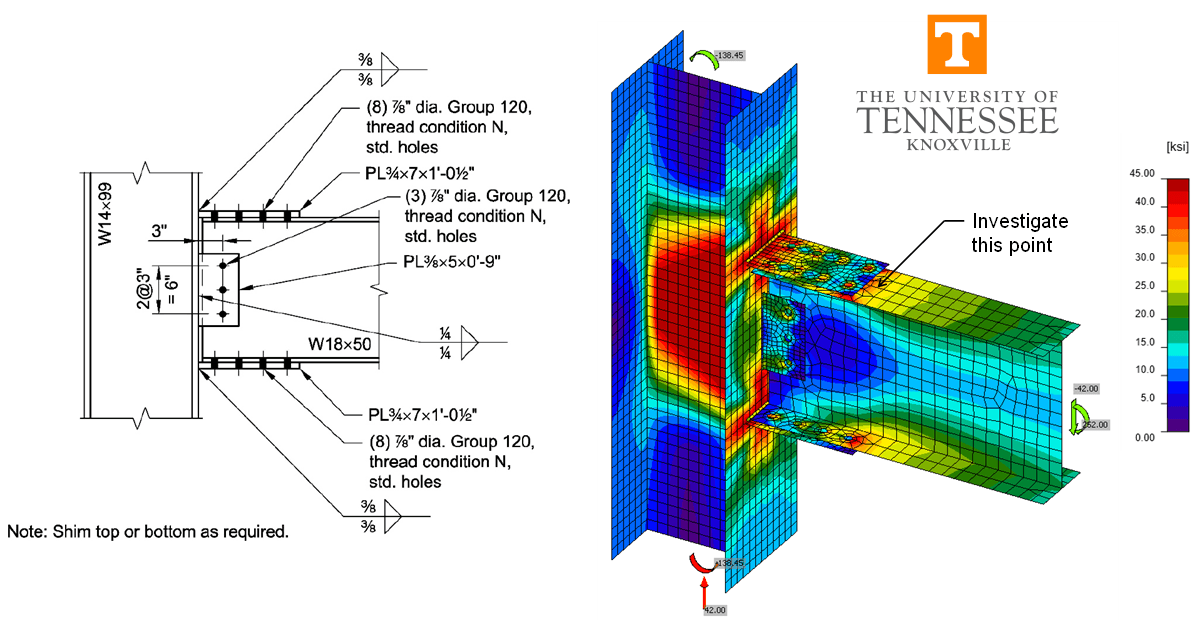
Consider, for example, the fully restrained moment connection between a wide flange steel beam and a wide flange steel column shown below. Moment in the beam is transferred to the column as follows:
- At the end of the beam, moment concentrates to the beam flanges, which are then subject to tension and compression.
- The beam flange to column flange welds transfer the beam flange forces to the column flange.
- A portion of the forces applied to the column flange are supported directly by the column while the remainder of the forces transfer through the column flange to the stiffeners.
- Force in the stiffener is transferred to the column web through shear in the stiffener to column web welds.
- The load spreads through the column cross-section, resulting in shear in the panel zone and moment in the column.
In traditional connection design, load paths such as this can help engineers develop a checklist of limit states and to ensure every step along the path has sufficient stiffness and strength. In design by inelastic analysis, load paths can help engineers by providing a mental model of connection behavior against which the results of numerical analyses can be compared.
Moment Connections
One of the major classifications of connections at the ends of beams is based on rotational stiffness. Simple shear connections are flexible enough to assume no moment is transmitted through the connection. Moment connections, on the other hand, transmit moment between the beam and column. Fully restrained connections are stiff enough to assume that no relative rotation occurs between members when transmitting the moment. Moment connections enable the beams and columns to form a moment frame that can serve as a lateral load-resisting system.
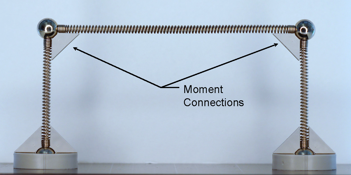
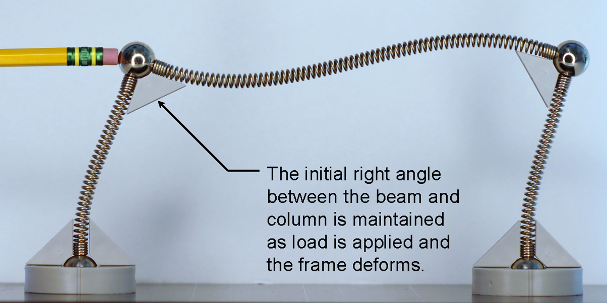
Moment frame action demonstrated with components from a (Mola Structural Kit)[ ]
Since most of the moment in a wide flange beam is resisted by the flanges, moment connections must engage the flanges of the beam directly. Moment connections typically also transfer shear or other forces from the beam to the column and thus also typically engage the web of the beam directly too. As a result, moment connections are generally statically indeterminate and the true distribution of stresses in the connection depends on the relative stiffness of the various components.
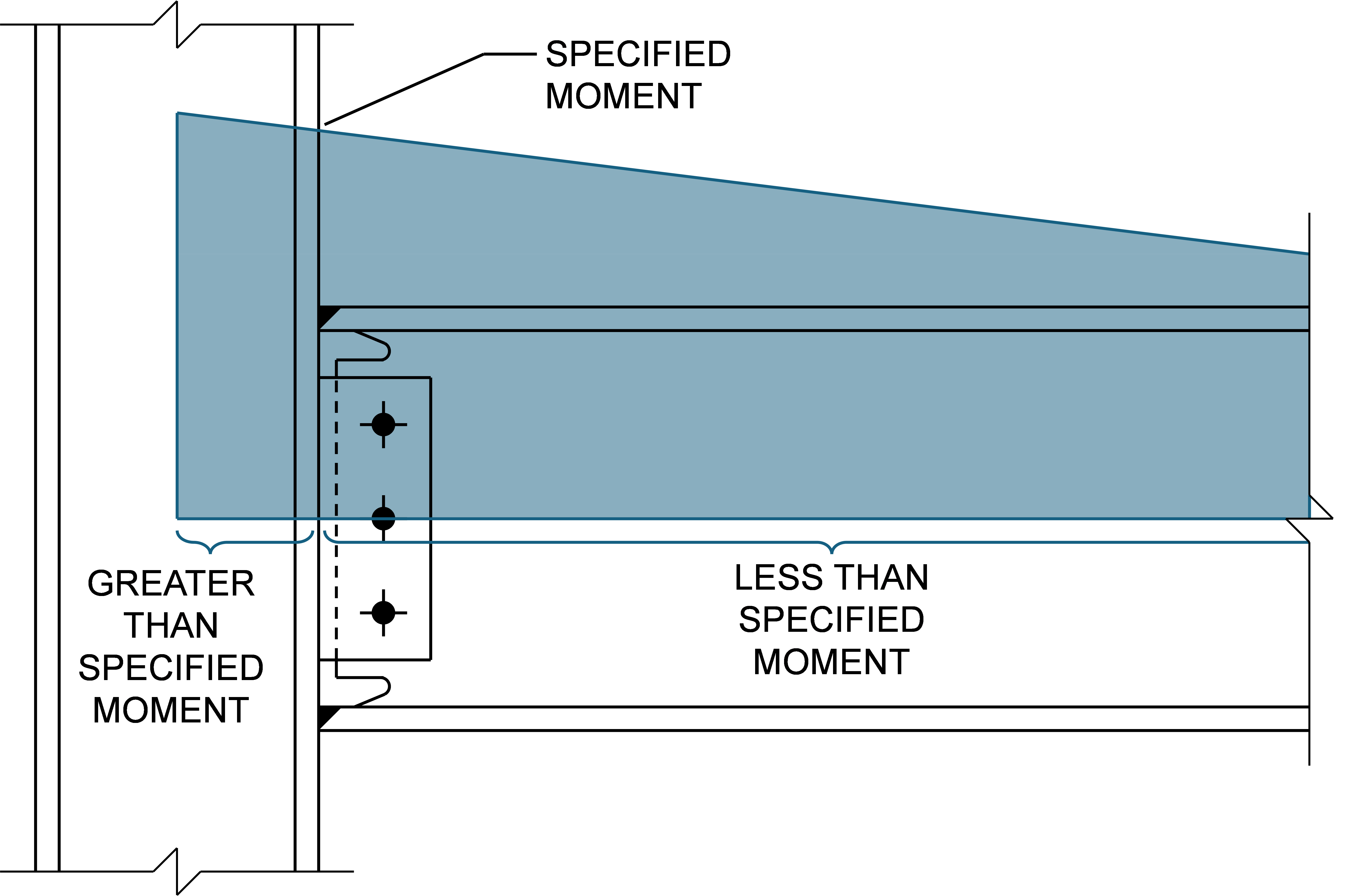
Shear forces induce a moment gradient in the beam. For moment connections, such as flange plate connections, that occur over a length of the beam, the moment is not constant. In hand calculations, the moment gradient is often conservatively neglected, and a single value of moment is used regardless of the length of the connection. The moment gradient cannot be neglected in IDEA StatiCa since the analyses ensure equilibrium and thus must be properly defined to be consistent with the structural analysis from which the required strengths were obtained. The specified moment will occur where defined by the “Forces in” option in the member menu.
In seismic design of intermediate and special moment frames, the beam-to-column connections are critical components that must be carefully designed to ensure ductility of the system. The connection must be strong enough to enable flexural yielding of the beams. The AISC standard Prequalified Connections for Special and Intermediate Steel Moment Frames for Seismic Applications (AISC 2022) describes and provides requirements for several moment connections that can achieve the desired behavior.
Connection
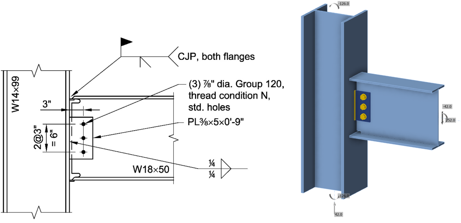
The connection examined in this exercise is based on AISC Design Examples V16.0, Example II.B-1.
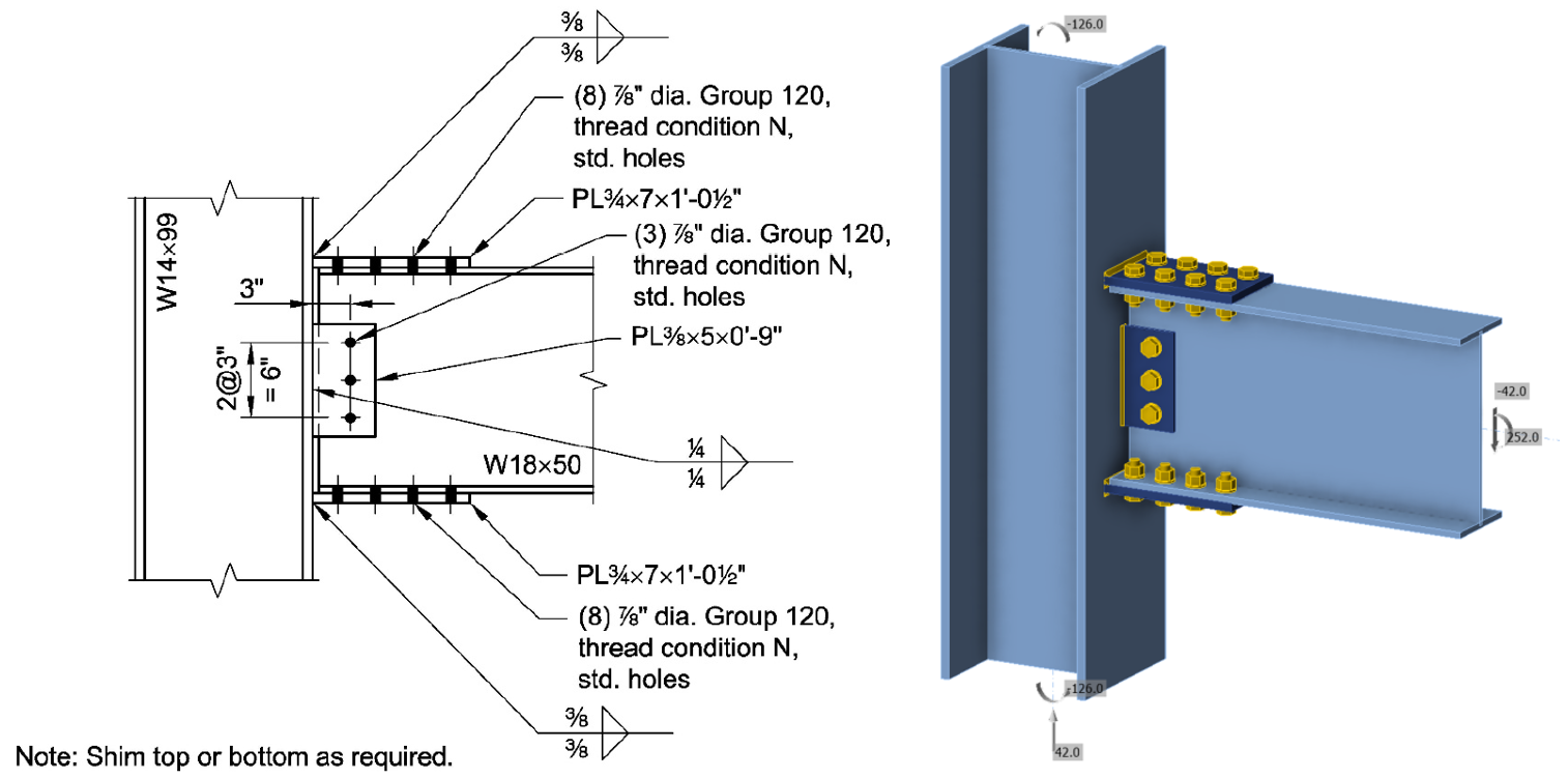
This connection has a required shear strength of Vu = 42 kips and a required moment strength of Mu = 252 kip-ft, both calculated using LRFD load combinations. While not defined in the example, the specified moment is assumed to act at the face of the supporting column. For the beam member, ensure that “Forces in” is set to “Connected member face”.
Procedure
The procedure for this exercise assumes that the learner has a working knowledge of how to use IDEA StatiCa (e.g., how to navigate the software, define and edit operations, perform analyses, and look up results). Guidance for how to develop such knowledge is available on the IDEA StatiCa website.
Retrieve the IDEA StatiCa file for the example connection provided with this exercise. Open the file in IDEA StatiCa. To perform the exercise, follow the narrative, complete the tasks, and answer the questions. Note that the design example and the (Catalog of AISC limit states and design requirements) can be helpful when answering the questions.
Load Path
The load path for moment transferring from the beam to the column is as follows:
- At the end of the beam, moment concentrates in the beam flanges, which are then subject to tension and compression.
- Bolts transfer the beam flange forces to the flange plates.
- The flange plates transfer the forces from the bolt groups to the welds through axial tension or compression.
- The welds transfer the forces from the flange plates to the column flange.
Beam
The beam is subject to moment; therefore, limit states such as flexural yielding and lateral-torsional buckling must be investigated as part of the member evaluation. The additional limit states of tensile rupture and block shear rupture of the tension flange need to be investigated as part of the connection evaluation since there are bolt holes in the tension flange. These limit states are checked using the provisions of AISC Specification Sections F13.1 and J4.3, respectively.
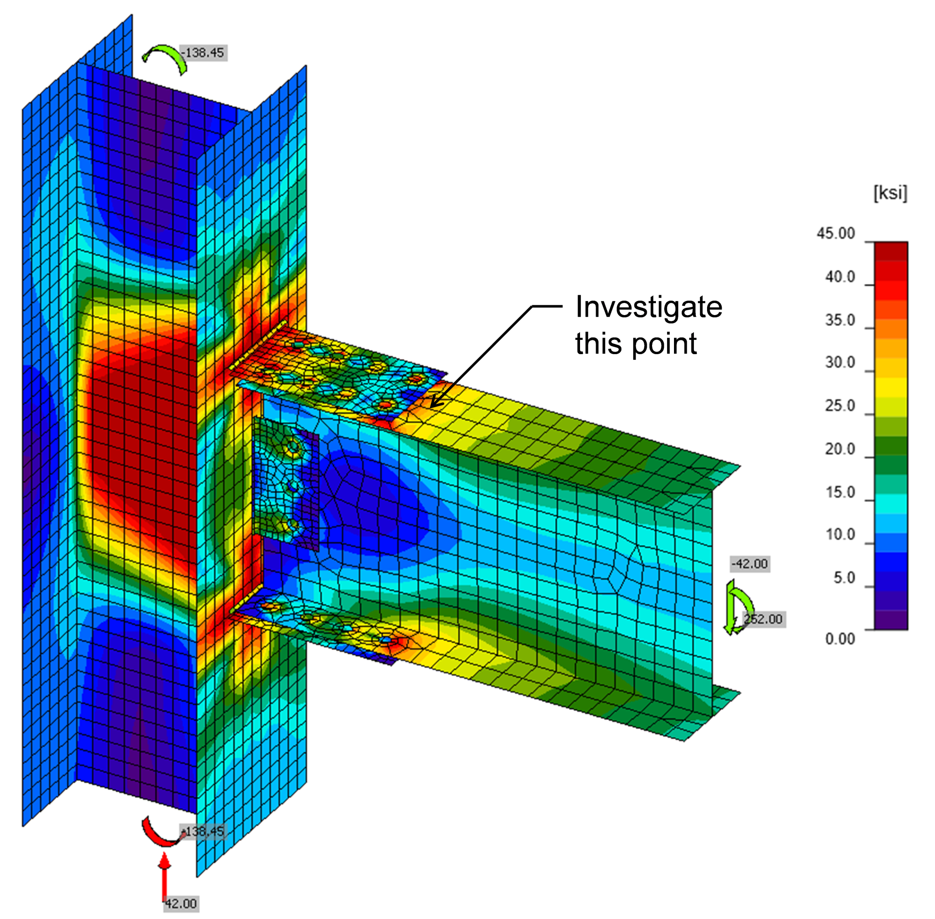
In IDEA StatiCa, these limit states are checked against the 5% plastic strain limit. Under the given loads, the beam experiences only minor amounts of plastic strain. The equivalent stress in the flanges near the end of the flange plates is approximately 30 ksi, indicated by the yellow color in the figure below.
Widget #NaN: widget_collapsible_list
Name: e7d66a16-0098-01b2-186d-af18223d3011
ID: e7d66a16-0098-01b2-186d-af18223d3011
Show Raw Data
{
  "title": {
    "name": "Headline",
    "type": "text",
    "value": ""
  },
  "description": {
    "name": "Description",
    "type": "text",
    "value": ""
  },
  "content_top": {
    "images": [],
    "linkedItemCodenames": [],
    "linkedItems": [],
    "links": [],
    "name": "Content before",
    "type": "rich_text",
    "value": "<p><br></p>"
  },
  "collapsible_items": {
    "name": "Collapsible items",
    "type": "modular_content",
    "value": [
      "lm3_01"
    ],
    "linkedItems": [
      {
        "elements": {
          "title": {
            "name": "Title",
            "type": "text",
            "value": "What is the equivalent stress in the flanges at the end of the flange plate based on elastic beam theory? Note that uniaxial longitudinal stress is equal to equivalent stress."
          },
          "description": {
            "name": "Description",
            "type": "text",
            "value": ""
          },
          "content_1": {
            "images": [],
            "linkedItemCodenames": [],
            "linkedItems": [],
            "links": [],
            "name": "Content column 1",
            "type": "rich_text",
            "value": "<p>The end of the flange plate is 12.5 in. away from the face of the column. The moment in the beam at the end of the flange plate is</p>\n<p>M = (252 kip-ft) (12 in./ft) – (42 kips) (12.5 in.) = 2,499 kip-in.</p>\n<p>The elastic section modulus of a W18x50 is <em>S</em><em><sub>x</sub></em> = 88.9 in.<sup>3</sup>. The stress in the flanges of the beam is</p>\n<p>σ = (2,499 kip-in.)/(88.9 in.<sup>3</sup>) = 28 ksi</p>\n<p>Matching well with the result from IDEA StatiCa.</p>"
          },
          "content_2": {
            "images": [],
            "linkedItemCodenames": [],
            "linkedItems": [],
            "links": [],
            "name": "Content column 2",
            "type": "rich_text",
            "value": "<p><br></p>"
          },
          "visibleinregion": {
            "name": "VisibleInRegion",
            "type": "multiple_choice",
            "value": []
          },
          "regions": {
            "name": "Region",
            "type": "taxonomy",
            "value": [],
            "taxonomyGroup": "region"
          },
          "translation__translation_connector": {
            "name": "Translation Connector",
            "type": "taxonomy",
            "value": [],
            "taxonomyGroup": "languages"
          },
          "translation__force_translation": {
            "name": "Force translation",
            "type": "multiple_choice",
            "value": []
          },
          "translation__last_translation": {
            "images": [],
            "linkedItemCodenames": [],
            "linkedItems": [],
            "links": [],
            "name": "Last translation",
            "type": "rich_text",
            "value": "<p><br></p>"
          },
          "translation__ai_translated": {
            "name": "AI translated",
            "type": "multiple_choice",
            "value": []
          }
        },
        "system": {
          "codename": "lm3_01",
          "collection": "default",
          "id": "7959a1b4-58ed-438c-81e4-38bc64751468",
          "language": "en-US",
          "lastModified": "2024-10-11T11:04:38.0851249Z",
          "name": "LM3-01",
          "sitemapLocations": [],
          "type": "widget_text_block",
          "workflowStep": "published",
          "workflow": "default"
        }
      }
    ]
  },
  "content_bottom": {
    "images": [],
    "linkedItemCodenames": [],
    "linkedItems": [],
    "links": [],
    "name": "Content after",
    "type": "rich_text",
    "value": "<p><br></p>"
  },
  "visibleinregion": {
    "name": "VisibleInRegion",
    "type": "multiple_choice",
    "value": []
  },
  "regions": {
    "name": "Region",
    "type": "taxonomy",
    "value": [],
    "taxonomyGroup": "region"
  },
  "translation__translation_connector": {
    "name": "Translation Connector",
    "type": "taxonomy",
    "value": [],
    "taxonomyGroup": "languages"
  },
  "translation__force_translation": {
    "name": "Force translation",
    "type": "multiple_choice",
    "value": []
  },
  "translation__last_translation": {
    "images": [],
    "linkedItemCodenames": [],
    "linkedItems": [],
    "links": [],
    "name": "Last translation",
    "type": "rich_text",
    "value": "<p><br></p>"
  },
  "translation__ai_translated": {
    "name": "AI translated",
    "type": "multiple_choice",
    "value": []
  }
}
Bolt Groups
Widget #NaN: widget_collapsible_list
Name: f65e92d4-80f4-0161-d2e7-02bafe806c9d
ID: f65e92d4-80f4-0161-d2e7-02bafe806c9d
Show Raw Data
{
  "title": {
    "name": "Headline",
    "type": "text",
    "value": ""
  },
  "description": {
    "name": "Description",
    "type": "text",
    "value": ""
  },
  "content_top": {
    "images": [],
    "linkedItemCodenames": [],
    "linkedItems": [],
    "links": [],
    "name": "Content before",
    "type": "rich_text",
    "value": "<p><br></p>"
  },
  "collapsible_items": {
    "name": "Collapsible items",
    "type": "modular_content",
    "value": [
      "untitled_content_item_337d82a"
    ],
    "linkedItems": [
      {
        "elements": {
          "title": {
            "name": "Title",
            "type": "text",
            "value": "What is the force in each bolt?"
          },
          "description": {
            "name": "Description",
            "type": "text",
            "value": ""
          },
          "content_1": {
            "images": [],
            "linkedItemCodenames": [],
            "linkedItems": [],
            "links": [],
            "name": "Content column 1",
            "type": "rich_text",
            "value": "<p>The specified moment is</p>\n<p>M = (252 kip-ft) (12 in./ft) = 3,024 kip-in.</p>\n<p>The moment arm between the bolt groups is equal to the beam depth (<em>d</em> = 18.0 in.). The force in each bolt group is</p>\n<p>P = (3,024 kip-in.)/(18.0 in.) = 168 kips</p>\n<p>Assuming each bolt carries the same force, the force in each bolt is</p>\n<p>P = (168 kips)/8 = 21 kips</p>"
          },
          "content_2": {
            "images": [],
            "linkedItemCodenames": [],
            "linkedItems": [],
            "links": [],
            "name": "Content column 2",
            "type": "rich_text",
            "value": "<p><br></p>"
          },
          "visibleinregion": {
            "name": "VisibleInRegion",
            "type": "multiple_choice",
            "value": []
          },
          "regions": {
            "name": "Region",
            "type": "taxonomy",
            "value": [],
            "taxonomyGroup": "region"
          },
          "translation__translation_connector": {
            "name": "Translation Connector",
            "type": "taxonomy",
            "value": [],
            "taxonomyGroup": "languages"
          },
          "translation__force_translation": {
            "name": "Force translation",
            "type": "multiple_choice",
            "value": []
          },
          "translation__last_translation": {
            "images": [],
            "linkedItemCodenames": [],
            "linkedItems": [],
            "links": [],
            "name": "Last translation",
            "type": "rich_text",
            "value": "<p><br></p>"
          },
          "translation__ai_translated": {
            "name": "AI translated",
            "type": "multiple_choice",
            "value": []
          }
        },
        "system": {
          "codename": "untitled_content_item_337d82a",
          "collection": "default",
          "id": "337d82a8-3ece-464f-a9b9-0fcb81a705b8",
          "language": "en-US",
          "lastModified": "2024-10-11T11:14:25.1220556Z",
          "name": "LM03-02",
          "sitemapLocations": [],
          "type": "widget_text_block",
          "workflowStep": "published",
          "workflow": "default"
        }
      }
    ]
  },
  "content_bottom": {
    "images": [],
    "linkedItemCodenames": [],
    "linkedItems": [],
    "links": [],
    "name": "Content after",
    "type": "rich_text",
    "value": "<p><br></p>"
  },
  "visibleinregion": {
    "name": "VisibleInRegion",
    "type": "multiple_choice",
    "value": []
  },
  "regions": {
    "name": "Region",
    "type": "taxonomy",
    "value": [],
    "taxonomyGroup": "region"
  },
  "translation__translation_connector": {
    "name": "Translation Connector",
    "type": "taxonomy",
    "value": [],
    "taxonomyGroup": "languages"
  },
  "translation__force_translation": {
    "name": "Force translation",
    "type": "multiple_choice",
    "value": []
  },
  "translation__last_translation": {
    "images": [],
    "linkedItemCodenames": [],
    "linkedItems": [],
    "links": [],
    "name": "Last translation",
    "type": "rich_text",
    "value": "<p><br></p>"
  },
  "translation__ai_translated": {
    "name": "AI translated",
    "type": "multiple_choice",
    "value": []
  }
}
Widget #NaN: widget_collapsible_list
Name: e521eaee-78b2-0109-010d-c3769dc56caf
ID: e521eaee-78b2-0109-010d-c3769dc56caf
Show Raw Data
{
  "title": {
    "name": "Headline",
    "type": "text",
    "value": ""
  },
  "description": {
    "name": "Description",
    "type": "text",
    "value": ""
  },
  "content_top": {
    "images": [],
    "linkedItemCodenames": [],
    "linkedItems": [],
    "links": [],
    "name": "Content before",
    "type": "rich_text",
    "value": "<p><br></p>"
  },
  "collapsible_items": {
    "name": "Collapsible items",
    "type": "modular_content",
    "value": [
      "lm03_03"
    ],
    "linkedItems": [
      {
        "elements": {
          "title": {
            "name": "Title",
            "type": "text",
            "value": "Compare the calculated force to the IDEA StatiCa results."
          },
          "description": {
            "name": "Description",
            "type": "text",
            "value": ""
          },
          "content_1": {
            "images": [
              {
                "description": null,
                "imageId": "dc625f06-b6d8-4ae7-a36c-edd4a7fd2d3d",
                "url": "https://assets-us-01.kc-usercontent.com:443/28eac049-c8ed-00e2-220c-12142a968dff/0a73530a-8ddd-4713-a96f-40077b309c82/LM3-06.png",
                "height": 309,
                "width": 686
              }
            ],
            "linkedItemCodenames": [],
            "linkedItems": [],
            "links": [],
            "name": "Content column 1",
            "type": "rich_text",
            "value": "<p>The force in the bolts in the top flange in IDEA StatiCa ranges from 18.93 to 19.57 kips.</p>\n<figure data-asset-id=\"dc625f06-b6d8-4ae7-a36c-edd4a7fd2d3d\" data-image-id=\"dc625f06-b6d8-4ae7-a36c-edd4a7fd2d3d\"><img src=\"https://assets-us-01.kc-usercontent.com:443/28eac049-c8ed-00e2-220c-12142a968dff/0a73530a-8ddd-4713-a96f-40077b309c82/LM3-06.png\" data-asset-id=\"dc625f06-b6d8-4ae7-a36c-edd4a7fd2d3d\" data-image-id=\"dc625f06-b6d8-4ae7-a36c-edd4a7fd2d3d\" alt=\"\"></figure>\n<p>The bolt forces in IDEA StatiCa are somewhat smaller than from the hand calculations.</p>\n<p>While it is common in design to use the moment at the face of the column to calculate the force in the bolts, using the moment at the center of the bolt group provides an answer closer to that from IDEA StatiCa. The center of the bolt group is 6.5 in. away from the face of the column. The moment in the beam at the center of the bolt group is</p>\n<p>M = (252 kip-ft) (12 in./ft) – (42 kips) (6.5 in.) = 2,751 kip-in.</p>\n<p>The moment arm between the bolt groups is equal to the beam depth (<em>d</em> = 18.0 in.). The force in each bolt group is</p>\n<p>P = (2,751 kip-in.)/(18.0 in.) = 152.8 kips</p>\n<p>Assuming each bolt carries the same force, the force in each bolt is</p>\n<p>P = (152.8 kips)/8 = 19.1 kips</p>"
          },
          "content_2": {
            "images": [],
            "linkedItemCodenames": [],
            "linkedItems": [],
            "links": [],
            "name": "Content column 2",
            "type": "rich_text",
            "value": "<p><br></p>"
          },
          "visibleinregion": {
            "name": "VisibleInRegion",
            "type": "multiple_choice",
            "value": []
          },
          "regions": {
            "name": "Region",
            "type": "taxonomy",
            "value": [],
            "taxonomyGroup": "region"
          },
          "translation__translation_connector": {
            "name": "Translation Connector",
            "type": "taxonomy",
            "value": [],
            "taxonomyGroup": "languages"
          },
          "translation__force_translation": {
            "name": "Force translation",
            "type": "multiple_choice",
            "value": []
          },
          "translation__last_translation": {
            "images": [],
            "linkedItemCodenames": [],
            "linkedItems": [],
            "links": [],
            "name": "Last translation",
            "type": "rich_text",
            "value": "<p><br></p>"
          },
          "translation__ai_translated": {
            "name": "AI translated",
            "type": "multiple_choice",
            "value": []
          }
        },
        "system": {
          "codename": "lm03_03",
          "collection": "default",
          "id": "bd86a1fa-08f5-473c-929d-e70a3cae46f8",
          "language": "en-US",
          "lastModified": "2024-10-11T11:10:31.6417677Z",
          "name": "LM03-03",
          "sitemapLocations": [],
          "type": "widget_text_block",
          "workflowStep": "published",
          "workflow": "default"
        }
      }
    ]
  },
  "content_bottom": {
    "images": [],
    "linkedItemCodenames": [],
    "linkedItems": [],
    "links": [],
    "name": "Content after",
    "type": "rich_text",
    "value": "<p><br></p>"
  },
  "visibleinregion": {
    "name": "VisibleInRegion",
    "type": "multiple_choice",
    "value": []
  },
  "regions": {
    "name": "Region",
    "type": "taxonomy",
    "value": [],
    "taxonomyGroup": "region"
  },
  "translation__translation_connector": {
    "name": "Translation Connector",
    "type": "taxonomy",
    "value": [],
    "taxonomyGroup": "languages"
  },
  "translation__force_translation": {
    "name": "Force translation",
    "type": "multiple_choice",
    "value": []
  },
  "translation__last_translation": {
    "images": [],
    "linkedItemCodenames": [],
    "linkedItems": [],
    "links": [],
    "name": "Last translation",
    "type": "rich_text",
    "value": "<p><br></p>"
  },
  "translation__ai_translated": {
    "name": "AI translated",
    "type": "multiple_choice",
    "value": []
  }
}
Widget #NaN: widget_collapsible_list
Name: e305660a-86ce-011b-f110-7858ea5ecf9d
ID: e305660a-86ce-011b-f110-7858ea5ecf9d
Show Raw Data
{
  "title": {
    "name": "Headline",
    "type": "text",
    "value": ""
  },
  "description": {
    "name": "Description",
    "type": "text",
    "value": ""
  },
  "content_top": {
    "images": [],
    "linkedItemCodenames": [],
    "linkedItems": [],
    "links": [],
    "name": "Content before",
    "type": "rich_text",
    "value": "<p><br></p>"
  },
  "collapsible_items": {
    "name": "Collapsible items",
    "type": "modular_content",
    "value": [
      "l03_04"
    ],
    "linkedItems": [
      {
        "elements": {
          "title": {
            "name": "Title",
            "type": "text",
            "value": "What limit states (or failure modes) need to be checked for the bolt group?"
          },
          "description": {
            "name": "Description",
            "type": "text",
            "value": ""
          },
          "content_1": {
            "images": [],
            "linkedItemCodenames": [],
            "linkedItems": [],
            "links": [],
            "name": "Content column 1",
            "type": "rich_text",
            "value": "<ul>\n  <li>Bolt shear rupture</li>\n  <li>Bearing at the bolt holes in the beam flange</li>\n  <li>Tearout at the bolt holes in the beam flange</li>\n  <li>Bearing at the bolt holes in the flange plate</li>\n  <li>Tearout at the bolt holes in the flange plate</li>\n</ul>"
          },
          "content_2": {
            "images": [],
            "linkedItemCodenames": [],
            "linkedItems": [],
            "links": [],
            "name": "Content column 2",
            "type": "rich_text",
            "value": "<p><br></p>"
          },
          "visibleinregion": {
            "name": "VisibleInRegion",
            "type": "multiple_choice",
            "value": []
          },
          "regions": {
            "name": "Region",
            "type": "taxonomy",
            "value": [],
            "taxonomyGroup": "region"
          },
          "translation__translation_connector": {
            "name": "Translation Connector",
            "type": "taxonomy",
            "value": [],
            "taxonomyGroup": "languages"
          },
          "translation__force_translation": {
            "name": "Force translation",
            "type": "multiple_choice",
            "value": []
          },
          "translation__last_translation": {
            "images": [],
            "linkedItemCodenames": [],
            "linkedItems": [],
            "links": [],
            "name": "Last translation",
            "type": "rich_text",
            "value": "<p><br></p>"
          },
          "translation__ai_translated": {
            "name": "AI translated",
            "type": "multiple_choice",
            "value": []
          }
        },
        "system": {
          "codename": "l03_04",
          "collection": "default",
          "id": "ea0e1db5-7407-4e76-8c6e-335ceddcd032",
          "language": "en-US",
          "lastModified": "2024-10-11T11:10:14.2865096Z",
          "name": "L03-04",
          "sitemapLocations": [],
          "type": "widget_text_block",
          "workflowStep": "published",
          "workflow": "default"
        }
      }
    ]
  },
  "content_bottom": {
    "images": [],
    "linkedItemCodenames": [],
    "linkedItems": [],
    "links": [],
    "name": "Content after",
    "type": "rich_text",
    "value": "<p><br></p>"
  },
  "visibleinregion": {
    "name": "VisibleInRegion",
    "type": "multiple_choice",
    "value": []
  },
  "regions": {
    "name": "Region",
    "type": "taxonomy",
    "value": [],
    "taxonomyGroup": "region"
  },
  "translation__translation_connector": {
    "name": "Translation Connector",
    "type": "taxonomy",
    "value": [],
    "taxonomyGroup": "languages"
  },
  "translation__force_translation": {
    "name": "Force translation",
    "type": "multiple_choice",
    "value": []
  },
  "translation__last_translation": {
    "images": [],
    "linkedItemCodenames": [],
    "linkedItems": [],
    "links": [],
    "name": "Last translation",
    "type": "rich_text",
    "value": "<p><br></p>"
  },
  "translation__ai_translated": {
    "name": "AI translated",
    "type": "multiple_choice",
    "value": []
  }
}
For each limit state, find where the results of the check are displayed in IDEA StatiCa and compare IDEA StatiCa’s calculations to your own.
Flange Plates
Widget #NaN: widget_collapsible_list
Name: 1cab5b56-d290-012c-bf27-3e86a56bc2c1
ID: 1cab5b56-d290-012c-bf27-3e86a56bc2c1
Show Raw Data
{
  "title": {
    "name": "Headline",
    "type": "text",
    "value": ""
  },
  "description": {
    "name": "Description",
    "type": "text",
    "value": ""
  },
  "content_top": {
    "images": [],
    "linkedItemCodenames": [],
    "linkedItems": [],
    "links": [],
    "name": "Content before",
    "type": "rich_text",
    "value": "<p><br></p>"
  },
  "collapsible_items": {
    "name": "Collapsible items",
    "type": "modular_content",
    "value": [
      "lm03_05"
    ],
    "linkedItems": [
      {
        "elements": {
          "title": {
            "name": "Title",
            "type": "text",
            "value": "The flange plates transfer load from the bolt groups to the welds through tension and compression. What is the force in each plate?"
          },
          "description": {
            "name": "Description",
            "type": "text",
            "value": ""
          },
          "content_1": {
            "images": [],
            "linkedItemCodenames": [],
            "linkedItems": [],
            "links": [],
            "name": "Content column 1",
            "type": "rich_text",
            "value": "<p>The moment in the beam at the face of the column is</p>\n<p>M = (252 kip-ft) (12 in./ft) = 3,024 kip-in.</p>\n<p>The moment arm between the flange plate is equal to the beam depth (<em>d</em> = 18.0 in.) plus the thickness of the flange plate (<em>t</em> = 0.75 in.). The force in each bolt group is</p>\n<p>P = (3,024 kip-in.)/(18.0 in. + 0.75 in.) = 161.3 kips</p>"
          },
          "content_2": {
            "images": [],
            "linkedItemCodenames": [],
            "linkedItems": [],
            "links": [],
            "name": "Content column 2",
            "type": "rich_text",
            "value": "<p><br></p>"
          },
          "visibleinregion": {
            "name": "VisibleInRegion",
            "type": "multiple_choice",
            "value": []
          },
          "regions": {
            "name": "Region",
            "type": "taxonomy",
            "value": [],
            "taxonomyGroup": "region"
          },
          "translation__translation_connector": {
            "name": "Translation Connector",
            "type": "taxonomy",
            "value": [],
            "taxonomyGroup": "languages"
          },
          "translation__force_translation": {
            "name": "Force translation",
            "type": "multiple_choice",
            "value": []
          },
          "translation__last_translation": {
            "images": [],
            "linkedItemCodenames": [],
            "linkedItems": [],
            "links": [],
            "name": "Last translation",
            "type": "rich_text",
            "value": "<p><br></p>"
          },
          "translation__ai_translated": {
            "name": "AI translated",
            "type": "multiple_choice",
            "value": []
          }
        },
        "system": {
          "codename": "lm03_05",
          "collection": "default",
          "id": "69cd9e4a-765f-4a02-ab17-3750943484b1",
          "language": "en-US",
          "lastModified": "2024-10-11T11:46:26.4107666Z",
          "name": "LM03-05",
          "sitemapLocations": [],
          "type": "widget_text_block",
          "workflowStep": "published",
          "workflow": "default"
        }
      }
    ]
  },
  "content_bottom": {
    "images": [],
    "linkedItemCodenames": [],
    "linkedItems": [],
    "links": [],
    "name": "Content after",
    "type": "rich_text",
    "value": "<p><br></p>"
  },
  "visibleinregion": {
    "name": "VisibleInRegion",
    "type": "multiple_choice",
    "value": []
  },
  "regions": {
    "name": "Region",
    "type": "taxonomy",
    "value": [],
    "taxonomyGroup": "region"
  },
  "translation__translation_connector": {
    "name": "Translation Connector",
    "type": "taxonomy",
    "value": [],
    "taxonomyGroup": "languages"
  },
  "translation__force_translation": {
    "name": "Force translation",
    "type": "multiple_choice",
    "value": []
  },
  "translation__last_translation": {
    "images": [],
    "linkedItemCodenames": [],
    "linkedItems": [],
    "links": [],
    "name": "Last translation",
    "type": "rich_text",
    "value": "<p><br></p>"
  },
  "translation__ai_translated": {
    "name": "AI translated",
    "type": "multiple_choice",
    "value": []
  }
}
Widget #NaN: widget_collapsible_list
Name: d5b9c963-e82c-01c9-b6c4-1b768c8d90e3
ID: d5b9c963-e82c-01c9-b6c4-1b768c8d90e3
Show Raw Data
{
  "title": {
    "name": "Headline",
    "type": "text",
    "value": ""
  },
  "description": {
    "name": "Description",
    "type": "text",
    "value": ""
  },
  "content_top": {
    "images": [],
    "linkedItemCodenames": [],
    "linkedItems": [],
    "links": [],
    "name": "Content before",
    "type": "rich_text",
    "value": "<p><br></p>"
  },
  "collapsible_items": {
    "name": "Collapsible items",
    "type": "modular_content",
    "value": [
      "lm03_06"
    ],
    "linkedItems": [
      {
        "elements": {
          "title": {
            "name": "Title",
            "type": "text",
            "value": "What limit states (or failure modes) need to be checked for the top flange plate?"
          },
          "description": {
            "name": "Description",
            "type": "text",
            "value": ""
          },
          "content_1": {
            "images": [],
            "linkedItemCodenames": [],
            "linkedItems": [],
            "links": [],
            "name": "Content column 1",
            "type": "rich_text",
            "value": "<ul>\n  <li>Tensile yielding</li>\n  <li>Tensile rupture</li>\n  <li>Block shear rupture</li>\n</ul>"
          },
          "content_2": {
            "images": [],
            "linkedItemCodenames": [],
            "linkedItems": [],
            "links": [],
            "name": "Content column 2",
            "type": "rich_text",
            "value": "<p><br></p>"
          },
          "visibleinregion": {
            "name": "VisibleInRegion",
            "type": "multiple_choice",
            "value": []
          },
          "regions": {
            "name": "Region",
            "type": "taxonomy",
            "value": [],
            "taxonomyGroup": "region"
          },
          "translation__translation_connector": {
            "name": "Translation Connector",
            "type": "taxonomy",
            "value": [],
            "taxonomyGroup": "languages"
          },
          "translation__force_translation": {
            "name": "Force translation",
            "type": "multiple_choice",
            "value": []
          },
          "translation__last_translation": {
            "images": [],
            "linkedItemCodenames": [],
            "linkedItems": [],
            "links": [],
            "name": "Last translation",
            "type": "rich_text",
            "value": "<p><br></p>"
          },
          "translation__ai_translated": {
            "name": "AI translated",
            "type": "multiple_choice",
            "value": []
          }
        },
        "system": {
          "codename": "lm03_06",
          "collection": "default",
          "id": "c2ccd9d5-aafa-4f06-9117-eacee6316d7d",
          "language": "en-US",
          "lastModified": "2024-10-11T11:47:16.6263101Z",
          "name": "LM03-06",
          "sitemapLocations": [],
          "type": "widget_text_block",
          "workflowStep": "published",
          "workflow": "default"
        }
      }
    ]
  },
  "content_bottom": {
    "images": [],
    "linkedItemCodenames": [],
    "linkedItems": [],
    "links": [],
    "name": "Content after",
    "type": "rich_text",
    "value": "<p><br></p>"
  },
  "visibleinregion": {
    "name": "VisibleInRegion",
    "type": "multiple_choice",
    "value": []
  },
  "regions": {
    "name": "Region",
    "type": "taxonomy",
    "value": [],
    "taxonomyGroup": "region"
  },
  "translation__translation_connector": {
    "name": "Translation Connector",
    "type": "taxonomy",
    "value": [],
    "taxonomyGroup": "languages"
  },
  "translation__force_translation": {
    "name": "Force translation",
    "type": "multiple_choice",
    "value": []
  },
  "translation__last_translation": {
    "images": [],
    "linkedItemCodenames": [],
    "linkedItems": [],
    "links": [],
    "name": "Last translation",
    "type": "rich_text",
    "value": "<p><br></p>"
  },
  "translation__ai_translated": {
    "name": "AI translated",
    "type": "multiple_choice",
    "value": []
  }
}
Widget #NaN: widget_collapsible_list
Name: bc6a816a-7dbf-01ba-0096-0a111aaef8ea
ID: bc6a816a-7dbf-01ba-0096-0a111aaef8ea
Show Raw Data
{
  "title": {
    "name": "Headline",
    "type": "text",
    "value": ""
  },
  "description": {
    "name": "Description",
    "type": "text",
    "value": ""
  },
  "content_top": {
    "images": [],
    "linkedItemCodenames": [],
    "linkedItems": [],
    "links": [],
    "name": "Content before",
    "type": "rich_text",
    "value": "<p><br></p>"
  },
  "collapsible_items": {
    "name": "Collapsible items",
    "type": "modular_content",
    "value": [
      "lm03_07"
    ],
    "linkedItems": [
      {
        "elements": {
          "title": {
            "name": "Title",
            "type": "text",
            "value": "How are these failure modes checked in IDEA StatiCa?"
          },
          "description": {
            "name": "Description",
            "type": "text",
            "value": ""
          },
          "content_1": {
            "images": [],
            "linkedItemCodenames": [],
            "linkedItems": [],
            "links": [],
            "name": "Content column 1",
            "type": "rich_text",
            "value": "<p>All are checked against the 5% plastic strain limit.</p>"
          },
          "content_2": {
            "images": [],
            "linkedItemCodenames": [],
            "linkedItems": [],
            "links": [],
            "name": "Content column 2",
            "type": "rich_text",
            "value": "<p><br></p>"
          },
          "visibleinregion": {
            "name": "VisibleInRegion",
            "type": "multiple_choice",
            "value": []
          },
          "regions": {
            "name": "Region",
            "type": "taxonomy",
            "value": [],
            "taxonomyGroup": "region"
          },
          "translation__translation_connector": {
            "name": "Translation Connector",
            "type": "taxonomy",
            "value": [],
            "taxonomyGroup": "languages"
          },
          "translation__force_translation": {
            "name": "Force translation",
            "type": "multiple_choice",
            "value": []
          },
          "translation__last_translation": {
            "images": [],
            "linkedItemCodenames": [],
            "linkedItems": [],
            "links": [],
            "name": "Last translation",
            "type": "rich_text",
            "value": "<p><br></p>"
          },
          "translation__ai_translated": {
            "name": "AI translated",
            "type": "multiple_choice",
            "value": []
          }
        },
        "system": {
          "codename": "lm03_07",
          "collection": "default",
          "id": "9dc915f3-f36d-4928-9bac-5ea785416c9e",
          "language": "en-US",
          "lastModified": "2024-10-11T11:48:02.825027Z",
          "name": "LM03-07",
          "sitemapLocations": [],
          "type": "widget_text_block",
          "workflowStep": "published",
          "workflow": "default"
        }
      }
    ]
  },
  "content_bottom": {
    "images": [],
    "linkedItemCodenames": [],
    "linkedItems": [],
    "links": [],
    "name": "Content after",
    "type": "rich_text",
    "value": "<p><br></p>"
  },
  "visibleinregion": {
    "name": "VisibleInRegion",
    "type": "multiple_choice",
    "value": []
  },
  "regions": {
    "name": "Region",
    "type": "taxonomy",
    "value": [],
    "taxonomyGroup": "region"
  },
  "translation__translation_connector": {
    "name": "Translation Connector",
    "type": "taxonomy",
    "value": [],
    "taxonomyGroup": "languages"
  },
  "translation__force_translation": {
    "name": "Force translation",
    "type": "multiple_choice",
    "value": []
  },
  "translation__last_translation": {
    "images": [],
    "linkedItemCodenames": [],
    "linkedItems": [],
    "links": [],
    "name": "Last translation",
    "type": "rich_text",
    "value": "<p><br></p>"
  },
  "translation__ai_translated": {
    "name": "AI translated",
    "type": "multiple_choice",
    "value": []
  }
}
Widget #NaN: widget_collapsible_list
Name: f8f35f62-e066-012f-11b4-b5efd4c7bc9e
ID: f8f35f62-e066-012f-11b4-b5efd4c7bc9e
Show Raw Data
{
  "title": {
    "name": "Headline",
    "type": "text",
    "value": ""
  },
  "description": {
    "name": "Description",
    "type": "text",
    "value": ""
  },
  "content_top": {
    "images": [],
    "linkedItemCodenames": [],
    "linkedItems": [],
    "links": [],
    "name": "Content before",
    "type": "rich_text",
    "value": "<p><br></p>"
  },
  "collapsible_items": {
    "name": "Collapsible items",
    "type": "modular_content",
    "value": [
      "lm03_08"
    ],
    "linkedItems": [
      {
        "elements": {
          "title": {
            "name": "Title",
            "type": "text",
            "value": "What limit states (or failure modes) need to be checked for the bottom flange plate?"
          },
          "description": {
            "name": "Description",
            "type": "text",
            "value": ""
          },
          "content_1": {
            "images": [],
            "linkedItemCodenames": [],
            "linkedItems": [],
            "links": [],
            "name": "Content column 1",
            "type": "rich_text",
            "value": "<ul>\n  <li>Compressive yielding</li>\n  <li>Compressive buckling (but it does not apply since <em>L</em><em><sub>c</sub></em>/<em>r</em> ≤ 25)</li>\n</ul>"
          },
          "content_2": {
            "images": [],
            "linkedItemCodenames": [],
            "linkedItems": [],
            "links": [],
            "name": "Content column 2",
            "type": "rich_text",
            "value": "<p><br></p>"
          },
          "visibleinregion": {
            "name": "VisibleInRegion",
            "type": "multiple_choice",
            "value": []
          },
          "regions": {
            "name": "Region",
            "type": "taxonomy",
            "value": [],
            "taxonomyGroup": "region"
          },
          "translation__translation_connector": {
            "name": "Translation Connector",
            "type": "taxonomy",
            "value": [],
            "taxonomyGroup": "languages"
          },
          "translation__force_translation": {
            "name": "Force translation",
            "type": "multiple_choice",
            "value": []
          },
          "translation__last_translation": {
            "images": [],
            "linkedItemCodenames": [],
            "linkedItems": [],
            "links": [],
            "name": "Last translation",
            "type": "rich_text",
            "value": "<p><br></p>"
          },
          "translation__ai_translated": {
            "name": "AI translated",
            "type": "multiple_choice",
            "value": []
          }
        },
        "system": {
          "codename": "lm03_08",
          "collection": "default",
          "id": "c519c68f-803e-4f58-8dd1-eba9470ce3e9",
          "language": "en-US",
          "lastModified": "2024-10-11T11:48:51.118236Z",
          "name": "LM03-08",
          "sitemapLocations": [],
          "type": "widget_text_block",
          "workflowStep": "published",
          "workflow": "default"
        }
      }
    ]
  },
  "content_bottom": {
    "images": [],
    "linkedItemCodenames": [],
    "linkedItems": [],
    "links": [],
    "name": "Content after",
    "type": "rich_text",
    "value": "<p><br></p>"
  },
  "visibleinregion": {
    "name": "VisibleInRegion",
    "type": "multiple_choice",
    "value": []
  },
  "regions": {
    "name": "Region",
    "type": "taxonomy",
    "value": [],
    "taxonomyGroup": "region"
  },
  "translation__translation_connector": {
    "name": "Translation Connector",
    "type": "taxonomy",
    "value": [],
    "taxonomyGroup": "languages"
  },
  "translation__force_translation": {
    "name": "Force translation",
    "type": "multiple_choice",
    "value": []
  },
  "translation__last_translation": {
    "images": [],
    "linkedItemCodenames": [],
    "linkedItems": [],
    "links": [],
    "name": "Last translation",
    "type": "rich_text",
    "value": "<p><br></p>"
  },
  "translation__ai_translated": {
    "name": "AI translated",
    "type": "multiple_choice",
    "value": []
  }
}
Widget #NaN: widget_collapsible_list
Name: be52832b-5271-01ef-0759-130b947abafc
ID: be52832b-5271-01ef-0759-130b947abafc
Show Raw Data
{
  "title": {
    "name": "Headline",
    "type": "text",
    "value": ""
  },
  "description": {
    "name": "Description",
    "type": "text",
    "value": ""
  },
  "content_top": {
    "images": [],
    "linkedItemCodenames": [],
    "linkedItems": [],
    "links": [],
    "name": "Content before",
    "type": "rich_text",
    "value": "<p><br></p>"
  },
  "collapsible_items": {
    "name": "Collapsible items",
    "type": "modular_content",
    "value": [
      "lm03_09"
    ],
    "linkedItems": [
      {
        "elements": {
          "title": {
            "name": "Title",
            "type": "text",
            "value": "How are these failure modes checked in IDEA StatiCa?"
          },
          "description": {
            "name": "Description",
            "type": "text",
            "value": ""
          },
          "content_1": {
            "images": [],
            "linkedItemCodenames": [],
            "linkedItems": [],
            "links": [],
            "name": "Content column 1",
            "type": "rich_text",
            "value": "<p>Compressive yielding is checked against the 5% plastic strain limit. Compressive buckling is checked by performing a linear buckling analysis and ensuring that the buckling ratio is greater than 3.0.</p>"
          },
          "content_2": {
            "images": [],
            "linkedItemCodenames": [],
            "linkedItems": [],
            "links": [],
            "name": "Content column 2",
            "type": "rich_text",
            "value": "<p><br></p>"
          },
          "visibleinregion": {
            "name": "VisibleInRegion",
            "type": "multiple_choice",
            "value": []
          },
          "regions": {
            "name": "Region",
            "type": "taxonomy",
            "value": [],
            "taxonomyGroup": "region"
          },
          "translation__translation_connector": {
            "name": "Translation Connector",
            "type": "taxonomy",
            "value": [],
            "taxonomyGroup": "languages"
          },
          "translation__force_translation": {
            "name": "Force translation",
            "type": "multiple_choice",
            "value": []
          },
          "translation__last_translation": {
            "images": [],
            "linkedItemCodenames": [],
            "linkedItems": [],
            "links": [],
            "name": "Last translation",
            "type": "rich_text",
            "value": "<p><br></p>"
          },
          "translation__ai_translated": {
            "name": "AI translated",
            "type": "multiple_choice",
            "value": []
          }
        },
        "system": {
          "codename": "lm03_09",
          "collection": "default",
          "id": "be213be5-3d36-4509-875e-b5ebf0a49af4",
          "language": "en-US",
          "lastModified": "2024-10-11T11:49:42.0462179Z",
          "name": "LM03-09",
          "sitemapLocations": [],
          "type": "widget_text_block",
          "workflowStep": "published",
          "workflow": "default"
        }
      }
    ]
  },
  "content_bottom": {
    "images": [],
    "linkedItemCodenames": [],
    "linkedItems": [],
    "links": [],
    "name": "Content after",
    "type": "rich_text",
    "value": "<p><br></p>"
  },
  "visibleinregion": {
    "name": "VisibleInRegion",
    "type": "multiple_choice",
    "value": []
  },
  "regions": {
    "name": "Region",
    "type": "taxonomy",
    "value": [],
    "taxonomyGroup": "region"
  },
  "translation__translation_connector": {
    "name": "Translation Connector",
    "type": "taxonomy",
    "value": [],
    "taxonomyGroup": "languages"
  },
  "translation__force_translation": {
    "name": "Force translation",
    "type": "multiple_choice",
    "value": []
  },
  "translation__last_translation": {
    "images": [],
    "linkedItemCodenames": [],
    "linkedItems": [],
    "links": [],
    "name": "Last translation",
    "type": "rich_text",
    "value": "<p><br></p>"
  },
  "translation__ai_translated": {
    "name": "AI translated",
    "type": "multiple_choice",
    "value": []
  }
}
Welds
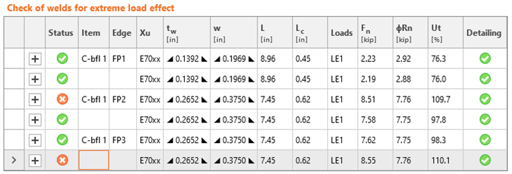
Fillet welds transfer load from the flange plates to the column flange. The required strength for the weld is the same as that for the flange plates.
Widget #NaN: widget_collapsible_list
Name: 5fc35fd7-2ee3-010d-fd09-06a28a06a158
ID: 5fc35fd7-2ee3-010d-fd09-06a28a06a158
Show Raw Data
{
  "title": {
    "name": "Headline",
    "type": "text",
    "value": ""
  },
  "description": {
    "name": "Description",
    "type": "text",
    "value": ""
  },
  "content_top": {
    "images": [],
    "linkedItemCodenames": [],
    "linkedItems": [],
    "links": [],
    "name": "Content before",
    "type": "rich_text",
    "value": "<p><br></p>"
  },
  "collapsible_items": {
    "name": "Collapsible items",
    "type": "modular_content",
    "value": [
      "lm03_10"
    ],
    "linkedItems": [
      {
        "elements": {
          "title": {
            "name": "Title",
            "type": "text",
            "value": "What limit states (or failure modes) need to be checked for the weld?"
          },
          "description": {
            "name": "Description",
            "type": "text",
            "value": ""
          },
          "content_1": {
            "images": [],
            "linkedItemCodenames": [],
            "linkedItems": [],
            "links": [],
            "name": "Content column 1",
            "type": "rich_text",
            "value": "<ul>\n  <li>Weld rupture</li>\n  <li>Base metal strength could be considered here, or as part of the flange plate and column checks.</li>\n</ul>"
          },
          "content_2": {
            "images": [],
            "linkedItemCodenames": [],
            "linkedItems": [],
            "links": [],
            "name": "Content column 2",
            "type": "rich_text",
            "value": "<p><br></p>"
          },
          "visibleinregion": {
            "name": "VisibleInRegion",
            "type": "multiple_choice",
            "value": []
          },
          "regions": {
            "name": "Region",
            "type": "taxonomy",
            "value": [],
            "taxonomyGroup": "region"
          },
          "translation__translation_connector": {
            "name": "Translation Connector",
            "type": "taxonomy",
            "value": [],
            "taxonomyGroup": "languages"
          },
          "translation__force_translation": {
            "name": "Force translation",
            "type": "multiple_choice",
            "value": []
          },
          "translation__last_translation": {
            "images": [],
            "linkedItemCodenames": [],
            "linkedItems": [],
            "links": [],
            "name": "Last translation",
            "type": "rich_text",
            "value": "<p><br></p>"
          },
          "translation__ai_translated": {
            "name": "AI translated",
            "type": "multiple_choice",
            "value": []
          }
        },
        "system": {
          "codename": "lm03_10",
          "collection": "default",
          "id": "9fc00417-f066-4127-a807-6bc7ff2cc218",
          "language": "en-US",
          "lastModified": "2024-10-11T11:50:39.091121Z",
          "name": "LM03-10",
          "sitemapLocations": [],
          "type": "widget_text_block",
          "workflowStep": "published",
          "workflow": "default"
        }
      }
    ]
  },
  "content_bottom": {
    "images": [],
    "linkedItemCodenames": [],
    "linkedItems": [],
    "links": [],
    "name": "Content after",
    "type": "rich_text",
    "value": "<p><br></p>"
  },
  "visibleinregion": {
    "name": "VisibleInRegion",
    "type": "multiple_choice",
    "value": []
  },
  "regions": {
    "name": "Region",
    "type": "taxonomy",
    "value": [],
    "taxonomyGroup": "region"
  },
  "translation__translation_connector": {
    "name": "Translation Connector",
    "type": "taxonomy",
    "value": [],
    "taxonomyGroup": "languages"
  },
  "translation__force_translation": {
    "name": "Force translation",
    "type": "multiple_choice",
    "value": []
  },
  "translation__last_translation": {
    "images": [],
    "linkedItemCodenames": [],
    "linkedItems": [],
    "links": [],
    "name": "Last translation",
    "type": "rich_text",
    "value": "<p><br></p>"
  },
  "translation__ai_translated": {
    "name": "AI translated",
    "type": "multiple_choice",
    "value": []
  }
}
In the design example using traditional calculations, the 3/8 in. fillet welds are sufficient for the applied load. In IDEA StatiCa, the 3/8 in. fillet welds are insufficient with a utilization ratio of 110%.
Widget #NaN: widget_collapsible_list
Name: d84d392d-dbe2-017b-ef75-3fe32d7c2b0e
ID: d84d392d-dbe2-017b-ef75-3fe32d7c2b0e
Show Raw Data
{
  "title": {
    "name": "Headline",
    "type": "text",
    "value": ""
  },
  "description": {
    "name": "Description",
    "type": "text",
    "value": ""
  },
  "content_top": {
    "images": [],
    "linkedItemCodenames": [],
    "linkedItems": [],
    "links": [],
    "name": "Content before",
    "type": "rich_text",
    "value": "<p><br></p>"
  },
  "collapsible_items": {
    "name": "Collapsible items",
    "type": "modular_content",
    "value": [
      "lm03_11"
    ],
    "linkedItems": [
      {
        "elements": {
          "title": {
            "name": "Title",
            "type": "text",
            "value": "What factors contribute to the difference in result?"
          },
          "description": {
            "name": "Description",
            "type": "text",
            "value": ""
          },
          "content_1": {
            "images": [
              {
                "description": null,
                "imageId": "eccb49a1-8240-4bbc-ba06-c7a0f7bf2ece",
                "url": "https://assets-us-01.kc-usercontent.com:443/28eac049-c8ed-00e2-220c-12142a968dff/d63f5eca-97d4-42e6-a2e0-a2be92cce6fe/LM3-08.png",
                "height": 465,
                "width": 172
              }
            ],
            "linkedItemCodenames": [],
            "linkedItems": [],
            "links": [],
            "name": "Content column 1",
            "type": "rich_text",
            "value": "<p>The design strength for the controlling weld segment is ϕ<em>R</em><em><sub>n</sub></em> = 7.76 kips and its length is <em>L</em><em><sub>c</sub></em> = 0.62 in, therefore the strength per length of weld is (7.76 kips)/(0.62 in.) = 12.5 kips/in. which matches the traditional calculations, meaning that the available strength is not a factor that contributes to the difference in result.</p>\n<p>θ = 90°</p>\n<p><em>w</em> = 3/8 in.</p>\n<p><em>F</em><em><sub>EXX</sub></em> = 70 ksi</p>\n<p><em>F</em><em><sub>nw</sub></em> = 0.6<em>F</em><em><sub>EXX</sub></em> = 0.6(70 ksi) = 42 ksi</p>\n<p><em>A</em><em><sub>we</sub></em> = 0.707<em>wL</em> = 0.707(3/8 in.)<em>L</em> = (0.265 in.)<em>L</em></p>\n<p><em>k</em><em><sub>ds</sub></em> = (1.0 + 0.50sin<sup>1.5</sup>θ) = [1.0 + 0.50 sin<sup>1.5</sup>(90°)] = 1.5</p>\n<p><em>R</em><em><sub>n</sub></em> = <em>F</em><em><sub>nw</sub></em><em>A</em><em><sub>we</sub></em><em>k</em><em><sub>ds</sub></em> = (42 ksi)(0.265 in.<sup>2</sup>)<em>L</em>(1.5) = (16.7 kips/in.)<em>L</em></p>\n<p>ϕ<em>R</em><em><sub>n</sub></em>/<em>L</em> = 0.75(16.7 kips/in.) = 12.5 kips/in.</p>\n<p>One factor that makes a difference is that the weld is assumed to be uniformly stressed in the traditional calculations whereas, in IDEA StatiCa, the weld is more highly stressed in the middle. The middle of the weld has a more direct load path that does not rely on bending of the column flange.</p>\n<figure data-asset-id=\"eccb49a1-8240-4bbc-ba06-c7a0f7bf2ece\" data-image-id=\"eccb49a1-8240-4bbc-ba06-c7a0f7bf2ece\"><img src=\"https://assets-us-01.kc-usercontent.com:443/28eac049-c8ed-00e2-220c-12142a968dff/d63f5eca-97d4-42e6-a2e0-a2be92cce6fe/LM3-08.png\" data-asset-id=\"eccb49a1-8240-4bbc-ba06-c7a0f7bf2ece\" data-image-id=\"eccb49a1-8240-4bbc-ba06-c7a0f7bf2ece\" alt=\"\"></figure>\n<p>Another factor that makes a difference is that, in IDEA StatiCa, the welds on the outside of the connection (i.e., the top of the top flange plate and the bottom of the bottom flange plate) are more highly stressed than the welds on the inside of the connection. While this difference in stress is physically reasonable since the outside welds are farther away from the neutral axis of the beam, it is not accounted for in the traditional calculations.</p>"
          },
          "content_2": {
            "images": [],
            "linkedItemCodenames": [],
            "linkedItems": [],
            "links": [],
            "name": "Content column 2",
            "type": "rich_text",
            "value": "<p><br></p>"
          },
          "visibleinregion": {
            "name": "VisibleInRegion",
            "type": "multiple_choice",
            "value": []
          },
          "regions": {
            "name": "Region",
            "type": "taxonomy",
            "value": [],
            "taxonomyGroup": "region"
          },
          "translation__translation_connector": {
            "name": "Translation Connector",
            "type": "taxonomy",
            "value": [],
            "taxonomyGroup": "languages"
          },
          "translation__force_translation": {
            "name": "Force translation",
            "type": "multiple_choice",
            "value": []
          },
          "translation__last_translation": {
            "images": [],
            "linkedItemCodenames": [],
            "linkedItems": [],
            "links": [],
            "name": "Last translation",
            "type": "rich_text",
            "value": "<p><br></p>"
          },
          "translation__ai_translated": {
            "name": "AI translated",
            "type": "multiple_choice",
            "value": []
          }
        },
        "system": {
          "codename": "lm03_11",
          "collection": "default",
          "id": "5c75b9c1-7685-45c2-9920-0dff920fe5ae",
          "language": "en-US",
          "lastModified": "2024-10-11T11:53:28.8800695Z",
          "name": "LM03-11",
          "sitemapLocations": [],
          "type": "widget_text_block",
          "workflowStep": "published",
          "workflow": "default"
        }
      }
    ]
  },
  "content_bottom": {
    "images": [],
    "linkedItemCodenames": [],
    "linkedItems": [],
    "links": [],
    "name": "Content after",
    "type": "rich_text",
    "value": "<p><br></p>"
  },
  "visibleinregion": {
    "name": "VisibleInRegion",
    "type": "multiple_choice",
    "value": []
  },
  "regions": {
    "name": "Region",
    "type": "taxonomy",
    "value": [],
    "taxonomyGroup": "region"
  },
  "translation__translation_connector": {
    "name": "Translation Connector",
    "type": "taxonomy",
    "value": [],
    "taxonomyGroup": "languages"
  },
  "translation__force_translation": {
    "name": "Force translation",
    "type": "multiple_choice",
    "value": []
  },
  "translation__last_translation": {
    "images": [],
    "linkedItemCodenames": [],
    "linkedItems": [],
    "links": [],
    "name": "Last translation",
    "type": "rich_text",
    "value": "<p><br></p>"
  },
  "translation__ai_translated": {
    "name": "AI translated",
    "type": "multiple_choice",
    "value": []
  }
}
Column
The load spreads through the column cross section, resulting in shear in the panel zone and moment in the column.
Widget #NaN: widget_collapsible_list
Name: 2f2dc36b-ba85-01a8-7c48-1078d4dac1a3
ID: 2f2dc36b-ba85-01a8-7c48-1078d4dac1a3
Show Raw Data
{
  "title": {
    "name": "Headline",
    "type": "text",
    "value": ""
  },
  "description": {
    "name": "Description",
    "type": "text",
    "value": ""
  },
  "content_top": {
    "images": [],
    "linkedItemCodenames": [],
    "linkedItems": [],
    "links": [],
    "name": "Content before",
    "type": "rich_text",
    "value": "<p><br></p>"
  },
  "collapsible_items": {
    "name": "Collapsible items",
    "type": "modular_content",
    "value": [
      "lm03_12"
    ],
    "linkedItems": [
      {
        "elements": {
          "title": {
            "name": "Title",
            "type": "text",
            "value": "What limit states (or failure modes) need to be checked for the column?"
          },
          "description": {
            "name": "Description",
            "type": "text",
            "value": ""
          },
          "content_1": {
            "images": [],
            "linkedItemCodenames": [],
            "linkedItems": [],
            "links": [],
            "name": "Content column 1",
            "type": "rich_text",
            "value": "<ul>\n  <li>Base metal strength. No specific limit state applies to the column flange as a base metal. In traditional calculations, it is common to ensure that the thickness of the connected material meets the recommendation of AISC <em>Manual</em> Equation 9-6.</li>\n  <li>At the top flange plate (in tension)\n    <ul>\n      <li>Flange local bending</li>\n      <li>Web local yielding</li>\n    </ul>\n  </li>\n  <li>At the bottom flange plate (in compression)\n    <ul>\n      <li>Web local yielding</li>\n      <li>Web local crippling</li>\n    </ul>\n  </li>\n  <li>Web panel-zone shear yielding</li>\n  <li>Member strength limit states</li>\n</ul>"
          },
          "content_2": {
            "images": [],
            "linkedItemCodenames": [],
            "linkedItems": [],
            "links": [],
            "name": "Content column 2",
            "type": "rich_text",
            "value": "<p><br></p>"
          },
          "visibleinregion": {
            "name": "VisibleInRegion",
            "type": "multiple_choice",
            "value": []
          },
          "regions": {
            "name": "Region",
            "type": "taxonomy",
            "value": [],
            "taxonomyGroup": "region"
          },
          "translation__translation_connector": {
            "name": "Translation Connector",
            "type": "taxonomy",
            "value": [],
            "taxonomyGroup": "languages"
          },
          "translation__force_translation": {
            "name": "Force translation",
            "type": "multiple_choice",
            "value": []
          },
          "translation__last_translation": {
            "images": [],
            "linkedItemCodenames": [],
            "linkedItems": [],
            "links": [],
            "name": "Last translation",
            "type": "rich_text",
            "value": "<p><br></p>"
          },
          "translation__ai_translated": {
            "name": "AI translated",
            "type": "multiple_choice",
            "value": []
          }
        },
        "system": {
          "codename": "lm03_12",
          "collection": "default",
          "id": "56286bbf-dbd5-4b03-b895-2fff9bdc682f",
          "language": "en-US",
          "lastModified": "2024-10-11T11:55:30.6510526Z",
          "name": "LM03-12",
          "sitemapLocations": [],
          "type": "widget_text_block",
          "workflowStep": "published",
          "workflow": "default"
        }
      }
    ]
  },
  "content_bottom": {
    "images": [],
    "linkedItemCodenames": [],
    "linkedItems": [],
    "links": [],
    "name": "Content after",
    "type": "rich_text",
    "value": "<p><br></p>"
  },
  "visibleinregion": {
    "name": "VisibleInRegion",
    "type": "multiple_choice",
    "value": []
  },
  "regions": {
    "name": "Region",
    "type": "taxonomy",
    "value": [],
    "taxonomyGroup": "region"
  },
  "translation__translation_connector": {
    "name": "Translation Connector",
    "type": "taxonomy",
    "value": [],
    "taxonomyGroup": "languages"
  },
  "translation__force_translation": {
    "name": "Force translation",
    "type": "multiple_choice",
    "value": []
  },
  "translation__last_translation": {
    "images": [],
    "linkedItemCodenames": [],
    "linkedItems": [],
    "links": [],
    "name": "Last translation",
    "type": "rich_text",
    "value": "<p><br></p>"
  },
  "translation__ai_translated": {
    "name": "AI translated",
    "type": "multiple_choice",
    "value": []
  }
}
Widget #NaN: widget_collapsible_list
Name: 81e1d2e1-d7af-0193-397c-29cb42d969d6
ID: 81e1d2e1-d7af-0193-397c-29cb42d969d6
Show Raw Data
{
"title": {
"name": "Headline",
"type": "text",
"value": ""
},
"description": {
"name": "Description",
"type": "text",
"value": ""
},
"content_top": {
"images": [],
"linkedItemCodenames": [],
"linkedItems": [],
"links": [],
"name": "Content before",
"type": "rich_text",
"value": "<p><br></p>"
},
"collapsible_items": {
"name": "Collapsible items",
"type": "modular_content",
"value": [
"lm03_13"
],
"linkedItems": [
{
"elements": {
"title": {
"name": "Title",
"type": "text",
"value": "Check the column flange for flange local bending according to AISC Specification Section J10.1. How is this limit state evaluated in IDEA StatiCa?"
},
"description": {
"name": "Description",
"type": "text",
"value": ""
},
"content_1": {
"images": [],
"linkedItemCodenames": [],
"linkedItems": [],
"links": [],
"name": "Content column 1",
"type": "rich_text",
"value": "<p>The required strength is equal to the force in the flange plates, Ru = 161.3 kips.</p>\n<p>The available strength is calculated as follows:</p>\n<p><em>R</em><em><sub>n</sub></em> = 6.25<em>F</em><em><sub>yf</sub></em><em>t</em><em><sub>f</sub></em><sup>2</sup> = 6.25(50 ksi)(0.780 in.)<sup>2</sup> = 190 kips</p>\n<p>ϕ<em>R</em><em><sub>n</sub></em> = 0.9(190 kips) = 171 kips</p>\n<p><em>R</em><em><sub>u</sub></em> ≤ ϕ<em>R</em><em><sub>n</sub></em>, therefore the strength is sufficient.</p>\n<p>As described in the commentary on the AISC Specification and <a href=\"https://www.ideastatica.com/support-center/catalog-of-aisc-limit-states-and-design-requirements#Flange_Local_Bending\">this article</a>, the check for flange local bending was originally intended to prevent weld fracture, but now remains in the Specification to limit potentially detrimental local flange deformations. As seen in the evaluation of welds, IDEA StatiCa explicitly considers the uneven demands on the welds, but IDEA StatiCa does not directly limit local flange deformations.</p>"
},
"content_2": {
"images": [],
"linkedItemCodenames": [],
"linkedItems": [],
"links": [],
"name": "Content column 2",
"type": "rich_text",
"value": "<p><br></p>"
},
"visibleinregion": {
"name": "VisibleInRegion",
"type": "multiple_choice",
"value": []
},
"regions": {
"name": "Region",
"type": "taxonomy",
"value": [],
"taxonomyGroup": "region"
},
"translation__translation_connector": {
"name": "Translation Connector",
"type": "taxonomy",
"value": [],
"taxonomyGroup": "languages"
},
"translation__force_translation": {
"name": "Force translation",
"type": "multiple_choice",
"value": []
},
"translation__last_translation": {
"images": [],
"linkedItemCodenames": [],
"linkedItems": [],
"links": [],
"name": "Last translation",
"type": "rich_text",
"value": "<p><br></p>"
},
"translation__ai_translated": {
"name": "AI translated",
"type": "multiple_choice",
"value": []
}
},
"system": {
"codename": "lm03_13",
"collection": "default",
"id": "7aa360fd-63dc-49fd-a152-b52bf7143579",
"language": "en-US",
"lastModified": "2024-10-11T11:58:23.6528381Z",
"name": "LM03-13",
"sitemapLocations": [],
"type": "widget_text_block",
"workflowStep": "published",
"workflow": "default"
}
}
]
},
"content_bottom": {
"images": [],
"linkedItemCodenames": [],
"linkedItems": [],
"links": [],
"name": "Content after",
"type": "rich_text",
"value": "<p><br></p>"
},
"visibleinregion": {
"name": "VisibleInRegion",
"type": "multiple_choice",
"value": []
},
"regions": {
"name": "Region",
"type": "taxonomy",
"value": [],
"taxonomyGroup": "region"
},
"translation__translation_connector": {
"name": "Translation Connector",
"type": "taxonomy",
"value": [],
"taxonomyGroup": "languages"
},
"translation__force_translation": {
"name": "Force translation",
"type": "multiple_choice",
"value": []
},
"translation__last_translation": {
"images": [],
"linkedItemCodenames": [],
"linkedItems": [],
"links": [],
"name": "Last translation",
"type": "rich_text",
"value": "<p><br></p>"
},
"translation__ai_translated": {
"name": "AI translated",
"type": "multiple_choice",
"value": []
}
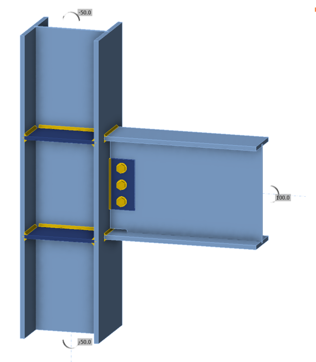
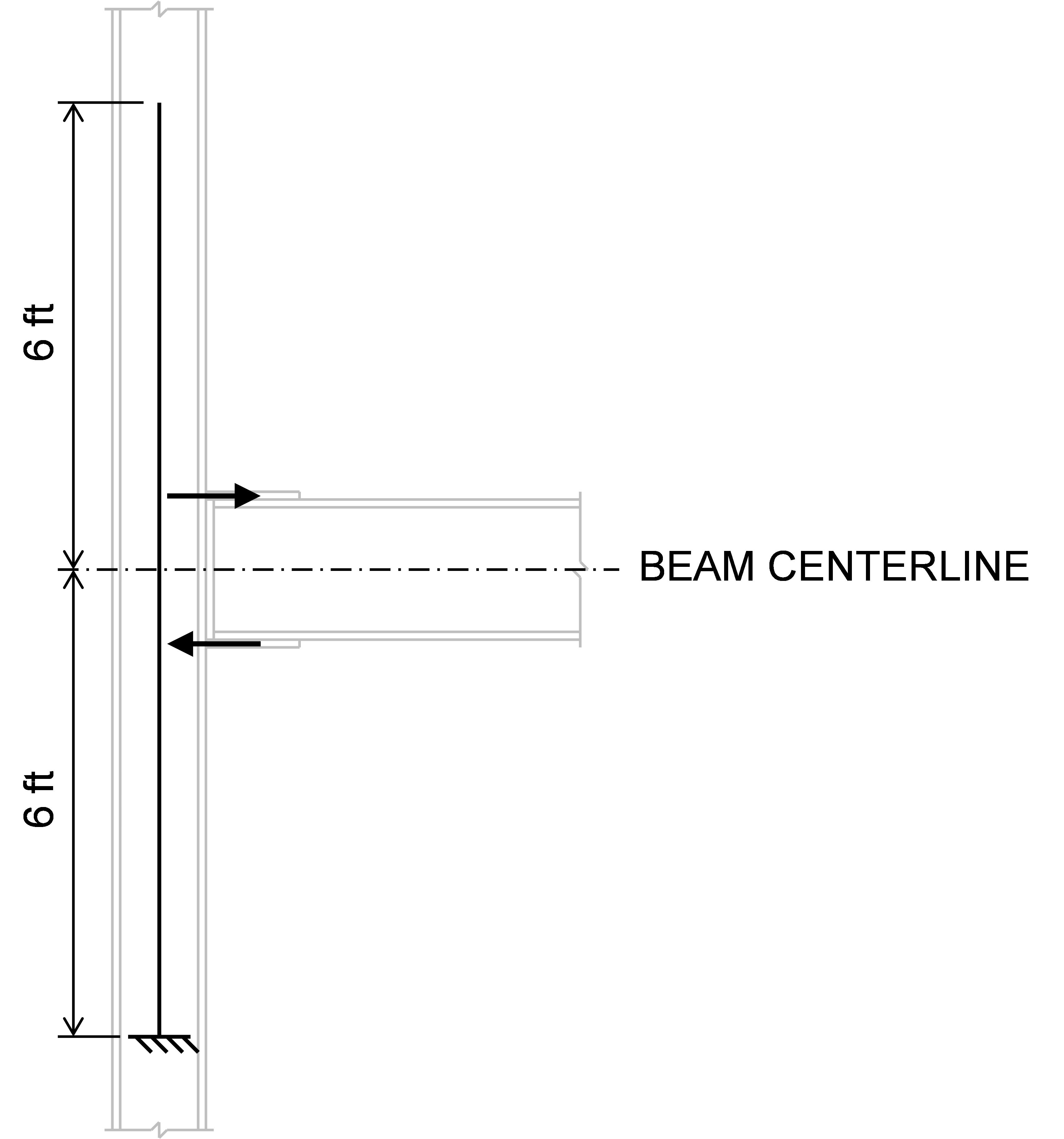
}Using the simplified model shown below, draw a shear diagram for the column and check the web panel zone shear according to AISC Specification Section J10.6. Assume that the effect of inelastic panel-zone deformation on frame stability is not accounted for in the analysis.
Widget #NaN: widget_collapsible_list
Name: 61e7f2d7-23e4-0163-a79f-103c3b5d6218
ID: 61e7f2d7-23e4-0163-a79f-103c3b5d6218
Show Raw Data
{
  "title": {
    "name": "Headline",
    "type": "text",
    "value": ""
  },
  "description": {
    "name": "Description",
    "type": "text",
    "value": ""
  },
  "content_top": {
    "images": [],
    "linkedItemCodenames": [],
    "linkedItems": [],
    "links": [],
    "name": "Content before",
    "type": "rich_text",
    "value": "<p><br></p>"
  },
  "collapsible_items": {
    "name": "Collapsible items",
    "type": "modular_content",
    "value": [
      "lm03_14"
    ],
    "linkedItems": [
      {
        "elements": {
          "title": {
            "name": "Title",
            "type": "text",
            "value": "How is this limit state evaluated in IDEA StatiCa?"
          },
          "description": {
            "name": "Description",
            "type": "text",
            "value": ""
          },
          "content_1": {
            "images": [
              {
                "description": null,
                "imageId": "f581c1d0-d3b7-472e-a545-bfe4d4b4f56d",
                "url": "https://assets-us-01.kc-usercontent.com:443/28eac049-c8ed-00e2-220c-12142a968dff/2b73fd2c-ef6d-4bda-97f2-2cdb9417c933/LM3-10.png",
                "height": 993,
                "width": 1134
              }
            ],
            "linkedItemCodenames": [],
            "linkedItems": [],
            "links": [],
            "name": "Content column 1",
            "type": "rich_text",
            "value": "<p>The forces in the flange plates are 161.3 kips. The distance between the applied forces is 18.0 in. + 0.75 in. = 18.75 in.</p>\n<p>From sum of forces in the horizontal direction, the horizontal reaction at the fixed support is zero.</p>\n<p>The required shear strength in the panel zone is <em>R</em><em><sub>u</sub></em> = 161.3 kips.</p>\n<figure data-asset-id=\"f581c1d0-d3b7-472e-a545-bfe4d4b4f56d\" data-image-id=\"f581c1d0-d3b7-472e-a545-bfe4d4b4f56d\"><img src=\"https://assets-us-01.kc-usercontent.com:443/28eac049-c8ed-00e2-220c-12142a968dff/2b73fd2c-ef6d-4bda-97f2-2cdb9417c933/LM3-10.png\" data-asset-id=\"f581c1d0-d3b7-472e-a545-bfe4d4b4f56d\" data-image-id=\"f581c1d0-d3b7-472e-a545-bfe4d4b4f56d\" alt=\"\"></figure>\n<p>The available strength is calculated as follows, noting that this column has no required axial strength (i.e., <em>P</em><em><sub>r</sub></em> = 0 kips):</p>\n<p><em>R</em><em><sub>n</sub></em> = 0.60<em>F</em><em><sub>y</sub></em><em>d</em><em><sub>c</sub></em><em>t</em><em><sub>w</sub></em> = 0.60(50 ksi)(14.2 in.)(0.485 in.) = 206.6 kips</p>\n<p>ϕ<em>R</em><em><sub>n</sub></em> = 0.9(206.6 kips) = 185.9 kips</p>\n<p><em>R</em><em><sub>u</sub></em> ≤ ϕ<em>R</em><em><sub>n</sub></em>, therefore the strength is sufficient.</p>\n<p>Panel zone shear yielding is captured explicitly in the IDEA StatiCa model and limited with the 5% plastic strain limit. More information can be found <a href=\"https://www.ideastatica.com/support-center/catalog-of-aisc-limit-states-and-design-requirements#Web_Panel-Zone_Shear_Yielding\">here</a>.</p>"
          },
          "content_2": {
            "images": [],
            "linkedItemCodenames": [],
            "linkedItems": [],
            "links": [],
            "name": "Content column 2",
            "type": "rich_text",
            "value": "<p><br></p>"
          },
          "visibleinregion": {
            "name": "VisibleInRegion",
            "type": "multiple_choice",
            "value": []
          },
          "regions": {
            "name": "Region",
            "type": "taxonomy",
            "value": [],
            "taxonomyGroup": "region"
          },
          "translation__translation_connector": {
            "name": "Translation Connector",
            "type": "taxonomy",
            "value": [],
            "taxonomyGroup": "languages"
          },
          "translation__force_translation": {
            "name": "Force translation",
            "type": "multiple_choice",
            "value": []
          },
          "translation__last_translation": {
            "images": [],
            "linkedItemCodenames": [],
            "linkedItems": [],
            "links": [],
            "name": "Last translation",
            "type": "rich_text",
            "value": "<p><br></p>"
          },
          "translation__ai_translated": {
            "name": "AI translated",
            "type": "multiple_choice",
            "value": []
          }
        },
        "system": {
          "codename": "lm03_14",
          "collection": "default",
          "id": "8983adda-371d-4625-acf3-0a95739e4a75",
          "language": "en-US",
          "lastModified": "2024-11-26T08:41:48.5753572Z",
          "name": "LM03-14",
          "sitemapLocations": [],
          "type": "widget_text_block",
          "workflowStep": "published",
          "workflow": "default"
        }
      }
    ]
  },
  "content_bottom": {
    "images": [],
    "linkedItemCodenames": [],
    "linkedItems": [],
    "links": [],
    "name": "Content after",
    "type": "rich_text",
    "value": "<p><br></p>"
  },
  "visibleinregion": {
    "name": "VisibleInRegion",
    "type": "multiple_choice",
    "value": []
  },
  "regions": {
    "name": "Region",
    "type": "taxonomy",
    "value": [],
    "taxonomyGroup": "region"
  },
  "translation__translation_connector": {
    "name": "Translation Connector",
    "type": "taxonomy",
    "value": [],
    "taxonomyGroup": "languages"
  },
  "translation__force_translation": {
    "name": "Force translation",
    "type": "multiple_choice",
    "value": []
  },
  "translation__last_translation": {
    "images": [],
    "linkedItemCodenames": [],
    "linkedItems": [],
    "links": [],
    "name": "Last translation",
    "type": "rich_text",
    "value": "<p><br></p>"
  },
  "translation__ai_translated": {
    "name": "AI translated",
    "type": "multiple_choice",
    "value": []
  }
}
General Procedure
For a more open-ended experience or for connections other than the bolted flange plate moment connection, complete the following tasks:
- Select one of the connections described below.
- Review the design example upon which the connection is based.
- Retrieve the IDEA StatiCa file for the connection provided with this exercise. Open the file in IDEA StatiCa.
- Describe the load path for this connection.
- Answer the following questions for each step in the load path:
- What is the required strength?
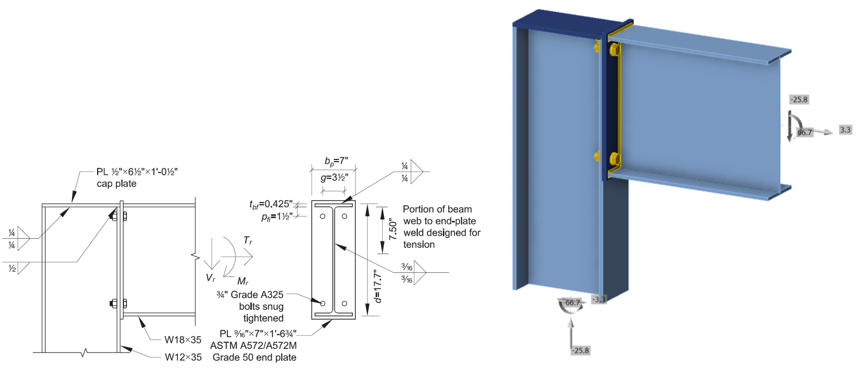
Connection 2 based on AISC Design Examples V16.0, Example II.B-3
Connection 3 based on AISC Design Guide 39, Example 5.2-1
References
AISC. (2022). Seismic Provisions for Structural Steel Buildings. American Institute of Steel Construction, Chicago, Illinois.
AISC. (2023). Companion to the AISC Steel Construction Manual, Volume 1: Design Examples, v16.0. American Institute of Steel Construction, Chicago, Illinois.
Eatherton, M. R., and Murray, T. M. (2023). End-Plate Moment Connections. Design Guide 39, American Institute of Steel Construction, Chicago, Illinois.