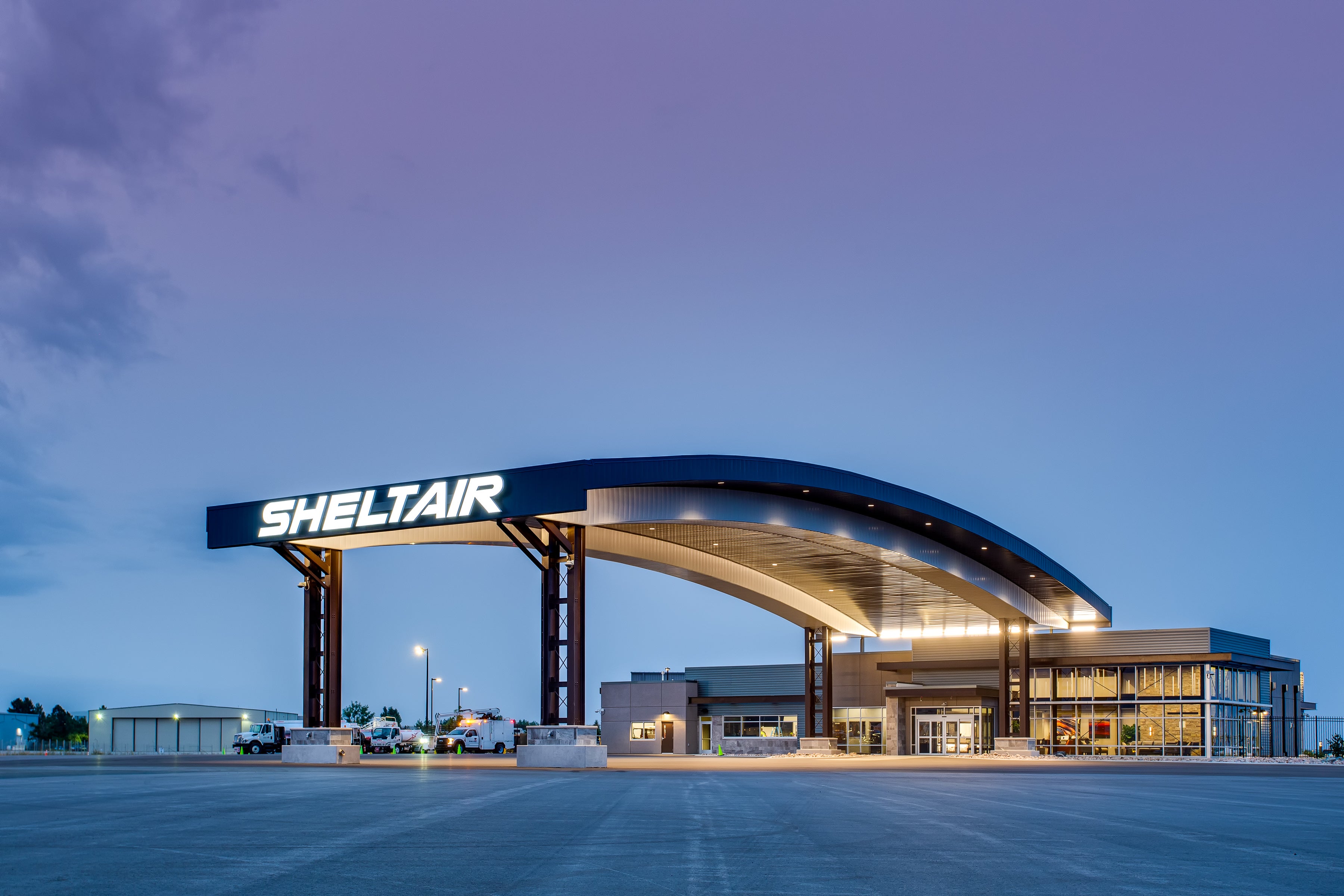
Robbins Engineering, founded in 2004 in Little Rock, Arkansas, designed this FBO(Fixed Base Operator) terminal and hangar for business aviation clients at a high-altitude airport with hurricane-force wind speeds.
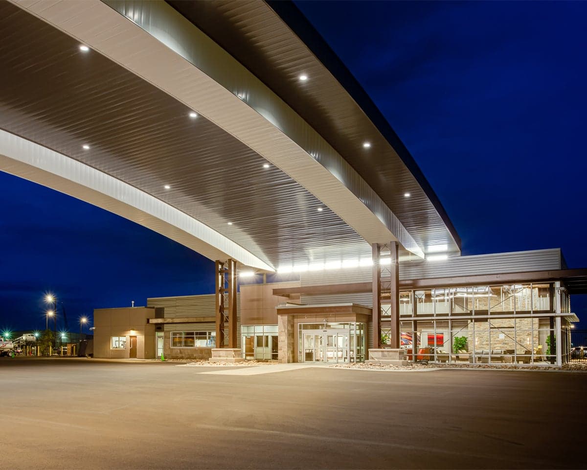
The most prominent part of this unique project was 132-foot clear span arched trusses supporting the 40-foot-high canopy for aircraft.

Structure and Design
The canopy has been designed as a structure for planes to pull under for loading and unloading of passengers. But this type of structure represents a large surface and is stressed mainly by wind.
The design team investigated several options before deciding on arched trusses supported by built-up laced columns (Figure 1). Twin W24x192 columns, 4 feet apart with round bar X-bracing and W8 struts between them, form each of the 4 built-up columns. The arched trusses are 6 feet deep, using WT12x88 chords and double angle webs.

Figure 1. RAM Elements model of the high canopy for aircraft.
The 132-foot clear span has one field-bolted splice point near midspan. Each end of each truss is attached to the W24 column’s inside flange via bolted endplate moment connections (Figure 2). 10- and 20-foot cantilever truss sections are similarly attached to the outside flanges of the columns. Vertical X-bracing installed between each pair of trusses, as well as angle lacing in the planes of both top and bottom chords, form a space truss between each pair of built-up columns. This creates the moment frame in the long direction. Each pair of laced columns functions as cantilevered vertical trusses in the orthogonal axis. Concrete tie beams join the columns in the long direction to resist the arches’ thrust under gravity loads.


