
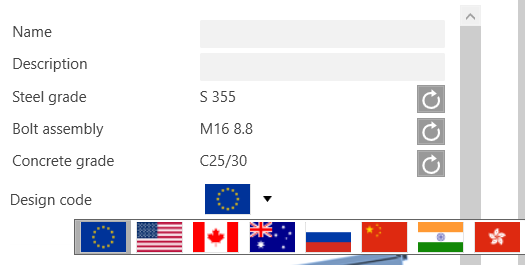
For now, IDEA StatiCa Steel users can choose from 8 international or national codes and standards.
- EN - Eurocode - used in the majority of European countries (without national annexes)
- AISC - American Code of Standard Practice for Steel Buildings and Bridges
- CISC - Canadian Code of Standard Practice for Structural Steel
- AS - Australian Standards and Codes of Practice
- SP - Russian National Standards
- GB - Chinese National Standards
- IS - Indian Standards
- HKG - Hong Kong Code of Practice for the Structural Use of Steel
Find more information in the blog post Codes and standards supported in IDEA StatiCa Steel.
News and updates for codes
We're constantly working on keeping the software updated based on the latest versions of codes and standards. Read the following paragraphs and find out what has been improved.
Widget #NaN: support_center_article
Name: RN 20.0: Hong Kong Code (HKG)
ID: eec5be4f-0cbf-454d-b657-049f2b33a188
Show Raw Data
{
"title": {
"name": "Main headline (H1)",
"type": "text",
"value": "Hong Kong Code (HKG)"
},
"preview_image": {
"name": "Preview image",
"type": "asset",
"value": [
{
"name": "Hong Kong Code (HKG)_MainPicture.png",
"description": "Hong Kong Code (HKG)",
"type": "image/png",
"size": 32033,
"url": "https://assets-us-01.kc-usercontent.com:443/28eac049-c8ed-00e2-220c-12142a968dff/1f676fd8-3296-4409-86d0-b84cdacf3e9c/Hong%20Kong%20Code%20%28HKG%29_MainPicture.png",
"width": 1200,
"height": 630,
"renditions": {}
}
]
},
"post_date": {
"name": "Post date",
"type": "date_time",
"value": null,
"displayTimeZone": null
},
"perex_content": {
"name": "Lead paragraph",
"type": "text",
"value": ""
},
"content": {
"images": [
{
"description": null,
"imageId": "ac80161a-595c-4910-99af-69aba5eae7d0",
"url": "https://assets-us-01.kc-usercontent.com:443/28eac049-c8ed-00e2-220c-12142a968dff/212e7d3f-0b45-4343-9f22-f1c96cdb1d36/Wizard_HK.png",
"height": 615,
"width": 368
}
],
"linkedItemCodenames": [],
"linkedItems": [],
"links": [],
"name": "Content",
"type": "rich_text",
"value": "<p>The Hong Kong steel design code (HK) for steel-to-steel connections and joints is now available alongside seven other design standards. Component bolts, preloaded bolts, and welds are checked according to HK CoP:2011 and CoP:2013, including detailing. Detailing check for bolts and concrete block resistance check has been implemented too.</p>\n<figure data-asset-id=\"ac80161a-595c-4910-99af-69aba5eae7d0\" data-image-id=\"ac80161a-595c-4910-99af-69aba5eae7d0\"><img src=\"https://assets-us-01.kc-usercontent.com:443/28eac049-c8ed-00e2-220c-12142a968dff/212e7d3f-0b45-4343-9f22-f1c96cdb1d36/Wizard_HK.png\" data-asset-id=\"ac80161a-595c-4910-99af-69aba5eae7d0\" data-image-id=\"ac80161a-595c-4910-99af-69aba5eae7d0\" alt=\"\"></figure>\n<p><em>Hong Kong standard</em></p>\n<p>This feature is available for the <strong>Expert</strong> and <strong>Enhanced</strong> version of IDEA StatiCa Steel product.</p>"
},
"regions": {
"name": "Region",
"type": "taxonomy",
"value": [
{
"name": "APAC",
"codename": "apac"
}
],
"taxonomyGroup": "region"
},
"product_groups": {
"name": "Product group",
"type": "taxonomy",
"value": [
{
"name": "Steel",
"codename": "steel"
},
{
"name": "Connection design",
"codename": "connection_design"
},
{
"name": "Member design",
"codename": "member_design"
}
],
"taxonomyGroup": "product_group"
},
"support_center_article_types": {
"name": "Support center article",
"type": "taxonomy",
"value": [
{
"name": "Knowledge base",
"codename": "knowledgebase_article"
}
],
"taxonomyGroup": "support_center_article"
},
"expertise_levels": {
"name": "Expertise level",
"type": "taxonomy",
"value": [],
"taxonomyGroup": "expertise_level"
},
"labels": {
"name": "Labels",
"type": "taxonomy",
"value": [
{
"name": "Connection",
"codename": "connection"
},
{
"name": "HKG (Hong Kong)",
"codename": "hkg__hong_kong_"
},
{
"name": "Member",
"codename": "member"
}
],
"taxonomyGroup": "labels"
},
"linked_items": {
"name": "Linked items",
"type": "modular_content",
"value": [
"release_notes_idea_statica_steel_20"
],
"linkedItems": [
{
"elements": {
"title": {
"name": "Main headline (H1)",
"type": "text",
"value": "Release notes IDEA StatiCa Steel 20"
},
"preview_image": {
"name": "Preview image",
"type": "asset",
"value": [
{
"name": "Section model view – drawings_mainPicture.png",
"description": "Section model view – drawings (“sketches”)",
"type": "image/png",
"size": 87056,
"url": "https://assets-us-01.kc-usercontent.com:443/28eac049-c8ed-00e2-220c-12142a968dff/647713ba-c2f5-45bd-81ca-d234b56a91dd/Section%20model%20view%20%E2%80%93%20drawings_mainPicture.png",
"width": 1200,
"height": 630,
"renditions": {}
}
]
},
"post_date": {
"name": "Post date",
"type": "date_time",
"value": "2020-05-26T00:00:00Z",
"displayTimeZone": null
},
"perex_content": {
"name": "Lead paragraph",
"type": "text",
"value": ""
},
"content": {
"images": [],
"linkedItemCodenames": [
"release_notes_idea_statica_20___introduction",
"release_notes_idea_statica_20___new_licensing_syst",
"section_model_view___drawings___sketches__",
"n110_new_connection_templates_in_the_starting_wizar",
"steel_to_timber_connections_7e1fa30",
"cleat_manufacturing_operation_improvements",
"notch_on_a_member",
"en_anchoring_code_check_improvement",
"contact_stress_between_two_plates",
"partially_supported_base_plate",
"cross_section_library_favorites",
"regional_based_item_order_in_the_cross_section_lib",
"typical_taiwan_cross_sections",
"indian_design_code__is_",
"unified_gui_for_cad_and_fea",
"untitled_content_item_3be21b7",
"multiple_selection_and_export_from_fea",
"idea_statica_member_beta"
],
"linkedItems": [
{
"elements": {
"title": {
"name": "Main headline (H1)",
"type": "text",
"value": "Introduction"
},
"preview_image": {
"name": "Preview image",
"type": "asset",
"value": []
},
"post_date": {
"name": "Post date",
"type": "date_time",
"value": null,
"displayTimeZone": null
},
"perex_content": {
"name": "Lead paragraph",
"type": "text",
"value": ""
},
"content": {
"images": [],
"linkedItemCodenames": [],
"linkedItems": [],
"links": [],
"name": "Content",
"type": "rich_text",
"value": "<p>The new version of IDEA StatiCa is here! It is the biggest implementation of customer feedback and wishes we have had in years. And that means something – IDEA StatiCa is used by over 3500 customers who share more than 4000 unique IDEA StatiCa projects <strong>every month</strong>.</p>\n<p>How did we get from number 10 to 20? The sheer volume of new functionalities seems to justify the “+10,” but the reason is more straightforward – align the numbering with year count. In 2020, we release IDEA StatiCa 20.</p>\n<p>This version brings an exceptional volume of new features and improvements. All that with our focus to enable engineers to work faster, evaluate the requirements of the national code thoroughly, and use the optimal amount of material. Highlights are:</p>\n<ul>\n <li>New online licensing system – no more hassle with installation</li>\n <li>IDEA StatiCa can now generate “sketches” to speed up the detailing process</li>\n <li>110 new connection templates added to the starting wizard</li>\n <li>Steel-to-timber connections can now be designed and checked</li>\n <li>Cross-section databases are now automatically filtered based on your regional settings</li>\n <li>Hong Kong and Indian codes are now supported</li>\n</ul>\n<p>We hope you will enjoy all our new features and improvements and would love to hear your feedback anytime. </p>\n<p>BTW, expect a little break from new features in Steel for the rest of the year. The 2020 autumn release will be focused on Concrete and BIM.</p>\n<p>Calculate yesterday’s estimates!</p>"
},
"regions": {
"name": "Region",
"type": "taxonomy",
"value": [],
"taxonomyGroup": "region"
},
"product_groups": {
"name": "Product group",
"type": "taxonomy",
"value": [
{
"name": "Steel",
"codename": "steel"
},
{
"name": "Concrete",
"codename": "concrete"
}
],
"taxonomyGroup": "product_group"
},
"support_center_article_types": {
"name": "Support center article",
"type": "taxonomy",
"value": [
{
"name": "Release notes",
"codename": "release_notes"
}
],
"taxonomyGroup": "support_center_article"
},
"expertise_levels": {
"name": "Expertise level",
"type": "taxonomy",
"value": [],
"taxonomyGroup": "expertise_level"
},
"labels": {
"name": "Labels",
"type": "taxonomy",
"value": [
{
"name": "Steel Topics",
"codename": "topic"
},
{
"name": "Concrete Topics",
"codename": "calculation_methods"
},
{
"name": "BIM link",
"codename": "bim_links"
}
],
"taxonomyGroup": "labels"
},
"linked_items": {
"name": "Linked items",
"type": "modular_content",
"value": [],
"linkedItems": []
},
"attachments__files": {
"name": "Attachments",
"type": "asset",
"value": []
},
"content_priority__value": {
"name": "Content priority value",
"type": "number",
"value": null
},
"options": {
"name": "Options",
"type": "multiple_choice",
"value": []
},
"url_slug": {
"name": "Url slug",
"type": "url_slug",
"value": "introduction-20-0"
},
"unique_url_slug": {
"name": "Unique URL slug",
"type": "custom",
"value": "[\"introduction-20-0\",\"[autogenerated]\"]"
},
"content_settings__sitemap": {
"name": "Show in sitemap",
"type": "multiple_choice",
"value": []
},
"content_settings__robots": {
"name": "Search engine indexing",
"type": "multiple_choice",
"value": []
},
"content_settings__is_hidden": {
"name": "Hidden nested content",
"type": "multiple_choice",
"value": [
{
"name": "yes",
"codename": "yes"
}
]
},
"metadata__page_title": {
"name": "Page title",
"type": "text",
"value": ""
},
"metadata__page_description": {
"name": "Page description",
"type": "text",
"value": ""
},
"metadata__page_keywords": {
"name": "Page keywords",
"type": "text",
"value": ""
},
"metadata__canonical_url": {
"name": "Canonical URL",
"type": "text",
"value": ""
},
"metadata__og_title": {
"name": "OG:title",
"type": "text",
"value": ""
},
"metadata__og_description": {
"name": "OG:description",
"type": "text",
"value": ""
},
"metadata__og_image": {
"name": "OG:image",
"type": "asset",
"value": []
},
"translation__translation_connector": {
"name": "Translation Connector",
"type": "taxonomy",
"value": [],
"taxonomyGroup": "languages"
},
"translation__force_translation": {
"name": "Force translation",
"type": "multiple_choice",
"value": []
},
"translation__last_translation": {
"images": [],
"linkedItemCodenames": [],
"linkedItems": [],
"links": [],
"name": "Last translation",
"type": "rich_text",
"value": "<p><br></p>"
},
"translation__ai_translated": {
"name": "AI translated",
"type": "multiple_choice",
"value": []
},
"page_tree_settings__page_label": {
"name": "Page label",
"type": "text",
"value": ""
},
"page_tree_settings__path_segment": {
"name": "Path segment",
"type": "text",
"value": ""
},
"page_tree_settings__breadcrumb_style": {
"name": "Breadcrumb style",
"type": "multiple_choice",
"value": []
},
"page_tree_settings__hide_in_breadcrumbs": {
"name": "Hide in breadcrumbs",
"type": "multiple_choice",
"value": []
}
},
"system": {
"codename": "release_notes_idea_statica_20___introduction",
"collection": "default",
"id": "41541554-d8a1-4031-ac29-f3ee71c053a1",
"language": "en-US",
"lastModified": "2025-06-09T12:21:11.3638447Z",
"name": "RN 20.0: Introduction",
"sitemapLocations": [],
"type": "support_center_article",
"workflowStep": "published",
"workflow": "default"
}
},
{
"elements": {
"title": {
"name": "Main headline (H1)",
"type": "text",
"value": "New licensing system"
},
"preview_image": {
"name": "Preview image",
"type": "asset",
"value": []
},
"post_date": {
"name": "Post date",
"type": "date_time",
"value": null,
"displayTimeZone": null
},
"perex_content": {
"name": "Lead paragraph",
"type": "text",
"value": ""
},
"content": {
"images": [
{
"description": null,
"imageId": "c8f006aa-3cbf-49ef-805e-29bcb6893935",
"url": "https://assets-us-01.kc-usercontent.com:443/28eac049-c8ed-00e2-220c-12142a968dff/d8b04196-671e-45f1-9afb-05c2873bc09b/Sign%20in%20box.jpg",
"height": 947,
"width": 552
},
{
"description": null,
"imageId": "883b3bdf-6d94-49a8-9745-83c822e8a756",
"url": "https://assets-us-01.kc-usercontent.com:443/28eac049-c8ed-00e2-220c-12142a968dff/9fde4043-99d8-4344-8a4a-da9264ff87c5/License%20manager.jpg",
"height": 600,
"width": 350
}
],
"linkedItemCodenames": [],
"linkedItems": [],
"links": [],
"name": "Content",
"type": "rich_text",
"value": "<p>The new online licensing system of IDEA StatiCa was implemented. It is account-based, which means that all you need to start IDEA StatiCa 20 is to insert your username (by default, an email) and password.</p>\n<p>Why?</p>\n<ul>\n <li>Our customers struggled with logistics related to license codes, license files, and dongles.</li>\n <li>IDEA StatiCa license could be fixed without the cooperation of the end-user (reactivation, etc.).</li>\n <li>Our customers had to deploy the network license on their servers.</li>\n <li>Company license could not be easily shared with employees on the road or on home-office</li>\n</ul>\n<p>The new online licensing system of IDEA StatiCa solves all these issues and much more. Everything is provided in a robust and secure IDEA StatiCa cloud for which users need only one thing to access – their username (by default, an email) and password.</p>\n<p>How does the online license work?</p>\n<ul>\n <li>IDEA StatiCa installation regularly checks with IDEA StatiCa license server to update the license and verify product configuration.</li>\n <li>IDEA StatiCa users do not have to be online all the time. The license will work for 72 hours without an internet connection. After that, connecting to the licensing server is necessary.</li>\n <li>Admins, as well as end-users, can view/edit the license via IDEA StatiCa Customer portal, an online backend with their licensing data</li>\n</ul>\n<figure data-asset-id=\"c8f006aa-3cbf-49ef-805e-29bcb6893935\" data-image-id=\"c8f006aa-3cbf-49ef-805e-29bcb6893935\"><img src=\"https://assets-us-01.kc-usercontent.com:443/28eac049-c8ed-00e2-220c-12142a968dff/d8b04196-671e-45f1-9afb-05c2873bc09b/Sign%20in%20box.jpg\" data-asset-id=\"c8f006aa-3cbf-49ef-805e-29bcb6893935\" data-image-id=\"c8f006aa-3cbf-49ef-805e-29bcb6893935\" alt=\"\"></figure>\n<h4>How to setup IDEA StatiCa version 20</h4>\n<ul>\n <li>Every customer of IDEA StatiCa has a primary email address in our system (confirmed in a past order)</li>\n <li>With the release of version 20, IDEA StatiCa will send Admin credentials to this email. The license will have entitlements based on purchased products and seats.</li>\n <li>Admins can then add and remove other users in the organization</li>\n <li>Every user in the organization can consume only selected type of IDEA StatiCa products</li>\n</ul>\n<figure data-asset-id=\"883b3bdf-6d94-49a8-9745-83c822e8a756\" data-image-id=\"883b3bdf-6d94-49a8-9745-83c822e8a756\"><img src=\"https://assets-us-01.kc-usercontent.com:443/28eac049-c8ed-00e2-220c-12142a968dff/9fde4043-99d8-4344-8a4a-da9264ff87c5/License%20manager.jpg\" data-asset-id=\"883b3bdf-6d94-49a8-9745-83c822e8a756\" data-image-id=\"883b3bdf-6d94-49a8-9745-83c822e8a756\" alt=\"\"></figure>\n<p><em>IDEA StatiCa license manager</em></p>\n<h4>Migration disclaimer</h4>\n<ul>\n <li>IDEA StatiCa 20 has only one way to license and launch – the new online licensing system.</li>\n <li>The old licensing systems (Eleckey, HASP) of versions up to 10.1 remains unchanged and functional. Lifetime entitlements (now called \"Perpetual\") will work indefinitely, but their technical support will be terminated on <strong>30. 6. 2021</strong>. After this date, license resets, reactivations, and other licensing support will not be provided anymore. Kindly make sure that your organization migrates to version 20 as soon as possible.</li>\n</ul>"
},
"regions": {
"name": "Region",
"type": "taxonomy",
"value": [],
"taxonomyGroup": "region"
},
"product_groups": {
"name": "Product group",
"type": "taxonomy",
"value": [
{
"name": "Licensing",
"codename": "licensing"
}
],
"taxonomyGroup": "product_group"
},
"support_center_article_types": {
"name": "Support center article",
"type": "taxonomy",
"value": [
{
"name": "Release notes",
"codename": "release_notes"
}
],
"taxonomyGroup": "support_center_article"
},
"expertise_levels": {
"name": "Expertise level",
"type": "taxonomy",
"value": [],
"taxonomyGroup": "expertise_level"
},
"labels": {
"name": "Labels",
"type": "taxonomy",
"value": [
{
"name": "Licensing",
"codename": "licensing"
}
],
"taxonomyGroup": "labels"
},
"linked_items": {
"name": "Linked items",
"type": "modular_content",
"value": [],
"linkedItems": []
},
"attachments__files": {
"name": "Attachments",
"type": "asset",
"value": []
},
"content_priority__value": {
"name": "Content priority value",
"type": "number",
"value": null
},
"options": {
"name": "Options",
"type": "multiple_choice",
"value": []
},
"url_slug": {
"name": "Url slug",
"type": "url_slug",
"value": "new-licensing-system"
},
"unique_url_slug": {
"name": "Unique URL slug",
"type": "custom",
"value": "[\"new-licensing-system\",\"[autogenerated]\"]"
},
"content_settings__sitemap": {
"name": "Show in sitemap",
"type": "multiple_choice",
"value": []
},
"content_settings__robots": {
"name": "Search engine indexing",
"type": "multiple_choice",
"value": []
},
"content_settings__is_hidden": {
"name": "Hidden nested content",
"type": "multiple_choice",
"value": [
{
"name": "yes",
"codename": "yes"
}
]
},
"metadata__page_title": {
"name": "Page title",
"type": "text",
"value": ""
},
"metadata__page_description": {
"name": "Page description",
"type": "text",
"value": ""
},
"metadata__page_keywords": {
"name": "Page keywords",
"type": "text",
"value": ""
},
"metadata__canonical_url": {
"name": "Canonical URL",
"type": "text",
"value": ""
},
"metadata__og_title": {
"name": "OG:title",
"type": "text",
"value": ""
},
"metadata__og_description": {
"name": "OG:description",
"type": "text",
"value": ""
},
"metadata__og_image": {
"name": "OG:image",
"type": "asset",
"value": []
},
"translation__translation_connector": {
"name": "Translation Connector",
"type": "taxonomy",
"value": [],
"taxonomyGroup": "languages"
},
"translation__force_translation": {
"name": "Force translation",
"type": "multiple_choice",
"value": []
},
"translation__last_translation": {
"images": [],
"linkedItemCodenames": [],
"linkedItems": [],
"links": [],
"name": "Last translation",
"type": "rich_text",
"value": "<p><br></p>"
},
"translation__ai_translated": {
"name": "AI translated",
"type": "multiple_choice",
"value": []
},
"page_tree_settings__page_label": {
"name": "Page label",
"type": "text",
"value": ""
},
"page_tree_settings__path_segment": {
"name": "Path segment",
"type": "text",
"value": ""
},
"page_tree_settings__breadcrumb_style": {
"name": "Breadcrumb style",
"type": "multiple_choice",
"value": []
},
"page_tree_settings__hide_in_breadcrumbs": {
"name": "Hide in breadcrumbs",
"type": "multiple_choice",
"value": []
}
},
"system": {
"codename": "release_notes_idea_statica_20___new_licensing_syst",
"collection": "default",
"id": "3469eafc-6ee0-4388-823f-5a32409eedcc",
"language": "en-US",
"lastModified": "2023-06-26T13:24:55.4141408Z",
"name": "RN 20.0: New licensing system",
"sitemapLocations": [],
"type": "support_center_article",
"workflowStep": "published",
"workflow": "default"
}
},
{
"elements": {
"title": {
"name": "Main headline (H1)",
"type": "text",
"value": "Vista del modello di sezione - disegni (\"schizzi\")"
},
"preview_image": {
"name": "Preview image",
"type": "asset",
"value": [
{
"name": "Section model view – drawings_mainPicture.png",
"description": null,
"type": "image/png",
"size": 87056,
"url": "https://assets-us-01.kc-usercontent.com:443/28eac049-c8ed-00e2-220c-12142a968dff/647713ba-c2f5-45bd-81ca-d234b56a91dd/Section%20model%20view%20%E2%80%93%20drawings_mainPicture.png",
"width": 1200,
"height": 630,
"renditions": {}
}
]
},
"post_date": {
"name": "Post date",
"type": "date_time",
"value": null,
"displayTimeZone": null
},
"perex_content": {
"name": "Lead paragraph",
"type": "text",
"value": ""
},
"content": {
"images": [
{
"description": null,
"imageId": "2319e454-c2ef-4c67-939f-17b5362a5869",
"url": "https://assets-us-01.kc-usercontent.com:443/28eac049-c8ed-00e2-220c-12142a968dff/10d85330-38bc-4a59-859d-e55f50c84757/Section2up.png",
"height": 888,
"width": 1392
},
{
"description": null,
"imageId": "580d274a-dfc0-4fcc-8e4a-7787112accbd",
"url": "https://assets-us-01.kc-usercontent.com:443/28eac049-c8ed-00e2-220c-12142a968dff/1cfa9097-eb11-4c6d-acca-687026b769a0/Section3up.png",
"height": 888,
"width": 1392
},
{
"description": null,
"imageId": "e754121d-3dd6-4954-be9d-38da04b7ee5a",
"url": "https://assets-us-01.kc-usercontent.com:443/28eac049-c8ed-00e2-220c-12142a968dff/94b3a62f-c84e-4968-af41-ce23e24f9953/Section5up.png",
"height": 687,
"width": 995
},
{
"description": null,
"imageId": "d3235040-4e79-4af0-a390-725dd761571f",
"url": "https://assets-us-01.kc-usercontent.com:443/28eac049-c8ed-00e2-220c-12142a968dff/d085fb8c-a181-4c8b-b4a3-b5efba659423/Section6up.png",
"height": 367,
"width": 937
},
{
"description": null,
"imageId": "82f73e29-b56a-4139-abfc-a4c210942877",
"url": "https://assets-us-01.kc-usercontent.com:443/28eac049-c8ed-00e2-220c-12142a968dff/197fe921-96c1-4f52-913f-9e12de161275/Section4up.png",
"height": 813,
"width": 1062
}
],
"linkedItemCodenames": [
"n324d24fd_fdcf_01ce_0052_c64faa60c63e"
],
"linkedItems": [
{
"elements": {
"url": {
"name": "Video URL",
"type": "text",
"value": "https://www.youtube.com/embed/wpY7xQg6MQc?start=1346"
}
},
"system": {
"codename": "n324d24fd_fdcf_01ce_0052_c64faa60c63e",
"collection": "default",
"id": "324d24fd-fdcf-01ce-0052-c64faa60c63e",
"language": "it-IT",
"lastModified": "2025-06-03T10:47:29.9513373Z",
"name": "324d24fd-fdcf-01ce-0052-c64faa60c63e",
"sitemapLocations": [],
"type": "video",
"workflowStep": null,
"workflow": null
}
}
],
"links": [],
"name": "Content",
"type": "rich_text",
"value": "<p>Tutti gli ingegneri strutturali, i progettisti e i disegnatori richiedono una chiara rappresentazione visiva dei loro progetti. Per questo motivo la possibilità di modificare i disegni era una caratteristica molto richiesta. Gli ingegneri vogliono generare \"schizzi\", i progettisti amano riceverli, in modo da non iniziare la progettazione da zero. D'ora in poi, è possibile definire e modificare i modelli di sezione nella finestra principale della scena 3D.</p>\n<figure data-asset-id=\"2319e454-c2ef-4c67-939f-17b5362a5869\" data-image-id=\"2319e454-c2ef-4c67-939f-17b5362a5869\"><img src=\"https://assets-us-01.kc-usercontent.com:443/28eac049-c8ed-00e2-220c-12142a968dff/10d85330-38bc-4a59-859d-e55f50c84757/Section2up.png\" data-asset-id=\"2319e454-c2ef-4c67-939f-17b5362a5869\" data-image-id=\"2319e454-c2ef-4c67-939f-17b5362a5869\" alt=\"\"></figure>\n<p>È possibile definire più viste di sezione, ognuna delle quali deve essere collegata alla piastra, e si possono modificare i confini della sezione o l'orientamento della stessa.</p>\n<figure data-asset-id=\"580d274a-dfc0-4fcc-8e4a-7787112accbd\" data-image-id=\"580d274a-dfc0-4fcc-8e4a-7787112accbd\"><img src=\"https://assets-us-01.kc-usercontent.com:443/28eac049-c8ed-00e2-220c-12142a968dff/1cfa9097-eb11-4c6d-acca-687026b769a0/Section3up.png\" data-asset-id=\"580d274a-dfc0-4fcc-8e4a-7787112accbd\" data-image-id=\"580d274a-dfc0-4fcc-8e4a-7787112accbd\" alt=\"\"></figure>\n<p>Per aggiungere una nuova sezione per produrre un disegno o uno schizzo, selezionare una piastra nel modello di connessione e nel menu del tasto destro del mouse selezionare <strong>Crea sezione</strong>. Per eliminarla, selezionare la piastra e scegliere <strong>Elimina sezione</strong>.</p>\n<figure data-asset-id=\"e754121d-3dd6-4954-be9d-38da04b7ee5a\" data-image-id=\"e754121d-3dd6-4954-be9d-38da04b7ee5a\"><img src=\"https://assets-us-01.kc-usercontent.com:443/28eac049-c8ed-00e2-220c-12142a968dff/94b3a62f-c84e-4968-af41-ce23e24f9953/Section5up.png\" data-asset-id=\"e754121d-3dd6-4954-be9d-38da04b7ee5a\" data-image-id=\"e754121d-3dd6-4954-be9d-38da04b7ee5a\" alt=\"\"></figure>\n<p>Per uscire dalla vista di sezione, fare clic sull'icona <strong>Denominazione della sezione</strong>. In seguito è possibile accedere nuovamente alle viste di sezione utilizzando questa icona e sfogliare e modificare tutte le sezioni aggiunte nel menu.</p>\n<figure data-asset-id=\"d3235040-4e79-4af0-a390-725dd761571f\" data-image-id=\"d3235040-4e79-4af0-a390-725dd761571f\"><img src=\"https://assets-us-01.kc-usercontent.com:443/28eac049-c8ed-00e2-220c-12142a968dff/d085fb8c-a181-4c8b-b4a3-b5efba659423/Section6up.png\" data-asset-id=\"d3235040-4e79-4af0-a390-725dd761571f\" data-image-id=\"d3235040-4e79-4af0-a390-725dd761571f\" alt=\"\"></figure>\n<p>La vista del modello di sezione può essere stampata su un rapporto o salvata in una galleria per un ulteriore utilizzo.</p>\n<p>È prevista la generazione automatica di etichette per le saldature e le piastre che descrivono rispettivamente il tipo e lo spessore della saldatura e lo spessore/dimensioni della piastra.</p>\n<figure data-asset-id=\"82f73e29-b56a-4139-abfc-a4c210942877\" data-image-id=\"82f73e29-b56a-4139-abfc-a4c210942877\"><img src=\"https://assets-us-01.kc-usercontent.com:443/28eac049-c8ed-00e2-220c-12142a968dff/197fe921-96c1-4f52-913f-9e12de161275/Section4up.png\" data-asset-id=\"82f73e29-b56a-4139-abfc-a4c210942877\" data-image-id=\"82f73e29-b56a-4139-abfc-a4c210942877\" alt=\"\"></figure>\n<p><em>Etichette di saldatura e di proprietà della piastra</em></p>\n<p>Questa funzione è disponibile solo nella versione <strong>Enhanced</strong> di IDEA StatiCa Steel.</p>\n<object type=\"application/kenticocloud\" data-type=\"item\" data-rel=\"component\" data-codename=\"n324d24fd_fdcf_01ce_0052_c64faa60c63e\"></object>"
},
"regions": {
"name": "Region",
"type": "taxonomy",
"value": [
{
"name": "AMER",
"codename": "amer"
},
{
"name": "EMEA",
"codename": "emea"
},
{
"name": "APAC",
"codename": "apac"
}
],
"taxonomyGroup": "region"
},
"product_groups": {
"name": "Product group",
"type": "taxonomy",
"value": [
{
"name": "Steel",
"codename": "steel"
},
{
"name": "Connection design",
"codename": "connection_design"
}
],
"taxonomyGroup": "product_group"
},
"support_center_article_types": {
"name": "Support center article",
"type": "taxonomy",
"value": [
{
"name": "Knowledge base",
"codename": "knowledgebase_article"
}
],
"taxonomyGroup": "support_center_article"
},
"expertise_levels": {
"name": "Expertise level",
"type": "taxonomy",
"value": [
{
"name": "Beginner",
"codename": "beginner"
},
{
"name": "Intermediate",
"codename": "intermediate"
},
{
"name": "Expert",
"codename": "expert"
}
],
"taxonomyGroup": "expertise_level"
},
"labels": {
"name": "Labels",
"type": "taxonomy",
"value": [
{
"name": "Connection",
"codename": "connection"
},
{
"name": "AISC (USA)",
"codename": "aisc"
},
{
"name": "Geometry",
"codename": "geometry"
},
{
"name": "Plates",
"codename": "plates"
},
{
"name": "EN (Eurocode)",
"codename": "eurocode"
},
{
"name": "Drawing",
"codename": "drawing"
},
{
"name": "Welds",
"codename": "welds"
},
{
"name": "Bolts",
"codename": "bolts"
}
],
"taxonomyGroup": "labels"
},
"linked_items": {
"name": "Linked items",
"type": "modular_content",
"value": [
"how_to_create_a_section_view"
],
"linkedItems": []
},
"attachments__files": {
"name": "Attachments",
"type": "asset",
"value": []
},
"content_priority__value": {
"name": "Content priority value",
"type": "number",
"value": null
},
"options": {
"name": "Options",
"type": "multiple_choice",
"value": []
},
"url_slug": {
"name": "Url slug",
"type": "url_slug",
"value": "vista-del-modello-di-sezione-disegni-schizzi"
},
"unique_url_slug": {
"name": "Unique URL slug",
"type": "custom",
"value": "[\"vista-del-modello-di-sezione-disegni-schizzi\",\"[autogenerated]\"]"
},
"content_settings__sitemap": {
"name": "Show in sitemap",
"type": "multiple_choice",
"value": []
},
"content_settings__robots": {
"name": "Search engine indexing",
"type": "multiple_choice",
"value": []
},
"content_settings__is_hidden": {
"name": "Hidden nested content",
"type": "multiple_choice",
"value": []
},
"metadata__page_title": {
"name": "Page title",
"type": "text",
"value": "Vista del modello di sezione - disegni"
},
"metadata__page_description": {
"name": "Page description",
"type": "text",
"value": "D'ora in poi, puoi definire e modificare i modelli di sezione della connessione nella finestra della scena 3D principale."
},
"metadata__page_keywords": {
"name": "Page keywords",
"type": "text",
"value": ""
},
"metadata__canonical_url": {
"name": "Canonical URL",
"type": "text",
"value": ""
},
"metadata__og_title": {
"name": "OG:title",
"type": "text",
"value": ""
},
"metadata__og_description": {
"name": "OG:description",
"type": "text",
"value": ""
},
"metadata__og_image": {
"name": "OG:image",
"type": "asset",
"value": []
},
"translation__translation_connector": {
"name": "Translation Connector",
"type": "taxonomy",
"value": [],
"taxonomyGroup": "languages"
},
"translation__force_translation": {
"name": "Force translation",
"type": "multiple_choice",
"value": []
},
"translation__last_translation": {
"images": [],
"linkedItemCodenames": [],
"linkedItems": [],
"links": [],
"name": "Last translation",
"type": "rich_text",
"value": "<p><br></p>"
},
"translation__ai_translated": {
"name": "AI translated",
"type": "multiple_choice",
"value": []
},
"page_tree_settings__page_label": {
"name": "Page label",
"type": "text",
"value": ""
},
"page_tree_settings__path_segment": {
"name": "Path segment",
"type": "text",
"value": ""
},
"page_tree_settings__breadcrumb_style": {
"name": "Breadcrumb style",
"type": "multiple_choice",
"value": []
},
"page_tree_settings__hide_in_breadcrumbs": {
"name": "Hide in breadcrumbs",
"type": "multiple_choice",
"value": []
}
},
"system": {
"codename": "section_model_view___drawings___sketches__",
"collection": "default",
"id": "8ee49013-36e6-4b81-8714-86e726487b73",
"language": "it-IT",
"lastModified": "2025-06-03T10:47:29.9513373Z",
"name": "RN 20.0: Section model view – drawings (“sketches”)",
"sitemapLocations": [],
"type": "support_center_article",
"workflowStep": "published",
"workflow": "default"
}
},
{
"elements": {
"title": {
"name": "Main headline (H1)",
"type": "text",
"value": "110 new connection templates in the starting wizard"
},
"preview_image": {
"name": "Preview image",
"type": "asset",
"value": [
{
"name": "Wizard_NewTemplates_MainPicture.png",
"description": "new wizard templates",
"type": "image/png",
"size": 127548,
"url": "https://assets-us-01.kc-usercontent.com:443/28eac049-c8ed-00e2-220c-12142a968dff/e435b181-456a-4b05-9fd8-8ae28ae699bf/Wizard_NewTemplates_MainPicture.png",
"width": 1200,
"height": 630,
"renditions": {}
}
]
},
"post_date": {
"name": "Post date",
"type": "date_time",
"value": null,
"displayTimeZone": null
},
"perex_content": {
"name": "Lead paragraph",
"type": "text",
"value": ""
},
"content": {
"images": [
{
"description": null,
"imageId": "102e58ea-ae3a-4ae8-8f1c-586f2d0821f6",
"url": "https://assets-us-01.kc-usercontent.com:443/28eac049-c8ed-00e2-220c-12142a968dff/4ffffa0b-c5d5-42b4-ad19-7fc08d68f1f6/Wizard_NewTemplates.png",
"height": 851,
"width": 1693
}
],
"linkedItemCodenames": [],
"linkedItems": [],
"links": [],
"name": "Content",
"type": "rich_text",
"value": "<p>IDEA StatiCa support team continuously gathers user requests for new templates. Result? 110 brand new connection templates that are available in the starting wizard of IDEA StatiCa Connection. Any template can then be further edited to achieve desired design parameters. This will help engineers all around the world to design hundreds of repetitive connections in seconds and spend their precious time figuring out the complex ones.</p>\n<figure data-asset-id=\"102e58ea-ae3a-4ae8-8f1c-586f2d0821f6\" data-image-id=\"102e58ea-ae3a-4ae8-8f1c-586f2d0821f6\"><img src=\"https://assets-us-01.kc-usercontent.com:443/28eac049-c8ed-00e2-220c-12142a968dff/4ffffa0b-c5d5-42b4-ad19-7fc08d68f1f6/Wizard_NewTemplates.png\" data-asset-id=\"102e58ea-ae3a-4ae8-8f1c-586f2d0821f6\" data-image-id=\"102e58ea-ae3a-4ae8-8f1c-586f2d0821f6\" alt=\"\"></figure>\n<p><em>New templates in the starting wizard.</em></p>\n<p>This feature is available for the <strong>Expert</strong> and <strong>Enhanced</strong> version of IDEA StatiCa Steel.</p>"
},
"regions": {
"name": "Region",
"type": "taxonomy",
"value": [
{
"name": "AMER",
"codename": "amer"
},
{
"name": "EMEA",
"codename": "emea"
},
{
"name": "APAC",
"codename": "apac"
}
],
"taxonomyGroup": "region"
},
"product_groups": {
"name": "Product group",
"type": "taxonomy",
"value": [
{
"name": "Steel",
"codename": "steel"
},
{
"name": "Connection design",
"codename": "connection_design"
}
],
"taxonomyGroup": "product_group"
},
"support_center_article_types": {
"name": "Support center article",
"type": "taxonomy",
"value": [
{
"name": "Knowledge base",
"codename": "knowledgebase_article"
}
],
"taxonomyGroup": "support_center_article"
},
"expertise_levels": {
"name": "Expertise level",
"type": "taxonomy",
"value": [],
"taxonomyGroup": "expertise_level"
},
"labels": {
"name": "Labels",
"type": "taxonomy",
"value": [
{
"name": "Connection",
"codename": "connection"
},
{
"name": "Connection Library",
"codename": "connection_browser"
}
],
"taxonomyGroup": "labels"
},
"linked_items": {
"name": "Linked items",
"type": "modular_content",
"value": [
"release_notes_idea_statica_steel_20",
"rn_21_1__connection_browser",
"rn_22_0__connection_browser_ii",
"connection_browser_renames_to_connection_library"
],
"linkedItems": [
"[Circular Reference]"
]
},
"attachments__files": {
"name": "Attachments",
"type": "asset",
"value": []
},
"content_priority__value": {
"name": "Content priority value",
"type": "number",
"value": null
},
"options": {
"name": "Options",
"type": "multiple_choice",
"value": []
},
"url_slug": {
"name": "Url slug",
"type": "url_slug",
"value": "110-new-connection-templates-in-the-starting-wizard"
},
"unique_url_slug": {
"name": "Unique URL slug",
"type": "custom",
"value": "[\"110-new-connection-templates-in-the-starting-wizard\",\"[autogenerated]\"]"
},
"content_settings__sitemap": {
"name": "Show in sitemap",
"type": "multiple_choice",
"value": []
},
"content_settings__robots": {
"name": "Search engine indexing",
"type": "multiple_choice",
"value": []
},
"content_settings__is_hidden": {
"name": "Hidden nested content",
"type": "multiple_choice",
"value": []
},
"metadata__page_title": {
"name": "Page title",
"type": "text",
"value": "110 new connection templates in the starting wizard"
},
"metadata__page_description": {
"name": "Page description",
"type": "text",
"value": "110 brand new connection templates that are available in the starting wizard of IDEA StatiCa Connection. "
},
"metadata__page_keywords": {
"name": "Page keywords",
"type": "text",
"value": ""
},
"metadata__canonical_url": {
"name": "Canonical URL",
"type": "text",
"value": ""
},
"metadata__og_title": {
"name": "OG:title",
"type": "text",
"value": ""
},
"metadata__og_description": {
"name": "OG:description",
"type": "text",
"value": ""
},
"metadata__og_image": {
"name": "OG:image",
"type": "asset",
"value": []
},
"translation__translation_connector": {
"name": "Translation Connector",
"type": "taxonomy",
"value": [],
"taxonomyGroup": "languages"
},
"translation__force_translation": {
"name": "Force translation",
"type": "multiple_choice",
"value": []
},
"translation__last_translation": {
"images": [],
"linkedItemCodenames": [],
"linkedItems": [],
"links": [],
"name": "Last translation",
"type": "rich_text",
"value": "<p><br></p>"
},
"translation__ai_translated": {
"name": "AI translated",
"type": "multiple_choice",
"value": []
},
"page_tree_settings__page_label": {
"name": "Page label",
"type": "text",
"value": ""
},
"page_tree_settings__path_segment": {
"name": "Path segment",
"type": "text",
"value": ""
},
"page_tree_settings__breadcrumb_style": {
"name": "Breadcrumb style",
"type": "multiple_choice",
"value": []
},
"page_tree_settings__hide_in_breadcrumbs": {
"name": "Hide in breadcrumbs",
"type": "multiple_choice",
"value": []
}
},
"system": {
"codename": "n110_new_connection_templates_in_the_starting_wizar",
"collection": "default",
"id": "0f93d36d-3e6b-41a8-af16-f25bad7d3811",
"language": "en-US",
"lastModified": "2023-05-17T12:17:58.0953266Z",
"name": "RN 20.0: 110 new connection templates in the starting wizard",
"sitemapLocations": [],
"type": "support_center_article",
"workflowStep": "published",
"workflow": "default"
}
},
{
"elements": {
"title": {
"name": "Main headline (H1)",
"type": "text",
"value": "Connessioni in legno (acciaio-legno)"
},
"preview_image": {
"name": "Preview image",
"type": "asset",
"value": [
{
"name": "SteelToTimberConnection_MainPicture.png",
"description": null,
"type": "image/png",
"size": 140585,
"url": "https://assets-us-01.kc-usercontent.com:443/28eac049-c8ed-00e2-220c-12142a968dff/aa89258e-6020-43a3-acf6-45c19a455aa3/SteelToTimberConnection_MainPicture.png",
"width": 1200,
"height": 630,
"renditions": {}
}
]
},
"post_date": {
"name": "Post date",
"type": "date_time",
"value": null,
"displayTimeZone": null
},
"perex_content": {
"name": "Lead paragraph",
"type": "text",
"value": "La progettazione delle connessioni acciaio-legno è stata a lungo una caratteristica richiesta. Per saperne di più sull'analisi delle giunzioni tra elementi in legno, sulle sue possibilità e sui suoi limiti."
},
"content": {
"images": [
{
"description": null,
"imageId": "adafd49a-b073-4d37-827c-2550757e2c6c",
"url": "https://assets-us-01.kc-usercontent.com:443/28eac049-c8ed-00e2-220c-12142a968dff/83b44b4b-4e4c-4f03-896c-e25d2de684d2/Timber2.PNG",
"height": 774,
"width": 877
},
{
"description": null,
"imageId": "e784745b-8e33-461b-b15b-dad47606d614",
"url": "https://assets-us-01.kc-usercontent.com:443/28eac049-c8ed-00e2-220c-12142a968dff/843342b7-3dce-40ad-8626-fea6ec896f60/steel-to-timber%20code-check.png",
"height": 630,
"width": 1200
},
{
"description": null,
"imageId": "cf705dff-df2c-4766-90a1-d6f330fe493a",
"url": "https://assets-us-01.kc-usercontent.com:443/28eac049-c8ed-00e2-220c-12142a968dff/5f495321-54ef-48b6-9e81-a2dcce7139b6/TimberManufacturingOperations.png",
"height": 263,
"width": 639
},
{
"description": null,
"imageId": "397dd720-98b3-479a-abe2-537b55c884e6",
"url": "https://assets-us-01.kc-usercontent.com:443/28eac049-c8ed-00e2-220c-12142a968dff/dc200967-1222-4d39-a79e-0471b11b62a0/Timber_wizard.png",
"height": 839,
"width": 1687
},
{
"description": null,
"imageId": "1639c709-2c90-40ae-9dc9-099c244779aa",
"url": "https://assets-us-01.kc-usercontent.com:443/28eac049-c8ed-00e2-220c-12142a968dff/bcb389d3-f3bc-44ad-a7b5-da46852c5f0a/TimberAngles.png",
"height": 1132,
"width": 1920
},
{
"description": null,
"imageId": "944f89ff-6de2-4ddd-a880-e000e29c0474",
"url": "https://assets-us-01.kc-usercontent.com:443/28eac049-c8ed-00e2-220c-12142a968dff/0774a5ce-0efc-491c-9bd6-b5e8d0e2a229/Timber%20warning%2023-0.png",
"height": 1153,
"width": 1920
},
{
"description": null,
"imageId": "02008f76-2a47-4cbc-9d36-4b452d9939f5",
"url": "https://assets-us-01.kc-usercontent.com:443/28eac049-c8ed-00e2-220c-12142a968dff/bc92f8a6-c95d-4d5b-945a-4cad2c7f07c7/2020-09-09%20Connection%20Wednesdays%20-%20Optimization%20of%20timber%20column%20anchoring.png",
"height": 600,
"width": 1000
},
{
"description": null,
"imageId": "65e75ec6-9518-4a30-bd03-0085c18b0f0f",
"url": "https://assets-us-01.kc-usercontent.com:443/28eac049-c8ed-00e2-220c-12142a968dff/d77dda04-b786-40ad-8696-3b7b35eca684/Steel%20to%20timber%20connection.jpg",
"height": 960,
"width": 1200
},
{
"description": null,
"imageId": "d8a5ec60-001c-4cc5-85a4-a7a17f3fb457",
"url": "https://assets-us-01.kc-usercontent.com:443/28eac049-c8ed-00e2-220c-12142a968dff/e5e277b9-b347-4bbd-9c3c-04ae623d796f/Family%20Home%20in%20Massachusetts%204.jpg",
"height": 1024,
"width": 768
}
],
"linkedItemCodenames": [
"n951d3bad_3273_014b_581f_d791559a77ef"
],
"linkedItems": [
{
"elements": {
"title": {
"name": "Title",
"type": "text",
"value": "Articoli correlati"
},
"description": {
"name": "Description",
"type": "text",
"value": ""
},
"featured_articles": {
"name": "Featured articles",
"type": "modular_content",
"value": [
"theoretical_background___general___steel_to_timber"
],
"linkedItems": [
{
"elements": {
"title": {
"name": "Main headline (H1)",
"type": "text",
"value": "Giunti acciaio-legno"
},
"preview_image": {
"name": "Preview image",
"type": "asset",
"value": [
{
"name": "steel-to-timber.png",
"description": "Nodo Acciaio-Legno",
"type": "image/png",
"size": 103746,
"url": "https://assets-us-01.kc-usercontent.com:443/28eac049-c8ed-00e2-220c-12142a968dff/66d851b6-b2cf-4c6d-88fb-f31a39793bd7/steel-to-timber.png",
"width": 1670,
"height": 680,
"renditions": {}
}
]
},
"post_date": {
"name": "Post date",
"type": "date_time",
"value": null,
"displayTimeZone": null
},
"perex_content": {
"name": "Lead paragraph",
"type": "text",
"value": ""
},
"content": {
"images": [
{
"description": "Nodo Acciaio-Legno",
"imageId": "77d5d63a-f694-4fc4-a04d-56cba71990ac",
"url": "https://assets-us-01.kc-usercontent.com:443/28eac049-c8ed-00e2-220c-12142a968dff/66d851b6-b2cf-4c6d-88fb-f31a39793bd7/steel-to-timber.png",
"height": 680,
"width": 1670
},
{
"description": null,
"imageId": "e784745b-8e33-461b-b15b-dad47606d614",
"url": "https://assets-us-01.kc-usercontent.com:443/28eac049-c8ed-00e2-220c-12142a968dff/843342b7-3dce-40ad-8626-fea6ec896f60/steel-to-timber%20code-check.png",
"height": 630,
"width": 1200
}
],
"linkedItemCodenames": [],
"linkedItems": [],
"links": [
{
"codename": "steel_to_timber_connections_7e1fa30",
"linkId": "7e1fa301-759e-4141-933e-ec6eaff7c918",
"urlSlug": "connessioni-in-legno-acciaio-legno",
"type": "support_center_article"
}
],
"name": "Content",
"type": "rich_text",
"value": "<p>I giunti acciaio-legno sono presenti al momento solo per la verifica delle piastre in acciaio e la determinazione dei vettori di forza negli elementi di fissaggio. Le piastre del fazzoletto possono essere applicate sia racchiuse che inserite.</p>\n<figure data-asset-id=\"77d5d63a-f694-4fc4-a04d-56cba71990ac\" data-image-id=\"77d5d63a-f694-4fc4-a04d-56cba71990ac\"><img src=\"https://assets-us-01.kc-usercontent.com:443/28eac049-c8ed-00e2-220c-12142a968dff/66d851b6-b2cf-4c6d-88fb-f31a39793bd7/steel-to-timber.png\" data-asset-id=\"77d5d63a-f694-4fc4-a04d-56cba71990ac\" data-image-id=\"77d5d63a-f694-4fc4-a04d-56cba71990ac\" alt=\"Nodo Acciaio-Legno\"></figure>\n<p>Le proprietà del materiale del legno non sono specificate. Le verifiche degli elementi di fissaggio e del legno devono essere eseguite manualmente o con un altro software secondo le regole di progettazione appropriate. Pertanto, l'analisi di rigidezza non è disponibile. </p>\n<figure data-asset-id=\"e784745b-8e33-461b-b15b-dad47606d614\" data-image-id=\"e784745b-8e33-461b-b15b-dad47606d614\"><img src=\"https://assets-us-01.kc-usercontent.com:443/28eac049-c8ed-00e2-220c-12142a968dff/843342b7-3dce-40ad-8626-fea6ec896f60/steel-to-timber%20code-check.png\" data-asset-id=\"e784745b-8e33-461b-b15b-dad47606d614\" data-image-id=\"e784745b-8e33-461b-b15b-dad47606d614\" alt=\"\"></figure>\n<p>La verifica di tutti gli altri componenti delle connessioni in acciaio è effettuata come di consueto.</p>\n<p>Per saperne di più su come lavorare con i giunti acciaio-legno, consulta l’<a data-item-id=\"7e1fa301-759e-4141-933e-ec6eaff7c918\" href=\"\">articolo sulle conoscenze di base</a>. </p>"
},
"regions": {
"name": "Region",
"type": "taxonomy",
"value": [],
"taxonomyGroup": "region"
},
"product_groups": {
"name": "Product group",
"type": "taxonomy",
"value": [
{
"name": "Steel",
"codename": "steel"
}
],
"taxonomyGroup": "product_group"
},
"support_center_article_types": {
"name": "Support center article",
"type": "taxonomy",
"value": [
{
"name": "Knowledge base",
"codename": "knowledgebase_article"
}
],
"taxonomyGroup": "support_center_article"
},
"expertise_levels": {
"name": "Expertise level",
"type": "taxonomy",
"value": [],
"taxonomyGroup": "expertise_level"
},
"labels": {
"name": "Labels",
"type": "taxonomy",
"value": [
{
"name": "Connection",
"codename": "connection"
}
],
"taxonomyGroup": "labels"
},
"linked_items": {
"name": "Linked items",
"type": "modular_content",
"value": [
"theoretical_background___general",
"steel_to_timber_connections_7e1fa30"
],
"linkedItems": [
{
"elements": {
"title": {
"name": "Main headline (H1)",
"type": "text",
"value": "IDEA StatiCa Connection - Progettazione strutturale delle connessioni in acciaio"
},
"preview_image": {
"name": "Preview image",
"type": "asset",
"value": [
{
"name": "IDEA StatiCa Connection - Theoretical background for design of steel connections.png",
"description": null,
"type": "image/png",
"size": 229717,
"url": "https://assets-us-01.kc-usercontent.com:443/28eac049-c8ed-00e2-220c-12142a968dff/3e1778e4-ff02-482b-956f-533da85c8f2a/IDEA%20StatiCa%20Connection%20-%20Theoretical%20background%20for%20design%20of%20steel%20connections.png",
"width": 1200,
"height": 630,
"renditions": {}
}
]
},
"post_date": {
"name": "Post date",
"type": "date_time",
"value": null,
"displayTimeZone": null
},
"perex_content": {
"name": "Lead paragraph",
"type": "text",
"value": ""
},
"content": {
"images": [],
"linkedItemCodenames": [
"n03a418b6_d6a1_0152_08f0_717ae076b89c",
"theoretical_background___general___introduction",
"n6ca78d06_0e35_017e_4662_bb568a49fd03",
"theoretical_background___general___material_model",
"n7b4fd257_b4c5_01f8_2537_1dbf060823e9",
"theoretical_background___general___plate_model_and",
"n11f70a5a_5682_014c_3b63_f1372bd54be4",
"theoretical_background___general___contacts",
"n146cc796_e298_0142_f36c_9321c6d796e8",
"theoretical_background___general___welds",
"e320490e_f68c_018c_bb31_bf4af06c56dd",
"theoretical_background___general___bolts_and_prelo",
"b0322627_5e33_0173_1820_84e50d8f6747",
"theoretical_background___general___anchor_bolts",
"e6403938_ef37_019a_c190_61cf0664d9fa",
"theoretical_background___general___concrete_block",
"f0ffe3c7_d6fe_0128_ad90_0608f33af334",
"theoretical_background___general___analysis_model",
"n8550a2c1_1d8a_0108_908f_8cd036ba16e8",
"theoretical_background___general___equilibrium_in_",
"n59c0e839_ed14_013a_ef5e_7f787227c595",
"theoretical_background___general___loads",
"c842c290_a901_01b2_60bb_7dd0d6feda3b",
"theoretical_background___general___strength_analys",
"n8fa973fc_5d8f_01cd_9919_05e448b09521",
"theoretical_background___general___stiffness_analy",
"n68cfe155_5c28_0159_050f_de77ccba9f42",
"theoretical_background___general___capacity_design",
"n5d29e921_2598_014d_7e95_6f631f7d090b",
"theoretical_background___general___joint_design_re",
"n243803da_d4a5_0192_1d18_23451dbf1318",
"theoretical_background___general___buckling_analys",
"n8ead43e1_86a2_017b_cf65_5e1c0f9d2fb8",
"theoretical_background___general___analysis_conver",
"n470445b5_0692_01c8_975e_3a969e7a1058",
"theoretical_background___general___steel_to_timber",
"n01e3462b_06f3_016f_4bec_d4ad726b2703",
"theoretical_background___general___thin_walled_mem",
"n63ddd344_bb56_012d_faf0_b9c1575343d8",
"lateral_torsional_restraint__theoretical_backgroun",
"n5d2ff47d_e690_01d4_38ae_35270563e589",
"theoretical_background___general___joints_of_hollo",
"n8b58b960_a4fe_01ec_b6a6_e5d769838977",
"fatigue_analysis_type",
"bfa41a97_824f_0175_e35d_7e395a322b76",
"theoretical_background___general___fire_design",
"n0826c13e_ed7e_0195_3e8b_8d2e691d3b0e",
"weld_sizing"
],
"linkedItems": [
{
"elements": {
"title": {
"name": "Title",
"type": "text",
"value": ""
},
"id": {
"name": "ID",
"type": "text",
"value": "general-introduction"
},
"printable_anchor": {
"name": "Printable anchor used in PDF content table",
"type": "multiple_choice",
"value": []
},
"translation__translation_connector": {
"name": "Translation Connector",
"type": "taxonomy",
"value": [],
"taxonomyGroup": "languages"
},
"translation__force_translation": {
"name": "Force translation",
"type": "multiple_choice",
"value": []
},
"translation__last_translation": {
"images": [],
"linkedItemCodenames": [],
"linkedItems": [],
"links": [],
"name": "Last translation",
"type": "rich_text",
"value": "<p><br></p>"
},
"translation__ai_translated": {
"name": "AI translated",
"type": "multiple_choice",
"value": []
}
},
"system": {
"codename": "n03a418b6_d6a1_0152_08f0_717ae076b89c",
"collection": "default",
"id": "03a418b6-d6a1-0152-08f0-717ae076b89c",
"language": "it-IT",
"lastModified": "2024-08-21T15:42:57.8294303Z",
"name": "03a418b6-d6a1-0152-08f0-717ae076b89c",
"sitemapLocations": [],
"type": "widget_anchor_target",
"workflowStep": null,
"workflow": null
}
},
{
"elements": {
"title": {
"name": "Main headline (H1)",
"type": "text",
"value": "Introduzione generale alla progettazione strutturale delle connessioni in acciaio"
},
"preview_image": {
"name": "Preview image",
"type": "asset",
"value": [
{
"name": "General introduction for structural design of steel connections 1200 x 630.png",
"description": null,
"type": "image/png",
"size": 181886,
"url": "https://assets-us-01.kc-usercontent.com:443/28eac049-c8ed-00e2-220c-12142a968dff/0bd1ae51-b3c4-427f-a6b3-981b9fd204c6/General%20introduction%20for%20structural%20design%20of%20steel%20connections%201200%20x%20630.png",
"width": 1200,
"height": 630,
"renditions": {}
}
]
},
"post_date": {
"name": "Post date",
"type": "date_time",
"value": null,
"displayTimeZone": null
},
"perex_content": {
"name": "Lead paragraph",
"type": "text",
"value": ""
},
"content": {
"images": [
{
"description": null,
"imageId": "cedfb2e2-64f2-40c2-8fec-92c8ad55a3ed",
"url": "https://assets-us-01.kc-usercontent.com:443/28eac049-c8ed-00e2-220c-12142a968dff/46167222-5959-469c-8c60-8a14b0148787/General%20introduction%20for%20structural%20design%20of%20steel%20connections.png",
"height": 611,
"width": 1645
},
{
"description": null,
"imageId": "ea4a8ae4-b44a-4176-a7df-1b27731870ab",
"url": "https://assets-us-01.kc-usercontent.com:443/28eac049-c8ed-00e2-220c-12142a968dff/f4350bd3-6406-41af-bb2b-ad67a241fade/T-stub-research.png",
"height": 745,
"width": 526
},
{
"description": null,
"imageId": "776fe656-ccd3-49b7-aa3f-db4d31162c9c",
"url": "https://assets-us-01.kc-usercontent.com:443/28eac049-c8ed-00e2-220c-12142a968dff/c37c3b86-71aa-4dd2-9afe-58e25c224a25/CBFEM-bolted_connection.png",
"height": 467,
"width": 980
},
{
"description": null,
"imageId": "0b89c581-e70a-4ff4-bb77-7ba3289f5c31",
"url": "https://assets-us-01.kc-usercontent.com:443/28eac049-c8ed-00e2-220c-12142a968dff/63f85aa4-522f-4485-8a75-08c0e58c5788/Massless_joint.png",
"height": 537,
"width": 1119
}
],
"linkedItemCodenames": [
"campus_cta"
],
"linkedItems": [
{
"elements": {
"title": {
"name": "Title",
"type": "text",
"value": "Vuoi migliorare le tue conoscenze? Visita il nostro campus"
},
"event_id": {
"name": "Event ID",
"type": "text",
"value": ""
},
"description_top": {
"name": "Description before",
"type": "text",
"value": "Scopri come utilizzare IDEA StatiCa in modo efficace con i nostri corsi di e-learning di autoapprendimento"
},
"link_text": {
"name": "Link text",
"type": "text",
"value": "Inizia ad imparare"
},
"link_url": {
"name": "Link URL",
"type": "text",
"value": ""
},
"content_item_link": {
"name": "Content Item Link",
"type": "modular_content",
"value": [
"campus_2_0___landing_page"
],
"linkedItems": []
},
"description_bottom": {
"name": "Description after",
"type": "text",
"value": ""
},
"button_styles": {
"name": "Button style",
"type": "multiple_choice",
"value": [
{
"name": "filled button",
"codename": "filled_button"
}
]
},
"button_position": {
"name": "Button position",
"type": "multiple_choice",
"value": [
{
"name": "center",
"codename": "center"
}
]
},
"visibleinregion": {
"name": "VisibleInRegion",
"type": "multiple_choice",
"value": []
},
"regions": {
"name": "Region",
"type": "taxonomy",
"value": [],
"taxonomyGroup": "region"
},
"translation__translation_connector": {
"name": "Translation Connector",
"type": "taxonomy",
"value": [],
"taxonomyGroup": "languages"
},
"translation__force_translation": {
"name": "Force translation",
"type": "multiple_choice",
"value": []
},
"translation__last_translation": {
"images": [],
"linkedItemCodenames": [],
"linkedItems": [],
"links": [],
"name": "Last translation",
"type": "rich_text",
"value": "<p><br></p>"
},
"translation__ai_translated": {
"name": "AI translated",
"type": "multiple_choice",
"value": []
}
},
"system": {
"codename": "campus_cta",
"collection": "default",
"id": "cdc58e56-be84-42f4-87e8-84a95e880757",
"language": "it-IT",
"lastModified": "2024-02-29T13:37:56.5957031Z",
"name": "Campus CTA",
"sitemapLocations": [],
"type": "widget_cta_button",
"workflowStep": "published",
"workflow": "default"
}
}
],
"links": [
{
"codename": "design_v2",
"linkId": "b0a659df-8f92-4d1f-abb6-2efa02bad946",
"urlSlug": "connection-design",
"type": "landing_page"
}
],
"name": "Content",
"type": "rich_text",
"value": "<h3>Introduzione</h3>\n<p>Nella progettazione di strutture in acciaio, gli ingegneri preferiscono l’utilizzo di membrature ad asta. Tuttavia, ci sono molti punti della struttura in cui la teoria delle membrature non è valida, ad esempio i giunti saldati, le connessioni bullonate, i piedritti, i fori nelle pareti, la rastrematura della sezione e i carichi concentrati. L'analisi strutturale in questi punti è complessa e richiede un'attenzione particolare. Il comportamento è non lineare e le non linearità devono essere rispettate, ad esempio la resistenza limite del materiale delle piastre, il contatto tra le piastre di estremità o la piastra di base e il blocco di calcestruzzo, le azioni unilaterali di bulloni e ancoraggi, le saldature. I codici di progetto, ad esempio EN1993-1-8, e la letteratura tecnica offrono metodi di soluzione ingegneristica. La loro caratteristica generale è la derivazione per forme strutturali tipiche e carichi semplici. Un metodo utilizzato molto spesso è quello delle componenti.</p>\n<h4>Metodo delle Componenti</h4>\n<p>Il metodo delle componenti (MC) risolve il giunto come un sistema di elementi interconnessi: le componenti. Per ogni tipo di giunto viene costruito il modello corrispondente per poter determinare le forze e le sollecitazioni in ogni componente. Si veda la figura seguente.</p>\n<figure data-asset-id=\"cedfb2e2-64f2-40c2-8fec-92c8ad55a3ed\" data-image-id=\"cedfb2e2-64f2-40c2-8fec-92c8ad55a3ed\"><img src=\"https://assets-us-01.kc-usercontent.com:443/28eac049-c8ed-00e2-220c-12142a968dff/46167222-5959-469c-8c60-8a14b0148787/General%20introduction%20for%20structural%20design%20of%20steel%20connections.png\" data-asset-id=\"cedfb2e2-64f2-40c2-8fec-92c8ad55a3ed\" data-image-id=\"cedfb2e2-64f2-40c2-8fec-92c8ad55a3ed\" alt=\"\"></figure>\n<p><em>Componenti di un giunto con piastre di estremità bullonate modellate da molle</em></p>\n<p>Ogni componente è verificato separatamente utilizzando le formule corrispondenti. Poiché per ogni tipo di giunto deve essere creato il modello appropriato, l'utilizzo del metodo presenta dei limiti nella risoluzione di giunti di forma generica e con carichi generici.</p>\n<p>IDEA StatiCa, insieme a un team di progetto del Dipartimento di Strutture in acciaio e legno della Facoltà di Ingegneria Civile di Praga e dell'Istituto di Strutture in metallo e legno della Facoltà di Ingegneria Civile dell'Università Tecnologica di Brno, ha sviluppato un metodo per la progettazione avanzata di giunti strutturali in acciaio.</p>\n<p>Il<strong> Modello agli Elementi Finiti Basato sulle Componenti</strong> (<strong>Component Based Finite Element Model - </strong><a href=\"https://www.cbfem.com/\" data-new-window=\"true\" target=\"_blank\" rel=\"noopener noreferrer\">CBFEM</a>) è:</p>\n<ul>\n <li><strong>Generale</strong> al punto da poter essere utilizzato per la maggior parte dei giunti, collegamenti a terra e dettagli nella pratica ingegneristica.</li>\n <li><strong>Semplice e veloce</strong> nella pratica quotidiana, al punto da fornire risultati in tempi paragonabili ai metodi e agli strumenti attuali.</li>\n <li><strong>Completo</strong> al punto da fornire all'ingegnere strutturale informazioni chiare sul comportamento, le sollecitazioni e le deformazioni dei giunti, e sulle riserve delle singoli componenti nonché sulla sicurezza e affidabilità complessive.</li>\n</ul>\n<p>Il metodo CBFEM si basa sull'idea di tenere valide la maggior parte delle parti verificate e molto utili del MC. Il punto debole del MC, ossia la sua generalità nell'analisi delle sollecitazioni dei singoli componenti, è stato sostituito dalla modellazione e dall'analisi con il metodo degli elementi finiti (FEM).</p>\n<p>Il FEM è un metodo generale comunemente utilizzato per l'analisi strutturale. L'uso del FEM per la modellazione di giunti di qualsiasi forma risulta ideale (Virdi, 1999). È necessaria l'analisi elastoplastica poiché l'acciaio normalmente si snerva nella struttura. In effetti, i risultati dell'analisi lineare non sono utili al fine della progettazione dei giunti.</p>\n<p>I modelli FEM sono utilizzati per scopi di ricerca sul comportamento dei giunti, e applicano solitamente elementi spaziali e valori misurati delle proprietà dei materiali.</p>\n<figure data-asset-id=\"ea4a8ae4-b44a-4176-a7df-1b27731870ab\" data-image-id=\"ea4a8ae4-b44a-4176-a7df-1b27731870ab\"><img src=\"https://assets-us-01.kc-usercontent.com:443/28eac049-c8ed-00e2-220c-12142a968dff/f4350bd3-6406-41af-bb2b-ad67a241fade/T-stub-research.png\" data-asset-id=\"ea4a8ae4-b44a-4176-a7df-1b27731870ab\" data-image-id=\"ea4a8ae4-b44a-4176-a7df-1b27731870ab\" alt=\"\"></figure>\n<p><em>Modello FEM di un giunto a scopo di ricerca. Si avvale di elementi spaziali 3D sia per le piastre che per i bulloni</em></p>\n<p>Sia le anime che le ali degli elementi collegati sono modellate con l’uso di <strong>elementi shell</strong> nel modello CBFEM, per il quale è disponibile una soluzione nota e verificata.</p>\n<p>Gli elementi di fissaggio, ossia bulloni e saldature, sono i più difficili dal punto di vista del modello di analisi. La modellazione di tali elementi nei programmi FEM generali è difficile perché i programmi non offrono le proprietà richieste. Pertanto, è stato necessario sviluppare componenti FEM speciali per modellare il comportamento delle saldature e dei bulloni in un giunto.</p>\n<figure data-asset-id=\"776fe656-ccd3-49b7-aa3f-db4d31162c9c\" data-image-id=\"776fe656-ccd3-49b7-aa3f-db4d31162c9c\"><img src=\"https://assets-us-01.kc-usercontent.com:443/28eac049-c8ed-00e2-220c-12142a968dff/c37c3b86-71aa-4dd2-9afe-58e25c224a25/CBFEM-bolted_connection.png\" data-asset-id=\"776fe656-ccd3-49b7-aa3f-db4d31162c9c\" data-image-id=\"776fe656-ccd3-49b7-aa3f-db4d31162c9c\" alt=\"\"></figure>\n<p><em>Modello CBFEM di connessione con piastra con piastra bullonata</em></p>\n<p>Nell’analisi di strutture a telaio o a trave primaria in acciaio, i giunti delle membrature sono modellati come punti senza massa. Le equazioni di equilibrio vengono assemblate nei giunti e le forze interne alle estremità delle travi vengono determinate dopo aver risolto l'intera struttura. Infatti, il giunto è caricato da queste forze. La risultante delle forze di tutte le membrature del giunto è pari a zero: l'intero giunto è in equilibrio.</p>\n<p>La forma reale di un giunto non è nota nel modello strutturale. L'ingegnere definisce solo se il giunto sia rigido o sia una cerniera.</p>\n<p>È necessario creare un modello affidabile di giunto, che rispetti lo stato reale, per progettare il giunto in modo corretto. Nel metodo CBFEM si utilizzano le estremità delle membrature con lunghezza pari a un multiplo di 2-3 dell'altezza massima della sezione. Questi segmenti sono modellati con elementi shell.</p>\n<figure data-asset-id=\"0b89c581-e70a-4ff4-bb77-7ba3289f5c31\" data-image-id=\"0b89c581-e70a-4ff4-bb77-7ba3289f5c31\"><img src=\"https://assets-us-01.kc-usercontent.com:443/28eac049-c8ed-00e2-220c-12142a968dff/63f85aa4-522f-4485-8a75-08c0e58c5788/Massless_joint.png\" data-asset-id=\"0b89c581-e70a-4ff4-bb77-7ba3289f5c31\" data-image-id=\"0b89c581-e70a-4ff4-bb77-7ba3289f5c31\" alt=\"\"></figure>\n<p><em>Un giunto teorico (senza massa) e la forma reale del giunto senza le estremità modificate della membratura</em></p>\n<p>Per una maggiore precisione del modello CBFEM, le forze di estremità sulle membrature 1D sono applicate come carichi alle estremità dei segmenti. Le sestine di forze del giunto teorico vengono trasferite all'estremità del segmento; i valori delle forze vengono mantenuti, ma i momenti vengono modificati dalle azioni delle forze sui bracci corrispondenti.</p>\n<p>Le estremità dei segmenti in corrispondenza del giunto non sono collegate. La connessione deve essere modellata. Il metodo CBFEM si avvale delle cosiddette operazioni di produzione per modellare la connessione. Le operazioni di produzione sono in particolare: tagli, offset, fori, rinforzi, nervature, piastre di estremità e piatti di giunzione, coprigiunti, fazzoletti e altro. Vengono inoltre aggiunti elementi di fissaggio (saldature e bulloni).</p>\n<p><a data-item-id=\"b0a659df-8f92-4d1f-abb6-2efa02bad946\" href=\"\">IDEA StatiCa Connection</a> può eseguire due tipi di analisi:</p>\n<ol>\n <li>Analisi lineare per geometria con non linearità del materiale e di contatto per l'analisi delle tensioni e delle deformazioni,</li>\n <li>Analisi degli autovalori per determinare la possibilità di instabilità.</li>\n</ol>\n<p>Nel caso delle connessioni, l'analisi non lineare per geometria non è necessaria, a meno che le piastre non siano molto sottili. La snellezza della piastra può essere determinata dall'analisi degli autovalori (instabilità). Per la snellezza limite in cui l'analisi lineare per geometria è ancora sufficiente, si veda il Capitolo 3.9. L'analisi non lineare per geometria non è implementata nel software.</p>\n<object type=\"application/kenticocloud\" data-type=\"item\" data-rel=\"link\" data-codename=\"campus_cta\"></object>"
},
"regions": {
"name": "Region",
"type": "taxonomy",
"value": [
{
"name": "AMER",
"codename": "amer"
},
{
"name": "EMEA",
"codename": "emea"
},
{
"name": "APAC",
"codename": "apac"
}
],
"taxonomyGroup": "region"
},
"product_groups": {
"name": "Product group",
"type": "taxonomy",
"value": [
{
"name": "Steel",
"codename": "steel"
},
{
"name": "Connection design",
"codename": "connection_design"
}
],
"taxonomyGroup": "product_group"
},
"support_center_article_types": {
"name": "Support center article",
"type": "taxonomy",
"value": [
{
"name": "Knowledge base",
"codename": "knowledgebase_article"
}
],
"taxonomyGroup": "support_center_article"
},
"expertise_levels": {
"name": "Expertise level",
"type": "taxonomy",
"value": [],
"taxonomyGroup": "expertise_level"
},
"labels": {
"name": "Labels",
"type": "taxonomy",
"value": [
{
"name": "Connection",
"codename": "connection"
},
{
"name": "AISC (USA)",
"codename": "aisc"
},
{
"name": "AS (Australia)",
"codename": "au"
},
{
"name": "CSA (Canada)",
"codename": "cisc"
},
{
"name": "EN (Eurocode)",
"codename": "eurocode"
},
{
"name": "IS (India)",
"codename": "is__india_"
},
{
"name": "GB (China)",
"codename": "gb__china_"
},
{
"name": "HKG (Hong Kong)",
"codename": "hkg__hong_kong_"
},
{
"name": "CBFEM",
"codename": "cbfem"
},
{
"name": "SP 16 (Russia)",
"codename": "sp_16__russia_"
}
],
"taxonomyGroup": "labels"
},
"linked_items": {
"name": "Linked items",
"type": "modular_content",
"value": [
"theoretical_background___general___material_model",
"theoretical_background___general___plate_model_and"
],
"linkedItems": [
{
"elements": {
"title": {
"name": "Main headline (H1)",
"type": "text",
"value": "Modello del materiale del collegamento in acciaio"
},
"preview_image": {
"name": "Preview image",
"type": "asset",
"value": [
{
"name": "General introduction for structural design of steel connections 1200 x 630.png",
"description": null,
"type": "image/png",
"size": 41327,
"url": "https://assets-us-01.kc-usercontent.com:443/28eac049-c8ed-00e2-220c-12142a968dff/6eecc704-6613-4c67-9761-855fa1704fe8/General%20introduction%20for%20structural%20design%20of%20steel%20connections%201200%20x%20630.png",
"width": 1200,
"height": 630,
"renditions": {}
}
]
},
"post_date": {
"name": "Post date",
"type": "date_time",
"value": null,
"displayTimeZone": null
},
"perex_content": {
"name": "Lead paragraph",
"type": "text",
"value": ""
},
"content": {
"images": [
{
"description": null,
"imageId": "717192f9-e565-4a12-883f-42d0072c19ea",
"url": "https://assets-us-01.kc-usercontent.com:443/28eac049-c8ed-00e2-220c-12142a968dff/7e614341-aaae-4910-8951-e06b88bee777/Structural%20design%20of%20a%20steel%20connection%20-%20Material%20diagrams%20of%20steel%20in%20numerical%20models.png",
"height": 1000,
"width": 1512
},
{
"description": null,
"imageId": "dfd68e37-fcac-4680-bf75-311501445825",
"url": "https://assets-us-01.kc-usercontent.com:443/28eac049-c8ed-00e2-220c-12142a968dff/a8534ead-a79c-483d-ae11-2d404c1d412a/Loads_Stress_Strain.png",
"height": 934,
"width": 1738
},
{
"description": null,
"imageId": "855c10c3-0722-42a1-9f3f-7db1f59f67c3",
"url": "https://assets-us-01.kc-usercontent.com:443/28eac049-c8ed-00e2-220c-12142a968dff/aed18cbc-9028-4cf1-bd0d-9b5ec0b036a0/plastic_strain-resistance.png",
"height": 661,
"width": 1327
}
],
"linkedItemCodenames": [],
"linkedItems": [],
"links": [
{
"codename": "design_v2",
"linkId": "b0a659df-8f92-4d1f-abb6-2efa02bad946",
"urlSlug": "connection-design",
"type": "landing_page"
},
{
"codename": "buckling",
"linkId": "7264c6af-2992-4866-b1e4-b8ca79ab1c57",
"urlSlug": "il-buckling-richiede-un-pensiero-critico",
"type": "blog_post"
}
],
"name": "Content",
"type": "rich_text",
"value": "<p>I diagrammi dei materiali più comuni che vengono utilizzati nella modellazione ad elementi finiti dell'acciaio strutturale sono il modello plastico o elastico ideale con incrudimento e il vero diagramma sforzo-deformazione. Il vero diagramma sforzo-deformazione è calcolato dalle proprietà dei materiali degli acciai dolci a temperatura ambiente ottenute nelle prove di trazione. La tensione e la deformazione reali possono essere ottenute come segue:</p>\n<p>\\[ \\sigma_{true}=\\sigma (1 + \\varepsilon) \\]</p>\n<p>\\[ \\varepsilon_{true}=\\ln (1 + \\varepsilon) \\]</p>\n<p>dove <em>σ</em><sub>true</sub> è la tensione reale, <em>ε</em><sub>true</sub> la deformazione reale, <em>σ</em> la tensione ingegneristica, e <em>ε</em> la deformazione ingegneristica.</p>\n<p>Le piastre in <a data-item-id=\"b0a659df-8f92-4d1f-abb6-2efa02bad946\" href=\"\">IDEA StatiCa Connection</a> sono modellate con materiale elastico perfettamente plastico con incrudimento lineare indicato nell’EN 1993-1-5, app. C, par. C6, (2) modello b). Il comportamento del materiale si basa sul criterio di snervamento di von Mises. Si presume che sia elastico prima di raggiungere il carico di snervamento di progetto, <em>f</em><em><sub>yd</sub></em>.</p>\n<p>Il criterio dello stato limite ultimo per le regioni non suscettibili a <a data-item-id=\"7264c6af-2992-4866-b1e4-b8ca79ab1c57\" href=\"\">buckling</a> è il raggiungimento del valore limite della deformazione della membrana principale. Si consiglia il valore del 5% (ad esempio EN1993-1-5, App. C, Par. C.8, Nota 1).</p>\n<figure data-asset-id=\"717192f9-e565-4a12-883f-42d0072c19ea\" data-image-id=\"717192f9-e565-4a12-883f-42d0072c19ea\"><img src=\"https://assets-us-01.kc-usercontent.com:443/28eac049-c8ed-00e2-220c-12142a968dff/7e614341-aaae-4910-8951-e06b88bee777/Structural%20design%20of%20a%20steel%20connection%20-%20Material%20diagrams%20of%20steel%20in%20numerical%20models.png\" data-asset-id=\"717192f9-e565-4a12-883f-42d0072c19ea\" data-image-id=\"717192f9-e565-4a12-883f-42d0072c19ea\" alt=\"\"></figure>\n<p><em>Diagrammi dei materiali dell'acciaio nei modelli numerici</em></p>\n<p>Il valore limite della deformazione plastica viene spesso discusso. Infatti, il carico ultimo ha una bassa sensibilità al valore limite della deformazione plastica quando viene utilizzato il modello plastico ideale. Ciò è dimostrato nel seguente esempio di un giunto trave-colonna. Una trave a sezione aperta IPE 180 è collegata ad una colonna a sezione aperta HEB 300 e caricata dal momento flettente. L'influenza del valore limite della deformazione plastica sulla resistenza della trave è mostrata nella figura seguente. La deformazione plastica limite varia dal 2 % all'8 %, ma la variazione del momento resistente è inferiore al 4 %.</p>\n<figure data-asset-id=\"dfd68e37-fcac-4680-bf75-311501445825\" data-image-id=\"dfd68e37-fcac-4680-bf75-311501445825\"><img src=\"https://assets-us-01.kc-usercontent.com:443/28eac049-c8ed-00e2-220c-12142a968dff/a8534ead-a79c-483d-ae11-2d404c1d412a/Loads_Stress_Strain.png\" data-asset-id=\"dfd68e37-fcac-4680-bf75-311501445825\" data-image-id=\"dfd68e37-fcac-4680-bf75-311501445825\" alt=\"\"></figure>\n<p><em>Un esempio di previsione dello stato limite ultimo di un giunto trave-pilastro</em></p>\n<figure data-asset-id=\"855c10c3-0722-42a1-9f3f-7db1f59f67c3\" data-image-id=\"855c10c3-0722-42a1-9f3f-7db1f59f67c3\"><img src=\"https://assets-us-01.kc-usercontent.com:443/28eac049-c8ed-00e2-220c-12142a968dff/aed18cbc-9028-4cf1-bd0d-9b5ec0b036a0/plastic_strain-resistance.png\" data-asset-id=\"855c10c3-0722-42a1-9f3f-7db1f59f67c3\" data-image-id=\"855c10c3-0722-42a1-9f3f-7db1f59f67c3\" alt=\"\"></figure>\n<p><em>L'influenza del valore limite della deformazione plastica sul momento resistente</em></p>"
},
"regions": {
"name": "Region",
"type": "taxonomy",
"value": [
{
"name": "AMER",
"codename": "amer"
},
{
"name": "EMEA",
"codename": "emea"
},
{
"name": "APAC",
"codename": "apac"
}
],
"taxonomyGroup": "region"
},
"product_groups": {
"name": "Product group",
"type": "taxonomy",
"value": [
{
"name": "Steel",
"codename": "steel"
},
{
"name": "Connection design",
"codename": "connection_design"
}
],
"taxonomyGroup": "product_group"
},
"support_center_article_types": {
"name": "Support center article",
"type": "taxonomy",
"value": [
{
"name": "Knowledge base",
"codename": "knowledgebase_article"
}
],
"taxonomyGroup": "support_center_article"
},
"expertise_levels": {
"name": "Expertise level",
"type": "taxonomy",
"value": [
{
"name": "Expert",
"codename": "expert"
},
{
"name": "Intermediate",
"codename": "intermediate"
}
],
"taxonomyGroup": "expertise_level"
},
"labels": {
"name": "Labels",
"type": "taxonomy",
"value": [
{
"name": "Connection",
"codename": "connection"
},
{
"name": "EN (Eurocode)",
"codename": "eurocode"
},
{
"name": "CBFEM",
"codename": "cbfem"
},
{
"name": "Plates",
"codename": "plates"
},
{
"name": "AISC (USA)",
"codename": "aisc"
}
],
"taxonomyGroup": "labels"
},
"linked_items": {
"name": "Linked items",
"type": "modular_content",
"value": [
"theoretical_background___general___introduction",
"user_defined_material__bolt_grade_or_something_els"
],
"linkedItems": [
"[Circular Reference]"
]
},
"attachments__files": {
"name": "Attachments",
"type": "asset",
"value": []
},
"content_priority__value": {
"name": "Content priority value",
"type": "number",
"value": null
},
"options": {
"name": "Options",
"type": "multiple_choice",
"value": []
},
"url_slug": {
"name": "Url slug",
"type": "url_slug",
"value": "material-model"
},
"unique_url_slug": {
"name": "Unique URL slug",
"type": "custom",
"value": "[\"material-model\",\"[autogenerated]\"]"
},
"content_settings__sitemap": {
"name": "Show in sitemap",
"type": "multiple_choice",
"value": [
{
"name": "default",
"codename": "default"
}
]
},
"content_settings__robots": {
"name": "Search engine indexing",
"type": "multiple_choice",
"value": [
{
"name": "default",
"codename": "default"
}
]
},
"content_settings__is_hidden": {
"name": "Hidden nested content",
"type": "multiple_choice",
"value": []
},
"metadata__page_title": {
"name": "Page title",
"type": "text",
"value": "Modello del materiale del collegamento in acciaio"
},
"metadata__page_description": {
"name": "Page description",
"type": "text",
"value": "Background teorico IDEA StatiCa Connection per la progettazione strutturale avanzata di connessioni in acciaio. Progettazione strutturale di connessioni in acciaio saldate e bullonate. Il modello dei materiali utilizzato nel CBFEM."
},
"metadata__page_keywords": {
"name": "Page keywords",
"type": "text",
"value": ""
},
"metadata__canonical_url": {
"name": "Canonical URL",
"type": "text",
"value": ""
},
"metadata__og_title": {
"name": "OG:title",
"type": "text",
"value": ""
},
"metadata__og_description": {
"name": "OG:description",
"type": "text",
"value": ""
},
"metadata__og_image": {
"name": "OG:image",
"type": "asset",
"value": []
},
"translation__translation_connector": {
"name": "Translation Connector",
"type": "taxonomy",
"value": [],
"taxonomyGroup": "languages"
},
"translation__force_translation": {
"name": "Force translation",
"type": "multiple_choice",
"value": []
},
"translation__last_translation": {
"images": [],
"linkedItemCodenames": [],
"linkedItems": [],
"links": [],
"name": "Last translation",
"type": "rich_text",
"value": "<p><br></p>"
},
"translation__ai_translated": {
"name": "AI translated",
"type": "multiple_choice",
"value": []
},
"page_tree_settings__page_label": {
"name": "Page label",
"type": "text",
"value": ""
},
"page_tree_settings__path_segment": {
"name": "Path segment",
"type": "text",
"value": ""
},
"page_tree_settings__breadcrumb_style": {
"name": "Breadcrumb style",
"type": "multiple_choice",
"value": []
},
"page_tree_settings__hide_in_breadcrumbs": {
"name": "Hide in breadcrumbs",
"type": "multiple_choice",
"value": []
}
},
"system": {
"codename": "theoretical_background___general___material_model",
"collection": "default",
"id": "46a108f9-c505-4a5e-af09-1785b0efc4c6",
"language": "it-IT",
"lastModified": "2024-06-21T08:07:11.9574034Z",
"name": "Theoretical background – General – Material model",
"sitemapLocations": [],
"type": "support_center_article",
"workflowStep": "published",
"workflow": "default"
}
},
{
"elements": {
"title": {
"name": "Main headline (H1)",
"type": "text",
"value": "Modello della piastra e convergenza della mesh"
},
"preview_image": {
"name": "Preview image",
"type": "asset",
"value": [
{
"name": "Structural design of a steel connection - Plate model and mesh convergence 1200 x 630.png",
"description": null,
"type": "image/png",
"size": 270126,
"url": "https://assets-us-01.kc-usercontent.com:443/28eac049-c8ed-00e2-220c-12142a968dff/9e267e77-096a-4f5a-96cb-7d90413c2d68/Structural%20design%20of%20a%20steel%20connection%20-%20Plate%20model%20and%20mesh%20convergence%201200%20x%20630.png",
"width": 1200,
"height": 630,
"renditions": {}
}
]
},
"post_date": {
"name": "Post date",
"type": "date_time",
"value": null,
"displayTimeZone": null
},
"perex_content": {
"name": "Lead paragraph",
"type": "text",
"value": ""
},
"content": {
"images": [
{
"description": null,
"imageId": "56b04327-298f-4d82-9f7d-0c066664772c",
"url": "https://assets-us-01.kc-usercontent.com:443/28eac049-c8ed-00e2-220c-12142a968dff/82635179-c288-44ba-bf8d-c12b80a32766/Structural%20design%20of%20a%20steel%20connection%20-%20Plate%20model%20and%20mesh%20convergence.png",
"height": 590,
"width": 414
},
{
"description": null,
"imageId": "8d24be01-1329-41ea-8233-9de761728436",
"url": "https://assets-us-01.kc-usercontent.com:443/28eac049-c8ed-00e2-220c-12142a968dff/7f71beb4-9fd6-4517-b069-6905b8176a8a/plate_mesh.png",
"height": 661,
"width": 304
},
{
"description": null,
"imageId": "d7f4071e-0e80-460f-8d61-f7e271cbb6a0",
"url": "https://assets-us-01.kc-usercontent.com:443/28eac049-c8ed-00e2-220c-12142a968dff/d5bcfb21-1bf5-4c38-9d34-8e4ffe398738/beam_to_column.png",
"height": 667,
"width": 1281
},
{
"description": null,
"imageId": "80bf0274-5a14-4471-90af-93f56fc0a914",
"url": "https://assets-us-01.kc-usercontent.com:443/28eac049-c8ed-00e2-220c-12142a968dff/601738d5-2a76-4d40-97f7-722342d6d256/mesh_influence.png",
"height": 621,
"width": 1009
},
{
"description": null,
"imageId": "79630fed-3e60-44f9-bd9c-c9d2d47ffaf8",
"url": "https://assets-us-01.kc-usercontent.com:443/28eac049-c8ed-00e2-220c-12142a968dff/c6c4099f-4691-4820-8691-8335303b111e/buckling_mesh.png",
"height": 591,
"width": 1644
},
{
"description": null,
"imageId": "bd5d475b-5787-403f-886a-685e33f1be9d",
"url": "https://assets-us-01.kc-usercontent.com:443/28eac049-c8ed-00e2-220c-12142a968dff/05531827-8853-4859-ac6a-0de511100185/T-stub-mesh.png",
"height": 636,
"width": 1765
}
],
"linkedItemCodenames": [],
"linkedItems": [],
"links": [],
"name": "Content",
"type": "rich_text",
"value": "<p>L'aumento del numero di elementi fornisce risultati più precisi, ma al costo di una maggiore richiesta di calcolo.</p>\n<h4>Modello della piastra</h4>\n<p>Si consigliano gli elementi shell per la modellazione delle piastre nella FEA delle connessioni strutturali. Si applicano elementi shell quadrangolari a 4 nodi con nodi agli angoli. Per ogni nodo si considerano sei gradi di libertà: 3 traslazioni<em>(u</em><sub>x</sub>, <em>u</em><sub>y</sub>, <em>u</em><sub>z</sub>) e 3 rotazioni<em>(φ</em><sub>x</sub>, <em>φ</em><sub>y</sub>, <em>φ</em><sub>z</sub>). Le deformazioni dell'elemento sono suddivise in componenti membranale e flessionale.</p>\n<p>La formulazione del comportamento membranale si basa sul lavoro di Ibrahimbegovic (1990). Si considerano le rotazioni perpendicolari al piano dell'elemento. Viene fornita una formulazione in 3D completa dell'elemento. Le deformazioni a taglio fuori piano sono considerate nella formulazione del comportamento flessionale di un elemento sulla base dell’ipotesi di Mindlin. Viene applicata la nostra variante stabilizzata dell’elemento piastra quadratico di Mindlin con deformazione a taglio costante lungo il bordo. Gli elementi sono ispirati agli elementi MITC4; si veda Dvorkin (1984). La membrana (shell) è suddivisa in cinque strati di integrazione nello spessore della piastra, in ogni punto di integrazione, e viene analizzato il comportamento plastico in ogni punto. Si chiama integrazione di Gauss-Lobatto. La fase elastoplastica non lineare del materiale viene analizzata in ogni strato sulla base delle deformazioni note. Vengono mostrate solo le sollecitazioni e le deformazioni massime di tutti gli strati.</p>\n<h4>Convergenza della mesh</h4>\n<p>Esistono alcuni criteri per la creazione della mesh nel modello della connessione. La verifica della connessione deve essere indipendente dalla dimensione dell'elemento. La creazione della mesh su una piastra separata non presenta problemi. Occorre prestare attenzione alle geometrie complesse, come i pannelli irrigiditi, i T-stubs e le piastre di base. Per geometrie complicate, deve essere eseguita l'analisi di sensibilità che considera la discretizzazione della mesh.</p>\n<p>Tutte le piastre della sezione sezione di una trave hanno una divisione comune in elementi. La dimensione degli elementi finiti generati è limitata. La dimensione minima dell'elemento è impostata su 10 mm e la dimensione massima dell'elemento su 50 mm (può essere impostata nella finestra Impostazione codice). Le mesh delle ali e delle anime sono indipendenti gli une dalle altre Il numero predefinito di elementi finiti è impostato su 8 elementi per altezza della sezione, come mostrato nella figura seguente. L'utente può modificare i valori predefiniti nella finestra Impostazione codice.</p>\n<figure data-asset-id=\"56b04327-298f-4d82-9f7d-0c066664772c\" data-image-id=\"56b04327-298f-4d82-9f7d-0c066664772c\"><img src=\"https://assets-us-01.kc-usercontent.com:443/28eac049-c8ed-00e2-220c-12142a968dff/82635179-c288-44ba-bf8d-c12b80a32766/Structural%20design%20of%20a%20steel%20connection%20-%20Plate%20model%20and%20mesh%20convergence.png\" data-asset-id=\"56b04327-298f-4d82-9f7d-0c066664772c\" data-image-id=\"56b04327-298f-4d82-9f7d-0c066664772c\" alt=\"\"></figure>\n<p><em>Mesh di una trave con vincoli tra le piastre d'ala e d'anima</em></p>\n<p>La mesh delle piastre di estremità è separata e indipendente dalle altre parti della connessione. La dimensione predefinita degli elementi finiti è impostata su 16 elementi per altezza della sezione, come mostrato in figura.</p>\n<figure data-asset-id=\"8d24be01-1329-41ea-8233-9de761728436\" data-image-id=\"8d24be01-1329-41ea-8233-9de761728436\"><img src=\"https://assets-us-01.kc-usercontent.com:443/28eac049-c8ed-00e2-220c-12142a968dff/7f71beb4-9fd6-4517-b069-6905b8176a8a/plate_mesh.png\" data-asset-id=\"8d24be01-1329-41ea-8233-9de761728436\" data-image-id=\"8d24be01-1329-41ea-8233-9de761728436\" alt=\"\"></figure>\n<p><em>La mesh su una piastra di estremità con 7 elementi lungo la sua larghezza</em></p>\n<p>L'esempio seguente di un giunto trave-pilastro mostra l'influenza della dimensione della mesh sulla resistenza al momento. Una trave a sezione aperta IPE 220 è collegata a un pilastro a sezione aperta HEA 200 e caricata da un momento flettente come mostrato nella figura seguente. La componente critica è il pannello del pilastro a taglio. Il numero di elementi finiti lungo l'altezza della sezione trasversale varia da 4 a 40 e i risultati vengono confrontati. Le linee tratteggiate rappresentano le differenze del 5%, 10% e 15%. Si consiglia di suddividere l'altezza della sezione in 8 elementi.</p>\n<figure data-asset-id=\"d7f4071e-0e80-460f-8d61-f7e271cbb6a0\" data-image-id=\"d7f4071e-0e80-460f-8d61-f7e271cbb6a0\"><img src=\"https://assets-us-01.kc-usercontent.com:443/28eac049-c8ed-00e2-220c-12142a968dff/d5bcfb21-1bf5-4c38-9d34-8e4ffe398738/beam_to_column.png\" data-asset-id=\"d7f4071e-0e80-460f-8d61-f7e271cbb6a0\" data-image-id=\"d7f4071e-0e80-460f-8d61-f7e271cbb6a0\" alt=\"\"></figure>\n<p><em>Modello di giunto trave-pilastro e deformazioni plastiche allo stato limite ultimo</em></p>\n<figure data-asset-id=\"80bf0274-5a14-4471-90af-93f56fc0a914\" data-image-id=\"80bf0274-5a14-4471-90af-93f56fc0a914\"><img src=\"https://assets-us-01.kc-usercontent.com:443/28eac049-c8ed-00e2-220c-12142a968dff/601738d5-2a76-4d40-97f7-722342d6d256/mesh_influence.png\" data-asset-id=\"80bf0274-5a14-4471-90af-93f56fc0a914\" data-image-id=\"80bf0274-5a14-4471-90af-93f56fc0a914\" alt=\"\"></figure>\n<p><em>Influenza del numero di elementi sulla resistenza al momento</em></p>\n<p>Viene presentato lo studio di sensibilità della mesh di un irrigidimento compresso e sottile di un pannello d’anima di un pilastro. Il numero di elementi lungo la larghezza dell'irrigidimento varia da 4 a 20. La figura seguente mostra la prima modalità di instabilità e l'influenza di un certo numero di elementi sulla resistenza all'instabilità e sul carico critico. Viene visualizzata la differenza del 5% e del 10%. Si consiglia di utilizzare 8 elementi lungo la larghezza dell'irrigidimento.</p>\n<figure data-asset-id=\"79630fed-3e60-44f9-bd9c-c9d2d47ffaf8\" data-image-id=\"79630fed-3e60-44f9-bd9c-c9d2d47ffaf8\"><img src=\"https://assets-us-01.kc-usercontent.com:443/28eac049-c8ed-00e2-220c-12142a968dff/c6c4099f-4691-4820-8691-8335303b111e/buckling_mesh.png\" data-asset-id=\"79630fed-3e60-44f9-bd9c-c9d2d47ffaf8\" data-image-id=\"79630fed-3e60-44f9-bd9c-c9d2d47ffaf8\" alt=\"\"></figure>\n<p><em>Prima modo di buckling e influenza del numero di elementi lungo l'irrigidimento sulla resistenza al momento</em></p>\n<p>Viene presentato lo studio di sensibilità della mesh di un T-stub soggetto a trazione. La metà della larghezza della flangia è suddivisa da 8 a 40 elementi e la dimensione minima dell'elemento è impostata a 1 mm. L'influenza del numero di elementi sulla resistenza del T-stub è mostrata nella figura seguente. Le linee tratteggiate rappresentano la differenza del 5%, 10% e 15%. Si consiglia di utilizzare 16 elementi sulla metà della larghezza dell'ala.</p>\n<figure data-asset-id=\"bd5d475b-5787-403f-886a-685e33f1be9d\" data-image-id=\"bd5d475b-5787-403f-886a-685e33f1be9d\"><img src=\"https://assets-us-01.kc-usercontent.com:443/28eac049-c8ed-00e2-220c-12142a968dff/05531827-8853-4859-ac6a-0de511100185/T-stub-mesh.png\" data-asset-id=\"bd5d475b-5787-403f-886a-685e33f1be9d\" data-image-id=\"bd5d475b-5787-403f-886a-685e33f1be9d\" alt=\"\"></figure>\n<p><em>Influenza del numero di elementi sulla resistenza del T-stub</em></p>"
},
"regions": {
"name": "Region",
"type": "taxonomy",
"value": [
{
"name": "AMER",
"codename": "amer"
},
{
"name": "EMEA",
"codename": "emea"
},
{
"name": "APAC",
"codename": "apac"
}
],
"taxonomyGroup": "region"
},
"product_groups": {
"name": "Product group",
"type": "taxonomy",
"value": [
{
"name": "Steel",
"codename": "steel"
},
{
"name": "Connection design",
"codename": "connection_design"
}
],
"taxonomyGroup": "product_group"
},
"support_center_article_types": {
"name": "Support center article",
"type": "taxonomy",
"value": [
{
"name": "Knowledge base",
"codename": "knowledgebase_article"
}
],
"taxonomyGroup": "support_center_article"
},
"expertise_levels": {
"name": "Expertise level",
"type": "taxonomy",
"value": [
{
"name": "Expert",
"codename": "expert"
}
],
"taxonomyGroup": "expertise_level"
},
"labels": {
"name": "Labels",
"type": "taxonomy",
"value": [
{
"name": "Connection",
"codename": "connection"
},
{
"name": "AISC (USA)",
"codename": "aisc"
},
{
"name": "AS (Australia)",
"codename": "au"
},
{
"name": "CSA (Canada)",
"codename": "cisc"
},
{
"name": "EN (Eurocode)",
"codename": "eurocode"
},
{
"name": "IS (India)",
"codename": "is__india_"
},
{
"name": "GB (China)",
"codename": "gb__china_"
},
{
"name": "HKG (Hong Kong)",
"codename": "hkg__hong_kong_"
},
{
"name": "CBFEM",
"codename": "cbfem"
},
{
"name": "Plates",
"codename": "plates"
},
{
"name": "SP 16 (Russia)",
"codename": "sp_16__russia_"
}
],
"taxonomyGroup": "labels"
},
"linked_items": {
"name": "Linked items",
"type": "modular_content",
"value": [
"theoretical_background___general___material_model",
"theoretical_background___general___contacts",
"footing_with_diagonal__en_"
],
"linkedItems": [
"[Circular Reference]",
{
"elements": {
"title": {
"name": "Main headline (H1)",
"type": "text",
"value": "Contatti tra le piastre di connessioni in acciaio"
},
"preview_image": {
"name": "Preview image",
"type": "asset",
"value": [
{
"name": "Structural design of a steel connection - Plate model and mesh convergence 1200 x 630.png",
"description": null,
"type": "image/png",
"size": 147666,
"url": "https://assets-us-01.kc-usercontent.com:443/28eac049-c8ed-00e2-220c-12142a968dff/bafc425d-f2cb-42c1-97e9-9731805f1904/Structural%20design%20of%20a%20steel%20connection%20-%20Plate%20model%20and%20mesh%20convergence%201200%20x%20630.png",
"width": 1200,
"height": 630,
"renditions": {}
}
]
},
"post_date": {
"name": "Post date",
"type": "date_time",
"value": null,
"displayTimeZone": null
},
"perex_content": {
"name": "Lead paragraph",
"type": "text",
"value": ""
},
"content": {
"images": [
{
"description": null,
"imageId": "636a0d8a-150f-43a6-89a2-fc32d594385b",
"url": "https://assets-us-01.kc-usercontent.com:443/28eac049-c8ed-00e2-220c-12142a968dff/c1c19e97-c73b-4e5c-b40e-1655f9e9d1d3/Structural%20design%20of%20a%20steel%20connection%20-%20Contacts%20between%20plates.png",
"height": 409,
"width": 1446
},
{
"description": null,
"imageId": "8ec0bea6-f990-4e43-81bf-a34c76e6dc74",
"url": "https://assets-us-01.kc-usercontent.com:443/28eac049-c8ed-00e2-220c-12142a968dff/02e3e1c2-223a-4a9f-800d-935e7b3dac76/edge-to-edge-contact.png",
"height": 846,
"width": 646
},
{
"description": null,
"imageId": "e47c299b-4acd-4b1f-bfa6-ef1fd1d972ca",
"url": "https://assets-us-01.kc-usercontent.com:443/28eac049-c8ed-00e2-220c-12142a968dff/02d6ce4a-86b1-4eac-9525-c59772b520e3/edge-to-surface-contact.png",
"height": 767,
"width": 1255
},
{
"description": null,
"imageId": "c159e0e3-13d4-46a1-8c23-e93ae0d81678",
"url": "https://assets-us-01.kc-usercontent.com:443/28eac049-c8ed-00e2-220c-12142a968dff/3762ca8b-a140-47c8-a32e-3e2db2d6ca4d/contacts.png",
"height": 767,
"width": 1637
}
],
"linkedItemCodenames": [],
"linkedItems": [],
"links": [
{
"codename": "contact_stress_between_two_plates",
"linkId": "22ff0f4a-a6f0-4086-bc4c-ed49f4aa86e2",
"urlSlug": "contact-stress-between-two-plates",
"type": "support_center_article"
}
],
"name": "Content",
"type": "rich_text",
"value": "<p>Per la modellazione del contatto tra piastre si raccomanda il metodo di penalità standard. Se viene rilevata la penetrazione di un nodo in una superficie di contatto opposta, viene aggiunta una rigidezza di penalità tra il nodo e la piastra opposta. La rigidezza di penalità è controllata da un algoritmo euristico durante l'iterazione non lineare per ottenere una migliore convergenza. Il solutore rileva automaticamente il punto di penetrazione e risolve la distribuzione della forza di contatto tra il nodo in penetrazione e i nodi della piastra opposta. Permette di creare contatti tra diverse mesh, come mostrato. Il vantaggio del metodo di penalità è l'assemblaggio automatico del modello. Il contatto tra piastre ha un impatto importante sulla ridistribuzione delle forze nella connessione.</p>\n<figure data-asset-id=\"636a0d8a-150f-43a6-89a2-fc32d594385b\" data-image-id=\"636a0d8a-150f-43a6-89a2-fc32d594385b\"><img src=\"https://assets-us-01.kc-usercontent.com:443/28eac049-c8ed-00e2-220c-12142a968dff/c1c19e97-c73b-4e5c-b40e-1655f9e9d1d3/Structural%20design%20of%20a%20steel%20connection%20-%20Contacts%20between%20plates.png\" data-asset-id=\"636a0d8a-150f-43a6-89a2-fc32d594385b\" data-image-id=\"636a0d8a-150f-43a6-89a2-fc32d594385b\" alt=\"\"></figure>\n<p><em>Esempio di separazione di piastre a contatto tra l'anima e le ali di due arcarecci con sezione a Z sovrapposti</em></p>\n<p>È possibile aggiungere un contatto tra</p>\n<ul>\n <li>due superfici,</li>\n <li>due bordi,</li>\n <li>bordo e superficie.</li>\n</ul>\n<figure data-asset-id=\"8ec0bea6-f990-4e43-81bf-a34c76e6dc74\" data-image-id=\"8ec0bea6-f990-4e43-81bf-a34c76e6dc74\"><img src=\"https://assets-us-01.kc-usercontent.com:443/28eac049-c8ed-00e2-220c-12142a968dff/02e3e1c2-223a-4a9f-800d-935e7b3dac76/edge-to-edge-contact.png\" data-asset-id=\"8ec0bea6-f990-4e43-81bf-a34c76e6dc74\" data-image-id=\"8ec0bea6-f990-4e43-81bf-a34c76e6dc74\" alt=\"\"></figure>\n<p><em>Esempio di contatto tra bordi tra la piastra inferiore e la piastra di estremità</em></p>\n<figure data-asset-id=\"e47c299b-4acd-4b1f-bfa6-ef1fd1d972ca\" data-image-id=\"e47c299b-4acd-4b1f-bfa6-ef1fd1d972ca\"><img src=\"https://assets-us-01.kc-usercontent.com:443/28eac049-c8ed-00e2-220c-12142a968dff/02d6ce4a-86b1-4eac-9525-c59772b520e3/edge-to-surface-contact.png\" data-asset-id=\"e47c299b-4acd-4b1f-bfa6-ef1fd1d972ca\" data-image-id=\"e47c299b-4acd-4b1f-bfa6-ef1fd1d972ca\" alt=\"\"></figure>\n<p><em>Esempio di contatto bordo-superficie tra l'ala inferiore della trave e l'ala del pilastro</em></p>\n<p>È possibile visualizzare le <a data-item-id=\"22ff0f4a-a6f0-4086-bc4c-ed49f4aa86e2\" href=\"\">tensioni di contatto</a>, i valori sono riportati nella tabella della verifica delle piastre. Tuttavia, le tensioni di contatto sono solo informative e non vengono utilizzate in alcuna verifica. Inoltre, la tensione attraverso lo spessore delle piastre dell'elemento shell non è considerata. </p>\n<figure data-asset-id=\"c159e0e3-13d4-46a1-8c23-e93ae0d81678\" data-image-id=\"c159e0e3-13d4-46a1-8c23-e93ae0d81678\"><img src=\"https://assets-us-01.kc-usercontent.com:443/28eac049-c8ed-00e2-220c-12142a968dff/3762ca8b-a140-47c8-a32e-3e2db2d6ca4d/contacts.png\" data-asset-id=\"c159e0e3-13d4-46a1-8c23-e93ae0d81678\" data-image-id=\"c159e0e3-13d4-46a1-8c23-e93ae0d81678\" alt=\"\"></figure>"
},
"regions": {
"name": "Region",
"type": "taxonomy",
"value": [
{
"name": "AMER",
"codename": "amer"
},
{
"name": "EMEA",
"codename": "emea"
},
{
"name": "APAC",
"codename": "apac"
}
],
"taxonomyGroup": "region"
},
"product_groups": {
"name": "Product group",
"type": "taxonomy",
"value": [
{
"name": "Steel",
"codename": "steel"
},
{
"name": "Connection design",
"codename": "connection_design"
}
],
"taxonomyGroup": "product_group"
},
"support_center_article_types": {
"name": "Support center article",
"type": "taxonomy",
"value": [
{
"name": "Knowledge base",
"codename": "knowledgebase_article"
}
],
"taxonomyGroup": "support_center_article"
},
"expertise_levels": {
"name": "Expertise level",
"type": "taxonomy",
"value": [],
"taxonomyGroup": "expertise_level"
},
"labels": {
"name": "Labels",
"type": "taxonomy",
"value": [
{
"name": "Connection",
"codename": "connection"
},
{
"name": "AISC (USA)",
"codename": "aisc"
},
{
"name": "CBFEM",
"codename": "cbfem"
},
{
"name": "Contacts",
"codename": "contacts"
},
{
"name": "EN (Eurocode)",
"codename": "eurocode"
}
],
"taxonomyGroup": "labels"
},
"linked_items": {
"name": "Linked items",
"type": "modular_content",
"value": [
"theoretical_background___general___plate_model_and",
"theoretical_background___general___welds",
"theoretical_background___general"
],
"linkedItems": [
"[Circular Reference]",
{
"elements": {
"title": {
"name": "Main headline (H1)",
"type": "text",
"value": "Analisi delle connessioni saldate"
},
"preview_image": {
"name": "Preview image",
"type": "asset",
"value": [
{
"name": "Structural design of a steel connection - Plate model and mesh convergence 1200 x 630.png",
"description": null,
"type": "image/png",
"size": 143061,
"url": "https://assets-us-01.kc-usercontent.com:443/28eac049-c8ed-00e2-220c-12142a968dff/a62801a2-1d6a-4743-8627-e232e90e69d9/Structural%20design%20of%20a%20steel%20connection%20-%20Plate%20model%20and%20mesh%20convergence%201200%20x%20630.png",
"width": 1200,
"height": 630,
"renditions": {}
}
]
},
"post_date": {
"name": "Post date",
"type": "date_time",
"value": null,
"displayTimeZone": null
},
"perex_content": {
"name": "Lead paragraph",
"type": "text",
"value": ""
},
"content": {
"images": [
{
"description": null,
"imageId": "4a260917-112f-4e2a-9d28-8da1b16a76df",
"url": "https://assets-us-01.kc-usercontent.com:443/28eac049-c8ed-00e2-220c-12142a968dff/0bd27c97-ebab-4887-9fc1-d9027cdf3df8/Structural%20design%20of%20a%20steel%20connection%20-%20Welds.png",
"height": 881,
"width": 1709
}
],
"linkedItemCodenames": [],
"linkedItems": [],
"links": [],
"name": "Content",
"type": "rich_text",
"value": "<p>Esistono diverse opzioni per la gestione delle saldature nei modelli numerici. Le grandi deformazioni rendono l'analisi meccanica più complessa ed è possibile utilizzare diverse descrizioni di mesh, diverse variabili cinetiche e cinematiche e modelli costitutivi. In genere si utilizzano diversi tipi di modelli geometrici 2D e 3D e quindi elementi finiti con la loro applicabilità a diversi livelli di accuratezza. Il modello del materiale più utilizzato è il comune modello di plasticità indipendente dalla velocità, basato sul criterio di snervamento di von Mises. Si descrivono due approcci utilizzati per le saldature. Le sollecitazioni residue e le deformazioni causate dalla saldatura non sono considerate nel modello di progetto.</p>\n<p>Il carico viene trasmesso alla piastra opposta attraverso vincoli di forza-deformazione basati sulla formulazione Lagrangiana. La connessione è chiamata vincolo multipunto (MPC) e mette in relazione i nodi degli elementi finiti di un bordo della piastra con un altro. I nodi degli elementi finiti non sono collegati direttamente. Il vantaggio di questo approccio è la possibilità di collegare mesh con densità diverse. Il vincolo consente di modellare la superficie della linea mediana delle piastre collegate con l'offset, che rispetta la configurazione reale della saldatura e lo spessore di gola. La distribuzione del carico nella saldatura è derivata dall'MPC, quindi le sollecitazioni sono calcolate nella sezione della gola. Ciò è importante per la distribuzione delle sollecitazioni nella piastra sotto la saldatura e per la modellazione dei T-stubs.</p>\n<h4>Ridistribuzione delle sollecitazioni plastiche nelle saldature</h4>\n<p>Il modello con i soli vincoli multipunto non rispetta la rigidezza della saldatura e la distribuzione delle sollecitazioni è conservativa. I picchi di sollecitazione che compaiono all'estremità dei bordi della piastra, negli angoli e negli arrotondamenti, regolano la resistenza lungo l'intera lunghezza della saldatura. Per eliminare l'effetto, tra le piastre viene aggiunto uno speciale elemento elastoplastico. L'elemento rispetta l'altezza, la posizione e l'orientamento della gola di saldatura. Viene inserito il solido di saldatura equivalente con le dimensioni di saldatura corrispondenti. Si applica l'analisi non lineare dei materiali e si determina il comportamento elastoplastico del solido di saldatura equivalente. Lo stato di plasticità è controllato dalle sollecitazioni nella sezione di gola della saldatura. I picchi di sollecitazione sono ridistribuiti lungo la parte più lunga della lunghezza della saldatura.</p>\n<p>Il modello elastoplastico delle saldature fornisce valori reali di sollecitazione e non è necessario fare una media o interpolare le sollecitazioni. I valori calcolati in corrispondenza dell'elemento di saldatura più sollecitato vengono utilizzati direttamente per le verifiche del componente di saldatura. In questo modo, non è necessario ridurre la resistenza delle saldature con orientamento multiplo, delle saldature su ali non irrigidite o delle saldature lunghe.</p>\n<figure data-asset-id=\"4a260917-112f-4e2a-9d28-8da1b16a76df\" data-image-id=\"4a260917-112f-4e2a-9d28-8da1b16a76df\"><img src=\"https://assets-us-01.kc-usercontent.com:443/28eac049-c8ed-00e2-220c-12142a968dff/0bd27c97-ebab-4887-9fc1-d9027cdf3df8/Structural%20design%20of%20a%20steel%20connection%20-%20Welds.png\" data-asset-id=\"4a260917-112f-4e2a-9d28-8da1b16a76df\" data-image-id=\"4a260917-112f-4e2a-9d28-8da1b16a76df\" alt=\"\"></figure>\n<p><em>Vincolo tra elemento di saldatura e nodi della mesh</em></p>\n<p>Le saldature in generale, pur avvalendosi della ridistribuzione plastica, possono essere impostate come continue, parziali e intermittenti. Le saldature continue si estendono su tutta la lunghezza del bordo, quelle parziali consentono di impostare gli offset da entrambi i lati del bordo, mentre le saldature intermittenti possono essere impostate con una lunghezza e un intervallo.</p>"
},
"regions": {
"name": "Region",
"type": "taxonomy",
"value": [
{
"name": "AMER",
"codename": "amer"
},
{
"name": "EMEA",
"codename": "emea"
},
{
"name": "APAC",
"codename": "apac"
}
],
"taxonomyGroup": "region"
},
"product_groups": {
"name": "Product group",
"type": "taxonomy",
"value": [
{
"name": "Steel",
"codename": "steel"
},
{
"name": "Connection design",
"codename": "connection_design"
}
],
"taxonomyGroup": "product_group"
},
"support_center_article_types": {
"name": "Support center article",
"type": "taxonomy",
"value": [
{
"name": "Knowledge base",
"codename": "knowledgebase_article"
}
],
"taxonomyGroup": "support_center_article"
},
"expertise_levels": {
"name": "Expertise level",
"type": "taxonomy",
"value": [],
"taxonomyGroup": "expertise_level"
},
"labels": {
"name": "Labels",
"type": "taxonomy",
"value": [
{
"name": "Connection",
"codename": "connection"
},
{
"name": "AISC (USA)",
"codename": "aisc"
},
{
"name": "AS (Australia)",
"codename": "au"
},
{
"name": "CSA (Canada)",
"codename": "cisc"
},
{
"name": "EN (Eurocode)",
"codename": "eurocode"
},
{
"name": "IS (India)",
"codename": "is__india_"
},
{
"name": "GB (China)",
"codename": "gb__china_"
},
{
"name": "HKG (Hong Kong)",
"codename": "hkg__hong_kong_"
},
{
"name": "CBFEM",
"codename": "cbfem"
},
{
"name": "Welds",
"codename": "welds"
},
{
"name": "SP 16 (Russia)",
"codename": "sp_16__russia_"
}
],
"taxonomyGroup": "labels"
},
"linked_items": {
"name": "Linked items",
"type": "modular_content",
"value": [
"welds__general_article_",
"theoretical_background___general___contacts",
"theoretical_background___general___bolts_and_prelo"
],
"linkedItems": [
{
"elements": {
"title": {
"name": "Main headline (H1)",
"type": "text",
"value": "Saldatura / Saldature in IDEA StatiCa"
},
"preview_image": {
"name": "Preview image",
"type": "asset",
"value": [
{
"name": "Weld + welds.png",
"description": null,
"type": "image/png",
"size": 204079,
"url": "https://assets-us-01.kc-usercontent.com:443/28eac049-c8ed-00e2-220c-12142a968dff/b0e51c7c-db21-42d6-8f4d-0665deccbafc/Weld%20%2B%20welds.png",
"width": 1200,
"height": 630,
"renditions": {}
}
]
},
"post_date": {
"name": "Post date",
"type": "date_time",
"value": null,
"displayTimeZone": "Europe/Prague"
},
"perex_content": {
"name": "Lead paragraph",
"type": "text",
"value": "Nell'articolo troverai tutte le informazioni necessarie in merito alle saldature e alle connessioni saldate. Vengono descritti il modello di saldatura e la demo del flusso di lavoro dell'applicazione."
},
"content": {
"images": [
{
"description": null,
"imageId": "455c8fb8-27c8-4c3e-ab28-341376c03fa3",
"url": "https://assets-us-01.kc-usercontent.com:443/28eac049-c8ed-00e2-220c-12142a968dff/a62801a2-1d6a-4743-8627-e232e90e69d9/Structural%20design%20of%20a%20steel%20connection%20-%20Plate%20model%20and%20mesh%20convergence%201200%20x%20630.png",
"height": 630,
"width": 1200
},
{
"description": null,
"imageId": "8c940183-360c-484a-ab14-dcfdcfbbd29b",
"url": "https://assets-us-01.kc-usercontent.com:443/28eac049-c8ed-00e2-220c-12142a968dff/9e3dc390-df9d-4ee5-a959-7c4cfa9aca3b/welds_distr.png",
"height": 409,
"width": 1333
},
{
"description": null,
"imageId": "eb79d5c6-d879-4afb-a5c1-5df03982810a",
"url": "https://assets-us-01.kc-usercontent.com:443/28eac049-c8ed-00e2-220c-12142a968dff/2a16ecdf-f660-47b6-bb32-9b9aeecf3314/6.png",
"height": 600,
"width": 1200
},
{
"description": null,
"imageId": "291e03d6-32ca-40af-903f-3620de689301",
"url": "https://assets-us-01.kc-usercontent.com:443/28eac049-c8ed-00e2-220c-12142a968dff/67cc32f0-0506-4cdf-9637-0bc86dfefa54/Weld%20size.png",
"height": 1098,
"width": 1467
},
{
"description": null,
"imageId": "5acc5b19-3a08-4b30-8dca-6793bcfd19a7",
"url": "https://assets-us-01.kc-usercontent.com:443/28eac049-c8ed-00e2-220c-12142a968dff/47ea3d3f-dff3-49c7-8e5f-5abab34e343d/04-1-fig7.png",
"height": 276,
"width": 563
},
{
"description": null,
"imageId": "450a4d6a-d571-4297-a195-63e33fdd30bc",
"url": "https://assets-us-01.kc-usercontent.com:443/28eac049-c8ed-00e2-220c-12142a968dff/12b10280-2125-44a3-b60e-6031f87a3e03/Missing%20welds.png",
"height": 308,
"width": 516
},
{
"description": null,
"imageId": "66cc6cf4-0454-4973-80d1-c036df7af58d",
"url": "https://assets-us-01.kc-usercontent.com:443/28eac049-c8ed-00e2-220c-12142a968dff/e38caf39-0947-4aff-be81-7d3eb57ada99/Screenshot%202020-10-05%20122254.png",
"height": 405,
"width": 618
},
{
"description": null,
"imageId": "401d916b-5fa2-4561-9051-9a6544652cea",
"url": "https://assets-us-01.kc-usercontent.com:443/28eac049-c8ed-00e2-220c-12142a968dff/20b7b61e-2508-4f74-9c1e-355619627e82/Butt%20welds%20upgraded%20model.png",
"height": 671,
"width": 1109
},
{
"description": null,
"imageId": "5062c6bd-0e2b-4f50-817b-0540cb5d686d",
"url": "https://assets-us-01.kc-usercontent.com:443/28eac049-c8ed-00e2-220c-12142a968dff/59c4504e-b3b9-4dc2-8b14-4f121a23e1c3/Welds1.png",
"height": 1033,
"width": 1920
},
{
"description": null,
"imageId": "e5be481f-5e66-43a8-8573-fdbc4d74a541",
"url": "https://assets-us-01.kc-usercontent.com:443/28eac049-c8ed-00e2-220c-12142a968dff/4dd4d3e4-77f0-4c14-9801-e9183f26cca6/WaC.png",
"height": 535,
"width": 1116
},
{
"description": null,
"imageId": "b2f8fc0a-893b-4d9a-8648-092ef3a5e88b",
"url": "https://assets-us-01.kc-usercontent.com:443/28eac049-c8ed-00e2-220c-12142a968dff/d631a548-e7ca-4f84-a3c1-5c0207280cc0/clash3.png",
"height": 631,
"width": 1201
},
{
"description": null,
"imageId": "388ba76a-be74-4fed-b0bb-9d7000ba1cad",
"url": "https://assets-us-01.kc-usercontent.com:443/28eac049-c8ed-00e2-220c-12142a968dff/b60903c8-dc26-4604-bc81-96d35d003afb/Welded-sections%200.png",
"height": 630,
"width": 1200
},
{
"description": null,
"imageId": "8f86157e-4555-4525-aff0-fb388b0d718f",
"url": "https://assets-us-01.kc-usercontent.com:443/28eac049-c8ed-00e2-220c-12142a968dff/172ca452-c56d-40ca-afc4-9dc406734d70/weldchecktable.png",
"height": 716,
"width": 609
},
{
"description": null,
"imageId": "6dca1495-d3ba-4128-84fc-1b5d279d3440",
"url": "https://assets-us-01.kc-usercontent.com:443/28eac049-c8ed-00e2-220c-12142a968dff/9e0a6490-1e33-44fa-ab30-1247a201de0f/Detailing%20improvements_main%20image.png",
"height": 630,
"width": 1200
},
{
"description": null,
"imageId": "552c02a6-a54a-4149-83e2-d0c17d78561f",
"url": "https://assets-us-01.kc-usercontent.com:443/28eac049-c8ed-00e2-220c-12142a968dff/13eae981-ca17-401d-b1c8-7da0416d207e/Welds%20-%20autodesign%2C%20input%2C%20warnings%2C%20visualization1.png",
"height": 520,
"width": 934
},
{
"description": null,
"imageId": "c1e8146a-47c2-4147-9c75-5ae4e738622d",
"url": "https://assets-us-01.kc-usercontent.com:443/28eac049-c8ed-00e2-220c-12142a968dff/ae2aa532-e36b-4125-a8b6-80015ebb8df3/Welds%20-%20autodesign%2C%20input%2C%20warnings%2C%20visualization10.png",
"height": 1152,
"width": 1920
},
{
"description": null,
"imageId": "bab985b6-6e6b-48eb-bff9-63acd1d8f859",
"url": "https://assets-us-01.kc-usercontent.com:443/28eac049-c8ed-00e2-220c-12142a968dff/e467c86d-22ea-47de-b048-7c2265a63cda/Welds%20-%20autodesign%2C%20input%2C%20warnings%2C%20visualization11.png",
"height": 607,
"width": 810
},
{
"description": null,
"imageId": "1cbe1a11-db46-4da7-ab2b-2f541984db0a",
"url": "https://assets-us-01.kc-usercontent.com:443/28eac049-c8ed-00e2-220c-12142a968dff/f7b68cff-d260-4f8a-8ab2-048893e63b39/Bolts%20and%20welds_warning%20message.png",
"height": 723,
"width": 870
},
{
"description": null,
"imageId": "69d70cd1-f9f7-47d5-8b4d-8226620d5ec9",
"url": "https://assets-us-01.kc-usercontent.com:443/28eac049-c8ed-00e2-220c-12142a968dff/202ed4a2-278b-466c-b2d2-47023adfa727/Weld%20sizing%20to%20ductility1.png",
"height": 630,
"width": 1200
},
{
"description": null,
"imageId": "0b97f49e-f205-43ee-b5de-00b203e18a3a",
"url": "https://assets-us-01.kc-usercontent.com:443/28eac049-c8ed-00e2-220c-12142a968dff/139beb9e-2e4e-4581-8a6b-e076578371d0/Weld%20sizing%20to%20capacity%20estimation1.png",
"height": 630,
"width": 1200
},
{
"description": null,
"imageId": "d6fde932-e78a-4406-835a-8ff0ea82666c",
"url": "https://assets-us-01.kc-usercontent.com:443/28eac049-c8ed-00e2-220c-12142a968dff/d8a95f95-4aa5-4b9e-9b51-d58130c4afab/Partial%20Joint%20Penetration%20%28PJP%29%20groove%20weld.png",
"height": 630,
"width": 1200
}
],
"linkedItemCodenames": [
"n82366d3c_a6de_0151_5c60_75a558cc3266",
"n5df531f6_b1e1_0152_bfd6_163c50e3fad9",
"n1782160b_660b_0118_660f_5596f0d8a5b2",
"n811eae43_c6a1_0135_25fb_c5d52191bbdb",
"n29744e2a_c2f7_0180_8280_6adb353fccd5"
],
"linkedItems": [
{
"elements": {
"url": {
"name": "Video URL",
"type": "text",
"value": "https://youtu.be/flp-YlgtokA"
}
},
"system": {
"codename": "n82366d3c_a6de_0151_5c60_75a558cc3266",
"collection": "default",
"id": "82366d3c-a6de-0151-5c60-75a558cc3266",
"language": "it-IT",
"lastModified": "2025-07-21T09:24:10.4350921Z",
"name": "82366d3c-a6de-0151-5c60-75a558cc3266",
"sitemapLocations": [],
"type": "video",
"workflowStep": null,
"workflow": null
}
},
{
"elements": {
"url": {
"name": "Video URL",
"type": "text",
"value": "https://youtu.be/0kdColtQArs?t=1904"
}
},
"system": {
"codename": "n5df531f6_b1e1_0152_bfd6_163c50e3fad9",
"collection": "default",
"id": "5df531f6-b1e1-0152-bfd6-163c50e3fad9",
"language": "it-IT",
"lastModified": "2025-07-21T09:24:10.4350921Z",
"name": "5df531f6-b1e1-0152-bfd6-163c50e3fad9",
"sitemapLocations": [],
"type": "video",
"workflowStep": null,
"workflow": null
}
},
{
"elements": {
"url": {
"name": "Video URL",
"type": "text",
"value": "https://youtu.be/tkZhFXxZObs?t=1585"
}
},
"system": {
"codename": "n1782160b_660b_0118_660f_5596f0d8a5b2",
"collection": "default",
"id": "1782160b-660b-0118-660f-5596f0d8a5b2",
"language": "it-IT",
"lastModified": "2025-07-21T09:24:10.4350921Z",
"name": "1782160b-660b-0118-660f-5596f0d8a5b2",
"sitemapLocations": [],
"type": "video",
"workflowStep": null,
"workflow": null
}
},
{
"elements": {
"url": {
"name": "Video URL",
"type": "text",
"value": "https://youtu.be/XDhloaKRcaE?t=630"
}
},
"system": {
"codename": "n811eae43_c6a1_0135_25fb_c5d52191bbdb",
"collection": "default",
"id": "811eae43-c6a1-0135-25fb-c5d52191bbdb",
"language": "it-IT",
"lastModified": "2025-07-21T09:24:10.4350921Z",
"name": "811eae43-c6a1-0135-25fb-c5d52191bbdb",
"sitemapLocations": [],
"type": "video",
"workflowStep": null,
"workflow": null
}
},
{
"elements": {
"title": {
"name": "Title",
"type": "text",
"value": "Articoli correlati"
},
"description": {
"name": "Description",
"type": "text",
"value": ""
},
"featured_articles": {
"name": "Featured articles",
"type": "modular_content",
"value": [
"bolts__bolted_connections__pins___"
],
"linkedItems": [
{
"elements": {
"title": {
"name": "Title (H1)",
"type": "text",
"value": "Bulloni e connessioni bullonate"
},
"preview_image": {
"name": "Preview image",
"type": "asset",
"value": [
{
"name": "bolted connection.png",
"description": null,
"type": "image/png",
"size": 173492,
"url": "https://assets-us-01.kc-usercontent.com:443/28eac049-c8ed-00e2-220c-12142a968dff/a13746db-b1ef-4099-bf39-cb76e7f6f444/bolted%20connection.png",
"width": 1200,
"height": 630,
"renditions": {}
}
]
},
"post_date": {
"name": "Post date",
"type": "date_time",
"value": "2021-02-04T00:00:00Z",
"displayTimeZone": null
},
"authors": {
"name": "Authors",
"type": "modular_content",
"value": [
"alexander_szotkowski_4483fb7"
],
"linkedItems": []
},
"perex_content": {
"name": "Lead paragraph",
"type": "text",
"value": "I bulloni e le saldature sono gli elementi più difficili nella progettazione delle connessioni in acciaio. I fogli di calcolo Excel molto spesso semplificano il loro calcolo. La loro modellazione nei programmi FEM generali è complicata, per questo motivo il metodo CBFEM è stato sviluppato e implementato in IDEA StatiCa."
},
"content": {
"images": [
{
"description": null,
"imageId": "206cf95d-3010-4d11-ab8a-aceb3f62bdc6",
"url": "https://assets-us-01.kc-usercontent.com:443/28eac049-c8ed-00e2-220c-12142a968dff/c166c28a-3f8f-4d50-99ba-857ed9b01e6c/Bolt%20bearing%20distances%201.png",
"height": 554,
"width": 1042
},
{
"description": null,
"imageId": "15a106be-af4c-4966-ac50-a889863e1a5c",
"url": "https://assets-us-01.kc-usercontent.com:443/28eac049-c8ed-00e2-220c-12142a968dff/b8152921-f220-412f-81de-8c8c83d7e2c2/Bolt%20bearing%20distances%202.png",
"height": 333,
"width": 1042
},
{
"description": null,
"imageId": "2546f7fb-18b9-4671-8e1b-238a6ec1b0e9",
"url": "https://assets-us-01.kc-usercontent.com:443/28eac049-c8ed-00e2-220c-12142a968dff/a0abb5ad-7dba-4687-bfd8-e64fa9c03512/756213100-huge.jpg",
"height": 3094,
"width": 5000
},
{
"description": null,
"imageId": "cca7ed64-cf29-48bd-bb61-96c49f4f1285",
"url": "https://assets-us-01.kc-usercontent.com:443/28eac049-c8ed-00e2-220c-12142a968dff/edfb27a5-88b9-4f39-ac2b-bd319f37ee29/Model%20type%200.png",
"height": 630,
"width": 1200
},
{
"description": null,
"imageId": "3ad5d43d-0568-4816-837a-543530a44c5c",
"url": "https://assets-us-01.kc-usercontent.com:443/28eac049-c8ed-00e2-220c-12142a968dff/d43f402a-8463-4e51-b040-bcbadaaab500/stiffness.png",
"height": 208,
"width": 543
}
],
"linkedItemCodenames": [
"untitled_content_item_a1697b4"
],
"linkedItems": [],
"links": [
{
"codename": "what_is_the_cbfem_",
"linkId": "6e068636-6a02-5d0e-89ad-6dcff4e21151",
"urlSlug": "che-cos-e-il-cbfem",
"type": "support_center_article"
},
{
"codename": "theoretical_background___general___bolts_and_prelo",
"linkId": "c2cc67f3-4000-4959-a195-b28becf63f2a",
"urlSlug": "bolts-and-preloaded-bolts",
"type": "support_center_article"
},
{
"codename": "theoretical_background___general",
"linkId": "d4aa2923-a94a-4c40-8fd8-93608acbf893",
"urlSlug": "general-theoretical-background",
"type": "support_center_article"
},
{
"codename": "patent",
"linkId": "627bdc92-14f2-416a-b7ef-7df116ea3e73",
"urlSlug": "patent",
"type": "landing_page"
},
{
"codename": "connection_stiffness_and_its_use_in_global_analysi",
"linkId": "6726bbc6-1826-4c43-9253-b8f6e0ab39a9",
"urlSlug": "connection-stiffness-and-its-use-in-global-analysis",
"type": "support_center_article"
},
{
"codename": "calculation_of_steel_connection_stiffness___reinve",
"linkId": "ab4c1281-d0ce-5c97-95ef-3c369206d272",
"urlSlug": "calculation-of-steel-connection-stiffness-reinvented",
"type": "webinar"
}
],
"name": "Content",
"type": "rich_text",
"value": "<h2>Modello di bullone secondo CBFEM</h2>\n<p>IDEA StatiCa ha un metodo unico nel suo solutore, il <a data-item-id=\"6e068636-6a02-5d0e-89ad-6dcff4e21151\" href=\"\">Component-based Finite Element Method (CBFEM)</a>. Il modello di bullone utilizzato nel CBFEM è descritto e verificato in base a diversi codici di progettazione dell'acciaio. La resistenza al carico e la capacità di deformazione sono inoltre confrontate con i principali programmi di ricerca sperimentale.</p>\n<p>Nel Metodo agli Elementi Finiti Basato sui Componenti (CBFEM), il bullone, con il suo comportamento in trazione, taglio e appoggio, è il componente descritto da molle non lineari dipendenti. Il bullone in trazione è descritto dalla molla con la sua rigidezza assiale iniziale, la resistenza di progetto, l'inizializzazione dello snervamento e la capacità di deformazione. Per l'inizializzazione dello snervamento e la capacità di deformazione, si assume che la deformazione plastica avvenga solo nella parte filettata del gambo del bullone.</p>\n<p>Nel nostro Approfondimento teorico, potete trovare <a data-item-id=\"c2cc67f3-4000-4959-a195-b28becf63f2a\" href=\"\">maggiori informazioni su come il metodo CBFEM descrive e verifica i bulloni</a>. Se volete saperne di più sul CBFEM in generale, il <a data-item-id=\"d4aa2923-a94a-4c40-8fd8-93608acbf893\" href=\"\">background teorico generale</a> completo è sicuramente il punto di partenza migliore.</p>\n<h2>Bulloni secondo i codici di progettazione</h2>\n<p>Vediamo come il CBFEM affronta i bulloni dal punto di vista dei singoli codici di progettazione. Finora IDEA StatiCa supporta otto codici di progettazione in cui si risolve la progettazione e/o il dettaglio di bulloni e bulloni precaricati.</p>\n<h3>Verifica di bulloni e bulloni precaricati secondo l'Eurocodice</h3>\n<p>La rigidezza iniziale e la resistenza di progetto dei bulloni a taglio sono modellate in CBFEM secondo i cl. 3.6 e 6.3.2 della norma EN 1993-1-8. La molla che rappresenta l'appoggio e la tensione ha un valore di riferimento per i bulloni precaricati. La molla che rappresenta l'appoggio e la tensione ha un comportamento bi-lineare di forza-deformazione con una rigidità iniziale e una resistenza di progetto secondo le Cl. 3.6 e 6.3.2 della norma EN 1993-1-8.</p>\n<p><strong>Dettaglio</strong></p>\n<p>La verifica dei bulloni viene eseguita se l'opzione è selezionata nell'impostazione del codice. Vengono controllate le dimensioni dal centro del bullone ai bordi della piastra e tra i bulloni. La distanza tra i bordi <em>e</em> = 1,2 e la distanza tra i bulloni p <em>=</em> 2,2 sono raccomandate nella Tabella 3.3 della norma EN 1993-1-8. L'utente può modificare entrambi i valori nella configurazione del codice. Gli utenti possono modificare entrambi i valori nell'impostazione del codice.</p>\n<h3>Verifica dei bulloni e dei bulloni precaricati secondo AISC</h3>\n<p>Le forze nei bulloni sono determinate dall'analisi agli elementi finiti. Le forze di trazione includono le forze di spinta. Le resistenze dei bulloni sono verificate secondo la norma AISC 360 - Capitolo J3.</p>\n<p><strong>Dettagli</strong></p>\n<p>Viene verificata la distanza minima tra i bulloni e la distanza tra il centro del bullone e un bordo di una parte collegata. La distanza minima di 2,66 volte (modificabile nell'impostazione del Codice) il diametro nominale dei bulloni tra i centri dei bulloni è verificata in base alla norma AISC 360-16 - J.3.3. La distanza minima tra il centro del bullone e un bordo di una parte collegata è verificata in base alla norma AISC 360-16 - J.3.4; i valori sono riportati nelle tabelle J3.4 e J3.4M.</p>\n<h3>Verifica dei bulloni e dei bulloni precaricati in base ad altre norme</h3>\n<ul>\n <li><a href=\"https://www.ideastatica.com/support-center/check-of-bolts-and-preloaded-bolts-according-to-cisc\" data-new-window=\"true\" target=\"_blank\" rel=\"noopener noreferrer\">Verifica dei bulloni e dei bulloni precaricati secondo CISC (Canada)</a></li>\n <li><a href=\"https://www.ideastatica.com/support-center/check-of-bolts-and-preloaded-bolts-according-to-chinese-standard\" data-new-window=\"true\" target=\"_blank\" rel=\"noopener noreferrer\">Verifica dei bulloni e dei bulloni precaricati secondo lo standard cinese (GB)</a></li>\n <li><a href=\"https://www.ideastatica.com/support-center/check-of-bolts-according-to-hong-kong-code\" data-new-window=\"true\" target=\"_blank\" rel=\"noopener noreferrer\">Verifica dei bulloni secondo il Codice di Hong Kong (HKG)</a></li>\n <li><a href=\"https://www.ideastatica.com/support-center/check-of-bolts-according-to-is-800\">Verifica dei bulloni precaricati secondo la norma IS 800 (India)</a></li>\n <li><a href=\"https://www.ideastatica.com/support-center/check-of-bolts-and-preloaded-bolts-according-to-sp\" data-new-window=\"true\" target=\"_blank\" rel=\"noopener noreferrer\">Verifica dei bulloni e dei bulloni precaricati secondo SP (Russia)</a></li>\n <li><a href=\"https://www.ideastatica.com/support-center/check-of-bolts-and-preloaded-bolts-according-to-as\" data-new-window=\"true\" target=\"_blank\" rel=\"noopener noreferrer\">Verifica di bulloni e bulloni precaricati secondo AS (Australia)</a></li>\n</ul>\n<h2>Dettaglio dei bulloni</h2>\n<p><strong>Come impostare le distanze</strong></p>\n<p>Le distanze dai bordi utilizzate per la resistenza dei bulloni devono essere rilevanti per le geometrie generali delle piastre, per le piastre con aperture, ritagli, ecc.</p>\n<p>L'algoritmo legge la direzione reale del vettore della forza di taglio risultante in un determinato bullone e calcola quindi le distanze necessarie per la verifica del cuscinetto.</p>\n<p>Le distanze dall'estremità<em>(</em><sub>e1</sub>) e dal bordo<em>(</em><sub>e2</sub>) sono determinate dividendo il contorno della piastra in tre segmenti. Il segmento finale è indicato da un intervallo di 60° nella direzione del vettore forza. I segmenti del bordo sono definiti da due intervalli di 65° perpendicolari al vettore forza. La distanza più breve tra un bullone e un segmento rilevante viene considerata come distanza di estremità o di bordo.</p>\n<figure data-asset-id=\"206cf95d-3010-4d11-ab8a-aceb3f62bdc6\" data-image-id=\"206cf95d-3010-4d11-ab8a-aceb3f62bdc6\"><img src=\"https://assets-us-01.kc-usercontent.com:443/28eac049-c8ed-00e2-220c-12142a968dff/c166c28a-3f8f-4d50-99ba-857ed9b01e6c/Bolt%20bearing%20distances%201.png\" data-asset-id=\"206cf95d-3010-4d11-ab8a-aceb3f62bdc6\" data-image-id=\"206cf95d-3010-4d11-ab8a-aceb3f62bdc6\" alt=\"\"></figure>\n<p>Le distanze tra i fori dei bulloni<em>(</em><sub>p1</sub>; <sub>p2</sub>) sono determinate ingrandendo virtualmente i fori dei bulloni circostanti di metà del loro diametro, quindi tracciando due linee in direzione e perpendicolari al vettore della forza di taglio. Le distanze dai fori allargati intersecati da queste linee vengono considerate come <sub>p1</sub> e <sub>p2</sub> nel calcolo.</p>\n<figure data-asset-id=\"15a106be-af4c-4966-ac50-a889863e1a5c\" data-image-id=\"15a106be-af4c-4966-ac50-a889863e1a5c\"><img src=\"https://assets-us-01.kc-usercontent.com:443/28eac049-c8ed-00e2-220c-12142a968dff/b8152921-f220-412f-81de-8c8c83d7e2c2/Bolt%20bearing%20distances%202.png\" data-asset-id=\"15a106be-af4c-4966-ac50-a889863e1a5c\" data-image-id=\"15a106be-af4c-4966-ac50-a889863e1a5c\" alt=\"\"></figure>\n<h2>Esempi di verifica</h2>\n<p>Abbiamo preparato diversi esempi di verifica per controllare i risultati rispetto ad altri metodi di calcolo.</p>\n<h4>EN</h4>\n<ul>\n <li><a href=\"https://www.ideastatica.com/support-center/bolted-connection-splices-in-shear\" data-new-window=\"true\" target=\"_blank\" rel=\"noopener noreferrer\">Connessione bullonata - Giunzioni a taglio</a></li>\n <li><a href=\"https://www.ideastatica.com/support-center/bolted-connection-interaction-of-shear-and-tension\" data-new-window=\"true\" target=\"_blank\" rel=\"noopener noreferrer\">Connessione bullonata - Interazione di taglio e trazione</a></li>\n <li><a href=\"https://www.ideastatica.com/support-center/haunched-joint-capacity-design\" data-new-window=\"true\" target=\"_blank\" rel=\"noopener noreferrer\">Giunto ad arco - Progettazione in capacità</a></li>\n</ul>\n<h4>AISC</h4>\n<ul>\n <li><a href=\"https://www.ideastatica.com/support-center/bolted-splice-connection\" data-new-window=\"true\" target=\"_blank\" rel=\"noopener noreferrer\">Connessione bullonata a giunzione</a></li>\n <li><a href=\"https://www.ideastatica.com/support-center/bolted-flange-plate-moment-connection-lrfd\" data-new-window=\"true\" target=\"_blank\" rel=\"noopener noreferrer\">Connessione a momento bullonata a piastra flangiata - LRFD</a></li>\n <li><a href=\"https://www.ideastatica.com/support-center/extended-moment-end-plate-connection-asd\" data-new-window=\"true\" target=\"_blank\" rel=\"noopener noreferrer\">Connessione a momento esteso a piastra terminale - ASD</a></li>\n</ul>\n<h2>Tecnologia brevettata per gli ingegneri strutturali</h2>\n<p>Sapete che il nostro modello di bullone fa parte di un brevetto statunitense? Leggete <a data-item-id=\"627bdc92-14f2-416a-b7ef-7df116ea3e73\" href=\"\">qui</a> la nostra storia di successo.</p>\n<figure data-asset-id=\"2546f7fb-18b9-4671-8e1b-238a6ec1b0e9\" data-image-id=\"2546f7fb-18b9-4671-8e1b-238a6ec1b0e9\"><img src=\"https://assets-us-01.kc-usercontent.com:443/28eac049-c8ed-00e2-220c-12142a968dff/a0abb5ad-7dba-4687-bfd8-e64fa9c03512/756213100-huge.jpg\" data-asset-id=\"2546f7fb-18b9-4671-8e1b-238a6ec1b0e9\" data-image-id=\"2546f7fb-18b9-4671-8e1b-238a6ec1b0e9\" alt=\"\"></figure>\n<h2>Un giunto a bullone - la nostra soluzione</h2>\n<p>A volte l'ingegnere ha bisogno di realizzare un <strong>giunto con un solo bullone</strong>, soprattutto se è prevista una cerniera, un rinforzo, un'asta o una diagonale. Per modellare e calcolare questo tipo di operazione, è necessario definire un <strong>tipo di modello</strong> appropriato per l'elemento. Per saperne di più, leggete <a href=\"https://www.ideastatica.com/support-center/how-to-model-one-bolt-connection\" data-new-window=\"true\" target=\"_blank\" rel=\"noopener noreferrer\">qui</a>.</p>\n<figure data-asset-id=\"cca7ed64-cf29-48bd-bb61-96c49f4f1285\" data-image-id=\"cca7ed64-cf29-48bd-bb61-96c49f4f1285\"><img src=\"https://assets-us-01.kc-usercontent.com:443/28eac049-c8ed-00e2-220c-12142a968dff/edfb27a5-88b9-4f39-ac2b-bd319f37ee29/Model%20type%200.png\" data-asset-id=\"cca7ed64-cf29-48bd-bb61-96c49f4f1285\" data-image-id=\"cca7ed64-cf29-48bd-bb61-96c49f4f1285\" alt=\"\"></figure>\n<h2>Bulloni, saldature e rigidità di un giunto</h2>\n<p>Sia i bulloni che le saldature presentano vantaggi e svantaggi. Uno degli aspetti importanti nella scelta di un giunto è la sua rigidità prevista. In generale, un giunto bullonato non è mai rigido come un giunto saldato. Se si sceglie una connessione con bulloni, si consiglia di calcolare la rigidità di tale connessione e di tenere conto della rigidità risultante nella struttura complessiva. Potete leggere <a data-item-id=\"6726bbc6-1826-4c43-9253-b8f6e0ab39a9\" href=\"\">qui</a> come si presenta un calcolo di questo tipo e cosa comporta, oppure guardare questo <a data-item-id=\"ab4c1281-d0ce-5c97-95ef-3c369206d272\" href=\"\">video</a>.</p>\n<figure data-asset-id=\"3ad5d43d-0568-4816-837a-543530a44c5c\" data-image-id=\"3ad5d43d-0568-4816-837a-543530a44c5c\"><img src=\"https://assets-us-01.kc-usercontent.com:443/28eac049-c8ed-00e2-220c-12142a968dff/d43f402a-8463-4e51-b040-bcbadaaab500/stiffness.png\" data-asset-id=\"3ad5d43d-0568-4816-837a-543530a44c5c\" data-image-id=\"3ad5d43d-0568-4816-837a-543530a44c5c\" alt=\"\"></figure>\n<object type=\"application/kenticocloud\" data-type=\"item\" data-rel=\"link\" data-codename=\"untitled_content_item_a1697b4\"></object>"
},
"regions": {
"name": "Region",
"type": "taxonomy",
"value": [
{
"name": "APAC",
"codename": "apac"
},
{
"name": "EMEA",
"codename": "emea"
},
{
"name": "AMER",
"codename": "amer"
}
],
"taxonomyGroup": "region"
},
"product_groups": {
"name": "Product group",
"type": "taxonomy",
"value": [
{
"name": "Connection design",
"codename": "connection_design"
},
{
"name": "Steel",
"codename": "steel"
}
],
"taxonomyGroup": "product_group"
},
"blog_categories": {
"name": "Blog category",
"type": "taxonomy",
"value": [
{
"name": "Features",
"codename": "features"
}
],
"taxonomyGroup": "blog_category"
},
"labels": {
"name": "Labels",
"type": "taxonomy",
"value": [
{
"name": "Bolts",
"codename": "bolts"
},
{
"name": "Connection",
"codename": "connection"
}
],
"taxonomyGroup": "labels"
},
"options": {
"name": "Options",
"type": "multiple_choice",
"value": []
},
"url_slug": {
"name": "URL slug",
"type": "url_slug",
"value": "bulloni-e-connessioni-bullonate"
},
"unique_url_slug": {
"name": "Unique URL slug",
"type": "custom",
"value": "[\"bolts-and-bolted-connections\",\"[autogenerated]\"]"
},
"metadata__page_title": {
"name": "Page title",
"type": "text",
"value": ""
},
"metadata__page_description": {
"name": "Page description",
"type": "text",
"value": ""
},
"metadata__page_keywords": {
"name": "Page keywords",
"type": "text",
"value": ""
},
"metadata__canonical_url": {
"name": "Canonical URL",
"type": "text",
"value": ""
},
"metadata__og_title": {
"name": "OG:title",
"type": "text",
"value": ""
},
"metadata__og_description": {
"name": "OG:description",
"type": "text",
"value": ""
},
"metadata__og_image": {
"name": "OG:image",
"type": "asset",
"value": []
},
"content_settings__sitemap": {
"name": "Show in sitemap",
"type": "multiple_choice",
"value": []
},
"content_settings__robots": {
"name": "Search engine indexing",
"type": "multiple_choice",
"value": []
},
"content_settings__is_hidden": {
"name": "Hidden nested content",
"type": "multiple_choice",
"value": []
},
"translation__translation_connector": {
"name": "Translation Connector",
"type": "taxonomy",
"value": [],
"taxonomyGroup": "languages"
},
"translation__force_translation": {
"name": "Force translation",
"type": "multiple_choice",
"value": []
},
"translation__last_translation": {
"images": [],
"linkedItemCodenames": [],
"linkedItems": [],
"links": [],
"name": "Last translation",
"type": "rich_text",
"value": "<p><br></p>"
},
"translation__ai_translated": {
"name": "AI translated",
"type": "multiple_choice",
"value": []
},
"page_tree_settings__page_label": {
"name": "Page label",
"type": "text",
"value": ""
},
"page_tree_settings__path_segment": {
"name": "Path segment",
"type": "text",
"value": ""
},
"page_tree_settings__breadcrumb_style": {
"name": "Breadcrumb style",
"type": "multiple_choice",
"value": []
},
"page_tree_settings__hide_in_breadcrumbs": {
"name": "Hide in breadcrumbs",
"type": "multiple_choice",
"value": []
}
},
"system": {
"codename": "bolts__bolted_connections__pins___",
"collection": "default",
"id": "2a640f70-d538-48bf-a941-2835e5d7370f",
"language": "it-IT",
"lastModified": "2024-08-22T09:49:21.0997037Z",
"name": "Bolts and bolted connections",
"sitemapLocations": [],
"type": "blog_post",
"workflowStep": "published",
"workflow": "default"
}
}
]
},
"support_center_articles": {
"name": "Support center article",
"type": "taxonomy",
"value": [],
"taxonomyGroup": "support_center_article"
},
"blog_categories": {
"name": "Blog category",
"type": "taxonomy",
"value": [],
"taxonomyGroup": "blog_category"
},
"labels": {
"name": "Labels",
"type": "taxonomy",
"value": [],
"taxonomyGroup": "labels"
},
"product_groups": {
"name": "Product group",
"type": "taxonomy",
"value": [],
"taxonomyGroup": "product_group"
},
"include_webinars": {
"name": "Include webinars",
"type": "multiple_choice",
"value": []
},
"include_case_studies": {
"name": "Only case studies",
"type": "multiple_choice",
"value": []
},
"translation__translation_connector": {
"name": "Translation Connector",
"type": "taxonomy",
"value": [],
"taxonomyGroup": "languages"
},
"translation__force_translation": {
"name": "Force translation",
"type": "multiple_choice",
"value": []
},
"translation__last_translation": {
"images": [],
"linkedItemCodenames": [],
"linkedItems": [],
"links": [],
"name": "Last translation",
"type": "rich_text",
"value": "<p><br></p>"
},
"translation__ai_translated": {
"name": "AI translated",
"type": "multiple_choice",
"value": []
}
},
"system": {
"codename": "n29744e2a_c2f7_0180_8280_6adb353fccd5",
"collection": "default",
"id": "29744e2a-c2f7-0180-8280-6adb353fccd5",
"language": "it-IT",
"lastModified": "2025-07-21T09:24:10.4350921Z",
"name": "29744e2a-c2f7-0180-8280-6adb353fccd5",
"sitemapLocations": [],
"type": "widget_support_center_articles",
"workflowStep": null,
"workflow": null
}
}
],
"links": [
{
"codename": "theoretical_background___ec___welds",
"linkId": "df238e7d-f2f3-4b2a-beec-3b7e8f11651e",
"urlSlug": "check-of-welds-according-to-eurocode",
"type": "support_center_article"
},
{
"codename": "theoretical_background___aisc___welds",
"linkId": "6a4c43f3-4910-44fa-9a88-a9f70967f647",
"urlSlug": "check-of-welds-according-to-aisc",
"type": "support_center_article"
},
{
"codename": "theoretical_background___cisc___welds",
"linkId": "cb00295b-bfcf-4c0f-8743-8532e311ca7b",
"urlSlug": "check-of-welds-according-to-csa",
"type": "support_center_article"
},
{
"codename": "theoretical_background___as___welds",
"linkId": "538b8bcb-f287-4259-b4e2-787c9792c367",
"urlSlug": "check-of-welds-according-to-as",
"type": "support_center_article"
},
{
"codename": "welds__is_",
"linkId": "5d152fe4-3e0b-4905-b4d2-56dd1e255416",
"urlSlug": "check-of-welds-according-to-is-800",
"type": "support_center_article"
},
{
"codename": "welds__hkg_",
"linkId": "e301fcc8-cc43-42a4-8480-8a72357cd91f",
"urlSlug": "check-of-welds-according-to-hong-kong-code",
"type": "support_center_article"
},
{
"codename": "theoretical_background___gb___welds",
"linkId": "0e848bd9-17f2-4448-83de-33c5b19bbde8",
"urlSlug": "check-of-welds-according-to-chinese-standard",
"type": "support_center_article"
},
{
"codename": "theoretical_background___sp___welds",
"linkId": "dad4f217-a192-41c1-bd71-6b540978346e",
"urlSlug": "check-of-welds-according-to-sp",
"type": "support_center_article"
},
{
"codename": "how_are_welds_modeled_in_idea_statica",
"linkId": "1bfd3251-61f8-5fec-b5a4-08d1a6fe5b5f",
"urlSlug": "come-vengono-modellate-le-saldature-in-idea-statica",
"type": "support_center_article"
},
{
"codename": "welds_de840e1",
"linkId": "de840e15-4e8e-4a27-8715-b8f27e643682",
"urlSlug": "welded-steel-connections-to-worry-or-not-to-worry",
"type": "blog_post"
},
{
"codename": "blog__weld___contact",
"linkId": "3caa8db0-05d2-4ae4-9175-763a14f01252",
"urlSlug": "reduce-weld-costs-by-enhanced-fabrication",
"type": "blog_post"
},
{
"codename": "what_is_the_correct_length_of_the_weld",
"linkId": "8af403c6-c098-56ce-96ee-3daaeaf4639e",
"urlSlug": "dimensioni-e-lunghezza-della-saldatura",
"type": "support_center_article"
},
{
"codename": "rn_20_1__check_of_missing_welds",
"linkId": "c1adb56e-c715-4213-b637-bc94b8f84def",
"urlSlug": "controllo-delle-saldature-mancanti",
"type": "support_center_article"
},
{
"codename": "rn_20_1__bim___recommended_welds",
"linkId": "d38299a4-0ea1-44c0-bf31-c2b61ad0d63b",
"urlSlug": "import-of-recommended-welds",
"type": "support_center_article"
},
{
"codename": "rn_20_1__butt_welds_upgraded_model",
"linkId": "040fcb75-d544-4d75-bc49-182d150177d7",
"urlSlug": "butt-welds-upgraded-model",
"type": "support_center_article"
},
{
"codename": "rn_21_1__weld_checks_specifics_as_per_en_and_is",
"linkId": "6a1966e1-7905-4ced-a002-c8f568072d4c",
"urlSlug": "weld-checks-specifics-as-per-eurocode-en-and-indian-standard-is",
"type": "support_center_article"
},
{
"codename": "weld_and_contact",
"linkId": "ddfe7eda-4125-461a-b0f1-90de133d5cc6",
"urlSlug": "combining-weld-and-contact-operations",
"type": "support_center_article"
},
{
"codename": "plate_and_weld_clash_check",
"linkId": "102a323e-f663-4c3a-8a1e-1c95edec23c6",
"urlSlug": "plate-and-weld-clash-check",
"type": "support_center_article"
},
{
"codename": "rn_23_0__welded_sections",
"linkId": "d0b2eca2-e40d-4ac8-bf4e-d2d0f8e09fbf",
"urlSlug": "check-welds-of-welded-sections",
"type": "support_center_article"
},
{
"codename": "weld_check_visualization",
"linkId": "b4706514-8348-4710-918e-fd6b6e80c5f5",
"urlSlug": "welds-autodesign-input-warnings-visualization",
"type": "support_center_article"
},
{
"codename": "rn_23_0__detailing_improvements_for_bolts_and_weld",
"linkId": "5f4c7d1f-5145-4fa0-a9bf-535808187857",
"urlSlug": "miglioramenti-al-dettaglio-per-bulloni-e-saldature-nell-eurocodice",
"type": "support_center_article"
},
{
"codename": "user_defined_material__bolt_grade_or_something_els",
"linkId": "898f72ce-7360-54a8-95b1-9b26a8d16346",
"urlSlug": "materiale-definito-dall-utente-libreria-di-materiali-e-gamme-di-prodotti-mprl",
"type": "support_center_article"
},
{
"codename": "rn_23_1__warning_for_welds_and_bolts_connecting_th",
"linkId": "139d124d-d3e0-463d-979a-86ae271d3e81",
"urlSlug": "warnings-for-welds-and-bolts-connecting-the-same-plates",
"type": "support_center_article"
},
{
"codename": "rn_24_0__autodesign_of_welds_to_minimum_ductility",
"linkId": "0248496a-4acc-4b33-8842-4afe0bd9e802",
"urlSlug": "dimensionamento-automatico-della-saldatura-in-base-alla-duttilita",
"type": "support_center_article"
},
{
"codename": "rn_24_0__weld_sizing_to_capacity_estimation",
"linkId": "b5fdc985-c8bd-41af-abf8-d6722fc84d43",
"urlSlug": "dimensionamento-automatico-della-saldatura-in-base-alla-stima-della-capacita",
"type": "support_center_article"
},
{
"codename": "rn_24_0__pjp_groove_welds_an_option_for_aisc",
"linkId": "d65d8320-3860-4fbc-984c-a73163766798",
"urlSlug": "saldature-a-scanalatura-a-penetrazione-parziale-del-giunto-pjp",
"type": "support_center_article"
},
{
"codename": "n08_24_us_webinar",
"linkId": "b8ee28ec-bc18-4a92-8c48-5e922b160899",
"urlSlug": "welds-bolts-in-idea-statica-aisc",
"type": "webinar"
}
],
"name": "Content",
"type": "rich_text",
"value": "<h2>Background teorico</h2>\n<p>Leggi le informazioni essenziali sul modello di saldatura nel nostro Background teorico. La parte generale descrive il modello computazionale stesso:</p>\n<p><a href=\"https://www.ideastatica.com/support-center/general-theoretical-background#Welded_connections_analysis\" data-new-window=\"true\" target=\"_blank\" rel=\"noopener noreferrer\">Background teorico: Analisi delle connessioni saldate</a></p>\n<figure data-asset-id=\"455c8fb8-27c8-4c3e-ab28-341376c03fa3\" data-image-id=\"455c8fb8-27c8-4c3e-ab28-341376c03fa3\"><img src=\"https://assets-us-01.kc-usercontent.com:443/28eac049-c8ed-00e2-220c-12142a968dff/a62801a2-1d6a-4743-8627-e232e90e69d9/Structural%20design%20of%20a%20steel%20connection%20-%20Plate%20model%20and%20mesh%20convergence%201200%20x%20630.png\" data-asset-id=\"455c8fb8-27c8-4c3e-ab28-341376c03fa3\" data-image-id=\"455c8fb8-27c8-4c3e-ab28-341376c03fa3\" alt=\"\"></figure>\n<p>Parti specifiche del Background teorico per ciascuno degli standard nazionali supportati:</p>\n<ul>\n <li><a data-item-id=\"df238e7d-f2f3-4b2a-beec-3b7e8f11651e\" href=\"\">Verifica delle saldature (EN)</a></li>\n <li><a data-item-id=\"6a4c43f3-4910-44fa-9a88-a9f70967f647\" href=\"\">Verifica delle saldature (AISC)</a></li>\n <li><a data-item-id=\"cb00295b-bfcf-4c0f-8743-8532e311ca7b\" href=\"\">Verifica delle saldature (CISC)</a></li>\n <li><a data-item-id=\"538b8bcb-f287-4259-b4e2-787c9792c367\" href=\"\">Verifica delle saldature (AS)</a></li>\n <li><a data-item-id=\"5d152fe4-3e0b-4905-b4d2-56dd1e255416\" href=\"\">Verifica delle saldature (IS)</a></li>\n <li><a data-item-id=\"e301fcc8-cc43-42a4-8480-8a72357cd91f\" href=\"\">Verifica delle saldature (HKG)</a></li>\n <li><a data-item-id=\"0e848bd9-17f2-4448-83de-33c5b19bbde8\" href=\"\">Verifica delle saldature (GB)</a></li>\n <li><a data-item-id=\"dad4f217-a192-41c1-bd71-6b540978346e\" href=\"\">Verifica delle saldature (SP)</a></li>\n</ul>\n<p>Una chiara dimostrazione di come si sviluppano le tensioni durante il carico e della distribuzione delle sollecitazioni lungo le saldature è riportata nell'articolo <a data-item-id=\"1bfd3251-61f8-5fec-b5a4-08d1a6fe5b5f\" href=\"\">Come vengono modellate le saldature in IDEA StatiCa</a>.</p>\n<figure data-asset-id=\"8c940183-360c-484a-ab14-dcfdcfbbd29b\" data-image-id=\"8c940183-360c-484a-ab14-dcfdcfbbd29b\"><img src=\"https://assets-us-01.kc-usercontent.com:443/28eac049-c8ed-00e2-220c-12142a968dff/9e3dc390-df9d-4ee5-a959-7c4cfa9aca3b/welds_distr.png\" data-asset-id=\"8c940183-360c-484a-ab14-dcfdcfbbd29b\" data-image-id=\"8c940183-360c-484a-ab14-dcfdcfbbd29b\" alt=\"\"></figure>\n<p>Inoltre, le saldature e le connessioni saldate sono discusse nei nostri articoli del blog <a data-item-id=\"de840e15-4e8e-4a27-8715-b8f27e643682\" href=\"\">Connessioni saldate in acciaio - preoccuparsi o non preoccuparsi?</a> e <a data-item-id=\"3caa8db0-05d2-4ae4-9175-763a14f01252\" href=\"\">Ridurre i costi delle saldature migliorando la fabbricazione</a> (dove viene discussa una combinazione di trasferimento del carico attraverso una saldatura e di contatto in compressione).</p>\n<figure data-asset-id=\"eb79d5c6-d879-4afb-a5c1-5df03982810a\" data-image-id=\"eb79d5c6-d879-4afb-a5c1-5df03982810a\"><img src=\"https://assets-us-01.kc-usercontent.com:443/28eac049-c8ed-00e2-220c-12142a968dff/2a16ecdf-f660-47b6-bb32-9b9aeecf3314/6.png\" data-asset-id=\"eb79d5c6-d879-4afb-a5c1-5df03982810a\" data-image-id=\"eb79d5c6-d879-4afb-a5c1-5df03982810a\" alt=\"\"></figure>\n<h2>Dimensioni e lunghezza della saldatura</h2>\n<p>Esistono diversi modi per definire le dimensioni della saldatura, a seconda della regione. Leggi l'articolo <a data-item-id=\"8af403c6-c098-56ce-96ee-3daaeaf4639e\" href=\"\">Dimensioni e lunghezza della saldatura</a> per scoprire come IDEA StatiCa definisce le dimensioni della saldatura o se avete bisogno di conoscere la lunghezza esatta della saldatura:</p>\n<figure data-asset-id=\"291e03d6-32ca-40af-903f-3620de689301\" data-image-id=\"291e03d6-32ca-40af-903f-3620de689301\"><img src=\"https://assets-us-01.kc-usercontent.com:443/28eac049-c8ed-00e2-220c-12142a968dff/67cc32f0-0506-4cdf-9637-0bc86dfefa54/Weld%20size.png\" data-asset-id=\"291e03d6-32ca-40af-903f-3620de689301\" data-image-id=\"291e03d6-32ca-40af-903f-3620de689301\" alt=\"\"></figure>\n<h2>Verifiche</h2>\n<p>Nel nostro Support Center sono disponibili numerosi studi di verifica che descrivono le prestazioni di diversi modelli di connessioni saldate e i confronti con le prove di laboratorio.</p>\n<p><a href=\"https://www.ideastatica.com/support-center/search?category=verification_example&q=weld\" data-new-window=\"true\" target=\"_blank\" rel=\"noopener noreferrer\">Studi di verifica su modelli con saldature</a></p>\n<figure data-asset-id=\"5acc5b19-3a08-4b30-8dca-6793bcfd19a7\" data-image-id=\"5acc5b19-3a08-4b30-8dca-6793bcfd19a7\"><img src=\"https://assets-us-01.kc-usercontent.com:443/28eac049-c8ed-00e2-220c-12142a968dff/47ea3d3f-dff3-49c7-8e5f-5abab34e343d/04-1-fig7.png\" data-asset-id=\"5acc5b19-3a08-4b30-8dca-6793bcfd19a7\" data-image-id=\"5acc5b19-3a08-4b30-8dca-6793bcfd19a7\" alt=\"\"></figure>\n<h2>Aggiornamenti nelle versioni</h2>\n<p>Le seguenti funzionalità fanno parte delle nostre note di rilascio di IDEA StatiCa e possono essere correlate alle saldature. Per ulteriori informazioni sulle caratteristiche, consultare gli articoli dedicati sotto i link:</p>\n<p><a data-item-id=\"c1adb56e-c715-4213-b637-bc94b8f84def\" href=\"\"><strong>Controllo delle saldature mancanti</strong></a><strong> </strong>(versione 20.1)</p>\n<p>Abbiamo aggiunto un altro utile strumento per aiutare automaticamente l'utente a trovare le parti non saldate della connessione: l'utility per analizzare un modello di connessione alla ricerca di saldature potenzialmente mancanti.</p>\n<figure data-asset-id=\"450a4d6a-d571-4297-a195-63e33fdd30bc\" data-image-id=\"450a4d6a-d571-4297-a195-63e33fdd30bc\"><img src=\"https://assets-us-01.kc-usercontent.com:443/28eac049-c8ed-00e2-220c-12142a968dff/12b10280-2125-44a3-b60e-6031f87a3e03/Missing%20welds.png\" data-asset-id=\"450a4d6a-d571-4297-a195-63e33fdd30bc\" data-image-id=\"450a4d6a-d571-4297-a195-63e33fdd30bc\" alt=\"\"></figure>\n<p><a data-item-id=\"d38299a4-0ea1-44c0-bf31-c2b61ad0d63b\" href=\"\"><strong>Importazione delle saldature consigliate</strong></a> (versione 20.1)</p>\n<p>Quando si importa una connessione da un software CAD, è ora disponibile un'opzione per aggiungere le saldature consigliate.</p>\n<figure data-asset-id=\"66cc6cf4-0454-4973-80d1-c036df7af58d\" data-image-id=\"66cc6cf4-0454-4973-80d1-c036df7af58d\"><img src=\"https://assets-us-01.kc-usercontent.com:443/28eac049-c8ed-00e2-220c-12142a968dff/e38caf39-0947-4aff-be81-7d3eb57ada99/Screenshot%202020-10-05%20122254.png\" data-asset-id=\"66cc6cf4-0454-4973-80d1-c036df7af58d\" data-image-id=\"66cc6cf4-0454-4973-80d1-c036df7af58d\" alt=\"\"></figure>\n<p><a data-item-id=\"040fcb75-d544-4d75-bc49-182d150177d7\" href=\"\"><strong>Modello aggiornato delle saldature di testa </strong></a><strong> </strong>(versione 20.1)</p>\n<p>Le dimensioni delle saldature di testa sono state corrette per le saldature di testa da bordo a superficie.</p>\n<figure data-asset-id=\"401d916b-5fa2-4561-9051-9a6544652cea\" data-image-id=\"401d916b-5fa2-4561-9051-9a6544652cea\"><img src=\"https://assets-us-01.kc-usercontent.com:443/28eac049-c8ed-00e2-220c-12142a968dff/20b7b61e-2508-4f74-9c1e-355619627e82/Butt%20welds%20upgraded%20model.png\" data-asset-id=\"401d916b-5fa2-4561-9051-9a6544652cea\" data-image-id=\"401d916b-5fa2-4561-9051-9a6544652cea\" alt=\"\"></figure>\n<p><a data-item-id=\"6a1966e1-7905-4ced-a002-c8f568072d4c\" href=\"\"><strong>Specifiche delle verifiche delle saldature secondo l'Eurocodice (EN) e la norma indiana (IS)</strong></a><strong> </strong>(versione 21.1)</p>\n<p>Per conformarsi alle norme e per garantire la sicurezza del progetto, il valore di resistenza considerato nella verifica delle saldature è stato calcolato ex novo a partire dal valore di resistenza dell'acciaio madre per le norme EN e IS e dal materiale della saldatura stessa.</p>\n<figure data-asset-id=\"5062c6bd-0e2b-4f50-817b-0540cb5d686d\" data-image-id=\"5062c6bd-0e2b-4f50-817b-0540cb5d686d\"><img src=\"https://assets-us-01.kc-usercontent.com:443/28eac049-c8ed-00e2-220c-12142a968dff/59c4504e-b3b9-4dc2-8b14-4f121a23e1c3/Welds1.png\" data-asset-id=\"5062c6bd-0e2b-4f50-817b-0540cb5d686d\" data-image-id=\"5062c6bd-0e2b-4f50-817b-0540cb5d686d\" alt=\"\"></figure>\n<p><a data-item-id=\"ddfe7eda-4125-461a-b0f1-90de133d5cc6\" href=\"\"><strong>Combinazione di operazioni di saldatura e contatto</strong></a><strong> </strong>(versione 22.1)</p>\n<p>Dalla versione 22.1 è possibile combinare le operazioni di saldatura e contatto.</p>\n<figure data-asset-id=\"e5be481f-5e66-43a8-8573-fdbc4d74a541\" data-image-id=\"e5be481f-5e66-43a8-8573-fdbc4d74a541\"><img src=\"https://assets-us-01.kc-usercontent.com:443/28eac049-c8ed-00e2-220c-12142a968dff/4dd4d3e4-77f0-4c14-9801-e9183f26cca6/WaC.png\" data-asset-id=\"e5be481f-5e66-43a8-8573-fdbc4d74a541\" data-image-id=\"e5be481f-5e66-43a8-8573-fdbc4d74a541\" alt=\"\"></figure>\n<p><a data-item-id=\"102a323e-f663-4c3a-8a1e-1c95edec23c6\" href=\"\"><strong>Verifica dell'interferenza tra piastra e saldatura</strong></a><strong> </strong>(versione 22.1)</p>\n<p>Le piastre e le parti del modello possono essere posizionate in modo da entrare in collisione con altre piastre e membrature</p>\n<figure data-asset-id=\"b2f8fc0a-893b-4d9a-8648-092ef3a5e88b\" data-image-id=\"b2f8fc0a-893b-4d9a-8648-092ef3a5e88b\"><img src=\"https://assets-us-01.kc-usercontent.com:443/28eac049-c8ed-00e2-220c-12142a968dff/d631a548-e7ca-4f84-a3c1-5c0207280cc0/clash3.png\" data-asset-id=\"b2f8fc0a-893b-4d9a-8648-092ef3a5e88b\" data-image-id=\"b2f8fc0a-893b-4d9a-8648-092ef3a5e88b\" alt=\"\"></figure>\n<p><a data-item-id=\"d0b2eca2-e40d-4ac8-bf4e-d2d0f8e09fbf\" href=\"\"><strong>Verifica delle saldature di sezioni saldate</strong></a><strong> </strong>(versione 23.0)</p>\n<p>IDEA StatiCa è in grado di verificare le saldature longitudinali di elementi con sezioni saldate.</p>\n<figure data-asset-id=\"388ba76a-be74-4fed-b0bb-9d7000ba1cad\" data-image-id=\"388ba76a-be74-4fed-b0bb-9d7000ba1cad\"><img src=\"https://assets-us-01.kc-usercontent.com:443/28eac049-c8ed-00e2-220c-12142a968dff/b60903c8-dc26-4604-bc81-96d35d003afb/Welded-sections%200.png\" data-asset-id=\"388ba76a-be74-4fed-b0bb-9d7000ba1cad\" data-image-id=\"388ba76a-be74-4fed-b0bb-9d7000ba1cad\" alt=\"\"></figure>\n<p><a data-item-id=\"b4706514-8348-4710-918e-fd6b6e80c5f5\" href=\"\"><strong>Miglioramento della visualizzazione delle verifiche delle saldature</strong></a> (versione 23.0)</p>\n<p>La verifica delle saldature con il metodo degli elementi finiti è diversa dai calcoli di progettazione tradizionali. Nei calcoli tradizionali, piccole eccentricità, deformazioni, torsioni, coefficiente di Poisson, ecc. possono essere trascurati.</p>\n<figure data-asset-id=\"8f86157e-4555-4525-aff0-fb388b0d718f\" data-image-id=\"8f86157e-4555-4525-aff0-fb388b0d718f\"><img src=\"https://assets-us-01.kc-usercontent.com:443/28eac049-c8ed-00e2-220c-12142a968dff/172ca452-c56d-40ca-afc4-9dc406734d70/weldchecktable.png\" data-asset-id=\"8f86157e-4555-4525-aff0-fb388b0d718f\" data-image-id=\"8f86157e-4555-4525-aff0-fb388b0d718f\" alt=\"\"></figure>\n<p><a data-item-id=\"5f4c7d1f-5145-4fa0-a9bf-535808187857\" href=\"\"><strong>Miglioramento dei dettagli per bulloni e saldature nell'Eurocodice</strong></a> (versione 23.0)</p>\n<p>Il controllo dei dettagli in IDEA StatiCa Connection è stato migliorato. Gli ingegneri possono avere una migliore visione d'insieme della progettazione e della verifica del codice di bulloni e saldature grazie alle informazioni approfondite e alle raccomandazioni secondo l'Eurocodice fornite nelle tabelle di verifica e nella relazione.</p>\n<figure data-asset-id=\"6dca1495-d3ba-4128-84fc-1b5d279d3440\" data-image-id=\"6dca1495-d3ba-4128-84fc-1b5d279d3440\"><img src=\"https://assets-us-01.kc-usercontent.com:443/28eac049-c8ed-00e2-220c-12142a968dff/9e0a6490-1e33-44fa-ab30-1247a201de0f/Detailing%20improvements_main%20image.png\" data-asset-id=\"6dca1495-d3ba-4128-84fc-1b5d279d3440\" data-image-id=\"6dca1495-d3ba-4128-84fc-1b5d279d3440\" alt=\"\"></figure>\n<p><a data-item-id=\"b4706514-8348-4710-918e-fd6b6e80c5f5\" href=\"\"><strong>Elettrodi di saldatura definiti dall'utente</strong></a> (versione 23.1)</p>\n<p>Il materiale di saldatura è un elemento modificabile nella <a data-item-id=\"898f72ce-7360-54a8-95b1-9b26a8d16346\" href=\"\">MPRL (Material and Product Range Library)</a>. Ciò significa che è possibile definire gli elettrodi di saldatura indipendentemente dal tipo di acciaio delle lamiere collegate.</p>\n<p>Per aggiungere un materiale di saldatura definito dall'utente, accedere alla scheda <strong>Materiali</strong>, aggiungere un materiale <strong>di saldatura </strong>e <strong>modificarne</strong> le proprietà.</p>\n<figure data-asset-id=\"552c02a6-a54a-4149-83e2-d0c17d78561f\" data-image-id=\"552c02a6-a54a-4149-83e2-d0c17d78561f\"><img src=\"https://assets-us-01.kc-usercontent.com:443/28eac049-c8ed-00e2-220c-12142a968dff/13eae981-ca17-401d-b1c8-7da0416d207e/Welds%20-%20autodesign%2C%20input%2C%20warnings%2C%20visualization1.png\" data-asset-id=\"552c02a6-a54a-4149-83e2-d0c17d78561f\" data-image-id=\"552c02a6-a54a-4149-83e2-d0c17d78561f\" alt=\"\"></figure>\n<p><a data-item-id=\"b4706514-8348-4710-918e-fd6b6e80c5f5\" href=\"\"><strong>Saldatura generale evidenziata nella scena 3D</strong></a> (versione 23.1)</p>\n<p>È stato apportato un semplice miglioramento alla scena 3D dell'applicazione Connessione per migliorare l'orientamento, soprattutto nei modelli di connessione più grandi importati tramite collegamenti BIM da applicazioni CAD.</p>\n<p>Quando si seleziona una <strong>saldatura generale o un'operazione di contatto</strong>, la saldatura nella scena 3D è evidenziata in arancione (per impostazione predefinita).</p>\n<figure data-asset-id=\"c1e8146a-47c2-4147-9c75-5ae4e738622d\" data-image-id=\"c1e8146a-47c2-4147-9c75-5ae4e738622d\"><img src=\"https://assets-us-01.kc-usercontent.com:443/28eac049-c8ed-00e2-220c-12142a968dff/ae2aa532-e36b-4125-a8b6-80015ebb8df3/Welds%20-%20autodesign%2C%20input%2C%20warnings%2C%20visualization10.png\" data-asset-id=\"c1e8146a-47c2-4147-9c75-5ae4e738622d\" data-image-id=\"c1e8146a-47c2-4147-9c75-5ae4e738622d\" alt=\"\"></figure>\n<p><a data-item-id=\"b4706514-8348-4710-918e-fd6b6e80c5f5\" href=\"\"><strong>Avviso per elettrodi più forti delle piastre</strong></a> (versione 23.1)</p>\n<p>Quando il <a data-item-id=\"5f4c7d1f-5145-4fa0-a9bf-535808187857\" href=\"\"><strong>controllodei dettagli</strong></a><strong> </strong>è attivato nell'<strong>impostazione del codice</strong> dell'applicazione Connection, gli utenti ricevono un avviso se il materiale dell'elettrodo di saldatura è più forte delle piastre saldate. Ciò contribuisce a garantire gli standard di sicurezza del progetto.</p>\n<p>Ciò si applica all'Eurocodice (EN) e alla norma indiana (IS), che contengono clausole che definiscono che la resistenza della saldatura è determinata dalla minore resistenza ultima delle piastre collegate e che richiedono che il materiale aggiunto degli elettrodi di saldatura sia più forte del materiale madre (EN 1993-1-8 - 4.5.3.2 e IS 800:2007 - 10.5.7.1.1).</p>\n<figure data-asset-id=\"bab985b6-6e6b-48eb-bff9-63acd1d8f859\" data-image-id=\"bab985b6-6e6b-48eb-bff9-63acd1d8f859\"><img src=\"https://assets-us-01.kc-usercontent.com:443/28eac049-c8ed-00e2-220c-12142a968dff/e467c86d-22ea-47de-b048-7c2265a63cda/Welds%20-%20autodesign%2C%20input%2C%20warnings%2C%20visualization11.png\" data-asset-id=\"bab985b6-6e6b-48eb-bff9-63acd1d8f859\" data-image-id=\"bab985b6-6e6b-48eb-bff9-63acd1d8f859\" alt=\"\"></figure>\n<p><a data-item-id=\"139d124d-d3e0-463d-979a-86ae271d3e81\" href=\"\"><strong>Avvertenze per le saldature e i bulloni che collegano le stesse piastre</strong></a> (versione 23.1)</p>\n<p>La progettazione di connessioni che combinano saldature e bulloni o bulloni e bulloni precaricati non è sicura e non è consentita dai codici. L'applicazione Connessioni informa automaticamente l'utente se in un progetto viene utilizzato un flusso di lavoro di questo tipo, per garantire una progettazione corretta e sicura.</p>\n<figure data-asset-id=\"1cbe1a11-db46-4da7-ab2b-2f541984db0a\" data-image-id=\"1cbe1a11-db46-4da7-ab2b-2f541984db0a\"><img src=\"https://assets-us-01.kc-usercontent.com:443/28eac049-c8ed-00e2-220c-12142a968dff/f7b68cff-d260-4f8a-8ab2-048893e63b39/Bolts%20and%20welds_warning%20message.png\" data-asset-id=\"1cbe1a11-db46-4da7-ab2b-2f541984db0a\" data-image-id=\"1cbe1a11-db46-4da7-ab2b-2f541984db0a\" alt=\"\"></figure>\n<p><a data-item-id=\"0248496a-4acc-4b33-8842-4afe0bd9e802\" href=\"\"><strong>Autoprogetto delle saldature per duttilità/completa resistenza/sovraresitenza</strong></a> (versione 24.0)</p>\n<p>Il dimensionamento automatico delle saldature elimina la noiosa e lunga fase di inserimento e verifica manuale di ogni saldatura. Grazie all'algoritmo di automazione, IDEA StatiCa consente una modellazione più rapida e una progettazione assolutamente sicura delle connessioni saldate.</p>\n<figure data-asset-id=\"69d70cd1-f9f7-47d5-8b4d-8226620d5ec9\" data-image-id=\"69d70cd1-f9f7-47d5-8b4d-8226620d5ec9\"><img src=\"https://assets-us-01.kc-usercontent.com:443/28eac049-c8ed-00e2-220c-12142a968dff/202ed4a2-278b-466c-b2d2-47023adfa727/Weld%20sizing%20to%20ductility1.png\" data-asset-id=\"69d70cd1-f9f7-47d5-8b4d-8226620d5ec9\" data-image-id=\"69d70cd1-f9f7-47d5-8b4d-8226620d5ec9\" alt=\"\"></figure>\n<p><a data-item-id=\"b5fdc985-c8bd-41af-abf8-d6722fc84d43\" href=\"\"><strong>Dimensionamento automatico delle saldature per la stima della capacità</strong></a> (versione 24.0)</p>\n<p>Il dimensionamento automatico delle saldature affronta la sfida della regolazione manuale delle dimensioni di ciascuna saldatura, che è noiosa e richiede molto tempo. Automatizzando questa operazione, IDEA StatiCa aiuta in modo significativo a velocizzare il processo di progettazione e favorisce una maggiore coerenza dei progetti di saldatura.</p>\n<figure data-asset-id=\"0b97f49e-f205-43ee-b5de-00b203e18a3a\" data-image-id=\"0b97f49e-f205-43ee-b5de-00b203e18a3a\"><img src=\"https://assets-us-01.kc-usercontent.com:443/28eac049-c8ed-00e2-220c-12142a968dff/139beb9e-2e4e-4581-8a6b-e076578371d0/Weld%20sizing%20to%20capacity%20estimation1.png\" data-asset-id=\"0b97f49e-f205-43ee-b5de-00b203e18a3a\" data-image-id=\"0b97f49e-f205-43ee-b5de-00b203e18a3a\" alt=\"\"></figure>\n<p><a data-item-id=\"d65d8320-3860-4fbc-984c-a73163766798\" href=\"\"><strong>Saldature a scanalatura a penetrazione parziale del giunto (PJP)</strong></a><strong> </strong>(versione 24.0)</p>\n<p>L'integrazione delle saldature a penetrazione parziale del giunto (PJP) all'interno delle linee guida AISC in IDEA StatiCa Connection risponde ai requisiti specifici stabiliti dall'AISC per le saldature di testa PJP, distinti da quelli per le saldature di raccordo.</p>\n<figure data-asset-id=\"d6fde932-e78a-4406-835a-8ff0ea82666c\" data-image-id=\"d6fde932-e78a-4406-835a-8ff0ea82666c\"><img src=\"https://assets-us-01.kc-usercontent.com:443/28eac049-c8ed-00e2-220c-12142a968dff/d8a95f95-4aa5-4b9e-9b51-d58130c4afab/Partial%20Joint%20Penetration%20%28PJP%29%20groove%20weld.png\" data-asset-id=\"d6fde932-e78a-4406-835a-8ff0ea82666c\" data-image-id=\"d6fde932-e78a-4406-835a-8ff0ea82666c\" alt=\"\"></figure>\n<h3>Avvertenze relative agli elementi di saldatura (versione 24.1)</h3>\n<p>Esistono due tipi di avvertenze incorporate:</p>\n<ul>\n <li>'Weld type changed to Butt weld due to edge connection' (cambio del tipo di saldatura causato da un'azione di modellazione)</li>\n <li>'La saldatura non è stata creata a causa di restrizioni geometriche' (che copre situazioni in cui le imprecisioni nella geometria causano una creazione non riuscita della saldatura).</li>\n</ul>\n<h2>Webinar e video</h2>\n<p>In passato abbiamo tenuto diversi webinar sulla modellazione delle connessioni saldate. Potete trovare ispirazione nelle seguenti registrazioni:</p>\n<h4>Saldature e bulloni in IDEA StatiCa (AISC)</h4>\n<p>La <a data-item-id=\"b8ee28ec-bc18-4a92-8c48-5e922b160899\" href=\"\">sessione del webinar</a> illustra la teoria dei bulloni e delle saldature e come vengono modellati in IDEA StatiCa. Verranno inoltre illustrate in dettaglio le operazioni di questi due componenti e alcuni suggerimenti. Infine, verrà spiegata l'interpretazione dei risultati e le formule utilizzate per verificare la conformità ai requisiti AISC.</p>\n<object type=\"application/kenticocloud\" data-type=\"item\" data-rel=\"component\" data-codename=\"n82366d3c_a6de_0151_5c60_75a558cc3266\"></object>\n<h4>Comprendere i risultati delle saldature per l'Eurocodice</h4>\n<p>La tabella dettagliata con i risultati può essere vista in tutte le formule, anche con i valori. Vengono fornite anche le sollecitazioni direzionali. L'utilizzo della saldatura è evidente. Ma l'utilizzo complessivo Utc è calcolato in base alla capacità dell'intera saldatura. Verificate come funziona.</p>\n<object type=\"application/kenticocloud\" data-type=\"item\" data-rel=\"component\" data-codename=\"n5df531f6_b1e1_0152_bfd6_163c50e3fad9\"></object>\n<h4>È possibile trovare una corrispondenza tra le tensioni della saldatura e i miei calcoli manuali?</h4>\n<p>La tensione in una saldatura viene calcolata nelle direzioni principali in base all'EC e i risultati vengono forniti nelle schede dei risultati. Sebbene l'analisi in IDEA StatiCa Connection sia basata sul CBFEM, in casi semplici è possibile confrontare le sollecitazioni con i calcoli manuali per verificare i valori risultanti.</p>\n<object type=\"application/kenticocloud\" data-type=\"item\" data-rel=\"component\" data-codename=\"n1782160b_660b_0118_660f_5596f0d8a5b2\"></object>\n<h4>Impostazione delle saldature di raccordo tra anima di un SHS e una superficie della piastra</h4>\n<p>Le sezioni cave e soprattutto gli angoli curvi delle loro sezioni trasversali sono talvolta difficili da gestire per quanto riguarda le saldature, ecc. Vediamo come impostare correttamente una semplice saldatura di raccordo su entrambi i lati di un elemento SHS, insieme ai suoi angoli che devono essere collegati alla superficie di una piastra.</p>\n<object type=\"application/kenticocloud\" data-type=\"item\" data-rel=\"component\" data-codename=\"n811eae43_c6a1_0135_25fb_c5d52191bbdb\"></object>\n<object type=\"application/kenticocloud\" data-type=\"item\" data-rel=\"component\" data-codename=\"n29744e2a_c2f7_0180_8280_6adb353fccd5\"></object>"
},
"regions": {
"name": "Region",
"type": "taxonomy",
"value": [
{
"name": "AMER",
"codename": "amer"
},
{
"name": "EMEA",
"codename": "emea"
},
{
"name": "APAC",
"codename": "apac"
}
],
"taxonomyGroup": "region"
},
"product_groups": {
"name": "Product group",
"type": "taxonomy",
"value": [
{
"name": "Steel",
"codename": "steel"
},
{
"name": "Connection design",
"codename": "connection_design"
},
{
"name": "Member design",
"codename": "member_design"
}
],
"taxonomyGroup": "product_group"
},
"support_center_article_types": {
"name": "Support center article",
"type": "taxonomy",
"value": [
{
"name": "Knowledge base",
"codename": "knowledgebase_article"
}
],
"taxonomyGroup": "support_center_article"
},
"expertise_levels": {
"name": "Expertise level",
"type": "taxonomy",
"value": [],
"taxonomyGroup": "expertise_level"
},
"labels": {
"name": "Labels",
"type": "taxonomy",
"value": [
{
"name": "Connection",
"codename": "connection"
},
{
"name": "Member",
"codename": "member"
},
{
"name": "Welds",
"codename": "welds"
},
{
"name": "EN (Eurocode)",
"codename": "eurocode"
},
{
"name": "AISC (USA)",
"codename": "aisc"
},
{
"name": "AS (Australia)",
"codename": "au"
},
{
"name": "CSA (Canada)",
"codename": "cisc"
},
{
"name": "IS (India)",
"codename": "is__india_"
},
{
"name": "GB (China)",
"codename": "gb__china_"
},
{
"name": "HKG (Hong Kong)",
"codename": "hkg__hong_kong_"
},
{
"name": "SP 16 (Russia)",
"codename": "sp_16__russia_"
}
],
"taxonomyGroup": "labels"
},
"linked_items": {
"name": "Linked items",
"type": "modular_content",
"value": [],
"linkedItems": []
},
"attachments__files": {
"name": "Attachments",
"type": "asset",
"value": []
},
"content_priority__value": {
"name": "Content priority value",
"type": "number",
"value": 9600
},
"options": {
"name": "Options",
"type": "multiple_choice",
"value": []
},
"url_slug": {
"name": "Url slug",
"type": "url_slug",
"value": "saldatura-saldature-in-idea-statica"
},
"unique_url_slug": {
"name": "Unique URL slug",
"type": "custom",
"value": "[\"saldatura-saldature-in-idea-statica\",\"[autogenerated]\"]"
},
"content_settings__sitemap": {
"name": "Show in sitemap",
"type": "multiple_choice",
"value": []
},
"content_settings__robots": {
"name": "Search engine indexing",
"type": "multiple_choice",
"value": []
},
"content_settings__is_hidden": {
"name": "Hidden nested content",
"type": "multiple_choice",
"value": []
},
"metadata__page_title": {
"name": "Page title",
"type": "text",
"value": "Saldatura / Saldature in IDEA StatiCa"
},
"metadata__page_description": {
"name": "Page description",
"type": "text",
"value": "In questo articolo si trovano tutte le informazioni necessarie sulle saldature e sulle connessioni saldate. Vengono descritti il modello di saldatura e la demo del flusso di lavoro dell'applicazione."
},
"metadata__page_keywords": {
"name": "Page keywords",
"type": "text",
"value": ""
},
"metadata__canonical_url": {
"name": "Canonical URL",
"type": "text",
"value": ""
},
"metadata__og_title": {
"name": "OG:title",
"type": "text",
"value": ""
},
"metadata__og_description": {
"name": "OG:description",
"type": "text",
"value": ""
},
"metadata__og_image": {
"name": "OG:image",
"type": "asset",
"value": []
},
"translation__translation_connector": {
"name": "Translation Connector",
"type": "taxonomy",
"value": [],
"taxonomyGroup": "languages"
},
"translation__force_translation": {
"name": "Force translation",
"type": "multiple_choice",
"value": []
},
"translation__last_translation": {
"images": [],
"linkedItemCodenames": [],
"linkedItems": [],
"links": [],
"name": "Last translation",
"type": "rich_text",
"value": "<p><br></p>"
},
"translation__ai_translated": {
"name": "AI translated",
"type": "multiple_choice",
"value": []
},
"page_tree_settings__page_label": {
"name": "Page label",
"type": "text",
"value": ""
},
"page_tree_settings__path_segment": {
"name": "Path segment",
"type": "text",
"value": ""
},
"page_tree_settings__breadcrumb_style": {
"name": "Breadcrumb style",
"type": "multiple_choice",
"value": []
},
"page_tree_settings__hide_in_breadcrumbs": {
"name": "Hide in breadcrumbs",
"type": "multiple_choice",
"value": []
}
},
"system": {
"codename": "welds__general_article_",
"collection": "default",
"id": "23e17b5c-1590-48e1-be86-e6141d9b6c02",
"language": "it-IT",
"lastModified": "2025-07-21T09:24:10.4350921Z",
"name": "Weld / Welds in IDEA StatiCa",
"sitemapLocations": [],
"type": "support_center_article",
"workflowStep": "published",
"workflow": "default"
}
},
"[Circular Reference]",
{
"elements": {
"title": {
"name": "Main headline (H1)",
"type": "text",
"value": "Connessioni con bulloni e bulloni precaricati"
},
"preview_image": {
"name": "Preview image",
"type": "asset",
"value": [
{
"name": "Structural design of a steel connection - Plate model and mesh convergence 1200 x 630.png",
"description": null,
"type": "image/png",
"size": 46932,
"url": "https://assets-us-01.kc-usercontent.com:443/28eac049-c8ed-00e2-220c-12142a968dff/b032cc9b-f2ed-4e1d-84fa-1cb2bc2fe8ad/Structural%20design%20of%20a%20steel%20connection%20-%20Plate%20model%20and%20mesh%20convergence%201200%20x%20630.png",
"width": 1200,
"height": 630,
"renditions": {}
}
]
},
"post_date": {
"name": "Post date",
"type": "date_time",
"value": null,
"displayTimeZone": null
},
"perex_content": {
"name": "Lead paragraph",
"type": "text",
"value": ""
},
"content": {
"images": [
{
"description": null,
"imageId": "acc623fd-ee60-4959-8227-ec855f72a150",
"url": "https://assets-us-01.kc-usercontent.com:443/28eac049-c8ed-00e2-220c-12142a968dff/6984c02e-b380-4b92-aca1-9712291cf94b/Structural%20design%20of%20a%20steel%20connection%20-%20Bolts%20and%20preloaded%20bolts.png",
"height": 892,
"width": 1542
},
{
"description": null,
"imageId": "ee6f8f98-26d7-46f8-9051-4032b2a043c8",
"url": "https://assets-us-01.kc-usercontent.com:443/28eac049-c8ed-00e2-220c-12142a968dff/8137accf-c8f2-4c63-8715-52ef53e2748f/EC-bolt_interaction.png",
"height": 716,
"width": 1181
},
{
"description": null,
"imageId": "2bfd95f4-5286-4ebc-9b3d-8e0fd58a01d4",
"url": "https://assets-us-01.kc-usercontent.com:443/28eac049-c8ed-00e2-220c-12142a968dff/944820ec-480b-40ff-a171-0a4df2168b13/bolts_bearing.png",
"height": 434,
"width": 1172
},
{
"description": null,
"imageId": "cd47edfc-388b-4726-bf51-d1061e981840",
"url": "https://assets-us-01.kc-usercontent.com:443/28eac049-c8ed-00e2-220c-12142a968dff/ccb7c437-2a67-438e-978c-310f790b5abc/bolts_friction.png",
"height": 396,
"width": 1099
}
],
"linkedItemCodenames": [],
"linkedItems": [],
"links": [
{
"codename": "design_v2",
"linkId": "b0a659df-8f92-4d1f-abb6-2efa02bad946",
"urlSlug": "connection-design",
"type": "landing_page"
}
],
"name": "Content",
"type": "rich_text",
"value": "<h3>Bulloni</h3>\n<p>Nel Metodo agli Elementi Finiti Basato sulle Componenti (CBFEM), il bullone, con il suo comportamento in trazione, taglio e bearing, è il componente descritto dalle molle dipendenti non lineari. Il gruppo bullone è composto da bullone, rondella e dado ed è simulato da una molla non lineare, da elementi a corpo rigido e da elementi di intervallo (gap elements).</p>\n<h4>Bullone in trazione</h4>\n<p>Il bullone in trazione è descritto da una molla con la sua rigidezza assiale iniziale, la resistenza di progetto, l'innescarsi dello snervamento e la capacità di deformazione. La rigidezza assiale iniziale è ricavata analiticamente nella linea guida VDI2230 e in Agerskov (1976).</p>\n<p>\\[D_{Lb} =\\frac{L_s+0.4d_b}{EA_{ss}}\\]</p>\n<p>\\[A_{pp}=\\frac{0.75D_H(L_w-D_H)}{D_{W1}^2-D_{W2}^2}\\]</p>\n<p>\\[A_{P1}=\\frac{\\pi}{4}(D_H^2-D_{W1}^2)\\]</p>\n<p>\\[A_{P2}=\\frac{1}{2}(D_{W2}^2-D_H^2)\\tan^{-1}A_{pp}\\]</p>\n<p>\\[A_P=A_{P1}+A_{P2}\\]</p>\n<p>\\[D_{LW}=\\frac{L_W}{EA_P}\\]</p>\n<p>\\[k=\\frac{1}{D_{LB}+D_{LW}}\\]</p>\n<p>dove:</p>\n<ul>\n <li>\\(d_b\\) – diametro del bullone</li>\n <li>\\(D_H\\) – diametro della testa del bullone</li>\n <li>\\(D_{W1}\\) – diametro interno della rondella</li>\n <li>\\(D_{W2}\\) – diametro esterno della rondella</li>\n <li>\\(L_W\\) – spessore della rondella</li>\n <li>\\(L_s\\) – lunghezza della parte non filettata del gambo</li>\n <li>\\(A_{ss}\\) – area lorda del bullone</li>\n <li>\\(E\\) – Modulo di elasticità di Young</li>\n</ul>\n<p>Il modello corrisponde ai dati sperimentali; si veda Gödrich et al. (2014). Per l’innesco dello snervamento e della capacità di deformazione, si presume che la deformazione plastica si verifichi solamente nella parte filettata del gambo del bullone.</p>\n<figure data-asset-id=\"acc623fd-ee60-4959-8227-ec855f72a150\" data-image-id=\"acc623fd-ee60-4959-8227-ec855f72a150\"><img src=\"https://assets-us-01.kc-usercontent.com:443/28eac049-c8ed-00e2-220c-12142a968dff/6984c02e-b380-4b92-aca1-9712291cf94b/Structural%20design%20of%20a%20steel%20connection%20-%20Bolts%20and%20preloaded%20bolts.png\" data-asset-id=\"acc623fd-ee60-4959-8227-ec855f72a150\" data-image-id=\"acc623fd-ee60-4959-8227-ec855f72a150\" alt=\"\"></figure>\n<p><em>Diagramma forza-deformazione per il carico della piastra</em></p>\n<p>Il diagramma forza-deformazione viene costruito utilizzando le seguenti equazioni:</p>\n<p>Rigidezza plastica:</p>\n<p>\\[ k_t = c_1 k \\]</p>\n<p>Forza al limite elastico:</p>\n<p>\\[ F_{t,el} = \\frac{F_{t,Rd}}{c_1 c_2 - c_1 +1} \\]</p>\n<p>Deformazione al limite elastico:</p>\n<p>\\[ u_{el} = \\frac{ F_{t,el} }{k} \\]</p>\n<p>Deformazione al limite plastico:</p>\n<p>\\[ u_{t,Rd} = c_2 u_{el} \\]</p>\n<p>\\[ c_1 = \\frac{f_{ub} - f_{yb}}{\\frac{1}{4} A E - f_{yb}} \\]</p>\n<p>\\[ c_2 = \\frac{AE}{4 f_{yb}} \\]</p>\n<p>dove:</p>\n<ul>\n <li>\\(F_{t,Rd}\\) – resistenza di progetto del bullone in trazione</li>\n <li>\\(f_{yb}\\) – resistenza limite del bullone</li>\n <li>\\(f_{ub}\\) – resistenza ultima del bullone</li>\n <li>\\(A\\) – allungamento dopo la frattura</li>\n</ul>\n<h4>Bullone a taglio</h4>\n<p>Solo la forza di compressione viene trasferita dal gambo del bullone alla piastra nel foro del bullone. È modellato da interpolazioni tra i nodi del gambo e i nodi sul bordo dei fori. La rigidezza di deformazione dell'elemento shell che modella le piastre distribuisce le forze tra i bulloni e simula il carico adeguato della piastra.</p>\n<p>I fori dei bulloni sono considerati standard (predefiniti) o asolati (possono essere impostati nell'editor delle piastre). I bulloni nei fori standard possono trasferire la forza di taglio in tutte le direzioni, mentre i bulloni nei fori asolati hanno una direzione esclusa e possono muoversi liberamente nella direzione selezionata.</p>\n<p>La rigidezza iniziale e la resistenza di progetto di un bullone a taglio sono definite dalle seguenti formule:</p>\n<p>\\[k_{el}=\\frac{1}{\\frac{1}{k_{11}}+\\frac{1}{k_{12}}}\\]</p>\n<p>\\[k_{11} = \\frac{8d_b^2f_{ub}}{d_{M16}}\\]</p>\n<p>\\[k_{12}=12k_td_bf_{up}\\]</p>\n<p>\\[k_t=\\min \\left ( 2.5,\\, \\frac{1.5t_{min}}{d_{M16}} \\right ) \\]</p>\n<p>\\[k_{pl}=\\frac{k_{el}}{1000}\\]</p>\n<p>dove:</p>\n<ul>\n <li>\\(d_b\\) – diametro del bullone</li>\n <li>\\(f_{ub}\\) – resistenza ultima del bullone</li>\n <li>\\(d_{M16}=16 \\textrm{ mm}\\) – diametro del bullone di riferimento M16</li>\n <li>\\(f_{up}\\) – resistenza ultima della piastra collegata</li>\n <li>\\(t_{min}\\) – spessore minimo della piastra collegata </li>\n</ul>\n<p>The spring representing the bolt in shear has bi-linear force deformation behavior. Initialization of yielding is expected at:</p>\n<p>La molla che rappresenta il bullone a taglio ha un comportamento bi-lineare di deformazione della forza. L'inizio dello snervamento è previsto a:</p>\n<p>\\[F_{V,el}=0.999 F_{V,Rd}\\]</p>\n<p>La capacità di deformazione è considerata come:</p>\n<p>\\[\\delta_{pl}=\\delta_{el}\\]</p>\n<p>dove:</p>\n<ul>\n <li>\\(F_{V,el}\\) – resistenza elastica del bullone a taglio</li>\n <li>\\(F_{V,Rd}\\) – resistenza di progetto del bullone a taglio</li>\n <li>\\(\\delta_{el}\\) – deformazione elastica del bullone a taglio</li>\n</ul>\n<h4>Interazione tra razione e taglio</h4>\n<p>L'interazione tra la forza assiale e quella di taglio può essere introdotta direttamente nel modello di analisi. La distribuzione delle forze riflette meglio la realtà (vedi diagramma allegato). I bulloni con un'elevata forza di trazione assorbono meno forza di taglio e viceversa.</p>\n<figure data-asset-id=\"ee6f8f98-26d7-46f8-9051-4032b2a043c8\" data-image-id=\"ee6f8f98-26d7-46f8-9051-4032b2a043c8\"><img src=\"https://assets-us-01.kc-usercontent.com:443/28eac049-c8ed-00e2-220c-12142a968dff/8137accf-c8f2-4c63-8715-52ef53e2748f/EC-bolt_interaction.png\" data-asset-id=\"ee6f8f98-26d7-46f8-9051-4032b2a043c8\" data-image-id=\"ee6f8f98-26d7-46f8-9051-4032b2a043c8\" alt=\"\"></figure>\n<p><em>Esempio di interazione tra forza assiale e di taglio (EC)</em></p>\n<h3>Bulloni precaricati</h3>\n<p>I bulloni precaricati sono utilizzati nelle unioni ad attrito nei casi in cui è necessario ridurre al minimo la deformabilità della struttura. Il modello di trazione in questo caso è lo stesso dei bulloni standard. La forza di taglio non viene trasferita tramite bearing bensì tramite attrito tra le piastre serrate.</p>\n<p>La resistenza allo slittamento di progetto di un bullone precaricato è influenzata da una forza di trazione applicata.</p>\n<p><a data-item-id=\"b0a659df-8f92-4d1f-abb6-2efa02bad946\" href=\"\">IDEA StatiCa Connection</a> verifica lo stato limite di pre-slittamento dei bulloni precaricati. Se si osserva un effetto di slittamento, i bulloni non soddisfano la verifica. In seguito, deve essere verificato lo stato limite post-slittamento, effettuando una verifica standard dei bulloni in bearing, in cui i fori dei bulloni sono caricati in modo portante e i bulloni in taglio.</p>\n<p>L'utente può decidere quale stato limite controllare tra la resistenza allo scorrimento importante o lo stato di post-scorrimento a taglio dei bulloni. Entrambe le verifiche su uno stesso bullone non sono combinate in un'unica soluzione. Si presume che il bullone abbia un comportamento standard dopo uno scorrimento importante e che possa essere verificato con la procedura di carico standard.</p>\n<p>Il carico del momento della connessione ha una leggera influenza sulla capacità a taglio. Tuttavia, viene risolta semplicemente in modo separato una verifica dell'attrito su ciascun bullone. Questa verifica è implementata nel componente FEM del bullone. Non vi sono informazioni generali sul fatto che il carico di trazione esterno di ciascun bullone derivi dal momento flettente o dal carico di trazione della connessione.</p>\n<figure data-asset-id=\"2bfd95f4-5286-4ebc-9b3d-8e0fd58a01d4\" data-image-id=\"2bfd95f4-5286-4ebc-9b3d-8e0fd58a01d4\"><img src=\"https://assets-us-01.kc-usercontent.com:443/28eac049-c8ed-00e2-220c-12142a968dff/944820ec-480b-40ff-a171-0a4df2168b13/bolts_bearing.png\" data-asset-id=\"2bfd95f4-5286-4ebc-9b3d-8e0fd58a01d4\" data-image-id=\"2bfd95f4-5286-4ebc-9b3d-8e0fd58a01d4\" alt=\"\"></figure>\n<p><em>Distribuzione delle tensioni in una connessione a taglio con bulloni standard</em></p>\n<figure data-asset-id=\"cd47edfc-388b-4726-bf51-d1061e981840\" data-image-id=\"cd47edfc-388b-4726-bf51-d1061e981840\"><img src=\"https://assets-us-01.kc-usercontent.com:443/28eac049-c8ed-00e2-220c-12142a968dff/ccb7c437-2a67-438e-978c-310f790b5abc/bolts_friction.png\" data-asset-id=\"cd47edfc-388b-4726-bf51-d1061e981840\" data-image-id=\"cd47edfc-388b-4726-bf51-d1061e981840\" alt=\"\"></figure>\n<p><em>Distribuzione delle tensioni in una connessione ad attrito con bulloni a taglio</em></p>"
},
"regions": {
"name": "Region",
"type": "taxonomy",
"value": [
{
"name": "AMER",
"codename": "amer"
},
{
"name": "EMEA",
"codename": "emea"
},
{
"name": "APAC",
"codename": "apac"
}
],
"taxonomyGroup": "region"
},
"product_groups": {
"name": "Product group",
"type": "taxonomy",
"value": [
{
"name": "Steel",
"codename": "steel"
}
],
"taxonomyGroup": "product_group"
},
"support_center_article_types": {
"name": "Support center article",
"type": "taxonomy",
"value": [
{
"name": "Knowledge base",
"codename": "knowledgebase_article"
}
],
"taxonomyGroup": "support_center_article"
},
"expertise_levels": {
"name": "Expertise level",
"type": "taxonomy",
"value": [],
"taxonomyGroup": "expertise_level"
},
"labels": {
"name": "Labels",
"type": "taxonomy",
"value": [
{
"name": "Connection",
"codename": "connection"
},
{
"name": "AISC (USA)",
"codename": "aisc"
},
{
"name": "AS (Australia)",
"codename": "au"
},
{
"name": "CSA (Canada)",
"codename": "cisc"
},
{
"name": "EN (Eurocode)",
"codename": "eurocode"
},
{
"name": "IS (India)",
"codename": "is__india_"
},
{
"name": "GB (China)",
"codename": "gb__china_"
},
{
"name": "HKG (Hong Kong)",
"codename": "hkg__hong_kong_"
},
{
"name": "SP 16 (Russia)",
"codename": "sp_16__russia_"
},
{
"name": "CBFEM",
"codename": "cbfem"
},
{
"name": "Bolts",
"codename": "bolts"
}
],
"taxonomyGroup": "labels"
},
"linked_items": {
"name": "Linked items",
"type": "modular_content",
"value": [
"theoretical_background___general___welds",
"theoretical_background___general___anchor_bolts",
"stiffness_analysis___idea_statica"
],
"linkedItems": [
"[Circular Reference]",
{
"elements": {
"title": {
"name": "Main headline (H1)",
"type": "text",
"value": "Bulloni di ancoraggio"
},
"preview_image": {
"name": "Preview image",
"type": "asset",
"value": [
{
"name": "Structural design of a steel connection - Plate model and mesh convergence 1200 x 630.png",
"description": null,
"type": "image/png",
"size": 55279,
"url": "https://assets-us-01.kc-usercontent.com:443/28eac049-c8ed-00e2-220c-12142a968dff/5faa7b81-d7ba-4645-aedc-99f1fd121fdf/Structural%20design%20of%20a%20steel%20connection%20-%20Plate%20model%20and%20mesh%20convergence%201200%20x%20630.png",
"width": 1200,
"height": 630,
"renditions": {}
}
]
},
"post_date": {
"name": "Post date",
"type": "date_time",
"value": null,
"displayTimeZone": null
},
"perex_content": {
"name": "Lead paragraph",
"type": "text",
"value": ""
},
"content": {
"images": [
{
"description": null,
"imageId": "170f71ad-dae9-42f3-b349-cd42b4df4e08",
"url": "https://assets-us-01.kc-usercontent.com:443/28eac049-c8ed-00e2-220c-12142a968dff/10228509-19b1-4d24-993c-c16c2bbc1f1b/anchor_stiffness.png",
"height": 800,
"width": 937
},
{
"description": null,
"imageId": "ce23a6f9-f3d2-4a77-98b6-4da922746e32",
"url": "https://assets-us-01.kc-usercontent.com:443/28eac049-c8ed-00e2-220c-12142a968dff/b9b077b4-3ece-4813-9fc1-7d46a2814653/stand-off_anchors.png",
"height": 1308,
"width": 2001
}
],
"linkedItemCodenames": [],
"linkedItems": [],
"links": [],
"name": "Content",
"type": "rich_text",
"value": "<p>Il bullone di ancoraggio viene modellato con procedimenti simili a quelli dei bulloni strutturali. Il bullone è fissato su un lato del blocco di calcestruzzo. La sua lunghezza, <em>L</em><sub>b</sub>, utilizzata per il calcolo della rigidezza del bullone, viene considerata come la somma della metà dello spessore del dado più lo spessore della rondella <em>t</em><sub>w</sub>,più lo spessore della piastra di base <em>t</em><sub>bp</sub>,<sub> </sub>più lo spessore della boiacca o dello spazio <em>t</em><sub>g</sub>, e la lunghezza libera inserita nel calcestruzzo, che si prevede pari a 8<em>d</em> , dove <em>d</em> è il diametro del bullone. Il fattore 8 è modificabile in Impostazione codice. Questo valore è conforme al Metodo delle Componenti (EN1993-1-8); la lunghezza libera inserita nel calcestruzzo può essere modificata in Impostazione codice. La rigidezza in trazione è calcolata come <em>k</em> = <em>E</em> <em>A</em><sub>s</sub> / <em>L</em><sub>b</sub>. Il diagramma carico-deformazione del bullone di ancoraggio è mostrato nella figura seguente. I valori secondo la norma ISO 898:2009 sono riassunti nella tabella e nelle formule seguenti.</p>\n<figure data-asset-id=\"170f71ad-dae9-42f3-b349-cd42b4df4e08\" data-image-id=\"170f71ad-dae9-42f3-b349-cd42b4df4e08\"><img src=\"https://assets-us-01.kc-usercontent.com:443/28eac049-c8ed-00e2-220c-12142a968dff/10228509-19b1-4d24-993c-c16c2bbc1f1b/anchor_stiffness.png\" data-asset-id=\"170f71ad-dae9-42f3-b349-cd42b4df4e08\" data-image-id=\"170f71ad-dae9-42f3-b349-cd42b4df4e08\" alt=\"\"></figure>\n<p><em>Diagramma carico-deformazione del bullone di ancoraggio</em></p>\n<p>\\[ F_{t,el}=\\frac{F_{t,Rd}}{c_1 c_2 - c_1 + 1} \\]</p>\n<p>\\[ k_t = c_1 k; \\qquad c_1 = \\frac{R_m - R_e}{\\left ( \\frac{1}{4} A - \\frac{R_e}{E} \\right )E} \\]</p>\n<p>\\[ u_{el} = \\frac{F_{t,el}}{k}; \\qquad u_{t,Rd} = c_2 u_{el}; \\qquad c_2 = \\frac{AE}{4R_e} \\]</p>\n<p>dove:</p>\n<ul>\n <li><em>A</em> – allungamento</li>\n <li><em>E</em> – Modulo di elasticità di Young</li>\n <li><em>F</em><sub>t,Rd</sub> – resistenza a trazione dell'acciaio dell'ancoraggio</li>\n <li><em>R</em><sub>m</sub> – resistenza ultima (a trazione)</li>\n <li><em>R</em><sub>e</sub> – resistenza limite di snervamento</li>\n</ul>\n<p>La rigidezza a taglio del bullone di ancoraggio viene considerata come la rigidezza a taglio del bullone strutturale.</p>\n<h4>Bulloni di ancoraggio con stand-off</h4>\n<p>Gli ancoraggi con stand-off possono essere verificati come fase di costruzione prima dell’applicazione del giunto do malta alla base del pilastro o come stato permanente. L'ancoraggio con stand-off è progettato come elemento asta caricato da forza di taglio, momento flettente e forza di compressione o trazione. L'ancoraggio è fissato da entrambi i lati; un lato è 0.5×<em>d</em> sotto il livello del calcestruzzo, l'altro lato è al centro dello spessore della piastra. La lunghezza libera di inflessione è calcolata, in via prudenziale, come il doppio della lunghezza dell'elemento asta. Si utilizza il modulo di sezione plastica. Le forze nell'ancoraggio con stand-off sono state determinate utilizzando l'analisi agli elementi finiti. Il momento flettente dipende dall’indice di rigidezza degli ancoraggi e della piastra di base.</p>\n<figure data-asset-id=\"ce23a6f9-f3d2-4a77-98b6-4da922746e32\" data-image-id=\"ce23a6f9-f3d2-4a77-98b6-4da922746e32\"><img src=\"https://assets-us-01.kc-usercontent.com:443/28eac049-c8ed-00e2-220c-12142a968dff/b9b077b4-3ece-4813-9fc1-7d46a2814653/stand-off_anchors.png\" data-asset-id=\"ce23a6f9-f3d2-4a77-98b6-4da922746e32\" data-image-id=\"ce23a6f9-f3d2-4a77-98b6-4da922746e32\" alt=\"\"></figure>\n<p><em>Ancoraggi con stand-off: determinazione del braccio di leva e delle lunghezze libere di inflessione; gli ancoraggi per sicurezza vengono considerati</em></p>"
},
"regions": {
"name": "Region",
"type": "taxonomy",
"value": [
{
"name": "AMER",
"codename": "amer"
},
{
"name": "EMEA",
"codename": "emea"
},
{
"name": "APAC",
"codename": "apac"
}
],
"taxonomyGroup": "region"
},
"product_groups": {
"name": "Product group",
"type": "taxonomy",
"value": [
{
"name": "Steel",
"codename": "steel"
},
{
"name": "Connection design",
"codename": "connection_design"
}
],
"taxonomyGroup": "product_group"
},
"support_center_article_types": {
"name": "Support center article",
"type": "taxonomy",
"value": [
{
"name": "Knowledge base",
"codename": "knowledgebase_article"
}
],
"taxonomyGroup": "support_center_article"
},
"expertise_levels": {
"name": "Expertise level",
"type": "taxonomy",
"value": [],
"taxonomyGroup": "expertise_level"
},
"labels": {
"name": "Labels",
"type": "taxonomy",
"value": [
{
"name": "Connection",
"codename": "connection"
},
{
"name": "AISC (USA)",
"codename": "aisc"
},
{
"name": "AS (Australia)",
"codename": "au"
},
{
"name": "CSA (Canada)",
"codename": "cisc"
},
{
"name": "EN (Eurocode)",
"codename": "eurocode"
},
{
"name": "IS (India)",
"codename": "is__india_"
},
{
"name": "GB (China)",
"codename": "gb__china_"
},
{
"name": "HKG (Hong Kong)",
"codename": "hkg__hong_kong_"
},
{
"name": "Anchoring",
"codename": "anchoring"
},
{
"name": "CBFEM",
"codename": "cbfem"
},
{
"name": "Steel-to-concrete",
"codename": "steel_to_concrete"
},
{
"name": "SP 16 (Russia)",
"codename": "sp_16__russia_"
}
],
"taxonomyGroup": "labels"
},
"linked_items": {
"name": "Linked items",
"type": "modular_content",
"value": [
"theoretical_background___general___bolts_and_prelo",
"theoretical_background___general___concrete_block",
"footing_with_diagonal__en_"
],
"linkedItems": [
"[Circular Reference]",
{
"elements": {
"title": {
"name": "Main headline (H1)",
"type": "text",
"value": "Modello strutturale di un blocco di calcestruzzo"
},
"preview_image": {
"name": "Preview image",
"type": "asset",
"value": [
{
"name": "Structural model of a concrete block 1200 x 630.png",
"description": null,
"type": "image/png",
"size": 86643,
"url": "https://assets-us-01.kc-usercontent.com:443/28eac049-c8ed-00e2-220c-12142a968dff/6be2b7b2-b7ff-47f3-9068-8894b8f353b7/Structural%20model%20of%20a%20concrete%20block%201200%20x%20630.png",
"width": 1200,
"height": 630,
"renditions": {}
}
]
},
"post_date": {
"name": "Post date",
"type": "date_time",
"value": null,
"displayTimeZone": null
},
"perex_content": {
"name": "Lead paragraph",
"type": "text",
"value": ""
},
"content": {
"images": [],
"linkedItemCodenames": [],
"linkedItems": [],
"links": [
{
"codename": "design_v2",
"linkId": "b0a659df-8f92-4d1f-abb6-2efa02bad946",
"urlSlug": "connection-design",
"type": "landing_page"
}
],
"name": "Content",
"type": "rich_text",
"value": "<h4>Modello del progetto</h4>\n<p>Nel CBFEM, è conveniente semplificare il blocco di calcestruzzo come elementi di contatto 2D. La connessione tra il calcestruzzo e la piastra di base resiste solo alla compressione. La compressione è trasferita attraverso il modello di sottosuolo Winkler-Pasternak, che rappresenta le deformazioni del blocco di calcestruzzo. La forza di trazione tra la piastra di base e il blocco di calcestruzzo è trasportata dai bulloni di ancoraggio. La forza di taglio è trasferita dall'attrito tra la piastra di base e il blocco di calcestruzzo, dalla chiave di taglio e dalla flessione dei bulloni di ancoraggio e dall'attrito. La resistenza dei bulloni a taglio è valutata analiticamente. L'attrito e la chiave di taglio sono modellati come un vincolo completo a punto singolo nel piano di contatto piastra di base - calcestruzzo.</p>\n<h4>Rigidezza alla deformazione</h4>\n<p>La rigidezza del blocco di calcestruzzo può essere prevista per la progettazione delle basi dei pilastri come un emisfero elastico. Il modello di sottosuolo Winkler-Pasternak è comunemente utilizzato per un calcolo semplificato delle fondazioni. La rigidità del sottosuolo viene determinata utilizzando il modulo di elasticità del calcestruzzo e l'altezza effettiva del sottosuolo come:</p>\n<p>\\[ k = \\frac{E_c}{(\\alpha_1 + \\upsilon) \\sqrt{\\frac{A_{eff}}{A_{ref}}}} \\left( \\frac{1}{\\frac{h}{a_2 d} + a_3}+a_4 \\right) \\]</p>\n<p>dove:</p>\n<ul>\n <li><em>k</em> - rigidezza del sottosuolo nel calcestruzzo a compressione</li>\n <li>E<sub>c</sub> - modulo di elasticità del calcestruzzo</li>\n <li><em>υ</em> - coefficiente di Poisson del blocco di calcestruzzo</li>\n <li>A<sub>eff</sub> - area effettiva in compressione</li>\n <li>A<sub>ref</sub> = 1 m<sup>2</sup> - area di riferimento</li>\n <li><em>d</em> - larghezza della piastra di base</li>\n <li><em>h</em> - altezza del blocco di calcestruzzo</li>\n <li>a<sub>1</sub> = 1,65; a<sub>2</sub> = 0,5; a<sub>3</sub> = 0,3; a<sub>4</sub> = 1,0 - coefficienti</li>\n</ul>\n<p>Nella formula devono essere utilizzate le unità del Sistema Internazionale, l'unità risultante è N/m<sup>3</sup>.</p>\n<h3>Trasferimento del carico di taglio alla piastra di base</h3>\n<p>Il carico di taglio sulla piastra di base può essere trasferito in tre modi:</p>\n<ul>\n <li>Attrito</li>\n <li>Ferro a taglio</li>\n <li>Ancoraggi</li>\n</ul>\n<p>L'utente può scegliere il modo in cui è trasferito il taglio modificando il funzionamento della piastra di base. Il software non consente alcuna combinazione di modalità di trasferimento del carico, tuttavia la norma EN 1993-1-8 - Cl. 6.2.2 e la norma Fib 58 - Capitolo 4.2 consentono di combinare il trasferimento del taglio mediante ancoraggi e attrito in determinate condizioni. In generale, è prudente trascurare l'attrito nella progettazione degli ancoraggi, anche se in alcuni casi può portare a una sottostima della fessurazione del calcestruzzo a livello di esercizio. Di norma, la resistenza all'attrito dovrebbe essere trascurata se:</p>\n<ul>\n <li>lo spessore dello strato del giunto di malta supera la metà del diametro dell'ancoraggio,</li>\n <li>la capacità dell'ancoraggio è regolata da una condizione di vicinanza al bordo,</li>\n <li>l'ancoraggio è destinato a resistere a carichi sismici.</li>\n</ul>\n<p>La combinazione con un ferro a taglio non dovrebbe mai essere consentita a causa della compatibilità di deformazione.</p>\n<h4>Trasferimento del carico di taglio per attrito</h4>\n<p>La resistenza al taglio è uguale al fattore di sicurezza della resistenza moltiplicato per il coefficiente di attrito (modificabile in Impostazione codice) e carico di compressione. Il carico di compressione comprende tutte le forze, ad es. nel caso di una base di colonna caricata da una forza di compressione e da un momento flettente, il carico di compressione utilizzato per la resistenza al taglio per attrito potrebbe essere superiore alla forza di compressione applicata.</p>\n<h4>Trasferimento del carico di taglio tramite il ferro a taglio</h4>\n<p>Il ferro di taglio è simulata come un tronchetto di membratura incassato nel calcestruzzo sotto la piastra di base. Si stima che il carico di taglio sia trasferito mediante una distribuzione uniforme del carico che agisce sull'intera porzione dell'ansa di taglio annegata nel blocco di calcestruzzo, vale a dire che tutti i nodi dell'ansa di taglio al di sotto della superficie del calcestruzzo sono caricati uniformemente. Non si assume che la porzione di chiave di taglio sopra la superficie del calcestruzzo di malta trasferisca il carico di taglio.</p>\n<p>Si tenga presente che il braccio di leva tra il carico di taglio applicato (alla piastra di base) e la resistenza al taglio (metà altezza dell'ansa a taglio annegata nel calcestruzzo) provoca un momento flettente che deve essere trasferito mediante forze di compressione nel calcestruzzo e forze di trazione negli ancoraggi.</p>\n<p>Il ferro a taglio è costituito da elementi finiti shell ed è verificato come una piastra regolare. Inoltre, le saldature del ferro a taglio alla piastra di base sono verificate utilizzando le procedure standard di <a data-item-id=\"b0a659df-8f92-4d1f-abb6-2efa02bad946\" href=\"\">IDEA StatiCa Connection</a>. Il calcolo manuale di solito assume la teoria della trave per il ferro a taglio, anche se non è accurato perché il rapporto lunghezza/larghezza è molto piccolo per il ferro a taglio. Pertanto, potrebbe esserci una differenza significativa tra IDEA StatiCa Connection e il calcolo manuale.</p>\n<h4>Trasferimento del carico di taglio da parte degli ancoraggi</h4>\n<p>La resistenza al taglio è determinata dalla resistenza al taglio degli ancoraggi. La resistenza dell'acciaio degli ancoraggi ha una curva di carico-deformazione elastoplastica, ma le modalità di rottura del calcestruzzo sono considerate perfettamente fragili.</p>"
},
"regions": {
"name": "Region",
"type": "taxonomy",
"value": [
{
"name": "AMER",
"codename": "amer"
},
{
"name": "EMEA",
"codename": "emea"
},
{
"name": "APAC",
"codename": "apac"
}
],
"taxonomyGroup": "region"
},
"product_groups": {
"name": "Product group",
"type": "taxonomy",
"value": [
{
"name": "Steel",
"codename": "steel"
},
{
"name": "Connection design",
"codename": "connection_design"
}
],
"taxonomyGroup": "product_group"
},
"support_center_article_types": {
"name": "Support center article",
"type": "taxonomy",
"value": [
{
"name": "Knowledge base",
"codename": "knowledgebase_article"
}
],
"taxonomyGroup": "support_center_article"
},
"expertise_levels": {
"name": "Expertise level",
"type": "taxonomy",
"value": [],
"taxonomyGroup": "expertise_level"
},
"labels": {
"name": "Labels",
"type": "taxonomy",
"value": [
{
"name": "Connection",
"codename": "connection"
},
{
"name": "AISC (USA)",
"codename": "aisc"
},
{
"name": "AS (Australia)",
"codename": "au"
},
{
"name": "CSA (Canada)",
"codename": "cisc"
},
{
"name": "EN (Eurocode)",
"codename": "eurocode"
},
{
"name": "IS (India)",
"codename": "is__india_"
},
{
"name": "GB (China)",
"codename": "gb__china_"
},
{
"name": "HKG (Hong Kong)",
"codename": "hkg__hong_kong_"
},
{
"name": "SP 16 (Russia)",
"codename": "sp_16__russia_"
},
{
"name": "Anchoring",
"codename": "anchoring"
},
{
"name": "CBFEM",
"codename": "cbfem"
},
{
"name": "Steel-to-concrete",
"codename": "steel_to_concrete"
}
],
"taxonomyGroup": "labels"
},
"linked_items": {
"name": "Linked items",
"type": "modular_content",
"value": [
"theoretical_background___general",
"theoretical_background___general___anchor_bolts",
"general_anchoring"
],
"linkedItems": [
"[Circular Reference]",
"[Circular Reference]",
{
"elements": {
"title": {
"name": "Main headline (H1)",
"type": "text",
"value": "Forme e opzioni di ancoraggio generiche"
},
"preview_image": {
"name": "Preview image",
"type": "asset",
"value": [
{
"name": "General Anchoring - main imagine.png",
"description": null,
"type": "image/png",
"size": 157433,
"url": "https://assets-us-01.kc-usercontent.com:443/28eac049-c8ed-00e2-220c-12142a968dff/ca72ab1c-2ae9-4e97-ba13-c5381558677a/General%20Anchoring%20-%20main%20imagine.png",
"width": 1200,
"height": 630,
"renditions": {}
}
]
},
"post_date": {
"name": "Post date",
"type": "date_time",
"value": null,
"displayTimeZone": null
},
"perex_content": {
"name": "Lead paragraph",
"type": "text",
"value": "Scopri come IDEA StatiCa Connection semplifica la progettazione degli ancoraggi e le verifiche di conformità. Collega facilmente gli elementi in acciaio e calcestruzzo per i collegamenti atipici, come l'ancoraggio asimmetrico o su muri verticali, le piastre di base parzialmente appoggiate ecc."
},
"content": {
"images": [
{
"description": null,
"imageId": "bfb97b36-b50b-4e6f-9933-392e2cb7533d",
"url": "https://assets-us-01.kc-usercontent.com:443/28eac049-c8ed-00e2-220c-12142a968dff/eb214dd8-4902-45c8-903e-62784598656e/Starting%20from%20Wizard.png",
"height": 1148,
"width": 1920
},
{
"description": null,
"imageId": "4fcf31c7-5a06-4d65-a726-5c9dba9ae6ac",
"url": "https://assets-us-01.kc-usercontent.com:443/28eac049-c8ed-00e2-220c-12142a968dff/cbe53c8a-1766-48c4-985f-cb88e9baa492/Base%20plate%20operation.png",
"height": 630,
"width": 1200
},
{
"description": null,
"imageId": "292edc1f-9da4-421d-bf45-904209180666",
"url": "https://assets-us-01.kc-usercontent.com:443/28eac049-c8ed-00e2-220c-12142a968dff/8bc894ba-a42e-4cbc-926a-88e8e59ac46b/Slotted%20holes.png",
"height": 758,
"width": 993
},
{
"description": null,
"imageId": "1ad41d64-a5d9-4feb-92dc-c5fa82b12301",
"url": "https://assets-us-01.kc-usercontent.com:443/28eac049-c8ed-00e2-220c-12142a968dff/baf203cd-0ec4-4252-92cf-bb4fb347eaf5/Stiffening%20plate%20as%20base%20plate.png",
"height": 630,
"width": 1200
},
{
"description": null,
"imageId": "d81a1ef7-5965-429e-92de-3e4a5f3b92db",
"url": "https://assets-us-01.kc-usercontent.com:443/28eac049-c8ed-00e2-220c-12142a968dff/6ddeadbd-2020-488c-8546-ec3983541b7f/Anchor%20block%20edge%20offset.png",
"height": 840,
"width": 1431
},
{
"description": null,
"imageId": "3110e607-6495-4c01-bfc6-4497b4a176b9",
"url": "https://assets-us-01.kc-usercontent.com:443/28eac049-c8ed-00e2-220c-12142a968dff/5e2adbae-be5f-4295-9146-9c51afe1f089/Options%20of%20anchoring.png",
"height": 630,
"width": 1200
},
{
"description": null,
"imageId": "c0f6b947-91fb-43ee-ab73-699de451c545",
"url": "https://assets-us-01.kc-usercontent.com:443/28eac049-c8ed-00e2-220c-12142a968dff/8bc67215-ae11-49eb-ab28-4488c2e35ed9/Anchor%20types.png",
"height": 503,
"width": 1141
},
{
"description": null,
"imageId": "434710a5-44eb-48cb-b6ab-0238385232b1",
"url": "https://assets-us-01.kc-usercontent.com:443/28eac049-c8ed-00e2-220c-12142a968dff/b3e6b115-3ff9-407b-b953-973d9da305c5/HILTI%20PROFIS%20plugin%20in%20Checkbot_cover.png",
"height": 630,
"width": 1200
},
{
"description": null,
"imageId": "442a511e-a111-4f6f-925f-108268c53994",
"url": "https://assets-us-01.kc-usercontent.com:443/28eac049-c8ed-00e2-220c-12142a968dff/012e5ee4-297b-41aa-b73d-c6c3001129ec/Friction%20coefficient.png",
"height": 825,
"width": 1000
},
{
"description": null,
"imageId": "0027bb13-44c9-4dcd-8ad4-71d4b23416f9",
"url": "https://assets-us-01.kc-usercontent.com:443/28eac049-c8ed-00e2-220c-12142a968dff/50f51eca-28d1-464e-bcc2-bd080825d884/Shear%20lug.png",
"height": 630,
"width": 1200
},
{
"description": null,
"imageId": "0f16146b-2b71-4e72-802d-7a6c4b68b4e2",
"url": "https://assets-us-01.kc-usercontent.com:443/28eac049-c8ed-00e2-220c-12142a968dff/45e23d57-c0af-4b88-affb-67bd96dbed31/Stand-off.png",
"height": 630,
"width": 1200
},
{
"description": null,
"imageId": "6317002b-28cf-4eb7-8b16-e7ecde0ea3f8",
"url": "https://assets-us-01.kc-usercontent.com:443/28eac049-c8ed-00e2-220c-12142a968dff/cb5128c9-34c7-4ec0-bb45-fa7cf5d138a8/Stiffeners%20for%20anchoring.png",
"height": 630,
"width": 1200
},
{
"description": null,
"imageId": "ee38e2ef-0ad9-4321-ac69-aeb8edf61667",
"url": "https://assets-us-01.kc-usercontent.com:443/28eac049-c8ed-00e2-220c-12142a968dff/fbccdd09-6781-4bd0-b09d-cef79df68884/Cracked%20concrete.png",
"height": 825,
"width": 1000
},
{
"description": null,
"imageId": "1d5deb73-261a-4793-abcc-7f86ce6cbce1",
"url": "https://assets-us-01.kc-usercontent.com:443/28eac049-c8ed-00e2-220c-12142a968dff/8c890417-d4e9-414d-abab-8bdac15662e6/Anchoring%20of%20steel%20beam%20to%20thin%20concrete%20block.png",
"height": 630,
"width": 1200
},
{
"description": null,
"imageId": "71ccb9c4-bacd-46c7-a6df-5277005d40e4",
"url": "https://assets-us-01.kc-usercontent.com:443/28eac049-c8ed-00e2-220c-12142a968dff/fa57007d-3aef-4922-b133-a596dddab959/release%20note%20intro%20slide%20import.png",
"height": 630,
"width": 1200
}
],
"linkedItemCodenames": [
"d37784f7_c94f_0100_db82_6410e72e5314",
"n65c8a515_30a9_0123_59a8_12a948bc9f71",
"ea64ef30_ef83_01dc_34fb_83ad243fc573"
],
"linkedItems": [
{
"elements": {
"url": {
"name": "Video URL",
"type": "text",
"value": "https://youtu.be/BtDmADepFX8?t=764"
}
},
"system": {
"codename": "d37784f7_c94f_0100_db82_6410e72e5314",
"collection": "default",
"id": "d37784f7-c94f-0100-db82-6410e72e5314",
"language": "it-IT",
"lastModified": "2025-10-08T10:57:58.704339Z",
"name": "d37784f7-c94f-0100-db82-6410e72e5314",
"sitemapLocations": [],
"type": "video",
"workflowStep": null,
"workflow": null
}
},
{
"elements": {
"url": {
"name": "Video URL",
"type": "text",
"value": "https://youtu.be/BtDmADepFX8?t=1423"
}
},
"system": {
"codename": "n65c8a515_30a9_0123_59a8_12a948bc9f71",
"collection": "default",
"id": "65c8a515-30a9-0123-59a8-12a948bc9f71",
"language": "it-IT",
"lastModified": "2025-10-08T10:57:58.704339Z",
"name": "65c8a515-30a9-0123-59a8-12a948bc9f71",
"sitemapLocations": [],
"type": "video",
"workflowStep": null,
"workflow": null
}
},
{
"elements": {
"url": {
"name": "Video URL",
"type": "text",
"value": "https://youtu.be/GuQo_eDSjdk"
}
},
"system": {
"codename": "ea64ef30_ef83_01dc_34fb_83ad243fc573",
"collection": "default",
"id": "ea64ef30-ef83-01dc-34fb-83ad243fc573",
"language": "it-IT",
"lastModified": "2025-10-08T10:57:58.704339Z",
"name": "ea64ef30-ef83-01dc-34fb-83ad243fc573",
"sitemapLocations": [],
"type": "video",
"workflowStep": null,
"workflow": null
}
}
],
"links": [
{
"codename": "bim_links___landing_page_2021",
"linkId": "48d2251b-1818-4c19-bfa8-f89955c2e64a",
"urlSlug": "bim-links",
"type": "landing_page"
},
{
"codename": "theoretical_background___general___concrete_block",
"linkId": "f697f64f-a1d7-4bce-8b21-0e61ad5c4abe",
"urlSlug": "concrete-block",
"type": "support_center_article"
},
{
"codename": "anchoring_with_different_offsets___sample_projects",
"linkId": "9c2ef6ff-c731-41b1-b5b9-b2c8891bfc13",
"urlSlug": "anchoring-with-different-offsets",
"type": "support_center_article"
},
{
"codename": "partially_supported_base_plate___sample_projects",
"linkId": "fdcfbf7c-a479-4997-bed2-4aca1b7bc280",
"urlSlug": "directly-anchored-beam",
"type": "support_center_article"
},
{
"codename": "theoretical_background___general___anchor_bolts",
"linkId": "0f627d74-37d9-4298-b983-90465a94c17e",
"urlSlug": "anchor-bolts",
"type": "support_center_article"
},
{
"codename": "rn_24_1__hilti_profis_plugin_in_checkbot",
"linkId": "9a784358-0e6c-4525-8a9c-b675bd76931e",
"urlSlug": "plugin-per-esportare-in-hilti-profis-in-idea-checkbot",
"type": "support_center_article"
},
{
"codename": "untitled_content_item_5a0ac0f",
"linkId": "5a0ac0f1-75d0-4c0e-9938-0c570d4addcc",
"urlSlug": "",
"type": "widget_support_center_crosslink"
},
{
"codename": "how_to_use_hilti_profis_engineering_plugin",
"linkId": "1b83d6d4-4559-40fc-b497-383d3a74494d",
"urlSlug": "how-to-use-hilti-profis-engineering-plugin",
"type": "support_center_article"
},
{
"codename": "shear_force_transfer_possibilities",
"linkId": "95aac2ff-1e49-586a-af70-31c1d9c56d12",
"urlSlug": "trasferimento-della-forza-di-taglio-nell-ancoraggio",
"type": "support_center_article"
},
{
"codename": "base_plate__shear_force_transfer_by_friction",
"linkId": "1888aa0e-7c44-4445-ab26-f637ace17a10",
"urlSlug": "trasferimento-della-forza-di-taglio-nella-piastra-di-base-per-attrito-e-ancoraggi",
"type": "support_center_article"
},
{
"codename": "rn_24_0__sliding",
"linkId": "5e75040c-50fe-4c63-9b78-57ae7396de1d",
"urlSlug": "opzione-di-scorrimento-per-un-blocco-di-fondazione-in-calcestruzzo",
"type": "support_center_article"
},
{
"codename": "prestressing_losses_bd46bb0",
"linkId": "bd46bb0f-2c06-4ed8-b4fd-eac4aea178d4",
"urlSlug": "",
"type": "widget_content_image_collapse_item"
},
{
"codename": "theoretical_background___ec___anchors",
"linkId": "c57cf277-3f01-4ec8-82bc-470f3f631a73",
"urlSlug": "check-of-anchors-according-to-eurocode",
"type": "support_center_article"
},
{
"codename": "theoretical_background___aisc___anchors",
"linkId": "7a7d73b3-8194-41fd-b23e-91f68234ae85",
"urlSlug": "design-check-of-anchors-according-to-aisc",
"type": "support_center_article"
},
{
"codename": "theoretical_background___as___anchors",
"linkId": "a6259b0a-c457-44ca-a1c6-83966f185a91",
"urlSlug": "check-of-anchors-according-to-as",
"type": "support_center_article"
},
{
"codename": "theoretical_background___cisc___anchors",
"linkId": "6d103b45-4653-4458-a972-ffff3f4d52b0",
"urlSlug": "check-of-anchors-according-to-cisc",
"type": "support_center_article"
},
{
"codename": "rn_23_1__notes_in_report_about_not_performed_check",
"linkId": "26962c6a-7395-4994-b91c-2f02923d157f",
"urlSlug": "limitazioni-su-alcune-verifiche-degli-ancoraggi",
"type": "support_center_article"
},
{
"codename": "theoretical_background___ec___concrete_block",
"linkId": "28992afa-3044-47f1-be8d-ad2a00d75f7a",
"urlSlug": "verifica-in-accordo-al-codice-dei-blocchi-in-calcestruzzo-en",
"type": "support_center_article"
},
{
"codename": "theoretical_background___aisc___concrete_block",
"linkId": "6a38bc4c-6bc7-4524-8c9a-0be6f5b4c3b5",
"urlSlug": "check-of-concrete-blocks-according-to-aisc",
"type": "support_center_article"
},
{
"codename": "theoretical_background___as___concrete_block",
"linkId": "ff093af7-42c8-41cf-a383-c932957da52f",
"urlSlug": "check-of-concrete-block-according-to-as",
"type": "support_center_article"
},
{
"codename": "theoretical_background___cisc___concrete_block",
"linkId": "2da79a62-639a-456d-9cbd-d705047df475",
"urlSlug": "check-of-concrete-block-according-to-csa",
"type": "support_center_article"
},
{
"codename": "n3d_detail_tutorial___eccentrically_loaded_anchori",
"linkId": "1190e6ba-03b2-47f6-a6a6-b210b8f84b24",
"urlSlug": "link-bim-da-connection-a-detail-3d-ancoraggio-caricato-eccentricamente",
"type": "support_center_article"
},
{
"codename": "menu_item___concrete___solution_for_walls_and_deta",
"linkId": "28aef793-fefb-4b04-aca5-0c334a7585f7",
"urlSlug": "",
"type": "navigation_menu_item"
},
{
"codename": "rn_24_1__3d_detail_out_of_beta",
"linkId": "b871eedc-885b-4f1b-993d-578acfe45641",
"urlSlug": "detail-3d-non-piu-in-versione-beta",
"type": "support_center_article"
}
],
"name": "Content",
"type": "rich_text",
"value": "<h3>Come modellare la connessione acciaio-calcestruzzo</h3>\n<p>La prima opzione consiste nel modellare l'ancoraggio utilizzando la nostra procedura guidata per le connessioni, che offre opzioni di connessione a momento e a taglio, di collegamenti a terra con o senza controventatura.</p>\n<figure data-asset-id=\"bfb97b36-b50b-4e6f-9933-392e2cb7533d\" data-image-id=\"bfb97b36-b50b-4e6f-9933-392e2cb7533d\"><img src=\"https://assets-us-01.kc-usercontent.com:443/28eac049-c8ed-00e2-220c-12142a968dff/eb214dd8-4902-45c8-903e-62784598656e/Starting%20from%20Wizard.png\" data-asset-id=\"bfb97b36-b50b-4e6f-9933-392e2cb7533d\" data-image-id=\"bfb97b36-b50b-4e6f-9933-392e2cb7533d\" alt=\"\"></figure>\n<p>Il secondo approccio per la modellazione di un basamento in calcestruzzo è l'operazione <strong>Piastra di base</strong>. Questo approccio è destinato specificamente a scenari in cui la piastra di base è perpendicolare all'elemento ancorato. Quando si utilizza questa operazione, gli ancoraggi vengono generati automaticamente. Inoltre, la forma della piastra di base può essere personalizzata nell'<strong>Editor</strong>, consentendo modifiche quali la creazione di piastre di base con <strong>bordi rotondi</strong> per soddisfare esigenze progettuali specifiche e la specificazione di <strong>fori asolati</strong> per gli ancoraggi.</p>\n<figure data-asset-id=\"4fcf31c7-5a06-4d65-a726-5c9dba9ae6ac\" data-image-id=\"4fcf31c7-5a06-4d65-a726-5c9dba9ae6ac\"><img src=\"https://assets-us-01.kc-usercontent.com:443/28eac049-c8ed-00e2-220c-12142a968dff/cbe53c8a-1766-48c4-985f-cb88e9baa492/Base%20plate%20operation.png\" data-asset-id=\"4fcf31c7-5a06-4d65-a726-5c9dba9ae6ac\" data-image-id=\"4fcf31c7-5a06-4d65-a726-5c9dba9ae6ac\" alt=\"\"></figure>\n<figure data-asset-id=\"292edc1f-9da4-421d-bf45-904209180666\" data-image-id=\"292edc1f-9da4-421d-bf45-904209180666\"><img src=\"https://assets-us-01.kc-usercontent.com:443/28eac049-c8ed-00e2-220c-12142a968dff/8bc894ba-a42e-4cbc-926a-88e8e59ac46b/Slotted%20holes.png\" data-asset-id=\"292edc1f-9da4-421d-bf45-904209180666\" data-image-id=\"292edc1f-9da4-421d-bf45-904209180666\" alt=\"\"></figure>\n<p>Per le situazioni in cui la piastra di base non è perpendicolare all'elemento ancorato, il processo di modellazione richiede un approccio diverso. In questi casi, è necessario utilizzare l'operazione <strong>Piatto di irrigidimento</strong> per modellare la piastra di base e l'operazione <strong>Griglia di fissaggio</strong> <strong>o Contatto</strong> per definire gli ancoraggi. La piastra di irrigidimento viene posizionata nell'angolo e nella posizione desiderati, mentre la griglia di fissaggio deve essere adattata al tipo di <strong>ancoraggio</strong>. Quindi il numero di elementi collegati viene modificato in uno e la piastra di irrigidimento viene definita come l'elemento selezionato.</p>\n<figure data-asset-id=\"1ad41d64-a5d9-4feb-92dc-c5fa82b12301\" data-image-id=\"1ad41d64-a5d9-4feb-92dc-c5fa82b12301\"><img src=\"https://assets-us-01.kc-usercontent.com:443/28eac049-c8ed-00e2-220c-12142a968dff/baf203cd-0ec4-4252-92cf-bb4fb347eaf5/Stiffening%20plate%20as%20base%20plate.png\" data-asset-id=\"1ad41d64-a5d9-4feb-92dc-c5fa82b12301\" data-image-id=\"1ad41d64-a5d9-4feb-92dc-c5fa82b12301\" alt=\"\"></figure>\n<p>Nei casi in cui la connessione è già modellata nel software CAD, è possibile importare il progetto di ancoraggio utilizzando i <a data-item-id=\"48d2251b-1818-4c19-bfa8-f89955c2e64a\" href=\"\">collegamenti BIM</a>.</p>\n<h4>Esempio di ancoraggio generico utilizzando il piatto di irrigidimento</h4>\n<p>Guarda la registrazione per imparare a progettare una piastra di base verticale personalizzata per la ringhiera di un balcone in una soletta di cemento.</p>\n<object type=\"application/kenticocloud\" data-type=\"item\" data-rel=\"component\" data-codename=\"d37784f7_c94f_0100_db82_6410e72e5314\"></object>\n<h3>Blocco di calcestruzzo</h3>\n<p>La <a data-item-id=\"f697f64f-a1d7-4bce-8b21-0e61ad5c4abe\" href=\"\">fondazione in calcestruzzo</a> è limitata a una forma rettangolare, ma le sue dimensioni possono essere modificate utilizzando valori di offset per ciascun bordo. L'inserimento di un singolo valore crea un offset uniforme attorno al contorno della sezione trasversale ancorata. Inserendo due valori si applicano offset simmetrici in due direzioni. Se si immettono quattro valori, gli offset vengono applicati singolarmente a ciascun bordo per ottenere facilmente <a data-item-id=\"9c2ef6ff-c731-41b1-b5b9-b2c8891bfc13\" href=\"\"><strong>un ancoraggio asimmetrico</strong></a>.</p>\n<figure data-asset-id=\"d81a1ef7-5965-429e-92de-3e4a5f3b92db\" data-image-id=\"d81a1ef7-5965-429e-92de-3e4a5f3b92db\"><img src=\"https://assets-us-01.kc-usercontent.com:443/28eac049-c8ed-00e2-220c-12142a968dff/6ddeadbd-2020-488c-8546-ec3983541b7f/Anchor%20block%20edge%20offset.png\" data-asset-id=\"d81a1ef7-5965-429e-92de-3e4a5f3b92db\" data-image-id=\"d81a1ef7-5965-429e-92de-3e4a5f3b92db\" alt=\"\"></figure>\n<p>L'operazione di offset consente di creare un blocco rettangolare in calcestruzzo, una plinto di fondazione, un muro in calcestruzzo, una trave, una colonna, un soffitto o un elemento inclinato.</p>\n<figure data-asset-id=\"3110e607-6495-4c01-bfc6-4497b4a176b9\" data-image-id=\"3110e607-6495-4c01-bfc6-4497b4a176b9\"><img src=\"https://assets-us-01.kc-usercontent.com:443/28eac049-c8ed-00e2-220c-12142a968dff/5e2adbae-be5f-4295-9146-9c51afe1f089/Options%20of%20anchoring.png\" data-asset-id=\"3110e607-6495-4c01-bfc6-4497b4a176b9\" data-image-id=\"3110e607-6495-4c01-bfc6-4497b4a176b9\" alt=\"\"></figure>\n<p>È inoltre possibile creare una <a data-item-id=\"fdcfbf7c-a479-4997-bed2-4aca1b7bc280\" href=\"\"><strong>piastra di base parzialmente supportata</strong></a> inserendo diversi valori di offset. In questo modo, ad esempio, una trave in acciaio può poggiare su un blocco di calcestruzzo con solo una parte della sua ala a contatto.</p>\n<p>È inoltre possibile inserire valori negativi per l'offset del blocco di calcestruzzo per creare un blocco più piccolo della piastra di base o della piastra ancorata dell'elemento.</p>\n<object type=\"application/kenticocloud\" data-type=\"item\" data-rel=\"component\" data-codename=\"n65c8a515_30a9_0123_59a8_12a948bc9f71\"></object>\n<h3>Tipi di ancoraggio</h3>\n<p>In IDEA StatiCa è possibile progettare diversi tipi di <a data-item-id=\"0f627d74-37d9-4298-b983-90465a94c17e\" href=\"\">ancoraggi</a>. È possibile scegliere tra <strong>ancoraggi diritti</strong>, <strong>ancoraggi con testa</strong> (piastre a rondella circolari o rettangolari) e <strong>ancoraggi a uncino</strong>. È possibile modificare la lunghezza, il diametro e il materiale degli elementi di fissaggio.</p>\n<p>Gli ancoraggi diritti sono automaticamente considerati post-installati, mentre gli ancoraggi con rondelle e uncino sono considerati gettati in opera, il che differenzia le verifiche richieste dal codice.</p>\n<figure data-asset-id=\"c0f6b947-91fb-43ee-ab73-699de451c545\" data-image-id=\"c0f6b947-91fb-43ee-ab73-699de451c545\"><img src=\"https://assets-us-01.kc-usercontent.com:443/28eac049-c8ed-00e2-220c-12142a968dff/8bc67215-ae11-49eb-ab28-4488c2e35ed9/Anchor%20types.png\" data-asset-id=\"c0f6b947-91fb-43ee-ab73-699de451c545\" data-image-id=\"c0f6b947-91fb-43ee-ab73-699de451c545\" alt=\"\"></figure>\n<p>Per progettare ancoraggi dal database proprietario di<strong> Hilti</strong> è possibile utilizzare il <a data-item-id=\"9a784358-0e6c-4525-8a9c-b675bd76931e\" href=\"\">plugin Hilti PROFIS in Checkbot</a>. Questo consente di trasferire i dati da software FEA e CAD di terze parti supportati a <a href=\"https://www.hilti.group/content/hilti/CP/XX/en/services/engineering/design-software.html\">Hilti PROFIS Engineering Suite</a> utilizzando <a data-item-id=\"5a0ac0f1-75d0-4c0e-9938-0c570d4addcc\" href=\"\">Checkbot</a> gratuito. Scopri <a data-item-id=\"1b83d6d4-4559-40fc-b497-383d3a74494d\" href=\"\">come utilizzare il plugin Hilti PROFIS Engineering Suite.</a></p>\n<figure data-asset-id=\"434710a5-44eb-48cb-b6ab-0238385232b1\" data-image-id=\"434710a5-44eb-48cb-b6ab-0238385232b1\"><img src=\"https://assets-us-01.kc-usercontent.com:443/28eac049-c8ed-00e2-220c-12142a968dff/b3e6b115-3ff9-407b-b953-973d9da305c5/HILTI%20PROFIS%20plugin%20in%20Checkbot_cover.png\" data-asset-id=\"434710a5-44eb-48cb-b6ab-0238385232b1\" data-image-id=\"434710a5-44eb-48cb-b6ab-0238385232b1\" alt=\"\"></figure>\n<h3>Trasferimento del taglio</h3>\n<p>Esistono tre opzioni per <a data-item-id=\"95aac2ff-1e49-586a-af70-31c1d9c56d12\" href=\"\">trasferire il taglio</a> dall'elemento ancorato al blocco di fondazione: attrito, ferro a taglio o ancoraggi. Il trasferimento del taglio viene sempre trasmesso esclusivamente attraverso una delle opzioni e non può essere combinato.</p>\n<p>L'opzione predefinita prevede il trasferimento del taglio <strong>tramite l'attrito </strong>tra la piastra di base e lo strato di malta, rappresentato dal <a data-item-id=\"1888aa0e-7c44-4445-ab26-f637ace17a10\" href=\"\">coefficiente di attrito</a> che può essere modificato in base al tipo di malta nelle impostazioni del progetto. Il coefficiente influisce sulla resistenza di attrito di progetto.</p>\n<figure data-asset-id=\"442a511e-a111-4f6f-925f-108268c53994\" data-image-id=\"442a511e-a111-4f6f-925f-108268c53994\"><img src=\"https://assets-us-01.kc-usercontent.com:443/28eac049-c8ed-00e2-220c-12142a968dff/012e5ee4-297b-41aa-b73d-c6c3001129ec/Friction%20coefficient.png\" data-asset-id=\"442a511e-a111-4f6f-925f-108268c53994\" data-image-id=\"442a511e-a111-4f6f-925f-108268c53994\" alt=\"\"></figure>\n<p>Un'altra opzione di trasferimento del taglio è rappresentata <strong>dal ferro a taglio. </strong>Questo elemento consiste in un generico elemento in acciaio saldato alla base della piastra di base. La chiave di taglio è definita dalla lunghezza, l'elemento in acciaio può essere posizionato in modo eccentrico e anche ruotato. La verifica secondo codice del ferro a taglio viene effettuata mediante la resistenza dell'acciaio della chiave a taglio e la resistenza del supporto in calcestruzzo.</p>\n<figure data-asset-id=\"0027bb13-44c9-4dcd-8ad4-71d4b23416f9\" data-image-id=\"0027bb13-44c9-4dcd-8ad4-71d4b23416f9\"><img src=\"https://assets-us-01.kc-usercontent.com:443/28eac049-c8ed-00e2-220c-12142a968dff/50f51eca-28d1-464e-bcc2-bd080825d884/Shear%20lug.png\" data-asset-id=\"0027bb13-44c9-4dcd-8ad4-71d4b23416f9\" data-image-id=\"0027bb13-44c9-4dcd-8ad4-71d4b23416f9\" alt=\"\"></figure>\n<p>Un'altra opzione per trasferire il taglio nella connessione IDEA StatiCa è rappresentata <strong>dagli ancoraggi.</strong></p>\n<p>L'ultima opzione è <a data-item-id=\"5e75040c-50fe-4c63-9b78-57ae7396de1d\" href=\"\">Sliding</a> che rappresenta una <strong>cerniera scorrevole </strong>(carrello) implementata solo per l'analisi in <a data-item-id=\"bd46bb0f-2c06-4ed8-b4fd-eac4aea178d4\" href=\"\">IDEA StatiCa Member</a>. Per la modellazione solo in Connection l'opzione non deve essere utilizzata.</p>\n<h3>Stand-off</h3>\n<p>Esistono 3 modi per modellare la connessione di una piastra di base con un blocco di fondazione. La prima opzione, che è anche quella predefinita, è un <strong>giunto diretto </strong>senza spazio tra due elementi. Un'altra opzione è un<strong> giunto di malta</strong> con spessore regolabile. In questi casi, è necessario prestare attenzione a impostare il valore reale del coefficiente di attrito tra la piastra di base, la malta e il basamento in calcestruzzo nelle impostazioni del progetto. Il valore predefinito è 0,25. L'ultima opzione è uno <strong>spazio (gap) </strong>che impedisce il contatto diretto tra la piastra di base e il blocco di calcestruzzo per evitare la corrosione.</p>\n<figure data-asset-id=\"0f16146b-2b71-4e72-802d-7a6c4b68b4e2\" data-image-id=\"0f16146b-2b71-4e72-802d-7a6c4b68b4e2\"><img src=\"https://assets-us-01.kc-usercontent.com:443/28eac049-c8ed-00e2-220c-12142a968dff/45e23d57-c0af-4b88-affb-67bd96dbed31/Stand-off.png\" data-asset-id=\"0f16146b-2b71-4e72-802d-7a6c4b68b4e2\" data-image-id=\"0f16146b-2b71-4e72-802d-7a6c4b68b4e2\" alt=\"\"></figure>\n<p>Le forze sono determinate utilizzando l'analisi agli elementi finiti. Il momento flettente degli ancoraggi con stand-off dipende dal <a data-item-id=\"0f627d74-37d9-4298-b983-90465a94c17e\" href=\"\">rapporto di rigidezza degli ancoraggi e della piastra di base</a>.</p>\n<h3>Irrigidimenti</h3>\n<p>Per fornire ulteriore resistenza, è possibile aggiungere degli irrigidimenti all'elemento collegato. Ciò può essere ottenuto utilizzando l'operazione <strong>Rinforzo</strong>, adatta ai casi in cui gli irrigidimenti sono applicati a una singola piastra (anima/flangia). In alternativa, l'operazione <strong>Nervatura </strong>consente di assegnare irrigidimenti a più parti della sezione trasversale.</p>\n<figure data-asset-id=\"6317002b-28cf-4eb7-8b16-e7ecde0ea3f8\" data-image-id=\"6317002b-28cf-4eb7-8b16-e7ecde0ea3f8\"><img src=\"https://assets-us-01.kc-usercontent.com:443/28eac049-c8ed-00e2-220c-12142a968dff/cb5128c9-34c7-4ec0-bb45-fa7cf5d138a8/Stiffeners%20for%20anchoring.png\" data-asset-id=\"6317002b-28cf-4eb7-8b16-e7ecde0ea3f8\" data-image-id=\"6317002b-28cf-4eb7-8b16-e7ecde0ea3f8\" alt=\"\"></figure>\n<h3>Verifiche normative degli ancoraggi</h3>\n<p>Di seguito sono riportati ulteriori dettagli sulla verifica del codice degli ancoraggi:</p>\n<ul>\n <li><a data-item-id=\"c57cf277-3f01-4ec8-82bc-470f3f631a73\" href=\"\">Verifica secondo codice degli ancoraggi - Eurocodice</a></li>\n <li><a data-item-id=\"7a7d73b3-8194-41fd-b23e-91f68234ae85\" href=\"\">Verifica secondo codice degli ancoraggi - AISC</a></li>\n <li><a data-item-id=\"a6259b0a-c457-44ca-a1c6-83966f185a91\" href=\"\">Verifica secondo codice degli ancoraggi - Norma australiana</a></li>\n <li><a data-item-id=\"6d103b45-4653-4458-a972-ffff3f4d52b0\" href=\"\">Verifica secondo codice degli ancoraggi - Norma canadese</a></li>\n</ul>\n<p>Non tutte le verifiche degli ancoraggi vengono eseguite nell'applicazione IDEA StatiCa Connection a causa delle <a data-item-id=\"26962c6a-7395-4994-b91c-2f02923d157f\" href=\"\">limitazioni</a> derivanti dalla configurazione degli ancoraggi.</p>\n<h3>Verifiche normative dei blocchi di calcestruzzo</h3>\n<p>Ulteriori dettagli sulla verifica normative dei blocchi in calcestruzzo sono riportati di seguito:</p>\n<ul>\n <li><a data-item-id=\"28992afa-3044-47f1-be8d-ad2a00d75f7a\" href=\"\">Verifica </a><a data-item-id=\"c57cf277-3f01-4ec8-82bc-470f3f631a73\" href=\"\">secondo codice</a><a data-item-id=\"28992afa-3044-47f1-be8d-ad2a00d75f7a\" href=\"\"> dei blocchi in calcestruzzo - Eurocodice</a></li>\n <li><a data-item-id=\"6a38bc4c-6bc7-4524-8c9a-0be6f5b4c3b5\" href=\"\">Verifica </a><a data-item-id=\"c57cf277-3f01-4ec8-82bc-470f3f631a73\" href=\"\">secondo codice</a><a data-item-id=\"6a38bc4c-6bc7-4524-8c9a-0be6f5b4c3b5\" href=\"\"> dei blocchi in calcestruzzo - AISC</a></li>\n <li><a data-item-id=\"ff093af7-42c8-41cf-a383-c932957da52f\" href=\"\">Verifica secondo codice dei blocchi di calcestruzzo - Norma australiana</a></li>\n <li><a data-item-id=\"2da79a62-639a-456d-9cbd-d705047df475\" href=\"\">Verifica secondo codice dei blocchi di calcestruzzo - Norma canadese</a></li>\n</ul>\n<h4>Verifica normativa del calcestruzzo fessurato o non fessurato</h4>\n<p>Nelle <strong>Impostazioni di progetto</strong>, è possibile impostare il calcestruzzo <strong>non fessurato</strong>, aumentando così la capacità di verifica del codice degli ancoraggi. Per le norme EN, ciò influisce sulla resistenza all'esplosione del calcestruzzo come parametro k<sub>5 </sub>e sulla<sub> </sub>resistenza a blowout del calcestruzzo come parametro k<sub>1</sub>. Per le norme AISC, invece, influisce sulla resistenza alla rottura del calcestruzzo e sul parametro Ψ<sub>c,N</sub>. Per impostazione predefinita, il calcestruzzo è impostato su fessurato, ma può essere modificato in non fessurato nelle impostazioni del progetto.</p>\n<figure data-asset-id=\"ee38e2ef-0ad9-4321-ac69-aeb8edf61667\" data-image-id=\"ee38e2ef-0ad9-4321-ac69-aeb8edf61667\"><img src=\"https://assets-us-01.kc-usercontent.com:443/28eac049-c8ed-00e2-220c-12142a968dff/fbccdd09-6781-4bd0-b09d-cef79df68884/Cracked%20concrete.png\" data-asset-id=\"ee38e2ef-0ad9-4321-ac69-aeb8edf61667\" data-image-id=\"ee38e2ef-0ad9-4321-ac69-aeb8edf61667\" alt=\"\"></figure>\n<h4>Disabilitare la verifica della rottura conica del calcestruzzo (pull-out)</h4>\n<p>I casi speciali di ancoraggio di travi o pilastri in acciaio a blocchi di calcestruzzo sottili, ad esempio in prossimità dei bordi delle pareti in calcestruzzo, presentano problemi soprattutto nella valutazione del pull-out del cono di calcestruzzo. In questi scenari, il cono di calcestruzzo è insufficiente e richiede un approccio alternativo.</p>\n<figure data-asset-id=\"1d5deb73-261a-4793-abcc-7f86ce6cbce1\" data-image-id=\"1d5deb73-261a-4793-abcc-7f86ce6cbce1\"><img src=\"https://assets-us-01.kc-usercontent.com:443/28eac049-c8ed-00e2-220c-12142a968dff/8c890417-d4e9-414d-abab-8bdac15662e6/Anchoring%20of%20steel%20beam%20to%20thin%20concrete%20block.png\" data-asset-id=\"1d5deb73-261a-4793-abcc-7f86ce6cbce1\" data-image-id=\"1d5deb73-261a-4793-abcc-7f86ce6cbce1\" alt=\"\"></figure>\n<p>In IDEA StatiCa Connection, è possibile disabilitare il controllo della <strong>resistenza a rottura del calcestruzzo</strong> nell'<strong>impostazioni di analisi</strong> e scegliere tra le seguenti opzioni:</p>\n<ul>\n <li><strong>Entrambe</strong> - Nella verifica del codice vengono considerate sia le forze di trazione che quelle di taglio.</li>\n <li><strong>Trazione </strong>- Si considerano solo le forze di trazione, mentre le forze di taglio si suppone siano assorbite dall'armatura.</li>\n <li><strong>Taglio</strong> - Si considerano solo le forze di taglio, mentre si presume che le forze di trazione siano assorbite dall'armatura.</li>\n <li><strong>Nessuna</strong> - Si presume che tutte le forze siano assorbite dall'armatura.</li>\n</ul>\n<p>Per tutte le opzioni, ad eccezione di <strong>Entrambe</strong>, la relazione specifica esplicitamente le forze che devono essere assorbite dall'armatura del blocco di calcestruzzo per ottenere un progetto soddisfacente.</p>\n<h4>Verifica del calcestruzzo - metodo avanzato</h4>\n<p>In base all'impostazione precedente, le verifiche del blocco di calcestruzzo possono risultare insoddisfacenti senza armatura. In questi casi, si ha la possibilità di <a data-item-id=\"1190e6ba-03b2-47f6-a6a6-b210b8f84b24\" href=\"\">esportare l'intero ancoraggio</a> nell'<a data-item-id=\"28aef793-fefb-4b04-aca5-0c334a7585f7\" href=\"\"><strong>applicazione Detail</strong></a> per ulteriori analisi e adeguamenti progettuali. Il modulo <strong>3D </strong>consente un'analisi precisa sia dell'armatura supplementare che del blocco in calcestruzzo.</p>\n<figure data-asset-id=\"71ccb9c4-bacd-46c7-a6df-5277005d40e4\" data-image-id=\"71ccb9c4-bacd-46c7-a6df-5277005d40e4\"><img src=\"https://assets-us-01.kc-usercontent.com:443/28eac049-c8ed-00e2-220c-12142a968dff/fa57007d-3aef-4922-b133-a596dddab959/release%20note%20intro%20slide%20import.png\" data-asset-id=\"71ccb9c4-bacd-46c7-a6df-5277005d40e4\" data-image-id=\"71ccb9c4-bacd-46c7-a6df-5277005d40e4\" alt=\"\"></figure>\n<p>Ulteriori informazioni generali su Detail come soluzione per l'ancoraggio sono disponibili nell'articolo <a data-item-id=\"b871eedc-885b-4f1b-993d-578acfe45641\" href=\"\">Detaail 3D (fuori Beta)</a>.</p>\n<object type=\"application/kenticocloud\" data-type=\"item\" data-rel=\"component\" data-codename=\"ea64ef30_ef83_01dc_34fb_83ad243fc573\"></object>"
},
"regions": {
"name": "Region",
"type": "taxonomy",
"value": [
{
"name": "AMER",
"codename": "amer"
},
{
"name": "EMEA",
"codename": "emea"
},
{
"name": "APAC",
"codename": "apac"
},
{
"name": "CZ/SK",
"codename": "cz_sk"
}
],
"taxonomyGroup": "region"
},
"product_groups": {
"name": "Product group",
"type": "taxonomy",
"value": [
{
"name": "Steel",
"codename": "steel"
},
{
"name": "Connection design",
"codename": "connection_design"
}
],
"taxonomyGroup": "product_group"
},
"support_center_article_types": {
"name": "Support center article",
"type": "taxonomy",
"value": [
{
"name": "Knowledge base",
"codename": "knowledgebase_article"
}
],
"taxonomyGroup": "support_center_article"
},
"expertise_levels": {
"name": "Expertise level",
"type": "taxonomy",
"value": [
{
"name": "Beginner",
"codename": "beginner"
},
{
"name": "Intermediate",
"codename": "intermediate"
}
],
"taxonomyGroup": "expertise_level"
},
"labels": {
"name": "Labels",
"type": "taxonomy",
"value": [
{
"name": "Connection",
"codename": "connection"
},
{
"name": "Geometry",
"codename": "geometry"
},
{
"name": "Anchoring",
"codename": "anchoring"
},
{
"name": "Concrete block",
"codename": "concrete_block"
},
{
"name": "Plates",
"codename": "plates"
},
{
"name": "Steel-to-concrete",
"codename": "steel_to_concrete"
},
{
"name": "Hilti",
"codename": "hilti"
}
],
"taxonomyGroup": "labels"
},
"linked_items": {
"name": "Linked items",
"type": "modular_content",
"value": [
"anchoring_improvements_and_limitations",
"shear_force_transfer_possibilities",
"theoretical_background___ec___concrete_block",
"concrete_cone_area_for_anchor_and_group_of_anchors"
],
"linkedItems": [
{
"elements": {
"title": {
"name": "Main headline (H1)",
"type": "text",
"value": "Verifica in accordo al codice dei blocchi in calcestruzzo (EN)"
},
"preview_image": {
"name": "Preview image",
"type": "asset",
"value": [
{
"name": "Code-check of concrete blocks (EN).png",
"description": null,
"type": "image/png",
"size": 162974,
"url": "https://assets-us-01.kc-usercontent.com:443/28eac049-c8ed-00e2-220c-12142a968dff/0c43b874-1786-43d0-baab-ab9edeab7bb9/Code-check%20of%20concrete%20blocks%20%28EN%29.png",
"width": 1200,
"height": 630,
"renditions": {}
}
]
},
"post_date": {
"name": "Post date",
"type": "date_time",
"value": null,
"displayTimeZone": null
},
"perex_content": {
"name": "Lead paragraph",
"type": "text",
"value": ""
},
"content": {
"images": [
{
"description": null,
"imageId": "3d2fa770-8190-4956-b4c1-1944703eb56d",
"url": "https://assets-us-01.kc-usercontent.com:443/28eac049-c8ed-00e2-220c-12142a968dff/bc19f6f0-49ee-49b5-8b17-6d457c8a1973/concrete_check.png",
"height": 89,
"width": 495
},
{
"description": null,
"imageId": "2bd7b832-413a-4eab-a6f2-2473016242d8",
"url": "https://assets-us-01.kc-usercontent.com:443/28eac049-c8ed-00e2-220c-12142a968dff/d1dfa07b-af9b-4cbb-b905-71f99a5191c5/stress_in_concrete.png",
"height": 407,
"width": 556
},
{
"description": null,
"imageId": "75114ca0-12af-4844-bcda-f05fe639a353",
"url": "https://assets-us-01.kc-usercontent.com:443/28eac049-c8ed-00e2-220c-12142a968dff/38a09e02-a691-4fe5-99eb-1cc15a9cc073/mesh_sensitivity_concrete.png",
"height": 771,
"width": 1056
},
{
"description": null,
"imageId": "78420fb2-f963-4c23-8c23-b147155bfcd9",
"url": "https://assets-us-01.kc-usercontent.com:443/28eac049-c8ed-00e2-220c-12142a968dff/46779b83-660f-4f35-911d-eb614c7659af/mesh_sensitivity_bending.png",
"height": 796,
"width": 971
},
{
"description": null,
"imageId": "df915d61-5a23-4387-a2e1-5b6bf7f43a7a",
"url": "https://assets-us-01.kc-usercontent.com:443/28eac049-c8ed-00e2-220c-12142a968dff/ea8ecf81-5d19-4da7-8db6-a77e20996d21/shear_check.png",
"height": 211,
"width": 497
}
],
"linkedItemCodenames": [],
"linkedItems": [],
"links": [],
"name": "Content",
"type": "rich_text",
"value": "<p>Il calcestruzzo al di sotto della piastra di base è simulato dal sottosuolo di Winkler con rigidezza uniforme, che fornisce le tensioni di contatto. Per la verifica a compressione si utilizza la tensione media in corrispondenza dell'area efficace determinata dalla norma EN 1993-1-8.</p>\n<p>La resistenza del calcestruzzo in compressione 3D è determinata in base alla norma EN 1993-1-8, calcolando la resistenza di progetto del calcestruzzo nel giunto, f<sub>jd</sub>, sotto l'area efficace, A<sub>eff</sub>, della piastra di base. La resistenza portante di progetto del giunto, f<sub>jd</sub>, è valutata in base alla Cl. 6.2.5 della EN 1993-1-8 e alla Cl. 6.7 della EN 1992-1-1. La qualità e lo spessore della malta sono introdotti dal coefficiente del giunto, β<sub>jd</sub>. Per una qualità del giunto di malta pari o superiore a quella del blocco di calcestruzzo, si prevede un valore di β<sub>jd</sub> = 1,0, mentre la norma EN 1993-1-8 raccomanda un valore di β<sub>jd</sub> = 0,67. L'area effettiva, <em>A</em><em><sub>eff</sub></em><sub>,cm</sub> sotto la piastra di base è stimata essere della forma della sezione trasversale della colonna aumentata della larghezza di appoggio aggiuntiva, <em>c</em>.</p>\n<p>\\[ c = t \\sqrt{\\frac{f_y}{3 f_{jd} \\gamma_{M0}}} \\]</p>\n<p>dove <em>t</em> è lo spessore della piastra di base, f<sub>y</sub> è la resistenza allo snervamento della piastra di base e γ<sub>M0</sub> è il fattore di sicurezza parziale per l'acciaio.</p>\n<p>L'area effettiva viene calcolata per iterazione fino a quando la differenza tra le larghezze di appoggio aggiuntive dell'iterazione corrente e di quella precedente |c<sub>i</sub> -c<sub>i-1</sub> | è inferiore a 1 mm. Per la prima iterazione, l'area della piastra di base viene assunta come area portante, A<sub>c0</sub>.</p>\n<p>L'area in cui il calcestruzzo è in compressione viene ricavata dai risultati di FEA. Quest'area in compressione, <em>A</em><em><sub>eff</sub></em><sub>,FEM</sub>, consente di determinare la posizione dell'asse neutro. L'utente può modificare quest'area modificando il parametro \"Area effettiva - influenza della dimensione della mesh\" in Impostazione del progetto. Il valore predefinito è 0,1 per il quale sono stati effettuati gli studi di verifica. Non è consigliabile diminuire questo valore. L'aumento di questo valore rende più sicura la valutazione della resistenza del calcestruzzo. Il valore nella finestra Impostazione del progetto determina il confine dell'area, <em>A</em><em><sub>eff</sub></em><sub>,FEM</sub>, ad esempio il valore di 0,1 prende in considerazione solo le aree in cui la sollecitazione nel calcestruzzo è superiore a 0,1 volte la sollecitazione massima nel calcestruzzo, <em>σ</em><em><sub>c</sub></em><sub>,max</sub>. L'intersezione tra l'area in compressione, <em>A</em><em><sub>eff</sub></em><sub>,FEM</sub>, e l'area efficace, <em>A</em><em><sub>eff</sub></em><sub>,cm</sub>, consente di valutare la resistenza per la base della colonna generalmente caricata di qualsiasi forma di colonna con qualsiasi irrigidimento ed è denominata A<sub>eff</sub>. La sollecitazione media <em>σ</em> sull'area efficace, A<sub>eff</sub>, è determinata come la forza di compressione divisa per l'area efficace. La verifica della componente è in tensioni <em>σ</em> ≤ f<sub>jd</sub>.</p>\n<p>Resistenza del calcestruzzo a compressione concentrata:</p>\n<p>\\[ f_{jd}= \\beta_j k_j \\frac{f_{ck}}{\\gamma_c} \\]</p>\n<p>Fattore di concentrazione che tiene conto dell'aumento della resistenza a compressione del calcestruzzo dovuto alla sollecitazione triassiale:</p>\n<p>\\[ k_j=\\sqrt{\\frac{A_{c1}}{A_{eff}}} \\le 3.0 \\]</p>\n<p>dove A<sub>c1</sub> è l'area di supporto determinata secondo la EN 1992-1-1 - Cl. 6.7. L'area deve essere concentrica e geometricamente simile all'area portante A<sub>eff</sub>.</p>\n<p>Tensione media sotto la piastra di base:</p>\n<p>\\[ \\sigma = \\frac{N}{A_{eff}} \\]</p>\n<p>Utilizzo in compressione [%]:</p>\n<p>\\[ Ut = \\frac{\\sigma}{f_{jd}} \\]</p>\n<p>dove:</p>\n<ul>\n <li>f<sub>ck</sub> - resistenza caratteristica a compressione del calcestruzzo</li>\n <li>β<sub>j</sub> = 0,67 - fattore di qualità della boiacca modificabile nella configurazione del codice</li>\n <li>γ<sub>c</sub> - fattore di sicurezza per il calcestruzzo</li>\n <li>A<sub>eff</sub> - area effettiva sulla quale si distribuisce la forza normale <em>N</em> della colonna</li>\n</ul>\n<figure data-asset-id=\"3d2fa770-8190-4956-b4c1-1944703eb56d\" data-image-id=\"3d2fa770-8190-4956-b4c1-1944703eb56d\"><img src=\"https://assets-us-01.kc-usercontent.com:443/28eac049-c8ed-00e2-220c-12142a968dff/bc19f6f0-49ee-49b5-8b17-6d457c8a1973/concrete_check.png\" data-asset-id=\"3d2fa770-8190-4956-b4c1-1944703eb56d\" data-image-id=\"3d2fa770-8190-4956-b4c1-1944703eb56d\" alt=\"\"></figure>\n<p>L'area efficace, <em>A</em><em><sub>eff</sub></em><sub>,cm</sub>, calcolata secondo l'EC per la compressione pura, è contrassegnata da una linea tratteggiata. La rappresentazione grafica mostra la modalità di verifica. L'area effettiva calcolata, <em>A</em><em><sub>eff</sub></em><sub>,fem</sub>, è contrassegnata in verde. L'area effettiva finale, A<sub>eff</sub>, per la verifica della sollecitazione di contatto è evidenziata come tratteggiata.</p>\n<figure data-asset-id=\"2bd7b832-413a-4eab-a6f2-2473016242d8\" data-image-id=\"2bd7b832-413a-4eab-a6f2-2473016242d8\"><img src=\"https://assets-us-01.kc-usercontent.com:443/28eac049-c8ed-00e2-220c-12142a968dff/d1dfa07b-af9b-4cbb-b905-71f99a5191c5/stress_in_concrete.png\" data-asset-id=\"2bd7b832-413a-4eab-a6f2-2473016242d8\" data-image-id=\"2bd7b832-413a-4eab-a6f2-2473016242d8\" alt=\"\"></figure>\n<p>In rare occasioni, soprattutto nel caso di colonne caricate solo a trazione (la compressione del calcestruzzo è causata da forze di trazione) o a trazione e momento flettente, l'intersezione delle aree <em>A</em><em><sub>eff</sub></em><sub>,cm</sub> e <em>A</em><em><sub>eff</sub></em><sub>,fem</sub> è estremamente piccola o nulla. In questi casi, le forze di compressione sono generalmente molto piccole, la verifica non rientra nell'ambito dell'Eurocodice e il calcestruzzo in compressione non viene controllato.</p>\n<h4>Sensibilità della mesh</h4>\n<p>Questa procedura di valutazione della resistenza del calcestruzzo in compressione è indipendente dalla maglia della piastra di base, come si può vedere nelle figure seguenti. L'esempio di valutazione del calcestruzzo a compressione secondo l'EC è illustrato. Sono stati analizzati due casi: il carico di compressione pura di 1200 kN e il carico di una combinazione di forza di compressione di 1200 kN e momento flettente di 90 kN.</p>\n<figure data-asset-id=\"75114ca0-12af-4844-bcda-f05fe639a353\" data-image-id=\"75114ca0-12af-4844-bcda-f05fe639a353\"><img src=\"https://assets-us-01.kc-usercontent.com:443/28eac049-c8ed-00e2-220c-12142a968dff/38a09e02-a691-4fe5-99eb-1cc15a9cc073/mesh_sensitivity_concrete.png\" data-asset-id=\"75114ca0-12af-4844-bcda-f05fe639a353\" data-image-id=\"75114ca0-12af-4844-bcda-f05fe639a353\" alt=\"\"></figure>\n<p>Influenza del numero di elementi sulla previsione della resistenza del calcestruzzo a compressione in caso di compressione pura</p>\n<figure data-asset-id=\"78420fb2-f963-4c23-8c23-b147155bfcd9\" data-image-id=\"78420fb2-f963-4c23-8c23-b147155bfcd9\"><img src=\"https://assets-us-01.kc-usercontent.com:443/28eac049-c8ed-00e2-220c-12142a968dff/46779b83-660f-4f35-911d-eb614c7659af/mesh_sensitivity_bending.png\" data-asset-id=\"78420fb2-f963-4c23-8c23-b147155bfcd9\" data-image-id=\"78420fb2-f963-4c23-8c23-b147155bfcd9\" alt=\"\"></figure>\n<p>Influenza del numero di elementi sulla previsione della resistenza del calcestruzzo a compressione in caso di compressione e flessione</p>\n<h3>Taglio nel blocco di calcestruzzo</h3>\n<p>Il taglio nel blocco di calcestruzzo può essere trasferito attraverso una delle tre modalità:</p>\n<ol>\n <li>Attrito<br>\n\\( Ut = \\frac{V}{V_{Rd}} \\)<br>\nV<sub>rd</sub> = <em>N</em> <sub>Cf</sub><br>\n</li>\n <li>Ferro a taglio<br>\n\\( Ut = \\max \\left ( \\frac{V_y}{V_{Rd,y}}, \\, \\frac{V_z}{V_{Rd,z}}, \\, \\frac{V}{V_{c,Rd}} \\right ) \\) \\(V_{Rd,y} = \\frac{A_{Vy} f_y}{\\sqrt{3} \\gamma_{M0}} \\)<br>\n\\( V_{Rd,z} = \\frac{A_{Vz} f_y}{\\sqrt{3} \\gamma_{M0}} \\)<br>\n\\( V_{c,Rd} = A \\sigma_{Rd,max} \\)<br>\nAnche il ferro a taglio e le saldature sono verificati mediante FEM.<br>\n</li>\n <li>Ancoraggi<br>\nLa verifica è fornita in conformità alla EN 1992-4.</li>\n</ol>\n<p>dove:</p>\n<ul>\n <li>A<sub>V,</sub><em><sub>y</sub></em>, A<sub>V,</sub><em><sub>z</sub></em> - aree di taglio della sezione trasversale del ferro a taglio in direzione degli assi <em>y</em> e <em>z</em></li>\n <li>f<sub>y</sub> - resistenza allo snervamento</li>\n <li>γ<sub>M0</sub> - fattore di sicurezza</li>\n <li><em>V</em><em><sub>y</sub></em> - componente della forza di taglio nel piano della piastra di base in direzione y</li>\n <li><em>V</em><em><sub>z</sub></em> - componente della forza di taglio nel piano della piastra di base in direzione z</li>\n <li><em>V</em> - forza di taglio (somma vettoriale di entrambe le componenti della forza di taglio)</li>\n <li><em>N</em> - forza perpendicolare alla piastra di base</li>\n <li>C<sub>f</sub> - coefficiente di attrito tra l'acciaio e il calcestruzzo/la boiacca; modificabile nell'impostazione del Codice</li>\n <li><em>A</em> = <em>l b</em> - area proiettata del capocorda a taglio, esclusa la parte sopra la superficie del calcestruzzo</li>\n <li><em>l</em> - lunghezza dell'ansa a taglio, esclusa la parte sopra la superficie del calcestruzzo</li>\n <li><em>b</em> - larghezza prevista dell'ansa a taglio nella direzione del carico di taglio</li>\n <li><em>σ</em><em><sub>Rd</sub></em><sub>,max</sub> = <sub>k1</sub> <em>v'</em> <sub>fcd</sub> - sollecitazione massima che può essere applicata ai bordi del nodo</li>\n <li>k<sub>1</sub> = 1 - fattore (EN 1992-1-1 - Equazione (6.60))</li>\n <li><em>v'</em> = 1 - <sub>fck</sub> / 250- fattore (EN 1992-1-1 - Equazione (6.57N))</li>\n <li>\\( f_{cd} = \\alpha_{cc} \\frac{f_{ck}} {\\gamma_c} \\) - resistenza alla compressione di progetto del calcestruzzo</li>\n <li>α<sub>cc</sub> - coefficiente per gli effetti a lungo termine sulla resistenza a compressione del calcestruzzo</li>\n <li>f<sub>ck</sub> - resistenza caratteristica a compressione del calcestruzzo</li>\n <li>γ<sub>c</sub> - fattore di sicurezza per il calcestruzzo</li>\n</ul>\n<figure data-asset-id=\"df915d61-5a23-4387-a2e1-5b6bf7f43a7a\" data-image-id=\"df915d61-5a23-4387-a2e1-5b6bf7f43a7a\"><img src=\"https://assets-us-01.kc-usercontent.com:443/28eac049-c8ed-00e2-220c-12142a968dff/ea8ecf81-5d19-4da7-8db6-a77e20996d21/shear_check.png\" data-asset-id=\"df915d61-5a23-4387-a2e1-5b6bf7f43a7a\" data-image-id=\"df915d61-5a23-4387-a2e1-5b6bf7f43a7a\" alt=\"\"></figure>\n<h3><br>\n</h3>"
},
"regions": {
"name": "Region",
"type": "taxonomy",
"value": [
{
"name": "EMEA",
"codename": "emea"
}
],
"taxonomyGroup": "region"
},
"product_groups": {
"name": "Product group",
"type": "taxonomy",
"value": [
{
"name": "Connection design",
"codename": "connection_design"
},
{
"name": "Steel",
"codename": "steel"
}
],
"taxonomyGroup": "product_group"
},
"support_center_article_types": {
"name": "Support center article",
"type": "taxonomy",
"value": [
{
"name": "Knowledge base",
"codename": "knowledgebase_article"
}
],
"taxonomyGroup": "support_center_article"
},
"expertise_levels": {
"name": "Expertise level",
"type": "taxonomy",
"value": [],
"taxonomyGroup": "expertise_level"
},
"labels": {
"name": "Labels",
"type": "taxonomy",
"value": [
{
"name": "Connection",
"codename": "connection"
},
{
"name": "Anchoring",
"codename": "anchoring"
},
{
"name": "CBFEM",
"codename": "cbfem"
},
{
"name": "Concrete block",
"codename": "concrete_block"
},
{
"name": "Steel-to-concrete",
"codename": "steel_to_concrete"
},
{
"name": "EN (Eurocode)",
"codename": "eurocode"
}
],
"taxonomyGroup": "labels"
},
"linked_items": {
"name": "Linked items",
"type": "modular_content",
"value": [
"theoretical_background___ec___capacity_design",
"general_anchoring"
],
"linkedItems": [
{
"elements": {
"title": {
"name": "Main headline (H1)",
"type": "text",
"value": "Progettazione in capacità (EN)"
},
"preview_image": {
"name": "Preview image",
"type": "asset",
"value": [
{
"name": "Capacity design (EN).png",
"description": null,
"type": "image/png",
"size": 49529,
"url": "https://assets-us-01.kc-usercontent.com:443/28eac049-c8ed-00e2-220c-12142a968dff/86899e19-92cd-480f-a12c-2429166f2009/Capacity%20design%20%28EN%29.png",
"width": 1200,
"height": 630,
"renditions": {}
}
]
},
"post_date": {
"name": "Post date",
"type": "date_time",
"value": null,
"displayTimeZone": null
},
"perex_content": {
"name": "Lead paragraph",
"type": "text",
"value": ""
},
"content": {
"images": [
{
"description": null,
"imageId": "ddc1fc96-f9c5-4d2d-9ca5-5150ad9bce19",
"url": "https://assets-us-01.kc-usercontent.com:443/28eac049-c8ed-00e2-220c-12142a968dff/278940a1-f39c-4dc3-baa9-ee0915804701/Steel%20connection%20capacity%20design.png",
"height": 1075,
"width": 1377
}
],
"linkedItemCodenames": [],
"linkedItems": [],
"links": [],
"name": "Content",
"type": "rich_text",
"value": "<p>La progettazione incapacità fa parte della verifica sismica e garantisce che il giunto abbia una capacità di deformazione sufficiente.</p>\n<p>L'obiettivo della progettazione in capacità è quello di confermare che un edificio abbia un comportamento duttile controllato per evitare il collasso in caso di terremoto di livello progettuale. Si prevede che la cerniera plastica appaia nell'elemento dissipativo e tutti gli elementi non dissipativi del giunto devono essere in grado di trasferire in modo sicuro le forze dovute allo snervamento dell'elemento dissipativo. L'elemento dissipativo è solitamente una trave in un telaio resistente al momento, ma può anche essere, ad esempio, una piastra di estremità. Il fattore di sicurezza non viene utilizzato per gli elementi dissipativi. All'elemento dissipativo vengono assegnati due fattori:</p>\n<ul>\n <li>γ<sub>ov</sub> - fattore di sovraresistenza - EN 1998-1, Cl. 6.2; il valore raccomandato è γ<sub>ov</sub> = 1,25; modificabile nei materiali.</li>\n <li>γ<sub>sh</sub> - fattore di incrudimento; i valori consigliati sono γ<sub>sh</sub> = 1,2 per travi in telai resistenti al momento, γ<sub>sh</sub> = 1,0 altrimenti; modificabile in esercizio</li>\n</ul>\n<p>Il diagramma dei materiali viene modificato secondo la figura seguente:</p>\n<figure data-asset-id=\"ddc1fc96-f9c5-4d2d-9ca5-5150ad9bce19\" data-image-id=\"ddc1fc96-f9c5-4d2d-9ca5-5150ad9bce19\"><img src=\"https://assets-us-01.kc-usercontent.com:443/28eac049-c8ed-00e2-220c-12142a968dff/278940a1-f39c-4dc3-baa9-ee0915804701/Steel%20connection%20capacity%20design.png\" data-asset-id=\"ddc1fc96-f9c5-4d2d-9ca5-5150ad9bce19\" data-image-id=\"ddc1fc96-f9c5-4d2d-9ca5-5150ad9bce19\" alt=\"\"></figure>\n<p>L'aumento della resistenza dell'elemento dissipativo consente l'inserimento di carichi che causano la comparsa della cerniera plastica nell'elemento dissipativo. Nel caso di un telaio resistente al momento e di una trave come elemento dissipativo, la trave deve essere caricata da <em>M</em><em><sub>y</sub></em><sub>,Ed</sub> = <em>γ</em><em><sub>ov</sub></em><em>γ</em><em><sub>sh</sub></em><em>f</em><em><sub>y</sub></em><em>W</em><em><sub>pl</sub></em><sub>,</sub><em><sub>y</sub></em> e dalla corrispondente forza di taglio <em>V</em><em><sub>z</sub></em><sub>,Ed</sub> = -2<em>M</em><em><sub>y</sub></em><sub>,Ed</sub> / L<sub>h</sub>, dove:</p>\n<ul>\n <li>f<sub>y</sub> - resistenza caratteristica allo snervamento</li>\n <li><em>W</em><em><sub>pl</sub></em><sub>,</sub><em><sub>y</sub></em> - modulo di sezione plastica</li>\n <li>L<sub>h</sub> - distanza tra le cerniere plastiche della trave</li>\n</ul>\n<p>Nel caso di un giunto asimmetrico, la trave deve essere caricata sia dai momenti flettenti positiviche da quelli negativi e dalle corrispondenti forze di taglio.</p>\n<p>Le piastre degli elementi dissipativi sono escluse dalla verifica.</p>"
},
"regions": {
"name": "Region",
"type": "taxonomy",
"value": [
{
"name": "EMEA",
"codename": "emea"
}
],
"taxonomyGroup": "region"
},
"product_groups": {
"name": "Product group",
"type": "taxonomy",
"value": [
{
"name": "Connection design",
"codename": "connection_design"
},
{
"name": "Steel",
"codename": "steel"
}
],
"taxonomyGroup": "product_group"
},
"support_center_article_types": {
"name": "Support center article",
"type": "taxonomy",
"value": [
{
"name": "Knowledge base",
"codename": "knowledgebase_article"
}
],
"taxonomyGroup": "support_center_article"
},
"expertise_levels": {
"name": "Expertise level",
"type": "taxonomy",
"value": [],
"taxonomyGroup": "expertise_level"
},
"labels": {
"name": "Labels",
"type": "taxonomy",
"value": [
{
"name": "Connection",
"codename": "connection"
},
{
"name": "CBFEM",
"codename": "cbfem"
},
{
"name": "Capacity design",
"codename": "capacity"
},
{
"name": "Seismicity",
"codename": "seismicity"
},
{
"name": "EN (Eurocode)",
"codename": "eurocode"
}
],
"taxonomyGroup": "labels"
},
"linked_items": {
"name": "Linked items",
"type": "modular_content",
"value": [
"theoretical_background___ec___concrete_block",
"capacity_design___seismic_analysis_in_idea_statica_f9e7675"
],
"linkedItems": [
"[Circular Reference]",
{
"elements": {
"title": {
"name": "Main headline (H1)",
"type": "text",
"value": "Analisi della progettazione in capacità per affrontare le verifiche sismiche"
},
"preview_image": {
"name": "Preview image",
"type": "asset",
"value": [
{
"name": "Capacity design analysis to deal with seismics.png",
"description": null,
"type": "image/png",
"size": 288529,
"url": "https://assets-us-01.kc-usercontent.com:443/28eac049-c8ed-00e2-220c-12142a968dff/6429e7d6-92ff-4d73-bd09-5917c18ee236/Capacity%20design%20analysis%20to%20deal%20with%20seismics.png",
"width": 1200,
"height": 630,
"renditions": {}
}
]
},
"post_date": {
"name": "Post date",
"type": "date_time",
"value": null,
"displayTimeZone": null
},
"perex_content": {
"name": "Lead paragraph",
"type": "text",
"value": ""
},
"content": {
"images": [],
"linkedItemCodenames": [
"n2bf13516_460c_015e_1a92_d5435d8d8037"
],
"linkedItems": [
{
"elements": {
"url": {
"name": "Video URL",
"type": "text",
"value": "https://youtu.be/M0NHsuQ0JX8?t=415"
}
},
"system": {
"codename": "n2bf13516_460c_015e_1a92_d5435d8d8037",
"collection": "default",
"id": "2bf13516-460c-015e-1a92-d5435d8d8037",
"language": "it-IT",
"lastModified": "2025-09-26T13:14:41.5565453Z",
"name": "2bf13516-460c-015e-1a92-d5435d8d8037",
"sitemapLocations": [],
"type": "video",
"workflowStep": null,
"workflow": null
}
}
],
"links": [],
"name": "Content",
"type": "rich_text",
"value": "<p>L'analisi di progettazione in capacità fornisce una verifica secondo codice per trattare gli effetti della sismicità e dei carichi sismici ottenuti dall'analisi spettrale. La verifica fornisce risultati sulla sufficiente duttilità di un giunto, cioè se la posizione di una cerniera plastica si verifica dove previsto (ad esempio nella trave), e calcola la capacità della connessione per dimostrare, ad esempio, che il collegamento colonna + trave è più resistente della trave. Il fattore di sovraresistenza e il fattore di incrudimento sono incorporati nel calcolo.</p>\n<object type=\"application/kenticocloud\" data-type=\"item\" data-rel=\"component\" data-codename=\"n2bf13516_460c_015e_1a92_d5435d8d8037\"></object>"
},
"regions": {
"name": "Region",
"type": "taxonomy",
"value": [],
"taxonomyGroup": "region"
},
"product_groups": {
"name": "Product group",
"type": "taxonomy",
"value": [
{
"name": "Connection design",
"codename": "connection_design"
},
{
"name": "Steel",
"codename": "steel"
}
],
"taxonomyGroup": "product_group"
},
"support_center_article_types": {
"name": "Support center article",
"type": "taxonomy",
"value": [
{
"name": "Knowledge base",
"codename": "knowledgebase_article"
}
],
"taxonomyGroup": "support_center_article"
},
"expertise_levels": {
"name": "Expertise level",
"type": "taxonomy",
"value": [
{
"name": "Intermediate",
"codename": "intermediate"
},
{
"name": "Beginner",
"codename": "beginner"
}
],
"taxonomyGroup": "expertise_level"
},
"labels": {
"name": "Labels",
"type": "taxonomy",
"value": [
{
"name": "Connection",
"codename": "connection"
},
{
"name": "AISC (USA)",
"codename": "aisc"
},
{
"name": "Capacity design",
"codename": "capacity"
},
{
"name": "Seismicity",
"codename": "seismicity"
},
{
"name": "EN (Eurocode)",
"codename": "eurocode"
}
],
"taxonomyGroup": "labels"
},
"linked_items": {
"name": "Linked items",
"type": "modular_content",
"value": [],
"linkedItems": []
},
"attachments__files": {
"name": "Attachments",
"type": "asset",
"value": []
},
"content_priority__value": {
"name": "Content priority value",
"type": "number",
"value": null
},
"options": {
"name": "Options",
"type": "multiple_choice",
"value": []
},
"url_slug": {
"name": "Url slug",
"type": "url_slug",
"value": "analisi-della-progettazione-in-capacita-per-affrontare-le-verifiche-sismiche"
},
"unique_url_slug": {
"name": "Unique URL slug",
"type": "custom",
"value": "[\"analisi-della-progettazione-in-capacita-per-affrontare-le-verifiche-sismiche\",\"[autogenerated]\"]"
},
"content_settings__sitemap": {
"name": "Show in sitemap",
"type": "multiple_choice",
"value": [
{
"name": "default",
"codename": "default"
}
]
},
"content_settings__robots": {
"name": "Search engine indexing",
"type": "multiple_choice",
"value": [
{
"name": "default",
"codename": "default"
}
]
},
"content_settings__is_hidden": {
"name": "Hidden nested content",
"type": "multiple_choice",
"value": []
},
"metadata__page_title": {
"name": "Page title",
"type": "text",
"value": ""
},
"metadata__page_description": {
"name": "Page description",
"type": "text",
"value": ""
},
"metadata__page_keywords": {
"name": "Page keywords",
"type": "text",
"value": ""
},
"metadata__canonical_url": {
"name": "Canonical URL",
"type": "text",
"value": ""
},
"metadata__og_title": {
"name": "OG:title",
"type": "text",
"value": "Analisi della progettazione in capacità per affrontare le verifiche sismiche"
},
"metadata__og_description": {
"name": "OG:description",
"type": "text",
"value": ""
},
"metadata__og_image": {
"name": "OG:image",
"type": "asset",
"value": []
},
"translation__translation_connector": {
"name": "Translation Connector",
"type": "taxonomy",
"value": [],
"taxonomyGroup": "languages"
},
"translation__force_translation": {
"name": "Force translation",
"type": "multiple_choice",
"value": []
},
"translation__last_translation": {
"images": [],
"linkedItemCodenames": [],
"linkedItems": [],
"links": [],
"name": "Last translation",
"type": "rich_text",
"value": "<p><br></p>"
},
"translation__ai_translated": {
"name": "AI translated",
"type": "multiple_choice",
"value": []
},
"page_tree_settings__page_label": {
"name": "Page label",
"type": "text",
"value": ""
},
"page_tree_settings__path_segment": {
"name": "Path segment",
"type": "text",
"value": ""
},
"page_tree_settings__breadcrumb_style": {
"name": "Breadcrumb style",
"type": "multiple_choice",
"value": []
},
"page_tree_settings__hide_in_breadcrumbs": {
"name": "Hide in breadcrumbs",
"type": "multiple_choice",
"value": []
}
},
"system": {
"codename": "capacity_design___seismic_analysis_in_idea_statica_f9e7675",
"collection": "default",
"id": "f9e7675c-904c-55ac-bd4e-c3cd5a0b5a42",
"language": "it-IT",
"lastModified": "2025-09-26T13:14:41.5565453Z",
"name": "Capacity design analysis to deal with seismics",
"sitemapLocations": [],
"type": "support_center_article",
"workflowStep": "published",
"workflow": "default"
}
}
]
},
"attachments__files": {
"name": "Attachments",
"type": "asset",
"value": []
},
"content_priority__value": {
"name": "Content priority value",
"type": "number",
"value": null
},
"options": {
"name": "Options",
"type": "multiple_choice",
"value": []
},
"url_slug": {
"name": "Url slug",
"type": "url_slug",
"value": "progettazione-in-capacita-en"
},
"unique_url_slug": {
"name": "Unique URL slug",
"type": "custom",
"value": "[\"progettazione-in-capacita-en\",\"[autogenerated]\"]"
},
"content_settings__sitemap": {
"name": "Show in sitemap",
"type": "multiple_choice",
"value": [
{
"name": "default",
"codename": "default"
}
]
},
"content_settings__robots": {
"name": "Search engine indexing",
"type": "multiple_choice",
"value": [
{
"name": "default",
"codename": "default"
}
]
},
"content_settings__is_hidden": {
"name": "Hidden nested content",
"type": "multiple_choice",
"value": []
},
"metadata__page_title": {
"name": "Page title",
"type": "text",
"value": "Progettazione in capacità (EN)"
},
"metadata__page_description": {
"name": "Page description",
"type": "text",
"value": "La progettazione incapacità è una parte della verifica sismica e garantisce che il giunto abbia una capacità di deformazione sufficiente. IDEA StatiCa software di ingegneria per la progettazione strutturale di connessioni e travi in acciaio"
},
"metadata__page_keywords": {
"name": "Page keywords",
"type": "text",
"value": ""
},
"metadata__canonical_url": {
"name": "Canonical URL",
"type": "text",
"value": ""
},
"metadata__og_title": {
"name": "OG:title",
"type": "text",
"value": ""
},
"metadata__og_description": {
"name": "OG:description",
"type": "text",
"value": ""
},
"metadata__og_image": {
"name": "OG:image",
"type": "asset",
"value": []
},
"translation__translation_connector": {
"name": "Translation Connector",
"type": "taxonomy",
"value": [],
"taxonomyGroup": "languages"
},
"translation__force_translation": {
"name": "Force translation",
"type": "multiple_choice",
"value": []
},
"translation__last_translation": {
"images": [],
"linkedItemCodenames": [],
"linkedItems": [],
"links": [],
"name": "Last translation",
"type": "rich_text",
"value": "<p><br></p>"
},
"translation__ai_translated": {
"name": "AI translated",
"type": "multiple_choice",
"value": []
},
"page_tree_settings__page_label": {
"name": "Page label",
"type": "text",
"value": ""
},
"page_tree_settings__path_segment": {
"name": "Path segment",
"type": "text",
"value": ""
},
"page_tree_settings__breadcrumb_style": {
"name": "Breadcrumb style",
"type": "multiple_choice",
"value": []
},
"page_tree_settings__hide_in_breadcrumbs": {
"name": "Hide in breadcrumbs",
"type": "multiple_choice",
"value": []
}
},
"system": {
"codename": "theoretical_background___ec___capacity_design",
"collection": "default",
"id": "88920ec5-fd39-4512-8d0e-f71084edfbeb",
"language": "it-IT",
"lastModified": "2025-09-26T13:11:29.8396295Z",
"name": "Theoretical background - EC - Capacity design",
"sitemapLocations": [],
"type": "support_center_article",
"workflowStep": "published",
"workflow": "default"
}
},
"[Circular Reference]"
]
},
"attachments__files": {
"name": "Attachments",
"type": "asset",
"value": []
},
"content_priority__value": {
"name": "Content priority value",
"type": "number",
"value": null
},
"options": {
"name": "Options",
"type": "multiple_choice",
"value": []
},
"url_slug": {
"name": "Url slug",
"type": "url_slug",
"value": "verifica-in-accordo-al-codice-dei-blocchi-in-calcestruzzo-en"
},
"unique_url_slug": {
"name": "Unique URL slug",
"type": "custom",
"value": "[\"verifica-in-accordo-al-codice-dei-blocchi-in-calcestruzzo-en\",\"[autogenerated]\"]"
},
"content_settings__sitemap": {
"name": "Show in sitemap",
"type": "multiple_choice",
"value": [
{
"name": "default",
"codename": "default"
}
]
},
"content_settings__robots": {
"name": "Search engine indexing",
"type": "multiple_choice",
"value": [
{
"name": "default",
"codename": "default"
}
]
},
"content_settings__is_hidden": {
"name": "Hidden nested content",
"type": "multiple_choice",
"value": []
},
"metadata__page_title": {
"name": "Page title",
"type": "text",
"value": "Verifica in accordo al codice dei blocchi in calcestruzzo (EN)"
},
"metadata__page_description": {
"name": "Page description",
"type": "text",
"value": "Il calcestruzzo sotto la piastra di base è simulato dal sottosuolo di Winkler con rigidezza uniforme, che fornisce le tensioni di contatto. IDEA StatiCa, software di calcolo del calcestruzzo per la verifica delle costruzioni in calcestruzzo"
},
"metadata__page_keywords": {
"name": "Page keywords",
"type": "text",
"value": ""
},
"metadata__canonical_url": {
"name": "Canonical URL",
"type": "text",
"value": ""
},
"metadata__og_title": {
"name": "OG:title",
"type": "text",
"value": ""
},
"metadata__og_description": {
"name": "OG:description",
"type": "text",
"value": ""
},
"metadata__og_image": {
"name": "OG:image",
"type": "asset",
"value": []
},
"translation__translation_connector": {
"name": "Translation Connector",
"type": "taxonomy",
"value": [],
"taxonomyGroup": "languages"
},
"translation__force_translation": {
"name": "Force translation",
"type": "multiple_choice",
"value": []
},
"translation__last_translation": {
"images": [],
"linkedItemCodenames": [],
"linkedItems": [],
"links": [],
"name": "Last translation",
"type": "rich_text",
"value": "<p><br></p>"
},
"translation__ai_translated": {
"name": "AI translated",
"type": "multiple_choice",
"value": []
},
"page_tree_settings__page_label": {
"name": "Page label",
"type": "text",
"value": ""
},
"page_tree_settings__path_segment": {
"name": "Path segment",
"type": "text",
"value": ""
},
"page_tree_settings__breadcrumb_style": {
"name": "Breadcrumb style",
"type": "multiple_choice",
"value": []
},
"page_tree_settings__hide_in_breadcrumbs": {
"name": "Hide in breadcrumbs",
"type": "multiple_choice",
"value": []
}
},
"system": {
"codename": "theoretical_background___ec___concrete_block",
"collection": "default",
"id": "28992afa-3044-47f1-be8d-ad2a00d75f7a",
"language": "it-IT",
"lastModified": "2025-12-03T13:23:03.4802994Z",
"name": "Theoretical background - EC - Concrete block",
"sitemapLocations": [],
"type": "support_center_article",
"workflowStep": "published",
"workflow": "default"
}
}
]
},
"attachments__files": {
"name": "Attachments",
"type": "asset",
"value": []
},
"content_priority__value": {
"name": "Content priority value",
"type": "number",
"value": 10
},
"options": {
"name": "Options",
"type": "multiple_choice",
"value": []
},
"url_slug": {
"name": "Url slug",
"type": "url_slug",
"value": "forme-e-opzioni-di-ancoraggio-generiche"
},
"unique_url_slug": {
"name": "Unique URL slug",
"type": "custom",
"value": "[\"general-anchoring\",\"[autogenerated]\"]"
},
"content_settings__sitemap": {
"name": "Show in sitemap",
"type": "multiple_choice",
"value": [
{
"name": "default",
"codename": "default"
}
]
},
"content_settings__robots": {
"name": "Search engine indexing",
"type": "multiple_choice",
"value": [
{
"name": "default",
"codename": "default"
}
]
},
"content_settings__is_hidden": {
"name": "Hidden nested content",
"type": "multiple_choice",
"value": []
},
"metadata__page_title": {
"name": "Page title",
"type": "text",
"value": "Forme e opzioni di ancoraggio generiche"
},
"metadata__page_description": {
"name": "Page description",
"type": "text",
"value": "Scopri come il collegamento acciaio - calcestruzzo può essere aggiunto e modificato per i collegamenti atipici come l'ancoraggio asimmetrico, le piastre di base parzialmente supportate, l'ancoraggio alle pareti, l'ancoraggio o a sbalzo."
},
"metadata__page_keywords": {
"name": "Page keywords",
"type": "text",
"value": "Ancoraggio, Ancoraggi, Connessione acciaio-calcestruzzo, Offset, Asimmetrico, Atipico, Fondazione, Blocco di calcestruzzo, Piastra di base, Parapetto, Piastra di base parzialmente supportata"
},
"metadata__canonical_url": {
"name": "Canonical URL",
"type": "text",
"value": ""
},
"metadata__og_title": {
"name": "OG:title",
"type": "text",
"value": ""
},
"metadata__og_description": {
"name": "OG:description",
"type": "text",
"value": ""
},
"metadata__og_image": {
"name": "OG:image",
"type": "asset",
"value": []
},
"translation__translation_connector": {
"name": "Translation Connector",
"type": "taxonomy",
"value": [],
"taxonomyGroup": "languages"
},
"translation__force_translation": {
"name": "Force translation",
"type": "multiple_choice",
"value": []
},
"translation__last_translation": {
"images": [],
"linkedItemCodenames": [],
"linkedItems": [],
"links": [],
"name": "Last translation",
"type": "rich_text",
"value": "<p><br></p>"
},
"translation__ai_translated": {
"name": "AI translated",
"type": "multiple_choice",
"value": []
},
"page_tree_settings__page_label": {
"name": "Page label",
"type": "text",
"value": ""
},
"page_tree_settings__path_segment": {
"name": "Path segment",
"type": "text",
"value": ""
},
"page_tree_settings__breadcrumb_style": {
"name": "Breadcrumb style",
"type": "multiple_choice",
"value": []
},
"page_tree_settings__hide_in_breadcrumbs": {
"name": "Hide in breadcrumbs",
"type": "multiple_choice",
"value": []
}
},
"system": {
"codename": "general_anchoring",
"collection": "default",
"id": "59463c40-8535-5ff4-bbae-00bd91ef7bfa",
"language": "it-IT",
"lastModified": "2025-10-08T10:57:58.704339Z",
"name": "General anchoring shapes and options",
"sitemapLocations": [],
"type": "support_center_article",
"workflowStep": "published",
"workflow": "default"
}
}
]
},
"attachments__files": {
"name": "Attachments",
"type": "asset",
"value": []
},
"content_priority__value": {
"name": "Content priority value",
"type": "number",
"value": null
},
"options": {
"name": "Options",
"type": "multiple_choice",
"value": []
},
"url_slug": {
"name": "Url slug",
"type": "url_slug",
"value": "concrete-block"
},
"unique_url_slug": {
"name": "Unique URL slug",
"type": "custom",
"value": "[\"concrete-block\",\"[autogenerated]\"]"
},
"content_settings__sitemap": {
"name": "Show in sitemap",
"type": "multiple_choice",
"value": [
{
"name": "default",
"codename": "default"
}
]
},
"content_settings__robots": {
"name": "Search engine indexing",
"type": "multiple_choice",
"value": [
{
"name": "default",
"codename": "default"
}
]
},
"content_settings__is_hidden": {
"name": "Hidden nested content",
"type": "multiple_choice",
"value": []
},
"metadata__page_title": {
"name": "Page title",
"type": "text",
"value": "Modello strutturale di un blocco di calcestruzzo"
},
"metadata__page_description": {
"name": "Page description",
"type": "text",
"value": "Progettazione strutturale di connessioni in acciaio e membrature in calcestruzzo. Il blocco di calcestruzzo non viene modellato, ma solo simulato dal modello di Winkler del sottosuolo con rigidezza uniforme."
},
"metadata__page_keywords": {
"name": "Page keywords",
"type": "text",
"value": ""
},
"metadata__canonical_url": {
"name": "Canonical URL",
"type": "text",
"value": ""
},
"metadata__og_title": {
"name": "OG:title",
"type": "text",
"value": ""
},
"metadata__og_description": {
"name": "OG:description",
"type": "text",
"value": ""
},
"metadata__og_image": {
"name": "OG:image",
"type": "asset",
"value": []
},
"translation__translation_connector": {
"name": "Translation Connector",
"type": "taxonomy",
"value": [],
"taxonomyGroup": "languages"
},
"translation__force_translation": {
"name": "Force translation",
"type": "multiple_choice",
"value": []
},
"translation__last_translation": {
"images": [],
"linkedItemCodenames": [],
"linkedItems": [],
"links": [],
"name": "Last translation",
"type": "rich_text",
"value": "<p><br></p>"
},
"translation__ai_translated": {
"name": "AI translated",
"type": "multiple_choice",
"value": []
},
"page_tree_settings__page_label": {
"name": "Page label",
"type": "text",
"value": ""
},
"page_tree_settings__path_segment": {
"name": "Path segment",
"type": "text",
"value": ""
},
"page_tree_settings__breadcrumb_style": {
"name": "Breadcrumb style",
"type": "multiple_choice",
"value": []
},
"page_tree_settings__hide_in_breadcrumbs": {
"name": "Hide in breadcrumbs",
"type": "multiple_choice",
"value": []
}
},
"system": {
"codename": "theoretical_background___general___concrete_block",
"collection": "default",
"id": "f697f64f-a1d7-4bce-8b21-0e61ad5c4abe",
"language": "it-IT",
"lastModified": "2024-08-21T13:03:39.2832558Z",
"name": "Theoretical background – General – Concrete block",
"sitemapLocations": [],
"type": "support_center_article",
"workflowStep": "published",
"workflow": "default"
}
},
{
"elements": {
"title": {
"name": "Main headline (H1)",
"type": "text",
"value": "Progettazione strutturale di collegamento a terra con diagonale (EN)"
},
"preview_image": {
"name": "Preview image",
"type": "asset",
"value": [
{
"name": "Main imagine.png",
"description": null,
"type": "image/png",
"size": 162243,
"url": "https://assets-us-01.kc-usercontent.com:443/28eac049-c8ed-00e2-220c-12142a968dff/a7ad6262-9a08-4171-9137-e4e46722c4bc/Main%20imagine.png",
"width": 1200,
"height": 630,
"renditions": {}
}
]
},
"post_date": {
"name": "Post date",
"type": "date_time",
"value": null,
"displayTimeZone": null
},
"perex_content": {
"name": "Lead paragraph",
"type": "text",
"value": "Impara a utilizzare IDEA StatiCa Connection per progettare e verificare la conformità al codice una connessione strutturale in acciaio, ad esempio un basamento di colonna con diagonale."
},
"content": {
"images": [
{
"description": null,
"imageId": "07655231-7f0b-4416-b337-61fdfe2bb67c",
"url": "https://assets-us-01.kc-usercontent.com:443/28eac049-c8ed-00e2-220c-12142a968dff/e593c345-fc97-40ba-ae38-61214398293d/25.0_01.png",
"height": 1149,
"width": 1920
},
{
"description": null,
"imageId": "f8a8f81e-36e0-4725-a455-6a9211cd13fa",
"url": "https://assets-us-01.kc-usercontent.com:443/28eac049-c8ed-00e2-220c-12142a968dff/6481c77b-37e3-4f7b-9f02-5fa4a91519e7/25.0_02.png",
"height": 1141,
"width": 1920
},
{
"description": null,
"imageId": "3b010b02-9a72-42f9-8581-66dd0f74ae96",
"url": "https://assets-us-01.kc-usercontent.com:443/28eac049-c8ed-00e2-220c-12142a968dff/76f62239-75f3-4b1e-a75d-e37a777d3595/03.png",
"height": 1133,
"width": 1917
},
{
"description": null,
"imageId": "72f505bf-9fd6-4fa4-8f91-bdff66de6c0f",
"url": "https://assets-us-01.kc-usercontent.com:443/28eac049-c8ed-00e2-220c-12142a968dff/25fdf353-af17-460f-9a48-fea633d85241/04.png",
"height": 1200,
"width": 1920
},
{
"description": null,
"imageId": "721556a4-86b8-4a06-b89f-cda9f1e9136c",
"url": "https://assets-us-01.kc-usercontent.com:443/28eac049-c8ed-00e2-220c-12142a968dff/c0c16072-5329-4ae3-9e17-3c2433d69a92/05.png",
"height": 822,
"width": 1266
},
{
"description": null,
"imageId": "827607e0-7362-47c4-9169-64b20708ade6",
"url": "https://assets-us-01.kc-usercontent.com:443/28eac049-c8ed-00e2-220c-12142a968dff/047ab57c-213b-4458-8ca6-cb263f92a6b8/06.png",
"height": 1200,
"width": 1920
},
{
"description": null,
"imageId": "c72657b4-32c7-44de-97c0-f4f4e4c2b301",
"url": "https://assets-us-01.kc-usercontent.com:443/28eac049-c8ed-00e2-220c-12142a968dff/97827e9d-c4c7-4af0-ac73-b03ef8f510d1/07.png",
"height": 811,
"width": 1242
},
{
"description": null,
"imageId": "a3d44624-a761-4ef5-9757-cdf2d9b96cc7",
"url": "https://assets-us-01.kc-usercontent.com:443/28eac049-c8ed-00e2-220c-12142a968dff/456a7551-565a-4209-ba85-bcdb7a8ae5d6/25.0_08.png",
"height": 1140,
"width": 1920
},
{
"description": null,
"imageId": "5c85a9e1-f5c7-42e3-b089-b4fa077f1e07",
"url": "https://assets-us-01.kc-usercontent.com:443/28eac049-c8ed-00e2-220c-12142a968dff/7ab31a9e-3811-476d-b5da-bfe6c5665778/25.0_09.png",
"height": 690,
"width": 1532
},
{
"description": null,
"imageId": "00a2a971-d0a9-4fb8-8d45-5de6a6f64c6b",
"url": "https://assets-us-01.kc-usercontent.com:443/28eac049-c8ed-00e2-220c-12142a968dff/db56b4b2-2452-460a-831f-0c52181b4a0a/25.0_10.png",
"height": 1148,
"width": 1920
},
{
"description": null,
"imageId": "ba3e3567-f968-42f4-bf36-d6c27d6e1118",
"url": "https://assets-us-01.kc-usercontent.com:443/28eac049-c8ed-00e2-220c-12142a968dff/d0111e34-c677-4ee8-b6d7-8f8716f0d375/11.png",
"height": 1195,
"width": 1912
},
{
"description": null,
"imageId": "0ffa6f13-9d9b-43da-8b63-0536f44fe356",
"url": "https://assets-us-01.kc-usercontent.com:443/28eac049-c8ed-00e2-220c-12142a968dff/43aded17-4ba3-48fd-bc92-400bbdd12f1a/25.0_12.png",
"height": 887,
"width": 1447
},
{
"description": null,
"imageId": "5b0215f0-f2a8-4048-b1e0-e96f3e00d6d7",
"url": "https://assets-us-01.kc-usercontent.com:443/28eac049-c8ed-00e2-220c-12142a968dff/aa9f53d1-2549-49f5-9d48-58ebd4d5eff9/13.png",
"height": 1200,
"width": 1920
},
{
"description": null,
"imageId": "35ae6db9-3541-484a-b91b-cff94bbaba43",
"url": "https://assets-us-01.kc-usercontent.com:443/28eac049-c8ed-00e2-220c-12142a968dff/776621ca-0488-4855-8125-3465a43f42eb/25.0_14.png",
"height": 1500,
"width": 2151
},
{
"description": null,
"imageId": "81d4eb00-9149-4a77-bc1f-d7937592a00f",
"url": "https://assets-us-01.kc-usercontent.com:443/28eac049-c8ed-00e2-220c-12142a968dff/357b7f23-65be-4e0a-b922-6519343315b2/25.0_15.png",
"height": 1138,
"width": 1920
},
{
"description": null,
"imageId": "f1366e5c-a41f-4dd1-8532-320ecad8478a",
"url": "https://assets-us-01.kc-usercontent.com:443/28eac049-c8ed-00e2-220c-12142a968dff/c079e35b-a266-4253-b199-9208af96c9f8/16.png",
"height": 1200,
"width": 1920
},
{
"description": null,
"imageId": "d62ce64e-c3b1-48db-ab43-4767eab29169",
"url": "https://assets-us-01.kc-usercontent.com:443/28eac049-c8ed-00e2-220c-12142a968dff/a2cf5055-03e2-48b6-8f7d-5beff775164a/17.png",
"height": 1197,
"width": 1917
},
{
"description": null,
"imageId": "fe880390-64ec-4b40-9cfd-259bb1f3ebeb",
"url": "https://assets-us-01.kc-usercontent.com:443/28eac049-c8ed-00e2-220c-12142a968dff/87aeeb32-e621-44f0-8da2-eb4eb8eac15d/25.0_18.png",
"height": 1140,
"width": 1920
},
{
"description": null,
"imageId": "94e0325b-ac28-4a0a-9d7c-fcfdec31a8da",
"url": "https://assets-us-01.kc-usercontent.com:443/28eac049-c8ed-00e2-220c-12142a968dff/b81ebf38-3ff8-4206-b4b6-37c0437e8e9a/25.0_19.png",
"height": 1148,
"width": 1920
},
{
"description": null,
"imageId": "bf80a298-850e-44a2-8289-5e60fafa7854",
"url": "https://assets-us-01.kc-usercontent.com:443/28eac049-c8ed-00e2-220c-12142a968dff/3ec4c71e-31c5-4f1a-8663-e1cd09278812/25.0_20.png",
"height": 1148,
"width": 1920
},
{
"description": null,
"imageId": "ae8f7cc5-c61e-4728-8065-18ac0d9316df",
"url": "https://assets-us-01.kc-usercontent.com:443/28eac049-c8ed-00e2-220c-12142a968dff/5e3fab43-7622-4cdd-be12-1f54f5291be5/25.0_21.png",
"height": 1148,
"width": 1920
},
{
"description": null,
"imageId": "a91302dc-d2ad-44e7-b8cb-47ca05a05415",
"url": "https://assets-us-01.kc-usercontent.com:443/28eac049-c8ed-00e2-220c-12142a968dff/0985607c-cb9a-479f-88fb-198bb7ac6922/25.0_22.png",
"height": 1148,
"width": 1920
},
{
"description": null,
"imageId": "7a2fe5e1-3a30-4d6a-b222-ce60d75196ae",
"url": "https://assets-us-01.kc-usercontent.com:443/28eac049-c8ed-00e2-220c-12142a968dff/0f9ae9b7-6361-48b7-b594-be1ccd51c7bf/25.0_23.png",
"height": 1148,
"width": 1920
}
],
"linkedItemCodenames": [
"tutorial_connection___footing_with_diagonal__en_",
"campus_cta",
"n4d2fd9b9_a0d9_011e_ea88_1c7e67e34c0c"
],
"linkedItems": [
{
"elements": {
"title": {
"name": "Title",
"type": "text",
"value": "Collegamento di base con diagonale (EN)"
},
"display_in_sample_projects": {
"name": "Display on \"Sample projects\" page",
"type": "multiple_choice",
"value": []
},
"product_groups": {
"name": "Product group",
"type": "taxonomy",
"value": [
{
"name": "Steel",
"codename": "steel"
},
{
"name": "Connection design",
"codename": "connection_design"
}
],
"taxonomyGroup": "product_group"
},
"preview_image": {
"name": "Preview image",
"type": "asset",
"value": []
},
"preview_files": {
"name": "Preview files (*.ideaCon)",
"type": "asset",
"value": [
{
"name": "Structural design of footing with diagonal (EN).ideaCon",
"description": null,
"type": "application/IdeaConnection",
"size": 75872,
"url": "https://assets-us-01.kc-usercontent.com:443/28eac049-c8ed-00e2-220c-12142a968dff/f667255d-14da-40ee-898d-314d0f3dcb7e/Structural%20design%20of%20footing%20with%20diagonal%20%28EN%29.ideaCon",
"renditions": null
}
]
},
"download_files": {
"name": "Download files (*.zip)",
"type": "asset",
"value": [
{
"name": "Structural design of footing with diagonal (EN).zip",
"description": null,
"type": "application/x-zip-compressed",
"size": 75996,
"url": "https://assets-us-01.kc-usercontent.com:443/28eac049-c8ed-00e2-220c-12142a968dff/f06ef029-768a-4563-bee7-cf19452856c9/Structural%20design%20of%20footing%20with%20diagonal%20%28EN%29.zip",
"renditions": null
}
]
},
"translation__translation_connector": {
"name": "Translation Connector",
"type": "taxonomy",
"value": [],
"taxonomyGroup": "languages"
},
"translation__force_translation": {
"name": "Force translation",
"type": "multiple_choice",
"value": []
},
"translation__last_translation": {
"images": [],
"linkedItemCodenames": [],
"linkedItems": [],
"links": [],
"name": "Last translation",
"type": "rich_text",
"value": "<p><br></p>"
},
"translation__ai_translated": {
"name": "AI translated",
"type": "multiple_choice",
"value": []
}
},
"system": {
"codename": "tutorial_connection___footing_with_diagonal__en_",
"collection": "default",
"id": "a963fc4c-519b-4213-8815-15cdbad9df8e",
"language": "it-IT",
"lastModified": "2025-07-24T10:40:51.2893634Z",
"name": "Connection tutorial - Footing with diagonal (EN)",
"sitemapLocations": [],
"type": "sample_project",
"workflowStep": "published",
"workflow": "default"
}
},
"[Circular Reference]",
{
"elements": {
"title": {
"name": "Title",
"type": "text",
"value": "CONTENUTI CORRELATI"
},
"description": {
"name": "Description",
"type": "text",
"value": ""
},
"featured_articles": {
"name": "Featured articles",
"type": "modular_content",
"value": [
"how_to_model_footing_with_connecting_plate",
"general_anchoring"
],
"linkedItems": [
{
"elements": {
"title": {
"name": "Main headline (H1)",
"type": "text",
"value": "Come modellare il collegamento con la piastra di connessione"
},
"preview_image": {
"name": "Preview image",
"type": "asset",
"value": [
{
"name": "How to model footing with connecting plate.png",
"description": null,
"type": "image/png",
"size": 87553,
"url": "https://assets-us-01.kc-usercontent.com:443/28eac049-c8ed-00e2-220c-12142a968dff/5066fd59-6a07-467e-be7a-16fac6afb64a/How%20to%20model%20footing%20with%20connecting%20plate.png",
"width": 1200,
"height": 630,
"renditions": {}
}
]
},
"post_date": {
"name": "Post date",
"type": "date_time",
"value": null,
"displayTimeZone": null
},
"perex_content": {
"name": "Lead paragraph",
"type": "text",
"value": ""
},
"content": {
"images": [
{
"description": null,
"imageId": "36e8806e-c4f0-4066-8823-89dbac282e7c",
"url": "https://assets-us-01.kc-usercontent.com:443/28eac049-c8ed-00e2-220c-12142a968dff/e1797fb2-fe31-4e44-aeec-2e49695473fe/1-0.png",
"height": 574,
"width": 1205
},
{
"description": null,
"imageId": "08105116-f1e3-4d85-8b84-e2ef7a868103",
"url": "https://assets-us-01.kc-usercontent.com:443/28eac049-c8ed-00e2-220c-12142a968dff/cb4329fb-0bd2-4323-b2e2-05a760da5e80/2-0.png",
"height": 709,
"width": 1204
},
{
"description": null,
"imageId": "9c508d86-be3f-44c8-83a6-259353cbca80",
"url": "https://assets-us-01.kc-usercontent.com:443/28eac049-c8ed-00e2-220c-12142a968dff/837c511c-f6e9-4822-a339-cf3b6f1392fd/3-0.png",
"height": 641,
"width": 1205
},
{
"description": null,
"imageId": "42524397-a12c-43f2-90e6-9a50a83d26e5",
"url": "https://assets-us-01.kc-usercontent.com:443/28eac049-c8ed-00e2-220c-12142a968dff/a330c1d7-47ae-468b-b3a7-f5b58c61b9c8/4-0.png",
"height": 695,
"width": 1204
},
{
"description": null,
"imageId": "ad9cc9e2-609b-4e85-b1b5-f0d0e6eaf741",
"url": "https://assets-us-01.kc-usercontent.com:443/28eac049-c8ed-00e2-220c-12142a968dff/8296f75b-ae48-4ae8-a14f-ea63631dde84/0-0.png",
"height": 818,
"width": 661
}
],
"linkedItemCodenames": [
"ec1bb5f3_2e29_0163_b123_7d7b6bd38a92"
],
"linkedItems": [
{
"elements": {
"url": {
"name": "Video URL",
"type": "text",
"value": "https://youtu.be/iL4pFcZjv7c"
}
},
"system": {
"codename": "ec1bb5f3_2e29_0163_b123_7d7b6bd38a92",
"collection": "default",
"id": "ec1bb5f3-2e29-0163-b123-7d7b6bd38a92",
"language": "it-IT",
"lastModified": "2025-07-24T10:43:23.811401Z",
"name": "ec1bb5f3-2e29-0163-b123-7d7b6bd38a92",
"sitemapLocations": [],
"type": "video",
"workflowStep": null,
"workflow": null
}
}
],
"links": [
{
"codename": "how_to_model_one_bolt_connection",
"linkId": "ac982d36-e45a-5d9f-93f8-344206647dc4",
"urlSlug": "how-to-model-one-bolt-connection",
"type": "support_center_article"
}
],
"name": "Content",
"type": "rich_text",
"value": "<p>Questo articolo mostra come modellare un elemento tubolare inclinato collegato da una piastra di connessione alla piastra di base, che è ancorata al blocco di calcestruzzo. Si tratta di un tipico ancoraggio di un elemento di rinforzo.</p>\n<p>1. Creare un Piatto di irrigidimento generico per formare la piastra di base.</p>\n<figure data-asset-id=\"36e8806e-c4f0-4066-8823-89dbac282e7c\" data-image-id=\"36e8806e-c4f0-4066-8823-89dbac282e7c\"><img src=\"https://assets-us-01.kc-usercontent.com:443/28eac049-c8ed-00e2-220c-12142a968dff/e1797fb2-fe31-4e44-aeec-2e49695473fe/1-0.png\" data-asset-id=\"36e8806e-c4f0-4066-8823-89dbac282e7c\" data-image-id=\"36e8806e-c4f0-4066-8823-89dbac282e7c\" alt=\"\"></figure>\n<p>2. Definire gli ancoraggi generici con l'operazione Griglia per bulloni per ancorare la piastra di base al blocco di cemento.</p>\n<figure data-asset-id=\"08105116-f1e3-4d85-8b84-e2ef7a868103\" data-image-id=\"08105116-f1e3-4d85-8b84-e2ef7a868103\"><img src=\"https://assets-us-01.kc-usercontent.com:443/28eac049-c8ed-00e2-220c-12142a968dff/cb4329fb-0bd2-4323-b2e2-05a760da5e80/2-0.png\" data-asset-id=\"08105116-f1e3-4d85-8b84-e2ef7a868103\" data-image-id=\"08105116-f1e3-4d85-8b84-e2ef7a868103\" alt=\"\"></figure>\n<p>3. Aggiungere un altro piatto di irrigidimento generico nella giusta posizione per creare una nervatura che passi attraverso il tubo e saldarla alla piastra di base.</p>\n<figure data-asset-id=\"9c508d86-be3f-44c8-83a6-259353cbca80\" data-image-id=\"9c508d86-be3f-44c8-83a6-259353cbca80\"><img src=\"https://assets-us-01.kc-usercontent.com:443/28eac049-c8ed-00e2-220c-12142a968dff/837c511c-f6e9-4822-a339-cf3b6f1392fd/3-0.png\" data-asset-id=\"9c508d86-be3f-44c8-83a6-259353cbca80\" data-image-id=\"9c508d86-be3f-44c8-83a6-259353cbca80\" alt=\"\"></figure>\n<p>4. Aggiungere l'operazione di produzione della piastra di connessione e regolarne le proprietà in modo che produca due bulloni. Le piastre vengono modellate nell'Editor in modo da ottenere una forma arrotondata.</p>\n<figure data-asset-id=\"42524397-a12c-43f2-90e6-9a50a83d26e5\" data-image-id=\"42524397-a12c-43f2-90e6-9a50a83d26e5\"><img src=\"https://assets-us-01.kc-usercontent.com:443/28eac049-c8ed-00e2-220c-12142a968dff/a330c1d7-47ae-468b-b3a7-f5b58c61b9c8/4-0.png\" data-asset-id=\"42524397-a12c-43f2-90e6-9a50a83d26e5\" data-image-id=\"42524397-a12c-43f2-90e6-9a50a83d26e5\" alt=\"\"></figure>\n<p>5. Il basamento con piastra di collegamento è pronto per essere calcolato. Per simulare l'elemento di rinforzo che trasferisce solo la forza normale e di taglio, cambiare il <a data-item-id=\"ac982d36-e45a-5d9f-93f8-344206647dc4\" href=\"\">tipo di modello</a> in N-Vy-Vz.</p>\n<figure data-asset-id=\"ad9cc9e2-609b-4e85-b1b5-f0d0e6eaf741\" data-image-id=\"ad9cc9e2-609b-4e85-b1b5-f0d0e6eaf741\"><img src=\"https://assets-us-01.kc-usercontent.com:443/28eac049-c8ed-00e2-220c-12142a968dff/8296f75b-ae48-4ae8-a14f-ea63631dde84/0-0.png\" data-asset-id=\"ad9cc9e2-609b-4e85-b1b5-f0d0e6eaf741\" data-image-id=\"ad9cc9e2-609b-4e85-b1b5-f0d0e6eaf741\" alt=\"\"></figure>\n<p>Vedere i dettagli nel video registrato.</p>\n<object type=\"application/kenticocloud\" data-type=\"item\" data-rel=\"component\" data-codename=\"ec1bb5f3_2e29_0163_b123_7d7b6bd38a92\"></object>"
},
"regions": {
"name": "Region",
"type": "taxonomy",
"value": [
{
"name": "AMER",
"codename": "amer"
},
{
"name": "EMEA",
"codename": "emea"
},
{
"name": "APAC",
"codename": "apac"
}
],
"taxonomyGroup": "region"
},
"product_groups": {
"name": "Product group",
"type": "taxonomy",
"value": [
{
"name": "Connection design",
"codename": "connection_design"
},
{
"name": "Steel",
"codename": "steel"
}
],
"taxonomyGroup": "product_group"
},
"support_center_article_types": {
"name": "Support center article",
"type": "taxonomy",
"value": [
{
"name": "Knowledge base",
"codename": "knowledgebase_article"
}
],
"taxonomyGroup": "support_center_article"
},
"expertise_levels": {
"name": "Expertise level",
"type": "taxonomy",
"value": [
{
"name": "Beginner",
"codename": "beginner"
},
{
"name": "Intermediate",
"codename": "intermediate"
}
],
"taxonomyGroup": "expertise_level"
},
"labels": {
"name": "Labels",
"type": "taxonomy",
"value": [
{
"name": "Connection",
"codename": "connection"
},
{
"name": "Anchoring",
"codename": "anchoring"
},
{
"name": "Bolts",
"codename": "bolts"
},
{
"name": "Manufacturing operations",
"codename": "manufacturing_operations"
},
{
"name": "Plates",
"codename": "plates"
},
{
"name": "Steel-to-concrete",
"codename": "steel_to_concrete"
}
],
"taxonomyGroup": "labels"
},
"linked_items": {
"name": "Linked items",
"type": "modular_content",
"value": [
"general_anchoring",
"shear_force_transfer_possibilities"
],
"linkedItems": [
"[Circular Reference]"
]
},
"attachments__files": {
"name": "Attachments",
"type": "asset",
"value": []
},
"content_priority__value": {
"name": "Content priority value",
"type": "number",
"value": null
},
"options": {
"name": "Options",
"type": "multiple_choice",
"value": []
},
"url_slug": {
"name": "Url slug",
"type": "url_slug",
"value": "come-modellare-il-collegamento-con-la-piastra-di-connessione"
},
"unique_url_slug": {
"name": "Unique URL slug",
"type": "custom",
"value": "[\"come-modellare-il-collegamento-con-la-piastra-di-connessione\",\"[autogenerated]\"]"
},
"content_settings__sitemap": {
"name": "Show in sitemap",
"type": "multiple_choice",
"value": [
{
"name": "default",
"codename": "default"
}
]
},
"content_settings__robots": {
"name": "Search engine indexing",
"type": "multiple_choice",
"value": [
{
"name": "default",
"codename": "default"
}
]
},
"content_settings__is_hidden": {
"name": "Hidden nested content",
"type": "multiple_choice",
"value": []
},
"metadata__page_title": {
"name": "Page title",
"type": "text",
"value": "Come modellare il collegamento con la piastra di connessione"
},
"metadata__page_description": {
"name": "Page description",
"type": "text",
"value": "Questo articolo mostra come modellare un elemento tubolare inclinato collegato da una piastra di connessione alla piastra di base, che è ancorata al blocco di calcestruzzo. Si tratta di un tipico ancoraggio di un elemento di rinforzo."
},
"metadata__page_keywords": {
"name": "Page keywords",
"type": "text",
"value": ""
},
"metadata__canonical_url": {
"name": "Canonical URL",
"type": "text",
"value": ""
},
"metadata__og_title": {
"name": "OG:title",
"type": "text",
"value": ""
},
"metadata__og_description": {
"name": "OG:description",
"type": "text",
"value": ""
},
"metadata__og_image": {
"name": "OG:image",
"type": "asset",
"value": []
},
"translation__translation_connector": {
"name": "Translation Connector",
"type": "taxonomy",
"value": [],
"taxonomyGroup": "languages"
},
"translation__force_translation": {
"name": "Force translation",
"type": "multiple_choice",
"value": []
},
"translation__last_translation": {
"images": [],
"linkedItemCodenames": [],
"linkedItems": [],
"links": [],
"name": "Last translation",
"type": "rich_text",
"value": "<p><br></p>"
},
"translation__ai_translated": {
"name": "AI translated",
"type": "multiple_choice",
"value": []
},
"page_tree_settings__page_label": {
"name": "Page label",
"type": "text",
"value": ""
},
"page_tree_settings__path_segment": {
"name": "Path segment",
"type": "text",
"value": ""
},
"page_tree_settings__breadcrumb_style": {
"name": "Breadcrumb style",
"type": "multiple_choice",
"value": []
},
"page_tree_settings__hide_in_breadcrumbs": {
"name": "Hide in breadcrumbs",
"type": "multiple_choice",
"value": []
}
},
"system": {
"codename": "how_to_model_footing_with_connecting_plate",
"collection": "default",
"id": "ab0eacd8-d775-519e-aa5d-51381d185870",
"language": "it-IT",
"lastModified": "2025-07-24T10:43:23.811401Z",
"name": "How to model footing with connecting plate",
"sitemapLocations": [],
"type": "support_center_article",
"workflowStep": "published",
"workflow": "default"
}
},
"[Circular Reference]"
]
},
"support_center_articles": {
"name": "Support center article",
"type": "taxonomy",
"value": [],
"taxonomyGroup": "support_center_article"
},
"blog_categories": {
"name": "Blog category",
"type": "taxonomy",
"value": [],
"taxonomyGroup": "blog_category"
},
"labels": {
"name": "Labels",
"type": "taxonomy",
"value": [],
"taxonomyGroup": "labels"
},
"product_groups": {
"name": "Product group",
"type": "taxonomy",
"value": [],
"taxonomyGroup": "product_group"
},
"include_webinars": {
"name": "Include webinars",
"type": "multiple_choice",
"value": []
},
"include_case_studies": {
"name": "Only case studies",
"type": "multiple_choice",
"value": []
},
"translation__translation_connector": {
"name": "Translation Connector",
"type": "taxonomy",
"value": [],
"taxonomyGroup": "languages"
},
"translation__force_translation": {
"name": "Force translation",
"type": "multiple_choice",
"value": []
},
"translation__last_translation": {
"images": [],
"linkedItemCodenames": [],
"linkedItems": [],
"links": [],
"name": "Last translation",
"type": "rich_text",
"value": "<p><br></p>"
},
"translation__ai_translated": {
"name": "AI translated",
"type": "multiple_choice",
"value": []
}
},
"system": {
"codename": "n4d2fd9b9_a0d9_011e_ea88_1c7e67e34c0c",
"collection": "default",
"id": "4d2fd9b9-a0d9-011e-ea88-1c7e67e34c0c",
"language": "it-IT",
"lastModified": "2025-07-24T10:41:21.9778775Z",
"name": "4d2fd9b9-a0d9-011e-ea88-1c7e67e34c0c",
"sitemapLocations": [],
"type": "widget_support_center_articles",
"workflowStep": null,
"workflow": null
}
}
],
"links": [
{
"codename": "rn_24_0__parametric_templates_in_connection_librar",
"linkId": "07f0d4e0-790e-4ddc-82eb-6bff094488b3",
"urlSlug": "modelli-parametrici-nella-connection-library",
"type": "support_center_article"
},
{
"codename": "how_to_model_one_bolt_connection",
"linkId": "ac982d36-e45a-5d9f-93f8-344206647dc4",
"urlSlug": "how-to-model-one-bolt-connection",
"type": "support_center_article"
},
{
"codename": "landing_page___steel_verification",
"linkId": "06158daa-1491-4e83-ac34-4964bd5a3c63",
"urlSlug": "verifiche-dell-acciaio",
"type": "landing_page"
}
],
"name": "Content",
"type": "rich_text",
"value": "<h2>1 Nuovo progetto</h2>\n<p>Avviamo <strong>IDEA StatiCa</strong> e selezioniamo l'applicazione <strong>Connessione</strong>. Creiamo un nuovo progetto selezionando un <a data-item-id=\"07f0d4e0-790e-4ddc-82eb-6bff094488b3\" href=\"\">modello parametrico</a> di partenza che si avvicini al progetto desiderato, compilando il nome e scegliendo il codice del progetto e le proprietà del materiale predefinito - S 235.</p>\n<figure data-asset-id=\"07655231-7f0b-4416-b337-61fdfe2bb67c\" data-image-id=\"07655231-7f0b-4416-b337-61fdfe2bb67c\"><img src=\"https://assets-us-01.kc-usercontent.com:443/28eac049-c8ed-00e2-220c-12142a968dff/e593c345-fc97-40ba-ae38-61214398293d/25.0_01.png\" data-asset-id=\"07655231-7f0b-4416-b337-61fdfe2bb67c\" data-image-id=\"07655231-7f0b-4416-b337-61fdfe2bb67c\" alt=\"\"></figure>\n<h2>2 Geometria</h2>\n<p>Sono stati aggiunti automaticamente una colonna e una piastra di base con ancoraggi.</p>\n<figure data-asset-id=\"f8a8f81e-36e0-4725-a455-6a9211cd13fa\" data-image-id=\"f8a8f81e-36e0-4725-a455-6a9211cd13fa\"><img src=\"https://assets-us-01.kc-usercontent.com:443/28eac049-c8ed-00e2-220c-12142a968dff/6481c77b-37e3-4f7b-9f02-5fa4a91519e7/25.0_02.png\" data-asset-id=\"f8a8f81e-36e0-4725-a455-6a9211cd13fa\" data-image-id=\"f8a8f81e-36e0-4725-a455-6a9211cd13fa\" alt=\"\"></figure>\n<p>Aggiungere un nuovo membro. È possibile utilizzare il pulsante Membri nella barra multifunzione superiore o fare clic con il pulsante destro del mouse sui Membri nella struttura del navigatore.</p>\n<figure data-asset-id=\"3b010b02-9a72-42f9-8581-66dd0f74ae96\" data-image-id=\"3b010b02-9a72-42f9-8581-66dd0f74ae96\"><img src=\"https://assets-us-01.kc-usercontent.com:443/28eac049-c8ed-00e2-220c-12142a968dff/76f62239-75f3-4b1e-a75d-e37a777d3595/03.png\" data-asset-id=\"3b010b02-9a72-42f9-8581-66dd0f74ae96\" data-image-id=\"3b010b02-9a72-42f9-8581-66dd0f74ae96\" alt=\"\"></figure>\n<p>Modificare la sezione trasversale in <strong>RHS120/80/8.0</strong>.</p>\n<figure data-asset-id=\"72f505bf-9fd6-4fa4-8f91-bdff66de6c0f\" data-image-id=\"72f505bf-9fd6-4fa4-8f91-bdff66de6c0f\"><img src=\"https://assets-us-01.kc-usercontent.com:443/28eac049-c8ed-00e2-220c-12142a968dff/25fdf353-af17-460f-9a48-fea633d85241/04.png\" data-asset-id=\"72f505bf-9fd6-4fa4-8f91-bdff66de6c0f\" data-image-id=\"72f505bf-9fd6-4fa4-8f91-bdff66de6c0f\" alt=\"\"></figure>\n<p>Modificare il passo del membro e il valore dell'<strong>offset ez</strong>. Impostate il <strong>tipo di modello</strong> su <strong>N-Vy-Vz</strong> poiché questo membro è in grado di trasferire solo forze assiali, altrimenti potrebbe verificarsi un meccanismo/singolarità o l'analisi potrebbe fallire.</p>\n<p>Per ulteriori informazioni sul tipo di modello, vedere <a data-item-id=\"ac982d36-e45a-5d9f-93f8-344206647dc4\" href=\"\">qui</a>.</p>\n<figure data-asset-id=\"721556a4-86b8-4a06-b89f-cda9f1e9136c\" data-image-id=\"721556a4-86b8-4a06-b89f-cda9f1e9136c\"><img src=\"https://assets-us-01.kc-usercontent.com:443/28eac049-c8ed-00e2-220c-12142a968dff/c0c16072-5329-4ae3-9e17-3c2433d69a92/05.png\" data-asset-id=\"721556a4-86b8-4a06-b89f-cda9f1e9136c\" data-image-id=\"721556a4-86b8-4a06-b89f-cda9f1e9136c\" alt=\"\"></figure>\n<p>Aggiungere un altro membro e modificarne la sezione trasversale.</p>\n<figure data-asset-id=\"827607e0-7362-47c4-9169-64b20708ade6\" data-image-id=\"827607e0-7362-47c4-9169-64b20708ade6\"><img src=\"https://assets-us-01.kc-usercontent.com:443/28eac049-c8ed-00e2-220c-12142a968dff/047ab57c-213b-4458-8ca6-cb263f92a6b8/06.png\" data-asset-id=\"827607e0-7362-47c4-9169-64b20708ade6\" data-image-id=\"827607e0-7362-47c4-9169-64b20708ade6\" alt=\"\"></figure>\n<p>Quindi modificare le sue proprietà.</p>\n<figure data-asset-id=\"c72657b4-32c7-44de-97c0-f4f4e4c2b301\" data-image-id=\"c72657b4-32c7-44de-97c0-f4f4e4c2b301\"><img src=\"https://assets-us-01.kc-usercontent.com:443/28eac049-c8ed-00e2-220c-12142a968dff/97827e9d-c4c7-4af0-ac73-b03ef8f510d1/07.png\" data-asset-id=\"c72657b4-32c7-44de-97c0-f4f4e4c2b301\" data-image-id=\"c72657b4-32c7-44de-97c0-f4f4e4c2b301\" alt=\"\"></figure>\n<p>Controllare la geometria dell'intero modello.</p>\n<figure data-asset-id=\"a3d44624-a761-4ef5-9757-cdf2d9b96cc7\" data-image-id=\"a3d44624-a761-4ef5-9757-cdf2d9b96cc7\"><img src=\"https://assets-us-01.kc-usercontent.com:443/28eac049-c8ed-00e2-220c-12142a968dff/456a7551-565a-4209-ba85-bcdb7a8ae5d6/25.0_08.png\" data-asset-id=\"a3d44624-a761-4ef5-9757-cdf2d9b96cc7\" data-image-id=\"a3d44624-a761-4ef5-9757-cdf2d9b96cc7\" alt=\"\"></figure>\n<h2>3 Effetti di carico</h2>\n<p>È stato aggiunto automaticamente un effetto di carico. Inserire i valori delle forze interne nel grafico. È possibile aggiungere altri casi di carico.</p>\n<figure data-asset-id=\"5c85a9e1-f5c7-42e3-b089-b4fa077f1e07\" data-image-id=\"5c85a9e1-f5c7-42e3-b089-b4fa077f1e07\"><img src=\"https://assets-us-01.kc-usercontent.com:443/28eac049-c8ed-00e2-220c-12142a968dff/7ab31a9e-3811-476d-b5da-bfe6c5665778/25.0_09.png\" data-asset-id=\"5c85a9e1-f5c7-42e3-b089-b4fa077f1e07\" data-image-id=\"5c85a9e1-f5c7-42e3-b089-b4fa077f1e07\" alt=\"\"></figure>\n<h2>4 Progetto</h2>\n<p>L'operazione di produzione <strong>Piastra di base</strong> è definita nel modello parametrico, pertanto è possibile modificarne le proprietà direttamente nella scheda Operazioni.</p>\n<p>È anche possibile <strong>esplodere</strong> il modello parametrico e utilizzare invece l'operazione di produzione.</p>\n<figure data-asset-id=\"00a2a971-d0a9-4fb8-8d45-5de6a6f64c6b\" data-image-id=\"00a2a971-d0a9-4fb8-8d45-5de6a6f64c6b\"><img src=\"https://assets-us-01.kc-usercontent.com:443/28eac049-c8ed-00e2-220c-12142a968dff/db56b4b2-2452-460a-831f-0c52181b4a0a/25.0_10.png\" data-asset-id=\"00a2a971-d0a9-4fb8-8d45-5de6a6f64c6b\" data-image-id=\"00a2a971-d0a9-4fb8-8d45-5de6a6f64c6b\" alt=\"\"></figure>\n<p>Aggiungere un'altra operazione di produzione e selezionare la <strong>piastra finale</strong>.</p>\n<figure data-asset-id=\"ba3e3567-f968-42f4-bf36-d6c27d6e1118\" data-image-id=\"ba3e3567-f968-42f4-bf36-d6c27d6e1118\"><img src=\"https://assets-us-01.kc-usercontent.com:443/28eac049-c8ed-00e2-220c-12142a968dff/d0111e34-c677-4ee8-b6d7-8f8716f0d375/11.png\" data-asset-id=\"ba3e3567-f968-42f4-bf36-d6c27d6e1118\" data-image-id=\"ba3e3567-f968-42f4-bf36-d6c27d6e1118\" alt=\"\"></figure>\n<p>Modificare le proprietà dell'operazione <strong>EP1</strong>.</p>\n<figure data-asset-id=\"0ffa6f13-9d9b-43da-8b63-0536f44fe356\" data-image-id=\"0ffa6f13-9d9b-43da-8b63-0536f44fe356\"><img src=\"https://assets-us-01.kc-usercontent.com:443/28eac049-c8ed-00e2-220c-12142a968dff/43aded17-4ba3-48fd-bc92-400bbdd12f1a/25.0_12.png\" data-asset-id=\"0ffa6f13-9d9b-43da-8b63-0536f44fe356\" data-image-id=\"0ffa6f13-9d9b-43da-8b63-0536f44fe356\" alt=\"\"></figure>\n<p>Aggiungere ora la <strong>piastra di collegamento</strong>.</p>\n<figure data-asset-id=\"5b0215f0-f2a8-4048-b1e0-e96f3e00d6d7\" data-image-id=\"5b0215f0-f2a8-4048-b1e0-e96f3e00d6d7\"><img src=\"https://assets-us-01.kc-usercontent.com:443/28eac049-c8ed-00e2-220c-12142a968dff/aa9f53d1-2549-49f5-9d48-58ebd4d5eff9/13.png\" data-asset-id=\"5b0215f0-f2a8-4048-b1e0-e96f3e00d6d7\" data-image-id=\"5b0215f0-f2a8-4048-b1e0-e96f3e00d6d7\" alt=\"\"></figure>\n<p>e ridefinire le sue proprietà.</p>\n<figure data-asset-id=\"35ae6db9-3541-484a-b91b-cff94bbaba43\" data-image-id=\"35ae6db9-3541-484a-b91b-cff94bbaba43\"><img src=\"https://assets-us-01.kc-usercontent.com:443/28eac049-c8ed-00e2-220c-12142a968dff/776621ca-0488-4855-8125-3465a43f42eb/25.0_14.png\" data-asset-id=\"35ae6db9-3541-484a-b91b-cff94bbaba43\" data-image-id=\"35ae6db9-3541-484a-b91b-cff94bbaba43\" alt=\"\"></figure>\n<p>Nell'angolo in alto a sinistra sono visualizzati i messaggi di avviso relativi alle piastre e agli scontri di saldatura. Inoltre, quando si attiva la modalità di visualizzazione <strong>trasparente</strong>, l'area degli scontri viene evidenziata nella finestra grafica 3D.</p>\n<figure data-asset-id=\"81d4eb00-9149-4a77-bc1f-d7937592a00f\" data-image-id=\"81d4eb00-9149-4a77-bc1f-d7937592a00f\"><img src=\"https://assets-us-01.kc-usercontent.com:443/28eac049-c8ed-00e2-220c-12142a968dff/357b7f23-65be-4e0a-b922-6519343315b2/25.0_15.png\" data-asset-id=\"81d4eb00-9149-4a77-bc1f-d7937592a00f\" data-image-id=\"81d4eb00-9149-4a77-bc1f-d7937592a00f\" alt=\"\"></figure>\n<p>Per eliminare le piastre e gli scontri di saldatura, tagliare un angolo della piastra di collegamento CPL1. A tale scopo, accedere all'<strong>Editor - Piastra di raccordo o fare clic con il pulsante destro del mouse sulla piastra di raccordo</strong> e creare uno <strong>smusso</strong> in corrispondenza dell'angolo numero 2.</p>\n<figure data-asset-id=\"f1366e5c-a41f-4dd1-8532-320ecad8478a\" data-image-id=\"f1366e5c-a41f-4dd1-8532-320ecad8478a\"><img src=\"https://assets-us-01.kc-usercontent.com:443/28eac049-c8ed-00e2-220c-12142a968dff/c079e35b-a266-4253-b199-9208af96c9f8/16.png\" data-asset-id=\"f1366e5c-a41f-4dd1-8532-320ecad8478a\" data-image-id=\"f1366e5c-a41f-4dd1-8532-320ecad8478a\" alt=\"\"></figure>\n<p>Terminare il progetto con l'operazione <strong>Stiffener.</strong></p>\n<figure data-asset-id=\"d62ce64e-c3b1-48db-ab43-4767eab29169\" data-image-id=\"d62ce64e-c3b1-48db-ab43-4767eab29169\"><img src=\"https://assets-us-01.kc-usercontent.com:443/28eac049-c8ed-00e2-220c-12142a968dff/a2cf5055-03e2-48b6-8f7d-5beff775164a/17.png\" data-asset-id=\"d62ce64e-c3b1-48db-ab43-4767eab29169\" data-image-id=\"d62ce64e-c3b1-48db-ab43-4767eab29169\" alt=\"\"></figure>\n<p>E impostare le proprietà corrette di STIFF1<strong>.</strong></p>\n<figure data-asset-id=\"fe880390-64ec-4b40-9cfd-259bb1f3ebeb\" data-image-id=\"fe880390-64ec-4b40-9cfd-259bb1f3ebeb\"><img src=\"https://assets-us-01.kc-usercontent.com:443/28eac049-c8ed-00e2-220c-12142a968dff/87aeeb32-e621-44f0-8da2-eb4eb8eac15d/25.0_18.png\" data-asset-id=\"fe880390-64ec-4b40-9cfd-259bb1f3ebeb\" data-image-id=\"fe880390-64ec-4b40-9cfd-259bb1f3ebeb\" alt=\"\"></figure>\n<p>Verifichiamo il disegno finale del giunto.</p>\n<figure data-asset-id=\"94e0325b-ac28-4a0a-9d7c-fcfdec31a8da\" data-image-id=\"94e0325b-ac28-4a0a-9d7c-fcfdec31a8da\"><img src=\"https://assets-us-01.kc-usercontent.com:443/28eac049-c8ed-00e2-220c-12142a968dff/b81ebf38-3ff8-4206-b4b6-37c0437e8e9a/25.0_19.png\" data-asset-id=\"94e0325b-ac28-4a0a-9d7c-fcfdec31a8da\" data-image-id=\"94e0325b-ac28-4a0a-9d7c-fcfdec31a8da\" alt=\"\"></figure>\n<h2>5 Verifica</h2>\n<p>Avviare l'analisi facendo clic su <strong>Calcola</strong> nella barra multifunzione. Il modello di analisi viene generato automaticamente, viene eseguito il calcolo basato su <a data-item-id=\"06158daa-1491-4e83-ac34-4964bd5a3c63\" href=\"\">CBFEM</a> e viene visualizzata la verifica complessiva insieme ai valori di base dei risultati della verifica.</p>\n<figure data-asset-id=\"bf80a298-850e-44a2-8289-5e60fafa7854\" data-image-id=\"bf80a298-850e-44a2-8289-5e60fafa7854\"><img src=\"https://assets-us-01.kc-usercontent.com:443/28eac049-c8ed-00e2-220c-12142a968dff/3ec4c71e-31c5-4f1a-8663-e1cd09278812/25.0_20.png\" data-asset-id=\"bf80a298-850e-44a2-8289-5e60fafa7854\" data-image-id=\"bf80a298-850e-44a2-8289-5e60fafa7854\" alt=\"\"></figure>\n<p>Andare alla voce <strong>Verifica </strong>nella barra multifunzione superiore<strong> e</strong> attivare <strong>Sollecitazioni equivalenti, Forze dei bulloni, Mesh</strong> e Forma <strong>deformata</strong> della struttura per ottenere un quadro completo del comportamento del giunto.</p>\n<figure data-asset-id=\"ae8f7cc5-c61e-4728-8065-18ac0d9316df\" data-image-id=\"ae8f7cc5-c61e-4728-8065-18ac0d9316df\"><img src=\"https://assets-us-01.kc-usercontent.com:443/28eac049-c8ed-00e2-220c-12142a968dff/5e3fab43-7622-4cdd-be12-1f54f5291be5/25.0_21.png\" data-asset-id=\"ae8f7cc5-c61e-4728-8065-18ac0d9316df\" data-image-id=\"ae8f7cc5-c61e-4728-8065-18ac0d9316df\" alt=\"\"></figure>\n<p>Inoltre, attivare la <strong>sollecitazione nel calcestruzzo</strong> dalla barra multifunzione superiore. Aprire la scheda <strong>Blocco di calcestruzzo</strong> per vedere i risultati dettagliati di questo elemento.</p>\n<figure data-asset-id=\"a91302dc-d2ad-44e7-b8cb-47ca05a05415\" data-image-id=\"a91302dc-d2ad-44e7-b8cb-47ca05a05415\"><img src=\"https://assets-us-01.kc-usercontent.com:443/28eac049-c8ed-00e2-220c-12142a968dff/0985607c-cb9a-479f-88fb-198bb7ac6922/25.0_22.png\" data-asset-id=\"a91302dc-d2ad-44e7-b8cb-47ca05a05415\" data-image-id=\"a91302dc-d2ad-44e7-b8cb-47ca05a05415\" alt=\"\"></figure>\n<h2>6 Relazione</h2>\n<p>Infine, passare alla scheda <strong>Relazione</strong>. IDEA StatiCa offre un report completamente personalizzabile da stampare o salvare in formato modificabile.</p>\n<figure data-asset-id=\"7a2fe5e1-3a30-4d6a-b222-ce60d75196ae\" data-image-id=\"7a2fe5e1-3a30-4d6a-b222-ce60d75196ae\"><img src=\"https://assets-us-01.kc-usercontent.com:443/28eac049-c8ed-00e2-220c-12142a968dff/0f9ae9b7-6361-48b7-b594-be1ccd51c7bf/25.0_23.png\" data-asset-id=\"7a2fe5e1-3a30-4d6a-b222-ce60d75196ae\" data-image-id=\"7a2fe5e1-3a30-4d6a-b222-ce60d75196ae\" alt=\"\"></figure>\n<p>Avete progettato, ottimizzato e verificato un giunto strutturale in acciaio secondo l'Eurocodice (EN).</p>\n<object type=\"application/kenticocloud\" data-type=\"item\" data-rel=\"link\" data-codename=\"tutorial_connection___footing_with_diagonal__en_\"></object>\n<object type=\"application/kenticocloud\" data-type=\"item\" data-rel=\"link\" data-codename=\"campus_cta\"></object>\n<object type=\"application/kenticocloud\" data-type=\"item\" data-rel=\"component\" data-codename=\"n4d2fd9b9_a0d9_011e_ea88_1c7e67e34c0c\"></object>"
},
"regions": {
"name": "Region",
"type": "taxonomy",
"value": [
{
"name": "EMEA",
"codename": "emea"
},
{
"name": "APAC",
"codename": "apac"
}
],
"taxonomyGroup": "region"
},
"product_groups": {
"name": "Product group",
"type": "taxonomy",
"value": [
{
"name": "Steel",
"codename": "steel"
},
{
"name": "Connection design",
"codename": "connection_design"
}
],
"taxonomyGroup": "product_group"
},
"support_center_article_types": {
"name": "Support center article",
"type": "taxonomy",
"value": [
{
"name": "Tutorials",
"codename": "tutorial"
}
],
"taxonomyGroup": "support_center_article"
},
"expertise_levels": {
"name": "Expertise level",
"type": "taxonomy",
"value": [
{
"name": "Beginner",
"codename": "beginner"
},
{
"name": "Intermediate",
"codename": "intermediate"
}
],
"taxonomyGroup": "expertise_level"
},
"labels": {
"name": "Labels",
"type": "taxonomy",
"value": [
{
"name": "EN (Eurocode)",
"codename": "eurocode"
},
{
"name": "Connection",
"codename": "connection"
},
{
"name": "Anchoring",
"codename": "anchoring"
},
{
"name": "Concrete block",
"codename": "concrete_block"
},
{
"name": "Steel-to-concrete",
"codename": "steel_to_concrete"
}
],
"taxonomyGroup": "labels"
},
"linked_items": {
"name": "Linked items",
"type": "modular_content",
"value": [],
"linkedItems": []
},
"attachments__files": {
"name": "Attachments",
"type": "asset",
"value": []
},
"content_priority__value": {
"name": "Content priority value",
"type": "number",
"value": 9900
},
"options": {
"name": "Options",
"type": "multiple_choice",
"value": []
},
"url_slug": {
"name": "Url slug",
"type": "url_slug",
"value": "progettazione-strutturale-di-collegamento-a-terra-con-diagonale-en"
},
"unique_url_slug": {
"name": "Unique URL slug",
"type": "custom",
"value": "[\"progettazione-strutturale-di-collegamento-a-terra-con-diagonale-en\",\"[autogenerated]\"]"
},
"content_settings__sitemap": {
"name": "Show in sitemap",
"type": "multiple_choice",
"value": [
{
"name": "default",
"codename": "default"
}
]
},
"content_settings__robots": {
"name": "Search engine indexing",
"type": "multiple_choice",
"value": [
{
"name": "default",
"codename": "default"
}
]
},
"content_settings__is_hidden": {
"name": "Hidden nested content",
"type": "multiple_choice",
"value": []
},
"metadata__page_title": {
"name": "Page title",
"type": "text",
"value": "Progettazione strutturale di collegamento a terra con diagonale (EN)"
},
"metadata__page_description": {
"name": "Page description",
"type": "text",
"value": "Tutorial passo-passo per la progettazione strutturale del collegamento in acciaio di un basamento con diagonale. Progettazione strutturale di connessioni in acciaio saldate e bullonate."
},
"metadata__page_keywords": {
"name": "Page keywords",
"type": "text",
"value": ""
},
"metadata__canonical_url": {
"name": "Canonical URL",
"type": "text",
"value": ""
},
"metadata__og_title": {
"name": "OG:title",
"type": "text",
"value": ""
},
"metadata__og_description": {
"name": "OG:description",
"type": "text",
"value": ""
},
"metadata__og_image": {
"name": "OG:image",
"type": "asset",
"value": []
},
"translation__translation_connector": {
"name": "Translation Connector",
"type": "taxonomy",
"value": [],
"taxonomyGroup": "languages"
},
"translation__force_translation": {
"name": "Force translation",
"type": "multiple_choice",
"value": []
},
"translation__last_translation": {
"images": [],
"linkedItemCodenames": [],
"linkedItems": [],
"links": [],
"name": "Last translation",
"type": "rich_text",
"value": "<p><br></p>"
},
"translation__ai_translated": {
"name": "AI translated",
"type": "multiple_choice",
"value": []
},
"page_tree_settings__page_label": {
"name": "Page label",
"type": "text",
"value": ""
},
"page_tree_settings__path_segment": {
"name": "Path segment",
"type": "text",
"value": ""
},
"page_tree_settings__breadcrumb_style": {
"name": "Breadcrumb style",
"type": "multiple_choice",
"value": []
},
"page_tree_settings__hide_in_breadcrumbs": {
"name": "Hide in breadcrumbs",
"type": "multiple_choice",
"value": []
}
},
"system": {
"codename": "footing_with_diagonal__en_",
"collection": "default",
"id": "6ac23cca-fb9d-5d98-b2b9-f6c1b0e916cb",
"language": "it-IT",
"lastModified": "2025-07-24T10:41:21.9778775Z",
"name": "Connection tutorial - Footing with diagonal (EN)",
"sitemapLocations": [],
"type": "support_center_article",
"workflowStep": "published",
"workflow": "default"
}
}
]
},
"attachments__files": {
"name": "Attachments",
"type": "asset",
"value": []
},
"content_priority__value": {
"name": "Content priority value",
"type": "number",
"value": null
},
"options": {
"name": "Options",
"type": "multiple_choice",
"value": []
},
"url_slug": {
"name": "Url slug",
"type": "url_slug",
"value": "anchor-bolts"
},
"unique_url_slug": {
"name": "Unique URL slug",
"type": "custom",
"value": "[\"anchor-bolts\",\"[autogenerated]\"]"
},
"content_settings__sitemap": {
"name": "Show in sitemap",
"type": "multiple_choice",
"value": [
{
"name": "default",
"codename": "default"
}
]
},
"content_settings__robots": {
"name": "Search engine indexing",
"type": "multiple_choice",
"value": [
{
"name": "default",
"codename": "default"
}
]
},
"content_settings__is_hidden": {
"name": "Hidden nested content",
"type": "multiple_choice",
"value": []
},
"metadata__page_title": {
"name": "Page title",
"type": "text",
"value": "Bulloni di ancoraggio"
},
"metadata__page_description": {
"name": "Page description",
"type": "text",
"value": "Background teorico di IDEA StatiCa Connection per la progettazione strutturale avanzata di connessioni in acciaio. saldate e bullonate. Descrizione dei bulloni di ancoraggio e della loro rigidezza, compresi gli ancoraggi con stand-off."
},
"metadata__page_keywords": {
"name": "Page keywords",
"type": "text",
"value": ""
},
"metadata__canonical_url": {
"name": "Canonical URL",
"type": "text",
"value": ""
},
"metadata__og_title": {
"name": "OG:title",
"type": "text",
"value": ""
},
"metadata__og_description": {
"name": "OG:description",
"type": "text",
"value": ""
},
"metadata__og_image": {
"name": "OG:image",
"type": "asset",
"value": []
},
"translation__translation_connector": {
"name": "Translation Connector",
"type": "taxonomy",
"value": [],
"taxonomyGroup": "languages"
},
"translation__force_translation": {
"name": "Force translation",
"type": "multiple_choice",
"value": []
},
"translation__last_translation": {
"images": [],
"linkedItemCodenames": [],
"linkedItems": [],
"links": [],
"name": "Last translation",
"type": "rich_text",
"value": "<p><br></p>"
},
"translation__ai_translated": {
"name": "AI translated",
"type": "multiple_choice",
"value": []
},
"page_tree_settings__page_label": {
"name": "Page label",
"type": "text",
"value": ""
},
"page_tree_settings__path_segment": {
"name": "Path segment",
"type": "text",
"value": ""
},
"page_tree_settings__breadcrumb_style": {
"name": "Breadcrumb style",
"type": "multiple_choice",
"value": []
},
"page_tree_settings__hide_in_breadcrumbs": {
"name": "Hide in breadcrumbs",
"type": "multiple_choice",
"value": []
}
},
"system": {
"codename": "theoretical_background___general___anchor_bolts",
"collection": "default",
"id": "0f627d74-37d9-4298-b983-90465a94c17e",
"language": "it-IT",
"lastModified": "2024-08-01T15:02:51.766623Z",
"name": "Theoretical background – General – Anchor bolts",
"sitemapLocations": [],
"type": "support_center_article",
"workflowStep": "published",
"workflow": "default"
}
}
]
},
"attachments__files": {
"name": "Attachments",
"type": "asset",
"value": []
},
"content_priority__value": {
"name": "Content priority value",
"type": "number",
"value": null
},
"options": {
"name": "Options",
"type": "multiple_choice",
"value": []
},
"url_slug": {
"name": "Url slug",
"type": "url_slug",
"value": "bolts-and-preloaded-bolts"
},
"unique_url_slug": {
"name": "Unique URL slug",
"type": "custom",
"value": "[\"bolts-and-preloaded-bolts\",\"[autogenerated]\"]"
},
"content_settings__sitemap": {
"name": "Show in sitemap",
"type": "multiple_choice",
"value": [
{
"name": "default",
"codename": "default"
}
]
},
"content_settings__robots": {
"name": "Search engine indexing",
"type": "multiple_choice",
"value": [
{
"name": "default",
"codename": "default"
}
]
},
"content_settings__is_hidden": {
"name": "Hidden nested content",
"type": "multiple_choice",
"value": []
},
"metadata__page_title": {
"name": "Page title",
"type": "text",
"value": "Connessioni con bulloni e bulloni precaricati"
},
"metadata__page_description": {
"name": "Page description",
"type": "text",
"value": "Background teorico di IDEA StatiCa Connessioni per la progettazione strutturale di connessioni in acciaio saldate e bullonate. Bulloni e bulloni precaricati, resistenza al taglio e comportamento nell'interazione trazione-taglio."
},
"metadata__page_keywords": {
"name": "Page keywords",
"type": "text",
"value": ""
},
"metadata__canonical_url": {
"name": "Canonical URL",
"type": "text",
"value": ""
},
"metadata__og_title": {
"name": "OG:title",
"type": "text",
"value": ""
},
"metadata__og_description": {
"name": "OG:description",
"type": "text",
"value": ""
},
"metadata__og_image": {
"name": "OG:image",
"type": "asset",
"value": []
},
"translation__translation_connector": {
"name": "Translation Connector",
"type": "taxonomy",
"value": [],
"taxonomyGroup": "languages"
},
"translation__force_translation": {
"name": "Force translation",
"type": "multiple_choice",
"value": []
},
"translation__last_translation": {
"images": [],
"linkedItemCodenames": [],
"linkedItems": [],
"links": [],
"name": "Last translation",
"type": "rich_text",
"value": "<p><br></p>"
},
"translation__ai_translated": {
"name": "AI translated",
"type": "multiple_choice",
"value": []
},
"page_tree_settings__page_label": {
"name": "Page label",
"type": "text",
"value": ""
},
"page_tree_settings__path_segment": {
"name": "Path segment",
"type": "text",
"value": ""
},
"page_tree_settings__breadcrumb_style": {
"name": "Breadcrumb style",
"type": "multiple_choice",
"value": []
},
"page_tree_settings__hide_in_breadcrumbs": {
"name": "Hide in breadcrumbs",
"type": "multiple_choice",
"value": []
}
},
"system": {
"codename": "theoretical_background___general___bolts_and_prelo",
"collection": "default",
"id": "c2cc67f3-4000-4959-a195-b28becf63f2a",
"language": "it-IT",
"lastModified": "2024-08-01T13:57:55.6764157Z",
"name": "Theoretical background – General – Bolts and preloaded bolts",
"sitemapLocations": [],
"type": "support_center_article",
"workflowStep": "published",
"workflow": "default"
}
}
]
},
"attachments__files": {
"name": "Attachments",
"type": "asset",
"value": []
},
"content_priority__value": {
"name": "Content priority value",
"type": "number",
"value": null
},
"options": {
"name": "Options",
"type": "multiple_choice",
"value": []
},
"url_slug": {
"name": "Url slug",
"type": "url_slug",
"value": "welds"
},
"unique_url_slug": {
"name": "Unique URL slug",
"type": "custom",
"value": "[\"welds\",\"[autogenerated]\"]"
},
"content_settings__sitemap": {
"name": "Show in sitemap",
"type": "multiple_choice",
"value": [
{
"name": "default",
"codename": "default"
}
]
},
"content_settings__robots": {
"name": "Search engine indexing",
"type": "multiple_choice",
"value": [
{
"name": "default",
"codename": "default"
}
]
},
"content_settings__is_hidden": {
"name": "Hidden nested content",
"type": "multiple_choice",
"value": []
},
"metadata__page_title": {
"name": "Page title",
"type": "text",
"value": "Analisi delle connessioni saldate"
},
"metadata__page_description": {
"name": "Page description",
"type": "text",
"value": "Background teorico di IDEA StatiCa Connection per la progettazione strutturale avanzata di connessioni in acciaio. Descrizione degli elementi finiti della saldatura. Progettazione strutturale di connessioni saldate."
},
"metadata__page_keywords": {
"name": "Page keywords",
"type": "text",
"value": ""
},
"metadata__canonical_url": {
"name": "Canonical URL",
"type": "text",
"value": ""
},
"metadata__og_title": {
"name": "OG:title",
"type": "text",
"value": ""
},
"metadata__og_description": {
"name": "OG:description",
"type": "text",
"value": ""
},
"metadata__og_image": {
"name": "OG:image",
"type": "asset",
"value": []
},
"translation__translation_connector": {
"name": "Translation Connector",
"type": "taxonomy",
"value": [],
"taxonomyGroup": "languages"
},
"translation__force_translation": {
"name": "Force translation",
"type": "multiple_choice",
"value": []
},
"translation__last_translation": {
"images": [],
"linkedItemCodenames": [],
"linkedItems": [],
"links": [],
"name": "Last translation",
"type": "rich_text",
"value": "<p><br></p>"
},
"translation__ai_translated": {
"name": "AI translated",
"type": "multiple_choice",
"value": []
},
"page_tree_settings__page_label": {
"name": "Page label",
"type": "text",
"value": ""
},
"page_tree_settings__path_segment": {
"name": "Path segment",
"type": "text",
"value": ""
},
"page_tree_settings__breadcrumb_style": {
"name": "Breadcrumb style",
"type": "multiple_choice",
"value": []
},
"page_tree_settings__hide_in_breadcrumbs": {
"name": "Hide in breadcrumbs",
"type": "multiple_choice",
"value": []
}
},
"system": {
"codename": "theoretical_background___general___welds",
"collection": "default",
"id": "68076977-c9aa-4fa5-b726-09433e204c2b",
"language": "it-IT",
"lastModified": "2024-08-01T10:54:58.4568423Z",
"name": "Theoretical background – General – Welds",
"sitemapLocations": [],
"type": "support_center_article",
"workflowStep": "published",
"workflow": "default"
}
},
"[Circular Reference]"
]
},
"attachments__files": {
"name": "Attachments",
"type": "asset",
"value": []
},
"content_priority__value": {
"name": "Content priority value",
"type": "number",
"value": null
},
"options": {
"name": "Options",
"type": "multiple_choice",
"value": []
},
"url_slug": {
"name": "Url slug",
"type": "url_slug",
"value": "contacts"
},
"unique_url_slug": {
"name": "Unique URL slug",
"type": "custom",
"value": "[\"contacts\",\"[autogenerated]\"]"
},
"content_settings__sitemap": {
"name": "Show in sitemap",
"type": "multiple_choice",
"value": []
},
"content_settings__robots": {
"name": "Search engine indexing",
"type": "multiple_choice",
"value": []
},
"content_settings__is_hidden": {
"name": "Hidden nested content",
"type": "multiple_choice",
"value": []
},
"metadata__page_title": {
"name": "Page title",
"type": "text",
"value": "Contatti tra le piastre di connessioni in acciaio"
},
"metadata__page_description": {
"name": "Page description",
"type": "text",
"value": "IDEA StatiCa Connection: basi teoriche per la progettazione strutturale avanzata di connessioni in acciaio. Descrizione dei contatti e loro applicazione nel CBFEM. Progettazione strutturale di connessioni in acciaio saldate e bullonate."
},
"metadata__page_keywords": {
"name": "Page keywords",
"type": "text",
"value": ""
},
"metadata__canonical_url": {
"name": "Canonical URL",
"type": "text",
"value": ""
},
"metadata__og_title": {
"name": "OG:title",
"type": "text",
"value": ""
},
"metadata__og_description": {
"name": "OG:description",
"type": "text",
"value": ""
},
"metadata__og_image": {
"name": "OG:image",
"type": "asset",
"value": []
},
"translation__translation_connector": {
"name": "Translation Connector",
"type": "taxonomy",
"value": [],
"taxonomyGroup": "languages"
},
"translation__force_translation": {
"name": "Force translation",
"type": "multiple_choice",
"value": []
},
"translation__last_translation": {
"images": [],
"linkedItemCodenames": [],
"linkedItems": [],
"links": [],
"name": "Last translation",
"type": "rich_text",
"value": "<p><br></p>"
},
"translation__ai_translated": {
"name": "AI translated",
"type": "multiple_choice",
"value": []
},
"page_tree_settings__page_label": {
"name": "Page label",
"type": "text",
"value": ""
},
"page_tree_settings__path_segment": {
"name": "Path segment",
"type": "text",
"value": ""
},
"page_tree_settings__breadcrumb_style": {
"name": "Breadcrumb style",
"type": "multiple_choice",
"value": []
},
"page_tree_settings__hide_in_breadcrumbs": {
"name": "Hide in breadcrumbs",
"type": "multiple_choice",
"value": []
}
},
"system": {
"codename": "theoretical_background___general___contacts",
"collection": "default",
"id": "6f860695-11fe-4c42-97ae-d8458876f7f6",
"language": "it-IT",
"lastModified": "2024-08-01T10:34:20.018051Z",
"name": "Theoretical background – General – Contacts",
"sitemapLocations": [],
"type": "support_center_article",
"workflowStep": "published",
"workflow": "default"
}
},
"[Circular Reference]"
]
},
"attachments__files": {
"name": "Attachments",
"type": "asset",
"value": []
},
"content_priority__value": {
"name": "Content priority value",
"type": "number",
"value": null
},
"options": {
"name": "Options",
"type": "multiple_choice",
"value": []
},
"url_slug": {
"name": "Url slug",
"type": "url_slug",
"value": "plate-model-and-mesh-convergence"
},
"unique_url_slug": {
"name": "Unique URL slug",
"type": "custom",
"value": "[\"plate-model-and-mesh-convergence\",\"[autogenerated]\"]"
},
"content_settings__sitemap": {
"name": "Show in sitemap",
"type": "multiple_choice",
"value": []
},
"content_settings__robots": {
"name": "Search engine indexing",
"type": "multiple_choice",
"value": []
},
"content_settings__is_hidden": {
"name": "Hidden nested content",
"type": "multiple_choice",
"value": []
},
"metadata__page_title": {
"name": "Page title",
"type": "text",
"value": "Modello della piastra e convergenza della mesh"
},
"metadata__page_description": {
"name": "Page description",
"type": "text",
"value": "IDEA StatiCa Connection background teorico per la progettazione strutturale avanzata di connessioni in acciaio saldate e bullonate. Descrizione degli elementi shell utilizzati nel CBFEM e convergenza della mesh."
},
"metadata__page_keywords": {
"name": "Page keywords",
"type": "text",
"value": ""
},
"metadata__canonical_url": {
"name": "Canonical URL",
"type": "text",
"value": ""
},
"metadata__og_title": {
"name": "OG:title",
"type": "text",
"value": ""
},
"metadata__og_description": {
"name": "OG:description",
"type": "text",
"value": ""
},
"metadata__og_image": {
"name": "OG:image",
"type": "asset",
"value": []
},
"translation__translation_connector": {
"name": "Translation Connector",
"type": "taxonomy",
"value": [],
"taxonomyGroup": "languages"
},
"translation__force_translation": {
"name": "Force translation",
"type": "multiple_choice",
"value": []
},
"translation__last_translation": {
"images": [],
"linkedItemCodenames": [],
"linkedItems": [],
"links": [],
"name": "Last translation",
"type": "rich_text",
"value": "<p><br></p>"
},
"translation__ai_translated": {
"name": "AI translated",
"type": "multiple_choice",
"value": []
},
"page_tree_settings__page_label": {
"name": "Page label",
"type": "text",
"value": ""
},
"page_tree_settings__path_segment": {
"name": "Path segment",
"type": "text",
"value": ""
},
"page_tree_settings__breadcrumb_style": {
"name": "Breadcrumb style",
"type": "multiple_choice",
"value": []
},
"page_tree_settings__hide_in_breadcrumbs": {
"name": "Hide in breadcrumbs",
"type": "multiple_choice",
"value": []
}
},
"system": {
"codename": "theoretical_background___general___plate_model_and",
"collection": "default",
"id": "58f9ab8b-c9a8-4039-8334-3c87a751de59",
"language": "it-IT",
"lastModified": "2024-08-01T10:11:16.9841643Z",
"name": "Theoretical background – General – Plate model and mesh convergence",
"sitemapLocations": [],
"type": "support_center_article",
"workflowStep": "published",
"workflow": "default"
}
}
]
},
"attachments__files": {
"name": "Attachments",
"type": "asset",
"value": []
},
"content_priority__value": {
"name": "Content priority value",
"type": "number",
"value": 9000
},
"options": {
"name": "Options",
"type": "multiple_choice",
"value": []
},
"url_slug": {
"name": "Url slug",
"type": "url_slug",
"value": "general-introduction"
},
"unique_url_slug": {
"name": "Unique URL slug",
"type": "custom",
"value": "[\"general-introduction\",\"[autogenerated]\"]"
},
"content_settings__sitemap": {
"name": "Show in sitemap",
"type": "multiple_choice",
"value": []
},
"content_settings__robots": {
"name": "Search engine indexing",
"type": "multiple_choice",
"value": []
},
"content_settings__is_hidden": {
"name": "Hidden nested content",
"type": "multiple_choice",
"value": []
},
"metadata__page_title": {
"name": "Page title",
"type": "text",
"value": "Introduzione generale alla progettazione strutturale di connessioni in acciaio"
},
"metadata__page_description": {
"name": "Page description",
"type": "text",
"value": "IDEA StatiCa Connection, base teorica per la progettazione strutturale avanzata di connessioni in acciaio saldate e bullonate utilizzando il modello agli elementi finiti basato sui componenti (CBFEM)."
},
"metadata__page_keywords": {
"name": "Page keywords",
"type": "text",
"value": ""
},
"metadata__canonical_url": {
"name": "Canonical URL",
"type": "text",
"value": ""
},
"metadata__og_title": {
"name": "OG:title",
"type": "text",
"value": ""
},
"metadata__og_description": {
"name": "OG:description",
"type": "text",
"value": ""
},
"metadata__og_image": {
"name": "OG:image",
"type": "asset",
"value": []
},
"translation__translation_connector": {
"name": "Translation Connector",
"type": "taxonomy",
"value": [],
"taxonomyGroup": "languages"
},
"translation__force_translation": {
"name": "Force translation",
"type": "multiple_choice",
"value": []
},
"translation__last_translation": {
"images": [],
"linkedItemCodenames": [],
"linkedItems": [],
"links": [],
"name": "Last translation",
"type": "rich_text",
"value": "<p><br></p>"
},
"translation__ai_translated": {
"name": "AI translated",
"type": "multiple_choice",
"value": []
},
"page_tree_settings__page_label": {
"name": "Page label",
"type": "text",
"value": ""
},
"page_tree_settings__path_segment": {
"name": "Path segment",
"type": "text",
"value": ""
},
"page_tree_settings__breadcrumb_style": {
"name": "Breadcrumb style",
"type": "multiple_choice",
"value": []
},
"page_tree_settings__hide_in_breadcrumbs": {
"name": "Hide in breadcrumbs",
"type": "multiple_choice",
"value": []
}
},
"system": {
"codename": "theoretical_background___general___introduction",
"collection": "default",
"id": "37176eac-af97-40d4-95d0-7868d05ad323",
"language": "it-IT",
"lastModified": "2024-08-01T10:13:10.0387931Z",
"name": "Theoretical background – General – Introduction",
"sitemapLocations": [],
"type": "support_center_article",
"workflowStep": "published",
"workflow": "default"
}
},
{
"elements": {
"title": {
"name": "Title",
"type": "text",
"value": ""
},
"id": {
"name": "ID",
"type": "text",
"value": "Steel-connection-material-model"
},
"printable_anchor": {
"name": "Printable anchor used in PDF content table",
"type": "multiple_choice",
"value": []
},
"translation__translation_connector": {
"name": "Translation Connector",
"type": "taxonomy",
"value": [],
"taxonomyGroup": "languages"
},
"translation__force_translation": {
"name": "Force translation",
"type": "multiple_choice",
"value": []
},
"translation__last_translation": {
"images": [],
"linkedItemCodenames": [],
"linkedItems": [],
"links": [],
"name": "Last translation",
"type": "rich_text",
"value": "<p><br></p>"
},
"translation__ai_translated": {
"name": "AI translated",
"type": "multiple_choice",
"value": []
}
},
"system": {
"codename": "n6ca78d06_0e35_017e_4662_bb568a49fd03",
"collection": "default",
"id": "6ca78d06-0e35-017e-4662-bb568a49fd03",
"language": "it-IT",
"lastModified": "2024-08-21T15:42:57.8294303Z",
"name": "6ca78d06-0e35-017e-4662-bb568a49fd03",
"sitemapLocations": [],
"type": "widget_anchor_target",
"workflowStep": null,
"workflow": null
}
},
"[Circular Reference]",
{
"elements": {
"title": {
"name": "Title",
"type": "text",
"value": ""
},
"id": {
"name": "ID",
"type": "text",
"value": "Plate-model-and-mesh-convergence"
},
"printable_anchor": {
"name": "Printable anchor used in PDF content table",
"type": "multiple_choice",
"value": []
},
"translation__translation_connector": {
"name": "Translation Connector",
"type": "taxonomy",
"value": [],
"taxonomyGroup": "languages"
},
"translation__force_translation": {
"name": "Force translation",
"type": "multiple_choice",
"value": []
},
"translation__last_translation": {
"images": [],
"linkedItemCodenames": [],
"linkedItems": [],
"links": [],
"name": "Last translation",
"type": "rich_text",
"value": "<p><br></p>"
},
"translation__ai_translated": {
"name": "AI translated",
"type": "multiple_choice",
"value": []
}
},
"system": {
"codename": "n7b4fd257_b4c5_01f8_2537_1dbf060823e9",
"collection": "default",
"id": "7b4fd257-b4c5-01f8-2537-1dbf060823e9",
"language": "it-IT",
"lastModified": "2024-08-21T15:42:57.8294303Z",
"name": "7b4fd257-b4c5-01f8-2537-1dbf060823e9",
"sitemapLocations": [],
"type": "widget_anchor_target",
"workflowStep": null,
"workflow": null
}
},
"[Circular Reference]",
{
"elements": {
"title": {
"name": "Title",
"type": "text",
"value": ""
},
"id": {
"name": "ID",
"type": "text",
"value": "Contacts-between-steel-connection-plates"
},
"printable_anchor": {
"name": "Printable anchor used in PDF content table",
"type": "multiple_choice",
"value": []
},
"translation__translation_connector": {
"name": "Translation Connector",
"type": "taxonomy",
"value": [],
"taxonomyGroup": "languages"
},
"translation__force_translation": {
"name": "Force translation",
"type": "multiple_choice",
"value": []
},
"translation__last_translation": {
"images": [],
"linkedItemCodenames": [],
"linkedItems": [],
"links": [],
"name": "Last translation",
"type": "rich_text",
"value": "<p><br></p>"
},
"translation__ai_translated": {
"name": "AI translated",
"type": "multiple_choice",
"value": []
}
},
"system": {
"codename": "n11f70a5a_5682_014c_3b63_f1372bd54be4",
"collection": "default",
"id": "11f70a5a-5682-014c-3b63-f1372bd54be4",
"language": "it-IT",
"lastModified": "2024-08-21T15:42:57.8294303Z",
"name": "11f70a5a-5682-014c-3b63-f1372bd54be4",
"sitemapLocations": [],
"type": "widget_anchor_target",
"workflowStep": null,
"workflow": null
}
},
"[Circular Reference]",
{
"elements": {
"title": {
"name": "Title",
"type": "text",
"value": ""
},
"id": {
"name": "ID",
"type": "text",
"value": "Welded_connections_analysis"
},
"printable_anchor": {
"name": "Printable anchor used in PDF content table",
"type": "multiple_choice",
"value": []
},
"translation__translation_connector": {
"name": "Translation Connector",
"type": "taxonomy",
"value": [],
"taxonomyGroup": "languages"
},
"translation__force_translation": {
"name": "Force translation",
"type": "multiple_choice",
"value": []
},
"translation__last_translation": {
"images": [],
"linkedItemCodenames": [],
"linkedItems": [],
"links": [],
"name": "Last translation",
"type": "rich_text",
"value": "<p><br></p>"
},
"translation__ai_translated": {
"name": "AI translated",
"type": "multiple_choice",
"value": []
}
},
"system": {
"codename": "n146cc796_e298_0142_f36c_9321c6d796e8",
"collection": "default",
"id": "146cc796-e298-0142-f36c-9321c6d796e8",
"language": "it-IT",
"lastModified": "2024-08-21T15:42:57.8294303Z",
"name": "146cc796-e298-0142-f36c-9321c6d796e8",
"sitemapLocations": [],
"type": "widget_anchor_target",
"workflowStep": null,
"workflow": null
}
},
"[Circular Reference]",
{
"elements": {
"title": {
"name": "Title",
"type": "text",
"value": ""
},
"id": {
"name": "ID",
"type": "text",
"value": "Bolts_and_preloaded_bolts_connections"
},
"printable_anchor": {
"name": "Printable anchor used in PDF content table",
"type": "multiple_choice",
"value": []
},
"translation__translation_connector": {
"name": "Translation Connector",
"type": "taxonomy",
"value": [],
"taxonomyGroup": "languages"
},
"translation__force_translation": {
"name": "Force translation",
"type": "multiple_choice",
"value": []
},
"translation__last_translation": {
"images": [],
"linkedItemCodenames": [],
"linkedItems": [],
"links": [],
"name": "Last translation",
"type": "rich_text",
"value": "<p><br></p>"
},
"translation__ai_translated": {
"name": "AI translated",
"type": "multiple_choice",
"value": []
}
},
"system": {
"codename": "e320490e_f68c_018c_bb31_bf4af06c56dd",
"collection": "default",
"id": "e320490e-f68c-018c-bb31-bf4af06c56dd",
"language": "it-IT",
"lastModified": "2024-08-21T15:42:57.8294303Z",
"name": "e320490e-f68c-018c-bb31-bf4af06c56dd",
"sitemapLocations": [],
"type": "widget_anchor_target",
"workflowStep": null,
"workflow": null
}
},
"[Circular Reference]",
{
"elements": {
"title": {
"name": "Title",
"type": "text",
"value": ""
},
"id": {
"name": "ID",
"type": "text",
"value": "Anchor_bolts"
},
"printable_anchor": {
"name": "Printable anchor used in PDF content table",
"type": "multiple_choice",
"value": []
},
"translation__translation_connector": {
"name": "Translation Connector",
"type": "taxonomy",
"value": [],
"taxonomyGroup": "languages"
},
"translation__force_translation": {
"name": "Force translation",
"type": "multiple_choice",
"value": []
},
"translation__last_translation": {
"images": [],
"linkedItemCodenames": [],
"linkedItems": [],
"links": [],
"name": "Last translation",
"type": "rich_text",
"value": "<p><br></p>"
},
"translation__ai_translated": {
"name": "AI translated",
"type": "multiple_choice",
"value": []
}
},
"system": {
"codename": "b0322627_5e33_0173_1820_84e50d8f6747",
"collection": "default",
"id": "b0322627-5e33-0173-1820-84e50d8f6747",
"language": "it-IT",
"lastModified": "2024-08-21T15:42:57.8294303Z",
"name": "b0322627-5e33-0173-1820-84e50d8f6747",
"sitemapLocations": [],
"type": "widget_anchor_target",
"workflowStep": null,
"workflow": null
}
},
"[Circular Reference]",
{
"elements": {
"title": {
"name": "Title",
"type": "text",
"value": ""
},
"id": {
"name": "ID",
"type": "text",
"value": "Structural_model_of_a_concrete_block"
},
"printable_anchor": {
"name": "Printable anchor used in PDF content table",
"type": "multiple_choice",
"value": []
},
"translation__translation_connector": {
"name": "Translation Connector",
"type": "taxonomy",
"value": [],
"taxonomyGroup": "languages"
},
"translation__force_translation": {
"name": "Force translation",
"type": "multiple_choice",
"value": []
},
"translation__last_translation": {
"images": [],
"linkedItemCodenames": [],
"linkedItems": [],
"links": [],
"name": "Last translation",
"type": "rich_text",
"value": "<p><br></p>"
},
"translation__ai_translated": {
"name": "AI translated",
"type": "multiple_choice",
"value": []
}
},
"system": {
"codename": "e6403938_ef37_019a_c190_61cf0664d9fa",
"collection": "default",
"id": "e6403938-ef37-019a-c190-61cf0664d9fa",
"language": "it-IT",
"lastModified": "2024-08-21T15:42:57.8294303Z",
"name": "e6403938-ef37-019a-c190-61cf0664d9fa",
"sitemapLocations": [],
"type": "widget_anchor_target",
"workflowStep": null,
"workflow": null
}
},
"[Circular Reference]",
{
"elements": {
"title": {
"name": "Title",
"type": "text",
"value": ""
},
"id": {
"name": "ID",
"type": "text",
"value": "Steel_joint_analysis_model"
},
"printable_anchor": {
"name": "Printable anchor used in PDF content table",
"type": "multiple_choice",
"value": []
},
"translation__translation_connector": {
"name": "Translation Connector",
"type": "taxonomy",
"value": [],
"taxonomyGroup": "languages"
},
"translation__force_translation": {
"name": "Force translation",
"type": "multiple_choice",
"value": []
},
"translation__last_translation": {
"images": [],
"linkedItemCodenames": [],
"linkedItems": [],
"links": [],
"name": "Last translation",
"type": "rich_text",
"value": "<p><br></p>"
},
"translation__ai_translated": {
"name": "AI translated",
"type": "multiple_choice",
"value": []
}
},
"system": {
"codename": "f0ffe3c7_d6fe_0128_ad90_0608f33af334",
"collection": "default",
"id": "f0ffe3c7-d6fe-0128-ad90-0608f33af334",
"language": "it-IT",
"lastModified": "2024-08-21T15:42:57.8294303Z",
"name": "f0ffe3c7-d6fe-0128-ad90-0608f33af334",
"sitemapLocations": [],
"type": "widget_anchor_target",
"workflowStep": null,
"workflow": null
}
},
{
"elements": {
"title": {
"name": "Main headline (H1)",
"type": "text",
"value": "Modello di analisi dei giunti in acciaio"
},
"preview_image": {
"name": "Preview image",
"type": "asset",
"value": [
{
"name": "Structural design of steel connection - Analysis model 1200 x 630.png",
"description": null,
"type": "image/png",
"size": 318947,
"url": "https://assets-us-01.kc-usercontent.com:443/28eac049-c8ed-00e2-220c-12142a968dff/d47f4cd6-9a70-4805-b232-991ea25f8be4/Structural%20design%20of%20steel%20connection%20-%20Analysis%20model%201200%20x%20630.png",
"width": 1200,
"height": 630,
"renditions": {}
}
]
},
"post_date": {
"name": "Post date",
"type": "date_time",
"value": null,
"displayTimeZone": null
},
"perex_content": {
"name": "Lead paragraph",
"type": "text",
"value": ""
},
"content": {
"images": [
{
"description": null,
"imageId": "a2574f21-91e0-405f-8b0d-d12f7b283000",
"url": "https://assets-us-01.kc-usercontent.com:443/28eac049-c8ed-00e2-220c-12142a968dff/63e297de-c550-403a-8916-b062feafa1da/Structural%20design%20of%20steel%20connection%20-%20Analysis%20model.png",
"height": 1112,
"width": 1389
},
{
"description": null,
"imageId": "8b01a70f-2677-46ec-b28c-af7736fed6e7",
"url": "https://assets-us-01.kc-usercontent.com:443/28eac049-c8ed-00e2-220c-12142a968dff/a46a953e-1453-453e-aee8-1db6f5dc8a92/plate_to_plate.png",
"height": 750,
"width": 886
},
{
"description": null,
"imageId": "0ed6b352-19d6-49be-b405-2ef0aab384b3",
"url": "https://assets-us-01.kc-usercontent.com:443/28eac049-c8ed-00e2-220c-12142a968dff/0f725712-9a98-4337-babe-db4c40fbf217/fin_plate.png",
"height": 617,
"width": 871
},
{
"description": null,
"imageId": "716fa2e4-5e89-481e-9b8b-92d52d99a643",
"url": "https://assets-us-01.kc-usercontent.com:443/28eac049-c8ed-00e2-220c-12142a968dff/0728f58f-9030-4cd6-9894-f3f891b6783d/gusset.png",
"height": 782,
"width": 711
}
],
"linkedItemCodenames": [],
"linkedItems": [],
"links": [],
"name": "Content",
"type": "rich_text",
"value": "<p>Il metodo CBFEM (Component Based Finite Element Model) consente di analizzare rapidamente giunti di diverse forme e configurazioni. Il modello è costituito da elementi a cui viene applicato il carico e da operazioni di produzione (compresi gli elementi di irrigidimento), che servono a collegare gli elementi tra loro. Le membrature non devono essere confuse con le operazioni di produzione perché i loro bordi tagliati sono collegati tramite link rigidi al nodo della connessione, quindi non si deformano correttamente se usati al posto delle operazioni di produzione (elementi di irrigidimento).</p>\n<p>Il modello FEM analizzato viene generato automaticamente. Il progettista non crea il modello FEM, ma crea la giunzione usando le operazioni di produzione - si veda la figura.</p>\n<figure data-asset-id=\"a2574f21-91e0-405f-8b0d-d12f7b283000\" data-image-id=\"a2574f21-91e0-405f-8b0d-d12f7b283000\"><img src=\"https://assets-us-01.kc-usercontent.com:443/28eac049-c8ed-00e2-220c-12142a968dff/63e297de-c550-403a-8916-b062feafa1da/Structural%20design%20of%20steel%20connection%20-%20Analysis%20model.png\" data-asset-id=\"a2574f21-91e0-405f-8b0d-d12f7b283000\" data-image-id=\"a2574f21-91e0-405f-8b0d-d12f7b283000\" alt=\"\"></figure>\n<p><em>Operazioni di produzione/elementi che possono essere utilizzati per costruire il giunto</em></p>\n<p>Ogni operazione di produzione aggiunge nuovi elementi alla connessione: tagli, piastre, bulloni, saldature.</p>\n<h3>Elementi portanti e vincoli</h3>\n<p>Una membratura del giunto è sempre impostata come \"portante\". Tutte le altre membrature sono \"collegate\". La membratura portante può essere scelta dal progettista e può essere \"continua\" o \"finita\" nel nodo. Gli elementi \"finiti\" sono vincolati su un'estremità, mentre gli elementi \"continui\" sono vincolati su entrambe le estremità.</p>\n<p>Le membrature collegate possono essere di diversi tipo, a seconda del carico che l'elemento può sopportare:</p>\n<ul>\n <li>Tipo N-Vy-Vz-Mx-My-Mz – la membratura è in grado di trasferire tutte e 6 le componenti delle forze interne</li>\n <li>Tipo N-Vy-Mz – la membratura è in grado di trasferire solo il carico nel piano XY – forze interne <em>N, V</em><em><sub>y</sub></em><em>, M</em><em><sub>z</sub></em></li>\n <li>Tipo N-Vz-My – la membratura è in grado di trasferire solo il carico nel piano XZ – forze interne <em>N, V</em><em><sub>z</sub></em><em>, M</em><em><sub>y</sub></em></li>\n <li>Tipo N-Vy-Vz – la membratura è in grado di trasferire solo sforzo normale <em>N</em> e sforzi di taglio <em>V</em><em><sub>y</sub></em> e <em>V</em><em><sub>z</sub></em></li>\n</ul>\n<figure data-asset-id=\"8b01a70f-2677-46ec-b28c-af7736fed6e7\" data-image-id=\"8b01a70f-2677-46ec-b28c-af7736fed6e7\"><img src=\"https://assets-us-01.kc-usercontent.com:443/28eac049-c8ed-00e2-220c-12142a968dff/a46a953e-1453-453e-aee8-1db6f5dc8a92/plate_to_plate.png\" data-asset-id=\"8b01a70f-2677-46ec-b28c-af7736fed6e7\" data-image-id=\"8b01a70f-2677-46ec-b28c-af7736fed6e7\" alt=\"\"></figure>\n<p><em>La connessione piastra con piastra trasferisce tutte le componenti delle forze interne</em></p>\n<figure data-asset-id=\"0ed6b352-19d6-49be-b405-2ef0aab384b3\" data-image-id=\"0ed6b352-19d6-49be-b405-2ef0aab384b3\"><img src=\"https://assets-us-01.kc-usercontent.com:443/28eac049-c8ed-00e2-220c-12142a968dff/0f725712-9a98-4337-babe-db4c40fbf217/fin_plate.png\" data-asset-id=\"0ed6b352-19d6-49be-b405-2ef0aab384b3\" data-image-id=\"0ed6b352-19d6-49be-b405-2ef0aab384b3\" alt=\"\"></figure>\n<p><em>La connessione con piatto rinforzato può trasferire solo i carichi nel piano XZ - forze interne N, V</em><em><sub>y</sub></em><em>, M</em><em><sub>y</sub></em></p>\n<figure data-asset-id=\"716fa2e4-5e89-481e-9b8b-92d52d99a643\" data-image-id=\"716fa2e4-5e89-481e-9b8b-92d52d99a643\"><img src=\"https://assets-us-01.kc-usercontent.com:443/28eac049-c8ed-00e2-220c-12142a968dff/0728f58f-9030-4cd6-9894-f3f891b6783d/gusset.png\" data-asset-id=\"716fa2e4-5e89-481e-9b8b-92d52d99a643\" data-image-id=\"716fa2e4-5e89-481e-9b8b-92d52d99a643\" alt=\"\"></figure>\n<p><em>La connessione a fazzoletto di un elemento di travatura reticolare può trasferire solo la forza assiale N e le forze di taglio V</em><em><sub>y </sub></em><em>e V</em><em><sub>z</sub></em></p>\n<p>Ogni giunto è in stato di equilibrio durante l'analisi della struttura a telaio. Se le forze di estremità delle singole membrature vengono applicate al modello CBFEM dettagliato, anche lo stato di equilibrio viene rispettato. Pertanto, non sarebbe necessario definire i supporti nel modello di analisi. Tuttavia, per ragioni pratiche, l'appoggio che resiste a tutte le traslazioni è definito nella prima estremità dell'elemento portante. Non influenza né lo stato di sollecitazione né le forze interne al giunto, ma solo la presentazione delle deformazioni.</p>\n<p>Per evitare l'insorgere di meccanismi instabili, alle estremità degli elementi collegati si definiscono tipi di supporto appropriati, che rispettino il tipo dei singoli elementi.</p>\n<p>La lunghezza predefinita di ogni elemento è il doppio della sua altezza. La lunghezza di un elemento dovrebbe essere almeno 1× l'altezza dell'elemento dopo l'ultima operazione di produzione (saldatura, apertura, irrigidimento, ecc.) a causa delle deformazioni corrette dopo i collegamenti rigidi che collegano l'estremità tagliata di un elemento al nodo di connessione.</p>"
},
"regions": {
"name": "Region",
"type": "taxonomy",
"value": [
{
"name": "AMER",
"codename": "amer"
},
{
"name": "EMEA",
"codename": "emea"
},
{
"name": "APAC",
"codename": "apac"
}
],
"taxonomyGroup": "region"
},
"product_groups": {
"name": "Product group",
"type": "taxonomy",
"value": [
{
"name": "Steel",
"codename": "steel"
},
{
"name": "Connection design",
"codename": "connection_design"
}
],
"taxonomyGroup": "product_group"
},
"support_center_article_types": {
"name": "Support center article",
"type": "taxonomy",
"value": [
{
"name": "Knowledge base",
"codename": "knowledgebase_article"
}
],
"taxonomyGroup": "support_center_article"
},
"expertise_levels": {
"name": "Expertise level",
"type": "taxonomy",
"value": [],
"taxonomyGroup": "expertise_level"
},
"labels": {
"name": "Labels",
"type": "taxonomy",
"value": [
{
"name": "Connection",
"codename": "connection"
},
{
"name": "AISC (USA)",
"codename": "aisc"
},
{
"name": "AS (Australia)",
"codename": "au"
},
{
"name": "CSA (Canada)",
"codename": "cisc"
},
{
"name": "EN (Eurocode)",
"codename": "eurocode"
},
{
"name": "IS (India)",
"codename": "is__india_"
},
{
"name": "GB (China)",
"codename": "gb__china_"
},
{
"name": "HKG (Hong Kong)",
"codename": "hkg__hong_kong_"
},
{
"name": "CBFEM",
"codename": "cbfem"
},
{
"name": "SP 16 (Russia)",
"codename": "sp_16__russia_"
}
],
"taxonomyGroup": "labels"
},
"linked_items": {
"name": "Linked items",
"type": "modular_content",
"value": [
"theoretical_background___general",
"theoretical_background___general___equilibrium_in_",
"what_is_the_cbfem_"
],
"linkedItems": [
"[Circular Reference]",
{
"elements": {
"title": {
"name": "Main headline (H1)",
"type": "text",
"value": "Equilibrio del nodo nel modello FEM 3D"
},
"preview_image": {
"name": "Preview image",
"type": "asset",
"value": [
{
"name": "Node equilibrium in the 3D FEM model 1200 x 630.png",
"description": null,
"type": "image/png",
"size": 152551,
"url": "https://assets-us-01.kc-usercontent.com:443/28eac049-c8ed-00e2-220c-12142a968dff/96b524be-4308-466a-8a0d-16aba93f5df5/Node%20equilibrium%20in%20the%203D%20FEM%20model%201200%20x%20630.png",
"width": 1200,
"height": 630,
"renditions": {}
}
]
},
"post_date": {
"name": "Post date",
"type": "date_time",
"value": null,
"displayTimeZone": null
},
"perex_content": {
"name": "Lead paragraph",
"type": "text",
"value": ""
},
"content": {
"images": [
{
"description": null,
"imageId": "c7882bc4-30ca-4cff-b9fc-549bc88167a0",
"url": "https://assets-us-01.kc-usercontent.com:443/28eac049-c8ed-00e2-220c-12142a968dff/6ed750c5-531a-4fa1-b9ee-7d11a50e6f3f/loads_in_equilibrium.png",
"height": 66,
"width": 66
},
{
"description": null,
"imageId": "e0b79257-ccb6-4543-8c98-68aafb7b6fbd",
"url": "https://assets-us-01.kc-usercontent.com:443/28eac049-c8ed-00e2-220c-12142a968dff/82457b84-fa4f-4320-9e1a-18f4d85b074d/no_equilibrium.png",
"height": 832,
"width": 1509
},
{
"description": null,
"imageId": "9addd78c-a6d4-42aa-99fe-735b818f9501",
"url": "https://assets-us-01.kc-usercontent.com:443/28eac049-c8ed-00e2-220c-12142a968dff/a1a76867-b7dd-453d-9409-59af9a44cdd8/equilibrium.png",
"height": 884,
"width": 1138
}
],
"linkedItemCodenames": [],
"linkedItems": [],
"links": [],
"name": "Content",
"type": "rich_text",
"value": "<p>I carichi in qualsiasi nodo del modello strutturale devono essere in equilibrio. Qualsiasi forza non equilibrata viene assorbita dai vincoli. Si raccomanda di utilizzare una combinazione di carichi invece di un inviluppo delle forze interne.</p>\n<p>Ogni nodo del modello FEM 3D deve essere in equilibrio. Il requisito dell'equilibrio è corretto, tuttavia non è necessario per la progettazione di giunti semplici. Una membratura del giunto è sempre \"resistente o portante\", mentre gli altri sono connessi. Se si verifica solo la connessione delle membrature collegate, non è necessario mantenere l'equilibrio. Sono quindi disponibili due modalità per inserire il carico:</p>\n<ul>\n <li><strong>Semplificata</strong>: per questa modalità, la membratura resistente è vincolata (elemento continuo su entrambi i lati) e il carico non è definito sulla membratura resistente</li>\n <li><strong>Avanzata</strong> (esatta con verifica dell'equilibrio): la membratura resistente è vincolata a un'estremità, i carichi sono applicati a tutte le membrature e si deve rispettare l'equilibrio</li>\n</ul>\n<p>La modalità può essere cambiata cliccando sul pulsante <strong>Carichi in equilibrio</strong>.</p>\n<figure data-asset-id=\"c7882bc4-30ca-4cff-b9fc-549bc88167a0\" data-image-id=\"c7882bc4-30ca-4cff-b9fc-549bc88167a0\"><img src=\"https://assets-us-01.kc-usercontent.com:443/28eac049-c8ed-00e2-220c-12142a968dff/6ed750c5-531a-4fa1-b9ee-7d11a50e6f3f/loads_in_equilibrium.png\" data-asset-id=\"c7882bc4-30ca-4cff-b9fc-549bc88167a0\" data-image-id=\"c7882bc4-30ca-4cff-b9fc-549bc88167a0\" alt=\"\"></figure>\n<p>La differenza tra le due modalità è illustrata nel seguente esempio di connessione a T. La trave è soggetta a un momento flettente finale di 41 kNm. Sul pilastro agisce anche una forza normale di compressione di 100 kN. Nel caso della modalità semplificata, la forza normale non viene presa in considerazione perché il pilastro è vincolato su entrambe le estremità. Il programma mostra solo l'effetto del momento flettente della trave. Gli effetti della forza normale sono analizzati solo nella modalità completa e sono mostrati nei risultati.</p>\n<figure data-asset-id=\"e0b79257-ccb6-4543-8c98-68aafb7b6fbd\" data-image-id=\"e0b79257-ccb6-4543-8c98-68aafb7b6fbd\"><img src=\"https://assets-us-01.kc-usercontent.com:443/28eac049-c8ed-00e2-220c-12142a968dff/82457b84-fa4f-4320-9e1a-18f4d85b074d/no_equilibrium.png\" data-asset-id=\"e0b79257-ccb6-4543-8c98-68aafb7b6fbd\" data-image-id=\"e0b79257-ccb6-4543-8c98-68aafb7b6fbd\" alt=\"\"></figure>\n<p><em>Inserimento semplificato: la forza normale nel pilastro NON viene presa in considerazione</em></p>\n<figure data-asset-id=\"9addd78c-a6d4-42aa-99fe-735b818f9501\" data-image-id=\"9addd78c-a6d4-42aa-99fe-735b818f9501\"><img src=\"https://assets-us-01.kc-usercontent.com:443/28eac049-c8ed-00e2-220c-12142a968dff/a1a76867-b7dd-453d-9409-59af9a44cdd8/equilibrium.png\" data-asset-id=\"9addd78c-a6d4-42aa-99fe-735b818f9501\" data-image-id=\"9addd78c-a6d4-42aa-99fe-735b818f9501\" alt=\"\"></figure>\n<p><em>Inserimento avanzato: si tiene conto della forza normale nel pilastro</em></p>\n<p>Il metodo semplificato è più facile per l'utente, ma può essere utilizzato solo quando l'utente è interessato a studiare gli elementi della connessione e non il comportamento dell'intero giunto.</p>\n<p>Nei casi in cui la membratura portante sia soggetto a un carico notevole e vicino alla sua capacità limite, è necessario avvalersi della modalità avanzata che rispetta tutte le forze interne al giunto.</p>"
},
"regions": {
"name": "Region",
"type": "taxonomy",
"value": [
{
"name": "AMER",
"codename": "amer"
},
{
"name": "EMEA",
"codename": "emea"
},
{
"name": "APAC",
"codename": "apac"
}
],
"taxonomyGroup": "region"
},
"product_groups": {
"name": "Product group",
"type": "taxonomy",
"value": [
{
"name": "Steel",
"codename": "steel"
},
{
"name": "Connection design",
"codename": "connection_design"
}
],
"taxonomyGroup": "product_group"
},
"support_center_article_types": {
"name": "Support center article",
"type": "taxonomy",
"value": [
{
"name": "Knowledge base",
"codename": "knowledgebase_article"
}
],
"taxonomyGroup": "support_center_article"
},
"expertise_levels": {
"name": "Expertise level",
"type": "taxonomy",
"value": [],
"taxonomyGroup": "expertise_level"
},
"labels": {
"name": "Labels",
"type": "taxonomy",
"value": [
{
"name": "Connection",
"codename": "connection"
},
{
"name": "AISC (USA)",
"codename": "aisc"
},
{
"name": "AS (Australia)",
"codename": "au"
},
{
"name": "CSA (Canada)",
"codename": "cisc"
},
{
"name": "EN (Eurocode)",
"codename": "eurocode"
},
{
"name": "IS (India)",
"codename": "is__india_"
},
{
"name": "GB (China)",
"codename": "gb__china_"
},
{
"name": "HKG (Hong Kong)",
"codename": "hkg__hong_kong_"
},
{
"name": "CBFEM",
"codename": "cbfem"
},
{
"name": "SP 16 (Russia)",
"codename": "sp_16__russia_"
},
{
"name": "Equilibrium",
"codename": "equilibrium"
}
],
"taxonomyGroup": "labels"
},
"linked_items": {
"name": "Linked items",
"type": "modular_content",
"value": [
"theoretical_background___general___analysis_model",
"theoretical_background___general___loads",
"different_ways_of_load_definition",
"rn_22_0__loads_in_equilibrium_by_default"
],
"linkedItems": [
"[Circular Reference]",
{
"elements": {
"title": {
"name": "Main headline (H1)",
"type": "text",
"value": "Forze interne nelle connessioni in acciaio"
},
"preview_image": {
"name": "Preview image",
"type": "asset",
"value": [
{
"name": "Internal forces in the steel connections.png",
"description": null,
"type": "image/png",
"size": 26152,
"url": "https://assets-us-01.kc-usercontent.com:443/28eac049-c8ed-00e2-220c-12142a968dff/7c4e8740-4dd4-4060-b79f-f2095bb24615/Internal%20forces%20in%20the%20steel%20connections.png",
"width": 1200,
"height": 630,
"renditions": {}
}
]
},
"post_date": {
"name": "Post date",
"type": "date_time",
"value": null,
"displayTimeZone": null
},
"perex_content": {
"name": "Lead paragraph",
"type": "text",
"value": ""
},
"content": {
"images": [
{
"description": null,
"imageId": "10096aab-7085-4165-96a7-c5a05676a1af",
"url": "https://assets-us-01.kc-usercontent.com:443/28eac049-c8ed-00e2-220c-12142a968dff/5627020e-d90c-42b3-be1e-dd6ad0cc2ba1/Structural%20design%20of%20steel%20connections%20-%20Loads.png",
"height": 723,
"width": 1454
},
{
"description": null,
"imageId": "0bfcbcb4-ae12-4731-a21e-87704c4a6d9a",
"url": "https://assets-us-01.kc-usercontent.com:443/28eac049-c8ed-00e2-220c-12142a968dff/f94c9234-06f3-455f-b8c0-0718fb1f3082/M_V.png",
"height": 785,
"width": 1224
},
{
"description": null,
"imageId": "8d26d59b-f842-4e4d-b55b-f667ee2a2e6a",
"url": "https://assets-us-01.kc-usercontent.com:443/28eac049-c8ed-00e2-220c-12142a968dff/bf7d9959-a914-4692-92b9-9c8e34bec9d7/1D_CBFEM.png",
"height": 693,
"width": 1330
},
{
"description": null,
"imageId": "9dea301a-b4b0-45ac-a201-17d2166608e9",
"url": "https://assets-us-01.kc-usercontent.com:443/28eac049-c8ed-00e2-220c-12142a968dff/41b9b039-09df-4358-a5df-193329807c2b/Mr.png",
"height": 770,
"width": 770
},
{
"description": null,
"imageId": "e622907f-9a02-4a70-ac5d-40dcd37bce98",
"url": "https://assets-us-01.kc-usercontent.com:443/28eac049-c8ed-00e2-220c-12142a968dff/73a64f02-d658-4e3e-a965-dc3c77832767/pinned.png",
"height": 776,
"width": 1246
},
{
"description": null,
"imageId": "74ae8357-4575-43b3-b11f-ecefebe5b415",
"url": "https://assets-us-01.kc-usercontent.com:443/28eac049-c8ed-00e2-220c-12142a968dff/d108966f-a62c-4b08-8a51-ed0db6d10eee/M_r_CBFEM.png",
"height": 724,
"width": 690
},
{
"description": null,
"imageId": "412d71c8-6632-4943-90cb-5f4465a1e332",
"url": "https://assets-us-01.kc-usercontent.com:443/28eac049-c8ed-00e2-220c-12142a968dff/2f8a04e0-e53d-471b-862f-5a3cf91af8db/node_bolts_position.png",
"height": 1581,
"width": 621
}
],
"linkedItemCodenames": [],
"linkedItems": [],
"links": [
{
"codename": "supported_integrations",
"linkId": "4a9855d4-6081-4707-86d5-7f4ad2bb3a57",
"urlSlug": "bim-integrations-old",
"type": "landing_page"
},
{
"codename": "design_v2",
"linkId": "b0a659df-8f92-4d1f-abb6-2efa02bad946",
"urlSlug": "connection-design",
"type": "landing_page"
}
],
"name": "Content",
"type": "rich_text",
"value": "<p>Le forze di estremità di una membratura del modello di analisi del telaio vengono trasferite alle estremità dei segmenti della membratura. Durante il trasferimento vengono rispettate le eccentricità degli elementi causate dalla progettazione del giunto.</p>\n<p>Il modello di analisi creato dal metodo CBFEM corrisponde in modo molto preciso al giunto reale, mentre l'analisi delle forze interne viene eseguita su un modello FEM 3D molto idealizzato, in cui i modelli delle singole travi sono creati utilizzando le linee d’asse e i giunti con nodi immateriali.</p>\n<figure data-asset-id=\"10096aab-7085-4165-96a7-c5a05676a1af\" data-image-id=\"10096aab-7085-4165-96a7-c5a05676a1af\"><img src=\"https://assets-us-01.kc-usercontent.com:443/28eac049-c8ed-00e2-220c-12142a968dff/5627020e-d90c-42b3-be1e-dd6ad0cc2ba1/Structural%20design%20of%20steel%20connections%20-%20Loads.png\" data-asset-id=\"10096aab-7085-4165-96a7-c5a05676a1af\" data-image-id=\"10096aab-7085-4165-96a7-c5a05676a1af\" alt=\"\"></figure>\n<p><em>Giunto di un pilastro verticale e di una trave orizzontale</em></p>\n<p>Le forze interne sono analizzate utilizzando membrature in 1D nel modello 3D. Nella figura seguente è riportato un esempio di forze interne.</p>\n<figure data-asset-id=\"0bfcbcb4-ae12-4731-a21e-87704c4a6d9a\" data-image-id=\"0bfcbcb4-ae12-4731-a21e-87704c4a6d9a\"><img src=\"https://assets-us-01.kc-usercontent.com:443/28eac049-c8ed-00e2-220c-12142a968dff/f94c9234-06f3-455f-b8c0-0718fb1f3082/M_V.png\" data-asset-id=\"0bfcbcb4-ae12-4731-a21e-87704c4a6d9a\" data-image-id=\"0bfcbcb4-ae12-4731-a21e-87704c4a6d9a\" alt=\"\"></figure>\n<p><em>Forze interne nella trave orizzontale; M e V sono le forze di estremità nell'unione</em></p>\n<p>Gli effetti causati da un elemento sull'unione sono importanti per la progettazione dell'unione (connessione). Gli effetti sono illustrati nella figura seguente:</p>\n<figure data-asset-id=\"8d26d59b-f842-4e4d-b55b-f667ee2a2e6a\" data-image-id=\"8d26d59b-f842-4e4d-b55b-f667ee2a2e6a\"><img src=\"https://assets-us-01.kc-usercontent.com:443/28eac049-c8ed-00e2-220c-12142a968dff/bf7d9959-a914-4692-92b9-9c8e34bec9d7/1D_CBFEM.png\" data-asset-id=\"8d26d59b-f842-4e4d-b55b-f667ee2a2e6a\" data-image-id=\"8d26d59b-f842-4e4d-b55b-f667ee2a2e6a\" alt=\"\"></figure>\n<p><em>Effetti dell'elemento sull'unione ; il modello CBFEM è disegnato in colore blu scuro</em></p>\n<p>Il momento M e la forza di taglio V agiscono sul giunto teorico. Il punto del giunto teorico non esiste nel modello CBFEM, quindi qui il carico non può essere applicato. Il modello deve essere sottoposto alle forze M e V, che devono essere trasferite all'estremità del segmento nella distanza r</p>\n<p><em>M</em><sub>c</sub> = <em>M</em> – <em>V</em> ∙ <em>r</em></p>\n<p><em>V</em><sub>c</sub> = <em>V</em></p>\n<p>Nel modello CBFEM, la sezione di estremità del segmento è soggetta al momento <em>M</em><sub>c</sub> e alla forza <em>V</em><sub>c</sub>.</p>\n<p>Quando si progetta il giunto, è necessario determinare e rispettare la sua posizione reale rispetto al punto teorico del giunto. Le forze interne nella posizione del giunto reale sono per lo più diverse dalle forze interne nel punto teorico del giunto. Grazie alla precisione del modello CBFEM, la progettazione viene eseguita su forze ridotte; si veda il momento <em>M</em><sub>r</sub> nella figura seguente:</p>\n<figure data-asset-id=\"9dea301a-b4b0-45ac-a201-17d2166608e9\" data-image-id=\"9dea301a-b4b0-45ac-a201-17d2166608e9\"><img src=\"https://assets-us-01.kc-usercontent.com:443/28eac049-c8ed-00e2-220c-12142a968dff/41b9b039-09df-4358-a5df-193329807c2b/Mr.png\" data-asset-id=\"9dea301a-b4b0-45ac-a201-17d2166608e9\" data-image-id=\"9dea301a-b4b0-45ac-a201-17d2166608e9\" alt=\"\"></figure>\n<p><em>Momento flettente nel modello CBFEM: la freccia indica la posizione reale della connessione</em></p>\n<p>Quando si carica il giunto, la soluzione del giunto reale deve corrispondere al modello teorico utilizzato per il calcolo delle forze interne. Per i giunti rigidi tale condizione è soddisfatta, ma la situazione può essere completamente diversa per le cerniere.</p>\n<figure data-asset-id=\"e622907f-9a02-4a70-ac5d-40dcd37bce98\" data-image-id=\"e622907f-9a02-4a70-ac5d-40dcd37bce98\"><img src=\"https://assets-us-01.kc-usercontent.com:443/28eac049-c8ed-00e2-220c-12142a968dff/73a64f02-d658-4e3e-a965-dc3c77832767/pinned.png\" data-asset-id=\"e622907f-9a02-4a70-ac5d-40dcd37bce98\" data-image-id=\"e622907f-9a02-4a70-ac5d-40dcd37bce98\" alt=\"\"></figure>\n<p><em>Posizione della cerniera nel modello FEM 3D teorico e nella struttura reale</em></p>\n<p>La figura precedente illustra la posizione della cerniera nel modello teorico degli elementi in 1D, che differisce dalla posizione reale nella struttura. Il modello teorico non corrisponde alla realtà. Quando si applicano le forze interne calcolate, al giunto spostato viene applicato un momento flettente significativo e il giunto progettato risulta troppo grande o non può essere progettato. La soluzione è semplice: entrambi i modelli devono corrispondere. O la cerniera nel modello di membratura in 1D deve essere definita nella posizione corretta, oppure la forza di taglio deve essere spostata per ottenere un momento zero nella posizione della cerniera.</p>\n<figure data-asset-id=\"74ae8357-4575-43b3-b11f-ecefebe5b415\" data-image-id=\"74ae8357-4575-43b3-b11f-ecefebe5b415\"><img src=\"https://assets-us-01.kc-usercontent.com:443/28eac049-c8ed-00e2-220c-12142a968dff/d108966f-a62c-4b08-8a51-ed0db6d10eee/M_r_CBFEM.png\" data-asset-id=\"74ae8357-4575-43b3-b11f-ecefebe5b415\" data-image-id=\"74ae8357-4575-43b3-b11f-ecefebe5b415\" alt=\"\"></figure>\n<p><em>Distribuzione del momento flettente sulla trave spostata: il momento zero è nella posizione della cerniera</em></p>\n<p>Lo spostamento della forza di taglio può essere definito nella tabella per la definizione della forza interna.</p>\n<p>La posizione dell'effetto del carico ha una grande influenza sulla corretta progettazione della connessione. Per evitare qualsiasi malinteso, consentiamo all'utente di selezionare tre opzioni: <strong>Nodo</strong> / <strong>Bulloni</strong> / <strong>Posizione</strong>.</p>\n<figure data-asset-id=\"412d71c8-6632-4943-90cb-5f4465a1e332\" data-image-id=\"412d71c8-6632-4943-90cb-5f4465a1e332\"><img src=\"https://assets-us-01.kc-usercontent.com:443/28eac049-c8ed-00e2-220c-12142a968dff/2f8a04e0-e53d-471b-862f-5a3cf91af8db/node_bolts_position.png\" data-asset-id=\"412d71c8-6632-4943-90cb-5f4465a1e332\" data-image-id=\"412d71c8-6632-4943-90cb-5f4465a1e332\" alt=\"\"></figure>\n<p>Si noti che quando si seleziona l'opzione Nodo, le forze vengono applicate all'estremità di un elemento selezionato, che di solito si trova nel nodo teorico, a meno che l'offset dell'elemento selezionato non sia impostato nella geometria.</p>\n<h4>Importazione dei carichi da programmi FEA</h4>\n<p>IDEA StatiCa consente di importare le forze interne da <a data-item-id=\"4a9855d4-6081-4707-86d5-7f4ad2bb3a57\" href=\"\">programmi FEA di terze parti</a>. I programmi FEA utilizzano un inviluppo delle forze interne provenienti da combinazioni. IDEA StatiCa Connection è un programma che risolve il giunto in acciaio in modo non lineare (modello elastico/plastico del materiale). Pertanto, <strong>non possono essere utilizzate combinazioni di inviluppi</strong>. IDEA StatiCa ricerca gli estremi delle forze interne<em>(N, V</em><em><sub>y</sub></em><em>, V</em><em><sub>z</sub></em><em>, M</em><em><sub>x</sub></em><em>, M</em><em><sub>y</sub></em><em>, M</em><em><sub>z</sub></em>) in tutte le combinazioni alle estremità di tutti gli elementi collegati al giunto. Per ogni valore estremo, vengono utilizzate anche tutte le altre forze interne di quella combinazione in tutti gli elementi rimanenti. Idea StatiCa determina la combinazione peggiore per ogni componente (piastra, saldatura, bullone ecc.) della connessione.</p>\n<p>L'utente può modificare questo elenco di casi di carico. Può lavorare con le combinazioni nella procedura guidata (o nel BIM), oppure può eliminare alcuni casi direttamente in <a data-item-id=\"b0a659df-8f92-4d1f-abb6-2efa02bad946\" href=\"\">IDEA StatiCa Connection</a>.</p>\n<p><strong>Attenzione!</strong></p>\n<p>È necessario tenere conto delle forze interne non equilibrate durante l'importazione. Ciò può accadere nei seguenti casi:</p>\n<ul>\n <li>La forza nodale è stata applicata alla posizione del nodo analizzato. Il software non è in grado di individuare quale elemento debba trasferire tale forza nodale e, pertanto, non ne tiene conto nel modello di analisi. <em>Soluzione: Non utilizzare le forze nodali nell'analisi complessiva. Se necessario, la forza deve essere aggiunta manualmente a una membratura selezionata come sforzo normale o di taglio.</em></li>\n <li>L'elemento caricato non in acciaio (solitamente in legno o calcestruzzo) è collegato al nodo in esame. Tale elemento non viene considerato nell'analisi e le sue forze interne vengono ignorate. <em>Soluzione: Sostituire l'elemento in calcestruzzo con un blocco in calcestruzzo e un ancoraggio.</em></li>\n <li>Il nodo è una parte di una soletta o di un muro (solitamente in calcestruzzo). La soletta o il muro non fanno parte del modello e le relative forze interne vengono ignorate. <em>Soluzione: Sostituire la soletta o il muro in calcestruzzo con un blocco in calcestruzzo e un ancoraggio.</em></li>\n <li>Alcune membrature sono collegate al nodo analizzato tramite collegamenti rigidi. Tali membrature non sono incluse nel modello e le loro forze interne vengono ignorate. <em>Soluzione: Aggiungere manualmente queste membrature all'elenco delle membrature collegate.</em></li>\n <li>Il software analizza i casi di carico sismico. Per la risoluzione della sismicità, la maggior parte dei software FEA dispone dell'analisi modale. Solitamente, i risultati delle forze interne dei casi di carico sismico forniscono solo gli inviluppi delle forze interne nelle sezioni. A causa del metodo di valutazione (radice quadrata della somma dei quadrati), le forze interne sono tutte positive e non è possibile trovare le forze corrispondenti all'estremo selezionato. Non è possibile raggiungere un equilibrio delle forze interne. <em>Soluzione: Modificare manualmente il segno positivo di alcune forze interne.</em></li>\n</ul>"
},
"regions": {
"name": "Region",
"type": "taxonomy",
"value": [
{
"name": "AMER",
"codename": "amer"
},
{
"name": "EMEA",
"codename": "emea"
},
{
"name": "APAC",
"codename": "apac"
}
],
"taxonomyGroup": "region"
},
"product_groups": {
"name": "Product group",
"type": "taxonomy",
"value": [
{
"name": "Steel",
"codename": "steel"
},
{
"name": "Connection design",
"codename": "connection_design"
}
],
"taxonomyGroup": "product_group"
},
"support_center_article_types": {
"name": "Support center article",
"type": "taxonomy",
"value": [
{
"name": "Knowledge base",
"codename": "knowledgebase_article"
}
],
"taxonomyGroup": "support_center_article"
},
"expertise_levels": {
"name": "Expertise level",
"type": "taxonomy",
"value": [],
"taxonomyGroup": "expertise_level"
},
"labels": {
"name": "Labels",
"type": "taxonomy",
"value": [
{
"name": "Connection",
"codename": "connection"
},
{
"name": "AISC (USA)",
"codename": "aisc"
},
{
"name": "AS (Australia)",
"codename": "au"
},
{
"name": "CSA (Canada)",
"codename": "cisc"
},
{
"name": "EN (Eurocode)",
"codename": "eurocode"
},
{
"name": "IS (India)",
"codename": "is__india_"
},
{
"name": "GB (China)",
"codename": "gb__china_"
},
{
"name": "HKG (Hong Kong)",
"codename": "hkg__hong_kong_"
},
{
"name": "Load effects",
"codename": "load_effects"
},
{
"name": "CBFEM",
"codename": "cbfem"
},
{
"name": "SP 16 (Russia)",
"codename": "sp_16__russia_"
}
],
"taxonomyGroup": "labels"
},
"linked_items": {
"name": "Linked items",
"type": "modular_content",
"value": [
"theoretical_background___general___equilibrium_in_",
"theoretical_background___general___strength_analys",
"different_ways_of_load_definition"
],
"linkedItems": [
"[Circular Reference]",
{
"elements": {
"title": {
"name": "Main headline (H1)",
"type": "text",
"value": "Analisi della resistenza dei giunti in acciaio"
},
"preview_image": {
"name": "Preview image",
"type": "asset",
"value": [
{
"name": "Strength analysis of steel joints.png",
"description": null,
"type": "image/png",
"size": 28422,
"url": "https://assets-us-01.kc-usercontent.com:443/28eac049-c8ed-00e2-220c-12142a968dff/e704a2d7-ac75-4fda-b9e5-06f1e63c01a0/Strength%20analysis%20of%20steel%20joints.png",
"width": 1200,
"height": 630,
"renditions": {}
}
]
},
"post_date": {
"name": "Post date",
"type": "date_time",
"value": null,
"displayTimeZone": null
},
"perex_content": {
"name": "Lead paragraph",
"type": "text",
"value": ""
},
"content": {
"images": [
{
"description": null,
"imageId": "1b2688b3-f6c8-49ce-b947-59d9f9b06f96",
"url": "https://assets-us-01.kc-usercontent.com:443/28eac049-c8ed-00e2-220c-12142a968dff/7957c668-0dc3-4b76-b960-3c1d98ef5232/Strength%20analysis%20of%20steel%20joints.png",
"height": 84,
"width": 198
},
{
"description": null,
"imageId": "2f9f2c24-302b-4687-a156-fbdb7174f6bf",
"url": "https://assets-us-01.kc-usercontent.com:443/28eac049-c8ed-00e2-220c-12142a968dff/1ce7928f-ee02-4720-9438-efaba07919d9/Analysis_incomplete.png",
"height": 87,
"width": 199
}
],
"linkedItemCodenames": [],
"linkedItems": [],
"links": [
{
"codename": "design_v2",
"linkId": "b0a659df-8f92-4d1f-abb6-2efa02bad946",
"urlSlug": "connection-design",
"type": "landing_page"
}
],
"name": "Content",
"type": "rich_text",
"value": "<p>L'analisi della resistenza è l'analisi dei giunti più importante. Le verifiche di deformazione delle piastre e le verifiche normative dei componenti sono eseguite mediante analisi elastoplastica.</p>\n<p>L'analisi dei giunti è non lineare per il materiale. Gli incrementi di carico vengono applicati gradualmente e si ricerca lo stato di sollecitazione. Esistono due modalità di analisi opzionali in <a data-item-id=\"b0a659df-8f92-4d1f-abb6-2efa02bad946\" href=\"\">IDEA StatiCa Connection</a>:</p>\n<ul>\n <li><strong>La risposta della struttura (giunto) al carico complessivo.</strong> In questa modalità, viene applicato tutto il carico definito (100%) e viene calcolato il corrispondente stato di tensione e deformazione.</li>\n</ul>\n<figure data-asset-id=\"1b2688b3-f6c8-49ce-b947-59d9f9b06f96\" data-image-id=\"1b2688b3-f6c8-49ce-b947-59d9f9b06f96\"><img src=\"https://assets-us-01.kc-usercontent.com:443/28eac049-c8ed-00e2-220c-12142a968dff/7957c668-0dc3-4b76-b960-3c1d98ef5232/Strength%20analysis%20of%20steel%20joints.png\" data-asset-id=\"1b2688b3-f6c8-49ce-b947-59d9f9b06f96\" data-image-id=\"1b2688b3-f6c8-49ce-b947-59d9f9b06f96\" alt=\"\"></figure>\n<ul>\n <li><strong>L'analisi termina al raggiungimento dello stato limite ultimo.</strong> Deve essere selezionata l’opzione \"Ferma alla deformazione limite\" in Impostazione codice. Tale stato si presenta quando la deformazione plastica raggiunge il limite definito. Se il carico definito è superiore alla capacità calcolata, l'analisi viene contrassegnata come non soddisfacente e viene mostrata la percentuale di carico utilizzato. Si noti che la resistenza analitica dei componenti, ad esempio dei bulloni, può essere superata.</li>\n</ul>\n<figure data-asset-id=\"2f9f2c24-302b-4687-a156-fbdb7174f6bf\" data-image-id=\"2f9f2c24-302b-4687-a156-fbdb7174f6bf\"><img src=\"https://assets-us-01.kc-usercontent.com:443/28eac049-c8ed-00e2-220c-12142a968dff/1ce7928f-ee02-4720-9438-efaba07919d9/Analysis_incomplete.png\" data-asset-id=\"2f9f2c24-302b-4687-a156-fbdb7174f6bf\" data-image-id=\"2f9f2c24-302b-4687-a156-fbdb7174f6bf\" alt=\"\"></figure>\n<p>La seconda modalità è più adatta alla progettazione pratica. La prima è preferibile per un'analisi dettagliata di giunti complessi.</p>"
},
"regions": {
"name": "Region",
"type": "taxonomy",
"value": [
{
"name": "AMER",
"codename": "amer"
},
{
"name": "EMEA",
"codename": "emea"
},
{
"name": "APAC",
"codename": "apac"
}
],
"taxonomyGroup": "region"
},
"product_groups": {
"name": "Product group",
"type": "taxonomy",
"value": [
{
"name": "Steel",
"codename": "steel"
},
{
"name": "Connection design",
"codename": "connection_design"
}
],
"taxonomyGroup": "product_group"
},
"support_center_article_types": {
"name": "Support center article",
"type": "taxonomy",
"value": [
{
"name": "Knowledge base",
"codename": "knowledgebase_article"
}
],
"taxonomyGroup": "support_center_article"
},
"expertise_levels": {
"name": "Expertise level",
"type": "taxonomy",
"value": [],
"taxonomyGroup": "expertise_level"
},
"labels": {
"name": "Labels",
"type": "taxonomy",
"value": [
{
"name": "Connection",
"codename": "connection"
},
{
"name": "AISC (USA)",
"codename": "aisc"
},
{
"name": "AS (Australia)",
"codename": "au"
},
{
"name": "CSA (Canada)",
"codename": "cisc"
},
{
"name": "EN (Eurocode)",
"codename": "eurocode"
},
{
"name": "IS (India)",
"codename": "is__india_"
},
{
"name": "GB (China)",
"codename": "gb__china_"
},
{
"name": "HKG (Hong Kong)",
"codename": "hkg__hong_kong_"
},
{
"name": "CBFEM",
"codename": "cbfem"
},
{
"name": "Plates",
"codename": "plates"
},
{
"name": "SP 16 (Russia)",
"codename": "sp_16__russia_"
}
],
"taxonomyGroup": "labels"
},
"linked_items": {
"name": "Linked items",
"type": "modular_content",
"value": [
"theoretical_background___general___loads",
"theoretical_background___general___stiffness_analy",
"theoretical_background___general"
],
"linkedItems": [
"[Circular Reference]",
{
"elements": {
"title": {
"name": "Main headline (H1)",
"type": "text",
"value": "Analisi della rigidezza e della capacità di deformazione dei giunti in acciaio"
},
"preview_image": {
"name": "Preview image",
"type": "asset",
"value": [
{
"name": "Strength analysis of steel joints.png",
"description": null,
"type": "image/png",
"size": 113406,
"url": "https://assets-us-01.kc-usercontent.com:443/28eac049-c8ed-00e2-220c-12142a968dff/c57e183b-4ddc-423a-a065-516ed2c64a35/Strength%20analysis%20of%20steel%20joints.png",
"width": 1200,
"height": 630,
"renditions": {}
}
]
},
"post_date": {
"name": "Post date",
"type": "date_time",
"value": null,
"displayTimeZone": null
},
"perex_content": {
"name": "Lead paragraph",
"type": "text",
"value": ""
},
"content": {
"images": [
{
"description": null,
"imageId": "5e1bd36b-759d-47db-9be4-55d519566a60",
"url": "https://assets-us-01.kc-usercontent.com:443/28eac049-c8ed-00e2-220c-12142a968dff/3004d62f-17a8-4ea8-ad57-30b9d67dd919/Supports_strength.png",
"height": 861,
"width": 712
},
{
"description": null,
"imageId": "5a5ec524-e4c6-4400-8814-8be3aa3c77d1",
"url": "https://assets-us-01.kc-usercontent.com:443/28eac049-c8ed-00e2-220c-12142a968dff/9630dab2-8eed-4eb7-a32e-44e15e27c374/stiffness.png",
"height": 837,
"width": 1468
},
{
"description": null,
"imageId": "6535dff5-6f62-439b-9144-5a72f1f746c0",
"url": "https://assets-us-01.kc-usercontent.com:443/28eac049-c8ed-00e2-220c-12142a968dff/b2dfb001-fc2f-4e19-b9b3-f5bcfb1b4463/rigid.png",
"height": 790,
"width": 1173
},
{
"description": null,
"imageId": "14a4f835-9e3b-400f-a7e5-a775ef42453d",
"url": "https://assets-us-01.kc-usercontent.com:443/28eac049-c8ed-00e2-220c-12142a968dff/fb77019c-bf4b-4be8-8779-7e78c25acf3f/semirigid.png",
"height": 820,
"width": 1157
},
{
"description": null,
"imageId": "96e6bbf9-ec55-42fb-8930-ad14fadcac03",
"url": "https://assets-us-01.kc-usercontent.com:443/28eac049-c8ed-00e2-220c-12142a968dff/48189f93-44cd-47d4-89ac-39c7c54e98f1/design_resistance.png",
"height": 538,
"width": 1070
},
{
"description": null,
"imageId": "68401921-4d75-4d82-a7a6-909b80481eb3",
"url": "https://assets-us-01.kc-usercontent.com:443/28eac049-c8ed-00e2-220c-12142a968dff/26898a8f-ca33-4da2-af79-9703fbff79a0/stiffness_length.png",
"height": 79,
"width": 384
},
{
"description": null,
"imageId": "9a3f28c9-8f1e-4081-99f0-516ef85464fa",
"url": "https://assets-us-01.kc-usercontent.com:443/28eac049-c8ed-00e2-220c-12142a968dff/3e8bcba8-0fb9-406d-8654-89b3ac2f4bc7/stiffness-bending_moment.png",
"height": 407,
"width": 731
}
],
"linkedItemCodenames": [],
"linkedItems": [],
"links": [
{
"codename": "design_v2",
"linkId": "b0a659df-8f92-4d1f-abb6-2efa02bad946",
"urlSlug": "connection-design",
"type": "landing_page"
},
{
"codename": "capacity_design___seismic_analysis_in_idea_statica",
"linkId": "02b63bda-ca02-5270-a15e-ab2642cfbdaf",
"urlSlug": "capacity-design-seismic-analysis-in-idea-statica-connection",
"type": "blog_post"
}
],
"name": "Content",
"type": "rich_text",
"value": "<p>I giunti sono classificati in base alla rigidezza: rigidi, semirigidi e a incernierati. L'ingegnere deve assicurarsi che la rigidezza del giunto confermi quella impostata nel software CAE.</p>\n<p>Il metodo CBFEM analizza la rigidezza di connessione dei singoli elementi del giunto. Per un'analisi corretta della rigidezza, è necessario creare un modello di analisi separato per ciascun elemento analizzato. In questo modo, l'analisi della rigidezza non è influenzata dalla rigidezza degli altri elementi del giunto, ma solo dal nodo stesso e dalla costruzione della connessione della membratura analizzata. Mentre la membratura portante presenta vincoli per l'analisi di resistenza (membratura SL nella figura seguente), tutte le membrature, eccetto quella analizzata, presentano vincoli per l'analisi di rigidezza (si vedano le due figure seguenti per l'analisi di rigidezza degli elementi B1 e B3). L'eccezione è rappresentata dalla base del pilastro, dove i vincoli sono forniti dalla fondazione in calcestruzzo, solo la membratura analizzata è soggetta a carico e le altre hanno vincoli solo in base al relativo tipo di modello.</p>\n<figure data-asset-id=\"5e1bd36b-759d-47db-9be4-55d519566a60\" data-image-id=\"5e1bd36b-759d-47db-9be4-55d519566a60\"><img src=\"https://assets-us-01.kc-usercontent.com:443/28eac049-c8ed-00e2-220c-12142a968dff/3004d62f-17a8-4ea8-ad57-30b9d67dd919/Supports_strength.png\" data-asset-id=\"5e1bd36b-759d-47db-9be4-55d519566a60\" data-image-id=\"5e1bd36b-759d-47db-9be4-55d519566a60\" alt=\"\"></figure>\n<p><em>Vincoli su membrature per l'analisi di resistenza</em></p>\n<figure data-asset-id=\"5a5ec524-e4c6-4400-8814-8be3aa3c77d1\" data-image-id=\"5a5ec524-e4c6-4400-8814-8be3aa3c77d1\"><img src=\"https://assets-us-01.kc-usercontent.com:443/28eac049-c8ed-00e2-220c-12142a968dff/9630dab2-8eed-4eb7-a32e-44e15e27c374/stiffness.png\" data-asset-id=\"5a5ec524-e4c6-4400-8814-8be3aa3c77d1\" data-image-id=\"5a5ec524-e4c6-4400-8814-8be3aa3c77d1\" alt=\"\"></figure>\n<table><tbody>\n <tr><td><em>Vincoli su membrature per l'analisi di resistenza della membratura B1</em></td><td><em>Vincoli su membrature per l'analisi di resistenza della membratura B3</em></td></tr>\n</tbody></table>\n<p>I carichi possono essere applicati solo alla membratura analizzata. Se viene definito il momento flettente <em>M</em><em><sub>y</sub></em>, si analizza la rigidezza rotazionale intorno all'asse y. Se viene definito il momento flettente <em>M</em><em><sub>z</sub></em>, si analizza la rigidezza rotazionale intorno all'asse z. Se viene definita la forza assiale <em>N</em>, si analizza la rigidezza assiale della connessione.</p>\n<p>Il programma genera automaticamente un diagramma completo, che viene visualizzato direttamente nell'interfaccia grafica e può essere aggiunto come output nella relazione di calcolo. Per carichi di progetto specifici, può essere studiata la rigidezza rotazionale o assiale. <a data-item-id=\"b0a659df-8f92-4d1f-abb6-2efa02bad946\" href=\"\">IDEA StatiCa Connection</a> può gestire anche l'interazione delle altre forze interne.</p>\n<p>Il diagramma mostra:</p>\n<ul>\n <li>Livello di carico di progetto <em>M</em><sub>Ed</sub></li>\n <li>Valore limite della capacità di connessione per una deformazione equivalente del 5% <em>M</em><sub>j,Rd</sub>; il limite per la deformazione plastica può essere modificato in Impostazione codice</li>\n <li>Il valore limite della capacità dell'elemento collegato (utile anche per la progettazione sismica) <em>M</em><sub>c,Rd</sub></li>\n <li>2/3 della capacità limite per il calcolo della rigidezza iniziale</li>\n <li>Valore della rigidezza iniziale <em>S</em><sub>j,ini</sub></li>\n <li>Valore della rigidezza secante <em>S</em><sub>js</sub></li>\n <li>Limiti per la classificazione delle connessioni, rigide e a cerniera</li>\n <li>Deformazione rotazionale <em>Φ</em></li>\n <li>Capacità rotazionale <em>Φ</em><sub>c</sub></li>\n</ul>\n<figure data-asset-id=\"6535dff5-6f62-439b-9144-5a72f1f746c0\" data-image-id=\"6535dff5-6f62-439b-9144-5a72f1f746c0\"><img src=\"https://assets-us-01.kc-usercontent.com:443/28eac049-c8ed-00e2-220c-12142a968dff/b2dfb001-fc2f-4e19-b9b3-f5bcfb1b4463/rigid.png\" data-asset-id=\"6535dff5-6f62-439b-9144-5a72f1f746c0\" data-image-id=\"6535dff5-6f62-439b-9144-5a72f1f746c0\" alt=\"\"></figure>\n<p><em>Connessione rigida saldata</em></p>\n<figure data-asset-id=\"14a4f835-9e3b-400f-a7e5-a775ef42453d\" data-image-id=\"14a4f835-9e3b-400f-a7e5-a775ef42453d\"><img src=\"https://assets-us-01.kc-usercontent.com:443/28eac049-c8ed-00e2-220c-12142a968dff/fb77019c-bf4b-4be8-8779-7e78c25acf3f/semirigid.png\" data-asset-id=\"14a4f835-9e3b-400f-a7e5-a775ef42453d\" data-image-id=\"14a4f835-9e3b-400f-a7e5-a775ef42453d\" alt=\"\"></figure>\n<p><em>SConnessione semirigida bullonata</em></p>\n<figure data-asset-id=\"96e6bbf9-ec55-42fb-8930-ad14fadcac03\" data-image-id=\"96e6bbf9-ec55-42fb-8930-ad14fadcac03\"><img src=\"https://assets-us-01.kc-usercontent.com:443/28eac049-c8ed-00e2-220c-12142a968dff/48189f93-44cd-47d4-89ac-39c7c54e98f1/design_resistance.png\" data-asset-id=\"96e6bbf9-ec55-42fb-8930-ad14fadcac03\" data-image-id=\"96e6bbf9-ec55-42fb-8930-ad14fadcac03\" alt=\"\"></figure>\n<p><em>Dopo aver raggiunto il 5% di deformazione a taglio nel pannello d'anima del pilastro, le zone plastiche si propagano rapidamente</em></p>\n<p>Il giunto viene classificato in base alla sua rigidezza in giunto rigido, semirigido o a cerniera, secondo il codice pertinente. Per la membratura analizzata può essere impostata la lunghezza teorica:</p>\n<figure data-asset-id=\"68401921-4d75-4d82-a7a6-909b80481eb3\" data-image-id=\"68401921-4d75-4d82-a7a6-909b80481eb3\"><img src=\"https://assets-us-01.kc-usercontent.com:443/28eac049-c8ed-00e2-220c-12142a968dff/26898a8f-ca33-4da2-af79-9703fbff79a0/stiffness_length.png\" data-asset-id=\"68401921-4d75-4d82-a7a6-909b80481eb3\" data-image-id=\"68401921-4d75-4d82-a7a6-909b80481eb3\" alt=\"\"></figure>\n<h3>Come vengono applicati i carichi?</h3>\n<p>Nell'analisi di rigidezza viene sottoposta a carico e studiata una sola membratura. La membratura analizzata può essere sottoposta a:</p>\n<ul>\n <li>Sforzo normale <em>N</em></li>\n <li>Sforzi di taglio <em>V</em><em><sub>y</sub></em> e <em>V</em><em><sub>z</sub></em></li>\n <li>Momenti flettenti <em>M</em><em><sub>y</sub></em> e <em>M</em><em><sub>z</sub></em></li>\n <li>Torsione <em>M</em><em><sub>x</sub></em></li>\n</ul>\n<p>Tutti gli effetti del carico sono applicati simultaneamente. Se i carichi applicati sono troppo piccoli, vengono tutti aumentati di un fattore in modo da raggiungere la resistenza del giunto. Quando si creano i diagrammi momento-rotazione o carico-deformazione, tutti gli effetti del carico vengono aumentati in modo proporzionale. </p>\n<p>Ad esempio, la membratura analizzata è sottoposta a:</p>\n<ul>\n <li>Sforzo normale <em>N</em> = 50 kN</li>\n <li>Sforzo di taglio <em>V</em><em><sub>z</sub></em> = -80 kN</li>\n <li>Momento flettente <em>M</em><em><sub>y</sub></em> = 30 kNm</li>\n</ul>\n<p>Le resistenze della membratura sono:</p>\n<ul>\n <li>Resistenza normale <em>N</em><sub>R</sub> = 2 111 kN</li>\n <li>Resistenza al taglio <em>V</em><em><sub>z,</sub></em><sub>R</sub> = 763 kN</li>\n <li>Resistenza al momento flettente <em>M</em><em><sub>y</sub></em><sub>,R</sub> = 226 kNm</li>\n</ul>\n<p>I carichi vengono moltiplicati per un fattore:</p>\n<p>\\[ \\alpha = \\textrm{min} \\left \\{ \\frac{N_R}{N}, \\, \\frac{M_{y,R}}{M_y}, \\, \\frac{M_{z,R}}{M_z} \\right \\} \\]</p>\n<p>Si noti che, se lo sforzo di taglio non è applicato sul nodo, cioè agisce su un braccio di leva, il momento flettente è influenzato. Momento flettente sul nodo, visto in un modello fil di ferro, viene utilizzato come carico impostato.</p>\n<figure data-asset-id=\"9a3f28c9-8f1e-4081-99f0-516ef85464fa\" data-image-id=\"9a3f28c9-8f1e-4081-99f0-516ef85464fa\"><img src=\"https://assets-us-01.kc-usercontent.com:443/28eac049-c8ed-00e2-220c-12142a968dff/3e8bcba8-0fb9-406d-8654-89b3ac2f4bc7/stiffness-bending_moment.png\" data-asset-id=\"9a3f28c9-8f1e-4081-99f0-516ef85464fa\" data-image-id=\"9a3f28c9-8f1e-4081-99f0-516ef85464fa\" alt=\"\"></figure>\n<p>In questo esempio, il fattore è \\( \\alpha = 7.53 \\). I carichi impostati vengono moltiplicati e poi applicati per step, e si tiene traccia dei risultati nel diagramma di rigidezza. I carichi applicati sono suddivisi in 12 step e, quando la connessione si avvicina alla resistenza, gli step vengono ulteriormente affinati. L'esempio dei primi tre step è riportato nella tabella seguente:</p>\n<table><tbody>\n <tr><td><br></td><td>Carichi impostati</td><td>Carichi applicati</td><td>Primo step</td><td>Secondo step</td><td>Terzo step</td></tr>\n <tr><td><br></td><td><br></td><td>100%</td><td>8.33%</td><td>16.67%</td><td>25.00%</td></tr>\n <tr><td><em><strong>N</strong></em></td><td>50</td><td>377</td><td>31</td><td>63</td><td>94</td></tr>\n <tr><td><em><strong>V</strong></em><em><strong><sub>y</sub></strong></em></td><td>0</td><td>0</td><td>0</td><td>0</td><td>0</td></tr>\n <tr><td><em><strong>V</strong></em><em><strong><sub>z</sub></strong></em></td><td>-80</td><td>-603</td><td>-50</td><td>-100</td><td>-151</td></tr>\n <tr><td><em><strong>M</strong></em><em><strong><sub>x</sub></strong></em></td><td>0</td><td>0</td><td>0</td><td>0</td><td>0</td></tr>\n <tr><td><em><strong>M</strong></em><em><strong><sub>y</sub></strong></em></td><td>30</td><td>226</td><td>19</td><td>38</td><td>57</td></tr>\n <tr><td><em><strong>M</strong></em><em><strong><sub>z</sub></strong></em></td><td>0</td><td>0</td><td>0</td><td>0</td><td>0</td></tr>\n</tbody></table>\n<h3>Capacità di deformazione</h3>\n<p>La capacità di deformazione/duttilità <em>δ</em><sub>Cd</sub> costituisce, insieme alla resistenza e alla rigidezza, uno dei tre parametri fondamentali che descrivono il comportamento delle connessioni. Nelle connessioni resistenti al momento, la duttilità si ottiene grazie a una sufficiente capacità di rotazione <em>φ</em><sub>Cd</sub>. La capacità di deformazione/rotazione viene calcolata separatamente per ogni connessione del giunto.</p>\n<p>Il software stima la capacità di deformazione come un punto in cui si verifica una delle seguenti condizioni:</p>\n<ul>\n <li>Si raggiunge la resistenza del bullone o dell'ancoraggio in trazione, a taglio o nell'interazione tensione/taglio</li>\n <li>Si raggiunge la resistenza di saldatura</li>\n <li>La deformazione plastica delle piastre è del 15 %</li>\n</ul>\n<p>La stima della capacità di rotazione è importante nelle connessioni esposte a <a data-item-id=\"02b63bda-ca02-5270-a15e-ab2642cfbdaf\" href=\"\">rischio sismico</a>, si vedano Gioncu e Mazzolani (2002) e Grecea (2004), e a carichi estremi, si veda Sherbourne e Bahaari (1994 e 1996). La capacità di deformazione dei componenti è stata studiata a partire dalla fine del secolo scorso (Foley e Vinnakota, 1995). Faella et al. (2000) hanno effettuato delle prove su elementi a T e hanno ricavato le espressioni analitiche per la capacità di deformazione. Kuhlmann e Kuhnemund (2000) hanno eseguito prove sull'anima di un pilastro sottoposto a compressione trasversale a diversi livelli di forza assiale di compressione nel pilastro. Da Silva et al. (2002) hanno previsto la capacità di deformazione a diversi livelli di forza assiale nella trave collegata. Sulla base dei risultati dei test combinati con l'analisi FE, sono state stabilite le capacità di deformazione dei componenti di base nei modelli analitici di Beg et al. (2004). In questo lavoro, i componenti sono rappresentati da spirali non lineari e opportunamente combinati per determinare la capacità di rotazione del giunto per le connessioni delle piastra di estremità, con piastra di estremità estesa o a filo e connessioni saldate. Per queste connessioni, i componenti più importanti che possono contribuire in modo significativo alla capacità di rotazione sono stati riconosciuti come l'anima in compressione, l'anima del pilastro in trazione, l'anima del pilastro in taglio, la flangia del pilastro in flessione e la piastra di estremità in flessione. I componenti relativi all'anima del pilastro sono rilevanti solo quando non ci sono irrigidimenti nel pilastro che resistono alle forze di compressione, trazione o taglio. La presenza di un irrigidimento elimina il componente corrispondente e il suo contributo alla capacità di rotazione del giunto può quindi essere trascurato. Le piastre di estremità e le flange del pilastro sono importanti solo per le connessioni delle piastre di estremità in cui i componenti agiscono come elementi a T, dove è inclusa anche la capacità di deformazione dei bulloni in tensione. Le questioni e i limiti della capacità di deformazione delle connessioni in acciaio ad alta resistenza sono stati studiati da Girao et al. (2004).</p>"
},
"regions": {
"name": "Region",
"type": "taxonomy",
"value": [
{
"name": "AMER",
"codename": "amer"
},
{
"name": "APAC",
"codename": "apac"
},
{
"name": "EMEA",
"codename": "emea"
}
],
"taxonomyGroup": "region"
},
"product_groups": {
"name": "Product group",
"type": "taxonomy",
"value": [
{
"name": "Steel",
"codename": "steel"
},
{
"name": "Connection design",
"codename": "connection_design"
}
],
"taxonomyGroup": "product_group"
},
"support_center_article_types": {
"name": "Support center article",
"type": "taxonomy",
"value": [
{
"name": "Knowledge base",
"codename": "knowledgebase_article"
}
],
"taxonomyGroup": "support_center_article"
},
"expertise_levels": {
"name": "Expertise level",
"type": "taxonomy",
"value": [],
"taxonomyGroup": "expertise_level"
},
"labels": {
"name": "Labels",
"type": "taxonomy",
"value": [
{
"name": "Connection",
"codename": "connection"
},
{
"name": "AISC (USA)",
"codename": "aisc"
},
{
"name": "AS (Australia)",
"codename": "au"
},
{
"name": "CSA (Canada)",
"codename": "cisc"
},
{
"name": "EN (Eurocode)",
"codename": "eurocode"
},
{
"name": "IS (India)",
"codename": "is__india_"
},
{
"name": "GB (China)",
"codename": "gb__china_"
},
{
"name": "HKG (Hong Kong)",
"codename": "hkg__hong_kong_"
},
{
"name": "SP 16 (Russia)",
"codename": "sp_16__russia_"
},
{
"name": "CBFEM",
"codename": "cbfem"
},
{
"name": "Rotational stiffness",
"codename": "rotational_stiffness"
},
{
"name": "Stiffness",
"codename": "stiffness"
}
],
"taxonomyGroup": "labels"
},
"linked_items": {
"name": "Linked items",
"type": "modular_content",
"value": [
"theoretical_background___general",
"how_is_determined_the_secant_and_the_initial_stiff"
],
"linkedItems": [
"[Circular Reference]"
]
},
"attachments__files": {
"name": "Attachments",
"type": "asset",
"value": []
},
"content_priority__value": {
"name": "Content priority value",
"type": "number",
"value": null
},
"options": {
"name": "Options",
"type": "multiple_choice",
"value": []
},
"url_slug": {
"name": "Url slug",
"type": "url_slug",
"value": "stiffness-analysis-and-deformation-capacity"
},
"unique_url_slug": {
"name": "Unique URL slug",
"type": "custom",
"value": "[\"stiffness-analysis-and-deformation-capacity\",\"[autogenerated]\"]"
},
"content_settings__sitemap": {
"name": "Show in sitemap",
"type": "multiple_choice",
"value": [
{
"name": "default",
"codename": "default"
}
]
},
"content_settings__robots": {
"name": "Search engine indexing",
"type": "multiple_choice",
"value": [
{
"name": "default",
"codename": "default"
}
]
},
"content_settings__is_hidden": {
"name": "Hidden nested content",
"type": "multiple_choice",
"value": [
{
"name": "yes",
"codename": "yes"
}
]
},
"metadata__page_title": {
"name": "Page title",
"type": "text",
"value": "Analisi della rigididezza e della capacità di deformazione dei giunti in acciaio"
},
"metadata__page_description": {
"name": "Page description",
"type": "text",
"value": "Progettazione strutturale di connessioni saldate e bullonate. Analisi della rigidezza di una connessione di singoli membri del giunto con il metodo CBFEM. IDEA StatiCa - software di analisi strutturale."
},
"metadata__page_keywords": {
"name": "Page keywords",
"type": "text",
"value": ""
},
"metadata__canonical_url": {
"name": "Canonical URL",
"type": "text",
"value": ""
},
"metadata__og_title": {
"name": "OG:title",
"type": "text",
"value": ""
},
"metadata__og_description": {
"name": "OG:description",
"type": "text",
"value": ""
},
"metadata__og_image": {
"name": "OG:image",
"type": "asset",
"value": []
},
"translation__translation_connector": {
"name": "Translation Connector",
"type": "taxonomy",
"value": [],
"taxonomyGroup": "languages"
},
"translation__force_translation": {
"name": "Force translation",
"type": "multiple_choice",
"value": []
},
"translation__last_translation": {
"images": [],
"linkedItemCodenames": [],
"linkedItems": [],
"links": [],
"name": "Last translation",
"type": "rich_text",
"value": "<p><br></p>"
},
"translation__ai_translated": {
"name": "AI translated",
"type": "multiple_choice",
"value": []
},
"page_tree_settings__page_label": {
"name": "Page label",
"type": "text",
"value": ""
},
"page_tree_settings__path_segment": {
"name": "Path segment",
"type": "text",
"value": ""
},
"page_tree_settings__breadcrumb_style": {
"name": "Breadcrumb style",
"type": "multiple_choice",
"value": []
},
"page_tree_settings__hide_in_breadcrumbs": {
"name": "Hide in breadcrumbs",
"type": "multiple_choice",
"value": []
}
},
"system": {
"codename": "theoretical_background___general___stiffness_analy",
"collection": "default",
"id": "1d4fea7b-0c1c-49fe-8142-6bbf5666bdc4",
"language": "it-IT",
"lastModified": "2024-08-02T09:00:46.0267496Z",
"name": "Theoretical background – General – Stiffness analysis and deformation capacity",
"sitemapLocations": [],
"type": "support_center_article",
"workflowStep": "published",
"workflow": "default"
}
},
"[Circular Reference]"
]
},
"attachments__files": {
"name": "Attachments",
"type": "asset",
"value": []
},
"content_priority__value": {
"name": "Content priority value",
"type": "number",
"value": null
},
"options": {
"name": "Options",
"type": "multiple_choice",
"value": []
},
"url_slug": {
"name": "Url slug",
"type": "url_slug",
"value": "strength-analysis"
},
"unique_url_slug": {
"name": "Unique URL slug",
"type": "custom",
"value": "[\"strength-analysis\",\"[autogenerated]\"]"
},
"content_settings__sitemap": {
"name": "Show in sitemap",
"type": "multiple_choice",
"value": [
{
"name": "default",
"codename": "default"
}
]
},
"content_settings__robots": {
"name": "Search engine indexing",
"type": "multiple_choice",
"value": [
{
"name": "default",
"codename": "default"
}
]
},
"content_settings__is_hidden": {
"name": "Hidden nested content",
"type": "multiple_choice",
"value": []
},
"metadata__page_title": {
"name": "Page title",
"type": "text",
"value": "Analisi della resistenza dei giunti in acciaio"
},
"metadata__page_description": {
"name": "Page description",
"type": "text",
"value": "Progettazione strutturale di connessioni saldate e bullonate. Le verifiche di deformazione delle piastre e le verifiche di codice dei componenti sono eseguite mediante analisi elastoplastica. IDEA StatiCa - software di analisi strutturale."
},
"metadata__page_keywords": {
"name": "Page keywords",
"type": "text",
"value": ""
},
"metadata__canonical_url": {
"name": "Canonical URL",
"type": "text",
"value": ""
},
"metadata__og_title": {
"name": "OG:title",
"type": "text",
"value": ""
},
"metadata__og_description": {
"name": "OG:description",
"type": "text",
"value": ""
},
"metadata__og_image": {
"name": "OG:image",
"type": "asset",
"value": []
},
"translation__translation_connector": {
"name": "Translation Connector",
"type": "taxonomy",
"value": [],
"taxonomyGroup": "languages"
},
"translation__force_translation": {
"name": "Force translation",
"type": "multiple_choice",
"value": []
},
"translation__last_translation": {
"images": [],
"linkedItemCodenames": [],
"linkedItems": [],
"links": [],
"name": "Last translation",
"type": "rich_text",
"value": "<p><br></p>"
},
"translation__ai_translated": {
"name": "AI translated",
"type": "multiple_choice",
"value": []
},
"page_tree_settings__page_label": {
"name": "Page label",
"type": "text",
"value": ""
},
"page_tree_settings__path_segment": {
"name": "Path segment",
"type": "text",
"value": ""
},
"page_tree_settings__breadcrumb_style": {
"name": "Breadcrumb style",
"type": "multiple_choice",
"value": []
},
"page_tree_settings__hide_in_breadcrumbs": {
"name": "Hide in breadcrumbs",
"type": "multiple_choice",
"value": []
}
},
"system": {
"codename": "theoretical_background___general___strength_analys",
"collection": "default",
"id": "41ccda74-0464-45a8-8e3f-7418a1cf8bc2",
"language": "it-IT",
"lastModified": "2024-08-02T08:24:28.8437906Z",
"name": "Theoretical background – General – Strength analysis",
"sitemapLocations": [],
"type": "support_center_article",
"workflowStep": "published",
"workflow": "default"
}
}
]
},
"attachments__files": {
"name": "Attachments",
"type": "asset",
"value": []
},
"content_priority__value": {
"name": "Content priority value",
"type": "number",
"value": null
},
"options": {
"name": "Options",
"type": "multiple_choice",
"value": []
},
"url_slug": {
"name": "Url slug",
"type": "url_slug",
"value": "loads"
},
"unique_url_slug": {
"name": "Unique URL slug",
"type": "custom",
"value": "[\"loads\",\"[autogenerated]\"]"
},
"content_settings__sitemap": {
"name": "Show in sitemap",
"type": "multiple_choice",
"value": [
{
"name": "default",
"codename": "default"
}
]
},
"content_settings__robots": {
"name": "Search engine indexing",
"type": "multiple_choice",
"value": [
{
"name": "default",
"codename": "default"
}
]
},
"content_settings__is_hidden": {
"name": "Hidden nested content",
"type": "multiple_choice",
"value": []
},
"metadata__page_title": {
"name": "Page title",
"type": "text",
"value": "Forze interne nelle connessioni in acciaio"
},
"metadata__page_description": {
"name": "Page description",
"type": "text",
"value": "L'articolo si concentra sulle forze interne nelle connessioni in acciaio. Progettazione strutturale di connessioni saldate e bullonate. IDEA StatiCa - software di analisi strutturale."
},
"metadata__page_keywords": {
"name": "Page keywords",
"type": "text",
"value": ""
},
"metadata__canonical_url": {
"name": "Canonical URL",
"type": "text",
"value": ""
},
"metadata__og_title": {
"name": "OG:title",
"type": "text",
"value": ""
},
"metadata__og_description": {
"name": "OG:description",
"type": "text",
"value": ""
},
"metadata__og_image": {
"name": "OG:image",
"type": "asset",
"value": []
},
"translation__translation_connector": {
"name": "Translation Connector",
"type": "taxonomy",
"value": [],
"taxonomyGroup": "languages"
},
"translation__force_translation": {
"name": "Force translation",
"type": "multiple_choice",
"value": []
},
"translation__last_translation": {
"images": [],
"linkedItemCodenames": [],
"linkedItems": [],
"links": [],
"name": "Last translation",
"type": "rich_text",
"value": "<p><br></p>"
},
"translation__ai_translated": {
"name": "AI translated",
"type": "multiple_choice",
"value": []
},
"page_tree_settings__page_label": {
"name": "Page label",
"type": "text",
"value": ""
},
"page_tree_settings__path_segment": {
"name": "Path segment",
"type": "text",
"value": ""
},
"page_tree_settings__breadcrumb_style": {
"name": "Breadcrumb style",
"type": "multiple_choice",
"value": []
},
"page_tree_settings__hide_in_breadcrumbs": {
"name": "Hide in breadcrumbs",
"type": "multiple_choice",
"value": []
}
},
"system": {
"codename": "theoretical_background___general___loads",
"collection": "default",
"id": "a8b6a02e-d12d-45e6-be23-9f45b1ee13d4",
"language": "it-IT",
"lastModified": "2024-08-02T08:06:34.9833707Z",
"name": "Theoretical background – General – Loads",
"sitemapLocations": [],
"type": "support_center_article",
"workflowStep": "published",
"workflow": "default"
}
}
]
},
"attachments__files": {
"name": "Attachments",
"type": "asset",
"value": []
},
"content_priority__value": {
"name": "Content priority value",
"type": "number",
"value": null
},
"options": {
"name": "Options",
"type": "multiple_choice",
"value": []
},
"url_slug": {
"name": "Url slug",
"type": "url_slug",
"value": "equilibrium-in-node"
},
"unique_url_slug": {
"name": "Unique URL slug",
"type": "custom",
"value": "[\"equilibrium-in-node\",\"[autogenerated]\"]"
},
"content_settings__sitemap": {
"name": "Show in sitemap",
"type": "multiple_choice",
"value": [
{
"name": "default",
"codename": "default"
}
]
},
"content_settings__robots": {
"name": "Search engine indexing",
"type": "multiple_choice",
"value": [
{
"name": "default",
"codename": "default"
}
]
},
"content_settings__is_hidden": {
"name": "Hidden nested content",
"type": "multiple_choice",
"value": []
},
"metadata__page_title": {
"name": "Page title",
"type": "text",
"value": "Equilibrio del nodo nel modello FEM 3D"
},
"metadata__page_description": {
"name": "Page description",
"type": "text",
"value": "Progettazione strutturale di connessioni saldate e bullonate. I carichi in qualsiasi nodo del modello strutturale devono essere in equilibrio. Eventuali forze non equilibrate vengono assorbite dai vincoli."
},
"metadata__page_keywords": {
"name": "Page keywords",
"type": "text",
"value": ""
},
"metadata__canonical_url": {
"name": "Canonical URL",
"type": "text",
"value": ""
},
"metadata__og_title": {
"name": "OG:title",
"type": "text",
"value": ""
},
"metadata__og_description": {
"name": "OG:description",
"type": "text",
"value": ""
},
"metadata__og_image": {
"name": "OG:image",
"type": "asset",
"value": []
},
"translation__translation_connector": {
"name": "Translation Connector",
"type": "taxonomy",
"value": [],
"taxonomyGroup": "languages"
},
"translation__force_translation": {
"name": "Force translation",
"type": "multiple_choice",
"value": []
},
"translation__last_translation": {
"images": [],
"linkedItemCodenames": [],
"linkedItems": [],
"links": [],
"name": "Last translation",
"type": "rich_text",
"value": "<p><br></p>"
},
"translation__ai_translated": {
"name": "AI translated",
"type": "multiple_choice",
"value": []
},
"page_tree_settings__page_label": {
"name": "Page label",
"type": "text",
"value": ""
},
"page_tree_settings__path_segment": {
"name": "Path segment",
"type": "text",
"value": ""
},
"page_tree_settings__breadcrumb_style": {
"name": "Breadcrumb style",
"type": "multiple_choice",
"value": []
},
"page_tree_settings__hide_in_breadcrumbs": {
"name": "Hide in breadcrumbs",
"type": "multiple_choice",
"value": []
}
},
"system": {
"codename": "theoretical_background___general___equilibrium_in_",
"collection": "default",
"id": "18aaa3c4-5b4c-4d8e-8bc4-26c9a0d8755f",
"language": "it-IT",
"lastModified": "2024-08-01T15:26:06.7529571Z",
"name": "Theoretical background – General – Equilibrium in node",
"sitemapLocations": [],
"type": "support_center_article",
"workflowStep": "published",
"workflow": "default"
}
}
]
},
"attachments__files": {
"name": "Attachments",
"type": "asset",
"value": []
},
"content_priority__value": {
"name": "Content priority value",
"type": "number",
"value": null
},
"options": {
"name": "Options",
"type": "multiple_choice",
"value": []
},
"url_slug": {
"name": "Url slug",
"type": "url_slug",
"value": "analysis-model"
},
"unique_url_slug": {
"name": "Unique URL slug",
"type": "custom",
"value": "[\"analysis-model\",\"[autogenerated]\"]"
},
"content_settings__sitemap": {
"name": "Show in sitemap",
"type": "multiple_choice",
"value": [
{
"name": "default",
"codename": "default"
}
]
},
"content_settings__robots": {
"name": "Search engine indexing",
"type": "multiple_choice",
"value": [
{
"name": "default",
"codename": "default"
}
]
},
"content_settings__is_hidden": {
"name": "Hidden nested content",
"type": "multiple_choice",
"value": []
},
"metadata__page_title": {
"name": "Page title",
"type": "text",
"value": "Modello di analisi dei giunti in acciaio"
},
"metadata__page_description": {
"name": "Page description",
"type": "text",
"value": "Progettazione strutturale di connessioni saldate e bullonate. Il modello di analisi viene generato automaticamente sulla base degli input provenienti dalle operazioni di produzione. IDEA StatiCa - software di analisi strutturale."
},
"metadata__page_keywords": {
"name": "Page keywords",
"type": "text",
"value": ""
},
"metadata__canonical_url": {
"name": "Canonical URL",
"type": "text",
"value": ""
},
"metadata__og_title": {
"name": "OG:title",
"type": "text",
"value": ""
},
"metadata__og_description": {
"name": "OG:description",
"type": "text",
"value": ""
},
"metadata__og_image": {
"name": "OG:image",
"type": "asset",
"value": []
},
"translation__translation_connector": {
"name": "Translation Connector",
"type": "taxonomy",
"value": [],
"taxonomyGroup": "languages"
},
"translation__force_translation": {
"name": "Force translation",
"type": "multiple_choice",
"value": []
},
"translation__last_translation": {
"images": [],
"linkedItemCodenames": [],
"linkedItems": [],
"links": [],
"name": "Last translation",
"type": "rich_text",
"value": "<p><br></p>"
},
"translation__ai_translated": {
"name": "AI translated",
"type": "multiple_choice",
"value": []
},
"page_tree_settings__page_label": {
"name": "Page label",
"type": "text",
"value": ""
},
"page_tree_settings__path_segment": {
"name": "Path segment",
"type": "text",
"value": ""
},
"page_tree_settings__breadcrumb_style": {
"name": "Breadcrumb style",
"type": "multiple_choice",
"value": []
},
"page_tree_settings__hide_in_breadcrumbs": {
"name": "Hide in breadcrumbs",
"type": "multiple_choice",
"value": []
}
},
"system": {
"codename": "theoretical_background___general___analysis_model",
"collection": "default",
"id": "5104f6f8-0dfb-4949-b4bf-34b9dc49de11",
"language": "it-IT",
"lastModified": "2024-08-01T15:12:36.0362887Z",
"name": "Theoretical background – General – Analysis model",
"sitemapLocations": [],
"type": "support_center_article",
"workflowStep": "published",
"workflow": "default"
}
},
{
"elements": {
"title": {
"name": "Title",
"type": "text",
"value": ""
},
"id": {
"name": "ID",
"type": "text",
"value": "Node_equilibrium_in_the_3D_FEM_model"
},
"printable_anchor": {
"name": "Printable anchor used in PDF content table",
"type": "multiple_choice",
"value": []
},
"translation__translation_connector": {
"name": "Translation Connector",
"type": "taxonomy",
"value": [],
"taxonomyGroup": "languages"
},
"translation__force_translation": {
"name": "Force translation",
"type": "multiple_choice",
"value": []
},
"translation__last_translation": {
"images": [],
"linkedItemCodenames": [],
"linkedItems": [],
"links": [],
"name": "Last translation",
"type": "rich_text",
"value": "<p><br></p>"
},
"translation__ai_translated": {
"name": "AI translated",
"type": "multiple_choice",
"value": []
}
},
"system": {
"codename": "n8550a2c1_1d8a_0108_908f_8cd036ba16e8",
"collection": "default",
"id": "8550a2c1-1d8a-0108-908f-8cd036ba16e8",
"language": "it-IT",
"lastModified": "2024-08-21T15:42:57.8294303Z",
"name": "8550a2c1-1d8a-0108-908f-8cd036ba16e8",
"sitemapLocations": [],
"type": "widget_anchor_target",
"workflowStep": null,
"workflow": null
}
},
"[Circular Reference]",
{
"elements": {
"title": {
"name": "Title",
"type": "text",
"value": ""
},
"id": {
"name": "ID",
"type": "text",
"value": "Internal_forces_in_the_steel_connections"
},
"printable_anchor": {
"name": "Printable anchor used in PDF content table",
"type": "multiple_choice",
"value": []
},
"translation__translation_connector": {
"name": "Translation Connector",
"type": "taxonomy",
"value": [],
"taxonomyGroup": "languages"
},
"translation__force_translation": {
"name": "Force translation",
"type": "multiple_choice",
"value": []
},
"translation__last_translation": {
"images": [],
"linkedItemCodenames": [],
"linkedItems": [],
"links": [],
"name": "Last translation",
"type": "rich_text",
"value": "<p><br></p>"
},
"translation__ai_translated": {
"name": "AI translated",
"type": "multiple_choice",
"value": []
}
},
"system": {
"codename": "n59c0e839_ed14_013a_ef5e_7f787227c595",
"collection": "default",
"id": "59c0e839-ed14-013a-ef5e-7f787227c595",
"language": "it-IT",
"lastModified": "2024-08-21T15:42:57.8294303Z",
"name": "59c0e839-ed14-013a-ef5e-7f787227c595",
"sitemapLocations": [],
"type": "widget_anchor_target",
"workflowStep": null,
"workflow": null
}
},
"[Circular Reference]",
{
"elements": {
"title": {
"name": "Title",
"type": "text",
"value": ""
},
"id": {
"name": "ID",
"type": "text",
"value": "Strength_analysis_of_steel_joints"
},
"printable_anchor": {
"name": "Printable anchor used in PDF content table",
"type": "multiple_choice",
"value": []
},
"translation__translation_connector": {
"name": "Translation Connector",
"type": "taxonomy",
"value": [],
"taxonomyGroup": "languages"
},
"translation__force_translation": {
"name": "Force translation",
"type": "multiple_choice",
"value": []
},
"translation__last_translation": {
"images": [],
"linkedItemCodenames": [],
"linkedItems": [],
"links": [],
"name": "Last translation",
"type": "rich_text",
"value": "<p><br></p>"
},
"translation__ai_translated": {
"name": "AI translated",
"type": "multiple_choice",
"value": []
}
},
"system": {
"codename": "c842c290_a901_01b2_60bb_7dd0d6feda3b",
"collection": "default",
"id": "c842c290-a901-01b2-60bb-7dd0d6feda3b",
"language": "it-IT",
"lastModified": "2024-08-21T15:42:57.8294303Z",
"name": "c842c290-a901-01b2-60bb-7dd0d6feda3b",
"sitemapLocations": [],
"type": "widget_anchor_target",
"workflowStep": null,
"workflow": null
}
},
"[Circular Reference]",
{
"elements": {
"title": {
"name": "Title",
"type": "text",
"value": ""
},
"id": {
"name": "ID",
"type": "text",
"value": "Stiffness_analysis_and_deformation_capacity_of_steel_joints"
},
"printable_anchor": {
"name": "Printable anchor used in PDF content table",
"type": "multiple_choice",
"value": []
},
"translation__translation_connector": {
"name": "Translation Connector",
"type": "taxonomy",
"value": [],
"taxonomyGroup": "languages"
},
"translation__force_translation": {
"name": "Force translation",
"type": "multiple_choice",
"value": []
},
"translation__last_translation": {
"images": [],
"linkedItemCodenames": [],
"linkedItems": [],
"links": [],
"name": "Last translation",
"type": "rich_text",
"value": "<p><br></p>"
},
"translation__ai_translated": {
"name": "AI translated",
"type": "multiple_choice",
"value": []
}
},
"system": {
"codename": "n8fa973fc_5d8f_01cd_9919_05e448b09521",
"collection": "default",
"id": "8fa973fc-5d8f-01cd-9919-05e448b09521",
"language": "it-IT",
"lastModified": "2024-08-21T15:42:57.8294303Z",
"name": "8fa973fc-5d8f-01cd-9919-05e448b09521",
"sitemapLocations": [],
"type": "widget_anchor_target",
"workflowStep": null,
"workflow": null
}
},
"[Circular Reference]",
{
"elements": {
"title": {
"name": "Title",
"type": "text",
"value": ""
},
"id": {
"name": "ID",
"type": "text",
"value": "Steel_connection_capacity_design"
},
"printable_anchor": {
"name": "Printable anchor used in PDF content table",
"type": "multiple_choice",
"value": []
},
"translation__translation_connector": {
"name": "Translation Connector",
"type": "taxonomy",
"value": [],
"taxonomyGroup": "languages"
},
"translation__force_translation": {
"name": "Force translation",
"type": "multiple_choice",
"value": []
},
"translation__last_translation": {
"images": [],
"linkedItemCodenames": [],
"linkedItems": [],
"links": [],
"name": "Last translation",
"type": "rich_text",
"value": "<p><br></p>"
},
"translation__ai_translated": {
"name": "AI translated",
"type": "multiple_choice",
"value": []
}
},
"system": {
"codename": "n68cfe155_5c28_0159_050f_de77ccba9f42",
"collection": "default",
"id": "68cfe155-5c28-0159-050f-de77ccba9f42",
"language": "it-IT",
"lastModified": "2024-08-21T15:42:57.8294303Z",
"name": "68cfe155-5c28-0159-050f-de77ccba9f42",
"sitemapLocations": [],
"type": "widget_anchor_target",
"workflowStep": null,
"workflow": null
}
},
{
"elements": {
"title": {
"name": "Main headline (H1)",
"type": "text",
"value": "Progettazione in capacità della connessione in acciaio"
},
"preview_image": {
"name": "Preview image",
"type": "asset",
"value": [
{
"name": "Steel connection capacity design.png",
"description": null,
"type": "image/png",
"size": 51411,
"url": "https://assets-us-01.kc-usercontent.com:443/28eac049-c8ed-00e2-220c-12142a968dff/5deed665-1455-445f-bcc9-6325dbfb41e1/Steel%20connection%20capacity%20design.png",
"width": 1200,
"height": 630,
"renditions": {}
}
]
},
"post_date": {
"name": "Post date",
"type": "date_time",
"value": null,
"displayTimeZone": null
},
"perex_content": {
"name": "Lead paragraph",
"type": "text",
"value": ""
},
"content": {
"images": [
{
"description": null,
"imageId": "ddc1fc96-f9c5-4d2d-9ca5-5150ad9bce19",
"url": "https://assets-us-01.kc-usercontent.com:443/28eac049-c8ed-00e2-220c-12142a968dff/278940a1-f39c-4dc3-baa9-ee0915804701/Steel%20connection%20capacity%20design.png",
"height": 1075,
"width": 1377
},
{
"description": null,
"imageId": "60d63b32-e0ab-41e1-b674-903365151edd",
"url": "https://assets-us-01.kc-usercontent.com:443/28eac049-c8ed-00e2-220c-12142a968dff/483ccbcc-0aaf-4302-be41-45b5bf3074b6/plastic%20hinge.png",
"height": 1038,
"width": 790
}
],
"linkedItemCodenames": [],
"linkedItems": [],
"links": [
{
"codename": "design_v2",
"linkId": "b0a659df-8f92-4d1f-abb6-2efa02bad946",
"urlSlug": "connection-design",
"type": "landing_page"
}
],
"name": "Content",
"type": "rich_text",
"value": "<p>La progettazione in capacità (gerarchia delle resistenze) è una parte della progettazione antisismica e della verifica del giunto. Laddove si fa affidamento sulla duttilità di una struttura, è necessario eseguire la gerarchia delle resistenze. </p>\n<p>L'obiettivo della gerarchia delle resistenze è quello di confermare che un edificio abbia un comportamento duttile controllato per evitare un collasso in caso di terremoto di livello progettuale.</p>\n<p>Viene selezionata una struttura dissipativa con una maggiore resistenza e un diagramma dei materiali modificato. Vengono definiti un fattore di sovraresistenza <em>(\\gamma_{ov}\\)</em> in Materiali e un fattore di incrudimento \\(\\gamma_{sh}\\)al funzionamento della struttura dissipativa. Si noti che la nomenclatura differisce tra i codici. Un elemento dissipativo è escluso dalla verifica di sollecitazione delle piastre. </p>\n<figure data-asset-id=\"ddc1fc96-f9c5-4d2d-9ca5-5150ad9bce19\" data-image-id=\"ddc1fc96-f9c5-4d2d-9ca5-5150ad9bce19\"><img src=\"https://assets-us-01.kc-usercontent.com:443/28eac049-c8ed-00e2-220c-12142a968dff/278940a1-f39c-4dc3-baa9-ee0915804701/Steel%20connection%20capacity%20design.png\" data-asset-id=\"ddc1fc96-f9c5-4d2d-9ca5-5150ad9bce19\" data-image-id=\"ddc1fc96-f9c5-4d2d-9ca5-5150ad9bce19\" alt=\"\"></figure>\n<p><em>Diagramma di materiale modificato per l'elemento dissipativo</em></p>\n<p><a data-item-id=\"b0a659df-8f92-4d1f-abb6-2efa02bad946\" href=\"\">IDEA StatiCa Connection</a> verifica la connessione sulla base del carico di progetto applicato, che dovrebbe creare una cerniera plastica nella struttura dissipativa selezionata, di solito la trave. La deformazione plastica della struttura dissipativa deve essere del 5% circa. Ciò può servire a confermare che l'entità e la posizione dei carichi sono state determinate correttamente. </p>\n<figure data-asset-id=\"60d63b32-e0ab-41e1-b674-903365151edd\" data-image-id=\"60d63b32-e0ab-41e1-b674-903365151edd\"><img src=\"https://assets-us-01.kc-usercontent.com:443/28eac049-c8ed-00e2-220c-12142a968dff/483ccbcc-0aaf-4302-be41-45b5bf3074b6/plastic%20hinge.png\" data-asset-id=\"60d63b32-e0ab-41e1-b674-903365151edd\" data-image-id=\"60d63b32-e0ab-41e1-b674-903365151edd\" alt=\"\"></figure>\n<p><em>La cerniera plastica si verifica nel punto previsto dell'elemento dissipativo: la trave</em></p>\n<p>I vincoli dell'elemento continuo sono automaticamente definiti con supporto a un'estremità e con momenti limitati all'altra estremità. In questo modo, il pilastro continuo può essere sottoposto a forza normale e a forze di taglio, e inoltre un lato può spostarsi lateralmente in modo da rivelare il cedimento dell'anima del pilastro a taglio.</p>\n<p>Si noti che i dettagli sono molto importanti per i giunti antisismici, ma non sono verificati in IDEA StatiCa. </p>"
},
"regions": {
"name": "Region",
"type": "taxonomy",
"value": [],
"taxonomyGroup": "region"
},
"product_groups": {
"name": "Product group",
"type": "taxonomy",
"value": [
{
"name": "Steel",
"codename": "steel"
},
{
"name": "Connection design",
"codename": "connection_design"
}
],
"taxonomyGroup": "product_group"
},
"support_center_article_types": {
"name": "Support center article",
"type": "taxonomy",
"value": [
{
"name": "Knowledge base",
"codename": "knowledgebase_article"
}
],
"taxonomyGroup": "support_center_article"
},
"expertise_levels": {
"name": "Expertise level",
"type": "taxonomy",
"value": [],
"taxonomyGroup": "expertise_level"
},
"labels": {
"name": "Labels",
"type": "taxonomy",
"value": [
{
"name": "Connection",
"codename": "connection"
},
{
"name": "AISC (USA)",
"codename": "aisc"
},
{
"name": "AS (Australia)",
"codename": "au"
},
{
"name": "CSA (Canada)",
"codename": "cisc"
},
{
"name": "EN (Eurocode)",
"codename": "eurocode"
},
{
"name": "IS (India)",
"codename": "is__india_"
},
{
"name": "GB (China)",
"codename": "gb__china_"
},
{
"name": "HKG (Hong Kong)",
"codename": "hkg__hong_kong_"
},
{
"name": "CBFEM",
"codename": "cbfem"
},
{
"name": "Seismicity",
"codename": "seismicity"
},
{
"name": "SP 16 (Russia)",
"codename": "sp_16__russia_"
}
],
"taxonomyGroup": "labels"
},
"linked_items": {
"name": "Linked items",
"type": "modular_content",
"value": [
"theoretical_background___general___stiffness_analy",
"theoretical_background___general___joint_design_re",
"idea_statica_tutorial___capacity_design"
],
"linkedItems": [
"[Circular Reference]",
{
"elements": {
"title": {
"name": "Main headline (H1)",
"type": "text",
"value": "Resistenza di progetto della connessione in acciaio"
},
"preview_image": {
"name": "Preview image",
"type": "asset",
"value": [
{
"name": "Steel connection design resistance.png",
"description": null,
"type": "image/png",
"size": 50286,
"url": "https://assets-us-01.kc-usercontent.com:443/28eac049-c8ed-00e2-220c-12142a968dff/9e65c98a-8bbc-4253-b619-1abde1c79bb6/Steel%20connection%20design%20resistance.png",
"width": 1200,
"height": 630,
"renditions": {}
}
]
},
"post_date": {
"name": "Post date",
"type": "date_time",
"value": null,
"displayTimeZone": null
},
"perex_content": {
"name": "Lead paragraph",
"type": "text",
"value": "La resistenza di progetto del giunto aiuta a stimare la riserva di resistenza della connessione."
},
"content": {
"images": [
{
"description": null,
"imageId": "aeb1691e-ba03-4612-b058-d255b489cfdd",
"url": "https://assets-us-01.kc-usercontent.com:443/28eac049-c8ed-00e2-220c-12142a968dff/793de987-9a57-45a5-b384-022d11a8b940/Steel%20connection%20resistance%20design.png",
"height": 604,
"width": 496
}
],
"linkedItemCodenames": [],
"linkedItems": [],
"links": [
{
"codename": "joint_design_connection__en_",
"linkId": "4171b781-9048-587e-8051-cadf1a05e547",
"urlSlug": "resistenza-di-progetto-dell-unione-en",
"type": "support_center_article"
}
],
"name": "Content",
"type": "rich_text",
"value": "<p>Il progettista, di solito, progetta la connessione/giunto per trasferire il carico di progetto noto. Tuttavia, è utile sapere anche quanto il progetto sia lontano dallo stato limite, cioè a quanto ammonti la riserva nel progetto e quanto sia sicura. È possibile fare ciò semplicemente tramite l’analisi <a data-item-id=\"4171b781-9048-587e-8051-cadf1a05e547\" href=\"\">Resistenza di progetto dell'unione</a>.</p>\n<p>L'utente inserisce il carico di progetto come in un progetto standard. Il software aumenta automaticamente tutti i componenti di carico in modo proporzionale, fino a quando non sia soddisfatta una delle verifiche previste. </p>\n<p>Le analisi di resistenza di progetto effettuano verifiche sui seguenti componenti:</p>\n<ul>\n <li>Deformazione plastica nelle piastre</li>\n <li>Bulloni: taglio, trazione e una combinazione di trazione e taglio</li>\n <li>Ancoraggi: resistenza a trazione e taglio dell'acciaio </li>\n <li>Saldature</li>\n</ul>\n<p>Si noti che altri componenti non inclusi nell'elenco precedente non saranno verificati poiché le direzioni delle forze in tali componenti sono sconosciute. Per questo motivo, è necessario effettuare sempre un'analisi EPS per verificare che tutti i controlli siano stati eseguiti correttamente. </p>\n<p>L'utente ottiene il rapporto tra il carico massimo e il carico di progetto. Inoltre, viene fornito un diagramma semplice. </p>\n<figure data-asset-id=\"aeb1691e-ba03-4612-b058-d255b489cfdd\" data-image-id=\"aeb1691e-ba03-4612-b058-d255b489cfdd\"><img src=\"https://assets-us-01.kc-usercontent.com:443/28eac049-c8ed-00e2-220c-12142a968dff/793de987-9a57-45a5-b384-022d11a8b940/Steel%20connection%20resistance%20design.png\" data-asset-id=\"aeb1691e-ba03-4612-b058-d255b489cfdd\" data-image-id=\"aeb1691e-ba03-4612-b058-d255b489cfdd\" alt=\"\"></figure>\n<p>Sono mostrati i risultati dei casi di carico definiti dall'utente, a meno che il fattore di resistenza di progetto del giunto non sia inferiore al 100%, il che significa che il calcolo non è convergente, e viene mostrata l'ultima fase di convergenza del caso di carico.</p>"
},
"regions": {
"name": "Region",
"type": "taxonomy",
"value": [
{
"name": "AMER",
"codename": "amer"
},
{
"name": "APAC",
"codename": "apac"
},
{
"name": "EMEA",
"codename": "emea"
}
],
"taxonomyGroup": "region"
},
"product_groups": {
"name": "Product group",
"type": "taxonomy",
"value": [
{
"name": "Steel",
"codename": "steel"
},
{
"name": "Connection design",
"codename": "connection_design"
}
],
"taxonomyGroup": "product_group"
},
"support_center_article_types": {
"name": "Support center article",
"type": "taxonomy",
"value": [
{
"name": "Knowledge base",
"codename": "knowledgebase_article"
}
],
"taxonomyGroup": "support_center_article"
},
"expertise_levels": {
"name": "Expertise level",
"type": "taxonomy",
"value": [],
"taxonomyGroup": "expertise_level"
},
"labels": {
"name": "Labels",
"type": "taxonomy",
"value": [
{
"name": "Connection",
"codename": "connection"
},
{
"name": "AISC (USA)",
"codename": "aisc"
},
{
"name": "AS (Australia)",
"codename": "au"
},
{
"name": "CSA (Canada)",
"codename": "cisc"
},
{
"name": "EN (Eurocode)",
"codename": "eurocode"
},
{
"name": "IS (India)",
"codename": "is__india_"
},
{
"name": "GB (China)",
"codename": "gb__china_"
},
{
"name": "HKG (Hong Kong)",
"codename": "hkg__hong_kong_"
},
{
"name": "CBFEM",
"codename": "cbfem"
},
{
"name": "SP 16 (Russia)",
"codename": "sp_16__russia_"
}
],
"taxonomyGroup": "labels"
},
"linked_items": {
"name": "Linked items",
"type": "modular_content",
"value": [
"theoretical_background___general___capacity_design",
"theoretical_background___general___buckling_analys",
"joint_design_connection__en_"
],
"linkedItems": [
"[Circular Reference]",
{
"elements": {
"title": {
"name": "Main headline (H1)",
"type": "text",
"value": "Analisi di instabilità dei giunti in acciaio"
},
"preview_image": {
"name": "Preview image",
"type": "asset",
"value": [
{
"name": "Steel joint buckling analysis.png",
"description": null,
"type": "image/png",
"size": 49352,
"url": "https://assets-us-01.kc-usercontent.com:443/28eac049-c8ed-00e2-220c-12142a968dff/365e6438-dbce-4868-984e-9e96a1f5c5ad/Steel%20joint%20buckling%20analysis.png",
"width": 1200,
"height": 630,
"renditions": {}
}
]
},
"post_date": {
"name": "Post date",
"type": "date_time",
"value": null,
"displayTimeZone": null
},
"perex_content": {
"name": "Lead paragraph",
"type": "text",
"value": ""
},
"content": {
"images": [
{
"description": null,
"imageId": "daa85f66-8e1f-4ad5-9669-b8c24536c88f",
"url": "https://assets-us-01.kc-usercontent.com:443/28eac049-c8ed-00e2-220c-12142a968dff/1571dacd-fb9b-4c75-9adf-91746be2a52c/Steel%20joint%20buckling%20analysis.png",
"height": 434,
"width": 758
},
{
"description": null,
"imageId": "64f50f79-57b5-48a7-8773-6f4a05ecaa2a",
"url": "https://assets-us-01.kc-usercontent.com:443/28eac049-c8ed-00e2-220c-12142a968dff/efa05183-1d66-4644-9e09-6d2167ea28c1/buckling2.png",
"height": 517,
"width": 1668
},
{
"description": null,
"imageId": "96acce5c-0e2d-4837-84a5-f073225fa84d",
"url": "https://assets-us-01.kc-usercontent.com:443/28eac049-c8ed-00e2-220c-12142a968dff/c79b0662-8042-4da8-b653-4607bdaf1fce/buckling3.png",
"height": 1373,
"width": 3751
}
],
"linkedItemCodenames": [],
"linkedItems": [],
"links": [
{
"codename": "design_v2",
"linkId": "b0a659df-8f92-4d1f-abb6-2efa02bad946",
"urlSlug": "connection-design",
"type": "landing_page"
}
],
"name": "Content",
"type": "rich_text",
"value": "<p>Solitamente, nei giunti, l'instabilità non è un problema rilevante. Tuttavia, è necessario verificare che non vi siano problemi di instabilità e che i risultati dell'analisi di resistenza, che si avvale solo dell'analisi lineare per geometria, siano corretti.</p>\n<p><a data-item-id=\"b0a659df-8f92-4d1f-abb6-2efa02bad946\" href=\"\">IDEA StatiCa Connection</a> può eseguire l'analisi di instabilità lineare di un modello di giunto. I risultati sono predetti dalle modalità di instabilità. Per ogni modalità di instabilità viene calcolato il carico critico, al quale si verifica l'instabilità del modello perfetto. Il carico critico è presentato da moltiplicatori del carico che agiscono sul giunto. In base alla modalità di instabilità e al moltiplicatore del carico critico, l'utente è in grado determinare la progettazione di instabilità sicura.</p>\n<p>Alcuni codici, ad esempio l'Eurocodice (EN 1993-1-1, capitolo 5.2.1), raccomandano un moltiplicatore di carico critico superiore a 15 per i modelli di strutture a barre. Se il moltiplicatore del carico critico è superiore a 15, il codice non richiede una verifica di instabilità delle membrature.</p>\n<p>Per i giunti, la questione è diversa e il codice non fornisce alcuna raccomandazione specifica. La progettazione dell'instabilità locale deve essere affrontata in un altro modo. In generale, l'instabilità locale può essere suddivisa in tre gruppi:</p>\n<ol>\n <li>Piastre che collegano le singole membrature</li>\n <li>Piastre di irrigidimento nel giunto: irrigidimenti, nervature, fazzoletti d’angolo corti</li>\n <li>Sezioni chiuse e sezioni a parete sottile</li>\n</ol>\n<p>L'instabilità delle piastre del gruppo 1 influisce sulla forma di instabilità dell'intera struttura. Pertanto, si raccomanda di applicare anche a queste piastre le stesse regole applicate a queste membrature, ossia di considerare un moltiplicatore di carico critico sicuro pari a 15 o superiore. L'ingegnere deve verificare che l'esecuzione reale del giunto corrisponda alle condizioni limite del modello utilizzato per l'analisi di instabilità dell'intera struttura.</p>\n<p>Le piastre del gruppo 2 influiscono sull'instabilità locale del giunto. Per tali piastre, il limite di sicurezza del moltiplicatore di carico critico 15 è conservativo, ma mancano indicazioni specifiche nei codici. La guida è fornita da <a href=\"https://www.ideastatica.com/support-center/all?category=verification_example&label=buckling\" data-new-window=\"true\" title=\"IDEA StatiCa Support Center\" target=\"_blank\" rel=\"noopener noreferrer\">pubblicazioni di ricerca</a> che raccomandano un limite di sicurezza di moltiplicatore di carico critico pari a 3.</p>\n<p>L'instabilità di piastre e membrature del gruppo 3 è molto problematica ed è necessaria una valutazione singola di ogni caso particolare.</p>\n<p>Per le piastre con un moltiplicatore di carico critico inferiore ai valori suggeriti (15 per il gruppo 1, 3 per il gruppo 2), non è possibile utilizzare la progettazione plastica. Per il loro controllo, sono necessari altri metodi non offerti da IDEA StatiCa.</p>\n<p>Il risultato dell'analisi di instabilità in IDEA StatiCa Connection non è una verifica definitiva. I codici non forniscono indicazioni sufficienti. La valutazione richiede un giudizio ingegneristico e IDEA StatiCa fornisce strumenti unici non disponibili nei software di progettazione standard.</p>\n<figure data-asset-id=\"daa85f66-8e1f-4ad5-9669-b8c24536c88f\" data-image-id=\"daa85f66-8e1f-4ad5-9669-b8c24536c88f\"><img src=\"https://assets-us-01.kc-usercontent.com:443/28eac049-c8ed-00e2-220c-12142a968dff/1571dacd-fb9b-4c75-9adf-91746be2a52c/Steel%20joint%20buckling%20analysis.png\" data-asset-id=\"daa85f66-8e1f-4ad5-9669-b8c24536c88f\" data-image-id=\"daa85f66-8e1f-4ad5-9669-b8c24536c88f\" alt=\"\"></figure>\n<p><em>Piastra a fazzoletto come allungamento di una travatura reticolare: esempio di piastra del gruppo 1 per la quale l'instabilità può essere trascurata se il fattore di instabilità critico è superiore a 15</em></p>\n<figure data-asset-id=\"64f50f79-57b5-48a7-8773-6f4a05ecaa2a\" data-image-id=\"64f50f79-57b5-48a7-8773-6f4a05ecaa2a\"><img src=\"https://assets-us-01.kc-usercontent.com:443/28eac049-c8ed-00e2-220c-12142a968dff/efa05183-1d66-4644-9e09-6d2167ea28c1/buckling2.png\" data-asset-id=\"64f50f79-57b5-48a7-8773-6f4a05ecaa2a\" data-image-id=\"64f50f79-57b5-48a7-8773-6f4a05ecaa2a\" alt=\"\"></figure>\n<p><em>Esempi di forme di instabilità di piastre del gruppo 2 in cui l'instabilità può essere trascurata se il fattore di instabilità critico è superiore a 3</em></p>\n<p>Il modello utilizzato per l'analisi di instabilità è sostenuto da supporti diversi rispetto a quelli impostati dall'utente nell’analisi delle sforzo e deformazione (EPS). L'elemento resistente è completamente vincolato. Il tipo di modello di una trave impostato come N-Vy-Vz-Mx-My-Mz (libero di muoversi nell’analisi delle sollecitazioni e delle deformazioni) è completamente vincolato nell'analisi di instabilità. Tutte le altre analisi della trave hanno momenti flettenti e forza normale limitati, ma sono liberi di muoversi lateralmente.</p>\n<ul>\n <li>Modello N-Vy-Vz-Mx-My-Mz: supporti nel modello di instabilità: N-Vy-Vz-Mx-My-Mz</li>\n <li>Modello N-Vy-Vz: supporti nel modello di instabilità: N-Mx-My-Mz</li>\n <li>Modello N-Vz-My: supporti nel modello di instabilità: N-Mx-My-Mz</li>\n <li>Modello N-Vy-Mz: supporti nel modello di instabilità: N-Mx-My-Mz</li>\n</ul>\n<p>Si assume che, in caso di giunto rigido, l'utente imposti il momento flettente e che l'instabilità del segmento corto della trave non sia rilevante. Diversamente, nel caso di un giunto a cerniera, l'utente imposta solo la forza normale e di taglio e non il momento flettente, ma l'instabilità dell'elemento a cerniera è rilevante e contribuisce al fattore di instabilità. Si veda la figura seguente. \"Model\" mostra il modello nell’analisi sforzo-deformazione, mentre \"Buckling\" mostra il modello nell'analisi di instabilità.</p>\n<figure data-asset-id=\"96acce5c-0e2d-4837-84a5-f073225fa84d\" data-image-id=\"96acce5c-0e2d-4837-84a5-f073225fa84d\"><img src=\"https://assets-us-01.kc-usercontent.com:443/28eac049-c8ed-00e2-220c-12142a968dff/c79b0662-8042-4da8-b653-4607bdaf1fce/buckling3.png\" data-asset-id=\"96acce5c-0e2d-4837-84a5-f073225fa84d\" data-image-id=\"96acce5c-0e2d-4837-84a5-f073225fa84d\" alt=\"\"></figure>"
},
"regions": {
"name": "Region",
"type": "taxonomy",
"value": [
{
"name": "AMER",
"codename": "amer"
},
{
"name": "EMEA",
"codename": "emea"
},
{
"name": "APAC",
"codename": "apac"
}
],
"taxonomyGroup": "region"
},
"product_groups": {
"name": "Product group",
"type": "taxonomy",
"value": [
{
"name": "Steel",
"codename": "steel"
},
{
"name": "Connection design",
"codename": "connection_design"
}
],
"taxonomyGroup": "product_group"
},
"support_center_article_types": {
"name": "Support center article",
"type": "taxonomy",
"value": [
{
"name": "Knowledge base",
"codename": "knowledgebase_article"
}
],
"taxonomyGroup": "support_center_article"
},
"expertise_levels": {
"name": "Expertise level",
"type": "taxonomy",
"value": [],
"taxonomyGroup": "expertise_level"
},
"labels": {
"name": "Labels",
"type": "taxonomy",
"value": [
{
"name": "Connection",
"codename": "connection"
},
{
"name": "AISC (USA)",
"codename": "aisc"
},
{
"name": "EN (Eurocode)",
"codename": "eurocode"
},
{
"name": "CBFEM",
"codename": "cbfem"
},
{
"name": "Buckling",
"codename": "buckling"
}
],
"taxonomyGroup": "labels"
},
"linked_items": {
"name": "Linked items",
"type": "modular_content",
"value": [
"theoretical_background___general___joint_design_re",
"theoretical_background___general___analysis_conver",
"buckling_analysis__en_",
"connection_wednesdays___focus_on_buckling"
],
"linkedItems": [
"[Circular Reference]",
{
"elements": {
"title": {
"name": "Main headline (H1)",
"type": "text",
"value": "Convergenza dell'analisi di modelli complessi di connessioni in acciaio"
},
"preview_image": {
"name": "Preview image",
"type": "asset",
"value": [
{
"name": "Analysis convergence of complex steel connection models.png",
"description": null,
"type": "image/png",
"size": 130661,
"url": "https://assets-us-01.kc-usercontent.com:443/28eac049-c8ed-00e2-220c-12142a968dff/f1cba547-bc8e-4e73-8aff-a6a76f89bb8e/Analysis%20convergence%20of%20complex%20steel%20connection%20models.png",
"width": 1200,
"height": 630,
"renditions": {}
}
]
},
"post_date": {
"name": "Post date",
"type": "date_time",
"value": null,
"displayTimeZone": null
},
"perex_content": {
"name": "Lead paragraph",
"type": "text",
"value": ""
},
"content": {
"images": [
{
"description": null,
"imageId": "b5960e4f-48b0-4031-915a-6a0960079231",
"url": "https://assets-us-01.kc-usercontent.com:443/28eac049-c8ed-00e2-220c-12142a968dff/a460d97a-00e3-4100-bd1a-866caaf8e6d1/Analysis%20convergence%20of%20complex%20steel%20connection%20models.png",
"height": 491,
"width": 1078
}
],
"linkedItemCodenames": [],
"linkedItems": [],
"links": [],
"name": "Content",
"type": "rich_text",
"value": "<p>L'analisi agli elementi finiti potrebbe non convergere per diversi motivi, di solito a causa di qualche elemento che non ha sufficienti supporti e può muoversi o ruotare liberamente.</p>\n<p>L'analisi agli elementi finiti richiede un diagramma sforzo-deformazione leggermente crescente dei modelli di materiale. In alcuni casi di modelli complicati, ad esempio con contatti multipli, l'aumento delle iterazioni divergenti potrebbe contribuire alla convergenza. Questo valore può essere impostato in Impostazione codice. Le cause più comuni di fallimento dell'analisi sono le singolarità in cui le parti di un modello non sono collegate correttamente e sono libere di muoversi o ruotare. L'utente riceve una notifica e deve verificare che il modello non presenti saldature o bulloni mancanti. La forma alterata viene mostrata con gli elementi che hanno causato la prima singolarità spostati di 1 m, in modo che tale singolarità possa essere facilmente individuata.</p>\n<figure data-asset-id=\"b5960e4f-48b0-4031-915a-6a0960079231\" data-image-id=\"b5960e4f-48b0-4031-915a-6a0960079231\"><img src=\"https://assets-us-01.kc-usercontent.com:443/28eac049-c8ed-00e2-220c-12142a968dff/a460d97a-00e3-4100-bd1a-866caaf8e6d1/Analysis%20convergence%20of%20complex%20steel%20connection%20models.png\" data-asset-id=\"b5960e4f-48b0-4031-915a-6a0960079231\" data-image-id=\"b5960e4f-48b0-4031-915a-6a0960079231\" alt=\"\"></figure>\n<p><em>Saldature mancanti sulle piastre a fazzoletto con conseguente singolarità </em></p>"
},
"regions": {
"name": "Region",
"type": "taxonomy",
"value": [
{
"name": "AMER",
"codename": "amer"
},
{
"name": "EMEA",
"codename": "emea"
},
{
"name": "APAC",
"codename": "apac"
}
],
"taxonomyGroup": "region"
},
"product_groups": {
"name": "Product group",
"type": "taxonomy",
"value": [
{
"name": "Steel",
"codename": "steel"
},
{
"name": "Connection design",
"codename": "connection_design"
}
],
"taxonomyGroup": "product_group"
},
"support_center_article_types": {
"name": "Support center article",
"type": "taxonomy",
"value": [
{
"name": "Knowledge base",
"codename": "knowledgebase_article"
}
],
"taxonomyGroup": "support_center_article"
},
"expertise_levels": {
"name": "Expertise level",
"type": "taxonomy",
"value": [],
"taxonomyGroup": "expertise_level"
},
"labels": {
"name": "Labels",
"type": "taxonomy",
"value": [
{
"name": "Connection",
"codename": "connection"
},
{
"name": "AISC (USA)",
"codename": "aisc"
},
{
"name": "AS (Australia)",
"codename": "au"
},
{
"name": "CSA (Canada)",
"codename": "cisc"
},
{
"name": "EN (Eurocode)",
"codename": "eurocode"
},
{
"name": "IS (India)",
"codename": "is__india_"
},
{
"name": "GB (China)",
"codename": "gb__china_"
},
{
"name": "HKG (Hong Kong)",
"codename": "hkg__hong_kong_"
},
{
"name": "CBFEM",
"codename": "cbfem"
},
{
"name": "SP 16 (Russia)",
"codename": "sp_16__russia_"
}
],
"taxonomyGroup": "labels"
},
"linked_items": {
"name": "Linked items",
"type": "modular_content",
"value": [
"theoretical_background___general___buckling_analys",
"theoretical_background___general___thin_walled_mem"
],
"linkedItems": [
"[Circular Reference]",
{
"elements": {
"title": {
"name": "Main headline (H1)",
"type": "text",
"value": "Membrature in acciaio a parete sottile"
},
"preview_image": {
"name": "Preview image",
"type": "asset",
"value": [
{
"name": "Thin-walled (cold-formed) members.png",
"description": null,
"type": "image/png",
"size": 86054,
"url": "https://assets-us-01.kc-usercontent.com:443/28eac049-c8ed-00e2-220c-12142a968dff/2a1d1ba5-cde5-49c7-bf83-33e33d6f8ab7/Thin-walled%20%28cold-formed%29%20members.png",
"width": 1200,
"height": 630,
"renditions": {}
}
]
},
"post_date": {
"name": "Post date",
"type": "date_time",
"value": null,
"displayTimeZone": null
},
"perex_content": {
"name": "Lead paragraph",
"type": "text",
"value": ""
},
"content": {
"images": [],
"linkedItemCodenames": [],
"linkedItems": [],
"links": [
{
"codename": "design_v2",
"linkId": "b0a659df-8f92-4d1f-abb6-2efa02bad946",
"urlSlug": "connection-design",
"type": "landing_page"
},
{
"codename": "rn_21_1__number_of_buckling_modes",
"linkId": "940e97db-790e-439d-95b7-c99b79c53c43",
"urlSlug": "number-of-buckling-modes",
"type": "support_center_article"
},
{
"codename": "theoretical_background___ec___bolts_and_preloaded_",
"linkId": "2f49e81d-802d-4857-84e1-8776e12bc8ee",
"urlSlug": "check-of-bolts-and-preloaded-bolts-according-to-eurocode",
"type": "support_center_article"
},
{
"codename": "theoretical_background___general___joints_of_hollo",
"linkId": "48d4bb94-7eb2-4c01-b2dc-56bae88b469b",
"urlSlug": "giunti-in-acciaio-di-membrature-a-sezione-cava",
"type": "support_center_article"
}
],
"name": "Content",
"type": "rich_text",
"value": "<p>L’uso di <a data-item-id=\"b0a659df-8f92-4d1f-abb6-2efa02bad946\" href=\"\">IDEA StatiCa Connection</a> per la progettazione di giunti di elementi a parete sottile è da affidare solamente a ingegneri esperti. L'analisi di instabilità è indispensabile e ogni forma di modalità deve essere analizzata attentamente.</p>\n<p>Il software IDEA StatiCa Connection è dedicato alla valutazione delle connessioni di elementi laminati a caldo che non sono significativamente affetti da instabilità. Grazie al calcolo veloce e stabile, viene eseguita l'analisi lineare per geometria e non lineare per materiale. Tuttavia, tale analisi non è sufficiente per la perdita di stabilità. Se l'instabilità può essere un problema, lo svolgimento di un'analisi di instabilità lineare aiuta a individuare le aree a rischio e a fornire un fattore per il punto di biforcazione di Eulero, ma ciò non è ancora sufficiente per le membrature a parete sottile. Per le membrature a parete sottile, è adatta solo l'analisi non lineare per geometria con imperfezioni.</p>\n<p>Se l'utente decide comunque di utilizzare il software IDEA StatiCa Connection per verificare le connessioni di elementi a parete sottile, deve:</p>\n<ul>\n <li>Eseguire l'analisi di instabilità lineare e valutare attentamente ogni forma di instabilità, le prime 5 forme di instabilità presentate potrebbero non essere sufficienti (<a data-item-id=\"940e97db-790e-439d-95b7-c99b79c53c43\" href=\"\">Come aumentare il numero delle forme valutate</a>)</li>\n <li>Non fare affidamento sulla plasticità delle piastre in acciaio e limitare piuttosto la sollecitazione di von Mises alla resistenza limite o anche inferiore</li>\n <li>Tenere presente che l'instabilità locale, che non viene considerata, può ridistribuire le forze interne nei componenti in modo diverso</li>\n <li>Tenere presente che la rigidezza dei componenti può essere diversa per via delle diverse modalità di cedimento o della loro combinazione.</li>\n <li>Tenere presente che le verifiche presentate e i dettagli dei componenti (ad esempio, bulloni, saldature) sono le seguenti guide per gli elementi standard. Le verifiche per gli elementi a parete sottile possono variare e quindi le verifiche fornite non sono corrette.</li>\n</ul>\n<p>La progettazione di connessioni di elementi a parete sottile è molto specifica e non è possibile fornire una guida generale. IDEA StatiCa Connection non è stata convalidata per questo uso.</p>\n<h4>Verifiche delle componenti – EN</h4>\n<p>Nella norma EN 1993-1-1 le membrature a parete sottile sono definite come segue: \"Le sezioni trasversali di classe 4 sono quelle in cui si verifica un’instabilità locale prima del raggiungimento della resistenza limite in una o più parti della sezione trasversale\". La parte principale di Eurocodice relativa all'acciaio si limita alle membrature con spessore del materiale t ≥ 3 mm. Il <a data-item-id=\"2f49e81d-802d-4857-84e1-8776e12bc8ee\" href=\"\">Capitolo 4 – Connessioni saldate</a> si applica solo a uno spessore del materiale t ≥ 4 mm. Pertanto, le verifiche dei componenti fornite dal software non si applicano alle membrature formate a freddo con spessori inferiori. Gli utenti ne devono essere a conoscenza e devono sostituire manualmente le verifiche con le formule appropriate della EN 1993-1-3.</p>\n<p>L’analisi di <a data-item-id=\"48d4bb94-7eb2-4c01-b2dc-56bae88b469b\" href=\"\">giunti a sezione cava</a> deve essere eseguita con attenzione anche per le membrature che non rientrano nell'intervallo di validità dei giunti saldati - EN 1993-1-8 - Tabella 7.1. Non esistono linee guida per tali giunti e i risultati del software non sono stati convalidati.</p>\n<h4>Verifiche delle componenti – AISC</h4>\n<p>Nel capitolo A dell'AISC 360-16 si trova una nota per l'utente che afferma: \"Per la progettazione di membrature strutturali in acciaio formate a freddo, si raccomanda l'applicazione delle disposizioni contenute nella specifica AISI North American Specification for the Design of Cold-Formed Steel Structural Members (AISI S100), ad eccezione dei profilati strutturali cavi formati a freddo (HSS), che sono progettati in conformità alla presente specifica.\" AISI S100 e AS/NZS 4600 forniscono delle formule per determinare la resistenza al taglio e alla trazione dei tipi di elementi di fissaggio più comuni, insieme al relativo campo di applicazione</p>\n<h4>Verifiche delle componenti – CISC</h4>\n<p>Il CSA S16-14, al capitolo 1, afferma: \"I requisiti per le strutture in acciaio come ponti, tralicci, strutture offshore ed elementi strutturali in acciaio formati a freddo sono indicati in altre norme del Gruppo CSA\"</p>"
},
"regions": {
"name": "Region",
"type": "taxonomy",
"value": [
{
"name": "AMER",
"codename": "amer"
},
{
"name": "EMEA",
"codename": "emea"
},
{
"name": "APAC",
"codename": "apac"
}
],
"taxonomyGroup": "region"
},
"product_groups": {
"name": "Product group",
"type": "taxonomy",
"value": [
{
"name": "Steel",
"codename": "steel"
},
{
"name": "Connection design",
"codename": "connection_design"
}
],
"taxonomyGroup": "product_group"
},
"support_center_article_types": {
"name": "Support center article",
"type": "taxonomy",
"value": [
{
"name": "Knowledge base",
"codename": "knowledgebase_article"
}
],
"taxonomyGroup": "support_center_article"
},
"expertise_levels": {
"name": "Expertise level",
"type": "taxonomy",
"value": [],
"taxonomyGroup": "expertise_level"
},
"labels": {
"name": "Labels",
"type": "taxonomy",
"value": [
{
"name": "Connection",
"codename": "connection"
},
{
"name": "AISC (USA)",
"codename": "aisc"
},
{
"name": "AS (Australia)",
"codename": "au"
},
{
"name": "CSA (Canada)",
"codename": "cisc"
},
{
"name": "EN (Eurocode)",
"codename": "eurocode"
},
{
"name": "IS (India)",
"codename": "is__india_"
},
{
"name": "GB (China)",
"codename": "gb__china_"
},
{
"name": "HKG (Hong Kong)",
"codename": "hkg__hong_kong_"
},
{
"name": "CBFEM",
"codename": "cbfem"
},
{
"name": "Buckling",
"codename": "buckling"
},
{
"name": "SP 16 (Russia)",
"codename": "sp_16__russia_"
}
],
"taxonomyGroup": "labels"
},
"linked_items": {
"name": "Linked items",
"type": "modular_content",
"value": [
"theoretical_background___general___analysis_conver",
"lateral_torsional_restraint__theoretical_backgroun",
"connection_wednesdays___focus_on_buckling",
"thin_walled__cold_formed__members"
],
"linkedItems": [
"[Circular Reference]",
{
"elements": {
"title": {
"name": "Main headline (H1)",
"type": "text",
"value": "Vincolo latero-torsionale nella progettazione strutturale"
},
"preview_image": {
"name": "Preview image",
"type": "asset",
"value": [
{
"name": "Lateral-torsional restraint in structural design.png",
"description": null,
"type": "image/png",
"size": 16266,
"url": "https://assets-us-01.kc-usercontent.com:443/28eac049-c8ed-00e2-220c-12142a968dff/32058846-31c2-471d-878d-1a080413a12d/Lateral-torsional%20restraint%20in%20structural%20design.png",
"width": 1200,
"height": 630,
"renditions": {}
}
]
},
"post_date": {
"name": "Post date",
"type": "date_time",
"value": null,
"displayTimeZone": null
},
"perex_content": {
"name": "Lead paragraph",
"type": "text",
"value": "Le travi sono spesso soggette al vincolo posto da soffitti o rivestimenti che le preserva dall’instabilità. La simulazione di tale vincolo è fornita dall'operazione di produzione Vincolo latero-torsionale (LTR)."
},
"content": {
"images": [
{
"description": null,
"imageId": "7b6a6908-8529-441f-b84d-51778489958a",
"url": "https://assets-us-01.kc-usercontent.com:443/28eac049-c8ed-00e2-220c-12142a968dff/ee764dc7-4e26-43a1-8f3b-3f2555263672/LTR.png",
"height": 530,
"width": 785
},
{
"description": null,
"imageId": "7fcd7a17-f5c2-4d08-9964-43a6727ac424",
"url": "https://assets-us-01.kc-usercontent.com:443/28eac049-c8ed-00e2-220c-12142a968dff/704a113e-5cce-45ed-9c15-3c28097bf4de/LTR2-eng.png",
"height": 930,
"width": 1898
},
{
"description": null,
"imageId": "02d0a026-39fd-4938-87d0-794aab18fa11",
"url": "https://assets-us-01.kc-usercontent.com:443/28eac049-c8ed-00e2-220c-12142a968dff/4bbed293-94ba-45b6-aafe-9b38dd103b00/LTR3.png",
"height": 793,
"width": 1750
},
{
"description": null,
"imageId": "f3f3f514-c968-4af0-9832-fb0394b94d3c",
"url": "https://assets-us-01.kc-usercontent.com:443/28eac049-c8ed-00e2-220c-12142a968dff/b68af254-356c-4729-977c-1395d6827f0c/LTR4.png",
"height": 793,
"width": 1703
},
{
"description": null,
"imageId": "bf736d70-434b-4ba1-acac-810ad8c29f8a",
"url": "https://assets-us-01.kc-usercontent.com:443/28eac049-c8ed-00e2-220c-12142a968dff/96410b67-ba2f-46f3-91ea-ad1c22d4ebc6/LTR5.png",
"height": 847,
"width": 1596
}
],
"linkedItemCodenames": [],
"linkedItems": [],
"links": [
{
"codename": "rn_22_0__lateral_torsional_restraint",
"linkId": "3410fe73-5e05-4f0b-9e97-52c983c69bbd",
"urlSlug": "vincolo-laterale-torsionale-per-le-membrature",
"type": "support_center_article"
},
{
"codename": "warping_of_members___load_in_shear_center",
"linkId": "cbb8d45e-a941-4f80-8bbb-c288edafdd5c",
"urlSlug": "warping-of-members-load-in-shear-center",
"type": "support_center_article"
},
{
"codename": "steel___member",
"linkId": "e2fb6b14-f5e4-4b81-8322-71acd2cdf487",
"urlSlug": "steel-member-design",
"type": "landing_page"
}
],
"name": "Content",
"type": "rich_text",
"value": "<h3>Descrizione del modello</h3>\n<p>Il <a data-item-id=\"3410fe73-5e05-4f0b-9e97-52c983c69bbd\" href=\"\">Vincolo latero-torsionale</a> è simulato da due rigidezze aggiunte a qualsiasi piastra:</p>\n<ul>\n <li>Laterale (taglio) <em>S</em> [N] applicato in direzione dell'asse <em>y</em> del sistema di coordinate locali della piastra</li>\n <li>Torsionale <em>C</em> [Nm/m] applicata intorno all'asse <em>x</em> del sistema di coordinate locali della piastra</li>\n</ul>\n<p>Gli utenti possono selezionare qualsiasi piastra di una membratura, la lunghezza del vincolo, il tipo (continuo o discreto con distanza impostata) e le rigidezze laterali e torsionali.</p>\n<figure data-asset-id=\"7b6a6908-8529-441f-b84d-51778489958a\" data-image-id=\"7b6a6908-8529-441f-b84d-51778489958a\"><img src=\"https://assets-us-01.kc-usercontent.com:443/28eac049-c8ed-00e2-220c-12142a968dff/ee764dc7-4e26-43a1-8f3b-3f2555263672/LTR.png\" data-asset-id=\"7b6a6908-8529-441f-b84d-51778489958a\" data-image-id=\"7b6a6908-8529-441f-b84d-51778489958a\" alt=\"\"></figure>\n<p><em>Sistema di coordinate locali di una piastra con LTR applicata</em></p>\n<p>I nodi degli elementi finiti sono collegati lungo la larghezza della piastra da elementi di corpo rigido di tipo 3 (RBE3) a un punto dell'asse longitudinale della piastra. La rigidezza torsionale è applicata a questo punto da un elemento speciale a una sola rigidezza, la rotazione attorno all'asse <em>x</em> . Tale punto è collegato anche da altri due RBE3 con un elemento speciale tra loro a una rigidezza, lo spostamento sull'asse <em>y</em> . </p>\n<p>La rigidezza laterale può essere impostata dall'utente come libera, rigida o con rigidezza impostata. La rigidezza rigida è sufficientemente elevata, pari a 1000 volte la rigidezza a taglio della piastra. La rigidezza <em>S</em> è impostata per unità di lunghezza (un metro) con un'unità di forza [N]. La rigidezza di un elemento <em>Si</em> ha un'unità di forza divisa per l'unità di lunghezza [N/m] ed è quindi:</p>\n<p>\\[ S_i = \\frac{S}{s_d} \\]</p>\n<p>dove:</p>\n<ul>\n <li> \\(s_d\\) – distance between two points [m]</li>\n</ul>\n<p>Per la tipologia discreta, la distanza viene impostata direttamente dall'utente. Per la tipologia continua, la distanza è sufficientemente piccola da non influenzare il comportamento della piastra.</p>\n<p>Analogamente, la rigidezza torsionale è impostata dall'utente come libera, rigida o con rigidezza impostata. La rigidezza rigida è sufficientemente elevata, pari a 1000 volte la rigidezza flessionale della piastra. La rigidezza <em>C</em> è impostata per unità di lunghezza (un metro) con un'unità di misura del momento flettente diviso per l'unità di lunghezza [Nm/m]. La rigidezza di un elemento <em>Ci</em> ha un’unità di momento flettente diviso per l'unità di lunghezza al quadrato [Nm/m<sup>2</sup>] ed è quindi:</p>\n<p>\\[ C_i = \\frac{C}{s_d} \\]</p>\n<p>Per una migliore comprensione dei valori di rigidezza, consultare il documento <a href=\"https://www.irbnet.de/daten/iconda/CIB_DC28847.pdf\">Raccomandazioni europee sulla stabilizzazione di strutture in acciaio con pannelli sandwich</a>.</p>\n<figure data-asset-id=\"7fcd7a17-f5c2-4d08-9964-43a6727ac424\" data-image-id=\"7fcd7a17-f5c2-4d08-9964-43a6727ac424\"><img src=\"https://assets-us-01.kc-usercontent.com:443/28eac049-c8ed-00e2-220c-12142a968dff/704a113e-5cce-45ed-9c15-3c28097bf4de/LTR2-eng.png\" data-asset-id=\"7fcd7a17-f5c2-4d08-9964-43a6727ac424\" data-image-id=\"7fcd7a17-f5c2-4d08-9964-43a6727ac424\" alt=\"\"></figure>\n<p><em>Gli elementi finiti nascosti e l'RBE3 forniscono la rigidezza laterale e torsionale alla piastra della membratura</em></p>\n<p>Si noti che gli RBE3 sono solo links di interpolazione che non forniscono alcuna rigidezza.</p>\n<h2>Verifica</h2>\n<p>Si è verificato, tramite il software LTBeam, che si avvale di elementi a barra (1D) con sette gradi di libertà, un modello che fornisce il vincolo LRT. Ciò significa che la sezione trasversale non è deformata, ma l'elemento può essere soggetto a <a data-item-id=\"cbb8d45e-a941-4f80-8bbb-c288edafdd5c\" href=\"\">warping</a>. Il confronto è mostrato su un esempio di sezione IPE 180 in acciaio S355 lunga 6 m. La trave è fissata ad entrambe le estremità con un carico uniforme di 20 kN/m applicato all'ala superiore. Il software LTBeam è in grado di determinare il momento elastico critico che corrisponde al risultato dell'analisi di instabilità lineare (LBA) in <a data-item-id=\"e2fb6b14-f5e4-4b81-8322-71acd2cdf487\" href=\"\">IDEA StatiCa Member</a>.</p>\n<figure data-asset-id=\"02d0a026-39fd-4938-87d0-794aab18fa11\" data-image-id=\"02d0a026-39fd-4938-87d0-794aab18fa11\"><img src=\"https://assets-us-01.kc-usercontent.com:443/28eac049-c8ed-00e2-220c-12142a968dff/4bbed293-94ba-45b6-aafe-9b38dd103b00/LTR3.png\" data-asset-id=\"02d0a026-39fd-4938-87d0-794aab18fa11\" data-image-id=\"02d0a026-39fd-4938-87d0-794aab18fa11\" alt=\"\"></figure>\n<p><em>Confronto tra LTBeam e IDEA StatiCa Member per la rigidezza laterale e torsionale</em> </p>\n<p>Il moltiplicatore di carico critico per l'instabilità elastica <em>α</em><em><sub>cr</sub></em><sub> </sub>con rigidezza laterale è molto simile secondo entrambi i software. La rigidezza laterale limite alla quale l'instabilità latero-torsionale ha un effetto fino a solo il 5% della resistenza a flessione della trave, è calcolata secondo la norma EN 1993-1-1 come S<sub>lim</sub> = 8 589 kN. Tuttavia, i risultati con il vincolo torsionale divergono a livelli più elevati di rigidezza rotazionale. Osservando la forma deformata in IDEA StatiCa Member, la differenza deriva dalla deformazione della sezione trasversale, la quale può essere captata solo dal modello shell. LTBeam fornisce, per una rigidezza torsionale alta, moltiplicatori di carico critico irrealisticamente elevati. </p>\n<p>Per verificare questa affermazione, presso l'università ETH è stato creato il modello di elementi shell ABAQUS. Anche in questo caso la trave è fissata ad entrambe le estremità, è realizzata in acciaio S355 e ha una lunghezza di 6 m. È stata utilizzata la sezione trasversale di trave IPE 240. La rigidezza torsionale limite, cioè l'instabilità latero-torsionale che ha un effetto solo fino al 5% della resistenza a flessione della trave, è stata calcolata come C<sub>lim</sub> = 27,13 kNm/m. Il modello è sottoposto a una forza a metà della campata in corrispondenza dell'ala superiore. </p>\n<figure data-asset-id=\"f3f3f514-c968-4af0-9832-fb0394b94d3c\" data-image-id=\"f3f3f514-c968-4af0-9832-fb0394b94d3c\"><img src=\"https://assets-us-01.kc-usercontent.com:443/28eac049-c8ed-00e2-220c-12142a968dff/b68af254-356c-4729-977c-1395d6827f0c/LTR4.png\" data-asset-id=\"f3f3f514-c968-4af0-9832-fb0394b94d3c\" data-image-id=\"f3f3f514-c968-4af0-9832-fb0394b94d3c\" alt=\"\"></figure>\n<p><em>Confronto tra ABAQUS, LTBeam e IDEA StatiCa Member per la rigidezza torsionale</em></p>\n<p>L'effetto della rigidezza torsionale è molto simile in entrambi i modelli costituiti da elementi shell, mentre LTBeam diverge. Soprattutto, le resistenze all'instabilità di ABAQUS e <a data-item-id=\"e2fb6b14-f5e4-4b81-8322-71acd2cdf487\" href=\"\">IDEA StatiCa Member</a> fornite dalla GMNIA quasi coincidono (le differenze sono fino al 4%).</p>\n<h2>Stima della rigidezza</h2>\n<p>Il vincolo LTR dato da solai riempiti di calcestruzzo e con azione composta data da montanti a taglio (shear studs) può essere assunto come rigido, almeno per quanto riguarda la rigidezza laterale. Le rigidezza date dalle lastre trapezoidali dei pannelli sandwich sono molto minori e possono essere determinate mediante esperimenti o calcoli. Il più delle volte, i valori di rigidezza laterale e torsionale sono raccomandati dai produttori di pannelli sandwich o di altri tipi di rivestimento. </p>\n<p>Il calcolo della rigidezza laterale <em>S</em> [N] data dalle lastre trapezoidali è riportato nella norma EN 1993-1-3, capitolo 10:</p>\n<p>\\[S=1000 \\sqrt{t^3} \\left ( 50+10 \\sqrt[3]{b_{roof}} \\right ) \\frac{s}{h_w} \\]</p>\n<p>dove:</p>\n<ul>\n <li><em>t</em> – spessore di progetto della lastra trapezoidale [mm]</li>\n <li><em>b</em><sub>roof</sub> – larghezza del tetto, ad esempio per un tetto spiovente, è la distanza tra il colmo e una gronda [mm]</li>\n <li><em>s</em> – distanza tra le travi [mm]</li>\n <li><em>h</em><sub>w</sub> – profondità del profilo della lastra trapezoidale [mm] </li>\n</ul>\n<p>La formula è valida se la lastra trapezoidale è collegata alla trave in corrispondenza di ogni nervatura. Se la lastra è collegata alla trave solo in corrispondenza di una nervatura ogni due, allora <em>S</em> deve essere sostituito da 0,2 <em>S</em>.</p>\n<p>La rigidezza laterale dei pannelli sandwich è descritta nella raccomandazione ECCS. La rigidezza degli elementi di fissaggio è fondamentale:</p>\n<p>\\[S=\\frac{k_v}{2B} \\sum_{k=1}^{n_k}c_k^2\\]</p>\n<p>dove:</p>\n<ul>\n <li><em>k</em><sub>v</sub> – rigidezza a taglio di un elemento di fissaggio</li>\n <li><em>B</em> - larghezza del pannello sandwich</li>\n <li><em>n</em><sub>k</sub> - numero di coppie di elementi di fissaggio per pannello e supporto</li>\n <li><em>c</em><sub>k</sub> - distanza tra i due elementi di fissaggio di una coppia</li>\n</ul>\n<p>La rigidezza torsionale è più complessa e può essere stimata anche in base alle raccomandazioni ECCS. Contiene il contributo degli elementi di fissaggio, del pannello sandwich e della distorsione della trave. La distorsione della trave può essere trascurata perché è già inclusa nel modello degli elementi shell.</p>\n<figure data-asset-id=\"bf736d70-434b-4ba1-acac-810ad8c29f8a\" data-image-id=\"bf736d70-434b-4ba1-acac-810ad8c29f8a\"><img src=\"https://assets-us-01.kc-usercontent.com:443/28eac049-c8ed-00e2-220c-12142a968dff/96410b67-ba2f-46f3-91ea-ad1c22d4ebc6/LTR5.png\" data-asset-id=\"bf736d70-434b-4ba1-acac-810ad8c29f8a\" data-image-id=\"bf736d70-434b-4ba1-acac-810ad8c29f8a\" alt=\"\"></figure>\n<p><em>Rigidezza torsionale (a sinistra) e laterale (a destra) fornita dai pannelli sandwich (ECCS, 2014)</em></p>\n<p>Nella pratica americana, il contenimento contro l'instabilità latero-torsionale è tipicamente assunto come totale o trascurabile in base al tipo e all'orientamento dell'impalcato. Ad esempio, la Tabella 8.1 del Manuale di progetto sismica AISC identifica le condizioni di vincolo per le travi soggette a compressione assiale. Tuttavia, se necessario, la rigidezza laterale può essere derivata dalla rigidezza del diaframma, <em>G</em>', calcolata secondo la norma AISI S310. Denavit et al. (2020) presentano un metodo di calcolo della rigidezza torsionale. </p>\n<h2>Riferimenti</h2>\n<ul>\n <li>CTICM, LTBeam v. 1.0.11, available at: <a href=\"https://www.cesdb.com/ltbeam.html\">https://www.cesdb.com/ltbeam.html</a></li>\n <li>Abaqus. <em>Reference manual</em>, versione 6.16. Simulia, Dassault Systéms. Francia, 2016.</li>\n <li>EN 1993-1-3: <em>Eurocodice 3: Progettazione di strutture in acciaio - Parte 1-3: </em>Norme generali - Norme supplementari per membrature e lamiere formate a freddo, CEN, 2006.</li>\n <li>ECCS TC7 - Technical Working Group TWG 7.9 Sandwich Panels and Related Structures, <em>European Recommendations on the Stabilization of Steel Structures by Sandwich Panels,</em> 2<sup>a</sup> edizione, 2014. ISBN 978-90-6363-081-2</li>\n <li>Denavit, M.D.; Jacobs, W.P.; Helwig, T.A. (2020). \"Continuous Bracing Requirements for Constrained-Axis Torsional Buckling,\" <em>Engineering Journal</em>, American Institute of Steel Construction, Vol. 57, pag. 69-89.</li>\n</ul>"
},
"regions": {
"name": "Region",
"type": "taxonomy",
"value": [
{
"name": "AMER",
"codename": "amer"
},
{
"name": "EMEA",
"codename": "emea"
},
{
"name": "APAC",
"codename": "apac"
}
],
"taxonomyGroup": "region"
},
"product_groups": {
"name": "Product group",
"type": "taxonomy",
"value": [
{
"name": "Steel",
"codename": "steel"
},
{
"name": "Connection design",
"codename": "connection_design"
},
{
"name": "Member design",
"codename": "member_design"
}
],
"taxonomyGroup": "product_group"
},
"support_center_article_types": {
"name": "Support center article",
"type": "taxonomy",
"value": [
{
"name": "Knowledge base",
"codename": "knowledgebase_article"
}
],
"taxonomyGroup": "support_center_article"
},
"expertise_levels": {
"name": "Expertise level",
"type": "taxonomy",
"value": [],
"taxonomyGroup": "expertise_level"
},
"labels": {
"name": "Labels",
"type": "taxonomy",
"value": [
{
"name": "Connection",
"codename": "connection"
},
{
"name": "Member",
"codename": "member"
},
{
"name": "EN (Eurocode)",
"codename": "eurocode"
},
{
"name": "Plates",
"codename": "plates"
},
{
"name": "AISC (USA)",
"codename": "aisc"
}
],
"taxonomyGroup": "labels"
},
"linked_items": {
"name": "Linked items",
"type": "modular_content",
"value": [
"theoretical_background___general___thin_walled_mem",
"theoretical_background___general___joints_of_hollo",
"lateral_torsional_buckling_of_a_beam_with_transver",
"rn_22_0__lateral_torsional_restraint"
],
"linkedItems": [
"[Circular Reference]",
{
"elements": {
"title": {
"name": "Main headline (H1)",
"type": "text",
"value": "Giunti in acciaio di membrature a sezione cava"
},
"preview_image": {
"name": "Preview image",
"type": "asset",
"value": [
{
"name": "Steel joints of hollow section cross-section members.png",
"description": null,
"type": "image/png",
"size": 78364,
"url": "https://assets-us-01.kc-usercontent.com:443/28eac049-c8ed-00e2-220c-12142a968dff/4475a919-e9f1-46ed-990f-c775b19da34b/Steel%20joints%20of%20hollow%20section%20cross-section%20members.png",
"width": 1200,
"height": 630,
"renditions": {}
}
]
},
"post_date": {
"name": "Post date",
"type": "date_time",
"value": null,
"displayTimeZone": null
},
"perex_content": {
"name": "Lead paragraph",
"type": "text",
"value": ""
},
"content": {
"images": [
{
"description": null,
"imageId": "5a438c97-6033-4a56-9d0b-f422e233ad59",
"url": "https://assets-us-01.kc-usercontent.com:443/28eac049-c8ed-00e2-220c-12142a968dff/0a007549-7dd8-4f3d-82bb-bd025ce91c63/hollow_sections2.PNG",
"height": 979,
"width": 1518
},
{
"description": null,
"imageId": "3d929273-3740-4b0f-80ac-cbcdef7156dc",
"url": "https://assets-us-01.kc-usercontent.com:443/28eac049-c8ed-00e2-220c-12142a968dff/ec91f617-98e4-4cce-8e89-dca42c9c7a0b/hollow_sections.png",
"height": 1050,
"width": 1657
},
{
"description": null,
"imageId": "d540c6c8-c955-4515-a5cf-538a3eebfb04",
"url": "https://assets-us-01.kc-usercontent.com:443/28eac049-c8ed-00e2-220c-12142a968dff/e7e89119-c6c4-4ec7-a097-48de5018924a/RN%2021%20-%20Solver%202-1200x630.png",
"height": 630,
"width": 1200
},
{
"description": null,
"imageId": "b5363002-d1cd-4fba-bed0-6a6ee7a7a425",
"url": "https://assets-us-01.kc-usercontent.com:443/28eac049-c8ed-00e2-220c-12142a968dff/c22a9cb4-c28e-4228-90a4-8b0c91ab3d2b/Hollow%20sections%20-%20reduction%20factor.png",
"height": 393,
"width": 651
}
],
"linkedItemCodenames": [],
"linkedItems": [],
"links": [
{
"codename": "design_v2",
"linkId": "b0a659df-8f92-4d1f-abb6-2efa02bad946",
"urlSlug": "connection-design",
"type": "landing_page"
}
],
"name": "Content",
"type": "rich_text",
"value": "<p>I giunti di membrature a sezione cava possono subire gravi deformazioni pur essendo in grado di sopportare carichi più elevati degli attuali. Dall’altro lato, le piastre possono deformarsi in un campo anelastico, perciò viene eseguita un'analisi non lineare per geometria e per materiale.</p>\n<h4>Deformazione fuori piano</h4>\n<p>Uno dei criteri per lo stato limite ultimo dei giunti a sezione cava è la deformazione fuori piano della sezione trasversale della sezione cava. Tale verifica è disponibile nel software (in Impostazione codice denominata Verifica delle deformazioni locali, attivata per impostazione predefinita nel caso membratura resistente con sezione cava). È riconosciuta dalle <a href=\"https://www.cidect.org/design-guides/\"><strong>Guide di progettazione CIDECT</strong></a>. I limiti sono pari al 3% della dimensione minore della sezione trasversale (0,03 <em>d</em><sub>0</sub> per CHS e 0,03 <em>b</em><sub>0</sub> per RHS) per lo stato limite ultimo e all'1% per lo stato limite di esercizio.</p>\n<figure data-asset-id=\"5a438c97-6033-4a56-9d0b-f422e233ad59\" data-image-id=\"5a438c97-6033-4a56-9d0b-f422e233ad59\"><img src=\"https://assets-us-01.kc-usercontent.com:443/28eac049-c8ed-00e2-220c-12142a968dff/0a007549-7dd8-4f3d-82bb-bd025ce91c63/hollow_sections2.PNG\" data-asset-id=\"5a438c97-6033-4a56-9d0b-f422e233ad59\" data-image-id=\"5a438c97-6033-4a56-9d0b-f422e233ad59\" alt=\"\"></figure>\n<p><em>Definizione delle dimensioni di </em><a data-item-id=\"376528a7-312a-52ea-b8a0-d2f726dd9f62\" href=\"\"><em>sezione trasversale</em></a><em> per sezione cava circolare (CHS) e sezione cava rettangolare (RHS)</em></p>\n<figure data-asset-id=\"3d929273-3740-4b0f-80ac-cbcdef7156dc\" data-image-id=\"3d929273-3740-4b0f-80ac-cbcdef7156dc\"><img src=\"https://assets-us-01.kc-usercontent.com:443/28eac049-c8ed-00e2-220c-12142a968dff/ec91f617-98e4-4cce-8e89-dca42c9c7a0b/hollow_sections.png\" data-asset-id=\"3d929273-3740-4b0f-80ac-cbcdef7156dc\" data-image-id=\"3d929273-3740-4b0f-80ac-cbcdef7156dc\" alt=\"\"></figure>\n<p><em>Tipici diagrammi sforzo-deformazione per giunti a sezione cava; la curva rossa è relativa all'elemento a parete sottile sottoposto a compressione, la curva verde agli elementi regolari sottoposti a compressione, la curva blu è riferita al giunto a X sottoposto a trazione</em></p>\n<h4>Analisi non lineare per geometria e per materiale (GMNA)</h4>\n<p>Nel caso di alcuni giunti di sezioni cave, soprattutto con un rapporto diametro/spessore elevato, l'analisi lineare per geometria potrebbe non cogliere il comportamento del giunto con sufficiente precisione e la resistenza al carico potrebbe essere sotto o sovrastimata. Si raccomanda di utilizzare analisi non lineari per geometria e per materiale più avanzate per i giunti di sezioni cave, anche se il tempo di calcolo è leggermente superiore. Se in Impostazione codice è selezionata per le sezioni cave l'analisi GMNA, viene utilizzata tale analisi per i modelli con una membratura a sezione cava definito come elemento portante, invece dell'analisi lineare per geometria e non lineare per materiale (MNA, utilizzata come standard in IDEA Statica Connection).</p>\n<p><em>Nota: Se l'elemento resistente non è a sezione cava, la soluzione GMNA è disabilitata per l'analisi dell'intero modello della connessione, indipendentemente dalla Impostazione del codice (GMNA on od off).</em></p>\n<h4>La sezione si deforma all'estremità del modello shell</h4>\n<p>La sezione trasversale può deformarsi alle estremità del modello costituito da elementi shell. I giunti di sezioni cave richiedono membrature relativamente lunghe, fino a 10 volte il diametro della sezione trasversale. Il super-elemento condensato è posto dietro la parte di modello costituita da elementi shell. Ciò consente un calcolo più rapido con la stessa precisione del modello completo costituito da elementi shell. Il super-elemento condensato ha solo proprietà materiali elastiche, e ciò significa che le deformazioni plastiche dovute alla modalità di cedimento studiata non dovrebbero raggiungere l’estremità del modello dell'elemento shell. Per questo motivo, il modello shell si estende per default per 1,25 volte l'altezza della sezione trasversale (modificabile in Impostazione codice), dietro l'ultima operazione di produzione. </p>\n<figure data-asset-id=\"d540c6c8-c955-4515-a5cf-538a3eebfb04\" data-image-id=\"d540c6c8-c955-4515-a5cf-538a3eebfb04\"><img src=\"https://assets-us-01.kc-usercontent.com:443/28eac049-c8ed-00e2-220c-12142a968dff/e7e89119-c6c4-4ec7-a097-48de5018924a/RN%2021%20-%20Solver%202-1200x630.png\" data-asset-id=\"d540c6c8-c955-4515-a5cf-538a3eebfb04\" data-image-id=\"d540c6c8-c955-4515-a5cf-538a3eebfb04\" alt=\"\"></figure>\n<h4>Resistenza a flessione dello shell ridotta per le sezioni cave (imperfezioni)</h4>\n<p>Nei codici, le resistenze al carico dei giunti di sezioni cave sono determinate dal Failure Mode Method, che si avvale di modelli di curve-fitting determinati da esperimenti e modelli numerici avanzati. La struttura reale contiene imperfezioni iniziali e sollecitazioni residue, che non sono registrate dai modelli shell in <a data-item-id=\"b0a659df-8f92-4d1f-abb6-2efa02bad946\" href=\"\">IDEA StatiCa Connection</a>. Per una maggiore conformità ai risultati dei codici, l'influenza delle sollecitazioni residue e delle imperfezioni iniziali viene simulata riducendo la resistenza a flessione delle membrane (shell) di sezioni cave con un rapporto <em>D</em>/(<em>2t</em>) elevato.</p>\n<figure data-asset-id=\"b5363002-d1cd-4fba-bed0-6a6ee7a7a425\" data-image-id=\"b5363002-d1cd-4fba-bed0-6a6ee7a7a425\"><img src=\"https://assets-us-01.kc-usercontent.com:443/28eac049-c8ed-00e2-220c-12142a968dff/c22a9cb4-c28e-4228-90a4-8b0c91ab3d2b/Hollow%20sections%20-%20reduction%20factor.png\" data-asset-id=\"b5363002-d1cd-4fba-bed0-6a6ee7a7a425\" data-image-id=\"b5363002-d1cd-4fba-bed0-6a6ee7a7a425\" alt=\"\"></figure>"
},
"regions": {
"name": "Region",
"type": "taxonomy",
"value": [
{
"name": "AMER",
"codename": "amer"
},
{
"name": "EMEA",
"codename": "emea"
},
{
"name": "APAC",
"codename": "apac"
}
],
"taxonomyGroup": "region"
},
"product_groups": {
"name": "Product group",
"type": "taxonomy",
"value": [
{
"name": "Steel",
"codename": "steel"
},
{
"name": "Connection design",
"codename": "connection_design"
}
],
"taxonomyGroup": "product_group"
},
"support_center_article_types": {
"name": "Support center article",
"type": "taxonomy",
"value": [
{
"name": "Knowledge base",
"codename": "knowledgebase_article"
}
],
"taxonomyGroup": "support_center_article"
},
"expertise_levels": {
"name": "Expertise level",
"type": "taxonomy",
"value": [],
"taxonomyGroup": "expertise_level"
},
"labels": {
"name": "Labels",
"type": "taxonomy",
"value": [
{
"name": "Connection",
"codename": "connection"
},
{
"name": "AISC (USA)",
"codename": "aisc"
},
{
"name": "CSA (Canada)",
"codename": "cisc"
},
{
"name": "EN (Eurocode)",
"codename": "eurocode"
},
{
"name": "IS (India)",
"codename": "is__india_"
},
{
"name": "GB (China)",
"codename": "gb__china_"
},
{
"name": "HKG (Hong Kong)",
"codename": "hkg__hong_kong_"
},
{
"name": "SP 16 (Russia)",
"codename": "sp_16__russia_"
},
{
"name": "CBFEM",
"codename": "cbfem"
},
{
"name": "AS (Australia)",
"codename": "au"
}
],
"taxonomyGroup": "labels"
},
"linked_items": {
"name": "Linked items",
"type": "modular_content",
"value": [
"lateral_torsional_restraint__theoretical_backgroun",
"fatigue_analysis_type",
"cbfem_design_book___hs___rectangular_hollow_sectio"
],
"linkedItems": [
"[Circular Reference]",
{
"elements": {
"title": {
"name": "Main headline (H1)",
"type": "text",
"value": "Analisi a fatica nella progettazione strutturale"
},
"preview_image": {
"name": "Preview image",
"type": "asset",
"value": [
{
"name": "Fatigue analysis type in structural design.png",
"description": null,
"type": "image/png",
"size": 93475,
"url": "https://assets-us-01.kc-usercontent.com:443/28eac049-c8ed-00e2-220c-12142a968dff/3ab1c538-0a29-4b29-aceb-a0a220070479/Fatigue%20analysis%20type%20in%20structural%20design.png",
"width": 1200,
"height": 630,
"renditions": {}
}
]
},
"post_date": {
"name": "Post date",
"type": "date_time",
"value": null,
"displayTimeZone": null
},
"perex_content": {
"name": "Lead paragraph",
"type": "text",
"value": "L’analisi a fatica serve a determinare l'intervallo di sforzo normale e di taglio tra due casi di carico. Le sollecitazioni corrispondono a quelle nominali e devono essere ulteriormente valutate attraverso i metodi di progettazione del codice."
},
"content": {
"images": [
{
"description": null,
"imageId": "c809153d-25c3-4725-a953-14143234806b",
"url": "https://assets-us-01.kc-usercontent.com:443/28eac049-c8ed-00e2-220c-12142a968dff/6096a5d7-d1dd-47f8-be7e-4f2943c80a20/FAT_weld.png",
"height": 485,
"width": 1073
},
{
"description": null,
"imageId": "709c7491-6499-4b38-9ef6-d3fa262da6cf",
"url": "https://assets-us-01.kc-usercontent.com:443/28eac049-c8ed-00e2-220c-12142a968dff/5d05e482-4c90-4f7f-a7f8-592b6d6be4f3/FAT_WP.png",
"height": 627,
"width": 1191
}
],
"linkedItemCodenames": [],
"linkedItems": [],
"links": [
{
"codename": "landing_page___steel_verification",
"linkId": "06158daa-1491-4e83-ac34-4964bd5a3c63",
"urlSlug": "verifiche-dell-acciaio",
"type": "landing_page"
},
{
"codename": "rn_22_0__fatigue_improvements",
"linkId": "a2f4a486-315f-4571-a9b3-abdcfff0b7a8",
"urlSlug": "analisi-della-fatica-come-vengono-visualizzati-i-risultati",
"type": "support_center_article"
}
],
"name": "Content",
"type": "rich_text",
"value": "<p>L’analisi a fatica non fornisce alcuna resistenza finale o numero di cicli che il dettaglio può sopportare. Fornisce solamente degli spunti per ulteriori calcoli in base ai codici.</p>\n<p>È sempre necessario impostare almeno due casi di carico. Il primo caso di carico è quello di riferimento. Si assume, ad esempio, un peso proprio della struttura e può contenere carichi nulli. Gli altri casi di carico simulano le azioni di fatica. Lo sforzo nominale normale e di taglio fornito da IDEA StatiCa è l'intervallo di sforzo tra l'azione di fatica, ad esempio LE2, e il caso di carico di riferimento.</p>\n<p>Ad esempio, lo sforzo di taglio in un determinato punto è di 50 MPa nel caso di carico di riferimento e di 180 MPa in LE2. Lo sforzo di taglio nominale indicato in questo punto è:</p>\n<p>\\[\\tau = 180-50=130\\, \\textrm{MPa}\\]</p>\n<p>Si noti che non deve verificarsi alcuno snervamento delle piastre determinato delle azioni di fatica, altrimenti gli intervalli di sforzo vengono distorti. </p>\n<p>Le sollecitazioni sono disponibili per:</p>\n<ul>\n <li>Bulloni</li>\n <li>Saldature</li>\n <li>Piastre</li>\n</ul>\n<h3>Bulloni</h3>\n<p>In corrispondenza dei bulloni, le sollecitazioni sono determinate semplicemente dividendo la forza per l'area corrispondente:</p>\n<ul>\n <li>\\(\\sigma = F_t / A_s \\)</li>\n <li>\\(\\tau = V / A \\)</li>\n</ul>\n<p>dove:</p>\n<ul>\n <li>\\(F_t\\) – forza di trazione nel bullone</li>\n <li>\\(A_s\\) – area del bullone sollecitata a trazione </li>\n <li>\\(V\\) – forza di taglio nel bullone; nel caso di più piani di taglio, si utilizza la forza di taglio più alta</li>\n <li>\\(A\\) – area del bullone resistente a taglio; area di sollecitazione a trazione se le filettature sono intercettate dal piano di taglio, altrimenti, area della sezione trasversale lorda</li>\n</ul>\n<h3>Saldature</h3>\n<p>Le saldature in <a data-item-id=\"06158daa-1491-4e83-ac34-4964bd5a3c63\" href=\"\">CBFEM</a> sono costituite dall'elemento di saldatura a vincoli multipli che collega le piastre. La distribuzione delle sollecitazioni nella saldatura è disturbata dai vincoli e, pertanto, le sollecitazioni sono considerate da una sezione situata a 1,5 volte la lunghezza del cordone dal punto iniziale. Vengono create tre sezioni per una saldatura ad angolo bilaterale. Due sezioni appartengono alla stessa categoria di dettaglio e viene mostrata solo quella più sollecitata. Sono mostrati lo sforzo normale massimo e lo sforzo di taglio corrispondente nello stesso punto, nonché lo sforzo di taglio massimo e lo sforzo normale corrispondente nello stesso punto.</p>\n<p>Si vedano anche i <a data-item-id=\"a2f4a486-315f-4571-a9b3-abdcfff0b7a8\" href=\"\">miglioramenti dell'analisi a fatica nella versione 22.0</a>.</p>\n<figure data-asset-id=\"c809153d-25c3-4725-a953-14143234806b\" data-image-id=\"c809153d-25c3-4725-a953-14143234806b\"><img src=\"https://assets-us-01.kc-usercontent.com:443/28eac049-c8ed-00e2-220c-12142a968dff/6096a5d7-d1dd-47f8-be7e-4f2943c80a20/FAT_weld.png\" data-asset-id=\"c809153d-25c3-4725-a953-14143234806b\" data-image-id=\"c809153d-25c3-4725-a953-14143234806b\" alt=\"\"></figure>\n<h3>Piastre</h3>\n<p>È possibile visualizzare le sollecitazioni nelle piastre creando una sezione definita dall'utente tramite un'operazione di produzione del piano di lavoro. Nella figura seguente sono stati creati due piani di lavoro per visualizzare le sollecitazioni intorno ai fori dei bulloni. Sono mostrati lo sforzo normale massimo e lo sforzo di taglio corrispondente nello stesso punto, nonché lo sforzo di taglio massimo e lo sforzo normale corrispondente nello stesso punto.</p>\n<figure data-asset-id=\"709c7491-6499-4b38-9ef6-d3fa262da6cf\" data-image-id=\"709c7491-6499-4b38-9ef6-d3fa262da6cf\"><img src=\"https://assets-us-01.kc-usercontent.com:443/28eac049-c8ed-00e2-220c-12142a968dff/5d05e482-4c90-4f7f-a7f8-592b6d6be4f3/FAT_WP.png\" data-asset-id=\"709c7491-6499-4b38-9ef6-d3fa262da6cf\" data-image-id=\"709c7491-6499-4b38-9ef6-d3fa262da6cf\" alt=\"\"></figure>"
},
"regions": {
"name": "Region",
"type": "taxonomy",
"value": [
{
"name": "AMER",
"codename": "amer"
},
{
"name": "EMEA",
"codename": "emea"
},
{
"name": "APAC",
"codename": "apac"
}
],
"taxonomyGroup": "region"
},
"product_groups": {
"name": "Product group",
"type": "taxonomy",
"value": [
{
"name": "Steel",
"codename": "steel"
},
{
"name": "Connection design",
"codename": "connection_design"
}
],
"taxonomyGroup": "product_group"
},
"support_center_article_types": {
"name": "Support center article",
"type": "taxonomy",
"value": [
{
"name": "Knowledge base",
"codename": "knowledgebase_article"
}
],
"taxonomyGroup": "support_center_article"
},
"expertise_levels": {
"name": "Expertise level",
"type": "taxonomy",
"value": [],
"taxonomyGroup": "expertise_level"
},
"labels": {
"name": "Labels",
"type": "taxonomy",
"value": [
{
"name": "AISC (USA)",
"codename": "aisc"
},
{
"name": "Bolts",
"codename": "bolts"
},
{
"name": "Plates",
"codename": "plates"
},
{
"name": "Welds",
"codename": "welds"
},
{
"name": "EN (Eurocode)",
"codename": "eurocode"
}
],
"taxonomyGroup": "labels"
},
"linked_items": {
"name": "Linked items",
"type": "modular_content",
"value": [
"theoretical_background___general",
"theoretical_background___general___joints_of_hollo",
"how_to_define_pre_loaded_bolts",
"how_are_welds_modeled_in_idea_statica"
],
"linkedItems": [
"[Circular Reference]",
"[Circular Reference]",
{
"elements": {
"title": {
"name": "Main headline (H1)",
"type": "text",
"value": "Come definire i bulloni precaricati"
},
"preview_image": {
"name": "Preview image",
"type": "asset",
"value": [
{
"name": "pre_loaded_MainPicture.png",
"description": null,
"type": "image/png",
"size": 86766,
"url": "https://assets-us-01.kc-usercontent.com:443/28eac049-c8ed-00e2-220c-12142a968dff/f80dc404-132f-449c-b8a8-c36e2c3fdefd/pre_loaded_MainPicture.png",
"width": 1200,
"height": 630,
"renditions": {}
}
]
},
"post_date": {
"name": "Post date",
"type": "date_time",
"value": null,
"displayTimeZone": null
},
"perex_content": {
"name": "Lead paragraph",
"type": "text",
"value": ""
},
"content": {
"images": [
{
"description": null,
"imageId": "6071f9a2-b820-4868-9807-9eab344f148c",
"url": "https://assets-us-01.kc-usercontent.com:443/28eac049-c8ed-00e2-220c-12142a968dff/d8f6adba-df04-42d9-8cec-70a39896ee90/pre_loaded_01.png",
"height": 700,
"width": 850
},
{
"description": null,
"imageId": "2b51fb7a-6c65-4c54-ad19-f583983af540",
"url": "https://assets-us-01.kc-usercontent.com:443/28eac049-c8ed-00e2-220c-12142a968dff/5621869a-85c6-4341-902e-559b1a4ba89c/pre_loaded_02.png",
"height": 279,
"width": 624
}
],
"linkedItemCodenames": [
"f8698261_12d1_01b7_aad6_e20cebb260a8"
],
"linkedItems": [
{
"elements": {
"url": {
"name": "Video URL",
"type": "text",
"value": "https://youtu.be/grZ-sR4T6hU?t=223"
}
},
"system": {
"codename": "f8698261_12d1_01b7_aad6_e20cebb260a8",
"collection": "default",
"id": "f8698261-12d1-01b7-aad6-e20cebb260a8",
"language": "it-IT",
"lastModified": "2024-09-18T14:18:29.5343206Z",
"name": "f8698261-12d1-01b7-aad6-e20cebb260a8",
"sitemapLocations": [],
"type": "video",
"workflowStep": null,
"workflow": null
}
}
],
"links": [],
"name": "Content",
"type": "rich_text",
"value": "<p>Per definire i bulloni precaricati in tutte le operazioni di produzione pertinenti (piastre di estremità, piastre di connessione, fazzoletti, ecc.), andare all'opzione <strong>Trasferimento della forza di taglio</strong> nella scheda Bulloni e scegliere l'opzione <strong>Attrito</strong>.</p>\n<figure data-asset-id=\"6071f9a2-b820-4868-9807-9eab344f148c\" data-image-id=\"6071f9a2-b820-4868-9807-9eab344f148c\"><img src=\"https://assets-us-01.kc-usercontent.com:443/28eac049-c8ed-00e2-220c-12142a968dff/d8f6adba-df04-42d9-8cec-70a39896ee90/pre_loaded_01.png\" data-asset-id=\"6071f9a2-b820-4868-9807-9eab344f148c\" data-image-id=\"6071f9a2-b820-4868-9807-9eab344f148c\" alt=\"\"></figure>\n<p>Per verificare allo SLU e allo SLE, è necessario eseguire l'analisi due volte (o fare due copie del modello): una prima volta per SLU e una seconda per SLE, <em>perché ciascuno degli stati limite ha un fattore di sicurezza diverso.</em></p>\n<p>Aprire la finestra <strong>Impostazione codice</strong> e modificare i coefficienti di sicurezza per ogni stato limite, nonché il coefficiente di attrito e il fattore di forza di pretensione in accordo al codice di progetto utilizzato, come descritto nel video.</p>\n<object type=\"application/kenticocloud\" data-type=\"item\" data-rel=\"component\" data-codename=\"f8698261_12d1_01b7_aad6_e20cebb260a8\"></object>\n<p>Nella scheda dei risultati <strong>Bulloni precaricati</strong> è possibile leggere la forza di resistenza allo scorrimento.</p>\n<figure data-asset-id=\"2b51fb7a-6c65-4c54-ad19-f583983af540\" data-image-id=\"2b51fb7a-6c65-4c54-ad19-f583983af540\"><img src=\"https://assets-us-01.kc-usercontent.com:443/28eac049-c8ed-00e2-220c-12142a968dff/5621869a-85c6-4341-902e-559b1a4ba89c/pre_loaded_02.png\" data-asset-id=\"2b51fb7a-6c65-4c54-ad19-f583983af540\" data-image-id=\"2b51fb7a-6c65-4c54-ad19-f583983af540\" alt=\"\"></figure>"
},
"regions": {
"name": "Region",
"type": "taxonomy",
"value": [],
"taxonomyGroup": "region"
},
"product_groups": {
"name": "Product group",
"type": "taxonomy",
"value": [
{
"name": "Steel",
"codename": "steel"
}
],
"taxonomyGroup": "product_group"
},
"support_center_article_types": {
"name": "Support center article",
"type": "taxonomy",
"value": [
{
"name": "Knowledge base",
"codename": "knowledgebase_article"
}
],
"taxonomyGroup": "support_center_article"
},
"expertise_levels": {
"name": "Expertise level",
"type": "taxonomy",
"value": [
{
"name": "Beginner",
"codename": "beginner"
},
{
"name": "Intermediate",
"codename": "intermediate"
}
],
"taxonomyGroup": "expertise_level"
},
"labels": {
"name": "Labels",
"type": "taxonomy",
"value": [
{
"name": "Connection",
"codename": "connection"
},
{
"name": "AISC (USA)",
"codename": "aisc"
},
{
"name": "Bolts",
"codename": "bolts"
},
{
"name": "Contacts",
"codename": "contacts"
},
{
"name": "EN (Eurocode)",
"codename": "eurocode"
}
],
"taxonomyGroup": "labels"
},
"linked_items": {
"name": "Linked items",
"type": "modular_content",
"value": [],
"linkedItems": []
},
"attachments__files": {
"name": "Attachments",
"type": "asset",
"value": []
},
"content_priority__value": {
"name": "Content priority value",
"type": "number",
"value": null
},
"options": {
"name": "Options",
"type": "multiple_choice",
"value": []
},
"url_slug": {
"name": "Url slug",
"type": "url_slug",
"value": "come-definire-i-bulloni-precaricati"
},
"unique_url_slug": {
"name": "Unique URL slug",
"type": "custom",
"value": "[\"how-to-define-preloaded-bolts\",\"[autogenerated]\"]"
},
"content_settings__sitemap": {
"name": "Show in sitemap",
"type": "multiple_choice",
"value": [
{
"name": "default",
"codename": "default"
}
]
},
"content_settings__robots": {
"name": "Search engine indexing",
"type": "multiple_choice",
"value": [
{
"name": "default",
"codename": "default"
}
]
},
"content_settings__is_hidden": {
"name": "Hidden nested content",
"type": "multiple_choice",
"value": []
},
"metadata__page_title": {
"name": "Page title",
"type": "text",
"value": "Come definire i bulloni precaricati"
},
"metadata__page_description": {
"name": "Page description",
"type": "text",
"value": "I bulloni precaricati possono essere definiti in tutte le operazioni di produzione pertinenti mediante l'opzione Trasferimento della forza di taglio nella scheda Bulloni."
},
"metadata__page_keywords": {
"name": "Page keywords",
"type": "text",
"value": ""
},
"metadata__canonical_url": {
"name": "Canonical URL",
"type": "text",
"value": ""
},
"metadata__og_title": {
"name": "OG:title",
"type": "text",
"value": ""
},
"metadata__og_description": {
"name": "OG:description",
"type": "text",
"value": ""
},
"metadata__og_image": {
"name": "OG:image",
"type": "asset",
"value": []
},
"translation__translation_connector": {
"name": "Translation Connector",
"type": "taxonomy",
"value": [],
"taxonomyGroup": "languages"
},
"translation__force_translation": {
"name": "Force translation",
"type": "multiple_choice",
"value": []
},
"translation__last_translation": {
"images": [],
"linkedItemCodenames": [],
"linkedItems": [],
"links": [],
"name": "Last translation",
"type": "rich_text",
"value": "<p><br></p>"
},
"translation__ai_translated": {
"name": "AI translated",
"type": "multiple_choice",
"value": []
},
"page_tree_settings__page_label": {
"name": "Page label",
"type": "text",
"value": ""
},
"page_tree_settings__path_segment": {
"name": "Path segment",
"type": "text",
"value": ""
},
"page_tree_settings__breadcrumb_style": {
"name": "Breadcrumb style",
"type": "multiple_choice",
"value": []
},
"page_tree_settings__hide_in_breadcrumbs": {
"name": "Hide in breadcrumbs",
"type": "multiple_choice",
"value": []
}
},
"system": {
"codename": "how_to_define_pre_loaded_bolts",
"collection": "default",
"id": "609266f4-ef0c-581c-bd49-b6552c96b17d",
"language": "it-IT",
"lastModified": "2024-09-18T14:18:29.5343206Z",
"name": "How to define preloaded bolts",
"sitemapLocations": [],
"type": "support_center_article",
"workflowStep": "published",
"workflow": "default"
}
},
{
"elements": {
"title": {
"name": "Main headline (H1)",
"type": "text",
"value": "Come vengono modellate le saldature in IDEA StatiCa"
},
"preview_image": {
"name": "Preview image",
"type": "asset",
"value": [
{
"name": "How are welds modeled in IDEA StatiCa.png",
"description": null,
"type": "image/png",
"size": 73594,
"url": "https://assets-us-01.kc-usercontent.com:443/28eac049-c8ed-00e2-220c-12142a968dff/a0b11ade-8452-43fd-97eb-b80885304258/How%20are%20welds%20modeled%20in%20IDEA%20StatiCa.png",
"width": 1200,
"height": 630,
"renditions": {}
}
]
},
"post_date": {
"name": "Post date",
"type": "date_time",
"value": null,
"displayTimeZone": null
},
"perex_content": {
"name": "Lead paragraph",
"type": "text",
"value": "La distribuzione delle forze in una connessione saldata può essere considerata elastica o plastica. Si utilizza un modello elastico-plastico ideale e lo stato di plasticità è controllato dalla sollecitazione nella sezione della gola di saldatura."
},
"content": {
"images": [
{
"description": null,
"imageId": "d19999fc-0947-4581-af63-66d4620b09e1",
"url": "https://assets-us-01.kc-usercontent.com:443/28eac049-c8ed-00e2-220c-12142a968dff/3fc7bab7-86b8-415c-b6de-546970c9b1d5/weld-1_250x222.png",
"height": 222,
"width": 250
},
{
"description": null,
"imageId": "c9cf2cc8-811e-4a81-afce-0d044b318c05",
"url": "https://assets-us-01.kc-usercontent.com:443/28eac049-c8ed-00e2-220c-12142a968dff/2fe8b4e0-bc19-4c07-bd93-a760abee0313/weld-4_250x342.png",
"height": 342,
"width": 250
},
{
"description": null,
"imageId": "98e4e3cb-3ed7-4cde-8db5-f2a31c57679c",
"url": "https://assets-us-01.kc-usercontent.com:443/28eac049-c8ed-00e2-220c-12142a968dff/976cc0ee-18b7-467e-b0fc-d3bc5766ae7a/weld-2_250x222.png",
"height": 222,
"width": 250
},
{
"description": null,
"imageId": "fe3bd3aa-e6c9-469f-bbfc-d9e60b1abe61",
"url": "https://assets-us-01.kc-usercontent.com:443/28eac049-c8ed-00e2-220c-12142a968dff/ed0adc89-652c-4044-8ce7-bc8f26aad2ce/weld-5_250x340.png",
"height": 340,
"width": 250
},
{
"description": null,
"imageId": "16b73a79-a665-435e-b32a-1e18ed6af9c7",
"url": "https://assets-us-01.kc-usercontent.com:443/28eac049-c8ed-00e2-220c-12142a968dff/7811b2a4-ab38-4583-b861-438336de3a77/weld-3_250x221.png",
"height": 221,
"width": 250
},
{
"description": null,
"imageId": "1c3525cb-9a62-43de-a098-a879da1d2f2c",
"url": "https://assets-us-01.kc-usercontent.com:443/28eac049-c8ed-00e2-220c-12142a968dff/80dca9ff-9544-4e19-83d7-8cc84c199cec/weld-6_250x322.png",
"height": 322,
"width": 250
},
{
"description": null,
"imageId": "dde5912d-23ac-4e28-ba2d-b9499e6834f1",
"url": "https://assets-us-01.kc-usercontent.com:443/28eac049-c8ed-00e2-220c-12142a968dff/62ee84cd-ddba-43e1-9019-9691eee7a28a/welds-1-1.png",
"height": 727,
"width": 1677
},
{
"description": null,
"imageId": "23bbd52d-1d35-4aa6-9dbc-284ec30bb558",
"url": "https://assets-us-01.kc-usercontent.com:443/28eac049-c8ed-00e2-220c-12142a968dff/58321395-bf2f-4d42-a0f1-a4f15320adae/welds-2-1.png",
"height": 745,
"width": 1642
},
{
"description": null,
"imageId": "8c940183-360c-484a-ab14-dcfdcfbbd29b",
"url": "https://assets-us-01.kc-usercontent.com:443/28eac049-c8ed-00e2-220c-12142a968dff/9e3dc390-df9d-4ee5-a959-7c4cfa9aca3b/welds_distr.png",
"height": 409,
"width": 1333
}
],
"linkedItemCodenames": [
"n8a9d119b_b7fe_01fd_9de3_af87010e078a"
],
"linkedItems": [
{
"elements": {
"url": {
"name": "Video URL",
"type": "text",
"value": "https://youtube.com/embed/kTynPii_V0I?start=1095"
}
},
"system": {
"codename": "n8a9d119b_b7fe_01fd_9de3_af87010e078a",
"collection": "default",
"id": "8a9d119b-b7fe-01fd-9de3-af87010e078a",
"language": "it-IT",
"lastModified": "2026-01-09T09:54:54.0097112Z",
"name": "8a9d119b-b7fe-01fd-9de3-af87010e078a",
"sitemapLocations": [],
"type": "video",
"workflowStep": null,
"workflow": null
}
}
],
"links": [],
"name": "Content",
"type": "rich_text",
"value": "<p>La resistenza della saldatura si riduce nelle connessioni a flange non irrigidite o nei giunti lunghi a causa delle sollecitazioni concentrate. La deformazione plastica in una saldatura è limitata al 5% come nella piastra. La resistenza di progetto della saldatura di raccordo viene determinata utilizzando il metodo direzionale indicato nella sezione 4.5.3.2 della norma EN1993-1-8:2006.</p>\n<h3>Sviluppo delle sollecitazioni</h3>\n<p>La distribuzione delle sollecitazioni in una connessione saldata di un giunto trave-colonna è illustrata di seguito. Il giunto è caricato da un momento flettente e da una forza di taglio. La resistenza di progetto è governata dallo snervamento della saldatura della flangia ed è limitata dal 5% della deformazione plastica.</p>\n<p><strong>1. Lo snervamento inizia nella saldatura della flangia</strong><br>\nF<sub>d</sub><em> </em>= 0,63R<sub>d</sub></p>\n<figure data-asset-id=\"d19999fc-0947-4581-af63-66d4620b09e1\" data-image-id=\"d19999fc-0947-4581-af63-66d4620b09e1\"><img src=\"https://assets-us-01.kc-usercontent.com:443/28eac049-c8ed-00e2-220c-12142a968dff/3fc7bab7-86b8-415c-b6de-546970c9b1d5/weld-1_250x222.png\" data-asset-id=\"d19999fc-0947-4581-af63-66d4620b09e1\" data-image-id=\"d19999fc-0947-4581-af63-66d4620b09e1\" alt=\"\"></figure>\n<figure data-asset-id=\"c9cf2cc8-811e-4a81-afce-0d044b318c05\" data-image-id=\"c9cf2cc8-811e-4a81-afce-0d044b318c05\"><img src=\"https://assets-us-01.kc-usercontent.com:443/28eac049-c8ed-00e2-220c-12142a968dff/2fe8b4e0-bc19-4c07-bd93-a760abee0313/weld-4_250x342.png\" data-asset-id=\"c9cf2cc8-811e-4a81-afce-0d044b318c05\" data-image-id=\"c9cf2cc8-811e-4a81-afce-0d044b318c05\" alt=\"\"></figure>\n<p><strong>2. Lo snervamento inizia nella saldatura dell'anima</strong><br>\nF<sub>d</sub><em> </em>= 0,95R<sub>d</sub></p>\n<figure data-asset-id=\"98e4e3cb-3ed7-4cde-8db5-f2a31c57679c\" data-image-id=\"98e4e3cb-3ed7-4cde-8db5-f2a31c57679c\"><img src=\"https://assets-us-01.kc-usercontent.com:443/28eac049-c8ed-00e2-220c-12142a968dff/976cc0ee-18b7-467e-b0fc-d3bc5766ae7a/weld-2_250x222.png\" data-asset-id=\"98e4e3cb-3ed7-4cde-8db5-f2a31c57679c\" data-image-id=\"98e4e3cb-3ed7-4cde-8db5-f2a31c57679c\" alt=\"\"></figure>\n<figure data-asset-id=\"fe3bd3aa-e6c9-469f-bbfc-d9e60b1abe61\" data-image-id=\"fe3bd3aa-e6c9-469f-bbfc-d9e60b1abe61\"><img src=\"https://assets-us-01.kc-usercontent.com:443/28eac049-c8ed-00e2-220c-12142a968dff/ed0adc89-652c-4044-8ce7-bc8f26aad2ce/weld-5_250x340.png\" data-asset-id=\"fe3bd3aa-e6c9-469f-bbfc-d9e60b1abe61\" data-image-id=\"fe3bd3aa-e6c9-469f-bbfc-d9e60b1abe61\" alt=\"\"></figure>\n<p><strong>3. Sollecitazione nelle saldature alla resistenza di progetto</strong><br>\nF<sub>d</sub> =R<sub>d</sub></p>\n<figure data-asset-id=\"16b73a79-a665-435e-b32a-1e18ed6af9c7\" data-image-id=\"16b73a79-a665-435e-b32a-1e18ed6af9c7\"><img src=\"https://assets-us-01.kc-usercontent.com:443/28eac049-c8ed-00e2-220c-12142a968dff/7811b2a4-ab38-4583-b861-438336de3a77/weld-3_250x221.png\" data-asset-id=\"16b73a79-a665-435e-b32a-1e18ed6af9c7\" data-image-id=\"16b73a79-a665-435e-b32a-1e18ed6af9c7\" alt=\"\"></figure>\n<figure data-asset-id=\"1c3525cb-9a62-43de-a098-a879da1d2f2c\" data-image-id=\"1c3525cb-9a62-43de-a098-a879da1d2f2c\"><img src=\"https://assets-us-01.kc-usercontent.com:443/28eac049-c8ed-00e2-220c-12142a968dff/80dca9ff-9544-4e19-83d7-8cc84c199cec/weld-6_250x322.png\" data-asset-id=\"1c3525cb-9a62-43de-a098-a879da1d2f2c\" data-image-id=\"1c3525cb-9a62-43de-a098-a879da1d2f2c\" alt=\"\"></figure>\n<h3>Larghezza effettiva</h3>\n<p>La larghezza effettiva di un giunto trave-colonna non irrigidito è mostrata di seguito. Le sollecitazioni si concentrano in una larghezza effettiva, mentre la resistenza della saldatura intorno alle parti non irrigidite si riduce. La distribuzione delle sollecitazioni è mostrata per una sezione aperta e per una sezione a scatola o a canale.</p>\n<p><strong>Colonna a sezione I</strong></p>\n<figure data-asset-id=\"dde5912d-23ac-4e28-ba2d-b9499e6834f1\" data-image-id=\"dde5912d-23ac-4e28-ba2d-b9499e6834f1\"><img src=\"https://assets-us-01.kc-usercontent.com:443/28eac049-c8ed-00e2-220c-12142a968dff/62ee84cd-ddba-43e1-9019-9691eee7a28a/welds-1-1.png\" data-asset-id=\"dde5912d-23ac-4e28-ba2d-b9499e6834f1\" data-image-id=\"dde5912d-23ac-4e28-ba2d-b9499e6834f1\" alt=\"\"></figure>\n<p><strong>Sezione colonna RHS</strong></p>\n<figure data-asset-id=\"23bbd52d-1d35-4aa6-9dbc-284ec30bb558\" data-image-id=\"23bbd52d-1d35-4aa6-9dbc-284ec30bb558\"><img src=\"https://assets-us-01.kc-usercontent.com:443/28eac049-c8ed-00e2-220c-12142a968dff/58321395-bf2f-4d42-a0f1-a4f15320adae/welds-2-1.png\" data-asset-id=\"23bbd52d-1d35-4aa6-9dbc-284ec30bb558\" data-image-id=\"23bbd52d-1d35-4aa6-9dbc-284ec30bb558\" alt=\"\"></figure>\n<p>La distribuzione non uniforme delle sollecitazioni lungo la lunghezza e l'influenza della lunghezza della saldatura sulla resistenza di progetto sono illustrate di seguito. La resistenza di una saldatura lunga si riduce a causa della concentrazione delle sollecitazioni nei bordi della saldatura.</p>\n<figure data-asset-id=\"8c940183-360c-484a-ab14-dcfdcfbbd29b\" data-image-id=\"8c940183-360c-484a-ab14-dcfdcfbbd29b\"><img src=\"https://assets-us-01.kc-usercontent.com:443/28eac049-c8ed-00e2-220c-12142a968dff/9e3dc390-df9d-4ee5-a959-7c4cfa9aca3b/welds_distr.png\" data-asset-id=\"8c940183-360c-484a-ab14-dcfdcfbbd29b\" data-image-id=\"8c940183-360c-484a-ab14-dcfdcfbbd29b\" alt=\"\"></figure>\n<p>Il modello di saldatura rispetta le proprietà della saldatura reale, come la geometria, la rigidità e la duttilità. La ridistribuzione plastica è una delle migliori caratteristiche che il CBFEM può offrire.</p>\n<object type=\"application/kenticocloud\" data-type=\"item\" data-rel=\"component\" data-codename=\"n8a9d119b_b7fe_01fd_9de3_af87010e078a\"></object>"
},
"regions": {
"name": "Region",
"type": "taxonomy",
"value": [],
"taxonomyGroup": "region"
},
"product_groups": {
"name": "Product group",
"type": "taxonomy",
"value": [
{
"name": "Steel",
"codename": "steel"
}
],
"taxonomyGroup": "product_group"
},
"support_center_article_types": {
"name": "Support center article",
"type": "taxonomy",
"value": [
{
"name": "Knowledge base",
"codename": "knowledgebase_article"
}
],
"taxonomyGroup": "support_center_article"
},
"expertise_levels": {
"name": "Expertise level",
"type": "taxonomy",
"value": [
{
"name": "Beginner",
"codename": "beginner"
},
{
"name": "Intermediate",
"codename": "intermediate"
}
],
"taxonomyGroup": "expertise_level"
},
"labels": {
"name": "Labels",
"type": "taxonomy",
"value": [
{
"name": "Connection",
"codename": "connection"
},
{
"name": "AISC (USA)",
"codename": "aisc"
},
{
"name": "CBFEM",
"codename": "cbfem"
},
{
"name": "Welds",
"codename": "welds"
},
{
"name": "EN (Eurocode)",
"codename": "eurocode"
}
],
"taxonomyGroup": "labels"
},
"linked_items": {
"name": "Linked items",
"type": "modular_content",
"value": [
"welds__general_article_",
"theoretical_background___general___welds"
],
"linkedItems": [
"[Circular Reference]",
"[Circular Reference]"
]
},
"attachments__files": {
"name": "Attachments",
"type": "asset",
"value": []
},
"content_priority__value": {
"name": "Content priority value",
"type": "number",
"value": null
},
"options": {
"name": "Options",
"type": "multiple_choice",
"value": []
},
"url_slug": {
"name": "Url slug",
"type": "url_slug",
"value": "come-vengono-modellate-le-saldature-in-idea-statica"
},
"unique_url_slug": {
"name": "Unique URL slug",
"type": "custom",
"value": "[\"come-vengono-modellate-le-saldature-in-idea-statica\",\"[autogenerated]\"]"
},
"content_settings__sitemap": {
"name": "Show in sitemap",
"type": "multiple_choice",
"value": [
{
"name": "default",
"codename": "default"
}
]
},
"content_settings__robots": {
"name": "Search engine indexing",
"type": "multiple_choice",
"value": [
{
"name": "default",
"codename": "default"
}
]
},
"content_settings__is_hidden": {
"name": "Hidden nested content",
"type": "multiple_choice",
"value": []
},
"metadata__page_title": {
"name": "Page title",
"type": "text",
"value": "Come vengono modellate le saldature in IDEA StatiCa"
},
"metadata__page_description": {
"name": "Page description",
"type": "text",
"value": "La distribuzione delle forze in una connessione saldata è considerata come un modello elastico-plastico ideale."
},
"metadata__page_keywords": {
"name": "Page keywords",
"type": "text",
"value": ""
},
"metadata__canonical_url": {
"name": "Canonical URL",
"type": "text",
"value": ""
},
"metadata__og_title": {
"name": "OG:title",
"type": "text",
"value": ""
},
"metadata__og_description": {
"name": "OG:description",
"type": "text",
"value": ""
},
"metadata__og_image": {
"name": "OG:image",
"type": "asset",
"value": []
},
"translation__translation_connector": {
"name": "Translation Connector",
"type": "taxonomy",
"value": [],
"taxonomyGroup": "languages"
},
"translation__force_translation": {
"name": "Force translation",
"type": "multiple_choice",
"value": []
},
"translation__last_translation": {
"images": [],
"linkedItemCodenames": [],
"linkedItems": [],
"links": [],
"name": "Last translation",
"type": "rich_text",
"value": "<p><br></p>"
},
"translation__ai_translated": {
"name": "AI translated",
"type": "multiple_choice",
"value": []
},
"page_tree_settings__page_label": {
"name": "Page label",
"type": "text",
"value": ""
},
"page_tree_settings__path_segment": {
"name": "Path segment",
"type": "text",
"value": ""
},
"page_tree_settings__breadcrumb_style": {
"name": "Breadcrumb style",
"type": "multiple_choice",
"value": []
},
"page_tree_settings__hide_in_breadcrumbs": {
"name": "Hide in breadcrumbs",
"type": "multiple_choice",
"value": []
}
},
"system": {
"codename": "how_are_welds_modeled_in_idea_statica",
"collection": "default",
"id": "1bfd3251-61f8-5fec-b5a4-08d1a6fe5b5f",
"language": "it-IT",
"lastModified": "2026-01-09T09:54:54.0097112Z",
"name": "How are welds modeled in IDEA StatiCa",
"sitemapLocations": [],
"type": "support_center_article",
"workflowStep": "published",
"workflow": "default"
}
}
]
},
"attachments__files": {
"name": "Attachments",
"type": "asset",
"value": []
},
"content_priority__value": {
"name": "Content priority value",
"type": "number",
"value": null
},
"options": {
"name": "Options",
"type": "multiple_choice",
"value": []
},
"url_slug": {
"name": "Url slug",
"type": "url_slug",
"value": "fatigue-analysis-type"
},
"unique_url_slug": {
"name": "Unique URL slug",
"type": "custom",
"value": "[\"fatigue-analysis-type\",\"[autogenerated]\"]"
},
"content_settings__sitemap": {
"name": "Show in sitemap",
"type": "multiple_choice",
"value": []
},
"content_settings__robots": {
"name": "Search engine indexing",
"type": "multiple_choice",
"value": []
},
"content_settings__is_hidden": {
"name": "Hidden nested content",
"type": "multiple_choice",
"value": []
},
"metadata__page_title": {
"name": "Page title",
"type": "text",
"value": "Analisi a fatica nella progettazione strutturale"
},
"metadata__page_description": {
"name": "Page description",
"type": "text",
"value": "Il tipo di analisi a fatica serve a determinare l'intervallo di sollecitazioni normali e di taglio tra due casi di carico. IDEA StatiCa - software di progettazione strutturale per la modellazione e la verifica delle connessioni in acciaio."
},
"metadata__page_keywords": {
"name": "Page keywords",
"type": "text",
"value": ""
},
"metadata__canonical_url": {
"name": "Canonical URL",
"type": "text",
"value": ""
},
"metadata__og_title": {
"name": "OG:title",
"type": "text",
"value": ""
},
"metadata__og_description": {
"name": "OG:description",
"type": "text",
"value": ""
},
"metadata__og_image": {
"name": "OG:image",
"type": "asset",
"value": []
},
"translation__translation_connector": {
"name": "Translation Connector",
"type": "taxonomy",
"value": [],
"taxonomyGroup": "languages"
},
"translation__force_translation": {
"name": "Force translation",
"type": "multiple_choice",
"value": []
},
"translation__last_translation": {
"images": [],
"linkedItemCodenames": [],
"linkedItems": [],
"links": [],
"name": "Last translation",
"type": "rich_text",
"value": "<p><br></p>"
},
"translation__ai_translated": {
"name": "AI translated",
"type": "multiple_choice",
"value": []
},
"page_tree_settings__page_label": {
"name": "Page label",
"type": "text",
"value": ""
},
"page_tree_settings__path_segment": {
"name": "Path segment",
"type": "text",
"value": ""
},
"page_tree_settings__breadcrumb_style": {
"name": "Breadcrumb style",
"type": "multiple_choice",
"value": []
},
"page_tree_settings__hide_in_breadcrumbs": {
"name": "Hide in breadcrumbs",
"type": "multiple_choice",
"value": []
}
},
"system": {
"codename": "fatigue_analysis_type",
"collection": "default",
"id": "d521d271-9a9d-4a76-92a7-8c1d94541764",
"language": "it-IT",
"lastModified": "2024-08-20T15:04:13.1267939Z",
"name": "Theoretical background – General – Fatigue analysis type",
"sitemapLocations": [],
"type": "support_center_article",
"workflowStep": "published",
"workflow": "default"
}
}
]
},
"attachments__files": {
"name": "Attachments",
"type": "asset",
"value": []
},
"content_priority__value": {
"name": "Content priority value",
"type": "number",
"value": null
},
"options": {
"name": "Options",
"type": "multiple_choice",
"value": []
},
"url_slug": {
"name": "Url slug",
"type": "url_slug",
"value": "giunti-in-acciaio-di-membrature-a-sezione-cava"
},
"unique_url_slug": {
"name": "Unique URL slug",
"type": "custom",
"value": "[\"giunti-in-acciaio-di-membrature-a-sezione-cava\",\"[autogenerated]\"]"
},
"content_settings__sitemap": {
"name": "Show in sitemap",
"type": "multiple_choice",
"value": [
{
"name": "default",
"codename": "default"
}
]
},
"content_settings__robots": {
"name": "Search engine indexing",
"type": "multiple_choice",
"value": [
{
"name": "default",
"codename": "default"
}
]
},
"content_settings__is_hidden": {
"name": "Hidden nested content",
"type": "multiple_choice",
"value": []
},
"metadata__page_title": {
"name": "Page title",
"type": "text",
"value": "Giunti in acciaio di membrature a sezione cava"
},
"metadata__page_description": {
"name": "Page description",
"type": "text",
"value": "Le unioni di elementi a sezione cava possono subire gravi deformazioni pur essendo in grado di sopportare carichi ancora più elevati. IDEA StatiCa - software di progettazione per la modellazione e la verifica delle connessioni in acciaio."
},
"metadata__page_keywords": {
"name": "Page keywords",
"type": "text",
"value": ""
},
"metadata__canonical_url": {
"name": "Canonical URL",
"type": "text",
"value": ""
},
"metadata__og_title": {
"name": "OG:title",
"type": "text",
"value": ""
},
"metadata__og_description": {
"name": "OG:description",
"type": "text",
"value": ""
},
"metadata__og_image": {
"name": "OG:image",
"type": "asset",
"value": []
},
"translation__translation_connector": {
"name": "Translation Connector",
"type": "taxonomy",
"value": [],
"taxonomyGroup": "languages"
},
"translation__force_translation": {
"name": "Force translation",
"type": "multiple_choice",
"value": []
},
"translation__last_translation": {
"images": [],
"linkedItemCodenames": [],
"linkedItems": [],
"links": [],
"name": "Last translation",
"type": "rich_text",
"value": "<p><br></p>"
},
"translation__ai_translated": {
"name": "AI translated",
"type": "multiple_choice",
"value": []
},
"page_tree_settings__page_label": {
"name": "Page label",
"type": "text",
"value": ""
},
"page_tree_settings__path_segment": {
"name": "Path segment",
"type": "text",
"value": ""
},
"page_tree_settings__breadcrumb_style": {
"name": "Breadcrumb style",
"type": "multiple_choice",
"value": []
},
"page_tree_settings__hide_in_breadcrumbs": {
"name": "Hide in breadcrumbs",
"type": "multiple_choice",
"value": []
}
},
"system": {
"codename": "theoretical_background___general___joints_of_hollo",
"collection": "default",
"id": "48d4bb94-7eb2-4c01-b2dc-56bae88b469b",
"language": "it-IT",
"lastModified": "2024-08-20T14:53:40.081564Z",
"name": "Theoretical background – General – Joints of hollow section cross-section members",
"sitemapLocations": [],
"type": "support_center_article",
"workflowStep": "published",
"workflow": "default"
}
}
]
},
"attachments__files": {
"name": "Attachments",
"type": "asset",
"value": []
},
"content_priority__value": {
"name": "Content priority value",
"type": "number",
"value": 8200
},
"options": {
"name": "Options",
"type": "multiple_choice",
"value": []
},
"url_slug": {
"name": "Url slug",
"type": "url_slug",
"value": "lateral-torsional-restraint"
},
"unique_url_slug": {
"name": "Unique URL slug",
"type": "custom",
"value": "[\"lateral-torsional-restraint\",\"[autogenerated]\"]"
},
"content_settings__sitemap": {
"name": "Show in sitemap",
"type": "multiple_choice",
"value": [
{
"name": "default",
"codename": "default"
}
]
},
"content_settings__robots": {
"name": "Search engine indexing",
"type": "multiple_choice",
"value": [
{
"name": "default",
"codename": "default"
}
]
},
"content_settings__is_hidden": {
"name": "Hidden nested content",
"type": "multiple_choice",
"value": []
},
"metadata__page_title": {
"name": "Page title",
"type": "text",
"value": "Vincolo latero-torsionale nella progettazione strutturale"
},
"metadata__page_description": {
"name": "Page description",
"type": "text",
"value": "Le travi in acciaio sono spesso limitate contro l'instabilità da soffitti o rivestimenti. La simulazione di tale restrizione è fornita dall'operazione di produzione Lateral-torsional restraint (LTR) nel software IDEA StatiCa."
},
"metadata__page_keywords": {
"name": "Page keywords",
"type": "text",
"value": ""
},
"metadata__canonical_url": {
"name": "Canonical URL",
"type": "text",
"value": ""
},
"metadata__og_title": {
"name": "OG:title",
"type": "text",
"value": ""
},
"metadata__og_description": {
"name": "OG:description",
"type": "text",
"value": ""
},
"metadata__og_image": {
"name": "OG:image",
"type": "asset",
"value": []
},
"translation__translation_connector": {
"name": "Translation Connector",
"type": "taxonomy",
"value": [],
"taxonomyGroup": "languages"
},
"translation__force_translation": {
"name": "Force translation",
"type": "multiple_choice",
"value": []
},
"translation__last_translation": {
"images": [],
"linkedItemCodenames": [],
"linkedItems": [],
"links": [],
"name": "Last translation",
"type": "rich_text",
"value": "<p><br></p>"
},
"translation__ai_translated": {
"name": "AI translated",
"type": "multiple_choice",
"value": []
},
"page_tree_settings__page_label": {
"name": "Page label",
"type": "text",
"value": ""
},
"page_tree_settings__path_segment": {
"name": "Path segment",
"type": "text",
"value": ""
},
"page_tree_settings__breadcrumb_style": {
"name": "Breadcrumb style",
"type": "multiple_choice",
"value": []
},
"page_tree_settings__hide_in_breadcrumbs": {
"name": "Hide in breadcrumbs",
"type": "multiple_choice",
"value": []
}
},
"system": {
"codename": "lateral_torsional_restraint__theoretical_backgroun",
"collection": "default",
"id": "b0ec62ed-a543-448b-8e82-c2352cd91daf",
"language": "it-IT",
"lastModified": "2024-08-20T14:17:13.5099843Z",
"name": "Theoretical background – General – Lateral-torsional restraint",
"sitemapLocations": [],
"type": "support_center_article",
"workflowStep": "published",
"workflow": "default"
}
},
{
"elements": {
"title": {
"name": "Title",
"type": "text",
"value": "Connection Wednesdays – Focus sul buckling"
},
"preview_image": {
"name": "Preview image",
"type": "asset",
"value": [
{
"name": "Focus-on-buckling.png",
"description": null,
"type": "image/png",
"size": 196067,
"url": "https://assets-us-01.kc-usercontent.com:443/28eac049-c8ed-00e2-220c-12142a968dff/4411a61a-6085-48da-ac07-b9f5ca5ea067/Focus-on-buckling.png",
"width": 1000,
"height": 600,
"renditions": {}
}
]
},
"post_date": {
"name": "Webinar date",
"type": "date_time",
"value": "2019-04-03T00:00:00Z",
"displayTimeZone": null
},
"post_date_2": {
"name": "Webinar date 2",
"type": "date_time",
"value": null,
"displayTimeZone": null
},
"agenda": {
"images": [],
"linkedItemCodenames": [],
"linkedItems": [],
"links": [],
"name": "Agenda",
"type": "rich_text",
"value": "<ul>\n <li>Analisi dell'instabilità</li>\n <li>Chiarimento dei risultati di instabilità (forme di instabilità, fattore del carico critico, instabilità locale e globale)</li>\n <li>Connessioni a parete sottile e comportamento di buckling</li>\n <li>Suggerimenti e trucchi per una progettazione più efficace in IDEA StatiCa Connection</li>\n</ul>"
},
"perex_content": {
"name": "Lead paragraph",
"type": "text",
"value": "Il webinar si concentra sulla spiegazione dei risultati dell'instabilità in IDEA StatiCa: forme di instabilità, fattori di carico critici, problemi di instabilità locale e globale o membrature a parete sottile."
},
"content": {
"images": [],
"linkedItemCodenames": [],
"linkedItems": [],
"links": [],
"name": "Content",
"type": "rich_text",
"value": "<p>Quante volte ti è capitato di avere a che fare con una topologia di progetto complessa, con connessioni in acciaio difficili, con una situazione di stabilità strutturale non convenzionale o con qualcosa che non è contemplato nei libri? Partecipate ai nostri webinar regolari del mercoledì e scoprite di più sul nostro software e sulla sua rivoluzionaria tecnologia CBFEM.</p>\n<p>Durante il webinar, otterrai una spiegazione dei risultati di buckling in IDEA StatiCa. Insieme, faremo un viaggio attraverso le forme di instabilità e i fattori di carico critico. Analizzeremo il problema dell'instabilità locale e globale e anche le membrature a parete sottile. Forse è il momento di iniziare a giocare con le connessioni, non di combatterle.</p>\n<p>Unitevi ai nostri esperti ingegneri di prodotto e calcolate le stime di ieri!</p>\n<h2>Registrazione del webinar</h2>"
},
"presenters": {
"name": "Presenters",
"type": "modular_content",
"value": [
"david_kucera",
"vit_hurcik"
],
"linkedItems": []
},
"recorded_video": {
"name": "Recorded video",
"type": "text",
"value": "https://www.youtube.com/embed/8orM2XWjAgM?feature=oembed"
},
"gotowebinar_key": {
"name": "GoToWebinar key",
"type": "text",
"value": ""
},
"marketing_consent": {
"images": [],
"linkedItemCodenames": [],
"linkedItems": [],
"links": [],
"name": "Marketing consent",
"type": "rich_text",
"value": "<p><br></p>"
},
"regions": {
"name": "Region",
"type": "taxonomy",
"value": [],
"taxonomyGroup": "region"
},
"product_groups": {
"name": "Product group",
"type": "taxonomy",
"value": [
{
"name": "Steel",
"codename": "steel"
},
{
"name": "Connection design",
"codename": "connection_design"
}
],
"taxonomyGroup": "product_group"
},
"labels": {
"name": "Labels",
"type": "taxonomy",
"value": [],
"taxonomyGroup": "labels"
},
"attachments__files": {
"name": "Attachments",
"type": "asset",
"value": []
},
"preview_image_amer": {
"name": "Preview image AMER",
"type": "asset",
"value": []
},
"preview_image_emea_apac": {
"name": "Preview image EMEA+APAC",
"type": "asset",
"value": []
},
"url_slug": {
"name": "URL slug",
"type": "url_slug",
"value": "connection-wednesdays-focus-sul-buckling"
},
"unique_url_slug": {
"name": "Unique URL slug",
"type": "custom",
"value": "[\"connection-wednesdays-focus-on-buckling\",\"[autogenerated]\"]"
},
"metadata__page_title": {
"name": "Page title",
"type": "text",
"value": "Connection Wednesdays – Focus on buckling"
},
"metadata__page_description": {
"name": "Page description",
"type": "text",
"value": "The webinar focuses on the buckling results in IDEA StatiCa—buckling shapes, critical load factors, issues of local and global buckling, or thin-walled members."
},
"metadata__page_keywords": {
"name": "Page keywords",
"type": "text",
"value": ""
},
"metadata__canonical_url": {
"name": "Canonical URL",
"type": "text",
"value": ""
},
"metadata__og_title": {
"name": "OG:title",
"type": "text",
"value": ""
},
"metadata__og_description": {
"name": "OG:description",
"type": "text",
"value": ""
},
"metadata__og_image": {
"name": "OG:image",
"type": "asset",
"value": []
},
"content_settings__sitemap": {
"name": "Show in sitemap",
"type": "multiple_choice",
"value": [
{
"name": "default",
"codename": "default"
}
]
},
"content_settings__robots": {
"name": "Search engine indexing",
"type": "multiple_choice",
"value": [
{
"name": "default",
"codename": "default"
}
]
},
"content_settings__is_hidden": {
"name": "Hidden nested content",
"type": "multiple_choice",
"value": []
},
"page_tree_settings__page_label": {
"name": "Page label",
"type": "text",
"value": ""
},
"page_tree_settings__path_segment": {
"name": "Path segment",
"type": "text",
"value": ""
},
"page_tree_settings__breadcrumb_style": {
"name": "Breadcrumb style",
"type": "multiple_choice",
"value": []
},
"page_tree_settings__hide_in_breadcrumbs": {
"name": "Hide in breadcrumbs",
"type": "multiple_choice",
"value": []
}
},
"system": {
"codename": "connection_wednesdays___focus_on_buckling",
"collection": "default",
"id": "73138153-6c7b-552e-a16d-030bf94b9488",
"language": "it-IT",
"lastModified": "2025-09-23T13:37:26.8865304Z",
"name": "Connection Wednesdays – Focus on buckling",
"sitemapLocations": [],
"type": "webinar",
"workflowStep": "published",
"workflow": "default"
}
}
]
},
"attachments__files": {
"name": "Attachments",
"type": "asset",
"value": []
},
"content_priority__value": {
"name": "Content priority value",
"type": "number",
"value": null
},
"options": {
"name": "Options",
"type": "multiple_choice",
"value": []
},
"url_slug": {
"name": "Url slug",
"type": "url_slug",
"value": "thin-walled-members"
},
"unique_url_slug": {
"name": "Unique URL slug",
"type": "custom",
"value": "[\"thin-walled-members\",\"[autogenerated]\"]"
},
"content_settings__sitemap": {
"name": "Show in sitemap",
"type": "multiple_choice",
"value": [
{
"name": "default",
"codename": "default"
}
]
},
"content_settings__robots": {
"name": "Search engine indexing",
"type": "multiple_choice",
"value": [
{
"name": "default",
"codename": "default"
}
]
},
"content_settings__is_hidden": {
"name": "Hidden nested content",
"type": "multiple_choice",
"value": []
},
"metadata__page_title": {
"name": "Page title",
"type": "text",
"value": "Membrature in acciaio a parete sottile"
},
"metadata__page_description": {
"name": "Page description",
"type": "text",
"value": "Per le membrature a parete sottile, è adatta solo l'analisi geometrica non lineare con imperfezioni. Progettazione strutturale di membrature in acciaio con software di ingegneria strutturale."
},
"metadata__page_keywords": {
"name": "Page keywords",
"type": "text",
"value": ""
},
"metadata__canonical_url": {
"name": "Canonical URL",
"type": "text",
"value": ""
},
"metadata__og_title": {
"name": "OG:title",
"type": "text",
"value": ""
},
"metadata__og_description": {
"name": "OG:description",
"type": "text",
"value": ""
},
"metadata__og_image": {
"name": "OG:image",
"type": "asset",
"value": []
},
"translation__translation_connector": {
"name": "Translation Connector",
"type": "taxonomy",
"value": [],
"taxonomyGroup": "languages"
},
"translation__force_translation": {
"name": "Force translation",
"type": "multiple_choice",
"value": []
},
"translation__last_translation": {
"images": [],
"linkedItemCodenames": [],
"linkedItems": [],
"links": [],
"name": "Last translation",
"type": "rich_text",
"value": "<p><br></p>"
},
"translation__ai_translated": {
"name": "AI translated",
"type": "multiple_choice",
"value": []
},
"page_tree_settings__page_label": {
"name": "Page label",
"type": "text",
"value": ""
},
"page_tree_settings__path_segment": {
"name": "Path segment",
"type": "text",
"value": ""
},
"page_tree_settings__breadcrumb_style": {
"name": "Breadcrumb style",
"type": "multiple_choice",
"value": []
},
"page_tree_settings__hide_in_breadcrumbs": {
"name": "Hide in breadcrumbs",
"type": "multiple_choice",
"value": []
}
},
"system": {
"codename": "theoretical_background___general___thin_walled_mem",
"collection": "default",
"id": "19564d6a-a80c-481f-a7a2-0c33d917e5c2",
"language": "it-IT",
"lastModified": "2024-08-20T13:20:54.8026905Z",
"name": "Theoretical background – General – Thin-walled steel members",
"sitemapLocations": [],
"type": "support_center_article",
"workflowStep": "published",
"workflow": "default"
}
}
]
},
"attachments__files": {
"name": "Attachments",
"type": "asset",
"value": []
},
"content_priority__value": {
"name": "Content priority value",
"type": "number",
"value": null
},
"options": {
"name": "Options",
"type": "multiple_choice",
"value": []
},
"url_slug": {
"name": "Url slug",
"type": "url_slug",
"value": "analysis-convergence"
},
"unique_url_slug": {
"name": "Unique URL slug",
"type": "custom",
"value": "[\"analysis-convergence\",\"[autogenerated]\"]"
},
"content_settings__sitemap": {
"name": "Show in sitemap",
"type": "multiple_choice",
"value": [
{
"name": "default",
"codename": "default"
}
]
},
"content_settings__robots": {
"name": "Search engine indexing",
"type": "multiple_choice",
"value": [
{
"name": "default",
"codename": "default"
}
]
},
"content_settings__is_hidden": {
"name": "Hidden nested content",
"type": "multiple_choice",
"value": []
},
"metadata__page_title": {
"name": "Page title",
"type": "text",
"value": "Convergenza dell'analisi di modelli complessi di connessioni in acciaio"
},
"metadata__page_description": {
"name": "Page description",
"type": "text",
"value": "L'analisi agli elementi finiti potrebbe non convergere a causa di qualche elemento che non è sufficientemente supportato e può muoversi o ruotare liberamente. Analisi della progettazione strutturale di connessioni complesse in acciaio."
},
"metadata__page_keywords": {
"name": "Page keywords",
"type": "text",
"value": ""
},
"metadata__canonical_url": {
"name": "Canonical URL",
"type": "text",
"value": ""
},
"metadata__og_title": {
"name": "OG:title",
"type": "text",
"value": ""
},
"metadata__og_description": {
"name": "OG:description",
"type": "text",
"value": ""
},
"metadata__og_image": {
"name": "OG:image",
"type": "asset",
"value": []
},
"translation__translation_connector": {
"name": "Translation Connector",
"type": "taxonomy",
"value": [],
"taxonomyGroup": "languages"
},
"translation__force_translation": {
"name": "Force translation",
"type": "multiple_choice",
"value": []
},
"translation__last_translation": {
"images": [],
"linkedItemCodenames": [],
"linkedItems": [],
"links": [],
"name": "Last translation",
"type": "rich_text",
"value": "<p><br></p>"
},
"translation__ai_translated": {
"name": "AI translated",
"type": "multiple_choice",
"value": []
},
"page_tree_settings__page_label": {
"name": "Page label",
"type": "text",
"value": ""
},
"page_tree_settings__path_segment": {
"name": "Path segment",
"type": "text",
"value": ""
},
"page_tree_settings__breadcrumb_style": {
"name": "Breadcrumb style",
"type": "multiple_choice",
"value": []
},
"page_tree_settings__hide_in_breadcrumbs": {
"name": "Hide in breadcrumbs",
"type": "multiple_choice",
"value": []
}
},
"system": {
"codename": "theoretical_background___general___analysis_conver",
"collection": "default",
"id": "102eecf1-5739-4cd8-a04e-79f120f541e9",
"language": "it-IT",
"lastModified": "2024-08-02T14:36:20.7159976Z",
"name": "Theoretical background – General – Analysis convergence",
"sitemapLocations": [],
"type": "support_center_article",
"workflowStep": "published",
"workflow": "default"
}
},
{
"elements": {
"title": {
"name": "Main headline (H1)",
"type": "text",
"value": "Analisi di buckling di un collegamento in acciaio (EN)"
},
"preview_image": {
"name": "Preview image",
"type": "asset",
"value": [
{
"name": "Buckling analysis of a steel connection (EN).png",
"description": null,
"type": "image/png",
"size": 31015,
"url": "https://assets-us-01.kc-usercontent.com:443/28eac049-c8ed-00e2-220c-12142a968dff/73e4c809-2e24-400b-a1dc-c2b370e61849/Buckling%20analysis%20of%20a%20steel%20connection%20%28EN%29.png",
"width": 1600,
"height": 840,
"renditions": {}
}
]
},
"post_date": {
"name": "Post date",
"type": "date_time",
"value": null,
"displayTimeZone": null
},
"perex_content": {
"name": "Lead paragraph",
"type": "text",
"value": "Questo tutorial mostra come utilizzare IDEA StatiCa Connection per modellare, progettare e verificare un giunto in acciaio strutturale e calcolare l'instabilità del collegamento."
},
"content": {
"images": [
{
"description": null,
"imageId": "a6981427-9bf8-490c-81be-6b03c12d1876",
"url": "https://assets-us-01.kc-usercontent.com:443/28eac049-c8ed-00e2-220c-12142a968dff/e0cf615f-2ba9-4da3-b09c-f086263ce42d/Buckling%20EN%201.png",
"height": 1152,
"width": 1919
},
{
"description": null,
"imageId": "eb89c3cf-1e2e-49ed-9f00-d8d991a17052",
"url": "https://assets-us-01.kc-usercontent.com:443/28eac049-c8ed-00e2-220c-12142a968dff/d8b5815e-0b69-4fda-9c68-a6b9fb7bc2a3/Buckling%20EN%202.png",
"height": 1152,
"width": 1919
},
{
"description": null,
"imageId": "1962f105-568e-4bb0-90fb-ebae342a4384",
"url": "https://assets-us-01.kc-usercontent.com:443/28eac049-c8ed-00e2-220c-12142a968dff/81c5bfa0-78bd-40af-84b6-2b5c40b8c15d/Buckling%20EN%203.png",
"height": 962,
"width": 1183
},
{
"description": null,
"imageId": "780f2d25-9529-4cda-ac61-990ded157d6e",
"url": "https://assets-us-01.kc-usercontent.com:443/28eac049-c8ed-00e2-220c-12142a968dff/7a259f08-4777-4592-a3e5-911e4b045679/Buckling%20EN%204.png",
"height": 1152,
"width": 1919
},
{
"description": null,
"imageId": "30aff843-d523-4e11-b51e-84f59974f956",
"url": "https://assets-us-01.kc-usercontent.com:443/28eac049-c8ed-00e2-220c-12142a968dff/f5a8b898-5ab6-475d-8c8f-f47a198e1006/Buckling%20EN%205.png",
"height": 931,
"width": 1140
},
{
"description": null,
"imageId": "5c347a47-b1b2-473f-9a21-9715f4b7e8b3",
"url": "https://assets-us-01.kc-usercontent.com:443/28eac049-c8ed-00e2-220c-12142a968dff/36ec5a55-6b73-4393-be03-7797fefdcbd5/2_4.png",
"height": 1160,
"width": 1920
},
{
"description": null,
"imageId": "724d1d4c-5f2b-4b29-b421-de33c6e0129e",
"url": "https://assets-us-01.kc-usercontent.com:443/28eac049-c8ed-00e2-220c-12142a968dff/ce6184cb-f9d6-45ae-845f-212754f5955a/3_5.png",
"height": 1160,
"width": 1920
},
{
"description": null,
"imageId": "918e50e7-cb2f-446f-8ffc-2fd20f1b9906",
"url": "https://assets-us-01.kc-usercontent.com:443/28eac049-c8ed-00e2-220c-12142a968dff/df42ea81-dc79-4ce9-80f9-0b0ff06b639e/Buckling%20EN%206.png",
"height": 1152,
"width": 1919
},
{
"description": null,
"imageId": "5b22483b-0119-4c16-ac4b-2ea7d7c4c6bc",
"url": "https://assets-us-01.kc-usercontent.com:443/28eac049-c8ed-00e2-220c-12142a968dff/3ea4de54-c8ac-4b5a-9acc-8505cbc741a4/Buckling%20analysis%20EN%204-2.png",
"height": 732,
"width": 652
},
{
"description": null,
"imageId": "b479a56c-54a3-42be-baf4-35190ae5c073",
"url": "https://assets-us-01.kc-usercontent.com:443/28eac049-c8ed-00e2-220c-12142a968dff/d27ab005-6f40-4a8f-8df0-3b34106a194e/Buckling%20analysis%20EN%204-4.png",
"height": 873,
"width": 1263
},
{
"description": null,
"imageId": "e6141b1c-210d-41d5-80cd-65308c7a2d36",
"url": "https://assets-us-01.kc-usercontent.com:443/28eac049-c8ed-00e2-220c-12142a968dff/b59b8c6f-21f3-45ef-9a02-37891c6e49ca/Buckling%20EN%208.png",
"height": 1151,
"width": 1919
},
{
"description": null,
"imageId": "99fb82fd-f2f9-426c-9c3b-8d52eb23f0df",
"url": "https://assets-us-01.kc-usercontent.com:443/28eac049-c8ed-00e2-220c-12142a968dff/9ff9b326-990c-4861-b110-5400ea76a950/Buckling%20EN%207.png",
"height": 1153,
"width": 1919
},
{
"description": null,
"imageId": "a85bebf0-13d6-4581-87d6-d01b4772145f",
"url": "https://assets-us-01.kc-usercontent.com:443/28eac049-c8ed-00e2-220c-12142a968dff/bde6bc87-242e-4712-af8d-0c9ce07311f2/Buckling%20analysis%20EN%205-3.png",
"height": 605,
"width": 1018
},
{
"description": null,
"imageId": "4fdee87e-a510-483b-bfa8-f2a52e4ce1db",
"url": "https://assets-us-01.kc-usercontent.com:443/28eac049-c8ed-00e2-220c-12142a968dff/6bc2d3d3-2a37-44b9-a0f0-be3754116f8d/results%20image%20with%20Vz%20force.png",
"height": 1040,
"width": 1920
},
{
"description": null,
"imageId": "6889fb28-efbf-405a-bf08-7d57aef2eadb",
"url": "https://assets-us-01.kc-usercontent.com:443/28eac049-c8ed-00e2-220c-12142a968dff/c6479af2-d8db-45aa-8304-f4b0ade98bd1/Buckling%20EN%209.png",
"height": 1150,
"width": 1919
}
],
"linkedItemCodenames": [
"buckling_analysis__en__924b4d1",
"campus_cta"
],
"linkedItems": [
"[Circular Reference]"
],
"links": [
{
"codename": "landing_page___downloads",
"linkId": "0dff6482-3e17-4ca2-bb66-b4abc6a8dde4",
"urlSlug": "download",
"type": "landing_page"
},
{
"codename": "units",
"linkId": "832da2a8-6d89-4598-84c5-dfc30515c634",
"urlSlug": "come-cambiare-unita-di-misura-in-idea-statica",
"type": "support_center_article"
},
{
"codename": "how_to_model_one_bolt_connection",
"linkId": "ac982d36-e45a-5d9f-93f8-344206647dc4",
"urlSlug": "how-to-model-one-bolt-connection",
"type": "support_center_article"
},
{
"codename": "how_to_define_correct_load_position",
"linkId": "a25875d5-40c2-5ae8-8919-18016fad28ff",
"urlSlug": "how-to-define-correct-load-position",
"type": "support_center_article"
},
{
"codename": "different_ways_of_load_definition",
"linkId": "3eca9f92-b870-40f1-b11b-dd1ba61acb5a",
"urlSlug": "diversi-modi-per-definire-gli-effetti-del-carico",
"type": "support_center_article"
},
{
"codename": "theoretical_background___general___buckling_analys",
"linkId": "c0240dcc-a0cd-4544-ab35-b69b96dd548f",
"urlSlug": "buckling-analysis",
"type": "support_center_article"
},
{
"codename": "global_buckling_vs__local_buckling__what_does_it_m",
"linkId": "86394c07-159a-5b98-b6ac-480ac7517b35",
"urlSlug": "instabilita-globale-e-instabilita-locale-che-cosa-significa",
"type": "support_center_article"
},
{
"codename": "buckling",
"linkId": "7264c6af-2992-4866-b1e4-b8ca79ab1c57",
"urlSlug": "il-buckling-richiede-un-pensiero-critico",
"type": "blog_post"
},
{
"codename": "gusset_plate_design_in_idea_statica_connection",
"linkId": "ae41f5ca-d7b8-41d8-8cad-e9dfb222f5a1",
"urlSlug": "progettazione-della-piastra-del-fazzoletto-in-idea-statica-connection",
"type": "support_center_article"
}
],
"name": "Content",
"type": "rich_text",
"value": "<h2>1 Nuovo progetto</h2>\n<p>Lancia <strong>IDEA StatiCa </strong>(<a data-item-id=\"0dff6482-3e17-4ca2-bb66-b4abc6a8dde4\" href=\"\">scarica la versione più recente</a>) e seleziona l'applicazione <strong>Connection </strong>.</p>\n<p>Creare un nuovo progetto selezionando il modello di partenza più vicino al progetto desiderato. Compilare il nome, selezionare il tipo di acciaio <strong>S355</strong>,<strong> </strong>codice di progettazione <strong>Eurocodice</strong> e <strong>Crea progetto</strong>.</p>\n<figure data-asset-id=\"a6981427-9bf8-490c-81be-6b03c12d1876\" data-image-id=\"a6981427-9bf8-490c-81be-6b03c12d1876\"><img src=\"https://assets-us-01.kc-usercontent.com:443/28eac049-c8ed-00e2-220c-12142a968dff/e0cf615f-2ba9-4da3-b09c-f086263ce42d/Buckling%20EN%201.png\" data-asset-id=\"a6981427-9bf8-490c-81be-6b03c12d1876\" data-image-id=\"a6981427-9bf8-490c-81be-6b03c12d1876\" alt=\"\"></figure>\n<p>Poiché si utilizza il codice EN, impostare le <strong>unità metriche</strong> (vedere <a data-item-id=\"832da2a8-6d89-4598-84c5-dfc30515c634\" href=\"\">Come modificare il sistema di unità</a>).</p>\n<h2>2 Geometria</h2>\n<p>Iniziare con la modifica della sezione trasversale dell'elemento orizzontale <strong>C</strong>. Utilizzare il <strong>tasto destro del mouse </strong>sull'elemento nella scena o il pulsante <strong>penna </strong>nelle proprietà per modificare la sezione trasversale della stessa forma.</p>\n<figure data-asset-id=\"eb89c3cf-1e2e-49ed-9f00-d8d991a17052\" data-image-id=\"eb89c3cf-1e2e-49ed-9f00-d8d991a17052\"><img src=\"https://assets-us-01.kc-usercontent.com:443/28eac049-c8ed-00e2-220c-12142a968dff/d8b5815e-0b69-4fda-9c68-a6b9fb7bc2a3/Buckling%20EN%202.png\" data-asset-id=\"eb89c3cf-1e2e-49ed-9f00-d8d991a17052\" data-image-id=\"eb89c3cf-1e2e-49ed-9f00-d8d991a17052\" alt=\"\"></figure>\n<p>Selezionare <strong>IPE220</strong> dalla libreria.</p>\n<figure data-asset-id=\"1962f105-568e-4bb0-90fb-ebae342a4384\" data-image-id=\"1962f105-568e-4bb0-90fb-ebae342a4384\"><img src=\"https://assets-us-01.kc-usercontent.com:443/28eac049-c8ed-00e2-220c-12142a968dff/81c5bfa0-78bd-40af-84b6-2b5c40b8c15d/Buckling%20EN%203.png\" data-asset-id=\"1962f105-568e-4bb0-90fb-ebae342a4384\" data-image-id=\"1962f105-568e-4bb0-90fb-ebae342a4384\" alt=\"\"></figure>\n<p>Ora, cambiare la sezione trasversale dell'elemento verticale <strong>B</strong> con un'altra forma, sempre utilizzando il <strong>tasto destro del mouse </strong>sull'elemento nella scena o il tasto <strong>più </strong>nelle proprietà.</p>\n<figure data-asset-id=\"780f2d25-9529-4cda-ac61-990ded157d6e\" data-image-id=\"780f2d25-9529-4cda-ac61-990ded157d6e\"><img src=\"https://assets-us-01.kc-usercontent.com:443/28eac049-c8ed-00e2-220c-12142a968dff/7a259f08-4777-4592-a3e5-911e4b045679/Buckling%20EN%204.png\" data-asset-id=\"780f2d25-9529-4cda-ac61-990ded157d6e\" data-image-id=\"780f2d25-9529-4cda-ac61-990ded157d6e\" alt=\"\"></figure>\n<p>Scegliere il gruppo <strong>sezioni cave rettangolari</strong> e confermare il tipo di sezione <strong>RHS120/80/8.0</strong>.</p>\n<figure data-asset-id=\"30aff843-d523-4e11-b51e-84f59974f956\" data-image-id=\"30aff843-d523-4e11-b51e-84f59974f956\"><img src=\"https://assets-us-01.kc-usercontent.com:443/28eac049-c8ed-00e2-220c-12142a968dff/f5a8b898-5ab6-475d-8c8f-f47a198e1006/Buckling%20EN%205.png\" data-asset-id=\"30aff843-d523-4e11-b51e-84f59974f956\" data-image-id=\"30aff843-d523-4e11-b51e-84f59974f956\" alt=\"\"></figure>\n<p>Ora è possibile modificare le proprietà dell'elemento <strong>B</strong>. Impostare il <strong>tipo di modello</strong> su <strong>N-Vy-Vz</strong> e il parametro <strong>Forze in</strong> su <strong>Bulloni</strong>.</p>\n<figure data-asset-id=\"5c347a47-b1b2-473f-9a21-9715f4b7e8b3\" data-image-id=\"5c347a47-b1b2-473f-9a21-9715f4b7e8b3\"><img src=\"https://assets-us-01.kc-usercontent.com:443/28eac049-c8ed-00e2-220c-12142a968dff/36ec5a55-6b73-4393-be03-7797fefdcbd5/2_4.png\" data-asset-id=\"5c347a47-b1b2-473f-9a21-9715f4b7e8b3\" data-image-id=\"5c347a47-b1b2-473f-9a21-9715f4b7e8b3\" alt=\"\"></figure>\n<p>Per ulteriori informazioni sui parametri Tipo di modello e Forze in, consultare gli articoli <a data-item-id=\"ac982d36-e45a-5d9f-93f8-344206647dc4\" href=\"\">Come modellare una connessione a bullone singolo (Tipo di modello)</a> e <a data-item-id=\"a25875d5-40c2-5ae8-8919-18016fad28ff\" href=\"\">Come definire la posizione corretta del carico (Forze in)</a>.</p>\n<h2>3 Effetti del carico</h2>\n<p>Continuiamo con gli <a data-item-id=\"3eca9f92-b870-40f1-b11b-dd1ba61acb5a\" href=\"\">effetti di carico</a>. L'effetto di carico <strong>LE1</strong> è stato aggiunto automaticamente. Inserire nella scheda <strong>-40 kN</strong> di forza normale <strong>N [kN]</strong> per l'elemento <strong>B / Fine</strong> e <strong>-20 kN</strong> di forza di taglio <strong>Vz [kN]</strong> per entrambe le estremità dell'elemento C<strong> (C / Inizio, C / Fine).</strong></p>\n<figure data-asset-id=\"724d1d4c-5f2b-4b29-b421-de33c6e0129e\" data-image-id=\"724d1d4c-5f2b-4b29-b421-de33c6e0129e\"><img src=\"https://assets-us-01.kc-usercontent.com:443/28eac049-c8ed-00e2-220c-12142a968dff/ce6184cb-f9d6-45ae-845f-212754f5955a/3_5.png\" data-asset-id=\"724d1d4c-5f2b-4b29-b421-de33c6e0129e\" data-image-id=\"724d1d4c-5f2b-4b29-b421-de33c6e0129e\" alt=\"\"></figure>\n<h2>4 Progetto</h2>\n<p>Definire ora le operazioni di produzione. Iniziare con il tasto destro del mouse e fare clic sulla riga <strong>Operazioni</strong> nell'albero delle entità della scena 3D. Selezionare il comando <strong>Nuova operazione</strong>.</p>\n<figure data-asset-id=\"918e50e7-cb2f-446f-8ffc-2fd20f1b9906\" data-image-id=\"918e50e7-cb2f-446f-8ffc-2fd20f1b9906\"><img src=\"https://assets-us-01.kc-usercontent.com:443/28eac049-c8ed-00e2-220c-12142a968dff/df42ea81-dc79-4ce9-80f9-0b0ff06b639e/Buckling%20EN%206.png\" data-asset-id=\"918e50e7-cb2f-446f-8ffc-2fd20f1b9906\" data-image-id=\"918e50e7-cb2f-446f-8ffc-2fd20f1b9906\" alt=\"\"></figure>\n<p>Selezionare l'operazione <strong>Piastra di collegamento</strong> dall'elenco delle operazioni di produzione disponibili.</p>\n<figure data-asset-id=\"5b22483b-0119-4c16-ac4b-2ea7d7c4c6bc\" data-image-id=\"5b22483b-0119-4c16-ac4b-2ea7d7c4c6bc\"><img src=\"https://assets-us-01.kc-usercontent.com:443/28eac049-c8ed-00e2-220c-12142a968dff/3ea4de54-c8ac-4b5a-9acc-8505cbc741a4/Buckling%20analysis%20EN%204-2.png\" data-asset-id=\"5b22483b-0119-4c16-ac4b-2ea7d7c4c6bc\" data-image-id=\"5b22483b-0119-4c16-ac4b-2ea7d7c4c6bc\" alt=\"\"></figure>\n<p>Definire ora le proprietà della piastra di collegamento <strong>CPL1</strong>. Modificare lo <strong>spessore </strong>del tassello e della piastra di collegamento in <strong>6 mm</strong>, la <strong>larghezza </strong>del tassello e della piastra di collegamento in <strong>140 mm</strong>, modificare il <strong>tipo di </strong>piastra di collegamento in <strong>Elemento intagliato</strong> e scegliere i bulloni <strong>M16 8.8 </strong>.</p>\n<figure data-asset-id=\"b479a56c-54a3-42be-baf4-35190ae5c073\" data-image-id=\"b479a56c-54a3-42be-baf4-35190ae5c073\"><img src=\"https://assets-us-01.kc-usercontent.com:443/28eac049-c8ed-00e2-220c-12142a968dff/d27ab005-6f40-4a8f-8df0-3b34106a194e/Buckling%20analysis%20EN%204-4.png\" data-asset-id=\"b479a56c-54a3-42be-baf4-35190ae5c073\" data-image-id=\"b479a56c-54a3-42be-baf4-35190ae5c073\" alt=\"\"></figure>\n<p>Il modello è pronto per essere analizzato.</p>\n<h2>5 Calcolo e verifica</h2>\n<p>Passare alla scheda <strong>Verifica</strong> della barra multifunzione superiore e avviare il calcolo dell'analisi EPS (sforzo/deformazione) e del buckling<strong> </strong>con il comando <strong>Calcola </strong>e <strong>sforzo/deformazione - Instabilità</strong>.</p>\n<figure data-asset-id=\"e6141b1c-210d-41d5-80cd-65308c7a2d36\" data-image-id=\"e6141b1c-210d-41d5-80cd-65308c7a2d36\"><img src=\"https://assets-us-01.kc-usercontent.com:443/28eac049-c8ed-00e2-220c-12142a968dff/b59b8c6f-21f3-45ef-9a02-37891c6e49ca/Buckling%20EN%208.png\" data-asset-id=\"e6141b1c-210d-41d5-80cd-65308c7a2d36\" data-image-id=\"e6141b1c-210d-41d5-80cd-65308c7a2d36\" alt=\"\"></figure>\n<p>Attivare le viste <strong>Forma di instabilità</strong>, <strong>Mesh</strong> e <strong>Deformata</strong>. La scheda dei fattori critici di buckling è riportata nella scheda <strong>Buckling </strong>.</p>\n<figure data-asset-id=\"99fb82fd-f2f9-426c-9c3b-8d52eb23f0df\" data-image-id=\"99fb82fd-f2f9-426c-9c3b-8d52eb23f0df\"><img src=\"https://assets-us-01.kc-usercontent.com:443/28eac049-c8ed-00e2-220c-12142a968dff/9ff9b326-990c-4861-b110-5400ea76a950/Buckling%20EN%207.png\" data-asset-id=\"99fb82fd-f2f9-426c-9c3b-8d52eb23f0df\" data-image-id=\"99fb82fd-f2f9-426c-9c3b-8d52eb23f0df\" alt=\"\"></figure>\n<p>Facendo clic su ciascuna riga della scheda dei fattori di buckling critici, è possibile sfogliare le forme deformate nella finestra 3D e analizzarle visivamente.</p>\n<p>Per comprendere i risultati dell'analisi, si consiglia di leggere i documenti consigliati, come ad esempio l'articolo del <a data-item-id=\"c0240dcc-a0cd-4544-ab35-b69b96dd548f\" href=\"\">Theoretical Background</a> o <a data-item-id=\"86394c07-159a-5b98-b6ac-480ac7517b35\" href=\"\">Instabilità globale e instabilità locale. Che cosa significa?</a> o il post del blog <a data-item-id=\"7264c6af-2992-4866-b1e4-b8ca79ab1c57\" href=\"\">Il buckling richiede un pensiero critico!</a></p>\n<p>Poiché si tratta di un caso di instabilità globale e il fattore di instabilità è inferiore a 15, è necessario utilizzare una delle ulteriori misure:</p>\n<ul>\n <li>Simulare gli effetti del 2° ordine - aggiungere un carico di taglio supplementare perpendicolare alla piastra di connessione come forza destabilizzante dovuta all'eccentricità con una grandezza di <em>V = N / </em>10 nella posizione del centro del gruppo di bulloni; un suggerimento per questo tipo di connessione si trova nell'articolo <a data-item-id=\"ae41f5ca-d7b8-41d8-8cad-e9dfb222f5a1\" href=\"\">Gusset plate design in IDEA StatiCa Connection</a>.</li>\n <li>o rafforzare la connessione e ricalcolare l'analisi di instabilità per garantire che il fattore di instabilità critico sia superiore a 15,</li>\n <li>oppure utilizzare un'analisi o un approccio diverso per garantire che l'instabilità non sia pericolosa per la connessione progettata.</li>\n</ul>\n<p>Utilizzeremo la prima misura. Tornate a <strong>Design</strong>, aprite l'effetto di carico <strong>LE1</strong> e inserite <strong>4 kN </strong>di forza di taglio <strong>Vy</strong> in <strong>B / End </strong>e <strong>-2 kN</strong> di forza di taglio <strong>Vy</strong> in <strong>C / Begin</strong> e <strong>C / End</strong>.</p>\n<figure data-asset-id=\"a85bebf0-13d6-4581-87d6-d01b4772145f\" data-image-id=\"a85bebf0-13d6-4581-87d6-d01b4772145f\"><img src=\"https://assets-us-01.kc-usercontent.com:443/28eac049-c8ed-00e2-220c-12142a968dff/bde6bc87-242e-4712-af8d-0c9ce07311f2/Buckling%20analysis%20EN%205-3.png\" data-asset-id=\"a85bebf0-13d6-4581-87d6-d01b4772145f\" data-image-id=\"a85bebf0-13d6-4581-87d6-d01b4772145f\" alt=\"\"></figure>\n<p>Ricalcolare l'analisi di sollecitazione/deformazione<strong> </strong>(non è più necessaria l'analisi di instabilità). I risultati complessivi mostrano che il collegamento supera tutte le verifiche del codice.</p>\n<figure data-asset-id=\"4fdee87e-a510-483b-bfa8-f2a52e4ce1db\" data-image-id=\"4fdee87e-a510-483b-bfa8-f2a52e4ce1db\"><img src=\"https://assets-us-01.kc-usercontent.com:443/28eac049-c8ed-00e2-220c-12142a968dff/6bc2d3d3-2a37-44b9-a0f0-be3754116f8d/results%20image%20with%20Vz%20force.png\" data-asset-id=\"4fdee87e-a510-483b-bfa8-f2a52e4ce1db\" data-image-id=\"4fdee87e-a510-483b-bfa8-f2a52e4ce1db\" alt=\"\"></figure>\n<h2>6 Relazione</h2>\n<p>Come ultimo passo, andare alla scheda <strong>Relazione </strong>e <strong>generarla </strong>. IDEA StatiCa offre un rapporto completamente personalizzabile da stampare o salvare in formato modificabile.</p>\n<figure data-asset-id=\"6889fb28-efbf-405a-bf08-7d57aef2eadb\" data-image-id=\"6889fb28-efbf-405a-bf08-7d57aef2eadb\"><img src=\"https://assets-us-01.kc-usercontent.com:443/28eac049-c8ed-00e2-220c-12142a968dff/c6479af2-d8db-45aa-8304-f4b0ade98bd1/Buckling%20EN%209.png\" data-asset-id=\"6889fb28-efbf-405a-bf08-7d57aef2eadb\" data-image-id=\"6889fb28-efbf-405a-bf08-7d57aef2eadb\" alt=\"\"></figure>\n<p>Avete progettato e verificato un giunto strutturale in acciaio secondo l'Eurocodice (EN).</p>\n<object type=\"application/kenticocloud\" data-type=\"item\" data-rel=\"link\" data-codename=\"buckling_analysis__en__924b4d1\"></object>\n<object type=\"application/kenticocloud\" data-type=\"item\" data-rel=\"link\" data-codename=\"campus_cta\"></object>"
},
"regions": {
"name": "Region",
"type": "taxonomy",
"value": [
{
"name": "EMEA",
"codename": "emea"
},
{
"name": "APAC",
"codename": "apac"
}
],
"taxonomyGroup": "region"
},
"product_groups": {
"name": "Product group",
"type": "taxonomy",
"value": [
{
"name": "Connection design",
"codename": "connection_design"
},
{
"name": "Steel",
"codename": "steel"
}
],
"taxonomyGroup": "product_group"
},
"support_center_article_types": {
"name": "Support center article",
"type": "taxonomy",
"value": [
{
"name": "Tutorials",
"codename": "tutorial"
}
],
"taxonomyGroup": "support_center_article"
},
"expertise_levels": {
"name": "Expertise level",
"type": "taxonomy",
"value": [
{
"name": "Intermediate",
"codename": "intermediate"
},
{
"name": "Beginner",
"codename": "beginner"
}
],
"taxonomyGroup": "expertise_level"
},
"labels": {
"name": "Labels",
"type": "taxonomy",
"value": [
{
"name": "Connection",
"codename": "connection"
},
{
"name": "Buckling",
"codename": "buckling"
},
{
"name": "EN (Eurocode)",
"codename": "eurocode"
}
],
"taxonomyGroup": "labels"
},
"linked_items": {
"name": "Linked items",
"type": "modular_content",
"value": [
"global_buckling_vs__local_buckling__what_does_it_m",
"buckling",
"connection_wednesdays___focus_on_buckling",
"lateral_torsional_buckling"
],
"linkedItems": [
"[Circular Reference]"
]
},
"attachments__files": {
"name": "Attachments",
"type": "asset",
"value": []
},
"content_priority__value": {
"name": "Content priority value",
"type": "number",
"value": 9850
},
"options": {
"name": "Options",
"type": "multiple_choice",
"value": []
},
"url_slug": {
"name": "Url slug",
"type": "url_slug",
"value": "buckling-analysis-en"
},
"unique_url_slug": {
"name": "Unique URL slug",
"type": "custom",
"value": "[\"buckling-analysis-en\",\"[autogenerated]\"]"
},
"content_settings__sitemap": {
"name": "Show in sitemap",
"type": "multiple_choice",
"value": [
{
"name": "default",
"codename": "default"
}
]
},
"content_settings__robots": {
"name": "Search engine indexing",
"type": "multiple_choice",
"value": [
{
"name": "default",
"codename": "default"
}
]
},
"content_settings__is_hidden": {
"name": "Hidden nested content",
"type": "multiple_choice",
"value": []
},
"metadata__page_title": {
"name": "Page title",
"type": "text",
"value": "Buckling analysis of a steel connection (EN)"
},
"metadata__page_description": {
"name": "Page description",
"type": "text",
"value": "IDEA StatiCa Connection step-by-step tutorial for the structural design of steel connections with a local buckling analysis of a fin plate connection. Structural design of welded and bolted steel connections."
},
"metadata__page_keywords": {
"name": "Page keywords",
"type": "text",
"value": ""
},
"metadata__canonical_url": {
"name": "Canonical URL",
"type": "text",
"value": ""
},
"metadata__og_title": {
"name": "OG:title",
"type": "text",
"value": ""
},
"metadata__og_description": {
"name": "OG:description",
"type": "text",
"value": ""
},
"metadata__og_image": {
"name": "OG:image",
"type": "asset",
"value": []
},
"translation__translation_connector": {
"name": "Translation Connector",
"type": "taxonomy",
"value": [],
"taxonomyGroup": "languages"
},
"translation__force_translation": {
"name": "Force translation",
"type": "multiple_choice",
"value": []
},
"translation__last_translation": {
"images": [],
"linkedItemCodenames": [],
"linkedItems": [],
"links": [],
"name": "Last translation",
"type": "rich_text",
"value": "<p><br></p>"
},
"translation__ai_translated": {
"name": "AI translated",
"type": "multiple_choice",
"value": []
},
"page_tree_settings__page_label": {
"name": "Page label",
"type": "text",
"value": ""
},
"page_tree_settings__path_segment": {
"name": "Path segment",
"type": "text",
"value": ""
},
"page_tree_settings__breadcrumb_style": {
"name": "Breadcrumb style",
"type": "multiple_choice",
"value": []
},
"page_tree_settings__hide_in_breadcrumbs": {
"name": "Hide in breadcrumbs",
"type": "multiple_choice",
"value": []
}
},
"system": {
"codename": "buckling_analysis__en_",
"collection": "default",
"id": "c0be24aa-06d0-5fe1-b962-3fcc76eb4dd4",
"language": "it-IT",
"lastModified": "2025-09-23T13:32:21.5619146Z",
"name": "Tutorial - Buckling analysis of a steel connection (EN)",
"sitemapLocations": [],
"type": "support_center_article",
"workflowStep": "published",
"workflow": "default"
}
},
"[Circular Reference]"
]
},
"attachments__files": {
"name": "Attachments",
"type": "asset",
"value": []
},
"content_priority__value": {
"name": "Content priority value",
"type": "number",
"value": null
},
"options": {
"name": "Options",
"type": "multiple_choice",
"value": []
},
"url_slug": {
"name": "Url slug",
"type": "url_slug",
"value": "buckling-analysis"
},
"unique_url_slug": {
"name": "Unique URL slug",
"type": "custom",
"value": "[\"buckling-analysis\",\"[autogenerated]\"]"
},
"content_settings__sitemap": {
"name": "Show in sitemap",
"type": "multiple_choice",
"value": [
{
"name": "default",
"codename": "default"
}
]
},
"content_settings__robots": {
"name": "Search engine indexing",
"type": "multiple_choice",
"value": [
{
"name": "default",
"codename": "default"
}
]
},
"content_settings__is_hidden": {
"name": "Hidden nested content",
"type": "multiple_choice",
"value": []
},
"metadata__page_title": {
"name": "Page title",
"type": "text",
"value": "Analisi di instabilità dei giunti in acciaio"
},
"metadata__page_description": {
"name": "Page description",
"type": "text",
"value": "È necessario verificare che non vi siano problemi di instabilità di una connessione in acciaio e che i risultati dell'analisi di resistenza, che utilizza solo l'analisi geometrica lineare, siano corretti."
},
"metadata__page_keywords": {
"name": "Page keywords",
"type": "text",
"value": ""
},
"metadata__canonical_url": {
"name": "Canonical URL",
"type": "text",
"value": ""
},
"metadata__og_title": {
"name": "OG:title",
"type": "text",
"value": ""
},
"metadata__og_description": {
"name": "OG:description",
"type": "text",
"value": ""
},
"metadata__og_image": {
"name": "OG:image",
"type": "asset",
"value": []
},
"translation__translation_connector": {
"name": "Translation Connector",
"type": "taxonomy",
"value": [],
"taxonomyGroup": "languages"
},
"translation__force_translation": {
"name": "Force translation",
"type": "multiple_choice",
"value": []
},
"translation__last_translation": {
"images": [],
"linkedItemCodenames": [],
"linkedItems": [],
"links": [],
"name": "Last translation",
"type": "rich_text",
"value": "<p><br></p>"
},
"translation__ai_translated": {
"name": "AI translated",
"type": "multiple_choice",
"value": []
},
"page_tree_settings__page_label": {
"name": "Page label",
"type": "text",
"value": ""
},
"page_tree_settings__path_segment": {
"name": "Path segment",
"type": "text",
"value": ""
},
"page_tree_settings__breadcrumb_style": {
"name": "Breadcrumb style",
"type": "multiple_choice",
"value": []
},
"page_tree_settings__hide_in_breadcrumbs": {
"name": "Hide in breadcrumbs",
"type": "multiple_choice",
"value": []
}
},
"system": {
"codename": "theoretical_background___general___buckling_analys",
"collection": "default",
"id": "c0240dcc-a0cd-4544-ab35-b69b96dd548f",
"language": "it-IT",
"lastModified": "2024-08-02T14:30:51.8055927Z",
"name": "Theoretical background – General – Buckling analysis",
"sitemapLocations": [],
"type": "support_center_article",
"workflowStep": "published",
"workflow": "default"
}
}
]
},
"attachments__files": {
"name": "Attachments",
"type": "asset",
"value": []
},
"content_priority__value": {
"name": "Content priority value",
"type": "number",
"value": null
},
"options": {
"name": "Options",
"type": "multiple_choice",
"value": []
},
"url_slug": {
"name": "Url slug",
"type": "url_slug",
"value": "joint-design-resistance"
},
"unique_url_slug": {
"name": "Unique URL slug",
"type": "custom",
"value": "[\"joint-design-resistance\",\"[autogenerated]\"]"
},
"content_settings__sitemap": {
"name": "Show in sitemap",
"type": "multiple_choice",
"value": [
{
"name": "default",
"codename": "default"
}
]
},
"content_settings__robots": {
"name": "Search engine indexing",
"type": "multiple_choice",
"value": [
{
"name": "default",
"codename": "default"
}
]
},
"content_settings__is_hidden": {
"name": "Hidden nested content",
"type": "multiple_choice",
"value": []
},
"metadata__page_title": {
"name": "Page title",
"type": "text",
"value": "Resistenza di progetto di connessione in acciaio"
},
"metadata__page_description": {
"name": "Page description",
"type": "text",
"value": "La resistenza di progetto del giunto aiuta a stimare la riserva di resistenza della connessione in acciaio. Progettazione strutturale di connessioni saldate e bullonate."
},
"metadata__page_keywords": {
"name": "Page keywords",
"type": "text",
"value": ""
},
"metadata__canonical_url": {
"name": "Canonical URL",
"type": "text",
"value": ""
},
"metadata__og_title": {
"name": "OG:title",
"type": "text",
"value": ""
},
"metadata__og_description": {
"name": "OG:description",
"type": "text",
"value": ""
},
"metadata__og_image": {
"name": "OG:image",
"type": "asset",
"value": []
},
"translation__translation_connector": {
"name": "Translation Connector",
"type": "taxonomy",
"value": [],
"taxonomyGroup": "languages"
},
"translation__force_translation": {
"name": "Force translation",
"type": "multiple_choice",
"value": []
},
"translation__last_translation": {
"images": [],
"linkedItemCodenames": [],
"linkedItems": [],
"links": [],
"name": "Last translation",
"type": "rich_text",
"value": "<p><br></p>"
},
"translation__ai_translated": {
"name": "AI translated",
"type": "multiple_choice",
"value": []
},
"page_tree_settings__page_label": {
"name": "Page label",
"type": "text",
"value": ""
},
"page_tree_settings__path_segment": {
"name": "Path segment",
"type": "text",
"value": ""
},
"page_tree_settings__breadcrumb_style": {
"name": "Breadcrumb style",
"type": "multiple_choice",
"value": []
},
"page_tree_settings__hide_in_breadcrumbs": {
"name": "Hide in breadcrumbs",
"type": "multiple_choice",
"value": []
}
},
"system": {
"codename": "theoretical_background___general___joint_design_re",
"collection": "default",
"id": "b295d2cd-5434-4e6b-86ef-e03799cfdbcb",
"language": "it-IT",
"lastModified": "2024-08-21T10:33:11.6709195Z",
"name": "Theoretical background – General – Joint design resistance",
"sitemapLocations": [],
"type": "support_center_article",
"workflowStep": "published",
"workflow": "default"
}
}
]
},
"attachments__files": {
"name": "Attachments",
"type": "asset",
"value": []
},
"content_priority__value": {
"name": "Content priority value",
"type": "number",
"value": null
},
"options": {
"name": "Options",
"type": "multiple_choice",
"value": []
},
"url_slug": {
"name": "Url slug",
"type": "url_slug",
"value": "capacity-design"
},
"unique_url_slug": {
"name": "Unique URL slug",
"type": "custom",
"value": "[\"capacity-design\",\"[autogenerated]\"]"
},
"content_settings__sitemap": {
"name": "Show in sitemap",
"type": "multiple_choice",
"value": [
{
"name": "default",
"codename": "default"
}
]
},
"content_settings__robots": {
"name": "Search engine indexing",
"type": "multiple_choice",
"value": [
{
"name": "default",
"codename": "default"
}
]
},
"content_settings__is_hidden": {
"name": "Hidden nested content",
"type": "multiple_choice",
"value": []
},
"metadata__page_title": {
"name": "Page title",
"type": "text",
"value": "Progettazione in capacità della connessione in acciaio"
},
"metadata__page_description": {
"name": "Page description",
"type": "text",
"value": "L'obiettivo della progettazione in capacità è confermare che un edificio abbia un comportamento duttile controllato, al fine di evitare un collasso in caso di terremoto di livello progettuale. Progettazione di connessioni saldate/bullonate."
},
"metadata__page_keywords": {
"name": "Page keywords",
"type": "text",
"value": ""
},
"metadata__canonical_url": {
"name": "Canonical URL",
"type": "text",
"value": ""
},
"metadata__og_title": {
"name": "OG:title",
"type": "text",
"value": ""
},
"metadata__og_description": {
"name": "OG:description",
"type": "text",
"value": ""
},
"metadata__og_image": {
"name": "OG:image",
"type": "asset",
"value": []
},
"translation__translation_connector": {
"name": "Translation Connector",
"type": "taxonomy",
"value": [],
"taxonomyGroup": "languages"
},
"translation__force_translation": {
"name": "Force translation",
"type": "multiple_choice",
"value": []
},
"translation__last_translation": {
"images": [],
"linkedItemCodenames": [],
"linkedItems": [],
"links": [],
"name": "Last translation",
"type": "rich_text",
"value": "<p><br></p>"
},
"translation__ai_translated": {
"name": "AI translated",
"type": "multiple_choice",
"value": []
},
"page_tree_settings__page_label": {
"name": "Page label",
"type": "text",
"value": ""
},
"page_tree_settings__path_segment": {
"name": "Path segment",
"type": "text",
"value": ""
},
"page_tree_settings__breadcrumb_style": {
"name": "Breadcrumb style",
"type": "multiple_choice",
"value": []
},
"page_tree_settings__hide_in_breadcrumbs": {
"name": "Hide in breadcrumbs",
"type": "multiple_choice",
"value": []
}
},
"system": {
"codename": "theoretical_background___general___capacity_design",
"collection": "default",
"id": "6c80a487-fae8-4eac-b120-0d81ca16a311",
"language": "it-IT",
"lastModified": "2024-08-02T14:07:46.567427Z",
"name": "Theoretical background – General – Capacity design",
"sitemapLocations": [],
"type": "support_center_article",
"workflowStep": "published",
"workflow": "default"
}
},
{
"elements": {
"title": {
"name": "Title",
"type": "text",
"value": ""
},
"id": {
"name": "ID",
"type": "text",
"value": "Steel_connection_design_resistance"
},
"printable_anchor": {
"name": "Printable anchor used in PDF content table",
"type": "multiple_choice",
"value": []
},
"translation__translation_connector": {
"name": "Translation Connector",
"type": "taxonomy",
"value": [],
"taxonomyGroup": "languages"
},
"translation__force_translation": {
"name": "Force translation",
"type": "multiple_choice",
"value": []
},
"translation__last_translation": {
"images": [],
"linkedItemCodenames": [],
"linkedItems": [],
"links": [],
"name": "Last translation",
"type": "rich_text",
"value": "<p><br></p>"
},
"translation__ai_translated": {
"name": "AI translated",
"type": "multiple_choice",
"value": []
}
},
"system": {
"codename": "n5d29e921_2598_014d_7e95_6f631f7d090b",
"collection": "default",
"id": "5d29e921-2598-014d-7e95-6f631f7d090b",
"language": "it-IT",
"lastModified": "2024-08-21T15:42:57.8294303Z",
"name": "5d29e921-2598-014d-7e95-6f631f7d090b",
"sitemapLocations": [],
"type": "widget_anchor_target",
"workflowStep": null,
"workflow": null
}
},
"[Circular Reference]",
{
"elements": {
"title": {
"name": "Title",
"type": "text",
"value": ""
},
"id": {
"name": "ID",
"type": "text",
"value": "Steel_joint_buckling_analysis"
},
"printable_anchor": {
"name": "Printable anchor used in PDF content table",
"type": "multiple_choice",
"value": []
},
"translation__translation_connector": {
"name": "Translation Connector",
"type": "taxonomy",
"value": [],
"taxonomyGroup": "languages"
},
"translation__force_translation": {
"name": "Force translation",
"type": "multiple_choice",
"value": []
},
"translation__last_translation": {
"images": [],
"linkedItemCodenames": [],
"linkedItems": [],
"links": [],
"name": "Last translation",
"type": "rich_text",
"value": "<p><br></p>"
},
"translation__ai_translated": {
"name": "AI translated",
"type": "multiple_choice",
"value": []
}
},
"system": {
"codename": "n243803da_d4a5_0192_1d18_23451dbf1318",
"collection": "default",
"id": "243803da-d4a5-0192-1d18-23451dbf1318",
"language": "it-IT",
"lastModified": "2024-08-21T15:42:57.8294303Z",
"name": "243803da-d4a5-0192-1d18-23451dbf1318",
"sitemapLocations": [],
"type": "widget_anchor_target",
"workflowStep": null,
"workflow": null
}
},
"[Circular Reference]",
{
"elements": {
"title": {
"name": "Title",
"type": "text",
"value": ""
},
"id": {
"name": "ID",
"type": "text",
"value": "Analysis_convergence_of_complex_steel_connection_models"
},
"printable_anchor": {
"name": "Printable anchor used in PDF content table",
"type": "multiple_choice",
"value": []
},
"translation__translation_connector": {
"name": "Translation Connector",
"type": "taxonomy",
"value": [],
"taxonomyGroup": "languages"
},
"translation__force_translation": {
"name": "Force translation",
"type": "multiple_choice",
"value": []
},
"translation__last_translation": {
"images": [],
"linkedItemCodenames": [],
"linkedItems": [],
"links": [],
"name": "Last translation",
"type": "rich_text",
"value": "<p><br></p>"
},
"translation__ai_translated": {
"name": "AI translated",
"type": "multiple_choice",
"value": []
}
},
"system": {
"codename": "n8ead43e1_86a2_017b_cf65_5e1c0f9d2fb8",
"collection": "default",
"id": "8ead43e1-86a2-017b-cf65-5e1c0f9d2fb8",
"language": "it-IT",
"lastModified": "2024-08-21T15:42:57.8294303Z",
"name": "8ead43e1-86a2-017b-cf65-5e1c0f9d2fb8",
"sitemapLocations": [],
"type": "widget_anchor_target",
"workflowStep": null,
"workflow": null
}
},
"[Circular Reference]",
{
"elements": {
"title": {
"name": "Title",
"type": "text",
"value": ""
},
"id": {
"name": "ID",
"type": "text",
"value": "Steel-to-timber connections"
},
"printable_anchor": {
"name": "Printable anchor used in PDF content table",
"type": "multiple_choice",
"value": []
},
"translation__translation_connector": {
"name": "Translation Connector",
"type": "taxonomy",
"value": [],
"taxonomyGroup": "languages"
},
"translation__force_translation": {
"name": "Force translation",
"type": "multiple_choice",
"value": []
},
"translation__last_translation": {
"images": [],
"linkedItemCodenames": [],
"linkedItems": [],
"links": [],
"name": "Last translation",
"type": "rich_text",
"value": "<p><br></p>"
},
"translation__ai_translated": {
"name": "AI translated",
"type": "multiple_choice",
"value": []
}
},
"system": {
"codename": "n470445b5_0692_01c8_975e_3a969e7a1058",
"collection": "default",
"id": "470445b5-0692-01c8-975e-3a969e7a1058",
"language": "it-IT",
"lastModified": "2024-08-21T15:42:57.8294303Z",
"name": "470445b5-0692-01c8-975e-3a969e7a1058",
"sitemapLocations": [],
"type": "widget_anchor_target",
"workflowStep": null,
"workflow": null
}
},
"[Circular Reference]",
{
"elements": {
"title": {
"name": "Title",
"type": "text",
"value": "Thin-walled steel members"
},
"id": {
"name": "ID",
"type": "text",
"value": "Thin-walled steel members"
},
"printable_anchor": {
"name": "Printable anchor used in PDF content table",
"type": "multiple_choice",
"value": []
},
"translation__translation_connector": {
"name": "Translation Connector",
"type": "taxonomy",
"value": [],
"taxonomyGroup": "languages"
},
"translation__force_translation": {
"name": "Force translation",
"type": "multiple_choice",
"value": []
},
"translation__last_translation": {
"images": [],
"linkedItemCodenames": [],
"linkedItems": [],
"links": [],
"name": "Last translation",
"type": "rich_text",
"value": "<p><br></p>"
},
"translation__ai_translated": {
"name": "AI translated",
"type": "multiple_choice",
"value": []
}
},
"system": {
"codename": "n01e3462b_06f3_016f_4bec_d4ad726b2703",
"collection": "default",
"id": "01e3462b-06f3-016f-4bec-d4ad726b2703",
"language": "it-IT",
"lastModified": "2024-08-21T15:42:57.8294303Z",
"name": "01e3462b-06f3-016f-4bec-d4ad726b2703",
"sitemapLocations": [],
"type": "widget_anchor_target",
"workflowStep": null,
"workflow": null
}
},
"[Circular Reference]",
{
"elements": {
"title": {
"name": "Title",
"type": "text",
"value": ""
},
"id": {
"name": "ID",
"type": "text",
"value": "Lateral-torsional restraint in structural design"
},
"printable_anchor": {
"name": "Printable anchor used in PDF content table",
"type": "multiple_choice",
"value": []
},
"translation__translation_connector": {
"name": "Translation Connector",
"type": "taxonomy",
"value": [],
"taxonomyGroup": "languages"
},
"translation__force_translation": {
"name": "Force translation",
"type": "multiple_choice",
"value": []
},
"translation__last_translation": {
"images": [],
"linkedItemCodenames": [],
"linkedItems": [],
"links": [],
"name": "Last translation",
"type": "rich_text",
"value": "<p><br></p>"
},
"translation__ai_translated": {
"name": "AI translated",
"type": "multiple_choice",
"value": []
}
},
"system": {
"codename": "n63ddd344_bb56_012d_faf0_b9c1575343d8",
"collection": "default",
"id": "63ddd344-bb56-012d-faf0-b9c1575343d8",
"language": "it-IT",
"lastModified": "2024-08-21T15:42:57.8294303Z",
"name": "63ddd344-bb56-012d-faf0-b9c1575343d8",
"sitemapLocations": [],
"type": "widget_anchor_target",
"workflowStep": null,
"workflow": null
}
},
"[Circular Reference]",
{
"elements": {
"title": {
"name": "Title",
"type": "text",
"value": ""
},
"id": {
"name": "ID",
"type": "text",
"value": "Steel joints of hollow section cross-section members"
},
"printable_anchor": {
"name": "Printable anchor used in PDF content table",
"type": "multiple_choice",
"value": []
},
"translation__translation_connector": {
"name": "Translation Connector",
"type": "taxonomy",
"value": [],
"taxonomyGroup": "languages"
},
"translation__force_translation": {
"name": "Force translation",
"type": "multiple_choice",
"value": []
},
"translation__last_translation": {
"images": [],
"linkedItemCodenames": [],
"linkedItems": [],
"links": [],
"name": "Last translation",
"type": "rich_text",
"value": "<p><br></p>"
},
"translation__ai_translated": {
"name": "AI translated",
"type": "multiple_choice",
"value": []
}
},
"system": {
"codename": "n5d2ff47d_e690_01d4_38ae_35270563e589",
"collection": "default",
"id": "5d2ff47d-e690-01d4-38ae-35270563e589",
"language": "it-IT",
"lastModified": "2024-08-21T15:42:57.8294303Z",
"name": "5d2ff47d-e690-01d4-38ae-35270563e589",
"sitemapLocations": [],
"type": "widget_anchor_target",
"workflowStep": null,
"workflow": null
}
},
"[Circular Reference]",
{
"elements": {
"title": {
"name": "Title",
"type": "text",
"value": ""
},
"id": {
"name": "ID",
"type": "text",
"value": "Fatigue_analysis_type_in_structural_design"
},
"printable_anchor": {
"name": "Printable anchor used in PDF content table",
"type": "multiple_choice",
"value": []
},
"translation__translation_connector": {
"name": "Translation Connector",
"type": "taxonomy",
"value": [],
"taxonomyGroup": "languages"
},
"translation__force_translation": {
"name": "Force translation",
"type": "multiple_choice",
"value": []
},
"translation__last_translation": {
"images": [],
"linkedItemCodenames": [],
"linkedItems": [],
"links": [],
"name": "Last translation",
"type": "rich_text",
"value": "<p><br></p>"
},
"translation__ai_translated": {
"name": "AI translated",
"type": "multiple_choice",
"value": []
}
},
"system": {
"codename": "n8b58b960_a4fe_01ec_b6a6_e5d769838977",
"collection": "default",
"id": "8b58b960-a4fe-01ec-b6a6-e5d769838977",
"language": "it-IT",
"lastModified": "2024-08-21T15:42:57.8294303Z",
"name": "8b58b960-a4fe-01ec-b6a6-e5d769838977",
"sitemapLocations": [],
"type": "widget_anchor_target",
"workflowStep": null,
"workflow": null
}
},
"[Circular Reference]",
{
"elements": {
"title": {
"name": "Title",
"type": "text",
"value": ""
},
"id": {
"name": "ID",
"type": "text",
"value": "Fire-design"
},
"printable_anchor": {
"name": "Printable anchor used in PDF content table",
"type": "multiple_choice",
"value": []
},
"translation__translation_connector": {
"name": "Translation Connector",
"type": "taxonomy",
"value": [],
"taxonomyGroup": "languages"
},
"translation__force_translation": {
"name": "Force translation",
"type": "multiple_choice",
"value": []
},
"translation__last_translation": {
"images": [],
"linkedItemCodenames": [],
"linkedItems": [],
"links": [],
"name": "Last translation",
"type": "rich_text",
"value": "<p><br></p>"
},
"translation__ai_translated": {
"name": "AI translated",
"type": "multiple_choice",
"value": []
}
},
"system": {
"codename": "bfa41a97_824f_0175_e35d_7e395a322b76",
"collection": "default",
"id": "bfa41a97-824f-0175-e35d-7e395a322b76",
"language": "it-IT",
"lastModified": "2024-08-21T15:42:57.8294303Z",
"name": "bfa41a97-824f-0175-e35d-7e395a322b76",
"sitemapLocations": [],
"type": "widget_anchor_target",
"workflowStep": null,
"workflow": null
}
},
{
"elements": {
"title": {
"name": "Main headline (H1)",
"type": "text",
"value": "Progettazione in caso di incendio"
},
"preview_image": {
"name": "Preview image",
"type": "asset",
"value": [
{
"name": "FireAnalysis01.png",
"description": null,
"type": "image/png",
"size": 107500,
"url": "https://assets-us-01.kc-usercontent.com:443/28eac049-c8ed-00e2-220c-12142a968dff/f29b58fd-46ae-43a3-9e19-14940d199ebb/FireAnalysis01.png",
"width": 1200,
"height": 630,
"renditions": {}
}
]
},
"post_date": {
"name": "Post date",
"type": "date_time",
"value": null,
"displayTimeZone": "Europe/Prague"
},
"perex_content": {
"name": "Lead paragraph",
"type": "text",
"value": "La progettazione al fuoco è disponibile per temperature impostate dall'utente. Vengono utilizzate caratteristiche del materiale ridotte in base alla temperatura preimpostata e alla curva di degrado del materiale. La resistenza al fuoco è disponibile nelle applicazioni Connection e Member."
},
"content": {
"images": [
{
"description": null,
"imageId": "c0145cee-e416-4c2b-bd73-b9ac1346e7f5",
"url": "https://assets-us-01.kc-usercontent.com:443/28eac049-c8ed-00e2-220c-12142a968dff/795061c3-0e71-4f9c-ab65-3c457ed0a624/Material%20degradation.png",
"height": 1169,
"width": 1736
}
],
"linkedItemCodenames": [],
"linkedItems": [],
"links": [
{
"codename": "steel___member",
"linkId": "e2fb6b14-f5e4-4b81-8322-71acd2cdf487",
"urlSlug": "steel-member-design",
"type": "landing_page"
},
{
"codename": "design_v2",
"linkId": "b0a659df-8f92-4d1f-abb6-2efa02bad946",
"urlSlug": "connection-design",
"type": "landing_page"
}
],
"name": "Content",
"type": "rich_text",
"value": "<h3>Temperatura</h3>\n<p>In <a data-item-id=\"e2fb6b14-f5e4-4b81-8322-71acd2cdf487\" href=\"\">IDEA StatiCa Member</a>, l'utente imposta una temperatura per l'intero modello. Tutte le entità del modello hanno una temperatura impostata.</p>\n<p>In <a data-item-id=\"b0a659df-8f92-4d1f-abb6-2efa02bad946\" href=\"\">IDEA StatiCa Connection</a>, l'utente può impostare la temperatura per ogni membratura o piastra separatamente. La temperatura degli elementi di collegamento (bulloni e saldature) viene assunta in base alla piastra di collegamento più calda.</p>\n<p>La temperatura di elementi e piastre nelle connessioni può essere determinata secondo la norma EN 1993-1-2 - Cl. 4.2.5 Steel temperature development [Sviluppo della temperatura dell'acciaio] e D.3 Temperature of joints in fire [Temperatura dei giunti in caso di incendio].</p>\n<h3>Degrado del materiale</h3>\n<p>Il degrado del materiale delle <strong>piastre d'acciaio</strong> è disponibile secondo tre codici:</p>\n<ul>\n <li>EN 1993-1-2 - Tabella 3.1</li>\n <li>AISC 360-16 - Tabella A-4.2.1</li>\n <li>CSA S16-14 - Tabella K.1</li>\n</ul>\n<p>Per le piastre d'acciaio a sei punti, viene utilizzato il diagramma di materiale multilineare secondo la norma EN 1993-1-2 - Figura 3.1. Viene mostrato un esempio per l'acciaio S355, degradazione del materiale secondo EN 1993-1-2 - Tabella 3.1, e temperatura \\(\\theta = 560^{\\circ}\\textrm{C}\\). L’inclinazione del ramo plastico oltre la resistenza limite \\(f_y\\) is \\(E_{a,\\theta}/1000\\). I fattori di riduzione per il modulo di elasticità \\(k_{E,\\theta}\\), per il limite di proporzionalità \\(k_{p,\\theta}\\),e la resistenza limite \\(k_{y,\\theta}\\) sono rispettivamente 0,426, 0,252 e 0,594. Si assume che la deformazione plastica si accumuli a partire dal limite di proporzionalità.</p>\n<table><tbody>\n <tr><td><br></td><td>Deformazione</td><td>Deformazione plastica</td><td>Tensione</td></tr>\n <tr><td><br></td><td>\\(\\varepsilon\\) [%]</td><td>\\(\\varepsilon_{pl}\\) [%]</td><td>\\(\\sigma\\) [MPa]</td></tr>\n <tr><td>0</td><td>0.00</td><td>0.00</td><td>0.0</td></tr>\n <tr><td>1</td><td>0.10</td><td>0.00</td><td>89.5</td></tr>\n <tr><td>2</td><td>0.25</td><td>0.15</td><td>131.4</td></tr>\n <tr><td>3</td><td>0.50</td><td>0.40</td><td>160.5</td></tr>\n <tr><td>4</td><td>1.00</td><td>0.90</td><td>191.3</td></tr>\n <tr><td>5</td><td>2.00</td><td>1.90</td><td>210.9</td></tr>\n <tr><td>6</td><td>15.00</td><td>14.90</td><td>222.5</td></tr>\n</tbody></table>\n<figure data-asset-id=\"c0145cee-e416-4c2b-bd73-b9ac1346e7f5\" data-image-id=\"c0145cee-e416-4c2b-bd73-b9ac1346e7f5\"><img src=\"https://assets-us-01.kc-usercontent.com:443/28eac049-c8ed-00e2-220c-12142a968dff/795061c3-0e71-4f9c-ab65-3c457ed0a624/Material%20degradation.png\" data-asset-id=\"c0145cee-e416-4c2b-bd73-b9ac1346e7f5\" data-image-id=\"c0145cee-e416-4c2b-bd73-b9ac1346e7f5\" alt=\"\"></figure>\n<p>Il degrado del materiale dei <strong>bulloni</strong> è disponibile secondo tre codici:</p>\n<ul>\n <li>EN 1993-1-2 - Tabella D.1</li>\n <li>AISC 360-16 - Tabella A-4.2.3</li>\n <li>CSA S16-14 - Tabella K.3</li>\n</ul>\n<p>Il degrado del materiale delle <strong>saldature </strong>è disponibile secondo un codice:</p>\n<ul>\n <li>EN 1993-1-2 - Tabella D.1</li>\n</ul>\n<p>Solo la resistenza di bulloni e saldature si riduce. La loro rigidezza rimane invariata rispetto alla temperatura ambiente.</p>\n<p>L'espansione termica è trascurata e non viene assunta in nessun modello. Se necessario, gli effetti dell'espansione termica devono essere simulati con carichi aggiuntivi.</p>\n<h3>Verifiche</h3>\n<p>Per impostazione predefinita, le piastre in acciaio sono verificate per deformazione plastica del 5%. </p>\n<p>Nell'Eurocodice è utilizzato, per le verifiche di bulloni e saldature, un fattore di sicurezza parziale dedicato alla resistenza di progetto al fuoco,\\(\\gamma_{M,fi}\\). In tutti gli altri codici, vengono utilizzati i fattori di resistenza o di sicurezza standard. Le curve di carico-deformazione e le verifiche di bulloni e saldature sono ridotte dei fattori \\(k_b\\) e \\(k_f\\) in base alla temperatura impostata.</p>\n<p>Si presume che i bulloni precaricati scorrano, ma sono verificati come normali bulloni completamente serrati.</p>\n<p>La temperatura del blocco di calcestruzzo e degli ancoraggi non è nota e i componenti corrispondenti non sono verificati nella progettazione al fuoco.</p>\n<h3>Rigidezza</h3>\n<p>L'analisi di rigidezza non è attualmente disponibile per la resistenza di progetto al fuoco. Si raccomanda di utilizzare l'analisi di rigidezza per la temperatura ambiente e di moltiplicare la rigidezza per il fattore di riduzione del modulo di elasticità \\(k_{E,\\theta}\\).</p>"
},
"regions": {
"name": "Region",
"type": "taxonomy",
"value": [
{
"name": "AMER",
"codename": "amer"
},
{
"name": "EMEA",
"codename": "emea"
},
{
"name": "APAC",
"codename": "apac"
}
],
"taxonomyGroup": "region"
},
"product_groups": {
"name": "Product group",
"type": "taxonomy",
"value": [
{
"name": "Steel",
"codename": "steel"
},
{
"name": "Connection design",
"codename": "connection_design"
},
{
"name": "Member design",
"codename": "member_design"
}
],
"taxonomyGroup": "product_group"
},
"support_center_article_types": {
"name": "Support center article",
"type": "taxonomy",
"value": [
{
"name": "Knowledge base",
"codename": "knowledgebase_article"
}
],
"taxonomyGroup": "support_center_article"
},
"expertise_levels": {
"name": "Expertise level",
"type": "taxonomy",
"value": [
{
"name": "Intermediate",
"codename": "intermediate"
},
{
"name": "Expert",
"codename": "expert"
}
],
"taxonomyGroup": "expertise_level"
},
"labels": {
"name": "Labels",
"type": "taxonomy",
"value": [
{
"name": "Connection",
"codename": "connection"
},
{
"name": "Member",
"codename": "member"
}
],
"taxonomyGroup": "labels"
},
"linked_items": {
"name": "Linked items",
"type": "modular_content",
"value": [
"theoretical_background___general",
"fire_design",
"rn_23_1__fire_resistance___automatic_temperature_c"
],
"linkedItems": [
"[Circular Reference]"
]
},
"attachments__files": {
"name": "Attachments",
"type": "asset",
"value": []
},
"content_priority__value": {
"name": "Content priority value",
"type": "number",
"value": null
},
"options": {
"name": "Options",
"type": "multiple_choice",
"value": []
},
"url_slug": {
"name": "Url slug",
"type": "url_slug",
"value": "progettazione-in-caso-di-incendio"
},
"unique_url_slug": {
"name": "Unique URL slug",
"type": "custom",
"value": "[\"fire-design\",\"[autogenerated]\"]"
},
"content_settings__sitemap": {
"name": "Show in sitemap",
"type": "multiple_choice",
"value": [
{
"name": "default",
"codename": "default"
}
]
},
"content_settings__robots": {
"name": "Search engine indexing",
"type": "multiple_choice",
"value": [
{
"name": "default",
"codename": "default"
}
]
},
"content_settings__is_hidden": {
"name": "Hidden nested content",
"type": "multiple_choice",
"value": []
},
"metadata__page_title": {
"name": "Page title",
"type": "text",
"value": "Progettazione in caso di incendio"
},
"metadata__page_description": {
"name": "Page description",
"type": "text",
"value": "La progettazione antincendio è disponibile per le temperature impostate dall'utente. Le caratteristiche ridotte del materiale vengono utilizzate in base alla temperatura preimpostata e alla curva di degrado del materiale."
},
"metadata__page_keywords": {
"name": "Page keywords",
"type": "text",
"value": ""
},
"metadata__canonical_url": {
"name": "Canonical URL",
"type": "text",
"value": ""
},
"metadata__og_title": {
"name": "OG:title",
"type": "text",
"value": ""
},
"metadata__og_description": {
"name": "OG:description",
"type": "text",
"value": ""
},
"metadata__og_image": {
"name": "OG:image",
"type": "asset",
"value": []
},
"translation__translation_connector": {
"name": "Translation Connector",
"type": "taxonomy",
"value": [],
"taxonomyGroup": "languages"
},
"translation__force_translation": {
"name": "Force translation",
"type": "multiple_choice",
"value": []
},
"translation__last_translation": {
"images": [],
"linkedItemCodenames": [],
"linkedItems": [],
"links": [],
"name": "Last translation",
"type": "rich_text",
"value": "<p><br></p>"
},
"translation__ai_translated": {
"name": "AI translated",
"type": "multiple_choice",
"value": []
},
"page_tree_settings__page_label": {
"name": "Page label",
"type": "text",
"value": ""
},
"page_tree_settings__path_segment": {
"name": "Path segment",
"type": "text",
"value": ""
},
"page_tree_settings__breadcrumb_style": {
"name": "Breadcrumb style",
"type": "multiple_choice",
"value": []
},
"page_tree_settings__hide_in_breadcrumbs": {
"name": "Hide in breadcrumbs",
"type": "multiple_choice",
"value": []
}
},
"system": {
"codename": "theoretical_background___general___fire_design",
"collection": "default",
"id": "df92d876-de52-4b5b-8c59-588dc854b0f2",
"language": "it-IT",
"lastModified": "2024-08-20T15:44:35.2728674Z",
"name": "Theoretical background - General - Fire design",
"sitemapLocations": [],
"type": "support_center_article",
"workflowStep": "published",
"workflow": "default"
}
},
{
"elements": {
"title": {
"name": "Title",
"type": "text",
"value": ""
},
"id": {
"name": "ID",
"type": "text",
"value": "Weld-sizing"
},
"printable_anchor": {
"name": "Printable anchor used in PDF content table",
"type": "multiple_choice",
"value": []
},
"translation__translation_connector": {
"name": "Translation Connector",
"type": "taxonomy",
"value": [],
"taxonomyGroup": "languages"
},
"translation__force_translation": {
"name": "Force translation",
"type": "multiple_choice",
"value": []
},
"translation__last_translation": {
"images": [],
"linkedItemCodenames": [],
"linkedItems": [],
"links": [],
"name": "Last translation",
"type": "rich_text",
"value": "<p><br></p>"
},
"translation__ai_translated": {
"name": "AI translated",
"type": "multiple_choice",
"value": []
}
},
"system": {
"codename": "n0826c13e_ed7e_0195_3e8b_8d2e691d3b0e",
"collection": "default",
"id": "0826c13e-ed7e-0195-3e8b-8d2e691d3b0e",
"language": "it-IT",
"lastModified": "2024-08-21T15:42:57.8294303Z",
"name": "0826c13e-ed7e-0195-3e8b-8d2e691d3b0e",
"sitemapLocations": [],
"type": "widget_anchor_target",
"workflowStep": null,
"workflow": null
}
},
{
"elements": {
"title": {
"name": "Main headline (H1)",
"type": "text",
"value": "Dimensionamento delle saldature"
},
"preview_image": {
"name": "Preview image",
"type": "asset",
"value": [
{
"name": "Automatic weld sizing9.png",
"description": null,
"type": "image/png",
"size": 190976,
"url": "https://assets-us-01.kc-usercontent.com:443/28eac049-c8ed-00e2-220c-12142a968dff/df6ad57c-d029-489c-88d3-efc47882f2b5/Automatic%20weld%20sizing9.png",
"width": 1392,
"height": 838,
"renditions": {}
}
]
},
"post_date": {
"name": "Post date",
"type": "date_time",
"value": null,
"displayTimeZone": "Europe/Prague"
},
"perex_content": {
"name": "Lead paragraph",
"type": "text",
"value": "Le saldature sono le più costose e le più rilevanti nelle connessioni in acciaio. Una sottodimensionamento o sovradimensionamento comporta dei problemi. Il dimensionamento automatico delle saldature è volto a una progettazione rapida, coerente e sicura delle connessioni in acciaio."
},
"content": {
"images": [
{
"description": null,
"imageId": "23b31177-b78d-49af-9ee4-8480098c3942",
"url": "https://assets-us-01.kc-usercontent.com:443/28eac049-c8ed-00e2-220c-12142a968dff/04f8a4f1-c853-4f9a-95ee-3f8ac8887067/3.png",
"height": 1150,
"width": 1920
},
{
"description": null,
"imageId": "b32d2f35-98c4-47f2-834f-f5968024303b",
"url": "https://assets-us-01.kc-usercontent.com:443/28eac049-c8ed-00e2-220c-12142a968dff/0e70d6dc-2d15-40e1-9eb6-9d2ed5036c6c/Weld%20sizing%20button.png",
"height": 131,
"width": 374
},
{
"description": null,
"imageId": "46affa46-f7a7-4caa-bb19-12d801c4c6f4",
"url": "https://assets-us-01.kc-usercontent.com:443/28eac049-c8ed-00e2-220c-12142a968dff/d01c2c80-c7bf-4e58-92ae-8769024d89c2/EN%201993-1-8%20-%206.2.3.png",
"height": 479,
"width": 1536
}
],
"linkedItemCodenames": [],
"linkedItems": [],
"links": [],
"name": "Content",
"type": "rich_text",
"value": "<p>Le saldature sono le più costose e le più rilevanti nelle connessioni in acciaio. Una progettazione insufficiente può determinare cedimenti fragili, mentre una progettazione eccessiva un ritiro eccessivo. Il dimensionamento automatico delle saldature è volto a una progettazione rapida, coerente e sicura delle connessioni in acciaio.</p>\n<p>In IDEA StatiCa Connection sono disponibili per tutti gli utenti due strategie di dimensionamento delle saldature:</p>\n<ul>\n <li>a resistenza massima</li>\n <li>con sovra-resistenza</li>\n</ul>\n<p>Per gli utenti dell'Eurocodice, ve ne sono altri due:</p>\n<ul>\n <li>alla stima della capacità</li>\n <li>alla duttilità minima</li>\n</ul>\n<p>Il metodo di dimensionamento della saldatura è specificato nella finestra di dialogo Operazioni.</p>\n<figure data-asset-id=\"23b31177-b78d-49af-9ee4-8480098c3942\" data-image-id=\"23b31177-b78d-49af-9ee4-8480098c3942\"><img src=\"https://assets-us-01.kc-usercontent.com:443/28eac049-c8ed-00e2-220c-12142a968dff/04f8a4f1-c853-4f9a-95ee-3f8ac8887067/3.png\" data-asset-id=\"23b31177-b78d-49af-9ee4-8480098c3942\" data-image-id=\"23b31177-b78d-49af-9ee4-8480098c3942\" alt=\"\"></figure>\n<p>Quando si esegue il dimensionamento, ogni saldatura riempita nel modello viene modificata in base al metodo di dimensionamento delle saldature. In genere, le dimensioni delle saldature aumentano in quest'ordine:</p>\n<ol>\n <li>Alla stima della capacità</li>\n <li>Alla duttilità minima</li>\n <li>Alla resistenza massima</li>\n <li>Con sovra-resistenza</li>\n</ol>\n<p>I metodi sono descritti in dettaglio di seguito. </p>\n<h3>Alla stima della capacità</h3>\n<p>Il dimensionamento delle saldature in base alla stima della capacità fornisce automaticamente dimensioni di saldatura sufficienti a consentire il trasferimento dei carichi impostati. </p>\n<p>La stima della capacità di saldatura è il primo utilizzo dell'apprendimento automatico (machine learning) in IDEA StatiCa. Al momento è implementato solo nell'Eurocodice. La resistenza di saldatura viene determinata in base all'elemento di saldatura più sollecitato. Pertanto, l'utilizzo della saldatura è altamente non lineare. La resistenza dell'intera lunghezza è stimata da un algoritmo di machine-learning basato sulla distribuzione delle tensioni lungo la lunghezza della saldatura.</p>\n<p>Il dimensionamento delle saldature alla stima della capacità richiede risultati. La dimensione delle saldature a corodone d'angolo viene regolata in base alla seguente formula:</p>\n<p>\\[ a_{new} = a \\cdot Ut_c / Ut_{target} \\]</p>\n<p>dove:</p>\n<ul>\n <li>\\(a_{new}\\) – dimensione della saldatura a cordone d'angolo regolata</li>\n <li>\\(a\\) – dimensione della saldatura a cordone d'angolo precedentemente impostata</li>\n <li>\\(Ut_c\\) – stima della capacità basata su un algoritmo di machine-learning visibile in Verifica saldature </li>\n <li>\\(Ut_{target}\\) – utilizzo del target in Impostazioni → Progettazione → Autoprogetto → Dimensionamento delle saldature</li>\n</ul>\n<p>Il risultato \\(a_{new}\\) viene arrotondato in base a Preferenze → Unità di applicazione → Arrotondamento nuova entità → Dimensione saldatura.</p>\n<p>Si noti che le dimensioni della saldatura sono limitate dalle regole di dettaglio, ad esempio non possono essere inferiori a 3 mm (EN 1993-1-8 - 4.5.2). Queste regole di dettaglio sono rispettate. Inoltre, si tenga presente che le saldature multiple in IDEA StatiCa sono spesso impostate da un unico valore. In questi casi, la dimensione viene impostata in base a quella più utilizzata.</p>\n<p>Inoltre, è disponibile un loop di calcolo. Quando il metodo di dimensionamento della saldatura è impostato su stima della capacità, si verifica quanto segue:</p>\n<ol>\n <li>Dimensionamento delle saldature a cordone d'angolo alla massima resistenza</li>\n <li>Calcolo del modello</li>\n <li>Dimensionamento delle saldature a cordone d'angolo alla stima della capacità</li>\n <li>Calcolo del modello</li>\n</ol>\n<figure data-asset-id=\"b32d2f35-98c4-47f2-834f-f5968024303b\" data-image-id=\"b32d2f35-98c4-47f2-834f-f5968024303b\"><img src=\"https://assets-us-01.kc-usercontent.com:443/28eac049-c8ed-00e2-220c-12142a968dff/0e70d6dc-2d15-40e1-9eb6-9d2ed5036c6c/Weld%20sizing%20button.png\" data-asset-id=\"b32d2f35-98c4-47f2-834f-f5968024303b\" data-image-id=\"b32d2f35-98c4-47f2-834f-f5968024303b\" alt=\"\"></figure>\n<p>Le saldature vengono quindi impostate con un solo clic al livello di utilizzo desiderato o al di sotto di esso.</p>\n<h3>Alla duttilità minima</h3>\n<p>Il dimensionamento delle saldature in base alla duttilità minima fornisce automaticamente connessioni saldate sufficientemente robuste da evitare cedimenti fragili. La resistenza della saldatura consente la resistenza limite iniziale della piastra, ma alla fine la saldatura si rompe.</p>\n<p>Il requisito di duttilità minima dei giunti saldati in FprEN 1993-1-8:2023 - 6.9(4). deriva dall'appendice nazionale olandese della norma EN 1993-1-8, in cui il rapporto fisso tra la resistenza della saldatura e la resistenza della piastra è di 0,8. È incluso anche nei famosi <a href=\"https://www.steelconstruction.info/images/a/a9/SCI_P358.pdf\">Libri verdi del Regno Unito, in particolare nei capitoli C2 e C3</a>. Tuttavia, il rapporto fisso è adatto solo per l'acciaio S355. Nell'Eurocodice di seconda generazione è stato esteso a tutti i tipi di acciaio.</p>\n<p>Tale requisito è verificato per le saldature ad angolo bilaterali da:</p>\n<p>\\[a/t=\\frac{\\beta_w\\gamma_{M2} f_y}{\\sqrt{2} f_u \\gamma_{M0} } \\cdot \\min \\left \\{1.0, 1.1\\frac{f_y}{f_u} \\right \\}\\]</p>\n<p>dove:</p>\n<ul>\n <li>\\(a\\) – altezza di gola della saldatura</li>\n <li>\\(t\\) – spessore della piastra collegata lungo il bordo</li>\n <li>\\(\\beta_w\\) – fattore di correlazione della saldatura </li>\n <li>\\(\\gamma_{M2}\\) – fattore di sicurezza per bulloni e saldature; modificabile in Impostazione codice</li>\n <li>\\(f_y\\) – resistenza limite della piastra</li>\n <li>\\(f_u\\) – resistenza ultima della saldatura</li>\n <li>\\(\\gamma_{M0}\\) – coefficiente di sicurezza per le piastre; modificabile in Impostazione codice</li>\n</ul>\n<p>L'altezza di gola della saldatura a cordone d'angolo unilaterale è due volte superiore a quella della saldatura a cordone d'angolo bilaterale.</p>\n<p>Si noti che il metodo è utile per le saldature con carico trasversale e funziona se la piastra è collegata per tutta la sua larghezza.</p>\n<h3>Alla massima resistenza</h3>\n<p>Il dimensionamento delle saldature alla massima resistenza consente di ottenere automaticamente saldature più resistenti della piastra collegata. Nel calcolo, si ipotizza che le piastre siano sottoposte a trazione e le saldature a carico trasversale, come nel caso peggiore per la resistenza e la duttilità delle saldature. Questa progettazione è utile per evitare cedimenti fragili delle saldature per carichi statici.</p>\n<p>Questo approccio è incluso anche nei largamente diffusi <a href=\"https://www.steelconstruction.info/File:SCI_P358.pdf\">Green Book del Regno Unito, in particolare nel capitolo C1</a>.</p>\n<p>\\[a/t=\\frac{\\beta_w\\gamma_{M2} f_y}{\\sqrt{2} f_u \\gamma_{M0} }\\]</p>\n<p>dove:</p>\n<ul>\n <li>\\(a\\) – altezza di gola della saldatura</li>\n <li>\\(t\\) – spessore della piastra collegata lungo il bordo</li>\n <li>\\(\\beta_w\\) – fattore di correlazione della saldatura </li>\n <li>\\(\\gamma_{M2}\\) – fattore di sicurezza per bulloni e saldature; modificabile in Impostazione codice</li>\n <li>\\(f_y\\) – resistenza limite della piastra</li>\n <li>\\(f_u\\) – resistenza ultima della saldatura</li>\n <li>\\(\\gamma_{M0}\\) – coefficiente di sicurezza per le piastre; modificabile in Impostazione codice</li>\n</ul>\n<p>Note that the method is useful for transversely loaded welds and works if the plate is connected by its full width.</p>\n<p>Si noti che il metodo è utile per le saldature con carico trasversale e funziona se la piastra è collegata per tutta la sua larghezza.</p>\n<h3>In sovraresistenza</h3>\n<p>Il dimensionamento delle saldature in sovraresistenza consente di ottenere automaticamente saldature molto più resistenti della piastra collegata. Il fattore di sovraresistenza è specificato Impostazioni → Progetto→ Autoprogetto → Dimensionamento delle saldature. Il valore predefinito di 1,4 è tratto dalla norma EN 1993-1-8 - 6.2.3 (5) per formare una cerniera plastica. </p>\n<figure data-asset-id=\"46affa46-f7a7-4caa-bb19-12d801c4c6f4\" data-image-id=\"46affa46-f7a7-4caa-bb19-12d801c4c6f4\"><img src=\"https://assets-us-01.kc-usercontent.com:443/28eac049-c8ed-00e2-220c-12142a968dff/d01c2c80-c7bf-4e58-92ae-8769024d89c2/EN%201993-1-8%20-%206.2.3.png\" data-asset-id=\"46affa46-f7a7-4caa-bb19-12d801c4c6f4\" data-image-id=\"46affa46-f7a7-4caa-bb19-12d801c4c6f4\" alt=\"\"></figure>\n<p>Nel calcolo, si ipotizza che le piastre siano sottoposte a trazione e le saldature a carico trasversale, come nel caso peggiore per la resistenza e la duttilità delle saldature. Questa progettazione è utile per evitare cedimenti fragili delle saldature in caso di progettazione plastica o di carico ciclico. Si noti che le grandi dimensioni della saldatura non garantiscono automaticamente un'elevata duttilità. Al contrario, possono comportare tensioni residue eccessive e deformazioni causate dal ritiro della saldatura.</p>\n<p>Tale requisito è verificato per le saldature a cordone d'angolo bilaterali da:</p>\n<p>\\[a/t=\\frac{\\beta_w\\gamma_{M2} f_y}{\\sqrt{2} f_u \\gamma_{M0} } \\cdot f_{overstrength}\\]</p>\n<p>dove:</p>\n<ul>\n <li>\\(a\\) – altezza di gola della saldatura</li>\n <li>\\(t\\) – spessore della piastra collegata lungo il bordo</li>\n <li>\\(\\beta_w\\) – fattore di correlazione della saldatura </li>\n <li>\\(\\gamma_{M2}\\) – fattore di sicurezza per bulloni e saldature; modificabile in Impostazione codice</li>\n <li>\\(f_y\\) – resistenza limite della piastra</li>\n <li>\\(f_u\\) – resistenza ultima della saldatura</li>\n <li>\\(\\gamma_{M0}\\) – fattore di sicurezza per le piastre; modificabile in Impostazione codice</li>\n <li>\\(f_{overstrength}\\) – fattore di sovraresistenza specificato in Impostazioni → Progetto → Autoprogetto→ Dimensionamento delle saldature</li>\n</ul>\n<p>Si noti che il metodo è utile per le saldature con carico trasversale e funziona se la piastra è collegata per tutta la sua larghezza.</p>"
},
"regions": {
"name": "Region",
"type": "taxonomy",
"value": [
{
"name": "AMER",
"codename": "amer"
},
{
"name": "EMEA",
"codename": "emea"
},
{
"name": "APAC",
"codename": "apac"
}
],
"taxonomyGroup": "region"
},
"product_groups": {
"name": "Product group",
"type": "taxonomy",
"value": [
{
"name": "Connection design",
"codename": "connection_design"
},
{
"name": "Steel",
"codename": "steel"
}
],
"taxonomyGroup": "product_group"
},
"support_center_article_types": {
"name": "Support center article",
"type": "taxonomy",
"value": [
{
"name": "Knowledge base",
"codename": "knowledgebase_article"
}
],
"taxonomyGroup": "support_center_article"
},
"expertise_levels": {
"name": "Expertise level",
"type": "taxonomy",
"value": [],
"taxonomyGroup": "expertise_level"
},
"labels": {
"name": "Labels",
"type": "taxonomy",
"value": [
{
"name": "Welds",
"codename": "welds"
},
{
"name": "Connection",
"codename": "connection"
},
{
"name": "Plates",
"codename": "plates"
}
],
"taxonomyGroup": "labels"
},
"linked_items": {
"name": "Linked items",
"type": "modular_content",
"value": [
"theoretical_background___general",
"rn_24_0__autodesign_of_welds_to_minimum_ductility",
"rn_24_0__weld_sizing_to_capacity_estimation",
"welds__general_article_"
],
"linkedItems": [
"[Circular Reference]",
"[Circular Reference]"
]
},
"attachments__files": {
"name": "Attachments",
"type": "asset",
"value": []
},
"content_priority__value": {
"name": "Content priority value",
"type": "number",
"value": null
},
"options": {
"name": "Options",
"type": "multiple_choice",
"value": []
},
"url_slug": {
"name": "Url slug",
"type": "url_slug",
"value": "dimensionamento-delle-saldature"
},
"unique_url_slug": {
"name": "Unique URL slug",
"type": "custom",
"value": "[\"dimensionamento-delle-saldature\",\"[autogenerated]\"]"
},
"content_settings__sitemap": {
"name": "Show in sitemap",
"type": "multiple_choice",
"value": []
},
"content_settings__robots": {
"name": "Search engine indexing",
"type": "multiple_choice",
"value": []
},
"content_settings__is_hidden": {
"name": "Hidden nested content",
"type": "multiple_choice",
"value": []
},
"metadata__page_title": {
"name": "Page title",
"type": "text",
"value": "Dimensionamento delle saldature"
},
"metadata__page_description": {
"name": "Page description",
"type": "text",
"value": "Le saldature sono le parti più costose e le più importanti nelle connessioni in acciaio. Il dimensionamento automatico delle saldature mira a una progettazione rapida, coerente e sicura delle connessioni in acciaio."
},
"metadata__page_keywords": {
"name": "Page keywords",
"type": "text",
"value": ""
},
"metadata__canonical_url": {
"name": "Canonical URL",
"type": "text",
"value": ""
},
"metadata__og_title": {
"name": "OG:title",
"type": "text",
"value": ""
},
"metadata__og_description": {
"name": "OG:description",
"type": "text",
"value": ""
},
"metadata__og_image": {
"name": "OG:image",
"type": "asset",
"value": []
},
"translation__translation_connector": {
"name": "Translation Connector",
"type": "taxonomy",
"value": [],
"taxonomyGroup": "languages"
},
"translation__force_translation": {
"name": "Force translation",
"type": "multiple_choice",
"value": []
},
"translation__last_translation": {
"images": [],
"linkedItemCodenames": [],
"linkedItems": [],
"links": [],
"name": "Last translation",
"type": "rich_text",
"value": "<p><br></p>"
},
"translation__ai_translated": {
"name": "AI translated",
"type": "multiple_choice",
"value": []
},
"page_tree_settings__page_label": {
"name": "Page label",
"type": "text",
"value": ""
},
"page_tree_settings__path_segment": {
"name": "Path segment",
"type": "text",
"value": ""
},
"page_tree_settings__breadcrumb_style": {
"name": "Breadcrumb style",
"type": "multiple_choice",
"value": []
},
"page_tree_settings__hide_in_breadcrumbs": {
"name": "Hide in breadcrumbs",
"type": "multiple_choice",
"value": []
}
},
"system": {
"codename": "weld_sizing",
"collection": "default",
"id": "cefcf73b-c8aa-48c4-b093-7f58b52ecd5c",
"language": "it-IT",
"lastModified": "2025-07-21T09:09:33.2533101Z",
"name": "Theoretical background – General – Weld sizing",
"sitemapLocations": [],
"type": "support_center_article",
"workflowStep": "published",
"workflow": "default"
}
}
],
"links": [
{
"codename": "theoretical_background___ec___plates__copy_",
"linkId": "13cc5bee-7ec7-422b-8dbe-8a57ef0073a9",
"urlSlug": "steel-connection-design-according-to-eurocode",
"type": "support_center_article"
},
{
"codename": "theoretical_background___aisc",
"linkId": "39660a09-9d6b-596f-acab-dbef59ebd019",
"urlSlug": "check-of-components-according-to-aisc",
"type": "support_center_article"
},
{
"codename": "check_of_components___cisc",
"linkId": "ccb0dd69-3047-537c-9214-82c29d42a56a",
"urlSlug": "check-of-components-according-to-csa",
"type": "support_center_article"
},
{
"codename": "australian_standard",
"linkId": "93b8c5be-e359-5cf8-a004-7b0ebf0553e7",
"urlSlug": "check-of-components-according-to-as-australian-standard",
"type": "support_center_article"
},
{
"codename": "check_of_components_according_to_sp",
"linkId": "b7bfd35a-ab30-57d6-b2de-6087b7101d97",
"urlSlug": "check-of-components-according-to-sp",
"type": "support_center_article"
},
{
"codename": "check_of_components_according_to_is_800",
"linkId": "c5aa2dab-e07e-4e66-b1f7-e0a2b6e5fe2b",
"urlSlug": "check-of-components-according-to-is-800",
"type": "support_center_article"
},
{
"codename": "check_of_components_according_to_hong_kong_code_of",
"linkId": "4656dcda-ef9a-4ff9-8e1f-fc340656806d",
"urlSlug": "check-of-components-according-to-hong-kong-code-of-practice",
"type": "support_center_article"
},
{
"codename": "check_of_components_according_to_chinese_standard",
"linkId": "3b79e492-7f7e-59b7-8748-cc333d8ece18",
"urlSlug": "check-of-components-according-to-chinese-standard-gb",
"type": "support_center_article"
}
],
"name": "Content",
"type": "rich_text",
"value": "<h2>Introduzione al metodo CBFEM</h2>\n<p><a href=\"#general-introduction\">Introduzione generale alla progettazione strutturale delle connessioni in acciaio</a><br>\n<a href=\"#Steel-connection-material-model\">Modello del materiale del collegamento in acciaio</a><br>\n<a href=\"#Plate-model-and-mesh-convergence\">Modello della piastra e convergenza della mesh</a><br>\n<a href=\"#Contacts-between-steel-connection-plates\">Contatti tra le piastre di connessioni in acciaio</a><br>\n<a href=\"#Welded connections analysis\">Analisi delle connessioni saldate</a><br>\n<a href=\"#Bolts and preloaded bolts connections\">Connessioni con bulloni e bulloni precaricati</a><br>\n<a href=\"#Anchor_bolts\">Bulloni di ancoraggio</a><br>\n<a href=\"#Structural model of a concrete block\">Modello strutturale di un blocco di calcestruzzo</a></p>\n<h2>Modello di analisi di IDEA StatiCa</h2>\n<p><a href=\"#Steel joint analysis model\">Modello di analisi dei giunti in acciaio</a><br>\n<a href=\"#Node equilibrium in the 3D FEM model\">Equilibrio del nodo nel modello FEM 3D</a><a href=\"#Equilibrium_in_node\"><br>\n</a><a href=\"#Internal forces in the steel connections\">Forze interne nelle connessioni in acciaio</a><br>\n<a href=\"#Strength analysis of steel joints\">Analisi della resistenza dei giunti in acciaio</a><br>\n<a href=\"#Stiffness analysis and deformation capacity of steel joints\">Analisi della rigidezza e della capacità di deformazione dei giunti in acciaio</a><br>\n<a href=\"#Steel connection capacity design\">Progettazione in capacità della connessione in acciaio</a><br>\n<a href=\"#Steel connection design resistance\">Resistenza di progetto della connessione in acciaio</a><br>\n<a href=\"#Steel joint buckling analysis\">Analisi di instabilità dei giunti in acciaio</a><br>\n<a href=\"#Analysis convergence of complex steel connection models\">Convergenza dell'analisi di modelli complessi di connessioni in acciaio</a><br>\n<a href=\"#Steel-to-timber connections\">Giunti acciaio-legno</a><br>\n<a href=\"#Thin-walled steel members\">Membrature in acciaio a parete sottile</a><br>\n<a href=\"#Lateral-torsional restraint in structural design\">Vincolo latero-torsionale nella progettazione strutturale</a><br>\n<a href=\"#Steel joints of hollow section cross-section members\">Giunti in acciaio di membrature a sezione cava</a><br>\n<a href=\"#Fatigue_analysis_type_in_structural_design\">Analisi a fatica nella progettazione strutturale</a><br>\n<a href=\"#Fire-design\">Progettazione in caso di incendio</a><br>\n<a href=\"#Weld-sizing\">Dimensionamento delle saldature</a></p>\n<h2>Specifiche per i codici nazionali</h2>\n<p><a data-item-id=\"13cc5bee-7ec7-422b-8dbe-8a57ef0073a9\" href=\"\">Verifica delle componenti in accordo a EN (Eurocodice)</a><br>\n<a data-item-id=\"39660a09-9d6b-596f-acab-dbef59ebd019\" href=\"\">Verifica delle componenti in accordo a AISC (American standards)</a><br>\n<a data-item-id=\"ccb0dd69-3047-537c-9214-82c29d42a56a\" href=\"\">Verifica delle componenti in accordo a CISC (Canadian standards)</a><br>\n<a data-item-id=\"93b8c5be-e359-5cf8-a004-7b0ebf0553e7\" href=\"\">Verifica delle componenti in accordo a AS (Australian standards)</a><br>\n<a data-item-id=\"b7bfd35a-ab30-57d6-b2de-6087b7101d97\" href=\"\">Verifica delle componenti in accordo a SP (Russian standards)<br>\n</a><a data-item-id=\"c5aa2dab-e07e-4e66-b1f7-e0a2b6e5fe2b\" href=\"\">Verifica delle componenti in accordo a IS 800 (Indian standards)</a><br>\n<a data-item-id=\"4656dcda-ef9a-4ff9-8e1f-fc340656806d\" href=\"\">Verifica delle componenti in accordo a HKG (Hong Kong Code of Practice)</a><br>\n<a data-item-id=\"3b79e492-7f7e-59b7-8748-cc333d8ece18\" href=\"\">Verifica delle componenti in accordo a GB (Chinese standards)</a></p>\n<h2>Introduzione al metodo CBFEM</h2>\n<object type=\"application/kenticocloud\" data-type=\"item\" data-rel=\"component\" data-codename=\"n03a418b6_d6a1_0152_08f0_717ae076b89c\"></object>\n<object type=\"application/kenticocloud\" data-type=\"item\" data-rel=\"link\" data-codename=\"theoretical_background___general___introduction\"></object>\n<object type=\"application/kenticocloud\" data-type=\"item\" data-rel=\"component\" data-codename=\"n6ca78d06_0e35_017e_4662_bb568a49fd03\"></object>\n<object type=\"application/kenticocloud\" data-type=\"item\" data-rel=\"link\" data-codename=\"theoretical_background___general___material_model\"></object>\n<object type=\"application/kenticocloud\" data-type=\"item\" data-rel=\"component\" data-codename=\"n7b4fd257_b4c5_01f8_2537_1dbf060823e9\"></object>\n<object type=\"application/kenticocloud\" data-type=\"item\" data-rel=\"link\" data-codename=\"theoretical_background___general___plate_model_and\"></object>\n<object type=\"application/kenticocloud\" data-type=\"item\" data-rel=\"component\" data-codename=\"n11f70a5a_5682_014c_3b63_f1372bd54be4\"></object>\n<object type=\"application/kenticocloud\" data-type=\"item\" data-rel=\"link\" data-codename=\"theoretical_background___general___contacts\"></object>\n<object type=\"application/kenticocloud\" data-type=\"item\" data-rel=\"component\" data-codename=\"n146cc796_e298_0142_f36c_9321c6d796e8\"></object>\n<object type=\"application/kenticocloud\" data-type=\"item\" data-rel=\"link\" data-codename=\"theoretical_background___general___welds\"></object>\n<object type=\"application/kenticocloud\" data-type=\"item\" data-rel=\"component\" data-codename=\"e320490e_f68c_018c_bb31_bf4af06c56dd\"></object>\n<object type=\"application/kenticocloud\" data-type=\"item\" data-rel=\"link\" data-codename=\"theoretical_background___general___bolts_and_prelo\"></object>\n<object type=\"application/kenticocloud\" data-type=\"item\" data-rel=\"component\" data-codename=\"b0322627_5e33_0173_1820_84e50d8f6747\"></object>\n<object type=\"application/kenticocloud\" data-type=\"item\" data-rel=\"link\" data-codename=\"theoretical_background___general___anchor_bolts\"></object>\n<object type=\"application/kenticocloud\" data-type=\"item\" data-rel=\"component\" data-codename=\"e6403938_ef37_019a_c190_61cf0664d9fa\"></object>\n<object type=\"application/kenticocloud\" data-type=\"item\" data-rel=\"link\" data-codename=\"theoretical_background___general___concrete_block\"></object>\n<h2>Modello di analisi di IDEA StatiCa</h2>\n<object type=\"application/kenticocloud\" data-type=\"item\" data-rel=\"component\" data-codename=\"f0ffe3c7_d6fe_0128_ad90_0608f33af334\"></object>\n<object type=\"application/kenticocloud\" data-type=\"item\" data-rel=\"link\" data-codename=\"theoretical_background___general___analysis_model\"></object>\n<object type=\"application/kenticocloud\" data-type=\"item\" data-rel=\"component\" data-codename=\"n8550a2c1_1d8a_0108_908f_8cd036ba16e8\"></object>\n<object type=\"application/kenticocloud\" data-type=\"item\" data-rel=\"link\" data-codename=\"theoretical_background___general___equilibrium_in_\"></object>\n<object type=\"application/kenticocloud\" data-type=\"item\" data-rel=\"component\" data-codename=\"n59c0e839_ed14_013a_ef5e_7f787227c595\"></object>\n<object type=\"application/kenticocloud\" data-type=\"item\" data-rel=\"link\" data-codename=\"theoretical_background___general___loads\"></object>\n<object type=\"application/kenticocloud\" data-type=\"item\" data-rel=\"component\" data-codename=\"c842c290_a901_01b2_60bb_7dd0d6feda3b\"></object>\n<object type=\"application/kenticocloud\" data-type=\"item\" data-rel=\"link\" data-codename=\"theoretical_background___general___strength_analys\"></object>\n<object type=\"application/kenticocloud\" data-type=\"item\" data-rel=\"component\" data-codename=\"n8fa973fc_5d8f_01cd_9919_05e448b09521\"></object>\n<object type=\"application/kenticocloud\" data-type=\"item\" data-rel=\"link\" data-codename=\"theoretical_background___general___stiffness_analy\"></object>\n<object type=\"application/kenticocloud\" data-type=\"item\" data-rel=\"component\" data-codename=\"n68cfe155_5c28_0159_050f_de77ccba9f42\"></object>\n<object type=\"application/kenticocloud\" data-type=\"item\" data-rel=\"link\" data-codename=\"theoretical_background___general___capacity_design\"></object>\n<object type=\"application/kenticocloud\" data-type=\"item\" data-rel=\"component\" data-codename=\"n5d29e921_2598_014d_7e95_6f631f7d090b\"></object>\n<object type=\"application/kenticocloud\" data-type=\"item\" data-rel=\"link\" data-codename=\"theoretical_background___general___joint_design_re\"></object>\n<object type=\"application/kenticocloud\" data-type=\"item\" data-rel=\"component\" data-codename=\"n243803da_d4a5_0192_1d18_23451dbf1318\"></object>\n<object type=\"application/kenticocloud\" data-type=\"item\" data-rel=\"link\" data-codename=\"theoretical_background___general___buckling_analys\"></object>\n<object type=\"application/kenticocloud\" data-type=\"item\" data-rel=\"component\" data-codename=\"n8ead43e1_86a2_017b_cf65_5e1c0f9d2fb8\"></object>\n<object type=\"application/kenticocloud\" data-type=\"item\" data-rel=\"link\" data-codename=\"theoretical_background___general___analysis_conver\"></object>\n<object type=\"application/kenticocloud\" data-type=\"item\" data-rel=\"component\" data-codename=\"n470445b5_0692_01c8_975e_3a969e7a1058\"></object>\n<object type=\"application/kenticocloud\" data-type=\"item\" data-rel=\"link\" data-codename=\"theoretical_background___general___steel_to_timber\"></object>\n<object type=\"application/kenticocloud\" data-type=\"item\" data-rel=\"component\" data-codename=\"n01e3462b_06f3_016f_4bec_d4ad726b2703\"></object>\n<object type=\"application/kenticocloud\" data-type=\"item\" data-rel=\"link\" data-codename=\"theoretical_background___general___thin_walled_mem\"></object>\n<object type=\"application/kenticocloud\" data-type=\"item\" data-rel=\"component\" data-codename=\"n63ddd344_bb56_012d_faf0_b9c1575343d8\"></object>\n<object type=\"application/kenticocloud\" data-type=\"item\" data-rel=\"link\" data-codename=\"lateral_torsional_restraint__theoretical_backgroun\"></object>\n<object type=\"application/kenticocloud\" data-type=\"item\" data-rel=\"component\" data-codename=\"n5d2ff47d_e690_01d4_38ae_35270563e589\"></object>\n<object type=\"application/kenticocloud\" data-type=\"item\" data-rel=\"link\" data-codename=\"theoretical_background___general___joints_of_hollo\"></object>\n<object type=\"application/kenticocloud\" data-type=\"item\" data-rel=\"component\" data-codename=\"n8b58b960_a4fe_01ec_b6a6_e5d769838977\"></object>\n<object type=\"application/kenticocloud\" data-type=\"item\" data-rel=\"link\" data-codename=\"fatigue_analysis_type\"></object>\n<object type=\"application/kenticocloud\" data-type=\"item\" data-rel=\"component\" data-codename=\"bfa41a97_824f_0175_e35d_7e395a322b76\"></object>\n<object type=\"application/kenticocloud\" data-type=\"item\" data-rel=\"link\" data-codename=\"theoretical_background___general___fire_design\"></object>\n<object type=\"application/kenticocloud\" data-type=\"item\" data-rel=\"component\" data-codename=\"n0826c13e_ed7e_0195_3e8b_8d2e691d3b0e\"></object>\n<object type=\"application/kenticocloud\" data-type=\"item\" data-rel=\"link\" data-codename=\"weld_sizing\"></object>"
},
"regions": {
"name": "Region",
"type": "taxonomy",
"value": [
{
"name": "AMER",
"codename": "amer"
},
{
"name": "EMEA",
"codename": "emea"
},
{
"name": "APAC",
"codename": "apac"
},
{
"name": "CZ/SK",
"codename": "cz_sk"
}
],
"taxonomyGroup": "region"
},
"product_groups": {
"name": "Product group",
"type": "taxonomy",
"value": [
{
"name": "Steel",
"codename": "steel"
},
{
"name": "Connection design",
"codename": "connection_design"
},
{
"name": "Member design",
"codename": "member_design"
}
],
"taxonomyGroup": "product_group"
},
"support_center_article_types": {
"name": "Support center article",
"type": "taxonomy",
"value": [
{
"name": "Theoretical background",
"codename": "theoretical_background"
}
],
"taxonomyGroup": "support_center_article"
},
"expertise_levels": {
"name": "Expertise level",
"type": "taxonomy",
"value": [],
"taxonomyGroup": "expertise_level"
},
"labels": {
"name": "Labels",
"type": "taxonomy",
"value": [
{
"name": "Connection",
"codename": "connection"
},
{
"name": "EN (Eurocode)",
"codename": "eurocode"
},
{
"name": "AISC (USA)",
"codename": "aisc"
},
{
"name": "AS (Australia)",
"codename": "au"
},
{
"name": "CSA (Canada)",
"codename": "cisc"
},
{
"name": "IS (India)",
"codename": "is__india_"
},
{
"name": "GB (China)",
"codename": "gb__china_"
},
{
"name": "HKG (Hong Kong)",
"codename": "hkg__hong_kong_"
},
{
"name": "SP 16 (Russia)",
"codename": "sp_16__russia_"
},
{
"name": "CBFEM",
"codename": "cbfem"
}
],
"taxonomyGroup": "labels"
},
"linked_items": {
"name": "Linked items",
"type": "modular_content",
"value": [],
"linkedItems": []
},
"attachments__files": {
"name": "Attachments",
"type": "asset",
"value": []
},
"content_priority__value": {
"name": "Content priority value",
"type": "number",
"value": 9990
},
"options": {
"name": "Options",
"type": "multiple_choice",
"value": []
},
"url_slug": {
"name": "Url slug",
"type": "url_slug",
"value": "general-theoretical-background"
},
"unique_url_slug": {
"name": "Unique URL slug",
"type": "custom",
"value": "[\"general-theoretical-background\",\"[autogenerated]\"]"
},
"content_settings__sitemap": {
"name": "Show in sitemap",
"type": "multiple_choice",
"value": [
{
"name": "default",
"codename": "default"
}
]
},
"content_settings__robots": {
"name": "Search engine indexing",
"type": "multiple_choice",
"value": [
{
"name": "default",
"codename": "default"
}
]
},
"content_settings__is_hidden": {
"name": "Hidden nested content",
"type": "multiple_choice",
"value": []
},
"metadata__page_title": {
"name": "Page title",
"type": "text",
"value": "IDEA StatiCa Connection - Progettazione strutturale delle connessioni in acciaio"
},
"metadata__page_description": {
"name": "Page description",
"type": "text",
"value": "IDEA StatiCa Connection: basi teoriche per la progettazione strutturale avanzata di connessioni in acciaio. Progetto strutturale di connessioni in acciaio saldate/bullonate con il modello agli elementi finiti basato sui componenti (CBFEM)."
},
"metadata__page_keywords": {
"name": "Page keywords",
"type": "text",
"value": ""
},
"metadata__canonical_url": {
"name": "Canonical URL",
"type": "text",
"value": ""
},
"metadata__og_title": {
"name": "OG:title",
"type": "text",
"value": ""
},
"metadata__og_description": {
"name": "OG:description",
"type": "text",
"value": ""
},
"metadata__og_image": {
"name": "OG:image",
"type": "asset",
"value": []
},
"translation__translation_connector": {
"name": "Translation Connector",
"type": "taxonomy",
"value": [],
"taxonomyGroup": "languages"
},
"translation__force_translation": {
"name": "Force translation",
"type": "multiple_choice",
"value": []
},
"translation__last_translation": {
"images": [],
"linkedItemCodenames": [],
"linkedItems": [],
"links": [],
"name": "Last translation",
"type": "rich_text",
"value": "<p><br></p>"
},
"translation__ai_translated": {
"name": "AI translated",
"type": "multiple_choice",
"value": []
},
"page_tree_settings__page_label": {
"name": "Page label",
"type": "text",
"value": ""
},
"page_tree_settings__path_segment": {
"name": "Path segment",
"type": "text",
"value": ""
},
"page_tree_settings__breadcrumb_style": {
"name": "Breadcrumb style",
"type": "multiple_choice",
"value": []
},
"page_tree_settings__hide_in_breadcrumbs": {
"name": "Hide in breadcrumbs",
"type": "multiple_choice",
"value": []
}
},
"system": {
"codename": "theoretical_background___general",
"collection": "default",
"id": "d4aa2923-a94a-4c40-8fd8-93608acbf893",
"language": "it-IT",
"lastModified": "2024-08-21T15:42:57.8294303Z",
"name": "Theoretical background Connection – General",
"sitemapLocations": [],
"type": "support_center_article",
"workflowStep": "published",
"workflow": "default"
}
},
"[Circular Reference]"
]
},
"attachments__files": {
"name": "Attachments",
"type": "asset",
"value": []
},
"content_priority__value": {
"name": "Content priority value",
"type": "number",
"value": null
},
"options": {
"name": "Options",
"type": "multiple_choice",
"value": []
},
"url_slug": {
"name": "Url slug",
"type": "url_slug",
"value": "giunti-acciaio-legno"
},
"unique_url_slug": {
"name": "Unique URL slug",
"type": "custom",
"value": "[\"steel-to-timber-joints-theoretical-background\",\"[autogenerated]\"]"
},
"content_settings__sitemap": {
"name": "Show in sitemap",
"type": "multiple_choice",
"value": [
{
"name": "default",
"codename": "default"
}
]
},
"content_settings__robots": {
"name": "Search engine indexing",
"type": "multiple_choice",
"value": [
{
"name": "default",
"codename": "default"
}
]
},
"content_settings__is_hidden": {
"name": "Hidden nested content",
"type": "multiple_choice",
"value": []
},
"metadata__page_title": {
"name": "Page title",
"type": "text",
"value": "Giunti acciaio-legno"
},
"metadata__page_description": {
"name": "Page description",
"type": "text",
"value": "Descrizione del modello di materiale utilizzato nel CBFEM"
},
"metadata__page_keywords": {
"name": "Page keywords",
"type": "text",
"value": ""
},
"metadata__canonical_url": {
"name": "Canonical URL",
"type": "text",
"value": ""
},
"metadata__og_title": {
"name": "OG:title",
"type": "text",
"value": ""
},
"metadata__og_description": {
"name": "OG:description",
"type": "text",
"value": ""
},
"metadata__og_image": {
"name": "OG:image",
"type": "asset",
"value": []
},
"translation__translation_connector": {
"name": "Translation Connector",
"type": "taxonomy",
"value": [],
"taxonomyGroup": "languages"
},
"translation__force_translation": {
"name": "Force translation",
"type": "multiple_choice",
"value": []
},
"translation__last_translation": {
"images": [],
"linkedItemCodenames": [],
"linkedItems": [],
"links": [],
"name": "Last translation",
"type": "rich_text",
"value": "<p><br></p>"
},
"translation__ai_translated": {
"name": "AI translated",
"type": "multiple_choice",
"value": []
},
"page_tree_settings__page_label": {
"name": "Page label",
"type": "text",
"value": ""
},
"page_tree_settings__path_segment": {
"name": "Path segment",
"type": "text",
"value": ""
},
"page_tree_settings__breadcrumb_style": {
"name": "Breadcrumb style",
"type": "multiple_choice",
"value": []
},
"page_tree_settings__hide_in_breadcrumbs": {
"name": "Hide in breadcrumbs",
"type": "multiple_choice",
"value": []
}
},
"system": {
"codename": "theoretical_background___general___steel_to_timber",
"collection": "default",
"id": "c16f8cbb-a469-4c46-ac70-2090e054fcf1",
"language": "it-IT",
"lastModified": "2024-08-21T14:58:26.7246295Z",
"name": "Theoretical background – General – Steel-to-timber joints",
"sitemapLocations": [],
"type": "support_center_article",
"workflowStep": "published",
"workflow": "default"
}
}
]
},
"support_center_articles": {
"name": "Support center article",
"type": "taxonomy",
"value": [],
"taxonomyGroup": "support_center_article"
},
"blog_categories": {
"name": "Blog category",
"type": "taxonomy",
"value": [],
"taxonomyGroup": "blog_category"
},
"labels": {
"name": "Labels",
"type": "taxonomy",
"value": [],
"taxonomyGroup": "labels"
},
"product_groups": {
"name": "Product group",
"type": "taxonomy",
"value": [],
"taxonomyGroup": "product_group"
},
"include_webinars": {
"name": "Include webinars",
"type": "multiple_choice",
"value": []
},
"include_case_studies": {
"name": "Only case studies",
"type": "multiple_choice",
"value": []
},
"translation__translation_connector": {
"name": "Translation Connector",
"type": "taxonomy",
"value": [],
"taxonomyGroup": "languages"
},
"translation__force_translation": {
"name": "Force translation",
"type": "multiple_choice",
"value": []
},
"translation__last_translation": {
"images": [],
"linkedItemCodenames": [],
"linkedItems": [],
"links": [],
"name": "Last translation",
"type": "rich_text",
"value": "<p><br></p>"
},
"translation__ai_translated": {
"name": "AI translated",
"type": "multiple_choice",
"value": []
}
},
"system": {
"codename": "n951d3bad_3273_014b_581f_d791559a77ef",
"collection": "default",
"id": "951d3bad-3273-014b-581f-d791559a77ef",
"language": "it-IT",
"lastModified": "2025-06-03T12:10:01.3740772Z",
"name": "951d3bad-3273-014b-581f-d791559a77ef",
"sitemapLocations": [],
"type": "widget_support_center_articles",
"workflowStep": null,
"workflow": null
}
}
],
"links": [
{
"codename": "theoretical_background___general___steel_to_timber",
"linkId": "c16f8cbb-a469-4c46-ac70-2090e054fcf1",
"urlSlug": "giunti-acciaio-legno",
"type": "support_center_article"
},
{
"codename": "rn_22_1_timber_connections__show_angle_to_grains",
"linkId": "eed5a14c-0581-42b1-8a67-7181fb8d4fdf",
"urlSlug": "angolo-rispetto-alla-venatura-delle-connessioni-acciaio-legno",
"type": "support_center_article"
},
{
"codename": "n2020_08_12_summer_series___one_or_two_joints___cop",
"linkId": "b57ff28d-bfd1-40a5-bd3a-081042f90081",
"urlSlug": "connection-wednesdays-optimization-of-timber-column-anchoring",
"type": "webinar"
},
{
"codename": "steel_to_timber_connections_d8e3456",
"linkId": "d8e3456b-1ac7-4a63-9eed-1a60eea8542e",
"urlSlug": "designing-steel-to-timber-connections",
"type": "blog_post"
},
{
"codename": "steel_to_timber_connection",
"linkId": "b016f9ce-4868-4abd-be3e-8c94465267d0",
"urlSlug": "family-home-in-massachusetts",
"type": "case_study"
}
],
"name": "Content",
"type": "rich_text",
"value": "<p>La <strong>progettazione delle connessioni acciaio-legno </strong>è un'altra fase che consente agli utenti di progettare e verificare a livello di codice vari tipi di connessioni e membrature di diversi materiali.</p>\n<figure data-asset-id=\"adafd49a-b073-4d37-827c-2550757e2c6c\" data-image-id=\"adafd49a-b073-4d37-827c-2550757e2c6c\"><img src=\"https://assets-us-01.kc-usercontent.com:443/28eac049-c8ed-00e2-220c-12142a968dff/83b44b4b-4e4c-4f03-896c-e25d2de684d2/Timber2.PNG\" data-asset-id=\"adafd49a-b073-4d37-827c-2550757e2c6c\" data-image-id=\"adafd49a-b073-4d37-827c-2550757e2c6c\" alt=\"\"></figure>\n<p><em>Esempio di connessioni acciaio-legno</em></p>\n<p>È possibile ottenere risultati sulle <strong>piastre di collegamento in acciaio</strong>. Le verifiche in accordo al codice per le piastre in acciaio sono disponibili in base al codice scelto. Le verifiche secondo codice di elementi in legno, bulloni e tasselli non vengono fornite e devono essere eseguite da un'applicazione di terze parti. D'altra parte, l'applicazione IDEA StatiCa Connection fornisce le forze di taglio e di trazione agenti su ciascun bullone o tassello per una precisa verifica manuale secondo codice.</p>\n<p>Si veda anche l'<a data-item-id=\"c16f8cbb-a469-4c46-ac70-2090e054fcf1\" href=\"\">articolo di approfondimento teorico sui giunti acciaio-legno</a>.</p>\n<figure data-asset-id=\"e784745b-8e33-461b-b15b-dad47606d614\" data-image-id=\"e784745b-8e33-461b-b15b-dad47606d614\"><img src=\"https://assets-us-01.kc-usercontent.com:443/28eac049-c8ed-00e2-220c-12142a968dff/843342b7-3dce-40ad-8626-fea6ec896f60/steel-to-timber%20code-check.png\" data-asset-id=\"e784745b-8e33-461b-b15b-dad47606d614\" data-image-id=\"e784745b-8e33-461b-b15b-dad47606d614\" alt=\"\"></figure>\n<h3>Modelli e operazioni di produzione</h3>\n<p>Sono state implementate due nuove operazioni di produzione per gli elementi in legno: Piastra di rinforzo e Piastra di collegamento. Gli utenti possono effettuare la selezione nel menu Operazioni di fabbricazione.</p>\n<figure data-asset-id=\"cf705dff-df2c-4766-90a1-d6f330fe493a\" data-image-id=\"cf705dff-df2c-4766-90a1-d6f330fe493a\"><img src=\"https://assets-us-01.kc-usercontent.com:443/28eac049-c8ed-00e2-220c-12142a968dff/5f495321-54ef-48b6-9e81-a2dcce7139b6/TimberManufacturingOperations.png\" data-asset-id=\"cf705dff-df2c-4766-90a1-d6f330fe493a\" data-image-id=\"cf705dff-df2c-4766-90a1-d6f330fe493a\" alt=\"\"></figure>\n<p><em>Piastra fazzoletto e Piastra di connessione per le operazioni di produzione delle travi in legno</em></p>\n<p>Per facilitare la progettazione delle connessioni acciaio-legno, sono stati aggiunti nuovi modelli all'applicazione guidata.</p>\n<figure data-asset-id=\"397dd720-98b3-479a-abe2-537b55c884e6\" data-image-id=\"397dd720-98b3-479a-abe2-537b55c884e6\"><img src=\"https://assets-us-01.kc-usercontent.com:443/28eac049-c8ed-00e2-220c-12142a968dff/dc200967-1222-4d39-a79e-0471b11b62a0/Timber_wizard.png\" data-asset-id=\"397dd720-98b3-479a-abe2-537b55c884e6\" data-image-id=\"397dd720-98b3-479a-abe2-537b55c884e6\" alt=\"\"></figure>\n<p><em>Modelli di connessione acciaio-legno</em></p>\n<h3>Aggiornamenti della funzione</h3>\n<p>La verifica delle connessioni in legno è stato implementata nella versione 20.0 di IDEA StatiCa.</p>\n<p>Dalla patch 22.0.1 è possibile visualizzare l'angolo delle fibre risultante per la verifica dei bulloni. Vedere l'<a data-item-id=\"eed5a14c-0581-42b1-8a67-7181fb8d4fdf\" href=\"\">articolo</a> dedicato delle <a data-item-id=\"eed5a14c-0581-42b1-8a67-7181fb8d4fdf\" href=\"\">Note di rilascio 22.1</a>.</p>\n<figure data-asset-id=\"1639c709-2c90-40ae-9dc9-099c244779aa\" data-image-id=\"1639c709-2c90-40ae-9dc9-099c244779aa\"><img src=\"https://assets-us-01.kc-usercontent.com:443/28eac049-c8ed-00e2-220c-12142a968dff/bcb389d3-f3bc-44ad-a7b5-da46852c5f0a/TimberAngles.png\" data-asset-id=\"1639c709-2c90-40ae-9dc9-099c244779aa\" data-image-id=\"1639c709-2c90-40ae-9dc9-099c244779aa\" alt=\"\"></figure>\n<p>Dalla patch 23.0.1, è stato visualizzato un avviso per sottolineare che i bulloni che attraversano l'elemento in legno non sono verificati (nella scena 3D e nel Report).</p>\n<figure data-asset-id=\"944f89ff-6de2-4ddd-a880-e000e29c0474\" data-image-id=\"944f89ff-6de2-4ddd-a880-e000e29c0474\"><img src=\"https://assets-us-01.kc-usercontent.com:443/28eac049-c8ed-00e2-220c-12142a968dff/0774a5ce-0efc-491c-9bd6-b5e8d0e2a229/Timber%20warning%2023-0.png\" data-asset-id=\"944f89ff-6de2-4ddd-a880-e000e29c0474\" data-image-id=\"944f89ff-6de2-4ddd-a880-e000e29c0474\" alt=\"\"></figure>\n<p>Questa funzione è disponibile per la versione <strong>Enhanced</strong> di IDEA StatiCa Steel.</p>\n<h3>Webinar e altre risorse</h3>\n<p>Scopri le possibilità di verifica delle connessioni in legno nella pratica nella registrazione del webinar <a data-item-id=\"b57ff28d-bfd1-40a5-bd3a-081042f90081\" href=\"\">Connection Wednesdays - Optimization of timber column anchoring</a>.</p>\n<figure data-asset-id=\"02008f76-2a47-4cbc-9d36-4b452d9939f5\" data-image-id=\"02008f76-2a47-4cbc-9d36-4b452d9939f5\"><img src=\"https://assets-us-01.kc-usercontent.com:443/28eac049-c8ed-00e2-220c-12142a968dff/bc92f8a6-c95d-4d5b-945a-4cad2c7f07c7/2020-09-09%20Connection%20Wednesdays%20-%20Optimization%20of%20timber%20column%20anchoring.png\" data-asset-id=\"02008f76-2a47-4cbc-9d36-4b452d9939f5\" data-image-id=\"02008f76-2a47-4cbc-9d36-4b452d9939f5\" alt=\"\"></figure>\n<p>Nel nostro blog, potete leggere un articolo sulla <a data-item-id=\"d8e3456b-1ac7-4a63-9eed-1a60eea8542e\" href=\"\">progettazione di connessioni acciaio-legno</a> a partire da luglio 2020.</p>\n<p>Date un'occhiata al caso di studio di una <a data-item-id=\"b016f9ce-4868-4abd-be3e-8c94465267d0\" href=\"\">casa famiglia in Massachusetts</a> realizzato da un nostro cliente, gli ingegneri CRAFT.</p>\n<figure data-asset-id=\"65e75ec6-9518-4a30-bd03-0085c18b0f0f\" data-image-id=\"65e75ec6-9518-4a30-bd03-0085c18b0f0f\"><img src=\"https://assets-us-01.kc-usercontent.com:443/28eac049-c8ed-00e2-220c-12142a968dff/d77dda04-b786-40ad-8696-3b7b35eca684/Steel%20to%20timber%20connection.jpg\" data-asset-id=\"65e75ec6-9518-4a30-bd03-0085c18b0f0f\" data-image-id=\"65e75ec6-9518-4a30-bd03-0085c18b0f0f\" alt=\"\"></figure>\n<figure data-asset-id=\"d8a5ec60-001c-4cc5-85a4-a7a17f3fb457\" data-image-id=\"d8a5ec60-001c-4cc5-85a4-a7a17f3fb457\"><img src=\"https://assets-us-01.kc-usercontent.com:443/28eac049-c8ed-00e2-220c-12142a968dff/e5e277b9-b347-4bbd-9c3c-04ae623d796f/Family%20Home%20in%20Massachusetts%204.jpg\" data-asset-id=\"d8a5ec60-001c-4cc5-85a4-a7a17f3fb457\" data-image-id=\"d8a5ec60-001c-4cc5-85a4-a7a17f3fb457\" alt=\"\"></figure>\n<object type=\"application/kenticocloud\" data-type=\"item\" data-rel=\"component\" data-codename=\"n951d3bad_3273_014b_581f_d791559a77ef\"></object>"
},
"regions": {
"name": "Region",
"type": "taxonomy",
"value": [],
"taxonomyGroup": "region"
},
"product_groups": {
"name": "Product group",
"type": "taxonomy",
"value": [
{
"name": "Steel",
"codename": "steel"
}
],
"taxonomyGroup": "product_group"
},
"support_center_article_types": {
"name": "Support center article",
"type": "taxonomy",
"value": [
{
"name": "Knowledge base",
"codename": "knowledgebase_article"
}
],
"taxonomyGroup": "support_center_article"
},
"expertise_levels": {
"name": "Expertise level",
"type": "taxonomy",
"value": [],
"taxonomyGroup": "expertise_level"
},
"labels": {
"name": "Labels",
"type": "taxonomy",
"value": [
{
"name": "Connection",
"codename": "connection"
},
{
"name": "Steel-to-timber",
"codename": "steel_to_timber"
}
],
"taxonomyGroup": "labels"
},
"linked_items": {
"name": "Linked items",
"type": "modular_content",
"value": [
"theoretical_background___general___steel_to_timber"
],
"linkedItems": [
"[Circular Reference]"
]
},
"attachments__files": {
"name": "Attachments",
"type": "asset",
"value": []
},
"content_priority__value": {
"name": "Content priority value",
"type": "number",
"value": null
},
"options": {
"name": "Options",
"type": "multiple_choice",
"value": []
},
"url_slug": {
"name": "Url slug",
"type": "url_slug",
"value": "connessioni-in-legno-acciaio-legno"
},
"unique_url_slug": {
"name": "Unique URL slug",
"type": "custom",
"value": "[\"connessioni-in-legno-acciaio-legno\",\"[autogenerated]\"]"
},
"content_settings__sitemap": {
"name": "Show in sitemap",
"type": "multiple_choice",
"value": []
},
"content_settings__robots": {
"name": "Search engine indexing",
"type": "multiple_choice",
"value": []
},
"content_settings__is_hidden": {
"name": "Hidden nested content",
"type": "multiple_choice",
"value": []
},
"metadata__page_title": {
"name": "Page title",
"type": "text",
"value": "Collegamenti acciaio-legno"
},
"metadata__page_description": {
"name": "Page description",
"type": "text",
"value": "Introduciamo le connessioni legno-acciaio per ampliare le possibilità di progettazione delle connessioni."
},
"metadata__page_keywords": {
"name": "Page keywords",
"type": "text",
"value": ""
},
"metadata__canonical_url": {
"name": "Canonical URL",
"type": "text",
"value": ""
},
"metadata__og_title": {
"name": "OG:title",
"type": "text",
"value": ""
},
"metadata__og_description": {
"name": "OG:description",
"type": "text",
"value": ""
},
"metadata__og_image": {
"name": "OG:image",
"type": "asset",
"value": []
},
"translation__translation_connector": {
"name": "Translation Connector",
"type": "taxonomy",
"value": [],
"taxonomyGroup": "languages"
},
"translation__force_translation": {
"name": "Force translation",
"type": "multiple_choice",
"value": []
},
"translation__last_translation": {
"images": [],
"linkedItemCodenames": [],
"linkedItems": [],
"links": [],
"name": "Last translation",
"type": "rich_text",
"value": "<p><br></p>"
},
"translation__ai_translated": {
"name": "AI translated",
"type": "multiple_choice",
"value": []
},
"page_tree_settings__page_label": {
"name": "Page label",
"type": "text",
"value": ""
},
"page_tree_settings__path_segment": {
"name": "Path segment",
"type": "text",
"value": ""
},
"page_tree_settings__breadcrumb_style": {
"name": "Breadcrumb style",
"type": "multiple_choice",
"value": []
},
"page_tree_settings__hide_in_breadcrumbs": {
"name": "Hide in breadcrumbs",
"type": "multiple_choice",
"value": []
}
},
"system": {
"codename": "steel_to_timber_connections_7e1fa30",
"collection": "default",
"id": "7e1fa301-759e-4141-933e-ec6eaff7c918",
"language": "it-IT",
"lastModified": "2025-06-03T12:10:01.3740772Z",
"name": "Timber connections (steel-to-timber)",
"sitemapLocations": [],
"type": "support_center_article",
"workflowStep": "published",
"workflow": "default"
}
},
{
"elements": {
"title": {
"name": "Main headline (H1)",
"type": "text",
"value": "Cleat manufacturing operation improvements"
},
"preview_image": {
"name": "Preview image",
"type": "asset",
"value": [
{
"name": "Cleat manufacturing operation improvementsMainPicture.png",
"description": "Cleat manufacturing operation improvements",
"type": "image/png",
"size": 105031,
"url": "https://assets-us-01.kc-usercontent.com:443/28eac049-c8ed-00e2-220c-12142a968dff/0f658fa5-ba2d-4426-bd31-3a07ed8f1162/Cleat%20manufacturing%20operation%20improvementsMainPicture.png",
"width": 1200,
"height": 630,
"renditions": {}
}
]
},
"post_date": {
"name": "Post date",
"type": "date_time",
"value": null,
"displayTimeZone": null
},
"perex_content": {
"name": "Lead paragraph",
"type": "text",
"value": ""
},
"content": {
"images": [
{
"description": "Cleat",
"imageId": "be24884e-304a-41f0-ab9f-7ea85617df21",
"url": "https://assets-us-01.kc-usercontent.com:443/28eac049-c8ed-00e2-220c-12142a968dff/65bdc71a-bc5d-43dc-8c68-56aee88719ae/CleatPlate.PNG",
"height": 810,
"width": 504
},
{
"description": "Cleat",
"imageId": "6a89e1f7-758d-498e-abd0-d2de59871dee",
"url": "https://assets-us-01.kc-usercontent.com:443/28eac049-c8ed-00e2-220c-12142a968dff/28725b89-366e-4590-b71a-1631c33b52fd/CleatPerpendicularPlates.PNG",
"height": 773,
"width": 729
},
{
"description": "Cleat",
"imageId": "25a95f57-c607-48b6-9353-f659066ad2ae",
"url": "https://assets-us-01.kc-usercontent.com:443/28eac049-c8ed-00e2-220c-12142a968dff/f4dd09c3-ea06-4588-bd14-6a0a50e60303/CleatT.PNG",
"height": 828,
"width": 940
}
],
"linkedItemCodenames": [],
"linkedItems": [],
"links": [],
"name": "Content",
"type": "rich_text",
"value": "<p>Cleat connections are popular among designers and engineers for their versatility. The improvements in Cleat manufacturing operations lead to new possibilities in the design of connections and joints. Any two perpendicular general plates cut each other can be connected by cleat and as well as any general plate and member plate.</p>\n<figure data-asset-id=\"be24884e-304a-41f0-ab9f-7ea85617df21\" data-image-id=\"be24884e-304a-41f0-ab9f-7ea85617df21\"><img src=\"https://assets-us-01.kc-usercontent.com:443/28eac049-c8ed-00e2-220c-12142a968dff/65bdc71a-bc5d-43dc-8c68-56aee88719ae/CleatPlate.PNG\" data-asset-id=\"be24884e-304a-41f0-ab9f-7ea85617df21\" data-image-id=\"be24884e-304a-41f0-ab9f-7ea85617df21\" alt=\"Cleat\"></figure>\n<p><em>Cleat examples: General plate connected by cleats to member.</em></p>\n<figure data-asset-id=\"6a89e1f7-758d-498e-abd0-d2de59871dee\" data-image-id=\"6a89e1f7-758d-498e-abd0-d2de59871dee\"><img src=\"https://assets-us-01.kc-usercontent.com:443/28eac049-c8ed-00e2-220c-12142a968dff/28725b89-366e-4590-b71a-1631c33b52fd/CleatPerpendicularPlates.PNG\" data-asset-id=\"6a89e1f7-758d-498e-abd0-d2de59871dee\" data-image-id=\"6a89e1f7-758d-498e-abd0-d2de59871dee\" alt=\"Cleat\"></figure>\n<p><em>Cleat examples: Two perpendicular plates connected by cleat.</em></p>\n<p>T-stub cross-section can be used to replace L-shapes in the Cleat manufacturing operation or to connect flanges and webs. Thanks to this, bolted connection types (used mainly in the US) can now be designed faster.</p>\n<figure data-asset-id=\"25a95f57-c607-48b6-9353-f659066ad2ae\" data-image-id=\"25a95f57-c607-48b6-9353-f659066ad2ae\"><img src=\"https://assets-us-01.kc-usercontent.com:443/28eac049-c8ed-00e2-220c-12142a968dff/f4dd09c3-ea06-4588-bd14-6a0a50e60303/CleatT.PNG\" data-asset-id=\"25a95f57-c607-48b6-9353-f659066ad2ae\" data-image-id=\"25a95f57-c607-48b6-9353-f659066ad2ae\" alt=\"Cleat\"></figure>\n<p><em>T-stub defined to flanges of the member.</em></p>\n<p>This feature is available for the <strong>Expert</strong> and <strong>Enhanced</strong> version of IDEA StatiCa Steel.</p>"
},
"regions": {
"name": "Region",
"type": "taxonomy",
"value": [
{
"name": "AMER",
"codename": "amer"
},
{
"name": "EMEA",
"codename": "emea"
},
{
"name": "APAC",
"codename": "apac"
}
],
"taxonomyGroup": "region"
},
"product_groups": {
"name": "Product group",
"type": "taxonomy",
"value": [
{
"name": "Steel",
"codename": "steel"
},
{
"name": "Connection design",
"codename": "connection_design"
}
],
"taxonomyGroup": "product_group"
},
"support_center_article_types": {
"name": "Support center article",
"type": "taxonomy",
"value": [
{
"name": "Knowledge base",
"codename": "knowledgebase_article"
}
],
"taxonomyGroup": "support_center_article"
},
"expertise_levels": {
"name": "Expertise level",
"type": "taxonomy",
"value": [
{
"name": "Beginner",
"codename": "beginner"
},
{
"name": "Intermediate",
"codename": "intermediate"
}
],
"taxonomyGroup": "expertise_level"
},
"labels": {
"name": "Labels",
"type": "taxonomy",
"value": [
{
"name": "Connection",
"codename": "connection"
},
{
"name": "Geometry",
"codename": "geometry"
},
{
"name": "Manufacturing operations",
"codename": "manufacturing_operations"
}
],
"taxonomyGroup": "labels"
},
"linked_items": {
"name": "Linked items",
"type": "modular_content",
"value": [
"release_notes_idea_statica_steel_20",
"dlouble_angle_cleat_connection",
"manufacturing_operation_improvements",
"n07_27_us_webinar"
],
"linkedItems": [
"[Circular Reference]"
]
},
"attachments__files": {
"name": "Attachments",
"type": "asset",
"value": []
},
"content_priority__value": {
"name": "Content priority value",
"type": "number",
"value": null
},
"options": {
"name": "Options",
"type": "multiple_choice",
"value": []
},
"url_slug": {
"name": "Url slug",
"type": "url_slug",
"value": "cleat-manufacturing-operation-improvements"
},
"unique_url_slug": {
"name": "Unique URL slug",
"type": "custom",
"value": "[\"cleat-manufacturing-operation-improvements\",\"[autogenerated]\"]"
},
"content_settings__sitemap": {
"name": "Show in sitemap",
"type": "multiple_choice",
"value": []
},
"content_settings__robots": {
"name": "Search engine indexing",
"type": "multiple_choice",
"value": []
},
"content_settings__is_hidden": {
"name": "Hidden nested content",
"type": "multiple_choice",
"value": []
},
"metadata__page_title": {
"name": "Page title",
"type": "text",
"value": "Cleat manufacturing operation improvements"
},
"metadata__page_description": {
"name": "Page description",
"type": "text",
"value": "Any two perpendicular general plates cut each other can be connected by cleat and as well as any general plate and member plate."
},
"metadata__page_keywords": {
"name": "Page keywords",
"type": "text",
"value": ""
},
"metadata__canonical_url": {
"name": "Canonical URL",
"type": "text",
"value": ""
},
"metadata__og_title": {
"name": "OG:title",
"type": "text",
"value": ""
},
"metadata__og_description": {
"name": "OG:description",
"type": "text",
"value": ""
},
"metadata__og_image": {
"name": "OG:image",
"type": "asset",
"value": []
},
"translation__translation_connector": {
"name": "Translation Connector",
"type": "taxonomy",
"value": [],
"taxonomyGroup": "languages"
},
"translation__force_translation": {
"name": "Force translation",
"type": "multiple_choice",
"value": []
},
"translation__last_translation": {
"images": [],
"linkedItemCodenames": [],
"linkedItems": [],
"links": [],
"name": "Last translation",
"type": "rich_text",
"value": "<p><br></p>"
},
"translation__ai_translated": {
"name": "AI translated",
"type": "multiple_choice",
"value": []
},
"page_tree_settings__page_label": {
"name": "Page label",
"type": "text",
"value": ""
},
"page_tree_settings__path_segment": {
"name": "Path segment",
"type": "text",
"value": ""
},
"page_tree_settings__breadcrumb_style": {
"name": "Breadcrumb style",
"type": "multiple_choice",
"value": []
},
"page_tree_settings__hide_in_breadcrumbs": {
"name": "Hide in breadcrumbs",
"type": "multiple_choice",
"value": []
}
},
"system": {
"codename": "cleat_manufacturing_operation_improvements",
"collection": "default",
"id": "d38df616-7e67-455d-b55c-47f08803f008",
"language": "en-US",
"lastModified": "2023-05-24T13:01:42.5815652Z",
"name": "RN 20.0: Cleat manufacturing operation improvements",
"sitemapLocations": [],
"type": "support_center_article",
"workflowStep": "published",
"workflow": "default"
}
},
{
"elements": {
"title": {
"name": "Main headline (H1)",
"type": "text",
"value": "Notch on a member"
},
"preview_image": {
"name": "Preview image",
"type": "asset",
"value": [
{
"name": "Notch on a member_MainPicture.png",
"description": "Notch on a member",
"type": "image/png",
"size": 122172,
"url": "https://assets-us-01.kc-usercontent.com:443/28eac049-c8ed-00e2-220c-12142a968dff/e24b565e-edee-4c85-b5e9-0c15d5e557a6/Notch%20on%20a%20member_MainPicture.png",
"width": 1200,
"height": 630,
"renditions": {}
}
]
},
"post_date": {
"name": "Post date",
"type": "date_time",
"value": null,
"displayTimeZone": null
},
"perex_content": {
"name": "Lead paragraph",
"type": "text",
"value": ""
},
"content": {
"images": [
{
"description": "Notch",
"imageId": "8bfad788-58be-4ef0-8172-c434f51fec3d",
"url": "https://assets-us-01.kc-usercontent.com:443/28eac049-c8ed-00e2-220c-12142a968dff/95a19e24-e2d9-423c-9f4c-a35c30ea2e9a/Notch2.png",
"height": 690,
"width": 1024
}
],
"linkedItemCodenames": [],
"linkedItems": [],
"links": [],
"name": "Content",
"type": "rich_text",
"value": "<p>In the case of the members' clash, the opening-notches had to be defined manually by the Opening manufacturing operation on the member flanges. This situation was causing an increased quantity of manufacturing operations. From now on, the feature Notch can be used whenever it is needed to avoid clashes between column-beam or beam-beam. This feature is implemented to Manufacturing operations End plate, Fin plate, Cleat.</p>\n<figure data-asset-id=\"8bfad788-58be-4ef0-8172-c434f51fec3d\" data-image-id=\"8bfad788-58be-4ef0-8172-c434f51fec3d\"><img src=\"https://assets-us-01.kc-usercontent.com:443/28eac049-c8ed-00e2-220c-12142a968dff/95a19e24-e2d9-423c-9f4c-a35c30ea2e9a/Notch2.png\" data-asset-id=\"8bfad788-58be-4ef0-8172-c434f51fec3d\" data-image-id=\"8bfad788-58be-4ef0-8172-c434f51fec3d\" alt=\"Notch\"></figure>\n<p><em>A notch at the flanges defined by the new feature.</em></p>\n<p>This feature is available for the <strong>Expert</strong> and <strong>Enhanced</strong> version of IDEA StatiCa Steel.</p>"
},
"regions": {
"name": "Region",
"type": "taxonomy",
"value": [
{
"name": "AMER",
"codename": "amer"
},
{
"name": "EMEA",
"codename": "emea"
},
{
"name": "APAC",
"codename": "apac"
}
],
"taxonomyGroup": "region"
},
"product_groups": {
"name": "Product group",
"type": "taxonomy",
"value": [
{
"name": "Steel",
"codename": "steel"
},
{
"name": "Connection design",
"codename": "connection_design"
}
],
"taxonomyGroup": "product_group"
},
"support_center_article_types": {
"name": "Support center article",
"type": "taxonomy",
"value": [
{
"name": "Knowledge base",
"codename": "knowledgebase_article"
}
],
"taxonomyGroup": "support_center_article"
},
"expertise_levels": {
"name": "Expertise level",
"type": "taxonomy",
"value": [
{
"name": "Beginner",
"codename": "beginner"
},
{
"name": "Intermediate",
"codename": "intermediate"
},
{
"name": "Expert",
"codename": "expert"
}
],
"taxonomyGroup": "expertise_level"
},
"labels": {
"name": "Labels",
"type": "taxonomy",
"value": [
{
"name": "Connection",
"codename": "connection"
},
{
"name": "AISC (USA)",
"codename": "aisc"
},
{
"name": "Geometry",
"codename": "geometry"
},
{
"name": "EN (Eurocode)",
"codename": "eurocode"
}
],
"taxonomyGroup": "labels"
},
"linked_items": {
"name": "Linked items",
"type": "modular_content",
"value": [
"release_notes_idea_statica_steel_20",
"manufacturing_operation_improvements"
],
"linkedItems": [
"[Circular Reference]"
]
},
"attachments__files": {
"name": "Attachments",
"type": "asset",
"value": []
},
"content_priority__value": {
"name": "Content priority value",
"type": "number",
"value": null
},
"options": {
"name": "Options",
"type": "multiple_choice",
"value": []
},
"url_slug": {
"name": "Url slug",
"type": "url_slug",
"value": "notch-on-a-member"
},
"unique_url_slug": {
"name": "Unique URL slug",
"type": "custom",
"value": "[\"notch-on-a-member\",\"[autogenerated]\"]"
},
"content_settings__sitemap": {
"name": "Show in sitemap",
"type": "multiple_choice",
"value": []
},
"content_settings__robots": {
"name": "Search engine indexing",
"type": "multiple_choice",
"value": []
},
"content_settings__is_hidden": {
"name": "Hidden nested content",
"type": "multiple_choice",
"value": []
},
"metadata__page_title": {
"name": "Page title",
"type": "text",
"value": "Notch on a member"
},
"metadata__page_description": {
"name": "Page description",
"type": "text",
"value": "From now on, the feature Notch can be used whenever it is needed to avoid clashes between column-beam or beam-beam. "
},
"metadata__page_keywords": {
"name": "Page keywords",
"type": "text",
"value": ""
},
"metadata__canonical_url": {
"name": "Canonical URL",
"type": "text",
"value": ""
},
"metadata__og_title": {
"name": "OG:title",
"type": "text",
"value": ""
},
"metadata__og_description": {
"name": "OG:description",
"type": "text",
"value": ""
},
"metadata__og_image": {
"name": "OG:image",
"type": "asset",
"value": []
},
"translation__translation_connector": {
"name": "Translation Connector",
"type": "taxonomy",
"value": [],
"taxonomyGroup": "languages"
},
"translation__force_translation": {
"name": "Force translation",
"type": "multiple_choice",
"value": []
},
"translation__last_translation": {
"images": [],
"linkedItemCodenames": [],
"linkedItems": [],
"links": [],
"name": "Last translation",
"type": "rich_text",
"value": "<p><br></p>"
},
"translation__ai_translated": {
"name": "AI translated",
"type": "multiple_choice",
"value": []
},
"page_tree_settings__page_label": {
"name": "Page label",
"type": "text",
"value": ""
},
"page_tree_settings__path_segment": {
"name": "Path segment",
"type": "text",
"value": ""
},
"page_tree_settings__breadcrumb_style": {
"name": "Breadcrumb style",
"type": "multiple_choice",
"value": []
},
"page_tree_settings__hide_in_breadcrumbs": {
"name": "Hide in breadcrumbs",
"type": "multiple_choice",
"value": []
}
},
"system": {
"codename": "notch_on_a_member",
"collection": "default",
"id": "f38f8b37-9823-4fe2-81fc-821864469902",
"language": "en-US",
"lastModified": "2023-06-13T12:56:33.1210762Z",
"name": "RN 20.0: Notch on a member",
"sitemapLocations": [],
"type": "support_center_article",
"workflowStep": "published",
"workflow": "default"
}
},
{
"elements": {
"title": {
"name": "Main headline (H1)",
"type": "text",
"value": "EN anchoring code-check improvement"
},
"preview_image": {
"name": "Preview image",
"type": "asset",
"value": [
{
"name": "anchoring_MainPicture.PNG",
"description": "EN anchoring code-check improvement",
"type": "image/png",
"size": 105381,
"url": "https://assets-us-01.kc-usercontent.com:443/28eac049-c8ed-00e2-220c-12142a968dff/48d02894-4a9f-4540-8d49-58302d0bbbe1/anchoring_MainPicture.PNG",
"width": 1200,
"height": 630,
"renditions": {}
}
]
},
"post_date": {
"name": "Post date",
"type": "date_time",
"value": null,
"displayTimeZone": null
},
"perex_content": {
"name": "Lead paragraph",
"type": "text",
"value": ""
},
"content": {
"images": [
{
"description": null,
"imageId": "fe165071-a511-42d7-9d1d-19b10b7d7ac2",
"url": "https://assets-us-01.kc-usercontent.com:443/28eac049-c8ed-00e2-220c-12142a968dff/04e577c3-ba9b-467a-bc66-d0f231f18d71/anchoring.PNG",
"height": 434,
"width": 474
}
],
"linkedItemCodenames": [],
"linkedItems": [],
"links": [],
"name": "Content",
"type": "rich_text",
"value": "<p>In the previous version of IDEA StatiCa Connection, anchoring checks were performed according to the ETAG code. From version 20, the anchoring checks are compliant with the currently valid EN 1992-4. That leads to a more efficient design compared to the old ETAG.</p>\n<figure data-asset-id=\"fe165071-a511-42d7-9d1d-19b10b7d7ac2\" data-image-id=\"fe165071-a511-42d7-9d1d-19b10b7d7ac2\"><img src=\"https://assets-us-01.kc-usercontent.com:443/28eac049-c8ed-00e2-220c-12142a968dff/04e577c3-ba9b-467a-bc66-d0f231f18d71/anchoring.PNG\" data-asset-id=\"fe165071-a511-42d7-9d1d-19b10b7d7ac2\" data-image-id=\"fe165071-a511-42d7-9d1d-19b10b7d7ac2\" alt=\"\"></figure>\n<p><em>Detailed results of anchor code-check according to EN 1992-4.</em></p>\n<p>All formulas and values are provided in the detailed results tables.</p>\n<p>IDEA StatiCa Connection 20 anchoring check summary:</p>\n<table><tbody>\n <tr><td><strong>National code</strong></td><td><strong>Anchoring check</strong></td></tr>\n <tr><td>EN</td><td>1992-4</td></tr>\n <tr><td>AISC</td><td>ACI 318-14</td></tr>\n <tr><td>CISC</td><td>CSA A23.3-14</td></tr>\n <tr><td>AS</td><td>AS 5216:2018</td></tr>\n <tr><td>SP, GB, IS, HKG</td><td>Not performed</td></tr>\n</tbody></table>\n<p>This feature is available for the <strong>Expert</strong> and <strong>Enhanced</strong> version of IDEA StatiCa Steel product.</p>"
},
"regions": {
"name": "Region",
"type": "taxonomy",
"value": [
{
"name": "EMEA",
"codename": "emea"
},
{
"name": "APAC",
"codename": "apac"
}
],
"taxonomyGroup": "region"
},
"product_groups": {
"name": "Product group",
"type": "taxonomy",
"value": [
{
"name": "Steel",
"codename": "steel"
},
{
"name": "Connection design",
"codename": "connection_design"
}
],
"taxonomyGroup": "product_group"
},
"support_center_article_types": {
"name": "Support center article",
"type": "taxonomy",
"value": [
{
"name": "Knowledge base",
"codename": "knowledgebase_article"
}
],
"taxonomyGroup": "support_center_article"
},
"expertise_levels": {
"name": "Expertise level",
"type": "taxonomy",
"value": [
{
"name": "Beginner",
"codename": "beginner"
},
{
"name": "Intermediate",
"codename": "intermediate"
}
],
"taxonomyGroup": "expertise_level"
},
"labels": {
"name": "Labels",
"type": "taxonomy",
"value": [
{
"name": "Connection",
"codename": "connection"
},
{
"name": "EN (Eurocode)",
"codename": "eurocode"
},
{
"name": "Anchoring",
"codename": "anchoring"
}
],
"taxonomyGroup": "labels"
},
"linked_items": {
"name": "Linked items",
"type": "modular_content",
"value": [],
"linkedItems": []
},
"attachments__files": {
"name": "Attachments",
"type": "asset",
"value": []
},
"content_priority__value": {
"name": "Content priority value",
"type": "number",
"value": null
},
"options": {
"name": "Options",
"type": "multiple_choice",
"value": []
},
"url_slug": {
"name": "Url slug",
"type": "url_slug",
"value": "en-anchoring-code-check-improvement"
},
"unique_url_slug": {
"name": "Unique URL slug",
"type": "custom",
"value": "[\"en-anchoring-code-check-improvement\",\"[autogenerated]\"]"
},
"content_settings__sitemap": {
"name": "Show in sitemap",
"type": "multiple_choice",
"value": []
},
"content_settings__robots": {
"name": "Search engine indexing",
"type": "multiple_choice",
"value": []
},
"content_settings__is_hidden": {
"name": "Hidden nested content",
"type": "multiple_choice",
"value": []
},
"metadata__page_title": {
"name": "Page title",
"type": "text",
"value": "EN anchoring code-check improvement"
},
"metadata__page_description": {
"name": "Page description",
"type": "text",
"value": "From version 20, the anchoring checks are compliant with the currently valid EN 1992-4."
},
"metadata__page_keywords": {
"name": "Page keywords",
"type": "text",
"value": ""
},
"metadata__canonical_url": {
"name": "Canonical URL",
"type": "text",
"value": ""
},
"metadata__og_title": {
"name": "OG:title",
"type": "text",
"value": ""
},
"metadata__og_description": {
"name": "OG:description",
"type": "text",
"value": ""
},
"metadata__og_image": {
"name": "OG:image",
"type": "asset",
"value": []
},
"translation__translation_connector": {
"name": "Translation Connector",
"type": "taxonomy",
"value": [],
"taxonomyGroup": "languages"
},
"translation__force_translation": {
"name": "Force translation",
"type": "multiple_choice",
"value": []
},
"translation__last_translation": {
"images": [],
"linkedItemCodenames": [],
"linkedItems": [],
"links": [],
"name": "Last translation",
"type": "rich_text",
"value": "<p><br></p>"
},
"translation__ai_translated": {
"name": "AI translated",
"type": "multiple_choice",
"value": []
},
"page_tree_settings__page_label": {
"name": "Page label",
"type": "text",
"value": ""
},
"page_tree_settings__path_segment": {
"name": "Path segment",
"type": "text",
"value": ""
},
"page_tree_settings__breadcrumb_style": {
"name": "Breadcrumb style",
"type": "multiple_choice",
"value": []
},
"page_tree_settings__hide_in_breadcrumbs": {
"name": "Hide in breadcrumbs",
"type": "multiple_choice",
"value": []
}
},
"system": {
"codename": "en_anchoring_code_check_improvement",
"collection": "default",
"id": "591e352e-a21e-4f06-a11f-4d23a54f6762",
"language": "en-US",
"lastModified": "2023-07-26T15:51:08.1001915Z",
"name": "RN 20.0: EN anchoring code-check improvement",
"sitemapLocations": [],
"type": "support_center_article",
"workflowStep": "published",
"workflow": "default"
}
},
{
"elements": {
"title": {
"name": "Main headline (H1)",
"type": "text",
"value": "Contact stress between two plates"
},
"preview_image": {
"name": "Preview image",
"type": "asset",
"value": [
{
"name": "ContactStress_MainPicture.png",
"description": "Contact stress between two plates",
"type": "image/png",
"size": 177383,
"url": "https://assets-us-01.kc-usercontent.com:443/28eac049-c8ed-00e2-220c-12142a968dff/02751d1b-41e0-40f8-9580-077a593e6678/ContactStress_MainPicture.png",
"width": 1200,
"height": 630,
"renditions": {}
}
]
},
"post_date": {
"name": "Post date",
"type": "date_time",
"value": null,
"displayTimeZone": null
},
"perex_content": {
"name": "Lead paragraph",
"type": "text",
"value": "Non-linear contact between plates is essential for proper steel connection design. "
},
"content": {
"images": [
{
"description": null,
"imageId": "ec50fef1-a68a-4606-86e9-b59923295b21",
"url": "https://assets-us-01.kc-usercontent.com:443/28eac049-c8ed-00e2-220c-12142a968dff/42f113c9-5091-4c9c-adfc-9bac3fdb7c22/ContactStress.png",
"height": 1014,
"width": 1143
}
],
"linkedItemCodenames": [],
"linkedItems": [],
"links": [],
"name": "Content",
"type": "rich_text",
"value": "<p>Contacts are defined automatically in case of a bolt group definition or manually by a manufacturing operation. From now on, the contact stress between the two plates can be displayed. This helps to better understand the connection behavior and better model validity control (prying actions, deformation, etc.).</p>\n<figure data-asset-id=\"ec50fef1-a68a-4606-86e9-b59923295b21\" data-image-id=\"ec50fef1-a68a-4606-86e9-b59923295b21\"><img src=\"https://assets-us-01.kc-usercontent.com:443/28eac049-c8ed-00e2-220c-12142a968dff/42f113c9-5091-4c9c-adfc-9bac3fdb7c22/ContactStress.png\" data-asset-id=\"ec50fef1-a68a-4606-86e9-b59923295b21\" data-image-id=\"ec50fef1-a68a-4606-86e9-b59923295b21\" alt=\"\"></figure>\n<p><em>Contact stress results between the end plate and the column flange.</em></p>\n<p>The values are shown in the check table of plates. However, the contact stresses are only informative and are not used in any check. Also, the through-thickness stress of shell elements is not considered. </p>\n<p>This feature is available for the <strong>Expert</strong> and <strong>Enhanced</strong> version of IDEA StatiCa Steel.</p>"
},
"regions": {
"name": "Region",
"type": "taxonomy",
"value": [
{
"name": "AMER",
"codename": "amer"
},
{
"name": "EMEA",
"codename": "emea"
},
{
"name": "APAC",
"codename": "apac"
}
],
"taxonomyGroup": "region"
},
"product_groups": {
"name": "Product group",
"type": "taxonomy",
"value": [
{
"name": "Steel",
"codename": "steel"
}
],
"taxonomyGroup": "product_group"
},
"support_center_article_types": {
"name": "Support center article",
"type": "taxonomy",
"value": [
{
"name": "Knowledge base",
"codename": "knowledgebase_article"
}
],
"taxonomyGroup": "support_center_article"
},
"expertise_levels": {
"name": "Expertise level",
"type": "taxonomy",
"value": [
{
"name": "Beginner",
"codename": "beginner"
},
{
"name": "Intermediate",
"codename": "intermediate"
},
{
"name": "Expert",
"codename": "expert"
}
],
"taxonomyGroup": "expertise_level"
},
"labels": {
"name": "Labels",
"type": "taxonomy",
"value": [
{
"name": "Connection",
"codename": "connection"
},
{
"name": "AISC (USA)",
"codename": "aisc"
},
{
"name": "Overall check",
"codename": "check"
},
{
"name": "EN (Eurocode)",
"codename": "eurocode"
}
],
"taxonomyGroup": "labels"
},
"linked_items": {
"name": "Linked items",
"type": "modular_content",
"value": [
"release_notes_idea_statica_steel_20",
"release_notes_idea_statica_concrete_20",
"weld_and_contact",
"theoretical_background___general___contacts"
],
"linkedItems": [
"[Circular Reference]",
{
"elements": {
"title": {
"name": "Main headline (H1)",
"type": "text",
"value": "Release notes IDEA StatiCa Concrete 20"
},
"preview_image": {
"name": "Preview image",
"type": "asset",
"value": [
{
"name": "Templates of the bridge diaphragms.png",
"description": "Parametric diaphragms template save the time of engineering.",
"type": "image/png",
"size": 528113,
"url": "https://assets-us-01.kc-usercontent.com:443/28eac049-c8ed-00e2-220c-12142a968dff/7b135ee4-b45a-4f20-9b6f-b3f0194219ce/Templates%20of%20the%20bridge%20diaphragms.png",
"width": 1847,
"height": 1814,
"renditions": {}
}
]
},
"post_date": {
"name": "Post date",
"type": "date_time",
"value": "2020-05-26T00:00:00Z",
"displayTimeZone": null
},
"perex_content": {
"name": "Lead paragraph",
"type": "text",
"value": ""
},
"content": {
"images": [],
"linkedItemCodenames": [
"release_notes_idea_statica_20___introduction__copy",
"release_notes_idea_statica_20___new_licensing_syst",
"parametric_diaphragms_templates",
"partially_loaded_areas",
"uk_national_annex_implementation"
],
"linkedItems": [
"[Circular Reference]"
],
"links": [],
"name": "Content",
"type": "rich_text",
"value": "<object type=\"application/kenticocloud\" data-type=\"item\" data-rel=\"link\" data-codename=\"release_notes_idea_statica_20___introduction__copy\"></object>\n<object type=\"application/kenticocloud\" data-type=\"item\" data-rel=\"link\" data-codename=\"release_notes_idea_statica_20___new_licensing_syst\"></object>\n<h2>IDEA StatiCa Detail</h2>\n<object type=\"application/kenticocloud\" data-type=\"item\" data-rel=\"link\" data-codename=\"parametric_diaphragms_templates\"></object>\n<object type=\"application/kenticocloud\" data-type=\"item\" data-rel=\"link\" data-codename=\"partially_loaded_areas\"></object>\n<object type=\"application/kenticocloud\" data-type=\"item\" data-rel=\"link\" data-codename=\"uk_national_annex_implementation\"></object>"
},
"regions": {
"name": "Region",
"type": "taxonomy",
"value": [
{
"name": "APAC",
"codename": "apac"
},
{
"name": "EMEA",
"codename": "emea"
},
{
"name": "AMER",
"codename": "amer"
}
],
"taxonomyGroup": "region"
},
"product_groups": {
"name": "Product group",
"type": "taxonomy",
"value": [
{
"name": "Concrete",
"codename": "concrete"
},
{
"name": "Reinforced concrete",
"codename": "reinforced_concrete"
},
{
"name": "Prestressed concrete",
"codename": "prestressed_concrete"
},
{
"name": "Licensing",
"codename": "licensing"
}
],
"taxonomyGroup": "product_group"
},
"support_center_article_types": {
"name": "Support center article",
"type": "taxonomy",
"value": [
{
"name": "Release notes",
"codename": "release_notes"
}
],
"taxonomyGroup": "support_center_article"
},
"expertise_levels": {
"name": "Expertise level",
"type": "taxonomy",
"value": [],
"taxonomyGroup": "expertise_level"
},
"labels": {
"name": "Labels",
"type": "taxonomy",
"value": [
{
"name": "Detail 2D",
"codename": "detail"
},
{
"name": "ACI (USA)",
"codename": "aci__usa_"
},
{
"name": "AISC (USA)",
"codename": "aisc"
},
{
"name": "Load effects",
"codename": "load_effects"
},
{
"name": "Diaphragms",
"codename": "diaphragms"
},
{
"name": "EN (Eurocode)",
"codename": "eurocode"
}
],
"taxonomyGroup": "labels"
},
"linked_items": {
"name": "Linked items",
"type": "modular_content",
"value": [
"release_notes_idea_statica_steel_20_1",
"release_notes_idea_statica_concrete_20_1",
"release_notes_idea_statica_steel_20",
"untitled_content_item_15d53ff"
],
"linkedItems": [
{
"elements": {
"title": {
"name": "Main headline (H1)",
"type": "text",
"value": "Release notes IDEA StatiCa Steel 20.1"
},
"preview_image": {
"name": "Preview image",
"type": "asset",
"value": [
{
"name": "Cost estimation2.png",
"description": null,
"type": "image/png",
"size": 97898,
"url": "https://assets-us-01.kc-usercontent.com:443/28eac049-c8ed-00e2-220c-12142a968dff/0b28ca50-d870-43f8-8fa2-1c1bb23c21d1/Cost%20estimation2.png",
"width": 1200,
"height": 630,
"renditions": {}
}
]
},
"post_date": {
"name": "Post date",
"type": "date_time",
"value": "2020-10-06T00:00:00Z",
"displayTimeZone": null
},
"perex_content": {
"name": "Lead paragraph",
"type": "text",
"value": ""
},
"content": {
"images": [
{
"description": null,
"imageId": "d17a4461-cadb-442b-b8d1-2632e344bd74",
"url": "https://assets-us-01.kc-usercontent.com:443/28eac049-c8ed-00e2-220c-12142a968dff/dd7227ef-53b8-4e98-80f2-73f001bda28c/BIM%2020.1%20Steel.PNG",
"height": 474,
"width": 1019
}
],
"linkedItemCodenames": [
"release_notes_idea_statica_20___introduction__copy_b4014f8",
"rn_20_1__cost_estimation",
"rn_20_1__predesign",
"release_notes_20_1__settings_and_templates",
"rn_20_1__new_connection_wizard",
"rn_20_1__new_connection_wizard__copy_",
"rn_20_1__bolt_bearing_distances__en_",
"rn_20_1__improved_model_of_contacts",
"rn_20_1__butt_welds_upgraded_model",
"rn_20_1__check_of_missing_welds",
"rn_20_1__connecting_plate_eccentricity",
"rn_20_1__bim___bulk_selection",
"rn_20_1__bim___recommended_welds",
"rn_20_1__others"
],
"linkedItems": [],
"links": [],
"name": "Content",
"type": "rich_text",
"value": "<object type=\"application/kenticocloud\" data-type=\"item\" data-rel=\"link\" data-codename=\"release_notes_idea_statica_20___introduction__copy_b4014f8\"></object>\n<h2>IDEA StatiCa Connection improvements</h2>\n<object type=\"application/kenticocloud\" data-type=\"item\" data-rel=\"link\" data-codename=\"rn_20_1__cost_estimation\"></object>\n<object type=\"application/kenticocloud\" data-type=\"item\" data-rel=\"link\" data-codename=\"rn_20_1__predesign\"></object>\n<object type=\"application/kenticocloud\" data-type=\"item\" data-rel=\"link\" data-codename=\"release_notes_20_1__settings_and_templates\"></object>\n<object type=\"application/kenticocloud\" data-type=\"item\" data-rel=\"link\" data-codename=\"rn_20_1__new_connection_wizard\"></object>\n<object type=\"application/kenticocloud\" data-type=\"item\" data-rel=\"link\" data-codename=\"rn_20_1__new_connection_wizard__copy_\"></object>\n<object type=\"application/kenticocloud\" data-type=\"item\" data-rel=\"link\" data-codename=\"rn_20_1__bolt_bearing_distances__en_\"></object>\n<object type=\"application/kenticocloud\" data-type=\"item\" data-rel=\"link\" data-codename=\"rn_20_1__improved_model_of_contacts\"></object>\n<object type=\"application/kenticocloud\" data-type=\"item\" data-rel=\"link\" data-codename=\"rn_20_1__butt_welds_upgraded_model\"></object>\n<object type=\"application/kenticocloud\" data-type=\"item\" data-rel=\"link\" data-codename=\"rn_20_1__check_of_missing_welds\"></object>\n<object type=\"application/kenticocloud\" data-type=\"item\" data-rel=\"link\" data-codename=\"rn_20_1__connecting_plate_eccentricity\"></object>\n<h2>BIM links</h2>\n<p>Versions of applications supported by IDEA StatiCa 20.1 (Steel)</p>\n<figure data-asset-id=\"d17a4461-cadb-442b-b8d1-2632e344bd74\" data-image-id=\"d17a4461-cadb-442b-b8d1-2632e344bd74\"><img src=\"https://assets-us-01.kc-usercontent.com:443/28eac049-c8ed-00e2-220c-12142a968dff/dd7227ef-53b8-4e98-80f2-73f001bda28c/BIM%2020.1%20Steel.PNG\" data-asset-id=\"d17a4461-cadb-442b-b8d1-2632e344bd74\" data-image-id=\"d17a4461-cadb-442b-b8d1-2632e344bd74\" alt=\"\"></figure>\n<object type=\"application/kenticocloud\" data-type=\"item\" data-rel=\"link\" data-codename=\"rn_20_1__bim___bulk_selection\"></object>\n<object type=\"application/kenticocloud\" data-type=\"item\" data-rel=\"link\" data-codename=\"rn_20_1__bim___recommended_welds\"></object>\n<h2>Licensing</h2>\n<p>Licensing improvements highlights:</p>\n<ul>\n <li>Possibility of the automatic sign out after you close IDEA StatiCa </li>\n <li>IDEA StatiCa launches 40 % faster </li>\n <li>Better error messages so you know what the problem with your license is </li>\n <li>New License dialog with “Forgotten password” button at hand</li>\n</ul>\n<object type=\"application/kenticocloud\" data-type=\"item\" data-rel=\"link\" data-codename=\"rn_20_1__others\"></object>"
},
"regions": {
"name": "Region",
"type": "taxonomy",
"value": [
{
"name": "AMER",
"codename": "amer"
},
{
"name": "EMEA",
"codename": "emea"
},
{
"name": "APAC",
"codename": "apac"
}
],
"taxonomyGroup": "region"
},
"product_groups": {
"name": "Product group",
"type": "taxonomy",
"value": [
{
"name": "Connection design",
"codename": "connection_design"
},
{
"name": "Steel",
"codename": "steel"
}
],
"taxonomyGroup": "product_group"
},
"support_center_article_types": {
"name": "Support center article",
"type": "taxonomy",
"value": [
{
"name": "Release notes",
"codename": "release_notes"
}
],
"taxonomyGroup": "support_center_article"
},
"expertise_levels": {
"name": "Expertise level",
"type": "taxonomy",
"value": [],
"taxonomyGroup": "expertise_level"
},
"labels": {
"name": "Labels",
"type": "taxonomy",
"value": [
{
"name": "Connection",
"codename": "connection"
},
{
"name": "Member",
"codename": "member"
},
{
"name": "Checkbot",
"codename": "checkbot"
},
{
"name": "IDEA Open Model (API)",
"codename": "idea_open_model__api_"
},
{
"name": "AISC (USA)",
"codename": "aisc"
},
{
"name": "EN (Eurocode)",
"codename": "eurocode"
},
{
"name": "BIM link",
"codename": "bim_links"
},
{
"name": "Advance Steel",
"codename": "advance_steel"
},
{
"name": "Tekla Structures",
"codename": "tekla_structures"
},
{
"name": "SAP2000",
"codename": "sap2000"
},
{
"name": "SCIA Engineer",
"codename": "scia"
},
{
"name": "STAAD.Pro",
"codename": "staad_pro"
},
{
"name": "Revit",
"codename": "revit"
},
{
"name": "Robot Structural Analysis",
"codename": "robot_structural_analysis_professional"
},
{
"name": "Advance Design",
"codename": "advance_design"
},
{
"name": "AxisVM",
"codename": "axisvm"
},
{
"name": "ETABS",
"codename": "etabs"
},
{
"name": "midas Civil + Gen",
"codename": "midas_civil_gen"
},
{
"name": "RFEM",
"codename": "rfem"
},
{
"name": "RSTAB",
"codename": "rstab"
}
],
"taxonomyGroup": "labels"
},
"linked_items": {
"name": "Linked items",
"type": "modular_content",
"value": [
"release_notes_idea_statica_21_0_d5c25f3",
"release_notes_idea_statica_concrete_20_1",
"release_notes_idea_statica_concrete_20",
"release_notes_idea_statica_steel_20"
],
"linkedItems": [
{
"elements": {
"title": {
"name": "Main headline (H1)",
"type": "text",
"value": "Note di rilascio IDEA StatiCa Steel & Concrete 21.0"
},
"preview_image": {
"name": "Preview image",
"type": "asset",
"value": [
{
"name": "Header image 21.0.png",
"description": null,
"type": "image/png",
"size": 334631,
"url": "https://assets-us-01.kc-usercontent.com:443/28eac049-c8ed-00e2-220c-12142a968dff/cae181ab-7e26-4fb1-83bf-287dc2e8e12b/Header%20image%2021.0.png",
"width": 1200,
"height": 630,
"renditions": {}
}
]
},
"post_date": {
"name": "Post date",
"type": "date_time",
"value": "2021-04-27T00:00:00Z",
"displayTimeZone": null
},
"perex_content": {
"name": "Lead paragraph",
"type": "text",
"value": ""
},
"content": {
"images": [],
"linkedItemCodenames": [],
"linkedItems": [],
"links": [
{
"codename": "section_model_view___drawings___sketches____copy_",
"linkId": "521c376f-96f7-4217-b0ee-29cc1d404d34",
"urlSlug": "solutore-cbfem-aggiornato",
"type": "support_center_article"
},
{
"codename": "n110_new_connection_templates_in_the_starting_wizar_ee6229e",
"linkId": "ee6229e8-74a9-4d81-8885-1cff547e4ead",
"urlSlug": "posizioni-relative-delle-membrature",
"type": "support_center_article"
},
{
"codename": "rn_21__connection_design_proposal__beta___copy_",
"linkId": "b520bdb9-5eed-4c7c-8a85-c55747fe7d62",
"urlSlug": "analisi-di-fatica-tensione-nominale",
"type": "support_center_article"
},
{
"codename": "rn_21__rotational_capacity_limited_by_bolt_and_wel",
"linkId": "78b4dbf9-2460-4648-91a2-a44c54525c78",
"urlSlug": "us-driven-improvements",
"type": "support_center_article"
},
{
"codename": "steel_to_timber_connections__copy_",
"linkId": "3ae00502-96d0-4d71-9d9e-89026f33e885",
"urlSlug": "connection-design-proposal-beta",
"type": "support_center_article"
},
{
"codename": "rn_21__anchorage_formulas__tooltips__copy_",
"linkId": "b1458c26-712b-4e35-a825-43f7991e6308",
"urlSlug": "rotational-capacity-limited-by-bolt-and-weld-failure-stiffness-analysis",
"type": "support_center_article"
},
{
"codename": "rn_21__fatigue_analysis__nominal_stress__copy_",
"linkId": "70ea715a-9e1e-4832-b615-777d72cb930f",
"urlSlug": "traffic-lights-for-forces-in-bolts",
"type": "support_center_article"
},
{
"codename": "rn_21__us_driven_improvements__copy_",
"linkId": "10388a66-2e50-4cf3-86bf-8fd0ddab836f",
"urlSlug": "russian-standard-sp-anchorage",
"type": "support_center_article"
},
{
"codename": "rn_21__anchorage_formulas__tooltips",
"linkId": "6ba36654-fe5a-4422-bd7a-0d62abcf2833",
"urlSlug": "anchorage-formulas-tooltips",
"type": "support_center_article"
},
{
"codename": "rn_21__code_check_manager__bim_links___copy_",
"linkId": "4b50449e-978d-49d2-9340-066edf43e30e",
"urlSlug": "enhanced-viewer-plugins-for-cad-systems",
"type": "support_center_article"
},
{
"codename": "rn_21__russian_standard__sp__anchorage__copy_",
"linkId": "6ae5ab82-3d6c-4c6c-a812-7f8f1ec7dc2d",
"urlSlug": "idea-statica-member-for-steel",
"type": "support_center_article"
},
{
"codename": "rn_21_0___fire_resistance_of_slender_columns",
"linkId": "c9d4974e-2ae8-4f70-abc6-5f110e74c716",
"urlSlug": "fire-resistance-of-slender-columns",
"type": "support_center_article"
},
{
"codename": "rn_21_0___improvement_of_stiffness_calculation",
"linkId": "43496020-132d-4159-b31c-d1cd14198e4f",
"urlSlug": "improvement-of-stiffness-calculation",
"type": "support_center_article"
},
{
"codename": "rn_21_0___rcs___improvement_of_interaction_check",
"linkId": "a460f91a-cd3b-420d-9369-6e4833befd6c",
"urlSlug": "improvement-of-interaction-check",
"type": "support_center_article"
},
{
"codename": "rn_21_0___detail___crack_width_check",
"linkId": "dc5cf57d-5669-49fb-bcd9-e83e32e2e425",
"urlSlug": "crack-width-check-improvements",
"type": "support_center_article"
},
{
"codename": "rn_21_0___detail___rebar_modeling_enhancement___su",
"linkId": "e891a412-d4f5-4473-8e9c-bded813ee5e3",
"urlSlug": "rebar-modeling-enhancement-superelement",
"type": "support_center_article"
},
{
"codename": "rn_21_0___member_for_concrete",
"linkId": "879fe0ab-6957-40c6-934a-11dcc189ac84",
"urlSlug": "idea-statica-member-for-concrete",
"type": "support_center_article"
},
{
"codename": "rn_21__member_for_steel__copy_",
"linkId": "a2d8bf12-cff7-45ae-92c4-b1e7e75c95a2",
"urlSlug": "code-check-manager-bim-links",
"type": "support_center_article"
},
{
"codename": "rn_20_1__others__copy_",
"linkId": "46cf750d-6c89-41af-bf0c-b32d12c6e186",
"urlSlug": "idea-statica-user-portal",
"type": "support_center_article"
}
],
"name": "Content",
"type": "rich_text",
"value": "<p>La nuova versione 21.0 di IDEA StatiCa aspira a semplificare ulteriormente il processo di progettazione ingegneristica. Abbiamo migliorato il modello analitico per ottenere risultati più precisi. Stiamo velocizzando i progetti regolando la posizione delle membrature l'una rispetto all'altra. Gli ingegneri possono ora ridurre i tempi di definizione delle connessioni semplici e moderate perché IDEA StatiCa le proporrà automaticamente - una nuova funzione di proposta di progetto. Le note di rilascio 21 descrivono anche i principali aggiornamenti AISC con spiegazioni e suggerimenti.</p>\n<p>La nuova versione 21.0 di IDEA StatiCa porta con sé un'altra serie di miglioramenti in Concrete per la comunità degli ingegneri. A partire dall'applicazione IDEA StatiCa Member, che è stata verificata a fondo ed è uscita dalla BETA, accompagnata da una serie di miglioramenti all'applicazione RCS, come la resistenza al fuoco, o all'applicazione Detail, dove l'attenzione principale è stata rivolta al solutore CSFM. Tutto questo aiuta la nostra applicazione a fornire calcoli più veloci, migliorando al contempo la stabilità e l'affidabilità.</p>\n<p>Calcolate le stime di ieri!</p>\n<h2>Novità per l'acciaio</h2>\n<h3>Solutore CBFEM aggiornato</h3>\n<ul>\n <li>Tempi di calcolo del 30% più veloci</li>\n <li>Modellazione più accurata delle connessioni a sezione cava</li>\n <li>Una nuova serie di verifiche e linee guida per interpretare i risultati tra le varie versioni</li>\n <li><a data-item-id=\"521c376f-96f7-4217-b0ee-29cc1d404d34\" href=\"\">Per saperne di più</a></li>\n</ul>\n<h3>Miglioramenti nella progettazione delle connessioni</h3>\n<ul>\n <li><a data-item-id=\"ee6229e8-74a9-4d81-8885-1cff547e4ead\" href=\"\">Opzioni di modellazione dell'acciaio superiore; posizione relativa degli elementi</a></li>\n <li><a data-item-id=\"b520bdb9-5eed-4c7c-8a85-c55747fe7d62\" href=\"\">Analisi di fatica: sollecitazione nominale</a></li>\n <li><a data-item-id=\"78b4dbf9-2460-4648-91a2-a44c54525c78\" href=\"\">Aggiornamento della conformità al codice AISC, nuovi modelli di connessione sismica</a></li>\n <li><a data-item-id=\"3ae00502-96d0-4d71-9d9e-89026f33e885\" href=\"\">Selezione automatica dei modelli di connessione</a></li>\n <li><a data-item-id=\"b1458c26-712b-4e35-a825-43f7991e6308\" href=\"\">Capacità rotazionale limitata dal cedimento di bulloni e saldature</a></li>\n <li><a data-item-id=\"70ea715a-9e1e-4832-b615-777d72cb930f\" href=\"\">Risultati a semaforo per le forze nei bulloni</a></li>\n <li><a data-item-id=\"10388a66-2e50-4cf3-86bf-8fd0ddab836f\" href=\"\">Formule di ancoraggio estese; specifiche per lo standard russo</a></li>\n <li><a data-item-id=\"6ba36654-fe5a-4422-bd7a-0d62abcf2833\" href=\"\">Formule di ancoraggio, tooltip</a></li>\n</ul>\n<h3>Selezione massiva con il Viewer</h3>\n<ul>\n <li><a data-item-id=\"4b50449e-978d-49d2-9340-066edf43e30e\" href=\"\">Il Viewer può ora esportare più connessioni</a> da applicazioni CAD/BIM in una sola volta</li>\n</ul>\n<h3>Progettazione di elementi in acciaio senza limiti</h3>\n<ul>\n <li>La nuova applicazione IDEA StatiCa Member sta diventando LIVE: progetta membrature generali in acciaio, comprese le connessioni (l'applicazione Connection è incorporata in essa).</li>\n <li>L'ingegnere strutturale non deve più stimare gli effetti delle condizioni al contorno e può analizzare e verificare membrature di qualsiasi topologia e carico.</li>\n <li>Possibilità di analizzare imperfezioni, grandi deformazioni (del 2° ordine), non linearità, torsione e svergolamento.</li>\n <li><a data-item-id=\"6ae5ab82-3d6c-4c6c-a812-7f8f1ec7dc2d\" href=\"\">Per saperne di più</a></li>\n</ul>\n<h2>Novità per Calcestruzzo e precompresso</h2>\n<h3>Miglioramenti alla progettazione in RCS e Detail</h3>\n<ul>\n <li><a data-item-id=\"c9d4974e-2ae8-4f70-abc6-5f110e74c716\" href=\"\">Resistenza al fuoco di colonne snelle</a></li>\n <li><a data-item-id=\"43496020-132d-4159-b31c-d1cd14198e4f\" href=\"\">Estensione del calcolo della rigidezza</a></li>\n <li><a data-item-id=\"a460f91a-cd3b-420d-9369-6e4833befd6c\" href=\"\">Miglioramento della verifica dell'interazione</a></li>\n <li><a data-item-id=\"dc5cf57d-5669-49fb-bcd9-e83e32e2e425\" href=\"\">Aggiornamento del controllo dell'ampiezza delle fessure</a></li>\n <li><a data-item-id=\"e891a412-d4f5-4473-8e9c-bded813ee5e3\" href=\"\">Miglioramento della velocità di analisi CSFM</a></li>\n</ul>\n<h3>Nuovi flussi di lavoro per il calcestruzzo con IDEA StatiCa Member</h3>\n<ul>\n <li>La nuova applicazione IDEA StatiCa Member è LIVE: progetta membrature in calcestruzzo con sezioni trasversali complesse e ha l'applicazione RCS incorporata.</li>\n <li>Tutte le verifiche ULS e SLS per travi e telai critici di varie topologie, tra cui capacità, taglio, torsione, interazione, limitazione delle sollecitazioni e ampiezza delle fessure.</li>\n <li><a data-item-id=\"879fe0ab-6957-40c6-934a-11dcc189ac84\" href=\"\">Per saperne di più</a></li>\n</ul>\n<h2>Collegamenti BIM</h2>\n<ul>\n <li><a data-item-id=\"a2d8bf12-cff7-45ae-92c4-b1e7e75c95a2\" href=\"\">Aggiornamento della versione supportata di software di<sup>terze</sup> parti</a></li>\n</ul>\n<h2>Portale utente e licenze</h2>\n<ul>\n <li><a data-item-id=\"46cf750d-6c89-41af-bf0c-b32d12c6e186\" href=\"\">Nuovo portale per la gestione delle licenze e l'invio di casi di supporto</a></li>\n</ul>"
},
"regions": {
"name": "Region",
"type": "taxonomy",
"value": [
{
"name": "AMER",
"codename": "amer"
},
{
"name": "EMEA",
"codename": "emea"
},
{
"name": "APAC",
"codename": "apac"
}
],
"taxonomyGroup": "region"
},
"product_groups": {
"name": "Product group",
"type": "taxonomy",
"value": [
{
"name": "Concrete",
"codename": "concrete"
},
{
"name": "Steel",
"codename": "steel"
},
{
"name": "Licensing",
"codename": "licensing"
}
],
"taxonomyGroup": "product_group"
},
"support_center_article_types": {
"name": "Support center article",
"type": "taxonomy",
"value": [
{
"name": "Release notes",
"codename": "release_notes"
}
],
"taxonomyGroup": "support_center_article"
},
"expertise_levels": {
"name": "Expertise level",
"type": "taxonomy",
"value": [],
"taxonomyGroup": "expertise_level"
},
"labels": {
"name": "Labels",
"type": "taxonomy",
"value": [
{
"name": "Connection",
"codename": "connection"
},
{
"name": "Detail 2D",
"codename": "detail"
},
{
"name": "Member",
"codename": "member"
},
{
"name": "Checkbot",
"codename": "checkbot"
},
{
"name": "Viewer",
"codename": "viewer"
},
{
"name": "RCS",
"codename": "rcs"
},
{
"name": "ACI (USA)",
"codename": "aci__usa_"
},
{
"name": "AISC (USA)",
"codename": "aisc"
},
{
"name": "EN (Eurocode)",
"codename": "eurocode"
},
{
"name": "BIM link",
"codename": "bim_links"
},
{
"name": "Advance Steel",
"codename": "advance_steel"
},
{
"name": "Tekla Structures",
"codename": "tekla_structures"
},
{
"name": "SAP2000",
"codename": "sap2000"
},
{
"name": "SCIA Engineer",
"codename": "scia"
},
{
"name": "STAAD.Pro",
"codename": "staad_pro"
},
{
"name": "Revit",
"codename": "revit"
},
{
"name": "Robot Structural Analysis",
"codename": "robot_structural_analysis_professional"
},
{
"name": "Advance Design",
"codename": "advance_design"
},
{
"name": "AxisVM",
"codename": "axisvm"
},
{
"name": "ETABS",
"codename": "etabs"
},
{
"name": "midas Civil + Gen",
"codename": "midas_civil_gen"
},
{
"name": "RFEM",
"codename": "rfem"
},
{
"name": "RSTAB",
"codename": "rstab"
}
],
"taxonomyGroup": "labels"
},
"linked_items": {
"name": "Linked items",
"type": "modular_content",
"value": [
"release_notes_idea_statica_21_1"
],
"linkedItems": [
{
"elements": {
"title": {
"name": "Main headline (H1)",
"type": "text",
"value": "Note di rilascio IDEA StatiCa Steel & Concrete 21.1"
},
"preview_image": {
"name": "Preview image",
"type": "asset",
"value": [
{
"name": "Release notes IDEA StatiCa v21-1 visual_1200x630.png",
"description": null,
"type": "image/png",
"size": 361528,
"url": "https://assets-us-01.kc-usercontent.com:443/28eac049-c8ed-00e2-220c-12142a968dff/33185747-640a-420b-a8f7-44c6ab6077cd/Release%20notes%20IDEA%20StatiCa%20v21-1%20visual_1200x630.png",
"width": 1200,
"height": 630,
"renditions": {}
}
]
},
"post_date": {
"name": "Post date",
"type": "date_time",
"value": "2021-10-10T00:00:00Z",
"displayTimeZone": null
},
"perex_content": {
"name": "Lead paragraph",
"type": "text",
"value": ""
},
"content": {
"images": [],
"linkedItemCodenames": [
"a314aca6_6c0d_0137_1167_4711acc79fa1",
"n4c72c9ba_0f41_018d_f4ff_60e893861309"
],
"linkedItems": [
{
"elements": {
"url": {
"name": "Video URL",
"type": "text",
"value": "https://youtu.be/OQ0kbjSDyPA"
}
},
"system": {
"codename": "a314aca6_6c0d_0137_1167_4711acc79fa1",
"collection": "default",
"id": "a314aca6-6c0d-0137-1167-4711acc79fa1",
"language": "it-IT",
"lastModified": "2025-10-02T09:06:05.2836608Z",
"name": "a314aca6-6c0d-0137-1167-4711acc79fa1",
"sitemapLocations": [],
"type": "video",
"workflowStep": null,
"workflow": null
}
},
{
"elements": {
"title": {
"name": "Title",
"type": "text",
"value": ""
},
"event_id": {
"name": "Event ID",
"type": "text",
"value": ""
},
"description_top": {
"name": "Description before",
"type": "text",
"value": ""
},
"link_text": {
"name": "Link text",
"type": "text",
"value": "Download PDF"
},
"link_url": {
"name": "Link URL",
"type": "text",
"value": "https://assets-us-01.kc-usercontent.com/1ca05609-4ad1-009e-bc40-2e1230b16a75/d772a6fc-71dc-47e3-ae48-308206f4c6e5/Release%20notes%20IDEA%20StatiCa%2021.1.pdf"
},
"content_item_link": {
"name": "Content Item Link",
"type": "modular_content",
"value": [],
"linkedItems": []
},
"description_bottom": {
"name": "Description after",
"type": "text",
"value": ""
},
"button_styles": {
"name": "Button style",
"type": "multiple_choice",
"value": [
{
"name": "filled button",
"codename": "filled_button"
}
]
},
"button_position": {
"name": "Button position",
"type": "multiple_choice",
"value": [
{
"name": "center",
"codename": "center"
}
]
},
"visibleinregion": {
"name": "VisibleInRegion",
"type": "multiple_choice",
"value": []
},
"regions": {
"name": "Region",
"type": "taxonomy",
"value": [],
"taxonomyGroup": "region"
},
"translation__translation_connector": {
"name": "Translation Connector",
"type": "taxonomy",
"value": [],
"taxonomyGroup": "languages"
},
"translation__force_translation": {
"name": "Force translation",
"type": "multiple_choice",
"value": []
},
"translation__last_translation": {
"images": [],
"linkedItemCodenames": [],
"linkedItems": [],
"links": [],
"name": "Last translation",
"type": "rich_text",
"value": "<p><br></p>"
},
"translation__ai_translated": {
"name": "AI translated",
"type": "multiple_choice",
"value": []
}
},
"system": {
"codename": "n4c72c9ba_0f41_018d_f4ff_60e893861309",
"collection": "default",
"id": "4c72c9ba-0f41-018d-f4ff-60e893861309",
"language": "it-IT",
"lastModified": "2025-10-02T09:06:05.2836608Z",
"name": "4c72c9ba-0f41-018d-f4ff-60e893861309",
"sitemapLocations": [],
"type": "widget_cta_button",
"workflowStep": null,
"workflow": null
}
}
],
"links": [
{
"codename": "rn_21_1__checkbot",
"linkId": "4074acd5-0f5f-40f9-aa70-ac1ff373919d",
"urlSlug": "checkbot-flussi-di-lavoro-bim-di-massa",
"type": "support_center_article"
},
{
"codename": "bim_links",
"linkId": "c79ee572-70be-4d42-9755-82ca8d39b5cc",
"urlSlug": "bim",
"type": "landing_page"
},
{
"codename": "rn_21_1___design_and_check_of_slender_columns",
"linkId": "87b9d2ac-7457-4179-b8ef-32ff8ec8f822",
"urlSlug": "design-and-check-of-slender-columns",
"type": "support_center_article"
},
{
"codename": "rn_21_1___structural_design_of_prestressed_discont",
"linkId": "0da35ada-445f-4099-85e6-95621c010fea",
"urlSlug": "structural-design-of-prestressed-discontinuity-regions",
"type": "support_center_article"
},
{
"codename": "rn_21_1___speeding_up_the_solver_of_idea_statica_f",
"linkId": "35d89861-cb2d-4650-8b12-d26a4d5e3603",
"urlSlug": "speeding-up-the-solver-of-idea-statica-for-concrete-design",
"type": "support_center_article"
},
{
"codename": "rn_21_1___crack_width_check_of_cross_sections_with",
"linkId": "754996ca-bca4-4953-aac7-de7b6aa4598a",
"urlSlug": "crack-width-check-of-cross-sections-with-a-large-concrete-cover",
"type": "support_center_article"
},
{
"codename": "rn_21_1__bulk_import_from_dxf_drawing_11428b8",
"linkId": "11428b88-a3f6-4b73-8e0e-3080894c3633",
"urlSlug": "bulk-import-from-dxf-drawing",
"type": "support_center_article"
},
{
"codename": "rn_21_1__ordering_of_load_cases",
"linkId": "73df02c3-5ea5-460a-b0e2-0738bca2595f",
"urlSlug": "ordering-of-load-cases-and-combinations-in-detail",
"type": "support_center_article"
},
{
"codename": "design_v2",
"linkId": "b0a659df-8f92-4d1f-abb6-2efa02bad946",
"urlSlug": "connection-design",
"type": "landing_page"
},
{
"codename": "rn_21_1__connection_browser",
"linkId": "5e9b20d3-786d-429b-97aa-f2e8ada196b4",
"urlSlug": "connection-browser-new-library-of-connections-v21-1",
"type": "support_center_article"
},
{
"codename": "rn_21_1__number_of_buckling_modes",
"linkId": "940e97db-790e-439d-95b7-c99b79c53c43",
"urlSlug": "number-of-buckling-modes",
"type": "support_center_article"
},
{
"codename": "rn_21_1__european_steels_according_to_product_shee",
"linkId": "5d9eadfb-a1b8-4e37-ad1f-d17a3287fcea",
"urlSlug": "european-steels-according-to-product-sheets",
"type": "support_center_article"
},
{
"codename": "rn_21_1__3d_visualization_of_deformations",
"linkId": "174db5ba-2d90-4846-b707-8c98bb6e6050",
"urlSlug": "visualizzazione-3d-delle-deformazioni",
"type": "support_center_article"
},
{
"codename": "rn_21_1__use_global_local_coordinates_in_supports_",
"linkId": "287c55f9-dc18-4fff-a491-71a1641679f6",
"urlSlug": "use-global-local-coordinates-in-supports-settings",
"type": "support_center_article"
},
{
"codename": "rn_21_1__weld_checks_specifics_as_per_en_and_is",
"linkId": "6a1966e1-7905-4ced-a002-c8f568072d4c",
"urlSlug": "weld-checks-specifics-as-per-eurocode-en-and-indian-standard-is",
"type": "support_center_article"
},
{
"codename": "rn_21_1__bearing_type_options_for_bolts",
"linkId": "c3e0558d-c799-44e3-8961-57cdbc9434d9",
"urlSlug": "bearing-type-options-for-bolts-in-version-21-1-and-onwards",
"type": "support_center_article"
},
{
"codename": "rn_21_1__right_click_mouse_button_design_proposal",
"linkId": "1ecd38ea-c2c8-4753-9b2b-c6288be8d2b3",
"urlSlug": "right-click-mouse-button-design-proposal",
"type": "support_center_article"
},
{
"codename": "rn_21_1__surface___all_around_new_cutting_method",
"linkId": "97f7c92f-a7e8-45a5-978b-3187a9925415",
"urlSlug": "superficie-metodo-di-taglio-tutto-intorno",
"type": "support_center_article"
},
{
"codename": "rn_21_1__through_bolts_for_hollow_sections_warning",
"linkId": "f89307a5-4bac-4632-bb5f-1a2586f199a3",
"urlSlug": "warning-per-i-bulloni-passanti-in-sezioni-cave-rettangolari",
"type": "support_center_article"
},
{
"codename": "rn_21_1__slip_resistance_check_update_according_to",
"linkId": "7510a749-ad18-4a34-bacf-44b7b9647bde",
"urlSlug": "slip-resistance-check-update-according-to-sp-16",
"type": "support_center_article"
},
{
"codename": "rn_21_1__baseplate_connection_without_anchors",
"linkId": "0f256907-a887-4488-93c1-a30f11220a33",
"urlSlug": "baseplate-connection-without-anchors",
"type": "support_center_article"
},
{
"codename": "rn_21_1___obsolete_applications",
"linkId": "91f72bc2-5d80-4dee-bcf9-b348e55493e9",
"urlSlug": "obsolete-applications-from-version-21-1",
"type": "support_center_article"
},
{
"codename": "untitled_content_item_26e29f8",
"linkId": "26e29f8c-f439-430a-8ffd-f16af55d4c31",
"urlSlug": "incidenti-risolti-nelle-patch-di-idea-statica",
"type": "support_center_article"
}
],
"name": "Content",
"type": "rich_text",
"value": "<p><em>Nota: Connection Browser è stato rinominato in </em><em><strong>Connection Library</strong></em><em> con la versione 23.0 (aprile 2023).</em></p>\n<p>IDEA StatiCa 21.1 è la seconda versione dell'anno e offre maggiori funzionalità rispetto a quella primaverile. Cosa abbiamo cercato di ottenere con questa versione? Stiamo spingendo i nostri flussi di lavoro BIM a un livello superiore, consentendo agli ingegneri di progettare di più nel calcestruzzo armato e precompresso, e implementando molte funzioni per la progettazione delle connessioni che ci sono state richieste da tutto il mondo da voi, i nostri clienti.</p>\n<p>Godetevi e calcolate i preventivi di ieri!</p>\n<object type=\"application/kenticocloud\" data-type=\"item\" data-rel=\"component\" data-codename=\"a314aca6_6c0d_0137_1167_4711acc79fa1\"></object>\n<h2>Novità per il BIM</h2>\n<p>Flussi di lavoro BIM affidabili sono fondamentali per un lavoro di progetto efficace. Ecco perché abbiamo investito in un massiccio aggiornamento dell'applicazione \"Code-Check Manager\". Gli abbiamo anche dato un nome migliore: <a data-item-id=\"4074acd5-0f5f-40f9-aa70-ac1ff373919d\" href=\"\">Checkbot</a>. Questa applicazione dall'aspetto elegante è il nuovo fulcro dei flussi di lavoro di IDEA StatiCa con software di<sup>terze parti</sup> che aumentano la produttività degli ingegneri che lavorano con i nostri collegamenti <a data-item-id=\"c79ee572-70be-4d42-9755-82ca8d39b5cc\" href=\"\">BIM</a>.</p>\n<h3>IDEA StatiCa Checkbot vi offre:</h3>\n<ul>\n <li>Controllo completo delle connessioni e dei membri importati</li>\n <li>Elenco chiaro di tutti gli elementi importati, compreso lo stato controllato/non controllato</li>\n <li>Visualizzazione 3D delle membrature e dei carichi importati</li>\n <li>Tabella di conversione per materiali e sezioni trasversali</li>\n <li>Gestione delle combinazioni di carico</li>\n</ul>\n<p>Il <a data-item-id=\"4074acd5-0f5f-40f9-aa70-ac1ff373919d\" href=\"\">Checkbot</a> può essere avviato dall'applicazione di<sup>terze parti</sup> o come applicazione indipendente e consente di combinare gli input provenienti da più fonti. <a data-item-id=\"4074acd5-0f5f-40f9-aa70-ac1ff373919d\" href=\"\">Per saperne di più su IDEA StatiCa Checkbot</a>.</p>\n<h2>Notizie per Calcestruzzo e precompressione</h2>\n<p>Le colonne snelle in cemento armato sono molto sensibili alle imperfezioni, il che comporta una pressione supplementare per gli ingegneri durante l'intero ciclo di progettazione e costruzione. IDEA StatiCa Member, dotato di un nuovo solutore GMNIA nella versione 21.1, fornisce uno strumento affidabile per gli ingegneri che devono fornire relazioni di progetto chiare e complete di colonne snelle. <a data-item-id=\"87b9d2ac-7457-4179-b8ef-32ff8ec8f822\" href=\"\">Per saperne di più sulla progettazione di colonne snelle.</a></p>\n<p>IDEA StatiCa Detail ha dimostrato di essere uno strumento di progettazione strutturale unico per le membrature critiche e i dettagli delle strutture in cemento armato. La versione 21.1 estende IDEA StatiCa Detail anche al calcestruzzo precompresso. Gli ingegneri possono ora comprendere, progettare e verificare a norma le discontinuità nelle membrature e nei dettagli prefabbricati. Ciò riduce drasticamente il tempo necessario per la progettazione di travi precompresse, diaframmi, ecc. <a data-item-id=\"0da35ada-445f-4099-85e6-95621c010fea\" href=\"\">Per saperne di più sulla progettazione delle regioni di discontinuità precompresse.</a></p>\n<p>Altri miglioramenti nel calcestruzzo e nella precompressione sono:</p>\n<ul>\n <li><a data-item-id=\"35d89861-cb2d-4650-8b12-d26a4d5e3603\" href=\"\">Accelerazione del solutore di IDEA StatiCa per la progettazione di discontinuità nel calcestruzzo fino al 30%.</a></li>\n <li><a data-item-id=\"754996ca-bca4-4953-aac7-de7b6aa4598a\" href=\"\">Miglioramento della verifica dell'ampiezza delle fessure nelle sezioni trasversali con un ampio copriferro in calcestruzzo</a></li>\n <li><a data-item-id=\"11428b88-a3f6-4b73-8e0e-3080894c3633\" href=\"\">Importazione massiva da un disegno DXF</a> a Detail (dalla patch 21.1.1 in poi)</li>\n <li><a data-item-id=\"73df02c3-5ea5-460a-b0e2-0738bca2595f\" href=\"\">Ordinamento dei casi di carico in Detail</a> (dalla patch 21.1.1 in poi)</li>\n</ul>\n<h2>Novità per l'acciaio</h2>\n<p>IDEA StatiCa Connection sta rapidamente diventando la scelta standard per la <a data-item-id=\"b0a659df-8f92-4d1f-abb6-2efa02bad946\" href=\"\">progettazione di connessioni</a> in tutto il mondo. La versione 21.1 apporta diversi miglioramenti alla verifica dei codici e alla modellazione, oltre a un nuovo approccio per la gestione di progetti di connessioni ripetitivi.</p>\n<p>È arrivato il Connection Browser! Questo strumento unico vi aiuterà a trovare una soluzione di progettazione adatta da una libreria di progetti predefiniti e ad applicarla immediatamente. Il Connection Browser funziona con tre database di connessioni in acciaio. Il primo è l'insieme definito da IDEA StatiCa in ogni installazione. Il secondo è l'insieme di progetti di connessioni creati e salvati da ciascun utente. Il terzo sarà un insieme aziendale di connessioni che ciascuno dei nostri clienti potrà creare e mantenere (questo sarà rilasciato in una delle patch della versione 21.1. in uscita tra un paio di settimane). <a data-item-id=\"5e9b20d3-786d-429b-97aa-f2e8ada196b4\" href=\"\">Per saperne di più sul Connection Browser</a>.</p>\n<h3>Miglioramenti alla progettazione e all'analisi delle connessioni:</h3>\n<ul>\n <li><a data-item-id=\"940e97db-790e-439d-95b7-c99b79c53c43\" href=\"\">Numero personalizzato di modalità di instabilità</a>: ora è possibile impostare fino a 30 modalità di instabilità.</li>\n <li><a data-item-id=\"5d9eadfb-a1b8-4e37-ad1f-d17a3287fcea\" href=\"\">Acciai europei in base alle schede prodotto</a> - specificamente per il mercato britannico</li>\n <li><a data-item-id=\"174db5ba-2d90-4846-b707-8c98bb6e6050\" href=\"\">Visualizzazione 3D delle deformazioni</a> degli elementi in acciaio</li>\n <li><a data-item-id=\"287c55f9-dc18-4fff-a491-71a1641679f6\" href=\"\">Utilizzo di coordinate globali/locali nelle impostazioni dei supporti</a></li>\n <li><a data-item-id=\"6a1966e1-7905-4ced-a002-c8f568072d4c\" href=\"\">Miglioramento della verifica delle saldature secondo l</a> 'Eurocodice e lo standard indiano.</li>\n <li><a data-item-id=\"c3e0558d-c799-44e3-8961-57cdbc9434d9\" href=\"\">Opzioni del tipo di cuscinetto per i bulloni</a> ora completamente sostituite</li>\n <li><a data-item-id=\"1ecd38ea-c2c8-4753-9b2b-c6288be8d2b3\" href=\"\">Proposta di progettazione con il tasto destro del mouse</a> (dalla patch 21.1.2 in poi)</li>\n <li><a data-item-id=\"97f7c92f-a7e8-45a5-978b-3187a9925415\" href=\"\">Superficie - tutto intorno nuovo metodo di taglio</a> (nella patch 21.1.2 e successive)</li>\n <li><a data-item-id=\"f89307a5-4bac-4632-bb5f-1a2586f199a3\" href=\"\">Avviso di bulloni passanti per sezioni cave</a> (dalla patch 21.1.2 in poi)</li>\n <li><a data-item-id=\"7510a749-ad18-4a34-bacf-44b7b9647bde\" href=\"\">Aggiornamento della verifica della resistenza allo scivolamento secondo SP16</a> (dalla patch 21.1.4 in poi)</li>\n <li><a data-item-id=\"0f256907-a887-4488-93c1-a30f11220a33\" href=\"\">Collegamento della piastra di base senza ancoraggi</a> (dalla patch 21.1.4 in poi)</li>\n</ul>\n<h2>Licenze</h2>\n<p>Alcune applicazioni obsolete saranno rimosse dal file di installazione della versione 21.1. Vedere l'<a data-item-id=\"91f72bc2-5d80-4dee-bcf9-b348e55493e9\" href=\"\">elenco delle applicazioni obsolete</a>.</p>\n<h2>Incidenti risolti</h2>\n<p>Consultate l'<a data-item-id=\"26e29f8c-f439-430a-8ffd-f16af55d4c31\" href=\"\">elenco</a> attuale <a data-item-id=\"26e29f8c-f439-430a-8ffd-f16af55d4c31\" href=\"\">degli incidenti risolti</a> segnalati dai nostri clienti.</p>\n<h2>Note di rilascio complete</h2>\n<p>Di seguito è possibile scaricare la <strong>versione completa delle note di rilascio </strong>per IDEA StatiCa versione 21.1 in PDF.</p>\n<object type=\"application/kenticocloud\" data-type=\"item\" data-rel=\"component\" data-codename=\"n4c72c9ba_0f41_018d_f4ff_60e893861309\"></object>"
},
"regions": {
"name": "Region",
"type": "taxonomy",
"value": [
{
"name": "AMER",
"codename": "amer"
},
{
"name": "EMEA",
"codename": "emea"
},
{
"name": "APAC",
"codename": "apac"
}
],
"taxonomyGroup": "region"
},
"product_groups": {
"name": "Product group",
"type": "taxonomy",
"value": [
{
"name": "Concrete",
"codename": "concrete"
},
{
"name": "Steel",
"codename": "steel"
},
{
"name": "Licensing",
"codename": "licensing"
}
],
"taxonomyGroup": "product_group"
},
"support_center_article_types": {
"name": "Support center article",
"type": "taxonomy",
"value": [
{
"name": "Release notes",
"codename": "release_notes"
}
],
"taxonomyGroup": "support_center_article"
},
"expertise_levels": {
"name": "Expertise level",
"type": "taxonomy",
"value": [],
"taxonomyGroup": "expertise_level"
},
"labels": {
"name": "Labels",
"type": "taxonomy",
"value": [
{
"name": "Connection",
"codename": "connection"
},
{
"name": "Detail 2D",
"codename": "detail"
},
{
"name": "Member",
"codename": "member"
},
{
"name": "Checkbot",
"codename": "checkbot"
},
{
"name": "Viewer",
"codename": "viewer"
},
{
"name": "RCS",
"codename": "rcs"
},
{
"name": "IDEA Open Model (API)",
"codename": "idea_open_model__api_"
},
{
"name": "ACI (USA)",
"codename": "aci__usa_"
},
{
"name": "AISC (USA)",
"codename": "aisc"
},
{
"name": "BIM link",
"codename": "bim_links"
},
{
"name": "EN (Eurocode)",
"codename": "eurocode"
}
],
"taxonomyGroup": "labels"
},
"linked_items": {
"name": "Linked items",
"type": "modular_content",
"value": [
"release_notes_idea_statica_22_0",
"release_notes_idea_statica_21_0_d5c25f3"
],
"linkedItems": [
{
"elements": {
"title": {
"name": "Main headline (H1)",
"type": "text",
"value": "Note di rilascio IDEA StatiCa Steel & Concrete 22.0"
},
"preview_image": {
"name": "Preview image",
"type": "asset",
"value": [
{
"name": "IDEA StatiCa 1200 x 630.png",
"description": null,
"type": "image/png",
"size": 531226,
"url": "https://assets-us-01.kc-usercontent.com:443/28eac049-c8ed-00e2-220c-12142a968dff/c62e9975-b1af-4bbb-88b6-f2fe31495eca/IDEA%20StatiCa%201200%20x%20630.png",
"width": 1200,
"height": 630,
"renditions": {}
}
]
},
"post_date": {
"name": "Post date",
"type": "date_time",
"value": "2022-04-22T00:00:00Z",
"displayTimeZone": null
},
"perex_content": {
"name": "Lead paragraph",
"type": "text",
"value": "La versione 22.0 di IDEA StatiCa è stata aggiornata e apporta numerosi miglioramenti alla progettazione strutturale sia in acciaio che in calcestruzzo. Lavorare con IDEA StatiCa richiederà meno tempo che mai, offrendo al contempo ulteriori opzioni di modellazione e progettazione."
},
"content": {
"images": [],
"linkedItemCodenames": [
"n5365c7a4_ed49_0148_c543_50ebd39e6aa1",
"n54d55257_3897_01f3_857f_598e98681e34"
],
"linkedItems": [
{
"elements": {
"url": {
"name": "Video URL",
"type": "text",
"value": "https://youtu.be/2dcY3UGYQyw"
}
},
"system": {
"codename": "n5365c7a4_ed49_0148_c543_50ebd39e6aa1",
"collection": "default",
"id": "5365c7a4-ed49-0148-c543-50ebd39e6aa1",
"language": "it-IT",
"lastModified": "2024-05-02T13:51:20.745364Z",
"name": "5365c7a4-ed49-0148-c543-50ebd39e6aa1",
"sitemapLocations": [],
"type": "video",
"workflowStep": null,
"workflow": null
}
},
{
"elements": {
"title": {
"name": "Title",
"type": "text",
"value": ""
},
"event_id": {
"name": "Event ID",
"type": "text",
"value": ""
},
"description_top": {
"name": "Description before",
"type": "text",
"value": ""
},
"link_text": {
"name": "Link text",
"type": "text",
"value": "Download PDF"
},
"link_url": {
"name": "Link URL",
"type": "text",
"value": "https://assets-us-01.kc-usercontent.com/1ca05609-4ad1-009e-bc40-2e1230b16a75/34143770-affa-404f-bb2f-2d0ceed82024/Release%20notes%20IDEA%20StatiCa%20Steel%20%26%20Concrete%2022.0%20_%20IDEA%20StatiCa.pdf"
},
"content_item_link": {
"name": "Content Item Link",
"type": "modular_content",
"value": [],
"linkedItems": []
},
"description_bottom": {
"name": "Description after",
"type": "text",
"value": ""
},
"button_styles": {
"name": "Button style",
"type": "multiple_choice",
"value": [
{
"name": "filled button",
"codename": "filled_button"
}
]
},
"button_position": {
"name": "Button position",
"type": "multiple_choice",
"value": [
{
"name": "center",
"codename": "center"
}
]
},
"visibleinregion": {
"name": "VisibleInRegion",
"type": "multiple_choice",
"value": []
},
"regions": {
"name": "Region",
"type": "taxonomy",
"value": [],
"taxonomyGroup": "region"
},
"translation__translation_connector": {
"name": "Translation Connector",
"type": "taxonomy",
"value": [],
"taxonomyGroup": "languages"
},
"translation__force_translation": {
"name": "Force translation",
"type": "multiple_choice",
"value": []
},
"translation__last_translation": {
"images": [],
"linkedItemCodenames": [],
"linkedItems": [],
"links": [],
"name": "Last translation",
"type": "rich_text",
"value": "<p><br></p>"
},
"translation__ai_translated": {
"name": "AI translated",
"type": "multiple_choice",
"value": []
}
},
"system": {
"codename": "n54d55257_3897_01f3_857f_598e98681e34",
"collection": "default",
"id": "54d55257-3897-01f3-857f-598e98681e34",
"language": "it-IT",
"lastModified": "2024-05-02T13:51:20.745364Z",
"name": "54d55257-3897-01f3-857f-598e98681e34",
"sitemapLocations": [],
"type": "widget_cta_button",
"workflowStep": null,
"workflow": null
}
}
],
"links": [
{
"codename": "rn_22_0__connection_browser_ii",
"linkId": "f15a7793-7b4f-4714-b8aa-13f6579d95e6",
"urlSlug": "company-sets-selection-in-the-connection-browser",
"type": "support_center_article"
},
{
"codename": "rn_21_1__surface___all_around_new_cutting_method",
"linkId": "97f7c92f-a7e8-45a5-978b-3187a9925415",
"urlSlug": "superficie-metodo-di-taglio-tutto-intorno",
"type": "support_center_article"
},
{
"codename": "rn_22_0__lateral_torsional_restraint",
"linkId": "3410fe73-5e05-4f0b-9e97-52c983c69bbd",
"urlSlug": "vincolo-laterale-torsionale-per-le-membrature",
"type": "support_center_article"
},
{
"codename": "rn_22_0__fatigue_improvements",
"linkId": "a2f4a486-315f-4571-a9b3-abdcfff0b7a8",
"urlSlug": "analisi-della-fatica-come-vengono-visualizzati-i-risultati",
"type": "support_center_article"
},
{
"codename": "rn_21_1__through_bolts_for_hollow_sections_warning",
"linkId": "f89307a5-4bac-4632-bb5f-1a2586f199a3",
"urlSlug": "warning-per-i-bulloni-passanti-in-sezioni-cave-rettangolari",
"type": "support_center_article"
},
{
"codename": "rn_21_1__baseplate_connection_without_anchors",
"linkId": "0f256907-a887-4488-93c1-a30f11220a33",
"urlSlug": "baseplate-connection-without-anchors",
"type": "support_center_article"
},
{
"codename": "rn_22_0__loads_in_equilibrium_by_default",
"linkId": "da6f80aa-abfd-4e64-b691-1dc7ea8e3d4c",
"urlSlug": "impostazione-predefinita-dei-carichi-in-equilibrio",
"type": "support_center_article"
},
{
"codename": "rn_22_0__australian_code_update",
"linkId": "e2d457a6-b2f9-4721-86be-c748df98ab24",
"urlSlug": "material-library-and-code-checks-update",
"type": "support_center_article"
},
{
"codename": "rn_22_0__curve_export_to_dxf",
"linkId": "213a6cc5-7041-41ba-b802-0c36bd1d724f",
"urlSlug": "esportazione-della-curva-momento-rotazione-in-csv-e-dxf",
"type": "support_center_article"
},
{
"codename": "rn_22_0__auto_calculation_of_self_weight_of_discon",
"linkId": "0e81f59d-e89c-424e-8e89-d2b86855097e",
"urlSlug": "auto-calculation-of-self-weight-of-discontinuity-regions",
"type": "support_center_article"
},
{
"codename": "rn_22_0__faster_csfm_solver",
"linkId": "e72403d0-17fe-4c34-9f4f-3efe4b71a8fc",
"urlSlug": "up-to-4-times-faster-csfm-solver",
"type": "support_center_article"
},
{
"codename": "rn_22_0__thorough_csfm_results",
"linkId": "c80ce766-75f2-407b-9dd0-6f06b8f0ee22",
"urlSlug": "thorough-csfm-results-available",
"type": "support_center_article"
},
{
"codename": "rn_22_0__auto_calculation_of_short_term_losses_for",
"linkId": "ba69d356-8ed7-4fe3-8f66-f74fd6d3a159",
"urlSlug": "auto-calculation-of-short-term-losses-for-post-tensioned-tendons",
"type": "support_center_article"
},
{
"codename": "rn_21_1__bulk_import_from_dxf_drawing_11428b8",
"linkId": "11428b88-a3f6-4b73-8e0e-3080894c3633",
"urlSlug": "bulk-import-from-dxf-drawing",
"type": "support_center_article"
},
{
"codename": "rn_21_1__ordering_of_load_cases",
"linkId": "73df02c3-5ea5-460a-b0e2-0738bca2595f",
"urlSlug": "ordering-of-load-cases-and-combinations-in-detail",
"type": "support_center_article"
},
{
"codename": "rn_21_1__improved_result_interpretation_of_concret",
"linkId": "48a5fe9b-d1ec-4d33-9c74-a5b65cb56026",
"urlSlug": "wireframe-view-result-interpretation-of-concrete-members",
"type": "support_center_article"
},
{
"codename": "rn_22_0__next_level_ui_enhancements_in_member_for_",
"linkId": "bae25668-6a99-45be-955e-c380837b7dd2",
"urlSlug": "model-management-improved-right-click-actions-and-point-loads-in-member",
"type": "support_center_article"
},
{
"codename": "rn22_0__implement_nen_1992_1_1_nb_2020_for_code_ch",
"linkId": "e6864600-b2e4-4368-865f-77dc7bec4f72",
"urlSlug": "dutch-annex-for-reinforced-and-prestressed-concrete-sections",
"type": "support_center_article"
},
{
"codename": "rn22_0__update_of_eccentricity_definition_of_norma",
"linkId": "293fcced-8994-4a81-a805-88267657c66a",
"urlSlug": "update-of-eccentricity-definition-of-a-normal-force-for-concrete-columns-according-to-eurocode",
"type": "support_center_article"
},
{
"codename": "checkbot",
"linkId": "caeb1a6c-2621-446f-8005-4d2799496a39",
"urlSlug": "checkbot",
"type": "landing_page"
},
{
"codename": "bim_links___landing_page_2021",
"linkId": "48d2251b-1818-4c19-bfa8-f89955c2e64a",
"urlSlug": "bim-links",
"type": "landing_page"
},
{
"codename": "rn_22_0__checkbot",
"linkId": "dfb6df2c-37af-40e5-bd91-a601e1d445b4",
"urlSlug": "aggiungere-o-unire-nodi-di-connessioni-e-membrature-in-checkbot",
"type": "support_center_article"
},
{
"codename": "rn_22_0__a_wider_range_of_3rd_party_applications",
"linkId": "3681c929-64b4-4975-b81b-16246c8e2ee1",
"urlSlug": "a-wider-range-of-3rd-party-applications",
"type": "support_center_article"
},
{
"codename": "rn_22_0__tailoring_of_imported_projects",
"linkId": "abb2c411-42f5-46ab-8c1c-2b9023e49492",
"urlSlug": "esportazione-di-connessioni-modificabili-da-checkbot",
"type": "support_center_article"
},
{
"codename": "rn_22_0__syncing_of_already_solved_connection_mode",
"linkId": "c13d1f3f-7f2a-456c-a43b-b403eb841e96",
"urlSlug": "syncing-of-solved-connection-models",
"type": "support_center_article"
},
{
"codename": "rn_22_0__sync_all_vs__sync_current_item",
"linkId": "48cd8c65-3e86-41f5-8da5-7aab4ce5d232",
"urlSlug": "sync-tutto-vs-sync-elemento-corrente",
"type": "support_center_article"
},
{
"codename": "rn_22_0__a_wider_range_of_3rd_party_applications__",
"linkId": "77759ee1-1027-4477-9142-647daf6cab7d",
"urlSlug": "improved-cross-section-conversion",
"type": "support_center_article"
},
{
"codename": "supported_integrations",
"linkId": "4a9855d4-6081-4707-86d5-7f4ad2bb3a57",
"urlSlug": "bim-integrations-old",
"type": "landing_page"
},
{
"codename": "rn_22_0___supported_bim_links_in_version_22_0",
"linkId": "6fe0ee48-06b6-4a1b-8949-43219506fa3e",
"urlSlug": "supported-bim-links-in-version-22-0",
"type": "support_center_article"
},
{
"codename": "how_to_set_which_products_i_take_from_the_license_",
"linkId": "92fb3b9d-2841-414f-9631-7f2e4f9ea57a",
"urlSlug": "come-impostare-quali-prodotti-prendere-dalla-license-pool",
"type": "support_center_article"
},
{
"codename": "rn_22_0__new_version_indicator",
"linkId": "b2fe11d9-156c-4787-94ba-8bad31645d0e",
"urlSlug": "new-version-indicator",
"type": "support_center_article"
},
{
"codename": "rn_22_0__decimal_separator_and_date_format",
"linkId": "3077c0e2-ee3e-45fd-8b47-343b3d1d941c",
"urlSlug": "separatore-decimale-e-formato-della-data-secondo-le-impostazioni-regionali-di-windows",
"type": "support_center_article"
},
{
"codename": "untitled_content_item_26e29f8",
"linkId": "26e29f8c-f439-430a-8ffd-f16af55d4c31",
"urlSlug": "incidenti-risolti-nelle-patch-di-idea-statica",
"type": "support_center_article"
}
],
"name": "Content",
"type": "rich_text",
"value": "<p><em>Nota: Connection Browser è stato rinominato in </em><em><strong>Connection Library</strong></em><em> con la versione 23.0 (aprile 2023)</em>.</p>\n<p>Cosa c'è di nuovo? Connection Browser può ora creare set aziendali di connessioni in acciaio. Due nuovi collegamenti BIM, miglioramento delle importazioni in Checkbot per tutti i collegamenti esistenti. Nuovi strumenti di modellazione delle connessioni, migliore analisi dei risultati del calcestruzzo, miglioramento dell'interfaccia utente delle nostre applicazioni e molto altro ancora.</p>\n<p>Scoprite tutti i miglioramenti qui sotto e calcolate i preventivi di ieri!</p>\n<object type=\"application/kenticocloud\" data-type=\"item\" data-rel=\"component\" data-codename=\"n5365c7a4_ed49_0148_c543_50ebd39e6aa1\"></object>\n<h2>Novità per l'acciaio</h2>\n<p>Sebbene le nostre applicazioni per la progettazione di connessioni e membrature in acciaio siano già leader di mercato, continuiamo a migliorarle rapidamente. Connection Browser consente ora di creare e condividere i progetti delle connessioni con i colleghi dell'azienda. Ciò significa che il vostro unico set di connessioni aziendali, sincronizzato automaticamente con tutti gli utenti della vostra licenza, è pronto per essere utilizzato!</p>\n<p>Abbiamo risolto il problema del taglio e della saldatura di elementi che attraversano un altro elemento di una sezione cava. Inoltre, sarete in grado di simulare il collegamento dell'elemento, ad esempio, a una soletta che fornisce un supporto aggiuntivo contro l'instabilità laterale-torsionale. Questo funziona sia per IDEA StatiCa Connection che per IDEA StatiCa Member.</p>\n<p>IDEA StatiCa Connection è ora in grado di verificare il contatto tra una piastra di base e un blocco di calcestruzzo anche senza gli ancoraggi installati. La nostra attenzione si è concentrata anche sull'aggiornamento della nostra libreria di materiali e sull'integrazione delle verifiche del codice in base al vostro codice di progettazione. Abbiamo specificato i punti da considerare quando si collegano sezioni cave con bulloni lunghi passanti.</p>\n<p>L'analisi della fatica è stata completata con la verifica delle sollecitazioni direttamente nelle saldature e nelle piastre adiacenti. Per una maggiore sicurezza, la configurazione dei carichi in equilibrio sarà d'ora in poi l'impostazione predefinita.</p>\n<p>Infine, ma non meno importante, il nostro servizio cloud gratuito Connection Lite è stato aggiornato per essere conforme all'ultima applicazione desktop.</p>\n<h3>Consentite al vostro team di progettare migliaia di connessioni:</h3>\n<ul>\n <li>Connection Browser crea ora set aziendali di progetti di connessioni in acciaio.</li>\n <li>Migliori filtri per trovare e salvare le connessioni</li>\n <li>Aggiornato il set di connessioni predefinito</li>\n</ul>\n<p><a data-item-id=\"f15a7793-7b4f-4714-b8aa-13f6579d95e6\" href=\"\">Leggi i set di aziende e Connection Browser</a></p>\n<h3>Miglioramenti alla progettazione e all'analisi delle connessioni:</h3>\n<ul>\n <li><a data-item-id=\"97f7c92f-a7e8-45a5-978b-3187a9925415\" href=\"\">Superficie - nuovo metodo di taglio per tutto il perimetro</a> (dalla patch 21.1.2)</li>\n <li><a data-item-id=\"3410fe73-5e05-4f0b-9e97-52c983c69bbd\" href=\"\">Vincolo laterale-torsionale sull'elemento con rigidezza definita</a></li>\n <li><a data-item-id=\"a2f4a486-315f-4571-a9b3-abdcfff0b7a8\" href=\"\">Miglioramenti nell'analisi della fatica</a> (dalla patch 21.1.1)</li>\n <li><a data-item-id=\"f89307a5-4bac-4632-bb5f-1a2586f199a3\" href=\"\">Avviso di bulloni passanti per sezioni cave</a> (dalla patch 21.1.2)</li>\n <li><a data-item-id=\"0f256907-a887-4488-93c1-a30f11220a33\" href=\"\">Connessione della piastra di base senza ancoraggi</a> (dalla patch 21.1.4)</li>\n <li><a data-item-id=\"da6f80aa-abfd-4e64-b691-1dc7ea8e3d4c\" href=\"\">Carichi in equilibrio come impostazione predefinita</a></li>\n <li><a data-item-id=\"e2d457a6-b2f9-4721-86be-c748df98ab24\" href=\"\">Aggiornamento della libreria dei materiali e dei controlli del codice</a></li>\n <li><a data-item-id=\"213a6cc5-7041-41ba-b802-0c36bd1d724f\" href=\"\">Esportazione di curve in DXF</a></li>\n <li>Aggiornamento di Connection Lite</li>\n</ul>\n<h2>Novità per il calcestruzzo e la precompressione</h2>\n<p>IDEA StatiCa Detail si è guadagnato una posizione di primo piano nella progettazione e nella valutazione di strutture e dettagli in calcestruzzo, soprattutto nei casi di parti difficili delle strutture con aperture o bruschi cambiamenti di geometria in cui non è possibile applicare la teoria classica delle travi. Abbiamo ascoltato le vostre richieste e sviluppato le funzioni più frequenti di IDEA StatiCa Detail. Ora gli ingegneri possono ridurre al minimo gli errori e lasciare che IDEA StatiCa calcoli automaticamente il peso proprio della struttura. Non importa quanto sia complessa la geometria, i codoli, le sezioni trasversali complesse, le regioni di discontinuità con spessori diversi. Abbiamo migliorato e velocizzato il solutore CSFM e ampliato i risultati dell'analisi. IDEA StatiCa Detail è uno strumento potente, veloce e sicuro per la progettazione strutturale di strutture in calcestruzzo.</p>\n<p>IDEA StatiCa Member - nella versione precedente abbiamo implementato il metodo non lineare GMNIA. Nella versione 22, ci siamo concentrati sui miglioramenti dell'interfaccia utente, come la facilitazione dell'inserimento della geometria e dei carichi, e soprattutto sull'interpretazione dei risultati dell'analisi non lineare. Questi miglioramenti dell'interfaccia utente accelerano il processo di modellazione, facilitano gli input e rendono il vostro lavoro in IDEA StatiCa Member ancora più efficiente.</p>\n<p>I miglioramenti in Calcestruzzo e precompressione includono:</p>\n<ul>\n <li><a data-item-id=\"0e81f59d-e89c-424e-8e89-d2b86855097e\" href=\"\">Calcolo automatico del peso proprio delle regioni di discontinuità.</a></li>\n <li><a data-item-id=\"e72403d0-17fe-4c34-9f4f-3efe4b71a8fc\" href=\"\">Risolutore CSFM fino a 4 volte più veloce</a></li>\n <li><a data-item-id=\"c80ce766-75f2-407b-9dd0-6f06b8f0ee22\" href=\"\">Disponibilità di risultati CSFM approfonditi</a></li>\n <li><a data-item-id=\"ba69d356-8ed7-4fe3-8f66-f74fd6d3a159\" href=\"\">Calcolo automatico delle perdite a breve termine per i tendini post-tesi in IDEA StatiCa Detail</a></li>\n <li><a data-item-id=\"11428b88-a3f6-4b73-8e0e-3080894c3633\" href=\"\">Importazione massiva da un disegno DXF a IDEA StatiCa Detail</a> (dalla patch 21.1.1)</li>\n <li><a data-item-id=\"73df02c3-5ea5-460a-b0e2-0738bca2595f\" href=\"\">Ordinamento dei casi di carico in IDEA StatiCa Detail</a> (dalla patch 21.1.1)</li>\n <li><a data-item-id=\"48a5fe9b-d1ec-4d33-9c74-a5b65cb56026\" href=\"\">Miglioramento dell'interpretazione dei risultati delle membrature in calcestruzzo</a> (dalla patch 21.1.2)</li>\n <li><a data-item-id=\"bae25668-6a99-45be-955e-c380837b7dd2\" href=\"\">Gestione del modello migliorata, azioni con il tasto destro del mouse e carichi puntuali in Member</a></li>\n <li><a data-item-id=\"e6864600-b2e4-4368-865f-77dc7bec4f72\" href=\"\">Implementazione dell'allegato olandese NEN 1992-1-1 NB 2020 per le verifiche in codice di sezioni in calcestruzzo armato e precompresso.</a></li>\n <li><a data-item-id=\"293fcced-8994-4a81-a805-88267657c66a\" href=\"\">Aggiornamento della definizione di eccentricità di una forza normale per colonne compresse in calcestruzzo</a></li>\n</ul>\n<h2>Novità per i link BIM</h2>\n<p>Gli ingegneri strutturali utilizzano molto <a data-item-id=\"caeb1a6c-2621-446f-8005-4d2799496a39\" href=\"\">IDEA StatiCa Checkbot</a>: in media, ogni mese vengono importati quasi 40.000 collegamenti in acciaio in tutto il mondo. La versione 22 lo rende ancora più utilizzabile nel processo di progettazione quotidiano, per tutti i <a data-item-id=\"48d2251b-1818-4c19-bfa8-f89955c2e64a\" href=\"\">collegamenti BIM</a> supportati.</p>\n<p>IDEA StatiCa Checkbot versione 22.0 offre:</p>\n<ul>\n <li><a data-item-id=\"dfb6df2c-37af-40e5-bd91-a601e1d445b4\" href=\"\">Strumenti di gestione migliorati</a> per aggiungere o unire i nodi delle connessioni e dei membri importati</li>\n <li><a data-item-id=\"3681c929-64b4-4975-b81b-16246c8e2ee1\" href=\"\">Una gamma più ampia di applicazioni di terze parti collegate</a> - nuovo collegamento per RAM Structural system, STRAP e Tekla Structural Designer</li>\n <li><a data-item-id=\"abb2c411-42f5-46ab-8c1c-2b9023e49492\" href=\"\">Esportazione di progetti di connessione modificabili</a> direttamente da Checkbot</li>\n <li><a data-item-id=\"c13d1f3f-7f2a-456c-a43b-b403eb841e96\" href=\"\">Risparmio di tempo nella sincronizzazione</a> di modelli di connessione già risolti</li>\n <li><a data-item-id=\"48cd8c65-3e86-41f5-8da5-7aab4ce5d232\" href=\"\">Sincronizza tutto vs. Sincronizza l'elemento corrente</a></li>\n <li><a data-item-id=\"77759ee1-1027-4477-9142-647daf6cab7d\" href=\"\">Conversione delle sezioni trasversali migliorata</a></li>\n</ul>\n<p><a data-item-id=\"caeb1a6c-2621-446f-8005-4d2799496a39\" href=\"\">Checkbot</a> può essere avviato da un'<a data-item-id=\"4a9855d4-6081-4707-86d5-7f4ad2bb3a57\" href=\"\">applicazione di<sup>terze parti</sup></a> o come applicazione autonoma e consente di combinare input provenienti da più fonti.</p>\n<p>Se si desidera verificare la compatibilità con la propria applicazione, è sufficiente consultare l'elenco delle <a data-item-id=\"6fe0ee48-06b6-4a1b-8949-43219506fa3e\" href=\"\">versioni</a> attivamente <a data-item-id=\"6fe0ee48-06b6-4a1b-8949-43219506fa3e\" href=\"\">supportate</a>.</p>\n<h2>Licenze e tutte le applicazioni</h2>\n<p>Abbiamo migliorato il modo di riservare e rilasciare i posti di licenza nel pool di licenze della vostra azienda. Le nuove finestre di dialogo facilitano l'identificazione dei posti occupati/disponibili. È inoltre possibile definire facilmente quando il posto deve tornare nel pool. Per saperne di più:</p>\n<ul>\n <li><a data-item-id=\"92fb3b9d-2841-414f-9631-7f2e4f9ea57a\" href=\"\">Riservare/rilasciare posti dal pool di licenze</a></li>\n</ul>\n<p>Altri miglioramenti:</p>\n<ul>\n <li><a data-item-id=\"b2fe11d9-156c-4787-94ba-8bad31645d0e\" href=\"\">Nuovo indicatore di versione</a> (dalla patch 21.1.1)</li>\n <li><a data-item-id=\"3077c0e2-ee3e-45fd-8b47-343b3d1d941c\" href=\"\">Separatore decimale e formato della data secondo le impostazioni regionali di Windows</a> (dalla patch 21.1.2)</li>\n</ul>\n<h2>Incidenti risolti</h2>\n<p>Consultate l'<a data-item-id=\"26e29f8c-f439-430a-8ffd-f16af55d4c31\" href=\"\">elenco</a> attuale <a data-item-id=\"26e29f8c-f439-430a-8ffd-f16af55d4c31\" href=\"\">degli incidenti risolti</a> segnalati dai nostri clienti.</p>\n<h2>Note di rilascio complete</h2>\n<p>Di seguito è possibile scaricare la <strong>versione completa delle note di rilascio </strong>di IDEA StatiCa v22.0 in PDF.</p>\n<object type=\"application/kenticocloud\" data-type=\"item\" data-rel=\"component\" data-codename=\"n54d55257_3897_01f3_857f_598e98681e34\"></object>"
},
"regions": {
"name": "Region",
"type": "taxonomy",
"value": [
{
"name": "AMER",
"codename": "amer"
},
{
"name": "EMEA",
"codename": "emea"
},
{
"name": "APAC",
"codename": "apac"
}
],
"taxonomyGroup": "region"
},
"product_groups": {
"name": "Product group",
"type": "taxonomy",
"value": [
{
"name": "Concrete",
"codename": "concrete"
},
{
"name": "Steel",
"codename": "steel"
},
{
"name": "Licensing",
"codename": "licensing"
}
],
"taxonomyGroup": "product_group"
},
"support_center_article_types": {
"name": "Support center article",
"type": "taxonomy",
"value": [
{
"name": "Release notes",
"codename": "release_notes"
}
],
"taxonomyGroup": "support_center_article"
},
"expertise_levels": {
"name": "Expertise level",
"type": "taxonomy",
"value": [],
"taxonomyGroup": "expertise_level"
},
"labels": {
"name": "Labels",
"type": "taxonomy",
"value": [
{
"name": "Connection",
"codename": "connection"
},
{
"name": "Detail 2D",
"codename": "detail"
},
{
"name": "Member",
"codename": "member"
},
{
"name": "Checkbot",
"codename": "checkbot"
},
{
"name": "Viewer",
"codename": "viewer"
},
{
"name": "RCS",
"codename": "rcs"
},
{
"name": "IDEA Open Model (API)",
"codename": "idea_open_model__api_"
},
{
"name": "ACI (USA)",
"codename": "aci__usa_"
},
{
"name": "AISC (USA)",
"codename": "aisc"
},
{
"name": "BIM link",
"codename": "bim_links"
},
{
"name": "EN (Eurocode)",
"codename": "eurocode"
}
],
"taxonomyGroup": "labels"
},
"linked_items": {
"name": "Linked items",
"type": "modular_content",
"value": [
"release_notes_idea_statica_21_1",
"release_notes_idea_statica_21_0_d5c25f3"
],
"linkedItems": [
"[Circular Reference]",
"[Circular Reference]"
]
},
"attachments__files": {
"name": "Attachments",
"type": "asset",
"value": []
},
"content_priority__value": {
"name": "Content priority value",
"type": "number",
"value": null
},
"options": {
"name": "Options",
"type": "multiple_choice",
"value": []
},
"url_slug": {
"name": "Url slug",
"type": "url_slug",
"value": "release-notes-idea-statica-22-0"
},
"unique_url_slug": {
"name": "Unique URL slug",
"type": "custom",
"value": "[\"release-notes-idea-statica-22-0\",\"[autogenerated]\"]"
},
"content_settings__sitemap": {
"name": "Show in sitemap",
"type": "multiple_choice",
"value": [
{
"name": "yes",
"codename": "true"
}
]
},
"content_settings__robots": {
"name": "Search engine indexing",
"type": "multiple_choice",
"value": [
{
"name": "index, follow",
"codename": "index__follow"
}
]
},
"content_settings__is_hidden": {
"name": "Hidden nested content",
"type": "multiple_choice",
"value": []
},
"metadata__page_title": {
"name": "Page title",
"type": "text",
"value": "Release notes IDEA StatiCa Steel & Concrete 22.0"
},
"metadata__page_description": {
"name": "Page description",
"type": "text",
"value": "The summary of new features and improvements in the IDEA StatiCa version v 22.0 for steel and concrete members."
},
"metadata__page_keywords": {
"name": "Page keywords",
"type": "text",
"value": ""
},
"metadata__canonical_url": {
"name": "Canonical URL",
"type": "text",
"value": ""
},
"metadata__og_title": {
"name": "OG:title",
"type": "text",
"value": ""
},
"metadata__og_description": {
"name": "OG:description",
"type": "text",
"value": ""
},
"metadata__og_image": {
"name": "OG:image",
"type": "asset",
"value": []
},
"translation__translation_connector": {
"name": "Translation Connector",
"type": "taxonomy",
"value": [],
"taxonomyGroup": "languages"
},
"translation__force_translation": {
"name": "Force translation",
"type": "multiple_choice",
"value": []
},
"translation__last_translation": {
"images": [],
"linkedItemCodenames": [],
"linkedItems": [],
"links": [],
"name": "Last translation",
"type": "rich_text",
"value": "<p><br></p>"
},
"translation__ai_translated": {
"name": "AI translated",
"type": "multiple_choice",
"value": []
},
"page_tree_settings__page_label": {
"name": "Page label",
"type": "text",
"value": ""
},
"page_tree_settings__path_segment": {
"name": "Path segment",
"type": "text",
"value": ""
},
"page_tree_settings__breadcrumb_style": {
"name": "Breadcrumb style",
"type": "multiple_choice",
"value": []
},
"page_tree_settings__hide_in_breadcrumbs": {
"name": "Hide in breadcrumbs",
"type": "multiple_choice",
"value": []
}
},
"system": {
"codename": "release_notes_idea_statica_22_0",
"collection": "default",
"id": "29c317b9-212a-4207-8b4f-16d75c99ea4d",
"language": "it-IT",
"lastModified": "2024-05-02T13:51:20.745364Z",
"name": "Release notes IDEA StatiCa 22.0",
"sitemapLocations": [],
"type": "support_center_article",
"workflowStep": "published",
"workflow": "default"
}
},
"[Circular Reference]"
]
},
"attachments__files": {
"name": "Attachments",
"type": "asset",
"value": []
},
"content_priority__value": {
"name": "Content priority value",
"type": "number",
"value": null
},
"options": {
"name": "Options",
"type": "multiple_choice",
"value": [
{
"name": "Show Print Button",
"codename": "show_print_button"
}
]
},
"url_slug": {
"name": "Url slug",
"type": "url_slug",
"value": "note-di-rilascio-idea-statica-steel-concrete-21-1"
},
"unique_url_slug": {
"name": "Unique URL slug",
"type": "custom",
"value": "[\"note-di-rilascio-idea-statica-steel-concrete-21-1\",\"[autogenerated]\"]"
},
"content_settings__sitemap": {
"name": "Show in sitemap",
"type": "multiple_choice",
"value": [
{
"name": "yes",
"codename": "true"
}
]
},
"content_settings__robots": {
"name": "Search engine indexing",
"type": "multiple_choice",
"value": [
{
"name": "index, follow",
"codename": "index__follow"
}
]
},
"content_settings__is_hidden": {
"name": "Hidden nested content",
"type": "multiple_choice",
"value": []
},
"metadata__page_title": {
"name": "Page title",
"type": "text",
"value": "Note di rilascio IDEA StatiCa Steel & Concrete 21.1"
},
"metadata__page_description": {
"name": "Page description",
"type": "text",
"value": "Il riepilogo delle nuove caratteristiche e dei miglioramenti della versione v 21.1 di IDEA StatiCa per le membrature in acciaio e calcestruzzo."
},
"metadata__page_keywords": {
"name": "Page keywords",
"type": "text",
"value": ""
},
"metadata__canonical_url": {
"name": "Canonical URL",
"type": "text",
"value": ""
},
"metadata__og_title": {
"name": "OG:title",
"type": "text",
"value": ""
},
"metadata__og_description": {
"name": "OG:description",
"type": "text",
"value": ""
},
"metadata__og_image": {
"name": "OG:image",
"type": "asset",
"value": []
},
"translation__translation_connector": {
"name": "Translation Connector",
"type": "taxonomy",
"value": [],
"taxonomyGroup": "languages"
},
"translation__force_translation": {
"name": "Force translation",
"type": "multiple_choice",
"value": []
},
"translation__last_translation": {
"images": [],
"linkedItemCodenames": [],
"linkedItems": [],
"links": [],
"name": "Last translation",
"type": "rich_text",
"value": "<p><br></p>"
},
"translation__ai_translated": {
"name": "AI translated",
"type": "multiple_choice",
"value": []
},
"page_tree_settings__page_label": {
"name": "Page label",
"type": "text",
"value": ""
},
"page_tree_settings__path_segment": {
"name": "Path segment",
"type": "text",
"value": ""
},
"page_tree_settings__breadcrumb_style": {
"name": "Breadcrumb style",
"type": "multiple_choice",
"value": []
},
"page_tree_settings__hide_in_breadcrumbs": {
"name": "Hide in breadcrumbs",
"type": "multiple_choice",
"value": []
}
},
"system": {
"codename": "release_notes_idea_statica_21_1",
"collection": "default",
"id": "6e8b2b16-b334-4518-9317-cf64b8503410",
"language": "it-IT",
"lastModified": "2025-10-02T09:06:05.2836608Z",
"name": "Release notes IDEA StatiCa 21.1",
"sitemapLocations": [],
"type": "support_center_article",
"workflowStep": "published",
"workflow": "default"
}
}
]
},
"attachments__files": {
"name": "Attachments",
"type": "asset",
"value": [
{
"name": "Release notes IDEA StatiCa 21.pdf",
"description": null,
"type": "application/pdf",
"size": 3627569,
"url": "https://assets-us-01.kc-usercontent.com:443/28eac049-c8ed-00e2-220c-12142a968dff/313e6ea1-3fe7-4a0d-a918-4e5a4d415fec/Release%20notes%20IDEA%20StatiCa%2021.pdf",
"renditions": null
}
]
},
"content_priority__value": {
"name": "Content priority value",
"type": "number",
"value": null
},
"options": {
"name": "Options",
"type": "multiple_choice",
"value": []
},
"url_slug": {
"name": "Url slug",
"type": "url_slug",
"value": "note-di-rilascio-idea-statica-steel-concrete-21-0"
},
"unique_url_slug": {
"name": "Unique URL slug",
"type": "custom",
"value": "[\"note-di-rilascio-idea-statica-steel-concrete-21-0\",\"[autogenerated]\"]"
},
"content_settings__sitemap": {
"name": "Show in sitemap",
"type": "multiple_choice",
"value": [
{
"name": "yes",
"codename": "true"
}
]
},
"content_settings__robots": {
"name": "Search engine indexing",
"type": "multiple_choice",
"value": [
{
"name": "index, follow",
"codename": "index__follow"
}
]
},
"content_settings__is_hidden": {
"name": "Hidden nested content",
"type": "multiple_choice",
"value": []
},
"metadata__page_title": {
"name": "Page title",
"type": "text",
"value": "Note di rilascio IDEA StatiCa Steel & Concrete 21.0"
},
"metadata__page_description": {
"name": "Page description",
"type": "text",
"value": ""
},
"metadata__page_keywords": {
"name": "Page keywords",
"type": "text",
"value": ""
},
"metadata__canonical_url": {
"name": "Canonical URL",
"type": "text",
"value": ""
},
"metadata__og_title": {
"name": "OG:title",
"type": "text",
"value": ""
},
"metadata__og_description": {
"name": "OG:description",
"type": "text",
"value": ""
},
"metadata__og_image": {
"name": "OG:image",
"type": "asset",
"value": []
},
"translation__translation_connector": {
"name": "Translation Connector",
"type": "taxonomy",
"value": [],
"taxonomyGroup": "languages"
},
"translation__force_translation": {
"name": "Force translation",
"type": "multiple_choice",
"value": []
},
"translation__last_translation": {
"images": [],
"linkedItemCodenames": [],
"linkedItems": [],
"links": [],
"name": "Last translation",
"type": "rich_text",
"value": "<p><br></p>"
},
"translation__ai_translated": {
"name": "AI translated",
"type": "multiple_choice",
"value": []
},
"page_tree_settings__page_label": {
"name": "Page label",
"type": "text",
"value": ""
},
"page_tree_settings__path_segment": {
"name": "Path segment",
"type": "text",
"value": ""
},
"page_tree_settings__breadcrumb_style": {
"name": "Breadcrumb style",
"type": "multiple_choice",
"value": []
},
"page_tree_settings__hide_in_breadcrumbs": {
"name": "Hide in breadcrumbs",
"type": "multiple_choice",
"value": []
}
},
"system": {
"codename": "release_notes_idea_statica_21_0_d5c25f3",
"collection": "default",
"id": "d5c25f3a-9cbb-47f7-b5a8-57d34bfb7e50",
"language": "it-IT",
"lastModified": "2025-10-02T09:04:55.1762495Z",
"name": "Release notes IDEA StatiCa 21.0",
"sitemapLocations": [],
"type": "support_center_article",
"workflowStep": "published",
"workflow": "default"
}
},
{
"elements": {
"title": {
"name": "Main headline (H1)",
"type": "text",
"value": "Release notes IDEA StatiCa Concrete 20.1"
},
"preview_image": {
"name": "Preview image",
"type": "asset",
"value": [
{
"name": "concrete-member-beta-loads.png",
"description": null,
"type": "image/png",
"size": 137781,
"url": "https://assets-us-01.kc-usercontent.com:443/28eac049-c8ed-00e2-220c-12142a968dff/d1383ca7-9032-44a0-81c3-dbac139ee7dd/concrete-member-beta-loads.png",
"width": 1920,
"height": 1040,
"renditions": {}
}
]
},
"post_date": {
"name": "Post date",
"type": "date_time",
"value": "2020-10-06T00:00:00Z",
"displayTimeZone": null
},
"perex_content": {
"name": "Lead paragraph",
"type": "text",
"value": ""
},
"content": {
"images": [
{
"description": null,
"imageId": "81558527-021b-45f6-8296-c45d594b9eec",
"url": "https://assets-us-01.kc-usercontent.com:443/28eac049-c8ed-00e2-220c-12142a968dff/fb59063e-4dc2-48d7-89f4-00cc24e249c7/BIM%2020.1%20Concrete.PNG",
"height": 219,
"width": 1026
}
],
"linkedItemCodenames": [
"release_notes_idea_statica_concrete_20___introduct",
"concrete_member_beta",
"partially_loaded_areas",
"improvement_in_concrete_design___fatigue_check"
],
"linkedItems": [],
"links": [],
"name": "Content",
"type": "rich_text",
"value": "<object type=\"application/kenticocloud\" data-type=\"item\" data-rel=\"link\" data-codename=\"release_notes_idea_statica_concrete_20___introduct\"></object>\n<object type=\"application/kenticocloud\" data-type=\"item\" data-rel=\"link\" data-codename=\"concrete_member_beta\"></object>\n<h2>IDEA StatiCa Detail</h2>\n<object type=\"application/kenticocloud\" data-type=\"item\" data-rel=\"link\" data-codename=\"partially_loaded_areas\"></object>\n<h2>IDEA StatiCa RCS</h2>\n<object type=\"application/kenticocloud\" data-type=\"item\" data-rel=\"link\" data-codename=\"improvement_in_concrete_design___fatigue_check\"></object>\n<h2>BIM links</h2>\n<p>Versions of applications supported by IDEA StatiCa 20.1 (Concrete)</p>\n<figure data-asset-id=\"81558527-021b-45f6-8296-c45d594b9eec\" data-image-id=\"81558527-021b-45f6-8296-c45d594b9eec\"><img src=\"https://assets-us-01.kc-usercontent.com:443/28eac049-c8ed-00e2-220c-12142a968dff/fb59063e-4dc2-48d7-89f4-00cc24e249c7/BIM%2020.1%20Concrete.PNG\" data-asset-id=\"81558527-021b-45f6-8296-c45d594b9eec\" data-image-id=\"81558527-021b-45f6-8296-c45d594b9eec\" alt=\"\"></figure>\n<h2>Licensing</h2>\n<p>Licensing improvements highlights:</p>\n<ul>\n <li>Possibility of the automatic sign out after you close IDEA StatiCa </li>\n <li>IDEA StatiCa launches 40 % faster </li>\n <li>Better error messages so you know what the problem with your license is </li>\n <li>New License dialog with \"Forgotten password\" button at hand </li>\n</ul>"
},
"regions": {
"name": "Region",
"type": "taxonomy",
"value": [
{
"name": "AMER",
"codename": "amer"
},
{
"name": "EMEA",
"codename": "emea"
},
{
"name": "APAC",
"codename": "apac"
}
],
"taxonomyGroup": "region"
},
"product_groups": {
"name": "Product group",
"type": "taxonomy",
"value": [
{
"name": "Concrete",
"codename": "concrete"
},
{
"name": "Reinforced concrete",
"codename": "reinforced_concrete"
},
{
"name": "Prestressed concrete",
"codename": "prestressed_concrete"
}
],
"taxonomyGroup": "product_group"
},
"support_center_article_types": {
"name": "Support center article",
"type": "taxonomy",
"value": [
{
"name": "Release notes",
"codename": "release_notes"
}
],
"taxonomyGroup": "support_center_article"
},
"expertise_levels": {
"name": "Expertise level",
"type": "taxonomy",
"value": [],
"taxonomyGroup": "expertise_level"
},
"labels": {
"name": "Labels",
"type": "taxonomy",
"value": [
{
"name": "Detail 2D",
"codename": "detail"
},
{
"name": "Checkbot",
"codename": "checkbot"
},
{
"name": "RCS",
"codename": "rcs"
},
{
"name": "Beam",
"codename": "beam"
}
],
"taxonomyGroup": "labels"
},
"linked_items": {
"name": "Linked items",
"type": "modular_content",
"value": [
"release_notes_idea_statica_21_0_d5c25f3",
"release_notes_idea_statica_steel_20_1",
"release_notes_idea_statica_concrete_20",
"release_notes_idea_statica_steel_20"
],
"linkedItems": [
"[Circular Reference]",
"[Circular Reference]",
"[Circular Reference]",
"[Circular Reference]"
]
},
"attachments__files": {
"name": "Attachments",
"type": "asset",
"value": []
},
"content_priority__value": {
"name": "Content priority value",
"type": "number",
"value": null
},
"options": {
"name": "Options",
"type": "multiple_choice",
"value": []
},
"url_slug": {
"name": "Url slug",
"type": "url_slug",
"value": "release-notes-idea-statica-concrete-20-1"
},
"unique_url_slug": {
"name": "Unique URL slug",
"type": "custom",
"value": "[\"release-notes-idea-statica-concrete-20-1\",\"[autogenerated]\"]"
},
"content_settings__sitemap": {
"name": "Show in sitemap",
"type": "multiple_choice",
"value": [
{
"name": "yes",
"codename": "true"
}
]
},
"content_settings__robots": {
"name": "Search engine indexing",
"type": "multiple_choice",
"value": [
{
"name": "index, follow",
"codename": "index__follow"
}
]
},
"content_settings__is_hidden": {
"name": "Hidden nested content",
"type": "multiple_choice",
"value": []
},
"metadata__page_title": {
"name": "Page title",
"type": "text",
"value": "Release notes IDEA StatiCa Concrete 20.1"
},
"metadata__page_description": {
"name": "Page description",
"type": "text",
"value": " We bring another batch of new features and improvements to enhance the design of your concrete projects."
},
"metadata__page_keywords": {
"name": "Page keywords",
"type": "text",
"value": ""
},
"metadata__canonical_url": {
"name": "Canonical URL",
"type": "text",
"value": ""
},
"metadata__og_title": {
"name": "OG:title",
"type": "text",
"value": ""
},
"metadata__og_description": {
"name": "OG:description",
"type": "text",
"value": ""
},
"metadata__og_image": {
"name": "OG:image",
"type": "asset",
"value": []
},
"translation__translation_connector": {
"name": "Translation Connector",
"type": "taxonomy",
"value": [],
"taxonomyGroup": "languages"
},
"translation__force_translation": {
"name": "Force translation",
"type": "multiple_choice",
"value": []
},
"translation__last_translation": {
"images": [],
"linkedItemCodenames": [],
"linkedItems": [],
"links": [],
"name": "Last translation",
"type": "rich_text",
"value": "<p><br></p>"
},
"translation__ai_translated": {
"name": "AI translated",
"type": "multiple_choice",
"value": []
},
"page_tree_settings__page_label": {
"name": "Page label",
"type": "text",
"value": ""
},
"page_tree_settings__path_segment": {
"name": "Path segment",
"type": "text",
"value": ""
},
"page_tree_settings__breadcrumb_style": {
"name": "Breadcrumb style",
"type": "multiple_choice",
"value": []
},
"page_tree_settings__hide_in_breadcrumbs": {
"name": "Hide in breadcrumbs",
"type": "multiple_choice",
"value": []
}
},
"system": {
"codename": "release_notes_idea_statica_concrete_20_1",
"collection": "default",
"id": "79ff8a70-a79d-483c-8ce8-218a5f43cadc",
"language": "en-US",
"lastModified": "2024-01-05T11:53:35.722567Z",
"name": "Release notes IDEA StatiCa Concrete 20.1",
"sitemapLocations": [],
"type": "support_center_article",
"workflowStep": "published",
"workflow": "default"
}
},
"[Circular Reference]",
"[Circular Reference]"
]
},
"attachments__files": {
"name": "Attachments",
"type": "asset",
"value": []
},
"content_priority__value": {
"name": "Content priority value",
"type": "number",
"value": null
},
"options": {
"name": "Options",
"type": "multiple_choice",
"value": []
},
"url_slug": {
"name": "Url slug",
"type": "url_slug",
"value": "release-notes-idea-statica-steel-20-1"
},
"unique_url_slug": {
"name": "Unique URL slug",
"type": "custom",
"value": "[\"release-notes-idea-statica-steel-20-1\",\"[autogenerated]\"]"
},
"content_settings__sitemap": {
"name": "Show in sitemap",
"type": "multiple_choice",
"value": [
{
"name": "default",
"codename": "default"
}
]
},
"content_settings__robots": {
"name": "Search engine indexing",
"type": "multiple_choice",
"value": [
{
"name": "default",
"codename": "default"
}
]
},
"content_settings__is_hidden": {
"name": "Hidden nested content",
"type": "multiple_choice",
"value": []
},
"metadata__page_title": {
"name": "Page title",
"type": "text",
"value": "Release notes IDEA StatiCa Steel 20.1"
},
"metadata__page_description": {
"name": "Page description",
"type": "text",
"value": "Speed up your connection design with the new version of IDEA StatiCa! "
},
"metadata__page_keywords": {
"name": "Page keywords",
"type": "text",
"value": ""
},
"metadata__canonical_url": {
"name": "Canonical URL",
"type": "text",
"value": ""
},
"metadata__og_title": {
"name": "OG:title",
"type": "text",
"value": ""
},
"metadata__og_description": {
"name": "OG:description",
"type": "text",
"value": ""
},
"metadata__og_image": {
"name": "OG:image",
"type": "asset",
"value": []
},
"translation__translation_connector": {
"name": "Translation Connector",
"type": "taxonomy",
"value": [],
"taxonomyGroup": "languages"
},
"translation__force_translation": {
"name": "Force translation",
"type": "multiple_choice",
"value": []
},
"translation__last_translation": {
"images": [],
"linkedItemCodenames": [],
"linkedItems": [],
"links": [],
"name": "Last translation",
"type": "rich_text",
"value": "<p><br></p>"
},
"translation__ai_translated": {
"name": "AI translated",
"type": "multiple_choice",
"value": []
},
"page_tree_settings__page_label": {
"name": "Page label",
"type": "text",
"value": ""
},
"page_tree_settings__path_segment": {
"name": "Path segment",
"type": "text",
"value": ""
},
"page_tree_settings__breadcrumb_style": {
"name": "Breadcrumb style",
"type": "multiple_choice",
"value": []
},
"page_tree_settings__hide_in_breadcrumbs": {
"name": "Hide in breadcrumbs",
"type": "multiple_choice",
"value": []
}
},
"system": {
"codename": "release_notes_idea_statica_steel_20_1",
"collection": "default",
"id": "28c5e551-7dcf-4aed-93a1-97e001d6f3bc",
"language": "en-US",
"lastModified": "2024-01-05T11:52:25.6399764Z",
"name": "Release notes IDEA StatiCa Steel 20.1",
"sitemapLocations": [],
"type": "support_center_article",
"workflowStep": "published",
"workflow": "default"
}
},
"[Circular Reference]",
"[Circular Reference]"
]
},
"attachments__files": {
"name": "Attachments",
"type": "asset",
"value": []
},
"content_priority__value": {
"name": "Content priority value",
"type": "number",
"value": null
},
"options": {
"name": "Options",
"type": "multiple_choice",
"value": []
},
"url_slug": {
"name": "Url slug",
"type": "url_slug",
"value": "release-notes-idea-statica-concrete-20"
},
"unique_url_slug": {
"name": "Unique URL slug",
"type": "custom",
"value": "[\"release-notes-idea-statica-concrete-20\",\"[autogenerated]\"]"
},
"content_settings__sitemap": {
"name": "Show in sitemap",
"type": "multiple_choice",
"value": [
{
"name": "default",
"codename": "default"
}
]
},
"content_settings__robots": {
"name": "Search engine indexing",
"type": "multiple_choice",
"value": [
{
"name": "default",
"codename": "default"
}
]
},
"content_settings__is_hidden": {
"name": "Hidden nested content",
"type": "multiple_choice",
"value": []
},
"metadata__page_title": {
"name": "Page title",
"type": "text",
"value": "Release notes IDEA StatiCa Concrete 20"
},
"metadata__page_description": {
"name": "Page description",
"type": "text",
"value": "Highlights of this version are Parametric templates of diaphragms, Partially loaded areas, and implementation of the UK National Annex. "
},
"metadata__page_keywords": {
"name": "Page keywords",
"type": "text",
"value": ""
},
"metadata__canonical_url": {
"name": "Canonical URL",
"type": "text",
"value": ""
},
"metadata__og_title": {
"name": "OG:title",
"type": "text",
"value": ""
},
"metadata__og_description": {
"name": "OG:description",
"type": "text",
"value": ""
},
"metadata__og_image": {
"name": "OG:image",
"type": "asset",
"value": []
},
"translation__translation_connector": {
"name": "Translation Connector",
"type": "taxonomy",
"value": [],
"taxonomyGroup": "languages"
},
"translation__force_translation": {
"name": "Force translation",
"type": "multiple_choice",
"value": []
},
"translation__last_translation": {
"images": [],
"linkedItemCodenames": [],
"linkedItems": [],
"links": [],
"name": "Last translation",
"type": "rich_text",
"value": "<p><br></p>"
},
"translation__ai_translated": {
"name": "AI translated",
"type": "multiple_choice",
"value": []
},
"page_tree_settings__page_label": {
"name": "Page label",
"type": "text",
"value": ""
},
"page_tree_settings__path_segment": {
"name": "Path segment",
"type": "text",
"value": ""
},
"page_tree_settings__breadcrumb_style": {
"name": "Breadcrumb style",
"type": "multiple_choice",
"value": []
},
"page_tree_settings__hide_in_breadcrumbs": {
"name": "Hide in breadcrumbs",
"type": "multiple_choice",
"value": []
}
},
"system": {
"codename": "release_notes_idea_statica_concrete_20",
"collection": "default",
"id": "2c50b5cb-2dde-450d-89bd-989d1b561084",
"language": "en-US",
"lastModified": "2023-03-18T18:16:58.6096214Z",
"name": "Release notes IDEA StatiCa Concrete 20",
"sitemapLocations": [],
"type": "support_center_article",
"workflowStep": "published",
"workflow": "default"
}
},
"[Circular Reference]"
]
},
"attachments__files": {
"name": "Attachments",
"type": "asset",
"value": []
},
"content_priority__value": {
"name": "Content priority value",
"type": "number",
"value": null
},
"options": {
"name": "Options",
"type": "multiple_choice",
"value": []
},
"url_slug": {
"name": "Url slug",
"type": "url_slug",
"value": "contact-stress-between-two-plates"
},
"unique_url_slug": {
"name": "Unique URL slug",
"type": "custom",
"value": "[\"contact-stress-between-two-plates\",\"[autogenerated]\"]"
},
"content_settings__sitemap": {
"name": "Show in sitemap",
"type": "multiple_choice",
"value": []
},
"content_settings__robots": {
"name": "Search engine indexing",
"type": "multiple_choice",
"value": []
},
"content_settings__is_hidden": {
"name": "Hidden nested content",
"type": "multiple_choice",
"value": []
},
"metadata__page_title": {
"name": "Page title",
"type": "text",
"value": "Contact stress between two plates"
},
"metadata__page_description": {
"name": "Page description",
"type": "text",
"value": "Non-linear contact between plates is essential for proper steel connection design."
},
"metadata__page_keywords": {
"name": "Page keywords",
"type": "text",
"value": ""
},
"metadata__canonical_url": {
"name": "Canonical URL",
"type": "text",
"value": ""
},
"metadata__og_title": {
"name": "OG:title",
"type": "text",
"value": ""
},
"metadata__og_description": {
"name": "OG:description",
"type": "text",
"value": ""
},
"metadata__og_image": {
"name": "OG:image",
"type": "asset",
"value": []
},
"translation__translation_connector": {
"name": "Translation Connector",
"type": "taxonomy",
"value": [],
"taxonomyGroup": "languages"
},
"translation__force_translation": {
"name": "Force translation",
"type": "multiple_choice",
"value": []
},
"translation__last_translation": {
"images": [],
"linkedItemCodenames": [],
"linkedItems": [],
"links": [],
"name": "Last translation",
"type": "rich_text",
"value": "<p><br></p>"
},
"translation__ai_translated": {
"name": "AI translated",
"type": "multiple_choice",
"value": []
},
"page_tree_settings__page_label": {
"name": "Page label",
"type": "text",
"value": ""
},
"page_tree_settings__path_segment": {
"name": "Path segment",
"type": "text",
"value": ""
},
"page_tree_settings__breadcrumb_style": {
"name": "Breadcrumb style",
"type": "multiple_choice",
"value": []
},
"page_tree_settings__hide_in_breadcrumbs": {
"name": "Hide in breadcrumbs",
"type": "multiple_choice",
"value": []
}
},
"system": {
"codename": "contact_stress_between_two_plates",
"collection": "default",
"id": "22ff0f4a-a6f0-4086-bc4c-ed49f4aa86e2",
"language": "en-US",
"lastModified": "2023-07-21T13:38:55.2231763Z",
"name": "RN 20.0: Contact stress between two plates",
"sitemapLocations": [],
"type": "support_center_article",
"workflowStep": "published",
"workflow": "default"
}
},
{
"elements": {
"title": {
"name": "Main headline (H1)",
"type": "text",
"value": "Partially supported base plate"
},
"preview_image": {
"name": "Preview image",
"type": "asset",
"value": [
{
"name": "PartialAnchoring_MainPicture.PNG",
"description": "Partially supported base plate",
"type": "image/png",
"size": 146907,
"url": "https://assets-us-01.kc-usercontent.com:443/28eac049-c8ed-00e2-220c-12142a968dff/2a0ed56f-c56f-40c8-af8f-abb74fdfb4e6/PartialAnchoring_MainPicture.PNG",
"width": 1200,
"height": 630,
"renditions": {}
}
]
},
"post_date": {
"name": "Post date",
"type": "date_time",
"value": null,
"displayTimeZone": null
},
"perex_content": {
"name": "Lead paragraph",
"type": "text",
"value": ""
},
"content": {
"images": [
{
"description": null,
"imageId": "125a7658-7acb-4353-ac91-ee0828ae9bd0",
"url": "https://assets-us-01.kc-usercontent.com:443/28eac049-c8ed-00e2-220c-12142a968dff/2007451c-4a0a-4256-871b-719e7ad0d9ac/PartialAnchoring.PNG",
"height": 771,
"width": 638
},
{
"description": null,
"imageId": "31054945-6614-49c5-a68c-879d22cd1b9f",
"url": "https://assets-us-01.kc-usercontent.com:443/28eac049-c8ed-00e2-220c-12142a968dff/ae47264b-c982-483d-bf60-5a07af38abb9/PartialAnchoring2.PNG",
"height": 384,
"width": 604
}
],
"linkedItemCodenames": [],
"linkedItems": [],
"links": [],
"name": "Content",
"type": "rich_text",
"value": "<p>Anchoring of the steel joints is now even more versatile, with the possibility to partially support the base plate or member.</p>\n<figure data-asset-id=\"125a7658-7acb-4353-ac91-ee0828ae9bd0\" data-image-id=\"125a7658-7acb-4353-ac91-ee0828ae9bd0\"><img src=\"https://assets-us-01.kc-usercontent.com:443/28eac049-c8ed-00e2-220c-12142a968dff/2007451c-4a0a-4256-871b-719e7ad0d9ac/PartialAnchoring.PNG\" data-asset-id=\"125a7658-7acb-4353-ac91-ee0828ae9bd0\" data-image-id=\"125a7658-7acb-4353-ac91-ee0828ae9bd0\" alt=\"\"></figure>\n<figure data-asset-id=\"31054945-6614-49c5-a68c-879d22cd1b9f\" data-image-id=\"31054945-6614-49c5-a68c-879d22cd1b9f\"><img src=\"https://assets-us-01.kc-usercontent.com:443/28eac049-c8ed-00e2-220c-12142a968dff/ae47264b-c982-483d-bf60-5a07af38abb9/PartialAnchoring2.PNG\" data-asset-id=\"31054945-6614-49c5-a68c-879d22cd1b9f\" data-image-id=\"31054945-6614-49c5-a68c-879d22cd1b9f\" alt=\"\"></figure>\n<p><em>General anchoring of the member with defined partial supporting concrete foundation block.</em></p>\n<p>This feature is available for the <strong>Expert</strong> and <strong>Enhanced</strong> version of IDEA StatiCa Steel product.</p>"
},
"regions": {
"name": "Region",
"type": "taxonomy",
"value": [
{
"name": "AMER",
"codename": "amer"
},
{
"name": "EMEA",
"codename": "emea"
},
{
"name": "APAC",
"codename": "apac"
}
],
"taxonomyGroup": "region"
},
"product_groups": {
"name": "Product group",
"type": "taxonomy",
"value": [
{
"name": "Steel",
"codename": "steel"
},
{
"name": "Connection design",
"codename": "connection_design"
}
],
"taxonomyGroup": "product_group"
},
"support_center_article_types": {
"name": "Support center article",
"type": "taxonomy",
"value": [
{
"name": "Knowledge base",
"codename": "knowledgebase_article"
}
],
"taxonomyGroup": "support_center_article"
},
"expertise_levels": {
"name": "Expertise level",
"type": "taxonomy",
"value": [
{
"name": "Beginner",
"codename": "beginner"
},
{
"name": "Intermediate",
"codename": "intermediate"
},
{
"name": "Expert",
"codename": "expert"
}
],
"taxonomyGroup": "expertise_level"
},
"labels": {
"name": "Labels",
"type": "taxonomy",
"value": [
{
"name": "Connection",
"codename": "connection"
},
{
"name": "Anchoring",
"codename": "anchoring"
}
],
"taxonomyGroup": "labels"
},
"linked_items": {
"name": "Linked items",
"type": "modular_content",
"value": [],
"linkedItems": []
},
"attachments__files": {
"name": "Attachments",
"type": "asset",
"value": []
},
"content_priority__value": {
"name": "Content priority value",
"type": "number",
"value": null
},
"options": {
"name": "Options",
"type": "multiple_choice",
"value": []
},
"url_slug": {
"name": "Url slug",
"type": "url_slug",
"value": "partially-supported-base-plate"
},
"unique_url_slug": {
"name": "Unique URL slug",
"type": "custom",
"value": "[\"partially-supported-base-plate\",\"[autogenerated]\"]"
},
"content_settings__sitemap": {
"name": "Show in sitemap",
"type": "multiple_choice",
"value": []
},
"content_settings__robots": {
"name": "Search engine indexing",
"type": "multiple_choice",
"value": []
},
"content_settings__is_hidden": {
"name": "Hidden nested content",
"type": "multiple_choice",
"value": []
},
"metadata__page_title": {
"name": "Page title",
"type": "text",
"value": "Partially supported base plate"
},
"metadata__page_description": {
"name": "Page description",
"type": "text",
"value": "Anchoring of the steel joints is now even more versatile, with the possibility to partially support the base plate or member."
},
"metadata__page_keywords": {
"name": "Page keywords",
"type": "text",
"value": ""
},
"metadata__canonical_url": {
"name": "Canonical URL",
"type": "text",
"value": ""
},
"metadata__og_title": {
"name": "OG:title",
"type": "text",
"value": ""
},
"metadata__og_description": {
"name": "OG:description",
"type": "text",
"value": ""
},
"metadata__og_image": {
"name": "OG:image",
"type": "asset",
"value": []
},
"translation__translation_connector": {
"name": "Translation Connector",
"type": "taxonomy",
"value": [],
"taxonomyGroup": "languages"
},
"translation__force_translation": {
"name": "Force translation",
"type": "multiple_choice",
"value": []
},
"translation__last_translation": {
"images": [],
"linkedItemCodenames": [],
"linkedItems": [],
"links": [],
"name": "Last translation",
"type": "rich_text",
"value": "<p><br></p>"
},
"translation__ai_translated": {
"name": "AI translated",
"type": "multiple_choice",
"value": []
},
"page_tree_settings__page_label": {
"name": "Page label",
"type": "text",
"value": ""
},
"page_tree_settings__path_segment": {
"name": "Path segment",
"type": "text",
"value": ""
},
"page_tree_settings__breadcrumb_style": {
"name": "Breadcrumb style",
"type": "multiple_choice",
"value": []
},
"page_tree_settings__hide_in_breadcrumbs": {
"name": "Hide in breadcrumbs",
"type": "multiple_choice",
"value": []
}
},
"system": {
"codename": "partially_supported_base_plate",
"collection": "default",
"id": "4abf1291-75e0-4633-8f41-f787f63e5f8f",
"language": "en-US",
"lastModified": "2023-07-26T15:57:53.3691799Z",
"name": "RN 20.0: Partially supported base plate",
"sitemapLocations": [],
"type": "support_center_article",
"workflowStep": "published",
"workflow": "default"
}
},
{
"elements": {
"title": {
"name": "Main headline (H1)",
"type": "text",
"value": "Cross-section library favorites"
},
"preview_image": {
"name": "Preview image",
"type": "asset",
"value": [
{
"name": "Cross-section library favorites_MainPicture.png",
"description": "Cross-section library favorites",
"type": "image/png",
"size": 48166,
"url": "https://assets-us-01.kc-usercontent.com:443/28eac049-c8ed-00e2-220c-12142a968dff/f8a008e6-dfcd-4d27-9a93-753753fb4b98/Cross-section%20library%20favorites_MainPicture.png",
"width": 1200,
"height": 630,
"renditions": {}
}
]
},
"post_date": {
"name": "Post date",
"type": "date_time",
"value": null,
"displayTimeZone": null
},
"perex_content": {
"name": "Lead paragraph",
"type": "text",
"value": ""
},
"content": {
"images": [
{
"description": null,
"imageId": "99051a0c-1cb3-495b-9f97-56dcb0935952",
"url": "https://assets-us-01.kc-usercontent.com:443/28eac049-c8ed-00e2-220c-12142a968dff/c08fd35c-e9f7-4e25-bc4e-3d2c29a8f577/Profiles_IN.png",
"height": 490,
"width": 346
}
],
"linkedItemCodenames": [],
"linkedItems": [],
"links": [],
"name": "Content",
"type": "rich_text",
"value": "<p>Cross-section library databases contain typical cross-sections for eight national design codes with a total count of more than thousand of items. That means a lot of possibilities for the design. But it can also make the process of listing and finding the desired cross-section awkward, especially for repetitive connection design. From version 20, the user can easily mark the desired cross-section family as a favorite one and let it get listed separately from the rest of the database. This speeds up the design process significantly.</p>\n<figure data-asset-id=\"99051a0c-1cb3-495b-9f97-56dcb0935952\" data-image-id=\"99051a0c-1cb3-495b-9f97-56dcb0935952\"><img src=\"https://assets-us-01.kc-usercontent.com:443/28eac049-c8ed-00e2-220c-12142a968dff/c08fd35c-e9f7-4e25-bc4e-3d2c29a8f577/Profiles_IN.png\" data-asset-id=\"99051a0c-1cb3-495b-9f97-56dcb0935952\" data-image-id=\"99051a0c-1cb3-495b-9f97-56dcb0935952\" alt=\"\"></figure>\n<p><em>User-defined favorite cross-sections.</em></p>\n<p>This feature is available for the <strong>Expert</strong> and <strong>Enhanced</strong> version of IDEA StatiCa Steel product.</p>"
},
"regions": {
"name": "Region",
"type": "taxonomy",
"value": [
{
"name": "AMER",
"codename": "amer"
},
{
"name": "EMEA",
"codename": "emea"
},
{
"name": "APAC",
"codename": "apac"
}
],
"taxonomyGroup": "region"
},
"product_groups": {
"name": "Product group",
"type": "taxonomy",
"value": [
{
"name": "Steel",
"codename": "steel"
},
{
"name": "Connection design",
"codename": "connection_design"
}
],
"taxonomyGroup": "product_group"
},
"support_center_article_types": {
"name": "Support center article",
"type": "taxonomy",
"value": [
{
"name": "Knowledge base",
"codename": "knowledgebase_article"
}
],
"taxonomyGroup": "support_center_article"
},
"expertise_levels": {
"name": "Expertise level",
"type": "taxonomy",
"value": [
{
"name": "Beginner",
"codename": "beginner"
},
{
"name": "Intermediate",
"codename": "intermediate"
},
{
"name": "Expert",
"codename": "expert"
}
],
"taxonomyGroup": "expertise_level"
},
"labels": {
"name": "Labels",
"type": "taxonomy",
"value": [
{
"name": "Connection",
"codename": "connection"
},
{
"name": "Geometry",
"codename": "geometry"
},
{
"name": "EN (Eurocode)",
"codename": "eurocode"
},
{
"name": "AISC (USA)",
"codename": "aisc"
},
{
"name": "AS (Australia)",
"codename": "au"
},
{
"name": "CSA (Canada)",
"codename": "cisc"
},
{
"name": "IS (India)",
"codename": "is__india_"
},
{
"name": "GB (China)",
"codename": "gb__china_"
},
{
"name": "HKG (Hong Kong)",
"codename": "hkg__hong_kong_"
},
{
"name": "SP 16 (Russia)",
"codename": "sp_16__russia_"
},
{
"name": "Cross-sections",
"codename": "cross_sections"
}
],
"taxonomyGroup": "labels"
},
"linked_items": {
"name": "Linked items",
"type": "modular_content",
"value": [
"release_notes_idea_statica_steel_20"
],
"linkedItems": [
"[Circular Reference]"
]
},
"attachments__files": {
"name": "Attachments",
"type": "asset",
"value": []
},
"content_priority__value": {
"name": "Content priority value",
"type": "number",
"value": null
},
"options": {
"name": "Options",
"type": "multiple_choice",
"value": []
},
"url_slug": {
"name": "Url slug",
"type": "url_slug",
"value": "cross-section-library-favorites"
},
"unique_url_slug": {
"name": "Unique URL slug",
"type": "custom",
"value": "[\"cross-section-library-favorites\",\"[autogenerated]\"]"
},
"content_settings__sitemap": {
"name": "Show in sitemap",
"type": "multiple_choice",
"value": []
},
"content_settings__robots": {
"name": "Search engine indexing",
"type": "multiple_choice",
"value": []
},
"content_settings__is_hidden": {
"name": "Hidden nested content",
"type": "multiple_choice",
"value": []
},
"metadata__page_title": {
"name": "Page title",
"type": "text",
"value": "Cross-section library favorites"
},
"metadata__page_description": {
"name": "Page description",
"type": "text",
"value": "Cross-section library databases contain typical cross-sections for eight national design codes with a total count of more than thousand of items. "
},
"metadata__page_keywords": {
"name": "Page keywords",
"type": "text",
"value": ""
},
"metadata__canonical_url": {
"name": "Canonical URL",
"type": "text",
"value": ""
},
"metadata__og_title": {
"name": "OG:title",
"type": "text",
"value": ""
},
"metadata__og_description": {
"name": "OG:description",
"type": "text",
"value": ""
},
"metadata__og_image": {
"name": "OG:image",
"type": "asset",
"value": []
},
"translation__translation_connector": {
"name": "Translation Connector",
"type": "taxonomy",
"value": [],
"taxonomyGroup": "languages"
},
"translation__force_translation": {
"name": "Force translation",
"type": "multiple_choice",
"value": []
},
"translation__last_translation": {
"images": [],
"linkedItemCodenames": [],
"linkedItems": [],
"links": [],
"name": "Last translation",
"type": "rich_text",
"value": "<p><br></p>"
},
"translation__ai_translated": {
"name": "AI translated",
"type": "multiple_choice",
"value": []
},
"page_tree_settings__page_label": {
"name": "Page label",
"type": "text",
"value": ""
},
"page_tree_settings__path_segment": {
"name": "Path segment",
"type": "text",
"value": ""
},
"page_tree_settings__breadcrumb_style": {
"name": "Breadcrumb style",
"type": "multiple_choice",
"value": []
},
"page_tree_settings__hide_in_breadcrumbs": {
"name": "Hide in breadcrumbs",
"type": "multiple_choice",
"value": []
}
},
"system": {
"codename": "cross_section_library_favorites",
"collection": "default",
"id": "71d5abf9-fbb5-419d-94bd-c2752edf272a",
"language": "en-US",
"lastModified": "2023-07-31T10:17:49.8284587Z",
"name": "RN 20.0: Cross-section library favorites",
"sitemapLocations": [],
"type": "support_center_article",
"workflowStep": "published",
"workflow": "default"
}
},
{
"elements": {
"title": {
"name": "Main headline (H1)",
"type": "text",
"value": "Regional-based item order in the cross-section library"
},
"preview_image": {
"name": "Preview image",
"type": "asset",
"value": [
{
"name": "Regional-based item order in the cross-section library_MainPicture.png",
"description": "Regional-based item order in the cross-section library",
"type": "image/png",
"size": 153549,
"url": "https://assets-us-01.kc-usercontent.com:443/28eac049-c8ed-00e2-220c-12142a968dff/7975a801-98b2-4a7d-bb0e-4ce954db9a06/Regional-based%20item%20order%20in%20the%20cross-section%20library_MainPicture.png",
"width": 1200,
"height": 630,
"renditions": {}
}
]
},
"post_date": {
"name": "Post date",
"type": "date_time",
"value": null,
"displayTimeZone": null
},
"perex_content": {
"name": "Lead paragraph",
"type": "text",
"value": ""
},
"content": {
"images": [
{
"description": null,
"imageId": "7b172517-7b33-42a5-914c-832d5028ae91",
"url": "https://assets-us-01.kc-usercontent.com:443/28eac049-c8ed-00e2-220c-12142a968dff/ac5fa390-46d0-4740-8e85-92304d56ec05/Location.png",
"height": 332,
"width": 636
}
],
"linkedItemCodenames": [],
"linkedItems": [],
"links": [],
"name": "Content",
"type": "rich_text",
"value": "<p>IDEA StatiCa automatically reorganizes the order of cross-section items based on the design code selected when launching IDEA StatiCa Connection. Thanks to this feature, e.g., engineers from the USA using AISC code will have the AISC relevant cross-sections in the first rows of the library. These settings can be set by all users individually across the organization to speed up the work of every engineer.</p>\n<figure data-asset-id=\"7b172517-7b33-42a5-914c-832d5028ae91\" data-image-id=\"7b172517-7b33-42a5-914c-832d5028ae91\"><img src=\"https://assets-us-01.kc-usercontent.com:443/28eac049-c8ed-00e2-220c-12142a968dff/ac5fa390-46d0-4740-8e85-92304d56ec05/Location.png\" data-asset-id=\"7b172517-7b33-42a5-914c-832d5028ae91\" data-image-id=\"7b172517-7b33-42a5-914c-832d5028ae91\" alt=\"\"></figure>\n<p><em>User preferences options which are available during the first start of IDEA StatiCa Connection.</em></p>\n<p>This feature is available for the <strong>Expert</strong> and <strong>Enhanced</strong> version of IDEA StatiCa Steel.</p>"
},
"regions": {
"name": "Region",
"type": "taxonomy",
"value": [
{
"name": "AMER",
"codename": "amer"
},
{
"name": "EMEA",
"codename": "emea"
},
{
"name": "APAC",
"codename": "apac"
}
],
"taxonomyGroup": "region"
},
"product_groups": {
"name": "Product group",
"type": "taxonomy",
"value": [
{
"name": "Steel",
"codename": "steel"
},
{
"name": "Connection design",
"codename": "connection_design"
}
],
"taxonomyGroup": "product_group"
},
"support_center_article_types": {
"name": "Support center article",
"type": "taxonomy",
"value": [
{
"name": "Knowledge base",
"codename": "knowledgebase_article"
}
],
"taxonomyGroup": "support_center_article"
},
"expertise_levels": {
"name": "Expertise level",
"type": "taxonomy",
"value": [],
"taxonomyGroup": "expertise_level"
},
"labels": {
"name": "Labels",
"type": "taxonomy",
"value": [
{
"name": "Connection",
"codename": "connection"
},
{
"name": "EN (Eurocode)",
"codename": "eurocode"
},
{
"name": "AISC (USA)",
"codename": "aisc"
},
{
"name": "AS (Australia)",
"codename": "au"
},
{
"name": "CSA (Canada)",
"codename": "cisc"
},
{
"name": "IS (India)",
"codename": "is__india_"
},
{
"name": "GB (China)",
"codename": "gb__china_"
},
{
"name": "HKG (Hong Kong)",
"codename": "hkg__hong_kong_"
},
{
"name": "SP 16 (Russia)",
"codename": "sp_16__russia_"
},
{
"name": "Geometry",
"codename": "geometry"
},
{
"name": "Cross-sections",
"codename": "cross_sections"
}
],
"taxonomyGroup": "labels"
},
"linked_items": {
"name": "Linked items",
"type": "modular_content",
"value": [
"release_notes_idea_statica_steel_20"
],
"linkedItems": [
"[Circular Reference]"
]
},
"attachments__files": {
"name": "Attachments",
"type": "asset",
"value": []
},
"content_priority__value": {
"name": "Content priority value",
"type": "number",
"value": null
},
"options": {
"name": "Options",
"type": "multiple_choice",
"value": []
},
"url_slug": {
"name": "Url slug",
"type": "url_slug",
"value": "regional-based-item-order-in-the-cross-section-library"
},
"unique_url_slug": {
"name": "Unique URL slug",
"type": "custom",
"value": "[\"regional-based-item-order-in-the-cross-section-library\",\"[autogenerated]\"]"
},
"content_settings__sitemap": {
"name": "Show in sitemap",
"type": "multiple_choice",
"value": []
},
"content_settings__robots": {
"name": "Search engine indexing",
"type": "multiple_choice",
"value": []
},
"content_settings__is_hidden": {
"name": "Hidden nested content",
"type": "multiple_choice",
"value": []
},
"metadata__page_title": {
"name": "Page title",
"type": "text",
"value": "Regional-based item order in the cross-section library"
},
"metadata__page_description": {
"name": "Page description",
"type": "text",
"value": "IDEA StatiCa automatically reorganizes the order of cross-section items based on the design code selected when launching IDEA StatiCa Connection. "
},
"metadata__page_keywords": {
"name": "Page keywords",
"type": "text",
"value": ""
},
"metadata__canonical_url": {
"name": "Canonical URL",
"type": "text",
"value": ""
},
"metadata__og_title": {
"name": "OG:title",
"type": "text",
"value": ""
},
"metadata__og_description": {
"name": "OG:description",
"type": "text",
"value": ""
},
"metadata__og_image": {
"name": "OG:image",
"type": "asset",
"value": []
},
"translation__translation_connector": {
"name": "Translation Connector",
"type": "taxonomy",
"value": [],
"taxonomyGroup": "languages"
},
"translation__force_translation": {
"name": "Force translation",
"type": "multiple_choice",
"value": []
},
"translation__last_translation": {
"images": [],
"linkedItemCodenames": [],
"linkedItems": [],
"links": [],
"name": "Last translation",
"type": "rich_text",
"value": "<p><br></p>"
},
"translation__ai_translated": {
"name": "AI translated",
"type": "multiple_choice",
"value": []
},
"page_tree_settings__page_label": {
"name": "Page label",
"type": "text",
"value": ""
},
"page_tree_settings__path_segment": {
"name": "Path segment",
"type": "text",
"value": ""
},
"page_tree_settings__breadcrumb_style": {
"name": "Breadcrumb style",
"type": "multiple_choice",
"value": []
},
"page_tree_settings__hide_in_breadcrumbs": {
"name": "Hide in breadcrumbs",
"type": "multiple_choice",
"value": []
}
},
"system": {
"codename": "regional_based_item_order_in_the_cross_section_lib",
"collection": "default",
"id": "38f38056-23ec-409e-af0d-7a1d0c6cfcd6",
"language": "en-US",
"lastModified": "2023-07-31T12:22:31.9735703Z",
"name": "RN 20.0: Regional-based item order in the cross-section library",
"sitemapLocations": [],
"type": "support_center_article",
"workflowStep": "published",
"workflow": "default"
}
},
{
"elements": {
"title": {
"name": "Main headline (H1)",
"type": "text",
"value": "Typical Taiwanese cross-sections"
},
"preview_image": {
"name": "Preview image",
"type": "asset",
"value": [
{
"name": "Typical Taiwan cross-sections_MainPicture.png",
"description": "Typical Taiwan cross-sections",
"type": "image/png",
"size": 36752,
"url": "https://assets-us-01.kc-usercontent.com:443/28eac049-c8ed-00e2-220c-12142a968dff/9f910151-e9bd-4102-9220-7dbeba117d77/Typical%20Taiwan%20cross-sections_MainPicture.png",
"width": 1200,
"height": 630,
"renditions": {}
}
]
},
"post_date": {
"name": "Post date",
"type": "date_time",
"value": null,
"displayTimeZone": null
},
"perex_content": {
"name": "Lead paragraph",
"type": "text",
"value": ""
},
"content": {
"images": [
{
"description": null,
"imageId": "dacf25a2-a545-4410-8540-e04564acf107",
"url": "https://assets-us-01.kc-usercontent.com:443/28eac049-c8ed-00e2-220c-12142a968dff/eb415f10-1cca-4b00-9326-ffbbd648c1ec/TWsections.png",
"height": 199,
"width": 350
}
],
"linkedItemCodenames": [],
"linkedItems": [],
"links": [],
"name": "Content",
"type": "rich_text",
"value": "<p>Typical Taiwan cross-sections were implemented in the cross-section library. The UC, L-angle, CHS, and RHS cross-sections with the marker (TW) are now available in the cross-section library.+</p>\n<figure data-asset-id=\"dacf25a2-a545-4410-8540-e04564acf107\" data-image-id=\"dacf25a2-a545-4410-8540-e04564acf107\"><img src=\"https://assets-us-01.kc-usercontent.com:443/28eac049-c8ed-00e2-220c-12142a968dff/eb415f10-1cca-4b00-9326-ffbbd648c1ec/TWsections.png\" data-asset-id=\"dacf25a2-a545-4410-8540-e04564acf107\" data-image-id=\"dacf25a2-a545-4410-8540-e04564acf107\" alt=\"\"></figure>\n<p><em>UC Taiwan cross-section in the library.</em></p>\n<p>This feature is available for the <strong>Expert</strong> and <strong>Enhanced</strong> version of IDEA StatiCa Steel product.</p>"
},
"regions": {
"name": "Region",
"type": "taxonomy",
"value": [
{
"name": "APAC",
"codename": "apac"
}
],
"taxonomyGroup": "region"
},
"product_groups": {
"name": "Product group",
"type": "taxonomy",
"value": [
{
"name": "Steel",
"codename": "steel"
},
{
"name": "Connection design",
"codename": "connection_design"
}
],
"taxonomyGroup": "product_group"
},
"support_center_article_types": {
"name": "Support center article",
"type": "taxonomy",
"value": [
{
"name": "Knowledge base",
"codename": "knowledgebase_article"
}
],
"taxonomyGroup": "support_center_article"
},
"expertise_levels": {
"name": "Expertise level",
"type": "taxonomy",
"value": [],
"taxonomyGroup": "expertise_level"
},
"labels": {
"name": "Labels",
"type": "taxonomy",
"value": [
{
"name": "Connection",
"codename": "connection"
},
{
"name": "Geometry",
"codename": "geometry"
}
],
"taxonomyGroup": "labels"
},
"linked_items": {
"name": "Linked items",
"type": "modular_content",
"value": [
"release_notes_idea_statica_steel_20",
"user_defined_material__bolt_grade_or_something_els",
"release_notes_idea_statica_concrete_20"
],
"linkedItems": [
"[Circular Reference]",
"[Circular Reference]"
]
},
"attachments__files": {
"name": "Attachments",
"type": "asset",
"value": []
},
"content_priority__value": {
"name": "Content priority value",
"type": "number",
"value": null
},
"options": {
"name": "Options",
"type": "multiple_choice",
"value": []
},
"url_slug": {
"name": "Url slug",
"type": "url_slug",
"value": "typical-taiwanese-cross-sections"
},
"unique_url_slug": {
"name": "Unique URL slug",
"type": "custom",
"value": "[\"typical-taiwanese-cross-sections\",\"[autogenerated]\"]"
},
"content_settings__sitemap": {
"name": "Show in sitemap",
"type": "multiple_choice",
"value": []
},
"content_settings__robots": {
"name": "Search engine indexing",
"type": "multiple_choice",
"value": []
},
"content_settings__is_hidden": {
"name": "Hidden nested content",
"type": "multiple_choice",
"value": []
},
"metadata__page_title": {
"name": "Page title",
"type": "text",
"value": "Typical Taiwan cross-sections"
},
"metadata__page_description": {
"name": "Page description",
"type": "text",
"value": "Typical Taiwan cross-sections were implemented in the cross-section library."
},
"metadata__page_keywords": {
"name": "Page keywords",
"type": "text",
"value": ""
},
"metadata__canonical_url": {
"name": "Canonical URL",
"type": "text",
"value": ""
},
"metadata__og_title": {
"name": "OG:title",
"type": "text",
"value": ""
},
"metadata__og_description": {
"name": "OG:description",
"type": "text",
"value": ""
},
"metadata__og_image": {
"name": "OG:image",
"type": "asset",
"value": []
},
"translation__translation_connector": {
"name": "Translation Connector",
"type": "taxonomy",
"value": [],
"taxonomyGroup": "languages"
},
"translation__force_translation": {
"name": "Force translation",
"type": "multiple_choice",
"value": []
},
"translation__last_translation": {
"images": [],
"linkedItemCodenames": [],
"linkedItems": [],
"links": [],
"name": "Last translation",
"type": "rich_text",
"value": "<p><br></p>"
},
"translation__ai_translated": {
"name": "AI translated",
"type": "multiple_choice",
"value": []
},
"page_tree_settings__page_label": {
"name": "Page label",
"type": "text",
"value": ""
},
"page_tree_settings__path_segment": {
"name": "Path segment",
"type": "text",
"value": ""
},
"page_tree_settings__breadcrumb_style": {
"name": "Breadcrumb style",
"type": "multiple_choice",
"value": []
},
"page_tree_settings__hide_in_breadcrumbs": {
"name": "Hide in breadcrumbs",
"type": "multiple_choice",
"value": []
}
},
"system": {
"codename": "typical_taiwan_cross_sections",
"collection": "default",
"id": "d9f8b301-1451-424d-98bf-36eaf72b5785",
"language": "en-US",
"lastModified": "2023-05-30T13:27:20.6402208Z",
"name": "RN 20.0: Typical Taiwanese cross-sections",
"sitemapLocations": [],
"type": "support_center_article",
"workflowStep": "published",
"workflow": "default"
}
},
{
"elements": {
"title": {
"name": "Main headline (H1)",
"type": "text",
"value": "Indian design code (IS)"
},
"preview_image": {
"name": "Preview image",
"type": "asset",
"value": [
{
"name": "Indian design code (IS)_MainPicture.png",
"description": "Indian design code (IS)",
"type": "image/png",
"size": 45041,
"url": "https://assets-us-01.kc-usercontent.com:443/28eac049-c8ed-00e2-220c-12142a968dff/62943473-1fcc-4398-8443-db406fc124c7/Indian%20design%20code%20%28IS%29_MainPicture.png",
"width": 1200,
"height": 630,
"renditions": {}
}
]
},
"post_date": {
"name": "Post date",
"type": "date_time",
"value": null,
"displayTimeZone": null
},
"perex_content": {
"name": "Lead paragraph",
"type": "text",
"value": ""
},
"content": {
"images": [
{
"description": null,
"imageId": "ce001934-a94f-4e4d-b2ca-21329dd56994",
"url": "https://assets-us-01.kc-usercontent.com:443/28eac049-c8ed-00e2-220c-12142a968dff/a0c99a89-4f6c-42fb-9c78-b72970175808/Wizard_IN.png",
"height": 615,
"width": 368
}
],
"linkedItemCodenames": [],
"linkedItems": [],
"links": [],
"name": "Content",
"type": "rich_text",
"value": "<p>The Indian steel design code (IS) for steel-to-steel joints is now available alongside seven other design standards. Components bolts, preloaded bolts, welds, and concrete in compression are checked according to IS 800:2007 and IS 456:2000, including detailing.</p>\n<p>Steel grades, bolt grades, and typical steel cross-sections are listed in the library.</p>\n<figure data-asset-id=\"ce001934-a94f-4e4d-b2ca-21329dd56994\" data-image-id=\"ce001934-a94f-4e4d-b2ca-21329dd56994\"><img src=\"https://assets-us-01.kc-usercontent.com:443/28eac049-c8ed-00e2-220c-12142a968dff/a0c99a89-4f6c-42fb-9c78-b72970175808/Wizard_IN.png\" data-asset-id=\"ce001934-a94f-4e4d-b2ca-21329dd56994\" data-image-id=\"ce001934-a94f-4e4d-b2ca-21329dd56994\" alt=\"\"></figure>\n<p><em>Indian code and typical cross-sections</em></p>\n<p>This feature is available for the <strong>Expert</strong> and <strong>Enhanced</strong> version of IDEA StatiCa Steel.</p>"
},
"regions": {
"name": "Region",
"type": "taxonomy",
"value": [
{
"name": "APAC",
"codename": "apac"
}
],
"taxonomyGroup": "region"
},
"product_groups": {
"name": "Product group",
"type": "taxonomy",
"value": [
{
"name": "Steel",
"codename": "steel"
},
{
"name": "Connection design",
"codename": "connection_design"
},
{
"name": "Member design",
"codename": "member_design"
}
],
"taxonomyGroup": "product_group"
},
"support_center_article_types": {
"name": "Support center article",
"type": "taxonomy",
"value": [
{
"name": "Knowledge base",
"codename": "knowledgebase_article"
}
],
"taxonomyGroup": "support_center_article"
},
"expertise_levels": {
"name": "Expertise level",
"type": "taxonomy",
"value": [
{
"name": "Beginner",
"codename": "beginner"
},
{
"name": "Intermediate",
"codename": "intermediate"
},
{
"name": "Expert",
"codename": "expert"
}
],
"taxonomyGroup": "expertise_level"
},
"labels": {
"name": "Labels",
"type": "taxonomy",
"value": [
{
"name": "Connection",
"codename": "connection"
},
{
"name": "IS (India)",
"codename": "is__india_"
},
{
"name": "Member",
"codename": "member"
}
],
"taxonomyGroup": "labels"
},
"linked_items": {
"name": "Linked items",
"type": "modular_content",
"value": [
"release_notes_idea_statica_steel_20"
],
"linkedItems": [
"[Circular Reference]"
]
},
"attachments__files": {
"name": "Attachments",
"type": "asset",
"value": []
},
"content_priority__value": {
"name": "Content priority value",
"type": "number",
"value": null
},
"options": {
"name": "Options",
"type": "multiple_choice",
"value": []
},
"url_slug": {
"name": "Url slug",
"type": "url_slug",
"value": "indian-design-code-is"
},
"unique_url_slug": {
"name": "Unique URL slug",
"type": "custom",
"value": "[\"indian-design-code-is\",\"[autogenerated]\"]"
},
"content_settings__sitemap": {
"name": "Show in sitemap",
"type": "multiple_choice",
"value": []
},
"content_settings__robots": {
"name": "Search engine indexing",
"type": "multiple_choice",
"value": []
},
"content_settings__is_hidden": {
"name": "Hidden nested content",
"type": "multiple_choice",
"value": []
},
"metadata__page_title": {
"name": "Page title",
"type": "text",
"value": "Indian design code (IS)"
},
"metadata__page_description": {
"name": "Page description",
"type": "text",
"value": "The Indian steel design code (IS) for steel-to-steel joints is now available alongside seven other design standards."
},
"metadata__page_keywords": {
"name": "Page keywords",
"type": "text",
"value": ""
},
"metadata__canonical_url": {
"name": "Canonical URL",
"type": "text",
"value": ""
},
"metadata__og_title": {
"name": "OG:title",
"type": "text",
"value": ""
},
"metadata__og_description": {
"name": "OG:description",
"type": "text",
"value": ""
},
"metadata__og_image": {
"name": "OG:image",
"type": "asset",
"value": []
},
"translation__translation_connector": {
"name": "Translation Connector",
"type": "taxonomy",
"value": [],
"taxonomyGroup": "languages"
},
"translation__force_translation": {
"name": "Force translation",
"type": "multiple_choice",
"value": []
},
"translation__last_translation": {
"images": [],
"linkedItemCodenames": [],
"linkedItems": [],
"links": [],
"name": "Last translation",
"type": "rich_text",
"value": "<p><br></p>"
},
"translation__ai_translated": {
"name": "AI translated",
"type": "multiple_choice",
"value": []
},
"page_tree_settings__page_label": {
"name": "Page label",
"type": "text",
"value": ""
},
"page_tree_settings__path_segment": {
"name": "Path segment",
"type": "text",
"value": ""
},
"page_tree_settings__breadcrumb_style": {
"name": "Breadcrumb style",
"type": "multiple_choice",
"value": []
},
"page_tree_settings__hide_in_breadcrumbs": {
"name": "Hide in breadcrumbs",
"type": "multiple_choice",
"value": []
}
},
"system": {
"codename": "indian_design_code__is_",
"collection": "default",
"id": "799e16d8-1aee-48ea-92a9-70f9f0027ea7",
"language": "en-US",
"lastModified": "2023-07-25T14:10:03.1487204Z",
"name": "RN 20.0: Indian design code (IS)",
"sitemapLocations": [],
"type": "support_center_article",
"workflowStep": "published",
"workflow": "default"
}
},
{
"elements": {
"title": {
"name": "Main headline (H1)",
"type": "text",
"value": "Unified GUI for CAD and FEA"
},
"preview_image": {
"name": "Preview image",
"type": "asset",
"value": [
{
"name": "Unified GUI for CAD and FEA_MainPicture.png",
"description": "Unified GUI for CAD and FEA",
"type": "image/png",
"size": 141384,
"url": "https://assets-us-01.kc-usercontent.com:443/28eac049-c8ed-00e2-220c-12142a968dff/1c78ea8c-e60d-4f04-a6da-ada2ecfb25e2/Unified%20GUI%20for%20CAD%20and%20FEA_MainPicture.png",
"width": 1200,
"height": 630,
"renditions": {}
}
]
},
"post_date": {
"name": "Post date",
"type": "date_time",
"value": null,
"displayTimeZone": null
},
"perex_content": {
"name": "Lead paragraph",
"type": "text",
"value": ""
},
"content": {
"images": [
{
"description": null,
"imageId": "955ee5ca-2305-48d4-85d8-57d7da93f9c2",
"url": "https://assets-us-01.kc-usercontent.com:443/28eac049-c8ed-00e2-220c-12142a968dff/9e702aa2-05aa-48a9-927f-e114c11dcf8f/CCM.png",
"height": 743,
"width": 815
}
],
"linkedItemCodenames": [],
"linkedItems": [],
"links": [],
"name": "Content",
"type": "rich_text",
"value": "<p>The user interface of the IDEA StatiCa application is the key to smooth everyday workflow. From now on, the user interface of the Code-check manager is unified for CAD and FEA applications, and it can be used to export, manage, recalculate, or synchronize all connection items or member items.</p>\n<figure data-asset-id=\"955ee5ca-2305-48d4-85d8-57d7da93f9c2\" data-image-id=\"955ee5ca-2305-48d4-85d8-57d7da93f9c2\"><img src=\"https://assets-us-01.kc-usercontent.com:443/28eac049-c8ed-00e2-220c-12142a968dff/9e702aa2-05aa-48a9-927f-e114c11dcf8f/CCM.png\" data-asset-id=\"955ee5ca-2305-48d4-85d8-57d7da93f9c2\" data-image-id=\"955ee5ca-2305-48d4-85d8-57d7da93f9c2\" alt=\"\"></figure>\n<p><em>Code-check manager application.</em></p>"
},
"regions": {
"name": "Region",
"type": "taxonomy",
"value": [],
"taxonomyGroup": "region"
},
"product_groups": {
"name": "Product group",
"type": "taxonomy",
"value": [
{
"name": "Steel",
"codename": "steel"
}
],
"taxonomyGroup": "product_group"
},
"support_center_article_types": {
"name": "Support center article",
"type": "taxonomy",
"value": [
{
"name": "Knowledge base",
"codename": "knowledgebase_article"
}
],
"taxonomyGroup": "support_center_article"
},
"expertise_levels": {
"name": "Expertise level",
"type": "taxonomy",
"value": [],
"taxonomyGroup": "expertise_level"
},
"labels": {
"name": "Labels",
"type": "taxonomy",
"value": [
{
"name": "Connection",
"codename": "connection"
}
],
"taxonomyGroup": "labels"
},
"linked_items": {
"name": "Linked items",
"type": "modular_content",
"value": [],
"linkedItems": []
},
"attachments__files": {
"name": "Attachments",
"type": "asset",
"value": []
},
"content_priority__value": {
"name": "Content priority value",
"type": "number",
"value": null
},
"options": {
"name": "Options",
"type": "multiple_choice",
"value": []
},
"url_slug": {
"name": "Url slug",
"type": "url_slug",
"value": "unified-gui-for-cad-and-fea"
},
"unique_url_slug": {
"name": "Unique URL slug",
"type": "custom",
"value": "[\"unified-gui-for-cad-and-fea\",\"[autogenerated]\"]"
},
"content_settings__sitemap": {
"name": "Show in sitemap",
"type": "multiple_choice",
"value": []
},
"content_settings__robots": {
"name": "Search engine indexing",
"type": "multiple_choice",
"value": []
},
"content_settings__is_hidden": {
"name": "Hidden nested content",
"type": "multiple_choice",
"value": []
},
"metadata__page_title": {
"name": "Page title",
"type": "text",
"value": "Unified GUI for CAD and FEA"
},
"metadata__page_description": {
"name": "Page description",
"type": "text",
"value": "The Code-check manager is unified for CAD and FEA applications. Use it for export, manage, recalculate, or synchronize all connection items or member items."
},
"metadata__page_keywords": {
"name": "Page keywords",
"type": "text",
"value": ""
},
"metadata__canonical_url": {
"name": "Canonical URL",
"type": "text",
"value": ""
},
"metadata__og_title": {
"name": "OG:title",
"type": "text",
"value": ""
},
"metadata__og_description": {
"name": "OG:description",
"type": "text",
"value": ""
},
"metadata__og_image": {
"name": "OG:image",
"type": "asset",
"value": []
},
"translation__translation_connector": {
"name": "Translation Connector",
"type": "taxonomy",
"value": [],
"taxonomyGroup": "languages"
},
"translation__force_translation": {
"name": "Force translation",
"type": "multiple_choice",
"value": []
},
"translation__last_translation": {
"images": [],
"linkedItemCodenames": [],
"linkedItems": [],
"links": [],
"name": "Last translation",
"type": "rich_text",
"value": "<p><br></p>"
},
"translation__ai_translated": {
"name": "AI translated",
"type": "multiple_choice",
"value": []
},
"page_tree_settings__page_label": {
"name": "Page label",
"type": "text",
"value": ""
},
"page_tree_settings__path_segment": {
"name": "Path segment",
"type": "text",
"value": ""
},
"page_tree_settings__breadcrumb_style": {
"name": "Breadcrumb style",
"type": "multiple_choice",
"value": []
},
"page_tree_settings__hide_in_breadcrumbs": {
"name": "Hide in breadcrumbs",
"type": "multiple_choice",
"value": []
}
},
"system": {
"codename": "unified_gui_for_cad_and_fea",
"collection": "default",
"id": "bbe4d6d7-8fed-4050-8a2d-e7edcc4a57f5",
"language": "en-US",
"lastModified": "2023-06-13T12:57:52.6747729Z",
"name": "RN 20.0: Unified GUI for CAD and FEA",
"sitemapLocations": [],
"type": "support_center_article",
"workflowStep": "published",
"workflow": "default"
}
},
{
"elements": {
"title": {
"name": "Main headline (H1)",
"type": "text",
"value": "Tekla Structures, Advance Steel and Revit"
},
"preview_image": {
"name": "Preview image",
"type": "asset",
"value": []
},
"post_date": {
"name": "Post date",
"type": "date_time",
"value": null,
"displayTimeZone": null
},
"perex_content": {
"name": "Lead paragraph",
"type": "text",
"value": ""
},
"content": {
"images": [],
"linkedItemCodenames": [],
"linkedItems": [],
"links": [],
"name": "Content",
"type": "rich_text",
"value": "<p>All CAD links are powered with the same technology now, and that allows us to improve the functionality in one push for all CAD applications. To IDEA StatiCa 20 was implemented a brand-new way of unsymmetrical cross-section beams import such as L-shapes, U-shapes, etc. Now the positioning of the cross-section is imported exactly how it is defined in the CAD application without further changes.</p>"
},
"regions": {
"name": "Region",
"type": "taxonomy",
"value": [],
"taxonomyGroup": "region"
},
"product_groups": {
"name": "Product group",
"type": "taxonomy",
"value": [
{
"name": "Steel",
"codename": "steel"
},
{
"name": "Connection design",
"codename": "connection_design"
}
],
"taxonomyGroup": "product_group"
},
"support_center_article_types": {
"name": "Support center article",
"type": "taxonomy",
"value": [
{
"name": "Knowledge base",
"codename": "knowledgebase_article"
}
],
"taxonomyGroup": "support_center_article"
},
"expertise_levels": {
"name": "Expertise level",
"type": "taxonomy",
"value": [],
"taxonomyGroup": "expertise_level"
},
"labels": {
"name": "Labels",
"type": "taxonomy",
"value": [
{
"name": "Advance Steel",
"codename": "advance_steel"
},
{
"name": "Tekla Structures",
"codename": "tekla_structures"
},
{
"name": "Revit",
"codename": "revit"
},
{
"name": "BIM link",
"codename": "bim_links"
}
],
"taxonomyGroup": "labels"
},
"linked_items": {
"name": "Linked items",
"type": "modular_content",
"value": [],
"linkedItems": []
},
"attachments__files": {
"name": "Attachments",
"type": "asset",
"value": []
},
"content_priority__value": {
"name": "Content priority value",
"type": "number",
"value": null
},
"options": {
"name": "Options",
"type": "multiple_choice",
"value": []
},
"url_slug": {
"name": "Url slug",
"type": "url_slug",
"value": "tekla-structures-advance-steel-and-revit"
},
"unique_url_slug": {
"name": "Unique URL slug",
"type": "custom",
"value": "[\"tekla-structures-advance-steel-and-revit\",\"[autogenerated]\"]"
},
"content_settings__sitemap": {
"name": "Show in sitemap",
"type": "multiple_choice",
"value": [
{
"name": "no",
"codename": "false"
}
]
},
"content_settings__robots": {
"name": "Search engine indexing",
"type": "multiple_choice",
"value": []
},
"content_settings__is_hidden": {
"name": "Hidden nested content",
"type": "multiple_choice",
"value": [
{
"name": "yes",
"codename": "yes"
}
]
},
"metadata__page_title": {
"name": "Page title",
"type": "text",
"value": "Tekla Structures, Advance Steel and Revit"
},
"metadata__page_description": {
"name": "Page description",
"type": "text",
"value": "All CAD links are powered with the same technology now, and that allows us to improve the functionality in one push for all CAD applications. "
},
"metadata__page_keywords": {
"name": "Page keywords",
"type": "text",
"value": ""
},
"metadata__canonical_url": {
"name": "Canonical URL",
"type": "text",
"value": ""
},
"metadata__og_title": {
"name": "OG:title",
"type": "text",
"value": ""
},
"metadata__og_description": {
"name": "OG:description",
"type": "text",
"value": ""
},
"metadata__og_image": {
"name": "OG:image",
"type": "asset",
"value": []
},
"translation__translation_connector": {
"name": "Translation Connector",
"type": "taxonomy",
"value": [],
"taxonomyGroup": "languages"
},
"translation__force_translation": {
"name": "Force translation",
"type": "multiple_choice",
"value": []
},
"translation__last_translation": {
"images": [],
"linkedItemCodenames": [],
"linkedItems": [],
"links": [],
"name": "Last translation",
"type": "rich_text",
"value": "<p><br></p>"
},
"translation__ai_translated": {
"name": "AI translated",
"type": "multiple_choice",
"value": []
},
"page_tree_settings__page_label": {
"name": "Page label",
"type": "text",
"value": ""
},
"page_tree_settings__path_segment": {
"name": "Path segment",
"type": "text",
"value": ""
},
"page_tree_settings__breadcrumb_style": {
"name": "Breadcrumb style",
"type": "multiple_choice",
"value": []
},
"page_tree_settings__hide_in_breadcrumbs": {
"name": "Hide in breadcrumbs",
"type": "multiple_choice",
"value": []
}
},
"system": {
"codename": "untitled_content_item_3be21b7",
"collection": "default",
"id": "3be21b7b-39e2-421b-8616-23c41b1322dc",
"language": "en-US",
"lastModified": "2023-06-13T12:58:04.0486882Z",
"name": "RN 20.0: Tekla Structures, Advance Steel and Revit",
"sitemapLocations": [],
"type": "support_center_article",
"workflowStep": "published",
"workflow": "default"
}
},
{
"elements": {
"title": {
"name": "Main headline (H1)",
"type": "text",
"value": "Multiple selection and export from FEA software"
},
"preview_image": {
"name": "Preview image",
"type": "asset",
"value": [
{
"name": "Multiple selection and export from FEA_MainPicture.png",
"description": "RFEM and RSTAB BIM link improvements",
"type": "image/png",
"size": 404747,
"url": "https://assets-us-01.kc-usercontent.com:443/28eac049-c8ed-00e2-220c-12142a968dff/0a0ef5d4-a327-4d86-8467-c0b9c8c062e7/Multiple%20selection%20and%20export%20from%20FEA_MainPicture.png",
"width": 1200,
"height": 630,
"renditions": {}
}
]
},
"post_date": {
"name": "Post date",
"type": "date_time",
"value": null,
"displayTimeZone": null
},
"perex_content": {
"name": "Lead paragraph",
"type": "text",
"value": ""
},
"content": {
"images": [
{
"description": "Connections imported from Robot Structural Analysis by multiple selection feature",
"imageId": "cef1fddb-6668-4742-b824-2bb67c1a99c2",
"url": "https://assets-us-01.kc-usercontent.com:443/28eac049-c8ed-00e2-220c-12142a968dff/726d8942-c761-4270-90e8-7f9691c972ac/BIMselection2.png",
"height": 716,
"width": 1277
},
{
"description": "Code-check manager commands",
"imageId": "e9760022-8172-4b1c-9b61-4bddad5cb758",
"url": "https://assets-us-01.kc-usercontent.com:443/28eac049-c8ed-00e2-220c-12142a968dff/214c4fd1-89f5-4eaa-8bf3-3e86f8b5c4ba/Code-check%20manager%20commands%2001.png",
"height": 269,
"width": 675
}
],
"linkedItemCodenames": [],
"linkedItems": [],
"links": [],
"name": "Content",
"type": "rich_text",
"value": "<p>Import from FEA applications is now easier than ever, the user can select multiple nodes, and Code-check manager will import all of them as unique connections. IDEA StatiCa integrates automatically to your software during the installation, adding a new command to the ribbon.</p>\n<figure data-asset-id=\"cef1fddb-6668-4742-b824-2bb67c1a99c2\" data-image-id=\"cef1fddb-6668-4742-b824-2bb67c1a99c2\"><img src=\"https://assets-us-01.kc-usercontent.com:443/28eac049-c8ed-00e2-220c-12142a968dff/726d8942-c761-4270-90e8-7f9691c972ac/BIMselection2.png\" data-asset-id=\"cef1fddb-6668-4742-b824-2bb67c1a99c2\" data-image-id=\"cef1fddb-6668-4742-b824-2bb67c1a99c2\" alt=\"Connections imported from Robot Structural Analysis by multiple selection feature\"></figure>\n<p>By running this command, open the Code-check manager. Drag the mouse to bulk select the chosen nodes and click the Connection button to import all data at once. After opening and designing the imported joints one by one, you can run the bulk analysis to code-check all the connections at once.</p>\n<p>Take advantage of the synchronization function - if you change anything (e.g. load combination, cross-section of a beam) in the structural model, at one click you upload the new data to all the joints on the list while you keep the design. Then click calculate all to check code-checks of the refreshed connection models.</p>\n<figure data-asset-id=\"e9760022-8172-4b1c-9b61-4bddad5cb758\" data-image-id=\"e9760022-8172-4b1c-9b61-4bddad5cb758\"><img src=\"https://assets-us-01.kc-usercontent.com:443/28eac049-c8ed-00e2-220c-12142a968dff/214c4fd1-89f5-4eaa-8bf3-3e86f8b5c4ba/Code-check%20manager%20commands%2001.png\" data-asset-id=\"e9760022-8172-4b1c-9b61-4bddad5cb758\" data-image-id=\"e9760022-8172-4b1c-9b61-4bddad5cb758\" alt=\"Code-check manager commands\"></figure>\n<p>This feature is available in any IDEA StatiCa Steel package. Mass Calculation and Synchronization of all listed items is available only in the Enhanced package IDEA StatiCa Steel.</p>\n<p>Please note that for SCIA Engineer, the Code-check manager has not yet been implemented and the BIM link imports single nodes one by one only.</p>"
},
"regions": {
"name": "Region",
"type": "taxonomy",
"value": [],
"taxonomyGroup": "region"
},
"product_groups": {
"name": "Product group",
"type": "taxonomy",
"value": [
{
"name": "Steel",
"codename": "steel"
},
{
"name": "Connection design",
"codename": "connection_design"
},
{
"name": "Member design",
"codename": "member_design"
}
],
"taxonomyGroup": "product_group"
},
"support_center_article_types": {
"name": "Support center article",
"type": "taxonomy",
"value": [
{
"name": "Knowledge base",
"codename": "knowledgebase_article"
}
],
"taxonomyGroup": "support_center_article"
},
"expertise_levels": {
"name": "Expertise level",
"type": "taxonomy",
"value": [],
"taxonomyGroup": "expertise_level"
},
"labels": {
"name": "Labels",
"type": "taxonomy",
"value": [
{
"name": "BIM link",
"codename": "bim_links"
},
{
"name": "Connection",
"codename": "connection"
},
{
"name": "Member",
"codename": "member"
}
],
"taxonomyGroup": "labels"
},
"linked_items": {
"name": "Linked items",
"type": "modular_content",
"value": [],
"linkedItems": []
},
"attachments__files": {
"name": "Attachments",
"type": "asset",
"value": []
},
"content_priority__value": {
"name": "Content priority value",
"type": "number",
"value": null
},
"options": {
"name": "Options",
"type": "multiple_choice",
"value": []
},
"url_slug": {
"name": "Url slug",
"type": "url_slug",
"value": "multiple-selection-and-export-from-fea-software"
},
"unique_url_slug": {
"name": "Unique URL slug",
"type": "custom",
"value": "[\"multiple-selection-and-export-from-fea-software\",\"[autogenerated]\"]"
},
"content_settings__sitemap": {
"name": "Show in sitemap",
"type": "multiple_choice",
"value": [
{
"name": "no",
"codename": "false"
}
]
},
"content_settings__robots": {
"name": "Search engine indexing",
"type": "multiple_choice",
"value": []
},
"content_settings__is_hidden": {
"name": "Hidden nested content",
"type": "multiple_choice",
"value": [
{
"name": "yes",
"codename": "yes"
}
]
},
"metadata__page_title": {
"name": "Page title",
"type": "text",
"value": "Multiple selection and export from FEA software"
},
"metadata__page_description": {
"name": "Page description",
"type": "text",
"value": "Import from FEA applications is now easier than ever, the user can select multiple nodes, and Code-check manager will import all of them as unique connections."
},
"metadata__page_keywords": {
"name": "Page keywords",
"type": "text",
"value": ""
},
"metadata__canonical_url": {
"name": "Canonical URL",
"type": "text",
"value": ""
},
"metadata__og_title": {
"name": "OG:title",
"type": "text",
"value": ""
},
"metadata__og_description": {
"name": "OG:description",
"type": "text",
"value": ""
},
"metadata__og_image": {
"name": "OG:image",
"type": "asset",
"value": []
},
"translation__translation_connector": {
"name": "Translation Connector",
"type": "taxonomy",
"value": [],
"taxonomyGroup": "languages"
},
"translation__force_translation": {
"name": "Force translation",
"type": "multiple_choice",
"value": []
},
"translation__last_translation": {
"images": [],
"linkedItemCodenames": [],
"linkedItems": [],
"links": [],
"name": "Last translation",
"type": "rich_text",
"value": "<p><br></p>"
},
"translation__ai_translated": {
"name": "AI translated",
"type": "multiple_choice",
"value": []
},
"page_tree_settings__page_label": {
"name": "Page label",
"type": "text",
"value": ""
},
"page_tree_settings__path_segment": {
"name": "Path segment",
"type": "text",
"value": ""
},
"page_tree_settings__breadcrumb_style": {
"name": "Breadcrumb style",
"type": "multiple_choice",
"value": []
},
"page_tree_settings__hide_in_breadcrumbs": {
"name": "Hide in breadcrumbs",
"type": "multiple_choice",
"value": []
}
},
"system": {
"codename": "multiple_selection_and_export_from_fea",
"collection": "default",
"id": "c5e26403-ee9d-4fff-a76a-6d3a8fc63c7f",
"language": "en-US",
"lastModified": "2023-06-13T12:58:31.7774227Z",
"name": "RN 20.0: Multiple selection and export from FEA software",
"sitemapLocations": [],
"type": "support_center_article",
"workflowStep": "published",
"workflow": "default"
}
},
{
"elements": {
"title": {
"name": "Main headline (H1)",
"type": "text",
"value": "IDEA StatiCa Member BETA"
},
"preview_image": {
"name": "Preview image",
"type": "asset",
"value": [
{
"name": "IDEA StatiCa Member BETA_MainPicture.png",
"description": "IDEA StatiCa Member BETA",
"type": "image/png",
"size": 181732,
"url": "https://assets-us-01.kc-usercontent.com:443/28eac049-c8ed-00e2-220c-12142a968dff/e5a06a87-f232-43ef-992a-a01a9b8afb6c/IDEA%20StatiCa%20Member%20BETA_MainPicture.png",
"width": 1200,
"height": 630,
"renditions": {}
}
]
},
"post_date": {
"name": "Post date",
"type": "date_time",
"value": null,
"displayTimeZone": null
},
"perex_content": {
"name": "Lead paragraph",
"type": "text",
"value": ""
},
"content": {
"images": [
{
"description": "Member",
"imageId": "d73471e9-a10b-47e6-8ab6-30ce1532d00b",
"url": "https://assets-us-01.kc-usercontent.com:443/28eac049-c8ed-00e2-220c-12142a968dff/364c1d4e-29f1-4979-9d44-ccee71d65d2a/Member1.png",
"height": 202,
"width": 594
},
{
"description": "Member - frame",
"imageId": "c2907b43-ddfa-489b-97b7-deec573a3901",
"url": "https://assets-us-01.kc-usercontent.com:443/28eac049-c8ed-00e2-220c-12142a968dff/55b3087c-5662-4633-9546-caca44c5aa19/Member2.png",
"height": 347,
"width": 432
},
{
"description": "Member - Operations",
"imageId": "6b094856-629f-4ce5-a74e-a89cfccca180",
"url": "https://assets-us-01.kc-usercontent.com:443/28eac049-c8ed-00e2-220c-12142a968dff/1adbdc89-6033-4de6-b17e-eb2391f920ae/Member_oper.png",
"height": 275,
"width": 1163
}
],
"linkedItemCodenames": [
"take_idea_statica_24_0_for_a_test_drive_today"
],
"linkedItems": [],
"links": [
{
"codename": "steel___v2",
"linkId": "f6acf868-1f2d-48e6-8ccb-711f6883d5f7",
"urlSlug": "steel",
"type": "landing_page"
}
],
"name": "Content",
"type": "rich_text",
"value": "<p>The BETA version of IDEA StatiCa was a hit! It instantly becomes one of the most launched IDEA StatiCa applications. Based on the user feedback, we have improved various GUI and checking features.</p>\n<p>Together with the university teams, we have finished the majority of verification and validation work. IDEA StatiCa Member MNA and LBA analyses are correctly tested in multiple experiments and examples. GMNIA analysis verification and validation for hot-rolled section members was tested as well. However, we must admit that the verification process is enormously laborious, and the job for welded section members is still in operation.</p>\n<p>IDEA StatiCa 20 brings an improved version of IDEA StatiCa Member so that structural engineers can properly handle buckling and stability issues in varying complexity of steel projects.</p>\n<p>To support smooth workflows, we implemented BIM links with several FEA applications – SAP 2000, ETABS, Autodesk Robot Structural Analysis, RFEM/RSTAB, and AxisVM.</p>\n<figure data-asset-id=\"d73471e9-a10b-47e6-8ab6-30ce1532d00b\" data-image-id=\"d73471e9-a10b-47e6-8ab6-30ce1532d00b\"><img src=\"https://assets-us-01.kc-usercontent.com:443/28eac049-c8ed-00e2-220c-12142a968dff/364c1d4e-29f1-4979-9d44-ccee71d65d2a/Member1.png\" data-asset-id=\"d73471e9-a10b-47e6-8ab6-30ce1532d00b\" data-image-id=\"d73471e9-a10b-47e6-8ab6-30ce1532d00b\" alt=\"Member\"></figure>\n<p><em>Global and local buckling simulated in IDEA StatiCa Member BETA</em></p>\n<p>IDEA StatiCa Member is automatically available to all users with IDEA StatiCa Steel license, edition Enhanced. More information, tutorials, sample projects, and a lot more can be found on our <a data-item-id=\"f6acf868-1f2d-48e6-8ccb-711f6883d5f7\" href=\"\">Steel pages</a>.</p>\n<figure data-asset-id=\"c2907b43-ddfa-489b-97b7-deec573a3901\" data-image-id=\"c2907b43-ddfa-489b-97b7-deec573a3901\"><img src=\"https://assets-us-01.kc-usercontent.com:443/28eac049-c8ed-00e2-220c-12142a968dff/55b3087c-5662-4633-9546-caca44c5aa19/Member2.png\" data-asset-id=\"c2907b43-ddfa-489b-97b7-deec573a3901\" data-image-id=\"c2907b43-ddfa-489b-97b7-deec573a3901\" alt=\"Member - frame\"></figure>\n<p><em>Buckling of a frame in IDEA StatiCa Member BETA</em></p>\n<p>Manufacturing operations in the previous version of the Member application were limited. From now on, the full designing potential is provided with five new manufacturing operations such as the cut of a member, cut of a plate, stiffening member, general weld, and transversal stiffener.</p>\n<figure data-asset-id=\"6b094856-629f-4ce5-a74e-a89cfccca180\" data-image-id=\"6b094856-629f-4ce5-a74e-a89cfccca180\"><img src=\"https://assets-us-01.kc-usercontent.com:443/28eac049-c8ed-00e2-220c-12142a968dff/1adbdc89-6033-4de6-b17e-eb2391f920ae/Member_oper.png\" data-asset-id=\"6b094856-629f-4ce5-a74e-a89cfccca180\" data-image-id=\"6b094856-629f-4ce5-a74e-a89cfccca180\" alt=\"Member - Operations\"></figure>\n<p>IDEA StatiCa Member manufacturing operations.</p>\n<p><br></p>\n<object type=\"application/kenticocloud\" data-type=\"item\" data-rel=\"link\" data-codename=\"take_idea_statica_24_0_for_a_test_drive_today\"></object>"
},
"regions": {
"name": "Region",
"type": "taxonomy",
"value": [
{
"name": "AMER",
"codename": "amer"
},
{
"name": "EMEA",
"codename": "emea"
},
{
"name": "APAC",
"codename": "apac"
}
],
"taxonomyGroup": "region"
},
"product_groups": {
"name": "Product group",
"type": "taxonomy",
"value": [
{
"name": "Steel",
"codename": "steel"
},
{
"name": "Member design",
"codename": "member_design"
}
],
"taxonomyGroup": "product_group"
},
"support_center_article_types": {
"name": "Support center article",
"type": "taxonomy",
"value": [
{
"name": "Knowledge base",
"codename": "knowledgebase_article"
}
],
"taxonomyGroup": "support_center_article"
},
"expertise_levels": {
"name": "Expertise level",
"type": "taxonomy",
"value": [
{
"name": "Beginner",
"codename": "beginner"
},
{
"name": "Intermediate",
"codename": "intermediate"
},
{
"name": "Expert",
"codename": "expert"
}
],
"taxonomyGroup": "expertise_level"
},
"labels": {
"name": "Labels",
"type": "taxonomy",
"value": [
{
"name": "Member",
"codename": "member"
},
{
"name": "AISC (USA)",
"codename": "aisc"
},
{
"name": "Geometry",
"codename": "geometry"
},
{
"name": "Manufacturing operations",
"codename": "manufacturing_operations"
},
{
"name": "EN (Eurocode)",
"codename": "eurocode"
}
],
"taxonomyGroup": "labels"
},
"linked_items": {
"name": "Linked items",
"type": "modular_content",
"value": [
"why_idea_statica_member_",
"release_notes_idea_statica_steel_20",
"theoretical_background_47e9c7c",
"member_model_organization___faq"
],
"linkedItems": [
"[Circular Reference]"
]
},
"attachments__files": {
"name": "Attachments",
"type": "asset",
"value": []
},
"content_priority__value": {
"name": "Content priority value",
"type": "number",
"value": null
},
"options": {
"name": "Options",
"type": "multiple_choice",
"value": []
},
"url_slug": {
"name": "Url slug",
"type": "url_slug",
"value": "idea-statica-member-beta"
},
"unique_url_slug": {
"name": "Unique URL slug",
"type": "custom",
"value": "[\"idea-statica-member-beta\",\"[autogenerated]\"]"
},
"content_settings__sitemap": {
"name": "Show in sitemap",
"type": "multiple_choice",
"value": []
},
"content_settings__robots": {
"name": "Search engine indexing",
"type": "multiple_choice",
"value": []
},
"content_settings__is_hidden": {
"name": "Hidden nested content",
"type": "multiple_choice",
"value": [
{
"name": "yes",
"codename": "yes"
}
]
},
"metadata__page_title": {
"name": "Page title",
"type": "text",
"value": "IDEA StatiCa Member BETA"
},
"metadata__page_description": {
"name": "Page description",
"type": "text",
"value": "Together with the university teams, we have finished the majority of verification and validation work."
},
"metadata__page_keywords": {
"name": "Page keywords",
"type": "text",
"value": ""
},
"metadata__canonical_url": {
"name": "Canonical URL",
"type": "text",
"value": ""
},
"metadata__og_title": {
"name": "OG:title",
"type": "text",
"value": ""
},
"metadata__og_description": {
"name": "OG:description",
"type": "text",
"value": ""
},
"metadata__og_image": {
"name": "OG:image",
"type": "asset",
"value": []
},
"translation__translation_connector": {
"name": "Translation Connector",
"type": "taxonomy",
"value": [],
"taxonomyGroup": "languages"
},
"translation__force_translation": {
"name": "Force translation",
"type": "multiple_choice",
"value": []
},
"translation__last_translation": {
"images": [],
"linkedItemCodenames": [],
"linkedItems": [],
"links": [],
"name": "Last translation",
"type": "rich_text",
"value": "<p><br></p>"
},
"translation__ai_translated": {
"name": "AI translated",
"type": "multiple_choice",
"value": []
},
"page_tree_settings__page_label": {
"name": "Page label",
"type": "text",
"value": ""
},
"page_tree_settings__path_segment": {
"name": "Path segment",
"type": "text",
"value": ""
},
"page_tree_settings__breadcrumb_style": {
"name": "Breadcrumb style",
"type": "multiple_choice",
"value": []
},
"page_tree_settings__hide_in_breadcrumbs": {
"name": "Hide in breadcrumbs",
"type": "multiple_choice",
"value": []
}
},
"system": {
"codename": "idea_statica_member_beta",
"collection": "default",
"id": "a643227f-dee9-4bac-b3de-10c421c1cae8",
"language": "en-US",
"lastModified": "2025-04-10T10:37:49.8769423Z",
"name": "RN 20.0: IDEA StatiCa Member BETA",
"sitemapLocations": [],
"type": "support_center_article",
"workflowStep": "published",
"workflow": "default"
}
}
],
"links": [],
"name": "Content",
"type": "rich_text",
"value": "<object type=\"application/kenticocloud\" data-type=\"item\" data-rel=\"link\" data-codename=\"release_notes_idea_statica_20___introduction\"></object>\n<object type=\"application/kenticocloud\" data-type=\"item\" data-rel=\"link\" data-codename=\"release_notes_idea_statica_20___new_licensing_syst\"></object>\n<h2>IDEA StatiCa Connection</h2>\n<object type=\"application/kenticocloud\" data-type=\"item\" data-rel=\"link\" data-codename=\"section_model_view___drawings___sketches__\"></object>\n<object type=\"application/kenticocloud\" data-type=\"item\" data-rel=\"link\" data-codename=\"n110_new_connection_templates_in_the_starting_wizar\"></object>\n<object type=\"application/kenticocloud\" data-type=\"item\" data-rel=\"link\" data-codename=\"steel_to_timber_connections_7e1fa30\"></object>\n<object type=\"application/kenticocloud\" data-type=\"item\" data-rel=\"link\" data-codename=\"cleat_manufacturing_operation_improvements\"></object>\n<object type=\"application/kenticocloud\" data-type=\"item\" data-rel=\"link\" data-codename=\"notch_on_a_member\"></object>\n<h2>Code check improvements</h2>\n<object type=\"application/kenticocloud\" data-type=\"item\" data-rel=\"link\" data-codename=\"en_anchoring_code_check_improvement\"></object>\n<object type=\"application/kenticocloud\" data-type=\"item\" data-rel=\"link\" data-codename=\"contact_stress_between_two_plates\"></object>\n<object type=\"application/kenticocloud\" data-type=\"item\" data-rel=\"link\" data-codename=\"partially_supported_base_plate\"></object>\n<object type=\"application/kenticocloud\" data-type=\"item\" data-rel=\"link\" data-codename=\"cross_section_library_favorites\"></object>\n<object type=\"application/kenticocloud\" data-type=\"item\" data-rel=\"link\" data-codename=\"regional_based_item_order_in_the_cross_section_lib\"></object>\n<object type=\"application/kenticocloud\" data-type=\"item\" data-rel=\"link\" data-codename=\"typical_taiwan_cross_sections\"></object>\n<object type=\"application/kenticocloud\" data-type=\"item\" data-rel=\"link\" data-codename=\"indian_design_code__is_\"></object>\n<h2>IDEA StatiCa Code-check manager</h2>\n<object type=\"application/kenticocloud\" data-type=\"item\" data-rel=\"link\" data-codename=\"unified_gui_for_cad_and_fea\"></object>\n<object type=\"application/kenticocloud\" data-type=\"item\" data-rel=\"link\" data-codename=\"untitled_content_item_3be21b7\"></object>\n<object type=\"application/kenticocloud\" data-type=\"item\" data-rel=\"link\" data-codename=\"multiple_selection_and_export_from_fea\"></object>\n<p><br></p>\n<object type=\"application/kenticocloud\" data-type=\"item\" data-rel=\"link\" data-codename=\"idea_statica_member_beta\"></object>\n<p><br></p>\n<p><br></p>"
},
"regions": {
"name": "Region",
"type": "taxonomy",
"value": [
{
"name": "AMER",
"codename": "amer"
},
{
"name": "EMEA",
"codename": "emea"
},
{
"name": "APAC",
"codename": "apac"
}
],
"taxonomyGroup": "region"
},
"product_groups": {
"name": "Product group",
"type": "taxonomy",
"value": [
{
"name": "Connection design",
"codename": "connection_design"
},
{
"name": "Steel",
"codename": "steel"
}
],
"taxonomyGroup": "product_group"
},
"support_center_article_types": {
"name": "Support center article",
"type": "taxonomy",
"value": [
{
"name": "Release notes",
"codename": "release_notes"
}
],
"taxonomyGroup": "support_center_article"
},
"expertise_levels": {
"name": "Expertise level",
"type": "taxonomy",
"value": [],
"taxonomyGroup": "expertise_level"
},
"labels": {
"name": "Labels",
"type": "taxonomy",
"value": [
{
"name": "Connection",
"codename": "connection"
},
{
"name": "Member",
"codename": "member"
},
{
"name": "Checkbot",
"codename": "checkbot"
},
{
"name": "AISC (USA)",
"codename": "aisc"
},
{
"name": "AS (Australia)",
"codename": "au"
},
{
"name": "CSA (Canada)",
"codename": "cisc"
},
{
"name": "EN (Eurocode)",
"codename": "eurocode"
},
{
"name": "IS (India)",
"codename": "is__india_"
},
{
"name": "GB (China)",
"codename": "gb__china_"
},
{
"name": "HKG (Hong Kong)",
"codename": "hkg__hong_kong_"
},
{
"name": "SP 16 (Russia)",
"codename": "sp_16__russia_"
},
{
"name": "BIM link",
"codename": "bim_links"
},
{
"name": "Advance Steel",
"codename": "advance_steel"
},
{
"name": "Tekla Structures",
"codename": "tekla_structures"
},
{
"name": "SAP2000",
"codename": "sap2000"
},
{
"name": "SCIA Engineer",
"codename": "scia"
},
{
"name": "STAAD.Pro",
"codename": "staad_pro"
},
{
"name": "Revit",
"codename": "revit"
},
{
"name": "Robot Structural Analysis",
"codename": "robot_structural_analysis_professional"
},
{
"name": "Advance Design",
"codename": "advance_design"
},
{
"name": "AxisVM",
"codename": "axisvm"
},
{
"name": "ETABS",
"codename": "etabs"
},
{
"name": "RFEM",
"codename": "rfem"
},
{
"name": "RSTAB",
"codename": "rstab"
}
],
"taxonomyGroup": "labels"
},
"linked_items": {
"name": "Linked items",
"type": "modular_content",
"value": [
"release_notes_idea_statica_steel_20_1",
"release_notes_idea_statica_concrete_20_1",
"release_notes_idea_statica_concrete_20"
],
"linkedItems": [
"[Circular Reference]",
"[Circular Reference]",
"[Circular Reference]"
]
},
"attachments__files": {
"name": "Attachments",
"type": "asset",
"value": []
},
"content_priority__value": {
"name": "Content priority value",
"type": "number",
"value": null
},
"options": {
"name": "Options",
"type": "multiple_choice",
"value": []
},
"url_slug": {
"name": "Url slug",
"type": "url_slug",
"value": "release-notes-idea-statica-steel-20"
},
"unique_url_slug": {
"name": "Unique URL slug",
"type": "custom",
"value": "[\"release-notes-idea-statica-steel-20\",\"[autogenerated]\"]"
},
"content_settings__sitemap": {
"name": "Show in sitemap",
"type": "multiple_choice",
"value": [
{
"name": "yes",
"codename": "true"
}
]
},
"content_settings__robots": {
"name": "Search engine indexing",
"type": "multiple_choice",
"value": [
{
"name": "index, follow",
"codename": "index__follow"
}
]
},
"content_settings__is_hidden": {
"name": "Hidden nested content",
"type": "multiple_choice",
"value": []
},
"metadata__page_title": {
"name": "Page title",
"type": "text",
"value": "Release notes IDEA StatiCa Steel 20"
},
"metadata__page_description": {
"name": "Page description",
"type": "text",
"value": "The new version of IDEA StatiCa is here! It is the biggest implementation of customer feedback and wishes we have had in years."
},
"metadata__page_keywords": {
"name": "Page keywords",
"type": "text",
"value": ""
},
"metadata__canonical_url": {
"name": "Canonical URL",
"type": "text",
"value": ""
},
"metadata__og_title": {
"name": "OG:title",
"type": "text",
"value": ""
},
"metadata__og_description": {
"name": "OG:description",
"type": "text",
"value": ""
},
"metadata__og_image": {
"name": "OG:image",
"type": "asset",
"value": []
},
"translation__translation_connector": {
"name": "Translation Connector",
"type": "taxonomy",
"value": [],
"taxonomyGroup": "languages"
},
"translation__force_translation": {
"name": "Force translation",
"type": "multiple_choice",
"value": []
},
"translation__last_translation": {
"images": [],
"linkedItemCodenames": [],
"linkedItems": [],
"links": [],
"name": "Last translation",
"type": "rich_text",
"value": "<p><br></p>"
},
"translation__ai_translated": {
"name": "AI translated",
"type": "multiple_choice",
"value": []
},
"page_tree_settings__page_label": {
"name": "Page label",
"type": "text",
"value": ""
},
"page_tree_settings__path_segment": {
"name": "Path segment",
"type": "text",
"value": ""
},
"page_tree_settings__breadcrumb_style": {
"name": "Breadcrumb style",
"type": "multiple_choice",
"value": []
},
"page_tree_settings__hide_in_breadcrumbs": {
"name": "Hide in breadcrumbs",
"type": "multiple_choice",
"value": []
}
},
"system": {
"codename": "release_notes_idea_statica_steel_20",
"collection": "default",
"id": "4ba1aea8-5819-4504-bfc7-717be84625d1",
"language": "en-US",
"lastModified": "2023-04-06T13:25:19.1966287Z",
"name": "RN 20.0: Release notes IDEA StatiCa Steel 20",
"sitemapLocations": [],
"type": "support_center_article",
"workflowStep": "published",
"workflow": "default"
}
}
]
},
"attachments__files": {
"name": "Attachments",
"type": "asset",
"value": []
},
"content_priority__value": {
"name": "Content priority value",
"type": "number",
"value": null
},
"options": {
"name": "Options",
"type": "multiple_choice",
"value": []
},
"url_slug": {
"name": "Url slug",
"type": "url_slug",
"value": "hong-kong-code-hkg"
},
"unique_url_slug": {
"name": "Unique URL slug",
"type": "custom",
"value": "[\"hong-kong-code-hkg\",\"[autogenerated]\"]"
},
"content_settings__sitemap": {
"name": "Show in sitemap",
"type": "multiple_choice",
"value": []
},
"content_settings__robots": {
"name": "Search engine indexing",
"type": "multiple_choice",
"value": []
},
"content_settings__is_hidden": {
"name": "Hidden nested content",
"type": "multiple_choice",
"value": []
},
"metadata__page_title": {
"name": "Page title",
"type": "text",
"value": ""
},
"metadata__page_description": {
"name": "Page description",
"type": "text",
"value": ""
},
"metadata__page_keywords": {
"name": "Page keywords",
"type": "text",
"value": ""
},
"metadata__canonical_url": {
"name": "Canonical URL",
"type": "text",
"value": ""
},
"metadata__og_title": {
"name": "OG:title",
"type": "text",
"value": ""
},
"metadata__og_description": {
"name": "OG:description",
"type": "text",
"value": ""
},
"metadata__og_image": {
"name": "OG:image",
"type": "asset",
"value": []
},
"translation__translation_connector": {
"name": "Translation Connector",
"type": "taxonomy",
"value": [],
"taxonomyGroup": "languages"
},
"translation__force_translation": {
"name": "Force translation",
"type": "multiple_choice",
"value": []
},
"translation__last_translation": {
"images": [],
"linkedItemCodenames": [],
"linkedItems": [],
"links": [],
"name": "Last translation",
"type": "rich_text",
"value": "<p><br></p>"
},
"translation__ai_translated": {
"name": "AI translated",
"type": "multiple_choice",
"value": []
},
"page_tree_settings__page_label": {
"name": "Page label",
"type": "text",
"value": ""
},
"page_tree_settings__path_segment": {
"name": "Path segment",
"type": "text",
"value": ""
},
"page_tree_settings__breadcrumb_style": {
"name": "Breadcrumb style",
"type": "multiple_choice",
"value": []
},
"page_tree_settings__hide_in_breadcrumbs": {
"name": "Hide in breadcrumbs",
"type": "multiple_choice",
"value": []
}
}Widget #NaN: support_center_article
Name: RN 20.0: Indian design code (IS)
ID: 799e16d8-1aee-48ea-92a9-70f9f0027ea7
Show Raw Data
{
"title": {
"name": "Main headline (H1)",
"type": "text",
"value": "Indian design code (IS)"
},
"preview_image": {
"name": "Preview image",
"type": "asset",
"value": [
{
"name": "Indian design code (IS)_MainPicture.png",
"description": "Indian design code (IS)",
"type": "image/png",
"size": 45041,
"url": "https://assets-us-01.kc-usercontent.com:443/28eac049-c8ed-00e2-220c-12142a968dff/62943473-1fcc-4398-8443-db406fc124c7/Indian%20design%20code%20%28IS%29_MainPicture.png",
"width": 1200,
"height": 630,
"renditions": {}
}
]
},
"post_date": {
"name": "Post date",
"type": "date_time",
"value": null,
"displayTimeZone": null
},
"perex_content": {
"name": "Lead paragraph",
"type": "text",
"value": ""
},
"content": {
"images": [
{
"description": null,
"imageId": "ce001934-a94f-4e4d-b2ca-21329dd56994",
"url": "https://assets-us-01.kc-usercontent.com:443/28eac049-c8ed-00e2-220c-12142a968dff/a0c99a89-4f6c-42fb-9c78-b72970175808/Wizard_IN.png",
"height": 615,
"width": 368
}
],
"linkedItemCodenames": [],
"linkedItems": [],
"links": [],
"name": "Content",
"type": "rich_text",
"value": "<p>The Indian steel design code (IS) for steel-to-steel joints is now available alongside seven other design standards. Components bolts, preloaded bolts, welds, and concrete in compression are checked according to IS 800:2007 and IS 456:2000, including detailing.</p>\n<p>Steel grades, bolt grades, and typical steel cross-sections are listed in the library.</p>\n<figure data-asset-id=\"ce001934-a94f-4e4d-b2ca-21329dd56994\" data-image-id=\"ce001934-a94f-4e4d-b2ca-21329dd56994\"><img src=\"https://assets-us-01.kc-usercontent.com:443/28eac049-c8ed-00e2-220c-12142a968dff/a0c99a89-4f6c-42fb-9c78-b72970175808/Wizard_IN.png\" data-asset-id=\"ce001934-a94f-4e4d-b2ca-21329dd56994\" data-image-id=\"ce001934-a94f-4e4d-b2ca-21329dd56994\" alt=\"\"></figure>\n<p><em>Indian code and typical cross-sections</em></p>\n<p>This feature is available for the <strong>Expert</strong> and <strong>Enhanced</strong> version of IDEA StatiCa Steel.</p>"
},
"regions": {
"name": "Region",
"type": "taxonomy",
"value": [
{
"name": "APAC",
"codename": "apac"
}
],
"taxonomyGroup": "region"
},
"product_groups": {
"name": "Product group",
"type": "taxonomy",
"value": [
{
"name": "Steel",
"codename": "steel"
},
{
"name": "Connection design",
"codename": "connection_design"
},
{
"name": "Member design",
"codename": "member_design"
}
],
"taxonomyGroup": "product_group"
},
"support_center_article_types": {
"name": "Support center article",
"type": "taxonomy",
"value": [
{
"name": "Knowledge base",
"codename": "knowledgebase_article"
}
],
"taxonomyGroup": "support_center_article"
},
"expertise_levels": {
"name": "Expertise level",
"type": "taxonomy",
"value": [
{
"name": "Beginner",
"codename": "beginner"
},
{
"name": "Intermediate",
"codename": "intermediate"
},
{
"name": "Expert",
"codename": "expert"
}
],
"taxonomyGroup": "expertise_level"
},
"labels": {
"name": "Labels",
"type": "taxonomy",
"value": [
{
"name": "Connection",
"codename": "connection"
},
{
"name": "IS (India)",
"codename": "is__india_"
},
{
"name": "Member",
"codename": "member"
}
],
"taxonomyGroup": "labels"
},
"linked_items": {
"name": "Linked items",
"type": "modular_content",
"value": [
"release_notes_idea_statica_steel_20"
],
"linkedItems": [
{
"elements": {
"title": {
"name": "Main headline (H1)",
"type": "text",
"value": "Release notes IDEA StatiCa Steel 20"
},
"preview_image": {
"name": "Preview image",
"type": "asset",
"value": [
{
"name": "Section model view – drawings_mainPicture.png",
"description": "Section model view – drawings (“sketches”)",
"type": "image/png",
"size": 87056,
"url": "https://assets-us-01.kc-usercontent.com:443/28eac049-c8ed-00e2-220c-12142a968dff/647713ba-c2f5-45bd-81ca-d234b56a91dd/Section%20model%20view%20%E2%80%93%20drawings_mainPicture.png",
"width": 1200,
"height": 630,
"renditions": {}
}
]
},
"post_date": {
"name": "Post date",
"type": "date_time",
"value": "2020-05-26T00:00:00Z",
"displayTimeZone": null
},
"perex_content": {
"name": "Lead paragraph",
"type": "text",
"value": ""
},
"content": {
"images": [],
"linkedItemCodenames": [
"release_notes_idea_statica_20___introduction",
"release_notes_idea_statica_20___new_licensing_syst",
"section_model_view___drawings___sketches__",
"n110_new_connection_templates_in_the_starting_wizar",
"steel_to_timber_connections_7e1fa30",
"cleat_manufacturing_operation_improvements",
"notch_on_a_member",
"en_anchoring_code_check_improvement",
"contact_stress_between_two_plates",
"partially_supported_base_plate",
"cross_section_library_favorites",
"regional_based_item_order_in_the_cross_section_lib",
"typical_taiwan_cross_sections",
"indian_design_code__is_",
"unified_gui_for_cad_and_fea",
"untitled_content_item_3be21b7",
"multiple_selection_and_export_from_fea",
"idea_statica_member_beta"
],
"linkedItems": [
{
"elements": {
"title": {
"name": "Main headline (H1)",
"type": "text",
"value": "Introduction"
},
"preview_image": {
"name": "Preview image",
"type": "asset",
"value": []
},
"post_date": {
"name": "Post date",
"type": "date_time",
"value": null,
"displayTimeZone": null
},
"perex_content": {
"name": "Lead paragraph",
"type": "text",
"value": ""
},
"content": {
"images": [],
"linkedItemCodenames": [],
"linkedItems": [],
"links": [],
"name": "Content",
"type": "rich_text",
"value": "<p>The new version of IDEA StatiCa is here! It is the biggest implementation of customer feedback and wishes we have had in years. And that means something – IDEA StatiCa is used by over 3500 customers who share more than 4000 unique IDEA StatiCa projects <strong>every month</strong>.</p>\n<p>How did we get from number 10 to 20? The sheer volume of new functionalities seems to justify the “+10,” but the reason is more straightforward – align the numbering with year count. In 2020, we release IDEA StatiCa 20.</p>\n<p>This version brings an exceptional volume of new features and improvements. All that with our focus to enable engineers to work faster, evaluate the requirements of the national code thoroughly, and use the optimal amount of material. Highlights are:</p>\n<ul>\n <li>New online licensing system – no more hassle with installation</li>\n <li>IDEA StatiCa can now generate “sketches” to speed up the detailing process</li>\n <li>110 new connection templates added to the starting wizard</li>\n <li>Steel-to-timber connections can now be designed and checked</li>\n <li>Cross-section databases are now automatically filtered based on your regional settings</li>\n <li>Hong Kong and Indian codes are now supported</li>\n</ul>\n<p>We hope you will enjoy all our new features and improvements and would love to hear your feedback anytime. </p>\n<p>BTW, expect a little break from new features in Steel for the rest of the year. The 2020 autumn release will be focused on Concrete and BIM.</p>\n<p>Calculate yesterday’s estimates!</p>"
},
"regions": {
"name": "Region",
"type": "taxonomy",
"value": [],
"taxonomyGroup": "region"
},
"product_groups": {
"name": "Product group",
"type": "taxonomy",
"value": [
{
"name": "Steel",
"codename": "steel"
},
{
"name": "Concrete",
"codename": "concrete"
}
],
"taxonomyGroup": "product_group"
},
"support_center_article_types": {
"name": "Support center article",
"type": "taxonomy",
"value": [
{
"name": "Release notes",
"codename": "release_notes"
}
],
"taxonomyGroup": "support_center_article"
},
"expertise_levels": {
"name": "Expertise level",
"type": "taxonomy",
"value": [],
"taxonomyGroup": "expertise_level"
},
"labels": {
"name": "Labels",
"type": "taxonomy",
"value": [
{
"name": "Steel Topics",
"codename": "topic"
},
{
"name": "Concrete Topics",
"codename": "calculation_methods"
},
{
"name": "BIM link",
"codename": "bim_links"
}
],
"taxonomyGroup": "labels"
},
"linked_items": {
"name": "Linked items",
"type": "modular_content",
"value": [],
"linkedItems": []
},
"attachments__files": {
"name": "Attachments",
"type": "asset",
"value": []
},
"content_priority__value": {
"name": "Content priority value",
"type": "number",
"value": null
},
"options": {
"name": "Options",
"type": "multiple_choice",
"value": []
},
"url_slug": {
"name": "Url slug",
"type": "url_slug",
"value": "introduction-20-0"
},
"unique_url_slug": {
"name": "Unique URL slug",
"type": "custom",
"value": "[\"introduction-20-0\",\"[autogenerated]\"]"
},
"content_settings__sitemap": {
"name": "Show in sitemap",
"type": "multiple_choice",
"value": []
},
"content_settings__robots": {
"name": "Search engine indexing",
"type": "multiple_choice",
"value": []
},
"content_settings__is_hidden": {
"name": "Hidden nested content",
"type": "multiple_choice",
"value": [
{
"name": "yes",
"codename": "yes"
}
]
},
"metadata__page_title": {
"name": "Page title",
"type": "text",
"value": ""
},
"metadata__page_description": {
"name": "Page description",
"type": "text",
"value": ""
},
"metadata__page_keywords": {
"name": "Page keywords",
"type": "text",
"value": ""
},
"metadata__canonical_url": {
"name": "Canonical URL",
"type": "text",
"value": ""
},
"metadata__og_title": {
"name": "OG:title",
"type": "text",
"value": ""
},
"metadata__og_description": {
"name": "OG:description",
"type": "text",
"value": ""
},
"metadata__og_image": {
"name": "OG:image",
"type": "asset",
"value": []
},
"translation__translation_connector": {
"name": "Translation Connector",
"type": "taxonomy",
"value": [],
"taxonomyGroup": "languages"
},
"translation__force_translation": {
"name": "Force translation",
"type": "multiple_choice",
"value": []
},
"translation__last_translation": {
"images": [],
"linkedItemCodenames": [],
"linkedItems": [],
"links": [],
"name": "Last translation",
"type": "rich_text",
"value": "<p><br></p>"
},
"translation__ai_translated": {
"name": "AI translated",
"type": "multiple_choice",
"value": []
},
"page_tree_settings__page_label": {
"name": "Page label",
"type": "text",
"value": ""
},
"page_tree_settings__path_segment": {
"name": "Path segment",
"type": "text",
"value": ""
},
"page_tree_settings__breadcrumb_style": {
"name": "Breadcrumb style",
"type": "multiple_choice",
"value": []
},
"page_tree_settings__hide_in_breadcrumbs": {
"name": "Hide in breadcrumbs",
"type": "multiple_choice",
"value": []
}
},
"system": {
"codename": "release_notes_idea_statica_20___introduction",
"collection": "default",
"id": "41541554-d8a1-4031-ac29-f3ee71c053a1",
"language": "en-US",
"lastModified": "2025-06-09T12:21:11.3638447Z",
"name": "RN 20.0: Introduction",
"sitemapLocations": [],
"type": "support_center_article",
"workflowStep": "published",
"workflow": "default"
}
},
{
"elements": {
"title": {
"name": "Main headline (H1)",
"type": "text",
"value": "New licensing system"
},
"preview_image": {
"name": "Preview image",
"type": "asset",
"value": []
},
"post_date": {
"name": "Post date",
"type": "date_time",
"value": null,
"displayTimeZone": null
},
"perex_content": {
"name": "Lead paragraph",
"type": "text",
"value": ""
},
"content": {
"images": [
{
"description": null,
"imageId": "c8f006aa-3cbf-49ef-805e-29bcb6893935",
"url": "https://assets-us-01.kc-usercontent.com:443/28eac049-c8ed-00e2-220c-12142a968dff/d8b04196-671e-45f1-9afb-05c2873bc09b/Sign%20in%20box.jpg",
"height": 947,
"width": 552
},
{
"description": null,
"imageId": "883b3bdf-6d94-49a8-9745-83c822e8a756",
"url": "https://assets-us-01.kc-usercontent.com:443/28eac049-c8ed-00e2-220c-12142a968dff/9fde4043-99d8-4344-8a4a-da9264ff87c5/License%20manager.jpg",
"height": 600,
"width": 350
}
],
"linkedItemCodenames": [],
"linkedItems": [],
"links": [],
"name": "Content",
"type": "rich_text",
"value": "<p>The new online licensing system of IDEA StatiCa was implemented. It is account-based, which means that all you need to start IDEA StatiCa 20 is to insert your username (by default, an email) and password.</p>\n<p>Why?</p>\n<ul>\n <li>Our customers struggled with logistics related to license codes, license files, and dongles.</li>\n <li>IDEA StatiCa license could be fixed without the cooperation of the end-user (reactivation, etc.).</li>\n <li>Our customers had to deploy the network license on their servers.</li>\n <li>Company license could not be easily shared with employees on the road or on home-office</li>\n</ul>\n<p>The new online licensing system of IDEA StatiCa solves all these issues and much more. Everything is provided in a robust and secure IDEA StatiCa cloud for which users need only one thing to access – their username (by default, an email) and password.</p>\n<p>How does the online license work?</p>\n<ul>\n <li>IDEA StatiCa installation regularly checks with IDEA StatiCa license server to update the license and verify product configuration.</li>\n <li>IDEA StatiCa users do not have to be online all the time. The license will work for 72 hours without an internet connection. After that, connecting to the licensing server is necessary.</li>\n <li>Admins, as well as end-users, can view/edit the license via IDEA StatiCa Customer portal, an online backend with their licensing data</li>\n</ul>\n<figure data-asset-id=\"c8f006aa-3cbf-49ef-805e-29bcb6893935\" data-image-id=\"c8f006aa-3cbf-49ef-805e-29bcb6893935\"><img src=\"https://assets-us-01.kc-usercontent.com:443/28eac049-c8ed-00e2-220c-12142a968dff/d8b04196-671e-45f1-9afb-05c2873bc09b/Sign%20in%20box.jpg\" data-asset-id=\"c8f006aa-3cbf-49ef-805e-29bcb6893935\" data-image-id=\"c8f006aa-3cbf-49ef-805e-29bcb6893935\" alt=\"\"></figure>\n<h4>How to setup IDEA StatiCa version 20</h4>\n<ul>\n <li>Every customer of IDEA StatiCa has a primary email address in our system (confirmed in a past order)</li>\n <li>With the release of version 20, IDEA StatiCa will send Admin credentials to this email. The license will have entitlements based on purchased products and seats.</li>\n <li>Admins can then add and remove other users in the organization</li>\n <li>Every user in the organization can consume only selected type of IDEA StatiCa products</li>\n</ul>\n<figure data-asset-id=\"883b3bdf-6d94-49a8-9745-83c822e8a756\" data-image-id=\"883b3bdf-6d94-49a8-9745-83c822e8a756\"><img src=\"https://assets-us-01.kc-usercontent.com:443/28eac049-c8ed-00e2-220c-12142a968dff/9fde4043-99d8-4344-8a4a-da9264ff87c5/License%20manager.jpg\" data-asset-id=\"883b3bdf-6d94-49a8-9745-83c822e8a756\" data-image-id=\"883b3bdf-6d94-49a8-9745-83c822e8a756\" alt=\"\"></figure>\n<p><em>IDEA StatiCa license manager</em></p>\n<h4>Migration disclaimer</h4>\n<ul>\n <li>IDEA StatiCa 20 has only one way to license and launch – the new online licensing system.</li>\n <li>The old licensing systems (Eleckey, HASP) of versions up to 10.1 remains unchanged and functional. Lifetime entitlements (now called \"Perpetual\") will work indefinitely, but their technical support will be terminated on <strong>30. 6. 2021</strong>. After this date, license resets, reactivations, and other licensing support will not be provided anymore. Kindly make sure that your organization migrates to version 20 as soon as possible.</li>\n</ul>"
},
"regions": {
"name": "Region",
"type": "taxonomy",
"value": [],
"taxonomyGroup": "region"
},
"product_groups": {
"name": "Product group",
"type": "taxonomy",
"value": [
{
"name": "Licensing",
"codename": "licensing"
}
],
"taxonomyGroup": "product_group"
},
"support_center_article_types": {
"name": "Support center article",
"type": "taxonomy",
"value": [
{
"name": "Release notes",
"codename": "release_notes"
}
],
"taxonomyGroup": "support_center_article"
},
"expertise_levels": {
"name": "Expertise level",
"type": "taxonomy",
"value": [],
"taxonomyGroup": "expertise_level"
},
"labels": {
"name": "Labels",
"type": "taxonomy",
"value": [
{
"name": "Licensing",
"codename": "licensing"
}
],
"taxonomyGroup": "labels"
},
"linked_items": {
"name": "Linked items",
"type": "modular_content",
"value": [],
"linkedItems": []
},
"attachments__files": {
"name": "Attachments",
"type": "asset",
"value": []
},
"content_priority__value": {
"name": "Content priority value",
"type": "number",
"value": null
},
"options": {
"name": "Options",
"type": "multiple_choice",
"value": []
},
"url_slug": {
"name": "Url slug",
"type": "url_slug",
"value": "new-licensing-system"
},
"unique_url_slug": {
"name": "Unique URL slug",
"type": "custom",
"value": "[\"new-licensing-system\",\"[autogenerated]\"]"
},
"content_settings__sitemap": {
"name": "Show in sitemap",
"type": "multiple_choice",
"value": []
},
"content_settings__robots": {
"name": "Search engine indexing",
"type": "multiple_choice",
"value": []
},
"content_settings__is_hidden": {
"name": "Hidden nested content",
"type": "multiple_choice",
"value": [
{
"name": "yes",
"codename": "yes"
}
]
},
"metadata__page_title": {
"name": "Page title",
"type": "text",
"value": ""
},
"metadata__page_description": {
"name": "Page description",
"type": "text",
"value": ""
},
"metadata__page_keywords": {
"name": "Page keywords",
"type": "text",
"value": ""
},
"metadata__canonical_url": {
"name": "Canonical URL",
"type": "text",
"value": ""
},
"metadata__og_title": {
"name": "OG:title",
"type": "text",
"value": ""
},
"metadata__og_description": {
"name": "OG:description",
"type": "text",
"value": ""
},
"metadata__og_image": {
"name": "OG:image",
"type": "asset",
"value": []
},
"translation__translation_connector": {
"name": "Translation Connector",
"type": "taxonomy",
"value": [],
"taxonomyGroup": "languages"
},
"translation__force_translation": {
"name": "Force translation",
"type": "multiple_choice",
"value": []
},
"translation__last_translation": {
"images": [],
"linkedItemCodenames": [],
"linkedItems": [],
"links": [],
"name": "Last translation",
"type": "rich_text",
"value": "<p><br></p>"
},
"translation__ai_translated": {
"name": "AI translated",
"type": "multiple_choice",
"value": []
},
"page_tree_settings__page_label": {
"name": "Page label",
"type": "text",
"value": ""
},
"page_tree_settings__path_segment": {
"name": "Path segment",
"type": "text",
"value": ""
},
"page_tree_settings__breadcrumb_style": {
"name": "Breadcrumb style",
"type": "multiple_choice",
"value": []
},
"page_tree_settings__hide_in_breadcrumbs": {
"name": "Hide in breadcrumbs",
"type": "multiple_choice",
"value": []
}
},
"system": {
"codename": "release_notes_idea_statica_20___new_licensing_syst",
"collection": "default",
"id": "3469eafc-6ee0-4388-823f-5a32409eedcc",
"language": "en-US",
"lastModified": "2023-06-26T13:24:55.4141408Z",
"name": "RN 20.0: New licensing system",
"sitemapLocations": [],
"type": "support_center_article",
"workflowStep": "published",
"workflow": "default"
}
},
{
"elements": {
"title": {
"name": "Main headline (H1)",
"type": "text",
"value": "Vista del modello di sezione - disegni (\"schizzi\")"
},
"preview_image": {
"name": "Preview image",
"type": "asset",
"value": [
{
"name": "Section model view – drawings_mainPicture.png",
"description": null,
"type": "image/png",
"size": 87056,
"url": "https://assets-us-01.kc-usercontent.com:443/28eac049-c8ed-00e2-220c-12142a968dff/647713ba-c2f5-45bd-81ca-d234b56a91dd/Section%20model%20view%20%E2%80%93%20drawings_mainPicture.png",
"width": 1200,
"height": 630,
"renditions": {}
}
]
},
"post_date": {
"name": "Post date",
"type": "date_time",
"value": null,
"displayTimeZone": null
},
"perex_content": {
"name": "Lead paragraph",
"type": "text",
"value": ""
},
"content": {
"images": [
{
"description": null,
"imageId": "2319e454-c2ef-4c67-939f-17b5362a5869",
"url": "https://assets-us-01.kc-usercontent.com:443/28eac049-c8ed-00e2-220c-12142a968dff/10d85330-38bc-4a59-859d-e55f50c84757/Section2up.png",
"height": 888,
"width": 1392
},
{
"description": null,
"imageId": "580d274a-dfc0-4fcc-8e4a-7787112accbd",
"url": "https://assets-us-01.kc-usercontent.com:443/28eac049-c8ed-00e2-220c-12142a968dff/1cfa9097-eb11-4c6d-acca-687026b769a0/Section3up.png",
"height": 888,
"width": 1392
},
{
"description": null,
"imageId": "e754121d-3dd6-4954-be9d-38da04b7ee5a",
"url": "https://assets-us-01.kc-usercontent.com:443/28eac049-c8ed-00e2-220c-12142a968dff/94b3a62f-c84e-4968-af41-ce23e24f9953/Section5up.png",
"height": 687,
"width": 995
},
{
"description": null,
"imageId": "d3235040-4e79-4af0-a390-725dd761571f",
"url": "https://assets-us-01.kc-usercontent.com:443/28eac049-c8ed-00e2-220c-12142a968dff/d085fb8c-a181-4c8b-b4a3-b5efba659423/Section6up.png",
"height": 367,
"width": 937
},
{
"description": null,
"imageId": "82f73e29-b56a-4139-abfc-a4c210942877",
"url": "https://assets-us-01.kc-usercontent.com:443/28eac049-c8ed-00e2-220c-12142a968dff/197fe921-96c1-4f52-913f-9e12de161275/Section4up.png",
"height": 813,
"width": 1062
}
],
"linkedItemCodenames": [
"n324d24fd_fdcf_01ce_0052_c64faa60c63e"
],
"linkedItems": [
{
"elements": {
"url": {
"name": "Video URL",
"type": "text",
"value": "https://www.youtube.com/embed/wpY7xQg6MQc?start=1346"
}
},
"system": {
"codename": "n324d24fd_fdcf_01ce_0052_c64faa60c63e",
"collection": "default",
"id": "324d24fd-fdcf-01ce-0052-c64faa60c63e",
"language": "it-IT",
"lastModified": "2025-06-03T10:47:29.9513373Z",
"name": "324d24fd-fdcf-01ce-0052-c64faa60c63e",
"sitemapLocations": [],
"type": "video",
"workflowStep": null,
"workflow": null
}
}
],
"links": [],
"name": "Content",
"type": "rich_text",
"value": "<p>Tutti gli ingegneri strutturali, i progettisti e i disegnatori richiedono una chiara rappresentazione visiva dei loro progetti. Per questo motivo la possibilità di modificare i disegni era una caratteristica molto richiesta. Gli ingegneri vogliono generare \"schizzi\", i progettisti amano riceverli, in modo da non iniziare la progettazione da zero. D'ora in poi, è possibile definire e modificare i modelli di sezione nella finestra principale della scena 3D.</p>\n<figure data-asset-id=\"2319e454-c2ef-4c67-939f-17b5362a5869\" data-image-id=\"2319e454-c2ef-4c67-939f-17b5362a5869\"><img src=\"https://assets-us-01.kc-usercontent.com:443/28eac049-c8ed-00e2-220c-12142a968dff/10d85330-38bc-4a59-859d-e55f50c84757/Section2up.png\" data-asset-id=\"2319e454-c2ef-4c67-939f-17b5362a5869\" data-image-id=\"2319e454-c2ef-4c67-939f-17b5362a5869\" alt=\"\"></figure>\n<p>È possibile definire più viste di sezione, ognuna delle quali deve essere collegata alla piastra, e si possono modificare i confini della sezione o l'orientamento della stessa.</p>\n<figure data-asset-id=\"580d274a-dfc0-4fcc-8e4a-7787112accbd\" data-image-id=\"580d274a-dfc0-4fcc-8e4a-7787112accbd\"><img src=\"https://assets-us-01.kc-usercontent.com:443/28eac049-c8ed-00e2-220c-12142a968dff/1cfa9097-eb11-4c6d-acca-687026b769a0/Section3up.png\" data-asset-id=\"580d274a-dfc0-4fcc-8e4a-7787112accbd\" data-image-id=\"580d274a-dfc0-4fcc-8e4a-7787112accbd\" alt=\"\"></figure>\n<p>Per aggiungere una nuova sezione per produrre un disegno o uno schizzo, selezionare una piastra nel modello di connessione e nel menu del tasto destro del mouse selezionare <strong>Crea sezione</strong>. Per eliminarla, selezionare la piastra e scegliere <strong>Elimina sezione</strong>.</p>\n<figure data-asset-id=\"e754121d-3dd6-4954-be9d-38da04b7ee5a\" data-image-id=\"e754121d-3dd6-4954-be9d-38da04b7ee5a\"><img src=\"https://assets-us-01.kc-usercontent.com:443/28eac049-c8ed-00e2-220c-12142a968dff/94b3a62f-c84e-4968-af41-ce23e24f9953/Section5up.png\" data-asset-id=\"e754121d-3dd6-4954-be9d-38da04b7ee5a\" data-image-id=\"e754121d-3dd6-4954-be9d-38da04b7ee5a\" alt=\"\"></figure>\n<p>Per uscire dalla vista di sezione, fare clic sull'icona <strong>Denominazione della sezione</strong>. In seguito è possibile accedere nuovamente alle viste di sezione utilizzando questa icona e sfogliare e modificare tutte le sezioni aggiunte nel menu.</p>\n<figure data-asset-id=\"d3235040-4e79-4af0-a390-725dd761571f\" data-image-id=\"d3235040-4e79-4af0-a390-725dd761571f\"><img src=\"https://assets-us-01.kc-usercontent.com:443/28eac049-c8ed-00e2-220c-12142a968dff/d085fb8c-a181-4c8b-b4a3-b5efba659423/Section6up.png\" data-asset-id=\"d3235040-4e79-4af0-a390-725dd761571f\" data-image-id=\"d3235040-4e79-4af0-a390-725dd761571f\" alt=\"\"></figure>\n<p>La vista del modello di sezione può essere stampata su un rapporto o salvata in una galleria per un ulteriore utilizzo.</p>\n<p>È prevista la generazione automatica di etichette per le saldature e le piastre che descrivono rispettivamente il tipo e lo spessore della saldatura e lo spessore/dimensioni della piastra.</p>\n<figure data-asset-id=\"82f73e29-b56a-4139-abfc-a4c210942877\" data-image-id=\"82f73e29-b56a-4139-abfc-a4c210942877\"><img src=\"https://assets-us-01.kc-usercontent.com:443/28eac049-c8ed-00e2-220c-12142a968dff/197fe921-96c1-4f52-913f-9e12de161275/Section4up.png\" data-asset-id=\"82f73e29-b56a-4139-abfc-a4c210942877\" data-image-id=\"82f73e29-b56a-4139-abfc-a4c210942877\" alt=\"\"></figure>\n<p><em>Etichette di saldatura e di proprietà della piastra</em></p>\n<p>Questa funzione è disponibile solo nella versione <strong>Enhanced</strong> di IDEA StatiCa Steel.</p>\n<object type=\"application/kenticocloud\" data-type=\"item\" data-rel=\"component\" data-codename=\"n324d24fd_fdcf_01ce_0052_c64faa60c63e\"></object>"
},
"regions": {
"name": "Region",
"type": "taxonomy",
"value": [
{
"name": "AMER",
"codename": "amer"
},
{
"name": "EMEA",
"codename": "emea"
},
{
"name": "APAC",
"codename": "apac"
}
],
"taxonomyGroup": "region"
},
"product_groups": {
"name": "Product group",
"type": "taxonomy",
"value": [
{
"name": "Steel",
"codename": "steel"
},
{
"name": "Connection design",
"codename": "connection_design"
}
],
"taxonomyGroup": "product_group"
},
"support_center_article_types": {
"name": "Support center article",
"type": "taxonomy",
"value": [
{
"name": "Knowledge base",
"codename": "knowledgebase_article"
}
],
"taxonomyGroup": "support_center_article"
},
"expertise_levels": {
"name": "Expertise level",
"type": "taxonomy",
"value": [
{
"name": "Beginner",
"codename": "beginner"
},
{
"name": "Intermediate",
"codename": "intermediate"
},
{
"name": "Expert",
"codename": "expert"
}
],
"taxonomyGroup": "expertise_level"
},
"labels": {
"name": "Labels",
"type": "taxonomy",
"value": [
{
"name": "Connection",
"codename": "connection"
},
{
"name": "AISC (USA)",
"codename": "aisc"
},
{
"name": "Geometry",
"codename": "geometry"
},
{
"name": "Plates",
"codename": "plates"
},
{
"name": "EN (Eurocode)",
"codename": "eurocode"
},
{
"name": "Drawing",
"codename": "drawing"
},
{
"name": "Welds",
"codename": "welds"
},
{
"name": "Bolts",
"codename": "bolts"
}
],
"taxonomyGroup": "labels"
},
"linked_items": {
"name": "Linked items",
"type": "modular_content",
"value": [
"how_to_create_a_section_view"
],
"linkedItems": []
},
"attachments__files": {
"name": "Attachments",
"type": "asset",
"value": []
},
"content_priority__value": {
"name": "Content priority value",
"type": "number",
"value": null
},
"options": {
"name": "Options",
"type": "multiple_choice",
"value": []
},
"url_slug": {
"name": "Url slug",
"type": "url_slug",
"value": "vista-del-modello-di-sezione-disegni-schizzi"
},
"unique_url_slug": {
"name": "Unique URL slug",
"type": "custom",
"value": "[\"vista-del-modello-di-sezione-disegni-schizzi\",\"[autogenerated]\"]"
},
"content_settings__sitemap": {
"name": "Show in sitemap",
"type": "multiple_choice",
"value": []
},
"content_settings__robots": {
"name": "Search engine indexing",
"type": "multiple_choice",
"value": []
},
"content_settings__is_hidden": {
"name": "Hidden nested content",
"type": "multiple_choice",
"value": []
},
"metadata__page_title": {
"name": "Page title",
"type": "text",
"value": "Vista del modello di sezione - disegni"
},
"metadata__page_description": {
"name": "Page description",
"type": "text",
"value": "D'ora in poi, puoi definire e modificare i modelli di sezione della connessione nella finestra della scena 3D principale."
},
"metadata__page_keywords": {
"name": "Page keywords",
"type": "text",
"value": ""
},
"metadata__canonical_url": {
"name": "Canonical URL",
"type": "text",
"value": ""
},
"metadata__og_title": {
"name": "OG:title",
"type": "text",
"value": ""
},
"metadata__og_description": {
"name": "OG:description",
"type": "text",
"value": ""
},
"metadata__og_image": {
"name": "OG:image",
"type": "asset",
"value": []
},
"translation__translation_connector": {
"name": "Translation Connector",
"type": "taxonomy",
"value": [],
"taxonomyGroup": "languages"
},
"translation__force_translation": {
"name": "Force translation",
"type": "multiple_choice",
"value": []
},
"translation__last_translation": {
"images": [],
"linkedItemCodenames": [],
"linkedItems": [],
"links": [],
"name": "Last translation",
"type": "rich_text",
"value": "<p><br></p>"
},
"translation__ai_translated": {
"name": "AI translated",
"type": "multiple_choice",
"value": []
},
"page_tree_settings__page_label": {
"name": "Page label",
"type": "text",
"value": ""
},
"page_tree_settings__path_segment": {
"name": "Path segment",
"type": "text",
"value": ""
},
"page_tree_settings__breadcrumb_style": {
"name": "Breadcrumb style",
"type": "multiple_choice",
"value": []
},
"page_tree_settings__hide_in_breadcrumbs": {
"name": "Hide in breadcrumbs",
"type": "multiple_choice",
"value": []
}
},
"system": {
"codename": "section_model_view___drawings___sketches__",
"collection": "default",
"id": "8ee49013-36e6-4b81-8714-86e726487b73",
"language": "it-IT",
"lastModified": "2025-06-03T10:47:29.9513373Z",
"name": "RN 20.0: Section model view – drawings (“sketches”)",
"sitemapLocations": [],
"type": "support_center_article",
"workflowStep": "published",
"workflow": "default"
}
},
{
"elements": {
"title": {
"name": "Main headline (H1)",
"type": "text",
"value": "110 new connection templates in the starting wizard"
},
"preview_image": {
"name": "Preview image",
"type": "asset",
"value": [
{
"name": "Wizard_NewTemplates_MainPicture.png",
"description": "new wizard templates",
"type": "image/png",
"size": 127548,
"url": "https://assets-us-01.kc-usercontent.com:443/28eac049-c8ed-00e2-220c-12142a968dff/e435b181-456a-4b05-9fd8-8ae28ae699bf/Wizard_NewTemplates_MainPicture.png",
"width": 1200,
"height": 630,
"renditions": {}
}
]
},
"post_date": {
"name": "Post date",
"type": "date_time",
"value": null,
"displayTimeZone": null
},
"perex_content": {
"name": "Lead paragraph",
"type": "text",
"value": ""
},
"content": {
"images": [
{
"description": null,
"imageId": "102e58ea-ae3a-4ae8-8f1c-586f2d0821f6",
"url": "https://assets-us-01.kc-usercontent.com:443/28eac049-c8ed-00e2-220c-12142a968dff/4ffffa0b-c5d5-42b4-ad19-7fc08d68f1f6/Wizard_NewTemplates.png",
"height": 851,
"width": 1693
}
],
"linkedItemCodenames": [],
"linkedItems": [],
"links": [],
"name": "Content",
"type": "rich_text",
"value": "<p>IDEA StatiCa support team continuously gathers user requests for new templates. Result? 110 brand new connection templates that are available in the starting wizard of IDEA StatiCa Connection. Any template can then be further edited to achieve desired design parameters. This will help engineers all around the world to design hundreds of repetitive connections in seconds and spend their precious time figuring out the complex ones.</p>\n<figure data-asset-id=\"102e58ea-ae3a-4ae8-8f1c-586f2d0821f6\" data-image-id=\"102e58ea-ae3a-4ae8-8f1c-586f2d0821f6\"><img src=\"https://assets-us-01.kc-usercontent.com:443/28eac049-c8ed-00e2-220c-12142a968dff/4ffffa0b-c5d5-42b4-ad19-7fc08d68f1f6/Wizard_NewTemplates.png\" data-asset-id=\"102e58ea-ae3a-4ae8-8f1c-586f2d0821f6\" data-image-id=\"102e58ea-ae3a-4ae8-8f1c-586f2d0821f6\" alt=\"\"></figure>\n<p><em>New templates in the starting wizard.</em></p>\n<p>This feature is available for the <strong>Expert</strong> and <strong>Enhanced</strong> version of IDEA StatiCa Steel.</p>"
},
"regions": {
"name": "Region",
"type": "taxonomy",
"value": [
{
"name": "AMER",
"codename": "amer"
},
{
"name": "EMEA",
"codename": "emea"
},
{
"name": "APAC",
"codename": "apac"
}
],
"taxonomyGroup": "region"
},
"product_groups": {
"name": "Product group",
"type": "taxonomy",
"value": [
{
"name": "Steel",
"codename": "steel"
},
{
"name": "Connection design",
"codename": "connection_design"
}
],
"taxonomyGroup": "product_group"
},
"support_center_article_types": {
"name": "Support center article",
"type": "taxonomy",
"value": [
{
"name": "Knowledge base",
"codename": "knowledgebase_article"
}
],
"taxonomyGroup": "support_center_article"
},
"expertise_levels": {
"name": "Expertise level",
"type": "taxonomy",
"value": [],
"taxonomyGroup": "expertise_level"
},
"labels": {
"name": "Labels",
"type": "taxonomy",
"value": [
{
"name": "Connection",
"codename": "connection"
},
{
"name": "Connection Library",
"codename": "connection_browser"
}
],
"taxonomyGroup": "labels"
},
"linked_items": {
"name": "Linked items",
"type": "modular_content",
"value": [
"release_notes_idea_statica_steel_20",
"rn_21_1__connection_browser",
"rn_22_0__connection_browser_ii",
"connection_browser_renames_to_connection_library"
],
"linkedItems": [
"[Circular Reference]"
]
},
"attachments__files": {
"name": "Attachments",
"type": "asset",
"value": []
},
"content_priority__value": {
"name": "Content priority value",
"type": "number",
"value": null
},
"options": {
"name": "Options",
"type": "multiple_choice",
"value": []
},
"url_slug": {
"name": "Url slug",
"type": "url_slug",
"value": "110-new-connection-templates-in-the-starting-wizard"
},
"unique_url_slug": {
"name": "Unique URL slug",
"type": "custom",
"value": "[\"110-new-connection-templates-in-the-starting-wizard\",\"[autogenerated]\"]"
},
"content_settings__sitemap": {
"name": "Show in sitemap",
"type": "multiple_choice",
"value": []
},
"content_settings__robots": {
"name": "Search engine indexing",
"type": "multiple_choice",
"value": []
},
"content_settings__is_hidden": {
"name": "Hidden nested content",
"type": "multiple_choice",
"value": []
},
"metadata__page_title": {
"name": "Page title",
"type": "text",
"value": "110 new connection templates in the starting wizard"
},
"metadata__page_description": {
"name": "Page description",
"type": "text",
"value": "110 brand new connection templates that are available in the starting wizard of IDEA StatiCa Connection. "
},
"metadata__page_keywords": {
"name": "Page keywords",
"type": "text",
"value": ""
},
"metadata__canonical_url": {
"name": "Canonical URL",
"type": "text",
"value": ""
},
"metadata__og_title": {
"name": "OG:title",
"type": "text",
"value": ""
},
"metadata__og_description": {
"name": "OG:description",
"type": "text",
"value": ""
},
"metadata__og_image": {
"name": "OG:image",
"type": "asset",
"value": []
},
"translation__translation_connector": {
"name": "Translation Connector",
"type": "taxonomy",
"value": [],
"taxonomyGroup": "languages"
},
"translation__force_translation": {
"name": "Force translation",
"type": "multiple_choice",
"value": []
},
"translation__last_translation": {
"images": [],
"linkedItemCodenames": [],
"linkedItems": [],
"links": [],
"name": "Last translation",
"type": "rich_text",
"value": "<p><br></p>"
},
"translation__ai_translated": {
"name": "AI translated",
"type": "multiple_choice",
"value": []
},
"page_tree_settings__page_label": {
"name": "Page label",
"type": "text",
"value": ""
},
"page_tree_settings__path_segment": {
"name": "Path segment",
"type": "text",
"value": ""
},
"page_tree_settings__breadcrumb_style": {
"name": "Breadcrumb style",
"type": "multiple_choice",
"value": []
},
"page_tree_settings__hide_in_breadcrumbs": {
"name": "Hide in breadcrumbs",
"type": "multiple_choice",
"value": []
}
},
"system": {
"codename": "n110_new_connection_templates_in_the_starting_wizar",
"collection": "default",
"id": "0f93d36d-3e6b-41a8-af16-f25bad7d3811",
"language": "en-US",
"lastModified": "2023-05-17T12:17:58.0953266Z",
"name": "RN 20.0: 110 new connection templates in the starting wizard",
"sitemapLocations": [],
"type": "support_center_article",
"workflowStep": "published",
"workflow": "default"
}
},
{
"elements": {
"title": {
"name": "Main headline (H1)",
"type": "text",
"value": "Connessioni in legno (acciaio-legno)"
},
"preview_image": {
"name": "Preview image",
"type": "asset",
"value": [
{
"name": "SteelToTimberConnection_MainPicture.png",
"description": null,
"type": "image/png",
"size": 140585,
"url": "https://assets-us-01.kc-usercontent.com:443/28eac049-c8ed-00e2-220c-12142a968dff/aa89258e-6020-43a3-acf6-45c19a455aa3/SteelToTimberConnection_MainPicture.png",
"width": 1200,
"height": 630,
"renditions": {}
}
]
},
"post_date": {
"name": "Post date",
"type": "date_time",
"value": null,
"displayTimeZone": null
},
"perex_content": {
"name": "Lead paragraph",
"type": "text",
"value": "La progettazione delle connessioni acciaio-legno è stata a lungo una caratteristica richiesta. Per saperne di più sull'analisi delle giunzioni tra elementi in legno, sulle sue possibilità e sui suoi limiti."
},
"content": {
"images": [
{
"description": null,
"imageId": "adafd49a-b073-4d37-827c-2550757e2c6c",
"url": "https://assets-us-01.kc-usercontent.com:443/28eac049-c8ed-00e2-220c-12142a968dff/83b44b4b-4e4c-4f03-896c-e25d2de684d2/Timber2.PNG",
"height": 774,
"width": 877
},
{
"description": null,
"imageId": "e784745b-8e33-461b-b15b-dad47606d614",
"url": "https://assets-us-01.kc-usercontent.com:443/28eac049-c8ed-00e2-220c-12142a968dff/843342b7-3dce-40ad-8626-fea6ec896f60/steel-to-timber%20code-check.png",
"height": 630,
"width": 1200
},
{
"description": null,
"imageId": "cf705dff-df2c-4766-90a1-d6f330fe493a",
"url": "https://assets-us-01.kc-usercontent.com:443/28eac049-c8ed-00e2-220c-12142a968dff/5f495321-54ef-48b6-9e81-a2dcce7139b6/TimberManufacturingOperations.png",
"height": 263,
"width": 639
},
{
"description": null,
"imageId": "397dd720-98b3-479a-abe2-537b55c884e6",
"url": "https://assets-us-01.kc-usercontent.com:443/28eac049-c8ed-00e2-220c-12142a968dff/dc200967-1222-4d39-a79e-0471b11b62a0/Timber_wizard.png",
"height": 839,
"width": 1687
},
{
"description": null,
"imageId": "1639c709-2c90-40ae-9dc9-099c244779aa",
"url": "https://assets-us-01.kc-usercontent.com:443/28eac049-c8ed-00e2-220c-12142a968dff/bcb389d3-f3bc-44ad-a7b5-da46852c5f0a/TimberAngles.png",
"height": 1132,
"width": 1920
},
{
"description": null,
"imageId": "944f89ff-6de2-4ddd-a880-e000e29c0474",
"url": "https://assets-us-01.kc-usercontent.com:443/28eac049-c8ed-00e2-220c-12142a968dff/0774a5ce-0efc-491c-9bd6-b5e8d0e2a229/Timber%20warning%2023-0.png",
"height": 1153,
"width": 1920
},
{
"description": null,
"imageId": "02008f76-2a47-4cbc-9d36-4b452d9939f5",
"url": "https://assets-us-01.kc-usercontent.com:443/28eac049-c8ed-00e2-220c-12142a968dff/bc92f8a6-c95d-4d5b-945a-4cad2c7f07c7/2020-09-09%20Connection%20Wednesdays%20-%20Optimization%20of%20timber%20column%20anchoring.png",
"height": 600,
"width": 1000
},
{
"description": null,
"imageId": "65e75ec6-9518-4a30-bd03-0085c18b0f0f",
"url": "https://assets-us-01.kc-usercontent.com:443/28eac049-c8ed-00e2-220c-12142a968dff/d77dda04-b786-40ad-8696-3b7b35eca684/Steel%20to%20timber%20connection.jpg",
"height": 960,
"width": 1200
},
{
"description": null,
"imageId": "d8a5ec60-001c-4cc5-85a4-a7a17f3fb457",
"url": "https://assets-us-01.kc-usercontent.com:443/28eac049-c8ed-00e2-220c-12142a968dff/e5e277b9-b347-4bbd-9c3c-04ae623d796f/Family%20Home%20in%20Massachusetts%204.jpg",
"height": 1024,
"width": 768
}
],
"linkedItemCodenames": [
"n951d3bad_3273_014b_581f_d791559a77ef"
],
"linkedItems": [
{
"elements": {
"title": {
"name": "Title",
"type": "text",
"value": "Articoli correlati"
},
"description": {
"name": "Description",
"type": "text",
"value": ""
},
"featured_articles": {
"name": "Featured articles",
"type": "modular_content",
"value": [
"theoretical_background___general___steel_to_timber"
],
"linkedItems": [
{
"elements": {
"title": {
"name": "Main headline (H1)",
"type": "text",
"value": "Giunti acciaio-legno"
},
"preview_image": {
"name": "Preview image",
"type": "asset",
"value": [
{
"name": "steel-to-timber.png",
"description": "Nodo Acciaio-Legno",
"type": "image/png",
"size": 103746,
"url": "https://assets-us-01.kc-usercontent.com:443/28eac049-c8ed-00e2-220c-12142a968dff/66d851b6-b2cf-4c6d-88fb-f31a39793bd7/steel-to-timber.png",
"width": 1670,
"height": 680,
"renditions": {}
}
]
},
"post_date": {
"name": "Post date",
"type": "date_time",
"value": null,
"displayTimeZone": null
},
"perex_content": {
"name": "Lead paragraph",
"type": "text",
"value": ""
},
"content": {
"images": [
{
"description": "Nodo Acciaio-Legno",
"imageId": "77d5d63a-f694-4fc4-a04d-56cba71990ac",
"url": "https://assets-us-01.kc-usercontent.com:443/28eac049-c8ed-00e2-220c-12142a968dff/66d851b6-b2cf-4c6d-88fb-f31a39793bd7/steel-to-timber.png",
"height": 680,
"width": 1670
},
{
"description": null,
"imageId": "e784745b-8e33-461b-b15b-dad47606d614",
"url": "https://assets-us-01.kc-usercontent.com:443/28eac049-c8ed-00e2-220c-12142a968dff/843342b7-3dce-40ad-8626-fea6ec896f60/steel-to-timber%20code-check.png",
"height": 630,
"width": 1200
}
],
"linkedItemCodenames": [],
"linkedItems": [],
"links": [
{
"codename": "steel_to_timber_connections_7e1fa30",
"linkId": "7e1fa301-759e-4141-933e-ec6eaff7c918",
"urlSlug": "connessioni-in-legno-acciaio-legno",
"type": "support_center_article"
}
],
"name": "Content",
"type": "rich_text",
"value": "<p>I giunti acciaio-legno sono presenti al momento solo per la verifica delle piastre in acciaio e la determinazione dei vettori di forza negli elementi di fissaggio. Le piastre del fazzoletto possono essere applicate sia racchiuse che inserite.</p>\n<figure data-asset-id=\"77d5d63a-f694-4fc4-a04d-56cba71990ac\" data-image-id=\"77d5d63a-f694-4fc4-a04d-56cba71990ac\"><img src=\"https://assets-us-01.kc-usercontent.com:443/28eac049-c8ed-00e2-220c-12142a968dff/66d851b6-b2cf-4c6d-88fb-f31a39793bd7/steel-to-timber.png\" data-asset-id=\"77d5d63a-f694-4fc4-a04d-56cba71990ac\" data-image-id=\"77d5d63a-f694-4fc4-a04d-56cba71990ac\" alt=\"Nodo Acciaio-Legno\"></figure>\n<p>Le proprietà del materiale del legno non sono specificate. Le verifiche degli elementi di fissaggio e del legno devono essere eseguite manualmente o con un altro software secondo le regole di progettazione appropriate. Pertanto, l'analisi di rigidezza non è disponibile. </p>\n<figure data-asset-id=\"e784745b-8e33-461b-b15b-dad47606d614\" data-image-id=\"e784745b-8e33-461b-b15b-dad47606d614\"><img src=\"https://assets-us-01.kc-usercontent.com:443/28eac049-c8ed-00e2-220c-12142a968dff/843342b7-3dce-40ad-8626-fea6ec896f60/steel-to-timber%20code-check.png\" data-asset-id=\"e784745b-8e33-461b-b15b-dad47606d614\" data-image-id=\"e784745b-8e33-461b-b15b-dad47606d614\" alt=\"\"></figure>\n<p>La verifica di tutti gli altri componenti delle connessioni in acciaio è effettuata come di consueto.</p>\n<p>Per saperne di più su come lavorare con i giunti acciaio-legno, consulta l’<a data-item-id=\"7e1fa301-759e-4141-933e-ec6eaff7c918\" href=\"\">articolo sulle conoscenze di base</a>. </p>"
},
"regions": {
"name": "Region",
"type": "taxonomy",
"value": [],
"taxonomyGroup": "region"
},
"product_groups": {
"name": "Product group",
"type": "taxonomy",
"value": [
{
"name": "Steel",
"codename": "steel"
}
],
"taxonomyGroup": "product_group"
},
"support_center_article_types": {
"name": "Support center article",
"type": "taxonomy",
"value": [
{
"name": "Knowledge base",
"codename": "knowledgebase_article"
}
],
"taxonomyGroup": "support_center_article"
},
"expertise_levels": {
"name": "Expertise level",
"type": "taxonomy",
"value": [],
"taxonomyGroup": "expertise_level"
},
"labels": {
"name": "Labels",
"type": "taxonomy",
"value": [
{
"name": "Connection",
"codename": "connection"
}
],
"taxonomyGroup": "labels"
},
"linked_items": {
"name": "Linked items",
"type": "modular_content",
"value": [
"theoretical_background___general",
"steel_to_timber_connections_7e1fa30"
],
"linkedItems": [
{
"elements": {
"title": {
"name": "Main headline (H1)",
"type": "text",
"value": "IDEA StatiCa Connection - Progettazione strutturale delle connessioni in acciaio"
},
"preview_image": {
"name": "Preview image",
"type": "asset",
"value": [
{
"name": "IDEA StatiCa Connection - Theoretical background for design of steel connections.png",
"description": null,
"type": "image/png",
"size": 229717,
"url": "https://assets-us-01.kc-usercontent.com:443/28eac049-c8ed-00e2-220c-12142a968dff/3e1778e4-ff02-482b-956f-533da85c8f2a/IDEA%20StatiCa%20Connection%20-%20Theoretical%20background%20for%20design%20of%20steel%20connections.png",
"width": 1200,
"height": 630,
"renditions": {}
}
]
},
"post_date": {
"name": "Post date",
"type": "date_time",
"value": null,
"displayTimeZone": null
},
"perex_content": {
"name": "Lead paragraph",
"type": "text",
"value": ""
},
"content": {
"images": [],
"linkedItemCodenames": [
"n03a418b6_d6a1_0152_08f0_717ae076b89c",
"theoretical_background___general___introduction",
"n6ca78d06_0e35_017e_4662_bb568a49fd03",
"theoretical_background___general___material_model",
"n7b4fd257_b4c5_01f8_2537_1dbf060823e9",
"theoretical_background___general___plate_model_and",
"n11f70a5a_5682_014c_3b63_f1372bd54be4",
"theoretical_background___general___contacts",
"n146cc796_e298_0142_f36c_9321c6d796e8",
"theoretical_background___general___welds",
"e320490e_f68c_018c_bb31_bf4af06c56dd",
"theoretical_background___general___bolts_and_prelo",
"b0322627_5e33_0173_1820_84e50d8f6747",
"theoretical_background___general___anchor_bolts",
"e6403938_ef37_019a_c190_61cf0664d9fa",
"theoretical_background___general___concrete_block",
"f0ffe3c7_d6fe_0128_ad90_0608f33af334",
"theoretical_background___general___analysis_model",
"n8550a2c1_1d8a_0108_908f_8cd036ba16e8",
"theoretical_background___general___equilibrium_in_",
"n59c0e839_ed14_013a_ef5e_7f787227c595",
"theoretical_background___general___loads",
"c842c290_a901_01b2_60bb_7dd0d6feda3b",
"theoretical_background___general___strength_analys",
"n8fa973fc_5d8f_01cd_9919_05e448b09521",
"theoretical_background___general___stiffness_analy",
"n68cfe155_5c28_0159_050f_de77ccba9f42",
"theoretical_background___general___capacity_design",
"n5d29e921_2598_014d_7e95_6f631f7d090b",
"theoretical_background___general___joint_design_re",
"n243803da_d4a5_0192_1d18_23451dbf1318",
"theoretical_background___general___buckling_analys",
"n8ead43e1_86a2_017b_cf65_5e1c0f9d2fb8",
"theoretical_background___general___analysis_conver",
"n470445b5_0692_01c8_975e_3a969e7a1058",
"theoretical_background___general___steel_to_timber",
"n01e3462b_06f3_016f_4bec_d4ad726b2703",
"theoretical_background___general___thin_walled_mem",
"n63ddd344_bb56_012d_faf0_b9c1575343d8",
"lateral_torsional_restraint__theoretical_backgroun",
"n5d2ff47d_e690_01d4_38ae_35270563e589",
"theoretical_background___general___joints_of_hollo",
"n8b58b960_a4fe_01ec_b6a6_e5d769838977",
"fatigue_analysis_type",
"bfa41a97_824f_0175_e35d_7e395a322b76",
"theoretical_background___general___fire_design",
"n0826c13e_ed7e_0195_3e8b_8d2e691d3b0e",
"weld_sizing"
],
"linkedItems": [
{
"elements": {
"title": {
"name": "Title",
"type": "text",
"value": ""
},
"id": {
"name": "ID",
"type": "text",
"value": "general-introduction"
},
"printable_anchor": {
"name": "Printable anchor used in PDF content table",
"type": "multiple_choice",
"value": []
},
"translation__translation_connector": {
"name": "Translation Connector",
"type": "taxonomy",
"value": [],
"taxonomyGroup": "languages"
},
"translation__force_translation": {
"name": "Force translation",
"type": "multiple_choice",
"value": []
},
"translation__last_translation": {
"images": [],
"linkedItemCodenames": [],
"linkedItems": [],
"links": [],
"name": "Last translation",
"type": "rich_text",
"value": "<p><br></p>"
},
"translation__ai_translated": {
"name": "AI translated",
"type": "multiple_choice",
"value": []
}
},
"system": {
"codename": "n03a418b6_d6a1_0152_08f0_717ae076b89c",
"collection": "default",
"id": "03a418b6-d6a1-0152-08f0-717ae076b89c",
"language": "it-IT",
"lastModified": "2024-08-21T15:42:57.8294303Z",
"name": "03a418b6-d6a1-0152-08f0-717ae076b89c",
"sitemapLocations": [],
"type": "widget_anchor_target",
"workflowStep": null,
"workflow": null
}
},
{
"elements": {
"title": {
"name": "Main headline (H1)",
"type": "text",
"value": "Introduzione generale alla progettazione strutturale delle connessioni in acciaio"
},
"preview_image": {
"name": "Preview image",
"type": "asset",
"value": [
{
"name": "General introduction for structural design of steel connections 1200 x 630.png",
"description": null,
"type": "image/png",
"size": 181886,
"url": "https://assets-us-01.kc-usercontent.com:443/28eac049-c8ed-00e2-220c-12142a968dff/0bd1ae51-b3c4-427f-a6b3-981b9fd204c6/General%20introduction%20for%20structural%20design%20of%20steel%20connections%201200%20x%20630.png",
"width": 1200,
"height": 630,
"renditions": {}
}
]
},
"post_date": {
"name": "Post date",
"type": "date_time",
"value": null,
"displayTimeZone": null
},
"perex_content": {
"name": "Lead paragraph",
"type": "text",
"value": ""
},
"content": {
"images": [
{
"description": null,
"imageId": "cedfb2e2-64f2-40c2-8fec-92c8ad55a3ed",
"url": "https://assets-us-01.kc-usercontent.com:443/28eac049-c8ed-00e2-220c-12142a968dff/46167222-5959-469c-8c60-8a14b0148787/General%20introduction%20for%20structural%20design%20of%20steel%20connections.png",
"height": 611,
"width": 1645
},
{
"description": null,
"imageId": "ea4a8ae4-b44a-4176-a7df-1b27731870ab",
"url": "https://assets-us-01.kc-usercontent.com:443/28eac049-c8ed-00e2-220c-12142a968dff/f4350bd3-6406-41af-bb2b-ad67a241fade/T-stub-research.png",
"height": 745,
"width": 526
},
{
"description": null,
"imageId": "776fe656-ccd3-49b7-aa3f-db4d31162c9c",
"url": "https://assets-us-01.kc-usercontent.com:443/28eac049-c8ed-00e2-220c-12142a968dff/c37c3b86-71aa-4dd2-9afe-58e25c224a25/CBFEM-bolted_connection.png",
"height": 467,
"width": 980
},
{
"description": null,
"imageId": "0b89c581-e70a-4ff4-bb77-7ba3289f5c31",
"url": "https://assets-us-01.kc-usercontent.com:443/28eac049-c8ed-00e2-220c-12142a968dff/63f85aa4-522f-4485-8a75-08c0e58c5788/Massless_joint.png",
"height": 537,
"width": 1119
}
],
"linkedItemCodenames": [
"campus_cta"
],
"linkedItems": [
{
"elements": {
"title": {
"name": "Title",
"type": "text",
"value": "Vuoi migliorare le tue conoscenze? Visita il nostro campus"
},
"event_id": {
"name": "Event ID",
"type": "text",
"value": ""
},
"description_top": {
"name": "Description before",
"type": "text",
"value": "Scopri come utilizzare IDEA StatiCa in modo efficace con i nostri corsi di e-learning di autoapprendimento"
},
"link_text": {
"name": "Link text",
"type": "text",
"value": "Inizia ad imparare"
},
"link_url": {
"name": "Link URL",
"type": "text",
"value": ""
},
"content_item_link": {
"name": "Content Item Link",
"type": "modular_content",
"value": [
"campus_2_0___landing_page"
],
"linkedItems": []
},
"description_bottom": {
"name": "Description after",
"type": "text",
"value": ""
},
"button_styles": {
"name": "Button style",
"type": "multiple_choice",
"value": [
{
"name": "filled button",
"codename": "filled_button"
}
]
},
"button_position": {
"name": "Button position",
"type": "multiple_choice",
"value": [
{
"name": "center",
"codename": "center"
}
]
},
"visibleinregion": {
"name": "VisibleInRegion",
"type": "multiple_choice",
"value": []
},
"regions": {
"name": "Region",
"type": "taxonomy",
"value": [],
"taxonomyGroup": "region"
},
"translation__translation_connector": {
"name": "Translation Connector",
"type": "taxonomy",
"value": [],
"taxonomyGroup": "languages"
},
"translation__force_translation": {
"name": "Force translation",
"type": "multiple_choice",
"value": []
},
"translation__last_translation": {
"images": [],
"linkedItemCodenames": [],
"linkedItems": [],
"links": [],
"name": "Last translation",
"type": "rich_text",
"value": "<p><br></p>"
},
"translation__ai_translated": {
"name": "AI translated",
"type": "multiple_choice",
"value": []
}
},
"system": {
"codename": "campus_cta",
"collection": "default",
"id": "cdc58e56-be84-42f4-87e8-84a95e880757",
"language": "it-IT",
"lastModified": "2024-02-29T13:37:56.5957031Z",
"name": "Campus CTA",
"sitemapLocations": [],
"type": "widget_cta_button",
"workflowStep": "published",
"workflow": "default"
}
}
],
"links": [
{
"codename": "design_v2",
"linkId": "b0a659df-8f92-4d1f-abb6-2efa02bad946",
"urlSlug": "connection-design",
"type": "landing_page"
}
],
"name": "Content",
"type": "rich_text",
"value": "<h3>Introduzione</h3>\n<p>Nella progettazione di strutture in acciaio, gli ingegneri preferiscono l’utilizzo di membrature ad asta. Tuttavia, ci sono molti punti della struttura in cui la teoria delle membrature non è valida, ad esempio i giunti saldati, le connessioni bullonate, i piedritti, i fori nelle pareti, la rastrematura della sezione e i carichi concentrati. L'analisi strutturale in questi punti è complessa e richiede un'attenzione particolare. Il comportamento è non lineare e le non linearità devono essere rispettate, ad esempio la resistenza limite del materiale delle piastre, il contatto tra le piastre di estremità o la piastra di base e il blocco di calcestruzzo, le azioni unilaterali di bulloni e ancoraggi, le saldature. I codici di progetto, ad esempio EN1993-1-8, e la letteratura tecnica offrono metodi di soluzione ingegneristica. La loro caratteristica generale è la derivazione per forme strutturali tipiche e carichi semplici. Un metodo utilizzato molto spesso è quello delle componenti.</p>\n<h4>Metodo delle Componenti</h4>\n<p>Il metodo delle componenti (MC) risolve il giunto come un sistema di elementi interconnessi: le componenti. Per ogni tipo di giunto viene costruito il modello corrispondente per poter determinare le forze e le sollecitazioni in ogni componente. Si veda la figura seguente.</p>\n<figure data-asset-id=\"cedfb2e2-64f2-40c2-8fec-92c8ad55a3ed\" data-image-id=\"cedfb2e2-64f2-40c2-8fec-92c8ad55a3ed\"><img src=\"https://assets-us-01.kc-usercontent.com:443/28eac049-c8ed-00e2-220c-12142a968dff/46167222-5959-469c-8c60-8a14b0148787/General%20introduction%20for%20structural%20design%20of%20steel%20connections.png\" data-asset-id=\"cedfb2e2-64f2-40c2-8fec-92c8ad55a3ed\" data-image-id=\"cedfb2e2-64f2-40c2-8fec-92c8ad55a3ed\" alt=\"\"></figure>\n<p><em>Componenti di un giunto con piastre di estremità bullonate modellate da molle</em></p>\n<p>Ogni componente è verificato separatamente utilizzando le formule corrispondenti. Poiché per ogni tipo di giunto deve essere creato il modello appropriato, l'utilizzo del metodo presenta dei limiti nella risoluzione di giunti di forma generica e con carichi generici.</p>\n<p>IDEA StatiCa, insieme a un team di progetto del Dipartimento di Strutture in acciaio e legno della Facoltà di Ingegneria Civile di Praga e dell'Istituto di Strutture in metallo e legno della Facoltà di Ingegneria Civile dell'Università Tecnologica di Brno, ha sviluppato un metodo per la progettazione avanzata di giunti strutturali in acciaio.</p>\n<p>Il<strong> Modello agli Elementi Finiti Basato sulle Componenti</strong> (<strong>Component Based Finite Element Model - </strong><a href=\"https://www.cbfem.com/\" data-new-window=\"true\" target=\"_blank\" rel=\"noopener noreferrer\">CBFEM</a>) è:</p>\n<ul>\n <li><strong>Generale</strong> al punto da poter essere utilizzato per la maggior parte dei giunti, collegamenti a terra e dettagli nella pratica ingegneristica.</li>\n <li><strong>Semplice e veloce</strong> nella pratica quotidiana, al punto da fornire risultati in tempi paragonabili ai metodi e agli strumenti attuali.</li>\n <li><strong>Completo</strong> al punto da fornire all'ingegnere strutturale informazioni chiare sul comportamento, le sollecitazioni e le deformazioni dei giunti, e sulle riserve delle singoli componenti nonché sulla sicurezza e affidabilità complessive.</li>\n</ul>\n<p>Il metodo CBFEM si basa sull'idea di tenere valide la maggior parte delle parti verificate e molto utili del MC. Il punto debole del MC, ossia la sua generalità nell'analisi delle sollecitazioni dei singoli componenti, è stato sostituito dalla modellazione e dall'analisi con il metodo degli elementi finiti (FEM).</p>\n<p>Il FEM è un metodo generale comunemente utilizzato per l'analisi strutturale. L'uso del FEM per la modellazione di giunti di qualsiasi forma risulta ideale (Virdi, 1999). È necessaria l'analisi elastoplastica poiché l'acciaio normalmente si snerva nella struttura. In effetti, i risultati dell'analisi lineare non sono utili al fine della progettazione dei giunti.</p>\n<p>I modelli FEM sono utilizzati per scopi di ricerca sul comportamento dei giunti, e applicano solitamente elementi spaziali e valori misurati delle proprietà dei materiali.</p>\n<figure data-asset-id=\"ea4a8ae4-b44a-4176-a7df-1b27731870ab\" data-image-id=\"ea4a8ae4-b44a-4176-a7df-1b27731870ab\"><img src=\"https://assets-us-01.kc-usercontent.com:443/28eac049-c8ed-00e2-220c-12142a968dff/f4350bd3-6406-41af-bb2b-ad67a241fade/T-stub-research.png\" data-asset-id=\"ea4a8ae4-b44a-4176-a7df-1b27731870ab\" data-image-id=\"ea4a8ae4-b44a-4176-a7df-1b27731870ab\" alt=\"\"></figure>\n<p><em>Modello FEM di un giunto a scopo di ricerca. Si avvale di elementi spaziali 3D sia per le piastre che per i bulloni</em></p>\n<p>Sia le anime che le ali degli elementi collegati sono modellate con l’uso di <strong>elementi shell</strong> nel modello CBFEM, per il quale è disponibile una soluzione nota e verificata.</p>\n<p>Gli elementi di fissaggio, ossia bulloni e saldature, sono i più difficili dal punto di vista del modello di analisi. La modellazione di tali elementi nei programmi FEM generali è difficile perché i programmi non offrono le proprietà richieste. Pertanto, è stato necessario sviluppare componenti FEM speciali per modellare il comportamento delle saldature e dei bulloni in un giunto.</p>\n<figure data-asset-id=\"776fe656-ccd3-49b7-aa3f-db4d31162c9c\" data-image-id=\"776fe656-ccd3-49b7-aa3f-db4d31162c9c\"><img src=\"https://assets-us-01.kc-usercontent.com:443/28eac049-c8ed-00e2-220c-12142a968dff/c37c3b86-71aa-4dd2-9afe-58e25c224a25/CBFEM-bolted_connection.png\" data-asset-id=\"776fe656-ccd3-49b7-aa3f-db4d31162c9c\" data-image-id=\"776fe656-ccd3-49b7-aa3f-db4d31162c9c\" alt=\"\"></figure>\n<p><em>Modello CBFEM di connessione con piastra con piastra bullonata</em></p>\n<p>Nell’analisi di strutture a telaio o a trave primaria in acciaio, i giunti delle membrature sono modellati come punti senza massa. Le equazioni di equilibrio vengono assemblate nei giunti e le forze interne alle estremità delle travi vengono determinate dopo aver risolto l'intera struttura. Infatti, il giunto è caricato da queste forze. La risultante delle forze di tutte le membrature del giunto è pari a zero: l'intero giunto è in equilibrio.</p>\n<p>La forma reale di un giunto non è nota nel modello strutturale. L'ingegnere definisce solo se il giunto sia rigido o sia una cerniera.</p>\n<p>È necessario creare un modello affidabile di giunto, che rispetti lo stato reale, per progettare il giunto in modo corretto. Nel metodo CBFEM si utilizzano le estremità delle membrature con lunghezza pari a un multiplo di 2-3 dell'altezza massima della sezione. Questi segmenti sono modellati con elementi shell.</p>\n<figure data-asset-id=\"0b89c581-e70a-4ff4-bb77-7ba3289f5c31\" data-image-id=\"0b89c581-e70a-4ff4-bb77-7ba3289f5c31\"><img src=\"https://assets-us-01.kc-usercontent.com:443/28eac049-c8ed-00e2-220c-12142a968dff/63f85aa4-522f-4485-8a75-08c0e58c5788/Massless_joint.png\" data-asset-id=\"0b89c581-e70a-4ff4-bb77-7ba3289f5c31\" data-image-id=\"0b89c581-e70a-4ff4-bb77-7ba3289f5c31\" alt=\"\"></figure>\n<p><em>Un giunto teorico (senza massa) e la forma reale del giunto senza le estremità modificate della membratura</em></p>\n<p>Per una maggiore precisione del modello CBFEM, le forze di estremità sulle membrature 1D sono applicate come carichi alle estremità dei segmenti. Le sestine di forze del giunto teorico vengono trasferite all'estremità del segmento; i valori delle forze vengono mantenuti, ma i momenti vengono modificati dalle azioni delle forze sui bracci corrispondenti.</p>\n<p>Le estremità dei segmenti in corrispondenza del giunto non sono collegate. La connessione deve essere modellata. Il metodo CBFEM si avvale delle cosiddette operazioni di produzione per modellare la connessione. Le operazioni di produzione sono in particolare: tagli, offset, fori, rinforzi, nervature, piastre di estremità e piatti di giunzione, coprigiunti, fazzoletti e altro. Vengono inoltre aggiunti elementi di fissaggio (saldature e bulloni).</p>\n<p><a data-item-id=\"b0a659df-8f92-4d1f-abb6-2efa02bad946\" href=\"\">IDEA StatiCa Connection</a> può eseguire due tipi di analisi:</p>\n<ol>\n <li>Analisi lineare per geometria con non linearità del materiale e di contatto per l'analisi delle tensioni e delle deformazioni,</li>\n <li>Analisi degli autovalori per determinare la possibilità di instabilità.</li>\n</ol>\n<p>Nel caso delle connessioni, l'analisi non lineare per geometria non è necessaria, a meno che le piastre non siano molto sottili. La snellezza della piastra può essere determinata dall'analisi degli autovalori (instabilità). Per la snellezza limite in cui l'analisi lineare per geometria è ancora sufficiente, si veda il Capitolo 3.9. L'analisi non lineare per geometria non è implementata nel software.</p>\n<object type=\"application/kenticocloud\" data-type=\"item\" data-rel=\"link\" data-codename=\"campus_cta\"></object>"
},
"regions": {
"name": "Region",
"type": "taxonomy",
"value": [
{
"name": "AMER",
"codename": "amer"
},
{
"name": "EMEA",
"codename": "emea"
},
{
"name": "APAC",
"codename": "apac"
}
],
"taxonomyGroup": "region"
},
"product_groups": {
"name": "Product group",
"type": "taxonomy",
"value": [
{
"name": "Steel",
"codename": "steel"
},
{
"name": "Connection design",
"codename": "connection_design"
}
],
"taxonomyGroup": "product_group"
},
"support_center_article_types": {
"name": "Support center article",
"type": "taxonomy",
"value": [
{
"name": "Knowledge base",
"codename": "knowledgebase_article"
}
],
"taxonomyGroup": "support_center_article"
},
"expertise_levels": {
"name": "Expertise level",
"type": "taxonomy",
"value": [],
"taxonomyGroup": "expertise_level"
},
"labels": {
"name": "Labels",
"type": "taxonomy",
"value": [
{
"name": "Connection",
"codename": "connection"
},
{
"name": "AISC (USA)",
"codename": "aisc"
},
{
"name": "AS (Australia)",
"codename": "au"
},
{
"name": "CSA (Canada)",
"codename": "cisc"
},
{
"name": "EN (Eurocode)",
"codename": "eurocode"
},
{
"name": "IS (India)",
"codename": "is__india_"
},
{
"name": "GB (China)",
"codename": "gb__china_"
},
{
"name": "HKG (Hong Kong)",
"codename": "hkg__hong_kong_"
},
{
"name": "CBFEM",
"codename": "cbfem"
},
{
"name": "SP 16 (Russia)",
"codename": "sp_16__russia_"
}
],
"taxonomyGroup": "labels"
},
"linked_items": {
"name": "Linked items",
"type": "modular_content",
"value": [
"theoretical_background___general___material_model",
"theoretical_background___general___plate_model_and"
],
"linkedItems": [
{
"elements": {
"title": {
"name": "Main headline (H1)",
"type": "text",
"value": "Modello del materiale del collegamento in acciaio"
},
"preview_image": {
"name": "Preview image",
"type": "asset",
"value": [
{
"name": "General introduction for structural design of steel connections 1200 x 630.png",
"description": null,
"type": "image/png",
"size": 41327,
"url": "https://assets-us-01.kc-usercontent.com:443/28eac049-c8ed-00e2-220c-12142a968dff/6eecc704-6613-4c67-9761-855fa1704fe8/General%20introduction%20for%20structural%20design%20of%20steel%20connections%201200%20x%20630.png",
"width": 1200,
"height": 630,
"renditions": {}
}
]
},
"post_date": {
"name": "Post date",
"type": "date_time",
"value": null,
"displayTimeZone": null
},
"perex_content": {
"name": "Lead paragraph",
"type": "text",
"value": ""
},
"content": {
"images": [
{
"description": null,
"imageId": "717192f9-e565-4a12-883f-42d0072c19ea",
"url": "https://assets-us-01.kc-usercontent.com:443/28eac049-c8ed-00e2-220c-12142a968dff/7e614341-aaae-4910-8951-e06b88bee777/Structural%20design%20of%20a%20steel%20connection%20-%20Material%20diagrams%20of%20steel%20in%20numerical%20models.png",
"height": 1000,
"width": 1512
},
{
"description": null,
"imageId": "dfd68e37-fcac-4680-bf75-311501445825",
"url": "https://assets-us-01.kc-usercontent.com:443/28eac049-c8ed-00e2-220c-12142a968dff/a8534ead-a79c-483d-ae11-2d404c1d412a/Loads_Stress_Strain.png",
"height": 934,
"width": 1738
},
{
"description": null,
"imageId": "855c10c3-0722-42a1-9f3f-7db1f59f67c3",
"url": "https://assets-us-01.kc-usercontent.com:443/28eac049-c8ed-00e2-220c-12142a968dff/aed18cbc-9028-4cf1-bd0d-9b5ec0b036a0/plastic_strain-resistance.png",
"height": 661,
"width": 1327
}
],
"linkedItemCodenames": [],
"linkedItems": [],
"links": [
{
"codename": "design_v2",
"linkId": "b0a659df-8f92-4d1f-abb6-2efa02bad946",
"urlSlug": "connection-design",
"type": "landing_page"
},
{
"codename": "buckling",
"linkId": "7264c6af-2992-4866-b1e4-b8ca79ab1c57",
"urlSlug": "il-buckling-richiede-un-pensiero-critico",
"type": "blog_post"
}
],
"name": "Content",
"type": "rich_text",
"value": "<p>I diagrammi dei materiali più comuni che vengono utilizzati nella modellazione ad elementi finiti dell'acciaio strutturale sono il modello plastico o elastico ideale con incrudimento e il vero diagramma sforzo-deformazione. Il vero diagramma sforzo-deformazione è calcolato dalle proprietà dei materiali degli acciai dolci a temperatura ambiente ottenute nelle prove di trazione. La tensione e la deformazione reali possono essere ottenute come segue:</p>\n<p>\\[ \\sigma_{true}=\\sigma (1 + \\varepsilon) \\]</p>\n<p>\\[ \\varepsilon_{true}=\\ln (1 + \\varepsilon) \\]</p>\n<p>dove <em>σ</em><sub>true</sub> è la tensione reale, <em>ε</em><sub>true</sub> la deformazione reale, <em>σ</em> la tensione ingegneristica, e <em>ε</em> la deformazione ingegneristica.</p>\n<p>Le piastre in <a data-item-id=\"b0a659df-8f92-4d1f-abb6-2efa02bad946\" href=\"\">IDEA StatiCa Connection</a> sono modellate con materiale elastico perfettamente plastico con incrudimento lineare indicato nell’EN 1993-1-5, app. C, par. C6, (2) modello b). Il comportamento del materiale si basa sul criterio di snervamento di von Mises. Si presume che sia elastico prima di raggiungere il carico di snervamento di progetto, <em>f</em><em><sub>yd</sub></em>.</p>\n<p>Il criterio dello stato limite ultimo per le regioni non suscettibili a <a data-item-id=\"7264c6af-2992-4866-b1e4-b8ca79ab1c57\" href=\"\">buckling</a> è il raggiungimento del valore limite della deformazione della membrana principale. Si consiglia il valore del 5% (ad esempio EN1993-1-5, App. C, Par. C.8, Nota 1).</p>\n<figure data-asset-id=\"717192f9-e565-4a12-883f-42d0072c19ea\" data-image-id=\"717192f9-e565-4a12-883f-42d0072c19ea\"><img src=\"https://assets-us-01.kc-usercontent.com:443/28eac049-c8ed-00e2-220c-12142a968dff/7e614341-aaae-4910-8951-e06b88bee777/Structural%20design%20of%20a%20steel%20connection%20-%20Material%20diagrams%20of%20steel%20in%20numerical%20models.png\" data-asset-id=\"717192f9-e565-4a12-883f-42d0072c19ea\" data-image-id=\"717192f9-e565-4a12-883f-42d0072c19ea\" alt=\"\"></figure>\n<p><em>Diagrammi dei materiali dell'acciaio nei modelli numerici</em></p>\n<p>Il valore limite della deformazione plastica viene spesso discusso. Infatti, il carico ultimo ha una bassa sensibilità al valore limite della deformazione plastica quando viene utilizzato il modello plastico ideale. Ciò è dimostrato nel seguente esempio di un giunto trave-colonna. Una trave a sezione aperta IPE 180 è collegata ad una colonna a sezione aperta HEB 300 e caricata dal momento flettente. L'influenza del valore limite della deformazione plastica sulla resistenza della trave è mostrata nella figura seguente. La deformazione plastica limite varia dal 2 % all'8 %, ma la variazione del momento resistente è inferiore al 4 %.</p>\n<figure data-asset-id=\"dfd68e37-fcac-4680-bf75-311501445825\" data-image-id=\"dfd68e37-fcac-4680-bf75-311501445825\"><img src=\"https://assets-us-01.kc-usercontent.com:443/28eac049-c8ed-00e2-220c-12142a968dff/a8534ead-a79c-483d-ae11-2d404c1d412a/Loads_Stress_Strain.png\" data-asset-id=\"dfd68e37-fcac-4680-bf75-311501445825\" data-image-id=\"dfd68e37-fcac-4680-bf75-311501445825\" alt=\"\"></figure>\n<p><em>Un esempio di previsione dello stato limite ultimo di un giunto trave-pilastro</em></p>\n<figure data-asset-id=\"855c10c3-0722-42a1-9f3f-7db1f59f67c3\" data-image-id=\"855c10c3-0722-42a1-9f3f-7db1f59f67c3\"><img src=\"https://assets-us-01.kc-usercontent.com:443/28eac049-c8ed-00e2-220c-12142a968dff/aed18cbc-9028-4cf1-bd0d-9b5ec0b036a0/plastic_strain-resistance.png\" data-asset-id=\"855c10c3-0722-42a1-9f3f-7db1f59f67c3\" data-image-id=\"855c10c3-0722-42a1-9f3f-7db1f59f67c3\" alt=\"\"></figure>\n<p><em>L'influenza del valore limite della deformazione plastica sul momento resistente</em></p>"
},
"regions": {
"name": "Region",
"type": "taxonomy",
"value": [
{
"name": "AMER",
"codename": "amer"
},
{
"name": "EMEA",
"codename": "emea"
},
{
"name": "APAC",
"codename": "apac"
}
],
"taxonomyGroup": "region"
},
"product_groups": {
"name": "Product group",
"type": "taxonomy",
"value": [
{
"name": "Steel",
"codename": "steel"
},
{
"name": "Connection design",
"codename": "connection_design"
}
],
"taxonomyGroup": "product_group"
},
"support_center_article_types": {
"name": "Support center article",
"type": "taxonomy",
"value": [
{
"name": "Knowledge base",
"codename": "knowledgebase_article"
}
],
"taxonomyGroup": "support_center_article"
},
"expertise_levels": {
"name": "Expertise level",
"type": "taxonomy",
"value": [
{
"name": "Expert",
"codename": "expert"
},
{
"name": "Intermediate",
"codename": "intermediate"
}
],
"taxonomyGroup": "expertise_level"
},
"labels": {
"name": "Labels",
"type": "taxonomy",
"value": [
{
"name": "Connection",
"codename": "connection"
},
{
"name": "EN (Eurocode)",
"codename": "eurocode"
},
{
"name": "CBFEM",
"codename": "cbfem"
},
{
"name": "Plates",
"codename": "plates"
},
{
"name": "AISC (USA)",
"codename": "aisc"
}
],
"taxonomyGroup": "labels"
},
"linked_items": {
"name": "Linked items",
"type": "modular_content",
"value": [
"theoretical_background___general___introduction",
"user_defined_material__bolt_grade_or_something_els"
],
"linkedItems": [
"[Circular Reference]"
]
},
"attachments__files": {
"name": "Attachments",
"type": "asset",
"value": []
},
"content_priority__value": {
"name": "Content priority value",
"type": "number",
"value": null
},
"options": {
"name": "Options",
"type": "multiple_choice",
"value": []
},
"url_slug": {
"name": "Url slug",
"type": "url_slug",
"value": "material-model"
},
"unique_url_slug": {
"name": "Unique URL slug",
"type": "custom",
"value": "[\"material-model\",\"[autogenerated]\"]"
},
"content_settings__sitemap": {
"name": "Show in sitemap",
"type": "multiple_choice",
"value": [
{
"name": "default",
"codename": "default"
}
]
},
"content_settings__robots": {
"name": "Search engine indexing",
"type": "multiple_choice",
"value": [
{
"name": "default",
"codename": "default"
}
]
},
"content_settings__is_hidden": {
"name": "Hidden nested content",
"type": "multiple_choice",
"value": []
},
"metadata__page_title": {
"name": "Page title",
"type": "text",
"value": "Modello del materiale del collegamento in acciaio"
},
"metadata__page_description": {
"name": "Page description",
"type": "text",
"value": "Background teorico IDEA StatiCa Connection per la progettazione strutturale avanzata di connessioni in acciaio. Progettazione strutturale di connessioni in acciaio saldate e bullonate. Il modello dei materiali utilizzato nel CBFEM."
},
"metadata__page_keywords": {
"name": "Page keywords",
"type": "text",
"value": ""
},
"metadata__canonical_url": {
"name": "Canonical URL",
"type": "text",
"value": ""
},
"metadata__og_title": {
"name": "OG:title",
"type": "text",
"value": ""
},
"metadata__og_description": {
"name": "OG:description",
"type": "text",
"value": ""
},
"metadata__og_image": {
"name": "OG:image",
"type": "asset",
"value": []
},
"translation__translation_connector": {
"name": "Translation Connector",
"type": "taxonomy",
"value": [],
"taxonomyGroup": "languages"
},
"translation__force_translation": {
"name": "Force translation",
"type": "multiple_choice",
"value": []
},
"translation__last_translation": {
"images": [],
"linkedItemCodenames": [],
"linkedItems": [],
"links": [],
"name": "Last translation",
"type": "rich_text",
"value": "<p><br></p>"
},
"translation__ai_translated": {
"name": "AI translated",
"type": "multiple_choice",
"value": []
},
"page_tree_settings__page_label": {
"name": "Page label",
"type": "text",
"value": ""
},
"page_tree_settings__path_segment": {
"name": "Path segment",
"type": "text",
"value": ""
},
"page_tree_settings__breadcrumb_style": {
"name": "Breadcrumb style",
"type": "multiple_choice",
"value": []
},
"page_tree_settings__hide_in_breadcrumbs": {
"name": "Hide in breadcrumbs",
"type": "multiple_choice",
"value": []
}
},
"system": {
"codename": "theoretical_background___general___material_model",
"collection": "default",
"id": "46a108f9-c505-4a5e-af09-1785b0efc4c6",
"language": "it-IT",
"lastModified": "2024-06-21T08:07:11.9574034Z",
"name": "Theoretical background – General – Material model",
"sitemapLocations": [],
"type": "support_center_article",
"workflowStep": "published",
"workflow": "default"
}
},
{
"elements": {
"title": {
"name": "Main headline (H1)",
"type": "text",
"value": "Modello della piastra e convergenza della mesh"
},
"preview_image": {
"name": "Preview image",
"type": "asset",
"value": [
{
"name": "Structural design of a steel connection - Plate model and mesh convergence 1200 x 630.png",
"description": null,
"type": "image/png",
"size": 270126,
"url": "https://assets-us-01.kc-usercontent.com:443/28eac049-c8ed-00e2-220c-12142a968dff/9e267e77-096a-4f5a-96cb-7d90413c2d68/Structural%20design%20of%20a%20steel%20connection%20-%20Plate%20model%20and%20mesh%20convergence%201200%20x%20630.png",
"width": 1200,
"height": 630,
"renditions": {}
}
]
},
"post_date": {
"name": "Post date",
"type": "date_time",
"value": null,
"displayTimeZone": null
},
"perex_content": {
"name": "Lead paragraph",
"type": "text",
"value": ""
},
"content": {
"images": [
{
"description": null,
"imageId": "56b04327-298f-4d82-9f7d-0c066664772c",
"url": "https://assets-us-01.kc-usercontent.com:443/28eac049-c8ed-00e2-220c-12142a968dff/82635179-c288-44ba-bf8d-c12b80a32766/Structural%20design%20of%20a%20steel%20connection%20-%20Plate%20model%20and%20mesh%20convergence.png",
"height": 590,
"width": 414
},
{
"description": null,
"imageId": "8d24be01-1329-41ea-8233-9de761728436",
"url": "https://assets-us-01.kc-usercontent.com:443/28eac049-c8ed-00e2-220c-12142a968dff/7f71beb4-9fd6-4517-b069-6905b8176a8a/plate_mesh.png",
"height": 661,
"width": 304
},
{
"description": null,
"imageId": "d7f4071e-0e80-460f-8d61-f7e271cbb6a0",
"url": "https://assets-us-01.kc-usercontent.com:443/28eac049-c8ed-00e2-220c-12142a968dff/d5bcfb21-1bf5-4c38-9d34-8e4ffe398738/beam_to_column.png",
"height": 667,
"width": 1281
},
{
"description": null,
"imageId": "80bf0274-5a14-4471-90af-93f56fc0a914",
"url": "https://assets-us-01.kc-usercontent.com:443/28eac049-c8ed-00e2-220c-12142a968dff/601738d5-2a76-4d40-97f7-722342d6d256/mesh_influence.png",
"height": 621,
"width": 1009
},
{
"description": null,
"imageId": "79630fed-3e60-44f9-bd9c-c9d2d47ffaf8",
"url": "https://assets-us-01.kc-usercontent.com:443/28eac049-c8ed-00e2-220c-12142a968dff/c6c4099f-4691-4820-8691-8335303b111e/buckling_mesh.png",
"height": 591,
"width": 1644
},
{
"description": null,
"imageId": "bd5d475b-5787-403f-886a-685e33f1be9d",
"url": "https://assets-us-01.kc-usercontent.com:443/28eac049-c8ed-00e2-220c-12142a968dff/05531827-8853-4859-ac6a-0de511100185/T-stub-mesh.png",
"height": 636,
"width": 1765
}
],
"linkedItemCodenames": [],
"linkedItems": [],
"links": [],
"name": "Content",
"type": "rich_text",
"value": "<p>L'aumento del numero di elementi fornisce risultati più precisi, ma al costo di una maggiore richiesta di calcolo.</p>\n<h4>Modello della piastra</h4>\n<p>Si consigliano gli elementi shell per la modellazione delle piastre nella FEA delle connessioni strutturali. Si applicano elementi shell quadrangolari a 4 nodi con nodi agli angoli. Per ogni nodo si considerano sei gradi di libertà: 3 traslazioni<em>(u</em><sub>x</sub>, <em>u</em><sub>y</sub>, <em>u</em><sub>z</sub>) e 3 rotazioni<em>(φ</em><sub>x</sub>, <em>φ</em><sub>y</sub>, <em>φ</em><sub>z</sub>). Le deformazioni dell'elemento sono suddivise in componenti membranale e flessionale.</p>\n<p>La formulazione del comportamento membranale si basa sul lavoro di Ibrahimbegovic (1990). Si considerano le rotazioni perpendicolari al piano dell'elemento. Viene fornita una formulazione in 3D completa dell'elemento. Le deformazioni a taglio fuori piano sono considerate nella formulazione del comportamento flessionale di un elemento sulla base dell’ipotesi di Mindlin. Viene applicata la nostra variante stabilizzata dell’elemento piastra quadratico di Mindlin con deformazione a taglio costante lungo il bordo. Gli elementi sono ispirati agli elementi MITC4; si veda Dvorkin (1984). La membrana (shell) è suddivisa in cinque strati di integrazione nello spessore della piastra, in ogni punto di integrazione, e viene analizzato il comportamento plastico in ogni punto. Si chiama integrazione di Gauss-Lobatto. La fase elastoplastica non lineare del materiale viene analizzata in ogni strato sulla base delle deformazioni note. Vengono mostrate solo le sollecitazioni e le deformazioni massime di tutti gli strati.</p>\n<h4>Convergenza della mesh</h4>\n<p>Esistono alcuni criteri per la creazione della mesh nel modello della connessione. La verifica della connessione deve essere indipendente dalla dimensione dell'elemento. La creazione della mesh su una piastra separata non presenta problemi. Occorre prestare attenzione alle geometrie complesse, come i pannelli irrigiditi, i T-stubs e le piastre di base. Per geometrie complicate, deve essere eseguita l'analisi di sensibilità che considera la discretizzazione della mesh.</p>\n<p>Tutte le piastre della sezione sezione di una trave hanno una divisione comune in elementi. La dimensione degli elementi finiti generati è limitata. La dimensione minima dell'elemento è impostata su 10 mm e la dimensione massima dell'elemento su 50 mm (può essere impostata nella finestra Impostazione codice). Le mesh delle ali e delle anime sono indipendenti gli une dalle altre Il numero predefinito di elementi finiti è impostato su 8 elementi per altezza della sezione, come mostrato nella figura seguente. L'utente può modificare i valori predefiniti nella finestra Impostazione codice.</p>\n<figure data-asset-id=\"56b04327-298f-4d82-9f7d-0c066664772c\" data-image-id=\"56b04327-298f-4d82-9f7d-0c066664772c\"><img src=\"https://assets-us-01.kc-usercontent.com:443/28eac049-c8ed-00e2-220c-12142a968dff/82635179-c288-44ba-bf8d-c12b80a32766/Structural%20design%20of%20a%20steel%20connection%20-%20Plate%20model%20and%20mesh%20convergence.png\" data-asset-id=\"56b04327-298f-4d82-9f7d-0c066664772c\" data-image-id=\"56b04327-298f-4d82-9f7d-0c066664772c\" alt=\"\"></figure>\n<p><em>Mesh di una trave con vincoli tra le piastre d'ala e d'anima</em></p>\n<p>La mesh delle piastre di estremità è separata e indipendente dalle altre parti della connessione. La dimensione predefinita degli elementi finiti è impostata su 16 elementi per altezza della sezione, come mostrato in figura.</p>\n<figure data-asset-id=\"8d24be01-1329-41ea-8233-9de761728436\" data-image-id=\"8d24be01-1329-41ea-8233-9de761728436\"><img src=\"https://assets-us-01.kc-usercontent.com:443/28eac049-c8ed-00e2-220c-12142a968dff/7f71beb4-9fd6-4517-b069-6905b8176a8a/plate_mesh.png\" data-asset-id=\"8d24be01-1329-41ea-8233-9de761728436\" data-image-id=\"8d24be01-1329-41ea-8233-9de761728436\" alt=\"\"></figure>\n<p><em>La mesh su una piastra di estremità con 7 elementi lungo la sua larghezza</em></p>\n<p>L'esempio seguente di un giunto trave-pilastro mostra l'influenza della dimensione della mesh sulla resistenza al momento. Una trave a sezione aperta IPE 220 è collegata a un pilastro a sezione aperta HEA 200 e caricata da un momento flettente come mostrato nella figura seguente. La componente critica è il pannello del pilastro a taglio. Il numero di elementi finiti lungo l'altezza della sezione trasversale varia da 4 a 40 e i risultati vengono confrontati. Le linee tratteggiate rappresentano le differenze del 5%, 10% e 15%. Si consiglia di suddividere l'altezza della sezione in 8 elementi.</p>\n<figure data-asset-id=\"d7f4071e-0e80-460f-8d61-f7e271cbb6a0\" data-image-id=\"d7f4071e-0e80-460f-8d61-f7e271cbb6a0\"><img src=\"https://assets-us-01.kc-usercontent.com:443/28eac049-c8ed-00e2-220c-12142a968dff/d5bcfb21-1bf5-4c38-9d34-8e4ffe398738/beam_to_column.png\" data-asset-id=\"d7f4071e-0e80-460f-8d61-f7e271cbb6a0\" data-image-id=\"d7f4071e-0e80-460f-8d61-f7e271cbb6a0\" alt=\"\"></figure>\n<p><em>Modello di giunto trave-pilastro e deformazioni plastiche allo stato limite ultimo</em></p>\n<figure data-asset-id=\"80bf0274-5a14-4471-90af-93f56fc0a914\" data-image-id=\"80bf0274-5a14-4471-90af-93f56fc0a914\"><img src=\"https://assets-us-01.kc-usercontent.com:443/28eac049-c8ed-00e2-220c-12142a968dff/601738d5-2a76-4d40-97f7-722342d6d256/mesh_influence.png\" data-asset-id=\"80bf0274-5a14-4471-90af-93f56fc0a914\" data-image-id=\"80bf0274-5a14-4471-90af-93f56fc0a914\" alt=\"\"></figure>\n<p><em>Influenza del numero di elementi sulla resistenza al momento</em></p>\n<p>Viene presentato lo studio di sensibilità della mesh di un irrigidimento compresso e sottile di un pannello d’anima di un pilastro. Il numero di elementi lungo la larghezza dell'irrigidimento varia da 4 a 20. La figura seguente mostra la prima modalità di instabilità e l'influenza di un certo numero di elementi sulla resistenza all'instabilità e sul carico critico. Viene visualizzata la differenza del 5% e del 10%. Si consiglia di utilizzare 8 elementi lungo la larghezza dell'irrigidimento.</p>\n<figure data-asset-id=\"79630fed-3e60-44f9-bd9c-c9d2d47ffaf8\" data-image-id=\"79630fed-3e60-44f9-bd9c-c9d2d47ffaf8\"><img src=\"https://assets-us-01.kc-usercontent.com:443/28eac049-c8ed-00e2-220c-12142a968dff/c6c4099f-4691-4820-8691-8335303b111e/buckling_mesh.png\" data-asset-id=\"79630fed-3e60-44f9-bd9c-c9d2d47ffaf8\" data-image-id=\"79630fed-3e60-44f9-bd9c-c9d2d47ffaf8\" alt=\"\"></figure>\n<p><em>Prima modo di buckling e influenza del numero di elementi lungo l'irrigidimento sulla resistenza al momento</em></p>\n<p>Viene presentato lo studio di sensibilità della mesh di un T-stub soggetto a trazione. La metà della larghezza della flangia è suddivisa da 8 a 40 elementi e la dimensione minima dell'elemento è impostata a 1 mm. L'influenza del numero di elementi sulla resistenza del T-stub è mostrata nella figura seguente. Le linee tratteggiate rappresentano la differenza del 5%, 10% e 15%. Si consiglia di utilizzare 16 elementi sulla metà della larghezza dell'ala.</p>\n<figure data-asset-id=\"bd5d475b-5787-403f-886a-685e33f1be9d\" data-image-id=\"bd5d475b-5787-403f-886a-685e33f1be9d\"><img src=\"https://assets-us-01.kc-usercontent.com:443/28eac049-c8ed-00e2-220c-12142a968dff/05531827-8853-4859-ac6a-0de511100185/T-stub-mesh.png\" data-asset-id=\"bd5d475b-5787-403f-886a-685e33f1be9d\" data-image-id=\"bd5d475b-5787-403f-886a-685e33f1be9d\" alt=\"\"></figure>\n<p><em>Influenza del numero di elementi sulla resistenza del T-stub</em></p>"
},
"regions": {
"name": "Region",
"type": "taxonomy",
"value": [
{
"name": "AMER",
"codename": "amer"
},
{
"name": "EMEA",
"codename": "emea"
},
{
"name": "APAC",
"codename": "apac"
}
],
"taxonomyGroup": "region"
},
"product_groups": {
"name": "Product group",
"type": "taxonomy",
"value": [
{
"name": "Steel",
"codename": "steel"
},
{
"name": "Connection design",
"codename": "connection_design"
}
],
"taxonomyGroup": "product_group"
},
"support_center_article_types": {
"name": "Support center article",
"type": "taxonomy",
"value": [
{
"name": "Knowledge base",
"codename": "knowledgebase_article"
}
],
"taxonomyGroup": "support_center_article"
},
"expertise_levels": {
"name": "Expertise level",
"type": "taxonomy",
"value": [
{
"name": "Expert",
"codename": "expert"
}
],
"taxonomyGroup": "expertise_level"
},
"labels": {
"name": "Labels",
"type": "taxonomy",
"value": [
{
"name": "Connection",
"codename": "connection"
},
{
"name": "AISC (USA)",
"codename": "aisc"
},
{
"name": "AS (Australia)",
"codename": "au"
},
{
"name": "CSA (Canada)",
"codename": "cisc"
},
{
"name": "EN (Eurocode)",
"codename": "eurocode"
},
{
"name": "IS (India)",
"codename": "is__india_"
},
{
"name": "GB (China)",
"codename": "gb__china_"
},
{
"name": "HKG (Hong Kong)",
"codename": "hkg__hong_kong_"
},
{
"name": "CBFEM",
"codename": "cbfem"
},
{
"name": "Plates",
"codename": "plates"
},
{
"name": "SP 16 (Russia)",
"codename": "sp_16__russia_"
}
],
"taxonomyGroup": "labels"
},
"linked_items": {
"name": "Linked items",
"type": "modular_content",
"value": [
"theoretical_background___general___material_model",
"theoretical_background___general___contacts",
"footing_with_diagonal__en_"
],
"linkedItems": [
"[Circular Reference]",
{
"elements": {
"title": {
"name": "Main headline (H1)",
"type": "text",
"value": "Contatti tra le piastre di connessioni in acciaio"
},
"preview_image": {
"name": "Preview image",
"type": "asset",
"value": [
{
"name": "Structural design of a steel connection - Plate model and mesh convergence 1200 x 630.png",
"description": null,
"type": "image/png",
"size": 147666,
"url": "https://assets-us-01.kc-usercontent.com:443/28eac049-c8ed-00e2-220c-12142a968dff/bafc425d-f2cb-42c1-97e9-9731805f1904/Structural%20design%20of%20a%20steel%20connection%20-%20Plate%20model%20and%20mesh%20convergence%201200%20x%20630.png",
"width": 1200,
"height": 630,
"renditions": {}
}
]
},
"post_date": {
"name": "Post date",
"type": "date_time",
"value": null,
"displayTimeZone": null
},
"perex_content": {
"name": "Lead paragraph",
"type": "text",
"value": ""
},
"content": {
"images": [
{
"description": null,
"imageId": "636a0d8a-150f-43a6-89a2-fc32d594385b",
"url": "https://assets-us-01.kc-usercontent.com:443/28eac049-c8ed-00e2-220c-12142a968dff/c1c19e97-c73b-4e5c-b40e-1655f9e9d1d3/Structural%20design%20of%20a%20steel%20connection%20-%20Contacts%20between%20plates.png",
"height": 409,
"width": 1446
},
{
"description": null,
"imageId": "8ec0bea6-f990-4e43-81bf-a34c76e6dc74",
"url": "https://assets-us-01.kc-usercontent.com:443/28eac049-c8ed-00e2-220c-12142a968dff/02e3e1c2-223a-4a9f-800d-935e7b3dac76/edge-to-edge-contact.png",
"height": 846,
"width": 646
},
{
"description": null,
"imageId": "e47c299b-4acd-4b1f-bfa6-ef1fd1d972ca",
"url": "https://assets-us-01.kc-usercontent.com:443/28eac049-c8ed-00e2-220c-12142a968dff/02d6ce4a-86b1-4eac-9525-c59772b520e3/edge-to-surface-contact.png",
"height": 767,
"width": 1255
},
{
"description": null,
"imageId": "c159e0e3-13d4-46a1-8c23-e93ae0d81678",
"url": "https://assets-us-01.kc-usercontent.com:443/28eac049-c8ed-00e2-220c-12142a968dff/3762ca8b-a140-47c8-a32e-3e2db2d6ca4d/contacts.png",
"height": 767,
"width": 1637
}
],
"linkedItemCodenames": [],
"linkedItems": [],
"links": [
{
"codename": "contact_stress_between_two_plates",
"linkId": "22ff0f4a-a6f0-4086-bc4c-ed49f4aa86e2",
"urlSlug": "contact-stress-between-two-plates",
"type": "support_center_article"
}
],
"name": "Content",
"type": "rich_text",
"value": "<p>Per la modellazione del contatto tra piastre si raccomanda il metodo di penalità standard. Se viene rilevata la penetrazione di un nodo in una superficie di contatto opposta, viene aggiunta una rigidezza di penalità tra il nodo e la piastra opposta. La rigidezza di penalità è controllata da un algoritmo euristico durante l'iterazione non lineare per ottenere una migliore convergenza. Il solutore rileva automaticamente il punto di penetrazione e risolve la distribuzione della forza di contatto tra il nodo in penetrazione e i nodi della piastra opposta. Permette di creare contatti tra diverse mesh, come mostrato. Il vantaggio del metodo di penalità è l'assemblaggio automatico del modello. Il contatto tra piastre ha un impatto importante sulla ridistribuzione delle forze nella connessione.</p>\n<figure data-asset-id=\"636a0d8a-150f-43a6-89a2-fc32d594385b\" data-image-id=\"636a0d8a-150f-43a6-89a2-fc32d594385b\"><img src=\"https://assets-us-01.kc-usercontent.com:443/28eac049-c8ed-00e2-220c-12142a968dff/c1c19e97-c73b-4e5c-b40e-1655f9e9d1d3/Structural%20design%20of%20a%20steel%20connection%20-%20Contacts%20between%20plates.png\" data-asset-id=\"636a0d8a-150f-43a6-89a2-fc32d594385b\" data-image-id=\"636a0d8a-150f-43a6-89a2-fc32d594385b\" alt=\"\"></figure>\n<p><em>Esempio di separazione di piastre a contatto tra l'anima e le ali di due arcarecci con sezione a Z sovrapposti</em></p>\n<p>È possibile aggiungere un contatto tra</p>\n<ul>\n <li>due superfici,</li>\n <li>due bordi,</li>\n <li>bordo e superficie.</li>\n</ul>\n<figure data-asset-id=\"8ec0bea6-f990-4e43-81bf-a34c76e6dc74\" data-image-id=\"8ec0bea6-f990-4e43-81bf-a34c76e6dc74\"><img src=\"https://assets-us-01.kc-usercontent.com:443/28eac049-c8ed-00e2-220c-12142a968dff/02e3e1c2-223a-4a9f-800d-935e7b3dac76/edge-to-edge-contact.png\" data-asset-id=\"8ec0bea6-f990-4e43-81bf-a34c76e6dc74\" data-image-id=\"8ec0bea6-f990-4e43-81bf-a34c76e6dc74\" alt=\"\"></figure>\n<p><em>Esempio di contatto tra bordi tra la piastra inferiore e la piastra di estremità</em></p>\n<figure data-asset-id=\"e47c299b-4acd-4b1f-bfa6-ef1fd1d972ca\" data-image-id=\"e47c299b-4acd-4b1f-bfa6-ef1fd1d972ca\"><img src=\"https://assets-us-01.kc-usercontent.com:443/28eac049-c8ed-00e2-220c-12142a968dff/02d6ce4a-86b1-4eac-9525-c59772b520e3/edge-to-surface-contact.png\" data-asset-id=\"e47c299b-4acd-4b1f-bfa6-ef1fd1d972ca\" data-image-id=\"e47c299b-4acd-4b1f-bfa6-ef1fd1d972ca\" alt=\"\"></figure>\n<p><em>Esempio di contatto bordo-superficie tra l'ala inferiore della trave e l'ala del pilastro</em></p>\n<p>È possibile visualizzare le <a data-item-id=\"22ff0f4a-a6f0-4086-bc4c-ed49f4aa86e2\" href=\"\">tensioni di contatto</a>, i valori sono riportati nella tabella della verifica delle piastre. Tuttavia, le tensioni di contatto sono solo informative e non vengono utilizzate in alcuna verifica. Inoltre, la tensione attraverso lo spessore delle piastre dell'elemento shell non è considerata. </p>\n<figure data-asset-id=\"c159e0e3-13d4-46a1-8c23-e93ae0d81678\" data-image-id=\"c159e0e3-13d4-46a1-8c23-e93ae0d81678\"><img src=\"https://assets-us-01.kc-usercontent.com:443/28eac049-c8ed-00e2-220c-12142a968dff/3762ca8b-a140-47c8-a32e-3e2db2d6ca4d/contacts.png\" data-asset-id=\"c159e0e3-13d4-46a1-8c23-e93ae0d81678\" data-image-id=\"c159e0e3-13d4-46a1-8c23-e93ae0d81678\" alt=\"\"></figure>"
},
"regions": {
"name": "Region",
"type": "taxonomy",
"value": [
{
"name": "AMER",
"codename": "amer"
},
{
"name": "EMEA",
"codename": "emea"
},
{
"name": "APAC",
"codename": "apac"
}
],
"taxonomyGroup": "region"
},
"product_groups": {
"name": "Product group",
"type": "taxonomy",
"value": [
{
"name": "Steel",
"codename": "steel"
},
{
"name": "Connection design",
"codename": "connection_design"
}
],
"taxonomyGroup": "product_group"
},
"support_center_article_types": {
"name": "Support center article",
"type": "taxonomy",
"value": [
{
"name": "Knowledge base",
"codename": "knowledgebase_article"
}
],
"taxonomyGroup": "support_center_article"
},
"expertise_levels": {
"name": "Expertise level",
"type": "taxonomy",
"value": [],
"taxonomyGroup": "expertise_level"
},
"labels": {
"name": "Labels",
"type": "taxonomy",
"value": [
{
"name": "Connection",
"codename": "connection"
},
{
"name": "AISC (USA)",
"codename": "aisc"
},
{
"name": "CBFEM",
"codename": "cbfem"
},
{
"name": "Contacts",
"codename": "contacts"
},
{
"name": "EN (Eurocode)",
"codename": "eurocode"
}
],
"taxonomyGroup": "labels"
},
"linked_items": {
"name": "Linked items",
"type": "modular_content",
"value": [
"theoretical_background___general___plate_model_and",
"theoretical_background___general___welds",
"theoretical_background___general"
],
"linkedItems": [
"[Circular Reference]",
{
"elements": {
"title": {
"name": "Main headline (H1)",
"type": "text",
"value": "Analisi delle connessioni saldate"
},
"preview_image": {
"name": "Preview image",
"type": "asset",
"value": [
{
"name": "Structural design of a steel connection - Plate model and mesh convergence 1200 x 630.png",
"description": null,
"type": "image/png",
"size": 143061,
"url": "https://assets-us-01.kc-usercontent.com:443/28eac049-c8ed-00e2-220c-12142a968dff/a62801a2-1d6a-4743-8627-e232e90e69d9/Structural%20design%20of%20a%20steel%20connection%20-%20Plate%20model%20and%20mesh%20convergence%201200%20x%20630.png",
"width": 1200,
"height": 630,
"renditions": {}
}
]
},
"post_date": {
"name": "Post date",
"type": "date_time",
"value": null,
"displayTimeZone": null
},
"perex_content": {
"name": "Lead paragraph",
"type": "text",
"value": ""
},
"content": {
"images": [
{
"description": null,
"imageId": "4a260917-112f-4e2a-9d28-8da1b16a76df",
"url": "https://assets-us-01.kc-usercontent.com:443/28eac049-c8ed-00e2-220c-12142a968dff/0bd27c97-ebab-4887-9fc1-d9027cdf3df8/Structural%20design%20of%20a%20steel%20connection%20-%20Welds.png",
"height": 881,
"width": 1709
}
],
"linkedItemCodenames": [],
"linkedItems": [],
"links": [],
"name": "Content",
"type": "rich_text",
"value": "<p>Esistono diverse opzioni per la gestione delle saldature nei modelli numerici. Le grandi deformazioni rendono l'analisi meccanica più complessa ed è possibile utilizzare diverse descrizioni di mesh, diverse variabili cinetiche e cinematiche e modelli costitutivi. In genere si utilizzano diversi tipi di modelli geometrici 2D e 3D e quindi elementi finiti con la loro applicabilità a diversi livelli di accuratezza. Il modello del materiale più utilizzato è il comune modello di plasticità indipendente dalla velocità, basato sul criterio di snervamento di von Mises. Si descrivono due approcci utilizzati per le saldature. Le sollecitazioni residue e le deformazioni causate dalla saldatura non sono considerate nel modello di progetto.</p>\n<p>Il carico viene trasmesso alla piastra opposta attraverso vincoli di forza-deformazione basati sulla formulazione Lagrangiana. La connessione è chiamata vincolo multipunto (MPC) e mette in relazione i nodi degli elementi finiti di un bordo della piastra con un altro. I nodi degli elementi finiti non sono collegati direttamente. Il vantaggio di questo approccio è la possibilità di collegare mesh con densità diverse. Il vincolo consente di modellare la superficie della linea mediana delle piastre collegate con l'offset, che rispetta la configurazione reale della saldatura e lo spessore di gola. La distribuzione del carico nella saldatura è derivata dall'MPC, quindi le sollecitazioni sono calcolate nella sezione della gola. Ciò è importante per la distribuzione delle sollecitazioni nella piastra sotto la saldatura e per la modellazione dei T-stubs.</p>\n<h4>Ridistribuzione delle sollecitazioni plastiche nelle saldature</h4>\n<p>Il modello con i soli vincoli multipunto non rispetta la rigidezza della saldatura e la distribuzione delle sollecitazioni è conservativa. I picchi di sollecitazione che compaiono all'estremità dei bordi della piastra, negli angoli e negli arrotondamenti, regolano la resistenza lungo l'intera lunghezza della saldatura. Per eliminare l'effetto, tra le piastre viene aggiunto uno speciale elemento elastoplastico. L'elemento rispetta l'altezza, la posizione e l'orientamento della gola di saldatura. Viene inserito il solido di saldatura equivalente con le dimensioni di saldatura corrispondenti. Si applica l'analisi non lineare dei materiali e si determina il comportamento elastoplastico del solido di saldatura equivalente. Lo stato di plasticità è controllato dalle sollecitazioni nella sezione di gola della saldatura. I picchi di sollecitazione sono ridistribuiti lungo la parte più lunga della lunghezza della saldatura.</p>\n<p>Il modello elastoplastico delle saldature fornisce valori reali di sollecitazione e non è necessario fare una media o interpolare le sollecitazioni. I valori calcolati in corrispondenza dell'elemento di saldatura più sollecitato vengono utilizzati direttamente per le verifiche del componente di saldatura. In questo modo, non è necessario ridurre la resistenza delle saldature con orientamento multiplo, delle saldature su ali non irrigidite o delle saldature lunghe.</p>\n<figure data-asset-id=\"4a260917-112f-4e2a-9d28-8da1b16a76df\" data-image-id=\"4a260917-112f-4e2a-9d28-8da1b16a76df\"><img src=\"https://assets-us-01.kc-usercontent.com:443/28eac049-c8ed-00e2-220c-12142a968dff/0bd27c97-ebab-4887-9fc1-d9027cdf3df8/Structural%20design%20of%20a%20steel%20connection%20-%20Welds.png\" data-asset-id=\"4a260917-112f-4e2a-9d28-8da1b16a76df\" data-image-id=\"4a260917-112f-4e2a-9d28-8da1b16a76df\" alt=\"\"></figure>\n<p><em>Vincolo tra elemento di saldatura e nodi della mesh</em></p>\n<p>Le saldature in generale, pur avvalendosi della ridistribuzione plastica, possono essere impostate come continue, parziali e intermittenti. Le saldature continue si estendono su tutta la lunghezza del bordo, quelle parziali consentono di impostare gli offset da entrambi i lati del bordo, mentre le saldature intermittenti possono essere impostate con una lunghezza e un intervallo.</p>"
},
"regions": {
"name": "Region",
"type": "taxonomy",
"value": [
{
"name": "AMER",
"codename": "amer"
},
{
"name": "EMEA",
"codename": "emea"
},
{
"name": "APAC",
"codename": "apac"
}
],
"taxonomyGroup": "region"
},
"product_groups": {
"name": "Product group",
"type": "taxonomy",
"value": [
{
"name": "Steel",
"codename": "steel"
},
{
"name": "Connection design",
"codename": "connection_design"
}
],
"taxonomyGroup": "product_group"
},
"support_center_article_types": {
"name": "Support center article",
"type": "taxonomy",
"value": [
{
"name": "Knowledge base",
"codename": "knowledgebase_article"
}
],
"taxonomyGroup": "support_center_article"
},
"expertise_levels": {
"name": "Expertise level",
"type": "taxonomy",
"value": [],
"taxonomyGroup": "expertise_level"
},
"labels": {
"name": "Labels",
"type": "taxonomy",
"value": [
{
"name": "Connection",
"codename": "connection"
},
{
"name": "AISC (USA)",
"codename": "aisc"
},
{
"name": "AS (Australia)",
"codename": "au"
},
{
"name": "CSA (Canada)",
"codename": "cisc"
},
{
"name": "EN (Eurocode)",
"codename": "eurocode"
},
{
"name": "IS (India)",
"codename": "is__india_"
},
{
"name": "GB (China)",
"codename": "gb__china_"
},
{
"name": "HKG (Hong Kong)",
"codename": "hkg__hong_kong_"
},
{
"name": "CBFEM",
"codename": "cbfem"
},
{
"name": "Welds",
"codename": "welds"
},
{
"name": "SP 16 (Russia)",
"codename": "sp_16__russia_"
}
],
"taxonomyGroup": "labels"
},
"linked_items": {
"name": "Linked items",
"type": "modular_content",
"value": [
"welds__general_article_",
"theoretical_background___general___contacts",
"theoretical_background___general___bolts_and_prelo"
],
"linkedItems": [
{
"elements": {
"title": {
"name": "Main headline (H1)",
"type": "text",
"value": "Saldatura / Saldature in IDEA StatiCa"
},
"preview_image": {
"name": "Preview image",
"type": "asset",
"value": [
{
"name": "Weld + welds.png",
"description": null,
"type": "image/png",
"size": 204079,
"url": "https://assets-us-01.kc-usercontent.com:443/28eac049-c8ed-00e2-220c-12142a968dff/b0e51c7c-db21-42d6-8f4d-0665deccbafc/Weld%20%2B%20welds.png",
"width": 1200,
"height": 630,
"renditions": {}
}
]
},
"post_date": {
"name": "Post date",
"type": "date_time",
"value": null,
"displayTimeZone": "Europe/Prague"
},
"perex_content": {
"name": "Lead paragraph",
"type": "text",
"value": "Nell'articolo troverai tutte le informazioni necessarie in merito alle saldature e alle connessioni saldate. Vengono descritti il modello di saldatura e la demo del flusso di lavoro dell'applicazione."
},
"content": {
"images": [
{
"description": null,
"imageId": "455c8fb8-27c8-4c3e-ab28-341376c03fa3",
"url": "https://assets-us-01.kc-usercontent.com:443/28eac049-c8ed-00e2-220c-12142a968dff/a62801a2-1d6a-4743-8627-e232e90e69d9/Structural%20design%20of%20a%20steel%20connection%20-%20Plate%20model%20and%20mesh%20convergence%201200%20x%20630.png",
"height": 630,
"width": 1200
},
{
"description": null,
"imageId": "8c940183-360c-484a-ab14-dcfdcfbbd29b",
"url": "https://assets-us-01.kc-usercontent.com:443/28eac049-c8ed-00e2-220c-12142a968dff/9e3dc390-df9d-4ee5-a959-7c4cfa9aca3b/welds_distr.png",
"height": 409,
"width": 1333
},
{
"description": null,
"imageId": "eb79d5c6-d879-4afb-a5c1-5df03982810a",
"url": "https://assets-us-01.kc-usercontent.com:443/28eac049-c8ed-00e2-220c-12142a968dff/2a16ecdf-f660-47b6-bb32-9b9aeecf3314/6.png",
"height": 600,
"width": 1200
},
{
"description": null,
"imageId": "291e03d6-32ca-40af-903f-3620de689301",
"url": "https://assets-us-01.kc-usercontent.com:443/28eac049-c8ed-00e2-220c-12142a968dff/67cc32f0-0506-4cdf-9637-0bc86dfefa54/Weld%20size.png",
"height": 1098,
"width": 1467
},
{
"description": null,
"imageId": "5acc5b19-3a08-4b30-8dca-6793bcfd19a7",
"url": "https://assets-us-01.kc-usercontent.com:443/28eac049-c8ed-00e2-220c-12142a968dff/47ea3d3f-dff3-49c7-8e5f-5abab34e343d/04-1-fig7.png",
"height": 276,
"width": 563
},
{
"description": null,
"imageId": "450a4d6a-d571-4297-a195-63e33fdd30bc",
"url": "https://assets-us-01.kc-usercontent.com:443/28eac049-c8ed-00e2-220c-12142a968dff/12b10280-2125-44a3-b60e-6031f87a3e03/Missing%20welds.png",
"height": 308,
"width": 516
},
{
"description": null,
"imageId": "66cc6cf4-0454-4973-80d1-c036df7af58d",
"url": "https://assets-us-01.kc-usercontent.com:443/28eac049-c8ed-00e2-220c-12142a968dff/e38caf39-0947-4aff-be81-7d3eb57ada99/Screenshot%202020-10-05%20122254.png",
"height": 405,
"width": 618
},
{
"description": null,
"imageId": "401d916b-5fa2-4561-9051-9a6544652cea",
"url": "https://assets-us-01.kc-usercontent.com:443/28eac049-c8ed-00e2-220c-12142a968dff/20b7b61e-2508-4f74-9c1e-355619627e82/Butt%20welds%20upgraded%20model.png",
"height": 671,
"width": 1109
},
{
"description": null,
"imageId": "5062c6bd-0e2b-4f50-817b-0540cb5d686d",
"url": "https://assets-us-01.kc-usercontent.com:443/28eac049-c8ed-00e2-220c-12142a968dff/59c4504e-b3b9-4dc2-8b14-4f121a23e1c3/Welds1.png",
"height": 1033,
"width": 1920
},
{
"description": null,
"imageId": "e5be481f-5e66-43a8-8573-fdbc4d74a541",
"url": "https://assets-us-01.kc-usercontent.com:443/28eac049-c8ed-00e2-220c-12142a968dff/4dd4d3e4-77f0-4c14-9801-e9183f26cca6/WaC.png",
"height": 535,
"width": 1116
},
{
"description": null,
"imageId": "b2f8fc0a-893b-4d9a-8648-092ef3a5e88b",
"url": "https://assets-us-01.kc-usercontent.com:443/28eac049-c8ed-00e2-220c-12142a968dff/d631a548-e7ca-4f84-a3c1-5c0207280cc0/clash3.png",
"height": 631,
"width": 1201
},
{
"description": null,
"imageId": "388ba76a-be74-4fed-b0bb-9d7000ba1cad",
"url": "https://assets-us-01.kc-usercontent.com:443/28eac049-c8ed-00e2-220c-12142a968dff/b60903c8-dc26-4604-bc81-96d35d003afb/Welded-sections%200.png",
"height": 630,
"width": 1200
},
{
"description": null,
"imageId": "8f86157e-4555-4525-aff0-fb388b0d718f",
"url": "https://assets-us-01.kc-usercontent.com:443/28eac049-c8ed-00e2-220c-12142a968dff/172ca452-c56d-40ca-afc4-9dc406734d70/weldchecktable.png",
"height": 716,
"width": 609
},
{
"description": null,
"imageId": "6dca1495-d3ba-4128-84fc-1b5d279d3440",
"url": "https://assets-us-01.kc-usercontent.com:443/28eac049-c8ed-00e2-220c-12142a968dff/9e0a6490-1e33-44fa-ab30-1247a201de0f/Detailing%20improvements_main%20image.png",
"height": 630,
"width": 1200
},
{
"description": null,
"imageId": "552c02a6-a54a-4149-83e2-d0c17d78561f",
"url": "https://assets-us-01.kc-usercontent.com:443/28eac049-c8ed-00e2-220c-12142a968dff/13eae981-ca17-401d-b1c8-7da0416d207e/Welds%20-%20autodesign%2C%20input%2C%20warnings%2C%20visualization1.png",
"height": 520,
"width": 934
},
{
"description": null,
"imageId": "c1e8146a-47c2-4147-9c75-5ae4e738622d",
"url": "https://assets-us-01.kc-usercontent.com:443/28eac049-c8ed-00e2-220c-12142a968dff/ae2aa532-e36b-4125-a8b6-80015ebb8df3/Welds%20-%20autodesign%2C%20input%2C%20warnings%2C%20visualization10.png",
"height": 1152,
"width": 1920
},
{
"description": null,
"imageId": "bab985b6-6e6b-48eb-bff9-63acd1d8f859",
"url": "https://assets-us-01.kc-usercontent.com:443/28eac049-c8ed-00e2-220c-12142a968dff/e467c86d-22ea-47de-b048-7c2265a63cda/Welds%20-%20autodesign%2C%20input%2C%20warnings%2C%20visualization11.png",
"height": 607,
"width": 810
},
{
"description": null,
"imageId": "1cbe1a11-db46-4da7-ab2b-2f541984db0a",
"url": "https://assets-us-01.kc-usercontent.com:443/28eac049-c8ed-00e2-220c-12142a968dff/f7b68cff-d260-4f8a-8ab2-048893e63b39/Bolts%20and%20welds_warning%20message.png",
"height": 723,
"width": 870
},
{
"description": null,
"imageId": "69d70cd1-f9f7-47d5-8b4d-8226620d5ec9",
"url": "https://assets-us-01.kc-usercontent.com:443/28eac049-c8ed-00e2-220c-12142a968dff/202ed4a2-278b-466c-b2d2-47023adfa727/Weld%20sizing%20to%20ductility1.png",
"height": 630,
"width": 1200
},
{
"description": null,
"imageId": "0b97f49e-f205-43ee-b5de-00b203e18a3a",
"url": "https://assets-us-01.kc-usercontent.com:443/28eac049-c8ed-00e2-220c-12142a968dff/139beb9e-2e4e-4581-8a6b-e076578371d0/Weld%20sizing%20to%20capacity%20estimation1.png",
"height": 630,
"width": 1200
},
{
"description": null,
"imageId": "d6fde932-e78a-4406-835a-8ff0ea82666c",
"url": "https://assets-us-01.kc-usercontent.com:443/28eac049-c8ed-00e2-220c-12142a968dff/d8a95f95-4aa5-4b9e-9b51-d58130c4afab/Partial%20Joint%20Penetration%20%28PJP%29%20groove%20weld.png",
"height": 630,
"width": 1200
}
],
"linkedItemCodenames": [
"n82366d3c_a6de_0151_5c60_75a558cc3266",
"n5df531f6_b1e1_0152_bfd6_163c50e3fad9",
"n1782160b_660b_0118_660f_5596f0d8a5b2",
"n811eae43_c6a1_0135_25fb_c5d52191bbdb",
"n29744e2a_c2f7_0180_8280_6adb353fccd5"
],
"linkedItems": [
{
"elements": {
"url": {
"name": "Video URL",
"type": "text",
"value": "https://youtu.be/flp-YlgtokA"
}
},
"system": {
"codename": "n82366d3c_a6de_0151_5c60_75a558cc3266",
"collection": "default",
"id": "82366d3c-a6de-0151-5c60-75a558cc3266",
"language": "it-IT",
"lastModified": "2025-07-21T09:24:10.4350921Z",
"name": "82366d3c-a6de-0151-5c60-75a558cc3266",
"sitemapLocations": [],
"type": "video",
"workflowStep": null,
"workflow": null
}
},
{
"elements": {
"url": {
"name": "Video URL",
"type": "text",
"value": "https://youtu.be/0kdColtQArs?t=1904"
}
},
"system": {
"codename": "n5df531f6_b1e1_0152_bfd6_163c50e3fad9",
"collection": "default",
"id": "5df531f6-b1e1-0152-bfd6-163c50e3fad9",
"language": "it-IT",
"lastModified": "2025-07-21T09:24:10.4350921Z",
"name": "5df531f6-b1e1-0152-bfd6-163c50e3fad9",
"sitemapLocations": [],
"type": "video",
"workflowStep": null,
"workflow": null
}
},
{
"elements": {
"url": {
"name": "Video URL",
"type": "text",
"value": "https://youtu.be/tkZhFXxZObs?t=1585"
}
},
"system": {
"codename": "n1782160b_660b_0118_660f_5596f0d8a5b2",
"collection": "default",
"id": "1782160b-660b-0118-660f-5596f0d8a5b2",
"language": "it-IT",
"lastModified": "2025-07-21T09:24:10.4350921Z",
"name": "1782160b-660b-0118-660f-5596f0d8a5b2",
"sitemapLocations": [],
"type": "video",
"workflowStep": null,
"workflow": null
}
},
{
"elements": {
"url": {
"name": "Video URL",
"type": "text",
"value": "https://youtu.be/XDhloaKRcaE?t=630"
}
},
"system": {
"codename": "n811eae43_c6a1_0135_25fb_c5d52191bbdb",
"collection": "default",
"id": "811eae43-c6a1-0135-25fb-c5d52191bbdb",
"language": "it-IT",
"lastModified": "2025-07-21T09:24:10.4350921Z",
"name": "811eae43-c6a1-0135-25fb-c5d52191bbdb",
"sitemapLocations": [],
"type": "video",
"workflowStep": null,
"workflow": null
}
},
{
"elements": {
"title": {
"name": "Title",
"type": "text",
"value": "Articoli correlati"
},
"description": {
"name": "Description",
"type": "text",
"value": ""
},
"featured_articles": {
"name": "Featured articles",
"type": "modular_content",
"value": [
"bolts__bolted_connections__pins___"
],
"linkedItems": [
{
"elements": {
"title": {
"name": "Title (H1)",
"type": "text",
"value": "Bulloni e connessioni bullonate"
},
"preview_image": {
"name": "Preview image",
"type": "asset",
"value": [
{
"name": "bolted connection.png",
"description": null,
"type": "image/png",
"size": 173492,
"url": "https://assets-us-01.kc-usercontent.com:443/28eac049-c8ed-00e2-220c-12142a968dff/a13746db-b1ef-4099-bf39-cb76e7f6f444/bolted%20connection.png",
"width": 1200,
"height": 630,
"renditions": {}
}
]
},
"post_date": {
"name": "Post date",
"type": "date_time",
"value": "2021-02-04T00:00:00Z",
"displayTimeZone": null
},
"authors": {
"name": "Authors",
"type": "modular_content",
"value": [
"alexander_szotkowski_4483fb7"
],
"linkedItems": []
},
"perex_content": {
"name": "Lead paragraph",
"type": "text",
"value": "I bulloni e le saldature sono gli elementi più difficili nella progettazione delle connessioni in acciaio. I fogli di calcolo Excel molto spesso semplificano il loro calcolo. La loro modellazione nei programmi FEM generali è complicata, per questo motivo il metodo CBFEM è stato sviluppato e implementato in IDEA StatiCa."
},
"content": {
"images": [
{
"description": null,
"imageId": "206cf95d-3010-4d11-ab8a-aceb3f62bdc6",
"url": "https://assets-us-01.kc-usercontent.com:443/28eac049-c8ed-00e2-220c-12142a968dff/c166c28a-3f8f-4d50-99ba-857ed9b01e6c/Bolt%20bearing%20distances%201.png",
"height": 554,
"width": 1042
},
{
"description": null,
"imageId": "15a106be-af4c-4966-ac50-a889863e1a5c",
"url": "https://assets-us-01.kc-usercontent.com:443/28eac049-c8ed-00e2-220c-12142a968dff/b8152921-f220-412f-81de-8c8c83d7e2c2/Bolt%20bearing%20distances%202.png",
"height": 333,
"width": 1042
},
{
"description": null,
"imageId": "2546f7fb-18b9-4671-8e1b-238a6ec1b0e9",
"url": "https://assets-us-01.kc-usercontent.com:443/28eac049-c8ed-00e2-220c-12142a968dff/a0abb5ad-7dba-4687-bfd8-e64fa9c03512/756213100-huge.jpg",
"height": 3094,
"width": 5000
},
{
"description": null,
"imageId": "cca7ed64-cf29-48bd-bb61-96c49f4f1285",
"url": "https://assets-us-01.kc-usercontent.com:443/28eac049-c8ed-00e2-220c-12142a968dff/edfb27a5-88b9-4f39-ac2b-bd319f37ee29/Model%20type%200.png",
"height": 630,
"width": 1200
},
{
"description": null,
"imageId": "3ad5d43d-0568-4816-837a-543530a44c5c",
"url": "https://assets-us-01.kc-usercontent.com:443/28eac049-c8ed-00e2-220c-12142a968dff/d43f402a-8463-4e51-b040-bcbadaaab500/stiffness.png",
"height": 208,
"width": 543
}
],
"linkedItemCodenames": [
"untitled_content_item_a1697b4"
],
"linkedItems": [],
"links": [
{
"codename": "what_is_the_cbfem_",
"linkId": "6e068636-6a02-5d0e-89ad-6dcff4e21151",
"urlSlug": "che-cos-e-il-cbfem",
"type": "support_center_article"
},
{
"codename": "theoretical_background___general___bolts_and_prelo",
"linkId": "c2cc67f3-4000-4959-a195-b28becf63f2a",
"urlSlug": "bolts-and-preloaded-bolts",
"type": "support_center_article"
},
{
"codename": "theoretical_background___general",
"linkId": "d4aa2923-a94a-4c40-8fd8-93608acbf893",
"urlSlug": "general-theoretical-background",
"type": "support_center_article"
},
{
"codename": "patent",
"linkId": "627bdc92-14f2-416a-b7ef-7df116ea3e73",
"urlSlug": "patent",
"type": "landing_page"
},
{
"codename": "connection_stiffness_and_its_use_in_global_analysi",
"linkId": "6726bbc6-1826-4c43-9253-b8f6e0ab39a9",
"urlSlug": "connection-stiffness-and-its-use-in-global-analysis",
"type": "support_center_article"
},
{
"codename": "calculation_of_steel_connection_stiffness___reinve",
"linkId": "ab4c1281-d0ce-5c97-95ef-3c369206d272",
"urlSlug": "calculation-of-steel-connection-stiffness-reinvented",
"type": "webinar"
}
],
"name": "Content",
"type": "rich_text",
"value": "<h2>Modello di bullone secondo CBFEM</h2>\n<p>IDEA StatiCa ha un metodo unico nel suo solutore, il <a data-item-id=\"6e068636-6a02-5d0e-89ad-6dcff4e21151\" href=\"\">Component-based Finite Element Method (CBFEM)</a>. Il modello di bullone utilizzato nel CBFEM è descritto e verificato in base a diversi codici di progettazione dell'acciaio. La resistenza al carico e la capacità di deformazione sono inoltre confrontate con i principali programmi di ricerca sperimentale.</p>\n<p>Nel Metodo agli Elementi Finiti Basato sui Componenti (CBFEM), il bullone, con il suo comportamento in trazione, taglio e appoggio, è il componente descritto da molle non lineari dipendenti. Il bullone in trazione è descritto dalla molla con la sua rigidezza assiale iniziale, la resistenza di progetto, l'inizializzazione dello snervamento e la capacità di deformazione. Per l'inizializzazione dello snervamento e la capacità di deformazione, si assume che la deformazione plastica avvenga solo nella parte filettata del gambo del bullone.</p>\n<p>Nel nostro Approfondimento teorico, potete trovare <a data-item-id=\"c2cc67f3-4000-4959-a195-b28becf63f2a\" href=\"\">maggiori informazioni su come il metodo CBFEM descrive e verifica i bulloni</a>. Se volete saperne di più sul CBFEM in generale, il <a data-item-id=\"d4aa2923-a94a-4c40-8fd8-93608acbf893\" href=\"\">background teorico generale</a> completo è sicuramente il punto di partenza migliore.</p>\n<h2>Bulloni secondo i codici di progettazione</h2>\n<p>Vediamo come il CBFEM affronta i bulloni dal punto di vista dei singoli codici di progettazione. Finora IDEA StatiCa supporta otto codici di progettazione in cui si risolve la progettazione e/o il dettaglio di bulloni e bulloni precaricati.</p>\n<h3>Verifica di bulloni e bulloni precaricati secondo l'Eurocodice</h3>\n<p>La rigidezza iniziale e la resistenza di progetto dei bulloni a taglio sono modellate in CBFEM secondo i cl. 3.6 e 6.3.2 della norma EN 1993-1-8. La molla che rappresenta l'appoggio e la tensione ha un valore di riferimento per i bulloni precaricati. La molla che rappresenta l'appoggio e la tensione ha un comportamento bi-lineare di forza-deformazione con una rigidità iniziale e una resistenza di progetto secondo le Cl. 3.6 e 6.3.2 della norma EN 1993-1-8.</p>\n<p><strong>Dettaglio</strong></p>\n<p>La verifica dei bulloni viene eseguita se l'opzione è selezionata nell'impostazione del codice. Vengono controllate le dimensioni dal centro del bullone ai bordi della piastra e tra i bulloni. La distanza tra i bordi <em>e</em> = 1,2 e la distanza tra i bulloni p <em>=</em> 2,2 sono raccomandate nella Tabella 3.3 della norma EN 1993-1-8. L'utente può modificare entrambi i valori nella configurazione del codice. Gli utenti possono modificare entrambi i valori nell'impostazione del codice.</p>\n<h3>Verifica dei bulloni e dei bulloni precaricati secondo AISC</h3>\n<p>Le forze nei bulloni sono determinate dall'analisi agli elementi finiti. Le forze di trazione includono le forze di spinta. Le resistenze dei bulloni sono verificate secondo la norma AISC 360 - Capitolo J3.</p>\n<p><strong>Dettagli</strong></p>\n<p>Viene verificata la distanza minima tra i bulloni e la distanza tra il centro del bullone e un bordo di una parte collegata. La distanza minima di 2,66 volte (modificabile nell'impostazione del Codice) il diametro nominale dei bulloni tra i centri dei bulloni è verificata in base alla norma AISC 360-16 - J.3.3. La distanza minima tra il centro del bullone e un bordo di una parte collegata è verificata in base alla norma AISC 360-16 - J.3.4; i valori sono riportati nelle tabelle J3.4 e J3.4M.</p>\n<h3>Verifica dei bulloni e dei bulloni precaricati in base ad altre norme</h3>\n<ul>\n <li><a href=\"https://www.ideastatica.com/support-center/check-of-bolts-and-preloaded-bolts-according-to-cisc\" data-new-window=\"true\" target=\"_blank\" rel=\"noopener noreferrer\">Verifica dei bulloni e dei bulloni precaricati secondo CISC (Canada)</a></li>\n <li><a href=\"https://www.ideastatica.com/support-center/check-of-bolts-and-preloaded-bolts-according-to-chinese-standard\" data-new-window=\"true\" target=\"_blank\" rel=\"noopener noreferrer\">Verifica dei bulloni e dei bulloni precaricati secondo lo standard cinese (GB)</a></li>\n <li><a href=\"https://www.ideastatica.com/support-center/check-of-bolts-according-to-hong-kong-code\" data-new-window=\"true\" target=\"_blank\" rel=\"noopener noreferrer\">Verifica dei bulloni secondo il Codice di Hong Kong (HKG)</a></li>\n <li><a href=\"https://www.ideastatica.com/support-center/check-of-bolts-according-to-is-800\">Verifica dei bulloni precaricati secondo la norma IS 800 (India)</a></li>\n <li><a href=\"https://www.ideastatica.com/support-center/check-of-bolts-and-preloaded-bolts-according-to-sp\" data-new-window=\"true\" target=\"_blank\" rel=\"noopener noreferrer\">Verifica dei bulloni e dei bulloni precaricati secondo SP (Russia)</a></li>\n <li><a href=\"https://www.ideastatica.com/support-center/check-of-bolts-and-preloaded-bolts-according-to-as\" data-new-window=\"true\" target=\"_blank\" rel=\"noopener noreferrer\">Verifica di bulloni e bulloni precaricati secondo AS (Australia)</a></li>\n</ul>\n<h2>Dettaglio dei bulloni</h2>\n<p><strong>Come impostare le distanze</strong></p>\n<p>Le distanze dai bordi utilizzate per la resistenza dei bulloni devono essere rilevanti per le geometrie generali delle piastre, per le piastre con aperture, ritagli, ecc.</p>\n<p>L'algoritmo legge la direzione reale del vettore della forza di taglio risultante in un determinato bullone e calcola quindi le distanze necessarie per la verifica del cuscinetto.</p>\n<p>Le distanze dall'estremità<em>(</em><sub>e1</sub>) e dal bordo<em>(</em><sub>e2</sub>) sono determinate dividendo il contorno della piastra in tre segmenti. Il segmento finale è indicato da un intervallo di 60° nella direzione del vettore forza. I segmenti del bordo sono definiti da due intervalli di 65° perpendicolari al vettore forza. La distanza più breve tra un bullone e un segmento rilevante viene considerata come distanza di estremità o di bordo.</p>\n<figure data-asset-id=\"206cf95d-3010-4d11-ab8a-aceb3f62bdc6\" data-image-id=\"206cf95d-3010-4d11-ab8a-aceb3f62bdc6\"><img src=\"https://assets-us-01.kc-usercontent.com:443/28eac049-c8ed-00e2-220c-12142a968dff/c166c28a-3f8f-4d50-99ba-857ed9b01e6c/Bolt%20bearing%20distances%201.png\" data-asset-id=\"206cf95d-3010-4d11-ab8a-aceb3f62bdc6\" data-image-id=\"206cf95d-3010-4d11-ab8a-aceb3f62bdc6\" alt=\"\"></figure>\n<p>Le distanze tra i fori dei bulloni<em>(</em><sub>p1</sub>; <sub>p2</sub>) sono determinate ingrandendo virtualmente i fori dei bulloni circostanti di metà del loro diametro, quindi tracciando due linee in direzione e perpendicolari al vettore della forza di taglio. Le distanze dai fori allargati intersecati da queste linee vengono considerate come <sub>p1</sub> e <sub>p2</sub> nel calcolo.</p>\n<figure data-asset-id=\"15a106be-af4c-4966-ac50-a889863e1a5c\" data-image-id=\"15a106be-af4c-4966-ac50-a889863e1a5c\"><img src=\"https://assets-us-01.kc-usercontent.com:443/28eac049-c8ed-00e2-220c-12142a968dff/b8152921-f220-412f-81de-8c8c83d7e2c2/Bolt%20bearing%20distances%202.png\" data-asset-id=\"15a106be-af4c-4966-ac50-a889863e1a5c\" data-image-id=\"15a106be-af4c-4966-ac50-a889863e1a5c\" alt=\"\"></figure>\n<h2>Esempi di verifica</h2>\n<p>Abbiamo preparato diversi esempi di verifica per controllare i risultati rispetto ad altri metodi di calcolo.</p>\n<h4>EN</h4>\n<ul>\n <li><a href=\"https://www.ideastatica.com/support-center/bolted-connection-splices-in-shear\" data-new-window=\"true\" target=\"_blank\" rel=\"noopener noreferrer\">Connessione bullonata - Giunzioni a taglio</a></li>\n <li><a href=\"https://www.ideastatica.com/support-center/bolted-connection-interaction-of-shear-and-tension\" data-new-window=\"true\" target=\"_blank\" rel=\"noopener noreferrer\">Connessione bullonata - Interazione di taglio e trazione</a></li>\n <li><a href=\"https://www.ideastatica.com/support-center/haunched-joint-capacity-design\" data-new-window=\"true\" target=\"_blank\" rel=\"noopener noreferrer\">Giunto ad arco - Progettazione in capacità</a></li>\n</ul>\n<h4>AISC</h4>\n<ul>\n <li><a href=\"https://www.ideastatica.com/support-center/bolted-splice-connection\" data-new-window=\"true\" target=\"_blank\" rel=\"noopener noreferrer\">Connessione bullonata a giunzione</a></li>\n <li><a href=\"https://www.ideastatica.com/support-center/bolted-flange-plate-moment-connection-lrfd\" data-new-window=\"true\" target=\"_blank\" rel=\"noopener noreferrer\">Connessione a momento bullonata a piastra flangiata - LRFD</a></li>\n <li><a href=\"https://www.ideastatica.com/support-center/extended-moment-end-plate-connection-asd\" data-new-window=\"true\" target=\"_blank\" rel=\"noopener noreferrer\">Connessione a momento esteso a piastra terminale - ASD</a></li>\n</ul>\n<h2>Tecnologia brevettata per gli ingegneri strutturali</h2>\n<p>Sapete che il nostro modello di bullone fa parte di un brevetto statunitense? Leggete <a data-item-id=\"627bdc92-14f2-416a-b7ef-7df116ea3e73\" href=\"\">qui</a> la nostra storia di successo.</p>\n<figure data-asset-id=\"2546f7fb-18b9-4671-8e1b-238a6ec1b0e9\" data-image-id=\"2546f7fb-18b9-4671-8e1b-238a6ec1b0e9\"><img src=\"https://assets-us-01.kc-usercontent.com:443/28eac049-c8ed-00e2-220c-12142a968dff/a0abb5ad-7dba-4687-bfd8-e64fa9c03512/756213100-huge.jpg\" data-asset-id=\"2546f7fb-18b9-4671-8e1b-238a6ec1b0e9\" data-image-id=\"2546f7fb-18b9-4671-8e1b-238a6ec1b0e9\" alt=\"\"></figure>\n<h2>Un giunto a bullone - la nostra soluzione</h2>\n<p>A volte l'ingegnere ha bisogno di realizzare un <strong>giunto con un solo bullone</strong>, soprattutto se è prevista una cerniera, un rinforzo, un'asta o una diagonale. Per modellare e calcolare questo tipo di operazione, è necessario definire un <strong>tipo di modello</strong> appropriato per l'elemento. Per saperne di più, leggete <a href=\"https://www.ideastatica.com/support-center/how-to-model-one-bolt-connection\" data-new-window=\"true\" target=\"_blank\" rel=\"noopener noreferrer\">qui</a>.</p>\n<figure data-asset-id=\"cca7ed64-cf29-48bd-bb61-96c49f4f1285\" data-image-id=\"cca7ed64-cf29-48bd-bb61-96c49f4f1285\"><img src=\"https://assets-us-01.kc-usercontent.com:443/28eac049-c8ed-00e2-220c-12142a968dff/edfb27a5-88b9-4f39-ac2b-bd319f37ee29/Model%20type%200.png\" data-asset-id=\"cca7ed64-cf29-48bd-bb61-96c49f4f1285\" data-image-id=\"cca7ed64-cf29-48bd-bb61-96c49f4f1285\" alt=\"\"></figure>\n<h2>Bulloni, saldature e rigidità di un giunto</h2>\n<p>Sia i bulloni che le saldature presentano vantaggi e svantaggi. Uno degli aspetti importanti nella scelta di un giunto è la sua rigidità prevista. In generale, un giunto bullonato non è mai rigido come un giunto saldato. Se si sceglie una connessione con bulloni, si consiglia di calcolare la rigidità di tale connessione e di tenere conto della rigidità risultante nella struttura complessiva. Potete leggere <a data-item-id=\"6726bbc6-1826-4c43-9253-b8f6e0ab39a9\" href=\"\">qui</a> come si presenta un calcolo di questo tipo e cosa comporta, oppure guardare questo <a data-item-id=\"ab4c1281-d0ce-5c97-95ef-3c369206d272\" href=\"\">video</a>.</p>\n<figure data-asset-id=\"3ad5d43d-0568-4816-837a-543530a44c5c\" data-image-id=\"3ad5d43d-0568-4816-837a-543530a44c5c\"><img src=\"https://assets-us-01.kc-usercontent.com:443/28eac049-c8ed-00e2-220c-12142a968dff/d43f402a-8463-4e51-b040-bcbadaaab500/stiffness.png\" data-asset-id=\"3ad5d43d-0568-4816-837a-543530a44c5c\" data-image-id=\"3ad5d43d-0568-4816-837a-543530a44c5c\" alt=\"\"></figure>\n<object type=\"application/kenticocloud\" data-type=\"item\" data-rel=\"link\" data-codename=\"untitled_content_item_a1697b4\"></object>"
},
"regions": {
"name": "Region",
"type": "taxonomy",
"value": [
{
"name": "APAC",
"codename": "apac"
},
{
"name": "EMEA",
"codename": "emea"
},
{
"name": "AMER",
"codename": "amer"
}
],
"taxonomyGroup": "region"
},
"product_groups": {
"name": "Product group",
"type": "taxonomy",
"value": [
{
"name": "Connection design",
"codename": "connection_design"
},
{
"name": "Steel",
"codename": "steel"
}
],
"taxonomyGroup": "product_group"
},
"blog_categories": {
"name": "Blog category",
"type": "taxonomy",
"value": [
{
"name": "Features",
"codename": "features"
}
],
"taxonomyGroup": "blog_category"
},
"labels": {
"name": "Labels",
"type": "taxonomy",
"value": [
{
"name": "Bolts",
"codename": "bolts"
},
{
"name": "Connection",
"codename": "connection"
}
],
"taxonomyGroup": "labels"
},
"options": {
"name": "Options",
"type": "multiple_choice",
"value": []
},
"url_slug": {
"name": "URL slug",
"type": "url_slug",
"value": "bulloni-e-connessioni-bullonate"
},
"unique_url_slug": {
"name": "Unique URL slug",
"type": "custom",
"value": "[\"bolts-and-bolted-connections\",\"[autogenerated]\"]"
},
"metadata__page_title": {
"name": "Page title",
"type": "text",
"value": ""
},
"metadata__page_description": {
"name": "Page description",
"type": "text",
"value": ""
},
"metadata__page_keywords": {
"name": "Page keywords",
"type": "text",
"value": ""
},
"metadata__canonical_url": {
"name": "Canonical URL",
"type": "text",
"value": ""
},
"metadata__og_title": {
"name": "OG:title",
"type": "text",
"value": ""
},
"metadata__og_description": {
"name": "OG:description",
"type": "text",
"value": ""
},
"metadata__og_image": {
"name": "OG:image",
"type": "asset",
"value": []
},
"content_settings__sitemap": {
"name": "Show in sitemap",
"type": "multiple_choice",
"value": []
},
"content_settings__robots": {
"name": "Search engine indexing",
"type": "multiple_choice",
"value": []
},
"content_settings__is_hidden": {
"name": "Hidden nested content",
"type": "multiple_choice",
"value": []
},
"translation__translation_connector": {
"name": "Translation Connector",
"type": "taxonomy",
"value": [],
"taxonomyGroup": "languages"
},
"translation__force_translation": {
"name": "Force translation",
"type": "multiple_choice",
"value": []
},
"translation__last_translation": {
"images": [],
"linkedItemCodenames": [],
"linkedItems": [],
"links": [],
"name": "Last translation",
"type": "rich_text",
"value": "<p><br></p>"
},
"translation__ai_translated": {
"name": "AI translated",
"type": "multiple_choice",
"value": []
},
"page_tree_settings__page_label": {
"name": "Page label",
"type": "text",
"value": ""
},
"page_tree_settings__path_segment": {
"name": "Path segment",
"type": "text",
"value": ""
},
"page_tree_settings__breadcrumb_style": {
"name": "Breadcrumb style",
"type": "multiple_choice",
"value": []
},
"page_tree_settings__hide_in_breadcrumbs": {
"name": "Hide in breadcrumbs",
"type": "multiple_choice",
"value": []
}
},
"system": {
"codename": "bolts__bolted_connections__pins___",
"collection": "default",
"id": "2a640f70-d538-48bf-a941-2835e5d7370f",
"language": "it-IT",
"lastModified": "2024-08-22T09:49:21.0997037Z",
"name": "Bolts and bolted connections",
"sitemapLocations": [],
"type": "blog_post",
"workflowStep": "published",
"workflow": "default"
}
}
]
},
"support_center_articles": {
"name": "Support center article",
"type": "taxonomy",
"value": [],
"taxonomyGroup": "support_center_article"
},
"blog_categories": {
"name": "Blog category",
"type": "taxonomy",
"value": [],
"taxonomyGroup": "blog_category"
},
"labels": {
"name": "Labels",
"type": "taxonomy",
"value": [],
"taxonomyGroup": "labels"
},
"product_groups": {
"name": "Product group",
"type": "taxonomy",
"value": [],
"taxonomyGroup": "product_group"
},
"include_webinars": {
"name": "Include webinars",
"type": "multiple_choice",
"value": []
},
"include_case_studies": {
"name": "Only case studies",
"type": "multiple_choice",
"value": []
},
"translation__translation_connector": {
"name": "Translation Connector",
"type": "taxonomy",
"value": [],
"taxonomyGroup": "languages"
},
"translation__force_translation": {
"name": "Force translation",
"type": "multiple_choice",
"value": []
},
"translation__last_translation": {
"images": [],
"linkedItemCodenames": [],
"linkedItems": [],
"links": [],
"name": "Last translation",
"type": "rich_text",
"value": "<p><br></p>"
},
"translation__ai_translated": {
"name": "AI translated",
"type": "multiple_choice",
"value": []
}
},
"system": {
"codename": "n29744e2a_c2f7_0180_8280_6adb353fccd5",
"collection": "default",
"id": "29744e2a-c2f7-0180-8280-6adb353fccd5",
"language": "it-IT",
"lastModified": "2025-07-21T09:24:10.4350921Z",
"name": "29744e2a-c2f7-0180-8280-6adb353fccd5",
"sitemapLocations": [],
"type": "widget_support_center_articles",
"workflowStep": null,
"workflow": null
}
}
],
"links": [
{
"codename": "theoretical_background___ec___welds",
"linkId": "df238e7d-f2f3-4b2a-beec-3b7e8f11651e",
"urlSlug": "check-of-welds-according-to-eurocode",
"type": "support_center_article"
},
{
"codename": "theoretical_background___aisc___welds",
"linkId": "6a4c43f3-4910-44fa-9a88-a9f70967f647",
"urlSlug": "check-of-welds-according-to-aisc",
"type": "support_center_article"
},
{
"codename": "theoretical_background___cisc___welds",
"linkId": "cb00295b-bfcf-4c0f-8743-8532e311ca7b",
"urlSlug": "check-of-welds-according-to-csa",
"type": "support_center_article"
},
{
"codename": "theoretical_background___as___welds",
"linkId": "538b8bcb-f287-4259-b4e2-787c9792c367",
"urlSlug": "check-of-welds-according-to-as",
"type": "support_center_article"
},
{
"codename": "welds__is_",
"linkId": "5d152fe4-3e0b-4905-b4d2-56dd1e255416",
"urlSlug": "check-of-welds-according-to-is-800",
"type": "support_center_article"
},
{
"codename": "welds__hkg_",
"linkId": "e301fcc8-cc43-42a4-8480-8a72357cd91f",
"urlSlug": "check-of-welds-according-to-hong-kong-code",
"type": "support_center_article"
},
{
"codename": "theoretical_background___gb___welds",
"linkId": "0e848bd9-17f2-4448-83de-33c5b19bbde8",
"urlSlug": "check-of-welds-according-to-chinese-standard",
"type": "support_center_article"
},
{
"codename": "theoretical_background___sp___welds",
"linkId": "dad4f217-a192-41c1-bd71-6b540978346e",
"urlSlug": "check-of-welds-according-to-sp",
"type": "support_center_article"
},
{
"codename": "how_are_welds_modeled_in_idea_statica",
"linkId": "1bfd3251-61f8-5fec-b5a4-08d1a6fe5b5f",
"urlSlug": "come-vengono-modellate-le-saldature-in-idea-statica",
"type": "support_center_article"
},
{
"codename": "welds_de840e1",
"linkId": "de840e15-4e8e-4a27-8715-b8f27e643682",
"urlSlug": "welded-steel-connections-to-worry-or-not-to-worry",
"type": "blog_post"
},
{
"codename": "blog__weld___contact",
"linkId": "3caa8db0-05d2-4ae4-9175-763a14f01252",
"urlSlug": "reduce-weld-costs-by-enhanced-fabrication",
"type": "blog_post"
},
{
"codename": "what_is_the_correct_length_of_the_weld",
"linkId": "8af403c6-c098-56ce-96ee-3daaeaf4639e",
"urlSlug": "dimensioni-e-lunghezza-della-saldatura",
"type": "support_center_article"
},
{
"codename": "rn_20_1__check_of_missing_welds",
"linkId": "c1adb56e-c715-4213-b637-bc94b8f84def",
"urlSlug": "controllo-delle-saldature-mancanti",
"type": "support_center_article"
},
{
"codename": "rn_20_1__bim___recommended_welds",
"linkId": "d38299a4-0ea1-44c0-bf31-c2b61ad0d63b",
"urlSlug": "import-of-recommended-welds",
"type": "support_center_article"
},
{
"codename": "rn_20_1__butt_welds_upgraded_model",
"linkId": "040fcb75-d544-4d75-bc49-182d150177d7",
"urlSlug": "butt-welds-upgraded-model",
"type": "support_center_article"
},
{
"codename": "rn_21_1__weld_checks_specifics_as_per_en_and_is",
"linkId": "6a1966e1-7905-4ced-a002-c8f568072d4c",
"urlSlug": "weld-checks-specifics-as-per-eurocode-en-and-indian-standard-is",
"type": "support_center_article"
},
{
"codename": "weld_and_contact",
"linkId": "ddfe7eda-4125-461a-b0f1-90de133d5cc6",
"urlSlug": "combining-weld-and-contact-operations",
"type": "support_center_article"
},
{
"codename": "plate_and_weld_clash_check",
"linkId": "102a323e-f663-4c3a-8a1e-1c95edec23c6",
"urlSlug": "plate-and-weld-clash-check",
"type": "support_center_article"
},
{
"codename": "rn_23_0__welded_sections",
"linkId": "d0b2eca2-e40d-4ac8-bf4e-d2d0f8e09fbf",
"urlSlug": "check-welds-of-welded-sections",
"type": "support_center_article"
},
{
"codename": "weld_check_visualization",
"linkId": "b4706514-8348-4710-918e-fd6b6e80c5f5",
"urlSlug": "welds-autodesign-input-warnings-visualization",
"type": "support_center_article"
},
{
"codename": "rn_23_0__detailing_improvements_for_bolts_and_weld",
"linkId": "5f4c7d1f-5145-4fa0-a9bf-535808187857",
"urlSlug": "miglioramenti-al-dettaglio-per-bulloni-e-saldature-nell-eurocodice",
"type": "support_center_article"
},
{
"codename": "user_defined_material__bolt_grade_or_something_els",
"linkId": "898f72ce-7360-54a8-95b1-9b26a8d16346",
"urlSlug": "materiale-definito-dall-utente-libreria-di-materiali-e-gamme-di-prodotti-mprl",
"type": "support_center_article"
},
{
"codename": "rn_23_1__warning_for_welds_and_bolts_connecting_th",
"linkId": "139d124d-d3e0-463d-979a-86ae271d3e81",
"urlSlug": "warnings-for-welds-and-bolts-connecting-the-same-plates",
"type": "support_center_article"
},
{
"codename": "rn_24_0__autodesign_of_welds_to_minimum_ductility",
"linkId": "0248496a-4acc-4b33-8842-4afe0bd9e802",
"urlSlug": "dimensionamento-automatico-della-saldatura-in-base-alla-duttilita",
"type": "support_center_article"
},
{
"codename": "rn_24_0__weld_sizing_to_capacity_estimation",
"linkId": "b5fdc985-c8bd-41af-abf8-d6722fc84d43",
"urlSlug": "dimensionamento-automatico-della-saldatura-in-base-alla-stima-della-capacita",
"type": "support_center_article"
},
{
"codename": "rn_24_0__pjp_groove_welds_an_option_for_aisc",
"linkId": "d65d8320-3860-4fbc-984c-a73163766798",
"urlSlug": "saldature-a-scanalatura-a-penetrazione-parziale-del-giunto-pjp",
"type": "support_center_article"
},
{
"codename": "n08_24_us_webinar",
"linkId": "b8ee28ec-bc18-4a92-8c48-5e922b160899",
"urlSlug": "welds-bolts-in-idea-statica-aisc",
"type": "webinar"
}
],
"name": "Content",
"type": "rich_text",
"value": "<h2>Background teorico</h2>\n<p>Leggi le informazioni essenziali sul modello di saldatura nel nostro Background teorico. La parte generale descrive il modello computazionale stesso:</p>\n<p><a href=\"https://www.ideastatica.com/support-center/general-theoretical-background#Welded_connections_analysis\" data-new-window=\"true\" target=\"_blank\" rel=\"noopener noreferrer\">Background teorico: Analisi delle connessioni saldate</a></p>\n<figure data-asset-id=\"455c8fb8-27c8-4c3e-ab28-341376c03fa3\" data-image-id=\"455c8fb8-27c8-4c3e-ab28-341376c03fa3\"><img src=\"https://assets-us-01.kc-usercontent.com:443/28eac049-c8ed-00e2-220c-12142a968dff/a62801a2-1d6a-4743-8627-e232e90e69d9/Structural%20design%20of%20a%20steel%20connection%20-%20Plate%20model%20and%20mesh%20convergence%201200%20x%20630.png\" data-asset-id=\"455c8fb8-27c8-4c3e-ab28-341376c03fa3\" data-image-id=\"455c8fb8-27c8-4c3e-ab28-341376c03fa3\" alt=\"\"></figure>\n<p>Parti specifiche del Background teorico per ciascuno degli standard nazionali supportati:</p>\n<ul>\n <li><a data-item-id=\"df238e7d-f2f3-4b2a-beec-3b7e8f11651e\" href=\"\">Verifica delle saldature (EN)</a></li>\n <li><a data-item-id=\"6a4c43f3-4910-44fa-9a88-a9f70967f647\" href=\"\">Verifica delle saldature (AISC)</a></li>\n <li><a data-item-id=\"cb00295b-bfcf-4c0f-8743-8532e311ca7b\" href=\"\">Verifica delle saldature (CISC)</a></li>\n <li><a data-item-id=\"538b8bcb-f287-4259-b4e2-787c9792c367\" href=\"\">Verifica delle saldature (AS)</a></li>\n <li><a data-item-id=\"5d152fe4-3e0b-4905-b4d2-56dd1e255416\" href=\"\">Verifica delle saldature (IS)</a></li>\n <li><a data-item-id=\"e301fcc8-cc43-42a4-8480-8a72357cd91f\" href=\"\">Verifica delle saldature (HKG)</a></li>\n <li><a data-item-id=\"0e848bd9-17f2-4448-83de-33c5b19bbde8\" href=\"\">Verifica delle saldature (GB)</a></li>\n <li><a data-item-id=\"dad4f217-a192-41c1-bd71-6b540978346e\" href=\"\">Verifica delle saldature (SP)</a></li>\n</ul>\n<p>Una chiara dimostrazione di come si sviluppano le tensioni durante il carico e della distribuzione delle sollecitazioni lungo le saldature è riportata nell'articolo <a data-item-id=\"1bfd3251-61f8-5fec-b5a4-08d1a6fe5b5f\" href=\"\">Come vengono modellate le saldature in IDEA StatiCa</a>.</p>\n<figure data-asset-id=\"8c940183-360c-484a-ab14-dcfdcfbbd29b\" data-image-id=\"8c940183-360c-484a-ab14-dcfdcfbbd29b\"><img src=\"https://assets-us-01.kc-usercontent.com:443/28eac049-c8ed-00e2-220c-12142a968dff/9e3dc390-df9d-4ee5-a959-7c4cfa9aca3b/welds_distr.png\" data-asset-id=\"8c940183-360c-484a-ab14-dcfdcfbbd29b\" data-image-id=\"8c940183-360c-484a-ab14-dcfdcfbbd29b\" alt=\"\"></figure>\n<p>Inoltre, le saldature e le connessioni saldate sono discusse nei nostri articoli del blog <a data-item-id=\"de840e15-4e8e-4a27-8715-b8f27e643682\" href=\"\">Connessioni saldate in acciaio - preoccuparsi o non preoccuparsi?</a> e <a data-item-id=\"3caa8db0-05d2-4ae4-9175-763a14f01252\" href=\"\">Ridurre i costi delle saldature migliorando la fabbricazione</a> (dove viene discussa una combinazione di trasferimento del carico attraverso una saldatura e di contatto in compressione).</p>\n<figure data-asset-id=\"eb79d5c6-d879-4afb-a5c1-5df03982810a\" data-image-id=\"eb79d5c6-d879-4afb-a5c1-5df03982810a\"><img src=\"https://assets-us-01.kc-usercontent.com:443/28eac049-c8ed-00e2-220c-12142a968dff/2a16ecdf-f660-47b6-bb32-9b9aeecf3314/6.png\" data-asset-id=\"eb79d5c6-d879-4afb-a5c1-5df03982810a\" data-image-id=\"eb79d5c6-d879-4afb-a5c1-5df03982810a\" alt=\"\"></figure>\n<h2>Dimensioni e lunghezza della saldatura</h2>\n<p>Esistono diversi modi per definire le dimensioni della saldatura, a seconda della regione. Leggi l'articolo <a data-item-id=\"8af403c6-c098-56ce-96ee-3daaeaf4639e\" href=\"\">Dimensioni e lunghezza della saldatura</a> per scoprire come IDEA StatiCa definisce le dimensioni della saldatura o se avete bisogno di conoscere la lunghezza esatta della saldatura:</p>\n<figure data-asset-id=\"291e03d6-32ca-40af-903f-3620de689301\" data-image-id=\"291e03d6-32ca-40af-903f-3620de689301\"><img src=\"https://assets-us-01.kc-usercontent.com:443/28eac049-c8ed-00e2-220c-12142a968dff/67cc32f0-0506-4cdf-9637-0bc86dfefa54/Weld%20size.png\" data-asset-id=\"291e03d6-32ca-40af-903f-3620de689301\" data-image-id=\"291e03d6-32ca-40af-903f-3620de689301\" alt=\"\"></figure>\n<h2>Verifiche</h2>\n<p>Nel nostro Support Center sono disponibili numerosi studi di verifica che descrivono le prestazioni di diversi modelli di connessioni saldate e i confronti con le prove di laboratorio.</p>\n<p><a href=\"https://www.ideastatica.com/support-center/search?category=verification_example&q=weld\" data-new-window=\"true\" target=\"_blank\" rel=\"noopener noreferrer\">Studi di verifica su modelli con saldature</a></p>\n<figure data-asset-id=\"5acc5b19-3a08-4b30-8dca-6793bcfd19a7\" data-image-id=\"5acc5b19-3a08-4b30-8dca-6793bcfd19a7\"><img src=\"https://assets-us-01.kc-usercontent.com:443/28eac049-c8ed-00e2-220c-12142a968dff/47ea3d3f-dff3-49c7-8e5f-5abab34e343d/04-1-fig7.png\" data-asset-id=\"5acc5b19-3a08-4b30-8dca-6793bcfd19a7\" data-image-id=\"5acc5b19-3a08-4b30-8dca-6793bcfd19a7\" alt=\"\"></figure>\n<h2>Aggiornamenti nelle versioni</h2>\n<p>Le seguenti funzionalità fanno parte delle nostre note di rilascio di IDEA StatiCa e possono essere correlate alle saldature. Per ulteriori informazioni sulle caratteristiche, consultare gli articoli dedicati sotto i link:</p>\n<p><a data-item-id=\"c1adb56e-c715-4213-b637-bc94b8f84def\" href=\"\"><strong>Controllo delle saldature mancanti</strong></a><strong> </strong>(versione 20.1)</p>\n<p>Abbiamo aggiunto un altro utile strumento per aiutare automaticamente l'utente a trovare le parti non saldate della connessione: l'utility per analizzare un modello di connessione alla ricerca di saldature potenzialmente mancanti.</p>\n<figure data-asset-id=\"450a4d6a-d571-4297-a195-63e33fdd30bc\" data-image-id=\"450a4d6a-d571-4297-a195-63e33fdd30bc\"><img src=\"https://assets-us-01.kc-usercontent.com:443/28eac049-c8ed-00e2-220c-12142a968dff/12b10280-2125-44a3-b60e-6031f87a3e03/Missing%20welds.png\" data-asset-id=\"450a4d6a-d571-4297-a195-63e33fdd30bc\" data-image-id=\"450a4d6a-d571-4297-a195-63e33fdd30bc\" alt=\"\"></figure>\n<p><a data-item-id=\"d38299a4-0ea1-44c0-bf31-c2b61ad0d63b\" href=\"\"><strong>Importazione delle saldature consigliate</strong></a> (versione 20.1)</p>\n<p>Quando si importa una connessione da un software CAD, è ora disponibile un'opzione per aggiungere le saldature consigliate.</p>\n<figure data-asset-id=\"66cc6cf4-0454-4973-80d1-c036df7af58d\" data-image-id=\"66cc6cf4-0454-4973-80d1-c036df7af58d\"><img src=\"https://assets-us-01.kc-usercontent.com:443/28eac049-c8ed-00e2-220c-12142a968dff/e38caf39-0947-4aff-be81-7d3eb57ada99/Screenshot%202020-10-05%20122254.png\" data-asset-id=\"66cc6cf4-0454-4973-80d1-c036df7af58d\" data-image-id=\"66cc6cf4-0454-4973-80d1-c036df7af58d\" alt=\"\"></figure>\n<p><a data-item-id=\"040fcb75-d544-4d75-bc49-182d150177d7\" href=\"\"><strong>Modello aggiornato delle saldature di testa </strong></a><strong> </strong>(versione 20.1)</p>\n<p>Le dimensioni delle saldature di testa sono state corrette per le saldature di testa da bordo a superficie.</p>\n<figure data-asset-id=\"401d916b-5fa2-4561-9051-9a6544652cea\" data-image-id=\"401d916b-5fa2-4561-9051-9a6544652cea\"><img src=\"https://assets-us-01.kc-usercontent.com:443/28eac049-c8ed-00e2-220c-12142a968dff/20b7b61e-2508-4f74-9c1e-355619627e82/Butt%20welds%20upgraded%20model.png\" data-asset-id=\"401d916b-5fa2-4561-9051-9a6544652cea\" data-image-id=\"401d916b-5fa2-4561-9051-9a6544652cea\" alt=\"\"></figure>\n<p><a data-item-id=\"6a1966e1-7905-4ced-a002-c8f568072d4c\" href=\"\"><strong>Specifiche delle verifiche delle saldature secondo l'Eurocodice (EN) e la norma indiana (IS)</strong></a><strong> </strong>(versione 21.1)</p>\n<p>Per conformarsi alle norme e per garantire la sicurezza del progetto, il valore di resistenza considerato nella verifica delle saldature è stato calcolato ex novo a partire dal valore di resistenza dell'acciaio madre per le norme EN e IS e dal materiale della saldatura stessa.</p>\n<figure data-asset-id=\"5062c6bd-0e2b-4f50-817b-0540cb5d686d\" data-image-id=\"5062c6bd-0e2b-4f50-817b-0540cb5d686d\"><img src=\"https://assets-us-01.kc-usercontent.com:443/28eac049-c8ed-00e2-220c-12142a968dff/59c4504e-b3b9-4dc2-8b14-4f121a23e1c3/Welds1.png\" data-asset-id=\"5062c6bd-0e2b-4f50-817b-0540cb5d686d\" data-image-id=\"5062c6bd-0e2b-4f50-817b-0540cb5d686d\" alt=\"\"></figure>\n<p><a data-item-id=\"ddfe7eda-4125-461a-b0f1-90de133d5cc6\" href=\"\"><strong>Combinazione di operazioni di saldatura e contatto</strong></a><strong> </strong>(versione 22.1)</p>\n<p>Dalla versione 22.1 è possibile combinare le operazioni di saldatura e contatto.</p>\n<figure data-asset-id=\"e5be481f-5e66-43a8-8573-fdbc4d74a541\" data-image-id=\"e5be481f-5e66-43a8-8573-fdbc4d74a541\"><img src=\"https://assets-us-01.kc-usercontent.com:443/28eac049-c8ed-00e2-220c-12142a968dff/4dd4d3e4-77f0-4c14-9801-e9183f26cca6/WaC.png\" data-asset-id=\"e5be481f-5e66-43a8-8573-fdbc4d74a541\" data-image-id=\"e5be481f-5e66-43a8-8573-fdbc4d74a541\" alt=\"\"></figure>\n<p><a data-item-id=\"102a323e-f663-4c3a-8a1e-1c95edec23c6\" href=\"\"><strong>Verifica dell'interferenza tra piastra e saldatura</strong></a><strong> </strong>(versione 22.1)</p>\n<p>Le piastre e le parti del modello possono essere posizionate in modo da entrare in collisione con altre piastre e membrature</p>\n<figure data-asset-id=\"b2f8fc0a-893b-4d9a-8648-092ef3a5e88b\" data-image-id=\"b2f8fc0a-893b-4d9a-8648-092ef3a5e88b\"><img src=\"https://assets-us-01.kc-usercontent.com:443/28eac049-c8ed-00e2-220c-12142a968dff/d631a548-e7ca-4f84-a3c1-5c0207280cc0/clash3.png\" data-asset-id=\"b2f8fc0a-893b-4d9a-8648-092ef3a5e88b\" data-image-id=\"b2f8fc0a-893b-4d9a-8648-092ef3a5e88b\" alt=\"\"></figure>\n<p><a data-item-id=\"d0b2eca2-e40d-4ac8-bf4e-d2d0f8e09fbf\" href=\"\"><strong>Verifica delle saldature di sezioni saldate</strong></a><strong> </strong>(versione 23.0)</p>\n<p>IDEA StatiCa è in grado di verificare le saldature longitudinali di elementi con sezioni saldate.</p>\n<figure data-asset-id=\"388ba76a-be74-4fed-b0bb-9d7000ba1cad\" data-image-id=\"388ba76a-be74-4fed-b0bb-9d7000ba1cad\"><img src=\"https://assets-us-01.kc-usercontent.com:443/28eac049-c8ed-00e2-220c-12142a968dff/b60903c8-dc26-4604-bc81-96d35d003afb/Welded-sections%200.png\" data-asset-id=\"388ba76a-be74-4fed-b0bb-9d7000ba1cad\" data-image-id=\"388ba76a-be74-4fed-b0bb-9d7000ba1cad\" alt=\"\"></figure>\n<p><a data-item-id=\"b4706514-8348-4710-918e-fd6b6e80c5f5\" href=\"\"><strong>Miglioramento della visualizzazione delle verifiche delle saldature</strong></a> (versione 23.0)</p>\n<p>La verifica delle saldature con il metodo degli elementi finiti è diversa dai calcoli di progettazione tradizionali. Nei calcoli tradizionali, piccole eccentricità, deformazioni, torsioni, coefficiente di Poisson, ecc. possono essere trascurati.</p>\n<figure data-asset-id=\"8f86157e-4555-4525-aff0-fb388b0d718f\" data-image-id=\"8f86157e-4555-4525-aff0-fb388b0d718f\"><img src=\"https://assets-us-01.kc-usercontent.com:443/28eac049-c8ed-00e2-220c-12142a968dff/172ca452-c56d-40ca-afc4-9dc406734d70/weldchecktable.png\" data-asset-id=\"8f86157e-4555-4525-aff0-fb388b0d718f\" data-image-id=\"8f86157e-4555-4525-aff0-fb388b0d718f\" alt=\"\"></figure>\n<p><a data-item-id=\"5f4c7d1f-5145-4fa0-a9bf-535808187857\" href=\"\"><strong>Miglioramento dei dettagli per bulloni e saldature nell'Eurocodice</strong></a> (versione 23.0)</p>\n<p>Il controllo dei dettagli in IDEA StatiCa Connection è stato migliorato. Gli ingegneri possono avere una migliore visione d'insieme della progettazione e della verifica del codice di bulloni e saldature grazie alle informazioni approfondite e alle raccomandazioni secondo l'Eurocodice fornite nelle tabelle di verifica e nella relazione.</p>\n<figure data-asset-id=\"6dca1495-d3ba-4128-84fc-1b5d279d3440\" data-image-id=\"6dca1495-d3ba-4128-84fc-1b5d279d3440\"><img src=\"https://assets-us-01.kc-usercontent.com:443/28eac049-c8ed-00e2-220c-12142a968dff/9e0a6490-1e33-44fa-ab30-1247a201de0f/Detailing%20improvements_main%20image.png\" data-asset-id=\"6dca1495-d3ba-4128-84fc-1b5d279d3440\" data-image-id=\"6dca1495-d3ba-4128-84fc-1b5d279d3440\" alt=\"\"></figure>\n<p><a data-item-id=\"b4706514-8348-4710-918e-fd6b6e80c5f5\" href=\"\"><strong>Elettrodi di saldatura definiti dall'utente</strong></a> (versione 23.1)</p>\n<p>Il materiale di saldatura è un elemento modificabile nella <a data-item-id=\"898f72ce-7360-54a8-95b1-9b26a8d16346\" href=\"\">MPRL (Material and Product Range Library)</a>. Ciò significa che è possibile definire gli elettrodi di saldatura indipendentemente dal tipo di acciaio delle lamiere collegate.</p>\n<p>Per aggiungere un materiale di saldatura definito dall'utente, accedere alla scheda <strong>Materiali</strong>, aggiungere un materiale <strong>di saldatura </strong>e <strong>modificarne</strong> le proprietà.</p>\n<figure data-asset-id=\"552c02a6-a54a-4149-83e2-d0c17d78561f\" data-image-id=\"552c02a6-a54a-4149-83e2-d0c17d78561f\"><img src=\"https://assets-us-01.kc-usercontent.com:443/28eac049-c8ed-00e2-220c-12142a968dff/13eae981-ca17-401d-b1c8-7da0416d207e/Welds%20-%20autodesign%2C%20input%2C%20warnings%2C%20visualization1.png\" data-asset-id=\"552c02a6-a54a-4149-83e2-d0c17d78561f\" data-image-id=\"552c02a6-a54a-4149-83e2-d0c17d78561f\" alt=\"\"></figure>\n<p><a data-item-id=\"b4706514-8348-4710-918e-fd6b6e80c5f5\" href=\"\"><strong>Saldatura generale evidenziata nella scena 3D</strong></a> (versione 23.1)</p>\n<p>È stato apportato un semplice miglioramento alla scena 3D dell'applicazione Connessione per migliorare l'orientamento, soprattutto nei modelli di connessione più grandi importati tramite collegamenti BIM da applicazioni CAD.</p>\n<p>Quando si seleziona una <strong>saldatura generale o un'operazione di contatto</strong>, la saldatura nella scena 3D è evidenziata in arancione (per impostazione predefinita).</p>\n<figure data-asset-id=\"c1e8146a-47c2-4147-9c75-5ae4e738622d\" data-image-id=\"c1e8146a-47c2-4147-9c75-5ae4e738622d\"><img src=\"https://assets-us-01.kc-usercontent.com:443/28eac049-c8ed-00e2-220c-12142a968dff/ae2aa532-e36b-4125-a8b6-80015ebb8df3/Welds%20-%20autodesign%2C%20input%2C%20warnings%2C%20visualization10.png\" data-asset-id=\"c1e8146a-47c2-4147-9c75-5ae4e738622d\" data-image-id=\"c1e8146a-47c2-4147-9c75-5ae4e738622d\" alt=\"\"></figure>\n<p><a data-item-id=\"b4706514-8348-4710-918e-fd6b6e80c5f5\" href=\"\"><strong>Avviso per elettrodi più forti delle piastre</strong></a> (versione 23.1)</p>\n<p>Quando il <a data-item-id=\"5f4c7d1f-5145-4fa0-a9bf-535808187857\" href=\"\"><strong>controllodei dettagli</strong></a><strong> </strong>è attivato nell'<strong>impostazione del codice</strong> dell'applicazione Connection, gli utenti ricevono un avviso se il materiale dell'elettrodo di saldatura è più forte delle piastre saldate. Ciò contribuisce a garantire gli standard di sicurezza del progetto.</p>\n<p>Ciò si applica all'Eurocodice (EN) e alla norma indiana (IS), che contengono clausole che definiscono che la resistenza della saldatura è determinata dalla minore resistenza ultima delle piastre collegate e che richiedono che il materiale aggiunto degli elettrodi di saldatura sia più forte del materiale madre (EN 1993-1-8 - 4.5.3.2 e IS 800:2007 - 10.5.7.1.1).</p>\n<figure data-asset-id=\"bab985b6-6e6b-48eb-bff9-63acd1d8f859\" data-image-id=\"bab985b6-6e6b-48eb-bff9-63acd1d8f859\"><img src=\"https://assets-us-01.kc-usercontent.com:443/28eac049-c8ed-00e2-220c-12142a968dff/e467c86d-22ea-47de-b048-7c2265a63cda/Welds%20-%20autodesign%2C%20input%2C%20warnings%2C%20visualization11.png\" data-asset-id=\"bab985b6-6e6b-48eb-bff9-63acd1d8f859\" data-image-id=\"bab985b6-6e6b-48eb-bff9-63acd1d8f859\" alt=\"\"></figure>\n<p><a data-item-id=\"139d124d-d3e0-463d-979a-86ae271d3e81\" href=\"\"><strong>Avvertenze per le saldature e i bulloni che collegano le stesse piastre</strong></a> (versione 23.1)</p>\n<p>La progettazione di connessioni che combinano saldature e bulloni o bulloni e bulloni precaricati non è sicura e non è consentita dai codici. L'applicazione Connessioni informa automaticamente l'utente se in un progetto viene utilizzato un flusso di lavoro di questo tipo, per garantire una progettazione corretta e sicura.</p>\n<figure data-asset-id=\"1cbe1a11-db46-4da7-ab2b-2f541984db0a\" data-image-id=\"1cbe1a11-db46-4da7-ab2b-2f541984db0a\"><img src=\"https://assets-us-01.kc-usercontent.com:443/28eac049-c8ed-00e2-220c-12142a968dff/f7b68cff-d260-4f8a-8ab2-048893e63b39/Bolts%20and%20welds_warning%20message.png\" data-asset-id=\"1cbe1a11-db46-4da7-ab2b-2f541984db0a\" data-image-id=\"1cbe1a11-db46-4da7-ab2b-2f541984db0a\" alt=\"\"></figure>\n<p><a data-item-id=\"0248496a-4acc-4b33-8842-4afe0bd9e802\" href=\"\"><strong>Autoprogetto delle saldature per duttilità/completa resistenza/sovraresitenza</strong></a> (versione 24.0)</p>\n<p>Il dimensionamento automatico delle saldature elimina la noiosa e lunga fase di inserimento e verifica manuale di ogni saldatura. Grazie all'algoritmo di automazione, IDEA StatiCa consente una modellazione più rapida e una progettazione assolutamente sicura delle connessioni saldate.</p>\n<figure data-asset-id=\"69d70cd1-f9f7-47d5-8b4d-8226620d5ec9\" data-image-id=\"69d70cd1-f9f7-47d5-8b4d-8226620d5ec9\"><img src=\"https://assets-us-01.kc-usercontent.com:443/28eac049-c8ed-00e2-220c-12142a968dff/202ed4a2-278b-466c-b2d2-47023adfa727/Weld%20sizing%20to%20ductility1.png\" data-asset-id=\"69d70cd1-f9f7-47d5-8b4d-8226620d5ec9\" data-image-id=\"69d70cd1-f9f7-47d5-8b4d-8226620d5ec9\" alt=\"\"></figure>\n<p><a data-item-id=\"b5fdc985-c8bd-41af-abf8-d6722fc84d43\" href=\"\"><strong>Dimensionamento automatico delle saldature per la stima della capacità</strong></a> (versione 24.0)</p>\n<p>Il dimensionamento automatico delle saldature affronta la sfida della regolazione manuale delle dimensioni di ciascuna saldatura, che è noiosa e richiede molto tempo. Automatizzando questa operazione, IDEA StatiCa aiuta in modo significativo a velocizzare il processo di progettazione e favorisce una maggiore coerenza dei progetti di saldatura.</p>\n<figure data-asset-id=\"0b97f49e-f205-43ee-b5de-00b203e18a3a\" data-image-id=\"0b97f49e-f205-43ee-b5de-00b203e18a3a\"><img src=\"https://assets-us-01.kc-usercontent.com:443/28eac049-c8ed-00e2-220c-12142a968dff/139beb9e-2e4e-4581-8a6b-e076578371d0/Weld%20sizing%20to%20capacity%20estimation1.png\" data-asset-id=\"0b97f49e-f205-43ee-b5de-00b203e18a3a\" data-image-id=\"0b97f49e-f205-43ee-b5de-00b203e18a3a\" alt=\"\"></figure>\n<p><a data-item-id=\"d65d8320-3860-4fbc-984c-a73163766798\" href=\"\"><strong>Saldature a scanalatura a penetrazione parziale del giunto (PJP)</strong></a><strong> </strong>(versione 24.0)</p>\n<p>L'integrazione delle saldature a penetrazione parziale del giunto (PJP) all'interno delle linee guida AISC in IDEA StatiCa Connection risponde ai requisiti specifici stabiliti dall'AISC per le saldature di testa PJP, distinti da quelli per le saldature di raccordo.</p>\n<figure data-asset-id=\"d6fde932-e78a-4406-835a-8ff0ea82666c\" data-image-id=\"d6fde932-e78a-4406-835a-8ff0ea82666c\"><img src=\"https://assets-us-01.kc-usercontent.com:443/28eac049-c8ed-00e2-220c-12142a968dff/d8a95f95-4aa5-4b9e-9b51-d58130c4afab/Partial%20Joint%20Penetration%20%28PJP%29%20groove%20weld.png\" data-asset-id=\"d6fde932-e78a-4406-835a-8ff0ea82666c\" data-image-id=\"d6fde932-e78a-4406-835a-8ff0ea82666c\" alt=\"\"></figure>\n<h3>Avvertenze relative agli elementi di saldatura (versione 24.1)</h3>\n<p>Esistono due tipi di avvertenze incorporate:</p>\n<ul>\n <li>'Weld type changed to Butt weld due to edge connection' (cambio del tipo di saldatura causato da un'azione di modellazione)</li>\n <li>'La saldatura non è stata creata a causa di restrizioni geometriche' (che copre situazioni in cui le imprecisioni nella geometria causano una creazione non riuscita della saldatura).</li>\n</ul>\n<h2>Webinar e video</h2>\n<p>In passato abbiamo tenuto diversi webinar sulla modellazione delle connessioni saldate. Potete trovare ispirazione nelle seguenti registrazioni:</p>\n<h4>Saldature e bulloni in IDEA StatiCa (AISC)</h4>\n<p>La <a data-item-id=\"b8ee28ec-bc18-4a92-8c48-5e922b160899\" href=\"\">sessione del webinar</a> illustra la teoria dei bulloni e delle saldature e come vengono modellati in IDEA StatiCa. Verranno inoltre illustrate in dettaglio le operazioni di questi due componenti e alcuni suggerimenti. Infine, verrà spiegata l'interpretazione dei risultati e le formule utilizzate per verificare la conformità ai requisiti AISC.</p>\n<object type=\"application/kenticocloud\" data-type=\"item\" data-rel=\"component\" data-codename=\"n82366d3c_a6de_0151_5c60_75a558cc3266\"></object>\n<h4>Comprendere i risultati delle saldature per l'Eurocodice</h4>\n<p>La tabella dettagliata con i risultati può essere vista in tutte le formule, anche con i valori. Vengono fornite anche le sollecitazioni direzionali. L'utilizzo della saldatura è evidente. Ma l'utilizzo complessivo Utc è calcolato in base alla capacità dell'intera saldatura. Verificate come funziona.</p>\n<object type=\"application/kenticocloud\" data-type=\"item\" data-rel=\"component\" data-codename=\"n5df531f6_b1e1_0152_bfd6_163c50e3fad9\"></object>\n<h4>È possibile trovare una corrispondenza tra le tensioni della saldatura e i miei calcoli manuali?</h4>\n<p>La tensione in una saldatura viene calcolata nelle direzioni principali in base all'EC e i risultati vengono forniti nelle schede dei risultati. Sebbene l'analisi in IDEA StatiCa Connection sia basata sul CBFEM, in casi semplici è possibile confrontare le sollecitazioni con i calcoli manuali per verificare i valori risultanti.</p>\n<object type=\"application/kenticocloud\" data-type=\"item\" data-rel=\"component\" data-codename=\"n1782160b_660b_0118_660f_5596f0d8a5b2\"></object>\n<h4>Impostazione delle saldature di raccordo tra anima di un SHS e una superficie della piastra</h4>\n<p>Le sezioni cave e soprattutto gli angoli curvi delle loro sezioni trasversali sono talvolta difficili da gestire per quanto riguarda le saldature, ecc. Vediamo come impostare correttamente una semplice saldatura di raccordo su entrambi i lati di un elemento SHS, insieme ai suoi angoli che devono essere collegati alla superficie di una piastra.</p>\n<object type=\"application/kenticocloud\" data-type=\"item\" data-rel=\"component\" data-codename=\"n811eae43_c6a1_0135_25fb_c5d52191bbdb\"></object>\n<object type=\"application/kenticocloud\" data-type=\"item\" data-rel=\"component\" data-codename=\"n29744e2a_c2f7_0180_8280_6adb353fccd5\"></object>"
},
"regions": {
"name": "Region",
"type": "taxonomy",
"value": [
{
"name": "AMER",
"codename": "amer"
},
{
"name": "EMEA",
"codename": "emea"
},
{
"name": "APAC",
"codename": "apac"
}
],
"taxonomyGroup": "region"
},
"product_groups": {
"name": "Product group",
"type": "taxonomy",
"value": [
{
"name": "Steel",
"codename": "steel"
},
{
"name": "Connection design",
"codename": "connection_design"
},
{
"name": "Member design",
"codename": "member_design"
}
],
"taxonomyGroup": "product_group"
},
"support_center_article_types": {
"name": "Support center article",
"type": "taxonomy",
"value": [
{
"name": "Knowledge base",
"codename": "knowledgebase_article"
}
],
"taxonomyGroup": "support_center_article"
},
"expertise_levels": {
"name": "Expertise level",
"type": "taxonomy",
"value": [],
"taxonomyGroup": "expertise_level"
},
"labels": {
"name": "Labels",
"type": "taxonomy",
"value": [
{
"name": "Connection",
"codename": "connection"
},
{
"name": "Member",
"codename": "member"
},
{
"name": "Welds",
"codename": "welds"
},
{
"name": "EN (Eurocode)",
"codename": "eurocode"
},
{
"name": "AISC (USA)",
"codename": "aisc"
},
{
"name": "AS (Australia)",
"codename": "au"
},
{
"name": "CSA (Canada)",
"codename": "cisc"
},
{
"name": "IS (India)",
"codename": "is__india_"
},
{
"name": "GB (China)",
"codename": "gb__china_"
},
{
"name": "HKG (Hong Kong)",
"codename": "hkg__hong_kong_"
},
{
"name": "SP 16 (Russia)",
"codename": "sp_16__russia_"
}
],
"taxonomyGroup": "labels"
},
"linked_items": {
"name": "Linked items",
"type": "modular_content",
"value": [],
"linkedItems": []
},
"attachments__files": {
"name": "Attachments",
"type": "asset",
"value": []
},
"content_priority__value": {
"name": "Content priority value",
"type": "number",
"value": 9600
},
"options": {
"name": "Options",
"type": "multiple_choice",
"value": []
},
"url_slug": {
"name": "Url slug",
"type": "url_slug",
"value": "saldatura-saldature-in-idea-statica"
},
"unique_url_slug": {
"name": "Unique URL slug",
"type": "custom",
"value": "[\"saldatura-saldature-in-idea-statica\",\"[autogenerated]\"]"
},
"content_settings__sitemap": {
"name": "Show in sitemap",
"type": "multiple_choice",
"value": []
},
"content_settings__robots": {
"name": "Search engine indexing",
"type": "multiple_choice",
"value": []
},
"content_settings__is_hidden": {
"name": "Hidden nested content",
"type": "multiple_choice",
"value": []
},
"metadata__page_title": {
"name": "Page title",
"type": "text",
"value": "Saldatura / Saldature in IDEA StatiCa"
},
"metadata__page_description": {
"name": "Page description",
"type": "text",
"value": "In questo articolo si trovano tutte le informazioni necessarie sulle saldature e sulle connessioni saldate. Vengono descritti il modello di saldatura e la demo del flusso di lavoro dell'applicazione."
},
"metadata__page_keywords": {
"name": "Page keywords",
"type": "text",
"value": ""
},
"metadata__canonical_url": {
"name": "Canonical URL",
"type": "text",
"value": ""
},
"metadata__og_title": {
"name": "OG:title",
"type": "text",
"value": ""
},
"metadata__og_description": {
"name": "OG:description",
"type": "text",
"value": ""
},
"metadata__og_image": {
"name": "OG:image",
"type": "asset",
"value": []
},
"translation__translation_connector": {
"name": "Translation Connector",
"type": "taxonomy",
"value": [],
"taxonomyGroup": "languages"
},
"translation__force_translation": {
"name": "Force translation",
"type": "multiple_choice",
"value": []
},
"translation__last_translation": {
"images": [],
"linkedItemCodenames": [],
"linkedItems": [],
"links": [],
"name": "Last translation",
"type": "rich_text",
"value": "<p><br></p>"
},
"translation__ai_translated": {
"name": "AI translated",
"type": "multiple_choice",
"value": []
},
"page_tree_settings__page_label": {
"name": "Page label",
"type": "text",
"value": ""
},
"page_tree_settings__path_segment": {
"name": "Path segment",
"type": "text",
"value": ""
},
"page_tree_settings__breadcrumb_style": {
"name": "Breadcrumb style",
"type": "multiple_choice",
"value": []
},
"page_tree_settings__hide_in_breadcrumbs": {
"name": "Hide in breadcrumbs",
"type": "multiple_choice",
"value": []
}
},
"system": {
"codename": "welds__general_article_",
"collection": "default",
"id": "23e17b5c-1590-48e1-be86-e6141d9b6c02",
"language": "it-IT",
"lastModified": "2025-07-21T09:24:10.4350921Z",
"name": "Weld / Welds in IDEA StatiCa",
"sitemapLocations": [],
"type": "support_center_article",
"workflowStep": "published",
"workflow": "default"
}
},
"[Circular Reference]",
{
"elements": {
"title": {
"name": "Main headline (H1)",
"type": "text",
"value": "Connessioni con bulloni e bulloni precaricati"
},
"preview_image": {
"name": "Preview image",
"type": "asset",
"value": [
{
"name": "Structural design of a steel connection - Plate model and mesh convergence 1200 x 630.png",
"description": null,
"type": "image/png",
"size": 46932,
"url": "https://assets-us-01.kc-usercontent.com:443/28eac049-c8ed-00e2-220c-12142a968dff/b032cc9b-f2ed-4e1d-84fa-1cb2bc2fe8ad/Structural%20design%20of%20a%20steel%20connection%20-%20Plate%20model%20and%20mesh%20convergence%201200%20x%20630.png",
"width": 1200,
"height": 630,
"renditions": {}
}
]
},
"post_date": {
"name": "Post date",
"type": "date_time",
"value": null,
"displayTimeZone": null
},
"perex_content": {
"name": "Lead paragraph",
"type": "text",
"value": ""
},
"content": {
"images": [
{
"description": null,
"imageId": "acc623fd-ee60-4959-8227-ec855f72a150",
"url": "https://assets-us-01.kc-usercontent.com:443/28eac049-c8ed-00e2-220c-12142a968dff/6984c02e-b380-4b92-aca1-9712291cf94b/Structural%20design%20of%20a%20steel%20connection%20-%20Bolts%20and%20preloaded%20bolts.png",
"height": 892,
"width": 1542
},
{
"description": null,
"imageId": "ee6f8f98-26d7-46f8-9051-4032b2a043c8",
"url": "https://assets-us-01.kc-usercontent.com:443/28eac049-c8ed-00e2-220c-12142a968dff/8137accf-c8f2-4c63-8715-52ef53e2748f/EC-bolt_interaction.png",
"height": 716,
"width": 1181
},
{
"description": null,
"imageId": "2bfd95f4-5286-4ebc-9b3d-8e0fd58a01d4",
"url": "https://assets-us-01.kc-usercontent.com:443/28eac049-c8ed-00e2-220c-12142a968dff/944820ec-480b-40ff-a171-0a4df2168b13/bolts_bearing.png",
"height": 434,
"width": 1172
},
{
"description": null,
"imageId": "cd47edfc-388b-4726-bf51-d1061e981840",
"url": "https://assets-us-01.kc-usercontent.com:443/28eac049-c8ed-00e2-220c-12142a968dff/ccb7c437-2a67-438e-978c-310f790b5abc/bolts_friction.png",
"height": 396,
"width": 1099
}
],
"linkedItemCodenames": [],
"linkedItems": [],
"links": [
{
"codename": "design_v2",
"linkId": "b0a659df-8f92-4d1f-abb6-2efa02bad946",
"urlSlug": "connection-design",
"type": "landing_page"
}
],
"name": "Content",
"type": "rich_text",
"value": "<h3>Bulloni</h3>\n<p>Nel Metodo agli Elementi Finiti Basato sulle Componenti (CBFEM), il bullone, con il suo comportamento in trazione, taglio e bearing, è il componente descritto dalle molle dipendenti non lineari. Il gruppo bullone è composto da bullone, rondella e dado ed è simulato da una molla non lineare, da elementi a corpo rigido e da elementi di intervallo (gap elements).</p>\n<h4>Bullone in trazione</h4>\n<p>Il bullone in trazione è descritto da una molla con la sua rigidezza assiale iniziale, la resistenza di progetto, l'innescarsi dello snervamento e la capacità di deformazione. La rigidezza assiale iniziale è ricavata analiticamente nella linea guida VDI2230 e in Agerskov (1976).</p>\n<p>\\[D_{Lb} =\\frac{L_s+0.4d_b}{EA_{ss}}\\]</p>\n<p>\\[A_{pp}=\\frac{0.75D_H(L_w-D_H)}{D_{W1}^2-D_{W2}^2}\\]</p>\n<p>\\[A_{P1}=\\frac{\\pi}{4}(D_H^2-D_{W1}^2)\\]</p>\n<p>\\[A_{P2}=\\frac{1}{2}(D_{W2}^2-D_H^2)\\tan^{-1}A_{pp}\\]</p>\n<p>\\[A_P=A_{P1}+A_{P2}\\]</p>\n<p>\\[D_{LW}=\\frac{L_W}{EA_P}\\]</p>\n<p>\\[k=\\frac{1}{D_{LB}+D_{LW}}\\]</p>\n<p>dove:</p>\n<ul>\n <li>\\(d_b\\) – diametro del bullone</li>\n <li>\\(D_H\\) – diametro della testa del bullone</li>\n <li>\\(D_{W1}\\) – diametro interno della rondella</li>\n <li>\\(D_{W2}\\) – diametro esterno della rondella</li>\n <li>\\(L_W\\) – spessore della rondella</li>\n <li>\\(L_s\\) – lunghezza della parte non filettata del gambo</li>\n <li>\\(A_{ss}\\) – area lorda del bullone</li>\n <li>\\(E\\) – Modulo di elasticità di Young</li>\n</ul>\n<p>Il modello corrisponde ai dati sperimentali; si veda Gödrich et al. (2014). Per l’innesco dello snervamento e della capacità di deformazione, si presume che la deformazione plastica si verifichi solamente nella parte filettata del gambo del bullone.</p>\n<figure data-asset-id=\"acc623fd-ee60-4959-8227-ec855f72a150\" data-image-id=\"acc623fd-ee60-4959-8227-ec855f72a150\"><img src=\"https://assets-us-01.kc-usercontent.com:443/28eac049-c8ed-00e2-220c-12142a968dff/6984c02e-b380-4b92-aca1-9712291cf94b/Structural%20design%20of%20a%20steel%20connection%20-%20Bolts%20and%20preloaded%20bolts.png\" data-asset-id=\"acc623fd-ee60-4959-8227-ec855f72a150\" data-image-id=\"acc623fd-ee60-4959-8227-ec855f72a150\" alt=\"\"></figure>\n<p><em>Diagramma forza-deformazione per il carico della piastra</em></p>\n<p>Il diagramma forza-deformazione viene costruito utilizzando le seguenti equazioni:</p>\n<p>Rigidezza plastica:</p>\n<p>\\[ k_t = c_1 k \\]</p>\n<p>Forza al limite elastico:</p>\n<p>\\[ F_{t,el} = \\frac{F_{t,Rd}}{c_1 c_2 - c_1 +1} \\]</p>\n<p>Deformazione al limite elastico:</p>\n<p>\\[ u_{el} = \\frac{ F_{t,el} }{k} \\]</p>\n<p>Deformazione al limite plastico:</p>\n<p>\\[ u_{t,Rd} = c_2 u_{el} \\]</p>\n<p>\\[ c_1 = \\frac{f_{ub} - f_{yb}}{\\frac{1}{4} A E - f_{yb}} \\]</p>\n<p>\\[ c_2 = \\frac{AE}{4 f_{yb}} \\]</p>\n<p>dove:</p>\n<ul>\n <li>\\(F_{t,Rd}\\) – resistenza di progetto del bullone in trazione</li>\n <li>\\(f_{yb}\\) – resistenza limite del bullone</li>\n <li>\\(f_{ub}\\) – resistenza ultima del bullone</li>\n <li>\\(A\\) – allungamento dopo la frattura</li>\n</ul>\n<h4>Bullone a taglio</h4>\n<p>Solo la forza di compressione viene trasferita dal gambo del bullone alla piastra nel foro del bullone. È modellato da interpolazioni tra i nodi del gambo e i nodi sul bordo dei fori. La rigidezza di deformazione dell'elemento shell che modella le piastre distribuisce le forze tra i bulloni e simula il carico adeguato della piastra.</p>\n<p>I fori dei bulloni sono considerati standard (predefiniti) o asolati (possono essere impostati nell'editor delle piastre). I bulloni nei fori standard possono trasferire la forza di taglio in tutte le direzioni, mentre i bulloni nei fori asolati hanno una direzione esclusa e possono muoversi liberamente nella direzione selezionata.</p>\n<p>La rigidezza iniziale e la resistenza di progetto di un bullone a taglio sono definite dalle seguenti formule:</p>\n<p>\\[k_{el}=\\frac{1}{\\frac{1}{k_{11}}+\\frac{1}{k_{12}}}\\]</p>\n<p>\\[k_{11} = \\frac{8d_b^2f_{ub}}{d_{M16}}\\]</p>\n<p>\\[k_{12}=12k_td_bf_{up}\\]</p>\n<p>\\[k_t=\\min \\left ( 2.5,\\, \\frac{1.5t_{min}}{d_{M16}} \\right ) \\]</p>\n<p>\\[k_{pl}=\\frac{k_{el}}{1000}\\]</p>\n<p>dove:</p>\n<ul>\n <li>\\(d_b\\) – diametro del bullone</li>\n <li>\\(f_{ub}\\) – resistenza ultima del bullone</li>\n <li>\\(d_{M16}=16 \\textrm{ mm}\\) – diametro del bullone di riferimento M16</li>\n <li>\\(f_{up}\\) – resistenza ultima della piastra collegata</li>\n <li>\\(t_{min}\\) – spessore minimo della piastra collegata </li>\n</ul>\n<p>The spring representing the bolt in shear has bi-linear force deformation behavior. Initialization of yielding is expected at:</p>\n<p>La molla che rappresenta il bullone a taglio ha un comportamento bi-lineare di deformazione della forza. L'inizio dello snervamento è previsto a:</p>\n<p>\\[F_{V,el}=0.999 F_{V,Rd}\\]</p>\n<p>La capacità di deformazione è considerata come:</p>\n<p>\\[\\delta_{pl}=\\delta_{el}\\]</p>\n<p>dove:</p>\n<ul>\n <li>\\(F_{V,el}\\) – resistenza elastica del bullone a taglio</li>\n <li>\\(F_{V,Rd}\\) – resistenza di progetto del bullone a taglio</li>\n <li>\\(\\delta_{el}\\) – deformazione elastica del bullone a taglio</li>\n</ul>\n<h4>Interazione tra razione e taglio</h4>\n<p>L'interazione tra la forza assiale e quella di taglio può essere introdotta direttamente nel modello di analisi. La distribuzione delle forze riflette meglio la realtà (vedi diagramma allegato). I bulloni con un'elevata forza di trazione assorbono meno forza di taglio e viceversa.</p>\n<figure data-asset-id=\"ee6f8f98-26d7-46f8-9051-4032b2a043c8\" data-image-id=\"ee6f8f98-26d7-46f8-9051-4032b2a043c8\"><img src=\"https://assets-us-01.kc-usercontent.com:443/28eac049-c8ed-00e2-220c-12142a968dff/8137accf-c8f2-4c63-8715-52ef53e2748f/EC-bolt_interaction.png\" data-asset-id=\"ee6f8f98-26d7-46f8-9051-4032b2a043c8\" data-image-id=\"ee6f8f98-26d7-46f8-9051-4032b2a043c8\" alt=\"\"></figure>\n<p><em>Esempio di interazione tra forza assiale e di taglio (EC)</em></p>\n<h3>Bulloni precaricati</h3>\n<p>I bulloni precaricati sono utilizzati nelle unioni ad attrito nei casi in cui è necessario ridurre al minimo la deformabilità della struttura. Il modello di trazione in questo caso è lo stesso dei bulloni standard. La forza di taglio non viene trasferita tramite bearing bensì tramite attrito tra le piastre serrate.</p>\n<p>La resistenza allo slittamento di progetto di un bullone precaricato è influenzata da una forza di trazione applicata.</p>\n<p><a data-item-id=\"b0a659df-8f92-4d1f-abb6-2efa02bad946\" href=\"\">IDEA StatiCa Connection</a> verifica lo stato limite di pre-slittamento dei bulloni precaricati. Se si osserva un effetto di slittamento, i bulloni non soddisfano la verifica. In seguito, deve essere verificato lo stato limite post-slittamento, effettuando una verifica standard dei bulloni in bearing, in cui i fori dei bulloni sono caricati in modo portante e i bulloni in taglio.</p>\n<p>L'utente può decidere quale stato limite controllare tra la resistenza allo scorrimento importante o lo stato di post-scorrimento a taglio dei bulloni. Entrambe le verifiche su uno stesso bullone non sono combinate in un'unica soluzione. Si presume che il bullone abbia un comportamento standard dopo uno scorrimento importante e che possa essere verificato con la procedura di carico standard.</p>\n<p>Il carico del momento della connessione ha una leggera influenza sulla capacità a taglio. Tuttavia, viene risolta semplicemente in modo separato una verifica dell'attrito su ciascun bullone. Questa verifica è implementata nel componente FEM del bullone. Non vi sono informazioni generali sul fatto che il carico di trazione esterno di ciascun bullone derivi dal momento flettente o dal carico di trazione della connessione.</p>\n<figure data-asset-id=\"2bfd95f4-5286-4ebc-9b3d-8e0fd58a01d4\" data-image-id=\"2bfd95f4-5286-4ebc-9b3d-8e0fd58a01d4\"><img src=\"https://assets-us-01.kc-usercontent.com:443/28eac049-c8ed-00e2-220c-12142a968dff/944820ec-480b-40ff-a171-0a4df2168b13/bolts_bearing.png\" data-asset-id=\"2bfd95f4-5286-4ebc-9b3d-8e0fd58a01d4\" data-image-id=\"2bfd95f4-5286-4ebc-9b3d-8e0fd58a01d4\" alt=\"\"></figure>\n<p><em>Distribuzione delle tensioni in una connessione a taglio con bulloni standard</em></p>\n<figure data-asset-id=\"cd47edfc-388b-4726-bf51-d1061e981840\" data-image-id=\"cd47edfc-388b-4726-bf51-d1061e981840\"><img src=\"https://assets-us-01.kc-usercontent.com:443/28eac049-c8ed-00e2-220c-12142a968dff/ccb7c437-2a67-438e-978c-310f790b5abc/bolts_friction.png\" data-asset-id=\"cd47edfc-388b-4726-bf51-d1061e981840\" data-image-id=\"cd47edfc-388b-4726-bf51-d1061e981840\" alt=\"\"></figure>\n<p><em>Distribuzione delle tensioni in una connessione ad attrito con bulloni a taglio</em></p>"
},
"regions": {
"name": "Region",
"type": "taxonomy",
"value": [
{
"name": "AMER",
"codename": "amer"
},
{
"name": "EMEA",
"codename": "emea"
},
{
"name": "APAC",
"codename": "apac"
}
],
"taxonomyGroup": "region"
},
"product_groups": {
"name": "Product group",
"type": "taxonomy",
"value": [
{
"name": "Steel",
"codename": "steel"
}
],
"taxonomyGroup": "product_group"
},
"support_center_article_types": {
"name": "Support center article",
"type": "taxonomy",
"value": [
{
"name": "Knowledge base",
"codename": "knowledgebase_article"
}
],
"taxonomyGroup": "support_center_article"
},
"expertise_levels": {
"name": "Expertise level",
"type": "taxonomy",
"value": [],
"taxonomyGroup": "expertise_level"
},
"labels": {
"name": "Labels",
"type": "taxonomy",
"value": [
{
"name": "Connection",
"codename": "connection"
},
{
"name": "AISC (USA)",
"codename": "aisc"
},
{
"name": "AS (Australia)",
"codename": "au"
},
{
"name": "CSA (Canada)",
"codename": "cisc"
},
{
"name": "EN (Eurocode)",
"codename": "eurocode"
},
{
"name": "IS (India)",
"codename": "is__india_"
},
{
"name": "GB (China)",
"codename": "gb__china_"
},
{
"name": "HKG (Hong Kong)",
"codename": "hkg__hong_kong_"
},
{
"name": "SP 16 (Russia)",
"codename": "sp_16__russia_"
},
{
"name": "CBFEM",
"codename": "cbfem"
},
{
"name": "Bolts",
"codename": "bolts"
}
],
"taxonomyGroup": "labels"
},
"linked_items": {
"name": "Linked items",
"type": "modular_content",
"value": [
"theoretical_background___general___welds",
"theoretical_background___general___anchor_bolts",
"stiffness_analysis___idea_statica"
],
"linkedItems": [
"[Circular Reference]",
{
"elements": {
"title": {
"name": "Main headline (H1)",
"type": "text",
"value": "Bulloni di ancoraggio"
},
"preview_image": {
"name": "Preview image",
"type": "asset",
"value": [
{
"name": "Structural design of a steel connection - Plate model and mesh convergence 1200 x 630.png",
"description": null,
"type": "image/png",
"size": 55279,
"url": "https://assets-us-01.kc-usercontent.com:443/28eac049-c8ed-00e2-220c-12142a968dff/5faa7b81-d7ba-4645-aedc-99f1fd121fdf/Structural%20design%20of%20a%20steel%20connection%20-%20Plate%20model%20and%20mesh%20convergence%201200%20x%20630.png",
"width": 1200,
"height": 630,
"renditions": {}
}
]
},
"post_date": {
"name": "Post date",
"type": "date_time",
"value": null,
"displayTimeZone": null
},
"perex_content": {
"name": "Lead paragraph",
"type": "text",
"value": ""
},
"content": {
"images": [
{
"description": null,
"imageId": "170f71ad-dae9-42f3-b349-cd42b4df4e08",
"url": "https://assets-us-01.kc-usercontent.com:443/28eac049-c8ed-00e2-220c-12142a968dff/10228509-19b1-4d24-993c-c16c2bbc1f1b/anchor_stiffness.png",
"height": 800,
"width": 937
},
{
"description": null,
"imageId": "ce23a6f9-f3d2-4a77-98b6-4da922746e32",
"url": "https://assets-us-01.kc-usercontent.com:443/28eac049-c8ed-00e2-220c-12142a968dff/b9b077b4-3ece-4813-9fc1-7d46a2814653/stand-off_anchors.png",
"height": 1308,
"width": 2001
}
],
"linkedItemCodenames": [],
"linkedItems": [],
"links": [],
"name": "Content",
"type": "rich_text",
"value": "<p>Il bullone di ancoraggio viene modellato con procedimenti simili a quelli dei bulloni strutturali. Il bullone è fissato su un lato del blocco di calcestruzzo. La sua lunghezza, <em>L</em><sub>b</sub>, utilizzata per il calcolo della rigidezza del bullone, viene considerata come la somma della metà dello spessore del dado più lo spessore della rondella <em>t</em><sub>w</sub>,più lo spessore della piastra di base <em>t</em><sub>bp</sub>,<sub> </sub>più lo spessore della boiacca o dello spazio <em>t</em><sub>g</sub>, e la lunghezza libera inserita nel calcestruzzo, che si prevede pari a 8<em>d</em> , dove <em>d</em> è il diametro del bullone. Il fattore 8 è modificabile in Impostazione codice. Questo valore è conforme al Metodo delle Componenti (EN1993-1-8); la lunghezza libera inserita nel calcestruzzo può essere modificata in Impostazione codice. La rigidezza in trazione è calcolata come <em>k</em> = <em>E</em> <em>A</em><sub>s</sub> / <em>L</em><sub>b</sub>. Il diagramma carico-deformazione del bullone di ancoraggio è mostrato nella figura seguente. I valori secondo la norma ISO 898:2009 sono riassunti nella tabella e nelle formule seguenti.</p>\n<figure data-asset-id=\"170f71ad-dae9-42f3-b349-cd42b4df4e08\" data-image-id=\"170f71ad-dae9-42f3-b349-cd42b4df4e08\"><img src=\"https://assets-us-01.kc-usercontent.com:443/28eac049-c8ed-00e2-220c-12142a968dff/10228509-19b1-4d24-993c-c16c2bbc1f1b/anchor_stiffness.png\" data-asset-id=\"170f71ad-dae9-42f3-b349-cd42b4df4e08\" data-image-id=\"170f71ad-dae9-42f3-b349-cd42b4df4e08\" alt=\"\"></figure>\n<p><em>Diagramma carico-deformazione del bullone di ancoraggio</em></p>\n<p>\\[ F_{t,el}=\\frac{F_{t,Rd}}{c_1 c_2 - c_1 + 1} \\]</p>\n<p>\\[ k_t = c_1 k; \\qquad c_1 = \\frac{R_m - R_e}{\\left ( \\frac{1}{4} A - \\frac{R_e}{E} \\right )E} \\]</p>\n<p>\\[ u_{el} = \\frac{F_{t,el}}{k}; \\qquad u_{t,Rd} = c_2 u_{el}; \\qquad c_2 = \\frac{AE}{4R_e} \\]</p>\n<p>dove:</p>\n<ul>\n <li><em>A</em> – allungamento</li>\n <li><em>E</em> – Modulo di elasticità di Young</li>\n <li><em>F</em><sub>t,Rd</sub> – resistenza a trazione dell'acciaio dell'ancoraggio</li>\n <li><em>R</em><sub>m</sub> – resistenza ultima (a trazione)</li>\n <li><em>R</em><sub>e</sub> – resistenza limite di snervamento</li>\n</ul>\n<p>La rigidezza a taglio del bullone di ancoraggio viene considerata come la rigidezza a taglio del bullone strutturale.</p>\n<h4>Bulloni di ancoraggio con stand-off</h4>\n<p>Gli ancoraggi con stand-off possono essere verificati come fase di costruzione prima dell’applicazione del giunto do malta alla base del pilastro o come stato permanente. L'ancoraggio con stand-off è progettato come elemento asta caricato da forza di taglio, momento flettente e forza di compressione o trazione. L'ancoraggio è fissato da entrambi i lati; un lato è 0.5×<em>d</em> sotto il livello del calcestruzzo, l'altro lato è al centro dello spessore della piastra. La lunghezza libera di inflessione è calcolata, in via prudenziale, come il doppio della lunghezza dell'elemento asta. Si utilizza il modulo di sezione plastica. Le forze nell'ancoraggio con stand-off sono state determinate utilizzando l'analisi agli elementi finiti. Il momento flettente dipende dall’indice di rigidezza degli ancoraggi e della piastra di base.</p>\n<figure data-asset-id=\"ce23a6f9-f3d2-4a77-98b6-4da922746e32\" data-image-id=\"ce23a6f9-f3d2-4a77-98b6-4da922746e32\"><img src=\"https://assets-us-01.kc-usercontent.com:443/28eac049-c8ed-00e2-220c-12142a968dff/b9b077b4-3ece-4813-9fc1-7d46a2814653/stand-off_anchors.png\" data-asset-id=\"ce23a6f9-f3d2-4a77-98b6-4da922746e32\" data-image-id=\"ce23a6f9-f3d2-4a77-98b6-4da922746e32\" alt=\"\"></figure>\n<p><em>Ancoraggi con stand-off: determinazione del braccio di leva e delle lunghezze libere di inflessione; gli ancoraggi per sicurezza vengono considerati</em></p>"
},
"regions": {
"name": "Region",
"type": "taxonomy",
"value": [
{
"name": "AMER",
"codename": "amer"
},
{
"name": "EMEA",
"codename": "emea"
},
{
"name": "APAC",
"codename": "apac"
}
],
"taxonomyGroup": "region"
},
"product_groups": {
"name": "Product group",
"type": "taxonomy",
"value": [
{
"name": "Steel",
"codename": "steel"
},
{
"name": "Connection design",
"codename": "connection_design"
}
],
"taxonomyGroup": "product_group"
},
"support_center_article_types": {
"name": "Support center article",
"type": "taxonomy",
"value": [
{
"name": "Knowledge base",
"codename": "knowledgebase_article"
}
],
"taxonomyGroup": "support_center_article"
},
"expertise_levels": {
"name": "Expertise level",
"type": "taxonomy",
"value": [],
"taxonomyGroup": "expertise_level"
},
"labels": {
"name": "Labels",
"type": "taxonomy",
"value": [
{
"name": "Connection",
"codename": "connection"
},
{
"name": "AISC (USA)",
"codename": "aisc"
},
{
"name": "AS (Australia)",
"codename": "au"
},
{
"name": "CSA (Canada)",
"codename": "cisc"
},
{
"name": "EN (Eurocode)",
"codename": "eurocode"
},
{
"name": "IS (India)",
"codename": "is__india_"
},
{
"name": "GB (China)",
"codename": "gb__china_"
},
{
"name": "HKG (Hong Kong)",
"codename": "hkg__hong_kong_"
},
{
"name": "Anchoring",
"codename": "anchoring"
},
{
"name": "CBFEM",
"codename": "cbfem"
},
{
"name": "Steel-to-concrete",
"codename": "steel_to_concrete"
},
{
"name": "SP 16 (Russia)",
"codename": "sp_16__russia_"
}
],
"taxonomyGroup": "labels"
},
"linked_items": {
"name": "Linked items",
"type": "modular_content",
"value": [
"theoretical_background___general___bolts_and_prelo",
"theoretical_background___general___concrete_block",
"footing_with_diagonal__en_"
],
"linkedItems": [
"[Circular Reference]",
{
"elements": {
"title": {
"name": "Main headline (H1)",
"type": "text",
"value": "Modello strutturale di un blocco di calcestruzzo"
},
"preview_image": {
"name": "Preview image",
"type": "asset",
"value": [
{
"name": "Structural model of a concrete block 1200 x 630.png",
"description": null,
"type": "image/png",
"size": 86643,
"url": "https://assets-us-01.kc-usercontent.com:443/28eac049-c8ed-00e2-220c-12142a968dff/6be2b7b2-b7ff-47f3-9068-8894b8f353b7/Structural%20model%20of%20a%20concrete%20block%201200%20x%20630.png",
"width": 1200,
"height": 630,
"renditions": {}
}
]
},
"post_date": {
"name": "Post date",
"type": "date_time",
"value": null,
"displayTimeZone": null
},
"perex_content": {
"name": "Lead paragraph",
"type": "text",
"value": ""
},
"content": {
"images": [],
"linkedItemCodenames": [],
"linkedItems": [],
"links": [
{
"codename": "design_v2",
"linkId": "b0a659df-8f92-4d1f-abb6-2efa02bad946",
"urlSlug": "connection-design",
"type": "landing_page"
}
],
"name": "Content",
"type": "rich_text",
"value": "<h4>Modello del progetto</h4>\n<p>Nel CBFEM, è conveniente semplificare il blocco di calcestruzzo come elementi di contatto 2D. La connessione tra il calcestruzzo e la piastra di base resiste solo alla compressione. La compressione è trasferita attraverso il modello di sottosuolo Winkler-Pasternak, che rappresenta le deformazioni del blocco di calcestruzzo. La forza di trazione tra la piastra di base e il blocco di calcestruzzo è trasportata dai bulloni di ancoraggio. La forza di taglio è trasferita dall'attrito tra la piastra di base e il blocco di calcestruzzo, dalla chiave di taglio e dalla flessione dei bulloni di ancoraggio e dall'attrito. La resistenza dei bulloni a taglio è valutata analiticamente. L'attrito e la chiave di taglio sono modellati come un vincolo completo a punto singolo nel piano di contatto piastra di base - calcestruzzo.</p>\n<h4>Rigidezza alla deformazione</h4>\n<p>La rigidezza del blocco di calcestruzzo può essere prevista per la progettazione delle basi dei pilastri come un emisfero elastico. Il modello di sottosuolo Winkler-Pasternak è comunemente utilizzato per un calcolo semplificato delle fondazioni. La rigidità del sottosuolo viene determinata utilizzando il modulo di elasticità del calcestruzzo e l'altezza effettiva del sottosuolo come:</p>\n<p>\\[ k = \\frac{E_c}{(\\alpha_1 + \\upsilon) \\sqrt{\\frac{A_{eff}}{A_{ref}}}} \\left( \\frac{1}{\\frac{h}{a_2 d} + a_3}+a_4 \\right) \\]</p>\n<p>dove:</p>\n<ul>\n <li><em>k</em> - rigidezza del sottosuolo nel calcestruzzo a compressione</li>\n <li>E<sub>c</sub> - modulo di elasticità del calcestruzzo</li>\n <li><em>υ</em> - coefficiente di Poisson del blocco di calcestruzzo</li>\n <li>A<sub>eff</sub> - area effettiva in compressione</li>\n <li>A<sub>ref</sub> = 1 m<sup>2</sup> - area di riferimento</li>\n <li><em>d</em> - larghezza della piastra di base</li>\n <li><em>h</em> - altezza del blocco di calcestruzzo</li>\n <li>a<sub>1</sub> = 1,65; a<sub>2</sub> = 0,5; a<sub>3</sub> = 0,3; a<sub>4</sub> = 1,0 - coefficienti</li>\n</ul>\n<p>Nella formula devono essere utilizzate le unità del Sistema Internazionale, l'unità risultante è N/m<sup>3</sup>.</p>\n<h3>Trasferimento del carico di taglio alla piastra di base</h3>\n<p>Il carico di taglio sulla piastra di base può essere trasferito in tre modi:</p>\n<ul>\n <li>Attrito</li>\n <li>Ferro a taglio</li>\n <li>Ancoraggi</li>\n</ul>\n<p>L'utente può scegliere il modo in cui è trasferito il taglio modificando il funzionamento della piastra di base. Il software non consente alcuna combinazione di modalità di trasferimento del carico, tuttavia la norma EN 1993-1-8 - Cl. 6.2.2 e la norma Fib 58 - Capitolo 4.2 consentono di combinare il trasferimento del taglio mediante ancoraggi e attrito in determinate condizioni. In generale, è prudente trascurare l'attrito nella progettazione degli ancoraggi, anche se in alcuni casi può portare a una sottostima della fessurazione del calcestruzzo a livello di esercizio. Di norma, la resistenza all'attrito dovrebbe essere trascurata se:</p>\n<ul>\n <li>lo spessore dello strato del giunto di malta supera la metà del diametro dell'ancoraggio,</li>\n <li>la capacità dell'ancoraggio è regolata da una condizione di vicinanza al bordo,</li>\n <li>l'ancoraggio è destinato a resistere a carichi sismici.</li>\n</ul>\n<p>La combinazione con un ferro a taglio non dovrebbe mai essere consentita a causa della compatibilità di deformazione.</p>\n<h4>Trasferimento del carico di taglio per attrito</h4>\n<p>La resistenza al taglio è uguale al fattore di sicurezza della resistenza moltiplicato per il coefficiente di attrito (modificabile in Impostazione codice) e carico di compressione. Il carico di compressione comprende tutte le forze, ad es. nel caso di una base di colonna caricata da una forza di compressione e da un momento flettente, il carico di compressione utilizzato per la resistenza al taglio per attrito potrebbe essere superiore alla forza di compressione applicata.</p>\n<h4>Trasferimento del carico di taglio tramite il ferro a taglio</h4>\n<p>Il ferro di taglio è simulata come un tronchetto di membratura incassato nel calcestruzzo sotto la piastra di base. Si stima che il carico di taglio sia trasferito mediante una distribuzione uniforme del carico che agisce sull'intera porzione dell'ansa di taglio annegata nel blocco di calcestruzzo, vale a dire che tutti i nodi dell'ansa di taglio al di sotto della superficie del calcestruzzo sono caricati uniformemente. Non si assume che la porzione di chiave di taglio sopra la superficie del calcestruzzo di malta trasferisca il carico di taglio.</p>\n<p>Si tenga presente che il braccio di leva tra il carico di taglio applicato (alla piastra di base) e la resistenza al taglio (metà altezza dell'ansa a taglio annegata nel calcestruzzo) provoca un momento flettente che deve essere trasferito mediante forze di compressione nel calcestruzzo e forze di trazione negli ancoraggi.</p>\n<p>Il ferro a taglio è costituito da elementi finiti shell ed è verificato come una piastra regolare. Inoltre, le saldature del ferro a taglio alla piastra di base sono verificate utilizzando le procedure standard di <a data-item-id=\"b0a659df-8f92-4d1f-abb6-2efa02bad946\" href=\"\">IDEA StatiCa Connection</a>. Il calcolo manuale di solito assume la teoria della trave per il ferro a taglio, anche se non è accurato perché il rapporto lunghezza/larghezza è molto piccolo per il ferro a taglio. Pertanto, potrebbe esserci una differenza significativa tra IDEA StatiCa Connection e il calcolo manuale.</p>\n<h4>Trasferimento del carico di taglio da parte degli ancoraggi</h4>\n<p>La resistenza al taglio è determinata dalla resistenza al taglio degli ancoraggi. La resistenza dell'acciaio degli ancoraggi ha una curva di carico-deformazione elastoplastica, ma le modalità di rottura del calcestruzzo sono considerate perfettamente fragili.</p>"
},
"regions": {
"name": "Region",
"type": "taxonomy",
"value": [
{
"name": "AMER",
"codename": "amer"
},
{
"name": "EMEA",
"codename": "emea"
},
{
"name": "APAC",
"codename": "apac"
}
],
"taxonomyGroup": "region"
},
"product_groups": {
"name": "Product group",
"type": "taxonomy",
"value": [
{
"name": "Steel",
"codename": "steel"
},
{
"name": "Connection design",
"codename": "connection_design"
}
],
"taxonomyGroup": "product_group"
},
"support_center_article_types": {
"name": "Support center article",
"type": "taxonomy",
"value": [
{
"name": "Knowledge base",
"codename": "knowledgebase_article"
}
],
"taxonomyGroup": "support_center_article"
},
"expertise_levels": {
"name": "Expertise level",
"type": "taxonomy",
"value": [],
"taxonomyGroup": "expertise_level"
},
"labels": {
"name": "Labels",
"type": "taxonomy",
"value": [
{
"name": "Connection",
"codename": "connection"
},
{
"name": "AISC (USA)",
"codename": "aisc"
},
{
"name": "AS (Australia)",
"codename": "au"
},
{
"name": "CSA (Canada)",
"codename": "cisc"
},
{
"name": "EN (Eurocode)",
"codename": "eurocode"
},
{
"name": "IS (India)",
"codename": "is__india_"
},
{
"name": "GB (China)",
"codename": "gb__china_"
},
{
"name": "HKG (Hong Kong)",
"codename": "hkg__hong_kong_"
},
{
"name": "SP 16 (Russia)",
"codename": "sp_16__russia_"
},
{
"name": "Anchoring",
"codename": "anchoring"
},
{
"name": "CBFEM",
"codename": "cbfem"
},
{
"name": "Steel-to-concrete",
"codename": "steel_to_concrete"
}
],
"taxonomyGroup": "labels"
},
"linked_items": {
"name": "Linked items",
"type": "modular_content",
"value": [
"theoretical_background___general",
"theoretical_background___general___anchor_bolts",
"general_anchoring"
],
"linkedItems": [
"[Circular Reference]",
"[Circular Reference]",
{
"elements": {
"title": {
"name": "Main headline (H1)",
"type": "text",
"value": "Forme e opzioni di ancoraggio generiche"
},
"preview_image": {
"name": "Preview image",
"type": "asset",
"value": [
{
"name": "General Anchoring - main imagine.png",
"description": null,
"type": "image/png",
"size": 157433,
"url": "https://assets-us-01.kc-usercontent.com:443/28eac049-c8ed-00e2-220c-12142a968dff/ca72ab1c-2ae9-4e97-ba13-c5381558677a/General%20Anchoring%20-%20main%20imagine.png",
"width": 1200,
"height": 630,
"renditions": {}
}
]
},
"post_date": {
"name": "Post date",
"type": "date_time",
"value": null,
"displayTimeZone": null
},
"perex_content": {
"name": "Lead paragraph",
"type": "text",
"value": "Scopri come IDEA StatiCa Connection semplifica la progettazione degli ancoraggi e le verifiche di conformità. Collega facilmente gli elementi in acciaio e calcestruzzo per i collegamenti atipici, come l'ancoraggio asimmetrico o su muri verticali, le piastre di base parzialmente appoggiate ecc."
},
"content": {
"images": [
{
"description": null,
"imageId": "bfb97b36-b50b-4e6f-9933-392e2cb7533d",
"url": "https://assets-us-01.kc-usercontent.com:443/28eac049-c8ed-00e2-220c-12142a968dff/eb214dd8-4902-45c8-903e-62784598656e/Starting%20from%20Wizard.png",
"height": 1148,
"width": 1920
},
{
"description": null,
"imageId": "4fcf31c7-5a06-4d65-a726-5c9dba9ae6ac",
"url": "https://assets-us-01.kc-usercontent.com:443/28eac049-c8ed-00e2-220c-12142a968dff/cbe53c8a-1766-48c4-985f-cb88e9baa492/Base%20plate%20operation.png",
"height": 630,
"width": 1200
},
{
"description": null,
"imageId": "292edc1f-9da4-421d-bf45-904209180666",
"url": "https://assets-us-01.kc-usercontent.com:443/28eac049-c8ed-00e2-220c-12142a968dff/8bc894ba-a42e-4cbc-926a-88e8e59ac46b/Slotted%20holes.png",
"height": 758,
"width": 993
},
{
"description": null,
"imageId": "1ad41d64-a5d9-4feb-92dc-c5fa82b12301",
"url": "https://assets-us-01.kc-usercontent.com:443/28eac049-c8ed-00e2-220c-12142a968dff/baf203cd-0ec4-4252-92cf-bb4fb347eaf5/Stiffening%20plate%20as%20base%20plate.png",
"height": 630,
"width": 1200
},
{
"description": null,
"imageId": "d81a1ef7-5965-429e-92de-3e4a5f3b92db",
"url": "https://assets-us-01.kc-usercontent.com:443/28eac049-c8ed-00e2-220c-12142a968dff/6ddeadbd-2020-488c-8546-ec3983541b7f/Anchor%20block%20edge%20offset.png",
"height": 840,
"width": 1431
},
{
"description": null,
"imageId": "3110e607-6495-4c01-bfc6-4497b4a176b9",
"url": "https://assets-us-01.kc-usercontent.com:443/28eac049-c8ed-00e2-220c-12142a968dff/5e2adbae-be5f-4295-9146-9c51afe1f089/Options%20of%20anchoring.png",
"height": 630,
"width": 1200
},
{
"description": null,
"imageId": "c0f6b947-91fb-43ee-ab73-699de451c545",
"url": "https://assets-us-01.kc-usercontent.com:443/28eac049-c8ed-00e2-220c-12142a968dff/8bc67215-ae11-49eb-ab28-4488c2e35ed9/Anchor%20types.png",
"height": 503,
"width": 1141
},
{
"description": null,
"imageId": "434710a5-44eb-48cb-b6ab-0238385232b1",
"url": "https://assets-us-01.kc-usercontent.com:443/28eac049-c8ed-00e2-220c-12142a968dff/b3e6b115-3ff9-407b-b953-973d9da305c5/HILTI%20PROFIS%20plugin%20in%20Checkbot_cover.png",
"height": 630,
"width": 1200
},
{
"description": null,
"imageId": "442a511e-a111-4f6f-925f-108268c53994",
"url": "https://assets-us-01.kc-usercontent.com:443/28eac049-c8ed-00e2-220c-12142a968dff/012e5ee4-297b-41aa-b73d-c6c3001129ec/Friction%20coefficient.png",
"height": 825,
"width": 1000
},
{
"description": null,
"imageId": "0027bb13-44c9-4dcd-8ad4-71d4b23416f9",
"url": "https://assets-us-01.kc-usercontent.com:443/28eac049-c8ed-00e2-220c-12142a968dff/50f51eca-28d1-464e-bcc2-bd080825d884/Shear%20lug.png",
"height": 630,
"width": 1200
},
{
"description": null,
"imageId": "0f16146b-2b71-4e72-802d-7a6c4b68b4e2",
"url": "https://assets-us-01.kc-usercontent.com:443/28eac049-c8ed-00e2-220c-12142a968dff/45e23d57-c0af-4b88-affb-67bd96dbed31/Stand-off.png",
"height": 630,
"width": 1200
},
{
"description": null,
"imageId": "6317002b-28cf-4eb7-8b16-e7ecde0ea3f8",
"url": "https://assets-us-01.kc-usercontent.com:443/28eac049-c8ed-00e2-220c-12142a968dff/cb5128c9-34c7-4ec0-bb45-fa7cf5d138a8/Stiffeners%20for%20anchoring.png",
"height": 630,
"width": 1200
},
{
"description": null,
"imageId": "ee38e2ef-0ad9-4321-ac69-aeb8edf61667",
"url": "https://assets-us-01.kc-usercontent.com:443/28eac049-c8ed-00e2-220c-12142a968dff/fbccdd09-6781-4bd0-b09d-cef79df68884/Cracked%20concrete.png",
"height": 825,
"width": 1000
},
{
"description": null,
"imageId": "1d5deb73-261a-4793-abcc-7f86ce6cbce1",
"url": "https://assets-us-01.kc-usercontent.com:443/28eac049-c8ed-00e2-220c-12142a968dff/8c890417-d4e9-414d-abab-8bdac15662e6/Anchoring%20of%20steel%20beam%20to%20thin%20concrete%20block.png",
"height": 630,
"width": 1200
},
{
"description": null,
"imageId": "71ccb9c4-bacd-46c7-a6df-5277005d40e4",
"url": "https://assets-us-01.kc-usercontent.com:443/28eac049-c8ed-00e2-220c-12142a968dff/fa57007d-3aef-4922-b133-a596dddab959/release%20note%20intro%20slide%20import.png",
"height": 630,
"width": 1200
}
],
"linkedItemCodenames": [
"d37784f7_c94f_0100_db82_6410e72e5314",
"n65c8a515_30a9_0123_59a8_12a948bc9f71",
"ea64ef30_ef83_01dc_34fb_83ad243fc573"
],
"linkedItems": [
{
"elements": {
"url": {
"name": "Video URL",
"type": "text",
"value": "https://youtu.be/BtDmADepFX8?t=764"
}
},
"system": {
"codename": "d37784f7_c94f_0100_db82_6410e72e5314",
"collection": "default",
"id": "d37784f7-c94f-0100-db82-6410e72e5314",
"language": "it-IT",
"lastModified": "2025-10-08T10:57:58.704339Z",
"name": "d37784f7-c94f-0100-db82-6410e72e5314",
"sitemapLocations": [],
"type": "video",
"workflowStep": null,
"workflow": null
}
},
{
"elements": {
"url": {
"name": "Video URL",
"type": "text",
"value": "https://youtu.be/BtDmADepFX8?t=1423"
}
},
"system": {
"codename": "n65c8a515_30a9_0123_59a8_12a948bc9f71",
"collection": "default",
"id": "65c8a515-30a9-0123-59a8-12a948bc9f71",
"language": "it-IT",
"lastModified": "2025-10-08T10:57:58.704339Z",
"name": "65c8a515-30a9-0123-59a8-12a948bc9f71",
"sitemapLocations": [],
"type": "video",
"workflowStep": null,
"workflow": null
}
},
{
"elements": {
"url": {
"name": "Video URL",
"type": "text",
"value": "https://youtu.be/GuQo_eDSjdk"
}
},
"system": {
"codename": "ea64ef30_ef83_01dc_34fb_83ad243fc573",
"collection": "default",
"id": "ea64ef30-ef83-01dc-34fb-83ad243fc573",
"language": "it-IT",
"lastModified": "2025-10-08T10:57:58.704339Z",
"name": "ea64ef30-ef83-01dc-34fb-83ad243fc573",
"sitemapLocations": [],
"type": "video",
"workflowStep": null,
"workflow": null
}
}
],
"links": [
{
"codename": "bim_links___landing_page_2021",
"linkId": "48d2251b-1818-4c19-bfa8-f89955c2e64a",
"urlSlug": "bim-links",
"type": "landing_page"
},
{
"codename": "theoretical_background___general___concrete_block",
"linkId": "f697f64f-a1d7-4bce-8b21-0e61ad5c4abe",
"urlSlug": "concrete-block",
"type": "support_center_article"
},
{
"codename": "anchoring_with_different_offsets___sample_projects",
"linkId": "9c2ef6ff-c731-41b1-b5b9-b2c8891bfc13",
"urlSlug": "anchoring-with-different-offsets",
"type": "support_center_article"
},
{
"codename": "partially_supported_base_plate___sample_projects",
"linkId": "fdcfbf7c-a479-4997-bed2-4aca1b7bc280",
"urlSlug": "directly-anchored-beam",
"type": "support_center_article"
},
{
"codename": "theoretical_background___general___anchor_bolts",
"linkId": "0f627d74-37d9-4298-b983-90465a94c17e",
"urlSlug": "anchor-bolts",
"type": "support_center_article"
},
{
"codename": "rn_24_1__hilti_profis_plugin_in_checkbot",
"linkId": "9a784358-0e6c-4525-8a9c-b675bd76931e",
"urlSlug": "plugin-per-esportare-in-hilti-profis-in-idea-checkbot",
"type": "support_center_article"
},
{
"codename": "untitled_content_item_5a0ac0f",
"linkId": "5a0ac0f1-75d0-4c0e-9938-0c570d4addcc",
"urlSlug": "",
"type": "widget_support_center_crosslink"
},
{
"codename": "how_to_use_hilti_profis_engineering_plugin",
"linkId": "1b83d6d4-4559-40fc-b497-383d3a74494d",
"urlSlug": "how-to-use-hilti-profis-engineering-plugin",
"type": "support_center_article"
},
{
"codename": "shear_force_transfer_possibilities",
"linkId": "95aac2ff-1e49-586a-af70-31c1d9c56d12",
"urlSlug": "trasferimento-della-forza-di-taglio-nell-ancoraggio",
"type": "support_center_article"
},
{
"codename": "base_plate__shear_force_transfer_by_friction",
"linkId": "1888aa0e-7c44-4445-ab26-f637ace17a10",
"urlSlug": "trasferimento-della-forza-di-taglio-nella-piastra-di-base-per-attrito-e-ancoraggi",
"type": "support_center_article"
},
{
"codename": "rn_24_0__sliding",
"linkId": "5e75040c-50fe-4c63-9b78-57ae7396de1d",
"urlSlug": "opzione-di-scorrimento-per-un-blocco-di-fondazione-in-calcestruzzo",
"type": "support_center_article"
},
{
"codename": "prestressing_losses_bd46bb0",
"linkId": "bd46bb0f-2c06-4ed8-b4fd-eac4aea178d4",
"urlSlug": "",
"type": "widget_content_image_collapse_item"
},
{
"codename": "theoretical_background___ec___anchors",
"linkId": "c57cf277-3f01-4ec8-82bc-470f3f631a73",
"urlSlug": "check-of-anchors-according-to-eurocode",
"type": "support_center_article"
},
{
"codename": "theoretical_background___aisc___anchors",
"linkId": "7a7d73b3-8194-41fd-b23e-91f68234ae85",
"urlSlug": "design-check-of-anchors-according-to-aisc",
"type": "support_center_article"
},
{
"codename": "theoretical_background___as___anchors",
"linkId": "a6259b0a-c457-44ca-a1c6-83966f185a91",
"urlSlug": "check-of-anchors-according-to-as",
"type": "support_center_article"
},
{
"codename": "theoretical_background___cisc___anchors",
"linkId": "6d103b45-4653-4458-a972-ffff3f4d52b0",
"urlSlug": "check-of-anchors-according-to-cisc",
"type": "support_center_article"
},
{
"codename": "rn_23_1__notes_in_report_about_not_performed_check",
"linkId": "26962c6a-7395-4994-b91c-2f02923d157f",
"urlSlug": "limitazioni-su-alcune-verifiche-degli-ancoraggi",
"type": "support_center_article"
},
{
"codename": "theoretical_background___ec___concrete_block",
"linkId": "28992afa-3044-47f1-be8d-ad2a00d75f7a",
"urlSlug": "verifica-in-accordo-al-codice-dei-blocchi-in-calcestruzzo-en",
"type": "support_center_article"
},
{
"codename": "theoretical_background___aisc___concrete_block",
"linkId": "6a38bc4c-6bc7-4524-8c9a-0be6f5b4c3b5",
"urlSlug": "check-of-concrete-blocks-according-to-aisc",
"type": "support_center_article"
},
{
"codename": "theoretical_background___as___concrete_block",
"linkId": "ff093af7-42c8-41cf-a383-c932957da52f",
"urlSlug": "check-of-concrete-block-according-to-as",
"type": "support_center_article"
},
{
"codename": "theoretical_background___cisc___concrete_block",
"linkId": "2da79a62-639a-456d-9cbd-d705047df475",
"urlSlug": "check-of-concrete-block-according-to-csa",
"type": "support_center_article"
},
{
"codename": "n3d_detail_tutorial___eccentrically_loaded_anchori",
"linkId": "1190e6ba-03b2-47f6-a6a6-b210b8f84b24",
"urlSlug": "link-bim-da-connection-a-detail-3d-ancoraggio-caricato-eccentricamente",
"type": "support_center_article"
},
{
"codename": "menu_item___concrete___solution_for_walls_and_deta",
"linkId": "28aef793-fefb-4b04-aca5-0c334a7585f7",
"urlSlug": "",
"type": "navigation_menu_item"
},
{
"codename": "rn_24_1__3d_detail_out_of_beta",
"linkId": "b871eedc-885b-4f1b-993d-578acfe45641",
"urlSlug": "detail-3d-non-piu-in-versione-beta",
"type": "support_center_article"
}
],
"name": "Content",
"type": "rich_text",
"value": "<h3>Come modellare la connessione acciaio-calcestruzzo</h3>\n<p>La prima opzione consiste nel modellare l'ancoraggio utilizzando la nostra procedura guidata per le connessioni, che offre opzioni di connessione a momento e a taglio, di collegamenti a terra con o senza controventatura.</p>\n<figure data-asset-id=\"bfb97b36-b50b-4e6f-9933-392e2cb7533d\" data-image-id=\"bfb97b36-b50b-4e6f-9933-392e2cb7533d\"><img src=\"https://assets-us-01.kc-usercontent.com:443/28eac049-c8ed-00e2-220c-12142a968dff/eb214dd8-4902-45c8-903e-62784598656e/Starting%20from%20Wizard.png\" data-asset-id=\"bfb97b36-b50b-4e6f-9933-392e2cb7533d\" data-image-id=\"bfb97b36-b50b-4e6f-9933-392e2cb7533d\" alt=\"\"></figure>\n<p>Il secondo approccio per la modellazione di un basamento in calcestruzzo è l'operazione <strong>Piastra di base</strong>. Questo approccio è destinato specificamente a scenari in cui la piastra di base è perpendicolare all'elemento ancorato. Quando si utilizza questa operazione, gli ancoraggi vengono generati automaticamente. Inoltre, la forma della piastra di base può essere personalizzata nell'<strong>Editor</strong>, consentendo modifiche quali la creazione di piastre di base con <strong>bordi rotondi</strong> per soddisfare esigenze progettuali specifiche e la specificazione di <strong>fori asolati</strong> per gli ancoraggi.</p>\n<figure data-asset-id=\"4fcf31c7-5a06-4d65-a726-5c9dba9ae6ac\" data-image-id=\"4fcf31c7-5a06-4d65-a726-5c9dba9ae6ac\"><img src=\"https://assets-us-01.kc-usercontent.com:443/28eac049-c8ed-00e2-220c-12142a968dff/cbe53c8a-1766-48c4-985f-cb88e9baa492/Base%20plate%20operation.png\" data-asset-id=\"4fcf31c7-5a06-4d65-a726-5c9dba9ae6ac\" data-image-id=\"4fcf31c7-5a06-4d65-a726-5c9dba9ae6ac\" alt=\"\"></figure>\n<figure data-asset-id=\"292edc1f-9da4-421d-bf45-904209180666\" data-image-id=\"292edc1f-9da4-421d-bf45-904209180666\"><img src=\"https://assets-us-01.kc-usercontent.com:443/28eac049-c8ed-00e2-220c-12142a968dff/8bc894ba-a42e-4cbc-926a-88e8e59ac46b/Slotted%20holes.png\" data-asset-id=\"292edc1f-9da4-421d-bf45-904209180666\" data-image-id=\"292edc1f-9da4-421d-bf45-904209180666\" alt=\"\"></figure>\n<p>Per le situazioni in cui la piastra di base non è perpendicolare all'elemento ancorato, il processo di modellazione richiede un approccio diverso. In questi casi, è necessario utilizzare l'operazione <strong>Piatto di irrigidimento</strong> per modellare la piastra di base e l'operazione <strong>Griglia di fissaggio</strong> <strong>o Contatto</strong> per definire gli ancoraggi. La piastra di irrigidimento viene posizionata nell'angolo e nella posizione desiderati, mentre la griglia di fissaggio deve essere adattata al tipo di <strong>ancoraggio</strong>. Quindi il numero di elementi collegati viene modificato in uno e la piastra di irrigidimento viene definita come l'elemento selezionato.</p>\n<figure data-asset-id=\"1ad41d64-a5d9-4feb-92dc-c5fa82b12301\" data-image-id=\"1ad41d64-a5d9-4feb-92dc-c5fa82b12301\"><img src=\"https://assets-us-01.kc-usercontent.com:443/28eac049-c8ed-00e2-220c-12142a968dff/baf203cd-0ec4-4252-92cf-bb4fb347eaf5/Stiffening%20plate%20as%20base%20plate.png\" data-asset-id=\"1ad41d64-a5d9-4feb-92dc-c5fa82b12301\" data-image-id=\"1ad41d64-a5d9-4feb-92dc-c5fa82b12301\" alt=\"\"></figure>\n<p>Nei casi in cui la connessione è già modellata nel software CAD, è possibile importare il progetto di ancoraggio utilizzando i <a data-item-id=\"48d2251b-1818-4c19-bfa8-f89955c2e64a\" href=\"\">collegamenti BIM</a>.</p>\n<h4>Esempio di ancoraggio generico utilizzando il piatto di irrigidimento</h4>\n<p>Guarda la registrazione per imparare a progettare una piastra di base verticale personalizzata per la ringhiera di un balcone in una soletta di cemento.</p>\n<object type=\"application/kenticocloud\" data-type=\"item\" data-rel=\"component\" data-codename=\"d37784f7_c94f_0100_db82_6410e72e5314\"></object>\n<h3>Blocco di calcestruzzo</h3>\n<p>La <a data-item-id=\"f697f64f-a1d7-4bce-8b21-0e61ad5c4abe\" href=\"\">fondazione in calcestruzzo</a> è limitata a una forma rettangolare, ma le sue dimensioni possono essere modificate utilizzando valori di offset per ciascun bordo. L'inserimento di un singolo valore crea un offset uniforme attorno al contorno della sezione trasversale ancorata. Inserendo due valori si applicano offset simmetrici in due direzioni. Se si immettono quattro valori, gli offset vengono applicati singolarmente a ciascun bordo per ottenere facilmente <a data-item-id=\"9c2ef6ff-c731-41b1-b5b9-b2c8891bfc13\" href=\"\"><strong>un ancoraggio asimmetrico</strong></a>.</p>\n<figure data-asset-id=\"d81a1ef7-5965-429e-92de-3e4a5f3b92db\" data-image-id=\"d81a1ef7-5965-429e-92de-3e4a5f3b92db\"><img src=\"https://assets-us-01.kc-usercontent.com:443/28eac049-c8ed-00e2-220c-12142a968dff/6ddeadbd-2020-488c-8546-ec3983541b7f/Anchor%20block%20edge%20offset.png\" data-asset-id=\"d81a1ef7-5965-429e-92de-3e4a5f3b92db\" data-image-id=\"d81a1ef7-5965-429e-92de-3e4a5f3b92db\" alt=\"\"></figure>\n<p>L'operazione di offset consente di creare un blocco rettangolare in calcestruzzo, una plinto di fondazione, un muro in calcestruzzo, una trave, una colonna, un soffitto o un elemento inclinato.</p>\n<figure data-asset-id=\"3110e607-6495-4c01-bfc6-4497b4a176b9\" data-image-id=\"3110e607-6495-4c01-bfc6-4497b4a176b9\"><img src=\"https://assets-us-01.kc-usercontent.com:443/28eac049-c8ed-00e2-220c-12142a968dff/5e2adbae-be5f-4295-9146-9c51afe1f089/Options%20of%20anchoring.png\" data-asset-id=\"3110e607-6495-4c01-bfc6-4497b4a176b9\" data-image-id=\"3110e607-6495-4c01-bfc6-4497b4a176b9\" alt=\"\"></figure>\n<p>È inoltre possibile creare una <a data-item-id=\"fdcfbf7c-a479-4997-bed2-4aca1b7bc280\" href=\"\"><strong>piastra di base parzialmente supportata</strong></a> inserendo diversi valori di offset. In questo modo, ad esempio, una trave in acciaio può poggiare su un blocco di calcestruzzo con solo una parte della sua ala a contatto.</p>\n<p>È inoltre possibile inserire valori negativi per l'offset del blocco di calcestruzzo per creare un blocco più piccolo della piastra di base o della piastra ancorata dell'elemento.</p>\n<object type=\"application/kenticocloud\" data-type=\"item\" data-rel=\"component\" data-codename=\"n65c8a515_30a9_0123_59a8_12a948bc9f71\"></object>\n<h3>Tipi di ancoraggio</h3>\n<p>In IDEA StatiCa è possibile progettare diversi tipi di <a data-item-id=\"0f627d74-37d9-4298-b983-90465a94c17e\" href=\"\">ancoraggi</a>. È possibile scegliere tra <strong>ancoraggi diritti</strong>, <strong>ancoraggi con testa</strong> (piastre a rondella circolari o rettangolari) e <strong>ancoraggi a uncino</strong>. È possibile modificare la lunghezza, il diametro e il materiale degli elementi di fissaggio.</p>\n<p>Gli ancoraggi diritti sono automaticamente considerati post-installati, mentre gli ancoraggi con rondelle e uncino sono considerati gettati in opera, il che differenzia le verifiche richieste dal codice.</p>\n<figure data-asset-id=\"c0f6b947-91fb-43ee-ab73-699de451c545\" data-image-id=\"c0f6b947-91fb-43ee-ab73-699de451c545\"><img src=\"https://assets-us-01.kc-usercontent.com:443/28eac049-c8ed-00e2-220c-12142a968dff/8bc67215-ae11-49eb-ab28-4488c2e35ed9/Anchor%20types.png\" data-asset-id=\"c0f6b947-91fb-43ee-ab73-699de451c545\" data-image-id=\"c0f6b947-91fb-43ee-ab73-699de451c545\" alt=\"\"></figure>\n<p>Per progettare ancoraggi dal database proprietario di<strong> Hilti</strong> è possibile utilizzare il <a data-item-id=\"9a784358-0e6c-4525-8a9c-b675bd76931e\" href=\"\">plugin Hilti PROFIS in Checkbot</a>. Questo consente di trasferire i dati da software FEA e CAD di terze parti supportati a <a href=\"https://www.hilti.group/content/hilti/CP/XX/en/services/engineering/design-software.html\">Hilti PROFIS Engineering Suite</a> utilizzando <a data-item-id=\"5a0ac0f1-75d0-4c0e-9938-0c570d4addcc\" href=\"\">Checkbot</a> gratuito. Scopri <a data-item-id=\"1b83d6d4-4559-40fc-b497-383d3a74494d\" href=\"\">come utilizzare il plugin Hilti PROFIS Engineering Suite.</a></p>\n<figure data-asset-id=\"434710a5-44eb-48cb-b6ab-0238385232b1\" data-image-id=\"434710a5-44eb-48cb-b6ab-0238385232b1\"><img src=\"https://assets-us-01.kc-usercontent.com:443/28eac049-c8ed-00e2-220c-12142a968dff/b3e6b115-3ff9-407b-b953-973d9da305c5/HILTI%20PROFIS%20plugin%20in%20Checkbot_cover.png\" data-asset-id=\"434710a5-44eb-48cb-b6ab-0238385232b1\" data-image-id=\"434710a5-44eb-48cb-b6ab-0238385232b1\" alt=\"\"></figure>\n<h3>Trasferimento del taglio</h3>\n<p>Esistono tre opzioni per <a data-item-id=\"95aac2ff-1e49-586a-af70-31c1d9c56d12\" href=\"\">trasferire il taglio</a> dall'elemento ancorato al blocco di fondazione: attrito, ferro a taglio o ancoraggi. Il trasferimento del taglio viene sempre trasmesso esclusivamente attraverso una delle opzioni e non può essere combinato.</p>\n<p>L'opzione predefinita prevede il trasferimento del taglio <strong>tramite l'attrito </strong>tra la piastra di base e lo strato di malta, rappresentato dal <a data-item-id=\"1888aa0e-7c44-4445-ab26-f637ace17a10\" href=\"\">coefficiente di attrito</a> che può essere modificato in base al tipo di malta nelle impostazioni del progetto. Il coefficiente influisce sulla resistenza di attrito di progetto.</p>\n<figure data-asset-id=\"442a511e-a111-4f6f-925f-108268c53994\" data-image-id=\"442a511e-a111-4f6f-925f-108268c53994\"><img src=\"https://assets-us-01.kc-usercontent.com:443/28eac049-c8ed-00e2-220c-12142a968dff/012e5ee4-297b-41aa-b73d-c6c3001129ec/Friction%20coefficient.png\" data-asset-id=\"442a511e-a111-4f6f-925f-108268c53994\" data-image-id=\"442a511e-a111-4f6f-925f-108268c53994\" alt=\"\"></figure>\n<p>Un'altra opzione di trasferimento del taglio è rappresentata <strong>dal ferro a taglio. </strong>Questo elemento consiste in un generico elemento in acciaio saldato alla base della piastra di base. La chiave di taglio è definita dalla lunghezza, l'elemento in acciaio può essere posizionato in modo eccentrico e anche ruotato. La verifica secondo codice del ferro a taglio viene effettuata mediante la resistenza dell'acciaio della chiave a taglio e la resistenza del supporto in calcestruzzo.</p>\n<figure data-asset-id=\"0027bb13-44c9-4dcd-8ad4-71d4b23416f9\" data-image-id=\"0027bb13-44c9-4dcd-8ad4-71d4b23416f9\"><img src=\"https://assets-us-01.kc-usercontent.com:443/28eac049-c8ed-00e2-220c-12142a968dff/50f51eca-28d1-464e-bcc2-bd080825d884/Shear%20lug.png\" data-asset-id=\"0027bb13-44c9-4dcd-8ad4-71d4b23416f9\" data-image-id=\"0027bb13-44c9-4dcd-8ad4-71d4b23416f9\" alt=\"\"></figure>\n<p>Un'altra opzione per trasferire il taglio nella connessione IDEA StatiCa è rappresentata <strong>dagli ancoraggi.</strong></p>\n<p>L'ultima opzione è <a data-item-id=\"5e75040c-50fe-4c63-9b78-57ae7396de1d\" href=\"\">Sliding</a> che rappresenta una <strong>cerniera scorrevole </strong>(carrello) implementata solo per l'analisi in <a data-item-id=\"bd46bb0f-2c06-4ed8-b4fd-eac4aea178d4\" href=\"\">IDEA StatiCa Member</a>. Per la modellazione solo in Connection l'opzione non deve essere utilizzata.</p>\n<h3>Stand-off</h3>\n<p>Esistono 3 modi per modellare la connessione di una piastra di base con un blocco di fondazione. La prima opzione, che è anche quella predefinita, è un <strong>giunto diretto </strong>senza spazio tra due elementi. Un'altra opzione è un<strong> giunto di malta</strong> con spessore regolabile. In questi casi, è necessario prestare attenzione a impostare il valore reale del coefficiente di attrito tra la piastra di base, la malta e il basamento in calcestruzzo nelle impostazioni del progetto. Il valore predefinito è 0,25. L'ultima opzione è uno <strong>spazio (gap) </strong>che impedisce il contatto diretto tra la piastra di base e il blocco di calcestruzzo per evitare la corrosione.</p>\n<figure data-asset-id=\"0f16146b-2b71-4e72-802d-7a6c4b68b4e2\" data-image-id=\"0f16146b-2b71-4e72-802d-7a6c4b68b4e2\"><img src=\"https://assets-us-01.kc-usercontent.com:443/28eac049-c8ed-00e2-220c-12142a968dff/45e23d57-c0af-4b88-affb-67bd96dbed31/Stand-off.png\" data-asset-id=\"0f16146b-2b71-4e72-802d-7a6c4b68b4e2\" data-image-id=\"0f16146b-2b71-4e72-802d-7a6c4b68b4e2\" alt=\"\"></figure>\n<p>Le forze sono determinate utilizzando l'analisi agli elementi finiti. Il momento flettente degli ancoraggi con stand-off dipende dal <a data-item-id=\"0f627d74-37d9-4298-b983-90465a94c17e\" href=\"\">rapporto di rigidezza degli ancoraggi e della piastra di base</a>.</p>\n<h3>Irrigidimenti</h3>\n<p>Per fornire ulteriore resistenza, è possibile aggiungere degli irrigidimenti all'elemento collegato. Ciò può essere ottenuto utilizzando l'operazione <strong>Rinforzo</strong>, adatta ai casi in cui gli irrigidimenti sono applicati a una singola piastra (anima/flangia). In alternativa, l'operazione <strong>Nervatura </strong>consente di assegnare irrigidimenti a più parti della sezione trasversale.</p>\n<figure data-asset-id=\"6317002b-28cf-4eb7-8b16-e7ecde0ea3f8\" data-image-id=\"6317002b-28cf-4eb7-8b16-e7ecde0ea3f8\"><img src=\"https://assets-us-01.kc-usercontent.com:443/28eac049-c8ed-00e2-220c-12142a968dff/cb5128c9-34c7-4ec0-bb45-fa7cf5d138a8/Stiffeners%20for%20anchoring.png\" data-asset-id=\"6317002b-28cf-4eb7-8b16-e7ecde0ea3f8\" data-image-id=\"6317002b-28cf-4eb7-8b16-e7ecde0ea3f8\" alt=\"\"></figure>\n<h3>Verifiche normative degli ancoraggi</h3>\n<p>Di seguito sono riportati ulteriori dettagli sulla verifica del codice degli ancoraggi:</p>\n<ul>\n <li><a data-item-id=\"c57cf277-3f01-4ec8-82bc-470f3f631a73\" href=\"\">Verifica secondo codice degli ancoraggi - Eurocodice</a></li>\n <li><a data-item-id=\"7a7d73b3-8194-41fd-b23e-91f68234ae85\" href=\"\">Verifica secondo codice degli ancoraggi - AISC</a></li>\n <li><a data-item-id=\"a6259b0a-c457-44ca-a1c6-83966f185a91\" href=\"\">Verifica secondo codice degli ancoraggi - Norma australiana</a></li>\n <li><a data-item-id=\"6d103b45-4653-4458-a972-ffff3f4d52b0\" href=\"\">Verifica secondo codice degli ancoraggi - Norma canadese</a></li>\n</ul>\n<p>Non tutte le verifiche degli ancoraggi vengono eseguite nell'applicazione IDEA StatiCa Connection a causa delle <a data-item-id=\"26962c6a-7395-4994-b91c-2f02923d157f\" href=\"\">limitazioni</a> derivanti dalla configurazione degli ancoraggi.</p>\n<h3>Verifiche normative dei blocchi di calcestruzzo</h3>\n<p>Ulteriori dettagli sulla verifica normative dei blocchi in calcestruzzo sono riportati di seguito:</p>\n<ul>\n <li><a data-item-id=\"28992afa-3044-47f1-be8d-ad2a00d75f7a\" href=\"\">Verifica </a><a data-item-id=\"c57cf277-3f01-4ec8-82bc-470f3f631a73\" href=\"\">secondo codice</a><a data-item-id=\"28992afa-3044-47f1-be8d-ad2a00d75f7a\" href=\"\"> dei blocchi in calcestruzzo - Eurocodice</a></li>\n <li><a data-item-id=\"6a38bc4c-6bc7-4524-8c9a-0be6f5b4c3b5\" href=\"\">Verifica </a><a data-item-id=\"c57cf277-3f01-4ec8-82bc-470f3f631a73\" href=\"\">secondo codice</a><a data-item-id=\"6a38bc4c-6bc7-4524-8c9a-0be6f5b4c3b5\" href=\"\"> dei blocchi in calcestruzzo - AISC</a></li>\n <li><a data-item-id=\"ff093af7-42c8-41cf-a383-c932957da52f\" href=\"\">Verifica secondo codice dei blocchi di calcestruzzo - Norma australiana</a></li>\n <li><a data-item-id=\"2da79a62-639a-456d-9cbd-d705047df475\" href=\"\">Verifica secondo codice dei blocchi di calcestruzzo - Norma canadese</a></li>\n</ul>\n<h4>Verifica normativa del calcestruzzo fessurato o non fessurato</h4>\n<p>Nelle <strong>Impostazioni di progetto</strong>, è possibile impostare il calcestruzzo <strong>non fessurato</strong>, aumentando così la capacità di verifica del codice degli ancoraggi. Per le norme EN, ciò influisce sulla resistenza all'esplosione del calcestruzzo come parametro k<sub>5 </sub>e sulla<sub> </sub>resistenza a blowout del calcestruzzo come parametro k<sub>1</sub>. Per le norme AISC, invece, influisce sulla resistenza alla rottura del calcestruzzo e sul parametro Ψ<sub>c,N</sub>. Per impostazione predefinita, il calcestruzzo è impostato su fessurato, ma può essere modificato in non fessurato nelle impostazioni del progetto.</p>\n<figure data-asset-id=\"ee38e2ef-0ad9-4321-ac69-aeb8edf61667\" data-image-id=\"ee38e2ef-0ad9-4321-ac69-aeb8edf61667\"><img src=\"https://assets-us-01.kc-usercontent.com:443/28eac049-c8ed-00e2-220c-12142a968dff/fbccdd09-6781-4bd0-b09d-cef79df68884/Cracked%20concrete.png\" data-asset-id=\"ee38e2ef-0ad9-4321-ac69-aeb8edf61667\" data-image-id=\"ee38e2ef-0ad9-4321-ac69-aeb8edf61667\" alt=\"\"></figure>\n<h4>Disabilitare la verifica della rottura conica del calcestruzzo (pull-out)</h4>\n<p>I casi speciali di ancoraggio di travi o pilastri in acciaio a blocchi di calcestruzzo sottili, ad esempio in prossimità dei bordi delle pareti in calcestruzzo, presentano problemi soprattutto nella valutazione del pull-out del cono di calcestruzzo. In questi scenari, il cono di calcestruzzo è insufficiente e richiede un approccio alternativo.</p>\n<figure data-asset-id=\"1d5deb73-261a-4793-abcc-7f86ce6cbce1\" data-image-id=\"1d5deb73-261a-4793-abcc-7f86ce6cbce1\"><img src=\"https://assets-us-01.kc-usercontent.com:443/28eac049-c8ed-00e2-220c-12142a968dff/8c890417-d4e9-414d-abab-8bdac15662e6/Anchoring%20of%20steel%20beam%20to%20thin%20concrete%20block.png\" data-asset-id=\"1d5deb73-261a-4793-abcc-7f86ce6cbce1\" data-image-id=\"1d5deb73-261a-4793-abcc-7f86ce6cbce1\" alt=\"\"></figure>\n<p>In IDEA StatiCa Connection, è possibile disabilitare il controllo della <strong>resistenza a rottura del calcestruzzo</strong> nell'<strong>impostazioni di analisi</strong> e scegliere tra le seguenti opzioni:</p>\n<ul>\n <li><strong>Entrambe</strong> - Nella verifica del codice vengono considerate sia le forze di trazione che quelle di taglio.</li>\n <li><strong>Trazione </strong>- Si considerano solo le forze di trazione, mentre le forze di taglio si suppone siano assorbite dall'armatura.</li>\n <li><strong>Taglio</strong> - Si considerano solo le forze di taglio, mentre si presume che le forze di trazione siano assorbite dall'armatura.</li>\n <li><strong>Nessuna</strong> - Si presume che tutte le forze siano assorbite dall'armatura.</li>\n</ul>\n<p>Per tutte le opzioni, ad eccezione di <strong>Entrambe</strong>, la relazione specifica esplicitamente le forze che devono essere assorbite dall'armatura del blocco di calcestruzzo per ottenere un progetto soddisfacente.</p>\n<h4>Verifica del calcestruzzo - metodo avanzato</h4>\n<p>In base all'impostazione precedente, le verifiche del blocco di calcestruzzo possono risultare insoddisfacenti senza armatura. In questi casi, si ha la possibilità di <a data-item-id=\"1190e6ba-03b2-47f6-a6a6-b210b8f84b24\" href=\"\">esportare l'intero ancoraggio</a> nell'<a data-item-id=\"28aef793-fefb-4b04-aca5-0c334a7585f7\" href=\"\"><strong>applicazione Detail</strong></a> per ulteriori analisi e adeguamenti progettuali. Il modulo <strong>3D </strong>consente un'analisi precisa sia dell'armatura supplementare che del blocco in calcestruzzo.</p>\n<figure data-asset-id=\"71ccb9c4-bacd-46c7-a6df-5277005d40e4\" data-image-id=\"71ccb9c4-bacd-46c7-a6df-5277005d40e4\"><img src=\"https://assets-us-01.kc-usercontent.com:443/28eac049-c8ed-00e2-220c-12142a968dff/fa57007d-3aef-4922-b133-a596dddab959/release%20note%20intro%20slide%20import.png\" data-asset-id=\"71ccb9c4-bacd-46c7-a6df-5277005d40e4\" data-image-id=\"71ccb9c4-bacd-46c7-a6df-5277005d40e4\" alt=\"\"></figure>\n<p>Ulteriori informazioni generali su Detail come soluzione per l'ancoraggio sono disponibili nell'articolo <a data-item-id=\"b871eedc-885b-4f1b-993d-578acfe45641\" href=\"\">Detaail 3D (fuori Beta)</a>.</p>\n<object type=\"application/kenticocloud\" data-type=\"item\" data-rel=\"component\" data-codename=\"ea64ef30_ef83_01dc_34fb_83ad243fc573\"></object>"
},
"regions": {
"name": "Region",
"type": "taxonomy",
"value": [
{
"name": "AMER",
"codename": "amer"
},
{
"name": "EMEA",
"codename": "emea"
},
{
"name": "APAC",
"codename": "apac"
},
{
"name": "CZ/SK",
"codename": "cz_sk"
}
],
"taxonomyGroup": "region"
},
"product_groups": {
"name": "Product group",
"type": "taxonomy",
"value": [
{
"name": "Steel",
"codename": "steel"
},
{
"name": "Connection design",
"codename": "connection_design"
}
],
"taxonomyGroup": "product_group"
},
"support_center_article_types": {
"name": "Support center article",
"type": "taxonomy",
"value": [
{
"name": "Knowledge base",
"codename": "knowledgebase_article"
}
],
"taxonomyGroup": "support_center_article"
},
"expertise_levels": {
"name": "Expertise level",
"type": "taxonomy",
"value": [
{
"name": "Beginner",
"codename": "beginner"
},
{
"name": "Intermediate",
"codename": "intermediate"
}
],
"taxonomyGroup": "expertise_level"
},
"labels": {
"name": "Labels",
"type": "taxonomy",
"value": [
{
"name": "Connection",
"codename": "connection"
},
{
"name": "Geometry",
"codename": "geometry"
},
{
"name": "Anchoring",
"codename": "anchoring"
},
{
"name": "Concrete block",
"codename": "concrete_block"
},
{
"name": "Plates",
"codename": "plates"
},
{
"name": "Steel-to-concrete",
"codename": "steel_to_concrete"
},
{
"name": "Hilti",
"codename": "hilti"
}
],
"taxonomyGroup": "labels"
},
"linked_items": {
"name": "Linked items",
"type": "modular_content",
"value": [
"anchoring_improvements_and_limitations",
"shear_force_transfer_possibilities",
"theoretical_background___ec___concrete_block",
"concrete_cone_area_for_anchor_and_group_of_anchors"
],
"linkedItems": [
{
"elements": {
"title": {
"name": "Main headline (H1)",
"type": "text",
"value": "Verifica in accordo al codice dei blocchi in calcestruzzo (EN)"
},
"preview_image": {
"name": "Preview image",
"type": "asset",
"value": [
{
"name": "Code-check of concrete blocks (EN).png",
"description": null,
"type": "image/png",
"size": 162974,
"url": "https://assets-us-01.kc-usercontent.com:443/28eac049-c8ed-00e2-220c-12142a968dff/0c43b874-1786-43d0-baab-ab9edeab7bb9/Code-check%20of%20concrete%20blocks%20%28EN%29.png",
"width": 1200,
"height": 630,
"renditions": {}
}
]
},
"post_date": {
"name": "Post date",
"type": "date_time",
"value": null,
"displayTimeZone": null
},
"perex_content": {
"name": "Lead paragraph",
"type": "text",
"value": ""
},
"content": {
"images": [
{
"description": null,
"imageId": "3d2fa770-8190-4956-b4c1-1944703eb56d",
"url": "https://assets-us-01.kc-usercontent.com:443/28eac049-c8ed-00e2-220c-12142a968dff/bc19f6f0-49ee-49b5-8b17-6d457c8a1973/concrete_check.png",
"height": 89,
"width": 495
},
{
"description": null,
"imageId": "2bd7b832-413a-4eab-a6f2-2473016242d8",
"url": "https://assets-us-01.kc-usercontent.com:443/28eac049-c8ed-00e2-220c-12142a968dff/d1dfa07b-af9b-4cbb-b905-71f99a5191c5/stress_in_concrete.png",
"height": 407,
"width": 556
},
{
"description": null,
"imageId": "75114ca0-12af-4844-bcda-f05fe639a353",
"url": "https://assets-us-01.kc-usercontent.com:443/28eac049-c8ed-00e2-220c-12142a968dff/38a09e02-a691-4fe5-99eb-1cc15a9cc073/mesh_sensitivity_concrete.png",
"height": 771,
"width": 1056
},
{
"description": null,
"imageId": "78420fb2-f963-4c23-8c23-b147155bfcd9",
"url": "https://assets-us-01.kc-usercontent.com:443/28eac049-c8ed-00e2-220c-12142a968dff/46779b83-660f-4f35-911d-eb614c7659af/mesh_sensitivity_bending.png",
"height": 796,
"width": 971
},
{
"description": null,
"imageId": "df915d61-5a23-4387-a2e1-5b6bf7f43a7a",
"url": "https://assets-us-01.kc-usercontent.com:443/28eac049-c8ed-00e2-220c-12142a968dff/ea8ecf81-5d19-4da7-8db6-a77e20996d21/shear_check.png",
"height": 211,
"width": 497
}
],
"linkedItemCodenames": [],
"linkedItems": [],
"links": [],
"name": "Content",
"type": "rich_text",
"value": "<p>Il calcestruzzo al di sotto della piastra di base è simulato dal sottosuolo di Winkler con rigidezza uniforme, che fornisce le tensioni di contatto. Per la verifica a compressione si utilizza la tensione media in corrispondenza dell'area efficace determinata dalla norma EN 1993-1-8.</p>\n<p>La resistenza del calcestruzzo in compressione 3D è determinata in base alla norma EN 1993-1-8, calcolando la resistenza di progetto del calcestruzzo nel giunto, f<sub>jd</sub>, sotto l'area efficace, A<sub>eff</sub>, della piastra di base. La resistenza portante di progetto del giunto, f<sub>jd</sub>, è valutata in base alla Cl. 6.2.5 della EN 1993-1-8 e alla Cl. 6.7 della EN 1992-1-1. La qualità e lo spessore della malta sono introdotti dal coefficiente del giunto, β<sub>jd</sub>. Per una qualità del giunto di malta pari o superiore a quella del blocco di calcestruzzo, si prevede un valore di β<sub>jd</sub> = 1,0, mentre la norma EN 1993-1-8 raccomanda un valore di β<sub>jd</sub> = 0,67. L'area effettiva, <em>A</em><em><sub>eff</sub></em><sub>,cm</sub> sotto la piastra di base è stimata essere della forma della sezione trasversale della colonna aumentata della larghezza di appoggio aggiuntiva, <em>c</em>.</p>\n<p>\\[ c = t \\sqrt{\\frac{f_y}{3 f_{jd} \\gamma_{M0}}} \\]</p>\n<p>dove <em>t</em> è lo spessore della piastra di base, f<sub>y</sub> è la resistenza allo snervamento della piastra di base e γ<sub>M0</sub> è il fattore di sicurezza parziale per l'acciaio.</p>\n<p>L'area effettiva viene calcolata per iterazione fino a quando la differenza tra le larghezze di appoggio aggiuntive dell'iterazione corrente e di quella precedente |c<sub>i</sub> -c<sub>i-1</sub> | è inferiore a 1 mm. Per la prima iterazione, l'area della piastra di base viene assunta come area portante, A<sub>c0</sub>.</p>\n<p>L'area in cui il calcestruzzo è in compressione viene ricavata dai risultati di FEA. Quest'area in compressione, <em>A</em><em><sub>eff</sub></em><sub>,FEM</sub>, consente di determinare la posizione dell'asse neutro. L'utente può modificare quest'area modificando il parametro \"Area effettiva - influenza della dimensione della mesh\" in Impostazione del progetto. Il valore predefinito è 0,1 per il quale sono stati effettuati gli studi di verifica. Non è consigliabile diminuire questo valore. L'aumento di questo valore rende più sicura la valutazione della resistenza del calcestruzzo. Il valore nella finestra Impostazione del progetto determina il confine dell'area, <em>A</em><em><sub>eff</sub></em><sub>,FEM</sub>, ad esempio il valore di 0,1 prende in considerazione solo le aree in cui la sollecitazione nel calcestruzzo è superiore a 0,1 volte la sollecitazione massima nel calcestruzzo, <em>σ</em><em><sub>c</sub></em><sub>,max</sub>. L'intersezione tra l'area in compressione, <em>A</em><em><sub>eff</sub></em><sub>,FEM</sub>, e l'area efficace, <em>A</em><em><sub>eff</sub></em><sub>,cm</sub>, consente di valutare la resistenza per la base della colonna generalmente caricata di qualsiasi forma di colonna con qualsiasi irrigidimento ed è denominata A<sub>eff</sub>. La sollecitazione media <em>σ</em> sull'area efficace, A<sub>eff</sub>, è determinata come la forza di compressione divisa per l'area efficace. La verifica della componente è in tensioni <em>σ</em> ≤ f<sub>jd</sub>.</p>\n<p>Resistenza del calcestruzzo a compressione concentrata:</p>\n<p>\\[ f_{jd}= \\beta_j k_j \\frac{f_{ck}}{\\gamma_c} \\]</p>\n<p>Fattore di concentrazione che tiene conto dell'aumento della resistenza a compressione del calcestruzzo dovuto alla sollecitazione triassiale:</p>\n<p>\\[ k_j=\\sqrt{\\frac{A_{c1}}{A_{eff}}} \\le 3.0 \\]</p>\n<p>dove A<sub>c1</sub> è l'area di supporto determinata secondo la EN 1992-1-1 - Cl. 6.7. L'area deve essere concentrica e geometricamente simile all'area portante A<sub>eff</sub>.</p>\n<p>Tensione media sotto la piastra di base:</p>\n<p>\\[ \\sigma = \\frac{N}{A_{eff}} \\]</p>\n<p>Utilizzo in compressione [%]:</p>\n<p>\\[ Ut = \\frac{\\sigma}{f_{jd}} \\]</p>\n<p>dove:</p>\n<ul>\n <li>f<sub>ck</sub> - resistenza caratteristica a compressione del calcestruzzo</li>\n <li>β<sub>j</sub> = 0,67 - fattore di qualità della boiacca modificabile nella configurazione del codice</li>\n <li>γ<sub>c</sub> - fattore di sicurezza per il calcestruzzo</li>\n <li>A<sub>eff</sub> - area effettiva sulla quale si distribuisce la forza normale <em>N</em> della colonna</li>\n</ul>\n<figure data-asset-id=\"3d2fa770-8190-4956-b4c1-1944703eb56d\" data-image-id=\"3d2fa770-8190-4956-b4c1-1944703eb56d\"><img src=\"https://assets-us-01.kc-usercontent.com:443/28eac049-c8ed-00e2-220c-12142a968dff/bc19f6f0-49ee-49b5-8b17-6d457c8a1973/concrete_check.png\" data-asset-id=\"3d2fa770-8190-4956-b4c1-1944703eb56d\" data-image-id=\"3d2fa770-8190-4956-b4c1-1944703eb56d\" alt=\"\"></figure>\n<p>L'area efficace, <em>A</em><em><sub>eff</sub></em><sub>,cm</sub>, calcolata secondo l'EC per la compressione pura, è contrassegnata da una linea tratteggiata. La rappresentazione grafica mostra la modalità di verifica. L'area effettiva calcolata, <em>A</em><em><sub>eff</sub></em><sub>,fem</sub>, è contrassegnata in verde. L'area effettiva finale, A<sub>eff</sub>, per la verifica della sollecitazione di contatto è evidenziata come tratteggiata.</p>\n<figure data-asset-id=\"2bd7b832-413a-4eab-a6f2-2473016242d8\" data-image-id=\"2bd7b832-413a-4eab-a6f2-2473016242d8\"><img src=\"https://assets-us-01.kc-usercontent.com:443/28eac049-c8ed-00e2-220c-12142a968dff/d1dfa07b-af9b-4cbb-b905-71f99a5191c5/stress_in_concrete.png\" data-asset-id=\"2bd7b832-413a-4eab-a6f2-2473016242d8\" data-image-id=\"2bd7b832-413a-4eab-a6f2-2473016242d8\" alt=\"\"></figure>\n<p>In rare occasioni, soprattutto nel caso di colonne caricate solo a trazione (la compressione del calcestruzzo è causata da forze di trazione) o a trazione e momento flettente, l'intersezione delle aree <em>A</em><em><sub>eff</sub></em><sub>,cm</sub> e <em>A</em><em><sub>eff</sub></em><sub>,fem</sub> è estremamente piccola o nulla. In questi casi, le forze di compressione sono generalmente molto piccole, la verifica non rientra nell'ambito dell'Eurocodice e il calcestruzzo in compressione non viene controllato.</p>\n<h4>Sensibilità della mesh</h4>\n<p>Questa procedura di valutazione della resistenza del calcestruzzo in compressione è indipendente dalla maglia della piastra di base, come si può vedere nelle figure seguenti. L'esempio di valutazione del calcestruzzo a compressione secondo l'EC è illustrato. Sono stati analizzati due casi: il carico di compressione pura di 1200 kN e il carico di una combinazione di forza di compressione di 1200 kN e momento flettente di 90 kN.</p>\n<figure data-asset-id=\"75114ca0-12af-4844-bcda-f05fe639a353\" data-image-id=\"75114ca0-12af-4844-bcda-f05fe639a353\"><img src=\"https://assets-us-01.kc-usercontent.com:443/28eac049-c8ed-00e2-220c-12142a968dff/38a09e02-a691-4fe5-99eb-1cc15a9cc073/mesh_sensitivity_concrete.png\" data-asset-id=\"75114ca0-12af-4844-bcda-f05fe639a353\" data-image-id=\"75114ca0-12af-4844-bcda-f05fe639a353\" alt=\"\"></figure>\n<p>Influenza del numero di elementi sulla previsione della resistenza del calcestruzzo a compressione in caso di compressione pura</p>\n<figure data-asset-id=\"78420fb2-f963-4c23-8c23-b147155bfcd9\" data-image-id=\"78420fb2-f963-4c23-8c23-b147155bfcd9\"><img src=\"https://assets-us-01.kc-usercontent.com:443/28eac049-c8ed-00e2-220c-12142a968dff/46779b83-660f-4f35-911d-eb614c7659af/mesh_sensitivity_bending.png\" data-asset-id=\"78420fb2-f963-4c23-8c23-b147155bfcd9\" data-image-id=\"78420fb2-f963-4c23-8c23-b147155bfcd9\" alt=\"\"></figure>\n<p>Influenza del numero di elementi sulla previsione della resistenza del calcestruzzo a compressione in caso di compressione e flessione</p>\n<h3>Taglio nel blocco di calcestruzzo</h3>\n<p>Il taglio nel blocco di calcestruzzo può essere trasferito attraverso una delle tre modalità:</p>\n<ol>\n <li>Attrito<br>\n\\( Ut = \\frac{V}{V_{Rd}} \\)<br>\nV<sub>rd</sub> = <em>N</em> <sub>Cf</sub><br>\n</li>\n <li>Ferro a taglio<br>\n\\( Ut = \\max \\left ( \\frac{V_y}{V_{Rd,y}}, \\, \\frac{V_z}{V_{Rd,z}}, \\, \\frac{V}{V_{c,Rd}} \\right ) \\) \\(V_{Rd,y} = \\frac{A_{Vy} f_y}{\\sqrt{3} \\gamma_{M0}} \\)<br>\n\\( V_{Rd,z} = \\frac{A_{Vz} f_y}{\\sqrt{3} \\gamma_{M0}} \\)<br>\n\\( V_{c,Rd} = A \\sigma_{Rd,max} \\)<br>\nAnche il ferro a taglio e le saldature sono verificati mediante FEM.<br>\n</li>\n <li>Ancoraggi<br>\nLa verifica è fornita in conformità alla EN 1992-4.</li>\n</ol>\n<p>dove:</p>\n<ul>\n <li>A<sub>V,</sub><em><sub>y</sub></em>, A<sub>V,</sub><em><sub>z</sub></em> - aree di taglio della sezione trasversale del ferro a taglio in direzione degli assi <em>y</em> e <em>z</em></li>\n <li>f<sub>y</sub> - resistenza allo snervamento</li>\n <li>γ<sub>M0</sub> - fattore di sicurezza</li>\n <li><em>V</em><em><sub>y</sub></em> - componente della forza di taglio nel piano della piastra di base in direzione y</li>\n <li><em>V</em><em><sub>z</sub></em> - componente della forza di taglio nel piano della piastra di base in direzione z</li>\n <li><em>V</em> - forza di taglio (somma vettoriale di entrambe le componenti della forza di taglio)</li>\n <li><em>N</em> - forza perpendicolare alla piastra di base</li>\n <li>C<sub>f</sub> - coefficiente di attrito tra l'acciaio e il calcestruzzo/la boiacca; modificabile nell'impostazione del Codice</li>\n <li><em>A</em> = <em>l b</em> - area proiettata del capocorda a taglio, esclusa la parte sopra la superficie del calcestruzzo</li>\n <li><em>l</em> - lunghezza dell'ansa a taglio, esclusa la parte sopra la superficie del calcestruzzo</li>\n <li><em>b</em> - larghezza prevista dell'ansa a taglio nella direzione del carico di taglio</li>\n <li><em>σ</em><em><sub>Rd</sub></em><sub>,max</sub> = <sub>k1</sub> <em>v'</em> <sub>fcd</sub> - sollecitazione massima che può essere applicata ai bordi del nodo</li>\n <li>k<sub>1</sub> = 1 - fattore (EN 1992-1-1 - Equazione (6.60))</li>\n <li><em>v'</em> = 1 - <sub>fck</sub> / 250- fattore (EN 1992-1-1 - Equazione (6.57N))</li>\n <li>\\( f_{cd} = \\alpha_{cc} \\frac{f_{ck}} {\\gamma_c} \\) - resistenza alla compressione di progetto del calcestruzzo</li>\n <li>α<sub>cc</sub> - coefficiente per gli effetti a lungo termine sulla resistenza a compressione del calcestruzzo</li>\n <li>f<sub>ck</sub> - resistenza caratteristica a compressione del calcestruzzo</li>\n <li>γ<sub>c</sub> - fattore di sicurezza per il calcestruzzo</li>\n</ul>\n<figure data-asset-id=\"df915d61-5a23-4387-a2e1-5b6bf7f43a7a\" data-image-id=\"df915d61-5a23-4387-a2e1-5b6bf7f43a7a\"><img src=\"https://assets-us-01.kc-usercontent.com:443/28eac049-c8ed-00e2-220c-12142a968dff/ea8ecf81-5d19-4da7-8db6-a77e20996d21/shear_check.png\" data-asset-id=\"df915d61-5a23-4387-a2e1-5b6bf7f43a7a\" data-image-id=\"df915d61-5a23-4387-a2e1-5b6bf7f43a7a\" alt=\"\"></figure>\n<h3><br>\n</h3>"
},
"regions": {
"name": "Region",
"type": "taxonomy",
"value": [
{
"name": "EMEA",
"codename": "emea"
}
],
"taxonomyGroup": "region"
},
"product_groups": {
"name": "Product group",
"type": "taxonomy",
"value": [
{
"name": "Connection design",
"codename": "connection_design"
},
{
"name": "Steel",
"codename": "steel"
}
],
"taxonomyGroup": "product_group"
},
"support_center_article_types": {
"name": "Support center article",
"type": "taxonomy",
"value": [
{
"name": "Knowledge base",
"codename": "knowledgebase_article"
}
],
"taxonomyGroup": "support_center_article"
},
"expertise_levels": {
"name": "Expertise level",
"type": "taxonomy",
"value": [],
"taxonomyGroup": "expertise_level"
},
"labels": {
"name": "Labels",
"type": "taxonomy",
"value": [
{
"name": "Connection",
"codename": "connection"
},
{
"name": "Anchoring",
"codename": "anchoring"
},
{
"name": "CBFEM",
"codename": "cbfem"
},
{
"name": "Concrete block",
"codename": "concrete_block"
},
{
"name": "Steel-to-concrete",
"codename": "steel_to_concrete"
},
{
"name": "EN (Eurocode)",
"codename": "eurocode"
}
],
"taxonomyGroup": "labels"
},
"linked_items": {
"name": "Linked items",
"type": "modular_content",
"value": [
"theoretical_background___ec___capacity_design",
"general_anchoring"
],
"linkedItems": [
{
"elements": {
"title": {
"name": "Main headline (H1)",
"type": "text",
"value": "Progettazione in capacità (EN)"
},
"preview_image": {
"name": "Preview image",
"type": "asset",
"value": [
{
"name": "Capacity design (EN).png",
"description": null,
"type": "image/png",
"size": 49529,
"url": "https://assets-us-01.kc-usercontent.com:443/28eac049-c8ed-00e2-220c-12142a968dff/86899e19-92cd-480f-a12c-2429166f2009/Capacity%20design%20%28EN%29.png",
"width": 1200,
"height": 630,
"renditions": {}
}
]
},
"post_date": {
"name": "Post date",
"type": "date_time",
"value": null,
"displayTimeZone": null
},
"perex_content": {
"name": "Lead paragraph",
"type": "text",
"value": ""
},
"content": {
"images": [
{
"description": null,
"imageId": "ddc1fc96-f9c5-4d2d-9ca5-5150ad9bce19",
"url": "https://assets-us-01.kc-usercontent.com:443/28eac049-c8ed-00e2-220c-12142a968dff/278940a1-f39c-4dc3-baa9-ee0915804701/Steel%20connection%20capacity%20design.png",
"height": 1075,
"width": 1377
}
],
"linkedItemCodenames": [],
"linkedItems": [],
"links": [],
"name": "Content",
"type": "rich_text",
"value": "<p>La progettazione incapacità fa parte della verifica sismica e garantisce che il giunto abbia una capacità di deformazione sufficiente.</p>\n<p>L'obiettivo della progettazione in capacità è quello di confermare che un edificio abbia un comportamento duttile controllato per evitare il collasso in caso di terremoto di livello progettuale. Si prevede che la cerniera plastica appaia nell'elemento dissipativo e tutti gli elementi non dissipativi del giunto devono essere in grado di trasferire in modo sicuro le forze dovute allo snervamento dell'elemento dissipativo. L'elemento dissipativo è solitamente una trave in un telaio resistente al momento, ma può anche essere, ad esempio, una piastra di estremità. Il fattore di sicurezza non viene utilizzato per gli elementi dissipativi. All'elemento dissipativo vengono assegnati due fattori:</p>\n<ul>\n <li>γ<sub>ov</sub> - fattore di sovraresistenza - EN 1998-1, Cl. 6.2; il valore raccomandato è γ<sub>ov</sub> = 1,25; modificabile nei materiali.</li>\n <li>γ<sub>sh</sub> - fattore di incrudimento; i valori consigliati sono γ<sub>sh</sub> = 1,2 per travi in telai resistenti al momento, γ<sub>sh</sub> = 1,0 altrimenti; modificabile in esercizio</li>\n</ul>\n<p>Il diagramma dei materiali viene modificato secondo la figura seguente:</p>\n<figure data-asset-id=\"ddc1fc96-f9c5-4d2d-9ca5-5150ad9bce19\" data-image-id=\"ddc1fc96-f9c5-4d2d-9ca5-5150ad9bce19\"><img src=\"https://assets-us-01.kc-usercontent.com:443/28eac049-c8ed-00e2-220c-12142a968dff/278940a1-f39c-4dc3-baa9-ee0915804701/Steel%20connection%20capacity%20design.png\" data-asset-id=\"ddc1fc96-f9c5-4d2d-9ca5-5150ad9bce19\" data-image-id=\"ddc1fc96-f9c5-4d2d-9ca5-5150ad9bce19\" alt=\"\"></figure>\n<p>L'aumento della resistenza dell'elemento dissipativo consente l'inserimento di carichi che causano la comparsa della cerniera plastica nell'elemento dissipativo. Nel caso di un telaio resistente al momento e di una trave come elemento dissipativo, la trave deve essere caricata da <em>M</em><em><sub>y</sub></em><sub>,Ed</sub> = <em>γ</em><em><sub>ov</sub></em><em>γ</em><em><sub>sh</sub></em><em>f</em><em><sub>y</sub></em><em>W</em><em><sub>pl</sub></em><sub>,</sub><em><sub>y</sub></em> e dalla corrispondente forza di taglio <em>V</em><em><sub>z</sub></em><sub>,Ed</sub> = -2<em>M</em><em><sub>y</sub></em><sub>,Ed</sub> / L<sub>h</sub>, dove:</p>\n<ul>\n <li>f<sub>y</sub> - resistenza caratteristica allo snervamento</li>\n <li><em>W</em><em><sub>pl</sub></em><sub>,</sub><em><sub>y</sub></em> - modulo di sezione plastica</li>\n <li>L<sub>h</sub> - distanza tra le cerniere plastiche della trave</li>\n</ul>\n<p>Nel caso di un giunto asimmetrico, la trave deve essere caricata sia dai momenti flettenti positiviche da quelli negativi e dalle corrispondenti forze di taglio.</p>\n<p>Le piastre degli elementi dissipativi sono escluse dalla verifica.</p>"
},
"regions": {
"name": "Region",
"type": "taxonomy",
"value": [
{
"name": "EMEA",
"codename": "emea"
}
],
"taxonomyGroup": "region"
},
"product_groups": {
"name": "Product group",
"type": "taxonomy",
"value": [
{
"name": "Connection design",
"codename": "connection_design"
},
{
"name": "Steel",
"codename": "steel"
}
],
"taxonomyGroup": "product_group"
},
"support_center_article_types": {
"name": "Support center article",
"type": "taxonomy",
"value": [
{
"name": "Knowledge base",
"codename": "knowledgebase_article"
}
],
"taxonomyGroup": "support_center_article"
},
"expertise_levels": {
"name": "Expertise level",
"type": "taxonomy",
"value": [],
"taxonomyGroup": "expertise_level"
},
"labels": {
"name": "Labels",
"type": "taxonomy",
"value": [
{
"name": "Connection",
"codename": "connection"
},
{
"name": "CBFEM",
"codename": "cbfem"
},
{
"name": "Capacity design",
"codename": "capacity"
},
{
"name": "Seismicity",
"codename": "seismicity"
},
{
"name": "EN (Eurocode)",
"codename": "eurocode"
}
],
"taxonomyGroup": "labels"
},
"linked_items": {
"name": "Linked items",
"type": "modular_content",
"value": [
"theoretical_background___ec___concrete_block",
"capacity_design___seismic_analysis_in_idea_statica_f9e7675"
],
"linkedItems": [
"[Circular Reference]",
{
"elements": {
"title": {
"name": "Main headline (H1)",
"type": "text",
"value": "Analisi della progettazione in capacità per affrontare le verifiche sismiche"
},
"preview_image": {
"name": "Preview image",
"type": "asset",
"value": [
{
"name": "Capacity design analysis to deal with seismics.png",
"description": null,
"type": "image/png",
"size": 288529,
"url": "https://assets-us-01.kc-usercontent.com:443/28eac049-c8ed-00e2-220c-12142a968dff/6429e7d6-92ff-4d73-bd09-5917c18ee236/Capacity%20design%20analysis%20to%20deal%20with%20seismics.png",
"width": 1200,
"height": 630,
"renditions": {}
}
]
},
"post_date": {
"name": "Post date",
"type": "date_time",
"value": null,
"displayTimeZone": null
},
"perex_content": {
"name": "Lead paragraph",
"type": "text",
"value": ""
},
"content": {
"images": [],
"linkedItemCodenames": [
"n2bf13516_460c_015e_1a92_d5435d8d8037"
],
"linkedItems": [
{
"elements": {
"url": {
"name": "Video URL",
"type": "text",
"value": "https://youtu.be/M0NHsuQ0JX8?t=415"
}
},
"system": {
"codename": "n2bf13516_460c_015e_1a92_d5435d8d8037",
"collection": "default",
"id": "2bf13516-460c-015e-1a92-d5435d8d8037",
"language": "it-IT",
"lastModified": "2025-09-26T13:14:41.5565453Z",
"name": "2bf13516-460c-015e-1a92-d5435d8d8037",
"sitemapLocations": [],
"type": "video",
"workflowStep": null,
"workflow": null
}
}
],
"links": [],
"name": "Content",
"type": "rich_text",
"value": "<p>L'analisi di progettazione in capacità fornisce una verifica secondo codice per trattare gli effetti della sismicità e dei carichi sismici ottenuti dall'analisi spettrale. La verifica fornisce risultati sulla sufficiente duttilità di un giunto, cioè se la posizione di una cerniera plastica si verifica dove previsto (ad esempio nella trave), e calcola la capacità della connessione per dimostrare, ad esempio, che il collegamento colonna + trave è più resistente della trave. Il fattore di sovraresistenza e il fattore di incrudimento sono incorporati nel calcolo.</p>\n<object type=\"application/kenticocloud\" data-type=\"item\" data-rel=\"component\" data-codename=\"n2bf13516_460c_015e_1a92_d5435d8d8037\"></object>"
},
"regions": {
"name": "Region",
"type": "taxonomy",
"value": [],
"taxonomyGroup": "region"
},
"product_groups": {
"name": "Product group",
"type": "taxonomy",
"value": [
{
"name": "Connection design",
"codename": "connection_design"
},
{
"name": "Steel",
"codename": "steel"
}
],
"taxonomyGroup": "product_group"
},
"support_center_article_types": {
"name": "Support center article",
"type": "taxonomy",
"value": [
{
"name": "Knowledge base",
"codename": "knowledgebase_article"
}
],
"taxonomyGroup": "support_center_article"
},
"expertise_levels": {
"name": "Expertise level",
"type": "taxonomy",
"value": [
{
"name": "Intermediate",
"codename": "intermediate"
},
{
"name": "Beginner",
"codename": "beginner"
}
],
"taxonomyGroup": "expertise_level"
},
"labels": {
"name": "Labels",
"type": "taxonomy",
"value": [
{
"name": "Connection",
"codename": "connection"
},
{
"name": "AISC (USA)",
"codename": "aisc"
},
{
"name": "Capacity design",
"codename": "capacity"
},
{
"name": "Seismicity",
"codename": "seismicity"
},
{
"name": "EN (Eurocode)",
"codename": "eurocode"
}
],
"taxonomyGroup": "labels"
},
"linked_items": {
"name": "Linked items",
"type": "modular_content",
"value": [],
"linkedItems": []
},
"attachments__files": {
"name": "Attachments",
"type": "asset",
"value": []
},
"content_priority__value": {
"name": "Content priority value",
"type": "number",
"value": null
},
"options": {
"name": "Options",
"type": "multiple_choice",
"value": []
},
"url_slug": {
"name": "Url slug",
"type": "url_slug",
"value": "analisi-della-progettazione-in-capacita-per-affrontare-le-verifiche-sismiche"
},
"unique_url_slug": {
"name": "Unique URL slug",
"type": "custom",
"value": "[\"analisi-della-progettazione-in-capacita-per-affrontare-le-verifiche-sismiche\",\"[autogenerated]\"]"
},
"content_settings__sitemap": {
"name": "Show in sitemap",
"type": "multiple_choice",
"value": [
{
"name": "default",
"codename": "default"
}
]
},
"content_settings__robots": {
"name": "Search engine indexing",
"type": "multiple_choice",
"value": [
{
"name": "default",
"codename": "default"
}
]
},
"content_settings__is_hidden": {
"name": "Hidden nested content",
"type": "multiple_choice",
"value": []
},
"metadata__page_title": {
"name": "Page title",
"type": "text",
"value": ""
},
"metadata__page_description": {
"name": "Page description",
"type": "text",
"value": ""
},
"metadata__page_keywords": {
"name": "Page keywords",
"type": "text",
"value": ""
},
"metadata__canonical_url": {
"name": "Canonical URL",
"type": "text",
"value": ""
},
"metadata__og_title": {
"name": "OG:title",
"type": "text",
"value": "Analisi della progettazione in capacità per affrontare le verifiche sismiche"
},
"metadata__og_description": {
"name": "OG:description",
"type": "text",
"value": ""
},
"metadata__og_image": {
"name": "OG:image",
"type": "asset",
"value": []
},
"translation__translation_connector": {
"name": "Translation Connector",
"type": "taxonomy",
"value": [],
"taxonomyGroup": "languages"
},
"translation__force_translation": {
"name": "Force translation",
"type": "multiple_choice",
"value": []
},
"translation__last_translation": {
"images": [],
"linkedItemCodenames": [],
"linkedItems": [],
"links": [],
"name": "Last translation",
"type": "rich_text",
"value": "<p><br></p>"
},
"translation__ai_translated": {
"name": "AI translated",
"type": "multiple_choice",
"value": []
},
"page_tree_settings__page_label": {
"name": "Page label",
"type": "text",
"value": ""
},
"page_tree_settings__path_segment": {
"name": "Path segment",
"type": "text",
"value": ""
},
"page_tree_settings__breadcrumb_style": {
"name": "Breadcrumb style",
"type": "multiple_choice",
"value": []
},
"page_tree_settings__hide_in_breadcrumbs": {
"name": "Hide in breadcrumbs",
"type": "multiple_choice",
"value": []
}
},
"system": {
"codename": "capacity_design___seismic_analysis_in_idea_statica_f9e7675",
"collection": "default",
"id": "f9e7675c-904c-55ac-bd4e-c3cd5a0b5a42",
"language": "it-IT",
"lastModified": "2025-09-26T13:14:41.5565453Z",
"name": "Capacity design analysis to deal with seismics",
"sitemapLocations": [],
"type": "support_center_article",
"workflowStep": "published",
"workflow": "default"
}
}
]
},
"attachments__files": {
"name": "Attachments",
"type": "asset",
"value": []
},
"content_priority__value": {
"name": "Content priority value",
"type": "number",
"value": null
},
"options": {
"name": "Options",
"type": "multiple_choice",
"value": []
},
"url_slug": {
"name": "Url slug",
"type": "url_slug",
"value": "progettazione-in-capacita-en"
},
"unique_url_slug": {
"name": "Unique URL slug",
"type": "custom",
"value": "[\"progettazione-in-capacita-en\",\"[autogenerated]\"]"
},
"content_settings__sitemap": {
"name": "Show in sitemap",
"type": "multiple_choice",
"value": [
{
"name": "default",
"codename": "default"
}
]
},
"content_settings__robots": {
"name": "Search engine indexing",
"type": "multiple_choice",
"value": [
{
"name": "default",
"codename": "default"
}
]
},
"content_settings__is_hidden": {
"name": "Hidden nested content",
"type": "multiple_choice",
"value": []
},
"metadata__page_title": {
"name": "Page title",
"type": "text",
"value": "Progettazione in capacità (EN)"
},
"metadata__page_description": {
"name": "Page description",
"type": "text",
"value": "La progettazione incapacità è una parte della verifica sismica e garantisce che il giunto abbia una capacità di deformazione sufficiente. IDEA StatiCa software di ingegneria per la progettazione strutturale di connessioni e travi in acciaio"
},
"metadata__page_keywords": {
"name": "Page keywords",
"type": "text",
"value": ""
},
"metadata__canonical_url": {
"name": "Canonical URL",
"type": "text",
"value": ""
},
"metadata__og_title": {
"name": "OG:title",
"type": "text",
"value": ""
},
"metadata__og_description": {
"name": "OG:description",
"type": "text",
"value": ""
},
"metadata__og_image": {
"name": "OG:image",
"type": "asset",
"value": []
},
"translation__translation_connector": {
"name": "Translation Connector",
"type": "taxonomy",
"value": [],
"taxonomyGroup": "languages"
},
"translation__force_translation": {
"name": "Force translation",
"type": "multiple_choice",
"value": []
},
"translation__last_translation": {
"images": [],
"linkedItemCodenames": [],
"linkedItems": [],
"links": [],
"name": "Last translation",
"type": "rich_text",
"value": "<p><br></p>"
},
"translation__ai_translated": {
"name": "AI translated",
"type": "multiple_choice",
"value": []
},
"page_tree_settings__page_label": {
"name": "Page label",
"type": "text",
"value": ""
},
"page_tree_settings__path_segment": {
"name": "Path segment",
"type": "text",
"value": ""
},
"page_tree_settings__breadcrumb_style": {
"name": "Breadcrumb style",
"type": "multiple_choice",
"value": []
},
"page_tree_settings__hide_in_breadcrumbs": {
"name": "Hide in breadcrumbs",
"type": "multiple_choice",
"value": []
}
},
"system": {
"codename": "theoretical_background___ec___capacity_design",
"collection": "default",
"id": "88920ec5-fd39-4512-8d0e-f71084edfbeb",
"language": "it-IT",
"lastModified": "2025-09-26T13:11:29.8396295Z",
"name": "Theoretical background - EC - Capacity design",
"sitemapLocations": [],
"type": "support_center_article",
"workflowStep": "published",
"workflow": "default"
}
},
"[Circular Reference]"
]
},
"attachments__files": {
"name": "Attachments",
"type": "asset",
"value": []
},
"content_priority__value": {
"name": "Content priority value",
"type": "number",
"value": null
},
"options": {
"name": "Options",
"type": "multiple_choice",
"value": []
},
"url_slug": {
"name": "Url slug",
"type": "url_slug",
"value": "verifica-in-accordo-al-codice-dei-blocchi-in-calcestruzzo-en"
},
"unique_url_slug": {
"name": "Unique URL slug",
"type": "custom",
"value": "[\"verifica-in-accordo-al-codice-dei-blocchi-in-calcestruzzo-en\",\"[autogenerated]\"]"
},
"content_settings__sitemap": {
"name": "Show in sitemap",
"type": "multiple_choice",
"value": [
{
"name": "default",
"codename": "default"
}
]
},
"content_settings__robots": {
"name": "Search engine indexing",
"type": "multiple_choice",
"value": [
{
"name": "default",
"codename": "default"
}
]
},
"content_settings__is_hidden": {
"name": "Hidden nested content",
"type": "multiple_choice",
"value": []
},
"metadata__page_title": {
"name": "Page title",
"type": "text",
"value": "Verifica in accordo al codice dei blocchi in calcestruzzo (EN)"
},
"metadata__page_description": {
"name": "Page description",
"type": "text",
"value": "Il calcestruzzo sotto la piastra di base è simulato dal sottosuolo di Winkler con rigidezza uniforme, che fornisce le tensioni di contatto. IDEA StatiCa, software di calcolo del calcestruzzo per la verifica delle costruzioni in calcestruzzo"
},
"metadata__page_keywords": {
"name": "Page keywords",
"type": "text",
"value": ""
},
"metadata__canonical_url": {
"name": "Canonical URL",
"type": "text",
"value": ""
},
"metadata__og_title": {
"name": "OG:title",
"type": "text",
"value": ""
},
"metadata__og_description": {
"name": "OG:description",
"type": "text",
"value": ""
},
"metadata__og_image": {
"name": "OG:image",
"type": "asset",
"value": []
},
"translation__translation_connector": {
"name": "Translation Connector",
"type": "taxonomy",
"value": [],
"taxonomyGroup": "languages"
},
"translation__force_translation": {
"name": "Force translation",
"type": "multiple_choice",
"value": []
},
"translation__last_translation": {
"images": [],
"linkedItemCodenames": [],
"linkedItems": [],
"links": [],
"name": "Last translation",
"type": "rich_text",
"value": "<p><br></p>"
},
"translation__ai_translated": {
"name": "AI translated",
"type": "multiple_choice",
"value": []
},
"page_tree_settings__page_label": {
"name": "Page label",
"type": "text",
"value": ""
},
"page_tree_settings__path_segment": {
"name": "Path segment",
"type": "text",
"value": ""
},
"page_tree_settings__breadcrumb_style": {
"name": "Breadcrumb style",
"type": "multiple_choice",
"value": []
},
"page_tree_settings__hide_in_breadcrumbs": {
"name": "Hide in breadcrumbs",
"type": "multiple_choice",
"value": []
}
},
"system": {
"codename": "theoretical_background___ec___concrete_block",
"collection": "default",
"id": "28992afa-3044-47f1-be8d-ad2a00d75f7a",
"language": "it-IT",
"lastModified": "2025-12-03T13:23:03.4802994Z",
"name": "Theoretical background - EC - Concrete block",
"sitemapLocations": [],
"type": "support_center_article",
"workflowStep": "published",
"workflow": "default"
}
}
]
},
"attachments__files": {
"name": "Attachments",
"type": "asset",
"value": []
},
"content_priority__value": {
"name": "Content priority value",
"type": "number",
"value": 10
},
"options": {
"name": "Options",
"type": "multiple_choice",
"value": []
},
"url_slug": {
"name": "Url slug",
"type": "url_slug",
"value": "forme-e-opzioni-di-ancoraggio-generiche"
},
"unique_url_slug": {
"name": "Unique URL slug",
"type": "custom",
"value": "[\"general-anchoring\",\"[autogenerated]\"]"
},
"content_settings__sitemap": {
"name": "Show in sitemap",
"type": "multiple_choice",
"value": [
{
"name": "default",
"codename": "default"
}
]
},
"content_settings__robots": {
"name": "Search engine indexing",
"type": "multiple_choice",
"value": [
{
"name": "default",
"codename": "default"
}
]
},
"content_settings__is_hidden": {
"name": "Hidden nested content",
"type": "multiple_choice",
"value": []
},
"metadata__page_title": {
"name": "Page title",
"type": "text",
"value": "Forme e opzioni di ancoraggio generiche"
},
"metadata__page_description": {
"name": "Page description",
"type": "text",
"value": "Scopri come il collegamento acciaio - calcestruzzo può essere aggiunto e modificato per i collegamenti atipici come l'ancoraggio asimmetrico, le piastre di base parzialmente supportate, l'ancoraggio alle pareti, l'ancoraggio o a sbalzo."
},
"metadata__page_keywords": {
"name": "Page keywords",
"type": "text",
"value": "Ancoraggio, Ancoraggi, Connessione acciaio-calcestruzzo, Offset, Asimmetrico, Atipico, Fondazione, Blocco di calcestruzzo, Piastra di base, Parapetto, Piastra di base parzialmente supportata"
},
"metadata__canonical_url": {
"name": "Canonical URL",
"type": "text",
"value": ""
},
"metadata__og_title": {
"name": "OG:title",
"type": "text",
"value": ""
},
"metadata__og_description": {
"name": "OG:description",
"type": "text",
"value": ""
},
"metadata__og_image": {
"name": "OG:image",
"type": "asset",
"value": []
},
"translation__translation_connector": {
"name": "Translation Connector",
"type": "taxonomy",
"value": [],
"taxonomyGroup": "languages"
},
"translation__force_translation": {
"name": "Force translation",
"type": "multiple_choice",
"value": []
},
"translation__last_translation": {
"images": [],
"linkedItemCodenames": [],
"linkedItems": [],
"links": [],
"name": "Last translation",
"type": "rich_text",
"value": "<p><br></p>"
},
"translation__ai_translated": {
"name": "AI translated",
"type": "multiple_choice",
"value": []
},
"page_tree_settings__page_label": {
"name": "Page label",
"type": "text",
"value": ""
},
"page_tree_settings__path_segment": {
"name": "Path segment",
"type": "text",
"value": ""
},
"page_tree_settings__breadcrumb_style": {
"name": "Breadcrumb style",
"type": "multiple_choice",
"value": []
},
"page_tree_settings__hide_in_breadcrumbs": {
"name": "Hide in breadcrumbs",
"type": "multiple_choice",
"value": []
}
},
"system": {
"codename": "general_anchoring",
"collection": "default",
"id": "59463c40-8535-5ff4-bbae-00bd91ef7bfa",
"language": "it-IT",
"lastModified": "2025-10-08T10:57:58.704339Z",
"name": "General anchoring shapes and options",
"sitemapLocations": [],
"type": "support_center_article",
"workflowStep": "published",
"workflow": "default"
}
}
]
},
"attachments__files": {
"name": "Attachments",
"type": "asset",
"value": []
},
"content_priority__value": {
"name": "Content priority value",
"type": "number",
"value": null
},
"options": {
"name": "Options",
"type": "multiple_choice",
"value": []
},
"url_slug": {
"name": "Url slug",
"type": "url_slug",
"value": "concrete-block"
},
"unique_url_slug": {
"name": "Unique URL slug",
"type": "custom",
"value": "[\"concrete-block\",\"[autogenerated]\"]"
},
"content_settings__sitemap": {
"name": "Show in sitemap",
"type": "multiple_choice",
"value": [
{
"name": "default",
"codename": "default"
}
]
},
"content_settings__robots": {
"name": "Search engine indexing",
"type": "multiple_choice",
"value": [
{
"name": "default",
"codename": "default"
}
]
},
"content_settings__is_hidden": {
"name": "Hidden nested content",
"type": "multiple_choice",
"value": []
},
"metadata__page_title": {
"name": "Page title",
"type": "text",
"value": "Modello strutturale di un blocco di calcestruzzo"
},
"metadata__page_description": {
"name": "Page description",
"type": "text",
"value": "Progettazione strutturale di connessioni in acciaio e membrature in calcestruzzo. Il blocco di calcestruzzo non viene modellato, ma solo simulato dal modello di Winkler del sottosuolo con rigidezza uniforme."
},
"metadata__page_keywords": {
"name": "Page keywords",
"type": "text",
"value": ""
},
"metadata__canonical_url": {
"name": "Canonical URL",
"type": "text",
"value": ""
},
"metadata__og_title": {
"name": "OG:title",
"type": "text",
"value": ""
},
"metadata__og_description": {
"name": "OG:description",
"type": "text",
"value": ""
},
"metadata__og_image": {
"name": "OG:image",
"type": "asset",
"value": []
},
"translation__translation_connector": {
"name": "Translation Connector",
"type": "taxonomy",
"value": [],
"taxonomyGroup": "languages"
},
"translation__force_translation": {
"name": "Force translation",
"type": "multiple_choice",
"value": []
},
"translation__last_translation": {
"images": [],
"linkedItemCodenames": [],
"linkedItems": [],
"links": [],
"name": "Last translation",
"type": "rich_text",
"value": "<p><br></p>"
},
"translation__ai_translated": {
"name": "AI translated",
"type": "multiple_choice",
"value": []
},
"page_tree_settings__page_label": {
"name": "Page label",
"type": "text",
"value": ""
},
"page_tree_settings__path_segment": {
"name": "Path segment",
"type": "text",
"value": ""
},
"page_tree_settings__breadcrumb_style": {
"name": "Breadcrumb style",
"type": "multiple_choice",
"value": []
},
"page_tree_settings__hide_in_breadcrumbs": {
"name": "Hide in breadcrumbs",
"type": "multiple_choice",
"value": []
}
},
"system": {
"codename": "theoretical_background___general___concrete_block",
"collection": "default",
"id": "f697f64f-a1d7-4bce-8b21-0e61ad5c4abe",
"language": "it-IT",
"lastModified": "2024-08-21T13:03:39.2832558Z",
"name": "Theoretical background – General – Concrete block",
"sitemapLocations": [],
"type": "support_center_article",
"workflowStep": "published",
"workflow": "default"
}
},
{
"elements": {
"title": {
"name": "Main headline (H1)",
"type": "text",
"value": "Progettazione strutturale di collegamento a terra con diagonale (EN)"
},
"preview_image": {
"name": "Preview image",
"type": "asset",
"value": [
{
"name": "Main imagine.png",
"description": null,
"type": "image/png",
"size": 162243,
"url": "https://assets-us-01.kc-usercontent.com:443/28eac049-c8ed-00e2-220c-12142a968dff/a7ad6262-9a08-4171-9137-e4e46722c4bc/Main%20imagine.png",
"width": 1200,
"height": 630,
"renditions": {}
}
]
},
"post_date": {
"name": "Post date",
"type": "date_time",
"value": null,
"displayTimeZone": null
},
"perex_content": {
"name": "Lead paragraph",
"type": "text",
"value": "Impara a utilizzare IDEA StatiCa Connection per progettare e verificare la conformità al codice una connessione strutturale in acciaio, ad esempio un basamento di colonna con diagonale."
},
"content": {
"images": [
{
"description": null,
"imageId": "07655231-7f0b-4416-b337-61fdfe2bb67c",
"url": "https://assets-us-01.kc-usercontent.com:443/28eac049-c8ed-00e2-220c-12142a968dff/e593c345-fc97-40ba-ae38-61214398293d/25.0_01.png",
"height": 1149,
"width": 1920
},
{
"description": null,
"imageId": "f8a8f81e-36e0-4725-a455-6a9211cd13fa",
"url": "https://assets-us-01.kc-usercontent.com:443/28eac049-c8ed-00e2-220c-12142a968dff/6481c77b-37e3-4f7b-9f02-5fa4a91519e7/25.0_02.png",
"height": 1141,
"width": 1920
},
{
"description": null,
"imageId": "3b010b02-9a72-42f9-8581-66dd0f74ae96",
"url": "https://assets-us-01.kc-usercontent.com:443/28eac049-c8ed-00e2-220c-12142a968dff/76f62239-75f3-4b1e-a75d-e37a777d3595/03.png",
"height": 1133,
"width": 1917
},
{
"description": null,
"imageId": "72f505bf-9fd6-4fa4-8f91-bdff66de6c0f",
"url": "https://assets-us-01.kc-usercontent.com:443/28eac049-c8ed-00e2-220c-12142a968dff/25fdf353-af17-460f-9a48-fea633d85241/04.png",
"height": 1200,
"width": 1920
},
{
"description": null,
"imageId": "721556a4-86b8-4a06-b89f-cda9f1e9136c",
"url": "https://assets-us-01.kc-usercontent.com:443/28eac049-c8ed-00e2-220c-12142a968dff/c0c16072-5329-4ae3-9e17-3c2433d69a92/05.png",
"height": 822,
"width": 1266
},
{
"description": null,
"imageId": "827607e0-7362-47c4-9169-64b20708ade6",
"url": "https://assets-us-01.kc-usercontent.com:443/28eac049-c8ed-00e2-220c-12142a968dff/047ab57c-213b-4458-8ca6-cb263f92a6b8/06.png",
"height": 1200,
"width": 1920
},
{
"description": null,
"imageId": "c72657b4-32c7-44de-97c0-f4f4e4c2b301",
"url": "https://assets-us-01.kc-usercontent.com:443/28eac049-c8ed-00e2-220c-12142a968dff/97827e9d-c4c7-4af0-ac73-b03ef8f510d1/07.png",
"height": 811,
"width": 1242
},
{
"description": null,
"imageId": "a3d44624-a761-4ef5-9757-cdf2d9b96cc7",
"url": "https://assets-us-01.kc-usercontent.com:443/28eac049-c8ed-00e2-220c-12142a968dff/456a7551-565a-4209-ba85-bcdb7a8ae5d6/25.0_08.png",
"height": 1140,
"width": 1920
},
{
"description": null,
"imageId": "5c85a9e1-f5c7-42e3-b089-b4fa077f1e07",
"url": "https://assets-us-01.kc-usercontent.com:443/28eac049-c8ed-00e2-220c-12142a968dff/7ab31a9e-3811-476d-b5da-bfe6c5665778/25.0_09.png",
"height": 690,
"width": 1532
},
{
"description": null,
"imageId": "00a2a971-d0a9-4fb8-8d45-5de6a6f64c6b",
"url": "https://assets-us-01.kc-usercontent.com:443/28eac049-c8ed-00e2-220c-12142a968dff/db56b4b2-2452-460a-831f-0c52181b4a0a/25.0_10.png",
"height": 1148,
"width": 1920
},
{
"description": null,
"imageId": "ba3e3567-f968-42f4-bf36-d6c27d6e1118",
"url": "https://assets-us-01.kc-usercontent.com:443/28eac049-c8ed-00e2-220c-12142a968dff/d0111e34-c677-4ee8-b6d7-8f8716f0d375/11.png",
"height": 1195,
"width": 1912
},
{
"description": null,
"imageId": "0ffa6f13-9d9b-43da-8b63-0536f44fe356",
"url": "https://assets-us-01.kc-usercontent.com:443/28eac049-c8ed-00e2-220c-12142a968dff/43aded17-4ba3-48fd-bc92-400bbdd12f1a/25.0_12.png",
"height": 887,
"width": 1447
},
{
"description": null,
"imageId": "5b0215f0-f2a8-4048-b1e0-e96f3e00d6d7",
"url": "https://assets-us-01.kc-usercontent.com:443/28eac049-c8ed-00e2-220c-12142a968dff/aa9f53d1-2549-49f5-9d48-58ebd4d5eff9/13.png",
"height": 1200,
"width": 1920
},
{
"description": null,
"imageId": "35ae6db9-3541-484a-b91b-cff94bbaba43",
"url": "https://assets-us-01.kc-usercontent.com:443/28eac049-c8ed-00e2-220c-12142a968dff/776621ca-0488-4855-8125-3465a43f42eb/25.0_14.png",
"height": 1500,
"width": 2151
},
{
"description": null,
"imageId": "81d4eb00-9149-4a77-bc1f-d7937592a00f",
"url": "https://assets-us-01.kc-usercontent.com:443/28eac049-c8ed-00e2-220c-12142a968dff/357b7f23-65be-4e0a-b922-6519343315b2/25.0_15.png",
"height": 1138,
"width": 1920
},
{
"description": null,
"imageId": "f1366e5c-a41f-4dd1-8532-320ecad8478a",
"url": "https://assets-us-01.kc-usercontent.com:443/28eac049-c8ed-00e2-220c-12142a968dff/c079e35b-a266-4253-b199-9208af96c9f8/16.png",
"height": 1200,
"width": 1920
},
{
"description": null,
"imageId": "d62ce64e-c3b1-48db-ab43-4767eab29169",
"url": "https://assets-us-01.kc-usercontent.com:443/28eac049-c8ed-00e2-220c-12142a968dff/a2cf5055-03e2-48b6-8f7d-5beff775164a/17.png",
"height": 1197,
"width": 1917
},
{
"description": null,
"imageId": "fe880390-64ec-4b40-9cfd-259bb1f3ebeb",
"url": "https://assets-us-01.kc-usercontent.com:443/28eac049-c8ed-00e2-220c-12142a968dff/87aeeb32-e621-44f0-8da2-eb4eb8eac15d/25.0_18.png",
"height": 1140,
"width": 1920
},
{
"description": null,
"imageId": "94e0325b-ac28-4a0a-9d7c-fcfdec31a8da",
"url": "https://assets-us-01.kc-usercontent.com:443/28eac049-c8ed-00e2-220c-12142a968dff/b81ebf38-3ff8-4206-b4b6-37c0437e8e9a/25.0_19.png",
"height": 1148,
"width": 1920
},
{
"description": null,
"imageId": "bf80a298-850e-44a2-8289-5e60fafa7854",
"url": "https://assets-us-01.kc-usercontent.com:443/28eac049-c8ed-00e2-220c-12142a968dff/3ec4c71e-31c5-4f1a-8663-e1cd09278812/25.0_20.png",
"height": 1148,
"width": 1920
},
{
"description": null,
"imageId": "ae8f7cc5-c61e-4728-8065-18ac0d9316df",
"url": "https://assets-us-01.kc-usercontent.com:443/28eac049-c8ed-00e2-220c-12142a968dff/5e3fab43-7622-4cdd-be12-1f54f5291be5/25.0_21.png",
"height": 1148,
"width": 1920
},
{
"description": null,
"imageId": "a91302dc-d2ad-44e7-b8cb-47ca05a05415",
"url": "https://assets-us-01.kc-usercontent.com:443/28eac049-c8ed-00e2-220c-12142a968dff/0985607c-cb9a-479f-88fb-198bb7ac6922/25.0_22.png",
"height": 1148,
"width": 1920
},
{
"description": null,
"imageId": "7a2fe5e1-3a30-4d6a-b222-ce60d75196ae",
"url": "https://assets-us-01.kc-usercontent.com:443/28eac049-c8ed-00e2-220c-12142a968dff/0f9ae9b7-6361-48b7-b594-be1ccd51c7bf/25.0_23.png",
"height": 1148,
"width": 1920
}
],
"linkedItemCodenames": [
"tutorial_connection___footing_with_diagonal__en_",
"campus_cta",
"n4d2fd9b9_a0d9_011e_ea88_1c7e67e34c0c"
],
"linkedItems": [
{
"elements": {
"title": {
"name": "Title",
"type": "text",
"value": "Collegamento di base con diagonale (EN)"
},
"display_in_sample_projects": {
"name": "Display on \"Sample projects\" page",
"type": "multiple_choice",
"value": []
},
"product_groups": {
"name": "Product group",
"type": "taxonomy",
"value": [
{
"name": "Steel",
"codename": "steel"
},
{
"name": "Connection design",
"codename": "connection_design"
}
],
"taxonomyGroup": "product_group"
},
"preview_image": {
"name": "Preview image",
"type": "asset",
"value": []
},
"preview_files": {
"name": "Preview files (*.ideaCon)",
"type": "asset",
"value": [
{
"name": "Structural design of footing with diagonal (EN).ideaCon",
"description": null,
"type": "application/IdeaConnection",
"size": 75872,
"url": "https://assets-us-01.kc-usercontent.com:443/28eac049-c8ed-00e2-220c-12142a968dff/f667255d-14da-40ee-898d-314d0f3dcb7e/Structural%20design%20of%20footing%20with%20diagonal%20%28EN%29.ideaCon",
"renditions": null
}
]
},
"download_files": {
"name": "Download files (*.zip)",
"type": "asset",
"value": [
{
"name": "Structural design of footing with diagonal (EN).zip",
"description": null,
"type": "application/x-zip-compressed",
"size": 75996,
"url": "https://assets-us-01.kc-usercontent.com:443/28eac049-c8ed-00e2-220c-12142a968dff/f06ef029-768a-4563-bee7-cf19452856c9/Structural%20design%20of%20footing%20with%20diagonal%20%28EN%29.zip",
"renditions": null
}
]
},
"translation__translation_connector": {
"name": "Translation Connector",
"type": "taxonomy",
"value": [],
"taxonomyGroup": "languages"
},
"translation__force_translation": {
"name": "Force translation",
"type": "multiple_choice",
"value": []
},
"translation__last_translation": {
"images": [],
"linkedItemCodenames": [],
"linkedItems": [],
"links": [],
"name": "Last translation",
"type": "rich_text",
"value": "<p><br></p>"
},
"translation__ai_translated": {
"name": "AI translated",
"type": "multiple_choice",
"value": []
}
},
"system": {
"codename": "tutorial_connection___footing_with_diagonal__en_",
"collection": "default",
"id": "a963fc4c-519b-4213-8815-15cdbad9df8e",
"language": "it-IT",
"lastModified": "2025-07-24T10:40:51.2893634Z",
"name": "Connection tutorial - Footing with diagonal (EN)",
"sitemapLocations": [],
"type": "sample_project",
"workflowStep": "published",
"workflow": "default"
}
},
"[Circular Reference]",
{
"elements": {
"title": {
"name": "Title",
"type": "text",
"value": "CONTENUTI CORRELATI"
},
"description": {
"name": "Description",
"type": "text",
"value": ""
},
"featured_articles": {
"name": "Featured articles",
"type": "modular_content",
"value": [
"how_to_model_footing_with_connecting_plate",
"general_anchoring"
],
"linkedItems": [
{
"elements": {
"title": {
"name": "Main headline (H1)",
"type": "text",
"value": "Come modellare il collegamento con la piastra di connessione"
},
"preview_image": {
"name": "Preview image",
"type": "asset",
"value": [
{
"name": "How to model footing with connecting plate.png",
"description": null,
"type": "image/png",
"size": 87553,
"url": "https://assets-us-01.kc-usercontent.com:443/28eac049-c8ed-00e2-220c-12142a968dff/5066fd59-6a07-467e-be7a-16fac6afb64a/How%20to%20model%20footing%20with%20connecting%20plate.png",
"width": 1200,
"height": 630,
"renditions": {}
}
]
},
"post_date": {
"name": "Post date",
"type": "date_time",
"value": null,
"displayTimeZone": null
},
"perex_content": {
"name": "Lead paragraph",
"type": "text",
"value": ""
},
"content": {
"images": [
{
"description": null,
"imageId": "36e8806e-c4f0-4066-8823-89dbac282e7c",
"url": "https://assets-us-01.kc-usercontent.com:443/28eac049-c8ed-00e2-220c-12142a968dff/e1797fb2-fe31-4e44-aeec-2e49695473fe/1-0.png",
"height": 574,
"width": 1205
},
{
"description": null,
"imageId": "08105116-f1e3-4d85-8b84-e2ef7a868103",
"url": "https://assets-us-01.kc-usercontent.com:443/28eac049-c8ed-00e2-220c-12142a968dff/cb4329fb-0bd2-4323-b2e2-05a760da5e80/2-0.png",
"height": 709,
"width": 1204
},
{
"description": null,
"imageId": "9c508d86-be3f-44c8-83a6-259353cbca80",
"url": "https://assets-us-01.kc-usercontent.com:443/28eac049-c8ed-00e2-220c-12142a968dff/837c511c-f6e9-4822-a339-cf3b6f1392fd/3-0.png",
"height": 641,
"width": 1205
},
{
"description": null,
"imageId": "42524397-a12c-43f2-90e6-9a50a83d26e5",
"url": "https://assets-us-01.kc-usercontent.com:443/28eac049-c8ed-00e2-220c-12142a968dff/a330c1d7-47ae-468b-b3a7-f5b58c61b9c8/4-0.png",
"height": 695,
"width": 1204
},
{
"description": null,
"imageId": "ad9cc9e2-609b-4e85-b1b5-f0d0e6eaf741",
"url": "https://assets-us-01.kc-usercontent.com:443/28eac049-c8ed-00e2-220c-12142a968dff/8296f75b-ae48-4ae8-a14f-ea63631dde84/0-0.png",
"height": 818,
"width": 661
}
],
"linkedItemCodenames": [
"ec1bb5f3_2e29_0163_b123_7d7b6bd38a92"
],
"linkedItems": [
{
"elements": {
"url": {
"name": "Video URL",
"type": "text",
"value": "https://youtu.be/iL4pFcZjv7c"
}
},
"system": {
"codename": "ec1bb5f3_2e29_0163_b123_7d7b6bd38a92",
"collection": "default",
"id": "ec1bb5f3-2e29-0163-b123-7d7b6bd38a92",
"language": "it-IT",
"lastModified": "2025-07-24T10:43:23.811401Z",
"name": "ec1bb5f3-2e29-0163-b123-7d7b6bd38a92",
"sitemapLocations": [],
"type": "video",
"workflowStep": null,
"workflow": null
}
}
],
"links": [
{
"codename": "how_to_model_one_bolt_connection",
"linkId": "ac982d36-e45a-5d9f-93f8-344206647dc4",
"urlSlug": "how-to-model-one-bolt-connection",
"type": "support_center_article"
}
],
"name": "Content",
"type": "rich_text",
"value": "<p>Questo articolo mostra come modellare un elemento tubolare inclinato collegato da una piastra di connessione alla piastra di base, che è ancorata al blocco di calcestruzzo. Si tratta di un tipico ancoraggio di un elemento di rinforzo.</p>\n<p>1. Creare un Piatto di irrigidimento generico per formare la piastra di base.</p>\n<figure data-asset-id=\"36e8806e-c4f0-4066-8823-89dbac282e7c\" data-image-id=\"36e8806e-c4f0-4066-8823-89dbac282e7c\"><img src=\"https://assets-us-01.kc-usercontent.com:443/28eac049-c8ed-00e2-220c-12142a968dff/e1797fb2-fe31-4e44-aeec-2e49695473fe/1-0.png\" data-asset-id=\"36e8806e-c4f0-4066-8823-89dbac282e7c\" data-image-id=\"36e8806e-c4f0-4066-8823-89dbac282e7c\" alt=\"\"></figure>\n<p>2. Definire gli ancoraggi generici con l'operazione Griglia per bulloni per ancorare la piastra di base al blocco di cemento.</p>\n<figure data-asset-id=\"08105116-f1e3-4d85-8b84-e2ef7a868103\" data-image-id=\"08105116-f1e3-4d85-8b84-e2ef7a868103\"><img src=\"https://assets-us-01.kc-usercontent.com:443/28eac049-c8ed-00e2-220c-12142a968dff/cb4329fb-0bd2-4323-b2e2-05a760da5e80/2-0.png\" data-asset-id=\"08105116-f1e3-4d85-8b84-e2ef7a868103\" data-image-id=\"08105116-f1e3-4d85-8b84-e2ef7a868103\" alt=\"\"></figure>\n<p>3. Aggiungere un altro piatto di irrigidimento generico nella giusta posizione per creare una nervatura che passi attraverso il tubo e saldarla alla piastra di base.</p>\n<figure data-asset-id=\"9c508d86-be3f-44c8-83a6-259353cbca80\" data-image-id=\"9c508d86-be3f-44c8-83a6-259353cbca80\"><img src=\"https://assets-us-01.kc-usercontent.com:443/28eac049-c8ed-00e2-220c-12142a968dff/837c511c-f6e9-4822-a339-cf3b6f1392fd/3-0.png\" data-asset-id=\"9c508d86-be3f-44c8-83a6-259353cbca80\" data-image-id=\"9c508d86-be3f-44c8-83a6-259353cbca80\" alt=\"\"></figure>\n<p>4. Aggiungere l'operazione di produzione della piastra di connessione e regolarne le proprietà in modo che produca due bulloni. Le piastre vengono modellate nell'Editor in modo da ottenere una forma arrotondata.</p>\n<figure data-asset-id=\"42524397-a12c-43f2-90e6-9a50a83d26e5\" data-image-id=\"42524397-a12c-43f2-90e6-9a50a83d26e5\"><img src=\"https://assets-us-01.kc-usercontent.com:443/28eac049-c8ed-00e2-220c-12142a968dff/a330c1d7-47ae-468b-b3a7-f5b58c61b9c8/4-0.png\" data-asset-id=\"42524397-a12c-43f2-90e6-9a50a83d26e5\" data-image-id=\"42524397-a12c-43f2-90e6-9a50a83d26e5\" alt=\"\"></figure>\n<p>5. Il basamento con piastra di collegamento è pronto per essere calcolato. Per simulare l'elemento di rinforzo che trasferisce solo la forza normale e di taglio, cambiare il <a data-item-id=\"ac982d36-e45a-5d9f-93f8-344206647dc4\" href=\"\">tipo di modello</a> in N-Vy-Vz.</p>\n<figure data-asset-id=\"ad9cc9e2-609b-4e85-b1b5-f0d0e6eaf741\" data-image-id=\"ad9cc9e2-609b-4e85-b1b5-f0d0e6eaf741\"><img src=\"https://assets-us-01.kc-usercontent.com:443/28eac049-c8ed-00e2-220c-12142a968dff/8296f75b-ae48-4ae8-a14f-ea63631dde84/0-0.png\" data-asset-id=\"ad9cc9e2-609b-4e85-b1b5-f0d0e6eaf741\" data-image-id=\"ad9cc9e2-609b-4e85-b1b5-f0d0e6eaf741\" alt=\"\"></figure>\n<p>Vedere i dettagli nel video registrato.</p>\n<object type=\"application/kenticocloud\" data-type=\"item\" data-rel=\"component\" data-codename=\"ec1bb5f3_2e29_0163_b123_7d7b6bd38a92\"></object>"
},
"regions": {
"name": "Region",
"type": "taxonomy",
"value": [
{
"name": "AMER",
"codename": "amer"
},
{
"name": "EMEA",
"codename": "emea"
},
{
"name": "APAC",
"codename": "apac"
}
],
"taxonomyGroup": "region"
},
"product_groups": {
"name": "Product group",
"type": "taxonomy",
"value": [
{
"name": "Connection design",
"codename": "connection_design"
},
{
"name": "Steel",
"codename": "steel"
}
],
"taxonomyGroup": "product_group"
},
"support_center_article_types": {
"name": "Support center article",
"type": "taxonomy",
"value": [
{
"name": "Knowledge base",
"codename": "knowledgebase_article"
}
],
"taxonomyGroup": "support_center_article"
},
"expertise_levels": {
"name": "Expertise level",
"type": "taxonomy",
"value": [
{
"name": "Beginner",
"codename": "beginner"
},
{
"name": "Intermediate",
"codename": "intermediate"
}
],
"taxonomyGroup": "expertise_level"
},
"labels": {
"name": "Labels",
"type": "taxonomy",
"value": [
{
"name": "Connection",
"codename": "connection"
},
{
"name": "Anchoring",
"codename": "anchoring"
},
{
"name": "Bolts",
"codename": "bolts"
},
{
"name": "Manufacturing operations",
"codename": "manufacturing_operations"
},
{
"name": "Plates",
"codename": "plates"
},
{
"name": "Steel-to-concrete",
"codename": "steel_to_concrete"
}
],
"taxonomyGroup": "labels"
},
"linked_items": {
"name": "Linked items",
"type": "modular_content",
"value": [
"general_anchoring",
"shear_force_transfer_possibilities"
],
"linkedItems": [
"[Circular Reference]"
]
},
"attachments__files": {
"name": "Attachments",
"type": "asset",
"value": []
},
"content_priority__value": {
"name": "Content priority value",
"type": "number",
"value": null
},
"options": {
"name": "Options",
"type": "multiple_choice",
"value": []
},
"url_slug": {
"name": "Url slug",
"type": "url_slug",
"value": "come-modellare-il-collegamento-con-la-piastra-di-connessione"
},
"unique_url_slug": {
"name": "Unique URL slug",
"type": "custom",
"value": "[\"come-modellare-il-collegamento-con-la-piastra-di-connessione\",\"[autogenerated]\"]"
},
"content_settings__sitemap": {
"name": "Show in sitemap",
"type": "multiple_choice",
"value": [
{
"name": "default",
"codename": "default"
}
]
},
"content_settings__robots": {
"name": "Search engine indexing",
"type": "multiple_choice",
"value": [
{
"name": "default",
"codename": "default"
}
]
},
"content_settings__is_hidden": {
"name": "Hidden nested content",
"type": "multiple_choice",
"value": []
},
"metadata__page_title": {
"name": "Page title",
"type": "text",
"value": "Come modellare il collegamento con la piastra di connessione"
},
"metadata__page_description": {
"name": "Page description",
"type": "text",
"value": "Questo articolo mostra come modellare un elemento tubolare inclinato collegato da una piastra di connessione alla piastra di base, che è ancorata al blocco di calcestruzzo. Si tratta di un tipico ancoraggio di un elemento di rinforzo."
},
"metadata__page_keywords": {
"name": "Page keywords",
"type": "text",
"value": ""
},
"metadata__canonical_url": {
"name": "Canonical URL",
"type": "text",
"value": ""
},
"metadata__og_title": {
"name": "OG:title",
"type": "text",
"value": ""
},
"metadata__og_description": {
"name": "OG:description",
"type": "text",
"value": ""
},
"metadata__og_image": {
"name": "OG:image",
"type": "asset",
"value": []
},
"translation__translation_connector": {
"name": "Translation Connector",
"type": "taxonomy",
"value": [],
"taxonomyGroup": "languages"
},
"translation__force_translation": {
"name": "Force translation",
"type": "multiple_choice",
"value": []
},
"translation__last_translation": {
"images": [],
"linkedItemCodenames": [],
"linkedItems": [],
"links": [],
"name": "Last translation",
"type": "rich_text",
"value": "<p><br></p>"
},
"translation__ai_translated": {
"name": "AI translated",
"type": "multiple_choice",
"value": []
},
"page_tree_settings__page_label": {
"name": "Page label",
"type": "text",
"value": ""
},
"page_tree_settings__path_segment": {
"name": "Path segment",
"type": "text",
"value": ""
},
"page_tree_settings__breadcrumb_style": {
"name": "Breadcrumb style",
"type": "multiple_choice",
"value": []
},
"page_tree_settings__hide_in_breadcrumbs": {
"name": "Hide in breadcrumbs",
"type": "multiple_choice",
"value": []
}
},
"system": {
"codename": "how_to_model_footing_with_connecting_plate",
"collection": "default",
"id": "ab0eacd8-d775-519e-aa5d-51381d185870",
"language": "it-IT",
"lastModified": "2025-07-24T10:43:23.811401Z",
"name": "How to model footing with connecting plate",
"sitemapLocations": [],
"type": "support_center_article",
"workflowStep": "published",
"workflow": "default"
}
},
"[Circular Reference]"
]
},
"support_center_articles": {
"name": "Support center article",
"type": "taxonomy",
"value": [],
"taxonomyGroup": "support_center_article"
},
"blog_categories": {
"name": "Blog category",
"type": "taxonomy",
"value": [],
"taxonomyGroup": "blog_category"
},
"labels": {
"name": "Labels",
"type": "taxonomy",
"value": [],
"taxonomyGroup": "labels"
},
"product_groups": {
"name": "Product group",
"type": "taxonomy",
"value": [],
"taxonomyGroup": "product_group"
},
"include_webinars": {
"name": "Include webinars",
"type": "multiple_choice",
"value": []
},
"include_case_studies": {
"name": "Only case studies",
"type": "multiple_choice",
"value": []
},
"translation__translation_connector": {
"name": "Translation Connector",
"type": "taxonomy",
"value": [],
"taxonomyGroup": "languages"
},
"translation__force_translation": {
"name": "Force translation",
"type": "multiple_choice",
"value": []
},
"translation__last_translation": {
"images": [],
"linkedItemCodenames": [],
"linkedItems": [],
"links": [],
"name": "Last translation",
"type": "rich_text",
"value": "<p><br></p>"
},
"translation__ai_translated": {
"name": "AI translated",
"type": "multiple_choice",
"value": []
}
},
"system": {
"codename": "n4d2fd9b9_a0d9_011e_ea88_1c7e67e34c0c",
"collection": "default",
"id": "4d2fd9b9-a0d9-011e-ea88-1c7e67e34c0c",
"language": "it-IT",
"lastModified": "2025-07-24T10:41:21.9778775Z",
"name": "4d2fd9b9-a0d9-011e-ea88-1c7e67e34c0c",
"sitemapLocations": [],
"type": "widget_support_center_articles",
"workflowStep": null,
"workflow": null
}
}
],
"links": [
{
"codename": "rn_24_0__parametric_templates_in_connection_librar",
"linkId": "07f0d4e0-790e-4ddc-82eb-6bff094488b3",
"urlSlug": "modelli-parametrici-nella-connection-library",
"type": "support_center_article"
},
{
"codename": "how_to_model_one_bolt_connection",
"linkId": "ac982d36-e45a-5d9f-93f8-344206647dc4",
"urlSlug": "how-to-model-one-bolt-connection",
"type": "support_center_article"
},
{
"codename": "landing_page___steel_verification",
"linkId": "06158daa-1491-4e83-ac34-4964bd5a3c63",
"urlSlug": "verifiche-dell-acciaio",
"type": "landing_page"
}
],
"name": "Content",
"type": "rich_text",
"value": "<h2>1 Nuovo progetto</h2>\n<p>Avviamo <strong>IDEA StatiCa</strong> e selezioniamo l'applicazione <strong>Connessione</strong>. Creiamo un nuovo progetto selezionando un <a data-item-id=\"07f0d4e0-790e-4ddc-82eb-6bff094488b3\" href=\"\">modello parametrico</a> di partenza che si avvicini al progetto desiderato, compilando il nome e scegliendo il codice del progetto e le proprietà del materiale predefinito - S 235.</p>\n<figure data-asset-id=\"07655231-7f0b-4416-b337-61fdfe2bb67c\" data-image-id=\"07655231-7f0b-4416-b337-61fdfe2bb67c\"><img src=\"https://assets-us-01.kc-usercontent.com:443/28eac049-c8ed-00e2-220c-12142a968dff/e593c345-fc97-40ba-ae38-61214398293d/25.0_01.png\" data-asset-id=\"07655231-7f0b-4416-b337-61fdfe2bb67c\" data-image-id=\"07655231-7f0b-4416-b337-61fdfe2bb67c\" alt=\"\"></figure>\n<h2>2 Geometria</h2>\n<p>Sono stati aggiunti automaticamente una colonna e una piastra di base con ancoraggi.</p>\n<figure data-asset-id=\"f8a8f81e-36e0-4725-a455-6a9211cd13fa\" data-image-id=\"f8a8f81e-36e0-4725-a455-6a9211cd13fa\"><img src=\"https://assets-us-01.kc-usercontent.com:443/28eac049-c8ed-00e2-220c-12142a968dff/6481c77b-37e3-4f7b-9f02-5fa4a91519e7/25.0_02.png\" data-asset-id=\"f8a8f81e-36e0-4725-a455-6a9211cd13fa\" data-image-id=\"f8a8f81e-36e0-4725-a455-6a9211cd13fa\" alt=\"\"></figure>\n<p>Aggiungere un nuovo membro. È possibile utilizzare il pulsante Membri nella barra multifunzione superiore o fare clic con il pulsante destro del mouse sui Membri nella struttura del navigatore.</p>\n<figure data-asset-id=\"3b010b02-9a72-42f9-8581-66dd0f74ae96\" data-image-id=\"3b010b02-9a72-42f9-8581-66dd0f74ae96\"><img src=\"https://assets-us-01.kc-usercontent.com:443/28eac049-c8ed-00e2-220c-12142a968dff/76f62239-75f3-4b1e-a75d-e37a777d3595/03.png\" data-asset-id=\"3b010b02-9a72-42f9-8581-66dd0f74ae96\" data-image-id=\"3b010b02-9a72-42f9-8581-66dd0f74ae96\" alt=\"\"></figure>\n<p>Modificare la sezione trasversale in <strong>RHS120/80/8.0</strong>.</p>\n<figure data-asset-id=\"72f505bf-9fd6-4fa4-8f91-bdff66de6c0f\" data-image-id=\"72f505bf-9fd6-4fa4-8f91-bdff66de6c0f\"><img src=\"https://assets-us-01.kc-usercontent.com:443/28eac049-c8ed-00e2-220c-12142a968dff/25fdf353-af17-460f-9a48-fea633d85241/04.png\" data-asset-id=\"72f505bf-9fd6-4fa4-8f91-bdff66de6c0f\" data-image-id=\"72f505bf-9fd6-4fa4-8f91-bdff66de6c0f\" alt=\"\"></figure>\n<p>Modificare il passo del membro e il valore dell'<strong>offset ez</strong>. Impostate il <strong>tipo di modello</strong> su <strong>N-Vy-Vz</strong> poiché questo membro è in grado di trasferire solo forze assiali, altrimenti potrebbe verificarsi un meccanismo/singolarità o l'analisi potrebbe fallire.</p>\n<p>Per ulteriori informazioni sul tipo di modello, vedere <a data-item-id=\"ac982d36-e45a-5d9f-93f8-344206647dc4\" href=\"\">qui</a>.</p>\n<figure data-asset-id=\"721556a4-86b8-4a06-b89f-cda9f1e9136c\" data-image-id=\"721556a4-86b8-4a06-b89f-cda9f1e9136c\"><img src=\"https://assets-us-01.kc-usercontent.com:443/28eac049-c8ed-00e2-220c-12142a968dff/c0c16072-5329-4ae3-9e17-3c2433d69a92/05.png\" data-asset-id=\"721556a4-86b8-4a06-b89f-cda9f1e9136c\" data-image-id=\"721556a4-86b8-4a06-b89f-cda9f1e9136c\" alt=\"\"></figure>\n<p>Aggiungere un altro membro e modificarne la sezione trasversale.</p>\n<figure data-asset-id=\"827607e0-7362-47c4-9169-64b20708ade6\" data-image-id=\"827607e0-7362-47c4-9169-64b20708ade6\"><img src=\"https://assets-us-01.kc-usercontent.com:443/28eac049-c8ed-00e2-220c-12142a968dff/047ab57c-213b-4458-8ca6-cb263f92a6b8/06.png\" data-asset-id=\"827607e0-7362-47c4-9169-64b20708ade6\" data-image-id=\"827607e0-7362-47c4-9169-64b20708ade6\" alt=\"\"></figure>\n<p>Quindi modificare le sue proprietà.</p>\n<figure data-asset-id=\"c72657b4-32c7-44de-97c0-f4f4e4c2b301\" data-image-id=\"c72657b4-32c7-44de-97c0-f4f4e4c2b301\"><img src=\"https://assets-us-01.kc-usercontent.com:443/28eac049-c8ed-00e2-220c-12142a968dff/97827e9d-c4c7-4af0-ac73-b03ef8f510d1/07.png\" data-asset-id=\"c72657b4-32c7-44de-97c0-f4f4e4c2b301\" data-image-id=\"c72657b4-32c7-44de-97c0-f4f4e4c2b301\" alt=\"\"></figure>\n<p>Controllare la geometria dell'intero modello.</p>\n<figure data-asset-id=\"a3d44624-a761-4ef5-9757-cdf2d9b96cc7\" data-image-id=\"a3d44624-a761-4ef5-9757-cdf2d9b96cc7\"><img src=\"https://assets-us-01.kc-usercontent.com:443/28eac049-c8ed-00e2-220c-12142a968dff/456a7551-565a-4209-ba85-bcdb7a8ae5d6/25.0_08.png\" data-asset-id=\"a3d44624-a761-4ef5-9757-cdf2d9b96cc7\" data-image-id=\"a3d44624-a761-4ef5-9757-cdf2d9b96cc7\" alt=\"\"></figure>\n<h2>3 Effetti di carico</h2>\n<p>È stato aggiunto automaticamente un effetto di carico. Inserire i valori delle forze interne nel grafico. È possibile aggiungere altri casi di carico.</p>\n<figure data-asset-id=\"5c85a9e1-f5c7-42e3-b089-b4fa077f1e07\" data-image-id=\"5c85a9e1-f5c7-42e3-b089-b4fa077f1e07\"><img src=\"https://assets-us-01.kc-usercontent.com:443/28eac049-c8ed-00e2-220c-12142a968dff/7ab31a9e-3811-476d-b5da-bfe6c5665778/25.0_09.png\" data-asset-id=\"5c85a9e1-f5c7-42e3-b089-b4fa077f1e07\" data-image-id=\"5c85a9e1-f5c7-42e3-b089-b4fa077f1e07\" alt=\"\"></figure>\n<h2>4 Progetto</h2>\n<p>L'operazione di produzione <strong>Piastra di base</strong> è definita nel modello parametrico, pertanto è possibile modificarne le proprietà direttamente nella scheda Operazioni.</p>\n<p>È anche possibile <strong>esplodere</strong> il modello parametrico e utilizzare invece l'operazione di produzione.</p>\n<figure data-asset-id=\"00a2a971-d0a9-4fb8-8d45-5de6a6f64c6b\" data-image-id=\"00a2a971-d0a9-4fb8-8d45-5de6a6f64c6b\"><img src=\"https://assets-us-01.kc-usercontent.com:443/28eac049-c8ed-00e2-220c-12142a968dff/db56b4b2-2452-460a-831f-0c52181b4a0a/25.0_10.png\" data-asset-id=\"00a2a971-d0a9-4fb8-8d45-5de6a6f64c6b\" data-image-id=\"00a2a971-d0a9-4fb8-8d45-5de6a6f64c6b\" alt=\"\"></figure>\n<p>Aggiungere un'altra operazione di produzione e selezionare la <strong>piastra finale</strong>.</p>\n<figure data-asset-id=\"ba3e3567-f968-42f4-bf36-d6c27d6e1118\" data-image-id=\"ba3e3567-f968-42f4-bf36-d6c27d6e1118\"><img src=\"https://assets-us-01.kc-usercontent.com:443/28eac049-c8ed-00e2-220c-12142a968dff/d0111e34-c677-4ee8-b6d7-8f8716f0d375/11.png\" data-asset-id=\"ba3e3567-f968-42f4-bf36-d6c27d6e1118\" data-image-id=\"ba3e3567-f968-42f4-bf36-d6c27d6e1118\" alt=\"\"></figure>\n<p>Modificare le proprietà dell'operazione <strong>EP1</strong>.</p>\n<figure data-asset-id=\"0ffa6f13-9d9b-43da-8b63-0536f44fe356\" data-image-id=\"0ffa6f13-9d9b-43da-8b63-0536f44fe356\"><img src=\"https://assets-us-01.kc-usercontent.com:443/28eac049-c8ed-00e2-220c-12142a968dff/43aded17-4ba3-48fd-bc92-400bbdd12f1a/25.0_12.png\" data-asset-id=\"0ffa6f13-9d9b-43da-8b63-0536f44fe356\" data-image-id=\"0ffa6f13-9d9b-43da-8b63-0536f44fe356\" alt=\"\"></figure>\n<p>Aggiungere ora la <strong>piastra di collegamento</strong>.</p>\n<figure data-asset-id=\"5b0215f0-f2a8-4048-b1e0-e96f3e00d6d7\" data-image-id=\"5b0215f0-f2a8-4048-b1e0-e96f3e00d6d7\"><img src=\"https://assets-us-01.kc-usercontent.com:443/28eac049-c8ed-00e2-220c-12142a968dff/aa9f53d1-2549-49f5-9d48-58ebd4d5eff9/13.png\" data-asset-id=\"5b0215f0-f2a8-4048-b1e0-e96f3e00d6d7\" data-image-id=\"5b0215f0-f2a8-4048-b1e0-e96f3e00d6d7\" alt=\"\"></figure>\n<p>e ridefinire le sue proprietà.</p>\n<figure data-asset-id=\"35ae6db9-3541-484a-b91b-cff94bbaba43\" data-image-id=\"35ae6db9-3541-484a-b91b-cff94bbaba43\"><img src=\"https://assets-us-01.kc-usercontent.com:443/28eac049-c8ed-00e2-220c-12142a968dff/776621ca-0488-4855-8125-3465a43f42eb/25.0_14.png\" data-asset-id=\"35ae6db9-3541-484a-b91b-cff94bbaba43\" data-image-id=\"35ae6db9-3541-484a-b91b-cff94bbaba43\" alt=\"\"></figure>\n<p>Nell'angolo in alto a sinistra sono visualizzati i messaggi di avviso relativi alle piastre e agli scontri di saldatura. Inoltre, quando si attiva la modalità di visualizzazione <strong>trasparente</strong>, l'area degli scontri viene evidenziata nella finestra grafica 3D.</p>\n<figure data-asset-id=\"81d4eb00-9149-4a77-bc1f-d7937592a00f\" data-image-id=\"81d4eb00-9149-4a77-bc1f-d7937592a00f\"><img src=\"https://assets-us-01.kc-usercontent.com:443/28eac049-c8ed-00e2-220c-12142a968dff/357b7f23-65be-4e0a-b922-6519343315b2/25.0_15.png\" data-asset-id=\"81d4eb00-9149-4a77-bc1f-d7937592a00f\" data-image-id=\"81d4eb00-9149-4a77-bc1f-d7937592a00f\" alt=\"\"></figure>\n<p>Per eliminare le piastre e gli scontri di saldatura, tagliare un angolo della piastra di collegamento CPL1. A tale scopo, accedere all'<strong>Editor - Piastra di raccordo o fare clic con il pulsante destro del mouse sulla piastra di raccordo</strong> e creare uno <strong>smusso</strong> in corrispondenza dell'angolo numero 2.</p>\n<figure data-asset-id=\"f1366e5c-a41f-4dd1-8532-320ecad8478a\" data-image-id=\"f1366e5c-a41f-4dd1-8532-320ecad8478a\"><img src=\"https://assets-us-01.kc-usercontent.com:443/28eac049-c8ed-00e2-220c-12142a968dff/c079e35b-a266-4253-b199-9208af96c9f8/16.png\" data-asset-id=\"f1366e5c-a41f-4dd1-8532-320ecad8478a\" data-image-id=\"f1366e5c-a41f-4dd1-8532-320ecad8478a\" alt=\"\"></figure>\n<p>Terminare il progetto con l'operazione <strong>Stiffener.</strong></p>\n<figure data-asset-id=\"d62ce64e-c3b1-48db-ab43-4767eab29169\" data-image-id=\"d62ce64e-c3b1-48db-ab43-4767eab29169\"><img src=\"https://assets-us-01.kc-usercontent.com:443/28eac049-c8ed-00e2-220c-12142a968dff/a2cf5055-03e2-48b6-8f7d-5beff775164a/17.png\" data-asset-id=\"d62ce64e-c3b1-48db-ab43-4767eab29169\" data-image-id=\"d62ce64e-c3b1-48db-ab43-4767eab29169\" alt=\"\"></figure>\n<p>E impostare le proprietà corrette di STIFF1<strong>.</strong></p>\n<figure data-asset-id=\"fe880390-64ec-4b40-9cfd-259bb1f3ebeb\" data-image-id=\"fe880390-64ec-4b40-9cfd-259bb1f3ebeb\"><img src=\"https://assets-us-01.kc-usercontent.com:443/28eac049-c8ed-00e2-220c-12142a968dff/87aeeb32-e621-44f0-8da2-eb4eb8eac15d/25.0_18.png\" data-asset-id=\"fe880390-64ec-4b40-9cfd-259bb1f3ebeb\" data-image-id=\"fe880390-64ec-4b40-9cfd-259bb1f3ebeb\" alt=\"\"></figure>\n<p>Verifichiamo il disegno finale del giunto.</p>\n<figure data-asset-id=\"94e0325b-ac28-4a0a-9d7c-fcfdec31a8da\" data-image-id=\"94e0325b-ac28-4a0a-9d7c-fcfdec31a8da\"><img src=\"https://assets-us-01.kc-usercontent.com:443/28eac049-c8ed-00e2-220c-12142a968dff/b81ebf38-3ff8-4206-b4b6-37c0437e8e9a/25.0_19.png\" data-asset-id=\"94e0325b-ac28-4a0a-9d7c-fcfdec31a8da\" data-image-id=\"94e0325b-ac28-4a0a-9d7c-fcfdec31a8da\" alt=\"\"></figure>\n<h2>5 Verifica</h2>\n<p>Avviare l'analisi facendo clic su <strong>Calcola</strong> nella barra multifunzione. Il modello di analisi viene generato automaticamente, viene eseguito il calcolo basato su <a data-item-id=\"06158daa-1491-4e83-ac34-4964bd5a3c63\" href=\"\">CBFEM</a> e viene visualizzata la verifica complessiva insieme ai valori di base dei risultati della verifica.</p>\n<figure data-asset-id=\"bf80a298-850e-44a2-8289-5e60fafa7854\" data-image-id=\"bf80a298-850e-44a2-8289-5e60fafa7854\"><img src=\"https://assets-us-01.kc-usercontent.com:443/28eac049-c8ed-00e2-220c-12142a968dff/3ec4c71e-31c5-4f1a-8663-e1cd09278812/25.0_20.png\" data-asset-id=\"bf80a298-850e-44a2-8289-5e60fafa7854\" data-image-id=\"bf80a298-850e-44a2-8289-5e60fafa7854\" alt=\"\"></figure>\n<p>Andare alla voce <strong>Verifica </strong>nella barra multifunzione superiore<strong> e</strong> attivare <strong>Sollecitazioni equivalenti, Forze dei bulloni, Mesh</strong> e Forma <strong>deformata</strong> della struttura per ottenere un quadro completo del comportamento del giunto.</p>\n<figure data-asset-id=\"ae8f7cc5-c61e-4728-8065-18ac0d9316df\" data-image-id=\"ae8f7cc5-c61e-4728-8065-18ac0d9316df\"><img src=\"https://assets-us-01.kc-usercontent.com:443/28eac049-c8ed-00e2-220c-12142a968dff/5e3fab43-7622-4cdd-be12-1f54f5291be5/25.0_21.png\" data-asset-id=\"ae8f7cc5-c61e-4728-8065-18ac0d9316df\" data-image-id=\"ae8f7cc5-c61e-4728-8065-18ac0d9316df\" alt=\"\"></figure>\n<p>Inoltre, attivare la <strong>sollecitazione nel calcestruzzo</strong> dalla barra multifunzione superiore. Aprire la scheda <strong>Blocco di calcestruzzo</strong> per vedere i risultati dettagliati di questo elemento.</p>\n<figure data-asset-id=\"a91302dc-d2ad-44e7-b8cb-47ca05a05415\" data-image-id=\"a91302dc-d2ad-44e7-b8cb-47ca05a05415\"><img src=\"https://assets-us-01.kc-usercontent.com:443/28eac049-c8ed-00e2-220c-12142a968dff/0985607c-cb9a-479f-88fb-198bb7ac6922/25.0_22.png\" data-asset-id=\"a91302dc-d2ad-44e7-b8cb-47ca05a05415\" data-image-id=\"a91302dc-d2ad-44e7-b8cb-47ca05a05415\" alt=\"\"></figure>\n<h2>6 Relazione</h2>\n<p>Infine, passare alla scheda <strong>Relazione</strong>. IDEA StatiCa offre un report completamente personalizzabile da stampare o salvare in formato modificabile.</p>\n<figure data-asset-id=\"7a2fe5e1-3a30-4d6a-b222-ce60d75196ae\" data-image-id=\"7a2fe5e1-3a30-4d6a-b222-ce60d75196ae\"><img src=\"https://assets-us-01.kc-usercontent.com:443/28eac049-c8ed-00e2-220c-12142a968dff/0f9ae9b7-6361-48b7-b594-be1ccd51c7bf/25.0_23.png\" data-asset-id=\"7a2fe5e1-3a30-4d6a-b222-ce60d75196ae\" data-image-id=\"7a2fe5e1-3a30-4d6a-b222-ce60d75196ae\" alt=\"\"></figure>\n<p>Avete progettato, ottimizzato e verificato un giunto strutturale in acciaio secondo l'Eurocodice (EN).</p>\n<object type=\"application/kenticocloud\" data-type=\"item\" data-rel=\"link\" data-codename=\"tutorial_connection___footing_with_diagonal__en_\"></object>\n<object type=\"application/kenticocloud\" data-type=\"item\" data-rel=\"link\" data-codename=\"campus_cta\"></object>\n<object type=\"application/kenticocloud\" data-type=\"item\" data-rel=\"component\" data-codename=\"n4d2fd9b9_a0d9_011e_ea88_1c7e67e34c0c\"></object>"
},
"regions": {
"name": "Region",
"type": "taxonomy",
"value": [
{
"name": "EMEA",
"codename": "emea"
},
{
"name": "APAC",
"codename": "apac"
}
],
"taxonomyGroup": "region"
},
"product_groups": {
"name": "Product group",
"type": "taxonomy",
"value": [
{
"name": "Steel",
"codename": "steel"
},
{
"name": "Connection design",
"codename": "connection_design"
}
],
"taxonomyGroup": "product_group"
},
"support_center_article_types": {
"name": "Support center article",
"type": "taxonomy",
"value": [
{
"name": "Tutorials",
"codename": "tutorial"
}
],
"taxonomyGroup": "support_center_article"
},
"expertise_levels": {
"name": "Expertise level",
"type": "taxonomy",
"value": [
{
"name": "Beginner",
"codename": "beginner"
},
{
"name": "Intermediate",
"codename": "intermediate"
}
],
"taxonomyGroup": "expertise_level"
},
"labels": {
"name": "Labels",
"type": "taxonomy",
"value": [
{
"name": "EN (Eurocode)",
"codename": "eurocode"
},
{
"name": "Connection",
"codename": "connection"
},
{
"name": "Anchoring",
"codename": "anchoring"
},
{
"name": "Concrete block",
"codename": "concrete_block"
},
{
"name": "Steel-to-concrete",
"codename": "steel_to_concrete"
}
],
"taxonomyGroup": "labels"
},
"linked_items": {
"name": "Linked items",
"type": "modular_content",
"value": [],
"linkedItems": []
},
"attachments__files": {
"name": "Attachments",
"type": "asset",
"value": []
},
"content_priority__value": {
"name": "Content priority value",
"type": "number",
"value": 9900
},
"options": {
"name": "Options",
"type": "multiple_choice",
"value": []
},
"url_slug": {
"name": "Url slug",
"type": "url_slug",
"value": "progettazione-strutturale-di-collegamento-a-terra-con-diagonale-en"
},
"unique_url_slug": {
"name": "Unique URL slug",
"type": "custom",
"value": "[\"progettazione-strutturale-di-collegamento-a-terra-con-diagonale-en\",\"[autogenerated]\"]"
},
"content_settings__sitemap": {
"name": "Show in sitemap",
"type": "multiple_choice",
"value": [
{
"name": "default",
"codename": "default"
}
]
},
"content_settings__robots": {
"name": "Search engine indexing",
"type": "multiple_choice",
"value": [
{
"name": "default",
"codename": "default"
}
]
},
"content_settings__is_hidden": {
"name": "Hidden nested content",
"type": "multiple_choice",
"value": []
},
"metadata__page_title": {
"name": "Page title",
"type": "text",
"value": "Progettazione strutturale di collegamento a terra con diagonale (EN)"
},
"metadata__page_description": {
"name": "Page description",
"type": "text",
"value": "Tutorial passo-passo per la progettazione strutturale del collegamento in acciaio di un basamento con diagonale. Progettazione strutturale di connessioni in acciaio saldate e bullonate."
},
"metadata__page_keywords": {
"name": "Page keywords",
"type": "text",
"value": ""
},
"metadata__canonical_url": {
"name": "Canonical URL",
"type": "text",
"value": ""
},
"metadata__og_title": {
"name": "OG:title",
"type": "text",
"value": ""
},
"metadata__og_description": {
"name": "OG:description",
"type": "text",
"value": ""
},
"metadata__og_image": {
"name": "OG:image",
"type": "asset",
"value": []
},
"translation__translation_connector": {
"name": "Translation Connector",
"type": "taxonomy",
"value": [],
"taxonomyGroup": "languages"
},
"translation__force_translation": {
"name": "Force translation",
"type": "multiple_choice",
"value": []
},
"translation__last_translation": {
"images": [],
"linkedItemCodenames": [],
"linkedItems": [],
"links": [],
"name": "Last translation",
"type": "rich_text",
"value": "<p><br></p>"
},
"translation__ai_translated": {
"name": "AI translated",
"type": "multiple_choice",
"value": []
},
"page_tree_settings__page_label": {
"name": "Page label",
"type": "text",
"value": ""
},
"page_tree_settings__path_segment": {
"name": "Path segment",
"type": "text",
"value": ""
},
"page_tree_settings__breadcrumb_style": {
"name": "Breadcrumb style",
"type": "multiple_choice",
"value": []
},
"page_tree_settings__hide_in_breadcrumbs": {
"name": "Hide in breadcrumbs",
"type": "multiple_choice",
"value": []
}
},
"system": {
"codename": "footing_with_diagonal__en_",
"collection": "default",
"id": "6ac23cca-fb9d-5d98-b2b9-f6c1b0e916cb",
"language": "it-IT",
"lastModified": "2025-07-24T10:41:21.9778775Z",
"name": "Connection tutorial - Footing with diagonal (EN)",
"sitemapLocations": [],
"type": "support_center_article",
"workflowStep": "published",
"workflow": "default"
}
}
]
},
"attachments__files": {
"name": "Attachments",
"type": "asset",
"value": []
},
"content_priority__value": {
"name": "Content priority value",
"type": "number",
"value": null
},
"options": {
"name": "Options",
"type": "multiple_choice",
"value": []
},
"url_slug": {
"name": "Url slug",
"type": "url_slug",
"value": "anchor-bolts"
},
"unique_url_slug": {
"name": "Unique URL slug",
"type": "custom",
"value": "[\"anchor-bolts\",\"[autogenerated]\"]"
},
"content_settings__sitemap": {
"name": "Show in sitemap",
"type": "multiple_choice",
"value": [
{
"name": "default",
"codename": "default"
}
]
},
"content_settings__robots": {
"name": "Search engine indexing",
"type": "multiple_choice",
"value": [
{
"name": "default",
"codename": "default"
}
]
},
"content_settings__is_hidden": {
"name": "Hidden nested content",
"type": "multiple_choice",
"value": []
},
"metadata__page_title": {
"name": "Page title",
"type": "text",
"value": "Bulloni di ancoraggio"
},
"metadata__page_description": {
"name": "Page description",
"type": "text",
"value": "Background teorico di IDEA StatiCa Connection per la progettazione strutturale avanzata di connessioni in acciaio. saldate e bullonate. Descrizione dei bulloni di ancoraggio e della loro rigidezza, compresi gli ancoraggi con stand-off."
},
"metadata__page_keywords": {
"name": "Page keywords",
"type": "text",
"value": ""
},
"metadata__canonical_url": {
"name": "Canonical URL",
"type": "text",
"value": ""
},
"metadata__og_title": {
"name": "OG:title",
"type": "text",
"value": ""
},
"metadata__og_description": {
"name": "OG:description",
"type": "text",
"value": ""
},
"metadata__og_image": {
"name": "OG:image",
"type": "asset",
"value": []
},
"translation__translation_connector": {
"name": "Translation Connector",
"type": "taxonomy",
"value": [],
"taxonomyGroup": "languages"
},
"translation__force_translation": {
"name": "Force translation",
"type": "multiple_choice",
"value": []
},
"translation__last_translation": {
"images": [],
"linkedItemCodenames": [],
"linkedItems": [],
"links": [],
"name": "Last translation",
"type": "rich_text",
"value": "<p><br></p>"
},
"translation__ai_translated": {
"name": "AI translated",
"type": "multiple_choice",
"value": []
},
"page_tree_settings__page_label": {
"name": "Page label",
"type": "text",
"value": ""
},
"page_tree_settings__path_segment": {
"name": "Path segment",
"type": "text",
"value": ""
},
"page_tree_settings__breadcrumb_style": {
"name": "Breadcrumb style",
"type": "multiple_choice",
"value": []
},
"page_tree_settings__hide_in_breadcrumbs": {
"name": "Hide in breadcrumbs",
"type": "multiple_choice",
"value": []
}
},
"system": {
"codename": "theoretical_background___general___anchor_bolts",
"collection": "default",
"id": "0f627d74-37d9-4298-b983-90465a94c17e",
"language": "it-IT",
"lastModified": "2024-08-01T15:02:51.766623Z",
"name": "Theoretical background – General – Anchor bolts",
"sitemapLocations": [],
"type": "support_center_article",
"workflowStep": "published",
"workflow": "default"
}
}
]
},
"attachments__files": {
"name": "Attachments",
"type": "asset",
"value": []
},
"content_priority__value": {
"name": "Content priority value",
"type": "number",
"value": null
},
"options": {
"name": "Options",
"type": "multiple_choice",
"value": []
},
"url_slug": {
"name": "Url slug",
"type": "url_slug",
"value": "bolts-and-preloaded-bolts"
},
"unique_url_slug": {
"name": "Unique URL slug",
"type": "custom",
"value": "[\"bolts-and-preloaded-bolts\",\"[autogenerated]\"]"
},
"content_settings__sitemap": {
"name": "Show in sitemap",
"type": "multiple_choice",
"value": [
{
"name": "default",
"codename": "default"
}
]
},
"content_settings__robots": {
"name": "Search engine indexing",
"type": "multiple_choice",
"value": [
{
"name": "default",
"codename": "default"
}
]
},
"content_settings__is_hidden": {
"name": "Hidden nested content",
"type": "multiple_choice",
"value": []
},
"metadata__page_title": {
"name": "Page title",
"type": "text",
"value": "Connessioni con bulloni e bulloni precaricati"
},
"metadata__page_description": {
"name": "Page description",
"type": "text",
"value": "Background teorico di IDEA StatiCa Connessioni per la progettazione strutturale di connessioni in acciaio saldate e bullonate. Bulloni e bulloni precaricati, resistenza al taglio e comportamento nell'interazione trazione-taglio."
},
"metadata__page_keywords": {
"name": "Page keywords",
"type": "text",
"value": ""
},
"metadata__canonical_url": {
"name": "Canonical URL",
"type": "text",
"value": ""
},
"metadata__og_title": {
"name": "OG:title",
"type": "text",
"value": ""
},
"metadata__og_description": {
"name": "OG:description",
"type": "text",
"value": ""
},
"metadata__og_image": {
"name": "OG:image",
"type": "asset",
"value": []
},
"translation__translation_connector": {
"name": "Translation Connector",
"type": "taxonomy",
"value": [],
"taxonomyGroup": "languages"
},
"translation__force_translation": {
"name": "Force translation",
"type": "multiple_choice",
"value": []
},
"translation__last_translation": {
"images": [],
"linkedItemCodenames": [],
"linkedItems": [],
"links": [],
"name": "Last translation",
"type": "rich_text",
"value": "<p><br></p>"
},
"translation__ai_translated": {
"name": "AI translated",
"type": "multiple_choice",
"value": []
},
"page_tree_settings__page_label": {
"name": "Page label",
"type": "text",
"value": ""
},
"page_tree_settings__path_segment": {
"name": "Path segment",
"type": "text",
"value": ""
},
"page_tree_settings__breadcrumb_style": {
"name": "Breadcrumb style",
"type": "multiple_choice",
"value": []
},
"page_tree_settings__hide_in_breadcrumbs": {
"name": "Hide in breadcrumbs",
"type": "multiple_choice",
"value": []
}
},
"system": {
"codename": "theoretical_background___general___bolts_and_prelo",
"collection": "default",
"id": "c2cc67f3-4000-4959-a195-b28becf63f2a",
"language": "it-IT",
"lastModified": "2024-08-01T13:57:55.6764157Z",
"name": "Theoretical background – General – Bolts and preloaded bolts",
"sitemapLocations": [],
"type": "support_center_article",
"workflowStep": "published",
"workflow": "default"
}
}
]
},
"attachments__files": {
"name": "Attachments",
"type": "asset",
"value": []
},
"content_priority__value": {
"name": "Content priority value",
"type": "number",
"value": null
},
"options": {
"name": "Options",
"type": "multiple_choice",
"value": []
},
"url_slug": {
"name": "Url slug",
"type": "url_slug",
"value": "welds"
},
"unique_url_slug": {
"name": "Unique URL slug",
"type": "custom",
"value": "[\"welds\",\"[autogenerated]\"]"
},
"content_settings__sitemap": {
"name": "Show in sitemap",
"type": "multiple_choice",
"value": [
{
"name": "default",
"codename": "default"
}
]
},
"content_settings__robots": {
"name": "Search engine indexing",
"type": "multiple_choice",
"value": [
{
"name": "default",
"codename": "default"
}
]
},
"content_settings__is_hidden": {
"name": "Hidden nested content",
"type": "multiple_choice",
"value": []
},
"metadata__page_title": {
"name": "Page title",
"type": "text",
"value": "Analisi delle connessioni saldate"
},
"metadata__page_description": {
"name": "Page description",
"type": "text",
"value": "Background teorico di IDEA StatiCa Connection per la progettazione strutturale avanzata di connessioni in acciaio. Descrizione degli elementi finiti della saldatura. Progettazione strutturale di connessioni saldate."
},
"metadata__page_keywords": {
"name": "Page keywords",
"type": "text",
"value": ""
},
"metadata__canonical_url": {
"name": "Canonical URL",
"type": "text",
"value": ""
},
"metadata__og_title": {
"name": "OG:title",
"type": "text",
"value": ""
},
"metadata__og_description": {
"name": "OG:description",
"type": "text",
"value": ""
},
"metadata__og_image": {
"name": "OG:image",
"type": "asset",
"value": []
},
"translation__translation_connector": {
"name": "Translation Connector",
"type": "taxonomy",
"value": [],
"taxonomyGroup": "languages"
},
"translation__force_translation": {
"name": "Force translation",
"type": "multiple_choice",
"value": []
},
"translation__last_translation": {
"images": [],
"linkedItemCodenames": [],
"linkedItems": [],
"links": [],
"name": "Last translation",
"type": "rich_text",
"value": "<p><br></p>"
},
"translation__ai_translated": {
"name": "AI translated",
"type": "multiple_choice",
"value": []
},
"page_tree_settings__page_label": {
"name": "Page label",
"type": "text",
"value": ""
},
"page_tree_settings__path_segment": {
"name": "Path segment",
"type": "text",
"value": ""
},
"page_tree_settings__breadcrumb_style": {
"name": "Breadcrumb style",
"type": "multiple_choice",
"value": []
},
"page_tree_settings__hide_in_breadcrumbs": {
"name": "Hide in breadcrumbs",
"type": "multiple_choice",
"value": []
}
},
"system": {
"codename": "theoretical_background___general___welds",
"collection": "default",
"id": "68076977-c9aa-4fa5-b726-09433e204c2b",
"language": "it-IT",
"lastModified": "2024-08-01T10:54:58.4568423Z",
"name": "Theoretical background – General – Welds",
"sitemapLocations": [],
"type": "support_center_article",
"workflowStep": "published",
"workflow": "default"
}
},
"[Circular Reference]"
]
},
"attachments__files": {
"name": "Attachments",
"type": "asset",
"value": []
},
"content_priority__value": {
"name": "Content priority value",
"type": "number",
"value": null
},
"options": {
"name": "Options",
"type": "multiple_choice",
"value": []
},
"url_slug": {
"name": "Url slug",
"type": "url_slug",
"value": "contacts"
},
"unique_url_slug": {
"name": "Unique URL slug",
"type": "custom",
"value": "[\"contacts\",\"[autogenerated]\"]"
},
"content_settings__sitemap": {
"name": "Show in sitemap",
"type": "multiple_choice",
"value": []
},
"content_settings__robots": {
"name": "Search engine indexing",
"type": "multiple_choice",
"value": []
},
"content_settings__is_hidden": {
"name": "Hidden nested content",
"type": "multiple_choice",
"value": []
},
"metadata__page_title": {
"name": "Page title",
"type": "text",
"value": "Contatti tra le piastre di connessioni in acciaio"
},
"metadata__page_description": {
"name": "Page description",
"type": "text",
"value": "IDEA StatiCa Connection: basi teoriche per la progettazione strutturale avanzata di connessioni in acciaio. Descrizione dei contatti e loro applicazione nel CBFEM. Progettazione strutturale di connessioni in acciaio saldate e bullonate."
},
"metadata__page_keywords": {
"name": "Page keywords",
"type": "text",
"value": ""
},
"metadata__canonical_url": {
"name": "Canonical URL",
"type": "text",
"value": ""
},
"metadata__og_title": {
"name": "OG:title",
"type": "text",
"value": ""
},
"metadata__og_description": {
"name": "OG:description",
"type": "text",
"value": ""
},
"metadata__og_image": {
"name": "OG:image",
"type": "asset",
"value": []
},
"translation__translation_connector": {
"name": "Translation Connector",
"type": "taxonomy",
"value": [],
"taxonomyGroup": "languages"
},
"translation__force_translation": {
"name": "Force translation",
"type": "multiple_choice",
"value": []
},
"translation__last_translation": {
"images": [],
"linkedItemCodenames": [],
"linkedItems": [],
"links": [],
"name": "Last translation",
"type": "rich_text",
"value": "<p><br></p>"
},
"translation__ai_translated": {
"name": "AI translated",
"type": "multiple_choice",
"value": []
},
"page_tree_settings__page_label": {
"name": "Page label",
"type": "text",
"value": ""
},
"page_tree_settings__path_segment": {
"name": "Path segment",
"type": "text",
"value": ""
},
"page_tree_settings__breadcrumb_style": {
"name": "Breadcrumb style",
"type": "multiple_choice",
"value": []
},
"page_tree_settings__hide_in_breadcrumbs": {
"name": "Hide in breadcrumbs",
"type": "multiple_choice",
"value": []
}
},
"system": {
"codename": "theoretical_background___general___contacts",
"collection": "default",
"id": "6f860695-11fe-4c42-97ae-d8458876f7f6",
"language": "it-IT",
"lastModified": "2024-08-01T10:34:20.018051Z",
"name": "Theoretical background – General – Contacts",
"sitemapLocations": [],
"type": "support_center_article",
"workflowStep": "published",
"workflow": "default"
}
},
"[Circular Reference]"
]
},
"attachments__files": {
"name": "Attachments",
"type": "asset",
"value": []
},
"content_priority__value": {
"name": "Content priority value",
"type": "number",
"value": null
},
"options": {
"name": "Options",
"type": "multiple_choice",
"value": []
},
"url_slug": {
"name": "Url slug",
"type": "url_slug",
"value": "plate-model-and-mesh-convergence"
},
"unique_url_slug": {
"name": "Unique URL slug",
"type": "custom",
"value": "[\"plate-model-and-mesh-convergence\",\"[autogenerated]\"]"
},
"content_settings__sitemap": {
"name": "Show in sitemap",
"type": "multiple_choice",
"value": []
},
"content_settings__robots": {
"name": "Search engine indexing",
"type": "multiple_choice",
"value": []
},
"content_settings__is_hidden": {
"name": "Hidden nested content",
"type": "multiple_choice",
"value": []
},
"metadata__page_title": {
"name": "Page title",
"type": "text",
"value": "Modello della piastra e convergenza della mesh"
},
"metadata__page_description": {
"name": "Page description",
"type": "text",
"value": "IDEA StatiCa Connection background teorico per la progettazione strutturale avanzata di connessioni in acciaio saldate e bullonate. Descrizione degli elementi shell utilizzati nel CBFEM e convergenza della mesh."
},
"metadata__page_keywords": {
"name": "Page keywords",
"type": "text",
"value": ""
},
"metadata__canonical_url": {
"name": "Canonical URL",
"type": "text",
"value": ""
},
"metadata__og_title": {
"name": "OG:title",
"type": "text",
"value": ""
},
"metadata__og_description": {
"name": "OG:description",
"type": "text",
"value": ""
},
"metadata__og_image": {
"name": "OG:image",
"type": "asset",
"value": []
},
"translation__translation_connector": {
"name": "Translation Connector",
"type": "taxonomy",
"value": [],
"taxonomyGroup": "languages"
},
"translation__force_translation": {
"name": "Force translation",
"type": "multiple_choice",
"value": []
},
"translation__last_translation": {
"images": [],
"linkedItemCodenames": [],
"linkedItems": [],
"links": [],
"name": "Last translation",
"type": "rich_text",
"value": "<p><br></p>"
},
"translation__ai_translated": {
"name": "AI translated",
"type": "multiple_choice",
"value": []
},
"page_tree_settings__page_label": {
"name": "Page label",
"type": "text",
"value": ""
},
"page_tree_settings__path_segment": {
"name": "Path segment",
"type": "text",
"value": ""
},
"page_tree_settings__breadcrumb_style": {
"name": "Breadcrumb style",
"type": "multiple_choice",
"value": []
},
"page_tree_settings__hide_in_breadcrumbs": {
"name": "Hide in breadcrumbs",
"type": "multiple_choice",
"value": []
}
},
"system": {
"codename": "theoretical_background___general___plate_model_and",
"collection": "default",
"id": "58f9ab8b-c9a8-4039-8334-3c87a751de59",
"language": "it-IT",
"lastModified": "2024-08-01T10:11:16.9841643Z",
"name": "Theoretical background – General – Plate model and mesh convergence",
"sitemapLocations": [],
"type": "support_center_article",
"workflowStep": "published",
"workflow": "default"
}
}
]
},
"attachments__files": {
"name": "Attachments",
"type": "asset",
"value": []
},
"content_priority__value": {
"name": "Content priority value",
"type": "number",
"value": 9000
},
"options": {
"name": "Options",
"type": "multiple_choice",
"value": []
},
"url_slug": {
"name": "Url slug",
"type": "url_slug",
"value": "general-introduction"
},
"unique_url_slug": {
"name": "Unique URL slug",
"type": "custom",
"value": "[\"general-introduction\",\"[autogenerated]\"]"
},
"content_settings__sitemap": {
"name": "Show in sitemap",
"type": "multiple_choice",
"value": []
},
"content_settings__robots": {
"name": "Search engine indexing",
"type": "multiple_choice",
"value": []
},
"content_settings__is_hidden": {
"name": "Hidden nested content",
"type": "multiple_choice",
"value": []
},
"metadata__page_title": {
"name": "Page title",
"type": "text",
"value": "Introduzione generale alla progettazione strutturale di connessioni in acciaio"
},
"metadata__page_description": {
"name": "Page description",
"type": "text",
"value": "IDEA StatiCa Connection, base teorica per la progettazione strutturale avanzata di connessioni in acciaio saldate e bullonate utilizzando il modello agli elementi finiti basato sui componenti (CBFEM)."
},
"metadata__page_keywords": {
"name": "Page keywords",
"type": "text",
"value": ""
},
"metadata__canonical_url": {
"name": "Canonical URL",
"type": "text",
"value": ""
},
"metadata__og_title": {
"name": "OG:title",
"type": "text",
"value": ""
},
"metadata__og_description": {
"name": "OG:description",
"type": "text",
"value": ""
},
"metadata__og_image": {
"name": "OG:image",
"type": "asset",
"value": []
},
"translation__translation_connector": {
"name": "Translation Connector",
"type": "taxonomy",
"value": [],
"taxonomyGroup": "languages"
},
"translation__force_translation": {
"name": "Force translation",
"type": "multiple_choice",
"value": []
},
"translation__last_translation": {
"images": [],
"linkedItemCodenames": [],
"linkedItems": [],
"links": [],
"name": "Last translation",
"type": "rich_text",
"value": "<p><br></p>"
},
"translation__ai_translated": {
"name": "AI translated",
"type": "multiple_choice",
"value": []
},
"page_tree_settings__page_label": {
"name": "Page label",
"type": "text",
"value": ""
},
"page_tree_settings__path_segment": {
"name": "Path segment",
"type": "text",
"value": ""
},
"page_tree_settings__breadcrumb_style": {
"name": "Breadcrumb style",
"type": "multiple_choice",
"value": []
},
"page_tree_settings__hide_in_breadcrumbs": {
"name": "Hide in breadcrumbs",
"type": "multiple_choice",
"value": []
}
},
"system": {
"codename": "theoretical_background___general___introduction",
"collection": "default",
"id": "37176eac-af97-40d4-95d0-7868d05ad323",
"language": "it-IT",
"lastModified": "2024-08-01T10:13:10.0387931Z",
"name": "Theoretical background – General – Introduction",
"sitemapLocations": [],
"type": "support_center_article",
"workflowStep": "published",
"workflow": "default"
}
},
{
"elements": {
"title": {
"name": "Title",
"type": "text",
"value": ""
},
"id": {
"name": "ID",
"type": "text",
"value": "Steel-connection-material-model"
},
"printable_anchor": {
"name": "Printable anchor used in PDF content table",
"type": "multiple_choice",
"value": []
},
"translation__translation_connector": {
"name": "Translation Connector",
"type": "taxonomy",
"value": [],
"taxonomyGroup": "languages"
},
"translation__force_translation": {
"name": "Force translation",
"type": "multiple_choice",
"value": []
},
"translation__last_translation": {
"images": [],
"linkedItemCodenames": [],
"linkedItems": [],
"links": [],
"name": "Last translation",
"type": "rich_text",
"value": "<p><br></p>"
},
"translation__ai_translated": {
"name": "AI translated",
"type": "multiple_choice",
"value": []
}
},
"system": {
"codename": "n6ca78d06_0e35_017e_4662_bb568a49fd03",
"collection": "default",
"id": "6ca78d06-0e35-017e-4662-bb568a49fd03",
"language": "it-IT",
"lastModified": "2024-08-21T15:42:57.8294303Z",
"name": "6ca78d06-0e35-017e-4662-bb568a49fd03",
"sitemapLocations": [],
"type": "widget_anchor_target",
"workflowStep": null,
"workflow": null
}
},
"[Circular Reference]",
{
"elements": {
"title": {
"name": "Title",
"type": "text",
"value": ""
},
"id": {
"name": "ID",
"type": "text",
"value": "Plate-model-and-mesh-convergence"
},
"printable_anchor": {
"name": "Printable anchor used in PDF content table",
"type": "multiple_choice",
"value": []
},
"translation__translation_connector": {
"name": "Translation Connector",
"type": "taxonomy",
"value": [],
"taxonomyGroup": "languages"
},
"translation__force_translation": {
"name": "Force translation",
"type": "multiple_choice",
"value": []
},
"translation__last_translation": {
"images": [],
"linkedItemCodenames": [],
"linkedItems": [],
"links": [],
"name": "Last translation",
"type": "rich_text",
"value": "<p><br></p>"
},
"translation__ai_translated": {
"name": "AI translated",
"type": "multiple_choice",
"value": []
}
},
"system": {
"codename": "n7b4fd257_b4c5_01f8_2537_1dbf060823e9",
"collection": "default",
"id": "7b4fd257-b4c5-01f8-2537-1dbf060823e9",
"language": "it-IT",
"lastModified": "2024-08-21T15:42:57.8294303Z",
"name": "7b4fd257-b4c5-01f8-2537-1dbf060823e9",
"sitemapLocations": [],
"type": "widget_anchor_target",
"workflowStep": null,
"workflow": null
}
},
"[Circular Reference]",
{
"elements": {
"title": {
"name": "Title",
"type": "text",
"value": ""
},
"id": {
"name": "ID",
"type": "text",
"value": "Contacts-between-steel-connection-plates"
},
"printable_anchor": {
"name": "Printable anchor used in PDF content table",
"type": "multiple_choice",
"value": []
},
"translation__translation_connector": {
"name": "Translation Connector",
"type": "taxonomy",
"value": [],
"taxonomyGroup": "languages"
},
"translation__force_translation": {
"name": "Force translation",
"type": "multiple_choice",
"value": []
},
"translation__last_translation": {
"images": [],
"linkedItemCodenames": [],
"linkedItems": [],
"links": [],
"name": "Last translation",
"type": "rich_text",
"value": "<p><br></p>"
},
"translation__ai_translated": {
"name": "AI translated",
"type": "multiple_choice",
"value": []
}
},
"system": {
"codename": "n11f70a5a_5682_014c_3b63_f1372bd54be4",
"collection": "default",
"id": "11f70a5a-5682-014c-3b63-f1372bd54be4",
"language": "it-IT",
"lastModified": "2024-08-21T15:42:57.8294303Z",
"name": "11f70a5a-5682-014c-3b63-f1372bd54be4",
"sitemapLocations": [],
"type": "widget_anchor_target",
"workflowStep": null,
"workflow": null
}
},
"[Circular Reference]",
{
"elements": {
"title": {
"name": "Title",
"type": "text",
"value": ""
},
"id": {
"name": "ID",
"type": "text",
"value": "Welded_connections_analysis"
},
"printable_anchor": {
"name": "Printable anchor used in PDF content table",
"type": "multiple_choice",
"value": []
},
"translation__translation_connector": {
"name": "Translation Connector",
"type": "taxonomy",
"value": [],
"taxonomyGroup": "languages"
},
"translation__force_translation": {
"name": "Force translation",
"type": "multiple_choice",
"value": []
},
"translation__last_translation": {
"images": [],
"linkedItemCodenames": [],
"linkedItems": [],
"links": [],
"name": "Last translation",
"type": "rich_text",
"value": "<p><br></p>"
},
"translation__ai_translated": {
"name": "AI translated",
"type": "multiple_choice",
"value": []
}
},
"system": {
"codename": "n146cc796_e298_0142_f36c_9321c6d796e8",
"collection": "default",
"id": "146cc796-e298-0142-f36c-9321c6d796e8",
"language": "it-IT",
"lastModified": "2024-08-21T15:42:57.8294303Z",
"name": "146cc796-e298-0142-f36c-9321c6d796e8",
"sitemapLocations": [],
"type": "widget_anchor_target",
"workflowStep": null,
"workflow": null
}
},
"[Circular Reference]",
{
"elements": {
"title": {
"name": "Title",
"type": "text",
"value": ""
},
"id": {
"name": "ID",
"type": "text",
"value": "Bolts_and_preloaded_bolts_connections"
},
"printable_anchor": {
"name": "Printable anchor used in PDF content table",
"type": "multiple_choice",
"value": []
},
"translation__translation_connector": {
"name": "Translation Connector",
"type": "taxonomy",
"value": [],
"taxonomyGroup": "languages"
},
"translation__force_translation": {
"name": "Force translation",
"type": "multiple_choice",
"value": []
},
"translation__last_translation": {
"images": [],
"linkedItemCodenames": [],
"linkedItems": [],
"links": [],
"name": "Last translation",
"type": "rich_text",
"value": "<p><br></p>"
},
"translation__ai_translated": {
"name": "AI translated",
"type": "multiple_choice",
"value": []
}
},
"system": {
"codename": "e320490e_f68c_018c_bb31_bf4af06c56dd",
"collection": "default",
"id": "e320490e-f68c-018c-bb31-bf4af06c56dd",
"language": "it-IT",
"lastModified": "2024-08-21T15:42:57.8294303Z",
"name": "e320490e-f68c-018c-bb31-bf4af06c56dd",
"sitemapLocations": [],
"type": "widget_anchor_target",
"workflowStep": null,
"workflow": null
}
},
"[Circular Reference]",
{
"elements": {
"title": {
"name": "Title",
"type": "text",
"value": ""
},
"id": {
"name": "ID",
"type": "text",
"value": "Anchor_bolts"
},
"printable_anchor": {
"name": "Printable anchor used in PDF content table",
"type": "multiple_choice",
"value": []
},
"translation__translation_connector": {
"name": "Translation Connector",
"type": "taxonomy",
"value": [],
"taxonomyGroup": "languages"
},
"translation__force_translation": {
"name": "Force translation",
"type": "multiple_choice",
"value": []
},
"translation__last_translation": {
"images": [],
"linkedItemCodenames": [],
"linkedItems": [],
"links": [],
"name": "Last translation",
"type": "rich_text",
"value": "<p><br></p>"
},
"translation__ai_translated": {
"name": "AI translated",
"type": "multiple_choice",
"value": []
}
},
"system": {
"codename": "b0322627_5e33_0173_1820_84e50d8f6747",
"collection": "default",
"id": "b0322627-5e33-0173-1820-84e50d8f6747",
"language": "it-IT",
"lastModified": "2024-08-21T15:42:57.8294303Z",
"name": "b0322627-5e33-0173-1820-84e50d8f6747",
"sitemapLocations": [],
"type": "widget_anchor_target",
"workflowStep": null,
"workflow": null
}
},
"[Circular Reference]",
{
"elements": {
"title": {
"name": "Title",
"type": "text",
"value": ""
},
"id": {
"name": "ID",
"type": "text",
"value": "Structural_model_of_a_concrete_block"
},
"printable_anchor": {
"name": "Printable anchor used in PDF content table",
"type": "multiple_choice",
"value": []
},
"translation__translation_connector": {
"name": "Translation Connector",
"type": "taxonomy",
"value": [],
"taxonomyGroup": "languages"
},
"translation__force_translation": {
"name": "Force translation",
"type": "multiple_choice",
"value": []
},
"translation__last_translation": {
"images": [],
"linkedItemCodenames": [],
"linkedItems": [],
"links": [],
"name": "Last translation",
"type": "rich_text",
"value": "<p><br></p>"
},
"translation__ai_translated": {
"name": "AI translated",
"type": "multiple_choice",
"value": []
}
},
"system": {
"codename": "e6403938_ef37_019a_c190_61cf0664d9fa",
"collection": "default",
"id": "e6403938-ef37-019a-c190-61cf0664d9fa",
"language": "it-IT",
"lastModified": "2024-08-21T15:42:57.8294303Z",
"name": "e6403938-ef37-019a-c190-61cf0664d9fa",
"sitemapLocations": [],
"type": "widget_anchor_target",
"workflowStep": null,
"workflow": null
}
},
"[Circular Reference]",
{
"elements": {
"title": {
"name": "Title",
"type": "text",
"value": ""
},
"id": {
"name": "ID",
"type": "text",
"value": "Steel_joint_analysis_model"
},
"printable_anchor": {
"name": "Printable anchor used in PDF content table",
"type": "multiple_choice",
"value": []
},
"translation__translation_connector": {
"name": "Translation Connector",
"type": "taxonomy",
"value": [],
"taxonomyGroup": "languages"
},
"translation__force_translation": {
"name": "Force translation",
"type": "multiple_choice",
"value": []
},
"translation__last_translation": {
"images": [],
"linkedItemCodenames": [],
"linkedItems": [],
"links": [],
"name": "Last translation",
"type": "rich_text",
"value": "<p><br></p>"
},
"translation__ai_translated": {
"name": "AI translated",
"type": "multiple_choice",
"value": []
}
},
"system": {
"codename": "f0ffe3c7_d6fe_0128_ad90_0608f33af334",
"collection": "default",
"id": "f0ffe3c7-d6fe-0128-ad90-0608f33af334",
"language": "it-IT",
"lastModified": "2024-08-21T15:42:57.8294303Z",
"name": "f0ffe3c7-d6fe-0128-ad90-0608f33af334",
"sitemapLocations": [],
"type": "widget_anchor_target",
"workflowStep": null,
"workflow": null
}
},
{
"elements": {
"title": {
"name": "Main headline (H1)",
"type": "text",
"value": "Modello di analisi dei giunti in acciaio"
},
"preview_image": {
"name": "Preview image",
"type": "asset",
"value": [
{
"name": "Structural design of steel connection - Analysis model 1200 x 630.png",
"description": null,
"type": "image/png",
"size": 318947,
"url": "https://assets-us-01.kc-usercontent.com:443/28eac049-c8ed-00e2-220c-12142a968dff/d47f4cd6-9a70-4805-b232-991ea25f8be4/Structural%20design%20of%20steel%20connection%20-%20Analysis%20model%201200%20x%20630.png",
"width": 1200,
"height": 630,
"renditions": {}
}
]
},
"post_date": {
"name": "Post date",
"type": "date_time",
"value": null,
"displayTimeZone": null
},
"perex_content": {
"name": "Lead paragraph",
"type": "text",
"value": ""
},
"content": {
"images": [
{
"description": null,
"imageId": "a2574f21-91e0-405f-8b0d-d12f7b283000",
"url": "https://assets-us-01.kc-usercontent.com:443/28eac049-c8ed-00e2-220c-12142a968dff/63e297de-c550-403a-8916-b062feafa1da/Structural%20design%20of%20steel%20connection%20-%20Analysis%20model.png",
"height": 1112,
"width": 1389
},
{
"description": null,
"imageId": "8b01a70f-2677-46ec-b28c-af7736fed6e7",
"url": "https://assets-us-01.kc-usercontent.com:443/28eac049-c8ed-00e2-220c-12142a968dff/a46a953e-1453-453e-aee8-1db6f5dc8a92/plate_to_plate.png",
"height": 750,
"width": 886
},
{
"description": null,
"imageId": "0ed6b352-19d6-49be-b405-2ef0aab384b3",
"url": "https://assets-us-01.kc-usercontent.com:443/28eac049-c8ed-00e2-220c-12142a968dff/0f725712-9a98-4337-babe-db4c40fbf217/fin_plate.png",
"height": 617,
"width": 871
},
{
"description": null,
"imageId": "716fa2e4-5e89-481e-9b8b-92d52d99a643",
"url": "https://assets-us-01.kc-usercontent.com:443/28eac049-c8ed-00e2-220c-12142a968dff/0728f58f-9030-4cd6-9894-f3f891b6783d/gusset.png",
"height": 782,
"width": 711
}
],
"linkedItemCodenames": [],
"linkedItems": [],
"links": [],
"name": "Content",
"type": "rich_text",
"value": "<p>Il metodo CBFEM (Component Based Finite Element Model) consente di analizzare rapidamente giunti di diverse forme e configurazioni. Il modello è costituito da elementi a cui viene applicato il carico e da operazioni di produzione (compresi gli elementi di irrigidimento), che servono a collegare gli elementi tra loro. Le membrature non devono essere confuse con le operazioni di produzione perché i loro bordi tagliati sono collegati tramite link rigidi al nodo della connessione, quindi non si deformano correttamente se usati al posto delle operazioni di produzione (elementi di irrigidimento).</p>\n<p>Il modello FEM analizzato viene generato automaticamente. Il progettista non crea il modello FEM, ma crea la giunzione usando le operazioni di produzione - si veda la figura.</p>\n<figure data-asset-id=\"a2574f21-91e0-405f-8b0d-d12f7b283000\" data-image-id=\"a2574f21-91e0-405f-8b0d-d12f7b283000\"><img src=\"https://assets-us-01.kc-usercontent.com:443/28eac049-c8ed-00e2-220c-12142a968dff/63e297de-c550-403a-8916-b062feafa1da/Structural%20design%20of%20steel%20connection%20-%20Analysis%20model.png\" data-asset-id=\"a2574f21-91e0-405f-8b0d-d12f7b283000\" data-image-id=\"a2574f21-91e0-405f-8b0d-d12f7b283000\" alt=\"\"></figure>\n<p><em>Operazioni di produzione/elementi che possono essere utilizzati per costruire il giunto</em></p>\n<p>Ogni operazione di produzione aggiunge nuovi elementi alla connessione: tagli, piastre, bulloni, saldature.</p>\n<h3>Elementi portanti e vincoli</h3>\n<p>Una membratura del giunto è sempre impostata come \"portante\". Tutte le altre membrature sono \"collegate\". La membratura portante può essere scelta dal progettista e può essere \"continua\" o \"finita\" nel nodo. Gli elementi \"finiti\" sono vincolati su un'estremità, mentre gli elementi \"continui\" sono vincolati su entrambe le estremità.</p>\n<p>Le membrature collegate possono essere di diversi tipo, a seconda del carico che l'elemento può sopportare:</p>\n<ul>\n <li>Tipo N-Vy-Vz-Mx-My-Mz – la membratura è in grado di trasferire tutte e 6 le componenti delle forze interne</li>\n <li>Tipo N-Vy-Mz – la membratura è in grado di trasferire solo il carico nel piano XY – forze interne <em>N, V</em><em><sub>y</sub></em><em>, M</em><em><sub>z</sub></em></li>\n <li>Tipo N-Vz-My – la membratura è in grado di trasferire solo il carico nel piano XZ – forze interne <em>N, V</em><em><sub>z</sub></em><em>, M</em><em><sub>y</sub></em></li>\n <li>Tipo N-Vy-Vz – la membratura è in grado di trasferire solo sforzo normale <em>N</em> e sforzi di taglio <em>V</em><em><sub>y</sub></em> e <em>V</em><em><sub>z</sub></em></li>\n</ul>\n<figure data-asset-id=\"8b01a70f-2677-46ec-b28c-af7736fed6e7\" data-image-id=\"8b01a70f-2677-46ec-b28c-af7736fed6e7\"><img src=\"https://assets-us-01.kc-usercontent.com:443/28eac049-c8ed-00e2-220c-12142a968dff/a46a953e-1453-453e-aee8-1db6f5dc8a92/plate_to_plate.png\" data-asset-id=\"8b01a70f-2677-46ec-b28c-af7736fed6e7\" data-image-id=\"8b01a70f-2677-46ec-b28c-af7736fed6e7\" alt=\"\"></figure>\n<p><em>La connessione piastra con piastra trasferisce tutte le componenti delle forze interne</em></p>\n<figure data-asset-id=\"0ed6b352-19d6-49be-b405-2ef0aab384b3\" data-image-id=\"0ed6b352-19d6-49be-b405-2ef0aab384b3\"><img src=\"https://assets-us-01.kc-usercontent.com:443/28eac049-c8ed-00e2-220c-12142a968dff/0f725712-9a98-4337-babe-db4c40fbf217/fin_plate.png\" data-asset-id=\"0ed6b352-19d6-49be-b405-2ef0aab384b3\" data-image-id=\"0ed6b352-19d6-49be-b405-2ef0aab384b3\" alt=\"\"></figure>\n<p><em>La connessione con piatto rinforzato può trasferire solo i carichi nel piano XZ - forze interne N, V</em><em><sub>y</sub></em><em>, M</em><em><sub>y</sub></em></p>\n<figure data-asset-id=\"716fa2e4-5e89-481e-9b8b-92d52d99a643\" data-image-id=\"716fa2e4-5e89-481e-9b8b-92d52d99a643\"><img src=\"https://assets-us-01.kc-usercontent.com:443/28eac049-c8ed-00e2-220c-12142a968dff/0728f58f-9030-4cd6-9894-f3f891b6783d/gusset.png\" data-asset-id=\"716fa2e4-5e89-481e-9b8b-92d52d99a643\" data-image-id=\"716fa2e4-5e89-481e-9b8b-92d52d99a643\" alt=\"\"></figure>\n<p><em>La connessione a fazzoletto di un elemento di travatura reticolare può trasferire solo la forza assiale N e le forze di taglio V</em><em><sub>y </sub></em><em>e V</em><em><sub>z</sub></em></p>\n<p>Ogni giunto è in stato di equilibrio durante l'analisi della struttura a telaio. Se le forze di estremità delle singole membrature vengono applicate al modello CBFEM dettagliato, anche lo stato di equilibrio viene rispettato. Pertanto, non sarebbe necessario definire i supporti nel modello di analisi. Tuttavia, per ragioni pratiche, l'appoggio che resiste a tutte le traslazioni è definito nella prima estremità dell'elemento portante. Non influenza né lo stato di sollecitazione né le forze interne al giunto, ma solo la presentazione delle deformazioni.</p>\n<p>Per evitare l'insorgere di meccanismi instabili, alle estremità degli elementi collegati si definiscono tipi di supporto appropriati, che rispettino il tipo dei singoli elementi.</p>\n<p>La lunghezza predefinita di ogni elemento è il doppio della sua altezza. La lunghezza di un elemento dovrebbe essere almeno 1× l'altezza dell'elemento dopo l'ultima operazione di produzione (saldatura, apertura, irrigidimento, ecc.) a causa delle deformazioni corrette dopo i collegamenti rigidi che collegano l'estremità tagliata di un elemento al nodo di connessione.</p>"
},
"regions": {
"name": "Region",
"type": "taxonomy",
"value": [
{
"name": "AMER",
"codename": "amer"
},
{
"name": "EMEA",
"codename": "emea"
},
{
"name": "APAC",
"codename": "apac"
}
],
"taxonomyGroup": "region"
},
"product_groups": {
"name": "Product group",
"type": "taxonomy",
"value": [
{
"name": "Steel",
"codename": "steel"
},
{
"name": "Connection design",
"codename": "connection_design"
}
],
"taxonomyGroup": "product_group"
},
"support_center_article_types": {
"name": "Support center article",
"type": "taxonomy",
"value": [
{
"name": "Knowledge base",
"codename": "knowledgebase_article"
}
],
"taxonomyGroup": "support_center_article"
},
"expertise_levels": {
"name": "Expertise level",
"type": "taxonomy",
"value": [],
"taxonomyGroup": "expertise_level"
},
"labels": {
"name": "Labels",
"type": "taxonomy",
"value": [
{
"name": "Connection",
"codename": "connection"
},
{
"name": "AISC (USA)",
"codename": "aisc"
},
{
"name": "AS (Australia)",
"codename": "au"
},
{
"name": "CSA (Canada)",
"codename": "cisc"
},
{
"name": "EN (Eurocode)",
"codename": "eurocode"
},
{
"name": "IS (India)",
"codename": "is__india_"
},
{
"name": "GB (China)",
"codename": "gb__china_"
},
{
"name": "HKG (Hong Kong)",
"codename": "hkg__hong_kong_"
},
{
"name": "CBFEM",
"codename": "cbfem"
},
{
"name": "SP 16 (Russia)",
"codename": "sp_16__russia_"
}
],
"taxonomyGroup": "labels"
},
"linked_items": {
"name": "Linked items",
"type": "modular_content",
"value": [
"theoretical_background___general",
"theoretical_background___general___equilibrium_in_",
"what_is_the_cbfem_"
],
"linkedItems": [
"[Circular Reference]",
{
"elements": {
"title": {
"name": "Main headline (H1)",
"type": "text",
"value": "Equilibrio del nodo nel modello FEM 3D"
},
"preview_image": {
"name": "Preview image",
"type": "asset",
"value": [
{
"name": "Node equilibrium in the 3D FEM model 1200 x 630.png",
"description": null,
"type": "image/png",
"size": 152551,
"url": "https://assets-us-01.kc-usercontent.com:443/28eac049-c8ed-00e2-220c-12142a968dff/96b524be-4308-466a-8a0d-16aba93f5df5/Node%20equilibrium%20in%20the%203D%20FEM%20model%201200%20x%20630.png",
"width": 1200,
"height": 630,
"renditions": {}
}
]
},
"post_date": {
"name": "Post date",
"type": "date_time",
"value": null,
"displayTimeZone": null
},
"perex_content": {
"name": "Lead paragraph",
"type": "text",
"value": ""
},
"content": {
"images": [
{
"description": null,
"imageId": "c7882bc4-30ca-4cff-b9fc-549bc88167a0",
"url": "https://assets-us-01.kc-usercontent.com:443/28eac049-c8ed-00e2-220c-12142a968dff/6ed750c5-531a-4fa1-b9ee-7d11a50e6f3f/loads_in_equilibrium.png",
"height": 66,
"width": 66
},
{
"description": null,
"imageId": "e0b79257-ccb6-4543-8c98-68aafb7b6fbd",
"url": "https://assets-us-01.kc-usercontent.com:443/28eac049-c8ed-00e2-220c-12142a968dff/82457b84-fa4f-4320-9e1a-18f4d85b074d/no_equilibrium.png",
"height": 832,
"width": 1509
},
{
"description": null,
"imageId": "9addd78c-a6d4-42aa-99fe-735b818f9501",
"url": "https://assets-us-01.kc-usercontent.com:443/28eac049-c8ed-00e2-220c-12142a968dff/a1a76867-b7dd-453d-9409-59af9a44cdd8/equilibrium.png",
"height": 884,
"width": 1138
}
],
"linkedItemCodenames": [],
"linkedItems": [],
"links": [],
"name": "Content",
"type": "rich_text",
"value": "<p>I carichi in qualsiasi nodo del modello strutturale devono essere in equilibrio. Qualsiasi forza non equilibrata viene assorbita dai vincoli. Si raccomanda di utilizzare una combinazione di carichi invece di un inviluppo delle forze interne.</p>\n<p>Ogni nodo del modello FEM 3D deve essere in equilibrio. Il requisito dell'equilibrio è corretto, tuttavia non è necessario per la progettazione di giunti semplici. Una membratura del giunto è sempre \"resistente o portante\", mentre gli altri sono connessi. Se si verifica solo la connessione delle membrature collegate, non è necessario mantenere l'equilibrio. Sono quindi disponibili due modalità per inserire il carico:</p>\n<ul>\n <li><strong>Semplificata</strong>: per questa modalità, la membratura resistente è vincolata (elemento continuo su entrambi i lati) e il carico non è definito sulla membratura resistente</li>\n <li><strong>Avanzata</strong> (esatta con verifica dell'equilibrio): la membratura resistente è vincolata a un'estremità, i carichi sono applicati a tutte le membrature e si deve rispettare l'equilibrio</li>\n</ul>\n<p>La modalità può essere cambiata cliccando sul pulsante <strong>Carichi in equilibrio</strong>.</p>\n<figure data-asset-id=\"c7882bc4-30ca-4cff-b9fc-549bc88167a0\" data-image-id=\"c7882bc4-30ca-4cff-b9fc-549bc88167a0\"><img src=\"https://assets-us-01.kc-usercontent.com:443/28eac049-c8ed-00e2-220c-12142a968dff/6ed750c5-531a-4fa1-b9ee-7d11a50e6f3f/loads_in_equilibrium.png\" data-asset-id=\"c7882bc4-30ca-4cff-b9fc-549bc88167a0\" data-image-id=\"c7882bc4-30ca-4cff-b9fc-549bc88167a0\" alt=\"\"></figure>\n<p>La differenza tra le due modalità è illustrata nel seguente esempio di connessione a T. La trave è soggetta a un momento flettente finale di 41 kNm. Sul pilastro agisce anche una forza normale di compressione di 100 kN. Nel caso della modalità semplificata, la forza normale non viene presa in considerazione perché il pilastro è vincolato su entrambe le estremità. Il programma mostra solo l'effetto del momento flettente della trave. Gli effetti della forza normale sono analizzati solo nella modalità completa e sono mostrati nei risultati.</p>\n<figure data-asset-id=\"e0b79257-ccb6-4543-8c98-68aafb7b6fbd\" data-image-id=\"e0b79257-ccb6-4543-8c98-68aafb7b6fbd\"><img src=\"https://assets-us-01.kc-usercontent.com:443/28eac049-c8ed-00e2-220c-12142a968dff/82457b84-fa4f-4320-9e1a-18f4d85b074d/no_equilibrium.png\" data-asset-id=\"e0b79257-ccb6-4543-8c98-68aafb7b6fbd\" data-image-id=\"e0b79257-ccb6-4543-8c98-68aafb7b6fbd\" alt=\"\"></figure>\n<p><em>Inserimento semplificato: la forza normale nel pilastro NON viene presa in considerazione</em></p>\n<figure data-asset-id=\"9addd78c-a6d4-42aa-99fe-735b818f9501\" data-image-id=\"9addd78c-a6d4-42aa-99fe-735b818f9501\"><img src=\"https://assets-us-01.kc-usercontent.com:443/28eac049-c8ed-00e2-220c-12142a968dff/a1a76867-b7dd-453d-9409-59af9a44cdd8/equilibrium.png\" data-asset-id=\"9addd78c-a6d4-42aa-99fe-735b818f9501\" data-image-id=\"9addd78c-a6d4-42aa-99fe-735b818f9501\" alt=\"\"></figure>\n<p><em>Inserimento avanzato: si tiene conto della forza normale nel pilastro</em></p>\n<p>Il metodo semplificato è più facile per l'utente, ma può essere utilizzato solo quando l'utente è interessato a studiare gli elementi della connessione e non il comportamento dell'intero giunto.</p>\n<p>Nei casi in cui la membratura portante sia soggetto a un carico notevole e vicino alla sua capacità limite, è necessario avvalersi della modalità avanzata che rispetta tutte le forze interne al giunto.</p>"
},
"regions": {
"name": "Region",
"type": "taxonomy",
"value": [
{
"name": "AMER",
"codename": "amer"
},
{
"name": "EMEA",
"codename": "emea"
},
{
"name": "APAC",
"codename": "apac"
}
],
"taxonomyGroup": "region"
},
"product_groups": {
"name": "Product group",
"type": "taxonomy",
"value": [
{
"name": "Steel",
"codename": "steel"
},
{
"name": "Connection design",
"codename": "connection_design"
}
],
"taxonomyGroup": "product_group"
},
"support_center_article_types": {
"name": "Support center article",
"type": "taxonomy",
"value": [
{
"name": "Knowledge base",
"codename": "knowledgebase_article"
}
],
"taxonomyGroup": "support_center_article"
},
"expertise_levels": {
"name": "Expertise level",
"type": "taxonomy",
"value": [],
"taxonomyGroup": "expertise_level"
},
"labels": {
"name": "Labels",
"type": "taxonomy",
"value": [
{
"name": "Connection",
"codename": "connection"
},
{
"name": "AISC (USA)",
"codename": "aisc"
},
{
"name": "AS (Australia)",
"codename": "au"
},
{
"name": "CSA (Canada)",
"codename": "cisc"
},
{
"name": "EN (Eurocode)",
"codename": "eurocode"
},
{
"name": "IS (India)",
"codename": "is__india_"
},
{
"name": "GB (China)",
"codename": "gb__china_"
},
{
"name": "HKG (Hong Kong)",
"codename": "hkg__hong_kong_"
},
{
"name": "CBFEM",
"codename": "cbfem"
},
{
"name": "SP 16 (Russia)",
"codename": "sp_16__russia_"
},
{
"name": "Equilibrium",
"codename": "equilibrium"
}
],
"taxonomyGroup": "labels"
},
"linked_items": {
"name": "Linked items",
"type": "modular_content",
"value": [
"theoretical_background___general___analysis_model",
"theoretical_background___general___loads",
"different_ways_of_load_definition",
"rn_22_0__loads_in_equilibrium_by_default"
],
"linkedItems": [
"[Circular Reference]",
{
"elements": {
"title": {
"name": "Main headline (H1)",
"type": "text",
"value": "Forze interne nelle connessioni in acciaio"
},
"preview_image": {
"name": "Preview image",
"type": "asset",
"value": [
{
"name": "Internal forces in the steel connections.png",
"description": null,
"type": "image/png",
"size": 26152,
"url": "https://assets-us-01.kc-usercontent.com:443/28eac049-c8ed-00e2-220c-12142a968dff/7c4e8740-4dd4-4060-b79f-f2095bb24615/Internal%20forces%20in%20the%20steel%20connections.png",
"width": 1200,
"height": 630,
"renditions": {}
}
]
},
"post_date": {
"name": "Post date",
"type": "date_time",
"value": null,
"displayTimeZone": null
},
"perex_content": {
"name": "Lead paragraph",
"type": "text",
"value": ""
},
"content": {
"images": [
{
"description": null,
"imageId": "10096aab-7085-4165-96a7-c5a05676a1af",
"url": "https://assets-us-01.kc-usercontent.com:443/28eac049-c8ed-00e2-220c-12142a968dff/5627020e-d90c-42b3-be1e-dd6ad0cc2ba1/Structural%20design%20of%20steel%20connections%20-%20Loads.png",
"height": 723,
"width": 1454
},
{
"description": null,
"imageId": "0bfcbcb4-ae12-4731-a21e-87704c4a6d9a",
"url": "https://assets-us-01.kc-usercontent.com:443/28eac049-c8ed-00e2-220c-12142a968dff/f94c9234-06f3-455f-b8c0-0718fb1f3082/M_V.png",
"height": 785,
"width": 1224
},
{
"description": null,
"imageId": "8d26d59b-f842-4e4d-b55b-f667ee2a2e6a",
"url": "https://assets-us-01.kc-usercontent.com:443/28eac049-c8ed-00e2-220c-12142a968dff/bf7d9959-a914-4692-92b9-9c8e34bec9d7/1D_CBFEM.png",
"height": 693,
"width": 1330
},
{
"description": null,
"imageId": "9dea301a-b4b0-45ac-a201-17d2166608e9",
"url": "https://assets-us-01.kc-usercontent.com:443/28eac049-c8ed-00e2-220c-12142a968dff/41b9b039-09df-4358-a5df-193329807c2b/Mr.png",
"height": 770,
"width": 770
},
{
"description": null,
"imageId": "e622907f-9a02-4a70-ac5d-40dcd37bce98",
"url": "https://assets-us-01.kc-usercontent.com:443/28eac049-c8ed-00e2-220c-12142a968dff/73a64f02-d658-4e3e-a965-dc3c77832767/pinned.png",
"height": 776,
"width": 1246
},
{
"description": null,
"imageId": "74ae8357-4575-43b3-b11f-ecefebe5b415",
"url": "https://assets-us-01.kc-usercontent.com:443/28eac049-c8ed-00e2-220c-12142a968dff/d108966f-a62c-4b08-8a51-ed0db6d10eee/M_r_CBFEM.png",
"height": 724,
"width": 690
},
{
"description": null,
"imageId": "412d71c8-6632-4943-90cb-5f4465a1e332",
"url": "https://assets-us-01.kc-usercontent.com:443/28eac049-c8ed-00e2-220c-12142a968dff/2f8a04e0-e53d-471b-862f-5a3cf91af8db/node_bolts_position.png",
"height": 1581,
"width": 621
}
],
"linkedItemCodenames": [],
"linkedItems": [],
"links": [
{
"codename": "supported_integrations",
"linkId": "4a9855d4-6081-4707-86d5-7f4ad2bb3a57",
"urlSlug": "bim-integrations-old",
"type": "landing_page"
},
{
"codename": "design_v2",
"linkId": "b0a659df-8f92-4d1f-abb6-2efa02bad946",
"urlSlug": "connection-design",
"type": "landing_page"
}
],
"name": "Content",
"type": "rich_text",
"value": "<p>Le forze di estremità di una membratura del modello di analisi del telaio vengono trasferite alle estremità dei segmenti della membratura. Durante il trasferimento vengono rispettate le eccentricità degli elementi causate dalla progettazione del giunto.</p>\n<p>Il modello di analisi creato dal metodo CBFEM corrisponde in modo molto preciso al giunto reale, mentre l'analisi delle forze interne viene eseguita su un modello FEM 3D molto idealizzato, in cui i modelli delle singole travi sono creati utilizzando le linee d’asse e i giunti con nodi immateriali.</p>\n<figure data-asset-id=\"10096aab-7085-4165-96a7-c5a05676a1af\" data-image-id=\"10096aab-7085-4165-96a7-c5a05676a1af\"><img src=\"https://assets-us-01.kc-usercontent.com:443/28eac049-c8ed-00e2-220c-12142a968dff/5627020e-d90c-42b3-be1e-dd6ad0cc2ba1/Structural%20design%20of%20steel%20connections%20-%20Loads.png\" data-asset-id=\"10096aab-7085-4165-96a7-c5a05676a1af\" data-image-id=\"10096aab-7085-4165-96a7-c5a05676a1af\" alt=\"\"></figure>\n<p><em>Giunto di un pilastro verticale e di una trave orizzontale</em></p>\n<p>Le forze interne sono analizzate utilizzando membrature in 1D nel modello 3D. Nella figura seguente è riportato un esempio di forze interne.</p>\n<figure data-asset-id=\"0bfcbcb4-ae12-4731-a21e-87704c4a6d9a\" data-image-id=\"0bfcbcb4-ae12-4731-a21e-87704c4a6d9a\"><img src=\"https://assets-us-01.kc-usercontent.com:443/28eac049-c8ed-00e2-220c-12142a968dff/f94c9234-06f3-455f-b8c0-0718fb1f3082/M_V.png\" data-asset-id=\"0bfcbcb4-ae12-4731-a21e-87704c4a6d9a\" data-image-id=\"0bfcbcb4-ae12-4731-a21e-87704c4a6d9a\" alt=\"\"></figure>\n<p><em>Forze interne nella trave orizzontale; M e V sono le forze di estremità nell'unione</em></p>\n<p>Gli effetti causati da un elemento sull'unione sono importanti per la progettazione dell'unione (connessione). Gli effetti sono illustrati nella figura seguente:</p>\n<figure data-asset-id=\"8d26d59b-f842-4e4d-b55b-f667ee2a2e6a\" data-image-id=\"8d26d59b-f842-4e4d-b55b-f667ee2a2e6a\"><img src=\"https://assets-us-01.kc-usercontent.com:443/28eac049-c8ed-00e2-220c-12142a968dff/bf7d9959-a914-4692-92b9-9c8e34bec9d7/1D_CBFEM.png\" data-asset-id=\"8d26d59b-f842-4e4d-b55b-f667ee2a2e6a\" data-image-id=\"8d26d59b-f842-4e4d-b55b-f667ee2a2e6a\" alt=\"\"></figure>\n<p><em>Effetti dell'elemento sull'unione ; il modello CBFEM è disegnato in colore blu scuro</em></p>\n<p>Il momento M e la forza di taglio V agiscono sul giunto teorico. Il punto del giunto teorico non esiste nel modello CBFEM, quindi qui il carico non può essere applicato. Il modello deve essere sottoposto alle forze M e V, che devono essere trasferite all'estremità del segmento nella distanza r</p>\n<p><em>M</em><sub>c</sub> = <em>M</em> – <em>V</em> ∙ <em>r</em></p>\n<p><em>V</em><sub>c</sub> = <em>V</em></p>\n<p>Nel modello CBFEM, la sezione di estremità del segmento è soggetta al momento <em>M</em><sub>c</sub> e alla forza <em>V</em><sub>c</sub>.</p>\n<p>Quando si progetta il giunto, è necessario determinare e rispettare la sua posizione reale rispetto al punto teorico del giunto. Le forze interne nella posizione del giunto reale sono per lo più diverse dalle forze interne nel punto teorico del giunto. Grazie alla precisione del modello CBFEM, la progettazione viene eseguita su forze ridotte; si veda il momento <em>M</em><sub>r</sub> nella figura seguente:</p>\n<figure data-asset-id=\"9dea301a-b4b0-45ac-a201-17d2166608e9\" data-image-id=\"9dea301a-b4b0-45ac-a201-17d2166608e9\"><img src=\"https://assets-us-01.kc-usercontent.com:443/28eac049-c8ed-00e2-220c-12142a968dff/41b9b039-09df-4358-a5df-193329807c2b/Mr.png\" data-asset-id=\"9dea301a-b4b0-45ac-a201-17d2166608e9\" data-image-id=\"9dea301a-b4b0-45ac-a201-17d2166608e9\" alt=\"\"></figure>\n<p><em>Momento flettente nel modello CBFEM: la freccia indica la posizione reale della connessione</em></p>\n<p>Quando si carica il giunto, la soluzione del giunto reale deve corrispondere al modello teorico utilizzato per il calcolo delle forze interne. Per i giunti rigidi tale condizione è soddisfatta, ma la situazione può essere completamente diversa per le cerniere.</p>\n<figure data-asset-id=\"e622907f-9a02-4a70-ac5d-40dcd37bce98\" data-image-id=\"e622907f-9a02-4a70-ac5d-40dcd37bce98\"><img src=\"https://assets-us-01.kc-usercontent.com:443/28eac049-c8ed-00e2-220c-12142a968dff/73a64f02-d658-4e3e-a965-dc3c77832767/pinned.png\" data-asset-id=\"e622907f-9a02-4a70-ac5d-40dcd37bce98\" data-image-id=\"e622907f-9a02-4a70-ac5d-40dcd37bce98\" alt=\"\"></figure>\n<p><em>Posizione della cerniera nel modello FEM 3D teorico e nella struttura reale</em></p>\n<p>La figura precedente illustra la posizione della cerniera nel modello teorico degli elementi in 1D, che differisce dalla posizione reale nella struttura. Il modello teorico non corrisponde alla realtà. Quando si applicano le forze interne calcolate, al giunto spostato viene applicato un momento flettente significativo e il giunto progettato risulta troppo grande o non può essere progettato. La soluzione è semplice: entrambi i modelli devono corrispondere. O la cerniera nel modello di membratura in 1D deve essere definita nella posizione corretta, oppure la forza di taglio deve essere spostata per ottenere un momento zero nella posizione della cerniera.</p>\n<figure data-asset-id=\"74ae8357-4575-43b3-b11f-ecefebe5b415\" data-image-id=\"74ae8357-4575-43b3-b11f-ecefebe5b415\"><img src=\"https://assets-us-01.kc-usercontent.com:443/28eac049-c8ed-00e2-220c-12142a968dff/d108966f-a62c-4b08-8a51-ed0db6d10eee/M_r_CBFEM.png\" data-asset-id=\"74ae8357-4575-43b3-b11f-ecefebe5b415\" data-image-id=\"74ae8357-4575-43b3-b11f-ecefebe5b415\" alt=\"\"></figure>\n<p><em>Distribuzione del momento flettente sulla trave spostata: il momento zero è nella posizione della cerniera</em></p>\n<p>Lo spostamento della forza di taglio può essere definito nella tabella per la definizione della forza interna.</p>\n<p>La posizione dell'effetto del carico ha una grande influenza sulla corretta progettazione della connessione. Per evitare qualsiasi malinteso, consentiamo all'utente di selezionare tre opzioni: <strong>Nodo</strong> / <strong>Bulloni</strong> / <strong>Posizione</strong>.</p>\n<figure data-asset-id=\"412d71c8-6632-4943-90cb-5f4465a1e332\" data-image-id=\"412d71c8-6632-4943-90cb-5f4465a1e332\"><img src=\"https://assets-us-01.kc-usercontent.com:443/28eac049-c8ed-00e2-220c-12142a968dff/2f8a04e0-e53d-471b-862f-5a3cf91af8db/node_bolts_position.png\" data-asset-id=\"412d71c8-6632-4943-90cb-5f4465a1e332\" data-image-id=\"412d71c8-6632-4943-90cb-5f4465a1e332\" alt=\"\"></figure>\n<p>Si noti che quando si seleziona l'opzione Nodo, le forze vengono applicate all'estremità di un elemento selezionato, che di solito si trova nel nodo teorico, a meno che l'offset dell'elemento selezionato non sia impostato nella geometria.</p>\n<h4>Importazione dei carichi da programmi FEA</h4>\n<p>IDEA StatiCa consente di importare le forze interne da <a data-item-id=\"4a9855d4-6081-4707-86d5-7f4ad2bb3a57\" href=\"\">programmi FEA di terze parti</a>. I programmi FEA utilizzano un inviluppo delle forze interne provenienti da combinazioni. IDEA StatiCa Connection è un programma che risolve il giunto in acciaio in modo non lineare (modello elastico/plastico del materiale). Pertanto, <strong>non possono essere utilizzate combinazioni di inviluppi</strong>. IDEA StatiCa ricerca gli estremi delle forze interne<em>(N, V</em><em><sub>y</sub></em><em>, V</em><em><sub>z</sub></em><em>, M</em><em><sub>x</sub></em><em>, M</em><em><sub>y</sub></em><em>, M</em><em><sub>z</sub></em>) in tutte le combinazioni alle estremità di tutti gli elementi collegati al giunto. Per ogni valore estremo, vengono utilizzate anche tutte le altre forze interne di quella combinazione in tutti gli elementi rimanenti. Idea StatiCa determina la combinazione peggiore per ogni componente (piastra, saldatura, bullone ecc.) della connessione.</p>\n<p>L'utente può modificare questo elenco di casi di carico. Può lavorare con le combinazioni nella procedura guidata (o nel BIM), oppure può eliminare alcuni casi direttamente in <a data-item-id=\"b0a659df-8f92-4d1f-abb6-2efa02bad946\" href=\"\">IDEA StatiCa Connection</a>.</p>\n<p><strong>Attenzione!</strong></p>\n<p>È necessario tenere conto delle forze interne non equilibrate durante l'importazione. Ciò può accadere nei seguenti casi:</p>\n<ul>\n <li>La forza nodale è stata applicata alla posizione del nodo analizzato. Il software non è in grado di individuare quale elemento debba trasferire tale forza nodale e, pertanto, non ne tiene conto nel modello di analisi. <em>Soluzione: Non utilizzare le forze nodali nell'analisi complessiva. Se necessario, la forza deve essere aggiunta manualmente a una membratura selezionata come sforzo normale o di taglio.</em></li>\n <li>L'elemento caricato non in acciaio (solitamente in legno o calcestruzzo) è collegato al nodo in esame. Tale elemento non viene considerato nell'analisi e le sue forze interne vengono ignorate. <em>Soluzione: Sostituire l'elemento in calcestruzzo con un blocco in calcestruzzo e un ancoraggio.</em></li>\n <li>Il nodo è una parte di una soletta o di un muro (solitamente in calcestruzzo). La soletta o il muro non fanno parte del modello e le relative forze interne vengono ignorate. <em>Soluzione: Sostituire la soletta o il muro in calcestruzzo con un blocco in calcestruzzo e un ancoraggio.</em></li>\n <li>Alcune membrature sono collegate al nodo analizzato tramite collegamenti rigidi. Tali membrature non sono incluse nel modello e le loro forze interne vengono ignorate. <em>Soluzione: Aggiungere manualmente queste membrature all'elenco delle membrature collegate.</em></li>\n <li>Il software analizza i casi di carico sismico. Per la risoluzione della sismicità, la maggior parte dei software FEA dispone dell'analisi modale. Solitamente, i risultati delle forze interne dei casi di carico sismico forniscono solo gli inviluppi delle forze interne nelle sezioni. A causa del metodo di valutazione (radice quadrata della somma dei quadrati), le forze interne sono tutte positive e non è possibile trovare le forze corrispondenti all'estremo selezionato. Non è possibile raggiungere un equilibrio delle forze interne. <em>Soluzione: Modificare manualmente il segno positivo di alcune forze interne.</em></li>\n</ul>"
},
"regions": {
"name": "Region",
"type": "taxonomy",
"value": [
{
"name": "AMER",
"codename": "amer"
},
{
"name": "EMEA",
"codename": "emea"
},
{
"name": "APAC",
"codename": "apac"
}
],
"taxonomyGroup": "region"
},
"product_groups": {
"name": "Product group",
"type": "taxonomy",
"value": [
{
"name": "Steel",
"codename": "steel"
},
{
"name": "Connection design",
"codename": "connection_design"
}
],
"taxonomyGroup": "product_group"
},
"support_center_article_types": {
"name": "Support center article",
"type": "taxonomy",
"value": [
{
"name": "Knowledge base",
"codename": "knowledgebase_article"
}
],
"taxonomyGroup": "support_center_article"
},
"expertise_levels": {
"name": "Expertise level",
"type": "taxonomy",
"value": [],
"taxonomyGroup": "expertise_level"
},
"labels": {
"name": "Labels",
"type": "taxonomy",
"value": [
{
"name": "Connection",
"codename": "connection"
},
{
"name": "AISC (USA)",
"codename": "aisc"
},
{
"name": "AS (Australia)",
"codename": "au"
},
{
"name": "CSA (Canada)",
"codename": "cisc"
},
{
"name": "EN (Eurocode)",
"codename": "eurocode"
},
{
"name": "IS (India)",
"codename": "is__india_"
},
{
"name": "GB (China)",
"codename": "gb__china_"
},
{
"name": "HKG (Hong Kong)",
"codename": "hkg__hong_kong_"
},
{
"name": "Load effects",
"codename": "load_effects"
},
{
"name": "CBFEM",
"codename": "cbfem"
},
{
"name": "SP 16 (Russia)",
"codename": "sp_16__russia_"
}
],
"taxonomyGroup": "labels"
},
"linked_items": {
"name": "Linked items",
"type": "modular_content",
"value": [
"theoretical_background___general___equilibrium_in_",
"theoretical_background___general___strength_analys",
"different_ways_of_load_definition"
],
"linkedItems": [
"[Circular Reference]",
{
"elements": {
"title": {
"name": "Main headline (H1)",
"type": "text",
"value": "Analisi della resistenza dei giunti in acciaio"
},
"preview_image": {
"name": "Preview image",
"type": "asset",
"value": [
{
"name": "Strength analysis of steel joints.png",
"description": null,
"type": "image/png",
"size": 28422,
"url": "https://assets-us-01.kc-usercontent.com:443/28eac049-c8ed-00e2-220c-12142a968dff/e704a2d7-ac75-4fda-b9e5-06f1e63c01a0/Strength%20analysis%20of%20steel%20joints.png",
"width": 1200,
"height": 630,
"renditions": {}
}
]
},
"post_date": {
"name": "Post date",
"type": "date_time",
"value": null,
"displayTimeZone": null
},
"perex_content": {
"name": "Lead paragraph",
"type": "text",
"value": ""
},
"content": {
"images": [
{
"description": null,
"imageId": "1b2688b3-f6c8-49ce-b947-59d9f9b06f96",
"url": "https://assets-us-01.kc-usercontent.com:443/28eac049-c8ed-00e2-220c-12142a968dff/7957c668-0dc3-4b76-b960-3c1d98ef5232/Strength%20analysis%20of%20steel%20joints.png",
"height": 84,
"width": 198
},
{
"description": null,
"imageId": "2f9f2c24-302b-4687-a156-fbdb7174f6bf",
"url": "https://assets-us-01.kc-usercontent.com:443/28eac049-c8ed-00e2-220c-12142a968dff/1ce7928f-ee02-4720-9438-efaba07919d9/Analysis_incomplete.png",
"height": 87,
"width": 199
}
],
"linkedItemCodenames": [],
"linkedItems": [],
"links": [
{
"codename": "design_v2",
"linkId": "b0a659df-8f92-4d1f-abb6-2efa02bad946",
"urlSlug": "connection-design",
"type": "landing_page"
}
],
"name": "Content",
"type": "rich_text",
"value": "<p>L'analisi della resistenza è l'analisi dei giunti più importante. Le verifiche di deformazione delle piastre e le verifiche normative dei componenti sono eseguite mediante analisi elastoplastica.</p>\n<p>L'analisi dei giunti è non lineare per il materiale. Gli incrementi di carico vengono applicati gradualmente e si ricerca lo stato di sollecitazione. Esistono due modalità di analisi opzionali in <a data-item-id=\"b0a659df-8f92-4d1f-abb6-2efa02bad946\" href=\"\">IDEA StatiCa Connection</a>:</p>\n<ul>\n <li><strong>La risposta della struttura (giunto) al carico complessivo.</strong> In questa modalità, viene applicato tutto il carico definito (100%) e viene calcolato il corrispondente stato di tensione e deformazione.</li>\n</ul>\n<figure data-asset-id=\"1b2688b3-f6c8-49ce-b947-59d9f9b06f96\" data-image-id=\"1b2688b3-f6c8-49ce-b947-59d9f9b06f96\"><img src=\"https://assets-us-01.kc-usercontent.com:443/28eac049-c8ed-00e2-220c-12142a968dff/7957c668-0dc3-4b76-b960-3c1d98ef5232/Strength%20analysis%20of%20steel%20joints.png\" data-asset-id=\"1b2688b3-f6c8-49ce-b947-59d9f9b06f96\" data-image-id=\"1b2688b3-f6c8-49ce-b947-59d9f9b06f96\" alt=\"\"></figure>\n<ul>\n <li><strong>L'analisi termina al raggiungimento dello stato limite ultimo.</strong> Deve essere selezionata l’opzione \"Ferma alla deformazione limite\" in Impostazione codice. Tale stato si presenta quando la deformazione plastica raggiunge il limite definito. Se il carico definito è superiore alla capacità calcolata, l'analisi viene contrassegnata come non soddisfacente e viene mostrata la percentuale di carico utilizzato. Si noti che la resistenza analitica dei componenti, ad esempio dei bulloni, può essere superata.</li>\n</ul>\n<figure data-asset-id=\"2f9f2c24-302b-4687-a156-fbdb7174f6bf\" data-image-id=\"2f9f2c24-302b-4687-a156-fbdb7174f6bf\"><img src=\"https://assets-us-01.kc-usercontent.com:443/28eac049-c8ed-00e2-220c-12142a968dff/1ce7928f-ee02-4720-9438-efaba07919d9/Analysis_incomplete.png\" data-asset-id=\"2f9f2c24-302b-4687-a156-fbdb7174f6bf\" data-image-id=\"2f9f2c24-302b-4687-a156-fbdb7174f6bf\" alt=\"\"></figure>\n<p>La seconda modalità è più adatta alla progettazione pratica. La prima è preferibile per un'analisi dettagliata di giunti complessi.</p>"
},
"regions": {
"name": "Region",
"type": "taxonomy",
"value": [
{
"name": "AMER",
"codename": "amer"
},
{
"name": "EMEA",
"codename": "emea"
},
{
"name": "APAC",
"codename": "apac"
}
],
"taxonomyGroup": "region"
},
"product_groups": {
"name": "Product group",
"type": "taxonomy",
"value": [
{
"name": "Steel",
"codename": "steel"
},
{
"name": "Connection design",
"codename": "connection_design"
}
],
"taxonomyGroup": "product_group"
},
"support_center_article_types": {
"name": "Support center article",
"type": "taxonomy",
"value": [
{
"name": "Knowledge base",
"codename": "knowledgebase_article"
}
],
"taxonomyGroup": "support_center_article"
},
"expertise_levels": {
"name": "Expertise level",
"type": "taxonomy",
"value": [],
"taxonomyGroup": "expertise_level"
},
"labels": {
"name": "Labels",
"type": "taxonomy",
"value": [
{
"name": "Connection",
"codename": "connection"
},
{
"name": "AISC (USA)",
"codename": "aisc"
},
{
"name": "AS (Australia)",
"codename": "au"
},
{
"name": "CSA (Canada)",
"codename": "cisc"
},
{
"name": "EN (Eurocode)",
"codename": "eurocode"
},
{
"name": "IS (India)",
"codename": "is__india_"
},
{
"name": "GB (China)",
"codename": "gb__china_"
},
{
"name": "HKG (Hong Kong)",
"codename": "hkg__hong_kong_"
},
{
"name": "CBFEM",
"codename": "cbfem"
},
{
"name": "Plates",
"codename": "plates"
},
{
"name": "SP 16 (Russia)",
"codename": "sp_16__russia_"
}
],
"taxonomyGroup": "labels"
},
"linked_items": {
"name": "Linked items",
"type": "modular_content",
"value": [
"theoretical_background___general___loads",
"theoretical_background___general___stiffness_analy",
"theoretical_background___general"
],
"linkedItems": [
"[Circular Reference]",
{
"elements": {
"title": {
"name": "Main headline (H1)",
"type": "text",
"value": "Analisi della rigidezza e della capacità di deformazione dei giunti in acciaio"
},
"preview_image": {
"name": "Preview image",
"type": "asset",
"value": [
{
"name": "Strength analysis of steel joints.png",
"description": null,
"type": "image/png",
"size": 113406,
"url": "https://assets-us-01.kc-usercontent.com:443/28eac049-c8ed-00e2-220c-12142a968dff/c57e183b-4ddc-423a-a065-516ed2c64a35/Strength%20analysis%20of%20steel%20joints.png",
"width": 1200,
"height": 630,
"renditions": {}
}
]
},
"post_date": {
"name": "Post date",
"type": "date_time",
"value": null,
"displayTimeZone": null
},
"perex_content": {
"name": "Lead paragraph",
"type": "text",
"value": ""
},
"content": {
"images": [
{
"description": null,
"imageId": "5e1bd36b-759d-47db-9be4-55d519566a60",
"url": "https://assets-us-01.kc-usercontent.com:443/28eac049-c8ed-00e2-220c-12142a968dff/3004d62f-17a8-4ea8-ad57-30b9d67dd919/Supports_strength.png",
"height": 861,
"width": 712
},
{
"description": null,
"imageId": "5a5ec524-e4c6-4400-8814-8be3aa3c77d1",
"url": "https://assets-us-01.kc-usercontent.com:443/28eac049-c8ed-00e2-220c-12142a968dff/9630dab2-8eed-4eb7-a32e-44e15e27c374/stiffness.png",
"height": 837,
"width": 1468
},
{
"description": null,
"imageId": "6535dff5-6f62-439b-9144-5a72f1f746c0",
"url": "https://assets-us-01.kc-usercontent.com:443/28eac049-c8ed-00e2-220c-12142a968dff/b2dfb001-fc2f-4e19-b9b3-f5bcfb1b4463/rigid.png",
"height": 790,
"width": 1173
},
{
"description": null,
"imageId": "14a4f835-9e3b-400f-a7e5-a775ef42453d",
"url": "https://assets-us-01.kc-usercontent.com:443/28eac049-c8ed-00e2-220c-12142a968dff/fb77019c-bf4b-4be8-8779-7e78c25acf3f/semirigid.png",
"height": 820,
"width": 1157
},
{
"description": null,
"imageId": "96e6bbf9-ec55-42fb-8930-ad14fadcac03",
"url": "https://assets-us-01.kc-usercontent.com:443/28eac049-c8ed-00e2-220c-12142a968dff/48189f93-44cd-47d4-89ac-39c7c54e98f1/design_resistance.png",
"height": 538,
"width": 1070
},
{
"description": null,
"imageId": "68401921-4d75-4d82-a7a6-909b80481eb3",
"url": "https://assets-us-01.kc-usercontent.com:443/28eac049-c8ed-00e2-220c-12142a968dff/26898a8f-ca33-4da2-af79-9703fbff79a0/stiffness_length.png",
"height": 79,
"width": 384
},
{
"description": null,
"imageId": "9a3f28c9-8f1e-4081-99f0-516ef85464fa",
"url": "https://assets-us-01.kc-usercontent.com:443/28eac049-c8ed-00e2-220c-12142a968dff/3e8bcba8-0fb9-406d-8654-89b3ac2f4bc7/stiffness-bending_moment.png",
"height": 407,
"width": 731
}
],
"linkedItemCodenames": [],
"linkedItems": [],
"links": [
{
"codename": "design_v2",
"linkId": "b0a659df-8f92-4d1f-abb6-2efa02bad946",
"urlSlug": "connection-design",
"type": "landing_page"
},
{
"codename": "capacity_design___seismic_analysis_in_idea_statica",
"linkId": "02b63bda-ca02-5270-a15e-ab2642cfbdaf",
"urlSlug": "capacity-design-seismic-analysis-in-idea-statica-connection",
"type": "blog_post"
}
],
"name": "Content",
"type": "rich_text",
"value": "<p>I giunti sono classificati in base alla rigidezza: rigidi, semirigidi e a incernierati. L'ingegnere deve assicurarsi che la rigidezza del giunto confermi quella impostata nel software CAE.</p>\n<p>Il metodo CBFEM analizza la rigidezza di connessione dei singoli elementi del giunto. Per un'analisi corretta della rigidezza, è necessario creare un modello di analisi separato per ciascun elemento analizzato. In questo modo, l'analisi della rigidezza non è influenzata dalla rigidezza degli altri elementi del giunto, ma solo dal nodo stesso e dalla costruzione della connessione della membratura analizzata. Mentre la membratura portante presenta vincoli per l'analisi di resistenza (membratura SL nella figura seguente), tutte le membrature, eccetto quella analizzata, presentano vincoli per l'analisi di rigidezza (si vedano le due figure seguenti per l'analisi di rigidezza degli elementi B1 e B3). L'eccezione è rappresentata dalla base del pilastro, dove i vincoli sono forniti dalla fondazione in calcestruzzo, solo la membratura analizzata è soggetta a carico e le altre hanno vincoli solo in base al relativo tipo di modello.</p>\n<figure data-asset-id=\"5e1bd36b-759d-47db-9be4-55d519566a60\" data-image-id=\"5e1bd36b-759d-47db-9be4-55d519566a60\"><img src=\"https://assets-us-01.kc-usercontent.com:443/28eac049-c8ed-00e2-220c-12142a968dff/3004d62f-17a8-4ea8-ad57-30b9d67dd919/Supports_strength.png\" data-asset-id=\"5e1bd36b-759d-47db-9be4-55d519566a60\" data-image-id=\"5e1bd36b-759d-47db-9be4-55d519566a60\" alt=\"\"></figure>\n<p><em>Vincoli su membrature per l'analisi di resistenza</em></p>\n<figure data-asset-id=\"5a5ec524-e4c6-4400-8814-8be3aa3c77d1\" data-image-id=\"5a5ec524-e4c6-4400-8814-8be3aa3c77d1\"><img src=\"https://assets-us-01.kc-usercontent.com:443/28eac049-c8ed-00e2-220c-12142a968dff/9630dab2-8eed-4eb7-a32e-44e15e27c374/stiffness.png\" data-asset-id=\"5a5ec524-e4c6-4400-8814-8be3aa3c77d1\" data-image-id=\"5a5ec524-e4c6-4400-8814-8be3aa3c77d1\" alt=\"\"></figure>\n<table><tbody>\n <tr><td><em>Vincoli su membrature per l'analisi di resistenza della membratura B1</em></td><td><em>Vincoli su membrature per l'analisi di resistenza della membratura B3</em></td></tr>\n</tbody></table>\n<p>I carichi possono essere applicati solo alla membratura analizzata. Se viene definito il momento flettente <em>M</em><em><sub>y</sub></em>, si analizza la rigidezza rotazionale intorno all'asse y. Se viene definito il momento flettente <em>M</em><em><sub>z</sub></em>, si analizza la rigidezza rotazionale intorno all'asse z. Se viene definita la forza assiale <em>N</em>, si analizza la rigidezza assiale della connessione.</p>\n<p>Il programma genera automaticamente un diagramma completo, che viene visualizzato direttamente nell'interfaccia grafica e può essere aggiunto come output nella relazione di calcolo. Per carichi di progetto specifici, può essere studiata la rigidezza rotazionale o assiale. <a data-item-id=\"b0a659df-8f92-4d1f-abb6-2efa02bad946\" href=\"\">IDEA StatiCa Connection</a> può gestire anche l'interazione delle altre forze interne.</p>\n<p>Il diagramma mostra:</p>\n<ul>\n <li>Livello di carico di progetto <em>M</em><sub>Ed</sub></li>\n <li>Valore limite della capacità di connessione per una deformazione equivalente del 5% <em>M</em><sub>j,Rd</sub>; il limite per la deformazione plastica può essere modificato in Impostazione codice</li>\n <li>Il valore limite della capacità dell'elemento collegato (utile anche per la progettazione sismica) <em>M</em><sub>c,Rd</sub></li>\n <li>2/3 della capacità limite per il calcolo della rigidezza iniziale</li>\n <li>Valore della rigidezza iniziale <em>S</em><sub>j,ini</sub></li>\n <li>Valore della rigidezza secante <em>S</em><sub>js</sub></li>\n <li>Limiti per la classificazione delle connessioni, rigide e a cerniera</li>\n <li>Deformazione rotazionale <em>Φ</em></li>\n <li>Capacità rotazionale <em>Φ</em><sub>c</sub></li>\n</ul>\n<figure data-asset-id=\"6535dff5-6f62-439b-9144-5a72f1f746c0\" data-image-id=\"6535dff5-6f62-439b-9144-5a72f1f746c0\"><img src=\"https://assets-us-01.kc-usercontent.com:443/28eac049-c8ed-00e2-220c-12142a968dff/b2dfb001-fc2f-4e19-b9b3-f5bcfb1b4463/rigid.png\" data-asset-id=\"6535dff5-6f62-439b-9144-5a72f1f746c0\" data-image-id=\"6535dff5-6f62-439b-9144-5a72f1f746c0\" alt=\"\"></figure>\n<p><em>Connessione rigida saldata</em></p>\n<figure data-asset-id=\"14a4f835-9e3b-400f-a7e5-a775ef42453d\" data-image-id=\"14a4f835-9e3b-400f-a7e5-a775ef42453d\"><img src=\"https://assets-us-01.kc-usercontent.com:443/28eac049-c8ed-00e2-220c-12142a968dff/fb77019c-bf4b-4be8-8779-7e78c25acf3f/semirigid.png\" data-asset-id=\"14a4f835-9e3b-400f-a7e5-a775ef42453d\" data-image-id=\"14a4f835-9e3b-400f-a7e5-a775ef42453d\" alt=\"\"></figure>\n<p><em>SConnessione semirigida bullonata</em></p>\n<figure data-asset-id=\"96e6bbf9-ec55-42fb-8930-ad14fadcac03\" data-image-id=\"96e6bbf9-ec55-42fb-8930-ad14fadcac03\"><img src=\"https://assets-us-01.kc-usercontent.com:443/28eac049-c8ed-00e2-220c-12142a968dff/48189f93-44cd-47d4-89ac-39c7c54e98f1/design_resistance.png\" data-asset-id=\"96e6bbf9-ec55-42fb-8930-ad14fadcac03\" data-image-id=\"96e6bbf9-ec55-42fb-8930-ad14fadcac03\" alt=\"\"></figure>\n<p><em>Dopo aver raggiunto il 5% di deformazione a taglio nel pannello d'anima del pilastro, le zone plastiche si propagano rapidamente</em></p>\n<p>Il giunto viene classificato in base alla sua rigidezza in giunto rigido, semirigido o a cerniera, secondo il codice pertinente. Per la membratura analizzata può essere impostata la lunghezza teorica:</p>\n<figure data-asset-id=\"68401921-4d75-4d82-a7a6-909b80481eb3\" data-image-id=\"68401921-4d75-4d82-a7a6-909b80481eb3\"><img src=\"https://assets-us-01.kc-usercontent.com:443/28eac049-c8ed-00e2-220c-12142a968dff/26898a8f-ca33-4da2-af79-9703fbff79a0/stiffness_length.png\" data-asset-id=\"68401921-4d75-4d82-a7a6-909b80481eb3\" data-image-id=\"68401921-4d75-4d82-a7a6-909b80481eb3\" alt=\"\"></figure>\n<h3>Come vengono applicati i carichi?</h3>\n<p>Nell'analisi di rigidezza viene sottoposta a carico e studiata una sola membratura. La membratura analizzata può essere sottoposta a:</p>\n<ul>\n <li>Sforzo normale <em>N</em></li>\n <li>Sforzi di taglio <em>V</em><em><sub>y</sub></em> e <em>V</em><em><sub>z</sub></em></li>\n <li>Momenti flettenti <em>M</em><em><sub>y</sub></em> e <em>M</em><em><sub>z</sub></em></li>\n <li>Torsione <em>M</em><em><sub>x</sub></em></li>\n</ul>\n<p>Tutti gli effetti del carico sono applicati simultaneamente. Se i carichi applicati sono troppo piccoli, vengono tutti aumentati di un fattore in modo da raggiungere la resistenza del giunto. Quando si creano i diagrammi momento-rotazione o carico-deformazione, tutti gli effetti del carico vengono aumentati in modo proporzionale. </p>\n<p>Ad esempio, la membratura analizzata è sottoposta a:</p>\n<ul>\n <li>Sforzo normale <em>N</em> = 50 kN</li>\n <li>Sforzo di taglio <em>V</em><em><sub>z</sub></em> = -80 kN</li>\n <li>Momento flettente <em>M</em><em><sub>y</sub></em> = 30 kNm</li>\n</ul>\n<p>Le resistenze della membratura sono:</p>\n<ul>\n <li>Resistenza normale <em>N</em><sub>R</sub> = 2 111 kN</li>\n <li>Resistenza al taglio <em>V</em><em><sub>z,</sub></em><sub>R</sub> = 763 kN</li>\n <li>Resistenza al momento flettente <em>M</em><em><sub>y</sub></em><sub>,R</sub> = 226 kNm</li>\n</ul>\n<p>I carichi vengono moltiplicati per un fattore:</p>\n<p>\\[ \\alpha = \\textrm{min} \\left \\{ \\frac{N_R}{N}, \\, \\frac{M_{y,R}}{M_y}, \\, \\frac{M_{z,R}}{M_z} \\right \\} \\]</p>\n<p>Si noti che, se lo sforzo di taglio non è applicato sul nodo, cioè agisce su un braccio di leva, il momento flettente è influenzato. Momento flettente sul nodo, visto in un modello fil di ferro, viene utilizzato come carico impostato.</p>\n<figure data-asset-id=\"9a3f28c9-8f1e-4081-99f0-516ef85464fa\" data-image-id=\"9a3f28c9-8f1e-4081-99f0-516ef85464fa\"><img src=\"https://assets-us-01.kc-usercontent.com:443/28eac049-c8ed-00e2-220c-12142a968dff/3e8bcba8-0fb9-406d-8654-89b3ac2f4bc7/stiffness-bending_moment.png\" data-asset-id=\"9a3f28c9-8f1e-4081-99f0-516ef85464fa\" data-image-id=\"9a3f28c9-8f1e-4081-99f0-516ef85464fa\" alt=\"\"></figure>\n<p>In questo esempio, il fattore è \\( \\alpha = 7.53 \\). I carichi impostati vengono moltiplicati e poi applicati per step, e si tiene traccia dei risultati nel diagramma di rigidezza. I carichi applicati sono suddivisi in 12 step e, quando la connessione si avvicina alla resistenza, gli step vengono ulteriormente affinati. L'esempio dei primi tre step è riportato nella tabella seguente:</p>\n<table><tbody>\n <tr><td><br></td><td>Carichi impostati</td><td>Carichi applicati</td><td>Primo step</td><td>Secondo step</td><td>Terzo step</td></tr>\n <tr><td><br></td><td><br></td><td>100%</td><td>8.33%</td><td>16.67%</td><td>25.00%</td></tr>\n <tr><td><em><strong>N</strong></em></td><td>50</td><td>377</td><td>31</td><td>63</td><td>94</td></tr>\n <tr><td><em><strong>V</strong></em><em><strong><sub>y</sub></strong></em></td><td>0</td><td>0</td><td>0</td><td>0</td><td>0</td></tr>\n <tr><td><em><strong>V</strong></em><em><strong><sub>z</sub></strong></em></td><td>-80</td><td>-603</td><td>-50</td><td>-100</td><td>-151</td></tr>\n <tr><td><em><strong>M</strong></em><em><strong><sub>x</sub></strong></em></td><td>0</td><td>0</td><td>0</td><td>0</td><td>0</td></tr>\n <tr><td><em><strong>M</strong></em><em><strong><sub>y</sub></strong></em></td><td>30</td><td>226</td><td>19</td><td>38</td><td>57</td></tr>\n <tr><td><em><strong>M</strong></em><em><strong><sub>z</sub></strong></em></td><td>0</td><td>0</td><td>0</td><td>0</td><td>0</td></tr>\n</tbody></table>\n<h3>Capacità di deformazione</h3>\n<p>La capacità di deformazione/duttilità <em>δ</em><sub>Cd</sub> costituisce, insieme alla resistenza e alla rigidezza, uno dei tre parametri fondamentali che descrivono il comportamento delle connessioni. Nelle connessioni resistenti al momento, la duttilità si ottiene grazie a una sufficiente capacità di rotazione <em>φ</em><sub>Cd</sub>. La capacità di deformazione/rotazione viene calcolata separatamente per ogni connessione del giunto.</p>\n<p>Il software stima la capacità di deformazione come un punto in cui si verifica una delle seguenti condizioni:</p>\n<ul>\n <li>Si raggiunge la resistenza del bullone o dell'ancoraggio in trazione, a taglio o nell'interazione tensione/taglio</li>\n <li>Si raggiunge la resistenza di saldatura</li>\n <li>La deformazione plastica delle piastre è del 15 %</li>\n</ul>\n<p>La stima della capacità di rotazione è importante nelle connessioni esposte a <a data-item-id=\"02b63bda-ca02-5270-a15e-ab2642cfbdaf\" href=\"\">rischio sismico</a>, si vedano Gioncu e Mazzolani (2002) e Grecea (2004), e a carichi estremi, si veda Sherbourne e Bahaari (1994 e 1996). La capacità di deformazione dei componenti è stata studiata a partire dalla fine del secolo scorso (Foley e Vinnakota, 1995). Faella et al. (2000) hanno effettuato delle prove su elementi a T e hanno ricavato le espressioni analitiche per la capacità di deformazione. Kuhlmann e Kuhnemund (2000) hanno eseguito prove sull'anima di un pilastro sottoposto a compressione trasversale a diversi livelli di forza assiale di compressione nel pilastro. Da Silva et al. (2002) hanno previsto la capacità di deformazione a diversi livelli di forza assiale nella trave collegata. Sulla base dei risultati dei test combinati con l'analisi FE, sono state stabilite le capacità di deformazione dei componenti di base nei modelli analitici di Beg et al. (2004). In questo lavoro, i componenti sono rappresentati da spirali non lineari e opportunamente combinati per determinare la capacità di rotazione del giunto per le connessioni delle piastra di estremità, con piastra di estremità estesa o a filo e connessioni saldate. Per queste connessioni, i componenti più importanti che possono contribuire in modo significativo alla capacità di rotazione sono stati riconosciuti come l'anima in compressione, l'anima del pilastro in trazione, l'anima del pilastro in taglio, la flangia del pilastro in flessione e la piastra di estremità in flessione. I componenti relativi all'anima del pilastro sono rilevanti solo quando non ci sono irrigidimenti nel pilastro che resistono alle forze di compressione, trazione o taglio. La presenza di un irrigidimento elimina il componente corrispondente e il suo contributo alla capacità di rotazione del giunto può quindi essere trascurato. Le piastre di estremità e le flange del pilastro sono importanti solo per le connessioni delle piastre di estremità in cui i componenti agiscono come elementi a T, dove è inclusa anche la capacità di deformazione dei bulloni in tensione. Le questioni e i limiti della capacità di deformazione delle connessioni in acciaio ad alta resistenza sono stati studiati da Girao et al. (2004).</p>"
},
"regions": {
"name": "Region",
"type": "taxonomy",
"value": [
{
"name": "AMER",
"codename": "amer"
},
{
"name": "APAC",
"codename": "apac"
},
{
"name": "EMEA",
"codename": "emea"
}
],
"taxonomyGroup": "region"
},
"product_groups": {
"name": "Product group",
"type": "taxonomy",
"value": [
{
"name": "Steel",
"codename": "steel"
},
{
"name": "Connection design",
"codename": "connection_design"
}
],
"taxonomyGroup": "product_group"
},
"support_center_article_types": {
"name": "Support center article",
"type": "taxonomy",
"value": [
{
"name": "Knowledge base",
"codename": "knowledgebase_article"
}
],
"taxonomyGroup": "support_center_article"
},
"expertise_levels": {
"name": "Expertise level",
"type": "taxonomy",
"value": [],
"taxonomyGroup": "expertise_level"
},
"labels": {
"name": "Labels",
"type": "taxonomy",
"value": [
{
"name": "Connection",
"codename": "connection"
},
{
"name": "AISC (USA)",
"codename": "aisc"
},
{
"name": "AS (Australia)",
"codename": "au"
},
{
"name": "CSA (Canada)",
"codename": "cisc"
},
{
"name": "EN (Eurocode)",
"codename": "eurocode"
},
{
"name": "IS (India)",
"codename": "is__india_"
},
{
"name": "GB (China)",
"codename": "gb__china_"
},
{
"name": "HKG (Hong Kong)",
"codename": "hkg__hong_kong_"
},
{
"name": "SP 16 (Russia)",
"codename": "sp_16__russia_"
},
{
"name": "CBFEM",
"codename": "cbfem"
},
{
"name": "Rotational stiffness",
"codename": "rotational_stiffness"
},
{
"name": "Stiffness",
"codename": "stiffness"
}
],
"taxonomyGroup": "labels"
},
"linked_items": {
"name": "Linked items",
"type": "modular_content",
"value": [
"theoretical_background___general",
"how_is_determined_the_secant_and_the_initial_stiff"
],
"linkedItems": [
"[Circular Reference]"
]
},
"attachments__files": {
"name": "Attachments",
"type": "asset",
"value": []
},
"content_priority__value": {
"name": "Content priority value",
"type": "number",
"value": null
},
"options": {
"name": "Options",
"type": "multiple_choice",
"value": []
},
"url_slug": {
"name": "Url slug",
"type": "url_slug",
"value": "stiffness-analysis-and-deformation-capacity"
},
"unique_url_slug": {
"name": "Unique URL slug",
"type": "custom",
"value": "[\"stiffness-analysis-and-deformation-capacity\",\"[autogenerated]\"]"
},
"content_settings__sitemap": {
"name": "Show in sitemap",
"type": "multiple_choice",
"value": [
{
"name": "default",
"codename": "default"
}
]
},
"content_settings__robots": {
"name": "Search engine indexing",
"type": "multiple_choice",
"value": [
{
"name": "default",
"codename": "default"
}
]
},
"content_settings__is_hidden": {
"name": "Hidden nested content",
"type": "multiple_choice",
"value": [
{
"name": "yes",
"codename": "yes"
}
]
},
"metadata__page_title": {
"name": "Page title",
"type": "text",
"value": "Analisi della rigididezza e della capacità di deformazione dei giunti in acciaio"
},
"metadata__page_description": {
"name": "Page description",
"type": "text",
"value": "Progettazione strutturale di connessioni saldate e bullonate. Analisi della rigidezza di una connessione di singoli membri del giunto con il metodo CBFEM. IDEA StatiCa - software di analisi strutturale."
},
"metadata__page_keywords": {
"name": "Page keywords",
"type": "text",
"value": ""
},
"metadata__canonical_url": {
"name": "Canonical URL",
"type": "text",
"value": ""
},
"metadata__og_title": {
"name": "OG:title",
"type": "text",
"value": ""
},
"metadata__og_description": {
"name": "OG:description",
"type": "text",
"value": ""
},
"metadata__og_image": {
"name": "OG:image",
"type": "asset",
"value": []
},
"translation__translation_connector": {
"name": "Translation Connector",
"type": "taxonomy",
"value": [],
"taxonomyGroup": "languages"
},
"translation__force_translation": {
"name": "Force translation",
"type": "multiple_choice",
"value": []
},
"translation__last_translation": {
"images": [],
"linkedItemCodenames": [],
"linkedItems": [],
"links": [],
"name": "Last translation",
"type": "rich_text",
"value": "<p><br></p>"
},
"translation__ai_translated": {
"name": "AI translated",
"type": "multiple_choice",
"value": []
},
"page_tree_settings__page_label": {
"name": "Page label",
"type": "text",
"value": ""
},
"page_tree_settings__path_segment": {
"name": "Path segment",
"type": "text",
"value": ""
},
"page_tree_settings__breadcrumb_style": {
"name": "Breadcrumb style",
"type": "multiple_choice",
"value": []
},
"page_tree_settings__hide_in_breadcrumbs": {
"name": "Hide in breadcrumbs",
"type": "multiple_choice",
"value": []
}
},
"system": {
"codename": "theoretical_background___general___stiffness_analy",
"collection": "default",
"id": "1d4fea7b-0c1c-49fe-8142-6bbf5666bdc4",
"language": "it-IT",
"lastModified": "2024-08-02T09:00:46.0267496Z",
"name": "Theoretical background – General – Stiffness analysis and deformation capacity",
"sitemapLocations": [],
"type": "support_center_article",
"workflowStep": "published",
"workflow": "default"
}
},
"[Circular Reference]"
]
},
"attachments__files": {
"name": "Attachments",
"type": "asset",
"value": []
},
"content_priority__value": {
"name": "Content priority value",
"type": "number",
"value": null
},
"options": {
"name": "Options",
"type": "multiple_choice",
"value": []
},
"url_slug": {
"name": "Url slug",
"type": "url_slug",
"value": "strength-analysis"
},
"unique_url_slug": {
"name": "Unique URL slug",
"type": "custom",
"value": "[\"strength-analysis\",\"[autogenerated]\"]"
},
"content_settings__sitemap": {
"name": "Show in sitemap",
"type": "multiple_choice",
"value": [
{
"name": "default",
"codename": "default"
}
]
},
"content_settings__robots": {
"name": "Search engine indexing",
"type": "multiple_choice",
"value": [
{
"name": "default",
"codename": "default"
}
]
},
"content_settings__is_hidden": {
"name": "Hidden nested content",
"type": "multiple_choice",
"value": []
},
"metadata__page_title": {
"name": "Page title",
"type": "text",
"value": "Analisi della resistenza dei giunti in acciaio"
},
"metadata__page_description": {
"name": "Page description",
"type": "text",
"value": "Progettazione strutturale di connessioni saldate e bullonate. Le verifiche di deformazione delle piastre e le verifiche di codice dei componenti sono eseguite mediante analisi elastoplastica. IDEA StatiCa - software di analisi strutturale."
},
"metadata__page_keywords": {
"name": "Page keywords",
"type": "text",
"value": ""
},
"metadata__canonical_url": {
"name": "Canonical URL",
"type": "text",
"value": ""
},
"metadata__og_title": {
"name": "OG:title",
"type": "text",
"value": ""
},
"metadata__og_description": {
"name": "OG:description",
"type": "text",
"value": ""
},
"metadata__og_image": {
"name": "OG:image",
"type": "asset",
"value": []
},
"translation__translation_connector": {
"name": "Translation Connector",
"type": "taxonomy",
"value": [],
"taxonomyGroup": "languages"
},
"translation__force_translation": {
"name": "Force translation",
"type": "multiple_choice",
"value": []
},
"translation__last_translation": {
"images": [],
"linkedItemCodenames": [],
"linkedItems": [],
"links": [],
"name": "Last translation",
"type": "rich_text",
"value": "<p><br></p>"
},
"translation__ai_translated": {
"name": "AI translated",
"type": "multiple_choice",
"value": []
},
"page_tree_settings__page_label": {
"name": "Page label",
"type": "text",
"value": ""
},
"page_tree_settings__path_segment": {
"name": "Path segment",
"type": "text",
"value": ""
},
"page_tree_settings__breadcrumb_style": {
"name": "Breadcrumb style",
"type": "multiple_choice",
"value": []
},
"page_tree_settings__hide_in_breadcrumbs": {
"name": "Hide in breadcrumbs",
"type": "multiple_choice",
"value": []
}
},
"system": {
"codename": "theoretical_background___general___strength_analys",
"collection": "default",
"id": "41ccda74-0464-45a8-8e3f-7418a1cf8bc2",
"language": "it-IT",
"lastModified": "2024-08-02T08:24:28.8437906Z",
"name": "Theoretical background – General – Strength analysis",
"sitemapLocations": [],
"type": "support_center_article",
"workflowStep": "published",
"workflow": "default"
}
}
]
},
"attachments__files": {
"name": "Attachments",
"type": "asset",
"value": []
},
"content_priority__value": {
"name": "Content priority value",
"type": "number",
"value": null
},
"options": {
"name": "Options",
"type": "multiple_choice",
"value": []
},
"url_slug": {
"name": "Url slug",
"type": "url_slug",
"value": "loads"
},
"unique_url_slug": {
"name": "Unique URL slug",
"type": "custom",
"value": "[\"loads\",\"[autogenerated]\"]"
},
"content_settings__sitemap": {
"name": "Show in sitemap",
"type": "multiple_choice",
"value": [
{
"name": "default",
"codename": "default"
}
]
},
"content_settings__robots": {
"name": "Search engine indexing",
"type": "multiple_choice",
"value": [
{
"name": "default",
"codename": "default"
}
]
},
"content_settings__is_hidden": {
"name": "Hidden nested content",
"type": "multiple_choice",
"value": []
},
"metadata__page_title": {
"name": "Page title",
"type": "text",
"value": "Forze interne nelle connessioni in acciaio"
},
"metadata__page_description": {
"name": "Page description",
"type": "text",
"value": "L'articolo si concentra sulle forze interne nelle connessioni in acciaio. Progettazione strutturale di connessioni saldate e bullonate. IDEA StatiCa - software di analisi strutturale."
},
"metadata__page_keywords": {
"name": "Page keywords",
"type": "text",
"value": ""
},
"metadata__canonical_url": {
"name": "Canonical URL",
"type": "text",
"value": ""
},
"metadata__og_title": {
"name": "OG:title",
"type": "text",
"value": ""
},
"metadata__og_description": {
"name": "OG:description",
"type": "text",
"value": ""
},
"metadata__og_image": {
"name": "OG:image",
"type": "asset",
"value": []
},
"translation__translation_connector": {
"name": "Translation Connector",
"type": "taxonomy",
"value": [],
"taxonomyGroup": "languages"
},
"translation__force_translation": {
"name": "Force translation",
"type": "multiple_choice",
"value": []
},
"translation__last_translation": {
"images": [],
"linkedItemCodenames": [],
"linkedItems": [],
"links": [],
"name": "Last translation",
"type": "rich_text",
"value": "<p><br></p>"
},
"translation__ai_translated": {
"name": "AI translated",
"type": "multiple_choice",
"value": []
},
"page_tree_settings__page_label": {
"name": "Page label",
"type": "text",
"value": ""
},
"page_tree_settings__path_segment": {
"name": "Path segment",
"type": "text",
"value": ""
},
"page_tree_settings__breadcrumb_style": {
"name": "Breadcrumb style",
"type": "multiple_choice",
"value": []
},
"page_tree_settings__hide_in_breadcrumbs": {
"name": "Hide in breadcrumbs",
"type": "multiple_choice",
"value": []
}
},
"system": {
"codename": "theoretical_background___general___loads",
"collection": "default",
"id": "a8b6a02e-d12d-45e6-be23-9f45b1ee13d4",
"language": "it-IT",
"lastModified": "2024-08-02T08:06:34.9833707Z",
"name": "Theoretical background – General – Loads",
"sitemapLocations": [],
"type": "support_center_article",
"workflowStep": "published",
"workflow": "default"
}
}
]
},
"attachments__files": {
"name": "Attachments",
"type": "asset",
"value": []
},
"content_priority__value": {
"name": "Content priority value",
"type": "number",
"value": null
},
"options": {
"name": "Options",
"type": "multiple_choice",
"value": []
},
"url_slug": {
"name": "Url slug",
"type": "url_slug",
"value": "equilibrium-in-node"
},
"unique_url_slug": {
"name": "Unique URL slug",
"type": "custom",
"value": "[\"equilibrium-in-node\",\"[autogenerated]\"]"
},
"content_settings__sitemap": {
"name": "Show in sitemap",
"type": "multiple_choice",
"value": [
{
"name": "default",
"codename": "default"
}
]
},
"content_settings__robots": {
"name": "Search engine indexing",
"type": "multiple_choice",
"value": [
{
"name": "default",
"codename": "default"
}
]
},
"content_settings__is_hidden": {
"name": "Hidden nested content",
"type": "multiple_choice",
"value": []
},
"metadata__page_title": {
"name": "Page title",
"type": "text",
"value": "Equilibrio del nodo nel modello FEM 3D"
},
"metadata__page_description": {
"name": "Page description",
"type": "text",
"value": "Progettazione strutturale di connessioni saldate e bullonate. I carichi in qualsiasi nodo del modello strutturale devono essere in equilibrio. Eventuali forze non equilibrate vengono assorbite dai vincoli."
},
"metadata__page_keywords": {
"name": "Page keywords",
"type": "text",
"value": ""
},
"metadata__canonical_url": {
"name": "Canonical URL",
"type": "text",
"value": ""
},
"metadata__og_title": {
"name": "OG:title",
"type": "text",
"value": ""
},
"metadata__og_description": {
"name": "OG:description",
"type": "text",
"value": ""
},
"metadata__og_image": {
"name": "OG:image",
"type": "asset",
"value": []
},
"translation__translation_connector": {
"name": "Translation Connector",
"type": "taxonomy",
"value": [],
"taxonomyGroup": "languages"
},
"translation__force_translation": {
"name": "Force translation",
"type": "multiple_choice",
"value": []
},
"translation__last_translation": {
"images": [],
"linkedItemCodenames": [],
"linkedItems": [],
"links": [],
"name": "Last translation",
"type": "rich_text",
"value": "<p><br></p>"
},
"translation__ai_translated": {
"name": "AI translated",
"type": "multiple_choice",
"value": []
},
"page_tree_settings__page_label": {
"name": "Page label",
"type": "text",
"value": ""
},
"page_tree_settings__path_segment": {
"name": "Path segment",
"type": "text",
"value": ""
},
"page_tree_settings__breadcrumb_style": {
"name": "Breadcrumb style",
"type": "multiple_choice",
"value": []
},
"page_tree_settings__hide_in_breadcrumbs": {
"name": "Hide in breadcrumbs",
"type": "multiple_choice",
"value": []
}
},
"system": {
"codename": "theoretical_background___general___equilibrium_in_",
"collection": "default",
"id": "18aaa3c4-5b4c-4d8e-8bc4-26c9a0d8755f",
"language": "it-IT",
"lastModified": "2024-08-01T15:26:06.7529571Z",
"name": "Theoretical background – General – Equilibrium in node",
"sitemapLocations": [],
"type": "support_center_article",
"workflowStep": "published",
"workflow": "default"
}
}
]
},
"attachments__files": {
"name": "Attachments",
"type": "asset",
"value": []
},
"content_priority__value": {
"name": "Content priority value",
"type": "number",
"value": null
},
"options": {
"name": "Options",
"type": "multiple_choice",
"value": []
},
"url_slug": {
"name": "Url slug",
"type": "url_slug",
"value": "analysis-model"
},
"unique_url_slug": {
"name": "Unique URL slug",
"type": "custom",
"value": "[\"analysis-model\",\"[autogenerated]\"]"
},
"content_settings__sitemap": {
"name": "Show in sitemap",
"type": "multiple_choice",
"value": [
{
"name": "default",
"codename": "default"
}
]
},
"content_settings__robots": {
"name": "Search engine indexing",
"type": "multiple_choice",
"value": [
{
"name": "default",
"codename": "default"
}
]
},
"content_settings__is_hidden": {
"name": "Hidden nested content",
"type": "multiple_choice",
"value": []
},
"metadata__page_title": {
"name": "Page title",
"type": "text",
"value": "Modello di analisi dei giunti in acciaio"
},
"metadata__page_description": {
"name": "Page description",
"type": "text",
"value": "Progettazione strutturale di connessioni saldate e bullonate. Il modello di analisi viene generato automaticamente sulla base degli input provenienti dalle operazioni di produzione. IDEA StatiCa - software di analisi strutturale."
},
"metadata__page_keywords": {
"name": "Page keywords",
"type": "text",
"value": ""
},
"metadata__canonical_url": {
"name": "Canonical URL",
"type": "text",
"value": ""
},
"metadata__og_title": {
"name": "OG:title",
"type": "text",
"value": ""
},
"metadata__og_description": {
"name": "OG:description",
"type": "text",
"value": ""
},
"metadata__og_image": {
"name": "OG:image",
"type": "asset",
"value": []
},
"translation__translation_connector": {
"name": "Translation Connector",
"type": "taxonomy",
"value": [],
"taxonomyGroup": "languages"
},
"translation__force_translation": {
"name": "Force translation",
"type": "multiple_choice",
"value": []
},
"translation__last_translation": {
"images": [],
"linkedItemCodenames": [],
"linkedItems": [],
"links": [],
"name": "Last translation",
"type": "rich_text",
"value": "<p><br></p>"
},
"translation__ai_translated": {
"name": "AI translated",
"type": "multiple_choice",
"value": []
},
"page_tree_settings__page_label": {
"name": "Page label",
"type": "text",
"value": ""
},
"page_tree_settings__path_segment": {
"name": "Path segment",
"type": "text",
"value": ""
},
"page_tree_settings__breadcrumb_style": {
"name": "Breadcrumb style",
"type": "multiple_choice",
"value": []
},
"page_tree_settings__hide_in_breadcrumbs": {
"name": "Hide in breadcrumbs",
"type": "multiple_choice",
"value": []
}
},
"system": {
"codename": "theoretical_background___general___analysis_model",
"collection": "default",
"id": "5104f6f8-0dfb-4949-b4bf-34b9dc49de11",
"language": "it-IT",
"lastModified": "2024-08-01T15:12:36.0362887Z",
"name": "Theoretical background – General – Analysis model",
"sitemapLocations": [],
"type": "support_center_article",
"workflowStep": "published",
"workflow": "default"
}
},
{
"elements": {
"title": {
"name": "Title",
"type": "text",
"value": ""
},
"id": {
"name": "ID",
"type": "text",
"value": "Node_equilibrium_in_the_3D_FEM_model"
},
"printable_anchor": {
"name": "Printable anchor used in PDF content table",
"type": "multiple_choice",
"value": []
},
"translation__translation_connector": {
"name": "Translation Connector",
"type": "taxonomy",
"value": [],
"taxonomyGroup": "languages"
},
"translation__force_translation": {
"name": "Force translation",
"type": "multiple_choice",
"value": []
},
"translation__last_translation": {
"images": [],
"linkedItemCodenames": [],
"linkedItems": [],
"links": [],
"name": "Last translation",
"type": "rich_text",
"value": "<p><br></p>"
},
"translation__ai_translated": {
"name": "AI translated",
"type": "multiple_choice",
"value": []
}
},
"system": {
"codename": "n8550a2c1_1d8a_0108_908f_8cd036ba16e8",
"collection": "default",
"id": "8550a2c1-1d8a-0108-908f-8cd036ba16e8",
"language": "it-IT",
"lastModified": "2024-08-21T15:42:57.8294303Z",
"name": "8550a2c1-1d8a-0108-908f-8cd036ba16e8",
"sitemapLocations": [],
"type": "widget_anchor_target",
"workflowStep": null,
"workflow": null
}
},
"[Circular Reference]",
{
"elements": {
"title": {
"name": "Title",
"type": "text",
"value": ""
},
"id": {
"name": "ID",
"type": "text",
"value": "Internal_forces_in_the_steel_connections"
},
"printable_anchor": {
"name": "Printable anchor used in PDF content table",
"type": "multiple_choice",
"value": []
},
"translation__translation_connector": {
"name": "Translation Connector",
"type": "taxonomy",
"value": [],
"taxonomyGroup": "languages"
},
"translation__force_translation": {
"name": "Force translation",
"type": "multiple_choice",
"value": []
},
"translation__last_translation": {
"images": [],
"linkedItemCodenames": [],
"linkedItems": [],
"links": [],
"name": "Last translation",
"type": "rich_text",
"value": "<p><br></p>"
},
"translation__ai_translated": {
"name": "AI translated",
"type": "multiple_choice",
"value": []
}
},
"system": {
"codename": "n59c0e839_ed14_013a_ef5e_7f787227c595",
"collection": "default",
"id": "59c0e839-ed14-013a-ef5e-7f787227c595",
"language": "it-IT",
"lastModified": "2024-08-21T15:42:57.8294303Z",
"name": "59c0e839-ed14-013a-ef5e-7f787227c595",
"sitemapLocations": [],
"type": "widget_anchor_target",
"workflowStep": null,
"workflow": null
}
},
"[Circular Reference]",
{
"elements": {
"title": {
"name": "Title",
"type": "text",
"value": ""
},
"id": {
"name": "ID",
"type": "text",
"value": "Strength_analysis_of_steel_joints"
},
"printable_anchor": {
"name": "Printable anchor used in PDF content table",
"type": "multiple_choice",
"value": []
},
"translation__translation_connector": {
"name": "Translation Connector",
"type": "taxonomy",
"value": [],
"taxonomyGroup": "languages"
},
"translation__force_translation": {
"name": "Force translation",
"type": "multiple_choice",
"value": []
},
"translation__last_translation": {
"images": [],
"linkedItemCodenames": [],
"linkedItems": [],
"links": [],
"name": "Last translation",
"type": "rich_text",
"value": "<p><br></p>"
},
"translation__ai_translated": {
"name": "AI translated",
"type": "multiple_choice",
"value": []
}
},
"system": {
"codename": "c842c290_a901_01b2_60bb_7dd0d6feda3b",
"collection": "default",
"id": "c842c290-a901-01b2-60bb-7dd0d6feda3b",
"language": "it-IT",
"lastModified": "2024-08-21T15:42:57.8294303Z",
"name": "c842c290-a901-01b2-60bb-7dd0d6feda3b",
"sitemapLocations": [],
"type": "widget_anchor_target",
"workflowStep": null,
"workflow": null
}
},
"[Circular Reference]",
{
"elements": {
"title": {
"name": "Title",
"type": "text",
"value": ""
},
"id": {
"name": "ID",
"type": "text",
"value": "Stiffness_analysis_and_deformation_capacity_of_steel_joints"
},
"printable_anchor": {
"name": "Printable anchor used in PDF content table",
"type": "multiple_choice",
"value": []
},
"translation__translation_connector": {
"name": "Translation Connector",
"type": "taxonomy",
"value": [],
"taxonomyGroup": "languages"
},
"translation__force_translation": {
"name": "Force translation",
"type": "multiple_choice",
"value": []
},
"translation__last_translation": {
"images": [],
"linkedItemCodenames": [],
"linkedItems": [],
"links": [],
"name": "Last translation",
"type": "rich_text",
"value": "<p><br></p>"
},
"translation__ai_translated": {
"name": "AI translated",
"type": "multiple_choice",
"value": []
}
},
"system": {
"codename": "n8fa973fc_5d8f_01cd_9919_05e448b09521",
"collection": "default",
"id": "8fa973fc-5d8f-01cd-9919-05e448b09521",
"language": "it-IT",
"lastModified": "2024-08-21T15:42:57.8294303Z",
"name": "8fa973fc-5d8f-01cd-9919-05e448b09521",
"sitemapLocations": [],
"type": "widget_anchor_target",
"workflowStep": null,
"workflow": null
}
},
"[Circular Reference]",
{
"elements": {
"title": {
"name": "Title",
"type": "text",
"value": ""
},
"id": {
"name": "ID",
"type": "text",
"value": "Steel_connection_capacity_design"
},
"printable_anchor": {
"name": "Printable anchor used in PDF content table",
"type": "multiple_choice",
"value": []
},
"translation__translation_connector": {
"name": "Translation Connector",
"type": "taxonomy",
"value": [],
"taxonomyGroup": "languages"
},
"translation__force_translation": {
"name": "Force translation",
"type": "multiple_choice",
"value": []
},
"translation__last_translation": {
"images": [],
"linkedItemCodenames": [],
"linkedItems": [],
"links": [],
"name": "Last translation",
"type": "rich_text",
"value": "<p><br></p>"
},
"translation__ai_translated": {
"name": "AI translated",
"type": "multiple_choice",
"value": []
}
},
"system": {
"codename": "n68cfe155_5c28_0159_050f_de77ccba9f42",
"collection": "default",
"id": "68cfe155-5c28-0159-050f-de77ccba9f42",
"language": "it-IT",
"lastModified": "2024-08-21T15:42:57.8294303Z",
"name": "68cfe155-5c28-0159-050f-de77ccba9f42",
"sitemapLocations": [],
"type": "widget_anchor_target",
"workflowStep": null,
"workflow": null
}
},
{
"elements": {
"title": {
"name": "Main headline (H1)",
"type": "text",
"value": "Progettazione in capacità della connessione in acciaio"
},
"preview_image": {
"name": "Preview image",
"type": "asset",
"value": [
{
"name": "Steel connection capacity design.png",
"description": null,
"type": "image/png",
"size": 51411,
"url": "https://assets-us-01.kc-usercontent.com:443/28eac049-c8ed-00e2-220c-12142a968dff/5deed665-1455-445f-bcc9-6325dbfb41e1/Steel%20connection%20capacity%20design.png",
"width": 1200,
"height": 630,
"renditions": {}
}
]
},
"post_date": {
"name": "Post date",
"type": "date_time",
"value": null,
"displayTimeZone": null
},
"perex_content": {
"name": "Lead paragraph",
"type": "text",
"value": ""
},
"content": {
"images": [
{
"description": null,
"imageId": "ddc1fc96-f9c5-4d2d-9ca5-5150ad9bce19",
"url": "https://assets-us-01.kc-usercontent.com:443/28eac049-c8ed-00e2-220c-12142a968dff/278940a1-f39c-4dc3-baa9-ee0915804701/Steel%20connection%20capacity%20design.png",
"height": 1075,
"width": 1377
},
{
"description": null,
"imageId": "60d63b32-e0ab-41e1-b674-903365151edd",
"url": "https://assets-us-01.kc-usercontent.com:443/28eac049-c8ed-00e2-220c-12142a968dff/483ccbcc-0aaf-4302-be41-45b5bf3074b6/plastic%20hinge.png",
"height": 1038,
"width": 790
}
],
"linkedItemCodenames": [],
"linkedItems": [],
"links": [
{
"codename": "design_v2",
"linkId": "b0a659df-8f92-4d1f-abb6-2efa02bad946",
"urlSlug": "connection-design",
"type": "landing_page"
}
],
"name": "Content",
"type": "rich_text",
"value": "<p>La progettazione in capacità (gerarchia delle resistenze) è una parte della progettazione antisismica e della verifica del giunto. Laddove si fa affidamento sulla duttilità di una struttura, è necessario eseguire la gerarchia delle resistenze. </p>\n<p>L'obiettivo della gerarchia delle resistenze è quello di confermare che un edificio abbia un comportamento duttile controllato per evitare un collasso in caso di terremoto di livello progettuale.</p>\n<p>Viene selezionata una struttura dissipativa con una maggiore resistenza e un diagramma dei materiali modificato. Vengono definiti un fattore di sovraresistenza <em>(\\gamma_{ov}\\)</em> in Materiali e un fattore di incrudimento \\(\\gamma_{sh}\\)al funzionamento della struttura dissipativa. Si noti che la nomenclatura differisce tra i codici. Un elemento dissipativo è escluso dalla verifica di sollecitazione delle piastre. </p>\n<figure data-asset-id=\"ddc1fc96-f9c5-4d2d-9ca5-5150ad9bce19\" data-image-id=\"ddc1fc96-f9c5-4d2d-9ca5-5150ad9bce19\"><img src=\"https://assets-us-01.kc-usercontent.com:443/28eac049-c8ed-00e2-220c-12142a968dff/278940a1-f39c-4dc3-baa9-ee0915804701/Steel%20connection%20capacity%20design.png\" data-asset-id=\"ddc1fc96-f9c5-4d2d-9ca5-5150ad9bce19\" data-image-id=\"ddc1fc96-f9c5-4d2d-9ca5-5150ad9bce19\" alt=\"\"></figure>\n<p><em>Diagramma di materiale modificato per l'elemento dissipativo</em></p>\n<p><a data-item-id=\"b0a659df-8f92-4d1f-abb6-2efa02bad946\" href=\"\">IDEA StatiCa Connection</a> verifica la connessione sulla base del carico di progetto applicato, che dovrebbe creare una cerniera plastica nella struttura dissipativa selezionata, di solito la trave. La deformazione plastica della struttura dissipativa deve essere del 5% circa. Ciò può servire a confermare che l'entità e la posizione dei carichi sono state determinate correttamente. </p>\n<figure data-asset-id=\"60d63b32-e0ab-41e1-b674-903365151edd\" data-image-id=\"60d63b32-e0ab-41e1-b674-903365151edd\"><img src=\"https://assets-us-01.kc-usercontent.com:443/28eac049-c8ed-00e2-220c-12142a968dff/483ccbcc-0aaf-4302-be41-45b5bf3074b6/plastic%20hinge.png\" data-asset-id=\"60d63b32-e0ab-41e1-b674-903365151edd\" data-image-id=\"60d63b32-e0ab-41e1-b674-903365151edd\" alt=\"\"></figure>\n<p><em>La cerniera plastica si verifica nel punto previsto dell'elemento dissipativo: la trave</em></p>\n<p>I vincoli dell'elemento continuo sono automaticamente definiti con supporto a un'estremità e con momenti limitati all'altra estremità. In questo modo, il pilastro continuo può essere sottoposto a forza normale e a forze di taglio, e inoltre un lato può spostarsi lateralmente in modo da rivelare il cedimento dell'anima del pilastro a taglio.</p>\n<p>Si noti che i dettagli sono molto importanti per i giunti antisismici, ma non sono verificati in IDEA StatiCa. </p>"
},
"regions": {
"name": "Region",
"type": "taxonomy",
"value": [],
"taxonomyGroup": "region"
},
"product_groups": {
"name": "Product group",
"type": "taxonomy",
"value": [
{
"name": "Steel",
"codename": "steel"
},
{
"name": "Connection design",
"codename": "connection_design"
}
],
"taxonomyGroup": "product_group"
},
"support_center_article_types": {
"name": "Support center article",
"type": "taxonomy",
"value": [
{
"name": "Knowledge base",
"codename": "knowledgebase_article"
}
],
"taxonomyGroup": "support_center_article"
},
"expertise_levels": {
"name": "Expertise level",
"type": "taxonomy",
"value": [],
"taxonomyGroup": "expertise_level"
},
"labels": {
"name": "Labels",
"type": "taxonomy",
"value": [
{
"name": "Connection",
"codename": "connection"
},
{
"name": "AISC (USA)",
"codename": "aisc"
},
{
"name": "AS (Australia)",
"codename": "au"
},
{
"name": "CSA (Canada)",
"codename": "cisc"
},
{
"name": "EN (Eurocode)",
"codename": "eurocode"
},
{
"name": "IS (India)",
"codename": "is__india_"
},
{
"name": "GB (China)",
"codename": "gb__china_"
},
{
"name": "HKG (Hong Kong)",
"codename": "hkg__hong_kong_"
},
{
"name": "CBFEM",
"codename": "cbfem"
},
{
"name": "Seismicity",
"codename": "seismicity"
},
{
"name": "SP 16 (Russia)",
"codename": "sp_16__russia_"
}
],
"taxonomyGroup": "labels"
},
"linked_items": {
"name": "Linked items",
"type": "modular_content",
"value": [
"theoretical_background___general___stiffness_analy",
"theoretical_background___general___joint_design_re",
"idea_statica_tutorial___capacity_design"
],
"linkedItems": [
"[Circular Reference]",
{
"elements": {
"title": {
"name": "Main headline (H1)",
"type": "text",
"value": "Resistenza di progetto della connessione in acciaio"
},
"preview_image": {
"name": "Preview image",
"type": "asset",
"value": [
{
"name": "Steel connection design resistance.png",
"description": null,
"type": "image/png",
"size": 50286,
"url": "https://assets-us-01.kc-usercontent.com:443/28eac049-c8ed-00e2-220c-12142a968dff/9e65c98a-8bbc-4253-b619-1abde1c79bb6/Steel%20connection%20design%20resistance.png",
"width": 1200,
"height": 630,
"renditions": {}
}
]
},
"post_date": {
"name": "Post date",
"type": "date_time",
"value": null,
"displayTimeZone": null
},
"perex_content": {
"name": "Lead paragraph",
"type": "text",
"value": "La resistenza di progetto del giunto aiuta a stimare la riserva di resistenza della connessione."
},
"content": {
"images": [
{
"description": null,
"imageId": "aeb1691e-ba03-4612-b058-d255b489cfdd",
"url": "https://assets-us-01.kc-usercontent.com:443/28eac049-c8ed-00e2-220c-12142a968dff/793de987-9a57-45a5-b384-022d11a8b940/Steel%20connection%20resistance%20design.png",
"height": 604,
"width": 496
}
],
"linkedItemCodenames": [],
"linkedItems": [],
"links": [
{
"codename": "joint_design_connection__en_",
"linkId": "4171b781-9048-587e-8051-cadf1a05e547",
"urlSlug": "resistenza-di-progetto-dell-unione-en",
"type": "support_center_article"
}
],
"name": "Content",
"type": "rich_text",
"value": "<p>Il progettista, di solito, progetta la connessione/giunto per trasferire il carico di progetto noto. Tuttavia, è utile sapere anche quanto il progetto sia lontano dallo stato limite, cioè a quanto ammonti la riserva nel progetto e quanto sia sicura. È possibile fare ciò semplicemente tramite l’analisi <a data-item-id=\"4171b781-9048-587e-8051-cadf1a05e547\" href=\"\">Resistenza di progetto dell'unione</a>.</p>\n<p>L'utente inserisce il carico di progetto come in un progetto standard. Il software aumenta automaticamente tutti i componenti di carico in modo proporzionale, fino a quando non sia soddisfatta una delle verifiche previste. </p>\n<p>Le analisi di resistenza di progetto effettuano verifiche sui seguenti componenti:</p>\n<ul>\n <li>Deformazione plastica nelle piastre</li>\n <li>Bulloni: taglio, trazione e una combinazione di trazione e taglio</li>\n <li>Ancoraggi: resistenza a trazione e taglio dell'acciaio </li>\n <li>Saldature</li>\n</ul>\n<p>Si noti che altri componenti non inclusi nell'elenco precedente non saranno verificati poiché le direzioni delle forze in tali componenti sono sconosciute. Per questo motivo, è necessario effettuare sempre un'analisi EPS per verificare che tutti i controlli siano stati eseguiti correttamente. </p>\n<p>L'utente ottiene il rapporto tra il carico massimo e il carico di progetto. Inoltre, viene fornito un diagramma semplice. </p>\n<figure data-asset-id=\"aeb1691e-ba03-4612-b058-d255b489cfdd\" data-image-id=\"aeb1691e-ba03-4612-b058-d255b489cfdd\"><img src=\"https://assets-us-01.kc-usercontent.com:443/28eac049-c8ed-00e2-220c-12142a968dff/793de987-9a57-45a5-b384-022d11a8b940/Steel%20connection%20resistance%20design.png\" data-asset-id=\"aeb1691e-ba03-4612-b058-d255b489cfdd\" data-image-id=\"aeb1691e-ba03-4612-b058-d255b489cfdd\" alt=\"\"></figure>\n<p>Sono mostrati i risultati dei casi di carico definiti dall'utente, a meno che il fattore di resistenza di progetto del giunto non sia inferiore al 100%, il che significa che il calcolo non è convergente, e viene mostrata l'ultima fase di convergenza del caso di carico.</p>"
},
"regions": {
"name": "Region",
"type": "taxonomy",
"value": [
{
"name": "AMER",
"codename": "amer"
},
{
"name": "APAC",
"codename": "apac"
},
{
"name": "EMEA",
"codename": "emea"
}
],
"taxonomyGroup": "region"
},
"product_groups": {
"name": "Product group",
"type": "taxonomy",
"value": [
{
"name": "Steel",
"codename": "steel"
},
{
"name": "Connection design",
"codename": "connection_design"
}
],
"taxonomyGroup": "product_group"
},
"support_center_article_types": {
"name": "Support center article",
"type": "taxonomy",
"value": [
{
"name": "Knowledge base",
"codename": "knowledgebase_article"
}
],
"taxonomyGroup": "support_center_article"
},
"expertise_levels": {
"name": "Expertise level",
"type": "taxonomy",
"value": [],
"taxonomyGroup": "expertise_level"
},
"labels": {
"name": "Labels",
"type": "taxonomy",
"value": [
{
"name": "Connection",
"codename": "connection"
},
{
"name": "AISC (USA)",
"codename": "aisc"
},
{
"name": "AS (Australia)",
"codename": "au"
},
{
"name": "CSA (Canada)",
"codename": "cisc"
},
{
"name": "EN (Eurocode)",
"codename": "eurocode"
},
{
"name": "IS (India)",
"codename": "is__india_"
},
{
"name": "GB (China)",
"codename": "gb__china_"
},
{
"name": "HKG (Hong Kong)",
"codename": "hkg__hong_kong_"
},
{
"name": "CBFEM",
"codename": "cbfem"
},
{
"name": "SP 16 (Russia)",
"codename": "sp_16__russia_"
}
],
"taxonomyGroup": "labels"
},
"linked_items": {
"name": "Linked items",
"type": "modular_content",
"value": [
"theoretical_background___general___capacity_design",
"theoretical_background___general___buckling_analys",
"joint_design_connection__en_"
],
"linkedItems": [
"[Circular Reference]",
{
"elements": {
"title": {
"name": "Main headline (H1)",
"type": "text",
"value": "Analisi di instabilità dei giunti in acciaio"
},
"preview_image": {
"name": "Preview image",
"type": "asset",
"value": [
{
"name": "Steel joint buckling analysis.png",
"description": null,
"type": "image/png",
"size": 49352,
"url": "https://assets-us-01.kc-usercontent.com:443/28eac049-c8ed-00e2-220c-12142a968dff/365e6438-dbce-4868-984e-9e96a1f5c5ad/Steel%20joint%20buckling%20analysis.png",
"width": 1200,
"height": 630,
"renditions": {}
}
]
},
"post_date": {
"name": "Post date",
"type": "date_time",
"value": null,
"displayTimeZone": null
},
"perex_content": {
"name": "Lead paragraph",
"type": "text",
"value": ""
},
"content": {
"images": [
{
"description": null,
"imageId": "daa85f66-8e1f-4ad5-9669-b8c24536c88f",
"url": "https://assets-us-01.kc-usercontent.com:443/28eac049-c8ed-00e2-220c-12142a968dff/1571dacd-fb9b-4c75-9adf-91746be2a52c/Steel%20joint%20buckling%20analysis.png",
"height": 434,
"width": 758
},
{
"description": null,
"imageId": "64f50f79-57b5-48a7-8773-6f4a05ecaa2a",
"url": "https://assets-us-01.kc-usercontent.com:443/28eac049-c8ed-00e2-220c-12142a968dff/efa05183-1d66-4644-9e09-6d2167ea28c1/buckling2.png",
"height": 517,
"width": 1668
},
{
"description": null,
"imageId": "96acce5c-0e2d-4837-84a5-f073225fa84d",
"url": "https://assets-us-01.kc-usercontent.com:443/28eac049-c8ed-00e2-220c-12142a968dff/c79b0662-8042-4da8-b653-4607bdaf1fce/buckling3.png",
"height": 1373,
"width": 3751
}
],
"linkedItemCodenames": [],
"linkedItems": [],
"links": [
{
"codename": "design_v2",
"linkId": "b0a659df-8f92-4d1f-abb6-2efa02bad946",
"urlSlug": "connection-design",
"type": "landing_page"
}
],
"name": "Content",
"type": "rich_text",
"value": "<p>Solitamente, nei giunti, l'instabilità non è un problema rilevante. Tuttavia, è necessario verificare che non vi siano problemi di instabilità e che i risultati dell'analisi di resistenza, che si avvale solo dell'analisi lineare per geometria, siano corretti.</p>\n<p><a data-item-id=\"b0a659df-8f92-4d1f-abb6-2efa02bad946\" href=\"\">IDEA StatiCa Connection</a> può eseguire l'analisi di instabilità lineare di un modello di giunto. I risultati sono predetti dalle modalità di instabilità. Per ogni modalità di instabilità viene calcolato il carico critico, al quale si verifica l'instabilità del modello perfetto. Il carico critico è presentato da moltiplicatori del carico che agiscono sul giunto. In base alla modalità di instabilità e al moltiplicatore del carico critico, l'utente è in grado determinare la progettazione di instabilità sicura.</p>\n<p>Alcuni codici, ad esempio l'Eurocodice (EN 1993-1-1, capitolo 5.2.1), raccomandano un moltiplicatore di carico critico superiore a 15 per i modelli di strutture a barre. Se il moltiplicatore del carico critico è superiore a 15, il codice non richiede una verifica di instabilità delle membrature.</p>\n<p>Per i giunti, la questione è diversa e il codice non fornisce alcuna raccomandazione specifica. La progettazione dell'instabilità locale deve essere affrontata in un altro modo. In generale, l'instabilità locale può essere suddivisa in tre gruppi:</p>\n<ol>\n <li>Piastre che collegano le singole membrature</li>\n <li>Piastre di irrigidimento nel giunto: irrigidimenti, nervature, fazzoletti d’angolo corti</li>\n <li>Sezioni chiuse e sezioni a parete sottile</li>\n</ol>\n<p>L'instabilità delle piastre del gruppo 1 influisce sulla forma di instabilità dell'intera struttura. Pertanto, si raccomanda di applicare anche a queste piastre le stesse regole applicate a queste membrature, ossia di considerare un moltiplicatore di carico critico sicuro pari a 15 o superiore. L'ingegnere deve verificare che l'esecuzione reale del giunto corrisponda alle condizioni limite del modello utilizzato per l'analisi di instabilità dell'intera struttura.</p>\n<p>Le piastre del gruppo 2 influiscono sull'instabilità locale del giunto. Per tali piastre, il limite di sicurezza del moltiplicatore di carico critico 15 è conservativo, ma mancano indicazioni specifiche nei codici. La guida è fornita da <a href=\"https://www.ideastatica.com/support-center/all?category=verification_example&label=buckling\" data-new-window=\"true\" title=\"IDEA StatiCa Support Center\" target=\"_blank\" rel=\"noopener noreferrer\">pubblicazioni di ricerca</a> che raccomandano un limite di sicurezza di moltiplicatore di carico critico pari a 3.</p>\n<p>L'instabilità di piastre e membrature del gruppo 3 è molto problematica ed è necessaria una valutazione singola di ogni caso particolare.</p>\n<p>Per le piastre con un moltiplicatore di carico critico inferiore ai valori suggeriti (15 per il gruppo 1, 3 per il gruppo 2), non è possibile utilizzare la progettazione plastica. Per il loro controllo, sono necessari altri metodi non offerti da IDEA StatiCa.</p>\n<p>Il risultato dell'analisi di instabilità in IDEA StatiCa Connection non è una verifica definitiva. I codici non forniscono indicazioni sufficienti. La valutazione richiede un giudizio ingegneristico e IDEA StatiCa fornisce strumenti unici non disponibili nei software di progettazione standard.</p>\n<figure data-asset-id=\"daa85f66-8e1f-4ad5-9669-b8c24536c88f\" data-image-id=\"daa85f66-8e1f-4ad5-9669-b8c24536c88f\"><img src=\"https://assets-us-01.kc-usercontent.com:443/28eac049-c8ed-00e2-220c-12142a968dff/1571dacd-fb9b-4c75-9adf-91746be2a52c/Steel%20joint%20buckling%20analysis.png\" data-asset-id=\"daa85f66-8e1f-4ad5-9669-b8c24536c88f\" data-image-id=\"daa85f66-8e1f-4ad5-9669-b8c24536c88f\" alt=\"\"></figure>\n<p><em>Piastra a fazzoletto come allungamento di una travatura reticolare: esempio di piastra del gruppo 1 per la quale l'instabilità può essere trascurata se il fattore di instabilità critico è superiore a 15</em></p>\n<figure data-asset-id=\"64f50f79-57b5-48a7-8773-6f4a05ecaa2a\" data-image-id=\"64f50f79-57b5-48a7-8773-6f4a05ecaa2a\"><img src=\"https://assets-us-01.kc-usercontent.com:443/28eac049-c8ed-00e2-220c-12142a968dff/efa05183-1d66-4644-9e09-6d2167ea28c1/buckling2.png\" data-asset-id=\"64f50f79-57b5-48a7-8773-6f4a05ecaa2a\" data-image-id=\"64f50f79-57b5-48a7-8773-6f4a05ecaa2a\" alt=\"\"></figure>\n<p><em>Esempi di forme di instabilità di piastre del gruppo 2 in cui l'instabilità può essere trascurata se il fattore di instabilità critico è superiore a 3</em></p>\n<p>Il modello utilizzato per l'analisi di instabilità è sostenuto da supporti diversi rispetto a quelli impostati dall'utente nell’analisi delle sforzo e deformazione (EPS). L'elemento resistente è completamente vincolato. Il tipo di modello di una trave impostato come N-Vy-Vz-Mx-My-Mz (libero di muoversi nell’analisi delle sollecitazioni e delle deformazioni) è completamente vincolato nell'analisi di instabilità. Tutte le altre analisi della trave hanno momenti flettenti e forza normale limitati, ma sono liberi di muoversi lateralmente.</p>\n<ul>\n <li>Modello N-Vy-Vz-Mx-My-Mz: supporti nel modello di instabilità: N-Vy-Vz-Mx-My-Mz</li>\n <li>Modello N-Vy-Vz: supporti nel modello di instabilità: N-Mx-My-Mz</li>\n <li>Modello N-Vz-My: supporti nel modello di instabilità: N-Mx-My-Mz</li>\n <li>Modello N-Vy-Mz: supporti nel modello di instabilità: N-Mx-My-Mz</li>\n</ul>\n<p>Si assume che, in caso di giunto rigido, l'utente imposti il momento flettente e che l'instabilità del segmento corto della trave non sia rilevante. Diversamente, nel caso di un giunto a cerniera, l'utente imposta solo la forza normale e di taglio e non il momento flettente, ma l'instabilità dell'elemento a cerniera è rilevante e contribuisce al fattore di instabilità. Si veda la figura seguente. \"Model\" mostra il modello nell’analisi sforzo-deformazione, mentre \"Buckling\" mostra il modello nell'analisi di instabilità.</p>\n<figure data-asset-id=\"96acce5c-0e2d-4837-84a5-f073225fa84d\" data-image-id=\"96acce5c-0e2d-4837-84a5-f073225fa84d\"><img src=\"https://assets-us-01.kc-usercontent.com:443/28eac049-c8ed-00e2-220c-12142a968dff/c79b0662-8042-4da8-b653-4607bdaf1fce/buckling3.png\" data-asset-id=\"96acce5c-0e2d-4837-84a5-f073225fa84d\" data-image-id=\"96acce5c-0e2d-4837-84a5-f073225fa84d\" alt=\"\"></figure>"
},
"regions": {
"name": "Region",
"type": "taxonomy",
"value": [
{
"name": "AMER",
"codename": "amer"
},
{
"name": "EMEA",
"codename": "emea"
},
{
"name": "APAC",
"codename": "apac"
}
],
"taxonomyGroup": "region"
},
"product_groups": {
"name": "Product group",
"type": "taxonomy",
"value": [
{
"name": "Steel",
"codename": "steel"
},
{
"name": "Connection design",
"codename": "connection_design"
}
],
"taxonomyGroup": "product_group"
},
"support_center_article_types": {
"name": "Support center article",
"type": "taxonomy",
"value": [
{
"name": "Knowledge base",
"codename": "knowledgebase_article"
}
],
"taxonomyGroup": "support_center_article"
},
"expertise_levels": {
"name": "Expertise level",
"type": "taxonomy",
"value": [],
"taxonomyGroup": "expertise_level"
},
"labels": {
"name": "Labels",
"type": "taxonomy",
"value": [
{
"name": "Connection",
"codename": "connection"
},
{
"name": "AISC (USA)",
"codename": "aisc"
},
{
"name": "EN (Eurocode)",
"codename": "eurocode"
},
{
"name": "CBFEM",
"codename": "cbfem"
},
{
"name": "Buckling",
"codename": "buckling"
}
],
"taxonomyGroup": "labels"
},
"linked_items": {
"name": "Linked items",
"type": "modular_content",
"value": [
"theoretical_background___general___joint_design_re",
"theoretical_background___general___analysis_conver",
"buckling_analysis__en_",
"connection_wednesdays___focus_on_buckling"
],
"linkedItems": [
"[Circular Reference]",
{
"elements": {
"title": {
"name": "Main headline (H1)",
"type": "text",
"value": "Convergenza dell'analisi di modelli complessi di connessioni in acciaio"
},
"preview_image": {
"name": "Preview image",
"type": "asset",
"value": [
{
"name": "Analysis convergence of complex steel connection models.png",
"description": null,
"type": "image/png",
"size": 130661,
"url": "https://assets-us-01.kc-usercontent.com:443/28eac049-c8ed-00e2-220c-12142a968dff/f1cba547-bc8e-4e73-8aff-a6a76f89bb8e/Analysis%20convergence%20of%20complex%20steel%20connection%20models.png",
"width": 1200,
"height": 630,
"renditions": {}
}
]
},
"post_date": {
"name": "Post date",
"type": "date_time",
"value": null,
"displayTimeZone": null
},
"perex_content": {
"name": "Lead paragraph",
"type": "text",
"value": ""
},
"content": {
"images": [
{
"description": null,
"imageId": "b5960e4f-48b0-4031-915a-6a0960079231",
"url": "https://assets-us-01.kc-usercontent.com:443/28eac049-c8ed-00e2-220c-12142a968dff/a460d97a-00e3-4100-bd1a-866caaf8e6d1/Analysis%20convergence%20of%20complex%20steel%20connection%20models.png",
"height": 491,
"width": 1078
}
],
"linkedItemCodenames": [],
"linkedItems": [],
"links": [],
"name": "Content",
"type": "rich_text",
"value": "<p>L'analisi agli elementi finiti potrebbe non convergere per diversi motivi, di solito a causa di qualche elemento che non ha sufficienti supporti e può muoversi o ruotare liberamente.</p>\n<p>L'analisi agli elementi finiti richiede un diagramma sforzo-deformazione leggermente crescente dei modelli di materiale. In alcuni casi di modelli complicati, ad esempio con contatti multipli, l'aumento delle iterazioni divergenti potrebbe contribuire alla convergenza. Questo valore può essere impostato in Impostazione codice. Le cause più comuni di fallimento dell'analisi sono le singolarità in cui le parti di un modello non sono collegate correttamente e sono libere di muoversi o ruotare. L'utente riceve una notifica e deve verificare che il modello non presenti saldature o bulloni mancanti. La forma alterata viene mostrata con gli elementi che hanno causato la prima singolarità spostati di 1 m, in modo che tale singolarità possa essere facilmente individuata.</p>\n<figure data-asset-id=\"b5960e4f-48b0-4031-915a-6a0960079231\" data-image-id=\"b5960e4f-48b0-4031-915a-6a0960079231\"><img src=\"https://assets-us-01.kc-usercontent.com:443/28eac049-c8ed-00e2-220c-12142a968dff/a460d97a-00e3-4100-bd1a-866caaf8e6d1/Analysis%20convergence%20of%20complex%20steel%20connection%20models.png\" data-asset-id=\"b5960e4f-48b0-4031-915a-6a0960079231\" data-image-id=\"b5960e4f-48b0-4031-915a-6a0960079231\" alt=\"\"></figure>\n<p><em>Saldature mancanti sulle piastre a fazzoletto con conseguente singolarità </em></p>"
},
"regions": {
"name": "Region",
"type": "taxonomy",
"value": [
{
"name": "AMER",
"codename": "amer"
},
{
"name": "EMEA",
"codename": "emea"
},
{
"name": "APAC",
"codename": "apac"
}
],
"taxonomyGroup": "region"
},
"product_groups": {
"name": "Product group",
"type": "taxonomy",
"value": [
{
"name": "Steel",
"codename": "steel"
},
{
"name": "Connection design",
"codename": "connection_design"
}
],
"taxonomyGroup": "product_group"
},
"support_center_article_types": {
"name": "Support center article",
"type": "taxonomy",
"value": [
{
"name": "Knowledge base",
"codename": "knowledgebase_article"
}
],
"taxonomyGroup": "support_center_article"
},
"expertise_levels": {
"name": "Expertise level",
"type": "taxonomy",
"value": [],
"taxonomyGroup": "expertise_level"
},
"labels": {
"name": "Labels",
"type": "taxonomy",
"value": [
{
"name": "Connection",
"codename": "connection"
},
{
"name": "AISC (USA)",
"codename": "aisc"
},
{
"name": "AS (Australia)",
"codename": "au"
},
{
"name": "CSA (Canada)",
"codename": "cisc"
},
{
"name": "EN (Eurocode)",
"codename": "eurocode"
},
{
"name": "IS (India)",
"codename": "is__india_"
},
{
"name": "GB (China)",
"codename": "gb__china_"
},
{
"name": "HKG (Hong Kong)",
"codename": "hkg__hong_kong_"
},
{
"name": "CBFEM",
"codename": "cbfem"
},
{
"name": "SP 16 (Russia)",
"codename": "sp_16__russia_"
}
],
"taxonomyGroup": "labels"
},
"linked_items": {
"name": "Linked items",
"type": "modular_content",
"value": [
"theoretical_background___general___buckling_analys",
"theoretical_background___general___thin_walled_mem"
],
"linkedItems": [
"[Circular Reference]",
{
"elements": {
"title": {
"name": "Main headline (H1)",
"type": "text",
"value": "Membrature in acciaio a parete sottile"
},
"preview_image": {
"name": "Preview image",
"type": "asset",
"value": [
{
"name": "Thin-walled (cold-formed) members.png",
"description": null,
"type": "image/png",
"size": 86054,
"url": "https://assets-us-01.kc-usercontent.com:443/28eac049-c8ed-00e2-220c-12142a968dff/2a1d1ba5-cde5-49c7-bf83-33e33d6f8ab7/Thin-walled%20%28cold-formed%29%20members.png",
"width": 1200,
"height": 630,
"renditions": {}
}
]
},
"post_date": {
"name": "Post date",
"type": "date_time",
"value": null,
"displayTimeZone": null
},
"perex_content": {
"name": "Lead paragraph",
"type": "text",
"value": ""
},
"content": {
"images": [],
"linkedItemCodenames": [],
"linkedItems": [],
"links": [
{
"codename": "design_v2",
"linkId": "b0a659df-8f92-4d1f-abb6-2efa02bad946",
"urlSlug": "connection-design",
"type": "landing_page"
},
{
"codename": "rn_21_1__number_of_buckling_modes",
"linkId": "940e97db-790e-439d-95b7-c99b79c53c43",
"urlSlug": "number-of-buckling-modes",
"type": "support_center_article"
},
{
"codename": "theoretical_background___ec___bolts_and_preloaded_",
"linkId": "2f49e81d-802d-4857-84e1-8776e12bc8ee",
"urlSlug": "check-of-bolts-and-preloaded-bolts-according-to-eurocode",
"type": "support_center_article"
},
{
"codename": "theoretical_background___general___joints_of_hollo",
"linkId": "48d4bb94-7eb2-4c01-b2dc-56bae88b469b",
"urlSlug": "giunti-in-acciaio-di-membrature-a-sezione-cava",
"type": "support_center_article"
}
],
"name": "Content",
"type": "rich_text",
"value": "<p>L’uso di <a data-item-id=\"b0a659df-8f92-4d1f-abb6-2efa02bad946\" href=\"\">IDEA StatiCa Connection</a> per la progettazione di giunti di elementi a parete sottile è da affidare solamente a ingegneri esperti. L'analisi di instabilità è indispensabile e ogni forma di modalità deve essere analizzata attentamente.</p>\n<p>Il software IDEA StatiCa Connection è dedicato alla valutazione delle connessioni di elementi laminati a caldo che non sono significativamente affetti da instabilità. Grazie al calcolo veloce e stabile, viene eseguita l'analisi lineare per geometria e non lineare per materiale. Tuttavia, tale analisi non è sufficiente per la perdita di stabilità. Se l'instabilità può essere un problema, lo svolgimento di un'analisi di instabilità lineare aiuta a individuare le aree a rischio e a fornire un fattore per il punto di biforcazione di Eulero, ma ciò non è ancora sufficiente per le membrature a parete sottile. Per le membrature a parete sottile, è adatta solo l'analisi non lineare per geometria con imperfezioni.</p>\n<p>Se l'utente decide comunque di utilizzare il software IDEA StatiCa Connection per verificare le connessioni di elementi a parete sottile, deve:</p>\n<ul>\n <li>Eseguire l'analisi di instabilità lineare e valutare attentamente ogni forma di instabilità, le prime 5 forme di instabilità presentate potrebbero non essere sufficienti (<a data-item-id=\"940e97db-790e-439d-95b7-c99b79c53c43\" href=\"\">Come aumentare il numero delle forme valutate</a>)</li>\n <li>Non fare affidamento sulla plasticità delle piastre in acciaio e limitare piuttosto la sollecitazione di von Mises alla resistenza limite o anche inferiore</li>\n <li>Tenere presente che l'instabilità locale, che non viene considerata, può ridistribuire le forze interne nei componenti in modo diverso</li>\n <li>Tenere presente che la rigidezza dei componenti può essere diversa per via delle diverse modalità di cedimento o della loro combinazione.</li>\n <li>Tenere presente che le verifiche presentate e i dettagli dei componenti (ad esempio, bulloni, saldature) sono le seguenti guide per gli elementi standard. Le verifiche per gli elementi a parete sottile possono variare e quindi le verifiche fornite non sono corrette.</li>\n</ul>\n<p>La progettazione di connessioni di elementi a parete sottile è molto specifica e non è possibile fornire una guida generale. IDEA StatiCa Connection non è stata convalidata per questo uso.</p>\n<h4>Verifiche delle componenti – EN</h4>\n<p>Nella norma EN 1993-1-1 le membrature a parete sottile sono definite come segue: \"Le sezioni trasversali di classe 4 sono quelle in cui si verifica un’instabilità locale prima del raggiungimento della resistenza limite in una o più parti della sezione trasversale\". La parte principale di Eurocodice relativa all'acciaio si limita alle membrature con spessore del materiale t ≥ 3 mm. Il <a data-item-id=\"2f49e81d-802d-4857-84e1-8776e12bc8ee\" href=\"\">Capitolo 4 – Connessioni saldate</a> si applica solo a uno spessore del materiale t ≥ 4 mm. Pertanto, le verifiche dei componenti fornite dal software non si applicano alle membrature formate a freddo con spessori inferiori. Gli utenti ne devono essere a conoscenza e devono sostituire manualmente le verifiche con le formule appropriate della EN 1993-1-3.</p>\n<p>L’analisi di <a data-item-id=\"48d4bb94-7eb2-4c01-b2dc-56bae88b469b\" href=\"\">giunti a sezione cava</a> deve essere eseguita con attenzione anche per le membrature che non rientrano nell'intervallo di validità dei giunti saldati - EN 1993-1-8 - Tabella 7.1. Non esistono linee guida per tali giunti e i risultati del software non sono stati convalidati.</p>\n<h4>Verifiche delle componenti – AISC</h4>\n<p>Nel capitolo A dell'AISC 360-16 si trova una nota per l'utente che afferma: \"Per la progettazione di membrature strutturali in acciaio formate a freddo, si raccomanda l'applicazione delle disposizioni contenute nella specifica AISI North American Specification for the Design of Cold-Formed Steel Structural Members (AISI S100), ad eccezione dei profilati strutturali cavi formati a freddo (HSS), che sono progettati in conformità alla presente specifica.\" AISI S100 e AS/NZS 4600 forniscono delle formule per determinare la resistenza al taglio e alla trazione dei tipi di elementi di fissaggio più comuni, insieme al relativo campo di applicazione</p>\n<h4>Verifiche delle componenti – CISC</h4>\n<p>Il CSA S16-14, al capitolo 1, afferma: \"I requisiti per le strutture in acciaio come ponti, tralicci, strutture offshore ed elementi strutturali in acciaio formati a freddo sono indicati in altre norme del Gruppo CSA\"</p>"
},
"regions": {
"name": "Region",
"type": "taxonomy",
"value": [
{
"name": "AMER",
"codename": "amer"
},
{
"name": "EMEA",
"codename": "emea"
},
{
"name": "APAC",
"codename": "apac"
}
],
"taxonomyGroup": "region"
},
"product_groups": {
"name": "Product group",
"type": "taxonomy",
"value": [
{
"name": "Steel",
"codename": "steel"
},
{
"name": "Connection design",
"codename": "connection_design"
}
],
"taxonomyGroup": "product_group"
},
"support_center_article_types": {
"name": "Support center article",
"type": "taxonomy",
"value": [
{
"name": "Knowledge base",
"codename": "knowledgebase_article"
}
],
"taxonomyGroup": "support_center_article"
},
"expertise_levels": {
"name": "Expertise level",
"type": "taxonomy",
"value": [],
"taxonomyGroup": "expertise_level"
},
"labels": {
"name": "Labels",
"type": "taxonomy",
"value": [
{
"name": "Connection",
"codename": "connection"
},
{
"name": "AISC (USA)",
"codename": "aisc"
},
{
"name": "AS (Australia)",
"codename": "au"
},
{
"name": "CSA (Canada)",
"codename": "cisc"
},
{
"name": "EN (Eurocode)",
"codename": "eurocode"
},
{
"name": "IS (India)",
"codename": "is__india_"
},
{
"name": "GB (China)",
"codename": "gb__china_"
},
{
"name": "HKG (Hong Kong)",
"codename": "hkg__hong_kong_"
},
{
"name": "CBFEM",
"codename": "cbfem"
},
{
"name": "Buckling",
"codename": "buckling"
},
{
"name": "SP 16 (Russia)",
"codename": "sp_16__russia_"
}
],
"taxonomyGroup": "labels"
},
"linked_items": {
"name": "Linked items",
"type": "modular_content",
"value": [
"theoretical_background___general___analysis_conver",
"lateral_torsional_restraint__theoretical_backgroun",
"connection_wednesdays___focus_on_buckling",
"thin_walled__cold_formed__members"
],
"linkedItems": [
"[Circular Reference]",
{
"elements": {
"title": {
"name": "Main headline (H1)",
"type": "text",
"value": "Vincolo latero-torsionale nella progettazione strutturale"
},
"preview_image": {
"name": "Preview image",
"type": "asset",
"value": [
{
"name": "Lateral-torsional restraint in structural design.png",
"description": null,
"type": "image/png",
"size": 16266,
"url": "https://assets-us-01.kc-usercontent.com:443/28eac049-c8ed-00e2-220c-12142a968dff/32058846-31c2-471d-878d-1a080413a12d/Lateral-torsional%20restraint%20in%20structural%20design.png",
"width": 1200,
"height": 630,
"renditions": {}
}
]
},
"post_date": {
"name": "Post date",
"type": "date_time",
"value": null,
"displayTimeZone": null
},
"perex_content": {
"name": "Lead paragraph",
"type": "text",
"value": "Le travi sono spesso soggette al vincolo posto da soffitti o rivestimenti che le preserva dall’instabilità. La simulazione di tale vincolo è fornita dall'operazione di produzione Vincolo latero-torsionale (LTR)."
},
"content": {
"images": [
{
"description": null,
"imageId": "7b6a6908-8529-441f-b84d-51778489958a",
"url": "https://assets-us-01.kc-usercontent.com:443/28eac049-c8ed-00e2-220c-12142a968dff/ee764dc7-4e26-43a1-8f3b-3f2555263672/LTR.png",
"height": 530,
"width": 785
},
{
"description": null,
"imageId": "7fcd7a17-f5c2-4d08-9964-43a6727ac424",
"url": "https://assets-us-01.kc-usercontent.com:443/28eac049-c8ed-00e2-220c-12142a968dff/704a113e-5cce-45ed-9c15-3c28097bf4de/LTR2-eng.png",
"height": 930,
"width": 1898
},
{
"description": null,
"imageId": "02d0a026-39fd-4938-87d0-794aab18fa11",
"url": "https://assets-us-01.kc-usercontent.com:443/28eac049-c8ed-00e2-220c-12142a968dff/4bbed293-94ba-45b6-aafe-9b38dd103b00/LTR3.png",
"height": 793,
"width": 1750
},
{
"description": null,
"imageId": "f3f3f514-c968-4af0-9832-fb0394b94d3c",
"url": "https://assets-us-01.kc-usercontent.com:443/28eac049-c8ed-00e2-220c-12142a968dff/b68af254-356c-4729-977c-1395d6827f0c/LTR4.png",
"height": 793,
"width": 1703
},
{
"description": null,
"imageId": "bf736d70-434b-4ba1-acac-810ad8c29f8a",
"url": "https://assets-us-01.kc-usercontent.com:443/28eac049-c8ed-00e2-220c-12142a968dff/96410b67-ba2f-46f3-91ea-ad1c22d4ebc6/LTR5.png",
"height": 847,
"width": 1596
}
],
"linkedItemCodenames": [],
"linkedItems": [],
"links": [
{
"codename": "rn_22_0__lateral_torsional_restraint",
"linkId": "3410fe73-5e05-4f0b-9e97-52c983c69bbd",
"urlSlug": "vincolo-laterale-torsionale-per-le-membrature",
"type": "support_center_article"
},
{
"codename": "warping_of_members___load_in_shear_center",
"linkId": "cbb8d45e-a941-4f80-8bbb-c288edafdd5c",
"urlSlug": "warping-of-members-load-in-shear-center",
"type": "support_center_article"
},
{
"codename": "steel___member",
"linkId": "e2fb6b14-f5e4-4b81-8322-71acd2cdf487",
"urlSlug": "steel-member-design",
"type": "landing_page"
}
],
"name": "Content",
"type": "rich_text",
"value": "<h3>Descrizione del modello</h3>\n<p>Il <a data-item-id=\"3410fe73-5e05-4f0b-9e97-52c983c69bbd\" href=\"\">Vincolo latero-torsionale</a> è simulato da due rigidezze aggiunte a qualsiasi piastra:</p>\n<ul>\n <li>Laterale (taglio) <em>S</em> [N] applicato in direzione dell'asse <em>y</em> del sistema di coordinate locali della piastra</li>\n <li>Torsionale <em>C</em> [Nm/m] applicata intorno all'asse <em>x</em> del sistema di coordinate locali della piastra</li>\n</ul>\n<p>Gli utenti possono selezionare qualsiasi piastra di una membratura, la lunghezza del vincolo, il tipo (continuo o discreto con distanza impostata) e le rigidezze laterali e torsionali.</p>\n<figure data-asset-id=\"7b6a6908-8529-441f-b84d-51778489958a\" data-image-id=\"7b6a6908-8529-441f-b84d-51778489958a\"><img src=\"https://assets-us-01.kc-usercontent.com:443/28eac049-c8ed-00e2-220c-12142a968dff/ee764dc7-4e26-43a1-8f3b-3f2555263672/LTR.png\" data-asset-id=\"7b6a6908-8529-441f-b84d-51778489958a\" data-image-id=\"7b6a6908-8529-441f-b84d-51778489958a\" alt=\"\"></figure>\n<p><em>Sistema di coordinate locali di una piastra con LTR applicata</em></p>\n<p>I nodi degli elementi finiti sono collegati lungo la larghezza della piastra da elementi di corpo rigido di tipo 3 (RBE3) a un punto dell'asse longitudinale della piastra. La rigidezza torsionale è applicata a questo punto da un elemento speciale a una sola rigidezza, la rotazione attorno all'asse <em>x</em> . Tale punto è collegato anche da altri due RBE3 con un elemento speciale tra loro a una rigidezza, lo spostamento sull'asse <em>y</em> . </p>\n<p>La rigidezza laterale può essere impostata dall'utente come libera, rigida o con rigidezza impostata. La rigidezza rigida è sufficientemente elevata, pari a 1000 volte la rigidezza a taglio della piastra. La rigidezza <em>S</em> è impostata per unità di lunghezza (un metro) con un'unità di forza [N]. La rigidezza di un elemento <em>Si</em> ha un'unità di forza divisa per l'unità di lunghezza [N/m] ed è quindi:</p>\n<p>\\[ S_i = \\frac{S}{s_d} \\]</p>\n<p>dove:</p>\n<ul>\n <li> \\(s_d\\) – distance between two points [m]</li>\n</ul>\n<p>Per la tipologia discreta, la distanza viene impostata direttamente dall'utente. Per la tipologia continua, la distanza è sufficientemente piccola da non influenzare il comportamento della piastra.</p>\n<p>Analogamente, la rigidezza torsionale è impostata dall'utente come libera, rigida o con rigidezza impostata. La rigidezza rigida è sufficientemente elevata, pari a 1000 volte la rigidezza flessionale della piastra. La rigidezza <em>C</em> è impostata per unità di lunghezza (un metro) con un'unità di misura del momento flettente diviso per l'unità di lunghezza [Nm/m]. La rigidezza di un elemento <em>Ci</em> ha un’unità di momento flettente diviso per l'unità di lunghezza al quadrato [Nm/m<sup>2</sup>] ed è quindi:</p>\n<p>\\[ C_i = \\frac{C}{s_d} \\]</p>\n<p>Per una migliore comprensione dei valori di rigidezza, consultare il documento <a href=\"https://www.irbnet.de/daten/iconda/CIB_DC28847.pdf\">Raccomandazioni europee sulla stabilizzazione di strutture in acciaio con pannelli sandwich</a>.</p>\n<figure data-asset-id=\"7fcd7a17-f5c2-4d08-9964-43a6727ac424\" data-image-id=\"7fcd7a17-f5c2-4d08-9964-43a6727ac424\"><img src=\"https://assets-us-01.kc-usercontent.com:443/28eac049-c8ed-00e2-220c-12142a968dff/704a113e-5cce-45ed-9c15-3c28097bf4de/LTR2-eng.png\" data-asset-id=\"7fcd7a17-f5c2-4d08-9964-43a6727ac424\" data-image-id=\"7fcd7a17-f5c2-4d08-9964-43a6727ac424\" alt=\"\"></figure>\n<p><em>Gli elementi finiti nascosti e l'RBE3 forniscono la rigidezza laterale e torsionale alla piastra della membratura</em></p>\n<p>Si noti che gli RBE3 sono solo links di interpolazione che non forniscono alcuna rigidezza.</p>\n<h2>Verifica</h2>\n<p>Si è verificato, tramite il software LTBeam, che si avvale di elementi a barra (1D) con sette gradi di libertà, un modello che fornisce il vincolo LRT. Ciò significa che la sezione trasversale non è deformata, ma l'elemento può essere soggetto a <a data-item-id=\"cbb8d45e-a941-4f80-8bbb-c288edafdd5c\" href=\"\">warping</a>. Il confronto è mostrato su un esempio di sezione IPE 180 in acciaio S355 lunga 6 m. La trave è fissata ad entrambe le estremità con un carico uniforme di 20 kN/m applicato all'ala superiore. Il software LTBeam è in grado di determinare il momento elastico critico che corrisponde al risultato dell'analisi di instabilità lineare (LBA) in <a data-item-id=\"e2fb6b14-f5e4-4b81-8322-71acd2cdf487\" href=\"\">IDEA StatiCa Member</a>.</p>\n<figure data-asset-id=\"02d0a026-39fd-4938-87d0-794aab18fa11\" data-image-id=\"02d0a026-39fd-4938-87d0-794aab18fa11\"><img src=\"https://assets-us-01.kc-usercontent.com:443/28eac049-c8ed-00e2-220c-12142a968dff/4bbed293-94ba-45b6-aafe-9b38dd103b00/LTR3.png\" data-asset-id=\"02d0a026-39fd-4938-87d0-794aab18fa11\" data-image-id=\"02d0a026-39fd-4938-87d0-794aab18fa11\" alt=\"\"></figure>\n<p><em>Confronto tra LTBeam e IDEA StatiCa Member per la rigidezza laterale e torsionale</em> </p>\n<p>Il moltiplicatore di carico critico per l'instabilità elastica <em>α</em><em><sub>cr</sub></em><sub> </sub>con rigidezza laterale è molto simile secondo entrambi i software. La rigidezza laterale limite alla quale l'instabilità latero-torsionale ha un effetto fino a solo il 5% della resistenza a flessione della trave, è calcolata secondo la norma EN 1993-1-1 come S<sub>lim</sub> = 8 589 kN. Tuttavia, i risultati con il vincolo torsionale divergono a livelli più elevati di rigidezza rotazionale. Osservando la forma deformata in IDEA StatiCa Member, la differenza deriva dalla deformazione della sezione trasversale, la quale può essere captata solo dal modello shell. LTBeam fornisce, per una rigidezza torsionale alta, moltiplicatori di carico critico irrealisticamente elevati. </p>\n<p>Per verificare questa affermazione, presso l'università ETH è stato creato il modello di elementi shell ABAQUS. Anche in questo caso la trave è fissata ad entrambe le estremità, è realizzata in acciaio S355 e ha una lunghezza di 6 m. È stata utilizzata la sezione trasversale di trave IPE 240. La rigidezza torsionale limite, cioè l'instabilità latero-torsionale che ha un effetto solo fino al 5% della resistenza a flessione della trave, è stata calcolata come C<sub>lim</sub> = 27,13 kNm/m. Il modello è sottoposto a una forza a metà della campata in corrispondenza dell'ala superiore. </p>\n<figure data-asset-id=\"f3f3f514-c968-4af0-9832-fb0394b94d3c\" data-image-id=\"f3f3f514-c968-4af0-9832-fb0394b94d3c\"><img src=\"https://assets-us-01.kc-usercontent.com:443/28eac049-c8ed-00e2-220c-12142a968dff/b68af254-356c-4729-977c-1395d6827f0c/LTR4.png\" data-asset-id=\"f3f3f514-c968-4af0-9832-fb0394b94d3c\" data-image-id=\"f3f3f514-c968-4af0-9832-fb0394b94d3c\" alt=\"\"></figure>\n<p><em>Confronto tra ABAQUS, LTBeam e IDEA StatiCa Member per la rigidezza torsionale</em></p>\n<p>L'effetto della rigidezza torsionale è molto simile in entrambi i modelli costituiti da elementi shell, mentre LTBeam diverge. Soprattutto, le resistenze all'instabilità di ABAQUS e <a data-item-id=\"e2fb6b14-f5e4-4b81-8322-71acd2cdf487\" href=\"\">IDEA StatiCa Member</a> fornite dalla GMNIA quasi coincidono (le differenze sono fino al 4%).</p>\n<h2>Stima della rigidezza</h2>\n<p>Il vincolo LTR dato da solai riempiti di calcestruzzo e con azione composta data da montanti a taglio (shear studs) può essere assunto come rigido, almeno per quanto riguarda la rigidezza laterale. Le rigidezza date dalle lastre trapezoidali dei pannelli sandwich sono molto minori e possono essere determinate mediante esperimenti o calcoli. Il più delle volte, i valori di rigidezza laterale e torsionale sono raccomandati dai produttori di pannelli sandwich o di altri tipi di rivestimento. </p>\n<p>Il calcolo della rigidezza laterale <em>S</em> [N] data dalle lastre trapezoidali è riportato nella norma EN 1993-1-3, capitolo 10:</p>\n<p>\\[S=1000 \\sqrt{t^3} \\left ( 50+10 \\sqrt[3]{b_{roof}} \\right ) \\frac{s}{h_w} \\]</p>\n<p>dove:</p>\n<ul>\n <li><em>t</em> – spessore di progetto della lastra trapezoidale [mm]</li>\n <li><em>b</em><sub>roof</sub> – larghezza del tetto, ad esempio per un tetto spiovente, è la distanza tra il colmo e una gronda [mm]</li>\n <li><em>s</em> – distanza tra le travi [mm]</li>\n <li><em>h</em><sub>w</sub> – profondità del profilo della lastra trapezoidale [mm] </li>\n</ul>\n<p>La formula è valida se la lastra trapezoidale è collegata alla trave in corrispondenza di ogni nervatura. Se la lastra è collegata alla trave solo in corrispondenza di una nervatura ogni due, allora <em>S</em> deve essere sostituito da 0,2 <em>S</em>.</p>\n<p>La rigidezza laterale dei pannelli sandwich è descritta nella raccomandazione ECCS. La rigidezza degli elementi di fissaggio è fondamentale:</p>\n<p>\\[S=\\frac{k_v}{2B} \\sum_{k=1}^{n_k}c_k^2\\]</p>\n<p>dove:</p>\n<ul>\n <li><em>k</em><sub>v</sub> – rigidezza a taglio di un elemento di fissaggio</li>\n <li><em>B</em> - larghezza del pannello sandwich</li>\n <li><em>n</em><sub>k</sub> - numero di coppie di elementi di fissaggio per pannello e supporto</li>\n <li><em>c</em><sub>k</sub> - distanza tra i due elementi di fissaggio di una coppia</li>\n</ul>\n<p>La rigidezza torsionale è più complessa e può essere stimata anche in base alle raccomandazioni ECCS. Contiene il contributo degli elementi di fissaggio, del pannello sandwich e della distorsione della trave. La distorsione della trave può essere trascurata perché è già inclusa nel modello degli elementi shell.</p>\n<figure data-asset-id=\"bf736d70-434b-4ba1-acac-810ad8c29f8a\" data-image-id=\"bf736d70-434b-4ba1-acac-810ad8c29f8a\"><img src=\"https://assets-us-01.kc-usercontent.com:443/28eac049-c8ed-00e2-220c-12142a968dff/96410b67-ba2f-46f3-91ea-ad1c22d4ebc6/LTR5.png\" data-asset-id=\"bf736d70-434b-4ba1-acac-810ad8c29f8a\" data-image-id=\"bf736d70-434b-4ba1-acac-810ad8c29f8a\" alt=\"\"></figure>\n<p><em>Rigidezza torsionale (a sinistra) e laterale (a destra) fornita dai pannelli sandwich (ECCS, 2014)</em></p>\n<p>Nella pratica americana, il contenimento contro l'instabilità latero-torsionale è tipicamente assunto come totale o trascurabile in base al tipo e all'orientamento dell'impalcato. Ad esempio, la Tabella 8.1 del Manuale di progetto sismica AISC identifica le condizioni di vincolo per le travi soggette a compressione assiale. Tuttavia, se necessario, la rigidezza laterale può essere derivata dalla rigidezza del diaframma, <em>G</em>', calcolata secondo la norma AISI S310. Denavit et al. (2020) presentano un metodo di calcolo della rigidezza torsionale. </p>\n<h2>Riferimenti</h2>\n<ul>\n <li>CTICM, LTBeam v. 1.0.11, available at: <a href=\"https://www.cesdb.com/ltbeam.html\">https://www.cesdb.com/ltbeam.html</a></li>\n <li>Abaqus. <em>Reference manual</em>, versione 6.16. Simulia, Dassault Systéms. Francia, 2016.</li>\n <li>EN 1993-1-3: <em>Eurocodice 3: Progettazione di strutture in acciaio - Parte 1-3: </em>Norme generali - Norme supplementari per membrature e lamiere formate a freddo, CEN, 2006.</li>\n <li>ECCS TC7 - Technical Working Group TWG 7.9 Sandwich Panels and Related Structures, <em>European Recommendations on the Stabilization of Steel Structures by Sandwich Panels,</em> 2<sup>a</sup> edizione, 2014. ISBN 978-90-6363-081-2</li>\n <li>Denavit, M.D.; Jacobs, W.P.; Helwig, T.A. (2020). \"Continuous Bracing Requirements for Constrained-Axis Torsional Buckling,\" <em>Engineering Journal</em>, American Institute of Steel Construction, Vol. 57, pag. 69-89.</li>\n</ul>"
},
"regions": {
"name": "Region",
"type": "taxonomy",
"value": [
{
"name": "AMER",
"codename": "amer"
},
{
"name": "EMEA",
"codename": "emea"
},
{
"name": "APAC",
"codename": "apac"
}
],
"taxonomyGroup": "region"
},
"product_groups": {
"name": "Product group",
"type": "taxonomy",
"value": [
{
"name": "Steel",
"codename": "steel"
},
{
"name": "Connection design",
"codename": "connection_design"
},
{
"name": "Member design",
"codename": "member_design"
}
],
"taxonomyGroup": "product_group"
},
"support_center_article_types": {
"name": "Support center article",
"type": "taxonomy",
"value": [
{
"name": "Knowledge base",
"codename": "knowledgebase_article"
}
],
"taxonomyGroup": "support_center_article"
},
"expertise_levels": {
"name": "Expertise level",
"type": "taxonomy",
"value": [],
"taxonomyGroup": "expertise_level"
},
"labels": {
"name": "Labels",
"type": "taxonomy",
"value": [
{
"name": "Connection",
"codename": "connection"
},
{
"name": "Member",
"codename": "member"
},
{
"name": "EN (Eurocode)",
"codename": "eurocode"
},
{
"name": "Plates",
"codename": "plates"
},
{
"name": "AISC (USA)",
"codename": "aisc"
}
],
"taxonomyGroup": "labels"
},
"linked_items": {
"name": "Linked items",
"type": "modular_content",
"value": [
"theoretical_background___general___thin_walled_mem",
"theoretical_background___general___joints_of_hollo",
"lateral_torsional_buckling_of_a_beam_with_transver",
"rn_22_0__lateral_torsional_restraint"
],
"linkedItems": [
"[Circular Reference]",
{
"elements": {
"title": {
"name": "Main headline (H1)",
"type": "text",
"value": "Giunti in acciaio di membrature a sezione cava"
},
"preview_image": {
"name": "Preview image",
"type": "asset",
"value": [
{
"name": "Steel joints of hollow section cross-section members.png",
"description": null,
"type": "image/png",
"size": 78364,
"url": "https://assets-us-01.kc-usercontent.com:443/28eac049-c8ed-00e2-220c-12142a968dff/4475a919-e9f1-46ed-990f-c775b19da34b/Steel%20joints%20of%20hollow%20section%20cross-section%20members.png",
"width": 1200,
"height": 630,
"renditions": {}
}
]
},
"post_date": {
"name": "Post date",
"type": "date_time",
"value": null,
"displayTimeZone": null
},
"perex_content": {
"name": "Lead paragraph",
"type": "text",
"value": ""
},
"content": {
"images": [
{
"description": null,
"imageId": "5a438c97-6033-4a56-9d0b-f422e233ad59",
"url": "https://assets-us-01.kc-usercontent.com:443/28eac049-c8ed-00e2-220c-12142a968dff/0a007549-7dd8-4f3d-82bb-bd025ce91c63/hollow_sections2.PNG",
"height": 979,
"width": 1518
},
{
"description": null,
"imageId": "3d929273-3740-4b0f-80ac-cbcdef7156dc",
"url": "https://assets-us-01.kc-usercontent.com:443/28eac049-c8ed-00e2-220c-12142a968dff/ec91f617-98e4-4cce-8e89-dca42c9c7a0b/hollow_sections.png",
"height": 1050,
"width": 1657
},
{
"description": null,
"imageId": "d540c6c8-c955-4515-a5cf-538a3eebfb04",
"url": "https://assets-us-01.kc-usercontent.com:443/28eac049-c8ed-00e2-220c-12142a968dff/e7e89119-c6c4-4ec7-a097-48de5018924a/RN%2021%20-%20Solver%202-1200x630.png",
"height": 630,
"width": 1200
},
{
"description": null,
"imageId": "b5363002-d1cd-4fba-bed0-6a6ee7a7a425",
"url": "https://assets-us-01.kc-usercontent.com:443/28eac049-c8ed-00e2-220c-12142a968dff/c22a9cb4-c28e-4228-90a4-8b0c91ab3d2b/Hollow%20sections%20-%20reduction%20factor.png",
"height": 393,
"width": 651
}
],
"linkedItemCodenames": [],
"linkedItems": [],
"links": [
{
"codename": "design_v2",
"linkId": "b0a659df-8f92-4d1f-abb6-2efa02bad946",
"urlSlug": "connection-design",
"type": "landing_page"
}
],
"name": "Content",
"type": "rich_text",
"value": "<p>I giunti di membrature a sezione cava possono subire gravi deformazioni pur essendo in grado di sopportare carichi più elevati degli attuali. Dall’altro lato, le piastre possono deformarsi in un campo anelastico, perciò viene eseguita un'analisi non lineare per geometria e per materiale.</p>\n<h4>Deformazione fuori piano</h4>\n<p>Uno dei criteri per lo stato limite ultimo dei giunti a sezione cava è la deformazione fuori piano della sezione trasversale della sezione cava. Tale verifica è disponibile nel software (in Impostazione codice denominata Verifica delle deformazioni locali, attivata per impostazione predefinita nel caso membratura resistente con sezione cava). È riconosciuta dalle <a href=\"https://www.cidect.org/design-guides/\"><strong>Guide di progettazione CIDECT</strong></a>. I limiti sono pari al 3% della dimensione minore della sezione trasversale (0,03 <em>d</em><sub>0</sub> per CHS e 0,03 <em>b</em><sub>0</sub> per RHS) per lo stato limite ultimo e all'1% per lo stato limite di esercizio.</p>\n<figure data-asset-id=\"5a438c97-6033-4a56-9d0b-f422e233ad59\" data-image-id=\"5a438c97-6033-4a56-9d0b-f422e233ad59\"><img src=\"https://assets-us-01.kc-usercontent.com:443/28eac049-c8ed-00e2-220c-12142a968dff/0a007549-7dd8-4f3d-82bb-bd025ce91c63/hollow_sections2.PNG\" data-asset-id=\"5a438c97-6033-4a56-9d0b-f422e233ad59\" data-image-id=\"5a438c97-6033-4a56-9d0b-f422e233ad59\" alt=\"\"></figure>\n<p><em>Definizione delle dimensioni di </em><a data-item-id=\"376528a7-312a-52ea-b8a0-d2f726dd9f62\" href=\"\"><em>sezione trasversale</em></a><em> per sezione cava circolare (CHS) e sezione cava rettangolare (RHS)</em></p>\n<figure data-asset-id=\"3d929273-3740-4b0f-80ac-cbcdef7156dc\" data-image-id=\"3d929273-3740-4b0f-80ac-cbcdef7156dc\"><img src=\"https://assets-us-01.kc-usercontent.com:443/28eac049-c8ed-00e2-220c-12142a968dff/ec91f617-98e4-4cce-8e89-dca42c9c7a0b/hollow_sections.png\" data-asset-id=\"3d929273-3740-4b0f-80ac-cbcdef7156dc\" data-image-id=\"3d929273-3740-4b0f-80ac-cbcdef7156dc\" alt=\"\"></figure>\n<p><em>Tipici diagrammi sforzo-deformazione per giunti a sezione cava; la curva rossa è relativa all'elemento a parete sottile sottoposto a compressione, la curva verde agli elementi regolari sottoposti a compressione, la curva blu è riferita al giunto a X sottoposto a trazione</em></p>\n<h4>Analisi non lineare per geometria e per materiale (GMNA)</h4>\n<p>Nel caso di alcuni giunti di sezioni cave, soprattutto con un rapporto diametro/spessore elevato, l'analisi lineare per geometria potrebbe non cogliere il comportamento del giunto con sufficiente precisione e la resistenza al carico potrebbe essere sotto o sovrastimata. Si raccomanda di utilizzare analisi non lineari per geometria e per materiale più avanzate per i giunti di sezioni cave, anche se il tempo di calcolo è leggermente superiore. Se in Impostazione codice è selezionata per le sezioni cave l'analisi GMNA, viene utilizzata tale analisi per i modelli con una membratura a sezione cava definito come elemento portante, invece dell'analisi lineare per geometria e non lineare per materiale (MNA, utilizzata come standard in IDEA Statica Connection).</p>\n<p><em>Nota: Se l'elemento resistente non è a sezione cava, la soluzione GMNA è disabilitata per l'analisi dell'intero modello della connessione, indipendentemente dalla Impostazione del codice (GMNA on od off).</em></p>\n<h4>La sezione si deforma all'estremità del modello shell</h4>\n<p>La sezione trasversale può deformarsi alle estremità del modello costituito da elementi shell. I giunti di sezioni cave richiedono membrature relativamente lunghe, fino a 10 volte il diametro della sezione trasversale. Il super-elemento condensato è posto dietro la parte di modello costituita da elementi shell. Ciò consente un calcolo più rapido con la stessa precisione del modello completo costituito da elementi shell. Il super-elemento condensato ha solo proprietà materiali elastiche, e ciò significa che le deformazioni plastiche dovute alla modalità di cedimento studiata non dovrebbero raggiungere l’estremità del modello dell'elemento shell. Per questo motivo, il modello shell si estende per default per 1,25 volte l'altezza della sezione trasversale (modificabile in Impostazione codice), dietro l'ultima operazione di produzione. </p>\n<figure data-asset-id=\"d540c6c8-c955-4515-a5cf-538a3eebfb04\" data-image-id=\"d540c6c8-c955-4515-a5cf-538a3eebfb04\"><img src=\"https://assets-us-01.kc-usercontent.com:443/28eac049-c8ed-00e2-220c-12142a968dff/e7e89119-c6c4-4ec7-a097-48de5018924a/RN%2021%20-%20Solver%202-1200x630.png\" data-asset-id=\"d540c6c8-c955-4515-a5cf-538a3eebfb04\" data-image-id=\"d540c6c8-c955-4515-a5cf-538a3eebfb04\" alt=\"\"></figure>\n<h4>Resistenza a flessione dello shell ridotta per le sezioni cave (imperfezioni)</h4>\n<p>Nei codici, le resistenze al carico dei giunti di sezioni cave sono determinate dal Failure Mode Method, che si avvale di modelli di curve-fitting determinati da esperimenti e modelli numerici avanzati. La struttura reale contiene imperfezioni iniziali e sollecitazioni residue, che non sono registrate dai modelli shell in <a data-item-id=\"b0a659df-8f92-4d1f-abb6-2efa02bad946\" href=\"\">IDEA StatiCa Connection</a>. Per una maggiore conformità ai risultati dei codici, l'influenza delle sollecitazioni residue e delle imperfezioni iniziali viene simulata riducendo la resistenza a flessione delle membrane (shell) di sezioni cave con un rapporto <em>D</em>/(<em>2t</em>) elevato.</p>\n<figure data-asset-id=\"b5363002-d1cd-4fba-bed0-6a6ee7a7a425\" data-image-id=\"b5363002-d1cd-4fba-bed0-6a6ee7a7a425\"><img src=\"https://assets-us-01.kc-usercontent.com:443/28eac049-c8ed-00e2-220c-12142a968dff/c22a9cb4-c28e-4228-90a4-8b0c91ab3d2b/Hollow%20sections%20-%20reduction%20factor.png\" data-asset-id=\"b5363002-d1cd-4fba-bed0-6a6ee7a7a425\" data-image-id=\"b5363002-d1cd-4fba-bed0-6a6ee7a7a425\" alt=\"\"></figure>"
},
"regions": {
"name": "Region",
"type": "taxonomy",
"value": [
{
"name": "AMER",
"codename": "amer"
},
{
"name": "EMEA",
"codename": "emea"
},
{
"name": "APAC",
"codename": "apac"
}
],
"taxonomyGroup": "region"
},
"product_groups": {
"name": "Product group",
"type": "taxonomy",
"value": [
{
"name": "Steel",
"codename": "steel"
},
{
"name": "Connection design",
"codename": "connection_design"
}
],
"taxonomyGroup": "product_group"
},
"support_center_article_types": {
"name": "Support center article",
"type": "taxonomy",
"value": [
{
"name": "Knowledge base",
"codename": "knowledgebase_article"
}
],
"taxonomyGroup": "support_center_article"
},
"expertise_levels": {
"name": "Expertise level",
"type": "taxonomy",
"value": [],
"taxonomyGroup": "expertise_level"
},
"labels": {
"name": "Labels",
"type": "taxonomy",
"value": [
{
"name": "Connection",
"codename": "connection"
},
{
"name": "AISC (USA)",
"codename": "aisc"
},
{
"name": "CSA (Canada)",
"codename": "cisc"
},
{
"name": "EN (Eurocode)",
"codename": "eurocode"
},
{
"name": "IS (India)",
"codename": "is__india_"
},
{
"name": "GB (China)",
"codename": "gb__china_"
},
{
"name": "HKG (Hong Kong)",
"codename": "hkg__hong_kong_"
},
{
"name": "SP 16 (Russia)",
"codename": "sp_16__russia_"
},
{
"name": "CBFEM",
"codename": "cbfem"
},
{
"name": "AS (Australia)",
"codename": "au"
}
],
"taxonomyGroup": "labels"
},
"linked_items": {
"name": "Linked items",
"type": "modular_content",
"value": [
"lateral_torsional_restraint__theoretical_backgroun",
"fatigue_analysis_type",
"cbfem_design_book___hs___rectangular_hollow_sectio"
],
"linkedItems": [
"[Circular Reference]",
{
"elements": {
"title": {
"name": "Main headline (H1)",
"type": "text",
"value": "Analisi a fatica nella progettazione strutturale"
},
"preview_image": {
"name": "Preview image",
"type": "asset",
"value": [
{
"name": "Fatigue analysis type in structural design.png",
"description": null,
"type": "image/png",
"size": 93475,
"url": "https://assets-us-01.kc-usercontent.com:443/28eac049-c8ed-00e2-220c-12142a968dff/3ab1c538-0a29-4b29-aceb-a0a220070479/Fatigue%20analysis%20type%20in%20structural%20design.png",
"width": 1200,
"height": 630,
"renditions": {}
}
]
},
"post_date": {
"name": "Post date",
"type": "date_time",
"value": null,
"displayTimeZone": null
},
"perex_content": {
"name": "Lead paragraph",
"type": "text",
"value": "L’analisi a fatica serve a determinare l'intervallo di sforzo normale e di taglio tra due casi di carico. Le sollecitazioni corrispondono a quelle nominali e devono essere ulteriormente valutate attraverso i metodi di progettazione del codice."
},
"content": {
"images": [
{
"description": null,
"imageId": "c809153d-25c3-4725-a953-14143234806b",
"url": "https://assets-us-01.kc-usercontent.com:443/28eac049-c8ed-00e2-220c-12142a968dff/6096a5d7-d1dd-47f8-be7e-4f2943c80a20/FAT_weld.png",
"height": 485,
"width": 1073
},
{
"description": null,
"imageId": "709c7491-6499-4b38-9ef6-d3fa262da6cf",
"url": "https://assets-us-01.kc-usercontent.com:443/28eac049-c8ed-00e2-220c-12142a968dff/5d05e482-4c90-4f7f-a7f8-592b6d6be4f3/FAT_WP.png",
"height": 627,
"width": 1191
}
],
"linkedItemCodenames": [],
"linkedItems": [],
"links": [
{
"codename": "landing_page___steel_verification",
"linkId": "06158daa-1491-4e83-ac34-4964bd5a3c63",
"urlSlug": "verifiche-dell-acciaio",
"type": "landing_page"
},
{
"codename": "rn_22_0__fatigue_improvements",
"linkId": "a2f4a486-315f-4571-a9b3-abdcfff0b7a8",
"urlSlug": "analisi-della-fatica-come-vengono-visualizzati-i-risultati",
"type": "support_center_article"
}
],
"name": "Content",
"type": "rich_text",
"value": "<p>L’analisi a fatica non fornisce alcuna resistenza finale o numero di cicli che il dettaglio può sopportare. Fornisce solamente degli spunti per ulteriori calcoli in base ai codici.</p>\n<p>È sempre necessario impostare almeno due casi di carico. Il primo caso di carico è quello di riferimento. Si assume, ad esempio, un peso proprio della struttura e può contenere carichi nulli. Gli altri casi di carico simulano le azioni di fatica. Lo sforzo nominale normale e di taglio fornito da IDEA StatiCa è l'intervallo di sforzo tra l'azione di fatica, ad esempio LE2, e il caso di carico di riferimento.</p>\n<p>Ad esempio, lo sforzo di taglio in un determinato punto è di 50 MPa nel caso di carico di riferimento e di 180 MPa in LE2. Lo sforzo di taglio nominale indicato in questo punto è:</p>\n<p>\\[\\tau = 180-50=130\\, \\textrm{MPa}\\]</p>\n<p>Si noti che non deve verificarsi alcuno snervamento delle piastre determinato delle azioni di fatica, altrimenti gli intervalli di sforzo vengono distorti. </p>\n<p>Le sollecitazioni sono disponibili per:</p>\n<ul>\n <li>Bulloni</li>\n <li>Saldature</li>\n <li>Piastre</li>\n</ul>\n<h3>Bulloni</h3>\n<p>In corrispondenza dei bulloni, le sollecitazioni sono determinate semplicemente dividendo la forza per l'area corrispondente:</p>\n<ul>\n <li>\\(\\sigma = F_t / A_s \\)</li>\n <li>\\(\\tau = V / A \\)</li>\n</ul>\n<p>dove:</p>\n<ul>\n <li>\\(F_t\\) – forza di trazione nel bullone</li>\n <li>\\(A_s\\) – area del bullone sollecitata a trazione </li>\n <li>\\(V\\) – forza di taglio nel bullone; nel caso di più piani di taglio, si utilizza la forza di taglio più alta</li>\n <li>\\(A\\) – area del bullone resistente a taglio; area di sollecitazione a trazione se le filettature sono intercettate dal piano di taglio, altrimenti, area della sezione trasversale lorda</li>\n</ul>\n<h3>Saldature</h3>\n<p>Le saldature in <a data-item-id=\"06158daa-1491-4e83-ac34-4964bd5a3c63\" href=\"\">CBFEM</a> sono costituite dall'elemento di saldatura a vincoli multipli che collega le piastre. La distribuzione delle sollecitazioni nella saldatura è disturbata dai vincoli e, pertanto, le sollecitazioni sono considerate da una sezione situata a 1,5 volte la lunghezza del cordone dal punto iniziale. Vengono create tre sezioni per una saldatura ad angolo bilaterale. Due sezioni appartengono alla stessa categoria di dettaglio e viene mostrata solo quella più sollecitata. Sono mostrati lo sforzo normale massimo e lo sforzo di taglio corrispondente nello stesso punto, nonché lo sforzo di taglio massimo e lo sforzo normale corrispondente nello stesso punto.</p>\n<p>Si vedano anche i <a data-item-id=\"a2f4a486-315f-4571-a9b3-abdcfff0b7a8\" href=\"\">miglioramenti dell'analisi a fatica nella versione 22.0</a>.</p>\n<figure data-asset-id=\"c809153d-25c3-4725-a953-14143234806b\" data-image-id=\"c809153d-25c3-4725-a953-14143234806b\"><img src=\"https://assets-us-01.kc-usercontent.com:443/28eac049-c8ed-00e2-220c-12142a968dff/6096a5d7-d1dd-47f8-be7e-4f2943c80a20/FAT_weld.png\" data-asset-id=\"c809153d-25c3-4725-a953-14143234806b\" data-image-id=\"c809153d-25c3-4725-a953-14143234806b\" alt=\"\"></figure>\n<h3>Piastre</h3>\n<p>È possibile visualizzare le sollecitazioni nelle piastre creando una sezione definita dall'utente tramite un'operazione di produzione del piano di lavoro. Nella figura seguente sono stati creati due piani di lavoro per visualizzare le sollecitazioni intorno ai fori dei bulloni. Sono mostrati lo sforzo normale massimo e lo sforzo di taglio corrispondente nello stesso punto, nonché lo sforzo di taglio massimo e lo sforzo normale corrispondente nello stesso punto.</p>\n<figure data-asset-id=\"709c7491-6499-4b38-9ef6-d3fa262da6cf\" data-image-id=\"709c7491-6499-4b38-9ef6-d3fa262da6cf\"><img src=\"https://assets-us-01.kc-usercontent.com:443/28eac049-c8ed-00e2-220c-12142a968dff/5d05e482-4c90-4f7f-a7f8-592b6d6be4f3/FAT_WP.png\" data-asset-id=\"709c7491-6499-4b38-9ef6-d3fa262da6cf\" data-image-id=\"709c7491-6499-4b38-9ef6-d3fa262da6cf\" alt=\"\"></figure>"
},
"regions": {
"name": "Region",
"type": "taxonomy",
"value": [
{
"name": "AMER",
"codename": "amer"
},
{
"name": "EMEA",
"codename": "emea"
},
{
"name": "APAC",
"codename": "apac"
}
],
"taxonomyGroup": "region"
},
"product_groups": {
"name": "Product group",
"type": "taxonomy",
"value": [
{
"name": "Steel",
"codename": "steel"
},
{
"name": "Connection design",
"codename": "connection_design"
}
],
"taxonomyGroup": "product_group"
},
"support_center_article_types": {
"name": "Support center article",
"type": "taxonomy",
"value": [
{
"name": "Knowledge base",
"codename": "knowledgebase_article"
}
],
"taxonomyGroup": "support_center_article"
},
"expertise_levels": {
"name": "Expertise level",
"type": "taxonomy",
"value": [],
"taxonomyGroup": "expertise_level"
},
"labels": {
"name": "Labels",
"type": "taxonomy",
"value": [
{
"name": "AISC (USA)",
"codename": "aisc"
},
{
"name": "Bolts",
"codename": "bolts"
},
{
"name": "Plates",
"codename": "plates"
},
{
"name": "Welds",
"codename": "welds"
},
{
"name": "EN (Eurocode)",
"codename": "eurocode"
}
],
"taxonomyGroup": "labels"
},
"linked_items": {
"name": "Linked items",
"type": "modular_content",
"value": [
"theoretical_background___general",
"theoretical_background___general___joints_of_hollo",
"how_to_define_pre_loaded_bolts",
"how_are_welds_modeled_in_idea_statica"
],
"linkedItems": [
"[Circular Reference]",
"[Circular Reference]",
{
"elements": {
"title": {
"name": "Main headline (H1)",
"type": "text",
"value": "Come definire i bulloni precaricati"
},
"preview_image": {
"name": "Preview image",
"type": "asset",
"value": [
{
"name": "pre_loaded_MainPicture.png",
"description": null,
"type": "image/png",
"size": 86766,
"url": "https://assets-us-01.kc-usercontent.com:443/28eac049-c8ed-00e2-220c-12142a968dff/f80dc404-132f-449c-b8a8-c36e2c3fdefd/pre_loaded_MainPicture.png",
"width": 1200,
"height": 630,
"renditions": {}
}
]
},
"post_date": {
"name": "Post date",
"type": "date_time",
"value": null,
"displayTimeZone": null
},
"perex_content": {
"name": "Lead paragraph",
"type": "text",
"value": ""
},
"content": {
"images": [
{
"description": null,
"imageId": "6071f9a2-b820-4868-9807-9eab344f148c",
"url": "https://assets-us-01.kc-usercontent.com:443/28eac049-c8ed-00e2-220c-12142a968dff/d8f6adba-df04-42d9-8cec-70a39896ee90/pre_loaded_01.png",
"height": 700,
"width": 850
},
{
"description": null,
"imageId": "2b51fb7a-6c65-4c54-ad19-f583983af540",
"url": "https://assets-us-01.kc-usercontent.com:443/28eac049-c8ed-00e2-220c-12142a968dff/5621869a-85c6-4341-902e-559b1a4ba89c/pre_loaded_02.png",
"height": 279,
"width": 624
}
],
"linkedItemCodenames": [
"f8698261_12d1_01b7_aad6_e20cebb260a8"
],
"linkedItems": [
{
"elements": {
"url": {
"name": "Video URL",
"type": "text",
"value": "https://youtu.be/grZ-sR4T6hU?t=223"
}
},
"system": {
"codename": "f8698261_12d1_01b7_aad6_e20cebb260a8",
"collection": "default",
"id": "f8698261-12d1-01b7-aad6-e20cebb260a8",
"language": "it-IT",
"lastModified": "2024-09-18T14:18:29.5343206Z",
"name": "f8698261-12d1-01b7-aad6-e20cebb260a8",
"sitemapLocations": [],
"type": "video",
"workflowStep": null,
"workflow": null
}
}
],
"links": [],
"name": "Content",
"type": "rich_text",
"value": "<p>Per definire i bulloni precaricati in tutte le operazioni di produzione pertinenti (piastre di estremità, piastre di connessione, fazzoletti, ecc.), andare all'opzione <strong>Trasferimento della forza di taglio</strong> nella scheda Bulloni e scegliere l'opzione <strong>Attrito</strong>.</p>\n<figure data-asset-id=\"6071f9a2-b820-4868-9807-9eab344f148c\" data-image-id=\"6071f9a2-b820-4868-9807-9eab344f148c\"><img src=\"https://assets-us-01.kc-usercontent.com:443/28eac049-c8ed-00e2-220c-12142a968dff/d8f6adba-df04-42d9-8cec-70a39896ee90/pre_loaded_01.png\" data-asset-id=\"6071f9a2-b820-4868-9807-9eab344f148c\" data-image-id=\"6071f9a2-b820-4868-9807-9eab344f148c\" alt=\"\"></figure>\n<p>Per verificare allo SLU e allo SLE, è necessario eseguire l'analisi due volte (o fare due copie del modello): una prima volta per SLU e una seconda per SLE, <em>perché ciascuno degli stati limite ha un fattore di sicurezza diverso.</em></p>\n<p>Aprire la finestra <strong>Impostazione codice</strong> e modificare i coefficienti di sicurezza per ogni stato limite, nonché il coefficiente di attrito e il fattore di forza di pretensione in accordo al codice di progetto utilizzato, come descritto nel video.</p>\n<object type=\"application/kenticocloud\" data-type=\"item\" data-rel=\"component\" data-codename=\"f8698261_12d1_01b7_aad6_e20cebb260a8\"></object>\n<p>Nella scheda dei risultati <strong>Bulloni precaricati</strong> è possibile leggere la forza di resistenza allo scorrimento.</p>\n<figure data-asset-id=\"2b51fb7a-6c65-4c54-ad19-f583983af540\" data-image-id=\"2b51fb7a-6c65-4c54-ad19-f583983af540\"><img src=\"https://assets-us-01.kc-usercontent.com:443/28eac049-c8ed-00e2-220c-12142a968dff/5621869a-85c6-4341-902e-559b1a4ba89c/pre_loaded_02.png\" data-asset-id=\"2b51fb7a-6c65-4c54-ad19-f583983af540\" data-image-id=\"2b51fb7a-6c65-4c54-ad19-f583983af540\" alt=\"\"></figure>"
},
"regions": {
"name": "Region",
"type": "taxonomy",
"value": [],
"taxonomyGroup": "region"
},
"product_groups": {
"name": "Product group",
"type": "taxonomy",
"value": [
{
"name": "Steel",
"codename": "steel"
}
],
"taxonomyGroup": "product_group"
},
"support_center_article_types": {
"name": "Support center article",
"type": "taxonomy",
"value": [
{
"name": "Knowledge base",
"codename": "knowledgebase_article"
}
],
"taxonomyGroup": "support_center_article"
},
"expertise_levels": {
"name": "Expertise level",
"type": "taxonomy",
"value": [
{
"name": "Beginner",
"codename": "beginner"
},
{
"name": "Intermediate",
"codename": "intermediate"
}
],
"taxonomyGroup": "expertise_level"
},
"labels": {
"name": "Labels",
"type": "taxonomy",
"value": [
{
"name": "Connection",
"codename": "connection"
},
{
"name": "AISC (USA)",
"codename": "aisc"
},
{
"name": "Bolts",
"codename": "bolts"
},
{
"name": "Contacts",
"codename": "contacts"
},
{
"name": "EN (Eurocode)",
"codename": "eurocode"
}
],
"taxonomyGroup": "labels"
},
"linked_items": {
"name": "Linked items",
"type": "modular_content",
"value": [],
"linkedItems": []
},
"attachments__files": {
"name": "Attachments",
"type": "asset",
"value": []
},
"content_priority__value": {
"name": "Content priority value",
"type": "number",
"value": null
},
"options": {
"name": "Options",
"type": "multiple_choice",
"value": []
},
"url_slug": {
"name": "Url slug",
"type": "url_slug",
"value": "come-definire-i-bulloni-precaricati"
},
"unique_url_slug": {
"name": "Unique URL slug",
"type": "custom",
"value": "[\"how-to-define-preloaded-bolts\",\"[autogenerated]\"]"
},
"content_settings__sitemap": {
"name": "Show in sitemap",
"type": "multiple_choice",
"value": [
{
"name": "default",
"codename": "default"
}
]
},
"content_settings__robots": {
"name": "Search engine indexing",
"type": "multiple_choice",
"value": [
{
"name": "default",
"codename": "default"
}
]
},
"content_settings__is_hidden": {
"name": "Hidden nested content",
"type": "multiple_choice",
"value": []
},
"metadata__page_title": {
"name": "Page title",
"type": "text",
"value": "Come definire i bulloni precaricati"
},
"metadata__page_description": {
"name": "Page description",
"type": "text",
"value": "I bulloni precaricati possono essere definiti in tutte le operazioni di produzione pertinenti mediante l'opzione Trasferimento della forza di taglio nella scheda Bulloni."
},
"metadata__page_keywords": {
"name": "Page keywords",
"type": "text",
"value": ""
},
"metadata__canonical_url": {
"name": "Canonical URL",
"type": "text",
"value": ""
},
"metadata__og_title": {
"name": "OG:title",
"type": "text",
"value": ""
},
"metadata__og_description": {
"name": "OG:description",
"type": "text",
"value": ""
},
"metadata__og_image": {
"name": "OG:image",
"type": "asset",
"value": []
},
"translation__translation_connector": {
"name": "Translation Connector",
"type": "taxonomy",
"value": [],
"taxonomyGroup": "languages"
},
"translation__force_translation": {
"name": "Force translation",
"type": "multiple_choice",
"value": []
},
"translation__last_translation": {
"images": [],
"linkedItemCodenames": [],
"linkedItems": [],
"links": [],
"name": "Last translation",
"type": "rich_text",
"value": "<p><br></p>"
},
"translation__ai_translated": {
"name": "AI translated",
"type": "multiple_choice",
"value": []
},
"page_tree_settings__page_label": {
"name": "Page label",
"type": "text",
"value": ""
},
"page_tree_settings__path_segment": {
"name": "Path segment",
"type": "text",
"value": ""
},
"page_tree_settings__breadcrumb_style": {
"name": "Breadcrumb style",
"type": "multiple_choice",
"value": []
},
"page_tree_settings__hide_in_breadcrumbs": {
"name": "Hide in breadcrumbs",
"type": "multiple_choice",
"value": []
}
},
"system": {
"codename": "how_to_define_pre_loaded_bolts",
"collection": "default",
"id": "609266f4-ef0c-581c-bd49-b6552c96b17d",
"language": "it-IT",
"lastModified": "2024-09-18T14:18:29.5343206Z",
"name": "How to define preloaded bolts",
"sitemapLocations": [],
"type": "support_center_article",
"workflowStep": "published",
"workflow": "default"
}
},
{
"elements": {
"title": {
"name": "Main headline (H1)",
"type": "text",
"value": "Come vengono modellate le saldature in IDEA StatiCa"
},
"preview_image": {
"name": "Preview image",
"type": "asset",
"value": [
{
"name": "How are welds modeled in IDEA StatiCa.png",
"description": null,
"type": "image/png",
"size": 73594,
"url": "https://assets-us-01.kc-usercontent.com:443/28eac049-c8ed-00e2-220c-12142a968dff/a0b11ade-8452-43fd-97eb-b80885304258/How%20are%20welds%20modeled%20in%20IDEA%20StatiCa.png",
"width": 1200,
"height": 630,
"renditions": {}
}
]
},
"post_date": {
"name": "Post date",
"type": "date_time",
"value": null,
"displayTimeZone": null
},
"perex_content": {
"name": "Lead paragraph",
"type": "text",
"value": "La distribuzione delle forze in una connessione saldata può essere considerata elastica o plastica. Si utilizza un modello elastico-plastico ideale e lo stato di plasticità è controllato dalla sollecitazione nella sezione della gola di saldatura."
},
"content": {
"images": [
{
"description": null,
"imageId": "d19999fc-0947-4581-af63-66d4620b09e1",
"url": "https://assets-us-01.kc-usercontent.com:443/28eac049-c8ed-00e2-220c-12142a968dff/3fc7bab7-86b8-415c-b6de-546970c9b1d5/weld-1_250x222.png",
"height": 222,
"width": 250
},
{
"description": null,
"imageId": "c9cf2cc8-811e-4a81-afce-0d044b318c05",
"url": "https://assets-us-01.kc-usercontent.com:443/28eac049-c8ed-00e2-220c-12142a968dff/2fe8b4e0-bc19-4c07-bd93-a760abee0313/weld-4_250x342.png",
"height": 342,
"width": 250
},
{
"description": null,
"imageId": "98e4e3cb-3ed7-4cde-8db5-f2a31c57679c",
"url": "https://assets-us-01.kc-usercontent.com:443/28eac049-c8ed-00e2-220c-12142a968dff/976cc0ee-18b7-467e-b0fc-d3bc5766ae7a/weld-2_250x222.png",
"height": 222,
"width": 250
},
{
"description": null,
"imageId": "fe3bd3aa-e6c9-469f-bbfc-d9e60b1abe61",
"url": "https://assets-us-01.kc-usercontent.com:443/28eac049-c8ed-00e2-220c-12142a968dff/ed0adc89-652c-4044-8ce7-bc8f26aad2ce/weld-5_250x340.png",
"height": 340,
"width": 250
},
{
"description": null,
"imageId": "16b73a79-a665-435e-b32a-1e18ed6af9c7",
"url": "https://assets-us-01.kc-usercontent.com:443/28eac049-c8ed-00e2-220c-12142a968dff/7811b2a4-ab38-4583-b861-438336de3a77/weld-3_250x221.png",
"height": 221,
"width": 250
},
{
"description": null,
"imageId": "1c3525cb-9a62-43de-a098-a879da1d2f2c",
"url": "https://assets-us-01.kc-usercontent.com:443/28eac049-c8ed-00e2-220c-12142a968dff/80dca9ff-9544-4e19-83d7-8cc84c199cec/weld-6_250x322.png",
"height": 322,
"width": 250
},
{
"description": null,
"imageId": "dde5912d-23ac-4e28-ba2d-b9499e6834f1",
"url": "https://assets-us-01.kc-usercontent.com:443/28eac049-c8ed-00e2-220c-12142a968dff/62ee84cd-ddba-43e1-9019-9691eee7a28a/welds-1-1.png",
"height": 727,
"width": 1677
},
{
"description": null,
"imageId": "23bbd52d-1d35-4aa6-9dbc-284ec30bb558",
"url": "https://assets-us-01.kc-usercontent.com:443/28eac049-c8ed-00e2-220c-12142a968dff/58321395-bf2f-4d42-a0f1-a4f15320adae/welds-2-1.png",
"height": 745,
"width": 1642
},
{
"description": null,
"imageId": "8c940183-360c-484a-ab14-dcfdcfbbd29b",
"url": "https://assets-us-01.kc-usercontent.com:443/28eac049-c8ed-00e2-220c-12142a968dff/9e3dc390-df9d-4ee5-a959-7c4cfa9aca3b/welds_distr.png",
"height": 409,
"width": 1333
}
],
"linkedItemCodenames": [
"n8a9d119b_b7fe_01fd_9de3_af87010e078a"
],
"linkedItems": [
{
"elements": {
"url": {
"name": "Video URL",
"type": "text",
"value": "https://youtube.com/embed/kTynPii_V0I?start=1095"
}
},
"system": {
"codename": "n8a9d119b_b7fe_01fd_9de3_af87010e078a",
"collection": "default",
"id": "8a9d119b-b7fe-01fd-9de3-af87010e078a",
"language": "it-IT",
"lastModified": "2026-01-09T09:54:54.0097112Z",
"name": "8a9d119b-b7fe-01fd-9de3-af87010e078a",
"sitemapLocations": [],
"type": "video",
"workflowStep": null,
"workflow": null
}
}
],
"links": [],
"name": "Content",
"type": "rich_text",
"value": "<p>La resistenza della saldatura si riduce nelle connessioni a flange non irrigidite o nei giunti lunghi a causa delle sollecitazioni concentrate. La deformazione plastica in una saldatura è limitata al 5% come nella piastra. La resistenza di progetto della saldatura di raccordo viene determinata utilizzando il metodo direzionale indicato nella sezione 4.5.3.2 della norma EN1993-1-8:2006.</p>\n<h3>Sviluppo delle sollecitazioni</h3>\n<p>La distribuzione delle sollecitazioni in una connessione saldata di un giunto trave-colonna è illustrata di seguito. Il giunto è caricato da un momento flettente e da una forza di taglio. La resistenza di progetto è governata dallo snervamento della saldatura della flangia ed è limitata dal 5% della deformazione plastica.</p>\n<p><strong>1. Lo snervamento inizia nella saldatura della flangia</strong><br>\nF<sub>d</sub><em> </em>= 0,63R<sub>d</sub></p>\n<figure data-asset-id=\"d19999fc-0947-4581-af63-66d4620b09e1\" data-image-id=\"d19999fc-0947-4581-af63-66d4620b09e1\"><img src=\"https://assets-us-01.kc-usercontent.com:443/28eac049-c8ed-00e2-220c-12142a968dff/3fc7bab7-86b8-415c-b6de-546970c9b1d5/weld-1_250x222.png\" data-asset-id=\"d19999fc-0947-4581-af63-66d4620b09e1\" data-image-id=\"d19999fc-0947-4581-af63-66d4620b09e1\" alt=\"\"></figure>\n<figure data-asset-id=\"c9cf2cc8-811e-4a81-afce-0d044b318c05\" data-image-id=\"c9cf2cc8-811e-4a81-afce-0d044b318c05\"><img src=\"https://assets-us-01.kc-usercontent.com:443/28eac049-c8ed-00e2-220c-12142a968dff/2fe8b4e0-bc19-4c07-bd93-a760abee0313/weld-4_250x342.png\" data-asset-id=\"c9cf2cc8-811e-4a81-afce-0d044b318c05\" data-image-id=\"c9cf2cc8-811e-4a81-afce-0d044b318c05\" alt=\"\"></figure>\n<p><strong>2. Lo snervamento inizia nella saldatura dell'anima</strong><br>\nF<sub>d</sub><em> </em>= 0,95R<sub>d</sub></p>\n<figure data-asset-id=\"98e4e3cb-3ed7-4cde-8db5-f2a31c57679c\" data-image-id=\"98e4e3cb-3ed7-4cde-8db5-f2a31c57679c\"><img src=\"https://assets-us-01.kc-usercontent.com:443/28eac049-c8ed-00e2-220c-12142a968dff/976cc0ee-18b7-467e-b0fc-d3bc5766ae7a/weld-2_250x222.png\" data-asset-id=\"98e4e3cb-3ed7-4cde-8db5-f2a31c57679c\" data-image-id=\"98e4e3cb-3ed7-4cde-8db5-f2a31c57679c\" alt=\"\"></figure>\n<figure data-asset-id=\"fe3bd3aa-e6c9-469f-bbfc-d9e60b1abe61\" data-image-id=\"fe3bd3aa-e6c9-469f-bbfc-d9e60b1abe61\"><img src=\"https://assets-us-01.kc-usercontent.com:443/28eac049-c8ed-00e2-220c-12142a968dff/ed0adc89-652c-4044-8ce7-bc8f26aad2ce/weld-5_250x340.png\" data-asset-id=\"fe3bd3aa-e6c9-469f-bbfc-d9e60b1abe61\" data-image-id=\"fe3bd3aa-e6c9-469f-bbfc-d9e60b1abe61\" alt=\"\"></figure>\n<p><strong>3. Sollecitazione nelle saldature alla resistenza di progetto</strong><br>\nF<sub>d</sub> =R<sub>d</sub></p>\n<figure data-asset-id=\"16b73a79-a665-435e-b32a-1e18ed6af9c7\" data-image-id=\"16b73a79-a665-435e-b32a-1e18ed6af9c7\"><img src=\"https://assets-us-01.kc-usercontent.com:443/28eac049-c8ed-00e2-220c-12142a968dff/7811b2a4-ab38-4583-b861-438336de3a77/weld-3_250x221.png\" data-asset-id=\"16b73a79-a665-435e-b32a-1e18ed6af9c7\" data-image-id=\"16b73a79-a665-435e-b32a-1e18ed6af9c7\" alt=\"\"></figure>\n<figure data-asset-id=\"1c3525cb-9a62-43de-a098-a879da1d2f2c\" data-image-id=\"1c3525cb-9a62-43de-a098-a879da1d2f2c\"><img src=\"https://assets-us-01.kc-usercontent.com:443/28eac049-c8ed-00e2-220c-12142a968dff/80dca9ff-9544-4e19-83d7-8cc84c199cec/weld-6_250x322.png\" data-asset-id=\"1c3525cb-9a62-43de-a098-a879da1d2f2c\" data-image-id=\"1c3525cb-9a62-43de-a098-a879da1d2f2c\" alt=\"\"></figure>\n<h3>Larghezza effettiva</h3>\n<p>La larghezza effettiva di un giunto trave-colonna non irrigidito è mostrata di seguito. Le sollecitazioni si concentrano in una larghezza effettiva, mentre la resistenza della saldatura intorno alle parti non irrigidite si riduce. La distribuzione delle sollecitazioni è mostrata per una sezione aperta e per una sezione a scatola o a canale.</p>\n<p><strong>Colonna a sezione I</strong></p>\n<figure data-asset-id=\"dde5912d-23ac-4e28-ba2d-b9499e6834f1\" data-image-id=\"dde5912d-23ac-4e28-ba2d-b9499e6834f1\"><img src=\"https://assets-us-01.kc-usercontent.com:443/28eac049-c8ed-00e2-220c-12142a968dff/62ee84cd-ddba-43e1-9019-9691eee7a28a/welds-1-1.png\" data-asset-id=\"dde5912d-23ac-4e28-ba2d-b9499e6834f1\" data-image-id=\"dde5912d-23ac-4e28-ba2d-b9499e6834f1\" alt=\"\"></figure>\n<p><strong>Sezione colonna RHS</strong></p>\n<figure data-asset-id=\"23bbd52d-1d35-4aa6-9dbc-284ec30bb558\" data-image-id=\"23bbd52d-1d35-4aa6-9dbc-284ec30bb558\"><img src=\"https://assets-us-01.kc-usercontent.com:443/28eac049-c8ed-00e2-220c-12142a968dff/58321395-bf2f-4d42-a0f1-a4f15320adae/welds-2-1.png\" data-asset-id=\"23bbd52d-1d35-4aa6-9dbc-284ec30bb558\" data-image-id=\"23bbd52d-1d35-4aa6-9dbc-284ec30bb558\" alt=\"\"></figure>\n<p>La distribuzione non uniforme delle sollecitazioni lungo la lunghezza e l'influenza della lunghezza della saldatura sulla resistenza di progetto sono illustrate di seguito. La resistenza di una saldatura lunga si riduce a causa della concentrazione delle sollecitazioni nei bordi della saldatura.</p>\n<figure data-asset-id=\"8c940183-360c-484a-ab14-dcfdcfbbd29b\" data-image-id=\"8c940183-360c-484a-ab14-dcfdcfbbd29b\"><img src=\"https://assets-us-01.kc-usercontent.com:443/28eac049-c8ed-00e2-220c-12142a968dff/9e3dc390-df9d-4ee5-a959-7c4cfa9aca3b/welds_distr.png\" data-asset-id=\"8c940183-360c-484a-ab14-dcfdcfbbd29b\" data-image-id=\"8c940183-360c-484a-ab14-dcfdcfbbd29b\" alt=\"\"></figure>\n<p>Il modello di saldatura rispetta le proprietà della saldatura reale, come la geometria, la rigidità e la duttilità. La ridistribuzione plastica è una delle migliori caratteristiche che il CBFEM può offrire.</p>\n<object type=\"application/kenticocloud\" data-type=\"item\" data-rel=\"component\" data-codename=\"n8a9d119b_b7fe_01fd_9de3_af87010e078a\"></object>"
},
"regions": {
"name": "Region",
"type": "taxonomy",
"value": [],
"taxonomyGroup": "region"
},
"product_groups": {
"name": "Product group",
"type": "taxonomy",
"value": [
{
"name": "Steel",
"codename": "steel"
}
],
"taxonomyGroup": "product_group"
},
"support_center_article_types": {
"name": "Support center article",
"type": "taxonomy",
"value": [
{
"name": "Knowledge base",
"codename": "knowledgebase_article"
}
],
"taxonomyGroup": "support_center_article"
},
"expertise_levels": {
"name": "Expertise level",
"type": "taxonomy",
"value": [
{
"name": "Beginner",
"codename": "beginner"
},
{
"name": "Intermediate",
"codename": "intermediate"
}
],
"taxonomyGroup": "expertise_level"
},
"labels": {
"name": "Labels",
"type": "taxonomy",
"value": [
{
"name": "Connection",
"codename": "connection"
},
{
"name": "AISC (USA)",
"codename": "aisc"
},
{
"name": "CBFEM",
"codename": "cbfem"
},
{
"name": "Welds",
"codename": "welds"
},
{
"name": "EN (Eurocode)",
"codename": "eurocode"
}
],
"taxonomyGroup": "labels"
},
"linked_items": {
"name": "Linked items",
"type": "modular_content",
"value": [
"welds__general_article_",
"theoretical_background___general___welds"
],
"linkedItems": [
"[Circular Reference]",
"[Circular Reference]"
]
},
"attachments__files": {
"name": "Attachments",
"type": "asset",
"value": []
},
"content_priority__value": {
"name": "Content priority value",
"type": "number",
"value": null
},
"options": {
"name": "Options",
"type": "multiple_choice",
"value": []
},
"url_slug": {
"name": "Url slug",
"type": "url_slug",
"value": "come-vengono-modellate-le-saldature-in-idea-statica"
},
"unique_url_slug": {
"name": "Unique URL slug",
"type": "custom",
"value": "[\"come-vengono-modellate-le-saldature-in-idea-statica\",\"[autogenerated]\"]"
},
"content_settings__sitemap": {
"name": "Show in sitemap",
"type": "multiple_choice",
"value": [
{
"name": "default",
"codename": "default"
}
]
},
"content_settings__robots": {
"name": "Search engine indexing",
"type": "multiple_choice",
"value": [
{
"name": "default",
"codename": "default"
}
]
},
"content_settings__is_hidden": {
"name": "Hidden nested content",
"type": "multiple_choice",
"value": []
},
"metadata__page_title": {
"name": "Page title",
"type": "text",
"value": "Come vengono modellate le saldature in IDEA StatiCa"
},
"metadata__page_description": {
"name": "Page description",
"type": "text",
"value": "La distribuzione delle forze in una connessione saldata è considerata come un modello elastico-plastico ideale."
},
"metadata__page_keywords": {
"name": "Page keywords",
"type": "text",
"value": ""
},
"metadata__canonical_url": {
"name": "Canonical URL",
"type": "text",
"value": ""
},
"metadata__og_title": {
"name": "OG:title",
"type": "text",
"value": ""
},
"metadata__og_description": {
"name": "OG:description",
"type": "text",
"value": ""
},
"metadata__og_image": {
"name": "OG:image",
"type": "asset",
"value": []
},
"translation__translation_connector": {
"name": "Translation Connector",
"type": "taxonomy",
"value": [],
"taxonomyGroup": "languages"
},
"translation__force_translation": {
"name": "Force translation",
"type": "multiple_choice",
"value": []
},
"translation__last_translation": {
"images": [],
"linkedItemCodenames": [],
"linkedItems": [],
"links": [],
"name": "Last translation",
"type": "rich_text",
"value": "<p><br></p>"
},
"translation__ai_translated": {
"name": "AI translated",
"type": "multiple_choice",
"value": []
},
"page_tree_settings__page_label": {
"name": "Page label",
"type": "text",
"value": ""
},
"page_tree_settings__path_segment": {
"name": "Path segment",
"type": "text",
"value": ""
},
"page_tree_settings__breadcrumb_style": {
"name": "Breadcrumb style",
"type": "multiple_choice",
"value": []
},
"page_tree_settings__hide_in_breadcrumbs": {
"name": "Hide in breadcrumbs",
"type": "multiple_choice",
"value": []
}
},
"system": {
"codename": "how_are_welds_modeled_in_idea_statica",
"collection": "default",
"id": "1bfd3251-61f8-5fec-b5a4-08d1a6fe5b5f",
"language": "it-IT",
"lastModified": "2026-01-09T09:54:54.0097112Z",
"name": "How are welds modeled in IDEA StatiCa",
"sitemapLocations": [],
"type": "support_center_article",
"workflowStep": "published",
"workflow": "default"
}
}
]
},
"attachments__files": {
"name": "Attachments",
"type": "asset",
"value": []
},
"content_priority__value": {
"name": "Content priority value",
"type": "number",
"value": null
},
"options": {
"name": "Options",
"type": "multiple_choice",
"value": []
},
"url_slug": {
"name": "Url slug",
"type": "url_slug",
"value": "fatigue-analysis-type"
},
"unique_url_slug": {
"name": "Unique URL slug",
"type": "custom",
"value": "[\"fatigue-analysis-type\",\"[autogenerated]\"]"
},
"content_settings__sitemap": {
"name": "Show in sitemap",
"type": "multiple_choice",
"value": []
},
"content_settings__robots": {
"name": "Search engine indexing",
"type": "multiple_choice",
"value": []
},
"content_settings__is_hidden": {
"name": "Hidden nested content",
"type": "multiple_choice",
"value": []
},
"metadata__page_title": {
"name": "Page title",
"type": "text",
"value": "Analisi a fatica nella progettazione strutturale"
},
"metadata__page_description": {
"name": "Page description",
"type": "text",
"value": "Il tipo di analisi a fatica serve a determinare l'intervallo di sollecitazioni normali e di taglio tra due casi di carico. IDEA StatiCa - software di progettazione strutturale per la modellazione e la verifica delle connessioni in acciaio."
},
"metadata__page_keywords": {
"name": "Page keywords",
"type": "text",
"value": ""
},
"metadata__canonical_url": {
"name": "Canonical URL",
"type": "text",
"value": ""
},
"metadata__og_title": {
"name": "OG:title",
"type": "text",
"value": ""
},
"metadata__og_description": {
"name": "OG:description",
"type": "text",
"value": ""
},
"metadata__og_image": {
"name": "OG:image",
"type": "asset",
"value": []
},
"translation__translation_connector": {
"name": "Translation Connector",
"type": "taxonomy",
"value": [],
"taxonomyGroup": "languages"
},
"translation__force_translation": {
"name": "Force translation",
"type": "multiple_choice",
"value": []
},
"translation__last_translation": {
"images": [],
"linkedItemCodenames": [],
"linkedItems": [],
"links": [],
"name": "Last translation",
"type": "rich_text",
"value": "<p><br></p>"
},
"translation__ai_translated": {
"name": "AI translated",
"type": "multiple_choice",
"value": []
},
"page_tree_settings__page_label": {
"name": "Page label",
"type": "text",
"value": ""
},
"page_tree_settings__path_segment": {
"name": "Path segment",
"type": "text",
"value": ""
},
"page_tree_settings__breadcrumb_style": {
"name": "Breadcrumb style",
"type": "multiple_choice",
"value": []
},
"page_tree_settings__hide_in_breadcrumbs": {
"name": "Hide in breadcrumbs",
"type": "multiple_choice",
"value": []
}
},
"system": {
"codename": "fatigue_analysis_type",
"collection": "default",
"id": "d521d271-9a9d-4a76-92a7-8c1d94541764",
"language": "it-IT",
"lastModified": "2024-08-20T15:04:13.1267939Z",
"name": "Theoretical background – General – Fatigue analysis type",
"sitemapLocations": [],
"type": "support_center_article",
"workflowStep": "published",
"workflow": "default"
}
}
]
},
"attachments__files": {
"name": "Attachments",
"type": "asset",
"value": []
},
"content_priority__value": {
"name": "Content priority value",
"type": "number",
"value": null
},
"options": {
"name": "Options",
"type": "multiple_choice",
"value": []
},
"url_slug": {
"name": "Url slug",
"type": "url_slug",
"value": "giunti-in-acciaio-di-membrature-a-sezione-cava"
},
"unique_url_slug": {
"name": "Unique URL slug",
"type": "custom",
"value": "[\"giunti-in-acciaio-di-membrature-a-sezione-cava\",\"[autogenerated]\"]"
},
"content_settings__sitemap": {
"name": "Show in sitemap",
"type": "multiple_choice",
"value": [
{
"name": "default",
"codename": "default"
}
]
},
"content_settings__robots": {
"name": "Search engine indexing",
"type": "multiple_choice",
"value": [
{
"name": "default",
"codename": "default"
}
]
},
"content_settings__is_hidden": {
"name": "Hidden nested content",
"type": "multiple_choice",
"value": []
},
"metadata__page_title": {
"name": "Page title",
"type": "text",
"value": "Giunti in acciaio di membrature a sezione cava"
},
"metadata__page_description": {
"name": "Page description",
"type": "text",
"value": "Le unioni di elementi a sezione cava possono subire gravi deformazioni pur essendo in grado di sopportare carichi ancora più elevati. IDEA StatiCa - software di progettazione per la modellazione e la verifica delle connessioni in acciaio."
},
"metadata__page_keywords": {
"name": "Page keywords",
"type": "text",
"value": ""
},
"metadata__canonical_url": {
"name": "Canonical URL",
"type": "text",
"value": ""
},
"metadata__og_title": {
"name": "OG:title",
"type": "text",
"value": ""
},
"metadata__og_description": {
"name": "OG:description",
"type": "text",
"value": ""
},
"metadata__og_image": {
"name": "OG:image",
"type": "asset",
"value": []
},
"translation__translation_connector": {
"name": "Translation Connector",
"type": "taxonomy",
"value": [],
"taxonomyGroup": "languages"
},
"translation__force_translation": {
"name": "Force translation",
"type": "multiple_choice",
"value": []
},
"translation__last_translation": {
"images": [],
"linkedItemCodenames": [],
"linkedItems": [],
"links": [],
"name": "Last translation",
"type": "rich_text",
"value": "<p><br></p>"
},
"translation__ai_translated": {
"name": "AI translated",
"type": "multiple_choice",
"value": []
},
"page_tree_settings__page_label": {
"name": "Page label",
"type": "text",
"value": ""
},
"page_tree_settings__path_segment": {
"name": "Path segment",
"type": "text",
"value": ""
},
"page_tree_settings__breadcrumb_style": {
"name": "Breadcrumb style",
"type": "multiple_choice",
"value": []
},
"page_tree_settings__hide_in_breadcrumbs": {
"name": "Hide in breadcrumbs",
"type": "multiple_choice",
"value": []
}
},
"system": {
"codename": "theoretical_background___general___joints_of_hollo",
"collection": "default",
"id": "48d4bb94-7eb2-4c01-b2dc-56bae88b469b",
"language": "it-IT",
"lastModified": "2024-08-20T14:53:40.081564Z",
"name": "Theoretical background – General – Joints of hollow section cross-section members",
"sitemapLocations": [],
"type": "support_center_article",
"workflowStep": "published",
"workflow": "default"
}
}
]
},
"attachments__files": {
"name": "Attachments",
"type": "asset",
"value": []
},
"content_priority__value": {
"name": "Content priority value",
"type": "number",
"value": 8200
},
"options": {
"name": "Options",
"type": "multiple_choice",
"value": []
},
"url_slug": {
"name": "Url slug",
"type": "url_slug",
"value": "lateral-torsional-restraint"
},
"unique_url_slug": {
"name": "Unique URL slug",
"type": "custom",
"value": "[\"lateral-torsional-restraint\",\"[autogenerated]\"]"
},
"content_settings__sitemap": {
"name": "Show in sitemap",
"type": "multiple_choice",
"value": [
{
"name": "default",
"codename": "default"
}
]
},
"content_settings__robots": {
"name": "Search engine indexing",
"type": "multiple_choice",
"value": [
{
"name": "default",
"codename": "default"
}
]
},
"content_settings__is_hidden": {
"name": "Hidden nested content",
"type": "multiple_choice",
"value": []
},
"metadata__page_title": {
"name": "Page title",
"type": "text",
"value": "Vincolo latero-torsionale nella progettazione strutturale"
},
"metadata__page_description": {
"name": "Page description",
"type": "text",
"value": "Le travi in acciaio sono spesso limitate contro l'instabilità da soffitti o rivestimenti. La simulazione di tale restrizione è fornita dall'operazione di produzione Lateral-torsional restraint (LTR) nel software IDEA StatiCa."
},
"metadata__page_keywords": {
"name": "Page keywords",
"type": "text",
"value": ""
},
"metadata__canonical_url": {
"name": "Canonical URL",
"type": "text",
"value": ""
},
"metadata__og_title": {
"name": "OG:title",
"type": "text",
"value": ""
},
"metadata__og_description": {
"name": "OG:description",
"type": "text",
"value": ""
},
"metadata__og_image": {
"name": "OG:image",
"type": "asset",
"value": []
},
"translation__translation_connector": {
"name": "Translation Connector",
"type": "taxonomy",
"value": [],
"taxonomyGroup": "languages"
},
"translation__force_translation": {
"name": "Force translation",
"type": "multiple_choice",
"value": []
},
"translation__last_translation": {
"images": [],
"linkedItemCodenames": [],
"linkedItems": [],
"links": [],
"name": "Last translation",
"type": "rich_text",
"value": "<p><br></p>"
},
"translation__ai_translated": {
"name": "AI translated",
"type": "multiple_choice",
"value": []
},
"page_tree_settings__page_label": {
"name": "Page label",
"type": "text",
"value": ""
},
"page_tree_settings__path_segment": {
"name": "Path segment",
"type": "text",
"value": ""
},
"page_tree_settings__breadcrumb_style": {
"name": "Breadcrumb style",
"type": "multiple_choice",
"value": []
},
"page_tree_settings__hide_in_breadcrumbs": {
"name": "Hide in breadcrumbs",
"type": "multiple_choice",
"value": []
}
},
"system": {
"codename": "lateral_torsional_restraint__theoretical_backgroun",
"collection": "default",
"id": "b0ec62ed-a543-448b-8e82-c2352cd91daf",
"language": "it-IT",
"lastModified": "2024-08-20T14:17:13.5099843Z",
"name": "Theoretical background – General – Lateral-torsional restraint",
"sitemapLocations": [],
"type": "support_center_article",
"workflowStep": "published",
"workflow": "default"
}
},
{
"elements": {
"title": {
"name": "Title",
"type": "text",
"value": "Connection Wednesdays – Focus sul buckling"
},
"preview_image": {
"name": "Preview image",
"type": "asset",
"value": [
{
"name": "Focus-on-buckling.png",
"description": null,
"type": "image/png",
"size": 196067,
"url": "https://assets-us-01.kc-usercontent.com:443/28eac049-c8ed-00e2-220c-12142a968dff/4411a61a-6085-48da-ac07-b9f5ca5ea067/Focus-on-buckling.png",
"width": 1000,
"height": 600,
"renditions": {}
}
]
},
"post_date": {
"name": "Webinar date",
"type": "date_time",
"value": "2019-04-03T00:00:00Z",
"displayTimeZone": null
},
"post_date_2": {
"name": "Webinar date 2",
"type": "date_time",
"value": null,
"displayTimeZone": null
},
"agenda": {
"images": [],
"linkedItemCodenames": [],
"linkedItems": [],
"links": [],
"name": "Agenda",
"type": "rich_text",
"value": "<ul>\n <li>Analisi dell'instabilità</li>\n <li>Chiarimento dei risultati di instabilità (forme di instabilità, fattore del carico critico, instabilità locale e globale)</li>\n <li>Connessioni a parete sottile e comportamento di buckling</li>\n <li>Suggerimenti e trucchi per una progettazione più efficace in IDEA StatiCa Connection</li>\n</ul>"
},
"perex_content": {
"name": "Lead paragraph",
"type": "text",
"value": "Il webinar si concentra sulla spiegazione dei risultati dell'instabilità in IDEA StatiCa: forme di instabilità, fattori di carico critici, problemi di instabilità locale e globale o membrature a parete sottile."
},
"content": {
"images": [],
"linkedItemCodenames": [],
"linkedItems": [],
"links": [],
"name": "Content",
"type": "rich_text",
"value": "<p>Quante volte ti è capitato di avere a che fare con una topologia di progetto complessa, con connessioni in acciaio difficili, con una situazione di stabilità strutturale non convenzionale o con qualcosa che non è contemplato nei libri? Partecipate ai nostri webinar regolari del mercoledì e scoprite di più sul nostro software e sulla sua rivoluzionaria tecnologia CBFEM.</p>\n<p>Durante il webinar, otterrai una spiegazione dei risultati di buckling in IDEA StatiCa. Insieme, faremo un viaggio attraverso le forme di instabilità e i fattori di carico critico. Analizzeremo il problema dell'instabilità locale e globale e anche le membrature a parete sottile. Forse è il momento di iniziare a giocare con le connessioni, non di combatterle.</p>\n<p>Unitevi ai nostri esperti ingegneri di prodotto e calcolate le stime di ieri!</p>\n<h2>Registrazione del webinar</h2>"
},
"presenters": {
"name": "Presenters",
"type": "modular_content",
"value": [
"david_kucera",
"vit_hurcik"
],
"linkedItems": []
},
"recorded_video": {
"name": "Recorded video",
"type": "text",
"value": "https://www.youtube.com/embed/8orM2XWjAgM?feature=oembed"
},
"gotowebinar_key": {
"name": "GoToWebinar key",
"type": "text",
"value": ""
},
"marketing_consent": {
"images": [],
"linkedItemCodenames": [],
"linkedItems": [],
"links": [],
"name": "Marketing consent",
"type": "rich_text",
"value": "<p><br></p>"
},
"regions": {
"name": "Region",
"type": "taxonomy",
"value": [],
"taxonomyGroup": "region"
},
"product_groups": {
"name": "Product group",
"type": "taxonomy",
"value": [
{
"name": "Steel",
"codename": "steel"
},
{
"name": "Connection design",
"codename": "connection_design"
}
],
"taxonomyGroup": "product_group"
},
"labels": {
"name": "Labels",
"type": "taxonomy",
"value": [],
"taxonomyGroup": "labels"
},
"attachments__files": {
"name": "Attachments",
"type": "asset",
"value": []
},
"preview_image_amer": {
"name": "Preview image AMER",
"type": "asset",
"value": []
},
"preview_image_emea_apac": {
"name": "Preview image EMEA+APAC",
"type": "asset",
"value": []
},
"url_slug": {
"name": "URL slug",
"type": "url_slug",
"value": "connection-wednesdays-focus-sul-buckling"
},
"unique_url_slug": {
"name": "Unique URL slug",
"type": "custom",
"value": "[\"connection-wednesdays-focus-on-buckling\",\"[autogenerated]\"]"
},
"metadata__page_title": {
"name": "Page title",
"type": "text",
"value": "Connection Wednesdays – Focus on buckling"
},
"metadata__page_description": {
"name": "Page description",
"type": "text",
"value": "The webinar focuses on the buckling results in IDEA StatiCa—buckling shapes, critical load factors, issues of local and global buckling, or thin-walled members."
},
"metadata__page_keywords": {
"name": "Page keywords",
"type": "text",
"value": ""
},
"metadata__canonical_url": {
"name": "Canonical URL",
"type": "text",
"value": ""
},
"metadata__og_title": {
"name": "OG:title",
"type": "text",
"value": ""
},
"metadata__og_description": {
"name": "OG:description",
"type": "text",
"value": ""
},
"metadata__og_image": {
"name": "OG:image",
"type": "asset",
"value": []
},
"content_settings__sitemap": {
"name": "Show in sitemap",
"type": "multiple_choice",
"value": [
{
"name": "default",
"codename": "default"
}
]
},
"content_settings__robots": {
"name": "Search engine indexing",
"type": "multiple_choice",
"value": [
{
"name": "default",
"codename": "default"
}
]
},
"content_settings__is_hidden": {
"name": "Hidden nested content",
"type": "multiple_choice",
"value": []
},
"page_tree_settings__page_label": {
"name": "Page label",
"type": "text",
"value": ""
},
"page_tree_settings__path_segment": {
"name": "Path segment",
"type": "text",
"value": ""
},
"page_tree_settings__breadcrumb_style": {
"name": "Breadcrumb style",
"type": "multiple_choice",
"value": []
},
"page_tree_settings__hide_in_breadcrumbs": {
"name": "Hide in breadcrumbs",
"type": "multiple_choice",
"value": []
}
},
"system": {
"codename": "connection_wednesdays___focus_on_buckling",
"collection": "default",
"id": "73138153-6c7b-552e-a16d-030bf94b9488",
"language": "it-IT",
"lastModified": "2025-09-23T13:37:26.8865304Z",
"name": "Connection Wednesdays – Focus on buckling",
"sitemapLocations": [],
"type": "webinar",
"workflowStep": "published",
"workflow": "default"
}
}
]
},
"attachments__files": {
"name": "Attachments",
"type": "asset",
"value": []
},
"content_priority__value": {
"name": "Content priority value",
"type": "number",
"value": null
},
"options": {
"name": "Options",
"type": "multiple_choice",
"value": []
},
"url_slug": {
"name": "Url slug",
"type": "url_slug",
"value": "thin-walled-members"
},
"unique_url_slug": {
"name": "Unique URL slug",
"type": "custom",
"value": "[\"thin-walled-members\",\"[autogenerated]\"]"
},
"content_settings__sitemap": {
"name": "Show in sitemap",
"type": "multiple_choice",
"value": [
{
"name": "default",
"codename": "default"
}
]
},
"content_settings__robots": {
"name": "Search engine indexing",
"type": "multiple_choice",
"value": [
{
"name": "default",
"codename": "default"
}
]
},
"content_settings__is_hidden": {
"name": "Hidden nested content",
"type": "multiple_choice",
"value": []
},
"metadata__page_title": {
"name": "Page title",
"type": "text",
"value": "Membrature in acciaio a parete sottile"
},
"metadata__page_description": {
"name": "Page description",
"type": "text",
"value": "Per le membrature a parete sottile, è adatta solo l'analisi geometrica non lineare con imperfezioni. Progettazione strutturale di membrature in acciaio con software di ingegneria strutturale."
},
"metadata__page_keywords": {
"name": "Page keywords",
"type": "text",
"value": ""
},
"metadata__canonical_url": {
"name": "Canonical URL",
"type": "text",
"value": ""
},
"metadata__og_title": {
"name": "OG:title",
"type": "text",
"value": ""
},
"metadata__og_description": {
"name": "OG:description",
"type": "text",
"value": ""
},
"metadata__og_image": {
"name": "OG:image",
"type": "asset",
"value": []
},
"translation__translation_connector": {
"name": "Translation Connector",
"type": "taxonomy",
"value": [],
"taxonomyGroup": "languages"
},
"translation__force_translation": {
"name": "Force translation",
"type": "multiple_choice",
"value": []
},
"translation__last_translation": {
"images": [],
"linkedItemCodenames": [],
"linkedItems": [],
"links": [],
"name": "Last translation",
"type": "rich_text",
"value": "<p><br></p>"
},
"translation__ai_translated": {
"name": "AI translated",
"type": "multiple_choice",
"value": []
},
"page_tree_settings__page_label": {
"name": "Page label",
"type": "text",
"value": ""
},
"page_tree_settings__path_segment": {
"name": "Path segment",
"type": "text",
"value": ""
},
"page_tree_settings__breadcrumb_style": {
"name": "Breadcrumb style",
"type": "multiple_choice",
"value": []
},
"page_tree_settings__hide_in_breadcrumbs": {
"name": "Hide in breadcrumbs",
"type": "multiple_choice",
"value": []
}
},
"system": {
"codename": "theoretical_background___general___thin_walled_mem",
"collection": "default",
"id": "19564d6a-a80c-481f-a7a2-0c33d917e5c2",
"language": "it-IT",
"lastModified": "2024-08-20T13:20:54.8026905Z",
"name": "Theoretical background – General – Thin-walled steel members",
"sitemapLocations": [],
"type": "support_center_article",
"workflowStep": "published",
"workflow": "default"
}
}
]
},
"attachments__files": {
"name": "Attachments",
"type": "asset",
"value": []
},
"content_priority__value": {
"name": "Content priority value",
"type": "number",
"value": null
},
"options": {
"name": "Options",
"type": "multiple_choice",
"value": []
},
"url_slug": {
"name": "Url slug",
"type": "url_slug",
"value": "analysis-convergence"
},
"unique_url_slug": {
"name": "Unique URL slug",
"type": "custom",
"value": "[\"analysis-convergence\",\"[autogenerated]\"]"
},
"content_settings__sitemap": {
"name": "Show in sitemap",
"type": "multiple_choice",
"value": [
{
"name": "default",
"codename": "default"
}
]
},
"content_settings__robots": {
"name": "Search engine indexing",
"type": "multiple_choice",
"value": [
{
"name": "default",
"codename": "default"
}
]
},
"content_settings__is_hidden": {
"name": "Hidden nested content",
"type": "multiple_choice",
"value": []
},
"metadata__page_title": {
"name": "Page title",
"type": "text",
"value": "Convergenza dell'analisi di modelli complessi di connessioni in acciaio"
},
"metadata__page_description": {
"name": "Page description",
"type": "text",
"value": "L'analisi agli elementi finiti potrebbe non convergere a causa di qualche elemento che non è sufficientemente supportato e può muoversi o ruotare liberamente. Analisi della progettazione strutturale di connessioni complesse in acciaio."
},
"metadata__page_keywords": {
"name": "Page keywords",
"type": "text",
"value": ""
},
"metadata__canonical_url": {
"name": "Canonical URL",
"type": "text",
"value": ""
},
"metadata__og_title": {
"name": "OG:title",
"type": "text",
"value": ""
},
"metadata__og_description": {
"name": "OG:description",
"type": "text",
"value": ""
},
"metadata__og_image": {
"name": "OG:image",
"type": "asset",
"value": []
},
"translation__translation_connector": {
"name": "Translation Connector",
"type": "taxonomy",
"value": [],
"taxonomyGroup": "languages"
},
"translation__force_translation": {
"name": "Force translation",
"type": "multiple_choice",
"value": []
},
"translation__last_translation": {
"images": [],
"linkedItemCodenames": [],
"linkedItems": [],
"links": [],
"name": "Last translation",
"type": "rich_text",
"value": "<p><br></p>"
},
"translation__ai_translated": {
"name": "AI translated",
"type": "multiple_choice",
"value": []
},
"page_tree_settings__page_label": {
"name": "Page label",
"type": "text",
"value": ""
},
"page_tree_settings__path_segment": {
"name": "Path segment",
"type": "text",
"value": ""
},
"page_tree_settings__breadcrumb_style": {
"name": "Breadcrumb style",
"type": "multiple_choice",
"value": []
},
"page_tree_settings__hide_in_breadcrumbs": {
"name": "Hide in breadcrumbs",
"type": "multiple_choice",
"value": []
}
},
"system": {
"codename": "theoretical_background___general___analysis_conver",
"collection": "default",
"id": "102eecf1-5739-4cd8-a04e-79f120f541e9",
"language": "it-IT",
"lastModified": "2024-08-02T14:36:20.7159976Z",
"name": "Theoretical background – General – Analysis convergence",
"sitemapLocations": [],
"type": "support_center_article",
"workflowStep": "published",
"workflow": "default"
}
},
{
"elements": {
"title": {
"name": "Main headline (H1)",
"type": "text",
"value": "Analisi di buckling di un collegamento in acciaio (EN)"
},
"preview_image": {
"name": "Preview image",
"type": "asset",
"value": [
{
"name": "Buckling analysis of a steel connection (EN).png",
"description": null,
"type": "image/png",
"size": 31015,
"url": "https://assets-us-01.kc-usercontent.com:443/28eac049-c8ed-00e2-220c-12142a968dff/73e4c809-2e24-400b-a1dc-c2b370e61849/Buckling%20analysis%20of%20a%20steel%20connection%20%28EN%29.png",
"width": 1600,
"height": 840,
"renditions": {}
}
]
},
"post_date": {
"name": "Post date",
"type": "date_time",
"value": null,
"displayTimeZone": null
},
"perex_content": {
"name": "Lead paragraph",
"type": "text",
"value": "Questo tutorial mostra come utilizzare IDEA StatiCa Connection per modellare, progettare e verificare un giunto in acciaio strutturale e calcolare l'instabilità del collegamento."
},
"content": {
"images": [
{
"description": null,
"imageId": "a6981427-9bf8-490c-81be-6b03c12d1876",
"url": "https://assets-us-01.kc-usercontent.com:443/28eac049-c8ed-00e2-220c-12142a968dff/e0cf615f-2ba9-4da3-b09c-f086263ce42d/Buckling%20EN%201.png",
"height": 1152,
"width": 1919
},
{
"description": null,
"imageId": "eb89c3cf-1e2e-49ed-9f00-d8d991a17052",
"url": "https://assets-us-01.kc-usercontent.com:443/28eac049-c8ed-00e2-220c-12142a968dff/d8b5815e-0b69-4fda-9c68-a6b9fb7bc2a3/Buckling%20EN%202.png",
"height": 1152,
"width": 1919
},
{
"description": null,
"imageId": "1962f105-568e-4bb0-90fb-ebae342a4384",
"url": "https://assets-us-01.kc-usercontent.com:443/28eac049-c8ed-00e2-220c-12142a968dff/81c5bfa0-78bd-40af-84b6-2b5c40b8c15d/Buckling%20EN%203.png",
"height": 962,
"width": 1183
},
{
"description": null,
"imageId": "780f2d25-9529-4cda-ac61-990ded157d6e",
"url": "https://assets-us-01.kc-usercontent.com:443/28eac049-c8ed-00e2-220c-12142a968dff/7a259f08-4777-4592-a3e5-911e4b045679/Buckling%20EN%204.png",
"height": 1152,
"width": 1919
},
{
"description": null,
"imageId": "30aff843-d523-4e11-b51e-84f59974f956",
"url": "https://assets-us-01.kc-usercontent.com:443/28eac049-c8ed-00e2-220c-12142a968dff/f5a8b898-5ab6-475d-8c8f-f47a198e1006/Buckling%20EN%205.png",
"height": 931,
"width": 1140
},
{
"description": null,
"imageId": "5c347a47-b1b2-473f-9a21-9715f4b7e8b3",
"url": "https://assets-us-01.kc-usercontent.com:443/28eac049-c8ed-00e2-220c-12142a968dff/36ec5a55-6b73-4393-be03-7797fefdcbd5/2_4.png",
"height": 1160,
"width": 1920
},
{
"description": null,
"imageId": "724d1d4c-5f2b-4b29-b421-de33c6e0129e",
"url": "https://assets-us-01.kc-usercontent.com:443/28eac049-c8ed-00e2-220c-12142a968dff/ce6184cb-f9d6-45ae-845f-212754f5955a/3_5.png",
"height": 1160,
"width": 1920
},
{
"description": null,
"imageId": "918e50e7-cb2f-446f-8ffc-2fd20f1b9906",
"url": "https://assets-us-01.kc-usercontent.com:443/28eac049-c8ed-00e2-220c-12142a968dff/df42ea81-dc79-4ce9-80f9-0b0ff06b639e/Buckling%20EN%206.png",
"height": 1152,
"width": 1919
},
{
"description": null,
"imageId": "5b22483b-0119-4c16-ac4b-2ea7d7c4c6bc",
"url": "https://assets-us-01.kc-usercontent.com:443/28eac049-c8ed-00e2-220c-12142a968dff/3ea4de54-c8ac-4b5a-9acc-8505cbc741a4/Buckling%20analysis%20EN%204-2.png",
"height": 732,
"width": 652
},
{
"description": null,
"imageId": "b479a56c-54a3-42be-baf4-35190ae5c073",
"url": "https://assets-us-01.kc-usercontent.com:443/28eac049-c8ed-00e2-220c-12142a968dff/d27ab005-6f40-4a8f-8df0-3b34106a194e/Buckling%20analysis%20EN%204-4.png",
"height": 873,
"width": 1263
},
{
"description": null,
"imageId": "e6141b1c-210d-41d5-80cd-65308c7a2d36",
"url": "https://assets-us-01.kc-usercontent.com:443/28eac049-c8ed-00e2-220c-12142a968dff/b59b8c6f-21f3-45ef-9a02-37891c6e49ca/Buckling%20EN%208.png",
"height": 1151,
"width": 1919
},
{
"description": null,
"imageId": "99fb82fd-f2f9-426c-9c3b-8d52eb23f0df",
"url": "https://assets-us-01.kc-usercontent.com:443/28eac049-c8ed-00e2-220c-12142a968dff/9ff9b326-990c-4861-b110-5400ea76a950/Buckling%20EN%207.png",
"height": 1153,
"width": 1919
},
{
"description": null,
"imageId": "a85bebf0-13d6-4581-87d6-d01b4772145f",
"url": "https://assets-us-01.kc-usercontent.com:443/28eac049-c8ed-00e2-220c-12142a968dff/bde6bc87-242e-4712-af8d-0c9ce07311f2/Buckling%20analysis%20EN%205-3.png",
"height": 605,
"width": 1018
},
{
"description": null,
"imageId": "4fdee87e-a510-483b-bfa8-f2a52e4ce1db",
"url": "https://assets-us-01.kc-usercontent.com:443/28eac049-c8ed-00e2-220c-12142a968dff/6bc2d3d3-2a37-44b9-a0f0-be3754116f8d/results%20image%20with%20Vz%20force.png",
"height": 1040,
"width": 1920
},
{
"description": null,
"imageId": "6889fb28-efbf-405a-bf08-7d57aef2eadb",
"url": "https://assets-us-01.kc-usercontent.com:443/28eac049-c8ed-00e2-220c-12142a968dff/c6479af2-d8db-45aa-8304-f4b0ade98bd1/Buckling%20EN%209.png",
"height": 1150,
"width": 1919
}
],
"linkedItemCodenames": [
"buckling_analysis__en__924b4d1",
"campus_cta"
],
"linkedItems": [
"[Circular Reference]"
],
"links": [
{
"codename": "landing_page___downloads",
"linkId": "0dff6482-3e17-4ca2-bb66-b4abc6a8dde4",
"urlSlug": "download",
"type": "landing_page"
},
{
"codename": "units",
"linkId": "832da2a8-6d89-4598-84c5-dfc30515c634",
"urlSlug": "come-cambiare-unita-di-misura-in-idea-statica",
"type": "support_center_article"
},
{
"codename": "how_to_model_one_bolt_connection",
"linkId": "ac982d36-e45a-5d9f-93f8-344206647dc4",
"urlSlug": "how-to-model-one-bolt-connection",
"type": "support_center_article"
},
{
"codename": "how_to_define_correct_load_position",
"linkId": "a25875d5-40c2-5ae8-8919-18016fad28ff",
"urlSlug": "how-to-define-correct-load-position",
"type": "support_center_article"
},
{
"codename": "different_ways_of_load_definition",
"linkId": "3eca9f92-b870-40f1-b11b-dd1ba61acb5a",
"urlSlug": "diversi-modi-per-definire-gli-effetti-del-carico",
"type": "support_center_article"
},
{
"codename": "theoretical_background___general___buckling_analys",
"linkId": "c0240dcc-a0cd-4544-ab35-b69b96dd548f",
"urlSlug": "buckling-analysis",
"type": "support_center_article"
},
{
"codename": "global_buckling_vs__local_buckling__what_does_it_m",
"linkId": "86394c07-159a-5b98-b6ac-480ac7517b35",
"urlSlug": "instabilita-globale-e-instabilita-locale-che-cosa-significa",
"type": "support_center_article"
},
{
"codename": "buckling",
"linkId": "7264c6af-2992-4866-b1e4-b8ca79ab1c57",
"urlSlug": "il-buckling-richiede-un-pensiero-critico",
"type": "blog_post"
},
{
"codename": "gusset_plate_design_in_idea_statica_connection",
"linkId": "ae41f5ca-d7b8-41d8-8cad-e9dfb222f5a1",
"urlSlug": "progettazione-della-piastra-del-fazzoletto-in-idea-statica-connection",
"type": "support_center_article"
}
],
"name": "Content",
"type": "rich_text",
"value": "<h2>1 Nuovo progetto</h2>\n<p>Lancia <strong>IDEA StatiCa </strong>(<a data-item-id=\"0dff6482-3e17-4ca2-bb66-b4abc6a8dde4\" href=\"\">scarica la versione più recente</a>) e seleziona l'applicazione <strong>Connection </strong>.</p>\n<p>Creare un nuovo progetto selezionando il modello di partenza più vicino al progetto desiderato. Compilare il nome, selezionare il tipo di acciaio <strong>S355</strong>,<strong> </strong>codice di progettazione <strong>Eurocodice</strong> e <strong>Crea progetto</strong>.</p>\n<figure data-asset-id=\"a6981427-9bf8-490c-81be-6b03c12d1876\" data-image-id=\"a6981427-9bf8-490c-81be-6b03c12d1876\"><img src=\"https://assets-us-01.kc-usercontent.com:443/28eac049-c8ed-00e2-220c-12142a968dff/e0cf615f-2ba9-4da3-b09c-f086263ce42d/Buckling%20EN%201.png\" data-asset-id=\"a6981427-9bf8-490c-81be-6b03c12d1876\" data-image-id=\"a6981427-9bf8-490c-81be-6b03c12d1876\" alt=\"\"></figure>\n<p>Poiché si utilizza il codice EN, impostare le <strong>unità metriche</strong> (vedere <a data-item-id=\"832da2a8-6d89-4598-84c5-dfc30515c634\" href=\"\">Come modificare il sistema di unità</a>).</p>\n<h2>2 Geometria</h2>\n<p>Iniziare con la modifica della sezione trasversale dell'elemento orizzontale <strong>C</strong>. Utilizzare il <strong>tasto destro del mouse </strong>sull'elemento nella scena o il pulsante <strong>penna </strong>nelle proprietà per modificare la sezione trasversale della stessa forma.</p>\n<figure data-asset-id=\"eb89c3cf-1e2e-49ed-9f00-d8d991a17052\" data-image-id=\"eb89c3cf-1e2e-49ed-9f00-d8d991a17052\"><img src=\"https://assets-us-01.kc-usercontent.com:443/28eac049-c8ed-00e2-220c-12142a968dff/d8b5815e-0b69-4fda-9c68-a6b9fb7bc2a3/Buckling%20EN%202.png\" data-asset-id=\"eb89c3cf-1e2e-49ed-9f00-d8d991a17052\" data-image-id=\"eb89c3cf-1e2e-49ed-9f00-d8d991a17052\" alt=\"\"></figure>\n<p>Selezionare <strong>IPE220</strong> dalla libreria.</p>\n<figure data-asset-id=\"1962f105-568e-4bb0-90fb-ebae342a4384\" data-image-id=\"1962f105-568e-4bb0-90fb-ebae342a4384\"><img src=\"https://assets-us-01.kc-usercontent.com:443/28eac049-c8ed-00e2-220c-12142a968dff/81c5bfa0-78bd-40af-84b6-2b5c40b8c15d/Buckling%20EN%203.png\" data-asset-id=\"1962f105-568e-4bb0-90fb-ebae342a4384\" data-image-id=\"1962f105-568e-4bb0-90fb-ebae342a4384\" alt=\"\"></figure>\n<p>Ora, cambiare la sezione trasversale dell'elemento verticale <strong>B</strong> con un'altra forma, sempre utilizzando il <strong>tasto destro del mouse </strong>sull'elemento nella scena o il tasto <strong>più </strong>nelle proprietà.</p>\n<figure data-asset-id=\"780f2d25-9529-4cda-ac61-990ded157d6e\" data-image-id=\"780f2d25-9529-4cda-ac61-990ded157d6e\"><img src=\"https://assets-us-01.kc-usercontent.com:443/28eac049-c8ed-00e2-220c-12142a968dff/7a259f08-4777-4592-a3e5-911e4b045679/Buckling%20EN%204.png\" data-asset-id=\"780f2d25-9529-4cda-ac61-990ded157d6e\" data-image-id=\"780f2d25-9529-4cda-ac61-990ded157d6e\" alt=\"\"></figure>\n<p>Scegliere il gruppo <strong>sezioni cave rettangolari</strong> e confermare il tipo di sezione <strong>RHS120/80/8.0</strong>.</p>\n<figure data-asset-id=\"30aff843-d523-4e11-b51e-84f59974f956\" data-image-id=\"30aff843-d523-4e11-b51e-84f59974f956\"><img src=\"https://assets-us-01.kc-usercontent.com:443/28eac049-c8ed-00e2-220c-12142a968dff/f5a8b898-5ab6-475d-8c8f-f47a198e1006/Buckling%20EN%205.png\" data-asset-id=\"30aff843-d523-4e11-b51e-84f59974f956\" data-image-id=\"30aff843-d523-4e11-b51e-84f59974f956\" alt=\"\"></figure>\n<p>Ora è possibile modificare le proprietà dell'elemento <strong>B</strong>. Impostare il <strong>tipo di modello</strong> su <strong>N-Vy-Vz</strong> e il parametro <strong>Forze in</strong> su <strong>Bulloni</strong>.</p>\n<figure data-asset-id=\"5c347a47-b1b2-473f-9a21-9715f4b7e8b3\" data-image-id=\"5c347a47-b1b2-473f-9a21-9715f4b7e8b3\"><img src=\"https://assets-us-01.kc-usercontent.com:443/28eac049-c8ed-00e2-220c-12142a968dff/36ec5a55-6b73-4393-be03-7797fefdcbd5/2_4.png\" data-asset-id=\"5c347a47-b1b2-473f-9a21-9715f4b7e8b3\" data-image-id=\"5c347a47-b1b2-473f-9a21-9715f4b7e8b3\" alt=\"\"></figure>\n<p>Per ulteriori informazioni sui parametri Tipo di modello e Forze in, consultare gli articoli <a data-item-id=\"ac982d36-e45a-5d9f-93f8-344206647dc4\" href=\"\">Come modellare una connessione a bullone singolo (Tipo di modello)</a> e <a data-item-id=\"a25875d5-40c2-5ae8-8919-18016fad28ff\" href=\"\">Come definire la posizione corretta del carico (Forze in)</a>.</p>\n<h2>3 Effetti del carico</h2>\n<p>Continuiamo con gli <a data-item-id=\"3eca9f92-b870-40f1-b11b-dd1ba61acb5a\" href=\"\">effetti di carico</a>. L'effetto di carico <strong>LE1</strong> è stato aggiunto automaticamente. Inserire nella scheda <strong>-40 kN</strong> di forza normale <strong>N [kN]</strong> per l'elemento <strong>B / Fine</strong> e <strong>-20 kN</strong> di forza di taglio <strong>Vz [kN]</strong> per entrambe le estremità dell'elemento C<strong> (C / Inizio, C / Fine).</strong></p>\n<figure data-asset-id=\"724d1d4c-5f2b-4b29-b421-de33c6e0129e\" data-image-id=\"724d1d4c-5f2b-4b29-b421-de33c6e0129e\"><img src=\"https://assets-us-01.kc-usercontent.com:443/28eac049-c8ed-00e2-220c-12142a968dff/ce6184cb-f9d6-45ae-845f-212754f5955a/3_5.png\" data-asset-id=\"724d1d4c-5f2b-4b29-b421-de33c6e0129e\" data-image-id=\"724d1d4c-5f2b-4b29-b421-de33c6e0129e\" alt=\"\"></figure>\n<h2>4 Progetto</h2>\n<p>Definire ora le operazioni di produzione. Iniziare con il tasto destro del mouse e fare clic sulla riga <strong>Operazioni</strong> nell'albero delle entità della scena 3D. Selezionare il comando <strong>Nuova operazione</strong>.</p>\n<figure data-asset-id=\"918e50e7-cb2f-446f-8ffc-2fd20f1b9906\" data-image-id=\"918e50e7-cb2f-446f-8ffc-2fd20f1b9906\"><img src=\"https://assets-us-01.kc-usercontent.com:443/28eac049-c8ed-00e2-220c-12142a968dff/df42ea81-dc79-4ce9-80f9-0b0ff06b639e/Buckling%20EN%206.png\" data-asset-id=\"918e50e7-cb2f-446f-8ffc-2fd20f1b9906\" data-image-id=\"918e50e7-cb2f-446f-8ffc-2fd20f1b9906\" alt=\"\"></figure>\n<p>Selezionare l'operazione <strong>Piastra di collegamento</strong> dall'elenco delle operazioni di produzione disponibili.</p>\n<figure data-asset-id=\"5b22483b-0119-4c16-ac4b-2ea7d7c4c6bc\" data-image-id=\"5b22483b-0119-4c16-ac4b-2ea7d7c4c6bc\"><img src=\"https://assets-us-01.kc-usercontent.com:443/28eac049-c8ed-00e2-220c-12142a968dff/3ea4de54-c8ac-4b5a-9acc-8505cbc741a4/Buckling%20analysis%20EN%204-2.png\" data-asset-id=\"5b22483b-0119-4c16-ac4b-2ea7d7c4c6bc\" data-image-id=\"5b22483b-0119-4c16-ac4b-2ea7d7c4c6bc\" alt=\"\"></figure>\n<p>Definire ora le proprietà della piastra di collegamento <strong>CPL1</strong>. Modificare lo <strong>spessore </strong>del tassello e della piastra di collegamento in <strong>6 mm</strong>, la <strong>larghezza </strong>del tassello e della piastra di collegamento in <strong>140 mm</strong>, modificare il <strong>tipo di </strong>piastra di collegamento in <strong>Elemento intagliato</strong> e scegliere i bulloni <strong>M16 8.8 </strong>.</p>\n<figure data-asset-id=\"b479a56c-54a3-42be-baf4-35190ae5c073\" data-image-id=\"b479a56c-54a3-42be-baf4-35190ae5c073\"><img src=\"https://assets-us-01.kc-usercontent.com:443/28eac049-c8ed-00e2-220c-12142a968dff/d27ab005-6f40-4a8f-8df0-3b34106a194e/Buckling%20analysis%20EN%204-4.png\" data-asset-id=\"b479a56c-54a3-42be-baf4-35190ae5c073\" data-image-id=\"b479a56c-54a3-42be-baf4-35190ae5c073\" alt=\"\"></figure>\n<p>Il modello è pronto per essere analizzato.</p>\n<h2>5 Calcolo e verifica</h2>\n<p>Passare alla scheda <strong>Verifica</strong> della barra multifunzione superiore e avviare il calcolo dell'analisi EPS (sforzo/deformazione) e del buckling<strong> </strong>con il comando <strong>Calcola </strong>e <strong>sforzo/deformazione - Instabilità</strong>.</p>\n<figure data-asset-id=\"e6141b1c-210d-41d5-80cd-65308c7a2d36\" data-image-id=\"e6141b1c-210d-41d5-80cd-65308c7a2d36\"><img src=\"https://assets-us-01.kc-usercontent.com:443/28eac049-c8ed-00e2-220c-12142a968dff/b59b8c6f-21f3-45ef-9a02-37891c6e49ca/Buckling%20EN%208.png\" data-asset-id=\"e6141b1c-210d-41d5-80cd-65308c7a2d36\" data-image-id=\"e6141b1c-210d-41d5-80cd-65308c7a2d36\" alt=\"\"></figure>\n<p>Attivare le viste <strong>Forma di instabilità</strong>, <strong>Mesh</strong> e <strong>Deformata</strong>. La scheda dei fattori critici di buckling è riportata nella scheda <strong>Buckling </strong>.</p>\n<figure data-asset-id=\"99fb82fd-f2f9-426c-9c3b-8d52eb23f0df\" data-image-id=\"99fb82fd-f2f9-426c-9c3b-8d52eb23f0df\"><img src=\"https://assets-us-01.kc-usercontent.com:443/28eac049-c8ed-00e2-220c-12142a968dff/9ff9b326-990c-4861-b110-5400ea76a950/Buckling%20EN%207.png\" data-asset-id=\"99fb82fd-f2f9-426c-9c3b-8d52eb23f0df\" data-image-id=\"99fb82fd-f2f9-426c-9c3b-8d52eb23f0df\" alt=\"\"></figure>\n<p>Facendo clic su ciascuna riga della scheda dei fattori di buckling critici, è possibile sfogliare le forme deformate nella finestra 3D e analizzarle visivamente.</p>\n<p>Per comprendere i risultati dell'analisi, si consiglia di leggere i documenti consigliati, come ad esempio l'articolo del <a data-item-id=\"c0240dcc-a0cd-4544-ab35-b69b96dd548f\" href=\"\">Theoretical Background</a> o <a data-item-id=\"86394c07-159a-5b98-b6ac-480ac7517b35\" href=\"\">Instabilità globale e instabilità locale. Che cosa significa?</a> o il post del blog <a data-item-id=\"7264c6af-2992-4866-b1e4-b8ca79ab1c57\" href=\"\">Il buckling richiede un pensiero critico!</a></p>\n<p>Poiché si tratta di un caso di instabilità globale e il fattore di instabilità è inferiore a 15, è necessario utilizzare una delle ulteriori misure:</p>\n<ul>\n <li>Simulare gli effetti del 2° ordine - aggiungere un carico di taglio supplementare perpendicolare alla piastra di connessione come forza destabilizzante dovuta all'eccentricità con una grandezza di <em>V = N / </em>10 nella posizione del centro del gruppo di bulloni; un suggerimento per questo tipo di connessione si trova nell'articolo <a data-item-id=\"ae41f5ca-d7b8-41d8-8cad-e9dfb222f5a1\" href=\"\">Gusset plate design in IDEA StatiCa Connection</a>.</li>\n <li>o rafforzare la connessione e ricalcolare l'analisi di instabilità per garantire che il fattore di instabilità critico sia superiore a 15,</li>\n <li>oppure utilizzare un'analisi o un approccio diverso per garantire che l'instabilità non sia pericolosa per la connessione progettata.</li>\n</ul>\n<p>Utilizzeremo la prima misura. Tornate a <strong>Design</strong>, aprite l'effetto di carico <strong>LE1</strong> e inserite <strong>4 kN </strong>di forza di taglio <strong>Vy</strong> in <strong>B / End </strong>e <strong>-2 kN</strong> di forza di taglio <strong>Vy</strong> in <strong>C / Begin</strong> e <strong>C / End</strong>.</p>\n<figure data-asset-id=\"a85bebf0-13d6-4581-87d6-d01b4772145f\" data-image-id=\"a85bebf0-13d6-4581-87d6-d01b4772145f\"><img src=\"https://assets-us-01.kc-usercontent.com:443/28eac049-c8ed-00e2-220c-12142a968dff/bde6bc87-242e-4712-af8d-0c9ce07311f2/Buckling%20analysis%20EN%205-3.png\" data-asset-id=\"a85bebf0-13d6-4581-87d6-d01b4772145f\" data-image-id=\"a85bebf0-13d6-4581-87d6-d01b4772145f\" alt=\"\"></figure>\n<p>Ricalcolare l'analisi di sollecitazione/deformazione<strong> </strong>(non è più necessaria l'analisi di instabilità). I risultati complessivi mostrano che il collegamento supera tutte le verifiche del codice.</p>\n<figure data-asset-id=\"4fdee87e-a510-483b-bfa8-f2a52e4ce1db\" data-image-id=\"4fdee87e-a510-483b-bfa8-f2a52e4ce1db\"><img src=\"https://assets-us-01.kc-usercontent.com:443/28eac049-c8ed-00e2-220c-12142a968dff/6bc2d3d3-2a37-44b9-a0f0-be3754116f8d/results%20image%20with%20Vz%20force.png\" data-asset-id=\"4fdee87e-a510-483b-bfa8-f2a52e4ce1db\" data-image-id=\"4fdee87e-a510-483b-bfa8-f2a52e4ce1db\" alt=\"\"></figure>\n<h2>6 Relazione</h2>\n<p>Come ultimo passo, andare alla scheda <strong>Relazione </strong>e <strong>generarla </strong>. IDEA StatiCa offre un rapporto completamente personalizzabile da stampare o salvare in formato modificabile.</p>\n<figure data-asset-id=\"6889fb28-efbf-405a-bf08-7d57aef2eadb\" data-image-id=\"6889fb28-efbf-405a-bf08-7d57aef2eadb\"><img src=\"https://assets-us-01.kc-usercontent.com:443/28eac049-c8ed-00e2-220c-12142a968dff/c6479af2-d8db-45aa-8304-f4b0ade98bd1/Buckling%20EN%209.png\" data-asset-id=\"6889fb28-efbf-405a-bf08-7d57aef2eadb\" data-image-id=\"6889fb28-efbf-405a-bf08-7d57aef2eadb\" alt=\"\"></figure>\n<p>Avete progettato e verificato un giunto strutturale in acciaio secondo l'Eurocodice (EN).</p>\n<object type=\"application/kenticocloud\" data-type=\"item\" data-rel=\"link\" data-codename=\"buckling_analysis__en__924b4d1\"></object>\n<object type=\"application/kenticocloud\" data-type=\"item\" data-rel=\"link\" data-codename=\"campus_cta\"></object>"
},
"regions": {
"name": "Region",
"type": "taxonomy",
"value": [
{
"name": "EMEA",
"codename": "emea"
},
{
"name": "APAC",
"codename": "apac"
}
],
"taxonomyGroup": "region"
},
"product_groups": {
"name": "Product group",
"type": "taxonomy",
"value": [
{
"name": "Connection design",
"codename": "connection_design"
},
{
"name": "Steel",
"codename": "steel"
}
],
"taxonomyGroup": "product_group"
},
"support_center_article_types": {
"name": "Support center article",
"type": "taxonomy",
"value": [
{
"name": "Tutorials",
"codename": "tutorial"
}
],
"taxonomyGroup": "support_center_article"
},
"expertise_levels": {
"name": "Expertise level",
"type": "taxonomy",
"value": [
{
"name": "Intermediate",
"codename": "intermediate"
},
{
"name": "Beginner",
"codename": "beginner"
}
],
"taxonomyGroup": "expertise_level"
},
"labels": {
"name": "Labels",
"type": "taxonomy",
"value": [
{
"name": "Connection",
"codename": "connection"
},
{
"name": "Buckling",
"codename": "buckling"
},
{
"name": "EN (Eurocode)",
"codename": "eurocode"
}
],
"taxonomyGroup": "labels"
},
"linked_items": {
"name": "Linked items",
"type": "modular_content",
"value": [
"global_buckling_vs__local_buckling__what_does_it_m",
"buckling",
"connection_wednesdays___focus_on_buckling",
"lateral_torsional_buckling"
],
"linkedItems": [
"[Circular Reference]"
]
},
"attachments__files": {
"name": "Attachments",
"type": "asset",
"value": []
},
"content_priority__value": {
"name": "Content priority value",
"type": "number",
"value": 9850
},
"options": {
"name": "Options",
"type": "multiple_choice",
"value": []
},
"url_slug": {
"name": "Url slug",
"type": "url_slug",
"value": "buckling-analysis-en"
},
"unique_url_slug": {
"name": "Unique URL slug",
"type": "custom",
"value": "[\"buckling-analysis-en\",\"[autogenerated]\"]"
},
"content_settings__sitemap": {
"name": "Show in sitemap",
"type": "multiple_choice",
"value": [
{
"name": "default",
"codename": "default"
}
]
},
"content_settings__robots": {
"name": "Search engine indexing",
"type": "multiple_choice",
"value": [
{
"name": "default",
"codename": "default"
}
]
},
"content_settings__is_hidden": {
"name": "Hidden nested content",
"type": "multiple_choice",
"value": []
},
"metadata__page_title": {
"name": "Page title",
"type": "text",
"value": "Buckling analysis of a steel connection (EN)"
},
"metadata__page_description": {
"name": "Page description",
"type": "text",
"value": "IDEA StatiCa Connection step-by-step tutorial for the structural design of steel connections with a local buckling analysis of a fin plate connection. Structural design of welded and bolted steel connections."
},
"metadata__page_keywords": {
"name": "Page keywords",
"type": "text",
"value": ""
},
"metadata__canonical_url": {
"name": "Canonical URL",
"type": "text",
"value": ""
},
"metadata__og_title": {
"name": "OG:title",
"type": "text",
"value": ""
},
"metadata__og_description": {
"name": "OG:description",
"type": "text",
"value": ""
},
"metadata__og_image": {
"name": "OG:image",
"type": "asset",
"value": []
},
"translation__translation_connector": {
"name": "Translation Connector",
"type": "taxonomy",
"value": [],
"taxonomyGroup": "languages"
},
"translation__force_translation": {
"name": "Force translation",
"type": "multiple_choice",
"value": []
},
"translation__last_translation": {
"images": [],
"linkedItemCodenames": [],
"linkedItems": [],
"links": [],
"name": "Last translation",
"type": "rich_text",
"value": "<p><br></p>"
},
"translation__ai_translated": {
"name": "AI translated",
"type": "multiple_choice",
"value": []
},
"page_tree_settings__page_label": {
"name": "Page label",
"type": "text",
"value": ""
},
"page_tree_settings__path_segment": {
"name": "Path segment",
"type": "text",
"value": ""
},
"page_tree_settings__breadcrumb_style": {
"name": "Breadcrumb style",
"type": "multiple_choice",
"value": []
},
"page_tree_settings__hide_in_breadcrumbs": {
"name": "Hide in breadcrumbs",
"type": "multiple_choice",
"value": []
}
},
"system": {
"codename": "buckling_analysis__en_",
"collection": "default",
"id": "c0be24aa-06d0-5fe1-b962-3fcc76eb4dd4",
"language": "it-IT",
"lastModified": "2025-09-23T13:32:21.5619146Z",
"name": "Tutorial - Buckling analysis of a steel connection (EN)",
"sitemapLocations": [],
"type": "support_center_article",
"workflowStep": "published",
"workflow": "default"
}
},
"[Circular Reference]"
]
},
"attachments__files": {
"name": "Attachments",
"type": "asset",
"value": []
},
"content_priority__value": {
"name": "Content priority value",
"type": "number",
"value": null
},
"options": {
"name": "Options",
"type": "multiple_choice",
"value": []
},
"url_slug": {
"name": "Url slug",
"type": "url_slug",
"value": "buckling-analysis"
},
"unique_url_slug": {
"name": "Unique URL slug",
"type": "custom",
"value": "[\"buckling-analysis\",\"[autogenerated]\"]"
},
"content_settings__sitemap": {
"name": "Show in sitemap",
"type": "multiple_choice",
"value": [
{
"name": "default",
"codename": "default"
}
]
},
"content_settings__robots": {
"name": "Search engine indexing",
"type": "multiple_choice",
"value": [
{
"name": "default",
"codename": "default"
}
]
},
"content_settings__is_hidden": {
"name": "Hidden nested content",
"type": "multiple_choice",
"value": []
},
"metadata__page_title": {
"name": "Page title",
"type": "text",
"value": "Analisi di instabilità dei giunti in acciaio"
},
"metadata__page_description": {
"name": "Page description",
"type": "text",
"value": "È necessario verificare che non vi siano problemi di instabilità di una connessione in acciaio e che i risultati dell'analisi di resistenza, che utilizza solo l'analisi geometrica lineare, siano corretti."
},
"metadata__page_keywords": {
"name": "Page keywords",
"type": "text",
"value": ""
},
"metadata__canonical_url": {
"name": "Canonical URL",
"type": "text",
"value": ""
},
"metadata__og_title": {
"name": "OG:title",
"type": "text",
"value": ""
},
"metadata__og_description": {
"name": "OG:description",
"type": "text",
"value": ""
},
"metadata__og_image": {
"name": "OG:image",
"type": "asset",
"value": []
},
"translation__translation_connector": {
"name": "Translation Connector",
"type": "taxonomy",
"value": [],
"taxonomyGroup": "languages"
},
"translation__force_translation": {
"name": "Force translation",
"type": "multiple_choice",
"value": []
},
"translation__last_translation": {
"images": [],
"linkedItemCodenames": [],
"linkedItems": [],
"links": [],
"name": "Last translation",
"type": "rich_text",
"value": "<p><br></p>"
},
"translation__ai_translated": {
"name": "AI translated",
"type": "multiple_choice",
"value": []
},
"page_tree_settings__page_label": {
"name": "Page label",
"type": "text",
"value": ""
},
"page_tree_settings__path_segment": {
"name": "Path segment",
"type": "text",
"value": ""
},
"page_tree_settings__breadcrumb_style": {
"name": "Breadcrumb style",
"type": "multiple_choice",
"value": []
},
"page_tree_settings__hide_in_breadcrumbs": {
"name": "Hide in breadcrumbs",
"type": "multiple_choice",
"value": []
}
},
"system": {
"codename": "theoretical_background___general___buckling_analys",
"collection": "default",
"id": "c0240dcc-a0cd-4544-ab35-b69b96dd548f",
"language": "it-IT",
"lastModified": "2024-08-02T14:30:51.8055927Z",
"name": "Theoretical background – General – Buckling analysis",
"sitemapLocations": [],
"type": "support_center_article",
"workflowStep": "published",
"workflow": "default"
}
}
]
},
"attachments__files": {
"name": "Attachments",
"type": "asset",
"value": []
},
"content_priority__value": {
"name": "Content priority value",
"type": "number",
"value": null
},
"options": {
"name": "Options",
"type": "multiple_choice",
"value": []
},
"url_slug": {
"name": "Url slug",
"type": "url_slug",
"value": "joint-design-resistance"
},
"unique_url_slug": {
"name": "Unique URL slug",
"type": "custom",
"value": "[\"joint-design-resistance\",\"[autogenerated]\"]"
},
"content_settings__sitemap": {
"name": "Show in sitemap",
"type": "multiple_choice",
"value": [
{
"name": "default",
"codename": "default"
}
]
},
"content_settings__robots": {
"name": "Search engine indexing",
"type": "multiple_choice",
"value": [
{
"name": "default",
"codename": "default"
}
]
},
"content_settings__is_hidden": {
"name": "Hidden nested content",
"type": "multiple_choice",
"value": []
},
"metadata__page_title": {
"name": "Page title",
"type": "text",
"value": "Resistenza di progetto di connessione in acciaio"
},
"metadata__page_description": {
"name": "Page description",
"type": "text",
"value": "La resistenza di progetto del giunto aiuta a stimare la riserva di resistenza della connessione in acciaio. Progettazione strutturale di connessioni saldate e bullonate."
},
"metadata__page_keywords": {
"name": "Page keywords",
"type": "text",
"value": ""
},
"metadata__canonical_url": {
"name": "Canonical URL",
"type": "text",
"value": ""
},
"metadata__og_title": {
"name": "OG:title",
"type": "text",
"value": ""
},
"metadata__og_description": {
"name": "OG:description",
"type": "text",
"value": ""
},
"metadata__og_image": {
"name": "OG:image",
"type": "asset",
"value": []
},
"translation__translation_connector": {
"name": "Translation Connector",
"type": "taxonomy",
"value": [],
"taxonomyGroup": "languages"
},
"translation__force_translation": {
"name": "Force translation",
"type": "multiple_choice",
"value": []
},
"translation__last_translation": {
"images": [],
"linkedItemCodenames": [],
"linkedItems": [],
"links": [],
"name": "Last translation",
"type": "rich_text",
"value": "<p><br></p>"
},
"translation__ai_translated": {
"name": "AI translated",
"type": "multiple_choice",
"value": []
},
"page_tree_settings__page_label": {
"name": "Page label",
"type": "text",
"value": ""
},
"page_tree_settings__path_segment": {
"name": "Path segment",
"type": "text",
"value": ""
},
"page_tree_settings__breadcrumb_style": {
"name": "Breadcrumb style",
"type": "multiple_choice",
"value": []
},
"page_tree_settings__hide_in_breadcrumbs": {
"name": "Hide in breadcrumbs",
"type": "multiple_choice",
"value": []
}
},
"system": {
"codename": "theoretical_background___general___joint_design_re",
"collection": "default",
"id": "b295d2cd-5434-4e6b-86ef-e03799cfdbcb",
"language": "it-IT",
"lastModified": "2024-08-21T10:33:11.6709195Z",
"name": "Theoretical background – General – Joint design resistance",
"sitemapLocations": [],
"type": "support_center_article",
"workflowStep": "published",
"workflow": "default"
}
}
]
},
"attachments__files": {
"name": "Attachments",
"type": "asset",
"value": []
},
"content_priority__value": {
"name": "Content priority value",
"type": "number",
"value": null
},
"options": {
"name": "Options",
"type": "multiple_choice",
"value": []
},
"url_slug": {
"name": "Url slug",
"type": "url_slug",
"value": "capacity-design"
},
"unique_url_slug": {
"name": "Unique URL slug",
"type": "custom",
"value": "[\"capacity-design\",\"[autogenerated]\"]"
},
"content_settings__sitemap": {
"name": "Show in sitemap",
"type": "multiple_choice",
"value": [
{
"name": "default",
"codename": "default"
}
]
},
"content_settings__robots": {
"name": "Search engine indexing",
"type": "multiple_choice",
"value": [
{
"name": "default",
"codename": "default"
}
]
},
"content_settings__is_hidden": {
"name": "Hidden nested content",
"type": "multiple_choice",
"value": []
},
"metadata__page_title": {
"name": "Page title",
"type": "text",
"value": "Progettazione in capacità della connessione in acciaio"
},
"metadata__page_description": {
"name": "Page description",
"type": "text",
"value": "L'obiettivo della progettazione in capacità è confermare che un edificio abbia un comportamento duttile controllato, al fine di evitare un collasso in caso di terremoto di livello progettuale. Progettazione di connessioni saldate/bullonate."
},
"metadata__page_keywords": {
"name": "Page keywords",
"type": "text",
"value": ""
},
"metadata__canonical_url": {
"name": "Canonical URL",
"type": "text",
"value": ""
},
"metadata__og_title": {
"name": "OG:title",
"type": "text",
"value": ""
},
"metadata__og_description": {
"name": "OG:description",
"type": "text",
"value": ""
},
"metadata__og_image": {
"name": "OG:image",
"type": "asset",
"value": []
},
"translation__translation_connector": {
"name": "Translation Connector",
"type": "taxonomy",
"value": [],
"taxonomyGroup": "languages"
},
"translation__force_translation": {
"name": "Force translation",
"type": "multiple_choice",
"value": []
},
"translation__last_translation": {
"images": [],
"linkedItemCodenames": [],
"linkedItems": [],
"links": [],
"name": "Last translation",
"type": "rich_text",
"value": "<p><br></p>"
},
"translation__ai_translated": {
"name": "AI translated",
"type": "multiple_choice",
"value": []
},
"page_tree_settings__page_label": {
"name": "Page label",
"type": "text",
"value": ""
},
"page_tree_settings__path_segment": {
"name": "Path segment",
"type": "text",
"value": ""
},
"page_tree_settings__breadcrumb_style": {
"name": "Breadcrumb style",
"type": "multiple_choice",
"value": []
},
"page_tree_settings__hide_in_breadcrumbs": {
"name": "Hide in breadcrumbs",
"type": "multiple_choice",
"value": []
}
},
"system": {
"codename": "theoretical_background___general___capacity_design",
"collection": "default",
"id": "6c80a487-fae8-4eac-b120-0d81ca16a311",
"language": "it-IT",
"lastModified": "2024-08-02T14:07:46.567427Z",
"name": "Theoretical background – General – Capacity design",
"sitemapLocations": [],
"type": "support_center_article",
"workflowStep": "published",
"workflow": "default"
}
},
{
"elements": {
"title": {
"name": "Title",
"type": "text",
"value": ""
},
"id": {
"name": "ID",
"type": "text",
"value": "Steel_connection_design_resistance"
},
"printable_anchor": {
"name": "Printable anchor used in PDF content table",
"type": "multiple_choice",
"value": []
},
"translation__translation_connector": {
"name": "Translation Connector",
"type": "taxonomy",
"value": [],
"taxonomyGroup": "languages"
},
"translation__force_translation": {
"name": "Force translation",
"type": "multiple_choice",
"value": []
},
"translation__last_translation": {
"images": [],
"linkedItemCodenames": [],
"linkedItems": [],
"links": [],
"name": "Last translation",
"type": "rich_text",
"value": "<p><br></p>"
},
"translation__ai_translated": {
"name": "AI translated",
"type": "multiple_choice",
"value": []
}
},
"system": {
"codename": "n5d29e921_2598_014d_7e95_6f631f7d090b",
"collection": "default",
"id": "5d29e921-2598-014d-7e95-6f631f7d090b",
"language": "it-IT",
"lastModified": "2024-08-21T15:42:57.8294303Z",
"name": "5d29e921-2598-014d-7e95-6f631f7d090b",
"sitemapLocations": [],
"type": "widget_anchor_target",
"workflowStep": null,
"workflow": null
}
},
"[Circular Reference]",
{
"elements": {
"title": {
"name": "Title",
"type": "text",
"value": ""
},
"id": {
"name": "ID",
"type": "text",
"value": "Steel_joint_buckling_analysis"
},
"printable_anchor": {
"name": "Printable anchor used in PDF content table",
"type": "multiple_choice",
"value": []
},
"translation__translation_connector": {
"name": "Translation Connector",
"type": "taxonomy",
"value": [],
"taxonomyGroup": "languages"
},
"translation__force_translation": {
"name": "Force translation",
"type": "multiple_choice",
"value": []
},
"translation__last_translation": {
"images": [],
"linkedItemCodenames": [],
"linkedItems": [],
"links": [],
"name": "Last translation",
"type": "rich_text",
"value": "<p><br></p>"
},
"translation__ai_translated": {
"name": "AI translated",
"type": "multiple_choice",
"value": []
}
},
"system": {
"codename": "n243803da_d4a5_0192_1d18_23451dbf1318",
"collection": "default",
"id": "243803da-d4a5-0192-1d18-23451dbf1318",
"language": "it-IT",
"lastModified": "2024-08-21T15:42:57.8294303Z",
"name": "243803da-d4a5-0192-1d18-23451dbf1318",
"sitemapLocations": [],
"type": "widget_anchor_target",
"workflowStep": null,
"workflow": null
}
},
"[Circular Reference]",
{
"elements": {
"title": {
"name": "Title",
"type": "text",
"value": ""
},
"id": {
"name": "ID",
"type": "text",
"value": "Analysis_convergence_of_complex_steel_connection_models"
},
"printable_anchor": {
"name": "Printable anchor used in PDF content table",
"type": "multiple_choice",
"value": []
},
"translation__translation_connector": {
"name": "Translation Connector",
"type": "taxonomy",
"value": [],
"taxonomyGroup": "languages"
},
"translation__force_translation": {
"name": "Force translation",
"type": "multiple_choice",
"value": []
},
"translation__last_translation": {
"images": [],
"linkedItemCodenames": [],
"linkedItems": [],
"links": [],
"name": "Last translation",
"type": "rich_text",
"value": "<p><br></p>"
},
"translation__ai_translated": {
"name": "AI translated",
"type": "multiple_choice",
"value": []
}
},
"system": {
"codename": "n8ead43e1_86a2_017b_cf65_5e1c0f9d2fb8",
"collection": "default",
"id": "8ead43e1-86a2-017b-cf65-5e1c0f9d2fb8",
"language": "it-IT",
"lastModified": "2024-08-21T15:42:57.8294303Z",
"name": "8ead43e1-86a2-017b-cf65-5e1c0f9d2fb8",
"sitemapLocations": [],
"type": "widget_anchor_target",
"workflowStep": null,
"workflow": null
}
},
"[Circular Reference]",
{
"elements": {
"title": {
"name": "Title",
"type": "text",
"value": ""
},
"id": {
"name": "ID",
"type": "text",
"value": "Steel-to-timber connections"
},
"printable_anchor": {
"name": "Printable anchor used in PDF content table",
"type": "multiple_choice",
"value": []
},
"translation__translation_connector": {
"name": "Translation Connector",
"type": "taxonomy",
"value": [],
"taxonomyGroup": "languages"
},
"translation__force_translation": {
"name": "Force translation",
"type": "multiple_choice",
"value": []
},
"translation__last_translation": {
"images": [],
"linkedItemCodenames": [],
"linkedItems": [],
"links": [],
"name": "Last translation",
"type": "rich_text",
"value": "<p><br></p>"
},
"translation__ai_translated": {
"name": "AI translated",
"type": "multiple_choice",
"value": []
}
},
"system": {
"codename": "n470445b5_0692_01c8_975e_3a969e7a1058",
"collection": "default",
"id": "470445b5-0692-01c8-975e-3a969e7a1058",
"language": "it-IT",
"lastModified": "2024-08-21T15:42:57.8294303Z",
"name": "470445b5-0692-01c8-975e-3a969e7a1058",
"sitemapLocations": [],
"type": "widget_anchor_target",
"workflowStep": null,
"workflow": null
}
},
"[Circular Reference]",
{
"elements": {
"title": {
"name": "Title",
"type": "text",
"value": "Thin-walled steel members"
},
"id": {
"name": "ID",
"type": "text",
"value": "Thin-walled steel members"
},
"printable_anchor": {
"name": "Printable anchor used in PDF content table",
"type": "multiple_choice",
"value": []
},
"translation__translation_connector": {
"name": "Translation Connector",
"type": "taxonomy",
"value": [],
"taxonomyGroup": "languages"
},
"translation__force_translation": {
"name": "Force translation",
"type": "multiple_choice",
"value": []
},
"translation__last_translation": {
"images": [],
"linkedItemCodenames": [],
"linkedItems": [],
"links": [],
"name": "Last translation",
"type": "rich_text",
"value": "<p><br></p>"
},
"translation__ai_translated": {
"name": "AI translated",
"type": "multiple_choice",
"value": []
}
},
"system": {
"codename": "n01e3462b_06f3_016f_4bec_d4ad726b2703",
"collection": "default",
"id": "01e3462b-06f3-016f-4bec-d4ad726b2703",
"language": "it-IT",
"lastModified": "2024-08-21T15:42:57.8294303Z",
"name": "01e3462b-06f3-016f-4bec-d4ad726b2703",
"sitemapLocations": [],
"type": "widget_anchor_target",
"workflowStep": null,
"workflow": null
}
},
"[Circular Reference]",
{
"elements": {
"title": {
"name": "Title",
"type": "text",
"value": ""
},
"id": {
"name": "ID",
"type": "text",
"value": "Lateral-torsional restraint in structural design"
},
"printable_anchor": {
"name": "Printable anchor used in PDF content table",
"type": "multiple_choice",
"value": []
},
"translation__translation_connector": {
"name": "Translation Connector",
"type": "taxonomy",
"value": [],
"taxonomyGroup": "languages"
},
"translation__force_translation": {
"name": "Force translation",
"type": "multiple_choice",
"value": []
},
"translation__last_translation": {
"images": [],
"linkedItemCodenames": [],
"linkedItems": [],
"links": [],
"name": "Last translation",
"type": "rich_text",
"value": "<p><br></p>"
},
"translation__ai_translated": {
"name": "AI translated",
"type": "multiple_choice",
"value": []
}
},
"system": {
"codename": "n63ddd344_bb56_012d_faf0_b9c1575343d8",
"collection": "default",
"id": "63ddd344-bb56-012d-faf0-b9c1575343d8",
"language": "it-IT",
"lastModified": "2024-08-21T15:42:57.8294303Z",
"name": "63ddd344-bb56-012d-faf0-b9c1575343d8",
"sitemapLocations": [],
"type": "widget_anchor_target",
"workflowStep": null,
"workflow": null
}
},
"[Circular Reference]",
{
"elements": {
"title": {
"name": "Title",
"type": "text",
"value": ""
},
"id": {
"name": "ID",
"type": "text",
"value": "Steel joints of hollow section cross-section members"
},
"printable_anchor": {
"name": "Printable anchor used in PDF content table",
"type": "multiple_choice",
"value": []
},
"translation__translation_connector": {
"name": "Translation Connector",
"type": "taxonomy",
"value": [],
"taxonomyGroup": "languages"
},
"translation__force_translation": {
"name": "Force translation",
"type": "multiple_choice",
"value": []
},
"translation__last_translation": {
"images": [],
"linkedItemCodenames": [],
"linkedItems": [],
"links": [],
"name": "Last translation",
"type": "rich_text",
"value": "<p><br></p>"
},
"translation__ai_translated": {
"name": "AI translated",
"type": "multiple_choice",
"value": []
}
},
"system": {
"codename": "n5d2ff47d_e690_01d4_38ae_35270563e589",
"collection": "default",
"id": "5d2ff47d-e690-01d4-38ae-35270563e589",
"language": "it-IT",
"lastModified": "2024-08-21T15:42:57.8294303Z",
"name": "5d2ff47d-e690-01d4-38ae-35270563e589",
"sitemapLocations": [],
"type": "widget_anchor_target",
"workflowStep": null,
"workflow": null
}
},
"[Circular Reference]",
{
"elements": {
"title": {
"name": "Title",
"type": "text",
"value": ""
},
"id": {
"name": "ID",
"type": "text",
"value": "Fatigue_analysis_type_in_structural_design"
},
"printable_anchor": {
"name": "Printable anchor used in PDF content table",
"type": "multiple_choice",
"value": []
},
"translation__translation_connector": {
"name": "Translation Connector",
"type": "taxonomy",
"value": [],
"taxonomyGroup": "languages"
},
"translation__force_translation": {
"name": "Force translation",
"type": "multiple_choice",
"value": []
},
"translation__last_translation": {
"images": [],
"linkedItemCodenames": [],
"linkedItems": [],
"links": [],
"name": "Last translation",
"type": "rich_text",
"value": "<p><br></p>"
},
"translation__ai_translated": {
"name": "AI translated",
"type": "multiple_choice",
"value": []
}
},
"system": {
"codename": "n8b58b960_a4fe_01ec_b6a6_e5d769838977",
"collection": "default",
"id": "8b58b960-a4fe-01ec-b6a6-e5d769838977",
"language": "it-IT",
"lastModified": "2024-08-21T15:42:57.8294303Z",
"name": "8b58b960-a4fe-01ec-b6a6-e5d769838977",
"sitemapLocations": [],
"type": "widget_anchor_target",
"workflowStep": null,
"workflow": null
}
},
"[Circular Reference]",
{
"elements": {
"title": {
"name": "Title",
"type": "text",
"value": ""
},
"id": {
"name": "ID",
"type": "text",
"value": "Fire-design"
},
"printable_anchor": {
"name": "Printable anchor used in PDF content table",
"type": "multiple_choice",
"value": []
},
"translation__translation_connector": {
"name": "Translation Connector",
"type": "taxonomy",
"value": [],
"taxonomyGroup": "languages"
},
"translation__force_translation": {
"name": "Force translation",
"type": "multiple_choice",
"value": []
},
"translation__last_translation": {
"images": [],
"linkedItemCodenames": [],
"linkedItems": [],
"links": [],
"name": "Last translation",
"type": "rich_text",
"value": "<p><br></p>"
},
"translation__ai_translated": {
"name": "AI translated",
"type": "multiple_choice",
"value": []
}
},
"system": {
"codename": "bfa41a97_824f_0175_e35d_7e395a322b76",
"collection": "default",
"id": "bfa41a97-824f-0175-e35d-7e395a322b76",
"language": "it-IT",
"lastModified": "2024-08-21T15:42:57.8294303Z",
"name": "bfa41a97-824f-0175-e35d-7e395a322b76",
"sitemapLocations": [],
"type": "widget_anchor_target",
"workflowStep": null,
"workflow": null
}
},
{
"elements": {
"title": {
"name": "Main headline (H1)",
"type": "text",
"value": "Progettazione in caso di incendio"
},
"preview_image": {
"name": "Preview image",
"type": "asset",
"value": [
{
"name": "FireAnalysis01.png",
"description": null,
"type": "image/png",
"size": 107500,
"url": "https://assets-us-01.kc-usercontent.com:443/28eac049-c8ed-00e2-220c-12142a968dff/f29b58fd-46ae-43a3-9e19-14940d199ebb/FireAnalysis01.png",
"width": 1200,
"height": 630,
"renditions": {}
}
]
},
"post_date": {
"name": "Post date",
"type": "date_time",
"value": null,
"displayTimeZone": "Europe/Prague"
},
"perex_content": {
"name": "Lead paragraph",
"type": "text",
"value": "La progettazione al fuoco è disponibile per temperature impostate dall'utente. Vengono utilizzate caratteristiche del materiale ridotte in base alla temperatura preimpostata e alla curva di degrado del materiale. La resistenza al fuoco è disponibile nelle applicazioni Connection e Member."
},
"content": {
"images": [
{
"description": null,
"imageId": "c0145cee-e416-4c2b-bd73-b9ac1346e7f5",
"url": "https://assets-us-01.kc-usercontent.com:443/28eac049-c8ed-00e2-220c-12142a968dff/795061c3-0e71-4f9c-ab65-3c457ed0a624/Material%20degradation.png",
"height": 1169,
"width": 1736
}
],
"linkedItemCodenames": [],
"linkedItems": [],
"links": [
{
"codename": "steel___member",
"linkId": "e2fb6b14-f5e4-4b81-8322-71acd2cdf487",
"urlSlug": "steel-member-design",
"type": "landing_page"
},
{
"codename": "design_v2",
"linkId": "b0a659df-8f92-4d1f-abb6-2efa02bad946",
"urlSlug": "connection-design",
"type": "landing_page"
}
],
"name": "Content",
"type": "rich_text",
"value": "<h3>Temperatura</h3>\n<p>In <a data-item-id=\"e2fb6b14-f5e4-4b81-8322-71acd2cdf487\" href=\"\">IDEA StatiCa Member</a>, l'utente imposta una temperatura per l'intero modello. Tutte le entità del modello hanno una temperatura impostata.</p>\n<p>In <a data-item-id=\"b0a659df-8f92-4d1f-abb6-2efa02bad946\" href=\"\">IDEA StatiCa Connection</a>, l'utente può impostare la temperatura per ogni membratura o piastra separatamente. La temperatura degli elementi di collegamento (bulloni e saldature) viene assunta in base alla piastra di collegamento più calda.</p>\n<p>La temperatura di elementi e piastre nelle connessioni può essere determinata secondo la norma EN 1993-1-2 - Cl. 4.2.5 Steel temperature development [Sviluppo della temperatura dell'acciaio] e D.3 Temperature of joints in fire [Temperatura dei giunti in caso di incendio].</p>\n<h3>Degrado del materiale</h3>\n<p>Il degrado del materiale delle <strong>piastre d'acciaio</strong> è disponibile secondo tre codici:</p>\n<ul>\n <li>EN 1993-1-2 - Tabella 3.1</li>\n <li>AISC 360-16 - Tabella A-4.2.1</li>\n <li>CSA S16-14 - Tabella K.1</li>\n</ul>\n<p>Per le piastre d'acciaio a sei punti, viene utilizzato il diagramma di materiale multilineare secondo la norma EN 1993-1-2 - Figura 3.1. Viene mostrato un esempio per l'acciaio S355, degradazione del materiale secondo EN 1993-1-2 - Tabella 3.1, e temperatura \\(\\theta = 560^{\\circ}\\textrm{C}\\). L’inclinazione del ramo plastico oltre la resistenza limite \\(f_y\\) is \\(E_{a,\\theta}/1000\\). I fattori di riduzione per il modulo di elasticità \\(k_{E,\\theta}\\), per il limite di proporzionalità \\(k_{p,\\theta}\\),e la resistenza limite \\(k_{y,\\theta}\\) sono rispettivamente 0,426, 0,252 e 0,594. Si assume che la deformazione plastica si accumuli a partire dal limite di proporzionalità.</p>\n<table><tbody>\n <tr><td><br></td><td>Deformazione</td><td>Deformazione plastica</td><td>Tensione</td></tr>\n <tr><td><br></td><td>\\(\\varepsilon\\) [%]</td><td>\\(\\varepsilon_{pl}\\) [%]</td><td>\\(\\sigma\\) [MPa]</td></tr>\n <tr><td>0</td><td>0.00</td><td>0.00</td><td>0.0</td></tr>\n <tr><td>1</td><td>0.10</td><td>0.00</td><td>89.5</td></tr>\n <tr><td>2</td><td>0.25</td><td>0.15</td><td>131.4</td></tr>\n <tr><td>3</td><td>0.50</td><td>0.40</td><td>160.5</td></tr>\n <tr><td>4</td><td>1.00</td><td>0.90</td><td>191.3</td></tr>\n <tr><td>5</td><td>2.00</td><td>1.90</td><td>210.9</td></tr>\n <tr><td>6</td><td>15.00</td><td>14.90</td><td>222.5</td></tr>\n</tbody></table>\n<figure data-asset-id=\"c0145cee-e416-4c2b-bd73-b9ac1346e7f5\" data-image-id=\"c0145cee-e416-4c2b-bd73-b9ac1346e7f5\"><img src=\"https://assets-us-01.kc-usercontent.com:443/28eac049-c8ed-00e2-220c-12142a968dff/795061c3-0e71-4f9c-ab65-3c457ed0a624/Material%20degradation.png\" data-asset-id=\"c0145cee-e416-4c2b-bd73-b9ac1346e7f5\" data-image-id=\"c0145cee-e416-4c2b-bd73-b9ac1346e7f5\" alt=\"\"></figure>\n<p>Il degrado del materiale dei <strong>bulloni</strong> è disponibile secondo tre codici:</p>\n<ul>\n <li>EN 1993-1-2 - Tabella D.1</li>\n <li>AISC 360-16 - Tabella A-4.2.3</li>\n <li>CSA S16-14 - Tabella K.3</li>\n</ul>\n<p>Il degrado del materiale delle <strong>saldature </strong>è disponibile secondo un codice:</p>\n<ul>\n <li>EN 1993-1-2 - Tabella D.1</li>\n</ul>\n<p>Solo la resistenza di bulloni e saldature si riduce. La loro rigidezza rimane invariata rispetto alla temperatura ambiente.</p>\n<p>L'espansione termica è trascurata e non viene assunta in nessun modello. Se necessario, gli effetti dell'espansione termica devono essere simulati con carichi aggiuntivi.</p>\n<h3>Verifiche</h3>\n<p>Per impostazione predefinita, le piastre in acciaio sono verificate per deformazione plastica del 5%. </p>\n<p>Nell'Eurocodice è utilizzato, per le verifiche di bulloni e saldature, un fattore di sicurezza parziale dedicato alla resistenza di progetto al fuoco,\\(\\gamma_{M,fi}\\). In tutti gli altri codici, vengono utilizzati i fattori di resistenza o di sicurezza standard. Le curve di carico-deformazione e le verifiche di bulloni e saldature sono ridotte dei fattori \\(k_b\\) e \\(k_f\\) in base alla temperatura impostata.</p>\n<p>Si presume che i bulloni precaricati scorrano, ma sono verificati come normali bulloni completamente serrati.</p>\n<p>La temperatura del blocco di calcestruzzo e degli ancoraggi non è nota e i componenti corrispondenti non sono verificati nella progettazione al fuoco.</p>\n<h3>Rigidezza</h3>\n<p>L'analisi di rigidezza non è attualmente disponibile per la resistenza di progetto al fuoco. Si raccomanda di utilizzare l'analisi di rigidezza per la temperatura ambiente e di moltiplicare la rigidezza per il fattore di riduzione del modulo di elasticità \\(k_{E,\\theta}\\).</p>"
},
"regions": {
"name": "Region",
"type": "taxonomy",
"value": [
{
"name": "AMER",
"codename": "amer"
},
{
"name": "EMEA",
"codename": "emea"
},
{
"name": "APAC",
"codename": "apac"
}
],
"taxonomyGroup": "region"
},
"product_groups": {
"name": "Product group",
"type": "taxonomy",
"value": [
{
"name": "Steel",
"codename": "steel"
},
{
"name": "Connection design",
"codename": "connection_design"
},
{
"name": "Member design",
"codename": "member_design"
}
],
"taxonomyGroup": "product_group"
},
"support_center_article_types": {
"name": "Support center article",
"type": "taxonomy",
"value": [
{
"name": "Knowledge base",
"codename": "knowledgebase_article"
}
],
"taxonomyGroup": "support_center_article"
},
"expertise_levels": {
"name": "Expertise level",
"type": "taxonomy",
"value": [
{
"name": "Intermediate",
"codename": "intermediate"
},
{
"name": "Expert",
"codename": "expert"
}
],
"taxonomyGroup": "expertise_level"
},
"labels": {
"name": "Labels",
"type": "taxonomy",
"value": [
{
"name": "Connection",
"codename": "connection"
},
{
"name": "Member",
"codename": "member"
}
],
"taxonomyGroup": "labels"
},
"linked_items": {
"name": "Linked items",
"type": "modular_content",
"value": [
"theoretical_background___general",
"fire_design",
"rn_23_1__fire_resistance___automatic_temperature_c"
],
"linkedItems": [
"[Circular Reference]"
]
},
"attachments__files": {
"name": "Attachments",
"type": "asset",
"value": []
},
"content_priority__value": {
"name": "Content priority value",
"type": "number",
"value": null
},
"options": {
"name": "Options",
"type": "multiple_choice",
"value": []
},
"url_slug": {
"name": "Url slug",
"type": "url_slug",
"value": "progettazione-in-caso-di-incendio"
},
"unique_url_slug": {
"name": "Unique URL slug",
"type": "custom",
"value": "[\"fire-design\",\"[autogenerated]\"]"
},
"content_settings__sitemap": {
"name": "Show in sitemap",
"type": "multiple_choice",
"value": [
{
"name": "default",
"codename": "default"
}
]
},
"content_settings__robots": {
"name": "Search engine indexing",
"type": "multiple_choice",
"value": [
{
"name": "default",
"codename": "default"
}
]
},
"content_settings__is_hidden": {
"name": "Hidden nested content",
"type": "multiple_choice",
"value": []
},
"metadata__page_title": {
"name": "Page title",
"type": "text",
"value": "Progettazione in caso di incendio"
},
"metadata__page_description": {
"name": "Page description",
"type": "text",
"value": "La progettazione antincendio è disponibile per le temperature impostate dall'utente. Le caratteristiche ridotte del materiale vengono utilizzate in base alla temperatura preimpostata e alla curva di degrado del materiale."
},
"metadata__page_keywords": {
"name": "Page keywords",
"type": "text",
"value": ""
},
"metadata__canonical_url": {
"name": "Canonical URL",
"type": "text",
"value": ""
},
"metadata__og_title": {
"name": "OG:title",
"type": "text",
"value": ""
},
"metadata__og_description": {
"name": "OG:description",
"type": "text",
"value": ""
},
"metadata__og_image": {
"name": "OG:image",
"type": "asset",
"value": []
},
"translation__translation_connector": {
"name": "Translation Connector",
"type": "taxonomy",
"value": [],
"taxonomyGroup": "languages"
},
"translation__force_translation": {
"name": "Force translation",
"type": "multiple_choice",
"value": []
},
"translation__last_translation": {
"images": [],
"linkedItemCodenames": [],
"linkedItems": [],
"links": [],
"name": "Last translation",
"type": "rich_text",
"value": "<p><br></p>"
},
"translation__ai_translated": {
"name": "AI translated",
"type": "multiple_choice",
"value": []
},
"page_tree_settings__page_label": {
"name": "Page label",
"type": "text",
"value": ""
},
"page_tree_settings__path_segment": {
"name": "Path segment",
"type": "text",
"value": ""
},
"page_tree_settings__breadcrumb_style": {
"name": "Breadcrumb style",
"type": "multiple_choice",
"value": []
},
"page_tree_settings__hide_in_breadcrumbs": {
"name": "Hide in breadcrumbs",
"type": "multiple_choice",
"value": []
}
},
"system": {
"codename": "theoretical_background___general___fire_design",
"collection": "default",
"id": "df92d876-de52-4b5b-8c59-588dc854b0f2",
"language": "it-IT",
"lastModified": "2024-08-20T15:44:35.2728674Z",
"name": "Theoretical background - General - Fire design",
"sitemapLocations": [],
"type": "support_center_article",
"workflowStep": "published",
"workflow": "default"
}
},
{
"elements": {
"title": {
"name": "Title",
"type": "text",
"value": ""
},
"id": {
"name": "ID",
"type": "text",
"value": "Weld-sizing"
},
"printable_anchor": {
"name": "Printable anchor used in PDF content table",
"type": "multiple_choice",
"value": []
},
"translation__translation_connector": {
"name": "Translation Connector",
"type": "taxonomy",
"value": [],
"taxonomyGroup": "languages"
},
"translation__force_translation": {
"name": "Force translation",
"type": "multiple_choice",
"value": []
},
"translation__last_translation": {
"images": [],
"linkedItemCodenames": [],
"linkedItems": [],
"links": [],
"name": "Last translation",
"type": "rich_text",
"value": "<p><br></p>"
},
"translation__ai_translated": {
"name": "AI translated",
"type": "multiple_choice",
"value": []
}
},
"system": {
"codename": "n0826c13e_ed7e_0195_3e8b_8d2e691d3b0e",
"collection": "default",
"id": "0826c13e-ed7e-0195-3e8b-8d2e691d3b0e",
"language": "it-IT",
"lastModified": "2024-08-21T15:42:57.8294303Z",
"name": "0826c13e-ed7e-0195-3e8b-8d2e691d3b0e",
"sitemapLocations": [],
"type": "widget_anchor_target",
"workflowStep": null,
"workflow": null
}
},
{
"elements": {
"title": {
"name": "Main headline (H1)",
"type": "text",
"value": "Dimensionamento delle saldature"
},
"preview_image": {
"name": "Preview image",
"type": "asset",
"value": [
{
"name": "Automatic weld sizing9.png",
"description": null,
"type": "image/png",
"size": 190976,
"url": "https://assets-us-01.kc-usercontent.com:443/28eac049-c8ed-00e2-220c-12142a968dff/df6ad57c-d029-489c-88d3-efc47882f2b5/Automatic%20weld%20sizing9.png",
"width": 1392,
"height": 838,
"renditions": {}
}
]
},
"post_date": {
"name": "Post date",
"type": "date_time",
"value": null,
"displayTimeZone": "Europe/Prague"
},
"perex_content": {
"name": "Lead paragraph",
"type": "text",
"value": "Le saldature sono le più costose e le più rilevanti nelle connessioni in acciaio. Una sottodimensionamento o sovradimensionamento comporta dei problemi. Il dimensionamento automatico delle saldature è volto a una progettazione rapida, coerente e sicura delle connessioni in acciaio."
},
"content": {
"images": [
{
"description": null,
"imageId": "23b31177-b78d-49af-9ee4-8480098c3942",
"url": "https://assets-us-01.kc-usercontent.com:443/28eac049-c8ed-00e2-220c-12142a968dff/04f8a4f1-c853-4f9a-95ee-3f8ac8887067/3.png",
"height": 1150,
"width": 1920
},
{
"description": null,
"imageId": "b32d2f35-98c4-47f2-834f-f5968024303b",
"url": "https://assets-us-01.kc-usercontent.com:443/28eac049-c8ed-00e2-220c-12142a968dff/0e70d6dc-2d15-40e1-9eb6-9d2ed5036c6c/Weld%20sizing%20button.png",
"height": 131,
"width": 374
},
{
"description": null,
"imageId": "46affa46-f7a7-4caa-bb19-12d801c4c6f4",
"url": "https://assets-us-01.kc-usercontent.com:443/28eac049-c8ed-00e2-220c-12142a968dff/d01c2c80-c7bf-4e58-92ae-8769024d89c2/EN%201993-1-8%20-%206.2.3.png",
"height": 479,
"width": 1536
}
],
"linkedItemCodenames": [],
"linkedItems": [],
"links": [],
"name": "Content",
"type": "rich_text",
"value": "<p>Le saldature sono le più costose e le più rilevanti nelle connessioni in acciaio. Una progettazione insufficiente può determinare cedimenti fragili, mentre una progettazione eccessiva un ritiro eccessivo. Il dimensionamento automatico delle saldature è volto a una progettazione rapida, coerente e sicura delle connessioni in acciaio.</p>\n<p>In IDEA StatiCa Connection sono disponibili per tutti gli utenti due strategie di dimensionamento delle saldature:</p>\n<ul>\n <li>a resistenza massima</li>\n <li>con sovra-resistenza</li>\n</ul>\n<p>Per gli utenti dell'Eurocodice, ve ne sono altri due:</p>\n<ul>\n <li>alla stima della capacità</li>\n <li>alla duttilità minima</li>\n</ul>\n<p>Il metodo di dimensionamento della saldatura è specificato nella finestra di dialogo Operazioni.</p>\n<figure data-asset-id=\"23b31177-b78d-49af-9ee4-8480098c3942\" data-image-id=\"23b31177-b78d-49af-9ee4-8480098c3942\"><img src=\"https://assets-us-01.kc-usercontent.com:443/28eac049-c8ed-00e2-220c-12142a968dff/04f8a4f1-c853-4f9a-95ee-3f8ac8887067/3.png\" data-asset-id=\"23b31177-b78d-49af-9ee4-8480098c3942\" data-image-id=\"23b31177-b78d-49af-9ee4-8480098c3942\" alt=\"\"></figure>\n<p>Quando si esegue il dimensionamento, ogni saldatura riempita nel modello viene modificata in base al metodo di dimensionamento delle saldature. In genere, le dimensioni delle saldature aumentano in quest'ordine:</p>\n<ol>\n <li>Alla stima della capacità</li>\n <li>Alla duttilità minima</li>\n <li>Alla resistenza massima</li>\n <li>Con sovra-resistenza</li>\n</ol>\n<p>I metodi sono descritti in dettaglio di seguito. </p>\n<h3>Alla stima della capacità</h3>\n<p>Il dimensionamento delle saldature in base alla stima della capacità fornisce automaticamente dimensioni di saldatura sufficienti a consentire il trasferimento dei carichi impostati. </p>\n<p>La stima della capacità di saldatura è il primo utilizzo dell'apprendimento automatico (machine learning) in IDEA StatiCa. Al momento è implementato solo nell'Eurocodice. La resistenza di saldatura viene determinata in base all'elemento di saldatura più sollecitato. Pertanto, l'utilizzo della saldatura è altamente non lineare. La resistenza dell'intera lunghezza è stimata da un algoritmo di machine-learning basato sulla distribuzione delle tensioni lungo la lunghezza della saldatura.</p>\n<p>Il dimensionamento delle saldature alla stima della capacità richiede risultati. La dimensione delle saldature a corodone d'angolo viene regolata in base alla seguente formula:</p>\n<p>\\[ a_{new} = a \\cdot Ut_c / Ut_{target} \\]</p>\n<p>dove:</p>\n<ul>\n <li>\\(a_{new}\\) – dimensione della saldatura a cordone d'angolo regolata</li>\n <li>\\(a\\) – dimensione della saldatura a cordone d'angolo precedentemente impostata</li>\n <li>\\(Ut_c\\) – stima della capacità basata su un algoritmo di machine-learning visibile in Verifica saldature </li>\n <li>\\(Ut_{target}\\) – utilizzo del target in Impostazioni → Progettazione → Autoprogetto → Dimensionamento delle saldature</li>\n</ul>\n<p>Il risultato \\(a_{new}\\) viene arrotondato in base a Preferenze → Unità di applicazione → Arrotondamento nuova entità → Dimensione saldatura.</p>\n<p>Si noti che le dimensioni della saldatura sono limitate dalle regole di dettaglio, ad esempio non possono essere inferiori a 3 mm (EN 1993-1-8 - 4.5.2). Queste regole di dettaglio sono rispettate. Inoltre, si tenga presente che le saldature multiple in IDEA StatiCa sono spesso impostate da un unico valore. In questi casi, la dimensione viene impostata in base a quella più utilizzata.</p>\n<p>Inoltre, è disponibile un loop di calcolo. Quando il metodo di dimensionamento della saldatura è impostato su stima della capacità, si verifica quanto segue:</p>\n<ol>\n <li>Dimensionamento delle saldature a cordone d'angolo alla massima resistenza</li>\n <li>Calcolo del modello</li>\n <li>Dimensionamento delle saldature a cordone d'angolo alla stima della capacità</li>\n <li>Calcolo del modello</li>\n</ol>\n<figure data-asset-id=\"b32d2f35-98c4-47f2-834f-f5968024303b\" data-image-id=\"b32d2f35-98c4-47f2-834f-f5968024303b\"><img src=\"https://assets-us-01.kc-usercontent.com:443/28eac049-c8ed-00e2-220c-12142a968dff/0e70d6dc-2d15-40e1-9eb6-9d2ed5036c6c/Weld%20sizing%20button.png\" data-asset-id=\"b32d2f35-98c4-47f2-834f-f5968024303b\" data-image-id=\"b32d2f35-98c4-47f2-834f-f5968024303b\" alt=\"\"></figure>\n<p>Le saldature vengono quindi impostate con un solo clic al livello di utilizzo desiderato o al di sotto di esso.</p>\n<h3>Alla duttilità minima</h3>\n<p>Il dimensionamento delle saldature in base alla duttilità minima fornisce automaticamente connessioni saldate sufficientemente robuste da evitare cedimenti fragili. La resistenza della saldatura consente la resistenza limite iniziale della piastra, ma alla fine la saldatura si rompe.</p>\n<p>Il requisito di duttilità minima dei giunti saldati in FprEN 1993-1-8:2023 - 6.9(4). deriva dall'appendice nazionale olandese della norma EN 1993-1-8, in cui il rapporto fisso tra la resistenza della saldatura e la resistenza della piastra è di 0,8. È incluso anche nei famosi <a href=\"https://www.steelconstruction.info/images/a/a9/SCI_P358.pdf\">Libri verdi del Regno Unito, in particolare nei capitoli C2 e C3</a>. Tuttavia, il rapporto fisso è adatto solo per l'acciaio S355. Nell'Eurocodice di seconda generazione è stato esteso a tutti i tipi di acciaio.</p>\n<p>Tale requisito è verificato per le saldature ad angolo bilaterali da:</p>\n<p>\\[a/t=\\frac{\\beta_w\\gamma_{M2} f_y}{\\sqrt{2} f_u \\gamma_{M0} } \\cdot \\min \\left \\{1.0, 1.1\\frac{f_y}{f_u} \\right \\}\\]</p>\n<p>dove:</p>\n<ul>\n <li>\\(a\\) – altezza di gola della saldatura</li>\n <li>\\(t\\) – spessore della piastra collegata lungo il bordo</li>\n <li>\\(\\beta_w\\) – fattore di correlazione della saldatura </li>\n <li>\\(\\gamma_{M2}\\) – fattore di sicurezza per bulloni e saldature; modificabile in Impostazione codice</li>\n <li>\\(f_y\\) – resistenza limite della piastra</li>\n <li>\\(f_u\\) – resistenza ultima della saldatura</li>\n <li>\\(\\gamma_{M0}\\) – coefficiente di sicurezza per le piastre; modificabile in Impostazione codice</li>\n</ul>\n<p>L'altezza di gola della saldatura a cordone d'angolo unilaterale è due volte superiore a quella della saldatura a cordone d'angolo bilaterale.</p>\n<p>Si noti che il metodo è utile per le saldature con carico trasversale e funziona se la piastra è collegata per tutta la sua larghezza.</p>\n<h3>Alla massima resistenza</h3>\n<p>Il dimensionamento delle saldature alla massima resistenza consente di ottenere automaticamente saldature più resistenti della piastra collegata. Nel calcolo, si ipotizza che le piastre siano sottoposte a trazione e le saldature a carico trasversale, come nel caso peggiore per la resistenza e la duttilità delle saldature. Questa progettazione è utile per evitare cedimenti fragili delle saldature per carichi statici.</p>\n<p>Questo approccio è incluso anche nei largamente diffusi <a href=\"https://www.steelconstruction.info/File:SCI_P358.pdf\">Green Book del Regno Unito, in particolare nel capitolo C1</a>.</p>\n<p>\\[a/t=\\frac{\\beta_w\\gamma_{M2} f_y}{\\sqrt{2} f_u \\gamma_{M0} }\\]</p>\n<p>dove:</p>\n<ul>\n <li>\\(a\\) – altezza di gola della saldatura</li>\n <li>\\(t\\) – spessore della piastra collegata lungo il bordo</li>\n <li>\\(\\beta_w\\) – fattore di correlazione della saldatura </li>\n <li>\\(\\gamma_{M2}\\) – fattore di sicurezza per bulloni e saldature; modificabile in Impostazione codice</li>\n <li>\\(f_y\\) – resistenza limite della piastra</li>\n <li>\\(f_u\\) – resistenza ultima della saldatura</li>\n <li>\\(\\gamma_{M0}\\) – coefficiente di sicurezza per le piastre; modificabile in Impostazione codice</li>\n</ul>\n<p>Note that the method is useful for transversely loaded welds and works if the plate is connected by its full width.</p>\n<p>Si noti che il metodo è utile per le saldature con carico trasversale e funziona se la piastra è collegata per tutta la sua larghezza.</p>\n<h3>In sovraresistenza</h3>\n<p>Il dimensionamento delle saldature in sovraresistenza consente di ottenere automaticamente saldature molto più resistenti della piastra collegata. Il fattore di sovraresistenza è specificato Impostazioni → Progetto→ Autoprogetto → Dimensionamento delle saldature. Il valore predefinito di 1,4 è tratto dalla norma EN 1993-1-8 - 6.2.3 (5) per formare una cerniera plastica. </p>\n<figure data-asset-id=\"46affa46-f7a7-4caa-bb19-12d801c4c6f4\" data-image-id=\"46affa46-f7a7-4caa-bb19-12d801c4c6f4\"><img src=\"https://assets-us-01.kc-usercontent.com:443/28eac049-c8ed-00e2-220c-12142a968dff/d01c2c80-c7bf-4e58-92ae-8769024d89c2/EN%201993-1-8%20-%206.2.3.png\" data-asset-id=\"46affa46-f7a7-4caa-bb19-12d801c4c6f4\" data-image-id=\"46affa46-f7a7-4caa-bb19-12d801c4c6f4\" alt=\"\"></figure>\n<p>Nel calcolo, si ipotizza che le piastre siano sottoposte a trazione e le saldature a carico trasversale, come nel caso peggiore per la resistenza e la duttilità delle saldature. Questa progettazione è utile per evitare cedimenti fragili delle saldature in caso di progettazione plastica o di carico ciclico. Si noti che le grandi dimensioni della saldatura non garantiscono automaticamente un'elevata duttilità. Al contrario, possono comportare tensioni residue eccessive e deformazioni causate dal ritiro della saldatura.</p>\n<p>Tale requisito è verificato per le saldature a cordone d'angolo bilaterali da:</p>\n<p>\\[a/t=\\frac{\\beta_w\\gamma_{M2} f_y}{\\sqrt{2} f_u \\gamma_{M0} } \\cdot f_{overstrength}\\]</p>\n<p>dove:</p>\n<ul>\n <li>\\(a\\) – altezza di gola della saldatura</li>\n <li>\\(t\\) – spessore della piastra collegata lungo il bordo</li>\n <li>\\(\\beta_w\\) – fattore di correlazione della saldatura </li>\n <li>\\(\\gamma_{M2}\\) – fattore di sicurezza per bulloni e saldature; modificabile in Impostazione codice</li>\n <li>\\(f_y\\) – resistenza limite della piastra</li>\n <li>\\(f_u\\) – resistenza ultima della saldatura</li>\n <li>\\(\\gamma_{M0}\\) – fattore di sicurezza per le piastre; modificabile in Impostazione codice</li>\n <li>\\(f_{overstrength}\\) – fattore di sovraresistenza specificato in Impostazioni → Progetto → Autoprogetto→ Dimensionamento delle saldature</li>\n</ul>\n<p>Si noti che il metodo è utile per le saldature con carico trasversale e funziona se la piastra è collegata per tutta la sua larghezza.</p>"
},
"regions": {
"name": "Region",
"type": "taxonomy",
"value": [
{
"name": "AMER",
"codename": "amer"
},
{
"name": "EMEA",
"codename": "emea"
},
{
"name": "APAC",
"codename": "apac"
}
],
"taxonomyGroup": "region"
},
"product_groups": {
"name": "Product group",
"type": "taxonomy",
"value": [
{
"name": "Connection design",
"codename": "connection_design"
},
{
"name": "Steel",
"codename": "steel"
}
],
"taxonomyGroup": "product_group"
},
"support_center_article_types": {
"name": "Support center article",
"type": "taxonomy",
"value": [
{
"name": "Knowledge base",
"codename": "knowledgebase_article"
}
],
"taxonomyGroup": "support_center_article"
},
"expertise_levels": {
"name": "Expertise level",
"type": "taxonomy",
"value": [],
"taxonomyGroup": "expertise_level"
},
"labels": {
"name": "Labels",
"type": "taxonomy",
"value": [
{
"name": "Welds",
"codename": "welds"
},
{
"name": "Connection",
"codename": "connection"
},
{
"name": "Plates",
"codename": "plates"
}
],
"taxonomyGroup": "labels"
},
"linked_items": {
"name": "Linked items",
"type": "modular_content",
"value": [
"theoretical_background___general",
"rn_24_0__autodesign_of_welds_to_minimum_ductility",
"rn_24_0__weld_sizing_to_capacity_estimation",
"welds__general_article_"
],
"linkedItems": [
"[Circular Reference]",
"[Circular Reference]"
]
},
"attachments__files": {
"name": "Attachments",
"type": "asset",
"value": []
},
"content_priority__value": {
"name": "Content priority value",
"type": "number",
"value": null
},
"options": {
"name": "Options",
"type": "multiple_choice",
"value": []
},
"url_slug": {
"name": "Url slug",
"type": "url_slug",
"value": "dimensionamento-delle-saldature"
},
"unique_url_slug": {
"name": "Unique URL slug",
"type": "custom",
"value": "[\"dimensionamento-delle-saldature\",\"[autogenerated]\"]"
},
"content_settings__sitemap": {
"name": "Show in sitemap",
"type": "multiple_choice",
"value": []
},
"content_settings__robots": {
"name": "Search engine indexing",
"type": "multiple_choice",
"value": []
},
"content_settings__is_hidden": {
"name": "Hidden nested content",
"type": "multiple_choice",
"value": []
},
"metadata__page_title": {
"name": "Page title",
"type": "text",
"value": "Dimensionamento delle saldature"
},
"metadata__page_description": {
"name": "Page description",
"type": "text",
"value": "Le saldature sono le parti più costose e le più importanti nelle connessioni in acciaio. Il dimensionamento automatico delle saldature mira a una progettazione rapida, coerente e sicura delle connessioni in acciaio."
},
"metadata__page_keywords": {
"name": "Page keywords",
"type": "text",
"value": ""
},
"metadata__canonical_url": {
"name": "Canonical URL",
"type": "text",
"value": ""
},
"metadata__og_title": {
"name": "OG:title",
"type": "text",
"value": ""
},
"metadata__og_description": {
"name": "OG:description",
"type": "text",
"value": ""
},
"metadata__og_image": {
"name": "OG:image",
"type": "asset",
"value": []
},
"translation__translation_connector": {
"name": "Translation Connector",
"type": "taxonomy",
"value": [],
"taxonomyGroup": "languages"
},
"translation__force_translation": {
"name": "Force translation",
"type": "multiple_choice",
"value": []
},
"translation__last_translation": {
"images": [],
"linkedItemCodenames": [],
"linkedItems": [],
"links": [],
"name": "Last translation",
"type": "rich_text",
"value": "<p><br></p>"
},
"translation__ai_translated": {
"name": "AI translated",
"type": "multiple_choice",
"value": []
},
"page_tree_settings__page_label": {
"name": "Page label",
"type": "text",
"value": ""
},
"page_tree_settings__path_segment": {
"name": "Path segment",
"type": "text",
"value": ""
},
"page_tree_settings__breadcrumb_style": {
"name": "Breadcrumb style",
"type": "multiple_choice",
"value": []
},
"page_tree_settings__hide_in_breadcrumbs": {
"name": "Hide in breadcrumbs",
"type": "multiple_choice",
"value": []
}
},
"system": {
"codename": "weld_sizing",
"collection": "default",
"id": "cefcf73b-c8aa-48c4-b093-7f58b52ecd5c",
"language": "it-IT",
"lastModified": "2025-07-21T09:09:33.2533101Z",
"name": "Theoretical background – General – Weld sizing",
"sitemapLocations": [],
"type": "support_center_article",
"workflowStep": "published",
"workflow": "default"
}
}
],
"links": [
{
"codename": "theoretical_background___ec___plates__copy_",
"linkId": "13cc5bee-7ec7-422b-8dbe-8a57ef0073a9",
"urlSlug": "steel-connection-design-according-to-eurocode",
"type": "support_center_article"
},
{
"codename": "theoretical_background___aisc",
"linkId": "39660a09-9d6b-596f-acab-dbef59ebd019",
"urlSlug": "check-of-components-according-to-aisc",
"type": "support_center_article"
},
{
"codename": "check_of_components___cisc",
"linkId": "ccb0dd69-3047-537c-9214-82c29d42a56a",
"urlSlug": "check-of-components-according-to-csa",
"type": "support_center_article"
},
{
"codename": "australian_standard",
"linkId": "93b8c5be-e359-5cf8-a004-7b0ebf0553e7",
"urlSlug": "check-of-components-according-to-as-australian-standard",
"type": "support_center_article"
},
{
"codename": "check_of_components_according_to_sp",
"linkId": "b7bfd35a-ab30-57d6-b2de-6087b7101d97",
"urlSlug": "check-of-components-according-to-sp",
"type": "support_center_article"
},
{
"codename": "check_of_components_according_to_is_800",
"linkId": "c5aa2dab-e07e-4e66-b1f7-e0a2b6e5fe2b",
"urlSlug": "check-of-components-according-to-is-800",
"type": "support_center_article"
},
{
"codename": "check_of_components_according_to_hong_kong_code_of",
"linkId": "4656dcda-ef9a-4ff9-8e1f-fc340656806d",
"urlSlug": "check-of-components-according-to-hong-kong-code-of-practice",
"type": "support_center_article"
},
{
"codename": "check_of_components_according_to_chinese_standard",
"linkId": "3b79e492-7f7e-59b7-8748-cc333d8ece18",
"urlSlug": "check-of-components-according-to-chinese-standard-gb",
"type": "support_center_article"
}
],
"name": "Content",
"type": "rich_text",
"value": "<h2>Introduzione al metodo CBFEM</h2>\n<p><a href=\"#general-introduction\">Introduzione generale alla progettazione strutturale delle connessioni in acciaio</a><br>\n<a href=\"#Steel-connection-material-model\">Modello del materiale del collegamento in acciaio</a><br>\n<a href=\"#Plate-model-and-mesh-convergence\">Modello della piastra e convergenza della mesh</a><br>\n<a href=\"#Contacts-between-steel-connection-plates\">Contatti tra le piastre di connessioni in acciaio</a><br>\n<a href=\"#Welded connections analysis\">Analisi delle connessioni saldate</a><br>\n<a href=\"#Bolts and preloaded bolts connections\">Connessioni con bulloni e bulloni precaricati</a><br>\n<a href=\"#Anchor_bolts\">Bulloni di ancoraggio</a><br>\n<a href=\"#Structural model of a concrete block\">Modello strutturale di un blocco di calcestruzzo</a></p>\n<h2>Modello di analisi di IDEA StatiCa</h2>\n<p><a href=\"#Steel joint analysis model\">Modello di analisi dei giunti in acciaio</a><br>\n<a href=\"#Node equilibrium in the 3D FEM model\">Equilibrio del nodo nel modello FEM 3D</a><a href=\"#Equilibrium_in_node\"><br>\n</a><a href=\"#Internal forces in the steel connections\">Forze interne nelle connessioni in acciaio</a><br>\n<a href=\"#Strength analysis of steel joints\">Analisi della resistenza dei giunti in acciaio</a><br>\n<a href=\"#Stiffness analysis and deformation capacity of steel joints\">Analisi della rigidezza e della capacità di deformazione dei giunti in acciaio</a><br>\n<a href=\"#Steel connection capacity design\">Progettazione in capacità della connessione in acciaio</a><br>\n<a href=\"#Steel connection design resistance\">Resistenza di progetto della connessione in acciaio</a><br>\n<a href=\"#Steel joint buckling analysis\">Analisi di instabilità dei giunti in acciaio</a><br>\n<a href=\"#Analysis convergence of complex steel connection models\">Convergenza dell'analisi di modelli complessi di connessioni in acciaio</a><br>\n<a href=\"#Steel-to-timber connections\">Giunti acciaio-legno</a><br>\n<a href=\"#Thin-walled steel members\">Membrature in acciaio a parete sottile</a><br>\n<a href=\"#Lateral-torsional restraint in structural design\">Vincolo latero-torsionale nella progettazione strutturale</a><br>\n<a href=\"#Steel joints of hollow section cross-section members\">Giunti in acciaio di membrature a sezione cava</a><br>\n<a href=\"#Fatigue_analysis_type_in_structural_design\">Analisi a fatica nella progettazione strutturale</a><br>\n<a href=\"#Fire-design\">Progettazione in caso di incendio</a><br>\n<a href=\"#Weld-sizing\">Dimensionamento delle saldature</a></p>\n<h2>Specifiche per i codici nazionali</h2>\n<p><a data-item-id=\"13cc5bee-7ec7-422b-8dbe-8a57ef0073a9\" href=\"\">Verifica delle componenti in accordo a EN (Eurocodice)</a><br>\n<a data-item-id=\"39660a09-9d6b-596f-acab-dbef59ebd019\" href=\"\">Verifica delle componenti in accordo a AISC (American standards)</a><br>\n<a data-item-id=\"ccb0dd69-3047-537c-9214-82c29d42a56a\" href=\"\">Verifica delle componenti in accordo a CISC (Canadian standards)</a><br>\n<a data-item-id=\"93b8c5be-e359-5cf8-a004-7b0ebf0553e7\" href=\"\">Verifica delle componenti in accordo a AS (Australian standards)</a><br>\n<a data-item-id=\"b7bfd35a-ab30-57d6-b2de-6087b7101d97\" href=\"\">Verifica delle componenti in accordo a SP (Russian standards)<br>\n</a><a data-item-id=\"c5aa2dab-e07e-4e66-b1f7-e0a2b6e5fe2b\" href=\"\">Verifica delle componenti in accordo a IS 800 (Indian standards)</a><br>\n<a data-item-id=\"4656dcda-ef9a-4ff9-8e1f-fc340656806d\" href=\"\">Verifica delle componenti in accordo a HKG (Hong Kong Code of Practice)</a><br>\n<a data-item-id=\"3b79e492-7f7e-59b7-8748-cc333d8ece18\" href=\"\">Verifica delle componenti in accordo a GB (Chinese standards)</a></p>\n<h2>Introduzione al metodo CBFEM</h2>\n<object type=\"application/kenticocloud\" data-type=\"item\" data-rel=\"component\" data-codename=\"n03a418b6_d6a1_0152_08f0_717ae076b89c\"></object>\n<object type=\"application/kenticocloud\" data-type=\"item\" data-rel=\"link\" data-codename=\"theoretical_background___general___introduction\"></object>\n<object type=\"application/kenticocloud\" data-type=\"item\" data-rel=\"component\" data-codename=\"n6ca78d06_0e35_017e_4662_bb568a49fd03\"></object>\n<object type=\"application/kenticocloud\" data-type=\"item\" data-rel=\"link\" data-codename=\"theoretical_background___general___material_model\"></object>\n<object type=\"application/kenticocloud\" data-type=\"item\" data-rel=\"component\" data-codename=\"n7b4fd257_b4c5_01f8_2537_1dbf060823e9\"></object>\n<object type=\"application/kenticocloud\" data-type=\"item\" data-rel=\"link\" data-codename=\"theoretical_background___general___plate_model_and\"></object>\n<object type=\"application/kenticocloud\" data-type=\"item\" data-rel=\"component\" data-codename=\"n11f70a5a_5682_014c_3b63_f1372bd54be4\"></object>\n<object type=\"application/kenticocloud\" data-type=\"item\" data-rel=\"link\" data-codename=\"theoretical_background___general___contacts\"></object>\n<object type=\"application/kenticocloud\" data-type=\"item\" data-rel=\"component\" data-codename=\"n146cc796_e298_0142_f36c_9321c6d796e8\"></object>\n<object type=\"application/kenticocloud\" data-type=\"item\" data-rel=\"link\" data-codename=\"theoretical_background___general___welds\"></object>\n<object type=\"application/kenticocloud\" data-type=\"item\" data-rel=\"component\" data-codename=\"e320490e_f68c_018c_bb31_bf4af06c56dd\"></object>\n<object type=\"application/kenticocloud\" data-type=\"item\" data-rel=\"link\" data-codename=\"theoretical_background___general___bolts_and_prelo\"></object>\n<object type=\"application/kenticocloud\" data-type=\"item\" data-rel=\"component\" data-codename=\"b0322627_5e33_0173_1820_84e50d8f6747\"></object>\n<object type=\"application/kenticocloud\" data-type=\"item\" data-rel=\"link\" data-codename=\"theoretical_background___general___anchor_bolts\"></object>\n<object type=\"application/kenticocloud\" data-type=\"item\" data-rel=\"component\" data-codename=\"e6403938_ef37_019a_c190_61cf0664d9fa\"></object>\n<object type=\"application/kenticocloud\" data-type=\"item\" data-rel=\"link\" data-codename=\"theoretical_background___general___concrete_block\"></object>\n<h2>Modello di analisi di IDEA StatiCa</h2>\n<object type=\"application/kenticocloud\" data-type=\"item\" data-rel=\"component\" data-codename=\"f0ffe3c7_d6fe_0128_ad90_0608f33af334\"></object>\n<object type=\"application/kenticocloud\" data-type=\"item\" data-rel=\"link\" data-codename=\"theoretical_background___general___analysis_model\"></object>\n<object type=\"application/kenticocloud\" data-type=\"item\" data-rel=\"component\" data-codename=\"n8550a2c1_1d8a_0108_908f_8cd036ba16e8\"></object>\n<object type=\"application/kenticocloud\" data-type=\"item\" data-rel=\"link\" data-codename=\"theoretical_background___general___equilibrium_in_\"></object>\n<object type=\"application/kenticocloud\" data-type=\"item\" data-rel=\"component\" data-codename=\"n59c0e839_ed14_013a_ef5e_7f787227c595\"></object>\n<object type=\"application/kenticocloud\" data-type=\"item\" data-rel=\"link\" data-codename=\"theoretical_background___general___loads\"></object>\n<object type=\"application/kenticocloud\" data-type=\"item\" data-rel=\"component\" data-codename=\"c842c290_a901_01b2_60bb_7dd0d6feda3b\"></object>\n<object type=\"application/kenticocloud\" data-type=\"item\" data-rel=\"link\" data-codename=\"theoretical_background___general___strength_analys\"></object>\n<object type=\"application/kenticocloud\" data-type=\"item\" data-rel=\"component\" data-codename=\"n8fa973fc_5d8f_01cd_9919_05e448b09521\"></object>\n<object type=\"application/kenticocloud\" data-type=\"item\" data-rel=\"link\" data-codename=\"theoretical_background___general___stiffness_analy\"></object>\n<object type=\"application/kenticocloud\" data-type=\"item\" data-rel=\"component\" data-codename=\"n68cfe155_5c28_0159_050f_de77ccba9f42\"></object>\n<object type=\"application/kenticocloud\" data-type=\"item\" data-rel=\"link\" data-codename=\"theoretical_background___general___capacity_design\"></object>\n<object type=\"application/kenticocloud\" data-type=\"item\" data-rel=\"component\" data-codename=\"n5d29e921_2598_014d_7e95_6f631f7d090b\"></object>\n<object type=\"application/kenticocloud\" data-type=\"item\" data-rel=\"link\" data-codename=\"theoretical_background___general___joint_design_re\"></object>\n<object type=\"application/kenticocloud\" data-type=\"item\" data-rel=\"component\" data-codename=\"n243803da_d4a5_0192_1d18_23451dbf1318\"></object>\n<object type=\"application/kenticocloud\" data-type=\"item\" data-rel=\"link\" data-codename=\"theoretical_background___general___buckling_analys\"></object>\n<object type=\"application/kenticocloud\" data-type=\"item\" data-rel=\"component\" data-codename=\"n8ead43e1_86a2_017b_cf65_5e1c0f9d2fb8\"></object>\n<object type=\"application/kenticocloud\" data-type=\"item\" data-rel=\"link\" data-codename=\"theoretical_background___general___analysis_conver\"></object>\n<object type=\"application/kenticocloud\" data-type=\"item\" data-rel=\"component\" data-codename=\"n470445b5_0692_01c8_975e_3a969e7a1058\"></object>\n<object type=\"application/kenticocloud\" data-type=\"item\" data-rel=\"link\" data-codename=\"theoretical_background___general___steel_to_timber\"></object>\n<object type=\"application/kenticocloud\" data-type=\"item\" data-rel=\"component\" data-codename=\"n01e3462b_06f3_016f_4bec_d4ad726b2703\"></object>\n<object type=\"application/kenticocloud\" data-type=\"item\" data-rel=\"link\" data-codename=\"theoretical_background___general___thin_walled_mem\"></object>\n<object type=\"application/kenticocloud\" data-type=\"item\" data-rel=\"component\" data-codename=\"n63ddd344_bb56_012d_faf0_b9c1575343d8\"></object>\n<object type=\"application/kenticocloud\" data-type=\"item\" data-rel=\"link\" data-codename=\"lateral_torsional_restraint__theoretical_backgroun\"></object>\n<object type=\"application/kenticocloud\" data-type=\"item\" data-rel=\"component\" data-codename=\"n5d2ff47d_e690_01d4_38ae_35270563e589\"></object>\n<object type=\"application/kenticocloud\" data-type=\"item\" data-rel=\"link\" data-codename=\"theoretical_background___general___joints_of_hollo\"></object>\n<object type=\"application/kenticocloud\" data-type=\"item\" data-rel=\"component\" data-codename=\"n8b58b960_a4fe_01ec_b6a6_e5d769838977\"></object>\n<object type=\"application/kenticocloud\" data-type=\"item\" data-rel=\"link\" data-codename=\"fatigue_analysis_type\"></object>\n<object type=\"application/kenticocloud\" data-type=\"item\" data-rel=\"component\" data-codename=\"bfa41a97_824f_0175_e35d_7e395a322b76\"></object>\n<object type=\"application/kenticocloud\" data-type=\"item\" data-rel=\"link\" data-codename=\"theoretical_background___general___fire_design\"></object>\n<object type=\"application/kenticocloud\" data-type=\"item\" data-rel=\"component\" data-codename=\"n0826c13e_ed7e_0195_3e8b_8d2e691d3b0e\"></object>\n<object type=\"application/kenticocloud\" data-type=\"item\" data-rel=\"link\" data-codename=\"weld_sizing\"></object>"
},
"regions": {
"name": "Region",
"type": "taxonomy",
"value": [
{
"name": "AMER",
"codename": "amer"
},
{
"name": "EMEA",
"codename": "emea"
},
{
"name": "APAC",
"codename": "apac"
},
{
"name": "CZ/SK",
"codename": "cz_sk"
}
],
"taxonomyGroup": "region"
},
"product_groups": {
"name": "Product group",
"type": "taxonomy",
"value": [
{
"name": "Steel",
"codename": "steel"
},
{
"name": "Connection design",
"codename": "connection_design"
},
{
"name": "Member design",
"codename": "member_design"
}
],
"taxonomyGroup": "product_group"
},
"support_center_article_types": {
"name": "Support center article",
"type": "taxonomy",
"value": [
{
"name": "Theoretical background",
"codename": "theoretical_background"
}
],
"taxonomyGroup": "support_center_article"
},
"expertise_levels": {
"name": "Expertise level",
"type": "taxonomy",
"value": [],
"taxonomyGroup": "expertise_level"
},
"labels": {
"name": "Labels",
"type": "taxonomy",
"value": [
{
"name": "Connection",
"codename": "connection"
},
{
"name": "EN (Eurocode)",
"codename": "eurocode"
},
{
"name": "AISC (USA)",
"codename": "aisc"
},
{
"name": "AS (Australia)",
"codename": "au"
},
{
"name": "CSA (Canada)",
"codename": "cisc"
},
{
"name": "IS (India)",
"codename": "is__india_"
},
{
"name": "GB (China)",
"codename": "gb__china_"
},
{
"name": "HKG (Hong Kong)",
"codename": "hkg__hong_kong_"
},
{
"name": "SP 16 (Russia)",
"codename": "sp_16__russia_"
},
{
"name": "CBFEM",
"codename": "cbfem"
}
],
"taxonomyGroup": "labels"
},
"linked_items": {
"name": "Linked items",
"type": "modular_content",
"value": [],
"linkedItems": []
},
"attachments__files": {
"name": "Attachments",
"type": "asset",
"value": []
},
"content_priority__value": {
"name": "Content priority value",
"type": "number",
"value": 9990
},
"options": {
"name": "Options",
"type": "multiple_choice",
"value": []
},
"url_slug": {
"name": "Url slug",
"type": "url_slug",
"value": "general-theoretical-background"
},
"unique_url_slug": {
"name": "Unique URL slug",
"type": "custom",
"value": "[\"general-theoretical-background\",\"[autogenerated]\"]"
},
"content_settings__sitemap": {
"name": "Show in sitemap",
"type": "multiple_choice",
"value": [
{
"name": "default",
"codename": "default"
}
]
},
"content_settings__robots": {
"name": "Search engine indexing",
"type": "multiple_choice",
"value": [
{
"name": "default",
"codename": "default"
}
]
},
"content_settings__is_hidden": {
"name": "Hidden nested content",
"type": "multiple_choice",
"value": []
},
"metadata__page_title": {
"name": "Page title",
"type": "text",
"value": "IDEA StatiCa Connection - Progettazione strutturale delle connessioni in acciaio"
},
"metadata__page_description": {
"name": "Page description",
"type": "text",
"value": "IDEA StatiCa Connection: basi teoriche per la progettazione strutturale avanzata di connessioni in acciaio. Progetto strutturale di connessioni in acciaio saldate/bullonate con il modello agli elementi finiti basato sui componenti (CBFEM)."
},
"metadata__page_keywords": {
"name": "Page keywords",
"type": "text",
"value": ""
},
"metadata__canonical_url": {
"name": "Canonical URL",
"type": "text",
"value": ""
},
"metadata__og_title": {
"name": "OG:title",
"type": "text",
"value": ""
},
"metadata__og_description": {
"name": "OG:description",
"type": "text",
"value": ""
},
"metadata__og_image": {
"name": "OG:image",
"type": "asset",
"value": []
},
"translation__translation_connector": {
"name": "Translation Connector",
"type": "taxonomy",
"value": [],
"taxonomyGroup": "languages"
},
"translation__force_translation": {
"name": "Force translation",
"type": "multiple_choice",
"value": []
},
"translation__last_translation": {
"images": [],
"linkedItemCodenames": [],
"linkedItems": [],
"links": [],
"name": "Last translation",
"type": "rich_text",
"value": "<p><br></p>"
},
"translation__ai_translated": {
"name": "AI translated",
"type": "multiple_choice",
"value": []
},
"page_tree_settings__page_label": {
"name": "Page label",
"type": "text",
"value": ""
},
"page_tree_settings__path_segment": {
"name": "Path segment",
"type": "text",
"value": ""
},
"page_tree_settings__breadcrumb_style": {
"name": "Breadcrumb style",
"type": "multiple_choice",
"value": []
},
"page_tree_settings__hide_in_breadcrumbs": {
"name": "Hide in breadcrumbs",
"type": "multiple_choice",
"value": []
}
},
"system": {
"codename": "theoretical_background___general",
"collection": "default",
"id": "d4aa2923-a94a-4c40-8fd8-93608acbf893",
"language": "it-IT",
"lastModified": "2024-08-21T15:42:57.8294303Z",
"name": "Theoretical background Connection – General",
"sitemapLocations": [],
"type": "support_center_article",
"workflowStep": "published",
"workflow": "default"
}
},
"[Circular Reference]"
]
},
"attachments__files": {
"name": "Attachments",
"type": "asset",
"value": []
},
"content_priority__value": {
"name": "Content priority value",
"type": "number",
"value": null
},
"options": {
"name": "Options",
"type": "multiple_choice",
"value": []
},
"url_slug": {
"name": "Url slug",
"type": "url_slug",
"value": "giunti-acciaio-legno"
},
"unique_url_slug": {
"name": "Unique URL slug",
"type": "custom",
"value": "[\"steel-to-timber-joints-theoretical-background\",\"[autogenerated]\"]"
},
"content_settings__sitemap": {
"name": "Show in sitemap",
"type": "multiple_choice",
"value": [
{
"name": "default",
"codename": "default"
}
]
},
"content_settings__robots": {
"name": "Search engine indexing",
"type": "multiple_choice",
"value": [
{
"name": "default",
"codename": "default"
}
]
},
"content_settings__is_hidden": {
"name": "Hidden nested content",
"type": "multiple_choice",
"value": []
},
"metadata__page_title": {
"name": "Page title",
"type": "text",
"value": "Giunti acciaio-legno"
},
"metadata__page_description": {
"name": "Page description",
"type": "text",
"value": "Descrizione del modello di materiale utilizzato nel CBFEM"
},
"metadata__page_keywords": {
"name": "Page keywords",
"type": "text",
"value": ""
},
"metadata__canonical_url": {
"name": "Canonical URL",
"type": "text",
"value": ""
},
"metadata__og_title": {
"name": "OG:title",
"type": "text",
"value": ""
},
"metadata__og_description": {
"name": "OG:description",
"type": "text",
"value": ""
},
"metadata__og_image": {
"name": "OG:image",
"type": "asset",
"value": []
},
"translation__translation_connector": {
"name": "Translation Connector",
"type": "taxonomy",
"value": [],
"taxonomyGroup": "languages"
},
"translation__force_translation": {
"name": "Force translation",
"type": "multiple_choice",
"value": []
},
"translation__last_translation": {
"images": [],
"linkedItemCodenames": [],
"linkedItems": [],
"links": [],
"name": "Last translation",
"type": "rich_text",
"value": "<p><br></p>"
},
"translation__ai_translated": {
"name": "AI translated",
"type": "multiple_choice",
"value": []
},
"page_tree_settings__page_label": {
"name": "Page label",
"type": "text",
"value": ""
},
"page_tree_settings__path_segment": {
"name": "Path segment",
"type": "text",
"value": ""
},
"page_tree_settings__breadcrumb_style": {
"name": "Breadcrumb style",
"type": "multiple_choice",
"value": []
},
"page_tree_settings__hide_in_breadcrumbs": {
"name": "Hide in breadcrumbs",
"type": "multiple_choice",
"value": []
}
},
"system": {
"codename": "theoretical_background___general___steel_to_timber",
"collection": "default",
"id": "c16f8cbb-a469-4c46-ac70-2090e054fcf1",
"language": "it-IT",
"lastModified": "2024-08-21T14:58:26.7246295Z",
"name": "Theoretical background – General – Steel-to-timber joints",
"sitemapLocations": [],
"type": "support_center_article",
"workflowStep": "published",
"workflow": "default"
}
}
]
},
"support_center_articles": {
"name": "Support center article",
"type": "taxonomy",
"value": [],
"taxonomyGroup": "support_center_article"
},
"blog_categories": {
"name": "Blog category",
"type": "taxonomy",
"value": [],
"taxonomyGroup": "blog_category"
},
"labels": {
"name": "Labels",
"type": "taxonomy",
"value": [],
"taxonomyGroup": "labels"
},
"product_groups": {
"name": "Product group",
"type": "taxonomy",
"value": [],
"taxonomyGroup": "product_group"
},
"include_webinars": {
"name": "Include webinars",
"type": "multiple_choice",
"value": []
},
"include_case_studies": {
"name": "Only case studies",
"type": "multiple_choice",
"value": []
},
"translation__translation_connector": {
"name": "Translation Connector",
"type": "taxonomy",
"value": [],
"taxonomyGroup": "languages"
},
"translation__force_translation": {
"name": "Force translation",
"type": "multiple_choice",
"value": []
},
"translation__last_translation": {
"images": [],
"linkedItemCodenames": [],
"linkedItems": [],
"links": [],
"name": "Last translation",
"type": "rich_text",
"value": "<p><br></p>"
},
"translation__ai_translated": {
"name": "AI translated",
"type": "multiple_choice",
"value": []
}
},
"system": {
"codename": "n951d3bad_3273_014b_581f_d791559a77ef",
"collection": "default",
"id": "951d3bad-3273-014b-581f-d791559a77ef",
"language": "it-IT",
"lastModified": "2025-06-03T12:10:01.3740772Z",
"name": "951d3bad-3273-014b-581f-d791559a77ef",
"sitemapLocations": [],
"type": "widget_support_center_articles",
"workflowStep": null,
"workflow": null
}
}
],
"links": [
{
"codename": "theoretical_background___general___steel_to_timber",
"linkId": "c16f8cbb-a469-4c46-ac70-2090e054fcf1",
"urlSlug": "giunti-acciaio-legno",
"type": "support_center_article"
},
{
"codename": "rn_22_1_timber_connections__show_angle_to_grains",
"linkId": "eed5a14c-0581-42b1-8a67-7181fb8d4fdf",
"urlSlug": "angolo-rispetto-alla-venatura-delle-connessioni-acciaio-legno",
"type": "support_center_article"
},
{
"codename": "n2020_08_12_summer_series___one_or_two_joints___cop",
"linkId": "b57ff28d-bfd1-40a5-bd3a-081042f90081",
"urlSlug": "connection-wednesdays-optimization-of-timber-column-anchoring",
"type": "webinar"
},
{
"codename": "steel_to_timber_connections_d8e3456",
"linkId": "d8e3456b-1ac7-4a63-9eed-1a60eea8542e",
"urlSlug": "designing-steel-to-timber-connections",
"type": "blog_post"
},
{
"codename": "steel_to_timber_connection",
"linkId": "b016f9ce-4868-4abd-be3e-8c94465267d0",
"urlSlug": "family-home-in-massachusetts",
"type": "case_study"
}
],
"name": "Content",
"type": "rich_text",
"value": "<p>La <strong>progettazione delle connessioni acciaio-legno </strong>è un'altra fase che consente agli utenti di progettare e verificare a livello di codice vari tipi di connessioni e membrature di diversi materiali.</p>\n<figure data-asset-id=\"adafd49a-b073-4d37-827c-2550757e2c6c\" data-image-id=\"adafd49a-b073-4d37-827c-2550757e2c6c\"><img src=\"https://assets-us-01.kc-usercontent.com:443/28eac049-c8ed-00e2-220c-12142a968dff/83b44b4b-4e4c-4f03-896c-e25d2de684d2/Timber2.PNG\" data-asset-id=\"adafd49a-b073-4d37-827c-2550757e2c6c\" data-image-id=\"adafd49a-b073-4d37-827c-2550757e2c6c\" alt=\"\"></figure>\n<p><em>Esempio di connessioni acciaio-legno</em></p>\n<p>È possibile ottenere risultati sulle <strong>piastre di collegamento in acciaio</strong>. Le verifiche in accordo al codice per le piastre in acciaio sono disponibili in base al codice scelto. Le verifiche secondo codice di elementi in legno, bulloni e tasselli non vengono fornite e devono essere eseguite da un'applicazione di terze parti. D'altra parte, l'applicazione IDEA StatiCa Connection fornisce le forze di taglio e di trazione agenti su ciascun bullone o tassello per una precisa verifica manuale secondo codice.</p>\n<p>Si veda anche l'<a data-item-id=\"c16f8cbb-a469-4c46-ac70-2090e054fcf1\" href=\"\">articolo di approfondimento teorico sui giunti acciaio-legno</a>.</p>\n<figure data-asset-id=\"e784745b-8e33-461b-b15b-dad47606d614\" data-image-id=\"e784745b-8e33-461b-b15b-dad47606d614\"><img src=\"https://assets-us-01.kc-usercontent.com:443/28eac049-c8ed-00e2-220c-12142a968dff/843342b7-3dce-40ad-8626-fea6ec896f60/steel-to-timber%20code-check.png\" data-asset-id=\"e784745b-8e33-461b-b15b-dad47606d614\" data-image-id=\"e784745b-8e33-461b-b15b-dad47606d614\" alt=\"\"></figure>\n<h3>Modelli e operazioni di produzione</h3>\n<p>Sono state implementate due nuove operazioni di produzione per gli elementi in legno: Piastra di rinforzo e Piastra di collegamento. Gli utenti possono effettuare la selezione nel menu Operazioni di fabbricazione.</p>\n<figure data-asset-id=\"cf705dff-df2c-4766-90a1-d6f330fe493a\" data-image-id=\"cf705dff-df2c-4766-90a1-d6f330fe493a\"><img src=\"https://assets-us-01.kc-usercontent.com:443/28eac049-c8ed-00e2-220c-12142a968dff/5f495321-54ef-48b6-9e81-a2dcce7139b6/TimberManufacturingOperations.png\" data-asset-id=\"cf705dff-df2c-4766-90a1-d6f330fe493a\" data-image-id=\"cf705dff-df2c-4766-90a1-d6f330fe493a\" alt=\"\"></figure>\n<p><em>Piastra fazzoletto e Piastra di connessione per le operazioni di produzione delle travi in legno</em></p>\n<p>Per facilitare la progettazione delle connessioni acciaio-legno, sono stati aggiunti nuovi modelli all'applicazione guidata.</p>\n<figure data-asset-id=\"397dd720-98b3-479a-abe2-537b55c884e6\" data-image-id=\"397dd720-98b3-479a-abe2-537b55c884e6\"><img src=\"https://assets-us-01.kc-usercontent.com:443/28eac049-c8ed-00e2-220c-12142a968dff/dc200967-1222-4d39-a79e-0471b11b62a0/Timber_wizard.png\" data-asset-id=\"397dd720-98b3-479a-abe2-537b55c884e6\" data-image-id=\"397dd720-98b3-479a-abe2-537b55c884e6\" alt=\"\"></figure>\n<p><em>Modelli di connessione acciaio-legno</em></p>\n<h3>Aggiornamenti della funzione</h3>\n<p>La verifica delle connessioni in legno è stato implementata nella versione 20.0 di IDEA StatiCa.</p>\n<p>Dalla patch 22.0.1 è possibile visualizzare l'angolo delle fibre risultante per la verifica dei bulloni. Vedere l'<a data-item-id=\"eed5a14c-0581-42b1-8a67-7181fb8d4fdf\" href=\"\">articolo</a> dedicato delle <a data-item-id=\"eed5a14c-0581-42b1-8a67-7181fb8d4fdf\" href=\"\">Note di rilascio 22.1</a>.</p>\n<figure data-asset-id=\"1639c709-2c90-40ae-9dc9-099c244779aa\" data-image-id=\"1639c709-2c90-40ae-9dc9-099c244779aa\"><img src=\"https://assets-us-01.kc-usercontent.com:443/28eac049-c8ed-00e2-220c-12142a968dff/bcb389d3-f3bc-44ad-a7b5-da46852c5f0a/TimberAngles.png\" data-asset-id=\"1639c709-2c90-40ae-9dc9-099c244779aa\" data-image-id=\"1639c709-2c90-40ae-9dc9-099c244779aa\" alt=\"\"></figure>\n<p>Dalla patch 23.0.1, è stato visualizzato un avviso per sottolineare che i bulloni che attraversano l'elemento in legno non sono verificati (nella scena 3D e nel Report).</p>\n<figure data-asset-id=\"944f89ff-6de2-4ddd-a880-e000e29c0474\" data-image-id=\"944f89ff-6de2-4ddd-a880-e000e29c0474\"><img src=\"https://assets-us-01.kc-usercontent.com:443/28eac049-c8ed-00e2-220c-12142a968dff/0774a5ce-0efc-491c-9bd6-b5e8d0e2a229/Timber%20warning%2023-0.png\" data-asset-id=\"944f89ff-6de2-4ddd-a880-e000e29c0474\" data-image-id=\"944f89ff-6de2-4ddd-a880-e000e29c0474\" alt=\"\"></figure>\n<p>Questa funzione è disponibile per la versione <strong>Enhanced</strong> di IDEA StatiCa Steel.</p>\n<h3>Webinar e altre risorse</h3>\n<p>Scopri le possibilità di verifica delle connessioni in legno nella pratica nella registrazione del webinar <a data-item-id=\"b57ff28d-bfd1-40a5-bd3a-081042f90081\" href=\"\">Connection Wednesdays - Optimization of timber column anchoring</a>.</p>\n<figure data-asset-id=\"02008f76-2a47-4cbc-9d36-4b452d9939f5\" data-image-id=\"02008f76-2a47-4cbc-9d36-4b452d9939f5\"><img src=\"https://assets-us-01.kc-usercontent.com:443/28eac049-c8ed-00e2-220c-12142a968dff/bc92f8a6-c95d-4d5b-945a-4cad2c7f07c7/2020-09-09%20Connection%20Wednesdays%20-%20Optimization%20of%20timber%20column%20anchoring.png\" data-asset-id=\"02008f76-2a47-4cbc-9d36-4b452d9939f5\" data-image-id=\"02008f76-2a47-4cbc-9d36-4b452d9939f5\" alt=\"\"></figure>\n<p>Nel nostro blog, potete leggere un articolo sulla <a data-item-id=\"d8e3456b-1ac7-4a63-9eed-1a60eea8542e\" href=\"\">progettazione di connessioni acciaio-legno</a> a partire da luglio 2020.</p>\n<p>Date un'occhiata al caso di studio di una <a data-item-id=\"b016f9ce-4868-4abd-be3e-8c94465267d0\" href=\"\">casa famiglia in Massachusetts</a> realizzato da un nostro cliente, gli ingegneri CRAFT.</p>\n<figure data-asset-id=\"65e75ec6-9518-4a30-bd03-0085c18b0f0f\" data-image-id=\"65e75ec6-9518-4a30-bd03-0085c18b0f0f\"><img src=\"https://assets-us-01.kc-usercontent.com:443/28eac049-c8ed-00e2-220c-12142a968dff/d77dda04-b786-40ad-8696-3b7b35eca684/Steel%20to%20timber%20connection.jpg\" data-asset-id=\"65e75ec6-9518-4a30-bd03-0085c18b0f0f\" data-image-id=\"65e75ec6-9518-4a30-bd03-0085c18b0f0f\" alt=\"\"></figure>\n<figure data-asset-id=\"d8a5ec60-001c-4cc5-85a4-a7a17f3fb457\" data-image-id=\"d8a5ec60-001c-4cc5-85a4-a7a17f3fb457\"><img src=\"https://assets-us-01.kc-usercontent.com:443/28eac049-c8ed-00e2-220c-12142a968dff/e5e277b9-b347-4bbd-9c3c-04ae623d796f/Family%20Home%20in%20Massachusetts%204.jpg\" data-asset-id=\"d8a5ec60-001c-4cc5-85a4-a7a17f3fb457\" data-image-id=\"d8a5ec60-001c-4cc5-85a4-a7a17f3fb457\" alt=\"\"></figure>\n<object type=\"application/kenticocloud\" data-type=\"item\" data-rel=\"component\" data-codename=\"n951d3bad_3273_014b_581f_d791559a77ef\"></object>"
},
"regions": {
"name": "Region",
"type": "taxonomy",
"value": [],
"taxonomyGroup": "region"
},
"product_groups": {
"name": "Product group",
"type": "taxonomy",
"value": [
{
"name": "Steel",
"codename": "steel"
}
],
"taxonomyGroup": "product_group"
},
"support_center_article_types": {
"name": "Support center article",
"type": "taxonomy",
"value": [
{
"name": "Knowledge base",
"codename": "knowledgebase_article"
}
],
"taxonomyGroup": "support_center_article"
},
"expertise_levels": {
"name": "Expertise level",
"type": "taxonomy",
"value": [],
"taxonomyGroup": "expertise_level"
},
"labels": {
"name": "Labels",
"type": "taxonomy",
"value": [
{
"name": "Connection",
"codename": "connection"
},
{
"name": "Steel-to-timber",
"codename": "steel_to_timber"
}
],
"taxonomyGroup": "labels"
},
"linked_items": {
"name": "Linked items",
"type": "modular_content",
"value": [
"theoretical_background___general___steel_to_timber"
],
"linkedItems": [
"[Circular Reference]"
]
},
"attachments__files": {
"name": "Attachments",
"type": "asset",
"value": []
},
"content_priority__value": {
"name": "Content priority value",
"type": "number",
"value": null
},
"options": {
"name": "Options",
"type": "multiple_choice",
"value": []
},
"url_slug": {
"name": "Url slug",
"type": "url_slug",
"value": "connessioni-in-legno-acciaio-legno"
},
"unique_url_slug": {
"name": "Unique URL slug",
"type": "custom",
"value": "[\"connessioni-in-legno-acciaio-legno\",\"[autogenerated]\"]"
},
"content_settings__sitemap": {
"name": "Show in sitemap",
"type": "multiple_choice",
"value": []
},
"content_settings__robots": {
"name": "Search engine indexing",
"type": "multiple_choice",
"value": []
},
"content_settings__is_hidden": {
"name": "Hidden nested content",
"type": "multiple_choice",
"value": []
},
"metadata__page_title": {
"name": "Page title",
"type": "text",
"value": "Collegamenti acciaio-legno"
},
"metadata__page_description": {
"name": "Page description",
"type": "text",
"value": "Introduciamo le connessioni legno-acciaio per ampliare le possibilità di progettazione delle connessioni."
},
"metadata__page_keywords": {
"name": "Page keywords",
"type": "text",
"value": ""
},
"metadata__canonical_url": {
"name": "Canonical URL",
"type": "text",
"value": ""
},
"metadata__og_title": {
"name": "OG:title",
"type": "text",
"value": ""
},
"metadata__og_description": {
"name": "OG:description",
"type": "text",
"value": ""
},
"metadata__og_image": {
"name": "OG:image",
"type": "asset",
"value": []
},
"translation__translation_connector": {
"name": "Translation Connector",
"type": "taxonomy",
"value": [],
"taxonomyGroup": "languages"
},
"translation__force_translation": {
"name": "Force translation",
"type": "multiple_choice",
"value": []
},
"translation__last_translation": {
"images": [],
"linkedItemCodenames": [],
"linkedItems": [],
"links": [],
"name": "Last translation",
"type": "rich_text",
"value": "<p><br></p>"
},
"translation__ai_translated": {
"name": "AI translated",
"type": "multiple_choice",
"value": []
},
"page_tree_settings__page_label": {
"name": "Page label",
"type": "text",
"value": ""
},
"page_tree_settings__path_segment": {
"name": "Path segment",
"type": "text",
"value": ""
},
"page_tree_settings__breadcrumb_style": {
"name": "Breadcrumb style",
"type": "multiple_choice",
"value": []
},
"page_tree_settings__hide_in_breadcrumbs": {
"name": "Hide in breadcrumbs",
"type": "multiple_choice",
"value": []
}
},
"system": {
"codename": "steel_to_timber_connections_7e1fa30",
"collection": "default",
"id": "7e1fa301-759e-4141-933e-ec6eaff7c918",
"language": "it-IT",
"lastModified": "2025-06-03T12:10:01.3740772Z",
"name": "Timber connections (steel-to-timber)",
"sitemapLocations": [],
"type": "support_center_article",
"workflowStep": "published",
"workflow": "default"
}
},
{
"elements": {
"title": {
"name": "Main headline (H1)",
"type": "text",
"value": "Cleat manufacturing operation improvements"
},
"preview_image": {
"name": "Preview image",
"type": "asset",
"value": [
{
"name": "Cleat manufacturing operation improvementsMainPicture.png",
"description": "Cleat manufacturing operation improvements",
"type": "image/png",
"size": 105031,
"url": "https://assets-us-01.kc-usercontent.com:443/28eac049-c8ed-00e2-220c-12142a968dff/0f658fa5-ba2d-4426-bd31-3a07ed8f1162/Cleat%20manufacturing%20operation%20improvementsMainPicture.png",
"width": 1200,
"height": 630,
"renditions": {}
}
]
},
"post_date": {
"name": "Post date",
"type": "date_time",
"value": null,
"displayTimeZone": null
},
"perex_content": {
"name": "Lead paragraph",
"type": "text",
"value": ""
},
"content": {
"images": [
{
"description": "Cleat",
"imageId": "be24884e-304a-41f0-ab9f-7ea85617df21",
"url": "https://assets-us-01.kc-usercontent.com:443/28eac049-c8ed-00e2-220c-12142a968dff/65bdc71a-bc5d-43dc-8c68-56aee88719ae/CleatPlate.PNG",
"height": 810,
"width": 504
},
{
"description": "Cleat",
"imageId": "6a89e1f7-758d-498e-abd0-d2de59871dee",
"url": "https://assets-us-01.kc-usercontent.com:443/28eac049-c8ed-00e2-220c-12142a968dff/28725b89-366e-4590-b71a-1631c33b52fd/CleatPerpendicularPlates.PNG",
"height": 773,
"width": 729
},
{
"description": "Cleat",
"imageId": "25a95f57-c607-48b6-9353-f659066ad2ae",
"url": "https://assets-us-01.kc-usercontent.com:443/28eac049-c8ed-00e2-220c-12142a968dff/f4dd09c3-ea06-4588-bd14-6a0a50e60303/CleatT.PNG",
"height": 828,
"width": 940
}
],
"linkedItemCodenames": [],
"linkedItems": [],
"links": [],
"name": "Content",
"type": "rich_text",
"value": "<p>Cleat connections are popular among designers and engineers for their versatility. The improvements in Cleat manufacturing operations lead to new possibilities in the design of connections and joints. Any two perpendicular general plates cut each other can be connected by cleat and as well as any general plate and member plate.</p>\n<figure data-asset-id=\"be24884e-304a-41f0-ab9f-7ea85617df21\" data-image-id=\"be24884e-304a-41f0-ab9f-7ea85617df21\"><img src=\"https://assets-us-01.kc-usercontent.com:443/28eac049-c8ed-00e2-220c-12142a968dff/65bdc71a-bc5d-43dc-8c68-56aee88719ae/CleatPlate.PNG\" data-asset-id=\"be24884e-304a-41f0-ab9f-7ea85617df21\" data-image-id=\"be24884e-304a-41f0-ab9f-7ea85617df21\" alt=\"Cleat\"></figure>\n<p><em>Cleat examples: General plate connected by cleats to member.</em></p>\n<figure data-asset-id=\"6a89e1f7-758d-498e-abd0-d2de59871dee\" data-image-id=\"6a89e1f7-758d-498e-abd0-d2de59871dee\"><img src=\"https://assets-us-01.kc-usercontent.com:443/28eac049-c8ed-00e2-220c-12142a968dff/28725b89-366e-4590-b71a-1631c33b52fd/CleatPerpendicularPlates.PNG\" data-asset-id=\"6a89e1f7-758d-498e-abd0-d2de59871dee\" data-image-id=\"6a89e1f7-758d-498e-abd0-d2de59871dee\" alt=\"Cleat\"></figure>\n<p><em>Cleat examples: Two perpendicular plates connected by cleat.</em></p>\n<p>T-stub cross-section can be used to replace L-shapes in the Cleat manufacturing operation or to connect flanges and webs. Thanks to this, bolted connection types (used mainly in the US) can now be designed faster.</p>\n<figure data-asset-id=\"25a95f57-c607-48b6-9353-f659066ad2ae\" data-image-id=\"25a95f57-c607-48b6-9353-f659066ad2ae\"><img src=\"https://assets-us-01.kc-usercontent.com:443/28eac049-c8ed-00e2-220c-12142a968dff/f4dd09c3-ea06-4588-bd14-6a0a50e60303/CleatT.PNG\" data-asset-id=\"25a95f57-c607-48b6-9353-f659066ad2ae\" data-image-id=\"25a95f57-c607-48b6-9353-f659066ad2ae\" alt=\"Cleat\"></figure>\n<p><em>T-stub defined to flanges of the member.</em></p>\n<p>This feature is available for the <strong>Expert</strong> and <strong>Enhanced</strong> version of IDEA StatiCa Steel.</p>"
},
"regions": {
"name": "Region",
"type": "taxonomy",
"value": [
{
"name": "AMER",
"codename": "amer"
},
{
"name": "EMEA",
"codename": "emea"
},
{
"name": "APAC",
"codename": "apac"
}
],
"taxonomyGroup": "region"
},
"product_groups": {
"name": "Product group",
"type": "taxonomy",
"value": [
{
"name": "Steel",
"codename": "steel"
},
{
"name": "Connection design",
"codename": "connection_design"
}
],
"taxonomyGroup": "product_group"
},
"support_center_article_types": {
"name": "Support center article",
"type": "taxonomy",
"value": [
{
"name": "Knowledge base",
"codename": "knowledgebase_article"
}
],
"taxonomyGroup": "support_center_article"
},
"expertise_levels": {
"name": "Expertise level",
"type": "taxonomy",
"value": [
{
"name": "Beginner",
"codename": "beginner"
},
{
"name": "Intermediate",
"codename": "intermediate"
}
],
"taxonomyGroup": "expertise_level"
},
"labels": {
"name": "Labels",
"type": "taxonomy",
"value": [
{
"name": "Connection",
"codename": "connection"
},
{
"name": "Geometry",
"codename": "geometry"
},
{
"name": "Manufacturing operations",
"codename": "manufacturing_operations"
}
],
"taxonomyGroup": "labels"
},
"linked_items": {
"name": "Linked items",
"type": "modular_content",
"value": [
"release_notes_idea_statica_steel_20",
"dlouble_angle_cleat_connection",
"manufacturing_operation_improvements",
"n07_27_us_webinar"
],
"linkedItems": [
"[Circular Reference]"
]
},
"attachments__files": {
"name": "Attachments",
"type": "asset",
"value": []
},
"content_priority__value": {
"name": "Content priority value",
"type": "number",
"value": null
},
"options": {
"name": "Options",
"type": "multiple_choice",
"value": []
},
"url_slug": {
"name": "Url slug",
"type": "url_slug",
"value": "cleat-manufacturing-operation-improvements"
},
"unique_url_slug": {
"name": "Unique URL slug",
"type": "custom",
"value": "[\"cleat-manufacturing-operation-improvements\",\"[autogenerated]\"]"
},
"content_settings__sitemap": {
"name": "Show in sitemap",
"type": "multiple_choice",
"value": []
},
"content_settings__robots": {
"name": "Search engine indexing",
"type": "multiple_choice",
"value": []
},
"content_settings__is_hidden": {
"name": "Hidden nested content",
"type": "multiple_choice",
"value": []
},
"metadata__page_title": {
"name": "Page title",
"type": "text",
"value": "Cleat manufacturing operation improvements"
},
"metadata__page_description": {
"name": "Page description",
"type": "text",
"value": "Any two perpendicular general plates cut each other can be connected by cleat and as well as any general plate and member plate."
},
"metadata__page_keywords": {
"name": "Page keywords",
"type": "text",
"value": ""
},
"metadata__canonical_url": {
"name": "Canonical URL",
"type": "text",
"value": ""
},
"metadata__og_title": {
"name": "OG:title",
"type": "text",
"value": ""
},
"metadata__og_description": {
"name": "OG:description",
"type": "text",
"value": ""
},
"metadata__og_image": {
"name": "OG:image",
"type": "asset",
"value": []
},
"translation__translation_connector": {
"name": "Translation Connector",
"type": "taxonomy",
"value": [],
"taxonomyGroup": "languages"
},
"translation__force_translation": {
"name": "Force translation",
"type": "multiple_choice",
"value": []
},
"translation__last_translation": {
"images": [],
"linkedItemCodenames": [],
"linkedItems": [],
"links": [],
"name": "Last translation",
"type": "rich_text",
"value": "<p><br></p>"
},
"translation__ai_translated": {
"name": "AI translated",
"type": "multiple_choice",
"value": []
},
"page_tree_settings__page_label": {
"name": "Page label",
"type": "text",
"value": ""
},
"page_tree_settings__path_segment": {
"name": "Path segment",
"type": "text",
"value": ""
},
"page_tree_settings__breadcrumb_style": {
"name": "Breadcrumb style",
"type": "multiple_choice",
"value": []
},
"page_tree_settings__hide_in_breadcrumbs": {
"name": "Hide in breadcrumbs",
"type": "multiple_choice",
"value": []
}
},
"system": {
"codename": "cleat_manufacturing_operation_improvements",
"collection": "default",
"id": "d38df616-7e67-455d-b55c-47f08803f008",
"language": "en-US",
"lastModified": "2023-05-24T13:01:42.5815652Z",
"name": "RN 20.0: Cleat manufacturing operation improvements",
"sitemapLocations": [],
"type": "support_center_article",
"workflowStep": "published",
"workflow": "default"
}
},
{
"elements": {
"title": {
"name": "Main headline (H1)",
"type": "text",
"value": "Notch on a member"
},
"preview_image": {
"name": "Preview image",
"type": "asset",
"value": [
{
"name": "Notch on a member_MainPicture.png",
"description": "Notch on a member",
"type": "image/png",
"size": 122172,
"url": "https://assets-us-01.kc-usercontent.com:443/28eac049-c8ed-00e2-220c-12142a968dff/e24b565e-edee-4c85-b5e9-0c15d5e557a6/Notch%20on%20a%20member_MainPicture.png",
"width": 1200,
"height": 630,
"renditions": {}
}
]
},
"post_date": {
"name": "Post date",
"type": "date_time",
"value": null,
"displayTimeZone": null
},
"perex_content": {
"name": "Lead paragraph",
"type": "text",
"value": ""
},
"content": {
"images": [
{
"description": "Notch",
"imageId": "8bfad788-58be-4ef0-8172-c434f51fec3d",
"url": "https://assets-us-01.kc-usercontent.com:443/28eac049-c8ed-00e2-220c-12142a968dff/95a19e24-e2d9-423c-9f4c-a35c30ea2e9a/Notch2.png",
"height": 690,
"width": 1024
}
],
"linkedItemCodenames": [],
"linkedItems": [],
"links": [],
"name": "Content",
"type": "rich_text",
"value": "<p>In the case of the members' clash, the opening-notches had to be defined manually by the Opening manufacturing operation on the member flanges. This situation was causing an increased quantity of manufacturing operations. From now on, the feature Notch can be used whenever it is needed to avoid clashes between column-beam or beam-beam. This feature is implemented to Manufacturing operations End plate, Fin plate, Cleat.</p>\n<figure data-asset-id=\"8bfad788-58be-4ef0-8172-c434f51fec3d\" data-image-id=\"8bfad788-58be-4ef0-8172-c434f51fec3d\"><img src=\"https://assets-us-01.kc-usercontent.com:443/28eac049-c8ed-00e2-220c-12142a968dff/95a19e24-e2d9-423c-9f4c-a35c30ea2e9a/Notch2.png\" data-asset-id=\"8bfad788-58be-4ef0-8172-c434f51fec3d\" data-image-id=\"8bfad788-58be-4ef0-8172-c434f51fec3d\" alt=\"Notch\"></figure>\n<p><em>A notch at the flanges defined by the new feature.</em></p>\n<p>This feature is available for the <strong>Expert</strong> and <strong>Enhanced</strong> version of IDEA StatiCa Steel.</p>"
},
"regions": {
"name": "Region",
"type": "taxonomy",
"value": [
{
"name": "AMER",
"codename": "amer"
},
{
"name": "EMEA",
"codename": "emea"
},
{
"name": "APAC",
"codename": "apac"
}
],
"taxonomyGroup": "region"
},
"product_groups": {
"name": "Product group",
"type": "taxonomy",
"value": [
{
"name": "Steel",
"codename": "steel"
},
{
"name": "Connection design",
"codename": "connection_design"
}
],
"taxonomyGroup": "product_group"
},
"support_center_article_types": {
"name": "Support center article",
"type": "taxonomy",
"value": [
{
"name": "Knowledge base",
"codename": "knowledgebase_article"
}
],
"taxonomyGroup": "support_center_article"
},
"expertise_levels": {
"name": "Expertise level",
"type": "taxonomy",
"value": [
{
"name": "Beginner",
"codename": "beginner"
},
{
"name": "Intermediate",
"codename": "intermediate"
},
{
"name": "Expert",
"codename": "expert"
}
],
"taxonomyGroup": "expertise_level"
},
"labels": {
"name": "Labels",
"type": "taxonomy",
"value": [
{
"name": "Connection",
"codename": "connection"
},
{
"name": "AISC (USA)",
"codename": "aisc"
},
{
"name": "Geometry",
"codename": "geometry"
},
{
"name": "EN (Eurocode)",
"codename": "eurocode"
}
],
"taxonomyGroup": "labels"
},
"linked_items": {
"name": "Linked items",
"type": "modular_content",
"value": [
"release_notes_idea_statica_steel_20",
"manufacturing_operation_improvements"
],
"linkedItems": [
"[Circular Reference]"
]
},
"attachments__files": {
"name": "Attachments",
"type": "asset",
"value": []
},
"content_priority__value": {
"name": "Content priority value",
"type": "number",
"value": null
},
"options": {
"name": "Options",
"type": "multiple_choice",
"value": []
},
"url_slug": {
"name": "Url slug",
"type": "url_slug",
"value": "notch-on-a-member"
},
"unique_url_slug": {
"name": "Unique URL slug",
"type": "custom",
"value": "[\"notch-on-a-member\",\"[autogenerated]\"]"
},
"content_settings__sitemap": {
"name": "Show in sitemap",
"type": "multiple_choice",
"value": []
},
"content_settings__robots": {
"name": "Search engine indexing",
"type": "multiple_choice",
"value": []
},
"content_settings__is_hidden": {
"name": "Hidden nested content",
"type": "multiple_choice",
"value": []
},
"metadata__page_title": {
"name": "Page title",
"type": "text",
"value": "Notch on a member"
},
"metadata__page_description": {
"name": "Page description",
"type": "text",
"value": "From now on, the feature Notch can be used whenever it is needed to avoid clashes between column-beam or beam-beam. "
},
"metadata__page_keywords": {
"name": "Page keywords",
"type": "text",
"value": ""
},
"metadata__canonical_url": {
"name": "Canonical URL",
"type": "text",
"value": ""
},
"metadata__og_title": {
"name": "OG:title",
"type": "text",
"value": ""
},
"metadata__og_description": {
"name": "OG:description",
"type": "text",
"value": ""
},
"metadata__og_image": {
"name": "OG:image",
"type": "asset",
"value": []
},
"translation__translation_connector": {
"name": "Translation Connector",
"type": "taxonomy",
"value": [],
"taxonomyGroup": "languages"
},
"translation__force_translation": {
"name": "Force translation",
"type": "multiple_choice",
"value": []
},
"translation__last_translation": {
"images": [],
"linkedItemCodenames": [],
"linkedItems": [],
"links": [],
"name": "Last translation",
"type": "rich_text",
"value": "<p><br></p>"
},
"translation__ai_translated": {
"name": "AI translated",
"type": "multiple_choice",
"value": []
},
"page_tree_settings__page_label": {
"name": "Page label",
"type": "text",
"value": ""
},
"page_tree_settings__path_segment": {
"name": "Path segment",
"type": "text",
"value": ""
},
"page_tree_settings__breadcrumb_style": {
"name": "Breadcrumb style",
"type": "multiple_choice",
"value": []
},
"page_tree_settings__hide_in_breadcrumbs": {
"name": "Hide in breadcrumbs",
"type": "multiple_choice",
"value": []
}
},
"system": {
"codename": "notch_on_a_member",
"collection": "default",
"id": "f38f8b37-9823-4fe2-81fc-821864469902",
"language": "en-US",
"lastModified": "2023-06-13T12:56:33.1210762Z",
"name": "RN 20.0: Notch on a member",
"sitemapLocations": [],
"type": "support_center_article",
"workflowStep": "published",
"workflow": "default"
}
},
{
"elements": {
"title": {
"name": "Main headline (H1)",
"type": "text",
"value": "EN anchoring code-check improvement"
},
"preview_image": {
"name": "Preview image",
"type": "asset",
"value": [
{
"name": "anchoring_MainPicture.PNG",
"description": "EN anchoring code-check improvement",
"type": "image/png",
"size": 105381,
"url": "https://assets-us-01.kc-usercontent.com:443/28eac049-c8ed-00e2-220c-12142a968dff/48d02894-4a9f-4540-8d49-58302d0bbbe1/anchoring_MainPicture.PNG",
"width": 1200,
"height": 630,
"renditions": {}
}
]
},
"post_date": {
"name": "Post date",
"type": "date_time",
"value": null,
"displayTimeZone": null
},
"perex_content": {
"name": "Lead paragraph",
"type": "text",
"value": ""
},
"content": {
"images": [
{
"description": null,
"imageId": "fe165071-a511-42d7-9d1d-19b10b7d7ac2",
"url": "https://assets-us-01.kc-usercontent.com:443/28eac049-c8ed-00e2-220c-12142a968dff/04e577c3-ba9b-467a-bc66-d0f231f18d71/anchoring.PNG",
"height": 434,
"width": 474
}
],
"linkedItemCodenames": [],
"linkedItems": [],
"links": [],
"name": "Content",
"type": "rich_text",
"value": "<p>In the previous version of IDEA StatiCa Connection, anchoring checks were performed according to the ETAG code. From version 20, the anchoring checks are compliant with the currently valid EN 1992-4. That leads to a more efficient design compared to the old ETAG.</p>\n<figure data-asset-id=\"fe165071-a511-42d7-9d1d-19b10b7d7ac2\" data-image-id=\"fe165071-a511-42d7-9d1d-19b10b7d7ac2\"><img src=\"https://assets-us-01.kc-usercontent.com:443/28eac049-c8ed-00e2-220c-12142a968dff/04e577c3-ba9b-467a-bc66-d0f231f18d71/anchoring.PNG\" data-asset-id=\"fe165071-a511-42d7-9d1d-19b10b7d7ac2\" data-image-id=\"fe165071-a511-42d7-9d1d-19b10b7d7ac2\" alt=\"\"></figure>\n<p><em>Detailed results of anchor code-check according to EN 1992-4.</em></p>\n<p>All formulas and values are provided in the detailed results tables.</p>\n<p>IDEA StatiCa Connection 20 anchoring check summary:</p>\n<table><tbody>\n <tr><td><strong>National code</strong></td><td><strong>Anchoring check</strong></td></tr>\n <tr><td>EN</td><td>1992-4</td></tr>\n <tr><td>AISC</td><td>ACI 318-14</td></tr>\n <tr><td>CISC</td><td>CSA A23.3-14</td></tr>\n <tr><td>AS</td><td>AS 5216:2018</td></tr>\n <tr><td>SP, GB, IS, HKG</td><td>Not performed</td></tr>\n</tbody></table>\n<p>This feature is available for the <strong>Expert</strong> and <strong>Enhanced</strong> version of IDEA StatiCa Steel product.</p>"
},
"regions": {
"name": "Region",
"type": "taxonomy",
"value": [
{
"name": "EMEA",
"codename": "emea"
},
{
"name": "APAC",
"codename": "apac"
}
],
"taxonomyGroup": "region"
},
"product_groups": {
"name": "Product group",
"type": "taxonomy",
"value": [
{
"name": "Steel",
"codename": "steel"
},
{
"name": "Connection design",
"codename": "connection_design"
}
],
"taxonomyGroup": "product_group"
},
"support_center_article_types": {
"name": "Support center article",
"type": "taxonomy",
"value": [
{
"name": "Knowledge base",
"codename": "knowledgebase_article"
}
],
"taxonomyGroup": "support_center_article"
},
"expertise_levels": {
"name": "Expertise level",
"type": "taxonomy",
"value": [
{
"name": "Beginner",
"codename": "beginner"
},
{
"name": "Intermediate",
"codename": "intermediate"
}
],
"taxonomyGroup": "expertise_level"
},
"labels": {
"name": "Labels",
"type": "taxonomy",
"value": [
{
"name": "Connection",
"codename": "connection"
},
{
"name": "EN (Eurocode)",
"codename": "eurocode"
},
{
"name": "Anchoring",
"codename": "anchoring"
}
],
"taxonomyGroup": "labels"
},
"linked_items": {
"name": "Linked items",
"type": "modular_content",
"value": [],
"linkedItems": []
},
"attachments__files": {
"name": "Attachments",
"type": "asset",
"value": []
},
"content_priority__value": {
"name": "Content priority value",
"type": "number",
"value": null
},
"options": {
"name": "Options",
"type": "multiple_choice",
"value": []
},
"url_slug": {
"name": "Url slug",
"type": "url_slug",
"value": "en-anchoring-code-check-improvement"
},
"unique_url_slug": {
"name": "Unique URL slug",
"type": "custom",
"value": "[\"en-anchoring-code-check-improvement\",\"[autogenerated]\"]"
},
"content_settings__sitemap": {
"name": "Show in sitemap",
"type": "multiple_choice",
"value": []
},
"content_settings__robots": {
"name": "Search engine indexing",
"type": "multiple_choice",
"value": []
},
"content_settings__is_hidden": {
"name": "Hidden nested content",
"type": "multiple_choice",
"value": []
},
"metadata__page_title": {
"name": "Page title",
"type": "text",
"value": "EN anchoring code-check improvement"
},
"metadata__page_description": {
"name": "Page description",
"type": "text",
"value": "From version 20, the anchoring checks are compliant with the currently valid EN 1992-4."
},
"metadata__page_keywords": {
"name": "Page keywords",
"type": "text",
"value": ""
},
"metadata__canonical_url": {
"name": "Canonical URL",
"type": "text",
"value": ""
},
"metadata__og_title": {
"name": "OG:title",
"type": "text",
"value": ""
},
"metadata__og_description": {
"name": "OG:description",
"type": "text",
"value": ""
},
"metadata__og_image": {
"name": "OG:image",
"type": "asset",
"value": []
},
"translation__translation_connector": {
"name": "Translation Connector",
"type": "taxonomy",
"value": [],
"taxonomyGroup": "languages"
},
"translation__force_translation": {
"name": "Force translation",
"type": "multiple_choice",
"value": []
},
"translation__last_translation": {
"images": [],
"linkedItemCodenames": [],
"linkedItems": [],
"links": [],
"name": "Last translation",
"type": "rich_text",
"value": "<p><br></p>"
},
"translation__ai_translated": {
"name": "AI translated",
"type": "multiple_choice",
"value": []
},
"page_tree_settings__page_label": {
"name": "Page label",
"type": "text",
"value": ""
},
"page_tree_settings__path_segment": {
"name": "Path segment",
"type": "text",
"value": ""
},
"page_tree_settings__breadcrumb_style": {
"name": "Breadcrumb style",
"type": "multiple_choice",
"value": []
},
"page_tree_settings__hide_in_breadcrumbs": {
"name": "Hide in breadcrumbs",
"type": "multiple_choice",
"value": []
}
},
"system": {
"codename": "en_anchoring_code_check_improvement",
"collection": "default",
"id": "591e352e-a21e-4f06-a11f-4d23a54f6762",
"language": "en-US",
"lastModified": "2023-07-26T15:51:08.1001915Z",
"name": "RN 20.0: EN anchoring code-check improvement",
"sitemapLocations": [],
"type": "support_center_article",
"workflowStep": "published",
"workflow": "default"
}
},
{
"elements": {
"title": {
"name": "Main headline (H1)",
"type": "text",
"value": "Contact stress between two plates"
},
"preview_image": {
"name": "Preview image",
"type": "asset",
"value": [
{
"name": "ContactStress_MainPicture.png",
"description": "Contact stress between two plates",
"type": "image/png",
"size": 177383,
"url": "https://assets-us-01.kc-usercontent.com:443/28eac049-c8ed-00e2-220c-12142a968dff/02751d1b-41e0-40f8-9580-077a593e6678/ContactStress_MainPicture.png",
"width": 1200,
"height": 630,
"renditions": {}
}
]
},
"post_date": {
"name": "Post date",
"type": "date_time",
"value": null,
"displayTimeZone": null
},
"perex_content": {
"name": "Lead paragraph",
"type": "text",
"value": "Non-linear contact between plates is essential for proper steel connection design. "
},
"content": {
"images": [
{
"description": null,
"imageId": "ec50fef1-a68a-4606-86e9-b59923295b21",
"url": "https://assets-us-01.kc-usercontent.com:443/28eac049-c8ed-00e2-220c-12142a968dff/42f113c9-5091-4c9c-adfc-9bac3fdb7c22/ContactStress.png",
"height": 1014,
"width": 1143
}
],
"linkedItemCodenames": [],
"linkedItems": [],
"links": [],
"name": "Content",
"type": "rich_text",
"value": "<p>Contacts are defined automatically in case of a bolt group definition or manually by a manufacturing operation. From now on, the contact stress between the two plates can be displayed. This helps to better understand the connection behavior and better model validity control (prying actions, deformation, etc.).</p>\n<figure data-asset-id=\"ec50fef1-a68a-4606-86e9-b59923295b21\" data-image-id=\"ec50fef1-a68a-4606-86e9-b59923295b21\"><img src=\"https://assets-us-01.kc-usercontent.com:443/28eac049-c8ed-00e2-220c-12142a968dff/42f113c9-5091-4c9c-adfc-9bac3fdb7c22/ContactStress.png\" data-asset-id=\"ec50fef1-a68a-4606-86e9-b59923295b21\" data-image-id=\"ec50fef1-a68a-4606-86e9-b59923295b21\" alt=\"\"></figure>\n<p><em>Contact stress results between the end plate and the column flange.</em></p>\n<p>The values are shown in the check table of plates. However, the contact stresses are only informative and are not used in any check. Also, the through-thickness stress of shell elements is not considered. </p>\n<p>This feature is available for the <strong>Expert</strong> and <strong>Enhanced</strong> version of IDEA StatiCa Steel.</p>"
},
"regions": {
"name": "Region",
"type": "taxonomy",
"value": [
{
"name": "AMER",
"codename": "amer"
},
{
"name": "EMEA",
"codename": "emea"
},
{
"name": "APAC",
"codename": "apac"
}
],
"taxonomyGroup": "region"
},
"product_groups": {
"name": "Product group",
"type": "taxonomy",
"value": [
{
"name": "Steel",
"codename": "steel"
}
],
"taxonomyGroup": "product_group"
},
"support_center_article_types": {
"name": "Support center article",
"type": "taxonomy",
"value": [
{
"name": "Knowledge base",
"codename": "knowledgebase_article"
}
],
"taxonomyGroup": "support_center_article"
},
"expertise_levels": {
"name": "Expertise level",
"type": "taxonomy",
"value": [
{
"name": "Beginner",
"codename": "beginner"
},
{
"name": "Intermediate",
"codename": "intermediate"
},
{
"name": "Expert",
"codename": "expert"
}
],
"taxonomyGroup": "expertise_level"
},
"labels": {
"name": "Labels",
"type": "taxonomy",
"value": [
{
"name": "Connection",
"codename": "connection"
},
{
"name": "AISC (USA)",
"codename": "aisc"
},
{
"name": "Overall check",
"codename": "check"
},
{
"name": "EN (Eurocode)",
"codename": "eurocode"
}
],
"taxonomyGroup": "labels"
},
"linked_items": {
"name": "Linked items",
"type": "modular_content",
"value": [
"release_notes_idea_statica_steel_20",
"release_notes_idea_statica_concrete_20",
"weld_and_contact",
"theoretical_background___general___contacts"
],
"linkedItems": [
"[Circular Reference]",
{
"elements": {
"title": {
"name": "Main headline (H1)",
"type": "text",
"value": "Release notes IDEA StatiCa Concrete 20"
},
"preview_image": {
"name": "Preview image",
"type": "asset",
"value": [
{
"name": "Templates of the bridge diaphragms.png",
"description": "Parametric diaphragms template save the time of engineering.",
"type": "image/png",
"size": 528113,
"url": "https://assets-us-01.kc-usercontent.com:443/28eac049-c8ed-00e2-220c-12142a968dff/7b135ee4-b45a-4f20-9b6f-b3f0194219ce/Templates%20of%20the%20bridge%20diaphragms.png",
"width": 1847,
"height": 1814,
"renditions": {}
}
]
},
"post_date": {
"name": "Post date",
"type": "date_time",
"value": "2020-05-26T00:00:00Z",
"displayTimeZone": null
},
"perex_content": {
"name": "Lead paragraph",
"type": "text",
"value": ""
},
"content": {
"images": [],
"linkedItemCodenames": [
"release_notes_idea_statica_20___introduction__copy",
"release_notes_idea_statica_20___new_licensing_syst",
"parametric_diaphragms_templates",
"partially_loaded_areas",
"uk_national_annex_implementation"
],
"linkedItems": [
"[Circular Reference]"
],
"links": [],
"name": "Content",
"type": "rich_text",
"value": "<object type=\"application/kenticocloud\" data-type=\"item\" data-rel=\"link\" data-codename=\"release_notes_idea_statica_20___introduction__copy\"></object>\n<object type=\"application/kenticocloud\" data-type=\"item\" data-rel=\"link\" data-codename=\"release_notes_idea_statica_20___new_licensing_syst\"></object>\n<h2>IDEA StatiCa Detail</h2>\n<object type=\"application/kenticocloud\" data-type=\"item\" data-rel=\"link\" data-codename=\"parametric_diaphragms_templates\"></object>\n<object type=\"application/kenticocloud\" data-type=\"item\" data-rel=\"link\" data-codename=\"partially_loaded_areas\"></object>\n<object type=\"application/kenticocloud\" data-type=\"item\" data-rel=\"link\" data-codename=\"uk_national_annex_implementation\"></object>"
},
"regions": {
"name": "Region",
"type": "taxonomy",
"value": [
{
"name": "APAC",
"codename": "apac"
},
{
"name": "EMEA",
"codename": "emea"
},
{
"name": "AMER",
"codename": "amer"
}
],
"taxonomyGroup": "region"
},
"product_groups": {
"name": "Product group",
"type": "taxonomy",
"value": [
{
"name": "Concrete",
"codename": "concrete"
},
{
"name": "Reinforced concrete",
"codename": "reinforced_concrete"
},
{
"name": "Prestressed concrete",
"codename": "prestressed_concrete"
},
{
"name": "Licensing",
"codename": "licensing"
}
],
"taxonomyGroup": "product_group"
},
"support_center_article_types": {
"name": "Support center article",
"type": "taxonomy",
"value": [
{
"name": "Release notes",
"codename": "release_notes"
}
],
"taxonomyGroup": "support_center_article"
},
"expertise_levels": {
"name": "Expertise level",
"type": "taxonomy",
"value": [],
"taxonomyGroup": "expertise_level"
},
"labels": {
"name": "Labels",
"type": "taxonomy",
"value": [
{
"name": "Detail 2D",
"codename": "detail"
},
{
"name": "ACI (USA)",
"codename": "aci__usa_"
},
{
"name": "AISC (USA)",
"codename": "aisc"
},
{
"name": "Load effects",
"codename": "load_effects"
},
{
"name": "Diaphragms",
"codename": "diaphragms"
},
{
"name": "EN (Eurocode)",
"codename": "eurocode"
}
],
"taxonomyGroup": "labels"
},
"linked_items": {
"name": "Linked items",
"type": "modular_content",
"value": [
"release_notes_idea_statica_steel_20_1",
"release_notes_idea_statica_concrete_20_1",
"release_notes_idea_statica_steel_20",
"untitled_content_item_15d53ff"
],
"linkedItems": [
{
"elements": {
"title": {
"name": "Main headline (H1)",
"type": "text",
"value": "Release notes IDEA StatiCa Steel 20.1"
},
"preview_image": {
"name": "Preview image",
"type": "asset",
"value": [
{
"name": "Cost estimation2.png",
"description": null,
"type": "image/png",
"size": 97898,
"url": "https://assets-us-01.kc-usercontent.com:443/28eac049-c8ed-00e2-220c-12142a968dff/0b28ca50-d870-43f8-8fa2-1c1bb23c21d1/Cost%20estimation2.png",
"width": 1200,
"height": 630,
"renditions": {}
}
]
},
"post_date": {
"name": "Post date",
"type": "date_time",
"value": "2020-10-06T00:00:00Z",
"displayTimeZone": null
},
"perex_content": {
"name": "Lead paragraph",
"type": "text",
"value": ""
},
"content": {
"images": [
{
"description": null,
"imageId": "d17a4461-cadb-442b-b8d1-2632e344bd74",
"url": "https://assets-us-01.kc-usercontent.com:443/28eac049-c8ed-00e2-220c-12142a968dff/dd7227ef-53b8-4e98-80f2-73f001bda28c/BIM%2020.1%20Steel.PNG",
"height": 474,
"width": 1019
}
],
"linkedItemCodenames": [
"release_notes_idea_statica_20___introduction__copy_b4014f8",
"rn_20_1__cost_estimation",
"rn_20_1__predesign",
"release_notes_20_1__settings_and_templates",
"rn_20_1__new_connection_wizard",
"rn_20_1__new_connection_wizard__copy_",
"rn_20_1__bolt_bearing_distances__en_",
"rn_20_1__improved_model_of_contacts",
"rn_20_1__butt_welds_upgraded_model",
"rn_20_1__check_of_missing_welds",
"rn_20_1__connecting_plate_eccentricity",
"rn_20_1__bim___bulk_selection",
"rn_20_1__bim___recommended_welds",
"rn_20_1__others"
],
"linkedItems": [],
"links": [],
"name": "Content",
"type": "rich_text",
"value": "<object type=\"application/kenticocloud\" data-type=\"item\" data-rel=\"link\" data-codename=\"release_notes_idea_statica_20___introduction__copy_b4014f8\"></object>\n<h2>IDEA StatiCa Connection improvements</h2>\n<object type=\"application/kenticocloud\" data-type=\"item\" data-rel=\"link\" data-codename=\"rn_20_1__cost_estimation\"></object>\n<object type=\"application/kenticocloud\" data-type=\"item\" data-rel=\"link\" data-codename=\"rn_20_1__predesign\"></object>\n<object type=\"application/kenticocloud\" data-type=\"item\" data-rel=\"link\" data-codename=\"release_notes_20_1__settings_and_templates\"></object>\n<object type=\"application/kenticocloud\" data-type=\"item\" data-rel=\"link\" data-codename=\"rn_20_1__new_connection_wizard\"></object>\n<object type=\"application/kenticocloud\" data-type=\"item\" data-rel=\"link\" data-codename=\"rn_20_1__new_connection_wizard__copy_\"></object>\n<object type=\"application/kenticocloud\" data-type=\"item\" data-rel=\"link\" data-codename=\"rn_20_1__bolt_bearing_distances__en_\"></object>\n<object type=\"application/kenticocloud\" data-type=\"item\" data-rel=\"link\" data-codename=\"rn_20_1__improved_model_of_contacts\"></object>\n<object type=\"application/kenticocloud\" data-type=\"item\" data-rel=\"link\" data-codename=\"rn_20_1__butt_welds_upgraded_model\"></object>\n<object type=\"application/kenticocloud\" data-type=\"item\" data-rel=\"link\" data-codename=\"rn_20_1__check_of_missing_welds\"></object>\n<object type=\"application/kenticocloud\" data-type=\"item\" data-rel=\"link\" data-codename=\"rn_20_1__connecting_plate_eccentricity\"></object>\n<h2>BIM links</h2>\n<p>Versions of applications supported by IDEA StatiCa 20.1 (Steel)</p>\n<figure data-asset-id=\"d17a4461-cadb-442b-b8d1-2632e344bd74\" data-image-id=\"d17a4461-cadb-442b-b8d1-2632e344bd74\"><img src=\"https://assets-us-01.kc-usercontent.com:443/28eac049-c8ed-00e2-220c-12142a968dff/dd7227ef-53b8-4e98-80f2-73f001bda28c/BIM%2020.1%20Steel.PNG\" data-asset-id=\"d17a4461-cadb-442b-b8d1-2632e344bd74\" data-image-id=\"d17a4461-cadb-442b-b8d1-2632e344bd74\" alt=\"\"></figure>\n<object type=\"application/kenticocloud\" data-type=\"item\" data-rel=\"link\" data-codename=\"rn_20_1__bim___bulk_selection\"></object>\n<object type=\"application/kenticocloud\" data-type=\"item\" data-rel=\"link\" data-codename=\"rn_20_1__bim___recommended_welds\"></object>\n<h2>Licensing</h2>\n<p>Licensing improvements highlights:</p>\n<ul>\n <li>Possibility of the automatic sign out after you close IDEA StatiCa </li>\n <li>IDEA StatiCa launches 40 % faster </li>\n <li>Better error messages so you know what the problem with your license is </li>\n <li>New License dialog with “Forgotten password” button at hand</li>\n</ul>\n<object type=\"application/kenticocloud\" data-type=\"item\" data-rel=\"link\" data-codename=\"rn_20_1__others\"></object>"
},
"regions": {
"name": "Region",
"type": "taxonomy",
"value": [
{
"name": "AMER",
"codename": "amer"
},
{
"name": "EMEA",
"codename": "emea"
},
{
"name": "APAC",
"codename": "apac"
}
],
"taxonomyGroup": "region"
},
"product_groups": {
"name": "Product group",
"type": "taxonomy",
"value": [
{
"name": "Connection design",
"codename": "connection_design"
},
{
"name": "Steel",
"codename": "steel"
}
],
"taxonomyGroup": "product_group"
},
"support_center_article_types": {
"name": "Support center article",
"type": "taxonomy",
"value": [
{
"name": "Release notes",
"codename": "release_notes"
}
],
"taxonomyGroup": "support_center_article"
},
"expertise_levels": {
"name": "Expertise level",
"type": "taxonomy",
"value": [],
"taxonomyGroup": "expertise_level"
},
"labels": {
"name": "Labels",
"type": "taxonomy",
"value": [
{
"name": "Connection",
"codename": "connection"
},
{
"name": "Member",
"codename": "member"
},
{
"name": "Checkbot",
"codename": "checkbot"
},
{
"name": "IDEA Open Model (API)",
"codename": "idea_open_model__api_"
},
{
"name": "AISC (USA)",
"codename": "aisc"
},
{
"name": "EN (Eurocode)",
"codename": "eurocode"
},
{
"name": "BIM link",
"codename": "bim_links"
},
{
"name": "Advance Steel",
"codename": "advance_steel"
},
{
"name": "Tekla Structures",
"codename": "tekla_structures"
},
{
"name": "SAP2000",
"codename": "sap2000"
},
{
"name": "SCIA Engineer",
"codename": "scia"
},
{
"name": "STAAD.Pro",
"codename": "staad_pro"
},
{
"name": "Revit",
"codename": "revit"
},
{
"name": "Robot Structural Analysis",
"codename": "robot_structural_analysis_professional"
},
{
"name": "Advance Design",
"codename": "advance_design"
},
{
"name": "AxisVM",
"codename": "axisvm"
},
{
"name": "ETABS",
"codename": "etabs"
},
{
"name": "midas Civil + Gen",
"codename": "midas_civil_gen"
},
{
"name": "RFEM",
"codename": "rfem"
},
{
"name": "RSTAB",
"codename": "rstab"
}
],
"taxonomyGroup": "labels"
},
"linked_items": {
"name": "Linked items",
"type": "modular_content",
"value": [
"release_notes_idea_statica_21_0_d5c25f3",
"release_notes_idea_statica_concrete_20_1",
"release_notes_idea_statica_concrete_20",
"release_notes_idea_statica_steel_20"
],
"linkedItems": [
{
"elements": {
"title": {
"name": "Main headline (H1)",
"type": "text",
"value": "Note di rilascio IDEA StatiCa Steel & Concrete 21.0"
},
"preview_image": {
"name": "Preview image",
"type": "asset",
"value": [
{
"name": "Header image 21.0.png",
"description": null,
"type": "image/png",
"size": 334631,
"url": "https://assets-us-01.kc-usercontent.com:443/28eac049-c8ed-00e2-220c-12142a968dff/cae181ab-7e26-4fb1-83bf-287dc2e8e12b/Header%20image%2021.0.png",
"width": 1200,
"height": 630,
"renditions": {}
}
]
},
"post_date": {
"name": "Post date",
"type": "date_time",
"value": "2021-04-27T00:00:00Z",
"displayTimeZone": null
},
"perex_content": {
"name": "Lead paragraph",
"type": "text",
"value": ""
},
"content": {
"images": [],
"linkedItemCodenames": [],
"linkedItems": [],
"links": [
{
"codename": "section_model_view___drawings___sketches____copy_",
"linkId": "521c376f-96f7-4217-b0ee-29cc1d404d34",
"urlSlug": "solutore-cbfem-aggiornato",
"type": "support_center_article"
},
{
"codename": "n110_new_connection_templates_in_the_starting_wizar_ee6229e",
"linkId": "ee6229e8-74a9-4d81-8885-1cff547e4ead",
"urlSlug": "posizioni-relative-delle-membrature",
"type": "support_center_article"
},
{
"codename": "rn_21__connection_design_proposal__beta___copy_",
"linkId": "b520bdb9-5eed-4c7c-8a85-c55747fe7d62",
"urlSlug": "analisi-di-fatica-tensione-nominale",
"type": "support_center_article"
},
{
"codename": "rn_21__rotational_capacity_limited_by_bolt_and_wel",
"linkId": "78b4dbf9-2460-4648-91a2-a44c54525c78",
"urlSlug": "us-driven-improvements",
"type": "support_center_article"
},
{
"codename": "steel_to_timber_connections__copy_",
"linkId": "3ae00502-96d0-4d71-9d9e-89026f33e885",
"urlSlug": "connection-design-proposal-beta",
"type": "support_center_article"
},
{
"codename": "rn_21__anchorage_formulas__tooltips__copy_",
"linkId": "b1458c26-712b-4e35-a825-43f7991e6308",
"urlSlug": "rotational-capacity-limited-by-bolt-and-weld-failure-stiffness-analysis",
"type": "support_center_article"
},
{
"codename": "rn_21__fatigue_analysis__nominal_stress__copy_",
"linkId": "70ea715a-9e1e-4832-b615-777d72cb930f",
"urlSlug": "traffic-lights-for-forces-in-bolts",
"type": "support_center_article"
},
{
"codename": "rn_21__us_driven_improvements__copy_",
"linkId": "10388a66-2e50-4cf3-86bf-8fd0ddab836f",
"urlSlug": "russian-standard-sp-anchorage",
"type": "support_center_article"
},
{
"codename": "rn_21__anchorage_formulas__tooltips",
"linkId": "6ba36654-fe5a-4422-bd7a-0d62abcf2833",
"urlSlug": "anchorage-formulas-tooltips",
"type": "support_center_article"
},
{
"codename": "rn_21__code_check_manager__bim_links___copy_",
"linkId": "4b50449e-978d-49d2-9340-066edf43e30e",
"urlSlug": "enhanced-viewer-plugins-for-cad-systems",
"type": "support_center_article"
},
{
"codename": "rn_21__russian_standard__sp__anchorage__copy_",
"linkId": "6ae5ab82-3d6c-4c6c-a812-7f8f1ec7dc2d",
"urlSlug": "idea-statica-member-for-steel",
"type": "support_center_article"
},
{
"codename": "rn_21_0___fire_resistance_of_slender_columns",
"linkId": "c9d4974e-2ae8-4f70-abc6-5f110e74c716",
"urlSlug": "fire-resistance-of-slender-columns",
"type": "support_center_article"
},
{
"codename": "rn_21_0___improvement_of_stiffness_calculation",
"linkId": "43496020-132d-4159-b31c-d1cd14198e4f",
"urlSlug": "improvement-of-stiffness-calculation",
"type": "support_center_article"
},
{
"codename": "rn_21_0___rcs___improvement_of_interaction_check",
"linkId": "a460f91a-cd3b-420d-9369-6e4833befd6c",
"urlSlug": "improvement-of-interaction-check",
"type": "support_center_article"
},
{
"codename": "rn_21_0___detail___crack_width_check",
"linkId": "dc5cf57d-5669-49fb-bcd9-e83e32e2e425",
"urlSlug": "crack-width-check-improvements",
"type": "support_center_article"
},
{
"codename": "rn_21_0___detail___rebar_modeling_enhancement___su",
"linkId": "e891a412-d4f5-4473-8e9c-bded813ee5e3",
"urlSlug": "rebar-modeling-enhancement-superelement",
"type": "support_center_article"
},
{
"codename": "rn_21_0___member_for_concrete",
"linkId": "879fe0ab-6957-40c6-934a-11dcc189ac84",
"urlSlug": "idea-statica-member-for-concrete",
"type": "support_center_article"
},
{
"codename": "rn_21__member_for_steel__copy_",
"linkId": "a2d8bf12-cff7-45ae-92c4-b1e7e75c95a2",
"urlSlug": "code-check-manager-bim-links",
"type": "support_center_article"
},
{
"codename": "rn_20_1__others__copy_",
"linkId": "46cf750d-6c89-41af-bf0c-b32d12c6e186",
"urlSlug": "idea-statica-user-portal",
"type": "support_center_article"
}
],
"name": "Content",
"type": "rich_text",
"value": "<p>La nuova versione 21.0 di IDEA StatiCa aspira a semplificare ulteriormente il processo di progettazione ingegneristica. Abbiamo migliorato il modello analitico per ottenere risultati più precisi. Stiamo velocizzando i progetti regolando la posizione delle membrature l'una rispetto all'altra. Gli ingegneri possono ora ridurre i tempi di definizione delle connessioni semplici e moderate perché IDEA StatiCa le proporrà automaticamente - una nuova funzione di proposta di progetto. Le note di rilascio 21 descrivono anche i principali aggiornamenti AISC con spiegazioni e suggerimenti.</p>\n<p>La nuova versione 21.0 di IDEA StatiCa porta con sé un'altra serie di miglioramenti in Concrete per la comunità degli ingegneri. A partire dall'applicazione IDEA StatiCa Member, che è stata verificata a fondo ed è uscita dalla BETA, accompagnata da una serie di miglioramenti all'applicazione RCS, come la resistenza al fuoco, o all'applicazione Detail, dove l'attenzione principale è stata rivolta al solutore CSFM. Tutto questo aiuta la nostra applicazione a fornire calcoli più veloci, migliorando al contempo la stabilità e l'affidabilità.</p>\n<p>Calcolate le stime di ieri!</p>\n<h2>Novità per l'acciaio</h2>\n<h3>Solutore CBFEM aggiornato</h3>\n<ul>\n <li>Tempi di calcolo del 30% più veloci</li>\n <li>Modellazione più accurata delle connessioni a sezione cava</li>\n <li>Una nuova serie di verifiche e linee guida per interpretare i risultati tra le varie versioni</li>\n <li><a data-item-id=\"521c376f-96f7-4217-b0ee-29cc1d404d34\" href=\"\">Per saperne di più</a></li>\n</ul>\n<h3>Miglioramenti nella progettazione delle connessioni</h3>\n<ul>\n <li><a data-item-id=\"ee6229e8-74a9-4d81-8885-1cff547e4ead\" href=\"\">Opzioni di modellazione dell'acciaio superiore; posizione relativa degli elementi</a></li>\n <li><a data-item-id=\"b520bdb9-5eed-4c7c-8a85-c55747fe7d62\" href=\"\">Analisi di fatica: sollecitazione nominale</a></li>\n <li><a data-item-id=\"78b4dbf9-2460-4648-91a2-a44c54525c78\" href=\"\">Aggiornamento della conformità al codice AISC, nuovi modelli di connessione sismica</a></li>\n <li><a data-item-id=\"3ae00502-96d0-4d71-9d9e-89026f33e885\" href=\"\">Selezione automatica dei modelli di connessione</a></li>\n <li><a data-item-id=\"b1458c26-712b-4e35-a825-43f7991e6308\" href=\"\">Capacità rotazionale limitata dal cedimento di bulloni e saldature</a></li>\n <li><a data-item-id=\"70ea715a-9e1e-4832-b615-777d72cb930f\" href=\"\">Risultati a semaforo per le forze nei bulloni</a></li>\n <li><a data-item-id=\"10388a66-2e50-4cf3-86bf-8fd0ddab836f\" href=\"\">Formule di ancoraggio estese; specifiche per lo standard russo</a></li>\n <li><a data-item-id=\"6ba36654-fe5a-4422-bd7a-0d62abcf2833\" href=\"\">Formule di ancoraggio, tooltip</a></li>\n</ul>\n<h3>Selezione massiva con il Viewer</h3>\n<ul>\n <li><a data-item-id=\"4b50449e-978d-49d2-9340-066edf43e30e\" href=\"\">Il Viewer può ora esportare più connessioni</a> da applicazioni CAD/BIM in una sola volta</li>\n</ul>\n<h3>Progettazione di elementi in acciaio senza limiti</h3>\n<ul>\n <li>La nuova applicazione IDEA StatiCa Member sta diventando LIVE: progetta membrature generali in acciaio, comprese le connessioni (l'applicazione Connection è incorporata in essa).</li>\n <li>L'ingegnere strutturale non deve più stimare gli effetti delle condizioni al contorno e può analizzare e verificare membrature di qualsiasi topologia e carico.</li>\n <li>Possibilità di analizzare imperfezioni, grandi deformazioni (del 2° ordine), non linearità, torsione e svergolamento.</li>\n <li><a data-item-id=\"6ae5ab82-3d6c-4c6c-a812-7f8f1ec7dc2d\" href=\"\">Per saperne di più</a></li>\n</ul>\n<h2>Novità per Calcestruzzo e precompresso</h2>\n<h3>Miglioramenti alla progettazione in RCS e Detail</h3>\n<ul>\n <li><a data-item-id=\"c9d4974e-2ae8-4f70-abc6-5f110e74c716\" href=\"\">Resistenza al fuoco di colonne snelle</a></li>\n <li><a data-item-id=\"43496020-132d-4159-b31c-d1cd14198e4f\" href=\"\">Estensione del calcolo della rigidezza</a></li>\n <li><a data-item-id=\"a460f91a-cd3b-420d-9369-6e4833befd6c\" href=\"\">Miglioramento della verifica dell'interazione</a></li>\n <li><a data-item-id=\"dc5cf57d-5669-49fb-bcd9-e83e32e2e425\" href=\"\">Aggiornamento del controllo dell'ampiezza delle fessure</a></li>\n <li><a data-item-id=\"e891a412-d4f5-4473-8e9c-bded813ee5e3\" href=\"\">Miglioramento della velocità di analisi CSFM</a></li>\n</ul>\n<h3>Nuovi flussi di lavoro per il calcestruzzo con IDEA StatiCa Member</h3>\n<ul>\n <li>La nuova applicazione IDEA StatiCa Member è LIVE: progetta membrature in calcestruzzo con sezioni trasversali complesse e ha l'applicazione RCS incorporata.</li>\n <li>Tutte le verifiche ULS e SLS per travi e telai critici di varie topologie, tra cui capacità, taglio, torsione, interazione, limitazione delle sollecitazioni e ampiezza delle fessure.</li>\n <li><a data-item-id=\"879fe0ab-6957-40c6-934a-11dcc189ac84\" href=\"\">Per saperne di più</a></li>\n</ul>\n<h2>Collegamenti BIM</h2>\n<ul>\n <li><a data-item-id=\"a2d8bf12-cff7-45ae-92c4-b1e7e75c95a2\" href=\"\">Aggiornamento della versione supportata di software di<sup>terze</sup> parti</a></li>\n</ul>\n<h2>Portale utente e licenze</h2>\n<ul>\n <li><a data-item-id=\"46cf750d-6c89-41af-bf0c-b32d12c6e186\" href=\"\">Nuovo portale per la gestione delle licenze e l'invio di casi di supporto</a></li>\n</ul>"
},
"regions": {
"name": "Region",
"type": "taxonomy",
"value": [
{
"name": "AMER",
"codename": "amer"
},
{
"name": "EMEA",
"codename": "emea"
},
{
"name": "APAC",
"codename": "apac"
}
],
"taxonomyGroup": "region"
},
"product_groups": {
"name": "Product group",
"type": "taxonomy",
"value": [
{
"name": "Concrete",
"codename": "concrete"
},
{
"name": "Steel",
"codename": "steel"
},
{
"name": "Licensing",
"codename": "licensing"
}
],
"taxonomyGroup": "product_group"
},
"support_center_article_types": {
"name": "Support center article",
"type": "taxonomy",
"value": [
{
"name": "Release notes",
"codename": "release_notes"
}
],
"taxonomyGroup": "support_center_article"
},
"expertise_levels": {
"name": "Expertise level",
"type": "taxonomy",
"value": [],
"taxonomyGroup": "expertise_level"
},
"labels": {
"name": "Labels",
"type": "taxonomy",
"value": [
{
"name": "Connection",
"codename": "connection"
},
{
"name": "Detail 2D",
"codename": "detail"
},
{
"name": "Member",
"codename": "member"
},
{
"name": "Checkbot",
"codename": "checkbot"
},
{
"name": "Viewer",
"codename": "viewer"
},
{
"name": "RCS",
"codename": "rcs"
},
{
"name": "ACI (USA)",
"codename": "aci__usa_"
},
{
"name": "AISC (USA)",
"codename": "aisc"
},
{
"name": "EN (Eurocode)",
"codename": "eurocode"
},
{
"name": "BIM link",
"codename": "bim_links"
},
{
"name": "Advance Steel",
"codename": "advance_steel"
},
{
"name": "Tekla Structures",
"codename": "tekla_structures"
},
{
"name": "SAP2000",
"codename": "sap2000"
},
{
"name": "SCIA Engineer",
"codename": "scia"
},
{
"name": "STAAD.Pro",
"codename": "staad_pro"
},
{
"name": "Revit",
"codename": "revit"
},
{
"name": "Robot Structural Analysis",
"codename": "robot_structural_analysis_professional"
},
{
"name": "Advance Design",
"codename": "advance_design"
},
{
"name": "AxisVM",
"codename": "axisvm"
},
{
"name": "ETABS",
"codename": "etabs"
},
{
"name": "midas Civil + Gen",
"codename": "midas_civil_gen"
},
{
"name": "RFEM",
"codename": "rfem"
},
{
"name": "RSTAB",
"codename": "rstab"
}
],
"taxonomyGroup": "labels"
},
"linked_items": {
"name": "Linked items",
"type": "modular_content",
"value": [
"release_notes_idea_statica_21_1"
],
"linkedItems": [
{
"elements": {
"title": {
"name": "Main headline (H1)",
"type": "text",
"value": "Note di rilascio IDEA StatiCa Steel & Concrete 21.1"
},
"preview_image": {
"name": "Preview image",
"type": "asset",
"value": [
{
"name": "Release notes IDEA StatiCa v21-1 visual_1200x630.png",
"description": null,
"type": "image/png",
"size": 361528,
"url": "https://assets-us-01.kc-usercontent.com:443/28eac049-c8ed-00e2-220c-12142a968dff/33185747-640a-420b-a8f7-44c6ab6077cd/Release%20notes%20IDEA%20StatiCa%20v21-1%20visual_1200x630.png",
"width": 1200,
"height": 630,
"renditions": {}
}
]
},
"post_date": {
"name": "Post date",
"type": "date_time",
"value": "2021-10-10T00:00:00Z",
"displayTimeZone": null
},
"perex_content": {
"name": "Lead paragraph",
"type": "text",
"value": ""
},
"content": {
"images": [],
"linkedItemCodenames": [
"a314aca6_6c0d_0137_1167_4711acc79fa1",
"n4c72c9ba_0f41_018d_f4ff_60e893861309"
],
"linkedItems": [
{
"elements": {
"url": {
"name": "Video URL",
"type": "text",
"value": "https://youtu.be/OQ0kbjSDyPA"
}
},
"system": {
"codename": "a314aca6_6c0d_0137_1167_4711acc79fa1",
"collection": "default",
"id": "a314aca6-6c0d-0137-1167-4711acc79fa1",
"language": "it-IT",
"lastModified": "2025-10-02T09:06:05.2836608Z",
"name": "a314aca6-6c0d-0137-1167-4711acc79fa1",
"sitemapLocations": [],
"type": "video",
"workflowStep": null,
"workflow": null
}
},
{
"elements": {
"title": {
"name": "Title",
"type": "text",
"value": ""
},
"event_id": {
"name": "Event ID",
"type": "text",
"value": ""
},
"description_top": {
"name": "Description before",
"type": "text",
"value": ""
},
"link_text": {
"name": "Link text",
"type": "text",
"value": "Download PDF"
},
"link_url": {
"name": "Link URL",
"type": "text",
"value": "https://assets-us-01.kc-usercontent.com/1ca05609-4ad1-009e-bc40-2e1230b16a75/d772a6fc-71dc-47e3-ae48-308206f4c6e5/Release%20notes%20IDEA%20StatiCa%2021.1.pdf"
},
"content_item_link": {
"name": "Content Item Link",
"type": "modular_content",
"value": [],
"linkedItems": []
},
"description_bottom": {
"name": "Description after",
"type": "text",
"value": ""
},
"button_styles": {
"name": "Button style",
"type": "multiple_choice",
"value": [
{
"name": "filled button",
"codename": "filled_button"
}
]
},
"button_position": {
"name": "Button position",
"type": "multiple_choice",
"value": [
{
"name": "center",
"codename": "center"
}
]
},
"visibleinregion": {
"name": "VisibleInRegion",
"type": "multiple_choice",
"value": []
},
"regions": {
"name": "Region",
"type": "taxonomy",
"value": [],
"taxonomyGroup": "region"
},
"translation__translation_connector": {
"name": "Translation Connector",
"type": "taxonomy",
"value": [],
"taxonomyGroup": "languages"
},
"translation__force_translation": {
"name": "Force translation",
"type": "multiple_choice",
"value": []
},
"translation__last_translation": {
"images": [],
"linkedItemCodenames": [],
"linkedItems": [],
"links": [],
"name": "Last translation",
"type": "rich_text",
"value": "<p><br></p>"
},
"translation__ai_translated": {
"name": "AI translated",
"type": "multiple_choice",
"value": []
}
},
"system": {
"codename": "n4c72c9ba_0f41_018d_f4ff_60e893861309",
"collection": "default",
"id": "4c72c9ba-0f41-018d-f4ff-60e893861309",
"language": "it-IT",
"lastModified": "2025-10-02T09:06:05.2836608Z",
"name": "4c72c9ba-0f41-018d-f4ff-60e893861309",
"sitemapLocations": [],
"type": "widget_cta_button",
"workflowStep": null,
"workflow": null
}
}
],
"links": [
{
"codename": "rn_21_1__checkbot",
"linkId": "4074acd5-0f5f-40f9-aa70-ac1ff373919d",
"urlSlug": "checkbot-flussi-di-lavoro-bim-di-massa",
"type": "support_center_article"
},
{
"codename": "bim_links",
"linkId": "c79ee572-70be-4d42-9755-82ca8d39b5cc",
"urlSlug": "bim",
"type": "landing_page"
},
{
"codename": "rn_21_1___design_and_check_of_slender_columns",
"linkId": "87b9d2ac-7457-4179-b8ef-32ff8ec8f822",
"urlSlug": "design-and-check-of-slender-columns",
"type": "support_center_article"
},
{
"codename": "rn_21_1___structural_design_of_prestressed_discont",
"linkId": "0da35ada-445f-4099-85e6-95621c010fea",
"urlSlug": "structural-design-of-prestressed-discontinuity-regions",
"type": "support_center_article"
},
{
"codename": "rn_21_1___speeding_up_the_solver_of_idea_statica_f",
"linkId": "35d89861-cb2d-4650-8b12-d26a4d5e3603",
"urlSlug": "speeding-up-the-solver-of-idea-statica-for-concrete-design",
"type": "support_center_article"
},
{
"codename": "rn_21_1___crack_width_check_of_cross_sections_with",
"linkId": "754996ca-bca4-4953-aac7-de7b6aa4598a",
"urlSlug": "crack-width-check-of-cross-sections-with-a-large-concrete-cover",
"type": "support_center_article"
},
{
"codename": "rn_21_1__bulk_import_from_dxf_drawing_11428b8",
"linkId": "11428b88-a3f6-4b73-8e0e-3080894c3633",
"urlSlug": "bulk-import-from-dxf-drawing",
"type": "support_center_article"
},
{
"codename": "rn_21_1__ordering_of_load_cases",
"linkId": "73df02c3-5ea5-460a-b0e2-0738bca2595f",
"urlSlug": "ordering-of-load-cases-and-combinations-in-detail",
"type": "support_center_article"
},
{
"codename": "design_v2",
"linkId": "b0a659df-8f92-4d1f-abb6-2efa02bad946",
"urlSlug": "connection-design",
"type": "landing_page"
},
{
"codename": "rn_21_1__connection_browser",
"linkId": "5e9b20d3-786d-429b-97aa-f2e8ada196b4",
"urlSlug": "connection-browser-new-library-of-connections-v21-1",
"type": "support_center_article"
},
{
"codename": "rn_21_1__number_of_buckling_modes",
"linkId": "940e97db-790e-439d-95b7-c99b79c53c43",
"urlSlug": "number-of-buckling-modes",
"type": "support_center_article"
},
{
"codename": "rn_21_1__european_steels_according_to_product_shee",
"linkId": "5d9eadfb-a1b8-4e37-ad1f-d17a3287fcea",
"urlSlug": "european-steels-according-to-product-sheets",
"type": "support_center_article"
},
{
"codename": "rn_21_1__3d_visualization_of_deformations",
"linkId": "174db5ba-2d90-4846-b707-8c98bb6e6050",
"urlSlug": "visualizzazione-3d-delle-deformazioni",
"type": "support_center_article"
},
{
"codename": "rn_21_1__use_global_local_coordinates_in_supports_",
"linkId": "287c55f9-dc18-4fff-a491-71a1641679f6",
"urlSlug": "use-global-local-coordinates-in-supports-settings",
"type": "support_center_article"
},
{
"codename": "rn_21_1__weld_checks_specifics_as_per_en_and_is",
"linkId": "6a1966e1-7905-4ced-a002-c8f568072d4c",
"urlSlug": "weld-checks-specifics-as-per-eurocode-en-and-indian-standard-is",
"type": "support_center_article"
},
{
"codename": "rn_21_1__bearing_type_options_for_bolts",
"linkId": "c3e0558d-c799-44e3-8961-57cdbc9434d9",
"urlSlug": "bearing-type-options-for-bolts-in-version-21-1-and-onwards",
"type": "support_center_article"
},
{
"codename": "rn_21_1__right_click_mouse_button_design_proposal",
"linkId": "1ecd38ea-c2c8-4753-9b2b-c6288be8d2b3",
"urlSlug": "right-click-mouse-button-design-proposal",
"type": "support_center_article"
},
{
"codename": "rn_21_1__surface___all_around_new_cutting_method",
"linkId": "97f7c92f-a7e8-45a5-978b-3187a9925415",
"urlSlug": "superficie-metodo-di-taglio-tutto-intorno",
"type": "support_center_article"
},
{
"codename": "rn_21_1__through_bolts_for_hollow_sections_warning",
"linkId": "f89307a5-4bac-4632-bb5f-1a2586f199a3",
"urlSlug": "warning-per-i-bulloni-passanti-in-sezioni-cave-rettangolari",
"type": "support_center_article"
},
{
"codename": "rn_21_1__slip_resistance_check_update_according_to",
"linkId": "7510a749-ad18-4a34-bacf-44b7b9647bde",
"urlSlug": "slip-resistance-check-update-according-to-sp-16",
"type": "support_center_article"
},
{
"codename": "rn_21_1__baseplate_connection_without_anchors",
"linkId": "0f256907-a887-4488-93c1-a30f11220a33",
"urlSlug": "baseplate-connection-without-anchors",
"type": "support_center_article"
},
{
"codename": "rn_21_1___obsolete_applications",
"linkId": "91f72bc2-5d80-4dee-bcf9-b348e55493e9",
"urlSlug": "obsolete-applications-from-version-21-1",
"type": "support_center_article"
},
{
"codename": "untitled_content_item_26e29f8",
"linkId": "26e29f8c-f439-430a-8ffd-f16af55d4c31",
"urlSlug": "incidenti-risolti-nelle-patch-di-idea-statica",
"type": "support_center_article"
}
],
"name": "Content",
"type": "rich_text",
"value": "<p><em>Nota: Connection Browser è stato rinominato in </em><em><strong>Connection Library</strong></em><em> con la versione 23.0 (aprile 2023).</em></p>\n<p>IDEA StatiCa 21.1 è la seconda versione dell'anno e offre maggiori funzionalità rispetto a quella primaverile. Cosa abbiamo cercato di ottenere con questa versione? Stiamo spingendo i nostri flussi di lavoro BIM a un livello superiore, consentendo agli ingegneri di progettare di più nel calcestruzzo armato e precompresso, e implementando molte funzioni per la progettazione delle connessioni che ci sono state richieste da tutto il mondo da voi, i nostri clienti.</p>\n<p>Godetevi e calcolate i preventivi di ieri!</p>\n<object type=\"application/kenticocloud\" data-type=\"item\" data-rel=\"component\" data-codename=\"a314aca6_6c0d_0137_1167_4711acc79fa1\"></object>\n<h2>Novità per il BIM</h2>\n<p>Flussi di lavoro BIM affidabili sono fondamentali per un lavoro di progetto efficace. Ecco perché abbiamo investito in un massiccio aggiornamento dell'applicazione \"Code-Check Manager\". Gli abbiamo anche dato un nome migliore: <a data-item-id=\"4074acd5-0f5f-40f9-aa70-ac1ff373919d\" href=\"\">Checkbot</a>. Questa applicazione dall'aspetto elegante è il nuovo fulcro dei flussi di lavoro di IDEA StatiCa con software di<sup>terze parti</sup> che aumentano la produttività degli ingegneri che lavorano con i nostri collegamenti <a data-item-id=\"c79ee572-70be-4d42-9755-82ca8d39b5cc\" href=\"\">BIM</a>.</p>\n<h3>IDEA StatiCa Checkbot vi offre:</h3>\n<ul>\n <li>Controllo completo delle connessioni e dei membri importati</li>\n <li>Elenco chiaro di tutti gli elementi importati, compreso lo stato controllato/non controllato</li>\n <li>Visualizzazione 3D delle membrature e dei carichi importati</li>\n <li>Tabella di conversione per materiali e sezioni trasversali</li>\n <li>Gestione delle combinazioni di carico</li>\n</ul>\n<p>Il <a data-item-id=\"4074acd5-0f5f-40f9-aa70-ac1ff373919d\" href=\"\">Checkbot</a> può essere avviato dall'applicazione di<sup>terze parti</sup> o come applicazione indipendente e consente di combinare gli input provenienti da più fonti. <a data-item-id=\"4074acd5-0f5f-40f9-aa70-ac1ff373919d\" href=\"\">Per saperne di più su IDEA StatiCa Checkbot</a>.</p>\n<h2>Notizie per Calcestruzzo e precompressione</h2>\n<p>Le colonne snelle in cemento armato sono molto sensibili alle imperfezioni, il che comporta una pressione supplementare per gli ingegneri durante l'intero ciclo di progettazione e costruzione. IDEA StatiCa Member, dotato di un nuovo solutore GMNIA nella versione 21.1, fornisce uno strumento affidabile per gli ingegneri che devono fornire relazioni di progetto chiare e complete di colonne snelle. <a data-item-id=\"87b9d2ac-7457-4179-b8ef-32ff8ec8f822\" href=\"\">Per saperne di più sulla progettazione di colonne snelle.</a></p>\n<p>IDEA StatiCa Detail ha dimostrato di essere uno strumento di progettazione strutturale unico per le membrature critiche e i dettagli delle strutture in cemento armato. La versione 21.1 estende IDEA StatiCa Detail anche al calcestruzzo precompresso. Gli ingegneri possono ora comprendere, progettare e verificare a norma le discontinuità nelle membrature e nei dettagli prefabbricati. Ciò riduce drasticamente il tempo necessario per la progettazione di travi precompresse, diaframmi, ecc. <a data-item-id=\"0da35ada-445f-4099-85e6-95621c010fea\" href=\"\">Per saperne di più sulla progettazione delle regioni di discontinuità precompresse.</a></p>\n<p>Altri miglioramenti nel calcestruzzo e nella precompressione sono:</p>\n<ul>\n <li><a data-item-id=\"35d89861-cb2d-4650-8b12-d26a4d5e3603\" href=\"\">Accelerazione del solutore di IDEA StatiCa per la progettazione di discontinuità nel calcestruzzo fino al 30%.</a></li>\n <li><a data-item-id=\"754996ca-bca4-4953-aac7-de7b6aa4598a\" href=\"\">Miglioramento della verifica dell'ampiezza delle fessure nelle sezioni trasversali con un ampio copriferro in calcestruzzo</a></li>\n <li><a data-item-id=\"11428b88-a3f6-4b73-8e0e-3080894c3633\" href=\"\">Importazione massiva da un disegno DXF</a> a Detail (dalla patch 21.1.1 in poi)</li>\n <li><a data-item-id=\"73df02c3-5ea5-460a-b0e2-0738bca2595f\" href=\"\">Ordinamento dei casi di carico in Detail</a> (dalla patch 21.1.1 in poi)</li>\n</ul>\n<h2>Novità per l'acciaio</h2>\n<p>IDEA StatiCa Connection sta rapidamente diventando la scelta standard per la <a data-item-id=\"b0a659df-8f92-4d1f-abb6-2efa02bad946\" href=\"\">progettazione di connessioni</a> in tutto il mondo. La versione 21.1 apporta diversi miglioramenti alla verifica dei codici e alla modellazione, oltre a un nuovo approccio per la gestione di progetti di connessioni ripetitivi.</p>\n<p>È arrivato il Connection Browser! Questo strumento unico vi aiuterà a trovare una soluzione di progettazione adatta da una libreria di progetti predefiniti e ad applicarla immediatamente. Il Connection Browser funziona con tre database di connessioni in acciaio. Il primo è l'insieme definito da IDEA StatiCa in ogni installazione. Il secondo è l'insieme di progetti di connessioni creati e salvati da ciascun utente. Il terzo sarà un insieme aziendale di connessioni che ciascuno dei nostri clienti potrà creare e mantenere (questo sarà rilasciato in una delle patch della versione 21.1. in uscita tra un paio di settimane). <a data-item-id=\"5e9b20d3-786d-429b-97aa-f2e8ada196b4\" href=\"\">Per saperne di più sul Connection Browser</a>.</p>\n<h3>Miglioramenti alla progettazione e all'analisi delle connessioni:</h3>\n<ul>\n <li><a data-item-id=\"940e97db-790e-439d-95b7-c99b79c53c43\" href=\"\">Numero personalizzato di modalità di instabilità</a>: ora è possibile impostare fino a 30 modalità di instabilità.</li>\n <li><a data-item-id=\"5d9eadfb-a1b8-4e37-ad1f-d17a3287fcea\" href=\"\">Acciai europei in base alle schede prodotto</a> - specificamente per il mercato britannico</li>\n <li><a data-item-id=\"174db5ba-2d90-4846-b707-8c98bb6e6050\" href=\"\">Visualizzazione 3D delle deformazioni</a> degli elementi in acciaio</li>\n <li><a data-item-id=\"287c55f9-dc18-4fff-a491-71a1641679f6\" href=\"\">Utilizzo di coordinate globali/locali nelle impostazioni dei supporti</a></li>\n <li><a data-item-id=\"6a1966e1-7905-4ced-a002-c8f568072d4c\" href=\"\">Miglioramento della verifica delle saldature secondo l</a> 'Eurocodice e lo standard indiano.</li>\n <li><a data-item-id=\"c3e0558d-c799-44e3-8961-57cdbc9434d9\" href=\"\">Opzioni del tipo di cuscinetto per i bulloni</a> ora completamente sostituite</li>\n <li><a data-item-id=\"1ecd38ea-c2c8-4753-9b2b-c6288be8d2b3\" href=\"\">Proposta di progettazione con il tasto destro del mouse</a> (dalla patch 21.1.2 in poi)</li>\n <li><a data-item-id=\"97f7c92f-a7e8-45a5-978b-3187a9925415\" href=\"\">Superficie - tutto intorno nuovo metodo di taglio</a> (nella patch 21.1.2 e successive)</li>\n <li><a data-item-id=\"f89307a5-4bac-4632-bb5f-1a2586f199a3\" href=\"\">Avviso di bulloni passanti per sezioni cave</a> (dalla patch 21.1.2 in poi)</li>\n <li><a data-item-id=\"7510a749-ad18-4a34-bacf-44b7b9647bde\" href=\"\">Aggiornamento della verifica della resistenza allo scivolamento secondo SP16</a> (dalla patch 21.1.4 in poi)</li>\n <li><a data-item-id=\"0f256907-a887-4488-93c1-a30f11220a33\" href=\"\">Collegamento della piastra di base senza ancoraggi</a> (dalla patch 21.1.4 in poi)</li>\n</ul>\n<h2>Licenze</h2>\n<p>Alcune applicazioni obsolete saranno rimosse dal file di installazione della versione 21.1. Vedere l'<a data-item-id=\"91f72bc2-5d80-4dee-bcf9-b348e55493e9\" href=\"\">elenco delle applicazioni obsolete</a>.</p>\n<h2>Incidenti risolti</h2>\n<p>Consultate l'<a data-item-id=\"26e29f8c-f439-430a-8ffd-f16af55d4c31\" href=\"\">elenco</a> attuale <a data-item-id=\"26e29f8c-f439-430a-8ffd-f16af55d4c31\" href=\"\">degli incidenti risolti</a> segnalati dai nostri clienti.</p>\n<h2>Note di rilascio complete</h2>\n<p>Di seguito è possibile scaricare la <strong>versione completa delle note di rilascio </strong>per IDEA StatiCa versione 21.1 in PDF.</p>\n<object type=\"application/kenticocloud\" data-type=\"item\" data-rel=\"component\" data-codename=\"n4c72c9ba_0f41_018d_f4ff_60e893861309\"></object>"
},
"regions": {
"name": "Region",
"type": "taxonomy",
"value": [
{
"name": "AMER",
"codename": "amer"
},
{
"name": "EMEA",
"codename": "emea"
},
{
"name": "APAC",
"codename": "apac"
}
],
"taxonomyGroup": "region"
},
"product_groups": {
"name": "Product group",
"type": "taxonomy",
"value": [
{
"name": "Concrete",
"codename": "concrete"
},
{
"name": "Steel",
"codename": "steel"
},
{
"name": "Licensing",
"codename": "licensing"
}
],
"taxonomyGroup": "product_group"
},
"support_center_article_types": {
"name": "Support center article",
"type": "taxonomy",
"value": [
{
"name": "Release notes",
"codename": "release_notes"
}
],
"taxonomyGroup": "support_center_article"
},
"expertise_levels": {
"name": "Expertise level",
"type": "taxonomy",
"value": [],
"taxonomyGroup": "expertise_level"
},
"labels": {
"name": "Labels",
"type": "taxonomy",
"value": [
{
"name": "Connection",
"codename": "connection"
},
{
"name": "Detail 2D",
"codename": "detail"
},
{
"name": "Member",
"codename": "member"
},
{
"name": "Checkbot",
"codename": "checkbot"
},
{
"name": "Viewer",
"codename": "viewer"
},
{
"name": "RCS",
"codename": "rcs"
},
{
"name": "IDEA Open Model (API)",
"codename": "idea_open_model__api_"
},
{
"name": "ACI (USA)",
"codename": "aci__usa_"
},
{
"name": "AISC (USA)",
"codename": "aisc"
},
{
"name": "BIM link",
"codename": "bim_links"
},
{
"name": "EN (Eurocode)",
"codename": "eurocode"
}
],
"taxonomyGroup": "labels"
},
"linked_items": {
"name": "Linked items",
"type": "modular_content",
"value": [
"release_notes_idea_statica_22_0",
"release_notes_idea_statica_21_0_d5c25f3"
],
"linkedItems": [
{
"elements": {
"title": {
"name": "Main headline (H1)",
"type": "text",
"value": "Note di rilascio IDEA StatiCa Steel & Concrete 22.0"
},
"preview_image": {
"name": "Preview image",
"type": "asset",
"value": [
{
"name": "IDEA StatiCa 1200 x 630.png",
"description": null,
"type": "image/png",
"size": 531226,
"url": "https://assets-us-01.kc-usercontent.com:443/28eac049-c8ed-00e2-220c-12142a968dff/c62e9975-b1af-4bbb-88b6-f2fe31495eca/IDEA%20StatiCa%201200%20x%20630.png",
"width": 1200,
"height": 630,
"renditions": {}
}
]
},
"post_date": {
"name": "Post date",
"type": "date_time",
"value": "2022-04-22T00:00:00Z",
"displayTimeZone": null
},
"perex_content": {
"name": "Lead paragraph",
"type": "text",
"value": "La versione 22.0 di IDEA StatiCa è stata aggiornata e apporta numerosi miglioramenti alla progettazione strutturale sia in acciaio che in calcestruzzo. Lavorare con IDEA StatiCa richiederà meno tempo che mai, offrendo al contempo ulteriori opzioni di modellazione e progettazione."
},
"content": {
"images": [],
"linkedItemCodenames": [
"n5365c7a4_ed49_0148_c543_50ebd39e6aa1",
"n54d55257_3897_01f3_857f_598e98681e34"
],
"linkedItems": [
{
"elements": {
"url": {
"name": "Video URL",
"type": "text",
"value": "https://youtu.be/2dcY3UGYQyw"
}
},
"system": {
"codename": "n5365c7a4_ed49_0148_c543_50ebd39e6aa1",
"collection": "default",
"id": "5365c7a4-ed49-0148-c543-50ebd39e6aa1",
"language": "it-IT",
"lastModified": "2024-05-02T13:51:20.745364Z",
"name": "5365c7a4-ed49-0148-c543-50ebd39e6aa1",
"sitemapLocations": [],
"type": "video",
"workflowStep": null,
"workflow": null
}
},
{
"elements": {
"title": {
"name": "Title",
"type": "text",
"value": ""
},
"event_id": {
"name": "Event ID",
"type": "text",
"value": ""
},
"description_top": {
"name": "Description before",
"type": "text",
"value": ""
},
"link_text": {
"name": "Link text",
"type": "text",
"value": "Download PDF"
},
"link_url": {
"name": "Link URL",
"type": "text",
"value": "https://assets-us-01.kc-usercontent.com/1ca05609-4ad1-009e-bc40-2e1230b16a75/34143770-affa-404f-bb2f-2d0ceed82024/Release%20notes%20IDEA%20StatiCa%20Steel%20%26%20Concrete%2022.0%20_%20IDEA%20StatiCa.pdf"
},
"content_item_link": {
"name": "Content Item Link",
"type": "modular_content",
"value": [],
"linkedItems": []
},
"description_bottom": {
"name": "Description after",
"type": "text",
"value": ""
},
"button_styles": {
"name": "Button style",
"type": "multiple_choice",
"value": [
{
"name": "filled button",
"codename": "filled_button"
}
]
},
"button_position": {
"name": "Button position",
"type": "multiple_choice",
"value": [
{
"name": "center",
"codename": "center"
}
]
},
"visibleinregion": {
"name": "VisibleInRegion",
"type": "multiple_choice",
"value": []
},
"regions": {
"name": "Region",
"type": "taxonomy",
"value": [],
"taxonomyGroup": "region"
},
"translation__translation_connector": {
"name": "Translation Connector",
"type": "taxonomy",
"value": [],
"taxonomyGroup": "languages"
},
"translation__force_translation": {
"name": "Force translation",
"type": "multiple_choice",
"value": []
},
"translation__last_translation": {
"images": [],
"linkedItemCodenames": [],
"linkedItems": [],
"links": [],
"name": "Last translation",
"type": "rich_text",
"value": "<p><br></p>"
},
"translation__ai_translated": {
"name": "AI translated",
"type": "multiple_choice",
"value": []
}
},
"system": {
"codename": "n54d55257_3897_01f3_857f_598e98681e34",
"collection": "default",
"id": "54d55257-3897-01f3-857f-598e98681e34",
"language": "it-IT",
"lastModified": "2024-05-02T13:51:20.745364Z",
"name": "54d55257-3897-01f3-857f-598e98681e34",
"sitemapLocations": [],
"type": "widget_cta_button",
"workflowStep": null,
"workflow": null
}
}
],
"links": [
{
"codename": "rn_22_0__connection_browser_ii",
"linkId": "f15a7793-7b4f-4714-b8aa-13f6579d95e6",
"urlSlug": "company-sets-selection-in-the-connection-browser",
"type": "support_center_article"
},
{
"codename": "rn_21_1__surface___all_around_new_cutting_method",
"linkId": "97f7c92f-a7e8-45a5-978b-3187a9925415",
"urlSlug": "superficie-metodo-di-taglio-tutto-intorno",
"type": "support_center_article"
},
{
"codename": "rn_22_0__lateral_torsional_restraint",
"linkId": "3410fe73-5e05-4f0b-9e97-52c983c69bbd",
"urlSlug": "vincolo-laterale-torsionale-per-le-membrature",
"type": "support_center_article"
},
{
"codename": "rn_22_0__fatigue_improvements",
"linkId": "a2f4a486-315f-4571-a9b3-abdcfff0b7a8",
"urlSlug": "analisi-della-fatica-come-vengono-visualizzati-i-risultati",
"type": "support_center_article"
},
{
"codename": "rn_21_1__through_bolts_for_hollow_sections_warning",
"linkId": "f89307a5-4bac-4632-bb5f-1a2586f199a3",
"urlSlug": "warning-per-i-bulloni-passanti-in-sezioni-cave-rettangolari",
"type": "support_center_article"
},
{
"codename": "rn_21_1__baseplate_connection_without_anchors",
"linkId": "0f256907-a887-4488-93c1-a30f11220a33",
"urlSlug": "baseplate-connection-without-anchors",
"type": "support_center_article"
},
{
"codename": "rn_22_0__loads_in_equilibrium_by_default",
"linkId": "da6f80aa-abfd-4e64-b691-1dc7ea8e3d4c",
"urlSlug": "impostazione-predefinita-dei-carichi-in-equilibrio",
"type": "support_center_article"
},
{
"codename": "rn_22_0__australian_code_update",
"linkId": "e2d457a6-b2f9-4721-86be-c748df98ab24",
"urlSlug": "material-library-and-code-checks-update",
"type": "support_center_article"
},
{
"codename": "rn_22_0__curve_export_to_dxf",
"linkId": "213a6cc5-7041-41ba-b802-0c36bd1d724f",
"urlSlug": "esportazione-della-curva-momento-rotazione-in-csv-e-dxf",
"type": "support_center_article"
},
{
"codename": "rn_22_0__auto_calculation_of_self_weight_of_discon",
"linkId": "0e81f59d-e89c-424e-8e89-d2b86855097e",
"urlSlug": "auto-calculation-of-self-weight-of-discontinuity-regions",
"type": "support_center_article"
},
{
"codename": "rn_22_0__faster_csfm_solver",
"linkId": "e72403d0-17fe-4c34-9f4f-3efe4b71a8fc",
"urlSlug": "up-to-4-times-faster-csfm-solver",
"type": "support_center_article"
},
{
"codename": "rn_22_0__thorough_csfm_results",
"linkId": "c80ce766-75f2-407b-9dd0-6f06b8f0ee22",
"urlSlug": "thorough-csfm-results-available",
"type": "support_center_article"
},
{
"codename": "rn_22_0__auto_calculation_of_short_term_losses_for",
"linkId": "ba69d356-8ed7-4fe3-8f66-f74fd6d3a159",
"urlSlug": "auto-calculation-of-short-term-losses-for-post-tensioned-tendons",
"type": "support_center_article"
},
{
"codename": "rn_21_1__bulk_import_from_dxf_drawing_11428b8",
"linkId": "11428b88-a3f6-4b73-8e0e-3080894c3633",
"urlSlug": "bulk-import-from-dxf-drawing",
"type": "support_center_article"
},
{
"codename": "rn_21_1__ordering_of_load_cases",
"linkId": "73df02c3-5ea5-460a-b0e2-0738bca2595f",
"urlSlug": "ordering-of-load-cases-and-combinations-in-detail",
"type": "support_center_article"
},
{
"codename": "rn_21_1__improved_result_interpretation_of_concret",
"linkId": "48a5fe9b-d1ec-4d33-9c74-a5b65cb56026",
"urlSlug": "wireframe-view-result-interpretation-of-concrete-members",
"type": "support_center_article"
},
{
"codename": "rn_22_0__next_level_ui_enhancements_in_member_for_",
"linkId": "bae25668-6a99-45be-955e-c380837b7dd2",
"urlSlug": "model-management-improved-right-click-actions-and-point-loads-in-member",
"type": "support_center_article"
},
{
"codename": "rn22_0__implement_nen_1992_1_1_nb_2020_for_code_ch",
"linkId": "e6864600-b2e4-4368-865f-77dc7bec4f72",
"urlSlug": "dutch-annex-for-reinforced-and-prestressed-concrete-sections",
"type": "support_center_article"
},
{
"codename": "rn22_0__update_of_eccentricity_definition_of_norma",
"linkId": "293fcced-8994-4a81-a805-88267657c66a",
"urlSlug": "update-of-eccentricity-definition-of-a-normal-force-for-concrete-columns-according-to-eurocode",
"type": "support_center_article"
},
{
"codename": "checkbot",
"linkId": "caeb1a6c-2621-446f-8005-4d2799496a39",
"urlSlug": "checkbot",
"type": "landing_page"
},
{
"codename": "bim_links___landing_page_2021",
"linkId": "48d2251b-1818-4c19-bfa8-f89955c2e64a",
"urlSlug": "bim-links",
"type": "landing_page"
},
{
"codename": "rn_22_0__checkbot",
"linkId": "dfb6df2c-37af-40e5-bd91-a601e1d445b4",
"urlSlug": "aggiungere-o-unire-nodi-di-connessioni-e-membrature-in-checkbot",
"type": "support_center_article"
},
{
"codename": "rn_22_0__a_wider_range_of_3rd_party_applications",
"linkId": "3681c929-64b4-4975-b81b-16246c8e2ee1",
"urlSlug": "a-wider-range-of-3rd-party-applications",
"type": "support_center_article"
},
{
"codename": "rn_22_0__tailoring_of_imported_projects",
"linkId": "abb2c411-42f5-46ab-8c1c-2b9023e49492",
"urlSlug": "esportazione-di-connessioni-modificabili-da-checkbot",
"type": "support_center_article"
},
{
"codename": "rn_22_0__syncing_of_already_solved_connection_mode",
"linkId": "c13d1f3f-7f2a-456c-a43b-b403eb841e96",
"urlSlug": "syncing-of-solved-connection-models",
"type": "support_center_article"
},
{
"codename": "rn_22_0__sync_all_vs__sync_current_item",
"linkId": "48cd8c65-3e86-41f5-8da5-7aab4ce5d232",
"urlSlug": "sync-tutto-vs-sync-elemento-corrente",
"type": "support_center_article"
},
{
"codename": "rn_22_0__a_wider_range_of_3rd_party_applications__",
"linkId": "77759ee1-1027-4477-9142-647daf6cab7d",
"urlSlug": "improved-cross-section-conversion",
"type": "support_center_article"
},
{
"codename": "supported_integrations",
"linkId": "4a9855d4-6081-4707-86d5-7f4ad2bb3a57",
"urlSlug": "bim-integrations-old",
"type": "landing_page"
},
{
"codename": "rn_22_0___supported_bim_links_in_version_22_0",
"linkId": "6fe0ee48-06b6-4a1b-8949-43219506fa3e",
"urlSlug": "supported-bim-links-in-version-22-0",
"type": "support_center_article"
},
{
"codename": "how_to_set_which_products_i_take_from_the_license_",
"linkId": "92fb3b9d-2841-414f-9631-7f2e4f9ea57a",
"urlSlug": "come-impostare-quali-prodotti-prendere-dalla-license-pool",
"type": "support_center_article"
},
{
"codename": "rn_22_0__new_version_indicator",
"linkId": "b2fe11d9-156c-4787-94ba-8bad31645d0e",
"urlSlug": "new-version-indicator",
"type": "support_center_article"
},
{
"codename": "rn_22_0__decimal_separator_and_date_format",
"linkId": "3077c0e2-ee3e-45fd-8b47-343b3d1d941c",
"urlSlug": "separatore-decimale-e-formato-della-data-secondo-le-impostazioni-regionali-di-windows",
"type": "support_center_article"
},
{
"codename": "untitled_content_item_26e29f8",
"linkId": "26e29f8c-f439-430a-8ffd-f16af55d4c31",
"urlSlug": "incidenti-risolti-nelle-patch-di-idea-statica",
"type": "support_center_article"
}
],
"name": "Content",
"type": "rich_text",
"value": "<p><em>Nota: Connection Browser è stato rinominato in </em><em><strong>Connection Library</strong></em><em> con la versione 23.0 (aprile 2023)</em>.</p>\n<p>Cosa c'è di nuovo? Connection Browser può ora creare set aziendali di connessioni in acciaio. Due nuovi collegamenti BIM, miglioramento delle importazioni in Checkbot per tutti i collegamenti esistenti. Nuovi strumenti di modellazione delle connessioni, migliore analisi dei risultati del calcestruzzo, miglioramento dell'interfaccia utente delle nostre applicazioni e molto altro ancora.</p>\n<p>Scoprite tutti i miglioramenti qui sotto e calcolate i preventivi di ieri!</p>\n<object type=\"application/kenticocloud\" data-type=\"item\" data-rel=\"component\" data-codename=\"n5365c7a4_ed49_0148_c543_50ebd39e6aa1\"></object>\n<h2>Novità per l'acciaio</h2>\n<p>Sebbene le nostre applicazioni per la progettazione di connessioni e membrature in acciaio siano già leader di mercato, continuiamo a migliorarle rapidamente. Connection Browser consente ora di creare e condividere i progetti delle connessioni con i colleghi dell'azienda. Ciò significa che il vostro unico set di connessioni aziendali, sincronizzato automaticamente con tutti gli utenti della vostra licenza, è pronto per essere utilizzato!</p>\n<p>Abbiamo risolto il problema del taglio e della saldatura di elementi che attraversano un altro elemento di una sezione cava. Inoltre, sarete in grado di simulare il collegamento dell'elemento, ad esempio, a una soletta che fornisce un supporto aggiuntivo contro l'instabilità laterale-torsionale. Questo funziona sia per IDEA StatiCa Connection che per IDEA StatiCa Member.</p>\n<p>IDEA StatiCa Connection è ora in grado di verificare il contatto tra una piastra di base e un blocco di calcestruzzo anche senza gli ancoraggi installati. La nostra attenzione si è concentrata anche sull'aggiornamento della nostra libreria di materiali e sull'integrazione delle verifiche del codice in base al vostro codice di progettazione. Abbiamo specificato i punti da considerare quando si collegano sezioni cave con bulloni lunghi passanti.</p>\n<p>L'analisi della fatica è stata completata con la verifica delle sollecitazioni direttamente nelle saldature e nelle piastre adiacenti. Per una maggiore sicurezza, la configurazione dei carichi in equilibrio sarà d'ora in poi l'impostazione predefinita.</p>\n<p>Infine, ma non meno importante, il nostro servizio cloud gratuito Connection Lite è stato aggiornato per essere conforme all'ultima applicazione desktop.</p>\n<h3>Consentite al vostro team di progettare migliaia di connessioni:</h3>\n<ul>\n <li>Connection Browser crea ora set aziendali di progetti di connessioni in acciaio.</li>\n <li>Migliori filtri per trovare e salvare le connessioni</li>\n <li>Aggiornato il set di connessioni predefinito</li>\n</ul>\n<p><a data-item-id=\"f15a7793-7b4f-4714-b8aa-13f6579d95e6\" href=\"\">Leggi i set di aziende e Connection Browser</a></p>\n<h3>Miglioramenti alla progettazione e all'analisi delle connessioni:</h3>\n<ul>\n <li><a data-item-id=\"97f7c92f-a7e8-45a5-978b-3187a9925415\" href=\"\">Superficie - nuovo metodo di taglio per tutto il perimetro</a> (dalla patch 21.1.2)</li>\n <li><a data-item-id=\"3410fe73-5e05-4f0b-9e97-52c983c69bbd\" href=\"\">Vincolo laterale-torsionale sull'elemento con rigidezza definita</a></li>\n <li><a data-item-id=\"a2f4a486-315f-4571-a9b3-abdcfff0b7a8\" href=\"\">Miglioramenti nell'analisi della fatica</a> (dalla patch 21.1.1)</li>\n <li><a data-item-id=\"f89307a5-4bac-4632-bb5f-1a2586f199a3\" href=\"\">Avviso di bulloni passanti per sezioni cave</a> (dalla patch 21.1.2)</li>\n <li><a data-item-id=\"0f256907-a887-4488-93c1-a30f11220a33\" href=\"\">Connessione della piastra di base senza ancoraggi</a> (dalla patch 21.1.4)</li>\n <li><a data-item-id=\"da6f80aa-abfd-4e64-b691-1dc7ea8e3d4c\" href=\"\">Carichi in equilibrio come impostazione predefinita</a></li>\n <li><a data-item-id=\"e2d457a6-b2f9-4721-86be-c748df98ab24\" href=\"\">Aggiornamento della libreria dei materiali e dei controlli del codice</a></li>\n <li><a data-item-id=\"213a6cc5-7041-41ba-b802-0c36bd1d724f\" href=\"\">Esportazione di curve in DXF</a></li>\n <li>Aggiornamento di Connection Lite</li>\n</ul>\n<h2>Novità per il calcestruzzo e la precompressione</h2>\n<p>IDEA StatiCa Detail si è guadagnato una posizione di primo piano nella progettazione e nella valutazione di strutture e dettagli in calcestruzzo, soprattutto nei casi di parti difficili delle strutture con aperture o bruschi cambiamenti di geometria in cui non è possibile applicare la teoria classica delle travi. Abbiamo ascoltato le vostre richieste e sviluppato le funzioni più frequenti di IDEA StatiCa Detail. Ora gli ingegneri possono ridurre al minimo gli errori e lasciare che IDEA StatiCa calcoli automaticamente il peso proprio della struttura. Non importa quanto sia complessa la geometria, i codoli, le sezioni trasversali complesse, le regioni di discontinuità con spessori diversi. Abbiamo migliorato e velocizzato il solutore CSFM e ampliato i risultati dell'analisi. IDEA StatiCa Detail è uno strumento potente, veloce e sicuro per la progettazione strutturale di strutture in calcestruzzo.</p>\n<p>IDEA StatiCa Member - nella versione precedente abbiamo implementato il metodo non lineare GMNIA. Nella versione 22, ci siamo concentrati sui miglioramenti dell'interfaccia utente, come la facilitazione dell'inserimento della geometria e dei carichi, e soprattutto sull'interpretazione dei risultati dell'analisi non lineare. Questi miglioramenti dell'interfaccia utente accelerano il processo di modellazione, facilitano gli input e rendono il vostro lavoro in IDEA StatiCa Member ancora più efficiente.</p>\n<p>I miglioramenti in Calcestruzzo e precompressione includono:</p>\n<ul>\n <li><a data-item-id=\"0e81f59d-e89c-424e-8e89-d2b86855097e\" href=\"\">Calcolo automatico del peso proprio delle regioni di discontinuità.</a></li>\n <li><a data-item-id=\"e72403d0-17fe-4c34-9f4f-3efe4b71a8fc\" href=\"\">Risolutore CSFM fino a 4 volte più veloce</a></li>\n <li><a data-item-id=\"c80ce766-75f2-407b-9dd0-6f06b8f0ee22\" href=\"\">Disponibilità di risultati CSFM approfonditi</a></li>\n <li><a data-item-id=\"ba69d356-8ed7-4fe3-8f66-f74fd6d3a159\" href=\"\">Calcolo automatico delle perdite a breve termine per i tendini post-tesi in IDEA StatiCa Detail</a></li>\n <li><a data-item-id=\"11428b88-a3f6-4b73-8e0e-3080894c3633\" href=\"\">Importazione massiva da un disegno DXF a IDEA StatiCa Detail</a> (dalla patch 21.1.1)</li>\n <li><a data-item-id=\"73df02c3-5ea5-460a-b0e2-0738bca2595f\" href=\"\">Ordinamento dei casi di carico in IDEA StatiCa Detail</a> (dalla patch 21.1.1)</li>\n <li><a data-item-id=\"48a5fe9b-d1ec-4d33-9c74-a5b65cb56026\" href=\"\">Miglioramento dell'interpretazione dei risultati delle membrature in calcestruzzo</a> (dalla patch 21.1.2)</li>\n <li><a data-item-id=\"bae25668-6a99-45be-955e-c380837b7dd2\" href=\"\">Gestione del modello migliorata, azioni con il tasto destro del mouse e carichi puntuali in Member</a></li>\n <li><a data-item-id=\"e6864600-b2e4-4368-865f-77dc7bec4f72\" href=\"\">Implementazione dell'allegato olandese NEN 1992-1-1 NB 2020 per le verifiche in codice di sezioni in calcestruzzo armato e precompresso.</a></li>\n <li><a data-item-id=\"293fcced-8994-4a81-a805-88267657c66a\" href=\"\">Aggiornamento della definizione di eccentricità di una forza normale per colonne compresse in calcestruzzo</a></li>\n</ul>\n<h2>Novità per i link BIM</h2>\n<p>Gli ingegneri strutturali utilizzano molto <a data-item-id=\"caeb1a6c-2621-446f-8005-4d2799496a39\" href=\"\">IDEA StatiCa Checkbot</a>: in media, ogni mese vengono importati quasi 40.000 collegamenti in acciaio in tutto il mondo. La versione 22 lo rende ancora più utilizzabile nel processo di progettazione quotidiano, per tutti i <a data-item-id=\"48d2251b-1818-4c19-bfa8-f89955c2e64a\" href=\"\">collegamenti BIM</a> supportati.</p>\n<p>IDEA StatiCa Checkbot versione 22.0 offre:</p>\n<ul>\n <li><a data-item-id=\"dfb6df2c-37af-40e5-bd91-a601e1d445b4\" href=\"\">Strumenti di gestione migliorati</a> per aggiungere o unire i nodi delle connessioni e dei membri importati</li>\n <li><a data-item-id=\"3681c929-64b4-4975-b81b-16246c8e2ee1\" href=\"\">Una gamma più ampia di applicazioni di terze parti collegate</a> - nuovo collegamento per RAM Structural system, STRAP e Tekla Structural Designer</li>\n <li><a data-item-id=\"abb2c411-42f5-46ab-8c1c-2b9023e49492\" href=\"\">Esportazione di progetti di connessione modificabili</a> direttamente da Checkbot</li>\n <li><a data-item-id=\"c13d1f3f-7f2a-456c-a43b-b403eb841e96\" href=\"\">Risparmio di tempo nella sincronizzazione</a> di modelli di connessione già risolti</li>\n <li><a data-item-id=\"48cd8c65-3e86-41f5-8da5-7aab4ce5d232\" href=\"\">Sincronizza tutto vs. Sincronizza l'elemento corrente</a></li>\n <li><a data-item-id=\"77759ee1-1027-4477-9142-647daf6cab7d\" href=\"\">Conversione delle sezioni trasversali migliorata</a></li>\n</ul>\n<p><a data-item-id=\"caeb1a6c-2621-446f-8005-4d2799496a39\" href=\"\">Checkbot</a> può essere avviato da un'<a data-item-id=\"4a9855d4-6081-4707-86d5-7f4ad2bb3a57\" href=\"\">applicazione di<sup>terze parti</sup></a> o come applicazione autonoma e consente di combinare input provenienti da più fonti.</p>\n<p>Se si desidera verificare la compatibilità con la propria applicazione, è sufficiente consultare l'elenco delle <a data-item-id=\"6fe0ee48-06b6-4a1b-8949-43219506fa3e\" href=\"\">versioni</a> attivamente <a data-item-id=\"6fe0ee48-06b6-4a1b-8949-43219506fa3e\" href=\"\">supportate</a>.</p>\n<h2>Licenze e tutte le applicazioni</h2>\n<p>Abbiamo migliorato il modo di riservare e rilasciare i posti di licenza nel pool di licenze della vostra azienda. Le nuove finestre di dialogo facilitano l'identificazione dei posti occupati/disponibili. È inoltre possibile definire facilmente quando il posto deve tornare nel pool. Per saperne di più:</p>\n<ul>\n <li><a data-item-id=\"92fb3b9d-2841-414f-9631-7f2e4f9ea57a\" href=\"\">Riservare/rilasciare posti dal pool di licenze</a></li>\n</ul>\n<p>Altri miglioramenti:</p>\n<ul>\n <li><a data-item-id=\"b2fe11d9-156c-4787-94ba-8bad31645d0e\" href=\"\">Nuovo indicatore di versione</a> (dalla patch 21.1.1)</li>\n <li><a data-item-id=\"3077c0e2-ee3e-45fd-8b47-343b3d1d941c\" href=\"\">Separatore decimale e formato della data secondo le impostazioni regionali di Windows</a> (dalla patch 21.1.2)</li>\n</ul>\n<h2>Incidenti risolti</h2>\n<p>Consultate l'<a data-item-id=\"26e29f8c-f439-430a-8ffd-f16af55d4c31\" href=\"\">elenco</a> attuale <a data-item-id=\"26e29f8c-f439-430a-8ffd-f16af55d4c31\" href=\"\">degli incidenti risolti</a> segnalati dai nostri clienti.</p>\n<h2>Note di rilascio complete</h2>\n<p>Di seguito è possibile scaricare la <strong>versione completa delle note di rilascio </strong>di IDEA StatiCa v22.0 in PDF.</p>\n<object type=\"application/kenticocloud\" data-type=\"item\" data-rel=\"component\" data-codename=\"n54d55257_3897_01f3_857f_598e98681e34\"></object>"
},
"regions": {
"name": "Region",
"type": "taxonomy",
"value": [
{
"name": "AMER",
"codename": "amer"
},
{
"name": "EMEA",
"codename": "emea"
},
{
"name": "APAC",
"codename": "apac"
}
],
"taxonomyGroup": "region"
},
"product_groups": {
"name": "Product group",
"type": "taxonomy",
"value": [
{
"name": "Concrete",
"codename": "concrete"
},
{
"name": "Steel",
"codename": "steel"
},
{
"name": "Licensing",
"codename": "licensing"
}
],
"taxonomyGroup": "product_group"
},
"support_center_article_types": {
"name": "Support center article",
"type": "taxonomy",
"value": [
{
"name": "Release notes",
"codename": "release_notes"
}
],
"taxonomyGroup": "support_center_article"
},
"expertise_levels": {
"name": "Expertise level",
"type": "taxonomy",
"value": [],
"taxonomyGroup": "expertise_level"
},
"labels": {
"name": "Labels",
"type": "taxonomy",
"value": [
{
"name": "Connection",
"codename": "connection"
},
{
"name": "Detail 2D",
"codename": "detail"
},
{
"name": "Member",
"codename": "member"
},
{
"name": "Checkbot",
"codename": "checkbot"
},
{
"name": "Viewer",
"codename": "viewer"
},
{
"name": "RCS",
"codename": "rcs"
},
{
"name": "IDEA Open Model (API)",
"codename": "idea_open_model__api_"
},
{
"name": "ACI (USA)",
"codename": "aci__usa_"
},
{
"name": "AISC (USA)",
"codename": "aisc"
},
{
"name": "BIM link",
"codename": "bim_links"
},
{
"name": "EN (Eurocode)",
"codename": "eurocode"
}
],
"taxonomyGroup": "labels"
},
"linked_items": {
"name": "Linked items",
"type": "modular_content",
"value": [
"release_notes_idea_statica_21_1",
"release_notes_idea_statica_21_0_d5c25f3"
],
"linkedItems": [
"[Circular Reference]",
"[Circular Reference]"
]
},
"attachments__files": {
"name": "Attachments",
"type": "asset",
"value": []
},
"content_priority__value": {
"name": "Content priority value",
"type": "number",
"value": null
},
"options": {
"name": "Options",
"type": "multiple_choice",
"value": []
},
"url_slug": {
"name": "Url slug",
"type": "url_slug",
"value": "release-notes-idea-statica-22-0"
},
"unique_url_slug": {
"name": "Unique URL slug",
"type": "custom",
"value": "[\"release-notes-idea-statica-22-0\",\"[autogenerated]\"]"
},
"content_settings__sitemap": {
"name": "Show in sitemap",
"type": "multiple_choice",
"value": [
{
"name": "yes",
"codename": "true"
}
]
},
"content_settings__robots": {
"name": "Search engine indexing",
"type": "multiple_choice",
"value": [
{
"name": "index, follow",
"codename": "index__follow"
}
]
},
"content_settings__is_hidden": {
"name": "Hidden nested content",
"type": "multiple_choice",
"value": []
},
"metadata__page_title": {
"name": "Page title",
"type": "text",
"value": "Release notes IDEA StatiCa Steel & Concrete 22.0"
},
"metadata__page_description": {
"name": "Page description",
"type": "text",
"value": "The summary of new features and improvements in the IDEA StatiCa version v 22.0 for steel and concrete members."
},
"metadata__page_keywords": {
"name": "Page keywords",
"type": "text",
"value": ""
},
"metadata__canonical_url": {
"name": "Canonical URL",
"type": "text",
"value": ""
},
"metadata__og_title": {
"name": "OG:title",
"type": "text",
"value": ""
},
"metadata__og_description": {
"name": "OG:description",
"type": "text",
"value": ""
},
"metadata__og_image": {
"name": "OG:image",
"type": "asset",
"value": []
},
"translation__translation_connector": {
"name": "Translation Connector",
"type": "taxonomy",
"value": [],
"taxonomyGroup": "languages"
},
"translation__force_translation": {
"name": "Force translation",
"type": "multiple_choice",
"value": []
},
"translation__last_translation": {
"images": [],
"linkedItemCodenames": [],
"linkedItems": [],
"links": [],
"name": "Last translation",
"type": "rich_text",
"value": "<p><br></p>"
},
"translation__ai_translated": {
"name": "AI translated",
"type": "multiple_choice",
"value": []
},
"page_tree_settings__page_label": {
"name": "Page label",
"type": "text",
"value": ""
},
"page_tree_settings__path_segment": {
"name": "Path segment",
"type": "text",
"value": ""
},
"page_tree_settings__breadcrumb_style": {
"name": "Breadcrumb style",
"type": "multiple_choice",
"value": []
},
"page_tree_settings__hide_in_breadcrumbs": {
"name": "Hide in breadcrumbs",
"type": "multiple_choice",
"value": []
}
},
"system": {
"codename": "release_notes_idea_statica_22_0",
"collection": "default",
"id": "29c317b9-212a-4207-8b4f-16d75c99ea4d",
"language": "it-IT",
"lastModified": "2024-05-02T13:51:20.745364Z",
"name": "Release notes IDEA StatiCa 22.0",
"sitemapLocations": [],
"type": "support_center_article",
"workflowStep": "published",
"workflow": "default"
}
},
"[Circular Reference]"
]
},
"attachments__files": {
"name": "Attachments",
"type": "asset",
"value": []
},
"content_priority__value": {
"name": "Content priority value",
"type": "number",
"value": null
},
"options": {
"name": "Options",
"type": "multiple_choice",
"value": [
{
"name": "Show Print Button",
"codename": "show_print_button"
}
]
},
"url_slug": {
"name": "Url slug",
"type": "url_slug",
"value": "note-di-rilascio-idea-statica-steel-concrete-21-1"
},
"unique_url_slug": {
"name": "Unique URL slug",
"type": "custom",
"value": "[\"note-di-rilascio-idea-statica-steel-concrete-21-1\",\"[autogenerated]\"]"
},
"content_settings__sitemap": {
"name": "Show in sitemap",
"type": "multiple_choice",
"value": [
{
"name": "yes",
"codename": "true"
}
]
},
"content_settings__robots": {
"name": "Search engine indexing",
"type": "multiple_choice",
"value": [
{
"name": "index, follow",
"codename": "index__follow"
}
]
},
"content_settings__is_hidden": {
"name": "Hidden nested content",
"type": "multiple_choice",
"value": []
},
"metadata__page_title": {
"name": "Page title",
"type": "text",
"value": "Note di rilascio IDEA StatiCa Steel & Concrete 21.1"
},
"metadata__page_description": {
"name": "Page description",
"type": "text",
"value": "Il riepilogo delle nuove caratteristiche e dei miglioramenti della versione v 21.1 di IDEA StatiCa per le membrature in acciaio e calcestruzzo."
},
"metadata__page_keywords": {
"name": "Page keywords",
"type": "text",
"value": ""
},
"metadata__canonical_url": {
"name": "Canonical URL",
"type": "text",
"value": ""
},
"metadata__og_title": {
"name": "OG:title",
"type": "text",
"value": ""
},
"metadata__og_description": {
"name": "OG:description",
"type": "text",
"value": ""
},
"metadata__og_image": {
"name": "OG:image",
"type": "asset",
"value": []
},
"translation__translation_connector": {
"name": "Translation Connector",
"type": "taxonomy",
"value": [],
"taxonomyGroup": "languages"
},
"translation__force_translation": {
"name": "Force translation",
"type": "multiple_choice",
"value": []
},
"translation__last_translation": {
"images": [],
"linkedItemCodenames": [],
"linkedItems": [],
"links": [],
"name": "Last translation",
"type": "rich_text",
"value": "<p><br></p>"
},
"translation__ai_translated": {
"name": "AI translated",
"type": "multiple_choice",
"value": []
},
"page_tree_settings__page_label": {
"name": "Page label",
"type": "text",
"value": ""
},
"page_tree_settings__path_segment": {
"name": "Path segment",
"type": "text",
"value": ""
},
"page_tree_settings__breadcrumb_style": {
"name": "Breadcrumb style",
"type": "multiple_choice",
"value": []
},
"page_tree_settings__hide_in_breadcrumbs": {
"name": "Hide in breadcrumbs",
"type": "multiple_choice",
"value": []
}
},
"system": {
"codename": "release_notes_idea_statica_21_1",
"collection": "default",
"id": "6e8b2b16-b334-4518-9317-cf64b8503410",
"language": "it-IT",
"lastModified": "2025-10-02T09:06:05.2836608Z",
"name": "Release notes IDEA StatiCa 21.1",
"sitemapLocations": [],
"type": "support_center_article",
"workflowStep": "published",
"workflow": "default"
}
}
]
},
"attachments__files": {
"name": "Attachments",
"type": "asset",
"value": [
{
"name": "Release notes IDEA StatiCa 21.pdf",
"description": null,
"type": "application/pdf",
"size": 3627569,
"url": "https://assets-us-01.kc-usercontent.com:443/28eac049-c8ed-00e2-220c-12142a968dff/313e6ea1-3fe7-4a0d-a918-4e5a4d415fec/Release%20notes%20IDEA%20StatiCa%2021.pdf",
"renditions": null
}
]
},
"content_priority__value": {
"name": "Content priority value",
"type": "number",
"value": null
},
"options": {
"name": "Options",
"type": "multiple_choice",
"value": []
},
"url_slug": {
"name": "Url slug",
"type": "url_slug",
"value": "note-di-rilascio-idea-statica-steel-concrete-21-0"
},
"unique_url_slug": {
"name": "Unique URL slug",
"type": "custom",
"value": "[\"note-di-rilascio-idea-statica-steel-concrete-21-0\",\"[autogenerated]\"]"
},
"content_settings__sitemap": {
"name": "Show in sitemap",
"type": "multiple_choice",
"value": [
{
"name": "yes",
"codename": "true"
}
]
},
"content_settings__robots": {
"name": "Search engine indexing",
"type": "multiple_choice",
"value": [
{
"name": "index, follow",
"codename": "index__follow"
}
]
},
"content_settings__is_hidden": {
"name": "Hidden nested content",
"type": "multiple_choice",
"value": []
},
"metadata__page_title": {
"name": "Page title",
"type": "text",
"value": "Note di rilascio IDEA StatiCa Steel & Concrete 21.0"
},
"metadata__page_description": {
"name": "Page description",
"type": "text",
"value": ""
},
"metadata__page_keywords": {
"name": "Page keywords",
"type": "text",
"value": ""
},
"metadata__canonical_url": {
"name": "Canonical URL",
"type": "text",
"value": ""
},
"metadata__og_title": {
"name": "OG:title",
"type": "text",
"value": ""
},
"metadata__og_description": {
"name": "OG:description",
"type": "text",
"value": ""
},
"metadata__og_image": {
"name": "OG:image",
"type": "asset",
"value": []
},
"translation__translation_connector": {
"name": "Translation Connector",
"type": "taxonomy",
"value": [],
"taxonomyGroup": "languages"
},
"translation__force_translation": {
"name": "Force translation",
"type": "multiple_choice",
"value": []
},
"translation__last_translation": {
"images": [],
"linkedItemCodenames": [],
"linkedItems": [],
"links": [],
"name": "Last translation",
"type": "rich_text",
"value": "<p><br></p>"
},
"translation__ai_translated": {
"name": "AI translated",
"type": "multiple_choice",
"value": []
},
"page_tree_settings__page_label": {
"name": "Page label",
"type": "text",
"value": ""
},
"page_tree_settings__path_segment": {
"name": "Path segment",
"type": "text",
"value": ""
},
"page_tree_settings__breadcrumb_style": {
"name": "Breadcrumb style",
"type": "multiple_choice",
"value": []
},
"page_tree_settings__hide_in_breadcrumbs": {
"name": "Hide in breadcrumbs",
"type": "multiple_choice",
"value": []
}
},
"system": {
"codename": "release_notes_idea_statica_21_0_d5c25f3",
"collection": "default",
"id": "d5c25f3a-9cbb-47f7-b5a8-57d34bfb7e50",
"language": "it-IT",
"lastModified": "2025-10-02T09:04:55.1762495Z",
"name": "Release notes IDEA StatiCa 21.0",
"sitemapLocations": [],
"type": "support_center_article",
"workflowStep": "published",
"workflow": "default"
}
},
{
"elements": {
"title": {
"name": "Main headline (H1)",
"type": "text",
"value": "Release notes IDEA StatiCa Concrete 20.1"
},
"preview_image": {
"name": "Preview image",
"type": "asset",
"value": [
{
"name": "concrete-member-beta-loads.png",
"description": null,
"type": "image/png",
"size": 137781,
"url": "https://assets-us-01.kc-usercontent.com:443/28eac049-c8ed-00e2-220c-12142a968dff/d1383ca7-9032-44a0-81c3-dbac139ee7dd/concrete-member-beta-loads.png",
"width": 1920,
"height": 1040,
"renditions": {}
}
]
},
"post_date": {
"name": "Post date",
"type": "date_time",
"value": "2020-10-06T00:00:00Z",
"displayTimeZone": null
},
"perex_content": {
"name": "Lead paragraph",
"type": "text",
"value": ""
},
"content": {
"images": [
{
"description": null,
"imageId": "81558527-021b-45f6-8296-c45d594b9eec",
"url": "https://assets-us-01.kc-usercontent.com:443/28eac049-c8ed-00e2-220c-12142a968dff/fb59063e-4dc2-48d7-89f4-00cc24e249c7/BIM%2020.1%20Concrete.PNG",
"height": 219,
"width": 1026
}
],
"linkedItemCodenames": [
"release_notes_idea_statica_concrete_20___introduct",
"concrete_member_beta",
"partially_loaded_areas",
"improvement_in_concrete_design___fatigue_check"
],
"linkedItems": [],
"links": [],
"name": "Content",
"type": "rich_text",
"value": "<object type=\"application/kenticocloud\" data-type=\"item\" data-rel=\"link\" data-codename=\"release_notes_idea_statica_concrete_20___introduct\"></object>\n<object type=\"application/kenticocloud\" data-type=\"item\" data-rel=\"link\" data-codename=\"concrete_member_beta\"></object>\n<h2>IDEA StatiCa Detail</h2>\n<object type=\"application/kenticocloud\" data-type=\"item\" data-rel=\"link\" data-codename=\"partially_loaded_areas\"></object>\n<h2>IDEA StatiCa RCS</h2>\n<object type=\"application/kenticocloud\" data-type=\"item\" data-rel=\"link\" data-codename=\"improvement_in_concrete_design___fatigue_check\"></object>\n<h2>BIM links</h2>\n<p>Versions of applications supported by IDEA StatiCa 20.1 (Concrete)</p>\n<figure data-asset-id=\"81558527-021b-45f6-8296-c45d594b9eec\" data-image-id=\"81558527-021b-45f6-8296-c45d594b9eec\"><img src=\"https://assets-us-01.kc-usercontent.com:443/28eac049-c8ed-00e2-220c-12142a968dff/fb59063e-4dc2-48d7-89f4-00cc24e249c7/BIM%2020.1%20Concrete.PNG\" data-asset-id=\"81558527-021b-45f6-8296-c45d594b9eec\" data-image-id=\"81558527-021b-45f6-8296-c45d594b9eec\" alt=\"\"></figure>\n<h2>Licensing</h2>\n<p>Licensing improvements highlights:</p>\n<ul>\n <li>Possibility of the automatic sign out after you close IDEA StatiCa </li>\n <li>IDEA StatiCa launches 40 % faster </li>\n <li>Better error messages so you know what the problem with your license is </li>\n <li>New License dialog with \"Forgotten password\" button at hand </li>\n</ul>"
},
"regions": {
"name": "Region",
"type": "taxonomy",
"value": [
{
"name": "AMER",
"codename": "amer"
},
{
"name": "EMEA",
"codename": "emea"
},
{
"name": "APAC",
"codename": "apac"
}
],
"taxonomyGroup": "region"
},
"product_groups": {
"name": "Product group",
"type": "taxonomy",
"value": [
{
"name": "Concrete",
"codename": "concrete"
},
{
"name": "Reinforced concrete",
"codename": "reinforced_concrete"
},
{
"name": "Prestressed concrete",
"codename": "prestressed_concrete"
}
],
"taxonomyGroup": "product_group"
},
"support_center_article_types": {
"name": "Support center article",
"type": "taxonomy",
"value": [
{
"name": "Release notes",
"codename": "release_notes"
}
],
"taxonomyGroup": "support_center_article"
},
"expertise_levels": {
"name": "Expertise level",
"type": "taxonomy",
"value": [],
"taxonomyGroup": "expertise_level"
},
"labels": {
"name": "Labels",
"type": "taxonomy",
"value": [
{
"name": "Detail 2D",
"codename": "detail"
},
{
"name": "Checkbot",
"codename": "checkbot"
},
{
"name": "RCS",
"codename": "rcs"
},
{
"name": "Beam",
"codename": "beam"
}
],
"taxonomyGroup": "labels"
},
"linked_items": {
"name": "Linked items",
"type": "modular_content",
"value": [
"release_notes_idea_statica_21_0_d5c25f3",
"release_notes_idea_statica_steel_20_1",
"release_notes_idea_statica_concrete_20",
"release_notes_idea_statica_steel_20"
],
"linkedItems": [
"[Circular Reference]",
"[Circular Reference]",
"[Circular Reference]",
"[Circular Reference]"
]
},
"attachments__files": {
"name": "Attachments",
"type": "asset",
"value": []
},
"content_priority__value": {
"name": "Content priority value",
"type": "number",
"value": null
},
"options": {
"name": "Options",
"type": "multiple_choice",
"value": []
},
"url_slug": {
"name": "Url slug",
"type": "url_slug",
"value": "release-notes-idea-statica-concrete-20-1"
},
"unique_url_slug": {
"name": "Unique URL slug",
"type": "custom",
"value": "[\"release-notes-idea-statica-concrete-20-1\",\"[autogenerated]\"]"
},
"content_settings__sitemap": {
"name": "Show in sitemap",
"type": "multiple_choice",
"value": [
{
"name": "yes",
"codename": "true"
}
]
},
"content_settings__robots": {
"name": "Search engine indexing",
"type": "multiple_choice",
"value": [
{
"name": "index, follow",
"codename": "index__follow"
}
]
},
"content_settings__is_hidden": {
"name": "Hidden nested content",
"type": "multiple_choice",
"value": []
},
"metadata__page_title": {
"name": "Page title",
"type": "text",
"value": "Release notes IDEA StatiCa Concrete 20.1"
},
"metadata__page_description": {
"name": "Page description",
"type": "text",
"value": " We bring another batch of new features and improvements to enhance the design of your concrete projects."
},
"metadata__page_keywords": {
"name": "Page keywords",
"type": "text",
"value": ""
},
"metadata__canonical_url": {
"name": "Canonical URL",
"type": "text",
"value": ""
},
"metadata__og_title": {
"name": "OG:title",
"type": "text",
"value": ""
},
"metadata__og_description": {
"name": "OG:description",
"type": "text",
"value": ""
},
"metadata__og_image": {
"name": "OG:image",
"type": "asset",
"value": []
},
"translation__translation_connector": {
"name": "Translation Connector",
"type": "taxonomy",
"value": [],
"taxonomyGroup": "languages"
},
"translation__force_translation": {
"name": "Force translation",
"type": "multiple_choice",
"value": []
},
"translation__last_translation": {
"images": [],
"linkedItemCodenames": [],
"linkedItems": [],
"links": [],
"name": "Last translation",
"type": "rich_text",
"value": "<p><br></p>"
},
"translation__ai_translated": {
"name": "AI translated",
"type": "multiple_choice",
"value": []
},
"page_tree_settings__page_label": {
"name": "Page label",
"type": "text",
"value": ""
},
"page_tree_settings__path_segment": {
"name": "Path segment",
"type": "text",
"value": ""
},
"page_tree_settings__breadcrumb_style": {
"name": "Breadcrumb style",
"type": "multiple_choice",
"value": []
},
"page_tree_settings__hide_in_breadcrumbs": {
"name": "Hide in breadcrumbs",
"type": "multiple_choice",
"value": []
}
},
"system": {
"codename": "release_notes_idea_statica_concrete_20_1",
"collection": "default",
"id": "79ff8a70-a79d-483c-8ce8-218a5f43cadc",
"language": "en-US",
"lastModified": "2024-01-05T11:53:35.722567Z",
"name": "Release notes IDEA StatiCa Concrete 20.1",
"sitemapLocations": [],
"type": "support_center_article",
"workflowStep": "published",
"workflow": "default"
}
},
"[Circular Reference]",
"[Circular Reference]"
]
},
"attachments__files": {
"name": "Attachments",
"type": "asset",
"value": []
},
"content_priority__value": {
"name": "Content priority value",
"type": "number",
"value": null
},
"options": {
"name": "Options",
"type": "multiple_choice",
"value": []
},
"url_slug": {
"name": "Url slug",
"type": "url_slug",
"value": "release-notes-idea-statica-steel-20-1"
},
"unique_url_slug": {
"name": "Unique URL slug",
"type": "custom",
"value": "[\"release-notes-idea-statica-steel-20-1\",\"[autogenerated]\"]"
},
"content_settings__sitemap": {
"name": "Show in sitemap",
"type": "multiple_choice",
"value": [
{
"name": "default",
"codename": "default"
}
]
},
"content_settings__robots": {
"name": "Search engine indexing",
"type": "multiple_choice",
"value": [
{
"name": "default",
"codename": "default"
}
]
},
"content_settings__is_hidden": {
"name": "Hidden nested content",
"type": "multiple_choice",
"value": []
},
"metadata__page_title": {
"name": "Page title",
"type": "text",
"value": "Release notes IDEA StatiCa Steel 20.1"
},
"metadata__page_description": {
"name": "Page description",
"type": "text",
"value": "Speed up your connection design with the new version of IDEA StatiCa! "
},
"metadata__page_keywords": {
"name": "Page keywords",
"type": "text",
"value": ""
},
"metadata__canonical_url": {
"name": "Canonical URL",
"type": "text",
"value": ""
},
"metadata__og_title": {
"name": "OG:title",
"type": "text",
"value": ""
},
"metadata__og_description": {
"name": "OG:description",
"type": "text",
"value": ""
},
"metadata__og_image": {
"name": "OG:image",
"type": "asset",
"value": []
},
"translation__translation_connector": {
"name": "Translation Connector",
"type": "taxonomy",
"value": [],
"taxonomyGroup": "languages"
},
"translation__force_translation": {
"name": "Force translation",
"type": "multiple_choice",
"value": []
},
"translation__last_translation": {
"images": [],
"linkedItemCodenames": [],
"linkedItems": [],
"links": [],
"name": "Last translation",
"type": "rich_text",
"value": "<p><br></p>"
},
"translation__ai_translated": {
"name": "AI translated",
"type": "multiple_choice",
"value": []
},
"page_tree_settings__page_label": {
"name": "Page label",
"type": "text",
"value": ""
},
"page_tree_settings__path_segment": {
"name": "Path segment",
"type": "text",
"value": ""
},
"page_tree_settings__breadcrumb_style": {
"name": "Breadcrumb style",
"type": "multiple_choice",
"value": []
},
"page_tree_settings__hide_in_breadcrumbs": {
"name": "Hide in breadcrumbs",
"type": "multiple_choice",
"value": []
}
},
"system": {
"codename": "release_notes_idea_statica_steel_20_1",
"collection": "default",
"id": "28c5e551-7dcf-4aed-93a1-97e001d6f3bc",
"language": "en-US",
"lastModified": "2024-01-05T11:52:25.6399764Z",
"name": "Release notes IDEA StatiCa Steel 20.1",
"sitemapLocations": [],
"type": "support_center_article",
"workflowStep": "published",
"workflow": "default"
}
},
"[Circular Reference]",
"[Circular Reference]"
]
},
"attachments__files": {
"name": "Attachments",
"type": "asset",
"value": []
},
"content_priority__value": {
"name": "Content priority value",
"type": "number",
"value": null
},
"options": {
"name": "Options",
"type": "multiple_choice",
"value": []
},
"url_slug": {
"name": "Url slug",
"type": "url_slug",
"value": "release-notes-idea-statica-concrete-20"
},
"unique_url_slug": {
"name": "Unique URL slug",
"type": "custom",
"value": "[\"release-notes-idea-statica-concrete-20\",\"[autogenerated]\"]"
},
"content_settings__sitemap": {
"name": "Show in sitemap",
"type": "multiple_choice",
"value": [
{
"name": "default",
"codename": "default"
}
]
},
"content_settings__robots": {
"name": "Search engine indexing",
"type": "multiple_choice",
"value": [
{
"name": "default",
"codename": "default"
}
]
},
"content_settings__is_hidden": {
"name": "Hidden nested content",
"type": "multiple_choice",
"value": []
},
"metadata__page_title": {
"name": "Page title",
"type": "text",
"value": "Release notes IDEA StatiCa Concrete 20"
},
"metadata__page_description": {
"name": "Page description",
"type": "text",
"value": "Highlights of this version are Parametric templates of diaphragms, Partially loaded areas, and implementation of the UK National Annex. "
},
"metadata__page_keywords": {
"name": "Page keywords",
"type": "text",
"value": ""
},
"metadata__canonical_url": {
"name": "Canonical URL",
"type": "text",
"value": ""
},
"metadata__og_title": {
"name": "OG:title",
"type": "text",
"value": ""
},
"metadata__og_description": {
"name": "OG:description",
"type": "text",
"value": ""
},
"metadata__og_image": {
"name": "OG:image",
"type": "asset",
"value": []
},
"translation__translation_connector": {
"name": "Translation Connector",
"type": "taxonomy",
"value": [],
"taxonomyGroup": "languages"
},
"translation__force_translation": {
"name": "Force translation",
"type": "multiple_choice",
"value": []
},
"translation__last_translation": {
"images": [],
"linkedItemCodenames": [],
"linkedItems": [],
"links": [],
"name": "Last translation",
"type": "rich_text",
"value": "<p><br></p>"
},
"translation__ai_translated": {
"name": "AI translated",
"type": "multiple_choice",
"value": []
},
"page_tree_settings__page_label": {
"name": "Page label",
"type": "text",
"value": ""
},
"page_tree_settings__path_segment": {
"name": "Path segment",
"type": "text",
"value": ""
},
"page_tree_settings__breadcrumb_style": {
"name": "Breadcrumb style",
"type": "multiple_choice",
"value": []
},
"page_tree_settings__hide_in_breadcrumbs": {
"name": "Hide in breadcrumbs",
"type": "multiple_choice",
"value": []
}
},
"system": {
"codename": "release_notes_idea_statica_concrete_20",
"collection": "default",
"id": "2c50b5cb-2dde-450d-89bd-989d1b561084",
"language": "en-US",
"lastModified": "2023-03-18T18:16:58.6096214Z",
"name": "Release notes IDEA StatiCa Concrete 20",
"sitemapLocations": [],
"type": "support_center_article",
"workflowStep": "published",
"workflow": "default"
}
},
"[Circular Reference]"
]
},
"attachments__files": {
"name": "Attachments",
"type": "asset",
"value": []
},
"content_priority__value": {
"name": "Content priority value",
"type": "number",
"value": null
},
"options": {
"name": "Options",
"type": "multiple_choice",
"value": []
},
"url_slug": {
"name": "Url slug",
"type": "url_slug",
"value": "contact-stress-between-two-plates"
},
"unique_url_slug": {
"name": "Unique URL slug",
"type": "custom",
"value": "[\"contact-stress-between-two-plates\",\"[autogenerated]\"]"
},
"content_settings__sitemap": {
"name": "Show in sitemap",
"type": "multiple_choice",
"value": []
},
"content_settings__robots": {
"name": "Search engine indexing",
"type": "multiple_choice",
"value": []
},
"content_settings__is_hidden": {
"name": "Hidden nested content",
"type": "multiple_choice",
"value": []
},
"metadata__page_title": {
"name": "Page title",
"type": "text",
"value": "Contact stress between two plates"
},
"metadata__page_description": {
"name": "Page description",
"type": "text",
"value": "Non-linear contact between plates is essential for proper steel connection design."
},
"metadata__page_keywords": {
"name": "Page keywords",
"type": "text",
"value": ""
},
"metadata__canonical_url": {
"name": "Canonical URL",
"type": "text",
"value": ""
},
"metadata__og_title": {
"name": "OG:title",
"type": "text",
"value": ""
},
"metadata__og_description": {
"name": "OG:description",
"type": "text",
"value": ""
},
"metadata__og_image": {
"name": "OG:image",
"type": "asset",
"value": []
},
"translation__translation_connector": {
"name": "Translation Connector",
"type": "taxonomy",
"value": [],
"taxonomyGroup": "languages"
},
"translation__force_translation": {
"name": "Force translation",
"type": "multiple_choice",
"value": []
},
"translation__last_translation": {
"images": [],
"linkedItemCodenames": [],
"linkedItems": [],
"links": [],
"name": "Last translation",
"type": "rich_text",
"value": "<p><br></p>"
},
"translation__ai_translated": {
"name": "AI translated",
"type": "multiple_choice",
"value": []
},
"page_tree_settings__page_label": {
"name": "Page label",
"type": "text",
"value": ""
},
"page_tree_settings__path_segment": {
"name": "Path segment",
"type": "text",
"value": ""
},
"page_tree_settings__breadcrumb_style": {
"name": "Breadcrumb style",
"type": "multiple_choice",
"value": []
},
"page_tree_settings__hide_in_breadcrumbs": {
"name": "Hide in breadcrumbs",
"type": "multiple_choice",
"value": []
}
},
"system": {
"codename": "contact_stress_between_two_plates",
"collection": "default",
"id": "22ff0f4a-a6f0-4086-bc4c-ed49f4aa86e2",
"language": "en-US",
"lastModified": "2023-07-21T13:38:55.2231763Z",
"name": "RN 20.0: Contact stress between two plates",
"sitemapLocations": [],
"type": "support_center_article",
"workflowStep": "published",
"workflow": "default"
}
},
{
"elements": {
"title": {
"name": "Main headline (H1)",
"type": "text",
"value": "Partially supported base plate"
},
"preview_image": {
"name": "Preview image",
"type": "asset",
"value": [
{
"name": "PartialAnchoring_MainPicture.PNG",
"description": "Partially supported base plate",
"type": "image/png",
"size": 146907,
"url": "https://assets-us-01.kc-usercontent.com:443/28eac049-c8ed-00e2-220c-12142a968dff/2a0ed56f-c56f-40c8-af8f-abb74fdfb4e6/PartialAnchoring_MainPicture.PNG",
"width": 1200,
"height": 630,
"renditions": {}
}
]
},
"post_date": {
"name": "Post date",
"type": "date_time",
"value": null,
"displayTimeZone": null
},
"perex_content": {
"name": "Lead paragraph",
"type": "text",
"value": ""
},
"content": {
"images": [
{
"description": null,
"imageId": "125a7658-7acb-4353-ac91-ee0828ae9bd0",
"url": "https://assets-us-01.kc-usercontent.com:443/28eac049-c8ed-00e2-220c-12142a968dff/2007451c-4a0a-4256-871b-719e7ad0d9ac/PartialAnchoring.PNG",
"height": 771,
"width": 638
},
{
"description": null,
"imageId": "31054945-6614-49c5-a68c-879d22cd1b9f",
"url": "https://assets-us-01.kc-usercontent.com:443/28eac049-c8ed-00e2-220c-12142a968dff/ae47264b-c982-483d-bf60-5a07af38abb9/PartialAnchoring2.PNG",
"height": 384,
"width": 604
}
],
"linkedItemCodenames": [],
"linkedItems": [],
"links": [],
"name": "Content",
"type": "rich_text",
"value": "<p>Anchoring of the steel joints is now even more versatile, with the possibility to partially support the base plate or member.</p>\n<figure data-asset-id=\"125a7658-7acb-4353-ac91-ee0828ae9bd0\" data-image-id=\"125a7658-7acb-4353-ac91-ee0828ae9bd0\"><img src=\"https://assets-us-01.kc-usercontent.com:443/28eac049-c8ed-00e2-220c-12142a968dff/2007451c-4a0a-4256-871b-719e7ad0d9ac/PartialAnchoring.PNG\" data-asset-id=\"125a7658-7acb-4353-ac91-ee0828ae9bd0\" data-image-id=\"125a7658-7acb-4353-ac91-ee0828ae9bd0\" alt=\"\"></figure>\n<figure data-asset-id=\"31054945-6614-49c5-a68c-879d22cd1b9f\" data-image-id=\"31054945-6614-49c5-a68c-879d22cd1b9f\"><img src=\"https://assets-us-01.kc-usercontent.com:443/28eac049-c8ed-00e2-220c-12142a968dff/ae47264b-c982-483d-bf60-5a07af38abb9/PartialAnchoring2.PNG\" data-asset-id=\"31054945-6614-49c5-a68c-879d22cd1b9f\" data-image-id=\"31054945-6614-49c5-a68c-879d22cd1b9f\" alt=\"\"></figure>\n<p><em>General anchoring of the member with defined partial supporting concrete foundation block.</em></p>\n<p>This feature is available for the <strong>Expert</strong> and <strong>Enhanced</strong> version of IDEA StatiCa Steel product.</p>"
},
"regions": {
"name": "Region",
"type": "taxonomy",
"value": [
{
"name": "AMER",
"codename": "amer"
},
{
"name": "EMEA",
"codename": "emea"
},
{
"name": "APAC",
"codename": "apac"
}
],
"taxonomyGroup": "region"
},
"product_groups": {
"name": "Product group",
"type": "taxonomy",
"value": [
{
"name": "Steel",
"codename": "steel"
},
{
"name": "Connection design",
"codename": "connection_design"
}
],
"taxonomyGroup": "product_group"
},
"support_center_article_types": {
"name": "Support center article",
"type": "taxonomy",
"value": [
{
"name": "Knowledge base",
"codename": "knowledgebase_article"
}
],
"taxonomyGroup": "support_center_article"
},
"expertise_levels": {
"name": "Expertise level",
"type": "taxonomy",
"value": [
{
"name": "Beginner",
"codename": "beginner"
},
{
"name": "Intermediate",
"codename": "intermediate"
},
{
"name": "Expert",
"codename": "expert"
}
],
"taxonomyGroup": "expertise_level"
},
"labels": {
"name": "Labels",
"type": "taxonomy",
"value": [
{
"name": "Connection",
"codename": "connection"
},
{
"name": "Anchoring",
"codename": "anchoring"
}
],
"taxonomyGroup": "labels"
},
"linked_items": {
"name": "Linked items",
"type": "modular_content",
"value": [],
"linkedItems": []
},
"attachments__files": {
"name": "Attachments",
"type": "asset",
"value": []
},
"content_priority__value": {
"name": "Content priority value",
"type": "number",
"value": null
},
"options": {
"name": "Options",
"type": "multiple_choice",
"value": []
},
"url_slug": {
"name": "Url slug",
"type": "url_slug",
"value": "partially-supported-base-plate"
},
"unique_url_slug": {
"name": "Unique URL slug",
"type": "custom",
"value": "[\"partially-supported-base-plate\",\"[autogenerated]\"]"
},
"content_settings__sitemap": {
"name": "Show in sitemap",
"type": "multiple_choice",
"value": []
},
"content_settings__robots": {
"name": "Search engine indexing",
"type": "multiple_choice",
"value": []
},
"content_settings__is_hidden": {
"name": "Hidden nested content",
"type": "multiple_choice",
"value": []
},
"metadata__page_title": {
"name": "Page title",
"type": "text",
"value": "Partially supported base plate"
},
"metadata__page_description": {
"name": "Page description",
"type": "text",
"value": "Anchoring of the steel joints is now even more versatile, with the possibility to partially support the base plate or member."
},
"metadata__page_keywords": {
"name": "Page keywords",
"type": "text",
"value": ""
},
"metadata__canonical_url": {
"name": "Canonical URL",
"type": "text",
"value": ""
},
"metadata__og_title": {
"name": "OG:title",
"type": "text",
"value": ""
},
"metadata__og_description": {
"name": "OG:description",
"type": "text",
"value": ""
},
"metadata__og_image": {
"name": "OG:image",
"type": "asset",
"value": []
},
"translation__translation_connector": {
"name": "Translation Connector",
"type": "taxonomy",
"value": [],
"taxonomyGroup": "languages"
},
"translation__force_translation": {
"name": "Force translation",
"type": "multiple_choice",
"value": []
},
"translation__last_translation": {
"images": [],
"linkedItemCodenames": [],
"linkedItems": [],
"links": [],
"name": "Last translation",
"type": "rich_text",
"value": "<p><br></p>"
},
"translation__ai_translated": {
"name": "AI translated",
"type": "multiple_choice",
"value": []
},
"page_tree_settings__page_label": {
"name": "Page label",
"type": "text",
"value": ""
},
"page_tree_settings__path_segment": {
"name": "Path segment",
"type": "text",
"value": ""
},
"page_tree_settings__breadcrumb_style": {
"name": "Breadcrumb style",
"type": "multiple_choice",
"value": []
},
"page_tree_settings__hide_in_breadcrumbs": {
"name": "Hide in breadcrumbs",
"type": "multiple_choice",
"value": []
}
},
"system": {
"codename": "partially_supported_base_plate",
"collection": "default",
"id": "4abf1291-75e0-4633-8f41-f787f63e5f8f",
"language": "en-US",
"lastModified": "2023-07-26T15:57:53.3691799Z",
"name": "RN 20.0: Partially supported base plate",
"sitemapLocations": [],
"type": "support_center_article",
"workflowStep": "published",
"workflow": "default"
}
},
{
"elements": {
"title": {
"name": "Main headline (H1)",
"type": "text",
"value": "Cross-section library favorites"
},
"preview_image": {
"name": "Preview image",
"type": "asset",
"value": [
{
"name": "Cross-section library favorites_MainPicture.png",
"description": "Cross-section library favorites",
"type": "image/png",
"size": 48166,
"url": "https://assets-us-01.kc-usercontent.com:443/28eac049-c8ed-00e2-220c-12142a968dff/f8a008e6-dfcd-4d27-9a93-753753fb4b98/Cross-section%20library%20favorites_MainPicture.png",
"width": 1200,
"height": 630,
"renditions": {}
}
]
},
"post_date": {
"name": "Post date",
"type": "date_time",
"value": null,
"displayTimeZone": null
},
"perex_content": {
"name": "Lead paragraph",
"type": "text",
"value": ""
},
"content": {
"images": [
{
"description": null,
"imageId": "99051a0c-1cb3-495b-9f97-56dcb0935952",
"url": "https://assets-us-01.kc-usercontent.com:443/28eac049-c8ed-00e2-220c-12142a968dff/c08fd35c-e9f7-4e25-bc4e-3d2c29a8f577/Profiles_IN.png",
"height": 490,
"width": 346
}
],
"linkedItemCodenames": [],
"linkedItems": [],
"links": [],
"name": "Content",
"type": "rich_text",
"value": "<p>Cross-section library databases contain typical cross-sections for eight national design codes with a total count of more than thousand of items. That means a lot of possibilities for the design. But it can also make the process of listing and finding the desired cross-section awkward, especially for repetitive connection design. From version 20, the user can easily mark the desired cross-section family as a favorite one and let it get listed separately from the rest of the database. This speeds up the design process significantly.</p>\n<figure data-asset-id=\"99051a0c-1cb3-495b-9f97-56dcb0935952\" data-image-id=\"99051a0c-1cb3-495b-9f97-56dcb0935952\"><img src=\"https://assets-us-01.kc-usercontent.com:443/28eac049-c8ed-00e2-220c-12142a968dff/c08fd35c-e9f7-4e25-bc4e-3d2c29a8f577/Profiles_IN.png\" data-asset-id=\"99051a0c-1cb3-495b-9f97-56dcb0935952\" data-image-id=\"99051a0c-1cb3-495b-9f97-56dcb0935952\" alt=\"\"></figure>\n<p><em>User-defined favorite cross-sections.</em></p>\n<p>This feature is available for the <strong>Expert</strong> and <strong>Enhanced</strong> version of IDEA StatiCa Steel product.</p>"
},
"regions": {
"name": "Region",
"type": "taxonomy",
"value": [
{
"name": "AMER",
"codename": "amer"
},
{
"name": "EMEA",
"codename": "emea"
},
{
"name": "APAC",
"codename": "apac"
}
],
"taxonomyGroup": "region"
},
"product_groups": {
"name": "Product group",
"type": "taxonomy",
"value": [
{
"name": "Steel",
"codename": "steel"
},
{
"name": "Connection design",
"codename": "connection_design"
}
],
"taxonomyGroup": "product_group"
},
"support_center_article_types": {
"name": "Support center article",
"type": "taxonomy",
"value": [
{
"name": "Knowledge base",
"codename": "knowledgebase_article"
}
],
"taxonomyGroup": "support_center_article"
},
"expertise_levels": {
"name": "Expertise level",
"type": "taxonomy",
"value": [
{
"name": "Beginner",
"codename": "beginner"
},
{
"name": "Intermediate",
"codename": "intermediate"
},
{
"name": "Expert",
"codename": "expert"
}
],
"taxonomyGroup": "expertise_level"
},
"labels": {
"name": "Labels",
"type": "taxonomy",
"value": [
{
"name": "Connection",
"codename": "connection"
},
{
"name": "Geometry",
"codename": "geometry"
},
{
"name": "EN (Eurocode)",
"codename": "eurocode"
},
{
"name": "AISC (USA)",
"codename": "aisc"
},
{
"name": "AS (Australia)",
"codename": "au"
},
{
"name": "CSA (Canada)",
"codename": "cisc"
},
{
"name": "IS (India)",
"codename": "is__india_"
},
{
"name": "GB (China)",
"codename": "gb__china_"
},
{
"name": "HKG (Hong Kong)",
"codename": "hkg__hong_kong_"
},
{
"name": "SP 16 (Russia)",
"codename": "sp_16__russia_"
},
{
"name": "Cross-sections",
"codename": "cross_sections"
}
],
"taxonomyGroup": "labels"
},
"linked_items": {
"name": "Linked items",
"type": "modular_content",
"value": [
"release_notes_idea_statica_steel_20"
],
"linkedItems": [
"[Circular Reference]"
]
},
"attachments__files": {
"name": "Attachments",
"type": "asset",
"value": []
},
"content_priority__value": {
"name": "Content priority value",
"type": "number",
"value": null
},
"options": {
"name": "Options",
"type": "multiple_choice",
"value": []
},
"url_slug": {
"name": "Url slug",
"type": "url_slug",
"value": "cross-section-library-favorites"
},
"unique_url_slug": {
"name": "Unique URL slug",
"type": "custom",
"value": "[\"cross-section-library-favorites\",\"[autogenerated]\"]"
},
"content_settings__sitemap": {
"name": "Show in sitemap",
"type": "multiple_choice",
"value": []
},
"content_settings__robots": {
"name": "Search engine indexing",
"type": "multiple_choice",
"value": []
},
"content_settings__is_hidden": {
"name": "Hidden nested content",
"type": "multiple_choice",
"value": []
},
"metadata__page_title": {
"name": "Page title",
"type": "text",
"value": "Cross-section library favorites"
},
"metadata__page_description": {
"name": "Page description",
"type": "text",
"value": "Cross-section library databases contain typical cross-sections for eight national design codes with a total count of more than thousand of items. "
},
"metadata__page_keywords": {
"name": "Page keywords",
"type": "text",
"value": ""
},
"metadata__canonical_url": {
"name": "Canonical URL",
"type": "text",
"value": ""
},
"metadata__og_title": {
"name": "OG:title",
"type": "text",
"value": ""
},
"metadata__og_description": {
"name": "OG:description",
"type": "text",
"value": ""
},
"metadata__og_image": {
"name": "OG:image",
"type": "asset",
"value": []
},
"translation__translation_connector": {
"name": "Translation Connector",
"type": "taxonomy",
"value": [],
"taxonomyGroup": "languages"
},
"translation__force_translation": {
"name": "Force translation",
"type": "multiple_choice",
"value": []
},
"translation__last_translation": {
"images": [],
"linkedItemCodenames": [],
"linkedItems": [],
"links": [],
"name": "Last translation",
"type": "rich_text",
"value": "<p><br></p>"
},
"translation__ai_translated": {
"name": "AI translated",
"type": "multiple_choice",
"value": []
},
"page_tree_settings__page_label": {
"name": "Page label",
"type": "text",
"value": ""
},
"page_tree_settings__path_segment": {
"name": "Path segment",
"type": "text",
"value": ""
},
"page_tree_settings__breadcrumb_style": {
"name": "Breadcrumb style",
"type": "multiple_choice",
"value": []
},
"page_tree_settings__hide_in_breadcrumbs": {
"name": "Hide in breadcrumbs",
"type": "multiple_choice",
"value": []
}
},
"system": {
"codename": "cross_section_library_favorites",
"collection": "default",
"id": "71d5abf9-fbb5-419d-94bd-c2752edf272a",
"language": "en-US",
"lastModified": "2023-07-31T10:17:49.8284587Z",
"name": "RN 20.0: Cross-section library favorites",
"sitemapLocations": [],
"type": "support_center_article",
"workflowStep": "published",
"workflow": "default"
}
},
{
"elements": {
"title": {
"name": "Main headline (H1)",
"type": "text",
"value": "Regional-based item order in the cross-section library"
},
"preview_image": {
"name": "Preview image",
"type": "asset",
"value": [
{
"name": "Regional-based item order in the cross-section library_MainPicture.png",
"description": "Regional-based item order in the cross-section library",
"type": "image/png",
"size": 153549,
"url": "https://assets-us-01.kc-usercontent.com:443/28eac049-c8ed-00e2-220c-12142a968dff/7975a801-98b2-4a7d-bb0e-4ce954db9a06/Regional-based%20item%20order%20in%20the%20cross-section%20library_MainPicture.png",
"width": 1200,
"height": 630,
"renditions": {}
}
]
},
"post_date": {
"name": "Post date",
"type": "date_time",
"value": null,
"displayTimeZone": null
},
"perex_content": {
"name": "Lead paragraph",
"type": "text",
"value": ""
},
"content": {
"images": [
{
"description": null,
"imageId": "7b172517-7b33-42a5-914c-832d5028ae91",
"url": "https://assets-us-01.kc-usercontent.com:443/28eac049-c8ed-00e2-220c-12142a968dff/ac5fa390-46d0-4740-8e85-92304d56ec05/Location.png",
"height": 332,
"width": 636
}
],
"linkedItemCodenames": [],
"linkedItems": [],
"links": [],
"name": "Content",
"type": "rich_text",
"value": "<p>IDEA StatiCa automatically reorganizes the order of cross-section items based on the design code selected when launching IDEA StatiCa Connection. Thanks to this feature, e.g., engineers from the USA using AISC code will have the AISC relevant cross-sections in the first rows of the library. These settings can be set by all users individually across the organization to speed up the work of every engineer.</p>\n<figure data-asset-id=\"7b172517-7b33-42a5-914c-832d5028ae91\" data-image-id=\"7b172517-7b33-42a5-914c-832d5028ae91\"><img src=\"https://assets-us-01.kc-usercontent.com:443/28eac049-c8ed-00e2-220c-12142a968dff/ac5fa390-46d0-4740-8e85-92304d56ec05/Location.png\" data-asset-id=\"7b172517-7b33-42a5-914c-832d5028ae91\" data-image-id=\"7b172517-7b33-42a5-914c-832d5028ae91\" alt=\"\"></figure>\n<p><em>User preferences options which are available during the first start of IDEA StatiCa Connection.</em></p>\n<p>This feature is available for the <strong>Expert</strong> and <strong>Enhanced</strong> version of IDEA StatiCa Steel.</p>"
},
"regions": {
"name": "Region",
"type": "taxonomy",
"value": [
{
"name": "AMER",
"codename": "amer"
},
{
"name": "EMEA",
"codename": "emea"
},
{
"name": "APAC",
"codename": "apac"
}
],
"taxonomyGroup": "region"
},
"product_groups": {
"name": "Product group",
"type": "taxonomy",
"value": [
{
"name": "Steel",
"codename": "steel"
},
{
"name": "Connection design",
"codename": "connection_design"
}
],
"taxonomyGroup": "product_group"
},
"support_center_article_types": {
"name": "Support center article",
"type": "taxonomy",
"value": [
{
"name": "Knowledge base",
"codename": "knowledgebase_article"
}
],
"taxonomyGroup": "support_center_article"
},
"expertise_levels": {
"name": "Expertise level",
"type": "taxonomy",
"value": [],
"taxonomyGroup": "expertise_level"
},
"labels": {
"name": "Labels",
"type": "taxonomy",
"value": [
{
"name": "Connection",
"codename": "connection"
},
{
"name": "EN (Eurocode)",
"codename": "eurocode"
},
{
"name": "AISC (USA)",
"codename": "aisc"
},
{
"name": "AS (Australia)",
"codename": "au"
},
{
"name": "CSA (Canada)",
"codename": "cisc"
},
{
"name": "IS (India)",
"codename": "is__india_"
},
{
"name": "GB (China)",
"codename": "gb__china_"
},
{
"name": "HKG (Hong Kong)",
"codename": "hkg__hong_kong_"
},
{
"name": "SP 16 (Russia)",
"codename": "sp_16__russia_"
},
{
"name": "Geometry",
"codename": "geometry"
},
{
"name": "Cross-sections",
"codename": "cross_sections"
}
],
"taxonomyGroup": "labels"
},
"linked_items": {
"name": "Linked items",
"type": "modular_content",
"value": [
"release_notes_idea_statica_steel_20"
],
"linkedItems": [
"[Circular Reference]"
]
},
"attachments__files": {
"name": "Attachments",
"type": "asset",
"value": []
},
"content_priority__value": {
"name": "Content priority value",
"type": "number",
"value": null
},
"options": {
"name": "Options",
"type": "multiple_choice",
"value": []
},
"url_slug": {
"name": "Url slug",
"type": "url_slug",
"value": "regional-based-item-order-in-the-cross-section-library"
},
"unique_url_slug": {
"name": "Unique URL slug",
"type": "custom",
"value": "[\"regional-based-item-order-in-the-cross-section-library\",\"[autogenerated]\"]"
},
"content_settings__sitemap": {
"name": "Show in sitemap",
"type": "multiple_choice",
"value": []
},
"content_settings__robots": {
"name": "Search engine indexing",
"type": "multiple_choice",
"value": []
},
"content_settings__is_hidden": {
"name": "Hidden nested content",
"type": "multiple_choice",
"value": []
},
"metadata__page_title": {
"name": "Page title",
"type": "text",
"value": "Regional-based item order in the cross-section library"
},
"metadata__page_description": {
"name": "Page description",
"type": "text",
"value": "IDEA StatiCa automatically reorganizes the order of cross-section items based on the design code selected when launching IDEA StatiCa Connection. "
},
"metadata__page_keywords": {
"name": "Page keywords",
"type": "text",
"value": ""
},
"metadata__canonical_url": {
"name": "Canonical URL",
"type": "text",
"value": ""
},
"metadata__og_title": {
"name": "OG:title",
"type": "text",
"value": ""
},
"metadata__og_description": {
"name": "OG:description",
"type": "text",
"value": ""
},
"metadata__og_image": {
"name": "OG:image",
"type": "asset",
"value": []
},
"translation__translation_connector": {
"name": "Translation Connector",
"type": "taxonomy",
"value": [],
"taxonomyGroup": "languages"
},
"translation__force_translation": {
"name": "Force translation",
"type": "multiple_choice",
"value": []
},
"translation__last_translation": {
"images": [],
"linkedItemCodenames": [],
"linkedItems": [],
"links": [],
"name": "Last translation",
"type": "rich_text",
"value": "<p><br></p>"
},
"translation__ai_translated": {
"name": "AI translated",
"type": "multiple_choice",
"value": []
},
"page_tree_settings__page_label": {
"name": "Page label",
"type": "text",
"value": ""
},
"page_tree_settings__path_segment": {
"name": "Path segment",
"type": "text",
"value": ""
},
"page_tree_settings__breadcrumb_style": {
"name": "Breadcrumb style",
"type": "multiple_choice",
"value": []
},
"page_tree_settings__hide_in_breadcrumbs": {
"name": "Hide in breadcrumbs",
"type": "multiple_choice",
"value": []
}
},
"system": {
"codename": "regional_based_item_order_in_the_cross_section_lib",
"collection": "default",
"id": "38f38056-23ec-409e-af0d-7a1d0c6cfcd6",
"language": "en-US",
"lastModified": "2023-07-31T12:22:31.9735703Z",
"name": "RN 20.0: Regional-based item order in the cross-section library",
"sitemapLocations": [],
"type": "support_center_article",
"workflowStep": "published",
"workflow": "default"
}
},
{
"elements": {
"title": {
"name": "Main headline (H1)",
"type": "text",
"value": "Typical Taiwanese cross-sections"
},
"preview_image": {
"name": "Preview image",
"type": "asset",
"value": [
{
"name": "Typical Taiwan cross-sections_MainPicture.png",
"description": "Typical Taiwan cross-sections",
"type": "image/png",
"size": 36752,
"url": "https://assets-us-01.kc-usercontent.com:443/28eac049-c8ed-00e2-220c-12142a968dff/9f910151-e9bd-4102-9220-7dbeba117d77/Typical%20Taiwan%20cross-sections_MainPicture.png",
"width": 1200,
"height": 630,
"renditions": {}
}
]
},
"post_date": {
"name": "Post date",
"type": "date_time",
"value": null,
"displayTimeZone": null
},
"perex_content": {
"name": "Lead paragraph",
"type": "text",
"value": ""
},
"content": {
"images": [
{
"description": null,
"imageId": "dacf25a2-a545-4410-8540-e04564acf107",
"url": "https://assets-us-01.kc-usercontent.com:443/28eac049-c8ed-00e2-220c-12142a968dff/eb415f10-1cca-4b00-9326-ffbbd648c1ec/TWsections.png",
"height": 199,
"width": 350
}
],
"linkedItemCodenames": [],
"linkedItems": [],
"links": [],
"name": "Content",
"type": "rich_text",
"value": "<p>Typical Taiwan cross-sections were implemented in the cross-section library. The UC, L-angle, CHS, and RHS cross-sections with the marker (TW) are now available in the cross-section library.+</p>\n<figure data-asset-id=\"dacf25a2-a545-4410-8540-e04564acf107\" data-image-id=\"dacf25a2-a545-4410-8540-e04564acf107\"><img src=\"https://assets-us-01.kc-usercontent.com:443/28eac049-c8ed-00e2-220c-12142a968dff/eb415f10-1cca-4b00-9326-ffbbd648c1ec/TWsections.png\" data-asset-id=\"dacf25a2-a545-4410-8540-e04564acf107\" data-image-id=\"dacf25a2-a545-4410-8540-e04564acf107\" alt=\"\"></figure>\n<p><em>UC Taiwan cross-section in the library.</em></p>\n<p>This feature is available for the <strong>Expert</strong> and <strong>Enhanced</strong> version of IDEA StatiCa Steel product.</p>"
},
"regions": {
"name": "Region",
"type": "taxonomy",
"value": [
{
"name": "APAC",
"codename": "apac"
}
],
"taxonomyGroup": "region"
},
"product_groups": {
"name": "Product group",
"type": "taxonomy",
"value": [
{
"name": "Steel",
"codename": "steel"
},
{
"name": "Connection design",
"codename": "connection_design"
}
],
"taxonomyGroup": "product_group"
},
"support_center_article_types": {
"name": "Support center article",
"type": "taxonomy",
"value": [
{
"name": "Knowledge base",
"codename": "knowledgebase_article"
}
],
"taxonomyGroup": "support_center_article"
},
"expertise_levels": {
"name": "Expertise level",
"type": "taxonomy",
"value": [],
"taxonomyGroup": "expertise_level"
},
"labels": {
"name": "Labels",
"type": "taxonomy",
"value": [
{
"name": "Connection",
"codename": "connection"
},
{
"name": "Geometry",
"codename": "geometry"
}
],
"taxonomyGroup": "labels"
},
"linked_items": {
"name": "Linked items",
"type": "modular_content",
"value": [
"release_notes_idea_statica_steel_20",
"user_defined_material__bolt_grade_or_something_els",
"release_notes_idea_statica_concrete_20"
],
"linkedItems": [
"[Circular Reference]",
"[Circular Reference]"
]
},
"attachments__files": {
"name": "Attachments",
"type": "asset",
"value": []
},
"content_priority__value": {
"name": "Content priority value",
"type": "number",
"value": null
},
"options": {
"name": "Options",
"type": "multiple_choice",
"value": []
},
"url_slug": {
"name": "Url slug",
"type": "url_slug",
"value": "typical-taiwanese-cross-sections"
},
"unique_url_slug": {
"name": "Unique URL slug",
"type": "custom",
"value": "[\"typical-taiwanese-cross-sections\",\"[autogenerated]\"]"
},
"content_settings__sitemap": {
"name": "Show in sitemap",
"type": "multiple_choice",
"value": []
},
"content_settings__robots": {
"name": "Search engine indexing",
"type": "multiple_choice",
"value": []
},
"content_settings__is_hidden": {
"name": "Hidden nested content",
"type": "multiple_choice",
"value": []
},
"metadata__page_title": {
"name": "Page title",
"type": "text",
"value": "Typical Taiwan cross-sections"
},
"metadata__page_description": {
"name": "Page description",
"type": "text",
"value": "Typical Taiwan cross-sections were implemented in the cross-section library."
},
"metadata__page_keywords": {
"name": "Page keywords",
"type": "text",
"value": ""
},
"metadata__canonical_url": {
"name": "Canonical URL",
"type": "text",
"value": ""
},
"metadata__og_title": {
"name": "OG:title",
"type": "text",
"value": ""
},
"metadata__og_description": {
"name": "OG:description",
"type": "text",
"value": ""
},
"metadata__og_image": {
"name": "OG:image",
"type": "asset",
"value": []
},
"translation__translation_connector": {
"name": "Translation Connector",
"type": "taxonomy",
"value": [],
"taxonomyGroup": "languages"
},
"translation__force_translation": {
"name": "Force translation",
"type": "multiple_choice",
"value": []
},
"translation__last_translation": {
"images": [],
"linkedItemCodenames": [],
"linkedItems": [],
"links": [],
"name": "Last translation",
"type": "rich_text",
"value": "<p><br></p>"
},
"translation__ai_translated": {
"name": "AI translated",
"type": "multiple_choice",
"value": []
},
"page_tree_settings__page_label": {
"name": "Page label",
"type": "text",
"value": ""
},
"page_tree_settings__path_segment": {
"name": "Path segment",
"type": "text",
"value": ""
},
"page_tree_settings__breadcrumb_style": {
"name": "Breadcrumb style",
"type": "multiple_choice",
"value": []
},
"page_tree_settings__hide_in_breadcrumbs": {
"name": "Hide in breadcrumbs",
"type": "multiple_choice",
"value": []
}
},
"system": {
"codename": "typical_taiwan_cross_sections",
"collection": "default",
"id": "d9f8b301-1451-424d-98bf-36eaf72b5785",
"language": "en-US",
"lastModified": "2023-05-30T13:27:20.6402208Z",
"name": "RN 20.0: Typical Taiwanese cross-sections",
"sitemapLocations": [],
"type": "support_center_article",
"workflowStep": "published",
"workflow": "default"
}
},
{
"elements": "[Circular Reference]",
"system": {
"codename": "indian_design_code__is_",
"collection": "default",
"id": "799e16d8-1aee-48ea-92a9-70f9f0027ea7",
"language": "en-US",
"lastModified": "2023-07-25T14:10:03.1487204Z",
"name": "RN 20.0: Indian design code (IS)",
"sitemapLocations": [],
"type": "support_center_article",
"workflowStep": "published",
"workflow": "default"
}
},
{
"elements": {
"title": {
"name": "Main headline (H1)",
"type": "text",
"value": "Unified GUI for CAD and FEA"
},
"preview_image": {
"name": "Preview image",
"type": "asset",
"value": [
{
"name": "Unified GUI for CAD and FEA_MainPicture.png",
"description": "Unified GUI for CAD and FEA",
"type": "image/png",
"size": 141384,
"url": "https://assets-us-01.kc-usercontent.com:443/28eac049-c8ed-00e2-220c-12142a968dff/1c78ea8c-e60d-4f04-a6da-ada2ecfb25e2/Unified%20GUI%20for%20CAD%20and%20FEA_MainPicture.png",
"width": 1200,
"height": 630,
"renditions": {}
}
]
},
"post_date": {
"name": "Post date",
"type": "date_time",
"value": null,
"displayTimeZone": null
},
"perex_content": {
"name": "Lead paragraph",
"type": "text",
"value": ""
},
"content": {
"images": [
{
"description": null,
"imageId": "955ee5ca-2305-48d4-85d8-57d7da93f9c2",
"url": "https://assets-us-01.kc-usercontent.com:443/28eac049-c8ed-00e2-220c-12142a968dff/9e702aa2-05aa-48a9-927f-e114c11dcf8f/CCM.png",
"height": 743,
"width": 815
}
],
"linkedItemCodenames": [],
"linkedItems": [],
"links": [],
"name": "Content",
"type": "rich_text",
"value": "<p>The user interface of the IDEA StatiCa application is the key to smooth everyday workflow. From now on, the user interface of the Code-check manager is unified for CAD and FEA applications, and it can be used to export, manage, recalculate, or synchronize all connection items or member items.</p>\n<figure data-asset-id=\"955ee5ca-2305-48d4-85d8-57d7da93f9c2\" data-image-id=\"955ee5ca-2305-48d4-85d8-57d7da93f9c2\"><img src=\"https://assets-us-01.kc-usercontent.com:443/28eac049-c8ed-00e2-220c-12142a968dff/9e702aa2-05aa-48a9-927f-e114c11dcf8f/CCM.png\" data-asset-id=\"955ee5ca-2305-48d4-85d8-57d7da93f9c2\" data-image-id=\"955ee5ca-2305-48d4-85d8-57d7da93f9c2\" alt=\"\"></figure>\n<p><em>Code-check manager application.</em></p>"
},
"regions": {
"name": "Region",
"type": "taxonomy",
"value": [],
"taxonomyGroup": "region"
},
"product_groups": {
"name": "Product group",
"type": "taxonomy",
"value": [
{
"name": "Steel",
"codename": "steel"
}
],
"taxonomyGroup": "product_group"
},
"support_center_article_types": {
"name": "Support center article",
"type": "taxonomy",
"value": [
{
"name": "Knowledge base",
"codename": "knowledgebase_article"
}
],
"taxonomyGroup": "support_center_article"
},
"expertise_levels": {
"name": "Expertise level",
"type": "taxonomy",
"value": [],
"taxonomyGroup": "expertise_level"
},
"labels": {
"name": "Labels",
"type": "taxonomy",
"value": [
{
"name": "Connection",
"codename": "connection"
}
],
"taxonomyGroup": "labels"
},
"linked_items": {
"name": "Linked items",
"type": "modular_content",
"value": [],
"linkedItems": []
},
"attachments__files": {
"name": "Attachments",
"type": "asset",
"value": []
},
"content_priority__value": {
"name": "Content priority value",
"type": "number",
"value": null
},
"options": {
"name": "Options",
"type": "multiple_choice",
"value": []
},
"url_slug": {
"name": "Url slug",
"type": "url_slug",
"value": "unified-gui-for-cad-and-fea"
},
"unique_url_slug": {
"name": "Unique URL slug",
"type": "custom",
"value": "[\"unified-gui-for-cad-and-fea\",\"[autogenerated]\"]"
},
"content_settings__sitemap": {
"name": "Show in sitemap",
"type": "multiple_choice",
"value": []
},
"content_settings__robots": {
"name": "Search engine indexing",
"type": "multiple_choice",
"value": []
},
"content_settings__is_hidden": {
"name": "Hidden nested content",
"type": "multiple_choice",
"value": []
},
"metadata__page_title": {
"name": "Page title",
"type": "text",
"value": "Unified GUI for CAD and FEA"
},
"metadata__page_description": {
"name": "Page description",
"type": "text",
"value": "The Code-check manager is unified for CAD and FEA applications. Use it for export, manage, recalculate, or synchronize all connection items or member items."
},
"metadata__page_keywords": {
"name": "Page keywords",
"type": "text",
"value": ""
},
"metadata__canonical_url": {
"name": "Canonical URL",
"type": "text",
"value": ""
},
"metadata__og_title": {
"name": "OG:title",
"type": "text",
"value": ""
},
"metadata__og_description": {
"name": "OG:description",
"type": "text",
"value": ""
},
"metadata__og_image": {
"name": "OG:image",
"type": "asset",
"value": []
},
"translation__translation_connector": {
"name": "Translation Connector",
"type": "taxonomy",
"value": [],
"taxonomyGroup": "languages"
},
"translation__force_translation": {
"name": "Force translation",
"type": "multiple_choice",
"value": []
},
"translation__last_translation": {
"images": [],
"linkedItemCodenames": [],
"linkedItems": [],
"links": [],
"name": "Last translation",
"type": "rich_text",
"value": "<p><br></p>"
},
"translation__ai_translated": {
"name": "AI translated",
"type": "multiple_choice",
"value": []
},
"page_tree_settings__page_label": {
"name": "Page label",
"type": "text",
"value": ""
},
"page_tree_settings__path_segment": {
"name": "Path segment",
"type": "text",
"value": ""
},
"page_tree_settings__breadcrumb_style": {
"name": "Breadcrumb style",
"type": "multiple_choice",
"value": []
},
"page_tree_settings__hide_in_breadcrumbs": {
"name": "Hide in breadcrumbs",
"type": "multiple_choice",
"value": []
}
},
"system": {
"codename": "unified_gui_for_cad_and_fea",
"collection": "default",
"id": "bbe4d6d7-8fed-4050-8a2d-e7edcc4a57f5",
"language": "en-US",
"lastModified": "2023-06-13T12:57:52.6747729Z",
"name": "RN 20.0: Unified GUI for CAD and FEA",
"sitemapLocations": [],
"type": "support_center_article",
"workflowStep": "published",
"workflow": "default"
}
},
{
"elements": {
"title": {
"name": "Main headline (H1)",
"type": "text",
"value": "Tekla Structures, Advance Steel and Revit"
},
"preview_image": {
"name": "Preview image",
"type": "asset",
"value": []
},
"post_date": {
"name": "Post date",
"type": "date_time",
"value": null,
"displayTimeZone": null
},
"perex_content": {
"name": "Lead paragraph",
"type": "text",
"value": ""
},
"content": {
"images": [],
"linkedItemCodenames": [],
"linkedItems": [],
"links": [],
"name": "Content",
"type": "rich_text",
"value": "<p>All CAD links are powered with the same technology now, and that allows us to improve the functionality in one push for all CAD applications. To IDEA StatiCa 20 was implemented a brand-new way of unsymmetrical cross-section beams import such as L-shapes, U-shapes, etc. Now the positioning of the cross-section is imported exactly how it is defined in the CAD application without further changes.</p>"
},
"regions": {
"name": "Region",
"type": "taxonomy",
"value": [],
"taxonomyGroup": "region"
},
"product_groups": {
"name": "Product group",
"type": "taxonomy",
"value": [
{
"name": "Steel",
"codename": "steel"
},
{
"name": "Connection design",
"codename": "connection_design"
}
],
"taxonomyGroup": "product_group"
},
"support_center_article_types": {
"name": "Support center article",
"type": "taxonomy",
"value": [
{
"name": "Knowledge base",
"codename": "knowledgebase_article"
}
],
"taxonomyGroup": "support_center_article"
},
"expertise_levels": {
"name": "Expertise level",
"type": "taxonomy",
"value": [],
"taxonomyGroup": "expertise_level"
},
"labels": {
"name": "Labels",
"type": "taxonomy",
"value": [
{
"name": "Advance Steel",
"codename": "advance_steel"
},
{
"name": "Tekla Structures",
"codename": "tekla_structures"
},
{
"name": "Revit",
"codename": "revit"
},
{
"name": "BIM link",
"codename": "bim_links"
}
],
"taxonomyGroup": "labels"
},
"linked_items": {
"name": "Linked items",
"type": "modular_content",
"value": [],
"linkedItems": []
},
"attachments__files": {
"name": "Attachments",
"type": "asset",
"value": []
},
"content_priority__value": {
"name": "Content priority value",
"type": "number",
"value": null
},
"options": {
"name": "Options",
"type": "multiple_choice",
"value": []
},
"url_slug": {
"name": "Url slug",
"type": "url_slug",
"value": "tekla-structures-advance-steel-and-revit"
},
"unique_url_slug": {
"name": "Unique URL slug",
"type": "custom",
"value": "[\"tekla-structures-advance-steel-and-revit\",\"[autogenerated]\"]"
},
"content_settings__sitemap": {
"name": "Show in sitemap",
"type": "multiple_choice",
"value": [
{
"name": "no",
"codename": "false"
}
]
},
"content_settings__robots": {
"name": "Search engine indexing",
"type": "multiple_choice",
"value": []
},
"content_settings__is_hidden": {
"name": "Hidden nested content",
"type": "multiple_choice",
"value": [
{
"name": "yes",
"codename": "yes"
}
]
},
"metadata__page_title": {
"name": "Page title",
"type": "text",
"value": "Tekla Structures, Advance Steel and Revit"
},
"metadata__page_description": {
"name": "Page description",
"type": "text",
"value": "All CAD links are powered with the same technology now, and that allows us to improve the functionality in one push for all CAD applications. "
},
"metadata__page_keywords": {
"name": "Page keywords",
"type": "text",
"value": ""
},
"metadata__canonical_url": {
"name": "Canonical URL",
"type": "text",
"value": ""
},
"metadata__og_title": {
"name": "OG:title",
"type": "text",
"value": ""
},
"metadata__og_description": {
"name": "OG:description",
"type": "text",
"value": ""
},
"metadata__og_image": {
"name": "OG:image",
"type": "asset",
"value": []
},
"translation__translation_connector": {
"name": "Translation Connector",
"type": "taxonomy",
"value": [],
"taxonomyGroup": "languages"
},
"translation__force_translation": {
"name": "Force translation",
"type": "multiple_choice",
"value": []
},
"translation__last_translation": {
"images": [],
"linkedItemCodenames": [],
"linkedItems": [],
"links": [],
"name": "Last translation",
"type": "rich_text",
"value": "<p><br></p>"
},
"translation__ai_translated": {
"name": "AI translated",
"type": "multiple_choice",
"value": []
},
"page_tree_settings__page_label": {
"name": "Page label",
"type": "text",
"value": ""
},
"page_tree_settings__path_segment": {
"name": "Path segment",
"type": "text",
"value": ""
},
"page_tree_settings__breadcrumb_style": {
"name": "Breadcrumb style",
"type": "multiple_choice",
"value": []
},
"page_tree_settings__hide_in_breadcrumbs": {
"name": "Hide in breadcrumbs",
"type": "multiple_choice",
"value": []
}
},
"system": {
"codename": "untitled_content_item_3be21b7",
"collection": "default",
"id": "3be21b7b-39e2-421b-8616-23c41b1322dc",
"language": "en-US",
"lastModified": "2023-06-13T12:58:04.0486882Z",
"name": "RN 20.0: Tekla Structures, Advance Steel and Revit",
"sitemapLocations": [],
"type": "support_center_article",
"workflowStep": "published",
"workflow": "default"
}
},
{
"elements": {
"title": {
"name": "Main headline (H1)",
"type": "text",
"value": "Multiple selection and export from FEA software"
},
"preview_image": {
"name": "Preview image",
"type": "asset",
"value": [
{
"name": "Multiple selection and export from FEA_MainPicture.png",
"description": "RFEM and RSTAB BIM link improvements",
"type": "image/png",
"size": 404747,
"url": "https://assets-us-01.kc-usercontent.com:443/28eac049-c8ed-00e2-220c-12142a968dff/0a0ef5d4-a327-4d86-8467-c0b9c8c062e7/Multiple%20selection%20and%20export%20from%20FEA_MainPicture.png",
"width": 1200,
"height": 630,
"renditions": {}
}
]
},
"post_date": {
"name": "Post date",
"type": "date_time",
"value": null,
"displayTimeZone": null
},
"perex_content": {
"name": "Lead paragraph",
"type": "text",
"value": ""
},
"content": {
"images": [
{
"description": "Connections imported from Robot Structural Analysis by multiple selection feature",
"imageId": "cef1fddb-6668-4742-b824-2bb67c1a99c2",
"url": "https://assets-us-01.kc-usercontent.com:443/28eac049-c8ed-00e2-220c-12142a968dff/726d8942-c761-4270-90e8-7f9691c972ac/BIMselection2.png",
"height": 716,
"width": 1277
},
{
"description": "Code-check manager commands",
"imageId": "e9760022-8172-4b1c-9b61-4bddad5cb758",
"url": "https://assets-us-01.kc-usercontent.com:443/28eac049-c8ed-00e2-220c-12142a968dff/214c4fd1-89f5-4eaa-8bf3-3e86f8b5c4ba/Code-check%20manager%20commands%2001.png",
"height": 269,
"width": 675
}
],
"linkedItemCodenames": [],
"linkedItems": [],
"links": [],
"name": "Content",
"type": "rich_text",
"value": "<p>Import from FEA applications is now easier than ever, the user can select multiple nodes, and Code-check manager will import all of them as unique connections. IDEA StatiCa integrates automatically to your software during the installation, adding a new command to the ribbon.</p>\n<figure data-asset-id=\"cef1fddb-6668-4742-b824-2bb67c1a99c2\" data-image-id=\"cef1fddb-6668-4742-b824-2bb67c1a99c2\"><img src=\"https://assets-us-01.kc-usercontent.com:443/28eac049-c8ed-00e2-220c-12142a968dff/726d8942-c761-4270-90e8-7f9691c972ac/BIMselection2.png\" data-asset-id=\"cef1fddb-6668-4742-b824-2bb67c1a99c2\" data-image-id=\"cef1fddb-6668-4742-b824-2bb67c1a99c2\" alt=\"Connections imported from Robot Structural Analysis by multiple selection feature\"></figure>\n<p>By running this command, open the Code-check manager. Drag the mouse to bulk select the chosen nodes and click the Connection button to import all data at once. After opening and designing the imported joints one by one, you can run the bulk analysis to code-check all the connections at once.</p>\n<p>Take advantage of the synchronization function - if you change anything (e.g. load combination, cross-section of a beam) in the structural model, at one click you upload the new data to all the joints on the list while you keep the design. Then click calculate all to check code-checks of the refreshed connection models.</p>\n<figure data-asset-id=\"e9760022-8172-4b1c-9b61-4bddad5cb758\" data-image-id=\"e9760022-8172-4b1c-9b61-4bddad5cb758\"><img src=\"https://assets-us-01.kc-usercontent.com:443/28eac049-c8ed-00e2-220c-12142a968dff/214c4fd1-89f5-4eaa-8bf3-3e86f8b5c4ba/Code-check%20manager%20commands%2001.png\" data-asset-id=\"e9760022-8172-4b1c-9b61-4bddad5cb758\" data-image-id=\"e9760022-8172-4b1c-9b61-4bddad5cb758\" alt=\"Code-check manager commands\"></figure>\n<p>This feature is available in any IDEA StatiCa Steel package. Mass Calculation and Synchronization of all listed items is available only in the Enhanced package IDEA StatiCa Steel.</p>\n<p>Please note that for SCIA Engineer, the Code-check manager has not yet been implemented and the BIM link imports single nodes one by one only.</p>"
},
"regions": {
"name": "Region",
"type": "taxonomy",
"value": [],
"taxonomyGroup": "region"
},
"product_groups": {
"name": "Product group",
"type": "taxonomy",
"value": [
{
"name": "Steel",
"codename": "steel"
},
{
"name": "Connection design",
"codename": "connection_design"
},
{
"name": "Member design",
"codename": "member_design"
}
],
"taxonomyGroup": "product_group"
},
"support_center_article_types": {
"name": "Support center article",
"type": "taxonomy",
"value": [
{
"name": "Knowledge base",
"codename": "knowledgebase_article"
}
],
"taxonomyGroup": "support_center_article"
},
"expertise_levels": {
"name": "Expertise level",
"type": "taxonomy",
"value": [],
"taxonomyGroup": "expertise_level"
},
"labels": {
"name": "Labels",
"type": "taxonomy",
"value": [
{
"name": "BIM link",
"codename": "bim_links"
},
{
"name": "Connection",
"codename": "connection"
},
{
"name": "Member",
"codename": "member"
}
],
"taxonomyGroup": "labels"
},
"linked_items": {
"name": "Linked items",
"type": "modular_content",
"value": [],
"linkedItems": []
},
"attachments__files": {
"name": "Attachments",
"type": "asset",
"value": []
},
"content_priority__value": {
"name": "Content priority value",
"type": "number",
"value": null
},
"options": {
"name": "Options",
"type": "multiple_choice",
"value": []
},
"url_slug": {
"name": "Url slug",
"type": "url_slug",
"value": "multiple-selection-and-export-from-fea-software"
},
"unique_url_slug": {
"name": "Unique URL slug",
"type": "custom",
"value": "[\"multiple-selection-and-export-from-fea-software\",\"[autogenerated]\"]"
},
"content_settings__sitemap": {
"name": "Show in sitemap",
"type": "multiple_choice",
"value": [
{
"name": "no",
"codename": "false"
}
]
},
"content_settings__robots": {
"name": "Search engine indexing",
"type": "multiple_choice",
"value": []
},
"content_settings__is_hidden": {
"name": "Hidden nested content",
"type": "multiple_choice",
"value": [
{
"name": "yes",
"codename": "yes"
}
]
},
"metadata__page_title": {
"name": "Page title",
"type": "text",
"value": "Multiple selection and export from FEA software"
},
"metadata__page_description": {
"name": "Page description",
"type": "text",
"value": "Import from FEA applications is now easier than ever, the user can select multiple nodes, and Code-check manager will import all of them as unique connections."
},
"metadata__page_keywords": {
"name": "Page keywords",
"type": "text",
"value": ""
},
"metadata__canonical_url": {
"name": "Canonical URL",
"type": "text",
"value": ""
},
"metadata__og_title": {
"name": "OG:title",
"type": "text",
"value": ""
},
"metadata__og_description": {
"name": "OG:description",
"type": "text",
"value": ""
},
"metadata__og_image": {
"name": "OG:image",
"type": "asset",
"value": []
},
"translation__translation_connector": {
"name": "Translation Connector",
"type": "taxonomy",
"value": [],
"taxonomyGroup": "languages"
},
"translation__force_translation": {
"name": "Force translation",
"type": "multiple_choice",
"value": []
},
"translation__last_translation": {
"images": [],
"linkedItemCodenames": [],
"linkedItems": [],
"links": [],
"name": "Last translation",
"type": "rich_text",
"value": "<p><br></p>"
},
"translation__ai_translated": {
"name": "AI translated",
"type": "multiple_choice",
"value": []
},
"page_tree_settings__page_label": {
"name": "Page label",
"type": "text",
"value": ""
},
"page_tree_settings__path_segment": {
"name": "Path segment",
"type": "text",
"value": ""
},
"page_tree_settings__breadcrumb_style": {
"name": "Breadcrumb style",
"type": "multiple_choice",
"value": []
},
"page_tree_settings__hide_in_breadcrumbs": {
"name": "Hide in breadcrumbs",
"type": "multiple_choice",
"value": []
}
},
"system": {
"codename": "multiple_selection_and_export_from_fea",
"collection": "default",
"id": "c5e26403-ee9d-4fff-a76a-6d3a8fc63c7f",
"language": "en-US",
"lastModified": "2023-06-13T12:58:31.7774227Z",
"name": "RN 20.0: Multiple selection and export from FEA software",
"sitemapLocations": [],
"type": "support_center_article",
"workflowStep": "published",
"workflow": "default"
}
},
{
"elements": {
"title": {
"name": "Main headline (H1)",
"type": "text",
"value": "IDEA StatiCa Member BETA"
},
"preview_image": {
"name": "Preview image",
"type": "asset",
"value": [
{
"name": "IDEA StatiCa Member BETA_MainPicture.png",
"description": "IDEA StatiCa Member BETA",
"type": "image/png",
"size": 181732,
"url": "https://assets-us-01.kc-usercontent.com:443/28eac049-c8ed-00e2-220c-12142a968dff/e5a06a87-f232-43ef-992a-a01a9b8afb6c/IDEA%20StatiCa%20Member%20BETA_MainPicture.png",
"width": 1200,
"height": 630,
"renditions": {}
}
]
},
"post_date": {
"name": "Post date",
"type": "date_time",
"value": null,
"displayTimeZone": null
},
"perex_content": {
"name": "Lead paragraph",
"type": "text",
"value": ""
},
"content": {
"images": [
{
"description": "Member",
"imageId": "d73471e9-a10b-47e6-8ab6-30ce1532d00b",
"url": "https://assets-us-01.kc-usercontent.com:443/28eac049-c8ed-00e2-220c-12142a968dff/364c1d4e-29f1-4979-9d44-ccee71d65d2a/Member1.png",
"height": 202,
"width": 594
},
{
"description": "Member - frame",
"imageId": "c2907b43-ddfa-489b-97b7-deec573a3901",
"url": "https://assets-us-01.kc-usercontent.com:443/28eac049-c8ed-00e2-220c-12142a968dff/55b3087c-5662-4633-9546-caca44c5aa19/Member2.png",
"height": 347,
"width": 432
},
{
"description": "Member - Operations",
"imageId": "6b094856-629f-4ce5-a74e-a89cfccca180",
"url": "https://assets-us-01.kc-usercontent.com:443/28eac049-c8ed-00e2-220c-12142a968dff/1adbdc89-6033-4de6-b17e-eb2391f920ae/Member_oper.png",
"height": 275,
"width": 1163
}
],
"linkedItemCodenames": [
"take_idea_statica_24_0_for_a_test_drive_today"
],
"linkedItems": [],
"links": [
{
"codename": "steel___v2",
"linkId": "f6acf868-1f2d-48e6-8ccb-711f6883d5f7",
"urlSlug": "steel",
"type": "landing_page"
}
],
"name": "Content",
"type": "rich_text",
"value": "<p>The BETA version of IDEA StatiCa was a hit! It instantly becomes one of the most launched IDEA StatiCa applications. Based on the user feedback, we have improved various GUI and checking features.</p>\n<p>Together with the university teams, we have finished the majority of verification and validation work. IDEA StatiCa Member MNA and LBA analyses are correctly tested in multiple experiments and examples. GMNIA analysis verification and validation for hot-rolled section members was tested as well. However, we must admit that the verification process is enormously laborious, and the job for welded section members is still in operation.</p>\n<p>IDEA StatiCa 20 brings an improved version of IDEA StatiCa Member so that structural engineers can properly handle buckling and stability issues in varying complexity of steel projects.</p>\n<p>To support smooth workflows, we implemented BIM links with several FEA applications – SAP 2000, ETABS, Autodesk Robot Structural Analysis, RFEM/RSTAB, and AxisVM.</p>\n<figure data-asset-id=\"d73471e9-a10b-47e6-8ab6-30ce1532d00b\" data-image-id=\"d73471e9-a10b-47e6-8ab6-30ce1532d00b\"><img src=\"https://assets-us-01.kc-usercontent.com:443/28eac049-c8ed-00e2-220c-12142a968dff/364c1d4e-29f1-4979-9d44-ccee71d65d2a/Member1.png\" data-asset-id=\"d73471e9-a10b-47e6-8ab6-30ce1532d00b\" data-image-id=\"d73471e9-a10b-47e6-8ab6-30ce1532d00b\" alt=\"Member\"></figure>\n<p><em>Global and local buckling simulated in IDEA StatiCa Member BETA</em></p>\n<p>IDEA StatiCa Member is automatically available to all users with IDEA StatiCa Steel license, edition Enhanced. More information, tutorials, sample projects, and a lot more can be found on our <a data-item-id=\"f6acf868-1f2d-48e6-8ccb-711f6883d5f7\" href=\"\">Steel pages</a>.</p>\n<figure data-asset-id=\"c2907b43-ddfa-489b-97b7-deec573a3901\" data-image-id=\"c2907b43-ddfa-489b-97b7-deec573a3901\"><img src=\"https://assets-us-01.kc-usercontent.com:443/28eac049-c8ed-00e2-220c-12142a968dff/55b3087c-5662-4633-9546-caca44c5aa19/Member2.png\" data-asset-id=\"c2907b43-ddfa-489b-97b7-deec573a3901\" data-image-id=\"c2907b43-ddfa-489b-97b7-deec573a3901\" alt=\"Member - frame\"></figure>\n<p><em>Buckling of a frame in IDEA StatiCa Member BETA</em></p>\n<p>Manufacturing operations in the previous version of the Member application were limited. From now on, the full designing potential is provided with five new manufacturing operations such as the cut of a member, cut of a plate, stiffening member, general weld, and transversal stiffener.</p>\n<figure data-asset-id=\"6b094856-629f-4ce5-a74e-a89cfccca180\" data-image-id=\"6b094856-629f-4ce5-a74e-a89cfccca180\"><img src=\"https://assets-us-01.kc-usercontent.com:443/28eac049-c8ed-00e2-220c-12142a968dff/1adbdc89-6033-4de6-b17e-eb2391f920ae/Member_oper.png\" data-asset-id=\"6b094856-629f-4ce5-a74e-a89cfccca180\" data-image-id=\"6b094856-629f-4ce5-a74e-a89cfccca180\" alt=\"Member - Operations\"></figure>\n<p>IDEA StatiCa Member manufacturing operations.</p>\n<p><br></p>\n<object type=\"application/kenticocloud\" data-type=\"item\" data-rel=\"link\" data-codename=\"take_idea_statica_24_0_for_a_test_drive_today\"></object>"
},
"regions": {
"name": "Region",
"type": "taxonomy",
"value": [
{
"name": "AMER",
"codename": "amer"
},
{
"name": "EMEA",
"codename": "emea"
},
{
"name": "APAC",
"codename": "apac"
}
],
"taxonomyGroup": "region"
},
"product_groups": {
"name": "Product group",
"type": "taxonomy",
"value": [
{
"name": "Steel",
"codename": "steel"
},
{
"name": "Member design",
"codename": "member_design"
}
],
"taxonomyGroup": "product_group"
},
"support_center_article_types": {
"name": "Support center article",
"type": "taxonomy",
"value": [
{
"name": "Knowledge base",
"codename": "knowledgebase_article"
}
],
"taxonomyGroup": "support_center_article"
},
"expertise_levels": {
"name": "Expertise level",
"type": "taxonomy",
"value": [
{
"name": "Beginner",
"codename": "beginner"
},
{
"name": "Intermediate",
"codename": "intermediate"
},
{
"name": "Expert",
"codename": "expert"
}
],
"taxonomyGroup": "expertise_level"
},
"labels": {
"name": "Labels",
"type": "taxonomy",
"value": [
{
"name": "Member",
"codename": "member"
},
{
"name": "AISC (USA)",
"codename": "aisc"
},
{
"name": "Geometry",
"codename": "geometry"
},
{
"name": "Manufacturing operations",
"codename": "manufacturing_operations"
},
{
"name": "EN (Eurocode)",
"codename": "eurocode"
}
],
"taxonomyGroup": "labels"
},
"linked_items": {
"name": "Linked items",
"type": "modular_content",
"value": [
"why_idea_statica_member_",
"release_notes_idea_statica_steel_20",
"theoretical_background_47e9c7c",
"member_model_organization___faq"
],
"linkedItems": [
"[Circular Reference]"
]
},
"attachments__files": {
"name": "Attachments",
"type": "asset",
"value": []
},
"content_priority__value": {
"name": "Content priority value",
"type": "number",
"value": null
},
"options": {
"name": "Options",
"type": "multiple_choice",
"value": []
},
"url_slug": {
"name": "Url slug",
"type": "url_slug",
"value": "idea-statica-member-beta"
},
"unique_url_slug": {
"name": "Unique URL slug",
"type": "custom",
"value": "[\"idea-statica-member-beta\",\"[autogenerated]\"]"
},
"content_settings__sitemap": {
"name": "Show in sitemap",
"type": "multiple_choice",
"value": []
},
"content_settings__robots": {
"name": "Search engine indexing",
"type": "multiple_choice",
"value": []
},
"content_settings__is_hidden": {
"name": "Hidden nested content",
"type": "multiple_choice",
"value": [
{
"name": "yes",
"codename": "yes"
}
]
},
"metadata__page_title": {
"name": "Page title",
"type": "text",
"value": "IDEA StatiCa Member BETA"
},
"metadata__page_description": {
"name": "Page description",
"type": "text",
"value": "Together with the university teams, we have finished the majority of verification and validation work."
},
"metadata__page_keywords": {
"name": "Page keywords",
"type": "text",
"value": ""
},
"metadata__canonical_url": {
"name": "Canonical URL",
"type": "text",
"value": ""
},
"metadata__og_title": {
"name": "OG:title",
"type": "text",
"value": ""
},
"metadata__og_description": {
"name": "OG:description",
"type": "text",
"value": ""
},
"metadata__og_image": {
"name": "OG:image",
"type": "asset",
"value": []
},
"translation__translation_connector": {
"name": "Translation Connector",
"type": "taxonomy",
"value": [],
"taxonomyGroup": "languages"
},
"translation__force_translation": {
"name": "Force translation",
"type": "multiple_choice",
"value": []
},
"translation__last_translation": {
"images": [],
"linkedItemCodenames": [],
"linkedItems": [],
"links": [],
"name": "Last translation",
"type": "rich_text",
"value": "<p><br></p>"
},
"translation__ai_translated": {
"name": "AI translated",
"type": "multiple_choice",
"value": []
},
"page_tree_settings__page_label": {
"name": "Page label",
"type": "text",
"value": ""
},
"page_tree_settings__path_segment": {
"name": "Path segment",
"type": "text",
"value": ""
},
"page_tree_settings__breadcrumb_style": {
"name": "Breadcrumb style",
"type": "multiple_choice",
"value": []
},
"page_tree_settings__hide_in_breadcrumbs": {
"name": "Hide in breadcrumbs",
"type": "multiple_choice",
"value": []
}
},
"system": {
"codename": "idea_statica_member_beta",
"collection": "default",
"id": "a643227f-dee9-4bac-b3de-10c421c1cae8",
"language": "en-US",
"lastModified": "2025-04-10T10:37:49.8769423Z",
"name": "RN 20.0: IDEA StatiCa Member BETA",
"sitemapLocations": [],
"type": "support_center_article",
"workflowStep": "published",
"workflow": "default"
}
}
],
"links": [],
"name": "Content",
"type": "rich_text",
"value": "<object type=\"application/kenticocloud\" data-type=\"item\" data-rel=\"link\" data-codename=\"release_notes_idea_statica_20___introduction\"></object>\n<object type=\"application/kenticocloud\" data-type=\"item\" data-rel=\"link\" data-codename=\"release_notes_idea_statica_20___new_licensing_syst\"></object>\n<h2>IDEA StatiCa Connection</h2>\n<object type=\"application/kenticocloud\" data-type=\"item\" data-rel=\"link\" data-codename=\"section_model_view___drawings___sketches__\"></object>\n<object type=\"application/kenticocloud\" data-type=\"item\" data-rel=\"link\" data-codename=\"n110_new_connection_templates_in_the_starting_wizar\"></object>\n<object type=\"application/kenticocloud\" data-type=\"item\" data-rel=\"link\" data-codename=\"steel_to_timber_connections_7e1fa30\"></object>\n<object type=\"application/kenticocloud\" data-type=\"item\" data-rel=\"link\" data-codename=\"cleat_manufacturing_operation_improvements\"></object>\n<object type=\"application/kenticocloud\" data-type=\"item\" data-rel=\"link\" data-codename=\"notch_on_a_member\"></object>\n<h2>Code check improvements</h2>\n<object type=\"application/kenticocloud\" data-type=\"item\" data-rel=\"link\" data-codename=\"en_anchoring_code_check_improvement\"></object>\n<object type=\"application/kenticocloud\" data-type=\"item\" data-rel=\"link\" data-codename=\"contact_stress_between_two_plates\"></object>\n<object type=\"application/kenticocloud\" data-type=\"item\" data-rel=\"link\" data-codename=\"partially_supported_base_plate\"></object>\n<object type=\"application/kenticocloud\" data-type=\"item\" data-rel=\"link\" data-codename=\"cross_section_library_favorites\"></object>\n<object type=\"application/kenticocloud\" data-type=\"item\" data-rel=\"link\" data-codename=\"regional_based_item_order_in_the_cross_section_lib\"></object>\n<object type=\"application/kenticocloud\" data-type=\"item\" data-rel=\"link\" data-codename=\"typical_taiwan_cross_sections\"></object>\n<object type=\"application/kenticocloud\" data-type=\"item\" data-rel=\"link\" data-codename=\"indian_design_code__is_\"></object>\n<h2>IDEA StatiCa Code-check manager</h2>\n<object type=\"application/kenticocloud\" data-type=\"item\" data-rel=\"link\" data-codename=\"unified_gui_for_cad_and_fea\"></object>\n<object type=\"application/kenticocloud\" data-type=\"item\" data-rel=\"link\" data-codename=\"untitled_content_item_3be21b7\"></object>\n<object type=\"application/kenticocloud\" data-type=\"item\" data-rel=\"link\" data-codename=\"multiple_selection_and_export_from_fea\"></object>\n<p><br></p>\n<object type=\"application/kenticocloud\" data-type=\"item\" data-rel=\"link\" data-codename=\"idea_statica_member_beta\"></object>\n<p><br></p>\n<p><br></p>"
},
"regions": {
"name": "Region",
"type": "taxonomy",
"value": [
{
"name": "AMER",
"codename": "amer"
},
{
"name": "EMEA",
"codename": "emea"
},
{
"name": "APAC",
"codename": "apac"
}
],
"taxonomyGroup": "region"
},
"product_groups": {
"name": "Product group",
"type": "taxonomy",
"value": [
{
"name": "Connection design",
"codename": "connection_design"
},
{
"name": "Steel",
"codename": "steel"
}
],
"taxonomyGroup": "product_group"
},
"support_center_article_types": {
"name": "Support center article",
"type": "taxonomy",
"value": [
{
"name": "Release notes",
"codename": "release_notes"
}
],
"taxonomyGroup": "support_center_article"
},
"expertise_levels": {
"name": "Expertise level",
"type": "taxonomy",
"value": [],
"taxonomyGroup": "expertise_level"
},
"labels": {
"name": "Labels",
"type": "taxonomy",
"value": [
{
"name": "Connection",
"codename": "connection"
},
{
"name": "Member",
"codename": "member"
},
{
"name": "Checkbot",
"codename": "checkbot"
},
{
"name": "AISC (USA)",
"codename": "aisc"
},
{
"name": "AS (Australia)",
"codename": "au"
},
{
"name": "CSA (Canada)",
"codename": "cisc"
},
{
"name": "EN (Eurocode)",
"codename": "eurocode"
},
{
"name": "IS (India)",
"codename": "is__india_"
},
{
"name": "GB (China)",
"codename": "gb__china_"
},
{
"name": "HKG (Hong Kong)",
"codename": "hkg__hong_kong_"
},
{
"name": "SP 16 (Russia)",
"codename": "sp_16__russia_"
},
{
"name": "BIM link",
"codename": "bim_links"
},
{
"name": "Advance Steel",
"codename": "advance_steel"
},
{
"name": "Tekla Structures",
"codename": "tekla_structures"
},
{
"name": "SAP2000",
"codename": "sap2000"
},
{
"name": "SCIA Engineer",
"codename": "scia"
},
{
"name": "STAAD.Pro",
"codename": "staad_pro"
},
{
"name": "Revit",
"codename": "revit"
},
{
"name": "Robot Structural Analysis",
"codename": "robot_structural_analysis_professional"
},
{
"name": "Advance Design",
"codename": "advance_design"
},
{
"name": "AxisVM",
"codename": "axisvm"
},
{
"name": "ETABS",
"codename": "etabs"
},
{
"name": "RFEM",
"codename": "rfem"
},
{
"name": "RSTAB",
"codename": "rstab"
}
],
"taxonomyGroup": "labels"
},
"linked_items": {
"name": "Linked items",
"type": "modular_content",
"value": [
"release_notes_idea_statica_steel_20_1",
"release_notes_idea_statica_concrete_20_1",
"release_notes_idea_statica_concrete_20"
],
"linkedItems": [
"[Circular Reference]",
"[Circular Reference]",
"[Circular Reference]"
]
},
"attachments__files": {
"name": "Attachments",
"type": "asset",
"value": []
},
"content_priority__value": {
"name": "Content priority value",
"type": "number",
"value": null
},
"options": {
"name": "Options",
"type": "multiple_choice",
"value": []
},
"url_slug": {
"name": "Url slug",
"type": "url_slug",
"value": "release-notes-idea-statica-steel-20"
},
"unique_url_slug": {
"name": "Unique URL slug",
"type": "custom",
"value": "[\"release-notes-idea-statica-steel-20\",\"[autogenerated]\"]"
},
"content_settings__sitemap": {
"name": "Show in sitemap",
"type": "multiple_choice",
"value": [
{
"name": "yes",
"codename": "true"
}
]
},
"content_settings__robots": {
"name": "Search engine indexing",
"type": "multiple_choice",
"value": [
{
"name": "index, follow",
"codename": "index__follow"
}
]
},
"content_settings__is_hidden": {
"name": "Hidden nested content",
"type": "multiple_choice",
"value": []
},
"metadata__page_title": {
"name": "Page title",
"type": "text",
"value": "Release notes IDEA StatiCa Steel 20"
},
"metadata__page_description": {
"name": "Page description",
"type": "text",
"value": "The new version of IDEA StatiCa is here! It is the biggest implementation of customer feedback and wishes we have had in years."
},
"metadata__page_keywords": {
"name": "Page keywords",
"type": "text",
"value": ""
},
"metadata__canonical_url": {
"name": "Canonical URL",
"type": "text",
"value": ""
},
"metadata__og_title": {
"name": "OG:title",
"type": "text",
"value": ""
},
"metadata__og_description": {
"name": "OG:description",
"type": "text",
"value": ""
},
"metadata__og_image": {
"name": "OG:image",
"type": "asset",
"value": []
},
"translation__translation_connector": {
"name": "Translation Connector",
"type": "taxonomy",
"value": [],
"taxonomyGroup": "languages"
},
"translation__force_translation": {
"name": "Force translation",
"type": "multiple_choice",
"value": []
},
"translation__last_translation": {
"images": [],
"linkedItemCodenames": [],
"linkedItems": [],
"links": [],
"name": "Last translation",
"type": "rich_text",
"value": "<p><br></p>"
},
"translation__ai_translated": {
"name": "AI translated",
"type": "multiple_choice",
"value": []
},
"page_tree_settings__page_label": {
"name": "Page label",
"type": "text",
"value": ""
},
"page_tree_settings__path_segment": {
"name": "Path segment",
"type": "text",
"value": ""
},
"page_tree_settings__breadcrumb_style": {
"name": "Breadcrumb style",
"type": "multiple_choice",
"value": []
},
"page_tree_settings__hide_in_breadcrumbs": {
"name": "Hide in breadcrumbs",
"type": "multiple_choice",
"value": []
}
},
"system": {
"codename": "release_notes_idea_statica_steel_20",
"collection": "default",
"id": "4ba1aea8-5819-4504-bfc7-717be84625d1",
"language": "en-US",
"lastModified": "2023-04-06T13:25:19.1966287Z",
"name": "RN 20.0: Release notes IDEA StatiCa Steel 20",
"sitemapLocations": [],
"type": "support_center_article",
"workflowStep": "published",
"workflow": "default"
}
}
]
},
"attachments__files": {
"name": "Attachments",
"type": "asset",
"value": []
},
"content_priority__value": {
"name": "Content priority value",
"type": "number",
"value": null
},
"options": {
"name": "Options",
"type": "multiple_choice",
"value": []
},
"url_slug": {
"name": "Url slug",
"type": "url_slug",
"value": "indian-design-code-is"
},
"unique_url_slug": {
"name": "Unique URL slug",
"type": "custom",
"value": "[\"indian-design-code-is\",\"[autogenerated]\"]"
},
"content_settings__sitemap": {
"name": "Show in sitemap",
"type": "multiple_choice",
"value": []
},
"content_settings__robots": {
"name": "Search engine indexing",
"type": "multiple_choice",
"value": []
},
"content_settings__is_hidden": {
"name": "Hidden nested content",
"type": "multiple_choice",
"value": []
},
"metadata__page_title": {
"name": "Page title",
"type": "text",
"value": "Indian design code (IS)"
},
"metadata__page_description": {
"name": "Page description",
"type": "text",
"value": "The Indian steel design code (IS) for steel-to-steel joints is now available alongside seven other design standards."
},
"metadata__page_keywords": {
"name": "Page keywords",
"type": "text",
"value": ""
},
"metadata__canonical_url": {
"name": "Canonical URL",
"type": "text",
"value": ""
},
"metadata__og_title": {
"name": "OG:title",
"type": "text",
"value": ""
},
"metadata__og_description": {
"name": "OG:description",
"type": "text",
"value": ""
},
"metadata__og_image": {
"name": "OG:image",
"type": "asset",
"value": []
},
"translation__translation_connector": {
"name": "Translation Connector",
"type": "taxonomy",
"value": [],
"taxonomyGroup": "languages"
},
"translation__force_translation": {
"name": "Force translation",
"type": "multiple_choice",
"value": []
},
"translation__last_translation": {
"images": [],
"linkedItemCodenames": [],
"linkedItems": [],
"links": [],
"name": "Last translation",
"type": "rich_text",
"value": "<p><br></p>"
},
"translation__ai_translated": {
"name": "AI translated",
"type": "multiple_choice",
"value": []
},
"page_tree_settings__page_label": {
"name": "Page label",
"type": "text",
"value": ""
},
"page_tree_settings__path_segment": {
"name": "Path segment",
"type": "text",
"value": ""
},
"page_tree_settings__breadcrumb_style": {
"name": "Breadcrumb style",
"type": "multiple_choice",
"value": []
},
"page_tree_settings__hide_in_breadcrumbs": {
"name": "Hide in breadcrumbs",
"type": "multiple_choice",
"value": []
}
}Widget #NaN: support_center_article
Name: RN 21.1: Weld checks specifics as per EN and IS
ID: 6a1966e1-7905-4ced-a002-c8f568072d4c
Show Raw Data
{
"title": {
"name": "Main headline (H1)",
"type": "text",
"value": "Weld checks specifics as per Eurocode (EN) and Indian Standard (IS)"
},
"preview_image": {
"name": "Preview image",
"type": "asset",
"value": [
{
"name": "Welds1.png",
"description": "Weld checks specifics as per Eurocode (EN) and Indian Standard (IS)",
"type": "image/png",
"size": 345341,
"url": "https://assets-us-01.kc-usercontent.com:443/28eac049-c8ed-00e2-220c-12142a968dff/59c4504e-b3b9-4dc2-8b14-4f121a23e1c3/Welds1.png",
"width": 1920,
"height": 1033,
"renditions": {}
}
]
},
"post_date": {
"name": "Post date",
"type": "date_time",
"value": null,
"displayTimeZone": null
},
"perex_content": {
"name": "Lead paragraph",
"type": "text",
"value": "To comply with the standards and to provide safety of the design, the strength value considered in the code check of welds is newly calculated from the strength value of the parent steel for EN and IS standards and the weld material itself."
},
"content": {
"images": [],
"linkedItemCodenames": [],
"linkedItems": [],
"links": [
{
"codename": "steel___v2",
"linkId": "f6acf868-1f2d-48e6-8ccb-711f6883d5f7",
"urlSlug": "steel",
"type": "landing_page"
}
],
"name": "Content",
"type": "rich_text",
"value": "<p>Weld strength <em>f</em><sub>u</sub> (EN, IS) is taken as a minimum from:</p>\n<ul>\n <li><em>f</em><sub>u</sub> of connected plate 1</li>\n <li><em>f</em><sub>u</sub> of connected plate 2</li>\n <li><em>f</em><sub>u</sub> of welding material selected in manufacturing operation</li>\n</ul>\n<p><br></p>\n<p>For other standards (AISC, CSA, AS, SP, GB, HKG), the strength is taken from the weld electrode.</p>\n<p><br></p>\n<p>Updated in <strong>Expert</strong> and <strong>Enhanced</strong> edition of <a data-item-id=\"f6acf868-1f2d-48e6-8ccb-711f6883d5f7\" href=\"\">IDEA StatiCa Steel</a>.</p>"
},
"regions": {
"name": "Region",
"type": "taxonomy",
"value": [
{
"name": "APAC",
"codename": "apac"
},
{
"name": "EMEA",
"codename": "emea"
}
],
"taxonomyGroup": "region"
},
"product_groups": {
"name": "Product group",
"type": "taxonomy",
"value": [
{
"name": "Steel",
"codename": "steel"
},
{
"name": "Connection design",
"codename": "connection_design"
}
],
"taxonomyGroup": "product_group"
},
"support_center_article_types": {
"name": "Support center article",
"type": "taxonomy",
"value": [
{
"name": "Knowledge base",
"codename": "knowledgebase_article"
}
],
"taxonomyGroup": "support_center_article"
},
"expertise_levels": {
"name": "Expertise level",
"type": "taxonomy",
"value": [],
"taxonomyGroup": "expertise_level"
},
"labels": {
"name": "Labels",
"type": "taxonomy",
"value": [
{
"name": "Connection",
"codename": "connection"
},
{
"name": "IS (India)",
"codename": "is__india_"
},
{
"name": "Welds",
"codename": "welds"
},
{
"name": "EN (Eurocode)",
"codename": "eurocode"
}
],
"taxonomyGroup": "labels"
},
"linked_items": {
"name": "Linked items",
"type": "modular_content",
"value": [
"release_notes_idea_statica_21_1",
"welds__general_article_"
],
"linkedItems": [
{
"elements": {
"title": {
"name": "Main headline (H1)",
"type": "text",
"value": "Note di rilascio IDEA StatiCa Steel & Concrete 21.1"
},
"preview_image": {
"name": "Preview image",
"type": "asset",
"value": [
{
"name": "Release notes IDEA StatiCa v21-1 visual_1200x630.png",
"description": null,
"type": "image/png",
"size": 361528,
"url": "https://assets-us-01.kc-usercontent.com:443/28eac049-c8ed-00e2-220c-12142a968dff/33185747-640a-420b-a8f7-44c6ab6077cd/Release%20notes%20IDEA%20StatiCa%20v21-1%20visual_1200x630.png",
"width": 1200,
"height": 630,
"renditions": {}
}
]
},
"post_date": {
"name": "Post date",
"type": "date_time",
"value": "2021-10-10T00:00:00Z",
"displayTimeZone": null
},
"perex_content": {
"name": "Lead paragraph",
"type": "text",
"value": ""
},
"content": {
"images": [],
"linkedItemCodenames": [
"a314aca6_6c0d_0137_1167_4711acc79fa1",
"n4c72c9ba_0f41_018d_f4ff_60e893861309"
],
"linkedItems": [
{
"elements": {
"url": {
"name": "Video URL",
"type": "text",
"value": "https://youtu.be/OQ0kbjSDyPA"
}
},
"system": {
"codename": "a314aca6_6c0d_0137_1167_4711acc79fa1",
"collection": "default",
"id": "a314aca6-6c0d-0137-1167-4711acc79fa1",
"language": "it-IT",
"lastModified": "2025-10-02T09:06:05.2836608Z",
"name": "a314aca6-6c0d-0137-1167-4711acc79fa1",
"sitemapLocations": [],
"type": "video",
"workflowStep": null,
"workflow": null
}
},
{
"elements": {
"title": {
"name": "Title",
"type": "text",
"value": ""
},
"event_id": {
"name": "Event ID",
"type": "text",
"value": ""
},
"description_top": {
"name": "Description before",
"type": "text",
"value": ""
},
"link_text": {
"name": "Link text",
"type": "text",
"value": "Download PDF"
},
"link_url": {
"name": "Link URL",
"type": "text",
"value": "https://assets-us-01.kc-usercontent.com/1ca05609-4ad1-009e-bc40-2e1230b16a75/d772a6fc-71dc-47e3-ae48-308206f4c6e5/Release%20notes%20IDEA%20StatiCa%2021.1.pdf"
},
"content_item_link": {
"name": "Content Item Link",
"type": "modular_content",
"value": [],
"linkedItems": []
},
"description_bottom": {
"name": "Description after",
"type": "text",
"value": ""
},
"button_styles": {
"name": "Button style",
"type": "multiple_choice",
"value": [
{
"name": "filled button",
"codename": "filled_button"
}
]
},
"button_position": {
"name": "Button position",
"type": "multiple_choice",
"value": [
{
"name": "center",
"codename": "center"
}
]
},
"visibleinregion": {
"name": "VisibleInRegion",
"type": "multiple_choice",
"value": []
},
"regions": {
"name": "Region",
"type": "taxonomy",
"value": [],
"taxonomyGroup": "region"
},
"translation__translation_connector": {
"name": "Translation Connector",
"type": "taxonomy",
"value": [],
"taxonomyGroup": "languages"
},
"translation__force_translation": {
"name": "Force translation",
"type": "multiple_choice",
"value": []
},
"translation__last_translation": {
"images": [],
"linkedItemCodenames": [],
"linkedItems": [],
"links": [],
"name": "Last translation",
"type": "rich_text",
"value": "<p><br></p>"
},
"translation__ai_translated": {
"name": "AI translated",
"type": "multiple_choice",
"value": []
}
},
"system": {
"codename": "n4c72c9ba_0f41_018d_f4ff_60e893861309",
"collection": "default",
"id": "4c72c9ba-0f41-018d-f4ff-60e893861309",
"language": "it-IT",
"lastModified": "2025-10-02T09:06:05.2836608Z",
"name": "4c72c9ba-0f41-018d-f4ff-60e893861309",
"sitemapLocations": [],
"type": "widget_cta_button",
"workflowStep": null,
"workflow": null
}
}
],
"links": [
{
"codename": "rn_21_1__checkbot",
"linkId": "4074acd5-0f5f-40f9-aa70-ac1ff373919d",
"urlSlug": "checkbot-flussi-di-lavoro-bim-di-massa",
"type": "support_center_article"
},
{
"codename": "bim_links",
"linkId": "c79ee572-70be-4d42-9755-82ca8d39b5cc",
"urlSlug": "bim",
"type": "landing_page"
},
{
"codename": "rn_21_1___design_and_check_of_slender_columns",
"linkId": "87b9d2ac-7457-4179-b8ef-32ff8ec8f822",
"urlSlug": "design-and-check-of-slender-columns",
"type": "support_center_article"
},
{
"codename": "rn_21_1___structural_design_of_prestressed_discont",
"linkId": "0da35ada-445f-4099-85e6-95621c010fea",
"urlSlug": "structural-design-of-prestressed-discontinuity-regions",
"type": "support_center_article"
},
{
"codename": "rn_21_1___speeding_up_the_solver_of_idea_statica_f",
"linkId": "35d89861-cb2d-4650-8b12-d26a4d5e3603",
"urlSlug": "speeding-up-the-solver-of-idea-statica-for-concrete-design",
"type": "support_center_article"
},
{
"codename": "rn_21_1___crack_width_check_of_cross_sections_with",
"linkId": "754996ca-bca4-4953-aac7-de7b6aa4598a",
"urlSlug": "crack-width-check-of-cross-sections-with-a-large-concrete-cover",
"type": "support_center_article"
},
{
"codename": "rn_21_1__bulk_import_from_dxf_drawing_11428b8",
"linkId": "11428b88-a3f6-4b73-8e0e-3080894c3633",
"urlSlug": "bulk-import-from-dxf-drawing",
"type": "support_center_article"
},
{
"codename": "rn_21_1__ordering_of_load_cases",
"linkId": "73df02c3-5ea5-460a-b0e2-0738bca2595f",
"urlSlug": "ordering-of-load-cases-and-combinations-in-detail",
"type": "support_center_article"
},
{
"codename": "design_v2",
"linkId": "b0a659df-8f92-4d1f-abb6-2efa02bad946",
"urlSlug": "connection-design",
"type": "landing_page"
},
{
"codename": "rn_21_1__connection_browser",
"linkId": "5e9b20d3-786d-429b-97aa-f2e8ada196b4",
"urlSlug": "connection-browser-new-library-of-connections-v21-1",
"type": "support_center_article"
},
{
"codename": "rn_21_1__number_of_buckling_modes",
"linkId": "940e97db-790e-439d-95b7-c99b79c53c43",
"urlSlug": "number-of-buckling-modes",
"type": "support_center_article"
},
{
"codename": "rn_21_1__european_steels_according_to_product_shee",
"linkId": "5d9eadfb-a1b8-4e37-ad1f-d17a3287fcea",
"urlSlug": "european-steels-according-to-product-sheets",
"type": "support_center_article"
},
{
"codename": "rn_21_1__3d_visualization_of_deformations",
"linkId": "174db5ba-2d90-4846-b707-8c98bb6e6050",
"urlSlug": "visualizzazione-3d-delle-deformazioni",
"type": "support_center_article"
},
{
"codename": "rn_21_1__use_global_local_coordinates_in_supports_",
"linkId": "287c55f9-dc18-4fff-a491-71a1641679f6",
"urlSlug": "use-global-local-coordinates-in-supports-settings",
"type": "support_center_article"
},
{
"codename": "rn_21_1__weld_checks_specifics_as_per_en_and_is",
"linkId": "6a1966e1-7905-4ced-a002-c8f568072d4c",
"urlSlug": "weld-checks-specifics-as-per-eurocode-en-and-indian-standard-is",
"type": "support_center_article"
},
{
"codename": "rn_21_1__bearing_type_options_for_bolts",
"linkId": "c3e0558d-c799-44e3-8961-57cdbc9434d9",
"urlSlug": "bearing-type-options-for-bolts-in-version-21-1-and-onwards",
"type": "support_center_article"
},
{
"codename": "rn_21_1__right_click_mouse_button_design_proposal",
"linkId": "1ecd38ea-c2c8-4753-9b2b-c6288be8d2b3",
"urlSlug": "right-click-mouse-button-design-proposal",
"type": "support_center_article"
},
{
"codename": "rn_21_1__surface___all_around_new_cutting_method",
"linkId": "97f7c92f-a7e8-45a5-978b-3187a9925415",
"urlSlug": "superficie-metodo-di-taglio-tutto-intorno",
"type": "support_center_article"
},
{
"codename": "rn_21_1__through_bolts_for_hollow_sections_warning",
"linkId": "f89307a5-4bac-4632-bb5f-1a2586f199a3",
"urlSlug": "warning-per-i-bulloni-passanti-in-sezioni-cave-rettangolari",
"type": "support_center_article"
},
{
"codename": "rn_21_1__slip_resistance_check_update_according_to",
"linkId": "7510a749-ad18-4a34-bacf-44b7b9647bde",
"urlSlug": "slip-resistance-check-update-according-to-sp-16",
"type": "support_center_article"
},
{
"codename": "rn_21_1__baseplate_connection_without_anchors",
"linkId": "0f256907-a887-4488-93c1-a30f11220a33",
"urlSlug": "baseplate-connection-without-anchors",
"type": "support_center_article"
},
{
"codename": "rn_21_1___obsolete_applications",
"linkId": "91f72bc2-5d80-4dee-bcf9-b348e55493e9",
"urlSlug": "obsolete-applications-from-version-21-1",
"type": "support_center_article"
},
{
"codename": "untitled_content_item_26e29f8",
"linkId": "26e29f8c-f439-430a-8ffd-f16af55d4c31",
"urlSlug": "incidenti-risolti-nelle-patch-di-idea-statica",
"type": "support_center_article"
}
],
"name": "Content",
"type": "rich_text",
"value": "<p><em>Nota: Connection Browser è stato rinominato in </em><em><strong>Connection Library</strong></em><em> con la versione 23.0 (aprile 2023).</em></p>\n<p>IDEA StatiCa 21.1 è la seconda versione dell'anno e offre maggiori funzionalità rispetto a quella primaverile. Cosa abbiamo cercato di ottenere con questa versione? Stiamo spingendo i nostri flussi di lavoro BIM a un livello superiore, consentendo agli ingegneri di progettare di più nel calcestruzzo armato e precompresso, e implementando molte funzioni per la progettazione delle connessioni che ci sono state richieste da tutto il mondo da voi, i nostri clienti.</p>\n<p>Godetevi e calcolate i preventivi di ieri!</p>\n<object type=\"application/kenticocloud\" data-type=\"item\" data-rel=\"component\" data-codename=\"a314aca6_6c0d_0137_1167_4711acc79fa1\"></object>\n<h2>Novità per il BIM</h2>\n<p>Flussi di lavoro BIM affidabili sono fondamentali per un lavoro di progetto efficace. Ecco perché abbiamo investito in un massiccio aggiornamento dell'applicazione \"Code-Check Manager\". Gli abbiamo anche dato un nome migliore: <a data-item-id=\"4074acd5-0f5f-40f9-aa70-ac1ff373919d\" href=\"\">Checkbot</a>. Questa applicazione dall'aspetto elegante è il nuovo fulcro dei flussi di lavoro di IDEA StatiCa con software di<sup>terze parti</sup> che aumentano la produttività degli ingegneri che lavorano con i nostri collegamenti <a data-item-id=\"c79ee572-70be-4d42-9755-82ca8d39b5cc\" href=\"\">BIM</a>.</p>\n<h3>IDEA StatiCa Checkbot vi offre:</h3>\n<ul>\n <li>Controllo completo delle connessioni e dei membri importati</li>\n <li>Elenco chiaro di tutti gli elementi importati, compreso lo stato controllato/non controllato</li>\n <li>Visualizzazione 3D delle membrature e dei carichi importati</li>\n <li>Tabella di conversione per materiali e sezioni trasversali</li>\n <li>Gestione delle combinazioni di carico</li>\n</ul>\n<p>Il <a data-item-id=\"4074acd5-0f5f-40f9-aa70-ac1ff373919d\" href=\"\">Checkbot</a> può essere avviato dall'applicazione di<sup>terze parti</sup> o come applicazione indipendente e consente di combinare gli input provenienti da più fonti. <a data-item-id=\"4074acd5-0f5f-40f9-aa70-ac1ff373919d\" href=\"\">Per saperne di più su IDEA StatiCa Checkbot</a>.</p>\n<h2>Notizie per Calcestruzzo e precompressione</h2>\n<p>Le colonne snelle in cemento armato sono molto sensibili alle imperfezioni, il che comporta una pressione supplementare per gli ingegneri durante l'intero ciclo di progettazione e costruzione. IDEA StatiCa Member, dotato di un nuovo solutore GMNIA nella versione 21.1, fornisce uno strumento affidabile per gli ingegneri che devono fornire relazioni di progetto chiare e complete di colonne snelle. <a data-item-id=\"87b9d2ac-7457-4179-b8ef-32ff8ec8f822\" href=\"\">Per saperne di più sulla progettazione di colonne snelle.</a></p>\n<p>IDEA StatiCa Detail ha dimostrato di essere uno strumento di progettazione strutturale unico per le membrature critiche e i dettagli delle strutture in cemento armato. La versione 21.1 estende IDEA StatiCa Detail anche al calcestruzzo precompresso. Gli ingegneri possono ora comprendere, progettare e verificare a norma le discontinuità nelle membrature e nei dettagli prefabbricati. Ciò riduce drasticamente il tempo necessario per la progettazione di travi precompresse, diaframmi, ecc. <a data-item-id=\"0da35ada-445f-4099-85e6-95621c010fea\" href=\"\">Per saperne di più sulla progettazione delle regioni di discontinuità precompresse.</a></p>\n<p>Altri miglioramenti nel calcestruzzo e nella precompressione sono:</p>\n<ul>\n <li><a data-item-id=\"35d89861-cb2d-4650-8b12-d26a4d5e3603\" href=\"\">Accelerazione del solutore di IDEA StatiCa per la progettazione di discontinuità nel calcestruzzo fino al 30%.</a></li>\n <li><a data-item-id=\"754996ca-bca4-4953-aac7-de7b6aa4598a\" href=\"\">Miglioramento della verifica dell'ampiezza delle fessure nelle sezioni trasversali con un ampio copriferro in calcestruzzo</a></li>\n <li><a data-item-id=\"11428b88-a3f6-4b73-8e0e-3080894c3633\" href=\"\">Importazione massiva da un disegno DXF</a> a Detail (dalla patch 21.1.1 in poi)</li>\n <li><a data-item-id=\"73df02c3-5ea5-460a-b0e2-0738bca2595f\" href=\"\">Ordinamento dei casi di carico in Detail</a> (dalla patch 21.1.1 in poi)</li>\n</ul>\n<h2>Novità per l'acciaio</h2>\n<p>IDEA StatiCa Connection sta rapidamente diventando la scelta standard per la <a data-item-id=\"b0a659df-8f92-4d1f-abb6-2efa02bad946\" href=\"\">progettazione di connessioni</a> in tutto il mondo. La versione 21.1 apporta diversi miglioramenti alla verifica dei codici e alla modellazione, oltre a un nuovo approccio per la gestione di progetti di connessioni ripetitivi.</p>\n<p>È arrivato il Connection Browser! Questo strumento unico vi aiuterà a trovare una soluzione di progettazione adatta da una libreria di progetti predefiniti e ad applicarla immediatamente. Il Connection Browser funziona con tre database di connessioni in acciaio. Il primo è l'insieme definito da IDEA StatiCa in ogni installazione. Il secondo è l'insieme di progetti di connessioni creati e salvati da ciascun utente. Il terzo sarà un insieme aziendale di connessioni che ciascuno dei nostri clienti potrà creare e mantenere (questo sarà rilasciato in una delle patch della versione 21.1. in uscita tra un paio di settimane). <a data-item-id=\"5e9b20d3-786d-429b-97aa-f2e8ada196b4\" href=\"\">Per saperne di più sul Connection Browser</a>.</p>\n<h3>Miglioramenti alla progettazione e all'analisi delle connessioni:</h3>\n<ul>\n <li><a data-item-id=\"940e97db-790e-439d-95b7-c99b79c53c43\" href=\"\">Numero personalizzato di modalità di instabilità</a>: ora è possibile impostare fino a 30 modalità di instabilità.</li>\n <li><a data-item-id=\"5d9eadfb-a1b8-4e37-ad1f-d17a3287fcea\" href=\"\">Acciai europei in base alle schede prodotto</a> - specificamente per il mercato britannico</li>\n <li><a data-item-id=\"174db5ba-2d90-4846-b707-8c98bb6e6050\" href=\"\">Visualizzazione 3D delle deformazioni</a> degli elementi in acciaio</li>\n <li><a data-item-id=\"287c55f9-dc18-4fff-a491-71a1641679f6\" href=\"\">Utilizzo di coordinate globali/locali nelle impostazioni dei supporti</a></li>\n <li><a data-item-id=\"6a1966e1-7905-4ced-a002-c8f568072d4c\" href=\"\">Miglioramento della verifica delle saldature secondo l</a> 'Eurocodice e lo standard indiano.</li>\n <li><a data-item-id=\"c3e0558d-c799-44e3-8961-57cdbc9434d9\" href=\"\">Opzioni del tipo di cuscinetto per i bulloni</a> ora completamente sostituite</li>\n <li><a data-item-id=\"1ecd38ea-c2c8-4753-9b2b-c6288be8d2b3\" href=\"\">Proposta di progettazione con il tasto destro del mouse</a> (dalla patch 21.1.2 in poi)</li>\n <li><a data-item-id=\"97f7c92f-a7e8-45a5-978b-3187a9925415\" href=\"\">Superficie - tutto intorno nuovo metodo di taglio</a> (nella patch 21.1.2 e successive)</li>\n <li><a data-item-id=\"f89307a5-4bac-4632-bb5f-1a2586f199a3\" href=\"\">Avviso di bulloni passanti per sezioni cave</a> (dalla patch 21.1.2 in poi)</li>\n <li><a data-item-id=\"7510a749-ad18-4a34-bacf-44b7b9647bde\" href=\"\">Aggiornamento della verifica della resistenza allo scivolamento secondo SP16</a> (dalla patch 21.1.4 in poi)</li>\n <li><a data-item-id=\"0f256907-a887-4488-93c1-a30f11220a33\" href=\"\">Collegamento della piastra di base senza ancoraggi</a> (dalla patch 21.1.4 in poi)</li>\n</ul>\n<h2>Licenze</h2>\n<p>Alcune applicazioni obsolete saranno rimosse dal file di installazione della versione 21.1. Vedere l'<a data-item-id=\"91f72bc2-5d80-4dee-bcf9-b348e55493e9\" href=\"\">elenco delle applicazioni obsolete</a>.</p>\n<h2>Incidenti risolti</h2>\n<p>Consultate l'<a data-item-id=\"26e29f8c-f439-430a-8ffd-f16af55d4c31\" href=\"\">elenco</a> attuale <a data-item-id=\"26e29f8c-f439-430a-8ffd-f16af55d4c31\" href=\"\">degli incidenti risolti</a> segnalati dai nostri clienti.</p>\n<h2>Note di rilascio complete</h2>\n<p>Di seguito è possibile scaricare la <strong>versione completa delle note di rilascio </strong>per IDEA StatiCa versione 21.1 in PDF.</p>\n<object type=\"application/kenticocloud\" data-type=\"item\" data-rel=\"component\" data-codename=\"n4c72c9ba_0f41_018d_f4ff_60e893861309\"></object>"
},
"regions": {
"name": "Region",
"type": "taxonomy",
"value": [
{
"name": "AMER",
"codename": "amer"
},
{
"name": "EMEA",
"codename": "emea"
},
{
"name": "APAC",
"codename": "apac"
}
],
"taxonomyGroup": "region"
},
"product_groups": {
"name": "Product group",
"type": "taxonomy",
"value": [
{
"name": "Concrete",
"codename": "concrete"
},
{
"name": "Steel",
"codename": "steel"
},
{
"name": "Licensing",
"codename": "licensing"
}
],
"taxonomyGroup": "product_group"
},
"support_center_article_types": {
"name": "Support center article",
"type": "taxonomy",
"value": [
{
"name": "Release notes",
"codename": "release_notes"
}
],
"taxonomyGroup": "support_center_article"
},
"expertise_levels": {
"name": "Expertise level",
"type": "taxonomy",
"value": [],
"taxonomyGroup": "expertise_level"
},
"labels": {
"name": "Labels",
"type": "taxonomy",
"value": [
{
"name": "Connection",
"codename": "connection"
},
{
"name": "Detail 2D",
"codename": "detail"
},
{
"name": "Member",
"codename": "member"
},
{
"name": "Checkbot",
"codename": "checkbot"
},
{
"name": "Viewer",
"codename": "viewer"
},
{
"name": "RCS",
"codename": "rcs"
},
{
"name": "IDEA Open Model (API)",
"codename": "idea_open_model__api_"
},
{
"name": "ACI (USA)",
"codename": "aci__usa_"
},
{
"name": "AISC (USA)",
"codename": "aisc"
},
{
"name": "BIM link",
"codename": "bim_links"
},
{
"name": "EN (Eurocode)",
"codename": "eurocode"
}
],
"taxonomyGroup": "labels"
},
"linked_items": {
"name": "Linked items",
"type": "modular_content",
"value": [
"release_notes_idea_statica_22_0",
"release_notes_idea_statica_21_0_d5c25f3"
],
"linkedItems": [
{
"elements": {
"title": {
"name": "Main headline (H1)",
"type": "text",
"value": "Note di rilascio IDEA StatiCa Steel & Concrete 22.0"
},
"preview_image": {
"name": "Preview image",
"type": "asset",
"value": [
{
"name": "IDEA StatiCa 1200 x 630.png",
"description": null,
"type": "image/png",
"size": 531226,
"url": "https://assets-us-01.kc-usercontent.com:443/28eac049-c8ed-00e2-220c-12142a968dff/c62e9975-b1af-4bbb-88b6-f2fe31495eca/IDEA%20StatiCa%201200%20x%20630.png",
"width": 1200,
"height": 630,
"renditions": {}
}
]
},
"post_date": {
"name": "Post date",
"type": "date_time",
"value": "2022-04-22T00:00:00Z",
"displayTimeZone": null
},
"perex_content": {
"name": "Lead paragraph",
"type": "text",
"value": "La versione 22.0 di IDEA StatiCa è stata aggiornata e apporta numerosi miglioramenti alla progettazione strutturale sia in acciaio che in calcestruzzo. Lavorare con IDEA StatiCa richiederà meno tempo che mai, offrendo al contempo ulteriori opzioni di modellazione e progettazione."
},
"content": {
"images": [],
"linkedItemCodenames": [
"n5365c7a4_ed49_0148_c543_50ebd39e6aa1",
"n54d55257_3897_01f3_857f_598e98681e34"
],
"linkedItems": [
{
"elements": {
"url": {
"name": "Video URL",
"type": "text",
"value": "https://youtu.be/2dcY3UGYQyw"
}
},
"system": {
"codename": "n5365c7a4_ed49_0148_c543_50ebd39e6aa1",
"collection": "default",
"id": "5365c7a4-ed49-0148-c543-50ebd39e6aa1",
"language": "it-IT",
"lastModified": "2024-05-02T13:51:20.745364Z",
"name": "5365c7a4-ed49-0148-c543-50ebd39e6aa1",
"sitemapLocations": [],
"type": "video",
"workflowStep": null,
"workflow": null
}
},
{
"elements": {
"title": {
"name": "Title",
"type": "text",
"value": ""
},
"event_id": {
"name": "Event ID",
"type": "text",
"value": ""
},
"description_top": {
"name": "Description before",
"type": "text",
"value": ""
},
"link_text": {
"name": "Link text",
"type": "text",
"value": "Download PDF"
},
"link_url": {
"name": "Link URL",
"type": "text",
"value": "https://assets-us-01.kc-usercontent.com/1ca05609-4ad1-009e-bc40-2e1230b16a75/34143770-affa-404f-bb2f-2d0ceed82024/Release%20notes%20IDEA%20StatiCa%20Steel%20%26%20Concrete%2022.0%20_%20IDEA%20StatiCa.pdf"
},
"content_item_link": {
"name": "Content Item Link",
"type": "modular_content",
"value": [],
"linkedItems": []
},
"description_bottom": {
"name": "Description after",
"type": "text",
"value": ""
},
"button_styles": {
"name": "Button style",
"type": "multiple_choice",
"value": [
{
"name": "filled button",
"codename": "filled_button"
}
]
},
"button_position": {
"name": "Button position",
"type": "multiple_choice",
"value": [
{
"name": "center",
"codename": "center"
}
]
},
"visibleinregion": {
"name": "VisibleInRegion",
"type": "multiple_choice",
"value": []
},
"regions": {
"name": "Region",
"type": "taxonomy",
"value": [],
"taxonomyGroup": "region"
},
"translation__translation_connector": {
"name": "Translation Connector",
"type": "taxonomy",
"value": [],
"taxonomyGroup": "languages"
},
"translation__force_translation": {
"name": "Force translation",
"type": "multiple_choice",
"value": []
},
"translation__last_translation": {
"images": [],
"linkedItemCodenames": [],
"linkedItems": [],
"links": [],
"name": "Last translation",
"type": "rich_text",
"value": "<p><br></p>"
},
"translation__ai_translated": {
"name": "AI translated",
"type": "multiple_choice",
"value": []
}
},
"system": {
"codename": "n54d55257_3897_01f3_857f_598e98681e34",
"collection": "default",
"id": "54d55257-3897-01f3-857f-598e98681e34",
"language": "it-IT",
"lastModified": "2024-05-02T13:51:20.745364Z",
"name": "54d55257-3897-01f3-857f-598e98681e34",
"sitemapLocations": [],
"type": "widget_cta_button",
"workflowStep": null,
"workflow": null
}
}
],
"links": [
{
"codename": "rn_22_0__connection_browser_ii",
"linkId": "f15a7793-7b4f-4714-b8aa-13f6579d95e6",
"urlSlug": "company-sets-selection-in-the-connection-browser",
"type": "support_center_article"
},
{
"codename": "rn_21_1__surface___all_around_new_cutting_method",
"linkId": "97f7c92f-a7e8-45a5-978b-3187a9925415",
"urlSlug": "superficie-metodo-di-taglio-tutto-intorno",
"type": "support_center_article"
},
{
"codename": "rn_22_0__lateral_torsional_restraint",
"linkId": "3410fe73-5e05-4f0b-9e97-52c983c69bbd",
"urlSlug": "vincolo-laterale-torsionale-per-le-membrature",
"type": "support_center_article"
},
{
"codename": "rn_22_0__fatigue_improvements",
"linkId": "a2f4a486-315f-4571-a9b3-abdcfff0b7a8",
"urlSlug": "analisi-della-fatica-come-vengono-visualizzati-i-risultati",
"type": "support_center_article"
},
{
"codename": "rn_21_1__through_bolts_for_hollow_sections_warning",
"linkId": "f89307a5-4bac-4632-bb5f-1a2586f199a3",
"urlSlug": "warning-per-i-bulloni-passanti-in-sezioni-cave-rettangolari",
"type": "support_center_article"
},
{
"codename": "rn_21_1__baseplate_connection_without_anchors",
"linkId": "0f256907-a887-4488-93c1-a30f11220a33",
"urlSlug": "baseplate-connection-without-anchors",
"type": "support_center_article"
},
{
"codename": "rn_22_0__loads_in_equilibrium_by_default",
"linkId": "da6f80aa-abfd-4e64-b691-1dc7ea8e3d4c",
"urlSlug": "impostazione-predefinita-dei-carichi-in-equilibrio",
"type": "support_center_article"
},
{
"codename": "rn_22_0__australian_code_update",
"linkId": "e2d457a6-b2f9-4721-86be-c748df98ab24",
"urlSlug": "material-library-and-code-checks-update",
"type": "support_center_article"
},
{
"codename": "rn_22_0__curve_export_to_dxf",
"linkId": "213a6cc5-7041-41ba-b802-0c36bd1d724f",
"urlSlug": "esportazione-della-curva-momento-rotazione-in-csv-e-dxf",
"type": "support_center_article"
},
{
"codename": "rn_22_0__auto_calculation_of_self_weight_of_discon",
"linkId": "0e81f59d-e89c-424e-8e89-d2b86855097e",
"urlSlug": "auto-calculation-of-self-weight-of-discontinuity-regions",
"type": "support_center_article"
},
{
"codename": "rn_22_0__faster_csfm_solver",
"linkId": "e72403d0-17fe-4c34-9f4f-3efe4b71a8fc",
"urlSlug": "up-to-4-times-faster-csfm-solver",
"type": "support_center_article"
},
{
"codename": "rn_22_0__thorough_csfm_results",
"linkId": "c80ce766-75f2-407b-9dd0-6f06b8f0ee22",
"urlSlug": "thorough-csfm-results-available",
"type": "support_center_article"
},
{
"codename": "rn_22_0__auto_calculation_of_short_term_losses_for",
"linkId": "ba69d356-8ed7-4fe3-8f66-f74fd6d3a159",
"urlSlug": "auto-calculation-of-short-term-losses-for-post-tensioned-tendons",
"type": "support_center_article"
},
{
"codename": "rn_21_1__bulk_import_from_dxf_drawing_11428b8",
"linkId": "11428b88-a3f6-4b73-8e0e-3080894c3633",
"urlSlug": "bulk-import-from-dxf-drawing",
"type": "support_center_article"
},
{
"codename": "rn_21_1__ordering_of_load_cases",
"linkId": "73df02c3-5ea5-460a-b0e2-0738bca2595f",
"urlSlug": "ordering-of-load-cases-and-combinations-in-detail",
"type": "support_center_article"
},
{
"codename": "rn_21_1__improved_result_interpretation_of_concret",
"linkId": "48a5fe9b-d1ec-4d33-9c74-a5b65cb56026",
"urlSlug": "wireframe-view-result-interpretation-of-concrete-members",
"type": "support_center_article"
},
{
"codename": "rn_22_0__next_level_ui_enhancements_in_member_for_",
"linkId": "bae25668-6a99-45be-955e-c380837b7dd2",
"urlSlug": "model-management-improved-right-click-actions-and-point-loads-in-member",
"type": "support_center_article"
},
{
"codename": "rn22_0__implement_nen_1992_1_1_nb_2020_for_code_ch",
"linkId": "e6864600-b2e4-4368-865f-77dc7bec4f72",
"urlSlug": "dutch-annex-for-reinforced-and-prestressed-concrete-sections",
"type": "support_center_article"
},
{
"codename": "rn22_0__update_of_eccentricity_definition_of_norma",
"linkId": "293fcced-8994-4a81-a805-88267657c66a",
"urlSlug": "update-of-eccentricity-definition-of-a-normal-force-for-concrete-columns-according-to-eurocode",
"type": "support_center_article"
},
{
"codename": "checkbot",
"linkId": "caeb1a6c-2621-446f-8005-4d2799496a39",
"urlSlug": "checkbot",
"type": "landing_page"
},
{
"codename": "bim_links___landing_page_2021",
"linkId": "48d2251b-1818-4c19-bfa8-f89955c2e64a",
"urlSlug": "bim-links",
"type": "landing_page"
},
{
"codename": "rn_22_0__checkbot",
"linkId": "dfb6df2c-37af-40e5-bd91-a601e1d445b4",
"urlSlug": "aggiungere-o-unire-nodi-di-connessioni-e-membrature-in-checkbot",
"type": "support_center_article"
},
{
"codename": "rn_22_0__a_wider_range_of_3rd_party_applications",
"linkId": "3681c929-64b4-4975-b81b-16246c8e2ee1",
"urlSlug": "a-wider-range-of-3rd-party-applications",
"type": "support_center_article"
},
{
"codename": "rn_22_0__tailoring_of_imported_projects",
"linkId": "abb2c411-42f5-46ab-8c1c-2b9023e49492",
"urlSlug": "esportazione-di-connessioni-modificabili-da-checkbot",
"type": "support_center_article"
},
{
"codename": "rn_22_0__syncing_of_already_solved_connection_mode",
"linkId": "c13d1f3f-7f2a-456c-a43b-b403eb841e96",
"urlSlug": "syncing-of-solved-connection-models",
"type": "support_center_article"
},
{
"codename": "rn_22_0__sync_all_vs__sync_current_item",
"linkId": "48cd8c65-3e86-41f5-8da5-7aab4ce5d232",
"urlSlug": "sync-tutto-vs-sync-elemento-corrente",
"type": "support_center_article"
},
{
"codename": "rn_22_0__a_wider_range_of_3rd_party_applications__",
"linkId": "77759ee1-1027-4477-9142-647daf6cab7d",
"urlSlug": "improved-cross-section-conversion",
"type": "support_center_article"
},
{
"codename": "supported_integrations",
"linkId": "4a9855d4-6081-4707-86d5-7f4ad2bb3a57",
"urlSlug": "bim-integrations-old",
"type": "landing_page"
},
{
"codename": "rn_22_0___supported_bim_links_in_version_22_0",
"linkId": "6fe0ee48-06b6-4a1b-8949-43219506fa3e",
"urlSlug": "supported-bim-links-in-version-22-0",
"type": "support_center_article"
},
{
"codename": "how_to_set_which_products_i_take_from_the_license_",
"linkId": "92fb3b9d-2841-414f-9631-7f2e4f9ea57a",
"urlSlug": "come-impostare-quali-prodotti-prendere-dalla-license-pool",
"type": "support_center_article"
},
{
"codename": "rn_22_0__new_version_indicator",
"linkId": "b2fe11d9-156c-4787-94ba-8bad31645d0e",
"urlSlug": "new-version-indicator",
"type": "support_center_article"
},
{
"codename": "rn_22_0__decimal_separator_and_date_format",
"linkId": "3077c0e2-ee3e-45fd-8b47-343b3d1d941c",
"urlSlug": "separatore-decimale-e-formato-della-data-secondo-le-impostazioni-regionali-di-windows",
"type": "support_center_article"
},
{
"codename": "untitled_content_item_26e29f8",
"linkId": "26e29f8c-f439-430a-8ffd-f16af55d4c31",
"urlSlug": "incidenti-risolti-nelle-patch-di-idea-statica",
"type": "support_center_article"
}
],
"name": "Content",
"type": "rich_text",
"value": "<p><em>Nota: Connection Browser è stato rinominato in </em><em><strong>Connection Library</strong></em><em> con la versione 23.0 (aprile 2023)</em>.</p>\n<p>Cosa c'è di nuovo? Connection Browser può ora creare set aziendali di connessioni in acciaio. Due nuovi collegamenti BIM, miglioramento delle importazioni in Checkbot per tutti i collegamenti esistenti. Nuovi strumenti di modellazione delle connessioni, migliore analisi dei risultati del calcestruzzo, miglioramento dell'interfaccia utente delle nostre applicazioni e molto altro ancora.</p>\n<p>Scoprite tutti i miglioramenti qui sotto e calcolate i preventivi di ieri!</p>\n<object type=\"application/kenticocloud\" data-type=\"item\" data-rel=\"component\" data-codename=\"n5365c7a4_ed49_0148_c543_50ebd39e6aa1\"></object>\n<h2>Novità per l'acciaio</h2>\n<p>Sebbene le nostre applicazioni per la progettazione di connessioni e membrature in acciaio siano già leader di mercato, continuiamo a migliorarle rapidamente. Connection Browser consente ora di creare e condividere i progetti delle connessioni con i colleghi dell'azienda. Ciò significa che il vostro unico set di connessioni aziendali, sincronizzato automaticamente con tutti gli utenti della vostra licenza, è pronto per essere utilizzato!</p>\n<p>Abbiamo risolto il problema del taglio e della saldatura di elementi che attraversano un altro elemento di una sezione cava. Inoltre, sarete in grado di simulare il collegamento dell'elemento, ad esempio, a una soletta che fornisce un supporto aggiuntivo contro l'instabilità laterale-torsionale. Questo funziona sia per IDEA StatiCa Connection che per IDEA StatiCa Member.</p>\n<p>IDEA StatiCa Connection è ora in grado di verificare il contatto tra una piastra di base e un blocco di calcestruzzo anche senza gli ancoraggi installati. La nostra attenzione si è concentrata anche sull'aggiornamento della nostra libreria di materiali e sull'integrazione delle verifiche del codice in base al vostro codice di progettazione. Abbiamo specificato i punti da considerare quando si collegano sezioni cave con bulloni lunghi passanti.</p>\n<p>L'analisi della fatica è stata completata con la verifica delle sollecitazioni direttamente nelle saldature e nelle piastre adiacenti. Per una maggiore sicurezza, la configurazione dei carichi in equilibrio sarà d'ora in poi l'impostazione predefinita.</p>\n<p>Infine, ma non meno importante, il nostro servizio cloud gratuito Connection Lite è stato aggiornato per essere conforme all'ultima applicazione desktop.</p>\n<h3>Consentite al vostro team di progettare migliaia di connessioni:</h3>\n<ul>\n <li>Connection Browser crea ora set aziendali di progetti di connessioni in acciaio.</li>\n <li>Migliori filtri per trovare e salvare le connessioni</li>\n <li>Aggiornato il set di connessioni predefinito</li>\n</ul>\n<p><a data-item-id=\"f15a7793-7b4f-4714-b8aa-13f6579d95e6\" href=\"\">Leggi i set di aziende e Connection Browser</a></p>\n<h3>Miglioramenti alla progettazione e all'analisi delle connessioni:</h3>\n<ul>\n <li><a data-item-id=\"97f7c92f-a7e8-45a5-978b-3187a9925415\" href=\"\">Superficie - nuovo metodo di taglio per tutto il perimetro</a> (dalla patch 21.1.2)</li>\n <li><a data-item-id=\"3410fe73-5e05-4f0b-9e97-52c983c69bbd\" href=\"\">Vincolo laterale-torsionale sull'elemento con rigidezza definita</a></li>\n <li><a data-item-id=\"a2f4a486-315f-4571-a9b3-abdcfff0b7a8\" href=\"\">Miglioramenti nell'analisi della fatica</a> (dalla patch 21.1.1)</li>\n <li><a data-item-id=\"f89307a5-4bac-4632-bb5f-1a2586f199a3\" href=\"\">Avviso di bulloni passanti per sezioni cave</a> (dalla patch 21.1.2)</li>\n <li><a data-item-id=\"0f256907-a887-4488-93c1-a30f11220a33\" href=\"\">Connessione della piastra di base senza ancoraggi</a> (dalla patch 21.1.4)</li>\n <li><a data-item-id=\"da6f80aa-abfd-4e64-b691-1dc7ea8e3d4c\" href=\"\">Carichi in equilibrio come impostazione predefinita</a></li>\n <li><a data-item-id=\"e2d457a6-b2f9-4721-86be-c748df98ab24\" href=\"\">Aggiornamento della libreria dei materiali e dei controlli del codice</a></li>\n <li><a data-item-id=\"213a6cc5-7041-41ba-b802-0c36bd1d724f\" href=\"\">Esportazione di curve in DXF</a></li>\n <li>Aggiornamento di Connection Lite</li>\n</ul>\n<h2>Novità per il calcestruzzo e la precompressione</h2>\n<p>IDEA StatiCa Detail si è guadagnato una posizione di primo piano nella progettazione e nella valutazione di strutture e dettagli in calcestruzzo, soprattutto nei casi di parti difficili delle strutture con aperture o bruschi cambiamenti di geometria in cui non è possibile applicare la teoria classica delle travi. Abbiamo ascoltato le vostre richieste e sviluppato le funzioni più frequenti di IDEA StatiCa Detail. Ora gli ingegneri possono ridurre al minimo gli errori e lasciare che IDEA StatiCa calcoli automaticamente il peso proprio della struttura. Non importa quanto sia complessa la geometria, i codoli, le sezioni trasversali complesse, le regioni di discontinuità con spessori diversi. Abbiamo migliorato e velocizzato il solutore CSFM e ampliato i risultati dell'analisi. IDEA StatiCa Detail è uno strumento potente, veloce e sicuro per la progettazione strutturale di strutture in calcestruzzo.</p>\n<p>IDEA StatiCa Member - nella versione precedente abbiamo implementato il metodo non lineare GMNIA. Nella versione 22, ci siamo concentrati sui miglioramenti dell'interfaccia utente, come la facilitazione dell'inserimento della geometria e dei carichi, e soprattutto sull'interpretazione dei risultati dell'analisi non lineare. Questi miglioramenti dell'interfaccia utente accelerano il processo di modellazione, facilitano gli input e rendono il vostro lavoro in IDEA StatiCa Member ancora più efficiente.</p>\n<p>I miglioramenti in Calcestruzzo e precompressione includono:</p>\n<ul>\n <li><a data-item-id=\"0e81f59d-e89c-424e-8e89-d2b86855097e\" href=\"\">Calcolo automatico del peso proprio delle regioni di discontinuità.</a></li>\n <li><a data-item-id=\"e72403d0-17fe-4c34-9f4f-3efe4b71a8fc\" href=\"\">Risolutore CSFM fino a 4 volte più veloce</a></li>\n <li><a data-item-id=\"c80ce766-75f2-407b-9dd0-6f06b8f0ee22\" href=\"\">Disponibilità di risultati CSFM approfonditi</a></li>\n <li><a data-item-id=\"ba69d356-8ed7-4fe3-8f66-f74fd6d3a159\" href=\"\">Calcolo automatico delle perdite a breve termine per i tendini post-tesi in IDEA StatiCa Detail</a></li>\n <li><a data-item-id=\"11428b88-a3f6-4b73-8e0e-3080894c3633\" href=\"\">Importazione massiva da un disegno DXF a IDEA StatiCa Detail</a> (dalla patch 21.1.1)</li>\n <li><a data-item-id=\"73df02c3-5ea5-460a-b0e2-0738bca2595f\" href=\"\">Ordinamento dei casi di carico in IDEA StatiCa Detail</a> (dalla patch 21.1.1)</li>\n <li><a data-item-id=\"48a5fe9b-d1ec-4d33-9c74-a5b65cb56026\" href=\"\">Miglioramento dell'interpretazione dei risultati delle membrature in calcestruzzo</a> (dalla patch 21.1.2)</li>\n <li><a data-item-id=\"bae25668-6a99-45be-955e-c380837b7dd2\" href=\"\">Gestione del modello migliorata, azioni con il tasto destro del mouse e carichi puntuali in Member</a></li>\n <li><a data-item-id=\"e6864600-b2e4-4368-865f-77dc7bec4f72\" href=\"\">Implementazione dell'allegato olandese NEN 1992-1-1 NB 2020 per le verifiche in codice di sezioni in calcestruzzo armato e precompresso.</a></li>\n <li><a data-item-id=\"293fcced-8994-4a81-a805-88267657c66a\" href=\"\">Aggiornamento della definizione di eccentricità di una forza normale per colonne compresse in calcestruzzo</a></li>\n</ul>\n<h2>Novità per i link BIM</h2>\n<p>Gli ingegneri strutturali utilizzano molto <a data-item-id=\"caeb1a6c-2621-446f-8005-4d2799496a39\" href=\"\">IDEA StatiCa Checkbot</a>: in media, ogni mese vengono importati quasi 40.000 collegamenti in acciaio in tutto il mondo. La versione 22 lo rende ancora più utilizzabile nel processo di progettazione quotidiano, per tutti i <a data-item-id=\"48d2251b-1818-4c19-bfa8-f89955c2e64a\" href=\"\">collegamenti BIM</a> supportati.</p>\n<p>IDEA StatiCa Checkbot versione 22.0 offre:</p>\n<ul>\n <li><a data-item-id=\"dfb6df2c-37af-40e5-bd91-a601e1d445b4\" href=\"\">Strumenti di gestione migliorati</a> per aggiungere o unire i nodi delle connessioni e dei membri importati</li>\n <li><a data-item-id=\"3681c929-64b4-4975-b81b-16246c8e2ee1\" href=\"\">Una gamma più ampia di applicazioni di terze parti collegate</a> - nuovo collegamento per RAM Structural system, STRAP e Tekla Structural Designer</li>\n <li><a data-item-id=\"abb2c411-42f5-46ab-8c1c-2b9023e49492\" href=\"\">Esportazione di progetti di connessione modificabili</a> direttamente da Checkbot</li>\n <li><a data-item-id=\"c13d1f3f-7f2a-456c-a43b-b403eb841e96\" href=\"\">Risparmio di tempo nella sincronizzazione</a> di modelli di connessione già risolti</li>\n <li><a data-item-id=\"48cd8c65-3e86-41f5-8da5-7aab4ce5d232\" href=\"\">Sincronizza tutto vs. Sincronizza l'elemento corrente</a></li>\n <li><a data-item-id=\"77759ee1-1027-4477-9142-647daf6cab7d\" href=\"\">Conversione delle sezioni trasversali migliorata</a></li>\n</ul>\n<p><a data-item-id=\"caeb1a6c-2621-446f-8005-4d2799496a39\" href=\"\">Checkbot</a> può essere avviato da un'<a data-item-id=\"4a9855d4-6081-4707-86d5-7f4ad2bb3a57\" href=\"\">applicazione di<sup>terze parti</sup></a> o come applicazione autonoma e consente di combinare input provenienti da più fonti.</p>\n<p>Se si desidera verificare la compatibilità con la propria applicazione, è sufficiente consultare l'elenco delle <a data-item-id=\"6fe0ee48-06b6-4a1b-8949-43219506fa3e\" href=\"\">versioni</a> attivamente <a data-item-id=\"6fe0ee48-06b6-4a1b-8949-43219506fa3e\" href=\"\">supportate</a>.</p>\n<h2>Licenze e tutte le applicazioni</h2>\n<p>Abbiamo migliorato il modo di riservare e rilasciare i posti di licenza nel pool di licenze della vostra azienda. Le nuove finestre di dialogo facilitano l'identificazione dei posti occupati/disponibili. È inoltre possibile definire facilmente quando il posto deve tornare nel pool. Per saperne di più:</p>\n<ul>\n <li><a data-item-id=\"92fb3b9d-2841-414f-9631-7f2e4f9ea57a\" href=\"\">Riservare/rilasciare posti dal pool di licenze</a></li>\n</ul>\n<p>Altri miglioramenti:</p>\n<ul>\n <li><a data-item-id=\"b2fe11d9-156c-4787-94ba-8bad31645d0e\" href=\"\">Nuovo indicatore di versione</a> (dalla patch 21.1.1)</li>\n <li><a data-item-id=\"3077c0e2-ee3e-45fd-8b47-343b3d1d941c\" href=\"\">Separatore decimale e formato della data secondo le impostazioni regionali di Windows</a> (dalla patch 21.1.2)</li>\n</ul>\n<h2>Incidenti risolti</h2>\n<p>Consultate l'<a data-item-id=\"26e29f8c-f439-430a-8ffd-f16af55d4c31\" href=\"\">elenco</a> attuale <a data-item-id=\"26e29f8c-f439-430a-8ffd-f16af55d4c31\" href=\"\">degli incidenti risolti</a> segnalati dai nostri clienti.</p>\n<h2>Note di rilascio complete</h2>\n<p>Di seguito è possibile scaricare la <strong>versione completa delle note di rilascio </strong>di IDEA StatiCa v22.0 in PDF.</p>\n<object type=\"application/kenticocloud\" data-type=\"item\" data-rel=\"component\" data-codename=\"n54d55257_3897_01f3_857f_598e98681e34\"></object>"
},
"regions": {
"name": "Region",
"type": "taxonomy",
"value": [
{
"name": "AMER",
"codename": "amer"
},
{
"name": "EMEA",
"codename": "emea"
},
{
"name": "APAC",
"codename": "apac"
}
],
"taxonomyGroup": "region"
},
"product_groups": {
"name": "Product group",
"type": "taxonomy",
"value": [
{
"name": "Concrete",
"codename": "concrete"
},
{
"name": "Steel",
"codename": "steel"
},
{
"name": "Licensing",
"codename": "licensing"
}
],
"taxonomyGroup": "product_group"
},
"support_center_article_types": {
"name": "Support center article",
"type": "taxonomy",
"value": [
{
"name": "Release notes",
"codename": "release_notes"
}
],
"taxonomyGroup": "support_center_article"
},
"expertise_levels": {
"name": "Expertise level",
"type": "taxonomy",
"value": [],
"taxonomyGroup": "expertise_level"
},
"labels": {
"name": "Labels",
"type": "taxonomy",
"value": [
{
"name": "Connection",
"codename": "connection"
},
{
"name": "Detail 2D",
"codename": "detail"
},
{
"name": "Member",
"codename": "member"
},
{
"name": "Checkbot",
"codename": "checkbot"
},
{
"name": "Viewer",
"codename": "viewer"
},
{
"name": "RCS",
"codename": "rcs"
},
{
"name": "IDEA Open Model (API)",
"codename": "idea_open_model__api_"
},
{
"name": "ACI (USA)",
"codename": "aci__usa_"
},
{
"name": "AISC (USA)",
"codename": "aisc"
},
{
"name": "BIM link",
"codename": "bim_links"
},
{
"name": "EN (Eurocode)",
"codename": "eurocode"
}
],
"taxonomyGroup": "labels"
},
"linked_items": {
"name": "Linked items",
"type": "modular_content",
"value": [
"release_notes_idea_statica_21_1",
"release_notes_idea_statica_21_0_d5c25f3"
],
"linkedItems": [
"[Circular Reference]",
{
"elements": {
"title": {
"name": "Main headline (H1)",
"type": "text",
"value": "Note di rilascio IDEA StatiCa Steel & Concrete 21.0"
},
"preview_image": {
"name": "Preview image",
"type": "asset",
"value": [
{
"name": "Header image 21.0.png",
"description": null,
"type": "image/png",
"size": 334631,
"url": "https://assets-us-01.kc-usercontent.com:443/28eac049-c8ed-00e2-220c-12142a968dff/cae181ab-7e26-4fb1-83bf-287dc2e8e12b/Header%20image%2021.0.png",
"width": 1200,
"height": 630,
"renditions": {}
}
]
},
"post_date": {
"name": "Post date",
"type": "date_time",
"value": "2021-04-27T00:00:00Z",
"displayTimeZone": null
},
"perex_content": {
"name": "Lead paragraph",
"type": "text",
"value": ""
},
"content": {
"images": [],
"linkedItemCodenames": [],
"linkedItems": [],
"links": [
{
"codename": "section_model_view___drawings___sketches____copy_",
"linkId": "521c376f-96f7-4217-b0ee-29cc1d404d34",
"urlSlug": "solutore-cbfem-aggiornato",
"type": "support_center_article"
},
{
"codename": "n110_new_connection_templates_in_the_starting_wizar_ee6229e",
"linkId": "ee6229e8-74a9-4d81-8885-1cff547e4ead",
"urlSlug": "posizioni-relative-delle-membrature",
"type": "support_center_article"
},
{
"codename": "rn_21__connection_design_proposal__beta___copy_",
"linkId": "b520bdb9-5eed-4c7c-8a85-c55747fe7d62",
"urlSlug": "analisi-di-fatica-tensione-nominale",
"type": "support_center_article"
},
{
"codename": "rn_21__rotational_capacity_limited_by_bolt_and_wel",
"linkId": "78b4dbf9-2460-4648-91a2-a44c54525c78",
"urlSlug": "us-driven-improvements",
"type": "support_center_article"
},
{
"codename": "steel_to_timber_connections__copy_",
"linkId": "3ae00502-96d0-4d71-9d9e-89026f33e885",
"urlSlug": "connection-design-proposal-beta",
"type": "support_center_article"
},
{
"codename": "rn_21__anchorage_formulas__tooltips__copy_",
"linkId": "b1458c26-712b-4e35-a825-43f7991e6308",
"urlSlug": "rotational-capacity-limited-by-bolt-and-weld-failure-stiffness-analysis",
"type": "support_center_article"
},
{
"codename": "rn_21__fatigue_analysis__nominal_stress__copy_",
"linkId": "70ea715a-9e1e-4832-b615-777d72cb930f",
"urlSlug": "traffic-lights-for-forces-in-bolts",
"type": "support_center_article"
},
{
"codename": "rn_21__us_driven_improvements__copy_",
"linkId": "10388a66-2e50-4cf3-86bf-8fd0ddab836f",
"urlSlug": "russian-standard-sp-anchorage",
"type": "support_center_article"
},
{
"codename": "rn_21__anchorage_formulas__tooltips",
"linkId": "6ba36654-fe5a-4422-bd7a-0d62abcf2833",
"urlSlug": "anchorage-formulas-tooltips",
"type": "support_center_article"
},
{
"codename": "rn_21__code_check_manager__bim_links___copy_",
"linkId": "4b50449e-978d-49d2-9340-066edf43e30e",
"urlSlug": "enhanced-viewer-plugins-for-cad-systems",
"type": "support_center_article"
},
{
"codename": "rn_21__russian_standard__sp__anchorage__copy_",
"linkId": "6ae5ab82-3d6c-4c6c-a812-7f8f1ec7dc2d",
"urlSlug": "idea-statica-member-for-steel",
"type": "support_center_article"
},
{
"codename": "rn_21_0___fire_resistance_of_slender_columns",
"linkId": "c9d4974e-2ae8-4f70-abc6-5f110e74c716",
"urlSlug": "fire-resistance-of-slender-columns",
"type": "support_center_article"
},
{
"codename": "rn_21_0___improvement_of_stiffness_calculation",
"linkId": "43496020-132d-4159-b31c-d1cd14198e4f",
"urlSlug": "improvement-of-stiffness-calculation",
"type": "support_center_article"
},
{
"codename": "rn_21_0___rcs___improvement_of_interaction_check",
"linkId": "a460f91a-cd3b-420d-9369-6e4833befd6c",
"urlSlug": "improvement-of-interaction-check",
"type": "support_center_article"
},
{
"codename": "rn_21_0___detail___crack_width_check",
"linkId": "dc5cf57d-5669-49fb-bcd9-e83e32e2e425",
"urlSlug": "crack-width-check-improvements",
"type": "support_center_article"
},
{
"codename": "rn_21_0___detail___rebar_modeling_enhancement___su",
"linkId": "e891a412-d4f5-4473-8e9c-bded813ee5e3",
"urlSlug": "rebar-modeling-enhancement-superelement",
"type": "support_center_article"
},
{
"codename": "rn_21_0___member_for_concrete",
"linkId": "879fe0ab-6957-40c6-934a-11dcc189ac84",
"urlSlug": "idea-statica-member-for-concrete",
"type": "support_center_article"
},
{
"codename": "rn_21__member_for_steel__copy_",
"linkId": "a2d8bf12-cff7-45ae-92c4-b1e7e75c95a2",
"urlSlug": "code-check-manager-bim-links",
"type": "support_center_article"
},
{
"codename": "rn_20_1__others__copy_",
"linkId": "46cf750d-6c89-41af-bf0c-b32d12c6e186",
"urlSlug": "idea-statica-user-portal",
"type": "support_center_article"
}
],
"name": "Content",
"type": "rich_text",
"value": "<p>La nuova versione 21.0 di IDEA StatiCa aspira a semplificare ulteriormente il processo di progettazione ingegneristica. Abbiamo migliorato il modello analitico per ottenere risultati più precisi. Stiamo velocizzando i progetti regolando la posizione delle membrature l'una rispetto all'altra. Gli ingegneri possono ora ridurre i tempi di definizione delle connessioni semplici e moderate perché IDEA StatiCa le proporrà automaticamente - una nuova funzione di proposta di progetto. Le note di rilascio 21 descrivono anche i principali aggiornamenti AISC con spiegazioni e suggerimenti.</p>\n<p>La nuova versione 21.0 di IDEA StatiCa porta con sé un'altra serie di miglioramenti in Concrete per la comunità degli ingegneri. A partire dall'applicazione IDEA StatiCa Member, che è stata verificata a fondo ed è uscita dalla BETA, accompagnata da una serie di miglioramenti all'applicazione RCS, come la resistenza al fuoco, o all'applicazione Detail, dove l'attenzione principale è stata rivolta al solutore CSFM. Tutto questo aiuta la nostra applicazione a fornire calcoli più veloci, migliorando al contempo la stabilità e l'affidabilità.</p>\n<p>Calcolate le stime di ieri!</p>\n<h2>Novità per l'acciaio</h2>\n<h3>Solutore CBFEM aggiornato</h3>\n<ul>\n <li>Tempi di calcolo del 30% più veloci</li>\n <li>Modellazione più accurata delle connessioni a sezione cava</li>\n <li>Una nuova serie di verifiche e linee guida per interpretare i risultati tra le varie versioni</li>\n <li><a data-item-id=\"521c376f-96f7-4217-b0ee-29cc1d404d34\" href=\"\">Per saperne di più</a></li>\n</ul>\n<h3>Miglioramenti nella progettazione delle connessioni</h3>\n<ul>\n <li><a data-item-id=\"ee6229e8-74a9-4d81-8885-1cff547e4ead\" href=\"\">Opzioni di modellazione dell'acciaio superiore; posizione relativa degli elementi</a></li>\n <li><a data-item-id=\"b520bdb9-5eed-4c7c-8a85-c55747fe7d62\" href=\"\">Analisi di fatica: sollecitazione nominale</a></li>\n <li><a data-item-id=\"78b4dbf9-2460-4648-91a2-a44c54525c78\" href=\"\">Aggiornamento della conformità al codice AISC, nuovi modelli di connessione sismica</a></li>\n <li><a data-item-id=\"3ae00502-96d0-4d71-9d9e-89026f33e885\" href=\"\">Selezione automatica dei modelli di connessione</a></li>\n <li><a data-item-id=\"b1458c26-712b-4e35-a825-43f7991e6308\" href=\"\">Capacità rotazionale limitata dal cedimento di bulloni e saldature</a></li>\n <li><a data-item-id=\"70ea715a-9e1e-4832-b615-777d72cb930f\" href=\"\">Risultati a semaforo per le forze nei bulloni</a></li>\n <li><a data-item-id=\"10388a66-2e50-4cf3-86bf-8fd0ddab836f\" href=\"\">Formule di ancoraggio estese; specifiche per lo standard russo</a></li>\n <li><a data-item-id=\"6ba36654-fe5a-4422-bd7a-0d62abcf2833\" href=\"\">Formule di ancoraggio, tooltip</a></li>\n</ul>\n<h3>Selezione massiva con il Viewer</h3>\n<ul>\n <li><a data-item-id=\"4b50449e-978d-49d2-9340-066edf43e30e\" href=\"\">Il Viewer può ora esportare più connessioni</a> da applicazioni CAD/BIM in una sola volta</li>\n</ul>\n<h3>Progettazione di elementi in acciaio senza limiti</h3>\n<ul>\n <li>La nuova applicazione IDEA StatiCa Member sta diventando LIVE: progetta membrature generali in acciaio, comprese le connessioni (l'applicazione Connection è incorporata in essa).</li>\n <li>L'ingegnere strutturale non deve più stimare gli effetti delle condizioni al contorno e può analizzare e verificare membrature di qualsiasi topologia e carico.</li>\n <li>Possibilità di analizzare imperfezioni, grandi deformazioni (del 2° ordine), non linearità, torsione e svergolamento.</li>\n <li><a data-item-id=\"6ae5ab82-3d6c-4c6c-a812-7f8f1ec7dc2d\" href=\"\">Per saperne di più</a></li>\n</ul>\n<h2>Novità per Calcestruzzo e precompresso</h2>\n<h3>Miglioramenti alla progettazione in RCS e Detail</h3>\n<ul>\n <li><a data-item-id=\"c9d4974e-2ae8-4f70-abc6-5f110e74c716\" href=\"\">Resistenza al fuoco di colonne snelle</a></li>\n <li><a data-item-id=\"43496020-132d-4159-b31c-d1cd14198e4f\" href=\"\">Estensione del calcolo della rigidezza</a></li>\n <li><a data-item-id=\"a460f91a-cd3b-420d-9369-6e4833befd6c\" href=\"\">Miglioramento della verifica dell'interazione</a></li>\n <li><a data-item-id=\"dc5cf57d-5669-49fb-bcd9-e83e32e2e425\" href=\"\">Aggiornamento del controllo dell'ampiezza delle fessure</a></li>\n <li><a data-item-id=\"e891a412-d4f5-4473-8e9c-bded813ee5e3\" href=\"\">Miglioramento della velocità di analisi CSFM</a></li>\n</ul>\n<h3>Nuovi flussi di lavoro per il calcestruzzo con IDEA StatiCa Member</h3>\n<ul>\n <li>La nuova applicazione IDEA StatiCa Member è LIVE: progetta membrature in calcestruzzo con sezioni trasversali complesse e ha l'applicazione RCS incorporata.</li>\n <li>Tutte le verifiche ULS e SLS per travi e telai critici di varie topologie, tra cui capacità, taglio, torsione, interazione, limitazione delle sollecitazioni e ampiezza delle fessure.</li>\n <li><a data-item-id=\"879fe0ab-6957-40c6-934a-11dcc189ac84\" href=\"\">Per saperne di più</a></li>\n</ul>\n<h2>Collegamenti BIM</h2>\n<ul>\n <li><a data-item-id=\"a2d8bf12-cff7-45ae-92c4-b1e7e75c95a2\" href=\"\">Aggiornamento della versione supportata di software di<sup>terze</sup> parti</a></li>\n</ul>\n<h2>Portale utente e licenze</h2>\n<ul>\n <li><a data-item-id=\"46cf750d-6c89-41af-bf0c-b32d12c6e186\" href=\"\">Nuovo portale per la gestione delle licenze e l'invio di casi di supporto</a></li>\n</ul>"
},
"regions": {
"name": "Region",
"type": "taxonomy",
"value": [
{
"name": "AMER",
"codename": "amer"
},
{
"name": "EMEA",
"codename": "emea"
},
{
"name": "APAC",
"codename": "apac"
}
],
"taxonomyGroup": "region"
},
"product_groups": {
"name": "Product group",
"type": "taxonomy",
"value": [
{
"name": "Concrete",
"codename": "concrete"
},
{
"name": "Steel",
"codename": "steel"
},
{
"name": "Licensing",
"codename": "licensing"
}
],
"taxonomyGroup": "product_group"
},
"support_center_article_types": {
"name": "Support center article",
"type": "taxonomy",
"value": [
{
"name": "Release notes",
"codename": "release_notes"
}
],
"taxonomyGroup": "support_center_article"
},
"expertise_levels": {
"name": "Expertise level",
"type": "taxonomy",
"value": [],
"taxonomyGroup": "expertise_level"
},
"labels": {
"name": "Labels",
"type": "taxonomy",
"value": [
{
"name": "Connection",
"codename": "connection"
},
{
"name": "Detail 2D",
"codename": "detail"
},
{
"name": "Member",
"codename": "member"
},
{
"name": "Checkbot",
"codename": "checkbot"
},
{
"name": "Viewer",
"codename": "viewer"
},
{
"name": "RCS",
"codename": "rcs"
},
{
"name": "ACI (USA)",
"codename": "aci__usa_"
},
{
"name": "AISC (USA)",
"codename": "aisc"
},
{
"name": "EN (Eurocode)",
"codename": "eurocode"
},
{
"name": "BIM link",
"codename": "bim_links"
},
{
"name": "Advance Steel",
"codename": "advance_steel"
},
{
"name": "Tekla Structures",
"codename": "tekla_structures"
},
{
"name": "SAP2000",
"codename": "sap2000"
},
{
"name": "SCIA Engineer",
"codename": "scia"
},
{
"name": "STAAD.Pro",
"codename": "staad_pro"
},
{
"name": "Revit",
"codename": "revit"
},
{
"name": "Robot Structural Analysis",
"codename": "robot_structural_analysis_professional"
},
{
"name": "Advance Design",
"codename": "advance_design"
},
{
"name": "AxisVM",
"codename": "axisvm"
},
{
"name": "ETABS",
"codename": "etabs"
},
{
"name": "midas Civil + Gen",
"codename": "midas_civil_gen"
},
{
"name": "RFEM",
"codename": "rfem"
},
{
"name": "RSTAB",
"codename": "rstab"
}
],
"taxonomyGroup": "labels"
},
"linked_items": {
"name": "Linked items",
"type": "modular_content",
"value": [
"release_notes_idea_statica_21_1"
],
"linkedItems": [
"[Circular Reference]"
]
},
"attachments__files": {
"name": "Attachments",
"type": "asset",
"value": [
{
"name": "Release notes IDEA StatiCa 21.pdf",
"description": null,
"type": "application/pdf",
"size": 3627569,
"url": "https://assets-us-01.kc-usercontent.com:443/28eac049-c8ed-00e2-220c-12142a968dff/313e6ea1-3fe7-4a0d-a918-4e5a4d415fec/Release%20notes%20IDEA%20StatiCa%2021.pdf",
"renditions": null
}
]
},
"content_priority__value": {
"name": "Content priority value",
"type": "number",
"value": null
},
"options": {
"name": "Options",
"type": "multiple_choice",
"value": []
},
"url_slug": {
"name": "Url slug",
"type": "url_slug",
"value": "note-di-rilascio-idea-statica-steel-concrete-21-0"
},
"unique_url_slug": {
"name": "Unique URL slug",
"type": "custom",
"value": "[\"note-di-rilascio-idea-statica-steel-concrete-21-0\",\"[autogenerated]\"]"
},
"content_settings__sitemap": {
"name": "Show in sitemap",
"type": "multiple_choice",
"value": [
{
"name": "yes",
"codename": "true"
}
]
},
"content_settings__robots": {
"name": "Search engine indexing",
"type": "multiple_choice",
"value": [
{
"name": "index, follow",
"codename": "index__follow"
}
]
},
"content_settings__is_hidden": {
"name": "Hidden nested content",
"type": "multiple_choice",
"value": []
},
"metadata__page_title": {
"name": "Page title",
"type": "text",
"value": "Note di rilascio IDEA StatiCa Steel & Concrete 21.0"
},
"metadata__page_description": {
"name": "Page description",
"type": "text",
"value": ""
},
"metadata__page_keywords": {
"name": "Page keywords",
"type": "text",
"value": ""
},
"metadata__canonical_url": {
"name": "Canonical URL",
"type": "text",
"value": ""
},
"metadata__og_title": {
"name": "OG:title",
"type": "text",
"value": ""
},
"metadata__og_description": {
"name": "OG:description",
"type": "text",
"value": ""
},
"metadata__og_image": {
"name": "OG:image",
"type": "asset",
"value": []
},
"translation__translation_connector": {
"name": "Translation Connector",
"type": "taxonomy",
"value": [],
"taxonomyGroup": "languages"
},
"translation__force_translation": {
"name": "Force translation",
"type": "multiple_choice",
"value": []
},
"translation__last_translation": {
"images": [],
"linkedItemCodenames": [],
"linkedItems": [],
"links": [],
"name": "Last translation",
"type": "rich_text",
"value": "<p><br></p>"
},
"translation__ai_translated": {
"name": "AI translated",
"type": "multiple_choice",
"value": []
},
"page_tree_settings__page_label": {
"name": "Page label",
"type": "text",
"value": ""
},
"page_tree_settings__path_segment": {
"name": "Path segment",
"type": "text",
"value": ""
},
"page_tree_settings__breadcrumb_style": {
"name": "Breadcrumb style",
"type": "multiple_choice",
"value": []
},
"page_tree_settings__hide_in_breadcrumbs": {
"name": "Hide in breadcrumbs",
"type": "multiple_choice",
"value": []
}
},
"system": {
"codename": "release_notes_idea_statica_21_0_d5c25f3",
"collection": "default",
"id": "d5c25f3a-9cbb-47f7-b5a8-57d34bfb7e50",
"language": "it-IT",
"lastModified": "2025-10-02T09:04:55.1762495Z",
"name": "Release notes IDEA StatiCa 21.0",
"sitemapLocations": [],
"type": "support_center_article",
"workflowStep": "published",
"workflow": "default"
}
}
]
},
"attachments__files": {
"name": "Attachments",
"type": "asset",
"value": []
},
"content_priority__value": {
"name": "Content priority value",
"type": "number",
"value": null
},
"options": {
"name": "Options",
"type": "multiple_choice",
"value": []
},
"url_slug": {
"name": "Url slug",
"type": "url_slug",
"value": "release-notes-idea-statica-22-0"
},
"unique_url_slug": {
"name": "Unique URL slug",
"type": "custom",
"value": "[\"release-notes-idea-statica-22-0\",\"[autogenerated]\"]"
},
"content_settings__sitemap": {
"name": "Show in sitemap",
"type": "multiple_choice",
"value": [
{
"name": "yes",
"codename": "true"
}
]
},
"content_settings__robots": {
"name": "Search engine indexing",
"type": "multiple_choice",
"value": [
{
"name": "index, follow",
"codename": "index__follow"
}
]
},
"content_settings__is_hidden": {
"name": "Hidden nested content",
"type": "multiple_choice",
"value": []
},
"metadata__page_title": {
"name": "Page title",
"type": "text",
"value": "Release notes IDEA StatiCa Steel & Concrete 22.0"
},
"metadata__page_description": {
"name": "Page description",
"type": "text",
"value": "The summary of new features and improvements in the IDEA StatiCa version v 22.0 for steel and concrete members."
},
"metadata__page_keywords": {
"name": "Page keywords",
"type": "text",
"value": ""
},
"metadata__canonical_url": {
"name": "Canonical URL",
"type": "text",
"value": ""
},
"metadata__og_title": {
"name": "OG:title",
"type": "text",
"value": ""
},
"metadata__og_description": {
"name": "OG:description",
"type": "text",
"value": ""
},
"metadata__og_image": {
"name": "OG:image",
"type": "asset",
"value": []
},
"translation__translation_connector": {
"name": "Translation Connector",
"type": "taxonomy",
"value": [],
"taxonomyGroup": "languages"
},
"translation__force_translation": {
"name": "Force translation",
"type": "multiple_choice",
"value": []
},
"translation__last_translation": {
"images": [],
"linkedItemCodenames": [],
"linkedItems": [],
"links": [],
"name": "Last translation",
"type": "rich_text",
"value": "<p><br></p>"
},
"translation__ai_translated": {
"name": "AI translated",
"type": "multiple_choice",
"value": []
},
"page_tree_settings__page_label": {
"name": "Page label",
"type": "text",
"value": ""
},
"page_tree_settings__path_segment": {
"name": "Path segment",
"type": "text",
"value": ""
},
"page_tree_settings__breadcrumb_style": {
"name": "Breadcrumb style",
"type": "multiple_choice",
"value": []
},
"page_tree_settings__hide_in_breadcrumbs": {
"name": "Hide in breadcrumbs",
"type": "multiple_choice",
"value": []
}
},
"system": {
"codename": "release_notes_idea_statica_22_0",
"collection": "default",
"id": "29c317b9-212a-4207-8b4f-16d75c99ea4d",
"language": "it-IT",
"lastModified": "2024-05-02T13:51:20.745364Z",
"name": "Release notes IDEA StatiCa 22.0",
"sitemapLocations": [],
"type": "support_center_article",
"workflowStep": "published",
"workflow": "default"
}
},
"[Circular Reference]"
]
},
"attachments__files": {
"name": "Attachments",
"type": "asset",
"value": []
},
"content_priority__value": {
"name": "Content priority value",
"type": "number",
"value": null
},
"options": {
"name": "Options",
"type": "multiple_choice",
"value": [
{
"name": "Show Print Button",
"codename": "show_print_button"
}
]
},
"url_slug": {
"name": "Url slug",
"type": "url_slug",
"value": "note-di-rilascio-idea-statica-steel-concrete-21-1"
},
"unique_url_slug": {
"name": "Unique URL slug",
"type": "custom",
"value": "[\"note-di-rilascio-idea-statica-steel-concrete-21-1\",\"[autogenerated]\"]"
},
"content_settings__sitemap": {
"name": "Show in sitemap",
"type": "multiple_choice",
"value": [
{
"name": "yes",
"codename": "true"
}
]
},
"content_settings__robots": {
"name": "Search engine indexing",
"type": "multiple_choice",
"value": [
{
"name": "index, follow",
"codename": "index__follow"
}
]
},
"content_settings__is_hidden": {
"name": "Hidden nested content",
"type": "multiple_choice",
"value": []
},
"metadata__page_title": {
"name": "Page title",
"type": "text",
"value": "Note di rilascio IDEA StatiCa Steel & Concrete 21.1"
},
"metadata__page_description": {
"name": "Page description",
"type": "text",
"value": "Il riepilogo delle nuove caratteristiche e dei miglioramenti della versione v 21.1 di IDEA StatiCa per le membrature in acciaio e calcestruzzo."
},
"metadata__page_keywords": {
"name": "Page keywords",
"type": "text",
"value": ""
},
"metadata__canonical_url": {
"name": "Canonical URL",
"type": "text",
"value": ""
},
"metadata__og_title": {
"name": "OG:title",
"type": "text",
"value": ""
},
"metadata__og_description": {
"name": "OG:description",
"type": "text",
"value": ""
},
"metadata__og_image": {
"name": "OG:image",
"type": "asset",
"value": []
},
"translation__translation_connector": {
"name": "Translation Connector",
"type": "taxonomy",
"value": [],
"taxonomyGroup": "languages"
},
"translation__force_translation": {
"name": "Force translation",
"type": "multiple_choice",
"value": []
},
"translation__last_translation": {
"images": [],
"linkedItemCodenames": [],
"linkedItems": [],
"links": [],
"name": "Last translation",
"type": "rich_text",
"value": "<p><br></p>"
},
"translation__ai_translated": {
"name": "AI translated",
"type": "multiple_choice",
"value": []
},
"page_tree_settings__page_label": {
"name": "Page label",
"type": "text",
"value": ""
},
"page_tree_settings__path_segment": {
"name": "Path segment",
"type": "text",
"value": ""
},
"page_tree_settings__breadcrumb_style": {
"name": "Breadcrumb style",
"type": "multiple_choice",
"value": []
},
"page_tree_settings__hide_in_breadcrumbs": {
"name": "Hide in breadcrumbs",
"type": "multiple_choice",
"value": []
}
},
"system": {
"codename": "release_notes_idea_statica_21_1",
"collection": "default",
"id": "6e8b2b16-b334-4518-9317-cf64b8503410",
"language": "it-IT",
"lastModified": "2025-10-02T09:06:05.2836608Z",
"name": "Release notes IDEA StatiCa 21.1",
"sitemapLocations": [],
"type": "support_center_article",
"workflowStep": "published",
"workflow": "default"
}
},
{
"elements": {
"title": {
"name": "Main headline (H1)",
"type": "text",
"value": "Saldatura / Saldature in IDEA StatiCa"
},
"preview_image": {
"name": "Preview image",
"type": "asset",
"value": [
{
"name": "Weld + welds.png",
"description": null,
"type": "image/png",
"size": 204079,
"url": "https://assets-us-01.kc-usercontent.com:443/28eac049-c8ed-00e2-220c-12142a968dff/b0e51c7c-db21-42d6-8f4d-0665deccbafc/Weld%20%2B%20welds.png",
"width": 1200,
"height": 630,
"renditions": {}
}
]
},
"post_date": {
"name": "Post date",
"type": "date_time",
"value": null,
"displayTimeZone": "Europe/Prague"
},
"perex_content": {
"name": "Lead paragraph",
"type": "text",
"value": "Nell'articolo troverai tutte le informazioni necessarie in merito alle saldature e alle connessioni saldate. Vengono descritti il modello di saldatura e la demo del flusso di lavoro dell'applicazione."
},
"content": {
"images": [
{
"description": null,
"imageId": "455c8fb8-27c8-4c3e-ab28-341376c03fa3",
"url": "https://assets-us-01.kc-usercontent.com:443/28eac049-c8ed-00e2-220c-12142a968dff/a62801a2-1d6a-4743-8627-e232e90e69d9/Structural%20design%20of%20a%20steel%20connection%20-%20Plate%20model%20and%20mesh%20convergence%201200%20x%20630.png",
"height": 630,
"width": 1200
},
{
"description": null,
"imageId": "8c940183-360c-484a-ab14-dcfdcfbbd29b",
"url": "https://assets-us-01.kc-usercontent.com:443/28eac049-c8ed-00e2-220c-12142a968dff/9e3dc390-df9d-4ee5-a959-7c4cfa9aca3b/welds_distr.png",
"height": 409,
"width": 1333
},
{
"description": null,
"imageId": "eb79d5c6-d879-4afb-a5c1-5df03982810a",
"url": "https://assets-us-01.kc-usercontent.com:443/28eac049-c8ed-00e2-220c-12142a968dff/2a16ecdf-f660-47b6-bb32-9b9aeecf3314/6.png",
"height": 600,
"width": 1200
},
{
"description": null,
"imageId": "291e03d6-32ca-40af-903f-3620de689301",
"url": "https://assets-us-01.kc-usercontent.com:443/28eac049-c8ed-00e2-220c-12142a968dff/67cc32f0-0506-4cdf-9637-0bc86dfefa54/Weld%20size.png",
"height": 1098,
"width": 1467
},
{
"description": null,
"imageId": "5acc5b19-3a08-4b30-8dca-6793bcfd19a7",
"url": "https://assets-us-01.kc-usercontent.com:443/28eac049-c8ed-00e2-220c-12142a968dff/47ea3d3f-dff3-49c7-8e5f-5abab34e343d/04-1-fig7.png",
"height": 276,
"width": 563
},
{
"description": null,
"imageId": "450a4d6a-d571-4297-a195-63e33fdd30bc",
"url": "https://assets-us-01.kc-usercontent.com:443/28eac049-c8ed-00e2-220c-12142a968dff/12b10280-2125-44a3-b60e-6031f87a3e03/Missing%20welds.png",
"height": 308,
"width": 516
},
{
"description": null,
"imageId": "66cc6cf4-0454-4973-80d1-c036df7af58d",
"url": "https://assets-us-01.kc-usercontent.com:443/28eac049-c8ed-00e2-220c-12142a968dff/e38caf39-0947-4aff-be81-7d3eb57ada99/Screenshot%202020-10-05%20122254.png",
"height": 405,
"width": 618
},
{
"description": null,
"imageId": "401d916b-5fa2-4561-9051-9a6544652cea",
"url": "https://assets-us-01.kc-usercontent.com:443/28eac049-c8ed-00e2-220c-12142a968dff/20b7b61e-2508-4f74-9c1e-355619627e82/Butt%20welds%20upgraded%20model.png",
"height": 671,
"width": 1109
},
{
"description": null,
"imageId": "5062c6bd-0e2b-4f50-817b-0540cb5d686d",
"url": "https://assets-us-01.kc-usercontent.com:443/28eac049-c8ed-00e2-220c-12142a968dff/59c4504e-b3b9-4dc2-8b14-4f121a23e1c3/Welds1.png",
"height": 1033,
"width": 1920
},
{
"description": null,
"imageId": "e5be481f-5e66-43a8-8573-fdbc4d74a541",
"url": "https://assets-us-01.kc-usercontent.com:443/28eac049-c8ed-00e2-220c-12142a968dff/4dd4d3e4-77f0-4c14-9801-e9183f26cca6/WaC.png",
"height": 535,
"width": 1116
},
{
"description": null,
"imageId": "b2f8fc0a-893b-4d9a-8648-092ef3a5e88b",
"url": "https://assets-us-01.kc-usercontent.com:443/28eac049-c8ed-00e2-220c-12142a968dff/d631a548-e7ca-4f84-a3c1-5c0207280cc0/clash3.png",
"height": 631,
"width": 1201
},
{
"description": null,
"imageId": "388ba76a-be74-4fed-b0bb-9d7000ba1cad",
"url": "https://assets-us-01.kc-usercontent.com:443/28eac049-c8ed-00e2-220c-12142a968dff/b60903c8-dc26-4604-bc81-96d35d003afb/Welded-sections%200.png",
"height": 630,
"width": 1200
},
{
"description": null,
"imageId": "8f86157e-4555-4525-aff0-fb388b0d718f",
"url": "https://assets-us-01.kc-usercontent.com:443/28eac049-c8ed-00e2-220c-12142a968dff/172ca452-c56d-40ca-afc4-9dc406734d70/weldchecktable.png",
"height": 716,
"width": 609
},
{
"description": null,
"imageId": "6dca1495-d3ba-4128-84fc-1b5d279d3440",
"url": "https://assets-us-01.kc-usercontent.com:443/28eac049-c8ed-00e2-220c-12142a968dff/9e0a6490-1e33-44fa-ab30-1247a201de0f/Detailing%20improvements_main%20image.png",
"height": 630,
"width": 1200
},
{
"description": null,
"imageId": "552c02a6-a54a-4149-83e2-d0c17d78561f",
"url": "https://assets-us-01.kc-usercontent.com:443/28eac049-c8ed-00e2-220c-12142a968dff/13eae981-ca17-401d-b1c8-7da0416d207e/Welds%20-%20autodesign%2C%20input%2C%20warnings%2C%20visualization1.png",
"height": 520,
"width": 934
},
{
"description": null,
"imageId": "c1e8146a-47c2-4147-9c75-5ae4e738622d",
"url": "https://assets-us-01.kc-usercontent.com:443/28eac049-c8ed-00e2-220c-12142a968dff/ae2aa532-e36b-4125-a8b6-80015ebb8df3/Welds%20-%20autodesign%2C%20input%2C%20warnings%2C%20visualization10.png",
"height": 1152,
"width": 1920
},
{
"description": null,
"imageId": "bab985b6-6e6b-48eb-bff9-63acd1d8f859",
"url": "https://assets-us-01.kc-usercontent.com:443/28eac049-c8ed-00e2-220c-12142a968dff/e467c86d-22ea-47de-b048-7c2265a63cda/Welds%20-%20autodesign%2C%20input%2C%20warnings%2C%20visualization11.png",
"height": 607,
"width": 810
},
{
"description": null,
"imageId": "1cbe1a11-db46-4da7-ab2b-2f541984db0a",
"url": "https://assets-us-01.kc-usercontent.com:443/28eac049-c8ed-00e2-220c-12142a968dff/f7b68cff-d260-4f8a-8ab2-048893e63b39/Bolts%20and%20welds_warning%20message.png",
"height": 723,
"width": 870
},
{
"description": null,
"imageId": "69d70cd1-f9f7-47d5-8b4d-8226620d5ec9",
"url": "https://assets-us-01.kc-usercontent.com:443/28eac049-c8ed-00e2-220c-12142a968dff/202ed4a2-278b-466c-b2d2-47023adfa727/Weld%20sizing%20to%20ductility1.png",
"height": 630,
"width": 1200
},
{
"description": null,
"imageId": "0b97f49e-f205-43ee-b5de-00b203e18a3a",
"url": "https://assets-us-01.kc-usercontent.com:443/28eac049-c8ed-00e2-220c-12142a968dff/139beb9e-2e4e-4581-8a6b-e076578371d0/Weld%20sizing%20to%20capacity%20estimation1.png",
"height": 630,
"width": 1200
},
{
"description": null,
"imageId": "d6fde932-e78a-4406-835a-8ff0ea82666c",
"url": "https://assets-us-01.kc-usercontent.com:443/28eac049-c8ed-00e2-220c-12142a968dff/d8a95f95-4aa5-4b9e-9b51-d58130c4afab/Partial%20Joint%20Penetration%20%28PJP%29%20groove%20weld.png",
"height": 630,
"width": 1200
}
],
"linkedItemCodenames": [
"n82366d3c_a6de_0151_5c60_75a558cc3266",
"n5df531f6_b1e1_0152_bfd6_163c50e3fad9",
"n1782160b_660b_0118_660f_5596f0d8a5b2",
"n811eae43_c6a1_0135_25fb_c5d52191bbdb",
"n29744e2a_c2f7_0180_8280_6adb353fccd5"
],
"linkedItems": [
{
"elements": {
"url": {
"name": "Video URL",
"type": "text",
"value": "https://youtu.be/flp-YlgtokA"
}
},
"system": {
"codename": "n82366d3c_a6de_0151_5c60_75a558cc3266",
"collection": "default",
"id": "82366d3c-a6de-0151-5c60-75a558cc3266",
"language": "it-IT",
"lastModified": "2025-07-21T09:24:10.4350921Z",
"name": "82366d3c-a6de-0151-5c60-75a558cc3266",
"sitemapLocations": [],
"type": "video",
"workflowStep": null,
"workflow": null
}
},
{
"elements": {
"url": {
"name": "Video URL",
"type": "text",
"value": "https://youtu.be/0kdColtQArs?t=1904"
}
},
"system": {
"codename": "n5df531f6_b1e1_0152_bfd6_163c50e3fad9",
"collection": "default",
"id": "5df531f6-b1e1-0152-bfd6-163c50e3fad9",
"language": "it-IT",
"lastModified": "2025-07-21T09:24:10.4350921Z",
"name": "5df531f6-b1e1-0152-bfd6-163c50e3fad9",
"sitemapLocations": [],
"type": "video",
"workflowStep": null,
"workflow": null
}
},
{
"elements": {
"url": {
"name": "Video URL",
"type": "text",
"value": "https://youtu.be/tkZhFXxZObs?t=1585"
}
},
"system": {
"codename": "n1782160b_660b_0118_660f_5596f0d8a5b2",
"collection": "default",
"id": "1782160b-660b-0118-660f-5596f0d8a5b2",
"language": "it-IT",
"lastModified": "2025-07-21T09:24:10.4350921Z",
"name": "1782160b-660b-0118-660f-5596f0d8a5b2",
"sitemapLocations": [],
"type": "video",
"workflowStep": null,
"workflow": null
}
},
{
"elements": {
"url": {
"name": "Video URL",
"type": "text",
"value": "https://youtu.be/XDhloaKRcaE?t=630"
}
},
"system": {
"codename": "n811eae43_c6a1_0135_25fb_c5d52191bbdb",
"collection": "default",
"id": "811eae43-c6a1-0135-25fb-c5d52191bbdb",
"language": "it-IT",
"lastModified": "2025-07-21T09:24:10.4350921Z",
"name": "811eae43-c6a1-0135-25fb-c5d52191bbdb",
"sitemapLocations": [],
"type": "video",
"workflowStep": null,
"workflow": null
}
},
{
"elements": {
"title": {
"name": "Title",
"type": "text",
"value": "Articoli correlati"
},
"description": {
"name": "Description",
"type": "text",
"value": ""
},
"featured_articles": {
"name": "Featured articles",
"type": "modular_content",
"value": [
"bolts__bolted_connections__pins___"
],
"linkedItems": [
{
"elements": {
"title": {
"name": "Title (H1)",
"type": "text",
"value": "Bulloni e connessioni bullonate"
},
"preview_image": {
"name": "Preview image",
"type": "asset",
"value": [
{
"name": "bolted connection.png",
"description": null,
"type": "image/png",
"size": 173492,
"url": "https://assets-us-01.kc-usercontent.com:443/28eac049-c8ed-00e2-220c-12142a968dff/a13746db-b1ef-4099-bf39-cb76e7f6f444/bolted%20connection.png",
"width": 1200,
"height": 630,
"renditions": {}
}
]
},
"post_date": {
"name": "Post date",
"type": "date_time",
"value": "2021-02-04T00:00:00Z",
"displayTimeZone": null
},
"authors": {
"name": "Authors",
"type": "modular_content",
"value": [
"alexander_szotkowski_4483fb7"
],
"linkedItems": []
},
"perex_content": {
"name": "Lead paragraph",
"type": "text",
"value": "I bulloni e le saldature sono gli elementi più difficili nella progettazione delle connessioni in acciaio. I fogli di calcolo Excel molto spesso semplificano il loro calcolo. La loro modellazione nei programmi FEM generali è complicata, per questo motivo il metodo CBFEM è stato sviluppato e implementato in IDEA StatiCa."
},
"content": {
"images": [
{
"description": null,
"imageId": "206cf95d-3010-4d11-ab8a-aceb3f62bdc6",
"url": "https://assets-us-01.kc-usercontent.com:443/28eac049-c8ed-00e2-220c-12142a968dff/c166c28a-3f8f-4d50-99ba-857ed9b01e6c/Bolt%20bearing%20distances%201.png",
"height": 554,
"width": 1042
},
{
"description": null,
"imageId": "15a106be-af4c-4966-ac50-a889863e1a5c",
"url": "https://assets-us-01.kc-usercontent.com:443/28eac049-c8ed-00e2-220c-12142a968dff/b8152921-f220-412f-81de-8c8c83d7e2c2/Bolt%20bearing%20distances%202.png",
"height": 333,
"width": 1042
},
{
"description": null,
"imageId": "2546f7fb-18b9-4671-8e1b-238a6ec1b0e9",
"url": "https://assets-us-01.kc-usercontent.com:443/28eac049-c8ed-00e2-220c-12142a968dff/a0abb5ad-7dba-4687-bfd8-e64fa9c03512/756213100-huge.jpg",
"height": 3094,
"width": 5000
},
{
"description": null,
"imageId": "cca7ed64-cf29-48bd-bb61-96c49f4f1285",
"url": "https://assets-us-01.kc-usercontent.com:443/28eac049-c8ed-00e2-220c-12142a968dff/edfb27a5-88b9-4f39-ac2b-bd319f37ee29/Model%20type%200.png",
"height": 630,
"width": 1200
},
{
"description": null,
"imageId": "3ad5d43d-0568-4816-837a-543530a44c5c",
"url": "https://assets-us-01.kc-usercontent.com:443/28eac049-c8ed-00e2-220c-12142a968dff/d43f402a-8463-4e51-b040-bcbadaaab500/stiffness.png",
"height": 208,
"width": 543
}
],
"linkedItemCodenames": [
"untitled_content_item_a1697b4"
],
"linkedItems": [],
"links": [
{
"codename": "what_is_the_cbfem_",
"linkId": "6e068636-6a02-5d0e-89ad-6dcff4e21151",
"urlSlug": "che-cos-e-il-cbfem",
"type": "support_center_article"
},
{
"codename": "theoretical_background___general___bolts_and_prelo",
"linkId": "c2cc67f3-4000-4959-a195-b28becf63f2a",
"urlSlug": "bolts-and-preloaded-bolts",
"type": "support_center_article"
},
{
"codename": "theoretical_background___general",
"linkId": "d4aa2923-a94a-4c40-8fd8-93608acbf893",
"urlSlug": "general-theoretical-background",
"type": "support_center_article"
},
{
"codename": "patent",
"linkId": "627bdc92-14f2-416a-b7ef-7df116ea3e73",
"urlSlug": "patent",
"type": "landing_page"
},
{
"codename": "connection_stiffness_and_its_use_in_global_analysi",
"linkId": "6726bbc6-1826-4c43-9253-b8f6e0ab39a9",
"urlSlug": "connection-stiffness-and-its-use-in-global-analysis",
"type": "support_center_article"
},
{
"codename": "calculation_of_steel_connection_stiffness___reinve",
"linkId": "ab4c1281-d0ce-5c97-95ef-3c369206d272",
"urlSlug": "calculation-of-steel-connection-stiffness-reinvented",
"type": "webinar"
}
],
"name": "Content",
"type": "rich_text",
"value": "<h2>Modello di bullone secondo CBFEM</h2>\n<p>IDEA StatiCa ha un metodo unico nel suo solutore, il <a data-item-id=\"6e068636-6a02-5d0e-89ad-6dcff4e21151\" href=\"\">Component-based Finite Element Method (CBFEM)</a>. Il modello di bullone utilizzato nel CBFEM è descritto e verificato in base a diversi codici di progettazione dell'acciaio. La resistenza al carico e la capacità di deformazione sono inoltre confrontate con i principali programmi di ricerca sperimentale.</p>\n<p>Nel Metodo agli Elementi Finiti Basato sui Componenti (CBFEM), il bullone, con il suo comportamento in trazione, taglio e appoggio, è il componente descritto da molle non lineari dipendenti. Il bullone in trazione è descritto dalla molla con la sua rigidezza assiale iniziale, la resistenza di progetto, l'inizializzazione dello snervamento e la capacità di deformazione. Per l'inizializzazione dello snervamento e la capacità di deformazione, si assume che la deformazione plastica avvenga solo nella parte filettata del gambo del bullone.</p>\n<p>Nel nostro Approfondimento teorico, potete trovare <a data-item-id=\"c2cc67f3-4000-4959-a195-b28becf63f2a\" href=\"\">maggiori informazioni su come il metodo CBFEM descrive e verifica i bulloni</a>. Se volete saperne di più sul CBFEM in generale, il <a data-item-id=\"d4aa2923-a94a-4c40-8fd8-93608acbf893\" href=\"\">background teorico generale</a> completo è sicuramente il punto di partenza migliore.</p>\n<h2>Bulloni secondo i codici di progettazione</h2>\n<p>Vediamo come il CBFEM affronta i bulloni dal punto di vista dei singoli codici di progettazione. Finora IDEA StatiCa supporta otto codici di progettazione in cui si risolve la progettazione e/o il dettaglio di bulloni e bulloni precaricati.</p>\n<h3>Verifica di bulloni e bulloni precaricati secondo l'Eurocodice</h3>\n<p>La rigidezza iniziale e la resistenza di progetto dei bulloni a taglio sono modellate in CBFEM secondo i cl. 3.6 e 6.3.2 della norma EN 1993-1-8. La molla che rappresenta l'appoggio e la tensione ha un valore di riferimento per i bulloni precaricati. La molla che rappresenta l'appoggio e la tensione ha un comportamento bi-lineare di forza-deformazione con una rigidità iniziale e una resistenza di progetto secondo le Cl. 3.6 e 6.3.2 della norma EN 1993-1-8.</p>\n<p><strong>Dettaglio</strong></p>\n<p>La verifica dei bulloni viene eseguita se l'opzione è selezionata nell'impostazione del codice. Vengono controllate le dimensioni dal centro del bullone ai bordi della piastra e tra i bulloni. La distanza tra i bordi <em>e</em> = 1,2 e la distanza tra i bulloni p <em>=</em> 2,2 sono raccomandate nella Tabella 3.3 della norma EN 1993-1-8. L'utente può modificare entrambi i valori nella configurazione del codice. Gli utenti possono modificare entrambi i valori nell'impostazione del codice.</p>\n<h3>Verifica dei bulloni e dei bulloni precaricati secondo AISC</h3>\n<p>Le forze nei bulloni sono determinate dall'analisi agli elementi finiti. Le forze di trazione includono le forze di spinta. Le resistenze dei bulloni sono verificate secondo la norma AISC 360 - Capitolo J3.</p>\n<p><strong>Dettagli</strong></p>\n<p>Viene verificata la distanza minima tra i bulloni e la distanza tra il centro del bullone e un bordo di una parte collegata. La distanza minima di 2,66 volte (modificabile nell'impostazione del Codice) il diametro nominale dei bulloni tra i centri dei bulloni è verificata in base alla norma AISC 360-16 - J.3.3. La distanza minima tra il centro del bullone e un bordo di una parte collegata è verificata in base alla norma AISC 360-16 - J.3.4; i valori sono riportati nelle tabelle J3.4 e J3.4M.</p>\n<h3>Verifica dei bulloni e dei bulloni precaricati in base ad altre norme</h3>\n<ul>\n <li><a href=\"https://www.ideastatica.com/support-center/check-of-bolts-and-preloaded-bolts-according-to-cisc\" data-new-window=\"true\" target=\"_blank\" rel=\"noopener noreferrer\">Verifica dei bulloni e dei bulloni precaricati secondo CISC (Canada)</a></li>\n <li><a href=\"https://www.ideastatica.com/support-center/check-of-bolts-and-preloaded-bolts-according-to-chinese-standard\" data-new-window=\"true\" target=\"_blank\" rel=\"noopener noreferrer\">Verifica dei bulloni e dei bulloni precaricati secondo lo standard cinese (GB)</a></li>\n <li><a href=\"https://www.ideastatica.com/support-center/check-of-bolts-according-to-hong-kong-code\" data-new-window=\"true\" target=\"_blank\" rel=\"noopener noreferrer\">Verifica dei bulloni secondo il Codice di Hong Kong (HKG)</a></li>\n <li><a href=\"https://www.ideastatica.com/support-center/check-of-bolts-according-to-is-800\">Verifica dei bulloni precaricati secondo la norma IS 800 (India)</a></li>\n <li><a href=\"https://www.ideastatica.com/support-center/check-of-bolts-and-preloaded-bolts-according-to-sp\" data-new-window=\"true\" target=\"_blank\" rel=\"noopener noreferrer\">Verifica dei bulloni e dei bulloni precaricati secondo SP (Russia)</a></li>\n <li><a href=\"https://www.ideastatica.com/support-center/check-of-bolts-and-preloaded-bolts-according-to-as\" data-new-window=\"true\" target=\"_blank\" rel=\"noopener noreferrer\">Verifica di bulloni e bulloni precaricati secondo AS (Australia)</a></li>\n</ul>\n<h2>Dettaglio dei bulloni</h2>\n<p><strong>Come impostare le distanze</strong></p>\n<p>Le distanze dai bordi utilizzate per la resistenza dei bulloni devono essere rilevanti per le geometrie generali delle piastre, per le piastre con aperture, ritagli, ecc.</p>\n<p>L'algoritmo legge la direzione reale del vettore della forza di taglio risultante in un determinato bullone e calcola quindi le distanze necessarie per la verifica del cuscinetto.</p>\n<p>Le distanze dall'estremità<em>(</em><sub>e1</sub>) e dal bordo<em>(</em><sub>e2</sub>) sono determinate dividendo il contorno della piastra in tre segmenti. Il segmento finale è indicato da un intervallo di 60° nella direzione del vettore forza. I segmenti del bordo sono definiti da due intervalli di 65° perpendicolari al vettore forza. La distanza più breve tra un bullone e un segmento rilevante viene considerata come distanza di estremità o di bordo.</p>\n<figure data-asset-id=\"206cf95d-3010-4d11-ab8a-aceb3f62bdc6\" data-image-id=\"206cf95d-3010-4d11-ab8a-aceb3f62bdc6\"><img src=\"https://assets-us-01.kc-usercontent.com:443/28eac049-c8ed-00e2-220c-12142a968dff/c166c28a-3f8f-4d50-99ba-857ed9b01e6c/Bolt%20bearing%20distances%201.png\" data-asset-id=\"206cf95d-3010-4d11-ab8a-aceb3f62bdc6\" data-image-id=\"206cf95d-3010-4d11-ab8a-aceb3f62bdc6\" alt=\"\"></figure>\n<p>Le distanze tra i fori dei bulloni<em>(</em><sub>p1</sub>; <sub>p2</sub>) sono determinate ingrandendo virtualmente i fori dei bulloni circostanti di metà del loro diametro, quindi tracciando due linee in direzione e perpendicolari al vettore della forza di taglio. Le distanze dai fori allargati intersecati da queste linee vengono considerate come <sub>p1</sub> e <sub>p2</sub> nel calcolo.</p>\n<figure data-asset-id=\"15a106be-af4c-4966-ac50-a889863e1a5c\" data-image-id=\"15a106be-af4c-4966-ac50-a889863e1a5c\"><img src=\"https://assets-us-01.kc-usercontent.com:443/28eac049-c8ed-00e2-220c-12142a968dff/b8152921-f220-412f-81de-8c8c83d7e2c2/Bolt%20bearing%20distances%202.png\" data-asset-id=\"15a106be-af4c-4966-ac50-a889863e1a5c\" data-image-id=\"15a106be-af4c-4966-ac50-a889863e1a5c\" alt=\"\"></figure>\n<h2>Esempi di verifica</h2>\n<p>Abbiamo preparato diversi esempi di verifica per controllare i risultati rispetto ad altri metodi di calcolo.</p>\n<h4>EN</h4>\n<ul>\n <li><a href=\"https://www.ideastatica.com/support-center/bolted-connection-splices-in-shear\" data-new-window=\"true\" target=\"_blank\" rel=\"noopener noreferrer\">Connessione bullonata - Giunzioni a taglio</a></li>\n <li><a href=\"https://www.ideastatica.com/support-center/bolted-connection-interaction-of-shear-and-tension\" data-new-window=\"true\" target=\"_blank\" rel=\"noopener noreferrer\">Connessione bullonata - Interazione di taglio e trazione</a></li>\n <li><a href=\"https://www.ideastatica.com/support-center/haunched-joint-capacity-design\" data-new-window=\"true\" target=\"_blank\" rel=\"noopener noreferrer\">Giunto ad arco - Progettazione in capacità</a></li>\n</ul>\n<h4>AISC</h4>\n<ul>\n <li><a href=\"https://www.ideastatica.com/support-center/bolted-splice-connection\" data-new-window=\"true\" target=\"_blank\" rel=\"noopener noreferrer\">Connessione bullonata a giunzione</a></li>\n <li><a href=\"https://www.ideastatica.com/support-center/bolted-flange-plate-moment-connection-lrfd\" data-new-window=\"true\" target=\"_blank\" rel=\"noopener noreferrer\">Connessione a momento bullonata a piastra flangiata - LRFD</a></li>\n <li><a href=\"https://www.ideastatica.com/support-center/extended-moment-end-plate-connection-asd\" data-new-window=\"true\" target=\"_blank\" rel=\"noopener noreferrer\">Connessione a momento esteso a piastra terminale - ASD</a></li>\n</ul>\n<h2>Tecnologia brevettata per gli ingegneri strutturali</h2>\n<p>Sapete che il nostro modello di bullone fa parte di un brevetto statunitense? Leggete <a data-item-id=\"627bdc92-14f2-416a-b7ef-7df116ea3e73\" href=\"\">qui</a> la nostra storia di successo.</p>\n<figure data-asset-id=\"2546f7fb-18b9-4671-8e1b-238a6ec1b0e9\" data-image-id=\"2546f7fb-18b9-4671-8e1b-238a6ec1b0e9\"><img src=\"https://assets-us-01.kc-usercontent.com:443/28eac049-c8ed-00e2-220c-12142a968dff/a0abb5ad-7dba-4687-bfd8-e64fa9c03512/756213100-huge.jpg\" data-asset-id=\"2546f7fb-18b9-4671-8e1b-238a6ec1b0e9\" data-image-id=\"2546f7fb-18b9-4671-8e1b-238a6ec1b0e9\" alt=\"\"></figure>\n<h2>Un giunto a bullone - la nostra soluzione</h2>\n<p>A volte l'ingegnere ha bisogno di realizzare un <strong>giunto con un solo bullone</strong>, soprattutto se è prevista una cerniera, un rinforzo, un'asta o una diagonale. Per modellare e calcolare questo tipo di operazione, è necessario definire un <strong>tipo di modello</strong> appropriato per l'elemento. Per saperne di più, leggete <a href=\"https://www.ideastatica.com/support-center/how-to-model-one-bolt-connection\" data-new-window=\"true\" target=\"_blank\" rel=\"noopener noreferrer\">qui</a>.</p>\n<figure data-asset-id=\"cca7ed64-cf29-48bd-bb61-96c49f4f1285\" data-image-id=\"cca7ed64-cf29-48bd-bb61-96c49f4f1285\"><img src=\"https://assets-us-01.kc-usercontent.com:443/28eac049-c8ed-00e2-220c-12142a968dff/edfb27a5-88b9-4f39-ac2b-bd319f37ee29/Model%20type%200.png\" data-asset-id=\"cca7ed64-cf29-48bd-bb61-96c49f4f1285\" data-image-id=\"cca7ed64-cf29-48bd-bb61-96c49f4f1285\" alt=\"\"></figure>\n<h2>Bulloni, saldature e rigidità di un giunto</h2>\n<p>Sia i bulloni che le saldature presentano vantaggi e svantaggi. Uno degli aspetti importanti nella scelta di un giunto è la sua rigidità prevista. In generale, un giunto bullonato non è mai rigido come un giunto saldato. Se si sceglie una connessione con bulloni, si consiglia di calcolare la rigidità di tale connessione e di tenere conto della rigidità risultante nella struttura complessiva. Potete leggere <a data-item-id=\"6726bbc6-1826-4c43-9253-b8f6e0ab39a9\" href=\"\">qui</a> come si presenta un calcolo di questo tipo e cosa comporta, oppure guardare questo <a data-item-id=\"ab4c1281-d0ce-5c97-95ef-3c369206d272\" href=\"\">video</a>.</p>\n<figure data-asset-id=\"3ad5d43d-0568-4816-837a-543530a44c5c\" data-image-id=\"3ad5d43d-0568-4816-837a-543530a44c5c\"><img src=\"https://assets-us-01.kc-usercontent.com:443/28eac049-c8ed-00e2-220c-12142a968dff/d43f402a-8463-4e51-b040-bcbadaaab500/stiffness.png\" data-asset-id=\"3ad5d43d-0568-4816-837a-543530a44c5c\" data-image-id=\"3ad5d43d-0568-4816-837a-543530a44c5c\" alt=\"\"></figure>\n<object type=\"application/kenticocloud\" data-type=\"item\" data-rel=\"link\" data-codename=\"untitled_content_item_a1697b4\"></object>"
},
"regions": {
"name": "Region",
"type": "taxonomy",
"value": [
{
"name": "APAC",
"codename": "apac"
},
{
"name": "EMEA",
"codename": "emea"
},
{
"name": "AMER",
"codename": "amer"
}
],
"taxonomyGroup": "region"
},
"product_groups": {
"name": "Product group",
"type": "taxonomy",
"value": [
{
"name": "Connection design",
"codename": "connection_design"
},
{
"name": "Steel",
"codename": "steel"
}
],
"taxonomyGroup": "product_group"
},
"blog_categories": {
"name": "Blog category",
"type": "taxonomy",
"value": [
{
"name": "Features",
"codename": "features"
}
],
"taxonomyGroup": "blog_category"
},
"labels": {
"name": "Labels",
"type": "taxonomy",
"value": [
{
"name": "Bolts",
"codename": "bolts"
},
{
"name": "Connection",
"codename": "connection"
}
],
"taxonomyGroup": "labels"
},
"options": {
"name": "Options",
"type": "multiple_choice",
"value": []
},
"url_slug": {
"name": "URL slug",
"type": "url_slug",
"value": "bulloni-e-connessioni-bullonate"
},
"unique_url_slug": {
"name": "Unique URL slug",
"type": "custom",
"value": "[\"bolts-and-bolted-connections\",\"[autogenerated]\"]"
},
"metadata__page_title": {
"name": "Page title",
"type": "text",
"value": ""
},
"metadata__page_description": {
"name": "Page description",
"type": "text",
"value": ""
},
"metadata__page_keywords": {
"name": "Page keywords",
"type": "text",
"value": ""
},
"metadata__canonical_url": {
"name": "Canonical URL",
"type": "text",
"value": ""
},
"metadata__og_title": {
"name": "OG:title",
"type": "text",
"value": ""
},
"metadata__og_description": {
"name": "OG:description",
"type": "text",
"value": ""
},
"metadata__og_image": {
"name": "OG:image",
"type": "asset",
"value": []
},
"content_settings__sitemap": {
"name": "Show in sitemap",
"type": "multiple_choice",
"value": []
},
"content_settings__robots": {
"name": "Search engine indexing",
"type": "multiple_choice",
"value": []
},
"content_settings__is_hidden": {
"name": "Hidden nested content",
"type": "multiple_choice",
"value": []
},
"translation__translation_connector": {
"name": "Translation Connector",
"type": "taxonomy",
"value": [],
"taxonomyGroup": "languages"
},
"translation__force_translation": {
"name": "Force translation",
"type": "multiple_choice",
"value": []
},
"translation__last_translation": {
"images": [],
"linkedItemCodenames": [],
"linkedItems": [],
"links": [],
"name": "Last translation",
"type": "rich_text",
"value": "<p><br></p>"
},
"translation__ai_translated": {
"name": "AI translated",
"type": "multiple_choice",
"value": []
},
"page_tree_settings__page_label": {
"name": "Page label",
"type": "text",
"value": ""
},
"page_tree_settings__path_segment": {
"name": "Path segment",
"type": "text",
"value": ""
},
"page_tree_settings__breadcrumb_style": {
"name": "Breadcrumb style",
"type": "multiple_choice",
"value": []
},
"page_tree_settings__hide_in_breadcrumbs": {
"name": "Hide in breadcrumbs",
"type": "multiple_choice",
"value": []
}
},
"system": {
"codename": "bolts__bolted_connections__pins___",
"collection": "default",
"id": "2a640f70-d538-48bf-a941-2835e5d7370f",
"language": "it-IT",
"lastModified": "2024-08-22T09:49:21.0997037Z",
"name": "Bolts and bolted connections",
"sitemapLocations": [],
"type": "blog_post",
"workflowStep": "published",
"workflow": "default"
}
}
]
},
"support_center_articles": {
"name": "Support center article",
"type": "taxonomy",
"value": [],
"taxonomyGroup": "support_center_article"
},
"blog_categories": {
"name": "Blog category",
"type": "taxonomy",
"value": [],
"taxonomyGroup": "blog_category"
},
"labels": {
"name": "Labels",
"type": "taxonomy",
"value": [],
"taxonomyGroup": "labels"
},
"product_groups": {
"name": "Product group",
"type": "taxonomy",
"value": [],
"taxonomyGroup": "product_group"
},
"include_webinars": {
"name": "Include webinars",
"type": "multiple_choice",
"value": []
},
"include_case_studies": {
"name": "Only case studies",
"type": "multiple_choice",
"value": []
},
"translation__translation_connector": {
"name": "Translation Connector",
"type": "taxonomy",
"value": [],
"taxonomyGroup": "languages"
},
"translation__force_translation": {
"name": "Force translation",
"type": "multiple_choice",
"value": []
},
"translation__last_translation": {
"images": [],
"linkedItemCodenames": [],
"linkedItems": [],
"links": [],
"name": "Last translation",
"type": "rich_text",
"value": "<p><br></p>"
},
"translation__ai_translated": {
"name": "AI translated",
"type": "multiple_choice",
"value": []
}
},
"system": {
"codename": "n29744e2a_c2f7_0180_8280_6adb353fccd5",
"collection": "default",
"id": "29744e2a-c2f7-0180-8280-6adb353fccd5",
"language": "it-IT",
"lastModified": "2025-07-21T09:24:10.4350921Z",
"name": "29744e2a-c2f7-0180-8280-6adb353fccd5",
"sitemapLocations": [],
"type": "widget_support_center_articles",
"workflowStep": null,
"workflow": null
}
}
],
"links": [
{
"codename": "theoretical_background___ec___welds",
"linkId": "df238e7d-f2f3-4b2a-beec-3b7e8f11651e",
"urlSlug": "check-of-welds-according-to-eurocode",
"type": "support_center_article"
},
{
"codename": "theoretical_background___aisc___welds",
"linkId": "6a4c43f3-4910-44fa-9a88-a9f70967f647",
"urlSlug": "check-of-welds-according-to-aisc",
"type": "support_center_article"
},
{
"codename": "theoretical_background___cisc___welds",
"linkId": "cb00295b-bfcf-4c0f-8743-8532e311ca7b",
"urlSlug": "check-of-welds-according-to-csa",
"type": "support_center_article"
},
{
"codename": "theoretical_background___as___welds",
"linkId": "538b8bcb-f287-4259-b4e2-787c9792c367",
"urlSlug": "check-of-welds-according-to-as",
"type": "support_center_article"
},
{
"codename": "welds__is_",
"linkId": "5d152fe4-3e0b-4905-b4d2-56dd1e255416",
"urlSlug": "check-of-welds-according-to-is-800",
"type": "support_center_article"
},
{
"codename": "welds__hkg_",
"linkId": "e301fcc8-cc43-42a4-8480-8a72357cd91f",
"urlSlug": "check-of-welds-according-to-hong-kong-code",
"type": "support_center_article"
},
{
"codename": "theoretical_background___gb___welds",
"linkId": "0e848bd9-17f2-4448-83de-33c5b19bbde8",
"urlSlug": "check-of-welds-according-to-chinese-standard",
"type": "support_center_article"
},
{
"codename": "theoretical_background___sp___welds",
"linkId": "dad4f217-a192-41c1-bd71-6b540978346e",
"urlSlug": "check-of-welds-according-to-sp",
"type": "support_center_article"
},
{
"codename": "how_are_welds_modeled_in_idea_statica",
"linkId": "1bfd3251-61f8-5fec-b5a4-08d1a6fe5b5f",
"urlSlug": "come-vengono-modellate-le-saldature-in-idea-statica",
"type": "support_center_article"
},
{
"codename": "welds_de840e1",
"linkId": "de840e15-4e8e-4a27-8715-b8f27e643682",
"urlSlug": "welded-steel-connections-to-worry-or-not-to-worry",
"type": "blog_post"
},
{
"codename": "blog__weld___contact",
"linkId": "3caa8db0-05d2-4ae4-9175-763a14f01252",
"urlSlug": "reduce-weld-costs-by-enhanced-fabrication",
"type": "blog_post"
},
{
"codename": "what_is_the_correct_length_of_the_weld",
"linkId": "8af403c6-c098-56ce-96ee-3daaeaf4639e",
"urlSlug": "dimensioni-e-lunghezza-della-saldatura",
"type": "support_center_article"
},
{
"codename": "rn_20_1__check_of_missing_welds",
"linkId": "c1adb56e-c715-4213-b637-bc94b8f84def",
"urlSlug": "controllo-delle-saldature-mancanti",
"type": "support_center_article"
},
{
"codename": "rn_20_1__bim___recommended_welds",
"linkId": "d38299a4-0ea1-44c0-bf31-c2b61ad0d63b",
"urlSlug": "import-of-recommended-welds",
"type": "support_center_article"
},
{
"codename": "rn_20_1__butt_welds_upgraded_model",
"linkId": "040fcb75-d544-4d75-bc49-182d150177d7",
"urlSlug": "butt-welds-upgraded-model",
"type": "support_center_article"
},
{
"codename": "rn_21_1__weld_checks_specifics_as_per_en_and_is",
"linkId": "6a1966e1-7905-4ced-a002-c8f568072d4c",
"urlSlug": "weld-checks-specifics-as-per-eurocode-en-and-indian-standard-is",
"type": "support_center_article"
},
{
"codename": "weld_and_contact",
"linkId": "ddfe7eda-4125-461a-b0f1-90de133d5cc6",
"urlSlug": "combining-weld-and-contact-operations",
"type": "support_center_article"
},
{
"codename": "plate_and_weld_clash_check",
"linkId": "102a323e-f663-4c3a-8a1e-1c95edec23c6",
"urlSlug": "plate-and-weld-clash-check",
"type": "support_center_article"
},
{
"codename": "rn_23_0__welded_sections",
"linkId": "d0b2eca2-e40d-4ac8-bf4e-d2d0f8e09fbf",
"urlSlug": "check-welds-of-welded-sections",
"type": "support_center_article"
},
{
"codename": "weld_check_visualization",
"linkId": "b4706514-8348-4710-918e-fd6b6e80c5f5",
"urlSlug": "welds-autodesign-input-warnings-visualization",
"type": "support_center_article"
},
{
"codename": "rn_23_0__detailing_improvements_for_bolts_and_weld",
"linkId": "5f4c7d1f-5145-4fa0-a9bf-535808187857",
"urlSlug": "miglioramenti-al-dettaglio-per-bulloni-e-saldature-nell-eurocodice",
"type": "support_center_article"
},
{
"codename": "user_defined_material__bolt_grade_or_something_els",
"linkId": "898f72ce-7360-54a8-95b1-9b26a8d16346",
"urlSlug": "materiale-definito-dall-utente-libreria-di-materiali-e-gamme-di-prodotti-mprl",
"type": "support_center_article"
},
{
"codename": "rn_23_1__warning_for_welds_and_bolts_connecting_th",
"linkId": "139d124d-d3e0-463d-979a-86ae271d3e81",
"urlSlug": "warnings-for-welds-and-bolts-connecting-the-same-plates",
"type": "support_center_article"
},
{
"codename": "rn_24_0__autodesign_of_welds_to_minimum_ductility",
"linkId": "0248496a-4acc-4b33-8842-4afe0bd9e802",
"urlSlug": "dimensionamento-automatico-della-saldatura-in-base-alla-duttilita",
"type": "support_center_article"
},
{
"codename": "rn_24_0__weld_sizing_to_capacity_estimation",
"linkId": "b5fdc985-c8bd-41af-abf8-d6722fc84d43",
"urlSlug": "dimensionamento-automatico-della-saldatura-in-base-alla-stima-della-capacita",
"type": "support_center_article"
},
{
"codename": "rn_24_0__pjp_groove_welds_an_option_for_aisc",
"linkId": "d65d8320-3860-4fbc-984c-a73163766798",
"urlSlug": "saldature-a-scanalatura-a-penetrazione-parziale-del-giunto-pjp",
"type": "support_center_article"
},
{
"codename": "n08_24_us_webinar",
"linkId": "b8ee28ec-bc18-4a92-8c48-5e922b160899",
"urlSlug": "welds-bolts-in-idea-statica-aisc",
"type": "webinar"
}
],
"name": "Content",
"type": "rich_text",
"value": "<h2>Background teorico</h2>\n<p>Leggi le informazioni essenziali sul modello di saldatura nel nostro Background teorico. La parte generale descrive il modello computazionale stesso:</p>\n<p><a href=\"https://www.ideastatica.com/support-center/general-theoretical-background#Welded_connections_analysis\" data-new-window=\"true\" target=\"_blank\" rel=\"noopener noreferrer\">Background teorico: Analisi delle connessioni saldate</a></p>\n<figure data-asset-id=\"455c8fb8-27c8-4c3e-ab28-341376c03fa3\" data-image-id=\"455c8fb8-27c8-4c3e-ab28-341376c03fa3\"><img src=\"https://assets-us-01.kc-usercontent.com:443/28eac049-c8ed-00e2-220c-12142a968dff/a62801a2-1d6a-4743-8627-e232e90e69d9/Structural%20design%20of%20a%20steel%20connection%20-%20Plate%20model%20and%20mesh%20convergence%201200%20x%20630.png\" data-asset-id=\"455c8fb8-27c8-4c3e-ab28-341376c03fa3\" data-image-id=\"455c8fb8-27c8-4c3e-ab28-341376c03fa3\" alt=\"\"></figure>\n<p>Parti specifiche del Background teorico per ciascuno degli standard nazionali supportati:</p>\n<ul>\n <li><a data-item-id=\"df238e7d-f2f3-4b2a-beec-3b7e8f11651e\" href=\"\">Verifica delle saldature (EN)</a></li>\n <li><a data-item-id=\"6a4c43f3-4910-44fa-9a88-a9f70967f647\" href=\"\">Verifica delle saldature (AISC)</a></li>\n <li><a data-item-id=\"cb00295b-bfcf-4c0f-8743-8532e311ca7b\" href=\"\">Verifica delle saldature (CISC)</a></li>\n <li><a data-item-id=\"538b8bcb-f287-4259-b4e2-787c9792c367\" href=\"\">Verifica delle saldature (AS)</a></li>\n <li><a data-item-id=\"5d152fe4-3e0b-4905-b4d2-56dd1e255416\" href=\"\">Verifica delle saldature (IS)</a></li>\n <li><a data-item-id=\"e301fcc8-cc43-42a4-8480-8a72357cd91f\" href=\"\">Verifica delle saldature (HKG)</a></li>\n <li><a data-item-id=\"0e848bd9-17f2-4448-83de-33c5b19bbde8\" href=\"\">Verifica delle saldature (GB)</a></li>\n <li><a data-item-id=\"dad4f217-a192-41c1-bd71-6b540978346e\" href=\"\">Verifica delle saldature (SP)</a></li>\n</ul>\n<p>Una chiara dimostrazione di come si sviluppano le tensioni durante il carico e della distribuzione delle sollecitazioni lungo le saldature è riportata nell'articolo <a data-item-id=\"1bfd3251-61f8-5fec-b5a4-08d1a6fe5b5f\" href=\"\">Come vengono modellate le saldature in IDEA StatiCa</a>.</p>\n<figure data-asset-id=\"8c940183-360c-484a-ab14-dcfdcfbbd29b\" data-image-id=\"8c940183-360c-484a-ab14-dcfdcfbbd29b\"><img src=\"https://assets-us-01.kc-usercontent.com:443/28eac049-c8ed-00e2-220c-12142a968dff/9e3dc390-df9d-4ee5-a959-7c4cfa9aca3b/welds_distr.png\" data-asset-id=\"8c940183-360c-484a-ab14-dcfdcfbbd29b\" data-image-id=\"8c940183-360c-484a-ab14-dcfdcfbbd29b\" alt=\"\"></figure>\n<p>Inoltre, le saldature e le connessioni saldate sono discusse nei nostri articoli del blog <a data-item-id=\"de840e15-4e8e-4a27-8715-b8f27e643682\" href=\"\">Connessioni saldate in acciaio - preoccuparsi o non preoccuparsi?</a> e <a data-item-id=\"3caa8db0-05d2-4ae4-9175-763a14f01252\" href=\"\">Ridurre i costi delle saldature migliorando la fabbricazione</a> (dove viene discussa una combinazione di trasferimento del carico attraverso una saldatura e di contatto in compressione).</p>\n<figure data-asset-id=\"eb79d5c6-d879-4afb-a5c1-5df03982810a\" data-image-id=\"eb79d5c6-d879-4afb-a5c1-5df03982810a\"><img src=\"https://assets-us-01.kc-usercontent.com:443/28eac049-c8ed-00e2-220c-12142a968dff/2a16ecdf-f660-47b6-bb32-9b9aeecf3314/6.png\" data-asset-id=\"eb79d5c6-d879-4afb-a5c1-5df03982810a\" data-image-id=\"eb79d5c6-d879-4afb-a5c1-5df03982810a\" alt=\"\"></figure>\n<h2>Dimensioni e lunghezza della saldatura</h2>\n<p>Esistono diversi modi per definire le dimensioni della saldatura, a seconda della regione. Leggi l'articolo <a data-item-id=\"8af403c6-c098-56ce-96ee-3daaeaf4639e\" href=\"\">Dimensioni e lunghezza della saldatura</a> per scoprire come IDEA StatiCa definisce le dimensioni della saldatura o se avete bisogno di conoscere la lunghezza esatta della saldatura:</p>\n<figure data-asset-id=\"291e03d6-32ca-40af-903f-3620de689301\" data-image-id=\"291e03d6-32ca-40af-903f-3620de689301\"><img src=\"https://assets-us-01.kc-usercontent.com:443/28eac049-c8ed-00e2-220c-12142a968dff/67cc32f0-0506-4cdf-9637-0bc86dfefa54/Weld%20size.png\" data-asset-id=\"291e03d6-32ca-40af-903f-3620de689301\" data-image-id=\"291e03d6-32ca-40af-903f-3620de689301\" alt=\"\"></figure>\n<h2>Verifiche</h2>\n<p>Nel nostro Support Center sono disponibili numerosi studi di verifica che descrivono le prestazioni di diversi modelli di connessioni saldate e i confronti con le prove di laboratorio.</p>\n<p><a href=\"https://www.ideastatica.com/support-center/search?category=verification_example&q=weld\" data-new-window=\"true\" target=\"_blank\" rel=\"noopener noreferrer\">Studi di verifica su modelli con saldature</a></p>\n<figure data-asset-id=\"5acc5b19-3a08-4b30-8dca-6793bcfd19a7\" data-image-id=\"5acc5b19-3a08-4b30-8dca-6793bcfd19a7\"><img src=\"https://assets-us-01.kc-usercontent.com:443/28eac049-c8ed-00e2-220c-12142a968dff/47ea3d3f-dff3-49c7-8e5f-5abab34e343d/04-1-fig7.png\" data-asset-id=\"5acc5b19-3a08-4b30-8dca-6793bcfd19a7\" data-image-id=\"5acc5b19-3a08-4b30-8dca-6793bcfd19a7\" alt=\"\"></figure>\n<h2>Aggiornamenti nelle versioni</h2>\n<p>Le seguenti funzionalità fanno parte delle nostre note di rilascio di IDEA StatiCa e possono essere correlate alle saldature. Per ulteriori informazioni sulle caratteristiche, consultare gli articoli dedicati sotto i link:</p>\n<p><a data-item-id=\"c1adb56e-c715-4213-b637-bc94b8f84def\" href=\"\"><strong>Controllo delle saldature mancanti</strong></a><strong> </strong>(versione 20.1)</p>\n<p>Abbiamo aggiunto un altro utile strumento per aiutare automaticamente l'utente a trovare le parti non saldate della connessione: l'utility per analizzare un modello di connessione alla ricerca di saldature potenzialmente mancanti.</p>\n<figure data-asset-id=\"450a4d6a-d571-4297-a195-63e33fdd30bc\" data-image-id=\"450a4d6a-d571-4297-a195-63e33fdd30bc\"><img src=\"https://assets-us-01.kc-usercontent.com:443/28eac049-c8ed-00e2-220c-12142a968dff/12b10280-2125-44a3-b60e-6031f87a3e03/Missing%20welds.png\" data-asset-id=\"450a4d6a-d571-4297-a195-63e33fdd30bc\" data-image-id=\"450a4d6a-d571-4297-a195-63e33fdd30bc\" alt=\"\"></figure>\n<p><a data-item-id=\"d38299a4-0ea1-44c0-bf31-c2b61ad0d63b\" href=\"\"><strong>Importazione delle saldature consigliate</strong></a> (versione 20.1)</p>\n<p>Quando si importa una connessione da un software CAD, è ora disponibile un'opzione per aggiungere le saldature consigliate.</p>\n<figure data-asset-id=\"66cc6cf4-0454-4973-80d1-c036df7af58d\" data-image-id=\"66cc6cf4-0454-4973-80d1-c036df7af58d\"><img src=\"https://assets-us-01.kc-usercontent.com:443/28eac049-c8ed-00e2-220c-12142a968dff/e38caf39-0947-4aff-be81-7d3eb57ada99/Screenshot%202020-10-05%20122254.png\" data-asset-id=\"66cc6cf4-0454-4973-80d1-c036df7af58d\" data-image-id=\"66cc6cf4-0454-4973-80d1-c036df7af58d\" alt=\"\"></figure>\n<p><a data-item-id=\"040fcb75-d544-4d75-bc49-182d150177d7\" href=\"\"><strong>Modello aggiornato delle saldature di testa </strong></a><strong> </strong>(versione 20.1)</p>\n<p>Le dimensioni delle saldature di testa sono state corrette per le saldature di testa da bordo a superficie.</p>\n<figure data-asset-id=\"401d916b-5fa2-4561-9051-9a6544652cea\" data-image-id=\"401d916b-5fa2-4561-9051-9a6544652cea\"><img src=\"https://assets-us-01.kc-usercontent.com:443/28eac049-c8ed-00e2-220c-12142a968dff/20b7b61e-2508-4f74-9c1e-355619627e82/Butt%20welds%20upgraded%20model.png\" data-asset-id=\"401d916b-5fa2-4561-9051-9a6544652cea\" data-image-id=\"401d916b-5fa2-4561-9051-9a6544652cea\" alt=\"\"></figure>\n<p><a data-item-id=\"6a1966e1-7905-4ced-a002-c8f568072d4c\" href=\"\"><strong>Specifiche delle verifiche delle saldature secondo l'Eurocodice (EN) e la norma indiana (IS)</strong></a><strong> </strong>(versione 21.1)</p>\n<p>Per conformarsi alle norme e per garantire la sicurezza del progetto, il valore di resistenza considerato nella verifica delle saldature è stato calcolato ex novo a partire dal valore di resistenza dell'acciaio madre per le norme EN e IS e dal materiale della saldatura stessa.</p>\n<figure data-asset-id=\"5062c6bd-0e2b-4f50-817b-0540cb5d686d\" data-image-id=\"5062c6bd-0e2b-4f50-817b-0540cb5d686d\"><img src=\"https://assets-us-01.kc-usercontent.com:443/28eac049-c8ed-00e2-220c-12142a968dff/59c4504e-b3b9-4dc2-8b14-4f121a23e1c3/Welds1.png\" data-asset-id=\"5062c6bd-0e2b-4f50-817b-0540cb5d686d\" data-image-id=\"5062c6bd-0e2b-4f50-817b-0540cb5d686d\" alt=\"\"></figure>\n<p><a data-item-id=\"ddfe7eda-4125-461a-b0f1-90de133d5cc6\" href=\"\"><strong>Combinazione di operazioni di saldatura e contatto</strong></a><strong> </strong>(versione 22.1)</p>\n<p>Dalla versione 22.1 è possibile combinare le operazioni di saldatura e contatto.</p>\n<figure data-asset-id=\"e5be481f-5e66-43a8-8573-fdbc4d74a541\" data-image-id=\"e5be481f-5e66-43a8-8573-fdbc4d74a541\"><img src=\"https://assets-us-01.kc-usercontent.com:443/28eac049-c8ed-00e2-220c-12142a968dff/4dd4d3e4-77f0-4c14-9801-e9183f26cca6/WaC.png\" data-asset-id=\"e5be481f-5e66-43a8-8573-fdbc4d74a541\" data-image-id=\"e5be481f-5e66-43a8-8573-fdbc4d74a541\" alt=\"\"></figure>\n<p><a data-item-id=\"102a323e-f663-4c3a-8a1e-1c95edec23c6\" href=\"\"><strong>Verifica dell'interferenza tra piastra e saldatura</strong></a><strong> </strong>(versione 22.1)</p>\n<p>Le piastre e le parti del modello possono essere posizionate in modo da entrare in collisione con altre piastre e membrature</p>\n<figure data-asset-id=\"b2f8fc0a-893b-4d9a-8648-092ef3a5e88b\" data-image-id=\"b2f8fc0a-893b-4d9a-8648-092ef3a5e88b\"><img src=\"https://assets-us-01.kc-usercontent.com:443/28eac049-c8ed-00e2-220c-12142a968dff/d631a548-e7ca-4f84-a3c1-5c0207280cc0/clash3.png\" data-asset-id=\"b2f8fc0a-893b-4d9a-8648-092ef3a5e88b\" data-image-id=\"b2f8fc0a-893b-4d9a-8648-092ef3a5e88b\" alt=\"\"></figure>\n<p><a data-item-id=\"d0b2eca2-e40d-4ac8-bf4e-d2d0f8e09fbf\" href=\"\"><strong>Verifica delle saldature di sezioni saldate</strong></a><strong> </strong>(versione 23.0)</p>\n<p>IDEA StatiCa è in grado di verificare le saldature longitudinali di elementi con sezioni saldate.</p>\n<figure data-asset-id=\"388ba76a-be74-4fed-b0bb-9d7000ba1cad\" data-image-id=\"388ba76a-be74-4fed-b0bb-9d7000ba1cad\"><img src=\"https://assets-us-01.kc-usercontent.com:443/28eac049-c8ed-00e2-220c-12142a968dff/b60903c8-dc26-4604-bc81-96d35d003afb/Welded-sections%200.png\" data-asset-id=\"388ba76a-be74-4fed-b0bb-9d7000ba1cad\" data-image-id=\"388ba76a-be74-4fed-b0bb-9d7000ba1cad\" alt=\"\"></figure>\n<p><a data-item-id=\"b4706514-8348-4710-918e-fd6b6e80c5f5\" href=\"\"><strong>Miglioramento della visualizzazione delle verifiche delle saldature</strong></a> (versione 23.0)</p>\n<p>La verifica delle saldature con il metodo degli elementi finiti è diversa dai calcoli di progettazione tradizionali. Nei calcoli tradizionali, piccole eccentricità, deformazioni, torsioni, coefficiente di Poisson, ecc. possono essere trascurati.</p>\n<figure data-asset-id=\"8f86157e-4555-4525-aff0-fb388b0d718f\" data-image-id=\"8f86157e-4555-4525-aff0-fb388b0d718f\"><img src=\"https://assets-us-01.kc-usercontent.com:443/28eac049-c8ed-00e2-220c-12142a968dff/172ca452-c56d-40ca-afc4-9dc406734d70/weldchecktable.png\" data-asset-id=\"8f86157e-4555-4525-aff0-fb388b0d718f\" data-image-id=\"8f86157e-4555-4525-aff0-fb388b0d718f\" alt=\"\"></figure>\n<p><a data-item-id=\"5f4c7d1f-5145-4fa0-a9bf-535808187857\" href=\"\"><strong>Miglioramento dei dettagli per bulloni e saldature nell'Eurocodice</strong></a> (versione 23.0)</p>\n<p>Il controllo dei dettagli in IDEA StatiCa Connection è stato migliorato. Gli ingegneri possono avere una migliore visione d'insieme della progettazione e della verifica del codice di bulloni e saldature grazie alle informazioni approfondite e alle raccomandazioni secondo l'Eurocodice fornite nelle tabelle di verifica e nella relazione.</p>\n<figure data-asset-id=\"6dca1495-d3ba-4128-84fc-1b5d279d3440\" data-image-id=\"6dca1495-d3ba-4128-84fc-1b5d279d3440\"><img src=\"https://assets-us-01.kc-usercontent.com:443/28eac049-c8ed-00e2-220c-12142a968dff/9e0a6490-1e33-44fa-ab30-1247a201de0f/Detailing%20improvements_main%20image.png\" data-asset-id=\"6dca1495-d3ba-4128-84fc-1b5d279d3440\" data-image-id=\"6dca1495-d3ba-4128-84fc-1b5d279d3440\" alt=\"\"></figure>\n<p><a data-item-id=\"b4706514-8348-4710-918e-fd6b6e80c5f5\" href=\"\"><strong>Elettrodi di saldatura definiti dall'utente</strong></a> (versione 23.1)</p>\n<p>Il materiale di saldatura è un elemento modificabile nella <a data-item-id=\"898f72ce-7360-54a8-95b1-9b26a8d16346\" href=\"\">MPRL (Material and Product Range Library)</a>. Ciò significa che è possibile definire gli elettrodi di saldatura indipendentemente dal tipo di acciaio delle lamiere collegate.</p>\n<p>Per aggiungere un materiale di saldatura definito dall'utente, accedere alla scheda <strong>Materiali</strong>, aggiungere un materiale <strong>di saldatura </strong>e <strong>modificarne</strong> le proprietà.</p>\n<figure data-asset-id=\"552c02a6-a54a-4149-83e2-d0c17d78561f\" data-image-id=\"552c02a6-a54a-4149-83e2-d0c17d78561f\"><img src=\"https://assets-us-01.kc-usercontent.com:443/28eac049-c8ed-00e2-220c-12142a968dff/13eae981-ca17-401d-b1c8-7da0416d207e/Welds%20-%20autodesign%2C%20input%2C%20warnings%2C%20visualization1.png\" data-asset-id=\"552c02a6-a54a-4149-83e2-d0c17d78561f\" data-image-id=\"552c02a6-a54a-4149-83e2-d0c17d78561f\" alt=\"\"></figure>\n<p><a data-item-id=\"b4706514-8348-4710-918e-fd6b6e80c5f5\" href=\"\"><strong>Saldatura generale evidenziata nella scena 3D</strong></a> (versione 23.1)</p>\n<p>È stato apportato un semplice miglioramento alla scena 3D dell'applicazione Connessione per migliorare l'orientamento, soprattutto nei modelli di connessione più grandi importati tramite collegamenti BIM da applicazioni CAD.</p>\n<p>Quando si seleziona una <strong>saldatura generale o un'operazione di contatto</strong>, la saldatura nella scena 3D è evidenziata in arancione (per impostazione predefinita).</p>\n<figure data-asset-id=\"c1e8146a-47c2-4147-9c75-5ae4e738622d\" data-image-id=\"c1e8146a-47c2-4147-9c75-5ae4e738622d\"><img src=\"https://assets-us-01.kc-usercontent.com:443/28eac049-c8ed-00e2-220c-12142a968dff/ae2aa532-e36b-4125-a8b6-80015ebb8df3/Welds%20-%20autodesign%2C%20input%2C%20warnings%2C%20visualization10.png\" data-asset-id=\"c1e8146a-47c2-4147-9c75-5ae4e738622d\" data-image-id=\"c1e8146a-47c2-4147-9c75-5ae4e738622d\" alt=\"\"></figure>\n<p><a data-item-id=\"b4706514-8348-4710-918e-fd6b6e80c5f5\" href=\"\"><strong>Avviso per elettrodi più forti delle piastre</strong></a> (versione 23.1)</p>\n<p>Quando il <a data-item-id=\"5f4c7d1f-5145-4fa0-a9bf-535808187857\" href=\"\"><strong>controllodei dettagli</strong></a><strong> </strong>è attivato nell'<strong>impostazione del codice</strong> dell'applicazione Connection, gli utenti ricevono un avviso se il materiale dell'elettrodo di saldatura è più forte delle piastre saldate. Ciò contribuisce a garantire gli standard di sicurezza del progetto.</p>\n<p>Ciò si applica all'Eurocodice (EN) e alla norma indiana (IS), che contengono clausole che definiscono che la resistenza della saldatura è determinata dalla minore resistenza ultima delle piastre collegate e che richiedono che il materiale aggiunto degli elettrodi di saldatura sia più forte del materiale madre (EN 1993-1-8 - 4.5.3.2 e IS 800:2007 - 10.5.7.1.1).</p>\n<figure data-asset-id=\"bab985b6-6e6b-48eb-bff9-63acd1d8f859\" data-image-id=\"bab985b6-6e6b-48eb-bff9-63acd1d8f859\"><img src=\"https://assets-us-01.kc-usercontent.com:443/28eac049-c8ed-00e2-220c-12142a968dff/e467c86d-22ea-47de-b048-7c2265a63cda/Welds%20-%20autodesign%2C%20input%2C%20warnings%2C%20visualization11.png\" data-asset-id=\"bab985b6-6e6b-48eb-bff9-63acd1d8f859\" data-image-id=\"bab985b6-6e6b-48eb-bff9-63acd1d8f859\" alt=\"\"></figure>\n<p><a data-item-id=\"139d124d-d3e0-463d-979a-86ae271d3e81\" href=\"\"><strong>Avvertenze per le saldature e i bulloni che collegano le stesse piastre</strong></a> (versione 23.1)</p>\n<p>La progettazione di connessioni che combinano saldature e bulloni o bulloni e bulloni precaricati non è sicura e non è consentita dai codici. L'applicazione Connessioni informa automaticamente l'utente se in un progetto viene utilizzato un flusso di lavoro di questo tipo, per garantire una progettazione corretta e sicura.</p>\n<figure data-asset-id=\"1cbe1a11-db46-4da7-ab2b-2f541984db0a\" data-image-id=\"1cbe1a11-db46-4da7-ab2b-2f541984db0a\"><img src=\"https://assets-us-01.kc-usercontent.com:443/28eac049-c8ed-00e2-220c-12142a968dff/f7b68cff-d260-4f8a-8ab2-048893e63b39/Bolts%20and%20welds_warning%20message.png\" data-asset-id=\"1cbe1a11-db46-4da7-ab2b-2f541984db0a\" data-image-id=\"1cbe1a11-db46-4da7-ab2b-2f541984db0a\" alt=\"\"></figure>\n<p><a data-item-id=\"0248496a-4acc-4b33-8842-4afe0bd9e802\" href=\"\"><strong>Autoprogetto delle saldature per duttilità/completa resistenza/sovraresitenza</strong></a> (versione 24.0)</p>\n<p>Il dimensionamento automatico delle saldature elimina la noiosa e lunga fase di inserimento e verifica manuale di ogni saldatura. Grazie all'algoritmo di automazione, IDEA StatiCa consente una modellazione più rapida e una progettazione assolutamente sicura delle connessioni saldate.</p>\n<figure data-asset-id=\"69d70cd1-f9f7-47d5-8b4d-8226620d5ec9\" data-image-id=\"69d70cd1-f9f7-47d5-8b4d-8226620d5ec9\"><img src=\"https://assets-us-01.kc-usercontent.com:443/28eac049-c8ed-00e2-220c-12142a968dff/202ed4a2-278b-466c-b2d2-47023adfa727/Weld%20sizing%20to%20ductility1.png\" data-asset-id=\"69d70cd1-f9f7-47d5-8b4d-8226620d5ec9\" data-image-id=\"69d70cd1-f9f7-47d5-8b4d-8226620d5ec9\" alt=\"\"></figure>\n<p><a data-item-id=\"b5fdc985-c8bd-41af-abf8-d6722fc84d43\" href=\"\"><strong>Dimensionamento automatico delle saldature per la stima della capacità</strong></a> (versione 24.0)</p>\n<p>Il dimensionamento automatico delle saldature affronta la sfida della regolazione manuale delle dimensioni di ciascuna saldatura, che è noiosa e richiede molto tempo. Automatizzando questa operazione, IDEA StatiCa aiuta in modo significativo a velocizzare il processo di progettazione e favorisce una maggiore coerenza dei progetti di saldatura.</p>\n<figure data-asset-id=\"0b97f49e-f205-43ee-b5de-00b203e18a3a\" data-image-id=\"0b97f49e-f205-43ee-b5de-00b203e18a3a\"><img src=\"https://assets-us-01.kc-usercontent.com:443/28eac049-c8ed-00e2-220c-12142a968dff/139beb9e-2e4e-4581-8a6b-e076578371d0/Weld%20sizing%20to%20capacity%20estimation1.png\" data-asset-id=\"0b97f49e-f205-43ee-b5de-00b203e18a3a\" data-image-id=\"0b97f49e-f205-43ee-b5de-00b203e18a3a\" alt=\"\"></figure>\n<p><a data-item-id=\"d65d8320-3860-4fbc-984c-a73163766798\" href=\"\"><strong>Saldature a scanalatura a penetrazione parziale del giunto (PJP)</strong></a><strong> </strong>(versione 24.0)</p>\n<p>L'integrazione delle saldature a penetrazione parziale del giunto (PJP) all'interno delle linee guida AISC in IDEA StatiCa Connection risponde ai requisiti specifici stabiliti dall'AISC per le saldature di testa PJP, distinti da quelli per le saldature di raccordo.</p>\n<figure data-asset-id=\"d6fde932-e78a-4406-835a-8ff0ea82666c\" data-image-id=\"d6fde932-e78a-4406-835a-8ff0ea82666c\"><img src=\"https://assets-us-01.kc-usercontent.com:443/28eac049-c8ed-00e2-220c-12142a968dff/d8a95f95-4aa5-4b9e-9b51-d58130c4afab/Partial%20Joint%20Penetration%20%28PJP%29%20groove%20weld.png\" data-asset-id=\"d6fde932-e78a-4406-835a-8ff0ea82666c\" data-image-id=\"d6fde932-e78a-4406-835a-8ff0ea82666c\" alt=\"\"></figure>\n<h3>Avvertenze relative agli elementi di saldatura (versione 24.1)</h3>\n<p>Esistono due tipi di avvertenze incorporate:</p>\n<ul>\n <li>'Weld type changed to Butt weld due to edge connection' (cambio del tipo di saldatura causato da un'azione di modellazione)</li>\n <li>'La saldatura non è stata creata a causa di restrizioni geometriche' (che copre situazioni in cui le imprecisioni nella geometria causano una creazione non riuscita della saldatura).</li>\n</ul>\n<h2>Webinar e video</h2>\n<p>In passato abbiamo tenuto diversi webinar sulla modellazione delle connessioni saldate. Potete trovare ispirazione nelle seguenti registrazioni:</p>\n<h4>Saldature e bulloni in IDEA StatiCa (AISC)</h4>\n<p>La <a data-item-id=\"b8ee28ec-bc18-4a92-8c48-5e922b160899\" href=\"\">sessione del webinar</a> illustra la teoria dei bulloni e delle saldature e come vengono modellati in IDEA StatiCa. Verranno inoltre illustrate in dettaglio le operazioni di questi due componenti e alcuni suggerimenti. Infine, verrà spiegata l'interpretazione dei risultati e le formule utilizzate per verificare la conformità ai requisiti AISC.</p>\n<object type=\"application/kenticocloud\" data-type=\"item\" data-rel=\"component\" data-codename=\"n82366d3c_a6de_0151_5c60_75a558cc3266\"></object>\n<h4>Comprendere i risultati delle saldature per l'Eurocodice</h4>\n<p>La tabella dettagliata con i risultati può essere vista in tutte le formule, anche con i valori. Vengono fornite anche le sollecitazioni direzionali. L'utilizzo della saldatura è evidente. Ma l'utilizzo complessivo Utc è calcolato in base alla capacità dell'intera saldatura. Verificate come funziona.</p>\n<object type=\"application/kenticocloud\" data-type=\"item\" data-rel=\"component\" data-codename=\"n5df531f6_b1e1_0152_bfd6_163c50e3fad9\"></object>\n<h4>È possibile trovare una corrispondenza tra le tensioni della saldatura e i miei calcoli manuali?</h4>\n<p>La tensione in una saldatura viene calcolata nelle direzioni principali in base all'EC e i risultati vengono forniti nelle schede dei risultati. Sebbene l'analisi in IDEA StatiCa Connection sia basata sul CBFEM, in casi semplici è possibile confrontare le sollecitazioni con i calcoli manuali per verificare i valori risultanti.</p>\n<object type=\"application/kenticocloud\" data-type=\"item\" data-rel=\"component\" data-codename=\"n1782160b_660b_0118_660f_5596f0d8a5b2\"></object>\n<h4>Impostazione delle saldature di raccordo tra anima di un SHS e una superficie della piastra</h4>\n<p>Le sezioni cave e soprattutto gli angoli curvi delle loro sezioni trasversali sono talvolta difficili da gestire per quanto riguarda le saldature, ecc. Vediamo come impostare correttamente una semplice saldatura di raccordo su entrambi i lati di un elemento SHS, insieme ai suoi angoli che devono essere collegati alla superficie di una piastra.</p>\n<object type=\"application/kenticocloud\" data-type=\"item\" data-rel=\"component\" data-codename=\"n811eae43_c6a1_0135_25fb_c5d52191bbdb\"></object>\n<object type=\"application/kenticocloud\" data-type=\"item\" data-rel=\"component\" data-codename=\"n29744e2a_c2f7_0180_8280_6adb353fccd5\"></object>"
},
"regions": {
"name": "Region",
"type": "taxonomy",
"value": [
{
"name": "AMER",
"codename": "amer"
},
{
"name": "EMEA",
"codename": "emea"
},
{
"name": "APAC",
"codename": "apac"
}
],
"taxonomyGroup": "region"
},
"product_groups": {
"name": "Product group",
"type": "taxonomy",
"value": [
{
"name": "Steel",
"codename": "steel"
},
{
"name": "Connection design",
"codename": "connection_design"
},
{
"name": "Member design",
"codename": "member_design"
}
],
"taxonomyGroup": "product_group"
},
"support_center_article_types": {
"name": "Support center article",
"type": "taxonomy",
"value": [
{
"name": "Knowledge base",
"codename": "knowledgebase_article"
}
],
"taxonomyGroup": "support_center_article"
},
"expertise_levels": {
"name": "Expertise level",
"type": "taxonomy",
"value": [],
"taxonomyGroup": "expertise_level"
},
"labels": {
"name": "Labels",
"type": "taxonomy",
"value": [
{
"name": "Connection",
"codename": "connection"
},
{
"name": "Member",
"codename": "member"
},
{
"name": "Welds",
"codename": "welds"
},
{
"name": "EN (Eurocode)",
"codename": "eurocode"
},
{
"name": "AISC (USA)",
"codename": "aisc"
},
{
"name": "AS (Australia)",
"codename": "au"
},
{
"name": "CSA (Canada)",
"codename": "cisc"
},
{
"name": "IS (India)",
"codename": "is__india_"
},
{
"name": "GB (China)",
"codename": "gb__china_"
},
{
"name": "HKG (Hong Kong)",
"codename": "hkg__hong_kong_"
},
{
"name": "SP 16 (Russia)",
"codename": "sp_16__russia_"
}
],
"taxonomyGroup": "labels"
},
"linked_items": {
"name": "Linked items",
"type": "modular_content",
"value": [],
"linkedItems": []
},
"attachments__files": {
"name": "Attachments",
"type": "asset",
"value": []
},
"content_priority__value": {
"name": "Content priority value",
"type": "number",
"value": 9600
},
"options": {
"name": "Options",
"type": "multiple_choice",
"value": []
},
"url_slug": {
"name": "Url slug",
"type": "url_slug",
"value": "saldatura-saldature-in-idea-statica"
},
"unique_url_slug": {
"name": "Unique URL slug",
"type": "custom",
"value": "[\"saldatura-saldature-in-idea-statica\",\"[autogenerated]\"]"
},
"content_settings__sitemap": {
"name": "Show in sitemap",
"type": "multiple_choice",
"value": []
},
"content_settings__robots": {
"name": "Search engine indexing",
"type": "multiple_choice",
"value": []
},
"content_settings__is_hidden": {
"name": "Hidden nested content",
"type": "multiple_choice",
"value": []
},
"metadata__page_title": {
"name": "Page title",
"type": "text",
"value": "Saldatura / Saldature in IDEA StatiCa"
},
"metadata__page_description": {
"name": "Page description",
"type": "text",
"value": "In questo articolo si trovano tutte le informazioni necessarie sulle saldature e sulle connessioni saldate. Vengono descritti il modello di saldatura e la demo del flusso di lavoro dell'applicazione."
},
"metadata__page_keywords": {
"name": "Page keywords",
"type": "text",
"value": ""
},
"metadata__canonical_url": {
"name": "Canonical URL",
"type": "text",
"value": ""
},
"metadata__og_title": {
"name": "OG:title",
"type": "text",
"value": ""
},
"metadata__og_description": {
"name": "OG:description",
"type": "text",
"value": ""
},
"metadata__og_image": {
"name": "OG:image",
"type": "asset",
"value": []
},
"translation__translation_connector": {
"name": "Translation Connector",
"type": "taxonomy",
"value": [],
"taxonomyGroup": "languages"
},
"translation__force_translation": {
"name": "Force translation",
"type": "multiple_choice",
"value": []
},
"translation__last_translation": {
"images": [],
"linkedItemCodenames": [],
"linkedItems": [],
"links": [],
"name": "Last translation",
"type": "rich_text",
"value": "<p><br></p>"
},
"translation__ai_translated": {
"name": "AI translated",
"type": "multiple_choice",
"value": []
},
"page_tree_settings__page_label": {
"name": "Page label",
"type": "text",
"value": ""
},
"page_tree_settings__path_segment": {
"name": "Path segment",
"type": "text",
"value": ""
},
"page_tree_settings__breadcrumb_style": {
"name": "Breadcrumb style",
"type": "multiple_choice",
"value": []
},
"page_tree_settings__hide_in_breadcrumbs": {
"name": "Hide in breadcrumbs",
"type": "multiple_choice",
"value": []
}
},
"system": {
"codename": "welds__general_article_",
"collection": "default",
"id": "23e17b5c-1590-48e1-be86-e6141d9b6c02",
"language": "it-IT",
"lastModified": "2025-07-21T09:24:10.4350921Z",
"name": "Weld / Welds in IDEA StatiCa",
"sitemapLocations": [],
"type": "support_center_article",
"workflowStep": "published",
"workflow": "default"
}
}
]
},
"attachments__files": {
"name": "Attachments",
"type": "asset",
"value": []
},
"content_priority__value": {
"name": "Content priority value",
"type": "number",
"value": null
},
"options": {
"name": "Options",
"type": "multiple_choice",
"value": []
},
"url_slug": {
"name": "Url slug",
"type": "url_slug",
"value": "weld-checks-specifics-as-per-eurocode-en-and-indian-standard-is"
},
"unique_url_slug": {
"name": "Unique URL slug",
"type": "custom",
"value": "[\"weld-checks-specifics-as-per-eurocode-en-and-indian-standard-is\",\"[autogenerated]\"]"
},
"content_settings__sitemap": {
"name": "Show in sitemap",
"type": "multiple_choice",
"value": [
{
"name": "default",
"codename": "default"
}
]
},
"content_settings__robots": {
"name": "Search engine indexing",
"type": "multiple_choice",
"value": [
{
"name": "default",
"codename": "default"
}
]
},
"content_settings__is_hidden": {
"name": "Hidden nested content",
"type": "multiple_choice",
"value": []
},
"metadata__page_title": {
"name": "Page title",
"type": "text",
"value": "Weld checks specifics as per Eurocode (EN) and Indian Standard (IS)"
},
"metadata__page_description": {
"name": "Page description",
"type": "text",
"value": "To comply with the standards and to provide safety of the design, the strength value considered in the code check of welds is newly calculated from the strength value of the parent steel for EN and IS standards and the weld material itself."
},
"metadata__page_keywords": {
"name": "Page keywords",
"type": "text",
"value": ""
},
"metadata__canonical_url": {
"name": "Canonical URL",
"type": "text",
"value": ""
},
"metadata__og_title": {
"name": "OG:title",
"type": "text",
"value": ""
},
"metadata__og_description": {
"name": "OG:description",
"type": "text",
"value": ""
},
"metadata__og_image": {
"name": "OG:image",
"type": "asset",
"value": []
},
"translation__translation_connector": {
"name": "Translation Connector",
"type": "taxonomy",
"value": [],
"taxonomyGroup": "languages"
},
"translation__force_translation": {
"name": "Force translation",
"type": "multiple_choice",
"value": []
},
"translation__last_translation": {
"images": [],
"linkedItemCodenames": [],
"linkedItems": [],
"links": [],
"name": "Last translation",
"type": "rich_text",
"value": "<p><br></p>"
},
"translation__ai_translated": {
"name": "AI translated",
"type": "multiple_choice",
"value": []
},
"page_tree_settings__page_label": {
"name": "Page label",
"type": "text",
"value": ""
},
"page_tree_settings__path_segment": {
"name": "Path segment",
"type": "text",
"value": ""
},
"page_tree_settings__breadcrumb_style": {
"name": "Breadcrumb style",
"type": "multiple_choice",
"value": []
},
"page_tree_settings__hide_in_breadcrumbs": {
"name": "Hide in breadcrumbs",
"type": "multiple_choice",
"value": []
}
}Other articles
Read more about updates for individual codes under the following links:
- AISC code-compliance update, new seismic connection templates