Widget #NaN: support_center_article
Name: General BIM Link tutorial - How to activate the link
ID: dd351d35-2833-4fa2-a88f-9c0c8769c77d
Show Raw Data
{
  "title": {
    "name": "Main headline (H1)",
    "type": "text",
    "value": "Come attivare il collegamento"
  },
  "preview_image": {
    "name": "Preview image",
    "type": "asset",
    "value": []
  },
  "post_date": {
    "name": "Post date",
    "type": "date_time",
    "value": null,
    "displayTimeZone": null
  },
  "perex_content": {
    "name": "Lead paragraph",
    "type": "text",
    "value": ""
  },
  "content": {
    "images": [
      {
        "description": null,
        "imageId": "9cad54c2-e42c-4598-bd6b-531f919390b4",
        "url": "https://assets-us-01.kc-usercontent.com:443/28eac049-c8ed-00e2-220c-12142a968dff/a344ea92-4286-44f1-88e1-669c6eb24d67/1-1.png",
        "height": 1200,
        "width": 1920
      },
      {
        "description": null,
        "imageId": "c8cad102-713d-4c84-b7f3-2ccfa81489e5",
        "url": "https://assets-us-01.kc-usercontent.com:443/28eac049-c8ed-00e2-220c-12142a968dff/556e9ea6-a817-41cf-9fc4-237a93e2a350/bim-link.png",
        "height": 1200,
        "width": 1143
      }
    ],
    "linkedItemCodenames": [],
    "linkedItems": [],
    "links": [
      {
        "codename": "landing_page___downloads",
        "linkId": "0dff6482-3e17-4ca2-bb66-b4abc6a8dde4",
        "urlSlug": "download",
        "type": "landing_page"
      },
      {
        "codename": "bim_links__supported_versions",
        "linkId": "eeb85fd1-4708-4f88-ad36-cbe30ac41eb7",
        "urlSlug": "collegamenti-bim-versioni-supportate-di-applicazioni-di-terze-parti",
        "type": "support_center_article"
      }
    ],
    "name": "Content",
    "type": "rich_text",
    "value": "<ul>\n  <li>Scaricare e installare l'<a data-item-id=\"0dff6482-3e17-4ca2-bb66-b4abc6a8dde4\" href=\"\">ultima versione di IDEA StatiCa</a>.</li>\n  <li>Assicurarsi di utilizzare una <a data-item-id=\"eeb85fd1-4708-4f88-ad36-cbe30ac41eb7\" href=\"\">versione supportata</a> della propria soluzione FEA/BIM.</li>\n</ul>\n<p>IDEA StatiCa integra i collegamenti BIM nelle soluzioni FEA/BIM durante la sua installazione. È possibile controllare lo stato e attivare altri collegamenti BIM per i software installati successivamente nel programma di installazione dei collegamenti BIM.</p>\n<p>Si noti che alcune soluzioni FEA richiedono ulteriori passaggi per attivare completamente il loro collegamento BIM a IDEA StatiCa.</p>\n<p>Apri IDEA StatiCa e naviga nella scheda <strong>BIM. </strong>Clicca su <strong>Attiva il tuo collegamento BIM... </strong>(Activate your BIM link...).</p>\n<figure data-asset-id=\"9cad54c2-e42c-4598-bd6b-531f919390b4\" data-image-id=\"9cad54c2-e42c-4598-bd6b-531f919390b4\"><img src=\"https://assets-us-01.kc-usercontent.com:443/28eac049-c8ed-00e2-220c-12142a968dff/a344ea92-4286-44f1-88e1-669c6eb24d67/1-1.png\" data-asset-id=\"9cad54c2-e42c-4598-bd6b-531f919390b4\" data-image-id=\"9cad54c2-e42c-4598-bd6b-531f919390b4\" alt=\"\"></figure>\n<p>Potrebbe apparire la notifica <em>\"Vuoi consentire a questa applicazione di apportare modifiche al tuo dispositivo?</em>\"; in tal caso, confermare con il pulsante <strong>Sì</strong>.</p>\n<p>Installare il collegamento BIM per il software selezionato (se trovato). La schermata indica anche lo stato di altri collegamenti BIM eventualmente già installati (Intalled).</p>\n<figure data-asset-id=\"c8cad102-713d-4c84-b7f3-2ccfa81489e5\" data-image-id=\"c8cad102-713d-4c84-b7f3-2ccfa81489e5\"><img src=\"https://assets-us-01.kc-usercontent.com:443/28eac049-c8ed-00e2-220c-12142a968dff/556e9ea6-a817-41cf-9fc4-237a93e2a350/bim-link.png\" data-asset-id=\"c8cad102-713d-4c84-b7f3-2ccfa81489e5\" data-image-id=\"c8cad102-713d-4c84-b7f3-2ccfa81489e5\" alt=\"\"></figure>"
  },
  "regions": {
    "name": "Region",
    "type": "taxonomy",
    "value": [
      {
        "name": "EMEA",
        "codename": "emea"
      },
      {
        "name": "AMER",
        "codename": "amer"
      },
      {
        "name": "APAC",
        "codename": "apac"
      }
    ],
    "taxonomyGroup": "region"
  },
  "product_groups": {
    "name": "Product group",
    "type": "taxonomy",
    "value": [
      {
        "name": "Steel",
        "codename": "steel"
      }
    ],
    "taxonomyGroup": "product_group"
  },
  "support_center_article_types": {
    "name": "Support center article",
    "type": "taxonomy",
    "value": [
      {
        "name": "Knowledge base",
        "codename": "knowledgebase_article"
      }
    ],
    "taxonomyGroup": "support_center_article"
  },
  "expertise_levels": {
    "name": "Expertise level",
    "type": "taxonomy",
    "value": [
      {
        "name": "Beginner",
        "codename": "beginner"
      },
      {
        "name": "Intermediate",
        "codename": "intermediate"
      }
    ],
    "taxonomyGroup": "expertise_level"
  },
  "labels": {
    "name": "Labels",
    "type": "taxonomy",
    "value": [
      {
        "name": "BIM link",
        "codename": "bim_links"
      }
    ],
    "taxonomyGroup": "labels"
  },
  "linked_items": {
    "name": "Linked items",
    "type": "modular_content",
    "value": [],
    "linkedItems": []
  },
  "attachments__files": {
    "name": "Attachments",
    "type": "asset",
    "value": []
  },
  "content_priority__value": {
    "name": "Content priority value",
    "type": "number",
    "value": null
  },
  "options": {
    "name": "Options",
    "type": "multiple_choice",
    "value": []
  },
  "url_slug": {
    "name": "Url slug",
    "type": "url_slug",
    "value": "come-attivare-il-collegamento"
  },
  "unique_url_slug": {
    "name": "Unique URL slug",
    "type": "custom",
    "value": "[\"how-to-activate-the-link\",\"[autogenerated]\"]"
  },
  "content_settings__sitemap": {
    "name": "Show in sitemap",
    "type": "multiple_choice",
    "value": [
      {
        "name": "default",
        "codename": "default"
      }
    ]
  },
  "content_settings__robots": {
    "name": "Search engine indexing",
    "type": "multiple_choice",
    "value": [
      {
        "name": "default",
        "codename": "default"
      }
    ]
  },
  "content_settings__is_hidden": {
    "name": "Hidden nested content",
    "type": "multiple_choice",
    "value": []
  },
  "metadata__page_title": {
    "name": "Page title",
    "type": "text",
    "value": ""
  },
  "metadata__page_description": {
    "name": "Page description",
    "type": "text",
    "value": ""
  },
  "metadata__page_keywords": {
    "name": "Page keywords",
    "type": "text",
    "value": ""
  },
  "metadata__canonical_url": {
    "name": "Canonical URL",
    "type": "text",
    "value": ""
  },
  "metadata__og_title": {
    "name": "OG:title",
    "type": "text",
    "value": ""
  },
  "metadata__og_description": {
    "name": "OG:description",
    "type": "text",
    "value": ""
  },
  "metadata__og_image": {
    "name": "OG:image",
    "type": "asset",
    "value": []
  },
  "translation__translation_connector": {
    "name": "Translation Connector",
    "type": "taxonomy",
    "value": [],
    "taxonomyGroup": "languages"
  },
  "translation__force_translation": {
    "name": "Force translation",
    "type": "multiple_choice",
    "value": []
  },
  "translation__last_translation": {
    "images": [],
    "linkedItemCodenames": [],
    "linkedItems": [],
    "links": [],
    "name": "Last translation",
    "type": "rich_text",
    "value": "<p><br></p>"
  },
  "translation__ai_translated": {
    "name": "AI translated",
    "type": "multiple_choice",
    "value": []
  },
  "page_tree_settings__page_label": {
    "name": "Page label",
    "type": "text",
    "value": ""
  },
  "page_tree_settings__path_segment": {
    "name": "Path segment",
    "type": "text",
    "value": "how-to-activate-the-link"
  },
  "page_tree_settings__breadcrumb_style": {
    "name": "Breadcrumb style",
    "type": "multiple_choice",
    "value": []
  },
  "page_tree_settings__hide_in_breadcrumbs": {
    "name": "Hide in breadcrumbs",
    "type": "multiple_choice",
    "value": []
  }
}
Scarica il progetto allegato e aprilo in Advance Steel.
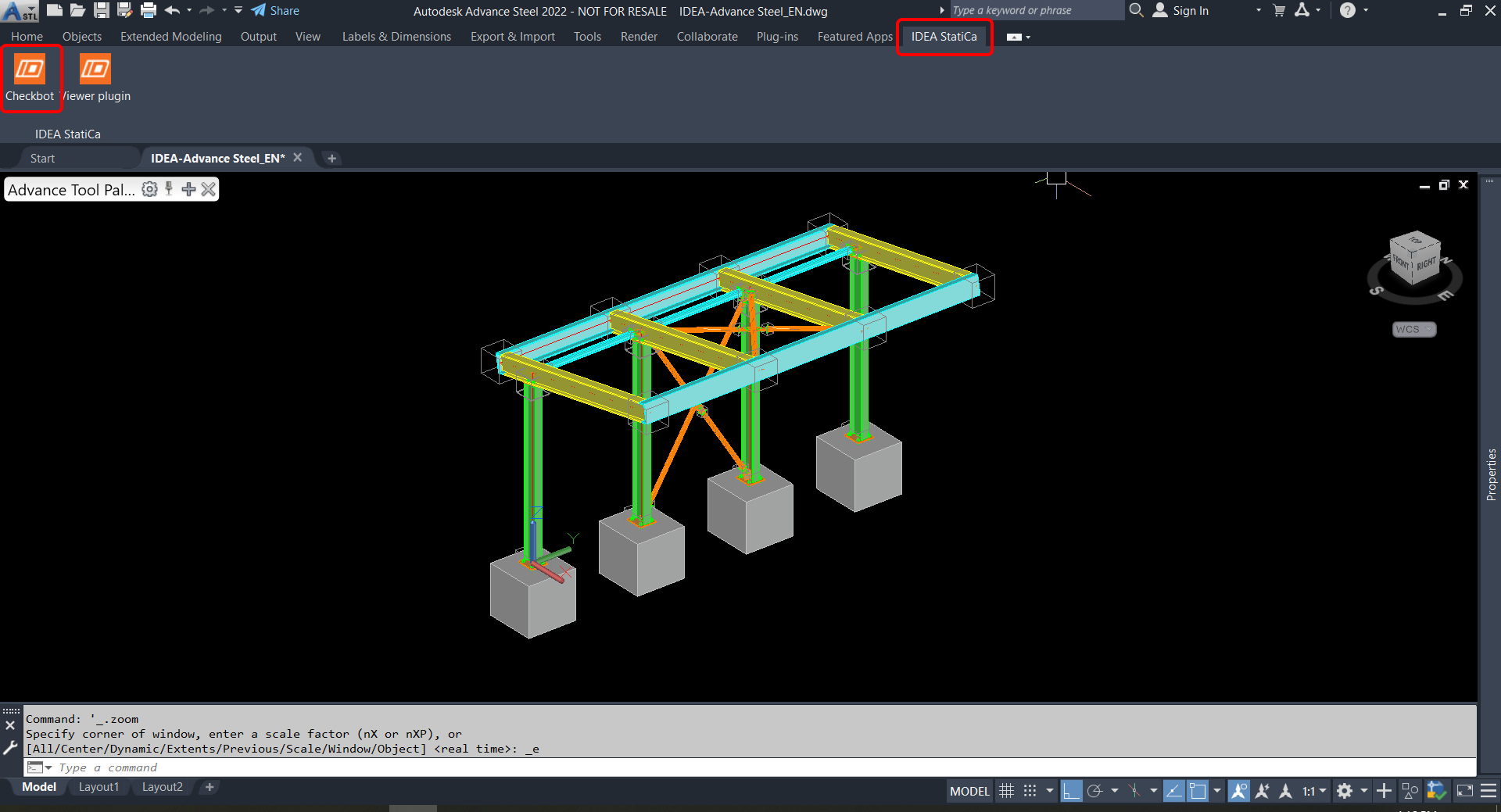
Il collegamento BIM viene integrato automaticamente. Lo si può trovare nella barra multifunzione superiore sotto IDEA StatiCa -> Checkbot. Questo aprirà l'applicazione Checkbot.
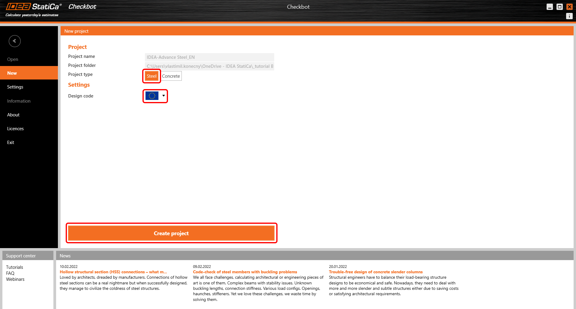
Selezionare l'opzione Nuovo con il tipo di progetto Acciaio e il codice di progetto IT. Selezionare quindi Crea progetto.
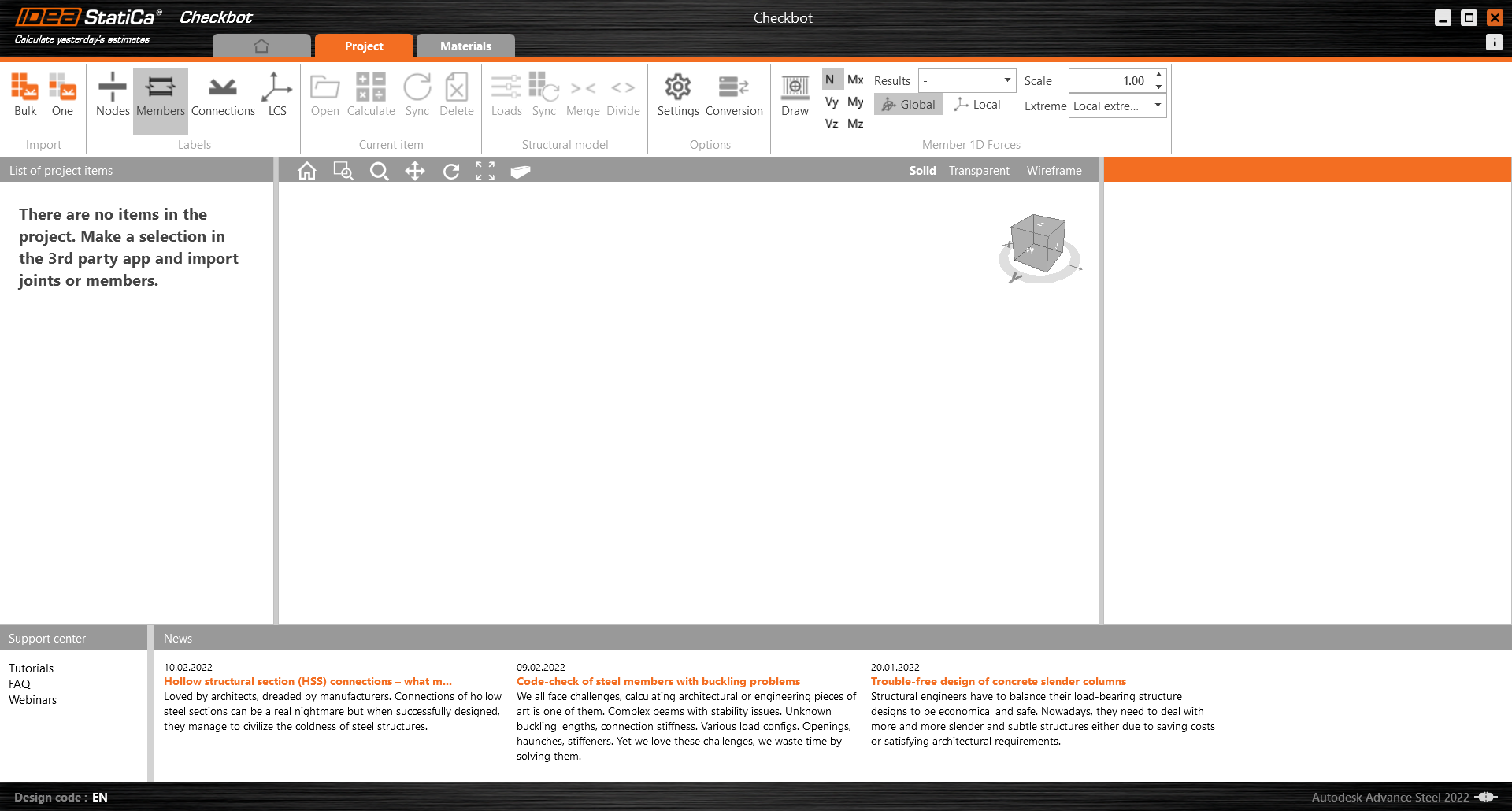
Il nuovo progetto Checkbot è pronto per importare le connessioni da Advance Steel.
Widget #NaN: support_center_article
Name: Advance Steel BIM Link tutorial - Import
ID: ee09394a-ce6a-43fd-8ea6-c1a1e17ec87e
Show Raw Data
{
  "title": {
    "name": "Main headline (H1)",
    "type": "text",
    "value": "Importazione"
  },
  "preview_image": {
    "name": "Preview image",
    "type": "asset",
    "value": []
  },
  "post_date": {
    "name": "Post date",
    "type": "date_time",
    "value": null,
    "displayTimeZone": null
  },
  "perex_content": {
    "name": "Lead paragraph",
    "type": "text",
    "value": ""
  },
  "content": {
    "images": [
      {
        "description": null,
        "imageId": "d0f97369-2294-445a-9d6f-172c077dee8b",
        "url": "https://assets-us-01.kc-usercontent.com:443/28eac049-c8ed-00e2-220c-12142a968dff/ba91468f-02b0-4775-b282-8c22cff8f463/CAD%20Import01.png",
        "height": 1030,
        "width": 1920
      },
      {
        "description": null,
        "imageId": "71237122-0578-4f2e-86db-9d8d6e6791fc",
        "url": "https://assets-us-01.kc-usercontent.com:443/28eac049-c8ed-00e2-220c-12142a968dff/be985dff-b3d9-4fe9-8ad5-49776a89158b/CAD%20Import01a.png",
        "height": 1020,
        "width": 1920
      },
      {
        "description": null,
        "imageId": "fba87dbd-2a11-46dd-a708-810c933f46c5",
        "url": "https://assets-us-01.kc-usercontent.com:443/28eac049-c8ed-00e2-220c-12142a968dff/9225cd25-c609-4df2-8060-5f38aa10baae/05_Advance%20Steel.png",
        "height": 1039,
        "width": 1920
      },
      {
        "description": null,
        "imageId": "48bf8d64-b68b-4885-971a-3c91ae2c0b54",
        "url": "https://assets-us-01.kc-usercontent.com:443/28eac049-c8ed-00e2-220c-12142a968dff/cd946a3a-b637-4cdc-b6ce-e7bfdf1dbcf1/CAD%20Import02.png",
        "height": 208,
        "width": 428
      },
      {
        "description": null,
        "imageId": "95e4991d-1c66-4480-82ed-9e750a96c348",
        "url": "https://assets-us-01.kc-usercontent.com:443/28eac049-c8ed-00e2-220c-12142a968dff/10cdad59-2293-49a9-9998-0a6ba793bd55/CAD%20Import03.png",
        "height": 1020,
        "width": 1920
      },
      {
        "description": null,
        "imageId": "b1e75809-052e-48b8-8355-d09750552fa3",
        "url": "https://assets-us-01.kc-usercontent.com:443/28eac049-c8ed-00e2-220c-12142a968dff/2c3f2e13-4f0e-4299-a50d-fc7aba2b638e/CAD%20Import04.png",
        "height": 1020,
        "width": 1920
      }
    ],
    "linkedItemCodenames": [],
    "linkedItems": [],
    "links": [
      {
        "codename": "checkbot",
        "linkId": "caeb1a6c-2621-446f-8005-4d2799496a39",
        "urlSlug": "checkbot",
        "type": "landing_page"
      }
    ],
    "name": "Content",
    "type": "rich_text",
    "value": "<p>Esistono due opzioni per l'importazione del modello in Checkbot:</p>\n<p>I. Per importare in Checkbot una parte più ampia della struttura, selezionare <strong>Bulk</strong>. (Utilizzato in questo tutorial).</p>\n<figure data-asset-id=\"d0f97369-2294-445a-9d6f-172c077dee8b\" data-image-id=\"d0f97369-2294-445a-9d6f-172c077dee8b\"><img src=\"https://assets-us-01.kc-usercontent.com:443/28eac049-c8ed-00e2-220c-12142a968dff/ba91468f-02b0-4775-b282-8c22cff8f463/CAD%20Import01.png\" data-asset-id=\"d0f97369-2294-445a-9d6f-172c077dee8b\" data-image-id=\"d0f97369-2294-445a-9d6f-172c077dee8b\" alt=\"\"></figure>\n<p>In questo modo si importeranno in <a data-item-id=\"caeb1a6c-2621-446f-8005-4d2799496a39\" href=\"\">Checkbot</a> tutte le parti selezionate della struttura, con le stesse coordinate, orientamenti e dimensioni delle sezioni del modello BIM. Il centro del giunto viene creato automaticamente dal software in base all'intersezione dei membri. Si consiglia di <em>non</em> importare tutte le connessioni contemporaneamente, ma di creare le connessioni in modo incrementale.</p>\n<p>II. In alternativa, è possibile esportare un singolo nodo utilizzando il pulsante <strong>Uno </strong>nella barra multifunzione superiore di Checkbot.</p>\n<figure data-asset-id=\"71237122-0578-4f2e-86db-9d8d6e6791fc\" data-image-id=\"71237122-0578-4f2e-86db-9d8d6e6791fc\"><img src=\"https://assets-us-01.kc-usercontent.com:443/28eac049-c8ed-00e2-220c-12142a968dff/be985dff-b3d9-4fe9-8ad5-49776a89158b/CAD%20Import01a.png\" data-asset-id=\"71237122-0578-4f2e-86db-9d8d6e6791fc\" data-image-id=\"71237122-0578-4f2e-86db-9d8d6e6791fc\" alt=\"\"></figure>\n<p><strong>Deselezionare tutto ciò che</strong> è presente nella struttura del modello BIM e premere <strong>Uno</strong>. Poi:</p>\n<ol>\n  <li>Nel modello BIM, <strong>selezionare il nodo</strong> che rappresenta il centro della connessione</li>\n  <li>A questo punto, <strong>selezionare le membratrue</strong>, come travi e colonne. L'ordine in cui vengolo selezionate le membrature definirà l'ordine delle membrature nel modello della connessione.</li>\n  <li>Selezionare <strong>tutte le altre entità di connessione</strong>, come bulloni, piastre, ecc. e confermare.</li>\n</ol>\n<p>La connessione verrà portata in Checkbot.</p>\n<p>Scegliere tra le due modalità di importazione (Bulk o Uno). Entrambe le modalità importano con successo la struttura.</p>\n<p>In Advance Steel, selezionare una delle colonne interne con controventature, assicurandosi di selezionare anche tutti gli oggetti di connessione.</p>\n<figure data-asset-id=\"fba87dbd-2a11-46dd-a708-810c933f46c5\" data-image-id=\"fba87dbd-2a11-46dd-a708-810c933f46c5\"><img src=\"https://assets-us-01.kc-usercontent.com:443/28eac049-c8ed-00e2-220c-12142a968dff/9225cd25-c609-4df2-8060-5f38aa10baae/05_Advance%20Steel.png\" data-asset-id=\"fba87dbd-2a11-46dd-a708-810c933f46c5\" data-image-id=\"fba87dbd-2a11-46dd-a708-810c933f46c5\" alt=\"\"></figure>\n<p>Potrebbe apparire la notifica<em>\"Vuoi importare anche le saldature consigliate?</em>\". Poiché tutte le saldature sono state create nel modello BIM, selezionare il pulsante <strong>No</strong>.</p>\n<figure data-asset-id=\"48bf8d64-b68b-4885-971a-3c91ae2c0b54\" data-image-id=\"48bf8d64-b68b-4885-971a-3c91ae2c0b54\"><img src=\"https://assets-us-01.kc-usercontent.com:443/28eac049-c8ed-00e2-220c-12142a968dff/cd946a3a-b637-4cdc-b6ce-e7bfdf1dbcf1/CAD%20Import02.png\" data-asset-id=\"48bf8d64-b68b-4885-971a-3c91ae2c0b54\" data-image-id=\"48bf8d64-b68b-4885-971a-3c91ae2c0b54\" alt=\"\"></figure>\n<p>Si noti che la numerazione dei nodi e degli elementi potrebbe essere diversa.</p>\n<figure data-asset-id=\"95e4991d-1c66-4480-82ed-9e750a96c348\" data-image-id=\"95e4991d-1c66-4480-82ed-9e750a96c348\"><img src=\"https://assets-us-01.kc-usercontent.com:443/28eac049-c8ed-00e2-220c-12142a968dff/10cdad59-2293-49a9-9998-0a6ba793bd55/CAD%20Import03.png\" data-asset-id=\"95e4991d-1c66-4480-82ed-9e750a96c348\" data-image-id=\"95e4991d-1c66-4480-82ed-9e750a96c348\" alt=\"\"></figure>\n<p>Si noti che l'area di lavoro 3D è progettata per mostrare una panoramica della struttura importata e non una vista dettagliata delle connessioni effettive. Per ulteriori informazioni su Checkbot, vedere <a href=\"https://www.ideastatica.com/support-center/checkbot-bulk-bim-workflows\" title=\"Checkbot\">qui</a>.</p>\n<figure data-asset-id=\"b1e75809-052e-48b8-8355-d09750552fa3\" data-image-id=\"b1e75809-052e-48b8-8355-d09750552fa3\"><img src=\"https://assets-us-01.kc-usercontent.com:443/28eac049-c8ed-00e2-220c-12142a968dff/2c3f2e13-4f0e-4299-a50d-fc7aba2b638e/CAD%20Import04.png\" data-asset-id=\"b1e75809-052e-48b8-8355-d09750552fa3\" data-image-id=\"b1e75809-052e-48b8-8355-d09750552fa3\" alt=\"\"></figure>"
  },
  "regions": {
    "name": "Region",
    "type": "taxonomy",
    "value": [
      {
        "name": "EMEA",
        "codename": "emea"
      },
      {
        "name": "AMER",
        "codename": "amer"
      },
      {
        "name": "APAC",
        "codename": "apac"
      }
    ],
    "taxonomyGroup": "region"
  },
  "product_groups": {
    "name": "Product group",
    "type": "taxonomy",
    "value": [
      {
        "name": "Connection design",
        "codename": "connection_design"
      },
      {
        "name": "Steel",
        "codename": "steel"
      }
    ],
    "taxonomyGroup": "product_group"
  },
  "support_center_article_types": {
    "name": "Support center article",
    "type": "taxonomy",
    "value": [
      {
        "name": "Knowledge base",
        "codename": "knowledgebase_article"
      }
    ],
    "taxonomyGroup": "support_center_article"
  },
  "expertise_levels": {
    "name": "Expertise level",
    "type": "taxonomy",
    "value": [
      {
        "name": "Beginner",
        "codename": "beginner"
      },
      {
        "name": "Intermediate",
        "codename": "intermediate"
      }
    ],
    "taxonomyGroup": "expertise_level"
  },
  "labels": {
    "name": "Labels",
    "type": "taxonomy",
    "value": [
      {
        "name": "BIM link",
        "codename": "bim_links"
      }
    ],
    "taxonomyGroup": "labels"
  },
  "linked_items": {
    "name": "Linked items",
    "type": "modular_content",
    "value": [],
    "linkedItems": []
  },
  "attachments__files": {
    "name": "Attachments",
    "type": "asset",
    "value": []
  },
  "content_priority__value": {
    "name": "Content priority value",
    "type": "number",
    "value": null
  },
  "options": {
    "name": "Options",
    "type": "multiple_choice",
    "value": []
  },
  "url_slug": {
    "name": "Url slug",
    "type": "url_slug",
    "value": "General CAD BIM Link tutorial - Import"
  },
  "unique_url_slug": {
    "name": "Unique URL slug",
    "type": "custom",
    "value": "[\"General-CAD-BIM-Link-tutorial---Import\",\"[autogenerated]\"]"
  },
  "content_settings__sitemap": {
    "name": "Show in sitemap",
    "type": "multiple_choice",
    "value": [
      {
        "name": "default",
        "codename": "default"
      }
    ]
  },
  "content_settings__robots": {
    "name": "Search engine indexing",
    "type": "multiple_choice",
    "value": [
      {
        "name": "default",
        "codename": "default"
      }
    ]
  },
  "content_settings__is_hidden": {
    "name": "Hidden nested content",
    "type": "multiple_choice",
    "value": [
      {
        "name": "yes",
        "codename": "yes"
      }
    ]
  },
  "metadata__page_title": {
    "name": "Page title",
    "type": "text",
    "value": "General CAD BIM Link tutorial - Steel connection import"
  },
  "metadata__page_description": {
    "name": "Page description",
    "type": "text",
    "value": "IDEA StatiCa step-by-step tutorial for importing steel connection from CAD into Checkbot. Structural design of welded and bolted steel connections."
  },
  "metadata__page_keywords": {
    "name": "Page keywords",
    "type": "text",
    "value": ""
  },
  "metadata__canonical_url": {
    "name": "Canonical URL",
    "type": "text",
    "value": ""
  },
  "metadata__og_title": {
    "name": "OG:title",
    "type": "text",
    "value": ""
  },
  "metadata__og_description": {
    "name": "OG:description",
    "type": "text",
    "value": ""
  },
  "metadata__og_image": {
    "name": "OG:image",
    "type": "asset",
    "value": []
  },
  "translation__translation_connector": {
    "name": "Translation Connector",
    "type": "taxonomy",
    "value": [],
    "taxonomyGroup": "languages"
  },
  "translation__force_translation": {
    "name": "Force translation",
    "type": "multiple_choice",
    "value": []
  },
  "translation__last_translation": {
    "images": [],
    "linkedItemCodenames": [],
    "linkedItems": [],
    "links": [],
    "name": "Last translation",
    "type": "rich_text",
    "value": "<p><br></p>"
  },
  "translation__ai_translated": {
    "name": "AI translated",
    "type": "multiple_choice",
    "value": []
  },
  "page_tree_settings__page_label": {
    "name": "Page label",
    "type": "text",
    "value": ""
  },
  "page_tree_settings__path_segment": {
    "name": "Path segment",
    "type": "text",
    "value": ""
  },
  "page_tree_settings__breadcrumb_style": {
    "name": "Breadcrumb style",
    "type": "multiple_choice",
    "value": []
  },
  "page_tree_settings__hide_in_breadcrumbs": {
    "name": "Hide in breadcrumbs",
    "type": "multiple_choice",
    "value": []
  }
}
Widget #NaN: support_center_article
Name: Advance Steel BIM Link tutorial - Geometry
ID: 1e7042b7-6781-4cfd-b82b-ab8bbc634143
Show Raw Data
{
  "title": {
    "name": "Main headline (H1)",
    "type": "text",
    "value": "Geometria"
  },
  "preview_image": {
    "name": "Preview image",
    "type": "asset",
    "value": []
  },
  "post_date": {
    "name": "Post date",
    "type": "date_time",
    "value": null,
    "displayTimeZone": null
  },
  "perex_content": {
    "name": "Lead paragraph",
    "type": "text",
    "value": ""
  },
  "content": {
    "images": [
      {
        "description": null,
        "imageId": "d38718ab-de37-4eb1-a935-f1bc9c350289",
        "url": "https://assets-us-01.kc-usercontent.com:443/28eac049-c8ed-00e2-220c-12142a968dff/5e7a1a0d-0884-4722-8471-120f6defb6ed/CAD%20Geometry01.png",
        "height": 1020,
        "width": 1920
      },
      {
        "description": null,
        "imageId": "48013444-4e9d-4912-9be5-cf048458dd0b",
        "url": "https://assets-us-01.kc-usercontent.com:443/28eac049-c8ed-00e2-220c-12142a968dff/6186b02b-8a22-4293-849e-eb913856b347/CAD%20Geometry02.png",
        "height": 1020,
        "width": 1920
      }
    ],
    "linkedItemCodenames": [],
    "linkedItems": [],
    "links": [
      {
        "codename": "checkbot",
        "linkId": "caeb1a6c-2621-446f-8005-4d2799496a39",
        "urlSlug": "checkbot",
        "type": "landing_page"
      }
    ],
    "name": "Content",
    "type": "rich_text",
    "value": "<p>Nell'elenco degli elementi del progetto sotto Connessioni e con una connessione evidenziata in <a data-item-id=\"caeb1a6c-2621-446f-8005-4d2799496a39\" href=\"\">Checkbot</a>, è possibile fare clic con il tasto destro del mouse e selezionare <strong>Apri </strong>o fare clic sul comando della barra multifunzione <strong>Apri</strong> per avviare la progettazione, la verifica secondo codice e la creazione di report.</p>\n<figure data-asset-id=\"d38718ab-de37-4eb1-a935-f1bc9c350289\" data-image-id=\"d38718ab-de37-4eb1-a935-f1bc9c350289\"><img src=\"https://assets-us-01.kc-usercontent.com:443/28eac049-c8ed-00e2-220c-12142a968dff/5e7a1a0d-0884-4722-8471-120f6defb6ed/CAD%20Geometry01.png\" data-asset-id=\"d38718ab-de37-4eb1-a935-f1bc9c350289\" data-image-id=\"d38718ab-de37-4eb1-a935-f1bc9c350289\" alt=\"\"></figure>\n<p>Le impostazioni delle membrature sono prese dall'applicazione BIM originale. È tuttavia possibile modificare le dimensioni della sezione di qualsiasi membratura nella schermata principale di Checkbot, ma questo interromperà il collegamento con l'applicazione BIM in questa sessione, a meno che non venga sincronizzato di nuovo.</p>\n<p>La connessione importata viene aperta nell'applicazione <strong>IDEA StatiCa Connection</strong>.</p>\n<figure data-asset-id=\"48013444-4e9d-4912-9be5-cf048458dd0b\" data-image-id=\"48013444-4e9d-4912-9be5-cf048458dd0b\"><img src=\"https://assets-us-01.kc-usercontent.com:443/28eac049-c8ed-00e2-220c-12142a968dff/6186b02b-8a22-4293-849e-eb913856b347/CAD%20Geometry02.png\" data-asset-id=\"48013444-4e9d-4912-9be5-cf048458dd0b\" data-image-id=\"48013444-4e9d-4912-9be5-cf048458dd0b\" alt=\"\"></figure>"
  },
  "regions": {
    "name": "Region",
    "type": "taxonomy",
    "value": [
      {
        "name": "EMEA",
        "codename": "emea"
      },
      {
        "name": "AMER",
        "codename": "amer"
      },
      {
        "name": "APAC",
        "codename": "apac"
      }
    ],
    "taxonomyGroup": "region"
  },
  "product_groups": {
    "name": "Product group",
    "type": "taxonomy",
    "value": [
      {
        "name": "Connection design",
        "codename": "connection_design"
      },
      {
        "name": "Steel",
        "codename": "steel"
      }
    ],
    "taxonomyGroup": "product_group"
  },
  "support_center_article_types": {
    "name": "Support center article",
    "type": "taxonomy",
    "value": [
      {
        "name": "Knowledge base",
        "codename": "knowledgebase_article"
      }
    ],
    "taxonomyGroup": "support_center_article"
  },
  "expertise_levels": {
    "name": "Expertise level",
    "type": "taxonomy",
    "value": [
      {
        "name": "Beginner",
        "codename": "beginner"
      },
      {
        "name": "Intermediate",
        "codename": "intermediate"
      }
    ],
    "taxonomyGroup": "expertise_level"
  },
  "labels": {
    "name": "Labels",
    "type": "taxonomy",
    "value": [
      {
        "name": "BIM link",
        "codename": "bim_links"
      }
    ],
    "taxonomyGroup": "labels"
  },
  "linked_items": {
    "name": "Linked items",
    "type": "modular_content",
    "value": [],
    "linkedItems": []
  },
  "attachments__files": {
    "name": "Attachments",
    "type": "asset",
    "value": []
  },
  "content_priority__value": {
    "name": "Content priority value",
    "type": "number",
    "value": null
  },
  "options": {
    "name": "Options",
    "type": "multiple_choice",
    "value": []
  },
  "url_slug": {
    "name": "Url slug",
    "type": "url_slug",
    "value": "geometria"
  },
  "unique_url_slug": {
    "name": "Unique URL slug",
    "type": "custom",
    "value": "[\"geometry\",\"[autogenerated]\"]"
  },
  "content_settings__sitemap": {
    "name": "Show in sitemap",
    "type": "multiple_choice",
    "value": [
      {
        "name": "default",
        "codename": "default"
      }
    ]
  },
  "content_settings__robots": {
    "name": "Search engine indexing",
    "type": "multiple_choice",
    "value": [
      {
        "name": "noindex, nofollow",
        "codename": "noindex__nofollow"
      }
    ]
  },
  "content_settings__is_hidden": {
    "name": "Hidden nested content",
    "type": "multiple_choice",
    "value": []
  },
  "metadata__page_title": {
    "name": "Page title",
    "type": "text",
    "value": "General CAD BIM Link tutorial - Steel connection geometry"
  },
  "metadata__page_description": {
    "name": "Page description",
    "type": "text",
    "value": "IDEA StatiCa step-by-step tutorial for geometry adjustment of a steel connection in Checkbot. Structural design of welded and bolted steel connections."
  },
  "metadata__page_keywords": {
    "name": "Page keywords",
    "type": "text",
    "value": ""
  },
  "metadata__canonical_url": {
    "name": "Canonical URL",
    "type": "text",
    "value": ""
  },
  "metadata__og_title": {
    "name": "OG:title",
    "type": "text",
    "value": ""
  },
  "metadata__og_description": {
    "name": "OG:description",
    "type": "text",
    "value": ""
  },
  "metadata__og_image": {
    "name": "OG:image",
    "type": "asset",
    "value": []
  },
  "translation__translation_connector": {
    "name": "Translation Connector",
    "type": "taxonomy",
    "value": [],
    "taxonomyGroup": "languages"
  },
  "translation__force_translation": {
    "name": "Force translation",
    "type": "multiple_choice",
    "value": []
  },
  "translation__last_translation": {
    "images": [],
    "linkedItemCodenames": [],
    "linkedItems": [],
    "links": [],
    "name": "Last translation",
    "type": "rich_text",
    "value": "<p><br></p>"
  },
  "translation__ai_translated": {
    "name": "AI translated",
    "type": "multiple_choice",
    "value": []
  },
  "page_tree_settings__page_label": {
    "name": "Page label",
    "type": "text",
    "value": ""
  },
  "page_tree_settings__path_segment": {
    "name": "Path segment",
    "type": "text",
    "value": "geometry-cad"
  },
  "page_tree_settings__breadcrumb_style": {
    "name": "Breadcrumb style",
    "type": "multiple_choice",
    "value": []
  },
  "page_tree_settings__hide_in_breadcrumbs": {
    "name": "Hide in breadcrumbs",
    "type": "multiple_choice",
    "value": []
  }
}
Widget #NaN: support_center_article
Name: Advance Steel BIM Link tutorial - Load effects
ID: ca1e09f3-3264-4ff5-94fe-09967c10cb36
Show Raw Data
{
  "title": {
    "name": "Main headline (H1)",
    "type": "text",
    "value": "Effetti del carico"
  },
  "preview_image": {
    "name": "Preview image",
    "type": "asset",
    "value": []
  },
  "post_date": {
    "name": "Post date",
    "type": "date_time",
    "value": null,
    "displayTimeZone": null
  },
  "perex_content": {
    "name": "Lead paragraph",
    "type": "text",
    "value": ""
  },
  "content": {
    "images": [
      {
        "description": null,
        "imageId": "a47f57d8-4b25-4367-85df-fc98bd82d69a",
        "url": "https://assets-us-01.kc-usercontent.com:443/28eac049-c8ed-00e2-220c-12142a968dff/7ad48b5c-8a05-4d62-a003-2fb8c29b6700/Load%20effects01.png",
        "height": 106,
        "width": 568
      },
      {
        "description": null,
        "imageId": "32ea5dd0-2da0-4476-b52b-79d27072a2d1",
        "url": "https://assets-us-01.kc-usercontent.com:443/28eac049-c8ed-00e2-220c-12142a968dff/998ec6f1-d884-46cd-b976-8d5aa06e6c36/Load%20effects02.png",
        "height": 1020,
        "width": 1920
      },
      {
        "description": null,
        "imageId": "07d1eace-58b2-48f3-969d-be70144d98c5",
        "url": "https://assets-us-01.kc-usercontent.com:443/28eac049-c8ed-00e2-220c-12142a968dff/e710994b-7a7a-4cc9-b55b-0b47c87f5da1/Load%20effects03.png",
        "height": 600,
        "width": 1188
      },
      {
        "description": null,
        "imageId": "cde1838e-9589-4179-be46-a15cd97d4c61",
        "url": "https://assets-us-01.kc-usercontent.com:443/28eac049-c8ed-00e2-220c-12142a968dff/ba97882d-07bc-4fcc-a7b8-6d122c5c96d4/Load%20effects04.png",
        "height": 1020,
        "width": 1920
      }
    ],
    "linkedItemCodenames": [],
    "linkedItems": [],
    "links": [
      {
        "codename": "steel___v2",
        "linkId": "f6acf868-1f2d-48e6-8ccb-711f6883d5f7",
        "urlSlug": "progettazione-dell-acciaio-piu-rapida-e-accurata",
        "type": "landing_page"
      }
    ],
    "name": "Content",
    "type": "rich_text",
    "value": "<p><a data-asset-id=\"98e62186-39f7-49fb-814d-efef8c08de97\" href=\"https://assets-us-01.kc-usercontent.com:443/28eac049-c8ed-00e2-220c-12142a968dff/d1a36c18-6b5e-4bf7-89e4-353c4513a0c0/Load%20effects.xlsx\">Scarica il foglio Excel allegato</a> con gli effetti di carico e aprilo.</p>\n<p>Selezionare i valori delle forze interne nella tabella e copiarli (Ctrl + C).</p>\n<figure data-asset-id=\"a47f57d8-4b25-4367-85df-fc98bd82d69a\" data-image-id=\"a47f57d8-4b25-4367-85df-fc98bd82d69a\"><img src=\"https://assets-us-01.kc-usercontent.com:443/28eac049-c8ed-00e2-220c-12142a968dff/7ad48b5c-8a05-4d62-a003-2fb8c29b6700/Load%20effects01.png\" data-asset-id=\"a47f57d8-4b25-4367-85df-fc98bd82d69a\" data-image-id=\"a47f57d8-4b25-4367-85df-fc98bd82d69a\" alt=\"\"></figure>\n<p>Quindi, in <a data-item-id=\"f6acf868-1f2d-48e6-8ccb-711f6883d5f7\" href=\"\">IDEA StatiCa Connection</a>, selezionate il pulsante <strong>XLS Import</strong> nella barra multifunzione superiore.</p>\n<figure data-asset-id=\"32ea5dd0-2da0-4476-b52b-79d27072a2d1\" data-image-id=\"32ea5dd0-2da0-4476-b52b-79d27072a2d1\"><img src=\"https://assets-us-01.kc-usercontent.com:443/28eac049-c8ed-00e2-220c-12142a968dff/998ec6f1-d884-46cd-b976-8d5aa06e6c36/Load%20effects02.png\" data-asset-id=\"32ea5dd0-2da0-4476-b52b-79d27072a2d1\" data-image-id=\"32ea5dd0-2da0-4476-b52b-79d27072a2d1\" alt=\"\"></figure>\n<p>Con un clic sinistro, selezionare la prima cella e incollare (Ctrl + V) i valori delle forze interne.</p>\n<figure data-asset-id=\"07d1eace-58b2-48f3-969d-be70144d98c5\" data-image-id=\"07d1eace-58b2-48f3-969d-be70144d98c5\"><img src=\"https://assets-us-01.kc-usercontent.com:443/28eac049-c8ed-00e2-220c-12142a968dff/e710994b-7a7a-4cc9-b55b-0b47c87f5da1/Load%20effects03.png\" data-asset-id=\"07d1eace-58b2-48f3-969d-be70144d98c5\" data-image-id=\"07d1eace-58b2-48f3-969d-be70144d98c5\" alt=\"\"></figure>\n<p>È necessario che l'ordine delle righe e delle colonne della tabella Excel sia lo stesso della tabella degli effetti di carico nell'applicazione IDEA StatiCa Connection. Se le righe o le colonne vengono scambiate, si otterrà un'immissione errata delle forze interne sui membri.</p>\n<figure data-asset-id=\"cde1838e-9589-4179-be46-a15cd97d4c61\" data-image-id=\"cde1838e-9589-4179-be46-a15cd97d4c61\"><img src=\"https://assets-us-01.kc-usercontent.com:443/28eac049-c8ed-00e2-220c-12142a968dff/ba97882d-07bc-4fcc-a7b8-6d122c5c96d4/Load%20effects04.png\" data-asset-id=\"cde1838e-9589-4179-be46-a15cd97d4c61\" data-image-id=\"cde1838e-9589-4179-be46-a15cd97d4c61\" alt=\"\"></figure>"
  },
  "regions": {
    "name": "Region",
    "type": "taxonomy",
    "value": [
      {
        "name": "AMER",
        "codename": "amer"
      },
      {
        "name": "EMEA",
        "codename": "emea"
      },
      {
        "name": "APAC",
        "codename": "apac"
      }
    ],
    "taxonomyGroup": "region"
  },
  "product_groups": {
    "name": "Product group",
    "type": "taxonomy",
    "value": [
      {
        "name": "Steel",
        "codename": "steel"
      },
      {
        "name": "Connection design",
        "codename": "connection_design"
      }
    ],
    "taxonomyGroup": "product_group"
  },
  "support_center_article_types": {
    "name": "Support center article",
    "type": "taxonomy",
    "value": [
      {
        "name": "Knowledge base",
        "codename": "knowledgebase_article"
      }
    ],
    "taxonomyGroup": "support_center_article"
  },
  "expertise_levels": {
    "name": "Expertise level",
    "type": "taxonomy",
    "value": [
      {
        "name": "Beginner",
        "codename": "beginner"
      },
      {
        "name": "Intermediate",
        "codename": "intermediate"
      }
    ],
    "taxonomyGroup": "expertise_level"
  },
  "labels": {
    "name": "Labels",
    "type": "taxonomy",
    "value": [
      {
        "name": "BIM link",
        "codename": "bim_links"
      }
    ],
    "taxonomyGroup": "labels"
  },
  "linked_items": {
    "name": "Linked items",
    "type": "modular_content",
    "value": [],
    "linkedItems": []
  },
  "attachments__files": {
    "name": "Attachments",
    "type": "asset",
    "value": []
  },
  "content_priority__value": {
    "name": "Content priority value",
    "type": "number",
    "value": null
  },
  "options": {
    "name": "Options",
    "type": "multiple_choice",
    "value": []
  },
  "url_slug": {
    "name": "Url slug",
    "type": "url_slug",
    "value": "effetti-del-carico"
  },
  "unique_url_slug": {
    "name": "Unique URL slug",
    "type": "custom",
    "value": "[\"load-effects\",\"[autogenerated]\"]"
  },
  "content_settings__sitemap": {
    "name": "Show in sitemap",
    "type": "multiple_choice",
    "value": [
      {
        "name": "default",
        "codename": "default"
      }
    ]
  },
  "content_settings__robots": {
    "name": "Search engine indexing",
    "type": "multiple_choice",
    "value": [
      {
        "name": "default",
        "codename": "default"
      }
    ]
  },
  "content_settings__is_hidden": {
    "name": "Hidden nested content",
    "type": "multiple_choice",
    "value": [
      {
        "name": "yes",
        "codename": "yes"
      }
    ]
  },
  "metadata__page_title": {
    "name": "Page title",
    "type": "text",
    "value": "General CAD BIM Link tutorial - Steel connection internal forces import"
  },
  "metadata__page_description": {
    "name": "Page description",
    "type": "text",
    "value": ""
  },
  "metadata__page_keywords": {
    "name": "Page keywords",
    "type": "text",
    "value": "IDEA StatiCa step-by-step tutorial for importing internal forces of a steel connection. Structural design of welded and bolted steel connections."
  },
  "metadata__canonical_url": {
    "name": "Canonical URL",
    "type": "text",
    "value": ""
  },
  "metadata__og_title": {
    "name": "OG:title",
    "type": "text",
    "value": ""
  },
  "metadata__og_description": {
    "name": "OG:description",
    "type": "text",
    "value": ""
  },
  "metadata__og_image": {
    "name": "OG:image",
    "type": "asset",
    "value": []
  },
  "translation__translation_connector": {
    "name": "Translation Connector",
    "type": "taxonomy",
    "value": [],
    "taxonomyGroup": "languages"
  },
  "translation__force_translation": {
    "name": "Force translation",
    "type": "multiple_choice",
    "value": []
  },
  "translation__last_translation": {
    "images": [],
    "linkedItemCodenames": [],
    "linkedItems": [],
    "links": [],
    "name": "Last translation",
    "type": "rich_text",
    "value": "<p><br></p>"
  },
  "translation__ai_translated": {
    "name": "AI translated",
    "type": "multiple_choice",
    "value": []
  },
  "page_tree_settings__page_label": {
    "name": "Page label",
    "type": "text",
    "value": ""
  },
  "page_tree_settings__path_segment": {
    "name": "Path segment",
    "type": "text",
    "value": "load-effects"
  },
  "page_tree_settings__breadcrumb_style": {
    "name": "Breadcrumb style",
    "type": "multiple_choice",
    "value": []
  },
  "page_tree_settings__hide_in_breadcrumbs": {
    "name": "Hide in breadcrumbs",
    "type": "multiple_choice",
    "value": []
  }
}
Widget #NaN: support_center_article
Name: Advance Steel BIM Link tutorial - Design Example (EN)
ID: 9ab29491-ff29-4f83-8070-30bd706dba12
Show Raw Data
{
  "title": {
    "name": "Main headline (H1)",
    "type": "text",
    "value": "Progetto"
  },
  "preview_image": {
    "name": "Preview image",
    "type": "asset",
    "value": []
  },
  "post_date": {
    "name": "Post date",
    "type": "date_time",
    "value": null,
    "displayTimeZone": null
  },
  "perex_content": {
    "name": "Lead paragraph",
    "type": "text",
    "value": ""
  },
  "content": {
    "images": [
      {
        "description": null,
        "imageId": "24c37810-4535-4004-8302-00a7a21fd7b2",
        "url": "https://assets-us-01.kc-usercontent.com:443/28eac049-c8ed-00e2-220c-12142a968dff/95108fce-27ed-46d7-b420-b4a8efa87ce4/CAD%20Design01.png",
        "height": 1020,
        "width": 1920
      },
      {
        "description": null,
        "imageId": "d7e2a379-a398-4c2c-acda-0a2e203ec7cb",
        "url": "https://assets-us-01.kc-usercontent.com:443/28eac049-c8ed-00e2-220c-12142a968dff/00ac76ea-d2c6-4650-9111-aa486081d2be/CAD%20Design02.png",
        "height": 1022,
        "width": 1920
      },
      {
        "description": null,
        "imageId": "620fe459-b24c-43b0-abd7-32c9f47bd327",
        "url": "https://assets-us-01.kc-usercontent.com:443/28eac049-c8ed-00e2-220c-12142a968dff/8054cad4-6f8a-4928-ad3b-b11c42d3764a/CAD%20Design03.png",
        "height": 1026,
        "width": 1920
      },
      {
        "description": null,
        "imageId": "90999327-b252-49d8-9547-aa3f79cb873c",
        "url": "https://assets-us-01.kc-usercontent.com:443/28eac049-c8ed-00e2-220c-12142a968dff/02d3757f-0f78-4c5d-9d2d-3cfff7ad5585/CAD%20Design04.png",
        "height": 1020,
        "width": 1920
      },
      {
        "description": null,
        "imageId": "960d3582-3b1a-4829-ac66-542f3d73a3ae",
        "url": "https://assets-us-01.kc-usercontent.com:443/28eac049-c8ed-00e2-220c-12142a968dff/891494ba-30cb-4c30-a472-2ed8408bf894/Design9A.png",
        "height": 124,
        "width": 159
      },
      {
        "description": null,
        "imageId": "17645ec3-a0ad-4564-9b61-dba0b5f9e862",
        "url": "https://assets-us-01.kc-usercontent.com:443/28eac049-c8ed-00e2-220c-12142a968dff/8c88085d-8815-405c-959f-4c3653a330cd/CAD%20Design05.png",
        "height": 746,
        "width": 950
      },
      {
        "description": null,
        "imageId": "3650306a-1e99-40d8-9ea7-1a249e971fa1",
        "url": "https://assets-us-01.kc-usercontent.com:443/28eac049-c8ed-00e2-220c-12142a968dff/836a43e9-55e7-4804-a5ee-41713d2e74af/CAD%20Design06.png",
        "height": 828,
        "width": 2100
      },
      {
        "description": null,
        "imageId": "48eb015f-5ba9-4970-8321-a941556fd805",
        "url": "https://assets-us-01.kc-usercontent.com:443/28eac049-c8ed-00e2-220c-12142a968dff/0e9e7099-7192-4b0e-9d5d-8d8fe07d036e/CAD%20Design07.png",
        "height": 1020,
        "width": 1920
      },
      {
        "description": null,
        "imageId": "40f63f3c-7532-427f-817c-c489765e2eee",
        "url": "https://assets-us-01.kc-usercontent.com:443/28eac049-c8ed-00e2-220c-12142a968dff/0c3f20f7-28a7-49b6-964d-aa09863807c3/CAD%20Design08.png",
        "height": 1020,
        "width": 1920
      }
    ],
    "linkedItemCodenames": [],
    "linkedItems": [],
    "links": [
      {
        "codename": "shear_force_transfer_possibilities",
        "linkId": "95aac2ff-1e49-586a-af70-31c1d9c56d12",
        "urlSlug": "trasferimento-della-forza-di-taglio-nell-ancoraggio",
        "type": "support_center_article"
      },
      {
        "codename": "landing_page___steel_verification",
        "linkId": "06158daa-1491-4e83-ac34-4964bd5a3c63",
        "urlSlug": "verifiche-dell-acciaio",
        "type": "landing_page"
      },
      {
        "codename": "how_to_change_analysis_type",
        "linkId": "e3f48b21-6104-5305-b77a-f96b04bec9de",
        "urlSlug": "how-to-change-analysis-type",
        "type": "support_center_article"
      },
      {
        "codename": "checkbot",
        "linkId": "caeb1a6c-2621-446f-8005-4d2799496a39",
        "urlSlug": "checkbot",
        "type": "landing_page"
      }
    ],
    "name": "Content",
    "type": "rich_text",
    "value": "<p>Per il diagonale si utilizzerà una <a href=\"https://www.ideastatica.com/support-center/how-to-model-one-bolt-connection\" title=\"Single bolt connections\">connessione a bullone singolo</a>. Per questo tipo di connessione, è necessario modificare il <strong>tipo di modello</strong> dell'elemento della controventatura in <strong>N-Vy-Vz</strong>. Selezionare la controventatura nell'elenco delle membrature e modificare il tipo di modello nell'elenco a discesa.</p>\n<figure data-asset-id=\"24c37810-4535-4004-8302-00a7a21fd7b2\" data-image-id=\"24c37810-4535-4004-8302-00a7a21fd7b2\"><img src=\"https://assets-us-01.kc-usercontent.com:443/28eac049-c8ed-00e2-220c-12142a968dff/95108fce-27ed-46d7-b420-b4a8efa87ce4/CAD%20Design01.png\" data-asset-id=\"24c37810-4535-4004-8302-00a7a21fd7b2\" data-image-id=\"24c37810-4535-4004-8302-00a7a21fd7b2\" alt=\"\"></figure>\n<p>Andare su <strong>Impostazione codice </strong>(Importazioni del progetto nella ultime versioni) nella barra multifunzione superiore e deselezionare l'opzione Calcestruzzo fessurato.</p>\n<figure data-asset-id=\"d7e2a379-a398-4c2c-acda-0a2e203ec7cb\" data-image-id=\"d7e2a379-a398-4c2c-acda-0a2e203ec7cb\"><img src=\"https://assets-us-01.kc-usercontent.com:443/28eac049-c8ed-00e2-220c-12142a968dff/00ac76ea-d2c6-4650-9111-aa486081d2be/CAD%20Design02.png\" data-asset-id=\"d7e2a379-a398-4c2c-acda-0a2e203ec7cb\" data-image-id=\"d7e2a379-a398-4c2c-acda-0a2e203ec7cb\" alt=\"\"></figure>\n<p>Regolare le proprietà degli ancoraggi e del blocco di calcestruzzo. Selezionare l'opzione <strong>Piano di taglio nella filettatura </strong>. Impostare il valore di <strong>Offset</strong> a <strong>200</strong> <strong>mm</strong>. Modificare la <strong>qualità</strong> del <strong>calcestruzzo</strong> in <strong>C25/30</strong>.</p>\n<figure data-asset-id=\"620fe459-b24c-43b0-abd7-32c9f47bd327\" data-image-id=\"620fe459-b24c-43b0-abd7-32c9f47bd327\"><img src=\"https://assets-us-01.kc-usercontent.com:443/28eac049-c8ed-00e2-220c-12142a968dff/8054cad4-6f8a-4928-ad3b-b11c42d3764a/CAD%20Design03.png\" data-asset-id=\"620fe459-b24c-43b0-abd7-32c9f47bd327\" data-image-id=\"620fe459-b24c-43b0-abd7-32c9f47bd327\" alt=\"\"></figure>\n<p>Selezionare infine il <a data-item-id=\"95aac2ff-1e49-586a-af70-31c1d9c56d12\" href=\"\"><strong>trasferimento delle forze di taglio</strong></a> agli <strong>ancoraggi</strong>.</p>\n<figure data-asset-id=\"90999327-b252-49d8-9547-aa3f79cb873c\" data-image-id=\"90999327-b252-49d8-9547-aa3f79cb873c\"><img src=\"https://assets-us-01.kc-usercontent.com:443/28eac049-c8ed-00e2-220c-12142a968dff/02d3757f-0f78-4c5d-9d2d-3cfff7ad5585/CAD%20Design04.png\" data-asset-id=\"90999327-b252-49d8-9547-aa3f79cb873c\" data-image-id=\"90999327-b252-49d8-9547-aa3f79cb873c\" alt=\"\"></figure>\n<h2>Verifica secondo codice e rapporto</h2>\n<p>Esegui ora una verifica secondo codice utilizzandoil comando <strong>Calcola </strong>nel pannello <a data-item-id=\"06158daa-1491-4e83-ac34-4964bd5a3c63\" href=\"\">CBFEM</a> della barra multifunzione superiore.<br>\nIn IDEA StatiCa Connection è possibile eseguire diversi tipi di analisi e verifiche del codice. Per ulteriori informazioni, consultate <a data-item-id=\"e3f48b21-6104-5305-b77a-f96b04bec9de\" href=\"\">qui</a>.</p>\n<figure data-asset-id=\"960d3582-3b1a-4829-ac66-542f3d73a3ae\" data-image-id=\"960d3582-3b1a-4829-ac66-542f3d73a3ae\"><img src=\"https://assets-us-01.kc-usercontent.com:443/28eac049-c8ed-00e2-220c-12142a968dff/891494ba-30cb-4c30-a472-2ed8408bf894/Design9A.png\" data-asset-id=\"960d3582-3b1a-4829-ac66-542f3d73a3ae\" data-image-id=\"960d3582-3b1a-4829-ac66-542f3d73a3ae\" alt=\"\"></figure>\n<p>Una volta terminata la verifica del codice, nella scheda <strong>Relazione </strong>è possibile creare una relazione contenente i risultati e i diagrammi del modello di connessione.</p>\n<figure data-asset-id=\"17645ec3-a0ad-4564-9b61-dba0b5f9e862\" data-image-id=\"17645ec3-a0ad-4564-9b61-dba0b5f9e862\"><img src=\"https://assets-us-01.kc-usercontent.com:443/28eac049-c8ed-00e2-220c-12142a968dff/8c88085d-8815-405c-959f-4c3653a330cd/CAD%20Design05.png\" data-asset-id=\"17645ec3-a0ad-4564-9b61-dba0b5f9e862\" data-image-id=\"17645ec3-a0ad-4564-9b61-dba0b5f9e862\" alt=\"\"></figure>\n<p>La relazione può essere stampato o salvato in diversi formati. Per ulteriori informazioni, vedere <a href=\"https://www.ideastatica.com/support-center/how-to-export-report-to-ms-word-dxf-or-pdf-files\" title=\"Report formats\">qui</a>.</p>\n<figure data-asset-id=\"3650306a-1e99-40d8-9ea7-1a249e971fa1\" data-image-id=\"3650306a-1e99-40d8-9ea7-1a249e971fa1\"><img src=\"https://assets-us-01.kc-usercontent.com:443/28eac049-c8ed-00e2-220c-12142a968dff/836a43e9-55e7-4804-a5ee-41713d2e74af/CAD%20Design06.png\" data-asset-id=\"3650306a-1e99-40d8-9ea7-1a249e971fa1\" data-image-id=\"3650306a-1e99-40d8-9ea7-1a249e971fa1\" alt=\"\"></figure>\n<p><strong>Salvare </strong>e uscire da questa connessione per tornare a Checkbot.</p>\n<p>In <a data-item-id=\"caeb1a6c-2621-446f-8005-4d2799496a39\" href=\"\">Checkbot</a>, si noterà che accanto alla connessione è presente un segno di spunta verde. Ciò significa che la connessione è valida e ha superato tutti i controlli di codice. Nel pannello Connessione è possibile vedere anche una rappresentazione della connessione e un riepilogo dei risultati della verifica del codice.</p>\n<figure data-asset-id=\"48eb015f-5ba9-4970-8321-a941556fd805\" data-image-id=\"48eb015f-5ba9-4970-8321-a941556fd805\"><img src=\"https://assets-us-01.kc-usercontent.com:443/28eac049-c8ed-00e2-220c-12142a968dff/0e9e7099-7192-4b0e-9d5d-8d8fe07d036e/CAD%20Design07.png\" data-asset-id=\"48eb015f-5ba9-4970-8321-a941556fd805\" data-image-id=\"48eb015f-5ba9-4970-8321-a941556fd805\" alt=\"\"></figure>\n<p>Se in Checkbot sono presenti più connessioni, ciascuna di esse deve essere aperta, progettata e sottoposta a verifica del codice.</p>\n<p>Nell'esempio seguente, si può notare che la nostra connessione alla piastra di base ha superato il rispettivo controllo del codice, mentre le altre connessioni devono ancora essere convalidate.</p>\n<figure data-asset-id=\"40f63f3c-7532-427f-817c-c489765e2eee\" data-image-id=\"40f63f3c-7532-427f-817c-c489765e2eee\"><img src=\"https://assets-us-01.kc-usercontent.com:443/28eac049-c8ed-00e2-220c-12142a968dff/0c3f20f7-28a7-49b6-964d-aa09863807c3/CAD%20Design08.png\" data-asset-id=\"40f63f3c-7532-427f-817c-c489765e2eee\" data-image-id=\"40f63f3c-7532-427f-817c-c489765e2eee\" alt=\"\"></figure>\n<p>È possibile continuare a progettare altre connessioni utilizzando lo stesso approccio presentato in precedenza.</p>"
  },
  "regions": {
    "name": "Region",
    "type": "taxonomy",
    "value": [
      {
        "name": "EMEA",
        "codename": "emea"
      },
      {
        "name": "APAC",
        "codename": "apac"
      }
    ],
    "taxonomyGroup": "region"
  },
  "product_groups": {
    "name": "Product group",
    "type": "taxonomy",
    "value": [
      {
        "name": "Connection design",
        "codename": "connection_design"
      },
      {
        "name": "Steel",
        "codename": "steel"
      }
    ],
    "taxonomyGroup": "product_group"
  },
  "support_center_article_types": {
    "name": "Support center article",
    "type": "taxonomy",
    "value": [
      {
        "name": "Knowledge base",
        "codename": "knowledgebase_article"
      }
    ],
    "taxonomyGroup": "support_center_article"
  },
  "expertise_levels": {
    "name": "Expertise level",
    "type": "taxonomy",
    "value": [
      {
        "name": "Beginner",
        "codename": "beginner"
      },
      {
        "name": "Intermediate",
        "codename": "intermediate"
      }
    ],
    "taxonomyGroup": "expertise_level"
  },
  "labels": {
    "name": "Labels",
    "type": "taxonomy",
    "value": [
      {
        "name": "BIM link",
        "codename": "bim_links"
      }
    ],
    "taxonomyGroup": "labels"
  },
  "linked_items": {
    "name": "Linked items",
    "type": "modular_content",
    "value": [],
    "linkedItems": []
  },
  "attachments__files": {
    "name": "Attachments",
    "type": "asset",
    "value": []
  },
  "content_priority__value": {
    "name": "Content priority value",
    "type": "number",
    "value": null
  },
  "options": {
    "name": "Options",
    "type": "multiple_choice",
    "value": []
  },
  "url_slug": {
    "name": "Url slug",
    "type": "url_slug",
    "value": "progetto"
  },
  "unique_url_slug": {
    "name": "Unique URL slug",
    "type": "custom",
    "value": "[\"design\",\"[autogenerated]\"]"
  },
  "content_settings__sitemap": {
    "name": "Show in sitemap",
    "type": "multiple_choice",
    "value": [
      {
        "name": "default",
        "codename": "default"
      }
    ]
  },
  "content_settings__robots": {
    "name": "Search engine indexing",
    "type": "multiple_choice",
    "value": [
      {
        "name": "default",
        "codename": "default"
      }
    ]
  },
  "content_settings__is_hidden": {
    "name": "Hidden nested content",
    "type": "multiple_choice",
    "value": [
      {
        "name": "yes",
        "codename": "yes"
      }
    ]
  },
  "metadata__page_title": {
    "name": "Page title",
    "type": "text",
    "value": "General CAD BIM Link tutorial - A steel connection design example"
  },
  "metadata__page_description": {
    "name": "Page description",
    "type": "text",
    "value": "IDEA StatiCa step-by-step tutorial for a steel connection example design and check. Structural design of welded and bolted steel connections for anchoring."
  },
  "metadata__page_keywords": {
    "name": "Page keywords",
    "type": "text",
    "value": ""
  },
  "metadata__canonical_url": {
    "name": "Canonical URL",
    "type": "text",
    "value": ""
  },
  "metadata__og_title": {
    "name": "OG:title",
    "type": "text",
    "value": ""
  },
  "metadata__og_description": {
    "name": "OG:description",
    "type": "text",
    "value": ""
  },
  "metadata__og_image": {
    "name": "OG:image",
    "type": "asset",
    "value": []
  },
  "translation__translation_connector": {
    "name": "Translation Connector",
    "type": "taxonomy",
    "value": [],
    "taxonomyGroup": "languages"
  },
  "translation__force_translation": {
    "name": "Force translation",
    "type": "multiple_choice",
    "value": []
  },
  "translation__last_translation": {
    "images": [],
    "linkedItemCodenames": [],
    "linkedItems": [],
    "links": [],
    "name": "Last translation",
    "type": "rich_text",
    "value": "<p><br></p>"
  },
  "translation__ai_translated": {
    "name": "AI translated",
    "type": "multiple_choice",
    "value": []
  },
  "page_tree_settings__page_label": {
    "name": "Page label",
    "type": "text",
    "value": ""
  },
  "page_tree_settings__path_segment": {
    "name": "Path segment",
    "type": "text",
    "value": "design-cad"
  },
  "page_tree_settings__breadcrumb_style": {
    "name": "Breadcrumb style",
    "type": "multiple_choice",
    "value": []
  },
  "page_tree_settings__hide_in_breadcrumbs": {
    "name": "Hide in breadcrumbs",
    "type": "multiple_choice",
    "value": []
  }
}
Widget #NaN: support_center_article
Name: Advance Steel BIM Link tutorial - Synchronize model
ID: aca0b91c-5609-4893-a930-c95fa3a27c6e
Show Raw Data
{
"title": {
"name": "Main headline (H1)",
"type": "text",
"value": "Sincronizzare il modello"
},
"preview_image": {
"name": "Preview image",
"type": "asset",
"value": []
},
"post_date": {
"name": "Post date",
"type": "date_time",
"value": null,
"displayTimeZone": null
},
"perex_content": {
"name": "Lead paragraph",
"type": "text",
"value": ""
},
"content": {
"images": [
{
"description": null,
"imageId": "06d20ca4-2fb6-4f94-882d-66634084d102",
"url": "https://assets-us-01.kc-usercontent.com:443/28eac049-c8ed-00e2-220c-12142a968dff/ff009b18-fc87-4bf8-990c-1f3d5a554cd0/Synchronize1F.png",
"height": 161,
"width": 862
},
{
"description": null,
"imageId": "92bb3350-ee7b-448e-8b74-a0e0e6725f9e",
"url": "https://assets-us-01.kc-usercontent.com:443/28eac049-c8ed-00e2-220c-12142a968dff/666f7361-b793-4528-9d2f-64ee8dfbbadf/CAD%20Synchronize01.png",
"height": 528,
"width": 672
},
{
"description": null,
"imageId": "3d21e85b-e671-4f97-9baf-1dabaf919456",
"url": "https://assets-us-01.kc-usercontent.com:443/28eac049-c8ed-00e2-220c-12142a968dff/48b9c8a7-e7cd-4eb3-ba82-3804b192f932/CAD%20Synchronize02.png",
"height": 1020,
"width": 1920
},
{
"description": null,
"imageId": "44bf104d-2a0e-46d2-bb11-31a35f37d1a7",
"url": "https://assets-us-01.kc-usercontent.com:443/28eac049-c8ed-00e2-220c-12142a968dff/602d9426-058c-42e9-9b4a-979a30176f2f/Synchronize4B.png",
"height": 202,
"width": 331
}
],
"linkedItemCodenames": [],
"linkedItems": [],
"links": [
{
"codename": "checkbot",
"linkId": "caeb1a6c-2621-446f-8005-4d2799496a39",
"urlSlug": "checkbot",
"type": "landing_page"
},
{
"codename": "bim_links__supported_versions",
"linkId": "eeb85fd1-4708-4f88-ad36-cbe30ac41eb7",
"urlSlug": "collegamenti-bim-versioni-supportate-di-applicazioni-di-terze-parti",
"type": "support_center_article"
}
],
"name": "Content",
"type": "rich_text",
"value": "<p>A volte il modello FEA/BIM viene modificato, ad esempio per quanto riguarda le dimensioni delle sezioni o i carichi. Queste modifiche possono essere sincronizzate tra <a data-item-id=\"caeb1a6c-2621-446f-8005-4d2799496a39\" href=\"\">Checkbot</a> e il modello FEA/BIM.</p>\n<p>Esistono due alternative possibili:</p>\n<ul>\n <li>Sincronizzare l'elemento corrente (se sono selezionati uno o più giunti).</li>\n <li>Sincronizzare l'intero modello strutturale importato</li>\n</ul>\n<figure data-asset-id=\"06d20ca4-2fb6-4f94-882d-66634084d102\" data-image-id=\"06d20ca4-2fb6-4f94-882d-66634084d102\"><img src=\"https://assets-us-01.kc-usercontent.com:443/28eac049-c8ed-00e2-220c-12142a968dff/ff009b18-fc87-4bf8-990c-1f3d5a554cd0/Synchronize1F.png\" data-asset-id=\"06d20ca4-2fb6-4f94-882d-66634084d102\" data-image-id=\"06d20ca4-2fb6-4f94-882d-66634084d102\" alt=\"\"></figure>\n<p>Per testare questa funzione, è possibile modificare le dimensioni o la forma di una sezione dell'elemento nell'<a data-item-id=\"eeb85fd1-4708-4f88-ad36-cbe30ac41eb7\" href=\"\">applicazione BIM</a>, oppure modificare un caso di carico o una combinazione, ecc: <strong>cambiare la colonna selezionata con una sezione più piccola</strong>.</p>\n<figure data-asset-id=\"92bb3350-ee7b-448e-8b74-a0e0e6725f9e\" data-image-id=\"92bb3350-ee7b-448e-8b74-a0e0e6725f9e\"><img src=\"https://assets-us-01.kc-usercontent.com:443/28eac049-c8ed-00e2-220c-12142a968dff/666f7361-b793-4528-9d2f-64ee8dfbbadf/CAD%20Synchronize01.png\" data-asset-id=\"92bb3350-ee7b-448e-8b74-a0e0e6725f9e\" data-image-id=\"92bb3350-ee7b-448e-8b74-a0e0e6725f9e\" alt=\"\"></figure>\n<p>In Checkbot selezionare le connessioni progettate (potrebbero essercene più di una) e dal pannello Elemento corrente selezionare <strong>Sincronizza</strong>.</p>\n<p>Il progetto Checkbot viene aggiornato, il progetto delle connessioni viene mantenuto ma i risultati vengono invalidati. Si può notare che la colonna è ora aggiornata, in corrispondenza della modifica nel modello BIM.</p>\n<figure data-asset-id=\"3d21e85b-e671-4f97-9baf-1dabaf919456\" data-image-id=\"3d21e85b-e671-4f97-9baf-1dabaf919456\"><img src=\"https://assets-us-01.kc-usercontent.com:443/28eac049-c8ed-00e2-220c-12142a968dff/48b9c8a7-e7cd-4eb3-ba82-3804b192f932/CAD%20Synchronize02.png\" data-asset-id=\"3d21e85b-e671-4f97-9baf-1dabaf919456\" data-image-id=\"3d21e85b-e671-4f97-9baf-1dabaf919456\" alt=\"\"></figure>\n<p>È sufficiente ricontrollare le connessioni evidenziate selezionando <strong>Calcola </strong>dal pannello dell'elemento corrente. Ricordate che modifiche più importanti nel modello potrebbero richiedere ulteriori passaggi di convalida con le connessioni interessate (come sopra).</p>\n<figure data-asset-id=\"44bf104d-2a0e-46d2-bb11-31a35f37d1a7\" data-image-id=\"44bf104d-2a0e-46d2-bb11-31a35f37d1a7\"><img src=\"https://assets-us-01.kc-usercontent.com:443/28eac049-c8ed-00e2-220c-12142a968dff/602d9426-058c-42e9-9b4a-979a30176f2f/Synchronize4B.png\" data-asset-id=\"44bf104d-2a0e-46d2-bb11-31a35f37d1a7\" data-image-id=\"44bf104d-2a0e-46d2-bb11-31a35f37d1a7\" alt=\"\"></figure>\n<p>Se le connessioni non danno i risultati desiderati, è possibile riaprirle per ottimizzare il progetto (ad esempio, rafforzarle se non superano la verifica del codice o alleggerirle se l'utilizzo è troppo basso).</p>"
},
"regions": {
"name": "Region",
"type": "taxonomy",
"value": [
{
"name": "EMEA",
"codename": "emea"
},
{
"name": "AMER",
"codename": "amer"
},
{
"name": "APAC",
"codename": "apac"
}
],
"taxonomyGroup": "region"
},
"product_groups": {
"name": "Product group",
"type": "taxonomy",
"value": [
{
"name": "Connection design",
"codename": "connection_design"
},
{
"name": "Steel",
"codename": "steel"
}
],
"taxonomyGroup": "product_group"
},
"support_center_article_types": {
"name": "Support center article",
"type": "taxonomy",
"value": [
{
"name": "Knowledge base",
"codename": "knowledgebase_article"
}
],
"taxonomyGroup": "support_center_article"
},
"expertise_levels": {
"name": "Expertise level",
"type": "taxonomy",
"value": [
{
"name": "Beginner",
"codename": "beginner"
},
{
"name": "Intermediate",
"codename": "intermediate"
}
],
"taxonomyGroup": "expertise_level"
},
"labels": {
"name": "Labels",
"type": "taxonomy",
"value": [
{
"name": "BIM link",
"codename": "bim_links"
}
],
"taxonomyGroup": "labels"
},
"linked_items": {
"name": "Linked items",
"type": "modular_content",
"value": [],
"linkedItems": []
},
"attachments__files": {
"name": "Attachments",
"type": "asset",
"value": []
},
"content_priority__value": {
"name": "Content priority value",
"type": "number",
"value": null
},
"options": {
"name": "Options",
"type": "multiple_choice",
"value": []
},
"url_slug": {
"name": "Url slug",
"type": "url_slug",
"value": "sincronizzare-il-modello"
},
"unique_url_slug": {
"name": "Unique URL slug",
"type": "custom",
"value": "[\"synchronize-model\",\"[autogenerated]\"]"
},
"content_settings__sitemap": {
"name": "Show in sitemap",
"type": "multiple_choice",
"value": [
{
"name": "default",
"codename": "default"
}
]
},
"content_settings__robots": {
"name": "Search engine indexing",
"type": "multiple_choice",
"value": [
{
"name": "default",
"codename": "default"
}
]
},
"content_settings__is_hidden": {
"name": "Hidden nested content",
"type": "multiple_choice",
"value": [
{
"name": "yes",
"codename": "yes"
}
]
},
"metadata__page_title": {
"name": "Page title",
"type": "text",
"value": "General CAD BIM Link tutorial - A steel connection synchronization\n"
},
"metadata__page_description": {
"name": "Page description",
"type": "text",
"value": "IDEA StatiCa step-by-step tutorial for synchronization of steel connection between Checkbot and the FEA/BIM model. Structural design of welded and bolted steel connections."
},
"metadata__page_keywords": {
"name": "Page keywords",
"type": "text",
"value": ""
},
"metadata__canonical_url": {
"name": "Canonical URL",
"type": "text",
"value": ""
},
"metadata__og_title": {
"name": "OG:title",
"type": "text",
"value": ""
},
"metadata__og_description": {
"name": "OG:description",
"type": "text",
"value": ""
},
"metadata__og_image": {
"name": "OG:image",
"type": "asset",
"value": []
},
"translation__translation_connector": {
"name": "Translation Connector",
"type": "taxonomy",
"value": [],
"taxonomyGroup": "languages"
},
"translation__force_translation": {
"name": "Force translation",
"type": "multiple_choice",
"value": []
},
"translation__last_translation": {
"images": [],
"linkedItemCodenames": [],
"linkedItems": [],
"links": [],
"name": "Last translation",
"type": "rich_text",
"value": "<p><br></p>"
},
"translation__ai_translated": {
"name": "AI translated",
"type": "multiple_choice",
"value": []
},
"page_tree_settings__page_label": {
"name": "Page label",
"type": "text",
"value": ""
},
"page_tree_settings__path_segment": {
"name": "Path segment",
"type": "text",
"value": "synchronize-model"
},
"page_tree_settings__breadcrumb_style": {
"name": "Breadcrumb style",
"type": "multiple_choice",
"value": []
},
"page_tree_settings__hide_in_breadcrumbs": {
"name": "Hide in breadcrumbs",
"type": "multiple_choice",
"value": []
}
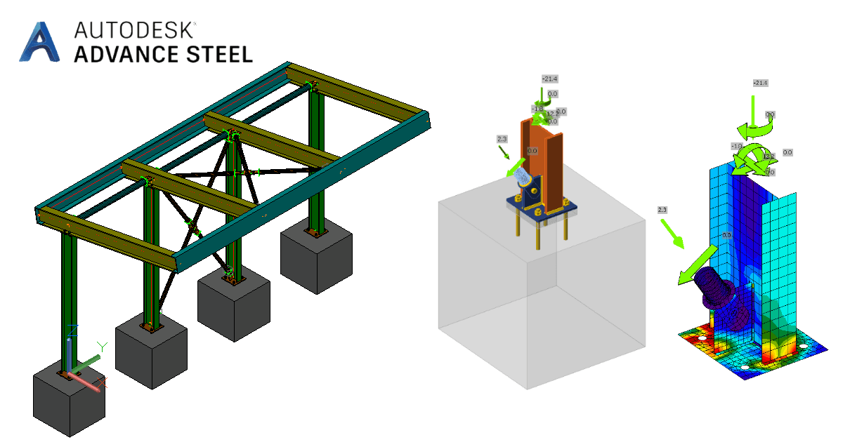
}È stato effettuato con successo il collegamento di Advance Steel con IDEA StatiCa Connection tramite Checkbot.
Per saperne di più sulle limitazioni note del collegamento BIM di Advance Steel.
Scopri come utilizzare IDEA StatiCa in modo efficace con i nostri corsi di e-learning di autoapprendimento
Inizia ad imparareARTICOLI CORRELATI

- Steel
- Connection design
- Member design
- Features
Progettazione delle connessioni: si può fare ancora più velocemente?
Leggi di più
- Steel
- Connection design
- Webinar
Connection Wednesdays - New way of project collaboration
Leggi di più
- Steel
- Connection design
- Webinar