
This feature is available for all supported FEM/CAD software. Importantly, the link between the two project files is maintained, allowing for easy updates and modifications.
Requirements and limitations
The geometry of the connection models imported from FEA and CAD must be identical. The global analysis model in FEA should closely represent the real CAD model, accounting for factors such as eccentricities, position of members, angles between members, etc.
If the connection topologies you want to merge differ (e.g., a different number of members or variations in member rotation), the software will issue a warning, and nothing will be merged. Additionally, the "Loads in Equilibrium" option (ensuring unbalanced forces = 0) serves as a verification tool for you.
For successful merging, the algorithm compares the positions of members in both projects and automatically matches the forces with the correct members. This means you don't need to worry about the order of the members.
How to merge the connections imported from FEA and CAD
You need to import the data from FEA and CAD models into two separate IDEA StatiCa Checkbot projects first and then merge the data inside the IDEA StatiCa Connection app.
Step 1:
- Open the FEA model, perform the calculation, and import the relevant nodes to Checkbot.
- Select the node you want to design and export it from Checkbot into a separate file.
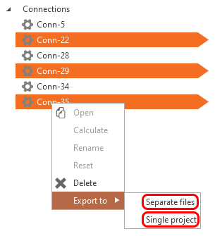
Step 2:
- Open the CAD model and export the relevant nodes to Checkbot (a different Checkbot project from the previous step 1 - there is one for the FEA model and one for the CAD model).
- Select the node you want to code-check and open it from the Checkbot project.
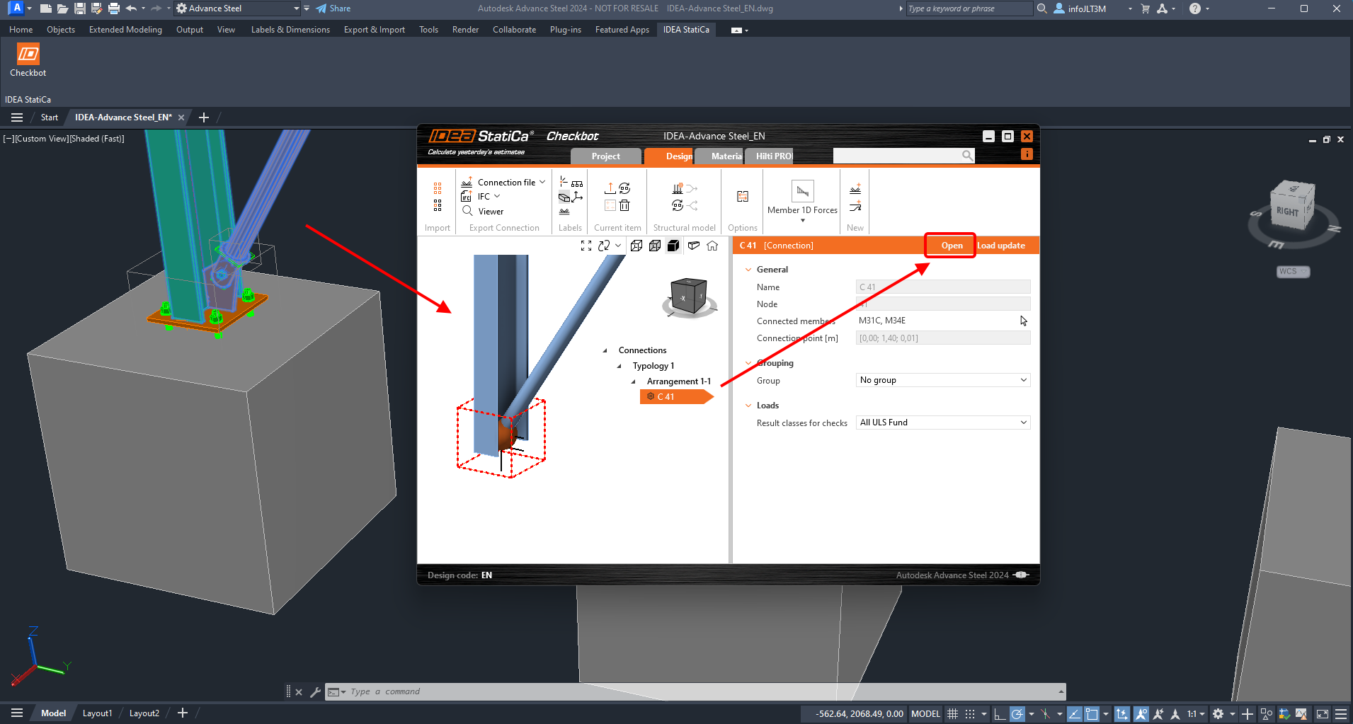
Step 3:
- The connection model is opened in the Connection app. Click the Connection Import button and select the exported file created in Step 1.
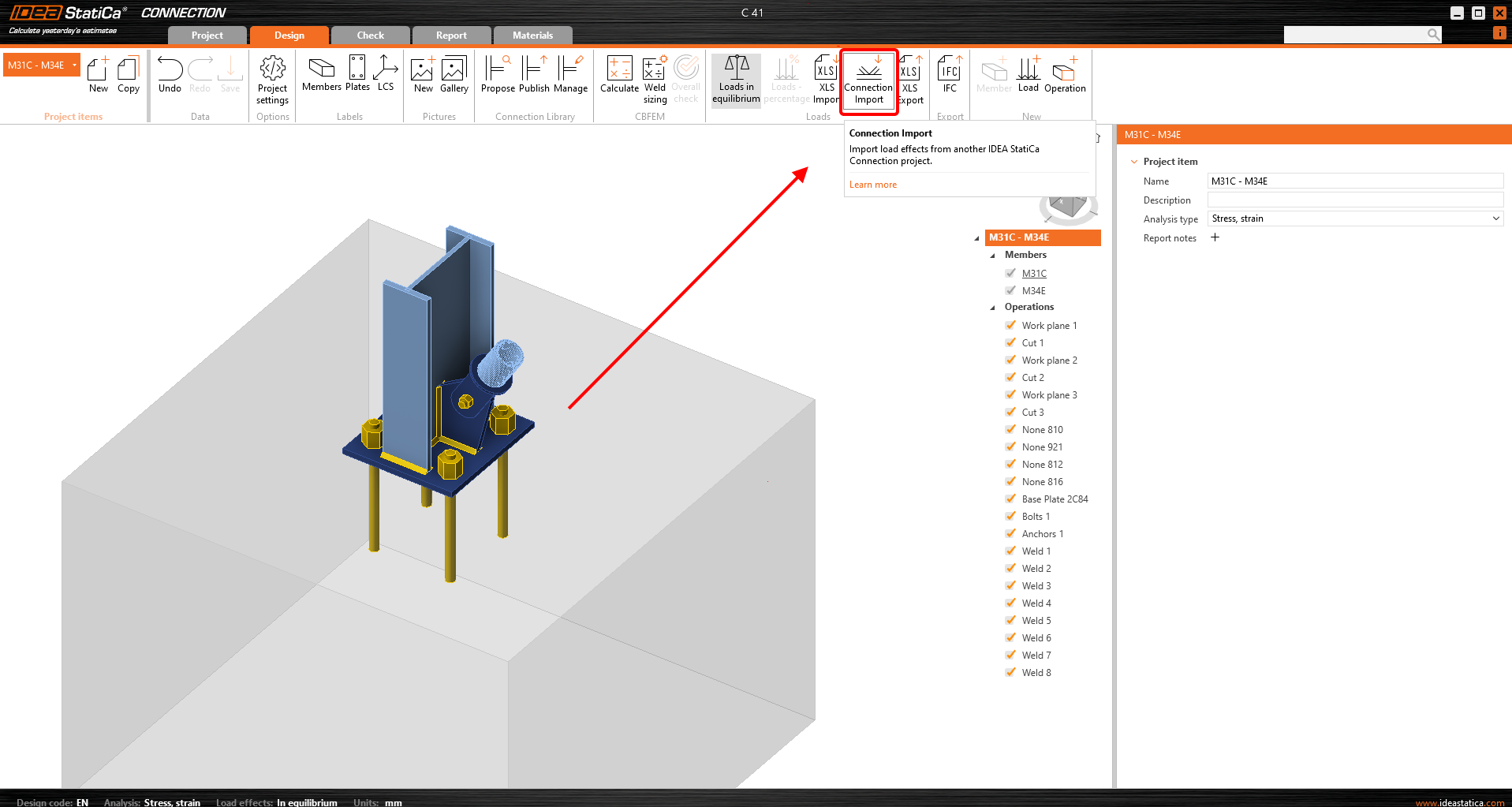
- You have the designed connection imported from the CAD model, and you added the internal forces from all load combinations at once from the FEA model. Now click Calculate and review the results.
More resources
You can follow the step-by-step tutorial.