Four anchor bolt types are available:
- Straight (assumed post-installed)
- Washer plate - Circular (assumed cast-in)
- Washer plate - Rectangle (assumed cast-in)
- Hook (assumed cast-in)
The steel resistances are determined according to EN 1993-1-8 and EN 1992-4 for cast-in anchors and post-installed fasteners, respectively.
The concrete resistances are determined according to EN 1992-4.
In case of post-installed (straight) fasteners, pull-out failure, combined pull-out and concrete failure of bonded anchors, and concrete splitting failure are not checked due to missing information available only for the particular anchor and glue type from the anchor manufacturer.
In the Project settings, settings are available to activate/deactivate concrete cone breakout checks in tension and shear. If the concrete cone breakout check is not activated, it is assumed that the dedicated reinforcement is designed to resist the force. The magnitude of the force is provided in formulas. User may use link to Detail application to perform the checks of reinforced concrete.
Furthermore, the concrete can be set as cracked or uncracked. Uncracked concrete should be in permanent compression that prevents shrinkage cracks. The resistances of uncracked concrete are higher.
FYI:
The Eurocode in its current form does not provide a clear and unambiguous answer as to when cast-in-place anchors should be designed according to EN 1993-1-8 or EN 1992-4. A useful guideline is the governing failure mode. If the dominant failure mode is tensile rupture of the steel anchor, EN 1993-1-8 should be applied. This typically concerns anchors with sufficient embedment length, such as anchor bolts. Conversely, where other failure modes govern (e.g. concrete-related failures), EN 1992-4 should be used. This applies primarily to fasteners.
In IDEA StatiCa:
- Cast-in-place anchors with washer plates and hooked anchors are designed according to EN 1993-1-8.
- Other anchor types are designed according to EN 1992-4 / EN 1992-1-1.
Some countries address this ambiguity through national provisions (e.g. the Netherlands), in line with the approach adopted in IDEA StatiCa. The reason is the difference in publication dates of the standards:
EN 1993-1-8 (2005) vs. EN 1992-4 (2018).
The new generation of Eurocodes adopts a clearer and better-explained approach to this issue.
Tensile steel resistance (EN 1993-1-8, Table 3.4)
Cast-in anchors are checked according to steel design code.
\[ F_{t,Rd} = \frac{c \cdot k_2 \cdot f_{ub} \cdot A_s}{\gamma_{M2}} \]
where:
- c – decrease in tensile resistance of bolts with cut thread according to EN 1993-1-8 – Cl. 3.6.1. (3) editable in Project Settings
- k2 = 0.9 – factor for non-countersunk anchors
- fub – anchor bolt ultimate tensile strength
- As – anchor bolt tensile stress area
Tensile steel resistance (EN 1992-4, Cl. 7.2.1.3)
Post-installed fasteners are checked according to concrete design code
\[ N_{Rd,s} = \frac{N_{Rk,s}}{\gamma_{Ms}} \]
where:
- NRk,s = c ∙ As ∙ fuk – characteristic resistance of a fastener in case of steel failure
- c – decrease in tensile resistance of bolts with cut thread according to EN 1993-1-8 – Cl. 3.6.1. (3) editable in Code setup
- As – anchor bolt tensile stress area
- fuk – anchor bolt characteristic ultimate tensile strength
Concrete cone failure resistance of anchor or group of anchors (EN 1992-4, Cl. 7.2.1.4):
\[ N_{Rd,c} = \frac{N_{Rk,c}}{\gamma_{Mc}} \]
where:
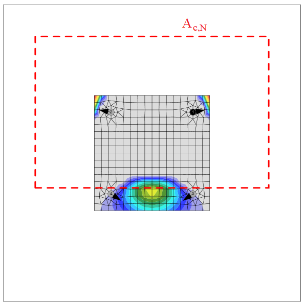
- \(N_{Rk,c}=N_{Rk,c}^0 \cdot \frac{A_{c,N}}{A_{c,N}^0} \cdot \psi_{s,N} \cdot \psi_{re,N} \cdot \psi_{ec,N} \cdot \psi_{M,N}\) – characteristic resistance of a fastener, a group of fasteners and the tensioned fasteners of a group of fasteners in case of concrete cone failure
- \(N_{Rk,c}^0 = k_1 \sqrt{f_{ck}} h_{ef}^{1.5}\) – characteristic resistance of a single fastener placed in concrete and not influenced by adjacent fasteners or edges of the concrete member
- k1 – factor taking into account concrete condition and anchor type; for cast-in headed anchors (with washer plates) k1 = 8.9 for cracked concrete and k1 = 12.7 for non-cracked concrete; for post-installed fasteners (straight anchors) k1 = 7.7 for cracked concrete and k1 = 11.0 for non-cracked concrete
The concrete breakout cone area for a group of anchors loaded by tension that creates a common concrete cone, Ac,N, is shown by the red dashed line.
Pull-out resistance (EN 1992-4, Cl. 7.2.1.5)
Pull-out resistance is checked for cast-in anchors with washer plates according to EN 1992-4, Cl. 7.2.1.5:
\[ N_{Rd,p}=\frac{N_{Rk,p}}{\gamma_{Mc}} \]
where:
- NRk,p = k2 ∙ Ah ∙ fck – characteristic resistance in case of pull-out failure
- k2 – coefficient dependent on concrete condition, k2 = 7.5 for cracked concrete, k2 = 10.5 for non-cracked concrete
- Ah – bearing area of head of anchor; for circular washer plate \(A_h = \frac{\pi}{4} \left ( d_h^2 - d^2 \right )\), for rectangular washer plate \(A_h = a_{wp}^2 - \frac{\pi}{4} d^2\)
Pull-out resistance (EN 1992-1-1, Cl. 8.4.4)
Pull-out resistance is checked for cast-in anchors with hook according to EN 1992-1-1, Cl. 8.4.4. Plain rods are assumed that require double anchorage length than ribbed reinforcement (Table 3.26 in BS 8110-1).
\[N_{Rd,p}=A_a \cdot f_{ya} \cdot \frac{l_b}{l_{bd}}\]
where:
- Aa – tensile stress area of an anchor
- fya – anchor yield strength
- lb – anchor length embedded in concrete
- \(l_{bd} = \alpha_1 \cdot \alpha_2 \cdot \alpha_3 \cdot \alpha_4 \cdot \alpha_5 \cdot l_{b,rqd}\) – design anchorage length
Several detailing rules are added:
- Anchor yield strength must not be higher than 300 MPa (EN 1993-1-8 – 6.2.6.12 (5))
- Minimum anchorage length \(l_{b,min}\) must be kept (EN 1992-1-1 – Equation (8.6)):
\[ l_b \ge l_{b,min} = \max \{ 0.3 \cdot l_{b,rqd}, 10\cdot \phi , 100 \}\]
- Anchorage length should be sufficient for the steel tensile failure mode to govern to facilitate plastic design
The pullout resistance of other types of anchors is not checked and must be guaranteed by the manufacturer.
Concrete blowout resistance (EN 1992-4, Cl. 7.2.1.8)
Blow-out failure is checked for cast-in headed anchors (Anchor type – washer) with edge distance c ≤ 0.5 hef according to EN 1992-4, Cl. 7.2.1.8. Anchors are treated as a group if their spacing near the edge is s ≤ 4 c1. Undercut anchors can be checked the same way but the value of Ah is unknown in the software. The blow-out failure of undercut anchors can be determined by selecting a washer plate with the corresponding dimension.
\[N_{Rd,cb} = \frac{N_{Rk,cb}}{\gamma_{Mc}}\]
where:
- \(N_{Rk,cb} = N_{Rk,cb}^0 \cdot \frac{A_{c,Nb}}{A_{c,Nb}^0} \cdot \psi_{s,Nb} \cdot \psi_{g,Nb} \cdot \psi_{ec,Nb}\) – characteristic resistance in case of concrete blow-out failure
- \(N_{Rk,cb}^0 = k_5 \cdot c_1 \cdot \sqrt{A_h} \cdot \sqrt{f_{ck}}\) – characteristic resistance of a single fastener, not influenced by adjacent fasteners or further edges
- Ac,Nb – actual projected area, limited by overlapping concrete break-out bodies of adjacent fasteners as well as by proximity of edges of the concrete member or the member thickness
- A = (4 ) – reference projected area of a single fastener with an edge distance equal to
Anchor shear steel resistance (EN 1993-1-8 – Cl. 6.2.2)
Anchor shear steel resistance of cast-in anchors is determined according to EN 1993-1-8 – 6.2.2 (7) regardless of direct or mortar joint stand-off. The addition of friction is problematic in practice and is not assumed. The background for Eurocode calculation is the Stevin Laboratory model presented in this paper. Holes should be standard, not oversized and the grout strength and thickness should be according to Cl. 6.2.5 (7).
\[F_{vb,Rd} = \min \{F_{1vb,Rd}, F_{2vb,Rd} \} \]
where:
- \(F_{1vb,Rd} = \frac{\alpha_v \cdot f_{ub} \cdot A}{\gamma_{M2}}\) – anchor shear resistance from Table 3.4
- αv = 0.6 for grades 4.6, 5.6, 8.8 and 0.5 for grades 4.8, 5.8, 6.8, 10.9
- fub – ultimate tensile strength of the bolt
- A – tensile stress area of the bolt
Anchor shear steel resistance (EN 1992-4 – Cl. 7.2.2.3)
Anchor shear steel resistance of post-installed fasteners is checked according to EN 1992-4 – Cl. 7.2.2.3. Friction is not taken into account. Shear with and without lever arm is recognized in dependence on base plate manufacturing operation settings.
\[V_{Rd,s} = \frac{V_{Rk,s}}{\gamma_{Ms}}\]
For stand-off: direct, the shear without lever arm is assumed (EN 1992-4 – Cl. 7.2.2.3.1):
VRk,s = k6 ∙ As ∙ fuk – characteristic resistance of a single fastener in case of steel failure; or fasteners with a ratio hef / dnom < 5 and a concrete compressive strength class < C20/25 the characteristic resistance VRk,s should be multiplied by a factor of 0.8.
For stand-off: mortar joint, the shear with lever arm is assumed (EN 1992-4 – Cl. 7.2.2.3.2):
\[V_{Rk,s}= \frac{\alpha_M \cdot M_{Rk,s}}{l_a}\]
where:
- k6 = 0.6 for anchors with fuk ≤ 500 MPa; k6 = 0.5 otherwise
- As – shear area of anchor; if shear plane in a thread is selected, the area reduced by threads is used; otherwise, full shank area is used
- fuk – anchor bolt ultimate strength
- αM = 2 – full restraint is assumed (EN 1992-4 – Cl. 6.2.2.3)
Concrete pry-out failure (EN 1992-4 – Cl. 7.2.2.4):
\[ V_{Rd,cp}= \frac{V_{Rk,cp}}{\gamma_{Mc}} \]
where:
- VRk,cp = k8 ∙ NRk,c – characteristic resistance of concrete pry-out failure
- k8 = 1 for hef < 60 mm; k8 = 2 for hef ≥ 60 mm (ETAG 001, Annex C – Cl. 5.2.3.3)
- NRk,c – characteristic resistance of a fastener, a group of fasteners, and the tensioned fasteners of a group of fasteners in case of concrete cone failure; all anchors are assumed to be in tension
Concrete edge failure (EN 1992-4 – Cl. 7.2.2.5):
Concrete edge failure is a brittle failure, and the worst possible case is checked, i.e. only the anchors located near the edge transfer the full shear load acting on a whole base plate. If anchors are positioned in a rectangular pattern, the row of anchors at the investigated edge transfers the shear load. If anchors are positioned irregularly, the two anchors nearest to the investigated edge transfer the shear load. Two edges in the direction of the shear load are investigated, and the worst case is shown in the results.
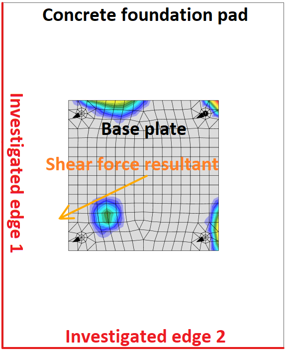
Investigated edges in dependence on the direction of the shear force resultant
\[ V_{Rd,c} = \frac{V_{Rk,c}}{\gamma_{Mc}} \]
where:
- \( V_{Rk,c}= V_{Rk,c}^0 \cdot \frac{A_{c,V}}{A_{c,V}^0} \cdot \psi_{s,V} \cdot \psi_{h,V} \cdot \psi_{ec,V} \cdot \psi_{\alpha,V} \cdot \psi_{re,V} \) – characteristic resistance of a fastener or a group of fasteners loaded towards the edge
- \( V_{Rk,c}^0 = k_9 \cdot d_{nom}^\alpha \cdot l_f^\beta \cdot f_{ck}^{0.5} \cdot c_1^{1.5}\) – initial value of the characteristic resistance of a fastener loaded perpendicular to the edge
- k9 – factor taking into account concrete condition; k9 = 1.7 for cracked concrete, k9 = 2.4 for non-cracked concrete
Interaction of tension and shear in steel (EN 1993-1-8 – Table 3.4)
The interaction of tension and shear for cast-in anchors is not necessary because it is implicitly included in the anchor shear check.
Explanation at Steel support from the Netherlands:
For checking of normal bolts, Table 3.4 of EN 1993-1-8 includes a formula for the interaction of normal force and shear force. However, this formula only applies to bolts in a normal (steel-steel) connection and not to anchors in a column base plate connection. When checking the shear resistance of the anchor, a tensile force in the bolt equal to the resistance to yielding was already taken into account; see Eq. 6.2 of Cl. 6.2.2 (7) of EN 1993-1-8. The actual tensile stress that occurs in the anchor is therefore not relevant. This calculation method is based on tests carried out at the TU Delft. These calculation rules from the Eurocode are identical to the calculation rules from the TGB series. The explanation of the calculation rule is included in NEN 6772 but not in EN 1993-1-8. For column base plate connections, it is therefore sufficient to only carry out the separate checks for tension and shear.
Interaction of tension and shear in steel (EN 1992-4 – Table 7.3)
The interaction of tension and shear for post-installed fasteners is determined separately for steel and concrete failure modes according to Table 7.3. Interaction in steel is checked according to Equation (7.54). The interaction in steel is checked for each anchor separately.
\[ \left ( \frac{N_{Ed}}{N_{Rd,s}} \right )^2 + \left ( \frac{V_{Ed}}{V_{Rd,s}} \right )^2 \le 1.0 \]
Interaction of tension and shear in concrete
Interaction in concrete is checked according to Equation (7.55).
\[ \left ( \frac{N_{Ed}}{N_{Rd,i}} \right )^{1.5} + \left ( \frac{V_{Ed}}{V_{Rd,i}} \right )^{1.5} \le 1.0 \]
The largest value of \(N_{Ed} / N_{Rd,i} \) and \(V_{Ed} / V_{Rd,i} \) for the different failure modes shall be taken. Note that values of \(N_{Ed}\) and \(N_{Rd,i}\) often belong to a group of anchors.
Anchors with stand-off
An anchor with stand-off is designed as a bar element loaded by shear force, bending moment, and compressive or tensile force. These internal forces are determined by the finite element model. The anchor is fixed on both sides, one side is 0.5×d below the concrete level, and the other side is in the middle of the thickness of the plate. The buckling length is conservatively assumed as twice the length of the bar element. Plastic section modulus is used. The bar element is designed according to EN 1993-1-1. The shear force may decrease the yield strength of the steel according to Cl. 6.2.8 but the minimum length of the anchor to fit the nut under the base plate ensures that the anchor fails in bending before the shear force reaches half the shear resistance. The reduction is therefore not necessary. The interaction of bending moment and compressive or tensile strength is assessed according to Cl. 6.2.1.
Shear resistance (EN 1993-1-1 Cl. 6.2.6):
\[ V_{pl,Rd} = \frac{A_V f_y / \sqrt{3}}{\gamma_{M2}} \]
where:
- AV = 0.844 As – shear area
- As – bolt area reduced by threads
- fy – bolt yield strength
- γM2 – partial safety factor
Tensile resistance (EN 1993-1-8 – Cl. 3.6.1):
\[ F_{t,Rd}=\frac{c k_2 f_{ub} A_s}{\gamma_{M2}} \ge F_t \]
where:
- c – decrease in tensile resistance of bolts with cut thread according to EN 1993-1-8 – Cl. 3.6.1. (3) editable in Code setup
- k2 = 0.9 – factor from Table 3.4 in EN 1993-1-8
- fub – anchor bolt ultimate strength
- As – anchor bolt tensile stress area
Compressive resistance (EN 1993-1-1 Cl. 6.3):
\[ F_{c,Rd} = \frac{\chi A_s f_y}{\gamma_{M2}} \]
where:
- \( \chi = \frac{1}{\Phi + \sqrt{\Phi^2 - \bar\lambda^2}} \le 1 \) – buckling reduction factor
- \( \Phi = 0.5 \left [1+ \alpha (\bar\lambda - 0.2) + \bar\lambda^2 \right ] \) – value to determine buckling reduction factor χ
- α = 0.49 – imperfection factor for buckling curve c (belonging to the full circle)
- \( \bar\lambda = \sqrt{\frac{A_s f_y}{N_{cr}}} \) – relative slenderness
Bending resistance (EN 1993-1-1 Cl. 6.2.5):
\[ M_{pl,Rd} = \frac{W_{pl} f_y}{\gamma_{M2}} \]
- \( W_{pl}= \frac{d_s^3}{6} \) – section modulus of the bolt
- fy – bolt yield strength
- γM2 – partial safety factor
Anchor steel utilization (EN 1993-1-1 Cl. 6.2.1)
\[ \frac{N_{Ed}}{N_{Rd}} + \frac{M_{Ed}}{M_{Rd}} \le 1 \]
where:
- NEd – tensile (positive) or compressive (negative sign) design force
- NRd – tensile (positive, Ft,Rd) or compressive (negative sign, Fc,Rd) design resistance
- MEd – design bending moment
- MRd = Mpl,Rd – design bending resistance
Detailing
A detailing check of anchors is performed if the option is selected in the Code setup. Only minimum spacing between anchors (measured centreline to centreline) is checked. The minimum spacing differs for each anchor type and is given in the European Technical Product Specification. Users can modify limit spacing value in the Code setup as a multiple of anchor bolt diameter.
Edge distances to steel plates follow the rules for bolts, i.e. e = 1.2 is recommended in Table 3.3 in EN 1993-1-8. User can modify this value in Code setup.