
Introduction
It used to be common practice for connection designers to choose the extreme force and moment components from all combinations and apply them simultaneously to perform connection design. This approach could work in simple cases, but once the connection becomes slightly more complex, the designer is in danger of either over-designing or under-designing the connection.
The only way to avoid any such mishaps is to design connections under all available combinations, which is now straightforward using the tools readily available in Checkbot, or by using the XLS import option to import the load effects from an XLS worksheet.
However, these methods introduce a new set of problems. Although the transfer of loads from the global analysis to the local connection model has been resolved, calculating for hundreds of combinations increases the analysis time significantly.
To accelerate the design process, it makes sense to reduce the number of combinations to a subset that contains the potentially critical ones. However, selecting the critical combinations beforehand is not a trivial task, as there is no strict mathematical rule that can be applied to the selection process. As such, the proposed workflow is to reduce the initial number of combinations to initiate the design process, check and amend the connection against them, and finally, once all checks are satisfied, run the calculation over the full combination set.
Selection criteria
In IDEA StatiCa, we can select the combination subset to be applied for the connection design based on the following criteria, which are applied to each of the members that connect to the investigated node:
- Combination contains extreme force/moment component for any of the 6 internal force/moment components per member (for n members we can obtain up to 12∙n combinations).
- Combination contains maximum shear resultant (up to n combinations)
- Combination contains maximum moment resultant (up to n combinations)
- Combination containing extreme internal axial forces ee below – up to 2∙n combinations)
- Combination containing extreme internal shear forces ee below – up to n combinations)
- Combination containing extreme internal resultant forces ee below – up to n combinations)
- Combinations containing extreme normal stresses e corners of the cross section bounding box, derived from (up to 2∙n combinations)
As a result, the combination subset can contain up to 20∙n combinations, where n is number of converging members.
Some points that should be considered are:
- A single combination might fulfil more than one of the above criteria, leading to fewer selected combinations than might be anticipated.
- Regarding points (4), (5), and (6) above: there have been cases reporting combinations that display extreme axial forces at internal locations (e.g. tension in internally positioned anchor bolts). To capture these cases, the axial shear d resultant forces the internal locations denoted TL, TR, BL, and BR in the image below are calculated:
Select the extremes and perform the analysis
To select the extremes to be analyzed, use the right mouse button on the Load effects and select the Calculate load extremes option.
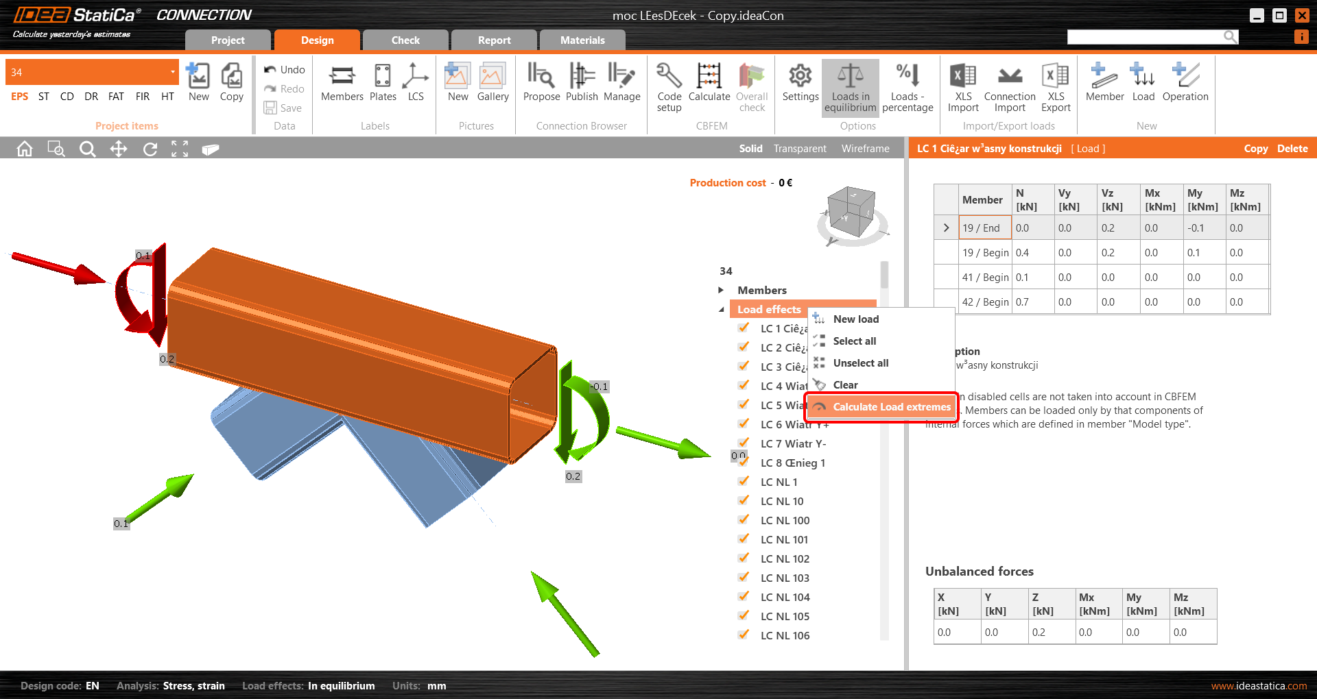
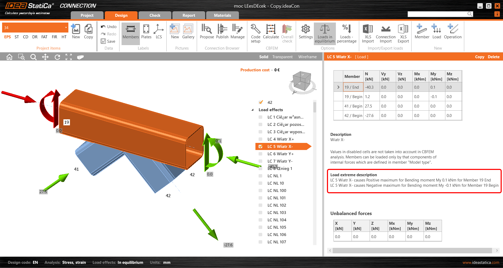
This unselects the irrelevant (non-extreme) load effects from the list. The reason for each selected extreme load effect is presented in the description under the table.
XLS import of extremes
You can also use the extremes selection when importing the load values from an Excel sheet. Check the Import only extremes box. You are instantly shown how many load effects are considered extremes.
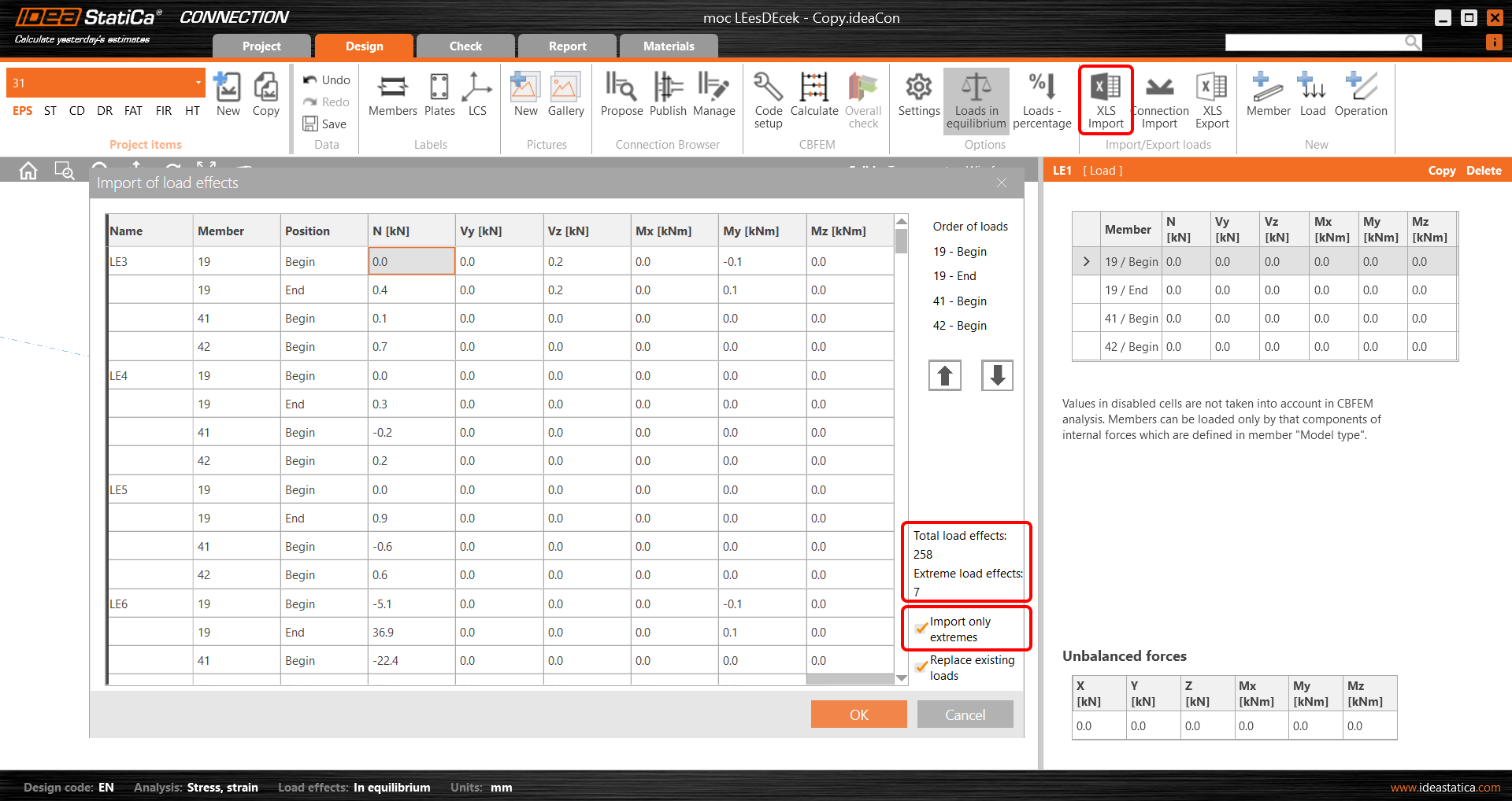
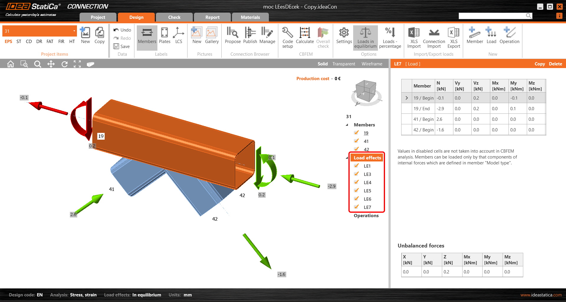
The extreme load effects are imported, and the rest are ignored.
Setting the tolerances
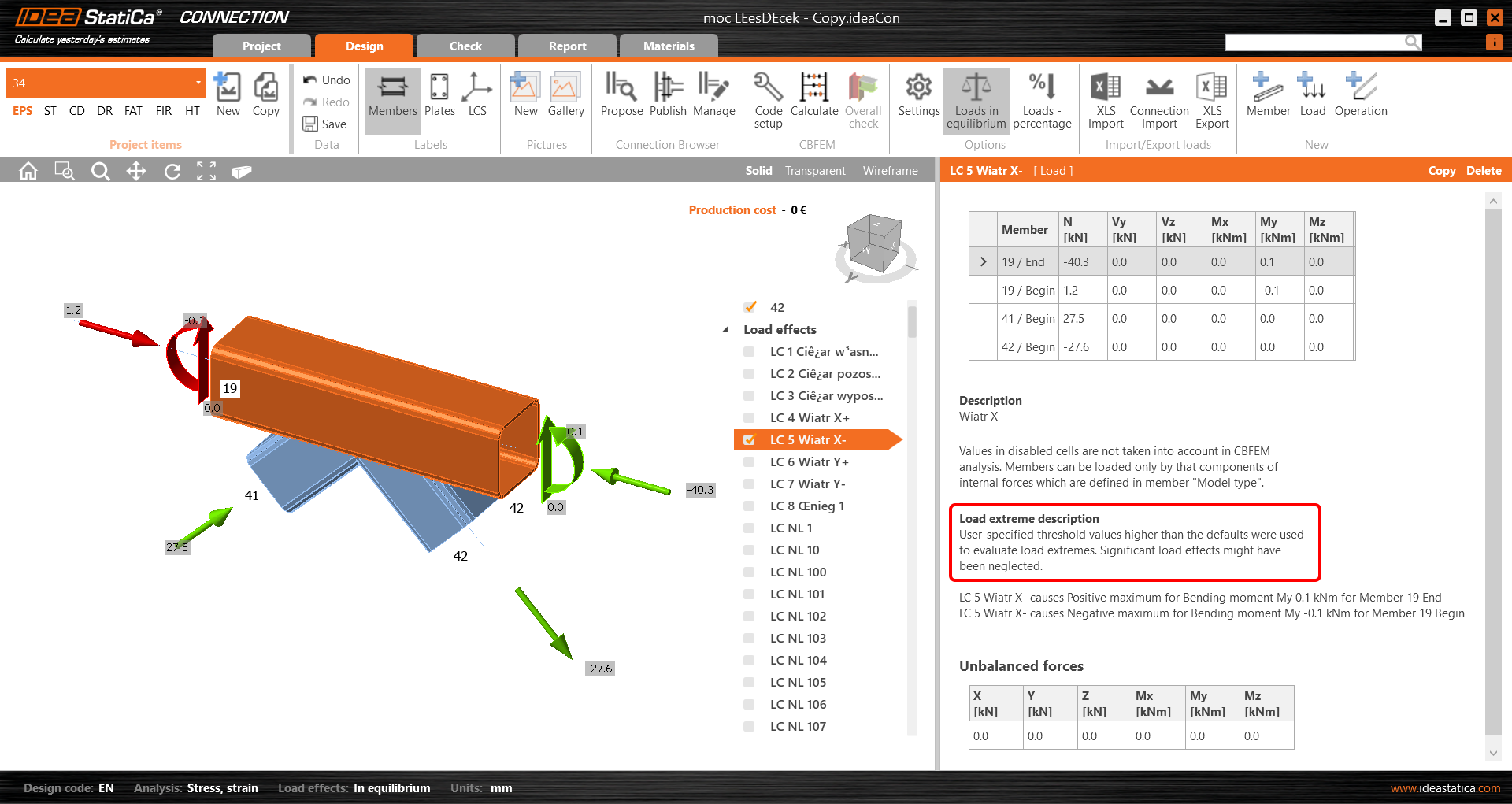
To neglect the irrelevant (small) values of extremes, you can set the limits/tolerances for each component of the internal forces. The force value (an absolute value) lower than the set limit will not be considered to evaluate extremes.
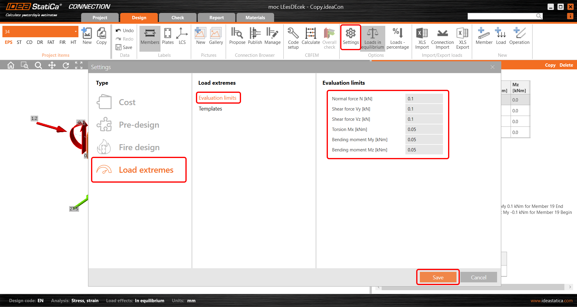
When you change these values to higher ones, a warning and the reasons for selecting the given load effect are presented.
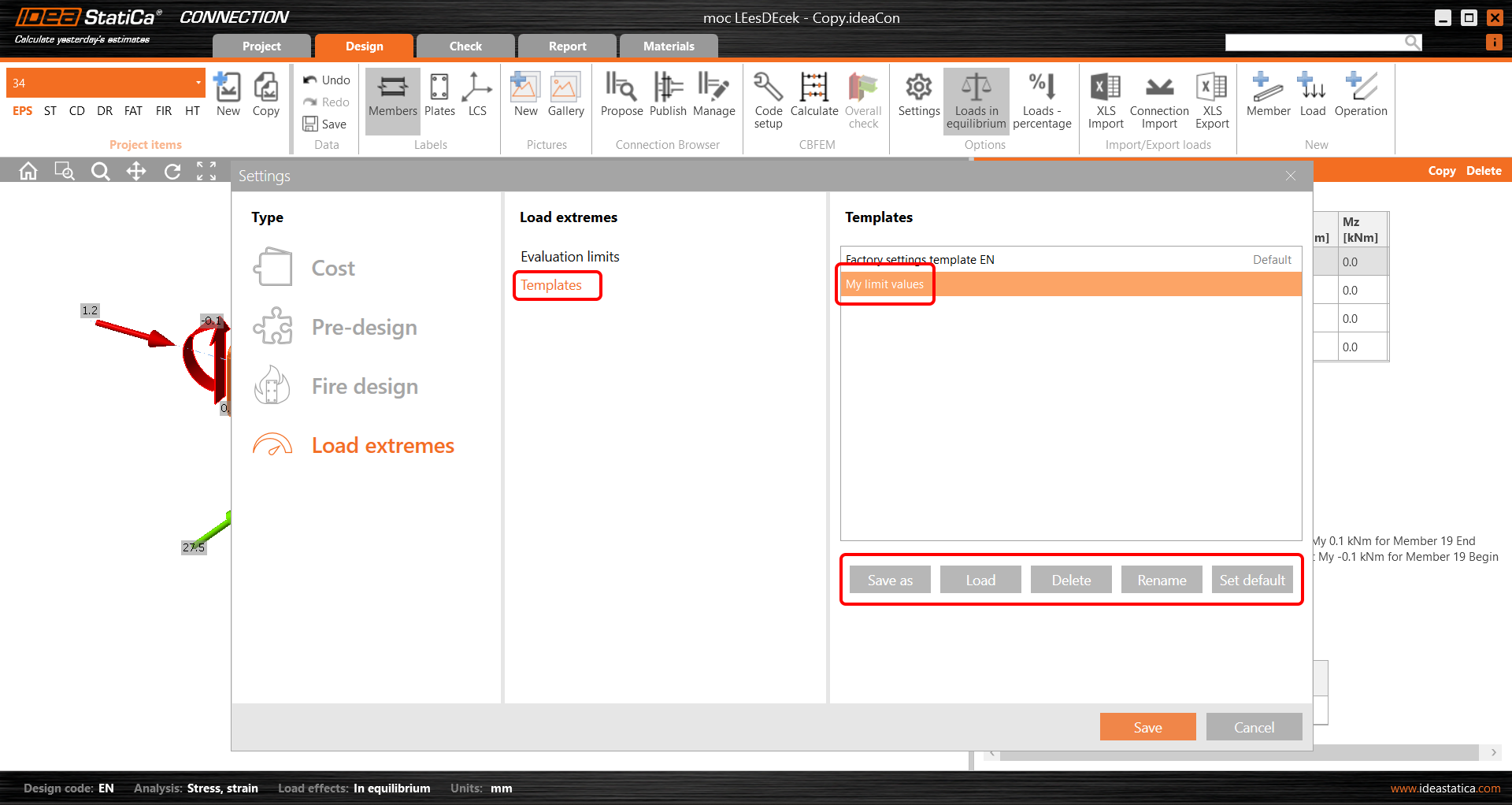
You can save your custom values among the templates and use them in another project by loading it or setting the template as the default one.
The feature was released in the 22.1.3 patch and updated in 23.0.1.
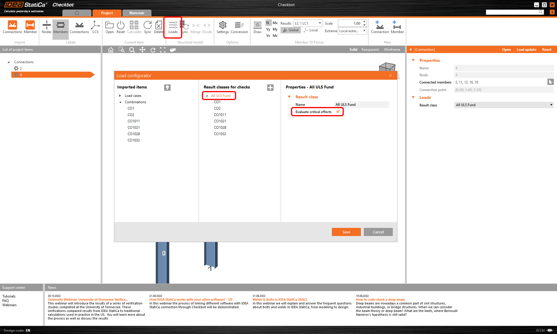
Selecting extreme loads via Checkbot (BIM link)
There is also another possibility to filter the load extremes in case you are using the BIM link (IDEA StatiCa Checkbot). Open the Load configurator in Checkbot and go to Result classes for checks in the middle column. Select the desired result class and in the right field, specify whether the loads should be filtered. When the Evaluate critical effects* checkbox is selected, the force extremes are filtered. (You need to call the Load update after closing the Load configurator window.)
Please note that the filtering algorithm differs from the above-mentioned procedure: Read more in the Evaluate critical effects for loads imported via BIM links article.
* The Evaluate critical effects function was removed and replaced by the Calculate load extremes function since version 25.1.2.