描述 本章对将钢板连接至未加劲柱的角焊缝,采用基于组件的有限元法(CBFEM)与组件法(CM)进行验证。钢板与开口截面柱及箱形截面柱相连,并承受拉力荷载。
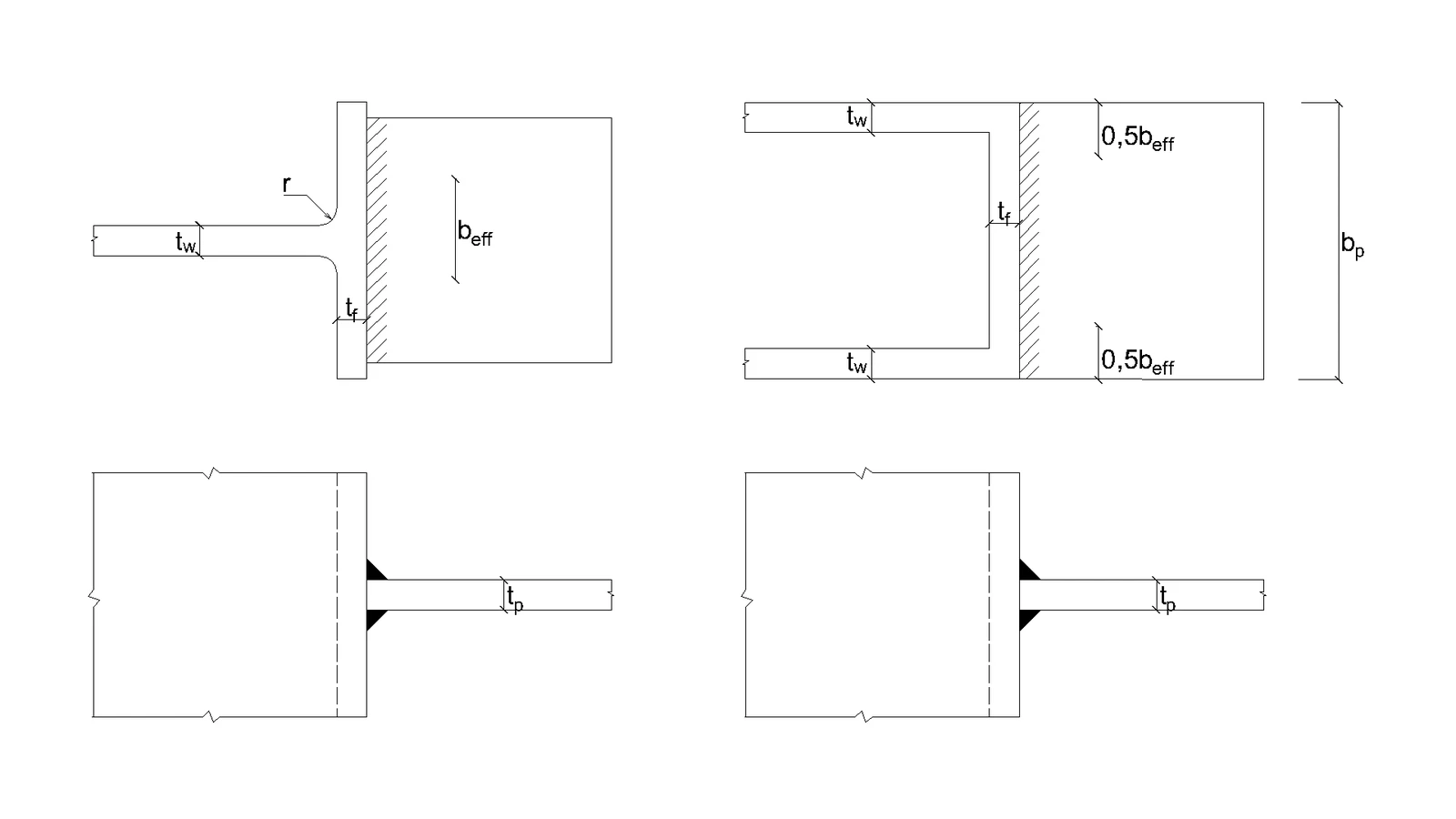
分析模型 本研究中仅考察角焊缝这一组件。焊缝按 EN 1993-1-8:2005 第 4 章进行设计,使其成为节点中最薄弱的组件。角焊缝的设计承载力见第 4.1 节 。垂直作用于柔性板的力受到限制,该柔性板焊接于未加劲截面上。应力集中于有效宽度范围内,而未加劲部分周围的焊缝承载力忽略不计,如图 4.5.1 所示。对于未加劲的 I 形或 H 形截面,有效宽度按下式计算:
b e f f = t w + 2 s + 7 k t f ( 4.5.1 ) b_\mathrm{eff} = t_\mathrm{w} + 2s + 7kt_\mathrm{f} \qquad (4.5.1) b eff = t w + 2 s + 7 k t f ( 4.5.1 )
k = t f ⋅ f y , f t p ⋅ f y , p ( 4.5.2 ) k = \frac{t_\mathrm{f} \cdot f_\mathrm{y,f} }{ t_\mathrm{p} \cdot f_\mathrm{y,p}} \qquad (4.5.2) k = t p ⋅ f y , p t f ⋅ f y , f ( 4.5.2 )
尺寸 s 对于轧制截面取 s = r s =r s = r s = 2 ⋅ a s = \sqrt{2} \cdot a s = 2 ⋅ a
b e f f = 2 t w + 5 t f but b e f f ≤ 2 t w + 5 k t f ( 4.5.1 ) b_\mathrm{eff} = 2t_\mathrm{w} + 5 t_\mathrm{f} \quad \textrm{but}\quad b_\mathrm{eff} \leq 2t_\mathrm{w} + 5 kt_\mathrm{f}\qquad (4.5.1) b eff = 2 t w + 5 t f but b eff ≤ 2 t w + 5 k t f ( 4.5.1 )
σ ⊥ 2 + 3 ⋅ ( τ ⊥ 2 + τ ∥ 2 ) ≤ f u β w ⋅ γ M 2 \sqrt{ \sigma_{\perp}^2 + 3 \cdot \left( \tau_{\perp}^2 + \tau_{\parallel}^2\right)} \leq \frac{f_u}{\beta_{\mathrm{w}} \cdot \gamma_{\mathrm{M2}}} σ ⊥ 2 + 3 ⋅ ( τ ⊥ 2 + τ ∥ 2 ) ≤ β w ⋅ γ M2 f u
σ ⊥ = τ ⊥ = σ N 2 = N b e f f ⋅ a ⋅ 1 2 \sigma_{\perp} = \tau_{\perp} = \frac{\sigma_{N}}{\sqrt{2}} = \frac{N}{b_\mathrm{eff} \cdot a}\cdot \frac{1}{\sqrt{2}} σ ⊥ = τ ⊥ = 2 σ N = b eff ⋅ a N ⋅ 2 1
τ ∥ = 0 \tau_{\parallel} = 0 τ ∥ = 0
( σ N 2 ) 2 + 3 ⋅ ( σ N 2 ) 2 ≤ f u β w ⋅ γ M 2 \sqrt{ \left( \frac{\sigma_{N}}{\sqrt{2}} \right)^2 + 3 \cdot \left( \frac{\sigma_{N}}{\sqrt{2}} \right)^2} \leq \frac{f_u}{\beta_{\mathrm{w}} \cdot \gamma_{\mathrm{M2}}} ( 2 σ N ) 2 + 3 ⋅ ( 2 σ N ) 2 ≤ β w ⋅ γ M2 f u
( N b e f f ⋅ a ⋅ 1 2 ) 2 + 3 ⋅ ( N b e f f ⋅ a ⋅ 1 2 ) 2 ≤ f u β w ⋅ γ M 2 \sqrt{ \left( \frac{N}{b_\mathrm{eff} \cdot a}\cdot \frac{1}{\sqrt{2}} \right)^2 + 3 \cdot \left( \frac{N}{b_\mathrm{eff}\cdot a}\cdot \frac{1}{\sqrt{2}} \right)^2} \leq \frac{f_u}{\beta_{\mathrm{w}} \cdot \gamma_{\mathrm{M2}}} ( b eff ⋅ a N ⋅ 2 1 ) 2 + 3 ⋅ ( b eff ⋅ a N ⋅ 2 1 ) 2 ≤ β w ⋅ γ M2 f u
N ≤ f u ⋅ b e f f ⋅ a β w ⋅ γ M 2 ⋅ 2 N \leq \frac{f_{u} \cdot b_\mathrm{eff} \cdot a }{\beta_{\mathrm{w}} \cdot \gamma_{\mathrm{M2}} \cdot \sqrt{2}} N ≤ β w ⋅ γ M2 ⋅ 2 f u ⋅ b eff ⋅ a
其中:
a a a
N N N
b e f f b_\mathrm{eff} b eff
β w \beta_{\mathrm{w}} β w
f u f_u f u
γ M 2 \gamma_{\mathrm{M2}} γ M2
Fig. 4.5.1 Effective width of an unstiffened joint (Fig. 4.8 in EN 1993-1-8:2005) \textsf{\textit{\footnotesize{Fig. 4.5.1 Effective width of an unstiffened joint (Fig. 4.8 in EN 1993-1-8:2005)}}} Fig. 4.5.1 Effective width of an unstiffened joint (Fig. 4.8 in EN 1993-1-8:2005)
数值模型 CBFEM(基于组件的有限元模型)中的焊缝组件详见通用理论背景 和欧洲规范理论背景 。焊缝部分区域进入塑性阶段,应力峰值沿焊缝长度重新分布。
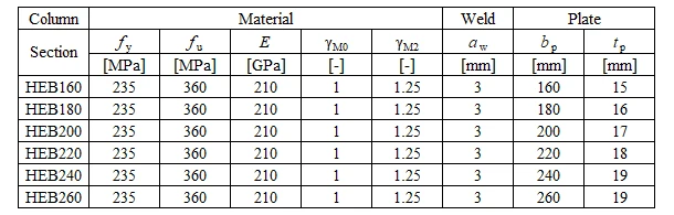
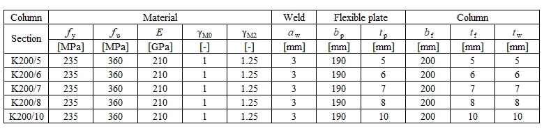
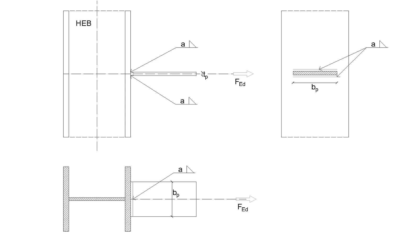
承载力验证 将 CBFEM(基于组件的有限元模型)计算所得设计承载力与 CM 结果进行比较,仅比较焊缝设计承载力。所考虑算例及材料的概况见表 4.5.1,节点几何形状及尺寸见图 4.5.2。
Tab. 4.5.1 Examples overview \textsf{\textit{\footnotesize{Tab. 4.5.1 Examples overview}}} Tab. 4.5.1 Examples overview
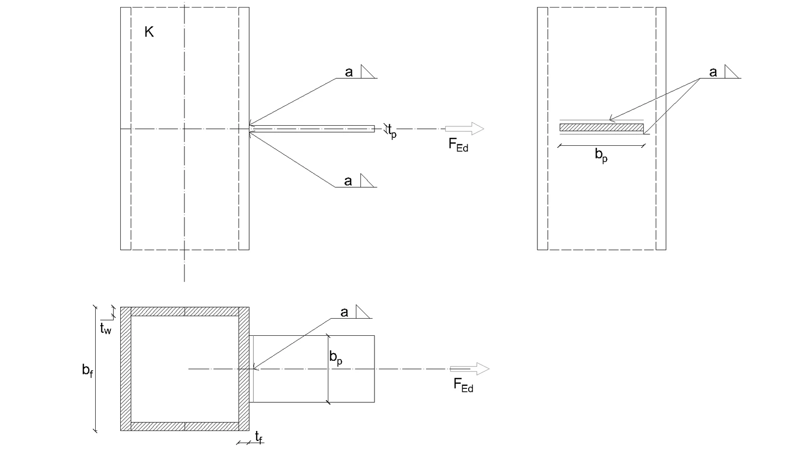
a) Flexible plate to open section b) Flexible plate to box section \textsf{\textit{\footnotesize{a) Flexible plate to open section b) Flexible plate to box section}}} a) Flexible plate to open section b) Flexible plate to box section
Fig. 4.5.2 Joint geometry and dimentions \textsf{\textit{\footnotesize{Fig. 4.5.2 Joint geometry and dimentions}}} Fig. 4.5.2 Joint geometry and dimentions
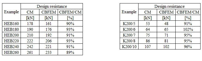
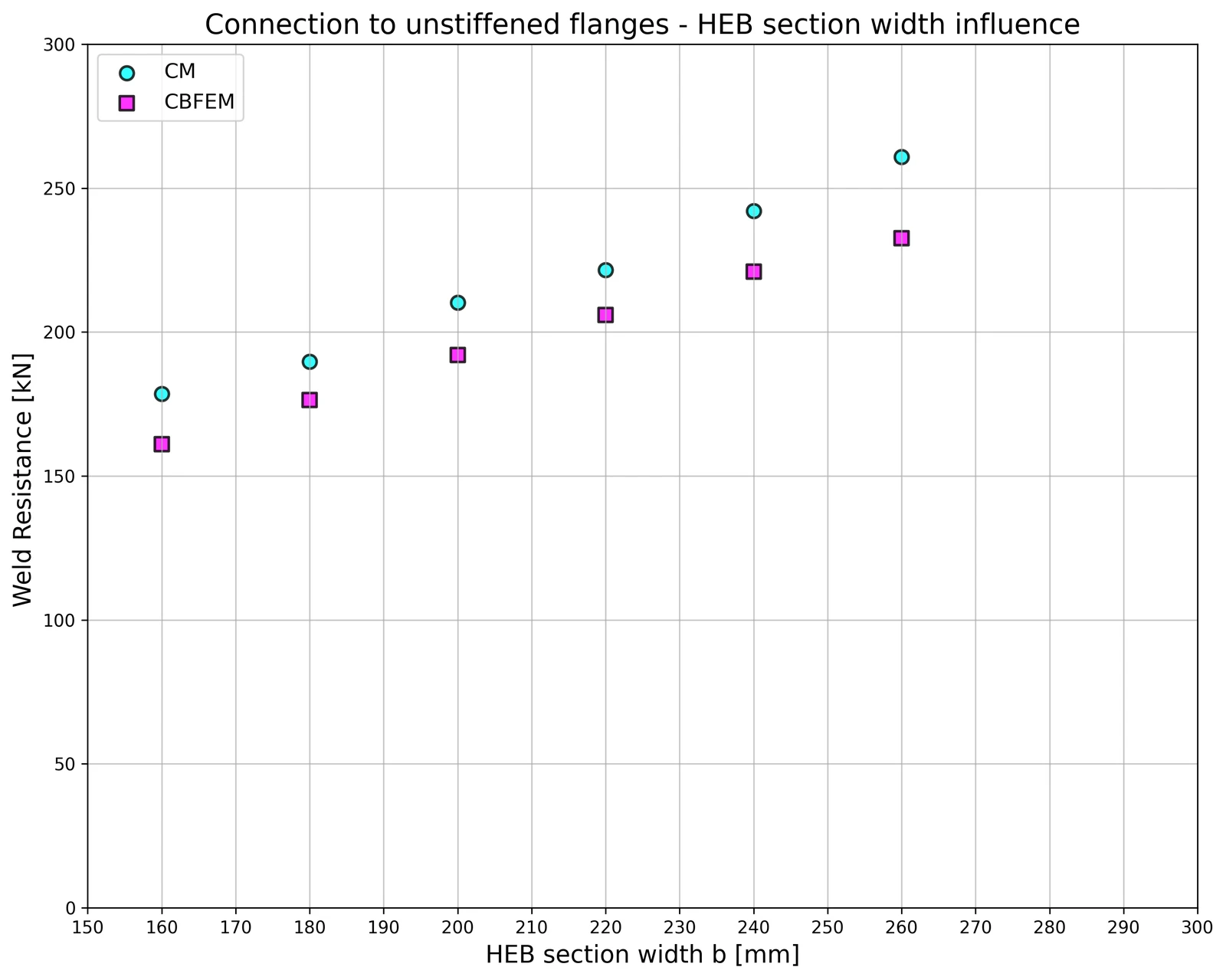
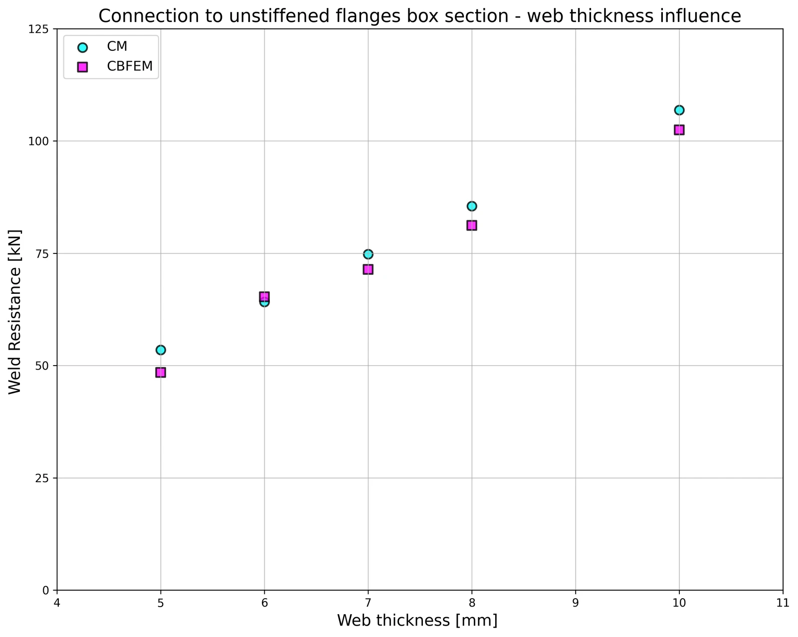
计算结果列于表 4.5.2。本研究针对两个参数展开:HEB 截面的翼缘宽度和箱形截面的腹板厚度。柔性板承受拉力荷载。HEB 截面翼缘宽度对节点设计承载力的影响见图 4.5.3,箱形截面腹板厚度与节点设计承载力的关系见图 4.5.4。
Tab. 4.5.2 Comparison of CBFEM and CM \textsf{\textit{\footnotesize{Tab. 4.5.2 Comparison of CBFEM and CM}}} Tab. 4.5.2 Comparison of CBFEM and CM
在敏感性分析中对 CBFEM(基于组件的有限元模型)与 CM 的结果进行比较。HEB 截面翼缘宽度对节点设计承载力的影响见图 4.5.3,箱形截面腹板厚度对节点设计承载力的影响见图 4.5.4。参数化研究表明,所有焊缝配置的计算结果吻合良好。
Fig. 4.5.3 Flange width of the HEB section Fig. 4.5.4 Web thickness of the box section \textsf{\textit{\footnotesize{Fig. 4.5.3 Flange width of the HEB section Fig. 4.5.4 Web thickness of the box section}}} Fig. 4.5.3 Flange width of the HEB section Fig. 4.5.4 Web thickness of the box section
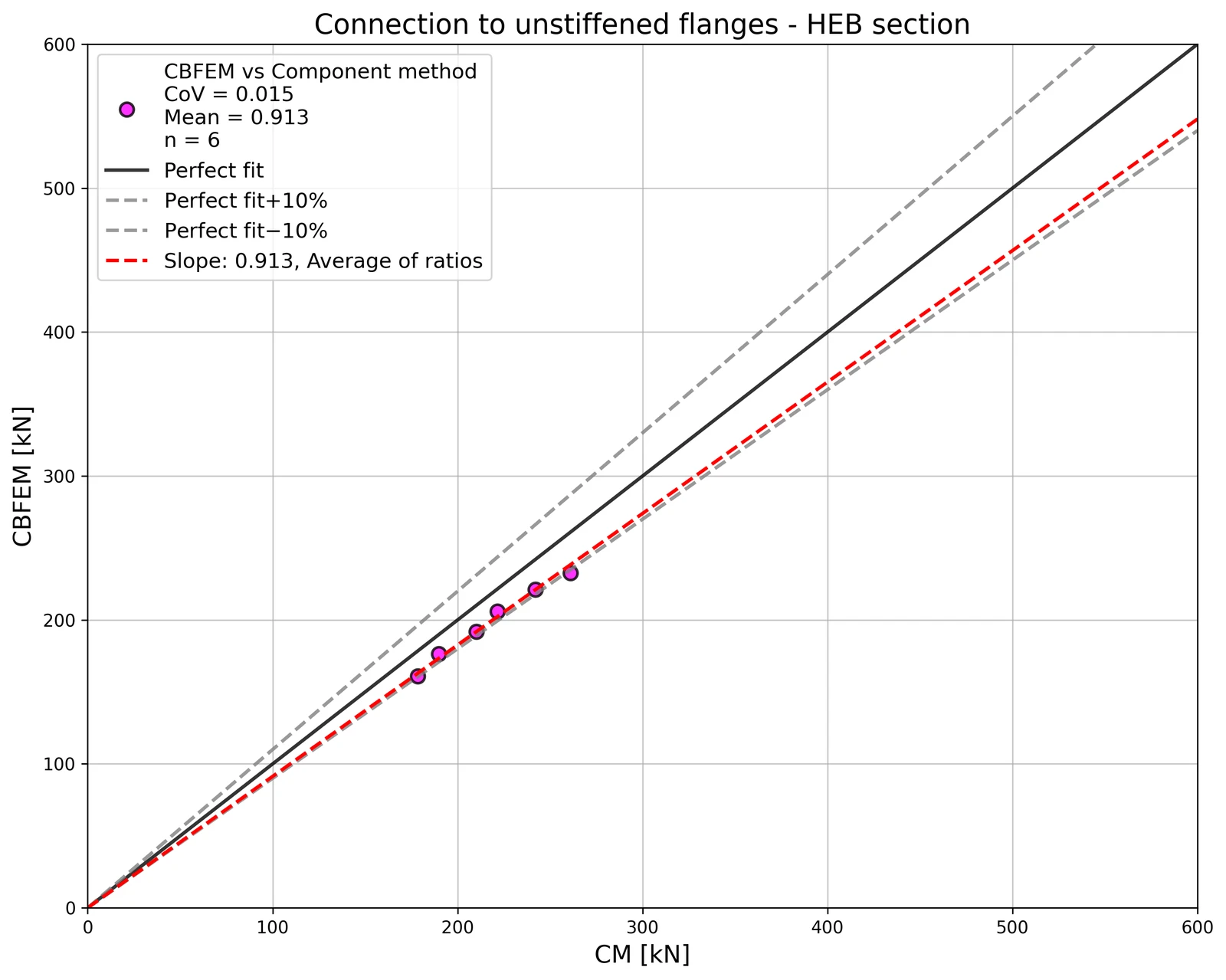
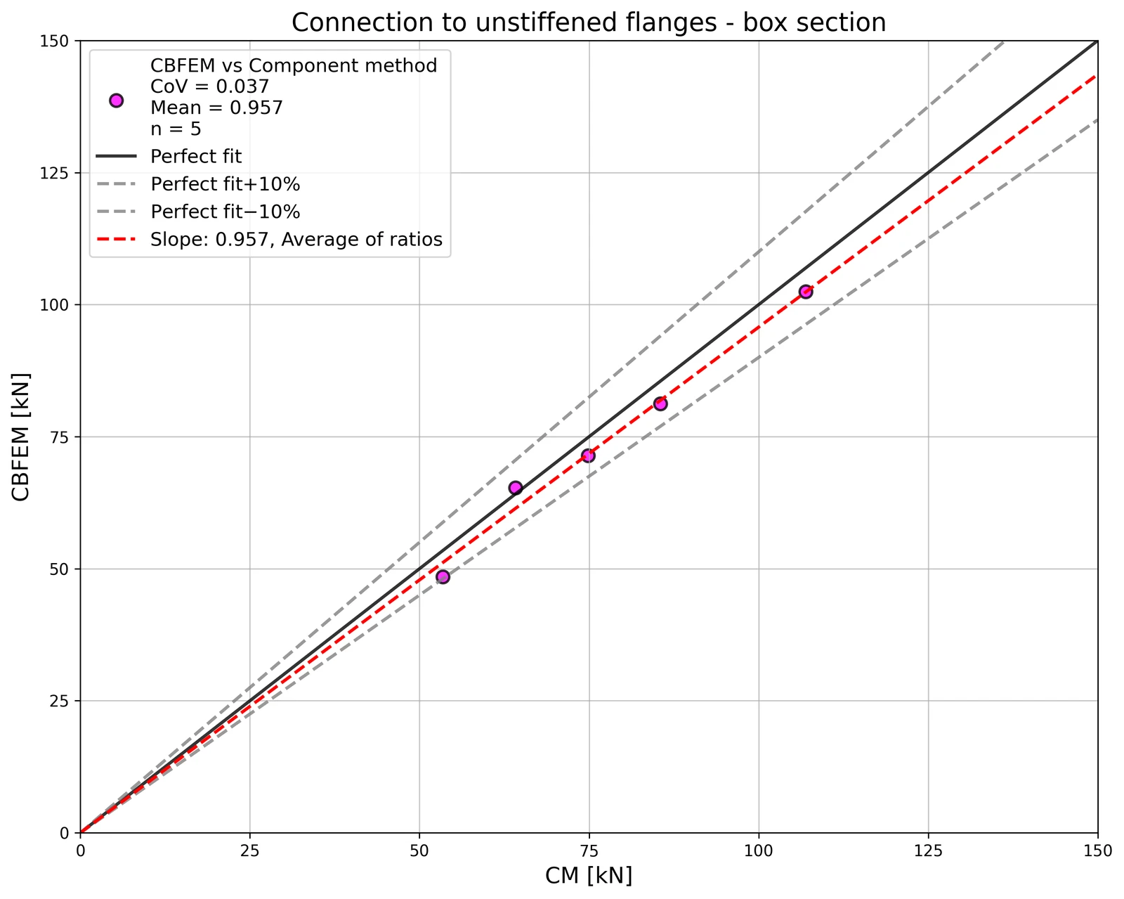
敏感性分析结果汇总于对比 CBFEM(基于组件的有限元模型)与 CM 设计承载力的图表中,见图 4.5.5,该图展示了 CBFEM(基于组件的有限元模型)模型的精度。
Fig. 4.5.5 Verification of CBFEM to CM \textsf{\textit{\footnotesize{Fig. 4.5.5 Verification of CBFEM to CM}}} Fig. 4.5.5 Verification of CBFEM to CM
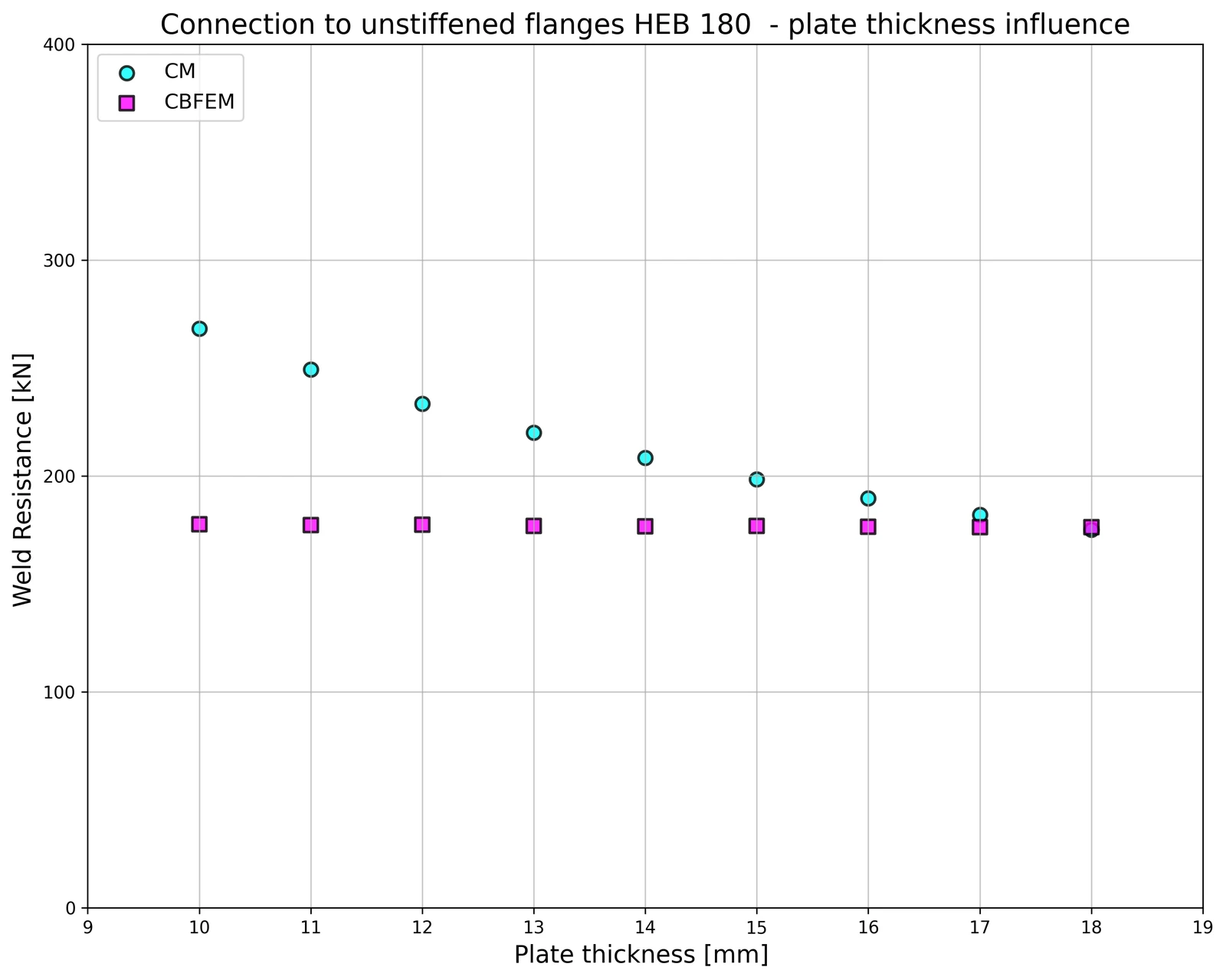
板厚对焊缝设计承载力的影响见图 4.5.6。柱截面为 HEB 180,翼缘厚度为 14 mm。当连接板厚度大于柱翼缘厚度时,CM 与 CBFEM(基于组件的有限元模型)所得焊缝承载力相同。反之,当连接板厚度等于或小于柱翼缘厚度时,数值模型所得设计承载力比 CM 小约 20%。这一差异源于采用壳单元的数值模型未考虑板厚的影响。
Fig. 4.5.6 Influence of plate thickness on the resistance of joint with unstiffened column HEB180 \textsf{\textit{\footnotesize{Fig. 4.5.6 Influence of plate thickness on the resistance of joint with unstiffened column HEB180}}} Fig. 4.5.6 Influence of plate thickness on the resistance of joint with unstiffened column HEB180
基准算例 输入参数
柱
• 钢材 S235
• RHS 200/200/5
柔性板
• 钢材 S235
• 厚度 t p = 17 mm
• 宽度 b p = 190 mm
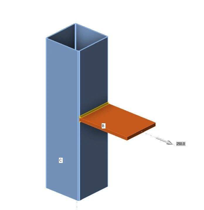
焊缝,双面角焊缝见图 4.5.7
• 计算厚度 a w = 5 mm
输出结果
• 抗拉设计承载力 N Rd = 68 kN
Fig. 4.5.7 Benchmark example for the welded connection of plate to unstiffened column \textsf{\textit{\footnotesize{Fig. 4.5.7 Benchmark example for the welded connection of plate to unstiffened column}}} Fig. 4.5.7 Benchmark example for the welded connection of plate to unstiffened column