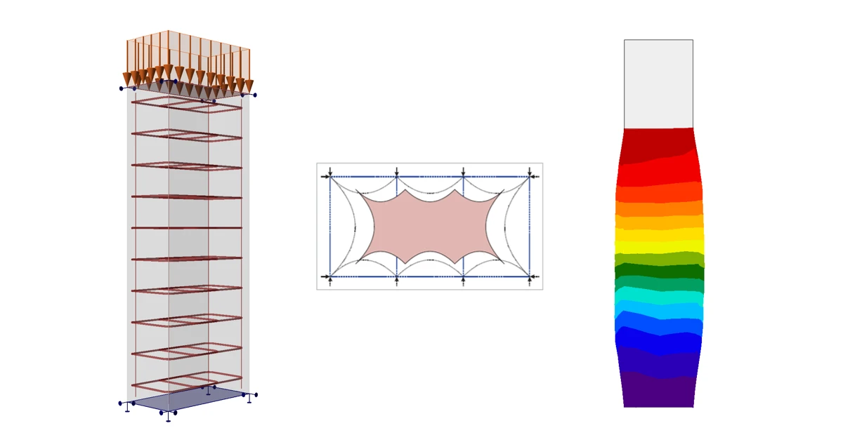
引言 混凝土结构中的被动约束效应是指混凝土的强度和延性因周围材料(如钢筋或外包层)提供的约束而显著提高的现象。这一效应对于提高混凝土在压力作用下的性能尤为重要,特别是在高荷载条件下。
以下是混凝土结构约束效应的几个关键方面:
强度提高 :约束可提高混凝土的抗压强度。施加侧向压力时,可抑制混凝土的侧向膨胀,使其在破坏前能承受更高的轴向荷载。
延性增强 :受约束混凝土表现出更大的延性,即在破坏前能产生更大的变形。
受荷行为 :约束将混凝土的破坏模式从脆性突然破坏转变为更具延性的渐进式破坏。这种破坏模式的转变对于结构在极端荷载条件下的安全性和完整性具有重要意义。
设计考虑 :受约束混凝土构件的设计涉及约束钢筋用量和布置的计算,以达到预期的强度和延性。EN(欧洲规范)等标准和规范提供了设计受约束混凝土构件的公式和指导原则。
应用 :约束广泛应用于柱、桥墩及其他关键结构构件的设计,也用于既有结构的加固和补强,以提高其承载能力。
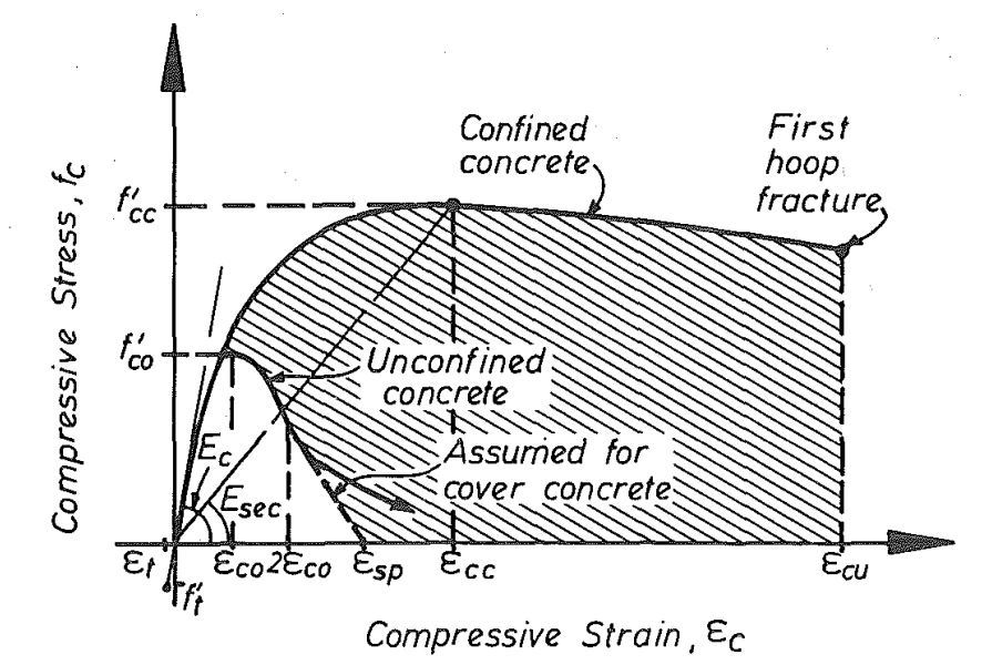
在下图中,可以观察到无约束混凝土和有约束混凝土的应力-应变图及承载能力的差异。
Fig. 1 Stress-strain model proposed for monotonic loading of confined and unconfined concrete [2] \textsf{\textit{\footnotesize{Fig. 1\qquad Stress-strain model proposed for monotonic loading of confined and unconfined concrete [2]}}} Fig. 1 Stress-strain model proposed for monotonic loading of confined and unconfined concrete [2]
承受高压荷载的柱——被动约束示例 在本示例中,我们将多种不同截面形状、不同拓扑形式和配筋率的柱在高压荷载作用下的计算结果进行对比,分别采用 IDEA StatiCa Detail 软件计算结果与 Morger 等人 [1] 提出的多种解析方法进行比较,这些解析方法来源于现行多项标准——fib 混凝土结构模型规范 2010(MC 2010)[3]、SIA 262:2013 混凝土结构(SIA 262)[4] 以及欧洲规范 2——混凝土结构设计 EN 1992-1-1:2023(EC 2)[5]。
在进入验证内容之前,先回顾 IDEA StatiCa Detail 软件中实现的三维 CSFM(协调应力场法)的理论基础——IDEA StatiCa Detail 中混凝土三维非连续区的结构设计
解析方法 整个验证基于文献 [1] 中已提及的解析方法。本文仅对解析计算方法及相关公式作简要介绍。为更深入理解,建议详细研读文献 [1]。
受压钢筋混凝土构件的承载力可通过将三个独立分量及其对应截面面积求和得到:(i)整个混凝土截面的单轴混凝土抗压强度,(ii)纵向钢筋的抗压强度,以及(iii)由约束钢筋提供的三轴应力状态引起的混凝土抗压强度增量:
N R = f c ⋅ A c ⏟ ( i ) + ( f s y . l − f c ) ⋅ A s . l ⏟ ( i i ) + Δ f c o n f ⋅ A c o n f ⏟ ( i i i ) N_{R}=\underset{(i)}{\underbrace{f_{c}\cdot A_{c}}}+\underset{(ii)}{\underbrace{(f_{sy.l}-f_{c})\cdot A_{s.l}}}+\underset{(iii)}{\underbrace{\Delta f_{conf}\cdot A_{conf}}} N R = ( i ) f c ⋅ A c + ( ii ) ( f sy . l − f c ) ⋅ A s . l + ( iii ) Δ f co n f ⋅ A co n f
其中 fc = 混凝土单轴抗压强度,Ac = 混凝土截面面积,fsy,l 和 As,l = 纵向钢筋的屈服强度和总截面面积,Δfconf = 约束引起的混凝土抗压强度增量,Aconf = 控制性约束混凝土面积。
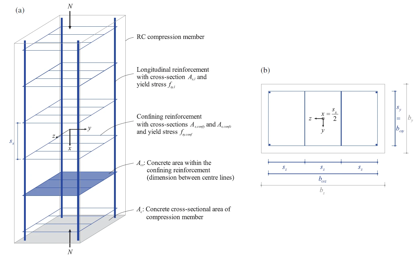
本文中,受压钢筋混凝土构件的坐标系选取使荷载方向与 x 轴一致,称为纵向。y 方向和 z 方向因此称为横向。
Fig. 2 Definition of most important geometrical parameters [1] \textsf{\textit{\footnotesize{Fig. 2\qquad Definition of most important geometrical parameters [1]}}} Fig. 2 Definition of most important geometrical parameters [1]
约束引起的混凝土抗压强度增量 Δfconf 约为侧向压应力的四倍 [6]。
Δ f c o n f = 4 ⋅ m i n ( σ c o n f y , σ c o n f z ) \Delta f_{conf}=4\cdot min(\sigma_{confy},\sigma_{confz}) Δ f co n f = 4 ⋅ min ( σ co n f y , σ co n f z )
假设约束钢筋屈服且约束力完全扩散,约束应力满足以下平衡条件:
σ c o n f y = ∑ A s . c o n f y ⋅ f s y . c o n f s x ⋅ b c s z ; σ c o n f z = ∑ A s . c o n f z ⋅ f s y . c o n f s x ⋅ b c s y \sigma_{confy}=\frac{\sum A_{s.confy}\cdot f_{sy.conf}}{s_{x}\cdot b_{csz}};\sigma_{confz}=\frac{\sum A_{s.confz}\cdot f_{sy.conf}}{s_{x}\cdot b_{csy}} σ co n f y = s x ⋅ b csz ∑ A s . co n f y ⋅ f sy . co n f ; σ co n f z = s x ⋅ b csy ∑ A s . co n f z ⋅ f sy . co n f
其中 fsy.conf 为约束钢筋的屈服强度。
以下各小节介绍根据现行设计规范(EC 2、SIA 262 和 MC 2010)以及文献 [1] 中提出的被动约束新模型方法,确定控制性约束混凝土面积 Aconf (及相应有效系数 k)的不同现有方法。
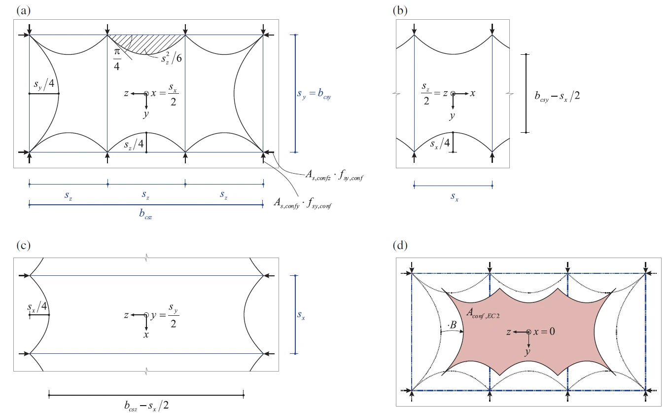
设计规范中的设计方法 EC2 基于约束钢筋离散分布荷载引入点之间的拱形作用,确定控制性约束混凝土面积 Aconf,EC2 。
A c o n f . E C 2 = ( b c s y ⋅ b c s z − ∑ s i 2 6 ) ⏟ A ⋅ ( ( b c s y ⋅ s x / 2 ) ⋅ ( b c s z − s x / 2 ) b c s y ⋅ b c s z ) ⏟ B A_{conf.EC2}=\underset{A}{\underbrace{\left( b_{csy}\cdot b_{csz}-\frac{\sum s^{2}_{i}}{6}\right)}}\cdot \underset{B}{\underbrace{\left( \frac{(b_{csy}\cdot s_{x}/2)\cdot(b_{csz}-s_{x}/2)}{b_{csy}\cdot b_{csz}}\right)}} A co n f . E C 2 = A ( b csy ⋅ b csz − 6 ∑ s i 2 ) ⋅ B ( b csy ⋅ b csz ( b csy ⋅ s x /2 ) ⋅ ( b csz − s x /2 ) )
= ( b c s y ⋅ b c s z − ∑ s i 2 6 ) ⋅ ( 1 − s x 2 ⋅ b c s y ) ⋅ ( 1 − s x 2 ⋅ b c s z ) = \left( b_{csy}\cdot b_{csz}-\frac{\sum s^{2}_{i}}{6}\right) \cdot \left(1-\frac{s_{x}}{2\cdot b_{csy}} \right) \cdot \left(1-\frac{s_{x}}{2\cdot b_{csz}} \right) = ( b csy ⋅ b csz − 6 ∑ s i 2 ) ⋅ ( 1 − 2 ⋅ b csy s x ) ⋅ ( 1 − 2 ⋅ b csz s x )
该公式适用于矩形截面,基于 Mander [2] 的研究成果。有关 A 部分和 B 部分的更多信息和理解,请参阅文献 [1]。
Fig. 3 Definition of confined concrete area according to EC 2: (a) confined concrete area at the section of a confining \textsf{\textit{\footnotesize{Fig. 3\qquad Definition of confined concrete area according to EC 2: (a) confined concrete area at the section of a confining }}} Fig. 3 Definition of confined concrete area according to EC 2: (a) confined concrete area at the section of a confining reinforcement layer (e.g., x = sx/2), (b) and (c) longitudinal dispersion of confining forces, (d) governing confined concrete \textsf{\textit{\footnotesize{reinforcement layer (e.g., x = sx/2), (b) and (c) longitudinal dispersion of confining forces, (d) governing confined concrete }}} reinforcement layer (e.g., x = sx/2), (b) and (c) longitudinal dispersion of confining forces, (d) governing confined concrete area at the center between two confining reinforcement layers (e.g., x=0, dotted lines indicating section from (a) as reference). \textsf{\textit{\footnotesize{area at the center between two confining reinforcement layers (e.g., x=0, dotted lines indicating section from (a) as reference).}}} area at the center between two confining reinforcement layers (e.g., x=0, dotted lines indicating section from (a) as reference).
值得注意的是,在 EC2 中,约束钢筋有效系数 k 用于表达承载力。系数 k 为控制性约束混凝土面积 Aconf 与截面面积 Ac 之比。
k = A c o n f A c k=\frac{A_{conf}}{A_{c}} k = A c A co n f
利用该系数,承载力 NR 可改写为:
N R = ( f c + k ⋅ Δ f c o n f ) ⋅ A c + ( f s y . l − f c ) ⋅ A s . l N_{R}=\left( f_{c}+k\cdot \Delta f_{conf}\right)\cdot A_{c}+(f_{sy.l}-f_{c})\cdot A_{s.l} N R = ( f c + k ⋅ Δ f co n f ) ⋅ A c + ( f sy . l − f c ) ⋅ A s . l
有效系数定义为:
k = ( b c s y ⋅ b c s z − 1 6 ∑ b i 2 b c y ⋅ b c z ) ⋅ ( 1 − s x 2 ⋅ b c s y ) ⋅ ( 1 − s x 2 ⋅ b c s z ) k=\left(\frac{b_{csy}\cdot b_{csz}-\frac{1}{6} \sum b_{i}^{2}}{b_{cy}\cdot b_{cz}}\right)\cdot \left(1-\frac{s_{x}}{2\cdot b_{csy}} \right)\cdot \left(1-\frac{s_{x}}{2\cdot b_{csz}} \right) k = ( b cy ⋅ b cz b csy ⋅ b csz − 6 1 ∑ b i 2 ) ⋅ ( 1 − 2 ⋅ b csy s x ) ⋅ ( 1 − 2 ⋅ b csz s x )
然而,为便于本文阐述,我们将沿用本章开头的承载力 NR 表达式,而非采用控制性约束混凝土面积 Aconf 。
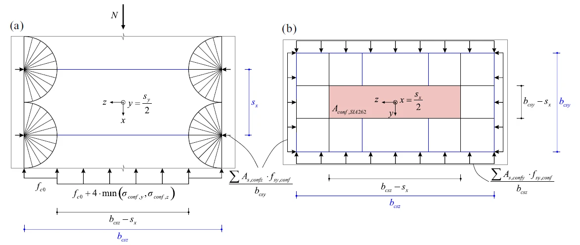
SIA 262 基于 Sigrist [7] 提出的图 4 所示应力场,定义控制性约束混凝土面积 Aconf,SIA262 。
A c o n f . S I A 262 = ( b c s y − s x ) ⋅ ( b c s z − s x ) A_{conf.SIA262}=(b_{csy}-s_{x})\cdot (b_{csz}-s_{x}) A co n f . S I A 262 = ( b csy − s x ) ⋅ ( b csz − s x )
Fig. 4 Definition of the confined concrete area according to SIA 262: (a) stress field and (b) lateral section at the level \textsf{\textit{\footnotesize{Fig. 4\qquad Definition of the confined concrete area according to SIA 262: (a) stress field and (b) lateral section at the level }}} Fig. 4 Definition of the confined concrete area according to SIA 262: (a) stress field and (b) lateral section at the level of the confining reinforcement (e.g., x = sx/2). \textsf{\textit{\footnotesize{of the confining reinforcement (e.g., x = sx/2). }}} of the confining reinforcement (e.g., x = sx/2).
MC 2010 将控制性约束混凝土面积定义为 EC 2 和 SIA 262 公式基础上两种模型的组合:
A c o n f . M C 2010 = ( b c s y ⋅ b c s z − ∑ s i 2 6 ) ⋅ ( ( b c s y ⋅ s x ) ⋅ ( b c s z − s x ) b c s y ⋅ b c s z ) A_{conf.MC2010}=\left( b_{csy}\cdot b_{csz}-\frac{\sum s^{2}_{i}}{6}\right)\cdot \left( \frac{(b_{csy}\cdot s_{x})\cdot(b_{csz}-s_{x})}{b_{csy}\cdot b_{csz}}\right) A co n f . M C 2010 = ( b csy ⋅ b csz − 6 ∑ s i 2 ) ⋅ ( b csy ⋅ b csz ( b csy ⋅ s x ) ⋅ ( b csz − s x ) )
= ( b c s y ⋅ b c s z − ∑ s i 2 6 ) ⋅ ( 1 − s x b c s y ) ⋅ ( 1 − s x b c s z ) = \left( b_{csy}\cdot b_{csz}-\frac{\sum s^{2}_{i}}{6}\right) \cdot \left(1-\frac{s_{x}}{b_{csy}} \right) \cdot \left(1-\frac{s_{x}}{b_{csz}} \right) = ( b csy ⋅ b csz − 6 ∑ s i 2 ) ⋅ ( 1 − b csy s x ) ⋅ ( 1 − b csz s x )
文献 [1] 中提出的被动约束新模型方法 将简化约束混凝土面积 Aconf,simp 定义为约束钢筋几何形状和间距的函数。
A c o n f . s i m p = ( b c s y − s x 2 + s z 2 2 ) ⋅ ( b c s z − s x 2 + s y 2 2 ) A_{conf.simp}=\left(b_{csy}-\frac{\sqrt{s_{x}^{2}+s_{z}^{2}}}{2}\right)\cdot \left(b_{csz}-\frac{\sqrt{s_{x}^{2}+s_{y}^{2}}}{2}\right) A co n f . s im p = ( b csy − 2 s x 2 + s z 2 ) ⋅ b csz − 2 s x 2 + s y 2
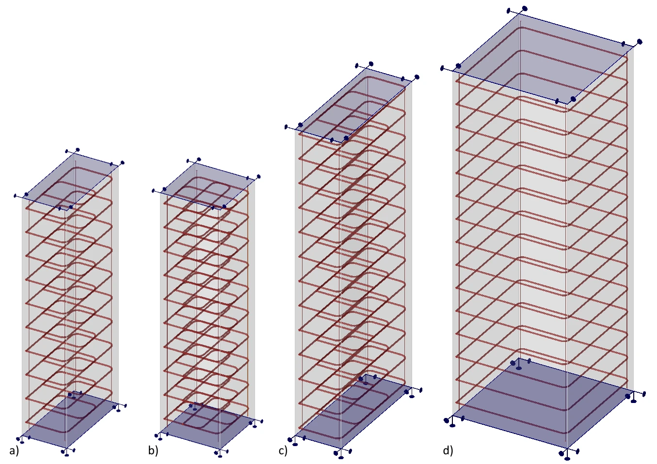
IDEA StatiCa Detail 模型 模型为实体块类型,具有不同的平面尺寸 bcy x bcz 、高度 hx 和箍筋间距 sx ,采用 C30/37 混凝土,底面在 X、Y、Z 方向由刚性面支座支承。为保证模型中顶部混凝土保护层的稳定性,顶面也在水平方向由刚性支座支承。所有模型的混凝土保护层 c 均为 30 mm。纵向钢筋始终为四根,直径 Φs,l = 10 mm 。箍筋、约束钢筋和纵向钢筋均采用 B500B 钢材建模。所有计算均采用特征值。
Fig. 5 IDEA StatiCa Detail models a) 0.75 x 1.5 x 4.0; b) 1.0 x 1.0 x 4.0; c) 0.75 x 2.5 x 5.0; d) 2.0 x 2.0 x 6.0 \textsf{\textit{\footnotesize{Fig. 5\qquad IDEA StatiCa Detail models a) 0.75 x 1.5 x 4.0; b) 1.0 x 1.0 x 4.0; c) 0.75 x 2.5 x 5.0; d) 2.0 x 2.0 x 6.0}}} Fig. 5 IDEA StatiCa Detail models a) 0.75 x 1.5 x 4.0; b) 1.0 x 1.0 x 4.0; c) 0.75 x 2.5 x 5.0; d) 2.0 x 2.0 x 6.0
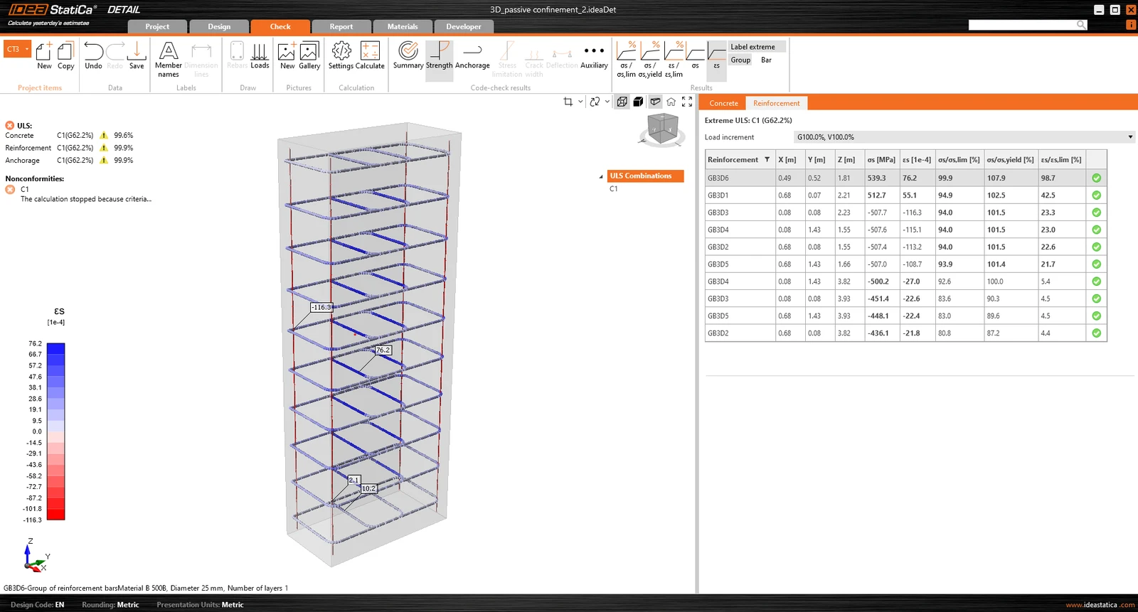
施加的荷载始终大于预期承载力。程序随后搜索在不超过任一已定义准则的前提下可施加的最大荷载。在本例中,始终以箍筋的极限应变准则为控制条件,最大值为 5%,但由于实现了拉力刚化,极限值通常更低。更多详情请参阅理论背景 。
在下图中可以看到,模型 0.75 x 1.5 x 4.0 的计算已停止,并找到了该构件所能承受的最大荷载倍数。
Fig. 6 IDEA StatiCa Detail – limit strain in reinforcement \textsf{\textit{\footnotesize{Fig. 6\qquad IDEA StatiCa Detail – limit strain in reinforcement}}} Fig. 6 IDEA StatiCa Detail – limit strain in reinforcement
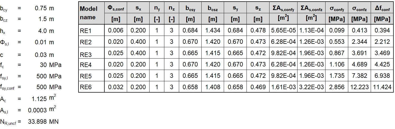
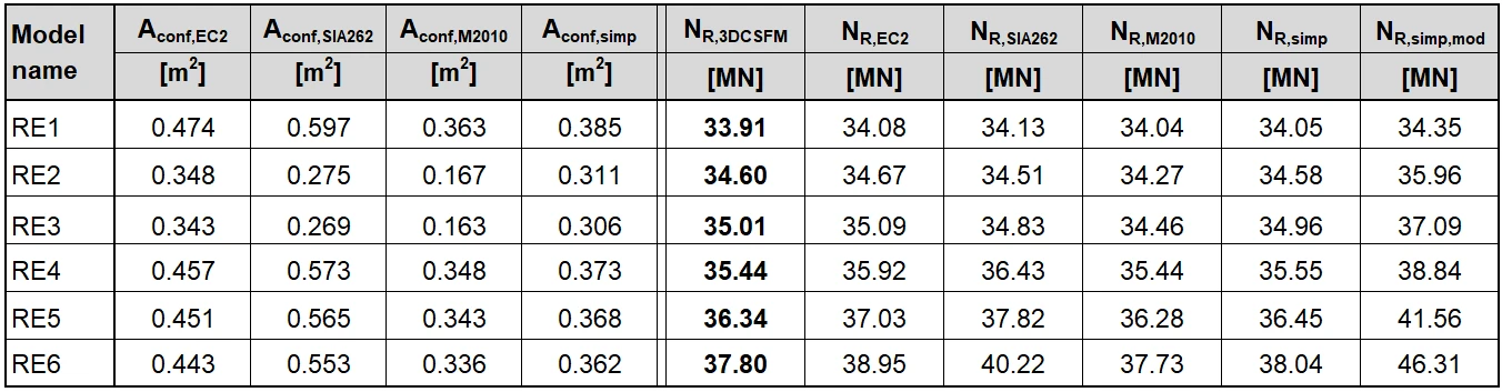
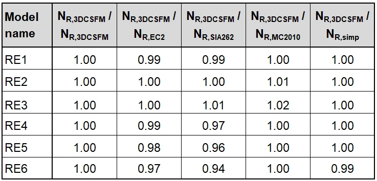
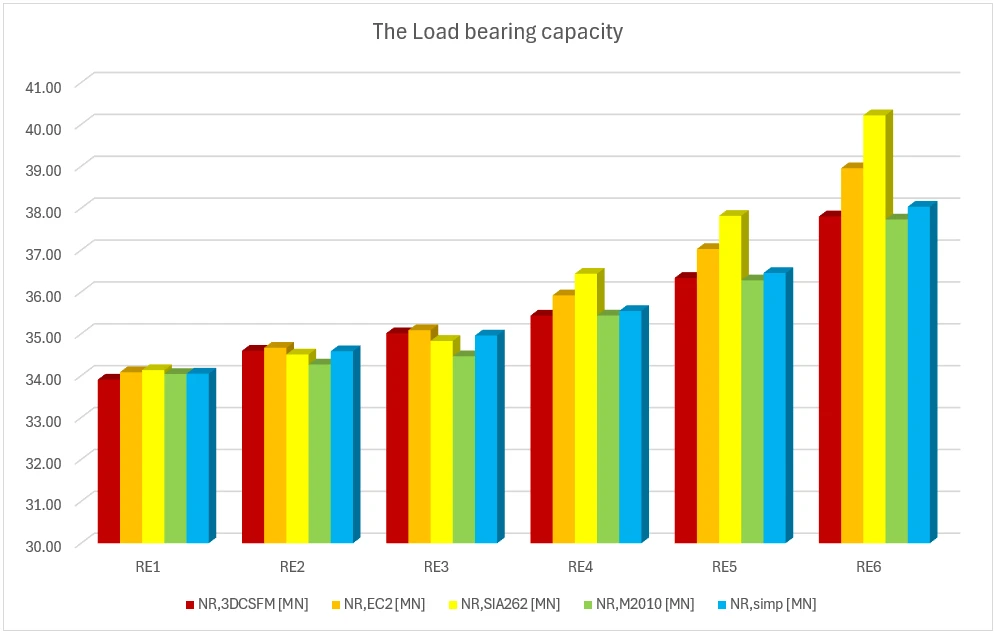
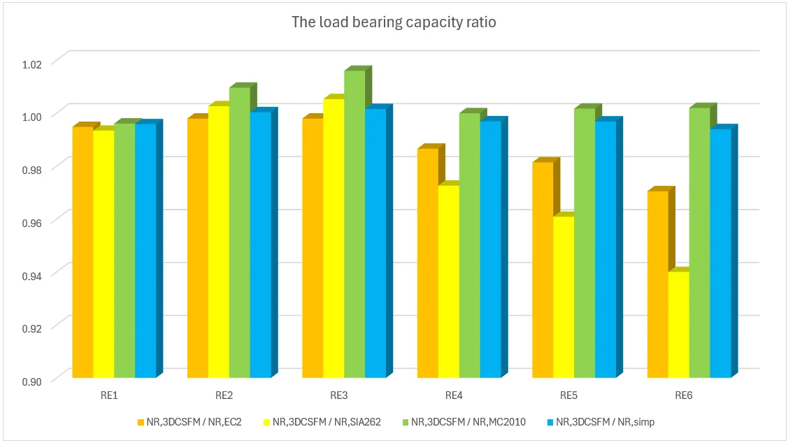
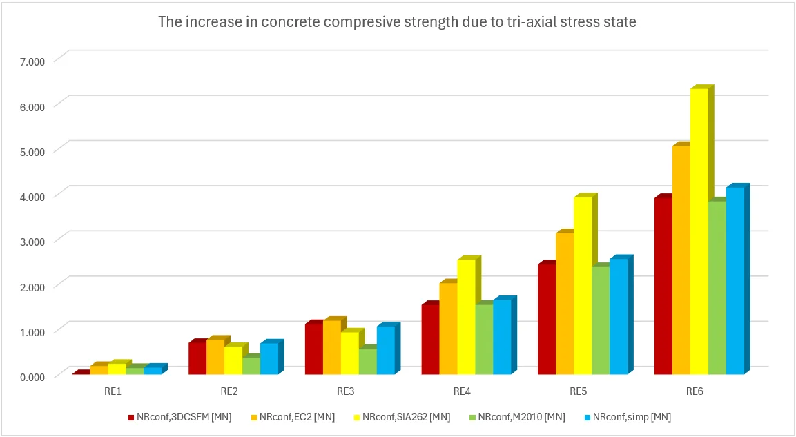
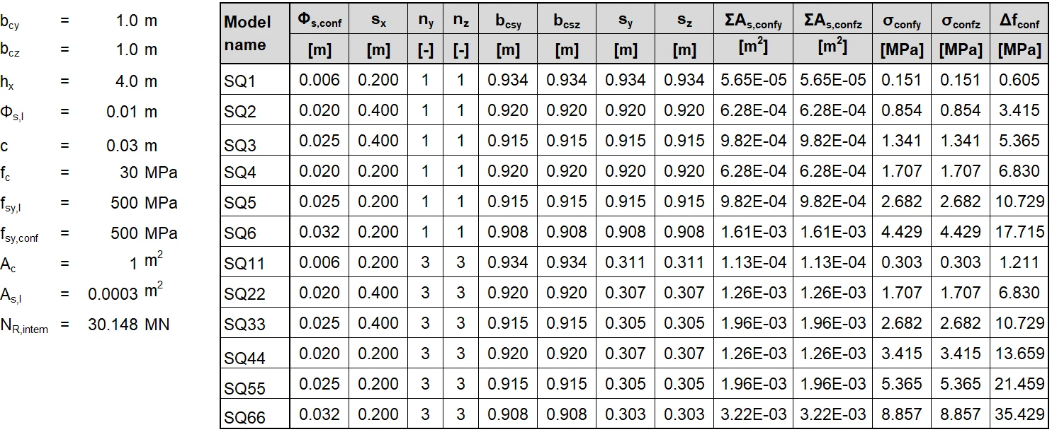
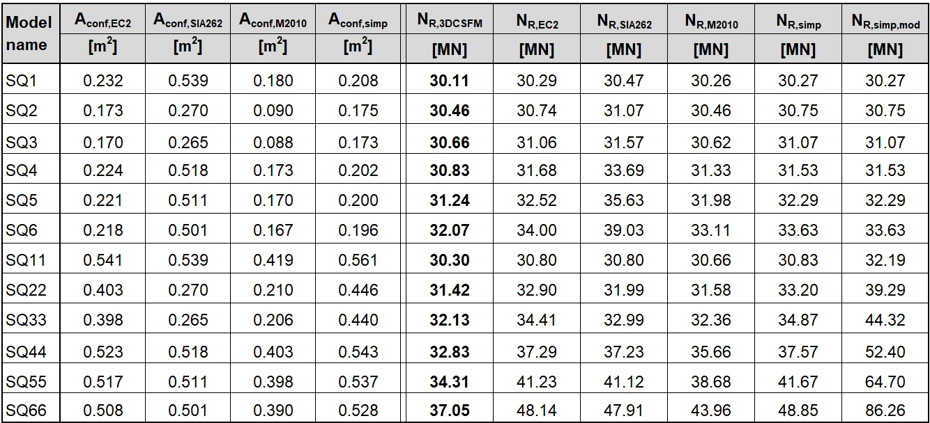
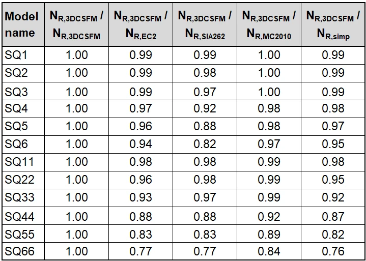
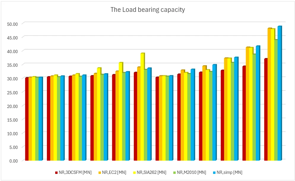
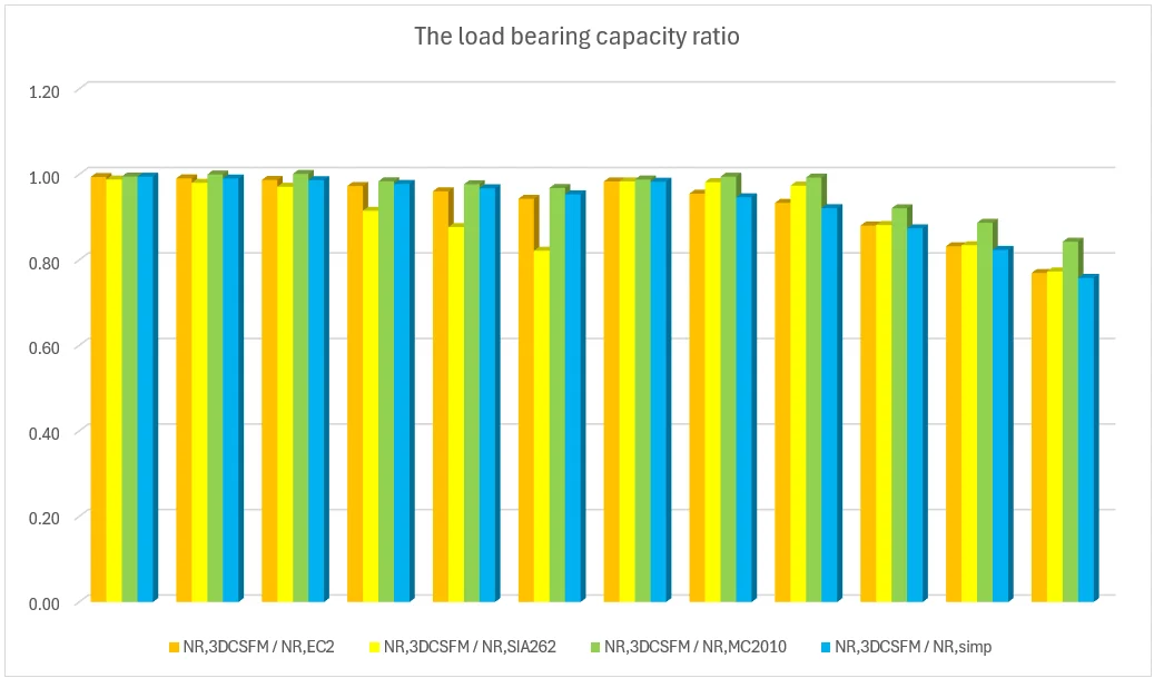
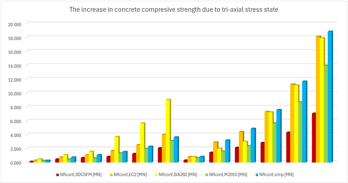
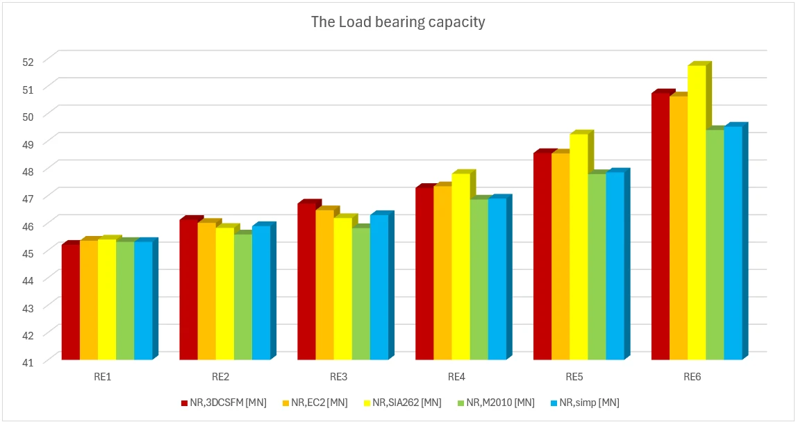
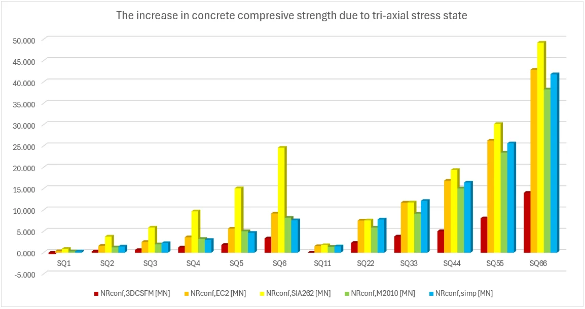
各模型对比 在以下表格和图表中,我们对 IDEA StatiCa Detail 软件中建立的所有模型与解析方法进行了比较,包括一个矩形模型和一个正方形模型的所有中间结果。但首先需要定义若干辅助变量。
Φs,l 和 Φs,conf 分别为纵向钢筋和约束钢筋的直径,ny 和 nz 为间距 sy 和 sz 的数量(即箍筋肢数为 n+1 ),NR,uncf 和 NR,conf 定义如下:
N R , u n c f = f c ⋅ A c + ( f s y . l − f c ) ⋅ A s . l ; N R , c o n f = Δ f c o n f ⋅ A c o n f N_{R,uncf}=f_{c}\cdot A_{c}+(f_{sy.l}-f_{c})\cdot A_{s.l}; N_{R,conf}=\Delta f_{conf}\cdot A_{conf} N R , u n c f = f c ⋅ A c + ( f sy . l − f c ) ⋅ A s . l ; N R , co n f = Δ f co n f ⋅ A co n f
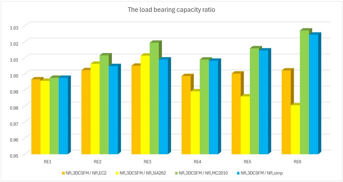
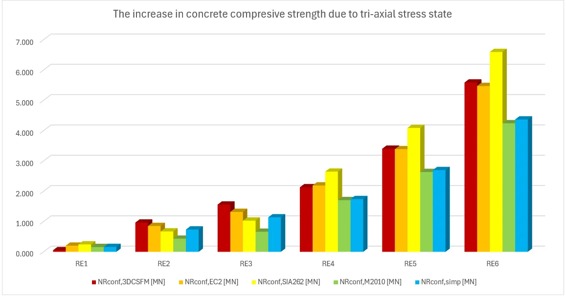
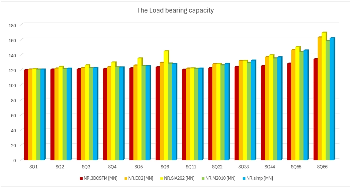
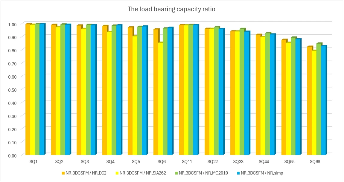
矩形模型 a) 0.75 x 1.5 x 4.0 正方形模型 b) 1.0 x 1.0 x 4.0 矩形模型 c) 0.75 x 2.5 x 5.0 正方形模型 d) 2.0 x 2.0 x 6.0 结论 从上述结果可以得出若干结论。总体而言,三维 CSFM(协调应力场法)的计算结果偏于保守,尤其对于正方形模型,在某些算例中约束引起的承载力提高不足一半。对于矩形模型,偏差在 2% 以内,吻合较好。在所研究的解析方法中,EC2 方法在所有模型中均表现出最佳的吻合度。本验证表明,从被动约束角度来看,采用三维 CSFM(协调应力场法)是安全的,并与现行标准的既有方法相符。
参考文献 [1] MORGER, Fabian; KENEL, Albin a KAUFMANN, Walter. Passive confinement of reinforced concrete members revisited. Online. Structural Concrete . ISSN 1464-4177. https://doi.org/10.1002/suco.202400209 .
[2] Mander JB, Priestley MJN, Park R. Observed stress-strain behavior of confined concrete. J Struct Eng. 1988;114:1827–49. https://doi.org/10.1061/(ASCE)0733-9445(1988)114:8(1827)
[3] International Federation for Structural Concrete (fib). Model code for concrete structures 2010; 2013.
[4] SIA. Swisscode SIA 262: concrete structures. Zurich, Switzerland: Swiss society of engineers and architects (SIA); 2013.
[5] EN 1992-1-1:2023. Eurocode 2—Design of concrete structures—Part 1-1: General rules and rules for buildings, bridges and civil engineering structures; 2023.
[6] Nielsen MP, Hoang LC. Limit analysis and concrete plasticity. 3rd ed. Boca Raton, FL: CRC Press; 2011. https://doi.org/10.1201/b10432
[7] Sigrist V. Zum Verformungsvermögen von Stahlbetonträgern [On the deformation capacity of structural concrete girders]. Doctoral Thesis. ETH Zürich; 1995. https://doi.org/10.3929/ethz-a-001492371