Widget #NaN: support_center_article
Name: Weld size differences between EC and AISC (CISC) codes
ID: c06cb68e-da64-517f-b983-b6bf80c8addd
Show Raw Data
{
"title": {
"name": "Main headline (H1)",
"type": "text",
"value": "Weld size differences between EC and AISC (CISC) codes"
},
"preview_image": {
"name": "Preview image",
"type": "asset",
"value": [
{
"name": "Weld size differences between EC and AISC (CISC) codes.png",
"description": "Weld size differences between EC and AISC (CISC) codes",
"type": "image/png",
"size": 140454,
"url": "https://assets-us-01.kc-usercontent.com:443/28eac049-c8ed-00e2-220c-12142a968dff/a224fbe0-28d0-4b11-8bfb-8fe2130934a1/Weld%20size%20differences%20between%20EC%20and%20AISC%20%28CISC%29%20codes.png",
"width": 1200,
"height": 630,
"renditions": {}
}
]
},
"post_date": {
"name": "Post date",
"type": "date_time",
"value": null,
"displayTimeZone": null
},
"perex_content": {
"name": "Lead paragraph",
"type": "text",
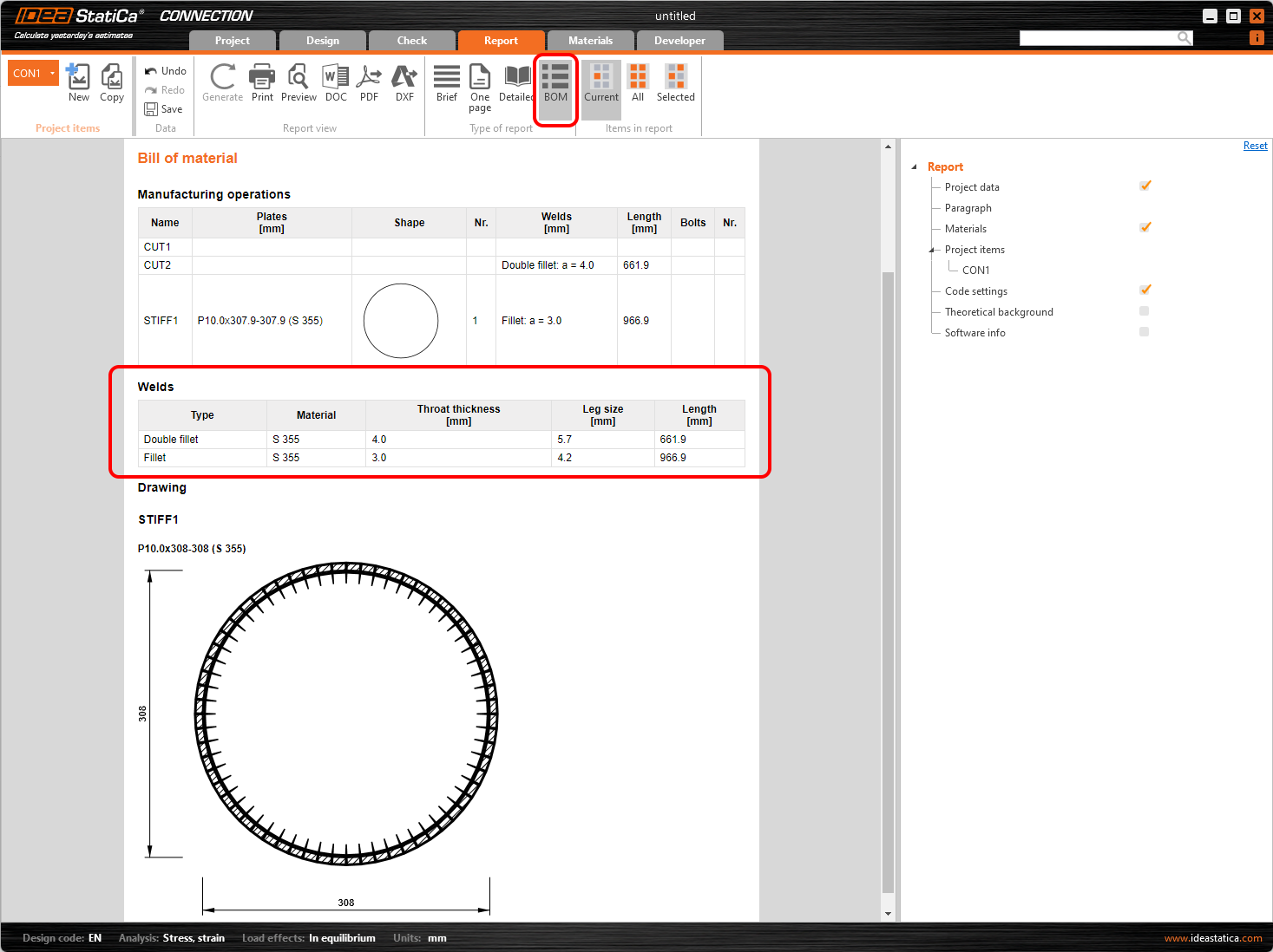
"value": "There is a difference between weld size definitions in welding operations when you design according to EC or AISC (CISC) codes. Please remember it while making a model of a joint in IDEA StatiCa."
},
"content": {
"images": [
{
"description": "Wels size",
"imageId": "e132c666-93e0-4b7f-9917-8ffc5a5dc770",
"url": "https://assets-us-01.kc-usercontent.com:443/28eac049-c8ed-00e2-220c-12142a968dff/82cd97fe-7c32-4d7d-b803-1794a985529a/Weld_size.png",
"height": 494,
"width": 809
}
],
"linkedItemCodenames": [],
"linkedItems": [],
"links": [],
"name": "Content",
"type": "rich_text",
"value": "<p>Under EN, the weld size is defined as the parameter <em>a,</em> which is <strong>the weld throat thickness</strong>.</p>\n<p>Under AISC (CISC), the weld size is defined as the parameter <em>z,</em> which is <strong>the weld leg size</strong>.</p>\n<p>You can simply calculate <em>a</em> from <em>z</em> and vice versa using the <a href=\"https://en.wikipedia.org/wiki/Pythagorean_theorem\">Pythagorean Theorem.</a></p>\n<figure data-asset-id=\"e132c666-93e0-4b7f-9917-8ffc5a5dc770\" data-image-id=\"e132c666-93e0-4b7f-9917-8ffc5a5dc770\"><img src=\"https://assets-us-01.kc-usercontent.com:443/28eac049-c8ed-00e2-220c-12142a968dff/82cd97fe-7c32-4d7d-b803-1794a985529a/Weld_size.png\" data-asset-id=\"e132c666-93e0-4b7f-9917-8ffc5a5dc770\" data-image-id=\"e132c666-93e0-4b7f-9917-8ffc5a5dc770\" alt=\"Wels size\"></figure>\n<p><br></p>"
},
"regions": {
"name": "Region",
"type": "taxonomy",
"value": [
{
"name": "AMER",
"codename": "amer"
},
{
"name": "EMEA",
"codename": "emea"
},
{
"name": "APAC",
"codename": "apac"
}
],
"taxonomyGroup": "region"
},
"product_groups": {
"name": "Product group",
"type": "taxonomy",
"value": [
{
"name": "Steel",
"codename": "steel"
}
],
"taxonomyGroup": "product_group"
},
"support_center_article_types": {
"name": "Support center article",
"type": "taxonomy",
"value": [
{
"name": "Knowledge base",
"codename": "knowledgebase_article"
}
],
"taxonomyGroup": "support_center_article"
},
"expertise_levels": {
"name": "Expertise level",
"type": "taxonomy",
"value": [
{
"name": "Beginner",
"codename": "beginner"
},
{
"name": "Intermediate",
"codename": "intermediate"
}
],
"taxonomyGroup": "expertise_level"
},
"labels": {
"name": "Labels",
"type": "taxonomy",
"value": [
{
"name": "AISC (USA)",
"codename": "aisc"
},
{
"name": "CSA (Canada)",
"codename": "cisc"
},
{
"name": "EN (Eurocode)",
"codename": "eurocode"
},
{
"name": "Welds",
"codename": "welds"
},
{
"name": "Connection",
"codename": "connection"
},
{
"name": "Member",
"codename": "member"
}
],
"taxonomyGroup": "labels"
},
"linked_items": {
"name": "Linked items",
"type": "modular_content",
"value": [
"welds__general_article_",
"theoretical_background___general___welds",
"what_is_the_correct_length_of_the_weld"
],
"linkedItems": [
{
"elements": {
"title": {
"name": "Main headline (H1)",
"type": "text",
"value": "Weld / Welds in IDEA StatiCa"
},
"preview_image": {
"name": "Preview image",
"type": "asset",
"value": [
{
"name": "Weld + welds.png",
"description": "Weld / Welds in IDEA StatiCa",
"type": "image/png",
"size": 204079,
"url": "https://assets-us-01.kc-usercontent.com:443/28eac049-c8ed-00e2-220c-12142a968dff/b0e51c7c-db21-42d6-8f4d-0665deccbafc/Weld%20%2B%20welds.png",
"width": 1200,
"height": 630,
"renditions": {}
}
]
},
"post_date": {
"name": "Post date",
"type": "date_time",
"value": null,
"displayTimeZone": "Europe/Prague"
},
"perex_content": {
"name": "Lead paragraph",
"type": "text",
"value": "In the article, you can find all the necessary information about welds and welded connections. The weld model is described as well as demo of the workflow in the application."
},
"content": {
"images": [
{
"description": "IDEA StatiCa Connection theoretical background for the advanced structural design of steel connections. Description of weld finite element. Structural design of welded connection.",
"imageId": "455c8fb8-27c8-4c3e-ab28-341376c03fa3",
"url": "https://assets-us-01.kc-usercontent.com:443/28eac049-c8ed-00e2-220c-12142a968dff/a62801a2-1d6a-4743-8627-e232e90e69d9/Structural%20design%20of%20a%20steel%20connection%20-%20Plate%20model%20and%20mesh%20convergence%201200%20x%20630.png",
"height": 630,
"width": 1200
},
{
"description": "",
"imageId": "8c940183-360c-484a-ab14-dcfdcfbbd29b",
"url": "https://assets-us-01.kc-usercontent.com:443/28eac049-c8ed-00e2-220c-12142a968dff/9e3dc390-df9d-4ee5-a959-7c4cfa9aca3b/welds_distr.png",
"height": 409,
"width": 1333
},
{
"description": null,
"imageId": "eb79d5c6-d879-4afb-a5c1-5df03982810a",
"url": "https://assets-us-01.kc-usercontent.com:443/28eac049-c8ed-00e2-220c-12142a968dff/2a16ecdf-f660-47b6-bb32-9b9aeecf3314/6.png",
"height": 600,
"width": 1200
},
{
"description": "Weld size and length",
"imageId": "291e03d6-32ca-40af-903f-3620de689301",
"url": "https://assets-us-01.kc-usercontent.com:443/28eac049-c8ed-00e2-220c-12142a968dff/67cc32f0-0506-4cdf-9637-0bc86dfefa54/Weld%20size.png",
"height": 1098,
"width": 1467
},
{
"description": "Fillet weld",
"imageId": "5acc5b19-3a08-4b30-8dca-6793bcfd19a7",
"url": "https://assets-us-01.kc-usercontent.com:443/28eac049-c8ed-00e2-220c-12142a968dff/47ea3d3f-dff3-49c7-8e5f-5abab34e343d/04-1-fig7.png",
"height": 276,
"width": 563
},
{
"description": "Check of missing welds",
"imageId": "450a4d6a-d571-4297-a195-63e33fdd30bc",
"url": "https://assets-us-01.kc-usercontent.com:443/28eac049-c8ed-00e2-220c-12142a968dff/12b10280-2125-44a3-b60e-6031f87a3e03/Missing%20welds.png",
"height": 308,
"width": 516
},
{
"description": "Export of recommended welds",
"imageId": "66cc6cf4-0454-4973-80d1-c036df7af58d",
"url": "https://assets-us-01.kc-usercontent.com:443/28eac049-c8ed-00e2-220c-12142a968dff/e38caf39-0947-4aff-be81-7d3eb57ada99/Screenshot%202020-10-05%20122254.png",
"height": 405,
"width": 618
},
{
"description": "Butt welds upgraded model",
"imageId": "401d916b-5fa2-4561-9051-9a6544652cea",
"url": "https://assets-us-01.kc-usercontent.com:443/28eac049-c8ed-00e2-220c-12142a968dff/20b7b61e-2508-4f74-9c1e-355619627e82/Butt%20welds%20upgraded%20model.png",
"height": 671,
"width": 1109
},
{
"description": "Weld checks specifics as per Eurocode (EN) and Indian Standard (IS)",
"imageId": "5062c6bd-0e2b-4f50-817b-0540cb5d686d",
"url": "https://assets-us-01.kc-usercontent.com:443/28eac049-c8ed-00e2-220c-12142a968dff/59c4504e-b3b9-4dc2-8b14-4f121a23e1c3/Welds1.png",
"height": 1033,
"width": 1920
},
{
"description": null,
"imageId": "e5be481f-5e66-43a8-8573-fdbc4d74a541",
"url": "https://assets-us-01.kc-usercontent.com:443/28eac049-c8ed-00e2-220c-12142a968dff/4dd4d3e4-77f0-4c14-9801-e9183f26cca6/WaC.png",
"height": 535,
"width": 1116
},
{
"description": "Plate clash warning",
"imageId": "b2f8fc0a-893b-4d9a-8648-092ef3a5e88b",
"url": "https://assets-us-01.kc-usercontent.com:443/28eac049-c8ed-00e2-220c-12142a968dff/d631a548-e7ca-4f84-a3c1-5c0207280cc0/clash3.png",
"height": 631,
"width": 1201
},
{
"description": "Check welds of welded sections",
"imageId": "388ba76a-be74-4fed-b0bb-9d7000ba1cad",
"url": "https://assets-us-01.kc-usercontent.com:443/28eac049-c8ed-00e2-220c-12142a968dff/b60903c8-dc26-4604-bc81-96d35d003afb/Welded-sections%200.png",
"height": 630,
"width": 1200
},
{
"description": "Weld check table",
"imageId": "8f86157e-4555-4525-aff0-fb388b0d718f",
"url": "https://assets-us-01.kc-usercontent.com:443/28eac049-c8ed-00e2-220c-12142a968dff/172ca452-c56d-40ca-afc4-9dc406734d70/weldchecktable.png",
"height": 716,
"width": 609
},
{
"description": "Detailing improvements for bolts and welds in Eurocode",
"imageId": "6dca1495-d3ba-4128-84fc-1b5d279d3440",
"url": "https://assets-us-01.kc-usercontent.com:443/28eac049-c8ed-00e2-220c-12142a968dff/9e0a6490-1e33-44fa-ab30-1247a201de0f/Detailing%20improvements_main%20image.png",
"height": 630,
"width": 1200
},
{
"description": null,
"imageId": "552c02a6-a54a-4149-83e2-d0c17d78561f",
"url": "https://assets-us-01.kc-usercontent.com:443/28eac049-c8ed-00e2-220c-12142a968dff/13eae981-ca17-401d-b1c8-7da0416d207e/Welds%20-%20autodesign%2C%20input%2C%20warnings%2C%20visualization1.png",
"height": 520,
"width": 934
},
{
"description": null,
"imageId": "c1e8146a-47c2-4147-9c75-5ae4e738622d",
"url": "https://assets-us-01.kc-usercontent.com:443/28eac049-c8ed-00e2-220c-12142a968dff/ae2aa532-e36b-4125-a8b6-80015ebb8df3/Welds%20-%20autodesign%2C%20input%2C%20warnings%2C%20visualization10.png",
"height": 1152,
"width": 1920
},
{
"description": null,
"imageId": "bab985b6-6e6b-48eb-bff9-63acd1d8f859",
"url": "https://assets-us-01.kc-usercontent.com:443/28eac049-c8ed-00e2-220c-12142a968dff/e467c86d-22ea-47de-b048-7c2265a63cda/Welds%20-%20autodesign%2C%20input%2C%20warnings%2C%20visualization11.png",
"height": 607,
"width": 810
},
{
"description": null,
"imageId": "1cbe1a11-db46-4da7-ab2b-2f541984db0a",
"url": "https://assets-us-01.kc-usercontent.com:443/28eac049-c8ed-00e2-220c-12142a968dff/f7b68cff-d260-4f8a-8ab2-048893e63b39/Bolts%20and%20welds_warning%20message.png",
"height": 723,
"width": 870
},
{
"description": "Weld sizing to ductility",
"imageId": "69d70cd1-f9f7-47d5-8b4d-8226620d5ec9",
"url": "https://assets-us-01.kc-usercontent.com:443/28eac049-c8ed-00e2-220c-12142a968dff/202ed4a2-278b-466c-b2d2-47023adfa727/Weld%20sizing%20to%20ductility1.png",
"height": 630,
"width": 1200
},
{
"description": "Weld sizing to capacity estimation",
"imageId": "0b97f49e-f205-43ee-b5de-00b203e18a3a",
"url": "https://assets-us-01.kc-usercontent.com:443/28eac049-c8ed-00e2-220c-12142a968dff/139beb9e-2e4e-4581-8a6b-e076578371d0/Weld%20sizing%20to%20capacity%20estimation1.png",
"height": 630,
"width": 1200
},
{
"description": "Partial Joint Penetration (PJP) groove weld",
"imageId": "d6fde932-e78a-4406-835a-8ff0ea82666c",
"url": "https://assets-us-01.kc-usercontent.com:443/28eac049-c8ed-00e2-220c-12142a968dff/d8a95f95-4aa5-4b9e-9b51-d58130c4afab/Partial%20Joint%20Penetration%20%28PJP%29%20groove%20weld.png",
"height": 630,
"width": 1200
},
{
"description": null,
"imageId": "4a731e96-e34c-4966-ad18-956f693bdf7d",
"url": "https://assets-us-01.kc-usercontent.com:443/28eac049-c8ed-00e2-220c-12142a968dff/1dd7c48e-f81a-4570-a239-8aa1a096c24d/Partial%20Joint%20Penetration%20%28PJP%29%20groove%20welds%2018.png",
"height": 329,
"width": 464
},
{
"description": null,
"imageId": "c98458a8-ce28-4e04-b397-4caa3bbe7d66",
"url": "https://assets-us-01.kc-usercontent.com:443/28eac049-c8ed-00e2-220c-12142a968dff/c15a1435-db8f-4d2a-84e1-51a0e516a84b/Weld%20spreading%20area%20v25.png",
"height": 534,
"width": 1828
},
{
"description": null,
"imageId": "99fa11e5-36be-46c2-9621-b7f333b81639",
"url": "https://assets-us-01.kc-usercontent.com:443/28eac049-c8ed-00e2-220c-12142a968dff/7ab584c9-fd6e-4489-969d-fd851e41008e/Weld%20spreading%20area%20-%20nodal%20forces.png",
"height": 944,
"width": 1092
},
{
"description": null,
"imageId": "5de940cd-26fb-4fb3-893d-5ed36e92b164",
"url": "https://assets-us-01.kc-usercontent.com:443/28eac049-c8ed-00e2-220c-12142a968dff/577d9983-9802-49ac-b805-f267c33c2280/AbaqusCoimbra.png",
"height": 650,
"width": 643
},
{
"description": null,
"imageId": "39492685-bd8a-4093-b540-660750c99c2f",
"url": "https://assets-us-01.kc-usercontent.com:443/28eac049-c8ed-00e2-220c-12142a968dff/66a85600-5ee6-4108-8dc2-36a915e7e09f/Contemplated%20geometries.png",
"height": 803,
"width": 2350
}
],
"linkedItemCodenames": [
"n638c5345_fccd_016e_9e22_78511c4aee78",
"db27997f_5f2c_0190_f326_366390069bd6",
"n63023176_3295_0199_0aee_b79c4f0acd2d",
"n7dd0835d_34ec_0188_3513_fe397f6f40a8",
"n05147820_d01e_015e_f3ca_579309c85ef7"
],
"linkedItems": [
{
"elements": {
"url": {
"name": "Video URL",
"type": "text",
"value": "https://youtu.be/flp-YlgtokA"
}
},
"system": {
"codename": "n638c5345_fccd_016e_9e22_78511c4aee78",
"collection": "default",
"id": "638c5345-fccd-016e-9e22-78511c4aee78",
"language": "en-US",
"lastModified": "2025-07-24T08:07:29.2911098Z",
"name": "638c5345-fccd-016e-9e22-78511c4aee78",
"sitemapLocations": [],
"type": "video",
"workflowStep": null,
"workflow": null
}
},
{
"elements": {
"url": {
"name": "Video URL",
"type": "text",
"value": "https://youtu.be/0kdColtQArs?t=1904"
}
},
"system": {
"codename": "db27997f_5f2c_0190_f326_366390069bd6",
"collection": "default",
"id": "db27997f-5f2c-0190-f326-366390069bd6",
"language": "en-US",
"lastModified": "2025-07-24T08:07:29.2911098Z",
"name": "db27997f-5f2c-0190-f326-366390069bd6",
"sitemapLocations": [],
"type": "video",
"workflowStep": null,
"workflow": null
}
},
{
"elements": {
"url": {
"name": "Video URL",
"type": "text",
"value": "https://youtu.be/tkZhFXxZObs?t=1585"
}
},
"system": {
"codename": "n63023176_3295_0199_0aee_b79c4f0acd2d",
"collection": "default",
"id": "63023176-3295-0199-0aee-b79c4f0acd2d",
"language": "en-US",
"lastModified": "2025-07-24T08:07:29.2911098Z",
"name": "63023176-3295-0199-0aee-b79c4f0acd2d",
"sitemapLocations": [],
"type": "video",
"workflowStep": null,
"workflow": null
}
},
{
"elements": {
"url": {
"name": "Video URL",
"type": "text",
"value": "https://youtu.be/XDhloaKRcaE?t=630"
}
},
"system": {
"codename": "n7dd0835d_34ec_0188_3513_fe397f6f40a8",
"collection": "default",
"id": "7dd0835d-34ec-0188-3513-fe397f6f40a8",
"language": "en-US",
"lastModified": "2025-07-24T08:07:29.2911098Z",
"name": "7dd0835d-34ec-0188-3513-fe397f6f40a8",
"sitemapLocations": [],
"type": "video",
"workflowStep": null,
"workflow": null
}
},
{
"elements": {
"title": {
"name": "Title",
"type": "text",
"value": "Related articles"
},
"description": {
"name": "Description",
"type": "text",
"value": ""
},
"featured_articles": {
"name": "Featured articles",
"type": "modular_content",
"value": [
"blog__weld___contact",
"bolts__bolted_connections__pins___",
"welds_de840e1"
],
"linkedItems": [
{
"elements": {
"title": {
"name": "Title (H1)",
"type": "text",
"value": "Reduce weld costs by enhanced fabrication"
},
"preview_image": {
"name": "Preview image",
"type": "asset",
"value": [
{
"name": "0_JANA.png",
"description": "Welding thickness",
"type": "image/png",
"size": 343981,
"url": "https://assets-us-01.kc-usercontent.com:443/28eac049-c8ed-00e2-220c-12142a968dff/8e269522-8afb-4871-8dfc-e22ca0839c09/0_JANA.png",
"width": 1200,
"height": 630,
"renditions": {}
}
]
},
"post_date": {
"name": "Post date",
"type": "date_time",
"value": "2022-11-24T00:00:00Z",
"displayTimeZone": "UTC"
},
"authors": {
"name": "Authors",
"type": "modular_content",
"value": [
"jana_kaderova__copy_"
],
"linkedItems": [
{
"elements": {
"name": {
"name": "Name",
"type": "text",
"value": "Ян Кубичек"
},
"position": {
"name": "Position",
"type": "text",
"value": "Инженер по развитию продукта\nIDEA StatiCa"
},
"images": {
"name": "Image",
"type": "asset",
"value": [
{
"name": "Ján WEB.png",
"description": null,
"type": "image/png",
"size": 262128,
"url": "https://assets-us-01.kc-usercontent.com:443/28eac049-c8ed-00e2-220c-12142a968dff/2bb4ee9a-f5f8-4c8a-9b83-9b8498521852/J%C3%A1n%20WEB.png",
"width": 325,
"height": 400,
"renditions": {}
}
]
},
"perex": {
"name": "Perex",
"type": "text",
"value": ""
},
"content": {
"images": [],
"linkedItemCodenames": [],
"linkedItems": [],
"links": [],
"name": "Content",
"type": "rich_text",
"value": "<p><br></p>"
},
"linkedin": {
"name": "LinkedIn",
"type": "text",
"value": ""
},
"url_slug": {
"name": "Url slug",
"type": "url_slug",
"value": "yan-kubichek"
},
"unique_url_slug": {
"name": "Unique URL slug",
"type": "custom",
"value": "[\"yan-kubichek\",\"[autogenerated]\"]"
},
"content_settings__sitemap": {
"name": "Show in sitemap",
"type": "multiple_choice",
"value": []
},
"content_settings__robots": {
"name": "Search engine indexing",
"type": "multiple_choice",
"value": []
},
"content_settings__is_hidden": {
"name": "Hidden nested content",
"type": "multiple_choice",
"value": []
},
"metadata__page_title": {
"name": "Page title",
"type": "text",
"value": ""
},
"metadata__page_description": {
"name": "Page description",
"type": "text",
"value": ""
},
"metadata__page_keywords": {
"name": "Page keywords",
"type": "text",
"value": ""
},
"metadata__canonical_url": {
"name": "Canonical URL",
"type": "text",
"value": ""
},
"metadata__og_title": {
"name": "OG:title",
"type": "text",
"value": ""
},
"metadata__og_description": {
"name": "OG:description",
"type": "text",
"value": ""
},
"metadata__og_image": {
"name": "OG:image",
"type": "asset",
"value": []
},
"translation__translation_connector": {
"name": "Translation Connector",
"type": "taxonomy",
"value": [],
"taxonomyGroup": "languages"
},
"translation__force_translation": {
"name": "Force translation",
"type": "multiple_choice",
"value": []
},
"translation__last_translation": {
"images": [],
"linkedItemCodenames": [],
"linkedItems": [],
"links": [],
"name": "Last translation",
"type": "rich_text",
"value": "<p><br></p>"
},
"translation__ai_translated": {
"name": "AI translated",
"type": "multiple_choice",
"value": []
},
"page_tree_settings__page_label": {
"name": "Page label",
"type": "text",
"value": "Ян Кубичек"
},
"page_tree_settings__path_segment": {
"name": "Path segment",
"type": "text",
"value": "yan-kubichek"
},
"page_tree_settings__breadcrumb_style": {
"name": "Breadcrumb style",
"type": "multiple_choice",
"value": []
},
"page_tree_settings__hide_in_breadcrumbs": {
"name": "Hide in breadcrumbs",
"type": "multiple_choice",
"value": []
}
},
"system": {
"codename": "jana_kaderova__copy_",
"collection": "default",
"id": "55de9eb7-c51a-4af7-94e1-b4975f51d82f",
"language": "ru-RU",
"lastModified": "2026-04-29T15:36:01.0742554Z",
"name": "Jan Kubicek",
"sitemapLocations": [],
"type": "author",
"workflowStep": "published",
"workflow": "default"
}
}
]
},
"perex_content": {
"name": "Lead paragraph",
"type": "text",
"value": "You can't build a steel structure without welding. But the designer can always decide what amount of welding will be needed for each of them. For every project, choosing workshop welding over onsite can greatly impact time and costs. Let's take a look at how sophisticated tools can help reduce the costs of this particular task."
},
"content": {
"images": [
{
"description": null,
"imageId": "eb79d5c6-d879-4afb-a5c1-5df03982810a",
"url": "https://assets-us-01.kc-usercontent.com:443/28eac049-c8ed-00e2-220c-12142a968dff/2a16ecdf-f660-47b6-bb32-9b9aeecf3314/6.png",
"height": 600,
"width": 1200
},
{
"description": null,
"imageId": "29614fc0-aa03-499c-b343-7c518253d397",
"url": "https://assets-us-01.kc-usercontent.com:443/28eac049-c8ed-00e2-220c-12142a968dff/d7f5114a-1fcd-4da4-9496-44a11d412653/1.png",
"height": 1152,
"width": 1920
},
{
"description": null,
"imageId": "9a6d9cfe-6a47-4004-ac16-16dc15eadf5d",
"url": "https://assets-us-01.kc-usercontent.com:443/28eac049-c8ed-00e2-220c-12142a968dff/6af8d357-08a5-4696-bc89-3f5b3938463a/5.png",
"height": 671,
"width": 1636
},
{
"description": null,
"imageId": "49e646c3-621b-4946-98c5-3330d6b697dc",
"url": "https://assets-us-01.kc-usercontent.com:443/28eac049-c8ed-00e2-220c-12142a968dff/40b0ff4a-152f-4245-af7e-7424793620db/7.png",
"height": 350,
"width": 910
},
{
"description": null,
"imageId": "29ab325a-b8f5-4f92-93af-d4e9a10b81c8",
"url": "https://assets-us-01.kc-usercontent.com:443/28eac049-c8ed-00e2-220c-12142a968dff/d2b3e9c9-3586-4eeb-963a-70e24edca19c/4.png",
"height": 822,
"width": 1920
}
],
"linkedItemCodenames": [
"n6926922d_e5b2_01a0_9cbf_12aabef97d08"
],
"linkedItems": [
{
"elements": {
"title": {
"name": "Title",
"type": "text",
"value": "Try IDEA StatiCa for free"
},
"event_id": {
"name": "Event ID",
"type": "text",
"value": ""
},
"description_top": {
"name": "Description before",
"type": "text",
"value": "Start your trial today and enjoy 14-days of full access and services free of charge. "
},
"link_text": {
"name": "Link text",
"type": "text",
"value": "START FREE TRIAL"
},
"link_url": {
"name": "Link URL",
"type": "text",
"value": ""
},
"content_item_link": {
"name": "Content Item Link",
"type": "modular_content",
"value": [
"landing_page_trial"
],
"linkedItems": [
{
"elements": {
"title": {
"name": "Main headline (H1)",
"type": "text",
"value": "Получите бесплатную пробную версию на 14 дней"
},
"subtitle": {
"name": "Subtitle",
"type": "text",
"value": "Оцените все преимущества IDEA StatiCa в течение 14 дней. Полный функционал, техническая поддержка и эксклюзивные материалы. Просто заполните форму ниже и лицензия будет отправлена на вашу электронную почту. "
},
"breadcrumbs_page_title": {
"name": "Breadcrumbs page title",
"type": "text",
"value": ""
},
"breadcrumbs_parent": {
"name": "Breadcrumbs parent",
"type": "modular_content",
"value": [],
"linkedItems": []
},
"content": {
"images": [],
"linkedItemCodenames": [],
"linkedItems": [],
"links": [],
"name": "Content",
"type": "rich_text",
"value": "<p>Отправляя результаты, вы принимаете <a href=\"/end-user-license-agreement\">Лицензионное соглашение с конечным пользователем</a></p>"
},
"shared_content": {
"images": [],
"linkedItemCodenames": [
"a873f8ec_0414_012c_9402_3e8b940979ef",
"n87142e18_13b6_0141_d455_b2f540b7be4b"
],
"linkedItems": [
{
"elements": {
"title": {
"name": "Title",
"type": "text",
"value": ""
},
"event_id": {
"name": "Event ID",
"type": "text",
"value": ""
},
"description_top": {
"name": "Description before",
"type": "text",
"value": ""
},
"link_text": {
"name": "Link text",
"type": "text",
"value": "Узнать больше о стоимости "
},
"link_url": {
"name": "Link URL",
"type": "text",
"value": "/pricing"
},
"content_item_link": {
"name": "Content Item Link",
"type": "modular_content",
"value": [],
"linkedItems": []
},
"description_bottom": {
"name": "Description after",
"type": "text",
"value": ""
},
"button_styles": {
"name": "Button style",
"type": "multiple_choice",
"value": [
{
"name": "link",
"codename": "link"
}
]
},
"button_position": {
"name": "Button position",
"type": "multiple_choice",
"value": []
},
"visibleinregion": {
"name": "VisibleInRegion",
"type": "multiple_choice",
"value": []
},
"regions": {
"name": "Region",
"type": "taxonomy",
"value": [],
"taxonomyGroup": "region"
},
"translation__translation_connector": {
"name": "Translation Connector",
"type": "taxonomy",
"value": [],
"taxonomyGroup": "languages"
},
"translation__force_translation": {
"name": "Force translation",
"type": "multiple_choice",
"value": []
},
"translation__last_translation": {
"images": [],
"linkedItemCodenames": [],
"linkedItems": [],
"links": [],
"name": "Last translation",
"type": "rich_text",
"value": "<p><br></p>"
},
"translation__ai_translated": {
"name": "AI translated",
"type": "multiple_choice",
"value": []
}
},
"system": {
"codename": "a873f8ec_0414_012c_9402_3e8b940979ef",
"collection": "default",
"id": "a873f8ec-0414-012c-9402-3e8b940979ef",
"language": "ru-RU",
"lastModified": "2021-03-17T13:19:46.3101872Z",
"name": "a873f8ec-0414-012c-9402-3e8b940979ef",
"sitemapLocations": [],
"type": "widget_cta_button",
"workflowStep": null,
"workflow": null
}
},
{
"elements": {
"title": {
"name": "Title",
"type": "text",
"value": ""
},
"event_id": {
"name": "Event ID",
"type": "text",
"value": ""
},
"description_top": {
"name": "Description before",
"type": "text",
"value": ""
},
"link_text": {
"name": "Link text",
"type": "text",
"value": "Узнать больше о системе лицензирования IDEA StatiCa "
},
"link_url": {
"name": "Link URL",
"type": "text",
"value": "/licensing"
},
"content_item_link": {
"name": "Content Item Link",
"type": "modular_content",
"value": [],
"linkedItems": []
},
"description_bottom": {
"name": "Description after",
"type": "text",
"value": ""
},
"button_styles": {
"name": "Button style",
"type": "multiple_choice",
"value": [
{
"name": "link",
"codename": "link"
}
]
},
"button_position": {
"name": "Button position",
"type": "multiple_choice",
"value": []
},
"visibleinregion": {
"name": "VisibleInRegion",
"type": "multiple_choice",
"value": []
},
"regions": {
"name": "Region",
"type": "taxonomy",
"value": [],
"taxonomyGroup": "region"
},
"translation__translation_connector": {
"name": "Translation Connector",
"type": "taxonomy",
"value": [],
"taxonomyGroup": "languages"
},
"translation__force_translation": {
"name": "Force translation",
"type": "multiple_choice",
"value": []
},
"translation__last_translation": {
"images": [],
"linkedItemCodenames": [],
"linkedItems": [],
"links": [],
"name": "Last translation",
"type": "rich_text",
"value": "<p><br></p>"
},
"translation__ai_translated": {
"name": "AI translated",
"type": "multiple_choice",
"value": []
}
},
"system": {
"codename": "n87142e18_13b6_0141_d455_b2f540b7be4b",
"collection": "default",
"id": "87142e18-13b6-0141-d455-b2f540b7be4b",
"language": "ru-RU",
"lastModified": "2021-03-17T13:19:46.3101872Z",
"name": "87142e18-13b6-0141-d455-b2f540b7be4b",
"sitemapLocations": [],
"type": "widget_cta_button",
"workflowStep": null,
"workflow": null
}
}
],
"links": [],
"name": "Shared content",
"type": "rich_text",
"value": "<object type=\"application/kenticocloud\" data-type=\"item\" data-rel=\"component\" data-codename=\"a873f8ec_0414_012c_9402_3e8b940979ef\"></object>\n<object type=\"application/kenticocloud\" data-type=\"item\" data-rel=\"component\" data-codename=\"n87142e18_13b6_0141_d455_b2f540b7be4b\"></object>"
},
"design": {
"name": "Design",
"type": "multiple_choice",
"value": []
},
"header_link": {
"name": "Header link",
"type": "text",
"value": ""
},
"header_content_item_link": {
"name": "Header Content Item Link",
"type": "modular_content",
"value": [],
"linkedItems": []
},
"header_cross_links": {
"name": "Header cross links",
"type": "modular_content",
"value": [],
"linkedItems": []
},
"header_content": {
"images": [],
"linkedItemCodenames": [],
"linkedItems": [],
"links": [],
"name": "Header content",
"type": "rich_text",
"value": "<p><br></p>"
},
"header_title": {
"name": "Header title",
"type": "text",
"value": ""
},
"header_alignment": {
"name": "Header alignment",
"type": "multiple_choice",
"value": []
},
"header_button_text": {
"name": "Header button text",
"type": "text",
"value": ""
},
"is_breadcrumbs_hidden": {
"name": "Hide breadcrumbs",
"type": "multiple_choice",
"value": []
},
"header_background_image": {
"name": "Background image",
"type": "asset",
"value": []
},
"header_background_image_effects": {
"name": "Background image effect",
"type": "multiple_choice",
"value": []
},
"is_header_full_height": {
"name": "Small height header",
"type": "multiple_choice",
"value": []
},
"header_background_video": {
"name": "Background video",
"type": "asset",
"value": []
},
"url_slug": {
"name": "URL slug",
"type": "url_slug",
"value": "free-trial"
},
"unique_url_slug": {
"name": "Unique URL slug",
"type": "custom",
"value": null
},
"content_settings__sitemap": {
"name": "Show in sitemap",
"type": "multiple_choice",
"value": []
},
"content_settings__robots": {
"name": "Search engine indexing",
"type": "multiple_choice",
"value": []
},
"content_settings__is_hidden": {
"name": "Hidden nested content",
"type": "multiple_choice",
"value": []
},
"metadata__page_title": {
"name": "Page title",
"type": "text",
"value": ""
},
"metadata__page_description": {
"name": "Page description",
"type": "text",
"value": ""
},
"metadata__page_keywords": {
"name": "Page keywords",
"type": "text",
"value": ""
},
"metadata__canonical_url": {
"name": "Canonical URL",
"type": "text",
"value": ""
},
"metadata__og_title": {
"name": "OG:title",
"type": "text",
"value": ""
},
"metadata__og_description": {
"name": "OG:description",
"type": "text",
"value": ""
},
"metadata__og_image": {
"name": "OG:image",
"type": "asset",
"value": []
},
"translation__translation_connector": {
"name": "Translation Connector",
"type": "taxonomy",
"value": [],
"taxonomyGroup": "languages"
},
"translation__force_translation": {
"name": "Force translation",
"type": "multiple_choice",
"value": []
},
"translation__last_translation": {
"images": [],
"linkedItemCodenames": [],
"linkedItems": [],
"links": [],
"name": "Last translation",
"type": "rich_text",
"value": "<p><br></p>"
},
"translation__ai_translated": {
"name": "AI translated",
"type": "multiple_choice",
"value": []
},
"page_tree_settings__page_label": {
"name": "Page label",
"type": "text",
"value": ""
},
"page_tree_settings__path_segment": {
"name": "Path segment",
"type": "text",
"value": ""
},
"page_tree_settings__breadcrumb_style": {
"name": "Breadcrumb style",
"type": "multiple_choice",
"value": []
},
"page_tree_settings__hide_in_breadcrumbs": {
"name": "Hide in breadcrumbs",
"type": "multiple_choice",
"value": []
}
},
"system": {
"codename": "landing_page_trial",
"collection": "default",
"id": "c9179b55-bed2-4f30-b430-d7edb80d2a36",
"language": "ru-RU",
"lastModified": "2021-03-17T13:19:46.3101872Z",
"name": "Free Trial - Form page",
"sitemapLocations": [],
"type": "landing_page",
"workflowStep": "published",
"workflow": "default"
}
}
]
},
"description_bottom": {
"name": "Description after",
"type": "text",
"value": ""
},
"button_styles": {
"name": "Button style",
"type": "multiple_choice",
"value": [
{
"name": "filled button",
"codename": "filled_button"
}
]
},
"button_position": {
"name": "Button position",
"type": "multiple_choice",
"value": [
{
"name": "center",
"codename": "center"
}
]
},
"visibleinregion": {
"name": "VisibleInRegion",
"type": "multiple_choice",
"value": []
},
"regions": {
"name": "Region",
"type": "taxonomy",
"value": [],
"taxonomyGroup": "region"
},
"translation__translation_connector": {
"name": "Translation Connector",
"type": "taxonomy",
"value": [],
"taxonomyGroup": "languages"
},
"translation__force_translation": {
"name": "Force translation",
"type": "multiple_choice",
"value": []
},
"translation__last_translation": {
"images": [],
"linkedItemCodenames": [],
"linkedItems": [],
"links": [],
"name": "Last translation",
"type": "rich_text",
"value": "<p><br></p>"
},
"translation__ai_translated": {
"name": "AI translated",
"type": "multiple_choice",
"value": []
}
},
"system": {
"codename": "n6926922d_e5b2_01a0_9cbf_12aabef97d08",
"collection": "default",
"id": "6926922d-e5b2-01a0-9cbf-12aabef97d08",
"language": "en-US",
"lastModified": "2023-07-18T13:00:16.948978Z",
"name": "6926922d-e5b2-01a0-9cbf-12aabef97d08",
"sitemapLocations": [],
"type": "widget_cta_button",
"workflowStep": null,
"workflow": null
}
}
],
"links": [
{
"codename": "cost_estimation",
"linkId": "dc6882ef-317b-417a-b684-943901355f3d",
"urlSlug": "how-much-does-your-connection-cost",
"type": "blog_post"
},
{
"codename": "theoretical_background___general___welds",
"linkId": "68076977-c9aa-4fa5-b726-09433e204c2b",
"urlSlug": "welds",
"type": "support_center_article"
},
{
"codename": "weld_and_contact",
"linkId": "ddfe7eda-4125-461a-b0f1-90de133d5cc6",
"urlSlug": "combining-weld-and-contact-operations",
"type": "support_center_article"
},
{
"codename": "release_notes_idea_statica_22_1",
"linkId": "8136efc3-3a87-48df-9cb2-890edbe4cfb2",
"urlSlug": "release-notes-idea-statica-22-1",
"type": "support_center_article"
},
{
"codename": "n2022_04_27_what_is_new_in_idea_statica_22_0__copy__16d6512",
"linkId": "16d6512d-82ee-4689-823f-5998c9421d66",
"urlSlug": "what-s-new-in-idea-statica-22-1",
"type": "webinar"
}
],
"name": "Content",
"type": "rich_text",
"value": "<p>It's interesting how different approaches to the same structure we could find throughout the regions, companies, or even between different designers. While some would weld everything together without thinking about a single bolt, others would cut the structure into several parts and connect everything together with dozens of bolts. Both approaches to connecting the structural members have their pros and cons. </p>\n<p>Purely welded connections are stiffer than bolted connections and are thus considered to be safer or can reduce deflections. But then some experienced (meaning expensive) welder has to be somewhere on site, safely hanged in the space, often in inhospitable weather. The weld quality checks are sometimes not even possible, and the less precise work brings obviously higher material costs.</p>\n<p>The workshop welding on the other hand may be more precise, it also requires transporting to the site. And onsite welding is often expensive in implementation and over-usage of welding materials. Read on to learn which approach best suits your projects.</p>\n<p>You already know that IDEA StatiCa can help you calculate not only the stiffness of the weld connections but also estimate the costs of the connection depending on the weld type, etc. That is not something new under the sun. <a data-item-id=\"dc6882ef-317b-417a-b684-943901355f3d\" href=\"\">You can read one of our articles about the connection cost calculation</a>. </p>\n<p>But we also believe that connection designs should be as precise as possible while securing sufficient connection resistance. And one of our features can help you exactly with this. </p>\n<h2>Designing contact between column and base plate</h2>\n<p>Imagine you need to design a steel column welded to its base plate. The load must be transferred from the upper structure to the foundations. In certain countries, it is possible to include the contact between the column and its base plate when evaluating the compressive strength of the connection.</p>\n<p>In most standards, such as Eurocode, the load is assumed to flow through the welds only. Therefore, the welds must be designed so that they resist the full compressive force from the structure above. Nevertheless, you can imagine that there exists a certain contact between the base of the column and its baseplate even before these two are welded together.</p>\n<p>In some regions, the technical guides allow taking this contact into account when evaluating the compressive resistance. Of course, there are certain criteria to be fulfilled so that it is permitted to use this approach. Then, the contact brings an additional resistance to the compressive strength of the base weld which leads to a more economical design of the welds.</p>\n<figure data-asset-id=\"eb79d5c6-d879-4afb-a5c1-5df03982810a\" data-image-id=\"eb79d5c6-d879-4afb-a5c1-5df03982810a\"><img src=\"https://assets-us-01.kc-usercontent.com:443/28eac049-c8ed-00e2-220c-12142a968dff/2a16ecdf-f660-47b6-bb32-9b9aeecf3314/6.png\" data-asset-id=\"eb79d5c6-d879-4afb-a5c1-5df03982810a\" data-image-id=\"eb79d5c6-d879-4afb-a5c1-5df03982810a\" alt=\"\"></figure>\n<p>The <a data-item-id=\"68076977-c9aa-4fa5-b726-09433e204c2b\" href=\"\">model of the weld</a> will then be set to have high stiffness. Once it starts to yield (i.e. to deform plastically), the contact is activated and the compression is taken by the contact. This leads to significant values of the stress in the weld even if the contact is applied. However, importantly, the resistance of the weld in shear is not decreased. The weld is not checked in compression anymore as this is taken by the contact but the tension and shear are still assigned to the weld and the appropriate checks are conducted.</p>\n<p>Practically speaking, you will add a contact <strong>and</strong> a weld on the appropriate edges of the member (the column in this instance) at the same time. From the load transfer perspective, the contact will be effective in compression only while the welds will transfer shear and tension forces. Both operations are available under the “Weld or contact” manufacturing operation.</p>\n<figure data-asset-id=\"29614fc0-aa03-499c-b343-7c518253d397\" data-image-id=\"29614fc0-aa03-499c-b343-7c518253d397\"><img src=\"https://assets-us-01.kc-usercontent.com:443/28eac049-c8ed-00e2-220c-12142a968dff/d7f5114a-1fcd-4da4-9496-44a11d412653/1.png\" data-asset-id=\"29614fc0-aa03-499c-b343-7c518253d397\" data-image-id=\"29614fc0-aa03-499c-b343-7c518253d397\" alt=\"\"></figure>\n<p>This is what you will see in IDEA StatiCa Connection:</p>\n<ul>\n <li>A red line representing the compressive contact is combined with a yellow line used to indicate the welds (when the transparent view is activated)</li>\n</ul>\n<figure data-asset-id=\"9a6d9cfe-6a47-4004-ac16-16dc15eadf5d\" data-image-id=\"9a6d9cfe-6a47-4004-ac16-16dc15eadf5d\"><img src=\"https://assets-us-01.kc-usercontent.com:443/28eac049-c8ed-00e2-220c-12142a968dff/6af8d357-08a5-4696-bc89-3f5b3938463a/5.png\" data-asset-id=\"9a6d9cfe-6a47-4004-ac16-16dc15eadf5d\" data-image-id=\"9a6d9cfe-6a47-4004-ac16-16dc15eadf5d\" alt=\"\"></figure>\n<ul>\n <li>In the results and reports, a down-facing arrow has been added next to the rectangle symbol of the fillet weld</li>\n</ul>\n<figure data-asset-id=\"49e646c3-621b-4946-98c5-3330d6b697dc\" data-image-id=\"49e646c3-621b-4946-98c5-3330d6b697dc\"><img src=\"https://assets-us-01.kc-usercontent.com:443/28eac049-c8ed-00e2-220c-12142a968dff/40b0ff4a-152f-4245-af7e-7424793620db/7.png\" data-asset-id=\"49e646c3-621b-4946-98c5-3330d6b697dc\" data-image-id=\"49e646c3-621b-4946-98c5-3330d6b697dc\" alt=\"\"></figure>\n<p>You can apply any type of fillet weld in combination with the contact (i.e. continuous, partial, or intermittent). Butt welds are not combined by their very nature.</p>\n<figure data-asset-id=\"29ab325a-b8f5-4f92-93af-d4e9a10b81c8\" data-image-id=\"29ab325a-b8f5-4f92-93af-d4e9a10b81c8\"><img src=\"https://assets-us-01.kc-usercontent.com:443/28eac049-c8ed-00e2-220c-12142a968dff/d2b3e9c9-3586-4eeb-963a-70e24edca19c/4.png\" data-asset-id=\"29ab325a-b8f5-4f92-93af-d4e9a10b81c8\" data-image-id=\"29ab325a-b8f5-4f92-93af-d4e9a10b81c8\" alt=\"\"></figure>\n<h3>Procedure limitations</h3>\n<p>The presented approach can be applied when the actual manufacturing operations are guaranteed: the edges of the welded member must be <strong>precisely</strong> <strong>machined </strong>so that there is <strong>no</strong> <strong>gap </strong>between the welded items. Due to these strict criteria, this procedure is limited to certain countries such as <a href=\"https://www.steel.org.au/getattachment/f68b3f37-530a-4316-8c4e-e2617a95b7de/Detailing-considerations-Design-Guide-7_bk745.pdf\" data-new-window=\"true\" target=\"_blank\" rel=\"noopener noreferrer\">The Netherlands</a> and the United Kingdom. We cannot stress enough that the responsibility for this criteria to be fulfilled remains with the engineer.</p>\n<h3>Discover more </h3>\n<p><a data-item-id=\"ddfe7eda-4125-461a-b0f1-90de133d5cc6\" href=\"\">The combination of the contact in compression</a> and a weld on the same edge of the steel plate is one of the new features in IDEA StatiCa version 22.1 released in October this year. See the full list of the new functionality in our <a data-item-id=\"8136efc3-3a87-48df-9cb2-890edbe4cfb2\" href=\"\">Release notes of IDEA StatiCa 22.1</a> for steel and concrete or watch a live presentation in our <a data-item-id=\"16d6512d-82ee-4689-823f-5998c9421d66\" href=\"\">What's new in IDEA StatiCa 22.1</a> release webinar.</p>\n<p><br>\n</p>\n<object type=\"application/kenticocloud\" data-type=\"item\" data-rel=\"component\" data-codename=\"n6926922d_e5b2_01a0_9cbf_12aabef97d08\"></object>"
},
"regions": {
"name": "Region",
"type": "taxonomy",
"value": [
{
"name": "AMER",
"codename": "amer"
},
{
"name": "EMEA",
"codename": "emea"
},
{
"name": "APAC",
"codename": "apac"
}
],
"taxonomyGroup": "region"
},
"product_groups": {
"name": "Product group",
"type": "taxonomy",
"value": [
{
"name": "Steel",
"codename": "steel"
},
{
"name": "Connection design",
"codename": "connection_design"
}
],
"taxonomyGroup": "product_group"
},
"blog_categories": {
"name": "Blog category",
"type": "taxonomy",
"value": [
{
"name": "Features",
"codename": "features"
}
],
"taxonomyGroup": "blog_category"
},
"labels": {
"name": "Labels",
"type": "taxonomy",
"value": [
{
"name": "Connection",
"codename": "connection"
},
{
"name": "EN (Eurocode)",
"codename": "eurocode"
},
{
"name": "AISC (USA)",
"codename": "aisc"
},
{
"name": "Welds",
"codename": "welds"
},
{
"name": "Contacts",
"codename": "contacts"
}
],
"taxonomyGroup": "labels"
},
"options": {
"name": "Options",
"type": "multiple_choice",
"value": []
},
"url_slug": {
"name": "URL slug",
"type": "url_slug",
"value": "reduce-weld-costs-by-enhanced-fabrication"
},
"unique_url_slug": {
"name": "Unique URL slug",
"type": "custom",
"value": "[\"reduce-weld-costs-by-enhanced-fabrication\",\"[autogenerated]\"]"
},
"metadata__page_title": {
"name": "Page title",
"type": "text",
"value": "Reduce weld costs by enhanced fabrication"
},
"metadata__page_description": {
"name": "Page description",
"type": "text",
"value": "For every project, choosing workshop welding over onsite can greatly impact time and costs. Let's take a look at how sophisticated tools can help reduce the costs of this particular task."
},
"metadata__page_keywords": {
"name": "Page keywords",
"type": "text",
"value": ""
},
"metadata__canonical_url": {
"name": "Canonical URL",
"type": "text",
"value": ""
},
"metadata__og_title": {
"name": "OG:title",
"type": "text",
"value": ""
},
"metadata__og_description": {
"name": "OG:description",
"type": "text",
"value": ""
},
"metadata__og_image": {
"name": "OG:image",
"type": "asset",
"value": []
},
"content_settings__sitemap": {
"name": "Show in sitemap",
"type": "multiple_choice",
"value": [
{
"name": "default",
"codename": "default"
}
]
},
"content_settings__robots": {
"name": "Search engine indexing",
"type": "multiple_choice",
"value": [
{
"name": "default",
"codename": "default"
}
]
},
"content_settings__is_hidden": {
"name": "Hidden nested content",
"type": "multiple_choice",
"value": []
},
"translation__translation_connector": {
"name": "Translation Connector",
"type": "taxonomy",
"value": [],
"taxonomyGroup": "languages"
},
"translation__force_translation": {
"name": "Force translation",
"type": "multiple_choice",
"value": []
},
"translation__last_translation": {
"images": [],
"linkedItemCodenames": [],
"linkedItems": [],
"links": [],
"name": "Last translation",
"type": "rich_text",
"value": "<p><br></p>"
},
"translation__ai_translated": {
"name": "AI translated",
"type": "multiple_choice",
"value": []
},
"page_tree_settings__page_label": {
"name": "Page label",
"type": "text",
"value": ""
},
"page_tree_settings__path_segment": {
"name": "Path segment",
"type": "text",
"value": ""
},
"page_tree_settings__breadcrumb_style": {
"name": "Breadcrumb style",
"type": "multiple_choice",
"value": []
},
"page_tree_settings__hide_in_breadcrumbs": {
"name": "Hide in breadcrumbs",
"type": "multiple_choice",
"value": []
}
},
"system": {
"codename": "blog__weld___contact",
"collection": "default",
"id": "3caa8db0-05d2-4ae4-9175-763a14f01252",
"language": "en-US",
"lastModified": "2023-07-18T13:00:16.948978Z",
"name": "Reduce weld costs by enhanced fabrication",
"sitemapLocations": [],
"type": "blog_post",
"workflowStep": "published",
"workflow": "default"
}
},
{
"elements": {
"title": {
"name": "Title (H1)",
"type": "text",
"value": "Bolts and bolted connections"
},
"preview_image": {
"name": "Preview image",
"type": "asset",
"value": [
{
"name": "bolted connection.png",
"description": "Bolted steel connection",
"type": "image/png",
"size": 173492,
"url": "https://assets-us-01.kc-usercontent.com:443/28eac049-c8ed-00e2-220c-12142a968dff/a13746db-b1ef-4099-bf39-cb76e7f6f444/bolted%20connection.png",
"width": 1200,
"height": 630,
"renditions": {}
}
]
},
"post_date": {
"name": "Post date",
"type": "date_time",
"value": "2021-02-04T00:00:00Z",
"displayTimeZone": null
},
"authors": {
"name": "Authors",
"type": "modular_content",
"value": [
"alexander_szotkowski_4483fb7"
],
"linkedItems": [
{
"elements": {
"name": {
"name": "Name",
"type": "text",
"value": "Александр Жотковски"
},
"position": {
"name": "Position",
"type": "text",
"value": "Инженер по развитию продукта\nIDEA StatiCa"
},
"images": {
"name": "Image",
"type": "asset",
"value": [
{
"name": "alexandr_500x500.png",
"description": null,
"type": "image/png",
"size": 212811,
"url": "https://assets-us-01.kc-usercontent.com:443/28eac049-c8ed-00e2-220c-12142a968dff/4a1d6e03-5d78-4c27-84f0-f3d86488445d/alexandr_500x500.png",
"width": 500,
"height": 500,
"renditions": {}
}
]
},
"perex": {
"name": "Perex",
"type": "text",
"value": ""
},
"content": {
"images": [],
"linkedItemCodenames": [],
"linkedItems": [],
"links": [],
"name": "Content",
"type": "rich_text",
"value": "<p><br></p>"
},
"linkedin": {
"name": "LinkedIn",
"type": "text",
"value": ""
},
"url_slug": {
"name": "Url slug",
"type": "url_slug",
"value": "aleksandr-zhotkovski"
},
"unique_url_slug": {
"name": "Unique URL slug",
"type": "custom",
"value": "[\"aleksandr-zhotkovski\",\"[autogenerated]\"]"
},
"content_settings__sitemap": {
"name": "Show in sitemap",
"type": "multiple_choice",
"value": []
},
"content_settings__robots": {
"name": "Search engine indexing",
"type": "multiple_choice",
"value": []
},
"content_settings__is_hidden": {
"name": "Hidden nested content",
"type": "multiple_choice",
"value": []
},
"metadata__page_title": {
"name": "Page title",
"type": "text",
"value": ""
},
"metadata__page_description": {
"name": "Page description",
"type": "text",
"value": ""
},
"metadata__page_keywords": {
"name": "Page keywords",
"type": "text",
"value": ""
},
"metadata__canonical_url": {
"name": "Canonical URL",
"type": "text",
"value": ""
},
"metadata__og_title": {
"name": "OG:title",
"type": "text",
"value": ""
},
"metadata__og_description": {
"name": "OG:description",
"type": "text",
"value": ""
},
"metadata__og_image": {
"name": "OG:image",
"type": "asset",
"value": []
},
"translation__translation_connector": {
"name": "Translation Connector",
"type": "taxonomy",
"value": [],
"taxonomyGroup": "languages"
},
"translation__force_translation": {
"name": "Force translation",
"type": "multiple_choice",
"value": []
},
"translation__last_translation": {
"images": [],
"linkedItemCodenames": [],
"linkedItems": [],
"links": [],
"name": "Last translation",
"type": "rich_text",
"value": "<p><br></p>"
},
"translation__ai_translated": {
"name": "AI translated",
"type": "multiple_choice",
"value": []
},
"page_tree_settings__page_label": {
"name": "Page label",
"type": "text",
"value": "Александр Жотковски"
},
"page_tree_settings__path_segment": {
"name": "Path segment",
"type": "text",
"value": "aleksandr-zhotkovski"
},
"page_tree_settings__breadcrumb_style": {
"name": "Breadcrumb style",
"type": "multiple_choice",
"value": []
},
"page_tree_settings__hide_in_breadcrumbs": {
"name": "Hide in breadcrumbs",
"type": "multiple_choice",
"value": []
}
},
"system": {
"codename": "alexander_szotkowski_4483fb7",
"collection": "default",
"id": "4483fb7a-fa90-4164-8976-461ac3cd874c",
"language": "ru-RU",
"lastModified": "2026-04-29T15:35:27.4220136Z",
"name": "Alexander Szotkowski",
"sitemapLocations": [],
"type": "author",
"workflowStep": "published",
"workflow": "default"
}
}
]
},
"perex_content": {
"name": "Lead paragraph",
"type": "text",
"value": "Bolts and welds are the most difficult elements in the design of steel connections. Excel spreadsheets very often simplify their calculation. Modeling them in general FEM programs is complicated because these programs do not offer the predefined sets of elements. That is why the CBFEM method was developed and implemented into IDEA StatiCa."
},
"content": {
"images": [
{
"description": "Bolt bearing distances (EN)",
"imageId": "206cf95d-3010-4d11-ab8a-aceb3f62bdc6",
"url": "https://assets-us-01.kc-usercontent.com:443/28eac049-c8ed-00e2-220c-12142a968dff/c166c28a-3f8f-4d50-99ba-857ed9b01e6c/Bolt%20bearing%20distances%201.png",
"height": 554,
"width": 1042
},
{
"description": "Bolt bearing distances (EN)",
"imageId": "15a106be-af4c-4966-ac50-a889863e1a5c",
"url": "https://assets-us-01.kc-usercontent.com:443/28eac049-c8ed-00e2-220c-12142a968dff/b8152921-f220-412f-81de-8c8c83d7e2c2/Bolt%20bearing%20distances%202.png",
"height": 333,
"width": 1042
},
{
"description": "IDEA StatiCa Patent",
"imageId": "2546f7fb-18b9-4671-8e1b-238a6ec1b0e9",
"url": "https://assets-us-01.kc-usercontent.com:443/28eac049-c8ed-00e2-220c-12142a968dff/a0abb5ad-7dba-4687-bfd8-e64fa9c03512/756213100-huge.jpg",
"height": 3094,
"width": 5000
},
{
"description": "How to model one bolt connection (Model type)",
"imageId": "cca7ed64-cf29-48bd-bb61-96c49f4f1285",
"url": "https://assets-us-01.kc-usercontent.com:443/28eac049-c8ed-00e2-220c-12142a968dff/edfb27a5-88b9-4f39-ac2b-bd319f37ee29/Model%20type%200.png",
"height": 630,
"width": 1200
},
{
"description": "stiffness",
"imageId": "3ad5d43d-0568-4816-837a-543530a44c5c",
"url": "https://assets-us-01.kc-usercontent.com:443/28eac049-c8ed-00e2-220c-12142a968dff/d43f402a-8463-4e51-b040-bcbadaaab500/stiffness.png",
"height": 208,
"width": 543
}
],
"linkedItemCodenames": [
"n4ca72f7d_ade8_0141_ad6f_baebda5b563b",
"untitled_content_item_a1697b4"
],
"linkedItems": [
{
"elements": {
"title": {
"name": "Title",
"type": "text",
"value": ""
},
"event_id": {
"name": "Event ID",
"type": "text",
"value": ""
},
"description_top": {
"name": "Description before",
"type": "text",
"value": ""
},
"link_text": {
"name": "Link text",
"type": "text",
"value": "More verification examples"
},
"link_url": {
"name": "Link URL",
"type": "text",
"value": "/support-center/all?product=steel&product=connection_design&category=verification_example&label=national_codes"
},
"content_item_link": {
"name": "Content Item Link",
"type": "modular_content",
"value": [],
"linkedItems": []
},
"description_bottom": {
"name": "Description after",
"type": "text",
"value": ""
},
"button_styles": {
"name": "Button style",
"type": "multiple_choice",
"value": [
{
"name": "button",
"codename": "button"
}
]
},
"button_position": {
"name": "Button position",
"type": "multiple_choice",
"value": [
{
"name": "left",
"codename": "left"
}
]
},
"visibleinregion": {
"name": "VisibleInRegion",
"type": "multiple_choice",
"value": []
},
"regions": {
"name": "Region",
"type": "taxonomy",
"value": [],
"taxonomyGroup": "region"
},
"translation__translation_connector": {
"name": "Translation Connector",
"type": "taxonomy",
"value": [],
"taxonomyGroup": "languages"
},
"translation__force_translation": {
"name": "Force translation",
"type": "multiple_choice",
"value": []
},
"translation__last_translation": {
"images": [],
"linkedItemCodenames": [],
"linkedItems": [],
"links": [],
"name": "Last translation",
"type": "rich_text",
"value": "<p><br></p>"
},
"translation__ai_translated": {
"name": "AI translated",
"type": "multiple_choice",
"value": []
}
},
"system": {
"codename": "n4ca72f7d_ade8_0141_ad6f_baebda5b563b",
"collection": "default",
"id": "4ca72f7d-ade8-0141-ad6f-baebda5b563b",
"language": "en-US",
"lastModified": "2023-03-18T16:51:44.632527Z",
"name": "4ca72f7d-ade8-0141-ad6f-baebda5b563b",
"sitemapLocations": [],
"type": "widget_cta_button",
"workflowStep": null,
"workflow": null
}
},
{
"elements": {
"iframe_title": {
"name": "Title",
"type": "text",
"value": "Join 10,000 fellow Engineers"
},
"iframe_description": {
"name": "Description",
"type": "text",
"value": "Get expert engineering tips straight to your inbox. \nSubscribe to the IDEA StatiCa Newsletter below."
},
"iframe_url": {
"name": "iframe URL",
"type": "text",
"value": "https://campaign.ideastatica.com/newsletter-subscription"
},
"iframe_height": {
"name": "Height",
"type": "number",
"value": 650
},
"iframe_width": {
"name": "Width",
"type": "number",
"value": 850
},
"visibleinregion": {
"name": "VisibleInRegion",
"type": "multiple_choice",
"value": []
},
"regions": {
"name": "Region",
"type": "taxonomy",
"value": [],
"taxonomyGroup": "region"
},
"translation__translation_connector": {
"name": "Translation Connector",
"type": "taxonomy",
"value": [],
"taxonomyGroup": "languages"
},
"translation__force_translation": {
"name": "Force translation",
"type": "multiple_choice",
"value": []
},
"translation__last_translation": {
"images": [],
"linkedItemCodenames": [],
"linkedItems": [],
"links": [],
"name": "Last translation",
"type": "rich_text",
"value": "<p><br></p>"
},
"translation__ai_translated": {
"name": "AI translated",
"type": "multiple_choice",
"value": []
}
},
"system": {
"codename": "untitled_content_item_a1697b4",
"collection": "default",
"id": "a1697b47-e5f7-4009-8b18-a29b3b27db65",
"language": "en-US",
"lastModified": "2024-07-31T13:13:49.8573977Z",
"name": "iframe widget - Newsletter Subscription",
"sitemapLocations": [],
"type": "widget_iframe",
"workflowStep": "published",
"workflow": "default"
}
}
],
"links": [
{
"codename": "what_is_the_cbfem_",
"linkId": "6e068636-6a02-5d0e-89ad-6dcff4e21151",
"urlSlug": "what-is-the-cbfem",
"type": "support_center_article"
},
{
"codename": "theoretical_background___general___bolts_and_prelo",
"linkId": "c2cc67f3-4000-4959-a195-b28becf63f2a",
"urlSlug": "bolts-and-preloaded-bolts",
"type": "support_center_article"
},
{
"codename": "theoretical_background___general",
"linkId": "d4aa2923-a94a-4c40-8fd8-93608acbf893",
"urlSlug": "general-theoretical-background",
"type": "support_center_article"
},
{
"codename": "patent",
"linkId": "627bdc92-14f2-416a-b7ef-7df116ea3e73",
"urlSlug": "patent",
"type": "landing_page"
},
{
"codename": "connection_stiffness_and_its_use_in_global_analysi",
"linkId": "6726bbc6-1826-4c43-9253-b8f6e0ab39a9",
"urlSlug": "connection-stiffness-and-its-use-in-global-analysis",
"type": "support_center_article"
},
{
"codename": "calculation_of_steel_connection_stiffness___reinve",
"linkId": "ab4c1281-d0ce-5c97-95ef-3c369206d272",
"urlSlug": "calculation-of-steel-connection-stiffness-reinvented",
"type": "webinar"
}
],
"name": "Content",
"type": "rich_text",
"value": "<h2>Bolt model according to CBFEM</h2>\n<p>IDEA StatiCa has a unique method in its solver, the <a data-item-id=\"6e068636-6a02-5d0e-89ad-6dcff4e21151\" href=\"\">Component-based Finite Element Method (CBFEM)</a>. The bolt model used in CBFEM is described and verified to several steel design codes. The load resistance and deformation capacity are also compared to the main experimental research programs.</p>\n<p>In the Component-Based Finite Element Method (CBFEM), bolt with its behavior in tension, shear, and bearing is the component described by the dependent nonlinear springs. The bolt in tension is described by spring with its axial initial stiffness, design resistance, initialization of yielding, and deformation capacity. For the initialization of yielding and deformation capacity, it is assumed that plastic deformation occurs in the threaded part of the bolt shank only.</p>\n<p>In our Theoretical background, you can find <a data-item-id=\"c2cc67f3-4000-4959-a195-b28becf63f2a\" href=\"\">more information on how the CBFEM method describes and verifies bolts</a>. If you want to know a bit more about CBFEM in general, the full <a data-item-id=\"d4aa2923-a94a-4c40-8fd8-93608acbf893\" href=\"\">General theoretical background</a> is definitely the best place to start from.</p>\n<h2>Bolts according to design codes</h2>\n<p>Let's take a look at how CBFEM approaches bolts from the point of view of individual design codes. So far, IDEA StatiCa supports eight design codes where design and/or detailing of bolts and preloaded bolts are being solved. </p>\n<h3>Check of bolts and preloaded bolts according to Eurocode</h3>\n<p>The initial stiffness and design resistance of bolts in shear are in CBFEM modeled according to Cl. 3.6 and 6.3.2 in EN 1993-1-8. The spring representing bearing and tension has a bi-linear force-deformation behavior with an initial stiffness and design resistance according to Cl. 3.6 and 6.3.2 in EN 1993-1-8.</p>\n<p><strong>Detailing </strong></p>\n<p>Checks of bolts is performed if the option is selected in Code setup. Dimensions from bolt center to plate edges and between bolts are checked. Edge distance <em>e</em> = 1.2 and spacing between bolts <em>p</em> = 2.2 are recommended in Table 3.3 in EN 1993-1-8. Users can modify both values in the Code setup.</p>\n<h3>Check of bolts and preloaded bolts according to AISC</h3>\n<p>The forces in bolts are determined by finite element analysis. The tensile forces include prying forces. The bolt resistances are checked according to AISC 360 - Chapter J3.</p>\n<p><strong>Detailing </strong></p>\n<p>The minimum spacing between bolts and distance to the bolt center to an edge of a connected part is checked. The minimum spacing 2.66 times (editable in Code setup) the nominal bolt diameter between centers of bolts is checked according to AISC 360-16 – J.3.3. The minimum distance to the bolt center to an edge of a connected part is checked according to AISC 360-16 – J.3.4; the values are in Table J3.4 and J3.4M.</p>\n<h3>Check of bolts and preloaded bolts according to other standards</h3>\n<ul>\n <li><a href=\"https://www.ideastatica.com/support-center/check-of-bolts-and-preloaded-bolts-according-to-cisc\" data-new-window=\"true\" target=\"_blank\" rel=\"noopener noreferrer\">Check of bolts and preloaded bolts according to CISC (Canada)</a></li>\n <li><a href=\"https://www.ideastatica.com/support-center/check-of-bolts-and-preloaded-bolts-according-to-chinese-standard\" data-new-window=\"true\" target=\"_blank\" rel=\"noopener noreferrer\">Check of bolts and preloaded bolts according to Chinese standard (GB)</a></li>\n <li><a href=\"https://www.ideastatica.com/support-center/check-of-bolts-according-to-hong-kong-code\" data-new-window=\"true\" target=\"_blank\" rel=\"noopener noreferrer\">Check of bolts according to Hong Kong Code (HKG)</a></li>\n <li><a href=\"https://www.ideastatica.com/support-center/check-of-bolts-according-to-is-800\">Check of preloaded bolts according to IS 800 (India)</a></li>\n <li><a href=\"https://www.ideastatica.com/support-center/check-of-bolts-and-preloaded-bolts-according-to-sp\" data-new-window=\"true\" target=\"_blank\" rel=\"noopener noreferrer\">Check of bolts and preloaded bolts according to SP (Russia)</a></li>\n <li><a href=\"https://www.ideastatica.com/support-center/check-of-bolts-and-preloaded-bolts-according-to-as\" data-new-window=\"true\" target=\"_blank\" rel=\"noopener noreferrer\">Check of bolts and preloaded bolts according to AS (Australia)</a></li>\n</ul>\n<h2>Bolt detailing </h2>\n<p><strong>How to set the distances</strong></p>\n<p>Edge distances used for bolt bearing resistance must be relevant for general plate geometries, plates with openings, cutouts, etc.</p>\n<p>The algorithm reads the real direction of the resulting shear force vector in a given bolt and then calculates the distances needed for the bearing check.</p>\n<p>The end (<em>e</em><sub>1</sub>) and edge (<em>e</em><sub>2</sub>) distances are determined by dividing the plate contour into three segments. The end segment is indicated by a 60° range in the direction of the force vector. The edge segments are defined by two 65° ranges perpendicular to the force vector. The shortest distance from a bolt to a relevant segment is then taken as an end, or an edge distance.</p>\n<figure data-asset-id=\"206cf95d-3010-4d11-ab8a-aceb3f62bdc6\" data-image-id=\"206cf95d-3010-4d11-ab8a-aceb3f62bdc6\"><img src=\"https://assets-us-01.kc-usercontent.com:443/28eac049-c8ed-00e2-220c-12142a968dff/c166c28a-3f8f-4d50-99ba-857ed9b01e6c/Bolt%20bearing%20distances%201.png\" data-asset-id=\"206cf95d-3010-4d11-ab8a-aceb3f62bdc6\" data-image-id=\"206cf95d-3010-4d11-ab8a-aceb3f62bdc6\" alt=\"Bolt bearing distances (EN)\"></figure>\n<p>The spacing distances between bolt holes (<em>p</em><sub>1</sub>; <em>p</em><sub>2</sub>) are determined by virtually enlarging the surrounding bolt holes by a half of their diameter, then drawing two lines in direction and perpendicular to the shear force vector. The distances to the enlarged bolt holes that are intersected by these lines are then considered as <em>p</em><sub>1</sub> and <em>p</em><sub>2</sub> in the calculation.</p>\n<figure data-asset-id=\"15a106be-af4c-4966-ac50-a889863e1a5c\" data-image-id=\"15a106be-af4c-4966-ac50-a889863e1a5c\"><img src=\"https://assets-us-01.kc-usercontent.com:443/28eac049-c8ed-00e2-220c-12142a968dff/b8152921-f220-412f-81de-8c8c83d7e2c2/Bolt%20bearing%20distances%202.png\" data-asset-id=\"15a106be-af4c-4966-ac50-a889863e1a5c\" data-image-id=\"15a106be-af4c-4966-ac50-a889863e1a5c\" alt=\"Bolt bearing distances (EN)\"></figure>\n<h2>Verification examples</h2>\n<p>We have prepared several verification examples to check the results in comparison with other computation methods.</p>\n<h4>EN</h4>\n<ul>\n <li><a href=\"https://www.ideastatica.com/support-center/bolted-connection-splices-in-shear\" data-new-window=\"true\" target=\"_blank\" rel=\"noopener noreferrer\">Bolted connection - Splices in shear</a></li>\n <li><a href=\"https://www.ideastatica.com/support-center/bolted-connection-interaction-of-shear-and-tension\" data-new-window=\"true\" target=\"_blank\" rel=\"noopener noreferrer\">Bolted connection - Interaction of shear and tension</a></li>\n <li><a href=\"https://www.ideastatica.com/support-center/haunched-joint-capacity-design\" data-new-window=\"true\" target=\"_blank\" rel=\"noopener noreferrer\">Haunched joint – capacity design</a></li>\n</ul>\n<h4>AISC</h4>\n<ul>\n <li><a href=\"https://www.ideastatica.com/support-center/bolted-splice-connection\" data-new-window=\"true\" target=\"_blank\" rel=\"noopener noreferrer\">Bolted splice connection</a></li>\n <li><a href=\"https://www.ideastatica.com/support-center/bolted-flange-plate-moment-connection-lrfd\" data-new-window=\"true\" target=\"_blank\" rel=\"noopener noreferrer\">Bolted flange plate moment connection – LRFD</a></li>\n <li><a href=\"https://www.ideastatica.com/support-center/extended-moment-end-plate-connection-asd\" data-new-window=\"true\" target=\"_blank\" rel=\"noopener noreferrer\">Extended moment end-plate connection – ASD</a></li>\n</ul>\n<object type=\"application/kenticocloud\" data-type=\"item\" data-rel=\"component\" data-codename=\"n4ca72f7d_ade8_0141_ad6f_baebda5b563b\"></object>\n<h2>Patented technology for structural engineers</h2>\n<p>Do you know that our bolt model solution is a part of a U.S. patent? Read <a data-item-id=\"627bdc92-14f2-416a-b7ef-7df116ea3e73\" href=\"\">here</a> about our success story. </p>\n<figure data-asset-id=\"2546f7fb-18b9-4671-8e1b-238a6ec1b0e9\" data-image-id=\"2546f7fb-18b9-4671-8e1b-238a6ec1b0e9\"><img src=\"https://assets-us-01.kc-usercontent.com:443/28eac049-c8ed-00e2-220c-12142a968dff/a0abb5ad-7dba-4687-bfd8-e64fa9c03512/756213100-huge.jpg\" data-asset-id=\"2546f7fb-18b9-4671-8e1b-238a6ec1b0e9\" data-image-id=\"2546f7fb-18b9-4671-8e1b-238a6ec1b0e9\" alt=\"IDEA StatiCa Patent\"></figure>\n<h2> One bolt joint - our solution </h2>\n<p>Sometimes, the engineer needs to make a <strong>joint with one bolt only</strong>, especially if e.g. a hinge, a bracing, a rod, or a diagonal is expected. To model and calculate this kind of operation, you need to define a proper <strong>Model type</strong> of the member. More about it can be read <a href=\"https://www.ideastatica.com/support-center/how-to-model-one-bolt-connection\" data-new-window=\"true\" target=\"_blank\" rel=\"noopener noreferrer\">here</a>. </p>\n<figure data-asset-id=\"cca7ed64-cf29-48bd-bb61-96c49f4f1285\" data-image-id=\"cca7ed64-cf29-48bd-bb61-96c49f4f1285\"><img src=\"https://assets-us-01.kc-usercontent.com:443/28eac049-c8ed-00e2-220c-12142a968dff/edfb27a5-88b9-4f39-ac2b-bd319f37ee29/Model%20type%200.png\" data-asset-id=\"cca7ed64-cf29-48bd-bb61-96c49f4f1285\" data-image-id=\"cca7ed64-cf29-48bd-bb61-96c49f4f1285\" alt=\"How to model one bolt connection (Model type)\"></figure>\n<h2>Bolts, welds, and stiffness of a joint</h2>\n<p>Both bolts and welds have their advantages and disadvantages. One of the important aspects when choosing a joint is its planned stiffness. In general, a bolted joint is never as rigid as a welded joint. If you choose a bolt connection, we recommend calculating the stiffness of such a connection and taking into account the resulting stiffness in the overall structure. You can read what such a calculation looks like and what it entails <a data-item-id=\"6726bbc6-1826-4c43-9253-b8f6e0ab39a9\" href=\"\">here</a>, or watch this <a data-item-id=\"ab4c1281-d0ce-5c97-95ef-3c369206d272\" href=\"\">video</a>.</p>\n<figure data-asset-id=\"3ad5d43d-0568-4816-837a-543530a44c5c\" data-image-id=\"3ad5d43d-0568-4816-837a-543530a44c5c\"><img src=\"https://assets-us-01.kc-usercontent.com:443/28eac049-c8ed-00e2-220c-12142a968dff/d43f402a-8463-4e51-b040-bcbadaaab500/stiffness.png\" data-asset-id=\"3ad5d43d-0568-4816-837a-543530a44c5c\" data-image-id=\"3ad5d43d-0568-4816-837a-543530a44c5c\" alt=\"stiffness\"></figure>\n<object type=\"application/kenticocloud\" data-type=\"item\" data-rel=\"link\" data-codename=\"untitled_content_item_a1697b4\"></object>"
},
"regions": {
"name": "Region",
"type": "taxonomy",
"value": [
{
"name": "APAC",
"codename": "apac"
},
{
"name": "EMEA",
"codename": "emea"
},
{
"name": "AMER",
"codename": "amer"
}
],
"taxonomyGroup": "region"
},
"product_groups": {
"name": "Product group",
"type": "taxonomy",
"value": [
{
"name": "Connection design",
"codename": "connection_design"
},
{
"name": "Steel",
"codename": "steel"
}
],
"taxonomyGroup": "product_group"
},
"blog_categories": {
"name": "Blog category",
"type": "taxonomy",
"value": [
{
"name": "Features",
"codename": "features"
}
],
"taxonomyGroup": "blog_category"
},
"labels": {
"name": "Labels",
"type": "taxonomy",
"value": [
{
"name": "Bolts",
"codename": "bolts"
},
{
"name": "Connection",
"codename": "connection"
}
],
"taxonomyGroup": "labels"
},
"options": {
"name": "Options",
"type": "multiple_choice",
"value": []
},
"url_slug": {
"name": "URL slug",
"type": "url_slug",
"value": "bolts-and-bolted-connections"
},
"unique_url_slug": {
"name": "Unique URL slug",
"type": "custom",
"value": "[\"bolts-and-bolted-connections\",\"[autogenerated]\"]"
},
"metadata__page_title": {
"name": "Page title",
"type": "text",
"value": ""
},
"metadata__page_description": {
"name": "Page description",
"type": "text",
"value": ""
},
"metadata__page_keywords": {
"name": "Page keywords",
"type": "text",
"value": ""
},
"metadata__canonical_url": {
"name": "Canonical URL",
"type": "text",
"value": ""
},
"metadata__og_title": {
"name": "OG:title",
"type": "text",
"value": ""
},
"metadata__og_description": {
"name": "OG:description",
"type": "text",
"value": ""
},
"metadata__og_image": {
"name": "OG:image",
"type": "asset",
"value": []
},
"content_settings__sitemap": {
"name": "Show in sitemap",
"type": "multiple_choice",
"value": []
},
"content_settings__robots": {
"name": "Search engine indexing",
"type": "multiple_choice",
"value": []
},
"content_settings__is_hidden": {
"name": "Hidden nested content",
"type": "multiple_choice",
"value": []
},
"translation__translation_connector": {
"name": "Translation Connector",
"type": "taxonomy",
"value": [],
"taxonomyGroup": "languages"
},
"translation__force_translation": {
"name": "Force translation",
"type": "multiple_choice",
"value": []
},
"translation__last_translation": {
"images": [],
"linkedItemCodenames": [],
"linkedItems": [],
"links": [],
"name": "Last translation",
"type": "rich_text",
"value": "<p><br></p>"
},
"translation__ai_translated": {
"name": "AI translated",
"type": "multiple_choice",
"value": []
},
"page_tree_settings__page_label": {
"name": "Page label",
"type": "text",
"value": ""
},
"page_tree_settings__path_segment": {
"name": "Path segment",
"type": "text",
"value": ""
},
"page_tree_settings__breadcrumb_style": {
"name": "Breadcrumb style",
"type": "multiple_choice",
"value": []
},
"page_tree_settings__hide_in_breadcrumbs": {
"name": "Hide in breadcrumbs",
"type": "multiple_choice",
"value": []
}
},
"system": {
"codename": "bolts__bolted_connections__pins___",
"collection": "default",
"id": "2a640f70-d538-48bf-a941-2835e5d7370f",
"language": "en-US",
"lastModified": "2023-03-18T16:51:44.632527Z",
"name": "Bolts and bolted connections",
"sitemapLocations": [],
"type": "blog_post",
"workflowStep": "published",
"workflow": "default"
}
},
{
"elements": {
"title": {
"name": "Title (H1)",
"type": "text",
"value": "Сварные соединения: беспокоиться или нет?"
},
"preview_image": {
"name": "Preview image",
"type": "asset",
"value": [
{
"name": "welded connection_1200x630.png",
"description": null,
"type": "image/png",
"size": 106781,
"url": "https://assets-us-01.kc-usercontent.com:443/28eac049-c8ed-00e2-220c-12142a968dff/6f49bc7d-47fb-41ae-98df-4ba24f41ec09/welded%20connection_1200x630.png",
"width": 1200,
"height": 630,
"renditions": {}
}
]
},
"post_date": {
"name": "Post date",
"type": "date_time",
"value": "2021-04-15T00:00:00Z",
"displayTimeZone": null
},
"authors": {
"name": "Authors",
"type": "modular_content",
"value": [
"lubomir_sabatka"
],
"linkedItems": [
{
"elements": {
"name": {
"name": "Name",
"type": "text",
"value": "Любомир Шабатка"
},
"position": {
"name": "Position",
"type": "text",
"value": "Генеральный директор, IDEA StatiCa"
},
"images": {
"name": "Image",
"type": "asset",
"value": [
{
"name": "Lubos WEB.png",
"description": null,
"type": "image/png",
"size": 337317,
"url": "https://assets-us-01.kc-usercontent.com:443/28eac049-c8ed-00e2-220c-12142a968dff/056f068c-1d64-4745-9ca2-0175c7f00421/Lubos%20WEB.png",
"width": 325,
"height": 400,
"renditions": {}
}
]
},
"perex": {
"name": "Perex",
"type": "text",
"value": ""
},
"content": {
"images": [],
"linkedItemCodenames": [],
"linkedItems": [],
"links": [],
"name": "Content",
"type": "rich_text",
"value": "<p>Любомир одним из первых, кто начал использовать CAE методы для расчёта строительных конструкций. Вместе со своими коллегами он занимался разработкой инструментов для данной отрасли более 20 лет - – Esa Prima Win, SCIA Engineer, и т.д. В 2009 он начинает заниматься расчётом строительных конструкций, использовать облачные технологии и внедрением технологии BIM. Он видит свою цель в разработке недостающих инструментов расчёта для инженеров-конструкторов и производителей строительных конструкций.</p>"
},
"linkedin": {
"name": "LinkedIn",
"type": "text",
"value": ""
},
"url_slug": {
"name": "Url slug",
"type": "url_slug",
"value": "lyubomir-shabatka"
},
"unique_url_slug": {
"name": "Unique URL slug",
"type": "custom",
"value": "[\"lyubomir-shabatka\",\"[autogenerated]\"]"
},
"content_settings__sitemap": {
"name": "Show in sitemap",
"type": "multiple_choice",
"value": []
},
"content_settings__robots": {
"name": "Search engine indexing",
"type": "multiple_choice",
"value": []
},
"content_settings__is_hidden": {
"name": "Hidden nested content",
"type": "multiple_choice",
"value": []
},
"metadata__page_title": {
"name": "Page title",
"type": "text",
"value": "Lubomir Sabatka"
},
"metadata__page_description": {
"name": "Page description",
"type": "text",
"value": ""
},
"metadata__page_keywords": {
"name": "Page keywords",
"type": "text",
"value": ""
},
"metadata__canonical_url": {
"name": "Canonical URL",
"type": "text",
"value": ""
},
"metadata__og_title": {
"name": "OG:title",
"type": "text",
"value": ""
},
"metadata__og_description": {
"name": "OG:description",
"type": "text",
"value": ""
},
"metadata__og_image": {
"name": "OG:image",
"type": "asset",
"value": []
},
"translation__translation_connector": {
"name": "Translation Connector",
"type": "taxonomy",
"value": [],
"taxonomyGroup": "languages"
},
"translation__force_translation": {
"name": "Force translation",
"type": "multiple_choice",
"value": []
},
"translation__last_translation": {
"images": [],
"linkedItemCodenames": [],
"linkedItems": [],
"links": [],
"name": "Last translation",
"type": "rich_text",
"value": "<p><br></p>"
},
"translation__ai_translated": {
"name": "AI translated",
"type": "multiple_choice",
"value": []
},
"page_tree_settings__page_label": {
"name": "Page label",
"type": "text",
"value": "Любомир Шабатка"
},
"page_tree_settings__path_segment": {
"name": "Path segment",
"type": "text",
"value": "lyubomir-shabatka"
},
"page_tree_settings__breadcrumb_style": {
"name": "Breadcrumb style",
"type": "multiple_choice",
"value": []
},
"page_tree_settings__hide_in_breadcrumbs": {
"name": "Hide in breadcrumbs",
"type": "multiple_choice",
"value": []
}
},
"system": {
"codename": "lubomir_sabatka",
"collection": "default",
"id": "4e685780-600b-4115-93aa-7d1db30fed2e",
"language": "ru-RU",
"lastModified": "2026-04-29T15:35:37.2821658Z",
"name": "Lubomir Sabatka",
"sitemapLocations": [],
"type": "author",
"workflowStep": "published",
"workflow": "default"
}
}
]
},
"perex_content": {
"name": "Lead paragraph",
"type": "text",
"value": "Сварные швы и болты - наиболее сложные элементы с точки зрения моделирования узлов. Заготовки в Excel могут немного упростить их расчёт. Моделировать такие соединения в FEA программах весьма сложно ввиду отсутствия готовых моделей и наборов для болтов и сварки. Для решения этих задач был разработан КМКЭ и реализован в программе IDEA StatiCa. "
},
"content": {
"images": [
{
"description": null,
"imageId": "1b729ddc-c60b-41f1-8dfa-eefc6245a27f",
"url": "https://assets-us-01.kc-usercontent.com:443/28eac049-c8ed-00e2-220c-12142a968dff/3074cf6b-3214-4d36-9152-779f274357c8/Weld.png",
"height": 709,
"width": 1307
},
{
"description": null,
"imageId": "0f4947a2-edea-469b-b4d5-c5d0c3705bad",
"url": "https://assets-us-01.kc-usercontent.com:443/28eac049-c8ed-00e2-220c-12142a968dff/2c8414e8-d973-4c9c-8fdf-39c9d5ed6809/Weld_Coefs.png",
"height": 364,
"width": 853
},
{
"description": null,
"imageId": "ffed132b-d4b9-4dd3-a7f0-980232559f11",
"url": "https://assets-us-01.kc-usercontent.com:443/28eac049-c8ed-00e2-220c-12142a968dff/a1a3ce82-7d5c-4c7f-8b04-bfd8b9be0390/weld.png",
"height": 349,
"width": 523
},
{
"description": null,
"imageId": "f9fa3bce-8f47-4f75-a081-ad507e953c2f",
"url": "https://assets-us-01.kc-usercontent.com:443/28eac049-c8ed-00e2-220c-12142a968dff/d2437755-1175-479b-97e8-4b24262b7021/welds_check.png",
"height": 435,
"width": 642
},
{
"description": null,
"imageId": "6e157615-f2aa-4114-a7f9-b88331f68286",
"url": "https://assets-us-01.kc-usercontent.com:443/28eac049-c8ed-00e2-220c-12142a968dff/a0f463d1-7875-431b-81ee-82ea9151b974/stress_in_weld.png",
"height": 606,
"width": 512
},
{
"description": null,
"imageId": "66cc6cf4-0454-4973-80d1-c036df7af58d",
"url": "https://assets-us-01.kc-usercontent.com:443/28eac049-c8ed-00e2-220c-12142a968dff/e38caf39-0947-4aff-be81-7d3eb57ada99/Screenshot%202020-10-05%20122254.png",
"height": 405,
"width": 618
},
{
"description": null,
"imageId": "450a4d6a-d571-4297-a195-63e33fdd30bc",
"url": "https://assets-us-01.kc-usercontent.com:443/28eac049-c8ed-00e2-220c-12142a968dff/12b10280-2125-44a3-b60e-6031f87a3e03/Missing%20welds.png",
"height": 308,
"width": 516
}
],
"linkedItemCodenames": [
"n99e5dc36_4e7e_0154_495c_041af04e415d"
],
"linkedItems": [
{
"elements": {
"title": {
"name": "Title",
"type": "text",
"value": ""
},
"event_id": {
"name": "Event ID",
"type": "text",
"value": ""
},
"description_top": {
"name": "Description before",
"type": "text",
"value": ""
},
"link_text": {
"name": "Link text",
"type": "text",
"value": "Попробуйте IDEA StatiCa бесплатно"
},
"link_url": {
"name": "Link URL",
"type": "text",
"value": ""
},
"content_item_link": {
"name": "Content Item Link",
"type": "modular_content",
"value": [
"landing_page_trial"
],
"linkedItems": [
"[Circular Reference]"
]
},
"description_bottom": {
"name": "Description after",
"type": "text",
"value": ""
},
"button_styles": {
"name": "Button style",
"type": "multiple_choice",
"value": [
{
"name": "button",
"codename": "button"
}
]
},
"button_position": {
"name": "Button position",
"type": "multiple_choice",
"value": [
{
"name": "left",
"codename": "left"
}
]
},
"visibleinregion": {
"name": "VisibleInRegion",
"type": "multiple_choice",
"value": []
},
"regions": {
"name": "Region",
"type": "taxonomy",
"value": [],
"taxonomyGroup": "region"
},
"translation__translation_connector": {
"name": "Translation Connector",
"type": "taxonomy",
"value": [],
"taxonomyGroup": "languages"
},
"translation__force_translation": {
"name": "Force translation",
"type": "multiple_choice",
"value": []
},
"translation__last_translation": {
"images": [],
"linkedItemCodenames": [],
"linkedItems": [],
"links": [],
"name": "Last translation",
"type": "rich_text",
"value": "<p><br></p>"
},
"translation__ai_translated": {
"name": "AI translated",
"type": "multiple_choice",
"value": []
}
},
"system": {
"codename": "n99e5dc36_4e7e_0154_495c_041af04e415d",
"collection": "default",
"id": "99e5dc36-4e7e-0154-495c-041af04e415d",
"language": "ru-RU",
"lastModified": "2023-07-19T12:08:28.9839503Z",
"name": "99e5dc36-4e7e-0154-495c-041af04e415d",
"sitemapLocations": [],
"type": "widget_cta_button",
"workflowStep": null,
"workflow": null
}
}
],
"links": [
{
"codename": "what_is_the_cbfem_",
"linkId": "6e068636-6a02-5d0e-89ad-6dcff4e21151",
"urlSlug": "what-is-cbfem",
"type": "support_center_article"
},
{
"codename": "theoretical_background___general___welds",
"linkId": "68076977-c9aa-4fa5-b726-09433e204c2b",
"urlSlug": "svarnie-shvi",
"type": "support_center_article"
},
{
"codename": "theoretical_background___general",
"linkId": "d4aa2923-a94a-4c40-8fd8-93608acbf893",
"urlSlug": "obschie-teoreticheskie-osnovi",
"type": "support_center_article"
},
{
"codename": "theoretical_background___aisc___detailing",
"linkId": "ffe45899-4875-4394-a9b5-bf87455fc52d",
"urlSlug": "detailing-of-bolts-and-welds-according-to-aisc",
"type": "support_center_article"
},
{
"codename": "welded_splice",
"linkId": "1cfcffb1-e431-5b5b-8443-ee54c95352b1",
"urlSlug": "welded-splice-connection-aisc",
"type": "support_center_article"
},
{
"codename": "all_welded_double_angle_connection",
"linkId": "1bd92fd0-aecf-58ba-88f1-818decf973c4",
"urlSlug": "all-welded-double-angle-connection-aisc",
"type": "support_center_article"
},
{
"codename": "verification_example___simple_welds",
"linkId": "ed81d3c1-f275-5cda-a7c7-6449e5c30312",
"urlSlug": "simple-welds-asd",
"type": "support_center_article"
},
{
"codename": "verification_example___simple_welds_ee2fa58",
"linkId": "ee2fa588-af99-5602-a575-3e0bfd234c67",
"urlSlug": "simple-welds-lrfd-aisc",
"type": "support_center_article"
},
{
"codename": "theoretical_background___ec___welds",
"linkId": "df238e7d-f2f3-4b2a-beec-3b7e8f11651e",
"urlSlug": "check-of-welds-according-to-eurocode",
"type": "support_center_article"
},
{
"codename": "cbfem_design_book___fillet_weld_in_lap_joint",
"linkId": "ebf3225a-7603-4d57-9370-040e27c3f66f",
"urlSlug": "fillet-weld-in-lap-joint",
"type": "support_center_article"
},
{
"codename": "cbfem_design_book___fillet_weld_in_fin_plate_joint",
"linkId": "44fdfc71-52f9-459d-abb7-7fa4a9d7066d",
"urlSlug": "fillet-weld-in-fin-plate-joint",
"type": "support_center_article"
},
{
"codename": "cbfem_design_book___fillet_weld_in_angle_plate_joi",
"linkId": "104ffb3c-62ca-4dd9-8107-23b3fcc189e5",
"urlSlug": "fillet-weld-in-angle-plate-joint",
"type": "support_center_article"
},
{
"codename": "cbfem_design_book___welded_portal_frame_eaves_mome",
"linkId": "9452524f-95da-45b1-80ed-3494014278af",
"urlSlug": "welded-portal-frame-eaves-moment-connection",
"type": "support_center_article"
},
{
"codename": "theoretical_background___cisc___welds",
"linkId": "cb00295b-bfcf-4c0f-8743-8532e311ca7b",
"urlSlug": "check-of-welds-according-to-csa",
"type": "support_center_article"
},
{
"codename": "theoretical_background___as___welds",
"linkId": "538b8bcb-f287-4259-b4e2-787c9792c367",
"urlSlug": "check-of-welds-according-to-as",
"type": "support_center_article"
},
{
"codename": "theoretical_background___as___detailing",
"linkId": "0f650241-104b-4d76-acdc-d1c36de7aa20",
"urlSlug": "detailing-of-bolts-and-welds-and-anchors-according-to-as",
"type": "support_center_article"
},
{
"codename": "theoretical_background___sp___welds",
"linkId": "dad4f217-a192-41c1-bd71-6b540978346e",
"urlSlug": "proverka-svarnih-shvov-po-sp-16-13330-2017",
"type": "support_center_article"
},
{
"codename": "theoretical_background___sp___detailing",
"linkId": "da3851cf-a0e4-4a56-a74e-92980edcb861",
"urlSlug": "konstruktivnie-proverki-boltov-svarnih-shvov-i-ankerov-po-sp",
"type": "support_center_article"
},
{
"codename": "theoretical_background___gb___welds",
"linkId": "0e848bd9-17f2-4448-83de-33c5b19bbde8",
"urlSlug": "check-of-welds-according-to-chinese-standard",
"type": "support_center_article"
},
{
"codename": "theoretical_background___gb___detailing",
"linkId": "d3ac46ce-2b78-4cec-b1b5-ca4ef2fb51e7",
"urlSlug": "detailing-of-bolts-and-welds-according-to-chinese-standard-gb",
"type": "support_center_article"
},
{
"codename": "welds__hkg_",
"linkId": "e301fcc8-cc43-42a4-8480-8a72357cd91f",
"urlSlug": "check-of-welds-according-to-hong-kong-code",
"type": "support_center_article"
},
{
"codename": "detailing__hkg_",
"linkId": "749477a9-b9d6-4808-913c-21603f384d8e",
"urlSlug": "detailing-of-bolts-and-welds-according-to-hong-kong-code",
"type": "support_center_article"
},
{
"codename": "welds__is_",
"linkId": "5d152fe4-3e0b-4905-b4d2-56dd1e255416",
"urlSlug": "check-of-welds-according-to-is-800",
"type": "support_center_article"
},
{
"codename": "detailing__is_",
"linkId": "3a55bcb9-6742-4915-b914-65903449fa9d",
"urlSlug": "detailing-according-to-indian-standard",
"type": "support_center_article"
},
{
"codename": "x_reasons_why_my_validation_failed",
"linkId": "9831da0e-b8f1-415e-9654-03ffa0408086",
"urlSlug": "7-reasons-why-my-validation-failed",
"type": "blog_post"
},
{
"codename": "campus",
"linkId": "3e6d7716-0c0c-4aa5-b3f1-bbc0bededcbc",
"urlSlug": "campus",
"type": "landing_page"
}
],
"name": "Content",
"type": "rich_text",
"value": "<h2>Модель сварных швов в КМКЭ</h2>\n<p>В решатель IDEA StatiCa заложена уникальная методика, которая носит название Компонентного метода конечных элементов (КМКЭ). Модель сварных швов, используемая в <a data-item-id=\"6e068636-6a02-5d0e-89ad-6dcff4e21151\" href=\"\">КМКЭ</a>, подробно описана и верифицирована на соответствие различным нормам проектирования. Прочность и деформативность модели сварных швов также сравнивалась с результатами в известных научно-вычислительных программах. </p>\n<p>Есть несколько подходов к описанию сварных швов в численных моделях. Большие деформации делают механический анализ более сложным. Здесь могут быть использованы различные способы описания сетки конечных элементов, кинетические и кинематические переменные, а также сложные модели. Как правило, в расчётах используются различные типы геометрических 2D и 3D моделей, и, как следствие, разные типы конечных элементов в зависимости от требуемой точности. Наиболее часто применяемой моделью материала является общая пластическая модель, не зависящая от времени, с критерием текучести по <a href=\"https://en.wikipedia.org/wiki/Von_Mises_yield_criterion\" data-new-window=\"true\" target=\"_blank\" rel=\"noopener noreferrer\">фон Мизесу</a>. Остаточные напряжения и деформации, вызванные свариванием деталей, в расчётной модели не учитываются. </p>\n<p>Передача нагрузки на соседнюю пластину описывается совместностью усилий и деформаций, сформулированной на основе Лагранжиана. Такое соединение называется многоузловым объединением ( МО, multi-point constraint, MPC, в английском варианте). Оно связывает узлы конечно-элементной сетки одной пластины с гранью или поверхностью другой пластины. Узлы не соединяются напрямую. Преимущество такого подхода - возможность соединять пластины с несогласованными сетками конечных элементов (сетки различной плотности). Эти ограничения позволяют моделировать срединную поверхность свариваемых пластин с небольшим смещением, соответствующим реальной конфигурации сварного шва и его толщине. Распределение нагрузки по сварному шву наследуется от МО (МРС), а напряжения вычисляются в сечении шва. Этот момент очень важен при распределении напряжений в пластине, расположенной под сварным швом при моделировании Т-образных соединений. </p>\n<figure data-asset-id=\"1b729ddc-c60b-41f1-8dfa-eefc6245a27f\" data-image-id=\"1b729ddc-c60b-41f1-8dfa-eefc6245a27f\"><img src=\"https://assets-us-01.kc-usercontent.com:443/28eac049-c8ed-00e2-220c-12142a968dff/3074cf6b-3214-4d36-9152-779f274357c8/Weld.png\" data-asset-id=\"1b729ddc-c60b-41f1-8dfa-eefc6245a27f\" data-image-id=\"1b729ddc-c60b-41f1-8dfa-eefc6245a27f\" alt=\"\"></figure>\n<p>В наших Теоретических основах вы можете найти <a data-item-id=\"68076977-c9aa-4fa5-b726-09433e204c2b\" href=\"\">больше информации об особенностях моделирования сварных швов в КМКЭ и верификации их моделей</a>.</p>\n<p>Если вы хотите узнать больше о КМКЭ в общем, то <a data-item-id=\"d4aa2923-a94a-4c40-8fd8-93608acbf893\" href=\"\">Общие теоретические основы</a> - это определённо то, что вам нужно для начала.</p>\n<h2>Сварные швы в нормативных методиках</h2>\n<h3>Проверка сварных швов по СП 16</h3>\n<p>В IDEA StatiCa можно задавать швы с полным проваром или угловые швы, они могут быть непрерывными по всей длине граней соединяемых деталей, частичными или прерывистыми. Швы с полным проваром считаются равнопрочными материалу соединяемых деталей и поэтому не проверяются. В случае угловых швов между интерполяционными кинематическими вставками, соединяющими пластины, добавляется специальный упругопластический элемент сварки. Материал этого элемента работает идеально-упруго-пластически, что позволяет перераспределять напряжения с более нагруженных элементов сварного шва на менее нагруженные и получить прочность шва, схожую с ручным расчётом в случае произвольных сварных швов или тавровых сварных швов в соединениях, не подкреплённых рёбрами жёсткости. Проверка выполняется для самого нагруженного элемента сварного шва.</p>\n<p>Самый нагруженный элемент углового сварного шва проверяется согласно п. 14.1 СП 16. Длина сварных швов в расчётах берётся равной фактической за вычетом 1 см на каждом непрерывном участке согласно п. 14.1.16 СП 16.13330.2017. </p>\n<p>Проверка по металлу шва выполняется по формуле:</p>\n<p>\\[ \\frac{N}{\\beta_f k_f l_{we} R_{wf} \\gamma_c} ≤ 1.0 \\]</p>\n<p>Аналогичным образом выполняется проверка по металлу границы сплавления:</p>\n<p>\\[ \\frac{N}{\\beta_z k_f l_{we} R_{wz} \\gamma_c} ≤ 1.0 \\]</p>\n<p>где:</p>\n<ul>\n <li><em>N</em> – приведённое усилие сдвига, действующее в элементе сварки</li>\n <li><em>β</em><sub>f</sub> – cкоэффициент проплавления металла шва по Табл. 39 СП 16.13330.2017. Он назначается в Настройках норм и расчётов в зависимости от вида сварки и положения шва (настроек материалов сварки)</li>\n <li><em>β</em><sub>z</sub> – коэффициент проплавления металла границы сплавления по Табл. 39 СП 16.13330.2017. Он задаётся в Настройках норм и расчётов в зависимости от вида сварки и положения шва (настроек материалов сварки)</li>\n <li><em>k</em><sub>f</sub> – катет сварного шва; угловые швы подразумеваются с одинаковыми катетами</li>\n <li>\\( l_{we} = \\frac{l_w}{l} \\cdot l_e \\) – расчётная длина элемента сварки</li>\n <li><em>l</em><sub>w</sub> = <em>l</em> – 10 mm – расчётная длина элемента сварки</li>\n <li><em>l</em> – фактическая длина сварного шва</li>\n <li><em>l</em><sub>e</sub> – фактическая длина элемента сварки</li>\n <li>\\( R_{wf} = 0.55 \\frac{R_{wun}}{\\gamma_{wm}} \\) – расчётное сопротивление сварного соединения при условном срезе угловых сварных швов <strong>по металлу шва</strong> – СП 16.13330.2017, Таблица 4</li>\n <li><em>R</em><sub>wz</sub> = 0.45 <em>R</em><sub>un</sub> – расчётное сопротивление сварного соединения при условном срезе угловых сварных швов <strong>по металлу</strong> <strong>границы сплавления </strong>– СП 16.13330.2017, Таблица 4</li>\n <li><em>γ</em><sub>c</sub> – коэффициент условий работы по Табл. 1 СП 16.13330.2017, может быть изменён в Настройках норм и расчётов</li>\n <li><em>R</em><sub>wun</sub> – нормативное сопротивление металла швов сварных соединений с угловыми сварными швами по Табл. Г.2 СП 16.13330.2017</li>\n <li><em>γ</em><sub>wm</sub> – коэффициент надёжности по металлу шва, принимается равным <em>γ</em><sub>wm</sub> = 1.25 для <em>R</em><sub>wun</sub> ≤ 490 МПа и <em>γ</em><sub>wm</sub> = 1.35 в остальных случаях – СП 16.13330.2017, Таблица 4</li>\n <li><em>R</em><sub>un</sub> – временное сопротивление стали соединяемых элементов</li>\n</ul>\n<table><tbody>\n <tr><td>Электрод</td><td><em>R</em><sub>wun</sub> [МПа]</td><td><em>R</em><sub>wf</sub> [МПа]</td></tr>\n <tr><td>E42</td><td>410</td><td>180</td></tr>\n <tr><td>E46</td><td>450</td><td>200</td></tr>\n <tr><td>E50</td><td>490</td><td>215</td></tr>\n <tr><td>E60</td><td>590</td><td>240</td></tr>\n <tr><td>E70</td><td>685</td><td>280</td></tr>\n <tr><td>E85</td><td>835</td><td>340</td></tr>\n</tbody></table>\n<p><br></p>\n<figure data-asset-id=\"0f4947a2-edea-469b-b4d5-c5d0c3705bad\" data-image-id=\"0f4947a2-edea-469b-b4d5-c5d0c3705bad\"><img src=\"https://assets-us-01.kc-usercontent.com:443/28eac049-c8ed-00e2-220c-12142a968dff/2c8414e8-d973-4c9c-8fdf-39c9d5ed6809/Weld_Coefs.png\" data-asset-id=\"0f4947a2-edea-469b-b4d5-c5d0c3705bad\" data-image-id=\"0f4947a2-edea-469b-b4d5-c5d0c3705bad\" alt=\"\"></figure>\n<p>Положение сварного шва может быть задано при выборе электрода и вида сварки в настройках Норм и расчётов.</p>\n<p>На эпюрах для сварных швов отображаются приведённые напряжения, которые вычисляются по следующей формуле:</p>\n<p>\\[ \\sigma = \\sqrt{ \\sigma_{\\perp}^2 + \\tau_{\\perp}^2 + \\tau_{\\parallel}^2 } \\]</p>\n<p><br></p>\n<figure data-asset-id=\"ffed132b-d4b9-4dd3-a7f0-980232559f11\" data-image-id=\"ffed132b-d4b9-4dd3-a7f0-980232559f11\"><img src=\"https://assets-us-01.kc-usercontent.com:443/28eac049-c8ed-00e2-220c-12142a968dff/a1a3ce82-7d5c-4c7f-8b04-bfd8b9be0390/weld.png\" data-asset-id=\"ffed132b-d4b9-4dd3-a7f0-980232559f11\" data-image-id=\"ffed132b-d4b9-4dd3-a7f0-980232559f11\" alt=\"\"></figure>\n<h3>Проверка сварных швов по AISC</h3>\n<p>Проверка выполняется согласно AISC 360 - Chapter J2. Прочность сварных швов CJP groove подразумевается такой же, как прочность металла границы сплавления и не проверяется. Все результаты необходимых проверок, как уже привыкли многие пользователи IDEA StatiCa, выводятся в табличном формате с текстовыми пояснениями.</p>\n<figure data-asset-id=\"f9fa3bce-8f47-4f75-a081-ad507e953c2f\" data-image-id=\"f9fa3bce-8f47-4f75-a081-ad507e953c2f\"><img src=\"https://assets-us-01.kc-usercontent.com:443/28eac049-c8ed-00e2-220c-12142a968dff/d2437755-1175-479b-97e8-4b24262b7021/welds_check.png\" data-asset-id=\"f9fa3bce-8f47-4f75-a081-ad507e953c2f\" data-image-id=\"f9fa3bce-8f47-4f75-a081-ad507e953c2f\" alt=\"\"></figure>\n<p>К <strong>конструктивным </strong>здесь относятся проверки минимального и максимального размера шва, а также достаточности длины шва. Максимальный размер шва проверяется по AISC 360-16 – J2. Минимальный - по Табл. J2.4. Подробные пояснения к параметрам можно найти <a data-item-id=\"ffe45899-4875-4394-a9b5-bf87455fc52d\" href=\"\">в этой статье</a>. </p>\n<p>Результаты IDEA StatiCa тщательно проверяются и верифицируются в соответствии с требованиями AISC: </p>\n<ul>\n <li><a data-item-id=\"1cfcffb1-e431-5b5b-8443-ee54c95352b1\" href=\"\">Стык на сварке</a></li>\n <li><a data-item-id=\"1bd92fd0-aecf-58ba-88f1-818decf973c4\" href=\"\">Соединения на сварке из спаренных уголков </a></li>\n <li><a data-item-id=\"ed81d3c1-f275-5cda-a7c7-6449e5c30312\" href=\"\">Простой стык на сварке</a></li>\n <li><a data-item-id=\"ee2fa588-af99-5602-a575-3e0bfd234c67\" href=\"\">Простой стык на сварке - LRFD</a> </li>\n <li><a href=\"https://www.ideastatica.com/support-center/all?category=verification_example&label=aisc\">другие примеры</a></li>\n</ul>\n<p>Будьте уверены в результатах. Ваши решения будут надёжными и полноценными. </p>\n<h3>Проверка сварных швов по Еврокоду</h3>\n<p>Угловые сварные швы проверяются по EN 1993-1-8. В этом случае инженер следит за расчётным сопротивлением и коэффициентами использования сварки. </p>\n<p>Для сварных швов используется автоматическое перераспределение пластических деформаций во избежание сингулярности напряжений в элементах сварки. что позволяет передавать напряжения на недогруженные участки сварного шва по его длине в случае текучести других участков.</p>\n<figure data-asset-id=\"6e157615-f2aa-4114-a7f9-b88331f68286\" data-image-id=\"6e157615-f2aa-4114-a7f9-b88331f68286\"><img src=\"https://assets-us-01.kc-usercontent.com:443/28eac049-c8ed-00e2-220c-12142a968dff/a0f463d1-7875-431b-81ee-82ea9151b974/stress_in_weld.png\" data-asset-id=\"6e157615-f2aa-4114-a7f9-b88331f68286\" data-image-id=\"6e157615-f2aa-4114-a7f9-b88331f68286\" alt=\"\"></figure>\n<p>Здесь также важно помнить о том, что прочность швов с полным проваром считается равной прочности основного металла и в программе они не проверяются. </p>\n<p>Чтобы больше узнать <a data-item-id=\"df238e7d-f2f3-4b2a-beec-3b7e8f11651e\" href=\"\">о проверке сварных швов по Еврокоду</a>, обратитесь за помощью к нашим Теоретическим основам. </p>\n<p><strong>Верификация сварных соединений по Еврокоду</strong>:</p>\n<ul>\n <li><a data-item-id=\"ebf3225a-7603-4d57-9370-040e27c3f66f\" href=\"\">Угловые сварные швы в нахлесточном стыке накладок</a></li>\n <li><a data-item-id=\"44fdfc71-52f9-459d-abb7-7fa4a9d7066d\" href=\"\">Угловые сварные швы в соединении на срезной планке</a></li>\n <li><a data-item-id=\"104ffb3c-62ca-4dd9-8107-23b3fcc189e5\" href=\"\">Угловые сварные швы крепления уголка к пластине</a></li>\n <li><a data-item-id=\"9452524f-95da-45b1-80ed-3494014278af\" href=\"\">Сварной стык жёсткого рамного узла </a></li>\n <li><a href=\"https://www.ideastatica.com/support-center/search?q=weld&category=verification_example&label=eurocode\">другие примеры</a></li>\n</ul>\n<h3>Проверка сварных швов по другим нормам</h3>\n<p>Многие из вас уже знают, что IDEA StatiCa позволяет выполнять проверку стальных узлов по нескольким нормативным документам. Кроме описанных выше СП, AISC и Еврокода, в КМКЭ осуществляется проверка сварных швов по следующим нормам:</p>\n<ul>\n <li><a data-item-id=\"cb00295b-bfcf-4c0f-8743-8532e311ca7b\" href=\"\">Проверка сварных швов по CISC (Канада)</a></li>\n <li><a data-item-id=\"538b8bcb-f287-4259-b4e2-787c9792c367\" href=\"\">Проверка сварных швов по AS (Австралия)</a> + <a data-item-id=\"0f650241-104b-4d76-acdc-d1c36de7aa20\" href=\"\">Конструктивные требования</a></li>\n <li><a data-item-id=\"dad4f217-a192-41c1-bd71-6b540978346e\" href=\"\">Проверка сварных швов по СП (Россия)</a> + <a data-item-id=\"da3851cf-a0e4-4a56-a74e-92980edcb861\" href=\"\">Конструктивные требования</a></li>\n <li><a data-item-id=\"0e848bd9-17f2-4448-83de-33c5b19bbde8\" href=\"\">Проверка сварных швов по GB (Китай)</a> + <a data-item-id=\"d3ac46ce-2b78-4cec-b1b5-ca4ef2fb51e7\" href=\"\">Конструктивные требования</a></li>\n <li><a data-item-id=\"0e848bd9-17f2-4448-83de-33c5b19bbde8\" href=\"\">Проверка сварных швов по</a><a data-item-id=\"e301fcc8-cc43-42a4-8480-8a72357cd91f\" href=\"\"> HKG (Гонконг)</a> + <a data-item-id=\"749477a9-b9d6-4808-913c-21603f384d8e\" href=\"\">Конструктивные требования</a></li>\n <li><a data-item-id=\"0e848bd9-17f2-4448-83de-33c5b19bbde8\" href=\"\">Проверка сварных швов по</a><a data-item-id=\"5d152fe4-3e0b-4905-b4d2-56dd1e255416\" href=\"\"> IS (Индия)</a> + <a data-item-id=\"3a55bcb9-6742-4915-b914-65903449fa9d\" href=\"\">Конструктивные требования</a></li>\n</ul>\n<h2>Передача сварных швов c помощью BIM интерфейсов</h2>\n<p>При моделировании стальных узлов в CAD программах в работе с BIM интерфейсами IDEA StatiCa раньше имелось несколько слабых мест, когда дело доходило до сварных швов. В новой версии IDEA StatiCa 20.1, вышедшей в октябре 2020 года, было реализовано несколько улучшений, полезных для инженеров-проектировщиков, которые значительно ускорили процесс расчёта и конструирования в целом. </p>\n<h3>Экспорт рекомендованных сварных швов</h3>\n<p>Иногда в процессе импорта моделей из CAD программ некоторые сварные швы могли пропускаться или не передавались корректно. Для таких случаев теперь есть опция \"Добавить рекомендуемые сварные швы\". Когда эта функция активна, программа выполняет проверку отсутствующих, но потенциально необходимых сварных швов. Такие сварные швы затем добавляются в модель и импортируются вместе с остальными компонентами. </p>\n<figure data-asset-id=\"66cc6cf4-0454-4973-80d1-c036df7af58d\" data-image-id=\"66cc6cf4-0454-4973-80d1-c036df7af58d\"><img src=\"https://assets-us-01.kc-usercontent.com:443/28eac049-c8ed-00e2-220c-12142a968dff/e38caf39-0947-4aff-be81-7d3eb57ada99/Screenshot%202020-10-05%20122254.png\" data-asset-id=\"66cc6cf4-0454-4973-80d1-c036df7af58d\" data-image-id=\"66cc6cf4-0454-4973-80d1-c036df7af58d\" alt=\"\"></figure>\n<h3>Проверка отсутствующих сварных швов</h3>\n<p>Чтобы избежать <a data-item-id=\"9831da0e-b8f1-415e-9654-03ffa0408086\" href=\"\">сингулярности в модели узла</a> после его импорта в IDEA StatiCa, лучше обязательно проверить, все ли сварные швы на месте. Для этой цели мы добавили новую полезную функцию, которая поможет пользователю быстро находить неприваренные детали узла. Программа сама распознаёт нужные элементы и отображает список всех пластин и их краёв, позволяя быстро и удобно добавить нужные сварные швы. </p>\n<p>Вызвать команду можно щелчком правой кнопки мыши на заголовке Операции дерева проекта в правой части рабочей области.</p>\n<figure data-asset-id=\"450a4d6a-d571-4297-a195-63e33fdd30bc\" data-image-id=\"450a4d6a-d571-4297-a195-63e33fdd30bc\"><img src=\"https://assets-us-01.kc-usercontent.com:443/28eac049-c8ed-00e2-220c-12142a968dff/12b10280-2125-44a3-b60e-6031f87a3e03/Missing%20welds.png\" data-asset-id=\"450a4d6a-d571-4297-a195-63e33fdd30bc\" data-image-id=\"450a4d6a-d571-4297-a195-63e33fdd30bc\" alt=\"\"></figure>\n<h2>Заключение</h2>\n<p>Расчёт узлов в IDEA StatiCa - это верифицированный КМКЭ метод, в который заложена верифицированная модель сварных швов, отражающая реалистичное распределение напряжений в конструкции, позволяющая выполнять все необходимые нормативные проверки и соединять пластины с несогласованными сетками конечных элементов. С валидацией результатов можно ознакомиться в примерах, выполненных по каждым нормам. Конечно-элементная модель узла в IDEA StatiCa создаётся автоматически, что является большим преимуществом для любого программно-вычислительного комплекса на основе МКЭ. Не так давно было реализовано несколько улучшений, позволяющих ускорить процесс импорта узлов из CAD систем. </p>\n<p>Сварка деталей - отличный технологический приём, очень полезный в конструировании стальных узлов. Однако, для расчёта и проверки сварных швов по нормам инженеру необходим точный и высокотехнологичный инструмент. И IDEA StatiCa как нельзя лучше подходит под это определение. Она будет незаменима в работе с любыми вашими проектами. </p>\n<object type=\"application/kenticocloud\" data-type=\"item\" data-rel=\"component\" data-codename=\"n99e5dc36_4e7e_0154_495c_041af04e415d\"></object>\n<p>Хотите улучшить свои навыки по моделированию и расчёту узлов? Пройдите онлайн-курс на платформе <a data-item-id=\"3e6d7716-0c0c-4aa5-b3f1-bbc0bededcbc\" href=\"\">IDEA StatiCa Campus</a>.</p>"
},
"regions": {
"name": "Region",
"type": "taxonomy",
"value": [],
"taxonomyGroup": "region"
},
"product_groups": {
"name": "Product group",
"type": "taxonomy",
"value": [
{
"name": "Steel",
"codename": "steel"
},
{
"name": "Connection design",
"codename": "connection_design"
}
],
"taxonomyGroup": "product_group"
},
"blog_categories": {
"name": "Blog category",
"type": "taxonomy",
"value": [
{
"name": "Features",
"codename": "features"
}
],
"taxonomyGroup": "blog_category"
},
"labels": {
"name": "Labels",
"type": "taxonomy",
"value": [
{
"name": "Welds",
"codename": "welds"
}
],
"taxonomyGroup": "labels"
},
"options": {
"name": "Options",
"type": "multiple_choice",
"value": []
},
"url_slug": {
"name": "URL slug",
"type": "url_slug",
"value": "welded-steel-connections-to-worry-or-not-to-worry"
},
"unique_url_slug": {
"name": "Unique URL slug",
"type": "custom",
"value": "[\"welded-steel-connections-to-worry-or-not-to-worry\",\"[autogenerated]\"]"
},
"metadata__page_title": {
"name": "Page title",
"type": "text",
"value": "Сварные соединения. Беспокоиться или нет?"
},
"metadata__page_description": {
"name": "Page description",
"type": "text",
"value": "Болтовые и сварные соединения – наиболее сложные элементы расчётной модели. Разработанный КМКЭ метод позволяет точно описать поведение болтов и сварных швов в составе узла."
},
"metadata__page_keywords": {
"name": "Page keywords",
"type": "text",
"value": ""
},
"metadata__canonical_url": {
"name": "Canonical URL",
"type": "text",
"value": ""
},
"metadata__og_title": {
"name": "OG:title",
"type": "text",
"value": ""
},
"metadata__og_description": {
"name": "OG:description",
"type": "text",
"value": ""
},
"metadata__og_image": {
"name": "OG:image",
"type": "asset",
"value": []
},
"content_settings__sitemap": {
"name": "Show in sitemap",
"type": "multiple_choice",
"value": []
},
"content_settings__robots": {
"name": "Search engine indexing",
"type": "multiple_choice",
"value": []
},
"content_settings__is_hidden": {
"name": "Hidden nested content",
"type": "multiple_choice",
"value": []
},
"translation__translation_connector": {
"name": "Translation Connector",
"type": "taxonomy",
"value": [],
"taxonomyGroup": "languages"
},
"translation__force_translation": {
"name": "Force translation",
"type": "multiple_choice",
"value": []
},
"translation__last_translation": {
"images": [],
"linkedItemCodenames": [],
"linkedItems": [],
"links": [],
"name": "Last translation",
"type": "rich_text",
"value": "<p><br></p>"
},
"translation__ai_translated": {
"name": "AI translated",
"type": "multiple_choice",
"value": []
},
"page_tree_settings__page_label": {
"name": "Page label",
"type": "text",
"value": ""
},
"page_tree_settings__path_segment": {
"name": "Path segment",
"type": "text",
"value": ""
},
"page_tree_settings__breadcrumb_style": {
"name": "Breadcrumb style",
"type": "multiple_choice",
"value": []
},
"page_tree_settings__hide_in_breadcrumbs": {
"name": "Hide in breadcrumbs",
"type": "multiple_choice",
"value": []
}
},
"system": {
"codename": "welds_de840e1",
"collection": "default",
"id": "de840e15-4e8e-4a27-8715-b8f27e643682",
"language": "ru-RU",
"lastModified": "2023-07-19T12:08:28.9839503Z",
"name": "Welded steel connections – to worry or not to worry?",
"sitemapLocations": [],
"type": "blog_post",
"workflowStep": "published",
"workflow": "default"
}
}
]
},
"support_center_articles": {
"name": "Support center article",
"type": "taxonomy",
"value": [],
"taxonomyGroup": "support_center_article"
},
"blog_categories": {
"name": "Blog category",
"type": "taxonomy",
"value": [],
"taxonomyGroup": "blog_category"
},
"labels": {
"name": "Labels",
"type": "taxonomy",
"value": [],
"taxonomyGroup": "labels"
},
"product_groups": {
"name": "Product group",
"type": "taxonomy",
"value": [],
"taxonomyGroup": "product_group"
},
"include_webinars": {
"name": "Include webinars",
"type": "multiple_choice",
"value": []
},
"include_case_studies": {
"name": "Only case studies",
"type": "multiple_choice",
"value": []
},
"translation__translation_connector": {
"name": "Translation Connector",
"type": "taxonomy",
"value": [],
"taxonomyGroup": "languages"
},
"translation__force_translation": {
"name": "Force translation",
"type": "multiple_choice",
"value": []
},
"translation__last_translation": {
"images": [],
"linkedItemCodenames": [],
"linkedItems": [],
"links": [],
"name": "Last translation",
"type": "rich_text",
"value": "<p><br></p>"
},
"translation__ai_translated": {
"name": "AI translated",
"type": "multiple_choice",
"value": []
}
},
"system": {
"codename": "n05147820_d01e_015e_f3ca_579309c85ef7",
"collection": "default",
"id": "05147820-d01e-015e-f3ca-579309c85ef7",
"language": "en-US",
"lastModified": "2025-07-24T08:07:29.2911098Z",
"name": "05147820-d01e-015e-f3ca-579309c85ef7",
"sitemapLocations": [],
"type": "widget_support_center_articles",
"workflowStep": null,
"workflow": null
}
}
],
"links": [
{
"codename": "theoretical_background___ec___welds",
"linkId": "df238e7d-f2f3-4b2a-beec-3b7e8f11651e",
"urlSlug": "check-of-welds-according-to-eurocode",
"type": "support_center_article"
},
{
"codename": "theoretical_background___aisc___welds",
"linkId": "6a4c43f3-4910-44fa-9a88-a9f70967f647",
"urlSlug": "check-of-welds-according-to-aisc",
"type": "support_center_article"
},
{
"codename": "theoretical_background___cisc___welds",
"linkId": "cb00295b-bfcf-4c0f-8743-8532e311ca7b",
"urlSlug": "check-of-welds-according-to-csa",
"type": "support_center_article"
},
{
"codename": "theoretical_background___as___welds",
"linkId": "538b8bcb-f287-4259-b4e2-787c9792c367",
"urlSlug": "check-of-welds-according-to-as",
"type": "support_center_article"
},
{
"codename": "welds__is_",
"linkId": "5d152fe4-3e0b-4905-b4d2-56dd1e255416",
"urlSlug": "check-of-welds-according-to-is-800",
"type": "support_center_article"
},
{
"codename": "welds__hkg_",
"linkId": "e301fcc8-cc43-42a4-8480-8a72357cd91f",
"urlSlug": "check-of-welds-according-to-hong-kong-code",
"type": "support_center_article"
},
{
"codename": "theoretical_background___gb___welds",
"linkId": "0e848bd9-17f2-4448-83de-33c5b19bbde8",
"urlSlug": "check-of-welds-according-to-chinese-standard",
"type": "support_center_article"
},
{
"codename": "theoretical_background___sp___welds",
"linkId": "dad4f217-a192-41c1-bd71-6b540978346e",
"urlSlug": "check-of-welds-according-to-sp",
"type": "support_center_article"
},
{
"codename": "how_are_welds_modeled_in_idea_statica",
"linkId": "1bfd3251-61f8-5fec-b5a4-08d1a6fe5b5f",
"urlSlug": "how-are-welds-modeled-in-idea-statica",
"type": "support_center_article"
},
{
"codename": "welds_de840e1",
"linkId": "de840e15-4e8e-4a27-8715-b8f27e643682",
"urlSlug": "welded-steel-connections-to-worry-or-not-to-worry",
"type": "blog_post"
},
{
"codename": "blog__weld___contact",
"linkId": "3caa8db0-05d2-4ae4-9175-763a14f01252",
"urlSlug": "reduce-weld-costs-by-enhanced-fabrication",
"type": "blog_post"
},
{
"codename": "what_is_the_correct_length_of_the_weld",
"linkId": "8af403c6-c098-56ce-96ee-3daaeaf4639e",
"urlSlug": "weld-size-and-length",
"type": "support_center_article"
},
{
"codename": "rn_20_1__check_of_missing_welds",
"linkId": "c1adb56e-c715-4213-b637-bc94b8f84def",
"urlSlug": "check-of-missing-welds",
"type": "support_center_article"
},
{
"codename": "rn_20_1__bim___recommended_welds",
"linkId": "d38299a4-0ea1-44c0-bf31-c2b61ad0d63b",
"urlSlug": "import-of-recommended-welds",
"type": "support_center_article"
},
{
"codename": "rn_20_1__butt_welds_upgraded_model",
"linkId": "040fcb75-d544-4d75-bc49-182d150177d7",
"urlSlug": "butt-welds-upgraded-model",
"type": "support_center_article"
},
{
"codename": "rn_21_1__weld_checks_specifics_as_per_en_and_is",
"linkId": "6a1966e1-7905-4ced-a002-c8f568072d4c",
"urlSlug": "weld-checks-specifics-as-per-eurocode-en-and-indian-standard-is",
"type": "support_center_article"
},
{
"codename": "weld_and_contact",
"linkId": "ddfe7eda-4125-461a-b0f1-90de133d5cc6",
"urlSlug": "combining-weld-and-contact-operations",
"type": "support_center_article"
},
{
"codename": "plate_and_weld_clash_check",
"linkId": "102a323e-f663-4c3a-8a1e-1c95edec23c6",
"urlSlug": "plate-and-weld-clash-check",
"type": "support_center_article"
},
{
"codename": "rn_23_0__welded_sections",
"linkId": "d0b2eca2-e40d-4ac8-bf4e-d2d0f8e09fbf",
"urlSlug": "check-welds-of-welded-sections",
"type": "support_center_article"
},
{
"codename": "weld_check_visualization",
"linkId": "b4706514-8348-4710-918e-fd6b6e80c5f5",
"urlSlug": "welds-autodesign-input-warnings-visualization",
"type": "support_center_article"
},
{
"codename": "rn_23_0__detailing_improvements_for_bolts_and_weld",
"linkId": "5f4c7d1f-5145-4fa0-a9bf-535808187857",
"urlSlug": "detailing-improvements-for-bolts-and-welds-in-eurocode",
"type": "support_center_article"
},
{
"codename": "user_defined_material__bolt_grade_or_something_els",
"linkId": "898f72ce-7360-54a8-95b1-9b26a8d16346",
"urlSlug": "user-defined-material-material-and-product-range-library-mprl",
"type": "support_center_article"
},
{
"codename": "rn_23_1__warning_for_welds_and_bolts_connecting_th",
"linkId": "139d124d-d3e0-463d-979a-86ae271d3e81",
"urlSlug": "warnings-for-welds-and-bolts-connecting-the-same-plates",
"type": "support_center_article"
},
{
"codename": "rn_24_0__autodesign_of_welds_to_minimum_ductility",
"linkId": "0248496a-4acc-4b33-8842-4afe0bd9e802",
"urlSlug": "automatic-weld-sizing-to-ductility",
"type": "support_center_article"
},
{
"codename": "rn_24_0__weld_sizing_to_capacity_estimation",
"linkId": "b5fdc985-c8bd-41af-abf8-d6722fc84d43",
"urlSlug": "automatic-weld-sizing-to-capacity-estimation",
"type": "support_center_article"
},
{
"codename": "rn_24_0__pjp_groove_welds_an_option_for_aisc",
"linkId": "d65d8320-3860-4fbc-984c-a73163766798",
"urlSlug": "partial-joint-penetration-pjp-groove-welds",
"type": "support_center_article"
},
{
"codename": "rn_25_0__regional_improvements_in_25_0",
"linkId": "b69964d5-581d-4184-bddd-80b58f80a902",
"urlSlug": "regional-improvements-in-25-0",
"type": "support_center_article"
},
{
"codename": "weld_spreading_area",
"linkId": "39838f72-2f1e-4385-9393-952efa63dc20",
"urlSlug": "weld-spreading-area",
"type": "support_center_article"
},
{
"codename": "moment_resistance_of_of_strong_axis_open_section_b",
"linkId": "7f29d59b-f37a-45fe-abf2-4bc19bc48be4",
"urlSlug": "moment-resistance-of-strong-axis-open-section-beam-to-column-welded-steel-joints",
"type": "support_center_article"
},
{
"codename": "n08_24_us_webinar",
"linkId": "b8ee28ec-bc18-4a92-8c48-5e922b160899",
"urlSlug": "welds-bolts-in-idea-statica-aisc",
"type": "webinar"
}
],
"name": "Content",
"type": "rich_text",
"value": "<h2>Theoretical Background</h2>\n<p>Read the essential information about the weld model in our Theoretical Background. The general part describes the computational model itself:</p>\n<p><a href=\"https://www.ideastatica.com/support-center/general-theoretical-background#Welded_connections_analysis\" data-new-window=\"true\" target=\"_blank\" rel=\"noopener noreferrer\">Theoretical Background: Welded connections analysis</a></p>\n<figure data-asset-id=\"455c8fb8-27c8-4c3e-ab28-341376c03fa3\" data-image-id=\"455c8fb8-27c8-4c3e-ab28-341376c03fa3\"><img src=\"https://assets-us-01.kc-usercontent.com:443/28eac049-c8ed-00e2-220c-12142a968dff/a62801a2-1d6a-4743-8627-e232e90e69d9/Structural%20design%20of%20a%20steel%20connection%20-%20Plate%20model%20and%20mesh%20convergence%201200%20x%20630.png\" data-asset-id=\"455c8fb8-27c8-4c3e-ab28-341376c03fa3\" data-image-id=\"455c8fb8-27c8-4c3e-ab28-341376c03fa3\" alt=\"IDEA StatiCa Connection theoretical background for the advanced structural design of steel connections. Description of weld finite element. Structural design of welded connection.\"></figure>\n<p>Specific parts of the Theoretical Background for each of the supported national standards:</p>\n<ul>\n <li><a data-item-id=\"df238e7d-f2f3-4b2a-beec-3b7e8f11651e\" href=\"\">Code-check of welds (EN)</a></li>\n <li><a data-item-id=\"6a4c43f3-4910-44fa-9a88-a9f70967f647\" href=\"\">Code-check of welds (AISC)</a></li>\n <li><a data-item-id=\"cb00295b-bfcf-4c0f-8743-8532e311ca7b\" href=\"\">Code-check of welds (CISC)</a></li>\n <li><a data-item-id=\"538b8bcb-f287-4259-b4e2-787c9792c367\" href=\"\">Code-check of welds (AS)</a></li>\n <li><a data-item-id=\"5d152fe4-3e0b-4905-b4d2-56dd1e255416\" href=\"\">Code-check of welds (IS)</a></li>\n <li><a data-item-id=\"e301fcc8-cc43-42a4-8480-8a72357cd91f\" href=\"\">Code-check of welds (HKG)</a></li>\n <li><a data-item-id=\"0e848bd9-17f2-4448-83de-33c5b19bbde8\" href=\"\">Code-check of welds (GB)</a></li>\n <li><a data-item-id=\"dad4f217-a192-41c1-bd71-6b540978346e\" href=\"\">Code-check of welds (SP)</a></li>\n</ul>\n<p>You can find a clear demo of how the stress develops during the loading as well as the distribution of the stress along the long welds is discussed in the <a data-item-id=\"1bfd3251-61f8-5fec-b5a4-08d1a6fe5b5f\" href=\"\">How are welds modeled in IDEA StatiCa</a> article.</p>\n<figure data-asset-id=\"8c940183-360c-484a-ab14-dcfdcfbbd29b\" data-image-id=\"8c940183-360c-484a-ab14-dcfdcfbbd29b\"><img src=\"https://assets-us-01.kc-usercontent.com:443/28eac049-c8ed-00e2-220c-12142a968dff/9e3dc390-df9d-4ee5-a959-7c4cfa9aca3b/welds_distr.png\" data-asset-id=\"8c940183-360c-484a-ab14-dcfdcfbbd29b\" data-image-id=\"8c940183-360c-484a-ab14-dcfdcfbbd29b\" alt=\"\"></figure>\n<p>Also, the welds and welded connections are discussed in our blog post articles <a data-item-id=\"de840e15-4e8e-4a27-8715-b8f27e643682\" href=\"\">Welded steel connections – to worry or not to worry?</a> and <a data-item-id=\"3caa8db0-05d2-4ae4-9175-763a14f01252\" href=\"\">Reduce weld costs by enhanced fabrication</a> (where a combination of the load transfer through a weld and contact in compression is discussed).</p>\n<figure data-asset-id=\"eb79d5c6-d879-4afb-a5c1-5df03982810a\" data-image-id=\"eb79d5c6-d879-4afb-a5c1-5df03982810a\"><img src=\"https://assets-us-01.kc-usercontent.com:443/28eac049-c8ed-00e2-220c-12142a968dff/2a16ecdf-f660-47b6-bb32-9b9aeecf3314/6.png\" data-asset-id=\"eb79d5c6-d879-4afb-a5c1-5df03982810a\" data-image-id=\"eb79d5c6-d879-4afb-a5c1-5df03982810a\" alt=\"\"></figure>\n<h2>Weld size and length</h2>\n<p>There are different ways how the size of the weld is defined, depending on the region. Read the <a data-item-id=\"8af403c6-c098-56ce-96ee-3daaeaf4639e\" href=\"\">Weld size and length</a> article to find out, how IDEA StatiCa defines the weld size or in case you need to know the exact length of the weld:</p>\n<figure data-asset-id=\"291e03d6-32ca-40af-903f-3620de689301\" data-image-id=\"291e03d6-32ca-40af-903f-3620de689301\"><img src=\"https://assets-us-01.kc-usercontent.com:443/28eac049-c8ed-00e2-220c-12142a968dff/67cc32f0-0506-4cdf-9637-0bc86dfefa54/Weld%20size.png\" data-asset-id=\"291e03d6-32ca-40af-903f-3620de689301\" data-image-id=\"291e03d6-32ca-40af-903f-3620de689301\" alt=\"Weld size and length\"></figure>\n<h2>Verifications</h2>\n<p>In our Support Center, you can find many verification studies describing the performance of different welded connection models as well as comparisons to laboratory tests.</p>\n<p><a href=\"https://www.ideastatica.com/support-center/search?category=verification_example&q=weld\" data-new-window=\"true\" target=\"_blank\" rel=\"noopener noreferrer\">Verification studies on models with welds</a></p>\n<figure data-asset-id=\"5acc5b19-3a08-4b30-8dca-6793bcfd19a7\" data-image-id=\"5acc5b19-3a08-4b30-8dca-6793bcfd19a7\"><img src=\"https://assets-us-01.kc-usercontent.com:443/28eac049-c8ed-00e2-220c-12142a968dff/47ea3d3f-dff3-49c7-8e5f-5abab34e343d/04-1-fig7.png\" data-asset-id=\"5acc5b19-3a08-4b30-8dca-6793bcfd19a7\" data-image-id=\"5acc5b19-3a08-4b30-8dca-6793bcfd19a7\" alt=\"Fillet weld\"></figure>\n<h2>Updates in versions</h2>\n<p>The following features are part of our release notes of IDEA StatiCa and may be related to the welds. Read more about the features in the dedicated articles under the links:</p>\n<p><a data-item-id=\"c1adb56e-c715-4213-b637-bc94b8f84def\" href=\"\"><strong>Check of missing welds</strong></a><strong> </strong>(version 20.1)</p>\n<p>We have added another useful tool to automatically help the user to find non-welded parts of the connection: the utility to analyze a connection model for potentially missing welds. </p>\n<figure data-asset-id=\"450a4d6a-d571-4297-a195-63e33fdd30bc\" data-image-id=\"450a4d6a-d571-4297-a195-63e33fdd30bc\"><img src=\"https://assets-us-01.kc-usercontent.com:443/28eac049-c8ed-00e2-220c-12142a968dff/12b10280-2125-44a3-b60e-6031f87a3e03/Missing%20welds.png\" data-asset-id=\"450a4d6a-d571-4297-a195-63e33fdd30bc\" data-image-id=\"450a4d6a-d571-4297-a195-63e33fdd30bc\" alt=\"Check of missing welds\"></figure>\n<p><a data-item-id=\"d38299a4-0ea1-44c0-bf31-c2b61ad0d63b\" href=\"\"><strong>Import of recommended welds</strong></a> (version 20.1)</p>\n<p>When importing a connection from CAD software, there is now an option to add recommended welds. </p>\n<figure data-asset-id=\"66cc6cf4-0454-4973-80d1-c036df7af58d\" data-image-id=\"66cc6cf4-0454-4973-80d1-c036df7af58d\"><img src=\"https://assets-us-01.kc-usercontent.com:443/28eac049-c8ed-00e2-220c-12142a968dff/e38caf39-0947-4aff-be81-7d3eb57ada99/Screenshot%202020-10-05%20122254.png\" data-asset-id=\"66cc6cf4-0454-4973-80d1-c036df7af58d\" data-image-id=\"66cc6cf4-0454-4973-80d1-c036df7af58d\" alt=\"Export of recommended welds\"></figure>\n<p><a data-item-id=\"040fcb75-d544-4d75-bc49-182d150177d7\" href=\"\"><strong>Upgraded model of butt welds</strong></a> (version 20.1)</p>\n<p>The size of butt welds was corrected for edge-to-surface butt welds. </p>\n<figure data-asset-id=\"401d916b-5fa2-4561-9051-9a6544652cea\" data-image-id=\"401d916b-5fa2-4561-9051-9a6544652cea\"><img src=\"https://assets-us-01.kc-usercontent.com:443/28eac049-c8ed-00e2-220c-12142a968dff/20b7b61e-2508-4f74-9c1e-355619627e82/Butt%20welds%20upgraded%20model.png\" data-asset-id=\"401d916b-5fa2-4561-9051-9a6544652cea\" data-image-id=\"401d916b-5fa2-4561-9051-9a6544652cea\" alt=\"Butt welds upgraded model\"></figure>\n<p><a data-item-id=\"6a1966e1-7905-4ced-a002-c8f568072d4c\" href=\"\"><strong>Weld checks specifics as per Eurocode (EN) and Indian Standard (IS)</strong></a><strong> </strong>(version 21.1)</p>\n<p>To comply with the standards and to provide safety of the design, the strength value considered in the code check of welds is newly calculated from the strength value of the parent steel for EN and IS standards and the weld material itself.</p>\n<figure data-asset-id=\"5062c6bd-0e2b-4f50-817b-0540cb5d686d\" data-image-id=\"5062c6bd-0e2b-4f50-817b-0540cb5d686d\"><img src=\"https://assets-us-01.kc-usercontent.com:443/28eac049-c8ed-00e2-220c-12142a968dff/59c4504e-b3b9-4dc2-8b14-4f121a23e1c3/Welds1.png\" data-asset-id=\"5062c6bd-0e2b-4f50-817b-0540cb5d686d\" data-image-id=\"5062c6bd-0e2b-4f50-817b-0540cb5d686d\" alt=\"Weld checks specifics as per Eurocode (EN) and Indian Standard (IS)\"></figure>\n<p><a data-item-id=\"ddfe7eda-4125-461a-b0f1-90de133d5cc6\" href=\"\"><strong>Combining weld and contact operations</strong></a><strong> </strong>(version 22.1)</p>\n<p>Since version 22.1, the weld and contact operations can be combined.</p>\n<figure data-asset-id=\"e5be481f-5e66-43a8-8573-fdbc4d74a541\" data-image-id=\"e5be481f-5e66-43a8-8573-fdbc4d74a541\"><img src=\"https://assets-us-01.kc-usercontent.com:443/28eac049-c8ed-00e2-220c-12142a968dff/4dd4d3e4-77f0-4c14-9801-e9183f26cca6/WaC.png\" data-asset-id=\"e5be481f-5e66-43a8-8573-fdbc4d74a541\" data-image-id=\"e5be481f-5e66-43a8-8573-fdbc4d74a541\" alt=\"\"></figure>\n<p><a data-item-id=\"102a323e-f663-4c3a-8a1e-1c95edec23c6\" href=\"\"><strong>Plate and weld clash check</strong></a><strong> </strong>(version 22.1)</p>\n<p>Plates, and parts of the model can be positioned in a way that collides with the other plates and members. </p>\n<figure data-asset-id=\"b2f8fc0a-893b-4d9a-8648-092ef3a5e88b\" data-image-id=\"b2f8fc0a-893b-4d9a-8648-092ef3a5e88b\"><img src=\"https://assets-us-01.kc-usercontent.com:443/28eac049-c8ed-00e2-220c-12142a968dff/d631a548-e7ca-4f84-a3c1-5c0207280cc0/clash3.png\" data-asset-id=\"b2f8fc0a-893b-4d9a-8648-092ef3a5e88b\" data-image-id=\"b2f8fc0a-893b-4d9a-8648-092ef3a5e88b\" alt=\"Plate clash warning\"></figure>\n<p><a data-item-id=\"d0b2eca2-e40d-4ac8-bf4e-d2d0f8e09fbf\" href=\"\"><strong>Check welds of welded sections</strong></a><strong> </strong>(version 23.0)</p>\n<p>IDEA StatiCa can check the longitudinal welds of members with welded cross-sections now.</p>\n<figure data-asset-id=\"388ba76a-be74-4fed-b0bb-9d7000ba1cad\" data-image-id=\"388ba76a-be74-4fed-b0bb-9d7000ba1cad\"><img src=\"https://assets-us-01.kc-usercontent.com:443/28eac049-c8ed-00e2-220c-12142a968dff/b60903c8-dc26-4604-bc81-96d35d003afb/Welded-sections%200.png\" data-asset-id=\"388ba76a-be74-4fed-b0bb-9d7000ba1cad\" data-image-id=\"388ba76a-be74-4fed-b0bb-9d7000ba1cad\" alt=\"Check welds of welded sections\"></figure>\n<p><a data-item-id=\"b4706514-8348-4710-918e-fd6b6e80c5f5\" href=\"\"><strong>Improved weld check visualization</strong></a> (version 23.0)</p>\n<p>Weld checking using a finite element method differs from traditional design calculations. In traditional calculations, small eccentricities, deformations, torsions, Poisson coefficient, etc. may be neglected.</p>\n<figure data-asset-id=\"8f86157e-4555-4525-aff0-fb388b0d718f\" data-image-id=\"8f86157e-4555-4525-aff0-fb388b0d718f\"><img src=\"https://assets-us-01.kc-usercontent.com:443/28eac049-c8ed-00e2-220c-12142a968dff/172ca452-c56d-40ca-afc4-9dc406734d70/weldchecktable.png\" data-asset-id=\"8f86157e-4555-4525-aff0-fb388b0d718f\" data-image-id=\"8f86157e-4555-4525-aff0-fb388b0d718f\" alt=\"Weld check table\"></figure>\n<p><a data-item-id=\"5f4c7d1f-5145-4fa0-a9bf-535808187857\" href=\"\"><strong>Detailing improvements for bolts and welds in Eurocode</strong></a> (version 23.0)</p>\n<p>The Detailing check in IDEA StatiCa Connection is improved. Engineers may have a better overview of the design and code-check of bolts and welds thanks to thorough information and recommendations according to Eurocode provided in Check tables as well as in the Report.</p>\n<figure data-asset-id=\"6dca1495-d3ba-4128-84fc-1b5d279d3440\" data-image-id=\"6dca1495-d3ba-4128-84fc-1b5d279d3440\"><img src=\"https://assets-us-01.kc-usercontent.com:443/28eac049-c8ed-00e2-220c-12142a968dff/9e0a6490-1e33-44fa-ab30-1247a201de0f/Detailing%20improvements_main%20image.png\" data-asset-id=\"6dca1495-d3ba-4128-84fc-1b5d279d3440\" data-image-id=\"6dca1495-d3ba-4128-84fc-1b5d279d3440\" alt=\"Detailing improvements for bolts and welds in Eurocode\"></figure>\n<p><a data-item-id=\"b4706514-8348-4710-918e-fd6b6e80c5f5\" href=\"\"><strong>User-defined welding electrodes</strong></a> (version 23.1)</p>\n<p>Weld material is an editable item in the <a data-item-id=\"898f72ce-7360-54a8-95b1-9b26a8d16346\" href=\"\">MPRL (Material and Product Range Library)</a>. This means you can define the welding electrodes independently on a steel grade of connected plates.</p>\n<p>To add a user-defined welding material, go to the tab <strong>Materials</strong>, add a <strong>Weld </strong>material, and <strong>Edit</strong> its properties.</p>\n<figure data-asset-id=\"552c02a6-a54a-4149-83e2-d0c17d78561f\" data-image-id=\"552c02a6-a54a-4149-83e2-d0c17d78561f\"><img src=\"https://assets-us-01.kc-usercontent.com:443/28eac049-c8ed-00e2-220c-12142a968dff/13eae981-ca17-401d-b1c8-7da0416d207e/Welds%20-%20autodesign%2C%20input%2C%20warnings%2C%20visualization1.png\" data-asset-id=\"552c02a6-a54a-4149-83e2-d0c17d78561f\" data-image-id=\"552c02a6-a54a-4149-83e2-d0c17d78561f\" alt=\"\"></figure>\n<p><a data-item-id=\"b4706514-8348-4710-918e-fd6b6e80c5f5\" href=\"\"><strong>General weld highlighted in the 3D scene</strong></a> (version 23.1)</p>\n<p>There is a simple improvement in the 3D scene of the Connection app for better orientation, especially in bigger connection models imported via BIM links from CAD applications.</p>\n<p>When a <strong>General weld or contact operation</strong> is selected, the weld in the 3D scene is highlighted in orange (by default).</p>\n<figure data-asset-id=\"c1e8146a-47c2-4147-9c75-5ae4e738622d\" data-image-id=\"c1e8146a-47c2-4147-9c75-5ae4e738622d\"><img src=\"https://assets-us-01.kc-usercontent.com:443/28eac049-c8ed-00e2-220c-12142a968dff/ae2aa532-e36b-4125-a8b6-80015ebb8df3/Welds%20-%20autodesign%2C%20input%2C%20warnings%2C%20visualization10.png\" data-asset-id=\"c1e8146a-47c2-4147-9c75-5ae4e738622d\" data-image-id=\"c1e8146a-47c2-4147-9c75-5ae4e738622d\" alt=\"\"></figure>\n<p><a data-item-id=\"b4706514-8348-4710-918e-fd6b6e80c5f5\" href=\"\"><strong>Warning for electrodes stronger than plates</strong></a> (version 23.1)</p>\n<p>When the <a data-item-id=\"5f4c7d1f-5145-4fa0-a9bf-535808187857\" href=\"\"><strong>Detailing</strong> <strong>check</strong></a><strong> </strong>is activated in the <strong>Code setup</strong> of the Connection app, users get a warning if a welding electrode material is stronger than the welded plates. This helps to ensure design safety standards.</p>\n<p>This applies to Eurocode (EN) and Indian standard (IS), which contain clauses defining that weld strength is determined by the smaller ultimate strength of connected plates and requirements that the added material of welding electrodes must be stronger than the parent material (EN 1993-1-8 – 4.5.3.2 and IS 800:2007 - 10.5.7.1.1).</p>\n<figure data-asset-id=\"bab985b6-6e6b-48eb-bff9-63acd1d8f859\" data-image-id=\"bab985b6-6e6b-48eb-bff9-63acd1d8f859\"><img src=\"https://assets-us-01.kc-usercontent.com:443/28eac049-c8ed-00e2-220c-12142a968dff/e467c86d-22ea-47de-b048-7c2265a63cda/Welds%20-%20autodesign%2C%20input%2C%20warnings%2C%20visualization11.png\" data-asset-id=\"bab985b6-6e6b-48eb-bff9-63acd1d8f859\" data-image-id=\"bab985b6-6e6b-48eb-bff9-63acd1d8f859\" alt=\"\"></figure>\n<p><a data-item-id=\"139d124d-d3e0-463d-979a-86ae271d3e81\" href=\"\"><strong>Warnings for welds and bolts connecting the same plates</strong></a> (version 23.1)</p>\n<p>Connection design combining welds and bolts or bolts and preloaded bolts is unsafe and not allowed by codes. The Connection application automatically informs you if such a workflow is used in a project to ensure proper, safe design.</p>\n<figure data-asset-id=\"1cbe1a11-db46-4da7-ab2b-2f541984db0a\" data-image-id=\"1cbe1a11-db46-4da7-ab2b-2f541984db0a\"><img src=\"https://assets-us-01.kc-usercontent.com:443/28eac049-c8ed-00e2-220c-12142a968dff/f7b68cff-d260-4f8a-8ab2-048893e63b39/Bolts%20and%20welds_warning%20message.png\" data-asset-id=\"1cbe1a11-db46-4da7-ab2b-2f541984db0a\" data-image-id=\"1cbe1a11-db46-4da7-ab2b-2f541984db0a\" alt=\"\"></figure>\n<p><a data-item-id=\"0248496a-4acc-4b33-8842-4afe0bd9e802\" href=\"\"><strong>Autodesign of welds to ductility/full-strength/overstrength</strong></a> (version 24.0)</p>\n<p>Automatic weld sizing removes the tedious and time-consuming manual input and check of each weld. With the automating algorithm, IDEA StatiCa provides faster modeling and absolutely safe design of welded connections.</p>\n<figure data-asset-id=\"69d70cd1-f9f7-47d5-8b4d-8226620d5ec9\" data-image-id=\"69d70cd1-f9f7-47d5-8b4d-8226620d5ec9\"><img src=\"https://assets-us-01.kc-usercontent.com:443/28eac049-c8ed-00e2-220c-12142a968dff/202ed4a2-278b-466c-b2d2-47023adfa727/Weld%20sizing%20to%20ductility1.png\" data-asset-id=\"69d70cd1-f9f7-47d5-8b4d-8226620d5ec9\" data-image-id=\"69d70cd1-f9f7-47d5-8b4d-8226620d5ec9\" alt=\"Weld sizing to ductility\"></figure>\n<p><a data-item-id=\"b5fdc985-c8bd-41af-abf8-d6722fc84d43\" href=\"\"><strong>Automatic weld sizing to capacity estimation</strong></a> (version 24.0)</p>\n<p>Automatic weld sizing addresses the challenge of manually adjusting each weld size, which is both tedious and time-consuming. By automating this, IDEA StatiCa significantly helps you speed up the design process and fosters more consistent weld designs across projects.</p>\n<figure data-asset-id=\"0b97f49e-f205-43ee-b5de-00b203e18a3a\" data-image-id=\"0b97f49e-f205-43ee-b5de-00b203e18a3a\"><img src=\"https://assets-us-01.kc-usercontent.com:443/28eac049-c8ed-00e2-220c-12142a968dff/139beb9e-2e4e-4581-8a6b-e076578371d0/Weld%20sizing%20to%20capacity%20estimation1.png\" data-asset-id=\"0b97f49e-f205-43ee-b5de-00b203e18a3a\" data-image-id=\"0b97f49e-f205-43ee-b5de-00b203e18a3a\" alt=\"Weld sizing to capacity estimation\"></figure>\n<p><a data-item-id=\"d65d8320-3860-4fbc-984c-a73163766798\" href=\"\"><strong>Partial Joint Penetration (PJP) groove welds</strong></a><strong> </strong>(version 24.0, 24.1, 25.0)</p>\n<p>The integration of partial joint penetration groove welds, or partial joint penetration butt welds, or simply PJP welds in IDEA StatiCa Connection addresses the specific requirements set for PJP butt welds, distinct from those for fillet welds.</p>\n<figure data-asset-id=\"d6fde932-e78a-4406-835a-8ff0ea82666c\" data-image-id=\"d6fde932-e78a-4406-835a-8ff0ea82666c\"><img src=\"https://assets-us-01.kc-usercontent.com:443/28eac049-c8ed-00e2-220c-12142a968dff/d8a95f95-4aa5-4b9e-9b51-d58130c4afab/Partial%20Joint%20Penetration%20%28PJP%29%20groove%20weld.png\" data-asset-id=\"d6fde932-e78a-4406-835a-8ff0ea82666c\" data-image-id=\"d6fde932-e78a-4406-835a-8ff0ea82666c\" alt=\"Partial Joint Penetration (PJP) groove weld\"></figure>\n<p>The size of a partial penetration weld is taken into analysis with the same value as inputted. IDEA StatiCa applies no adjustments, such as reduction of the nominal weld size - this is on the user side before the input.</p>\n<figure data-asset-id=\"4a731e96-e34c-4966-ad18-956f693bdf7d\" data-image-id=\"4a731e96-e34c-4966-ad18-956f693bdf7d\"><img src=\"https://assets-us-01.kc-usercontent.com:443/28eac049-c8ed-00e2-220c-12142a968dff/1dd7c48e-f81a-4570-a239-8aa1a096c24d/Partial%20Joint%20Penetration%20%28PJP%29%20groove%20welds%2018.png\" data-asset-id=\"4a731e96-e34c-4966-ad18-956f693bdf7d\" data-image-id=\"4a731e96-e34c-4966-ad18-956f693bdf7d\" alt=\"\"></figure>\n<p><strong>Warnings related to weld elements (version 24.1)</strong></p>\n<p>There are two types of warnings embedded:</p>\n<ul>\n <li>'Weld type changed to Butt weld due to edge-to-edge connection' (change of weld type caused by modeling action)</li>\n <li>'Weld was not created due to geometry restrictions' (covering situations when inaccuracies in geometry cause unsuccessful weld creation)</li>\n</ul>\n<p><a data-item-id=\"b69964d5-581d-4184-bddd-80b58f80a902\" href=\"\"><strong>Regional improvements (version 25.0)</strong></a></p>\n<p>For local engineers, version 25.0 offers several improvements like PJP welds in Eurocode, implementation of the new ACI and not just for US engineers, anchoring checks for Chinese standard, differentiation of UK and US terminology, and more.</p>\n<p><a data-item-id=\"39838f72-2f1e-4385-9393-952efa63dc20\" href=\"\"><strong>Weld spreading area (version 25.0)</strong></a></p>\n<p>The weld spreading area is slightly changed in version 25.0. In the following article, it is clearly explained how the distribution of forces works from one plate to another through welds now.</p>\n<p>The weld spreading area differs greatly between butt welds and fillet welds. The spreading area from the plate edge to another plate surface is defined according to the following figure:</p>\n<figure data-asset-id=\"c98458a8-ce28-4e04-b397-4caa3bbe7d66\" data-image-id=\"c98458a8-ce28-4e04-b397-4caa3bbe7d66\"><img src=\"https://assets-us-01.kc-usercontent.com:443/28eac049-c8ed-00e2-220c-12142a968dff/c15a1435-db8f-4d2a-84e1-51a0e516a84b/Weld%20spreading%20area%20v25.png\" data-asset-id=\"c98458a8-ce28-4e04-b397-4caa3bbe7d66\" data-image-id=\"c98458a8-ce28-4e04-b397-4caa3bbe7d66\" alt=\"\"></figure>\n<p>The force coming from the edge plate is then distributed into the nodes of the surface plate based on the vicinity of the node to the weld spreading area.</p>\n<figure data-asset-id=\"99fa11e5-36be-46c2-9621-b7f333b81639\" data-image-id=\"99fa11e5-36be-46c2-9621-b7f333b81639\"><img src=\"https://assets-us-01.kc-usercontent.com:443/28eac049-c8ed-00e2-220c-12142a968dff/7ab584c9-fd6e-4489-969d-fd851e41008e/Weld%20spreading%20area%20-%20nodal%20forces.png\" data-asset-id=\"99fa11e5-36be-46c2-9621-b7f333b81639\" data-image-id=\"99fa11e5-36be-46c2-9621-b7f333b81639\" alt=\"\"></figure>\n<p>What does the change in version 25.0 entail?</p>\n<ul>\n <li>The spreading area was decreased for butt welds</li>\n <li>The spreading area of fillet welds now more accurately reflects the fillet weld size</li>\n <li>The thickness of the surface plate is now irrelevant for the weld spreading area</li>\n</ul>\n<p>Why were the changes made?</p>\n<ul>\n <li>Recently, we ran a <a data-item-id=\"7f29d59b-f37a-45fe-abf2-4bc19bc48be4\" href=\"\">joint project</a> with <a href=\"https://www.uc.pt/en/\" data-new-window=\"true\" target=\"_blank\" rel=\"noopener noreferrer\">University of Coimbra</a> and <a href=\"https://isise.net/\" data-new-window=\"true\" target=\"_blank\" rel=\"noopener noreferrer\">ISISE</a>. The project goal was to create a series of numerical models in <a href=\"https://www.3ds.com/products/simulia/abaqus\" data-new-window=\"true\" target=\"_blank\" rel=\"noopener noreferrer\">Abaqus</a> (general finite element software package with solid finite elements) and compare the results to IDEA StatiCa Connection (shell finite elements). The focus is on welded beam-to-column moment connections. The comparison shows that:\n <ul>\n <li>The results of rolled columns without a significant compressive force in the column are in good agreement </li>\n <li>The results of butt-welded columns are slightly unconservative (by 5.8 %). This is why this change – reduction of weld spreading area for butt welds – is made.</li>\n </ul>\n </li>\n</ul>\n<figure data-asset-id=\"5de940cd-26fb-4fb3-893d-5ed36e92b164\" data-image-id=\"5de940cd-26fb-4fb3-893d-5ed36e92b164\"><img src=\"https://assets-us-01.kc-usercontent.com:443/28eac049-c8ed-00e2-220c-12142a968dff/577d9983-9802-49ac-b805-f267c33c2280/AbaqusCoimbra.png\" data-asset-id=\"5de940cd-26fb-4fb3-893d-5ed36e92b164\" data-image-id=\"5de940cd-26fb-4fb3-893d-5ed36e92b164\" alt=\"\"></figure>\n<figure data-asset-id=\"39492685-bd8a-4093-b540-660750c99c2f\" data-image-id=\"39492685-bd8a-4093-b540-660750c99c2f\"><img src=\"https://assets-us-01.kc-usercontent.com:443/28eac049-c8ed-00e2-220c-12142a968dff/66a85600-5ee6-4108-8dc2-36a915e7e09f/Contemplated%20geometries.png\" data-asset-id=\"39492685-bd8a-4093-b540-660750c99c2f\" data-image-id=\"39492685-bd8a-4093-b540-660750c99c2f\" alt=\"\"></figure>\n<h2>Webinars and videos</h2>\n<p>In the past, we have held several webinars on the modeling of welded connections. You can find inspiration in the following recordings:</p>\n<h4>Welds & Bolts in IDEA StatiCa (AISC)</h4>\n<p>The <a data-item-id=\"b8ee28ec-bc18-4a92-8c48-5e922b160899\" href=\"\">webinar session</a> covers the theory behind bolts and welds and how they are modeled in IDEA StatiCa. Also, the operations of these two components will be detailed and some tips. Finally, the interpretation of the results will be explained and the formulas used to check that they meet AISC requirements.</p>\n<object type=\"application/kenticocloud\" data-type=\"item\" data-rel=\"component\" data-codename=\"n638c5345_fccd_016e_9e22_78511c4aee78\"></object>\n<h4>Understanding the weld results for Eurocode</h4>\n<p>The detailed table with results can be seen in all formulas, even with values. Directional stresses are provided too. The utilization of the weld is eminent. But overall utilization Utc is calculated from the capacity of the whole weld. Check how it’s working.</p>\n<object type=\"application/kenticocloud\" data-type=\"item\" data-rel=\"component\" data-codename=\"db27997f_5f2c_0190_f326_366390069bd6\"></object>\n<h4>Can we find a match in weld stress to my hand calculations?</h4>\n<p>The stress in a weld is calculated in the main directions according to the EC and the results are provided in the results tabs. Though the analysis in IDEA StatiCa Connection is based on CBFEM, in simple cases, the stress can be compared to hand calculations to verify the resulting values.</p>\n<object type=\"application/kenticocloud\" data-type=\"item\" data-rel=\"component\" data-codename=\"n63023176_3295_0199_0aee_b79c4f0acd2d\"></object>\n<h4>Setting fillet welds along with an SHS web and a plate surface</h4>\n<p>Hollow sections and mainly the curved corners of their cross-sections are sometimes tricky to deal with regarding welding etc. See how to properly set a simple fillet weld on both sides of an SHS member, along with its corners that have to be connected to a surface of a plate.</p>\n<object type=\"application/kenticocloud\" data-type=\"item\" data-rel=\"component\" data-codename=\"n7dd0835d_34ec_0188_3513_fe397f6f40a8\"></object>\n<object type=\"application/kenticocloud\" data-type=\"item\" data-rel=\"component\" data-codename=\"n05147820_d01e_015e_f3ca_579309c85ef7\"></object>"
},
"regions": {
"name": "Region",
"type": "taxonomy",
"value": [
{
"name": "AMER",
"codename": "amer"
},
{
"name": "EMEA",
"codename": "emea"
},
{
"name": "APAC",
"codename": "apac"
}
],
"taxonomyGroup": "region"
},
"product_groups": {
"name": "Product group",
"type": "taxonomy",
"value": [
{
"name": "Steel",
"codename": "steel"
},
{
"name": "Connection design",
"codename": "connection_design"
},
{
"name": "Member design",
"codename": "member_design"
}
],
"taxonomyGroup": "product_group"
},
"support_center_article_types": {
"name": "Support center article",
"type": "taxonomy",
"value": [
{
"name": "Knowledge base",
"codename": "knowledgebase_article"
}
],
"taxonomyGroup": "support_center_article"
},
"expertise_levels": {
"name": "Expertise level",
"type": "taxonomy",
"value": [],
"taxonomyGroup": "expertise_level"
},
"labels": {
"name": "Labels",
"type": "taxonomy",
"value": [
{
"name": "Connection",
"codename": "connection"
},
{
"name": "Member",
"codename": "member"
},
{
"name": "Welds",
"codename": "welds"
},
{
"name": "EN (Eurocode)",
"codename": "eurocode"
},
{
"name": "AISC (USA)",
"codename": "aisc"
},
{
"name": "AS (Australia)",
"codename": "au"
},
{
"name": "CSA (Canada)",
"codename": "cisc"
},
{
"name": "IS (India)",
"codename": "is__india_"
},
{
"name": "GB (China)",
"codename": "gb__china_"
},
{
"name": "HKG (Hong Kong)",
"codename": "hkg__hong_kong_"
},
{
"name": "SP 16 (Russia)",
"codename": "sp_16__russia_"
}
],
"taxonomyGroup": "labels"
},
"linked_items": {
"name": "Linked items",
"type": "modular_content",
"value": [],
"linkedItems": []
},
"attachments__files": {
"name": "Attachments",
"type": "asset",
"value": []
},
"content_priority__value": {
"name": "Content priority value",
"type": "number",
"value": 9600
},
"options": {
"name": "Options",
"type": "multiple_choice",
"value": []
},
"url_slug": {
"name": "Url slug",
"type": "url_slug",
"value": "weld-welds-in-idea-statica"
},
"unique_url_slug": {
"name": "Unique URL slug",
"type": "custom",
"value": "[\"weld-welds-in-idea-statica\",\"[autogenerated]\"]"
},
"content_settings__sitemap": {
"name": "Show in sitemap",
"type": "multiple_choice",
"value": []
},
"content_settings__robots": {
"name": "Search engine indexing",
"type": "multiple_choice",
"value": []
},
"content_settings__is_hidden": {
"name": "Hidden nested content",
"type": "multiple_choice",
"value": []
},
"metadata__page_title": {
"name": "Page title",
"type": "text",
"value": "Weld / Welds in IDEA StatiCa"
},
"metadata__page_description": {
"name": "Page description",
"type": "text",
"value": "In the article, you can find all the necessary information about welds and welded connections. The weld model is described as well as demo of the workflow in the application."
},
"metadata__page_keywords": {
"name": "Page keywords",
"type": "text",
"value": ""
},
"metadata__canonical_url": {
"name": "Canonical URL",
"type": "text",
"value": ""
},
"metadata__og_title": {
"name": "OG:title",
"type": "text",
"value": ""
},
"metadata__og_description": {
"name": "OG:description",
"type": "text",
"value": ""
},
"metadata__og_image": {
"name": "OG:image",
"type": "asset",
"value": []
},
"translation__translation_connector": {
"name": "Translation Connector",
"type": "taxonomy",
"value": [],
"taxonomyGroup": "languages"
},
"translation__force_translation": {
"name": "Force translation",
"type": "multiple_choice",
"value": []
},
"translation__last_translation": {
"images": [],
"linkedItemCodenames": [],
"linkedItems": [],
"links": [],
"name": "Last translation",
"type": "rich_text",
"value": "<p><br></p>"
},
"translation__ai_translated": {
"name": "AI translated",
"type": "multiple_choice",
"value": []
},
"page_tree_settings__page_label": {
"name": "Page label",
"type": "text",
"value": ""
},
"page_tree_settings__path_segment": {
"name": "Path segment",
"type": "text",
"value": ""
},
"page_tree_settings__breadcrumb_style": {
"name": "Breadcrumb style",
"type": "multiple_choice",
"value": []
},
"page_tree_settings__hide_in_breadcrumbs": {
"name": "Hide in breadcrumbs",
"type": "multiple_choice",
"value": []
}
},
"system": {
"codename": "welds__general_article_",
"collection": "default",
"id": "23e17b5c-1590-48e1-be86-e6141d9b6c02",
"language": "en-US",
"lastModified": "2025-07-24T08:07:29.2911098Z",
"name": "Weld / Welds in IDEA StatiCa",
"sitemapLocations": [],
"type": "support_center_article",
"workflowStep": "published",
"workflow": "default"
}
},
{
"elements": {
"title": {
"name": "Main headline (H1)",
"type": "text",
"value": "Сварные швы"
},
"preview_image": {
"name": "Preview image",
"type": "asset",
"value": []
},
"post_date": {
"name": "Post date",
"type": "date_time",
"value": null,
"displayTimeZone": null
},
"perex_content": {
"name": "Lead paragraph",
"type": "text",
"value": ""
},
"content": {
"images": [
{
"description": null,
"imageId": "44650b4e-a09f-489a-8ea7-f175e99c5181",
"url": "https://assets-us-01.kc-usercontent.com:443/28eac049-c8ed-00e2-220c-12142a968dff/07d9037e-f930-42d4-9eb7-a058107d9e7a/2-18.png",
"height": 709,
"width": 1307
}
],
"linkedItemCodenames": [],
"linkedItems": [],
"links": [],
"name": "Content",
"type": "rich_text",
"value": "<p>Существует несколько вариантов численного моделирования сварных швов. Отказ от предположения малости перемещений и переход к большим деформациям значительно усложняют расчёты. Однако имеется возможность различного описания сетки КЭ, использования других кинематических вариаций и соответствующих моделей. Используемые в повседневной практике различные геометрические модели - 2D и 3D, имеют различную степень приближения к реальным результатам. Чаще всего используется пластическая модель материала, не зависящая от скорости нагружения, с критерием текучести по Фон-Мизесу. Ниже описывается два подхода для описания сварных швов. Остаточные напряжения, вызванные сваркой, расчётной моделью не учитываются.</p>\n<h4><strong>Сварка - Непосредственное соединение пластин</strong></h4>\n<p>Первый подход состоит в моделировании сварного шва между пластинами путём прямого объединения узлов сетки пластин в окрестностях шва. Нагрузка передаётся с одной пластины на другую через специальные ограничения, в основу которых заложена формулировка Лагранжа для усилий и деформаций. Это называется многоузловым объединением (multi point constraint - MPC), связывающим узлы сетки одной пластины с узлами другой. Но при этом узлы сеток не соединяются напрямую друг с другом. Преимуществом такого подхода является возможность стыковки несогласующихся сеток КЭ (разной крупности). Таким образом, данный способ позволяет замоделировать срединную поверхность присоединяемой пластины с небольшим смещением, с некоторым приближением к реальному положению сварного шва и его толщине. Передача нагрузки на сварной шов происходит через МРС, таким образом находятся напряжения в сечении сварного шва. Этому стоит уделять особое внимание при вычислении напряжений в пластине под сварным швом и при моделировании тавровых соединений.</p>\n<h4><strong>Сварка – Упругопластические элементы с перераспределением пластических деформаций</strong></h4>\n<p>Модель с многоузловым объединением не учитывает жёсткость сварного шва, а напряжения вычисляются с большим запасом. Пики напряжений, возникающие на концах сварных швов, в углах и закруглениях, влияют на прочность всего сварного шва, хотя отдельные его участки могут быть менее нагруженными. Для устранения этого эффекта была разработана улучшенная модель сварных швов. Суть её в том, что между пластинами добавляются специальные упругопластические элементы, учитывающие положение сварного шва, его ориентацию и толщину. Добавляемый эквивалентный объёмный КЭ сварного шва имеет размеры, соответствующие размеру сварного шва. Материал данного объёмного элемента работает нелинейно, поведение шва считается упругопластическим. Момент появления пластического течения при упруго-идеально-пластической работе отслеживается по величинам напряжений в сечении сварного шва. Пики напряжений перераспределяются вдоль большей части сварного шва.</p>\n<h4>Оценка напряжений в сварном шве</h4>\n<p>Пластическая модель сварных швов даёт истинные значения напряжений, и необходимости в дальнейшей интерполяции результатов нет. Вычисленные значения напрямую используются для проверок. В этом случае больше нет необходимости занижать прочность сварных швов с ломаной осью, швов у неподкреплённых полок и длинных швов.</p>\n<figure data-asset-id=\"44650b4e-a09f-489a-8ea7-f175e99c5181\" data-image-id=\"44650b4e-a09f-489a-8ea7-f175e99c5181\"><img src=\"https://assets-us-01.kc-usercontent.com:443/28eac049-c8ed-00e2-220c-12142a968dff/07d9037e-f930-42d4-9eb7-a058107d9e7a/2-18.png\" data-asset-id=\"44650b4e-a09f-489a-8ea7-f175e99c5181\" data-image-id=\"44650b4e-a09f-489a-8ea7-f175e99c5181\" alt=\"\"></figure>\n<p><em>Ограничения между конечными элементами сварки и узлами сетки </em></p>\n<p>Сварные швы общего вида, использующие пластическое распределение, могут быть непрерывными, частичными или прерывистыми. Непрерывные сварные швы устраиваются по всей заданной грани, частичный сварной шов задаётся так же, но со смещениями в начале и конце, а при задании прерывистых швов можно назначать длины привариваемых участков и зазоры между ними.</p>"
},
"regions": {
"name": "Region",
"type": "taxonomy",
"value": [],
"taxonomyGroup": "region"
},
"product_groups": {
"name": "Product group",
"type": "taxonomy",
"value": [
{
"name": "Steel",
"codename": "steel"
},
{
"name": "Connection design",
"codename": "connection_design"
}
],
"taxonomyGroup": "product_group"
},
"support_center_article_types": {
"name": "Support center article",
"type": "taxonomy",
"value": [
{
"name": "Theoretical background",
"codename": "theoretical_background"
}
],
"taxonomyGroup": "support_center_article"
},
"expertise_levels": {
"name": "Expertise level",
"type": "taxonomy",
"value": [],
"taxonomyGroup": "expertise_level"
},
"labels": {
"name": "Labels",
"type": "taxonomy",
"value": [
{
"name": "Connection",
"codename": "connection"
},
{
"name": "CBFEM",
"codename": "cbfem"
},
{
"name": "Welds",
"codename": "welds"
}
],
"taxonomyGroup": "labels"
},
"linked_items": {
"name": "Linked items",
"type": "modular_content",
"value": [
"theoretical_background___general"
],
"linkedItems": [
{
"elements": {
"title": {
"name": "Main headline (H1)",
"type": "text",
"value": "Общие теоретические основы"
},
"preview_image": {
"name": "Preview image",
"type": "asset",
"value": [
{
"name": "IDEA StatiCa Connection - Theoretical background for steel connections.png",
"description": "Сложные косынки башни",
"type": "image/png",
"size": 53476,
"url": "https://assets-us-01.kc-usercontent.com:443/28eac049-c8ed-00e2-220c-12142a968dff/d76b5659-6e93-4ed4-a64b-dca8e3086a0f/IDEA%20StatiCa%20Connection%20-%20Theoretical%20background%20for%20steel%20connections.png",
"width": 800,
"height": 800,
"renditions": {}
}
]
},
"post_date": {
"name": "Post date",
"type": "date_time",
"value": null,
"displayTimeZone": null
},
"perex_content": {
"name": "Lead paragraph",
"type": "text",
"value": ""
},
"content": {
"images": [],
"linkedItemCodenames": [
"theoretical_background___general___introduction",
"theoretical_background___general___material_model",
"theoretical_background___general___plate_model_and",
"theoretical_background___general___contacts",
"theoretical_background___general___welds",
"theoretical_background___general___bolts_and_prelo",
"theoretical_background___general___anchor_bolts",
"theoretical_background___general___concrete_block",
"theoretical_background___general___analysis_model",
"theoretical_background___general___equilibrium_in_",
"theoretical_background___general___loads",
"theoretical_background___general___strength_analys",
"theoretical_background___general___stiffness_analy",
"theoretical_background___general___capacity_design",
"theoretical_background___general___joint_design_re",
"theoretical_background___general___buckling_analys",
"theoretical_background___general___analysis_conver",
"theoretical_background___general___thin_walled_mem",
"theoretical_background___general___joints_of_hollo"
],
"linkedItems": [
{
"elements": {
"title": {
"name": "Main headline (H1)",
"type": "text",
"value": "Общая информация"
},
"preview_image": {
"name": "Preview image",
"type": "asset",
"value": []
},
"post_date": {
"name": "Post date",
"type": "date_time",
"value": null,
"displayTimeZone": null
},
"perex_content": {
"name": "Lead paragraph",
"type": "text",
"value": ""
},
"content": {
"images": [
{
"description": null,
"imageId": "ffad4635-4f85-491b-8f46-e41a88f1fc80",
"url": "https://assets-us-01.kc-usercontent.com:443/28eac049-c8ed-00e2-220c-12142a968dff/258f3683-fa43-47c1-aac9-ef9b93921625/1-1.png",
"height": 425,
"width": 1040
},
{
"description": null,
"imageId": "ea4a8ae4-b44a-4176-a7df-1b27731870ab",
"url": "https://assets-us-01.kc-usercontent.com:443/28eac049-c8ed-00e2-220c-12142a968dff/f4350bd3-6406-41af-bb2b-ad67a241fade/T-stub-research.png",
"height": 745,
"width": 526
},
{
"description": null,
"imageId": "776fe656-ccd3-49b7-aa3f-db4d31162c9c",
"url": "https://assets-us-01.kc-usercontent.com:443/28eac049-c8ed-00e2-220c-12142a968dff/c37c3b86-71aa-4dd2-9afe-58e25c224a25/CBFEM-bolted_connection.png",
"height": 467,
"width": 980
},
{
"description": null,
"imageId": "0b89c581-e70a-4ff4-bb77-7ba3289f5c31",
"url": "https://assets-us-01.kc-usercontent.com:443/28eac049-c8ed-00e2-220c-12142a968dff/63f85aa4-522f-4485-8a75-08c0e58c5788/Massless_joint.png",
"height": 537,
"width": 1119
}
],
"linkedItemCodenames": [],
"linkedItems": [],
"links": [],
"name": "Content",
"type": "rich_text",
"value": "<h3>Введение</h3>\n<p>При расчёте стальных конструкций они зачастую моделируются стержневыми элементами. Однако, многие области конструкции не соответствуют стержневым моделям, например, сварные или болтовые соединения, опорные узлы и отверстия вс тенах, места изменений сечения и приложения сосредоточенных нагрузок. Расчёт таких областей весьма сложен и требует особого внимания. Также стоит учитывать нелинейное поведение конструкции, которая может проявляться, например, в материале пластин, контактных поверхностях между фланцами или опорной плитой и бетонным блоком, односторонние эффекты при моделировании анкеров и сварных швов и т.д. В нормах проектирования, н-р, EN 1993-1-8 и технической литературе предлагается множество инженерных решений подобных вопросов. Их общая идея – упрощение и типизация моделей и нагрузок. Чаще всего используется компонентный метод.</p>\n<h4>Компонентный метод</h4>\n<p>Компонентный метод (КМ) рассматривает узел как совокупность связанных элементов – компонентов. Соответствующая расчётная модель строится для каждого типа узла и позволяет вычислить усилия и напряжения в каждом компоненте – см. картинку ниже.</p>\n<figure data-asset-id=\"ffad4635-4f85-491b-8f46-e41a88f1fc80\" data-image-id=\"ffad4635-4f85-491b-8f46-e41a88f1fc80\"><img src=\"https://assets-us-01.kc-usercontent.com:443/28eac049-c8ed-00e2-220c-12142a968dff/258f3683-fa43-47c1-aac9-ef9b93921625/1-1.png\" data-asset-id=\"ffad4635-4f85-491b-8f46-e41a88f1fc80\" data-image-id=\"ffad4635-4f85-491b-8f46-e41a88f1fc80\" alt=\"\"></figure>\n<p><em>Компоненты узла с фланцами на болтах моделируются упругими связями</em></p>\n<p>Каждый компонент проверяется отдельно по своим формулам. В силу того, что для каждого типа узла приходится строить отдельную модель, компонентный метод весьма ограничен и плохо подходит для сложных узлов, нагруженных произвольным образом.</p>\n<p>Совместно с коллективом Кафедры Стальных и Деревянных Конструкций Факультета Гражданского Строительства в Праге и Институтом Металлических и Деревянных Конструкций Факультета Гражданского Строительства Технологического Университета в Брно компания IDEA StatiCa разработала новую продвинутую методику для расчёта узлов стальных конструкций.</p>\n<p>Особенности нового <strong>Компонентного метода конечных элементов</strong> (КМКЭ) состоят в следующем:</p>\n<ul>\n <li><strong>Универсальность</strong>. Метод применим к большинству типов соединений, опорных узлов, деталей, встречающихся в инженерной практике.</li>\n <li><strong>Удобство и быстрота</strong>. КМКЭ очень прост для использования в ежедневной практике, результаты расчёта можно получить гораздо быстрее по сравнению с другими программами.</li>\n <li><strong>Комплексное решение</strong>. КМКЭ даёт инженеру понятную информацию о работе узла, его напряжённо-деформированном состоянии и резервах несущей способности отдельных компонентов, а также общие данные о безопасности и надёжности конструкции</li>\n</ul>\n<p>В основу КМКЭ заложен следующий принцип: многие верифицированные модели КМ и его сильные стороны сохраняются. Слабое место КМ – его универсальность при вычислении напряжений в отдельных компонентах, заменяется методом конечных элементов (МКЭ) и соответствующими расчётами. </p>\n<p>МКЭ весьма универсален и очень часто используется для расчёта строительных конструкций. Его применимость к моделированию узлов любой формы кажется вполне обоснованной (Virdi, 1999). Подразумевается, что расчёт должен быть упругопластическим, так как сталь в строительных конструкциях обычно подвержена текучести. Фактически, результаты упругого расчёта для узлов являются бесполезными.</p>\n<p>МКЭ модели используются для исследования поведения узла, который моделируется объёмными элементами с заданными характеристиками реального материала.</p>\n<figure data-asset-id=\"ea4a8ae4-b44a-4176-a7df-1b27731870ab\" data-image-id=\"ea4a8ae4-b44a-4176-a7df-1b27731870ab\"><img src=\"https://assets-us-01.kc-usercontent.com:443/28eac049-c8ed-00e2-220c-12142a968dff/f4350bd3-6406-41af-bb2b-ad67a241fade/T-stub-research.png\" data-asset-id=\"ea4a8ae4-b44a-4176-a7df-1b27731870ab\" data-image-id=\"ea4a8ae4-b44a-4176-a7df-1b27731870ab\" alt=\"\"></figure>\n<p><em>КМКЭ модель фланцевого соединения на болтах</em></p>\n<p>И стенки, и полки соединяемых элементов в КМКЭ моделируются плоскими конечными элементами, для которых давно доступно известное решение.</p>\n<p>Крепёжные элементы – болты и сварные швы – одно из самых проблемных мест при построени расчётной модели. Их моделирование в МКЭ программах общего вида – очень сложная задача, так как они не предоставляют всех необходимых свойств для описания этих моделей. Поэтому для сварки и болтов были разработаны специальные КЭ модели.</p>\n<figure data-asset-id=\"776fe656-ccd3-49b7-aa3f-db4d31162c9c\" data-image-id=\"776fe656-ccd3-49b7-aa3f-db4d31162c9c\"><img src=\"https://assets-us-01.kc-usercontent.com:443/28eac049-c8ed-00e2-220c-12142a968dff/c37c3b86-71aa-4dd2-9afe-58e25c224a25/CBFEM-bolted_connection.png\" data-asset-id=\"776fe656-ccd3-49b7-aa3f-db4d31162c9c\" data-image-id=\"776fe656-ccd3-49b7-aa3f-db4d31162c9c\" alt=\"\"></figure>\n<p><em>КМКЭ модель фланцевого соединения на болтах</em></p>\n<p>При расчёте стальных каркасов или балочных клеток узлы моделируются точками, не имеющими массы. Для узлов записываются уравнения равновесия, и затем в ходе расчёта всей конструкции находятся внутренние усилия по концам каждого стержневого элемента. Фактически, узел испытывает воздействие именно этих усилий, равнодействующая которых равна нулю – так как узел при статическом нагружении находится в равновесии. </p>\n<p>В расчётной схеме конструкции (н-р, каркаса) реальная форма узла не учитывается. Расчётчик лишь задаёт тип поведения этого узла – шарнирный или жёсткий.</p>\n<p>Для корректного расчёта и конструирования узла должна создаваться надёжная модель, учитывающая его реальное состояние и размеры. В КМКЭ размеры узла зависят от размеров сечений – расстояние от узла до конца элемента составляет примерно 2-3 высоты его сечения. Эти участки моделируются пластинчатыми элементами.</p>\n<figure data-asset-id=\"0b89c581-e70a-4ff4-bb77-7ba3289f5c31\" data-image-id=\"0b89c581-e70a-4ff4-bb77-7ba3289f5c31\"><img src=\"https://assets-us-01.kc-usercontent.com:443/28eac049-c8ed-00e2-220c-12142a968dff/63f85aa4-522f-4485-8a75-08c0e58c5788/Massless_joint.png\" data-asset-id=\"0b89c581-e70a-4ff4-bb77-7ba3289f5c31\" data-image-id=\"0b89c581-e70a-4ff4-bb77-7ba3289f5c31\" alt=\"\"></figure>\n<p><em>Теоретический (безмассовый) узел и реальный - с учётом размеров элементов, но без креплений</em></p>\n<p>Для большей точности КМКЭ модели усилия с торцов 1D элементов прикладываются как нагрузки к концам элементов в IDEA StatiCa. Все 6 составляющих внутренних усилий прикладываются к концу элемента – их значения сохраняются, за исключением моментов, которые пересчитываются в соответствии с заданными плечами сил.</p>\n<p>Концы отдельных элементов никак не соединяются друг с другом. Поэтому для моделирования всех соединений и стыков элементов друг с другом используются так называемые монтажные операции. Они подразделяются на: вырезы, смещения, отверстия, рёбра жёсткости, торцевые пластины и стыки, уголки, фасонки и другие. К ним, как правило, добавляются элементы крепежа – сварные швы и болты. Таким образом элементы крепятся друг к другу.</p>\n<p>В IDEA StatiCa Connection можно выполнить два типа расчёта:</p>\n<ol>\n <li>Геометрически линейный, но физически нелинейный расчёт с учётом контактных поверхностей для получения напряжённо-деформированного состояния (НДС) узла,</li>\n <li>Расчёт с вычислением собственных чисел для определения коэффициентов запаса устойчивости узла.</li>\n</ol>\n<p>При расчёте узлов учёт геометрической нелинейности не нужен ввиду того, что его расчётная модель строится из тонких пластин. Их гибкость может быть определена при помощи расчёта узла на устойчивость (вычисления собственных чисел). В разделе 3.9 приводится описание границ применимости геометрически линейного расчёта с точки зрения предельной гибкости. Геометрическая нелинейность в программе не учитывается за исключением случаев использования отдельной опции в Настройках норм.</p>"
},
"regions": {
"name": "Region",
"type": "taxonomy",
"value": [],
"taxonomyGroup": "region"
},
"product_groups": {
"name": "Product group",
"type": "taxonomy",
"value": [
{
"name": "Steel",
"codename": "steel"
},
{
"name": "Connection design",
"codename": "connection_design"
}
],
"taxonomyGroup": "product_group"
},
"support_center_article_types": {
"name": "Support center article",
"type": "taxonomy",
"value": [
{
"name": "Theoretical background",
"codename": "theoretical_background"
}
],
"taxonomyGroup": "support_center_article"
},
"expertise_levels": {
"name": "Expertise level",
"type": "taxonomy",
"value": [],
"taxonomyGroup": "expertise_level"
},
"labels": {
"name": "Labels",
"type": "taxonomy",
"value": [
{
"name": "Connection",
"codename": "connection"
},
{
"name": "CBFEM",
"codename": "cbfem"
}
],
"taxonomyGroup": "labels"
},
"linked_items": {
"name": "Linked items",
"type": "modular_content",
"value": [
"theoretical_background___general",
"theoretical_background___general___plate_model_and",
"theoretical_background___general___analysis_conver",
"theoretical_background___general___analysis_model",
"theoretical_background___general___concrete_block",
"theoretical_background___general___introduction",
"theoretical_background___general___joint_design_re",
"theoretical_background___general___bolts_and_prelo",
"theoretical_background___general___anchor_bolts",
"theoretical_background___general___loads",
"theoretical_background___general___capacity_design",
"theoretical_background___general___contacts",
"theoretical_background___general___buckling_analys",
"theoretical_background___general___stiffness_analy",
"theoretical_background___general___thin_walled_mem",
"theoretical_background___general___joints_of_hollo",
"theoretical_background___general___welds",
"theoretical_background___general___material_model",
"theoretical_background___general___equilibrium_in_",
"theoretical_background___general___strength_analys"
],
"linkedItems": [
"[Circular Reference]",
{
"elements": {
"title": {
"name": "Main headline (H1)",
"type": "text",
"value": "Модель пластин, сетка конечных элементов и сходимость расчёта"
},
"preview_image": {
"name": "Preview image",
"type": "asset",
"value": []
},
"post_date": {
"name": "Post date",
"type": "date_time",
"value": null,
"displayTimeZone": null
},
"perex_content": {
"name": "Lead paragraph",
"type": "text",
"value": ""
},
"content": {
"images": [
{
"description": null,
"imageId": "56b04327-298f-4d82-9f7d-0c066664772c",
"url": "https://assets-us-01.kc-usercontent.com:443/28eac049-c8ed-00e2-220c-12142a968dff/82635179-c288-44ba-bf8d-c12b80a32766/Structural%20design%20of%20a%20steel%20connection%20-%20Plate%20model%20and%20mesh%20convergence.png",
"height": 590,
"width": 414
},
{
"description": null,
"imageId": "8d24be01-1329-41ea-8233-9de761728436",
"url": "https://assets-us-01.kc-usercontent.com:443/28eac049-c8ed-00e2-220c-12142a968dff/7f71beb4-9fd6-4517-b069-6905b8176a8a/plate_mesh.png",
"height": 661,
"width": 304
},
{
"description": null,
"imageId": "49aab304-fbe4-4115-ac50-46e4f05bd91a",
"url": "https://assets-us-01.kc-usercontent.com:443/28eac049-c8ed-00e2-220c-12142a968dff/814931f7-a921-4238-a02c-1ad3944e5e4b/2-9.png",
"height": 232,
"width": 482
},
{
"description": null,
"imageId": "71b4976c-5a42-45e6-bb27-03171118cb80",
"url": "https://assets-us-01.kc-usercontent.com:443/28eac049-c8ed-00e2-220c-12142a968dff/fc813593-aa64-4ed1-9aff-db916fd30111/2-10.png",
"height": 286,
"width": 410
},
{
"description": null,
"imageId": "8e7e1a71-c868-49a2-b037-60dfa5cabae3",
"url": "https://assets-us-01.kc-usercontent.com:443/28eac049-c8ed-00e2-220c-12142a968dff/dc238405-48c4-4352-a97c-7f2e0f66e9c5/2-11.png",
"height": 248,
"width": 572
},
{
"description": null,
"imageId": "fa45e7f4-8a4c-4bc7-84b7-57a3f6ef9552",
"url": "https://assets-us-01.kc-usercontent.com:443/28eac049-c8ed-00e2-220c-12142a968dff/e856cc95-98d0-46f0-b47e-96ccd041be87/2-12.png",
"height": 311,
"width": 878
}
],
"linkedItemCodenames": [],
"linkedItems": [],
"links": [],
"name": "Content",
"type": "rich_text",
"value": "<p>Увеличение количества конечных элементов обеспечит большую точность результов, но потребует больших затрат машинного времени.</p>\n<h4>Модель пластин</h4>\n<p>Для моделирования пластин в соединениях стальных конструкций рекомендуется использовать КЭ оболочек. Здесь применяются четырёхузловые (четырёхугольные) элементы оболочек, узлы пластины находятся в её углах. В каждом узле имеется по 6 степеней свободы: 3 поступательные (<em>u</em><sub>x</sub>, <em>u</em><sub>y</sub>, <em>u</em><sub>z</sub>) и 3 вращательные (<em>φ</em><sub>x</sub>, <em>φ</em><sub>y</sub>, <em>φ</em><sub>z</sub>). Деформации элемента разделяются на мембранные и изгибные составляющие.</p>\n<p>За основу поведения КЭ оболочки в плоскости взята работа Ибрагимбеговича (Ibrahimbegovic, 1990). Учитываются углы поворота, перпендикулярные плоскости элемента. Обеспечивается полное трёхмерное описание элемента. Сдвиговые деформации из плоскости учитываются формулировками, описывающими поведение изгибаемых пластин, согласно гипотезе Миндлина (Mindlin). Используются элементы типа MITC4, см работу Дворкина (Dvorkin, 1984). Пластина имеет 5 точек интегрирования по высоте, появление пластических деформаций фиксируется в каждом слое (каждой точке). Подобный способ носит название «интегрирование по Гауссу-Лобатто (Gauss - Lobatto integration). Нелинейная стадия работы выявляется для каждого слоя на основе известных относительных деформаций.</p>\n<h4>Сходимость решения и сетка конечных элементов</h4>\n<p>При генерации сетки конечных элементов расчётной модели необходимо следовать определённым правилам. Результаты проверки соединения не должны зависеть от размера сетки КЭ. Разбивка отдельных пластин на конечные элементы обычно не вызывает сложности. Особое же внимание следует уделять сложным геометрическим объектам, таким как укреплённые панели, Т-образные стыки и опорные пластины. Для таких моделей необходимо выполнять сопоставление получаемых результатов в зависимости от размера сетки КЭ.</p>\n<p>Все КЭ пластин балочных элементов, которыми моделируются сечения, имеют одинаковый размер. Размер КЭ ограничен заданными значениями. По умолчанию минимальный размер элемента составляет 10 мм, а максимальный – 50 мм. Сетки стенок и поясов элементов не зависят друг от друга. Число КЭ по высоте сечения по умолчанию равно 8, как показано на рисунке ниже. Пользователь может изменить значения, используемые по умолчанию, в Настройках норм.</p>\n<figure data-asset-id=\"56b04327-298f-4d82-9f7d-0c066664772c\" data-image-id=\"56b04327-298f-4d82-9f7d-0c066664772c\"><img src=\"https://assets-us-01.kc-usercontent.com:443/28eac049-c8ed-00e2-220c-12142a968dff/82635179-c288-44ba-bf8d-c12b80a32766/Structural%20design%20of%20a%20steel%20connection%20-%20Plate%20model%20and%20mesh%20convergence.png\" data-asset-id=\"56b04327-298f-4d82-9f7d-0c066664772c\" data-image-id=\"56b04327-298f-4d82-9f7d-0c066664772c\" alt=\"\"></figure>\n<p><em>Сетка балочного элемента с объединением перемещений между стенкой и поясами</em></p>\n<p>Генерация сетки КЭ торцевых пластин производится независимо от других частей соединения. По высоте пластина разбивается по умолчанию на 16 элементов, как показано на рисунке ниже.</p>\n<figure data-asset-id=\"8d24be01-1329-41ea-8233-9de761728436\" data-image-id=\"8d24be01-1329-41ea-8233-9de761728436\"><img src=\"https://assets-us-01.kc-usercontent.com:443/28eac049-c8ed-00e2-220c-12142a968dff/7f71beb4-9fd6-4517-b069-6905b8176a8a/plate_mesh.png\" data-asset-id=\"8d24be01-1329-41ea-8233-9de761728436\" data-image-id=\"8d24be01-1329-41ea-8233-9de761728436\" alt=\"\"></figure>\n<p><em>Сетка КЭ торцевой пластины, 7 элементов по ширине</em></p>\n<p>Следующий пример - стык балки с колонной показывает, как влияет размер сетки КЭ на предельный момент. Балка двутаврового профиля IPE 220 крепится к двутавровой колонне HEA200 и загружается изгибающим моментом, как показано на следующем рисунке. Критическим компонентом здесь является стенка колонны, подверженная срезу. Число КЭ по высоте сечения меняется от 4 до 40, для каждого случая оцениваются результаты и затем производится их сравнение. Пунктирные линии показывают различия в результатах, равные 5%, 10% и 15%. Рекомендуется производить разбивку сечения по высоте на 8 конечных элементов.</p>\n<figure data-asset-id=\"49aab304-fbe4-4115-ac50-46e4f05bd91a\" data-image-id=\"49aab304-fbe4-4115-ac50-46e4f05bd91a\"><img src=\"https://assets-us-01.kc-usercontent.com:443/28eac049-c8ed-00e2-220c-12142a968dff/814931f7-a921-4238-a02c-1ad3944e5e4b/2-9.png\" data-asset-id=\"49aab304-fbe4-4115-ac50-46e4f05bd91a\" data-image-id=\"49aab304-fbe4-4115-ac50-46e4f05bd91a\" alt=\"\"></figure>\n<p><em>Стык балки с колонной и пластические деформации в предельном состоянии</em></p>\n<figure data-asset-id=\"71b4976c-5a42-45e6-bb27-03171118cb80\" data-image-id=\"71b4976c-5a42-45e6-bb27-03171118cb80\"><img src=\"https://assets-us-01.kc-usercontent.com:443/28eac049-c8ed-00e2-220c-12142a968dff/fc813593-aa64-4ed1-9aff-db916fd30111/2-10.png\" data-asset-id=\"71b4976c-5a42-45e6-bb27-03171118cb80\" data-image-id=\"71b4976c-5a42-45e6-bb27-03171118cb80\" alt=\"\"></figure>\n<p><em>Влияние количества элементов вдоль края на предельный момент</em></p>\n<p>Ниже приводится пример исследования чувствительности к размеру сетки тонкой пластины - сжатого ребра жёсткости, установленного на колонне. Геометрия модели берётся по примеру из раздела 6.3. Количество элементов по ширине ребра жёсткости меняется от 4 до 20 и производится сравнение результатов. Первая форма потери устойчивости и влияние количества элементов на устойчивость узла и величину предельного момента приводятся на рисунках ниже. На графиках показаны различия в 5% и 10%. Для расчётов рёбер жёсткости (пластин) рекомендуется принимать 8 элементов по ширине.</p>\n<figure data-asset-id=\"8e7e1a71-c868-49a2-b037-60dfa5cabae3\" data-image-id=\"8e7e1a71-c868-49a2-b037-60dfa5cabae3\"><img src=\"https://assets-us-01.kc-usercontent.com:443/28eac049-c8ed-00e2-220c-12142a968dff/dc238405-48c4-4352-a97c-7f2e0f66e9c5/2-11.png\" data-asset-id=\"8e7e1a71-c868-49a2-b037-60dfa5cabae3\" data-image-id=\"8e7e1a71-c868-49a2-b037-60dfa5cabae3\" alt=\"\"></figure>\n<p><em>Первая форма потери устойчивости и влияние числа элементов вдоль ребра жёсткости на предельный момент</em></p>\n<p>Также рассматривается пример влияния крупности сетки на результаты на примере Т-образного фланцевого соединения. Геометрия фланцевого соединения описана в разделе 5.1. Половина ширины фланца разбивается на элементы – от 8 до 40, и минимальный размер элемента принимается равным 1 мм. Влияние числа элементов на расчётное сопротивление фланцевого узла поясняется на рисунках. Пунктирные линии обозначают расхождения в 5%, 10% и 15% соответственно. Для расчётов рекомендуется принимать 16 элементов по ширине половины фланца.</p>\n<figure data-asset-id=\"fa45e7f4-8a4c-4bc7-84b7-57a3f6ef9552\" data-image-id=\"fa45e7f4-8a4c-4bc7-84b7-57a3f6ef9552\"><img src=\"https://assets-us-01.kc-usercontent.com:443/28eac049-c8ed-00e2-220c-12142a968dff/e856cc95-98d0-46f0-b47e-96ccd041be87/2-12.png\" data-asset-id=\"fa45e7f4-8a4c-4bc7-84b7-57a3f6ef9552\" data-image-id=\"fa45e7f4-8a4c-4bc7-84b7-57a3f6ef9552\" alt=\"\"></figure>\n<p><em>Влияние числа элементов на пред. нагрузку на фланцевое соединение</em></p>"
},
"regions": {
"name": "Region",
"type": "taxonomy",
"value": [],
"taxonomyGroup": "region"
},
"product_groups": {
"name": "Product group",
"type": "taxonomy",
"value": [
{
"name": "Steel",
"codename": "steel"
},
{
"name": "Connection design",
"codename": "connection_design"
}
],
"taxonomyGroup": "product_group"
},
"support_center_article_types": {
"name": "Support center article",
"type": "taxonomy",
"value": [
{
"name": "Theoretical background",
"codename": "theoretical_background"
}
],
"taxonomyGroup": "support_center_article"
},
"expertise_levels": {
"name": "Expertise level",
"type": "taxonomy",
"value": [
{
"name": "Expert",
"codename": "expert"
}
],
"taxonomyGroup": "expertise_level"
},
"labels": {
"name": "Labels",
"type": "taxonomy",
"value": [
{
"name": "Connection",
"codename": "connection"
},
{
"name": "CBFEM",
"codename": "cbfem"
},
{
"name": "Plates",
"codename": "plates"
}
],
"taxonomyGroup": "labels"
},
"linked_items": {
"name": "Linked items",
"type": "modular_content",
"value": [
"theoretical_background___general"
],
"linkedItems": [
"[Circular Reference]"
]
},
"attachments__files": {
"name": "Attachments",
"type": "asset",
"value": []
},
"content_priority__value": {
"name": "Content priority value",
"type": "number",
"value": null
},
"options": {
"name": "Options",
"type": "multiple_choice",
"value": []
},
"url_slug": {
"name": "Url slug",
"type": "url_slug",
"value": "model-plastin-setka-konechnih-elementov-i-shodimost-rascheta"
},
"unique_url_slug": {
"name": "Unique URL slug",
"type": "custom",
"value": "[\"model-plastin-setka-konechnih-elementov-i-shodimost-rascheta\",\"[autogenerated]\"]"
},
"content_settings__sitemap": {
"name": "Show in sitemap",
"type": "multiple_choice",
"value": []
},
"content_settings__robots": {
"name": "Search engine indexing",
"type": "multiple_choice",
"value": []
},
"content_settings__is_hidden": {
"name": "Hidden nested content",
"type": "multiple_choice",
"value": []
},
"metadata__page_title": {
"name": "Page title",
"type": "text",
"value": "Plate model and mesh convergence"
},
"metadata__page_description": {
"name": "Page description",
"type": "text",
"value": "Description of shell elements used in CBFEM and mesh convergence. "
},
"metadata__page_keywords": {
"name": "Page keywords",
"type": "text",
"value": ""
},
"metadata__canonical_url": {
"name": "Canonical URL",
"type": "text",
"value": ""
},
"metadata__og_title": {
"name": "OG:title",
"type": "text",
"value": ""
},
"metadata__og_description": {
"name": "OG:description",
"type": "text",
"value": ""
},
"metadata__og_image": {
"name": "OG:image",
"type": "asset",
"value": []
},
"translation__translation_connector": {
"name": "Translation Connector",
"type": "taxonomy",
"value": [],
"taxonomyGroup": "languages"
},
"translation__force_translation": {
"name": "Force translation",
"type": "multiple_choice",
"value": []
},
"translation__last_translation": {
"images": [],
"linkedItemCodenames": [],
"linkedItems": [],
"links": [],
"name": "Last translation",
"type": "rich_text",
"value": "<p><br></p>"
},
"translation__ai_translated": {
"name": "AI translated",
"type": "multiple_choice",
"value": []
},
"page_tree_settings__page_label": {
"name": "Page label",
"type": "text",
"value": ""
},
"page_tree_settings__path_segment": {
"name": "Path segment",
"type": "text",
"value": ""
},
"page_tree_settings__breadcrumb_style": {
"name": "Breadcrumb style",
"type": "multiple_choice",
"value": []
},
"page_tree_settings__hide_in_breadcrumbs": {
"name": "Hide in breadcrumbs",
"type": "multiple_choice",
"value": []
}
},
"system": {
"codename": "theoretical_background___general___plate_model_and",
"collection": "default",
"id": "58f9ab8b-c9a8-4039-8334-3c87a751de59",
"language": "ru-RU",
"lastModified": "2023-03-18T19:13:30.5355737Z",
"name": "Theoretical background – General – Plate model and mesh convergence",
"sitemapLocations": [],
"type": "support_center_article",
"workflowStep": "published",
"workflow": "default"
}
},
{
"elements": {
"title": {
"name": "Main headline (H1)",
"type": "text",
"value": "Сходимость расчёта"
},
"preview_image": {
"name": "Preview image",
"type": "asset",
"value": []
},
"post_date": {
"name": "Post date",
"type": "date_time",
"value": null,
"displayTimeZone": null
},
"perex_content": {
"name": "Lead paragraph",
"type": "text",
"value": ""
},
"content": {
"images": [
{
"description": null,
"imageId": "b5960e4f-48b0-4031-915a-6a0960079231",
"url": "https://assets-us-01.kc-usercontent.com:443/28eac049-c8ed-00e2-220c-12142a968dff/a460d97a-00e3-4100-bd1a-866caaf8e6d1/Analysis%20convergence%20of%20complex%20steel%20connection%20models.png",
"height": 491,
"width": 1078
},
{
"description": null,
"imageId": "ced7521e-d133-4fb7-b110-219e0a9dc451",
"url": "https://assets-us-01.kc-usercontent.com:443/28eac049-c8ed-00e2-220c-12142a968dff/d643c8d1-1fe1-40b7-a99a-03c306a06df5/3-22.png",
"height": 646,
"width": 1112
}
],
"linkedItemCodenames": [],
"linkedItems": [],
"links": [],
"name": "Content",
"type": "rich_text",
"value": "<p>Для лучшей сходимости КМКЭ расчёта вторая ветвь диаграммы работы стали, отвечающая за пластическое деформирование, строится с небольшим наклоном. В некоторых случаях, особенно при работе со сложными моделями, в которых имеется большое количество контактных поверхностей, расчёт не всегда может сходиться к решению. В этом случае будет полезным увеличить количество расходящихся итераций (или количество итераций расчёта), это может решить проблему. Этот параметр может быть изменён в Настройках норм и расчётов. Наиболее распространённой ошибкой, не позволяющей завершить расчёт, является сингулярность матрицы жёсткости. Эта ошибка возникает, когда отдельные части модели не соединены должным образом друг с другом и имеют активные степени свободы (могут беспрепятственно перемещаться или поворачиваться). Чтобы проще было понять, где именно в модели возникла сингулярность, достаточно взглянуть на деформированную схему – незакреплённые элементы смещаются на 1 м относительно исходного положения.</p>\n<figure data-asset-id=\"b5960e4f-48b0-4031-915a-6a0960079231\" data-image-id=\"b5960e4f-48b0-4031-915a-6a0960079231\"><img src=\"https://assets-us-01.kc-usercontent.com:443/28eac049-c8ed-00e2-220c-12142a968dff/a460d97a-00e3-4100-bd1a-866caaf8e6d1/Analysis%20convergence%20of%20complex%20steel%20connection%20models.png\" data-asset-id=\"b5960e4f-48b0-4031-915a-6a0960079231\" data-image-id=\"b5960e4f-48b0-4031-915a-6a0960079231\" alt=\"\"></figure>\n<p><em>Отсутствие сварных швов крепления фасонки к опорной плите приводит к сингулярности</em></p>\n<figure data-asset-id=\"ced7521e-d133-4fb7-b110-219e0a9dc451\" data-image-id=\"ced7521e-d133-4fb7-b110-219e0a9dc451\"><img src=\"https://assets-us-01.kc-usercontent.com:443/28eac049-c8ed-00e2-220c-12142a968dff/d643c8d1-1fe1-40b7-a99a-03c306a06df5/3-22.png\" data-asset-id=\"ced7521e-d133-4fb7-b110-219e0a9dc451\" data-image-id=\"ced7521e-d133-4fb7-b110-219e0a9dc451\" alt=\"\"></figure>\n<p><em>Незакреплённый элемент смещается на 1м от заданного положения, позволяя быстро обнаружить сингулярность</em></p>"
},
"regions": {
"name": "Region",
"type": "taxonomy",
"value": [],
"taxonomyGroup": "region"
},
"product_groups": {
"name": "Product group",
"type": "taxonomy",
"value": [
{
"name": "Steel",
"codename": "steel"
},
{
"name": "Connection design",
"codename": "connection_design"
}
],
"taxonomyGroup": "product_group"
},
"support_center_article_types": {
"name": "Support center article",
"type": "taxonomy",
"value": [
{
"name": "Theoretical background",
"codename": "theoretical_background"
}
],
"taxonomyGroup": "support_center_article"
},
"expertise_levels": {
"name": "Expertise level",
"type": "taxonomy",
"value": [],
"taxonomyGroup": "expertise_level"
},
"labels": {
"name": "Labels",
"type": "taxonomy",
"value": [
{
"name": "Connection",
"codename": "connection"
},
{
"name": "CBFEM",
"codename": "cbfem"
}
],
"taxonomyGroup": "labels"
},
"linked_items": {
"name": "Linked items",
"type": "modular_content",
"value": [],
"linkedItems": []
},
"attachments__files": {
"name": "Attachments",
"type": "asset",
"value": []
},
"content_priority__value": {
"name": "Content priority value",
"type": "number",
"value": null
},
"options": {
"name": "Options",
"type": "multiple_choice",
"value": []
},
"url_slug": {
"name": "Url slug",
"type": "url_slug",
"value": "analysis-convergence"
},
"unique_url_slug": {
"name": "Unique URL slug",
"type": "custom",
"value": "[\"analysis-convergence\",\"[autogenerated]\"]"
},
"content_settings__sitemap": {
"name": "Show in sitemap",
"type": "multiple_choice",
"value": [
{
"name": "default",
"codename": "default"
}
]
},
"content_settings__robots": {
"name": "Search engine indexing",
"type": "multiple_choice",
"value": [
{
"name": "default",
"codename": "default"
}
]
},
"content_settings__is_hidden": {
"name": "Hidden nested content",
"type": "multiple_choice",
"value": []
},
"metadata__page_title": {
"name": "Page title",
"type": "text",
"value": "Сходимость расчёта"
},
"metadata__page_description": {
"name": "Page description",
"type": "text",
"value": "Конечно-элементный расчёт иногда может не сходиться к решению из-за того, что некоторые элементы расчётной схемы могут свободно перемещаться или вращаться, превращая схему в механизм."
},
"metadata__page_keywords": {
"name": "Page keywords",
"type": "text",
"value": ""
},
"metadata__canonical_url": {
"name": "Canonical URL",
"type": "text",
"value": ""
},
"metadata__og_title": {
"name": "OG:title",
"type": "text",
"value": ""
},
"metadata__og_description": {
"name": "OG:description",
"type": "text",
"value": ""
},
"metadata__og_image": {
"name": "OG:image",
"type": "asset",
"value": []
},
"translation__translation_connector": {
"name": "Translation Connector",
"type": "taxonomy",
"value": [],
"taxonomyGroup": "languages"
},
"translation__force_translation": {
"name": "Force translation",
"type": "multiple_choice",
"value": []
},
"translation__last_translation": {
"images": [],
"linkedItemCodenames": [],
"linkedItems": [],
"links": [],
"name": "Last translation",
"type": "rich_text",
"value": "<p><br></p>"
},
"translation__ai_translated": {
"name": "AI translated",
"type": "multiple_choice",
"value": []
},
"page_tree_settings__page_label": {
"name": "Page label",
"type": "text",
"value": ""
},
"page_tree_settings__path_segment": {
"name": "Path segment",
"type": "text",
"value": ""
},
"page_tree_settings__breadcrumb_style": {
"name": "Breadcrumb style",
"type": "multiple_choice",
"value": []
},
"page_tree_settings__hide_in_breadcrumbs": {
"name": "Hide in breadcrumbs",
"type": "multiple_choice",
"value": []
}
},
"system": {
"codename": "theoretical_background___general___analysis_conver",
"collection": "default",
"id": "102eecf1-5739-4cd8-a04e-79f120f541e9",
"language": "ru-RU",
"lastModified": "2023-03-18T19:13:10.6191822Z",
"name": "Theoretical background – General – Analysis convergence",
"sitemapLocations": [],
"type": "support_center_article",
"workflowStep": "published",
"workflow": "default"
}
},
{
"elements": {
"title": {
"name": "Main headline (H1)",
"type": "text",
"value": "Расчётная модель"
},
"preview_image": {
"name": "Preview image",
"type": "asset",
"value": []
},
"post_date": {
"name": "Post date",
"type": "date_time",
"value": null,
"displayTimeZone": null
},
"perex_content": {
"name": "Lead paragraph",
"type": "text",
"value": ""
},
"content": {
"images": [
{
"description": null,
"imageId": "a2574f21-91e0-405f-8b0d-d12f7b283000",
"url": "https://assets-us-01.kc-usercontent.com:443/28eac049-c8ed-00e2-220c-12142a968dff/63e297de-c550-403a-8916-b062feafa1da/Structural%20design%20of%20steel%20connection%20-%20Analysis%20model.png",
"height": 1112,
"width": 1389
},
{
"description": null,
"imageId": "8b01a70f-2677-46ec-b28c-af7736fed6e7",
"url": "https://assets-us-01.kc-usercontent.com:443/28eac049-c8ed-00e2-220c-12142a968dff/a46a953e-1453-453e-aee8-1db6f5dc8a92/plate_to_plate.png",
"height": 750,
"width": 886
},
{
"description": null,
"imageId": "0ed6b352-19d6-49be-b405-2ef0aab384b3",
"url": "https://assets-us-01.kc-usercontent.com:443/28eac049-c8ed-00e2-220c-12142a968dff/0f725712-9a98-4337-babe-db4c40fbf217/fin_plate.png",
"height": 617,
"width": 871
},
{
"description": null,
"imageId": "716fa2e4-5e89-481e-9b8b-92d52d99a643",
"url": "https://assets-us-01.kc-usercontent.com:443/28eac049-c8ed-00e2-220c-12142a968dff/0728f58f-9030-4cd6-9894-f3f891b6783d/gusset.png",
"height": 782,
"width": 711
}
],
"linkedItemCodenames": [],
"linkedItems": [],
"links": [],
"name": "Content",
"type": "rich_text",
"value": "<p>Разработанный компонентный метод конечных элементов предоставляет возможность быстрого расчёта узлов практически любой формы и конфигурации. Модель собирается из элементов, к которым прикладываются нагрузки, и монтажных операций (включая элементы усиления), которые служат для соединения элементов между собой. Не стоит путать «элементы» с «элементами усиления» (первое – Элемент, второе – Монтажная операция); при подрезке «элементы» крепятся к главной точке узла и могут деформироваться не так, как «элементы усиления». Возьмите за правило: всё</p>\n<p>Расчётная модель узла строится автоматически. Пользователь не тратит время на создание КЭ-модели, он конструирует узел при помощи монтажных операций – см. рисунок ниже.</p>\n<figure data-asset-id=\"a2574f21-91e0-405f-8b0d-d12f7b283000\" data-image-id=\"a2574f21-91e0-405f-8b0d-d12f7b283000\"><img src=\"https://assets-us-01.kc-usercontent.com:443/28eac049-c8ed-00e2-220c-12142a968dff/63e297de-c550-403a-8916-b062feafa1da/Structural%20design%20of%20steel%20connection%20-%20Analysis%20model.png\" data-asset-id=\"a2574f21-91e0-405f-8b0d-d12f7b283000\" data-image-id=\"a2574f21-91e0-405f-8b0d-d12f7b283000\" alt=\"\"></figure>\n<p><em>Монтажные операции/элементы, с помощью которых конструируется узел</em></p>\n<p>Каждая монтажная операция создаёт в узле определённые элементы или производит некоторые действия – добавляет пластины, болты, сварные швы, вырезы, отверстия и т.д.</p>\n<h3>Несущий элемент и опоры</h3>\n<p>Независимо от конфигурации один элемент узла всегда назначается «несущим». Все остальные элементы считаются «присоединяемыми». Несущий элемент может быть назначен пользователем. Он может быть «Непрерывным» или «Конечным». Несущие элементы с типом «Конечный» всегда закрепляется с одного конца, а «Непрерывный» - с обоих концов.</p>\n<p>Присоединяемые элементы могут быть различных типов, в зависимости от их характера работы и воспринимаемых усилий:</p>\n<ul>\n <li>Тип <strong>N-V</strong><strong><sub>y</sub></strong><strong>-V</strong><strong><sub>z</sub></strong><strong>-M</strong><strong><sub>x</sub></strong><strong>-M</strong><strong><sub>y</sub></strong><strong>-M</strong><strong><sub>z</sub></strong> – элемент может передавать все 6 компонентов внутренних усилий (н-р, несущий элемент пространственного каркаса).</li>\n <li>Тип <strong>N-V</strong><strong><sub>y</sub></strong><strong>-M</strong><strong><sub>z</sub></strong> – элемент может передавать только нагрузки в плоскости XY, а именно N, V<sub>y</sub> и M<sub>z</sub> (балочные элементы, элементы плоских расчётных схем).</li>\n <li>Тип <strong>N-V</strong><strong><sub>z</sub></strong><strong>-M</strong><strong><sub>y</sub></strong> – элемент может передавать только нагрузки в плоскости XZ – а именно N, V<sub>z</sub>, M<sub>y</sub> (балочные элементы, элементы плоских расчётных схем). </li>\n <li>Тип <strong>N-V</strong><strong><sub>y</sub></strong><strong>-V</strong><strong><sub>z</sub></strong><strong> </strong>– элемент может передавать только поступательные нагрузки – всё, кроме моментов (связевые элементы каркасов, тонкие пластины)</li>\n</ul>\n<p><br></p>\n<figure data-asset-id=\"8b01a70f-2677-46ec-b28c-af7736fed6e7\" data-image-id=\"8b01a70f-2677-46ec-b28c-af7736fed6e7\"><img src=\"https://assets-us-01.kc-usercontent.com:443/28eac049-c8ed-00e2-220c-12142a968dff/a46a953e-1453-453e-aee8-1db6f5dc8a92/plate_to_plate.png\" data-asset-id=\"8b01a70f-2677-46ec-b28c-af7736fed6e7\" data-image-id=\"8b01a70f-2677-46ec-b28c-af7736fed6e7\" alt=\"\"></figure>\n<p><em>Стык балок на торцевых пластинах. Передаются все компоненты усилий</em></p>\n<figure data-asset-id=\"0ed6b352-19d6-49be-b405-2ef0aab384b3\" data-image-id=\"0ed6b352-19d6-49be-b405-2ef0aab384b3\"><img src=\"https://assets-us-01.kc-usercontent.com:443/28eac049-c8ed-00e2-220c-12142a968dff/0f725712-9a98-4337-babe-db4c40fbf217/fin_plate.png\" data-asset-id=\"0ed6b352-19d6-49be-b405-2ef0aab384b3\" data-image-id=\"0ed6b352-19d6-49be-b405-2ef0aab384b3\" alt=\"\"></figure>\n<p><em>Планка на болтах. Передаются нагрузки только в плоскости XZ – усилия N, V</em><em><sub>z</sub></em><em>, M</em><em><sub>y</sub></em></p>\n<figure data-asset-id=\"716fa2e4-5e89-481e-9b8b-92d52d99a643\" data-image-id=\"716fa2e4-5e89-481e-9b8b-92d52d99a643\"><img src=\"https://assets-us-01.kc-usercontent.com:443/28eac049-c8ed-00e2-220c-12142a968dff/0728f58f-9030-4cd6-9894-f3f891b6783d/gusset.png\" data-asset-id=\"716fa2e4-5e89-481e-9b8b-92d52d99a643\" data-image-id=\"716fa2e4-5e89-481e-9b8b-92d52d99a643\" alt=\"\"></figure>\n<p><em>Связевой элемент – крепление решётки к колонне. Элемент B передаёт только поступательные усилия N, V</em><em><sub>y</sub></em><em> и V</em><em><sub>z</sub></em></p>\n<p>При статическом расчёте стержневой конструкции каждый её узел (место сопряжения элементов) находится в состоянии равновесия. Это условие должно соблюдаться и в КМКЭ модели при задании нагрузок на концах отдельных элементов. Поэтому задавать какие-либо опоры не обязательно – условия равновесия и так выполняются. Однако, из некоторых практических соображений, несущий элемент всё равно закрепляется в начале от всех перемещений (полная заделка). Это никак не сказывается на напряжениях и внутренних усилиях в элементах, а влияет только на вид деформированной схемы.</p>\n<p>На конце каждого элемента задаются закрепления, соответствующие его типу. Это позволяет избежать геометрической изменяемости и некорректных результатов.</p>\n<p>Длина каждого элемента по умолчанию принимается равной двум высотам сечения. Свободная длина элемента должна составлять не менее одной высоты его сечения от местоположения последней монтажной операции (сварного шва, отверстия, ребра жёсткости и т.д.). Это обусловлено тем, что на конце каждого элемента в месте его подрезки создаются жёсткие вставки, и если длина участка элемента до этой вставки будет слишком маленькой, то он будет деформироваться некорректно.</p>\n<p><br></p>"
},
"regions": {
"name": "Region",
"type": "taxonomy",
"value": [],
"taxonomyGroup": "region"
},
"product_groups": {
"name": "Product group",
"type": "taxonomy",
"value": [
{
"name": "Steel",
"codename": "steel"
},
{
"name": "Connection design",
"codename": "connection_design"
}
],
"taxonomyGroup": "product_group"
},
"support_center_article_types": {
"name": "Support center article",
"type": "taxonomy",
"value": [
{
"name": "Theoretical background",
"codename": "theoretical_background"
}
],
"taxonomyGroup": "support_center_article"
},
"expertise_levels": {
"name": "Expertise level",
"type": "taxonomy",
"value": [],
"taxonomyGroup": "expertise_level"
},
"labels": {
"name": "Labels",
"type": "taxonomy",
"value": [
{
"name": "Connection",
"codename": "connection"
},
{
"name": "CBFEM",
"codename": "cbfem"
}
],
"taxonomyGroup": "labels"
},
"linked_items": {
"name": "Linked items",
"type": "modular_content",
"value": [
"theoretical_background___general"
],
"linkedItems": [
"[Circular Reference]"
]
},
"attachments__files": {
"name": "Attachments",
"type": "asset",
"value": []
},
"content_priority__value": {
"name": "Content priority value",
"type": "number",
"value": null
},
"options": {
"name": "Options",
"type": "multiple_choice",
"value": []
},
"url_slug": {
"name": "Url slug",
"type": "url_slug",
"value": "analysis-model"
},
"unique_url_slug": {
"name": "Unique URL slug",
"type": "custom",
"value": "[\"analysis-model\",\"[autogenerated]\"]"
},
"content_settings__sitemap": {
"name": "Show in sitemap",
"type": "multiple_choice",
"value": [
{
"name": "default",
"codename": "default"
}
]
},
"content_settings__robots": {
"name": "Search engine indexing",
"type": "multiple_choice",
"value": [
{
"name": "default",
"codename": "default"
}
]
},
"content_settings__is_hidden": {
"name": "Hidden nested content",
"type": "multiple_choice",
"value": []
},
"metadata__page_title": {
"name": "Page title",
"type": "text",
"value": "Расчётная модель"
},
"metadata__page_description": {
"name": "Page description",
"type": "text",
"value": "Расчётная модель создаётся автоматически в соответствии с заданными монтажными операциями."
},
"metadata__page_keywords": {
"name": "Page keywords",
"type": "text",
"value": ""
},
"metadata__canonical_url": {
"name": "Canonical URL",
"type": "text",
"value": ""
},
"metadata__og_title": {
"name": "OG:title",
"type": "text",
"value": ""
},
"metadata__og_description": {
"name": "OG:description",
"type": "text",
"value": ""
},
"metadata__og_image": {
"name": "OG:image",
"type": "asset",
"value": []
},
"translation__translation_connector": {
"name": "Translation Connector",
"type": "taxonomy",
"value": [],
"taxonomyGroup": "languages"
},
"translation__force_translation": {
"name": "Force translation",
"type": "multiple_choice",
"value": []
},
"translation__last_translation": {
"images": [],
"linkedItemCodenames": [],
"linkedItems": [],
"links": [],
"name": "Last translation",
"type": "rich_text",
"value": "<p><br></p>"
},
"translation__ai_translated": {
"name": "AI translated",
"type": "multiple_choice",
"value": []
},
"page_tree_settings__page_label": {
"name": "Page label",
"type": "text",
"value": ""
},
"page_tree_settings__path_segment": {
"name": "Path segment",
"type": "text",
"value": ""
},
"page_tree_settings__breadcrumb_style": {
"name": "Breadcrumb style",
"type": "multiple_choice",
"value": []
},
"page_tree_settings__hide_in_breadcrumbs": {
"name": "Hide in breadcrumbs",
"type": "multiple_choice",
"value": []
}
},
"system": {
"codename": "theoretical_background___general___analysis_model",
"collection": "default",
"id": "5104f6f8-0dfb-4949-b4bf-34b9dc49de11",
"language": "ru-RU",
"lastModified": "2023-03-18T19:13:12.0260109Z",
"name": "Theoretical background – General – Analysis model",
"sitemapLocations": [],
"type": "support_center_article",
"workflowStep": "published",
"workflow": "default"
}
},
{
"elements": {
"title": {
"name": "Main headline (H1)",
"type": "text",
"value": "Бетонные блоки"
},
"preview_image": {
"name": "Preview image",
"type": "asset",
"value": []
},
"post_date": {
"name": "Post date",
"type": "date_time",
"value": null,
"displayTimeZone": null
},
"perex_content": {
"name": "Lead paragraph",
"type": "text",
"value": ""
},
"content": {
"images": [],
"linkedItemCodenames": [],
"linkedItems": [],
"links": [],
"name": "Content",
"type": "rich_text",
"value": "<h4>Расчётная модель</h4>\n<p>В КМКЭ удобно моделировать бетонный блок контактными 2D элементами. Это значительно упрощает расчёты. Контактные элементы между бетоном и опорной плитой работают только на сжатие. Сжимающие напряжения находятся по модели Винклера-Пастернака и определяют деформации бетонного блока. Растягивающие усилия между опорной плитой и бетоном воспринимаются только анкерными болтами. Сдвигающее усилие воспринимается трением по границе стали и бетона, противосдвиговым упором и анкерами (за счёт изгибной жёсткости). Прочность анкеров при сдвиге оценивается аналитически. Трение и противосдвиговой упор моделируются как полное одноузловое ограничение в плоскости контакта стали и бетона.</p>\n<h4>Жёскость при деформировании</h4>\n<p>Бетонный блок при расчёте опорных узлов колонн может быть определён как упругое полупространство с заданной жёсткостью. Для упрощения расчётов фундаментов обычно используется модель упругого основания (далее – УО) Винклера-Пастернака. Его жёсткость определяется с учётом модуля упругости бетона и эффективной высоты УО по формуле:</p>\n<p>\\[ k = \\frac{E_c}{(\\alpha_1 + \\upsilon) \\sqrt{\\frac{A_{eff}}{A_{ref}}}} \\left( \\frac{1}{\\frac{h}{a_2 d} + a_3}+a_4 \\right) \\]</p>\n<p>где:</p>\n<ul>\n <li><em>k</em> – жёсткость бетонного основания при сжатии</li>\n <li><em>E</em><sub>c</sub> – модуль упругости бетона</li>\n <li><em>υ</em> – коэффициент Пуассона бетона фундамента</li>\n <li><em>A</em><sub>eff</sub> – эффективная площадь при сжатии</li>\n <li><em>A</em><sub>ref</sub> = 10 m<sup>2</sup> – опорное значение площади</li>\n <li><em>d</em> – ширина опорной плиты</li>\n <li><em>h</em> – высота бетонного блока</li>\n <li><em>a</em><sub>1</sub> = 1.65; <em>a</em><sub>2</sub> = 0.5; <em>a</em><sub>3</sub> = 0.3; <em>a</em><sub>4</sub> = 1.0 – коэффициенты</li>\n</ul>\n<p>Для формулы должны использоваться единицы измерения в системе СИ, результат вычислений (жёсткость) при этом будет в Н/м<sup>3</sup>.</p>\n<h3>Передача сдвигающего усилия в опорном узле</h3>\n<p>Сдвигающее усилие, действующее в плоскости опорной плиты, может быть воспринято:</p>\n<ul>\n <li>Трением</li>\n <li>Противосдвиговым упором</li>\n <li>Анкерами</li>\n</ul>\n<p>Пользователь может выбрать нужный вариант в настройках монтажной операции Опорная плита. Программа не позволяет использовать сразу несколько вариантов, однако EN 1993-1-8 – Cl. 6.2.2 и Fib 58 – Chapter 4.2 в определённых случаях разрешает передавать сдвиговое усилие через анкера и трение. В общем случае, пренебрежение трением при расчёте анкеров будет идти в запас, хотя в некоторых случаях это может привести к недооценке трещиностойкости бетона на стадии эксплуатации. Как правило, пренебрегать сопротивлением трения можно, если:</p>\n<ul>\n <li>толщина бетонного раствора превышает половину диаметра анкера,</li>\n <li>несущая способность анкера определяется близостью его расположения к краю фундамента (скалывание),</li>\n <li>Анкер предназначен для восприятия сейсмических нагрузок.</li>\n</ul>\n<p>Комбинации с использованием противосдвигового упора не допускаются ни в каких случаях в виду совместности деформаций (в расчётной модели противосдвиговой упор заменяется полным одноузловым ограничением).</p>\n<h4>Восприятие усилия трением</h4>\n<p>Прочность на сдвиг определяется как коэффициент надёжности, помноженный на коэффициент трения (задаётся в Настройках) и на сжимающую нагрузку. При вычислении сжимающей нагрузки учитываются все нагрузки, то есть, в случае колонны, загруженной продольной силой и изгибающим моментом, величина, используемая в проверке на сдвиг, будет больше именно за счёт изгиба.</p>\n<h4>Восприятие усилия противосдвиговым упором</h4>\n<p>TПротивосдвиговой упор представляет собой профиль, погружённый в бетон под опорной плитой. Предполагается, что сдвигающее усилие распределяется по погружённому в бетонный блок профилю равномерно, то есть все узлы упора нагружены одинаково. Часть противосдвигового упора, находящаяся над поверхностью бетонного блока (в зазоре, заполненном раствором), нагрузки не воспринимает. Также следует помнить, что плечо между сдвигающей силой (приложенной в уровне опорной плиты) и отпором погружённого профиля может вызывать изгиб, который передаётся на анкера в виде растягивающих и сжимающих усилий.</p>\n<p>Противосдвиговой упор разбивается на пластинчатые КЭ и проверяется как остальные пластины. Сварные швы крепления противосдвигового упора к опорной плите также проверяются по стандартной процедуре, реализованной в IDEA StatiCa Connection. В ручных расчётах противосдвиговые упоры обычно рассматриваются как балки, что не совсем корректно, так как отношение длины профиля к его ширине слишком мало. Поэтому результаты расчётов, сделанных в IDEA StatiCa Connection, могут отличаться от традиционных.</p>\n<h4>Восприятие усилия анкерами</h4>\n<p>Сопротивление сдвигу в этом случае определяется прочностью анкеров на срез. Поведение стали анкеров принимается упругопластическим, но разрушение бетона по всем формам считается идеально хрупким.</p>"
},
"regions": {
"name": "Region",
"type": "taxonomy",
"value": [],
"taxonomyGroup": "region"
},
"product_groups": {
"name": "Product group",
"type": "taxonomy",
"value": [
{
"name": "Steel",
"codename": "steel"
},
{
"name": "Connection design",
"codename": "connection_design"
}
],
"taxonomyGroup": "product_group"
},
"support_center_article_types": {
"name": "Support center article",
"type": "taxonomy",
"value": [
{
"name": "Theoretical background",
"codename": "theoretical_background"
}
],
"taxonomyGroup": "support_center_article"
},
"expertise_levels": {
"name": "Expertise level",
"type": "taxonomy",
"value": [],
"taxonomyGroup": "expertise_level"
},
"labels": {
"name": "Labels",
"type": "taxonomy",
"value": [
{
"name": "Connection",
"codename": "connection"
},
{
"name": "Anchoring",
"codename": "anchoring"
},
{
"name": "CBFEM",
"codename": "cbfem"
},
{
"name": "Steel-to-concrete",
"codename": "steel_to_concrete"
}
],
"taxonomyGroup": "labels"
},
"linked_items": {
"name": "Linked items",
"type": "modular_content",
"value": [
"theoretical_background___general"
],
"linkedItems": [
"[Circular Reference]"
]
},
"attachments__files": {
"name": "Attachments",
"type": "asset",
"value": []
},
"content_priority__value": {
"name": "Content priority value",
"type": "number",
"value": null
},
"options": {
"name": "Options",
"type": "multiple_choice",
"value": []
},
"url_slug": {
"name": "Url slug",
"type": "url_slug",
"value": "betonnie-bloki"
},
"unique_url_slug": {
"name": "Unique URL slug",
"type": "custom",
"value": "[\"betonnie-bloki\",\"[autogenerated]\"]"
},
"content_settings__sitemap": {
"name": "Show in sitemap",
"type": "multiple_choice",
"value": [
{
"name": "default",
"codename": "default"
}
]
},
"content_settings__robots": {
"name": "Search engine indexing",
"type": "multiple_choice",
"value": [
{
"name": "default",
"codename": "default"
}
]
},
"content_settings__is_hidden": {
"name": "Hidden nested content",
"type": "multiple_choice",
"value": []
},
"metadata__page_title": {
"name": "Page title",
"type": "text",
"value": "Concrete block"
},
"metadata__page_description": {
"name": "Page description",
"type": "text",
"value": "Concrete block is not modeled but only simulated by Winkler subsoil model with uniform stiffness."
},
"metadata__page_keywords": {
"name": "Page keywords",
"type": "text",
"value": ""
},
"metadata__canonical_url": {
"name": "Canonical URL",
"type": "text",
"value": ""
},
"metadata__og_title": {
"name": "OG:title",
"type": "text",
"value": ""
},
"metadata__og_description": {
"name": "OG:description",
"type": "text",
"value": ""
},
"metadata__og_image": {
"name": "OG:image",
"type": "asset",
"value": []
},
"translation__translation_connector": {
"name": "Translation Connector",
"type": "taxonomy",
"value": [],
"taxonomyGroup": "languages"
},
"translation__force_translation": {
"name": "Force translation",
"type": "multiple_choice",
"value": []
},
"translation__last_translation": {
"images": [],
"linkedItemCodenames": [],
"linkedItems": [],
"links": [],
"name": "Last translation",
"type": "rich_text",
"value": "<p><br></p>"
},
"translation__ai_translated": {
"name": "AI translated",
"type": "multiple_choice",
"value": []
},
"page_tree_settings__page_label": {
"name": "Page label",
"type": "text",
"value": ""
},
"page_tree_settings__path_segment": {
"name": "Path segment",
"type": "text",
"value": ""
},
"page_tree_settings__breadcrumb_style": {
"name": "Breadcrumb style",
"type": "multiple_choice",
"value": []
},
"page_tree_settings__hide_in_breadcrumbs": {
"name": "Hide in breadcrumbs",
"type": "multiple_choice",
"value": []
}
},
"system": {
"codename": "theoretical_background___general___concrete_block",
"collection": "default",
"id": "f697f64f-a1d7-4bce-8b21-0e61ad5c4abe",
"language": "ru-RU",
"lastModified": "2023-03-18T19:13:18.730517Z",
"name": "Theoretical background – General – Concrete block",
"sitemapLocations": [],
"type": "support_center_article",
"workflowStep": "published",
"workflow": "default"
}
},
"[Circular Reference]",
{
"elements": {
"title": {
"name": "Main headline (H1)",
"type": "text",
"value": "Расчёт предельной нагрузки для узла"
},
"preview_image": {
"name": "Preview image",
"type": "asset",
"value": []
},
"post_date": {
"name": "Post date",
"type": "date_time",
"value": null,
"displayTimeZone": null
},
"perex_content": {
"name": "Lead paragraph",
"type": "text",
"value": "Данный режим расчёта позволяет оценить резервы несущей способности узла"
},
"content": {
"images": [
{
"description": null,
"imageId": "4a713ec9-708a-42c6-9b87-516706e749ef",
"url": "https://assets-us-01.kc-usercontent.com:443/28eac049-c8ed-00e2-220c-12142a968dff/d84f42c3-f270-4886-9faf-fb9530de46cc/3_8_DR.png",
"height": 442,
"width": 497
}
],
"linkedItemCodenames": [],
"linkedItems": [],
"links": [],
"name": "Content",
"type": "rich_text",
"value": "<p>Рассчитывая узлы, инженер, как правило, решает конкретную задачу – вычисление реакции узла, напряжённо-деформированного состояния, от известной нагрузки. Однако, зачастую бывает необходимо понимать, насколько это состояние близко к предельному. Другими словами, насколько велики резервы его несущей способности и безопасна его конструкция? Ответить на этот вопрос поможет режим «Расчёт предельной нагрузки».</p>\n<p>Пользователь задаёт нагрузки в обычном режиме. Программа пропорционально увеличивает все компоненты нагрузки до тех пор, пока какая-нибудь из проверок не будет выполняться. К ним относятся:</p>\n<ul>\n <li>проверка пластин,</li>\n <li>проверка болтов – по прочности на срез, растяжение и их совместное действие,</li>\n <li>проверка анкеров – по срезу и растяжению</li>\n <li>проверка сварных швов.</li>\n</ul>\n<p>В итоге пользователь получает коэффициент отношения максимальной приложенной нагрузки к заданной расчётной. По результатам расчёта строится простой и наглядный график. Для более точной оценки работоспособности узла рекомендуется выполнить поверочный расчёт в режиме Напряжения/Деформации (EPS). </p>\n<figure data-asset-id=\"4a713ec9-708a-42c6-9b87-516706e749ef\" data-image-id=\"4a713ec9-708a-42c6-9b87-516706e749ef\"><img src=\"https://assets-us-01.kc-usercontent.com:443/28eac049-c8ed-00e2-220c-12142a968dff/d84f42c3-f270-4886-9faf-fb9530de46cc/3_8_DR.png\" data-asset-id=\"4a713ec9-708a-42c6-9b87-516706e749ef\" data-image-id=\"4a713ec9-708a-42c6-9b87-516706e749ef\" alt=\"\"></figure>\n<p>Результаты расчёта на заданное загружение отображаются, только если величины нагрузок не превышают расчётного сопротивления узла. В противном случае результат расчёта покажет коэффициент менее 100%. Это значит, что итерационный процесс не был завершён, так как нагрузка уже превышает предельную. При этом результаты отобразятся только для последней итерации.</p>"
},
"regions": {
"name": "Region",
"type": "taxonomy",
"value": [],
"taxonomyGroup": "region"
},
"product_groups": {
"name": "Product group",
"type": "taxonomy",
"value": [
{
"name": "Steel",
"codename": "steel"
},
{
"name": "Connection design",
"codename": "connection_design"
}
],
"taxonomyGroup": "product_group"
},
"support_center_article_types": {
"name": "Support center article",
"type": "taxonomy",
"value": [
{
"name": "Theoretical background",
"codename": "theoretical_background"
}
],
"taxonomyGroup": "support_center_article"
},
"expertise_levels": {
"name": "Expertise level",
"type": "taxonomy",
"value": [],
"taxonomyGroup": "expertise_level"
},
"labels": {
"name": "Labels",
"type": "taxonomy",
"value": [
{
"name": "Connection",
"codename": "connection"
},
{
"name": "CBFEM",
"codename": "cbfem"
}
],
"taxonomyGroup": "labels"
},
"linked_items": {
"name": "Linked items",
"type": "modular_content",
"value": [
"theoretical_background___general"
],
"linkedItems": [
"[Circular Reference]"
]
},
"attachments__files": {
"name": "Attachments",
"type": "asset",
"value": []
},
"content_priority__value": {
"name": "Content priority value",
"type": "number",
"value": null
},
"options": {
"name": "Options",
"type": "multiple_choice",
"value": []
},
"url_slug": {
"name": "Url slug",
"type": "url_slug",
"value": "raschet-predel-noi-nagruzki-dlya-uzla"
},
"unique_url_slug": {
"name": "Unique URL slug",
"type": "custom",
"value": "[\"raschet-predel-noi-nagruzki-dlya-uzla\",\"[autogenerated]\"]"
},
"content_settings__sitemap": {
"name": "Show in sitemap",
"type": "multiple_choice",
"value": [
{
"name": "default",
"codename": "default"
}
]
},
"content_settings__robots": {
"name": "Search engine indexing",
"type": "multiple_choice",
"value": [
{
"name": "default",
"codename": "default"
}
]
},
"content_settings__is_hidden": {
"name": "Hidden nested content",
"type": "multiple_choice",
"value": []
},
"metadata__page_title": {
"name": "Page title",
"type": "text",
"value": "Joint design resistance"
},
"metadata__page_description": {
"name": "Page description",
"type": "text",
"value": "Joint design resistance helps to estimate reserve in the connection resistance."
},
"metadata__page_keywords": {
"name": "Page keywords",
"type": "text",
"value": ""
},
"metadata__canonical_url": {
"name": "Canonical URL",
"type": "text",
"value": ""
},
"metadata__og_title": {
"name": "OG:title",
"type": "text",
"value": ""
},
"metadata__og_description": {
"name": "OG:description",
"type": "text",
"value": ""
},
"metadata__og_image": {
"name": "OG:image",
"type": "asset",
"value": []
},
"translation__translation_connector": {
"name": "Translation Connector",
"type": "taxonomy",
"value": [],
"taxonomyGroup": "languages"
},
"translation__force_translation": {
"name": "Force translation",
"type": "multiple_choice",
"value": []
},
"translation__last_translation": {
"images": [],
"linkedItemCodenames": [],
"linkedItems": [],
"links": [],
"name": "Last translation",
"type": "rich_text",
"value": "<p><br></p>"
},
"translation__ai_translated": {
"name": "AI translated",
"type": "multiple_choice",
"value": []
},
"page_tree_settings__page_label": {
"name": "Page label",
"type": "text",
"value": ""
},
"page_tree_settings__path_segment": {
"name": "Path segment",
"type": "text",
"value": ""
},
"page_tree_settings__breadcrumb_style": {
"name": "Breadcrumb style",
"type": "multiple_choice",
"value": []
},
"page_tree_settings__hide_in_breadcrumbs": {
"name": "Hide in breadcrumbs",
"type": "multiple_choice",
"value": []
}
},
"system": {
"codename": "theoretical_background___general___joint_design_re",
"collection": "default",
"id": "b295d2cd-5434-4e6b-86ef-e03799cfdbcb",
"language": "ru-RU",
"lastModified": "2023-03-18T19:13:24.7572242Z",
"name": "Theoretical background – General – Joint design resistance",
"sitemapLocations": [],
"type": "support_center_article",
"workflowStep": "published",
"workflow": "default"
}
},
{
"elements": {
"title": {
"name": "Main headline (H1)",
"type": "text",
"value": "Обычные и преднапряжённые болты"
},
"preview_image": {
"name": "Preview image",
"type": "asset",
"value": []
},
"post_date": {
"name": "Post date",
"type": "date_time",
"value": null,
"displayTimeZone": null
},
"perex_content": {
"name": "Lead paragraph",
"type": "text",
"value": ""
},
"content": {
"images": [
{
"description": null,
"imageId": "cb40f7d9-ca29-4214-bba2-e2ec726c1c7a",
"url": "https://assets-us-01.kc-usercontent.com:443/28eac049-c8ed-00e2-220c-12142a968dff/bb5974b0-f495-4346-b911-748f6c5e4c89/2-19.png",
"height": 382,
"width": 560
},
{
"description": null,
"imageId": "ee6f8f98-26d7-46f8-9051-4032b2a043c8",
"url": "https://assets-us-01.kc-usercontent.com:443/28eac049-c8ed-00e2-220c-12142a968dff/8137accf-c8f2-4c63-8715-52ef53e2748f/EC-bolt_interaction.png",
"height": 716,
"width": 1181
},
{
"description": null,
"imageId": "2bfd95f4-5286-4ebc-9b3d-8e0fd58a01d4",
"url": "https://assets-us-01.kc-usercontent.com:443/28eac049-c8ed-00e2-220c-12142a968dff/944820ec-480b-40ff-a171-0a4df2168b13/bolts_bearing.png",
"height": 434,
"width": 1172
},
{
"description": null,
"imageId": "cd47edfc-388b-4726-bf51-d1061e981840",
"url": "https://assets-us-01.kc-usercontent.com:443/28eac049-c8ed-00e2-220c-12142a968dff/ccb7c437-2a67-438e-978c-310f790b5abc/bolts_friction.png",
"height": 396,
"width": 1099
}
],
"linkedItemCodenames": [],
"linkedItems": [],
"links": [],
"name": "Content",
"type": "rich_text",
"value": "<h3>Болты</h3>\n<p>В КМКЭ болты моделируются нелинейными упругими связями, воспринимающими растяжение, срез и смятие соответственно. При растяжении болт заменяется упругой связью, имеющей только продольную жёсткость, предел прочности, а также начальный предел текучести и деформативности. Продольная жёсткость описывается аналитически, как в VDI2230. Модель хорошо отвечает экспериментальным данным (см. Gödrih, 2014). При задании предела текучести и деформативности считается, что пластическая деформация возникает только в резьбовой части тела болта.</p>\n<figure data-asset-id=\"cb40f7d9-ca29-4214-bba2-e2ec726c1c7a\" data-image-id=\"cb40f7d9-ca29-4214-bba2-e2ec726c1c7a\"><img src=\"https://assets-us-01.kc-usercontent.com:443/28eac049-c8ed-00e2-220c-12142a968dff/bb5974b0-f495-4346-b911-748f6c5e4c89/2-19.png\" data-asset-id=\"cb40f7d9-ca29-4214-bba2-e2ec726c1c7a\" data-image-id=\"cb40f7d9-ca29-4214-bba2-e2ec726c1c7a\" alt=\"\"></figure>\n<p><em>Зависимость деформаций от усилия при смятии пластины</em></p>\n<p>Данная зависимость строится по следующим уравнениям и формулам:</p>\n<p>Упругая жёсткость:</p>\n<p>\\( k=\\frac{E A_s}{L_b} \\)</p>\n<p>Пластическая жёсткость:</p>\n<p>\\[ k_t = c_1 k \\]</p>\n<p>Усилие на границе упругости:</p>\n<p>\\[ F_{t,el} = \\frac{F_{t,Rd}}{c_1 c_2 - c_1 +1} \\]</p>\n<p>Деформация на границе упругости:</p>\n<p>\\[ u_{el} = \\frac{ F_{t,el} }{k} \\]</p>\n<p>Деформация на границе пластичности:</p>\n<p>\\[ u_{t,Rd} = c_2 u_{el} \\]</p>\n<p>где:</p>\n<ul>\n <li><em>E</em> – модуль упругости болта</li>\n <li><em>A</em><sub>s</sub> – площадь сечения болта нетто (по резьбе)</li>\n <li><em>L</em><sub>b</sub> – рабочая длина, то есть, размер пакета (сумма толщин пластин, стянутых болтом), толщина шайб, половина толщины гайки и половина толщины головки болта</li>\n <li><em>F</em><sub>t,Rd</sub> – предел прочности болта при растяжении</li>\n <li>\\( c_1 = \\frac{R_m - R_e}{\\frac{1}{4} A E - R_e} \\)</li>\n <li>\\( c_2 = \\frac{AE}{4 R_e} \\)</li>\n</ul>\n<p>В окрестностях отверстия от болта на пластину передаются только сжимающие усилия. Это осуществляется при помощи специальных интерполяционных вставок между узлами тела болта и узлами краёв отверстий. Деформационная жёсткость элемента оболочки, которыми моделируются пластины, распределяет усилия между болтами и обеспечивает имитацию процесса смятия пластины.</p>\n<p>Отверстия под болты по умолчанию назначаются круглыми, но могут быть овальными (их форму можно изменить в редакторе пластин). Болты в обычных (круглых) отверстиях могут воспринимать срезающие усилия по всем направлениям, в то время как болты в овальных отверстиях могут свободно перемещаться по горизонтали или вертикали, не воспринимая поперечных усилий по этим направлениям.</p>\n<p>Совместное действие продольной и поперечных сил в болте может быть напрямую учтено его расчётной моделью. Такое распределение усилий достаточно приближено к реальности (см. диаграмму). Болты, подверженные высоким растягивающим усилиям, воспринимают меньшие срезающие усилия и наоборот.</p>\n<figure data-asset-id=\"ee6f8f98-26d7-46f8-9051-4032b2a043c8\" data-image-id=\"ee6f8f98-26d7-46f8-9051-4032b2a043c8\"><img src=\"https://assets-us-01.kc-usercontent.com:443/28eac049-c8ed-00e2-220c-12142a968dff/8137accf-c8f2-4c63-8715-52ef53e2748f/EC-bolt_interaction.png\" data-asset-id=\"ee6f8f98-26d7-46f8-9051-4032b2a043c8\" data-image-id=\"ee6f8f98-26d7-46f8-9051-4032b2a043c8\" alt=\"\"></figure>\n<p><em>Диаграмма взаимодействия растягивающего и срезающего усилий (Еврокод)</em></p>\n<h3>Преднапряжённые болты</h3>\n<p>Преднапряжённые болты используются в случаях, когда требуется минимизировать деформации узла. Поведение таких болтов при растяжении аналогично обычным болтам. Сдвигающее усилие в таких соединениях воспринимается не смятием пластин, а трением между ними (болто-контактом).</p>\n<p>Расчётная прочность болто-контакта на срез для преднапряжённых болтов (класса прочности 8.8 и выше) зависит от величины приложенного растягивающего усилия.</p>\n<p>В IDEA StatiCa Connection выполняется проверка фрикционных соединений именно на восприятие сдвигающего усилия болто-контактом (проверка деформаций соединения на малость – в таких соединениях не должно возникать проскальзывания). Если наблюдается проскальзывание, преднапряжённые болты не проходят проверку по деформациям. В таком случае после необходимо выполнить проверку болтов, считая их обычными, воспринимающими срез, растяжение и передающими смятие на соединяемые пластины.</p>\n<p>Пользователь сам выбирает, какую проверку следует выполнять – на восприятие усилий за счёт трения (2 ГПС) либо же на прочность (смятие, срез и растяжение) после проскальзывания (1 ГПС). Выполнить обе проверки сразу для одного узла нельзя. Подразумевается, что после проскальзывания фрикционное соединение работает как соединение на обычных болтах, которые при этом могут проверяться на срез, растяжение и смятие пластин.</p>\n<p>Изгибающий момент, приложенный к соединению, оказывает несущественное влияние на несущую способность болто-контакта. Тем не менее было принято выполнять проверку на трение для каждого болта отдельно. Эта проверка встроена в КМКЭ модель болта. В общем случае сложно сказать, является ли внешняя растягивающая нагрузка в болте нагрузкой от момента или растягивающей нагрузки, приложенной к узлу.</p>\n<figure data-asset-id=\"2bfd95f4-5286-4ebc-9b3d-8e0fd58a01d4\" data-image-id=\"2bfd95f4-5286-4ebc-9b3d-8e0fd58a01d4\"><img src=\"https://assets-us-01.kc-usercontent.com:443/28eac049-c8ed-00e2-220c-12142a968dff/944820ec-480b-40ff-a171-0a4df2168b13/bolts_bearing.png\" data-asset-id=\"2bfd95f4-5286-4ebc-9b3d-8e0fd58a01d4\" data-image-id=\"2bfd95f4-5286-4ebc-9b3d-8e0fd58a01d4\" alt=\"\"></figure>\n<figure data-asset-id=\"cd47edfc-388b-4726-bf51-d1061e981840\" data-image-id=\"cd47edfc-388b-4726-bf51-d1061e981840\"><img src=\"https://assets-us-01.kc-usercontent.com:443/28eac049-c8ed-00e2-220c-12142a968dff/ccb7c437-2a67-438e-978c-310f790b5abc/bolts_friction.png\" data-asset-id=\"cd47edfc-388b-4726-bf51-d1061e981840\" data-image-id=\"cd47edfc-388b-4726-bf51-d1061e981840\" alt=\"\"></figure>\n<p><em>Изополя напряжений в соединении на обычных болтах и высокопрочных</em></p>"
},
"regions": {
"name": "Region",
"type": "taxonomy",
"value": [],
"taxonomyGroup": "region"
},
"product_groups": {
"name": "Product group",
"type": "taxonomy",
"value": [
{
"name": "Steel",
"codename": "steel"
},
{
"name": "Connection design",
"codename": "connection_design"
}
],
"taxonomyGroup": "product_group"
},
"support_center_article_types": {
"name": "Support center article",
"type": "taxonomy",
"value": [
{
"name": "Theoretical background",
"codename": "theoretical_background"
}
],
"taxonomyGroup": "support_center_article"
},
"expertise_levels": {
"name": "Expertise level",
"type": "taxonomy",
"value": [],
"taxonomyGroup": "expertise_level"
},
"labels": {
"name": "Labels",
"type": "taxonomy",
"value": [
{
"name": "Connection",
"codename": "connection"
},
{
"name": "CBFEM",
"codename": "cbfem"
},
{
"name": "Bolts",
"codename": "bolts"
}
],
"taxonomyGroup": "labels"
},
"linked_items": {
"name": "Linked items",
"type": "modular_content",
"value": [
"theoretical_background___general"
],
"linkedItems": [
"[Circular Reference]"
]
},
"attachments__files": {
"name": "Attachments",
"type": "asset",
"value": []
},
"content_priority__value": {
"name": "Content priority value",
"type": "number",
"value": null
},
"options": {
"name": "Options",
"type": "multiple_choice",
"value": []
},
"url_slug": {
"name": "Url slug",
"type": "url_slug",
"value": "obichnie-i-prednapryazhennie-bolti"
},
"unique_url_slug": {
"name": "Unique URL slug",
"type": "custom",
"value": "[\"obichnie-i-prednapryazhennie-bolti\",\"[autogenerated]\"]"
},
"content_settings__sitemap": {
"name": "Show in sitemap",
"type": "multiple_choice",
"value": [
{
"name": "default",
"codename": "default"
}
]
},
"content_settings__robots": {
"name": "Search engine indexing",
"type": "multiple_choice",
"value": [
{
"name": "default",
"codename": "default"
}
]
},
"content_settings__is_hidden": {
"name": "Hidden nested content",
"type": "multiple_choice",
"value": []
},
"metadata__page_title": {
"name": "Page title",
"type": "text",
"value": "Bolts and preloaded bolts"
},
"metadata__page_description": {
"name": "Page description",
"type": "text",
"value": "Description of bolts and preloaded bolts; their tensile, shear resistance and behavior in tensile-shear interaction."
},
"metadata__page_keywords": {
"name": "Page keywords",
"type": "text",
"value": ""
},
"metadata__canonical_url": {
"name": "Canonical URL",
"type": "text",
"value": ""
},
"metadata__og_title": {
"name": "OG:title",
"type": "text",
"value": ""
},
"metadata__og_description": {
"name": "OG:description",
"type": "text",
"value": ""
},
"metadata__og_image": {
"name": "OG:image",
"type": "asset",
"value": []
},
"translation__translation_connector": {
"name": "Translation Connector",
"type": "taxonomy",
"value": [],
"taxonomyGroup": "languages"
},
"translation__force_translation": {
"name": "Force translation",
"type": "multiple_choice",
"value": []
},
"translation__last_translation": {
"images": [],
"linkedItemCodenames": [],
"linkedItems": [],
"links": [],
"name": "Last translation",
"type": "rich_text",
"value": "<p><br></p>"
},
"translation__ai_translated": {
"name": "AI translated",
"type": "multiple_choice",
"value": []
},
"page_tree_settings__page_label": {
"name": "Page label",
"type": "text",
"value": ""
},
"page_tree_settings__path_segment": {
"name": "Path segment",
"type": "text",
"value": ""
},
"page_tree_settings__breadcrumb_style": {
"name": "Breadcrumb style",
"type": "multiple_choice",
"value": []
},
"page_tree_settings__hide_in_breadcrumbs": {
"name": "Hide in breadcrumbs",
"type": "multiple_choice",
"value": []
}
},
"system": {
"codename": "theoretical_background___general___bolts_and_prelo",
"collection": "default",
"id": "c2cc67f3-4000-4959-a195-b28becf63f2a",
"language": "ru-RU",
"lastModified": "2023-03-18T19:13:14.7215903Z",
"name": "Theoretical background – General – Bolts and preloaded bolts",
"sitemapLocations": [],
"type": "support_center_article",
"workflowStep": "published",
"workflow": "default"
}
},
{
"elements": {
"title": {
"name": "Main headline (H1)",
"type": "text",
"value": "Анкерные болты"
},
"preview_image": {
"name": "Preview image",
"type": "asset",
"value": []
},
"post_date": {
"name": "Post date",
"type": "date_time",
"value": null,
"displayTimeZone": null
},
"perex_content": {
"name": "Lead paragraph",
"type": "text",
"value": ""
},
"content": {
"images": [
{
"description": null,
"imageId": "170f71ad-dae9-42f3-b349-cd42b4df4e08",
"url": "https://assets-us-01.kc-usercontent.com:443/28eac049-c8ed-00e2-220c-12142a968dff/10228509-19b1-4d24-993c-c16c2bbc1f1b/anchor_stiffness.png",
"height": 800,
"width": 937
},
{
"description": null,
"imageId": "777124f5-89f3-494f-af30-46a8a809a711",
"url": "https://assets-us-01.kc-usercontent.com:443/28eac049-c8ed-00e2-220c-12142a968dff/607b1610-ce70-4412-a67d-5e7851d09078/2-23.png",
"height": 845,
"width": 1321
}
],
"linkedItemCodenames": [],
"linkedItems": [],
"links": [],
"name": "Content",
"type": "rich_text",
"value": "<p>Анкерные болты моделируются по тем же принципам, что и обычные. Только в этом случае болт с одного конца закрепляется в бетоне. Его длина, <em>L</em><sub>b</sub>,берётся как сумма толщин шайбы, <em>t</em><sub>w</sub>, опорной плиты, <em>t</em><sub>bp</sub>, слоя раствора, <em>t</em><sub>g</sub>, и свободной длины анкера в бетоне, которая предполагается равной 8<em>d,</em> где <em>d</em> – диаметр анкера (этот коэффициент может быть изменён в Настройках норм и расчётов). Это значение берётся в соответствии с положениями Компонентного Метода (EN 1993-1-8); значение свободной длины анкера в бетоне также может быть изменено в Настройках норм и расчётов. Осевая жёсткость анкеров при растяжении определяется как <em>k</em> = <em>E</em> <em>A</em><sub>s</sub> / <em>L</em><sub>b</sub>. </p>\n<p>Диаграмма работы анкерных болтов приводится на следующем рисунке. Ниже даются сводная таблица и общие формулы из ISO 898:2009.</p>\n<figure data-asset-id=\"170f71ad-dae9-42f3-b349-cd42b4df4e08\" data-image-id=\"170f71ad-dae9-42f3-b349-cd42b4df4e08\"><img src=\"https://assets-us-01.kc-usercontent.com:443/28eac049-c8ed-00e2-220c-12142a968dff/10228509-19b1-4d24-993c-c16c2bbc1f1b/anchor_stiffness.png\" data-asset-id=\"170f71ad-dae9-42f3-b349-cd42b4df4e08\" data-image-id=\"170f71ad-dae9-42f3-b349-cd42b4df4e08\" alt=\"\"></figure>\n<p><em>Диаграмма работы анкерного болта</em></p>\n<p>\\[ F_{t,el}=\\frac{F_{t,Rd}}{c_1 c_2 - c_1 + 1} \\]</p>\n<p>\\[ k_t = c_1 k; \\qquad c_1 = \\frac{R_m - R_e}{\\left ( \\frac{1}{4} A - \\frac{R_e}{E} \\right )E} \\]</p>\n<p>\\[ u_{el} = \\frac{F_{t,el}}{k}; \\qquad u_{t,Rd} = c_2 u_{el}; \\qquad c_2 = \\frac{AE}{4R_e} \\]</p>\n<p>где:</p>\n<ul>\n <li><em>A</em> – удлинение анкера</li>\n <li><em>E</em> – модуль Юнга (упругости)</li>\n <li><em>F</em><sub>t,Rd</sub> – прочность стали анкера при растяжении</li>\n <li><em>R</em><sub>m</sub> – предел прочности стали (при растяжении)</li>\n <li><em>R</em><sub>e</sub> – предел текучести</li>\n</ul>\n<p>Жёсткость анкерных болтов при сдвиге принимается как для обычных болтов.</p>\n<h4>Анкерные болты с зазором</h4>\n<p>Анкеры с зазором могут проверяться на стадии монтажа перед тем, как зазор заполняется на постоянной основе. Анкерные болты с зазором моделируются стержневыми элементами, нагруженными срезающим усилием, изгибающим моментом и/или сжимающим или растягивающим усилием. Эти величины определяются в процессе МКЭ расчёта. Анкер закрепляется с двух сторон, с одной стороны – на 0,5d ниже поверхности бетона, а с другой – в середине толщины опорной пластины. При расчёте на устойчивость для расчётной длины стержня обычно берётся коэффициент, равный двум. В расчётах используется пластический момент сопротивления. Форма эпюры изгибающих моментов зависит от соотношения жёсткостей анкеров и опорной плиты.</p>\n<figure data-asset-id=\"777124f5-89f3-494f-af30-46a8a809a711\" data-image-id=\"777124f5-89f3-494f-af30-46a8a809a711\"><img src=\"https://assets-us-01.kc-usercontent.com:443/28eac049-c8ed-00e2-220c-12142a968dff/607b1610-ce70-4412-a67d-5e7851d09078/2-23.png\" data-asset-id=\"777124f5-89f3-494f-af30-46a8a809a711\" data-image-id=\"777124f5-89f3-494f-af30-46a8a809a711\" alt=\"\"></figure>\n<p><em>Анкеры с зазором – плечо поперечной силы и расчётные длины; первый случай (жёсткие анкеры) более консервативный</em></p>"
},
"regions": {
"name": "Region",
"type": "taxonomy",
"value": [],
"taxonomyGroup": "region"
},
"product_groups": {
"name": "Product group",
"type": "taxonomy",
"value": [
{
"name": "Steel",
"codename": "steel"
},
{
"name": "Connection design",
"codename": "connection_design"
}
],
"taxonomyGroup": "product_group"
},
"support_center_article_types": {
"name": "Support center article",
"type": "taxonomy",
"value": [
{
"name": "Theoretical background",
"codename": "theoretical_background"
}
],
"taxonomyGroup": "support_center_article"
},
"expertise_levels": {
"name": "Expertise level",
"type": "taxonomy",
"value": [],
"taxonomyGroup": "expertise_level"
},
"labels": {
"name": "Labels",
"type": "taxonomy",
"value": [
{
"name": "Connection",
"codename": "connection"
},
{
"name": "Anchoring",
"codename": "anchoring"
},
{
"name": "CBFEM",
"codename": "cbfem"
},
{
"name": "Steel-to-concrete",
"codename": "steel_to_concrete"
}
],
"taxonomyGroup": "labels"
},
"linked_items": {
"name": "Linked items",
"type": "modular_content",
"value": [
"theoretical_background___general"
],
"linkedItems": [
"[Circular Reference]"
]
},
"attachments__files": {
"name": "Attachments",
"type": "asset",
"value": []
},
"content_priority__value": {
"name": "Content priority value",
"type": "number",
"value": null
},
"options": {
"name": "Options",
"type": "multiple_choice",
"value": []
},
"url_slug": {
"name": "Url slug",
"type": "url_slug",
"value": "ankernie-bolti"
},
"unique_url_slug": {
"name": "Unique URL slug",
"type": "custom",
"value": "[\"ankernie-bolti\",\"[autogenerated]\"]"
},
"content_settings__sitemap": {
"name": "Show in sitemap",
"type": "multiple_choice",
"value": [
{
"name": "default",
"codename": "default"
}
]
},
"content_settings__robots": {
"name": "Search engine indexing",
"type": "multiple_choice",
"value": [
{
"name": "default",
"codename": "default"
}
]
},
"content_settings__is_hidden": {
"name": "Hidden nested content",
"type": "multiple_choice",
"value": []
},
"metadata__page_title": {
"name": "Page title",
"type": "text",
"value": "Anchor bolts"
},
"metadata__page_description": {
"name": "Page description",
"type": "text",
"value": "Description of anchor bolts and their stiffness including anchors with stand-off"
},
"metadata__page_keywords": {
"name": "Page keywords",
"type": "text",
"value": ""
},
"metadata__canonical_url": {
"name": "Canonical URL",
"type": "text",
"value": ""
},
"metadata__og_title": {
"name": "OG:title",
"type": "text",
"value": ""
},
"metadata__og_description": {
"name": "OG:description",
"type": "text",
"value": ""
},
"metadata__og_image": {
"name": "OG:image",
"type": "asset",
"value": []
},
"translation__translation_connector": {
"name": "Translation Connector",
"type": "taxonomy",
"value": [],
"taxonomyGroup": "languages"
},
"translation__force_translation": {
"name": "Force translation",
"type": "multiple_choice",
"value": []
},
"translation__last_translation": {
"images": [],
"linkedItemCodenames": [],
"linkedItems": [],
"links": [],
"name": "Last translation",
"type": "rich_text",
"value": "<p><br></p>"
},
"translation__ai_translated": {
"name": "AI translated",
"type": "multiple_choice",
"value": []
},
"page_tree_settings__page_label": {
"name": "Page label",
"type": "text",
"value": ""
},
"page_tree_settings__path_segment": {
"name": "Path segment",
"type": "text",
"value": ""
},
"page_tree_settings__breadcrumb_style": {
"name": "Breadcrumb style",
"type": "multiple_choice",
"value": []
},
"page_tree_settings__hide_in_breadcrumbs": {
"name": "Hide in breadcrumbs",
"type": "multiple_choice",
"value": []
}
},
"system": {
"codename": "theoretical_background___general___anchor_bolts",
"collection": "default",
"id": "0f627d74-37d9-4298-b983-90465a94c17e",
"language": "ru-RU",
"lastModified": "2023-03-18T19:13:13.3590491Z",
"name": "Theoretical background – General – Anchor bolts",
"sitemapLocations": [],
"type": "support_center_article",
"workflowStep": "published",
"workflow": "default"
}
},
{
"elements": {
"title": {
"name": "Main headline (H1)",
"type": "text",
"value": "Нагрузки"
},
"preview_image": {
"name": "Preview image",
"type": "asset",
"value": []
},
"post_date": {
"name": "Post date",
"type": "date_time",
"value": null,
"displayTimeZone": null
},
"perex_content": {
"name": "Lead paragraph",
"type": "text",
"value": ""
},
"content": {
"images": [
{
"description": null,
"imageId": "10096aab-7085-4165-96a7-c5a05676a1af",
"url": "https://assets-us-01.kc-usercontent.com:443/28eac049-c8ed-00e2-220c-12142a968dff/5627020e-d90c-42b3-be1e-dd6ad0cc2ba1/Structural%20design%20of%20steel%20connections%20-%20Loads.png",
"height": 723,
"width": 1454
},
{
"description": null,
"imageId": "0bfcbcb4-ae12-4731-a21e-87704c4a6d9a",
"url": "https://assets-us-01.kc-usercontent.com:443/28eac049-c8ed-00e2-220c-12142a968dff/f94c9234-06f3-455f-b8c0-0718fb1f3082/M_V.png",
"height": 785,
"width": 1224
},
{
"description": null,
"imageId": "8d26d59b-f842-4e4d-b55b-f667ee2a2e6a",
"url": "https://assets-us-01.kc-usercontent.com:443/28eac049-c8ed-00e2-220c-12142a968dff/bf7d9959-a914-4692-92b9-9c8e34bec9d7/1D_CBFEM.png",
"height": 693,
"width": 1330
},
{
"description": null,
"imageId": "9dea301a-b4b0-45ac-a201-17d2166608e9",
"url": "https://assets-us-01.kc-usercontent.com:443/28eac049-c8ed-00e2-220c-12142a968dff/41b9b039-09df-4358-a5df-193329807c2b/Mr.png",
"height": 770,
"width": 770
},
{
"description": null,
"imageId": "e622907f-9a02-4a70-ac5d-40dcd37bce98",
"url": "https://assets-us-01.kc-usercontent.com:443/28eac049-c8ed-00e2-220c-12142a968dff/73a64f02-d658-4e3e-a965-dc3c77832767/pinned.png",
"height": 776,
"width": 1246
},
{
"description": null,
"imageId": "74ae8357-4575-43b3-b11f-ecefebe5b415",
"url": "https://assets-us-01.kc-usercontent.com:443/28eac049-c8ed-00e2-220c-12142a968dff/d108966f-a62c-4b08-8a51-ed0db6d10eee/M_r_CBFEM.png",
"height": 724,
"width": 690
},
{
"description": null,
"imageId": "412d71c8-6632-4943-90cb-5f4465a1e332",
"url": "https://assets-us-01.kc-usercontent.com:443/28eac049-c8ed-00e2-220c-12142a968dff/2f8a04e0-e53d-471b-862f-5a3cf91af8db/node_bolts_position.png",
"height": 1581,
"width": 621
}
],
"linkedItemCodenames": [],
"linkedItems": [],
"links": [],
"name": "Content",
"type": "rich_text",
"value": "<p>Усилия на концах элемента стержневой расчётной схемы приводятся к усилиям, приложенным к элементам сечения элемента в IDEA StatiCa. При приведении усилий учитываются эксцентриситеты отдельных элементов, вызванные конструкцией узла. </p>\n<p>Расчётная КМКЭ-модель очень точно учитывает реальную форму узла, в то время как величины внутренних усилий берутся из идеализированной КЭ пространственной стержневой схемы, в которой балки и колонны моделируются просто осевыми линиями, а узлы – сопряжения этих элементов – просто узлами, не имеющими размеров.</p>\n<figure data-asset-id=\"10096aab-7085-4165-96a7-c5a05676a1af\" data-image-id=\"10096aab-7085-4165-96a7-c5a05676a1af\"><img src=\"https://assets-us-01.kc-usercontent.com:443/28eac049-c8ed-00e2-220c-12142a968dff/5627020e-d90c-42b3-be1e-dd6ad0cc2ba1/Structural%20design%20of%20steel%20connections%20-%20Loads.png\" data-asset-id=\"10096aab-7085-4165-96a7-c5a05676a1af\" data-image-id=\"10096aab-7085-4165-96a7-c5a05676a1af\" alt=\"\"></figure>\n<p><em>Узел стыка балки с колонной. Реальная форма узла и его теоретическая КЭ модель</em></p>\n<p>Внутренние усилия находятся в пространственных стержневых элементах. Ниже приводится пример – эпюры внутренних усилий в стержневом элементе.</p>\n<figure data-asset-id=\"0bfcbcb4-ae12-4731-a21e-87704c4a6d9a\" data-image-id=\"0bfcbcb4-ae12-4731-a21e-87704c4a6d9a\"><img src=\"https://assets-us-01.kc-usercontent.com:443/28eac049-c8ed-00e2-220c-12142a968dff/f94c9234-06f3-455f-b8c0-0718fb1f3082/M_V.png\" data-asset-id=\"0bfcbcb4-ae12-4731-a21e-87704c4a6d9a\" data-image-id=\"0bfcbcb4-ae12-4731-a21e-87704c4a6d9a\" alt=\"\"></figure>\n<p><em>Эпюры изгибающего момента и поперечной силы в балке. M и V – величины усилий в узле</em></p>\n<p>При конструировании и расчёте узла (соединения) важно учесть его реальные размеры. Это в свою очередь влияет на процедуру задания нагрузок – см. поясняющие рисунки ниже:</p>\n<figure data-asset-id=\"8d26d59b-f842-4e4d-b55b-f667ee2a2e6a\" data-image-id=\"8d26d59b-f842-4e4d-b55b-f667ee2a2e6a\"><img src=\"https://assets-us-01.kc-usercontent.com:443/28eac049-c8ed-00e2-220c-12142a968dff/bf7d9959-a914-4692-92b9-9c8e34bec9d7/1D_CBFEM.png\" data-asset-id=\"8d26d59b-f842-4e4d-b55b-f667ee2a2e6a\" data-image-id=\"8d26d59b-f842-4e4d-b55b-f667ee2a2e6a\" alt=\"\"></figure>\n<p><em>Влияние реальных размеров узла на нагрузки в КМКЭ модели (выделена тёмно-синим цветом)</em></p>\n<p>Изгибающий момент <em>М</em> и поперечная сила <em>V </em>действуют в теоретическом узле. Эта точка – теоретический узел, в КМКЭ модели фактически не существует. Следовательно, в ней не могут быть заданы нагрузки. Их можно приложить только к концам элементов, но значения этих нагрузок должны быть пересчитаны с учётом реальных размеров элементов узла – расстояний r (от конца элемента до т.н. теоретического узла)</p>\n<p><em>M</em><sub>c</sub> = <em>M</em> – <em>V</em> ∙ <em>r</em></p>\n<p><em>V</em><sub>c</sub> = <em>V</em></p>\n<p>IКМКЭ модель узла оперирует именно усилиями, приложенными к торцам элементов – <em>M</em><sub>c</sub> и <em>V</em><sub>c</sub>, несмотря на то, что в загружениях задаются именно усилия из стержневой модели - <em>M</em> и <em>V.</em></p>\n<p>При расчёте и конструировании узла необходимо также учитывать его реальное положение в составе конструкции относительно теоретического узла. Обычно внутренние усилия, действующие в реальном узле, отличаются от усилий, действующих в теоретическом узле. Благодаря использованию точной КМКЭ модели расчёт соединений производится на заниженные значения усилий – см. рисунок с эпюрой <em>M</em><sub>r</sub>:</p>\n<figure data-asset-id=\"9dea301a-b4b0-45ac-a201-17d2166608e9\" data-image-id=\"9dea301a-b4b0-45ac-a201-17d2166608e9\"><img src=\"https://assets-us-01.kc-usercontent.com:443/28eac049-c8ed-00e2-220c-12142a968dff/41b9b039-09df-4358-a5df-193329807c2b/Mr.png\" data-asset-id=\"9dea301a-b4b0-45ac-a201-17d2166608e9\" data-image-id=\"9dea301a-b4b0-45ac-a201-17d2166608e9\" alt=\"\"></figure>\n<p><em>Эпюра изгибающего момента в КМКЭ модели. Стрелка указывает на фактическое расположение стыка элементов</em></p>\n<p>При задании нагрузок необходимо понимать, что реальная конструкция узла должна соответствовать принятой ранее теоретической модели с точки зрения внутренних усилий. Для жёстких соединений всё кажется довольно очевидным – внутренние усилия идентичны, но в случае шарнирных узлов есть существенные различия.</p>\n<figure data-asset-id=\"e622907f-9a02-4a70-ac5d-40dcd37bce98\" data-image-id=\"e622907f-9a02-4a70-ac5d-40dcd37bce98\"><img src=\"https://assets-us-01.kc-usercontent.com:443/28eac049-c8ed-00e2-220c-12142a968dff/73a64f02-d658-4e3e-a965-dc3c77832767/pinned.png\" data-asset-id=\"e622907f-9a02-4a70-ac5d-40dcd37bce98\" data-image-id=\"e622907f-9a02-4a70-ac5d-40dcd37bce98\" alt=\"\"></figure>\n<p><em>Положение шарнира в теоретической КЭ модели 3D узла и его фактическое положение в реальной конструкции (КМКЭ модели)</em></p>\n<p>Предыдущий рисунок как раз демонстрирует различия в положении шарнира в стержневой КЭ модели и в реальной конструкции узла. Следует помнить, что любая теоретическая модель в полной мере не соответствует реальности. При приложении к узлу вычисленных значений внутренних усилий (см. рисунок выше), в шарнире возникнет существенный изгибающий момент (шарнир смещен относительно теоретического узла). В этом случае узел будет перегружен или же вовсе не сможет быть рассчитан. Решение данной проблемы весьма простое – модели должны согласоваться друг с другом. Либо шарнир будет задаваться в нужном положении в КЭ стержневой модели, либо же эпюра внутренних усилий будет смещаться в сторону до тех пор, пока изгибающий момент в шарнире не станет нулевым.</p>\n<figure data-asset-id=\"74ae8357-4575-43b3-b11f-ecefebe5b415\" data-image-id=\"74ae8357-4575-43b3-b11f-ecefebe5b415\"><img src=\"https://assets-us-01.kc-usercontent.com:443/28eac049-c8ed-00e2-220c-12142a968dff/d108966f-a62c-4b08-8a51-ed0db6d10eee/M_r_CBFEM.png\" data-asset-id=\"74ae8357-4575-43b3-b11f-ecefebe5b415\" data-image-id=\"74ae8357-4575-43b3-b11f-ecefebe5b415\" alt=\"\"></figure>\n<p><em>Смещённая эпюра изгибающего момента в балке: момент в шарнире нулевой</em>Смещение эпюр может быть задано в таблице задания внутренних усилий (в версии 9.0 и новее это задаётся в свойствах самого элемента).</p>\n<p>Положение заданных внутренних усилий оказывает большое влияние на правильность результатов расчёта. Во избежание недоразумений пользователь сам может выбрать место приложения усилий – <strong>Узел/ Болты / Позиция</strong>. Второй вариант предназначен для тех случаев, когда болты перпендикулярны оси элемента и физически пересекают какой-либо из его элементов сечения. </p>\n<figure data-asset-id=\"412d71c8-6632-4943-90cb-5f4465a1e332\" data-image-id=\"412d71c8-6632-4943-90cb-5f4465a1e332\"><img src=\"https://assets-us-01.kc-usercontent.com:443/28eac049-c8ed-00e2-220c-12142a968dff/2f8a04e0-e53d-471b-862f-5a3cf91af8db/node_bolts_position.png\" data-asset-id=\"412d71c8-6632-4943-90cb-5f4465a1e332\" data-image-id=\"412d71c8-6632-4943-90cb-5f4465a1e332\" alt=\"\"></figure>\n<p><em>Варианты приложения усилий – в узле, в болтах, в заданной позиции</em></p>\n<p>Обратите внимание на то, что при выборе опции «Узел» для задания положения нагрузок, усилия будут прикладываться в начале выбранного элемента, которое, как правило, находится в главной (теоретической) точке узла, если только вручную не было задано смещение этого элемента.</p>\n<h4>Импорт нагрузок из сторонних КЭ-программ</h4>\n<p>IDEA StatiCa при импорте из сторонних КЭ-программ считывает из них результаты расчётов (внутренние усилия, деформации, реакции). Также считывается информация по комбинациям. Список и содержание комбинаций отображаются в мастере (или же BIM приложении).</p>\n<p>При расчётах в КЭ программах обычно работают с огибающими комбинациями. В IDEA StatiCa Connection узлы стальных конструкций рассчитываются в нелинейной постановке (модель материал конструкций – упругопластическая). Это значит, что использовать огибающие комбинации в данном случае нельзя, так как они являются совокупностью линейных расчётов. При расчёте в IDEA StatiCa определяется наихудшее сочетание внутренних усилий (<em>N, V</em><em><sub>y</sub></em><em>, V</em><em><sub>z</sub></em><em>, M</em><em><sub>x</sub></em><em>, M</em><em><sub>y</sub></em><em>, M</em><em><sub>z</sub></em>) из всех заданных комбинаций усилий, приложенных к концам элементов, сходящихся в узле. Для каждого экстремального значения также определяются соответствующие значения внутренних усилий, приложенных к остальным элементам. Это сочетание усилий и используется как загружение при моделировании узла в IDEA StatiCa Connection.</p>\n<p>Пользователь может при желании вносить изменения в список загружений. Он может работать с загружениями в специальном мастере (или BIM-связке) или же может удалить некоторые из загружений непосредственно в IDEA StatiCa Connection.</p>\n<p><strong>Внимание!</strong></p>\n<p>При импорте обязательно нужно контролировать равновесие нагрузок, действующих в узле. В следующих случаях можно получить несбалансированные усилия:</p>\n<ul>\n <li>В импортируемой схеме имеются нагрузки, приложенные к рассматриваемому узлу как сосредоточенные. Программа может не понять, какому из элементов следует воспринимать эту узловую нагрузку, и проигнорирует её в расчётной модели. <br>\n<em><strong>Возможное решение:</strong></em> <em>Не прикладывайте узловых нагрузок при расчёте всей конструкции. При необходимости усилие может быть вручную назначено выбранному элементу как продольная или поперечная сила</em>.<br>\n</li>\n <li>К рассматриваемому узлу крепится неметаллический (обычно бетонный или деревянный) элемент, воспринимающий нагрузку. Такой элемент не участвует в расчёте и усилия в нём не будут учитываться. <br>\n<em><strong>Возможное решение:</strong></em><em> замените рассматриваемый элемент бетонным блоком с анкерами. </em><br>\n</li>\n <li>Узел является частью какой-нибудь стены или плиты (обычно из ЖБ). Плита или стена не рассматриваются как часть расчётной схемы, и усилия в них будут проигнорированы. <br>\n<em><strong>Возможное решение: </strong></em><em>замените плиту или стену бетонным блоком с анкерами.</em><br>\n</li>\n <li>Некоторые элементы присоединяются к узлу при помощи жёстких вставок. Такие элементы не будут включены в модель, и усилия в них будут проигнорированы. <br>\n<em><strong>Возможное решение: </strong></em><em>добавьте эти элементы в IDEA StatiCa вручную.</em><br>\n</li>\n <li>В программе, из которой осуществляется импорт, производился расчёт на сейсмические нагрузки. Большинство программ на основе МКЭ для решения задач, связанных с сейсмикой, используют процедуру модального расчёта. Результаты внутренних усилий при расчётах на сейсмические нагрузки обычно представляются в виде огибающих по сечениям. Ввиду импользуемого метода расчёта (извлечение квадратного корня из суммы квадратов) все внутренние усилия будут положительными, а найти усилия, соответствующие заданному экстремальному значению. В этом случае внутренние усилия не будут находиться в равновесии. <br>\n<em><strong>Возможное решение: </strong></em><em>знаки внутренних усилий можно изменить вручную.</em></li>\n</ul>"
},
"regions": {
"name": "Region",
"type": "taxonomy",
"value": [],
"taxonomyGroup": "region"
},
"product_groups": {
"name": "Product group",
"type": "taxonomy",
"value": [
{
"name": "Steel",
"codename": "steel"
},
{
"name": "Connection design",
"codename": "connection_design"
}
],
"taxonomyGroup": "product_group"
},
"support_center_article_types": {
"name": "Support center article",
"type": "taxonomy",
"value": [
{
"name": "Theoretical background",
"codename": "theoretical_background"
}
],
"taxonomyGroup": "support_center_article"
},
"expertise_levels": {
"name": "Expertise level",
"type": "taxonomy",
"value": [],
"taxonomyGroup": "expertise_level"
},
"labels": {
"name": "Labels",
"type": "taxonomy",
"value": [
{
"name": "Connection",
"codename": "connection"
},
{
"name": "CBFEM",
"codename": "cbfem"
},
{
"name": "Load effects",
"codename": "load_effects"
}
],
"taxonomyGroup": "labels"
},
"linked_items": {
"name": "Linked items",
"type": "modular_content",
"value": [
"theoretical_background___general"
],
"linkedItems": [
"[Circular Reference]"
]
},
"attachments__files": {
"name": "Attachments",
"type": "asset",
"value": []
},
"content_priority__value": {
"name": "Content priority value",
"type": "number",
"value": null
},
"options": {
"name": "Options",
"type": "multiple_choice",
"value": []
},
"url_slug": {
"name": "Url slug",
"type": "url_slug",
"value": "loads"
},
"unique_url_slug": {
"name": "Unique URL slug",
"type": "custom",
"value": "[\"loads\",\"[autogenerated]\"]"
},
"content_settings__sitemap": {
"name": "Show in sitemap",
"type": "multiple_choice",
"value": [
{
"name": "default",
"codename": "default"
}
]
},
"content_settings__robots": {
"name": "Search engine indexing",
"type": "multiple_choice",
"value": [
{
"name": "default",
"codename": "default"
}
]
},
"content_settings__is_hidden": {
"name": "Hidden nested content",
"type": "multiple_choice",
"value": []
},
"metadata__page_title": {
"name": "Page title",
"type": "text",
"value": "Нагрузки"
},
"metadata__page_description": {
"name": "Page description",
"type": "text",
"value": "Подробное описание нагрузок, действующих в узле."
},
"metadata__page_keywords": {
"name": "Page keywords",
"type": "text",
"value": ""
},
"metadata__canonical_url": {
"name": "Canonical URL",
"type": "text",
"value": ""
},
"metadata__og_title": {
"name": "OG:title",
"type": "text",
"value": ""
},
"metadata__og_description": {
"name": "OG:description",
"type": "text",
"value": ""
},
"metadata__og_image": {
"name": "OG:image",
"type": "asset",
"value": []
},
"translation__translation_connector": {
"name": "Translation Connector",
"type": "taxonomy",
"value": [],
"taxonomyGroup": "languages"
},
"translation__force_translation": {
"name": "Force translation",
"type": "multiple_choice",
"value": []
},
"translation__last_translation": {
"images": [],
"linkedItemCodenames": [],
"linkedItems": [],
"links": [],
"name": "Last translation",
"type": "rich_text",
"value": "<p><br></p>"
},
"translation__ai_translated": {
"name": "AI translated",
"type": "multiple_choice",
"value": []
},
"page_tree_settings__page_label": {
"name": "Page label",
"type": "text",
"value": ""
},
"page_tree_settings__path_segment": {
"name": "Path segment",
"type": "text",
"value": ""
},
"page_tree_settings__breadcrumb_style": {
"name": "Breadcrumb style",
"type": "multiple_choice",
"value": []
},
"page_tree_settings__hide_in_breadcrumbs": {
"name": "Hide in breadcrumbs",
"type": "multiple_choice",
"value": []
}
},
"system": {
"codename": "theoretical_background___general___loads",
"collection": "default",
"id": "a8b6a02e-d12d-45e6-be23-9f45b1ee13d4",
"language": "ru-RU",
"lastModified": "2023-03-18T19:13:27.5095592Z",
"name": "Theoretical background – General – Loads",
"sitemapLocations": [],
"type": "support_center_article",
"workflowStep": "published",
"workflow": "default"
}
},
{
"elements": {
"title": {
"name": "Main headline (H1)",
"type": "text",
"value": "Расчёт узла с учётом образования пластического шарнира"
},
"preview_image": {
"name": "Preview image",
"type": "asset",
"value": []
},
"post_date": {
"name": "Post date",
"type": "date_time",
"value": null,
"displayTimeZone": null
},
"perex_content": {
"name": "Lead paragraph",
"type": "text",
"value": ""
},
"content": {
"images": [
{
"description": null,
"imageId": "ddc1fc96-f9c5-4d2d-9ca5-5150ad9bce19",
"url": "https://assets-us-01.kc-usercontent.com:443/28eac049-c8ed-00e2-220c-12142a968dff/278940a1-f39c-4dc3-baa9-ee0915804701/Steel%20connection%20capacity%20design.png",
"height": 1075,
"width": 1377
},
{
"description": null,
"imageId": "60d63b32-e0ab-41e1-b674-903365151edd",
"url": "https://assets-us-01.kc-usercontent.com:443/28eac049-c8ed-00e2-220c-12142a968dff/483ccbcc-0aaf-4302-be41-45b5bf3074b6/plastic%20hinge.png",
"height": 1038,
"width": 790
}
],
"linkedItemCodenames": [],
"linkedItems": [],
"links": [],
"name": "Content",
"type": "rich_text",
"value": "<p>Данный расчёт является неотъемлемой частью процесса проектирования конструкций в сейсмоопасных регионах. Расчёт выполняется в том предположении, что в одном из элементов наблюдается появление пластического шарнира.</p>\n<p>Цель расчёта с учётом пластического шарнира – подтверждение заложенного варианта пластического разрушения (механизма) для предотвращения неконтролируемого обрушения, возникающего при расчётном землетрясении.</p>\n<p>Один из элементов назначается диссипативным, прочность которого будет выше, чем остальных, и диаграмма работы немного будет отличаться. Коэффициент переупрочнения \\(\\gamma_{ov}\\) задаётся в Материалах, а коэффициент деформационного упрочнения \\(\\gamma_{sh}\\) – в настройках свойств самого диссипативного элемента. Обращаем ваше внимание на то, что наименования коэффициентов и терминов могут варьироваться в зависимости от выбранных норм проектирования. Диссипативный элемент не включается в проверку пластин по пластическим деформациям. </p>\n<figure data-asset-id=\"ddc1fc96-f9c5-4d2d-9ca5-5150ad9bce19\" data-image-id=\"ddc1fc96-f9c5-4d2d-9ca5-5150ad9bce19\"><img src=\"https://assets-us-01.kc-usercontent.com:443/28eac049-c8ed-00e2-220c-12142a968dff/278940a1-f39c-4dc3-baa9-ee0915804701/Steel%20connection%20capacity%20design.png\" data-asset-id=\"ddc1fc96-f9c5-4d2d-9ca5-5150ad9bce19\" data-image-id=\"ddc1fc96-f9c5-4d2d-9ca5-5150ad9bce19\" alt=\"\"></figure>\n<p><em>Модифицированная диаграмма работы диссипативного элемента</em></p>\n<p>При расчёте IDEA StatiCa Connection проверяет узел на действие приложенной нагрузки, которая должна приводить к появлению пластического шарнира в выбранном диссипативном элементе, обычно балке. Уровень пластических деформаций в этом элементе обычно должен составлять около 5 %. Это может служить подтверждением правильного задания как положения нагрузок, так и их величины. </p>\n<figure data-asset-id=\"60d63b32-e0ab-41e1-b674-903365151edd\" data-image-id=\"60d63b32-e0ab-41e1-b674-903365151edd\"><img src=\"https://assets-us-01.kc-usercontent.com:443/28eac049-c8ed-00e2-220c-12142a968dff/483ccbcc-0aaf-4302-be41-45b5bf3074b6/plastic%20hinge.png\" data-asset-id=\"60d63b32-e0ab-41e1-b674-903365151edd\" data-image-id=\"60d63b32-e0ab-41e1-b674-903365151edd\" alt=\"\"></figure>\n<p><em>Пластический шарнир, возникающий в характерном месте диссипативного элемента – балки</em></p>\n<p>Опорные связи непрерывного элемента автоматически задаются с одной стороны – полным защемлением, а с другой - с запретом изгибающих моментов. В этом случае непрерывная колонна может быть нагружена продольной и поперечными силами, а также имеет возможность перемещаться в стороны, чтобы можно было отследить предельное состояние стенки колонны. </p>\n<p>Особенно важно в расчёте подобных узлов на сейсмическую нагрузку соблюдать конструктивные требования, которые для данного расчёта в IDEA StatiCa не проверяются. </p>"
},
"regions": {
"name": "Region",
"type": "taxonomy",
"value": [],
"taxonomyGroup": "region"
},
"product_groups": {
"name": "Product group",
"type": "taxonomy",
"value": [
{
"name": "Steel",
"codename": "steel"
},
{
"name": "Connection design",
"codename": "connection_design"
}
],
"taxonomyGroup": "product_group"
},
"support_center_article_types": {
"name": "Support center article",
"type": "taxonomy",
"value": [
{
"name": "Theoretical background",
"codename": "theoretical_background"
}
],
"taxonomyGroup": "support_center_article"
},
"expertise_levels": {
"name": "Expertise level",
"type": "taxonomy",
"value": [],
"taxonomyGroup": "expertise_level"
},
"labels": {
"name": "Labels",
"type": "taxonomy",
"value": [
{
"name": "Connection",
"codename": "connection"
},
{
"name": "CBFEM",
"codename": "cbfem"
},
{
"name": "Seismicity",
"codename": "seismicity"
}
],
"taxonomyGroup": "labels"
},
"linked_items": {
"name": "Linked items",
"type": "modular_content",
"value": [
"theoretical_background___general"
],
"linkedItems": [
"[Circular Reference]"
]
},
"attachments__files": {
"name": "Attachments",
"type": "asset",
"value": []
},
"content_priority__value": {
"name": "Content priority value",
"type": "number",
"value": null
},
"options": {
"name": "Options",
"type": "multiple_choice",
"value": []
},
"url_slug": {
"name": "Url slug",
"type": "url_slug",
"value": "raschet-uzla-s-uchetom-obrazovaniya-plasticheskogo-sharnira"
},
"unique_url_slug": {
"name": "Unique URL slug",
"type": "custom",
"value": "[\"raschet-uzla-s-uchetom-obrazovaniya-plasticheskogo-sharnira\",\"[autogenerated]\"]"
},
"content_settings__sitemap": {
"name": "Show in sitemap",
"type": "multiple_choice",
"value": [
{
"name": "default",
"codename": "default"
}
]
},
"content_settings__robots": {
"name": "Search engine indexing",
"type": "multiple_choice",
"value": [
{
"name": "default",
"codename": "default"
}
]
},
"content_settings__is_hidden": {
"name": "Hidden nested content",
"type": "multiple_choice",
"value": []
},
"metadata__page_title": {
"name": "Page title",
"type": "text",
"value": "Capacity design"
},
"metadata__page_description": {
"name": "Page description",
"type": "text",
"value": "The objective of capacity design is to confirm a building undergoes controlled ductile behavior in order to avoid a collapse in a design-level earthquake."
},
"metadata__page_keywords": {
"name": "Page keywords",
"type": "text",
"value": ""
},
"metadata__canonical_url": {
"name": "Canonical URL",
"type": "text",
"value": ""
},
"metadata__og_title": {
"name": "OG:title",
"type": "text",
"value": ""
},
"metadata__og_description": {
"name": "OG:description",
"type": "text",
"value": ""
},
"metadata__og_image": {
"name": "OG:image",
"type": "asset",
"value": []
},
"translation__translation_connector": {
"name": "Translation Connector",
"type": "taxonomy",
"value": [],
"taxonomyGroup": "languages"
},
"translation__force_translation": {
"name": "Force translation",
"type": "multiple_choice",
"value": []
},
"translation__last_translation": {
"images": [],
"linkedItemCodenames": [],
"linkedItems": [],
"links": [],
"name": "Last translation",
"type": "rich_text",
"value": "<p><br></p>"
},
"translation__ai_translated": {
"name": "AI translated",
"type": "multiple_choice",
"value": []
},
"page_tree_settings__page_label": {
"name": "Page label",
"type": "text",
"value": ""
},
"page_tree_settings__path_segment": {
"name": "Path segment",
"type": "text",
"value": ""
},
"page_tree_settings__breadcrumb_style": {
"name": "Breadcrumb style",
"type": "multiple_choice",
"value": []
},
"page_tree_settings__hide_in_breadcrumbs": {
"name": "Hide in breadcrumbs",
"type": "multiple_choice",
"value": []
}
},
"system": {
"codename": "theoretical_background___general___capacity_design",
"collection": "default",
"id": "6c80a487-fae8-4eac-b120-0d81ca16a311",
"language": "ru-RU",
"lastModified": "2023-03-18T19:13:17.3861189Z",
"name": "Theoretical background – General – Capacity design",
"sitemapLocations": [],
"type": "support_center_article",
"workflowStep": "published",
"workflow": "default"
}
},
{
"elements": {
"title": {
"name": "Main headline (H1)",
"type": "text",
"value": "Контактные поверхности"
},
"preview_image": {
"name": "Preview image",
"type": "asset",
"value": []
},
"post_date": {
"name": "Post date",
"type": "date_time",
"value": null,
"displayTimeZone": null
},
"perex_content": {
"name": "Lead paragraph",
"type": "text",
"value": ""
},
"content": {
"images": [
{
"description": null,
"imageId": "636a0d8a-150f-43a6-89a2-fc32d594385b",
"url": "https://assets-us-01.kc-usercontent.com:443/28eac049-c8ed-00e2-220c-12142a968dff/c1c19e97-c73b-4e5c-b40e-1655f9e9d1d3/Structural%20design%20of%20a%20steel%20connection%20-%20Contacts%20between%20plates.png",
"height": 409,
"width": 1446
},
{
"description": null,
"imageId": "8ec0bea6-f990-4e43-81bf-a34c76e6dc74",
"url": "https://assets-us-01.kc-usercontent.com:443/28eac049-c8ed-00e2-220c-12142a968dff/02e3e1c2-223a-4a9f-800d-935e7b3dac76/edge-to-edge-contact.png",
"height": 846,
"width": 646
},
{
"description": null,
"imageId": "e47c299b-4acd-4b1f-bfa6-ef1fd1d972ca",
"url": "https://assets-us-01.kc-usercontent.com:443/28eac049-c8ed-00e2-220c-12142a968dff/02d6ce4a-86b1-4eac-9525-c59772b520e3/edge-to-surface-contact.png",
"height": 767,
"width": 1255
},
{
"description": null,
"imageId": "c159e0e3-13d4-46a1-8c23-e93ae0d81678",
"url": "https://assets-us-01.kc-usercontent.com:443/28eac049-c8ed-00e2-220c-12142a968dff/3762ca8b-a140-47c8-a32e-3e2db2d6ca4d/contacts.png",
"height": 767,
"width": 1637
}
],
"linkedItemCodenames": [],
"linkedItems": [],
"links": [],
"name": "Content",
"type": "rich_text",
"value": "<p>Для моделирования контактных поверхностей обычно используется стандартный метод «пенальти». Если в схеме имеется узел, проникающий в поверхность соседней пластины, то между этим узлом и пластиной добавляется «штрафная» жёсткость. В процессе итерационного расчёта эта жёсткость контролируется специальным алгоритмом («эвристическим») для достижения лучшей сходимости. Решатель автоматически определяет узлы расчётной схемы, проникающие в соседние пластины, и вычисляет распределение контактных напряжений между этими узлами и пластинами. Это позволяет создавать контактные зоны с разной сеткой на пластинах, как показано на рисунке. Преимуществом метода «пенальти» является автоматизация создания расчётной модели. Контактные зоны между пластинами существенно влияют на распределение напряжений между элементами узла.</p>\n<figure data-asset-id=\"636a0d8a-150f-43a6-89a2-fc32d594385b\" data-image-id=\"636a0d8a-150f-43a6-89a2-fc32d594385b\"><img src=\"https://assets-us-01.kc-usercontent.com:443/28eac049-c8ed-00e2-220c-12142a968dff/c1c19e97-c73b-4e5c-b40e-1655f9e9d1d3/Structural%20design%20of%20a%20steel%20connection%20-%20Contacts%20between%20plates.png\" data-asset-id=\"636a0d8a-150f-43a6-89a2-fc32d594385b\" data-image-id=\"636a0d8a-150f-43a6-89a2-fc32d594385b\" alt=\"\"></figure>\n<p><em>Пример, демонстрирующий работу контактных зон между стенками и полками Z-образных профилей</em></p>\n<p>Программа позволяет создавать контактные поверхности между</p>\n<ul>\n <li>двумя поверхностями (гранями),</li>\n <li>двумя краями (торцами),</li>\n <li>краем (торцом) и поверхностью (гранью).</li>\n</ul>\n<figure data-asset-id=\"8ec0bea6-f990-4e43-81bf-a34c76e6dc74\" data-image-id=\"8ec0bea6-f990-4e43-81bf-a34c76e6dc74\"><img src=\"https://assets-us-01.kc-usercontent.com:443/28eac049-c8ed-00e2-220c-12142a968dff/02e3e1c2-223a-4a9f-800d-935e7b3dac76/edge-to-edge-contact.png\" data-asset-id=\"8ec0bea6-f990-4e43-81bf-a34c76e6dc74\" data-image-id=\"8ec0bea6-f990-4e43-81bf-a34c76e6dc74\" alt=\"\"></figure>\n<p><em>Пример контакта между двумя краями – торцом фланца и опорного столика</em></p>\n<figure data-asset-id=\"e47c299b-4acd-4b1f-bfa6-ef1fd1d972ca\" data-image-id=\"e47c299b-4acd-4b1f-bfa6-ef1fd1d972ca\"><img src=\"https://assets-us-01.kc-usercontent.com:443/28eac049-c8ed-00e2-220c-12142a968dff/02d6ce4a-86b1-4eac-9525-c59772b520e3/edge-to-surface-contact.png\" data-asset-id=\"e47c299b-4acd-4b1f-bfa6-ef1fd1d972ca\" data-image-id=\"e47c299b-4acd-4b1f-bfa6-ef1fd1d972ca\" alt=\"\"></figure>\n<p><em>Пример контакта между краем и поверхностью – торцом нижней полки балки и гранью колонны</em></p>\n<p>Напряжения в контактных поверхностях могут быть отображены на 3D виде, а их значения выводятся в таблицу проверки пластин. Однако, эти значения не используются в проверках и носят исключительно информативный характер. Напряжения в пластинах из плоскости и за счёт давления слоёв друг на друга также не учитываются. </p>\n<figure data-asset-id=\"c159e0e3-13d4-46a1-8c23-e93ae0d81678\" data-image-id=\"c159e0e3-13d4-46a1-8c23-e93ae0d81678\"><img src=\"https://assets-us-01.kc-usercontent.com:443/28eac049-c8ed-00e2-220c-12142a968dff/3762ca8b-a140-47c8-a32e-3e2db2d6ca4d/contacts.png\" data-asset-id=\"c159e0e3-13d4-46a1-8c23-e93ae0d81678\" data-image-id=\"c159e0e3-13d4-46a1-8c23-e93ae0d81678\" alt=\"\"></figure>"
},
"regions": {
"name": "Region",
"type": "taxonomy",
"value": [],
"taxonomyGroup": "region"
},
"product_groups": {
"name": "Product group",
"type": "taxonomy",
"value": [
{
"name": "Steel",
"codename": "steel"
},
{
"name": "Connection design",
"codename": "connection_design"
}
],
"taxonomyGroup": "product_group"
},
"support_center_article_types": {
"name": "Support center article",
"type": "taxonomy",
"value": [
{
"name": "Theoretical background",
"codename": "theoretical_background"
}
],
"taxonomyGroup": "support_center_article"
},
"expertise_levels": {
"name": "Expertise level",
"type": "taxonomy",
"value": [],
"taxonomyGroup": "expertise_level"
},
"labels": {
"name": "Labels",
"type": "taxonomy",
"value": [
{
"name": "Connection",
"codename": "connection"
},
{
"name": "CBFEM",
"codename": "cbfem"
},
{
"name": "Contacts",
"codename": "contacts"
}
],
"taxonomyGroup": "labels"
},
"linked_items": {
"name": "Linked items",
"type": "modular_content",
"value": [
"theoretical_background___general"
],
"linkedItems": [
"[Circular Reference]"
]
},
"attachments__files": {
"name": "Attachments",
"type": "asset",
"value": []
},
"content_priority__value": {
"name": "Content priority value",
"type": "number",
"value": null
},
"options": {
"name": "Options",
"type": "multiple_choice",
"value": []
},
"url_slug": {
"name": "Url slug",
"type": "url_slug",
"value": "kontaktnie-poverhnosti"
},
"unique_url_slug": {
"name": "Unique URL slug",
"type": "custom",
"value": "[\"kontaktnie-poverhnosti\",\"[autogenerated]\"]"
},
"content_settings__sitemap": {
"name": "Show in sitemap",
"type": "multiple_choice",
"value": []
},
"content_settings__robots": {
"name": "Search engine indexing",
"type": "multiple_choice",
"value": []
},
"content_settings__is_hidden": {
"name": "Hidden nested content",
"type": "multiple_choice",
"value": []
},
"metadata__page_title": {
"name": "Page title",
"type": "text",
"value": "Contacts"
},
"metadata__page_description": {
"name": "Page description",
"type": "text",
"value": "Description of contacts and their application in CBFEM"
},
"metadata__page_keywords": {
"name": "Page keywords",
"type": "text",
"value": ""
},
"metadata__canonical_url": {
"name": "Canonical URL",
"type": "text",
"value": ""
},
"metadata__og_title": {
"name": "OG:title",
"type": "text",
"value": ""
},
"metadata__og_description": {
"name": "OG:description",
"type": "text",
"value": ""
},
"metadata__og_image": {
"name": "OG:image",
"type": "asset",
"value": []
},
"translation__translation_connector": {
"name": "Translation Connector",
"type": "taxonomy",
"value": [],
"taxonomyGroup": "languages"
},
"translation__force_translation": {
"name": "Force translation",
"type": "multiple_choice",
"value": []
},
"translation__last_translation": {
"images": [],
"linkedItemCodenames": [],
"linkedItems": [],
"links": [],
"name": "Last translation",
"type": "rich_text",
"value": "<p><br></p>"
},
"translation__ai_translated": {
"name": "AI translated",
"type": "multiple_choice",
"value": []
},
"page_tree_settings__page_label": {
"name": "Page label",
"type": "text",
"value": ""
},
"page_tree_settings__path_segment": {
"name": "Path segment",
"type": "text",
"value": ""
},
"page_tree_settings__breadcrumb_style": {
"name": "Breadcrumb style",
"type": "multiple_choice",
"value": []
},
"page_tree_settings__hide_in_breadcrumbs": {
"name": "Hide in breadcrumbs",
"type": "multiple_choice",
"value": []
}
},
"system": {
"codename": "theoretical_background___general___contacts",
"collection": "default",
"id": "6f860695-11fe-4c42-97ae-d8458876f7f6",
"language": "ru-RU",
"lastModified": "2023-03-18T19:13:20.0790391Z",
"name": "Theoretical background – General – Contacts",
"sitemapLocations": [],
"type": "support_center_article",
"workflowStep": "published",
"workflow": "default"
}
},
{
"elements": {
"title": {
"name": "Main headline (H1)",
"type": "text",
"value": "Линейный расчёт устойчивости"
},
"preview_image": {
"name": "Preview image",
"type": "asset",
"value": []
},
"post_date": {
"name": "Post date",
"type": "date_time",
"value": null,
"displayTimeZone": null
},
"perex_content": {
"name": "Lead paragraph",
"type": "text",
"value": ""
},
"content": {
"images": [
{
"description": null,
"imageId": "7fd0fb40-332b-487a-a1b7-9c3343902093",
"url": "https://assets-us-01.kc-usercontent.com:443/28eac049-c8ed-00e2-220c-12142a968dff/99e3d321-a684-4713-a753-15b42751be10/3-19.png",
"height": 381,
"width": 563
},
{
"description": null,
"imageId": "64f50f79-57b5-48a7-8773-6f4a05ecaa2a",
"url": "https://assets-us-01.kc-usercontent.com:443/28eac049-c8ed-00e2-220c-12142a968dff/efa05183-1d66-4644-9e09-6d2167ea28c1/buckling2.png",
"height": 517,
"width": 1668
},
{
"description": null,
"imageId": "a6156ffb-a944-4deb-9c78-bfef0a77d0c2",
"url": "https://assets-us-01.kc-usercontent.com:443/28eac049-c8ed-00e2-220c-12142a968dff/bc87ec1e-6f22-4219-b2d6-51c6ca409bff/3_9_Buckling.png",
"height": 422,
"width": 1115
}
],
"linkedItemCodenames": [],
"linkedItems": [],
"links": [],
"name": "Content",
"type": "rich_text",
"value": "<p>Обычно линейный расчёт устойчивости не так важен для узлов. Однако, проверку можно выполнять для того, чтобы быть уверенным, что результаты прочностного расчёта (который геометрически линейный) корректны.</p>\n<p>IDEA StatiCa Connection позволяет выполнять линейный расчёт устойчивости модели узла. В качестве результатов отображаются формы потери устойчивости. Критическая нагрузка, при которой происходит потеря устойчивости идеализированной модели, вычисляется для каждой формы. Величина этой силы представлена множителем к действующей в узле нагрузке. В соответствии с этими результатами пользователь может сам предусмотреть мероприятия для обеспечения надёжности конструкции.</p>\n<p>Некоторые нормы проектирования, например, Еврокоды, рекомендуют опираться на коэффициент не менее 15 для стержневых моделей конструкций. Если критическая нагрузка превышает в 15 раз действующую, то, согласно нормам, выполнять проверку конструкций на устойчивость не обязательно.</p>\n<p>Для узлов ситуация обстоит немного иначе, и нормы не дают особых рекомендаций. Вопрос местной устойчивости следует решать по-другому. Как правило, местная потеря устойчивости происходит в следующих частях конструкции:</p>\n<ol>\n <li>Пластины, соединяющие отдельные элементы</li>\n <li>Элементы жёсткости – рёбра, диафрагмы и короткие вуты</li>\n <li>Замкнутые профили и тонкостенные сеченияПотеря устойчивости пластин из группы 1 влияет на форму потери устойчивости всего элемента. Поэтому рекомендуется применять к таким пластинам те же правила, что и к элементам, то есть, считать безопасными коэффициенты, равные или большие 15. При этом инженер должен следить за соответствием граничных условий модели узла, используемой для расчёта устойчивости, глобальной модели всей конструкции.</li>\n</ol>\n<p>Пластины группы 2 влияют на местную потерую устойчивости в узле. Для таких пластин граничное значение коэффициента, равное 15, слишком консервативно, а в нормах отсутствуют чёткие рекомендации по этому случаю. Рекомендации могут быть взяты из <a href=\"https://www.ideastatica.com/support-center/all?category=scientific_article&label=buckling\">результатов исследований</a>, в ходе которых выяснилось, что для таких пластин коэффициента, равного 3, вполне достаточно. Потеря устойчивости пластин и элементов из группы 3 – самый сложный вопрос и требует индивидуальной проработки каждого случая.</p>\n<p>Для пластин с коэффициентом, меньшим рекомендуемого значения (15 для группы 1, 3 для группы 2), пластический расчёт не применим. Для их проверки следует использовать другие методики, которых нет в IDEA StatiCa.</p>\n<p>Результаты проверки узла в режиме «Устойчивость» совсем не похожи на привычные результаты проверок. Для таких случаев нормы не дают чётких рекомендаций. Оценка этих результатов требует серьёзных инженерных познаний. IDEA StatiCa обладает уникальным набором инструментов, которые не всегда есть в обычных программно-вычислительных комплексах, и будет вам надёжным помощником в решении сложных вопросов, связанных с устойчивостью.</p>\n<figure data-asset-id=\"7fd0fb40-332b-487a-a1b7-9c3343902093\" data-image-id=\"7fd0fb40-332b-487a-a1b7-9c3343902093\"><img src=\"https://assets-us-01.kc-usercontent.com:443/28eac049-c8ed-00e2-220c-12142a968dff/99e3d321-a684-4713-a753-15b42751be10/3-19.png\" data-asset-id=\"7fd0fb40-332b-487a-a1b7-9c3343902093\" data-image-id=\"7fd0fb40-332b-487a-a1b7-9c3343902093\" alt=\"\"></figure>\n<p><em>Фасонка является продолжением трубы – пример пластины из группы 1, для которой минимальный коэффициент запаса равен 15</em></p>\n<figure data-asset-id=\"64f50f79-57b5-48a7-8773-6f4a05ecaa2a\" data-image-id=\"64f50f79-57b5-48a7-8773-6f4a05ecaa2a\"><img src=\"https://assets-us-01.kc-usercontent.com:443/28eac049-c8ed-00e2-220c-12142a968dff/efa05183-1d66-4644-9e09-6d2167ea28c1/buckling2.png\" data-asset-id=\"64f50f79-57b5-48a7-8773-6f4a05ecaa2a\" data-image-id=\"64f50f79-57b5-48a7-8773-6f4a05ecaa2a\" alt=\"\"></figure>\n<p><em>Примеры форм потери устойчивости пластин из 2ой группы, где минимальный коэффициент запаса равен 3</em></p>\n<p>Модель, используемая для расчёта устойчивости, имеет граничные условия, отличающиеся от модели, используемой для расчёта НДС узла. Опорный элемент по-прежнему полностью закрепляется. Расчётная модель элемента N-Vy-Vz-Mx-My-Mz (в режиме НДС конец такого элемента полностью свободен от перемещений) соответствует полной заделке в режиме расчёта устойчивости. Все другие типы расчётных моделей ограничивают изгиб в двух плоскостях, но допускают поступательные перемещения по этим осям.</p>\n<ul>\n <li>Расчётная модель N-Vy-Vz-Mx-My-Mz: <br>\nопоры в модели для оценки устойчивости по направлениям: N-Vy-Vz-Mx-My-Mz</li>\n <li>Расчётная модель N-Vy-Vz: <br>\nопоры в модели для оценки устойчивости по направлениям: N-Mx-My-Mz</li>\n <li>Расчётная модель N-Vz-My: <br>\nопоры в модели для оценки устойчивости по направлениям: N-Mx-My-Mz</li>\n <li>Расчётная модель N-Vy-Mz: <br>\nопоры в модели для оценки устойчивости по направлениям: N-Mx-My-Mz</li>\n</ul>\n<p>Предполагается, что в случае жёсткого узла пользователь задаёт изгибающий момент и устойчивость короткого участка балки не является столь значимым фактором. С другой стороны, в случае шарнирного узла пользователь задаёт только нормальную и срезающие силы без изгибающих моментов, но в этом случае потеря устойчивости элемента, примыкающего к узлу, будет критичной, так как это сильно влияет на коэффициент запаса устойчивости. Взгляните на картинки ниже. «Модель» - используется для анализа НДС узла, а «Устойчивость» — это модель для оценки устойчивости узла.</p>\n<figure data-asset-id=\"a6156ffb-a944-4deb-9c78-bfef0a77d0c2\" data-image-id=\"a6156ffb-a944-4deb-9c78-bfef0a77d0c2\"><img src=\"https://assets-us-01.kc-usercontent.com:443/28eac049-c8ed-00e2-220c-12142a968dff/bc87ec1e-6f22-4219-b2d6-51c6ca409bff/3_9_Buckling.png\" data-asset-id=\"a6156ffb-a944-4deb-9c78-bfef0a77d0c2\" data-image-id=\"a6156ffb-a944-4deb-9c78-bfef0a77d0c2\" alt=\"\"></figure>"
},
"regions": {
"name": "Region",
"type": "taxonomy",
"value": [],
"taxonomyGroup": "region"
},
"product_groups": {
"name": "Product group",
"type": "taxonomy",
"value": [
{
"name": "Steel",
"codename": "steel"
},
{
"name": "Connection design",
"codename": "connection_design"
}
],
"taxonomyGroup": "product_group"
},
"support_center_article_types": {
"name": "Support center article",
"type": "taxonomy",
"value": [
{
"name": "Theoretical background",
"codename": "theoretical_background"
}
],
"taxonomyGroup": "support_center_article"
},
"expertise_levels": {
"name": "Expertise level",
"type": "taxonomy",
"value": [],
"taxonomyGroup": "expertise_level"
},
"labels": {
"name": "Labels",
"type": "taxonomy",
"value": [
{
"name": "Connection",
"codename": "connection"
},
{
"name": "CBFEM",
"codename": "cbfem"
},
{
"name": "Buckling",
"codename": "buckling"
}
],
"taxonomyGroup": "labels"
},
"linked_items": {
"name": "Linked items",
"type": "modular_content",
"value": [],
"linkedItems": []
},
"attachments__files": {
"name": "Attachments",
"type": "asset",
"value": []
},
"content_priority__value": {
"name": "Content priority value",
"type": "number",
"value": null
},
"options": {
"name": "Options",
"type": "multiple_choice",
"value": []
},
"url_slug": {
"name": "Url slug",
"type": "url_slug",
"value": "lineinii-raschet-ustoichivosti"
},
"unique_url_slug": {
"name": "Unique URL slug",
"type": "custom",
"value": "[\"lineinii-raschet-ustoichivosti\",\"[autogenerated]\"]"
},
"content_settings__sitemap": {
"name": "Show in sitemap",
"type": "multiple_choice",
"value": [
{
"name": "default",
"codename": "default"
}
]
},
"content_settings__robots": {
"name": "Search engine indexing",
"type": "multiple_choice",
"value": [
{
"name": "default",
"codename": "default"
}
]
},
"content_settings__is_hidden": {
"name": "Hidden nested content",
"type": "multiple_choice",
"value": []
},
"metadata__page_title": {
"name": "Page title",
"type": "text",
"value": "Buckling analysis"
},
"metadata__page_description": {
"name": "Page description",
"type": "text",
"value": "Buckling should be checked that there are no buckling issues and the results of strength analysis, which uses only geometrically linear analysis, are correct."
},
"metadata__page_keywords": {
"name": "Page keywords",
"type": "text",
"value": ""
},
"metadata__canonical_url": {
"name": "Canonical URL",
"type": "text",
"value": ""
},
"metadata__og_title": {
"name": "OG:title",
"type": "text",
"value": ""
},
"metadata__og_description": {
"name": "OG:description",
"type": "text",
"value": ""
},
"metadata__og_image": {
"name": "OG:image",
"type": "asset",
"value": []
},
"translation__translation_connector": {
"name": "Translation Connector",
"type": "taxonomy",
"value": [],
"taxonomyGroup": "languages"
},
"translation__force_translation": {
"name": "Force translation",
"type": "multiple_choice",
"value": []
},
"translation__last_translation": {
"images": [],
"linkedItemCodenames": [],
"linkedItems": [],
"links": [],
"name": "Last translation",
"type": "rich_text",
"value": "<p><br></p>"
},
"translation__ai_translated": {
"name": "AI translated",
"type": "multiple_choice",
"value": []
},
"page_tree_settings__page_label": {
"name": "Page label",
"type": "text",
"value": ""
},
"page_tree_settings__path_segment": {
"name": "Path segment",
"type": "text",
"value": ""
},
"page_tree_settings__breadcrumb_style": {
"name": "Breadcrumb style",
"type": "multiple_choice",
"value": []
},
"page_tree_settings__hide_in_breadcrumbs": {
"name": "Hide in breadcrumbs",
"type": "multiple_choice",
"value": []
}
},
"system": {
"codename": "theoretical_background___general___buckling_analys",
"collection": "default",
"id": "c0240dcc-a0cd-4544-ab35-b69b96dd548f",
"language": "ru-RU",
"lastModified": "2023-03-18T19:13:16.0623708Z",
"name": "Theoretical background – General – Buckling analysis",
"sitemapLocations": [],
"type": "support_center_article",
"workflowStep": "published",
"workflow": "default"
}
},
{
"elements": {
"title": {
"name": "Main headline (H1)",
"type": "text",
"value": "Расчёт жёсткости и деформативности"
},
"preview_image": {
"name": "Preview image",
"type": "asset",
"value": []
},
"post_date": {
"name": "Post date",
"type": "date_time",
"value": null,
"displayTimeZone": null
},
"perex_content": {
"name": "Lead paragraph",
"type": "text",
"value": ""
},
"content": {
"images": [
{
"description": null,
"imageId": "5e1bd36b-759d-47db-9be4-55d519566a60",
"url": "https://assets-us-01.kc-usercontent.com:443/28eac049-c8ed-00e2-220c-12142a968dff/3004d62f-17a8-4ea8-ad57-30b9d67dd919/Supports_strength.png",
"height": 861,
"width": 712
},
{
"description": null,
"imageId": "5a5ec524-e4c6-4400-8814-8be3aa3c77d1",
"url": "https://assets-us-01.kc-usercontent.com:443/28eac049-c8ed-00e2-220c-12142a968dff/9630dab2-8eed-4eb7-a32e-44e15e27c374/stiffness.png",
"height": 837,
"width": 1468
},
{
"description": null,
"imageId": "6535dff5-6f62-439b-9144-5a72f1f746c0",
"url": "https://assets-us-01.kc-usercontent.com:443/28eac049-c8ed-00e2-220c-12142a968dff/b2dfb001-fc2f-4e19-b9b3-f5bcfb1b4463/rigid.png",
"height": 790,
"width": 1173
},
{
"description": null,
"imageId": "14a4f835-9e3b-400f-a7e5-a775ef42453d",
"url": "https://assets-us-01.kc-usercontent.com:443/28eac049-c8ed-00e2-220c-12142a968dff/fb77019c-bf4b-4be8-8779-7e78c25acf3f/semirigid.png",
"height": 820,
"width": 1157
},
{
"description": null,
"imageId": "a7575493-693b-4b53-add0-ceda2b839b3a",
"url": "https://assets-us-01.kc-usercontent.com:443/28eac049-c8ed-00e2-220c-12142a968dff/ed058877-7cd5-4195-a40a-cd59ab3db530/3-18.png",
"height": 437,
"width": 850
},
{
"description": null,
"imageId": "627eb8a6-5573-43b6-b435-679dcc8990c6",
"url": "https://assets-us-01.kc-usercontent.com:443/28eac049-c8ed-00e2-220c-12142a968dff/34e4728c-c793-4b89-93f3-d69a86e52d72/3-18_1.png",
"height": 81,
"width": 392
}
],
"linkedItemCodenames": [],
"linkedItems": [],
"links": [],
"name": "Content",
"type": "rich_text",
"value": "<p>Узлы можно классифицировать на жёсткие, полужёсткие и шарнирные в зависимости от их деформативной способности. При глобальном расчёте инженер-конструктор должен быть уверен в том, что принятые им гипотезы о жёсткости/шарнирности узлов соответствуют их реальной работе.</p>\n<p>При помощи КМКЭ можно оценивать жёсткость прикрепления отдельных элементов узла. Для правильного расчёта жёсткости необходимо создать отдельные расчётные модели для каждого исследуемого элемента. На жёсткость прикрепления отдельного элемента не влияет жёсткость других, а влияет сам узел и способ присоединения к нему этого элемента. Если при расчёте прочности (элемент SL на рисунке ниже) закрепляется только «несущий» элемент, то при расчёте жёсткости закрепляются все элементы, кроме рассчитываемого (ниже приводятся рисунки – для расчёта прочности и для расчёта жёсткости элементов B1 и B3).</p>\n<figure data-asset-id=\"5e1bd36b-759d-47db-9be4-55d519566a60\" data-image-id=\"5e1bd36b-759d-47db-9be4-55d519566a60\"><img src=\"https://assets-us-01.kc-usercontent.com:443/28eac049-c8ed-00e2-220c-12142a968dff/3004d62f-17a8-4ea8-ad57-30b9d67dd919/Supports_strength.png\" data-asset-id=\"5e1bd36b-759d-47db-9be4-55d519566a60\" data-image-id=\"5e1bd36b-759d-47db-9be4-55d519566a60\" alt=\"\"></figure>\n<p><em>Закрепления элементов при расчёте на прочность</em></p>\n<figure data-asset-id=\"5a5ec524-e4c6-4400-8814-8be3aa3c77d1\" data-image-id=\"5a5ec524-e4c6-4400-8814-8be3aa3c77d1\"><img src=\"https://assets-us-01.kc-usercontent.com:443/28eac049-c8ed-00e2-220c-12142a968dff/9630dab2-8eed-4eb7-a32e-44e15e27c374/stiffness.png\" data-asset-id=\"5a5ec524-e4c6-4400-8814-8be3aa3c77d1\" data-image-id=\"5a5ec524-e4c6-4400-8814-8be3aa3c77d1\" alt=\"\"></figure>\n<table><tbody>\n <tr><td><em>Закрепления элементов при расчёте жёсткости элемента B1</em></td><td><em>Закрепления элементов при расчёте жёсткости элемента B3</em></td></tr>\n</tbody></table>\n<p>Нагрузки в этом режиме могут быть приложены только к рассчитываемому элементу. Если задаётся изгибающий момент<em> M</em><em><sub>y</sub></em>, то анализируется вращательная жёсткость относительно <br>\nоси Y. Если будет задан <em>M</em><em><sub>z</sub></em> – вращательная жёсткость относительно оси Z. Если приложить к элементу продольную силу, программа отобразит график продольной жёсткости.</p>\n<p>График жёсткости программа строит автоматически, он отображается в графическом окне и может быть добавлен в отчёт. Графики вращательной жёсткости или поступательной продольной жёсткости могут быть построены для конкретной величины нагрузки. IDEA StatiCa Connection также может выполнять эту процедуру с учётом влияния других внутренних усилий.</p>\n<p>На графике отображаются:</p>\n<ul>\n <li>Уровень расчётной нагрузки <em>M</em><sub>Ed</sub></li>\n <li>Предел несущей способности соединения при 5% эквивалентной деформации <em>M</em><sub>j,Rd</sub>; предельное значение пластической деформации может быть изменено в Настройках норм и расчётов</li>\n <li>Предел несущей способности элемента (подходит также для сейсмостойкого проектирования) <em>M</em><sub>c,Rd</sub></li>\n <li>2/3 предела несущей способности для расчёта начальной жёсткости</li>\n <li>Величина начальной жёсткости <em>S</em><sub>j,ini</sub></li>\n <li>Величина секущей жёсткости <em>S</em><sub>js</sub></li>\n <li>Граничные значения, по которым можно разделить узлы на группы – жёсткие и шарнирные</li>\n <li>Угол поворота <em>Φ</em></li>\n <li>Предельный угол поворота<em> Φ</em><sub>c</sub></li>\n</ul>\n<figure data-asset-id=\"6535dff5-6f62-439b-9144-5a72f1f746c0\" data-image-id=\"6535dff5-6f62-439b-9144-5a72f1f746c0\"><img src=\"https://assets-us-01.kc-usercontent.com:443/28eac049-c8ed-00e2-220c-12142a968dff/b2dfb001-fc2f-4e19-b9b3-f5bcfb1b4463/rigid.png\" data-asset-id=\"6535dff5-6f62-439b-9144-5a72f1f746c0\" data-image-id=\"6535dff5-6f62-439b-9144-5a72f1f746c0\" alt=\"\"></figure>\n<p><em>Жёсткий узел на сварке</em></p>\n<figure data-asset-id=\"14a4f835-9e3b-400f-a7e5-a775ef42453d\" data-image-id=\"14a4f835-9e3b-400f-a7e5-a775ef42453d\"><img src=\"https://assets-us-01.kc-usercontent.com:443/28eac049-c8ed-00e2-220c-12142a968dff/fb77019c-bf4b-4be8-8779-7e78c25acf3f/semirigid.png\" data-asset-id=\"14a4f835-9e3b-400f-a7e5-a775ef42453d\" data-image-id=\"14a4f835-9e3b-400f-a7e5-a775ef42453d\" alt=\"\"></figure>\n<p><em>Полужёсткий узел на сварке и болтах</em></p>\n<figure data-asset-id=\"a7575493-693b-4b53-add0-ceda2b839b3a\" data-image-id=\"a7575493-693b-4b53-add0-ceda2b839b3a\"><img src=\"https://assets-us-01.kc-usercontent.com:443/28eac049-c8ed-00e2-220c-12142a968dff/ed058877-7cd5-4195-a40a-cd59ab3db530/3-18.png\" data-asset-id=\"a7575493-693b-4b53-add0-ceda2b839b3a\" data-image-id=\"a7575493-693b-4b53-add0-ceda2b839b3a\" alt=\"\"></figure>\n<p><em>После достижения 5% деформации в стенке колонны при сдвиге развитие пластических деформаций идёт быстрее</em></p>\n<p>Узлы классифицируются по их жёсткости на жёсткие, полужёсткие и шарнирные в зависимости от заданных норм. Для рассчитываемого элемента можно задать теоретические длины в плоскостях XOZ и XOY:</p>\n<figure data-asset-id=\"627eb8a6-5573-43b6-b435-679dcc8990c6\" data-image-id=\"627eb8a6-5573-43b6-b435-679dcc8990c6\"><img src=\"https://assets-us-01.kc-usercontent.com:443/28eac049-c8ed-00e2-220c-12142a968dff/34e4728c-c793-4b89-93f3-d69a86e52d72/3-18_1.png\" data-asset-id=\"627eb8a6-5573-43b6-b435-679dcc8990c6\" data-image-id=\"627eb8a6-5573-43b6-b435-679dcc8990c6\" alt=\"\"></figure>\n<p>Под теоретической длиной здесь подразумевается пролёт балки в метрах до ближайшего раскрепления от перемещений по заданному направлению</p>\n<h3>Предельная деформативность</h3>\n<p>Предельная деформативность/пластичность <em>δ</em><sub>Cd</sub> относится к понятиям прочности и жёсткости, которые в совокупности описывают работу соединения. В рамных узлах пластичность достигается за счёт значительного предельного угла поворота <em>φ</em><sub>Cd </sub>(предельного угла поворота). Предельные значения деформативности/угла поворота вычисляются для каждого соединения отдельно друг от друга. </p>\n<p>Оценка предельного угла поворота – особенно важный вопрос при конструировании узлов, подверженных сейсмическим нагрузкам: см. (Gioncu and Mazzolani, 2002) и (Grecea 2004), и экстремальным нагрузкам: см. (Sherbourne AN, Bahaari, 1994 and 1996). Вопросами изучения предельной деформативности элементов стальных узлов занимаются уже с конца предыдущего века (Foley and Vinnakota, 1995). Faella и другие (2000) проводили эксперименты на Т-образных фланцах и аналитически выводили зависимости для предельной деформативности. Kuhlmann и Kuhnemund (2000) проводили тесты применительно к стенке колонны, подверженной поперечному сжатию, при различных уровнях продольной силы в колонне. Da Silva и другие (2002) исследовали предельную деформативность при различных значениях продольной силы в прикрепляемой балке. На основании результатов экспериментов в сочетании с КЭ расчётом (Beg и другие, 2004) были получены значения предельной деформативности по основным аналитическим моделям. В данной работе компоненты представлялись нелинейными пружинами, объединёнными соответствующим образом. С помощью такой модели определялась предельная деформативность рамных узлов, фланцевых соединений (с пластиной заподлицо и с болтами в верхней части) и соединений на сварке. Как оказалось, наиболее существенный вклад в предельную деформативность колонны вносят пружины, отвечающие за сжатие и растяжение стенки, её сдвиг, а также связи, моделирующие изгиб пояса колонны и изгиб торцевой пластины (фланца). Компоненты, относящиеся к стенке колонны, оказывают существенное влияние только в случае отсутствия рёбер жёсткости, которые берут на себя сжимающие, растягивающие и сдвигающие усилия. Наличие ребра жёсткости сводит к минимуму работу этого компонента (стенка колонны), и поэтому его влиянием на предельную деформативность можно пренебречь. Торцевые пластины (фланцы) и пояса колонны важно учитывать только при расчёте фланцевых соединений (крепление балки к колонне через торцевую пластину), где компоненты взаимодействуют по Т-образной схеме, в которой также учитывается деформативность болтов при растяжении. Girao и другие в 2004 году занимались вопросами изучения пределов деформативной способности соединений из высокопрочной стали.</p>"
},
"regions": {
"name": "Region",
"type": "taxonomy",
"value": [],
"taxonomyGroup": "region"
},
"product_groups": {
"name": "Product group",
"type": "taxonomy",
"value": [
{
"name": "Steel",
"codename": "steel"
},
{
"name": "Connection design",
"codename": "connection_design"
}
],
"taxonomyGroup": "product_group"
},
"support_center_article_types": {
"name": "Support center article",
"type": "taxonomy",
"value": [
{
"name": "Theoretical background",
"codename": "theoretical_background"
}
],
"taxonomyGroup": "support_center_article"
},
"expertise_levels": {
"name": "Expertise level",
"type": "taxonomy",
"value": [],
"taxonomyGroup": "expertise_level"
},
"labels": {
"name": "Labels",
"type": "taxonomy",
"value": [
{
"name": "Connection",
"codename": "connection"
},
{
"name": "CBFEM",
"codename": "cbfem"
},
{
"name": "Rotational stiffness",
"codename": "rotational_stiffness"
},
{
"name": "Stiffness",
"codename": "stiffness"
}
],
"taxonomyGroup": "labels"
},
"linked_items": {
"name": "Linked items",
"type": "modular_content",
"value": [
"theoretical_background___general"
],
"linkedItems": [
"[Circular Reference]"
]
},
"attachments__files": {
"name": "Attachments",
"type": "asset",
"value": []
},
"content_priority__value": {
"name": "Content priority value",
"type": "number",
"value": null
},
"options": {
"name": "Options",
"type": "multiple_choice",
"value": []
},
"url_slug": {
"name": "Url slug",
"type": "url_slug",
"value": "stiffness-analysis-and-deformation-capacity"
},
"unique_url_slug": {
"name": "Unique URL slug",
"type": "custom",
"value": "[\"stiffness-analysis-and-deformation-capacity\",\"[autogenerated]\"]"
},
"content_settings__sitemap": {
"name": "Show in sitemap",
"type": "multiple_choice",
"value": [
{
"name": "default",
"codename": "default"
}
]
},
"content_settings__robots": {
"name": "Search engine indexing",
"type": "multiple_choice",
"value": [
{
"name": "default",
"codename": "default"
}
]
},
"content_settings__is_hidden": {
"name": "Hidden nested content",
"type": "multiple_choice",
"value": []
},
"metadata__page_title": {
"name": "Page title",
"type": "text",
"value": "Stiffness analysis and deformation capacity"
},
"metadata__page_description": {
"name": "Page description",
"type": "text",
"value": "The CBFEM method enables to analyze the stiffness of connection of individual joint members."
},
"metadata__page_keywords": {
"name": "Page keywords",
"type": "text",
"value": ""
},
"metadata__canonical_url": {
"name": "Canonical URL",
"type": "text",
"value": ""
},
"metadata__og_title": {
"name": "OG:title",
"type": "text",
"value": ""
},
"metadata__og_description": {
"name": "OG:description",
"type": "text",
"value": ""
},
"metadata__og_image": {
"name": "OG:image",
"type": "asset",
"value": []
},
"translation__translation_connector": {
"name": "Translation Connector",
"type": "taxonomy",
"value": [],
"taxonomyGroup": "languages"
},
"translation__force_translation": {
"name": "Force translation",
"type": "multiple_choice",
"value": []
},
"translation__last_translation": {
"images": [],
"linkedItemCodenames": [],
"linkedItems": [],
"links": [],
"name": "Last translation",
"type": "rich_text",
"value": "<p><br></p>"
},
"translation__ai_translated": {
"name": "AI translated",
"type": "multiple_choice",
"value": []
},
"page_tree_settings__page_label": {
"name": "Page label",
"type": "text",
"value": ""
},
"page_tree_settings__path_segment": {
"name": "Path segment",
"type": "text",
"value": ""
},
"page_tree_settings__breadcrumb_style": {
"name": "Breadcrumb style",
"type": "multiple_choice",
"value": []
},
"page_tree_settings__hide_in_breadcrumbs": {
"name": "Hide in breadcrumbs",
"type": "multiple_choice",
"value": []
}
},
"system": {
"codename": "theoretical_background___general___stiffness_analy",
"collection": "default",
"id": "1d4fea7b-0c1c-49fe-8142-6bbf5666bdc4",
"language": "ru-RU",
"lastModified": "2023-03-18T19:13:31.8869065Z",
"name": "Theoretical background – General – Stiffness analysis and deformation capacity",
"sitemapLocations": [],
"type": "support_center_article",
"workflowStep": "published",
"workflow": "default"
}
},
{
"elements": {
"title": {
"name": "Main headline (H1)",
"type": "text",
"value": "Тонкостенные элементы"
},
"preview_image": {
"name": "Preview image",
"type": "asset",
"value": []
},
"post_date": {
"name": "Post date",
"type": "date_time",
"value": null,
"displayTimeZone": null
},
"perex_content": {
"name": "Lead paragraph",
"type": "text",
"value": ""
},
"content": {
"images": [],
"linkedItemCodenames": [],
"linkedItems": [],
"links": [],
"name": "Content",
"type": "rich_text",
"value": "<p>Программное обеспечение IDEA StatiCa Connection предназначено для анализа узлов из прокатных профилей, которые не сильно подвержены потере устойчивости. В программе реализован геометрически линейный и физически нелинейный расчёт в силу его быстроты и стабильности. Однако, этого расчёта может быть недостаточно в тех случаях, когда элементы узла теряют устойчивость. Когда потеря устойчивости оказывается серьёзной проблемой, расчёт устойчивости в линейной постановке как раз помогает выявить наиболее опасные области и получить коэффициенты запаса по Эйлеру (точки бифуркации). Но этого всё равно оказывается недостаточно при расчёте тонкостенных стержней. Их расчёт следует выполнять в геометрически нелинейной постановке с учётом начальных несовершенств.</p>\n<p>Если вы всё-таки решили использовать IDEA StatiCa для расчёта соединений из тонкостенных профилей, вам следует:</p>\n<ul>\n <li>Выполнить линейный расчёт на устойчивость и досконально проанализировать каждую форму потери устойчивости, первых пяти форм может быть недостаточно.</li>\n <li>Не руководствуйтесь пластикой, возникающей в пластинах, скорее, наоборот, ограничьте напряжения по фон-Мизесу пределом текучести или даже меньшим значением.</li>\n <li>Помните, что местная потеря устойчивости, которая не учитывается, может привести к различному распределению внутренних усилий в компонентах.</li>\n <li>Не забывайте, что жёсткость компонентов может быть различной при различных формах потери устойчивости или их комбинациях.</li>\n <li>Помните, что отображаемые коэффициенты использования и результаты конструктивных проверок компонентов (болтов, сварных швов) вычисляются аналогично стандартным элементам. Эти же проверки для тонкостенных элементов могут отличаться, поэтому их результаты могут быть некорректными. </li>\n</ul>\n<p>Расчёт и проектирование соединений из тонкостенных элементов очень сложный вопрос, для которого нет общего подхода. Использовать IDEA StatiCa Connection в этой области не предполагалось.</p>\n<h4>Проверка компонентов – EN</h4>\n<p>В EN 1993-1-1 тонкостенные элементы определены следующим образом: «Класс 4 - сечения, в которых потеря местной устойчивости наступает до достижения предела текучести в одной или более зонах поперечного сечения». Основной раздел Еврокода для стальных конструкций ограничивает толщину элементов величиной t≥3мм, а глава 4 – использование сварных соединений – они применимы только к элементам с толщиной t≥4мм. Поэтому проверки компонентов, предоставляемые программой, не подходят для ЛСТК. Об этом нужно помнить и обязательно не забывать проверять такие элементы вручную по формулам из EN 1993-1-3.</p>\n<p>Расчёту узлов из полых профилей также следует уделять пристальное внимание, особенно если они не описаны в таблице 7.1 EN 1993-1-8. Для этих случаев нет особых указаний, и тестирование IDEA StatiCa в этой области не выполнялось.</p>\n<h4>Проверка компонентов – AISC</h4>\n<p>В разделе А из AISC 360-16 имеется следующее примечание: «При расчёте и проектировании конструкций из ЛСТК (холодногнутых профилей) следует руководствоваться положениями документа AISI North American Specification for the Design of Cold-Formed Steel Structural Members (AISI S100), за исключением сечений из ЛСТК (HSS), которые были запроектированы в соответствии с данным документом». А в документах AISI S100 и AS/NZS 4600 приводятся формулы для проверки прочности на срез и растяжение наиболее часто используемых типов крепежа вместе с областями их применения.</p>\n<h4>Проверка компонентов – CISC</h4>\n<p>В Главе 1 CSA S16-14 говорится: “Требования к стальным конструкциям, таким как мосты, антенные мачты, морские сооружения и конструкции из холодногнутых профилей приводятся в других документах CSA Group Standards (Стандартах группы CSA)”.</p>"
},
"regions": {
"name": "Region",
"type": "taxonomy",
"value": [],
"taxonomyGroup": "region"
},
"product_groups": {
"name": "Product group",
"type": "taxonomy",
"value": [
{
"name": "Steel",
"codename": "steel"
},
{
"name": "Connection design",
"codename": "connection_design"
}
],
"taxonomyGroup": "product_group"
},
"support_center_article_types": {
"name": "Support center article",
"type": "taxonomy",
"value": [
{
"name": "Theoretical background",
"codename": "theoretical_background"
}
],
"taxonomyGroup": "support_center_article"
},
"expertise_levels": {
"name": "Expertise level",
"type": "taxonomy",
"value": [],
"taxonomyGroup": "expertise_level"
},
"labels": {
"name": "Labels",
"type": "taxonomy",
"value": [
{
"name": "Connection",
"codename": "connection"
},
{
"name": "CBFEM",
"codename": "cbfem"
},
{
"name": "Buckling",
"codename": "buckling"
}
],
"taxonomyGroup": "labels"
},
"linked_items": {
"name": "Linked items",
"type": "modular_content",
"value": [],
"linkedItems": []
},
"attachments__files": {
"name": "Attachments",
"type": "asset",
"value": []
},
"content_priority__value": {
"name": "Content priority value",
"type": "number",
"value": null
},
"options": {
"name": "Options",
"type": "multiple_choice",
"value": []
},
"url_slug": {
"name": "Url slug",
"type": "url_slug",
"value": "tonkostennie-elementi"
},
"unique_url_slug": {
"name": "Unique URL slug",
"type": "custom",
"value": "[\"tonkostennie-elementi\",\"[autogenerated]\"]"
},
"content_settings__sitemap": {
"name": "Show in sitemap",
"type": "multiple_choice",
"value": [
{
"name": "default",
"codename": "default"
}
]
},
"content_settings__robots": {
"name": "Search engine indexing",
"type": "multiple_choice",
"value": [
{
"name": "default",
"codename": "default"
}
]
},
"content_settings__is_hidden": {
"name": "Hidden nested content",
"type": "multiple_choice",
"value": []
},
"metadata__page_title": {
"name": "Page title",
"type": "text",
"value": "Thin-walled members"
},
"metadata__page_description": {
"name": "Page description",
"type": "text",
"value": "For thin-walled members, only geometrically nonlinear analysis with imperfections is suitable."
},
"metadata__page_keywords": {
"name": "Page keywords",
"type": "text",
"value": ""
},
"metadata__canonical_url": {
"name": "Canonical URL",
"type": "text",
"value": ""
},
"metadata__og_title": {
"name": "OG:title",
"type": "text",
"value": ""
},
"metadata__og_description": {
"name": "OG:description",
"type": "text",
"value": ""
},
"metadata__og_image": {
"name": "OG:image",
"type": "asset",
"value": []
},
"translation__translation_connector": {
"name": "Translation Connector",
"type": "taxonomy",
"value": [],
"taxonomyGroup": "languages"
},
"translation__force_translation": {
"name": "Force translation",
"type": "multiple_choice",
"value": []
},
"translation__last_translation": {
"images": [],
"linkedItemCodenames": [],
"linkedItems": [],
"links": [],
"name": "Last translation",
"type": "rich_text",
"value": "<p><br></p>"
},
"translation__ai_translated": {
"name": "AI translated",
"type": "multiple_choice",
"value": []
},
"page_tree_settings__page_label": {
"name": "Page label",
"type": "text",
"value": ""
},
"page_tree_settings__path_segment": {
"name": "Path segment",
"type": "text",
"value": ""
},
"page_tree_settings__breadcrumb_style": {
"name": "Breadcrumb style",
"type": "multiple_choice",
"value": []
},
"page_tree_settings__hide_in_breadcrumbs": {
"name": "Hide in breadcrumbs",
"type": "multiple_choice",
"value": []
}
},
"system": {
"codename": "theoretical_background___general___thin_walled_mem",
"collection": "default",
"id": "19564d6a-a80c-481f-a7a2-0c33d917e5c2",
"language": "ru-RU",
"lastModified": "2023-07-19T13:57:06.006788Z",
"name": "Theoretical background – General – Thin-walled steel members",
"sitemapLocations": [],
"type": "support_center_article",
"workflowStep": "published",
"workflow": "default"
}
},
{
"elements": {
"title": {
"name": "Main headline (H1)",
"type": "text",
"value": "Узлы из элементов замкнутого профиля (труб)"
},
"preview_image": {
"name": "Preview image",
"type": "asset",
"value": []
},
"post_date": {
"name": "Post date",
"type": "date_time",
"value": null,
"displayTimeZone": null
},
"perex_content": {
"name": "Lead paragraph",
"type": "text",
"value": ""
},
"content": {
"images": [
{
"description": null,
"imageId": "5a438c97-6033-4a56-9d0b-f422e233ad59",
"url": "https://assets-us-01.kc-usercontent.com:443/28eac049-c8ed-00e2-220c-12142a968dff/0a007549-7dd8-4f3d-82bb-bd025ce91c63/hollow_sections2.PNG",
"height": 979,
"width": 1518
},
{
"description": null,
"imageId": "5c4442c9-e0ad-4357-9cb5-28985125311d",
"url": "https://assets-us-01.kc-usercontent.com:443/28eac049-c8ed-00e2-220c-12142a968dff/65fc105f-7f35-452a-99e8-87687d85d514/3-24.png",
"height": 443,
"width": 807
}
],
"linkedItemCodenames": [],
"linkedItems": [],
"links": [],
"name": "Content",
"type": "rich_text",
"value": "<p>Узлы из тонкостенных профилей могут подвергаться серьёзным деформациям, но при этом допуская прирост нагрузки. С другой стороны, их отдельные стенки могут терять устойчивость в неупругом диапазоне. Для решения подобной проблемы был реализован физически и геометрически нелинейный расчёт.</p>\n<h4>Деформации из плоскости</h4>\n<p>Одним из критериев наступления предельного состояния в подобных узлах является деформация трубы из плоскости. Эта проверка реализована в программе (в Настройках норм за это отвечает чек-бокс «Проверка локальных пластических деформаций», он по умолчанию активен для моделей узлов, в которых несущим элементом выбрана труба). Это описано в нормах <a href=\"https://www.cidect.org/design-guides/\">CIDECT</a>. Предельные значения составляют составляют 3 % от меньшего размера сечения (0.03 d0 для круглых труб и 0.03 b0 для прямоугольных труб) для первого предельного состояния и 1 % для второго предельного состояния.</p>\n<figure data-asset-id=\"5a438c97-6033-4a56-9d0b-f422e233ad59\" data-image-id=\"5a438c97-6033-4a56-9d0b-f422e233ad59\"><img src=\"https://assets-us-01.kc-usercontent.com:443/28eac049-c8ed-00e2-220c-12142a968dff/0a007549-7dd8-4f3d-82bb-bd025ce91c63/hollow_sections2.PNG\" data-asset-id=\"5a438c97-6033-4a56-9d0b-f422e233ad59\" data-image-id=\"5a438c97-6033-4a56-9d0b-f422e233ad59\" alt=\"\"></figure>\n<p><em>Размеры сечений для круглых и прямоугольных труб, используемые в проверках</em></p>\n<figure data-asset-id=\"5c4442c9-e0ad-4357-9cb5-28985125311d\" data-image-id=\"5c4442c9-e0ad-4357-9cb5-28985125311d\"><img src=\"https://assets-us-01.kc-usercontent.com:443/28eac049-c8ed-00e2-220c-12142a968dff/65fc105f-7f35-452a-99e8-87687d85d514/3-24.png\" data-asset-id=\"5c4442c9-e0ad-4357-9cb5-28985125311d\" data-image-id=\"5c4442c9-e0ad-4357-9cb5-28985125311d\" alt=\"\"></figure>\n<p><em>Характерные для узлов из труб диаграммы работы; красная кривая соответствует тонкостенным (гибким) элементам, подверженным сжатию, зелёная – обычным элементам при сжатии, голубая – Х-образным узлам, подверженным растяжению</em></p>\n<h4>Геометрически и физически нелинейный расчёт (ГФНР)</h4>\n<p>Для некоторых узлов из труб, особенно в случаях, когда отношение диаметра (высоты стенки) к толщине очень велико, геометрически линейный расчёт может не давать полное представление о работе узла, а прочность таких конструкций может быть завышена либо занижена. В подобных случаях для узлов из труб (или тонкостенных профилей) рекомендуется использовать более продвинутый геометрически и физически нелинейный расчёт, даже несмотря на большие затраты машинного времени. Если в Настройках норм активен чек-бокс Геометрическая нелинейность (ГНЛ), то расчёт моделей, в которых опорный элемент имеет сечение трубы, будет выполняться как с учётом физической, так и с учётом геометрической нелинейности (по умолчанию в IDEA StatiCa Connection активна только физическая нелинейность, ФНЛ).</p>"
},
"regions": {
"name": "Region",
"type": "taxonomy",
"value": [],
"taxonomyGroup": "region"
},
"product_groups": {
"name": "Product group",
"type": "taxonomy",
"value": [
{
"name": "Steel",
"codename": "steel"
},
{
"name": "Connection design",
"codename": "connection_design"
}
],
"taxonomyGroup": "product_group"
},
"support_center_article_types": {
"name": "Support center article",
"type": "taxonomy",
"value": [
{
"name": "Theoretical background",
"codename": "theoretical_background"
}
],
"taxonomyGroup": "support_center_article"
},
"expertise_levels": {
"name": "Expertise level",
"type": "taxonomy",
"value": [],
"taxonomyGroup": "expertise_level"
},
"labels": {
"name": "Labels",
"type": "taxonomy",
"value": [
{
"name": "Connection",
"codename": "connection"
},
{
"name": "CBFEM",
"codename": "cbfem"
}
],
"taxonomyGroup": "labels"
},
"linked_items": {
"name": "Linked items",
"type": "modular_content",
"value": [],
"linkedItems": []
},
"attachments__files": {
"name": "Attachments",
"type": "asset",
"value": []
},
"content_priority__value": {
"name": "Content priority value",
"type": "number",
"value": null
},
"options": {
"name": "Options",
"type": "multiple_choice",
"value": []
},
"url_slug": {
"name": "Url slug",
"type": "url_slug",
"value": "uzli-iz-elementov-zamknutogo-profilya-trub"
},
"unique_url_slug": {
"name": "Unique URL slug",
"type": "custom",
"value": "[\"uzli-iz-elementov-zamknutogo-profilya-trub\",\"[autogenerated]\"]"
},
"content_settings__sitemap": {
"name": "Show in sitemap",
"type": "multiple_choice",
"value": [
{
"name": "default",
"codename": "default"
}
]
},
"content_settings__robots": {
"name": "Search engine indexing",
"type": "multiple_choice",
"value": [
{
"name": "default",
"codename": "default"
}
]
},
"content_settings__is_hidden": {
"name": "Hidden nested content",
"type": "multiple_choice",
"value": []
},
"metadata__page_title": {
"name": "Page title",
"type": "text",
"value": "Joints of hollow section cross-section members"
},
"metadata__page_description": {
"name": "Page description",
"type": "text",
"value": "Joints of hollow section members may undergo serious deformations while able to carry still higher loads."
},
"metadata__page_keywords": {
"name": "Page keywords",
"type": "text",
"value": ""
},
"metadata__canonical_url": {
"name": "Canonical URL",
"type": "text",
"value": ""
},
"metadata__og_title": {
"name": "OG:title",
"type": "text",
"value": ""
},
"metadata__og_description": {
"name": "OG:description",
"type": "text",
"value": ""
},
"metadata__og_image": {
"name": "OG:image",
"type": "asset",
"value": []
},
"translation__translation_connector": {
"name": "Translation Connector",
"type": "taxonomy",
"value": [],
"taxonomyGroup": "languages"
},
"translation__force_translation": {
"name": "Force translation",
"type": "multiple_choice",
"value": []
},
"translation__last_translation": {
"images": [],
"linkedItemCodenames": [],
"linkedItems": [],
"links": [],
"name": "Last translation",
"type": "rich_text",
"value": "<p><br></p>"
},
"translation__ai_translated": {
"name": "AI translated",
"type": "multiple_choice",
"value": []
},
"page_tree_settings__page_label": {
"name": "Page label",
"type": "text",
"value": ""
},
"page_tree_settings__path_segment": {
"name": "Path segment",
"type": "text",
"value": ""
},
"page_tree_settings__breadcrumb_style": {
"name": "Breadcrumb style",
"type": "multiple_choice",
"value": []
},
"page_tree_settings__hide_in_breadcrumbs": {
"name": "Hide in breadcrumbs",
"type": "multiple_choice",
"value": []
}
},
"system": {
"codename": "theoretical_background___general___joints_of_hollo",
"collection": "default",
"id": "48d4bb94-7eb2-4c01-b2dc-56bae88b469b",
"language": "ru-RU",
"lastModified": "2023-03-18T19:13:26.1684022Z",
"name": "Theoretical background – General – Joints of hollow section cross-section members",
"sitemapLocations": [],
"type": "support_center_article",
"workflowStep": "published",
"workflow": "default"
}
},
"[Circular Reference]",
{
"elements": {
"title": {
"name": "Main headline (H1)",
"type": "text",
"value": "Модель материала"
},
"preview_image": {
"name": "Preview image",
"type": "asset",
"value": []
},
"post_date": {
"name": "Post date",
"type": "date_time",
"value": null,
"displayTimeZone": null
},
"perex_content": {
"name": "Lead paragraph",
"type": "text",
"value": ""
},
"content": {
"images": [
{
"description": null,
"imageId": "c032c8d3-ad66-49a0-8617-033aa6e93912",
"url": "https://assets-us-01.kc-usercontent.com:443/28eac049-c8ed-00e2-220c-12142a968dff/25170fe0-c7ae-4e6f-9396-f98ecd2ec1e4/2-4.png",
"height": 484,
"width": 757
},
{
"description": null,
"imageId": "dfd68e37-fcac-4680-bf75-311501445825",
"url": "https://assets-us-01.kc-usercontent.com:443/28eac049-c8ed-00e2-220c-12142a968dff/a8534ead-a79c-483d-ae11-2d404c1d412a/Loads_Stress_Strain.png",
"height": 934,
"width": 1738
},
{
"description": null,
"imageId": "ff031a61-cf46-4006-b700-36f4a6a8fa48",
"url": "https://assets-us-01.kc-usercontent.com:443/28eac049-c8ed-00e2-220c-12142a968dff/d7b17767-c9b4-47d5-9313-53b7c79a5d9a/2-6.png",
"height": 224,
"width": 361
}
],
"linkedItemCodenames": [],
"linkedItems": [],
"links": [],
"name": "Content",
"type": "rich_text",
"value": "<p>Для описания работы материала стальных конструкций, как правило, используются следующие модели (диаграммы работы): упруго-идеально-пластическая, идеально-упругая упрочняющаяся и истинная диаграмма напряжение-деформация. Истинная диаграмма работы строится по результатам испытаний лёгких сталей на растяжение при заданной температуре окружающей среды. Истинные значения напряжения и деформации могут быть получены из следующих формул:</p>\n<p>\\[ \\sigma_{ист}=\\sigma (1 + \\epsilon) \\]</p>\n<p>\\[ \\epsilon_{ист}=\\ln (1 + \\epsilon) \\]</p>\n<p>где <em>σ</em><sub>ист</sub> – истинное напряжение, <em>ε</em><sub>ист</sub> – истинная деформация, <em>σ</em> и <em>ε</em> – номинальное напряжение и деформация.</p>\n<p>Пластины в IDEA StatiCa Connection моделируются упругопластическими с условным пределом текучести, выраженным практически горизонтальной ветвью на диаграмме работы согласно EN1993-1-5, п. С.6, (2) с небольшим наклоном, равным tan<sup>-1</sup> (E/1000). Поведение материала подчиняется критерию текучести по фон Мизесу. Считается, что вплоть до достижения условного предела текучести fyd материал работает упруго, <em>f</em><sub>yd</sub>.</p>\n<p>Критерием наступления предельного состояния для областей, не подверженных потере устойчивости, является достижение главной мембранной деформацией предельной величины. Рекомендуется использовать значение предельной пластической деформации, равное 5% (см. EN1993-1-5 app. C par. C8 note 1).</p>\n<figure data-asset-id=\"c032c8d3-ad66-49a0-8617-033aa6e93912\" data-image-id=\"c032c8d3-ad66-49a0-8617-033aa6e93912\"><img src=\"https://assets-us-01.kc-usercontent.com:443/28eac049-c8ed-00e2-220c-12142a968dff/25170fe0-c7ae-4e6f-9396-f98ecd2ec1e4/2-4.png\" data-asset-id=\"c032c8d3-ad66-49a0-8617-033aa6e93912\" data-image-id=\"c032c8d3-ad66-49a0-8617-033aa6e93912\" alt=\"\"></figure>\n<p><em>Диаграммы работы материала в численных моделях</em></p>\n<p>Величина предельной пластической деформации часто служит предметом для дискуссий. По правде говоря, в упруго-идеально-пластической модели предельная нагрузка не сильно чувствительна к величине предельной пластической деформации. Продемонстрируем это на примере стыка балки с колонной. Балка двутаврового профиля IPE 180 крепится к двутавровой колонне HEB 300 и загружается изгибающим моментом.</p>\n<p>Влияние величины предельной пластической деформации на расчётную несущую способность балки показано ниже. Предельная пластическая деформация менялась от 2% до 8%, но при этом изменение несущей способности (предельного момента) составило менее 4%</p>\n<figure data-asset-id=\"dfd68e37-fcac-4680-bf75-311501445825\" data-image-id=\"dfd68e37-fcac-4680-bf75-311501445825\"><img src=\"https://assets-us-01.kc-usercontent.com:443/28eac049-c8ed-00e2-220c-12142a968dff/a8534ead-a79c-483d-ae11-2d404c1d412a/Loads_Stress_Strain.png\" data-asset-id=\"dfd68e37-fcac-4680-bf75-311501445825\" data-image-id=\"dfd68e37-fcac-4680-bf75-311501445825\" alt=\"\"></figure>\n<p><em>Нагрузки, эквивалентные напряжения и деформации в узле. Пример возможного наступления предельного состояния стыка балки с колонной</em></p>\n<figure data-asset-id=\"ff031a61-cf46-4006-b700-36f4a6a8fa48\" data-image-id=\"ff031a61-cf46-4006-b700-36f4a6a8fa48\"><img src=\"https://assets-us-01.kc-usercontent.com:443/28eac049-c8ed-00e2-220c-12142a968dff/d7b17767-c9b4-47d5-9313-53b7c79a5d9a/2-6.png\" data-asset-id=\"ff031a61-cf46-4006-b700-36f4a6a8fa48\" data-image-id=\"ff031a61-cf46-4006-b700-36f4a6a8fa48\" alt=\"\"></figure>\n<p><em>Влияние величины предельной пластической деформации на предельный момент</em></p>"
},
"regions": {
"name": "Region",
"type": "taxonomy",
"value": [],
"taxonomyGroup": "region"
},
"product_groups": {
"name": "Product group",
"type": "taxonomy",
"value": [
{
"name": "Steel",
"codename": "steel"
},
{
"name": "Connection design",
"codename": "connection_design"
}
],
"taxonomyGroup": "product_group"
},
"support_center_article_types": {
"name": "Support center article",
"type": "taxonomy",
"value": [
{
"name": "Theoretical background",
"codename": "theoretical_background"
}
],
"taxonomyGroup": "support_center_article"
},
"expertise_levels": {
"name": "Expertise level",
"type": "taxonomy",
"value": [
{
"name": "Expert",
"codename": "expert"
},
{
"name": "Intermediate",
"codename": "intermediate"
}
],
"taxonomyGroup": "expertise_level"
},
"labels": {
"name": "Labels",
"type": "taxonomy",
"value": [
{
"name": "Connection",
"codename": "connection"
},
{
"name": "CBFEM",
"codename": "cbfem"
},
{
"name": "Plates",
"codename": "plates"
}
],
"taxonomyGroup": "labels"
},
"linked_items": {
"name": "Linked items",
"type": "modular_content",
"value": [
"theoretical_background___general"
],
"linkedItems": [
"[Circular Reference]"
]
},
"attachments__files": {
"name": "Attachments",
"type": "asset",
"value": []
},
"content_priority__value": {
"name": "Content priority value",
"type": "number",
"value": null
},
"options": {
"name": "Options",
"type": "multiple_choice",
"value": []
},
"url_slug": {
"name": "Url slug",
"type": "url_slug",
"value": "model-materiala"
},
"unique_url_slug": {
"name": "Unique URL slug",
"type": "custom",
"value": "[\"model-materiala\",\"[autogenerated]\"]"
},
"content_settings__sitemap": {
"name": "Show in sitemap",
"type": "multiple_choice",
"value": [
{
"name": "default",
"codename": "default"
}
]
},
"content_settings__robots": {
"name": "Search engine indexing",
"type": "multiple_choice",
"value": [
{
"name": "default",
"codename": "default"
}
]
},
"content_settings__is_hidden": {
"name": "Hidden nested content",
"type": "multiple_choice",
"value": []
},
"metadata__page_title": {
"name": "Page title",
"type": "text",
"value": "Material model"
},
"metadata__page_description": {
"name": "Page description",
"type": "text",
"value": "Description of material model used in CBFEM"
},
"metadata__page_keywords": {
"name": "Page keywords",
"type": "text",
"value": ""
},
"metadata__canonical_url": {
"name": "Canonical URL",
"type": "text",
"value": ""
},
"metadata__og_title": {
"name": "OG:title",
"type": "text",
"value": ""
},
"metadata__og_description": {
"name": "OG:description",
"type": "text",
"value": ""
},
"metadata__og_image": {
"name": "OG:image",
"type": "asset",
"value": []
},
"translation__translation_connector": {
"name": "Translation Connector",
"type": "taxonomy",
"value": [],
"taxonomyGroup": "languages"
},
"translation__force_translation": {
"name": "Force translation",
"type": "multiple_choice",
"value": []
},
"translation__last_translation": {
"images": [],
"linkedItemCodenames": [],
"linkedItems": [],
"links": [],
"name": "Last translation",
"type": "rich_text",
"value": "<p><br></p>"
},
"translation__ai_translated": {
"name": "AI translated",
"type": "multiple_choice",
"value": []
},
"page_tree_settings__page_label": {
"name": "Page label",
"type": "text",
"value": ""
},
"page_tree_settings__path_segment": {
"name": "Path segment",
"type": "text",
"value": ""
},
"page_tree_settings__breadcrumb_style": {
"name": "Breadcrumb style",
"type": "multiple_choice",
"value": []
},
"page_tree_settings__hide_in_breadcrumbs": {
"name": "Hide in breadcrumbs",
"type": "multiple_choice",
"value": []
}
},
"system": {
"codename": "theoretical_background___general___material_model",
"collection": "default",
"id": "46a108f9-c505-4a5e-af09-1785b0efc4c6",
"language": "ru-RU",
"lastModified": "2023-03-18T19:13:28.8937052Z",
"name": "Theoretical background – General – Material model",
"sitemapLocations": [],
"type": "support_center_article",
"workflowStep": "published",
"workflow": "default"
}
},
{
"elements": {
"title": {
"name": "Main headline (H1)",
"type": "text",
"value": "Равновесие узла"
},
"preview_image": {
"name": "Preview image",
"type": "asset",
"value": []
},
"post_date": {
"name": "Post date",
"type": "date_time",
"value": null,
"displayTimeZone": null
},
"perex_content": {
"name": "Lead paragraph",
"type": "text",
"value": ""
},
"content": {
"images": [
{
"description": null,
"imageId": "36f7387e-030b-4733-bfa8-01b0493e9514",
"url": "https://assets-us-01.kc-usercontent.com:443/28eac049-c8ed-00e2-220c-12142a968dff/aeed04b7-903c-409f-a4fc-6da051e44cd1/loads%20in%20eq.png",
"height": 90,
"width": 73
},
{
"description": null,
"imageId": "e0b79257-ccb6-4543-8c98-68aafb7b6fbd",
"url": "https://assets-us-01.kc-usercontent.com:443/28eac049-c8ed-00e2-220c-12142a968dff/82457b84-fa4f-4320-9e1a-18f4d85b074d/no_equilibrium.png",
"height": 832,
"width": 1509
},
{
"description": null,
"imageId": "9addd78c-a6d4-42aa-99fe-735b818f9501",
"url": "https://assets-us-01.kc-usercontent.com:443/28eac049-c8ed-00e2-220c-12142a968dff/a1a76867-b7dd-453d-9409-59af9a44cdd8/equilibrium.png",
"height": 884,
"width": 1138
}
],
"linkedItemCodenames": [],
"linkedItems": [],
"links": [],
"name": "Content",
"type": "rich_text",
"value": "<p>Каждый узел КЭ схемы в 3D должен находиться в равновесии. Данное требование логично и правильно, но для расчёта простых узлов соблюдать его не обязательно. Как уже говорилось, один из элементов узла всегда является «несущим», а остальные – «присоединяемыми». Если стоит задача только о проверке соединений узла – сварных швов, болтов, то условие равновесия можно не соблюдать. Это практически никак не скажется на коэффициентах использования анализируемых элементов (болтов и сварных швов). Поэтому в программе доступны два режима задания нагрузок (для версии 9.0 и новее есть отличия):</p>\n<ul>\n <li><strong>Упрощённый</strong> – в этом режиме «несущий» элемент закрепляется с двух сторон, а нагрузки прикладываются только к «присоединяемым» элементам.</li>\n <li><strong>Расширенный</strong> (более точный с проверкой равновесия). При этом «несущий» элемент закрепляется только с одного конца, а нагрузки могут быть приложены ко всем элементам узла. Условие равновесия нагрузок в узле проверяется программой.</li>\n</ul>\n<p>Нужный режим можно задать в группе ленты Опции, щёлкнув на кнопку <strong>Равновесие нагрузок</strong>.</p>\n<figure data-asset-id=\"36f7387e-030b-4733-bfa8-01b0493e9514\" data-image-id=\"36f7387e-030b-4733-bfa8-01b0493e9514\"><img src=\"https://assets-us-01.kc-usercontent.com:443/28eac049-c8ed-00e2-220c-12142a968dff/aeed04b7-903c-409f-a4fc-6da051e44cd1/loads%20in%20eq.png\" data-asset-id=\"36f7387e-030b-4733-bfa8-01b0493e9514\" data-image-id=\"36f7387e-030b-4733-bfa8-01b0493e9514\" alt=\"\"></figure>\n<p>Различия при использовании двух разных режимов приводится ниже. В качестве примера рассматривается рамный узел – стык балки и колонны. К концу балки приложен изгибающий момент 41 кНм. Колонна испытывает действие сжимающей нагрузки в 100 кН. В случае упрощённого режима продольная сила в колонне не учитывается, так как она закрепляется с двух концов. Программа покажет только влияние изгибающего момента. Действие продольной силы можно оценить только в расширенном режиме.</p>\n<figure data-asset-id=\"e0b79257-ccb6-4543-8c98-68aafb7b6fbd\" data-image-id=\"e0b79257-ccb6-4543-8c98-68aafb7b6fbd\"><img src=\"https://assets-us-01.kc-usercontent.com:443/28eac049-c8ed-00e2-220c-12142a968dff/82457b84-fa4f-4320-9e1a-18f4d85b074d/no_equilibrium.png\" data-asset-id=\"e0b79257-ccb6-4543-8c98-68aafb7b6fbd\" data-image-id=\"e0b79257-ccb6-4543-8c98-68aafb7b6fbd\" alt=\"\"></figure>\n<p><em>Упрощённый режим: продольная сила в колонне НЕ учитывается</em></p>\n<figure data-asset-id=\"9addd78c-a6d4-42aa-99fe-735b818f9501\" data-image-id=\"9addd78c-a6d4-42aa-99fe-735b818f9501\"><img src=\"https://assets-us-01.kc-usercontent.com:443/28eac049-c8ed-00e2-220c-12142a968dff/a1a76867-b7dd-453d-9409-59af9a44cdd8/equilibrium.png\" data-asset-id=\"9addd78c-a6d4-42aa-99fe-735b818f9501\" data-image-id=\"9addd78c-a6d4-42aa-99fe-735b818f9501\" alt=\"\"></figure>\n<p><em>Расширенный режим: продольная сила в колонне учитывается</em>Упрощённый режим более удобен для пользователя, но он подходит только для случая, когда анализируются отдельные элементы узла (болты, сварные швы), а не работа всего узла.</p>\n<p>В случае, когда «несущий» элемент испытывает значительные нагрузки и напряжения в нём близки к предельным, необходимо использовать расширенный режим, задавая при этом соответствующие внутренние усилия.</p>"
},
"regions": {
"name": "Region",
"type": "taxonomy",
"value": [],
"taxonomyGroup": "region"
},
"product_groups": {
"name": "Product group",
"type": "taxonomy",
"value": [
{
"name": "Steel",
"codename": "steel"
},
{
"name": "Connection design",
"codename": "connection_design"
}
],
"taxonomyGroup": "product_group"
},
"support_center_article_types": {
"name": "Support center article",
"type": "taxonomy",
"value": [
{
"name": "Theoretical background",
"codename": "theoretical_background"
}
],
"taxonomyGroup": "support_center_article"
},
"expertise_levels": {
"name": "Expertise level",
"type": "taxonomy",
"value": [],
"taxonomyGroup": "expertise_level"
},
"labels": {
"name": "Labels",
"type": "taxonomy",
"value": [
{
"name": "Connection",
"codename": "connection"
},
{
"name": "CBFEM",
"codename": "cbfem"
}
],
"taxonomyGroup": "labels"
},
"linked_items": {
"name": "Linked items",
"type": "modular_content",
"value": [
"theoretical_background___general"
],
"linkedItems": [
"[Circular Reference]"
]
},
"attachments__files": {
"name": "Attachments",
"type": "asset",
"value": []
},
"content_priority__value": {
"name": "Content priority value",
"type": "number",
"value": null
},
"options": {
"name": "Options",
"type": "multiple_choice",
"value": []
},
"url_slug": {
"name": "Url slug",
"type": "url_slug",
"value": "ravnovesie-uzla"
},
"unique_url_slug": {
"name": "Unique URL slug",
"type": "custom",
"value": "[\"ravnovesie-uzla\",\"[autogenerated]\"]"
},
"content_settings__sitemap": {
"name": "Show in sitemap",
"type": "multiple_choice",
"value": [
{
"name": "default",
"codename": "default"
}
]
},
"content_settings__robots": {
"name": "Search engine indexing",
"type": "multiple_choice",
"value": [
{
"name": "default",
"codename": "default"
}
]
},
"content_settings__is_hidden": {
"name": "Hidden nested content",
"type": "multiple_choice",
"value": []
},
"metadata__page_title": {
"name": "Page title",
"type": "text",
"value": "Equilibrium in node"
},
"metadata__page_description": {
"name": "Page description",
"type": "text",
"value": "The loads in any node in the structural model need to be in equilibrium. Any unbalanced forces are taken by supports. "
},
"metadata__page_keywords": {
"name": "Page keywords",
"type": "text",
"value": ""
},
"metadata__canonical_url": {
"name": "Canonical URL",
"type": "text",
"value": ""
},
"metadata__og_title": {
"name": "OG:title",
"type": "text",
"value": ""
},
"metadata__og_description": {
"name": "OG:description",
"type": "text",
"value": ""
},
"metadata__og_image": {
"name": "OG:image",
"type": "asset",
"value": []
},
"translation__translation_connector": {
"name": "Translation Connector",
"type": "taxonomy",
"value": [],
"taxonomyGroup": "languages"
},
"translation__force_translation": {
"name": "Force translation",
"type": "multiple_choice",
"value": []
},
"translation__last_translation": {
"images": [],
"linkedItemCodenames": [],
"linkedItems": [],
"links": [],
"name": "Last translation",
"type": "rich_text",
"value": "<p><br></p>"
},
"translation__ai_translated": {
"name": "AI translated",
"type": "multiple_choice",
"value": []
},
"page_tree_settings__page_label": {
"name": "Page label",
"type": "text",
"value": ""
},
"page_tree_settings__path_segment": {
"name": "Path segment",
"type": "text",
"value": ""
},
"page_tree_settings__breadcrumb_style": {
"name": "Breadcrumb style",
"type": "multiple_choice",
"value": []
},
"page_tree_settings__hide_in_breadcrumbs": {
"name": "Hide in breadcrumbs",
"type": "multiple_choice",
"value": []
}
},
"system": {
"codename": "theoretical_background___general___equilibrium_in_",
"collection": "default",
"id": "18aaa3c4-5b4c-4d8e-8bc4-26c9a0d8755f",
"language": "ru-RU",
"lastModified": "2023-03-18T19:13:21.5115071Z",
"name": "Theoretical background – General – Equilibrium in node",
"sitemapLocations": [],
"type": "support_center_article",
"workflowStep": "published",
"workflow": "default"
}
},
{
"elements": {
"title": {
"name": "Main headline (H1)",
"type": "text",
"value": "Расчёт на прочность"
},
"preview_image": {
"name": "Preview image",
"type": "asset",
"value": []
},
"post_date": {
"name": "Post date",
"type": "date_time",
"value": null,
"displayTimeZone": null
},
"perex_content": {
"name": "Lead paragraph",
"type": "text",
"value": ""
},
"content": {
"images": [
{
"description": null,
"imageId": "824a9931-250c-48b4-ae70-7fc217d307b4",
"url": "https://assets-us-01.kc-usercontent.com:443/28eac049-c8ed-00e2-220c-12142a968dff/e461e9fc-8d25-41a8-b9be-b108e2c34805/Analysis_Complete.png",
"height": 99,
"width": 258
},
{
"description": null,
"imageId": "b15b0e6d-c5e7-4bcb-9162-62221485d5b8",
"url": "https://assets-us-01.kc-usercontent.com:443/28eac049-c8ed-00e2-220c-12142a968dff/d16bd2cc-acd6-44f0-988e-72c4e71d0a2d/Analysis_Incomplete.png",
"height": 93,
"width": 261
}
],
"linkedItemCodenames": [],
"linkedItems": [],
"links": [],
"name": "Content",
"type": "rich_text",
"value": "<p>Расчёт узла производится с учётом нелинейной работы материала. Нагрузка прикладывается пошагово, для каждого шага определяется соответствующее равновесное напряжённо-деформированное состояние (НДС). В IDEA Connection имеется два режима расчёта:</p>\n<ul>\n <li><strong>Отклик конструкции (узла) на всю приложенную нагрузку</strong>. В этом режиме к узлу прикладывается вся заданная нагрузка (100%) и вычисляется результирующее НДС.</li>\n</ul>\n<figure data-asset-id=\"824a9931-250c-48b4-ae70-7fc217d307b4\" data-image-id=\"824a9931-250c-48b4-ae70-7fc217d307b4\"><img src=\"https://assets-us-01.kc-usercontent.com:443/28eac049-c8ed-00e2-220c-12142a968dff/e461e9fc-8d25-41a8-b9be-b108e2c34805/Analysis_Complete.png\" data-asset-id=\"824a9931-250c-48b4-ae70-7fc217d307b4\" data-image-id=\"824a9931-250c-48b4-ae70-7fc217d307b4\" alt=\"\"></figure>\n<ul>\n <li><strong>Расчёт узла до наступления предельного состояния</strong>. В этом режиме ищется такое состояние узла, при котором все проверки ещё удовлетворяются, но дальнейший прирост нагрузки не возможен, так как при этом не будет выполняться одна из проверок (или несколько сразу). В случае, когда нагрузка превышает расчётную несущую способность узла, расчёт помечается красной меткой, а в статусе отображается процент приложенной нагрузки.</li>\n</ul>\n<figure data-asset-id=\"b15b0e6d-c5e7-4bcb-9162-62221485d5b8\" data-image-id=\"b15b0e6d-c5e7-4bcb-9162-62221485d5b8\"><img src=\"https://assets-us-01.kc-usercontent.com:443/28eac049-c8ed-00e2-220c-12142a968dff/d16bd2cc-acd6-44f0-988e-72c4e71d0a2d/Analysis_Incomplete.png\" data-asset-id=\"b15b0e6d-c5e7-4bcb-9162-62221485d5b8\" data-image-id=\"b15b0e6d-c5e7-4bcb-9162-62221485d5b8\" alt=\"\"></figure>\n<p>Второй режим более полезен в практическом использовании. Первый – лучше подходит для детального анализа сложных узлов.</p>"
},
"regions": {
"name": "Region",
"type": "taxonomy",
"value": [],
"taxonomyGroup": "region"
},
"product_groups": {
"name": "Product group",
"type": "taxonomy",
"value": [
{
"name": "Steel",
"codename": "steel"
},
{
"name": "Connection design",
"codename": "connection_design"
}
],
"taxonomyGroup": "product_group"
},
"support_center_article_types": {
"name": "Support center article",
"type": "taxonomy",
"value": [
{
"name": "Theoretical background",
"codename": "theoretical_background"
}
],
"taxonomyGroup": "support_center_article"
},
"expertise_levels": {
"name": "Expertise level",
"type": "taxonomy",
"value": [],
"taxonomyGroup": "expertise_level"
},
"labels": {
"name": "Labels",
"type": "taxonomy",
"value": [
{
"name": "Connection",
"codename": "connection"
},
{
"name": "CBFEM",
"codename": "cbfem"
},
{
"name": "Plates",
"codename": "plates"
}
],
"taxonomyGroup": "labels"
},
"linked_items": {
"name": "Linked items",
"type": "modular_content",
"value": [
"theoretical_background___general"
],
"linkedItems": [
"[Circular Reference]"
]
},
"attachments__files": {
"name": "Attachments",
"type": "asset",
"value": []
},
"content_priority__value": {
"name": "Content priority value",
"type": "number",
"value": null
},
"options": {
"name": "Options",
"type": "multiple_choice",
"value": []
},
"url_slug": {
"name": "Url slug",
"type": "url_slug",
"value": "raschet-na-prochnost"
},
"unique_url_slug": {
"name": "Unique URL slug",
"type": "custom",
"value": "[\"raschet-na-prochnost\",\"[autogenerated]\"]"
},
"content_settings__sitemap": {
"name": "Show in sitemap",
"type": "multiple_choice",
"value": [
{
"name": "default",
"codename": "default"
}
]
},
"content_settings__robots": {
"name": "Search engine indexing",
"type": "multiple_choice",
"value": [
{
"name": "default",
"codename": "default"
}
]
},
"content_settings__is_hidden": {
"name": "Hidden nested content",
"type": "multiple_choice",
"value": []
},
"metadata__page_title": {
"name": "Page title",
"type": "text",
"value": "Strength analysis"
},
"metadata__page_description": {
"name": "Page description",
"type": "text",
"value": "Strain check of plates together with code checks of components are performed by elastic-plastic analysis."
},
"metadata__page_keywords": {
"name": "Page keywords",
"type": "text",
"value": ""
},
"metadata__canonical_url": {
"name": "Canonical URL",
"type": "text",
"value": ""
},
"metadata__og_title": {
"name": "OG:title",
"type": "text",
"value": ""
},
"metadata__og_description": {
"name": "OG:description",
"type": "text",
"value": ""
},
"metadata__og_image": {
"name": "OG:image",
"type": "asset",
"value": []
},
"translation__translation_connector": {
"name": "Translation Connector",
"type": "taxonomy",
"value": [],
"taxonomyGroup": "languages"
},
"translation__force_translation": {
"name": "Force translation",
"type": "multiple_choice",
"value": []
},
"translation__last_translation": {
"images": [],
"linkedItemCodenames": [],
"linkedItems": [],
"links": [],
"name": "Last translation",
"type": "rich_text",
"value": "<p><br></p>"
},
"translation__ai_translated": {
"name": "AI translated",
"type": "multiple_choice",
"value": []
},
"page_tree_settings__page_label": {
"name": "Page label",
"type": "text",
"value": ""
},
"page_tree_settings__path_segment": {
"name": "Path segment",
"type": "text",
"value": ""
},
"page_tree_settings__breadcrumb_style": {
"name": "Breadcrumb style",
"type": "multiple_choice",
"value": []
},
"page_tree_settings__hide_in_breadcrumbs": {
"name": "Hide in breadcrumbs",
"type": "multiple_choice",
"value": []
}
},
"system": {
"codename": "theoretical_background___general___strength_analys",
"collection": "default",
"id": "41ccda74-0464-45a8-8e3f-7418a1cf8bc2",
"language": "ru-RU",
"lastModified": "2023-03-18T19:13:33.2559316Z",
"name": "Theoretical background – General – Strength analysis",
"sitemapLocations": [],
"type": "support_center_article",
"workflowStep": "published",
"workflow": "default"
}
}
]
},
"attachments__files": {
"name": "Attachments",
"type": "asset",
"value": []
},
"content_priority__value": {
"name": "Content priority value",
"type": "number",
"value": null
},
"options": {
"name": "Options",
"type": "multiple_choice",
"value": []
},
"url_slug": {
"name": "Url slug",
"type": "url_slug",
"value": "obschaya-informatsiya"
},
"unique_url_slug": {
"name": "Unique URL slug",
"type": "custom",
"value": "[\"obschaya-informatsiya\",\"[autogenerated]\"]"
},
"content_settings__sitemap": {
"name": "Show in sitemap",
"type": "multiple_choice",
"value": []
},
"content_settings__robots": {
"name": "Search engine indexing",
"type": "multiple_choice",
"value": []
},
"content_settings__is_hidden": {
"name": "Hidden nested content",
"type": "multiple_choice",
"value": []
},
"metadata__page_title": {
"name": "Page title",
"type": "text",
"value": "Theoretical background – General – Introduction"
},
"metadata__page_description": {
"name": "Page description",
"type": "text",
"value": "Introduction to the Component-based Finite Element Method"
},
"metadata__page_keywords": {
"name": "Page keywords",
"type": "text",
"value": ""
},
"metadata__canonical_url": {
"name": "Canonical URL",
"type": "text",
"value": ""
},
"metadata__og_title": {
"name": "OG:title",
"type": "text",
"value": ""
},
"metadata__og_description": {
"name": "OG:description",
"type": "text",
"value": ""
},
"metadata__og_image": {
"name": "OG:image",
"type": "asset",
"value": []
},
"translation__translation_connector": {
"name": "Translation Connector",
"type": "taxonomy",
"value": [],
"taxonomyGroup": "languages"
},
"translation__force_translation": {
"name": "Force translation",
"type": "multiple_choice",
"value": []
},
"translation__last_translation": {
"images": [],
"linkedItemCodenames": [],
"linkedItems": [],
"links": [],
"name": "Last translation",
"type": "rich_text",
"value": "<p><br></p>"
},
"translation__ai_translated": {
"name": "AI translated",
"type": "multiple_choice",
"value": []
},
"page_tree_settings__page_label": {
"name": "Page label",
"type": "text",
"value": ""
},
"page_tree_settings__path_segment": {
"name": "Path segment",
"type": "text",
"value": ""
},
"page_tree_settings__breadcrumb_style": {
"name": "Breadcrumb style",
"type": "multiple_choice",
"value": []
},
"page_tree_settings__hide_in_breadcrumbs": {
"name": "Hide in breadcrumbs",
"type": "multiple_choice",
"value": []
}
},
"system": {
"codename": "theoretical_background___general___introduction",
"collection": "default",
"id": "37176eac-af97-40d4-95d0-7868d05ad323",
"language": "ru-RU",
"lastModified": "2023-03-18T19:13:23.3925857Z",
"name": "Theoretical background – General – Introduction",
"sitemapLocations": [],
"type": "support_center_article",
"workflowStep": "published",
"workflow": "default"
}
},
"[Circular Reference]",
"[Circular Reference]",
"[Circular Reference]",
"[Circular Reference]",
"[Circular Reference]",
"[Circular Reference]",
"[Circular Reference]",
"[Circular Reference]",
"[Circular Reference]",
"[Circular Reference]",
"[Circular Reference]",
"[Circular Reference]",
"[Circular Reference]",
"[Circular Reference]",
"[Circular Reference]",
"[Circular Reference]",
"[Circular Reference]",
"[Circular Reference]"
],
"links": [],
"name": "Content",
"type": "rich_text",
"value": "<object type=\"application/kenticocloud\" data-type=\"item\" data-rel=\"link\" data-codename=\"theoretical_background___general___introduction\"></object>\n<h2>CBFEM Components</h2>\n<object type=\"application/kenticocloud\" data-type=\"item\" data-rel=\"link\" data-codename=\"theoretical_background___general___material_model\"></object>\n<object type=\"application/kenticocloud\" data-type=\"item\" data-rel=\"link\" data-codename=\"theoretical_background___general___plate_model_and\"></object>\n<object type=\"application/kenticocloud\" data-type=\"item\" data-rel=\"link\" data-codename=\"theoretical_background___general___contacts\"></object>\n<object type=\"application/kenticocloud\" data-type=\"item\" data-rel=\"link\" data-codename=\"theoretical_background___general___welds\"></object>\n<object type=\"application/kenticocloud\" data-type=\"item\" data-rel=\"link\" data-codename=\"theoretical_background___general___bolts_and_prelo\"></object>\n<object type=\"application/kenticocloud\" data-type=\"item\" data-rel=\"link\" data-codename=\"theoretical_background___general___anchor_bolts\"></object>\n<object type=\"application/kenticocloud\" data-type=\"item\" data-rel=\"link\" data-codename=\"theoretical_background___general___concrete_block\"></object>\n<h2>Analysis</h2>\n<object type=\"application/kenticocloud\" data-type=\"item\" data-rel=\"link\" data-codename=\"theoretical_background___general___analysis_model\"></object>\n<object type=\"application/kenticocloud\" data-type=\"item\" data-rel=\"link\" data-codename=\"theoretical_background___general___equilibrium_in_\"></object>\n<object type=\"application/kenticocloud\" data-type=\"item\" data-rel=\"link\" data-codename=\"theoretical_background___general___loads\"></object>\n<object type=\"application/kenticocloud\" data-type=\"item\" data-rel=\"link\" data-codename=\"theoretical_background___general___strength_analys\"></object>\n<object type=\"application/kenticocloud\" data-type=\"item\" data-rel=\"link\" data-codename=\"theoretical_background___general___stiffness_analy\"></object>\n<object type=\"application/kenticocloud\" data-type=\"item\" data-rel=\"link\" data-codename=\"theoretical_background___general___capacity_design\"></object>\n<object type=\"application/kenticocloud\" data-type=\"item\" data-rel=\"link\" data-codename=\"theoretical_background___general___joint_design_re\"></object>\n<object type=\"application/kenticocloud\" data-type=\"item\" data-rel=\"link\" data-codename=\"theoretical_background___general___buckling_analys\"></object>\n<object type=\"application/kenticocloud\" data-type=\"item\" data-rel=\"link\" data-codename=\"theoretical_background___general___analysis_conver\"></object>\n<object type=\"application/kenticocloud\" data-type=\"item\" data-rel=\"link\" data-codename=\"theoretical_background___general___thin_walled_mem\"></object>\n<object type=\"application/kenticocloud\" data-type=\"item\" data-rel=\"link\" data-codename=\"theoretical_background___general___joints_of_hollo\"></object>"
},
"regions": {
"name": "Region",
"type": "taxonomy",
"value": [],
"taxonomyGroup": "region"
},
"product_groups": {
"name": "Product group",
"type": "taxonomy",
"value": [
{
"name": "Steel",
"codename": "steel"
},
{
"name": "Connection design",
"codename": "connection_design"
},
{
"name": "Member design",
"codename": "member_design"
}
],
"taxonomyGroup": "product_group"
},
"support_center_article_types": {
"name": "Support center article",
"type": "taxonomy",
"value": [
{
"name": "Theoretical background",
"codename": "theoretical_background"
}
],
"taxonomyGroup": "support_center_article"
},
"expertise_levels": {
"name": "Expertise level",
"type": "taxonomy",
"value": [],
"taxonomyGroup": "expertise_level"
},
"labels": {
"name": "Labels",
"type": "taxonomy",
"value": [
{
"name": "Connection",
"codename": "connection"
},
{
"name": "Member",
"codename": "member"
},
{
"name": "CBFEM",
"codename": "cbfem"
}
],
"taxonomyGroup": "labels"
},
"linked_items": {
"name": "Linked items",
"type": "modular_content",
"value": [
"check_of_components_according_to_sp"
],
"linkedItems": [
{
"elements": {
"title": {
"name": "Main headline (H1)",
"type": "text",
"value": "Проверка компонентов согласно СП 16"
},
"preview_image": {
"name": "Preview image",
"type": "asset",
"value": [
{
"name": "Check of components Russian standard (SP).png",
"description": null,
"type": "image/png",
"size": 50196,
"url": "https://assets-us-01.kc-usercontent.com:443/28eac049-c8ed-00e2-220c-12142a968dff/d9b83fc7-1927-4973-97e5-c31a8d11a39d/Check%20of%20components%20Russian%20standard%20%28SP%29.png",
"width": 800,
"height": 800,
"renditions": {}
}
]
},
"post_date": {
"name": "Post date",
"type": "date_time",
"value": null,
"displayTimeZone": null
},
"perex_content": {
"name": "Lead paragraph",
"type": "text",
"value": ""
},
"content": {
"images": [],
"linkedItemCodenames": [
"theoretical_background___sp___plates",
"theoretical_background___sp___bolts_and_preloaded_",
"theoretical_background___sp___welds",
"theoretical_background___sp___concrete_block",
"theoretical_background___sp___detailing",
"theoretical_background___sp___joint_classification",
"theoretical_background___sp___capacity_design"
],
"linkedItems": [],
"links": [],
"name": "Content",
"type": "rich_text",
"value": "<p>Компонентный метод конечных элементов (КМКЭ) сочетает в себе преимущества универсального метода конечных элементов (МКЭ) и стандартного метода компонентов (МК). Напряжения и внутренние усилия, определяемые при помощи точной КМКЭ модели, используются для проверок всех компонентов узла – обычных и преднапряжённых болтов и сварных швов согласно СП 16.13330.2017 (далее – СП 16). Проверка анкеров согласно российским нормам в версии 20 ещё не реализована.</p>\n<object type=\"application/kenticocloud\" data-type=\"item\" data-rel=\"link\" data-codename=\"theoretical_background___sp___plates\"></object>\n<object type=\"application/kenticocloud\" data-type=\"item\" data-rel=\"link\" data-codename=\"theoretical_background___sp___bolts_and_preloaded_\"></object>\n<object type=\"application/kenticocloud\" data-type=\"item\" data-rel=\"link\" data-codename=\"theoretical_background___sp___welds\"></object>\n<object type=\"application/kenticocloud\" data-type=\"item\" data-rel=\"link\" data-codename=\"theoretical_background___sp___concrete_block\"></object>\n<object type=\"application/kenticocloud\" data-type=\"item\" data-rel=\"link\" data-codename=\"theoretical_background___sp___detailing\"></object>\n<object type=\"application/kenticocloud\" data-type=\"item\" data-rel=\"link\" data-codename=\"theoretical_background___sp___joint_classification\"></object>\n<object type=\"application/kenticocloud\" data-type=\"item\" data-rel=\"link\" data-codename=\"theoretical_background___sp___capacity_design\"></object>\n<p><br></p>"
},
"regions": {
"name": "Region",
"type": "taxonomy",
"value": [
{
"name": "EMEA",
"codename": "emea"
},
{
"name": "APAC",
"codename": "apac"
}
],
"taxonomyGroup": "region"
},
"product_groups": {
"name": "Product group",
"type": "taxonomy",
"value": [
{
"name": "Connection design",
"codename": "connection_design"
},
{
"name": "Steel",
"codename": "steel"
}
],
"taxonomyGroup": "product_group"
},
"support_center_article_types": {
"name": "Support center article",
"type": "taxonomy",
"value": [
{
"name": "Theoretical background",
"codename": "theoretical_background"
}
],
"taxonomyGroup": "support_center_article"
},
"expertise_levels": {
"name": "Expertise level",
"type": "taxonomy",
"value": [
{
"name": "Intermediate",
"codename": "intermediate"
},
{
"name": "Expert",
"codename": "expert"
}
],
"taxonomyGroup": "expertise_level"
},
"labels": {
"name": "Labels",
"type": "taxonomy",
"value": [
{
"name": "CBFEM",
"codename": "cbfem"
},
{
"name": "SP 16 (Russia)",
"codename": "sp_16__russia_"
}
],
"taxonomyGroup": "labels"
},
"linked_items": {
"name": "Linked items",
"type": "modular_content",
"value": [],
"linkedItems": []
},
"attachments__files": {
"name": "Attachments",
"type": "asset",
"value": []
},
"content_priority__value": {
"name": "Content priority value",
"type": "number",
"value": null
},
"options": {
"name": "Options",
"type": "multiple_choice",
"value": []
},
"url_slug": {
"name": "Url slug",
"type": "url_slug",
"value": "proverka-komponentov-soglasno-sp-16"
},
"unique_url_slug": {
"name": "Unique URL slug",
"type": "custom",
"value": "[\"proverka-komponentov-soglasno-sp-16\",\"[autogenerated]\"]"
},
"content_settings__sitemap": {
"name": "Show in sitemap",
"type": "multiple_choice",
"value": [
{
"name": "default",
"codename": "default"
}
]
},
"content_settings__robots": {
"name": "Search engine indexing",
"type": "multiple_choice",
"value": [
{
"name": "default",
"codename": "default"
}
]
},
"content_settings__is_hidden": {
"name": "Hidden nested content",
"type": "multiple_choice",
"value": []
},
"metadata__page_title": {
"name": "Page title",
"type": "text",
"value": ""
},
"metadata__page_description": {
"name": "Page description",
"type": "text",
"value": ""
},
"metadata__page_keywords": {
"name": "Page keywords",
"type": "text",
"value": ""
},
"metadata__canonical_url": {
"name": "Canonical URL",
"type": "text",
"value": ""
},
"metadata__og_title": {
"name": "OG:title",
"type": "text",
"value": ""
},
"metadata__og_description": {
"name": "OG:description",
"type": "text",
"value": ""
},
"metadata__og_image": {
"name": "OG:image",
"type": "asset",
"value": []
},
"translation__translation_connector": {
"name": "Translation Connector",
"type": "taxonomy",
"value": [],
"taxonomyGroup": "languages"
},
"translation__force_translation": {
"name": "Force translation",
"type": "multiple_choice",
"value": []
},
"translation__last_translation": {
"images": [],
"linkedItemCodenames": [],
"linkedItems": [],
"links": [],
"name": "Last translation",
"type": "rich_text",
"value": "<p><br></p>"
},
"translation__ai_translated": {
"name": "AI translated",
"type": "multiple_choice",
"value": []
},
"page_tree_settings__page_label": {
"name": "Page label",
"type": "text",
"value": ""
},
"page_tree_settings__path_segment": {
"name": "Path segment",
"type": "text",
"value": ""
},
"page_tree_settings__breadcrumb_style": {
"name": "Breadcrumb style",
"type": "multiple_choice",
"value": []
},
"page_tree_settings__hide_in_breadcrumbs": {
"name": "Hide in breadcrumbs",
"type": "multiple_choice",
"value": []
}
},
"system": {
"codename": "check_of_components_according_to_sp",
"collection": "default",
"id": "b7bfd35a-ab30-57d6-b2de-6087b7101d97",
"language": "ru-RU",
"lastModified": "2023-03-18T19:09:10.9398488Z",
"name": "Check of components according to SP (Russian standards)",
"sitemapLocations": [],
"type": "support_center_article",
"workflowStep": "published",
"workflow": "default"
}
}
]
},
"attachments__files": {
"name": "Attachments",
"type": "asset",
"value": []
},
"content_priority__value": {
"name": "Content priority value",
"type": "number",
"value": null
},
"options": {
"name": "Options",
"type": "multiple_choice",
"value": []
},
"url_slug": {
"name": "Url slug",
"type": "url_slug",
"value": "obschie-teoreticheskie-osnovi"
},
"unique_url_slug": {
"name": "Unique URL slug",
"type": "custom",
"value": "[\"obschie-teoreticheskie-osnovi\",\"[autogenerated]\"]"
},
"content_settings__sitemap": {
"name": "Show in sitemap",
"type": "multiple_choice",
"value": [
{
"name": "default",
"codename": "default"
}
]
},
"content_settings__robots": {
"name": "Search engine indexing",
"type": "multiple_choice",
"value": [
{
"name": "default",
"codename": "default"
}
]
},
"content_settings__is_hidden": {
"name": "Hidden nested content",
"type": "multiple_choice",
"value": []
},
"metadata__page_title": {
"name": "Page title",
"type": "text",
"value": "Общие теоретические основы"
},
"metadata__page_description": {
"name": "Page description",
"type": "text",
"value": ""
},
"metadata__page_keywords": {
"name": "Page keywords",
"type": "text",
"value": ""
},
"metadata__canonical_url": {
"name": "Canonical URL",
"type": "text",
"value": ""
},
"metadata__og_title": {
"name": "OG:title",
"type": "text",
"value": ""
},
"metadata__og_description": {
"name": "OG:description",
"type": "text",
"value": ""
},
"metadata__og_image": {
"name": "OG:image",
"type": "asset",
"value": []
},
"translation__translation_connector": {
"name": "Translation Connector",
"type": "taxonomy",
"value": [],
"taxonomyGroup": "languages"
},
"translation__force_translation": {
"name": "Force translation",
"type": "multiple_choice",
"value": []
},
"translation__last_translation": {
"images": [],
"linkedItemCodenames": [],
"linkedItems": [],
"links": [],
"name": "Last translation",
"type": "rich_text",
"value": "<p><br></p>"
},
"translation__ai_translated": {
"name": "AI translated",
"type": "multiple_choice",
"value": []
},
"page_tree_settings__page_label": {
"name": "Page label",
"type": "text",
"value": ""
},
"page_tree_settings__path_segment": {
"name": "Path segment",
"type": "text",
"value": ""
},
"page_tree_settings__breadcrumb_style": {
"name": "Breadcrumb style",
"type": "multiple_choice",
"value": []
},
"page_tree_settings__hide_in_breadcrumbs": {
"name": "Hide in breadcrumbs",
"type": "multiple_choice",
"value": []
}
},
"system": {
"codename": "theoretical_background___general",
"collection": "default",
"id": "d4aa2923-a94a-4c40-8fd8-93608acbf893",
"language": "ru-RU",
"lastModified": "2023-03-18T19:13:09.2680989Z",
"name": "Theoretical background Connection – General",
"sitemapLocations": [],
"type": "support_center_article",
"workflowStep": "published",
"workflow": "default"
}
}
]
},
"attachments__files": {
"name": "Attachments",
"type": "asset",
"value": []
},
"content_priority__value": {
"name": "Content priority value",
"type": "number",
"value": null
},
"options": {
"name": "Options",
"type": "multiple_choice",
"value": []
},
"url_slug": {
"name": "Url slug",
"type": "url_slug",
"value": "svarnie-shvi"
},
"unique_url_slug": {
"name": "Unique URL slug",
"type": "custom",
"value": "[\"svarnie-shvi\",\"[autogenerated]\"]"
},
"content_settings__sitemap": {
"name": "Show in sitemap",
"type": "multiple_choice",
"value": [
{
"name": "default",
"codename": "default"
}
]
},
"content_settings__robots": {
"name": "Search engine indexing",
"type": "multiple_choice",
"value": [
{
"name": "default",
"codename": "default"
}
]
},
"content_settings__is_hidden": {
"name": "Hidden nested content",
"type": "multiple_choice",
"value": []
},
"metadata__page_title": {
"name": "Page title",
"type": "text",
"value": "Welds"
},
"metadata__page_description": {
"name": "Page description",
"type": "text",
"value": "Description of weld finite element"
},
"metadata__page_keywords": {
"name": "Page keywords",
"type": "text",
"value": ""
},
"metadata__canonical_url": {
"name": "Canonical URL",
"type": "text",
"value": ""
},
"metadata__og_title": {
"name": "OG:title",
"type": "text",
"value": ""
},
"metadata__og_description": {
"name": "OG:description",
"type": "text",
"value": ""
},
"metadata__og_image": {
"name": "OG:image",
"type": "asset",
"value": []
},
"translation__translation_connector": {
"name": "Translation Connector",
"type": "taxonomy",
"value": [],
"taxonomyGroup": "languages"
},
"translation__force_translation": {
"name": "Force translation",
"type": "multiple_choice",
"value": []
},
"translation__last_translation": {
"images": [],
"linkedItemCodenames": [],
"linkedItems": [],
"links": [],
"name": "Last translation",
"type": "rich_text",
"value": "<p><br></p>"
},
"translation__ai_translated": {
"name": "AI translated",
"type": "multiple_choice",
"value": []
},
"page_tree_settings__page_label": {
"name": "Page label",
"type": "text",
"value": ""
},
"page_tree_settings__path_segment": {
"name": "Path segment",
"type": "text",
"value": ""
},
"page_tree_settings__breadcrumb_style": {
"name": "Breadcrumb style",
"type": "multiple_choice",
"value": []
},
"page_tree_settings__hide_in_breadcrumbs": {
"name": "Hide in breadcrumbs",
"type": "multiple_choice",
"value": []
}
},
"system": {
"codename": "theoretical_background___general___welds",
"collection": "default",
"id": "68076977-c9aa-4fa5-b726-09433e204c2b",
"language": "ru-RU",
"lastModified": "2023-03-18T19:13:35.9046396Z",
"name": "Theoretical background – General – Welds",
"sitemapLocations": [],
"type": "support_center_article",
"workflowStep": "published",
"workflow": "default"
}
},
{
"elements": {
"title": {
"name": "Main headline (H1)",
"type": "text",
"value": "Weld size and length"
},
"preview_image": {
"name": "Preview image",
"type": "asset",
"value": [
{
"name": "What is the correct length of the weld.png",
"description": "What is the correct length of the weld?",
"type": "image/png",
"size": 78278,
"url": "https://assets-us-01.kc-usercontent.com:443/28eac049-c8ed-00e2-220c-12142a968dff/3ad9b82c-b661-468e-8aa2-4819f55369ea/What%20is%20the%20correct%20length%20of%20the%20weld.png",
"width": 1200,
"height": 630,
"renditions": {}
}
]
},
"post_date": {
"name": "Post date",
"type": "date_time",
"value": null,
"displayTimeZone": null
},
"perex_content": {
"name": "Lead paragraph",
"type": "text",
"value": "The article discusses the definition of the size and length of a weld in IDEA StatiCa Connection and Member."
},
"content": {
"images": [
{
"description": "",
"imageId": "b5377112-7275-479f-9a38-8af9a7dbcfcb",
"url": "https://assets-us-01.kc-usercontent.com:443/28eac049-c8ed-00e2-220c-12142a968dff/9b5cb08a-9946-41f6-8d2d-67491f033f20/weld_0-0.png",
"height": 701,
"width": 701
},
{
"description": "Length of the weld",
"imageId": "cf40d0e0-c879-4892-ad2e-f6555820f1a3",
"url": "https://assets-us-01.kc-usercontent.com:443/28eac049-c8ed-00e2-220c-12142a968dff/88c6cf4e-94e6-4051-a0ae-e257beb4e6b8/weld_3-0.png",
"height": 143,
"width": 699
},
{
"description": "Weld size and length",
"imageId": "291e03d6-32ca-40af-903f-3620de689301",
"url": "https://assets-us-01.kc-usercontent.com:443/28eac049-c8ed-00e2-220c-12142a968dff/67cc32f0-0506-4cdf-9637-0bc86dfefa54/Weld%20size.png",
"height": 1098,
"width": 1467
}
],
"linkedItemCodenames": [
"weld_size_differences_between_ec_and_aisc__cisc__c"
],
"linkedItems": [
{
"elements": "[Circular Reference]",
"system": {
"codename": "weld_size_differences_between_ec_and_aisc__cisc__c",
"collection": "default",
"id": "c06cb68e-da64-517f-b983-b6bf80c8addd",
"language": "en-US",
"lastModified": "2023-07-18T11:38:27.5478364Z",
"name": "Weld size differences between EC and AISC (CISC) codes",
"sitemapLocations": [],
"type": "support_center_article",
"workflowStep": "published",
"workflow": "default"
}
}
],
"links": [],
"name": "Content",
"type": "rich_text",
"value": "<object type=\"application/kenticocloud\" data-type=\"item\" data-rel=\"link\" data-codename=\"weld_size_differences_between_ec_and_aisc__cisc__c\"></object>\n<h2>Weld length</h2>\n<p>If you need to know the exact length of a weld, go to the Check tab once the calculation has been performed. The length of the weld is related to the central line of the tube.</p>\n<figure data-asset-id=\"b5377112-7275-479f-9a38-8af9a7dbcfcb\" data-image-id=\"b5377112-7275-479f-9a38-8af9a7dbcfcb\"><img src=\"https://assets-us-01.kc-usercontent.com:443/28eac049-c8ed-00e2-220c-12142a968dff/9b5cb08a-9946-41f6-8d2d-67491f033f20/weld_0-0.png\" data-asset-id=\"b5377112-7275-479f-9a38-8af9a7dbcfcb\" data-image-id=\"b5377112-7275-479f-9a38-8af9a7dbcfcb\" alt=\"\"></figure>\n<figure data-asset-id=\"cf40d0e0-c879-4892-ad2e-f6555820f1a3\" data-image-id=\"cf40d0e0-c879-4892-ad2e-f6555820f1a3\"><img src=\"https://assets-us-01.kc-usercontent.com:443/28eac049-c8ed-00e2-220c-12142a968dff/88c6cf4e-94e6-4051-a0ae-e257beb4e6b8/weld_3-0.png\" data-asset-id=\"cf40d0e0-c879-4892-ad2e-f6555820f1a3\" data-image-id=\"cf40d0e0-c879-4892-ad2e-f6555820f1a3\" alt=\"Length of the weld\"></figure>\n<p>You can also find all welds sizes and lengths in Report, under the Bill of Materials (BOM).</p>\n<figure data-asset-id=\"291e03d6-32ca-40af-903f-3620de689301\" data-image-id=\"291e03d6-32ca-40af-903f-3620de689301\"><img src=\"https://assets-us-01.kc-usercontent.com:443/28eac049-c8ed-00e2-220c-12142a968dff/67cc32f0-0506-4cdf-9637-0bc86dfefa54/Weld%20size.png\" data-asset-id=\"291e03d6-32ca-40af-903f-3620de689301\" data-image-id=\"291e03d6-32ca-40af-903f-3620de689301\" alt=\"Weld size and length\"></figure>"
},
"regions": {
"name": "Region",
"type": "taxonomy",
"value": [
{
"name": "AMER",
"codename": "amer"
},
{
"name": "EMEA",
"codename": "emea"
},
{
"name": "APAC",
"codename": "apac"
}
],
"taxonomyGroup": "region"
},
"product_groups": {
"name": "Product group",
"type": "taxonomy",
"value": [
{
"name": "Connection design",
"codename": "connection_design"
},
{
"name": "Steel",
"codename": "steel"
}
],
"taxonomyGroup": "product_group"
},
"support_center_article_types": {
"name": "Support center article",
"type": "taxonomy",
"value": [
{
"name": "Knowledge base",
"codename": "knowledgebase_article"
}
],
"taxonomyGroup": "support_center_article"
},
"expertise_levels": {
"name": "Expertise level",
"type": "taxonomy",
"value": [
{
"name": "Intermediate",
"codename": "intermediate"
},
{
"name": "Beginner",
"codename": "beginner"
}
],
"taxonomyGroup": "expertise_level"
},
"labels": {
"name": "Labels",
"type": "taxonomy",
"value": [
{
"name": "Connection",
"codename": "connection"
},
{
"name": "EN (Eurocode)",
"codename": "eurocode"
},
{
"name": "Anchoring",
"codename": "anchoring"
},
{
"name": "Welds",
"codename": "welds"
},
{
"name": "AISC (USA)",
"codename": "aisc"
}
],
"taxonomyGroup": "labels"
},
"linked_items": {
"name": "Linked items",
"type": "modular_content",
"value": [
"welds__general_article_",
"theoretical_background___general___welds"
],
"linkedItems": [
"[Circular Reference]",
"[Circular Reference]"
]
},
"attachments__files": {
"name": "Attachments",
"type": "asset",
"value": []
},
"content_priority__value": {
"name": "Content priority value",
"type": "number",
"value": null
},
"options": {
"name": "Options",
"type": "multiple_choice",
"value": []
},
"url_slug": {
"name": "Url slug",
"type": "url_slug",
"value": "weld-size-and-length"
},
"unique_url_slug": {
"name": "Unique URL slug",
"type": "custom",
"value": "[\"weld-size-and-length\",\"[autogenerated]\"]"
},
"content_settings__sitemap": {
"name": "Show in sitemap",
"type": "multiple_choice",
"value": [
{
"name": "default",
"codename": "default"
}
]
},
"content_settings__robots": {
"name": "Search engine indexing",
"type": "multiple_choice",
"value": [
{
"name": "default",
"codename": "default"
}
]
},
"content_settings__is_hidden": {
"name": "Hidden nested content",
"type": "multiple_choice",
"value": []
},
"metadata__page_title": {
"name": "Page title",
"type": "text",
"value": "Weld size and length"
},
"metadata__page_description": {
"name": "Page description",
"type": "text",
"value": "The article discusses the definition of the size and length of a weld in IDEA StatiCa Connection and Member."
},
"metadata__page_keywords": {
"name": "Page keywords",
"type": "text",
"value": ""
},
"metadata__canonical_url": {
"name": "Canonical URL",
"type": "text",
"value": ""
},
"metadata__og_title": {
"name": "OG:title",
"type": "text",
"value": ""
},
"metadata__og_description": {
"name": "OG:description",
"type": "text",
"value": ""
},
"metadata__og_image": {
"name": "OG:image",
"type": "asset",
"value": []
},
"translation__translation_connector": {
"name": "Translation Connector",
"type": "taxonomy",
"value": [],
"taxonomyGroup": "languages"
},
"translation__force_translation": {
"name": "Force translation",
"type": "multiple_choice",
"value": []
},
"translation__last_translation": {
"images": [],
"linkedItemCodenames": [],
"linkedItems": [],
"links": [],
"name": "Last translation",
"type": "rich_text",
"value": "<p><br></p>"
},
"translation__ai_translated": {
"name": "AI translated",
"type": "multiple_choice",
"value": []
},
"page_tree_settings__page_label": {
"name": "Page label",
"type": "text",
"value": ""
},
"page_tree_settings__path_segment": {
"name": "Path segment",
"type": "text",
"value": ""
},
"page_tree_settings__breadcrumb_style": {
"name": "Breadcrumb style",
"type": "multiple_choice",
"value": []
},
"page_tree_settings__hide_in_breadcrumbs": {
"name": "Hide in breadcrumbs",
"type": "multiple_choice",
"value": []
}
},
"system": {
"codename": "what_is_the_correct_length_of_the_weld",
"collection": "default",
"id": "8af403c6-c098-56ce-96ee-3daaeaf4639e",
"language": "en-US",
"lastModified": "2023-07-18T11:48:56.6470519Z",
"name": "Weld size and length",
"sitemapLocations": [],
"type": "support_center_article",
"workflowStep": "published",
"workflow": "default"
}
}
]
},
"attachments__files": {
"name": "Attachments",
"type": "asset",
"value": []
},
"content_priority__value": {
"name": "Content priority value",
"type": "number",
"value": 5800
},
"options": {
"name": "Options",
"type": "multiple_choice",
"value": []
},
"url_slug": {
"name": "Url slug",
"type": "url_slug",
"value": "weld-size-differences-between-ec-and-aisc-cisc-codes"
},
"unique_url_slug": {
"name": "Unique URL slug",
"type": "custom",
"value": "[\"weld-size-differences-between-ec-and-aisc-cisc-codes\",\"[autogenerated]\"]"
},
"content_settings__sitemap": {
"name": "Show in sitemap",
"type": "multiple_choice",
"value": [
{
"name": "default",
"codename": "default"
}
]
},
"content_settings__robots": {
"name": "Search engine indexing",
"type": "multiple_choice",
"value": [
{
"name": "default",
"codename": "default"
}
]
},
"content_settings__is_hidden": {
"name": "Hidden nested content",
"type": "multiple_choice",
"value": []
},
"metadata__page_title": {
"name": "Page title",
"type": "text",
"value": "Weld size differences between EC and AISC (CISC) codes"
},
"metadata__page_description": {
"name": "Page description",
"type": "text",
"value": "There is a difference between weld size definition in welding operations when you design according to EC or AISC (CISC) codes. "
},
"metadata__page_keywords": {
"name": "Page keywords",
"type": "text",
"value": ""
},
"metadata__canonical_url": {
"name": "Canonical URL",
"type": "text",
"value": ""
},
"metadata__og_title": {
"name": "OG:title",
"type": "text",
"value": ""
},
"metadata__og_description": {
"name": "OG:description",
"type": "text",
"value": ""
},
"metadata__og_image": {
"name": "OG:image",
"type": "asset",
"value": []
},
"translation__translation_connector": {
"name": "Translation Connector",
"type": "taxonomy",
"value": [],
"taxonomyGroup": "languages"
},
"translation__force_translation": {
"name": "Force translation",
"type": "multiple_choice",
"value": []
},
"translation__last_translation": {
"images": [],
"linkedItemCodenames": [],
"linkedItems": [],
"links": [],
"name": "Last translation",
"type": "rich_text",
"value": "<p><br></p>"
},
"translation__ai_translated": {
"name": "AI translated",
"type": "multiple_choice",
"value": []
},
"page_tree_settings__page_label": {
"name": "Page label",
"type": "text",
"value": ""
},
"page_tree_settings__path_segment": {
"name": "Path segment",
"type": "text",
"value": ""
},
"page_tree_settings__breadcrumb_style": {
"name": "Breadcrumb style",
"type": "multiple_choice",
"value": []
},
"page_tree_settings__hide_in_breadcrumbs": {
"name": "Hide in breadcrumbs",
"type": "multiple_choice",
"value": []
}
}Weld length
If you need to know the exact length of a weld, go to the Check tab once the calculation has been performed. The length of the weld is related to the central line of the tube.
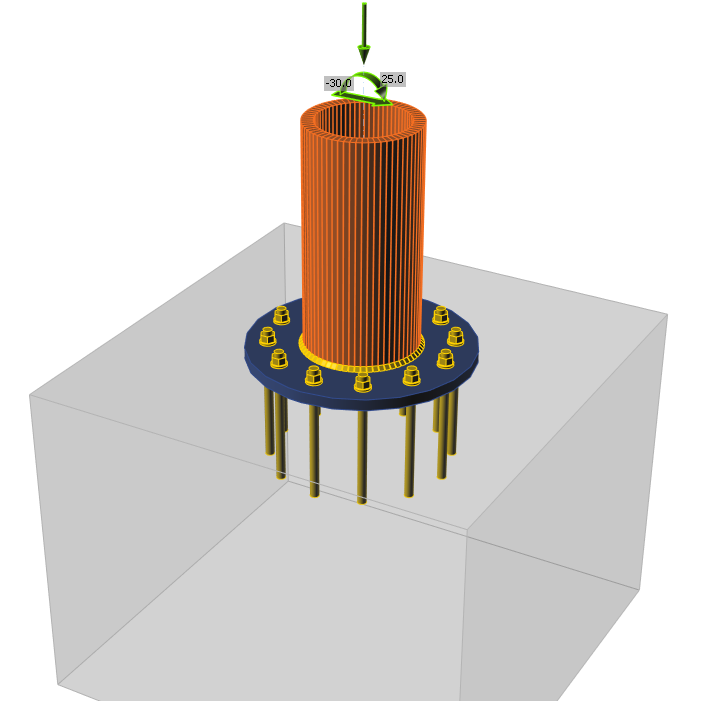
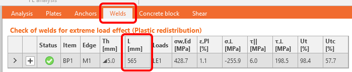
You can also find all welds sizes and lengths in Report, under the Bill of Materials (BOM).