Widget #NaN: support_center_article
Name: Weld size differences between EC and AISC (CISC) codes
ID: c06cb68e-da64-517f-b983-b6bf80c8addd
Show Raw Data
{
"title": {
"name": "Main headline (H1)",
"type": "text",
"value": "Differenze dimensionali delle saldature tra i codici EC e AISC (CISC)"
},
"preview_image": {
"name": "Preview image",
"type": "asset",
"value": [
{
"name": "Weld size differences between EC and AISC (CISC) codes.png",
"description": null,
"type": "image/png",
"size": 140454,
"url": "https://assets-us-01.kc-usercontent.com:443/28eac049-c8ed-00e2-220c-12142a968dff/a224fbe0-28d0-4b11-8bfb-8fe2130934a1/Weld%20size%20differences%20between%20EC%20and%20AISC%20%28CISC%29%20codes.png",
"width": 1200,
"height": 630,
"renditions": {}
}
]
},
"post_date": {
"name": "Post date",
"type": "date_time",
"value": null,
"displayTimeZone": null
},
"perex_content": {
"name": "Lead paragraph",
"type": "text",
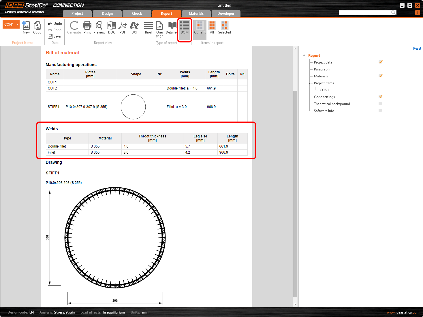
"value": "Esiste una differenza tra le definizioni delle dimensioni della saldatura nelle operazioni di saldatura quando si progetta in base ai codici EC o AISC (CISC), è bene tenerne conto durante la modellazione di una giunzione in IDEA StatiCa."
},
"content": {
"images": [
{
"description": null,
"imageId": "e132c666-93e0-4b7f-9917-8ffc5a5dc770",
"url": "https://assets-us-01.kc-usercontent.com:443/28eac049-c8ed-00e2-220c-12142a968dff/82cd97fe-7c32-4d7d-b803-1794a985529a/Weld_size.png",
"height": 494,
"width": 809
}
],
"linkedItemCodenames": [],
"linkedItems": [],
"links": [],
"name": "Content",
"type": "rich_text",
"value": "<p>Secondo la norma EN, la dimensione della saldatura è definita dal parametro <em><strong>a</strong></em>, che è lo <strong>spessore della gola di saldatura</strong>.</p>\n<p>Secondo AISC (CISC), la dimensione della saldatura è definita dal parametro <em><strong>z</strong></em>, che rappresenta la <strong>dimensione della gamba di saldatura</strong>.</p>\n<p>È possibile calcolare semplicemente <em>a</em> da <em>z</em> e viceversa utilizzando il metodo del <a href=\"https://en.wikipedia.org/wiki/Pythagorean_theorem\">Teorema di Pitagora.</a></p>\n<figure data-asset-id=\"e132c666-93e0-4b7f-9917-8ffc5a5dc770\" data-image-id=\"e132c666-93e0-4b7f-9917-8ffc5a5dc770\"><img src=\"https://assets-us-01.kc-usercontent.com:443/28eac049-c8ed-00e2-220c-12142a968dff/82cd97fe-7c32-4d7d-b803-1794a985529a/Weld_size.png\" data-asset-id=\"e132c666-93e0-4b7f-9917-8ffc5a5dc770\" data-image-id=\"e132c666-93e0-4b7f-9917-8ffc5a5dc770\" alt=\"\"></figure>\n<p><br></p>"
},
"regions": {
"name": "Region",
"type": "taxonomy",
"value": [
{
"name": "AMER",
"codename": "amer"
},
{
"name": "EMEA",
"codename": "emea"
},
{
"name": "APAC",
"codename": "apac"
}
],
"taxonomyGroup": "region"
},
"product_groups": {
"name": "Product group",
"type": "taxonomy",
"value": [
{
"name": "Steel",
"codename": "steel"
}
],
"taxonomyGroup": "product_group"
},
"support_center_article_types": {
"name": "Support center article",
"type": "taxonomy",
"value": [
{
"name": "Knowledge base",
"codename": "knowledgebase_article"
}
],
"taxonomyGroup": "support_center_article"
},
"expertise_levels": {
"name": "Expertise level",
"type": "taxonomy",
"value": [
{
"name": "Beginner",
"codename": "beginner"
},
{
"name": "Intermediate",
"codename": "intermediate"
}
],
"taxonomyGroup": "expertise_level"
},
"labels": {
"name": "Labels",
"type": "taxonomy",
"value": [
{
"name": "AISC (USA)",
"codename": "aisc"
},
{
"name": "CSA (Canada)",
"codename": "cisc"
},
{
"name": "EN (Eurocode)",
"codename": "eurocode"
},
{
"name": "Welds",
"codename": "welds"
},
{
"name": "Connection",
"codename": "connection"
},
{
"name": "Member",
"codename": "member"
}
],
"taxonomyGroup": "labels"
},
"linked_items": {
"name": "Linked items",
"type": "modular_content",
"value": [
"welds__general_article_",
"theoretical_background___general___welds",
"what_is_the_correct_length_of_the_weld"
],
"linkedItems": [
{
"elements": {
"title": {
"name": "Main headline (H1)",
"type": "text",
"value": "Saldatura / Saldature in IDEA StatiCa"
},
"preview_image": {
"name": "Preview image",
"type": "asset",
"value": [
{
"name": "Weld + welds.png",
"description": null,
"type": "image/png",
"size": 204079,
"url": "https://assets-us-01.kc-usercontent.com:443/28eac049-c8ed-00e2-220c-12142a968dff/b0e51c7c-db21-42d6-8f4d-0665deccbafc/Weld%20%2B%20welds.png",
"width": 1200,
"height": 630,
"renditions": {}
}
]
},
"post_date": {
"name": "Post date",
"type": "date_time",
"value": null,
"displayTimeZone": "Europe/Prague"
},
"perex_content": {
"name": "Lead paragraph",
"type": "text",
"value": "Nell'articolo troverai tutte le informazioni necessarie in merito alle saldature e alle connessioni saldate. Vengono descritti il modello di saldatura e la demo del flusso di lavoro dell'applicazione."
},
"content": {
"images": [
{
"description": null,
"imageId": "455c8fb8-27c8-4c3e-ab28-341376c03fa3",
"url": "https://assets-us-01.kc-usercontent.com:443/28eac049-c8ed-00e2-220c-12142a968dff/a62801a2-1d6a-4743-8627-e232e90e69d9/Structural%20design%20of%20a%20steel%20connection%20-%20Plate%20model%20and%20mesh%20convergence%201200%20x%20630.png",
"height": 630,
"width": 1200
},
{
"description": null,
"imageId": "8c940183-360c-484a-ab14-dcfdcfbbd29b",
"url": "https://assets-us-01.kc-usercontent.com:443/28eac049-c8ed-00e2-220c-12142a968dff/9e3dc390-df9d-4ee5-a959-7c4cfa9aca3b/welds_distr.png",
"height": 409,
"width": 1333
},
{
"description": null,
"imageId": "eb79d5c6-d879-4afb-a5c1-5df03982810a",
"url": "https://assets-us-01.kc-usercontent.com:443/28eac049-c8ed-00e2-220c-12142a968dff/2a16ecdf-f660-47b6-bb32-9b9aeecf3314/6.png",
"height": 600,
"width": 1200
},
{
"description": null,
"imageId": "291e03d6-32ca-40af-903f-3620de689301",
"url": "https://assets-us-01.kc-usercontent.com:443/28eac049-c8ed-00e2-220c-12142a968dff/67cc32f0-0506-4cdf-9637-0bc86dfefa54/Weld%20size.png",
"height": 1098,
"width": 1467
},
{
"description": null,
"imageId": "5acc5b19-3a08-4b30-8dca-6793bcfd19a7",
"url": "https://assets-us-01.kc-usercontent.com:443/28eac049-c8ed-00e2-220c-12142a968dff/47ea3d3f-dff3-49c7-8e5f-5abab34e343d/04-1-fig7.png",
"height": 276,
"width": 563
},
{
"description": null,
"imageId": "450a4d6a-d571-4297-a195-63e33fdd30bc",
"url": "https://assets-us-01.kc-usercontent.com:443/28eac049-c8ed-00e2-220c-12142a968dff/12b10280-2125-44a3-b60e-6031f87a3e03/Missing%20welds.png",
"height": 308,
"width": 516
},
{
"description": null,
"imageId": "66cc6cf4-0454-4973-80d1-c036df7af58d",
"url": "https://assets-us-01.kc-usercontent.com:443/28eac049-c8ed-00e2-220c-12142a968dff/e38caf39-0947-4aff-be81-7d3eb57ada99/Screenshot%202020-10-05%20122254.png",
"height": 405,
"width": 618
},
{
"description": null,
"imageId": "401d916b-5fa2-4561-9051-9a6544652cea",
"url": "https://assets-us-01.kc-usercontent.com:443/28eac049-c8ed-00e2-220c-12142a968dff/20b7b61e-2508-4f74-9c1e-355619627e82/Butt%20welds%20upgraded%20model.png",
"height": 671,
"width": 1109
},
{
"description": null,
"imageId": "5062c6bd-0e2b-4f50-817b-0540cb5d686d",
"url": "https://assets-us-01.kc-usercontent.com:443/28eac049-c8ed-00e2-220c-12142a968dff/59c4504e-b3b9-4dc2-8b14-4f121a23e1c3/Welds1.png",
"height": 1033,
"width": 1920
},
{
"description": null,
"imageId": "e5be481f-5e66-43a8-8573-fdbc4d74a541",
"url": "https://assets-us-01.kc-usercontent.com:443/28eac049-c8ed-00e2-220c-12142a968dff/4dd4d3e4-77f0-4c14-9801-e9183f26cca6/WaC.png",
"height": 535,
"width": 1116
},
{
"description": null,
"imageId": "b2f8fc0a-893b-4d9a-8648-092ef3a5e88b",
"url": "https://assets-us-01.kc-usercontent.com:443/28eac049-c8ed-00e2-220c-12142a968dff/d631a548-e7ca-4f84-a3c1-5c0207280cc0/clash3.png",
"height": 631,
"width": 1201
},
{
"description": null,
"imageId": "388ba76a-be74-4fed-b0bb-9d7000ba1cad",
"url": "https://assets-us-01.kc-usercontent.com:443/28eac049-c8ed-00e2-220c-12142a968dff/b60903c8-dc26-4604-bc81-96d35d003afb/Welded-sections%200.png",
"height": 630,
"width": 1200
},
{
"description": null,
"imageId": "8f86157e-4555-4525-aff0-fb388b0d718f",
"url": "https://assets-us-01.kc-usercontent.com:443/28eac049-c8ed-00e2-220c-12142a968dff/172ca452-c56d-40ca-afc4-9dc406734d70/weldchecktable.png",
"height": 716,
"width": 609
},
{
"description": null,
"imageId": "6dca1495-d3ba-4128-84fc-1b5d279d3440",
"url": "https://assets-us-01.kc-usercontent.com:443/28eac049-c8ed-00e2-220c-12142a968dff/9e0a6490-1e33-44fa-ab30-1247a201de0f/Detailing%20improvements_main%20image.png",
"height": 630,
"width": 1200
},
{
"description": null,
"imageId": "552c02a6-a54a-4149-83e2-d0c17d78561f",
"url": "https://assets-us-01.kc-usercontent.com:443/28eac049-c8ed-00e2-220c-12142a968dff/13eae981-ca17-401d-b1c8-7da0416d207e/Welds%20-%20autodesign%2C%20input%2C%20warnings%2C%20visualization1.png",
"height": 520,
"width": 934
},
{
"description": null,
"imageId": "c1e8146a-47c2-4147-9c75-5ae4e738622d",
"url": "https://assets-us-01.kc-usercontent.com:443/28eac049-c8ed-00e2-220c-12142a968dff/ae2aa532-e36b-4125-a8b6-80015ebb8df3/Welds%20-%20autodesign%2C%20input%2C%20warnings%2C%20visualization10.png",
"height": 1152,
"width": 1920
},
{
"description": null,
"imageId": "bab985b6-6e6b-48eb-bff9-63acd1d8f859",
"url": "https://assets-us-01.kc-usercontent.com:443/28eac049-c8ed-00e2-220c-12142a968dff/e467c86d-22ea-47de-b048-7c2265a63cda/Welds%20-%20autodesign%2C%20input%2C%20warnings%2C%20visualization11.png",
"height": 607,
"width": 810
},
{
"description": null,
"imageId": "1cbe1a11-db46-4da7-ab2b-2f541984db0a",
"url": "https://assets-us-01.kc-usercontent.com:443/28eac049-c8ed-00e2-220c-12142a968dff/f7b68cff-d260-4f8a-8ab2-048893e63b39/Bolts%20and%20welds_warning%20message.png",
"height": 723,
"width": 870
},
{
"description": null,
"imageId": "69d70cd1-f9f7-47d5-8b4d-8226620d5ec9",
"url": "https://assets-us-01.kc-usercontent.com:443/28eac049-c8ed-00e2-220c-12142a968dff/202ed4a2-278b-466c-b2d2-47023adfa727/Weld%20sizing%20to%20ductility1.png",
"height": 630,
"width": 1200
},
{
"description": null,
"imageId": "0b97f49e-f205-43ee-b5de-00b203e18a3a",
"url": "https://assets-us-01.kc-usercontent.com:443/28eac049-c8ed-00e2-220c-12142a968dff/139beb9e-2e4e-4581-8a6b-e076578371d0/Weld%20sizing%20to%20capacity%20estimation1.png",
"height": 630,
"width": 1200
},
{
"description": null,
"imageId": "d6fde932-e78a-4406-835a-8ff0ea82666c",
"url": "https://assets-us-01.kc-usercontent.com:443/28eac049-c8ed-00e2-220c-12142a968dff/d8a95f95-4aa5-4b9e-9b51-d58130c4afab/Partial%20Joint%20Penetration%20%28PJP%29%20groove%20weld.png",
"height": 630,
"width": 1200
}
],
"linkedItemCodenames": [
"n82366d3c_a6de_0151_5c60_75a558cc3266",
"n5df531f6_b1e1_0152_bfd6_163c50e3fad9",
"n1782160b_660b_0118_660f_5596f0d8a5b2",
"n811eae43_c6a1_0135_25fb_c5d52191bbdb",
"n29744e2a_c2f7_0180_8280_6adb353fccd5"
],
"linkedItems": [
{
"elements": {
"url": {
"name": "Video URL",
"type": "text",
"value": "https://youtu.be/flp-YlgtokA"
}
},
"system": {
"codename": "n82366d3c_a6de_0151_5c60_75a558cc3266",
"collection": "default",
"id": "82366d3c-a6de-0151-5c60-75a558cc3266",
"language": "it-IT",
"lastModified": "2025-07-21T09:24:10.4350921Z",
"name": "82366d3c-a6de-0151-5c60-75a558cc3266",
"sitemapLocations": [],
"type": "video",
"workflowStep": null,
"workflow": null
}
},
{
"elements": {
"url": {
"name": "Video URL",
"type": "text",
"value": "https://youtu.be/0kdColtQArs?t=1904"
}
},
"system": {
"codename": "n5df531f6_b1e1_0152_bfd6_163c50e3fad9",
"collection": "default",
"id": "5df531f6-b1e1-0152-bfd6-163c50e3fad9",
"language": "it-IT",
"lastModified": "2025-07-21T09:24:10.4350921Z",
"name": "5df531f6-b1e1-0152-bfd6-163c50e3fad9",
"sitemapLocations": [],
"type": "video",
"workflowStep": null,
"workflow": null
}
},
{
"elements": {
"url": {
"name": "Video URL",
"type": "text",
"value": "https://youtu.be/tkZhFXxZObs?t=1585"
}
},
"system": {
"codename": "n1782160b_660b_0118_660f_5596f0d8a5b2",
"collection": "default",
"id": "1782160b-660b-0118-660f-5596f0d8a5b2",
"language": "it-IT",
"lastModified": "2025-07-21T09:24:10.4350921Z",
"name": "1782160b-660b-0118-660f-5596f0d8a5b2",
"sitemapLocations": [],
"type": "video",
"workflowStep": null,
"workflow": null
}
},
{
"elements": {
"url": {
"name": "Video URL",
"type": "text",
"value": "https://youtu.be/XDhloaKRcaE?t=630"
}
},
"system": {
"codename": "n811eae43_c6a1_0135_25fb_c5d52191bbdb",
"collection": "default",
"id": "811eae43-c6a1-0135-25fb-c5d52191bbdb",
"language": "it-IT",
"lastModified": "2025-07-21T09:24:10.4350921Z",
"name": "811eae43-c6a1-0135-25fb-c5d52191bbdb",
"sitemapLocations": [],
"type": "video",
"workflowStep": null,
"workflow": null
}
},
{
"elements": {
"title": {
"name": "Title",
"type": "text",
"value": "Articoli correlati"
},
"description": {
"name": "Description",
"type": "text",
"value": ""
},
"featured_articles": {
"name": "Featured articles",
"type": "modular_content",
"value": [
"bolts__bolted_connections__pins___"
],
"linkedItems": [
{
"elements": {
"title": {
"name": "Title (H1)",
"type": "text",
"value": "Bulloni e connessioni bullonate"
},
"preview_image": {
"name": "Preview image",
"type": "asset",
"value": [
{
"name": "bolted connection.png",
"description": null,
"type": "image/png",
"size": 173492,
"url": "https://assets-us-01.kc-usercontent.com:443/28eac049-c8ed-00e2-220c-12142a968dff/a13746db-b1ef-4099-bf39-cb76e7f6f444/bolted%20connection.png",
"width": 1200,
"height": 630,
"renditions": {}
}
]
},
"post_date": {
"name": "Post date",
"type": "date_time",
"value": "2021-02-04T00:00:00Z",
"displayTimeZone": null
},
"authors": {
"name": "Authors",
"type": "modular_content",
"value": [
"alexander_szotkowski_4483fb7"
],
"linkedItems": [
{
"elements": {
"name": {
"name": "Name",
"type": "text",
"value": "Alexander Szotkowski"
},
"position": {
"name": "Position",
"type": "text",
"value": "Product Engineer\nIDEA StatiCa"
},
"images": {
"name": "Image",
"type": "asset",
"value": [
{
"name": "alexandr_500x500.png",
"description": null,
"type": "image/png",
"size": 212811,
"url": "https://assets-us-01.kc-usercontent.com:443/28eac049-c8ed-00e2-220c-12142a968dff/4a1d6e03-5d78-4c27-84f0-f3d86488445d/alexandr_500x500.png",
"width": 500,
"height": 500,
"renditions": {}
}
]
},
"perex": {
"name": "Perex",
"type": "text",
"value": ""
},
"content": {
"images": [],
"linkedItemCodenames": [],
"linkedItems": [],
"links": [],
"name": "Content",
"type": "rich_text",
"value": "<p><br></p>"
},
"linkedin": {
"name": "LinkedIn",
"type": "text",
"value": ""
},
"url_slug": {
"name": "Url slug",
"type": "url_slug",
"value": "alexander-szotkowski"
},
"unique_url_slug": {
"name": "Unique URL slug",
"type": "custom",
"value": "[\"alexander-szotkowski\",\"[autogenerated]\"]"
},
"content_settings__sitemap": {
"name": "Show in sitemap",
"type": "multiple_choice",
"value": []
},
"content_settings__robots": {
"name": "Search engine indexing",
"type": "multiple_choice",
"value": []
},
"content_settings__is_hidden": {
"name": "Hidden nested content",
"type": "multiple_choice",
"value": []
},
"metadata__page_title": {
"name": "Page title",
"type": "text",
"value": ""
},
"metadata__page_description": {
"name": "Page description",
"type": "text",
"value": ""
},
"metadata__page_keywords": {
"name": "Page keywords",
"type": "text",
"value": ""
},
"metadata__canonical_url": {
"name": "Canonical URL",
"type": "text",
"value": ""
},
"metadata__og_title": {
"name": "OG:title",
"type": "text",
"value": ""
},
"metadata__og_description": {
"name": "OG:description",
"type": "text",
"value": ""
},
"metadata__og_image": {
"name": "OG:image",
"type": "asset",
"value": []
},
"translation__translation_connector": {
"name": "Translation Connector",
"type": "taxonomy",
"value": [],
"taxonomyGroup": "languages"
},
"translation__force_translation": {
"name": "Force translation",
"type": "multiple_choice",
"value": []
},
"translation__last_translation": {
"images": [],
"linkedItemCodenames": [],
"linkedItems": [],
"links": [],
"name": "Last translation",
"type": "rich_text",
"value": "<p><br></p>"
},
"translation__ai_translated": {
"name": "AI translated",
"type": "multiple_choice",
"value": []
},
"page_tree_settings__page_label": {
"name": "Page label",
"type": "text",
"value": "Alexander Szotkowski"
},
"page_tree_settings__path_segment": {
"name": "Path segment",
"type": "text",
"value": "alexander-szotkowski"
},
"page_tree_settings__breadcrumb_style": {
"name": "Breadcrumb style",
"type": "multiple_choice",
"value": []
},
"page_tree_settings__hide_in_breadcrumbs": {
"name": "Hide in breadcrumbs",
"type": "multiple_choice",
"value": []
}
},
"system": {
"codename": "alexander_szotkowski_4483fb7",
"collection": "default",
"id": "4483fb7a-fa90-4164-8976-461ac3cd874c",
"language": "it-IT",
"lastModified": "2026-04-29T15:21:04.7017439Z",
"name": "Alexander Szotkowski",
"sitemapLocations": [],
"type": "author",
"workflowStep": "published",
"workflow": "default"
}
}
]
},
"perex_content": {
"name": "Lead paragraph",
"type": "text",
"value": "I bulloni e le saldature sono gli elementi più difficili nella progettazione delle connessioni in acciaio. I fogli di calcolo Excel molto spesso semplificano il loro calcolo. La loro modellazione nei programmi FEM generali è complicata, per questo motivo il metodo CBFEM è stato sviluppato e implementato in IDEA StatiCa."
},
"content": {
"images": [
{
"description": null,
"imageId": "206cf95d-3010-4d11-ab8a-aceb3f62bdc6",
"url": "https://assets-us-01.kc-usercontent.com:443/28eac049-c8ed-00e2-220c-12142a968dff/c166c28a-3f8f-4d50-99ba-857ed9b01e6c/Bolt%20bearing%20distances%201.png",
"height": 554,
"width": 1042
},
{
"description": null,
"imageId": "15a106be-af4c-4966-ac50-a889863e1a5c",
"url": "https://assets-us-01.kc-usercontent.com:443/28eac049-c8ed-00e2-220c-12142a968dff/b8152921-f220-412f-81de-8c8c83d7e2c2/Bolt%20bearing%20distances%202.png",
"height": 333,
"width": 1042
},
{
"description": null,
"imageId": "2546f7fb-18b9-4671-8e1b-238a6ec1b0e9",
"url": "https://assets-us-01.kc-usercontent.com:443/28eac049-c8ed-00e2-220c-12142a968dff/a0abb5ad-7dba-4687-bfd8-e64fa9c03512/756213100-huge.jpg",
"height": 3094,
"width": 5000
},
{
"description": null,
"imageId": "cca7ed64-cf29-48bd-bb61-96c49f4f1285",
"url": "https://assets-us-01.kc-usercontent.com:443/28eac049-c8ed-00e2-220c-12142a968dff/edfb27a5-88b9-4f39-ac2b-bd319f37ee29/Model%20type%200.png",
"height": 630,
"width": 1200
},
{
"description": null,
"imageId": "3ad5d43d-0568-4816-837a-543530a44c5c",
"url": "https://assets-us-01.kc-usercontent.com:443/28eac049-c8ed-00e2-220c-12142a968dff/d43f402a-8463-4e51-b040-bcbadaaab500/stiffness.png",
"height": 208,
"width": 543
}
],
"linkedItemCodenames": [
"untitled_content_item_a1697b4"
],
"linkedItems": [
{
"elements": {
"iframe_title": {
"name": "Title",
"type": "text",
"value": "Unisciti a 10.000 colleghi ingegneri"
},
"iframe_description": {
"name": "Description",
"type": "text",
"value": "Ricevi suggerimenti tecnici da esperti direttamente nella tua casella di posta. \nIscriviti alla newsletter di IDEA StatiCa qui sotto."
},
"iframe_url": {
"name": "iframe URL",
"type": "text",
"value": "https://campaign.ideastatica.com/newsletter-subscription"
},
"iframe_height": {
"name": "Height",
"type": "number",
"value": 650
},
"iframe_width": {
"name": "Width",
"type": "number",
"value": 850
},
"visibleinregion": {
"name": "VisibleInRegion",
"type": "multiple_choice",
"value": []
},
"regions": {
"name": "Region",
"type": "taxonomy",
"value": [],
"taxonomyGroup": "region"
},
"translation__translation_connector": {
"name": "Translation Connector",
"type": "taxonomy",
"value": [],
"taxonomyGroup": "languages"
},
"translation__force_translation": {
"name": "Force translation",
"type": "multiple_choice",
"value": []
},
"translation__last_translation": {
"images": [],
"linkedItemCodenames": [],
"linkedItems": [],
"links": [],
"name": "Last translation",
"type": "rich_text",
"value": "<p><br></p>"
},
"translation__ai_translated": {
"name": "AI translated",
"type": "multiple_choice",
"value": []
}
},
"system": {
"codename": "untitled_content_item_a1697b4",
"collection": "default",
"id": "a1697b47-e5f7-4009-8b18-a29b3b27db65",
"language": "it-IT",
"lastModified": "2024-08-22T09:53:56.5105385Z",
"name": "iframe widget - Newsletter Subscription",
"sitemapLocations": [],
"type": "widget_iframe",
"workflowStep": "published",
"workflow": "default"
}
}
],
"links": [
{
"codename": "what_is_the_cbfem_",
"linkId": "6e068636-6a02-5d0e-89ad-6dcff4e21151",
"urlSlug": "che-cos-e-il-cbfem",
"type": "support_center_article"
},
{
"codename": "theoretical_background___general___bolts_and_prelo",
"linkId": "c2cc67f3-4000-4959-a195-b28becf63f2a",
"urlSlug": "bolts-and-preloaded-bolts",
"type": "support_center_article"
},
{
"codename": "theoretical_background___general",
"linkId": "d4aa2923-a94a-4c40-8fd8-93608acbf893",
"urlSlug": "general-theoretical-background",
"type": "support_center_article"
},
{
"codename": "patent",
"linkId": "627bdc92-14f2-416a-b7ef-7df116ea3e73",
"urlSlug": "patent",
"type": "landing_page"
},
{
"codename": "connection_stiffness_and_its_use_in_global_analysi",
"linkId": "6726bbc6-1826-4c43-9253-b8f6e0ab39a9",
"urlSlug": "connection-stiffness-and-its-use-in-global-analysis",
"type": "support_center_article"
},
{
"codename": "calculation_of_steel_connection_stiffness___reinve",
"linkId": "ab4c1281-d0ce-5c97-95ef-3c369206d272",
"urlSlug": "calculation-of-steel-connection-stiffness-reinvented",
"type": "webinar"
}
],
"name": "Content",
"type": "rich_text",
"value": "<h2>Modello di bullone secondo CBFEM</h2>\n<p>IDEA StatiCa ha un metodo unico nel suo solutore, il <a data-item-id=\"6e068636-6a02-5d0e-89ad-6dcff4e21151\" href=\"\">Component-based Finite Element Method (CBFEM)</a>. Il modello di bullone utilizzato nel CBFEM è descritto e verificato in base a diversi codici di progettazione dell'acciaio. La resistenza al carico e la capacità di deformazione sono inoltre confrontate con i principali programmi di ricerca sperimentale.</p>\n<p>Nel Metodo agli Elementi Finiti Basato sui Componenti (CBFEM), il bullone, con il suo comportamento in trazione, taglio e appoggio, è il componente descritto da molle non lineari dipendenti. Il bullone in trazione è descritto dalla molla con la sua rigidezza assiale iniziale, la resistenza di progetto, l'inizializzazione dello snervamento e la capacità di deformazione. Per l'inizializzazione dello snervamento e la capacità di deformazione, si assume che la deformazione plastica avvenga solo nella parte filettata del gambo del bullone.</p>\n<p>Nel nostro Approfondimento teorico, potete trovare <a data-item-id=\"c2cc67f3-4000-4959-a195-b28becf63f2a\" href=\"\">maggiori informazioni su come il metodo CBFEM descrive e verifica i bulloni</a>. Se volete saperne di più sul CBFEM in generale, il <a data-item-id=\"d4aa2923-a94a-4c40-8fd8-93608acbf893\" href=\"\">background teorico generale</a> completo è sicuramente il punto di partenza migliore.</p>\n<h2>Bulloni secondo i codici di progettazione</h2>\n<p>Vediamo come il CBFEM affronta i bulloni dal punto di vista dei singoli codici di progettazione. Finora IDEA StatiCa supporta otto codici di progettazione in cui si risolve la progettazione e/o il dettaglio di bulloni e bulloni precaricati.</p>\n<h3>Verifica di bulloni e bulloni precaricati secondo l'Eurocodice</h3>\n<p>La rigidezza iniziale e la resistenza di progetto dei bulloni a taglio sono modellate in CBFEM secondo i cl. 3.6 e 6.3.2 della norma EN 1993-1-8. La molla che rappresenta l'appoggio e la tensione ha un valore di riferimento per i bulloni precaricati. La molla che rappresenta l'appoggio e la tensione ha un comportamento bi-lineare di forza-deformazione con una rigidità iniziale e una resistenza di progetto secondo le Cl. 3.6 e 6.3.2 della norma EN 1993-1-8.</p>\n<p><strong>Dettaglio</strong></p>\n<p>La verifica dei bulloni viene eseguita se l'opzione è selezionata nell'impostazione del codice. Vengono controllate le dimensioni dal centro del bullone ai bordi della piastra e tra i bulloni. La distanza tra i bordi <em>e</em> = 1,2 e la distanza tra i bulloni p <em>=</em> 2,2 sono raccomandate nella Tabella 3.3 della norma EN 1993-1-8. L'utente può modificare entrambi i valori nella configurazione del codice. Gli utenti possono modificare entrambi i valori nell'impostazione del codice.</p>\n<h3>Verifica dei bulloni e dei bulloni precaricati secondo AISC</h3>\n<p>Le forze nei bulloni sono determinate dall'analisi agli elementi finiti. Le forze di trazione includono le forze di spinta. Le resistenze dei bulloni sono verificate secondo la norma AISC 360 - Capitolo J3.</p>\n<p><strong>Dettagli</strong></p>\n<p>Viene verificata la distanza minima tra i bulloni e la distanza tra il centro del bullone e un bordo di una parte collegata. La distanza minima di 2,66 volte (modificabile nell'impostazione del Codice) il diametro nominale dei bulloni tra i centri dei bulloni è verificata in base alla norma AISC 360-16 - J.3.3. La distanza minima tra il centro del bullone e un bordo di una parte collegata è verificata in base alla norma AISC 360-16 - J.3.4; i valori sono riportati nelle tabelle J3.4 e J3.4M.</p>\n<h3>Verifica dei bulloni e dei bulloni precaricati in base ad altre norme</h3>\n<ul>\n <li><a href=\"https://www.ideastatica.com/support-center/check-of-bolts-and-preloaded-bolts-according-to-cisc\" data-new-window=\"true\" target=\"_blank\" rel=\"noopener noreferrer\">Verifica dei bulloni e dei bulloni precaricati secondo CISC (Canada)</a></li>\n <li><a href=\"https://www.ideastatica.com/support-center/check-of-bolts-and-preloaded-bolts-according-to-chinese-standard\" data-new-window=\"true\" target=\"_blank\" rel=\"noopener noreferrer\">Verifica dei bulloni e dei bulloni precaricati secondo lo standard cinese (GB)</a></li>\n <li><a href=\"https://www.ideastatica.com/support-center/check-of-bolts-according-to-hong-kong-code\" data-new-window=\"true\" target=\"_blank\" rel=\"noopener noreferrer\">Verifica dei bulloni secondo il Codice di Hong Kong (HKG)</a></li>\n <li><a href=\"https://www.ideastatica.com/support-center/check-of-bolts-according-to-is-800\">Verifica dei bulloni precaricati secondo la norma IS 800 (India)</a></li>\n <li><a href=\"https://www.ideastatica.com/support-center/check-of-bolts-and-preloaded-bolts-according-to-sp\" data-new-window=\"true\" target=\"_blank\" rel=\"noopener noreferrer\">Verifica dei bulloni e dei bulloni precaricati secondo SP (Russia)</a></li>\n <li><a href=\"https://www.ideastatica.com/support-center/check-of-bolts-and-preloaded-bolts-according-to-as\" data-new-window=\"true\" target=\"_blank\" rel=\"noopener noreferrer\">Verifica di bulloni e bulloni precaricati secondo AS (Australia)</a></li>\n</ul>\n<h2>Dettaglio dei bulloni</h2>\n<p><strong>Come impostare le distanze</strong></p>\n<p>Le distanze dai bordi utilizzate per la resistenza dei bulloni devono essere rilevanti per le geometrie generali delle piastre, per le piastre con aperture, ritagli, ecc.</p>\n<p>L'algoritmo legge la direzione reale del vettore della forza di taglio risultante in un determinato bullone e calcola quindi le distanze necessarie per la verifica del cuscinetto.</p>\n<p>Le distanze dall'estremità<em>(</em><sub>e1</sub>) e dal bordo<em>(</em><sub>e2</sub>) sono determinate dividendo il contorno della piastra in tre segmenti. Il segmento finale è indicato da un intervallo di 60° nella direzione del vettore forza. I segmenti del bordo sono definiti da due intervalli di 65° perpendicolari al vettore forza. La distanza più breve tra un bullone e un segmento rilevante viene considerata come distanza di estremità o di bordo.</p>\n<figure data-asset-id=\"206cf95d-3010-4d11-ab8a-aceb3f62bdc6\" data-image-id=\"206cf95d-3010-4d11-ab8a-aceb3f62bdc6\"><img src=\"https://assets-us-01.kc-usercontent.com:443/28eac049-c8ed-00e2-220c-12142a968dff/c166c28a-3f8f-4d50-99ba-857ed9b01e6c/Bolt%20bearing%20distances%201.png\" data-asset-id=\"206cf95d-3010-4d11-ab8a-aceb3f62bdc6\" data-image-id=\"206cf95d-3010-4d11-ab8a-aceb3f62bdc6\" alt=\"\"></figure>\n<p>Le distanze tra i fori dei bulloni<em>(</em><sub>p1</sub>; <sub>p2</sub>) sono determinate ingrandendo virtualmente i fori dei bulloni circostanti di metà del loro diametro, quindi tracciando due linee in direzione e perpendicolari al vettore della forza di taglio. Le distanze dai fori allargati intersecati da queste linee vengono considerate come <sub>p1</sub> e <sub>p2</sub> nel calcolo.</p>\n<figure data-asset-id=\"15a106be-af4c-4966-ac50-a889863e1a5c\" data-image-id=\"15a106be-af4c-4966-ac50-a889863e1a5c\"><img src=\"https://assets-us-01.kc-usercontent.com:443/28eac049-c8ed-00e2-220c-12142a968dff/b8152921-f220-412f-81de-8c8c83d7e2c2/Bolt%20bearing%20distances%202.png\" data-asset-id=\"15a106be-af4c-4966-ac50-a889863e1a5c\" data-image-id=\"15a106be-af4c-4966-ac50-a889863e1a5c\" alt=\"\"></figure>\n<h2>Esempi di verifica</h2>\n<p>Abbiamo preparato diversi esempi di verifica per controllare i risultati rispetto ad altri metodi di calcolo.</p>\n<h4>EN</h4>\n<ul>\n <li><a href=\"https://www.ideastatica.com/support-center/bolted-connection-splices-in-shear\" data-new-window=\"true\" target=\"_blank\" rel=\"noopener noreferrer\">Connessione bullonata - Giunzioni a taglio</a></li>\n <li><a href=\"https://www.ideastatica.com/support-center/bolted-connection-interaction-of-shear-and-tension\" data-new-window=\"true\" target=\"_blank\" rel=\"noopener noreferrer\">Connessione bullonata - Interazione di taglio e trazione</a></li>\n <li><a href=\"https://www.ideastatica.com/support-center/haunched-joint-capacity-design\" data-new-window=\"true\" target=\"_blank\" rel=\"noopener noreferrer\">Giunto ad arco - Progettazione in capacità</a></li>\n</ul>\n<h4>AISC</h4>\n<ul>\n <li><a href=\"https://www.ideastatica.com/support-center/bolted-splice-connection\" data-new-window=\"true\" target=\"_blank\" rel=\"noopener noreferrer\">Connessione bullonata a giunzione</a></li>\n <li><a href=\"https://www.ideastatica.com/support-center/bolted-flange-plate-moment-connection-lrfd\" data-new-window=\"true\" target=\"_blank\" rel=\"noopener noreferrer\">Connessione a momento bullonata a piastra flangiata - LRFD</a></li>\n <li><a href=\"https://www.ideastatica.com/support-center/extended-moment-end-plate-connection-asd\" data-new-window=\"true\" target=\"_blank\" rel=\"noopener noreferrer\">Connessione a momento esteso a piastra terminale - ASD</a></li>\n</ul>\n<h2>Tecnologia brevettata per gli ingegneri strutturali</h2>\n<p>Sapete che il nostro modello di bullone fa parte di un brevetto statunitense? Leggete <a data-item-id=\"627bdc92-14f2-416a-b7ef-7df116ea3e73\" href=\"\">qui</a> la nostra storia di successo.</p>\n<figure data-asset-id=\"2546f7fb-18b9-4671-8e1b-238a6ec1b0e9\" data-image-id=\"2546f7fb-18b9-4671-8e1b-238a6ec1b0e9\"><img src=\"https://assets-us-01.kc-usercontent.com:443/28eac049-c8ed-00e2-220c-12142a968dff/a0abb5ad-7dba-4687-bfd8-e64fa9c03512/756213100-huge.jpg\" data-asset-id=\"2546f7fb-18b9-4671-8e1b-238a6ec1b0e9\" data-image-id=\"2546f7fb-18b9-4671-8e1b-238a6ec1b0e9\" alt=\"\"></figure>\n<h2>Un giunto a bullone - la nostra soluzione</h2>\n<p>A volte l'ingegnere ha bisogno di realizzare un <strong>giunto con un solo bullone</strong>, soprattutto se è prevista una cerniera, un rinforzo, un'asta o una diagonale. Per modellare e calcolare questo tipo di operazione, è necessario definire un <strong>tipo di modello</strong> appropriato per l'elemento. Per saperne di più, leggete <a href=\"https://www.ideastatica.com/support-center/how-to-model-one-bolt-connection\" data-new-window=\"true\" target=\"_blank\" rel=\"noopener noreferrer\">qui</a>.</p>\n<figure data-asset-id=\"cca7ed64-cf29-48bd-bb61-96c49f4f1285\" data-image-id=\"cca7ed64-cf29-48bd-bb61-96c49f4f1285\"><img src=\"https://assets-us-01.kc-usercontent.com:443/28eac049-c8ed-00e2-220c-12142a968dff/edfb27a5-88b9-4f39-ac2b-bd319f37ee29/Model%20type%200.png\" data-asset-id=\"cca7ed64-cf29-48bd-bb61-96c49f4f1285\" data-image-id=\"cca7ed64-cf29-48bd-bb61-96c49f4f1285\" alt=\"\"></figure>\n<h2>Bulloni, saldature e rigidità di un giunto</h2>\n<p>Sia i bulloni che le saldature presentano vantaggi e svantaggi. Uno degli aspetti importanti nella scelta di un giunto è la sua rigidità prevista. In generale, un giunto bullonato non è mai rigido come un giunto saldato. Se si sceglie una connessione con bulloni, si consiglia di calcolare la rigidità di tale connessione e di tenere conto della rigidità risultante nella struttura complessiva. Potete leggere <a data-item-id=\"6726bbc6-1826-4c43-9253-b8f6e0ab39a9\" href=\"\">qui</a> come si presenta un calcolo di questo tipo e cosa comporta, oppure guardare questo <a data-item-id=\"ab4c1281-d0ce-5c97-95ef-3c369206d272\" href=\"\">video</a>.</p>\n<figure data-asset-id=\"3ad5d43d-0568-4816-837a-543530a44c5c\" data-image-id=\"3ad5d43d-0568-4816-837a-543530a44c5c\"><img src=\"https://assets-us-01.kc-usercontent.com:443/28eac049-c8ed-00e2-220c-12142a968dff/d43f402a-8463-4e51-b040-bcbadaaab500/stiffness.png\" data-asset-id=\"3ad5d43d-0568-4816-837a-543530a44c5c\" data-image-id=\"3ad5d43d-0568-4816-837a-543530a44c5c\" alt=\"\"></figure>\n<object type=\"application/kenticocloud\" data-type=\"item\" data-rel=\"link\" data-codename=\"untitled_content_item_a1697b4\"></object>"
},
"regions": {
"name": "Region",
"type": "taxonomy",
"value": [
{
"name": "APAC",
"codename": "apac"
},
{
"name": "EMEA",
"codename": "emea"
},
{
"name": "AMER",
"codename": "amer"
}
],
"taxonomyGroup": "region"
},
"product_groups": {
"name": "Product group",
"type": "taxonomy",
"value": [
{
"name": "Connection design",
"codename": "connection_design"
},
{
"name": "Steel",
"codename": "steel"
}
],
"taxonomyGroup": "product_group"
},
"blog_categories": {
"name": "Blog category",
"type": "taxonomy",
"value": [
{
"name": "Features",
"codename": "features"
}
],
"taxonomyGroup": "blog_category"
},
"labels": {
"name": "Labels",
"type": "taxonomy",
"value": [
{
"name": "Bolts",
"codename": "bolts"
},
{
"name": "Connection",
"codename": "connection"
}
],
"taxonomyGroup": "labels"
},
"options": {
"name": "Options",
"type": "multiple_choice",
"value": []
},
"url_slug": {
"name": "URL slug",
"type": "url_slug",
"value": "bulloni-e-connessioni-bullonate"
},
"unique_url_slug": {
"name": "Unique URL slug",
"type": "custom",
"value": "[\"bolts-and-bolted-connections\",\"[autogenerated]\"]"
},
"metadata__page_title": {
"name": "Page title",
"type": "text",
"value": ""
},
"metadata__page_description": {
"name": "Page description",
"type": "text",
"value": ""
},
"metadata__page_keywords": {
"name": "Page keywords",
"type": "text",
"value": ""
},
"metadata__canonical_url": {
"name": "Canonical URL",
"type": "text",
"value": ""
},
"metadata__og_title": {
"name": "OG:title",
"type": "text",
"value": ""
},
"metadata__og_description": {
"name": "OG:description",
"type": "text",
"value": ""
},
"metadata__og_image": {
"name": "OG:image",
"type": "asset",
"value": []
},
"content_settings__sitemap": {
"name": "Show in sitemap",
"type": "multiple_choice",
"value": []
},
"content_settings__robots": {
"name": "Search engine indexing",
"type": "multiple_choice",
"value": []
},
"content_settings__is_hidden": {
"name": "Hidden nested content",
"type": "multiple_choice",
"value": []
},
"translation__translation_connector": {
"name": "Translation Connector",
"type": "taxonomy",
"value": [],
"taxonomyGroup": "languages"
},
"translation__force_translation": {
"name": "Force translation",
"type": "multiple_choice",
"value": []
},
"translation__last_translation": {
"images": [],
"linkedItemCodenames": [],
"linkedItems": [],
"links": [],
"name": "Last translation",
"type": "rich_text",
"value": "<p><br></p>"
},
"translation__ai_translated": {
"name": "AI translated",
"type": "multiple_choice",
"value": []
},
"page_tree_settings__page_label": {
"name": "Page label",
"type": "text",
"value": ""
},
"page_tree_settings__path_segment": {
"name": "Path segment",
"type": "text",
"value": ""
},
"page_tree_settings__breadcrumb_style": {
"name": "Breadcrumb style",
"type": "multiple_choice",
"value": []
},
"page_tree_settings__hide_in_breadcrumbs": {
"name": "Hide in breadcrumbs",
"type": "multiple_choice",
"value": []
}
},
"system": {
"codename": "bolts__bolted_connections__pins___",
"collection": "default",
"id": "2a640f70-d538-48bf-a941-2835e5d7370f",
"language": "it-IT",
"lastModified": "2024-08-22T09:49:21.0997037Z",
"name": "Bolts and bolted connections",
"sitemapLocations": [],
"type": "blog_post",
"workflowStep": "published",
"workflow": "default"
}
}
]
},
"support_center_articles": {
"name": "Support center article",
"type": "taxonomy",
"value": [],
"taxonomyGroup": "support_center_article"
},
"blog_categories": {
"name": "Blog category",
"type": "taxonomy",
"value": [],
"taxonomyGroup": "blog_category"
},
"labels": {
"name": "Labels",
"type": "taxonomy",
"value": [],
"taxonomyGroup": "labels"
},
"product_groups": {
"name": "Product group",
"type": "taxonomy",
"value": [],
"taxonomyGroup": "product_group"
},
"include_webinars": {
"name": "Include webinars",
"type": "multiple_choice",
"value": []
},
"include_case_studies": {
"name": "Only case studies",
"type": "multiple_choice",
"value": []
},
"translation__translation_connector": {
"name": "Translation Connector",
"type": "taxonomy",
"value": [],
"taxonomyGroup": "languages"
},
"translation__force_translation": {
"name": "Force translation",
"type": "multiple_choice",
"value": []
},
"translation__last_translation": {
"images": [],
"linkedItemCodenames": [],
"linkedItems": [],
"links": [],
"name": "Last translation",
"type": "rich_text",
"value": "<p><br></p>"
},
"translation__ai_translated": {
"name": "AI translated",
"type": "multiple_choice",
"value": []
}
},
"system": {
"codename": "n29744e2a_c2f7_0180_8280_6adb353fccd5",
"collection": "default",
"id": "29744e2a-c2f7-0180-8280-6adb353fccd5",
"language": "it-IT",
"lastModified": "2025-07-21T09:24:10.4350921Z",
"name": "29744e2a-c2f7-0180-8280-6adb353fccd5",
"sitemapLocations": [],
"type": "widget_support_center_articles",
"workflowStep": null,
"workflow": null
}
}
],
"links": [
{
"codename": "theoretical_background___ec___welds",
"linkId": "df238e7d-f2f3-4b2a-beec-3b7e8f11651e",
"urlSlug": "check-of-welds-according-to-eurocode",
"type": "support_center_article"
},
{
"codename": "theoretical_background___aisc___welds",
"linkId": "6a4c43f3-4910-44fa-9a88-a9f70967f647",
"urlSlug": "check-of-welds-according-to-aisc",
"type": "support_center_article"
},
{
"codename": "theoretical_background___cisc___welds",
"linkId": "cb00295b-bfcf-4c0f-8743-8532e311ca7b",
"urlSlug": "check-of-welds-according-to-csa",
"type": "support_center_article"
},
{
"codename": "theoretical_background___as___welds",
"linkId": "538b8bcb-f287-4259-b4e2-787c9792c367",
"urlSlug": "check-of-welds-according-to-as",
"type": "support_center_article"
},
{
"codename": "welds__is_",
"linkId": "5d152fe4-3e0b-4905-b4d2-56dd1e255416",
"urlSlug": "check-of-welds-according-to-is-800",
"type": "support_center_article"
},
{
"codename": "welds__hkg_",
"linkId": "e301fcc8-cc43-42a4-8480-8a72357cd91f",
"urlSlug": "check-of-welds-according-to-hong-kong-code",
"type": "support_center_article"
},
{
"codename": "theoretical_background___gb___welds",
"linkId": "0e848bd9-17f2-4448-83de-33c5b19bbde8",
"urlSlug": "check-of-welds-according-to-chinese-standard",
"type": "support_center_article"
},
{
"codename": "theoretical_background___sp___welds",
"linkId": "dad4f217-a192-41c1-bd71-6b540978346e",
"urlSlug": "check-of-welds-according-to-sp",
"type": "support_center_article"
},
{
"codename": "how_are_welds_modeled_in_idea_statica",
"linkId": "1bfd3251-61f8-5fec-b5a4-08d1a6fe5b5f",
"urlSlug": "come-vengono-modellate-le-saldature-in-idea-statica",
"type": "support_center_article"
},
{
"codename": "welds_de840e1",
"linkId": "de840e15-4e8e-4a27-8715-b8f27e643682",
"urlSlug": "welded-steel-connections-to-worry-or-not-to-worry",
"type": "blog_post"
},
{
"codename": "blog__weld___contact",
"linkId": "3caa8db0-05d2-4ae4-9175-763a14f01252",
"urlSlug": "reduce-weld-costs-by-enhanced-fabrication",
"type": "blog_post"
},
{
"codename": "what_is_the_correct_length_of_the_weld",
"linkId": "8af403c6-c098-56ce-96ee-3daaeaf4639e",
"urlSlug": "dimensioni-e-lunghezza-della-saldatura",
"type": "support_center_article"
},
{
"codename": "rn_20_1__check_of_missing_welds",
"linkId": "c1adb56e-c715-4213-b637-bc94b8f84def",
"urlSlug": "controllo-delle-saldature-mancanti",
"type": "support_center_article"
},
{
"codename": "rn_20_1__bim___recommended_welds",
"linkId": "d38299a4-0ea1-44c0-bf31-c2b61ad0d63b",
"urlSlug": "import-of-recommended-welds",
"type": "support_center_article"
},
{
"codename": "rn_20_1__butt_welds_upgraded_model",
"linkId": "040fcb75-d544-4d75-bc49-182d150177d7",
"urlSlug": "butt-welds-upgraded-model",
"type": "support_center_article"
},
{
"codename": "rn_21_1__weld_checks_specifics_as_per_en_and_is",
"linkId": "6a1966e1-7905-4ced-a002-c8f568072d4c",
"urlSlug": "weld-checks-specifics-as-per-eurocode-en-and-indian-standard-is",
"type": "support_center_article"
},
{
"codename": "weld_and_contact",
"linkId": "ddfe7eda-4125-461a-b0f1-90de133d5cc6",
"urlSlug": "combining-weld-and-contact-operations",
"type": "support_center_article"
},
{
"codename": "plate_and_weld_clash_check",
"linkId": "102a323e-f663-4c3a-8a1e-1c95edec23c6",
"urlSlug": "plate-and-weld-clash-check",
"type": "support_center_article"
},
{
"codename": "rn_23_0__welded_sections",
"linkId": "d0b2eca2-e40d-4ac8-bf4e-d2d0f8e09fbf",
"urlSlug": "check-welds-of-welded-sections",
"type": "support_center_article"
},
{
"codename": "weld_check_visualization",
"linkId": "b4706514-8348-4710-918e-fd6b6e80c5f5",
"urlSlug": "welds-autodesign-input-warnings-visualization",
"type": "support_center_article"
},
{
"codename": "rn_23_0__detailing_improvements_for_bolts_and_weld",
"linkId": "5f4c7d1f-5145-4fa0-a9bf-535808187857",
"urlSlug": "miglioramenti-al-dettaglio-per-bulloni-e-saldature-nell-eurocodice",
"type": "support_center_article"
},
{
"codename": "user_defined_material__bolt_grade_or_something_els",
"linkId": "898f72ce-7360-54a8-95b1-9b26a8d16346",
"urlSlug": "materiale-definito-dall-utente-libreria-di-materiali-e-gamme-di-prodotti-mprl",
"type": "support_center_article"
},
{
"codename": "rn_23_1__warning_for_welds_and_bolts_connecting_th",
"linkId": "139d124d-d3e0-463d-979a-86ae271d3e81",
"urlSlug": "warnings-for-welds-and-bolts-connecting-the-same-plates",
"type": "support_center_article"
},
{
"codename": "rn_24_0__autodesign_of_welds_to_minimum_ductility",
"linkId": "0248496a-4acc-4b33-8842-4afe0bd9e802",
"urlSlug": "dimensionamento-automatico-della-saldatura-in-base-alla-duttilita",
"type": "support_center_article"
},
{
"codename": "rn_24_0__weld_sizing_to_capacity_estimation",
"linkId": "b5fdc985-c8bd-41af-abf8-d6722fc84d43",
"urlSlug": "dimensionamento-automatico-della-saldatura-in-base-alla-stima-della-capacita",
"type": "support_center_article"
},
{
"codename": "rn_24_0__pjp_groove_welds_an_option_for_aisc",
"linkId": "d65d8320-3860-4fbc-984c-a73163766798",
"urlSlug": "saldature-a-scanalatura-a-penetrazione-parziale-del-giunto-pjp",
"type": "support_center_article"
},
{
"codename": "n08_24_us_webinar",
"linkId": "b8ee28ec-bc18-4a92-8c48-5e922b160899",
"urlSlug": "welds-bolts-in-idea-statica-aisc",
"type": "webinar"
}
],
"name": "Content",
"type": "rich_text",
"value": "<h2>Background teorico</h2>\n<p>Leggi le informazioni essenziali sul modello di saldatura nel nostro Background teorico. La parte generale descrive il modello computazionale stesso:</p>\n<p><a href=\"https://www.ideastatica.com/support-center/general-theoretical-background#Welded_connections_analysis\" data-new-window=\"true\" target=\"_blank\" rel=\"noopener noreferrer\">Background teorico: Analisi delle connessioni saldate</a></p>\n<figure data-asset-id=\"455c8fb8-27c8-4c3e-ab28-341376c03fa3\" data-image-id=\"455c8fb8-27c8-4c3e-ab28-341376c03fa3\"><img src=\"https://assets-us-01.kc-usercontent.com:443/28eac049-c8ed-00e2-220c-12142a968dff/a62801a2-1d6a-4743-8627-e232e90e69d9/Structural%20design%20of%20a%20steel%20connection%20-%20Plate%20model%20and%20mesh%20convergence%201200%20x%20630.png\" data-asset-id=\"455c8fb8-27c8-4c3e-ab28-341376c03fa3\" data-image-id=\"455c8fb8-27c8-4c3e-ab28-341376c03fa3\" alt=\"\"></figure>\n<p>Parti specifiche del Background teorico per ciascuno degli standard nazionali supportati:</p>\n<ul>\n <li><a data-item-id=\"df238e7d-f2f3-4b2a-beec-3b7e8f11651e\" href=\"\">Verifica delle saldature (EN)</a></li>\n <li><a data-item-id=\"6a4c43f3-4910-44fa-9a88-a9f70967f647\" href=\"\">Verifica delle saldature (AISC)</a></li>\n <li><a data-item-id=\"cb00295b-bfcf-4c0f-8743-8532e311ca7b\" href=\"\">Verifica delle saldature (CISC)</a></li>\n <li><a data-item-id=\"538b8bcb-f287-4259-b4e2-787c9792c367\" href=\"\">Verifica delle saldature (AS)</a></li>\n <li><a data-item-id=\"5d152fe4-3e0b-4905-b4d2-56dd1e255416\" href=\"\">Verifica delle saldature (IS)</a></li>\n <li><a data-item-id=\"e301fcc8-cc43-42a4-8480-8a72357cd91f\" href=\"\">Verifica delle saldature (HKG)</a></li>\n <li><a data-item-id=\"0e848bd9-17f2-4448-83de-33c5b19bbde8\" href=\"\">Verifica delle saldature (GB)</a></li>\n <li><a data-item-id=\"dad4f217-a192-41c1-bd71-6b540978346e\" href=\"\">Verifica delle saldature (SP)</a></li>\n</ul>\n<p>Una chiara dimostrazione di come si sviluppano le tensioni durante il carico e della distribuzione delle sollecitazioni lungo le saldature è riportata nell'articolo <a data-item-id=\"1bfd3251-61f8-5fec-b5a4-08d1a6fe5b5f\" href=\"\">Come vengono modellate le saldature in IDEA StatiCa</a>.</p>\n<figure data-asset-id=\"8c940183-360c-484a-ab14-dcfdcfbbd29b\" data-image-id=\"8c940183-360c-484a-ab14-dcfdcfbbd29b\"><img src=\"https://assets-us-01.kc-usercontent.com:443/28eac049-c8ed-00e2-220c-12142a968dff/9e3dc390-df9d-4ee5-a959-7c4cfa9aca3b/welds_distr.png\" data-asset-id=\"8c940183-360c-484a-ab14-dcfdcfbbd29b\" data-image-id=\"8c940183-360c-484a-ab14-dcfdcfbbd29b\" alt=\"\"></figure>\n<p>Inoltre, le saldature e le connessioni saldate sono discusse nei nostri articoli del blog <a data-item-id=\"de840e15-4e8e-4a27-8715-b8f27e643682\" href=\"\">Connessioni saldate in acciaio - preoccuparsi o non preoccuparsi?</a> e <a data-item-id=\"3caa8db0-05d2-4ae4-9175-763a14f01252\" href=\"\">Ridurre i costi delle saldature migliorando la fabbricazione</a> (dove viene discussa una combinazione di trasferimento del carico attraverso una saldatura e di contatto in compressione).</p>\n<figure data-asset-id=\"eb79d5c6-d879-4afb-a5c1-5df03982810a\" data-image-id=\"eb79d5c6-d879-4afb-a5c1-5df03982810a\"><img src=\"https://assets-us-01.kc-usercontent.com:443/28eac049-c8ed-00e2-220c-12142a968dff/2a16ecdf-f660-47b6-bb32-9b9aeecf3314/6.png\" data-asset-id=\"eb79d5c6-d879-4afb-a5c1-5df03982810a\" data-image-id=\"eb79d5c6-d879-4afb-a5c1-5df03982810a\" alt=\"\"></figure>\n<h2>Dimensioni e lunghezza della saldatura</h2>\n<p>Esistono diversi modi per definire le dimensioni della saldatura, a seconda della regione. Leggi l'articolo <a data-item-id=\"8af403c6-c098-56ce-96ee-3daaeaf4639e\" href=\"\">Dimensioni e lunghezza della saldatura</a> per scoprire come IDEA StatiCa definisce le dimensioni della saldatura o se avete bisogno di conoscere la lunghezza esatta della saldatura:</p>\n<figure data-asset-id=\"291e03d6-32ca-40af-903f-3620de689301\" data-image-id=\"291e03d6-32ca-40af-903f-3620de689301\"><img src=\"https://assets-us-01.kc-usercontent.com:443/28eac049-c8ed-00e2-220c-12142a968dff/67cc32f0-0506-4cdf-9637-0bc86dfefa54/Weld%20size.png\" data-asset-id=\"291e03d6-32ca-40af-903f-3620de689301\" data-image-id=\"291e03d6-32ca-40af-903f-3620de689301\" alt=\"\"></figure>\n<h2>Verifiche</h2>\n<p>Nel nostro Support Center sono disponibili numerosi studi di verifica che descrivono le prestazioni di diversi modelli di connessioni saldate e i confronti con le prove di laboratorio.</p>\n<p><a href=\"https://www.ideastatica.com/support-center/search?category=verification_example&q=weld\" data-new-window=\"true\" target=\"_blank\" rel=\"noopener noreferrer\">Studi di verifica su modelli con saldature</a></p>\n<figure data-asset-id=\"5acc5b19-3a08-4b30-8dca-6793bcfd19a7\" data-image-id=\"5acc5b19-3a08-4b30-8dca-6793bcfd19a7\"><img src=\"https://assets-us-01.kc-usercontent.com:443/28eac049-c8ed-00e2-220c-12142a968dff/47ea3d3f-dff3-49c7-8e5f-5abab34e343d/04-1-fig7.png\" data-asset-id=\"5acc5b19-3a08-4b30-8dca-6793bcfd19a7\" data-image-id=\"5acc5b19-3a08-4b30-8dca-6793bcfd19a7\" alt=\"\"></figure>\n<h2>Aggiornamenti nelle versioni</h2>\n<p>Le seguenti funzionalità fanno parte delle nostre note di rilascio di IDEA StatiCa e possono essere correlate alle saldature. Per ulteriori informazioni sulle caratteristiche, consultare gli articoli dedicati sotto i link:</p>\n<p><a data-item-id=\"c1adb56e-c715-4213-b637-bc94b8f84def\" href=\"\"><strong>Controllo delle saldature mancanti</strong></a><strong> </strong>(versione 20.1)</p>\n<p>Abbiamo aggiunto un altro utile strumento per aiutare automaticamente l'utente a trovare le parti non saldate della connessione: l'utility per analizzare un modello di connessione alla ricerca di saldature potenzialmente mancanti.</p>\n<figure data-asset-id=\"450a4d6a-d571-4297-a195-63e33fdd30bc\" data-image-id=\"450a4d6a-d571-4297-a195-63e33fdd30bc\"><img src=\"https://assets-us-01.kc-usercontent.com:443/28eac049-c8ed-00e2-220c-12142a968dff/12b10280-2125-44a3-b60e-6031f87a3e03/Missing%20welds.png\" data-asset-id=\"450a4d6a-d571-4297-a195-63e33fdd30bc\" data-image-id=\"450a4d6a-d571-4297-a195-63e33fdd30bc\" alt=\"\"></figure>\n<p><a data-item-id=\"d38299a4-0ea1-44c0-bf31-c2b61ad0d63b\" href=\"\"><strong>Importazione delle saldature consigliate</strong></a> (versione 20.1)</p>\n<p>Quando si importa una connessione da un software CAD, è ora disponibile un'opzione per aggiungere le saldature consigliate.</p>\n<figure data-asset-id=\"66cc6cf4-0454-4973-80d1-c036df7af58d\" data-image-id=\"66cc6cf4-0454-4973-80d1-c036df7af58d\"><img src=\"https://assets-us-01.kc-usercontent.com:443/28eac049-c8ed-00e2-220c-12142a968dff/e38caf39-0947-4aff-be81-7d3eb57ada99/Screenshot%202020-10-05%20122254.png\" data-asset-id=\"66cc6cf4-0454-4973-80d1-c036df7af58d\" data-image-id=\"66cc6cf4-0454-4973-80d1-c036df7af58d\" alt=\"\"></figure>\n<p><a data-item-id=\"040fcb75-d544-4d75-bc49-182d150177d7\" href=\"\"><strong>Modello aggiornato delle saldature di testa </strong></a><strong> </strong>(versione 20.1)</p>\n<p>Le dimensioni delle saldature di testa sono state corrette per le saldature di testa da bordo a superficie.</p>\n<figure data-asset-id=\"401d916b-5fa2-4561-9051-9a6544652cea\" data-image-id=\"401d916b-5fa2-4561-9051-9a6544652cea\"><img src=\"https://assets-us-01.kc-usercontent.com:443/28eac049-c8ed-00e2-220c-12142a968dff/20b7b61e-2508-4f74-9c1e-355619627e82/Butt%20welds%20upgraded%20model.png\" data-asset-id=\"401d916b-5fa2-4561-9051-9a6544652cea\" data-image-id=\"401d916b-5fa2-4561-9051-9a6544652cea\" alt=\"\"></figure>\n<p><a data-item-id=\"6a1966e1-7905-4ced-a002-c8f568072d4c\" href=\"\"><strong>Specifiche delle verifiche delle saldature secondo l'Eurocodice (EN) e la norma indiana (IS)</strong></a><strong> </strong>(versione 21.1)</p>\n<p>Per conformarsi alle norme e per garantire la sicurezza del progetto, il valore di resistenza considerato nella verifica delle saldature è stato calcolato ex novo a partire dal valore di resistenza dell'acciaio madre per le norme EN e IS e dal materiale della saldatura stessa.</p>\n<figure data-asset-id=\"5062c6bd-0e2b-4f50-817b-0540cb5d686d\" data-image-id=\"5062c6bd-0e2b-4f50-817b-0540cb5d686d\"><img src=\"https://assets-us-01.kc-usercontent.com:443/28eac049-c8ed-00e2-220c-12142a968dff/59c4504e-b3b9-4dc2-8b14-4f121a23e1c3/Welds1.png\" data-asset-id=\"5062c6bd-0e2b-4f50-817b-0540cb5d686d\" data-image-id=\"5062c6bd-0e2b-4f50-817b-0540cb5d686d\" alt=\"\"></figure>\n<p><a data-item-id=\"ddfe7eda-4125-461a-b0f1-90de133d5cc6\" href=\"\"><strong>Combinazione di operazioni di saldatura e contatto</strong></a><strong> </strong>(versione 22.1)</p>\n<p>Dalla versione 22.1 è possibile combinare le operazioni di saldatura e contatto.</p>\n<figure data-asset-id=\"e5be481f-5e66-43a8-8573-fdbc4d74a541\" data-image-id=\"e5be481f-5e66-43a8-8573-fdbc4d74a541\"><img src=\"https://assets-us-01.kc-usercontent.com:443/28eac049-c8ed-00e2-220c-12142a968dff/4dd4d3e4-77f0-4c14-9801-e9183f26cca6/WaC.png\" data-asset-id=\"e5be481f-5e66-43a8-8573-fdbc4d74a541\" data-image-id=\"e5be481f-5e66-43a8-8573-fdbc4d74a541\" alt=\"\"></figure>\n<p><a data-item-id=\"102a323e-f663-4c3a-8a1e-1c95edec23c6\" href=\"\"><strong>Verifica dell'interferenza tra piastra e saldatura</strong></a><strong> </strong>(versione 22.1)</p>\n<p>Le piastre e le parti del modello possono essere posizionate in modo da entrare in collisione con altre piastre e membrature</p>\n<figure data-asset-id=\"b2f8fc0a-893b-4d9a-8648-092ef3a5e88b\" data-image-id=\"b2f8fc0a-893b-4d9a-8648-092ef3a5e88b\"><img src=\"https://assets-us-01.kc-usercontent.com:443/28eac049-c8ed-00e2-220c-12142a968dff/d631a548-e7ca-4f84-a3c1-5c0207280cc0/clash3.png\" data-asset-id=\"b2f8fc0a-893b-4d9a-8648-092ef3a5e88b\" data-image-id=\"b2f8fc0a-893b-4d9a-8648-092ef3a5e88b\" alt=\"\"></figure>\n<p><a data-item-id=\"d0b2eca2-e40d-4ac8-bf4e-d2d0f8e09fbf\" href=\"\"><strong>Verifica delle saldature di sezioni saldate</strong></a><strong> </strong>(versione 23.0)</p>\n<p>IDEA StatiCa è in grado di verificare le saldature longitudinali di elementi con sezioni saldate.</p>\n<figure data-asset-id=\"388ba76a-be74-4fed-b0bb-9d7000ba1cad\" data-image-id=\"388ba76a-be74-4fed-b0bb-9d7000ba1cad\"><img src=\"https://assets-us-01.kc-usercontent.com:443/28eac049-c8ed-00e2-220c-12142a968dff/b60903c8-dc26-4604-bc81-96d35d003afb/Welded-sections%200.png\" data-asset-id=\"388ba76a-be74-4fed-b0bb-9d7000ba1cad\" data-image-id=\"388ba76a-be74-4fed-b0bb-9d7000ba1cad\" alt=\"\"></figure>\n<p><a data-item-id=\"b4706514-8348-4710-918e-fd6b6e80c5f5\" href=\"\"><strong>Miglioramento della visualizzazione delle verifiche delle saldature</strong></a> (versione 23.0)</p>\n<p>La verifica delle saldature con il metodo degli elementi finiti è diversa dai calcoli di progettazione tradizionali. Nei calcoli tradizionali, piccole eccentricità, deformazioni, torsioni, coefficiente di Poisson, ecc. possono essere trascurati.</p>\n<figure data-asset-id=\"8f86157e-4555-4525-aff0-fb388b0d718f\" data-image-id=\"8f86157e-4555-4525-aff0-fb388b0d718f\"><img src=\"https://assets-us-01.kc-usercontent.com:443/28eac049-c8ed-00e2-220c-12142a968dff/172ca452-c56d-40ca-afc4-9dc406734d70/weldchecktable.png\" data-asset-id=\"8f86157e-4555-4525-aff0-fb388b0d718f\" data-image-id=\"8f86157e-4555-4525-aff0-fb388b0d718f\" alt=\"\"></figure>\n<p><a data-item-id=\"5f4c7d1f-5145-4fa0-a9bf-535808187857\" href=\"\"><strong>Miglioramento dei dettagli per bulloni e saldature nell'Eurocodice</strong></a> (versione 23.0)</p>\n<p>Il controllo dei dettagli in IDEA StatiCa Connection è stato migliorato. Gli ingegneri possono avere una migliore visione d'insieme della progettazione e della verifica del codice di bulloni e saldature grazie alle informazioni approfondite e alle raccomandazioni secondo l'Eurocodice fornite nelle tabelle di verifica e nella relazione.</p>\n<figure data-asset-id=\"6dca1495-d3ba-4128-84fc-1b5d279d3440\" data-image-id=\"6dca1495-d3ba-4128-84fc-1b5d279d3440\"><img src=\"https://assets-us-01.kc-usercontent.com:443/28eac049-c8ed-00e2-220c-12142a968dff/9e0a6490-1e33-44fa-ab30-1247a201de0f/Detailing%20improvements_main%20image.png\" data-asset-id=\"6dca1495-d3ba-4128-84fc-1b5d279d3440\" data-image-id=\"6dca1495-d3ba-4128-84fc-1b5d279d3440\" alt=\"\"></figure>\n<p><a data-item-id=\"b4706514-8348-4710-918e-fd6b6e80c5f5\" href=\"\"><strong>Elettrodi di saldatura definiti dall'utente</strong></a> (versione 23.1)</p>\n<p>Il materiale di saldatura è un elemento modificabile nella <a data-item-id=\"898f72ce-7360-54a8-95b1-9b26a8d16346\" href=\"\">MPRL (Material and Product Range Library)</a>. Ciò significa che è possibile definire gli elettrodi di saldatura indipendentemente dal tipo di acciaio delle lamiere collegate.</p>\n<p>Per aggiungere un materiale di saldatura definito dall'utente, accedere alla scheda <strong>Materiali</strong>, aggiungere un materiale <strong>di saldatura </strong>e <strong>modificarne</strong> le proprietà.</p>\n<figure data-asset-id=\"552c02a6-a54a-4149-83e2-d0c17d78561f\" data-image-id=\"552c02a6-a54a-4149-83e2-d0c17d78561f\"><img src=\"https://assets-us-01.kc-usercontent.com:443/28eac049-c8ed-00e2-220c-12142a968dff/13eae981-ca17-401d-b1c8-7da0416d207e/Welds%20-%20autodesign%2C%20input%2C%20warnings%2C%20visualization1.png\" data-asset-id=\"552c02a6-a54a-4149-83e2-d0c17d78561f\" data-image-id=\"552c02a6-a54a-4149-83e2-d0c17d78561f\" alt=\"\"></figure>\n<p><a data-item-id=\"b4706514-8348-4710-918e-fd6b6e80c5f5\" href=\"\"><strong>Saldatura generale evidenziata nella scena 3D</strong></a> (versione 23.1)</p>\n<p>È stato apportato un semplice miglioramento alla scena 3D dell'applicazione Connessione per migliorare l'orientamento, soprattutto nei modelli di connessione più grandi importati tramite collegamenti BIM da applicazioni CAD.</p>\n<p>Quando si seleziona una <strong>saldatura generale o un'operazione di contatto</strong>, la saldatura nella scena 3D è evidenziata in arancione (per impostazione predefinita).</p>\n<figure data-asset-id=\"c1e8146a-47c2-4147-9c75-5ae4e738622d\" data-image-id=\"c1e8146a-47c2-4147-9c75-5ae4e738622d\"><img src=\"https://assets-us-01.kc-usercontent.com:443/28eac049-c8ed-00e2-220c-12142a968dff/ae2aa532-e36b-4125-a8b6-80015ebb8df3/Welds%20-%20autodesign%2C%20input%2C%20warnings%2C%20visualization10.png\" data-asset-id=\"c1e8146a-47c2-4147-9c75-5ae4e738622d\" data-image-id=\"c1e8146a-47c2-4147-9c75-5ae4e738622d\" alt=\"\"></figure>\n<p><a data-item-id=\"b4706514-8348-4710-918e-fd6b6e80c5f5\" href=\"\"><strong>Avviso per elettrodi più forti delle piastre</strong></a> (versione 23.1)</p>\n<p>Quando il <a data-item-id=\"5f4c7d1f-5145-4fa0-a9bf-535808187857\" href=\"\"><strong>controllodei dettagli</strong></a><strong> </strong>è attivato nell'<strong>impostazione del codice</strong> dell'applicazione Connection, gli utenti ricevono un avviso se il materiale dell'elettrodo di saldatura è più forte delle piastre saldate. Ciò contribuisce a garantire gli standard di sicurezza del progetto.</p>\n<p>Ciò si applica all'Eurocodice (EN) e alla norma indiana (IS), che contengono clausole che definiscono che la resistenza della saldatura è determinata dalla minore resistenza ultima delle piastre collegate e che richiedono che il materiale aggiunto degli elettrodi di saldatura sia più forte del materiale madre (EN 1993-1-8 - 4.5.3.2 e IS 800:2007 - 10.5.7.1.1).</p>\n<figure data-asset-id=\"bab985b6-6e6b-48eb-bff9-63acd1d8f859\" data-image-id=\"bab985b6-6e6b-48eb-bff9-63acd1d8f859\"><img src=\"https://assets-us-01.kc-usercontent.com:443/28eac049-c8ed-00e2-220c-12142a968dff/e467c86d-22ea-47de-b048-7c2265a63cda/Welds%20-%20autodesign%2C%20input%2C%20warnings%2C%20visualization11.png\" data-asset-id=\"bab985b6-6e6b-48eb-bff9-63acd1d8f859\" data-image-id=\"bab985b6-6e6b-48eb-bff9-63acd1d8f859\" alt=\"\"></figure>\n<p><a data-item-id=\"139d124d-d3e0-463d-979a-86ae271d3e81\" href=\"\"><strong>Avvertenze per le saldature e i bulloni che collegano le stesse piastre</strong></a> (versione 23.1)</p>\n<p>La progettazione di connessioni che combinano saldature e bulloni o bulloni e bulloni precaricati non è sicura e non è consentita dai codici. L'applicazione Connessioni informa automaticamente l'utente se in un progetto viene utilizzato un flusso di lavoro di questo tipo, per garantire una progettazione corretta e sicura.</p>\n<figure data-asset-id=\"1cbe1a11-db46-4da7-ab2b-2f541984db0a\" data-image-id=\"1cbe1a11-db46-4da7-ab2b-2f541984db0a\"><img src=\"https://assets-us-01.kc-usercontent.com:443/28eac049-c8ed-00e2-220c-12142a968dff/f7b68cff-d260-4f8a-8ab2-048893e63b39/Bolts%20and%20welds_warning%20message.png\" data-asset-id=\"1cbe1a11-db46-4da7-ab2b-2f541984db0a\" data-image-id=\"1cbe1a11-db46-4da7-ab2b-2f541984db0a\" alt=\"\"></figure>\n<p><a data-item-id=\"0248496a-4acc-4b33-8842-4afe0bd9e802\" href=\"\"><strong>Autoprogetto delle saldature per duttilità/completa resistenza/sovraresitenza</strong></a> (versione 24.0)</p>\n<p>Il dimensionamento automatico delle saldature elimina la noiosa e lunga fase di inserimento e verifica manuale di ogni saldatura. Grazie all'algoritmo di automazione, IDEA StatiCa consente una modellazione più rapida e una progettazione assolutamente sicura delle connessioni saldate.</p>\n<figure data-asset-id=\"69d70cd1-f9f7-47d5-8b4d-8226620d5ec9\" data-image-id=\"69d70cd1-f9f7-47d5-8b4d-8226620d5ec9\"><img src=\"https://assets-us-01.kc-usercontent.com:443/28eac049-c8ed-00e2-220c-12142a968dff/202ed4a2-278b-466c-b2d2-47023adfa727/Weld%20sizing%20to%20ductility1.png\" data-asset-id=\"69d70cd1-f9f7-47d5-8b4d-8226620d5ec9\" data-image-id=\"69d70cd1-f9f7-47d5-8b4d-8226620d5ec9\" alt=\"\"></figure>\n<p><a data-item-id=\"b5fdc985-c8bd-41af-abf8-d6722fc84d43\" href=\"\"><strong>Dimensionamento automatico delle saldature per la stima della capacità</strong></a> (versione 24.0)</p>\n<p>Il dimensionamento automatico delle saldature affronta la sfida della regolazione manuale delle dimensioni di ciascuna saldatura, che è noiosa e richiede molto tempo. Automatizzando questa operazione, IDEA StatiCa aiuta in modo significativo a velocizzare il processo di progettazione e favorisce una maggiore coerenza dei progetti di saldatura.</p>\n<figure data-asset-id=\"0b97f49e-f205-43ee-b5de-00b203e18a3a\" data-image-id=\"0b97f49e-f205-43ee-b5de-00b203e18a3a\"><img src=\"https://assets-us-01.kc-usercontent.com:443/28eac049-c8ed-00e2-220c-12142a968dff/139beb9e-2e4e-4581-8a6b-e076578371d0/Weld%20sizing%20to%20capacity%20estimation1.png\" data-asset-id=\"0b97f49e-f205-43ee-b5de-00b203e18a3a\" data-image-id=\"0b97f49e-f205-43ee-b5de-00b203e18a3a\" alt=\"\"></figure>\n<p><a data-item-id=\"d65d8320-3860-4fbc-984c-a73163766798\" href=\"\"><strong>Saldature a scanalatura a penetrazione parziale del giunto (PJP)</strong></a><strong> </strong>(versione 24.0)</p>\n<p>L'integrazione delle saldature a penetrazione parziale del giunto (PJP) all'interno delle linee guida AISC in IDEA StatiCa Connection risponde ai requisiti specifici stabiliti dall'AISC per le saldature di testa PJP, distinti da quelli per le saldature di raccordo.</p>\n<figure data-asset-id=\"d6fde932-e78a-4406-835a-8ff0ea82666c\" data-image-id=\"d6fde932-e78a-4406-835a-8ff0ea82666c\"><img src=\"https://assets-us-01.kc-usercontent.com:443/28eac049-c8ed-00e2-220c-12142a968dff/d8a95f95-4aa5-4b9e-9b51-d58130c4afab/Partial%20Joint%20Penetration%20%28PJP%29%20groove%20weld.png\" data-asset-id=\"d6fde932-e78a-4406-835a-8ff0ea82666c\" data-image-id=\"d6fde932-e78a-4406-835a-8ff0ea82666c\" alt=\"\"></figure>\n<h3>Avvertenze relative agli elementi di saldatura (versione 24.1)</h3>\n<p>Esistono due tipi di avvertenze incorporate:</p>\n<ul>\n <li>'Weld type changed to Butt weld due to edge connection' (cambio del tipo di saldatura causato da un'azione di modellazione)</li>\n <li>'La saldatura non è stata creata a causa di restrizioni geometriche' (che copre situazioni in cui le imprecisioni nella geometria causano una creazione non riuscita della saldatura).</li>\n</ul>\n<h2>Webinar e video</h2>\n<p>In passato abbiamo tenuto diversi webinar sulla modellazione delle connessioni saldate. Potete trovare ispirazione nelle seguenti registrazioni:</p>\n<h4>Saldature e bulloni in IDEA StatiCa (AISC)</h4>\n<p>La <a data-item-id=\"b8ee28ec-bc18-4a92-8c48-5e922b160899\" href=\"\">sessione del webinar</a> illustra la teoria dei bulloni e delle saldature e come vengono modellati in IDEA StatiCa. Verranno inoltre illustrate in dettaglio le operazioni di questi due componenti e alcuni suggerimenti. Infine, verrà spiegata l'interpretazione dei risultati e le formule utilizzate per verificare la conformità ai requisiti AISC.</p>\n<object type=\"application/kenticocloud\" data-type=\"item\" data-rel=\"component\" data-codename=\"n82366d3c_a6de_0151_5c60_75a558cc3266\"></object>\n<h4>Comprendere i risultati delle saldature per l'Eurocodice</h4>\n<p>La tabella dettagliata con i risultati può essere vista in tutte le formule, anche con i valori. Vengono fornite anche le sollecitazioni direzionali. L'utilizzo della saldatura è evidente. Ma l'utilizzo complessivo Utc è calcolato in base alla capacità dell'intera saldatura. Verificate come funziona.</p>\n<object type=\"application/kenticocloud\" data-type=\"item\" data-rel=\"component\" data-codename=\"n5df531f6_b1e1_0152_bfd6_163c50e3fad9\"></object>\n<h4>È possibile trovare una corrispondenza tra le tensioni della saldatura e i miei calcoli manuali?</h4>\n<p>La tensione in una saldatura viene calcolata nelle direzioni principali in base all'EC e i risultati vengono forniti nelle schede dei risultati. Sebbene l'analisi in IDEA StatiCa Connection sia basata sul CBFEM, in casi semplici è possibile confrontare le sollecitazioni con i calcoli manuali per verificare i valori risultanti.</p>\n<object type=\"application/kenticocloud\" data-type=\"item\" data-rel=\"component\" data-codename=\"n1782160b_660b_0118_660f_5596f0d8a5b2\"></object>\n<h4>Impostazione delle saldature di raccordo tra anima di un SHS e una superficie della piastra</h4>\n<p>Le sezioni cave e soprattutto gli angoli curvi delle loro sezioni trasversali sono talvolta difficili da gestire per quanto riguarda le saldature, ecc. Vediamo come impostare correttamente una semplice saldatura di raccordo su entrambi i lati di un elemento SHS, insieme ai suoi angoli che devono essere collegati alla superficie di una piastra.</p>\n<object type=\"application/kenticocloud\" data-type=\"item\" data-rel=\"component\" data-codename=\"n811eae43_c6a1_0135_25fb_c5d52191bbdb\"></object>\n<object type=\"application/kenticocloud\" data-type=\"item\" data-rel=\"component\" data-codename=\"n29744e2a_c2f7_0180_8280_6adb353fccd5\"></object>"
},
"regions": {
"name": "Region",
"type": "taxonomy",
"value": [
{
"name": "AMER",
"codename": "amer"
},
{
"name": "EMEA",
"codename": "emea"
},
{
"name": "APAC",
"codename": "apac"
}
],
"taxonomyGroup": "region"
},
"product_groups": {
"name": "Product group",
"type": "taxonomy",
"value": [
{
"name": "Steel",
"codename": "steel"
},
{
"name": "Connection design",
"codename": "connection_design"
},
{
"name": "Member design",
"codename": "member_design"
}
],
"taxonomyGroup": "product_group"
},
"support_center_article_types": {
"name": "Support center article",
"type": "taxonomy",
"value": [
{
"name": "Knowledge base",
"codename": "knowledgebase_article"
}
],
"taxonomyGroup": "support_center_article"
},
"expertise_levels": {
"name": "Expertise level",
"type": "taxonomy",
"value": [],
"taxonomyGroup": "expertise_level"
},
"labels": {
"name": "Labels",
"type": "taxonomy",
"value": [
{
"name": "Connection",
"codename": "connection"
},
{
"name": "Member",
"codename": "member"
},
{
"name": "Welds",
"codename": "welds"
},
{
"name": "EN (Eurocode)",
"codename": "eurocode"
},
{
"name": "AISC (USA)",
"codename": "aisc"
},
{
"name": "AS (Australia)",
"codename": "au"
},
{
"name": "CSA (Canada)",
"codename": "cisc"
},
{
"name": "IS (India)",
"codename": "is__india_"
},
{
"name": "GB (China)",
"codename": "gb__china_"
},
{
"name": "HKG (Hong Kong)",
"codename": "hkg__hong_kong_"
},
{
"name": "SP 16 (Russia)",
"codename": "sp_16__russia_"
}
],
"taxonomyGroup": "labels"
},
"linked_items": {
"name": "Linked items",
"type": "modular_content",
"value": [],
"linkedItems": []
},
"attachments__files": {
"name": "Attachments",
"type": "asset",
"value": []
},
"content_priority__value": {
"name": "Content priority value",
"type": "number",
"value": 9600
},
"options": {
"name": "Options",
"type": "multiple_choice",
"value": []
},
"url_slug": {
"name": "Url slug",
"type": "url_slug",
"value": "saldatura-saldature-in-idea-statica"
},
"unique_url_slug": {
"name": "Unique URL slug",
"type": "custom",
"value": "[\"saldatura-saldature-in-idea-statica\",\"[autogenerated]\"]"
},
"content_settings__sitemap": {
"name": "Show in sitemap",
"type": "multiple_choice",
"value": []
},
"content_settings__robots": {
"name": "Search engine indexing",
"type": "multiple_choice",
"value": []
},
"content_settings__is_hidden": {
"name": "Hidden nested content",
"type": "multiple_choice",
"value": []
},
"metadata__page_title": {
"name": "Page title",
"type": "text",
"value": "Saldatura / Saldature in IDEA StatiCa"
},
"metadata__page_description": {
"name": "Page description",
"type": "text",
"value": "In questo articolo si trovano tutte le informazioni necessarie sulle saldature e sulle connessioni saldate. Vengono descritti il modello di saldatura e la demo del flusso di lavoro dell'applicazione."
},
"metadata__page_keywords": {
"name": "Page keywords",
"type": "text",
"value": ""
},
"metadata__canonical_url": {
"name": "Canonical URL",
"type": "text",
"value": ""
},
"metadata__og_title": {
"name": "OG:title",
"type": "text",
"value": ""
},
"metadata__og_description": {
"name": "OG:description",
"type": "text",
"value": ""
},
"metadata__og_image": {
"name": "OG:image",
"type": "asset",
"value": []
},
"translation__translation_connector": {
"name": "Translation Connector",
"type": "taxonomy",
"value": [],
"taxonomyGroup": "languages"
},
"translation__force_translation": {
"name": "Force translation",
"type": "multiple_choice",
"value": []
},
"translation__last_translation": {
"images": [],
"linkedItemCodenames": [],
"linkedItems": [],
"links": [],
"name": "Last translation",
"type": "rich_text",
"value": "<p><br></p>"
},
"translation__ai_translated": {
"name": "AI translated",
"type": "multiple_choice",
"value": []
},
"page_tree_settings__page_label": {
"name": "Page label",
"type": "text",
"value": ""
},
"page_tree_settings__path_segment": {
"name": "Path segment",
"type": "text",
"value": ""
},
"page_tree_settings__breadcrumb_style": {
"name": "Breadcrumb style",
"type": "multiple_choice",
"value": []
},
"page_tree_settings__hide_in_breadcrumbs": {
"name": "Hide in breadcrumbs",
"type": "multiple_choice",
"value": []
}
},
"system": {
"codename": "welds__general_article_",
"collection": "default",
"id": "23e17b5c-1590-48e1-be86-e6141d9b6c02",
"language": "it-IT",
"lastModified": "2025-07-21T09:24:10.4350921Z",
"name": "Weld / Welds in IDEA StatiCa",
"sitemapLocations": [],
"type": "support_center_article",
"workflowStep": "published",
"workflow": "default"
}
},
{
"elements": {
"title": {
"name": "Main headline (H1)",
"type": "text",
"value": "Analisi delle connessioni saldate"
},
"preview_image": {
"name": "Preview image",
"type": "asset",
"value": [
{
"name": "Structural design of a steel connection - Plate model and mesh convergence 1200 x 630.png",
"description": null,
"type": "image/png",
"size": 143061,
"url": "https://assets-us-01.kc-usercontent.com:443/28eac049-c8ed-00e2-220c-12142a968dff/a62801a2-1d6a-4743-8627-e232e90e69d9/Structural%20design%20of%20a%20steel%20connection%20-%20Plate%20model%20and%20mesh%20convergence%201200%20x%20630.png",
"width": 1200,
"height": 630,
"renditions": {}
}
]
},
"post_date": {
"name": "Post date",
"type": "date_time",
"value": null,
"displayTimeZone": null
},
"perex_content": {
"name": "Lead paragraph",
"type": "text",
"value": ""
},
"content": {
"images": [
{
"description": null,
"imageId": "4a260917-112f-4e2a-9d28-8da1b16a76df",
"url": "https://assets-us-01.kc-usercontent.com:443/28eac049-c8ed-00e2-220c-12142a968dff/0bd27c97-ebab-4887-9fc1-d9027cdf3df8/Structural%20design%20of%20a%20steel%20connection%20-%20Welds.png",
"height": 881,
"width": 1709
}
],
"linkedItemCodenames": [],
"linkedItems": [],
"links": [],
"name": "Content",
"type": "rich_text",
"value": "<p>Esistono diverse opzioni per la gestione delle saldature nei modelli numerici. Le grandi deformazioni rendono l'analisi meccanica più complessa ed è possibile utilizzare diverse descrizioni di mesh, diverse variabili cinetiche e cinematiche e modelli costitutivi. In genere si utilizzano diversi tipi di modelli geometrici 2D e 3D e quindi elementi finiti con la loro applicabilità a diversi livelli di accuratezza. Il modello del materiale più utilizzato è il comune modello di plasticità indipendente dalla velocità, basato sul criterio di snervamento di von Mises. Si descrivono due approcci utilizzati per le saldature. Le sollecitazioni residue e le deformazioni causate dalla saldatura non sono considerate nel modello di progetto.</p>\n<p>Il carico viene trasmesso alla piastra opposta attraverso vincoli di forza-deformazione basati sulla formulazione Lagrangiana. La connessione è chiamata vincolo multipunto (MPC) e mette in relazione i nodi degli elementi finiti di un bordo della piastra con un altro. I nodi degli elementi finiti non sono collegati direttamente. Il vantaggio di questo approccio è la possibilità di collegare mesh con densità diverse. Il vincolo consente di modellare la superficie della linea mediana delle piastre collegate con l'offset, che rispetta la configurazione reale della saldatura e lo spessore di gola. La distribuzione del carico nella saldatura è derivata dall'MPC, quindi le sollecitazioni sono calcolate nella sezione della gola. Ciò è importante per la distribuzione delle sollecitazioni nella piastra sotto la saldatura e per la modellazione dei T-stubs.</p>\n<h4>Ridistribuzione delle sollecitazioni plastiche nelle saldature</h4>\n<p>Il modello con i soli vincoli multipunto non rispetta la rigidezza della saldatura e la distribuzione delle sollecitazioni è conservativa. I picchi di sollecitazione che compaiono all'estremità dei bordi della piastra, negli angoli e negli arrotondamenti, regolano la resistenza lungo l'intera lunghezza della saldatura. Per eliminare l'effetto, tra le piastre viene aggiunto uno speciale elemento elastoplastico. L'elemento rispetta l'altezza, la posizione e l'orientamento della gola di saldatura. Viene inserito il solido di saldatura equivalente con le dimensioni di saldatura corrispondenti. Si applica l'analisi non lineare dei materiali e si determina il comportamento elastoplastico del solido di saldatura equivalente. Lo stato di plasticità è controllato dalle sollecitazioni nella sezione di gola della saldatura. I picchi di sollecitazione sono ridistribuiti lungo la parte più lunga della lunghezza della saldatura.</p>\n<p>Il modello elastoplastico delle saldature fornisce valori reali di sollecitazione e non è necessario fare una media o interpolare le sollecitazioni. I valori calcolati in corrispondenza dell'elemento di saldatura più sollecitato vengono utilizzati direttamente per le verifiche del componente di saldatura. In questo modo, non è necessario ridurre la resistenza delle saldature con orientamento multiplo, delle saldature su ali non irrigidite o delle saldature lunghe.</p>\n<figure data-asset-id=\"4a260917-112f-4e2a-9d28-8da1b16a76df\" data-image-id=\"4a260917-112f-4e2a-9d28-8da1b16a76df\"><img src=\"https://assets-us-01.kc-usercontent.com:443/28eac049-c8ed-00e2-220c-12142a968dff/0bd27c97-ebab-4887-9fc1-d9027cdf3df8/Structural%20design%20of%20a%20steel%20connection%20-%20Welds.png\" data-asset-id=\"4a260917-112f-4e2a-9d28-8da1b16a76df\" data-image-id=\"4a260917-112f-4e2a-9d28-8da1b16a76df\" alt=\"\"></figure>\n<p><em>Vincolo tra elemento di saldatura e nodi della mesh</em></p>\n<p>Le saldature in generale, pur avvalendosi della ridistribuzione plastica, possono essere impostate come continue, parziali e intermittenti. Le saldature continue si estendono su tutta la lunghezza del bordo, quelle parziali consentono di impostare gli offset da entrambi i lati del bordo, mentre le saldature intermittenti possono essere impostate con una lunghezza e un intervallo.</p>"
},
"regions": {
"name": "Region",
"type": "taxonomy",
"value": [
{
"name": "AMER",
"codename": "amer"
},
{
"name": "EMEA",
"codename": "emea"
},
{
"name": "APAC",
"codename": "apac"
}
],
"taxonomyGroup": "region"
},
"product_groups": {
"name": "Product group",
"type": "taxonomy",
"value": [
{
"name": "Steel",
"codename": "steel"
},
{
"name": "Connection design",
"codename": "connection_design"
}
],
"taxonomyGroup": "product_group"
},
"support_center_article_types": {
"name": "Support center article",
"type": "taxonomy",
"value": [
{
"name": "Knowledge base",
"codename": "knowledgebase_article"
}
],
"taxonomyGroup": "support_center_article"
},
"expertise_levels": {
"name": "Expertise level",
"type": "taxonomy",
"value": [],
"taxonomyGroup": "expertise_level"
},
"labels": {
"name": "Labels",
"type": "taxonomy",
"value": [
{
"name": "Connection",
"codename": "connection"
},
{
"name": "AISC (USA)",
"codename": "aisc"
},
{
"name": "AS (Australia)",
"codename": "au"
},
{
"name": "CSA (Canada)",
"codename": "cisc"
},
{
"name": "EN (Eurocode)",
"codename": "eurocode"
},
{
"name": "IS (India)",
"codename": "is__india_"
},
{
"name": "GB (China)",
"codename": "gb__china_"
},
{
"name": "HKG (Hong Kong)",
"codename": "hkg__hong_kong_"
},
{
"name": "CBFEM",
"codename": "cbfem"
},
{
"name": "Welds",
"codename": "welds"
},
{
"name": "SP 16 (Russia)",
"codename": "sp_16__russia_"
}
],
"taxonomyGroup": "labels"
},
"linked_items": {
"name": "Linked items",
"type": "modular_content",
"value": [
"welds__general_article_",
"theoretical_background___general___contacts",
"theoretical_background___general___bolts_and_prelo"
],
"linkedItems": [
"[Circular Reference]",
{
"elements": {
"title": {
"name": "Main headline (H1)",
"type": "text",
"value": "Contatti tra le piastre di connessioni in acciaio"
},
"preview_image": {
"name": "Preview image",
"type": "asset",
"value": [
{
"name": "Structural design of a steel connection - Plate model and mesh convergence 1200 x 630.png",
"description": null,
"type": "image/png",
"size": 147666,
"url": "https://assets-us-01.kc-usercontent.com:443/28eac049-c8ed-00e2-220c-12142a968dff/bafc425d-f2cb-42c1-97e9-9731805f1904/Structural%20design%20of%20a%20steel%20connection%20-%20Plate%20model%20and%20mesh%20convergence%201200%20x%20630.png",
"width": 1200,
"height": 630,
"renditions": {}
}
]
},
"post_date": {
"name": "Post date",
"type": "date_time",
"value": null,
"displayTimeZone": null
},
"perex_content": {
"name": "Lead paragraph",
"type": "text",
"value": ""
},
"content": {
"images": [
{
"description": null,
"imageId": "636a0d8a-150f-43a6-89a2-fc32d594385b",
"url": "https://assets-us-01.kc-usercontent.com:443/28eac049-c8ed-00e2-220c-12142a968dff/c1c19e97-c73b-4e5c-b40e-1655f9e9d1d3/Structural%20design%20of%20a%20steel%20connection%20-%20Contacts%20between%20plates.png",
"height": 409,
"width": 1446
},
{
"description": null,
"imageId": "8ec0bea6-f990-4e43-81bf-a34c76e6dc74",
"url": "https://assets-us-01.kc-usercontent.com:443/28eac049-c8ed-00e2-220c-12142a968dff/02e3e1c2-223a-4a9f-800d-935e7b3dac76/edge-to-edge-contact.png",
"height": 846,
"width": 646
},
{
"description": null,
"imageId": "e47c299b-4acd-4b1f-bfa6-ef1fd1d972ca",
"url": "https://assets-us-01.kc-usercontent.com:443/28eac049-c8ed-00e2-220c-12142a968dff/02d6ce4a-86b1-4eac-9525-c59772b520e3/edge-to-surface-contact.png",
"height": 767,
"width": 1255
},
{
"description": null,
"imageId": "c159e0e3-13d4-46a1-8c23-e93ae0d81678",
"url": "https://assets-us-01.kc-usercontent.com:443/28eac049-c8ed-00e2-220c-12142a968dff/3762ca8b-a140-47c8-a32e-3e2db2d6ca4d/contacts.png",
"height": 767,
"width": 1637
}
],
"linkedItemCodenames": [],
"linkedItems": [],
"links": [
{
"codename": "contact_stress_between_two_plates",
"linkId": "22ff0f4a-a6f0-4086-bc4c-ed49f4aa86e2",
"urlSlug": "contact-stress-between-two-plates",
"type": "support_center_article"
}
],
"name": "Content",
"type": "rich_text",
"value": "<p>Per la modellazione del contatto tra piastre si raccomanda il metodo di penalità standard. Se viene rilevata la penetrazione di un nodo in una superficie di contatto opposta, viene aggiunta una rigidezza di penalità tra il nodo e la piastra opposta. La rigidezza di penalità è controllata da un algoritmo euristico durante l'iterazione non lineare per ottenere una migliore convergenza. Il solutore rileva automaticamente il punto di penetrazione e risolve la distribuzione della forza di contatto tra il nodo in penetrazione e i nodi della piastra opposta. Permette di creare contatti tra diverse mesh, come mostrato. Il vantaggio del metodo di penalità è l'assemblaggio automatico del modello. Il contatto tra piastre ha un impatto importante sulla ridistribuzione delle forze nella connessione.</p>\n<figure data-asset-id=\"636a0d8a-150f-43a6-89a2-fc32d594385b\" data-image-id=\"636a0d8a-150f-43a6-89a2-fc32d594385b\"><img src=\"https://assets-us-01.kc-usercontent.com:443/28eac049-c8ed-00e2-220c-12142a968dff/c1c19e97-c73b-4e5c-b40e-1655f9e9d1d3/Structural%20design%20of%20a%20steel%20connection%20-%20Contacts%20between%20plates.png\" data-asset-id=\"636a0d8a-150f-43a6-89a2-fc32d594385b\" data-image-id=\"636a0d8a-150f-43a6-89a2-fc32d594385b\" alt=\"\"></figure>\n<p><em>Esempio di separazione di piastre a contatto tra l'anima e le ali di due arcarecci con sezione a Z sovrapposti</em></p>\n<p>È possibile aggiungere un contatto tra</p>\n<ul>\n <li>due superfici,</li>\n <li>due bordi,</li>\n <li>bordo e superficie.</li>\n</ul>\n<figure data-asset-id=\"8ec0bea6-f990-4e43-81bf-a34c76e6dc74\" data-image-id=\"8ec0bea6-f990-4e43-81bf-a34c76e6dc74\"><img src=\"https://assets-us-01.kc-usercontent.com:443/28eac049-c8ed-00e2-220c-12142a968dff/02e3e1c2-223a-4a9f-800d-935e7b3dac76/edge-to-edge-contact.png\" data-asset-id=\"8ec0bea6-f990-4e43-81bf-a34c76e6dc74\" data-image-id=\"8ec0bea6-f990-4e43-81bf-a34c76e6dc74\" alt=\"\"></figure>\n<p><em>Esempio di contatto tra bordi tra la piastra inferiore e la piastra di estremità</em></p>\n<figure data-asset-id=\"e47c299b-4acd-4b1f-bfa6-ef1fd1d972ca\" data-image-id=\"e47c299b-4acd-4b1f-bfa6-ef1fd1d972ca\"><img src=\"https://assets-us-01.kc-usercontent.com:443/28eac049-c8ed-00e2-220c-12142a968dff/02d6ce4a-86b1-4eac-9525-c59772b520e3/edge-to-surface-contact.png\" data-asset-id=\"e47c299b-4acd-4b1f-bfa6-ef1fd1d972ca\" data-image-id=\"e47c299b-4acd-4b1f-bfa6-ef1fd1d972ca\" alt=\"\"></figure>\n<p><em>Esempio di contatto bordo-superficie tra l'ala inferiore della trave e l'ala del pilastro</em></p>\n<p>È possibile visualizzare le <a data-item-id=\"22ff0f4a-a6f0-4086-bc4c-ed49f4aa86e2\" href=\"\">tensioni di contatto</a>, i valori sono riportati nella tabella della verifica delle piastre. Tuttavia, le tensioni di contatto sono solo informative e non vengono utilizzate in alcuna verifica. Inoltre, la tensione attraverso lo spessore delle piastre dell'elemento shell non è considerata. </p>\n<figure data-asset-id=\"c159e0e3-13d4-46a1-8c23-e93ae0d81678\" data-image-id=\"c159e0e3-13d4-46a1-8c23-e93ae0d81678\"><img src=\"https://assets-us-01.kc-usercontent.com:443/28eac049-c8ed-00e2-220c-12142a968dff/3762ca8b-a140-47c8-a32e-3e2db2d6ca4d/contacts.png\" data-asset-id=\"c159e0e3-13d4-46a1-8c23-e93ae0d81678\" data-image-id=\"c159e0e3-13d4-46a1-8c23-e93ae0d81678\" alt=\"\"></figure>"
},
"regions": {
"name": "Region",
"type": "taxonomy",
"value": [
{
"name": "AMER",
"codename": "amer"
},
{
"name": "EMEA",
"codename": "emea"
},
{
"name": "APAC",
"codename": "apac"
}
],
"taxonomyGroup": "region"
},
"product_groups": {
"name": "Product group",
"type": "taxonomy",
"value": [
{
"name": "Steel",
"codename": "steel"
},
{
"name": "Connection design",
"codename": "connection_design"
}
],
"taxonomyGroup": "product_group"
},
"support_center_article_types": {
"name": "Support center article",
"type": "taxonomy",
"value": [
{
"name": "Knowledge base",
"codename": "knowledgebase_article"
}
],
"taxonomyGroup": "support_center_article"
},
"expertise_levels": {
"name": "Expertise level",
"type": "taxonomy",
"value": [],
"taxonomyGroup": "expertise_level"
},
"labels": {
"name": "Labels",
"type": "taxonomy",
"value": [
{
"name": "Connection",
"codename": "connection"
},
{
"name": "AISC (USA)",
"codename": "aisc"
},
{
"name": "CBFEM",
"codename": "cbfem"
},
{
"name": "Contacts",
"codename": "contacts"
},
{
"name": "EN (Eurocode)",
"codename": "eurocode"
}
],
"taxonomyGroup": "labels"
},
"linked_items": {
"name": "Linked items",
"type": "modular_content",
"value": [
"theoretical_background___general___plate_model_and",
"theoretical_background___general___welds",
"theoretical_background___general"
],
"linkedItems": [
{
"elements": {
"title": {
"name": "Main headline (H1)",
"type": "text",
"value": "Modello della piastra e convergenza della mesh"
},
"preview_image": {
"name": "Preview image",
"type": "asset",
"value": [
{
"name": "Structural design of a steel connection - Plate model and mesh convergence 1200 x 630.png",
"description": null,
"type": "image/png",
"size": 270126,
"url": "https://assets-us-01.kc-usercontent.com:443/28eac049-c8ed-00e2-220c-12142a968dff/9e267e77-096a-4f5a-96cb-7d90413c2d68/Structural%20design%20of%20a%20steel%20connection%20-%20Plate%20model%20and%20mesh%20convergence%201200%20x%20630.png",
"width": 1200,
"height": 630,
"renditions": {}
}
]
},
"post_date": {
"name": "Post date",
"type": "date_time",
"value": null,
"displayTimeZone": null
},
"perex_content": {
"name": "Lead paragraph",
"type": "text",
"value": ""
},
"content": {
"images": [
{
"description": null,
"imageId": "56b04327-298f-4d82-9f7d-0c066664772c",
"url": "https://assets-us-01.kc-usercontent.com:443/28eac049-c8ed-00e2-220c-12142a968dff/82635179-c288-44ba-bf8d-c12b80a32766/Structural%20design%20of%20a%20steel%20connection%20-%20Plate%20model%20and%20mesh%20convergence.png",
"height": 590,
"width": 414
},
{
"description": null,
"imageId": "8d24be01-1329-41ea-8233-9de761728436",
"url": "https://assets-us-01.kc-usercontent.com:443/28eac049-c8ed-00e2-220c-12142a968dff/7f71beb4-9fd6-4517-b069-6905b8176a8a/plate_mesh.png",
"height": 661,
"width": 304
},
{
"description": null,
"imageId": "d7f4071e-0e80-460f-8d61-f7e271cbb6a0",
"url": "https://assets-us-01.kc-usercontent.com:443/28eac049-c8ed-00e2-220c-12142a968dff/d5bcfb21-1bf5-4c38-9d34-8e4ffe398738/beam_to_column.png",
"height": 667,
"width": 1281
},
{
"description": null,
"imageId": "80bf0274-5a14-4471-90af-93f56fc0a914",
"url": "https://assets-us-01.kc-usercontent.com:443/28eac049-c8ed-00e2-220c-12142a968dff/601738d5-2a76-4d40-97f7-722342d6d256/mesh_influence.png",
"height": 621,
"width": 1009
},
{
"description": null,
"imageId": "79630fed-3e60-44f9-bd9c-c9d2d47ffaf8",
"url": "https://assets-us-01.kc-usercontent.com:443/28eac049-c8ed-00e2-220c-12142a968dff/c6c4099f-4691-4820-8691-8335303b111e/buckling_mesh.png",
"height": 591,
"width": 1644
},
{
"description": null,
"imageId": "bd5d475b-5787-403f-886a-685e33f1be9d",
"url": "https://assets-us-01.kc-usercontent.com:443/28eac049-c8ed-00e2-220c-12142a968dff/05531827-8853-4859-ac6a-0de511100185/T-stub-mesh.png",
"height": 636,
"width": 1765
}
],
"linkedItemCodenames": [],
"linkedItems": [],
"links": [],
"name": "Content",
"type": "rich_text",
"value": "<p>L'aumento del numero di elementi fornisce risultati più precisi, ma al costo di una maggiore richiesta di calcolo.</p>\n<h4>Modello della piastra</h4>\n<p>Si consigliano gli elementi shell per la modellazione delle piastre nella FEA delle connessioni strutturali. Si applicano elementi shell quadrangolari a 4 nodi con nodi agli angoli. Per ogni nodo si considerano sei gradi di libertà: 3 traslazioni<em>(u</em><sub>x</sub>, <em>u</em><sub>y</sub>, <em>u</em><sub>z</sub>) e 3 rotazioni<em>(φ</em><sub>x</sub>, <em>φ</em><sub>y</sub>, <em>φ</em><sub>z</sub>). Le deformazioni dell'elemento sono suddivise in componenti membranale e flessionale.</p>\n<p>La formulazione del comportamento membranale si basa sul lavoro di Ibrahimbegovic (1990). Si considerano le rotazioni perpendicolari al piano dell'elemento. Viene fornita una formulazione in 3D completa dell'elemento. Le deformazioni a taglio fuori piano sono considerate nella formulazione del comportamento flessionale di un elemento sulla base dell’ipotesi di Mindlin. Viene applicata la nostra variante stabilizzata dell’elemento piastra quadratico di Mindlin con deformazione a taglio costante lungo il bordo. Gli elementi sono ispirati agli elementi MITC4; si veda Dvorkin (1984). La membrana (shell) è suddivisa in cinque strati di integrazione nello spessore della piastra, in ogni punto di integrazione, e viene analizzato il comportamento plastico in ogni punto. Si chiama integrazione di Gauss-Lobatto. La fase elastoplastica non lineare del materiale viene analizzata in ogni strato sulla base delle deformazioni note. Vengono mostrate solo le sollecitazioni e le deformazioni massime di tutti gli strati.</p>\n<h4>Convergenza della mesh</h4>\n<p>Esistono alcuni criteri per la creazione della mesh nel modello della connessione. La verifica della connessione deve essere indipendente dalla dimensione dell'elemento. La creazione della mesh su una piastra separata non presenta problemi. Occorre prestare attenzione alle geometrie complesse, come i pannelli irrigiditi, i T-stubs e le piastre di base. Per geometrie complicate, deve essere eseguita l'analisi di sensibilità che considera la discretizzazione della mesh.</p>\n<p>Tutte le piastre della sezione sezione di una trave hanno una divisione comune in elementi. La dimensione degli elementi finiti generati è limitata. La dimensione minima dell'elemento è impostata su 10 mm e la dimensione massima dell'elemento su 50 mm (può essere impostata nella finestra Impostazione codice). Le mesh delle ali e delle anime sono indipendenti gli une dalle altre Il numero predefinito di elementi finiti è impostato su 8 elementi per altezza della sezione, come mostrato nella figura seguente. L'utente può modificare i valori predefiniti nella finestra Impostazione codice.</p>\n<figure data-asset-id=\"56b04327-298f-4d82-9f7d-0c066664772c\" data-image-id=\"56b04327-298f-4d82-9f7d-0c066664772c\"><img src=\"https://assets-us-01.kc-usercontent.com:443/28eac049-c8ed-00e2-220c-12142a968dff/82635179-c288-44ba-bf8d-c12b80a32766/Structural%20design%20of%20a%20steel%20connection%20-%20Plate%20model%20and%20mesh%20convergence.png\" data-asset-id=\"56b04327-298f-4d82-9f7d-0c066664772c\" data-image-id=\"56b04327-298f-4d82-9f7d-0c066664772c\" alt=\"\"></figure>\n<p><em>Mesh di una trave con vincoli tra le piastre d'ala e d'anima</em></p>\n<p>La mesh delle piastre di estremità è separata e indipendente dalle altre parti della connessione. La dimensione predefinita degli elementi finiti è impostata su 16 elementi per altezza della sezione, come mostrato in figura.</p>\n<figure data-asset-id=\"8d24be01-1329-41ea-8233-9de761728436\" data-image-id=\"8d24be01-1329-41ea-8233-9de761728436\"><img src=\"https://assets-us-01.kc-usercontent.com:443/28eac049-c8ed-00e2-220c-12142a968dff/7f71beb4-9fd6-4517-b069-6905b8176a8a/plate_mesh.png\" data-asset-id=\"8d24be01-1329-41ea-8233-9de761728436\" data-image-id=\"8d24be01-1329-41ea-8233-9de761728436\" alt=\"\"></figure>\n<p><em>La mesh su una piastra di estremità con 7 elementi lungo la sua larghezza</em></p>\n<p>L'esempio seguente di un giunto trave-pilastro mostra l'influenza della dimensione della mesh sulla resistenza al momento. Una trave a sezione aperta IPE 220 è collegata a un pilastro a sezione aperta HEA 200 e caricata da un momento flettente come mostrato nella figura seguente. La componente critica è il pannello del pilastro a taglio. Il numero di elementi finiti lungo l'altezza della sezione trasversale varia da 4 a 40 e i risultati vengono confrontati. Le linee tratteggiate rappresentano le differenze del 5%, 10% e 15%. Si consiglia di suddividere l'altezza della sezione in 8 elementi.</p>\n<figure data-asset-id=\"d7f4071e-0e80-460f-8d61-f7e271cbb6a0\" data-image-id=\"d7f4071e-0e80-460f-8d61-f7e271cbb6a0\"><img src=\"https://assets-us-01.kc-usercontent.com:443/28eac049-c8ed-00e2-220c-12142a968dff/d5bcfb21-1bf5-4c38-9d34-8e4ffe398738/beam_to_column.png\" data-asset-id=\"d7f4071e-0e80-460f-8d61-f7e271cbb6a0\" data-image-id=\"d7f4071e-0e80-460f-8d61-f7e271cbb6a0\" alt=\"\"></figure>\n<p><em>Modello di giunto trave-pilastro e deformazioni plastiche allo stato limite ultimo</em></p>\n<figure data-asset-id=\"80bf0274-5a14-4471-90af-93f56fc0a914\" data-image-id=\"80bf0274-5a14-4471-90af-93f56fc0a914\"><img src=\"https://assets-us-01.kc-usercontent.com:443/28eac049-c8ed-00e2-220c-12142a968dff/601738d5-2a76-4d40-97f7-722342d6d256/mesh_influence.png\" data-asset-id=\"80bf0274-5a14-4471-90af-93f56fc0a914\" data-image-id=\"80bf0274-5a14-4471-90af-93f56fc0a914\" alt=\"\"></figure>\n<p><em>Influenza del numero di elementi sulla resistenza al momento</em></p>\n<p>Viene presentato lo studio di sensibilità della mesh di un irrigidimento compresso e sottile di un pannello d’anima di un pilastro. Il numero di elementi lungo la larghezza dell'irrigidimento varia da 4 a 20. La figura seguente mostra la prima modalità di instabilità e l'influenza di un certo numero di elementi sulla resistenza all'instabilità e sul carico critico. Viene visualizzata la differenza del 5% e del 10%. Si consiglia di utilizzare 8 elementi lungo la larghezza dell'irrigidimento.</p>\n<figure data-asset-id=\"79630fed-3e60-44f9-bd9c-c9d2d47ffaf8\" data-image-id=\"79630fed-3e60-44f9-bd9c-c9d2d47ffaf8\"><img src=\"https://assets-us-01.kc-usercontent.com:443/28eac049-c8ed-00e2-220c-12142a968dff/c6c4099f-4691-4820-8691-8335303b111e/buckling_mesh.png\" data-asset-id=\"79630fed-3e60-44f9-bd9c-c9d2d47ffaf8\" data-image-id=\"79630fed-3e60-44f9-bd9c-c9d2d47ffaf8\" alt=\"\"></figure>\n<p><em>Prima modo di buckling e influenza del numero di elementi lungo l'irrigidimento sulla resistenza al momento</em></p>\n<p>Viene presentato lo studio di sensibilità della mesh di un T-stub soggetto a trazione. La metà della larghezza della flangia è suddivisa da 8 a 40 elementi e la dimensione minima dell'elemento è impostata a 1 mm. L'influenza del numero di elementi sulla resistenza del T-stub è mostrata nella figura seguente. Le linee tratteggiate rappresentano la differenza del 5%, 10% e 15%. Si consiglia di utilizzare 16 elementi sulla metà della larghezza dell'ala.</p>\n<figure data-asset-id=\"bd5d475b-5787-403f-886a-685e33f1be9d\" data-image-id=\"bd5d475b-5787-403f-886a-685e33f1be9d\"><img src=\"https://assets-us-01.kc-usercontent.com:443/28eac049-c8ed-00e2-220c-12142a968dff/05531827-8853-4859-ac6a-0de511100185/T-stub-mesh.png\" data-asset-id=\"bd5d475b-5787-403f-886a-685e33f1be9d\" data-image-id=\"bd5d475b-5787-403f-886a-685e33f1be9d\" alt=\"\"></figure>\n<p><em>Influenza del numero di elementi sulla resistenza del T-stub</em></p>"
},
"regions": {
"name": "Region",
"type": "taxonomy",
"value": [
{
"name": "AMER",
"codename": "amer"
},
{
"name": "EMEA",
"codename": "emea"
},
{
"name": "APAC",
"codename": "apac"
}
],
"taxonomyGroup": "region"
},
"product_groups": {
"name": "Product group",
"type": "taxonomy",
"value": [
{
"name": "Steel",
"codename": "steel"
},
{
"name": "Connection design",
"codename": "connection_design"
}
],
"taxonomyGroup": "product_group"
},
"support_center_article_types": {
"name": "Support center article",
"type": "taxonomy",
"value": [
{
"name": "Knowledge base",
"codename": "knowledgebase_article"
}
],
"taxonomyGroup": "support_center_article"
},
"expertise_levels": {
"name": "Expertise level",
"type": "taxonomy",
"value": [
{
"name": "Expert",
"codename": "expert"
}
],
"taxonomyGroup": "expertise_level"
},
"labels": {
"name": "Labels",
"type": "taxonomy",
"value": [
{
"name": "Connection",
"codename": "connection"
},
{
"name": "AISC (USA)",
"codename": "aisc"
},
{
"name": "AS (Australia)",
"codename": "au"
},
{
"name": "CSA (Canada)",
"codename": "cisc"
},
{
"name": "EN (Eurocode)",
"codename": "eurocode"
},
{
"name": "IS (India)",
"codename": "is__india_"
},
{
"name": "GB (China)",
"codename": "gb__china_"
},
{
"name": "HKG (Hong Kong)",
"codename": "hkg__hong_kong_"
},
{
"name": "CBFEM",
"codename": "cbfem"
},
{
"name": "Plates",
"codename": "plates"
},
{
"name": "SP 16 (Russia)",
"codename": "sp_16__russia_"
}
],
"taxonomyGroup": "labels"
},
"linked_items": {
"name": "Linked items",
"type": "modular_content",
"value": [
"theoretical_background___general___material_model",
"theoretical_background___general___contacts",
"footing_with_diagonal__en_"
],
"linkedItems": [
"[Circular Reference]"
]
},
"attachments__files": {
"name": "Attachments",
"type": "asset",
"value": []
},
"content_priority__value": {
"name": "Content priority value",
"type": "number",
"value": null
},
"options": {
"name": "Options",
"type": "multiple_choice",
"value": []
},
"url_slug": {
"name": "Url slug",
"type": "url_slug",
"value": "plate-model-and-mesh-convergence"
},
"unique_url_slug": {
"name": "Unique URL slug",
"type": "custom",
"value": "[\"plate-model-and-mesh-convergence\",\"[autogenerated]\"]"
},
"content_settings__sitemap": {
"name": "Show in sitemap",
"type": "multiple_choice",
"value": []
},
"content_settings__robots": {
"name": "Search engine indexing",
"type": "multiple_choice",
"value": []
},
"content_settings__is_hidden": {
"name": "Hidden nested content",
"type": "multiple_choice",
"value": []
},
"metadata__page_title": {
"name": "Page title",
"type": "text",
"value": "Modello della piastra e convergenza della mesh"
},
"metadata__page_description": {
"name": "Page description",
"type": "text",
"value": "IDEA StatiCa Connection background teorico per la progettazione strutturale avanzata di connessioni in acciaio saldate e bullonate. Descrizione degli elementi shell utilizzati nel CBFEM e convergenza della mesh."
},
"metadata__page_keywords": {
"name": "Page keywords",
"type": "text",
"value": ""
},
"metadata__canonical_url": {
"name": "Canonical URL",
"type": "text",
"value": ""
},
"metadata__og_title": {
"name": "OG:title",
"type": "text",
"value": ""
},
"metadata__og_description": {
"name": "OG:description",
"type": "text",
"value": ""
},
"metadata__og_image": {
"name": "OG:image",
"type": "asset",
"value": []
},
"translation__translation_connector": {
"name": "Translation Connector",
"type": "taxonomy",
"value": [],
"taxonomyGroup": "languages"
},
"translation__force_translation": {
"name": "Force translation",
"type": "multiple_choice",
"value": []
},
"translation__last_translation": {
"images": [],
"linkedItemCodenames": [],
"linkedItems": [],
"links": [],
"name": "Last translation",
"type": "rich_text",
"value": "<p><br></p>"
},
"translation__ai_translated": {
"name": "AI translated",
"type": "multiple_choice",
"value": []
},
"page_tree_settings__page_label": {
"name": "Page label",
"type": "text",
"value": ""
},
"page_tree_settings__path_segment": {
"name": "Path segment",
"type": "text",
"value": ""
},
"page_tree_settings__breadcrumb_style": {
"name": "Breadcrumb style",
"type": "multiple_choice",
"value": []
},
"page_tree_settings__hide_in_breadcrumbs": {
"name": "Hide in breadcrumbs",
"type": "multiple_choice",
"value": []
}
},
"system": {
"codename": "theoretical_background___general___plate_model_and",
"collection": "default",
"id": "58f9ab8b-c9a8-4039-8334-3c87a751de59",
"language": "it-IT",
"lastModified": "2024-08-01T10:11:16.9841643Z",
"name": "Theoretical background – General – Plate model and mesh convergence",
"sitemapLocations": [],
"type": "support_center_article",
"workflowStep": "published",
"workflow": "default"
}
},
"[Circular Reference]",
{
"elements": {
"title": {
"name": "Main headline (H1)",
"type": "text",
"value": "IDEA StatiCa Connection - Progettazione strutturale delle connessioni in acciaio"
},
"preview_image": {
"name": "Preview image",
"type": "asset",
"value": [
{
"name": "IDEA StatiCa Connection - Theoretical background for design of steel connections.png",
"description": null,
"type": "image/png",
"size": 229717,
"url": "https://assets-us-01.kc-usercontent.com:443/28eac049-c8ed-00e2-220c-12142a968dff/3e1778e4-ff02-482b-956f-533da85c8f2a/IDEA%20StatiCa%20Connection%20-%20Theoretical%20background%20for%20design%20of%20steel%20connections.png",
"width": 1200,
"height": 630,
"renditions": {}
}
]
},
"post_date": {
"name": "Post date",
"type": "date_time",
"value": null,
"displayTimeZone": null
},
"perex_content": {
"name": "Lead paragraph",
"type": "text",
"value": ""
},
"content": {
"images": [],
"linkedItemCodenames": [
"n03a418b6_d6a1_0152_08f0_717ae076b89c",
"theoretical_background___general___introduction",
"n6ca78d06_0e35_017e_4662_bb568a49fd03",
"theoretical_background___general___material_model",
"n7b4fd257_b4c5_01f8_2537_1dbf060823e9",
"theoretical_background___general___plate_model_and",
"n11f70a5a_5682_014c_3b63_f1372bd54be4",
"theoretical_background___general___contacts",
"n146cc796_e298_0142_f36c_9321c6d796e8",
"theoretical_background___general___welds",
"e320490e_f68c_018c_bb31_bf4af06c56dd",
"theoretical_background___general___bolts_and_prelo",
"b0322627_5e33_0173_1820_84e50d8f6747",
"theoretical_background___general___anchor_bolts",
"e6403938_ef37_019a_c190_61cf0664d9fa",
"theoretical_background___general___concrete_block",
"f0ffe3c7_d6fe_0128_ad90_0608f33af334",
"theoretical_background___general___analysis_model",
"n8550a2c1_1d8a_0108_908f_8cd036ba16e8",
"theoretical_background___general___equilibrium_in_",
"n59c0e839_ed14_013a_ef5e_7f787227c595",
"theoretical_background___general___loads",
"c842c290_a901_01b2_60bb_7dd0d6feda3b",
"theoretical_background___general___strength_analys",
"n8fa973fc_5d8f_01cd_9919_05e448b09521",
"theoretical_background___general___stiffness_analy",
"n68cfe155_5c28_0159_050f_de77ccba9f42",
"theoretical_background___general___capacity_design",
"n5d29e921_2598_014d_7e95_6f631f7d090b",
"theoretical_background___general___joint_design_re",
"n243803da_d4a5_0192_1d18_23451dbf1318",
"theoretical_background___general___buckling_analys",
"n8ead43e1_86a2_017b_cf65_5e1c0f9d2fb8",
"theoretical_background___general___analysis_conver",
"n470445b5_0692_01c8_975e_3a969e7a1058",
"theoretical_background___general___steel_to_timber",
"n01e3462b_06f3_016f_4bec_d4ad726b2703",
"theoretical_background___general___thin_walled_mem",
"n63ddd344_bb56_012d_faf0_b9c1575343d8",
"lateral_torsional_restraint__theoretical_backgroun",
"n5d2ff47d_e690_01d4_38ae_35270563e589",
"theoretical_background___general___joints_of_hollo",
"n8b58b960_a4fe_01ec_b6a6_e5d769838977",
"fatigue_analysis_type",
"bfa41a97_824f_0175_e35d_7e395a322b76",
"theoretical_background___general___fire_design",
"n0826c13e_ed7e_0195_3e8b_8d2e691d3b0e",
"weld_sizing"
],
"linkedItems": [
{
"elements": {
"title": {
"name": "Title",
"type": "text",
"value": ""
},
"id": {
"name": "ID",
"type": "text",
"value": "general-introduction"
},
"printable_anchor": {
"name": "Printable anchor used in PDF content table",
"type": "multiple_choice",
"value": []
},
"translation__translation_connector": {
"name": "Translation Connector",
"type": "taxonomy",
"value": [],
"taxonomyGroup": "languages"
},
"translation__force_translation": {
"name": "Force translation",
"type": "multiple_choice",
"value": []
},
"translation__last_translation": {
"images": [],
"linkedItemCodenames": [],
"linkedItems": [],
"links": [],
"name": "Last translation",
"type": "rich_text",
"value": "<p><br></p>"
},
"translation__ai_translated": {
"name": "AI translated",
"type": "multiple_choice",
"value": []
}
},
"system": {
"codename": "n03a418b6_d6a1_0152_08f0_717ae076b89c",
"collection": "default",
"id": "03a418b6-d6a1-0152-08f0-717ae076b89c",
"language": "it-IT",
"lastModified": "2024-08-21T15:42:57.8294303Z",
"name": "03a418b6-d6a1-0152-08f0-717ae076b89c",
"sitemapLocations": [],
"type": "widget_anchor_target",
"workflowStep": null,
"workflow": null
}
},
{
"elements": {
"title": {
"name": "Title",
"type": "text",
"value": ""
},
"id": {
"name": "ID",
"type": "text",
"value": "Steel-connection-material-model"
},
"printable_anchor": {
"name": "Printable anchor used in PDF content table",
"type": "multiple_choice",
"value": []
},
"translation__translation_connector": {
"name": "Translation Connector",
"type": "taxonomy",
"value": [],
"taxonomyGroup": "languages"
},
"translation__force_translation": {
"name": "Force translation",
"type": "multiple_choice",
"value": []
},
"translation__last_translation": {
"images": [],
"linkedItemCodenames": [],
"linkedItems": [],
"links": [],
"name": "Last translation",
"type": "rich_text",
"value": "<p><br></p>"
},
"translation__ai_translated": {
"name": "AI translated",
"type": "multiple_choice",
"value": []
}
},
"system": {
"codename": "n6ca78d06_0e35_017e_4662_bb568a49fd03",
"collection": "default",
"id": "6ca78d06-0e35-017e-4662-bb568a49fd03",
"language": "it-IT",
"lastModified": "2024-08-21T15:42:57.8294303Z",
"name": "6ca78d06-0e35-017e-4662-bb568a49fd03",
"sitemapLocations": [],
"type": "widget_anchor_target",
"workflowStep": null,
"workflow": null
}
},
{
"elements": {
"title": {
"name": "Title",
"type": "text",
"value": ""
},
"id": {
"name": "ID",
"type": "text",
"value": "Plate-model-and-mesh-convergence"
},
"printable_anchor": {
"name": "Printable anchor used in PDF content table",
"type": "multiple_choice",
"value": []
},
"translation__translation_connector": {
"name": "Translation Connector",
"type": "taxonomy",
"value": [],
"taxonomyGroup": "languages"
},
"translation__force_translation": {
"name": "Force translation",
"type": "multiple_choice",
"value": []
},
"translation__last_translation": {
"images": [],
"linkedItemCodenames": [],
"linkedItems": [],
"links": [],
"name": "Last translation",
"type": "rich_text",
"value": "<p><br></p>"
},
"translation__ai_translated": {
"name": "AI translated",
"type": "multiple_choice",
"value": []
}
},
"system": {
"codename": "n7b4fd257_b4c5_01f8_2537_1dbf060823e9",
"collection": "default",
"id": "7b4fd257-b4c5-01f8-2537-1dbf060823e9",
"language": "it-IT",
"lastModified": "2024-08-21T15:42:57.8294303Z",
"name": "7b4fd257-b4c5-01f8-2537-1dbf060823e9",
"sitemapLocations": [],
"type": "widget_anchor_target",
"workflowStep": null,
"workflow": null
}
},
"[Circular Reference]",
{
"elements": {
"title": {
"name": "Title",
"type": "text",
"value": ""
},
"id": {
"name": "ID",
"type": "text",
"value": "Contacts-between-steel-connection-plates"
},
"printable_anchor": {
"name": "Printable anchor used in PDF content table",
"type": "multiple_choice",
"value": []
},
"translation__translation_connector": {
"name": "Translation Connector",
"type": "taxonomy",
"value": [],
"taxonomyGroup": "languages"
},
"translation__force_translation": {
"name": "Force translation",
"type": "multiple_choice",
"value": []
},
"translation__last_translation": {
"images": [],
"linkedItemCodenames": [],
"linkedItems": [],
"links": [],
"name": "Last translation",
"type": "rich_text",
"value": "<p><br></p>"
},
"translation__ai_translated": {
"name": "AI translated",
"type": "multiple_choice",
"value": []
}
},
"system": {
"codename": "n11f70a5a_5682_014c_3b63_f1372bd54be4",
"collection": "default",
"id": "11f70a5a-5682-014c-3b63-f1372bd54be4",
"language": "it-IT",
"lastModified": "2024-08-21T15:42:57.8294303Z",
"name": "11f70a5a-5682-014c-3b63-f1372bd54be4",
"sitemapLocations": [],
"type": "widget_anchor_target",
"workflowStep": null,
"workflow": null
}
},
"[Circular Reference]",
{
"elements": {
"title": {
"name": "Title",
"type": "text",
"value": ""
},
"id": {
"name": "ID",
"type": "text",
"value": "Welded_connections_analysis"
},
"printable_anchor": {
"name": "Printable anchor used in PDF content table",
"type": "multiple_choice",
"value": []
},
"translation__translation_connector": {
"name": "Translation Connector",
"type": "taxonomy",
"value": [],
"taxonomyGroup": "languages"
},
"translation__force_translation": {
"name": "Force translation",
"type": "multiple_choice",
"value": []
},
"translation__last_translation": {
"images": [],
"linkedItemCodenames": [],
"linkedItems": [],
"links": [],
"name": "Last translation",
"type": "rich_text",
"value": "<p><br></p>"
},
"translation__ai_translated": {
"name": "AI translated",
"type": "multiple_choice",
"value": []
}
},
"system": {
"codename": "n146cc796_e298_0142_f36c_9321c6d796e8",
"collection": "default",
"id": "146cc796-e298-0142-f36c-9321c6d796e8",
"language": "it-IT",
"lastModified": "2024-08-21T15:42:57.8294303Z",
"name": "146cc796-e298-0142-f36c-9321c6d796e8",
"sitemapLocations": [],
"type": "widget_anchor_target",
"workflowStep": null,
"workflow": null
}
},
"[Circular Reference]",
{
"elements": {
"title": {
"name": "Title",
"type": "text",
"value": ""
},
"id": {
"name": "ID",
"type": "text",
"value": "Bolts_and_preloaded_bolts_connections"
},
"printable_anchor": {
"name": "Printable anchor used in PDF content table",
"type": "multiple_choice",
"value": []
},
"translation__translation_connector": {
"name": "Translation Connector",
"type": "taxonomy",
"value": [],
"taxonomyGroup": "languages"
},
"translation__force_translation": {
"name": "Force translation",
"type": "multiple_choice",
"value": []
},
"translation__last_translation": {
"images": [],
"linkedItemCodenames": [],
"linkedItems": [],
"links": [],
"name": "Last translation",
"type": "rich_text",
"value": "<p><br></p>"
},
"translation__ai_translated": {
"name": "AI translated",
"type": "multiple_choice",
"value": []
}
},
"system": {
"codename": "e320490e_f68c_018c_bb31_bf4af06c56dd",
"collection": "default",
"id": "e320490e-f68c-018c-bb31-bf4af06c56dd",
"language": "it-IT",
"lastModified": "2024-08-21T15:42:57.8294303Z",
"name": "e320490e-f68c-018c-bb31-bf4af06c56dd",
"sitemapLocations": [],
"type": "widget_anchor_target",
"workflowStep": null,
"workflow": null
}
},
{
"elements": {
"title": {
"name": "Main headline (H1)",
"type": "text",
"value": "Connessioni con bulloni e bulloni precaricati"
},
"preview_image": {
"name": "Preview image",
"type": "asset",
"value": [
{
"name": "Structural design of a steel connection - Plate model and mesh convergence 1200 x 630.png",
"description": null,
"type": "image/png",
"size": 46932,
"url": "https://assets-us-01.kc-usercontent.com:443/28eac049-c8ed-00e2-220c-12142a968dff/b032cc9b-f2ed-4e1d-84fa-1cb2bc2fe8ad/Structural%20design%20of%20a%20steel%20connection%20-%20Plate%20model%20and%20mesh%20convergence%201200%20x%20630.png",
"width": 1200,
"height": 630,
"renditions": {}
}
]
},
"post_date": {
"name": "Post date",
"type": "date_time",
"value": null,
"displayTimeZone": null
},
"perex_content": {
"name": "Lead paragraph",
"type": "text",
"value": ""
},
"content": {
"images": [
{
"description": null,
"imageId": "acc623fd-ee60-4959-8227-ec855f72a150",
"url": "https://assets-us-01.kc-usercontent.com:443/28eac049-c8ed-00e2-220c-12142a968dff/6984c02e-b380-4b92-aca1-9712291cf94b/Structural%20design%20of%20a%20steel%20connection%20-%20Bolts%20and%20preloaded%20bolts.png",
"height": 892,
"width": 1542
},
{
"description": null,
"imageId": "ee6f8f98-26d7-46f8-9051-4032b2a043c8",
"url": "https://assets-us-01.kc-usercontent.com:443/28eac049-c8ed-00e2-220c-12142a968dff/8137accf-c8f2-4c63-8715-52ef53e2748f/EC-bolt_interaction.png",
"height": 716,
"width": 1181
},
{
"description": null,
"imageId": "2bfd95f4-5286-4ebc-9b3d-8e0fd58a01d4",
"url": "https://assets-us-01.kc-usercontent.com:443/28eac049-c8ed-00e2-220c-12142a968dff/944820ec-480b-40ff-a171-0a4df2168b13/bolts_bearing.png",
"height": 434,
"width": 1172
},
{
"description": null,
"imageId": "cd47edfc-388b-4726-bf51-d1061e981840",
"url": "https://assets-us-01.kc-usercontent.com:443/28eac049-c8ed-00e2-220c-12142a968dff/ccb7c437-2a67-438e-978c-310f790b5abc/bolts_friction.png",
"height": 396,
"width": 1099
}
],
"linkedItemCodenames": [],
"linkedItems": [],
"links": [
{
"codename": "design_v2",
"linkId": "b0a659df-8f92-4d1f-abb6-2efa02bad946",
"urlSlug": "connection-design",
"type": "landing_page"
}
],
"name": "Content",
"type": "rich_text",
"value": "<h3>Bulloni</h3>\n<p>Nel Metodo agli Elementi Finiti Basato sulle Componenti (CBFEM), il bullone, con il suo comportamento in trazione, taglio e bearing, è il componente descritto dalle molle dipendenti non lineari. Il gruppo bullone è composto da bullone, rondella e dado ed è simulato da una molla non lineare, da elementi a corpo rigido e da elementi di intervallo (gap elements).</p>\n<h4>Bullone in trazione</h4>\n<p>Il bullone in trazione è descritto da una molla con la sua rigidezza assiale iniziale, la resistenza di progetto, l'innescarsi dello snervamento e la capacità di deformazione. La rigidezza assiale iniziale è ricavata analiticamente nella linea guida VDI2230 e in Agerskov (1976).</p>\n<p>\\[D_{Lb} =\\frac{L_s+0.4d_b}{EA_{ss}}\\]</p>\n<p>\\[A_{pp}=\\frac{0.75D_H(L_w-D_H)}{D_{W1}^2-D_{W2}^2}\\]</p>\n<p>\\[A_{P1}=\\frac{\\pi}{4}(D_H^2-D_{W1}^2)\\]</p>\n<p>\\[A_{P2}=\\frac{1}{2}(D_{W2}^2-D_H^2)\\tan^{-1}A_{pp}\\]</p>\n<p>\\[A_P=A_{P1}+A_{P2}\\]</p>\n<p>\\[D_{LW}=\\frac{L_W}{EA_P}\\]</p>\n<p>\\[k=\\frac{1}{D_{LB}+D_{LW}}\\]</p>\n<p>dove:</p>\n<ul>\n <li>\\(d_b\\) – diametro del bullone</li>\n <li>\\(D_H\\) – diametro della testa del bullone</li>\n <li>\\(D_{W1}\\) – diametro interno della rondella</li>\n <li>\\(D_{W2}\\) – diametro esterno della rondella</li>\n <li>\\(L_W\\) – spessore della rondella</li>\n <li>\\(L_s\\) – lunghezza della parte non filettata del gambo</li>\n <li>\\(A_{ss}\\) – area lorda del bullone</li>\n <li>\\(E\\) – Modulo di elasticità di Young</li>\n</ul>\n<p>Il modello corrisponde ai dati sperimentali; si veda Gödrich et al. (2014). Per l’innesco dello snervamento e della capacità di deformazione, si presume che la deformazione plastica si verifichi solamente nella parte filettata del gambo del bullone.</p>\n<figure data-asset-id=\"acc623fd-ee60-4959-8227-ec855f72a150\" data-image-id=\"acc623fd-ee60-4959-8227-ec855f72a150\"><img src=\"https://assets-us-01.kc-usercontent.com:443/28eac049-c8ed-00e2-220c-12142a968dff/6984c02e-b380-4b92-aca1-9712291cf94b/Structural%20design%20of%20a%20steel%20connection%20-%20Bolts%20and%20preloaded%20bolts.png\" data-asset-id=\"acc623fd-ee60-4959-8227-ec855f72a150\" data-image-id=\"acc623fd-ee60-4959-8227-ec855f72a150\" alt=\"\"></figure>\n<p><em>Diagramma forza-deformazione per il carico della piastra</em></p>\n<p>Il diagramma forza-deformazione viene costruito utilizzando le seguenti equazioni:</p>\n<p>Rigidezza plastica:</p>\n<p>\\[ k_t = c_1 k \\]</p>\n<p>Forza al limite elastico:</p>\n<p>\\[ F_{t,el} = \\frac{F_{t,Rd}}{c_1 c_2 - c_1 +1} \\]</p>\n<p>Deformazione al limite elastico:</p>\n<p>\\[ u_{el} = \\frac{ F_{t,el} }{k} \\]</p>\n<p>Deformazione al limite plastico:</p>\n<p>\\[ u_{t,Rd} = c_2 u_{el} \\]</p>\n<p>\\[ c_1 = \\frac{f_{ub} - f_{yb}}{\\frac{1}{4} A E - f_{yb}} \\]</p>\n<p>\\[ c_2 = \\frac{AE}{4 f_{yb}} \\]</p>\n<p>dove:</p>\n<ul>\n <li>\\(F_{t,Rd}\\) – resistenza di progetto del bullone in trazione</li>\n <li>\\(f_{yb}\\) – resistenza limite del bullone</li>\n <li>\\(f_{ub}\\) – resistenza ultima del bullone</li>\n <li>\\(A\\) – allungamento dopo la frattura</li>\n</ul>\n<h4>Bullone a taglio</h4>\n<p>Solo la forza di compressione viene trasferita dal gambo del bullone alla piastra nel foro del bullone. È modellato da interpolazioni tra i nodi del gambo e i nodi sul bordo dei fori. La rigidezza di deformazione dell'elemento shell che modella le piastre distribuisce le forze tra i bulloni e simula il carico adeguato della piastra.</p>\n<p>I fori dei bulloni sono considerati standard (predefiniti) o asolati (possono essere impostati nell'editor delle piastre). I bulloni nei fori standard possono trasferire la forza di taglio in tutte le direzioni, mentre i bulloni nei fori asolati hanno una direzione esclusa e possono muoversi liberamente nella direzione selezionata.</p>\n<p>La rigidezza iniziale e la resistenza di progetto di un bullone a taglio sono definite dalle seguenti formule:</p>\n<p>\\[k_{el}=\\frac{1}{\\frac{1}{k_{11}}+\\frac{1}{k_{12}}}\\]</p>\n<p>\\[k_{11} = \\frac{8d_b^2f_{ub}}{d_{M16}}\\]</p>\n<p>\\[k_{12}=12k_td_bf_{up}\\]</p>\n<p>\\[k_t=\\min \\left ( 2.5,\\, \\frac{1.5t_{min}}{d_{M16}} \\right ) \\]</p>\n<p>\\[k_{pl}=\\frac{k_{el}}{1000}\\]</p>\n<p>dove:</p>\n<ul>\n <li>\\(d_b\\) – diametro del bullone</li>\n <li>\\(f_{ub}\\) – resistenza ultima del bullone</li>\n <li>\\(d_{M16}=16 \\textrm{ mm}\\) – diametro del bullone di riferimento M16</li>\n <li>\\(f_{up}\\) – resistenza ultima della piastra collegata</li>\n <li>\\(t_{min}\\) – spessore minimo della piastra collegata </li>\n</ul>\n<p>The spring representing the bolt in shear has bi-linear force deformation behavior. Initialization of yielding is expected at:</p>\n<p>La molla che rappresenta il bullone a taglio ha un comportamento bi-lineare di deformazione della forza. L'inizio dello snervamento è previsto a:</p>\n<p>\\[F_{V,el}=0.999 F_{V,Rd}\\]</p>\n<p>La capacità di deformazione è considerata come:</p>\n<p>\\[\\delta_{pl}=\\delta_{el}\\]</p>\n<p>dove:</p>\n<ul>\n <li>\\(F_{V,el}\\) – resistenza elastica del bullone a taglio</li>\n <li>\\(F_{V,Rd}\\) – resistenza di progetto del bullone a taglio</li>\n <li>\\(\\delta_{el}\\) – deformazione elastica del bullone a taglio</li>\n</ul>\n<h4>Interazione tra razione e taglio</h4>\n<p>L'interazione tra la forza assiale e quella di taglio può essere introdotta direttamente nel modello di analisi. La distribuzione delle forze riflette meglio la realtà (vedi diagramma allegato). I bulloni con un'elevata forza di trazione assorbono meno forza di taglio e viceversa.</p>\n<figure data-asset-id=\"ee6f8f98-26d7-46f8-9051-4032b2a043c8\" data-image-id=\"ee6f8f98-26d7-46f8-9051-4032b2a043c8\"><img src=\"https://assets-us-01.kc-usercontent.com:443/28eac049-c8ed-00e2-220c-12142a968dff/8137accf-c8f2-4c63-8715-52ef53e2748f/EC-bolt_interaction.png\" data-asset-id=\"ee6f8f98-26d7-46f8-9051-4032b2a043c8\" data-image-id=\"ee6f8f98-26d7-46f8-9051-4032b2a043c8\" alt=\"\"></figure>\n<p><em>Esempio di interazione tra forza assiale e di taglio (EC)</em></p>\n<h3>Bulloni precaricati</h3>\n<p>I bulloni precaricati sono utilizzati nelle unioni ad attrito nei casi in cui è necessario ridurre al minimo la deformabilità della struttura. Il modello di trazione in questo caso è lo stesso dei bulloni standard. La forza di taglio non viene trasferita tramite bearing bensì tramite attrito tra le piastre serrate.</p>\n<p>La resistenza allo slittamento di progetto di un bullone precaricato è influenzata da una forza di trazione applicata.</p>\n<p><a data-item-id=\"b0a659df-8f92-4d1f-abb6-2efa02bad946\" href=\"\">IDEA StatiCa Connection</a> verifica lo stato limite di pre-slittamento dei bulloni precaricati. Se si osserva un effetto di slittamento, i bulloni non soddisfano la verifica. In seguito, deve essere verificato lo stato limite post-slittamento, effettuando una verifica standard dei bulloni in bearing, in cui i fori dei bulloni sono caricati in modo portante e i bulloni in taglio.</p>\n<p>L'utente può decidere quale stato limite controllare tra la resistenza allo scorrimento importante o lo stato di post-scorrimento a taglio dei bulloni. Entrambe le verifiche su uno stesso bullone non sono combinate in un'unica soluzione. Si presume che il bullone abbia un comportamento standard dopo uno scorrimento importante e che possa essere verificato con la procedura di carico standard.</p>\n<p>Il carico del momento della connessione ha una leggera influenza sulla capacità a taglio. Tuttavia, viene risolta semplicemente in modo separato una verifica dell'attrito su ciascun bullone. Questa verifica è implementata nel componente FEM del bullone. Non vi sono informazioni generali sul fatto che il carico di trazione esterno di ciascun bullone derivi dal momento flettente o dal carico di trazione della connessione.</p>\n<figure data-asset-id=\"2bfd95f4-5286-4ebc-9b3d-8e0fd58a01d4\" data-image-id=\"2bfd95f4-5286-4ebc-9b3d-8e0fd58a01d4\"><img src=\"https://assets-us-01.kc-usercontent.com:443/28eac049-c8ed-00e2-220c-12142a968dff/944820ec-480b-40ff-a171-0a4df2168b13/bolts_bearing.png\" data-asset-id=\"2bfd95f4-5286-4ebc-9b3d-8e0fd58a01d4\" data-image-id=\"2bfd95f4-5286-4ebc-9b3d-8e0fd58a01d4\" alt=\"\"></figure>\n<p><em>Distribuzione delle tensioni in una connessione a taglio con bulloni standard</em></p>\n<figure data-asset-id=\"cd47edfc-388b-4726-bf51-d1061e981840\" data-image-id=\"cd47edfc-388b-4726-bf51-d1061e981840\"><img src=\"https://assets-us-01.kc-usercontent.com:443/28eac049-c8ed-00e2-220c-12142a968dff/ccb7c437-2a67-438e-978c-310f790b5abc/bolts_friction.png\" data-asset-id=\"cd47edfc-388b-4726-bf51-d1061e981840\" data-image-id=\"cd47edfc-388b-4726-bf51-d1061e981840\" alt=\"\"></figure>\n<p><em>Distribuzione delle tensioni in una connessione ad attrito con bulloni a taglio</em></p>"
},
"regions": {
"name": "Region",
"type": "taxonomy",
"value": [
{
"name": "AMER",
"codename": "amer"
},
{
"name": "EMEA",
"codename": "emea"
},
{
"name": "APAC",
"codename": "apac"
}
],
"taxonomyGroup": "region"
},
"product_groups": {
"name": "Product group",
"type": "taxonomy",
"value": [
{
"name": "Steel",
"codename": "steel"
}
],
"taxonomyGroup": "product_group"
},
"support_center_article_types": {
"name": "Support center article",
"type": "taxonomy",
"value": [
{
"name": "Knowledge base",
"codename": "knowledgebase_article"
}
],
"taxonomyGroup": "support_center_article"
},
"expertise_levels": {
"name": "Expertise level",
"type": "taxonomy",
"value": [],
"taxonomyGroup": "expertise_level"
},
"labels": {
"name": "Labels",
"type": "taxonomy",
"value": [
{
"name": "Connection",
"codename": "connection"
},
{
"name": "AISC (USA)",
"codename": "aisc"
},
{
"name": "AS (Australia)",
"codename": "au"
},
{
"name": "CSA (Canada)",
"codename": "cisc"
},
{
"name": "EN (Eurocode)",
"codename": "eurocode"
},
{
"name": "IS (India)",
"codename": "is__india_"
},
{
"name": "GB (China)",
"codename": "gb__china_"
},
{
"name": "HKG (Hong Kong)",
"codename": "hkg__hong_kong_"
},
{
"name": "SP 16 (Russia)",
"codename": "sp_16__russia_"
},
{
"name": "CBFEM",
"codename": "cbfem"
},
{
"name": "Bolts",
"codename": "bolts"
}
],
"taxonomyGroup": "labels"
},
"linked_items": {
"name": "Linked items",
"type": "modular_content",
"value": [
"theoretical_background___general___welds",
"theoretical_background___general___anchor_bolts",
"stiffness_analysis___idea_statica"
],
"linkedItems": [
"[Circular Reference]",
{
"elements": {
"title": {
"name": "Main headline (H1)",
"type": "text",
"value": "Bulloni di ancoraggio"
},
"preview_image": {
"name": "Preview image",
"type": "asset",
"value": [
{
"name": "Structural design of a steel connection - Plate model and mesh convergence 1200 x 630.png",
"description": null,
"type": "image/png",
"size": 55279,
"url": "https://assets-us-01.kc-usercontent.com:443/28eac049-c8ed-00e2-220c-12142a968dff/5faa7b81-d7ba-4645-aedc-99f1fd121fdf/Structural%20design%20of%20a%20steel%20connection%20-%20Plate%20model%20and%20mesh%20convergence%201200%20x%20630.png",
"width": 1200,
"height": 630,
"renditions": {}
}
]
},
"post_date": {
"name": "Post date",
"type": "date_time",
"value": null,
"displayTimeZone": null
},
"perex_content": {
"name": "Lead paragraph",
"type": "text",
"value": ""
},
"content": {
"images": [
{
"description": null,
"imageId": "170f71ad-dae9-42f3-b349-cd42b4df4e08",
"url": "https://assets-us-01.kc-usercontent.com:443/28eac049-c8ed-00e2-220c-12142a968dff/10228509-19b1-4d24-993c-c16c2bbc1f1b/anchor_stiffness.png",
"height": 800,
"width": 937
},
{
"description": null,
"imageId": "ce23a6f9-f3d2-4a77-98b6-4da922746e32",
"url": "https://assets-us-01.kc-usercontent.com:443/28eac049-c8ed-00e2-220c-12142a968dff/b9b077b4-3ece-4813-9fc1-7d46a2814653/stand-off_anchors.png",
"height": 1308,
"width": 2001
}
],
"linkedItemCodenames": [],
"linkedItems": [],
"links": [],
"name": "Content",
"type": "rich_text",
"value": "<p>Il bullone di ancoraggio viene modellato con procedimenti simili a quelli dei bulloni strutturali. Il bullone è fissato su un lato del blocco di calcestruzzo. La sua lunghezza, <em>L</em><sub>b</sub>, utilizzata per il calcolo della rigidezza del bullone, viene considerata come la somma della metà dello spessore del dado più lo spessore della rondella <em>t</em><sub>w</sub>,più lo spessore della piastra di base <em>t</em><sub>bp</sub>,<sub> </sub>più lo spessore della boiacca o dello spazio <em>t</em><sub>g</sub>, e la lunghezza libera inserita nel calcestruzzo, che si prevede pari a 8<em>d</em> , dove <em>d</em> è il diametro del bullone. Il fattore 8 è modificabile in Impostazione codice. Questo valore è conforme al Metodo delle Componenti (EN1993-1-8); la lunghezza libera inserita nel calcestruzzo può essere modificata in Impostazione codice. La rigidezza in trazione è calcolata come <em>k</em> = <em>E</em> <em>A</em><sub>s</sub> / <em>L</em><sub>b</sub>. Il diagramma carico-deformazione del bullone di ancoraggio è mostrato nella figura seguente. I valori secondo la norma ISO 898:2009 sono riassunti nella tabella e nelle formule seguenti.</p>\n<figure data-asset-id=\"170f71ad-dae9-42f3-b349-cd42b4df4e08\" data-image-id=\"170f71ad-dae9-42f3-b349-cd42b4df4e08\"><img src=\"https://assets-us-01.kc-usercontent.com:443/28eac049-c8ed-00e2-220c-12142a968dff/10228509-19b1-4d24-993c-c16c2bbc1f1b/anchor_stiffness.png\" data-asset-id=\"170f71ad-dae9-42f3-b349-cd42b4df4e08\" data-image-id=\"170f71ad-dae9-42f3-b349-cd42b4df4e08\" alt=\"\"></figure>\n<p><em>Diagramma carico-deformazione del bullone di ancoraggio</em></p>\n<p>\\[ F_{t,el}=\\frac{F_{t,Rd}}{c_1 c_2 - c_1 + 1} \\]</p>\n<p>\\[ k_t = c_1 k; \\qquad c_1 = \\frac{R_m - R_e}{\\left ( \\frac{1}{4} A - \\frac{R_e}{E} \\right )E} \\]</p>\n<p>\\[ u_{el} = \\frac{F_{t,el}}{k}; \\qquad u_{t,Rd} = c_2 u_{el}; \\qquad c_2 = \\frac{AE}{4R_e} \\]</p>\n<p>dove:</p>\n<ul>\n <li><em>A</em> – allungamento</li>\n <li><em>E</em> – Modulo di elasticità di Young</li>\n <li><em>F</em><sub>t,Rd</sub> – resistenza a trazione dell'acciaio dell'ancoraggio</li>\n <li><em>R</em><sub>m</sub> – resistenza ultima (a trazione)</li>\n <li><em>R</em><sub>e</sub> – resistenza limite di snervamento</li>\n</ul>\n<p>La rigidezza a taglio del bullone di ancoraggio viene considerata come la rigidezza a taglio del bullone strutturale.</p>\n<h4>Bulloni di ancoraggio con stand-off</h4>\n<p>Gli ancoraggi con stand-off possono essere verificati come fase di costruzione prima dell’applicazione del giunto do malta alla base del pilastro o come stato permanente. L'ancoraggio con stand-off è progettato come elemento asta caricato da forza di taglio, momento flettente e forza di compressione o trazione. L'ancoraggio è fissato da entrambi i lati; un lato è 0.5×<em>d</em> sotto il livello del calcestruzzo, l'altro lato è al centro dello spessore della piastra. La lunghezza libera di inflessione è calcolata, in via prudenziale, come il doppio della lunghezza dell'elemento asta. Si utilizza il modulo di sezione plastica. Le forze nell'ancoraggio con stand-off sono state determinate utilizzando l'analisi agli elementi finiti. Il momento flettente dipende dall’indice di rigidezza degli ancoraggi e della piastra di base.</p>\n<figure data-asset-id=\"ce23a6f9-f3d2-4a77-98b6-4da922746e32\" data-image-id=\"ce23a6f9-f3d2-4a77-98b6-4da922746e32\"><img src=\"https://assets-us-01.kc-usercontent.com:443/28eac049-c8ed-00e2-220c-12142a968dff/b9b077b4-3ece-4813-9fc1-7d46a2814653/stand-off_anchors.png\" data-asset-id=\"ce23a6f9-f3d2-4a77-98b6-4da922746e32\" data-image-id=\"ce23a6f9-f3d2-4a77-98b6-4da922746e32\" alt=\"\"></figure>\n<p><em>Ancoraggi con stand-off: determinazione del braccio di leva e delle lunghezze libere di inflessione; gli ancoraggi per sicurezza vengono considerati</em></p>"
},
"regions": {
"name": "Region",
"type": "taxonomy",
"value": [
{
"name": "AMER",
"codename": "amer"
},
{
"name": "EMEA",
"codename": "emea"
},
{
"name": "APAC",
"codename": "apac"
}
],
"taxonomyGroup": "region"
},
"product_groups": {
"name": "Product group",
"type": "taxonomy",
"value": [
{
"name": "Steel",
"codename": "steel"
},
{
"name": "Connection design",
"codename": "connection_design"
}
],
"taxonomyGroup": "product_group"
},
"support_center_article_types": {
"name": "Support center article",
"type": "taxonomy",
"value": [
{
"name": "Knowledge base",
"codename": "knowledgebase_article"
}
],
"taxonomyGroup": "support_center_article"
},
"expertise_levels": {
"name": "Expertise level",
"type": "taxonomy",
"value": [],
"taxonomyGroup": "expertise_level"
},
"labels": {
"name": "Labels",
"type": "taxonomy",
"value": [
{
"name": "Connection",
"codename": "connection"
},
{
"name": "AISC (USA)",
"codename": "aisc"
},
{
"name": "AS (Australia)",
"codename": "au"
},
{
"name": "CSA (Canada)",
"codename": "cisc"
},
{
"name": "EN (Eurocode)",
"codename": "eurocode"
},
{
"name": "IS (India)",
"codename": "is__india_"
},
{
"name": "GB (China)",
"codename": "gb__china_"
},
{
"name": "HKG (Hong Kong)",
"codename": "hkg__hong_kong_"
},
{
"name": "Anchoring",
"codename": "anchoring"
},
{
"name": "CBFEM",
"codename": "cbfem"
},
{
"name": "Steel-to-concrete",
"codename": "steel_to_concrete"
},
{
"name": "SP 16 (Russia)",
"codename": "sp_16__russia_"
}
],
"taxonomyGroup": "labels"
},
"linked_items": {
"name": "Linked items",
"type": "modular_content",
"value": [
"theoretical_background___general___bolts_and_prelo",
"theoretical_background___general___concrete_block",
"footing_with_diagonal__en_"
],
"linkedItems": [
"[Circular Reference]"
]
},
"attachments__files": {
"name": "Attachments",
"type": "asset",
"value": []
},
"content_priority__value": {
"name": "Content priority value",
"type": "number",
"value": null
},
"options": {
"name": "Options",
"type": "multiple_choice",
"value": []
},
"url_slug": {
"name": "Url slug",
"type": "url_slug",
"value": "anchor-bolts"
},
"unique_url_slug": {
"name": "Unique URL slug",
"type": "custom",
"value": "[\"anchor-bolts\",\"[autogenerated]\"]"
},
"content_settings__sitemap": {
"name": "Show in sitemap",
"type": "multiple_choice",
"value": [
{
"name": "default",
"codename": "default"
}
]
},
"content_settings__robots": {
"name": "Search engine indexing",
"type": "multiple_choice",
"value": [
{
"name": "default",
"codename": "default"
}
]
},
"content_settings__is_hidden": {
"name": "Hidden nested content",
"type": "multiple_choice",
"value": []
},
"metadata__page_title": {
"name": "Page title",
"type": "text",
"value": "Bulloni di ancoraggio"
},
"metadata__page_description": {
"name": "Page description",
"type": "text",
"value": "Background teorico di IDEA StatiCa Connection per la progettazione strutturale avanzata di connessioni in acciaio. saldate e bullonate. Descrizione dei bulloni di ancoraggio e della loro rigidezza, compresi gli ancoraggi con stand-off."
},
"metadata__page_keywords": {
"name": "Page keywords",
"type": "text",
"value": ""
},
"metadata__canonical_url": {
"name": "Canonical URL",
"type": "text",
"value": ""
},
"metadata__og_title": {
"name": "OG:title",
"type": "text",
"value": ""
},
"metadata__og_description": {
"name": "OG:description",
"type": "text",
"value": ""
},
"metadata__og_image": {
"name": "OG:image",
"type": "asset",
"value": []
},
"translation__translation_connector": {
"name": "Translation Connector",
"type": "taxonomy",
"value": [],
"taxonomyGroup": "languages"
},
"translation__force_translation": {
"name": "Force translation",
"type": "multiple_choice",
"value": []
},
"translation__last_translation": {
"images": [],
"linkedItemCodenames": [],
"linkedItems": [],
"links": [],
"name": "Last translation",
"type": "rich_text",
"value": "<p><br></p>"
},
"translation__ai_translated": {
"name": "AI translated",
"type": "multiple_choice",
"value": []
},
"page_tree_settings__page_label": {
"name": "Page label",
"type": "text",
"value": ""
},
"page_tree_settings__path_segment": {
"name": "Path segment",
"type": "text",
"value": ""
},
"page_tree_settings__breadcrumb_style": {
"name": "Breadcrumb style",
"type": "multiple_choice",
"value": []
},
"page_tree_settings__hide_in_breadcrumbs": {
"name": "Hide in breadcrumbs",
"type": "multiple_choice",
"value": []
}
},
"system": {
"codename": "theoretical_background___general___anchor_bolts",
"collection": "default",
"id": "0f627d74-37d9-4298-b983-90465a94c17e",
"language": "it-IT",
"lastModified": "2024-08-01T15:02:51.766623Z",
"name": "Theoretical background – General – Anchor bolts",
"sitemapLocations": [],
"type": "support_center_article",
"workflowStep": "published",
"workflow": "default"
}
},
{
"elements": {
"title": {
"name": "Main headline (H1)",
"type": "text",
"value": "Analisi della rigidezza di una connessione con sezione personalizzata (EN)"
},
"preview_image": {
"name": "Preview image",
"type": "asset",
"value": [
{
"name": "Stiffness analysis of a steel connection (EN) Preview picture1.1.png",
"description": null,
"type": "image/png",
"size": 55721,
"url": "https://assets-us-01.kc-usercontent.com:443/28eac049-c8ed-00e2-220c-12142a968dff/8330ce6e-b1af-4d94-8d76-50abd54c35f4/Stiffness%20analysis%20of%20a%20steel%20connection%20%28EN%29%20Preview%20picture1.1.png",
"width": 1200,
"height": 630,
"renditions": {}
}
]
},
"post_date": {
"name": "Post date",
"type": "date_time",
"value": null,
"displayTimeZone": null
},
"perex_content": {
"name": "Lead paragraph",
"type": "text",
"value": "Questa esercitazione mostra come utilizzare IDEA StatiCa Connection per modellare, progettare e verificare un giunto in acciaio strutturale e calcolare la rigidezza della connessione. Viene mostrata anche la definizione di una sezione personalizzata."
},
"content": {
"images": [
{
"description": null,
"imageId": "7a513728-e51b-4ee1-923d-c68aa9833506",
"url": "https://assets-us-01.kc-usercontent.com:443/28eac049-c8ed-00e2-220c-12142a968dff/5b756020-9ced-4887-b35d-549ff91964e5/Stiffness%20analysis%20of%20a%20steel%20connection%20%28EN%29%2001.png",
"height": 1135,
"width": 1920
},
{
"description": null,
"imageId": "2d59f913-fee2-4d22-9f00-1db8c7918c0d",
"url": "https://assets-us-01.kc-usercontent.com:443/28eac049-c8ed-00e2-220c-12142a968dff/e988310f-ebec-4941-bafc-d6d6afdb2a2d/2.png",
"height": 1200,
"width": 1920
},
{
"description": null,
"imageId": "7cd228b4-3a13-432c-a6e7-d534db0c214f",
"url": "https://assets-us-01.kc-usercontent.com:443/28eac049-c8ed-00e2-220c-12142a968dff/5fbdd682-7b0a-4982-b905-c1d7975e1d39/Stiffness%20analysis%20of%20a%20steel%20connection%20%28EN%29%2003.png",
"height": 525,
"width": 800
},
{
"description": null,
"imageId": "e22e8114-2c49-49fc-aa31-e56ca36df2c1",
"url": "https://assets-us-01.kc-usercontent.com:443/28eac049-c8ed-00e2-220c-12142a968dff/9f5bbdfd-2ca2-4807-8767-7b2f74786ea6/Stiffness%20analysis%20of%20a%20steel%20connection%20%28EN%29%2004.png",
"height": 687,
"width": 1187
},
{
"description": null,
"imageId": "3cb2fd28-42d7-48e7-b0ba-ff80acf8d912",
"url": "https://assets-us-01.kc-usercontent.com:443/28eac049-c8ed-00e2-220c-12142a968dff/bf83c5ed-8463-4a89-a59b-458078273d45/Stiffness%20analysis%20of%20a%20steel%20connection%20%28EN%29%2005.png",
"height": 1140,
"width": 1920
},
{
"description": null,
"imageId": "6afe76f0-84c9-40b4-bc31-bff6e3df3eb5",
"url": "https://assets-us-01.kc-usercontent.com:443/28eac049-c8ed-00e2-220c-12142a968dff/e2522baa-d0cc-45f9-a864-9f7c2a67d4f7/Stiffness%20analysis%20of%20a%20steel%20connection%20%28EN%29%2006.png",
"height": 1140,
"width": 1920
},
{
"description": null,
"imageId": "1f3dedda-9175-4e43-a996-f52e842b7e21",
"url": "https://assets-us-01.kc-usercontent.com:443/28eac049-c8ed-00e2-220c-12142a968dff/33b62b4d-f758-4619-8b11-9146d2504b67/Stiffness%20analysis%20of%20a%20steel%20connection%20%28EN%29%2007.png",
"height": 1140,
"width": 1920
},
{
"description": null,
"imageId": "2d35a8a1-b28b-4c08-943f-ab62b08a0d97",
"url": "https://assets-us-01.kc-usercontent.com:443/28eac049-c8ed-00e2-220c-12142a968dff/de0e86d0-9d8b-4de9-9d7a-341fe8f1fc2e/Stiffness%20analysis%20of%20a%20steel%20connection%20%28EN%29%2008.png",
"height": 1140,
"width": 1920
},
{
"description": null,
"imageId": "2164f68d-a5ab-4ba5-b475-8cf2c5ea9d82",
"url": "https://assets-us-01.kc-usercontent.com:443/28eac049-c8ed-00e2-220c-12142a968dff/bc89ae89-55ce-4b0a-9137-0fc2f52e4da5/Stiffness%20analysis%20of%20a%20steel%20connection%20%28EN%29%2009.png",
"height": 1140,
"width": 1920
},
{
"description": null,
"imageId": "b4d61790-7e75-4ca0-99e7-6e77d98f6ffa",
"url": "https://assets-us-01.kc-usercontent.com:443/28eac049-c8ed-00e2-220c-12142a968dff/7b1d1b69-f293-4ba5-8240-7cdd3cd7130c/Stiffness%20analysis%20of%20a%20steel%20connection%20%28EN%29%2010.png",
"height": 1140,
"width": 1920
},
{
"description": null,
"imageId": "9bd874dd-1d48-46ba-9978-57c2a1766bed",
"url": "https://assets-us-01.kc-usercontent.com:443/28eac049-c8ed-00e2-220c-12142a968dff/3fe24e9d-4800-41f6-995b-9fb2c3e3ed99/Stiffness%20analysis%20of%20a%20steel%20connection%20%28EN%29%2011.png",
"height": 417,
"width": 947
},
{
"description": null,
"imageId": "75696949-e850-4cfd-901b-8bc26a785941",
"url": "https://assets-us-01.kc-usercontent.com:443/28eac049-c8ed-00e2-220c-12142a968dff/52e90116-65b7-44ae-b985-d919a4cf355a/3.png",
"height": 1200,
"width": 1920
},
{
"description": null,
"imageId": "b28eca3b-860c-46f7-9d57-9d4fb1a21d8c",
"url": "https://assets-us-01.kc-usercontent.com:443/28eac049-c8ed-00e2-220c-12142a968dff/0deae9f1-88dc-4d45-a246-3028916438ed/1.png",
"height": 1200,
"width": 1920
},
{
"description": null,
"imageId": "f59058fa-508c-4645-ac18-61e4407836e4",
"url": "https://assets-us-01.kc-usercontent.com:443/28eac049-c8ed-00e2-220c-12142a968dff/1196f9c6-be5c-4be7-a7c2-287b4de9f31e/Stiffness%20analysis%20of%20a%20steel%20connection%20%28EN%29%2014.png",
"height": 887,
"width": 1657
},
{
"description": null,
"imageId": "1db5049f-5912-47cf-9723-2d7192d9bd85",
"url": "https://assets-us-01.kc-usercontent.com:443/28eac049-c8ed-00e2-220c-12142a968dff/660a4cca-e00b-4bc5-bc1a-116f27d8ac29/Stiffness%20analysis%20of%20a%20steel%20connection%20%28EN%29%2015.png",
"height": 1140,
"width": 1920
},
{
"description": null,
"imageId": "0fcaf5aa-cfaf-4927-8d35-914a90da4984",
"url": "https://assets-us-01.kc-usercontent.com:443/28eac049-c8ed-00e2-220c-12142a968dff/a1d88b42-1875-4d21-8917-6f753db9142b/Stiffness%20analysis%20of%20a%20steel%20connection%20%28EN%29%2016.png",
"height": 1148,
"width": 1920
},
{
"description": null,
"imageId": "f3418355-c0bc-4790-ab5e-20da7756eac3",
"url": "https://assets-us-01.kc-usercontent.com:443/28eac049-c8ed-00e2-220c-12142a968dff/0f23422c-64b5-4a78-a530-e6bac030fb43/Stiffness%20analysis%20of%20a%20steel%20connection%20%28EN%29%2017.png",
"height": 1138,
"width": 1920
},
{
"description": null,
"imageId": "c535369e-1b65-41ce-ae03-70745febd468",
"url": "https://assets-us-01.kc-usercontent.com:443/28eac049-c8ed-00e2-220c-12142a968dff/23f44fdf-3f2a-48d1-b831-45a9754812a4/Stiffness%20analysis%20of%20a%20steel%20connection%20%28EN%29%2018.png",
"height": 691,
"width": 1030
},
{
"description": null,
"imageId": "058da95a-e8fc-4e0e-acce-97ca1496341f",
"url": "https://assets-us-01.kc-usercontent.com:443/28eac049-c8ed-00e2-220c-12142a968dff/0c89fb3e-cea4-4c5a-96c6-0ea8e82113e4/Stiffness%20analysis%20of%20a%20steel%20connection%20%28EN%29%2019.png",
"height": 886,
"width": 1266
},
{
"description": null,
"imageId": "23b63768-1d63-4e62-9d20-4c031fb45c5d",
"url": "https://assets-us-01.kc-usercontent.com:443/28eac049-c8ed-00e2-220c-12142a968dff/b3128af7-36e0-42a9-88c8-93b4868884e3/Stiffness%20analysis%20of%20a%20steel%20connection%20%28EN%29%2020.png",
"height": 915,
"width": 815
},
{
"description": null,
"imageId": "df8c8717-949f-44d6-97c4-ad2c476ca025",
"url": "https://assets-us-01.kc-usercontent.com:443/28eac049-c8ed-00e2-220c-12142a968dff/0759af56-cf0c-48aa-8e2b-2f34d571316a/Stiffness%20analysis%20of%20a%20steel%20connection%20%28EN%29%2021.png",
"height": 887,
"width": 1380
},
{
"description": null,
"imageId": "26475752-ec4b-44c7-97b4-d7b455b64fd0",
"url": "https://assets-us-01.kc-usercontent.com:443/28eac049-c8ed-00e2-220c-12142a968dff/cc628205-9a7f-4475-8a34-de6f0521648b/Stiffness%20analysis%20of%20a%20steel%20connection%20%28EN%29%2022.png",
"height": 1139,
"width": 1920
},
{
"description": null,
"imageId": "e5b84b21-2d73-41aa-8456-2f4d5eea89a8",
"url": "https://assets-us-01.kc-usercontent.com:443/28eac049-c8ed-00e2-220c-12142a968dff/40bc9612-34ba-497c-b5a1-b6335f133458/Stiffness%20analysis%20of%20a%20steel%20connection%20%28EN%29%2023.png",
"height": 1138,
"width": 1920
}
],
"linkedItemCodenames": [
"n1ffd563f_b773_0170_4e7e_8059d517eac5",
"n05c8f9e7_03bd_01a6_af20_00316703568b",
"c1ffcee6_a167_0143_997a_1f477e1384e8",
"campus_cta"
],
"linkedItems": [
{
"elements": {
"url": {
"name": "Video URL",
"type": "text",
"value": "https://www.youtube.com/embed/7Lsql8tmA3g?"
}
},
"system": {
"codename": "n1ffd563f_b773_0170_4e7e_8059d517eac5",
"collection": "default",
"id": "1ffd563f-b773-0170-4e7e-8059d517eac5",
"language": "it-IT",
"lastModified": "2025-09-26T13:35:45.6974343Z",
"name": "1ffd563f-b773-0170-4e7e-8059d517eac5",
"sitemapLocations": [],
"type": "video",
"workflowStep": null,
"workflow": null
}
},
{
"elements": {
"url": {
"name": "Video URL",
"type": "text",
"value": "https://www.youtube.com/embed/-RL70AVl36g?"
}
},
"system": {
"codename": "n05c8f9e7_03bd_01a6_af20_00316703568b",
"collection": "default",
"id": "05c8f9e7-03bd-01a6-af20-00316703568b",
"language": "it-IT",
"lastModified": "2025-09-26T13:35:45.6974343Z",
"name": "05c8f9e7-03bd-01a6-af20-00316703568b",
"sitemapLocations": [],
"type": "video",
"workflowStep": null,
"workflow": null
}
},
{
"elements": {
"title": {
"name": "Title",
"type": "text",
"value": "Analisi della rigidezza (EN)"
},
"display_in_sample_projects": {
"name": "Display on \"Sample projects\" page",
"type": "multiple_choice",
"value": []
},
"product_groups": {
"name": "Product group",
"type": "taxonomy",
"value": [
{
"name": "Steel",
"codename": "steel"
},
{
"name": "Connection design",
"codename": "connection_design"
}
],
"taxonomyGroup": "product_group"
},
"preview_image": {
"name": "Preview image",
"type": "asset",
"value": [
{
"name": "Stiffness analysis of a steel connection (EN) Preview picture1.1.png",
"description": null,
"type": "image/png",
"size": 55721,
"url": "https://assets-us-01.kc-usercontent.com:443/28eac049-c8ed-00e2-220c-12142a968dff/8330ce6e-b1af-4d94-8d76-50abd54c35f4/Stiffness%20analysis%20of%20a%20steel%20connection%20%28EN%29%20Preview%20picture1.1.png",
"width": 1200,
"height": 630,
"renditions": {}
}
]
},
"preview_files": {
"name": "Preview files (*.ideaCon)",
"type": "asset",
"value": [
{
"name": "Stifness analysis of a steel connection (EN).ideaCon",
"description": null,
"type": "application/IdeaConnection",
"size": 74096,
"url": "https://assets-us-01.kc-usercontent.com:443/28eac049-c8ed-00e2-220c-12142a968dff/85943088-b075-47ba-a50b-a3d663b0a113/Stifness%20analysis%20of%20a%20steel%20connection%20%28EN%29.ideaCon",
"renditions": null
}
]
},
"download_files": {
"name": "Download files (*.zip)",
"type": "asset",
"value": [
{
"name": "Stifness analysis of a steel connection (EN).zip",
"description": null,
"type": "application/x-zip-compressed",
"size": 74395,
"url": "https://assets-us-01.kc-usercontent.com:443/28eac049-c8ed-00e2-220c-12142a968dff/3740006d-f76b-4de8-96af-ae786807ba93/Stifness%20analysis%20of%20a%20steel%20connection%20%28EN%29.zip",
"renditions": null
}
]
},
"translation__translation_connector": {
"name": "Translation Connector",
"type": "taxonomy",
"value": [],
"taxonomyGroup": "languages"
},
"translation__force_translation": {
"name": "Force translation",
"type": "multiple_choice",
"value": []
},
"translation__last_translation": {
"images": [],
"linkedItemCodenames": [],
"linkedItems": [],
"links": [],
"name": "Last translation",
"type": "rich_text",
"value": "<p><br></p>"
},
"translation__ai_translated": {
"name": "AI translated",
"type": "multiple_choice",
"value": []
}
},
"system": {
"codename": "c1ffcee6_a167_0143_997a_1f477e1384e8",
"collection": "default",
"id": "c1ffcee6-a167-0143-997a-1f477e1384e8",
"language": "it-IT",
"lastModified": "2025-09-26T13:35:45.6974343Z",
"name": "c1ffcee6-a167-0143-997a-1f477e1384e8",
"sitemapLocations": [],
"type": "sample_project",
"workflowStep": null,
"workflow": null
}
}
],
"links": [
{
"codename": "landing_page___downloads",
"linkId": "0dff6482-3e17-4ca2-bb66-b4abc6a8dde4",
"urlSlug": "download",
"type": "landing_page"
},
{
"codename": "rn_25_0__connection_wizard",
"linkId": "cc99ba50-ed96-445b-b357-96fbd857ba58",
"urlSlug": "wizard-di-idea-connection",
"type": "support_center_article"
},
{
"codename": "how_to_create_and_use_a_custom_cross_section",
"linkId": "a93fbea4-d814-5dcb-aa9e-35315063cb88",
"urlSlug": "come-creare-e-utilizzare-una-sezione-personalizzata",
"type": "support_center_article"
},
{
"codename": "how_is_determined_the_secant_and_the_initial_stiff",
"linkId": "4597d16d-e951-52fc-940a-382698f2fd03",
"urlSlug": "analisi-della-rigidezza",
"type": "support_center_article"
},
{
"codename": "theoretical_background___general",
"linkId": "d4aa2923-a94a-4c40-8fd8-93608acbf893",
"urlSlug": "general-theoretical-background",
"type": "support_center_article"
}
],
"name": "Content",
"type": "rich_text",
"value": "<h2>1 Nuovo progetto</h2>\n<p>Lanciare <strong>IDEA StatiCa </strong><a data-item-id=\"0dff6482-3e17-4ca2-bb66-b4abc6a8dde4\" href=\"\">(scaricate la versione più recente</a>) e selezionare l'applicazione <strong>Connection </strong>.</p>\n<p>Creare un nuovo progetto selezionando <a data-item-id=\"cc99ba50-ed96-445b-b357-96fbd857ba58\" href=\"\">dalla procedura guidata</a> il <a data-item-id=\"cc99ba50-ed96-445b-b357-96fbd857ba58\" href=\"\">modello</a> di partenza più vicino al progetto desiderato. Compilare il nome, selezionare il tipo di acciaio <strong>S355</strong>,<strong> </strong>codice di progettazione <strong>Eurocodice</strong> e <strong>Crea progetto</strong>.</p>\n<figure data-asset-id=\"7a513728-e51b-4ee1-923d-c68aa9833506\" data-image-id=\"7a513728-e51b-4ee1-923d-c68aa9833506\"><img src=\"https://assets-us-01.kc-usercontent.com:443/28eac049-c8ed-00e2-220c-12142a968dff/5b756020-9ced-4887-b35d-549ff91964e5/Stiffness%20analysis%20of%20a%20steel%20connection%20%28EN%29%2001.png\" data-asset-id=\"7a513728-e51b-4ee1-923d-c68aa9833506\" data-image-id=\"7a513728-e51b-4ee1-923d-c68aa9833506\" alt=\"\"></figure>\n<h2>2 Geometria</h2>\n<p>Inizieremo con la definizione della sezione trasversale personalizzata composta da tre diverse sezioni.</p>\n<p>Fare clic con il tasto destro del mouse sull'elemento verticale <strong>C </strong>e<strong> </strong>aprire il menu contestuale con le azioni disponibili. Utilizzare il pulsante <strong>Più</strong> per aggiungere una nuova sezione trasversale.</p>\n<figure data-asset-id=\"2d59f913-fee2-4d22-9f00-1db8c7918c0d\" data-image-id=\"2d59f913-fee2-4d22-9f00-1db8c7918c0d\"><img src=\"https://assets-us-01.kc-usercontent.com:443/28eac049-c8ed-00e2-220c-12142a968dff/e988310f-ebec-4941-bafc-d6d6afdb2a2d/2.png\" data-asset-id=\"2d59f913-fee2-4d22-9f00-1db8c7918c0d\" data-image-id=\"2d59f913-fee2-4d22-9f00-1db8c7918c0d\" alt=\"\"></figure>\n<p>Passare alla scheda <strong>Saldata, composto </strong>e selezionare la sezione <strong>Acciaio generica </strong>per aggiungere una forma definita dall'utente.</p>\n<figure data-asset-id=\"7cd228b4-3a13-432c-a6e7-d534db0c214f\" data-image-id=\"7cd228b4-3a13-432c-a6e7-d534db0c214f\"><img src=\"https://assets-us-01.kc-usercontent.com:443/28eac049-c8ed-00e2-220c-12142a968dff/5fbdd682-7b0a-4982-b905-c1d7975e1d39/Stiffness%20analysis%20of%20a%20steel%20connection%20%28EN%29%2003.png\" data-asset-id=\"7cd228b4-3a13-432c-a6e7-d534db0c214f\" data-image-id=\"7cd228b4-3a13-432c-a6e7-d534db0c214f\" alt=\"\"></figure>\n<p>Nell'<strong>editor delle sezioni</strong>, iniziare aggiungendo una nuova<strong> sezione a I</strong>.</p>\n<figure data-asset-id=\"e22e8114-2c49-49fc-aa31-e56ca36df2c1\" data-image-id=\"e22e8114-2c49-49fc-aa31-e56ca36df2c1\"><img src=\"https://assets-us-01.kc-usercontent.com:443/28eac049-c8ed-00e2-220c-12142a968dff/9f5bbdfd-2ca2-4807-8767-7b2f74786ea6/Stiffness%20analysis%20of%20a%20steel%20connection%20%28EN%29%2004.png\" data-asset-id=\"e22e8114-2c49-49fc-aa31-e56ca36df2c1\" data-image-id=\"e22e8114-2c49-49fc-aa31-e56ca36df2c1\" alt=\"\"></figure>\n<figure data-asset-id=\"3cb2fd28-42d7-48e7-b0ba-ff80acf8d912\" data-image-id=\"3cb2fd28-42d7-48e7-b0ba-ff80acf8d912\"><img src=\"https://assets-us-01.kc-usercontent.com:443/28eac049-c8ed-00e2-220c-12142a968dff/bf83c5ed-8463-4a89-a59b-458078273d45/Stiffness%20analysis%20of%20a%20steel%20connection%20%28EN%29%2005.png\" data-asset-id=\"3cb2fd28-42d7-48e7-b0ba-ff80acf8d912\" data-image-id=\"3cb2fd28-42d7-48e7-b0ba-ff80acf8d912\" alt=\"\"></figure>\n<p>E cambiare il profilo preselezionato in <strong>IPE270</strong>.</p>\n<figure data-asset-id=\"6afe76f0-84c9-40b4-bc31-bff6e3df3eb5\" data-image-id=\"6afe76f0-84c9-40b4-bc31-bff6e3df3eb5\"><img src=\"https://assets-us-01.kc-usercontent.com:443/28eac049-c8ed-00e2-220c-12142a968dff/e2522baa-d0cc-45f9-a864-9f7c2a67d4f7/Stiffness%20analysis%20of%20a%20steel%20connection%20%28EN%29%2006.png\" data-asset-id=\"6afe76f0-84c9-40b4-bc31-bff6e3df3eb5\" data-image-id=\"6afe76f0-84c9-40b4-bc31-bff6e3df3eb5\" alt=\"\"></figure>\n<p>Quindi fare clic su <strong>Nuovo </strong>per aggiungere un'altra sezione e selezionare <strong>Sezioni T (taglio a I)</strong>.</p>\n<figure data-asset-id=\"1f3dedda-9175-4e43-a996-f52e842b7e21\" data-image-id=\"1f3dedda-9175-4e43-a996-f52e842b7e21\"><img src=\"https://assets-us-01.kc-usercontent.com:443/28eac049-c8ed-00e2-220c-12142a968dff/33b62b4d-f758-4619-8b11-9146d2504b67/Stiffness%20analysis%20of%20a%20steel%20connection%20%28EN%29%2007.png\" data-asset-id=\"1f3dedda-9175-4e43-a996-f52e842b7e21\" data-image-id=\"1f3dedda-9175-4e43-a996-f52e842b7e21\" alt=\"\"></figure>\n<p>Per la <strong>forma </strong>selezionare <strong>IPE270 </strong>dalla libreria delle sezioni e inserire <strong>120 mm </strong>per l'<strong> altezza </strong>e confermare<strong> OK</strong>.</p>\n<figure data-asset-id=\"2d35a8a1-b28b-4c08-943f-ab62b08a0d97\" data-image-id=\"2d35a8a1-b28b-4c08-943f-ab62b08a0d97\"><img src=\"https://assets-us-01.kc-usercontent.com:443/28eac049-c8ed-00e2-220c-12142a968dff/de0e86d0-9d8b-4de9-9d7a-341fe8f1fc2e/Stiffness%20analysis%20of%20a%20steel%20connection%20%28EN%29%2008.png\" data-asset-id=\"2d35a8a1-b28b-4c08-943f-ab62b08a0d97\" data-image-id=\"2d35a8a1-b28b-4c08-943f-ab62b08a0d97\" alt=\"\"></figure>\n<p>Posizionare ora la sezione T selezionando il <strong>componente Master</strong>, il <strong>punto Master</strong> e <strong> </strong>il <strong>Punto di inserimento </strong>appropriati e inserire la rotazione <strong>Rx1</strong> di <strong>90°</strong> e lo spostamento in direzione <strong>z</strong> di <strong>3,3 mm</strong>.</p>\n<figure data-asset-id=\"2164f68d-a5ab-4ba5-b475-8cf2c5ea9d82\" data-image-id=\"2164f68d-a5ab-4ba5-b475-8cf2c5ea9d82\"><img src=\"https://assets-us-01.kc-usercontent.com:443/28eac049-c8ed-00e2-220c-12142a968dff/bc89ae89-55ce-4b0a-9137-0fc2f52e4da5/Stiffness%20analysis%20of%20a%20steel%20connection%20%28EN%29%2009.png\" data-asset-id=\"2164f68d-a5ab-4ba5-b475-8cf2c5ea9d82\" data-image-id=\"2164f68d-a5ab-4ba5-b475-8cf2c5ea9d82\" alt=\"\"></figure>\n<p>Creare una <strong>copia </strong>di questa sezione, modificare la rotazione <strong>Rx1 </strong>a <strong>-90° </strong>e chiudere l'editor con il pulsante <strong>OK </strong>.</p>\n<figure data-asset-id=\"b4d61790-7e75-4ca0-99e7-6e77d98f6ffa\" data-image-id=\"b4d61790-7e75-4ca0-99e7-6e77d98f6ffa\"><img src=\"https://assets-us-01.kc-usercontent.com:443/28eac049-c8ed-00e2-220c-12142a968dff/7b1d1b69-f293-4ba5-8240-7cdd3cd7130c/Stiffness%20analysis%20of%20a%20steel%20connection%20%28EN%29%2010.png\" data-asset-id=\"b4d61790-7e75-4ca0-99e7-6e77d98f6ffa\" data-image-id=\"b4d61790-7e75-4ca0-99e7-6e77d98f6ffa\" alt=\"\"></figure>\n<p>Per ulteriori informazioni sull'editor di sezioni generiche, consultare l'articolo <a data-item-id=\"a93fbea4-d814-5dcb-aa9e-35315063cb88\" href=\"\">Come creare e utilizzare una sezione personalizzata</a>.</p>\n<h2>3 Effetti del carico</h2>\n<p>Regolare i valori di<strong> </strong>dell'<strong>effetto di carico LE1</strong>.</p>\n<figure data-asset-id=\"9bd874dd-1d48-46ba-9978-57c2a1766bed\" data-image-id=\"9bd874dd-1d48-46ba-9978-57c2a1766bed\"><img src=\"https://assets-us-01.kc-usercontent.com:443/28eac049-c8ed-00e2-220c-12142a968dff/3fe24e9d-4800-41f6-995b-9fb2c3e3ed99/Stiffness%20analysis%20of%20a%20steel%20connection%20%28EN%29%2011.png\" data-asset-id=\"9bd874dd-1d48-46ba-9978-57c2a1766bed\" data-image-id=\"9bd874dd-1d48-46ba-9978-57c2a1766bed\" alt=\"\"></figure>\n<h2>4 Progettazione</h2>\n<p>Impostare le travi collegate su un <strong>profilo IPE240</strong>.</p>\n<figure data-asset-id=\"75696949-e850-4cfd-901b-8bc26a785941\" data-image-id=\"75696949-e850-4cfd-901b-8bc26a785941\"><img src=\"https://assets-us-01.kc-usercontent.com:443/28eac049-c8ed-00e2-220c-12142a968dff/52e90116-65b7-44ae-b985-d919a4cf355a/3.png\" data-asset-id=\"75696949-e850-4cfd-901b-8bc26a785941\" data-image-id=\"75696949-e850-4cfd-901b-8bc26a785941\" alt=\"\"></figure>\n<p>Regolare i parametri delle <strong>operazioni</strong>, disattivare gli irrigidimenti.</p>\n<figure data-asset-id=\"b28eca3b-860c-46f7-9d57-9d4fb1a21d8c\" data-image-id=\"b28eca3b-860c-46f7-9d57-9d4fb1a21d8c\"><img src=\"https://assets-us-01.kc-usercontent.com:443/28eac049-c8ed-00e2-220c-12142a968dff/0deae9f1-88dc-4d45-a246-3028916438ed/1.png\" data-asset-id=\"b28eca3b-860c-46f7-9d57-9d4fb1a21d8c\" data-image-id=\"b28eca3b-860c-46f7-9d57-9d4fb1a21d8c\" alt=\"\"></figure>\n<h2>5 Calcolo e verifica</h2>\n<p>Selezionare la voce di progetto <strong>CON1 </strong>e impostare il tipo di analisi su<strong> Analisi della rigidezza (ST</strong>).</p>\n<figure data-asset-id=\"f59058fa-508c-4645-ac18-61e4407836e4\" data-image-id=\"f59058fa-508c-4645-ac18-61e4407836e4\"><img src=\"https://assets-us-01.kc-usercontent.com:443/28eac049-c8ed-00e2-220c-12142a968dff/1196f9c6-be5c-4be7-a7c2-287b4de9f31e/Stiffness%20analysis%20of%20a%20steel%20connection%20%28EN%29%2014.png\" data-asset-id=\"f59058fa-508c-4645-ac18-61e4407836e4\" data-image-id=\"f59058fa-508c-4645-ac18-61e4407836e4\" alt=\"\"></figure>\n<p>Verificare che la membratura <strong>B2 </strong>sia impostata come <strong>membratura analizzato </strong>(sottolineato nell'elenco delle membrature e visualizzato nelle proprietà della membrature) oppure impostarla come membratura analizzata tramite il menu del tasto destro del mouse. Eseguire quindi il <strong>calcolo</strong>.</p>\n<figure data-asset-id=\"1db5049f-5912-47cf-9723-2d7192d9bd85\" data-image-id=\"1db5049f-5912-47cf-9723-2d7192d9bd85\"><img src=\"https://assets-us-01.kc-usercontent.com:443/28eac049-c8ed-00e2-220c-12142a968dff/660a4cca-e00b-4bc5-bc1a-116f27d8ac29/Stiffness%20analysis%20of%20a%20steel%20connection%20%28EN%29%2015.png\" data-asset-id=\"1db5049f-5912-47cf-9723-2d7192d9bd85\" data-image-id=\"1db5049f-5912-47cf-9723-2d7192d9bd85\" alt=\"\"></figure>\n<p>Passare alla scheda <strong>Verifica </strong>e attivare le opzioni <strong>Deformazione plastica</strong>, <strong>Forze del bullone</strong>, <strong>Maglia </strong>e <strong>Deformata </strong>per vedere il comportamento della connessione. Nella scheda Rigidezza rotazionale si legge la <strong>classe</strong> <strong>Semi-rigida</strong> e il valore della Rigidezza rotazionale iniziale <strong>Sj,ini</strong>.</p>\n<figure data-asset-id=\"0fcaf5aa-cfaf-4927-8d35-914a90da4984\" data-image-id=\"0fcaf5aa-cfaf-4927-8d35-914a90da4984\"><img src=\"https://assets-us-01.kc-usercontent.com:443/28eac049-c8ed-00e2-220c-12142a968dff/a1d88b42-1875-4d21-8917-6f753db9142b/Stiffness%20analysis%20of%20a%20steel%20connection%20%28EN%29%2016.png\" data-asset-id=\"0fcaf5aa-cfaf-4927-8d35-914a90da4984\" data-image-id=\"0fcaf5aa-cfaf-4927-8d35-914a90da4984\" alt=\"\"></figure>\n<p><em>Nota: per un'ulteriore comprensione della \"</em><em><strong>Lunghezza teorica per My, Mz</strong></em><em>\" e dei risultati, consultare l' articolo </em><a data-item-id=\"4597d16d-e951-52fc-940a-382698f2fd03\" href=\"\"><em>Analisi della rigidezza</em></a><em> e il capitolo </em><em><strong>Analisi della rigidezza e capacità di deformazione dei giunti in acciaio</strong></em><em>.</em></p>\n<h2>6 Ottimizzazione del collegamento</h2>\n<p>Tornare alla scheda <strong>Progetto </strong>per ottimizzare la connessione per ottenere una connessione rigida.</p>\n<figure data-asset-id=\"f3418355-c0bc-4790-ab5e-20da7756eac3\" data-image-id=\"f3418355-c0bc-4790-ab5e-20da7756eac3\"><img src=\"https://assets-us-01.kc-usercontent.com:443/28eac049-c8ed-00e2-220c-12142a968dff/0f23422c-64b5-4a78-a530-e6bac030fb43/Stiffness%20analysis%20of%20a%20steel%20connection%20%28EN%29%2017.png\" data-asset-id=\"f3418355-c0bc-4790-ab5e-20da7756eac3\" data-image-id=\"f3418355-c0bc-4790-ab5e-20da7756eac3\" alt=\"\"></figure>\n<p>Fare clic su <strong>Operazioni </strong>ed <strong>Esplodere </strong>il modello per separare le operazioni <strong>(EP1 e STIFF1</strong>).</p>\n<figure data-asset-id=\"c535369e-1b65-41ce-ae03-70745febd468\" data-image-id=\"c535369e-1b65-41ce-ae03-70745febd468\"><img src=\"https://assets-us-01.kc-usercontent.com:443/28eac049-c8ed-00e2-220c-12142a968dff/23f44fdf-3f2a-48d1-b831-45a9754812a4/Stiffness%20analysis%20of%20a%20steel%20connection%20%28EN%29%2018.png\" data-asset-id=\"c535369e-1b65-41ce-ae03-70745febd468\" data-image-id=\"c535369e-1b65-41ce-ae03-70745febd468\" alt=\"\"></figure>\n<p>Assicurarsi che l'<strong>operazione di irrigidimento </strong>sia disattivata e regolare lo spessore, le dimensioni e la posizione dei bulloni della <strong>piastra di estreminità EP1</strong>.</p>\n<figure data-asset-id=\"058da95a-e8fc-4e0e-acce-97ca1496341f\" data-image-id=\"058da95a-e8fc-4e0e-acce-97ca1496341f\"><img src=\"https://assets-us-01.kc-usercontent.com:443/28eac049-c8ed-00e2-220c-12142a968dff/0c89fb3e-cea4-4c5a-96c6-0ea8e82113e4/Stiffness%20analysis%20of%20a%20steel%20connection%20%28EN%29%2019.png\" data-asset-id=\"058da95a-e8fc-4e0e-acce-97ca1496341f\" data-image-id=\"058da95a-e8fc-4e0e-acce-97ca1496341f\" alt=\"\"></figure>\n<p>Aggiungere una nuova operazione <strong>Rinforzo</strong>.</p>\n<figure data-asset-id=\"23b63768-1d63-4e62-9d20-4c031fb45c5d\" data-image-id=\"23b63768-1d63-4e62-9d20-4c031fb45c5d\"><img src=\"https://assets-us-01.kc-usercontent.com:443/28eac049-c8ed-00e2-220c-12142a968dff/b3128af7-36e0-42a9-88c8-93b4868884e3/Stiffness%20analysis%20of%20a%20steel%20connection%20%28EN%29%2020.png\" data-asset-id=\"23b63768-1d63-4e62-9d20-4c031fb45c5d\" data-image-id=\"23b63768-1d63-4e62-9d20-4c031fb45c5d\" alt=\"\"></figure>\n<p>Impostare la voce <strong>Relativo a</strong> a <strong>Piastra </strong>(la piastra <strong>EP1a</strong> viene selezionata automaticamente),<strong> </strong>e inserire <strong>150 mm</strong> sia per <strong>Larghezza </strong>che per <strong>Profondità</strong>.</p>\n<figure data-asset-id=\"df8c8717-949f-44d6-97c4-ad2c476ca025\" data-image-id=\"df8c8717-949f-44d6-97c4-ad2c476ca025\"><img src=\"https://assets-us-01.kc-usercontent.com:443/28eac049-c8ed-00e2-220c-12142a968dff/0759af56-cf0c-48aa-8e2b-2f34d571316a/Stiffness%20analysis%20of%20a%20steel%20connection%20%28EN%29%2021.png\" data-asset-id=\"df8c8717-949f-44d6-97c4-ad2c476ca025\" data-image-id=\"df8c8717-949f-44d6-97c4-ad2c476ca025\" alt=\"\"></figure>\n<p>Calcolare di nuovo l'analisi della rigidezza e nella scheda <strong>Verifica </strong>vedrai che la <strong>classe </strong>è<strong> </strong>diventata <strong>Rigida</strong> e il valore più alto della rigidezza rotazionale iniziale <strong>Sj,ini</strong>.</p>\n<figure data-asset-id=\"26475752-ec4b-44c7-97b4-d7b455b64fd0\" data-image-id=\"26475752-ec4b-44c7-97b4-d7b455b64fd0\"><img src=\"https://assets-us-01.kc-usercontent.com:443/28eac049-c8ed-00e2-220c-12142a968dff/cc628205-9a7f-4475-8a34-de6f0521648b/Stiffness%20analysis%20of%20a%20steel%20connection%20%28EN%29%2022.png\" data-asset-id=\"26475752-ec4b-44c7-97b4-d7b455b64fd0\" data-image-id=\"26475752-ec4b-44c7-97b4-d7b455b64fd0\" alt=\"\"></figure>\n<h2>7 Relazione</h2>\n<p>Come ultimo passo, passare alla scheda <strong>Relazione</strong>. IDEA StatiCa offre un report completamente personalizzabile da stampare o salvare in formato modificabile.</p>\n<figure data-asset-id=\"e5b84b21-2d73-41aa-8456-2f4d5eea89a8\" data-image-id=\"e5b84b21-2d73-41aa-8456-2f4d5eea89a8\"><img src=\"https://assets-us-01.kc-usercontent.com:443/28eac049-c8ed-00e2-220c-12142a968dff/40bc9612-34ba-497c-b5a1-b6335f133458/Stiffness%20analysis%20of%20a%20steel%20connection%20%28EN%29%2023.png\" data-asset-id=\"e5b84b21-2d73-41aa-8456-2f4d5eea89a8\" data-image-id=\"e5b84b21-2d73-41aa-8456-2f4d5eea89a8\" alt=\"\"></figure>\n<p>Hai progettato e verificato un giunto strutturale in acciaio secondo l'Eurocodice (EN).</p>\n<h2>8 Video di spiegazione</h2>\n<object type=\"application/kenticocloud\" data-type=\"item\" data-rel=\"component\" data-codename=\"n1ffd563f_b773_0170_4e7e_8059d517eac5\"></object>\n<object type=\"application/kenticocloud\" data-type=\"item\" data-rel=\"component\" data-codename=\"n05c8f9e7_03bd_01a6_af20_00316703568b\"></object>\n<p>Per ulteriori informazioni, leggi la sezione \" <a data-item-id=\"d4aa2923-a94a-4c40-8fd8-93608acbf893\" href=\"\">Teoria di base\"</a>.</p>\n<object type=\"application/kenticocloud\" data-type=\"item\" data-rel=\"component\" data-codename=\"c1ffcee6_a167_0143_997a_1f477e1384e8\"></object>\n<object type=\"application/kenticocloud\" data-type=\"item\" data-rel=\"link\" data-codename=\"campus_cta\"></object>"
},
"regions": {
"name": "Region",
"type": "taxonomy",
"value": [
{
"name": "EMEA",
"codename": "emea"
},
{
"name": "APAC",
"codename": "apac"
}
],
"taxonomyGroup": "region"
},
"product_groups": {
"name": "Product group",
"type": "taxonomy",
"value": [
{
"name": "Steel",
"codename": "steel"
},
{
"name": "Connection design",
"codename": "connection_design"
}
],
"taxonomyGroup": "product_group"
},
"support_center_article_types": {
"name": "Support center article",
"type": "taxonomy",
"value": [
{
"name": "Tutorials",
"codename": "tutorial"
}
],
"taxonomyGroup": "support_center_article"
},
"expertise_levels": {
"name": "Expertise level",
"type": "taxonomy",
"value": [
{
"name": "Beginner",
"codename": "beginner"
},
{
"name": "Intermediate",
"codename": "intermediate"
}
],
"taxonomyGroup": "expertise_level"
},
"labels": {
"name": "Labels",
"type": "taxonomy",
"value": [
{
"name": "Connection",
"codename": "connection"
},
{
"name": "EN (Eurocode)",
"codename": "eurocode"
},
{
"name": "Rotational stiffness",
"codename": "rotational_stiffness"
},
{
"name": "Stiffness",
"codename": "stiffness"
}
],
"taxonomyGroup": "labels"
},
"linked_items": {
"name": "Linked items",
"type": "modular_content",
"value": [
"how_is_determined_the_secant_and_the_initial_stiff"
],
"linkedItems": []
},
"attachments__files": {
"name": "Attachments",
"type": "asset",
"value": []
},
"content_priority__value": {
"name": "Content priority value",
"type": "number",
"value": 9500
},
"options": {
"name": "Options",
"type": "multiple_choice",
"value": []
},
"url_slug": {
"name": "Url slug",
"type": "url_slug",
"value": "analisi-della-rigidezza-di-una-connessione-con-sezione-personalizzata-en"
},
"unique_url_slug": {
"name": "Unique URL slug",
"type": "custom",
"value": "[\"analisi-della-rigidezza-di-una-connessione-con-sezione-personalizzata-en\",\"[autogenerated]\"]"
},
"content_settings__sitemap": {
"name": "Show in sitemap",
"type": "multiple_choice",
"value": [
{
"name": "default",
"codename": "default"
}
]
},
"content_settings__robots": {
"name": "Search engine indexing",
"type": "multiple_choice",
"value": [
{
"name": "default",
"codename": "default"
}
]
},
"content_settings__is_hidden": {
"name": "Hidden nested content",
"type": "multiple_choice",
"value": []
},
"metadata__page_title": {
"name": "Page title",
"type": "text",
"value": "Analisi della rigidezza di una connessione in acciaio (EN)"
},
"metadata__page_description": {
"name": "Page description",
"type": "text",
"value": "Questo tutorial mostra come utilizzare IDEA StatiCa Connection per modellare, progettare e verificare un giunto in acciaio strutturale e calcolare la rigidezza della connessione."
},
"metadata__page_keywords": {
"name": "Page keywords",
"type": "text",
"value": ""
},
"metadata__canonical_url": {
"name": "Canonical URL",
"type": "text",
"value": ""
},
"metadata__og_title": {
"name": "OG:title",
"type": "text",
"value": ""
},
"metadata__og_description": {
"name": "OG:description",
"type": "text",
"value": ""
},
"metadata__og_image": {
"name": "OG:image",
"type": "asset",
"value": []
},
"translation__translation_connector": {
"name": "Translation Connector",
"type": "taxonomy",
"value": [],
"taxonomyGroup": "languages"
},
"translation__force_translation": {
"name": "Force translation",
"type": "multiple_choice",
"value": []
},
"translation__last_translation": {
"images": [],
"linkedItemCodenames": [],
"linkedItems": [],
"links": [],
"name": "Last translation",
"type": "rich_text",
"value": "<p><br></p>"
},
"translation__ai_translated": {
"name": "AI translated",
"type": "multiple_choice",
"value": []
},
"page_tree_settings__page_label": {
"name": "Page label",
"type": "text",
"value": ""
},
"page_tree_settings__path_segment": {
"name": "Path segment",
"type": "text",
"value": ""
},
"page_tree_settings__breadcrumb_style": {
"name": "Breadcrumb style",
"type": "multiple_choice",
"value": []
},
"page_tree_settings__hide_in_breadcrumbs": {
"name": "Hide in breadcrumbs",
"type": "multiple_choice",
"value": []
}
},
"system": {
"codename": "stiffness_analysis___idea_statica",
"collection": "default",
"id": "fc3a9480-1343-5936-aed6-6d4ced8bbdad",
"language": "it-IT",
"lastModified": "2025-09-26T13:35:45.6974343Z",
"name": "Tutorial - Stiffness analysis of a connection with a custom cross-section (EN)",
"sitemapLocations": [],
"type": "support_center_article",
"workflowStep": "published",
"workflow": "default"
}
}
]
},
"attachments__files": {
"name": "Attachments",
"type": "asset",
"value": []
},
"content_priority__value": {
"name": "Content priority value",
"type": "number",
"value": null
},
"options": {
"name": "Options",
"type": "multiple_choice",
"value": []
},
"url_slug": {
"name": "Url slug",
"type": "url_slug",
"value": "bolts-and-preloaded-bolts"
},
"unique_url_slug": {
"name": "Unique URL slug",
"type": "custom",
"value": "[\"bolts-and-preloaded-bolts\",\"[autogenerated]\"]"
},
"content_settings__sitemap": {
"name": "Show in sitemap",
"type": "multiple_choice",
"value": [
{
"name": "default",
"codename": "default"
}
]
},
"content_settings__robots": {
"name": "Search engine indexing",
"type": "multiple_choice",
"value": [
{
"name": "default",
"codename": "default"
}
]
},
"content_settings__is_hidden": {
"name": "Hidden nested content",
"type": "multiple_choice",
"value": []
},
"metadata__page_title": {
"name": "Page title",
"type": "text",
"value": "Connessioni con bulloni e bulloni precaricati"
},
"metadata__page_description": {
"name": "Page description",
"type": "text",
"value": "Background teorico di IDEA StatiCa Connessioni per la progettazione strutturale di connessioni in acciaio saldate e bullonate. Bulloni e bulloni precaricati, resistenza al taglio e comportamento nell'interazione trazione-taglio."
},
"metadata__page_keywords": {
"name": "Page keywords",
"type": "text",
"value": ""
},
"metadata__canonical_url": {
"name": "Canonical URL",
"type": "text",
"value": ""
},
"metadata__og_title": {
"name": "OG:title",
"type": "text",
"value": ""
},
"metadata__og_description": {
"name": "OG:description",
"type": "text",
"value": ""
},
"metadata__og_image": {
"name": "OG:image",
"type": "asset",
"value": []
},
"translation__translation_connector": {
"name": "Translation Connector",
"type": "taxonomy",
"value": [],
"taxonomyGroup": "languages"
},
"translation__force_translation": {
"name": "Force translation",
"type": "multiple_choice",
"value": []
},
"translation__last_translation": {
"images": [],
"linkedItemCodenames": [],
"linkedItems": [],
"links": [],
"name": "Last translation",
"type": "rich_text",
"value": "<p><br></p>"
},
"translation__ai_translated": {
"name": "AI translated",
"type": "multiple_choice",
"value": []
},
"page_tree_settings__page_label": {
"name": "Page label",
"type": "text",
"value": ""
},
"page_tree_settings__path_segment": {
"name": "Path segment",
"type": "text",
"value": ""
},
"page_tree_settings__breadcrumb_style": {
"name": "Breadcrumb style",
"type": "multiple_choice",
"value": []
},
"page_tree_settings__hide_in_breadcrumbs": {
"name": "Hide in breadcrumbs",
"type": "multiple_choice",
"value": []
}
},
"system": {
"codename": "theoretical_background___general___bolts_and_prelo",
"collection": "default",
"id": "c2cc67f3-4000-4959-a195-b28becf63f2a",
"language": "it-IT",
"lastModified": "2024-08-01T13:57:55.6764157Z",
"name": "Theoretical background – General – Bolts and preloaded bolts",
"sitemapLocations": [],
"type": "support_center_article",
"workflowStep": "published",
"workflow": "default"
}
},
{
"elements": {
"title": {
"name": "Title",
"type": "text",
"value": ""
},
"id": {
"name": "ID",
"type": "text",
"value": "Anchor_bolts"
},
"printable_anchor": {
"name": "Printable anchor used in PDF content table",
"type": "multiple_choice",
"value": []
},
"translation__translation_connector": {
"name": "Translation Connector",
"type": "taxonomy",
"value": [],
"taxonomyGroup": "languages"
},
"translation__force_translation": {
"name": "Force translation",
"type": "multiple_choice",
"value": []
},
"translation__last_translation": {
"images": [],
"linkedItemCodenames": [],
"linkedItems": [],
"links": [],
"name": "Last translation",
"type": "rich_text",
"value": "<p><br></p>"
},
"translation__ai_translated": {
"name": "AI translated",
"type": "multiple_choice",
"value": []
}
},
"system": {
"codename": "b0322627_5e33_0173_1820_84e50d8f6747",
"collection": "default",
"id": "b0322627-5e33-0173-1820-84e50d8f6747",
"language": "it-IT",
"lastModified": "2024-08-21T15:42:57.8294303Z",
"name": "b0322627-5e33-0173-1820-84e50d8f6747",
"sitemapLocations": [],
"type": "widget_anchor_target",
"workflowStep": null,
"workflow": null
}
},
"[Circular Reference]",
{
"elements": {
"title": {
"name": "Title",
"type": "text",
"value": ""
},
"id": {
"name": "ID",
"type": "text",
"value": "Structural_model_of_a_concrete_block"
},
"printable_anchor": {
"name": "Printable anchor used in PDF content table",
"type": "multiple_choice",
"value": []
},
"translation__translation_connector": {
"name": "Translation Connector",
"type": "taxonomy",
"value": [],
"taxonomyGroup": "languages"
},
"translation__force_translation": {
"name": "Force translation",
"type": "multiple_choice",
"value": []
},
"translation__last_translation": {
"images": [],
"linkedItemCodenames": [],
"linkedItems": [],
"links": [],
"name": "Last translation",
"type": "rich_text",
"value": "<p><br></p>"
},
"translation__ai_translated": {
"name": "AI translated",
"type": "multiple_choice",
"value": []
}
},
"system": {
"codename": "e6403938_ef37_019a_c190_61cf0664d9fa",
"collection": "default",
"id": "e6403938-ef37-019a-c190-61cf0664d9fa",
"language": "it-IT",
"lastModified": "2024-08-21T15:42:57.8294303Z",
"name": "e6403938-ef37-019a-c190-61cf0664d9fa",
"sitemapLocations": [],
"type": "widget_anchor_target",
"workflowStep": null,
"workflow": null
}
},
{
"elements": {
"title": {
"name": "Title",
"type": "text",
"value": ""
},
"id": {
"name": "ID",
"type": "text",
"value": "Steel_joint_analysis_model"
},
"printable_anchor": {
"name": "Printable anchor used in PDF content table",
"type": "multiple_choice",
"value": []
},
"translation__translation_connector": {
"name": "Translation Connector",
"type": "taxonomy",
"value": [],
"taxonomyGroup": "languages"
},
"translation__force_translation": {
"name": "Force translation",
"type": "multiple_choice",
"value": []
},
"translation__last_translation": {
"images": [],
"linkedItemCodenames": [],
"linkedItems": [],
"links": [],
"name": "Last translation",
"type": "rich_text",
"value": "<p><br></p>"
},
"translation__ai_translated": {
"name": "AI translated",
"type": "multiple_choice",
"value": []
}
},
"system": {
"codename": "f0ffe3c7_d6fe_0128_ad90_0608f33af334",
"collection": "default",
"id": "f0ffe3c7-d6fe-0128-ad90-0608f33af334",
"language": "it-IT",
"lastModified": "2024-08-21T15:42:57.8294303Z",
"name": "f0ffe3c7-d6fe-0128-ad90-0608f33af334",
"sitemapLocations": [],
"type": "widget_anchor_target",
"workflowStep": null,
"workflow": null
}
},
{
"elements": {
"title": {
"name": "Title",
"type": "text",
"value": ""
},
"id": {
"name": "ID",
"type": "text",
"value": "Node_equilibrium_in_the_3D_FEM_model"
},
"printable_anchor": {
"name": "Printable anchor used in PDF content table",
"type": "multiple_choice",
"value": []
},
"translation__translation_connector": {
"name": "Translation Connector",
"type": "taxonomy",
"value": [],
"taxonomyGroup": "languages"
},
"translation__force_translation": {
"name": "Force translation",
"type": "multiple_choice",
"value": []
},
"translation__last_translation": {
"images": [],
"linkedItemCodenames": [],
"linkedItems": [],
"links": [],
"name": "Last translation",
"type": "rich_text",
"value": "<p><br></p>"
},
"translation__ai_translated": {
"name": "AI translated",
"type": "multiple_choice",
"value": []
}
},
"system": {
"codename": "n8550a2c1_1d8a_0108_908f_8cd036ba16e8",
"collection": "default",
"id": "8550a2c1-1d8a-0108-908f-8cd036ba16e8",
"language": "it-IT",
"lastModified": "2024-08-21T15:42:57.8294303Z",
"name": "8550a2c1-1d8a-0108-908f-8cd036ba16e8",
"sitemapLocations": [],
"type": "widget_anchor_target",
"workflowStep": null,
"workflow": null
}
},
{
"elements": {
"title": {
"name": "Title",
"type": "text",
"value": ""
},
"id": {
"name": "ID",
"type": "text",
"value": "Internal_forces_in_the_steel_connections"
},
"printable_anchor": {
"name": "Printable anchor used in PDF content table",
"type": "multiple_choice",
"value": []
},
"translation__translation_connector": {
"name": "Translation Connector",
"type": "taxonomy",
"value": [],
"taxonomyGroup": "languages"
},
"translation__force_translation": {
"name": "Force translation",
"type": "multiple_choice",
"value": []
},
"translation__last_translation": {
"images": [],
"linkedItemCodenames": [],
"linkedItems": [],
"links": [],
"name": "Last translation",
"type": "rich_text",
"value": "<p><br></p>"
},
"translation__ai_translated": {
"name": "AI translated",
"type": "multiple_choice",
"value": []
}
},
"system": {
"codename": "n59c0e839_ed14_013a_ef5e_7f787227c595",
"collection": "default",
"id": "59c0e839-ed14-013a-ef5e-7f787227c595",
"language": "it-IT",
"lastModified": "2024-08-21T15:42:57.8294303Z",
"name": "59c0e839-ed14-013a-ef5e-7f787227c595",
"sitemapLocations": [],
"type": "widget_anchor_target",
"workflowStep": null,
"workflow": null
}
},
{
"elements": {
"title": {
"name": "Title",
"type": "text",
"value": ""
},
"id": {
"name": "ID",
"type": "text",
"value": "Strength_analysis_of_steel_joints"
},
"printable_anchor": {
"name": "Printable anchor used in PDF content table",
"type": "multiple_choice",
"value": []
},
"translation__translation_connector": {
"name": "Translation Connector",
"type": "taxonomy",
"value": [],
"taxonomyGroup": "languages"
},
"translation__force_translation": {
"name": "Force translation",
"type": "multiple_choice",
"value": []
},
"translation__last_translation": {
"images": [],
"linkedItemCodenames": [],
"linkedItems": [],
"links": [],
"name": "Last translation",
"type": "rich_text",
"value": "<p><br></p>"
},
"translation__ai_translated": {
"name": "AI translated",
"type": "multiple_choice",
"value": []
}
},
"system": {
"codename": "c842c290_a901_01b2_60bb_7dd0d6feda3b",
"collection": "default",
"id": "c842c290-a901-01b2-60bb-7dd0d6feda3b",
"language": "it-IT",
"lastModified": "2024-08-21T15:42:57.8294303Z",
"name": "c842c290-a901-01b2-60bb-7dd0d6feda3b",
"sitemapLocations": [],
"type": "widget_anchor_target",
"workflowStep": null,
"workflow": null
}
},
{
"elements": {
"title": {
"name": "Title",
"type": "text",
"value": ""
},
"id": {
"name": "ID",
"type": "text",
"value": "Stiffness_analysis_and_deformation_capacity_of_steel_joints"
},
"printable_anchor": {
"name": "Printable anchor used in PDF content table",
"type": "multiple_choice",
"value": []
},
"translation__translation_connector": {
"name": "Translation Connector",
"type": "taxonomy",
"value": [],
"taxonomyGroup": "languages"
},
"translation__force_translation": {
"name": "Force translation",
"type": "multiple_choice",
"value": []
},
"translation__last_translation": {
"images": [],
"linkedItemCodenames": [],
"linkedItems": [],
"links": [],
"name": "Last translation",
"type": "rich_text",
"value": "<p><br></p>"
},
"translation__ai_translated": {
"name": "AI translated",
"type": "multiple_choice",
"value": []
}
},
"system": {
"codename": "n8fa973fc_5d8f_01cd_9919_05e448b09521",
"collection": "default",
"id": "8fa973fc-5d8f-01cd-9919-05e448b09521",
"language": "it-IT",
"lastModified": "2024-08-21T15:42:57.8294303Z",
"name": "8fa973fc-5d8f-01cd-9919-05e448b09521",
"sitemapLocations": [],
"type": "widget_anchor_target",
"workflowStep": null,
"workflow": null
}
},
{
"elements": {
"title": {
"name": "Title",
"type": "text",
"value": ""
},
"id": {
"name": "ID",
"type": "text",
"value": "Steel_connection_capacity_design"
},
"printable_anchor": {
"name": "Printable anchor used in PDF content table",
"type": "multiple_choice",
"value": []
},
"translation__translation_connector": {
"name": "Translation Connector",
"type": "taxonomy",
"value": [],
"taxonomyGroup": "languages"
},
"translation__force_translation": {
"name": "Force translation",
"type": "multiple_choice",
"value": []
},
"translation__last_translation": {
"images": [],
"linkedItemCodenames": [],
"linkedItems": [],
"links": [],
"name": "Last translation",
"type": "rich_text",
"value": "<p><br></p>"
},
"translation__ai_translated": {
"name": "AI translated",
"type": "multiple_choice",
"value": []
}
},
"system": {
"codename": "n68cfe155_5c28_0159_050f_de77ccba9f42",
"collection": "default",
"id": "68cfe155-5c28-0159-050f-de77ccba9f42",
"language": "it-IT",
"lastModified": "2024-08-21T15:42:57.8294303Z",
"name": "68cfe155-5c28-0159-050f-de77ccba9f42",
"sitemapLocations": [],
"type": "widget_anchor_target",
"workflowStep": null,
"workflow": null
}
},
{
"elements": {
"title": {
"name": "Title",
"type": "text",
"value": ""
},
"id": {
"name": "ID",
"type": "text",
"value": "Steel_connection_design_resistance"
},
"printable_anchor": {
"name": "Printable anchor used in PDF content table",
"type": "multiple_choice",
"value": []
},
"translation__translation_connector": {
"name": "Translation Connector",
"type": "taxonomy",
"value": [],
"taxonomyGroup": "languages"
},
"translation__force_translation": {
"name": "Force translation",
"type": "multiple_choice",
"value": []
},
"translation__last_translation": {
"images": [],
"linkedItemCodenames": [],
"linkedItems": [],
"links": [],
"name": "Last translation",
"type": "rich_text",
"value": "<p><br></p>"
},
"translation__ai_translated": {
"name": "AI translated",
"type": "multiple_choice",
"value": []
}
},
"system": {
"codename": "n5d29e921_2598_014d_7e95_6f631f7d090b",
"collection": "default",
"id": "5d29e921-2598-014d-7e95-6f631f7d090b",
"language": "it-IT",
"lastModified": "2024-08-21T15:42:57.8294303Z",
"name": "5d29e921-2598-014d-7e95-6f631f7d090b",
"sitemapLocations": [],
"type": "widget_anchor_target",
"workflowStep": null,
"workflow": null
}
},
{
"elements": {
"title": {
"name": "Title",
"type": "text",
"value": ""
},
"id": {
"name": "ID",
"type": "text",
"value": "Steel_joint_buckling_analysis"
},
"printable_anchor": {
"name": "Printable anchor used in PDF content table",
"type": "multiple_choice",
"value": []
},
"translation__translation_connector": {
"name": "Translation Connector",
"type": "taxonomy",
"value": [],
"taxonomyGroup": "languages"
},
"translation__force_translation": {
"name": "Force translation",
"type": "multiple_choice",
"value": []
},
"translation__last_translation": {
"images": [],
"linkedItemCodenames": [],
"linkedItems": [],
"links": [],
"name": "Last translation",
"type": "rich_text",
"value": "<p><br></p>"
},
"translation__ai_translated": {
"name": "AI translated",
"type": "multiple_choice",
"value": []
}
},
"system": {
"codename": "n243803da_d4a5_0192_1d18_23451dbf1318",
"collection": "default",
"id": "243803da-d4a5-0192-1d18-23451dbf1318",
"language": "it-IT",
"lastModified": "2024-08-21T15:42:57.8294303Z",
"name": "243803da-d4a5-0192-1d18-23451dbf1318",
"sitemapLocations": [],
"type": "widget_anchor_target",
"workflowStep": null,
"workflow": null
}
},
{
"elements": {
"title": {
"name": "Title",
"type": "text",
"value": ""
},
"id": {
"name": "ID",
"type": "text",
"value": "Analysis_convergence_of_complex_steel_connection_models"
},
"printable_anchor": {
"name": "Printable anchor used in PDF content table",
"type": "multiple_choice",
"value": []
},
"translation__translation_connector": {
"name": "Translation Connector",
"type": "taxonomy",
"value": [],
"taxonomyGroup": "languages"
},
"translation__force_translation": {
"name": "Force translation",
"type": "multiple_choice",
"value": []
},
"translation__last_translation": {
"images": [],
"linkedItemCodenames": [],
"linkedItems": [],
"links": [],
"name": "Last translation",
"type": "rich_text",
"value": "<p><br></p>"
},
"translation__ai_translated": {
"name": "AI translated",
"type": "multiple_choice",
"value": []
}
},
"system": {
"codename": "n8ead43e1_86a2_017b_cf65_5e1c0f9d2fb8",
"collection": "default",
"id": "8ead43e1-86a2-017b-cf65-5e1c0f9d2fb8",
"language": "it-IT",
"lastModified": "2024-08-21T15:42:57.8294303Z",
"name": "8ead43e1-86a2-017b-cf65-5e1c0f9d2fb8",
"sitemapLocations": [],
"type": "widget_anchor_target",
"workflowStep": null,
"workflow": null
}
},
{
"elements": {
"title": {
"name": "Title",
"type": "text",
"value": ""
},
"id": {
"name": "ID",
"type": "text",
"value": "Steel-to-timber connections"
},
"printable_anchor": {
"name": "Printable anchor used in PDF content table",
"type": "multiple_choice",
"value": []
},
"translation__translation_connector": {
"name": "Translation Connector",
"type": "taxonomy",
"value": [],
"taxonomyGroup": "languages"
},
"translation__force_translation": {
"name": "Force translation",
"type": "multiple_choice",
"value": []
},
"translation__last_translation": {
"images": [],
"linkedItemCodenames": [],
"linkedItems": [],
"links": [],
"name": "Last translation",
"type": "rich_text",
"value": "<p><br></p>"
},
"translation__ai_translated": {
"name": "AI translated",
"type": "multiple_choice",
"value": []
}
},
"system": {
"codename": "n470445b5_0692_01c8_975e_3a969e7a1058",
"collection": "default",
"id": "470445b5-0692-01c8-975e-3a969e7a1058",
"language": "it-IT",
"lastModified": "2024-08-21T15:42:57.8294303Z",
"name": "470445b5-0692-01c8-975e-3a969e7a1058",
"sitemapLocations": [],
"type": "widget_anchor_target",
"workflowStep": null,
"workflow": null
}
},
{
"elements": {
"title": {
"name": "Title",
"type": "text",
"value": "Thin-walled steel members"
},
"id": {
"name": "ID",
"type": "text",
"value": "Thin-walled steel members"
},
"printable_anchor": {
"name": "Printable anchor used in PDF content table",
"type": "multiple_choice",
"value": []
},
"translation__translation_connector": {
"name": "Translation Connector",
"type": "taxonomy",
"value": [],
"taxonomyGroup": "languages"
},
"translation__force_translation": {
"name": "Force translation",
"type": "multiple_choice",
"value": []
},
"translation__last_translation": {
"images": [],
"linkedItemCodenames": [],
"linkedItems": [],
"links": [],
"name": "Last translation",
"type": "rich_text",
"value": "<p><br></p>"
},
"translation__ai_translated": {
"name": "AI translated",
"type": "multiple_choice",
"value": []
}
},
"system": {
"codename": "n01e3462b_06f3_016f_4bec_d4ad726b2703",
"collection": "default",
"id": "01e3462b-06f3-016f-4bec-d4ad726b2703",
"language": "it-IT",
"lastModified": "2024-08-21T15:42:57.8294303Z",
"name": "01e3462b-06f3-016f-4bec-d4ad726b2703",
"sitemapLocations": [],
"type": "widget_anchor_target",
"workflowStep": null,
"workflow": null
}
},
{
"elements": {
"title": {
"name": "Title",
"type": "text",
"value": ""
},
"id": {
"name": "ID",
"type": "text",
"value": "Lateral-torsional restraint in structural design"
},
"printable_anchor": {
"name": "Printable anchor used in PDF content table",
"type": "multiple_choice",
"value": []
},
"translation__translation_connector": {
"name": "Translation Connector",
"type": "taxonomy",
"value": [],
"taxonomyGroup": "languages"
},
"translation__force_translation": {
"name": "Force translation",
"type": "multiple_choice",
"value": []
},
"translation__last_translation": {
"images": [],
"linkedItemCodenames": [],
"linkedItems": [],
"links": [],
"name": "Last translation",
"type": "rich_text",
"value": "<p><br></p>"
},
"translation__ai_translated": {
"name": "AI translated",
"type": "multiple_choice",
"value": []
}
},
"system": {
"codename": "n63ddd344_bb56_012d_faf0_b9c1575343d8",
"collection": "default",
"id": "63ddd344-bb56-012d-faf0-b9c1575343d8",
"language": "it-IT",
"lastModified": "2024-08-21T15:42:57.8294303Z",
"name": "63ddd344-bb56-012d-faf0-b9c1575343d8",
"sitemapLocations": [],
"type": "widget_anchor_target",
"workflowStep": null,
"workflow": null
}
},
{
"elements": {
"title": {
"name": "Title",
"type": "text",
"value": ""
},
"id": {
"name": "ID",
"type": "text",
"value": "Steel joints of hollow section cross-section members"
},
"printable_anchor": {
"name": "Printable anchor used in PDF content table",
"type": "multiple_choice",
"value": []
},
"translation__translation_connector": {
"name": "Translation Connector",
"type": "taxonomy",
"value": [],
"taxonomyGroup": "languages"
},
"translation__force_translation": {
"name": "Force translation",
"type": "multiple_choice",
"value": []
},
"translation__last_translation": {
"images": [],
"linkedItemCodenames": [],
"linkedItems": [],
"links": [],
"name": "Last translation",
"type": "rich_text",
"value": "<p><br></p>"
},
"translation__ai_translated": {
"name": "AI translated",
"type": "multiple_choice",
"value": []
}
},
"system": {
"codename": "n5d2ff47d_e690_01d4_38ae_35270563e589",
"collection": "default",
"id": "5d2ff47d-e690-01d4-38ae-35270563e589",
"language": "it-IT",
"lastModified": "2024-08-21T15:42:57.8294303Z",
"name": "5d2ff47d-e690-01d4-38ae-35270563e589",
"sitemapLocations": [],
"type": "widget_anchor_target",
"workflowStep": null,
"workflow": null
}
},
{
"elements": {
"title": {
"name": "Title",
"type": "text",
"value": ""
},
"id": {
"name": "ID",
"type": "text",
"value": "Fatigue_analysis_type_in_structural_design"
},
"printable_anchor": {
"name": "Printable anchor used in PDF content table",
"type": "multiple_choice",
"value": []
},
"translation__translation_connector": {
"name": "Translation Connector",
"type": "taxonomy",
"value": [],
"taxonomyGroup": "languages"
},
"translation__force_translation": {
"name": "Force translation",
"type": "multiple_choice",
"value": []
},
"translation__last_translation": {
"images": [],
"linkedItemCodenames": [],
"linkedItems": [],
"links": [],
"name": "Last translation",
"type": "rich_text",
"value": "<p><br></p>"
},
"translation__ai_translated": {
"name": "AI translated",
"type": "multiple_choice",
"value": []
}
},
"system": {
"codename": "n8b58b960_a4fe_01ec_b6a6_e5d769838977",
"collection": "default",
"id": "8b58b960-a4fe-01ec-b6a6-e5d769838977",
"language": "it-IT",
"lastModified": "2024-08-21T15:42:57.8294303Z",
"name": "8b58b960-a4fe-01ec-b6a6-e5d769838977",
"sitemapLocations": [],
"type": "widget_anchor_target",
"workflowStep": null,
"workflow": null
}
},
{
"elements": {
"title": {
"name": "Title",
"type": "text",
"value": ""
},
"id": {
"name": "ID",
"type": "text",
"value": "Fire-design"
},
"printable_anchor": {
"name": "Printable anchor used in PDF content table",
"type": "multiple_choice",
"value": []
},
"translation__translation_connector": {
"name": "Translation Connector",
"type": "taxonomy",
"value": [],
"taxonomyGroup": "languages"
},
"translation__force_translation": {
"name": "Force translation",
"type": "multiple_choice",
"value": []
},
"translation__last_translation": {
"images": [],
"linkedItemCodenames": [],
"linkedItems": [],
"links": [],
"name": "Last translation",
"type": "rich_text",
"value": "<p><br></p>"
},
"translation__ai_translated": {
"name": "AI translated",
"type": "multiple_choice",
"value": []
}
},
"system": {
"codename": "bfa41a97_824f_0175_e35d_7e395a322b76",
"collection": "default",
"id": "bfa41a97-824f-0175-e35d-7e395a322b76",
"language": "it-IT",
"lastModified": "2024-08-21T15:42:57.8294303Z",
"name": "bfa41a97-824f-0175-e35d-7e395a322b76",
"sitemapLocations": [],
"type": "widget_anchor_target",
"workflowStep": null,
"workflow": null
}
},
{
"elements": {
"title": {
"name": "Title",
"type": "text",
"value": ""
},
"id": {
"name": "ID",
"type": "text",
"value": "Weld-sizing"
},
"printable_anchor": {
"name": "Printable anchor used in PDF content table",
"type": "multiple_choice",
"value": []
},
"translation__translation_connector": {
"name": "Translation Connector",
"type": "taxonomy",
"value": [],
"taxonomyGroup": "languages"
},
"translation__force_translation": {
"name": "Force translation",
"type": "multiple_choice",
"value": []
},
"translation__last_translation": {
"images": [],
"linkedItemCodenames": [],
"linkedItems": [],
"links": [],
"name": "Last translation",
"type": "rich_text",
"value": "<p><br></p>"
},
"translation__ai_translated": {
"name": "AI translated",
"type": "multiple_choice",
"value": []
}
},
"system": {
"codename": "n0826c13e_ed7e_0195_3e8b_8d2e691d3b0e",
"collection": "default",
"id": "0826c13e-ed7e-0195-3e8b-8d2e691d3b0e",
"language": "it-IT",
"lastModified": "2024-08-21T15:42:57.8294303Z",
"name": "0826c13e-ed7e-0195-3e8b-8d2e691d3b0e",
"sitemapLocations": [],
"type": "widget_anchor_target",
"workflowStep": null,
"workflow": null
}
}
],
"links": [
{
"codename": "theoretical_background___ec___plates__copy_",
"linkId": "13cc5bee-7ec7-422b-8dbe-8a57ef0073a9",
"urlSlug": "steel-connection-design-according-to-eurocode",
"type": "support_center_article"
},
{
"codename": "theoretical_background___aisc",
"linkId": "39660a09-9d6b-596f-acab-dbef59ebd019",
"urlSlug": "check-of-components-according-to-aisc",
"type": "support_center_article"
},
{
"codename": "check_of_components___cisc",
"linkId": "ccb0dd69-3047-537c-9214-82c29d42a56a",
"urlSlug": "check-of-components-according-to-csa",
"type": "support_center_article"
},
{
"codename": "australian_standard",
"linkId": "93b8c5be-e359-5cf8-a004-7b0ebf0553e7",
"urlSlug": "check-of-components-according-to-as-australian-standard",
"type": "support_center_article"
},
{
"codename": "check_of_components_according_to_sp",
"linkId": "b7bfd35a-ab30-57d6-b2de-6087b7101d97",
"urlSlug": "check-of-components-according-to-sp",
"type": "support_center_article"
},
{
"codename": "check_of_components_according_to_is_800",
"linkId": "c5aa2dab-e07e-4e66-b1f7-e0a2b6e5fe2b",
"urlSlug": "check-of-components-according-to-is-800",
"type": "support_center_article"
},
{
"codename": "check_of_components_according_to_hong_kong_code_of",
"linkId": "4656dcda-ef9a-4ff9-8e1f-fc340656806d",
"urlSlug": "check-of-components-according-to-hong-kong-code-of-practice",
"type": "support_center_article"
},
{
"codename": "check_of_components_according_to_chinese_standard",
"linkId": "3b79e492-7f7e-59b7-8748-cc333d8ece18",
"urlSlug": "check-of-components-according-to-chinese-standard-gb",
"type": "support_center_article"
}
],
"name": "Content",
"type": "rich_text",
"value": "<h2>Introduzione al metodo CBFEM</h2>\n<p><a href=\"#general-introduction\">Introduzione generale alla progettazione strutturale delle connessioni in acciaio</a><br>\n<a href=\"#Steel-connection-material-model\">Modello del materiale del collegamento in acciaio</a><br>\n<a href=\"#Plate-model-and-mesh-convergence\">Modello della piastra e convergenza della mesh</a><br>\n<a href=\"#Contacts-between-steel-connection-plates\">Contatti tra le piastre di connessioni in acciaio</a><br>\n<a href=\"#Welded connections analysis\">Analisi delle connessioni saldate</a><br>\n<a href=\"#Bolts and preloaded bolts connections\">Connessioni con bulloni e bulloni precaricati</a><br>\n<a href=\"#Anchor_bolts\">Bulloni di ancoraggio</a><br>\n<a href=\"#Structural model of a concrete block\">Modello strutturale di un blocco di calcestruzzo</a></p>\n<h2>Modello di analisi di IDEA StatiCa</h2>\n<p><a href=\"#Steel joint analysis model\">Modello di analisi dei giunti in acciaio</a><br>\n<a href=\"#Node equilibrium in the 3D FEM model\">Equilibrio del nodo nel modello FEM 3D</a><a href=\"#Equilibrium_in_node\"><br>\n</a><a href=\"#Internal forces in the steel connections\">Forze interne nelle connessioni in acciaio</a><br>\n<a href=\"#Strength analysis of steel joints\">Analisi della resistenza dei giunti in acciaio</a><br>\n<a href=\"#Stiffness analysis and deformation capacity of steel joints\">Analisi della rigidezza e della capacità di deformazione dei giunti in acciaio</a><br>\n<a href=\"#Steel connection capacity design\">Progettazione in capacità della connessione in acciaio</a><br>\n<a href=\"#Steel connection design resistance\">Resistenza di progetto della connessione in acciaio</a><br>\n<a href=\"#Steel joint buckling analysis\">Analisi di instabilità dei giunti in acciaio</a><br>\n<a href=\"#Analysis convergence of complex steel connection models\">Convergenza dell'analisi di modelli complessi di connessioni in acciaio</a><br>\n<a href=\"#Steel-to-timber connections\">Giunti acciaio-legno</a><br>\n<a href=\"#Thin-walled steel members\">Membrature in acciaio a parete sottile</a><br>\n<a href=\"#Lateral-torsional restraint in structural design\">Vincolo latero-torsionale nella progettazione strutturale</a><br>\n<a href=\"#Steel joints of hollow section cross-section members\">Giunti in acciaio di membrature a sezione cava</a><br>\n<a href=\"#Fatigue_analysis_type_in_structural_design\">Analisi a fatica nella progettazione strutturale</a><br>\n<a href=\"#Fire-design\">Progettazione in caso di incendio</a><br>\n<a href=\"#Weld-sizing\">Dimensionamento delle saldature</a></p>\n<h2>Specifiche per i codici nazionali</h2>\n<p><a data-item-id=\"13cc5bee-7ec7-422b-8dbe-8a57ef0073a9\" href=\"\">Verifica delle componenti in accordo a EN (Eurocodice)</a><br>\n<a data-item-id=\"39660a09-9d6b-596f-acab-dbef59ebd019\" href=\"\">Verifica delle componenti in accordo a AISC (American standards)</a><br>\n<a data-item-id=\"ccb0dd69-3047-537c-9214-82c29d42a56a\" href=\"\">Verifica delle componenti in accordo a CISC (Canadian standards)</a><br>\n<a data-item-id=\"93b8c5be-e359-5cf8-a004-7b0ebf0553e7\" href=\"\">Verifica delle componenti in accordo a AS (Australian standards)</a><br>\n<a data-item-id=\"b7bfd35a-ab30-57d6-b2de-6087b7101d97\" href=\"\">Verifica delle componenti in accordo a SP (Russian standards)<br>\n</a><a data-item-id=\"c5aa2dab-e07e-4e66-b1f7-e0a2b6e5fe2b\" href=\"\">Verifica delle componenti in accordo a IS 800 (Indian standards)</a><br>\n<a data-item-id=\"4656dcda-ef9a-4ff9-8e1f-fc340656806d\" href=\"\">Verifica delle componenti in accordo a HKG (Hong Kong Code of Practice)</a><br>\n<a data-item-id=\"3b79e492-7f7e-59b7-8748-cc333d8ece18\" href=\"\">Verifica delle componenti in accordo a GB (Chinese standards)</a></p>\n<h2>Introduzione al metodo CBFEM</h2>\n<object type=\"application/kenticocloud\" data-type=\"item\" data-rel=\"component\" data-codename=\"n03a418b6_d6a1_0152_08f0_717ae076b89c\"></object>\n<object type=\"application/kenticocloud\" data-type=\"item\" data-rel=\"link\" data-codename=\"theoretical_background___general___introduction\"></object>\n<object type=\"application/kenticocloud\" data-type=\"item\" data-rel=\"component\" data-codename=\"n6ca78d06_0e35_017e_4662_bb568a49fd03\"></object>\n<object type=\"application/kenticocloud\" data-type=\"item\" data-rel=\"link\" data-codename=\"theoretical_background___general___material_model\"></object>\n<object type=\"application/kenticocloud\" data-type=\"item\" data-rel=\"component\" data-codename=\"n7b4fd257_b4c5_01f8_2537_1dbf060823e9\"></object>\n<object type=\"application/kenticocloud\" data-type=\"item\" data-rel=\"link\" data-codename=\"theoretical_background___general___plate_model_and\"></object>\n<object type=\"application/kenticocloud\" data-type=\"item\" data-rel=\"component\" data-codename=\"n11f70a5a_5682_014c_3b63_f1372bd54be4\"></object>\n<object type=\"application/kenticocloud\" data-type=\"item\" data-rel=\"link\" data-codename=\"theoretical_background___general___contacts\"></object>\n<object type=\"application/kenticocloud\" data-type=\"item\" data-rel=\"component\" data-codename=\"n146cc796_e298_0142_f36c_9321c6d796e8\"></object>\n<object type=\"application/kenticocloud\" data-type=\"item\" data-rel=\"link\" data-codename=\"theoretical_background___general___welds\"></object>\n<object type=\"application/kenticocloud\" data-type=\"item\" data-rel=\"component\" data-codename=\"e320490e_f68c_018c_bb31_bf4af06c56dd\"></object>\n<object type=\"application/kenticocloud\" data-type=\"item\" data-rel=\"link\" data-codename=\"theoretical_background___general___bolts_and_prelo\"></object>\n<object type=\"application/kenticocloud\" data-type=\"item\" data-rel=\"component\" data-codename=\"b0322627_5e33_0173_1820_84e50d8f6747\"></object>\n<object type=\"application/kenticocloud\" data-type=\"item\" data-rel=\"link\" data-codename=\"theoretical_background___general___anchor_bolts\"></object>\n<object type=\"application/kenticocloud\" data-type=\"item\" data-rel=\"component\" data-codename=\"e6403938_ef37_019a_c190_61cf0664d9fa\"></object>\n<object type=\"application/kenticocloud\" data-type=\"item\" data-rel=\"link\" data-codename=\"theoretical_background___general___concrete_block\"></object>\n<h2>Modello di analisi di IDEA StatiCa</h2>\n<object type=\"application/kenticocloud\" data-type=\"item\" data-rel=\"component\" data-codename=\"f0ffe3c7_d6fe_0128_ad90_0608f33af334\"></object>\n<object type=\"application/kenticocloud\" data-type=\"item\" data-rel=\"link\" data-codename=\"theoretical_background___general___analysis_model\"></object>\n<object type=\"application/kenticocloud\" data-type=\"item\" data-rel=\"component\" data-codename=\"n8550a2c1_1d8a_0108_908f_8cd036ba16e8\"></object>\n<object type=\"application/kenticocloud\" data-type=\"item\" data-rel=\"link\" data-codename=\"theoretical_background___general___equilibrium_in_\"></object>\n<object type=\"application/kenticocloud\" data-type=\"item\" data-rel=\"component\" data-codename=\"n59c0e839_ed14_013a_ef5e_7f787227c595\"></object>\n<object type=\"application/kenticocloud\" data-type=\"item\" data-rel=\"link\" data-codename=\"theoretical_background___general___loads\"></object>\n<object type=\"application/kenticocloud\" data-type=\"item\" data-rel=\"component\" data-codename=\"c842c290_a901_01b2_60bb_7dd0d6feda3b\"></object>\n<object type=\"application/kenticocloud\" data-type=\"item\" data-rel=\"link\" data-codename=\"theoretical_background___general___strength_analys\"></object>\n<object type=\"application/kenticocloud\" data-type=\"item\" data-rel=\"component\" data-codename=\"n8fa973fc_5d8f_01cd_9919_05e448b09521\"></object>\n<object type=\"application/kenticocloud\" data-type=\"item\" data-rel=\"link\" data-codename=\"theoretical_background___general___stiffness_analy\"></object>\n<object type=\"application/kenticocloud\" data-type=\"item\" data-rel=\"component\" data-codename=\"n68cfe155_5c28_0159_050f_de77ccba9f42\"></object>\n<object type=\"application/kenticocloud\" data-type=\"item\" data-rel=\"link\" data-codename=\"theoretical_background___general___capacity_design\"></object>\n<object type=\"application/kenticocloud\" data-type=\"item\" data-rel=\"component\" data-codename=\"n5d29e921_2598_014d_7e95_6f631f7d090b\"></object>\n<object type=\"application/kenticocloud\" data-type=\"item\" data-rel=\"link\" data-codename=\"theoretical_background___general___joint_design_re\"></object>\n<object type=\"application/kenticocloud\" data-type=\"item\" data-rel=\"component\" data-codename=\"n243803da_d4a5_0192_1d18_23451dbf1318\"></object>\n<object type=\"application/kenticocloud\" data-type=\"item\" data-rel=\"link\" data-codename=\"theoretical_background___general___buckling_analys\"></object>\n<object type=\"application/kenticocloud\" data-type=\"item\" data-rel=\"component\" data-codename=\"n8ead43e1_86a2_017b_cf65_5e1c0f9d2fb8\"></object>\n<object type=\"application/kenticocloud\" data-type=\"item\" data-rel=\"link\" data-codename=\"theoretical_background___general___analysis_conver\"></object>\n<object type=\"application/kenticocloud\" data-type=\"item\" data-rel=\"component\" data-codename=\"n470445b5_0692_01c8_975e_3a969e7a1058\"></object>\n<object type=\"application/kenticocloud\" data-type=\"item\" data-rel=\"link\" data-codename=\"theoretical_background___general___steel_to_timber\"></object>\n<object type=\"application/kenticocloud\" data-type=\"item\" data-rel=\"component\" data-codename=\"n01e3462b_06f3_016f_4bec_d4ad726b2703\"></object>\n<object type=\"application/kenticocloud\" data-type=\"item\" data-rel=\"link\" data-codename=\"theoretical_background___general___thin_walled_mem\"></object>\n<object type=\"application/kenticocloud\" data-type=\"item\" data-rel=\"component\" data-codename=\"n63ddd344_bb56_012d_faf0_b9c1575343d8\"></object>\n<object type=\"application/kenticocloud\" data-type=\"item\" data-rel=\"link\" data-codename=\"lateral_torsional_restraint__theoretical_backgroun\"></object>\n<object type=\"application/kenticocloud\" data-type=\"item\" data-rel=\"component\" data-codename=\"n5d2ff47d_e690_01d4_38ae_35270563e589\"></object>\n<object type=\"application/kenticocloud\" data-type=\"item\" data-rel=\"link\" data-codename=\"theoretical_background___general___joints_of_hollo\"></object>\n<object type=\"application/kenticocloud\" data-type=\"item\" data-rel=\"component\" data-codename=\"n8b58b960_a4fe_01ec_b6a6_e5d769838977\"></object>\n<object type=\"application/kenticocloud\" data-type=\"item\" data-rel=\"link\" data-codename=\"fatigue_analysis_type\"></object>\n<object type=\"application/kenticocloud\" data-type=\"item\" data-rel=\"component\" data-codename=\"bfa41a97_824f_0175_e35d_7e395a322b76\"></object>\n<object type=\"application/kenticocloud\" data-type=\"item\" data-rel=\"link\" data-codename=\"theoretical_background___general___fire_design\"></object>\n<object type=\"application/kenticocloud\" data-type=\"item\" data-rel=\"component\" data-codename=\"n0826c13e_ed7e_0195_3e8b_8d2e691d3b0e\"></object>\n<object type=\"application/kenticocloud\" data-type=\"item\" data-rel=\"link\" data-codename=\"weld_sizing\"></object>"
},
"regions": {
"name": "Region",
"type": "taxonomy",
"value": [
{
"name": "AMER",
"codename": "amer"
},
{
"name": "EMEA",
"codename": "emea"
},
{
"name": "APAC",
"codename": "apac"
},
{
"name": "CZ/SK",
"codename": "cz_sk"
}
],
"taxonomyGroup": "region"
},
"product_groups": {
"name": "Product group",
"type": "taxonomy",
"value": [
{
"name": "Steel",
"codename": "steel"
},
{
"name": "Connection design",
"codename": "connection_design"
},
{
"name": "Member design",
"codename": "member_design"
}
],
"taxonomyGroup": "product_group"
},
"support_center_article_types": {
"name": "Support center article",
"type": "taxonomy",
"value": [
{
"name": "Theoretical background",
"codename": "theoretical_background"
}
],
"taxonomyGroup": "support_center_article"
},
"expertise_levels": {
"name": "Expertise level",
"type": "taxonomy",
"value": [],
"taxonomyGroup": "expertise_level"
},
"labels": {
"name": "Labels",
"type": "taxonomy",
"value": [
{
"name": "Connection",
"codename": "connection"
},
{
"name": "EN (Eurocode)",
"codename": "eurocode"
},
{
"name": "AISC (USA)",
"codename": "aisc"
},
{
"name": "AS (Australia)",
"codename": "au"
},
{
"name": "CSA (Canada)",
"codename": "cisc"
},
{
"name": "IS (India)",
"codename": "is__india_"
},
{
"name": "GB (China)",
"codename": "gb__china_"
},
{
"name": "HKG (Hong Kong)",
"codename": "hkg__hong_kong_"
},
{
"name": "SP 16 (Russia)",
"codename": "sp_16__russia_"
},
{
"name": "CBFEM",
"codename": "cbfem"
}
],
"taxonomyGroup": "labels"
},
"linked_items": {
"name": "Linked items",
"type": "modular_content",
"value": [],
"linkedItems": []
},
"attachments__files": {
"name": "Attachments",
"type": "asset",
"value": []
},
"content_priority__value": {
"name": "Content priority value",
"type": "number",
"value": 9990
},
"options": {
"name": "Options",
"type": "multiple_choice",
"value": []
},
"url_slug": {
"name": "Url slug",
"type": "url_slug",
"value": "general-theoretical-background"
},
"unique_url_slug": {
"name": "Unique URL slug",
"type": "custom",
"value": "[\"general-theoretical-background\",\"[autogenerated]\"]"
},
"content_settings__sitemap": {
"name": "Show in sitemap",
"type": "multiple_choice",
"value": [
{
"name": "default",
"codename": "default"
}
]
},
"content_settings__robots": {
"name": "Search engine indexing",
"type": "multiple_choice",
"value": [
{
"name": "default",
"codename": "default"
}
]
},
"content_settings__is_hidden": {
"name": "Hidden nested content",
"type": "multiple_choice",
"value": []
},
"metadata__page_title": {
"name": "Page title",
"type": "text",
"value": "IDEA StatiCa Connection - Progettazione strutturale delle connessioni in acciaio"
},
"metadata__page_description": {
"name": "Page description",
"type": "text",
"value": "IDEA StatiCa Connection: basi teoriche per la progettazione strutturale avanzata di connessioni in acciaio. Progetto strutturale di connessioni in acciaio saldate/bullonate con il modello agli elementi finiti basato sui componenti (CBFEM)."
},
"metadata__page_keywords": {
"name": "Page keywords",
"type": "text",
"value": ""
},
"metadata__canonical_url": {
"name": "Canonical URL",
"type": "text",
"value": ""
},
"metadata__og_title": {
"name": "OG:title",
"type": "text",
"value": ""
},
"metadata__og_description": {
"name": "OG:description",
"type": "text",
"value": ""
},
"metadata__og_image": {
"name": "OG:image",
"type": "asset",
"value": []
},
"translation__translation_connector": {
"name": "Translation Connector",
"type": "taxonomy",
"value": [],
"taxonomyGroup": "languages"
},
"translation__force_translation": {
"name": "Force translation",
"type": "multiple_choice",
"value": []
},
"translation__last_translation": {
"images": [],
"linkedItemCodenames": [],
"linkedItems": [],
"links": [],
"name": "Last translation",
"type": "rich_text",
"value": "<p><br></p>"
},
"translation__ai_translated": {
"name": "AI translated",
"type": "multiple_choice",
"value": []
},
"page_tree_settings__page_label": {
"name": "Page label",
"type": "text",
"value": ""
},
"page_tree_settings__path_segment": {
"name": "Path segment",
"type": "text",
"value": ""
},
"page_tree_settings__breadcrumb_style": {
"name": "Breadcrumb style",
"type": "multiple_choice",
"value": []
},
"page_tree_settings__hide_in_breadcrumbs": {
"name": "Hide in breadcrumbs",
"type": "multiple_choice",
"value": []
}
},
"system": {
"codename": "theoretical_background___general",
"collection": "default",
"id": "d4aa2923-a94a-4c40-8fd8-93608acbf893",
"language": "it-IT",
"lastModified": "2024-08-21T15:42:57.8294303Z",
"name": "Theoretical background Connection – General",
"sitemapLocations": [],
"type": "support_center_article",
"workflowStep": "published",
"workflow": "default"
}
}
]
},
"attachments__files": {
"name": "Attachments",
"type": "asset",
"value": []
},
"content_priority__value": {
"name": "Content priority value",
"type": "number",
"value": null
},
"options": {
"name": "Options",
"type": "multiple_choice",
"value": []
},
"url_slug": {
"name": "Url slug",
"type": "url_slug",
"value": "contacts"
},
"unique_url_slug": {
"name": "Unique URL slug",
"type": "custom",
"value": "[\"contacts\",\"[autogenerated]\"]"
},
"content_settings__sitemap": {
"name": "Show in sitemap",
"type": "multiple_choice",
"value": []
},
"content_settings__robots": {
"name": "Search engine indexing",
"type": "multiple_choice",
"value": []
},
"content_settings__is_hidden": {
"name": "Hidden nested content",
"type": "multiple_choice",
"value": []
},
"metadata__page_title": {
"name": "Page title",
"type": "text",
"value": "Contatti tra le piastre di connessioni in acciaio"
},
"metadata__page_description": {
"name": "Page description",
"type": "text",
"value": "IDEA StatiCa Connection: basi teoriche per la progettazione strutturale avanzata di connessioni in acciaio. Descrizione dei contatti e loro applicazione nel CBFEM. Progettazione strutturale di connessioni in acciaio saldate e bullonate."
},
"metadata__page_keywords": {
"name": "Page keywords",
"type": "text",
"value": ""
},
"metadata__canonical_url": {
"name": "Canonical URL",
"type": "text",
"value": ""
},
"metadata__og_title": {
"name": "OG:title",
"type": "text",
"value": ""
},
"metadata__og_description": {
"name": "OG:description",
"type": "text",
"value": ""
},
"metadata__og_image": {
"name": "OG:image",
"type": "asset",
"value": []
},
"translation__translation_connector": {
"name": "Translation Connector",
"type": "taxonomy",
"value": [],
"taxonomyGroup": "languages"
},
"translation__force_translation": {
"name": "Force translation",
"type": "multiple_choice",
"value": []
},
"translation__last_translation": {
"images": [],
"linkedItemCodenames": [],
"linkedItems": [],
"links": [],
"name": "Last translation",
"type": "rich_text",
"value": "<p><br></p>"
},
"translation__ai_translated": {
"name": "AI translated",
"type": "multiple_choice",
"value": []
},
"page_tree_settings__page_label": {
"name": "Page label",
"type": "text",
"value": ""
},
"page_tree_settings__path_segment": {
"name": "Path segment",
"type": "text",
"value": ""
},
"page_tree_settings__breadcrumb_style": {
"name": "Breadcrumb style",
"type": "multiple_choice",
"value": []
},
"page_tree_settings__hide_in_breadcrumbs": {
"name": "Hide in breadcrumbs",
"type": "multiple_choice",
"value": []
}
},
"system": {
"codename": "theoretical_background___general___contacts",
"collection": "default",
"id": "6f860695-11fe-4c42-97ae-d8458876f7f6",
"language": "it-IT",
"lastModified": "2024-08-01T10:34:20.018051Z",
"name": "Theoretical background – General – Contacts",
"sitemapLocations": [],
"type": "support_center_article",
"workflowStep": "published",
"workflow": "default"
}
},
"[Circular Reference]"
]
},
"attachments__files": {
"name": "Attachments",
"type": "asset",
"value": []
},
"content_priority__value": {
"name": "Content priority value",
"type": "number",
"value": null
},
"options": {
"name": "Options",
"type": "multiple_choice",
"value": []
},
"url_slug": {
"name": "Url slug",
"type": "url_slug",
"value": "welds"
},
"unique_url_slug": {
"name": "Unique URL slug",
"type": "custom",
"value": "[\"welds\",\"[autogenerated]\"]"
},
"content_settings__sitemap": {
"name": "Show in sitemap",
"type": "multiple_choice",
"value": [
{
"name": "default",
"codename": "default"
}
]
},
"content_settings__robots": {
"name": "Search engine indexing",
"type": "multiple_choice",
"value": [
{
"name": "default",
"codename": "default"
}
]
},
"content_settings__is_hidden": {
"name": "Hidden nested content",
"type": "multiple_choice",
"value": []
},
"metadata__page_title": {
"name": "Page title",
"type": "text",
"value": "Analisi delle connessioni saldate"
},
"metadata__page_description": {
"name": "Page description",
"type": "text",
"value": "Background teorico di IDEA StatiCa Connection per la progettazione strutturale avanzata di connessioni in acciaio. Descrizione degli elementi finiti della saldatura. Progettazione strutturale di connessioni saldate."
},
"metadata__page_keywords": {
"name": "Page keywords",
"type": "text",
"value": ""
},
"metadata__canonical_url": {
"name": "Canonical URL",
"type": "text",
"value": ""
},
"metadata__og_title": {
"name": "OG:title",
"type": "text",
"value": ""
},
"metadata__og_description": {
"name": "OG:description",
"type": "text",
"value": ""
},
"metadata__og_image": {
"name": "OG:image",
"type": "asset",
"value": []
},
"translation__translation_connector": {
"name": "Translation Connector",
"type": "taxonomy",
"value": [],
"taxonomyGroup": "languages"
},
"translation__force_translation": {
"name": "Force translation",
"type": "multiple_choice",
"value": []
},
"translation__last_translation": {
"images": [],
"linkedItemCodenames": [],
"linkedItems": [],
"links": [],
"name": "Last translation",
"type": "rich_text",
"value": "<p><br></p>"
},
"translation__ai_translated": {
"name": "AI translated",
"type": "multiple_choice",
"value": []
},
"page_tree_settings__page_label": {
"name": "Page label",
"type": "text",
"value": ""
},
"page_tree_settings__path_segment": {
"name": "Path segment",
"type": "text",
"value": ""
},
"page_tree_settings__breadcrumb_style": {
"name": "Breadcrumb style",
"type": "multiple_choice",
"value": []
},
"page_tree_settings__hide_in_breadcrumbs": {
"name": "Hide in breadcrumbs",
"type": "multiple_choice",
"value": []
}
},
"system": {
"codename": "theoretical_background___general___welds",
"collection": "default",
"id": "68076977-c9aa-4fa5-b726-09433e204c2b",
"language": "it-IT",
"lastModified": "2024-08-01T10:54:58.4568423Z",
"name": "Theoretical background – General – Welds",
"sitemapLocations": [],
"type": "support_center_article",
"workflowStep": "published",
"workflow": "default"
}
},
{
"elements": {
"title": {
"name": "Main headline (H1)",
"type": "text",
"value": "Dimensioni e lunghezza della saldatura"
},
"preview_image": {
"name": "Preview image",
"type": "asset",
"value": [
{
"name": "What is the correct length of the weld.png",
"description": null,
"type": "image/png",
"size": 78278,
"url": "https://assets-us-01.kc-usercontent.com:443/28eac049-c8ed-00e2-220c-12142a968dff/3ad9b82c-b661-468e-8aa2-4819f55369ea/What%20is%20the%20correct%20length%20of%20the%20weld.png",
"width": 1200,
"height": 630,
"renditions": {}
}
]
},
"post_date": {
"name": "Post date",
"type": "date_time",
"value": null,
"displayTimeZone": null
},
"perex_content": {
"name": "Lead paragraph",
"type": "text",
"value": "L'articolo illustra la definizione delle dimensioni e della lunghezza di una saldatura in IDEA StatiCa Connection e Member."
},
"content": {
"images": [
{
"description": null,
"imageId": "b5377112-7275-479f-9a38-8af9a7dbcfcb",
"url": "https://assets-us-01.kc-usercontent.com:443/28eac049-c8ed-00e2-220c-12142a968dff/9b5cb08a-9946-41f6-8d2d-67491f033f20/weld_0-0.png",
"height": 701,
"width": 701
},
{
"description": null,
"imageId": "cf40d0e0-c879-4892-ad2e-f6555820f1a3",
"url": "https://assets-us-01.kc-usercontent.com:443/28eac049-c8ed-00e2-220c-12142a968dff/88c6cf4e-94e6-4051-a0ae-e257beb4e6b8/weld_3-0.png",
"height": 143,
"width": 699
},
{
"description": null,
"imageId": "291e03d6-32ca-40af-903f-3620de689301",
"url": "https://assets-us-01.kc-usercontent.com:443/28eac049-c8ed-00e2-220c-12142a968dff/67cc32f0-0506-4cdf-9637-0bc86dfefa54/Weld%20size.png",
"height": 1098,
"width": 1467
}
],
"linkedItemCodenames": [
"weld_size_differences_between_ec_and_aisc__cisc__c"
],
"linkedItems": [
{
"elements": "[Circular Reference]",
"system": {
"codename": "weld_size_differences_between_ec_and_aisc__cisc__c",
"collection": "default",
"id": "c06cb68e-da64-517f-b983-b6bf80c8addd",
"language": "it-IT",
"lastModified": "2024-05-06T12:41:20.7008741Z",
"name": "Weld size differences between EC and AISC (CISC) codes",
"sitemapLocations": [],
"type": "support_center_article",
"workflowStep": "published",
"workflow": "default"
}
}
],
"links": [],
"name": "Content",
"type": "rich_text",
"value": "<object type=\"application/kenticocloud\" data-type=\"item\" data-rel=\"link\" data-codename=\"weld_size_differences_between_ec_and_aisc__cisc__c\"></object>\n<h2>Lunghezza della saldatura</h2>\n<p>Se hai bisogno di conoscere la lunghezza esatta di una saldatura, una volta eseguito il calcolo vai alla scheda Verifica. La lunghezza della saldatura è relativa alla linea centrale del tubo.</p>\n<figure data-asset-id=\"b5377112-7275-479f-9a38-8af9a7dbcfcb\" data-image-id=\"b5377112-7275-479f-9a38-8af9a7dbcfcb\"><img src=\"https://assets-us-01.kc-usercontent.com:443/28eac049-c8ed-00e2-220c-12142a968dff/9b5cb08a-9946-41f6-8d2d-67491f033f20/weld_0-0.png\" data-asset-id=\"b5377112-7275-479f-9a38-8af9a7dbcfcb\" data-image-id=\"b5377112-7275-479f-9a38-8af9a7dbcfcb\" alt=\"\"></figure>\n<figure data-asset-id=\"cf40d0e0-c879-4892-ad2e-f6555820f1a3\" data-image-id=\"cf40d0e0-c879-4892-ad2e-f6555820f1a3\"><img src=\"https://assets-us-01.kc-usercontent.com:443/28eac049-c8ed-00e2-220c-12142a968dff/88c6cf4e-94e6-4051-a0ae-e257beb4e6b8/weld_3-0.png\" data-asset-id=\"cf40d0e0-c879-4892-ad2e-f6555820f1a3\" data-image-id=\"cf40d0e0-c879-4892-ad2e-f6555820f1a3\" alt=\"\"></figure>\n<p>È inoltre possibile trovare tutte le dimensioni e lunghezze delle saldature in Relazione, sotto la Distinta materiali (BOM).</p>\n<figure data-asset-id=\"291e03d6-32ca-40af-903f-3620de689301\" data-image-id=\"291e03d6-32ca-40af-903f-3620de689301\"><img src=\"https://assets-us-01.kc-usercontent.com:443/28eac049-c8ed-00e2-220c-12142a968dff/67cc32f0-0506-4cdf-9637-0bc86dfefa54/Weld%20size.png\" data-asset-id=\"291e03d6-32ca-40af-903f-3620de689301\" data-image-id=\"291e03d6-32ca-40af-903f-3620de689301\" alt=\"\"></figure>"
},
"regions": {
"name": "Region",
"type": "taxonomy",
"value": [
{
"name": "AMER",
"codename": "amer"
},
{
"name": "EMEA",
"codename": "emea"
},
{
"name": "APAC",
"codename": "apac"
}
],
"taxonomyGroup": "region"
},
"product_groups": {
"name": "Product group",
"type": "taxonomy",
"value": [
{
"name": "Connection design",
"codename": "connection_design"
},
{
"name": "Steel",
"codename": "steel"
}
],
"taxonomyGroup": "product_group"
},
"support_center_article_types": {
"name": "Support center article",
"type": "taxonomy",
"value": [
{
"name": "Knowledge base",
"codename": "knowledgebase_article"
}
],
"taxonomyGroup": "support_center_article"
},
"expertise_levels": {
"name": "Expertise level",
"type": "taxonomy",
"value": [
{
"name": "Intermediate",
"codename": "intermediate"
},
{
"name": "Beginner",
"codename": "beginner"
}
],
"taxonomyGroup": "expertise_level"
},
"labels": {
"name": "Labels",
"type": "taxonomy",
"value": [
{
"name": "Connection",
"codename": "connection"
},
{
"name": "EN (Eurocode)",
"codename": "eurocode"
},
{
"name": "Anchoring",
"codename": "anchoring"
},
{
"name": "Welds",
"codename": "welds"
},
{
"name": "AISC (USA)",
"codename": "aisc"
}
],
"taxonomyGroup": "labels"
},
"linked_items": {
"name": "Linked items",
"type": "modular_content",
"value": [
"welds__general_article_",
"theoretical_background___general___welds"
],
"linkedItems": [
"[Circular Reference]",
"[Circular Reference]"
]
},
"attachments__files": {
"name": "Attachments",
"type": "asset",
"value": []
},
"content_priority__value": {
"name": "Content priority value",
"type": "number",
"value": null
},
"options": {
"name": "Options",
"type": "multiple_choice",
"value": []
},
"url_slug": {
"name": "Url slug",
"type": "url_slug",
"value": "dimensioni-e-lunghezza-della-saldatura"
},
"unique_url_slug": {
"name": "Unique URL slug",
"type": "custom",
"value": "[\"weld-size-and-length\",\"[autogenerated]\"]"
},
"content_settings__sitemap": {
"name": "Show in sitemap",
"type": "multiple_choice",
"value": [
{
"name": "default",
"codename": "default"
}
]
},
"content_settings__robots": {
"name": "Search engine indexing",
"type": "multiple_choice",
"value": [
{
"name": "default",
"codename": "default"
}
]
},
"content_settings__is_hidden": {
"name": "Hidden nested content",
"type": "multiple_choice",
"value": []
},
"metadata__page_title": {
"name": "Page title",
"type": "text",
"value": "Dimensioni e lunghezza della saldatura"
},
"metadata__page_description": {
"name": "Page description",
"type": "text",
"value": "L'articolo illustra la definizione delle dimensioni e della lunghezza di una saldatura in IDEA StatiCa Connection e Member."
},
"metadata__page_keywords": {
"name": "Page keywords",
"type": "text",
"value": ""
},
"metadata__canonical_url": {
"name": "Canonical URL",
"type": "text",
"value": ""
},
"metadata__og_title": {
"name": "OG:title",
"type": "text",
"value": ""
},
"metadata__og_description": {
"name": "OG:description",
"type": "text",
"value": ""
},
"metadata__og_image": {
"name": "OG:image",
"type": "asset",
"value": []
},
"translation__translation_connector": {
"name": "Translation Connector",
"type": "taxonomy",
"value": [],
"taxonomyGroup": "languages"
},
"translation__force_translation": {
"name": "Force translation",
"type": "multiple_choice",
"value": []
},
"translation__last_translation": {
"images": [],
"linkedItemCodenames": [],
"linkedItems": [],
"links": [],
"name": "Last translation",
"type": "rich_text",
"value": "<p><br></p>"
},
"translation__ai_translated": {
"name": "AI translated",
"type": "multiple_choice",
"value": []
},
"page_tree_settings__page_label": {
"name": "Page label",
"type": "text",
"value": ""
},
"page_tree_settings__path_segment": {
"name": "Path segment",
"type": "text",
"value": ""
},
"page_tree_settings__breadcrumb_style": {
"name": "Breadcrumb style",
"type": "multiple_choice",
"value": []
},
"page_tree_settings__hide_in_breadcrumbs": {
"name": "Hide in breadcrumbs",
"type": "multiple_choice",
"value": []
}
},
"system": {
"codename": "what_is_the_correct_length_of_the_weld",
"collection": "default",
"id": "8af403c6-c098-56ce-96ee-3daaeaf4639e",
"language": "it-IT",
"lastModified": "2024-05-06T12:39:10.7580236Z",
"name": "Weld size and length",
"sitemapLocations": [],
"type": "support_center_article",
"workflowStep": "published",
"workflow": "default"
}
}
]
},
"attachments__files": {
"name": "Attachments",
"type": "asset",
"value": []
},
"content_priority__value": {
"name": "Content priority value",
"type": "number",
"value": 5800
},
"options": {
"name": "Options",
"type": "multiple_choice",
"value": []
},
"url_slug": {
"name": "Url slug",
"type": "url_slug",
"value": "differenze-dimensionali-delle-saldature-tra-i-codici-ec-e-aisc-cisc"
},
"unique_url_slug": {
"name": "Unique URL slug",
"type": "custom",
"value": "[\"weld-size-differences-between-ec-and-aisc-cisc-codes\",\"[autogenerated]\"]"
},
"content_settings__sitemap": {
"name": "Show in sitemap",
"type": "multiple_choice",
"value": [
{
"name": "default",
"codename": "default"
}
]
},
"content_settings__robots": {
"name": "Search engine indexing",
"type": "multiple_choice",
"value": [
{
"name": "default",
"codename": "default"
}
]
},
"content_settings__is_hidden": {
"name": "Hidden nested content",
"type": "multiple_choice",
"value": []
},
"metadata__page_title": {
"name": "Page title",
"type": "text",
"value": "Differenze di dimensione delle saldature tra i codici EC e AISC (CISC)"
},
"metadata__page_description": {
"name": "Page description",
"type": "text",
"value": "Esiste una differenza tra la definizione delle dimensioni della saldatura nelle operazioni di saldatura quando si progetta secondo i codici EC o AISC (CISC). "
},
"metadata__page_keywords": {
"name": "Page keywords",
"type": "text",
"value": ""
},
"metadata__canonical_url": {
"name": "Canonical URL",
"type": "text",
"value": ""
},
"metadata__og_title": {
"name": "OG:title",
"type": "text",
"value": ""
},
"metadata__og_description": {
"name": "OG:description",
"type": "text",
"value": ""
},
"metadata__og_image": {
"name": "OG:image",
"type": "asset",
"value": []
},
"translation__translation_connector": {
"name": "Translation Connector",
"type": "taxonomy",
"value": [],
"taxonomyGroup": "languages"
},
"translation__force_translation": {
"name": "Force translation",
"type": "multiple_choice",
"value": []
},
"translation__last_translation": {
"images": [],
"linkedItemCodenames": [],
"linkedItems": [],
"links": [],
"name": "Last translation",
"type": "rich_text",
"value": "<p><br></p>"
},
"translation__ai_translated": {
"name": "AI translated",
"type": "multiple_choice",
"value": []
},
"page_tree_settings__page_label": {
"name": "Page label",
"type": "text",
"value": ""
},
"page_tree_settings__path_segment": {
"name": "Path segment",
"type": "text",
"value": ""
},
"page_tree_settings__breadcrumb_style": {
"name": "Breadcrumb style",
"type": "multiple_choice",
"value": []
},
"page_tree_settings__hide_in_breadcrumbs": {
"name": "Hide in breadcrumbs",
"type": "multiple_choice",
"value": []
}
}Lunghezza della saldatura
Se hai bisogno di conoscere la lunghezza esatta di una saldatura, una volta eseguito il calcolo vai alla scheda Verifica. La lunghezza della saldatura è relativa alla linea centrale del tubo.
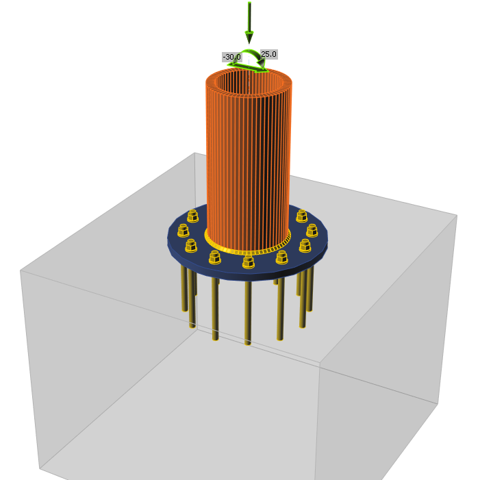
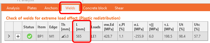
È inoltre possibile trovare tutte le dimensioni e lunghezze delle saldature in Relazione, sotto la Distinta materiali (BOM).