Description
The objective of this study is verification of bolted portal frame eaves connection, as shown in Fig. 9.2.1. Rafter is bolted using end plate on the column flange. The column is stiffened with two horizontal stiffeners in levels of the beam flanges. Compressed plates, e.g. horizontal stiffeners of column, web panel in shear or compression, and compressed beam flange, are designed as cross-section class 3. Horizontal beam is 6 m long loaded by continuous load over the entire length.
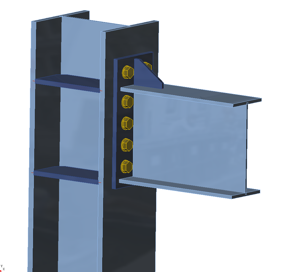
Fig. 9.2.1 Bolted portal frame eaves connection
Analytical model
Eight components are examined: fillet weld, web panel in shear, column web in transverse compression, column web in transverse tension, beam flange in compression and tension, column flange in bending, end plate in bending, and bolts. All components are designed according to EN 1993-1-8:2005. Design loads of components depend on the position. The web panel in shear is loaded by design loads on the vertical axis of the column. Other components are loaded by reduced design loads in column flange to which horizontal beam is connected.
Fillet weld
The weld is closed around the whole cross-section of the beam. The thickness of the weld on the flanges can differ from the thickness of the weld on the web. Vertical shear force is transferred only by welds on the web and plastic stress distribution is considered. Bending moment is transferred by whole weld shape, and elastic stress distribution is considered. Effective weld width depending on the horizontal stiffness of the column is considered (because of bending of the unstiffened column flange). Design of the weld is done according to EN 1993-1-8:2005, Cl. 4.5.3.2(6). The assessment is carried out in two major points: on the upper or lower edge of the flange (maximum bending stress) and in the crossing of the flange and the web (combination of shear force and bending moment stresses).
Web panel in shear
The thickness of the column web is designed to be third class at most; see EN 1993-1-8:2005, Cl. 6.2.6.1(1). Two contributions to the load capacity are considered: resistance of the column wall in shear and the contribution from the frame behavior of the column flanges and horizontal stiffeners; see EN 1993-1-8:2005, Cl. 6.2.6.1 (6.7 and 6.8).