10.2.1 Description
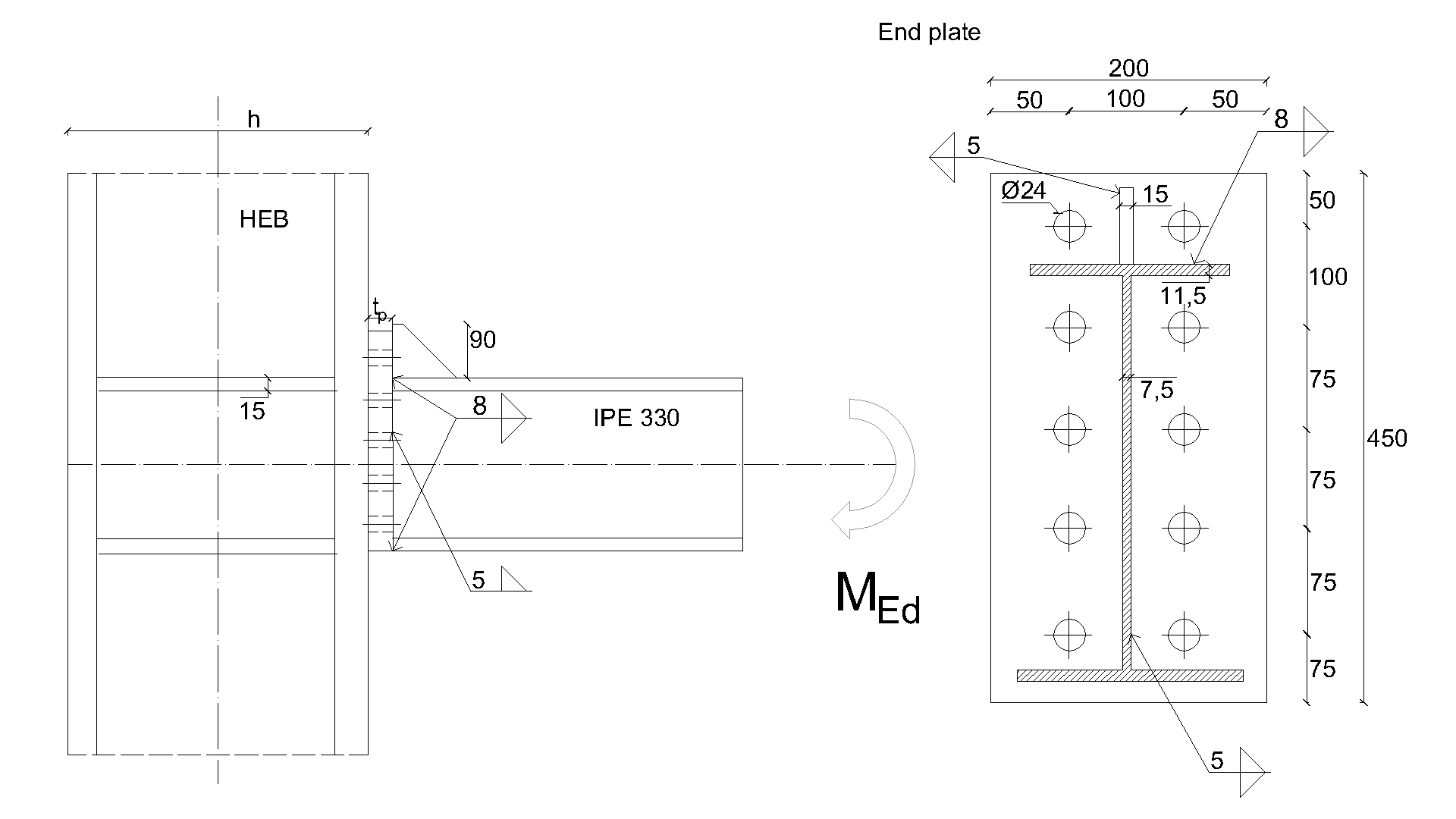
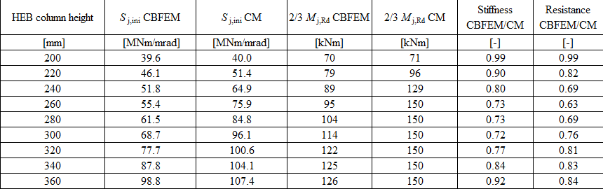
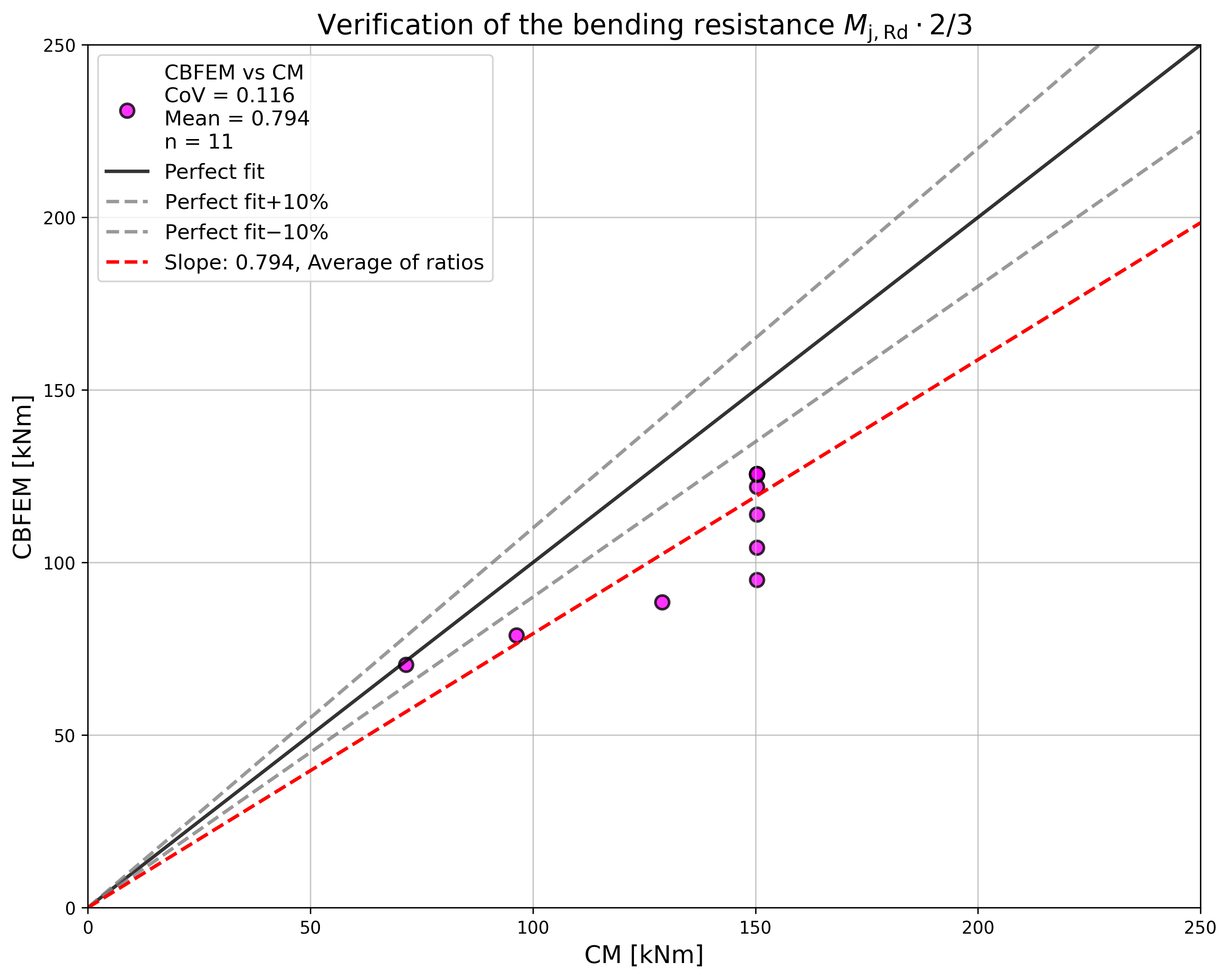
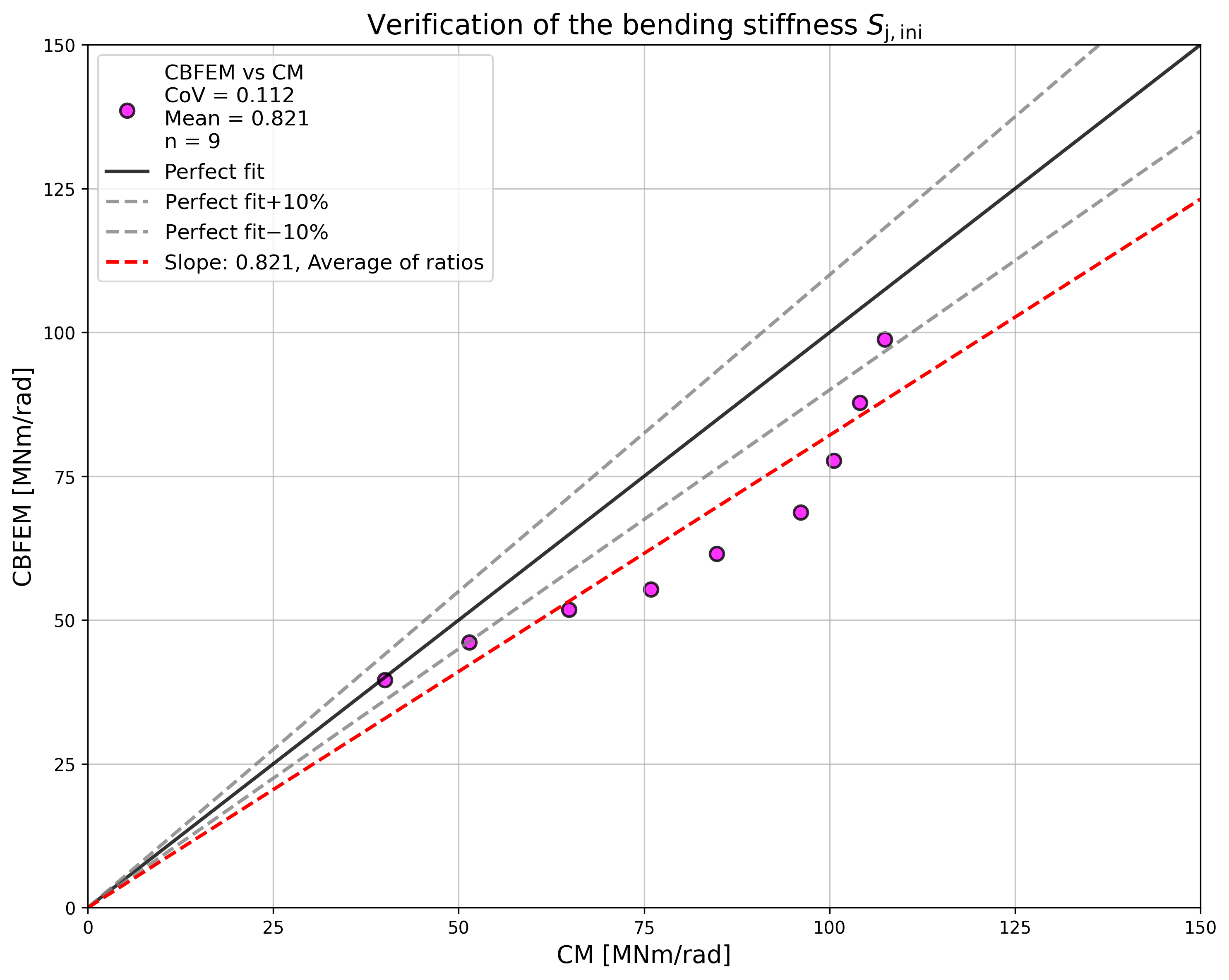
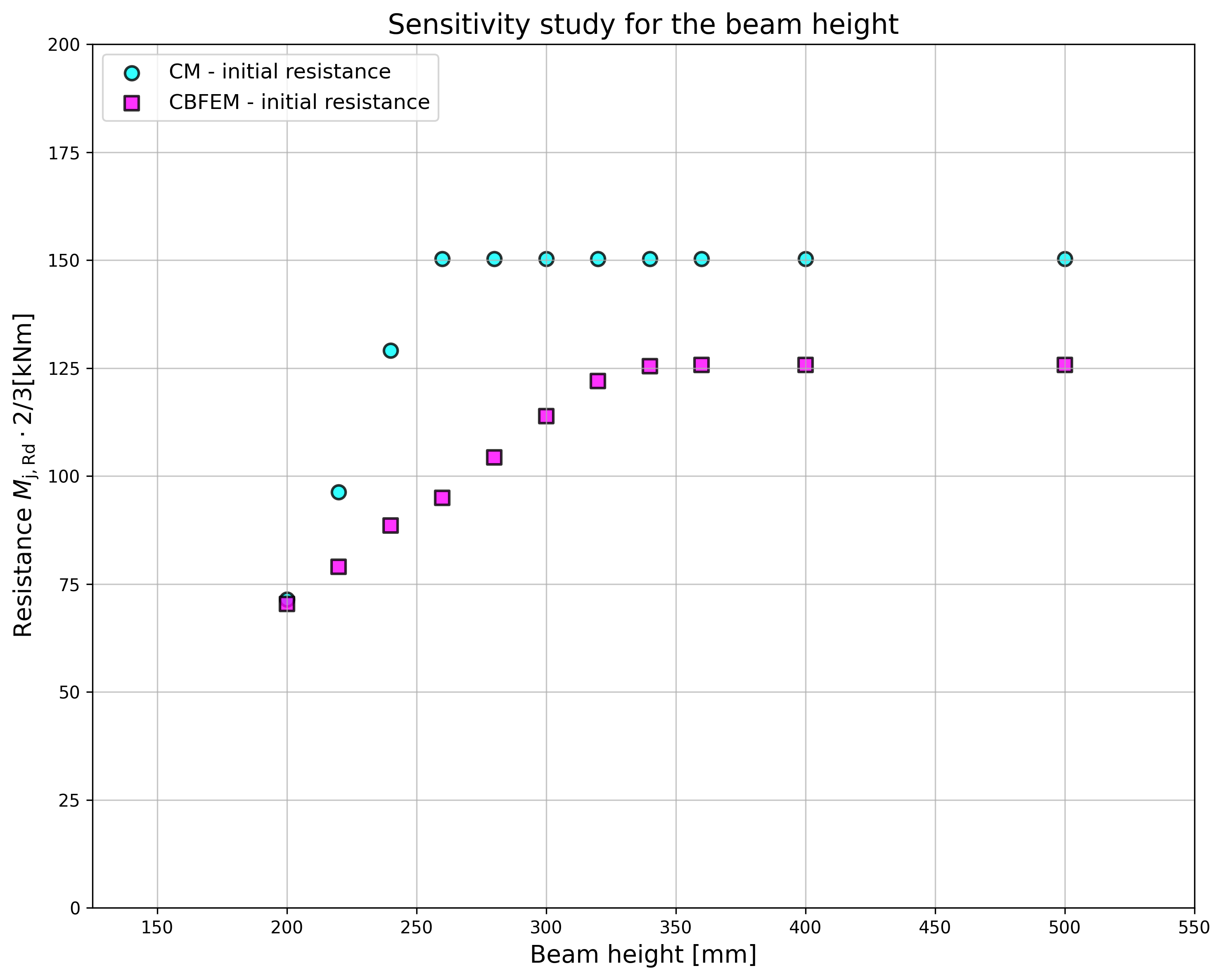
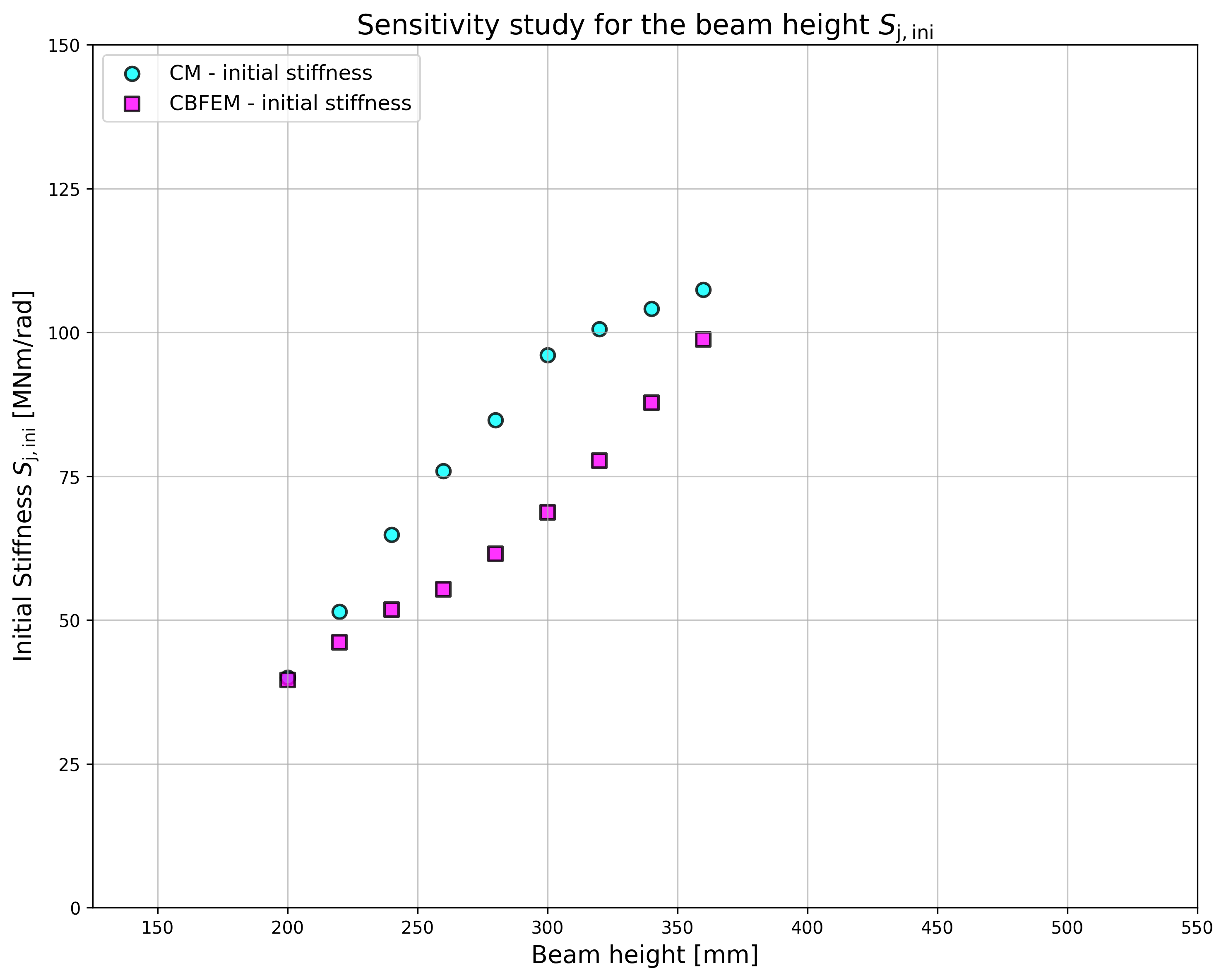
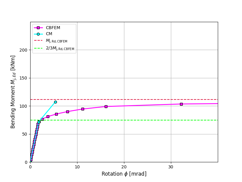
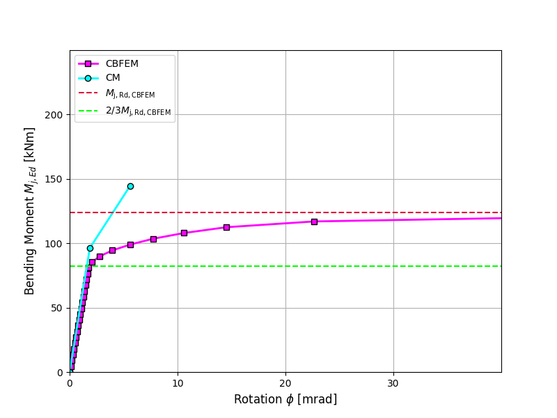
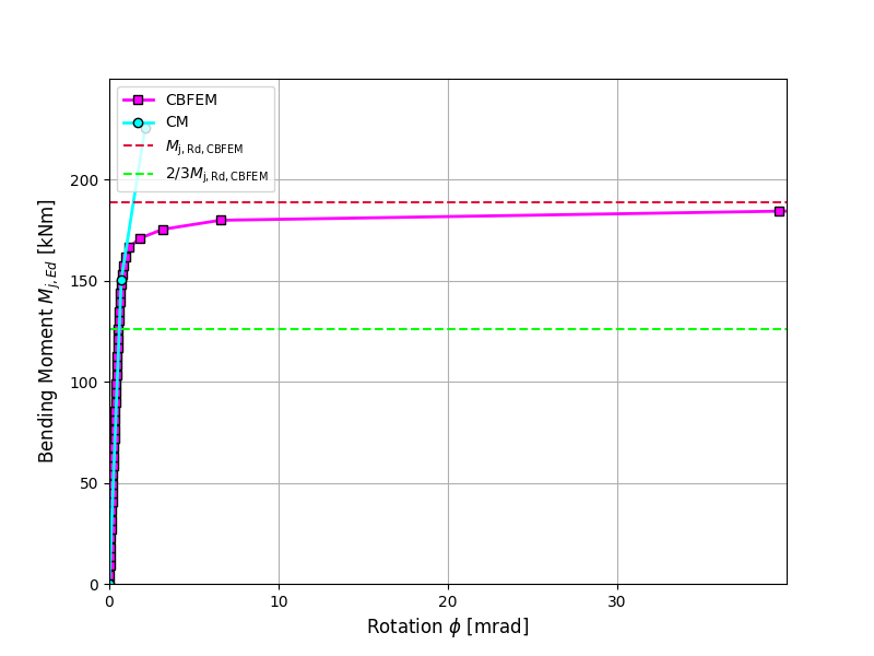
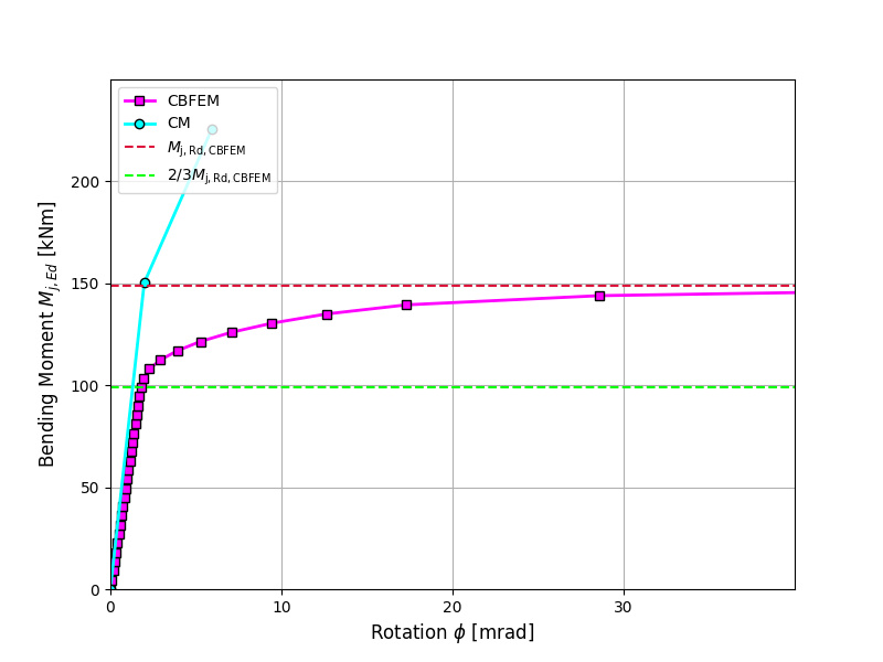
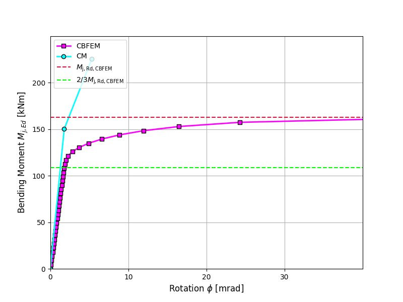
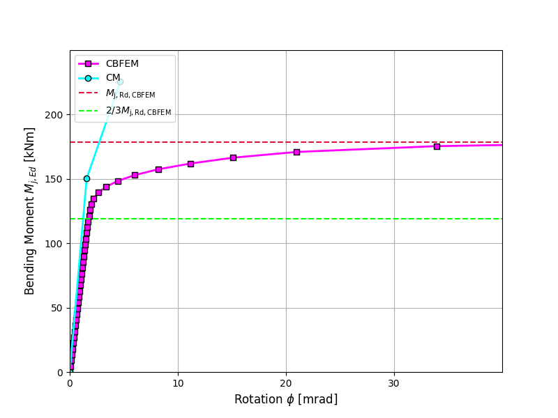
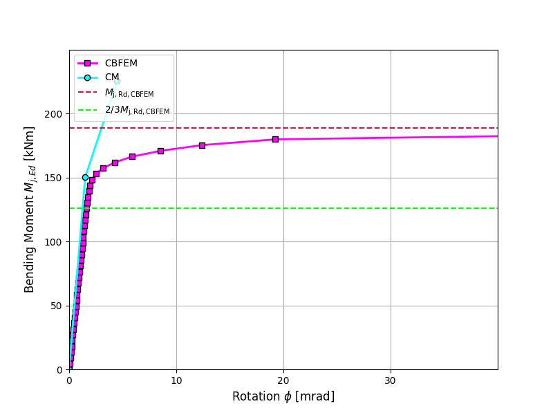
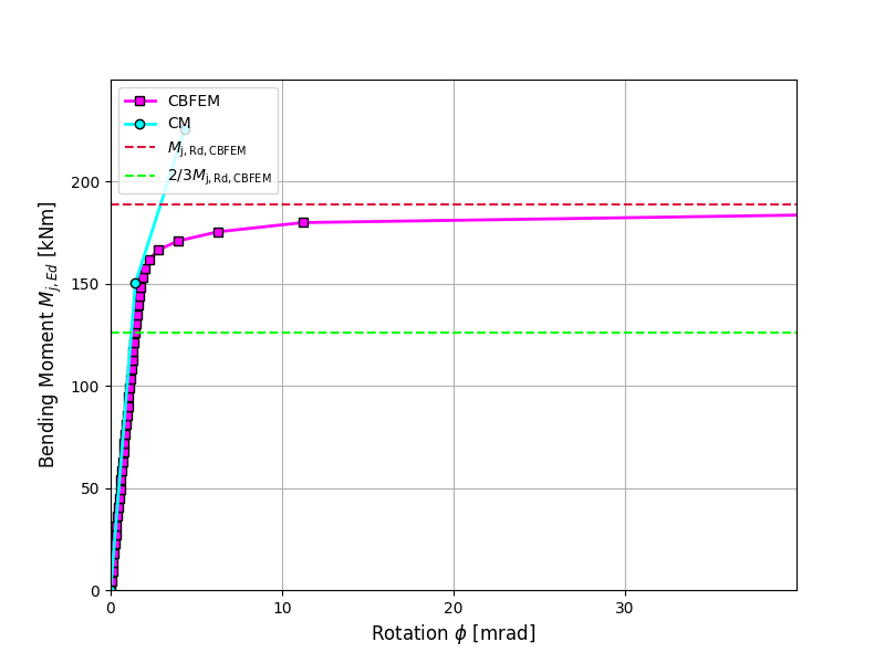
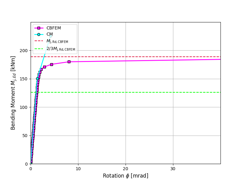
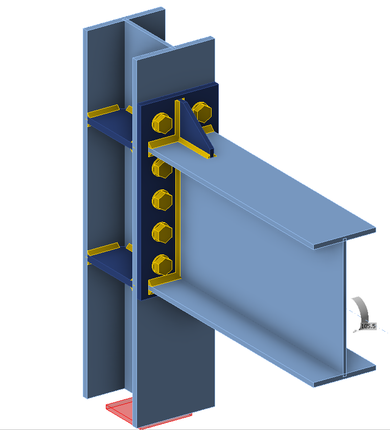
The prediction of rotational stiffness is verified on a bolted eaves moment joint. A bolted joint of open section column HEB and beam IPE is studied and the joint’s behaviour is described on moment-rotation diagram. The results of analytical model by the component-based finite element method (CBFEM) are compared with the component method (CM). The numerical results in form of a benchmark case are available.
10.2.2 Analytical model
The rotational stiffness of a joint should be determined from deformation of its basic components, which are represented by the stiffness coefficient ki. The rotational stiffness of the joint Sj is obtained from:
\[ S_j = \frac{E z^2}{\mu \Sigma_i \frac{1}{k_i}} \]
where
\(k_i\) — the stiffness coefficient for the joint component i;
\(z\) — the lever arm, see 6.2.7;
\(μ\) — the stiffness ratio, see 6.3.1.
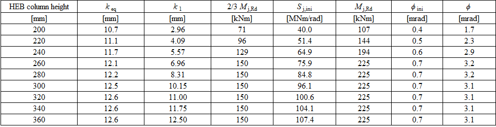
The joint components that are taken into account in this example are column web panel in shear k1 which equals infinity for a stiffened column and a single equivalent stiffness coefficient keq for end-plate joint with two or more bolt-rows in tension.
\[k_{\mathit{1}} = 0.38 \, \frac{A_{\mathit{vc}}}{\beta \, z}\]
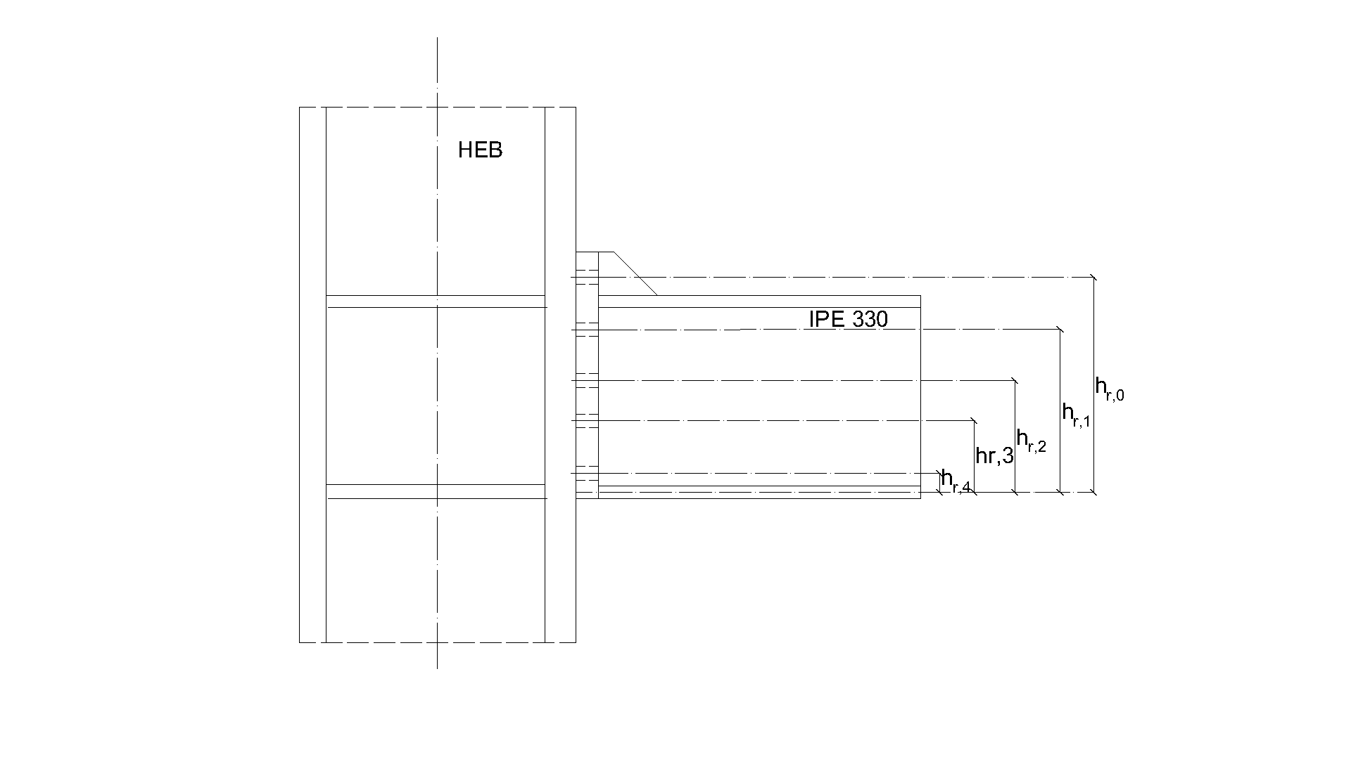
\[k_{eq} = \frac{(k_{eff,0}h_{r,0}) + (k_{eff,1}h_{r,1}) + (k_{eff,2}h_{r,2}) + (k_{eff,3}h_{r,3}) + (k_{eff,4}h_{r,4})}{z_{eq}}\]
\[k_{eff,i} = \frac{1}{\frac{1}{k_{5,i}} + \frac{1}{k_{10}} + \frac{1}{k_{4,i}}}\]
\[z_{eq} = \frac{(k_{eff,0}h_{r,0}^2) + (k_{eff,1}h_{r,1}^2) + (k_{eff,2}h_{r,2}^2) + (k_{eff,3}h_{r,3}^2) + (k_{eff,4}h_{r,4}^2)}{(k_{eff,0}h_{r,0}) + (k_{eff,1}h_{r,1}) + (k_{eff,2}h_{r,2}) + (k_{eff,3}h_{r,3}) + (k_{eff,4}h_{r,4})}\]
\[S_{\mathit{j,\,ini}} = \frac{E \, z_{\mathit{eq}}^{2}}{\mu \left( \frac{1}{k_{\mathit{eq}}} + \frac{1}{k_{\mathit{1}}} \right)}\]