The anchor bolt resistances are evaluated according to STO 36554501-048-2016 for headed and post-installed anchors. STO often uses tabulated values in Annex, in which case the formulas from SP 43, SP16 or EN 1992-4 are used because of their general validity. Pull-out failure of straight anchors, combined pull-out and concrete failure of bonded anchors, and concrete splitting failure are not checked due to missing information available only for the particular anchor and glue type from the anchor manufacturer.
In the Code setup, concrete can be set as cracked or uncracked. The resistances of uncracked concrete are higher.
Tensile steel resistance (SP 43 - Annex G):
Tensile steel resistance of anchors in STO uses tabulated values in Annex A. Therefore, a general formula from SP 43 - Annex G is used.
\[ N_{ult,s} = \frac{A_{sa} \cdot R_{ba} \cdot \gamma_c}{k_0} \]
where:
- Rba = 0.8 ⋅ Rbyn – anchor bolt design yield strength
- Rbyn – characteristic yield strength of anchor steel
- Asa – net cross-sectional area of a bolt
- k0 – factor for loading type; editable in Code setup; k0 = 1.05 for static loading and k0 = 1.35 for dynamic loading; for the portable anchors with anchor plates, installed freely in the tubes, k0 is taken equal to 1.15 for dynamic loads (SP 43 – G.9)
- γc – service factor – SP 16, Table 1, editable in Code setup
Pull-out resistance (EN 1992-4, Cl. 7.2.1.5)
Pull-out resistance of anchors in STO uses tabulated values in Annex A. Therefore, the general formula from EN 1992-4, Cl. 7.2.1.5 is used for anchors with washer plates:
\[ N_{ult,p}=\frac{N_{n,p} \cdot \psi_c}{\gamma_{bt} \gamma_{Np}} \]
where:
- Nn,p \(\cdot \psi_c\) = k2 ∙ Ah ∙ Rbn – characteristic resistance in case of pull-out failure
- k2 – coefficient dependent on concrete condition, k2 = 7.5 for cracked concrete, k2 = 10.5 for non-cracked concrete
- Ah – bearing area of head of anchor; for circular washer plate \(A_h = \frac{\pi}{4} \left ( d_h^2 - d^2 \right )\), for rectangular washer plate \(A_h = a_{wp}^2 - \frac{\pi}{4} d^2\)
The pullout resistance of other types of anchors is not checked and must be guaranteed by manufacturer or determined by STO, Annex A.
Concrete cone failure resistance of anchor or group of anchors (STO - Cl. 6.1.3):
\[N_{ult,c}=\frac{N_{n,c}^0}{\gamma_{bt} \cdot \gamma_{Nc}} \cdot \frac{A_{c,N}}{A_{c,N}^0} \cdot \psi_{s,N} \cdot \psi_{re,N} \cdot \psi_{ec,N}\]
where:
- \(N_{n,c}^0 = k_1 \sqrt{R_{b,n}} h_{ef}^{1.5}\) – characteristic resistance of a single fastener placed in concrete and not influenced by adjacent fasteners or edges of the concrete member
- k1 – factor taking into account concrete condition; k1 = 8.4 for cracked concrete and k1 = 11.8 for non-cracked concrete
- Rb,n – characteristic concrete compressive cylinder strength
- h– embedment depth of the anchor in concrete; for three or four close edges, effective \(h'_{ef} = \max \left \{ \frac{c_{max}}{c_{cr,N}} \cdot h_{ef}, \, \frac{s_{max}}{s_{cr,N}} \cdot h_{ef} \right \}\) is used instead in formulas for , , , , , , and
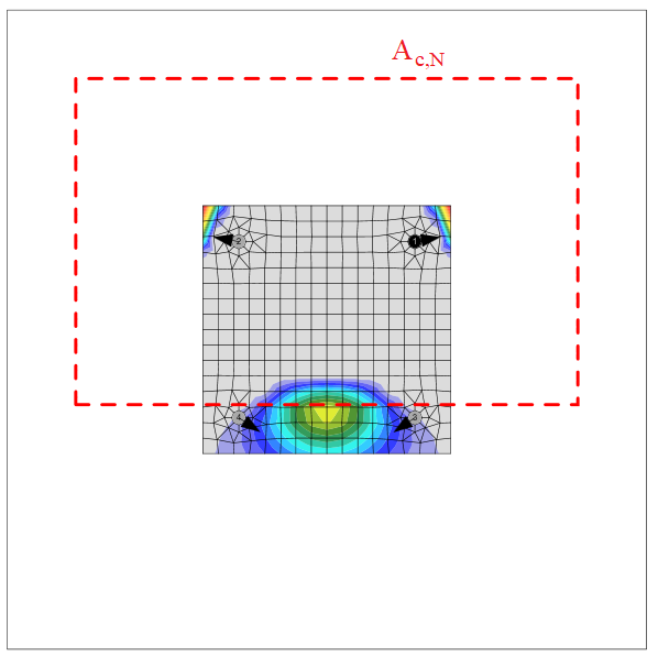
The concrete breakout cone area for group of anchors loaded by tension that create common concrete cone, Ac,N, is shown by red dashed line.
Anchor shear steel resistance (SP16 - Cl. 14.2.9 and STO - Cl. 6.2.1)
According to STO - Cl. 6.2.1, two scenarios are investigated:
- Shear without lever arm (Stand-off: Direct)
- Shear with lever arm (Stand-off: Mortar joint)
Shear without lever arm
Shear steel resistance of anchors in STO uses tabulated values in Annex A. Therefore, a general formula from SP16 is used. It is assumed that anchors are threaded rods. Friction is not taken into account.
A bolt subject to a design shear force is designed according to SP16 - Cl. 14.2.9 and shall satisfy:
\[ V_{ult,s} = R_{bs} A_b \gamma_b \gamma_c \]
where:
- Rbs – design shear strength of a bolt – SP 16, Table 5
- Ab – bolt gross section area
- γb – service factor of bolt joint – SP 16, Table 41 – γb = 1.0 for single bolting and multibolting with accuracy class A, γb = 0.9 for multibolting and accuracy class B and high strength bolts (Rbun ≥ 800 MPa)
- – service factor – SP 16, Table 1, editable in Code setup
| Rbyn [MPa] | Rbs [MPa] |
| \(R_{byn} \le 300 \) | \(0.42 \cdot R_{bun} \) |
| \(300 < R_{byn} \le 400 \) | \(0.41 \cdot R_{bun} \) |
| \(400 < R_{byn} \le 936 \) | \(0.40 \cdot R_{bun} \) |
| \(936 > R_{byn} \) | \(0.35 \cdot R_{bun} \) |
Shear with lever arm (STO - Cl. 6.2.1.5)
\[ V_{ult,s} = \frac{M_{n,s}}{l_s} \gamma_b \gamma_c \]
where:
- \(M_{n,s} = M_{n,s}^0 \left ( 1- \frac{N_{an}}{N_{ult,s}} \right ) \) – characteristic bending resistance of the anchor decreased by the tensile force in the anchor
- Mn,s0 = 1.2 Wel Rbun – characteristic bending resistance of the anchor (ETAG 001, Annex C – Equation (5.5b))
- \( W_{el} = \frac{\pi d^3}{32}\) – section modulus of the anchor
- d – anchor bolt diameter; if shear plane in thread is selected, the diameter reduced by threads is used; otherwise, nominal diameter, , is used
Concrete pry-out failure (STO - Cl. 6.2.2):
\[ V_{ult,cp}= k \cdot \frac{N_{ult,c}}{\gamma_{V,cp}} \]
where:
- k – factor for concrete pryout failure (STO 36554501-048-2016 - Cl. 6.2.2.3) taken as k = 2 as default (ETAG 001, Annex C – Cl. 5.2.3.3) editable in Code setup
- Nult,c – resistance of a fastener or a group of fasteners in case of concrete cone failure; all anchors are assumed to be in tension and γNc = 1.0
- γV,cp – partial safety factor taking account of the installation safety of an anchor system for concrete pryout failure editable in Code setup
Concrete edge failure (STO - Cl. 6.2.3):
Concrete edge failure is a brittle failure and the worst possible case is checked, i.e. only the anchors located near the edge transfer the full shear load acting on a whole base plate. If anchors are positioned in a rectangular pattern, the row of anchors at the investigated edge transfers the shear load. If anchors are positioned irregularly, the two anchors nearest to the investigated edge transfer the shear load. Two edges in the direction of the shear load are investigated and the worst case is shown in results.
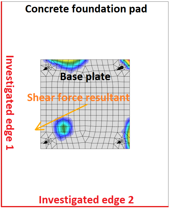
Investigated edges in dependence on the direction of the shear force resultant
Resistance of a fastener or a group of fasteners loaded towards the edge:
\[ V_{ult,c}= \frac{V_{n,c}^0}{\gamma_{bt} \cdot \gamma_{Vc}} \cdot \frac{A_{c,V}}{A_{c,V}^0} \cdot \psi_{s,V} \cdot \psi_{h,V} \cdot \psi_{\alpha,V} \cdot \psi_{ec,V} \cdot \psi_{re,V} \]
where:
- \( V_{n,c}^0 = k_3 \cdot d_{nom}^\alpha \cdot l_f^\beta \cdot \sqrt{R_{b,n}} \cdot c_1^{1.5}\) – initial value of the characteristic resistance of a fastener loaded perpendicular to the edge
- k3 – factor taking into account concrete condition; k3 = 2.0 for cracked concrete, k3 = 2.8 for non-cracked concrete
- \( \alpha = 0.1 \left ( \frac{l_f}{c_1} \right ) ^{0.5} \)
- \( \beta = 0.1 \left ( \frac{d_{nom}}{c_1} \right ) ^{0.2} \)
Interaction of tensile and shear forces (STO - Cl. 6.3):
Interaction of tensile and shear forces is determined according to STO - Cl. 6.3., Equation (6.55):
\[ \beta_N^{1.5} + \beta_V^{1.5} \le 1.0 \]
where:
- \(\beta_N = \max \left \{ \frac{N_{an}}{N_{ult,s}}; \, \frac{N_{an}}{N_{ult,p}}; \, \frac{N_{an}}{N_{ult,c}} \right \} \) – coefficient defined as the largest value of the ratio of the design tensile forces to the value of the ultimate tensile resistances for each of the failure mechanisms
- \(\beta_V = \max \left \{ \frac{V_{an}}{V_{ult,s}}; \, \frac{V_{an}}{V_{ult,cp}}; \, \frac{V_{an}}{V_{ult,c}} \right \} \) – coefficient defined as the largest value of the ratio of the design shear forces to the value of the ultimate shear resistances for each of the failure mechanisms
Anchors with stand-off
Anchor with stand-off is designed as a bar element loaded by shear force, bending moment and compressive or tensile force. These internal forces are determined by finite element model. The anchor is fixed on both sides, one side is 0.5×d below the concrete level, the other side is in the middle of the thickness of the plate. The buckling length is conservatively assumed as twice the length of the bar element. Plastic section modulus is used. The bar element is designed according to SP 16. The shear force may decrease the yield strength of the steel but the minimum length of the anchor to fit the nut under the base plate ensures that the anchor fails in bending before the shear force reaches half the shear resistance. The reduction is therefore not necessary. Interaction of bending moment and compressive or tensile strength is assumed linear.
Shear resistance:
A bolt subject to a design shear force is designed according to SP16 - Cl. 14.2.9 and shall satisfy:
\[ V_{ult,s} = R_{bs} A_{bn} \gamma_b \gamma_c \]
where:
- Rbs – design shear strength of a bolt – SP 16, Table 5
- Abn – bolt gross section area
- γb – service factor of bolt joint – SP 16, Table 41 – γb = 1.0 for single bolting and multibolting with accuracy class A, γb = 0.9 for multibolting and accuracy class B and high strength bolts (Rbun ≥ 800 MPa)
- – service factor – SP 16, Table 1, editable in Code setup
| Rbyn [MPa] | Rbs [MPa] |
| \(R_{byn} < 300 \) | \(0.42 \cdot R_{bun} \) |
| \(300 \le R_{byn} < 400 \) | \(0.41 \cdot R_{bun} \) |
| \(400 \le R_{byn} < 936 \) | \(0.40 \cdot R_{bun} \) |
| \(936 < R_{byn} \) | \(0.35 \cdot R_{bun} \) |
Tensile and compressive resistance:
Steel resistance of anchors in STO uses tabulated values in Annex A. Therefore, a general formula from SP 43 - Annex G is used.
\[ N_{ult,s} = \frac{A_{sa} \cdot R_{ba} \cdot \gamma_c }{k_0} \]
where:
- Rba = 0.8 ⋅ Rbyn – anchor bolt design yield strength
- Rbyn – characteristic yield strength of anchor steel
- Asa – net cross-sectional area of a bolt
- γc – service factor – SP 16, Table 1, editable in Code setup
Bending resistance:
\[ M_{ult,s} = W_n R_{ba} \gamma_c \]
- \( W_{n}= \frac{d_s^3}{6} \) – section modulus of the bolt
- \(d_s = \sqrt{\frac{4A_{bn}}{\pi}}\) – anchor bolt diameter reduced by threads
- Rba = 0.8 ⋅ Rbyn – anchor bolt design yield strength
- Rbyn – characteristic yield strength of anchor steel
Stand-off anchor steel utilization
Linear interaction is used:
\[ \frac{N}{N_{ult,s}} + \frac{M}{M_{ult,s}} \le 1 \]
Stand-off anchor Concrete utilization
All concrete checks are also performed and following interaction for concrete failure modes is provided:
\[ \beta_N^{1.5} + \beta_V^{1.5} \le 1.0 \]
where:
- \(\beta_N = \max \left \{ \frac{N_{an}}{N_{ult,p}}; \, \frac{N_{an}}{N_{ult,c}} \right \} \) – coefficient defined as the largest value of the ratio of the design tensile forces to the value of the ultimate tensile resistances for each of the failure mechanisms
- \(\beta_V = \max \left \{ \frac{V_{an}}{V_{ult,cp}}; \, \frac{V_{an}}{V_{ult,c}} \right \} \) – coefficient defined as the largest value of the ratio of the design shear forces to the value of the ultimate shear resistances for each of the failure mechanisms