
Description
This study is focused on the verification of component-based finite element method (CBFEM) for the resistance of the symmetrical double splice bolted connection to an analytical model (AM).
Analytical model
The bolt resistance in shear and the plate resistance in bearing are designed according to Tab. 3.4 in chapter 3.6.1 in EN 1993-1-8:2005. For long connection, reduction factor according to cl. 3.8 is considered. Design resistance of connected members with reductions for fastener holes is taken into account according to cl 3.10.
Verification of resistance
Design resistances calculated by CBFEM were compared with results of analytical model (AM). Results are summarised in Tab. 5.2.1. The parameters are bolt material, splice thickness, bolt diameter, and bolt distances, see Figs. 5.2.1 to 5.2.4.
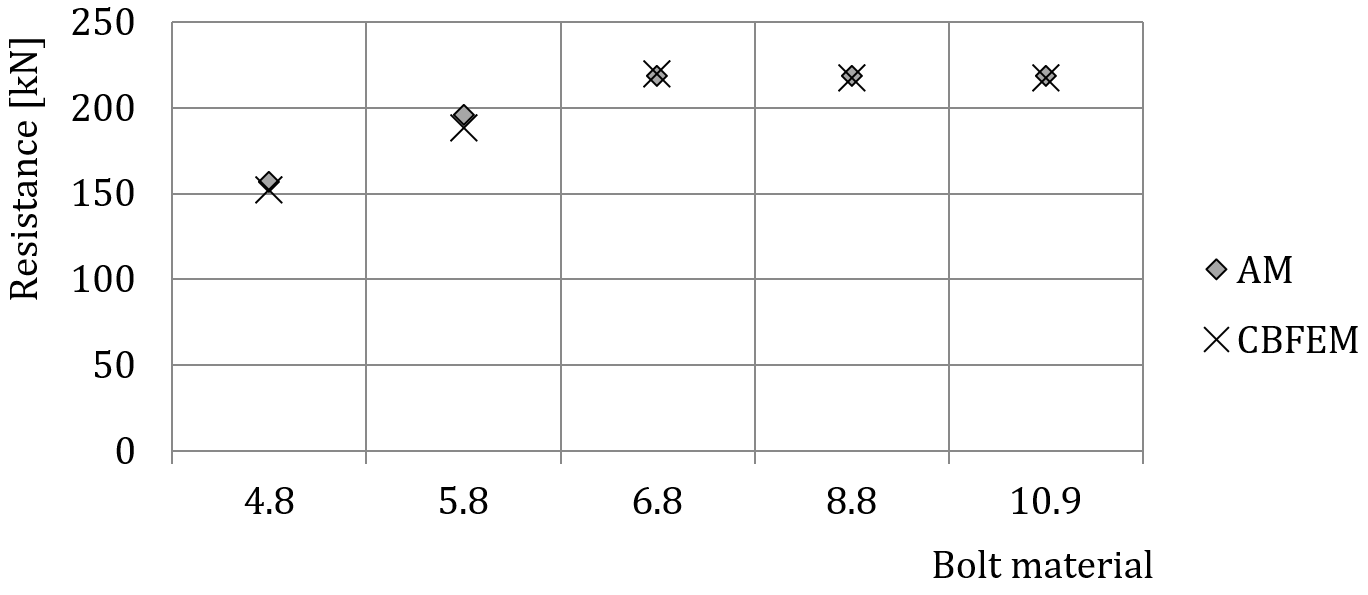
Fig. 5.2.1 Sensitivity study for the bolt material
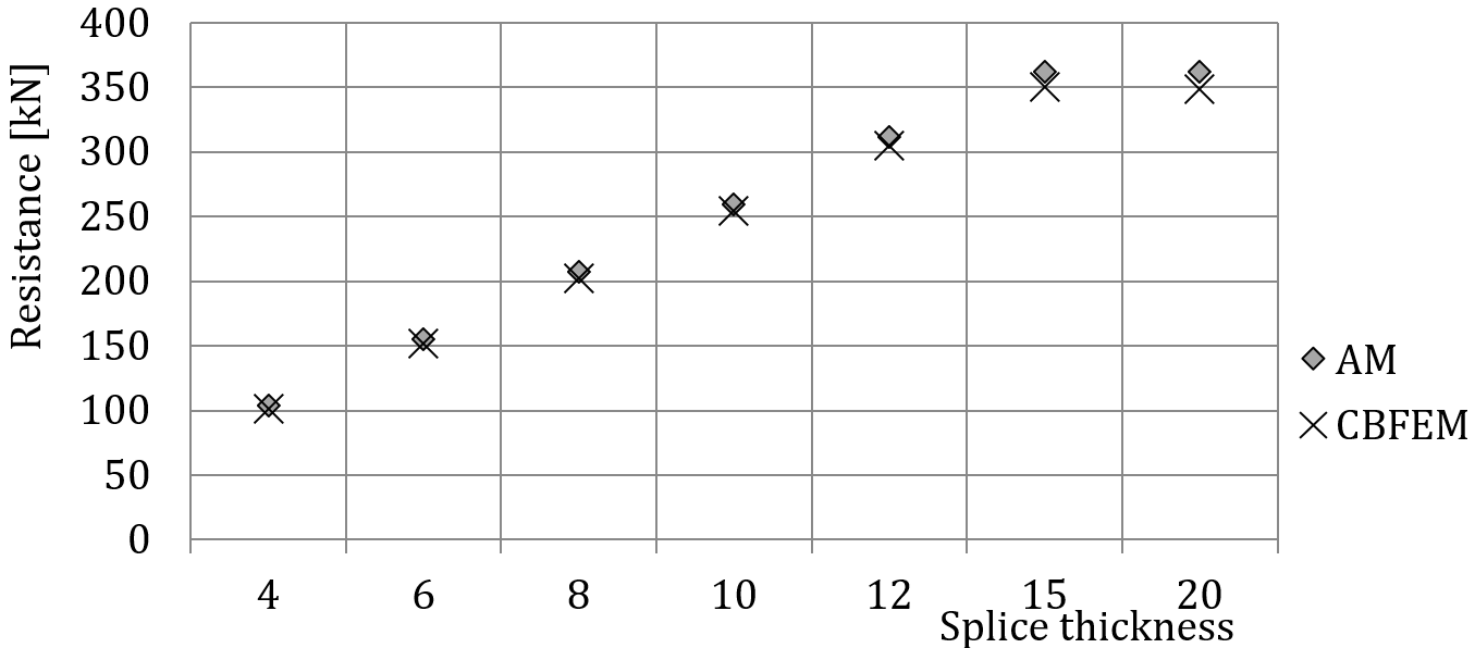
Fig. 5.2.2 Sensitivity study for the splice thickness
Tab. 5.2.1 Sensitivity study of resistance
Joint description: splice 150/10mm, bolts 2×M20 in distances p =70, e1=50, plates 2×150/6mm, steel S235
| Bolt material | Analytical Model (AM) | CBFEM | AM/ CBFEM | ||
| Resistance [kN] | Critical component | Resistance [kN] | Critical component | ||
| 4.8 | 157 | Bolt in shear | 152 | Bolt in shear | 1,03 |
| 5.8 | 196 | Bolt in shear | 188 | Bolt in shear | 1,04 |
| 6.8 | 218 | Bearing | 214 | Bearing | 1,01 |
| 8.8 | 218 | Bearing | 218 | Bearing | 1,00 |
| 10.9 | 218 | Bearing | 218 | Bearing | 1,00 |
Joint description: splice height 200mm, bolts 3×M16 8,8 in distances p = 55mm e1 = 40mm, plates 2×200/10 mm, steel S235
| Splice thickness | Analytical Model (AM) | CBFEM | AM/ CBFEM | ||
| Resistance [kN] | Critical component | Resistance [kN] | Critical component | ||
| 4 | 104 | Bearing | 104 | Bearing | 1,00 |
| 6 | 156 | Bearing | 156 | Bearing | 1,00 |
| 8 | 208 | Bearing | 207 | Bearing | 1,00 |
| 10 | 259 | Bearing | 258 | Bearing | 1,00 |
| 12 | 311 | Bearing | 309 | Bearing | 1,00 |
| 15 | 362 | Bolt in shear | 350 | Interaction of tension and shear in bolt | 1,03 |
| 20 | 362 | Bolt in shear | 349 | Interaction of tension and shear in bolt | 1,04 |
Joint description: splice 120/10mm, bolts 2×MX 8,8, plates 2×120/6 mm, steel S235
| Analytical Model (AM) | CBFEM | AM/ CBFEM | ||||
| Diam. | Distances | Resistance [kN] | Critical component | Resistance [kN] | Critical component | |
| M16 | p = 55, e1 = 40 | 171 | Bearing | 170 | Bearing | 1,00 |
| M20 | p = 70, e1= 50 | 218 | Bearing | 219 | Bearing | 1,00 |
| M24 | p = 80, e1 = 60 | 244 | Splice in tension | 241 | Splice in tension | 1,01 |
| M27 | p = 90, e1 = 70 | 233 | Splice in tension | 236 | Splice in tension | 0,99 |
| M30 | p = 100, e1 = 75 | 226 | Splice in tension | 231 | Splice in tension | 0,98 |
Joint description: Splice 200/6 mm, bolts 3×M16 8,8, plates 2×200/3mm, steel S235
| Analytical Model (AM) | CBFEM | AM/ CBFEM | |||
| Bolt spacing | Resistance [kN] | Critical component | Resistance [kN] | Critical component | |
| p = 40, e1 = 25 | 98 | Bearing | 95 | Bearing | 1,03 |
| p = 55, e1 = 40 | 156 | Bearing | 152 | Bearing | 1,02 |
| p = 70, e1 = 55 | 207 | Bearing | 205 | Bearing | 1,01 |
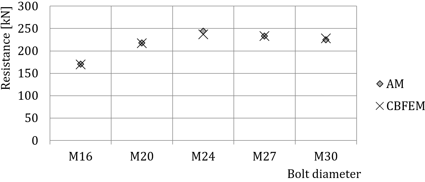
Fig. 5.2.3 Sensitivity study for the bolt diameter
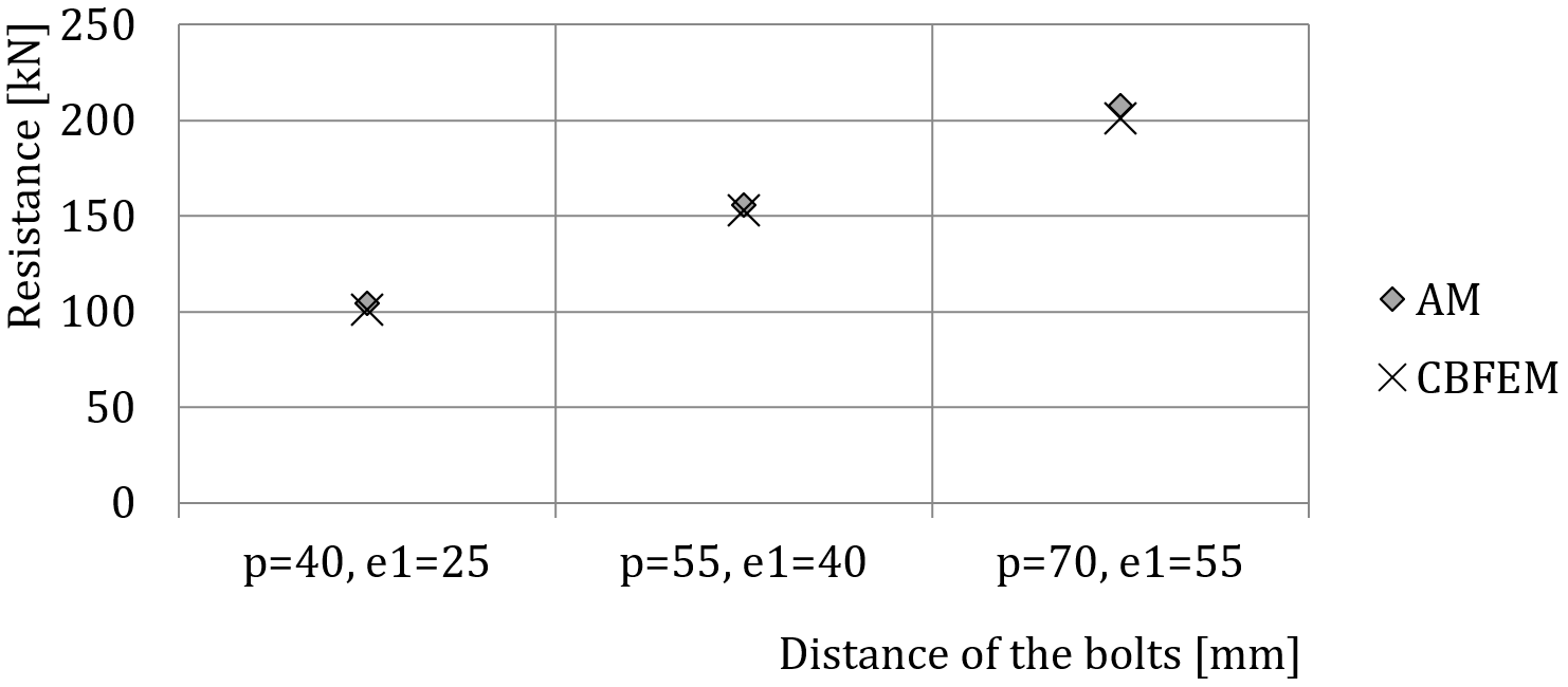
Fig. 5.2.4 Sensitivity study for the distance of bolts
The results of sensitivity studies are summarized in the graph in Fig. 5.2.5. The results show that the differences between the two calculation methods are below 5 %. The analytical model gives generally higher resistance.
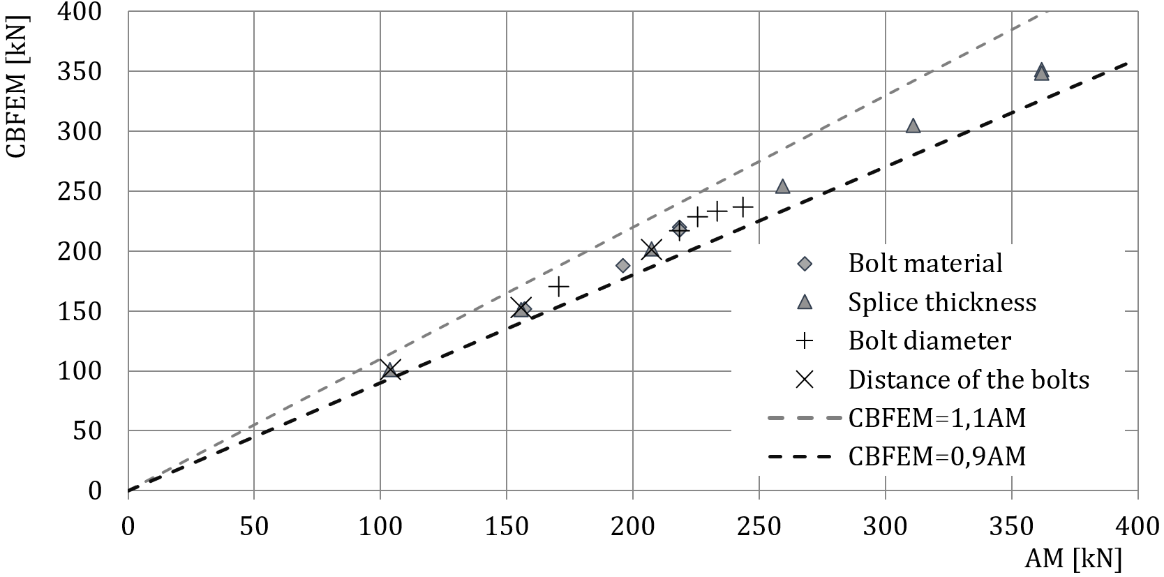
Fig. 5.2.5 Verification of CBFEM to AM for the symmetrical double splice connection
Benchmark example
Inputs
Connected member
- Steel S235
- Splice 200/10 mm
Connectors
Bolts
- 3 × M16 8.8
- Distances e1 = 40 mm, p = 55 mm
2 x splice
- Steel S235
- Plate 380×200×10
Outputs
- Design resistance FRd = 258 kN
- Critical is bearing of the connected splice
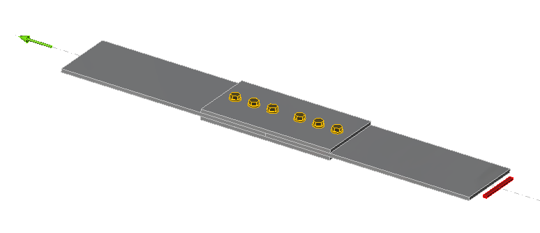
Fig. 5.2.6 Benchmark example of the bolted splices in shear