Bolt model according to CBFEM
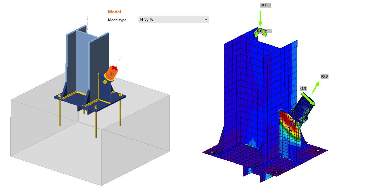
IDEA StatiCa has a unique method in its solver, the Component-based Finite Element Method (CBFEM). The bolt model used in CBFEM is described and verified to several steel design codes. The load resistance and deformation capacity are also compared to the main experimental research programs.
In the Component-Based Finite Element Method (CBFEM), bolt with its behavior in tension, shear, and bearing is the component described by the dependent nonlinear springs. The bolt in tension is described by spring with its axial initial stiffness, design resistance, initialization of yielding, and deformation capacity. For the initialization of yielding and deformation capacity, it is assumed that plastic deformation occurs in the threaded part of the bolt shank only.
In our Theoretical background, you can find more information on how the CBFEM method describes and verifies bolts. If you want to know a bit more about CBFEM in general, the full General theoretical background is definitely the best place to start from.
Bolts according to design codes
Let's take a look at how CBFEM approaches bolts from the point of view of individual design codes. So far, IDEA StatiCa supports eight design codes where design and/or detailing of bolts and preloaded bolts are being solved.
Check of bolts and preloaded bolts according to Eurocode
The initial stiffness and design resistance of bolts in shear are in CBFEM modeled according to Cl. 3.6 and 6.3.2 in EN 1993-1-8. The spring representing bearing and tension has a bi-linear force-deformation behavior with an initial stiffness and design resistance according to Cl. 3.6 and 6.3.2 in EN 1993-1-8.
Detailing
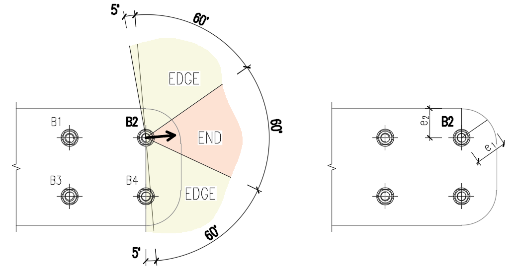
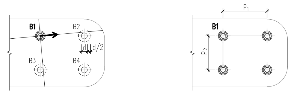
Checks of bolts is performed if the option is selected in Code setup. Dimensions from bolt center to plate edges and between bolts are checked. Edge distance = 1.2 and spacing between bolts = 2.2 are recommended in Table 3.3 in EN 1993-1-8. Users can modify both values in the Code setup.