Introduction
The CSFM considers continuous stress fields in the concrete (2D finite elements), complemented by discrete “rod” elements representing the reinforcement (1D finite elements). Therefore, the reinforcement is not diffusely embedded into the concrete 2D finite elements, but explicitly modeled and connected to them. A plane stress state is considered in the calculation model.
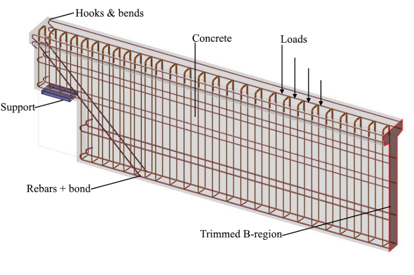
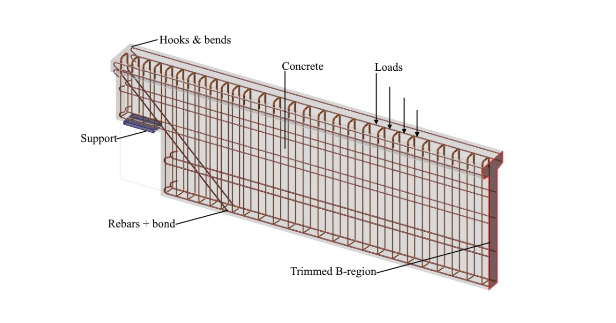
\[ \textsf{\textit{\footnotesize{Fig. 8\qquad Visualization of the calculation model of a structural element (trimmed beam) in Idea StatiCa Detail.}}}\]
Both entire walls and beams, as well as details (parts) of beams (isolated discontinuity region, also called trimmed end), can be modeled. In the case of walls and entire beams, supports must be defined in such a way that an (externally) isostatic (statically determinate) or hyperstatic (statically indeterminate) structure results. The load transfer at the trimmed ends of beams is introduced by means of a special Saint-Venant transfer zone (described in Section 3.3), which ensures a realistic stress distribution in the analyzed detail region.