Description
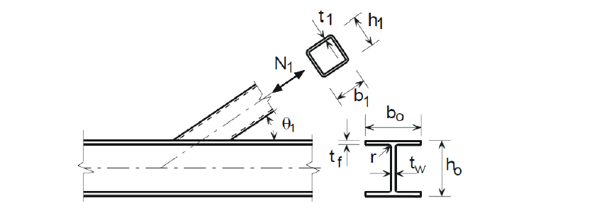
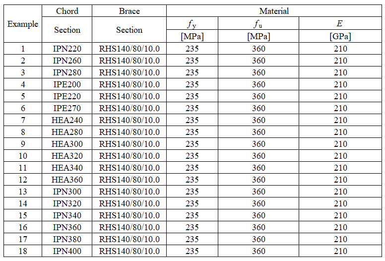
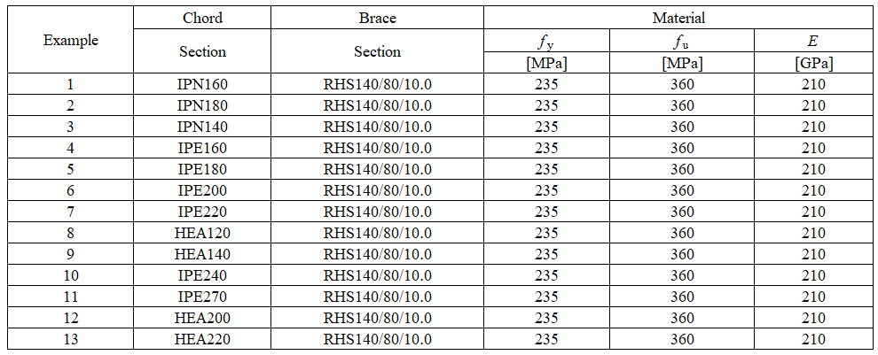
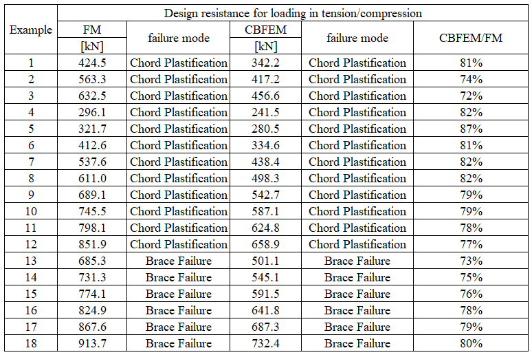
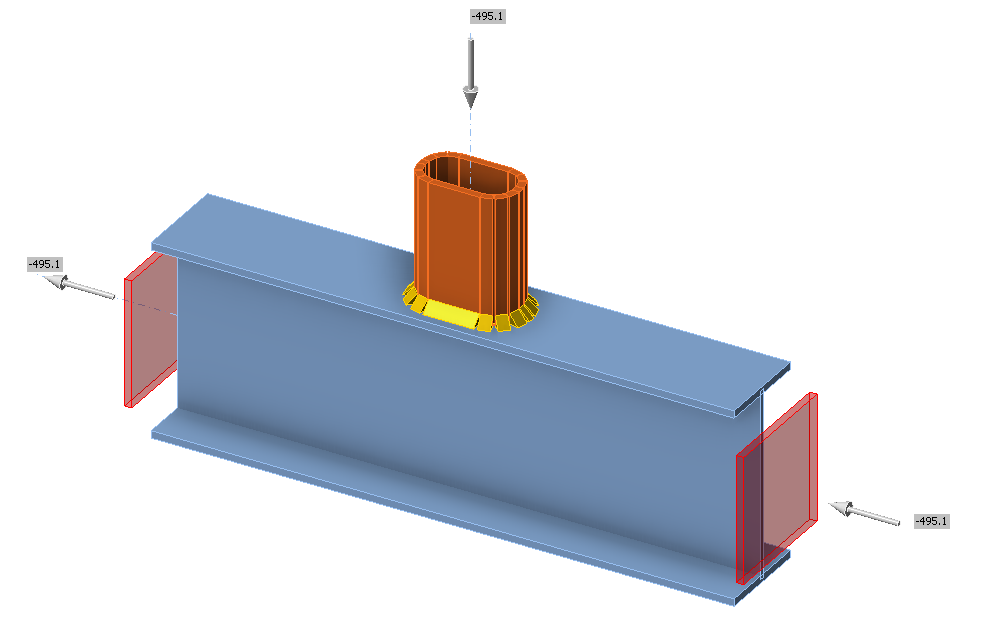
A uniplanar T-joint of a rectangular hollow section brace to an open section chord, which is located in a lattice truss is studied. The RHS brace is welded directly onto the H or I chord, open sections, without use of reinforcing plates. The prediction by component-based finite element method (CBFEM) is verified with the failure modes method (FM) implemented in EN 1993-1-8:2005.
Analytical model
Three failure modes occur in the uniplanar T-joint of the welded rectangular hollow sections to the open sections: the local yielding of brace, called brace failure, the chord web failure, and the chord shear. All these failure modes are examined in this study; see Fig. 7.4.1. Welds are designed not to be the weakest component in a joint according to EN 1993-1-8:2005. The elements of lattice trusses are loaded by normal forces and bending moments. A point of action of internal forces of T-joint is described as follows:
Axially loaded H/I chord
Normal forces in the chord right and left of a T-joint act in the direction of chord longitudinal axis.
Diffraction loaded H/I chord
Bending moments right and left of a T-joint in plane of the T-joint are considered in the chord, and these bending moments rotate around one of the axes in plane of the chord cross-section for rotation in plane of the T-joint.
Axially loaded RHS brace
The normal force in the brace of a T-joint acts in the direction of brace longitudinal axis.
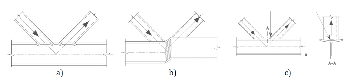
\[ \textsf{\textit{\footnotesize{Fig. 7.4.1 Major failure modes a) chord web failure, b) chord shear (in case of gap), c) brace failure}}}\]
The resistance of the chord web is determined using the method given in section 7.6 of the EN 1993-1-8:2005, which is described in (Wardenier et al,. 2010). The stresses from the brace are transferred through the flange of the chord to an effective area of the chord web. This area is located in the chord web at the point where the brace walls cross the chord web. The design axial resistance of the joint is the minimum of the design resistances: