Description
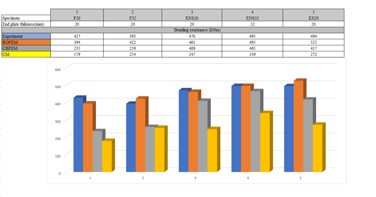
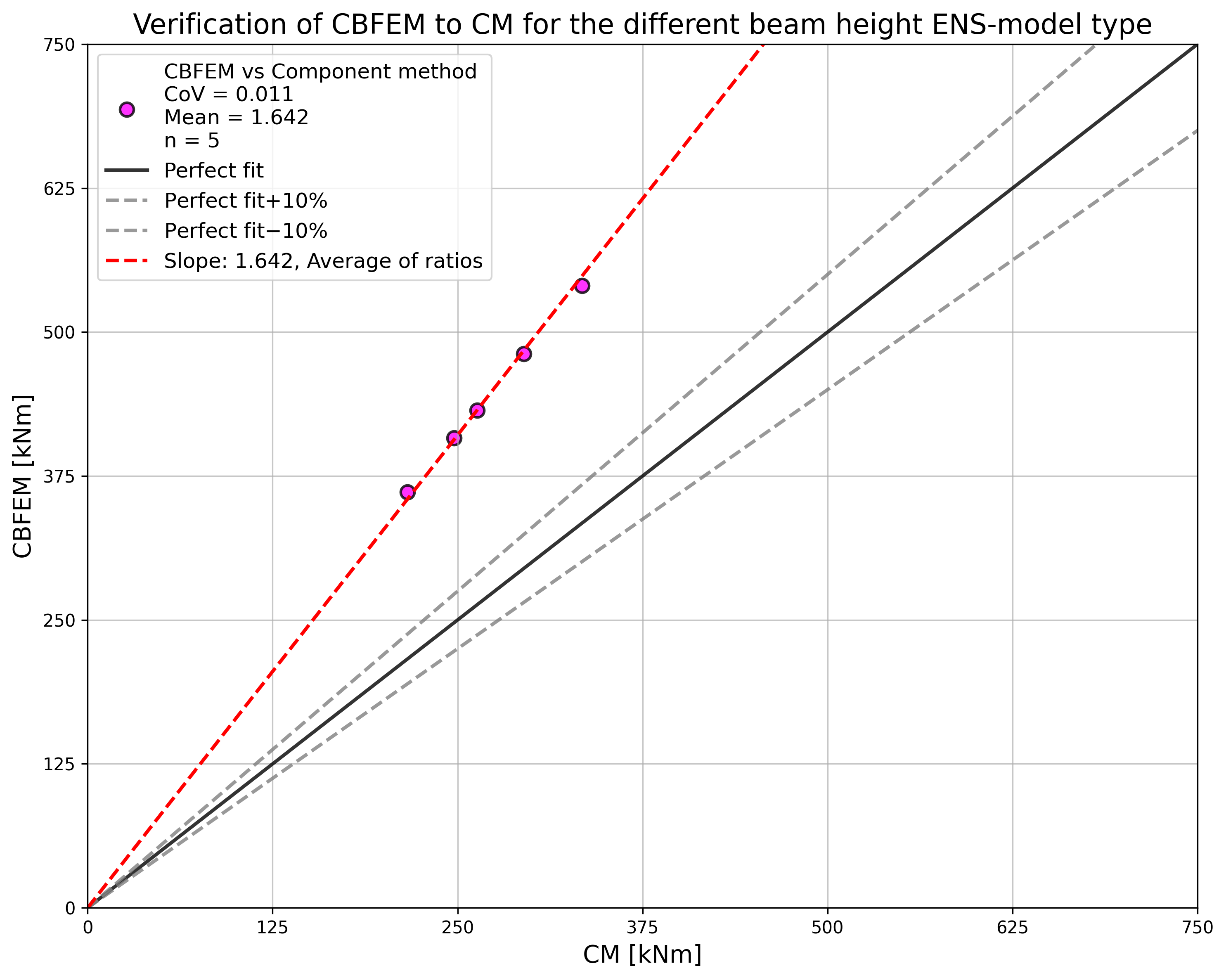
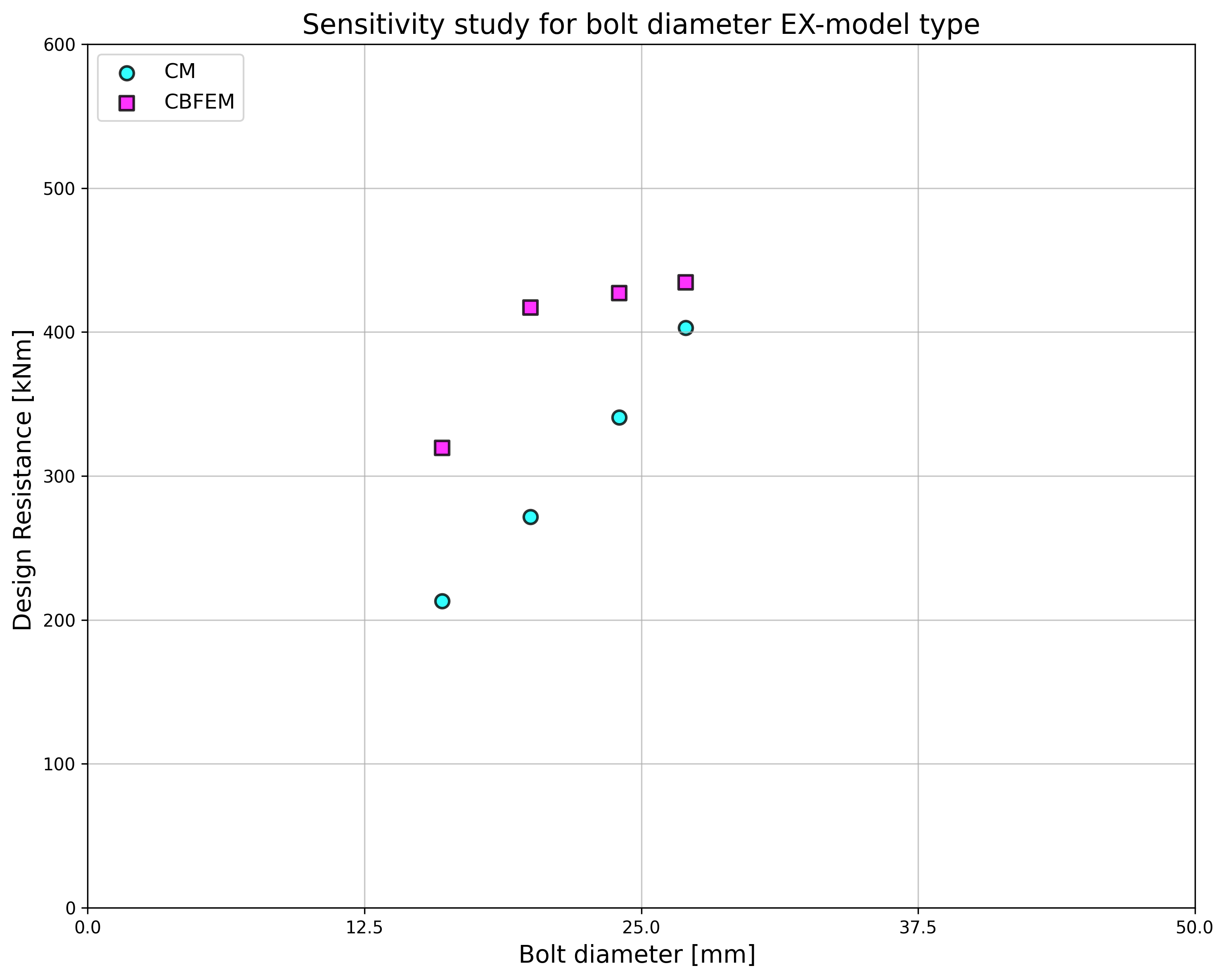
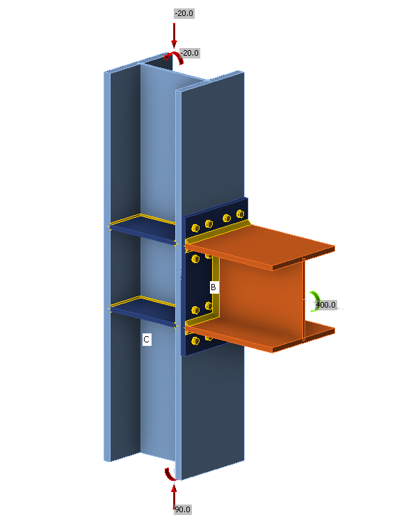
This study is focused on the verification of the component-based finite element method (CBFEM) for the resistance of the end plate connection with four bolts in a row to an analytical model (AM), and a research-oriented finite element model (ROFEM) validated on experiments.
Analytical model
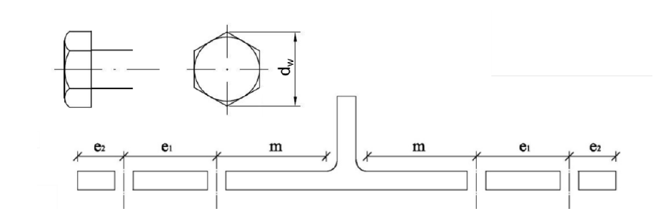
The bolt resistance in shear and tension and the plate resistance in bearing and punching shear are designed according to Tab. 3.4, Chapter 3.6.1 in EN 1993-1-8:2006. The equivalent T-stub in tension, according to Chapter 6.2.4, was modified by Jaspart et al. (2010) , see Fig. 5.7.1 and Tab. 5.7.1.
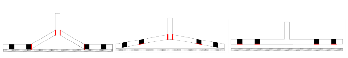
\[ \textsf{\textit{\footnotesize{Fig. 5.7.1 Failure modes of T-stub with four bolts in a row: mode 1 (left), mode 2 (middle), mode 3 (right)}}}\]
Tab. 5.7.1 Failure modes of T-stub with four bolts in a row (Jaspart et al. 2010)
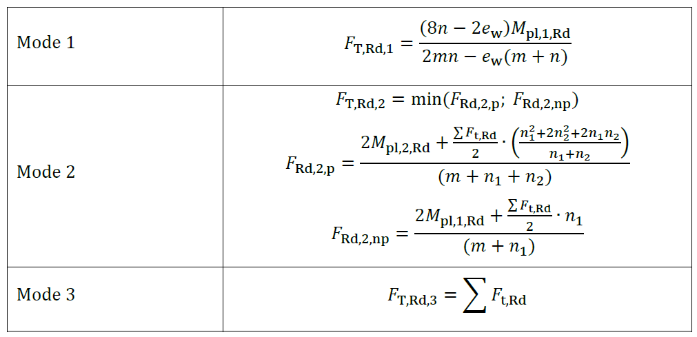
In Tab 5.7.1 is 𝐹t,Rd the bolt tensile resistance, 𝑒w=𝑑w/4, 𝑑w is the diameter of the washer, or the width across points of the bolt head or nut, as relevant, 𝑚, 𝑛=𝑒1+𝑒2;𝑛≤1.25𝑚, 𝑛1=𝑒1, 𝑛2=𝑒2;𝑛2≤1,25𝑚+𝑛1 see Fig. 5.8.2, 𝑀pl,1,Rd=0.25𝑙eff,1𝑡f2𝑓y/𝛾M0, 𝑀pl,2,Rd=0.25𝑙eff,2𝑡f2𝑓y/𝛾M0, 𝑙eff is effective length, 𝑡f is the flange thickness, and 𝑓y is the yield strength, see Fig. 5.7.2.