The appreciated user-friendly UI of IDEA StatiCa Connection allows structural engineers to work efficiently on everyday tasks as well as on complex projects. Quick and well-arranged input and overall automatization of the CBFEM analysis with a clear result overview don't leave any room for dead ends or process errors.
However, one should not be comforted, this is still a tool dedicated to engineers that need to consider a couple of facts and rules of the structural design. So, what is it you shouldn't forget when starting a new connection project?
You can find the condensed answer on this webpage Key principles of IDEA StatiCa Connection. Pointing out the essentials, every user of IDEA Statica Connection is more than recommended to read this. Let's highlight some.
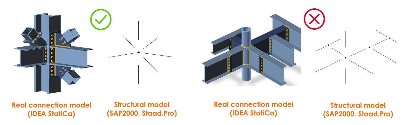
A connection model consists of one structural node
A common question our users ask is, how complex my connection model can be? Though we claim no limits in topology or loading, there are some limits considering the engineering judgment. In other words, the structural model consisting of a node and connected beams and columns in your structural software (SAP2000, SCIA Engineer) must correspond to the real connection model used in IDEA StatiCa Connection.
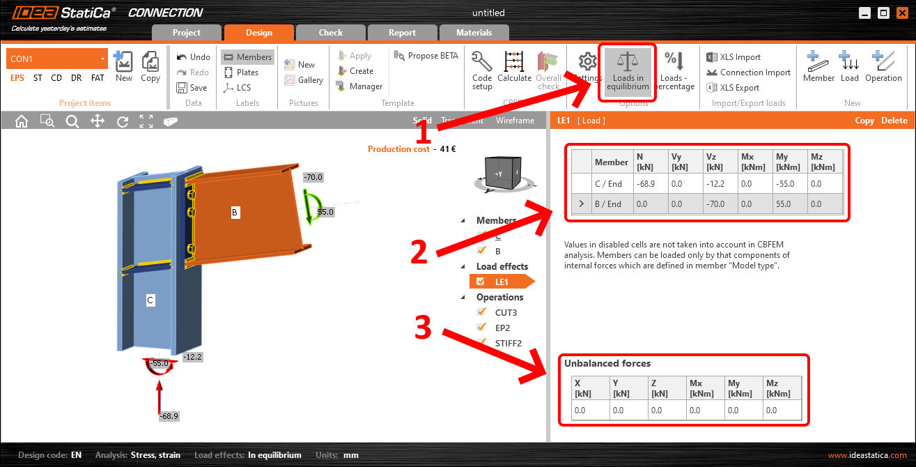
The load effects that you input are the nodal internal forces
Another frequent misunderstanding is in inputting the loads for the analysis of your connection. So those are the internal forces you get as the results from your structural model and after that, you use it for the connection analysis and code-check. By the law of statics, internal forces in a node have to be in equilibrium, meaning if you sum up them in each direction, you get zero. For most cases, have the Loads in equilibrium turned on and input the internal forces for each member. Then you can visually check that the unbalanced forces tab shows all zeros.