Connection design can be difficult to teach, given the detailed nature of the topic and the fundamentally three-dimensional behavior of most connections. However, connections are critically important, and lessons learned in the study of connection design, including load path and identification and evaluation of failure modes, are general and applicable to structural design broadly. IDEA StatiCa uses a rigorous nonlinear analysis model and has an easy-to-use interface with a three-dimensional display of results (e.g., deformed shape, stress, plastic strain) and thus is well suited for the exploration of the behavior of structural steel connections. Building on these strengths, a suite of guided exercises that use IDEA StatiCa as a virtual laboratory to help students learn about concepts in structural steel connection behavior and design was developed. These learning modules were primarily targeted to advanced undergraduate and graduate students but were made suitable for practicing engineers as well. The learning modules were developed by Associate Professor Mark D. Denavit from the University of Tennessee, Knoxville.
This learning module is derived from Learning Module: Load Path and Failure Modes of Fully Restrained Moment Connections (AISC) and modified for Eurocode by Assistant Professor Martin Vild from Brno university of Technology.
Learning Objective
After performing this exercise, the learner should be able to describe the load path for a fixed connection and identify relevant failure modes.
Background
Load Path
Loads applied to a structure are transferred through members and connections before eventually being resisted by the ground. Tracking the path of the load from its point of load application to the ground can be a helpful qualitative exercise to ensure the path is continuous, and that each component along the path has sufficient stiffness and strength. Tracking a subset of the load path through a connection provides the same benefits.
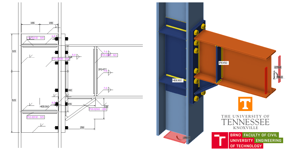
Consider, for example, the steel I-section beam-to-column fixed connection shown below. This connection is inspired by Equaljoints project for seismic applications. Moment in the beam is transferred to the column as follows:
- At the end of the beam, moment concentrates to the beam flanges, which are then subject to tension and compression.
- The haunch is added to increase the lever arm and thus the bending resistance. The bending moment is the highest in the node, and thanks to the shear force, it continually decreases. The stresses due to bending moment flow primarily through the top flange and the flange of the haunch.
- The shear stress flows through the beam web and the haunch web where the stiffness against vertical load is the highest.
- From the beam and the haunch, the load is distributed into the end plate by butt welds.
In traditional connection design, load paths such as this can help engineers develop a checklist of limit states and to ensure every step along the path has sufficient stiffness and strength. In design by inelastic analysis, load paths can help engineers by providing a mental model of connection behavior against which the results of numerical analyses can be compared.
Moment Connections
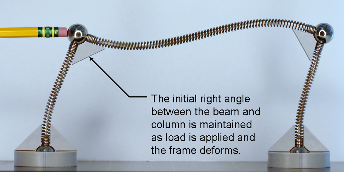
One of the major classifications of connections at the ends of beams is based on rotational stiffness. Simple shear connections are flexible enough to assume no moment is transmitted through the connection. Moment connections, on the other hand, transmit moment between the beam and column. Fully restrained connections are stiff enough to assume that no relative rotation occurs between members when transmitting the moment. Moment connections enable the beams and columns to form a moment frame that can serve as a lateral load-resisting system.
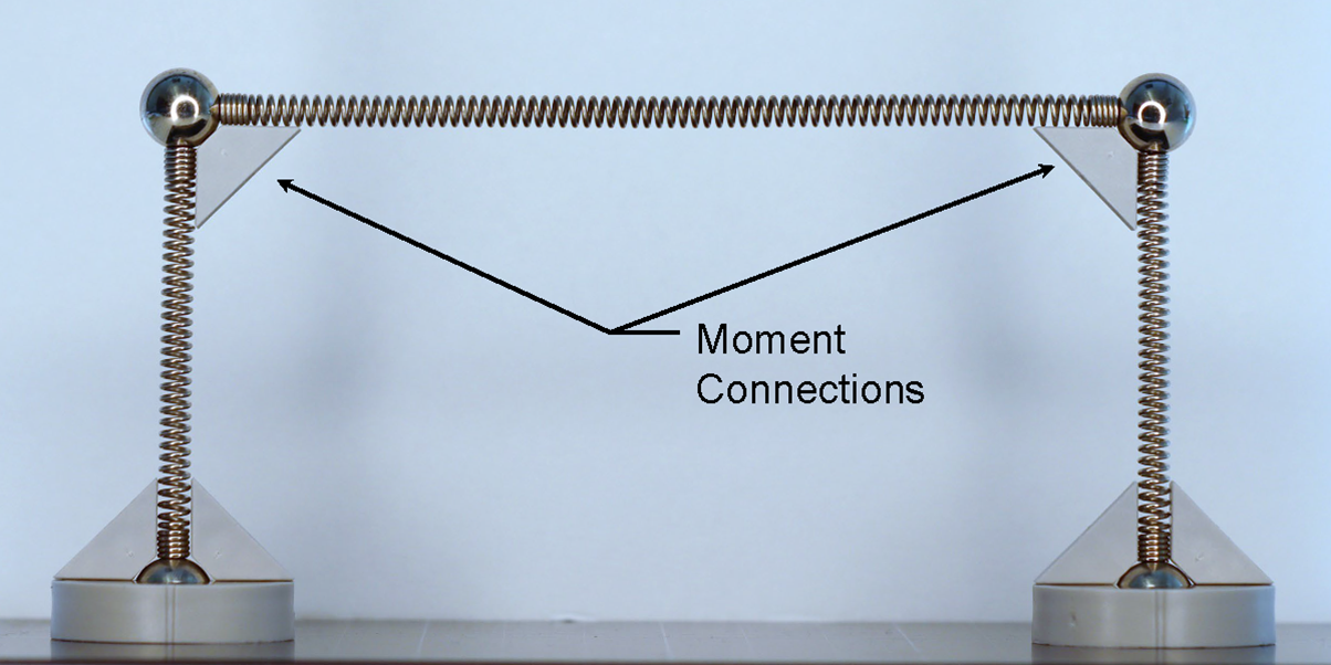
Moment frame action demonstrated with components from a Mola Structural Kit
Since most of the moment in a wide flange beam is resisted by the flanges, moment connections must engage the flanges of the beam directly. Moment connections typically also transfer shear or other forces from the beam to the column and thus also typically engage the web of the beam directly too. As a result, moment connections are generally statically indeterminate and the true distribution of stresses in the connection depends on the relative stiffness of the various components.
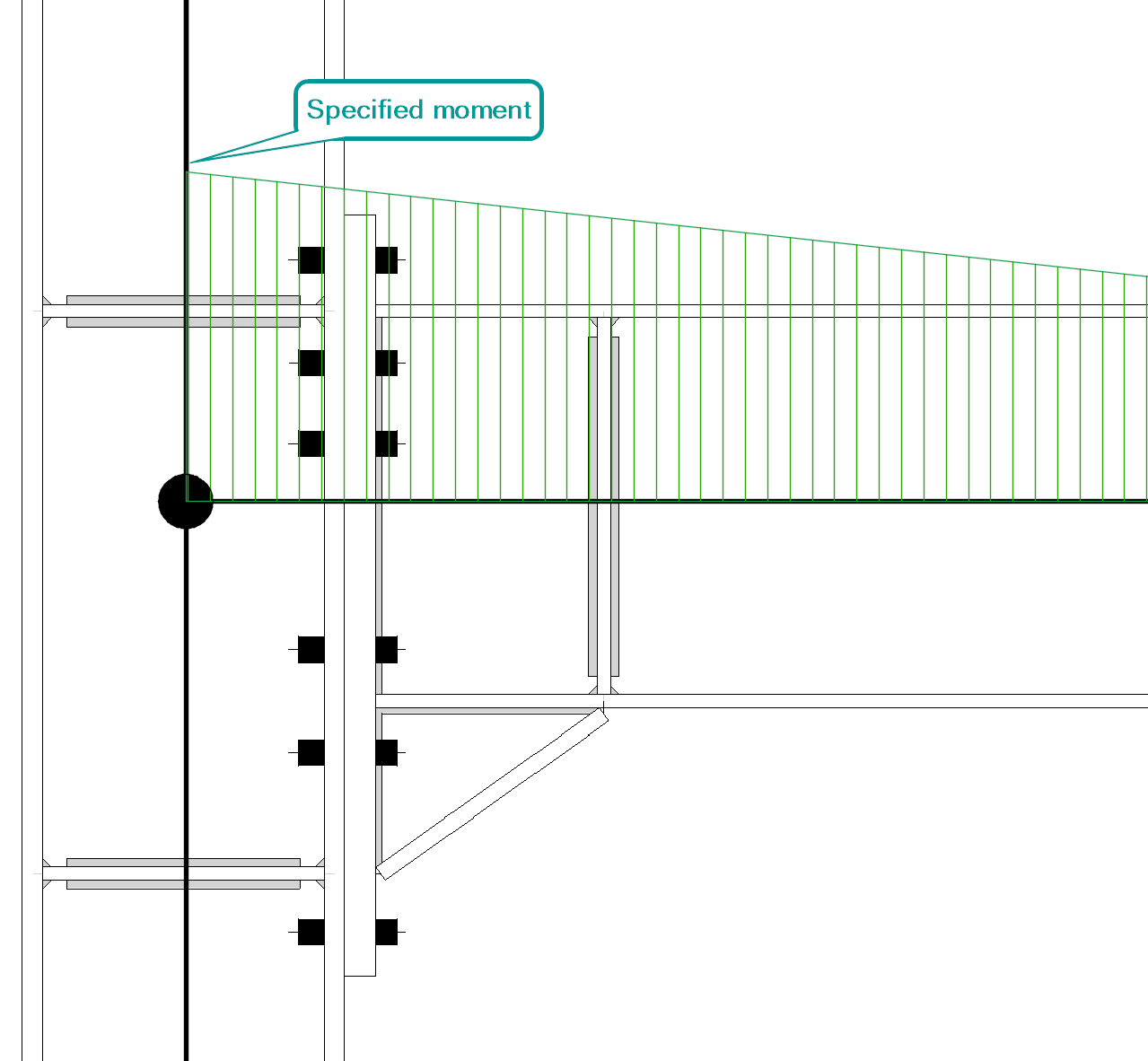
Shear forces induce a moment gradient in the beam. For moment connections, such as flange plate connections, that occur over a length of the beam, the moment is not constant. In hand calculations, the moment gradient is often conservatively neglected, and a single value of moment is used regardless of the length of the connection. The moment gradient cannot be neglected in IDEA StatiCa since the analyses ensure equilibrium and thus must be properly defined to be consistent with the structural analysis from which the required strengths were obtained. The specified moment will occur where defined by the “Forces in” option in the member menu.
Connection
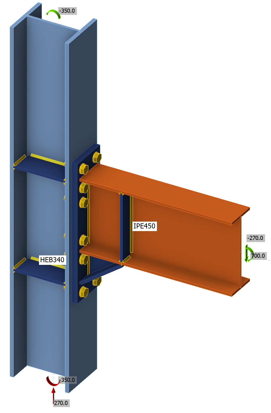
The examined connections are inspired by Equaljoints project. The haunched joint is selected for the first connection.
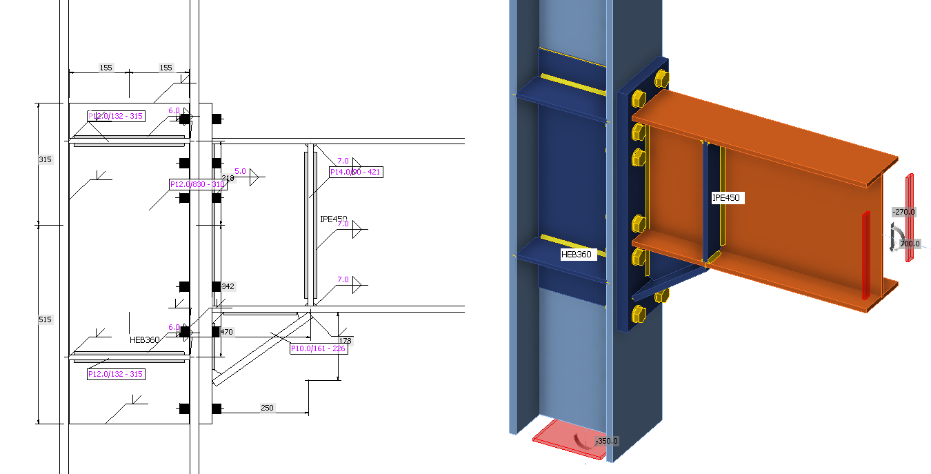
This connection is loaded by design shear force 270 kN and design bending moment 700 kNm. The loads are specified in node.
Procedure
The procedure for this exercise assumes that the learner has a working knowledge of how to use IDEA StatiCa (e.g., how to navigate the software, define and edit operations, perform analyses, and look up results). Guidance for how to develop such knowledge is available on the IDEA StatiCa website.
Retrieve the IDEA StatiCa file for the example connection provided with this exercise. Open the file in IDEA StatiCa. To perform the exercise, follow the narrative, complete the tasks, and answer the questions.
Load Path
The load path for shear transferring from the beam to the column is as follows:
- Shear is concentrated at the beam web.
- Shear flows through welds by shear perpendicular stresses, \(\tau_\perp\), to the end plate.
- Through the end plate, the load is distributed into the bolts.
- Via shear stresses in bolts, the shear is transferred to the column flange and then by normal force in the column into the ground.
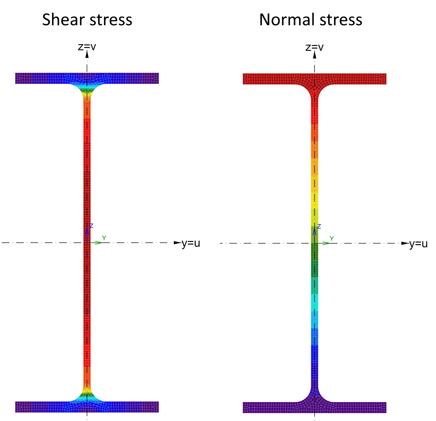
Shear stresses caused by unit shear force and normal stresses caused by unit bending moment at elastic stage
The load path for the bending moment transferring from the beam to the column is as follows:
- Moment concentrates mostly to the beam flanges, which are then subject to tension and compression.
- The haunch is added to increase the lever arm and thus the bending resistance. The bending moment is the highest in the node, and thanks to the shear force, it continually decreases. The stresses due to bending moment flow primarily through the top flange and the flange of the haunch.
- From the beam and the haunch, the load is distributed into the end plate by butt welds.
- The beam flange to column flange welds transfer the beam flange forces to the column flange.
Beam
The beam is subject to moment; therefore, failure modes such as flexural yielding and lateral-torsional buckling must be investigated as part of the member evaluation. The effect of lateral-torsional buckling may be checked in IDEA StatiCa Member using GMNIA or by code calculation according to EN 1993-1-1 – Cl. 6.3.2. Flexural yielding is in IDEA StatiCa checked against the 5% plastic strain limit. The most dangerous cross-section is at the end of the haunch.
Widget #NaN: widget_collapsible_list
Name: b495bbff-f77f-0149-5c6c-556c0a2ef6f9
ID: b495bbff-f77f-0149-5c6c-556c0a2ef6f9
Show Raw Data
{
  "title": {
    "name": "Headline",
    "type": "text",
    "value": ""
  },
  "description": {
    "name": "Description",
    "type": "text",
    "value": ""
  },
  "content_top": {
    "images": [],
    "linkedItemCodenames": [],
    "linkedItems": [],
    "links": [],
    "name": "Content before",
    "type": "rich_text",
    "value": "<p><br></p>"
  },
  "collapsible_items": {
    "name": "Collapsible items",
    "type": "modular_content",
    "value": [
      "lm03en_01"
    ],
    "linkedItems": [
      {
        "elements": {
          "title": {
            "name": "Title",
            "type": "text",
            "value": "What is the bending moment at the beam just before the beginning of the haunch? Compare the stress in the beam flanges with IDEA StatiCa. "
          },
          "description": {
            "name": "Description",
            "type": "text",
            "value": ""
          },
          "content_1": {
            "images": [
              {
                "description": null,
                "imageId": "951c2ea3-b62b-422e-a863-a5196453c4f8",
                "url": "https://assets-us-01.kc-usercontent.com:443/28eac049-c8ed-00e2-220c-12142a968dff/51b30146-efc3-4f55-98dc-344d2f4b2e73/LM03EN-06.png",
                "height": 1035,
                "width": 1311
              },
              {
                "description": null,
                "imageId": "08bc52bc-4e2d-4289-81a5-bdc15aadddbd",
                "url": "https://assets-us-01.kc-usercontent.com:443/28eac049-c8ed-00e2-220c-12142a968dff/9028485f-4ecb-4912-acde-50b2c9aca295/LM03EN-07.png",
                "height": 744,
                "width": 482
              }
            ],
            "linkedItemCodenames": [],
            "linkedItems": [],
            "links": [],
            "name": "Content column 1",
            "type": "rich_text",
            "value": "<p>The distance to the start of the haunch is:</p>\n<p>\\[ h_c/2+t_p+b_h = 360/2+35+255 = 470 \\textrm{ mm} \\]</p>\n<p>And the bending moment:</p>\n<p>\\[ M_{Ed} + 0.470 \\cdot V_{Ed} = 700 + 0.470 \\cdot (-270) = 573.1 \\textrm{ kNm} \\]</p>\n<figure data-asset-id=\"951c2ea3-b62b-422e-a863-a5196453c4f8\" data-image-id=\"951c2ea3-b62b-422e-a863-a5196453c4f8\"><img src=\"https://assets-us-01.kc-usercontent.com:443/28eac049-c8ed-00e2-220c-12142a968dff/51b30146-efc3-4f55-98dc-344d2f4b2e73/LM03EN-06.png\" data-asset-id=\"951c2ea3-b62b-422e-a863-a5196453c4f8\" data-image-id=\"951c2ea3-b62b-422e-a863-a5196453c4f8\" alt=\"\"></figure>\n<p>The stress in the beam can be calculated using elastic or plastic section modulus. Using elastic section modulus, we obtain:</p>\n<p>\\[ M_{Ed} / W_{el,y} = 573.1 \\cdot 10^6/ 1.5\\cdot 10^6 = 382 \\textrm{ MPa}\\]</p>\n<p>This is higher than the yield strength, which means the flanges must already yield.</p>\n<p>Using plastic section modulus:</p>\n<p>\\[ M_{Ed} / W_{pl,y} = 573.1 \\cdot 10^6/ 1.7\\cdot 10^6 = 337 \\textrm{ MPa}\\]</p>\n<p>This is below yield strength. The cross-section is yielding but is not fully plasticized. We can expect 355 MPa at flanges and an elasto-plastic stress distribution in the web.</p>\n<p>Note that uniaxial longitudinal stress is equal to equivalent stress shown by IDEA StatiCa. The stresses confirm our calculations.</p>\n<figure data-asset-id=\"08bc52bc-4e2d-4289-81a5-bdc15aadddbd\" data-image-id=\"08bc52bc-4e2d-4289-81a5-bdc15aadddbd\"><img src=\"https://assets-us-01.kc-usercontent.com:443/28eac049-c8ed-00e2-220c-12142a968dff/9028485f-4ecb-4912-acde-50b2c9aca295/LM03EN-07.png\" data-asset-id=\"08bc52bc-4e2d-4289-81a5-bdc15aadddbd\" data-image-id=\"08bc52bc-4e2d-4289-81a5-bdc15aadddbd\" alt=\"\"></figure>"
          },
          "content_2": {
            "images": [],
            "linkedItemCodenames": [],
            "linkedItems": [],
            "links": [],
            "name": "Content column 2",
            "type": "rich_text",
            "value": "<p><br></p>"
          },
          "visibleinregion": {
            "name": "VisibleInRegion",
            "type": "multiple_choice",
            "value": []
          },
          "regions": {
            "name": "Region",
            "type": "taxonomy",
            "value": [],
            "taxonomyGroup": "region"
          },
          "translation__translation_connector": {
            "name": "Translation Connector",
            "type": "taxonomy",
            "value": [],
            "taxonomyGroup": "languages"
          },
          "translation__force_translation": {
            "name": "Force translation",
            "type": "multiple_choice",
            "value": []
          },
          "translation__last_translation": {
            "images": [],
            "linkedItemCodenames": [],
            "linkedItems": [],
            "links": [],
            "name": "Last translation",
            "type": "rich_text",
            "value": "<p><br></p>"
          },
          "translation__ai_translated": {
            "name": "AI translated",
            "type": "multiple_choice",
            "value": []
          }
        },
        "system": {
          "codename": "lm03en_01",
          "collection": "default",
          "id": "90dcab9b-911b-4cb6-a688-ded109c8fed9",
          "language": "en-US",
          "lastModified": "2024-10-23T15:18:53.5197468Z",
          "name": "LM03EN-01",
          "sitemapLocations": [],
          "type": "widget_text_block",
          "workflowStep": "published",
          "workflow": "default"
        }
      }
    ]
  },
  "content_bottom": {
    "images": [],
    "linkedItemCodenames": [],
    "linkedItems": [],
    "links": [],
    "name": "Content after",
    "type": "rich_text",
    "value": "<p><br></p>"
  },
  "visibleinregion": {
    "name": "VisibleInRegion",
    "type": "multiple_choice",
    "value": []
  },
  "regions": {
    "name": "Region",
    "type": "taxonomy",
    "value": [],
    "taxonomyGroup": "region"
  },
  "translation__translation_connector": {
    "name": "Translation Connector",
    "type": "taxonomy",
    "value": [],
    "taxonomyGroup": "languages"
  },
  "translation__force_translation": {
    "name": "Force translation",
    "type": "multiple_choice",
    "value": []
  },
  "translation__last_translation": {
    "images": [],
    "linkedItemCodenames": [],
    "linkedItems": [],
    "links": [],
    "name": "Last translation",
    "type": "rich_text",
    "value": "<p><br></p>"
  },
  "translation__ai_translated": {
    "name": "AI translated",
    "type": "multiple_choice",
    "value": []
  }
}
Widget #NaN: widget_collapsible_list
Name: 55ae80f2-0f0d-01cf-3ceb-93545b969e49
ID: 55ae80f2-0f0d-01cf-3ceb-93545b969e49
Show Raw Data
{
"title": {
"name": "Headline",
"type": "text",
"value": ""
},
"description": {
"name": "Description",
"type": "text",
"value": ""
},
"content_top": {
"images": [],
"linkedItemCodenames": [],
"linkedItems": [],
"links": [],
"name": "Content before",
"type": "rich_text",
"value": "<p><br></p>"
},
"collapsible_items": {
"name": "Collapsible items",
"type": "modular_content",
"value": [
"lm03en_02_66352d9"
],
"linkedItems": [
{
"elements": {
"title": {
"name": "Title",
"type": "text",
"value": "How is bending moment resistance of the member checked in IDEA StatiCa?"
},
"description": {
"name": "Description",
"type": "text",
"value": ""
},
"content_1": {
"images": [],
"linkedItemCodenames": [],
"linkedItems": [],
"links": [],
"name": "Content column 1",
"type": "rich_text",
"value": "<p>The check of all plates including members in IDEA StatiCa is done against plastic strain limit set by default to 5%. </p>"
},
"content_2": {
"images": [],
"linkedItemCodenames": [],
"linkedItems": [],
"links": [],
"name": "Content column 2",
"type": "rich_text",
"value": "<p><br></p>"
},
"visibleinregion": {
"name": "VisibleInRegion",
"type": "multiple_choice",
"value": []
},
"regions": {
"name": "Region",
"type": "taxonomy",
"value": [],
"taxonomyGroup": "region"
},
"translation__translation_connector": {
"name": "Translation Connector",
"type": "taxonomy",
"value": [],
"taxonomyGroup": "languages"
},
"translation__force_translation": {
"name": "Force translation",
"type": "multiple_choice",
"value": []
},
"translation__last_translation": {
"images": [],
"linkedItemCodenames": [],
"linkedItems": [],
"links": [],
"name": "Last translation",
"type": "rich_text",
"value": "<p><br></p>"
},
"translation__ai_translated": {
"name": "AI translated",
"type": "multiple_choice",
"value": []
}
},
"system": {
"codename": "lm03en_02_66352d9",
"collection": "default",
"id": "66352d94-c48e-41bb-9111-a8b27d8fdef3",
"language": "en-US",
"lastModified": "2024-10-23T11:35:14.9205866Z",
"name": "LM03EN-02",
"sitemapLocations": [],
"type": "widget_text_block",
"workflowStep": "published",
"workflow": "default"
}
}
]
},
"content_bottom": {
"images": [],
"linkedItemCodenames": [],
"linkedItems": [],
"links": [],
"name": "Content after",
"type": "rich_text",
"value": "<p><br></p>"
},
"visibleinregion": {
"name": "VisibleInRegion",
"type": "multiple_choice",
"value": []
},
"regions": {
"name": "Region",
"type": "taxonomy",
"value": [],
"taxonomyGroup": "region"
},
"translation__translation_connector": {
"name": "Translation Connector",
"type": "taxonomy",
"value": [],
"taxonomyGroup": "languages"
},
"translation__force_translation": {
"name": "Force translation",
"type": "multiple_choice",
"value": []
},
"translation__last_translation": {
"images": [],
"linkedItemCodenames": [],
"linkedItems": [],
"links": [],
"name": "Last translation",
"type": "rich_text",
"value": "<p><br></p>"
},
"translation__ai_translated": {
"name": "AI translated",
"type": "multiple_choice",
"value": []
}
}Haunch
Haunch increases the beam cross-section, increasing connection strength and stiffness by increasing lever arm between tension in bolts and the compression center.
Widget #NaN: widget_collapsible_list
Name: a40c0bec-331c-0191-16dd-731db2a29b4a
ID: a40c0bec-331c-0191-16dd-731db2a29b4a
Show Raw Data
{
  "title": {
    "name": "Headline",
    "type": "text",
    "value": ""
  },
  "description": {
    "name": "Description",
    "type": "text",
    "value": ""
  },
  "content_top": {
    "images": [],
    "linkedItemCodenames": [],
    "linkedItems": [],
    "links": [],
    "name": "Content before",
    "type": "rich_text",
    "value": "<p><br></p>"
  },
  "collapsible_items": {
    "name": "Collapsible items",
    "type": "modular_content",
    "value": [
      "lm03en_02"
    ],
    "linkedItems": [
      {
        "elements": {
          "title": {
            "name": "Title",
            "type": "text",
            "value": "What is the bending moment at the connection between haunch and end plate? What are the stresses in the haunch at this location (use simplified calculation)? Compare the calculated stresses to IDEA StatiCa."
          },
          "description": {
            "name": "Description",
            "type": "text",
            "value": ""
          },
          "content_1": {
            "images": [
              {
                "description": null,
                "imageId": "f9a178df-bc75-48ce-891f-5258aa4aa30b",
                "url": "https://assets-us-01.kc-usercontent.com:443/28eac049-c8ed-00e2-220c-12142a968dff/b6068f7c-f621-4cf3-ad02-c94668fa79a7/LM03EN-08.png",
                "height": 1035,
                "width": 1311
              },
              {
                "description": null,
                "imageId": "9acdb5db-936b-4ea0-913d-94c189377577",
                "url": "https://assets-us-01.kc-usercontent.com:443/28eac049-c8ed-00e2-220c-12142a968dff/7dd9e19d-0f9b-4502-bfab-33abed6086a5/LM03EN-09.png",
                "height": 744,
                "width": 482
              },
              {
                "description": null,
                "imageId": "22ece7f4-46f3-4f2a-85e7-5e6f7e0a15c4",
                "url": "https://assets-us-01.kc-usercontent.com:443/28eac049-c8ed-00e2-220c-12142a968dff/a2398f5b-fe6b-4ce0-aac2-f2651edcd148/LM3EN-10.png",
                "height": 691,
                "width": 1030
              }
            ],
            "linkedItemCodenames": [],
            "linkedItems": [],
            "links": [],
            "name": "Content column 1",
            "type": "rich_text",
            "value": "<p>The bending moment at the haunch end is:</p>\n<p>\\[ M_{Ed} + (h_c/2+t_p) \\cdot V_{Ed} = 700 + (0.36/2+0.035) \\cdot (-270) = 642 \\textrm{ kNm}\\]</p>\n<figure data-asset-id=\"f9a178df-bc75-48ce-891f-5258aa4aa30b\" data-image-id=\"f9a178df-bc75-48ce-891f-5258aa4aa30b\"><img src=\"https://assets-us-01.kc-usercontent.com:443/28eac049-c8ed-00e2-220c-12142a968dff/b6068f7c-f621-4cf3-ad02-c94668fa79a7/LM03EN-08.png\" data-asset-id=\"f9a178df-bc75-48ce-891f-5258aa4aa30b\" data-image-id=\"f9a178df-bc75-48ce-891f-5258aa4aa30b\" alt=\"\"></figure>\n<p>The exact calculation of section modulus of beam and a haunch is relatively complicated. Plastic section modulus can be exactly calculated in general cross-section editor. In simplified calculation, we can neglect beam bottom flange and assume haunch web and flange thicknesses equal to beam web and flange thicknesses.</p>\n<p>\\[W_{pl,y} = 2 \\cdot [(14.6 \\cdot 190) \\cdot (450+178)/2 +(450+178)/2 \\cdot (450+178)/4)] = 1 840 668 \\textrm{ mm}^3 \\]</p>\n<p>The stress at the haunch end is:</p>\n<p>\\[ \\sigma = M_{Ed}/W_{pl,y} = 642 \\cdot 10^6 / 1840668 = 349 \\textrm{ MPa}\\]</p>\n<p>Again, we should expect yielding in flanges and not fully utilized web. This agrees well with IDEA StatiCa.</p>\n<figure data-asset-id=\"9acdb5db-936b-4ea0-913d-94c189377577\" data-image-id=\"9acdb5db-936b-4ea0-913d-94c189377577\"><img src=\"https://assets-us-01.kc-usercontent.com:443/28eac049-c8ed-00e2-220c-12142a968dff/7dd9e19d-0f9b-4502-bfab-33abed6086a5/LM03EN-09.png\" data-asset-id=\"9acdb5db-936b-4ea0-913d-94c189377577\" data-image-id=\"9acdb5db-936b-4ea0-913d-94c189377577\" alt=\"\"></figure>\n<figure data-asset-id=\"22ece7f4-46f3-4f2a-85e7-5e6f7e0a15c4\" data-image-id=\"22ece7f4-46f3-4f2a-85e7-5e6f7e0a15c4\"><img src=\"https://assets-us-01.kc-usercontent.com:443/28eac049-c8ed-00e2-220c-12142a968dff/a2398f5b-fe6b-4ce0-aac2-f2651edcd148/LM3EN-10.png\" data-asset-id=\"22ece7f4-46f3-4f2a-85e7-5e6f7e0a15c4\" data-image-id=\"22ece7f4-46f3-4f2a-85e7-5e6f7e0a15c4\" alt=\"\"></figure>\n<p><em>Stresses from unit bending moment and cross-sectional properties of the hauch just behind end plate</em></p>"
          },
          "content_2": {
            "images": [],
            "linkedItemCodenames": [],
            "linkedItems": [],
            "links": [],
            "name": "Content column 2",
            "type": "rich_text",
            "value": "<p><br></p>"
          },
          "visibleinregion": {
            "name": "VisibleInRegion",
            "type": "multiple_choice",
            "value": []
          },
          "regions": {
            "name": "Region",
            "type": "taxonomy",
            "value": [],
            "taxonomyGroup": "region"
          },
          "translation__translation_connector": {
            "name": "Translation Connector",
            "type": "taxonomy",
            "value": [],
            "taxonomyGroup": "languages"
          },
          "translation__force_translation": {
            "name": "Force translation",
            "type": "multiple_choice",
            "value": []
          },
          "translation__last_translation": {
            "images": [],
            "linkedItemCodenames": [],
            "linkedItems": [],
            "links": [],
            "name": "Last translation",
            "type": "rich_text",
            "value": "<p><br></p>"
          },
          "translation__ai_translated": {
            "name": "AI translated",
            "type": "multiple_choice",
            "value": []
          }
        },
        "system": {
          "codename": "lm03en_02",
          "collection": "default",
          "id": "48ac60df-61ae-44a4-ab24-30624fefc654",
          "language": "en-US",
          "lastModified": "2024-10-23T10:03:04.9820152Z",
          "name": "LM03EN-02",
          "sitemapLocations": [],
          "type": "widget_text_block",
          "workflowStep": "published",
          "workflow": "default"
        }
      }
    ]
  },
  "content_bottom": {
    "images": [],
    "linkedItemCodenames": [],
    "linkedItems": [],
    "links": [],
    "name": "Content after",
    "type": "rich_text",
    "value": "<p><br></p>"
  },
  "visibleinregion": {
    "name": "VisibleInRegion",
    "type": "multiple_choice",
    "value": []
  },
  "regions": {
    "name": "Region",
    "type": "taxonomy",
    "value": [],
    "taxonomyGroup": "region"
  },
  "translation__translation_connector": {
    "name": "Translation Connector",
    "type": "taxonomy",
    "value": [],
    "taxonomyGroup": "languages"
  },
  "translation__force_translation": {
    "name": "Force translation",
    "type": "multiple_choice",
    "value": []
  },
  "translation__last_translation": {
    "images": [],
    "linkedItemCodenames": [],
    "linkedItems": [],
    "links": [],
    "name": "Last translation",
    "type": "rich_text",
    "value": "<p><br></p>"
  },
  "translation__ai_translated": {
    "name": "AI translated",
    "type": "multiple_choice",
    "value": []
  }
}
End plate
The shear and normal stresses are transferred into the end plate via welds. Full-penetration butt welds are used for critical welds of flanges. Fillet welds are used at the web where the welds are less loaded.
Widget #NaN: widget_collapsible_list
Name: 4f519c84-7a3a-01d2-d802-11cf05b7af07
ID: 4f519c84-7a3a-01d2-d802-11cf05b7af07
Show Raw Data
{
"title": {
"name": "Headline",
"type": "text",
"value": ""
},
"description": {
"name": "Description",
"type": "text",
"value": ""
},
"content_top": {
"images": [],
"linkedItemCodenames": [],
"linkedItems": [],
"links": [],
"name": "Content before",
"type": "rich_text",
"value": "<p><br></p>"
},
"collapsible_items": {
"name": "Collapsible items",
"type": "modular_content",
"value": [
"lm03en_03"
],
"linkedItems": [
{
"elements": {
"title": {
"name": "Title",
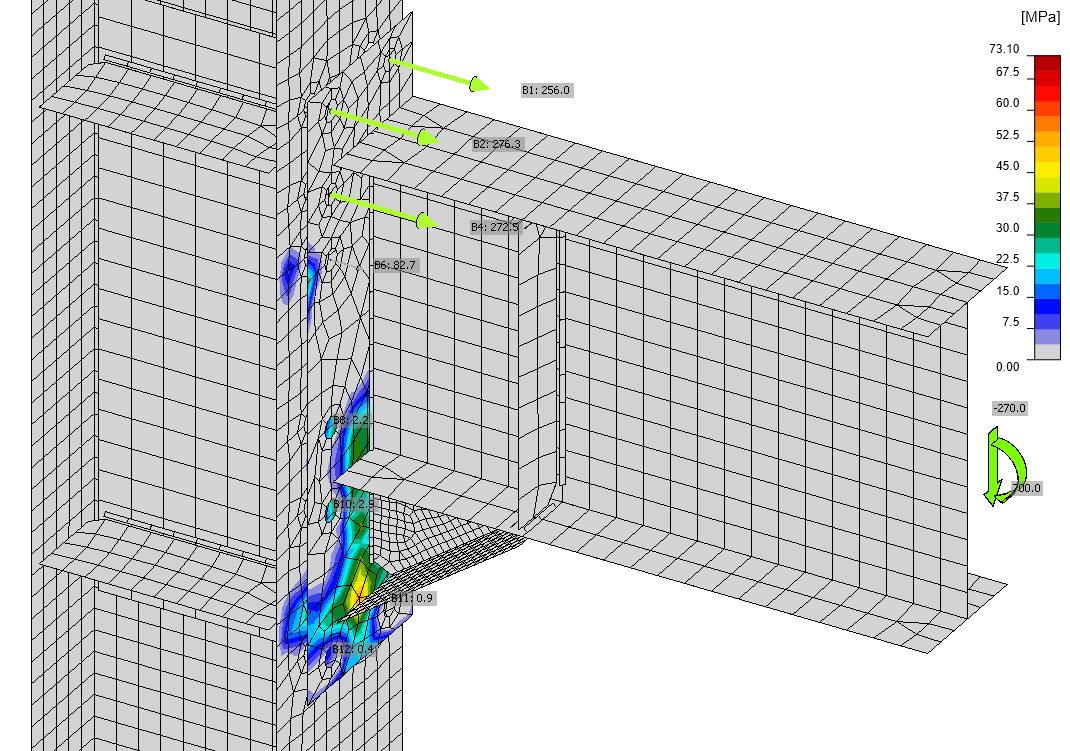
"type": "text",
"value": "What direction of stresses do you expect in the fillet welds at beam web? What is the expected value of perpendicular shear stress in the fillet weld caused by the shear force?"
},
"description": {
"name": "Description",
"type": "text",
"value": ""
},
"content_1": {
"images": [
{
"description": null,
"imageId": "a8155100-9f8c-4d5a-96af-26cb3c3f4191",
"url": "https://assets-us-01.kc-usercontent.com:443/28eac049-c8ed-00e2-220c-12142a968dff/209ed55e-838e-45f1-8eb3-d89691b2254b/LM3EN-11.png",
"height": 618,
"width": 800
}
],
"linkedItemCodenames": [],
"linkedItems": [],
"links": [],
"name": "Content column 1",
"type": "rich_text",
"value": "<p>There are several approaches we can use for designing welds at I-section.</p>\n<ul>\n <li>The most simple is to assume that welds at flanges take bending moments and welds at the web transfer shear force</li>\n <li>More accurate at the elastic stage is the assumption that weld group transfers the bending moment in ratio of moment of inertias, i.e.:</li>\n</ul>\n<p>\\[M_{flange} = I_{flange}/I_{total}\\]</p>\n<p>\\[M_{web} = I_{web}/I_{total}\\]</p>\n<p>where: </p>\n<ul>\n <li><em>M</em><sub>flange</sub> – portion of bending moment transferred via flange welds</li>\n <li><em>M</em><sub>web</sub> – portion of bending moment transferred via web welds\n <ul>\n <li>Note that \\(M_{flange}+M_{web} = M_{total}\\)</li>\n </ul>\n </li>\n <li><em>I</em><sub>flange</sub> – moment of inertia of flanges</li>\n <li><em>I</em><sub>web</sub> – moment of inertia of web</li>\n <li><em>I</em><sub>total</sub> – total moment of inertia\n <ul>\n <li>Note that \\(I_{flange}+I_{web} = I_{total}\\)</li>\n </ul>\n </li>\n</ul>\n<p>The shear force is assumed to be taken only by beam web.</p>\n<p>So we can expect significant shear stresses parallel to the weld axis, \\(\\tau_\\parallel\\) and some normal and shear stresses, \\(\\sigma_\\perp\\) and \\(\\tau_\\perp\\) due to bending.</p>\n<p>The magnitude of \\(\\tau_\\parallel\\) can be calculated by summing up the fillet weld areas at the beam web and the hauch web:</p>\n<p>\\[A_w = 2 \\cdot 5 \\cdot 421 + 2 \\cdot 5 \\cdot 118 = 5390\\textrm{ mm}^2\\]</p>\n<p>Then we can calculate the expected uniform stress:</p>\n<p>\\[\\tau_\\parallel = V_{Ed} / A_w = 270 \\cdot 10^3 / 5390=50 \\textrm{ MPa}\\]</p>\n<p>Comparison to IDEA StatiCa results shows a complicated stress pattern exceeding the calculated value:</p>\n<figure data-asset-id=\"a8155100-9f8c-4d5a-96af-26cb3c3f4191\" data-image-id=\"a8155100-9f8c-4d5a-96af-26cb3c3f4191\"><img src=\"https://assets-us-01.kc-usercontent.com:443/28eac049-c8ed-00e2-220c-12142a968dff/209ed55e-838e-45f1-8eb3-d89691b2254b/LM3EN-11.png\" data-asset-id=\"a8155100-9f8c-4d5a-96af-26cb3c3f4191\" data-image-id=\"a8155100-9f8c-4d5a-96af-26cb3c3f4191\" alt=\"\"></figure>"
},
"content_2": {
"images": [],
"linkedItemCodenames": [],
"linkedItems": [],
"links": [],
"name": "Content column 2",
"type": "rich_text",
"value": "<p><br></p>"
},
"visibleinregion": {
"name": "VisibleInRegion",
"type": "multiple_choice",
"value": []
},
"regions": {
"name": "Region",
"type": "taxonomy",
"value": [],
"taxonomyGroup": "region"
},
"translation__translation_connector": {
"name": "Translation Connector",
"type": "taxonomy",
"value": [],
"taxonomyGroup": "languages"
},
"translation__force_translation": {
"name": "Force translation",
"type": "multiple_choice",
"value": []
},
"translation__last_translation": {
"images": [],
"linkedItemCodenames": [],
"linkedItems": [],
"links": [],
"name": "Last translation",
"type": "rich_text",
"value": "<p><br></p>"
},
"translation__ai_translated": {
"name": "AI translated",
"type": "multiple_choice",
"value": []
}
},
"system": {
"codename": "lm03en_03",
"collection": "default",
"id": "64e0e048-f0ec-43ed-a098-dbf7a27771d4",
"language": "en-US",
"lastModified": "2024-10-23T15:23:18.7690566Z",
"name": "LM03EN-03",
"sitemapLocations": [],
"type": "widget_text_block",
"workflowStep": "published",
"workflow": "default"
}
}
]
},
"content_bottom": {
"images": [],
"linkedItemCodenames": [],
"linkedItems": [],
"links": [],
"name": "Content after",
"type": "rich_text",
"value": "<p><br></p>"
},
"visibleinregion": {
"name": "VisibleInRegion",
"type": "multiple_choice",
"value": []
},
"regions": {
"name": "Region",
"type": "taxonomy",
"value": [],
"taxonomyGroup": "region"
},
"translation__translation_connector": {
"name": "Translation Connector",
"type": "taxonomy",
"value": [],
"taxonomyGroup": "languages"
},
"translation__force_translation": {
"name": "Force translation",
"type": "multiple_choice",
"value": []
},
"translation__last_translation": {
"images": [],
"linkedItemCodenames": [],
"linkedItems": [],
"links": [],
"name": "Last translation",
"type": "rich_text",
"value": "<p><br></p>"
},
"translation__ai_translated": {
"name": "AI translated",
"type": "multiple_choice",
"value": []
}
}The load is transferred through the end plate into bolts. Typically, it is assumed that the shear forces are distributed evenly into all bolts. Alternatively, the bolts loaded most in tension are excluded and it is assumed that the bolts in compression zone transfer shear force.
Widget #NaN: widget_collapsible_list
Name: fc596577-7b89-0196-6737-badd021e659f
ID: fc596577-7b89-0196-6737-badd021e659f
Show Raw Data
{
  "title": {
    "name": "Headline",
    "type": "text",
    "value": ""
  },
  "description": {
    "name": "Description",
    "type": "text",
    "value": ""
  },
  "content_top": {
    "images": [],
    "linkedItemCodenames": [],
    "linkedItems": [],
    "links": [],
    "name": "Content before",
    "type": "rich_text",
    "value": "<p><br></p>"
  },
  "collapsible_items": {
    "name": "Collapsible items",
    "type": "modular_content",
    "value": [
      "lm03en_04"
    ],
    "linkedItems": [
      {
        "elements": {
          "title": {
            "name": "Title",
            "type": "text",
            "value": "Calculate shear force in bolts and compare to IDEA StatiCa."
          },
          "description": {
            "name": "Description",
            "type": "text",
            "value": ""
          },
          "content_1": {
            "images": [
              {
                "description": null,
                "imageId": "6db641e0-009b-42a6-a79a-ff3087ec0a15",
                "url": "https://assets-us-01.kc-usercontent.com:443/28eac049-c8ed-00e2-220c-12142a968dff/0ba4edd7-ee5a-4a4b-9d1f-aa11bd0a6f32/LM3EN-12.png",
                "height": 610,
                "width": 850
              }
            ],
            "linkedItemCodenames": [],
            "linkedItems": [],
            "links": [],
            "name": "Content column 1",
            "type": "rich_text",
            "value": "<p>\\[F_{v,Ed} = V_{Ed} / n = 270 / 12 = 22.5 \\textrm{ kN}\\]</p>\n<p>where:</p>\n<ul>\n  <li>\\(F_{v,Ed}\\) – shear force in one bolt</li>\n  <li>\\(V_{Ed}\\) – total shear force</li>\n  <li>\\(n\\) – number of bolts</li>\n</ul>\n<p>The forces in IDEA StatiCa are quite diverse, which is caused by a significant deformation of the column web in shear and end plate.</p>\n<figure data-asset-id=\"6db641e0-009b-42a6-a79a-ff3087ec0a15\" data-image-id=\"6db641e0-009b-42a6-a79a-ff3087ec0a15\"><img src=\"https://assets-us-01.kc-usercontent.com:443/28eac049-c8ed-00e2-220c-12142a968dff/0ba4edd7-ee5a-4a4b-9d1f-aa11bd0a6f32/LM3EN-12.png\" data-asset-id=\"6db641e0-009b-42a6-a79a-ff3087ec0a15\" data-image-id=\"6db641e0-009b-42a6-a79a-ff3087ec0a15\" alt=\"\"></figure>"
          },
          "content_2": {
            "images": [],
            "linkedItemCodenames": [],
            "linkedItems": [],
            "links": [],
            "name": "Content column 2",
            "type": "rich_text",
            "value": "<p><br></p>"
          },
          "visibleinregion": {
            "name": "VisibleInRegion",
            "type": "multiple_choice",
            "value": []
          },
          "regions": {
            "name": "Region",
            "type": "taxonomy",
            "value": [],
            "taxonomyGroup": "region"
          },
          "translation__translation_connector": {
            "name": "Translation Connector",
            "type": "taxonomy",
            "value": [],
            "taxonomyGroup": "languages"
          },
          "translation__force_translation": {
            "name": "Force translation",
            "type": "multiple_choice",
            "value": []
          },
          "translation__last_translation": {
            "images": [],
            "linkedItemCodenames": [],
            "linkedItems": [],
            "links": [],
            "name": "Last translation",
            "type": "rich_text",
            "value": "<p><br></p>"
          },
          "translation__ai_translated": {
            "name": "AI translated",
            "type": "multiple_choice",
            "value": []
          }
        },
        "system": {
          "codename": "lm03en_04",
          "collection": "default",
          "id": "eea26581-4641-4eee-9ed1-915321dabf34",
          "language": "en-US",
          "lastModified": "2024-10-16T15:09:57.4786437Z",
          "name": "LM03EN-04",
          "sitemapLocations": [],
          "type": "widget_text_block",
          "workflowStep": "published",
          "workflow": "default"
        }
      }
    ]
  },
  "content_bottom": {
    "images": [],
    "linkedItemCodenames": [],
    "linkedItems": [],
    "links": [],
    "name": "Content after",
    "type": "rich_text",
    "value": "<p><br></p>"
  },
  "visibleinregion": {
    "name": "VisibleInRegion",
    "type": "multiple_choice",
    "value": []
  },
  "regions": {
    "name": "Region",
    "type": "taxonomy",
    "value": [],
    "taxonomyGroup": "region"
  },
  "translation__translation_connector": {
    "name": "Translation Connector",
    "type": "taxonomy",
    "value": [],
    "taxonomyGroup": "languages"
  },
  "translation__force_translation": {
    "name": "Force translation",
    "type": "multiple_choice",
    "value": []
  },
  "translation__last_translation": {
    "images": [],
    "linkedItemCodenames": [],
    "linkedItems": [],
    "links": [],
    "name": "Last translation",
    "type": "rich_text",
    "value": "<p><br></p>"
  },
  "translation__ai_translated": {
    "name": "AI translated",
    "type": "multiple_choice",
    "value": []
  }
}
Widget #NaN: widget_collapsible_list
Name: dd3d7834-cb9b-016f-e14f-33d6e7c1ffa4
ID: dd3d7834-cb9b-016f-e14f-33d6e7c1ffa4
Show Raw Data
{
  "title": {
    "name": "Headline",
    "type": "text",
    "value": ""
  },
  "description": {
    "name": "Description",
    "type": "text",
    "value": ""
  },
  "content_top": {
    "images": [],
    "linkedItemCodenames": [],
    "linkedItems": [],
    "links": [],
    "name": "Content before",
    "type": "rich_text",
    "value": "<p><br></p>"
  },
  "collapsible_items": {
    "name": "Collapsible items",
    "type": "modular_content",
    "value": [
      "lm03en_05"
    ],
    "linkedItems": [
      {
        "elements": {
          "title": {
            "name": "Title",
            "type": "text",
            "value": "What failure modes must be checked for bolts loaded in tension and shear?"
          },
          "description": {
            "name": "Description",
            "type": "text",
            "value": ""
          },
          "content_1": {
            "images": [],
            "linkedItemCodenames": [],
            "linkedItems": [],
            "links": [],
            "name": "Content column 1",
            "type": "rich_text",
            "value": "<p>For snug-tight bolts loaded in tension and shear, following failure modes must be checked according to EN 1993-1-8 – Table 3.4:</p>\n<ul>\n  <li>Bolt in shear</li>\n  <li>Bolt in tension</li>\n  <li>Interaction tension and shear</li>\n</ul>\n<p>For the connected plates (EN 1993-1-8 – Table 3.4):</p>\n<ul>\n  <li>Bearing</li>\n  <li>Punching shear</li>\n</ul>\n<p>All the above failure modes are checked in IDEA StatiCa by code formulas.</p>\n<p>Further for plates using component method:</p>\n<ul>\n  <li>T-stub in tension (end plate in bending and column flange in bending)</li>\n</ul>\n<p>This failure mode is checked by plastic strain limit.</p>"
          },
          "content_2": {
            "images": [],
            "linkedItemCodenames": [],
            "linkedItems": [],
            "links": [],
            "name": "Content column 2",
            "type": "rich_text",
            "value": "<p><br></p>"
          },
          "visibleinregion": {
            "name": "VisibleInRegion",
            "type": "multiple_choice",
            "value": []
          },
          "regions": {
            "name": "Region",
            "type": "taxonomy",
            "value": [],
            "taxonomyGroup": "region"
          },
          "translation__translation_connector": {
            "name": "Translation Connector",
            "type": "taxonomy",
            "value": [],
            "taxonomyGroup": "languages"
          },
          "translation__force_translation": {
            "name": "Force translation",
            "type": "multiple_choice",
            "value": []
          },
          "translation__last_translation": {
            "images": [],
            "linkedItemCodenames": [],
            "linkedItems": [],
            "links": [],
            "name": "Last translation",
            "type": "rich_text",
            "value": "<p><br></p>"
          },
          "translation__ai_translated": {
            "name": "AI translated",
            "type": "multiple_choice",
            "value": []
          }
        },
        "system": {
          "codename": "lm03en_05",
          "collection": "default",
          "id": "88a2372f-4330-4048-94c4-ac54710733b4",
          "language": "en-US",
          "lastModified": "2024-10-23T11:31:58.2289731Z",
          "name": "LM03EN-05",
          "sitemapLocations": [],
          "type": "widget_text_block",
          "workflowStep": "published",
          "workflow": "default"
        }
      }
    ]
  },
  "content_bottom": {
    "images": [],
    "linkedItemCodenames": [],
    "linkedItems": [],
    "links": [],
    "name": "Content after",
    "type": "rich_text",
    "value": "<p><br></p>"
  },
  "visibleinregion": {
    "name": "VisibleInRegion",
    "type": "multiple_choice",
    "value": []
  },
  "regions": {
    "name": "Region",
    "type": "taxonomy",
    "value": [],
    "taxonomyGroup": "region"
  },
  "translation__translation_connector": {
    "name": "Translation Connector",
    "type": "taxonomy",
    "value": [],
    "taxonomyGroup": "languages"
  },
  "translation__force_translation": {
    "name": "Force translation",
    "type": "multiple_choice",
    "value": []
  },
  "translation__last_translation": {
    "images": [],
    "linkedItemCodenames": [],
    "linkedItems": [],
    "links": [],
    "name": "Last translation",
    "type": "rich_text",
    "value": "<p><br></p>"
  },
  "translation__ai_translated": {
    "name": "AI translated",
    "type": "multiple_choice",
    "value": []
  }
}
The first rows of bolts are loaded by tension and the end plate is in contact with column flange at the haunch flange.
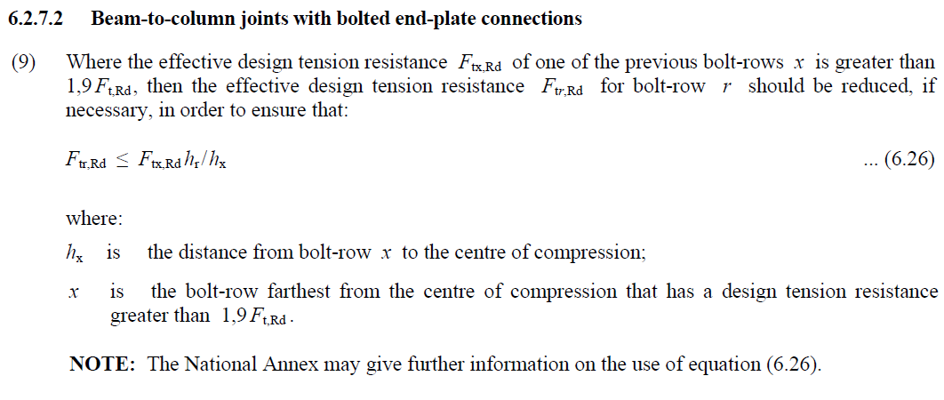
To calculate bending moment by hand, the tensile forces in bolts may be assumed plastically provided Clause 6.2.7.2 (9) is satisfied. Basically mode 1 or 2 (relatively thin end plate or column flange compared to bolts) should govern to ensure ductile behavior.
Widget #NaN: widget_collapsible_list
Name: bf7fe9fb-ec73-012c-450d-ad59e6f94db0
ID: bf7fe9fb-ec73-012c-450d-ad59e6f94db0
Show Raw Data
{
"title": {
"name": "Headline",
"type": "text",
"value": ""
},
"description": {
"name": "Description",
"type": "text",
"value": ""
},
"content_top": {
"images": [],
"linkedItemCodenames": [],
"linkedItems": [],
"links": [],
"name": "Content before",
"type": "rich_text",
"value": "<p><br></p>"
},
"collapsible_items": {
"name": "Collapsible items",
"type": "modular_content",
"value": [
"lm03en_04_1210a42"
],
"linkedItems": [
{
"elements": {
"title": {
"name": "Title",
"type": "text",
"value": "Based on IDEA StatiCa results, quickly estimate lever arm and check that tensile forces in bolts are realistic."
},
"description": {
"name": "Description",
"type": "text",
"value": ""
},
"content_1": {
"images": [],
"linkedItemCodenames": [],
"linkedItems": [],
"links": [],
"name": "Content column 1",
"type": "rich_text",
"value": "<p>The lever arm is the distance between a center of tension and a center of compression.</p>\n<p>The center of tension may be assumed as the top beam flange, because the tensile forces in bolts are similar at both sides of the top flange. No other bolt row has significant tensile bolt forces.</p>\n<p>The center of compression may be assumed near the haunch bottom flange, because there seems to be the center of contact stresses between the end plate and the column flange.</p>\n<p>The lever arm is estimated as:</p>\n<p>\\[l=450-15/2+158-18/2=592 \\textrm{ mm}\\]</p>\n<p>And the average force in the top four bolts is estimated as:</p>\n<p>\\[F_{t,Ed} = M_{Ed}/l/n=700/0.592/4=296 \\textrm{ kN}\\]</p>\n<p>Tensile forces in IDEA StatiCa are between 261 kN and 283 kN. The difference may be attributed to neglected tensile forces in the third bolt row.</p>"
},
"content_2": {
"images": [],
"linkedItemCodenames": [],
"linkedItems": [],
"links": [],
"name": "Content column 2",
"type": "rich_text",
"value": "<p><br></p>"
},
"visibleinregion": {
"name": "VisibleInRegion",
"type": "multiple_choice",
"value": []
},
"regions": {
"name": "Region",
"type": "taxonomy",
"value": [],
"taxonomyGroup": "region"
},
"translation__translation_connector": {
"name": "Translation Connector",
"type": "taxonomy",
"value": [],
"taxonomyGroup": "languages"
},
"translation__force_translation": {
"name": "Force translation",
"type": "multiple_choice",
"value": []
},
"translation__last_translation": {
"images": [],
"linkedItemCodenames": [],
"linkedItems": [],
"links": [],
"name": "Last translation",
"type": "rich_text",
"value": "<p><br></p>"
},
"translation__ai_translated": {
"name": "AI translated",
"type": "multiple_choice",
"value": []
}
},
"system": {
"codename": "lm03en_04_1210a42",
"collection": "default",
"id": "1210a42a-b9de-4728-854a-5b65ef042d21",
"language": "en-US",
"lastModified": "2024-10-23T15:31:12.4110338Z",
"name": "LM03EN-06",
"sitemapLocations": [],
"type": "widget_text_block",
"workflowStep": "published",
"workflow": "default"
}
}
]
},
"content_bottom": {
"images": [],
"linkedItemCodenames": [],
"linkedItems": [],
"links": [],
"name": "Content after",
"type": "rich_text",
"value": "<p><br></p>"
},
"visibleinregion": {
"name": "VisibleInRegion",
"type": "multiple_choice",
"value": []
},
"regions": {
"name": "Region",
"type": "taxonomy",
"value": [],
"taxonomyGroup": "region"
},
"translation__translation_connector": {
"name": "Translation Connector",
"type": "taxonomy",
"value": [],
"taxonomyGroup": "languages"
},
"translation__force_translation": {
"name": "Force translation",
"type": "multiple_choice",
"value": []
},
"translation__last_translation": {
"images": [],
"linkedItemCodenames": [],
"linkedItems": [],
"links": [],
"name": "Last translation",
"type": "rich_text",
"value": "<p><br></p>"
},
"translation__ai_translated": {
"name": "AI translated",
"type": "multiple_choice",
"value": []
}
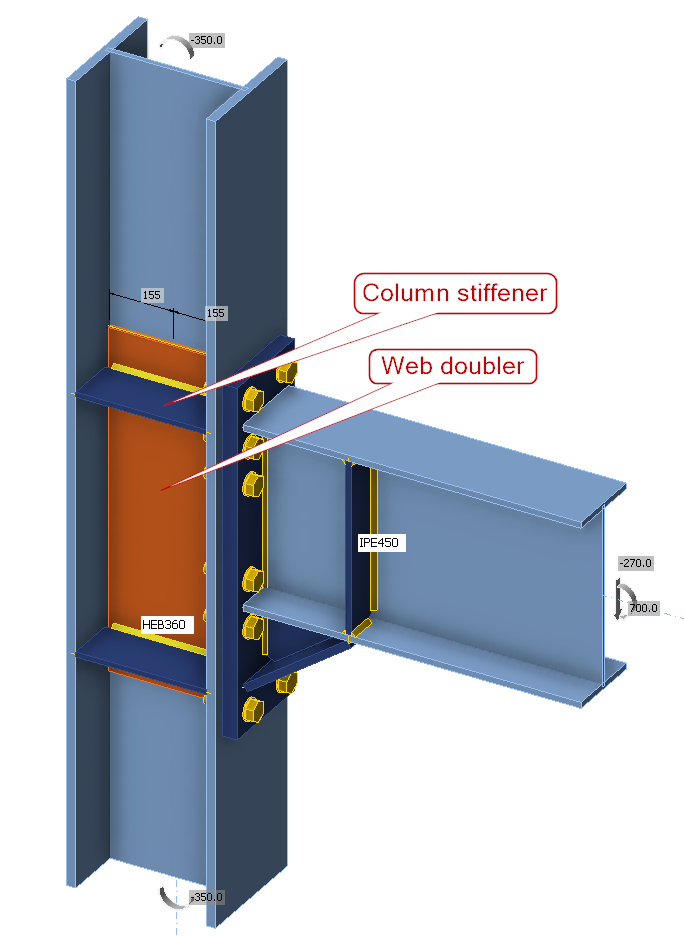
}Column
The load is transferred to the column via tensile and shear forces in end-plate bolts and via contact forces between end plate and column flange.
Widget #NaN: widget_collapsible_list
Name: 566b83c3-08e9-010b-58ea-cd04d3293e70
ID: 566b83c3-08e9-010b-58ea-cd04d3293e70
Show Raw Data
{
  "title": {
    "name": "Headline",
    "type": "text",
    "value": ""
  },
  "description": {
    "name": "Description",
    "type": "text",
    "value": ""
  },
  "content_top": {
    "images": [],
    "linkedItemCodenames": [],
    "linkedItems": [],
    "links": [],
    "name": "Content before",
    "type": "rich_text",
    "value": "<p><br></p>"
  },
  "collapsible_items": {
    "name": "Collapsible items",
    "type": "modular_content",
    "value": [
      "lm03en_06"
    ],
    "linkedItems": [
      {
        "elements": {
          "title": {
            "name": "Title",
            "type": "text",
            "value": "What are the purposes of column web stiffener and column web doubler? What components are they helping?"
          },
          "description": {
            "name": "Description",
            "type": "text",
            "value": ""
          },
          "content_1": {
            "images": [],
            "linkedItemCodenames": [],
            "linkedItems": [],
            "links": [],
            "name": "Content column 1",
            "type": "rich_text",
            "value": "<h5>Column web stiffener</h5>\n<p>Column web stiffener increases the strength and stiffness of column web against concentrated forces applied by contact forces, in this case by haunch flange. They also increase the yield lines for T-stubs in tension at the upper bolt rows.</p>\n<p>Affected components:</p>\n<ul>\n  <li>Column web in transverse tension</li>\n  <li>Column web in transverse compression</li>\n  <li>Column flange in bending</li>\n</ul>\n<h5>Column web doubler</h5>\n<p>Column web doubler is primarily applied to resist the significant shear force in the column web induced by compressive force of the haunch flange and tensile force of upper bolt rows.</p>\n<p>Affected component:</p>\n<ul>\n  <li>Column web in shear</li>\n</ul>"
          },
          "content_2": {
            "images": [],
            "linkedItemCodenames": [],
            "linkedItems": [],
            "links": [],
            "name": "Content column 2",
            "type": "rich_text",
            "value": "<p><br></p>"
          },
          "visibleinregion": {
            "name": "VisibleInRegion",
            "type": "multiple_choice",
            "value": []
          },
          "regions": {
            "name": "Region",
            "type": "taxonomy",
            "value": [],
            "taxonomyGroup": "region"
          },
          "translation__translation_connector": {
            "name": "Translation Connector",
            "type": "taxonomy",
            "value": [],
            "taxonomyGroup": "languages"
          },
          "translation__force_translation": {
            "name": "Force translation",
            "type": "multiple_choice",
            "value": []
          },
          "translation__last_translation": {
            "images": [],
            "linkedItemCodenames": [],
            "linkedItems": [],
            "links": [],
            "name": "Last translation",
            "type": "rich_text",
            "value": "<p><br></p>"
          },
          "translation__ai_translated": {
            "name": "AI translated",
            "type": "multiple_choice",
            "value": []
          }
        },
        "system": {
          "codename": "lm03en_06",
          "collection": "default",
          "id": "c8700b47-6280-4e9a-895e-b0ddaea5a3d4",
          "language": "en-US",
          "lastModified": "2024-10-23T11:47:03.614405Z",
          "name": "LM03EN-06",
          "sitemapLocations": [],
          "type": "widget_text_block",
          "workflowStep": "published",
          "workflow": "default"
        }
      }
    ]
  },
  "content_bottom": {
    "images": [],
    "linkedItemCodenames": [],
    "linkedItems": [],
    "links": [],
    "name": "Content after",
    "type": "rich_text",
    "value": "<p><br></p>"
  },
  "visibleinregion": {
    "name": "VisibleInRegion",
    "type": "multiple_choice",
    "value": []
  },
  "regions": {
    "name": "Region",
    "type": "taxonomy",
    "value": [],
    "taxonomyGroup": "region"
  },
  "translation__translation_connector": {
    "name": "Translation Connector",
    "type": "taxonomy",
    "value": [],
    "taxonomyGroup": "languages"
  },
  "translation__force_translation": {
    "name": "Force translation",
    "type": "multiple_choice",
    "value": []
  },
  "translation__last_translation": {
    "images": [],
    "linkedItemCodenames": [],
    "linkedItems": [],
    "links": [],
    "name": "Last translation",
    "type": "rich_text",
    "value": "<p><br></p>"
  },
  "translation__ai_translated": {
    "name": "AI translated",
    "type": "multiple_choice",
    "value": []
  }
}
Widget #NaN: widget_collapsible_list
Name: fdb6e7e6-4647-01bd-2526-b00763accc79
ID: fdb6e7e6-4647-01bd-2526-b00763accc79
Show Raw Data
{
  "title": {
    "name": "Headline",
    "type": "text",
    "value": ""
  },
  "description": {
    "name": "Description",
    "type": "text",
    "value": ""
  },
  "content_top": {
    "images": [],
    "linkedItemCodenames": [],
    "linkedItems": [],
    "links": [],
    "name": "Content before",
    "type": "rich_text",
    "value": "<p><br></p>"
  },
  "collapsible_items": {
    "name": "Collapsible items",
    "type": "modular_content",
    "value": [
      "lm03en_07"
    ],
    "linkedItems": [
      {
        "elements": {
          "title": {
            "name": "Title",
            "type": "text",
            "value": "Try to remove column web stiffeners and column web doubler. Will the governing failure mode change?"
          },
          "description": {
            "name": "Description",
            "type": "text",
            "value": ""
          },
          "content_1": {
            "images": [
              {
                "description": null,
                "imageId": "2c088d46-cc02-4650-bf82-7205626a6b2b",
                "url": "https://assets-us-01.kc-usercontent.com:443/28eac049-c8ed-00e2-220c-12142a968dff/d513d898-5b99-444d-84ce-6811b3805933/LM3EN-16.png",
                "height": 463,
                "width": 720
              }
            ],
            "linkedItemCodenames": [],
            "linkedItems": [],
            "links": [],
            "name": "Content column 1",
            "type": "rich_text",
            "value": "<p>Several operations should be deactivated:</p>\n<figure data-asset-id=\"2c088d46-cc02-4650-bf82-7205626a6b2b\" data-image-id=\"2c088d46-cc02-4650-bf82-7205626a6b2b\"><img src=\"https://assets-us-01.kc-usercontent.com:443/28eac049-c8ed-00e2-220c-12142a968dff/d513d898-5b99-444d-84ce-6811b3805933/LM3EN-16.png\" data-asset-id=\"2c088d46-cc02-4650-bf82-7205626a6b2b\" data-image-id=\"2c088d46-cc02-4650-bf82-7205626a6b2b\" alt=\"\"></figure>\n<p>The analysis stops at reaching weld resistance at 97% of applied load and weld utilized at 100%.</p>\n<p>This is a surprising result. Column web in shear failure mode would be a logical assumption. At the second glance, the result makes sense: The column web in shear deforms much more, and while it does not cause its failure (exceeding 5% plastic strain limit), it increases the demand on other components. Weld is the most brittle and fails first when the surrounding plates deform.</p>"
          },
          "content_2": {
            "images": [],
            "linkedItemCodenames": [],
            "linkedItems": [],
            "links": [],
            "name": "Content column 2",
            "type": "rich_text",
            "value": "<p><br></p>"
          },
          "visibleinregion": {
            "name": "VisibleInRegion",
            "type": "multiple_choice",
            "value": []
          },
          "regions": {
            "name": "Region",
            "type": "taxonomy",
            "value": [],
            "taxonomyGroup": "region"
          },
          "translation__translation_connector": {
            "name": "Translation Connector",
            "type": "taxonomy",
            "value": [],
            "taxonomyGroup": "languages"
          },
          "translation__force_translation": {
            "name": "Force translation",
            "type": "multiple_choice",
            "value": []
          },
          "translation__last_translation": {
            "images": [],
            "linkedItemCodenames": [],
            "linkedItems": [],
            "links": [],
            "name": "Last translation",
            "type": "rich_text",
            "value": "<p><br></p>"
          },
          "translation__ai_translated": {
            "name": "AI translated",
            "type": "multiple_choice",
            "value": []
          }
        },
        "system": {
          "codename": "lm03en_07",
          "collection": "default",
          "id": "584b04a5-ddc4-4988-bb9b-f53e5c180fd4",
          "language": "en-US",
          "lastModified": "2024-11-27T12:43:44.3481699Z",
          "name": "LM03EN-07",
          "sitemapLocations": [],
          "type": "widget_text_block",
          "workflowStep": "published",
          "workflow": "default"
        }
      }
    ]
  },
  "content_bottom": {
    "images": [],
    "linkedItemCodenames": [],
    "linkedItems": [],
    "links": [],
    "name": "Content after",
    "type": "rich_text",
    "value": "<p><br></p>"
  },
  "visibleinregion": {
    "name": "VisibleInRegion",
    "type": "multiple_choice",
    "value": []
  },
  "regions": {
    "name": "Region",
    "type": "taxonomy",
    "value": [],
    "taxonomyGroup": "region"
  },
  "translation__translation_connector": {
    "name": "Translation Connector",
    "type": "taxonomy",
    "value": [],
    "taxonomyGroup": "languages"
  },
  "translation__force_translation": {
    "name": "Force translation",
    "type": "multiple_choice",
    "value": []
  },
  "translation__last_translation": {
    "images": [],
    "linkedItemCodenames": [],
    "linkedItems": [],
    "links": [],
    "name": "Last translation",
    "type": "rich_text",
    "value": "<p><br></p>"
  },
  "translation__ai_translated": {
    "name": "AI translated",
    "type": "multiple_choice",
    "value": []
  }
}