The building is located directly above an underground structure. As a result, some piles that would normally be installed beneath the columns cannot be constructed. To address this, the engineers proposed the use of transfer walls to support the affected columns.
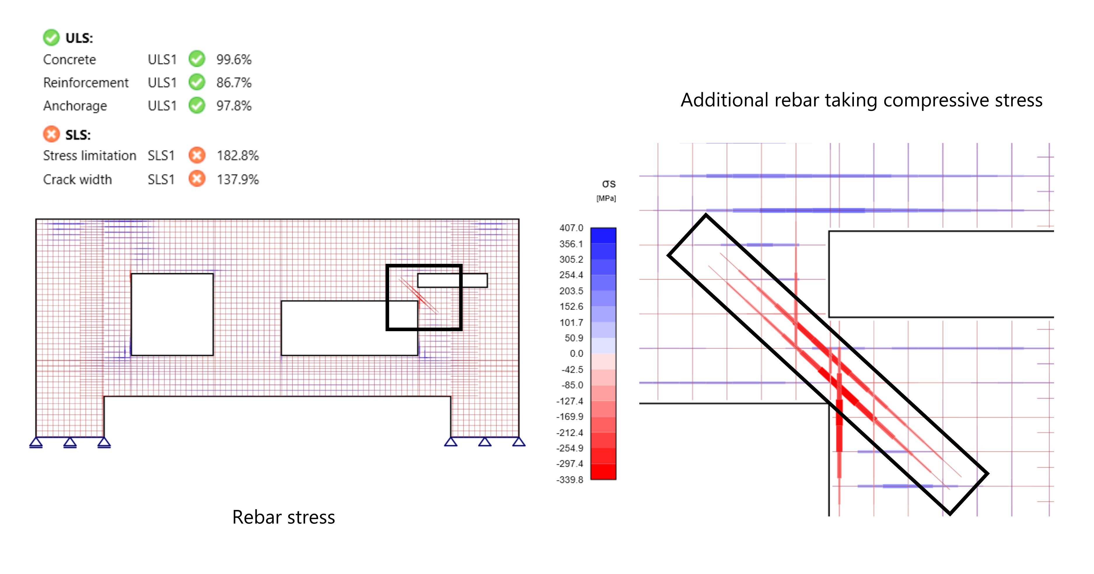
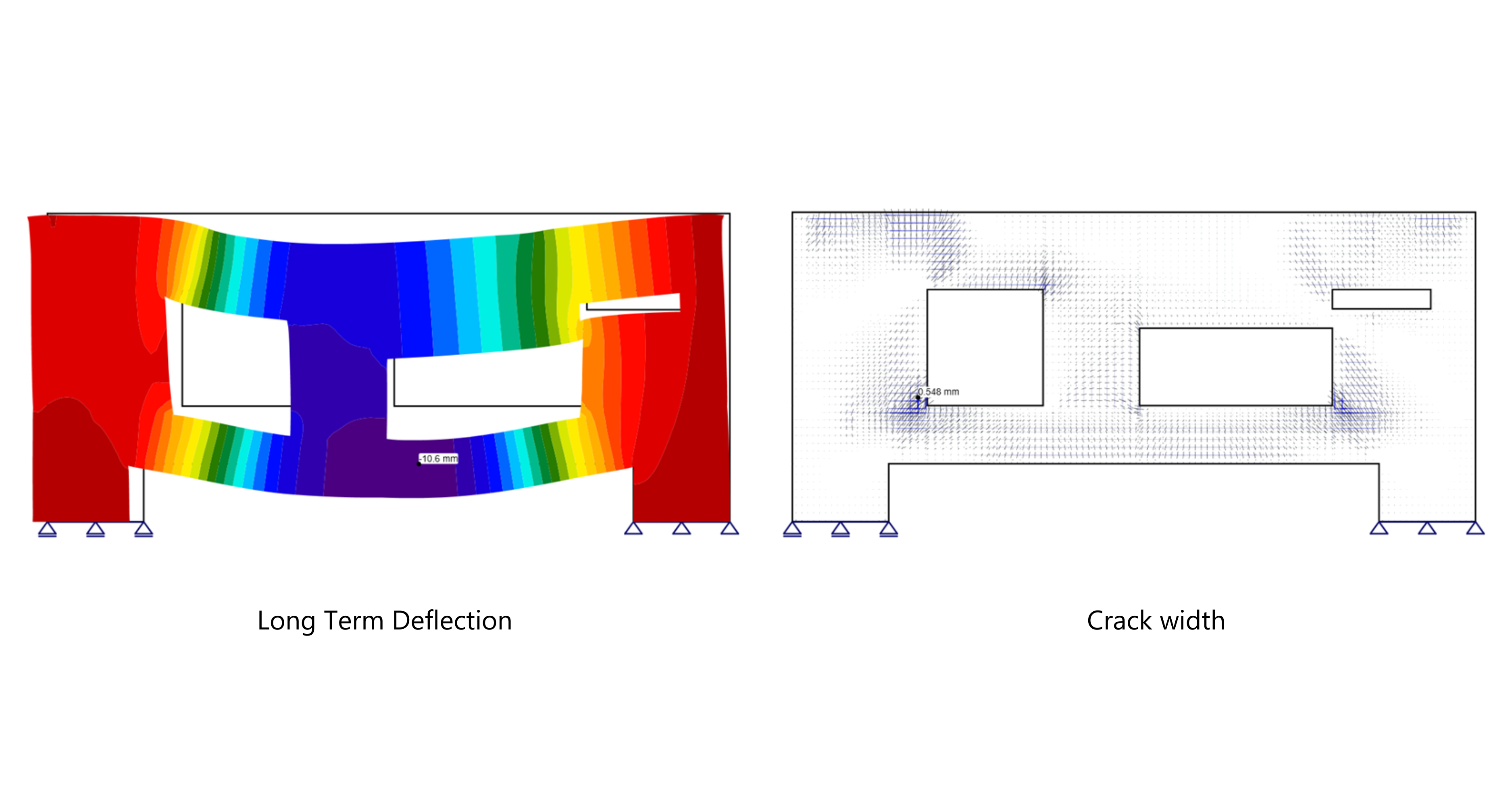
However, the design of transfer walls is inherently complex, particularly when openings are present. Furthermore, for underground structures, serviceability limit state (SLS) considerations, such as crack width control, are more critical, as these structures are in contact with soil and therefore more susceptible to durability issues, including corrosion. Well-established design methods, such as the strut-and-tie method, primarily address ultimate limit state (ULS) requirements but do not adequately cover SLS behaviour.
Transfer Wall Design
Transfer wall design is a complex subject because it often behaves like D-regions, where the assumption of plane section is not valid, hence normal empirical formulas found in design code cannot be used. This means that the design feature inside global FEA software, which often uses a beam or column design assumption, is not suitable for this problem.

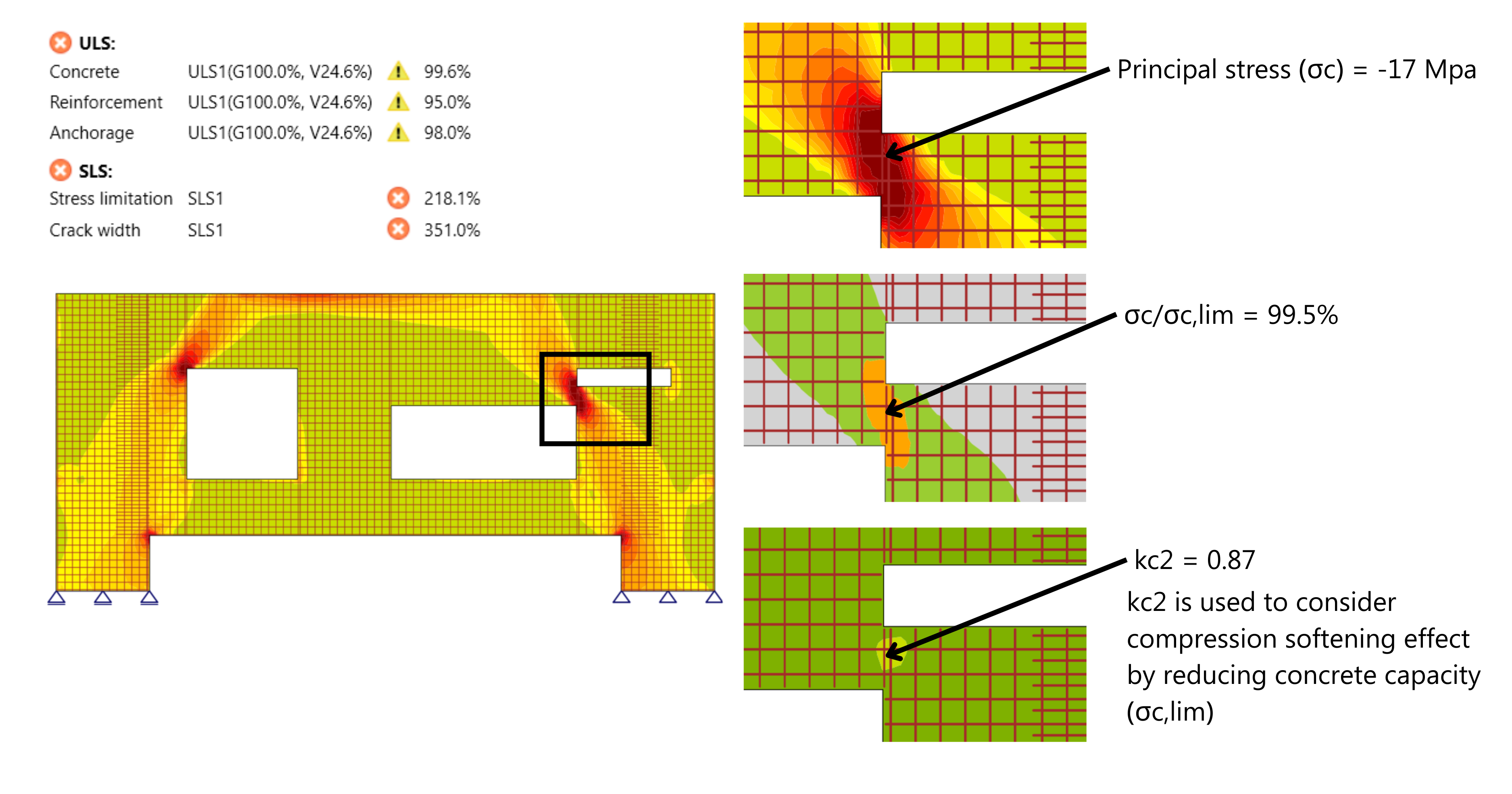
In the wall shown above, engineers have two options for designing the wall. One is to use strut-and-tie, although this a good and suitable method, there is a lot of manual work and trial-error involved, which might be time consuming. Second is to use approximation in global FEA software by evaluating principal tensile stresses to determine reinforcement requirements and verifying that principal compressive stresses remain below the concrete’s design strength.
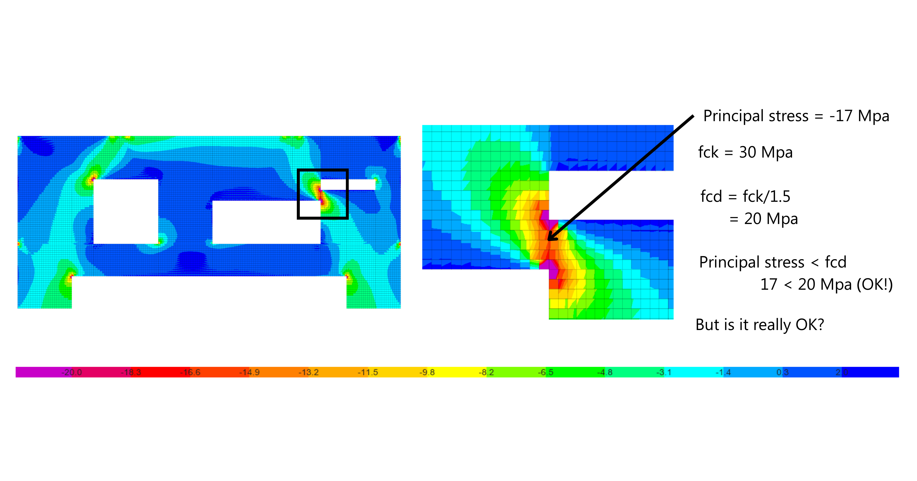
Option two seems like a more practical and time efficient choice, but there is a hidden danger lying in it.