1. The objective
The objective of this article is the verification of the LBA (linear bifurcation analysis) module of the IDEA Member application. Beams in bending are analyzed and the influence of different loading conditions is investigated. The resulting elastic critical moments from IDEA Member are compared to the elastic critical moments based on Annex I of EN 1999-1-1 [1]. Numerical solutions from ANSYS [2] and LTBeam [3] software are also presented.
2. Model description
A total of 18 individual cases was analyzed to verify the LBA module. All of them share the same cross-section IPE 240 and the same steel grade S 235. Three different loading conditions were investigated (A – end moments, B – force in the middle, C – continuous load). Six relative slenderness values were verified ranging from 0.6 to 1.6.
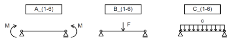
Fig. 1: Various boundary conditions and load cases used for verification
3. Analytical solution
The three-factor formula found in Annex I of EN 1999-1-1 is used to calculate the elastic critical moment for lateral-torsional buckling of the beams:
\[ M_{cr} = \mu_{cr} \frac{\pi \sqrt{E I_z G I_t}}{L} \]
\[ \mu_{cr} = \frac{c_1}{k_z} \left [ \sqrt{1+\kappa_{wt}^2 + (C_2 \zeta_g - C_3 \zeta_j)^2} - (C_2 \zeta_g - C_3 \zeta_j) \right ] \]
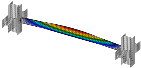
Fig. 2: Buckling mode of a simply supported beam (C_5)
4. Results
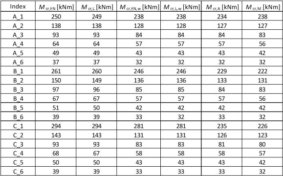
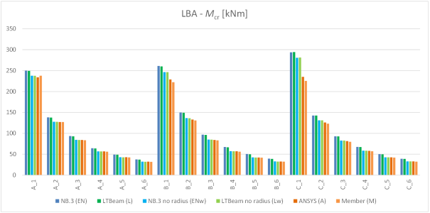
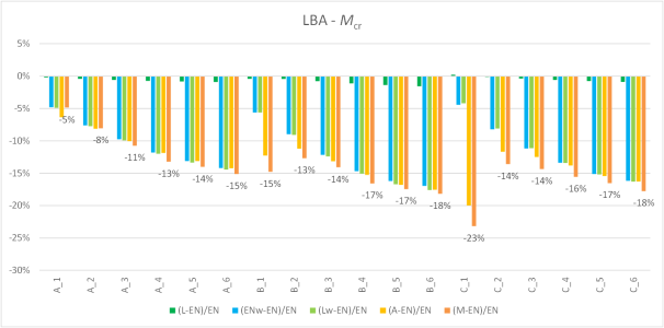
The elastic critical moment from IDEA Member (M) is compared to an analytical value for a rolled cross-section (EN) and for its representation without the web-flange radii (ENw). Furthermore, the same two sets of values are presented as an output from the LTBeam software [3] (L – with radii, Lw – without radii). Finally, results from the ANSYS software [2] without radii (A) are presented.
Tab. 1: Resulting elastic critical moments